
Programming interactivity
736
-
Upload
upacifico-cl -
Category
Documents
-
view
0 -
download
0
Transcript of Programming interactivity


Download at Boykma.Com

Programming InteractivityA Designer’s Guide to Processing, Arduino, and
openFrameworks
Joshua Noble
Beijing • Cambridge • Farnham • Köln • Sebastopol • Taipei • Tokyo
Download at Boykma.Com

Programming Interactivityby Joshua Noble
Copyright © 2009 Joshua Noble. All rights reserved.Printed in the United States of America.
Published by O’Reilly Media, Inc., 1005 Gravenstein Highway North, Sebastopol, CA 95472.
O’Reilly books may be purchased for educational, business, or sales promotional use. Online editionsare also available for most titles (http://my.safaribooksonline.com). For more information, contact ourcorporate/institutional sales department: (800) 998-9938 or [email protected].
Editor: Steve WeissProduction Editor: Sumita MukherjiCopyeditor: Kim WimpsettProofreader: Sumita MukherjiProduction Services: Newgen
Indexer: Ellen Troutman ZaigCover Designer: Karen MontgomeryInterior Designer: David FutatoIllustrator: Robert Romano
Printing History:July 2009: First Edition.
Nutshell Handbook, the Nutshell Handbook logo, and the O’Reilly logo are registered trademarks ofO’Reilly Media, Inc. Programming Interactivity, the image of guinea fowl, and related trade dress aretrademarks of O’Reilly Media, Inc.
Many of the designations used by manufacturers and sellers to distinguish their products are claimed astrademarks. Where those designations appear in this book, and O’Reilly Media, Inc., was aware of atrademark claim, the designations have been printed in caps or initial caps.
While every precaution has been taken in the preparation of this book, the publisher and author assumeno responsibility for errors or omissions, or for damages resulting from the use of the information con-tained herein.
TM
This book uses RepKover™, a durable and flexible lay-flat binding.
ISBN: 978-0-596-15414-1
[M]
1247251884
Download at Boykma.Com

Table of Contents
Preface . . . . . . . . . . . . . . . . . . . . . . . . . . . . . . . . . . . . . . . . . . . . . . . . . . . . . . . . . . . . . . . . . . . . . xv
Part I. Introductions
1. Introducing Interaction Design . . . . . . . . . . . . . . . . . . . . . . . . . . . . . . . . . . . . . . . . . . . . 3What This Book Is for 3Programming for Interactivity 4
The Nature of Interaction 5Messages and Interaction 7Interfaces and Interaction 8Languages of Interaction 10
Design and Interaction 12Art and Interaction 13Data Exchange and Exploration 15Working Process 19
2. Programming Basics . . . . . . . . . . . . . . . . . . . . . . . . . . . . . . . . . . . . . . . . . . . . . . . . . . . . 21Why You’ll Read This Chapter More Than Once 22The Nature of Code 22Variables 23
Simple Types 24Arrays 29Casting 33Operators 33
Control Statements 37if/then 37for Loop 38while Loop 39continue 40break 40
Functions 41
iii
Download at Boykma.Com

Defining a Function 41Passing Parameters to a Method 42Some Suggestions on Writing Functions 44Overloading Functions 44
Objects and Properties 46Scope 49Review 50
3. Processing . . . . . . . . . . . . . . . . . . . . . . . . . . . . . . . . . . . . . . . . . . . . . . . . . . . . . . . . . . . . 53Downloading and Installing Processing 54Exploring the Processing IDE 54The Basics of a Processing Application 56
The setup() Method 56The draw() Method 57
The Basics of Drawing with Processing 60The rect(), ellipse(), and line() Methods 60RGB Versus Hexadecimal 62The fill() Method 63The background() Method 65The line() Method 65The stroke() and strokeWeight() Methods 65The curve() Method 66The vertex() and curveVertex() Methods 66
Capturing Simple User Interaction 67The mouseX and mouseY Variables 68The mousePressed() Method 69The mouseReleased() and mouseDragged() Methods 70The keyPressed and key Variables 73
Importing Libraries 77Downloading Libraries 77
Loading Things into Processing 79Loading and Displaying Images 79Displaying Videos in the Processing Environment 81Using the Movie Class 81Reading and Writing Files 83
Running and Debugging Applications 85Exporting Processing Applications 86Conclusion 88Review 89
4. Arduino . . . . . . . . . . . . . . . . . . . . . . . . . . . . . . . . . . . . . . . . . . . . . . . . . . . . . . . . . . . . . . 91Starting with Arduino 92
Installing the IDE 93
iv | Table of Contents
Download at Boykma.Com

Configuring the IDE 96Touring Two Arduino Boards 97
The Controller 97Duemilanove Versus Mini 97
Touring the Arduino IDE 102The Basics of an Arduino Application 105
The setup Statement 106The loop Method 106
Features of the Arduino Language 108Constants 109Methods 110Arrays 111Strings 112
How to Connect Things to Your Board 115Hello World 117Debugging Your Application 122Importing Libraries 124Running Your Code 126
Running Your Board Without a USB Connection 126Review 127
5. Programming Revisited . . . . . . . . . . . . . . . . . . . . . . . . . . . . . . . . . . . . . . . . . . . . . . . . 129Object-Oriented Programming 129Classes 130
The Basics of a Class 131Class Rules 132
Public and Private Properties 133Inheritance 135Processing: Classes and Files 137C++: Classes and Files 139
.cpp and .h 140A Simple C++ Application 142
Pointers and References 144Reference 146Pointer 146When to Use Pointers 147Large Data Objects 148Pointers and Arrays 149When Are You Going to Use This? 150
Review 151
6. openFrameworks . . . . . . . . . . . . . . . . . . . . . . . . . . . . . . . . . . . . . . . . . . . . . . . . . . . . . 153Your IDE and Computer 154
Table of Contents | v
Download at Boykma.Com

Windows 154Mac OS X 155Linux 155
Taking Another Quick Tour of C++ 156Basic Variable Types 157Arrays 157Methods 158Classes and Objects in C++ 159
Getting Started with oF 160Touring an oF Application 166
Methods 166Variables 168
Creating “Hello, World” 168Drawing in 2D 171
Setting Drawing Modes 172Drawing Polygons 174
Displaying Video Files and Images 176Images 176Video 178
Importing Libraries 180ofxOpenCv 181ofxVectorGraphics 181ofxVectorMath 182ofxNetwork 182ofxOsc 182
Compiling an oF Program 183Compiling in Xcode 183Compiling in Code::Blocks 184
Debugging an oF Application 184Using the printf Statement 184Using the GNU Debugger 185Using the Debugger in Xcode 186Using the Debugger in Code::Blocks 188
Review 188
Part II. Themes
7. Sound and Audio . . . . . . . . . . . . . . . . . . . . . . . . . . . . . . . . . . . . . . . . . . . . . . . . . . . . . 193Sound As Feedback 194Sound and Interaction 197How Sound Works on a Computer 199Audio in Processing 202
vi | Table of Contents
Download at Boykma.Com

Instantiating the Minim Library 202Generating Sounds with Minim 204Filtering Sounds with Minim 208
Sound in openFrameworks 214openFrameworks and the FMOD Ex Library 221The Sound Object Library 228The Magic of the Fast Fourier Transform 233Physical Manipulation of Sound with Arduino 238A Quick Note on PWM 239Creating Interactions with Sound 242Further Resources 242Review 243
8. Physical Input . . . . . . . . . . . . . . . . . . . . . . . . . . . . . . . . . . . . . . . . . . . . . . . . . . . . . . . . 245Interacting with Physical Controls 245Thinking About Kinetics 246Getting Gear for This Chapter 247Controlling Controls 248
The Button As an Electrical Object 248The Button As an Interactive Object 248The Button As a Value in Code 248
Turning Knobs 249The Dial As an Interactive Object 249Potentiometers 249
Using Lights 251Wiring an LED 252
Detecting Touch and Vibration 253Reading a Piezo Sensor 254Getting Piezo Sensors 255
Communicating with Other Applications 259Sending Messages from the Arduino 262
openFrameworks 263Detecting Motion 265
PIR Motion Sensor 265Reading Distance 267
Reading Input from an Infrared Sensor 269Understanding Binary Numbers 270
Binary Numbers 270Bits and Bit Operations 271Why Do You Need to Know Any of This? 273
Detecting Forces and Tilt 273Introducing I2C 278What Is a Physical Interface? 283
Table of Contents | vii
Download at Boykma.Com

What’s Next 284Review 286
9. Programming Graphics . . . . . . . . . . . . . . . . . . . . . . . . . . . . . . . . . . . . . . . . . . . . . . . . 289The Screen and Graphics 289Seeing Is Thinking, Looking Is Reading 292Math, Graphics, and Coordinate Systems 293Drawing Strategies 296
Use Loops to Draw 296Use Arrays to Draw 298Draw Only What You Need 303Use Sprites 303
Processing and Transformation Matrices 303Creating Motion 307
Shaping the Gaze 308Setting the Mood 308Creating Tweens 310
Using Vectors 315Using Graphical Controls 325
ControlP5 Library 326Event Handling 326
Importing and Exporting Graphics 328Using PostScript in Processing 329Using PostScript Files in oF 330
What’s Next 333Review 334
10. Bitmaps and Pixels . . . . . . . . . . . . . . . . . . . . . . . . . . . . . . . . . . . . . . . . . . . . . . . . . . . . 337Using Pixels As Data 338Using Pixels and Bitmaps As Input 340Providing Feedback with Bitmaps 341Looping Through Pixels 342Manipulating Bitmaps 345
Manipulating Color Bytes 347Using Convolution in Full Color 348
Analyzing Bitmaps in oF 349Analyzing Color 350Analyzing Brightness 351Detecting Motion 353Using Edge Detection 355
Using Pixel Data 361Using Textures 368
Textures in oF 369
viii | Table of Contents
Download at Boykma.Com

Textures in Processing 373Saving a Bitmap 375What’s Next 376Review 377
11. Physical Feedback . . . . . . . . . . . . . . . . . . . . . . . . . . . . . . . . . . . . . . . . . . . . . . . . . . . . 379Using Motors 380
DC Motors 381Stepper Motors 384Other Options 386
Using Servos 386Connecting a Servo 387Communicating with the Servo 387Wiring a Servo 388
Using Household Currents 392Working with Appliances 393Introducing the LilyPad Board 395Using Vibration 397Using an LED Matrix 404
Using the Matrix Library 404Using the LedControl Library 407Using the SPI Protocol 410
Using LCDs 412Serial LCD 416
Using Solenoids for Movement 417What’s Next 420Review 421
12. Protocols and Communication . . . . . . . . . . . . . . . . . . . . . . . . . . . . . . . . . . . . . . . . . . 423Communicating Over Networks 425Using XML 426Understanding Networks and the Internet 429
Network Organization 429Network Identification 430Network Data Flow 431
Handling Network Communication in Processing 432Client Class 432Server Class 433Sharing Data Across Applications 436
Understanding Protocols in Networking 441Using ofxNetwork 442Creating Networks with the Arduino 450
Initializing the Ethernet Library 451
Table of Contents | ix
Download at Boykma.Com

Creating a Client Connection 452Creating a Server Connection 453
Using Carnivore to Communicate 456Installing the Carnivore Library 457Creating a Carnivore Client 458
Communicating with Bluetooth 460Using Bluetooth in Processing 461Using the bluetoothDesktop Library 461Using the Arduino Bluetooth 464
Communicating Using MIDI 467Review 471
Part III. Explorations
13. Graphics and OpenGL . . . . . . . . . . . . . . . . . . . . . . . . . . . . . . . . . . . . . . . . . . . . . . . . . . 475What Does 3D Have to Do with Interaction? 475Understanding 3D 476Working with 3D in Processing 477
Lighting in Processing 478Controlling the Viewer’s Perspective 480
Making Custom Shapes in Processing 484Using Coordinates and Transforms in Processing 487Working with 3D in OpenGL 489
So, What Is OpenGL? 489Transformations 490OpenGL in Processing 490Open GL in openFrameworks 492
Using Matrices and Transformations in OpenGL 493Using Vertices in OpenGL 496Drawing with Textures in oF 496Lighting in OpenGL 500Blending Modes in OpenGL 501Using Textures and Shading in Processing 506
Applying Material Properties 507Using Another Way of Shading 508
What Does GLSL Look Like? 508Vertex Shaders 508Fragment Shader 509Variables Inside Shaders 510
Using an ofShader Addon 510What to Do Next 513Review 514
x | Table of Contents
Download at Boykma.Com

14. Detection and Gestures . . . . . . . . . . . . . . . . . . . . . . . . . . . . . . . . . . . . . . . . . . . . . . . . 517Computer Vision 518
Interfaces Without Controls 519Example CV Projects 520
OpenCV 521Using Blobs and Tracking 521
Starting with ofxOpenCV 522Tracking Blobs with ofxOpenCV 527
Using OpenCV in Processing 537Exploring Further in OpenCV 542
Detecting Gestures 543Using ezGestures in Processing 544Using Gestures in oF 548
Implementing Face Recognition 550Exploring Touch Devices with oF 554
TouchKit 554Tuio 555Touchlib 555reacTIVision 555
What’s Next 556Review 557
15. Movement and Location . . . . . . . . . . . . . . . . . . . . . . . . . . . . . . . . . . . . . . . . . . . . . . . 559Using Movement As and in Interaction 559Using Software-Based Serial Ports 561Understanding and Using GPS 563Storing Data 575Logging GPS Data to an Arduino 577
Using the Breadcrumbs Library 578Implementing Hardware-Based Logging 579
Sending GPS Data 580Determining Location by IP Address 583What to Do Next 589Review 589
16. Interfaces and Controls . . . . . . . . . . . . . . . . . . . . . . . . . . . . . . . . . . . . . . . . . . . . . . . . 591Examining Tools, Affordances, and Aesthetics 592Reexamining Tilt 593Exploring InputShield 597Understanding Touch 599Exploring Open Source Touch Hardware 600
Nort_/D 600Liquidware TouchShield 603
Table of Contents | xi
Download at Boykma.Com

Drawing to the TouchShield Screen 607Controlling Servos Through the TouchShield 609Setting Up Communication Between Arduino and TouchShield 611
Communicating Using OSC 614Using the Wiimote 616
Using the Wii Nunchuck in Arduino 616Tracking Wii Remote Positioning in Processing 622
What’s Next 625Review 626
17. Spaces and Environments . . . . . . . . . . . . . . . . . . . . . . . . . . . . . . . . . . . . . . . . . . . . . . 627Using Architecture and Space 627Sensing Environmental Data 628Using an XBee with Arduino 629
Creating a Simple Test 632Configuring the XBee Module 634Addressing in the XBee 635XBee Library for Processing 637
Placing Objects in 2D 641Using the X10 Protocol 651Setting Up an RFID Sensor 654Reading Heat and Humidity 659What’s Next 664Review 664
18. Further Resources . . . . . . . . . . . . . . . . . . . . . . . . . . . . . . . . . . . . . . . . . . . . . . . . . . . . . 667What’s Next? 667
Software Tools 667Construction Processes 670Artificial Intelligence 671Physics 677Hardware Platforms 678
Bibliography 681Interaction Design 681Programming 682Hardware 683Art 683
Conclusion 684
xii | Table of Contents
Download at Boykma.Com

Appendix: Circuit Diagram Symbols . . . . . . . . . . . . . . . . . . . . . . . . . . . . . . . . . . . . . . . . . . . . 685
Programming Glossary . . . . . . . . . . . . . . . . . . . . . . . . . . . . . . . . . . . . . . . . . . . . . . . . . . . . . . 687
Index . . . . . . . . . . . . . . . . . . . . . . . . . . . . . . . . . . . . . . . . . . . . . . . . . . . . . . . . . . . . . . . . . . . . . 693
Table of Contents | xiii
Download at Boykma.Com

Download at Boykma.Com

Preface
This is a book about creating physical interaction with computer systems. It focuseson designing hardware and programming for systems that use either physical input orphysical feedback. This book has been a dream of mine since I was an art studentbeginning to create interactive installations and finding that there was no simple in-troduction to the topics that I wanted to explore. At the time, I didn’t know whatplatforms, tools, and programming languages were available for creating interactiveart, and I didn’t know where to find more information about these topics that a relativenovice programmer could understand. As I began teaching, I was asked the same ques-tion again and again by students: “where do I begin?” Much has changed in the sevenyears since then, though, and now many excellent projects are helping beginners pro-gram, artists create, and programmers rapidly prototype applications. We’ll cover threeof these projects in this book: Processing, Arduino, and openFrameworks. This bookintends to answer the question “Where do I begin?” in as comprehensive a manner aspossible. It is the intention of this book to be useful for almost any type of project. Thisbook will provide technical advice, critical commentary for you to consider, code thatyou can use, hardware diagrams that you can use, and further resources for you toexplore.
Ten years ago, the idea of artists or designers writing code or designing hardware wasalmost unheard of. Today, not only has it become commonplace, but it has become animportant arena of expression and exploration. The dialogue between technology anddesign is a vital and vibrant one that shapes art and technology alike. I hope that thisbook can be, in some small way, another path into this conversation for more artistsand designers.
Who This Book Is ForThis book is aimed at designers, artists, amateur programmers, or anyone interested inworking with physical interaction in computing. No assumption is made about yourtechnical background or previous experience. The only assumption is that you areinterested in learning to program and build hardware. This book is an introduction toa great number of topics, and throughout the book we list links to further resources soyou can expand your knowledge or explore a particular topic that interests you.
xv
Download at Boykma.Com

We encourage you to make as much use as possible of these resources and to use thisbook as a map for exploring a great number of technologies and techniques.
How This Book Is OrganizedThis book is broken into three parts. The first introduces the three projects that will beused throughout this book, the second introduces some of the most common themesin creating interaction in designs and applications, and the third introduces some ofthe more advanced topics that you may want to explore further. Also included withsome of the chapters are interviews with programmers, artists, designers, and authorswho work with the tools covered in this book. Covering such a massive range of topicsmeans that this book doesn’t go into great depth about most of them, but it is filledwith references to other books, websites, designers, and artists that you may find helpfulor inspiring.
What Is—and Isn’t—in This BookMy excitement about the ideas and rapid growth of the field of interaction design ishard to contain. However, as exciting and far-reaching as interaction design is, thelimitations of time and physical book size dictate that I be selective about what is andisn’t covered in this book.
What’s inThis book covers Processing, Arduino, and openFrameworks. To help novice pro-grammers, it covers some of the core elements of programming in C and C++ for Ar-duino and openFrameworks and also covers the Processing language. We introducedozens of libraries for openFrameworks and Processing—too many to list here. Someof these are official libraries or add-ons for the two frameworks, and some are simplyextensions that have been created for this book or provided by altruistic coders.
We also introduce some of the basics of electronics and how computer hardwarefunctions, as well as many tools and components that you can use with an Arduino.The Arduino and Processing IDEs are covered, as are two different IDEs foropenFrameworks, namely, CodeBlocks, and Xcode. The Arduino Duemilanove andMini are covered in depth, and we discuss other boards only briefly. We cover manyelectronic components that have designed expressly for the Arduino, called shields, indepth as well.
What’s Not inWhile this book shows how to create some circuits, it doesn’t cover a great deal of thefundamentals of electronics or hardware, how to create circuits, or electronics theory.
xvi | Preface
Download at Boykma.Com

Chapter 18 lists some excellent tutorials and references. While the book does cover theProcessing subset of the Java programming language, to conserve space and maintainfocus, it doesn’t cover Java. The book doesn’t cover many aspects of C++, such astemplates, inline functions, operator overloading, and abstract classes. Again, though,listed in Chapter 18 are several excellent resources that you can use to learn about thesedeeper topics in C++.
There are so many Arduino-compatible boards now that it’s almost impossible to coverthem all in depth; the book mentions the Mega, the Nano, and several other boardsonly in passing and leaves out many of the Arduino-compatible boards that are notcreated by the Arduino team. Quite a few components and other tools that we wouldhave liked to discuss in depth could not be included to maintain scope and to savespace. A good camera for computer vision was not included either, though a glance atthe openFrameworks or Processing forums will likely provide a more up-to-date dis-cussion than could have been given here.
Many topics that we would have liked to include have been left out because of spaceconsiderations: artificial intelligence, data visualization, and algorithmic music, amongothers. Though these are all potentially interesting areas for artists and designers, thefocus of the book is on teaching some of the theory and techniques for interactiondesign as well as the basics of hardware and programming. The resources listed at theend of the book can provide the names of some materials that might help you explorethese topics.
Companion WebsiteAll the code included in this book are available for download from the book’s com-panion website, http://www.oreilly.com/catalog/9780596154141.
Typographical Conventions Used in This BookThe following typographical conventions are used in this book:
ItalicIndicates new terms, URLs, email addresses, filenames, file extensions, pathnames, and directories.
Constant widthIndicates direct references to code, text output from executing scripts, XML tags,HTML tags, and the contents of files.
Constant width boldShows commands or other text that should be typed literally by the user.
Constant width italicShows text that should be replaced with user-supplied values.
Preface | xvii
Download at Boykma.Com

This icon signifies a tip, suggestion, or general note.
This icon indicates a warning or caution.
Hexadecimal numbers in this book are denoted with the prefix 0x.
Using Code ExamplesThis book is here to help you get your job done. In general, you may use the code inthis book in your programs and documentation. You do not need to contact us forpermission unless you’re reproducing a significant portion of the code. For example,writing a program that uses several chunks of code from this book does not requirepermission. Answering a question by citing this book and quoting example code doesnot require permission. On the other hand, selling or distributing a CD-ROM of ex-amples from O’Reilly books does require permission. Incorporating a significantamount of example code from this book into your product’s documentation does re-quire permission.
We appreciate, but do not require, attribution. An attribution usually includes the title,author, publisher, and ISBN. For example: Programming Interactivity by Joshua Noble.Copyright 2009 Joshua Noble, 978-0-596-15414-1.
If you think your use of code examples falls outside fair use or the permission givenhere, feel free to contact us at [email protected].
Safari® Books OnlineWhen you see a Safari® Books Online icon on the cover of your favoritetechnology book, that means the book is available online through theO’Reilly Network Safari Bookshelf.
Safari offers a solution that’s better than e-books. It’s a virtual library that lets you easilysearch thousands of top tech books, cut and paste code samples, download chapters,and find quick answers when you need the most accurate, current information. Try itfor free at http://my.safaribooksonline.com.
xviii | Preface
Download at Boykma.Com

We’d Like to Hear from YouPlease address comments and questions concerning this book to the publisher:
O’Reilly Media, Inc.1005 Gravenstein Highway NorthSebastopol, CA 95472800-998-9938 (in the United States or Canada)707-829-0515 (international or local)707-829-0104 (fax)
We have a web page for this book, where we list errata, examples, and any additionalinformation. You can access this page at:
http://www.oreilly.com/catalog/9780596154141
To comment or ask technical questions about this book, send email to:
For more information about our books, conferences, Resource Centers, and theO’Reilly Network, see our website at:
http://www.oreilly.com
AcknowledgmentsI need, first and foremost, to thank the wonderful engineers, artists, programmers, anddreamers who created the platforms that I’ve covered in this book. It is to all of themthat I would like to dedicate this book. A woefully short list has to include MassimoBanzi, Tom Igoe, David Cuartielles, Gianluca Martino, David A. Mellis, Ben Fry, CaseyReas, Zach Lieberman, Theo Watson, Arturo Castro, and Chris O’Shea, the creatorsof the frameworks covered in this book. There are dozens, if not hundreds, of othernames that should be on this list, but space is too limited to list them all. All I can sayis thank to you to all the creators of these frameworks and to everyone who uses themto inspire, invent, amaze, and enrich the dialogue about design, technology, and art.This book is a humble attempt to thank you all for everything that you’ve given to meand to every other programmer, artist, or designer interested for working with com-puting in novel and interesting ways and bringing more people into the conversation.I would also like to extend my deepest thanks to all my interviewees for taking the timeto respond to my questions and enrich this book and for so enriching the world ofinteraction design and art. To everyone who provided code for this book as well, createdopen source code, or answered questions on any of the forums for beginners, thankyou for your efforts to create a community.
Preface | xix
Download at Boykma.Com

This book is as much my effort as it is the sum of the efforts of the editorial team thatworked on it. My technical editors, Michael Margolis, Adam Parrish, and Jeremy Rotz-stain, have been absolutely fantastic. Their expertise, suggestions, and fresh look atwhat I was working on shaped not only this book but enlightened me, showed me newways of solving problems, introduced me to new tools and techniques, and sharpenedmy thinking and broadened my horizons for the better. This book is a collaborationbetween all four of us in every sense of the word. I cannot pay them enough thanks fortheir excellent work. I would also like to thank Justin Hunyh and Mike Gionfriddofrom LiquidWare as well as Nathan Seidle from Sparkfun for all of their help. Myeditors, Robyn Thomas and Kim Wimpsett, have been incredible, helping me with mysometime torturous grammar and patiently working with my propensity for sending inextremely rough drafts to bounce ideas off of them. They have made this book betterthan it ever could have been without their watchful eyes and guidance. Finally, I needto thank Steve Weiss for listening to my idea when I first proposed it and helping guideit through to completion.
I need to thank all of my friends in New York, Amsterdam, Geneva, London, Zurich,Boston, Paris, and Toulouse for their support, their ideas, their Internet, and their en-couragement. I would like to thank my family as well, and particularly my mother, fortheir support and humor.
xx | Preface
Download at Boykma.Com

PART I
Introductions
Part I of this book is an introduction not only to writing code and working with hard-ware, but also to the three tools that you’ll be learning about in this book: Processing,Arduino, and openFrameworks. You’ll learn about writing software in general andabout writing code for each of the three platforms in particular. Each of the three plat-forms approaches the applications that you’ll use to actually write code in a slightlydifferent way, but the general concepts of working with the code are the same acrossall three. One thing you’ll come to realize as you learn more about programming is thatthe core concepts of programming are quite similar across a lot of different program-ming languages. This means that the knowledge you have about Processing, for in-stance, can help you if you decide to create a project using Arduino. Understandinghow these different frameworks are similar will help you leverage your knowledge inone to work with the other. Understanding how they’re different will help you choosethe right one for the kind of project that you want to create.
Chapter 1, Introducing Interaction Design, will give you an introduction into what in-teractive design means and the tools available to build interactivity. In Chapter 2,Programming Basics, you’ll be introduced to the fundamental concepts of program-ming. There you’ll learn how programming an application works, learn what codereally is, see some of the key terminology and concepts, and get ready to dive intoactually writing code in each of the three programming tools that you’ll be exploring.Chapter 3, Processing, introduces you to the Processing language and environment andshows you some code to get you started working with video, sound, images, andsimple graphics. Chapter 4, Arduino, introduces the Arduino language, hardware plat-form, and environment. Since the Arduino platform consists of a programming lan-guage, a hardware device, and an IDE that you use to write code, you’ll be learningabout how to use all three. In Chapter 5, Programming Revisited, you’ll learn aboutsome more advanced topics in programming that will prepare you to work with open-Frameworks, like classes and object-oriented programming. Finally, in Chapter 6,openFrameworks, you’ll be introduced to the C++ programming language and theopenFrameworks way of using it.
Download at Boykma.Com

This first part might involve taking a lot of first steps for you, but once you have steppedyour way through it, you’ll understand a great deal about three tools that can help youbuild almost any kind of interactive project by creating your own hardware andsoftware.
Download at Boykma.Com

CHAPTER 1
Introducing Interaction Design
The scientist and philosopher Alfred Korzybski once remarked, “The map is not theterritory,” and it’s in that spirit that this book was written. The map may not be theterritory, but it is helpful for getting around the territory and for finding where you areand where you want to go. This book covers a vast range of topics from programmingto electronics to interaction design to art, but it doesn’t cover any one of them in greatdepth. It covers all of these topics because they are part of an emerging territory that isoften called interaction design, and that territory encompasses art, design, psychology,engineering, and programming. It’s also a territory that is becoming more and moreaccessible thanks to excellent projects like the ones that we’ll be exploring in the book—tools that have been created to make code and coding easier to do.
You should use this book like a map to see what technologies exist and the areas ininteraction design that you might want to explore. This isn’t a cookbook or an in-depthtechnical manual, but it will point you in the direction of other books, researchers,designers, projects, and artists as you go along. This book will also give you the technicalunderstanding to know how to find information on almost any kind of project that youwant to explore and what to do with that information once you find it.
What This Book Is forThis book was created under the premise that technology and code are not tools solelyfor computer scientists or engineers to create applications and that no one be intimi-dated by or shy away from working with and exploring electronics, hardware, and code.Artists and designers can be interested in enabling interaction between users and be-tween applications in ways that can be accentuated by the addition of custom computerapplications or that can be realized only through the use of custom computer applica-tions. You can focus on creating applications that emphasize their technological natureor on creating applications that feel very high-tech or use familiar metaphors like akeyboard and mouse or touchscreen. You can also choose to accentuate other aspectsof the interaction or hide the technology behind a more organic interface. This book isspecifically about the interactions that users or viewers can have with computers,
3
Download at Boykma.Com

electronics, tools, and the platforms that artists and designers can use to create appli-cations and electronics that users can interact with. You’ll be learning about three tools:Processing, openFrameworks, and Arduino.
These frameworks are designed specifically for artists and designers and as such areperfect for discussing how we can begin to create interactive designs and artworks. Eachof them has a different background and uses different kinds of technology, but all ofthem are created with the goal of helping you explore and create applications morepainlessly and quickly. In addition to showing you specifics of those three tools, thisbook focuses on three slightly more abstract concepts: code, interaction design, andideas. Creating code is a similar activity whether you’re writing something in C++ foropenFrameworks or you’re creating some logic in a circuit with Arduino. In both cases,you’re creating a process that will run many times, perhaps even thousands of times,and that will generate the outcome you want. That outcome could be lighting up anLED when someone presses a button, or it could be creating graphics when a certaincolor is detected in a video feed.
This book also makes a few assumptions about you, the reader. I assume that you don’thave a deep, or even any, programming or technical background. I also assume thatyou’re a designer, artist, or other creative thinker interested in learning about code tocreate interactive applications in some way or shape. You might be a designer wantingto begin playing with interactive elements in your designs, wanting to create physicallyreactive applications to explore some interaction design concept, or wanting to proto-type an idea for a product. You might be an artist wanting to begin working withinteractive installations or with interactive computer graphics. You might be an archi-tect wanting to get a basic understanding of programming and hardware to explorereactive architecture. You might be none of these at all, which is fine, too, as long asyou’re interested in exploring these themes while you learn about the three frameworksthis book describes.
You’ll explore the nature of interaction through common tools and techniques as wellas through some discussions with designers, engineers, and artists working with inter-action. In all likelihood, this book will not radically alter your perception of what in-teraction is, nor will it introduce you to radically new modes of interaction. This bookwill introduce to you to methods of creating common interactive elements that you canthen use to explore further techniques of facilitating interactions between users or cre-ating interactive elements that a user or viewer can experience.
Programming for InteractivityThis book is called Programming Interactivity because it’s focused primarily on pro-gramming for interaction design, that is, programming to create an application withwhich users interact directly. There are many styles of programming, and some tech-niques and ways of thinking about code are better suited to programming servers ordatabases than interaction. In this book, we’re going to concentrate explicitly on things
4 | Chapter 1: Introducing Interaction Design
Download at Boykma.Com

you can use to tell users something or to have users tell your application something.One of the great challenges in interaction design is actually creating real interactionsbetween what you’re designing and the user who will be using it.
The Nature of InteractionSo then, what exactly is interaction? Interaction could be defined as the exchange ofinformation between two or more active participants. The writer and video game de-signer Chris Crawford describes interaction as “an iterative process of listening, think-ing, and speaking between two or more actors.” Generally, when we’re talking aboutinteraction and programming it’s because one element in the interaction is a computersystem of some sort or some control element that a person is trying to get to do some-thing. The person for whom the computer or mechanical system is being designed iscalled the user, and what the user is using is called the system. There are many differentterms floating around today, such as human computer interaction, computer humaninteraction, or experience design. All mean more or less the same thing: designing asystem of some sort that a person can interact with in a way that is meaningful to them.As an interaction designer, you’re trying to understand what the user wants to do andhow the system that you’re creating should respond. That system can be almostanything: a game, a menu, a series of connected sensors and lights, a complicatedphysically interactive application, or even a group of other people.
There is another key concept in interaction design that you should understand: thefeedback loop. The feedback loop is a process of an entity communicating with itselfwhile checking with either an internal or external regulatory system. That sounds alittle more complex than it actually is. You’re actually already quite familiar with bio-logical regulatory systems; sweating keeps your body cool, breathing keeps oxygenflowing through your body, and blinking keeps your eyes from drying out. When youneed more oxygen, your body breathes harder. This isn’t something you have to tellyour body to do; it simply does it. To maintain a constant level of oxygen, it sends outsignals to breathe more and more deeply or frequently until it reaches the correct level.It feeds back on itself, sending signals to itself to breathe more again and again until itdoesn’t need to send those signals anymore. You can also think of the feedback thatyou give yourself while staying upright on a bicycle. You’re constantly adjusting yourbalance minutely, with your brain feeding data to your body and your body feedingdata back in a constant loop that helps you stay balanced. These loops are importantin the notion of a system that does something constantly. Without feedback, systemscan’t regulate themselves because they won’t know what they’re doing.
Let’s start at messaging and work our way up to interaction. While one participantcertainly may be more active than the other, the “interaction” doesn’t really apply whenwe use it to describe a transmission, that is, a message sent to someone with no way ofhandling a response. Think of a television commercial or a radio broadcast: it’s simplya signal that you can listen to if you’re in the right place at the right time and you have
Programming for Interactivity | 5
Download at Boykma.Com

the right equipment. These broadcasts flow on regardless of whether you or anyoneelse is listening, and they occur on their own time, in their own tempo.
When you give a user a way of rewinding or controlling the tempo of information, anextra layer of user control is added. You can’t really interact with a book or a static webpage, or even the vast majority of dynamic web pages, but you can control the speedat which you read them, and you can rewind information that you’re not sure about.These are really guided transmissions in that they give you a chunk of information thatis more or less established and ask you which part of it you want to view. Scrolling,linking, fast-forwarding, and rewinding are all the techniques of guided transmissions.
When you give a user a way to accomplish a task or input data into the system thatchanges it in a substantial way and you create a means for that system to respond towhat the user is doing, then you’re creating interaction. Reactive interaction is reallythe beginning of interaction because it gets you started thinking about what the userwill do and how your system or object will react. For everything that user does, thesystem or object needs to have a response, even if that response is “I didn’t understand”or another kind of error message. This can also be built into a single system. Manykinds of applications monitor their own performance, checking the state of a propertyin the system or the number of boxes available in a warehouse, for instance. If youimagine this as being an interaction between two people, then you might imagine aparent giving a child an order.
A somewhat more complex model of interaction is one where the system is constantlydoing a task and the users’ input regulates that task. Many industrial monitoring sys-tems function this way, as do the underlying parts of game engines, and many inter-active installations. The difficulty of creating this kind of interaction is ensuring thatusers always know what the system is doing at any given time, understand how theycan modify it, and understand exactly how their modifications to one aspect of thesystem might affect another. If you imagine this between two people, then you mightimagine a parent helping a child walk, ensuring that she doesn’t don’t fall over as shegoes. You can also imagine how a regulatory system might function, where the systemregulates the user as they’re executing a task. This isn’t really two entities fully com-municating because the regulated system doesn’t respond—it simply changes its be-havior—but it does involve continuous systems. Systems can perform this task on theirown as well, monitoring a process and providing regulation of an ongoing process.
This last mode of interaction blends into another. It is a very similar but slightly morecomplex model of creating interaction that might be described as the didactic, or learn-ing, mode of interaction. Here, the system is still running continuously, and the usercan see into the system, but instead of regulating the behavior, the user is learning fromthe output data. A lot of monitoring applications function this way, providing a viewinto relevant data and data points that the user can use to learn about a process. Again,the system isn’t actively conversing with a user; it’s just running and reporting infor-mation to the user. The user also has his process driven by the reporting from the system
6 | Chapter 1: Introducing Interaction Design
Download at Boykma.Com

but not really modified by it, which is why it’s a learning model. Both systems andpeople are more than capable of learning from themselves, albeit in quite different ways.
A more complex mode of interaction is a management type model where the user com-municates something to a system and the system communicates something back thatallows the user to carry on with a secondary task. This is where you begin to see thereal complexities of communication between users and systems. The user is commu-nicating with a system and asks the system to perform some task. The system respondsin a way that allows a user to continue with a secondary task. The system continues torun, and the user continues to run even while she has her own internal feedback loopoccurring. One can find this in many real-time monitoring applications in fields fromfinance to medicine.
Finally, we have the most complex mode of interaction: a full-fledged conversation.This is something that humans have mastered doing amongst one another, but it’sanother matter altogether to create this between a human and a machine because ofhow complex the notion of a conversation really is. When you think about how muchdata is communicated in a conversation through words, tone of voice, facial expres-sions, body posture, subtext, and context, you realize it’s a substantial amount of in-formation being exchanged and processed at extremely high rates. Most user-systemconversations are a great deal less complex.
A simple but good example of this is navigating using a mobile device: the device isconstantly updating its position and displaying that back to the user and providingdirections, while the user is actively traveling and querying the device for information.Enabling this conversational mode of interaction between users and systems is one ofthe most pressing challenges in interaction design and engineering. These modes ofinteraction all present different challenges and help users do different kinds of things.You’ll find that the appropriate mode depends on the users, the task, and the contextin which the interaction is taking place.
Messages and InteractionInteraction happens via messages sent from systems to users, and vice versa. Thesemessages can be text, speech, colors, visual feedback, or mechanical and physical inputor feedback. Depending on the kind of application, winking can be just as clear andimportant a message as pushing a button. One thing that interaction designers talkabout a great deal is how to construct and receive messages in a way that is simple andunambiguous for users and for the system.
One of the most difficult tasks in creating interactive applications is to understand howthe system sees messages from users and how the user sees messages from the system.With applications that have a great degree of interactivity, allow more tasks for the userand the system, and allow for more sophisticated messages, it is easy for a conversationto become unclear to one party. When a message isn’t understood, it’s quite important
Programming for Interactivity | 7
Download at Boykma.Com

to help the other party understand not just what wasn’t understood but also how it canbe fixed. If I don’t understand something that someone says to me, I ask that personto repeat it. If I ask for a web page that doesn’t exist, the server responds with an errorpage that tells me the page doesn’t exist. The more freedom each party has, the greaterthe possibility of erroneous, unintended messages, and the greater the need for edu-cating one party about what the other party understands and how that understandingis being constructed.
Think for a moment about a conversation between two adults. Communicating likethis requires years of what could be described as user training: learning a language,learning appropriate and inappropriate behavior, learning a value system, and so on.It is because of this that the interaction between two humans can be as rich as it is. Thisidea of training the user to understand what messages the system understands and whata message from the system means is a tricky process. Creating a program with a datagridwhere a user can select items is quite simple for the user to begin to understand becausemost computer-literate users are familiar with the notion of a datagrid. We see datagridsquite frequently, and we generally have an understanding of what they can do, whatthey can’t do, a rough understanding of what error messages coming from datagridsmight mean, and how to use them. If you’re using a new kind of control or interface,you’ll have to make sure that you provide ways for users to learn what your system is,how it works, and what they can do with it.
There is a correlation between the richness of interactive system and the difficulty ofcreating it: the richer the interaction, the more that can go wrong. This is part of whydesigners spend so much time and energy attempting to create anticipatable experien-ces: interactive experiences where a user or viewer can leverage other realms of knowl-edge or other experiences interacting. Popular slogans in design like “principle of leastsurprise” or express the notion that the familiar interaction is the preferable interactionbecause the learning curve for the user is much more shallow than a truly novel inter-action. Users must learn how feedback is returned to them and how to modify theirbehavior based on the feedback, both of which can be a lengthy process.
Interfaces and InteractionOne part of the feedback from a system is actual messages sent back and forth—textprompts, for example—but the interface is another important part of the communi-cation of an interaction. An interface sits between two actors and facilitates their com-munication. This can be a screen, a control panel, an interactive wall, or simply amicrophone and a pair of speakers. The interface is whatever shared materials the userand the system use to send and receive messages. Interface design is a very large topicunto itself, but it gets a little more manageable if you consider it in terms of what itmeans for designing an interaction.
8 | Chapter 1: Introducing Interaction Design
Download at Boykma.Com

The interface is the medium of the communication between the user and the system.It drives a lot of what is possible and what is not possible, what is efficient and whatisn’t, and what the tone of the interaction is. If you think about how you talk to someoneon the phone versus how you talk to them in person, you’re probably using more handgestures, facial expressions, and other forms of nonverbal communication in personand being more direct and using your tone of voice more when you are on the phone.What we use to do something affects a lot of how we do that thing. Having a functional,expressive, and attractive interface is very important in creating the means for an in-teraction to occur. The attractiveness of an interface is an important part of making aninteraction pleasant to a use; the colors, text, symmetry, sounds, and graphics are im-portant and are communicative elements that shape a great deal about what a userthinks about your system. This shouldn’t come as a great surprise to anyone, but usersprefer good-looking interfaces. What makes those interfaces attractive is largely a mat-ter of context, both for your users and for the task that they’re trying to accomplishwith your system. While users prefer attractive interfaces, they need functional inter-faces. The functionality of an interface is part of what makes a system good for a taskand what makes a user able to use your system. Even if what that system does is ratheropaque, the user still needs a functional interface that shows him what his input doesand gives him feedback.
It’s important to remember that interaction is more than the use of an interface. Whenwe consider the most common interactions between a user and a machine—for exam-ple, a cell phone call—they’re quite simple in terms of the interaction between the userand the object. For a cell phone, you simply dial numbers to find someone else in asystem; it alerts you if you’re being sought, and it sends and receives sound. This rel-atively simple interaction is important for reasons other than the interaction betweenthe person and the object; it’s important because of the context of that interaction: youcan make a cell phone call from almost anywhere. Before cell phones, you needed aphone line available to you, but now, with a cell phone, you simply need a phone andan account. You can reach people while both of you are away from home, and you canbe reached when you are away from your home or office. When the cell phone firstemerged, cell phone users already understood how to make and receive telephone calls,and the general pattern of the user interface was already established. True innovationsin user interfaces are very difficult to realize because they often require very substantialengineering efforts and serious thinking by the interaction designer to ensure that theinterface will function properly. Also, they require a lot of user training and retraining.There aren’t a great deal of true revolutions in user interfaces: the creation of the key-board, Doug Englebar’s mouse (the prototype of the mouse we know today), IvanSutherland’s sketchpad, the desktop GUI, and now the capacitive touchscreen. Thesewere technological changes and impressive feats of engineering, and they were alsoshifts in the way the people used computers. Revolutionary interfaces shape more thanjust the way that a tool appears; they redefine the possibilities of how a tool can be used.
Programming for Interactivity | 9
Download at Boykma.Com

Languages of InteractionAll interactions have a certain vocabulary that they use. If you think of how you deletesomething from the desktop with a mouse, you might say, “I select the file and drag itto the trash.” The actual actions that you’re performing when you do this are a littledifferent from what the system understands you to be doing, but that’s not really what’simportant. What’s important is that you understand what the actions you can performare and you know that the system understands those actions in the same way and willperform them in the same way that you expect. Having a meaningful, efficient, andproductive interaction, just like creating a language or a code, requires that both partiesagree on the meaning of the symbol and the meaning of the order in which actionsoccur. Those particular understandings are going to be quite different depending onthe interface and type of interaction that the user undertakes.
In this book, we’ll examine some of the many different kinds of interactions, but don’ttake this next section as a list of categories. Considering the pervasiveness of computingand interactions that exist with computing, there are so very many kinds interactionbetween humans and computers that it is difficult to even reference some of the mostcommon modes of interaction without some overlap between categories.
Physical manipulationThese are the first interfaces that were created for electronics and some of the firstdesigned multifunction man/machine interactions. Typically, before the advent ofthe car and radio, which were the first two common machines with multiple in-terface elements, a machine had a single switch or use. The user’s attention wasfocused on a single task at a time. Radios and automobiles presented novel chal-lenges because both required multiple actions by nonspecialists; in the case of theautomobile, this included speed and direction at all times and other tasks at irreg-ular times. The interface might be a control that represents either a state that canbe activated by flipping a switch or pushing a button or a range that can be set byturning a knob or pushing a slider. The interface lets users not only control thevalues that they are setting but also check values via labeling of sliders, knobs, dials,and switches. Dials, oscilloscopes, and other feedback interface elements let usersverify information more quickly without referring to the actual interface elementthat they were manipulating. This requires that the user monitor multiple sourcesof information at a given time while manipulating controls. Physical manipulationof a control is one of the most important and interesting ways of creating interactionwith system.
Input using codeAt the dawn of the age of computing, the classic user interaction model was aterminal where a user input code commands that were then run and the resultswere reported to the screen in the form of text. The driving interactive concept wasto command the machine via a system of commands that the computer had beenpreprogrammed to recognize. The user had to be knowledgeable or at the very least
10 | Chapter 1: Introducing Interaction Design
Download at Boykma.Com

comfortable with requesting help from a very bare interface. This is certainly notthe end of keyboard-based interactive behaviors, though. Consider the notion ofthe hot key, for instance Ctrl+Z for undo, beloved by so many programmers andubiquitous in all applications from word and image processing applications tobrowsers. The hot key is no different from the command line but accentuates theuser interface by allowing the user to automate repetitive tasks or perform a taskquickly without diverting their attention from another task.
Mouse manipulationThis is the most common method of interacting with a computer at this momentand the interface for which almost all commonly used applications have been de-signed. Consider the language of working with the mouse, the techniques that havebeen implemented by designers and learned by users: drag-and-drop, double-click,and click-and-hold. These movements and the meanings behind them in differentapplications are not completely standard, nor are they entirely fixed. One appli-cation may use a given gesture in many different ways in a single application andrely on the user understanding the feedback given to them by the application toknow which meaning of the gesture will be used in the current context.
Presence, location, and imageThe use of the presence and absence of the participant or user is an extremely simplebut profoundly intuitive way of interacting. This can be detected by weight, mo-tion, light, heat, or, in certain cases, sound. The reaction to simple presence orabsence acts as a switch, begins a process, or ends a process. The presence of thebody, though simple, is a powerful basis of interaction; it engages users and asksusers to engage with their presence, their position, and their image. This can be assimple as an automatic door sliding open as we approach, or as complex as TheoWatson’s Audio Space, where visitors don a headset equipped with earphones anda microphone and record messages that are then placed in the spot where they wererecorded. As another user enters the location where a message was left, the messageis played back along with any recorded by previous visitors. Each message soundsas if it is coming from the spot where it was recorded. We can imagine the body asa switch, or we can imagine the body as the image of the body and analyze thisusing photos or videos in any great number of ways. This theme of embodimentdrives a great deal of fascinating interactions using what is called computer vision,that is, the analysis of images input using a camera, turned into pixels, and thenanalyzed. Later in this book, we’ll examine using computer vision to detect move-ment in an image and even to detect the location of a human face within an image.
Haptic interfaces and multitouchAt the time of the writing of this book, Apple iPhone, Microsoft Surface, and agreat number of new tools for multiple touch-based interfaces have already beenintroduced. Given the excitement around these technologies, the speed of changeand innovation will likely outstrip any attempts by myself or my editors to keepthis text abreast of the most cutting-edge products or technologies. Nevertheless,the fundamentals of designing and structuring interactions using these
Programming for Interactivity | 11
Download at Boykma.Com

gesture-based interfaces will likely not change. These essentials are based on whatwill be familiar gestures to anyone who has used any of these products: using twofingers to expand or contract, turning two fingers to rotate, tapping to select. Theseare not used simply for software applications, either. Consider how often the wav-ing gesture is used in an airport bathroom with sinks to turn on the water, papertowel dispensers, and hand driers. The language of these gestures becomes a lan-guage that we can use to enable interaction much as a common natural language,an icon, or a pattern of buttons pressed on a video game controller.
GestureThe gesture is a fascinating interactive model because it so readily associates itselfwith signs, writing, and physicality. This notion of the interaction that is not drivenby a keyboard or a mouse is particularly powerful because mouse and key inter-action is often nonintuitive for certain kinds of tasks. Gestures are often imple-mented with touchscreen interfaces or mouse movements or pens and are veryoften used for drawing applications, simple navigation elements, adaptive tech-nologies, or applications for children. There are many different cutting-edge in-teractive approaches that are being explored, from writing recognition systems andnovel key input strategies like Swype to hand motion recognition systems via video.
Voice and speech recognitionVoice recognition is the programming of a computer to recognize certain words orphrases and perform certain tasks based on those commands. Commands can beas simple as voice activation, that is, having the voice act as a switch to turn some-thing on, and as complex as recognizing different words as commands. For a com-puter, words or commands are recognized as patterns of sounds that are thenstrung together and compared with a dictionary of patterns to determine what thecommand could be. Speech recognition is a much more advanced topic, usingroughly the same approach as a simple command recognition engine, but with afar larger dictionary and more powerful tools to determine the input. Beyondspeech, the voice itself can be used to provide input, volume, tone, and duration,and can be used to drive the interaction between users and applications.
This is just a short list of some of the most prevalent themes in interaction design. Inthis book, there won’t be space to cover all of these approaches to interactivity, but youwill learn some of the basics behind each of them and get information about furtherresources that you can use for your own design work.
Design and InteractionThe great industrial designer Henry Dreyfuss called design “the measure of man.” Bythis, he meant that the design of things is an excellent way to understand and analyzethe activities of human beings. Defining the word design is a task better left to others,so I’ll leave my contribution at this: interaction design is the creation of tools for howwe do specific things. The more specific the thing, the more finely the tool can be honed
12 | Chapter 1: Introducing Interaction Design
Download at Boykma.Com

for it, and the more specific the interaction design can be. Interaction is sometimesconfused with “doing something with a tool,” and although that’s important, it’s a littleless specific than “how we do things with a tool.” Thinking about tools in terms ofhow, rather than just what, when, or why, isolates those things about the interactionthat define the experience of doing that task. A lot depends on the task as well. Asingular task with a singular action does not foster much dissonance; therefore, it canbear a lot more dissonance before it becomes meaningless. A task of multiple actionscreates much greater dissonance and can lose meaningfulness much more quickly.
The design of an interaction is a complex process that involves a lot of modeling of howa system will work, how a user will approach the goal she’s trying to accomplish, andhow the interface needs to be configured to allow for all of these different operations.All of these taken together create the context of the interaction that you’re making. Thecontext is very important to what choices you should make for the design of an inter-action. You might want to make the interaction very cut and dry so that everything thatthe user expects is given to her as quickly as possible and in an unambiguous manner.Most business applications or very task-based applications function this way; usersknow what they can do in unambiguous terms, and the interaction doesn’t deviatemuch from that initial information. There is a real pleasure in knowing what to expectand getting it so that you can make the interaction—and by extension the applicationor object—attractive. Or, you might want to make something much more playful,where the reward is in discovering the interaction and seeing it change throughout theuse of it. Either way, a good understanding of the context of the user will help youcreate a better system and a better experience.
One of the tricks of interaction design is that fundamentally what users are trying todo when they’re interacting with a system is to correlate it to something else that they’remore familiar with. Anyone who has ever said or heard anyone else say “the computeris thinking” has seen a little bit of anthropomorphic thought applied to a computer. Ashuman beings, we are very good at a few different things, and when it comes to inter-action design, one of the more important is using our understanding of the inner pro-cesses of other people. Interaction with a system doesn’t really involve understandingwhat someone else is thinking, but it does use some of the same cognitive processes.To that end, as an interaction designer, you want to give good cues that will help usersunderstand what’s going on. They may not need to know exactly what the process ofyour system is, and probably shouldn’t, but they do need to know more or less whatyour system is doing with the information that they give it.
Art and InteractionInteractivity in art has been a hotly discussed and debated topic for at least 20 yearsnow, and the kinds of interactivity that you see in art pieces are constantly changing toexpand the definitions of art and interaction. There are many computer games that canbe considered art, many art pieces that can be considered industrial design, and a vast
Art and Interaction | 13
Download at Boykma.Com

and ever-increasing number of projects that can fit comfortably into art galleries anddesign shows.
For the purposes of this book, there isn’t much point in differentiating between thefields of interactive art, industrial design, interaction design, and traditional softwareengineering. Although these different fields might seem quite different from oneanother, they actually all share common goals. They all attempt to create objects andexperiences for users, they use similar tools and processes, and they all share a commonworkflow that goes from sketch to prototype to final product to showing. You can thinkof a continuum, where at one end there are predictable and well-defined things thatmay be more suited for completing a task, and at the other end are more unpredictableand dissonant works that challenge and provoke us but may not be useful in our ev-eryday lives. There is a curious dance between art and design in interactive art that playson the relationship between simplicity and complexity, usefulness and uselessness, andgoals and open interpretations. Deciding which end of that spectrum is more interestingto you has a lot of bearing on how you think about the interaction but it doesn’t changethe code that you write or the way that you design your hardware.
Making interactive art is quite different from making noninteractive art because thereal object of interactive art is the situation. In painting, the object is the painting itself;in sculpture, it is the object and the space around it; in a video piece, the object is thevideo projection. In an interactive artwork, the object of the art is really the interactionbetween the viewer and the system that the artist has created. That system can be verytechnologically complex, it can have a single simple technical element, or it can havenone at all. This book discusses artists and artworks that make heavy use of technology,what are often called new media artists, because they are artists who use or develop thetools that you’ll be learning how to use. I distinguish new media art from interactiveart because projects that use programming (but that aren’t interactive) don’t have thatkey characteristic of being created in the situation where the viewer encounters them.There are many technologically sophisticated projects that use the tools covered in thisbook but that are not actually interactive. For the most part, this book covers artistswho work with interactivity and projects that generate feedback in response to theactions of a user.
One of the interesting challenges of working with interactive art is that the art can betruly useful and functional in many ways while still being art. You also have a great dealof control over the context of what that art is; an artwork can be viewed or experiencedin any location that the user chooses, altered to become something unrecognizable, orused in a way that it was not intended to be used when it was first created. Manydesigners are exploring what they call critical design, designed objects that not onlyfunction but exist to be thought-provoking as well, making users think in critical waysthat are usually associated with art rather than with design. This overlap between thedesign of an object and the creation of an art experience is part of what makes inter-activity such a rich topic for artists to explore because you can open the realm of whata user can experience and explore in deeply expressive ways.
14 | Chapter 1: Introducing Interaction Design
Download at Boykma.Com

Data Exchange and ExplorationThe task or goal that an interaction facilitates is as important as the way in which aninteraction is carried out between a user and a system. Again, the types listed here aren’tbeing included to make a list of types of interactive work, but to show some of thecommon themes that run through interactive art and design and to help you get an ideaof what you’ll be exploring in this book:
Supporting data visualizationData visualization is an increasingly relevant theme given the amount of data thatwe as members of an increasingly information-centric society must process. A well-formed data visualization is a powerful tool because it lets a user not only com-prehend individual data points but also understand the relationship between whatare called data points, detect patterns in the data, and even reconfigure and recon-textualize information. Data visualization accelerates the ability of the user toprocess and synthesize new information by not simply learning a fact but by lo-cating the fact within a discourse quickly.
As the designer and writer Frank van Ham notes, “They should be massively col-laborative...not focus on analysis but on communication...it should be visual andend user driven.” The goal of data visualization is to generate, for the user, a viewinto data. This can be a view that will help the user understand the data better, asin the work of Ben Fry, where he creates beautiful diagrams that let a viewer morequickly and more fully understand the relationships between the objects in thedata. His approach is informed by aesthetic considerations and by careful cognitiveand psychological research. I Want You to Want Me by Jonathan Harris and SepKamvar retrieves data from online data sites and uses that information to generateinteractive visualizations. While still data visualization, this piece is a far moredynamic and whimsical approach than the usual graph and chart approach usedin standard visualizations, and yet it performs deep and meaningful data parsingand analysis.
The interaction of the user can be a process of refining, exploring juxtaposition,mining new data, or storytelling. When designing data and the interaction with it,we must consider not only what data is presented, but also how users will interpretthat data, what they might want to do with it, and how they would want to interactwith it. Interaction is far easier when the view into data and the visual representa-tion of that view are clearly related. For instance, the visual representation of thedata and the visual representation of filtering should be clear so that the user easilyunderstands what is being filtered and how to change it.
Organizing tasksSome interactions are interesting because of what they allow us to accomplish. Theorganization of tasks or actions or of discrete and discontinuous objects is thedriving force behind much of the thinking in interface design. When you look backat the history of interfaces for machines and computers, you can see an evolution
Data Exchange and Exploration | 15
Download at Boykma.Com

of organizing tasks, applications, information, and acts. The now ubiquitous desk-top model allowed the user to organize tasks in a way that leveraged both naturalcognitive abilities, like the ability to organize things spatially, and a familiar motiffor any office worker, namely, the desktop.
One challenge for interaction design is to conceive of ways to effectively put work-ing spaces and organizational tools in places other than the traditional desktopenvironment. Computing is everywhere, and users want access to programs anddata at more places. How to enable interaction on very small screens or with noscreen at all is an increasingly relevant challenge given the environments in whichusers are interacting with environments.
Some of the themes of exploration are how to develop novel desktops environmentsusing new tools like multitouch screens, how to create tools for users to create theirown interfaces to fit their needs at a particular time, and how to create interfacesfor data visualization and tasks around data visualization.
These types of interactive applications tend much more to practical and functionalconcerns, enabling users to complete tasks, organize information, and save infor-mation. This certainly does not mean that they need to attempt to replicate anoperating system in functionality, but rather that they draw on that vocabulary ofinteraction. This can be used in a somewhat more subversive ways as well, as withAdrian Ward’s Auto-Illustrator.
Creating experiencesNot all interactive designs need to rely on the traditional application model. In fact,one of the most common and powerful modes of interaction is what might be calledthe experiential model of interaction. These are often computer games, reactivedrawings, or eye-catching graphic displays that engage and entertain without a setpurpose. They often use novel connections between audio and visual stimulationand create either spectacles that entertain users or have entertaining interactions.The experiential interaction is very evident in the design of many kinds of computergames, where the user can play a character in the game and see the world throughthat character’s eye. Many times the interaction in these kinds of games is goaloriented, whether that goal be moving to the next level, killing enemies, or scoringpoints in some way or another. Many interactive installations use a similar modelof interaction, where the interaction is playful but often lacks the goal-driven natureof gaming and instead focuses on enabling the viewing of a spectacle or a playingwith some engine that creates a sound or graphics. The goal of this kind of inter-action is often simply to entertain or engage.
Both games and interactive installations often allow for fast switching betweenmultiple views, perspectives, or models within the flow of the applications. Thiscan be useful not just in gaming but also in an architectural fly-through, to showwhat a building will be like to walk through, or in data visualization. Gaming styleinterfaces are also quite common, with first-person views onto a 3D world or witha 2D view onto a world with the user controlling the view onto that world. These
16 | Chapter 1: Introducing Interaction Design
Download at Boykma.Com

also often involve creating an environment that is reactive to user’s actions andindependently active when the user is inactive to create the illusion of a world.Interactive installations or more playful and less task-oriented pieces willsometimes also involve inverted mediums, where one draws a sound, a sound cre-ates an image, a physical object becomes a virtual one, or vice versa.
Enabling collaboration between usersThe interactiveness of an art piece most certainly does not need to be driven bydata or a virtual world; it can be driven by multiple participants in concert withone another. We can conceive of this in a very straightforward way, such as in awhiteboard collaborative application, or in an unpredictable and experimentalway, where the input of one user is added to the input of the others in a way thatcan’t easily be anticipated. As with many of these topics, a range exists of predict-able and consonant works to unpredictable and dissonant works. Locative gamingwhere the game play is driven by the users’ locations is another kind of interactiveapplication that uses collaboration between users to drive the interaction. Manynetwork-based applications also use the model of collaboration between users todrive the interaction. The system in these kinds of interactions tends to facilitatecommunication and ensure that messages from one user are received by anotherinstead of generating messages and feedback for a user like a single-player game.
These applications can use chat-based metaphors or presence-based metaphorslike some of the large multiplayer games that have become popular lately, or theycan create a physical manifestation of each user. As long as the user has someindication of how many other users are interacting and how their actions areaffecting the environment or those other users, the interaction can be verycompelling.
Controlling mechanicsOne of my favorite teachers, writers, and engineers, Tom Igoe, wrote, “Computersshould take whatever physical form suits our needs for computing.” It is very lim-iting to think of computing strictly in terms of the computer itself and the tradi-tional interface to the computer, that is, the screen. In fact, interactive designs andartworks can be far more. With the Arduino, we can easily create computers thatcontrol machines out in the physical world. These machines can perform tasks assimple as turning lights on and off or as complex as the control of robotics. Themachine can be controlled manually by a user or by many users, or it can be reac-tive, controlled by a program that dictates its responses in reaction to stimulus fromusers or viewers or from a physical environment.
The control of mechanics can be very task-oriented with rigidly defined effects foreach user action, or it can be very playful as in a collaborative application. In thelatter case, the controls that the user has can be very loosely defined; that is, theuser may have to play with the installation to discover the action that the controlperforms. In the case of task-oriented controls, the labeling and structure of thecontrols should be very clearly delineated.
Data Exchange and Exploration | 17
Download at Boykma.Com

Using tools for performance and as performanceAn application can be used as a way of creating an aspect of performance, aidinga performance, or accentuating a performance. You can think of examples as simpleas the modification of an electric guitar to projects as complex as completely newinterfaces for musical development. An interactive application or tool is a meansto a performance or interaction, driven by a performer or driven by the audience.Some of the most interesting uses of this mode of interaction involve sharing acontrol between the performer and the audience, though this does require someuser training to ensure that the audience understands what they are supposed tobe doing. These tools don’t have to be as conceptually simple as creating a newtool for a performer to use on a stage. They can allow users to create new elementsin a performance, control objects from remote locations, or create performers outof the audience.
Creating environmentsMany architects are beginning to explore what is called reactive architecture, themarriage of architectural practices with computing to create houses and environ-ments that react to users, environmental factors, and external commands. Themodel of a feedback system is quite important to this model of interaction. Theenvironment needs to monitor itself using sensors or timers to know when tochange its state and when to maintain its state. At the simplest, a timer can be usedto tell a house to turn the lights on and off, a temperature sensor can be used tomaintain a certain temperature, a motion sensor can detect presence, or a humiditysensor can be used to control a dehumidifier. However, by using more complexsensors and systems, you can track movement in a space by using tags, cameras,microphones, or wireless radios and have a system use that data to make changesin the environment to make it more comfortable, to make it louder, or to configureit correctly. Many architects and technologists are designing spaces and buildingsthat can be configured with a command by a user to change the way a space is usedor to make the space itself more interactive. These sorts of spaces are often calledsmart rooms or enabled architecture, and they are an important area of research forboth architects and engineers. Computing doesn’t have to be limited to indoorspaces, though; outdoor spaces like parks, walking trails, squares, or streets canalso be sites for interesting technological interventions that can be playful, helpful,or thought-provoking. It is important, though, to always consider the appropri-ateness of an application for the space in which it exists and how the user engagesthat interaction. In a public space, this becomes especially important since a usershould have the decision of whether to interact with it.
Telling a narrative or storyOne of the more interesting themes beginning to emerge in interactive design is thenotion of using interaction to tell a story or narrative. These sorts of works typicallyrely on the interface to allow the user to control the flow or direction of the narrativeusing techniques cribbed from data visualization or gaming. Despite using con-
18 | Chapter 1: Introducing Interaction Design
Download at Boykma.Com

cepts familiar from gaming and visualization, narratives offer a different set ofchallenges more familiar to filmmakers and authors than to engineering concerns.
Working ProcessThe actual process of creating interactive work generally follows a combination of anyof the following processes:
ConceptionConception can consist of sketches in a notebook, a daydream, a product or processof research or something developed in consultation with a client who wants theapplication for commercial purposes, or any combination of the three. You shouldtry to map out in as much detail as possible what you would like the applicationto do, how the interaction should feel to the user, and the goals of the application.All projects will require research and planning of some kind. You shouldn’t let thissuffocate you or stifle your creativity, but you should include it. Starting to sketchwithout a clear plan of what you’re doing can often lead to great and new ideas.For most people, I dare say that starting to write code without a clear plan of whatthey’re doing usually doesn’t produce something usable.
ResearchWhen you’ve decided what you would like your application to look like and howyou would like it to function, you’ll need to do the research on what componentsyou might need and what libraries or existing code might be available that canhelp you create your project. If you need hardware, you should determine yourbudget for your application and determine which components you’ll need and howthey fit into your budget. It’s important to ask questions either on forums or ofcolleagues to ensure that the components or approaches you’re considering willwork. Most projects will require different technologies, but almost all the requisitepieces will be available, or you will be able to leverage existing projects that havebeen created by you or by another artist or developer. Twenty years ago, this maynot have been true, but it is now.
DesignThe design phase is one of the more amorphous because it blends so easily into theresearch, conception, and actual building of your project. Sometimes you may nothave a design phase, and sometimes all you will have is a design phase, dependingon the requirements and nature of what you are building. At the very least, youshould define all the parts of your application clearly, have a clear vision of howthey will appear to a user and how they will respond to a user, and understandexactly how a user’s action should correlate to an action by the system. It may helpto create diagrams that show the flow of actions and responses from the user tothe system and back. It may also help to create diagrams of different parts of thesystem and show how those will appear to the user, what the user might want todo with them, and how they relate to the interaction overall. You might not want
Working Process | 19
Download at Boykma.Com

to plan everything in your application, but the more that you can plan, the easierthe actual building of your application will be.
BuildThis is the process of actually putting together hardware and writing code. This iswhere you’ll write, debug, probably research some more, and ultimately assembleyour application.
TestOnce you’re finished building your application, it’s important to test it. Testingcan be as complex as creating situations for users to use your application and ob-serving how they use it, or it can be as simple as using the application or hardwareyourself and ensuring that everything works.
After testing, you might be ready to present your project by installing it or makingit available for download. If your project is a piece of hardware, then you may beready to prepare it for manufacture, if that’s your aim, or to place it in the locationand environment that you mean it to be used. You’ll want to make sure that ev-erything works as intended before sending a project off, so having a good testingphase is important.
Now that you’ve learned a little bit about what this book is about and the differentideas that you’ll be exploring, you can start learning how to code.
20 | Chapter 1: Introducing Interaction Design
Download at Boykma.Com

CHAPTER 2
Programming Basics
Writing code is never extremely easy; however, it is also not as difficult as you mightimagine. The basis of all programming is simple logic, and programming languages uselots of simple math symbols and English words. So, if you’re comfortable with thingslike equals signs, some very basic algebra, and a smattering of English words, you’llprobably do just fine. This chapter is by necessity far shorter than it could be. Learningall of the intricacies of writing code in even a single programming language, much lessmultiple languages, takes years of study. However, you can easily learn some of thebasics, read documents, ask questions on user forums, and use what other people havecreated, and then find yourself able to create projects and designs within a short amountof time. With that in mind, this chapter is a simple introduction to the fundamentalsthat the rest of this book relies on.
There are a few types of readers using this book. The first says, “I just want it to work.”For you, this chapter will explain just enough that you’ll be able to follow along withthe examples in this book and the ones that you find online, and be able modify themslightly to get them to do what you need them to do. You’ll definitely want to read thischapter, probably more than once, but know that I understand your predicament. Iwas there once myself. You should know, though, that simply copying and pastingcode with no understanding of what it’s doing is a very easy way to become seriouslyfrustrated. You should know at least the basics of what your code is doing. Anotherkind of reader says, “I want it to work, and I want to know why it works.” For you,this chapter will be an introduction. You’ll probably read it, read some examples, andcome back to this chapter again later. That’s a good thing. You’ll probably also wantother books soon. Some of the best are listed in Chapter 18. Another kind of readermay be familiar with some material covered in this book but not others. For you, thischapter will probably be a review and may not even be necessary, but you might wantto flip through it just in case you’re not familiar with the Processing or Arduino lan-guages or some of basics of C++. If you are familiar with the basics of all of theselanguages, then you might want to skip ahead to the chapters on the tools themselvesor to Chapter 5 for some more advanced material on programming. Whichever type
21
Download at Boykma.Com

you are, you should read enough to understand what the code listings in the rest of thebook describe.
Why You’ll Read This Chapter More Than OnceIn all likelihood, the first time you read this chapter, some of it will not make sense.That’s perfectly normal and to be expected. As you read through the rest of this book,when you have questions, return to this chapter. There’s no substitute for seeing howcode functions within the context of something interesting to you. Some of the ideasmight not make sense at first, but after seeing them put into practice, being patient,and hacking at them, you’ll find that none of this is wildly complicated. Don’t be afraidwhen you don’t understand something, don’t be afraid to look back at this chapter,and above all, don’t be afraid to copy code from this book and change it until it breaks.Hacking at code, taking stuff that works, breaking it, and then figuring out why it breaksis the best way to understand. Of course, the goal throughout this book is to try toprovide code that will just work and satisfy the first kind of reader, those of you whosimply want it to work and be done with it. In either event, though, this is going torequire some patience, because it simply won’t make sense the first time through. Witha little bit of patience, though, and the willingness to experiment, fail, and try again,you’ll find that this isn’t all that difficult.
The Nature of CodeThroughout this chapter, you’ll be learning about programming—writing code, to bemore exact—so it’s important to know not only what code is but how it fits into theprocess of creating a program. There are a few key terms that you should understandbefore starting to program:
CodeCode is a series of instructions that a computer will execute when the code is run.It is written in a programming language that, like natural languages, is essentiallya contract between two parties. In the case of code, though, the two parties are theprogrammer and the compiler. You’ll learn more about a compiler shortly; for themoment, we’ll just think of it as the listener who understands our code. Code canbe as simple as adding two numbers or as complex as rendering an animation.What matters is that you write correct instructions to the compiler using a pro-gramming language and a text editor of some sort and then tell the compiler whatfiles contain the instructions. Writing code is typing code instructions into a textfile that will later be passed to a compiler of some sort. To write a program canmean writing source code from scratch, or it can mean putting several programstogether and creating a way for them to communicate. This can also mean config-uring prebuilt projects. Creating applications and code doesn’t always require
22 | Chapter 2: Programming Basics
Download at Boykma.Com

writing code, but if you have this book, then you’re probably interested in creatingcode.
FilesCode is stored in text files that usually any text editor can open. These files containyour code and nothing else. For larger and more complex projects, you can linkmultiple files together. Sometimes, larger projects will have many hundreds of codefiles that will all be linked together to create the sum of the code for the application.Arduino projects use .pde files and sometimes .c files. Processing projects alsouse .pde files and sometimes .java files. openFrameworks projects use .cpp and .hfiles. In each case, the different file types do different things and have differentpurposes that you’ll learn more about later in this book.
CompilerA compiler is a program that takes a code file (or many code files) and turns it intoa series of instructions that a computer will run as a program. Most modern com-puters do not directly process any instructions that you write; instead, you ask acompiler to turn your code into machine instructions. The compiler optimizesmachine instructions for the computer to run very quickly, but they would be verydifficult for a person to write, so the better step is to write code in a more human-friendly way and convert it to machine-friendly instructions. This means that whenyou write code for an Arduino controller or write some Java code, you don’t simplyrun that code; you compile it and have the compiler create an executable file thatyour computer can run. You can imagine the process of writing code as a series oftranslations in which you tell the compiler what you want to do with the programthat it will create in a high-level programming language like Processing or C++ andthe compiler then creates a machine language file that will run that file.
ExecutableAn executable is a file that can be run as an application. It is the result of writingcode and compiling it. Sometimes the terms application and executable are usedinterchangeably, but they’re not the same. An application may consist of manyexecutable files, or it may consist of only one. In either case, for the kinds of projectsyou’ll be learning to build in this book, you’ll always have an executable.
Now you’re ready to get started writing your own code.
VariablesLooking at variables is a good place to start. Everyone remembers variables from theirfirst algebra classes. You might have seen something like this written on a blackboardor whiteboard:
x = 5
That says, “There’s something called x, and it is equal to the number 5.” Variables incomputing are very similar. They represent something, and in fact they always
Variables | 23
Download at Boykma.Com

represent a certain kind of something. That’s a little different than the algebra examplebecause that example didn’t need to say that x is going to be a number; it just says, “xis a number.” If you wanted to use code to make a number called x and use it as avariable, you would do it like this:
int x;
The int indicates (or sets) the type of the variable. You can’t just make any type ofvariable; you have to make specific kinds of variables. The kind of variable is called itstype; types are dealt with a lot more in the next section, so for right now, let’s concen-trate on getting the basics of variables down.
int x = 5;
This code creates a variable named x that is an integer and has the value of 5. What thismeans is that somewhere in your computer’s memory there is something called x thatis storing the value 5. You can set the value of x right away, as in int x = 5, or createit and leave it for later use, as in int x. Look at another example:
int y = 10;int x = 5;int z = x + y;
This snippet shows some code that creates variables, gives two of them values, and setsa third variable’s value to be the sum of the first two.
Simple TypesIn the platforms covered in this book, all variables are typed. This means that they havea type that tells the computer what sorts of things are going to be stored in the variable.This is because numbers, letters (usually called characters), and true/false (calledboolean values) all require different amounts of space to store and move around.
Here are some of the most common types that you’ll encounter in each of the pro-gramming languages in this book.
int
This is the datatype for integers, which are numbers without a decimal point, like 2 or20,392. Now, we’re about to run into our first real problem in this chapter: there arethree programming languages used in this book; they all have similar things, but theysometimes work just a little bit differently. In Processing, integers can be as large as2,147,483,647 and as low as –2,147,483,648. In Arduino and C++, the languages thatopenFrameworks (oF) uses, things work a little differently, and understanding whyrequires a quick explanation of signed and unsigned variables. The next small sectionexplaining signed and unsigned variables might be a bit heavy at first, so you may wantto skim over it the first time, particularly if you’re more interested in working withProcessing.
24 | Chapter 2: Programming Basics
Download at Boykma.Com

Signed versus unsigned
As mentioned earlier, variables need to be declared with a type because the computerneeds to know how much space they will take up. That means that sometimes an intis 4 bytes or 32 bits of information all the time and that it can store 4 bytes worth ofinformation. So, what happens when you need a negative int? Well, you have to storewhether it’s negative or positive, and the way you do that is by moving all the valuesof the int down into the negative values. For the moment, you’ll see how this works inC++, the language that oF uses, and then the rest of the languages will be addressed.In C++, where the int represents a value in between –2,147,483,647 to 2,147,483,647,if you have an int that is never going to use a negative number, you can use an unsignedint that stores anything from 0 to 4,294,967,295. This is what’s called having signed orunsigned variables. Unsigned variables don’t store negative numbers, whereas signedvariables do. The way this works requires a little bit of thinking about binary numbers.
An int is 32 binary values. Binary counting uses 1 and 0 to count instead of 0 through9 like we’re used to doing. This means that when you want to set a variable to 1, you’llactually be storing the value 1 in the place where the variable is stored. When you wantto store the value 2, you’ll be storing 10, which means 1 in the 2’s place and nothingin the 1’s place. Additionally, 3 is represented as 11, which means 1 in the 2’s placeand 1 in the 1’s place, for 2+1, which is 3. Further, 4 is represented as 100, which is 1in the 4’s place and nothing in the 2’s or 1’s place. Therefore, 16 is 1,000, 17 is 1,001,18 is 1,010, and so on. This is called two’s complement math because it counts everythingup by squaring for the next value. That’s a very quick introduction to binary math, butdon’t worry, there’s a much more comprehensive discussion of this in several chapterslater in this book where you begin using bits and binary.
Figure 2-1 shows the ways that signed and unsigned variables work. Remember that inC++ the int is 32 bits, so there will be 32 boxes to show what each bit stores.
In unsigned numbers, the first bit is counted like any other bit. In signed numbers, thefirst bit is used to store whether the number is positive or not, and this is why unsignedvariables can store larger values than signed variables.
Arduino and C++ use unsigned variables, and all variables are signed unless you indi-cate otherwise by putting unsigned in front of the variable type:
unsigned int = 5;
Processing does not use unsigned variables; all numerical variables in Processing aresigned.
In C++, the language you’ll use with oF, signed ints are −2,147,483,647 to2,147,483,647, and unsigned ints are between 0 and 4,294,967,295. In Arduino, theint can be between −32,768 to 32,767. Tricky? Not really. Lots of times you won’t haveto think about what you’re storing in the int. When you do have to think about howlarge the value you’re going to be storing is, it’s time to use a bigger number type, likelong or double. We’ll discuss these later in this section. When using Processing, you
Variables | 25
Download at Boykma.Com

never have to think about how large the value will be at all, so it isn’t a problem. Simplyfigure out whether you’ll need a decimal point. If you do, then use a float; if you don’t,then use an int.
float
The float is the datatype for floating-point numbers, which are numbers that have adecimal point. Floating-point numbers are often used to approximate analog and con-tinuous values because they have a greater range of values than integers. Signed floatvariables can be as large as 2,147,483,647 and as low as −2,147,483,647. Float variablesaren’t signed in C++ or Arduino.
char
This type can contain characters, that is, single letters or typographic symbols such asA, d, and $. Here are two char variable declarations:
char firstLetter = 'a';char secondLetter = 'b';
So, what is different about floats, ints, and chars? char variables can sometimes be addedtogether like numbers, but it’s not going to work the way you think it will. Whenworking with Processing or Arduino, it’s not going to work period, and with C++ inopenFrameworks it will work, but not as you might expect:
Figure 2-1. Setting the bits of signed and unsigned variables
26 | Chapter 2: Programming Basics
Download at Boykma.Com

char thirdLetter = a + b; // this won't become 'ab' or 'c'
Like I mentioned earlier, Processing and Arduino aren’t going to like this at all. They’rejust going to throw errors at you and complain. C++, however, will work, and the nextsection will explain why.
ASCIIThere are a few ways that characters in a computer are stored, and one way is as numbersin a system called American Standard Code for Information Interchange, or ASCII. InASCII, a is 97, and b is 98. That’s why if you run the following snippet of code througha C++ compiler or through Processing or Arduino, it’ll happily say that c is 195:
char a = 'a';char b = 'b';int c = a+b; // notice that a+b is being stored as an int
You can store the result of two characters being added together if you store the value ofthe result as an int because adding the characters together is really adding the numbersthat they are stored as together.
All keyboard-related things can be stored as a char. That includes particular keys onthe keyboard. These are called character escapes, and they have a particularly specialplace in programming because this is how you determine when the user has clicked akey that can’t be represented with a letter or number. There are other encoding systemsthat correlate numbers to letters, Unicode Transformation Format, or UTF, is a verypopular one that you might hear mentioned. Encoding is a complex topic and the mostimportant thing to understand is that the char is both a number and character.
bool or boolean
Boolean values store two possible values: true and false. In C++ and Arduino, thetrue is actually a 1, and the false is actually a 0. It’s usually clearer to use true andfalse, but you can use 1 and 0 if you like. They’re very handy for storing very simpleresults: you received a message from the server or you didn’t, the user clicked the F keyor they didn’t.
For Arduino and Processing, you do the following:
boolean b = true;
In C++, you do this:
bool b = true;
Note that the Processing and Arduino version uses the word boolean, while C++ usesthe word bool.
Both true and false are reserved words. That means that the compiler only recognizesthem as being values that you can use to set Boolean variables. This means that youcan’t, for example, do this:
Variables | 27
Download at Boykma.Com

boolean true = false;
It will cause errors, which is something that, although unavoidable, you generally wantto restrict to more interesting things that will help you create your projects.
string
A string is a sequence of characters. This is both a helpful, metaphorical way to thinkabout it and a matter of fact, and it is something that you’ll investigate more closelylater. The string includes helpful methods for looking at individual characters, com-paring strings to see whether they’re the same or different, searching strings for partsof the string (for example, finding “toast” in “toaster”), and extracting parts of strings(getting “toast” out of “toaster”). The differences between a string and a char is that astring is always defined inside double quotes ("Abc") and can consist of multiple char-acters, while char variables are defined inside single quotes ('A') and can consist ofonly one character.
Here are some strings in Processing:
String f = "foo";String b = "bar";String fb = f+b;// this will be "foobar"
Here are some strings in C++:
string f = "foo";string b = "bar";string foobar = f+" "+b;// this will be "foo bar" note the space w/in quotes
Note that Processing uses String, while C++ uses string. Why isn’t there any Arduinoexample? Arduino doesn’t have a String or a string, because it doesn’t need one. We’llhave to leave the explanation for this until the next section. Suffice to say, it’s not ahuge problem.
Since a String is defined within quotes:
String super = "super";
including quotes in a String requires the (backslash) character to be used preceding thequote:
String quoted = "He said \"It's super\"."
This is known as an escape sequence. Other escape sequences include t for the tabcharacter, which is written \t with the escape character, and n for newline, which iswritten \n. A single backslash is indicated by \\ because without the \ in front, thecompiler would think that you’re writing an escape sequence. If you wanted to writethe characters \that’s great!, you’d write this:
String quoted = "\\that's great!";
Otherwise, without the double backslash, you’d end up with this:
" hat's great!"
28 | Chapter 2: Programming Basics
Download at Boykma.Com

The compiler would assume that the \t is a tab.
byte
The byte is the datatype for bytes, that is, 8 bits of information storing numerical values.In Processing the byte stores values from −128 to 127 (a signed value), and in the Ar-duino it stores from 0 to 255 (an unsigned value). Bytes are a convenient datatype forsending information that can’t or shouldn’t be represented by strings or other kinds ofnumbers such as the contents of a file, data sent to or from hardware, data about thepixel of an image, or a millisecond of sound.
Here are bytes in Processing and Arduino:
byte firstByte = 55;byte newByte = 10+firstByte;
Now, the byte newByte is just a value waiting to have something done with it. If youwere to treat newByte like a char, it would be A and if you treat it like an int, it wouldbe 65. Because bytes are so lightweight, they often are used to represent data that needsto be read or written, or sent quickly, or as data that doesn’t have an easy representationin other formats.
C++ does not have a byte type. Where you would use a byte in Processing or Arduino,you use a char in C++. Why is this? Remember that the char is an ASCII number value,that is, a number between either −128 and 127 or 0 through 255, that represents a letteror character. The designers of C++, taking a cue from the C programming languagethat preceded it, being as efficient as possible, recognized that this value could be usednot only for characters but for anything. Hence, in C++ you use the char more fre-quently than in Processing or Arduino.
long
The long variable allows you to store very large nonfloating-point numbers, like an int.In C++ and Arduino, the long can store values from −2,147,483,648 to 2,147,483,647.In Processing, the maximum value is considerably larger: 18,446,744,073,709,551,615.
ArraysThe array is a slightly more complex datatype than the ones that were shown earlier.An array contains one or more variables in a list. Remember one of the problems thatyou’re going to run into in this book is that there are three different programmingplatforms used in this book, each of which does things slightly differently. We’ll lookat three different arrays filled with integers in each of our platforms to give you a feelfor the similarities and differences.
The array is a list of multiple elements; in the code snippet below, it will contain inte-gers. You’re going to create an array that holds three int values: 1, 2, 3. It’s nothingtoo thrilling, but it’s a good place to start.
Variables | 29
Download at Boykma.Com

Note the markers above each of the elements in the array in Figure 2-2: numbers[0],numbers[1], numbers[2]. These are the array access operators. That’s not a typo; theydo count up from 0. We’ll come back to these after we look at creating the array.
Figure 2-2. An array with three integers
Here’s what the array looks like in Processing:
int[] numbers = new int[3];numbers[0] = 1;numbers[1] = 2;numbers[2] = 3;
First, look at the declaration of the array, as shown in Figure 2-3.
Figure 2-3. An array containing three integers as declared in Processing
You can declare arrays to be filled with any type, even types that you create yourself.We’ll get to this later. The code snippet sets all the values of the array. When you wantto access an element in the array, you use the access operators, [] to access the indexposition in the array that is specified within the square brackets:
int x = numbers[0];
The following sets x to 1, because the first item in our numbers array is 1:
int y = numbers[1] + numbers[2];
The following sets y to the values of the second plus the third elements of numbers, thatis, 2 plus 3, which equals 5. If you use the = operator in front of the array with the accessoperator, it sets the value of the element in the array at that point:
numbers[0] = 1;numbers[0] = 5;
30 | Chapter 2: Programming Basics
Download at Boykma.Com

Whereas numbers[0] originally was 1, it is now 5. The array is really storage, and eachelement in the array is like a box that can store any variable of the type declared whenthe array is created. When any item within the array is set, it will store that value untilit is changed.
Instead of putting each number into the array on a separate line of code, the array valuescan be created all at once:
int arr[] = {1, 2, 3};
or:
int arr[3] = {1, 2, 3};
Note that above the array does not need to have a number length assigned to it. Thisresults in the same array as creating the array in the first example; however, it assumesthat you know all the values that will go into the array. If you do not, use the firstmethod described.
The next language to look at is the declaration of an array in Arduino. Luckily for thesake of brevity, the Arduino platform deals with arrays very similarly to Processing.Creating an array in Arduino or C++ can be done in any one of the three following ways.
Here’s what the array looks like in Arduino or C++:
int arr[] = {1, 2, 3};
or:
int arr[3];
or:
int array[3] = {1, 2, 3};
Figure 2-4 breaks down the parts in the array.
Figure 2-4. Creating an array in C++
The only difference between the array in Processing and in Arduino is that while Pro-cessing supports the new keyword when creating an array, Arduino does not. If youknow all the elements when you’re creating the array, do it like so:
int array[3] = {1, 2, 3};
Variables | 31
Download at Boykma.Com

Otherwise, you should construct an array like this:
int[] arr = new int[3];
Now that we’ve covered the basics of arrays, you’ll look at some of the more complexaspects of dealing with the array. The first is the error that you’re sure to encounter atsome point, specifically, the “out of bounds access” error in all its many forms. Whatthis means is that you’ve tried to access an element in the array that does not exist.
In Arduino and C++, arrays can be initialized as shown here:
char arr[3] = {'a', 'b', 'c'};char badArrayAccess = arr[3];
When you try to do something with the badArrayAccess variable, you’ll find that notonly is it not a char, but that accessing it might just crash your program. This is becausethe array arr contains three char variables, and you’re trying to access a fourth one,which violates the number of elements established when declaring the array. Anothermistake is trying to store the wrong kinds of variables in the array, as shown here:
char arr[3]; // an array of chars, with space for 3 variablesfloat f = 2.3;arr[0] = f; // oops! arr expects chars, so will turn f into "2"bool b = true;arr[1] = b; // oops! arr expects chars, so will convert b into "1"
This won’t cause an error; however, it won’t return the variables correctly, because thearray declared is expecting char variables, so when you place float and bool variableswithin that array, it automatically converts them to char, with frequently unpredictableresults. Table 2-1 is a quick comparison of the datatypes and how the three languagesuse them.
Table 2-1. Comparison of datatypes
Arduino Processing C++ Use
int int int A number without a decimal point, for example: 4 or −12
float float float A number with a decimal point, for example: 1.23 or −128.12
char char char A single character or number that will be treated as a character, forexample: a, 1, !
None (use char[]instead)
String string A grouping of characters together, for example: hello, 172 Cherry Street
byte byte None (use charinstead)
The value of a byte, between −128 and 127 if the byte is signed and 0and 255 if it is not signed
boolean boolean bool A true or false value
double (butsame as float)
double double A floating-point number with higher precision than float
32 | Chapter 2: Programming Basics
Download at Boykma.Com

CastingWhat do you do if you have a number that is an integer but you need it to be a float?You cast it. This means that you convert it from its original type into a new type:
Here’s what casting looks like in Processing, Arduino, and C++:
int i = 5;float f = (float)i; // float is now 5.0
Why can’t you simply set f to i?
float f = i;
Types won’t allow you to do that, because that’s the point of a type. You know whatspecific type values are, how much memory they require, and how they can be used.The previous code will cause an error if you try to run it. Instead, cast the variable. Youcan’t change the type of a variable once it’s declared. In this example, i will always bean int, but if you need to use it as a float, you can very easily cast it. Some other examplesof casting involving char variables because they are such a fundamental datatype. Forinstance, if you want to cast a char to a float and then back you do the following:
char ch = 'f';int fAsInt = (int)ch;// now fAsInt is 102char newChar = char(fAsInt); // newChar is now 'f'
One important thing to note is that you cannot cast an array:
char[] foo = {'a', 'b', 'c', 'd'};int[](foo); // ERROR
To cast anything in an array, you need to cast every element of the array. We’ll coverthis in greater detail in the sections on loops, but for now, we’ll look at this:
char[] foo = {'a', 'b', 'c', 'd'};int i = int(foo[0]);
Here you create an array of char variables and then read one of those char values outof the array and cast it as an int.
OperatorsOperators are the symbols that a compiler uses to perform commands and calculationsin your program. Operators let you set variables like the = operator, compare variableslike the == operator, add variables like the + operator, and so on. There are three majortypes of operators. The first operators are the mathematical operators that performmathematical operations. These should be familiar from any math class you’ve evertaken. The second are assignment operators that change values. The third are com-parison operators, which determine whether two variables are equal, different, greaterthan, or less than another variable.
Variables | 33
Download at Boykma.Com

Mathematical operators work pretty much as expected, with one notable exception.+ adds two values, for example:
int apples = 5int moreApples = apples + 3; // moreApples is equal to 8.
The exception occurs when you add strings; you end up with the two strings stucktogether:
string first = "John";string second = "Brown";string full = first+second; // now full is JohnBrown
This is because of something called operator overloading. If you’re curious enough, youcan check some of the recommended programming books from Chapter 18 for a fulldescription, or look online because it’s a more advanced topic.
The other simple mathematical operators are – (subtraction), * (multiplication),and / (division). The last mathematical operator is %, the modulo.
The modulo tells you what is left over (the remainder) when the value on the left isdivided by the value on the right. Here are some examples:
8 % 2 // equals 0 since there's no remainder when 8 is divided by 217 % 2 // equals 1 since there's a remainder of 1 when 17 is divided by 219 % 5 // equals 4 since the remainder is 4 when 19 is divided by 512 % 11 // equals 1 since the a remainder of 1 when 12 is divided by 1119.0 % 5 // equals 4.0 since we're dealing with floats
Assignment operators work from right to left. That is, the operator uses the value onthe right to assign or change the variable on the left. For example:
int age = 6;
The = operator sets the variable on the left to 6. There are other types of assignmentoperators that change the value of the variable on the left, just like the = operator. Forinstance:
+=Adds the value on the right to the value on the left:
int height = 6;height += 1; // height is now 7height += 10; // height is now 17
-=Subtracts the value on the right from the variable on the left:
int size = 16;size -= 8; // height is now 8size -= 6; // height is now 2
++ and –Add one or subtract one from the variable on the left:
34 | Chapter 2: Programming Basics
Download at Boykma.Com

int hearts = 2;hearts++; // hearts is now 3hearts--; // hearts is now 2 againhearts--; // hearts is now 1
*= or /=These work roughly the same as the += and -= statements, multiplying or dividingthe variable on the left by the value on the right:
int i = 15;i /= 3; // i is now 5int j = 20;j /= 2; // j is now 10float k = 100.0;k /= 3.333333; // k is now 30.000004float m = 100.0;m /= '2'; // not a good ideai *= 4; // i is now 20m *= 0.5; // m was 2.0 and is now 1.0
Comparisons are very important in programming and particularly important in usingcontrol statements, which will be discussed in the next section. Before we get to that,though, you need to become familiar with the various operators. These operators arecommon across all the programming languages discussed in this book and, with slightvariations, across all programming languages. Comparisons allow you to determinewhether variables are the same, different, greater than, or less than one another:
== (equal to)Compares whether two things are equal. For example:
5 == 4 // false'a' == 'a' // true(12 / 3) == (2 * 2); // true4.1 == 4 // falsechar(102) == int('f') // true, because 102 is 'f' in ASCII"duck" == 0.002 // false, because it doesn't make any sense
!= (not equal to)Checks whether things are not equal, for example:
3 != 1 //true, they're not equal'B' != 'b' // also true, they're not equal
> (greater than)Checks whether the value on the left is greater than the value on the right, just likein math class:
4 > 3 // true5 > 192901.2 //false"fudge" > 8 // false, because it doesn't make any sense
< (less than)Checks whether the value on the left is smaller than the value on the right, again,just like in math class:
Variables | 35
Download at Boykma.Com

3 < 2 // false'g' < 106 // since 'g' is 103 in ASCII this is true-100 < 100 // true
>= (greater than or equal to)Checks whether the value on the left is greater than or equal to the value on theright, just like in math class:
3 >= 3 // true, since they're equal0 >= −0.001 // since 0 is greater than −0.001, this is true'?' >= 'h' // true, since '?' is 63 in ASCII and 'h' is 1044 >= 28 // false"happy" >= "sad" // false, because it doesn't make any sense
<= (less than or equal to)Checks whether the value on the left is smaller than or equal to the value on theright, again, just like in math class:
13.001 <= 13.001 // true, since they're equal0 <= −0.001 // since 0 is greater than −0.001, this is false'!' <= '7' // true, since '!' is 33 in ASCII and 'h' is 55
&&Evaluates the statement on the left and the statements on the right and returnstrue if they are both true:
(4 > 3) && ('f' > '1') // true((5 * 2) == 10) && ((6 - 3) != 4) // true(5 < 10) && (2 > 4) // false, even though the left is true, the right isn't
||Evaluates the statement on the left and the statements on the right and returnstrue if either one of them is true:
(4 < 3) || ('f' > 'e') // true, left isn't true but the right is((5 * 2) == 10) || ((6 - 3) != 4) // both are true('b'=='g') || (2 > 4) // false, none of them are true
You may be wondering what to do with all these evaluations and comparisons. Theanswer is control statements. Table 2-2 lists operators and their uses.
Table 2-2. Operators and their uses
Operator Use
+, -, *, / Adds, subtracts, multiplies, and divides.
% Modulo; returns the remainder of a division.
= Assignment; assigns the value on the right to the variable on the left.
+=, -=, *=, /=
Mathematical assignment; adds, subtracts, multiples, or divides the value on the left by the value on the rightand sets the value on the right to that result.
++ Adds 1 to the value to the left.
-- Subtracts 1 from the value to the right.
36 | Chapter 2: Programming Basics
Download at Boykma.Com

Operator Use
== Compares the value on the left with the value on the right. If they are equal, then the expression is true.
!= Compares the value on the left with the value on the right. If they are not equal, then the expression is true.
>, >= Compares the value on the left with the value on the right. If the value on the left is greater than or greaterthan or equal to the value on the left, the expression is true.
<, <= Compares the value on the left with the value on the right. If the value on the left is lesser than or greater thanor equal to the value on the left, the expression is true.
&& Checks the truth of the expression to the left of the operator and to the right; if both are true, the entireexpression is true.
|| Checks the expression to the left of the operator and to the right of the operator; if either is true, the entireexpression is true.
Control StatementsYou’ll often want to control how the logic of your program flows. If one thing is true,then you’ll want to do something different if it’s false. You might also want to dosomething a certain number of times or until something becomes false. There are twokinds of control statements that you can use to create this kind of logic flow in yourapplication: conditional logic statements, which check whether something is true orfalse, and loop statements, which do something a set number of times or until some-thing becomes false.
if/thenThe if/then is a conditional logic statement, and it works just like it does in English:“If it’s raining, then I’ll bring an umbrella.” These statements look like this:
if(condition) { result if the condition is true} else { result if the condition is false}
There must be a true/false expression in the brackets next to the if. Here’s an example:
int myWeight = 72;
if(myWeight > 100) { print(" you're getting heavy! ");} else { print(" you're still doing ok ");}
You can also use the if statement without an else:
int myHeight = 181;
if(myHeight > 200) {
Control Statements | 37
Download at Boykma.Com

print(" you're too tall ");}
This just means that the actions inside the brackets will execute if the statement istrue; otherwise, you don’t do anything. You can also check that things are not true:
boolean allDone = false;
if(!allDone) { // if not all done print(" keep going! ");} else { print(" ok, quit! ");}
There is one last permutation on this pattern:
if(age == 5){ print(" you're 5!");} else if(age == 25) { print(" you're 25!");} else { print(" can't login "); // if neither of the above is true}
In this example, there is a new term introduced, else if. What this does is evaluateanother statement before going on to the else statement. This means that if the firststatement doesn’t evaluate to true, then check each else if looking for the first onethat is true. If none is true, then do the else statement.
for LoopThe for statement lets us do things over and over again, for a specified number ofrepetitions. Loops are frequently used to loop through arrays and examine, use, or altereach element within them. This is going to be particularly useful when dealing with thepixels in images or frames of video, as well as sounds, data from the Internet, and manyother kinds of information that needs to be sorted through:
int i;for(i = 0; i < 10; i++) { print(char(i)+", "); // this will print 0, 1, 2, 3, 4, 5, 6, 7, 8, 9,}
The for statement uses three different statements, as shown in Figure 2-5.
The integer i is used to set the number of times that the loop will execute, running allthe code inside the code block. In the initialization of the for loop, you set i to 0; aslong as i is less than 10, you continue looping, and each time the for loop is passed,i is incremented by 1.
Of course, it is also entirely possible to use subtraction in the for loop:
for(int i = 5; i>-1; i--){ print(i);}
38 | Chapter 2: Programming Basics
Download at Boykma.Com

Another great use of the for loop is to go through an array and look at each item in thearray:
int[] intArr = {0, 1, 2, 3, 4, 5};int sum = 0;for(int j = 0; j < 6; j++){ sum += intArr[j]; // we'll get the item in the array using the loop}
Each time the loop executes, sum will be incremented using the next integer in theintArr array.
while LoopThe while loop is similar to the for loop, but it is slightly less sophisticated:
while(trueOrFalse){//something to do each time}
As long as the expression that the while is evaluating each time through remains true,the loop will continue executing. This is important to note because if the evaluatedvariable does not become false, the loop will never exit, and your program could be-come locked up while the loop runs. Creating an infinite loop—that is, a loop that neverexits—is easy and will certainly make your program unusable, so take care when usingany of the control statements. Here’s an example using a counter, much like in thefor loop:
int j = 0;
while(j < 100) { print(" what's up? "+j); j++; // if j is not incremented we end up with an infinite loop}
Each time the loop executes, the integer j is incremented. When j is no longer less than100, the loop is exited, and the program continues on:
Figure 2-5. A for loop
Control Statements | 39
Download at Boykma.Com

boolean ready = false;float number = 0.0;
while(ready != true) { print(" we're just waiting" ); number += 0.1; if(number > 1.0){ ready = true; }}print(" we're ready ");
In this example, you increment a number and use a second variable, a Boolean value,to determine whether you are in fact ready. Until the ready variable is true, the loopwill continue executing, and the “we’re ready” message will not be printed.
continueThe continue statement tells a loop to skip over any further instructions and go on tothe next repetition. For instance, if you wanted to loop through a certain number ofitems and process only odd numbers, you could do this:
for(int i = 0; i< 10; i++) { if( i % 2 == 0){ continue; } println(i + " is not divisible by 2");}
This will print the following:
1 is not divisible by 23 is not divisible by 25 is not divisible by 27 is not divisible by 29 is not divisible by 2
The continue statement here starts the loop over again. If you have a complicated op-eration to perform, then using the continue statement allows you to evaluate whetheryou need to run that operation and to skip it if you do not. This means your code doesonly what is necessary.
breakThe break statement breaks the loop. It is a great tool to use when you’re loopingthrough an array looking for something and suddenly you find it. Once you’ve foundit, you can quit looping easily by using the break statement:
int[] intArr = {1, 2, 3, 4, 5, 6, 2, 12, 2, 1, 19, 123, 1, 3, 13};int counter = 0;
while(counter < intArr.length){
40 | Chapter 2: Programming Basics
Download at Boykma.Com

if(intArr[counter] == 5) { // we're looking for 5 print(" found it at "); break; } counter++;}// code will continue from here after the breakprint(counter); // found the value 5 in intArr[4]
FunctionsWhat is a function?
A function is a name for a grouping of one or more lines of code and is somewhat likea variable in that it has a type and a name. It’s very much unlike a variable in that itdoesn’t just store information; it manipulates it. Going back to the basic algebra analogyyou saw earlier when first looking at variables, a variable is something like this:
x
A function is something more like an instruction with something that is given at thebeginning of the instruction and something that is expected in return. Writing out afunction in simple English, you might see something like this: “When someone givesyou some money, add the amount given to you to the amount that you already haveand report that number back to me.”
There are a few parts there that can be broken out:
• An amount of money that you are given
• Adding the amount given to you to the amount that you already have
• Reporting that number
Those three things can be thought of in order as follows: what the function takes orwhat will be passed in to it, what it does, and what it returns. Functions are set patternsof behavior in your program that take certain kinds of values, do something with thosevalues, and return something when they are finished.
Defining a FunctionTo turn the written example into code, you would define a variable to be used to keeptrack of all the money that you have:
int myBank = 0;
Then you create a function that takes money, adds it to myBank, and returns that value:
int moneyReceived(int money){ myBank += money; return myBank;}
Functions | 41
Download at Boykma.Com

Now, you have defined a function called moneyReceived(). Using pseudocode or talkingthough what a function is supposed to do can be quite helpful when trying to under-stand it. “Take an integer, add it to the money already in the bank, and return thatvalue.” Figure 2-6 is a diagram that helps walk you through what the function is sup-posed to do.
Figure 2-6. Declaring a function
Notice that the return statement is returning something that is of the same type as thetype listed in front of the function name. The variable myBank is an int that themoneyReceived() function returns.
Passing Parameters to a MethodOnce the function is defined, it’s time to call it. To call the function, you need to passthe correct kinds of parameters to it, which requires knowing what parameters thefunction requires. In the moneyReceived() function example, the required parameter isa single integer. Both of the following examples are legal:
moneyReceived(4);
or:
int priceOfDinner = 17;moneyReceived(priceOfDinner);
This next one is not legal:
float f = 1.32;moneyReceived(f);
because the variable being passed to the function is not the correct type. This is whybeing able to see the function declaration, that is, where its return type, name, andparameters are established, is so important.
The return statement indicates the type of value that the method will return, just as atype for a variable determines what kind of value the variable will store. Functions thatdon’t return anything are declared void, and any other kind of return value needs to be
42 | Chapter 2: Programming Basics
Download at Boykma.Com

declared. For example, if you created a function that would return a char, you woulddeclare it like so:
char myFunction()
Note that the function always has the following pattern: type, function name, paren-theses, and any parameters that need to be passed to the function:
int multiplyByTwo(int value){ return value * 2;}
This next function takes an integer value, multiplies that value by 2, and then returnswhatever that value is. When a function has a return type, it can be used to set thevalues of variables:
int x = 5;int twoTimesX = multiplyByTwo(x); // twoTimesX is now 10
Here, you use a function to return a char based on the value passed into the function:
char convertIntToChar(int i){ char ch = char(i); return ch;}
New variables can be set using the values returned from a function:
string addExclamationPoints(string s) { return s+"!!!";}string myStr = addExclamationPoints("hello"); // myStr will be 'hello!!!'
That’s a bit tricky to see what’s going on at first, but you simply have to understandthat the function is going to become equal to a string when it’s all done with its oper-ations, which means that you can treat it like a string. Your program will take care ofmaking sure that everything within the function will be run before it gets used to setthe value of the variable.
That’s why having functions typed is so important. Anything typed as an integer canbe used to create a new integer:
int squareOfEight = square(8);
This will work if the square() function looks like this:
int square(int val) { return val*val;}
Since square() returns an int, you can use it set an int. If it returned a float or anotherdatatype, it wouldn’t work, which makes reading and understanding the return typesof functions so important.
Functions | 43
Download at Boykma.Com

Some Suggestions on Writing FunctionsName them well. Functions should do what their names indicate. A function calledsquare is very well named if it takes an integer or float as a parameter and returns thesquare of that value. It’s not so well named if it doesn’t do that. Generally thinking offunctions as verbs is a good way to go because it makes you think about what that thingshould do in the first place and help you remember what you meant it to do later whenyou have to look back at it.
Make them no smaller than sensible and no larger than necessary. A function of 200to 300 lines of code should probably be broken down into smaller functions. This helpsyou reuse different parts of the code in different places, where necessary, and helps youlocate problems more quickly when they occur. Being able to isolate a problem toseveral lines of code instead of several hundred can save you hours.
When you find yourself needing to do the same tasks repeatedly, put the code into afunction and call that function. For instance, if you are frequently resizing images andsaving them to a folder somewhere online, you could make a function like this:
resizeAndSave(int picHeight, int picWidth, String urlToSave)
This cleans up your code, saves you typing, and makes debugging problems easier. Theless stuff you have to look at, the more quickly you’ll be able to find things, locateproblems, and remember where you left off in a piece of code.
Overloading FunctionsFunction declarations are important for two reasons. First, the function declarationtells you what parameters to pass to the function and what kinds of things you can dowith any values returned from a function. Second, the function declaration and theparameters that the function take are unique for the function that the compiler uses. Afunction that accepts two strings is considered different from a function that acceptsthree strings, even if those functions have the same name. Making multiple functionswith the same name that accept different parameters allows you to use the same func-tionality to handle different situations. This is called overloading a method, allowing itto accept multiple sets of parameters.
Think of a verb like “draw.” It’s easy for us to differentiate between “drawing a picture”and “drawing a card” because of the context. The compiler treats functions that sameway, which makes it easier for us to name functions with the same functionality by thesame name and rely on the compiler to differentiate between them using the contextof the kinds of parameters passed. Sizes for a video could be set using int values or floatvalues, for example. The compiler considers each of these functions to be completelyseparate, even if they have the same name. When the function is called, if float valuesare passed, then the function of that name that accepts floats is used.
Here is an example of an overloaded function in Processing:
44 | Chapter 2: Programming Basics
Download at Boykma.Com

char multiplyByTwo(char value){
return char(int(value) * 2);}
String multiplyByTwo(String value) { return value+value;}
int multiplyByTwo(int value){
return value * 2;}
int[] multiplyByTwo(int value[]){ for(int i = 0; i<value.length; i++) { value[i] *= 2; } return value;}
This function accepts an int, a String, a char, and an array of ints (int[]). The versionof the function that will be called is dependent on what is passed to it.
Here it is in Processing:
println(multiplyByTwo('z'));// this will print ô println(multiplyByTwo(5)); // this will print 10 println(multiplyByTwo("string"));// this will print stringstring int[] foo = {1, 2, 3, 4}; println(multiplyByTwo(foo));//this will print 2, 4, 6, 8
Overloading functions is a great tool because it allows you to make a single way to dosomething and modify it slightly to take different kinds of variables as parameters. Onething to note is that although having different types of parameters, as shown here, isfine:
int function(int i) {}
int function(float f) {}
int function(char c) {}
having different return types does not always work:
int function(int i) {}
float function(float f) {}
char function(char c) {}
Functions | 45
Download at Boykma.Com

This will throw an error in Arduino and C++ but not in Processing. Generally, it’s notthe best idea, but it’s your code, your project, and your call.
Objects and PropertiesSo, what’s an object? An object is a grouping of multiple properties into a single thingthat represents all those different properties. That sounds wretchedly abstract, but it’sactually quite simple: think of a chair. A chair has a height, a weight, and a number oflegs. So, those are three different properties of a thing called a chair. If you were to thinkabout how you’d represent that in code, you’d probably say something like this:
Chair myChair;myChair.height = 22;
See the dot (.) after the name of the Chair instance but before the property? That’s thedot operator, and in a lot of the most popular programming languages today it’s theway that you access the properties of an object to use or set them. Let’s look more atwhat to do with the chair:
myChair.legs = 4;myChair.weight = 5;
So, now you’ve made a chair called myChair that has some different properties: legs,weight, and height. Well, that’s not particularly useful. Let’s think of something thatmight be a little bit more useful to you. The following code snippets will all be usingProcessing:
PImage img = loadImage("mypicture.jpg");image(img, 20, 10);img.x = 300; // set the x position of the imageimg.y = 300; // set the y position of the image
The previous code might be a little mysterious at first, but let’s look at the parts thatyou can make sense of right away. PImage is an object in Processing that lets you loadand display image files, resize them, and manipulate their pixels. The explanation ofall that needs to wait until the next chapter, which focuses on the Processing language.For the moment, you want to focus on these two lines:
img.x = 300; // set the x position of the imageimg.y = 300; // set the y position of the image
What you know after looking at these lines is that the PImage has an x property and ay property. So, when you create a PImage object, like our img object created in theprevious code snippet, you can get or set those properties. That means that you can tellthe object where the image should be, or you can find out where the image is. It alldepends on which side of the equals sign you’re placing the image on:
int xPosition = img.x; // get the image x positionimg.x = 400; // set the image x position
46 | Chapter 2: Programming Basics
Download at Boykma.Com

Now, let’s look at another thing that an image can do, which is copy all of its pixelsand return them to be used by another image. The PImage does this by using the copyfunction. Let’s take a look at calling that function:
img.copy();
Notice the . operator there again? Just like the properties, the . operator is how youcall functions as well. You might think that’s confusing, but it’s actually sort of helpful.The . indicates that you’re using something within that object. So, the PImage copyfunction is another property of the PImage, just one that happens to be a function.
Methods versus functions: usually functions that are part of somethinglike the PImage—for instance, copy—are called methods. The differencebetween them is mostly semantic and isn’t something you should worryabout. Just remember that if you see the term method, it’s referring to afunction that belongs to an object like PImage.
Now, if you happen to look at the documentation for the copy function on the Pro-cessing website, you’ll see something that looks like Figure 2-7.
Figure 2-7. The documentation for the PImage copy from Processing.org
Objects and Properties | 47
Download at Boykma.Com

So, what does this tell you? It shows you an example of using the PImage copy, and itshows you what the signature of the function looks like. Here it is in Processing:
img.copy(sx, sy, swidth, sheight, dx, dy, dwidth, dheight);img.copy(srcImg, sx, sy, swidth, sheight, dx, dy, dwidth, dheight);
This tells you that the PImage has a function called copy that has two different ways itcan be called. You’ll need to read the rest of the PImage documentation on the Processingwebsite to know what parameters you need to pass to each of these functions, but thenames of those parameters should be somewhat helpful. Looking at the documentationshown in Figure 2-7 for the first function, you see several parameters with an s appendedto them and several with a d appended to them. The s stands for source, and the dstands for destination, making them a little easier to understand. The function copiesthe pixels from one PImage object to another PImage object. Now that you have a roughidea of what sorts of parameters these functions take, you can call them on two differentPImage objects:
PImage p1 = loadImage("baby.jpg");image(p1, 0, 0);PImage p2 = new PImage(400, 400);p2.copy(p1, 0, 0, p1.width, p1.height, 10, 10, p1.width * 2, p1.height * 2);image(p2, 100, 100);
Take a moment to read the fourth line carefully. You’re calling a function on the p2PImage, on p2, and passing the height and width of p1 as parameters. Let’s look at thatfunction signature one more time:
img.copy(srcImg, sx, sy, swidth, sheight, dx, dy, dwidth, dheight);
srcImg is the PImage you want to copy pixels from, and sx and sy are where you wantto copy the image from. dx and dy is where the image will be copied to and how wideand high the image will appear. You can use the properties of a PImage to pass valuesto a function of another PImage. You’ll see this quite frequently, where properties ofobjects are stored, passed around, and accessed later.
Let’s imagine for a moment that you’ve made some object that has a whole bunch ofPImage objects inside it. You’ll call it a PhotoAlbum. That object has a function on it calledgetNewestPicture. In using your PhotoAlbum class, you might have something that lookslike this in Processing:
PhotoAlbum newAlbum;newAlbum.getNewestPicture().filter(BLUR);
So, even though we haven’t covered the filter function, I’d bet you can guess whatdoing filter(BLUR) will do. The interesting thing to note here is how a value from thegetNewestPicture function has another function called on it right away. You could justas easily say this in Processing:
PhotoAlbum newAlbum;PImage img = newAlbum.getNewestPicture();img.filter(BLUR);
48 | Chapter 2: Programming Basics
Download at Boykma.Com

The two code snippets here will do exactly the same thing, but they’ll do them in slightlydifferent ways. It isn’t important which way you do these things; it’s only importantthat you’re able to follow both the ways that they’re done because you’ll encounterthem both.
ScopeScope is one of those nefarious things that can create some of the most mysterious bugsknown. Luckily for you, it’s quite easy to keep it straight because there’s a simple rulethat will keep you out of trouble.
Let’s first look at the following little Processing code snippet:
void setup() {
if(true) { int i = 0; } i+=1; print(i);
}
OK, that was rather pointless, but if you try to compile it, you’ll see something inter-esting pop up above the Processing console window (we’ll cover how to do that inChapter 3). You’ll see this:
Cannot find anything named "i"
What was that? The scope of something means the place in your program where thingsare accessible. Figure 2-8 shows where in the function that each variable is accessible.
Figure 2-8. Variable scope throughout a short function
Scope | 49
Download at Boykma.Com

The general rule of variable scope is this: all variables exist within the brackets thatsurround them. If you have a variable within a function, you have this:
void someFunction() { int anInt;}
The variable anInt is going to exist in that function, until the closing bracket for thefunction, which is the } at the end of the function. If a variable is defined within anif statement, then you have this:
if(something) { int anInt;}anInt = 5; // can't do this! anInt doesn't exist out here
In this case, anInt exists only inside that if statement, not anywhere else. Why is this?The short answer is that it makes it easier for your program to figure out what thingsare being used and what things aren’t so that it can run more efficiently. Just rememberthe rule of the brackets: if there’s a bracket before a variable, it exists only until anotherbracket closes it.
Some variables are available everywhere in a program, so they never go out of scope.These kinds of variables are called global variables. In a Processing or Arduino appli-cation, you can create a global variable by declaring it outside of the setup() methodof your application. In an oF application, it’s a little different to do. You’ll learn moreabout variables and global variables in each chapter relating to the specific languagethat you’ll be looking at, because each one handles them in a slightly different fashion.
ReviewVariables represent data stored in the computer’s memory for your program to access.
Variables have a type that describes what kind of information can be stored in themand specified when the variable is declared, for instance:
int weight = 150;
or:
float f = 1.12;
Variables are declared and then initialized. These can be done in separate steps:
int apples;apples = 5;
or at the same time:
int apples = 5;
Variables can be cast to another variable type by using the name of the new type andparentheses to cast the variable:
50 | Chapter 2: Programming Basics
Download at Boykma.Com

float f = 98.9;int myInt = int(f); //myInt is now the float f converted into an int
All variable types can be stored in arrays. These are declared with the length of the arrayand the type of variable stored in the array:
int arr[6]; // creates an array that can hold up to 6 integers
Accessing an array at any point within it is done by using the index, which begins at 0and extends to the length of the array minus 1:
arr[0] = 1;arr[1] = 2;print(arr[0]); // will print '1', the first element in the array
Arrays can be filled when they are declared, as shown here:
int arr[3] = {1, 2, 3};
or the elements in the array can be set one at a time.
Control structures allow you to control the flow your program. The most commonlyused control structure are branching structures:
if(somethingTrueOrFalse){ //if the evaluated statement is true} else { //if the evaluated statement is false}
and loops:
for(int i = 0; i<someNumber; i++) { //do something someNumber of times}
Functions are declared with a name, a return type, and any parameter that the functionrequires:
returnType functionName(parameterType parameterName) {//what the function does}
Using a function is usually referred to as calling the function. This is separate fromdeclaring the function:
splitString(0, 10, 'hello there'); // this calls the function declared above
Functions can be overloaded, which means that multiple method declarations can bemade with the same name and different parameters. When you call one of the functions,the compiler will determine which version of the function you meant to call.
Review | 51
Download at Boykma.Com

Download at Boykma.Com

CHAPTER 3
Processing
Processing was one of the first open source projects that was specifically designed forsimplifying the practice of creating interactive graphical applications so that nonprog-rammers could easily create artworks. Artists and designers developed Processing asan alternative to similar proprietary tools. It’s completely open source and free todownload, use, and modify as you see fit. Casey Reas and Ben Fry started the projectat MIT under the tutelage of John Maeda, but a group of developers maintain it bymaking frequent updates to the core application. The Processing project includes anintegrated development environment (IDE) that can be used to develop applications,a programming language specifically designed to simplify programming for visual de-sign, and tools to publish your applications to the web or to the desktop.
One of the reasons that we brought up the Java Virtual Machine (JVM) in the intro-duction is that Processing is a Java application; that is, it runs in the JVM. A Processingapplication that you as the artist create is also a Java application that requires the JVMto run. You can take two different approaches to running Processing applications. Thefirst is running your Processing application on the Web, which means putting yourapplication in a Hypertext Markup Language (HTML) page where a browser like Fire-fox, Internet Explorer, or Safari will encounter your application and start the JVM torun your application. The second is running your Processing application on the desk-top, using the JVM that is installed on the user’s machine.
What can you do with Processing? Because Processing is built in Java and runs usingJava, it can do almost anything Java will do, and although Java can’t quite do every-thing you’ll see in computational art and design, it certainly comes close. With it youcan do everything from reading and writing data on the Internet; working with images,videos, and sound; drawing two- and three-dimensionally; creating artificial intelli-gence; simulating physics; and much more. If you can do it, there’s a very good chanceyou can do it using Processing.
53
Download at Boykma.Com

In this chapter, we’ll cover the basics of getting started with Processing, including thefollowing: downloading and installing the environment, writing some simpleprograms, using external libraries that let you extend what Processing is capable of,and running applications on the Internet and on the desktop.
Downloading and Installing ProcessingThe first step to installing Processing is to head to http://processing.org and look for theDownload section. You’ll see four downloads, one for each major operating system(Windows, Mac OS X, and Linux) and one for Windows users who don’t want to installanother instance of the JVM.
Processing includes an instance of the JVM, so you don’t need to worry about config-uring your computer. In other words, everything Processing needs is right in the initialdownload. Download the appropriate archive for your operating system, and move thefiles in the archive to somewhere you normally store applications. On a Windowscomputer, this might be a location like C:\Program Files\Processing\. On a Mac, it mightbe something like /Applications/Processing/. On a Linux machine, it might be some-where like ~/Applications/.
Once you’ve downloaded and uncompressed the application, you’re done—you’veinstalled Processing. Go ahead and start the application, and then type the followingsimple program in the window:
fill(0, 0, 255);rect(0, 0, 100, 100);print(" I'm working ");
Click the Run button (shown in the next section in Figure 3-1) to execute the program.This makes sure you have everything set up correctly. If this opens a new small windowwith a blue square in it and prints “I’m working” into the Console window, everythingis good to go.
Exploring the Processing IDEBefore we talk about the IDE in detail, it’s important to understand the setup of theProcessing environment. While the application is stored in your C:\Program Files di-rectory (for Windows users) or in your /Applications/ directory (for Mac or Linux users),the sketches that you create in Processing are usually stored in your home documentsfolder. This means that for a Windows user the default location for all your differentsketches might be C:\Documents And Settings\User\My Documents\processing\, for aMac user it might be /Users/user/Documents/Processing/, and for a Linux user it mightbe home/user/processing/. You can always set this to a different location by openingProcessing, opening the Preferences dialog and changing the “Sketchbook location”option to be wherever you’d like. The important thing is that you remember where it is.
54 | Chapter 3: Processing
Download at Boykma.Com

Each Processing sketch you create and save will have its own folder. When you save aProcessing sketch as image_fun, for example, a folder called image_fun will be createdin the Processing project directory. If you’re planning on working with images, MP3files, videos, or other external data, you’ll want to create a folder called data and storeit in the project folder for the project that will use it. We’ll discuss this in greater detailin the section “Importing Libraries” on page 77. You can always view the folder fora particular sketch by pressing Ctrl+K (⌘-K on a Mac) when the sketch is open in theIDE.
As you can see in Figure 3-1, the Processing IDE has four main areas: the controls, theCode window, the Messages window, and the Console window.
Figure 3-1. The Processing IDE
The controls area is where all the buttons to run, save, stop, open, export, and createnew applications appear. After you’ve entered any code in the Code window and you’reready to see what it looks like when it runs, click the Run button, which opens a newwindow and runs your application in that window. To stop your application, eitherclose the window or click the Stop button. The Export button creates a folder calledapplet within your project folder and saves all the necessary files there. You can findmore information on this in the section “Exporting Processing Applica-tions” on page 86 later in this chapter.
The Code window is where you enter all the code for the application. It supports a fewof the common text editor functions, like Ctrl-F (⌘-F on a Mac) for Find and Ctrl-Z(⌘-Z on a Mac) for Undo.
Exploring the Processing IDE | 55
Download at Boykma.Com

The Messages window is where any system messages that might appear will be shown.It isn’t widely used.
The Console window is where any trace statements or errors that occur while yourapplication is running will be shown. Trace statements and printing messages to theconsol will be discussed a little later on in this chapter.
The Basics of a Processing ApplicationA Processing application has two fundamental methods. These methods are the in-structions for your application at two core moments. The first, setup(), is invoked whenthe application first starts. The second, draw(), is invoked over and over again fromright after startup until the application closes. Let’s take a look at the first of these anddissect what a method really is.
The setup() MethodAny instructions put in the setup() method run when the application first starts. Con-ceptually, you can think of this as any kind of preparation that you might be used toin daily life. Getting ready to go for a run: stretch. Getting ready to fly overseas: makesure you have a passport. Getting ready to cook dinner: check to see everything youneed is in the refrigerator. In terms of our Processing application, the setup() methodmakes sure any information you want to use in the rest of the application is preparedproperly.
Here’s an example:
void setup(){ size(200, 200); frameRate(30); print(" all done setting up");}
So, what’s going on in this code snippet? Well, first you have the return type of thismethod, and then you have its name. Taken together these are called the declarationof this method. If you don’t remember what a method declaration is, review Chap-ter 2. The rest of the code snippet is methods that have already been defined in the coreProcessing language. That is, you don’t need to redefine them, you simply need to passthe correct values to them.
The size() method
On the second line of the previous code snippet is the size() method. It has twoparameters: how wide the application is supposed to be and how tall it’s supposed tobe, both in pixels. This idea of measuring things in pixels is very popular; you’ll see itin any graphics program, photo or video editing program, and in the core code thatruns all of these programs. Get inches or centimeters out of your head; in this world,
56 | Chapter 3: Processing
Download at Boykma.Com

everything is measured in pixels. This size()method makes the window that our ap-plication is going to run in. Go ahead and write the previous code in the ProcessingIDE, and click Run. Then change the size, and click Run again. You’ll see that thesize() method takes two parameters:
void size(width, height)
Frequently when programmers talk about a method, they refer to the signature of amethod. This means what parameters it takes and what values it returns. If this doesn’tsound familiar, review Chapter 2, specifically, the section on methods. In the setup()example, the size() method takes two integer (numbers without any decimal values)values and returns void, that is, nothing.
The frameRate() method
The next method in the previous code snippet is the frameRate() method, which de-termines how many frames per second your application is going to attempt to display.Processing will never run faster than the frame rate you set, but it might run more slowlyif you have too many things going at once or some parts of your code are inefficient.More frames per second means your animations will run faster and everything willhappen more rapidly; however, it also can mean that if you’re trying to do somethingtoo data intensive, Processing will lag when trying keep up with the frame rate you set.And how is this done? Well, the number you pass to the frameRate() method is thenumber of times per second that the draw() method is called.
The print() method
The print() method puts a message from the application to the Console window inthe Processing IDE. You can print all sorts of things: messages, numbers, the value ofcertain kinds of objects, and so forth. These provide not only an easy way to get somefeedback from your program but also a simple way to do some debugging when thingsaren’t working the way you’d like them to work. Expecting something to have a valueof 10? Print it to see what it really is. All the print messages appear in the Consolewindow at the bottom of the Processing IDE, as shown in Figure 3-2.
The draw() MethodThe draw() method is where the drawing of the application happens, but it can be muchmore than that. The draw() method is the heartbeat of your application; any behaviordefined in this method will be called at the number of times per second specified as theframe rate of your application.
This is a simple example of a draw() method:
void draw() {println("hi");}
The Basics of a Processing Application | 57
Download at Boykma.Com

Assuming that the frame rate of your application is 30 times a second, the message"hi" will print to the Console window of the Processing IDE 30 times a second. That’snot very exciting, is it? But it demonstrates what the draw() method is: the definitionof the behavior of any processing application at a regular interval determined by theframe rate, after the application runs the setup() method.
Now, let’s look at a slightly more interesting example and dissect it:
int x = 0;
void setup() { size(300, 300);}
void draw() { // make x a little bit bigger x += 2; // draw a circle using x as the height and width of the circle ellipse(150, 150, x, x); // if x is too big, we can't see it in our window, so put it back // to 0 and start over if(x > 300) { x = 0; }}
Figure 3-2. The Console window in an application
58 | Chapter 3: Processing
Download at Boykma.Com

First things first—you’re making an int variable, x, to store a value:
int x = 0;
Since x isn’t inside a method, it’s going to exist throughout the entire application. Thatis, when you set it to 20 in the draw() method, then the next time the draw() methodis called the value of x is still going to be 20. This is important because it lets yougradually animate the value of x.
This refers to the idea of scope; if that concept isn’t ringing any bells foryou, review Chapter 2.
To set up the application using the setup() method, simply set the size of the windowso that it’s big enough. Nothing much is too interesting there, so you can skip right tothe draw() method:
void draw() {
Each time you call draw(), you’re going to make this number bigger by 2. You couldalso write x = x+2;, but the following is simpler and does the same thing:
x += 2;
Now that you’ve made x a little bit bigger, you can use it to draw a circle into thewindow:
ellipse(150, 150, x, x);
Look ahead in this chapter to the section “The Basics of Drawing withProcessing” on page 60 for more information about the ellipse()method.
If the value of x is too high, the circle will be drawn too large for it to show up correctlyin your window (300 pixels); you’ll want to reset x to 0 so that the circles placed in thewindow begin growing again in size:
if(x > 300) { x = 0; }}
In Figure 3-3, you can see the animation about halfway through its cycle of incrementingthe x value and drawing gradually larger and larger circles.
The draw() method is important because the Processing application uses it to set up alot of the interaction with the application. For instance, the mousePressed() methodand the mouseMove() methods that are discussed in the section “Capturing Simple UserInteraction” on page 67 will not work without a draw() method being defined. You
The Basics of a Processing Application | 59
Download at Boykma.Com

can imagine that the draw() method tells the application that you want to listen towhatever happens with the application as each frame is drawn. Even if nothing is be-tween the brackets of the draw() method, generally you should always define adraw() method.
The Basics of Drawing with ProcessingBecause Processing is a tool for artists, one of the most important tasks it helps you doeasily is drawing. You’ll find much more information on drawing using vectors andbitmaps in Chapters 9 and 10, and you’ll find information about OpenGL, some of thebasics of 3D, and how to create complex drawing systems in Chapter 13. For right now,you’ll learn how to draw simple shapes, draw lines, and create colors to fill in thoseshapes and lines.
The rect(), ellipse(), and line() MethodsEach of the three simplest drawing methods, rect(), ellipse(), and line(), lets youdraw shapes in the display window of your application. The rect() method draws arectangle in the display window and uses the following syntax:
rect(x, y, width, height)
Each of the values for the rect() method can be either int or float. The x and y positionvariables passed to the rectangle determine the location of the upper-left corner of therectangle. This keeps in line with the general rule in computer graphics of referring to
Figure 3-3. The demo application drawing circles
60 | Chapter 3: Processing
Download at Boykma.Com

the upper-left corner as 0, 0 (to anyone with a math background this is a little odd,since Cartesian coordinates have the y values flipped).
The ellipse() method is quite similar to rect():
ellipse(x, y, width, height)
Each of the values passed to the ellipse() method can be int or float. If you make theheight and width of the ellipse the same, you get a circle, of course, so you don’t needa circle() method.
Finally, the line() method uses the following syntax:
line(x1, y1, x2, y2)
The x1 and y1 values define where the line is going to start, and the x2 and y2 valuesdefine the end of the line. Here’s a simple example incorporating each of the threemethods:
void setup() { size(300, 300);}
void draw() { rect(100, 100, 50, 50); ellipse(200, 200, 40, 40); line(0, 0, 300, 300);}
Notice in Figure 3-4 that because the line is drawn after the rectangle and ellipse, it’son top of both of them. Each drawing command draws on top of what is already drawnin the display window.
Figure 3-4. Drawing using rect(), ellipse(), and line()
The Basics of Drawing with Processing | 61
Download at Boykma.Com

Now, let’s take a brief interlude and learn about two ways to represent color.
RGB Versus HexadecimalThere are two ways of representing numbers in Processing in particular and computingin general: RGB and hexadecimal. Both are similar in that they revolve around the useof red, green, and blue values. This is because the pixels in computer monitors arecolored using mixtures of these values to determine what color a pixel should be. InRGB, you use three numbers between 0 and 255 and pass them to the color() method.For example, the following defines white:
int fullred = 255;int fullgreen = 255;int fullblue = 255;color(fullred, fullgreen, fullblue);
Conversely, the following defines black:
int fullred = 0;int fullgreen = 0;int fullblue = 0;color(fullred, fullgreen, fullblue);
All red and no green or blue is red, all green and blue and no red is yellow, and anytimeall the numbers are the same the color is a gray (or white/black).
RGB is an easy way of thinking about color perhaps, but another way is commonlyused on the Internet for HTML pages and has grown in popularity in other types ofcoding as well: hexadecimal numbers.
What’s a hexadecimal number? Well, a decimal number counts from 1 to 9 and thenstarts incrementing the number behind the 1. So, once you get to 9, you go to 10, andonce you get to 19, you go to 20. This is the decimal system. The hexadecimal systemis based on the number 16 and is very efficient for computers because computers liketo process things in numbers that are cleanly divisible by 4 and 16, which 10 is not. Ahexadecimal counting looks like this: 0, 1, 2, 3, 4, 5, 6, 7, 8, 9, A, B, C, D, E, F. So, thatmeans that to write 13 in hexadecimal, you write D. To write 24, you write 18. To write100, you write 64. The important concept is that to write 255, you write FF, whichmeans representing numbers takes fewer characters to represent (“255” being threecharacters while “FF” is only two), which is part of where the efficiency comes from.Less characters means more efficient processing. Hexadecimal numbers for colors arewritten all together like this:
0xFF00FF
or:
#FF00FF
That actually says red = 255, green = 0, blue = 255, just in a more efficient way. The0x and # prefixes tell the Processing compiler you’re sending a hexadecimal number,
62 | Chapter 3: Processing
Download at Boykma.Com

not just mistyping a number. You’ll need to use those if you want to use hexadecimalnumbers.
Here are some other colors:
• 000000 = black
• FFFFFF = white
• 00FFFF = yellow
We’ll cover one final concept of hexadecimal numbers: the alpha value. The alphavalue controls the transparency of a color and is indicated in hexadecimal by puttingtwo more numbers at the beginning of the number to indicate, on a scale of 0–255(which is really 0–FF), how transparent the color should be.
0x800000FF is an entirely “blue” blue (that is, all blue and nothing else) that’s 50%transparent. You can break it down into the following:
• Alpha = 80 (that is, 50%)
• Red = 00 (that is, 0%)
• Green = 00 (that is, 0%)
• Blue = FF (that is, 100%)
0xFFFF0000 is an entirely “red” red, that is, 0% transparent or totally opaque with fullred values and no green or blue to mix with it, and 0x00FFFF00 is a magenta that isinvisible. This is why computer color is sometimes referred to as ARGB, which standsfor “alpha, red, green, blue.”
Now that you know the basics of colors, you can move on to using more interestingcolors than white and black with shapes.
The fill() MethodThe fill() method is named as such because it determines what goes inside any shapesthat have empty space in them. Processing considers two-dimensional shapes like rec-tangles and circles to be a group of points that have an empty space that will be coloredin by a fill color. Essentially, imagine that setting the fill sets how any empty shapeswill be filled in. Without a fill, Processing won’t know what color you want your shapesto be filled in with. The fill() method lets you define the color that will be used to fillin those shapes.
Before you really dive into the fill() method, it’s important to remember that methodscan be overloaded; that is, they can have multiple signatures. If this doesn’t seem fa-miliar to you or you’d like a refresher on this, review Chapter 2.
The fill() method has many different ways of letting you set the color that will beused to fill shapes:
The Basics of Drawing with Processing | 63
Download at Boykma.Com

fill(int gray)This is an int between 0 (black) and 255 (white).
fill(int gray, int alpha)This is an int between 0 (black) and 255 (white) and a second number for the alphaof the fill between 0 (transparent) and 255 (fully opaque).
fill(int value1, int value2, int value3)Each of these values is a number between 0 and 255 for each of the following colors:red, green, and blue. For instance, fill(255, 0, 0) is bright red, fill(255, 255,255) is white, fill(255, 255, 0) is yellow, and fill(0, 0, 0) is black.
fill int(value1, int value2, int value3, int alpha)This is the same as the previous example, but the additional alpha parameter letsyou set how transparent the fill will be.
fill(color color)The fill() method can also be passed a variable of type color, as shown here:
void draw(){ color c = color(200, 0, 0); fill(c); rect(0, 0, 100, 100);}
fill(color color, int alpha)When passing a variable of type color, you can specify an alpha value:
color c = color(200, 0, 0); fill(c, 150);
fill(int hex)This is a fill using a hexadecimal value for the color, which can be represented byusing the 0x prefix or the # prefix in the hexadecimal code. However, Processingexpects that if you use 0x, you’ll provide an alpha value in the hexadecimal code.This means if you don’t want to pass a separate alpha value, use the 0x prefix. Ifyou do want to pass a separate alpha value, use the # prefix.
fill(int hex, int alpha)This method uses a hexadecimal number but should be used with the # symbol infront of the number, which can be a six-digit number only. The alpha value can beanywhere from 0 to 255.
The fill() method sets the color that Processing will use to draw all shapes in theapplication until it’s changed. For example, if you set the fill to blue like so:
fill(0, 0, 255);
and then draw four rectangles, they will be filled with a blue color.
64 | Chapter 3: Processing
Download at Boykma.Com

The background() MethodTo set the color of the background window that your application is running in, use thebackground() method. The background() method uses the same overloaded methods asthe fill() method, with the method name changed to background(), of course. Thebackground() method also completely covers up everything that was drawn in the can-vas of your application. When you want to erase everything that has been drawn, youcall the background() method. This is really helpful in animation because it lets youeasily draw something again and again while changing its position or size without hav-ing all the previous artifacts hanging around.
The line() MethodYou can use the line() method in two ways. The first is for any two-dimensional lines:
line(x1, y1, x2, y2)
The second is for any three-dimensional lines:
line(x1, y1, z1, x2, y2, z2)
Now, of course, a three-dimensional line will simply appear like a two-dimensional lineuntil you begin moving objects around in three-dimensional space; we’ll cover that inChapter 13. You need to take smaller steps first. The line() method simply draws aline from the point described in the first two (or three parameters) to the point. Youcan set the color of the line using the stroke() method and thickness of the line usingthe strokeWeight() method.
The stroke() and strokeWeight() MethodsThe stroke() method uses the same parameters as the fill() method, letting you setthe color of the line either by using up to four values from 0 to 255 or by using hexa-decimal numbers. The strokeWeight() method simply sets the width of the lines inpixels. Let’s take a look:
void draw(){ stroke(0xFFCCFF00); // here we set the color to yellow strokeWeight(5); // set the stroke weight to 5 // draw the lines line(0, 100, 600, 400); line(600, 400, 300, 0); line(300, 0, 0, 100);}
This draws a rectangular shape with yellow lines, 5 pixels thick.
The Basics of Drawing with Processing | 65
Download at Boykma.Com

The curve() MethodThe curve() method draws a curved line and is similar to the line() method except itrequires you to specify anchors that the line will curve toward.
You can use the curve() method in two dimensions:
curve(x1, y1, x2, y2, x3, y3, x4, y4);
or in three dimensions:
curve(x1, y1, z1, x2, y2, z2, x3, y3, z3, x4, y4, z4);
All the variables here can be either floating-point numbers or integers. The x1, y1, andz1 variables are the coordinates for the first anchor point, that is, the first point that thecurve will be bent toward. The x2, y2, and z2 variables are the coordinates for the firstpoint, that is, where the line begins, in either two- or three-dimensional space. The x3,y3, and z3 parameters are the coordinates for the second point, that is, where the lineends, and the x4, y4, and z4 parameters are the coordinates for the second anchor, thatis, the second point that the curve will be bent toward:
void setup(){ size(400, 400);}
void draw(){ background(255); fill(0); int xVal = mouseX*3-100; int yVal = mouseY*3-100; curve(xVal, yVal, 100, 100, 100, 300, xVal, yVal); curve(xVal, yVal, 100, 300, 300, 300, xVal, yVal); curve(xVal, yVal, 300, 300, 300, 100, xVal, yVal); curve(xVal, yVal, 300, 100, 100, 100, xVal, yVal);}
When this code snippet runs, you’ll have something that looks like Figure 3-5.
The vertex() and curveVertex() MethodsWhat is a vertex? A vertex is a point where two lines in a shape meet, for example, atthe point of a triangle or point of a star. In Processing, you can use any three or morevertices to create a shape with or without a fill by calling the beginShape() method,creating the vertices, and then calling the endShape() method. The beginShape() andendShape() methods tell the Processing environment you intend to define points thatshould be joined by lines to create a shape. Three vertices create a triangle, four aquadrilateral, and so on. The Processing environment will create a shape from the ver-tices that you’ve selected, creating lines between those vertices, and filling the spacewithin those lines with the fill color you’ve defined. The following example createsthree vertices: one at 0, 0, which is the upper-left corner of the window; one at 400,
66 | Chapter 3: Processing
Download at Boykma.Com

400, which is the lower-right corner of the window; and one at the user’s mouse posi-tion. The snippet results in the shape shown in Figure 3-6.
void setup() { size(400, 400);}
void draw(){ background(255); fill(0); beginShape(); vertex(0, 0); vertex(400, 400); vertex(mouseX, mouseY); endShape();}
Capturing Simple User InteractionTo begin at the beginning, you’ll see how Processing handles the two most commonmodes of user interaction: the mouse and the keyboard. To capture interactions withthese two tools, what you really need to know is when the mouse is moving, when themouse button has been pressed, when the user is dragging (that is, holding the mousebutton down and moving the mouse), whether a key has been pressed, and what keyhas been pressed. All these methods and variables already exist in the Processing ap-plication. All you need to do is invoke them, that is, to tell the Processing environment
Figure 3-5. Running the curve drawing sample
Capturing Simple User Interaction | 67
Download at Boykma.Com

that you want to do something when the method is invoked or access the variable eitherwhen one of the methods is invoked or in the draw() method of your application.
The mouseX and mouseY VariablesThe mouseX and mouseY variables contain the position of the mouse in x and y coordi-nates. This is done in pixels, so if the mouse is in the furthest upper-left corner of thewindow, mouseX is 0 and mouseY is 0. If the mouse pointer is in the lower-right cornerof a window that is 300 × 300 pixels, then mouseX is 300 and mouseY is 300. You candetermine the position of the mouse at any time by using these variables. In the fol-lowing code snippet, you can determine the position of the mouse whenever thedraw() method is called:
PFont arial;
void setup() { // make the size of our window size(300, 300); // load the font from the system arial = createFont("Arial", 32); // set up font so our application is using the font whenever // we call the text method to write things into the window
Figure 3-6. Creating vertices and a fill
68 | Chapter 3: Processing
Download at Boykma.Com
textFont(arial, 15);}
void draw() { // this makes the background black, overwriting anything there // we're doing this because we want to make sure we don't end up // with every set of numbers on the screen at the same time. background(0); // here's where we really do the work, putting the mouse position // in the window at the location where the mouse is currently text(" position is "+mouseX+" "+mouseY, mouseX, mouseY);}
As you can see from the code comments, this example shows a little more than justusing the mouse position; instead, it uses the text() method to put the position of themouse on the screen in text at the position of the mouse itself. You do this by using thetext() method, which takes three parameters:
void text(string message, xPosition, yPosition);
The first parameter is the message, and the second and third parameters can be floatsor ints and are for positioning the location of the text. In the previous example, youput the text where the user’s mouse is using the mouseX and mouseY variables.
The mousePressed() MethodProcessing applications have a mousePressed() method that is called whenever the userclicks the left mouse button. This callback method is called whenever the applicationhas focus and the user presses the mouse button. As mentioned in the previous section,without a draw() method in your application, the mousePressed() method will not work.Let’s look at a quick example that uses a few drawing concepts and also shows youhow to use the mousePressed() method:
int alphaValue = 0;
void setup() { size(350, 300); background(0xFFFFFFFF);}
void draw() { background(0xFFFFFFFF); fill(255, 0, 0, alphaValue); rect(100, 100, 100, 100);}
void mousePressed() { print(mouseX + "\n"); alphaValue = mouseX;}
Capturing Simple User Interaction | 69
Download at Boykma.Com

The mousePressed() method here sets the alpha value of the fill that will be used whendrawing the rectangle to be the position of the user’s mouse. The application will drawusing the alphaValue variable that is set each time the mouse is clicked.
The mouseReleased() and mouseDragged() MethodsThe mouseReleased() method notifies you when the user has released the mouse button.It functions similarly to the mousePressed() method and lets you create actions that youwould like to have invoked when the mouse button is released. The mouseDragged()method works much the same way, but is generally (though certainly not always) usedto determine whether the user is dragging the mouse by holding the button down andmoving the mouse around. Many times when looking at mouse-driven applicationsyou’ll see the mouseDragged() method being used to set a boolean variable that indicateswhether the user is dragging. In the following example, though, you’ll put some actualdrawing logic in the mouseDragged() method:
int lastX = 0;int lastY = 0;
void setup() { size(400, 400);}
void draw() { lastX = mouseX; lastY = mouseY;}
void mouseDragged() { line(lastX, lastY, mouseX, mouseY);}
Now you have a simple drawing application. You simply store the last position of theuser’s mouse and then, when the mouse is being dragged, draw a line from the lastposition to the current position. Try running this code and then comment out the linesin the draw() method that set the lastX and lastY variables to see how the applicationchanges.
An, easier way to do this is to use the pmouseX and pmouseY variables. These representthe x and y mouse positions in the previous frame of the application. To use thesevariables, you would use the following code:
void mouseDragged() { line(pmouseX, pmouseY, mouseX, mouseY);}
To extend this a little bit, you’ll next create a slightly more complex drawing applicationthat allows someone to click a location and have the Processing application includethat location in the shape. This code sample has three distinct pieces that you’ll examineone by one. The first you’ll look at is a class that is defined in this example.
70 | Chapter 3: Processing
Download at Boykma.Com

First, you have the declaration of the name of the class, Point, and the bracket thatindicates you’re about to define all the methods and types of that class:
class Point{
Next, you have the two values that are going to store the x and y values of Point:
float x; float y;
Here is the constructor for this class:
Point(float _x, float _y){ x = _x; y = _y;}
The constructor takes two values, _x and _y, and sets the x and y values of Point to thetwo values passed into the constructor. What this Point class now lets you do is storethe location where someone has clicked.
Now that you’ve defined the Point class, you can create an array of those Point objects.Since you want to allow for shapes with six vertices, in order to store them, you’ll needan array of Point instances with six elements:
Point[] pts = new Point[6];
Now all that’s left to do is set the mousePressed() method so that it stores the mouseXand mouseY positions using the Point class and then draws all those Point instances intothe window. We’ll break down each step of the code because this is pretty complex:
Point[] pts = new Point[6];int count = 0;void setup(){ size(500, 500);}
In the draw() method, the background is drawn filled in, the fill for any drawing is setusing the fill() method, and a for loop is used to draw a vertex for each of the points:
void draw(){ background(255); fill(0); beginShape(); for(int i = 0; i<pts.length; i++){
Just to avoid any errors that may come from the Point object not being instantiated,you check to make sure that the Point in the current position in the array isn’t null:
if(pts[i] != null) {
If it isn’t null, you’ll use it to create a vertex using Point from the pts array:
vertex(pts[i].x, pts[i].y); } }
Capturing Simple User Interaction | 71
Download at Boykma.Com

Now you’re done drawing the shape:
endShape();}
When the user presses the mouse, you want to store their mouse position for use in thepts array. You do this by creating a new Point object, passing it the current mouseX andmouseY positions, and storing that in the pts array at the count position:
void mousePressed(){ if(count > 5){ count = 0; } Point newPoint = new Point(mouseX, mouseY); pts[count] = newPoint; count++;}
Finally, you have the declaration for the Point class:
class Point{ float x; float y; Point(float _x, float _y){ x = _x; y = _y; }}
So, what happens when you click in the window? Let’s change the Point class con-structor slightly so you can see it better:
Point(float _x, float _y){ println(" x is: "+_x+" and y is "+_y); x = _x; y = _y; }
Now, when you click in the Processing window, you’ll see the following printed out inthe Console window (depending on where you click, of course):
x is: 262.0 and y is 51.0x is: 234.0 and y is 193.0x is: 362.0 and y is 274.0x is: 125.0 and y is 340.0x is: 17.0 and y is 155.0
So, why is this happening? Look at the mousePressed(d) method again:
void mousePressed(){... Point newPoint = new Point(mouseX, mouseY); pts[count] = newPoint;}
Every time the mousePressed event is called, you create a new Point, calling the con-structor of the Point class and storing the mouseX and mouseY positions in the Point.
72 | Chapter 3: Processing
Download at Boykma.Com

Once you’ve created the Point object, you store the point in the pts array so that youcan use it for placing vertices in the draw() method.
So, in the following example, you’ll use for loops, classes, and arrays, as well as thevertex() method. The last code sample was a difficult one that bears a little studying.There's a lot more information on classes in Chapter 5.
The keyPressed and key VariablesMany times you’ll want to know whether someone is pressing a key on the keyboard.You can determine when a key is pressed and which key it is in two ways. The first isto check the keyPressed variable in the draw() method:
void draw() { if(keyPressed) { print(" you pressed "+key); }}
Notice how you can use the key variable to determine what key is being pressed. Anykeypress is automatically stored by your Processing application in this built-in variable.
Processing also defines a keyPressed() method that you can use in much the same wayas the mousePressed() or mouseMoved() method:
void keyPressed(){ print(" you're pressing a key \n that key is "+key);}
Any code to handle key presses should go inside the keyPressed() method. For instance,handling arrow key presses in a game, or the user pressing the Return button afterthey’ve entered their name in a text field.
Interview: Ben FryBen Fry was one of the originators of the Processing project along with Casey Reas. Hehas lectured worldwide on data visualization, media art, and computer science; pub-lished two books, Processing: A Programming Handbook for Visual Designers and Ar-tists (coauthored with Casey Reas; MIT Press) and Visualizing Data (O’Reilly); and hascreated numerous data visualizations, illustrations, and essays.
What made you get interested in data visualization? Was it an aesthetic thought or moreof a problem set that you realized wasn’t being properly addressed, or some combinationof the two?
Ben Fry: It’s the combination of the two. I’d been interested in graphic design andcomputer science since an embarrassingly young age: I found advertising and logos andtypography interesting even in middle school and did my first BASIC programs evenyounger. In college I studied graphic design but especially enjoyed information design(and motion graphics and kinetic information display). For a long time I thought thatUI design was the way to go and did internships and a first job in that. But it wasn’t
Capturing Simple User Interaction | 73
Download at Boykma.Com

until grad school at MIT that I was able to bring the design and visualization sidestogether. At school my focus was primarily in graphic design actually, with a minor incomputer science (at least for undergrad). Design was the primary subject because Ithought it would give me more flexibility and teach me more about how to think. I wasled to computational art because of how it melded these two (until then) very distinctinterests together. One of the disappointments was actually being a few months in andrealizing I was no longer “cross disciplinary,” because my two primary disciplines ofinterest were now merged. The positive side was that I could focus on the combinationin a more direct way, but the negative was that I could no longer play the two againstone another the way I could when I was younger.
I see a theme in your work of the role of the designer in society, in science, in computation,and in places where visual design considerations were usually taken as being secondaryto other considerations. Is that an accurate evaluation? Do you see a need for visual designin other places where it’s not being valued correctly?
Ben: I think that’s correct, and I see two sides to it. First, the society/science/computa-tion aspects are what I’m most drawn to and curious about. Second, there’s a morepragmatic point in that fewer people are interested in those issues, so I can carve outmy own niche.
Looking at your work visually, I very often have this reaction that goes something like“Wow...oh.” At first the visual beauty and complexity really strike me, and then I realizewhat is being visualized. Is this something intentional or something you hear a lot and issomething desired?
Ben: People tend to separate making things beautiful or informative, and this disparityis especially wide when dealing with information. But unless you have some of both, Idon’t think it’s particularly fulfilling. So, my hope is always that the project is stillrewarding after the initial “Ooh!” Otherwise, the “pretty” part is easy to write off. Onsome level, I’m just making things that I want to look at, and I want them to be visuallyand intellectually stimulating. Of course, this quickly gets into highly subjective terri-tory, and I’m unwilling to refer to my own work as “beautiful”—that’s a personalopinion that may or may not be shared by the viewer. I also consider it a failure if peoplestop at “Ooh!” If the image doesn’t make people curious enough to delve deeper andcurious about the subject matter, then I’m not doing my job (at least as I see it).
A piece like the graphics piece “aligning humans and animals” is both an excellent illus-tration and a piece that sort of alludes to a world of information in a reasonably scientif-ically rigorous way. In that way, it reminds me of some contemporary artists (CarstenNicolai jumps to mind) who work with difficult concepts and make them visible and legible.Can you talk about some of the contemporary artists or designers who you feel inspired by?
Ben: I get a lot of inspiration from typography, motion graphics, and film. But I don’thave a good list of specific people or pieces, since it’s always little tidbits here and there:the cinematography found in Kubrick movies, cheesy film info graphics, and the bal-ance of beauty and structure (and ubiquity) in the typographic work of someone likeMatthew Carter. I started a blog partly so that I could write about such things andassemble them in one place. When I find something like the scientist who’s pouringmolten aluminum into ant holes (http://benfry.com/writing/archives/98) so that he can
74 | Chapter 3: Processing
Download at Boykma.Com

see their structure (after letting the aluminum cool and removing the dirt), I havesomewhere to post that. But those are the sort of ideas that stick with me—associatingthe organic shape from the ant colony and how it connects to other shapes like it,whether spindly arrangements of lakes in northern Canada or a complicated networktopology diagram.
In glancing through your writing on your blog and looking at the books you’ve written,the breadth of topics you cover is quite interesting—from typography to baseball playersto storyboarding the government and privacy—but they all seem to have a common skeinof the interpretation or misinterpretation of data. Do you or have you had a methodologyfor finding topics to approach?
Ben: It’s largely just the things I’m curious about, but it’s a way for me to assemble mythoughts. I don’t tend to enjoy blogs, books, and so on that seem to have a directconnection to my work (they tend to muddle my thinking), but I’d never been able tofigure that out why. As I’ve started assembling things, it’s easier to understand wheremy head is. It’s partly to improve at writing, and it’s partly therapeutic.
As for methodology, I’m desperately trying to stick to themes around information anddata, though it strays a little bit into film and motion, usually as it relates to drawing(which has to do with communication) or narrative (since that’s what visualization isabout). It’s tough for me to stay away from politics or, say, the Space Olympics skit onlast week’s Saturday Night Live, but I don’t want to spiral into general interest or anonline diary.
Do you think your design work may ever lead you away from information visualizationand toward something more abstractly aesthetic, or is that something you’re not interestedin?
Ben: Nah, I think I’m too obsessed with information. It’s more likely the other wayaround—that it might lead me away from design and into more about how we thinkabout data in general (for instance, along the vector of all the privacy and security postson the blog that get to the “we have all this data, now what?”). But I love the visual sideequally, so I don’t really think I could ever give that up completely.
How much of the creation of Processing was simply wanting a tool for your own uses, andhow much was an interest in creating a tool for others to use, and how did these two fittogether?
Ben: Hmm, I think it may have been equal parts initially but then became more aboutthe tool for others. The amount of time it takes to make a tool for yourself and to make(and support and maintain) a tool used by strangers is multiple orders of magnitudedifferent. Even faced with that, we’ve chosen to continue the public part of it (often tothe detriment of our own work).
That said, it’s still very much driven by my personal work—specific improvements areoften aligned with projects that I’m developing at one time or another. And to be honest,there are areas that we don’t cover well enough (sound, for instance) because Caseyand I don’t make as much use of it in our own work.
I think that Processing is more of a “giving back” project. I learned programming be-cause lots of people shared code with me (whether directly or indirectly) when I was
Capturing Simple User Interaction | 75
Download at Boykma.Com

10 or 12 years old, so I owe them. It’s also a matter of opening up this sort of work topeople who are more talented and can take it further. Every once in a while I see some-thing built with Processing that makes me want to give up on doing my own projectsand just work a lot harder on Processing itself.
As a programmer I really love the Deprocess and Revisionist pieces because they documenttwo different processes that center around a single thing: the developing of code and therunning of code.
Ben: These are both about making an image of what’s in one’s head...that I have ageneral idea of what code changes over time look like, or what running code looks like,but I really want to see that. And I suspect that’s what other people respond to as well—that the images aren’t particularly groundbreaking (we’ve seen visual diffs and codetraces before), but it’s a bit like seeing a dream realized or reading an article that per-fectly articulates the way you feel about, say, a complicated political situation or societalphenomenon.
Do you have a clear vision for the future of Processing, or has the community of processing,which is large and very active, taken over guiding the project in a sense?
Ben: I think the community has guided us in a lot of our decision making. If you lookat our goals when we started, the project (online web delivery, plus support for featureslike serial I/O, hardware devices, and so on) and where we are now (full-scale applica-tions, accelerated graphics, and dozens upon dozens of libraries), you can see how thatinvisible hand has pushed progress.
Some of the more recent developments have to do with using the API in other languages(JavaScript, Ruby, and Python), which is something that wasn’t really feasible whenwe started but yet I’m really excited about. That’s something where the communityhas really picked it up and run.
Are there sorts of projects that people aren’t really exploring with Processing that you everthink, “I wish people were doing this more”?
Ben: One of Casey’s and my personal goals in the project was that if we made the easythings easy, and made the hard things less painful, the overall level of quality in suchwork could perhaps improve a bit—or put another way, that you’d be able to get awaywith a lot less B.S. I don’t think we’ve been as successful in this as I would like.
How did you approach the idea of creating a language for nonprogrammers? Did you referto other “friendly” languages like Ruby or Python? Or was it driven by what you imaginedusers would be doing with it? Was it driven by the idea of making a “teaching” languageas well?
Ben: It was a combination of all those things, plus all our accumulated biases andquibbles based on past experiences.
But to be sure, we haven’t created an ultimate language of some sort—we simply triedto assemble what we knew and make an evolutionary jump forward toward where wethought things should be. If it were more revolutionary, I think the syntax and mentalmodel would be quite different. But we had to balance that against the practical (how
76 | Chapter 3: Processing
Download at Boykma.Com

far from existing languages people were willing to diverge and how quickly softwarewe created needed to run).
Beyond the cognitive processes of analyzing data and understanding data, you also workwith allowing users to interact with it. Do you find that the notion of interacting with datato be as rich a territory as the notion of displaying it legibly and informatively?
Ben: Oh, it’s absolutely a rich territory, because it gets closer to involving more of oursenses and/or our bodies. There are few things in our environment that we just stareat statically—we reach and manipulate them and move them around to see what theydo (look at any 6-month-old baby). The more we can do this with information, themore we’ll be able to learn.
Importing LibrariesOne of the great aspects of using Processing is the wide and varied range of librariesthat have been contributed to the project by users. Most processing libraries are con-tained within .jar files. JAR stands for Java archive and is a file format developed bySun that is commonly used for storing multiple files together that can be accessed bya Java application. In Processing applications, the Java application that will be accessingthe .jar files is the Processing environment. When you include a library in a Processingcode file and run the application, the Processing environment loads the .jar file andgrabs any required information from the .jar and includes it in the application it’sbuilding.
Downloading LibrariesMany Processing libraries are available for download at www.processing.org/reference/libraries/index.html. The libraries here include libraries used for working with 3D li-braries, libraries that communicate with Bluetooth-enabled devices, and simple gesturerecognition libraries for recognizing the movements made by a user with a mouse orWii remote controller.
For this example, you’ll download the ControlP5 library, install it to the Processingdirectory, and write a quick test to ensure that it works properly. First, locate the Con-trolP5 library on the Libraries page of the Processing site under the Reference heading.Clicking ControlP5 on the Libraries page brings you to the ControlP5 page at http://www.sojamo.de/libraries/controlP5/. Once you’ve downloaded the folder, unzippingthe .zip file will create the controlP5 folder. Inside this is a library folder that containsall the .jar files that the Processing application will access.
Now that you’ve downloaded the library, the libraries folder of your Processing sketch-book. The Processing sketchbook is a folder on your computer where all of your ap-plications and libraries are stored. To change the sketchbook location, you can openthe Preferences window from the Processing application and set value in the
Importing Libraries | 77
Download at Boykma.Com

“Sketchbook location” field. You’ll need to copy the contributed library’s folder intothe “libraries” folder at this location. To go to the sketchbook, you hit Ctrl-K (⌘-K onMac OS X). If this is the first library you’ve added, then you need to create the “libraries”folder. For instance, on my computer the Processing sketchbook is installed at /Users/base/processing, so I place the controlP5 folder at /Users/base/processing/libraries/. Yoursetup may vary depending on where you’ve installed Processing and your system type.Once the library is in the correct location, restart the Processing IDE, and type thefollowing code in the IDE window:
import controlP5.*;
Then, run the application. If a message appears at the bottom of the IDE saying this:
You need to modify your classpath, sourcepath, bootclasspath, and/or extdirs setup. Jikes could not find package "controlP5" in the code folder or in any libraries.
then the ControlP5 library has not been created properly. Double check that the folderis in the correct location. If you don’t get this message, you’ve successfully set up Con-trolP5. We’ll talk about it in greater depth in Chapter 7. For now, we’ll talk about someof the more common libraries for Processing and what they do:
Minim by Damien Di FedeThis uses the JavaSound API to provide an easy-to-use audio library. This is asimple API that provides a reasonable amount of flexibility for more advanced usersbut is highly recommended for beginners. It’s clear and well documented.
OCD by Kristian Linn DamkjerThe Obsessive Camera Direction (OCD) library allows intuitive control and crea-tion of Processing 3D camera views.
surfaceLib by Andreas Köberle and Christian RiekoffThis offers an easy way to create different 3D surfaces. It contains a library ofsurfaces and a class to extend.
Physics by Jeffrey Traer BernsteinThis is a nice and simple particle system physics engine that helps you get startedusing particles, springs, gravity, and drag.
AI Libraries by Aaron SteedThese are a great set of libraries to assist with artificial programming tasks such asgenetic algorithms and the AStar pathfinding algorithm. We’ll discuss this ingreater detail in Chapter 18.
bluetoothDesktop by Patrick MeisterThis library lets you send and receive data via Bluetooth wireless networks.
proMidi by Christian RiekoffThis library lets Processing send and receive MIDI information.
78 | Chapter 3: Processing
Download at Boykma.Com

oscP5 by Andreas SchlegelThis library is an OpenSound Control (OSC) implementation for Processing. OSCis a protocol for communication among computers, sound synthesizers, and othermultimedia devices.
Almost all of these will be discussed in later chapters when demonstrating how toextend Processing to help you work with physical interactions, other programminglanguages like Arduino, and other devices like GPS devices and physical controls.
Loading Things into ProcessingNow that we’ve covered some of the basics of drawing with processing and some ofthe basics of capturing user interaction, you’ll learn how the Processing environmentloads data, images, and movies. Earlier, we mentioned the default setup of a Processingproject, with the folder data stored in the same folder as the .pde file. The Processingapplication expects that anything that’s going to be loaded into the application will bein that folder. If you want to load a file named sample.jpg, you should place it in thedata folder within the same folder as the .pde file you’re working with.
Loading and Displaying ImagesFirst, you’ll learn how to load images. One class and two methods encapsulate the mostbasic approach to loading and displaying images: the PImage class, the loadImage()method, and the image() method.
The PImage class
Processing relies on a class called PImage to handle displaying and sizing images in theProcessing environment. When you create a PImage object, you’re setting up an objectthat can have an image loaded into it and then can be displayed in the Processingenvironment. To declare a PImage object, simply declare it anywhere in the application,but preferably at the top of the code, as shown here:
PImage img;
Once you’ve declared the PImage object, you can load an image into it using theloadImage() method.
The loadImage() method
This method takes as a parameter the name of an image file and loads that image fileinto a PImage object. The name of the file can be either the name of a file in the filesystem(in other words, in the data folder of your Processing applications home folder) or thename of a file using a URL. This means you can do something like this to load a JPEGfile from the Internet:
Loading Things into Processing | 79
Download at Boykma.Com

PImage rocks; rocks = loadImage("http://thefactoryfactory.com/images/hello.jpg");
Or you can do the following to load an image from the data folder within your Pro-cessing applications folder:
PImage rocks; rocks = loadImage("hello.jpg");
The loadImage() method lets you load JPEG, PNG, GIF, and TGA images. Other for-mats, such as TIF, BMP, or RAW files, can’t be displayed by Processing without doingsome serious tinkering.
Now that you’ve looked at implementing the class that helps you display images andyou’ve seen how to load images into the application, let’s look at actually displayingthose images using the image() method.
The image() method
The image() method takes three parameters:
image(PImage, xPosition, yPosition);
The first is the PImage object that should be displayed. If the PImage has not been createdwith loadImage(), then trying to put it on the screen using the image() method willcause an error. There are ways around this, but we’ll leave those to Chapter 10. Fornow, let’s say that until a PImage object has had an image loaded into it, don’t try touse it with the image() method. The next two parameters are the x and y positions ofthe upper-left corner of the image. This is where the image will be displayed. Here’s asimple example:
PImage img;
void setup() { size(400, 400); img = loadImage("sample.jpg"); image(img, 0, 0);}
As soon as the setup() method is called, the window is given a size, the sample.jpg fileis loaded into the PImage, and the PImage is placed in the window at the 0, 0 position(that is, in the upper-left corner of the window). You can also size the PImage using theimage() method. Like so many methods in Processing, the image() method isoverloaded, letting you pass optional width and height values that will size the image:
image(img, x, y, width, height)
By default, the image is displayed in the Processing window at its default height andwidth, but you can also set the height and width of the image. Be aware, though, thatthe image may have a different aspect ratio and might look stretched or squashedslightly if using a size that doesn’t match the original aspect ratio.
80 | Chapter 3: Processing
Download at Boykma.Com

Displaying Videos in the Processing EnvironmentThe Processing environment contains a Movie class to display videos. This class relieson the Apple QuickTime video libraries, so if your computer doesn’t have theQuickTime libraries installed on it, you’ll need to download and install them for youroperating system. Note that at this time, working with video in Processing on Linux isa fairly difficult and involved process. The GSVideo library is fairly new and has asomewhat difficult setup procedure; however, it does appear quite workable and allowsLinux users to work with different video formats in Processing. For the sake of brevityin this book, we’ll leave you to explore it on your own, if you’re curious.
Using the Movie ClassThe Movie class lets you load QuickTime movies; load movie files with .mov file exten-sions; play, loop, and pause movies; change the speed; and tint the video. Creating aMovie object is somewhat similar to creating an image using the PImage class, with oneimportant distinction: you need to first import all the libraries that contain the infor-mation about the Movie class and how it works. These are all stored in a separate locationthat can be accessed by using the import statement, as shown here:
import processing.video.*;
Next, declare a Movie variable:
Movie mov;
In the setup() method, you need to instantiate, or create, a new instance of thatMovie class. You do this by calling the constructor of the Movie class. The constructorof the Movie class is another overloaded method that has four signatures:
Movie(parent, filename)Movie(parent, filename, fps)Movie(parent, url)Movie(parent, url, fps)
The parent parameter is the Processing application that will use and display theMovie class. For a simpler application, the parent is almost always the application itself,which you can reference using the this keyword:
Movie(this, http://sample.com/movie.mov");
This isn’t vital to understand, but all Processing applications are instances of a Javaclass called PApplet. The PApplet class handles calling the setup() and draw() methodsand handling the mouse movement and key presses. Sometimes, if you’re referencinga Processing application from a child object loaded into it, the parent PApplet will bethe application that your child is loaded into. This is fairly advanced stuff and notsomething you’ll likely be dealing with, but if you come across the parent parameter,the this keyword in an application, or the PApplet, you’ll know that all these thingsrefer to the main application class.
Loading Things into Processing | 81
Download at Boykma.Com
The filename and url parameters work much the same as they do in the loadImage()method. When loading a local file stored on the machine that the Processing applicationis running on, use the filename of the .mov file. When loading a file from a site on theInternet, use a URL. Finally, as an optional parameter, you can pass a frame rate thatthe movie should be played at, if the frame rate of your movie and the frame rate of theProcessing application are different. In the setup() method of this application, usingthe reference to the Processing application and the local filename, you’ll instantiate theMovie object:
void setup() { size(320, 240); mov = new Movie(this, "sample.mov"); mov.play();}
In this code snippet, take a look at the play() method. This is important because it tellsthe Processing environment to start reading from the movie file right away. Withoutcalling this method, the Processing application won’t read the frames from the movieto display them. It’s important to call either the play() or loop() method whenever youwant the Processing environment to begin displaying your movie.
To read a movie, you need to define a movieEvent() method in the application. Why?Well, as the QuickTime Player plays the movie, it streams its video in pieces or frames(not too different from the frames of a film movie) to the Processing application, whichthen displays them in the window. The movieEvent() method is the QuickTime Playernotifying the Processing environment that a frame is ready to be displayed in much thesame way that the mousePressed() method is the machine notifying the Processing en-vironment that the mouse has moved. To get the information for the frame, you wantto call the read() method of the Movie class. This reads the information for the frameinto the Movie class and prepares the frame for display in the Processing environment:
void movieEvent(Movie m) { m.read();}
To draw the current frame of the movie into the window, you use the image() methodagain just the same as you did for a PImage that contained all the information for apicture:
void draw() { image(mov, 0, 0);}
This draws the current frame of the movie into the 0, 0, or upper-left, corner of thewindow. Figure 3-7 shows the results of the complete code listing:
import processing.video.*;Movie mov;
void setup() { size(320, 240);
82 | Chapter 3: Processing
Download at Boykma.Com

mov = new Movie(this, "sample.mov"); mov.play();}
void movieEvent(Movie m) { m.read();}
void draw() { image(mov, 0, 0);}
Figure 3-7. Showing a video using the Movie class
Reading and Writing FilesThe last thing to look at is reading in files. You can read in a file in two ways, and theone you should use depends on the kind of file you want to load. To load a picture,you would use the loadImage() method; to load a simple text file, you would use theloadStrings() method; and to load a file that isn’t a text file, you would use the loadBytes() method. Since loading and parsing binary data with the loadBytes() methodare much more involved, we’ll leave those topics for Chapter 12 and focus instead ofreading and writing simple text files.
The loadStrings() method
The LoadStrings() method is useful for loading files that contain text and only text.This means that loading more complex text documents like Microsoft Word files isn’tgoing to work as smoothly as you’d like because they contain lots of information otherthan just the text. Generally, files with a .txt extension or plain-text files without an
Loading Things into Processing | 83
Download at Boykma.Com

extension are OK. This means that files created in Notepad or in TextEdit will be loadedand displayed without any problems. To load the file, you call the loadStrings()method with either the filename or the URL of the text that you want to load:
loadStrings("list.txt");
Now, that’s not quite enough, because you need to store the data once you have loadedit. For that purpose, you’ll use an array of String objects:
String lines[] = loadStrings("list.txt");
This code makes the lines array contain all the lines from the text file, each with itsown string in the array. To use these strings and display them, you’ll create a for loopand draw each string on the canvas using the text() method, as shown here:
void setup(){
size(500, 400);
PFont font; font = loadFont("Ziggurat-HTF-Black-32.vlw"); textFont(font, 32);
String[] lines = loadStrings("list.txt"); print("there are " + lines.length + " lines in your file"); for (int i=0; i < lines.length; i++) { text(lines[i], 20 + i*30, 50 + i*30);//put each line in a new place }}
As a quick reminder, the text file that you load must be in the data folder of yourProcessing application or be downloaded from the Internet.
The saveStrings() method
Just as you can read strings from a text file with the loadStrings() method, you canwrite them out to a file just as easily. The process is somewhat inverted. First, you makean array of strings:
String[] lines = new String[4];lines[0] = "hello";lines[1] = "out";lines[2] = "there";lines[3] = "!";
After creating an array, you can write the data back to a file by passing its name to thesaveStrings() method:
saveStrings("data/greeting.txt", lines);
This creates and saves a file called greeting.txt with each element from the lines arrayon a separate line in the file.
84 | Chapter 3: Processing
Download at Boykma.Com

Running and Debugging ApplicationsTo run your application, simply click the Run button in the Processing IDE; you’ll seethe output shown in Figure 3-8.
Figure 3-8. Running a Processing application
It couldn’t be easier, could it?
What happens when it doesn’t run? Look at the Message window in Figure 3-9.
Figure 3-9. Viewing an error in the Message window
Running and Debugging Applications | 85
Download at Boykma.Com

Note the message, which is, in this case, very helpful:
The function printd(String) does not exist.
You see that the method you tried to call, printd(), doesn’t exist. The Processing en-vironment will also return deeper errors. For example, if you enter the following linein a setup() method:
frameRate(frames);
you may see this in the Console window:
No accessible field named "frames" was found in type "Temporary_85_2574".
This error indicates you’ve forgotten to define the variable frames. Change that line tothis:
String frames = "foo";frameRate(frames);
You’ll see the following in the Console window:
Perhaps you wanted the overloaded version "void frameRate(float $1):" instead?
This tells you the frameRate() method does not accept a string as a parameter. Instead,it takes a float or an integer. Since the Processing IDE always highlights the offendingline, figuring out which line is causing the problems tends to be quite easy. Some errors,though, aren’t so easy to figure out. In these cases, checking the Processing forums athttp://processing.org/discourse/yabb_beta/YaBB.cgi is usually your best bet. Thousandsif not tens of thousands of Processing users from all over the world ask and give adviceon these forums. If you’re having a problem, chances are someone has had it before,asked there, and gotten an answer.
Exporting Processing ApplicationsNow, while running and debugging certainly helps when you want to see how theapplication is doing and check for errors in the code, it doesn’t much help when you’retrying to share it with a friend. To do that, you need to export the application.
The first step is to either select the Export Application option in the File menu or hitCtrl-E (⌘+E on OS X). This will bring up a dialog, shown in Figure 3-10, asking youwhat operating systems you would like to create a dialog for.
Once you click the Export button, you’ll be shown the location of your created exe-cutable files in your filesystem (Figure 3-11). There should be four folders, one for eachoperating system that you’ve created an application for and one for an applet that canrun in a web browser. Each folder for the operating system version contains your ap-plication, compiled and ready to run on a desktop machine. The fourth folder containsthe file necessary to place your application in a website where it can be viewed in abrowser.
86 | Chapter 3: Processing
Download at Boykma.Com

If you take a slightly closer look at what is generated by the export, you’ll see fourdistinct folders. The first folder is the applet folder. This folder contains all the files thatyou’ll need in order to put your Processing application on the Internet. You’ll see eachfile in the order that it appears in. This application is named first_sketch, so all the fileswill have that name:
Figure 3-10. Exporting an application
Figure 3-11. What is created after exporting an application
Exporting Processing Applications | 87
Download at Boykma.Com

first_sketch.jarThis is the Java archive, or .jar file, that contains the Java runnable version of thesketch. When someone views the web page that contains your application, this filecontains information about your application that will be used to run it.
first_sketch.javaThis is the Java code file that contains the code that the Java Virtual Machine willrun to create your application.
first_sketch.pdeThis is your Processing code file.
index.htmlThis is an HTML web page generated by the export that has the first_sketch.jar fileembedded in it. When users open this page in a browser, if they do not have thecorrect Java runtime installed, a message directs them to the Sun site, where theycan download it. This file is created, so that you can simply post the file to theInternet after you’ve created your application and have a ready-made page con-taining your Processing application.
loading.gifThis .gif file is a simple image to show while the Java runtime is preparing to displayyour application.
So, in order to display your application online, simply place all the files in this folderin a publicly accessible location on a website.
The other three folders contain runnable executable versions of your processing ap-plication for each of the three major home operating systems: Windows, Mac OS X,and Linux. A Windows application for instance, has an .exe extension; an OS X appli-cation has an .app extension; and a Linux executable application doesn’t have anyextension. Each of these three options lets you show your application outside thebrowser. If you have a friend who has a Windows computer that you want to send theProcessing application to, you would simply compress the folder and all the files itcontains into an archive and send it to that person. They could then unzip the file andrun it by clicking the executable file. Each of these folders contains somewhat differentfiles, but they all contain the .java file for their application and the Processing .pde filewithin their source folder. This is important to note because if you don’t want to sharethe source of your application, that is, the code that makes up your Processing appli-cation, remove this folder. If you want to share (remember that sharing is a good thing),then by all means leave it in and share your discoveries and ideas.
ConclusionIf you’re already thinking of exploring more about Processing, head to the Processingwebsite at http://processing.org where you’ll find tutorials, exhaustive references,and many exhibitions of work made with Processing. Also, the excellent book,
88 | Chapter 3: Processing
Download at Boykma.Com

Processing: A Programming Handbook for Visual Designers and Artists (MIT Press),written by Casey Reas et al., provides a far more in-depth look at Processing than thischapter possibly could.
What next? Well, if you’re only interested in working with Processing, then skip aheadto Part II, Themes, where we explore different themes in computation and art and showyou more examples of how to use Processing. If you’re interested in learning aboutmore tools for creating art and design with, then continue with the next chapter. InChapter 4, we discuss the open source hardware initiative that helps create physicalinteractions and integrates nicely with Processing.
ReviewProcessing is both an IDE and a programming language. Both are included in thedownload, which is available at processing.org/download.
Processing is based on the Java programming language, but is simplified to help artistsand designers more easily prototype visual and interactive applications.
The Processing IDE has controls on the top toolbar to run an application; stop anapplication; and create, open, save, or export an application. All of these commandsare also available in the File menu or as hotkeys.
Clicking the Run button compiles your code and starts running your application.
A Processing application has two primary methods: the setup() method, which is calledwhen the application starts up, and the draw() method, which is called at regularintervals.
You set the number of times the draw() method is called per second using theframeRate() method.
The Processing drawing methods can be called within the draw() or setup() method,for example, with rect(), ellipse(), or line(). The method background() clears alldrawing currently in the display window.
When drawing any shape, the fill() method determines what color the fill of the shapewill be. If the noFill() method is called, then all shapes will not use a fill until thefill() method is called again.
Processing defines mouseX and mouseY variables to report the position of the user’smouse, as well as a key variable and a keyPressed() method to help you capture theuser’s keyboard input.
You can import libraries into Processing by downloading the library files and placingthem in the Processing libraries folder and restarting the Processing IDE. Once thelibrary has been loaded, you can use it in your application with the import statementto import all of its information, as shown here:
import ddf.minim.*; // just an example, using Minim
Review | 89
Download at Boykma.Com

The PImage object and loadImage() method allow you load image files into your Pro-cessing application and display and manipulate them.
The Movie class enables you to load QuickTime movies into your application, displaythem, and access their pixel data.
The saveStrings() and loadStrings() methods let you load data from text files, witha .txt extension, and also to save data to those files.
The print() method is helpful when debugging because it lets you trace the values ofvariables at crucial points where their values are being changed.
The Processing IDE prints any error messages to the Console window at the bottom ofthe IDE. These messages can be helpful when trying to determine the cause of an erroror bug. This Console window is also where any print messages are displayed.
You can export a Processing application as either a standalone executable, an .exe filefor Windows, an .app file for Mac OS X, or you can export it for the Web as a Java applet.
90 | Chapter 3: Processing
Download at Boykma.Com

CHAPTER 4
Arduino
The word Arduino refers to three separate tools, which, bundled together, create thetoolkit that we refer to as Arduino. First, there is the Arduino controller, which existsin several forms, from large to small to a freely available schematic that anyone withthe requisite knowledge can assemble for about $12. Second, there is the language andcompiler, which creates code for this microcontroller, and which, much like the Pro-cessing language, simplifies many of the tasks that challenge designers and developersalike when working with hardware and physical interaction. Finally, there is theArduino programming environment, which, again like the Processing IDE, is a simpleopen source IDE built in Java. Therefore, because the word Arduino can have severalmeanings, I’ll be quite specific when referring to a particular aspect of the environment,such as the Arduino language. When I simply refer to Arduino, I’m referring to theenvironment as a whole.
So, with that established, what is Arduino? The Arduino environment is a goal, and thatgoal is to simplify the creation of interactive applications or objects by simplifying theprogramming language used to create instructions and by providing a powerful yetbasic controller that can easily be used for many common programming tasks whilestill being robust enough to support more complex projects. The Arduino controller isone of the most remarkable and popular open source projects because it enables somuch. Programming microcontrollers can be, to the untrained, daunting and frustrat-ing. Yet, being able to create working computers the size of a matchbox that can easilyinteract with hardware opens up an entirely new world of possibilities to interactivedesigner and artists.
Tinkering is what happens when you try something you don’t quite know how to do,guided by whim, imagination, and curiosity. When you tinker, there are no instructions,but there are also no failures, no right or wrong way of doing things. It’s about figuringout how things work and reworking them.
—Massimo Banzi, one the originators of the Arduino project
91
Download at Boykma.Com

What sorts of things do people make with Arduino? They create physical controls thatpeople can interact with, including buttons, dials, levers, and knobs. They create in-teractive environments that use weight sensors, ultrasonic and infrared sensors, andtemperature sensors. They create ways to control their appliances, control the lights intheir houses, and control video cameras or still cameras (what is generally called homeautomation or a smart house). They create small robotics or mechanical toys. Theycreate small autonomous programs that communicate with one another and send sig-nals, thereby creating miniature or not-so-miniature networks. The potential of thecontroller, what it can do, and what it can enable you to do is enormous. So, with littlefurther ado, let’s get started.
Starting with ArduinoFirst, and perhaps most important, you’ll need an Arduino controller. This can be anyone of many controllers, though I recommend that beginners use the Duemilanovecontroller or the Arduino Mini. Of the two, the Duemilanove is probably easier forbeginners to start. The differences between these two will be covered in the section“Duemilanove Versus Mini” on page 97. If you’re already comfortable with elec-tronics and wiring and you have a compelling reason, then you can easily apply theinformation in this chapter to one of the other Arduino controllers. Note that if youhave decided to use the Mini controller, you’ll need a Mini USB adapter in order toupload applications to the Arduino controller. We’ll explain exactly what that meanslater, but for the time being, make sure that if you get a Mini, you also get a Mini USBadapter with it. The Duemilanove doesn’t require a Mini USB adapter because a USBport is attached to the board. There is also, as of the writing of this book, the Mega,which provides a great deal more computational power and pins for input and output.In addition, there is the Pro and the Pro Mini; you might explore these later after you’vegrown more comfortable with the Arduino. All of these are available from a great num-ber of online electronics supply stores; a quick online search will be able to guide youto a few places.
You’ll also need a USB cable with one end that is USB A and the other USB B, as shownin Figure 4-1.
You’ll use the USB cable to connect the Arduino controller to your computer, since theArduino controller connects only with the USB B (the most square shape), and mostcomputers use only the USB A (the more rectangular shape). If you don’t have a Due-milanove or similar board that has a built-in LED, it’s also recommended that youpurchase an LED light from an electronics store for testing purposes. Using a blinkinglight is a great way of verifying that the board is working and is a great tool for debuggingcode.
92 | Chapter 4: Arduino
Download at Boykma.Com

Installing the IDEThe next part of the Arduino controller that you’ll need is the IDE, which you candownload from the Arduino website at www.arduino.cc/en/Main/Software. Select youroperating system, and download the zipped files. Once you’ve downloaded the files,unzip them. On a Mac, you should see something like Figure 4-2.
Figure 4-2. Arduino download
The drivers are what allow your computer to communicate with the Arduino board.Without these drivers installed, you won’t be able to communicate with the Arduino,so it’s important that they are installed before you try to upload any code. The filestructure on a Windows or Linux computer will be the same, but the process for in-stalling will be slightly different.
Figure 4-1. USB A and USB B cables
Starting with Arduino | 93
Download at Boykma.Com

Mac OS X
To install the Mac drivers, simply double-click the appropriate drivers for your pro-cessor type. Once the .dmg file is mounted, double-click the .pkg file contained inthe .dmg file to install the drivers. You can now plug in the controller.
Windows
The easiest way to install the Windows drivers for the Arduino controller is simply toplug the controller into your computer and wait for the Found New Hardware Wizardto appear. You may need to open the Device Manager, as shown in Figure 4-3.
Figure 4-3. Selecting devices
Continue to the “Please choose your search and installation options” window, and addthe location of the drivers folder to the locations that Windows will search for the driverin by adding it to the “Search for driver software in this location” field, as shown inFigure 4-4.
Click Next until you get to the final screen, and then click Finish. The drivers are nowinstalled, and you’re ready to go.
94 | Chapter 4: Arduino
Download at Boykma.Com

Linux
I hate to perpetuate stereotypes about Linux users, but I’m going to assume that ifyou’re running Linux, you’re clever enough to troubleshoot a lot of the difficulties andpeculiarities of your particular distribution. With that in mind, here’s a slightly morehigh-level overview of what’s involved in getting Arduino running on a Linux machine,because it’s a slightly more involved process. You will need to install the followingprograms:
• The Java Runtime Engine (called the JRE)
• avr-gcc (aka “gcc-avr”)
• avr-libc
How you install these programs is going to depend on which distribution you are using.You will also need a compatible kernel. If you have brltty installed (the default onrecent versions of Ubuntu), you’ll need to remove it. Once you’ve done this, downloadthe latest Arduino Linux distribution, extract these files to a directory, and run thearduino script. If you encounter problems, consult the Linux install instructions atwww.arduino.cc/playground/Learning/Linux, where there are links to more detailed in-structions for several of the most popular Linux distributions.
Figure 4-4. Browsing for the installer files
Starting with Arduino | 95
Download at Boykma.Com

Configuring the IDEOnce you’ve installed the drivers, you can run the IDE. On all systems, the ArduinoIDE is an executable in the folder where the download was unzipped. You shouldn’tmove the actual executable because it requires the /hardware folder in order to operatecorrectly. Once you start up the IDE, you’ll need to configure it correctly. This meanstelling the IDE which board you’re using and which serial port is connected to theArduino controller. To select the board, go to Tools→Board, and select the board type,as shown in Figure 4-5.
Figure 4-5. Selecting the Arduino board
Next, you’ll need to select the port on which the board will operate. On a Macintosh,this will be the option with the letters tty in it, as shown in Figure 4-6.
Figure 4-6. Selecting a port on Mac OS X
On a Windows computer, the ports will have the word COM in the title. You may needto do a little testing to determine which port is the correct one on your computer. Onceyou get the correct port, you’re ready to go. If you’d like to run a simple script to checkwhether your board is working correctly, look ahead to the section titled “Touring theArduino IDE” on page 102.
96 | Chapter 4: Arduino
Download at Boykma.Com

Touring Two Arduino BoardsNow that you know how to install the Arduino IDE and drivers, you can move on tolooking at the boards themselves. The Mini and Duemilinove are quite similar, but thedifferences between them are substantial.
The ControllerSo, what is this controller? Really, it’s just the same thing as your average computer,minus the hard drive and a few other things you might be used to having. The coreelements are there, however. Input/Output (I/O) is done through pins and the USBport, the processor is there, and there is a small amount of random access memory(RAM) that acts much the same as RAM in a larger computer. Of course, all of thesethings are on a far smaller scale than a laptop or desktop computer, which means thatthe engineering is quite different in some respects, and there are many different issuesthat you need to consider with a microcontroller that you would not need to considerwith a normal computer, particularly when working with powering other devices andpowering the controller itself. That said, the general principles still apply, which makesworking with microcontrollers a good way to learn more about the inner workings ofcomputers and of computing.
Duemilanove Versus MiniWe’ll be looking at two controllers. The Duemilanove controller, shown in Fig-ure 4-7, is a slightly larger controller that is a little easier to work with for beginners,since components can be attached directly to the controller.
The other Arduino controller that we’ll examine is the Mini. This controller is muchsmaller, and that changes the types of projects that it can be used with. The Minirequires a separate USB adapter (see Figure 4-8) that allows you communicate with thecontroller over USB for uploading code and receiving messages over the Serial port.The Mini also requires that you purchase a prototyping board in order to wire anycomponents to it or to power it separately from a computer using a battery. This isn’ta great impediment, and you should purchase a prototyping board anyway for doingany kind of serious work with the Arduino controller.
The Duemilanove comes with small LED lights that you’ll find next to the USB porton the Duemilanove. When you connect the controller to power, if there is a programcurrently loaded into the memory of the controller, a light should begin blinking. TheMini does not have such an easy way to tell that it’s plugged in and powering up cor-rectly, but making a small program that can turn on an LED that is connected to oneof the Mini’s pins is easy enough to do. We’ll cover doing that a little bit later in thesection “Hello World” on page 117.
Touring Two Arduino Boards | 97
Download at Boykma.Com

Duemilanove means 2009 in Italian, the first language of Massimo Banzi, who is onethe originators of the Arduino project. It is designed to be easy to understand and towork for those without experience in electronics. It has 20 pins (6 analog and 14 digital),6 pulse-width modulation-enabled pins, a TX and RX pin pairing, and an I2C port.None of that makes sense? Then read on.
What’s a pin?
A pin provides an input or output through which the controller can communicate withcomponents. Smallish copper wires can be inserted into the pins connectors, and you’reoff to the races. When you look at the Duemilanove, you’ll see a row of small blackholes along either side of the controller that a wire can be inserted into.
Figure 4-7. Arduino Duemilanove controller
Figure 4-8. Arduino Mini and Programmer
98 | Chapter 4: Arduino
Download at Boykma.Com

Digital versus analog pins
Digital pins have two values that can be read or written to them: high and low. Highmeans that 5 volts (V) is being sent to the pin either from the controller or from acomponent. Low means that the pin is at 0V. Now, start to imagine the sorts of infor-mation that this can encompass: on/off, there/not there, ready/not ready. Any kind ofbinary information can be read or written to a digital pin.
Analog pins are slightly different; they can have a wide range of information read orwritten to them. How wide a range? Well, from 0 to 255 can be written, which repre-sents 256 steps of voltage information, once again starting with 0V and going up to 5V.Analog values from 0 to 1,023 can be read (representing voltages from 0 to 5V). Thesepins are what we use to read and write information that has a range of values, such asthe position of a dial, the distance of an object from an infrared sensor, or the brightnessof an LED light.
In addition to the digital and analog pins, there are connectors relating to the poweringof components.
Figure 4-9 shows the Duemilanove. Note that the digital pins are at the top of thepicture. These are where you’ll plug in any controls that communicate using digitalsignals, that is, either an on or off state. We’ll talk more about this later in this chapter,but for the moment, understand that when we’re referring to the digital ports, the portsat the top of the board are what we mean. Some of the ports are also enabled for pulsewidth modulation (PWM), which means, in essence, that they can be used to sendanalog information to a component. Those are ports 3, 5, 6, 9, 10, and 11. That meansthat these ports can be set to do things other than just digital communication. Thepossible values of these pins is IN (that is, the information is coming from the compo-nent to the control) and OUT (meaning the information is going to the componentfrom the controller).
At the bottom of the controller, we have the power connectors that provide 5V power,provide 3.3V power, and provide two ground pins that can be used to ground anycomponents that you attach to the Arduino controller. Power, voltage, and ground areall defined in the Programming Glossary at the end of the book, so if you’re not quitefamiliar with those terms, then make sure to read it.
Just to the right of the power pins are the Analog In pins. These allow you receive analoginformation, that is, information in a range of voltage from 0 to 5V, in 4.9mV (millivolt)increments, which means that the analog information can be between 0 and 1,023.These pins are quite important, because many different types of controls send analoginformation in a range of values, such as a dial being turned or an infrared sensorsending range information.
Above the analog pins is the processor that the Arduino controller runs. Just above theprocessor is the reset button. This allows you to restart your program. This is importantto know because the controller saves any program uploaded to it. So, if you write a
Touring Two Arduino Boards | 99
Download at Boykma.Com

program for your controller that is made to blink an LED on or off, it will begin runningthat program when you power up the Arduino. The reset button stops the programthat is currently running. To change the program saved on the Arduino, you’ll need toclear the memory by uploading a new program.
Just to the right of the reset button are the ICSP pins. These allow you to communicateusing the I2C protocol, which allows for much more complex kinds of communicationthan the other ports. You can also use analog pins 4 and 5 to communicate over I2C.In Chapter 8, we’ll be communicating with an accelerometer to detect pitch and ac-celeration over I2C. I2C also allows you to easily communicate many devices usingyour Arduino controller, up to 127. It’s not easy, but it not impossible either.
The Arduino Mini (see Figure 4-10) was first introduced in 2006 and is a space-savingalternative to the Duemilanove. It can be so much smaller because it uses a differentprocessor package, does not have the same easy access pins that the Duemilanove has,and requires a USB adapter that can communicate with the computer over USB. Thatsaid, the size of the controller means you can use it in projects where space is truly ata premium.
Figure 4-9. Arduino Duemilanove
100 | Chapter 4: Arduino
Download at Boykma.Com

Pins on the Mini versus Duemilanove
When you turn over the Mini controller, you’ll see a row of small copper pins thatrepresent each pin. These function in the same way as the connectors on the Duemi-lanove, but whereas you can simply insert a wire into the Duemilanove, you’ll need toinsert the Mini into a prototyping board and then attach a wire to the same line on theboard, as shown in Figure 4-10.
Figure 4-10. Connecting the Arduino Mini to the Programmer
The Mini has 14 digital pins, which, as you can see in the diagram in Figure 4-10, has8 along the left side of the board and 4 more along the bottom of the right side. Sincethe pins are not marked on the Mini as they are on the Duemilanove, it’s important toknow which pin is which. Above the four digital pins on the right side of the controllerare the four analog pins. Unlike the Duemilanove, all of these can be set to read datain or write data out. The other four analog pins (4–7) are at the bottom of the controllerin a square-shaped formation.
Next to analog pins 4–7 are a pair of power pins, a ground pin, and a +5V pin to powercomponents. Looking at the Mini, there are 3 +5V power pins and 4 ground pins, oneon each side of the board. This makes the Mini even better suited for working in tightplaces, because grounding pins can be accessed from all sides of the controller, a realblessing when space is at a premium.
As of the writing of this book, there are eight other Arduino controllers:
NanoA compact board designed for breadboard use, the Nano connects to the computerusing a Mini USB B cable.
Touring Two Arduino Boards | 101
Download at Boykma.Com

BluetoothThe Arduino BT controller contains a Bluetooth module that allows for wirelesscommunication and programming. It is compatible with Arduino shields.
LilyPadDesigned for wearable application, this board can be sewn onto fabric and is astylish purple.
ProThis board is designed for advanced users who want to leave a board embeddedin a project. It’s cheaper than a Duemilanove and easily powered by a battery, butit requires additional components and assembly.
Pro MiniLike the Pro, the Pro Mini is designed for advanced users requiring a low-cost,small board and willing to do some extra work.
SerialThis is a basic board that uses RS232 as an interface to a computer for programmingor communication. This board is easy enough to assemble—you can use it as alearning exercise.
Serial Single SidedThis board is designed to be etched and assembled by hand. It is slightly largerthan the Duemilanove, but it’s still compatible with many accessories for theDuemilanove.
MegaThis is a larger, more powerful Arduino board compatible with many accessoriesfor the Duemilanove.
There are also numerous non-Arduino microcontroller boards that are quite similar tothe Arduino: Freeduino, Sanguino, Bare Bones Board, LEDuino, and Miduino, amongothers. The nice thing is that once you’ve learned the basics of using one of these boards,you can apply that knowledge to using any of the others depending on your preferenceand the particulars of your project.
Touring the Arduino IDEFirst, we’ll take a look at the IDE, and then we’ll look at the language that the Arduinocontroller uses. Looking around the IDE you’ll notice that it’s quite similar to the Pro-cessing IDE. This is no accident; the Processing project shared the code and designphilosophy for the Arduino IDE, keeping a light, simple, and intuitive design with theIDE.
Before discussing the IDE, we’ll explain how Arduino works. In Processing, for exam-ple, you compile and then run the code. Arduino adds an extra step to this: You compilethe code, but the next step is to upload it to the Arduino controller so you can run it.Your computer doesn’t run Arduino code, so you’ll need to upload your code to a
102 | Chapter 4: Arduino
Download at Boykma.Com

controller that can run the code in order to test what you’ve written. As soon as codeis uploaded to the Arduino controller, it runs right away, so the run step of the Pro-cessing workflow is entirely removed. Now, take a look at the buttons at the top of thecontroller (see Figure 4-11).
Figure 4-11. Controls of the Arduino IDE
Clicking the Run button does not in fact run your code; it checks for errors and compilesyour code. Still, when you’re writing code, it’s quite handy to know what your errorsare before you’ve uploaded anything to the board. The Stop button stops the IDE fromlistening on the Serial port. There’s more information on how this works in the section“Debugging Your Application” later in this chapter. The New button simply creates aa new application but, note that it doesn’t save it automatically. The Open button opensa project from your local machine. The Save button saves your project. The Upload toBoard button actually uploads your code to the board, assuming that the board isproperly connected and all the drivers are properly installed. Finally, the last button onthe right opens the Serial Monitor window. This is quite important if you want feedbackfrom the controller. Other than what the controller itself is doing obviously, you’ll wantto view the serial monitor on occasion.
The Sketch menu of the toolbar (shown in Figure 4-12) contains some duplicates ofthe functionality in the IDE controls but also contains some other interesting options.
The Import Library option allows you to import functionality from a library createdfor a specific purpose, for instance, working with Motors or I2C communication. Thesecan be either the default libraries that come with Arduino or a library that you havecreated yourself. If you select the Stepper library, for example, you’ll see the followingline appear in the code window:
#include <Stepper.h>
This imports the Stepper library into the project, making all of its functionalityavailable to your application. You’ll find more information on importing libraries and
Touring the Arduino IDE | 103
Download at Boykma.Com

functionality later in this chapter. The Show Sketch Folder option is a shortcut thatbrings up the folder in your operating system (OS) where the application files are stored.This is helpful if you’re storing other files with your application or need to copy orchange a file in the file system. Finally, the Add File option allows you to select a fileeasily from anywhere in your operating system and save it to the folder where yourapplication is located.
The Tools menu (shown in Figure 4-13) contains menu buttons for selecting the con-troller and port on which the controller is connected to your computer. Additionally,this menu item contains the Auto Format option, which formats all your code to stand-ardize the indentations and spacing. It also contains a Copy for Forum option, whichcopies all the code in an application to the system clipboard of your computer in anHTML-ready format so that it can be pasted into a web page without losing its for-matting. The Archive Sketch option simply creates a .zip file of your application. Finally,the Burn Bootloader option is a rather advanced topic. Suffice to say that you won’tneed to burn a bootloader with any of the controllers that we’ll be looking at unlessyou’re building your own board.
Figure 4-13. Tools menu of the Arduino IDE
Figure 4-12. The Sketch menu options
104 | Chapter 4: Arduino
Download at Boykma.Com

So, now that we’ve examined the basics, let’s start writing some code. The code windowis the main window of the IDE, which is where all your code will go. Once you’vewritten something, you’ll want to compile the code, which you can do by clicking theRun button. Give the following code a spin:
void setup() { pinMode(13, OUTPUT); // sets digital pin 13 as output}
void loop() { digitalWrite(13, HIGH); delay(500); digitalWrite(13, LOW); delay(500);}
For those of you with Duemilanove controllers, if there are no errors, you can click thebutton to upload the code to your board. You should see the TX and RX lights on yourcontroller blink as the code is being uploaded and the memory for the programinitialized, and you’ll then see a message displayed in the console window of the IDEthat says something like this:
Binary sketch size: 1092 bytes (of a 14336 byte maximum)
If that works, you’ll see the LED on your board start blinking, and you’re ready for thenext section. If it doesn’t, your controller is probably not connected properly. Checkthe settings for your controller and the port in the Arduino IDE, and try again.
For those of you with Mini controllers, skip ahead to the section “How to ConnectThings to Your Board” on page 115 if you want to see something blink, and then returnto this section. Why is this? Well, you still need to wire the USB Adapter and the Minitogether. It’s not too difficult, but there are a few little things that can go wrong.
The Basics of an Arduino ApplicationWe’re going to jump into code now rather than wiring for one simple reason: you’vealready seen code, so what you learned in the previous chapter will help you understandthe new things in this chapter. In fact, the Arduino language is structured quite similarlyto the Processing language with regard to how the application itself is structured. Thereis a setup() statement, and code within that statement runs once when the applicationfirst starts up. Then there is loop() statement which runs over and over again. Almostall Arduino applications consist of the declaration of some variables that will be neededthroughout the lifetime of the application, one-time initialization to set things up readyto run, and functions to use in the main loop.
The Basics of an Arduino Application | 105
Download at Boykma.Com

The setup StatementThe setup statement is the first thing called in the Arduino application. As in a Pro-cessing application, this is where things that need to be initialized should be placed.For instance, if you’re going to use the Serial port for debugging your application, you’llneed to start the Serial connection using the Serial.begin() method in the setup()method. Some devices need to be initialized when the microcontroller starts up; otherdevices need to have a signal sent to them just after the device starts up but before it’sused. These are the sorts of tasks that should be handled in the setup statement. Allapplications must have a setup() method, even if nothing is done in them. This isbecause the compiler will check for this method, and if it isn’t defined, an error willoccur.
The loop MethodThe loop() method contains anything that needs to happen repeatedly in the applica-tion; that could be checking for a new value from a control, sending information to acomputer, sending a signal to a pin, or sending debug information. Any instructions inthis method will be run repeatedly until the application is terminated. Usually we wantto check any values that might be input from a control or another program, determinewhat to do with the input, and then send any information or instructions to any othercomponents or programs that might need them. We’ll look at two examples, one simpleand one more complex.
In Figure 4-14, you’ll see the organization of the code for a simple program to turn alight on and off when a button is pressed. There are three distinct elements to thisprogram:
initializationThis element contains all the variables and values that will be used throughout theprogram. Recall that if a variable is declared within a method, then it exists onlywithin that method. This is called variable scope. If this doesn’t sound familiar,take a look back at Chapter 2.
setupThis element contains the code to configure the pin for the button to receive in-formation from a control and set the pin for the light to send information.
loopThis element contains the code to check the value of the button. If it is sending aLOW signal, that is, if the button is pressed, then send a signal to the light to turnon; otherwise, it tells the light to turn off.
Figure 4-14 shows how an Arduino application breaks these elements down.
106 | Chapter 4: Arduino
Download at Boykma.Com

Figure 4-14. The organization of a simple Arduino application
Another, slightly more complex example is to use a potentiometer (more commonlybut less accurately called a dial) to set the position of a stepper motor. Stepper motorsare covered in much greater detail later in this chapter and in Chapter 11, but for themoment, think of a stepper motor as being a motor that has distinct positions that itcan be placed at, rather than a simple motor like a fan that simply spins. To use a steppermotor in Arduino, import the Stepper library into the application. Once again, you’lllearn more about importing libraries into an Arduino application later in this chapter;for the moment, we want more to familiarize you with the structure of an Arduinoapplication. So, our steps for this application will be as follows:
1. import: before you do anything else, you need to import any libraries that you’lluse in the application.
2. initialization: this initializes the variables, which in this case includes theStepper object that you’ll use to handle positioning the stepper motor correctly.
3. setup: this sets the speed of the Stepper object.
4. loop: this checks the value of the dial and sets the position of the stepper motoraccordingly.
Figure 4-15 shows the organization of the Arduino application.
The Basics of an Arduino Application | 107
Download at Boykma.Com

Features of the Arduino LanguageThe Arduino language is designed to support communication with electronic compo-nents. It works in a similar way to Processing, but it is structured a little bit differentlybecause it deals with different problems. When dealing with electrical components,you are usually sending information as voltage or, in the case of I2C, sending commu-nication in binary strings. Still, these forms of communication are at the very root andcore of computing; they are, to use two very geeky terms, low level and close to themetal. When one sends an instruction as a pattern of electrical bursts, they’re reallyworking at the level that electrical components speak rather than asking a higher-level or more abstract programming language to do it for them.
The language that Arduino uses is built on the C language. Now, a quick word on C isrelevant here because it’s important to understand what C is and how Arduino is andisn’t like C. C is an old programming language that makes it very well suited for ourpurposes because it was designed back when computing memory and processing powerwere at a premium. This means that while C may not be friendly to read and write for
Figure 4-15. The organization of a more complex Arduino application
108 | Chapter 4: Arduino
Download at Boykma.Com

the new programmer, it certainly is stingy with its resources, making it perfect for doingthings on a microcontroller where resources are more limited than on a desktop ma-chine or laptop. The Arduino language has a relationship with C somewhat similar tothe relationship that the Processing language has with Java. If you understand C, you’llunderstand a lot of Arduino, and conversely, if you understand Arduino, you’ll under-stand some C. Now, it’s important to note that Arduino is not quite C, which is to saythat if you find some neat C code somewhere that you want to run, pasting it into theArduino IDE and expecting it to work might lead to disappointment. You can do this,but it requires some planning and some serious knowledge of what you’re doing.
C is a general-purpose, block-structured, procedural imperative com-puter programming language developed in 1972 by Dennis Ritchie atthe Bell Telephone Laboratories to use with the Unix operating system.It was named C because many of its features were derived from an earlierlanguage called B. Compilers, libraries, and interpreters of other higher-level languages are often implemented in C.
The basics of the Arduino programming language are similar to C++ and Processing.Methods are defined with a return type and any parameters like so:
return methodName(params...) {}
Variables are defined like so:
variableType variableName;
Some of the other features of the Arduino language aren’t going to be so immediatelyfamiliar, but the next few paragraphs will help explain some of the more important.
ConstantsThe Arduino language has the following constant variables that can be used throughoutany Arduino application:
true/falseYou can always use true and false just as they are. These are predefined, neverchange, and are always available:
if(variable == true) {doSomething();} else {doSomethingElse();}
HIGH/LOWThese define the voltage level on a digital pin, either 5V or 0V. These make yourcode more readable:
digitalWrite(13, HIGH);
Features of the Arduino Language | 109
Download at Boykma.Com

INPUT/OUTPUTThese are constants used for setting pins that can be used either for output or forinput:
pinMode(11, OUTPUT);
As you’ll notice, the OUTPUT constant is used to set the value of the pin using thepinMode() method. This seems like a good place to segue into the core methods ofthe Arduino language.
MethodsNow you should learn about some of the methods of the Arduino language:
pinMode(pinNumber, mode)Remember that the digital pins of the Arduino controller can be set to either inputor output, which is to say that they’ll send values to a controller or receive valuesfrom a controller. Before we use a digital pin, though, we need to establish in whichdirection the information on that controller will be flowing. Usually you do this inthe setup() method, because you’ll rarely need to do it more than once in anapplication.
digitalWrite(value)This method sets a digital pin to HIGH if value is high or LOW if value is low, whichis to say that it sends 5V or 0V through the pin. This can work only on pins thathave been set to OUTPUT using pinMode(). For example:
pinMode(11, OUTPUT);digitalWrite(11, HIGH);
If the pinMode() method hasn’t been used to set the pin to be OUTPUT, then callingdigitalWrite will have no effect.
int digitalRead(pinNumber)This method reads the state of a pin that is in input mode. This can be either HIGH orLOW, that is, 5V or 0V, and no other value. The digitalRead method is used forreading buttons, switches, anything that has a simple on and off, and any controlthat returns a simple true or false, 1 or 0, or other type of binary value. It returnsthe value of the pin read as an integer.
analogRead(pinNumber)This reads the value of an analog pin, returning a range from 0 to 1,023, thatrepresents the voltage being passed into the pin. As you’ll discover later, it is im-portant that any controllers you connect to your Arduino controller send analogsignals in the range between 0 and 5V because higher values will not be read andcould damage the board. This method returns an integer and so can be used asshown here:
int analogVal = analogRead(11);
110 | Chapter 4: Arduino
Download at Boykma.Com

This code snippet uses the value returned from the analogRead method and storesit in the analogVal integer. This is a common technique that allows you to retrievethe value from a pin and use that value later in your code.
analogWrite(pin,value)This writes an analog value to a pin and can be any value between 0 and 255. Thismeans that the value sent to this method can be used as an adjustable voltage andsent through the pin to any controller on the side:
analogWrite(11, 122);
delay(ms)This method tells the program to wait for a given number of milliseconds beforeexecuting the next instruction. In practice, this means that in the following linesof code:
digitalWrite(13, HIGH);delay(1000);digitalWrite(13, LOW);
there will be a delay of one full second between when the first instruction and thethird instruction are executed. In practice, this is often used for timing, such ascontrolling how long, for example, a light stays lit.
millis()This returns the number of milliseconds since the program started running. Thiscan be useful if you need to keep track of time, which you can do by storing theresult of the millis call and then comparing with another millis call at some laterpoint, as shown here:
long timer = 0;void setup() { timer = millis();// get the timer the first time}void loop() { int lengthOfALoop = millis() – timer; // compare it timer = millis(); // now set the timer variable again}
Of course, you might want to do something more interesting with millis, but it’sa start.
ArraysArduino treats arrays in much the same way as C++ and somewhat like Processing,though you cannot use the constructor with an array as with Processing. The same rulesabout what can be stored in the array apply:
int intArray[10];intArray[4] = 4;intArray[3] = "hello!"; // doesn't work!
Features of the Arduino Language | 111
Download at Boykma.Com

You can also declare and initialize an array at the same time:
int preinitialized[3] = {1, 2, 3};
StringsWorking with Strings in Arduino is different from working with Strings in Processingor openFrameworks because the Arduino language doesn’t use a String class likeC++ and Processing. This might seem like a big deal at first, but you’ll realize afterworking with Arduino for a little while that the types of things that you do with Arduinodon’t require strings or text as frequently. If you do need to work with a String class,you need to make an array of characters, as shown here:
char name[5] = {'j', 'o', 's', 'h', 0};orchar name[] = "josh";
If you need to, for example, store multiple strings in an array, you can create an arraywith multiple char arrays stored within it:
char* multichar[4];char name1[5] = {'j', 'o', 's', 'h',0};char name2[5] ={'t', 'o', 'd', 'd',0};orchar * multichar[] = {"josh", "todd"};
OK, so what’s going on here? You’ll notice that there’s a little pointer magic being usedto store the arrays. Pointers are covered in greater detail in Chapter 5. When you declarethe array, you’re declaring that it will store pointers to char variables. Though this mayseem a little strange at first, it isn’t hard to get used to, and generally, in Arduino, you’renot dealing very extensively in strings.
Interview: David CuartiellesDavid Cuartielles was one of the originators of the Arduino project along with MassimoBanzi. He currently teaches and mentors at the University of Malmo in Sweden. Youcan find more information about his work and thoughts at www.0j0.org.
What sorts of things are you most excited about working on?
David Cuartielles: We take projects that we consider challenging. We could say thatwe don’t do this for the money but for the pleasure of making things the best waypossible. We are in a constant learning process. For example, today I came to Seoul(Korea) to teach about generative music using Arduino boards, a topic I have beenresearching for the last months, just for fun. Now it is time to see if this research wasworth the effort!
Can you explain the history of the Arduino controller and what the original motivationsfor it were?
112 | Chapter 4: Arduino
Download at Boykma.Com

David: For the individual people in the team, the motivations were a little different.To me, the important thing was to create an educational tool that would be so cheapthat people could afford giving it away inside their pieces.
We made it in a couple of days of hacking during after-work hours at Interaction DesignInstitute Ivrea (IDII) in Italy. Massimo Banzi and I were discussing the need of some-thing like this. A couple of his students joined the discussion, and one of them, DavidMellis, started to craft the software in a very neat way, wrapping functionality togetherin a way that was very easy for people without a true technical background to under-stand. We were trying to create a new way to prototype and a new way to think aboutprototyping things.
How did you begin working with electronics and coding?
David: I burned my first computer at the age of 9. It was a Commodore 64, and I wastrying to make an LED screen. It was fun and sad at the same time. It took a couple ofmonths until I could get replacement parts to fix it. I use all the Arduino controllersextensively; it is very powerful when used in, I guess, “expert mode.” I like to codealoud, letting people around me look at the code while I write it...I guess that is why Ibecame a teacher.
You run a toy-making company (according to a bio I found of you online). Can you talka little bit about making toys and how you began doing that and what sorts of toys youfind yourself making.
David: Right now we are focusing on sound. Everything you see around has the shapeof a keyboard, as if we didn’t know how to play with any other tools. Our first toycollection is dealing with this issue. At the same time, we are documenting all ourprocesses, and we are trying to make the first open source toy collection in the world.
What is the philosophy of open hardware? How is it different/same as the open sourcesoftware philosophy?
David: To me the only difference is that one of those two happens to have a physicalrepresentation. Hardware costs money beyond the personal effort of creation. Softwarecan be given completely for free; hardware cannot.
You do a lot of workshops and teaching. What sorts of things do you try to focus on withbeginning students?
David: I focus on learning. Many people come to me with a motor in one hand or ascreen or whatever weird gadget and ask, “Can I hook this up to Arduino?” Then Ianswer, “Yes, what for?” I don’t fancy technology. To me, it is just a way to understandmore about our current way of living.
For me, it is more important that people understand how it works than them makingthe fanciest project in the world. On the other hand, once people understand, it be-comes much easier to make fun projects.
This is a very broad question, so feel free to answer however you would like: How areinteractions developed? What sorts of processes do you go through from envisioning aproject to creating a rough prototype to creating a finished piece?
Features of the Arduino Language | 113
Download at Boykma.Com

David: This is a lot of value in knowing what may or not work while developing a piece.However, many times we give a try to things we don’t fully believe in just because wecan try them easily, and we can clarify our potential doubts by actually physically in-teracting with the object.
To me, the idea of “designing an interaction” is based either in the concept of aesthet-ically pleasant interaction or, sometimes, in the more functionalist of meaningfulinteraction. The issue for me is, “Is it really possible to anticipate the audience’s feelingstoward whatever object or experience we produce?” Shall we then “design the inter-action” or just make something that is pleasant for us?
You very often work with other designers, engineers, and artists. Can you talk a little bitabout how you find it best to work with others on a particular art piece? Is this differentfrom how the core Arduino team has collaborated on the design of the various Arduinocontrollers?
David: Yes, with Arduino we have kind of a higher mission than making just one piece.We want to help people make their own pieces, and that requires an extra effort indocumentation and community building. Working on making a piece for/together withsomeone means solving technical issues and accommodating as much as possible theproject’s expectations. Making Arduino means trying to set up a quality standard inhow to speak about things.
How do you see the relationship between industrial design and engineering and fine artsand more visual design changing now and also in the next few years?
David: Right now we are experiencing a revival of the craft, not only in design but alsoin the arts. Conceptual art is being left behind, and artists are going back to the galleriesbringing illustrations and beautifying our lives with objects. It is a cycle that in myopinion was a logical step to take after postmodernism. Visual design (understood asgraphic design) is in my eyes a very powerful tool for artists to express their ideas andpoint controversial topics. Illustration is a technique to do so.
Industrial design and engineering are experiencing some kind of similar romance. Nowwe are seeing new tools that allow industrial designers to jump from conceptualizingto actually crafting the objects to a certain extent. They don’t just do boxes and let usimagine the rest; they prototype the interaction and start to give extra thoughts to thephysical affordances of objects in terms of how they will be used as digital artifacts.
Do you see a difference between “interactive art” and “interactive design”?
David: Yes and no. I jump from one to the other constantly, because I come from theline of action of “critical design” where we create objects to express existential conflicts.This ends up being very close to art. On the other hand, during the last years, I havegotten to know a lot of people coming from the conceptual arts and moving towardelectronic art, and their theoretical framework is so much heavier than mine. There iswhere I think that art and design differ a little. Design has sometimes that quality ofnot needing to express anything, and just entertain instead.
114 | Chapter 4: Arduino
Download at Boykma.Com

What do you see as the most exciting areas or themes of exploration in physical computing?
David: Now that we have both Wii Remote and iPhone, anything else is rediscoveringthe wheel...just kidding, of course. I think there is a lot to do. The field of haptics (touch-based feedback) is still in an early stage. There is no common language for physicalprogramming of objects. We have to learn about new smart materials—not just textiles,but all sort of intelligent plastics, and so on.
As I see it, considering the state of the art of technology, projects are constructed fromeither physical computing objects with embedded intelligence or computer visioninstallations, or hybrids. Knowing about one of the fields is a must for interaction de-signers. Many times there are two ways of solving the same issue, and those two wayscan be framed within these two categories.
What are some of the projects or designs that you’ve seen that you feel best embody theidea of an interactive device?
David: I love the Wii Remote because it has everything people have been discussingphysical computing should be. It is nothing but a magic wand, a link to the infrastruc-ture that does almost nothing by itself, but it has a very good cause-effect relationship(thanks to the well-crafted software). I also like that it is hackable; it is a property ofdigital technologies to be hackable, modifiable, and copyable.
On the other hand, there is a project by some of my students called Table Talk thatanyone can find on YouTube (created by Marcus Ericsson et al.; see http://tabletalk.se/); it shows the idea of subtle interaction that happens without having to jump onthings or dance or clap your hands. It is the total opposite to the Wii Remote, and itbest expresses this second category of devices that do things without demanding usersto be crazily active.
How to Connect Things to Your BoardOf course, the one thing that we haven’t talked about much yet is how to actuallyconnect things to your board. To connect a component to your board, you need tocreate an electrical connection between the correct pin on your board and the correctcorresponding pin on the component. There are two ways of getting this done: usinga project board and solder or using a prototyping board.
Soldering should be used once your designs are really ready. Prototyping boards savetime and solder because they allow you to fix mistakes easily. Just pop the wires out,and connect them in the right place; it’s much easier than needing to undo a bunch ofsolder and resolder it all. There are lots of situations in electronics where you don’twant to use a prototyping board because they can allow stray current to leak aroundplaces you might not want it, but since the controller of the Arduino is already some-what protected, a breadboard is fine to use. Figure 4-16 shows a prototyping board.
To connect the controller to the board, you can use either solid 24-gauge wire or jumperwires like the kind shown in Figure 4-17.
How to Connect Things to Your Board | 115
Download at Boykma.Com

Both the prototyping board and the wires can be secured from an electronics store andwill make your Arduino experimenting life a lot easier. A prototyping board has twodifferent directions for its rows. The rows on the edge of the board travel the length ofthe board, as you can see in Figure 4-18.
Figure 4-16. A breadboard or prototyping board
Figure 4-17. A box of jumper wires
116 | Chapter 4: Arduino
Download at Boykma.Com

Figure 4-18. Top of a breadboard with lengthwise rows
The top two rows are usually used with one row providing access to power for allcomponents and the other providing a ground for all components on the board. Themiddle of the board is a little different, as shown in Figure 4-19.
Figure 4-19. The middle of the board runs width-wise
The middle of the board is where you connect components and controllers together.Each row can be connected to the others using either 24-gauge wire or jumper wires.Connecting two rows together makes them share a circuit.
Once you have your design ready to go, you can easily pick up a drilled breadboard,some solder, and a soldering iron and get started making a more permanent version ofyour project. Until then, though, it’s easier to use the prototyping board.
Hello WorldThe Hello World of the Arduino controller is a blinking light. For this to work, you’llneed to do your first little bit of wiring with the Arduino controller, attaching an LEDto pin 13 of your controller, as shown in Figure 4-20.
To attach the Mini and upload code, you’ll want to configure it like Figure 4-21.
Hello World | 117
Download at Boykma.Com

Figure 4-21. Connecting the Mini to the programmer
Figure 4-20. Diecimilia with LED attached
118 | Chapter 4: Arduino
Download at Boykma.Com

That might be a bit hard to follow what’s going on; let’s look at a schematic of it inFigure 4-22.
Figure 4-22. Connecting the Mini to the programmer part 2
Once you’ve attached the pin to the controller, put the following code in the codewindow of the IDE, and click Run. After the IDE has finished compiling the code, clickUpload. It should take a few seconds to upload the code to the controller, and thenyou should see the LED blink on and then off in a somewhat syncopated rhythm:
int ledPin = 13;
void setup() // run once, when the application starts{ pinMode(ledPin, OUTPUT); // sets the pin where our LED is as an output}
void loop() // run over and over again{ digitalWrite(ledPin, HIGH); // sets the LED on delay(1000); // waits for a second digitalWrite(ledPin, LOW); // sets the LED off delay(500); // waits for a half second}
That’s not too exciting yet, is it? In the spirit of interactivity, let’s give you some controlover that LED. We’re going to use the INPUT mode of the pin that a button is connectedto so we can send a signal and control the LED with the button:
Hello World | 119
Download at Boykma.Com

int ledPin= 13; // choose the pin for the LEDint buttonPin = 10; // choose the input pin (for a pushbutton)
void setup() { // set the pin for the light as an output pin pinMode(ledPin, OUTPUT); // set the pin for the button as an input pin pinMode(buttonPin, INPUT);}
void loop() { // get the value on the pin that the button is connected to int val = digitalRead(buttonPin); // check if the input is LOW, this will indicate // whether the button is pressed if (val == 0) { // if the button is pressed, then turn the light on digitalWrite(lightPin, HIGH); // turn LED ON // otherwise, turn the light on } else { digitalWrite(lightPin, LOW); // turn LED OFF }}
To get this to work properly, you’ll need to add a new element to the wiring scheme:the resistor. A resistor is aptly named because what it does is resist the flow of electricity.Resistors are used to control the flow of current. Current can move either way througha resistor, so it doesn’t matter which way they’re connected in a circuit. To read thebutton, what we’ll do is send 5V through a resistor over to the button and allow a buttonpress to complete that circuit. When the circuit is completed, flowing all the waythrough, the value from pin 10 will read LOW, and the light will be given power toturn it on. With the Arduino Mini, your schematic will look like Figure 4-23.
Figure 4-23. Wiring a button to the Mini
For the Duemilanove, you’ll want to create the circuit in Figure 4-24.
120 | Chapter 4: Arduino
Download at Boykma.Com

This is where using a breadboard pays off. If you’re using the Mini, plug the +5V pininto one of the connection lines that runs the length of the board and a ground pin intothe other connection line. Next, use the 10K resistor to create a connection betweenone pin of the button and the connection line that carries the 5V. The button will havetwo connection points, so one gets connected with the resistor and the other gets con-nected to the ground connection line. Then, connect the LED to the ground connectionline and pin 13. Take a look at Figure 4-25.
Figure 4-25. Wiring up the button
Figure 4-24. Wiring a button to the Decimilia
Hello World | 121
Download at Boykma.Com

Even though Figure 4-25 shows the Mini version, the Duemilanove version is evensimpler. Simply connect the resistor directly from the 5V to the same connection lineon a breadboard as the button. Then, run a wire from that connection line to pin 10.Ground the other button connection by running a wire to the Decimiliar’s ground pin.Plug the LED in, and you’re off to the races.
To upload the code, simply click the Upload button, as shown in Figure 4-26.
Figure 4-26. Uploading code to the Arduino board
You should see the LEDs on the board begin flashing, and you should see a messageprinted out in the console window. Your Arduino controller may take a second or twoto begin running the code, but you’ll be able to turn the light on and off.
Debugging Your ApplicationSo, what do we do if we need to know the value being sent back from a sensor to acontroller? Or, what if there’s something going wrong that you can’t quite sort out?You’ll use the serial library to send messages, character strings actually, back from thecontroller to the computer so you can see what’s happening. This lets you send mes-sages to know that something is working or not working and to monitor the valuesbeing passed around in your application. Wherever you have some code that you needto monitor, you can use the Serial print() method to allow you to check the values ofvariables or the execution of code and see those messages in real time using the Serialwindow of the Arduino IDE.
Use the begin() method of the Serial class in the setup() method of your applicationto set the communications speed:
int speed = 9600;
void setup() { Serial.begin(speed)}
This sets the data rate in bits per second (baud) for serial data transmission. For com-municating with the computer, use one of these rates: 300, 1200, 2400, 4800, 9600,14400, 19200, 28800, 38400, 57600, or 115200. The higher the number, the faster theArduino controller will send messages to the computer but also the higher demandyou’ll make on your controller. Note, too, that the speed needs to be the same on the
122 | Chapter 4: Arduino
Download at Boykma.Com

sending and receiving, so if you’re trying to read data on the Serial Monitor of yourArduino IDE, you’ll need to make sure that you’re using the same speed in the IDE asyou’ve set in the begin() method. Once you’ve called the begin() method of the Serial,you can send data from your Arduino controller to your computer using the print()method:
Serial.print(data)
The print() method is more or less like the Processing print() method that you en-countered in Chapter 3 and the printf() you’ll encounter in Chapter 6, but it is opti-mized to save space for Arduino and so works slightly differently. By default, theprint() method, with no format specified, prints an ASCII string. For example, thefollowing:
int b = 79;Serial.print(b);
prints the string 79 to the Serial Monitor window. The following little application willprint the message every two seconds:
int i = 0;
void setup() { Serial.begin(9600);}
void loop() { Serial.print(" hey there, just saying hi for the "); Serial.print(i); Serial.print("th time. \n"); delay(2000); i++;}
Once you’ve uploaded the application to the board, you start monitoring the outputof the Serial by clicking the Serial Monitor button, as shown in Figure 4-27.
Figure 4-27. Starting the Serial Monitor
Once the Serial Monitor is started, you can see the output in the bottom of the ArduinoIDE, as in Figure 4-28.
Debugging Your Application | 123
Download at Boykma.Com

Figure 4-28. Monitoring the Serial output
You’ll need to make sure that the baud rate selected in the drop-down list above theoutput window matches the rate that you passed to the Serial begin() method, or theSerial Monitor won’t be listening at the same rate that the controller is sending.
You can also pass additional parameters to the print() method to get the output to beformatted a specific way:
int b = 79;Serial.print(b, HEX);
This prints the string 4F, which is the number 79 in hexadecimal. Table 4-1 lists mostof the format specifiers for the Serial print() method.
Table 4-1. Output with the Serial print() method
Format specifier Output
DEC Prints the value as a decimal
HEX Prints the value as a hexadecimal
OCT Prints the value as a octal value
BIN Prints the value as a binary number
BYTE Prints the value as a single byte using an ASCII characters
No format specified Prints the value as a string
Importing LibrariesThere are many extremely useful libraries for the Arduino controller that help you dothings like work with LED lights, control motors, use LCD screens, or even controlcertain kinds of cell phones with your Arduino controller.
For this section, we’ll primarily use the Stepper library for demonstrations. The Stepperlibrary comes with the Arduino download and allows you to reduce the number ofconnections required by a stepper motor from four to two. We won’t get into why thisis good and what this allows us to achieve in any great detail until Chapter 8, focusinginstead here on how the library functions in the Arduino environment.
124 | Chapter 4: Arduino
Download at Boykma.Com

An Arduino library is generally made up of four parts:, an .h file, a .cpp file, akeywords.txt file that highlights Arduino library words in the IDE, and the actual binarylibrary code. Arduino uses .h files to contain the information about a library, the vari-ables it contains, the methods that it has, and so forth. The .cpp file contains the defi-nitions for those methods and variables and is compiled into the binary library filesused at runtime by the Arduino controller. For those of you experienced working withC or C++ already (which, after you read through the sections on openFrameworks,will be all of you), you’ll recognize the .h file and what it does. The .h file is what isimported into the Arduino application, using the #include statement. If you want toknow what is in a library, glancing at the .h file will tell you. For example, looking atthe Stepper.h file, you’ll see the following:
// constructors:Stepper(int number_of_steps, int motor_pin_1, int motor_pin_2);Stepper(int number_of_steps, int motor_pin_1, int motor_pin_2, ¬ int motor_pin_3, int motor_pin_4);// speed setter method:void setSpeed(long whatSpeed);// mover method:void step(int number_of_steps);int version(void);
This tells you that to create a new instance of the stepper, you pass it the number ofsteps, the pin that the first motor is connected to, and the pin to which the secondmotor is connected. Once you’ve created the stepper, you can call two methods on it:setSpeed() and step(). Learning to read .h files is a great asset in working with Arduino,openFrameworks, C, and C++, because it saves you the time of digging through doc-umentation, and helps you get acquainted with the inner workings of the programminglanguages.
So, now that you’ve had a crash course in .h files, you’ll look at importing some func-tionality. It’s actually quite simple; you add the following line to the top of the appli-cation file:
#include <Stepper.h>
This will import all the stepper functionality, allowing you to create new Stepper objectsand call their methods. For instance:
Stepper stepper(100, 8, 9, 10, 11); // note that we don't use = new Stepper();void setup(){ // set the speed of the motor to 50 RPM stepper.setSpeed(50);}
The Arduino download comes with a few core libraries that we’ll outline in a roughway, just to give you an idea what’s out there:
Importing Libraries | 125
Download at Boykma.Com

EEPROMDepending on the board, the microcontroller on the Arduino board has 4 kilobytes,1 kilobyte, or 512 bytes of EEPROM, which is permanent memory, like an ex-tremely small little hard drive that you can save information to. So, how big is 512bytes? It’s 128 integers, or 512 boolean values, so it’s not a lot, but it’s enough.
So, you ask what you might do with it. You can save the last values input by a user,save the last state of a controller, save the highest reading ever for a component,save just a little tiny bit of GPS data, or store a URL or some other kind of valuableinformation.
StepperThis library allows you to control stepper motors. To use it, you will need a steppermotor and the appropriate hardware to control it.
What you might use it for: making things that use stepper motors, of course, suchas making small robot arms, rotating cameras, manipulating toys, pointing things,or driving things.
WireTwo Wire Interface (TWI/I2C) is for sending and receiving data over a net of de-vices or sensors. This library allows you to communicate with I2C/TWI devices.On the Arduino, SDA (data line) is on analog input pin 4, and SCL (clock line) ison analog input pin 5.
So, you ask what you might use it for. You can read GPS sensors, read from RFIDreaders, control accelerometers, and in fact do many of the things that we’re goingto do later in this book.
Running Your CodeOnce you have loaded your program onto the board, it is saved in the program memoryof the board whether the board is being powered or not. There’s no worry about thecontroller forgetting its program. When the controller starts up again, it will automat-ically run the last program that it had loaded into it.
You can clear the RAM memory of the board either by grounding the reset pin, whichworks on the Duemilanove and the Mini, or by simply pressing the reset button, whichworks only on the Duemilanove. This restarts the board and the program that is savedon the board, but doesn’t clear the program. That will happen only when a new programis uploaded to the board.
Running Your Board Without a USB ConnectionThere are two ways to run your Arduino, both of which are available to you with theDuemilanove controller, and one of which is available to you with the Mini controller.The first is to plug the controller directly into a wall using a 9V or 12V DC adapter, and
126 | Chapter 4: Arduino
Download at Boykma.Com

this can be done only with the Duemilanove. Most electronics supply shops will haveone of these adapters with the correct attachment end that will fit in the DuemilanoveDC port.
The other option, which is available on both controllers, is to simply use a 9V batterywith a snap-on cap that allows you to get two wires from the battery to send to thecontroller. On the Mini, attach the positive lead (the red wire) of the battery cap to the+9V pin and the ground lead (the black wire) of the battery cap to the ground pin. Onthe Duemilanove, attach the positive lead to the 9V Voltage In (Vin) pin and the groundlead to the ground pin. You’re now wireless and free to wander around with yourArduino.
When connecting to a power source, be careful. You can fry your con-troller by sending voltage to the wrong pin. If working with a battery,always connect the ground first and the positive lead later.
All right, you’ve seen the beginnings of the Arduino; now you can either flip ahead toChapter 8, where you will work with the Arduino to provide some real interactivity, oryou can read the next chapter, which delves a little deeper into programming to get youready for openFrameworks and C++.
ReviewThe Arduino project is several different components: a microcontroller board, a sim-plified version of C and C++ for nonengineers to use in programming their microcon-troller, and an IDE and compiler used to create and load code onto the microcontrollerboard.
To get started with the Arduino, you’ll need to download the Arduino IDE and compilerfrom the http://arduino.cc website and purchase one of boards from one of the onlinesuppliers.
Once you have the board and the IDE ready, you’ll need to configure the IDE correctlyfor your board by plugging the board in and then, in the IDE, going to the Tools menu,selecting the board option, and selecting the board that you’re using.
You can run a simple blinking light script to ensure that your board is workingproperly.
Pins can be either input, which means they will read values from a control, or outputvalues to a control. Communication between the Arduino and any controls attachedto it is done via the amount of voltage being sent either to or from the Arduino. Arduinocontrollers have two kinds of pins: analog pins that can read and write analog values,from 0 to 5V, and digital pins that simply read or write binary values represented as 0volts or 5 volts.
Review | 127
Download at Boykma.Com
Running an Arduino program has two steps: the first is to compile the code on yourcomputer in the Arduino IDE. You can do this by pressing Ctrl+R (⌘-R on OS X). Onceyour code compiles, you upload it to the Arduino board using the Upload to I/O Boardbutton on the Arduino IDE or by pressing Ctrl+U (⌘-U on OS X).
An Arduino application has two required methods: the setup() method that is calledonce when the application first starts up, and the loop() method that is called over andover.
To attach an LED to your Arduino, connect the first lead of the LED to a resistor,connect the resistor to any digital pin, and connect the second lead of the LED toGround. Once you use the digitalWrite() method to set that pin to HIGH, the LED willlight up.
To connect a button to your Arduino, attach a button with a resistor to a digital pinand the other end of the button to the 5V pin of the Arduino. Buttons are an easy wayto get started creating some physical interactivity in your designs.
To debug your application, you can use the Serial.print() method to send messagesfrom your Arduino controller to the console of the Arduino IDE at critical junctions tohelp you see what your application is doing.
The Serial.print() method can be formatted by passing a second parameter to theprint() method to specify what format should be used.
You can import libraries to your Arduino application using the Sketch menu item ofthe toolbar at the top of the Application menu and then selecting the Import Libraryoption. You can also write the name of the .h file that the library uses, if you’ve placedit in the libraries folder of your Arduino installation, like so:
#include <Wire.h>
Other Arduino libraries allow you to work with stepper motors, Two-Wire Interface,the memory of the Arduino controller, and many other techniques or controls.
Once you’ve written a working program and have uploaded it to the Arduino, the boardwill save the code in program memory and begin executing the program. The code willstart as soon as the board is powered up again.
128 | Chapter 4: Arduino
Download at Boykma.Com

CHAPTER 5
Programming Revisited
In this chapter, we’ll cover several more advanced topics that you will need to under-stand to use some of the other code samples in this book. First among these is object-oriented programming (OOP), that is, programming using classes and objects as thefundamental units to organize your code. This topic is a fundamental part of the natureof C++, which is quite important to understand if you’re going to work withopenFrameworks (oF) in any meaningful way. We will cover file structure and how tocreate classes and objects in C++. Finally, we will cover pointers and references, whichare quite advanced topics but important ones if you plan on doing any serious workwith openFrameworks. It also helps a lot when looking at libraries created for Arduinoor if you decide to build your own library.
Object-Oriented ProgrammingTo work with oF—and, in many cases, to work with Processing—you need to under-stand object-oriented programming, which is a way of organizing and assembling yourcode that is used in many different kinds of programming languages and for manydifferent purposes. Hundreds of programming languages support OOP, and the prin-ciples don’t vary too greatly across languages, so once you understand the basics of it,you’ll find yourself better able to follow along with code that you encounter and betterable to construct your own code when you’re working on a project. At its core, OOPis the philosophy of creating classes that represent different tasks or objects in yourapplication to delegate responsibility and organize the structure of your application.Classes can handle specific functionality like reading data from a camera and displayingit to a screen, they can represent a data object like a file, and they can be events for onepart of an application to tell another about something that has happened. The class isthe blueprint for what kind of object the class will create. When you create one of theseclasses to use in your application, you call that particular instance of the class anobject. There may be unfamiliar terms in that previous sentence, but there probablyaren’t any unfamiliar concepts. My favorite analogy is the car analogy.
129
Download at Boykma.Com

Imagine a car. What are the abstract qualities of a car? Let’s stick with four right now:doors, windows, wheels, and the motor. So, we have a really basic abstract car that hasa few different characteristics that we can identify. We’re not talking about anyparticular car; we’re talking about any car. Now, let’s picture a particular car. I’mthinking of the red 1975 Volvo 240L station wagon that my parents had when I was akid; you’re most likely thinking of a different car. We can both identify our particularcars as being two instances of the abstract kind-of-thing car that share all the commoncharacteristics of a car as well as having their own particular characteristics that makethem unique objects. If you can handle that leap of taxonomic thinking, objects andclasses should be fairly easy for you. Let’s go forward.
ClassesAll three tools profiled in this book—Arduino, Processing, and openFrameworks—provide a wide and rich variety of data types and methods. That said, it is inevitablethat as you work with these tools you’ll need to add your own constructions to theseframeworks to create the works that you envision. These things that you need to addcan be different kinds, but in all likelihood, they’ll consist of some data and somefunctionality. In other words, they will probably consist of some variables and somemethods. Once again, we need to approach this with the three distinct programminglanguages discussed in this book in mind. Arduino doesn’t use classes as much as Pro-cessing or oF. This is because sending and receiving bytes from a microcontroller orfrom hardware tends to be a very “low-level” operation; that is, it doesn’t frequentlyrequire the use of classes and new types. Arduino, and the C programming languageon which it is based, can use something called a struct, which is collection of propertieswith a name, but we won’t be discussing structs in this book. This isn’t because structsaren’t important, but rather because they aren’t particularly important in the commontasks that are done in Arduino. Lots of times in Arduino when you need to do newthings, you write new functions. This isn’t always the case; when you’re creating alibrary, for instance, you’ll end up creating classes. But for beginners, OOP isn’t some-thing that you’ll be doing a lot in Arduino. In Processing and C++, however, the kindsof things that these languages are good at frequently require new data types and newobjects with their own methods. In Processing and C++, when you need to create anew different type to do something in your application or to store some data, you createa class.
Why do you use classes? The short answer is that you use classes to break functionalityinto logical pieces that represent how you use them, how the application regards them,and how they are organized. An application that handles reading data from multiplecameras and saving images from them as pictures will probably have a Camera class, aPicture class, and maybe a File class. A game with spaceships might have the classesSpaceship, Enemy, Asteroid, and so on. Using classes helps make the code for an appli-cation easier to read, modify, debug, and reuse.
130 | Chapter 5: Programming Revisited
Download at Boykma.Com

The Basics of a ClassThe concept of a class is a difficult one for many people at first; however, with a littlebit of patience, you’ll find that it’s not all that different from the way you see the world.A class is a grouping of variables and methods into an object that contains and controlsaccess to them all. Think of a very simple description of dog. A dog has a breed, an age,and a weight, for example. These are all traits that, if you were trying to describe thedog in code, you would use variables to describe. A dog also has some actions it canperform; it can run, it can eat, or it can bark. If you were to describe these actions incode, you would make methods to describe them. Let’s go ahead and make a simpleclass in Processing that shows what this Dog class might look like:
class Dog{
String breed; int age; int weight;
Dog(){} // we'll talk about this one much more void run(){} void bark(){} void eat(){}};
In C++, that class will look exactly the same. The differences between Processing andC++ are going to become more apparent later.
That’s all. When you want to create a Dog in your application, just like when you makea String, you create a new instance of a Dog, declare the variable, and call the constructor:
Dog rover = new Dog();
Now that you’ve made rover, you can describe rover and call his methods:
rover.breed = "shepard"; // set the breed of the dogrover.age = 3; // set his agerover.weight = 50; // set his weightrover.run(); // tell him to runrover.bark(); // tell him to bark
That was nothing terribly challenging, was it? So, the concept of classes really isn’t thatdifficult, because the idea was created to make programming easier for people, to makewriting code mimic the way that people perceive and classify the world. Classes haveproperties (variables), like the breed property of the Dog, and methods (behaviors), likethe run() method of the Dog. All methods of a class are created equal, except one, whichwe call the constructor. Let’s revisit making the Dog variable rover once again:
Dog rover = new Dog();
Let’s look more closely at = new Dog();. This calls the constructor, performing anyactions that you want to perform when the Dog is first created. This will be the firstthing that this instance of the Dog does, because this is where the Dog really begins, in
Classes | 131
Download at Boykma.Com

the constructor call. The Dog() method is a special method, which is why it doesn’treturn anything; that is, it doesn’t declare a return type. Let’s continue thinking aboutthe Dog example. A Dog, rover in particular, has to have an age. It’s impossible to havea dog without an age, so let’s go ahead and say that when the Dog is created, you set itsage:
Dog() { age = 1;}
This means now that by default whenever you make a Dog, its age will be 1:
Dog rover = new Dog();println(rover.age); // prints 1, because the dog is 'just born' ;)
So now, you’ve created a simple class that you can use to create objects possessing allof the properties that you require. A well-written class lets you group functionality anddata together in logical objects that allow you to focus on what the code needs to do,rather than how it is structured. This topic will be revisited many times in the followingchapters.
Class RulesClasses can be declared in files outside your primary code file. To work with a class ormultiple classes that have been defined in separate files, those files and classes need tobe imported. This is handled slightly differently in each of the different programmingenvironments discussed here, so we’ll discuss it in the chapter relevant to each of theselanguages. The filenames that these classes should be saved in are particular to eachenvironment and language as well. In C++, classes are saved across two filetypes: .cpp files and .h files. The reason for this and the way that it works will be dis-cussed in Chapter 6. In Processing, these external class files are saved in .pde files thatare then imported. There are also .java files that can be imported into the Processingenvironment.
Both in Processing and in C++, the class declaration must always look like this:
class ClassName{ // all the things the class has};
Note that the class declaration is followed by curly brackets that enclose the definitionof the class, which, in C++, is followed by a semicolon. In Processing and Java, thesemicolon isn’t required, but the brackets function the same way.
Classes should have a declared constructor unless they’re just for storing data. Forexample:
class Point{ int xPosition; int yPosition;};
132 | Chapter 5: Programming Revisited
Download at Boykma.Com

This doesn’t require a constructor, but when you use your code, you’ll have to use itlike this:
Point pt = new Point();pt.x = 129;pt.y = 120;
If a constructor is provided for this class, as shown here:
class Point{
int xPosition; int yPosition; // this is the constructor for this class Point(int xPos, int yPos){ xPosition = xPos; yPosition = yPos; }};
then the class can be used as follows:
Point pt = new Point(129, 120);
This saves you some typing and makes your code more compact. It also avoids theclassic problem that you might run into later where you have Point objects that don’thave any values because none were set. This way, all Point objects will have an x andy. In this case, the problem is taken care of, and you can concentrate on your projectand not hunting down bugs.
A class generally should have good method names linked to the job that class is sup-posed to do. A good rule of thumb is to say that classes should be nouns and methodsshould be verbs. This isn’t for the compiler; the compiler doesn’t care what you callyour class, variable, or method. This is more for you, the person writing the code.Remembering what you were thinking when you wrote a class or what the class shouldbe used for is far easier if you have names for the class and the methods that make senseto you. For instance, a Dog should have run(), bark(), and eat() methods, but not apaper() method. A method called fetchThePaper() would be far more appropriate, butultimately, your code is your own, and you can do whatever you like with it.
Public and Private PropertiesA class has a name, and it has two basic kinds of properties: public and private. Pub-lic ones are available to the outside world, which means that other classes can use thoseproperties and methods. Private properties are not available to the outside world, onlyto methods and variables that are inside the class, which means that other classes cannotuse those properties and methods. When we create a class, we have the following shellin C++:
Public and Private Properties | 133
Download at Boykma.Com

class Dog { public: //all public stuff goes here private: //all private stuff goes here}; // a closing bracket and a ; to mark the end of the class
To give the Dog class some methods, you simply put the method definitions underneaththe public and private keywords, depending on whether you needed that method tobe public or private like so:
class Dog { public: void bark() { printf("bark"); }
void sleep() { // sleep() can call dream, because the dream() method //is within the Dog class dream();}
private: void dream() { printf("dream"); }};
In Processing, you do not need to use the public: keyword on top of all the publicvariables. Instead, each method is marked as public and private separately, like so:
class Dog{
public void bark(){ println("bark"); }
// sleep() can call dream, because the dream() method //is within the Dog class public void sleep() { dream(); }
private void dream() { println("dreaming"); }
};
Now, if you create a Dog, called Rover, and try to call the dream() method on him, you’llget an error because dream() is private and cannot be accessed by external operations,that is, operations that are not going on inside the class itself:
134 | Chapter 5: Programming Revisited
Download at Boykma.Com

Dog d;d.bark();d.dream(); // this doesn't work
Now, that may not make a ton of sense right away: why make things that we can’t use?The answer to that is design and usage. Sometimes you want to make certain methodsor properties of a class hidden to anything outside of that class. Generally, you want aclass to expose the interface that something outside of your class can access and havethe class do what it is supposed to do. Methods or properties that aren’t necessary forthe outside world to use or manipulate can be declared private to keep objects outsidethe class from accessing them or using them inappropriately. You might not ever makemethods private, but if you work with C++ and Processing long enough, you’re guar-anteed to run into methods and variables that have been marked private when you’relooking at other people’s code. Now you’ll understand what it is and why they mighthave done it.
InheritanceDiscussing public and private brings us to inheritance. This is a big part of OOP, and,like many of the other topics in OOP, seems tricky at first but ends up being fairly easyand common sense. We’ll look at some simple examples using Dog and then some morecomplicated examples using shapes later to help you get the hang of it.
Inheritance means that a class you’re making extends another class, getting all of itsvariables and methods that have been marked public. Imagine there is a general kindof Dog and then specialized kinds of dogs that can do all the things that all dogs can do,such as run, bark, smell, plus some other things. If I were to make a class calledRetriever, I could rewrite all the Dog stuff in the Retriever class, or I could just say this:A Retriever is a Dog with some other special stuff added on. Let’s say the Retrieverdoes everything the Dog does plus it fetches.
Here’s the code in Processing:
class Retriever extends Dog{
public void retrieve() { println("fetch"); }
}
Here’s the code in C++:
class Retriever : public Dog {public: void retrieve() { printf("retrieve"); }
Inheritance | 135
Download at Boykma.Com

private:
};
Does this mean that you can have the Retriever bark? Since the Retriever is a Dog, theanswer is yes, because all the methods and variables from the Dog are available to theRetriever class that extends it.
Here’s the code in Processing:
Retriever r = new Retriever();r.bark(); // totally ok, from the parent classr.retrieve();
Here’s the code in C++:
Retriever r; // note, you don't need to do = new...()r.bark(); // totally ok, from the parent classr.retrieve();
In Figure 5-1, you can see how the methods of classes are passed down what is some-times called the chain of inheritance.
Figure 5-1. Inheritance in classes
The Dog class defines two methods: run() and bark(). The Retriever logically extendsthe Dog, since the Retriever is a dog, but it is also a specific kind of dog, namely, thekind of Dog that can fetch things. So, the Retriever defines only one method, but actuallyit has three because it inherits from the Dog. The Labrador is a kind of Retriever andhence is a Dog as well. A Labrador can do all the things a plain old Retriever can dobecause it extends the Retriever, but it also can swim. So, even though the class for theLabrador class has only one method, it can do four things, run(), bark(), fetch(), andswim(), because it always inherits all the methods of its parent classes.
Why is this important? Well, if you’re going to make interactive designs and artworkthat use code, you’re going to end up reading a lot of code. You’re inevitably going torun into a class that is calling methods that you won’t see anywhere when you look atthe code listing. It’s probably defined in one of the parent classes that the class extends.
136 | Chapter 5: Programming Revisited
Download at Boykma.Com
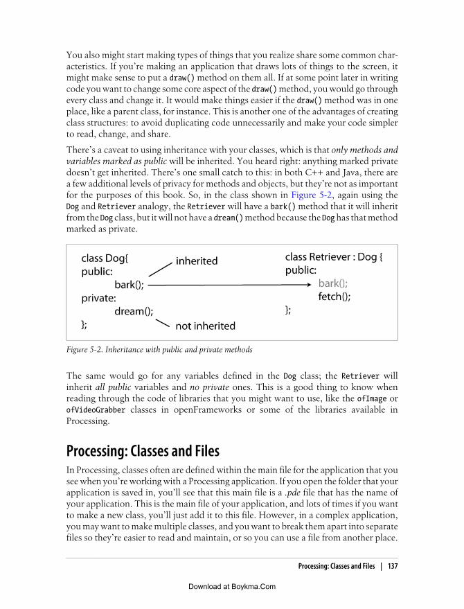
You also might start making types of things that you realize share some common char-acteristics. If you’re making an application that draws lots of things to the screen, itmight make sense to put a draw() method on them all. If at some point later in writingcode you want to change some core aspect of the draw() method, you would go throughevery class and change it. It would make things easier if the draw() method was in oneplace, like a parent class, for instance. This is another one of the advantages of creatingclass structures: to avoid duplicating code unnecessarily and make your code simplerto read, change, and share.
There’s a caveat to using inheritance with your classes, which is that only methods andvariables marked as public will be inherited. You heard right: anything marked privatedoesn’t get inherited. There’s one small catch to this: in both C++ and Java, there area few additional levels of privacy for methods and objects, but they’re not as importantfor the purposes of this book. So, in the class shown in Figure 5-2, again using theDog and Retriever analogy, the Retriever will have a bark() method that it will inheritfrom the Dog class, but it will not have a dream() method because the Dog has that methodmarked as private.
Figure 5-2. Inheritance with public and private methods
The same would go for any variables defined in the Dog class; the Retriever willinherit all public variables and no private ones. This is a good thing to know whenreading through the code of libraries that you might want to use, like the ofImage orofVideoGrabber classes in openFrameworks or some of the libraries available inProcessing.
Processing: Classes and FilesIn Processing, classes often are defined within the main file for the application that yousee when you’re working with a Processing application. If you open the folder that yourapplication is saved in, you’ll see that this main file is a .pde file that has the name ofyour application. This is the main file of your application, and lots of times if you wantto make a new class, you’ll just add it to this file. However, in a complex application,you may want to make multiple classes, and you want to break them apart into separatefiles so they’re easier to read and maintain, or so you can use a file from another place.
Processing: Classes and Files | 137
Download at Boykma.Com

To do this, all you need to do is create a new .pde file in the same folder and put yourclass declaration and description into that file.
To create a new .pde file within your application folder that will automatically be im-ported into your application, click the New Tab icon at the right of the Processing IDE,as shown in Figure 5-3.
Figure 5-3. Creating a class in Processing
This opens a small dialog box asking you to name your new file (Figure 5-4).
Figure 5-4. Naming your file
After you’ve given your file a name, Processing automatically creates the new .pde filein your sketch folder. You can begin adding your class to the file and then using it inyour main application file, that is, the file that contains the draw() and setup() methods(Figure 5-5).
138 | Chapter 5: Programming Revisited
Download at Boykma.Com

What do you get for putting this extra work into creating new files and classes? Thereare two distinct advantages to creating files and separate classes: it makes organizingyour code and debugging your application easier, and once you’ve written some classesthat work well and do something that you’d like to use again, it’s easy to copy and pastethe file into a new project and reuse all your code from the class. This last bit is, althoughoversimplified, a lot of the basis of the Processing, Arduino, and openFrameworksprojects: providing reusable code to speed up creating your projects.
C++: Classes and FilesC++ is an object-oriented language. It’s quite difficult to write anything in C++ withoutcreating at least a few classes, and as you work with oF, you’ll find classes and classfiles all over the place. If you’ve read this chapter up to this point, you should have afairly good idea of what a class is and what it does.
So, now we’re going to define an absurdly simple class called Name:
class Name {public: string firstName; string secondName;
Name(string first, string second) { firstName = first; secondName = second; }};
Figure 5-5. The newly created class file
C++: Classes and Files | 139
Download at Boykma.Com

Next up is creating an instance of Name. So, somewhere else in our code, we create aninstance of Name like so:
Name name("josh", "noble");
That’s it. We’ve made a class, and we’ve instantiated an instance of it. We’re sort ofoff to the races.
So, what are some things that are commonly created and stored as classes? A goodexample is one of the oF core classes, the ofSoundPlayer class. This class representswhat it sounds like it would represent: a sound player. It has methods to play, stop, setthe volume, and set the position that the player reads from. We wouldn’t expect it todo anything else, and in fact it doesn’t. It also provides lots of useful properties thathelp us determine whether a sound is currently playing and whether there was a prob-lem loading the sound.
Why do we use classes? In the short answer, we use classes to break functionality intological pieces that represent how we use them, how the application regards them, andhow they are organized. It makes sense to think of a spaceship game having spaceships,enemies, asteroids, planets, high scores, and so on. For example, we use classes toorganize all the functionality that an enemy would need into one place so that whenwe need to make a enemy, we know we’re always getting the same characteristics, andwhen we need to make a change to the enemies, we can do it in just one place. It’s farmore difficult to introduce classes later than it is to simply begin with them. The theoryof how to best organize classes is a serious topic that has spawned many a serious nerd-spat. We’re not going to delve into it deeply, but in Chapter 18, there are some pointersto introductory texts as well as heavy classics.
.cpp and .h
.cpp and .h shall now forever be burned into your mind as the two file formats of aC++ class. That’s right: two file formats and two separate files. The why of this is a bitirrelevant; what’s important is that you follow how the two work together and howyou’ll use them. We’re going to take this slowly because it’s important.
In an oF application, there will be two types of files: .cpp and .h files. .cpp files containthe implementation of a class, while the .h file contains the prototype of that class. Theprototype of that class, the .h file, is going to contain the following:
• Any import statements that the class needs to make
• The name of the class
• Anything that the class extends (more on this later)
• Declarations of variables that the class defines (sometimes referred to as properties)
• Declarations of methods that the class defines
140 | Chapter 5: Programming Revisited
Download at Boykma.Com

The definition of the class, the .cpp file, will contain the following:
• The actual definition of any methods that the class defines
So, why are there so many things in the .h file and so few in the .cpp? Well, usually thedefinition of a method takes up a lot more space than the declaration of it. If I want todefine a method that adds two numbers and returns them, I define it like so:
int addEmUp(int a, int b);
This is the kind of thing that you’ll see in an .h file—methods with signatures but nobodies. Take a moment to let that sink in: the method is being declared, not defined.Now, if I want to do something with this method, I need to actually define it, so I’ll dothe following:
int addEmUp(int a, int b){ return a+b;}
Here, you actually see the meat of the method: add the two numbers and return it.These are the kinds of things that you’ll see in the definition of a class in the .cpp files.
If you want to have your class contain a variable, and you will, then you can define thatin the .h header file as well. Just remember that the declarations go in the .h file andthe definitions go in the .cpp file, and you’ll be OK. When you’re working with oF,you’ll frequently see things that look like Figure 5-6.
Figure 5-6. How methods are spread across .h and .cpp files
C++: Classes and Files | 141
Download at Boykma.Com

Don’t worry about all the specifics of this diagram; we’re going to return to it in Chap-ter 6 when we discuss oF in greater detail. For now, just notice how the setup(),update(), and draw() methods are declared but not defined in the .h file, and how theyare defined in the .cpp file with the name of the class in front of them. This is going tobe a wonderfully familiar pattern for you by the end of this book.
A Simple C++ ApplicationExample 5-1 is your first C++ class, helpfully named FirstClass. First up you havethe .h file where all the definitions are made:
Example 5-1. FirstClass.h
// make sure we have one and only one "First class"#ifndef _FIRSTCLASS#define _FIRSTCLASS
// give the class a nameclass FirstClass{// declare all the public variables and methods, that is, all the values that can// be sharedpublic: FirstClass(); int howManyClasses();// declare all the private variables and methods, that is, all the values that are// only for the internal workings of the class, not for sharingprivate: int classProperty;};
#endif
We’ll talk this through, because the first thing you see is this really odd #ifndef. Don’tlet this scare you away, because it actually has a perfectly good explanation. Frequentlyin a larger project, you’ll have a single class that is referenced in lots of other classes.Going back to our little space game example, our Enemy class is going to be needed inmore than one place. When the compiler is compiling our classes, we don’t want it tocompile Enemy multiple times; we want it to compile the enemy only once. This weirdlittle #ifndef statement tells the compiler that if it hasn’t already defined somethingcalled _FIRSTCLASS, then it should go ahead and compile everything in here. If it hasalready defined something called _FIRSTCLASS and, by extension, also compiled all thecode in our header file, then we don’t want it to do anything. The #ifndef acts just likeany other if statement. Take a glance at the end of the class, and note the #endif; thisis just like the closing } on a regular C++ if statement. The rest of it is much morestraightforward. The class keyword goes in front of the name of the class and a {. Allthe class data is contained within the opening class statement { and the closing classstatement };.
142 | Chapter 5: Programming Revisited
Download at Boykma.Com

Inside of that you can see the word public. This means that after the public keyword,everything will be publicly accessible, which means that it is available to other classesthat have access to instances of FirstClass. Everything up until the private keywordwill be public, and, logically, everything after the private keyword will be private.
So, by looking at the .h file, you know the name of the class, what properties your classdefines, what methods it defines, and whether those properties and methods are publicor private. That’s great, but it’s not quite everything, so we’ll list the .cpp file so youcan see how all these methods are actually defined in Example 5-2.
Example 5-2. FirstClass.cpp
// first import our header file#include "FirstClass.h"// then import the file that contains the 'print' method#include <iostream>
// this is our constructor for the FirstClass objectFirstClass::FirstClass(){ // this is a little magic to get something printed // to the screen printf(" FirstClass \n"); classProperty = 1; // initialize our property}
int FirstClass::howManyClasses(){ // once again, just a little message to say 'hello' printf(" howManyClasses method says: 'just one class'' \n"); // note that we're returning classProperty, take a look at the method // declaration to understand why we're doing this (hint, it says 'int') return classProperty; // do something else with our property}
Note that for each of the methods that are declared in the .h file there is a correspondingdefinition in the .cpp file. Here, you can see how each of the methods of the class is puttogether with both a definition in the .cpp file and a declaration in the .h file. So far, sogood. You have an instance of a class, but you aren’t creating an instance of it anywhereyet. That’s about to change with the final file. This last file is not a class but is a sin-gle .cpp file called main. There is a rule in C++ that says you must have one file thathas a method called main(). When your application is launched, this is the method thatwill get called, so it’s where all your initialization code goes. In an oF application, thisis just creating an instance of your application and running it; this will all be coveredin greater detail in Chapter 6. There is no rule that says you must have a file calledmain in order to run your application, but it’s the way it’s done in oF, and that meansit’s the way we’ll demonstrate in Example 5-3.
C++: Classes and Files | 143
Download at Boykma.Com

Example 5-3. main.cpp
#include "FirstClass.h"
// all applications must have a 'main' methodint main() { FirstClass firstClass; // here is an instance of our class firstClass.howManyClasses(); // here we call a method of that inst. return 0; // here we're all done}
So, is this the only way to make a simple C++ application (Figure 5-7)? The answer isno; however, this is the way that oF is set up, so this is the way that we’ll show.
Figure 5-7. The organization of a C++ application
There are many more tricks to classes in C++ and many more wonderful mysteriousthings that you can do. If you want to learn more, you’re in luck, because there aredozens of good manuals and guides to help you learn C++. If you don’t really want tolearn more, you’re in luck, because oF hides much of the complication of C++, allowingyou to concentrate on other parts of your project.
Pointers and ReferencesC++ is a very powerful and very fast programming language because it is very “low-level.” That is, it doesn’t hide the inner workings of the computer nearly as much as alanguage like Processing. This has upsides and downsides. To follow many of theopenFrameworks examples in this book, you’ll need to have at least a cursory familiaritywith two concepts: the pointer and the reference. If you’re not interested in workingwith openFrameworks and C++ right now, then feel free to skip this section and moveon. You might come back to it later; you might not. Above all, this book is meant tobe helpful to you, not to shove things at you that you’re not interested in.
144 | Chapter 5: Programming Revisited
Download at Boykma.Com

The pointer and the reference are complementary concepts that are inextricably linked.To understand how they work, though, you need to first understand what happenswhen a variable is declared and see how the memory of a computer works. Take a lookat this:
int gumballs = 6;
What you’re doing here is telling the computer to store something the size of an intwith a value of 6 and a variable name of gumballs. It’s important to understand that thevalue and the variable name are separate. They are exchanged for one another whenneeded. One example is when you add 5 to gumballs:
int moreGumballs = gumballs + 5; // "gumballs" is replaced with 6
This is easy to do because gumballs is really representing a part of memory. That sectionof memory is represented by hexadecimal numbers like 0x2ac8 that simply stand forthe beginning of the location in the computer’s memory where the value of gumballs isstored. The variable gumballs simply stores that location so that you can access it easily.When you set gumballs to 8:
gumballs = 8;
what you’re doing is changing the value that is stored in the section of memory thatgumballs represents. When you set gumballs, you set that section of the computer’smemory. When you get gumballs, you read that section of the computer’s memory.You’re reading the bytes stored in the computer’s memory by location. That locationis referred to by the friendly variable name, but in reality, it’s a physical location. Itreally doesn’t matter a ton, until you start to deal with pointers and references, becausethe pointer and the reference let you declare up front whether you want to work witha pointer to a location in memory, or whether you want to deal with that memoryexplicitly. We’ll talk more about when and why you would do each of those things later.
Here’s a simple example that you can run with any C++ compiler to see how this works:
#include <iostream>int main () { int gumballs = 6; int gumdrops = 12; // here's where we make the magic printf(" the variable gumdrops has the value of %i and ¬ the address of %p \n", gumdrops, &gumdrops); printf(" the variable gumballs has the value of %i and ¬the address of %p \n", gumballs, &gumballs);}
This will print out something that might look like this:
the variable gumdrops has the value of 12 and the address of 0xbffff998the variable gumballs has the value of 6 and the address of 0xbffff99c
Notice two things. First, notice the & in front of the two variables:
&gumdrops&gumballs
Pointers and References | 145
Download at Boykma.Com

These are both references, which indicate that you want the name of the location inmemory where these are stored. When you use the variable name, you just get backwhat’s stored there. When you use the reference, though, you get the name of thelocation where the actual value is stored. Second, notice the actual location in memory:0xbffff998. That’s just on my computer at one particular moment in time, so if yourun the code, your output will almost certainly look different. This is interesting becausethis is the place that gumdrops is stored. What is stored there is an integer, 12, and theway you get at that integer is by using the variable name gumdrop.
ReferenceThe reference, as mentioned earlier, is the location in memory where a variable is stored.Any variable’s address can be accessed using the reference operator (&). Though muchmore can be done with references, in this book we’re going to limit the use of referencessolely to initializing pointers. With that in mind, we’ll talk about a pointer and showhow the pointer works.
PointerPointers are so called because they do in fact point at things; in particular, they pointat locations in memory much like you just saw in the discussion of references.
The pointer, like a variable and a method, has a type. This is so you know what kindof thing is stored in the memory that the pointer is pointing at. Let’s go ahead and makea pointer to point at gumdrops:
int* pGumdrops = &gumdrops;
There are two important things to notice here. First is that when the pointer is created,the pGumdrops variable uses the same type as the variable whose address the pointer isgoing to point to. If you are making a pointer to point to a float, then the pointer mustbe of type float; if you are making a pointer to point to an object of a class calledVideo, then the pointer must be of type Video (assuming that Video is a class). The secondis that the pointer is marked as a pointer by the presence of the * after the type decla-ration. A pointer to a float would look like this:
float* pointerToAFloat;
In the following code snippet, you have declared the pointer, but have not initialized it.This means that it doesn’t point at anything yet:
pointerToAFloat = &someFloat;
Now you have initialized the pointer, which means that it can be passed around in placeof the variable itself, which is all well and good, but it doesn’t help you do things withthe pointer. To do things with the pointer, you need to dereference the pointer:
int copyOfGumdrops = *pGumdrops;
146 | Chapter 5: Programming Revisited
Download at Boykma.Com

To dereference the pointer—that is, to get the information that is stored in the locationthat the pointer points to—you dereference the pointer by using the * symbol in frontof the name of the pointer. Think of the * as indicating that you’re either telling thepointer to point to some place in particular, initializing it, or getting what it points at.Here’s another example showing how dereferencing the pointer works:
int gumdrops = 12;int* pGumdrops = &gumdrops;
printf(" pGumdrops is %i \n", *pGumdrops);// will be 12gumdrops = 6;printf(" pGumdrops is %i \n", *pGumdrops);// will be 6gumdrops = 123;printf(" pGumdrops is %i \n", *pGumdrops);// will be 123
Any time you change the value of gumdrops, the value that pGumdrops points to changes.Figure 5-8 illustrates the relationship between the variable and the pointer. When youdo the following:
int gumdrops = 12;int* pGumdrops = &gumdrops;
you are creating the relationship shown in Figure 5-8.
Figure 5-8. The relationship between a pointer and a reference, two sides of the same coin
When to Use PointersAs you may recall from the earlier discussion on methods, when something is passedto a method, a copy of it is used for manipulation. This generally means that when youpass something to a method, it doesn’t alter the original variable:
void addExclamation(string s){ s+="!";}
string myName = "josh";addExclamation(myName);printf( myName ); // will still be 'josh', not 'josh!'
Pointers and References | 147
Download at Boykma.Com

If you wanted to alter the variable that is passed in to the addExclamation() method,you would pass a pointer to the method:
void addExclamation(string* s){ *s+="!";}
string myName = "josh";string* pName = &myName;func(pName);printf( myName ); // will now be 'josh!', not 'josh'
When you pass a pointer you are passing an object that points to the actual memory,and dereferencing the pointer allows you to change what is actually in memory. If youhave a very large picture that you want to alter, you want to alter the picture, not createa copy of the picture and alter that. Why not? Because it might not be the picture that’scurrently open, because you might want to alter a particular picture in the filesystem,or because the picture might be really large and altering might take up too muchmemory. This brings us to the second extremely common situation in which you mightuse pointers.
Large Data ObjectsIf you have a video file, a huge photo, or a lot of sound data, you don’t want to bemaking copies of that all over your program, though you’ll probably need to access itall over the place. The judicious use of the pointer is a way to allow different parts ofa program to access a variable and alter that variable by making multiple copies of it.
There are several very important rules to pointers. Write these down somewhere, com-mit them to memory, or otherwise preserve them:
• Don’t try to access a pointer before it has been initialized. This:
int* pInt;printf(" printing out pInt %i ", *pInt);
will not print anything meaningful.
• Check whether a pointer is NULL before doing anything with it:
if(ptr != NULL) { // now you can use the pointer}
If you try to use the pointer and it isn’t assigned to anything, then your applicationwon’t do what you want it to do and might crash.
• Although you can do this:
int* ptInt = 212;
you really shouldn’t. This can create bugs that are really difficult to track down.When using a pointer, unless you’re very confident in your skills, brave, or just
148 | Chapter 5: Programming Revisited
Download at Boykma.Com

very smart, you should set pointers to initialized variables. If you’re comfortablewith dynamically allocating memory, it can be a very powerful tool.
• You might come across code that looks like this:
FirstClass* fc = new FirstClass();
This creates a new FirstClass and keeps a pointer to the object that can be usedto access that object. If this is something that you’re curious about understandingbetter, look in Chapter 18 for a list of books focusing entirely on C++.
• If you dynamically create an object, you have to clean up after yourself by callingdelete on the pointer:
FirstClass* fc = new FirstClass();// do some things with fc...// now we're all done with it, so clean updelete fc;
If you don’t delete pointers that you’ve dynamically allocated when you’re doneusing them, and especially if you assign them in a method and don’t delete thembefore the method is finished, you’re creating what’s called a memory leak. Thesecan cause your application to run slowly or crash.
Pointers and ArraysPointers and arrays have a very close relationship. An array is in fact either a pointerto a section of memory or a pointer to a bunch of pointers. Really, when you make anarray of int variables:
int gumballs[10];
what you’re saying is that there are going to be a list of 10 integers next to one another.It’s the same thing as this:
&gumballs[0]
How’s that? Take a look at what declaring the array actually does in Figure 5-9.
Figure 5-9. An array and a pointer
Pointers and References | 149
Download at Boykma.Com

What you are doing is making a series of 10 integers, all in a row, within memory.Nothing links them together, except that they are all right next to one another. Whenyou get the second element in the array, what you’re doing is getting the next integerafter the initial integer. The array itself is just a pointer to the location in memory wherethe first element of the array is stored, along with a number to indicate how many moreplaces are stored for the array. In this case, there are 9 after the initial place, for a totalof 10. So, if the beginning of the array is the location of the first element in memory,how do we get the next element in memory? By adding one to the pointer. Don’t letthis throw you for a loop, because it’s deceptively simple:
int myInt = 4;int* ptInt = &myInt;int* nextPointer = ptInt + 1;// point to the next piece of memory
Imagine a row of shoe boxes. Imagine that you make a metaphorical pointer to thesecond shoe box by saying “that red shoe box there.” Saying “the next shoe box” is likesaying “the shoe box to the right of the red shoe box.” You’re not doing anything withthe shoes inside those shoe boxes; you’re just getting the next shoe box. That’s exactlywhat adding to the pointer does. You’re not adding to the value that the pointer ispointing to, you’re adding to the location in memory that you’re interested in accessing.Going back to our gumballs array of integers, when you get the second element in thearray, what you’re doing is this:
gumballs + 1
because gumballs is a pointer to the location of the first element in the array. You cando some really clever things with pointer arithmetic, but they aren’t particularly im-portant at the moment.
When Are You Going to Use This?If you follow along with this book, you’re going to encounter pointers first when gettingsound data in an openFrameworks application. The main application class in oF iscalled ofBaseApp, and it has an audioReceived() method that you can use to get datafrom the sound card of a computer. The audioReceived() method looks like this:
void audioReceived (float * input, int bufferSize, int nChannels)
That pointer to float is a pointer to the beginning of an array of sound samples. Allthe data of a sound is stored in a computer in an array of floating-point variables. Whenyou want to work with the sound that your computer’s sound card has captured, you’llget a pointer to an array and a bufferSize variable that tells you how large the array is.To use that sound data, you simply loop through the values in that array using a forloop:
for (int i = 0; i < bufferSize; i++){ printf("left channel is %f and right channel is %f",input[i*2], input[i*2+1]);}
150 | Chapter 5: Programming Revisited
Download at Boykma.Com

The reasoning behind the way the elements are accessed from the input array will beexplained in Chapter 7. For the time being, just rest assured that, if you’ve followedeverything in this chapter and the previous section in particular, you’re going to be ableto put it to use to make some interesting stuff. If you didn’t really follow that last bit,don’t sweat it too much, because you’re not going to really need to work with pointersif you don’t want to quite yet. You’ll find that as you spend more time around thesethings and see how they’re used more, they’ll start to make a lot more sense to you.
ReviewA class is a group of variables and methods that are stored together within a singleobject. For example:
class Point{ int xPosition; int yPosition;};
Once classes are defined, they can be used like other variable types. First defined, theninitialized:
Point pt = new Point();
Classes can define multiple methods and variables. One of the special methods that aclass defines is the constructor. The constructor is a method that has the same name asthe class and is called when the class is instantiated.
class Point{ int xPosition; int yPosition; Point(){ // anything to do when the object is first constructed }};
The constructor is the only method that does not use a return type.
Pointers are a special type that exist in C++ and Arduino that point to a location inmemory where a value is stored. They are declared with a type, like any other variable,but use an * immediately after the type declaration to indicate to the compiler that thevariable is a pointer:
int* intPt;
A reference refers to the actual location in memory where the value of variable is definedand is indicated by the & in front of the variable. Once the pointer is declared, it can beset to point to the reference of a variable:
int apples = 18;intPt = &apples;
Review | 151
Download at Boykma.Com

Pointers can be set only to the reference of a variable or a value but should usually beset only to the reference of a variable.
Pointers can be incremented using the + and decremented using the − symbol. Thismoves the location in memory to which the pointer points.
152 | Chapter 5: Programming Revisited
Download at Boykma.Com

CHAPTER 6
openFrameworks
openFrameworks (oF) is the third and last tool you’ll learn about in this part of thebook. As you may have guessed from its name, oF is a framework, which is a collectionof code created to help you do something in particular. Some frameworks are designedfor working with databases, and others are designed for working with Internet traffic.Frameworks don’t provide you with a prebuilt tool in the way that Processing andArduino do, but they provide you with code that you can use to create your ownprograms.
Specifically, oF is a framework for artists and designers working with interactive designand media art. That sounds simple enough, right? It is written in C++ and expects thatyou write programs in C++. As mentioned in Chapter 2, C++ is a big, powerful, old,and (again for emphasis) powerful programming language. You can create featuresusing oF that would not be possible in Processing because the underlying language isso much more flexible and low-level. Although this isn’t always ideal or necessary, whenit is, you’ll appreciate it. It isn’t always necessary to use oF, though. Sometimes Pro-cessing will work just as well. Let’s take a quick look at some tasks you can do inProcessing that aren’t as easy to do in oF, and vice versa:
Make a project visible on the InternetUse Processing; this is much trickier to do with oF.
Make a project that renders a lot of 3D graphicsUse oF; this is where C++ really shines.
Make a project that can run on many different computers without a lot of configurationUse Processing; this is rather tricky to do with oF.
Make a project that uses a computer vision library like OpenCVUse oF Processing doesn’t communicate with a C++ library like OpenCV as easilyas oF.
Make a project that interfaces with the Arduino controllerUse either, depending on what you need to do with the information from the Ar-duino controller.
153
Download at Boykma.Com

openFrameworks is developed by Zach Lieberman, and Theo Watson, Arturo Castro,and Chris O'Shea, along with help from collaborators at Parsons School of Design,MediaLabMadrid, and Hangar Center for the Arts, as well as a far-flung network ofdevelopers, artists, and engineers. The framework originated in the Design and MediaArts program at Parsons School of Design, where Lieberman was a student. He foundhimself needing increasingly more power for his projects and began to learn C++. Ashe worked, he realized that although thousands of different libraries were available toC++ developers, nothing provided the same kind of ease of use and low barrier to entryfor artists like Processing does for Java development. Hence, openFrameworks wasborn.
Your IDE and ComputerYour computer and its operating system are about to become very important for amoment. That’s because oF, unlike Arduino and Processing, does not have an integra-ted development environment (IDE). It requires that you use another IDE, and thatIDE depends on your platform and what’s available to you. So, we’ll break it down byoperating system. Because the requirements and instructions for getting your IDE setup may change without warning, the following sections are going to be less ofstep-by-step instructions and more of a general overview of what is involved. TheopenFrameworks website (www.openframeworks.cc) will have the most current in-structions, and you can probably resolve any problems you run into on its forums.
Roughly, each of these OS + IDE combinations requires two steps. The first is to installand configure the IDE correctly, and the second is to download the appropriate oFpackage. Since oF really is just a collection of C++ code, you simply put the code filesin the appropriate location for the IDE. You can then get started running the sampleprograms that come with oF, or can start building your own programs.
WindowsThose wanting to work with Windows are well taken care of. The structure and phi-losophy of oF work well with Windows, and several major Windows-based projectshave been built in oF on Windows already.
Visual Studio
Visual Studio is probably the most popular development environment for Windows.It’s developed by Microsoft and is very powerful, but as of this writing, it does notalways play well with oF. That said, it is a well-designed IDE that provides a lot of toolsfor developers. The current version of Visual Studio is Visual Studio 2008, and the freeversion of Visual Studio is Visual Studio C++ Express Edition.
154 | Chapter 6: openFrameworks
Download at Boykma.Com

Code::Blocks for Windows
Code::Blocks is an open source IDE for C++ development. Currently, it is the preferredtool for working with oF on Windows. Code::Blocks comes bundled with a compilersystem called MinGW that replicates the free and open source GNU Compiler Collec-tion. If you don’t really follow that last bit, don’t worry about it—just know thatbecause of MinGW, Code::Blocks is free. To get started with Code::Blocks, first down-load the IDE from www.codeblocks.org and install it. Once you’ve gotten Code::Blocksset up, download the oF for Windows Code::Blocks project files. Once you’ve down-loaded the packages, you’ll be able to open any one of the example programs and runthem. Simply navigate to the apps/examples/ section of the download and open up anyone of the applications in the Code::Blocks IDE to get started.
Mac OS XAnyone with a Mac will have access to Xcode, which means you have access to anexcellent IDE. Take a look at the top-level directory on your main hard drive. If yousee a folder called Developer, then you’re set. Otherwise, you’ll need to install the De-veloper Tools packages. You can do this in two ways: insert the operating system DVDthat came with your computer and install the Developer Tools, or go to http://developer.apple.com/technology/xcode.html and download and install the Developer Tools fromthe .dmg file you’ve downloaded. You’ll need admin privileges on the computer to dothis.
Once you’ve gotten set up with Xcode, you can download the Xcode oF package andget started by opening any one of the xcodeproj files in the example applications folder.
LinuxLovers of Linux have many options, but we’ll cover just two. In either event, you’regoing to need to grab the following libraries via APT or RPM (your package manage-ment tools):
• freeglut3
• alsa-dev
• libxmu-dev
• libxxf86vm-dev
Code::Blocks for Linux
Code::Blocks for Linux is quite a bit different from Code::Blocks for Windows. To getCode::Blocks up and running, you’ll need to get the following tools installed:
• gdb
• wxWidgets
Your IDE and Computer | 155
Download at Boykma.Com

Once you have those installed, you can go ahead and grab the appropriate Code::BlocksIDE and get started. You’ll have to take a few more steps, so I highly recommend yourefer to the instructions on the openFrameworks wiki.
Using makefiles
Ah, the makefile—the classic build tool. If you’re thinking about using makefiles,you’re probably at least a little C++ savvy already. You don’t need anything more thanthe libraries listed earlier in the section “Linux” on page 95 and the .sh files includedwith the download to build and clean all the sample projects.
Taking Another Quick Tour of C++In the previous tools you looked at in this book, Processing and Arduino, you learnedabout the more popular language that each of those languages extends and resembles:Java in the case of Processing, and C in the case of Arduino. In both those cases, how-ever, we had to note that although the tools’ languages were similar and derived fromJava and C, respectively, they were not quite the same. You cannot just use Java codein a Processing program; you need to take certain steps for that to happen. The samegoes for Arduino regarding C. oF is different because oF is C++, end of story. Anythingyou can do with C++, you can do with oF, because oF is simply a C++ library that wasbuilt with the intention of making C++ easier to use. This has a wonderful upside toit, in that oF is very straightforward, incredibly extensible, and is as powerful as C++,which is to say, it’s about as powerful as programming languages get.
The downsides, though, are that C++ can be difficult to learn and that the tools acrossplatforms aren’t completely standardized. So, in order to get you an appropriate tourof oF, you’ll need to take a rudimentary tour of C++. Now, as with many other thingsin this book, this tour is an introduction, not a complete guide. Hundreds of C++ booksexist for a reason: C++ is a massive topic. This quick tour is intended to provide youwith the information you’ll need to get started with oF C++, and creating interactiveprograms using them. At some point, though, you’ll need to refer to another resource,be it the oF forums, an online reference (of which there are many good ones), or anotherbook. That said, oF makes working with C++ easy and relatively painless while lettingyou (once you’re comfortable) reach into some pretty tricky territory.
Bjarne Stroustrup developed C++ in 1979 at Bell Labs as an enhance-ment to the C programming language and named it C with Classes. In1983, it was renamed C++. The idea of creating a new language origi-nated from Stroustrup’s experience in programming for his Ph.D. thesis.C++ is one of the most widely used programming languages, and is usedto create programs and systems, from video games to software for thespace shuttle to other programming languages.
156 | Chapter 6: openFrameworks
Download at Boykma.Com

Basic Variable TypesThe basic variable types in C++ are more or less the same as the variable types inArduino with one fairly crucial difference: where Arduino uses the byte type, C++ usesthe char. This is worth mentioning because at some point you’ll probably encountersome code that does something strange like get all the bytes from a JPEG file into a chararray. The reason that the bytes of a JPEG are stored in char variables is that the charstores exactly 1 byte of information, which can be a character like B (hence the namechar); a small number, up to 32,647; or some bytes, like a pixel in a JPEG. Just be awarethat you’ll see the char type used in some places where the information being repre-sented isn’t an alphanumeric character.
These are the other most common C++ variable types:
boolFor storing true/false values
intFor storing integer numbers, for example, 1 or 89; in all likelihood, this has a max-imum value of 32767 on your computer
longFor storing large integer values, for example, 3831080; in all likelihood, this has amaximum value of 2147483647 on your computer
floatFor storing floating-point numbers, for example, 3.14 or 0.01
charFor storing character values, for example, 'f' or 'g'
stringFor storing strings of characters, for example, "C++" or "openFrameworks"
ArraysArrays in C++ are identical to arrays in Arduino because Arduino is written in C++.To create an array, give the type of object that the array will store and a length for thearray:
int arr[5] = { 5, 10, 15, 20, 25 };
One thing to note is that you can’t initialize an array like this in the class declarationin your .h file. You need to declare the array first: int arr[5]; and then assign valuesto it in the setup() method of your application. There are other ways to create an arrayas well, using static variables, but this is probably the most common approach. Thisshould be pretty familiar; if it isn’t, refer to the discussion of arrays in Chapter 2.
Taking Another Quick Tour of C++ | 157
Download at Boykma.Com

MethodsMethods have signatures:
returnType methodName(params) { }
Methods can be overloaded:
String overloadedMethod(bool b);String overloadedMethod(char c);String overloadedMethod(String s);
Each of these methods will be treated as a separate method, although this isn’t ex-tremely common. In oF, it does crop up now and again, and it’s important to knowwhat’s going on if you see it.
Methods can be scoped to an object or be static. This might be a little complex; thenagain, it might be a cinch for you to understand. It isn’t a vital aspect of working withoF, but it is something you might come across, and it is helpful to understand. To start,think back to the idea of scope. Sometimes methods or variables are scoped to a class.This means you can’t call the method without an instance of a class. For instance, anoF program has a draw() method. You can’t call draw() without having a program inwhich to draw. That’s fairly simple, isn’t it?
ofBaseApp myApp;myApp.draw();
So far, so good. Imagine you have a method you want to call without making any objectsat all, for instance, the local date and time. You don’t want to have to make a dateobject just to get the time; you just want to know what time it is. In those cases, youuse what are called static methods. Now, this is a sticky topic with a lot of nuances toit, but generally (and for our purposes) this means a method is available without beingcalled on an object. This means that calling a static method is not like the previousexample where the draw() method of a particular instance of ofBaseApp (you’ll learnexactly what this class is a little later on in this chapter) is being called:
myApp.draw(); // calling a method of an *instance*
Sometimes, however, you’ll see a method being called like this:
NameOfClass::nameOfMethod();// calling a method of a *class*
For instance, this might be something like the following:
// this calls the static method of the ApplicationTime class// the method is the same for every ApplicationTime instance// and it always does the same thingApplicationTime::staticTimeMethod();
You look around and don’t see any instance of ApplicationTime anywhere, but themethod is being called and works fine. What gives? This means the ApplicationTimeclass has a static method called staticTimeMethod() that can be called anywhere, at anytime, without having to create an instance of the ApplicationTime class.
158 | Chapter 6: openFrameworks
Download at Boykma.Com

The ApplicationTime class would probably look like this:
class ApplicationTime {
public : static int staticTimeMethod(); // can be accessed from anywhere};
The static keyword in front of that method marks it as being accessed from anywhereby using the name of the class, followed by two colons:
ApplicationTime::staticTimeMethod()
You might not ever need to use static methods in your code, but you probably will runinto it them some point. As with many other things in this book, static methods havea lot of very subtle and complex nuances, and this book isn’t the place to cover them.
Classes and Objects in C++If you skipped over it, or weren’t aware that it existed, now would be an excellent timeto review the section “C++: Classes and Files” on page 139 in Chapter 5. Generally,and particularly in oF, a class is stored in two separate files, an .h file that declares allthe variables and methods of the class, and a .cpp file that defines all the methods of aclass.
A class is declared in the NameOfClass.h file, as shown here:
class NameOfClass {public: void publicMethod(int);private: int privateMethod();}
In the NameOfClass.cpp file, the class is defined as follows:
// we have to include the header file#include "NameOfClass.h"
// all class declarations require the name of the class// followed by :: to ensure that the method is included// with the classvoid NameOfClass::publicMethod(int i) {//do some stuff}int NameOfClass::publicMethod() {//do some other stuff}
You should make note of four elements here: the class is declared in the .h file, themethods are declared but not defined in the .h file, the .h file is included in the .cpp file,and all the methods in the class use the name of the class and double colons before themethod definition. If this seems unfamiliar at all, review Chapter 5.
Taking Another Quick Tour of C++ | 159
Download at Boykma.Com

At this point, you’re ready to start exploring openFrameworks. Again, although C++is complex and sometimes a bit obtuse, openFrameworks is designed to make workingwith C++ as easy and straightforward as possible so that you can get started experi-menting and making your projects quickly.
Getting Started with oFGetting started with oF is as simple as downloading the appropriate package for yourcomputer, compiling it, and starting to look through the sample programs that havebeen built by the oF team. These should appear in something like the configurationshown in Figure 6-1.
Figure 6-1. Directory structure of openFrameworks
Figure 6-1 shows the Mac OS X Finder, so obviously if you’re on Windows or Linux,you’ll see something different, but the general idea is the same. The oF folder containsthe following folders:
160 | Chapter 6: openFrameworks
Download at Boykma.Com

addonsThis contains all the added-on features for openFrameworks that have been con-tributed by users over the past year or so. These libraries change often, and newones are added frequently, so it’s important to remember that these are dynamicif you’re planning on using these libraries in a program because you need to ex-plicitly include them in your program.
appsThis is where your programs should be stored. If you have a strong preference, youcan organize them in other ways, but that would go against the flow and wouldbreak some of your code. The example programs that use the core oF libraries arestored here, as are the example programs that show you how to use each of theadd-on libraries. These are some of your best learning resources because they giveyou wonderful starting points for exploring oF and C++, and because they’re usu-ally well commented and documented.
libsThis is where the libraries that oF relies on are stored. These range from externallibraries like fmodex, which is used for two- and three-dimensional sound manip-ulation, to the GLee library, which is used for OpenGL graphics. Most important,you’ll see the core openFrameworks folder, which stores the header files that defineall the core oF functionality in six folders. As you find your ideas and techniquesbecoming more and more sophisticated, you’ll probably need more libraries thanthose provided here.
openFrameworksThe openFrameworks folder contains the core of the oF framework within six fold-ers. The app folder contains the header file for the ofBaseApp class, which is thebase program class of any oF program. The ofBaseApp class lets you easily togglebetween full-screen and window views, set up code to handle mouse movementsand keyboard presses, and integrate the simplified drawing routines with thegraphics environment of your operating system. The communication folder con-tains tools for communicating over serial ports that can be used to communicatewith the Arduino controller. The events folder contains ofEvents, which handlessending and receiving events in an oF application.
The graphics folder contains five classes, each of which is broken into a .hand .cpp file: ofBitmapFont, for working with bitmapped fonts, ofGraphics forworking with 2D drawing, ofImage for working with bitmapped image data,ofTexture for working with OpenGL textures, and ofTrueTypeFont for workingwith fonts.
The sound folder contains two classes for working with sound: the ofSoundPlayerthat is a more simplified class for creating and playing sound files and the ofSoundStream class that provides more low-level access to the sound capabilities of yourcomputer.
Getting Started with oF | 161
Download at Boykma.Com

The video folder contains code for capturing video from a video camera and forplaying back captured video or video files loaded from your computer. We’ll talkmore about all these topics in later chapters, which are organized thematically.
Finally, the utils folder contains useful code for helping you work with math, usefulcode to get and measure time, and some core data types that are used throughoutthe program.
One of the first steps you’ll want to take after you’ve downloaded oF is to go to theapps/examples folder and try running one or two of these programs. After you’ve runa program, open the code files, and explore how the program is put together. Keep aneye out for the references to ofBaseApp, and in the .h header file, look at the #importstatements. You might not understand everything in these sections, but exploring thesefiles is a good way to get familiar with what the libraries are, how they are imported,and how an oF program is structured.
oF is built out of multiple layers of libraries and code that uses those libraries. As yougrow more comfortable with oF and with C++, you'll probably delve deeper into theofficial oF libraries and the underlying third party libraries that they use. At the begin-ning though, you'll just want to focus at the top. The diagram in Figure 6-2 shows thestructure of an oF application.
Figure 6-2. openFrameworks application structure
162 | Chapter 6: openFrameworks
Download at Boykma.Com

As you can see, your application sits atop the openFrameworks libraries, which sit atopa series of third-party libraries. As you learn more and more about oF and how all thelibraries interrelate, you’ll be delving deeper into both the oF and third-party librariesto do more.
Interview: Theo WatsonTheo Watson, along with Zach Lieberman, is head of the openFrameworks project.Theo’s work ranges from creating new tools for artistic expression, experimental mu-sical systems, and immersive environments with full-body interaction. He lives inAmsterdam.
Can you talk a little bit about how you got started programming and working with in-teractive art?
Theo Watson: Before I was doing programming work, I was really obsessed withsound. I was at Parsons, and I was skipping a lot of classes because I was so interestedin working with music and, more particularly, with making instruments. I started offdoing Max/MSP and was creating synthesizers that would take radio signals and usethem to modulate the sounds that the synthesizers would make. That way, the syn-thesizers wouldn’t just be making the sounds that you thought they would be making,but would also be driven by where you were based on which radio stations could bepicked up in that area. I was very stubborn about doing any visual work; I wanted tokeep everything based in sound.
Later, I had a class with Zach Lieberman called Audio Visual Synthesis. I had lost theuse of my arms over the summer because of carpal tunnel syndrome, so I couldn’t usea computer, and I wanted to make something that I didn’t need to actually touch—something I could control using just my voice. That got me thinking...what if I didn’teven need to control it at all? It would create a performance for itself, and then it couldnot only create a performance for itself but appreciate itself as well. It remembers whatit has played so it builds up an interpretation of that. And because the microphoneinformation is imperfect, it creates these very subtle variations that were stored andcarried into the next performance.
When I played it back through MIDI using the information as a piano, it sounded verymuch like a jazz pianist. It totally blew my mind. It wasn’t anything intentional, becauseof the feedback loop that was delayed and imperfect; what it was hearing was quitedifferent from what it was playing.
Do you see your artistic work and your work on oF as being distinct from one another,or are they part of the same project for you?
Theo: We approached openFrameworks and our own work from the perspective ofhaving an idea and really wanting to make it. I’m really taken with the idea of learningthe skills as you go and doing whatever it takes to achieve your vision. I really firmlybelieve that you can get something unexpected back as feedback from your art.
From the process of making something, I can have something that I want to do in anart project and not have any idea how to accomplish that and then treat that as a process
Getting Started with oF | 163
Download at Boykma.Com

of learning how to do something. As something that shapes my ideas about what I’mdoing, there’s this constant back and forth and feedback. Neither Zach nor I are engi-neers; we’re just people with funny ideas who have a bit of a nerdy background and atechnical fascination with learning what we need to know.
What kinds of things have you done with openFrameworks?
Theo: It’s really good that both Zach and I make projects; it gives us a real impetus tomake sure that everything works because we’re using oF ourselves. In my latest project,for example, I put it together in about two weeks, and if it weren’t for oF, it would havetaken about two months to make. It wasn’t something that I was always excited about,but it’s beginning to become more appealing to me now.
There were things that I had never used in oF. For example, I was trying to figure outhow to use 3D vector rotations, and then I just happened to glance into ofVectorMath,and there was a bunch of code to help me. I was sitting there with a pencil and a pieceof paper, and then it hit me: “Oh, yeah, I know there’s something like this.” I looked,and there it was, so I didn’t have to figure out. I could spend time on the more interestingstuff. So, it’s not like we’re just making sure the code compiles and then putting it outthere; we’re using it in installations that have to run sometimes for weeks straightwithout crashes, so oF is just as important to us as it is to anyone using it.
Zach and I worked together on LaserTAG. LaserTAG was a really nice project becauseit reached so many people—both people who played with it and people who down-loaded the software, set up the projector, and used the project themselves. It’s workingat a different scale both in terms of physical size and in terms of audience size. It’ssomething that people are getting really excited about, and that’s really amazing to me.I want to push those ideas and put people into situations where they can shape theirenvironment and experience their environment. I think Zach and I are going to perhapscollaborate on something else soon, aside from oF, of course.
Can you talk a little bit about the philosophy of openFrameworks?
Theo: The motive of oF is to get rid of all the frustration of getting a window, gettingsomething drawn in the window, and getting an image displayed in it. For some peoplefirst starting out, getting a window displayed and getting a shape drawn in it are reallybig deals. You have to deal with all this stuff that really isn’t going to be interesting toyou at all. You really should be thinking about how to make your idea richer, not “Whyam I having this strange windowing error?”
When learning to code, you can start anywhere. My entry was with PHP and withMax/MSP. What I loved about Max/MSP that is a bit underrated was that in some waysit teaches you to be a good programmer because it teaches you how to break a probleminto discrete parts. So, it helps you visualize how to break something into parts. Lotsof times when I run into people who’ve never programmed before, a big hurdle is thatthey frequently don’t know how to break something into the correct kinds of parts orthey underestimate what it means to make something.
How did openFrameworks get started?
Theo: The idea of oF came about because Zach was teaching these classes, and in everyclass he was essentially trying to do the same thing every time—to get people up to
164 | Chapter 6: openFrameworks
Download at Boykma.Com

speed, so to speak, with programming, with building an application, with being ableto understand graphics and how graphics are drawn on the computer screen, withplaying a sound, with capturing a sound, and so forth.
It actually started that summer, and I wasn’t involved in it at all, because I was workingon my thesis all that year. On that project, I was very determined that I write every lineof code myself, and I ended up writing all the computer vision code for my project. Iwrote every single function—including contour detection—that I used in that project.I mean everything, so I was very much busy at that point, working on my own stuff.
But then what happened was, after Parsons, we had a very rough outline of oF that wasin use, and it was great for these students, so you could say “use ofCircle” instead ofneeding to work with cosine and sine, for example, and your class could be more in-teresting. It became something where we were incorporating more and more function-ality, and it was stuff that was more and more interesting to me. When someone asked,“How do I do this?” and we didn’t know, we would end up spending three or four daystrying to solve the problem, and it would be a really valuable thing to learn. Later I’dfind myself using that same information or knowledge in my own work, so it becamesomething I was doing to teach myself as much as because it was something we wantedto add to oF.
What kinds of people have you found using oF?
Theo: The forums have sprung up in a really interesting way, because there’s such awide range of kinds of things that people are talking about and backgrounds that peopleare coming from. A lot of people who are a lot smarter than us are participating, whichis great because it’s really helping to lower the barrier to entry, because not only is therethis framework that we’ve put together but additionally there are people other than usto answer questions. For example, there’s Arturo Castro. We wanted to do a Linuxversion of oF, but neither of us really knew a lot about Linux, especially video and audiocapture in Linux, but he did, so he really took over that part of it, which is amazingbecause the community around this project is allowing us—all of us involved with oFor using oF—to make and use things that maybe we aren’t as familiar with as we’dneed to be without it. So, we’re very lucky.
We really want people to use it in the most unusual way they can imagine. We don’twant it to be just about using computer vision, where people are going to say, “OK, Ineed to do computer vision, so I’ll use oF.” We’re quite interested in things that usemachinery, sound, or nontraditional means of interacting. I want to take it away fromcomputer vision, graphics, and installation work and allow people to work more richlywith sound.
Are there particular types of projects that you want to see people using openFrameworksfor or particular ways you want to see people using it?
Theo: We don’t want to have to tell people, “This is the way you have to use it.” Wejust want to see it used in new and different ways, so every time there’s a new project,I feel like there’s very often a new plug-in for that project that’s born out of it. As longas people don’t claim they wrote oF, we’re fine with anything they do with it. If that issomething having to do with maximizing profits in a design project, we’re fine with
Getting Started with oF | 165
Download at Boykma.Com
that. We don’t want to force people to share their code; we won’t use GPL, becausewe don’t want to restrict what people can do with it. We want them to feel they can dowhatever they want with it. We think it should be up to the end user—to the peopleplaying with it—to decide what they need.
Touring an oF ApplicationThe core of an oF program is the main application class, ofBaseApp. Since oF is a bare-bones C++ library, the best way to understand it is to look at the code, and the firstplace to look is the program. Everything you make in oF will have an ofBaseApp classsomewhere in it.
MethodsAll the methods in the ofBaseApp class are event-handling methods. This means theyare triggered in response to events that happen within your program, such as the usermoving the mouse, the user pressing a key, the program quitting, or your programredrawing. At its simplest, working with oF is adding new code to the appropriatemethod and waiting for the program to call your methods. If you want to work withthe users mouse actions, add some code to the mouseMoved() method of theofBaseApp. The core oF framework handles creating the window and adding the ap-propriate code behind the scenes. To do something when these events occur, yousimply need to create a class that extends ofBaseApp and add the appropriate methods.If that sounds a little intimidating, don’t worry, because we’ll walk you through it afterlooking at each of the methods in the ofBaseApp class.
The setup() method is called when the program first starts up, the same as in Arduinoand Processing. If something has to run only once or it is important to run at the be-ginning of your program, it should be in setup(). Also, if you’re defining variables inyour .h file, you should initialize them. For instance, in a .h file you might have:
int numberOfVideos;
In your setup method, you should initialize that if you’re going to need it once yourapplication starts running:
numberOfVideos = 5;
The update() method is called just before the draw() method. This is important becausein oF you generally want to put any data processing you need to do in the update()method so you’re drawing with new data. If you need to check and see, for example,whether any new sound is coming from a microphone before you draw the sound wave,you’ll want to do that in the update() method.
166 | Chapter 6: openFrameworks
Download at Boykma.Com

The draw() method is called when the program draws its graphics, much like in Pro-cessing. In contrast with Processing, however, in oF you should have drawing code onlyin your draw() method to keep your program running smoothly.
The exit() method is called when the program exits and closes down. If you want todo any final processing or data logging in your program, or to free memory, which we’lldiscuss later, this is the place to do it.
The keyPressed() and keyReleased() methods are callbacks that handle any key actionsthat the user makes:
• keyPressed(int key)sends the code of the key just pressed as an integer
• keyReleased(int key)sends the code of the key just released as an integer
The ofBaseApp class defines four callback methods to handle mouse movements. Youcan add any code to handle these events to these methods. The mouseMoved() methodpasses in the current x and y position in pixels of the mouse. The mouseDragged() andmousePressed() methods pass in the x and y positions and also the button that has beenpressed. The mouseReleased() method is triggered whenever either mouse button isreleased:
mouseMoved(int x, int y)mouseDragged(int x, int y, int button)mousePressed(int x, int y, int button)mouseReleased()
The audioReceived() method is a little more complex than the other methods becauseit receives a pointer to the stream of audio data and because dealing with a pointer isa little tricky. This requires that you remember what a pointer really is—a piece ofinformation that tells you the location of something:
audioReceived(float * input, int bufferSize, int nChannels)audioRequested (float * output, int bufferSize, int nChannels)
Imagine you get some data in the audioReceived() callback. That data represents thewaveform of the sound that the computer’s microphone has captured in a list of float-ing-point numbers, maybe something like 0.000688 or –0.000688 for a loud noise, or0 for silence. The numbers represent the waveform of the sound, just like a waveformdisplay that you might see on an oscilloscope or in recording software. Instead of send-ing all the data—all those floating-point numbers—to ofBaseApp, the program sendsjust a single value: the location in memory where all this data is stored. That meansinstead of needing to send a few hundred values, the program needs to send only one(Figure 6-3), saving the space that would be needed if it had to copy all the data everytime.
Touring an oF Application | 167
Download at Boykma.Com

Figure 6-3. Passing a pointer to an array of data for sound processing
So, you simply pass the location of the first item in the array of sound data and thenstart processing the data in the audioReceived() method. You’ll learn more about thisin Chapter 7, so we’ll leave it be for the moment. You might also want to look back atChapter 5 in the section “Pointers and References” on page 144.
VariablesThe two variables that ofBaseApp defines are the mouseX and mouseY values:
int mouseX, mouseY;
mouseX and mouseY let you always determine the location of the user’s mouse. Sincewe’re talking about the mouse position, we’ll point out two very handy methods youcan call to figure out the size of the screen where your program is being displayed. Thismight not be as important if you always know the computer that your program is goingto be running on, but if you’re going to be moving it around or you don’t feel likemeasuring your screen, you can use these methods to find the height and width of thescreen in pixels:
int ofGetScreenHeight();int ofGetScreenWidth();
You’ll be using these later in this chapter to help control the speed of a movie file withthe mouse position.
Now that you have a basic idea of what is included in an oF program, you’ll create oneof your own.
Creating “Hello, World”In this section, you’ll create a simple program that will print the words “Hello oFWorld” to the screen. As described in Chapter 5, your program will be spread acrossthree different files, HelloWorldApp.h, HelloWorldApp.cpp, and main.cpp. In all the oFdownloads, you can use the empty project templates so you don’t have to create a newproject yourself. Simply copy the emptyProject template and give it a new name, andyou have all the classes, libraries, and paths you need to create your program.
168 | Chapter 6: openFrameworks
Download at Boykma.Com

All oF programs extend the ofBaseApp class. Any methods you want your program touse will be defined in the .h file of your application class. In this case, you need to useonly the setup() and draw() methods. Any methods you do not extend in your programare simply left as they were in the original program.
Here’s the HelloWorldApp.h file:
#ifndef _HELLO_WORLD#define _HELLO_WORLD
#include "ofMain.h" // we need to include all the oF files, linked here
class HelloWorldApp : public ofBaseApp{
public:
void setup(); // we need this to load the font void draw(); // we need this to draw the font to the screen
ofTrueTypeFont franklin; // this is the font that we'll be loading
};
#endif
These two lines may jump out at you from HelloWorldApp.h:
#ifndef _HELLO_WORLD#define _HELLO_WORLD
These two lines are what are called preprocessor instructions, and they’re important tothe compiler that’s going to create your oF program from your code, because it tellsthe compiler to make the class only once. In a simple program like the one you havehere, this isn’t a big deal, but in more complicated programs, the compiler may try tocompile the class multiple times, which would cause all kinds of problems.
It’s interesting to note the declaration of the font object. To use a font in oF, you needto create an object that can load a font file, in this case, a TrueType font (TTF) file, andcreate the correct characters to display on the screen from that font file:
ofTrueTypeFont franklin
The next part of your program is the definition of the methods of the HelloWorld class,which in this case loads the font from a TTF file, sets the background color of yourprogram, and then actually writes the text to the screen. This all happens in the .cppfile. Here’s the HelloWorldApp.cpp file:
#include "HelloWorldApp.h"
void HelloWorldApp::setup(){
To use the font, you need to load the file. Since you need to do this only once, you doit in the setup() method. The loadFont() method takes two parameters: the name ofthe file and the size of the font you want to use. Each font size must be loaded separately,
Creating “Hello, World” | 169
Download at Boykma.Com

so if you wanted to have your Franklin Black font in 32 and 64, you’d need to createtwo separate ofTrueTypeFont objects to store those settings:
// load our font and give it a font name franklin.loadFont("frabk.ttf",32);
Next, you set up the background of your program, passing in the red, green, and bluevalues, all set to 255 here, making your program’s background white:
ofBackground(255,255,255);}
The draw() method redraws the graphics of the program, just the same as in a Processingprogram:
void HelloWorldApp::draw(){ ofSetColor(0, 0, 0); franklin.drawString("HELLO WORLD!", 100,380);}
The setColor() method sets the color of any drawing that the program will do, and inthis case, that drawing is going to be the text. Since you’re passing 0, 0, 0, which is RGBblack, the text will appear in black. The drawString() method writes the text to thelocation on the screen specified by the x and y coordinates.
Now that the program is ready, you need to run it. In C++, as you may recall, you dothis in a main() method, which is a special method that the compiler looks for when itstarts compiling your code. In an openFrameworks program, this method is always inthe main.cpp file. For an oF program, the main() method should set up the window sizeand then start the program. The framework handles everything else.
The first step you’ll see here is the setup of the window. You can specify a window witha size, or you can just say oF_FULLSCREEN to make the program fill the screen of thecomputer that it’s being run on. The next line of code contains the call to theofRunApp() method that starts the program. You pass it a new instance of the program,and the ofRunApp() method takes care of starting the program and calling its update()and draw() methods.
Here’s the main.cpp file:
#include "ofMain.h"#include "HelloWorldApp.h"
int main( ){
// can be oF_WINDOW or oF_FULLSCREEN // pass in width and height too: ofSetupOpenGL(1024,768, oF_WINDOW);// <-------- setup the GL context // this kicks off the running of my app ofRunApp(new HelloWorldApp);
}
170 | Chapter 6: openFrameworks
Download at Boykma.Com

And that’s the “Hello, World” of openFrameworks. Now, the preceding code samplecontained one method that did not receive the attention it merits because it raises animportant point about how oF applications are organized. Take a look at the call to theloadFont() method:
franklin.loadFont("frabk.ttf",32);
This is actually loading the ttf file from the data folder into your application. Everyapplication can have a data folder to store any images or other files it might need to load.
openFrameworks assumes that a folder called data is in the same direc-tory as your program. Whenever you load an image, font, AppleQuickTime movie, or other kind of file, by default your oF program willlook in the data folder. Unless you have a good reason to do so, youshould always store data within this folder to leverage the work that thecreators of oF have put into the framework.
You’ve now seen how to write your first oF application.
Drawing in 2DTo begin, drawing in oF is quite similar to drawing in Processing; you set the color thatthe drawing will use, set the fill mode of the drawing (whether the shape will be filledin with color), and then use one of the predefined drawing methods to draw the shapeto the screen. For example, to draw two circles to the screen, you would simply addthe following methods to the draw() method of a program:
void simpleGraphics::setup(){ ofSetCircleResolution(100); ofBackground(255,255,255);}
void simpleGraphics::draw(){
ofSetColor(0xFF0000); ofFill(); // draw "filled shapes" ofCircle(100,400,100);
// now just an outline ofNoFill(); ofSetColor(0x333333); ofCircle(400,400,200);
}
The .h header file for the class would look like so:
#ifndef _SIMPLE_DRAW#define _CHAP_SIX_GRAPHICS
Drawing in 2D | 171
Download at Boykma.Com

#include "ofMain.h"#include "ofAddons.h"
class simpleGraphics : public ofBaseApp{
public:
void setup(); void draw();
};
#endif
Since you’re not overriding any of the other methods of the ofBaseApp class, you don’tneed to include them in the header file for your class. The result will look somethinglike Figure 6-4.
Figure 6-4. Using the ofCircle() method
Setting color in oF is similar to the way you set it in Processing. The ofSetColor()method takes either RGB values, RGB and alpha values, or hex color values:
void ofSetColor(int r, int g, int b); // 0-255void ofSetColor(int r, int g, int b, int a); // 0-255void ofSetColor(int hexColor); // hex, like web 0xFF0033;
Setting Drawing ModesThe drawing mode of a program indicates whether lines or shapes should have fills. InoF, you set these drawing modes using one of two methods. If you want your drawingto have a fill, that is, a color that fills in the shape, you call the method ofFill() beforedoing any drawing; if not, then call ofNoFill():
172 | Chapter 6: openFrameworks
Download at Boykma.Com

ofSetColor(0xCCCCFF); // set our color to light blueofFill(); // drawing will use "filled shapes"ofRect(100, 100, 200, 200); // draw a rectangle 200x200 pixel
// now just an outlineofNoFill();ofRect(400, 100, 200, 200);
This code draws two rectangles that will sit next to one another. You’ll see what thatlooks like in a few moments after you add a little more detail to the rectangles. oFprovides quite a few convenience drawing methods for drawing simple 2D shapes:
void ofTriangle(float x1,float y1,float x2,float y2,float x3, float y3);void ofCircle(float x,float y, float radius);void ofEllipse(float x, float y, float width, float height);void ofLine(float x1,float y1,float x2,float y2);void ofRect(float x1,float y1,float w, float h);
Putting a few of these methods together, you can make a simple drawing (as shown inFigure 6-5) that overlaps squares and circles with varying alpha values.
Figure 6-5. Drawing with varying alpha values
void simpleGraphics::setup(){ ofSetCircleResolution(100); ofBackground(0, 0, 0);}
void simpleGraphics::draw(){ ofEnableAlphaBlending(); int i = 0; // make a variable to use for our loop ofFill(); // draw filled shapes while(i < 6) {
ofSetColor(255, 255, 255, 255 - (i * 51)); // decreasing alpha ofRect((i * 100)+30, 0, 200, 200); // draw a rectangle 200x200 pixel
ofSetColor(255, 255, 255, i * 51); // increasing alpha ofEllipse((i * 100)+30, 150, 100, 100); // draw an ellipse
Drawing in 2D | 173
Download at Boykma.Com

i++; }
}
Drawing PolygonsThe Open Graphics Language (OpenGL) handles all the drawing in oF. Chapter 13 inthis book is dedicated to OpenGL, so in this chapter you’ll learn how to get oF to drawwithout touching any actual OpenGL code. Sometimes you don’t want to draw a circle,square, ellipse, or triangle, and you don’t want to delve into OpenGL. For this, you canuse several polygon-drawing functions in oF to draw shapes by placing points andsetting fills. This works much the same as drawing vectors in Adobe Flash, AdobeIllustrator, and many other paint programs: you place three or more points, and theprogram creates the fill between those points that defines the shape. In oF, you tell theprogram to begin to draw a polygonal shape, you add points (vertices in oF) that definethe edges of the point, and then you close the shape, which triggers the filling in of yourshape.
This method is called before the shape is drawn, telling the oF application that you’restarting to draw a shape:
void ofBeginShape();
This method is called after the shape is drawn, telling the oF application that you’refinished drawing the shape:
void ofEndShape(bool bClose);
This method takes a single parameter: a boolean that indicates that whether the shapeshould be closed, that is, whether or any space between the first point and the last pointshould just be closed up by OpenGL. The default is true.
The following places a vertex at the position on the screen indicated by the x and yvalues passed into it:
ofVertex(float x, float y);
When you place a vertex, OpenGL automatically connects the previous point (if oneexists) and the next point (when one exists) via the location of the just added pointwith two straight lines.
If you don’t want to draw straight lines (and sometimes you just won’t), then you mightwant to use the ofCurveVertex() method:
ofCurveVertex(float x, float y);
This method places a vertex that a line will curve to from the previous point and thatwill be curved from to the next vertex. ofCurveVertex() has one tricky part: for reasonsthat have to do with the way OpenGL draws vertex curves, you need to add the first
174 | Chapter 6: openFrameworks
Download at Boykma.Com

and last vertices in the shape twice. The following code snippet shows how to use theofCurveVertex() method:
ofSetColor(0xffffff);ofFill();ofBeginShape(); ofCurveVertex(20, 20);// that's not a typo; you need to add the first ofCurveVertex(20, 20); // point twice ofCurveVertex(220, 20); ofCurveVertex(220, 220); ofCurveVertex(20, 220);// that's not a typo; you need to add the last ofCurveVertex(20, 20);// point twice as well ofCurveVertex(20, 20);ofEndShape(false);
One drawback to the ofVertexCurve() method is that you have no control over howcurved the curve is. To control the curviness of the curve, you’ll want to use theofBezierVertex() method, which lets you set the starting point of the curve and thendefine two control points (Figure 6-6) that will be used to define the shape of the lineon its way to the next vertex:
ofBezierVertex(float x1, float y1, float x2, float y2, float x3, float y3)
Figure 6-6. A Bezier curve
In the ofBezierCurve() method, the first two floats, x1 and y1, set the location of theline; the next two, x2 and y2, set the location of the first control point; and the last two,x3 and y3, set the location of the second control point. This lets you create quite complexshapes by combining multiple Bezier curves. For example, the following code snippetin the draw() method of an oF program creates two moving Bezier curves:
ofEnableAlphaBlending();float bez1X1 = 350+50 * cos(ofGetElapsedTimef()*2.0f);float bez1Y1 = 200+100 * sin(ofGetElapsedTimef()/3.5f);float bez1X2 = 400+30 * cos(ofGetElapsedTimef()*5.0f);float bez1Y2 = 300+100 * sin(ofGetElapsedTimef());
Drawing in 2D | 175
Download at Boykma.Com

float bez2X1 = 350+50 * cos(ofGetElapsedTimef()*2.0f);float bez2Y1 = 200-100 * sin(ofGetElapsedTimef()/3.5f);float bez2X2 = 400+30 * cos(ofGetElapsedTimef()*5.0f);float bez2Y2 = 300-100 * sin(ofGetElapsedTimef());
ofFill();ofSetColor(255, 0, 0, 127);ofBeginShape(); // first we create the point from which to begin drawing ofVertex(100,300); // then create the Bezier vertex ofBezierVertex(100,300,bez1X2,bez1Y2,650,300); ofBezierVertex(650,300,bez2X2,bez2Y2,100,300); // finish the shape ofVertex(650,300);ofEndShape();
ofFill();ofSetColor(255, 0, 0, 127);ofBeginShape(); ofVertex(100,300); ofBezierVertex(bez1X1,bez1Y1,bez1X2,bez1Y2,650,300); ofBezierVertex(bez2X1,bez2Y1,bez2X2,bez2Y2,100,300); ofVertex(650,300);ofEndShape();
Figure 6-7 shows what the previous code will look like when run.
Figure 6-7. Drawing with Bezier curves
Displaying Video Files and ImagesNow that you can draw some simple shapes with oF, you might be interested in loadingand displaying video files and images.
ImagesYou can display images in an oF program by using the ofImage class, which handlesmost of the dirty work of loading an image into memory and displaying it on the screen.Though, as with all things, you can do this work yourself, but it’s often easier to haveoF do it for you until you really need to do it for yourself.
176 | Chapter 6: openFrameworks
Download at Boykma.Com

The ofImage class is a core class of oF, which means you don’t have to use any importstatements to include this class in your program. Simply declare an instance of theofImage class in the header file of your program, and you’re ready to go. The followingis an example of a header file for an oF program that will use an ofImage class:
#ifndef _IMAGE_APP#define _IMAGE_APP#include "ofMain.h"
class imageApp : public ofBaseApp{
public:
void setup(); void update(); void draw();
ofImage milkShakeImg; ofImage friesImg;};
#endif
Most of the time when you’re dealing with an image, you’re dealing with image files:JPEG, PNG, and so on. To load an image from a file, call the loadImage() method, andpass the relative or absolute name of the file that you want to load as an argument. Therelative filename is the file path from the program to the location of the image. Theabsolute name is something that starts with C:\... if you’re using Windowsand /Folder/... if you’re using OS X or Linux. Generally, you’ll want to use the datafolder within your oF program:
void loadImage(string fileName);
This loads the image into memory so that you can display it or manipulate it as you seefit. Once you’ve loaded the image, you need to draw it into the graphics window. Youdo this using one of the draw() methods of the ofImage class, like so:
void draw(float x, float y); // use the images default sizevoid draw(float x, float y, float w, float h); // specify image size
In the previous code the x and y parameters dictate where the image will be drawn inthe program window. This overloaded method also lets you either use the default sizeof the image file you’ve loaded or set a new height and width for the image:
void resize(int newWidth, int newHeight);
To dynamically resize an image, in an animation, for example, use the resize() methodto change the size of the image:
void saveImage(string fileName);
The saveImage() method lets you save an image to a file that you pass in as a string tothe method name. You might want to do this if you’re manipulating an image or cre-ating a new image from a screen capture. You’ll learn how to use a screen capture later
Displaying Video Files and Images | 177
Download at Boykma.Com

in this chapter. If you want to look at doing pixel-level manipulations with an imagefile, look ahead to Chapter 10.
VideoYou can work with video from a prerecorded movie file and from a live video source.The first option is to display a video that has been saved in a QuickTime, WMV, orMPEG file. You might want to load the file, play it, rewind it, speed it up, or even graband manipulate the individual pixels that make up the image. oF helps you do all thesetasks with its ofVideoPlayer class, which you’ll learn about in this section. The secondoption for working with video is using a camera attached to your computer. You mightwant to display the video from your camera, resize the display, or manipulate the pixelsof your video to create new images. oF helps you do all these tasks with itsofVideoGrabber class, which you’ll learn about in Chapter 10.
Working with video is a huge topic, and because oF lets you do so many things byextending its functionality and integrating so many different libraries, this chapter isonly scratching the surface of the topic. We’ll save the majority of the other function-ality for the later chapters in this book and concentrate on the basics in this chapter.
Creating a program that loads a movie is a cinch. Simply declare an instance of theofVideoPlayer class in an .h file for the program, and then load the movie in thesetup() method of the program:
#ifndef _VIDEO_APP#define _VIDEO_APP
#include "ofMain.h"#include "ofAddons.h"
class videoApp : public ofBaseApp{
public:
void setup(); void update(); void draw();
ofVideoPlayer player; float screenHeight; bool isPaused;
void mouseMoved( int x, int y ); void keyPressed (int key);};
#endif
178 | Chapter 6: openFrameworks
Download at Boykma.Com

Once you have declared all the methods and variables of the videoApp class, you canmove on to defining it in the videoApp.cpp file. You’ll use two very important methodshere. The first is the draw() method for ofVideoPlayer that draws the pixels from thecurrent frame of the movie onto the screen. This needs to be called in the draw() methodof your program. The second is the idleMovie() method, which in essence tells themovie to load the next chunk of data from the file and prepare to display itself. This iscalled in the update() method of the oF app, keeping with the philosophy of doing allnondrawing related processing in the update() method before the draw(). If you omitthis method, the movie will play fine, but skipping around in the movie won’t work,so it’s important to remind the player to do its internal housekeeping:
#include "videoApp.h"
void videoApp::setup(){ ofBackground(255,255,255); screenHeight = float(ofGetScreenHeight()); player.loadMovie("a_movie2.mpeg");// this loads from the data folder player.play(); isPaused = false;}
void videoApp::update(){ player.idleMovie();}
void videoApp::draw(){ player.draw(20, 20);}
void videoApp::mouseMoved( int x, int y ){ float yPos = (mouseY / screenHeight ) * 2.0; player.setSpeed(yPos);}
void videoApp::keyPressed (int key) { if( isPaused ) { isPaused = false; } else { isPaused = true; } player.setPaused(isPaused);}
You won’t recognize a few methods here unless you’ve done a little creative investiga-tion into the header files already. The ofVideoPlayer class uses the loadMovie() methodto load a video file into memory:
bool loadMovie(string name);
Displaying Video Files and Images | 179
Download at Boykma.Com

Remember that, by default, oF expects you’re loading files from the data folder of yourprogram, so the value of name you pass into the loadMovie() method should be relativelocation of your movie file.
To control the speed of the movie, you use the setSpeed() method; 1.0 is normal speed,which means 0.5 is half speed, and 2.0 is double speed:
void setSpeed(float speed);
Next, try using the setPosition() method of the ofVideoPlayer class:
void setPosition(float pct)
This sets the position of the video as a percentage of its total length, so 0.5 is halfwaythrough the movie file, and 1.0 is the end of the movie file.
This concludes your brief introduction to working with video in oF, though you’ll findplenty more information in Chapter 10.
Importing LibrariesOne of the wonderful things about the community that has grown up around oF is thatnew libraries are being developed all the time to fit not only the needs of the peopledeveloping them, but also the needs of the community of people who are using oF.While oF includes libraries to do many of the simpler things that you might want todo, you might be interested in working with more complex kinds of functionality. Forthis, you can look at the add-ons to oF that oF users have created.
These libraries are all stored in the addons folder of the file you downloaded. Each ofthose folders contains an add-on that has been created with a specific purpose. An add-on isn’t included in your program by default, so to include one, you simply tell thecompiler you want to include that add-on, and away you go. The ofxOpenCV add-onis a great example. With the ofxOpenCV library, you can use the OpenCV computervision library created by Intel in your oF program. You can do motion tracking, facedetection, and much more with this library, but you have to include it first. To do that,look at the ofxOpenCv directory in the addons folder; you’ll see a file calledofxOpenCv.h, which contains all the import statements needed for the add-on to runcorrectly. Opening the install.xml file, you see the following:
#ifndef OFX_CV_H#define OFX_CV_H
//--------------------------// constants#include "ofxCvConstants.h"
//--------------------------// images#include "ofxCvImage.h"#include "ofxCvGrayscaleImage.h"
180 | Chapter 6: openFrameworks
Download at Boykma.Com

#include "ofxCvColorImage.h"#include "ofxCvFloatImage.h"#include "ofxCvShortImage.h"
//--------------------------// contours and blobs#include "ofxCvContourFinder.h"
#endif
When you include the ofxOpenCv.h file in your application, you're including everythingthat ofxOpenCv.h includes. This means that the whole library is being imported, al-lowing you to get it all with only one statement: #include "ofxOpenCv.h". Now yourapplication is ready to go:
// standard defining of app#ifndef _OPENCV_APP#define _OPENCV_APP#include "ofxOpenCv.h"
// everything else as usualclass opencvApp : public ofBaseApp{// rest of our app};
#endif
And that’s it.
The following are some of the add-ons you might want to use.
ofxOpenCvComputer vision is a huge and fascinating topic that can open all kinds of new possi-bilities, from face detection to analyzing movement to blue screening images. We’lldiscuss the ofxOpenCv package in great detail in Chapter 14.
You might use ofxOpenCv for tracking motion, detecting faces in a video screen, rec-ognizing user gestures, or compositing images in real time.
ofxVectorGraphicsGenerally speaking, you’ll encounter two kinds of graphics in computer programming:bitmap and vector. Vector graphics are defined by paths, lines, and fills that createshapes and are a lot more lightweight than a bitmaps because an image can simply besome mathematical information that the graphics card will use to create an image. Thesize of a vector image doesn’t matter as much, because it’s only the values that describethe shape. Bitmaps are defined by data about each pixel in the image, which means thatas the image gets bigger, the number of pixels gets bigger, and the amount of data that
Importing Libraries | 181
Download at Boykma.Com

your program needs to work with gets much larger. Vectors are perfect for quicklydrawing graphics that use basics shapes.
You might use ofxVectorGraphics for creating large animations, creating an EPS file,creating precise curves and lines, and graphing data.
ofxVectorMathIn graphics programming, you’ll encounter two types of vectors: one type is a vectorgraphic, and the other is the mathematical concept of a vector, which you might re-member from high school math. Vectors are essentially an array of numbers that rep-resent the position and heading (or orientation) of an object; they are an important partof creating 2D and 3D graphics. We’ll talk more about them when we discuss OpenGLin Chapter 13. When working with vectors, as anyone with a mathematical backgroundor some experience with graphics programming will tell you, you’ll need to work withsome rather complex math on the odd occasion. Luckily, a lot of the work has beendone for you and is stored in the ofxVectorMath add-on, which provides a few of themost important operations for you.
You might use ofxVectorMath for helping you out when working with vector graphicsor OpenGL and you have some heavy-duty calculations to do.
ofxNetworkThis add-on helps you send and receive data over a network. With it, an oF programcan act as a client and read data from another computer, a server, or another devicealtogether. A program can also act as a server and send information to a series of clientprograms.
You might use ofxNetwork for sending data to a website, creating a program that runsin multiple geographic locations at the same time and communicates, or storing orsaving data from a program.
ofxOscOpen Sound Control (OSC) is a protocol for communication between computers,sound synthesizers, and other multimedia devices. OSC is used to create robotics, helpprograms communicate with one another, and help devices communicate with a com-puter. OSC is really just a message format that ensures that devices creating OSC mes-sages and devices receiving OSC messages are all using the same specification.
You might use ofxOsc for communicating with a keyboard, drum pad, or other MIDIdevice; having an oF program communicate with non-Arduino hardware; or commu-nicating with a Processing or Flash program.
182 | Chapter 6: openFrameworks
Download at Boykma.Com

Compiling an oF ProgramDepending on the IDE you use, compiling your program is a little bit different.
Compiling in XcodeIf you’re using a Mac with OS X, you’ll be using Xcode. To build your program inXcode, make sure the Active Build Configuration drop-down menu is set to Release,as shown in Figure 6-8.
Figure 6-8. The build configuration set to Release
Then, click the Build and Go button, and select the Build and Run option, as shownin Figure 6-9.
Figure 6-9. Building and running your program
Compiling an oF Program | 183
Download at Boykma.Com

Compiling in Code::BlocksIf you’re on Linux or Windows, you’ll probably be using Code::Blocks (unless you’reusing the makefile approach). To build and run your project in Code::Blocks, click F9,or click the Build and Run button, as shown in Figure 6-10.
Figure 6-10. Building your project
You can also change the configuration of your project, whether you’re preparing it forbuild or for release, by using the “Build target” drop-down menu shown in Fig-ure 6-10. To just build your project and check it for errors, click Ctrl+F9. This won’trun your program, but it will tell you whether you have any errors, which is often quiteuseful.
Debugging an oF ApplicationInvariably, things will go wrong with the code you write. Luckily, you can use severaltools to figure out what went wrong and how to fix it. The following sections highlightsome strategies to use when writing code to help make debugging easier and faster.
Using the printf StatementThe printf statement is one of the greatest tools available to you when working withcode. Anywhere you have code that might be executing in an unexpected way or youhave a variable that isn’t behaving as expected, you can use the printf statement andpass it the variable name to determine the value of the variable at a given point in time.The printf method is a bit of a strange one because it can take an essentially unlimitednumber of parameters. It takes a string that includes holders for the values you wantto print, followed by those values. For example, if you wanted to print an integer, youwould use the %i placeholder, like so:
184 | Chapter 6: openFrameworks
Download at Boykma.Com

int widthOfSomething = 5;printf(" this is the width of something: %i", widthOfSomething);
This prints the following:
this is the width of something: 5
See how the %i is replaced by the value of the integer that is passed at the end? Say, forinstance, that you have an ofVideoPlayer object with a variable height and width thatyou want to check at a vital point in your program. You would use the following:
printf(" video is %i by %i ", player.width, player.height);
which would print this:
video is 240 by 320
So, the two %i symbols are replaced by the two integers that are passed to the printfmethod. This does require that you know what kinds of things you’re trying to print,though. If you have a float, for example, 1.8, and you print it as an integer using %i,you won’t see “1.8” printed; you’ll see “–1073741824,” which is just a bit different. Toprint a float, you’ll want to use %f. Printing a string is a little bit tricky. I’ll show youthe snippet, and if you’re curious, you can look it up in greater detail (though it’s a bittricky, it isn’t all that important right now):
string s = "I'm a string!";printf("The string says: %s ", s.c_str());
Notice the call to the c_str()method of the string class. It returns a version of thestring that printf() can use. Without it, you won’t see anything printed to the Console.
Table 6-1 lists the flags you can use for printf.
Table 6-1. printf flags
Specifier Output Example
c Character a
d or i Signed decimal integer −392
f Decimal floating point 392.65
g Use the shorter of %e or %f 392.65
s String of characters sample
u Unsigned decimal integer 7235
x Unsigned hexadecimal integer 7fa
p Pointer address 0xbffffa18
Using the GNU DebuggerBeyond printf, both Xcode and Code::Blocks provide a debugger that interfaces withthe GNU Debugger, which is a wonderful tool that lets you pause your program in themiddle of the program, examine values, and move to the next line of code. This book
Debugging an oF Application | 185
Download at Boykma.Com

doesn’t have enough space to permit going deeply into debugging, but you’ll learn howto get a debugging session started in Xcode and Code::Blocks; the rest of the discoveryis left to you.
Using the Debugger in XcodeFirst, set a breakpoint anywhere in your code by double-clicking a line number to theleft of your code in your code view (Figure 6-11).
Figure 6-11. Setting a breakpoint in Xcode
Then, make sure your project is set to Debug mode, as shown in Figure 6-12.
Figure 6-12. Setting your build configuration to Debug
Initiate a debugging session by clicking the Build and Go button and selecting the Buildand Debug option, as shown in Figure 6-13.
Once you’ve started a debugging session, the debugger will run your code until it en-counters the line where you’ve set a breakpoint, as shown in Figure 6-14.
186 | Chapter 6: openFrameworks
Download at Boykma.Com

By clicking the Step Over button that you see above the variable, you can stepthrough the code, which means you can advance the debugger line by line to see what
Figure 6-13. Building and debugging your program
Figure 6-14. Running code up to a breakpoint in Xcode
Debugging an oF Application | 187
Download at Boykma.Com

is going on in your code. If you encounter a variable that contains a value you didn’texpect, set a breakpoint in front of where that variable is altered, and step through thecode. This helps you understand the flow of your program and how values are beingpassed around.
You may find that certain methods aren’t doing what you expect them to do. If youknow that the logic inside the method is sound, you can set breakpoints just inside themethod to see what’s getting passed in when the method gets called. This can help youunderstand how the program is calling that method and what’s going on outside it.There are many other tricks to using debugging effectively; what’s most important tounderstand is that the debugger lets you check the value of a variable at a given pointin time.
Using the Debugger in Code::BlocksSetting breakpoints in Code::Blocks is similar to setting a breakpoint in Xcode; simplyclick on a line number. A bright red circle appears. This tells you where the debuggerwill stop when it is executing code. Next, you simply start the debugging session. Fromthe Debug menu, select Debug → Start (Figure 6-15) or click F8.
Figure 6-15. Starting the debugger in Code::Blocks
Once the debugger is running, you can check the values of your variables by lookingat the variables in the Watches window (Figure 6-16).
By clicking F7, you can step through the code line by line to see what is going on inyour code. Of course, you can do many other things with the Code::Blocks debugger,but we’ll leave that to you to discover if you’re interested.
ReviewopenFrameworks is a C++ framework created to simplify advanced graphics and soundprogramming for artists and designers.
openFrameworks does not supply an IDE and requires that you use one of the availableIDEs for your operating system. Xcode is recommended for Mac OS X, andCode::Blocks is recommended for Linux and Windows.
188 | Chapter 6: openFrameworks
Download at Boykma.Com

All oF programs use a base class called ofBaseApp. To create an oF program, you createyour own application class that extends this ofBaseApp.
A very basic oF program consists of three files: the .cpp file for the ofBaseApp class,the .h file for the ofBaseApp class, and the main.cpp file.
The ofBaseApp class has three primary routine methods: setup(), which is called whenthe program starts up; update(), which is called just before draw() and should be whereyou put any code that changes data; and draw(), which is where the program does itsactual drawing.
The ofBaseApp class defines callback methods for letting your program know when theuser has moved a mouse or clicked a key. You can find all these methods in theofBaseApp.h file.
A few simple 2D drawing methods are provided in oF that you can use to create imagesand animations; they’re all stored in the ofGraphics files. These methods help you easilydraw circles, lines, rectangles, and curves.
To load images into an oF program, declare an object of the ofImage class in your .hfile. Then, in your setup() method, load an image source into your ofImage using theload() method for ofImage. In your program’s draw() method, call the draw() methodof the image to display the pixels from the images on the screen.
To play videos, declare an object of the ofVideoPlayer class in your .h file. Then, inyour startup method, load a video file into your ofVideoPlayer using the load() methodofVideoPlayer. In your program’s draw() method, call the draw() method of the imageto display the pixels from each of the videos on the screen.
To import add-on libraries into your program, add the definition for that add-on intothe .h file of your ofBaseApp class.
Figure 6-16. Viewing the values of variables at runtime in the Code::Blocks debugger
Review | 189
Download at Boykma.Com

The easiest way to debug your program is to use the printf statement and check thevalues of your program as it executes your code.
If you’re using Xcode or Code::Blocks, you can use the built-in debugger to set break-points by clicking the line numbers of the code in which you’re interested. When youstart a debugging session, the debugger will stop once it reaches that line of code; thislets you see the values of your variable during runtime. This is a fairly advanced oper-ation, so consult the manual for your IDE to learn more.
190 | Chapter 6: openFrameworks
Download at Boykma.Com

PART II
Themes
Now that you’ve been introduced to the different tools that you can use to create in-teractive applications using hardware and software, this book will move on to some ofthe major themes in interactivity. Understanding how you can use sound, physicalcontrols, video, and graphics in interaction is more than a matter of just looking atcode; it also requires that you understand some of the theory and fundamentals behindeach of these methods. This “Themes” part looks at some of the most commonly ex-plored means of creating interaction between users and systems and shows you howto create examples of those themes in the appropriate technology. You can create somekinds of applications only in Arduino or openFrameworks, while in other cases, thetechnology that you use is entirely up to you.
Interaction design is more than just writing code; it’s also understanding how theapproach that you’re taking to interaction creates meaning for the user and for yoursystem. Good interaction requires good input and feedback, and will vary dependingon the medium that you’re using to communicate. For example, audio presents muchdifferent challenges than video does, and integrating different mediums for input andoutput requires that you match up the strengths, weaknesses, and differences of themediums creatively.
Throughout this part, you’ll be exploring different techniques for writing code, usingsensors and controls, and integrating preexisting libraries into openFrameworks, Pro-cessing, and Arduino applications. Chapter 7, Sound and Audio, introduces workingwith audio in applications and shows you some of the techniques and libraries forprocessing signals, playing files, and generating sound. Chapter 8, Physical Input, in-troduces you to working with physical input via controls and sensors for Arduino.Chapter 9, Programming Graphics, shows you some more advanced techniques forcreating vector graphics and basic physics on a screen with Processing andopenFrameworks. Chapter 10, Bitmaps and Pixels, focuses on using bitmaps and videosand how to work with and manipulate individual pixels in openFrameworks and Pro-cessing. Chapter 11, Physical Feedback, introduces you to components and techniquesthat you can leverage to create physical feedback in your application with the Arduino
Download at Boykma.Com

controller. Finally, Chapter 12, Protocols and Communication, shows you how to workwith networks and data protocols with all three of the tools.
By the end of this part, you will have a good introduction to several of the key methodsof input and feedback that you can use in your own interactive designs.
Download at Boykma.Com

CHAPTER 7
Sound and Audio
Our primary experience of computing and of computers is through the screen. Thefeedback to the user and the input of the user are both most often communicatedvisually. This isn’t, however, how our experience of the world works, or how our cog-nitive and perceptual facilities function. One of our most finely turned and emotionallyevocative senses, our hearing, is often relegated to a lesser role or is ignored altogetherin interactive design. In some scenarios, sound isn’t a viable method of input or feed-back. We don’t want to have to talk to a computer or have it making noise in a quietoffice. In other situations, neglecting the possibility of aural interaction with a user isa great loss to both an art piece or a product. Video game designers have put great effortand attention into their sound engines and the quality of the sounds in their games.Architects and interior designers, stage designers, sociologists, and of course musiciansand sound artists all understand how our experience of the world is shaped by sound.Sound isn’t always vital to a particular task, but it’s an essential component of a richand complete experience. You don’t need to hear anything to enter your credit cardnumber into a form, but a well-crafted, logical, and sensible use of sound in an appli-cation helps you perceive the world.
When sound is married effectively with a visual element, both elements are strength-ened. Imagine a ball hitting a wall with and then again without the sound of it. Beingable to hear the sound tells you a great deal about the room, including whether it echoes,whether it’s muffled, and how large it is. It tells you a great deal about the wall, aboutthe ball, and about the strength with which the ball was thrown. These shape the mentalimage and shape the understanding of the world around that image. When you createapplications, it’s of utmost importance that you help the user understand the applica-tion. From this little thought experiment, you can begin to see how sound can shape,heighten, and enrich a user’s understanding of the world.
Sound physically affects us beyond its movement of the air that surrounds us; a soundwave causes the area of the human brain that is responsible for processing audio signalsto generate electrical pulses at the same frequency. The sound wave for an A note, 440Hz, causes the brain to produce electrical pulses at 440 Hz. So, your physical reactionto sound reaches beyond the pressure on your ears and, in some extreme cases, your
193
Download at Boykma.Com

stomach and skin and reaches into your brain as well. Our experience of hearing is aphysical phenomenon on many different levels.
The physical nature of sound also makes it a very powerful tool for input. Asking aparticipant to interact with a device through sound is, while not completely novel,engaging in that it asks them to draw more attention to themselves than asking themto input something through a keyboard. An application that asks you to talk to it de-mands your attention and your presence in a way that keyboard input does not. Thiskind of vocal input also tells your application a lot more about the user. An incredibleamount of information is contained within the voice that can be used by application:the volume, pitch, cadence, rhythm, pauses, and starts.
In this chapter, you’ll learn some of the techniques for creating and processing audioin Processing and openFrameworks as well as learn more about how computers processaudio and how you can analyze audio signals.
Sound As FeedbackSound can influence a person’s perception of objects and information. A higher soundis in a different location than a lower one. A major chord is a different type of objectthan a minor chord. A sudden change in pitch signals a change in the state of yoursystem. Typically, humans can hear any sounds between 20 Hz and 20,000 Hz. This isan immense data set; however, we’ll offer a few caveats. First, the human ear is far moresensitive to certain ranges of sound than others. These ranges correlate generally tonormal human vocal ranges. Second, the ear can’t detect all changes in frequency. Theamount of change of a frequency depends greatly on the volume of the sound and therange that it’s in. Despite these limits, the amount of information that can be trans-mitted in audio is immense.
Here are a few general examples about how you can use sound to give a user directfeedback on an action or on information:
As a recognition or audio iconThink of an action, one without a visible indication of what has happened. If youcan’t provide any visual signal to a user, then a sound can signal the user. This canbe a simple clicking sound that accompanies pressing a button or a small, subtlesound that acknowledges that a transaction at an ATM has completed. The sounddoes the same thing as a pop-up message. Given the myriad of contexts in whichusers interact with applications today—in a busy office, on a bus, in their cars—it’s difficult to create omnicontextually appropriate sounds, so many designersavoid the use of sound altogether. This doesn’t mean that using sounds as feedbackisn’t useful, appropriate, or even enriching. It does, however, shape a lot of thethinking about the use of sound. Some research suggests that the first time a userperforms a task, audio feedback is extremely helpful, but that with repeated
194 | Chapter 7: Sound and Audio
Download at Boykma.Com

performances of that same task, sonic feedback becomes a potential nuisance. It’simportant to consider this when designing for a task-driven activity.
As an associative or textural messageIn more passive activities, sound becomes something quite different. Think of al-most any product, and you’ll probably hear a jingle dancing through your head. Asound can be, just like an image, an iconic signifier or a branding tool. Movies,television shows, commercials, radio broadcasts, and even operating systems allhave musical signatures. This is because sound is a very ephemeral and, frequently,a deeply emotional experience. It’s partly that ephemeral quality that makes soundsuch a powerful experience.
As an aid to simulationIn less task-driven interactions, in play, for example, or in exploratory applications,sound becomes a vital part of the feedback to the user because we experience somuch of the world in a fully audiovisual environment. The experience of a worldor environment without sound is at least a little limited. The higher the fidelity ofthe sound and the more closely the sound is appropriately related to the event, themore fully realized the environment will seem. Think of a video game that involvescomputer-generated enemies shooting at you. When enemies are right next to you,you would expect that the sound of their gunfire would be louder than when theyare far away from you. The sound “seems right” if it matches our experientialexpectation. The audio can give a user information if it’s contextually correct. Ifyou see someone walking down a hallway and you hear echoes, this is contextuallycorrect and gives a sense of the hallway, their footsteps, and the scene as a whole.The sound of footsteps echoing in a field doesn’t really give a user informationbecause it isn’t contextually accurate.
Humans are very skilled at positioning sound. This is a product of the developmentof our ability, via hearing, to detect danger from potential predators or enemies.This means that auditory signals can transmit spatial information. Playing anyvideo game will bear this out. Using two or four speakers, you can experience arich world of physical data, positioning Doppler effects, echoes, and other factsthat give you so much information. You’ll learn more about creating 3D sound inopenFrameworks later in this chapter.
As a product of play or nondirected actionCreating tools for making sound is one of the oldest endeavors. Creating instru-ments is a complex and vast topic. Nearly all of us have at least some experiencewith an instrument for creating sound, whether it’s a guitar, a drum, the tappingof our foot, our own voice, a computer program, or a programming language. Oneof our favorite pieces for working with sound is the Sonic Wire Sculptor by AmitPitaru. It combines the ability to visualize sound, to make something out of themost ephemeral of art forms, with a tool that gives the user the ability to createboth drawings and music. The Reactable project (which Sergi Jordà et al.,
Sound As Feedback | 195
Download at Boykma.Com

developed at Pompeu Fabra University of Barcelona) is another excellent exampleof a music and sound-making tool.
As a way of telling us information about the objects making the soundsThis ties in to a certain degree to the third point, as an aid to simulation. The sourceof a sound is oftentimes indicated in the sound itself. Hitting a glass with a forksounds like a glass, a person whistling sounds like air rushing past something, arock landing in water tells you a great deal about the size of the rock, and whenyou hear someone’s voice, you gather a great deal of information about them. Youcan hear what makes the sound. You also hear where the sound is coming from,the location, the echo, the shape of the room or space, and how much backgroundnoise distracts from the primary noise.
As an emotional triggerThe beeps, clicks, and verification sounds that you’re accustomed to hearing in anapplication are small, subtle tones. Those small audible feedback signals are ap-propriate for use in a business application, an operating system, or a website. Manybooks and discussions of using sound in interaction are limited to these sorts ofauditory signals because, on a pragmatic level, the majority of work done in inter-action design is for websites and business applications. Part of the premise of thisbook is to consider the possibilities for communication outside these sorts of con-texts.
The powerful subconscious emotional significance of sound as a signifier is almostalways on display in limited and subtle ways in traditional applicationinteraction design and surrounds us in our day-to-day lives, in the soaring stringsin a poignant moment of a film, in the cheer when a goal is scored in football, orin the opening stanza of a national anthem. Because the context of interaction withprograms changes rapidly and dramatically, the nature of the sound and the in-formation that it conveys changes as well. At the dawn of the video gaming indus-try, the 8-bit sound employed by game designers was aimed at producing simplefeedback signals to accompany visuals. Now sound design is employed in gamesto add emotional elements, drive the narrative, heighten tension or rewards, oralert players to events offscreen.
The best way to determine how to create the signals and understanding in your usersor audience is to experiment and observe closely how the sounds you use are received.Although engineering is often the art of avoiding failure, interaction and industrialdesign are the art of failing and understanding the failures correctly. Sound in particularis difficult to understand in the context of an application without seeing how othersreact to it. A good sound design is a deeply enriching aspect to any experience that isimmersive, emotionally affective, and truly communicative, and takes a great amountof practice, testing, and tweaking to get right. That said, getting it right is well worththe effort.
196 | Chapter 7: Sound and Audio
Download at Boykma.Com

Sound and InteractionInteractive art that works with sound is bound to the interaction that the user has withthe sound. That depth of interaction is determined by the control that the user orparticipant has over the sound.
The key element to understand is how the audience will control the sound that theywill hear or that they create. If the user doesn’t have any control over the sound theyhear, that person is a spectator. The control that users have over the sound can vary.The acoustics of an automobile, the road noise, the sound of the engine, and the acous-tic qualities of the interior are very important to the driver. All of these become elementsthat the driver controls and alters while driving. Spend any time with someone wholoves cars, and they’ll invariably tell you about the sound of an engine when it’s revvedup. The interaction there is simple: press on the pedal. What it communicates, though,is quite rich and complex. If it were simply a sound that the driver did not control, thenit would not have the same attractiveness to the driver. It’s part of the experience ofdriving and an element of the experience that industrial engineers pay close attentionto. The industrial designer Raymond Loewy wrote, “A fridge has to be beautiful. Thismeans it also has to sound good.”
Interaction is generally processing-oriented. This means that the elements of interactionnever stand on their own: they are always interrelated and linked to a temporal devel-opment. Sounds themselves are inherently bound to processes in time. As interactivesystems become more and more common, where the processes of the system are moreand more difficult for users to understand, providing continuous feedback becomesmore important. While visual information relies on movement and color, a sound cancreate a more continuous signal. The idea isn’t to have an application buzz or beep theentire time the user is interacting with it, because some of the aspects of sound makeworking with it less desirable, such as public space, low sound quality, and bandwidthproblems.
Let’s examine some of the most common ways of using sound as the driver of aninteraction:
The user creates a sound that she or someone else can hearThis is essentially a recap of using sound as feedback for play or nondirected action.In these sorts of scenarios, the user’s goal is to manipulate, control, or make asound. This doesn’t have to be as directed and purposeful as playing a piano or asfinely controlled as a recording studio mixing board. Helping people make novelsounds can be a sort of play, a way of communicating whether someone can controlthe generation of sound, or a way of sending a signal to someone else. Some sound-generating interactive instruments are the theremin, RjDj, the iPhone DJing ap-plication, and of course the classic DJ turntable setup. What these all have in com-mon isn’t just that they make sound, but that the sound is produced interactively.In the case of the theremin and turntables, the sound is produced by a user’s ges-tures. Think of using the Wii to drive a theremin, using the accelerometer to change
Sound and Interaction | 197
Download at Boykma.Com

the tempo of a drum, or having a painting application create different sounds basedon the color and stroke that users create on a canvas.
The user creates a sound input using a toolSound is everywhere and has such a vast range of tempos, timbres, pitches, andvolumes that it’s nearly impossible to prune it down into neat input data, unlessyou know exactly what kind of sound you’re expecting. You may remember rotarydial phones—the old phones that sent a series of clicks for each number. The callrouting system used those clicks to determine what number you were dialing. Thatsystem was later replaced by push-button phones that used a different tone torepresent each number. These are both prosaic but excellent examples of sound-creating tools that create input. Any well-known music instrument can create avery precise tone that could be used as a command. A MIDI keyboard or a tool likethe Monome control board offers even more possibilities. Any sound that can bereproduced with any degree of fidelity can be mapped to a command. The sort offidelity required for complex commands isn’t well suited to the human voice, butit can be very well suited to any instrument.
The user creates a sound that is the inputTwo different types of applications use sound that users generate on their own,that is, without an extra tool: those that use sound data and those that use speechdata. While it’s true that spoken words are sound data, getting a computer torecognize speech is different from having it process sound. If you’re interested onlyin processing the sound that users make, you can use a few different approaches.The first, and perhaps more obvious, is to use a microphone. From a microphone,you can analyze the volume of the user’s speech, varying some input based on howloud they are talking. You can also determine whether they have just begun talkingby taking a “snapshot” of the sound in a given period of time (a second, for instance)and comparing it with the sound in the next snapshot. Big changes in sound canindicate an activation that can act like a switch. Volume is a spectrum that meansthat it doesn’t report data that’s on or off but rather data from 0 to 100. Pitch, thefrequency of the user’s voice or the sound he is creating, works much the sameway. It can be turned into any kind of spectrum values. Another thing that you candetermine from a voice is its tempo. You can do this using beat detection, whicha library like Minim for Processing makes very easy. The speed of sound is anotherspectrum of data that you can use. Adding another microphone lets you createpositional data by simply comparing which mic is louder. Finally, as mentionedearlier, sound is vibration, and many piezo elements or small microphones can beused with Arduino to create up to 10 sound and vibrational inputs. These couldbe used to determine the position of a user within a room, enable many differentelements to communicate, or create an interface that uses highly sensitive soundsto catch taps, touches, or rattling.
The user talks or says a word to create the inputSpeech recognition is exciting, filled with interactive possibilities, and is, at themoment, very difficult to do. Speech recognition doesn’t mean recognizing who is
198 | Chapter 7: Sound and Audio
Download at Boykma.Com

talking (that’s called voice recognition), but rather recognizing what someone issaying. As you might imagine, the difficulty of the task grows as the vocabularygrows. Recognizing a “yes” or a “no” is quite easy. Understanding a full-speedEnglish sentence with a possible vocabulary of 25,000 words is very, very difficult.Beyond the computational difficulties, there aren’t any easy ways to get startedworking with speech recognition. A few open source speech recognition enginesexist that you can play with, but they’re a little difficult to get started with. Ideally,this will change soon so that artists and designers can get started making voice-activated and speech-driven applications.
You should consider creating an application that enables sound interactions for severalreasons. On a practical level, sound creates opportunities for you to let users withphysical or situational mobility issues interact with your application. Sound interactionalso enables communication where no keyboard or physical input can be used. On acompletely different level, interacting through sound can be fun. Making noises is likeplay, and making noises to drive an application that does something playful in responseis a fun interaction all around: the input is fun, and the feedback is fun.
How Sound Works on a ComputerBefore we can discuss a representation of sound, we need to discuss what sound actuallyis. Sound is a wave of air pressure that we can detect with our ears. That wave has botha minimum and maximum pressure that define the sound frequency. Higher soundshave a higher frequency, and lower sounds have a lower frequency, which means thatthe maximum and minimum values occur much more closely together. The volume ofthe sound is, roughly speaking, the amount of air that the sound displaces. So, a puresingle tone is single wave, which might look something like one of the two waves inFigure 7-1.
Figure 7-1. Single tones
How Sound Works on a Computer | 199
Download at Boykma.Com

It’s interesting to note that when two or three tones are combined, they create a complextone that looks like the ones in Figure 7-2.
Figure 7-2. Two and three tones combined into a single tone
For you to work with sound on a computer, you or someone else needs to have capturedthe sound using a microphone; alternatively, you might have synthesized it using asound synthesizer. In the case of capturing sound, you’re converting the wave in theair to an electromagnetic wave. That electromagnetic signal is then sent to a piece ofhardware called an analog to digital converter, which converts the electromagnetic waveinto a series of integers or floating-point numbers. This is where one of the trickiestparts of working with sound comes into play.
A wave is a smooth curve, whereas a series of numbers trying to represent that curveneeds to reduce some of the complexity of that curve. Why is that? Take a look atFigure 7-3.
Figure 7-3. Sine wave representation of sound wave numeric values
Notice in the upper two diagrams of Figure 7-3 how a higher sampling rate means thatthe values of the blocks, which represent the values in the array of floating-point num-bers for passing audio data around an application, more closely approximate the curves.The sample rate is actually the number of samples taken per second. In CD audio, the
200 | Chapter 7: Sound and Audio
Download at Boykma.Com

waveform is sampled at 44.1 KHz (kilohertz), or 44,100 samples per second. That’s themost common modern sample rate for consumer audio, but it’s not the only possibility.Older audio files used to go as low as 11 KHz or 22 KHz, whereas modern video usesan audio sample rate of 48 KHz. Greater sample rates mean larger data sets, and lowersample rates mean smaller data sets. Depending on your needs, one sample rate mightbe more appropriate than another. A nice compromise is 44.1 KHz.
In the lower two diagrams of Figure 7-3, the one on the left shows how a lower bit ratemakes it more difficult to accurately approximate a sound. Specifically, 8-bit audio (256possible values per sample) isn’t a very good representation of a sound: think of thefirst Nintendo Entertainment System. That has its own charm, but you wouldn’t wantto record most music with it. CDs use 16-bit audio, allowing more than 65,000 possiblevalues for each sample. Modern digital audio software also starts at 16-bit, but it’sincreasingly popular to record at 24-bit, with a massive 16 million possible values persample.
For uncompressed audio, such as a .wav or .aiff file, sound approximation is done bymeasuring the wave many, many times a second and converting that measurement intoa binary number of a certain size. Each measurement is called a sample, and the overallprocess is referred to as sampling. This creates a representation of the wave usingslices of discrete values; the representation looks like stairs when you lay it over thesine-wave diagram. These factors (the number of measurements per second, or samplerate, and the precision of measurements, or bit depth) determine the basic quality of anuncompressed audio file. What about MP3 files? They operate in much the same way,but with an extra level of compression to save space. You’ll notice that an MP3 file issmaller than the same data saved in WAV format. This saves space but also reducesquality, and means that the actual data stored in an MP3 file is different.
As you work through the examples in this chapter, you’ll find arrays of floating-pointnumbers used again and again. This is because floating-point numbers are the root ofaudio processing, storing and manipulating data as numbers, and then writing thenumbers to the audio card of a computer. Listed below is some of the equipment andhardware interaction used to make, capture, or play sound:
Sound cardA sound card (also known as an audio card) is a computer expansion card thatfacilitates the input and output of audio signals to/from a computer with the helpof specialized software. Typical uses of sound cards include providing the audiocomponent for multimedia applications such as music composition, video or audioediting, presentation/education, and entertainment (games). Many computershave sound capabilities built-in, while others require additional expansion cardsto provide for audio capability.
Buffering and buffersComputers grab only what you need from a file to send to the sound card. This iscalled buffering. You’ll notice that much of the sound data that you receive when
How Sound Works on a Computer | 201
Download at Boykma.Com

working with audio is grabbed in small chunks that are often passed around eitheras arrays of floating-point numbers or as pointers to arrays of floating-pointnumbers.
Drivers and devicesMost libraries enable communication between your software and your computersound card. The average sound card handles both writing sound out to a speakerand reading and digitizing sound coming from a microphone. For most otherdevices, like keyboards, instruments, or other devices, you’ll need to have yourapplication enable the device either by using a library for Arduino, Processing, oropenFrameworks, or by having your application interface with another system.The applications that enable an operating system to communicate with other ap-plications are called drivers and are often used to facilitate communication overUSB or Serial ports. This chapter explains some of the basics of how to use theMIDI and OSC protocols, both of which let you communicate with other systemsand devices, many of which are quite relevant to processing audio signals.
Audio in ProcessingWhile Processing has a great deal of support for working with graphics, video, andOpenGL built into the core libraries, it doesn’t provide nearly as much functionalityfor working with audio. Luckily, the Processing community has developed several ex-cellent libraries for working with sound. The Minim library, developed by Damien DiFede, is one of the best known and most complete, though several others are availableas well. It’s available with the Processing download as one of the core libraries.
Instantiating the Minim LibraryThe philosophy in creating Minim was, as Damien puts it, to “make integrating audiointo your sketches as simple as possible while still providing a reasonable amount offlexibility for more advanced users. There are no callbacks, and you do not ever needto directly manipulate sample arrays; all of the dirty work is handled for you.”
The core of the Minim library is a class called Minim. Every time you use the Minimlibrary, you need to instantiate a Minim object and call its constructor with the thiskeyword. You can perform four tasks with the Minim object: play an audio file that youload into your application, play audio that you create in your program, monitor audioand get data about it, and record audio to disk. Different classes in the Minim libraryhandle these tasks and you can obtain instances of those classes by calling the appro-priate methods of Minim:
Minim minim;// remember that the 'this' keyword refers to your Processing applicationminim = new Minim(this);
202 | Chapter 7: Sound and Audio
Download at Boykma.Com

Now that you have the library initialized, you can begin doing things with it, like loadingMP3 files and playing them back:
import ddf.minim.*;AudioPlayer song;Minim minim;void setup(){ size(800, 800); // don't forget to instantiate the minim library minim = new Minim(this); // this loads song.mp3 from the data folder song = minim.loadFile("song.mp3");
}
This is a common pattern in the Minim library and in a lot of sound manipulationlibraries, like the C++ Sound Object library. A core class is instantiated, and then newobjects are created from that core object to do specific tasks like playing files, creatingfilters, or generating tones. To load an audio file, the AudioPlayer class provides monoand stereo playback of WAV, AIFF, AU, SND, and MP3 files. AudioPlayer is instanti-ated by the static Minim loadFile() method. Once you’ve created AudioPlayer, youcan pause, play, and apply filters, as well as read data from the raw audio file using theright and left arrays, all from AudioPlayer. The left and right properties ofAudioPlayer are arrays filled with floating-point numbers that represent the left andright channels in the audio file. In the draw() method, those arrays can be used to drawa line of small ellipses. You’ll be hearing the sound, and seeing a representation of it aswell:
void draw(){ fill(0x000000, 30); rect(0, 0, width, height); //background(0); stroke(255); noFill(); for(int i = 0; i < song.bufferSize() - 1; i++) { ellipse(i * 4, 100 + song.left.get(i)*100, 5, 5); ellipse(i * 4, 250 + song.right.get(i)*100, 5, 5); }}
The AudioPlayer class also defines play() and pause() methods for the playback of theaudio information:
bool isPlaying = false;void mousePressed(){ if(isPlaying) { song.pause(); isPlaying = false; } else {
Audio in Processing | 203
Download at Boykma.Com

song.play(); isPlaying = true; }}void stop(){ song.stop(); minim.stop(); super.stop();}
In these few lines of code, you have an instantiated an audio library that can load anaudio file, control the playback, and read the data from the audio file as it plays to creategraphics.
Generating Sounds with MinimMinim also defines methods to generate new sounds from equations. Four fundamentalkinds of waves can generate sounds: triangle, square, sine, and sawtooth. The namesare derived from the appearance of the waves when they are graphed, as in Figure 7-4.
Figure 7-4. Sound wave pattern types
Each of these creates a slight variation of the familiar single tone that can be the baseof a more complex tone. Minim simplifies generating tones for you by providing severalconvenience classes that generate tones and let you manipulate their frequency andamplitude in your application. While generating a sine wave may not seem useful whenyou need to provide feedback to a user, it’s an excellent way to begin building complexlayers of sound that increase in pitch or volume depending on input.
Before we go over the code for generating the waves, it’s important to understand howthe Minim library gets access to the sound card of the computer on which it’s running.Generating a sine or sawtooth wave is really a process of feeding floating-point valuesto the sound card so that it can convert them into analog signals. The AudioOutput classis used to store information about the data being sent to the sound card for manipu-lation while the application is running. Though the AudioOutput class has several dozenmethods, in the interest of space we’ll discuss these two:
204 | Chapter 7: Sound and Audio
Download at Boykma.Com

addSignal(AudioSignal signal)Adds a signal to the chain of signals that will be played.
removeSignal(AudioSignal signal)Removes a signal from the chain of signals that will be played.
Additionally, the AudioOutput class defines the following variables:
leftIs an array containing all the samples for the left channel of the sound being sentto the sound card.
rightIs an array containing all the samples for the right channel of the sound being sentto the sound card.
mixIs an array of data containing the mix of the left and right channels.
Any time you need access to the data being sent to the sound card—say you’re mixingseveral tones together and want the final mix of all the sounds—the mix property of theAudioOutput class will give you access to that information.
You can’t use AudioOutput before it has had all of its information set by the Minimframework. To do this, you use the main Minim class, which defines a getLineOut()method with the following four signatures:
getLineOut(int type)getLineOut(int type, int bufferSize)getLineOut(int type, int bufferSize, float sampleRate)getLineOut(int type, int bufferSize, float sampleRate, int bitDepth)
You’ll notice that all the methods require a type parameter, which can be one of thefollowing:
MONOSets up a mono, or single-channel, output.
STEREOSets up a stereo, or two-channel, output.
The getLineOut() method instantiates and gives data to AudioOutput, as shown here:
AudioOutput out;out = minim.getLineOut(Minim.STEREO);
Without calling the getLineOut() method, none of the audio data generated by theSineWave or SquareWave classes will be routed correctly to the sound card. Now that youknow how to start the sound, take a look at generating a square wave and a sine wave:
import ddf.minim.*;import ddf.minim.signals.*;
AudioOutput out;SquareWave square;
Audio in Processing | 205
Download at Boykma.Com

SawWave saw;Minim minim;
void setup(){ size(800, 800); //don't forget, you always need to start Minim first minim = new Minim(this);
//get system access to the line out out = minim.getLineOut(Minim.STEREO, 512);
// create a SquareWave with a frequency of 440 Hz, // an amplitude of 1 with 44100 samples per second square = new SquareWave(440, 1, 44100); // create a SawWave with a frequency of 600Hz and // an amplitude of 1 saw = new SawWave(600, 1, 44100);
// now you can attach the square wave and the filter to the output out.addSignal(square); out.addSignal(saw);}
void draw() { saw.setFreq(mouseX); square.setFreq(mouseY);}
void stop() { minim.stop(); super.stop();}
Running this program should give you an idea of what setting the frequency on a sineor square wave sounds like. In the next chapter, which covers using controls with theArduino board, you’ll learn how to use physical knobs to tune a sine wave. That is justthe beginning of what is possible when you combine means of input and means offeedback.
Another thing that you’ll probably want to do with the Minim library is playback andmanipulate audio files. To play audio files in Minim, you use the AudioPlayer. Likemany of the other objects in the Minim library, you create the object by having it re-turned from a method on the main Minim object. For the AudioPlayer, it looks like this:
AudioPlayer player = Minim.loadFile("myfile.mp3");
This starts the file streaming from its location. The name of the file can be just thefilename, like “mysong.wav”, in which case Minim will look in all of the places Pro-cessing looks (the data folder, the sketch folder, etc.), it can be the full path to the file,or it can be a URL:
206 | Chapter 7: Sound and Audio
Download at Boykma.Com

void play()Starts playback from the current position.
void play(int millis)Starts playback millis from the beginning.
One of the difficulties in working with sound in Java is that certain implementationsof the JVM have small quirks. One of them affects how Minim changes the volume ofthe sound when you play back an MP3 file. On some machines, you’ll use thesetGain() method and on others you’ll use the setVolume() method. Both take floatingpoint values, usually between –80 and 12 for setGain() and 0 to 1.0 for setVolume().The easiest way to check whether some functionality is supported is to call thehasControl() method of the AudioPlayer class:
AudioPlayer player = Minim.loadFile("myfile.mp3");boolean hasVolume = player.hasControl(Controller.VOLUME);
This code snippet shown below loads up two files and then allows the user to fadebetween them using the movement of the mouse. The code will be broken up into thefollowing:
import ddf.minim.*;
AudioPlayer player;AudioPlayer player2;Minim minim;
boolean hasVolume;
void setup(){ size(512, 200); minim = new Minim(this);
// load a file, give the AudioPlayer buffers that are 1024 samples long player = minim.loadFile("two.mp3", 1024); player2 = minim.loadFile("one.mp3", 1024); // play the file player.play(); player.printControls(); player2.play(); hasVolume = player.hasControl(Controller.VOLUME);}
void draw(){ background(0); // erase the background stroke(0, 255, 0); float gain1 = 0; float gain2 = 0;If the setup on the users computer can alter the volume, then set that using the mouse position, otherwise, set the gain using the mouse position. The effect will be more or less the same. if(hasVolume) {
Audio in Processing | 207
Download at Boykma.Com

player.setVolume(mouseX / width); gain1 = map(player.getVolume(), 0, 1, 0, 50); } else { player.setGain(map(mouseX, 0, width, -20, 1)); gain1 = map(player.getGain(), -20, 1, 0, 50); }
As mentioned earlier in this chapter, the sound buffer is really just a big array of floatingpoint numbers that represent the sound wave. To draw the sound wave to the screen,you can just loop through all the values in each channel and use the value howeveryou’d like. Here, it’s just being used to draw a line:
for(int i = 0; i < player.left.size()-1; i++) { line(i, 50 + player.left.get(i)*gain1, i+1, 50 + player.left.get(i+1)*gain1); line(i, 150 + player.right.get(i)*gain1, i+1, 150 + player.right.get(i+1)*gain1); } stroke(255, 0, 0); if(hasVolume) { player2.setVolume(width - mouseX / width); gain2 = map(player2.getVolume(), 0.0, 1, 0, 50); } else { player2.setGain(map(width - mouseX, 0, width, -20, 1)); gain2 = map(player2.getGain(), -20, 1, 0, 50); } for(int i = 0; i < player2.left.size()-1; i++) { line(i, 50 + player2.left.get(i)*gain2, i+1, 50 + player2.left.get(i+1)*gain2); line(i, 150 + player2.right.get(i)*gain2, i+1, 150 + player2.right.get(i+1)*gain2); }}
void stop(){ // always close Minim audio classes when you are done with them player.close(); player2.close(); minim.stop(); super.stop();}
Filtering Sounds with MinimFiltering sounds is an important element of manipulating them. Filtering a sound caninvolve removing a narrow band of its sound frequency, removing the highest or lowestfrequency part of a complex sound, changing its pitch, or removing popping soundsfrom audio to smooth it out, among other things. Being able to create and tune filtersin Minim is quite simple. The following example creates a SquareWave tone and thenapplies a LowPass filter to it, the frequency of which is controlled by the mouse position:
import ddf.minim.*;import ddf.minim.signals.*;import ddf.minim.effects.*;
208 | Chapter 7: Sound and Audio
Download at Boykma.Com

AudioOutput out;SquareWave square;LowPassSP lowpass;Minim minim;
void setup(){ size(800, 800); // don't forget to instantiate the minim library minim = new Minim(this); // get a stereo line out with a sample buffer of 512 samples out = minim.getLineOut(Minim.STEREO, 512); // create a SquareWave with a frequency of 440 Hz, // an amplitude of 1, and the same sample rate as out square = new SquareWave(440, 1, 44100); // create a LowPassSP filter with a cutoff frequency of 200 Hz // that expects audio with the same sample rate as out lowpass = new LowPassSP(200, 44100);
// now we can attach the square wave and the filter to our output out.addSignal(square); out.addEffect(lowpass);}
void draw(){ try { if(out.hasSignal(square)) { out.removeEffect(lowpass); } // set the frequency of the lowpass filter that we're using lowpass.setFreq(mouseY); out.addEffect(lowpass); } catch(Exception e) { }}
You’ll want to make sure that you include a stop() method to close out the Minimlibrary:
void stop(){ out.close(); minim.stop(); super.stop();}
This is very small taste of what the Minim library can do, but it is a starting place toexplore how to create sophisticated sound in your Processing applications. For moreinformation on the Minim library, go to the Minim website and look at the thorough,well-written, and extremely helpful documentation by Damien Di Fede.
Audio in Processing | 209
Download at Boykma.Com

Interview: Amit PitaruAmit Pitaru is an artist, designer, and researcher. He develops instruments and instal-lations for music and animation, and has exhibited and performed at the London De-sign Museum, Paris Pompidou Center, Sundance Film Festival, and ICC Museum inTokyo. He is also a designer with a particular interest in assistive technologies anduniversal design. In addition, he creates toys and software that are inclusively accessibleto people with various disabilities. He also teaches at the ITP program of New YorkUniversity and the Cooper Union in New York City.
You’ve mentioned the idea of there being an infinite learning curve when learning how tomake interactive art or interactive design objects. Can you elaborate on that?
Amit Pitaru: Think about other crafts, for instance, photography. When the camerawas introduced and it became accessible to anyone who could afford it, there wereperhaps five years where people had to figure out how to use it. During these five years,much of the work that was done, if you judge from history, was more experimentalthan artistic. The really good stuff came afterward. There’s value in the experimentalnew work, in finding new territory and such, but it’s not the stuff that we look at todayas the remastery of the medium. So, what do you do when you have a medium like newmedia, when a certain period of five years of technical mastery is expanded to becomeinfinite? Do people ever snap out of the learning mode, and will artists be able to over-come this learning period? Or will they forever be dealing with technical mastery?
You can look at that a different way and say that the ultimate goal of any artist is tospark this creative feedback loop where they could get into this little tunnel of creativityand come out with something really beautiful at the end. You want to be in the zone,in the flow—whatever you want to call it. It’s the same when you’re writing or you’redrawing, or anything. The question is, how do you start that spark? How do you sparkthis process with new media? Having that technical proficiency (or hiring someone whoknows how to do what you can’t do) is a relevant issue because of what we said before:the learning curve is infinitely expanded because the technologies keep changing all thetime. Sometimes it’s better to learn a single technology and then stop worrying aboutthe technology and realize that it’s better to then concentrate on making your artworkthan learning new skills and techniques.
I know some people who really enjoy the process of learning everything and really thrivefrom exploring technical challenges, and I know other people who really want to bypassthat stuff and get to the part where they make their work or their object.
Amit: It’s very different if you actually enjoy programming or you want to use pro-gramming as a method to do something that you know is possible. It’s the bottom-upversus top-down approach. You learn because you want to get somewhere, but at somepoint, you get new ideas because of what you just learned. For instance, say someonewants to do a motion-tracking thing that can output whatever. That’s an artistic idea,but by its definition someone needs to build all of this technology. I think everyoneshould try to learn the technology, but I’m not sure that person should go and doeverything themselves. I think the trick for people like that is to respect the craft. Theyneed to understand that anybody who makes it look easy has had just as much practice
210 | Chapter 7: Sound and Audio
Download at Boykma.Com

as any other craft or sport, so just jumping into it—unless you’re some sort ofsuperhacker—will make you understand that this craft requires practice and attention.
How did you get started programming?
Amit: My background is in music, not programming. I started programming on a leapof faith, but I had some musical instruments that I wanted to play and ended up enjoyingthe process of learning how to program very much. I think this was because of mymusical training and the analogies that I made very quickly between the type of ab-stractions that code has and the abstraction that a musical rotation would have or theunderstanding of what a musical piece would have when you’re composing it. I thinkyou’ll find a lot of commonalities there.
What do you actually learn when you want to start programming?
Amit: One of the things that happens with new artists who are trying to get into thisis that they still don’t have a connection between what they want to see and the amountof work it requires. For example, suppose you want to do sound analysis. If all youwant to do is grab the volume of the microphone, then it’s something you could dowith a beginner’s exercise. If you want to grab the pitch of the microphone, you needa few months because it’s not as straightforward. If you want to do speech recognitionand you don’t understand the gaps in difficulties, you won’t understand the hugemountains between those three things. If you want to start programming and you’reset on doing speech recognition, before you even know how to write a lot of code, youmay put yourself in a bad situation, especially once you realize how big of a task thisis. I think it’s really important to learn a little bit of code first, understand what’s pos-sible, and come up with ideas and goals that somehow relate to the type of things youcan do.
You teach at NYU and Cooper Union. What do you teach there?
Amit: I’m very interested in assisted technology, so the latest course I taught was mak-ing games, video games, and hardware for children with disabilities. We hooked upwith a hospital and a school, and we actually developed games and hardware that thestudents are now using. Those things were delivered to them as products. So, it was aninteresting exercise in constraints at the end because, as a person who does art forpeople to use, it is so important to understand usability. We’re tapping now into adifferent subject, but I find that if we have to list the things that new media artist needto know—for example, if you’re working on something interactive—you have to learnusability design. All the courses that I teach heighten students’ sensibilities to howpeople use the things that they make, whether it’s art or not. I pay close attention tothis in any work that I do.
What do you find that your students have the most difficulty learning, other than the basicsof code?
Amit: I try not to mix topics too much. If I’m teaching about disability design for aparticular target or particular niche, I don’t want necessarily to teach them the ABCsof code at the same time. For example, let’s talk about teaching a person how to startprogramming. I think the most difficult thing is to be able to visualize the system thatthey are creating. Once they are able to control visual representation of how program
Audio in Processing | 211
Download at Boykma.Com

flows and how program is structured, that’s when they really have to simulate (if notall of the program, then parts of your program at a time) in their own brain. Basically,you can’t just have the machine run the program and then look at the output and say,“OK, I know what to do.” Usually, programming involves running the code togetherwith the machine, to some extent, and that is a skill that takes time to learn, and thatis a skill that needs to be learned. For example, if I draw 10 horizontal lines and I aska painter, “What do you see?”, they’ll respond “I see 10 horizontal lines”. What I wantthem to think about now is a program that creates 10 lines evenly spaced horizontally.Then it could be 10, 20, or 30. I want them to see the process that creates those lines,the computational process, and then understand how that system can be flexed andexpanded and how different variables go in there.
What do you find when you’re teaching a class more centered on usability or interactiondesign? What are the first things you have to get people to think about?
Amit: You need to start by understanding how you react to the world. In art schoolthey would tell you, “OK, stand upside down on your hands and describe what yousee,” just to break the usual way of looking. Here, you have to do the same thing. Askyourself how you perceive a certain situation if you are interacting with anything,whether it’s an ATM machine or artwork at the mall. And break those different thingsthat are happening in your mind down as much as you can, and try to find patterns inthe way that you see things. Then, you have to look at how other people perceive thesame thing, and once you are open to that, the realizations that you have to test every-thing that you do daily is important. At the end of the day, most of the works that arebeing done fall down upon the stupidest and smallest details. Art should be commu-nicated before it’s understood. You can’t build a piece of art that delivers on yourintentions without learning usability.
What do you think it means to be making new media art?
Amit: If you want to be a new media artist today, you are in an excellent place, almostin all aspects. First of all, the system isn’t defined yet, so you’re allowed to be inside ofthe accepted genres or on the outside, because there really is no outside; you can dowhatever you want. I often see people who try to define what new media is, and I runaway from that like the plague. I think it’s our luxury right now not to be defined. Theonly time it’s worth trying to define yourself and what exactly you want to be doing inthis field is if you want to be a commercial new media artist and the art world has figuredout a system for artists to make money, which it hasn’t.
How did you think about the making of the interface for the Sonic Wire Sculptor?
Amit: When I built it, I built it for myself. The evolution of this thing started fromlooking at musical instruments. Musical instruments evolved over centuries to be asperfect as they are today. There’s the guitar, the piano—revision after revision afterrevision of becoming perfect in the way we think, the way we move. It’d be really hardto make a better piano, but it’s that kind of thinking that got me really interested inwhat would is important for the interface of an instrument. Turntables in particularare enjoyable to touch, so I knew when I was making an instrument that it had to beenjoyable to touch. I realized how much I enjoy touching the instruments that I know
212 | Chapter 7: Sound and Audio
Download at Boykma.Com

how to play. That was an important part of learning to play them, and that’s an im-portant part of expressing myself with them.
The next step was constraining myself and saying, “Well, instead of asking what kindof sound and what kind of drawing, if I can draw a line—a simple, single wave line—what would that sound like?” Another issue in interactive art, and usability in general,is about how you map things into another, such as how you map a line to a sound.
If I wanted to hold a note, the same way as holding a note on a piano or when playingthe trumpet, I don’t want to move anything, but I still want that note to come out.That’s one thing that must happen, so you must give a dimension there, where the notecan actually visually extract, even if you’re not actually moving anything.
Another thing was notation. I was really interested in notation, and I was really inter-ested in the texture of the sound, rather than the notes themselves. I wanted the ingre-dient of the note, not the note. So if I made a three-dimensional sculpture of the pieceand then I actually move it in space to see what happens to notation, I thought thatwould be interesting. So, all those things came together, and I don’t know what camefirst, but they were all on my mind, and they made enough sense for me to put a lot oftime into programming it.
Once I had created the Sonic Wire Sculptor, I got some interest from museums to showit in the context of art. When I was performing, people wanted to use it all the time, soI started the second version of the tool. I thought, “How do I make this enjoyable tothe person who walks into the room and who hasn’t seen this before and doesn’t knowwhat it is if I’m not there to explain it to them?”
It took me about six or seven shows to get it right. I noticed that if I just put it with thecomputer and the touch screen, people felt very intimidated. It just didn’t work right,and it wasn’t enjoyable. I couldn’t break the ice and get people to touch it, withoutcommitting to it. And I noticed that when you’re looking at artwork, like a drawing orpainting in a museum, you control the level of engagement that you want to have withthe piece. But with interactive work specifically like Sonic Wire Sculptor, it’s all ornothing. So, how do you create an atmosphere where the viewer has control over theengagement? How do you create an atmosphere where the engagement pulls the viewerin and they want more of it?
Now, I have an actual device that looks like a moon crossed with a Russian missilecontrol system that I fabricated out of wood and metal, and that wasn’t arbitrary. Youknow, it’s really retro, so when you come into the room and see this sculptural thingthat’s kind of heavy and bulky and weird, it makes sense. There’s an embodiment tothe sound, and it makes sense that sounds would come out of this. Then I put this thingin the center of the room, and I have a projection that mirrors everything that’s hap-pening on the interface of this instrument. So, you can be next to the tool, playing andlooking at your little screen at the same time, and everybody sees what you’re doing onthe big screen. This is actually surround installation, and the sound actually spinsaround depending on the space of the sculpture. So, that got more people into it, andthen I put couches and an air conditioner there. And the result is that now when I putit there, people will stay there, sometimes up to 40 minutes, and people will clap. Thedifference between the first time when no one wanted to stay in the room for more than
Audio in Processing | 213
Download at Boykma.Com

30 seconds and now is unbelievable! And pay mind that I almost didn’t change anythingin the software.
When you’re in play mode, you don’t mind failing, like killing yourself 50 times in agame and restarting a game, when you feel there’s no consequence to failing. This iswhere you learn at your best. When I look at a piece of interactive art that doesn’t havethis learning scaffold—where you want to be playful with it, you want to engage withit, you want to try it out, and the system accommodates you to do that—I feel that thatpiece is lacking in soul. It’s as extreme as that for me.
Sound in openFrameworksIt’s certainly not this book’s intention to overwhelm you with library names and strangeacronyms, but they are an important part of working with openFrameworks. For manypurposes, the code included in the openFrameworks core library will do just fine. Inequally as many cases, though, you’ll want to work with the underlying engines totweak something, add some functionality, get a different value to work with, or do anyof several tasks. When you glance into the libs folder of openFrameworks, you’ll seethe libraries with the classes that openFrameworks uses to make an openFrameworksapplication, specifically, ofGraphics, ofTexture, ofSoundStream, and so on. When work-ing with sound, you’ll work with two classes most of the time: ofSoundPlayer andofSoundStream. ofSoundStream is used for more low-level access to the sound buffer anduses the RtAudio library developed at McGill University by Gary P. Scavone. RtAudioprovides an API that lets you control and read data from the audio hardware of yourcomputer. The other library used in openFrameworks for the ofSoundPlayer class is theFMOD Ex library. It provides more high-level methods to play and manipulate sounds.
You can manipulate sound with openFrameworks using two approaches. The first op-tion is to directly manipulate the sound data sent from the sound card by using theofSoundStream class that is included as a part of the core oF distribution. The secondoption is to use a library like the ofxSndObj add-on. This wraps the Sound Object librarydeveloped by Victor Lazzini to provide you with a powerful, flexible library that in-cludes a wealth of tools for generating, manipulating, and mixing sounds. First, let’slook at the ofSoundStream class.
The ofBaseApp class defines two callback methods that let you work with sound:audioReceived() is called when the system receives any sound, and audioRequested()is called before the system sends sound to the sound card. Both of these callbacks bothrequire that the ofSoundStreamSetup() method is called before they will be activated.This tells the RtAudio library to start up, begin processing audio from the system mi-crophone (or line in), and send data to the system sound card:
ofSoundStreamSetup(int nOutputs, int nInputs, int sampleRate, int bufferSize, int nBuffers)
214 | Chapter 7: Sound and Audio
Download at Boykma.Com

The ofSoundStreamSetup() method has five parameters:
nOutputIs the number of output channels that your computer supports. Usually this willbe two: left and right. If you have a surround sound setup, it might be four or five.
nInputsIs the number of input channels that your system uses.
sampleRateIs usually 44,100 KHz, or CD quality, though you may want to make it higher orlower depending on the needs of your application.
bufferSizeIs the size of the buffer that your system supports. At the time of writing this book,on any operating system, it’s probably 256 values.
nBuffersIs the number of buffers that your system will create and swap out. The morebuffers, the faster your computer will write information into the buffer, but themore memory it will take up. You should probably use two for each channel thatyou’re using. Here’s an example call:
ofSoundStreamSetup(2, 0, 44100, 256, 4);
The previous snippet will send two channels of stereo sound to theaudioReceived() method each time the underlying RtAudio library sends informa-tion from the sound card. This should be called in the setup method of your open-Frameworks application. Now, look at the first of two callback methods. TheaudioReceived() method is called whenever the system microphone detects sound:
void audioReceived(float * input, int bufferSize, int nChannels)
inputIs a pointer to the array of data.
bufferSizeIs the size of the buffer, the number of floating point values in the input array.
nChannelsIs the number of sound channels represented in the sound data.
The input parameter is always an array of floating-point numbers with the length givenin the bufferSize variable. This sounds a little tricky to work with, but as you can see,by using a for loop with a length determined by bufferSize, it isn’t that difficult:
float samples[bufferSize];for (int i = 0; i < bufferSize; i++) { // increment the sample counter samples[sampleCounter] = input[i];}
Sound in openFrameworks | 215
Download at Boykma.Com

Remember that the pointer to a float is actually just the first element in an array. If thisdoesn’t ring any bells, look back at Chapter 5. Also, note that this callback won’t betriggered unless you call ofSoundStreamSetup() with one or two channels set as theinput, like so:
ofSoundStreamSetup(0, 2, 44100, 256, 4);
Next, the audioRequested() method is called when the system needs one buffer worthof audio to send to the sound card. The method sends the array of floating-point in-formation that represents the buffer of audio data, the size of the buffer, and the numberof channels:
void audioRequested() (float * output, int bufferSize, int nChannels)
To have the audioRequested() callback triggered by the system, you would need to callofSoundStreamSetup() with one or two channels in the output. If you want to alter thedata before it’s sent to the sound buffer, you must do it within this method.
Now you’ll use these two methods to create a way to record sound from the microphoneand shift the pitch around. Example 7-1 shows the header file for the audioReceived1application, which is followed by the .cpp file for the application (Example 7-2).
Example 7-1. audioReceived1.h
#ifndef AUDIO_RECIEVED1#define AUDIO_RECIEVED1
#include "ofMain.h"#define LENGTH 220500 // 1 channel, 5 secclass audioReceived1 : public ofBaseApp{ public:
float lsample[LENGTH]; float rsample[LENGTH]; float ltemp[LENGTH]; float rtemp[LENGTH];
bool recording; int lastKey; int sampleCounter; int playbackCounter; int recordingLength; void setup(); void update(); void draw(); void keyPressed(int key); void octaveDown (); void octaveUp (); void audioReceived(float * input, int bufferSize, int nChannels); void audioRequested(float * output, int bufferSize, int nChannels);
};
#endif
216 | Chapter 7: Sound and Audio
Download at Boykma.Com

Example 7-2. audioReceived1.cpp
#include "audioReceived1.h"
// set up the audiovoid audioReceived1::setup(){ ofBackground(255,255,255); // 2 output channels, 2 input channels, 44100 samples per second // 256 samples per buffer, 4 num buffers (latency) ofSoundStreamSetup(2, 2, this, 44100, 256, 4); recording = true;}
The audioReceived() method notifies the application when sound has been sent fromthe microphone. If the recording variable is true and you haven’t gotten too manysamples, say 10 seconds worth, then capture the left channel input to the lsample arrayand the right channel input to the rsample array:
void audioReceived1::audioReceived (float * input, int bufferSize, int nChannels){ if(sampleCounter < 220499) { // don't get too many samples for (int i = 0; i < bufferSize; i++) { lsample[sampleCounter] = input[i*2]; rsample[sampleCounter] = input[i*2+1]; sampleCounter++; } } else { if(recording) { recording = false; } }}
Next, define the audioRequested() method. The values sent from the microphone werestored in the lsample and rsample arrays. If your application is recording, then you don’twant to mess up the recording by writing data to the speakers, so send all zeros; oth-erwise, play back the sampled sound from the lsample and rsample buffers:
void audioReceived1::audioRequested(float * output, int bufferSize, int nChannels){ if (!recording) { if(playbackCounter >= LENGTH) { playbackCounter = 0; } // loop over the buffer of samples for (int i = 0; i < bufferSize; i++) { // increment the sample counter output[i*2] = lsample[playbackCounter]; output[i*2+1] = rsample[playbackCounter]; playbackCounter++; } } // if we are recording, output silence if (recording) { for (int i = 0; i < bufferSize; i++) {
Sound in openFrameworks | 217
Download at Boykma.Com

output[i] = 0; } }}
The octaveDown() and octaveUp() methods mirror one another. The octaveDown()method takes small sections of the lsample and rSample arrays, divides them by 2.0,and then adds the current value in each array to the next value to smooth out the sound.This helps avoid empty popping spots in the playback of the sound. The octaveUp()method works in much the same fashion, though it doesn’t require the smoothing ofvalues that the octaveDown() method does. This uses a technique called windowing,which is often used in digital signal processing to reduce noise and processing timewhen processing a signal. Windowing is a fairly complex topic and the mathematicsbehind it aren’t entirely relevant to how you’ll use it. The basic idea of it though issimpler to understand—a portion of the signal is taken and then clamped down to zeroat both ends:
void audioReceived1::octaveDown (){ int winLen = 5000; int halfWin = winLen / 2; if (!recording) { int numWins = int(LENGTH / winLen);
This is where the creation of the windows begins, looping through the sound from eachchannel, averaging each number with the following value, and storing it in the tempo-rary array for that channel. Each value is spaced out more in the array, a somewhatcrude way of lowering the tone of the sound:
for (int i = 0; i < numWins; i++) { int windowStart = i * winLen; for (int j = 0; j < halfWin; j++) { ltemp[windowStart + (j*2)] = lsample[windowStart + j]; ltemp[windowStart + (j*2) + 1] = (lsample[windowStart + j] + lsample[windowStart + j + 1]) / 2.0f; rtemp[windowStart + (j*2)] = rsample[windowStart + j]; rtemp[windowStart + (j*2) + 1] = (rsample[windowStart + j] + rsample[windowStart + j + 1]) / 2.0f; } } for (int i = 0; i < LENGTH; i++) { rsample[i] = rtemp[i]; lsample[i] = ltemp[i]; } }}
void audioReceived1::octaveUp (){ int winLen = 5000; int halfWin = winLen / 2; if (!recording) { int numWins = int(LENGTH / winLen);
218 | Chapter 7: Sound and Audio
Download at Boykma.Com

Here the inverse of the octaveDown() method is used—every other value from the sampleis used to populate the temporary array for each channel:
for (int i = 0; i < numWins; i++) { int winSt = i * winLen; // store the start of the window for (int j = 0; j < halfWin; j++) { ltemp[winSt + j] = lsample[winSt + (j * 2)]; ltemp[winSt + halfWin + j] = lsample[winSt + (j*2)]; rtemp[winSt + j] = rsample[winSt + (j * 2)]; rtemp[winSt + halfWin + j] = rsample[winSt + (j*2)]; } // now average the values a little to prevent loud clicks ltemp[winSt + halfWin - 1] = (ltemp[winSt + halfWin - 1] + ltemp[winSt + halfWin]) / 2.0f; rtemp[winSt + halfWin - 1] = (rtemp[winSt + halfWin - 1] + rtemp[winSt + halfWin]) / 2.0f; }
for (int i = 0; i < LENGTH; i++) { rsample[i] = rtemp[i]; lsample[i] = ltemp[i]; } }}
void audioReceived1::keyPressed(int key) { if(key == 357) // up octaveUp(); if(key == 359) // down octaveDown();}
You’ll notice that if you use the octave up and down methods repeatedly, the soundquality deteriorates very quickly. This is because the algorithms used here are prettysimplistic and lead to dropping values quickly. A much more sophisticated approachis to use a library called SMBPitchShift, which was written by Stephen Bernsee (hisname will come up later in this chapter in the section “The Magic of the Fast FourierTransform” on page 233). This library lets you change the pitch of a sound in semi-tones. A semitone, also called a half step or a half tone, is the smallest musical interval;an example is the shift from C and D♭. It also preserves the sound through the shifts inpitch with much greater accuracy than the previous example. Example 7-3 shows theheader file for that library.
Example 7-3. SMBPitchShift.h
#ifndef _SMB_PITCH_SHIFT#define _SMB_PITCH_SHIFT
#include <string.h>#include <math.h>#include <stdio.h>
#define M_PI 3.14159265358979323846#define MAX_FRAME_LENGTH 8192
Sound in openFrameworks | 219
Download at Boykma.Com

class smbPitchShifter{ public: static void smbPitchShift(float pitchShift, long numSampsToProcess, long fftFrameSize, long osamp, float sampleRate, float *indata, float *outdata); static void smbFft(float *fftBuffer, long fftFrameSize, long sign); static double smbAtan2(double x, double y);
};
For the sake of brevity, we’ll omit the .cpp file for smbPitchShifter. You can check itout in the code downloads for this book in the code samples for Chapter 7. Under-standing the methods that this function defines and what parameters they take isenough for the moment:
float pitchShiftIs the amount to shift the pitch up or down. To determine the amount to shift, takethe number of semitones that you want to step up or down, divide it by 12 toaccount for the number of notes, and since the harmonic scale is logarithmic, raiseit to the power of 2:
int semitones = −1; // go down one semitonefloat pitchShift = pow(2., semitones/12.); // convert semitones to factor
long numSampsToProcessIs the number of samples total that need to be processed.
long fftFrameSizeIs the size of the frame that the method will try to shift at a given time. You shouldprobably stick with 2,048.
long osampIs the amount to overlap frames. Essentially, a higher number here, say 32, willproduce higher-quality but slower shifts, while a lower number, like 4, will operatefaster but with less quality.
float sampleRateIs the sample rate of your sound.
float *indataIs a pointer to the audio data that you want to pitch shift.
float *outdataIs a pointer to the data that will contain the pitch-shifted sound. In the followingcode snippets, the indata and outdata are the same.
If you’ve correctly placed smbPitchShifter in the src folder of your application, you canimport it and use smbPitchShifter in the octaveUp() and octaveDown() methods, asshown here:
220 | Chapter 7: Sound and Audio
Download at Boykma.Com

void audioReceived2::octaveDown (){ int semitones = −3; // shift up by 3 semitones float pitchShift = pow(2., semitones/12.); // convert semitones //to factor int arrayBitLength = LENGTH * sizeof(float); // the call to the memcpy method copies the values from the ltemp //array into // the lsample array memcpy(ltemp, lsample, arrayBitLength); memcpy(rtemp, rsample, arrayBitLength); smbPitchShifter::smbPitchShift(pitchShift, (long) LENGTH, 2048, 4, 44100, ltemp, ltemp); smbPitchShifter::smbPitchShift(pitchShift, (long) LENGTH, 2048, 4, 44100, rtemp, rtemp); memcpy(lsample, ltemp, arrayBitLength); memcpy(rsample, rtemp, arrayBitLength);}
void audioReceived2::octaveUp (){
long semitones = 3; // shift up by 3 semitones float pitchShift = pow(2., semitones/12.); // convert semitones to //factor int arrayBitLength = LENGTH * sizeof(float); memcpy(ltemp, lsample, arrayBitLength); memcpy(rtemp, rsample, arrayBitLength); smbPitchShifter::smbPitchShift(pitchShift, (long) LENGTH, 2048, 4, 44100, ltemp, ltemp); smbPitchShifter::smbPitchShift(pitchShift, (long) LENGTH, 2048, 4, 44100, rtemp, rtemp); memcpy(lsample, ltemp, arrayBitLength); memcpy(rsample, rtemp, arrayBitLength);}
One of the greatest strengths of C++ is its popularity. That popularity means that thereis always a vast body of code written by researchers over the past 20 years and madeavailable to the world for free by programmers and artists. You can almost always finda working example of something that you want to do.
The ofSoundStream part of the openFrameworks sound is simple, fast, and requires thatyou do most of the audio processing yourself. In the next section, we’ll look atofSoundPlayer, which leverages the powerful FMOD Ex library to provide some veryuseful shortcuts for playing back and processing sound.
openFrameworks and the FMOD Ex LibraryThe ofSoundPlayer class offers higher-level access and uses the FMOD Ex library de-veloped by Firelight Technology. FMOD Ex is used in many major video games and isavailable for all the major operating system platforms: Xbox, PlayStation 3, and iPhone.If you look at the ofSoundPlayer header file, ofSoundPlayer.h, in the sound folder ofoF/libs, you’ll see some of the core functionality that the ofSoundPlayer class enables:
openFrameworks and the FMOD Ex Library | 221
Download at Boykma.Com

void loadSound(string fileName, bool stream = false);void unloadSound();void play();void stop();
void setVolume(float vol);void setPan(float vol);void setSpeed(float spd);void setPaused(bool bP);void setLoop(bool bLp);void setMultiPlay(bool bMp);void setPosition(float pct); // 0 = start, 1 = end;
These methods are all very straightforward to understand and use, so in this section,we’ll move on to a different aspect of the FMOD libraries: using the 3D sound engine.
FMOD Ex is the low-level sound engine part of the FMOD suite of tools. This libraryis included with openFrameworks. FMOD Ex input channels can be mapped to anyoutput channel and output to mono, stereo, 5.1, 7.1, and Dolby Pro Logic or Pro Logic2 with ease. The API includes a whole suite of 14 DSP effects, such as echo, chorus,reverb, and so on, which can be applied throughout the DSP mixing network. The APIcan play back .wav, .midi, .mp3, .xma, .ogg and .mod files. FMOD Ex also lets you workwith 3D sound and supply 3D positions for the sound source and listener. FMOD Exwill automatically apply volume, filtering, surround panning, and Doppler effects tomono, stereo, and even multichannel samples.
Because the implementation of FMOD Ex in openFrameworks is all contained withinofSoundPlayer, looking at the ofSoundPlayer.h file will give you an idea of what sort offunctionality is built-in. Take note of these two methods:
static void initializeFmod();static void closeFmod();
These methods start up and close down the FMOD Ex engine. If you glance at thedefinitions of these methods in ofSoundPlayer.cpp, you’ll see the calls to the FMOD Exengine:
FMOD_System_Init(sys, 32, FMOD_INIT_NORMAL, NULL); //do we want //just 32 channels?
FMOD_System_GetMasterChannelGroup(sys, &channelgroup);bFmodInitialized = true;
It’s these sorts of calls that you’re going to add and modify slightly. The FMOD Exengine isn’t set up to run in 3D sound mode the way that openFrameworks has imple-mented it. The solution is to create a new class that extends the ofSoundPlayer classthat we’ll call Sound3D.
Here’s what the header file for that class looks like:
#ifndef SOUND_3D#define SOUND_3D#include "ofMain.h"
222 | Chapter 7: Sound and Audio
Download at Boykma.Com

class Sound3D : public ofSoundPlayer { public: Sound3D();
These two methods are the most interesting:
static void initializeFmod(); static void closeFmod(); void loadSound(string fileName, bool stream = false); void play(); static FMOD_CHANNELGROUP * getChannelGroup(); static FMOD_SYSTEM * getSystem();};#endif
The definition of the Sound3D class in Example 7-4 sets up the FMOD Ex library tooperate in 3D mode.
Example 7-4. Sound3D.cpp
#include "Sound3D.h"bool bFmod3DInitialized = false;
static FMOD_CHANNELGROUP * channelgroup;static FMOD_SYSTEM * sys;
Sound3D::Sound3D(){
initializeFmod();}
// this should only be called oncevoid Sound3D::initializeFmod(){
if(!bFmod3DInitialized){ FMOD_System_Create(&sys); FMOD_System_Init(sys, 32, FMOD_INIT_NORMAL, NULL); //do we want just 32 channels?
Here, the FMOD Ex engine is set to use 3D mode. Now that the two static variablesare declared, the FMOD_CHANNELGROUP and the FMOD_SYSTEM are passed to theFMOD_System_GetMasterChannelGroup() method. The FMOD_SYSTEM instance is initializedand then the FMOD_CHANNELGROUP is set as the channel that the system will use:
FMOD_System_Set3DSettings(sys, 10.0f, 10.0f, 10.0f); FMOD_System_GetMasterChannelGroup(sys, &channelgroup); bFmod3DInitialized = true; }}
These two methods are provided to allow access to the channelgroup and the sys vari-ables. These are used by the oF application to set the locations of the sounds and thelisteners:
openFrameworks and the FMOD Ex Library | 223
Download at Boykma.Com

FMOD_CHANNELGROUP * Sound3D::getChannelGroup() { return channelgroup;}
FMOD_SYSTEM * Sound3D::getSystem() { return sys;}
void Sound3D::loadSound(string fileName, bool stream){ result = FMOD_System_CreateSound(sys, ofToDataPath(fileName).c_str(), FMOD_3D, NULL, &sound); result = FMOD_Sound_Set3DMinMaxDistance(sound, 1.f, 5000.0f);
if (result != FMOD_OK){ bLoadedOk = false; printf("ofSoundPlayer: Could not load sound file %s \n", fileName.c_str() ); } else { bLoadedOk = true; FMOD_Sound_GetLength(sound, &length, FMOD_TIMEUNIT_PCM); isStreaming = stream; }}
void Sound3D::play(){
FMOD_System_PlaySound(sys, FMOD_CHANNEL_FREE, sound, bPaused, &channel); FMOD_VECTOR pos = { 0.0f, 0.0f, 0.0f }; FMOD_VECTOR vel = { 0.0f, 0.0f, 0.0f }; FMOD_Channel_Set3DAttributes(channel, &pos, &vel); FMOD_Channel_GetFrequency(channel, &internalFreq); FMOD_Channel_SetVolume(channel,volume);}
Now you’re ready to create an actual application that uses FMOD Ex. All the positionsof the listeners and the sound emanating from the channel are positioned usingFMOD_VECTOR vector objects. Chapter 9 discusses vectors in far greater detail. A vectoris an object with a direction and a length. In the case of a 3D vector, like theFMOD_VECTOR type, there are x, y, and z values that each represent a direction. FMODuses four different vectors for the listener and two for the channel, as shown in Fig-ure 7-5. The listener vectors represent the position, facing, relative up, and velocity ofthe listener, who is most likely the user. The channel vectors represent the position andvelocity of the sound origin.
In the following header file (Example 7-5), you’ll see the four vectors for the listenerand the two for the sound defined, along with a pointer to the actual FMOD_SYSTEM var-iable that the ofSoundPlayer class defines. Other than that, the rest of the header file israther straightforward.
Example 7-5. fmodApp.h
#ifndef _FMOD_APP#define _FMOD_APP
224 | Chapter 7: Sound and Audio
Download at Boykma.Com

#include "ofMain.h"#include "Sound3D.h"
class fmodApp : public ofBaseApp{
public:
void setup(); void update(); void draw(); void keyPressed( int key ); void mouseDragged( int x, int y, int button ); Sound3D player; // note these reference to the FMOD_SYSTEM // this is why you added the getSystem method to Sound3D FMOD_SYSTEM* sys; FMOD_VECTOR listenerVelocity; FMOD_VECTOR listenerUp; FMOD_VECTOR listenerForward; FMOD_VECTOR listenerPos;
FMOD_VECTOR soundPosition; FMOD_VECTOR soundVelocity; bool settingListener; bool settingSound;};
#endif
Figure 7-5. The vectors used by the FMOD Ex to place sounds and listeners
The fmodApp.cpp file contains a few other “newish” methods specific to the FMODengine that require a little bit of explanation. First, all the vectors are initialized in thesetup() method. Neither the listener nor sound is given a velocity here. You can ex-periment with changing these values on your own:
#include "fmodApp.h"void fmodApp::setup(){
listenerVelocity.x = 0; listenerVelocity.y = 0; listenerVelocity.z = 0; listenerUp.x = 0.f;
openFrameworks and the FMOD Ex Library | 225
Download at Boykma.Com

listenerUp.y = 0.f; listenerUp.z = 0; listenerForward.x = 0.f; listenerForward.y = 0.f; listenerForward.z = 1.0; listenerPos.x = 3.f; listenerPos.y = 3.f; listenerPos.z = 1.f; soundPosition.x = 3.f; soundPosition.y = 3.f; soundPosition.z = 1.0; soundVelocity.x = 0; soundVelocity.y = 0; soundVelocity.z = 0.0;
Next, the player has a sound loaded from the openFrameworks application’s datafolder, and the play() method is called on it:
player.loadSound("synth.wav"); player.setVolume(0.75); player.setMultiPlay(true); player.play();
Next, use the getSystem() method that you added to the ofSoundPlayer class. You’llneed to use the scoping resolution operator :: to call the static method. If you’re notfamiliar with this, take a look back at Chapter 5. Set the sys variable to theFMOD_SYSTEM instance that the Sound3D class has initialized:
sys = Sound3D::getSystem();}
void fmodApp::update() { if(!player.getIsPlaying()) player.play();
Next, ensure that the sound loops, but check whether the player is playing. If it isn’t,restart the playback of the .wav file. The listener attributes are set in theupdate() method of the oF application using the FMOD_System_Set3DListenerAttributes() method, and the channel attributes are set using the FMOD_Channel_Set3DAttributes() method. These are both rather longish methods and are filled with pointers,which means that you’ll need to use the reference operator & in front of the vectors thatyou pass to these methods. Note also that you must pass the system needs to set thelistener attributes, which is why the getSystem() method was added to the Sound3D class.Since this example has only one listener, just pass 0 for the listener and the correctvectors for the rest of the parameters to represent the position of the listener in 3D space:
FMOD_System_Set3DListenerAttributes(FMOD_SYSTEM *system, int listener, const FMOD_VECTOR *pos, const FMOD_VECTOR *vel, const FMOD_VECTOR *forward, const FMOD_VECTOR *up);
226 | Chapter 7: Sound and Audio
Download at Boykma.Com

Setting the properties of the channel is a little simpler. Pass the channel, which is thevector that represents the position of the sound in 3D space and its velocity:
FMOD_Channel_Set3DAttributes(FMOD_CHANNEL *channel, const FMOD_VECTOR *pos, const FMOD_VECTOR *vel);
Here are the actual calls that you’ll want to add to your application:
FMOD_System_Set3DListenerAttributes(sys, 0, &listenerPos, &listenerVelocity, &listenerForward, &listenerUp); FMOD_Channel_Set3DAttributes(player.channel, &soundPosition, &soundVelocity);
Right after this, you’ll need to tell the system to update the sounds based on all thevalues that you set:
FMOD_System_Update(sys);}
Next, in the draw() method, draw circles at the positions of the listener and the soundin the application window so you have a visual representation of the sound and listenerpositions:
void fmodApp::draw(){ ofSetColor(0xff0000); ofEllipse(soundPosition.x * 100, soundPosition.y * 100, 10, 10); ofSetColor(0x0000ff); ofEllipse(listenerPos.x * 100, listenerPos.y * 100, 10, 10);}
Allow the user to set the sound and listener positions by dragging the mouse. This couldbe anything—a user’s movement in a space, an accelerometer, a joystick, or almostanything else that can create three numbers. The important thing is to get the threenumbers:
void fmodApp::mouseDragged( int x, int y, int button ) { if(settingListener) { soundPosition.x = float(x) / 100.f; soundPosition.y = float(y) / 100.f; soundPosition.z = −2.0 - float( x/100.f ) } else { listenerPos.x= float(x) / 100.f; listenerPos.y = float(y) / 100.f; soundPosition.z = −2.0 - float( x/100.f ) }}
Finally, to let the user toggle between editing the sound and listener positions, makeany key press change the object for which the position is being modified:
void fmodApp::keyPressed( int key ){ if(settingListener) { settingListener = false; settingSound = true; } else { settingListener = true;
openFrameworks and the FMOD Ex Library | 227
Download at Boykma.Com

settingSound = false; }}
This is just the bare surface of what the FMOD Ex library can do. It can create up to16 channels and position each of them in 3D space, navigate a listener or even multiplelisteners through multidimensional space, create echoes based on the geometry of aspace, simulate Doppler effects, and do a lot more. It lets you use sophisticated tech-niques to place, shape, and simulate sound. Having the ability to create complex andrealistic sound helps with one of the main points of working with sound that was men-tioned at the beginning of this chapter: sound gives us a lot of information about theworld. In the case of a virtual world, correct sound goes a long way toward giving usinformation about a world that may not immediately be visible to the user.
The Sound Object LibraryOne thing that FMOD Ex doesn’t do is generate new sounds. To create and mix com-plex new sounds in openFrameworks, you can use the Sound Object library (also calledSndObj).
The Sound Object library is an object-oriented audio processing library created byVictor Lazzarini. It provides objects for the synthesis and processing of sound that canbe used to build applications for computer-generated music. The core code, includingsound file and text input/output, is fully portable across several platforms. Platform-specific code includes real-time audio I/O and MIDI input support for Linux (OSS,ALSA, and Jack), Windows (MME and ASIO), and Mac OS X (CoreAudio but no MIDIat the moment). The source code for the core library classes can be compiled under anyC++ compiler.
At the core of the Sound Object library is SndObj (pronounced “sound object”), whichcan generate signals with audio or control characteristics. It has a number of basicattributes, such as an output vector, a sampling rate, a vector size, and an input con-nection, which points to another SndObj. Depending on the type of SndObj, other at-tributes will also be featured; for example, an oscillator will have an input connectionfor a function table, a delay line will have a delay buffer, and so on.
The Sound Object library provides tools for loading, playing, and analyzing audio files;creating sine, sawtooth, and square waves; mixing sounds; and recording to audio files.To make working with the Sound Object library a little easier in openFrameworks, youcan download the ofxSndObj add-on from addons.openframeworks.cc. This means thatyou can use the Sound Object library in openFrameworks in two ways: on its own,which requires that you download and compile the library yourself, or using theofxSndObj add-on, which requires only that you download and install ofxSndObj. Forthe purposes of this book, we’ll concentrate primarily on using the add-on, though ifyou’re interested, you can check out the Sound Object library’s website and look at theexamples of using it on its own.
228 | Chapter 7: Sound and Audio
Download at Boykma.Com

The core of the ofxSndObj add-on is the ofxSndObj class. Any time you create anapplication that uses the ofxSndObj add-on, you need to make sure you include aninstance of the ofxSndObj class. At a minimum, you’ll need to follow these three steps:
1. Instantiate an instance of ofxSndObj.
2. Call either the startOut() or startSystemInOut() method to initialize the outputand input for the Sound Object library.
3. Call the ofxSndObj add-on’s startProcessing() method.
We’ll now look at a skeletal application that uses the ofxSndObj library. The followingis the header .h file:
#ifndef _TEST_APP#define _TEST_APP
#define MACOSX
#include "ofMain.h"#include "ofxSndObj.h"#include "AudioDefs.h"
class testApp : public ofBaseApp{
public:
void setup(); ofxSndObj sndobj;};
#endif
The following are the definitions in the .cpp file:
void testApp::setup(){ sndobj.startOut(true, 1); sndobj.startProcessing();}
This creates the Sound Object library and starts the processing thread that will assembleand mix all the different sounds that you create and send them to your computer’ssound card. Next, you’ll create a pair of tones.
An oscillator is an object that creates repetitive variation, typically in time, of somemeasure about a central value (often a point of equilibrium) or between two or moredifferent states. In Sound Object, oscillators are used to create tones. Just as the actualsound that our ear detects possesses a frequency at which the wave oscillates and anamplitude, the Sound Object oscillator object has a frequency, an amplitude, and atype of wave that it represents. The type of wave that the oscillator creates is determinedby the ofxSOTable object passed to it. The ofxSOTable object contains a function thatdetermines what changes to make to the signal every time it’s processed. This tableobject is where you set the type of wave that the oscillator will create and how many
The Sound Object Library | 229
Download at Boykma.Com

milliseconds the wave will play before repeating. This may seem a bit strange at first,but seeing an example should help you. First, we’ll look at how the two objects areconstructed.
The init() method for ofxSOOscillator looks like this:
void init(ofxSndObj& parent, ofxSOTable t, float frequency, float amp, ofxBaseSndObj b, int type);
The ofxSOTable() method accepts the following parameters:
ofxSOTable tableDetermines the oscillator, what kind of wave it will produce (SINE, SAW, SQUARE),and how long its cycle will be.
float frIs the frequency offset of the wave, and it controls the pitch. By default this is 440Hz.
float ampIs the amplitude offset, and it controls the loudness of the wave. By default this isset to 1.0.
ofxBaseSndObj inputfrIs the frequency control input, which is another ofxSndObj object. The fundamentalfrequency can be controlled by another object, letting you link the frequency thatthe wave produces to another object.
The init() method for ofxSOTable looks like this:
void init(ofxSndObj& parent, long length, int type, float phase);
The parameters are shown here:
long lengthIs the table length.
int typeSets the wave that the table will generate to one of these preset wave shapes: SINE,SAW, SQUARE, or BUZZ.
Now, look at the following header file for an application using the ofxSndObj add-on.A lot of the extra methods have been stripped out to make it easier to read:
#ifndef _OFXSNDOBJ_OSCIL#define _OFXSNDOBJ_OSCIL
#define MACOSX
#include "ofMain.h"#include "AudioDefs.h"
class ofxSndObjOscilEx : public ofBaseApp{
230 | Chapter 7: Sound and Audio
Download at Boykma.Com

public:
void setup();
void mouseDragged(int x, int y, int button);
ofxSOTable t1; ofxSOTable t2; ofxSOOscillator o1; ofxSOOscillator o2;
ofxSndObj sndobj;};
#endif
Since the objects are going to have their constructors called when the application is firstrun, you’ll need to always make sure that you call the init() methods on each object.The general pattern for working with both the ofxSndObj and Sound Object libraries(if you choose to do so at some point) is to initialize the library, start communicationwith the system sound card, initialize any objects that you want to use in generatingyour sound, and then call the startProcessing() method of the main ofxSndObj objectto process all the sound objects and create the final sounds. After that, it’s easy to tunethe sound objects, change their frequencies or amplitudes, change the components thatgo into a mix, and even add new objects. This is essentially the pattern that is on displayhere. All the objects are initialized in the setup() method, and the two oscillators arethen altered by the user’s mouse movement in the mouseDragged() method:
#include "ofxSndObjOscilEx.h"#include "stdio.h"
void ofxSndObjOscilEx::setup(){
ofBackground(255,0,0); sndobj.startOut(true, 1);
t1.init(sndobj, 2500l, SINE, 1.f); t2.init(sndobj, 2500l, SQUARE, 1.f);
o1.init(sndobj, t1, 1.f, 100.0f); o2.init(sndobj, t2, 200.f, 10000.f, o1, OFXSNDOBJOSCILLATOR);
sndobj.setOutput(o2, OFXSNDOBJOSCILLATOR, 1); sndobj.setOutput(o2, OFXSNDOBJOSCILLATOR, 2);
sndobj.startProcessing();}
void ofxSndObjOscilEx::mouseDragged(int x, int y, int button){ float xFreq, yFreq; o1.setFrequency(x * 3);
The Sound Object Library | 231
Download at Boykma.Com

o2.setFrequency(y * 3);}
The tones are a sort of “Hello, World” for the Sound Object library. One of the nextsteps to take is to begin working with loops, including creating them from other sounds,setting their duration, and mixing them together. This next example will use three ofthe ofxSndObj objects: ofxSOLoop, ofxSOWav, and ofxSOMixer.
ofxSOLoop lets you create and tune loops of other tracks. You can loop either an audiofile loaded into the Sound Object library or a sound or series of sounds that have beencreated in Sound Object. The init() method of this class takes the followingparameters:
void init(ofxSndObj& parent, float xfadetime, float looptime, ofxBaseSndObj inObject, int intype, float pitch);
parentReferences the main (or parent) ofxSndObj object that all ofxSndObj objects mustuse to communicate with the underlying system.
xfadetimeIs the amount of time that the end of a loop will play over the beginning of the loopwhen it restarts. This is given in seconds.
looptimeIs the length of the loop in seconds.
inObjectIs the object that is the source of the loop.
intypeIs the type of object that is being passed in as a loop. It’s important to get thiscorrect. Take a look at ofxSndObj.h for all the different types along with theirinteger values listed in the enum at the top of the header.
pitchIs the bend to the pitch of the loop.
ofxSOWav lets you load a .wav file into the Sound Object library. At the moment, MP3files aren’t supported. The following is the init() method:
void init(ofxSndObj& parent, string filePath, bool stereo, int channel);
filePath is the path to the sound file that is being loaded. The stereo and channelvariables simply indicate whether the sound should be played in stereo and on whichchannel the sound should be played.
ofxSOMixer creates a mix of all the objects added to it. The init() method simply takesthe reference to the ofxSndObj object to start the mixer, and all the objects are addedusing the addObject() and removeObject() methods:
void init(ofxSndObj& parent);void addObject(ofxBaseSndObj b, int type);void removeObject(ofxBaseSndObj b, int type);
232 | Chapter 7: Sound and Audio
Download at Boykma.Com

Again, it’s important that the correct types be passed in to the addObject() andremoveObject() methods. Without these types, the mixer will not know what type ofobject is being added or where to find it. Now, let’s move on to the example; we’ll keepthe code sample here short. The only references will be to those objects in the headerfile that are different from the previous example. First, declare ofxSOMixer, the twoofxSOWav instances, the two ofxSOLoop instances, and of course the ofxSndObj instance:
ofxSOMixer m;ofxSOWav wavFile;ofxSOWav wavFile2;ofxSOLoop looper;ofxSOLoop looper2;ofxSndObj sndobj;
The setup() method calls the init() method of each of these objects, passing theofxSOWav objects to ofxSOLoop to create their sources and passing the ofxSOLoop objectsto ofxSOMixer:
void testApp::setup(){
ofBackground(255,0,0);
sndobj.startOut(true, 1); // initialize the mixer first m.init(&sndobj); // load the wav files wavFile.init(&sndobj, "tester.wav", true, 2); wavFile.init(&sndobj, "tester.wav", true, 2); // now create the two loopers looper.init(&sndobj, 1.f, 10, wavFile, OFXSNDOBJWAV, 1.f); looper2.init(&sndobj, 1.f, 10, wavFile2, OFXSNDOBJWAV, 1.f); // add the two loops to the mixer m.addObject(looper, OFXSNDOBJLOOP); // always remember to call startProcessing when you're ready // to have sndobj startup sndobj.startProcessing();
}
You can do a great deal more interesting work with the ofxSndObj add-on as well aswith the Sound Object library. For example, you can input audio via a microphone,manipulate it, mix it with loaded sound, tune it with great precision, and then send itto audio files or speakers. There’s much more information on the SndObj library athttp://sndobj.sourceforge.net/.
The Magic of the Fast Fourier TransformYou’ve all probably seen a equalizer readout on a stereo or audio program that showsyou how loud a song is in different frequencies. The lower frequencies are often shownin bands to the left, and the higher frequencies to bands in the right. There are a fewdifferent approaches to analyzing a sound this way, but the most common is called the
The Magic of the Fast Fourier Transform | 233
Download at Boykma.Com

Fourier transform, named after the French mathematician Joseph Fourier. A transformis a mathematical term for the multiplying of a differential equation by a function tocreate a new equation that is simpler to solve. The Fourier Transform is very useful insignal processing, but involves a lot of computation and processing time. The fastFourier transform is essentially a fast version of the discrete Fourier transform that wasdeveloped in 1969 so that Fourier Transforms could be calculated more quickly.
In looking at the fast Fourier transform (FFT), we’ll give you two different explanationsof varying difficulty. You’ll see the terms fast Fourier transform and FFT everywhere inaudio-processing code. In its most simplified and pragmatic form, the fast Fouriertransform is used to decompose a signal into partial waves that can be more easilyanalyzed. When you want to analyze the spectrum or amplitude of each frequency ofan audio buffer, you’ll probably in one way or another be using the Fourier transform.
In a little more detail, the Fourier transform helps represent any signal as the sum ofmany different sine or cosine or sinusoidal waves (the name given to a wave that is acombination of a sine wave and a cosine wave). This is important because it lets youfigure out how loud a complex signal is at a given frequency, for instance, 440 Hz.Complex signals are tested by taking a sine wave and multiplying it by many smallersignals to determine which smaller signals show the greatest correspondence to thecomplex signal that you’re attempting to analyze. These smaller signals are either sineor cosine waves or sinusoids. You could almost imagine this as many small filters, eachof which isolates a small frequency range in a signal and determines how loud thosefrequencies are in the given range. This is computationally and mathematically quiteefficient, which is why it’s in widespread use. In the discrete Fourier transform, for anynumber of samples that you’re trying to determine a frequency for the signal at, you’llneed to determine the same number of sine waves to approximate that signal over time.This is where the fast in the fast Fourier transform comes in. Imagine that the signalyou’re trying to process is a simple sinusoidal wave. You don’t need to process theentire signal; you probably just want some information about its phase, frequency, andmagnitude instead of sine and cosine waves from some predefined frequencies. Thefast Fourier transform is a way of doing this quickly and without needing to calculatethe number of values that the less efficient discrete Fourier transform requires. One ofthe drawbacks of the fast in the FFT is that it almost always requires a number ofsamples divisible by 2, as you’ll see in both the openFrameworks and Processingexamples.
Many distinct FFT algorithms exist that involve a wide range of mathematics, and you’llfind a great body of literature related to Fourier transformations and to digital signalprocessing as a whole. An excellent tutorial, created by Stephen Bernsee, is available atwww.dspdimension.com/admin/dft-a-pied/.
This doesn’t quite explain why you would want to use the FFT, though. If you wantto know how loud a sound is at a particular Hertz range, say, between 300 Hz and 325Hz, you can use the FFT. This lets you analyze the tonal makeup of a complex sound.In the implementations of the FFT in Processing and openFrameworks, performing the
234 | Chapter 7: Sound and Audio
Download at Boykma.Com

FFT returns a spectrum of sound. The spectrum does not represent individualfrequencies, that is, 300 and then 301 and then 302, but actually represents frequencybands centered on particular frequencies. In other words, 300 to 325 is actually roughlyan estimate of the amplitude of the sound at 312.
To use the FFT in openFrameworks, you need to create an ofSoundPlayer instance anduse the ofSoundGetSpectrum() method, which looks like this:
float * ofSoundGetSpectrum(int nBands)
nBands is the number of slices of the sound spectrum that you want to receive. Moreslices means more accurate data, but it also means slower processing, so keep that inmind if you’re using this to drive complex animations. The float * part means a pointerto a floating-point number. Remember that an array of floating-point numbers is reallyjust a pointer to the first number in the array and an idea of the length of the array. Todynamically create an array, that is, create and store data on the fly, you simply needto give the address of the first element and have an idea of how many values are fol-lowing it. If this is a little foggy for you, look back at Chapter 5. You’ll see how thereturned value is used in the code snippets that follow. The first step is to declare apointer to a float in the header file of the application:
float * fftSmoothed;
Then, you can call ofSoundGetSpectrum() like so:
fftSmoothed = ofSoundGetSpectrum(128);
You can find a call to the ofSoundGetSpectrum() method in the example applicationsthat come with the openFrameworks downloads:
int nBandsToGet = 128;int numberOfFreqsToGet = 256;float * val = ofSoundGetSpectrum(nBandsToGet);// request 128 values for fft for (int i = 0;i < nBandsToGet; i++){ // smooth the values out a little fftSmoothed[i] *= 0.96f; // take the max, either the smoothed or the incoming: if (fftSmoothed[i] < val[i]) fftSmoothed[i] = val[i]; }
Notice that here the values are smoothed out by comparing the previous values withthe new values and taking the larger of the two. This prevents any really sudden drops.
The draw() method of that application has the values being used to draw rectangles,which will create a display not unlike the classic equalizer display of bars from anamplifier or audio player:
float width = (float)(5*128) / nBandsToGet; for (int i = 0;i < nBandsToGet; i++){ // (we use negative height here, because we want to flip them // because the top corner is 0,0) ofRect(100+i*width,ofGetHeight()-100,width,-(fftSmoothed[i] * 200)); }
The Magic of the Fast Fourier Transform | 235
Download at Boykma.Com

In Processing, Minim provides a way to perform the FFT via the FFT object. You con-struct it as shown here:
FFT(int timeSize, float sampleRate);
For instance:
FFT fft = FFT(256, 44100);
To use the FFT implementation that the Minim library provides, you need to use anAudioSource object or some object that extends AudioSource. In this example, theAudioPlayer object is used to load an MP3 and then read the spectrum from that audio.Note the two import statements at the top. The first one is necessary to access the MinimFFT object:
import ddf.minim.analysis.*;import ddf.minim.*;
Minim minim;AudioPlayer player;FFT fft;String windowName;
void setup() { size(512, 200); minim = new Minim(this);
player= minim.loadFile("song.mp3", 2048); player.loop(); fft = new FFT(player.bufferSize(), player.sampleRate()); windowName = "None";}
void draw() { background(0); stroke(255); // perform the FFT on the samples in the mix of the songs, left and right channel fft.forward(player.mix); for(int i = 0; i < fft.specSize(); i++) { // draw the line for frequency band i, scaling it by 4 so we can see it a bit better line(i, height, i, height - fft.getBand(i)*4); } fill(255);}
void stop() { // always close Minim audio classes when you finish with them player.close(); minim.stop();
super.stop();}
236 | Chapter 7: Sound and Audio
Download at Boykma.Com

You can also use the fast Fourier transform with the Sound Object library foropenFrameworks. The ofxSndObj class defines a createFFT() method that you pass theobject containing the sound for which you would like a sound spectrum along with thetype of object that you’re passing in. Here, you’re passing an ofxSOMixer object to thecreateFFT() method:
sndobj.createFFT(table, m, OFXSNDOBJMIXER);
Note that you must also pass in an ofxSOTable object:
createFFT(ofxSOTable table, ofxBaseSndObj base, int type)
The base object that is passed in will provide the sound, while the ofxSOTable objectdefines any functions that will be performed on the sound to trim values from thereturned spectrum. You can access the sound spectrum that is created by the SoundObject library by passing an array of floating-point numbers to the getFFT() method,like so:
float fft[1024];sndobj.getFFT(fft);
Now you can use the fft array for creating graphics or performing any other kinds ofcalculations based on the returned spectrum. Take a look at the following application:
#ifndef _SNDOBJ_FFT#define _SNDOBJ_FFT
#define MACOSX
#include "ofMain.h"#include "ofxSndObj.h"#include "AudioDefs.h"
class ofxSndObjFFT : public ofBaseApp{
public:
void setup(); void update(); void draw();
ofxSOMixer m; ofxSOWav wavFile;
float fft[1024];
ofxSOTable table; ofxSOLoop looper; ofxSndObj sndobj;};
#endif
The Magic of the Fast Fourier Transform | 237
Download at Boykma.Com

Example 7-6 shows the .cpp file for this application. The setup() method contains allthe initialization code for the Sound Object library, and the update() and draw() meth-ods read the FFT spectrum and draw circles based on the amplitude values for eachfrequency.
Example 7-6. testApp.cpp
#include "testApp.h"#include "stdio.h"
void testApp::setup(){
ofBackground(255,0,0); sndobj.startOut(true, 1);
m.init(sndobj); // load the file wavFile.init(sndobj, "tester.wav", true, 2); // create a loop looper.init(sndobj, 1.f, 10, wavFile, OFXSNDOBJWAV, 1.f); // add the loop to a mix m.addObject(looper, OFXSNDOBJLOOP); table.init(sndobj, 2500, 1, 1.f); // create the FFT based on the sound in the mixer sndobj.createFFT(table, m, OFXSNDOBJMIXER); sndobj.startProcessing();}
void testApp::update() { sndobj.getFFT(fft); ofBackground(255, 255, 255);}
void testApp::draw(){ ofSetColor(0, 255, 0); ofNoFill(); // draw empty circles int i; // the constant DEF_VECSIZE tells how large our system thinks a sound buffer should be for(i = DEF_VECSIZE; i>0; i--) { // draw a circle based on the values in the spectrum ofCircle(300, 300, fft[i] / (i*2)); }}
Physical Manipulation of Sound with ArduinoThis chapter began by talking about the physical nature of sound. Yet we haven’t reallylooked at any direct electrical manipulation of sound. We’re about to rectify that. Oneof the most commonly used sensors for the Arduino controller is a piezo sensor. You
238 | Chapter 7: Sound and Audio
Download at Boykma.Com

can find a more thorough discussion of piezoelectricity and how to find these sensorsin Chapter 8, so the introduction to this sensor will be brief here.
Piezo sensors are usually used to detect vibration and pressure by outputting moreelectricity when they are bent or altered. However, it’s possible to do more with a piezosensor than detect pressure. In fact, one of the more common uses of a piezo sensor isin a buzzer. Many older electronics and primitive speakers use piezo elements. Theiroutput range is quite limited, but for simple tones without a great deal of depth, a piezois quite adequate. Thanks to some excellent work by David Cuartielles, who figuredout the amount of time to push a common piezo sensor HIGH to replicate each note ofthe common eight-note scale, you can use Table 7-1 to play notes from a piezo sensor.
Table 7-1. Piezo sensor notes
Note Frequency Perioda Pulse widthb
C 261 3830 1915
D 294 3400 1700
E 329 3038 1519
F 349 2864 1432
G 392 2550 1275
A 440 2272 1136
B 493 2028 1014
C (high C) 523 1912 956a (Length of time It takes to make the tone)b (Length of the high signal in the tone)
This concept of pulse width is one that will require a little bit more exploration. For theArduino, the pulse is a short blast of 5-volt current, and the width is the length of timethat the controller sends those 5 volts. You’ll notice on your controller (or, if you havean Arduino Mini, in the schematic for your controller) that some pins are marked PWM.
A Quick Note on PWMPWM stands for pulse width modulation, and it’s important because your Arduinocontroller can’t actually output analog voltages. It can output only digital voltages,either 0 or 5 volts. To output analog voltages, the computer uses averaged voltages,flipping between 0 and 5 volts at an appropriate interval to simulate the desired outputvoltage, as in Figure 7-6.
To make a tone—for example, an A—you send a 5-volt signal to the piezo sensor for1,136 microseconds and then send a 0-volt signal or no signal to the piezo for 1,136microseconds. In the following code, you’ll see two arrays filled with the notes andtheir relative microsecond delays.
A Quick Note on PWM | 239
Download at Boykma.Com

// this enumerates the different notesbyte names[] = {'c', 'd', 'e', 'f', 'g', 'a', 'b', 'C'};// enumerate the tones and the period required for themint tones[] = {1915, 1700, 1519, 1432, 1275, 1136, 1014, 956};
The duration of the pulse is in microseconds, not milliseconds; 1,136microseconds is 1.136 milliseconds and 0.001136 seconds.
A melody can be input as a series of notes with lengths in front of them, for example,4a, which indicates a note with a length about four times the base length. Notice nextthat the notes in the names array correlate to the correct lengths in the tones array. Foreach note, the PWM value will be looked up in the tones array. The microsecond valueis used to send a HIGH signal and then a LOW signal from the digital pin. The rest of thecode that follows finds the correct note and adjusts the length of the note. This isbecause high notes will be shorter than longer notes since the amount of time in thesignal required to make the sound is longer.
The piezo sensor will almost certainly have a red wire and a black wire. If not, look atthe data sheet for your piezo sensor to determine which wire is the ground and whichis the power. The power line is connected to digital pin 3 of the Arduino controller,
Figure 7-6. Pulse width modulation
240 | Chapter 7: Sound and Audio
Download at Boykma.Com

and the ground is connected to the ground pin on the Arduino. The rest of this code iscarefully annotated for you:
int speakerOut = 3; // this is the pin that the piezo element should be connected to// this enumerates the different notesbyte names[] = {'c', 'd', 'e', 'f', 'g', 'a', 'b', 'C'};// enumerate the tones and the frequency required for themint tones[] = {1915, 1700, 1519, 1432, 1275, 1136, 1014, 956};// here's the melody we'll play, with the length of the note and the note itselfbyte melody[] = "4c4d4e4f4g4a4b4C";int eachNote = 0;int noteLength = 0;int findNote = 0;int melodyLength = 8;int theRightNote;
void setup() { pinMode(3, OUTPUT);}
void loop() { //start our program digitalWrite(speakerOut, LOW); int correctedNoteLength;
//loop through each notes in our melody for (eachNote = 0; eachNote < melodyLength; eachNote++) { // find the note that we're suppposed to play for (findNote=0;findNote<8;findNote++) { //store that note if (names[findNote] == melody[eachNote*2 + 1]) { theRightNote = findNote; } }
// adjust the note because higher notes take less time to play // so we need to add some time to higher notes and subtract time // from lower notes int adjustmentAmt = (1450 - tones[theRightNote])*3; correctedNoteLength = (((melody[eachNote*2]) * 200) + adjustmentAmt) / 100;
//make sure that we play the note for the length specified in the length for (noteLength = 0; noteLength <= correctedNoteLength; noteLength++) { digitalWrite(speakerOut,HIGH); delayMicroseconds(tones[theRightNote]); digitalWrite(speakerOut, LOW); delayMicroseconds(tones[theRightNote]); } } }
If you liked this, you can find an updated example of this code by David Cuartielles onthe Arduino website and a more complex example that uses an actual speaker insteadof a piezo element created by Alexandre Quessy.
A Quick Note on PWM | 241
Download at Boykma.Com

Creating Interactions with SoundNow that you’ve learned some basic sound generation and manipulation techniques,the question becomes, how do you create interactions with these libraries and techni-ques? FFT lets you do rather sophisticated analysis of sounds. Analyzing sounds letsyou do things based on a pitch or on the amplitude of a sound in a particular frequencyrange. This lets you create an input based on the volume or pitch of people’s voices,based on tones as old touch-tone telephones once did, or based on certain patterns ofsounds. With all the libraries that have been presented in this chapter, we’ve justscratched the surface of what they can do, and all of them deserve a closer look.
Using the Minim library, you can create tones and sounds; load, play back, and processaudio files; mix and loop multiple complex series of sounds; and apply effects to thosesounds. With the Sound Object library, you can create tones, loops, mixes of sounds,and tones, and you can perform exact manipulations of those tones. This opens up twooptions: first, you can programmatically create audible feedback for a user or listener,and second, you can let users create their own sounds, loops, and mixes based on aninterface and input system that you devise. Applying audio effects, pitch bending, tun-ing, and control of the timing of sounds is rich interactive terrain both as input and asfeedback. Finally, with the FMOD Ex library, you can create 3D sound and soundeffects to provide physically realized feedback that can position, respond, and informa user.
Further ResourcesFor anyone serious about making computer sound, the following four tools are invalu-able: PureData, Max/MSP, Csound, and SuperCollider.
PureData, created by Miller Puckette and maintained by Puckette and a large group ofcollaborators, is a real-time graphical programming environment for audio, video, andgraphical processing. Max/MSP shares some core ideas and lineage with PureData andhas a very similar interface: a graphical programming environment bolstered by awealth of plug-ins. It’s a commercial product and must be purchased, but it providesa substantial community and a wide range of tools that make it a worthwhile invest-ment. It’s very popular with composers, sound artists, and interactive artists, and hasbeen used to generate music by DJs, in sound installation, and in live performances ofall kinds all over the world.
Csound is a system and programming environment for creating sounds, mixing, andcreating filters. Finally, SuperCollider is an environment and programming languagereleased in 1996 by James McCartney. It consists of a server that processes commandsto perform real-time audio synthesis and algorithmic composition and a scripting lan-guage that lets you pass commands to that server. Since then, it has been evolving intoa system used and further developed by both scientists and artists working with sound.
242 | Chapter 7: Sound and Audio
Download at Boykma.Com

It’s an efficient and expressive dynamic programming language, and it’s an interestingframework for acoustic research, algorithmic music, and interactive programming.
For understanding music, digital signal processing, and sound on a computer, TheComputer Music Tutorial by Curtis Roads (MIT Press) is a must. It’s a little bit datedat this point, but the explanations of fundamental concepts in signal processing, syn-thesizer generation, and the mathematics behind sound are invaluable.
HCI Beyond the GUI, edited by Philip Kortum (Morgan Kaufmann), also provides a lotof very valuable information for designers or artists thinking about working with soundas an interactive element, particularly for application development or more commer-cially or product-oriented design efforts. David Huron wrote a wonderful book on thetopic of sound, surprise, and expectation called Sweet Anticipation (MIT Press) thataddresses the psychology of music and sound. Leonard Meyer’s Emotion and Meaningin Music (University of Chicago Press) is also a wonderful book on similar topics thatwould be well suited to anyone with a background in music.
If you’re interested in working with electronics for music and audio production eitherby assembling components from low-level components or by repurposing other elec-tronics the book, Handmade Electronic Music by Nic Collins (Routledge) is a gold mineof tutorials, information, and inspiration. It’s also a fine primer for many of the basicconcepts of electronics that we don’t have space to cover in this book.
Voice user interfaces are one of the most tantalizing interactive elements of workingwith sound. Unfortunately, at this time they are also difficult to begin working withright away. In the interest of preventing this book from becoming out-of-date tooquickly, we’ll make only a few mentions of projects that might be of interest. A fullyopen-source library called Sphinx, developed at Carnegie Mellon University, was pri-marily intended to run on Linux but has been ported to Mac OS X and Windows. TheJulius library has been developed over the past dozen or so years by a rotating team ofresearchers at Japanese universities. Currently, the project is headed up out of KyotoUniversity. The Julius project is being updated frequently and has a fairly large userbase. It has successfully been used in iPhone applications and seems quite promising.By the time this book is published, better documentation and resources may be avail-able for this Julius and Sphinx.
ReviewSound is a wave of air pressure that has both a maximum and minimum pressure aswell as a frequency.
The sound card is a device that converts sounds into digital signals. Devices that needto communicate with an operating system use applications called drivers to exchangeinformation with an operating system. Buffering is the technique of storing a smallportion of the audio data received from the audio card.
Review | 243
Download at Boykma.Com

In a Processing application, you can use the Minim library to load sounds and playthem back by using the load() and play() methods of the Minim object. The AudioOutput class of the Minim library allows you to output sounds through your sound card,the AudioInput allows you to input sounds.
The Minim library allows you to create filters, for instance a LowPass filter, and waves,for instance a SquareWave or a SineWave.
Sound in oF is done through two classes ofSoundPlayer and the ofSoundStream. TheofSoundPlayer wraps the FMOD Ex library for higher-level sound access and theofSoundStream uses the rtAudio library for lower-level access to data directly fromthe sound card.
Pitch shifting is a technique for changing the pitch of a sound by shifting the value ofeach number in the sound data up or down a certain amount. This often involves theuse of technique called windowing, which is used to create a small section of a signalfor analysis.
The FMOD Ex library can also be used to create 3D sounds that lets you place boththe listener and the sound origin.
To generate sounds in oF, you can use the ofxSndObj library that uses the Sound Objectlibrary for oF to load sounds, create waves, and mix these together.
You can also play sounds with the Arduino controller by using Pulse Width Modulationto send signals to a peizo element at a specific interval to create a sound.
The Fast Fourier Transform is an algorithm used to determine how loud a signal iswithin a certain frequency range. This is often used to create equalizer views or to dorudimentary beat detection.
244 | Chapter 7: Sound and Audio
Download at Boykma.Com

CHAPTER 8
Physical Input
Interaction design opens new possibilities of interaction between humans and tech-nology. Physical computing is a particular type of interaction design that centers on theinteraction between the human body and the computer. All the types of interactionexplored in this chapter are driven by physical actions, both the sending of informationout into the physical world and the sending of information from the physical worldinto the digital world. The power of physical interaction is in the connection of a phys-ical action to an abstracted result, be that an auditory or visual result.
Some of the controls explored in this chapter are instantly familiar, such as knobs,buttons, and sliders, and some aren’t so instantly familiar, such as accelerometers andinfrared sensors. All the code will be Arduino, and we’ll include diagrams to help youget your components connected to your board.
Interacting with Physical ControlsHuman beings are flat perceivers; that is, we perceive the world as a flat 2D space. Thisis advantageous, evolutionarily speaking, because it’s a natural limit to the amount ofinformation humans can accept. However, humans are quite skilled at mentallymanipulating a series of two-dimensional images into a fully realized three-dimensionalspace, assembling it piece by piece. To record information, we are quite accustomedto drawing flat representations, maps, and diagrams, with which a three-dimensionalmental model can be mentally assembled. The classic way of turning two-dimensionalinformation into three-dimensional information is to physically manipulate the objector environment. You want to see how it fits together, so you turn it over; you want tosee the other side, so you walk around it. This physicality is an inseparable aspect ofinformation gathering, and as anyone who has spent time interacting with alternativeinterfaces like a multitouch user interface or any other kind of haptic interface canattest, varying the physical interaction frequently leads to new experiences, new reali-zations, and new ways of thinking.
245
Download at Boykma.Com

One of the great strengths of using physical interaction is the ability to separate thefeedback from the action that the user takes. Anyone who has spent time making musiccan relate to the intuitiveness of turning knobs to speed or slow a beat or change a pitch.We have tools that help us physically and cognitively understand and work with aninterface using physical objects that we manipulate with our hands.
In the simplest model of physical input: you press a button, and a light goes on. In amore complex model, you tilt and turn a sensor, and the tone a computer plays changes;you turn a pair of dials, and a camera pans and rotates. What these all have in common,of course, is that they’re physically driven by controls that are instantly recognizable ascontrols. In this chapter, we’ll focus on such controls. An entirely separate realm ofphysical computing uses implicit interfaces and focuses on gathering physical or envi-ronment data in ways that aren’t directly controlled by the user, and we’ll cover someof those later in this book. When you think about an explicit interface, you’re dealingwith quite different challenges than when you’re dealing with an implicit interface.
All controls require some discovery to use—some instruction given to us by a combi-nation of the controls and the labels around the controls. With anything that we makefor others to use or that we ourselves learn to use, the creator must provide a discoveryprocess that the participant actively takes part in. When we are faced with a new controlor a new series of controls, those controls have unknown consequences and side effects.To understand those consequences and side effects, we have to discover how to workthe equipment. How we approach engendering this discovery process, and specifically,how we engineer the discoverability of an object, is one of the most important decisionsin making an application or device.
Any equipment that we interact with via controls has three elements to it: the thingsthat we touch, the electricity that powers and communicates with the system, and thesoftware that handles that communication. While you as the developer and creatorwill, of course, be concerned with all three, you have to remember that the user willdeal only with the first.
Thinking About KineticsHere’s an interesting question: is kinetic motion thinking? Well, yes. To paraphrasethe psychologist Scott Kelso, it’s important to remember that the brain and the mindthat it engenders didn’t evolve just to picture and analyze the world. The brain andmind are both parts of a larger system that always exists within a physical realm. A lotof research suggests that the ways in which humans think is an extension of their ex-istence as embodied minds. The way that we think is driven by our physicality, and ourphysicality drives the way that we think. Your goal in interaction design is to tailor thedesign of your application to your users’ capabilities and to the way that they processinformation and make decisions—in short, to the way that they think. Interacting withphysical controls allows users to act and react kinetically.
246 | Chapter 8: Physical Input
Download at Boykma.Com

We’ve all seen muscle memory in action, abstractly. An experienced guitarist isn’t con-sciously aware of each finger. They see through the action to the task. In a sense, thisis the goal of industrial interaction design: to allow workers to perform their actioninstinctively and without the need to consider each action but to instead consider itslarger consequence. A task itself is often an impediment to seeing through it to thedesired result. Most often when making an interactive system, the goal should be en-abling the user to realize a goal or see through the interaction to the system below it.When we speak or listen to our native language, we don’t have to actively think toprocess and produce the information. Physical interaction is much the same; we’readept with our hands, and we learn certain movements quickly and well enough thatwe can perform them before our conscious mind is fully aware of what we are doing.Tapping into this fundamental human ability lets your users engage your system morefully and develop habits around that system more quickly.
Muscle memory is more than the movement of the body. Many linguists have notedhow native Chinese speakers frequently “write characters in the air” with their fingerswhen attempting to recall the stroke order for a particular character. This is a linguisticexample, but it extends to other tasks. Ask a piano player to write down the keys thatthey hit in a piece of music they know. Usually, unless they can sit at the piano and usetheir muscle memory of the order of the keys, they can’t do it. This is because thememory isn’t a visual memory; it’s isolated in the act of finger movements. A greatmany tasks are far easier to accomplish with a kinetic or physical interface.
Getting Gear for This ChapterThis chapter, and the rest of the Arduino chapters, will be a bit challenging because ofall the controls and components you’ll use. For each type of control we discuss, partsmay go in and out of production and in and out of stock at popular electronics stores.Updates may be made to a component that may necessitate minor changes in the codeshown here. But the controls we discuss are common and classic enough that they willlikely remain consistent for several years. What follows is a list of essential gear thatall the examples will use:
Arduino boardThis chapter and its diagrams assume that you’re using or referring to the ArduinoDiecimila or Duemilanove board. If you’re using the Mini or the Nano, you canstill run all the code in this chapter, but you’ll need to check the differences betweenthe two boards to make sure you’re making connections to the correct pins.
Prototyping boardThis is just a board with electrical conductive metal and a plastic grid atop it thatallows circuits to be created easily without soldering, saving you time, solder, andthe pain of having to unsolder mistakes.
Getting Gear for This Chapter | 247
Download at Boykma.Com
10 KiloOhm resistors (always written as 10K)You can find these at any hobby electronics shop and even at some hardware stores.
22- or 24-gauge single-core plastic-coated wireWire gauge refers to the thickness of the wire. The smaller the gauge, the larger thewire; the thinner the wire, the easier it is to bend and turn. Getting several differentcolors of wire lets you follow what you’re doing more easily when you create cir-cuits with a prototyping board.
For everything else, please refer to the later section “Getting Gear for This Chap-ter” on page 247, which will include names, models, manufacturers, and likely sourcesfor all the controls and components in this chapter.
Controlling ControlsWe’ve already discussed how to attach a button to an Arduino controller, but now let’stalk about what attaching a button to an Arduino controller “really does.” The “reallydoes” is in quotation marks, because any element in any interactive object exists asseveral different things. Even the simple button is rather complex.
The Button As an Electrical ObjectA button works by completing a circuit external to the controller. The Arduino boardsends a small amount of electricity to the button. When the button itself is pressed, thecircuit is completed, and the input pin to which the button has been connected detectsthe change in voltage, alerting the controller that the button has been pressed.
The Button As an Interactive ObjectButtons are far more commonly encountered in the digital age than knobs, largelybecause buttons define a binary operation that shape a user’s behavior so quickly:on/off, start/stop. The button guides behavior by breaking down all the possible in-teractions, even a complex series of interactions, into a set of binary oppositions. Evenwhen the button controls a range, it controls the range in fixed increments. You pusha button to increase or decrease the temperature of an oven 5 degrees for each click, orthe volume of a stereo increases in fixed amounts with a click.
The Button As a Value in CodeThe Arduino controller registers the button press as voltage passing to a pin on thecontroller. In Chapter 4, you saw how the button is wired to the Arduino controller:the button has two wires, voltage is passed through one wire, and the other is connectedto a port that listens for a 5-volt signal. When the button is pressed, the circuit iscompleted, and the Arduino controller registers the voltage change. All the controls
248 | Chapter 8: Physical Input
Download at Boykma.Com

that the Arduino interfaces with send electrical signals that the controller reads andprocesses in an application.
Turning KnobsButtons operate using a digital signal, which indicates two things: we read the buttonusing the digitalRead() method (see Chapter 4), and the possible values for the buttonare HIGH or LOW, or 0 and 1. A button can’t be anything other than pressed or not pressed.Analog signals, in contrast, can be a range of values. In Arduino, you read the analogvalues as integers from 0 to 1,023. These analog values correlate to the amount ofvoltage sent into the analog pin on the analog input of the controller. Any value from0 to 5 volts means that each 4.8 millivolts correlates to an increase or decrease of aninteger value.
The Dial As an Interactive ObjectA dial fully represents a range and allows for a smooth transition from one value in therange to the next. Although buttons allow for greater precision in setting the value, theyjarringly move from one state to the next. Imagine a stereo suddenly turned on or anengine roaring to life. Think of the dial for the volume of an old stereo or the hands ofa clock.
Each turn of the dial increments or decrements a value in a fixed immutable amount,but we tend to experience these amounts as fluid changes. The hour hand of a clockseems to turn imperceptibly; turning the volume on a mixing console changes the vol-ume subtly enough that the music seems to simply rise in volume.
PotentiometersPotentiometers, perhaps known to you as knobs or a dials, work by receiving a currentand increasing or decreasing the amount of voltage on a pin as it’s turned. For theArduino controller, this means that the potentiometer is connected to three places onthe board (Figure 8-1) to provide the three things that the potentiometer needs to com-municate with the board:
• Voltage (in this case, 5 volts from the +5-volt pin),
• A ground (from the ground bus),
• An analog input to read how much voltage is being returned (in this case, the AnIn 0 pin)
Turning Knobs | 249
Download at Boykma.Com

Figure 8-1. Connecting a potentiometer to an Arduino board
You can configure the Arduino board to read data from the analog pins by using theanalogRead() method. This method, like the digitalRead() method, takes the numberof the port that should be read and returns the value that is read from the port. In thecase of analog data, that value can be from 0 to 1,023.
In the following code snippet, the analog value sets the blinking rate of an LED:
int potentiometerPin = 0;int ledPin = 13;int val = 0;
void setup(){ pinMode(ledPin, OUTPUT); Serial.begin(9600);}
void loop(){ val = analogRead(potentiometerPin); Serial.println(val); digitalWrite(ledPin, HIGH); delay(val); digitalWrite(ledPin, LOW); delay(val);}
To use the value from the potentiometer to set the brightness of the LED, you need toremember that analog output can be any value from 0 to 255, so you divide the analoginput value by 4, converting the 0 to 1,023 range to the 0 to 255 range:
int potentiometerPin = 0;int ledPin = 9;int val = 0;
void setup(){ // setup isn't doing anything, but we still need it here}
250 | Chapter 8: Physical Input
Download at Boykma.Com

void loop(){ val = analogRead(potentiometerPin); Serial.println(val); analogWrite(ledPin, val/4);}
A slightly different twist on the potentiometer is the 0.5-millimeter-tall soft potenti-ometer that provides a very different form factor that you can use for flatter, fingertip-tactile interfaces.
The soft potentiometer shown in Figure 8-2 is manufactured by Spectra Symbol and iswidely available. A few other suppliers are creating them, so checking at any of therecommended suppliers should give you an idea of what’s available for your region andprice range. This particular soft potentiometer can be wired the same as a standard dialpotentiometer, while providing a much different appearance and experience for a user.
Figure 8-2. Soft potentiometer
Using LightsA light is generally used as a feedback mechanism to tell users that something is on orhas changed, to inform them of progress by blinking, or to warn them. When a lightblinks, you instinctively pay attention to it. When a light suddenly comes on, you noticeit. When a light goes off, you tend not to notice. If a light is always on, you’ll noticeonly if you’re searching for the cause of something gone wrong.
Lights are one of the oldest electronic feedback mechanisms because they’re simple toengineer, easy to comprehend with a well-placed label or icon, and cheap.
Using Lights | 251
Download at Boykma.Com

Wiring an LEDAttaching a small light to the Arduino board is quite easy. Create a circuit with a 220Ohm resistor to the 5-volt pin of the Arduino and then connect that to the longer legof the LED. Connect the shorter leg of the LED to the ground pin of the Arduino.
Figure 8-3 shows the electrical diagram.
Figure 8-3. Connecting an LED
This raises an interesting question: how do you wire multiple lights? Since the lightsimply requires a complete circuit and enough voltage to power the bulb, you can easilyadd multiple lights to the circuit and power them all at the same time, as shown inFigure 8-4.
Figure 8-4. Wiring multiple LEDs to an Arduino board
When the lights are wired to the digital out, both are turned on or off by the digitalport either sending a HIGH value or sending a LOW value. You can also send analog valuesto the lights by using the analogWrite() and using any one of the pins marked PWMto power the lights, but you’ll need to add a resistor to the circuit:
int ledPin = 9;int amountOfLight = 0;
void setup(){}
void loop(){
252 | Chapter 8: Physical Input
Download at Boykma.Com

if(amountOfLight > 254) { amountOfLight = 0; } analogWrite(ledPin, amountOfLight); amountOfLight+=1; delay(10);}
Since the loop() method is going to repeat every 10 milliseconds, you can use that loopto slowly increase the amount of power that is sent to the lights, creating a slow linearlyincreasing glow. Of course, the next thing you might want to do is add multiple lightsand control them independently. While this is fairly easy to do with a limited numberof lights by using the same number of lights as digital out or analog out ports that theArduino controller possesses, using more lights in more complex configurations is anentirely different matter. Chapter 11 will cover more complex ways of using LEDs inyour applications.
Detecting Touch and VibrationA piezoelectric sensor (piezo sensor for short) is a device that uses the piezoelectric effectto measure pressure, acceleration, strain, or force by converting these factors to anelectrical signal. Piezo sensors use a phenomenon called piezoelectricity, the ability ofsome materials (notably crystals and certain ceramics) to generate an electric potentialin response to physical stress. What this means is that the material of a piezo sensor,usually a crystalline coating over metal, returns more current when bent or otherwisedisturbed. This lets you detect very slight changes in the sensor, for example, a breezeor the touch of a finger.
The principles behind the piezo sensor should give you an idea of how the sensor con-nects to the Arduino board. A certain amount of current is sent through the sensor,and that current is fed through the sensor. When the sensor is bent, the resistance ofthe sensor increases, and the amount of current returned from the sensor is reduced.Many electrical supply stores carry small hobbyist piezo sensors (Figure 8-5) that havetwo wires attached to them.
Figure 8-5. Piezo elements
Detecting Touch and Vibration | 253
Download at Boykma.Com

To connect the piezo sensor, you’ll want to connect 5 volts to the input of the sensor,the red wire, and connect the output of the sensor, the black wire, to an Analog In pinon the Arduino controller.
Reading a Piezo SensorThe following code will detect vibration in a piezo sensor attached to your Arduinowith 5 volts of power (+5V pin) connected to the red wire of the piezo and the otherend of the piezo sensor connected to Analog In pin 2:
int piezoPin = 2; // input for the piezoint ledPin = 13; // output pin for the LEDint val = 0; // variable to store the value coming from the sensor
void setup() { pinMode(ledPin, OUTPUT); // declare the ledPin as an OUTPUT}
void loop() { val = analogRead(piezoPin); // read the value from the sensor // a nice even number that could represent a little bit of change if(val < 100) { // if there's resistance on the piezo, turn the light on digitalWrite(ledPin, HIGH); } else { // otherwise, turn the light off digitalWrite(ledPin, LOW); }}
Detecting force in a piezo sensor can also detect the amount of force up to a certainrange; however, the piezo sensor reaches a maximum value quickly. If you want todetect more force than the piezo sensor allows, you can use a flexible pressure sensor.These sensors read the amount of force that is exerted on a flexible piece of electro-conductive material and commonly range from 1 to 100 pounds of maximum forcedetection. The sensor in Figure 8-6, manufactured by FlexiForce, is accurate from 0 to25 pounds of pressure and is about 0.2 millimeters thick, making it unobtrusive andeasy to conceal inside levers, soft objects, punching bags, and shoes, among otherpossibilities.
Figure 8-6. FlexiForce sensor
254 | Chapter 8: Physical Input
Download at Boykma.Com

Getting Piezo SensorsRadioShack stocks a small piezo sensor kit that consists of a piezo sensor held inside asmall plastic case. Carefully open the case to remove the sensor, or simply leave it insidethe case. It’s easier to work with the sensor outside of the case, but it’s also moredelicate, so be careful not to disconnect the wires from the back or to tear the materialof the piezo element itself. You can also buy piezo sensors from a well-stocked elec-tronics supplier.
Interview: Tom IgoeTom Igoe is the author of Making Things Talk (Make Books) and Physical Computing(Course Technology). He teaches at the Interactive Telecommunications Program atNew York University.
You wrote a great post on your blog about the themes that emerge again and again inphysical computing. Why do you think artists and designers are drawn to these themes?
Tom Igoe: I think people return to the same ways of creating interaction because ofthe technology involved. Certain things like gloves, interactive mirrors, mechanicalpixels, tilt controllers, and so on, all come up a lot because they’re easy to do and they’rethings that are already popular. People tend to build what they already know exists. Ifyou look at that list of themes and ideas from that blog post you mention, one of thethings that really strikes me is that the interaction in almost all of them is quite vague.In other words, with the theremin, for example, you’re waving your hands to make this“wooooo” sound. Your body is a kind of cursor, and as a result, people don’t have tomess with the nuances of interactive design as much. You seldom see a class in an artschool or a design school that focuses on designing a control panel or control surface,because, frankly, it’s kind of boring to artists and designers who are just learning howto think about interaction design. They think, “Why would I want to design a powerplant control system?” The thing is that power plant control systems are really cool,and there are a lot of interesting problems there, but you can’t see that by looking at itpurely aesthetically. It’s only when you get people to think about it in a performativesense—how the needs of system and the needs of the users map to a set of controls—that you realize it’s quite complex and quite interesting.
One of the biggest difficulties in beginning to work with interactive design is deciding whichskills are important to you. I think people often don’t realize how important being able todesign an interaction is. Being able to design the functionality of a control panel is a realskill.
Tom: It’s true—I think it’s a skill-born experience. I think that you’re always learningnew skill sets, and a woodworker is always learning new tools and new variations ontools, too. But what I think you’re referring to in terms of the practice of craft for yearsis that you do have to repeat and hone a skill. People who work a lot with their product,whether their product is a physical interface or software interface, have gained a craftthat you can’t teach easily. That’s a natural extension from dealing with all the limita-tions that you run into. Often people who come from an industrial design backgroundor an art background are used to the idea that they’re making an object or product that
Detecting Touch and Vibration | 255
Download at Boykma.Com

does one thing. They’re the ones who have the most trouble establishing the boundariesof their project when they start to do physical computing projects. It’s because it’s thefirst time they use software, and software always makes them want to do too manythings. For them to suddenly have the ability to do almost anything is a little mind-blowing for them. There’s a difference between an application and a platform. Whenyou’re making something, you have to decide whether that thing is a platform orwhether it’s an application. I think if anything is the craft of building applications, it ishaving an understanding of the limitations that a particular task needs.
What are the most important and or difficult things for students to learn when it comesto physical interaction?
Tom: I think that one of the biggest challenges in the physical computing is learningto think specifically. If a designer can’t describe the action that they want to bring about,then they can’t really design for that action. The ones who can do it best are those whocome from theater and performance—those who’ve taken an acting class—becausethey know that you can’t get up on stage and think. You have to get up on stage andtake an action, and that action has to communicate something. So, often I see studentswho say, “Well, then I’m going to make it possible for them to interact.” I’ll try to pushthem to be very specific, and they respond, “Well, you know, they’re gonna make thething happen.” And that just doesn’t work. I think that a lot of people who deal withphysical interaction don’t understand that you have to be that specific when you thinkabout the interaction because at the guts of that “thing,” somewhere there’s a piece ofsoftware that’s going to be looking for that series of actions.
How do you teach students how to make an interaction that can be understood by theuser...that the interaction is appropriately discoverable?
Tom: People like to use the dirty word intuitive for that, and I always tell them thatthere’s no such thing as intuition when it comes to user interface. I make students readthe first two chapters of Donald Norman’s Design of Everyday Old Things (Basic Books).They read it and realize that there is this idea of a mental model and of affordances andthat you can lead a person to a decision. You should be leading people to the next thingto do, and there are some good “next” things to do. You have to organize things in away that allows a user to read the interface and follow it along. It’s really interesting tojust sit down and analyze physical interfaces. The writer and designer Dan Safer doesthis quite a bit, as do I. If you do figure out how to lead people in the physical designof a layout and the performance of it, you solve a lot of your software and electronicproblems because you don’t have to write code to listen to every sensor in the system.The user is going to pay attention to the switch that’s blinking, so you can stop checkingthe other 16. Someone else who’s very bright about these things is Chris Crawford. Hisbook Art of Interactive Design (No Starch Press) talks about conversational error mes-sages. Recognizing that all device interaction is a conversation, it’s an iterative loop ofthinking and speaking. So often, artists, more so than designers, get really good at thespeaking side of the conversation and don’t develop the listening skills. This is the areawhere I find the great difference between people who are attempting to make interactiveart as opposed to those who are attempting to make interactive design. The distinctioncomes in that art is primarily an act of self-expression, whereas design is primarily anact of facilitating communication. Artists have to make things that do something or say
256 | Chapter 8: Physical Input
Download at Boykma.Com

something. This is one of the reasons interactive art is kind of a fallacy. I always tellstudents, look, it doesn’t matter which side of the divide between art and design youfall on, but be clear on the distinction, and when you make your choices, be clear onwhich of the two is governing your choices.
You attended the Interactive Telecommunications Program at NYU as a student and nowyou teach there. What and why are things different now as opposed to when you werethere as a student?
Tom: This program is often jokingly described as the center for the study of the recentlypossible. What that means is that we don’t necessarily do bleeding-edge technology.We look at what’s being done and say, “OK, how can this be applied?” It has to changeevery three years. When I first heard about the program, people were working on in-teractive video with laser discs and Mac Pluses. One of the interesting things here whenI was a student was you had a lot of people trying to be the next Nam June Paik anddoing big video installations. Over the years there was a shift from space-based appli-cations like installations to device-based applications—partially out of its immediacyand partially out of recognition that you don’t always get to build a space to show yourwork in. You might have to make things that don’t need a space to be presented in.The cell phone really changed how people think about devices and communication.Streaming media has really been a constant line of research. What has stayed constantis the question of how you communicate with a user through the limitations of a device.
As someone who does physical computing and interactive design, in what sort of role insociety do you see yourself? How do see yourself or refer to yourself?
Tom: I don’t know what I call myself. I use the word designer a lot. It gets overused abit and abused a bit. It has a lot of baggage, but I still find it useful because for medesigners facilitate communication and facilitate action. I come from a theater designbackground where your role is to serve the action, and everything else is secondary.And nobody remembers your name. People in industrial design and people in archi-tecture of course wouldn’t necessarily agree with me. I very much doubt Santiago Cal-atrava feels that it’s his role for everybody to forget his name. But nonetheless, he’s stillthere to facilitate you getting things done.
Recognizing that a designer’s job is to make it easier for people to do things throughtools is another big part of it. Facilitator I think comes up a lot, too, because, again,what you’re really doing is figuring out how to get this person to talk to that person.How do you get people interested in something? The answer is that you start withsomething that they’re already interested in. Games are a great example of this, too.So, facilitation, direction, and engagement, all of that; ultimately my feeling is thatwhatever we are as technologists or designers, our role should be to serve, and to makepeople’s lives better in some way.
Do you think there are fundamental things that everyone who wants to do things withinteractive design or art has to learn?
Tom: Yes, but I can’t say that there are specifics. So, for example, I think that everyonedoing this should learn some programming regardless of the language. It doesn’t meanyou have to get good at it; you just have to know and understand it. In fact, some of
Detecting Touch and Vibration | 257
Download at Boykma.Com

the best people coming out of the ITP program are crappy programmers, but they knowwhat can be achieved through programming.
I think everybody should get his or her hands on digital hardware at some point. Un-derstanding the connection between code and physical reality is huge. At the end ofthe day, everything we do is grounded in our physical reality, and you need to have ahandle on that. An understanding of formative communication is the key, and thatmeans a lot of different things. You need to understand that the communication is theperformance. You need to have an understanding of what hardware can do and how itinterfaces with a person and you need to understand that physical interaction is alwaysa performance by the user.
How did you get involved with the Arduino project?
Tom: I got involved in 1995 when I visited the Ivrea school. Massimo Banzi told methat they were working with this board called Arduino, and I already knew Wiring atthat point, which was Hernando Barragan’s project. Massimo and David Cuartielleswere using the Arduino in the workshop that we did. I saw it and I thought that I’d useit in my own classes and knew a lot of other people would use it in their classes, too.Later, they decided they needed a core team of developers, and I joined. What I do onthe team is be opinionated. David Mellis does the software work; David Cuartielles,Massimo, and Gianluca Martino do the hardware work. I do a lot of the beta testingand looking at the design of the board. Occasionally, I’ll contribute real hardcore tech-nical things. I guess I’m a bit like the fifth wheel in that way; I remind them about thingsthey may have forgotten.
What are the things that you find the most exciting in physical computing right now?
Tom: In the past couple of years, I’ve gotten interested in communication betweenthings, and specifically between physical things, which is more possible than it has everbeen. When I first started teaching physical computing, you just didn’t do wireless,right? Now, you can spend 40 bucks and buy two XBee wireless controllers, and in 15minutes you have wireless communication. So, that’s huge, and I think that changesthings in terms of interactive design, too, because even the people who are the mosttechnology obsessed now are interested in tackling the problem of getting two thingsto talk to each other. So, they’re designing a conversation. It’s easy to step from thereto “Now why don’t you design a conversation between two people?” What’s gone onwith social networking is huge. I think it’s interesting when people start to think aboutthe information flow of social networking. How can we incorporate that flow of infor-mation in the everyday environment for use by other people because we’re alreadyletting it be used when it’s online. What happens when my daily thoughts are on thewall, what happens when it’s on my car, or anywhere else?
On a technological level and on an ecological level, it’s still not simple and cheap to doWiFi from a microcontroller. When it is, in terms of both money and electrical power,that’s a change I’m very interested in.
The other one is sustainable technology development. I’m curious to see that get easy;by that, I mean I want it to be so easy to think not only about how to make somethingbut also how to unmake it that people automatically think about this stuff ecologically.
258 | Chapter 8: Physical Input
Download at Boykma.Com

By that I mean they think about the destruction of the thing as a fuel for technicalnutrients. That’s still a ways off, but I think it’s essential, and I think it’s really inter-esting. There’s such an obsession with how to make things, and it’s almost seductiveto get hooked into how to make it, not even worrying about what it does. I’d love tosee that same kind of seductive energy linked into how to recycle it.
Communicating with Other ApplicationsSo far, we’ve covered getting input, which is one half of the interaction or conversation;however, at some point, you’ll probably want to use the input from the Arduino tocommunicate with other applications built in Processing and openFrameworks. Com-municating with Processing and openFrameworks is done via the serial port. In Chap-ter 4, we looked at using the Serial class in an Arduino application to send debugginginformation to the Arduino IDE. So, thinking about that for a moment, you’re sendinga message from the Arduino controller to the computer and listening to that message.That’s not some magic in the Arduino IDE; it’s something that all modern computersare able to do. Therefore, you can use the same Serial methods to communicate witha Processing or openFrameworks application.
So, what is the Serial object and what is serial communication? It’s a way of sendinginformation from your computer to another machine that could be another computerbut is more frequently another kind of device. Serial communication uses a protocolcalled RS-232. This protocol dictates how messages are sent and received using theserial port. Many devices use serial communication to communicate with a parentcomputer: Bluetooth-enabled devices, GPS sensors, older printers and mice, bar-codescanners, and, of course, the Arduino board. How do you do it? Well, it’s pretty low-level and can be pretty simple or quite complex. To send a message from a Processingapplication to the Arduino board, the event flow is like the following:
import processing.serial.*;
// Declare the serial port that we're going to useSerial arduinoPort;
void setup() { // uncomment the next line if you want to // see all the available controllers // println(Serial.list());
Now you set up the communication between the Arduino and the Processing applica-tion. The following line may need to be changed if the Arduino isn’t connected on thefirst serial port of your computer:
arduinoPort = new Serial(this, Serial.list()[0], 9600);}
void draw() {}
Communicating with Other Applications | 259
Download at Boykma.Com

void keyPressed() { // Send the key that was pressed arduinoPort.write(key);}
When you send the key, it will be the ASCII representation of the key, which meansthat on the Arduino side, you need to listen for a number, not a character. This isimportant.
The constructor of the Serial object has a few different signatures:
Serial(parent, name, rate)Serial(parent)Serial(parent, rate)Serial(parent, name)
parent:PAppletIs the Processing application that owns the Serial object. You usually just use this.
rate:intIs the serial rate at which you’re communicating; 9600 is the default, so if you’veset your Arduino controller to communicate at a different rate, you’ll want tochange this.
name:StringIs the name of the port. If you uncomment the Serial.list() call in the previouscode snippet, you’ll see the names of all the available ports.
You can create the serial port in some other ways, but we’ll leave those for you toexplore, because at the moment, we need to move on to the Arduino code.
The new stuff here is all in the loop() method of the Arduino application:
int message = 0; // for incoming serial dataint ledPin = 13;
void setup(){ pinMode(ledPin, OUTPUT); Serial.begin(9600); // opens serial port, sets data rate to 9600 bps}
void loop() {
The Serial objects available() method tells how much data has arrived and is availableon the serial port from the Processing application. This is important because were youto not wait until you were sure that all the messages had been received, you might getincorrect data. It’s important to always make sure that there is something in the bufferbefore you try to use it. In the following example, you’ll turn the light on if you geta ! from the Processing application, and you’ll turn the light off if you get a ?. Otherwise,just ignore it:
// do something only when we receive data: if (Serial.available() > 0) { // read the incoming byte:
260 | Chapter 8: Physical Input
Download at Boykma.Com

message = Serial.read(); if(message == '!') { digitalWrite(ledPin, HIGH); }
if(message == '?') { digitalWrite(ledPin, LOW); } }}
In openFrameworks, you send messages to an Arduino controller by using theofSerial object. It’s quite similar to the Serial object that Processing contains, so themethods that it defines should be familiar to you:
bool setup(string portName, int baudrate)Starts up the communication between the openFrameworks application andthe Arduino board using the name of the port, something like"/dev/tty.usbserial-A6004920" if you’re on OS X or "COM1" if you’re on Windows.
bool setup(int deviceNumber, int baudrate)Starts up the communication between the openFrameworks application and theArduino board using the device number. This can be problematic if you have any-thing else plugged into your computer and don’t know the device number of theArduino port.
int readBytes(unsigned char * buffer, int length)Reads multiple bytes from the Arduino into a character array.
int writeBytes(unsigned char * buffer, int length)Writes multiple bytes out to the Arduino.
bool writeByte(unsigned char singleByte)Writes a single byte out to the controller.
int readByte()Reads a single byte from the controller. This is an int, so if the controller sends acharacter, you’ll get its ASCII representation.
In the previous Processing application, you simply sent the ASCII key number over theserial port to the Arduino board. To duplicate the same functionality inopenFrameworks, you’d simply do what’s shown in Example 8-1.
Example 8-1. OFSendSerial.h
#ifndef _OF_SEND_SERIAL#define _OF_SEND_SERIAL
#include "ofMain.h"
class OFSendSerial : public ofBaseApp{
public: void setup();
Communicating with Other Applications | 261
Download at Boykma.Com

void keyPressed(int key); ofSerial serial; // here's our ofSerial object that we'll use};#endif
You would implement it as shown in Example 8-2.
Example 8-2. OFSendSerial.cpp
#include "OFSendSerial.h"void OFSendSerial::setup(){ serial.setup("/dev/tty.usbserial-A6004920", 19200);
}
void OFSendSerial::keyPressed (int key){ serial.writeByte(key);}
And that’s all there is to it.
Sending Messages from the ArduinoTo have a Processing or openFrameworks application receive messages from Arduino,you need to make sure that something is listening in the application. In Example 8-3,you send a message to the serial port if digital pin 13 is HIGH, which could be any digitalsignal, a button press, or something similar.
Example 8-3. Arduino
int buttonPin = 13;
void setup() { // open the serial port at 9600 bps: Serial.begin(9600);}
void loop() { if(digitalRead(buttonPin ) == HIGH) { Serial.print("!"); } else { Serial.print("?"); } delay(200);}
In the following Processing code (Example 8-4), you listen on the port for any incominginformation from the serial port and print the data that you receive from the Arduinocontroller. Of course, you can do far more sophisticated things with the data you re-ceive, but for this demonstration, let’s keep it simple.
262 | Chapter 8: Physical Input
Download at Boykma.Com

Example 8-4. Processing
import processing.serial.*;
Serial arduinoPort;void setup() { // set up the communication between the Arduino and the Processing app arduinoPort = new Serial(this, Serial.list()[0], 9600);}
void draw() { // Expand array size to the number of bytes you expect byte[] inBuffer = new byte[7]; while (arduinoPort.available() > 0) { inBuffer = arduinoPort.readBytes(); arduinoPort.readBytes(inBuffer); if (inBuffer != null) { String myString = new String(inBuffer); println(myString); } }}
openFrameworksCommunication between an Arduino board and an openFrameworks application usesthe ofSerial object. The ofSerial class defines the following methods:
void enumerateDevices()Prints out to the console all the devices that are connected to the serial port.
void close()Stops the openFrameworks application from listening on the serial port.
bool setup()Is the setup method without the port name and rate, by default it uses port 0 at9600 baud.
bool setup(string portName, int baudrate)Uses the portName to set up the connection.
bool setup(int deviceNumber, int baudrate)Uses the devicenumber if there are multiple devices connected.
int readBytes(unsigned char * buffer, int length)Reads any bytes from the buffer that the Arduino controller has sent.
int writeBytes(unsigned char * buffer, int length)Writes some data to the serial buffer that the Arduino controller can receive.
bool writeByte(unsigned char singleByte)Writes a single byte to the serial buffer for the Arduino controller.
int readByte()Reads a single byte from the buffer; it returns −1 on no read or error.
Sending Messages from the Arduino | 263
Download at Boykma.Com

void flush(bool flushIn, bool flushOut)Flushes the buffer of incoming serial data; you can specify whether both the in-coming and outgoing data are flushed. If there’s some data in the serial buffer, itwill be deleted by calling flush().
int available()Returns 0 if the serial connection isn’t available and another number, usually a 1,if it is.
We show a common pattern for working with the ofSerial application here. First,define the number of bytes that you’re expecting. A Boolean value, like a button beingpressed, would just be a single byte. The values from a potentiometer would be integersand so would be 2 bytes. This is the header file for the application:
#define NUM_BYTES
Next, define the application:
class SerialDemo : public ofBaseApp { public: void setup(); void update();
Next, use a Boolean value to determine whether you should try to read from the buffer.An openFrameworks application runs faster than the serial protocol can send and re-ceive information, so you should try to read from the serial buffer only every five framesor so. This value will be set to true when you’re ready to read from the serial port;otherwise, it remains false:
bool bSendSerialMessage; // a flag for sending serial // this will be used to count the number of frames // that have passed since the last time the app reads from the serial port int countCycles;
Here’s the ofSerial object:
ofSerial serial;};#endif
In the .cpp file for your application, the setup() method of your application will needto call the setup() method of the ofSerial object:
void testApp::setup(){ bSendSerialMessage = false; serial.enumerateDevices(); // this will print all the devices // this is set to the port where your device is connected serial.setup("/dev/tty.usbserial-A4001JEC", 9600);}
The update() method of ofApplication should do all the reading from and writing tothe serial port. When the bSendSerialMessage flag is set to true, the openFrameworksapplication sends a message to the Arduino board telling it that it’s ready to receive data:
264 | Chapter 8: Physical Input
Download at Boykma.Com

void testApp::update(){ if (bSendSerialMessage){
// send a handshake to the Arduino serial sIf the erial.writeByte('x'); // make sure there's something to write all the data to unsigned char bytesReturned[NUM_BYTES]; memset(bytesReturned, 0, NUM_BYTES);
The openFrameworks application reads bytes from the serial port until nothing is leftto read:
// keep reading bytes, until there's none left to read while( serial.readBytes(bytesReturned, NUM_BYTES) > 0){} }
Once you’ve read all the data out of the serial port and into the bytesReturned variable,set the bSendSerialMessage flag to false:
// wait a few cycles before asking again bSendSerialMessage = false; }
Now you can use the signal sent from the Arduino however you’d like. ThecountCycles variable is incremented until it hits 5; then the bSendSerialMessage variableis set to true, and the next time the update() method is called, the openFrameworksapplication will read from the serial port:
countCycles++; if(countCycles == 5) { bSendSerialMessage = true; countCycles = 0; }}
Detecting MotionMotion detection is one of the most immediately satisfying experiences to create for auser or viewer, and it’s also quite simple to implement. You can use motion detectionin an environmental way, with the motion detection not being apparent to the user, oryou can use it more like a control to signal the computer. The difference between beingapparent or hidden for the user is determined by the placement and obviousness of thecontrol. A motion detector for security should not be apparent to the user, or it willnot be as effective in securing the area around it. A motion detector to detect whethera person is putting their hands under a faucet to start the flow of water, while not readilyvisible, is a control that the user is aware of, for example.
PIR Motion SensorYou provide motion detection for your application in several ways. One is a passiveinfrared (PIR) motion sensor, shown in Figure 8-7.
Detecting Motion | 265
Download at Boykma.Com

If your PIR sensor comes with a connector like the one shown in Figure 8-7, you mayneed to cut this off so you can connect the sensor to the Arduino controller, as shownin Figure 8-8.
Figure 8-8. Connecting a Parallax PIR motion detector to the Arduino
The following code will light the LED on the Arduino controller when motion is de-tected by the PIR sensor. The source code is quite simple:
int alarmPin = 3; // motion alarm output from PIRint ledPin = 13; // output pin for the LEDint motionAlarm = 0;
Figure 8-7. PIR motion sensor
266 | Chapter 8: Physical Input
Download at Boykma.Com

void setup(){ pinMode(ledPin, OUTPUT); digitalWrite(ledPin, LOW);}
void loop(){ motionAlarm = digitalRead(alarmPin); // this is a very simple loop that lights an LED if motion detected if(motionAlarm == HIGH){ digitalWrite(ledPin, HIGH);// we've detected motion delay(500); digitalWrite(ledPin, LOW); // turn off the light }}
The kind of motion detection offered by the PIR motion detection sensor is really usefulonly for very simple interactions. Combined with another system, though, it can bequite powerful. Applications or machines that turn on or enter a ready state when auser approaches create a powerful affordance: preparedness. Other, more precise waysexist for not only detecting motion but also gathering more information about themotion and position of an object; you’ll learn about these methods in the next section.
Reading DistanceSome sensors provide information about the distance to an object, and these are ex-tremely useful because they detect presence and distance. While a simpler motion sen-sor can tell you whether something has moved within its range, a distance sensor willalso tell you how far away that thing is. They’re used extensively in hobbyist robotsbecause they’re simple to program, do not require a great deal of power, and providevery important information, such as how far away objects are. With that sort of infor-mation, you can go further than simply giving a user or audience binary feedback (suchas you’re moving or you’re not) and give them analog feedback (such as you’re this faraway, now this far, now this far). It creates a more fluid interaction and experiencebecause, while it may start rather suddenly when a person comes into range of thesensor, it does not end there.
You’ll see two technologies widely used: ultrasonic and infrared. Ultrasonic sensorswork by detecting how long it takes a sound wave to bounce off an object. The sensorprovides an output that indicates the amount of time it takes for the echo signal toreturn to the sensor, and the magnitude of the echo delay is proportional to distance.One of the most popular lines of ultrasonic sensors is the Daventech Range Finderseries, which has several different models varying in price and the range at which theyfunction. The two most common are the SRF04 and SRF08. The SRF04 is a good andcheap sensor that is accurate to about 4 meters. The SRF08 is a little more expensiveand has a range of about 8 meters.
Reading Distance | 267
Download at Boykma.Com

Daventech sensors provide an output signal that has a pulse width proportional todistance. Using the Arduino pulseIn() method, this signal can be measured and usedas a distance value:
long echo = 0;int usPin = 9; // Ultrasound signal pinlong val = 0;void setup() { Serial.begin(9600);}
long ping(){ pinMode(usPin, OUTPUT); // Switch signalpin to output digitalWrite(usPin, LOW); // Send low pulse delayMicroseconds(2); // Wait for 2 microseconds digitalWrite(usPin, HIGH); // Send high pulse delayMicroseconds(5); // Wait for 5 microseconds digitalWrite(usPin, LOW); // Holdoff pinMode(usPin, INPUT); // Switch signalpin to input digitalWrite(usPin, HIGH); // Turn on pullup resistor echo = pulseIn(usPin, HIGH); // Listen for echo
Now the value returned from the pulseIn() method can be used to determine how faraway the object is in centimeters from the ultrasonic sensor by multiplying the echo by58.138. This value comes from the manufacturer’s specifications sheet, so you mightwant to check your sensor before assuming that this code will work. If you want thevalue in inches, you can multiply the value by 0.39:
long ultrasoundValue = (echo / 58.138); return ultrasoundValue;}
void loop() { long x = ping(); Serial.println(x); delay(250); //delay 1/4 seconds.}
Try adding a video or audio application written in Processing or openFrameworks thatuses an ultrasonic sensor to control the speed of a video or audio file playing. Anothercommon use of distance sensing is to detect presence or the absence of presence: start-ing an application or device when motion is detected within a certain range or whensomething that the device is programmed to expect is absent. An alarm on a door orwindow could function this way, as could a simple trip wire type of interaction. Motiondetection is also an interesting possibility for mobile or handheld devices if you indicateto the user how to direct the sensor. This allows them to point the device at an objector surface to activate a reaction to it based on distance. Used in tandem with an accel-erometer within the same handheld device or as part of a large set of controls, buttons,or potentiometers, a distance sensor can be a rich input for an interface to utilize.
Another way to measure distance, which uses technology borrowed from autofocuscameras, is infrared. The infrared sensor has two lenses, the first of which emits a beam
268 | Chapter 8: Physical Input
Download at Boykma.Com

of infrared light and the second of which detects any infrared light reflected back. If thesecond lens detects any light, then the angle of the beam is measured by an opticalsensor and used to determine the distance. The greater the angle, the greater the dis-tance. The Sharp Ranger line is a popular choice, particularly for measuring accuratedistances up to a meter.
Figure 8-9 shows how to wire an infrared sensor to your Arduino board.
Figure 8-9. Connecting an infrared sensor to the Arduino board
Reading Input from an Infrared SensorTo read data from an IR sensor, you need to initialize the pin that will be connected tothe IR sensor and use the analogRead() method to read values from the sensor.
Generally, the sensor will report slight differences in readings from the sensor. You cansmooth out your reading using the average of several readings. This may not be nec-essary, but if you find that your readings are slightly erratic, then using an average maybe the answer. The following snippet is an example of averaging the readings from 10IR sensor readings:
#define NUMREADINGS 10
int readings[NUMREADINGS]; // the readings from the analog inputint index = 0; // the index of the current readingint total = 0; // the running totalint average = 0; // the average
int inputPin = 0;
void setup(){ Serial.begin(9600); // start serial communication for (int i = 0; i < NUMREADINGS; i++) readings[i] = 0; // initialize all the readings to 0}
void loop(){
Reading Distance | 269
Download at Boykma.Com

total -= readings[index]; // subtract the last reading readings[index] = analogRead(inputPin); // read from the sensor total += readings[index]; // add the reading to the total index++;
if (index >= NUMREADINGS) {// if at the end of the array index = 0; // start again at the beginning } average = total / NUMREADINGS;// calculate the average Serial.println(average); // send it to over the Serial}
Understanding Binary NumbersAs you may have heard at some point, computers and electronic components do notgenerally use decimal numbers. That means values like 17, 4, and 1,977—while cer-tainly recognizable and usable in any computer program—aren’t recognizable by thecomputer at runtime in that decimal form. Instead, computers and some sensors usebinary counting. What follows is a quick introduction to binary numbers and, moreimportantly, how binary numbers and bit shifting work.
Binary NumbersWhen you count from 1 to 13, you’ll notice that you’re counting up to 9 and thenshifting a 1 over; then, you’re continuing counting until you get to the next 9:
9, 10, 11....19, 20, 21....29, 30, 31...99, 100, 101...999, 1,000, 1,001
Notice how every time a 9 appears in the last place, you increment the value on the leftand put a 0 on the right, and if all the numbers are nine, you add a 1 to the front. Thiscounting system is called decimal. It’s something so automatic that it takes a momentto realize that this is just one counting system among many. A binary counting systemis similar to a decimal counting system, but instead of using 10 numbers to count, ituses only 2, which is why it’s called binary.
When you count in binary numbers, the numbers reset every two values, so to countto four, you do the following:
1, 10, 11, 100
Notice how every time you have a 1 in the right column, you add another 1 on the leftand transform the number on the right to a 0. Replicating the counting that you did indecimal system would look like this:
1001, 1010, 1011...10011, 10100, 10101...11101, 11110, 11111...1100011,1100100, 1100101, 1100110...1111100111, 1111101000, 1111101001
That requires more numbers for certain, but why? Remember that underneath all theniceties that a computer provides to make it easier for us to work with code and num-bers, the computer represents everything by the presence or absence of an electrical
270 | Chapter 8: Physical Input
Download at Boykma.Com

current. For representing values simply by a presence or an absence, what could bebetter than a numbering system with two values: 0 and 1?
Bits and Bit OperationsNow that you have a rough idea of how counting in binary works, let’s look at usingobjects that are represented in binary using bit shifting.
Bit shifting means shifting bits around by places. Although the uses of it are a little trickyto understand, the principles behind it aren’t. Consider a situation where people arediscussing salaries. Since they all make salaries that are measured in the thousands,they might say things like “52K” or “65.” What they’re doing, really, is shifting thenumbers by three places so that 48,000 becomes 48. Now, some information isn’texplicitly expressed, but if you know you’re talking in thousands, then no informationis actually lost. If you know that when you say “70” you really mean 70,000, it isn’t abig deal, because you can always mentally “shift” those three places. The same workswith percentages. Everyone knows that the “50” in a 50/50 chance is really 0.5. Youjust shift the value up two places to make it easier to think about because percentagesuse nice round numbers and those are easier to think and talk about. Bit shifting isessentially the same principle, except that shifting in binary is a bit more natural for acomputer than for a human so it looks a bit strange at first. Bit shifting looks like this:
Let’s say you have the integer 3:
int val = 3;
You know that as an int this variable has 16 bits available to it, so that, as far as yourcomputer is concerned, you’re really storing this:
0000 0000 0000 0011
and all those extra zeros are just placeholders. The only things doing anything are thelast two numbers. Normally, this isn’t a big deal at all, because computers have enoughmemory that wasting a few extra spaces is nothing to get bent out of shape about. That’sfine for a laptop or an Arduino controller, but sometimes for very small sensors that’snot fine, and they might do something like send you an integer in two pieces. And thatcould be a problem. Why? Well, what if you had a relatively big integer, for example,30,000?
0111 0101 0011 0000
If you had to send that integer as two pieces in binary the first time, you’d get thefollowing:
0111 0101
This is 117 in decimal, and the second time you’d get the following:
0011 0000
Understanding Binary Numbers | 271
Download at Boykma.Com

and this is 48 in decimal. Now, even if you know that you’re supposed to be gettingsomething kind of like 30,000, how are you going to turn those two numbers into whatyou’re expecting back? The answer lies in the magic of shifting. Let’s say that you’regetting a value from an accelerometer sensor that sends information in two pieces. Sinceyou know that the sensor is sending the first 8 bits of the number and then the second8 bits (that is, the two halves of the integer), just shift the first 8 bits over and then putthe next 8 bits behind it. To do this, use a bit shift operator:
<<Returns the value on the left up by the number of places indicated on the right.
<<= and +=Sets the variable on the left by shifting up by the number of bits indicated on theright, the same way that += adds the value on the right to the value on the left:
int val = 3;val <<= 1;
In the code snippet above, the variable val is now 6, because 3 in binary is 11, so movedover 1, it’s 110, or 6.
Back to the sensor example, say that the total is 30,000, or 0111 0101 0011 0000 inbinary. To shift the integer values over correctly so you get the first half of the number,you’d do the following:
int valueFromSensor = firstHalfOfValue; //this is 0111 0101valueFromSensor <<= 8; //now our value is shifted over correctly// since the second half won't affect the top, just add itvalueFromSensor += secondHalfOfValue;
Another bit shift operation is the right shift, which works the opposite of the left shift.It’s not used as commonly in the types of code that you’ll encounter because there isn’tas much of a need to make big numbers into small ones, but it’s available, and it’s goodto know:
>>Shifts the value on the left down by the number of places indicated on the right.
>>=Shifts the value on the left down by the number of bits indicated on the right, justlike += adds the value on the right to the value on the left:
int val = 100;// val is 1100100val >>= 2; // removing the last two digits, val is now 11001 or 25
So, to recap in a slightly more academic fashion, you have this:
00010111 << 1 = 0010111000010111 >> 1 = 00001011
In the first case, the left digit is shifted out, and a new 0 was shifted into the rightposition. In the second case, the last digit, a 1, was shifted out, and a new 0 was placed
272 | Chapter 8: Physical Input
Download at Boykma.Com

into the left position. Multiple shifts are sometimes shortened to a single shift by somenumber of digits. For example:
00010111 << 2 = 01011100
A word of warning and a word of explanation as well: for the Arduino controller, aninteger is 16 bits, that is, a binary number with 16 places. It’s very important to notethat the first of those digits indicates whether the number is negative or positive, so thenumber is only 15 digits long, with a final bit to indicate either a positive or negativenumber. Here’s a few integer values:
0111111111111111 = 32767
Now, you would think that the value of that number if it was shifted to the left wouldbe 65,534, but it’s not, because the first bit says whether the number is negative orpositive. It would actually be the following:
1111111111111110 = −2
Why is that important? When you start bit shifting numbers around, you may encoun-ter some surprise negative numbers. This would be one source of those sorts of errors.
Why Do You Need to Know Any of This?The complete answer lies at the end of the section “Introducing I2C” on page 278,where you begin working with I2C. Beyond that, though, this section was an excellentintroduction to how the fundamentals of a computer actually function. It’s also goodto understand how bits and bit shifting actually works, because when working withsensors and the Arduino controller, you’ll frequently see the bit shifting operators usedin example code. As mentioned earlier, frequently smaller electrical components donot use larger numerical values and so will assume that any controller accessing theirdata can assemble those larger values using bit shifting. Now that you’ve read thissection, you’ll be able to follow along with how those controls send data.
Detecting Forces and TiltAccelerometers are sensors that detect forces acting upon them, specifically, the forceof acceleration. Much the same way as you can detect the acceleration of your car whenyou press on the gas by the feeling that you have of being pushed back into the seat,the accelerometer detects the force of any acceleration onto it by detecting the shift inthe forces acting on the internals of the sensor and reporting how much they’vechanged. Two-dimensional accelerometers detect forces registering changes in the x-and y-axes, and three-dimensional accelerometers detect changes in the x-, y-, andz-axes.
In this example, you’re going to use an SEN-00849, which is a simple board that holdsthe accelerometer and provides easy access to its x, y, and z pins. Later in this chapter,
Detecting Forces and Tilt | 273
Download at Boykma.Com

we’ll look at another accelerometer, but for now, the SEN-00849 is easy to use; matchthe pin to an Analog In, and you’re off to the races.
Figure 8-10 shows the wiring diagram to connect to an accelerometer.
Figure 8-10. Connecting an accelerometer to the Arduino controller
The following snippet is a simple example of reading from an accelerometer using theanalogRead() method to read the value for the plane that the accelerometer reportsvalues for:
int xpin = 2; // x-axis of the accelerometerint ypin = 1; // y-axisint zpin = 0; // z-axis (only on 3-axis models)
void setup(){ Serial.begin(9600);}
void loop(){ Serial.print(analogRead(xpin)); Serial.print(" "); Serial.print(analogRead(ypin)); Serial.print(" "); Serial.println(analogRead(zpin)); delay(50);}
Although this is a simple application, it’s an effective one. Once you get the values fromthe accelerometer, you can do all kinds of things with them, such as create a drawingtool, create a pointer, control a sound, change a game, or rotate in a 3D world.
In the following example, you’re going to send a message from an accelerometer to anopenFrameworks application. First up is the code for the Arduino application. You’ll
274 | Chapter 8: Physical Input
Download at Boykma.Com

see a few familiar things here, including the averaging of data from the controller, justlike in when you saw a sketch with the infrared sensor. As you’ll notice after workingwith an accelerometer for any length of time, the data from the accelerometer is jumpy,varying quite quickly by as much as 100 with no input. To avoid this, you’ll simplyaverage that value over eight readings:
int groundpin = 18; // analog input pin 4int powerpin = 19; // analog input pin 5int xpin = 5; // x-axis of the accelerometerint ypin = 3; // y-axisint zpin = 1; // z-axis (only on 3-axis models)
int xVal = 0;int yVal = 0;int zVal = 0;
int xVals[8];// an array of the last 8 x coordinate readingsint yVals[8];// an array of the last 8 y coordinate readingsint zVals[8];// an array of the last 8 z coordinate readingsint xAvg = 0; // the x value we'll send to our oF applicationint yAvg = 0;// the y value we'll send to our oF applicationint zAvg = 0;// the z value we'll send to our oF application
int currentSample = 0;
void setup(){ Serial.begin(19200);}
void loop(){ // we use currentSample as an index into the array and increment at the // end of the main loop(), so see if we need to reset it at the // very start of the loop if (currentSample == 8) { currentSample = 0; }
xVal = analogRead(xpin); yVal = analogRead(ypin); zVal = analogRead(zpin);
xVals[currentSample] = xVal; yVals[currentSample] = yVal; zVals[currentSample] = zVal;
Here is where the values are averaged to avoid having strong spikes or dips in thereadings:
for (int i=0; i < 8; i++) { xAvg += xVals[i]; yAvg += yVals[i]; zAvg += zVals[i]; }
Detecting Forces and Tilt | 275
Download at Boykma.Com

These will under read for the first seven cycles, but that shouldn’t make a huge differ-ence unless you need to read the value from the accelerometer right away, in whichcase you could just not send the data for the first seven cycles:
xAvg = (xAvg / 8); yAvg = (yAvg / 8); zAvg = (zAvg / 8); // --------------------- // print the value only if we get the 'handshake' // --------------------- if( Serial.available() > 0) { Serial.read(); printVal(xAvg); printVal(yAvg); printVal(zAvg); } currentSample++; // increment the sample
}
//here's the tricky stuff: break the number into two// bytes so we can send it to oF without any problemsvoid printVal(int val) { byte highByte = ((val >> 8) & 0xFF); byte lowByte = ((val >> 0) & 0xFF);
Serial.print( highByte, BYTE ); Serial.print( lowByte, BYTE );
}
You’ll notice that the value prints to the serial only if you’ve gotten something backfrom the openFrameworks application. Why is this? An Arduino controller and aC++ application run at slightly different speeds. If you were to send a message to theC++ application every time the controller ran its loop() method, you’d send a messagewhile the application was still in the middle of processing the previous message. It’s asif you were trying to write down what someone was saying as they were talking: it’squite helpful if they stop at the end of a sentence and wait for you to catch up. This isthe same thing as when the openFrameworks application has finished processing amessage from the Arduino board and sends a message back, in this case a single char-acter, x, just to say: “OK, I’m ready for the next message.” This ensures that the open-Frameworks application hears the right values, and the Arduino board sends informa-tion only when the openFrameworks application is ready.
Let’s look at the openFrameworks code in Example 8-5. It’s short, and it’s not veryexciting, but it does show you something important: how to get complex data from theArduino board into your openFrameworks application. What to do with that infor-mation once you get it is entirely up to you. You could use it to draw, you could use itto create a sound like an electronic theremin, or you could use it control the speed anddistortion of a video; it’s entirely up to you.
276 | Chapter 8: Physical Input
Download at Boykma.Com

Example 8-5. oFArduino.h
#ifndef _OF_ARDUINO_COMM#define _OF_ARDUINO_COMM
#include "ofMain.h"
#define NUM_BYTES 6
class OFArduino : public ofBaseApp{
public:
void setup(); void update(); void draw();
int xVal; int yVal; int zVal;
bool bSendSerialMessage; // a flag for whether to send // our 'handshake' //data from serial, we will be reading 6 bytes, two bytes for each integer unsigned char bytesRead[NUM_BYTES]; int countCycles; // this is how to keep track of our time ofSerial serial; // this is ofSerial object that enables all this};
#endif
Note the countCycles variable. You’re going to use that to make sure that you’ve gottenall information from the serial buffer before sending another handshake message to theArduino board. Simply count to 5, and then get the next set of data. You’ll see this inthe update() method, shown here in Example 8-6.
Example 8-6. oFArduino.cpp
#include "OFArduino.h"
void OFArduino::setup(){
countCycles = 0; // start our count at 0 bSendSerialMessage = true; // send a message right away // serial.enumerateDevices(); // uncomment this line to see all your devices
// set this to our COM port, the same one we use in the Arduino IDE // the second part is the baud rate of the controller serial.setup("/dev/tty.usbserial-A6004920", 19200);}
void OFArduino::update(){
if (bSendSerialMessage){
Detecting Forces and Tilt | 277
Download at Boykma.Com

// send a message to the Arduino controller telling it that we're // ready to get accelerometer data serial.writeByte('x');
unsigned char bytesReturned[NUM_BYTES]; memset(bytesReturned, 0, NUM_BYTES);
// keep reading bytes, until there's none left to read while( serial.readBytes(bytesReturned, NUM_BYTES) > 0){ };
// make our integers from the individual bytes xVal = bytesReturned[0]; xVal <<= 8; xVal += bytesReturned[1];
yVal = bytesReturned[2]; yVal <<= 8; yVal += bytesReturned[3];
zVal = bytesReturned[4]; zVal <<= 8; zVal += bytesReturned[5];
printf("first %i %i %i \n", xVal, yVal, zVal); // get ready to wait a few frames before asking again bSendSerialMessage = false; }
countCycles++;
if(countCycles == 5) { bSendSerialMessage = true; countCycles = 0; }}
Accelerometers are very rich territory for interaction, particularly when dealing withmobile or handheld devices. Anything that a user can directly manipulate in a physicalway becomes an excellent candidate for an accelerometer. Tilting, shaking, and posi-tioning can all be used as input methods via an accelerometer. Coupled with an unwiredtransmission via the XBee wireless data controller, the accelerometer allows the userfree motion around a space while still retaining their ability to send input.
Introducing I2CWith Inter-Integrated Circuit (I2C), you very quickly get into some complicated con-cepts. If you’re interested, come along for the ride; if not, return to this section whenyou need it. When might you need it? Well, you need it when you need to communicatewith an LCD display, a complex temperature sensor, a compass, or a touch sensor.
278 | Chapter 8: Physical Input
Download at Boykma.Com

First, you should understand the concept of a clock in device communication. A deviceneeds to keep track of its timing, in other words, how frequently it should be sendinghigh and low signals out to any other devices connected to it. If a device has an internalclock, like the Arduino controller, then it can keep its own time. That’s fine for theArduino controller, because you expect that you’re going to be sending it instructionsand then having it run on its own. But what about something that you don’t expect torun on its own? For example, what about a compass sensor? You expect that you’regoing to plug it into something to help it display information and know when to turnon and off, probably even providing power for it. It’s a reasonable assumption thatwhatever the compass sensor is going to be plugged into will have a clock, so why can’tyou just use that clock instead of needing to have one in the compass? The answer is,you can. The catch, though, is that in order to use the clock of the controller, you needto be connected to that clock and get messages on it. This is what I2C is for—allowingmultiple devices to be connected to a larger device in a network of sorts that will tell itwhen to update and read data from it. This network looks something like Figure 8-11.
Figure 8-11. A controller using multiple devices over I2C
From the diagram in Figure 8-11, you’ll notice that multiple devices are connected tothe master device. This is one of the great powers of I2C. It allows you to communicatewith up to 127 different devices. They can’t all communicate at the same time, becausethere’s only one data line, but with a little clever code you can ensure that all the deviceson the line know when they should be talking, or sending information, and when theyshould be listening, or reading the information on the data line. The clock ensures thatsynchronizing all these devices is fairly easy, because the master device simply tells allthe slave devices when to talk and when to listen. The slave devices can be anything,even other Arduino controllers, which should give you not only a hint of how powerfulI2C can be but also some bright ideas about distributing your application across mul-tiple Arduino controllers.
I2C is built into the Arduino controller. Analog Pin 4 is the SDA, or data pin, and AnalogPin 5 is SCK, or clock pin. Plugging a device into the Arduino controller and creatingan I2C circuit are both quite easy. I2C communication, however, is generally a littlemore difficult and would involve some rather intricate-looking code if not for the Wirelibrary created by Nicolas Zambetti to work with I2C communication.
Introducing I2C | 279
Download at Boykma.Com

First, here’s an example of how to set up I2C using the Wire library in an Arduinosketch:
#include <Wire.h>
void setup(){ Wire.begin(); // this 'joins' or initializes the circuit}
That’s it. It’s not so bad, right? Next, here’s how to send a command to a slave device:
Wire.beginTransmission(20); // transmit to device #20Wire.send("x is "); // sends five bytesWire.send(x); // sends value of x as one byteWire.endTransmission(); // stop transmitting
The beginTransmission() method indicates the device to which you want to send data.Now, this is very important to understand and admittedly counterintuitive. The num-ber of the device doesn’t actually have anything to do with the physical location of thedevice—it’s the device identifier. We’ll talk more about this later, but suffice to say thateither the device will generally be set by the manufacturer of the device or you will haveto set it manually. The send() method indicates what you’re going to send to the device,and it’s very important because devices have different commands in different formatsand send and receive information in formats tailored to their function. This means thatit’s important to read the manual or data sheet for any device that you’re trying tocommunicate with. To finish the transmission, you call the endTransmission() method.
So, that’s the first step of using I2C with Arduino. The next step is to request informa-tion from a device. You need to know how much data you’re expecting from the devicethat you’re communicating with. For example, if you’re expecting a single character,you need to know that and expect that from the device. Again, this is where the datasheet and documentation for any device will come in handy. You’ll know just whatdata any device will send in response to any particular request and what that datarepresents.
In the following snippet, you expect that the device with the address of 2 will be sending6 bytes of information, and you indicate that with the requestFrom() method:
Wire.requestFrom(2, 6); // request 6 bytes from slave device #2while(Wire.available()){ // slave may send less than requested char c = Wire.receive(); // receive a byte as character Serial.print(c); // print the character}
The requestFrom() method uses the following format:
Wire.requestFrom(whichDevice, howManyBytes);
The requestFrom() method uses two parameters:
whichDeviceIs the identification number of the device from which you’re requesting data.
280 | Chapter 8: Physical Input
Download at Boykma.Com

howManyBytesIs the number of bytes that you’re expecting the device to send. This is yet anotherreason to consult the data sheet and a fine justification, if one was needed, forspending a little time studying the number of bytes that different data types require.
The Wire library also defines methods for having your Arduino controller act as a slaveto another master control (another Arduino or another kind of device), but we’re notgoing to get into those at the moment. Instead, let’s look at how to use the Arduinocontroller for a slightly different kind of LED light than you first looked at, using theBlinkM controller.
A great site and resource for information on electronics, hacking, and good ideas allaround is Tod Kurt of ThingM. He and his partner have created a nifty little light calledthe BlinkM, shown in Figure 8-12, that lets you control the color of the light and setsequences of colors and blinking patterns.
Figure 8-12. The BlinkM and connecting it to your Arduino controller
The following code is quite simple and liberally borrows from the BlinkM examplesbut does show a couple of really interesting things about I2C. The first thing to noticeis that you address the BlinkM, which means that you give it an address that it will usefor I2C communication. This means that you could connect multiple BlinkM control-lers and send commands to each of them independently of the other. The address is asingle byte, and you use it for all the BlinkM commands that you send. The Wire libraryis hidden within the BlinkM functions that are imported in the #include statement atthe top of the file, which is nice, because it lets you concentrate on what’s possible withthe I2C library before delving too deeply into it. You can give a controller an address
Introducing I2C | 281
Download at Boykma.Com

and then use that address to control that particular component. To start, the followingcode sends a hexadecimal-based RGB color to the BlinkM via a serial command:
#include "Wire.h"#include "BlinkM_funcs.h"
The address can be any value that you set BlinkM to. If you don’t know how to set theBlinkM address, then you can leave it at the default value: 0x10.
byte blinkm_addr = 0x10; // the address to set the BlinkM tochar serInStr[6]; // array to hold the HEX color the user inputs
void setup(){
Here is where you initialize the BlinkM. The BlinkM_stopScript() method stops theBlinkM from running any script that has been uploaded to it previously:
BlinkM_beginWithPower(); // start up the blinkM BlinkM_setAddress( blinkm_addr ); // set the address BlinkM_stopScript(blinkm_addr); // stop the BlinkM from running its script Serial.begin(9600);
}
void loop(){ int num; int i = 0; if(Serial.available()) { delay(10); while (Serial.available()) { serInStr[i] = Serial.read(); if(++i >= 6) break; }
void loop(){ if(Serial.available() >=6) { for(int i=0; i < 6; i++) { serInStr[i] = Serial.read(); } }
For each RGB value in the color that you want the BlinkM to display, create a bytevalue that contains that value. In this example, the hexadecimal numbers sent overserial port from the Arduino console (or any other kind of application, for that matter)are used to create those bytes. Once you’ve created all the values, you can pass themto the BlinkM_fadeToRGB() method:
byte a = toHex( serInStr[0],serInStr[1] ); byte b = toHex( serInStr[2],serInStr[3] ); byte c = toHex( serInStr[4],serInStr[5] );
282 | Chapter 8: Physical Input
Download at Boykma.Com

BlinkM_fadeToRGB( blinkm_addr, a,b,c); }}
This method takes a hexadecimal number up to 255 and converts it into a byte value:
// copied directly from the BlinkM examples#include <ctype.h>uint8_t toHex(char hi, char lo){ uint8_t b; hi = toupper(hi); if( isxdigit(hi) ) { if( hi > '9' ) hi -= 7; // software offset for A-F hi -= 0x30; // subtract ASCII offset b = hi<<4; lo = toupper(lo); if( isxdigit(lo) ) { if( lo > '9' ) lo -= 7; // software offset for A-F lo -= 0x30; // subtract ASCII offset b = b + lo; return b; } // else error } // else error return 0;}
What would you add to have another BlinkM connected to your Arduino? If you an-swered “another address,” you would be correct. All that is required to wire them upis to attach the second BlinkM to Analog Out Pins 4 and 5 of the Arduino controllerto connect it to the I2C circuit. The rest is up to you to complete as a project.
What Is a Physical Interface?Not all interactive applications require a physical interface for a user to send input intoa system, but many do. The more controls that you provide to your user, the moreimportant the organization used to present those controls becomes. The more complexthe interaction between your application and the user, the more control the user willneed over the application. In these situations, an interface that provides some sense ofwhat can be input and how the system regards that input helps a user understand whatcan be done with an application and how to do it. You can use the following to helpwhen creating an interface:
Appearance and labelingAny control can be labeled by a piece of text, by its color, or by its appearance.This can be quite simple or quite complex, whimsical or purely functional. Thelabeling of a control can be revealed, animated, variable, or based on the state ofan application. Consider all the different elements that can contribute to the la-beling of a control: color, typography, material, size, weight, and texture. Any or
What Is a Physical Interface? | 283
Download at Boykma.Com

all of these can be used in novel and interesting ways or in predictable ways thatwill reassure a user.
Task-based organizationControls that perform the same task should be organized by their appearance andby their location within the interface. The layout of many commonly used pro-grams displays this characteristic; tool palettes, menus, mixing consoles, and com-puter keyboards all group their individual controls by the larger task.
Alignment organizationElements that are visually aligned with one another become related to one anotherwhen a user’s eye tracks across the interface. This is particularly important in thediscovery period of an application, which is the period when a user is trying to figureout what the system does and can do by the interface. Alignment can indicate whichobjects are related to one another, which objects are subordinate to another.
The organization of controls does two things: it aids the user in understanding thesystem, and it provides a personality for the system. The system must provide somefeedback of what it’s doing for the user to understand not only why the system hasdone what it already has done, but also what it’s going to do in the future. You canscript some things for a user, but you can’t script all things. For anything that you can’tscript, you should provide meaningful allowances and meaningful descriptors. Chap-ter 11 examines physical feedback in much greater detail.
What’s NextNow that you have a grasp on how to use some basic and not so basic controls, youcan begin to play with them and play with the interactions that people might have withthem. Remember, even though you have to worry about all the technical details, yourusers and participants don’t. They’re concerned only with what they can touch or useand what they can get back from that.
A physical interface lets you work with the material qualities of your interface. Whilemany of the visual effects that you associate with screen-based interfaces are very dif-ficult if not impossible to replicate in a physical interface, the materiality is available toyou. The texture, color, environmental context, tactile characteristics, and emotionalresonance of materiality are all richly communicative elements that, even if they don’tprovide a way for you to get information from your users, provide invaluable ways tosubtly communicate with your users. Industrial designers obsessively focus on the ma-terials of their products for a good reason. Take a look at some of the classic works ofindustrial design by Raymond Loewy, or Digital By Design (Thames and Hudson) byConny Freyer et al., the principals at Troika design studios in London. The boundariesof the physical interface are nearly limitless, and new technologies are constantly re-defining the materials that you can use in an interface. Though many of the types ofphysical input that are covered in this chapter are rather basic, other components andcontrols are readily available on Sparkfun at sparkfun.com, on Newark at newarkelec
284 | Chapter 8: Physical Input
Download at Boykma.Com

tronics.com, and from many other hobbyist electronics suppliers for creating physicalinteraction, not to mention some of the more exotic and experimental materials andtechnologies recently made available.
Just as important as the material and componentry chosen are the action and the actualphysical interaction that a user will employ. Our everyday world is filled with objectsfor which you already have muscle memory, a cultural language, and an emotionalattachment that can be leveraged and used by you, the interaction designer. Considera piano. An innumerable number of associations and kinds of familiarity exist with thepiano in Western culture. People will instinctively know how to use a piano, knowwhat sort of data that their input is creating, and have a certain set of associations withthe type of feedback they will receive. This is a powerful affordance for you to designan interaction around. The immediate problem is a technical one: how do you extractdata from a piano? Analog information must be transformed into digital informationin order to process and use the information in any kind of digital realm. In the case ofthe piano, either you can capture the sound with a microphone and analyze it in a pieceof software, or you can use a MIDI device that digitizes the sound for you and thenprocess that digital data. (The MIDI protocol and how to use MIDI devices will becovered in detail in Chapter 12.) Some of the techniques you learned in Chapter 7 willhelp you get started processing audio.
Despite the increasing digitalization of our lives, we still frequently interface throughthe world in a broadly physical fashion. The tools that you can use to input data intoyour application are all around you in everyday life. Some careful observation of howpeople interact with their physical environments will open up a whole new way to thinkabout what you can do to make applications more intuitive, expressive, enjoyable, andmeaningful.
Two excellent books on controls or physical computing are by Tom Igoe’s and DanO’Sullivan’s: Physical Computing (Course Technology) and Igoe’s Making ThingsTalk (Make Books). They’re invaluable resources and inspirations to anyone interestedin working with physical computing and physical interfaces.
The book Practical Electronics for Inventors by Paul Scherz (McGraw-Hil) is anotherwonderful reference book that will help you with the basic to intermediate concepts ofworking with electronics. It covers everything from integrated circuits, semiconductors,stepper motors and servos, and LCD displays to rectifiers, amplifiers, modulators,mixers, and voltage regulators.
Brendan Dawes wrote a book called Analog In, Digital Out (New Rider’s Press) forthinking about physical interfaces and how to design them. They’ve already been men-tioned in Chapter 1, but Universal Principles of Design by William Lidwell (Rockport)and Design of Everyday Things by Don Norman (Basic Books) are both particularlyrelevant to designing physical interfaces.
What’s Next | 285
Download at Boykma.Com

ReviewPotentiometers, perhaps known to you as knobs or a dials, work by receiving a currentand increasing or decreasing the amount of voltage on a pin as it’s turned.
A piezoelectric sensor (piezo sensor for short) is a device that uses the piezoelectriceffect to measure pressure, acceleration, strain, or force by converting these factors toan electrical signal.
The Serial port is a way of sending information from your computer to another machinethat could be another computer but is more frequently another kind of device. Serialcommunication uses a protocol called RS-232.
To communicate by serial with a Processing application, use the Serial class and set itto use the port that the Arduino is connected to and baud rate that your Arduino isconfigured to use. For instance:
new Serial(this, Serial.list()[0], 9600);
To communicate by serial with an oF application, use the ofSerial class and set it touse the port that the Arduino is connected to and baud rate that your Arduino is con-figured to use. For instance:
serial.setup("/dev/tty.usbserial-A6004920", 19200);
To send messages from the Arduino to another application, write data to the Serial portusing Serial.print().
In a Processing application, you can read data sent over the Serial port by using theSerial.readBytes() method. You should make sure that data is available first by usingthe Serial.available() method:
while (arduinoPort.available() > 0) { arduinoPort.readBytes(inBuffer);}
In an oF application the ofSerial class operates similarly, with a readBytes() methodto read from the Arduino controller. It takes an additional parameter, which is thenumber of bytes you’re expecting:
readBytes(unsigned char * buffer, int length);
When reading data from an infrared sensor, it is good to average readings by takingmultiple readings, adding them together, and dividing by the number of total readings.
Binary numbers count using only the numbers 1 and 0 and counting up using placesof 2. For instance, 1, 10, 11, 100, 101, 110, 111, 1000....
Bit shifting is moving the bits of a number up or down in binary. Shift left means tomove the bits up; for instance, 5 shifted left one place becomes 10 because 5 is 101,and shifted left one place it becomes 1010 or, in decimal, 10.
286 | Chapter 8: Physical Input
Download at Boykma.Com

Shift right means to move the bits down; for instance, 4 shifted right one place becomes2 because 4 is 100, and shifted down you get 10 or, in decimal, 2.
I2C or Inter-Integrated Circuits can be used with the Arduino by attaching a device toAnalog Pins 4 and 5. Pin 4 is the SDA, or data pin, and Analog Pin 5 is SCK, or clockpin. I2C is requently used to communicate with devices that requires timing signalsfrom a microprocessor.
To make I2C communication easier, you can use the Wire library that comes bundledwith the Arduino.
Review | 287
Download at Boykma.Com

Download at Boykma.Com

CHAPTER 9
Programming Graphics
There’s an excellent reason for the hundreds of books out there on computer graphics,programmatic animation, and the mathematics and techniques that make it possible;they’re vast topics. That said, as with so many other topics in this book, our goal is notto comprehensively cover this area, but to provide an introduction to some basic tech-niques, inform you of some more advanced techniques, and point you to places to gofor more information so that you’ll have a grounding when you encounter more ad-vanced topics or technical challenges in your projects.
It’s quite difficult to overstate the importance of providing graphical feedback andguidance for users. That said, it makes sense to describe exactly what this chapter isgoing to cover. In both Processing and oF, you’ve learned some of the basics of drawingusing the API that each framework provides. Chapter 13 will cover using OpenGL,drawing in 3D, improving drawing performance, and using textures. So in this chapter,we’ll focus on a few simple topics that will stitch the basics to the more advanced stuff:how to create animations, how to structure your code when you’re creating an anima-tion, and how to do some more sophisticated vector drawing. We’ll also talk abouthow to create graphics that are useful to users, provide information, encourage explo-ration, and help the user easily understand what is going on behind the screen and howtheir interactions are driving those systems and processes.
We’ll also explain how to use and create graphical elements that users can interact with,both drawing them and using libraries that have been created in Processing and inopenFrameworks. There’s great power in a familiar screen-based control. By workingwith screen-based controls and nonscreen-based controls in tandem, you can leveragenot only the familiarity of a control, a button, a dial, or a slider, but you can link themto a physical reaction or create user input by using a control in a new way that reima-gines them for the viewer.
The Screen and GraphicsA screen is a surface, and any graphics that appear on that screen define the space withinthat surface, whether it is deep or flat, representational or abstract, open or closed.
289
Download at Boykma.Com

Roughly speaking, those images and graphics can be divided into a few different typesthat have quite different uses:
DiagramsDiagrams are graphics that represent particular views into information or an in-struction. Graphs, manuals, assembly instructions, and warnings are all examplesof diagrams. The purpose of a diagram or visualization is insight: the view of aparticular relationship between two or more represented elements. Accurate dia-grams are not just conveniences wrapped in graphics. There is substantial evidenceto show that visualizations and graphics improve cognition in many ways. Gener-ally, the expectation of a diagram is that all of its signs are unambiguous; that is,the signs that it uses and data that it represents are clear. Diagrams tend to en-courage interaction within their parameters. That is, a diagram that consists of amap of election statistics will lead viewers to want to be able to highlight data, callit out, select additional parameters, or alter existing ones.
A recent wealth of excellent projects use data visualization to create visually stun-ning graphics that simultaneously encourage playful and engaging interaction.Some excellent example projects include NYTE by SENSEable City Lab, SimilarDiversity by Philipp Steinweber and Andreas Koller, any of the excellent projectsby Santiago Ortiz and the Bestiario collective, They Rule by Josh On, and State ofthe Union by Brad Borevitz. These projects use engaging graphics and animationsto create an interactive view into a particular dataset. There are also several won-derful books on creating diagrams and data visualizations. The two bibles in thisfield are The Visual Display of Quantitative Information and Envisioning Informa-tion, both by Edward R. Tufte (and both by Graphics Press). Visualizing Data byBen Fry is an excellent primer not only on Processing but information graphics asa whole. Information Graphics by Robert L. Harris is also a helpful book for think-ing about how to work with graphs and instructions in a more traditional way. Ona more academic and scientific level, both Information Visualization, Second Edi-tion: Perception for Design by Colin Ware and Readings in Information Visualiza-tion: Using Vision to Think by Stuart K. Card et al. (both published by MorganKaufmann) are dense but marvelous books filled with essays on vision, perceptualpsychology, and how cognition and vision interrelate.
ScenesScenes are narratives that bring the user’s eye around the image in a constructiveact. This is not to say that the only things that draw the eye in a certain trajectoryto create a temporal experience of a graphic or image are those that are narrativein a linear sense. There is, however, a difference between something that is orderedby how you shape the user’s gaze than by more explicit signals such as numberingor boxes. Comic books frequently have wonderful examples of this, as do manyclassical paintings, motion graphics, and, of course, video games. Scenes urgeexploration—the ability to zoom, explore, and change perspective. The graphicsare viewed as representing a world and should provide functionality that allows
290 | Chapter 9: Programming Graphics
Download at Boykma.Com

exploration. There is no better developed or more educational thing to do whenthinking of devising a scene or world-based graphics than to play video games,particularly first-person games. The interaction demands of a user will be largelycontextual to the needs of the world but will include, at the very least, a way tonavigate in any direction and a way to increase or decrease speed.
Immersive graphics have been a trope of interactive graphics since the advent ofcomputer graphics and animations. Everything from simulations to first-personshooters to architectural walk-throughs to novel interactive worlds like ZoltanSzegedy-Maszak’s Promenade to Jeffery Shaw’s Legible City all have used the ideaof a navigable 2D or 3D space. There are several great books on designing worldsand narrative graphics systems. Chris Crawford on Interactive Storytelling (NewRiders) is a wonderful primer to the possibilities of creating and fleshing out anarrative within a world for a user. The 3D Math Primer for Graphics and GameDevelopment by Fletcher Dunn is a valuable reference for anyone looking to seri-ously develop an interactive world.
Algorithmic drawingsAlgorithmic drawings are fundamentally meant to express the output of a systemto a viewer. They also encourage interaction in the same way that a diagram does,changing the underlying system through some interaction to alter the output of thesystem. So, what kinds of interaction does a user require for an algorithmic system?If you’re looking to have user interaction drive the algorithms, then you’ll want toinclude controls to manipulate variables, alter patterns, and explore the visualiza-tion and easy and appropriate control types for each variable. An analog variablerequires an analog type control such as a slider or a dial, a complex multimodalvariable requires a complex input like an accelerometer or 3D control, and a binaryvariable requires an on or off switch.
It is quite difficult to discuss algorithmic art without mentioning Casey Reas rightaway, since he is not only one of the most forward-thinking visual artists workingwith software today but also has created one of the most popular tools for gener-ating algorithmic drawings: Processing. It is very difficult to talk about algorithmicart without mentioning the artist Sol Lewitt as well. Neither of these artists createsinteractive works per se, but they are touchstones for anyone interested in thealgorithmic art as something other than a screen saver. In the 1970s, people likeMyron Kreuger, Ben Laposky, and Stan Vanderbeek created works that were thefront-runners of algorithmic art. In the last few years, artist/programmers likeThomas Straum, Robert Hodgin, Erik Natzke, Karsten Schmidt, Paul Prudence,and Marius Watz have shaped much of the ideas that people have about what analgorithmic piece of artwork looks like, particularly a piece made with Processing.The book Processing written by Casey Reas et al. (MIT Press) is a wonderful placeto start thinking about algorithmic pieces. John Madea’s Creative Code (Thamesand Hudson), likewise, introduces the reader to some of the most important ideasand thinkers. A much more advanced text, worth its trouble, though, is The Art ofArtificial Evolution by Juan Romero and Penousal Machado (Springer). Finally,
The Screen and Graphics | 291
Download at Boykma.Com

browsing the Processing website, at http://processing.org, will introduce you toseveral relevant artworks and artists.
Drawing toolsDrawing tools can utilize user interaction to create the graphics, either as a part ofa larger algorithm or as the sole provider of information. User input can be takenas data and thrust in a larger system—physics for example, as in the whimsical caseof the classic Flash game Linerider—or the novelty of their manner of input, likemany of Camille Utterbach’s pieces. It’s important to give a user fine-grained con-trol over their drawing. The more interesting the tool, the less the user will focuson the drawing itself; the less interesting the tool, the more the user will focus onthe drawing.
The interactive possibilities for a drawing tool are very rich indeed. By looking ata piece like Amit Pitaru’s Sonic Wire Sculputor, you can see how to make even atool that draws only simple lines fascinating by interfacing it with another system.A drawing system very often needs to interface with something else, such as aprinter, an orchestra, a camera, or some machine that alters the physical environ-ment in some fashion. It is important when combining systems, however, to ensurethat the user is given a complete view into the system with which they areinteracting.
Although this isn’t in any way an exhaustive look at the tropes in creating interactivegraphics, it gives you a sense of some of the various ways of presenting interactivegraphics, rather than just images for people to view.
Seeing Is Thinking, Looking Is ReadingIt’s important to realize that a graphic or a visual signal to a user is not an isolatedobject. Any piece of feedback given to a user is contextualized by the grammar of yourapplication and the understanding that the user brings to the application. Any inter-active application is ultimately a conversation with a user, and any symbol within thatapplication is modified by the grammar that is used to organize any signs. That wordgrammar is a slightly odd one. Think of the relationship that a subject has to the objectof a sentence and the relation that the verb of a sentence has to the subject and object:“John throws the ball.” Now imagine how we describe the actions of users from theperspective of users. When they see a control, a shape, an instruction, or an image, theyare seeing the image as it is, but they are also seeing how it exists within the context ofthe application up to that point, how it relates to what they expect to be seeing, andhow it relates to what they think they can do with it as information. So, design is theconscious effort to impose order, but the use of or interaction with a design is the effortto discover how to use that order.
Donald Hoffman makes an excellent case for the rules of visual thought in his veryreadable and very entertaining book Visual Intelligence (W. W. Norton) that’s worthlooking at for anyone interested in visual communication. Thinking is the attempt by
292 | Chapter 9: Programming Graphics
Download at Boykma.Com

the brain to make a rational explanation for what it encounters. One part of your jobin designing an interaction and an interface is to help guide the brain of the user towardthe appropriate rational description of the object that they see. This is where patternsare important. When hearing a rapid, verbal conversation in a language that you un-derstand, it is quite easy to fill in the blanks to make sense of what the speakers aresaying. The same goes for the workings of a system and the interaction that a user haswith it. If they understand the visual grammar of an interface, then they will find itmuch easier to understand the feedback given by the system and easier to create mean-ingful input.
Ask anyone to multiply 57 by 91 in their head. Then give her a piece of paper and askher to multiply two other two-digit numbers. Almost everyone will be able to performthis task more quickly on paper. This is not because there is any inherent value in theact of writing, but because being able to refer to the numbers, line them up visually,and break the calculations into smaller calculations is far easier when you can refer tothe material that you are working with. This goes for almost all tasks: having a visualreference makes tasks easier. The easier a visual reference is to identify, organize, andmanipulate, the more it will aid thinking. Creating distinct, good icons; having an easilylegible color scheme; and making objects easy to manipulate are aids that help the userthink. These things may seem a little bit like common sense, but it’s important tocontextualize them correctly. An interaction does not require visual affordances justbecause they are pleasant; an interaction requires visual affordances because they let auser employ vision to think.
Math, Graphics, and Coordinate SystemsIn any computer drawing that you do, you’ll be using a coordinate system. This maysound complex, but it is actually quite simple. A coordinate system is just a way ofdetermining in any given mathematical measurement, pixels or feet or miles, wherethings are and how big they are. The easiest coordinate system to imagine is the oneused whenever you draw a rectangle. For example, in Processing, you draw a rectangleusing the following syntax:
rect(50, 50, 50, 50);
This syntax creates a rectangle that starts at 50 pixels in the x position and 50 pixels inthe y position that is 50 pixels high and 50 pixels wide, as shown in Figure 9-1.
If you recall Cartesian coordinates from your high-school algebra class, you’ll remem-ber that the y position in a Cartesian system decreases as you go further down they-axis. In screen coordinates, this is inverted; the y values go up as you look furtherdown the y-axis. (Figure 9-2 shows a comparison of the two coordinate systems.) Thiscreates some difficulties when figuring out where something is supposed to go on ascreen, because any mathematical calculations assume that the coordinate system hasy increasing as you look further up the y-axis.
Math, Graphics, and Coordinate Systems | 293
Download at Boykma.Com

Most of the mathematics involved in determining the distance and direction of an objectstay the same, but the meaning of the values change from one system to another becausea negative value in a Cartesian system can be a positive value in a screen system, andvice versa. Luckily, for the most part, though, the frameworks that you’ll use to draw—Processing and openFrameworks—have convenience methods that let you avoid con-verting from one system to another. The coordinate systems are a good thing to un-derstand, though, when you’re creating drawing commands for your computer.
Another thing you’ll almost certainly remember from your geometry class is the notionof a point, a location in two or three-dimensional space. On a screen, the point is a pairof x and y coordinates; in three-dimensional space, those coordinates are joined by a zcoordinate. One thing that you’ll frequently find yourself doing is calculating the dis-tance between points. This is easily done by using the Pythagorean theorem: distance= square root of x2 + y2. You can express this simply by using one of the built-in squareroot methods of Arduino, C++, or Processing. The following code snippet is in C++,though the Processing version is similarly straightforward:
float dist(int startX, int startY, int endX, int endY){ return sqrt((endX-startX)*(endX-startX) + (endY-startY)*(endY-startY));}
Figure 9-1. Positioning a rectangle in screen space
Figure 9-2. Screen coordinate and Cartesian coordinate systems
294 | Chapter 9: Programming Graphics
Download at Boykma.Com

In addition to drawing lines, rectangles, triangles, ellipses, and other primitive graphictypes at some point, you’ll probably want to rotate objects that you’ve drawn. Oneoddity of working with graphics in computing is that rotate operations are almost al-ways calculated and reported using radians instead of degrees. As you may recall fromyour geometry classes, a circle is 2π radians around, which makes 360 degrees equalto 2π, 90 degrees equal to π/2, and 180 degrees equal to π. Now, since π is an irrationaland infinite number, most programs use a constant value that stands in for an approx-imate value of π, or they use convenience methods to allow you to continue thinkingand calculating in degrees and simply convert those values to radians when you’refinished with your calculations to rotate your objects or drawings easily.
Given that both Processing and openFrameworks are designed for users without a greatdeal of mathematical experience, a few of the most commonly used operations haveconvenient methods. Processing provides, among others, the following:
lerp(value1, value2, amt)Calculates a number between two numbers at a specific increment. lerp is actuallyshort for linear interpretation, which means translating a value to a given range.For example, you might want to get a number at 60 percent of a particular range,say, 0 to 255:
lerp(0, 255, 0.6); // returns 153.0
dist(x1, y1, x2, y2) and dist(x1, y1, z1, x2, y2, z2)Calculate the distance between 2D and 3D points, respectively.
map(value, low1, high1, low2, high2)Remaps a number from one range to another. You might need to take a numberfrom one range, 0 to 255 for example, and put it into a different range, 0 to 10:
print(map(100, 0, 255, 0, 10));//prints 3.9215686
atan2(y, x)Calculates the angle (in radians) between the two points.
These are just a few of the many methods both provided in the Processing languageand expanded by user-contributed libraries. You’ll notice that these methods revolvemostly around calculating values in one range and then converting that to anotherrange. This is because conversions are a very important part of working with graphics:converting not only between coordinate systems but between ranges set by your UIelements and data, locations within one visual element to locations within anothervisual element, and much more. The other vital group of methods revolves aroundtrigonometry. At the heart of graphics programming and graphical processes is a lot ofgood old-fashioned high school trig. Some of the methods that openFrameworks pro-vides for working with vectors will be examined later in this chapter. The core C++libraries provide many of the basic methods that you’ll need for trigonometric calcu-lations, such as sin() to calculate the sine of a number in radians, cos() to calculatethe cosine, and so on.
Math, Graphics, and Coordinate Systems | 295
Download at Boykma.Com

All of this may sound quite dull, and in fact, it’s quite often mathematically complexto put together a drawing. However, one of the beautiful aspects of algorithmic drawingis that once you’ve struck upon something interesting to you, usually with very smalltweaks to the equations that you’re using you can generate drawings that varyimmensely.
Two excellent books on mathematics for graphics are Mathematics and Physics forProgrammers by Danny Kodicek (Charles River Media), which has more of a generalfocus, and 3D Math Primer for Graphics and Game Development by Fletcher Dunn(Jones and Bartlett), which is specific to 3D graphics. Two other Processing books thathave a lot of great information about mathematics and drawing are Ira Greenberg’sProcessing: Creating Coding and Computational Art (Springer) and Daniel Shiffman’sThe Nature of Code (http://www.shiffman.net/teaching/nature/). Though all the code inthese books is in Processing, it can very easily be converted to C++ for use in an oFapplication.
Drawing StrategiesAnyone can see what a house or a dog or a face looks like. They can perceive it in verygreat detail when they attend to each element of it. That perception, though, doesn’ttranslate to the ability to draw that face until that perception is accompanied by aknowledge of how to decompose the object into requisite pieces and assess them notonly in terms of how it appears but also how it must be drawn. Anyone who has spenttime trying to draw themselves—or, for that matter, anything in the world—can attestthat vision and construction are different. So, it is with creating graphics in computing.Graphics that you see are composed of thousands of triangles, squares, simple linesand fills between them, or pixel-by-pixel constructions. This is important to understandin the same way that understanding that seeing something and being able to draw itare different. Depending on your intended outcome, you can employ several differentstrategies. Let’s look at a few.
Use Loops to DrawThe for and while loops are useful drawing tools, because they let you consistentlyrepeat a pattern, an idea, to vary what you draw as your loop unfolds or to vary thenumber of drawings with response to some input or to provide a certain feedback. Let’slook at drawing a repeating pattern, an ellipse, and varying it with each loop with asimple example in Processing:
void setup() { size(800, 800);}
void draw() { background(0, 0, 0); for(int i = 0; i < 50; i++)
296 | Chapter 9: Programming Graphics
Download at Boykma.Com

{ // draw 50 circles // in the center of the screen with the circles // progressively getting closer and closer to the mouse ellipse(400 - (i*10 - (0.02*i*mouseX)), 400 - (i*10 - (0.02*i*mouseY)), i*2, i*2); // we're just increasing the size of the circles here fill(255, 255, 255, 20); }}
So, here the ellipses are progressively drawn closer and closer to the mouse position.Notice how the code just increases the integer i and uses that value each time theprogram passes through the for loop. This draws circles that gradually increase in sizeand modifies the value that is used to place those circles incrementally. Since thedraw() method itself loops over and over again, the drawing is redrawn every frame,and the reaction to the user’s mouse is re-created.
The MouseResponseColor class has the getDistance() method that calculates the dis-tance from one point to another. Let’s look at another example of using the mouseposition in drawing, this time using oF, in Example 9-1.
Example 9-1. MouseResponseColor.h
#ifndef _MOUSE_COLORATION#define _MOUSE_COLORATION#include "ofMain.h"
class MouseResponseColor : public ofBaseApp{
public:
void setup(); void draw();
float getDistance(int startX, int startY, int endX, int endY);
float max_distance;};
#endif
You can see how this is used in the .cpp file for this application shown in Example 9-2.
Example 9-2. MouseResponseColor.cpp
#include "MouseResponseColor.h"
void MouseResponseColor::setup(){
ofSetWindowShape(700,700); max_distance = ofDist(0, 0, 700, 700); ofEnableSmoothing();
Drawing Strategies | 297
Download at Boykma.Com

ofEnableAlphaBlending();}
void MouseResponseColor::draw(){ int i, j; int height = ofGetHeight(); int width = ofGetWidth();
for(i = 0; i <= height; i += 20) { for(j = 0; j <= width; j += 20) { float dist_color = getDistance(mouseX, mouseY, i, j); dist_color = dist_color/max_distance * 100;
To get the colors into the range between 0 and 255, multiply the values by 5:
ofSetColor(dist_color*5,dist_color*5,dist_color*5, 123); ofEllipse(i, j, 20, 20); } }}
float MouseResponseColor::getDistance(int startX, int startY, int endX, int endY){ return sqrt((endX-startX)*(endX-startX) + (endY-startY)*(endY-startY));}
We moved quickly into following the mouse because it gets us to what we want to talkabout, which is using the graphics as a feedback loop. Average users will figure out inseveral milliseconds that the mouse position is determining the drawing. They’ll figureout in several seconds how to control the drawing with their mouse. Unless your draw-ing changes, gives them greater control, or does something fantastically novel, a usercan get bored rather quickly. That said, the techniques of drawing for a mouse-drivendrawing, laser pointer-driven drawing, or bodily driven drawing are not that different.
Use Arrays to DrawThe drawings shown in the previous examples are vector-based, which means that theyconsist of a series of points that are connected by lines and filled in by a color. If youwant to store a particular drawing, you could try to store the data about the drawingthat you’ve just made, but this can be a lot of information, saving and manipulatingeach pixel for each drawing. Instead, you can simply use an array to store the data thatwas used to create the drawing, its points, and the color used to fill it. This a commonstrategy because it lets you store multiple drawings in a single place, access them, andmanipulate them easily each time you draw the screen.
In the following oF application (Examples 9-3 and 9-4), there are 20 circles that areredrawn in each frame. However, those circles maintain a somewhat steady positionbecause their positions are each drawn from two different arrays, one storing x positionsand another storing y positions. This allows you to create the illusion of consistentobjects, even though they are redrawn in each frame. This is, in fact, the basis of all
298 | Chapter 9: Programming Graphics
Download at Boykma.Com

computer animation: storing data points to represent the locations of objects, updatingthem each frame, and then redrawing them all.
Example 9-3. MouseCircleFollow.h
#ifndef _MOUSE_C_FOLLOW#define _MOUSE_C_FOLLOW
#include "ofMain.h"
#define numOfCircles 20
class MouseCircleFollow : public ofBaseApp{
public:
void setup(); void draw(); void update();
float xPos[numOfCircles]; float yPos[numOfCircles];
float dist(int startX, int startY, int endX, int endY); float createRandomizedNewPos(float in, float mouse); float max_distance;};
#endif
Example 9-4. MouseCircleFollow.cpp
#include "MouseCircleFollow.h"
void MouseCircleFollow::setup(){
ofSetWindowShape(700,700); max_distance = dist(0, 0, 700, 700); ofEnableSmoothing(); ofEnableAlphaBlending(); int i;
Each circle should start at a random location to give the application some initial move-ment before the circles begin to converge on the mouse location:
for(i = 0; i<numOfCircles; i++) { xPos[i] = ofRandomf() * 700; yPos[i] = ofRandomf() * 700; }
}
void MouseCircleFollow::update(){ int i, j;
Drawing Strategies | 299
Download at Boykma.Com

float modifier; for(i = 0; i<numOfCircles; i++) { if(mouseX > xPos[i]) { xPos[i] += createRandomizedNewPos(xPos[i], mouseX); } else { xPos[i] -= createRandomizedNewPos(xPos[i], mouseX); }
if(mouseY > yPos[i]) { yPos[i] += createRandomizedNewPos(yPos[i], mouseY); } else { yPos[i] -= createRandomizedNewPos(yPos[i], mouseY); } }}
void MouseCircleFollow::draw(){ int i; ofSetColor(255,255,255, 100); for(i = 0; i<numOfCircles; i++) { ofEllipse(xPos[i],yPos[i],20,20); }}
Here, a new position for the circle is created that will more or less follow the mouse,but not too precisely to create the illusion of somewhat randomized movement. It’spurely an aesthetic decision and isn’t necessary for this code to run correctly:
float MouseCircleFollow::createRandomizedNewPos(float in, float mouse){ return ofRandomf()/2 * tanhl(sqrt((mouse - in)*(mouse - in)))+0.05;}
float MouseCircleFollow::dist(int startX, int startY, int endX, int endY){ return sqrt((endX-startX)*(endX-startX) + (endY-startY)*(endY-startY));}
You can extend the use of arrays with a little additional mathematics to track not onlythe position of the x and y positions but also the angle of an object. Figure 9-3 showsthe results of the MouseFollow code.
There are a few discrete sections to this code (Example 9-5): determining the locationof each block relative to the mouse position, updating the arrays that store the positionsof each block, and finally, drawing each rectangle.
Example 9-5. MouseFollow.h
#ifndef _MOUSE_FOLLOW#define _MOUSE_FOLLOW
#include "ofMain.h"
300 | Chapter 9: Programming Graphics
Download at Boykma.Com

#define numSegments 200#define segLength 10
class MouseFollow : public ofBaseApp{
public:
void setup(); void update(); void draw();
Figure 9-3. The preceding application running
Here are the three methods that perform each of the discrete steps mentioned earlier:
void reachSegment(int i, float xin, float yin); void positionSegment(int a, int b); void drawSegment(float x, float y, float a, float sw);
float xPos[numSegments]; float yPos[numSegments]; float angle[numSegments]; float targetX, targetY; float randX, randY;};
#endif
Example 9-6. MouseFollow.cpp
#include "MouseFollow.h"
void MouseFollow::setup()
Drawing Strategies | 301
Download at Boykma.Com

{ ofSetWindowShape(1000, 1000); ofEnableSmoothing(); ofEnableAlphaBlending(); ofSetColor(255, 255, 255, 123);}
The update() method uses two loops to determine the position of each segment in thearray by calculating a corkscrew pattern between the origin of the mouse position andthe new position. The “corkscrew” is calculated in the positionSegment() method:
void MouseFollow::update() { reachSegment(0, mouseX-500, mouseY-500); int i; for(i = 1; i<numSegments; i++) { reachSegment(i, targetX, targetY); } for(i = numSegments-1; i>=1; i--) { positionSegment(i, i-1); }}
Now that the positions for each segment have been calculated, they can be drawn tothe screen:
void MouseFollow::draw(){ for(i=0; i<numSegments; i++) { drawSegment(xPos[i], yPos[i], angle[i], (i+1)*2); }}
void MouseFollow::positionSegment(int a, int b) { xPos[b] = xPos[a] + cos(angle[a]) * segLength; yPos[b] = yPos[a] + sin(angle[a]) * segLength;}
The reachSegment() method determines where the next segment should be placed sothat the segments, as a total, start at the origin and reach to the mouse position:
void MouseFollow::reachSegment(int i, float xin, float yin) { float dx = xin - xPos[i]; float dy = yin - yPos[i]; angle[i] = atan2(dy, dx); targetX = xin - cos(angle[i]) * segLength; targetY = yin - sin(angle[i]) * segLength;}
Now draw the actual segment and rotate it, if it needs to be rotated at all:
void MouseFollow::drawSegment(float x, float y, float a, float sw) {
glPushMatrix(); glTranslatef(x,y,0); glRotatef(a, 0, 0, 0); ofRect(500,500, sw, segLength);
302 | Chapter 9: Programming Graphics
Download at Boykma.Com

glPopMatrix();
}
Draw Only What You NeedOne of the most important rules of making efficient graphics code is to draw only whatyou need. It’s important to do only the drawing that is necessary in each frame. Eachtime your application draws the processor of the computer and the memory that yourgraphics require increase. One strategy is to set Boolean values to true or false thatindicate whether a particular drawing operation needs to be done:
bool updateLines;bool updateBackground;
You can then check the variables in the draw() method of the application:
app::draw() { if(updateLines) { // ... do some drawing for the lines // and set the value to false, since you've just updated the lines } if(updateBackground) { // ... redraw the background // and set the value to false, since you've just updated the background }}
Use SpritesAnother strategy is to break the drawing into requisite parts. For instance, the back-ground of a graphic will not need to be redrawn as often as the foreground, which isthe object of visual interest. This means that it makes sense to define your visual objects,or sprites as they are sometimes called, as separate classes. For instance, a shape thathas a variable color and a label should be broken into a class with a draw() method onit that will set the color appropriately and set the text on the label. In your main ap-plication, you simply call draw() on each sprite instance, and they handle creating theirown colors and graphics.
Processing and Transformation MatricesImagine for a moment that the window of a Processing application is a piece of paperand you are seated at a desk in front of this piece of paper with a pencil in your hand.Your hand is sitting at the 0, 0 point of the paper, the upper-left corner. If you want todraw something in the lower-right corner of that piece of paper, you can move yourhand down to the lower right of the page, or you can push the page so that the lower-right corner is beneath where your hand already sits. Take that thought and apply it to
Processing and Transformation Matrices | 303
Download at Boykma.Com

Processing: drawing a circle in the lower right of a 300 × 300 pixel window would looklike this:
ellipse(270, 270, 30, 30);
The ellipse is drawn 270 pixels down and 270 pixels to the right of the window. Nowtake a look at the following bit of code and think of moving the piece of paper:
ellipse(270, 270, 30, 30);translate(−30, −30);ellipse(270, 270, 30, 30);
This bit of code will create the drawing shown in Figure 9-4 on the left by moving thecoordinate system of the Processing application up and to the left by 30 pixels.
Figure 9-4. Transforming the coordinate space
One easy way of thinking of the translate() method is to imagine that it moves theupper-left corner of the drawing space. Move the drawing space down 20 pixels, andall drawings will appear 20 pixels lower on the screen. The proper way of thinking ofthe translate() method is that it modifies the coordinate space of the application; thatis, it moves the position of the 0, 0 point in the application, what you might know asthe origin of the coordinate system.
You can call the translate() method in two ways: the first is for two-dimensional space,and the second is for three-dimensional space:
translate(int x, int y);translate(int x, int y, int z);
or:
translate(float x, float y);translate(float x, float y, float z);
This simplifies your drawing greatly by allowing a single algorithm, for example onethat creates a particular shape, to be reused without modifying any of its coordinates.In algorithmic drawing, this is quite important because a drawing composed of several
304 | Chapter 9: Programming Graphics
Download at Boykma.Com

dozen or more shapes is painstaking work to put together correctly. Usingtranslate() allows you to use the same piece of code again and again, moving thecoordinate system of the application to place each instance of a drawing.
Returning to the drawing metaphor that we began with, imagine now that each pieceof paper can be moved around for a moment and then put back to the original position.This is done frequently when drawing—moving a page here and there to draw moreeasily. Processing uses a similar concept called a matrix stack to let you make changesto the coordinate system of your application and then undo or modify the changes.Look at the matrix stack in Figure 9-5.
Figure 9-5. The coordinate matrix
Initially, there is only one transformation in the matrix stack, the original coordinatesystem. When a call is made to pushMatrix(), a new coordinate system is added to thestack. All drawing goes on in that new coordinate system, and any changes made aremade to that system. Next, in Figure 9-5, a translation is made to the coordinate systemusing the translate() method to move it 30 pixels to the right and 30 pixels down.This affects only the current coordinate system in the matrix stack. Finally,popMatrix() is called, and the translated matrix is removed from the matrix stack,meaning that any changes made to the old coordinate system will not be used in newdrawings.
To recap the methods in the matrix stack:
pushMatrix()Saves the current coordinate system to the matrix stack, making it available for use.
popMatrix()Removes the current coordinate system from the matrix stack, removing all of itstransformations from any future drawings.
Once again, when do you want to use a matrix stack? You want to use a matrix stackwhen animating is a great time consumer, because modifying and switching out coor-dinate systems is much easier than doing the math and redrawing each shape whenrotating or scaling shapes. The following code creates a series of four matrices. Eachnew matrix saves the previous one and then uses its coordinates as the origin, meaningthat changes are cumulative:
Processing and Transformation Matrices | 305
Download at Boykma.Com

float rotateAmt = 0.0;
void setup() { size(700, 700);}
void draw() { background(122);
The first matrix will be translated over 100 pixels and down 100 pixels:
pushMatrix(); translate(100, 100); ellipse(30, 30, 300, 300); rect(250, 250, 200, 200); pushMatrix();
The second matrix will take the position of the first matrix, move it 100 pixels furtherover and use the mouseX to set the y position of the matrix:
fill(255, 100); translate(100, mouseX - 100); ellipse(0, 0, 300, 300); rect(100, 100, 200, 200); pushMatrix(); fill(255, 100);
The third matrix will take the position of the second matrix and further modify it byusing the mouseY to set the x position of the matrix:
translate(mouseY - 100, 100); ellipse(0, 0, 300, 300); rect(100, 100, 200, 200); pushMatrix();
The final matrix adds rotation and then draws three more rectangles into the newmatrix:
rotate(PI*rotateAmt); translate(200, 200); rect(0, 0, 50, 50); rect(−200, −200, 50, 50); rect(−100, −100, 50, 50);
Now all of the matrices need to be cleared by calling popMatrix() for each of them:
popMatrix(); popMatrix(); popMatrix(); popMatrix();
// modify the rotate variable rotateAmt += 0.01;
}
306 | Chapter 9: Programming Graphics
Download at Boykma.Com

Take a moment to run this code, and notice how the three coordinate systems buildoff the changes to the first. Looking at the code, you’ll notice a new method,rotate(). This is in fact the reason for the discussion of radians earlier in this chapter,since the rotate() method takes a floating-point value for the amount that the coor-dinate system should be rotated in radians, not degrees.
The rotate(float value) method, used in Figure 9-6, rotates the drawing coordinatesby the specified amount.
For convenience sake, there is also a radians() method that takes de-grees and returns radians.
Figure 9-6. The rotate() method of the Processing language
The same technique can be used in openFrameworks, but it relies on OpenGL, so itwill be covered in Chapter 13.
Creating MotionMost motion is perceptual. In other words, we know what looks right and what lookswrong. There are lots of ways to quantify data around animation and animated mo-tions, but animation is really a matter of looking right to the viewer. There are twofundamental types of animation: frame-based animation and cast-based (sprite) ani-mation. You can think of these as ways to organize your drawing. Either you can draweverything at once, or you can organize your code to make sprites or graphical objectsthat have their own drawing routines. You’ll find that many times the ideal way tocreate your animations and graphics is to combine frame animation and sprite anima-tion. Consider a simple maze game like Pac-Man. In Pac-Man, the main charactermoves around the game screen eating dots. To convey the effect of the main charactereating, his mouth opens and closes in a loop of frames played over and over againwithout change as he moves around. The simple movement of the character aroundthe maze is done by redrawing the sprite in a new location, but the change in his
Creating Motion | 307
Download at Boykma.Com

appearance brought on by his mouth moving is done by playing a loop of predrawnimages over and over again.
Lots of animation is done around equations. The equations determine the speed ofmotion of objects. There are three basic kinds of motion: uniform motion, acceleratedmotion, and chaotic motion. Uniform motion is motion that does not change—it’s thesame direction and same speed all the time. The following snippet uses uniform motion:
int circleXPos = 1;void draw() { circleXPos += 3; ellipse(circleXPos, 10, 10, 10); // never changes}
Uniform motion is pretty well described by points, either in two or three dimensions.
Accelerated motion is what you encounter in the world: mass, gravity, wind, forcespushing and pulling on all objects. Accelerated motion is made a lot easier by usingvectors, a mathematical entity like a point, but with a direction and velocity in additionto a location.
Finally, chaotic motion is motion that you don’t often encounter in the world. It doesn’tmean something that is necessarily purely chaotic, just that it is affected by some degreeof randomness. Adding a call to Processing’s random() method or oF’s ofRandom() andadding it into a perfectly stable accelerated motion or uniform motion equation will dothe trick.
Shaping the GazeWhen you look at how most interfaces allow the user to navigate through them, you’llfind the same metaphors of static screens that display a certain view and that can bemanipulated by the user. There is a reason for this: the injudicious use of motion canbe very disruptive. For interactivity, you want the animation and motion that you em-ploy to help people understand what the application is doing, what the user can donext, what they should pay attention to, and how their input is affecting the application.To drive participation, you must provide users with a sense not only that they aredriving an animation or a motion but also how they are doing it. Animations andmovements create anticipation (or focal points of attention), provide feedback on anaction, or create relations.
Setting the MoodMotion, like color, has a tone or a sense associated with it. A smooth, gradual motionfeels orderly. A jittery, fast motion can be something that demands attention or some-thing that has gone wrong. A twisting, meandering motion can be something idling. Arapid turning or twisting can be something dynamic. A rapid camera shift implies a
308 | Chapter 9: Programming Graphics
Download at Boykma.Com

sudden event. A good motion artist or animator can use all these types of movementto give their artwork life, tone, and texture, or drive a narrative.
Two of the simplest generalizations of motion are those that appear mechanical andthose that appear organic. Mechanical motions are geometric, efficient, repetitive andfrequently less complex to compute. A piston turning, or the hand of a clock turning,is a crisp, clean, orderly movement that speaks to the engineering that has gone onbeneath these surfaces or around these objects. Organic motions are smoothly nonlin-ear, are idiosyncratic, and vary greatly in response to their environments, such as a leaffalling as the wind blows, a person dancing, water rippling, or smoke rising in a stillroom. These two types of motion evoke much different emotional and cognitive re-sponses from people, just as different colors do.
It’s often difficult at first to think about how to represent or break down motion. Youcan refer to diagrams from physics classes to show linear, quintic, or quadratic motion,as in Figure 9-7.
Figure 9-7. Some different types of motion
The most straightforward way to create this kind of motion is to use the equation todraw. The following snippet uses the Sine wave to draw the position of a series of circles:
float theta = 0.0f; // Start angle at 0float waveAmplitude = 75; // how high you want the wave to be drawnfloat dx; // Value for incrementing X, to be calculated //as a function of period and xspacingfloat[] yvalues; // Using an array to store height values for //the wave (not entirely necessary)
void setup() { size(300,300); smooth(); stroke(255); yvalues = new float[500];}
void draw() { fill(0, 50); rect(0, 0, 300, 300);
Creating Motion | 309
Download at Boykma.Com

noFill(); // Increment theta (try different values for 'angular velocity' here theta += 0.05;
// For every x value, calculate a y value with sine function float x = theta; int i; for (i = 0; i < yvalues.length; i++) { yvalues[i] = sin(x)*waveAmplitude; x+=0.5; } for (i = 0; i < yvalues.length; i++) { ellipse(i*mouseX/10, width/2+yvalues[i], 16, 16); }}
This is an easy way of creating motion for many sprites using the same equation, butit can be a problem if you have to create many different kinds of motion for severaldifferent objects. A better way of moving several elements in different styles is to usetweens.
Creating TweensSetting an initial point and then using random or semi-random values to set the nextposition that will be drawn can easily create some organic looking motion, but not allorganic motions have to be random, though. Gravity, acceleration, and decelerationare all organic and natural motions that can be simulated with simple equations. Oneway of doing this is by using the ShapeTween library. ShapeTween is a library forProcessing that provides an easy way of animating elements within a sketch. Tween isshort for “between” and is used to describe an animation that occurs by interpolatingthe state of an animation between two defined states. This differs from traditional cellanimation, where every frame is defined.
To use the tween() method, make an instance of the Tween class and then pass it fourparameters: parent, an object to draw in (your Processing application); duration, theduration of the tween; durationType, what units to measure the duration in (secondsor milliseconds); and easing, an optional easing method. The easing() method is a wayto use mathematical modeling to give the tween more character:
Tween( parent, duration )Tween( parent, duration, durationType )Tween( parent, duration, durationType, easing )
The following is a snippet that creates a tween using a cosine equation to determinethe motion and moves an ellipse:
import megamu.shapetween.*;
Tween tween;void setup(){ tween = new Tween(this, 2, Tween.SECONDS, Shaper.COSINE);
310 | Chapter 9: Programming Graphics
Download at Boykma.Com

}
void draw(){ background(255); ellipse(tween.time()*width, tween.position()*height, 4, 4);}
Run this application so that you can see how the tween works because animations arevery difficult to capture in a still image; you’ll learn far more looking at it yourselfrunning in a Processing application. Here’s another example of a tween. This time,instead of tweening height and width, you’ll tween a color:
import megamu.shapetween.*;
Tween tween;
color[] colorArr = new color[3];
int colorInd1 = 0;int colorInd2 = 1;
void setup(){
size( 200, 200 ); colorMode( RGB ); smooth(); tween= new Tween(this, 3.0, Tween.SECONDS, Shaper.COSINE); tween.start();
colorArr[0] = color( 255, 0, 0 ); colorArr[1] = color( 0, 0, 255 ); colorArr[2] = color( 0, 255, 0 );}
void draw(){
When the code stops running, switch the colors that will be tweened to by advancingthe array indexes to get the next elements in the array and restart the tween:
if(!tween.isTweening()) {
colorInd1++; colorInd2++;
if(colorInd1 > 2) { colorInd1 = 0; } if(colorInd2 > 2) { colorInd2 = 0; }
tween.start(); } // tween the colors color c = lerpColor( colorArr[colorInd1], colorArr[colorInd2], tween.position() );
noStroke(); fill( c ); // set the color to our new tweened color
Creating Motion | 311
Download at Boykma.Com

ellipse( 100, 100, 140, 140 ); // draw a circle using that new color}
Tweening in oF uses all the same mathematical principles but doesn’t have a nice easytween library to use. However, the semi-famous easing equations of Robert Penner havebeen ported to C++ specifically for use in oF. You can grab these in the code downloadsfor this book and get started building your own tweens using those equations.
Interview: Casey ReasCasey Reas is a digital artist, teacher, writer and one of the founders of the Processingproject. His works have been shown at the Seoul Museum of Art (Seoul, South Korea),Laboral (Gijon, Spain), and The Cooper-Hewitt Museum (New York). He is also anassociate professor and chair of the department of Design Media Arts at the Universityof California, Los Angeles.
You’ve talked about a perceived divide between artists who are algorithmically inclinedand artists who are more straightforward “algorithmic artists.” Do you feel that thisdivision has lost its relevance or power?
Casey Reas: I would prefer for this division to be irrelevant in the present. I do makedistinctions among the long list of pioneers, but not along this division. I feel that mywork relates to the concepts of [Sol] LeWitt and [Manfred] Mohr, but not strongly to[Nam June] Paik or [Ben] Laposky. It’s fascinating to dig deeper and deeper into thishistory to learn about the different perspectives. Most of the first people to use a com-puter to make visual images were researchers and academics who had access to the rareand expensive computers of the time. They saw the potential and explored it. Therewere fewer people with backgrounds in the arts (for example Manfred Mohr and VeraMolnar) who were working and thinking algorithmically using traditional media. Theystarted to use computers to further explore their ideas.
How much of the creation of Processing was simply wanting a tool for your own uses andhow much was an interest in creating a tool for others to use, and how did these two fittogether?
Casey: It was more of a desire to make a tool for teaching and for sketching software.We weren’t happy with the tools that were used to teach programming within the visualarts context, and we also thought we could improve upon the tools we used to writequick programs to explore ideas. At that time (2001) we were writing all of our softwarein C++, using OpenGL for graphics. We had a robust development system for writingefficient and reliable software, but it didn’t let us quickly prototype concepts. Earlyversions of Processing allowed us to do two important things. First, we could teachworkshops where students could start to write programs after only a few minutes ofinstruction. Second, we could sit down for a few hours and quickly write many shortprograms. Processing has now evolved to a production environment, and Ben and Iboth write software using Processing from start to finish.
Can you talk a little about how you first started working with John Maeda?
312 | Chapter 9: Programming Graphics
Download at Boykma.Com

Casey: In 1998, I was working at a studio in New York called i/o 360, and John stoppedby one day to see Gong Szeto, one of the studio’s owners. I was fascinated with John’swork (I had seen his Reactive Books, posters, and a stunning promotional piece forGilbert Paper), and we started a conversation that eventually led to my application tothe MIT Media Lab. I worked within his Aesthetics and Computation Group as a re-search assistant for two years from 1999 to 2001. I didn’t know how to program whenI first met John (I could script a little Lingo and wrote some BASIC and LOGO as akid). He encouraged (enforced, actually) that I learn enough to be able to hit the groundrunning if I was accepted to MIT. I started learning on my own and took classes atNYU. I started at MIT about 18 months later.
Pieces like “The Protean Image” play with the notion of users assisting in generating aprocess and altering software through their input and decisions. There’s both a very anon-ymous survey-like element to the work and, on the other hand, a sense that one is creatingsomething.
Casey: “The Protean Image” was an exploration to give people access to the samesystems that I had been using in my work for the last three years. It’s a metaprocessthat can be used to generate software. The goal of working with other people is to gobeyond my personal preferences and limitations. Some unique configurations that Ihadn’t yet explored came out of watching people use the machine for a few hours. Thecards for the project are a way to easily and inexpensively encode the decisions so theycan be easily compared, changed, and categorized. They let people think about thedecisions they are making and not about how to use an interface. A person can easilygrab a group of cards off the wall and try them in the machine. If they like one, theycan pull it out and look at the marks. It’s very easy to use. Also, the Protean Image cardsare the identical size to the standardized mainframe punch cards. It’s a wink to the past.
Some of your talk about systems and evolution has some parallels with how people describeworking with artificial intelligence or artificial life research.
Casey: It was an interest in artificial life that got me started on this work in the firstplace—also the related study of emergence and distributed thinking. Books by Resnick,Kelly, Holland, Braitenberg, and Levy planted some fertile seeds in my head. I’m alsointerested in the new artificial intelligence—people building embodied behavior fol-lowing the ideas articulated by Rodney Brooks, et al. I’m not an expert in either area,and I’m not personally interested in building life or intelligence. I’m interested in theideas that underlie that work.
When do you consider that a system you’ve made is successful? What sorts of things doyou find yourself looking for in it?
Casey: It’s both an intellectual evaluation and an intuitive reaction. My recent work isabout the relationship between a simple set of rules and the result. I look for the simplestrules to create the most unexpected results. I want the viewer to have access to both,and I’m interested in how he or she is able to imagine the space between the two. I alsodon’t place the emphasis on objects, I’m very focused on systems and processes andthe relations among objects. I’m also interested in the relation between the natural andthe artificial. I strive for an ambiguous space between.
Creating Motion | 313
Download at Boykma.Com

In some cases the data in your works are obvious and important to understanding thecontext of the work, and in other cases the data is hidden. How do you regard the inter-relation of data and art?
Casey: Data and art can be synonymous or distinct. It depends on the context.
What does the notion of artistic process give to you as an artist?
Casey: It shifts the focus from things to concepts. From a realization to potential. Forme, potential is always more exciting than the resolution.
What’s your impression of how people are using Processing?
Casey: I’m so impressed with how people are using the ideas behind Processing as wellas their explorations with the tool itself. The list of exciting subprojects is too long tomention. An area of new emphasis is OpenGL and GPU integration. The kind of ad-vanced work created by Aaron Koblin, Robert Hodgin, and Karsten Schmidt requiresmore power than plain Processing. New libraries are in development to make thesefeatures more accessible. I’m very excited by how people are extended Processing. Thishas been an amazing year for people exploring and hacking. There have been impressiveimplementations in JavaScript (Processing.js by John Resig), Ruby (Ruby-Processingby Jeremy Ashkenas), and ActionScript (Procesing.as by Tim Ryan), and people havemade prototypes for Python and Scala integration. The original Processing offshoot,Mobile Processing, is doing well. And the sister electronics projects Arduino and Wiringare making a tremendous impact within their domain. We’ve never thought of Pro-cessing exclusively as a Java wrapper; it’s more of a point of view and set of priorities.We’re excited to see this propagate. Ben and I both wish there was more emphasis onmobile development, but this is now seriously happening as well (it’s too early to talkabout this).
Do you feel that your artwork and your work in creating and advancing the Processinglanguage and IDE are part of the same project for you—that they’re somehow integrated?
Casey: They all overlap to an extent, but they also compete for focus. I have three areasof professional focus: Processing development, teaching, and artistic practice. Teachingand Processing are easy to align. The book Processing: A Programming Handbook forVisual Designers and Artists (MIT Press) grew out of my interactions with the studentsat UCLA, and some of my graduate students have written interesting Processing libra-ries. I use the Processing software for most of my artwork, but the time that I spendteaching and working on Processing completes with this pursuit.
As a teacher, how do you approach getting art and design students to think about thecreation of systems in code?
Casey: Everything is done through exercises and projects. In the first undergraduateclass, we work on short exercises to teach technical skills and mix in longer projectsthat allow them to apply their emerging technical skills to ideas about interactivity. Thesubsequent classes focus on developing one 10-week project. It starts with conceptualdevelopment, moves into prototyping, and then moves to refinement. In this class,we’ve done live visual performances to music, we’ve visually explored emergent sys-tems, and we have worked on ideas for navigating through different types of software
314 | Chapter 9: Programming Graphics
Download at Boykma.Com

space. We also read and discuss relevant texts and spend hours talking about examplesand the students’ work.
Do you have any advice for artists who want to work with code but who are lacking atechnical or engineering background?
Casey: Some people can teach themselves with the help of online examples and books,and others need the structure of a class to get started. There are some great books andexcellent classes to sample. It doesn’t take an extensive technical background, justmotivation and time. I think people should realize, though, that although learning toprogram is not difficult, it can take years to be proficient and more than a lifetime tomaster. Using software such as Photoshop or Illustrator to edit photographs or drawis another way to indirectly get into programming. The rules of programming are em-bedded within the menus and interfaces. The type of thinking necessary for program-ming can be introduced indirectly.
Are there ways to work with code that perhaps don’t immediately generate a product thatcan still be helpful to an artist?
Casey: Yes, of course. Code can be used as part of a larger process. For example, I’veused code to generate data that I’ve transformed into sculpture. The same way manyartists make sketches in Photoshop before they begin to paint, programs can be writtento work through or explore ideas in preparation for another medium.
Are there particularly important things for an artist to understand as they attempt tointegrate their artistic ideas with programming-based ideas?
Casey: Among burgeoning artist/programmers, I think the most interesting softwareis typically written by artists who were using ideas and concepts related to softwarebefore they actually started to write code or collaborate with a programmer. This is anatural progression that puts ideas before technique.
Using VectorsWhat are vectors for? At its root, the act of creating computer graphics consists of twofundamental activities: creating a world inside a computer that is defined by mathe-matical entities and some rules binding those all entities together, and producing two-dimensional images of that world. A graphics program is a camera onto that world.When the camera says that it’s about to take a picture, all those mathematical entitiesare converted into shapes, colors, and lines. Since all the entities that you’ll use to draware mathematical entities, you’ll have to familiarize yourself with a little bit of mathe-matics. Not much mathematical knowledge is needed; basic geometry and some basicalgebra is plenty to get you started. That said, a quick review is in order.
In geometry, a point is a location in space. A point does not have any size. Its onlyproperty is a location. A geometrical vector has two properties: length and direction.For example, a vector value might be something like “50 kilometers an hour west.” Avector does not have a fixed location in space, though you can use vectors to draw lines
Using Vectors | 315
Download at Boykma.Com

if you provide a starting location for the vector. This combination of “distance anddirection” is sometimes called a displacement. So, what kinds of things are vectors usedfor? They’re used to find the point at which two lines intersect, the distance of a pointto a line, or whether a shape is convex or concave. They’re used to find objects closestto the eye or determine whether a plane is facing away from the camera. They’re usedto determine how much light hits a surface (illumination), how much of that light isseen by the viewer (reflection), and what other objects are reflected in that surface (raytracing). Vectors are also quite important when trying to do any physics, creating col-lisions between objects, creating barriers, and making gravity or other forces that affectobjects.
Vectors are widely used in Processing code, particularly the PVector class that is inclu-ded with the core Processing code. It allows you to easily represent a 3D vector andthat greatly simplifies trying to create animations in three dimensions. The basics ofworking with vectors can be grasped quite easily. Every object that is affected by a forceshould be assigned a vector. Any forces that need to act on that object will also beassigned a vector.
The PVector describes a two or three-dimensional vector with either two or three prop-erties to describe the vector. In the case of a 3D vector, those are x, y, and z. It’s com-monly used to store position, velocity, or acceleration. You might be wondering whyposition is included in that list because, in physics at least, position is a point. Thinkof a ball moving across the screen: at any given instant, it has a position, a velocity, andacceleration. To determine what the position will be you’ll want to combine the ve-locity, acceleration, and position together, but since velocity and acceleration are rep-resented as vectors, it’s easier to use the vector math methods of the PVector class. ThePVector has two constructors that you can use for creating 2D and 3D vectorsrespectively:
PVector(float x, float y)PVector(float x, float y, float z)
That vector can be used to calculate the force and direction of that object at a givenmoment. So first things first, you’ll need an object, Ball, to move around (see Exam-ple 9-7). It will need to have a few vectors to keep track of the different forces on it. Anobject moving around in two-dimensional space will have a location, a velocity, and arate of acceleration. Each of these can be represented by a vector.
Example 9-7. Ball
class Ball { PVector location; PVector velocity; PVector acceleration; float mass = 20; // how heavy are we? float maximum_velocity = 20; // we'll use this to make sure things don't get too fast // How bouncy are we? 1 means we don't lose any speed in bouncing,
316 | Chapter 9: Programming Graphics
Download at Boykma.Com

// higher means we gain speed, lower means we lose it float bounce = 1.0;
Now the Ball needs a constructor. Since Processing provides overload methods, youcan use those to make two constructors: one that you create vectors for and one thatinitializes values on its own:
Ball(PVector initialAcceleration, PVector initialVelocity, PVector initialLocation) { acceleration = initialAcceleration.copy(); velocity.set(initialVelocity); location.set(initialLocation);}
Ball() { acceleration = new PVector (0.0, 0.0, 0.0); location = new PVector (0.0, 0.0, 0.0); velocity = new PVector (1.0, 0.0, 0.0);}
Now that the basic elements of the Ball have been established, you’ll need to add forcesto the Ball to represent wind, gravity, and any other elements that you might want touse. The location vector shouldn’t be manipulated, but the velocity and accelerationshould, since those are the values that will be used to determine the new position ofthe Ball when the draw() method is called.
To accurately represent the way that the mass of an object affects its movement, youneed to modify the force using the mass. Mathematically, this is done by dividing theforce vector by the mass. The Vector3D class provides a simple convenience methodthat you can use to do this, the div() method. The acceleration of the Ball also needsto be modified by the force; a negative force slows the acceleration, a positive forceaccelerates it. This is done mathematically by adding the new force vector to the ac-celeration vector to ensure that all the values of the acceleration are affected:
void addForce(Vector3D force) { force.div(mass); // make sure the force is modified by the mass acceleration.add(force); // the acceleration is affected by the force}
Now that new forces can modify the object’s acceleration, all that’s left to do is makea method that can do all the necessary calculations in each frame of the animation. Thisis going to be broken into two methods to make it more readable and better organized.The first method, update(), does all the calculations required to determine the currentposition of the Ball:
void update() { velocity.add(acceleration); // add the accleration to the velocity velocity.limit(maximum_velocity); location.add(velocity); // the acceleration all comes from the forces on the Ball which are reset // each frame so we need to reset the acceleration to keep things within // bounds correctly acceleration.set(0.0f,0.0f,0.0f);
Using Vectors | 317
Download at Boykma.Com

// bounce off the walls by reversing the velocity if (location.y > height) { velocity.y *= -bounce; location.y = height; } if (location.y < 1) { velocity.y *= -bounce; location.y = 1; } if ((location.x > width) || (location.x < 0)) { velocity.x *= -bounce; }
The drawFrame() method handles actually drawing a small white ball to the screen:
// Method to displayvoid drawFrame() { update(); ellipseMode(CENTER); noStroke(); fill(255); ellipse(location.x, location.y, 20, 20); }}
Now it’s time to put the Ball in play:
Ball ball;PVector wind;
void setup() { size(200,200); smooth(); background(0); ball = new Ball(); wind = new PVector(0.01, 0.0, 0.0);}
void draw() { fill(0, 10); rect(0, 0, 200, 200);
// Add gravity to thing // This isn't "real" gravity, just a made up force vector Vector3D grav = new PVector (0,0.05); ball.add_force(grav);
// give our Wind some random variation float newWind = noise(mouseX, mouseY)-0.5; wind.x += newWind; wind.limit(1.0); ball.addForce(wind); ball.drawFrame();}
318 | Chapter 9: Programming Graphics
Download at Boykma.Com

openFrameworks also provides three different classes in the ofxVectorMath add-on thatis available in the oF download: ofxVec2f, ofxVec3f, and ofxVec4f. The numbers withinthose class names tell you how many dimensions the class operates on. Why an ofxVec4f? Without getting too deep into the mathematics of it, among other things, usinga 4D vector helps prevent a certain mathematical error when rotating 3D objects that’sfamous enough to have its own name: “gimbal lock.” Kodicek has a good explanationof this in Mathematics and Physics for Programmers (Charles River Media), as doesFletcher Dunnin’s 3D Math Primer for Graphics and Game Development (Jones andBartlett).
Each of these classes defines a few key methods:
align()Takes another vector as a parameter and returns true if the two vectors are lookingin the same direction and false if they aren’t. This is quite useful when trying toline things up or determine the position of objects.
rescale()Takes a float that represents the new length of the vector. Remember that the vectorhas a direction and a length.
Rotate()Turns the vector around its origin. This is one of the tasks you’ll do most frequentlywith a vector.
normalizeReduces the length of vector to one, which makes it faster and easier to comparethe directions of two vectors. A normalized vector also prevents any odd behaviorfrom overly large or small vectors.
limitSets a limit on the size of the vector, both in the x and y values. This is quite handyif you need to restrain a value for some reason, keeping something from going toofast, for example.
angleTakes a vector as a parameter and compares the angles between the two vectors indegrees. This is a very helpful method for determining the orientation of objectsto one another.
All the ofxVectorMath vector classes override the mathematical functions, +, -, /, and*, to perform vector addition, subtraction, division, and multiplication. This is, again,very convenient, as you’ll see in the following examples. The Ball example in the pre-vious Processing example will be translated to C++ use in oF so that you have an objectyou can manipulate (see Examples 9-8 and 9-9).
Example 9-8. Ball.h
#ifndef BALL#define BALL
Using Vectors | 319
Download at Boykma.Com

#include "ofMain.h"#include "ofxVectorMath.h"
#define otherObjsCount 2
class Ball{ public: Ball();
void addForce(ofxVec3f force); void updateBall();
ofxVec3f location; ofxVec3f velocity; ofxVec3f acceleration; float mass; // how heavy are we? float maximum_velocity; // How bouncy are we? 1 means we don't lose any speed in bouncing, // higher means we gain speed, lower means we lose it float bounce; int color[3];
// Method to display void drawFrame();};
#endif
Example 9-9. Ball.cpp
#include "Ball.h"
Ball::Ball() {
color[0] = 255; color[1] = 255; color[2] = 255;
location.set(ofRandom(0.0f,800.0f), 0.0f, 0.0f); velocity.set(0.0f, 0.0f, 0.0f);
acceleration.set(0.0f, 0.0f, 0.0f);
mass = ofRandom(0, 20); // how heavy are we? maximum_velocity = 5; // How bouncy are we? 1 means we don't lose any speed in bouncing, // higher means we gain speed, lower means we lose it bounce = 1.0;
}
void Ball::addForce(ofxVec3f force) { force /= mass;
320 | Chapter 9: Programming Graphics
Download at Boykma.Com

acceleration += force;}
To update the Ball, add the acceleration to the velocity, and then add the velocity tothe location. If the acceleration is constant then the Ball will keep going faster andfaster; if the acceleration is negative then the Ball will begin slowing down:
void Ball::updateBall() {
velocity += acceleration; location += velocity; acceleration.set(0.0f,0.0f,0.0f); // this assumes that the height of the window is 800px and the //width is 1000 // you can also use the getWindowSize() method to determine how //large the window is if (location.y > 800) { velocity.y *= -bounce; location.y = 1000; } if(location.y < 0) { velocity.y *= -bounce; location.y = 0; } if (location.x > 1000) { velocity.x *= -bounce; location.x = 1000; } if (location.x < 0) { velocity.x *= -bounce; location.x = 0; }
}
// Method to displayvoid Ball::drawFrame() { ofSetColor(color[0], color[1], color[2]); ofCircle(location.x, location.y, 50);}
That application that uses the Ball class will simply instantiate several of them andapply gravity and wind forces to them with two additional features added. Notice themouseMove() method of the application; the mouse movement is altered by the user’smouse position. The center of the screen has the x and y gravity both at 0. Moving themouse pointer alters the direction of the gravity, so positioning the mouse pointer atthe top of the screen means the gravity will draw the objects to the top of the screen(Examples 9-10 and 9-11).
Example 9-10. ch09Vector.h
#ifndef CH9_VECTOR#define CH9_VECTOR
Using Vectors | 321
Download at Boykma.Com

#include "ofMain.h"#include "Ball.h"
#define numBalls 3
class ch09vector : public ofBaseApp {
public:
void setup(); void update(); void draw();
void mouseMoved(int x, int y ); void drawConnectors();
ofxVec3f wind; ofxVec3f gravity;
Ball b1; Ball b2; Ball b3;
Ball* balls[3];};
#endif
Example 9-11. ch09Vector.cpp
#include "ch09vector.h"
void ch09vector::setup() {
Here are the two forces that will be applied to each Ball, creating constant forces onthem:
gravity = ofxVec3f(0.0, 1.0f, 0.0); wind = ofxVec3f(0.5f, 0.0, 0.0);
b1.color[0] = 0; b2.color[1] = 0; b3.color[2] = 0;
balls[0] = &b1; //use a reference so we can access the pointer later balls[1] = &b2; balls[2] = &b3;
ofEnableAlphaBlending(); //for smooth animation, set vertical sync if we can ofSetVerticalSync(true); // also, frame rate: ofSetFrameRate(60);}
322 | Chapter 9: Programming Graphics
Download at Boykma.Com

On each call to update(), the application adds the forces to the balls again so that theirvelocities and accelerations will reflect constant forces acting on them like wind andgravity:
void ch09vector::update(){
b1.addForce(gravity); b2.addForce(gravity); b3.addForce(gravity);
b1.addForce(wind); b2.addForce(wind); b3.addForce(wind);
b1.updateBall(); b2.updateBall(); b3.updateBall();
}
void ch09vector::draw(){
b1.drawFrame(); b2.drawFrame(); b3.drawFrame();
drawConnectors();}
void ch09vector::mouseMoved(int x, int y ){ gravity.set(float((x −500)/100), float((y - 500)/100), 0);}
The drawConnectors() method draws a line from the center of each Ball drawn on thescreen by reading the location vector of each Ball and using that to supply values to anofLine() call:
void ch09vector::drawConnectors() { int i, j; for(i=0; i<numBalls; i++) { for(j=i+1; j<numBalls; j++) { ofLine(balls[i]->location.x, balls[i]->location.y, balls[j]->location.x, balls[j]->location.y); } }}
So far so good, but now you’ll add some collision detection to the balls. Add the fol-lowing to Example 9-11:
void ch09vector::checkCollision(){ int i, j;
Using Vectors | 323
Download at Boykma.Com

for(i=0; i<numBalls; i++) { for(j=i+1; j<numBalls; j++) { if(balls[i]->location.x+100 > balls[j]->location.x && balls[i]->location.x < balls[j]->location.x+100) { if (balls[i]->location.y+100 > balls[j]->location.y && balls[i]->location.y < balls[j]->location.y+100) { balls[i]->collision(balls[j]); } } } }
}
This determines whether the balls are actually colliding with one another. You’ll alsoneed to add a checkCollision() call to the update() method of the application. The callto the collision() method of the Ball implies that you’ll be adding a collision()method:
void Ball::collision(Ball* b1){ // this helps cut down on typing :) float m1 = mass; float m2 = b1->mass; // note pointer access using the -> float x1 = location.x; float x2 = b1->location.x; float y1 = location.y; float y2 = b1->location.y;
// we'll just declare all these things we'll need at once float newMass, diff, angle, newX, newY, newVelocityX, newVelocityY, fy21, sign;
newMass = m2/m1; newX = x2-x1; newY = y2-y1; newVelocityX = b1->velocity.x - velocity.x; newVelocityY = b1->velocity.y - velocity.y;
// If the balls aren't heading at one another, we don't want to alter them // because they could be heading away from each other. if ( (newVelocityX*newX + newVelocityY*newY) >= 0) return;
fy21=1.0E-12*fabs(newY); if ( fabs(newX)<fy21 ) { if (newX<0) { sign=-1; } else { sign=1;} newX=fy21*sign; }
// Now that we've figured out which direction things are heading, // set their velocities.
324 | Chapter 9: Programming Graphics
Download at Boykma.Com

angle=newY/newX; diff = −2 * (newVelocityX + angle * newVelocityY)/((1 + angle * angle) * ( 1 + newMass )) ; b1->velocity.x = b1->velocity.x + diff; b1->velocity.y = b1->velocity.y + angle * diff; velocity.x = velocity.x – newMass * diff; velocity.y = velocity.y - angle * newMass * diff;
}
The mathematics behind this method is simpler than the code implies. For now, it’smore appropriate to look at the general algorithm and explain how vectors play intothat than explain the equations. The general steps for doing collision detection follow:
1. Determine the vector that results from subtracting the two Ball vectors from oneanother.
2. Determine the angle of that vector so that you know how direct the collision is: isit head-on or a glancing collision?
3. Determine the difference in velocity based on the initial velocities and the angle.
4. Modify the velocity vector of each Ball.
Using Graphical ControlsGraphical controls provide an easy way for a user to modify a value, to provide yourselfan interface for testing, to provide a simpler alternative to a more complex interaction,or to explicitly request information from a user. In certain situations, an interactioncan be very complex and novel, and in other situations, it’s more appropriate to use asimple text input or button that a user can click. Determining what type of control ismost appropriate for a given situation is largely a matter of understanding how a userwill approach your application, what they’ll want to accomplish, and what will helpthem do that. These are commonly referred to as use cases, and it involves consideringcarefully the environment, the users, the nature of your application, the understandingthat users will have of the system, and the actions or tasks that they may want toaccomplish.
Any interface is a map of the possible interactions that a user can have with a system.As such, the user will always make great assumptions about your system based on theinterface you provide them. Just as you need to ensure that the control is appropriatefor the context and the data required of a user, the feedback for the interaction shouldmap to the action that a user takes. When a user inputs a value, it is quite importantthat they can understand directly how that value has changed the system that they areinteracting with. Without this, the interaction loses meaning, the users role is reduced,and your application ceases to be a communication.
Using Graphical Controls | 325
Download at Boykma.Com

ControlP5 LibraryControlP5 is a controller library for Processing that enables you to easily add controls,toggle them on or off, set and read their feedback, and organize control panels ofgrouped controls. The German artist, designer, and programmer Andreas Schlegeldeveloped the ControlP5 library as well as the oscP5 OSC communication library andsDrop file-system library. The root of the ControlP5 library is the ControlP5 class, whichis declared in the Processing application and then has controls references added to it.
ControlP5 looks something like this:
import controlP5.*;ControlP5 controller; // declare the controller
void setup() { // tell the controller what application will be running it controller = new ControlP5(this);}
Once the controller has been created, buttons can be added by using the addButton()method using the syntax:
addButton(String buttonName, Object value, int x, int y, int width, int height)
This method adds a button with the name passed as the buttonName parameter and withthe value set as the value parameter. The value will tell your program that the buttonhas been clicked.
Event HandlingAn important concept in working with controls is an event. An easy way to think of anevent is to think about an alarm clock. You’ll hear lots of things at night—a dog barking,a car horn, maybe the people next door—but when you hear your alarm clock, youknow it’s time to get up. You can think of this as there being lots of events during thewee hours of the morning but only one event that tells you that it’s time to get up. Inprogramming terms, you’ve set an event handler for the alarm clock event. Only thatevent will trigger the action that you’ve associated with it.
In programming terms, an event handler is a method or function that handles a specifickind of event. Usually that event is defined by a class; for instance, in the case of theControlP5 library, the event is called a ControlEvent, and the event handler function isalways called controlEvent(). The event handler looks like so:
void controlEvent(ControlEvent event) { println("got a control event from controller "+event.controller().value());}
The ControlEvent object has a reference to whatever the last value of the last controlthat was modified in it was, so you can access that by accessing the controller() methodof the event and the value() method of the controller:
326 | Chapter 9: Programming Graphics
Download at Boykma.Com

event.controller().value()
You’ll see this same pattern used differently in the openFrameworks GUI add-on laterin this section. For now, though, you’ll put the ControlP5 library to use. Here, thebutton values set the background color:
import controlP5.*;
ControlP5 controlP5;int buttonValue = 0;
void setup() { size(400,400); controlP5 = new ControlP5(this); controlP5.addButton("white",255,100,160,80,20); controlP5.addButton("black",0,100,190,80,20);}
void draw() { background(buttonValue);}
void controlEvent(ControlEvent event) { buttonValue = int(event.controller().value());}
Another feature that the ControlP5 library offers is the ability to set id values for eachcontrol so that the controlEvent() method can determine which control has been al-tered. Here, a slider and knob control are kept synchronized by examining the ID ofthe control that was most recently edited:
void controlEvent(ControlEvent event) { int id = event.controller().id();}
Now you know the id of the control that sent the signal. For this to be truly helpful,though, you need to set an id for each control. Luckily, that’s quite easy. Declare aslider:
Slider s;
Then, add it to the ControlP5 instance and assign it an id:
s = control.addSlider("slider",0,255,128,100,160,10,100); s.setId(1);
The same pattern used previously to set the background color is used here with a knob:
import controlP5.*;
// Declare the ControlP5ControlP5 control;int bgColor = 0;int sliderVal = 100;// Declare the two controls that will be usedKnob k;
Using Graphical Controls | 327
Download at Boykma.Com

Slider s;
float sliderValue;float knobValue;
void setup() { size(400,400); control = new ControlP5(this); s = control.addSlider("slider",0,255,128,100,160,10,100); s.setId(1); k = control.addKnob("knob", 0,255,128, 200, 160, 40); k.setId(2);}
void draw() { background(0, 0, bgColor); k.setValue(knobValue); s.setValue(sliderValue);}
void controlEvent(ControlEvent event) { int id = event.controller().id(); if(id == 1) { knobValue = event.controller().value(); } else { sliderValue = event.controller().value(); } bgColor = int(event.controller().value());}
Importing and Exporting GraphicsOne aspect of 2D graphics that we haven’t discussed yet is how to work with graphicsin formats other than what’s provided in the Processing or openFrameworks environ-ments. You might want to save graphics in a file format that another application canopen and run; you might want to print your graphics, or you might want to importvector graphics from a file and display them on the screen. All this can be done in twodifferent ways. The first is to use bitmapped images like JPEG files. This approach willbe discussed Chapter 10. The other approach is to use Encapsulated PostScript (EPS)files that define vector information about a graphic. If you’ve ever used a vector drawingprogram such as Adobe Illustrator, OpenOffice Draw, or Inkscape, you’ve probablyseen how a drawing can be created in these programs and then exported. The EPSformat is a lightweight way to save graphics because, like all vector graphics, it doesn’trequire all the bitmap data to save the information of an image; it requires only thepositions of the vectors and the fills that those shapes use. PostScript is primarily de-signed to present publication-quality text because it can scale up to billboard size ordown to postcard size without affecting the quality of the image.
328 | Chapter 9: Programming Graphics
Download at Boykma.Com

Using PostScript in ProcessingSimplePostscript is a library that can be used to output .ps files. It implements most ofthe basic PostScript functionality used for drawing. The following code creates a simpledrawing and saves it out to a .ps file:
import SimplePostscript.*;SimplePostscript ps;
void setup() { size(200,200); ps=new SimplePostscript(this);
If this file exists, then we just open it, otherwise this line will create the file in the samefolder as the application:
ps.open("pattern.ps",0,0, 200,200); noLoop();}
void draw() { background(255); stroke(0); ps.setlinewidth(0.25);
Now this begins drawing to the file itself:
ps.setgray(0); int step=2; for(int y=0; y<height; y+=step) { beginShape(); for(int x=0; x<width; x+=step/2) { float z=y+calc(x,y); vertex(x,z); if (x==0) ps.moveto(x,z); else ps.lineto(x,z); } endShape(); ps.stroke(); } ps.close();}
float calc(float x,float y) { return 10*(sin(x*0.1)*cos((y+x*0.33)*0.1));}
There is another option for importing vector graphics files: Scalable Vector Graphics(SVG). SVG files are, for the sake of this discussion, equivalent to PostScript files. Theyhave the same type of information and similar uses. PostScript is great, but there’s notcurrently an easy way to import PostScript files into Processing. Importing SVG files iseasy and is built into Processing. All that’s required is declaring a PShape file and thendrawing it using the shape() method:
Importing and Exporting Graphics | 329
Download at Boykma.Com

PShape s;void setup() { s = loadShape("svgFile.svg"); smooth(); noLoop();}
void draw() { // the shape method signature looks like this: // shape(PShape s, int x, int y, int width, int height) shape(s, 10, 10, 80, 80);}
Both SVG and PostScript are ways to save, store, or prepare to print vector graphics.
Using PostScript Files in oFUsing PostScript files in oF is similar to using them in Processing. There isn’t a way towork with SVG at the moment. All the PostScript functionality is contained in an add-on called ofxVectorGraphics. You access the ofxVectorGraphics library through anobject called ofxVectorGraphics. Simply create one of these in your header file, and callthe beginEPS() method to indicate that all the points you’re creating should be includedin the generated EPS file. All the drawing for an EPS file is done using the graphicsmethods of the ofxVectorGraphics object that you’ve created. These are similar to thestandard 2D drawing methods of oF: rect(), ellipse(), arc(), bezier(), setColor(),and so on. Take a look at the addons/ofxVectorGraphics/src/ofxVectorGraphics.h file tosee them all. When you’re finished drawing, call endEPS() to save all your graphics datato the file.
The beginEPS() method takes a string that will be the name of the generated .psPostScript file:
ofxVectorGraphics graphics;graphics.beingEPS("myFile.eps");
When you begin drawing a distinct shape, call graphics.beginShape(), and when you’refinished drawing that shape, call graphics.endShape(). Once you’re sure you have allthe graphics that you want to be included in your file, you call graphics.endEPS(), whichwrites the file to the data folder of your application.
Here’s a simple example of using some of the ofxVectorGraphics drawing methods todraw shapes to a graphics file:
#ifndef _VECTOR_GRFX_APP#define _VECTOR_GRFX_APP
#include "ofMain.h"#include "ofxVectorGraphics.h"
class VectorGrfxApp : public ofBaseApp{
public:
330 | Chapter 9: Programming Graphics
Download at Boykma.Com

void setup(); void update(); void draw();
void keyPressed(int key); void mouseMoved(int x, int y ); void mouseDragged(int x, int y, int button); void mousePressed(int x, int y, int button);
ofxVectorGraphics output; bool capture;
vector <ofPoint> pts; float angles[30]; int phaseoffset; int steps;};
#endif
The .cpp file of the application takes care of actually creating the .ps file in the draw()method (Example 9-12).
Example 9-12. VectorGrfxApp.cpp
#include "VectorGrfxApp.h"#include "stdio.h"
void VectorGrfxApp::setup(){ capture = false; output.enableDraw(); ofSetCircleResolution(50); phaseoffset = 0; steps = 30; for(int i = 0; i < 30; i+=2) { angles[i] = 2 * PI / steps * i + phaseoffset; }}
void VectorGrfxApp::update(){ ofBackground(255, 255, 255);}
void VectorGrfxApp::draw(){
You don’t want to capture every frame, only capture one frame when the user haspressed the space bar, which sets the capture property to true:
if(capture){ output.beginEPS("test.ps"); } // draw all the shapes in red output.setColor(0xff0000); output.fill();
Importing and Exporting Graphics | 331
Download at Boykma.Com

The ofxVectorGraphics class defines a few methods for drawing simple shapes. It isused here to create a circle, rectangle, and triangle:
output.circle(100, 100, 80); output.rect(200, 20, 160, 160); output.triangle( 460, 20, 380, 180, 560, 180); // set the color we'll be using output.setColor(0x999999); output.noFill(); output.setLineWidth(1.0); float ang; // use all the angle values set in the mouseMoved method to draw some circles for(int i = 0; i < 30; i++){ ang = angles[i] * 180 / PI; output.ellipse(ang + 20, ang + 250, mouseX * 0.1 * cos(angles[i]) + ang, mouseY * 0.25 * sin(angles[i]) + ang); }
Now, the application draws to the screen using all the points set in themouseDragged() method:
if( pts.size() > 0 ){
int numPts = pts.size(); output.setColor(0x0000ff); output.beginShape(); // begin the shape int rescaleRes = 6; //create nice smooth curves between points
for(int i = 0; i < numPts; i++){ //we need to draw the first and last point //twice for a catmull curve if(i == 0 || i == numPts −1){ output.curveVertex(pts[i].x, pts[i].y); } if(i % rescaleRes == 0) { output.curveVertex(pts[i].x, pts[i].y); } } output.endShape(); // end the shape } // this will write the PS file to the data folder if(capture){ output.endEPS(); capture =false; }}
If the user presses the space bar, set the capture variable to true so that the draw()method will write to the .ps file:
void VectorGrfxApp::keyPressed(int key){ if(key == ' '){ capture = true; }}
332 | Chapter 9: Programming Graphics
Download at Boykma.Com

void VectorGrfxApp::mouseMoved(int x, int y ){ // make some values that will be used in the draw() method //to draw circles for(int i = 0; i < 30; i++) { angles[i] = 2 * PI / steps * i + phaseoffset; } phaseoffset += PI / 180 * 1;}
void VectorGrfxApp::mouseDragged(int x, int y, int button){
//we add a new point to our line pts.push_back(ofPoint()); int last = pts.size()-1;
pts[last].x = x; pts[last].y = y;
}// start storing the linevoid VectorGrfxApp::mousePressed(int x, int y, int button){ pts.clear(); //store the first point of the line pts.push_back(ofPoint()); pts[0].x = x; pts[0].y = y;
}
Vector graphics need not be limited to the screen. By creating SVG and PostScript filesyou can create print ready graphics or lightweight graphics that can easily be stored,sent over the Internet to be displayed on other computers, or reloaded and manipulatedlater.
What’s NextThere are far too many techniques to use in creating vector graphics for it to ever fit ina single book much less in a single chapter. Depending on what you want to do, youmight want to consider a few different directions. Chapter 13 of this book coversOpenGL, which is really important to understand if you want to create 3D graphics orcomplex animations. Although you can get away without knowing any OpenGL whenworking with Processing, it’s much more commonly used in oF applications, and anycomplex blending and drawing will most likely require it.
If you’re not familiar with vector math and linear algebra, then continuing to study alittle more wouldn’t hurt. Vector math is a very important topic to understand ingraphics and computation. I would recommend that anyone seriously interested inlearning more about graphics programming study up on matrix math. Beyond math,there are many algorithmic tricks to learn that can help you figure out how to do thingsthat you might not know how to do. The Graphics Gems series of books is an interesting
What’s Next | 333
Download at Boykma.Com

and important series that contains a lot of the core algorithms used in graphics pro-gramming. I wouldn’t recommend that you buy the books, though, but I would rec-ommend that you go to the online code repository and download the free source codethere; it’s worth browsing. All the books that have been published about Processingare excellent resources for learning more about graphics in general and Processing inparticular. In addition, the oF and Processing forums are both active and helpful.Andrew Glassner is one of the giants of computer graphics, and in addition to theacademic works for which he is best known, he has written three introductory bookson graphics that might be interesting to you: Andrew Glassner’s Notebook (MorganKaufmann), Andrew Glassner’s Other Notebook (AK Peters), and Morphs, Mallards,and Montages (AK Peters). These are a less technical read and are full of interestingtechniques and ideas.
Finally, you should look at the graphics of applications that you like, both on the Pro-cessing exhibition page of the Processing site, where many wonderful projects arehighlighted, and on the oF website, where several of the most interesting projects areprofiled along with example code. Find artists using Processing, oF, other graphicsapplications such as Flash, Director, and even animation, and think about their graph-ics and animations both in terms of what makes them visually appealing and in termsof their construction.
ReviewThere are two coordinates to consider when working with graphics in the screen: theCartesian coordinate set used in mathematics and the screen coordinate set used whenplacing pixels on the screen.
Points on the screen are represented by two-dimensional or three-dimensional points.Forces on the screen are represented as two or three-dimensional vectors, that is, aspeed and a direction.
A few common strategies will help you organize your drawing code more effectivelyand create more efficient code: draw using loops, use arrays to store values you’ll needfor an animation, and use sprite objects that can handle their own drawing routines.
Processing and oF use matrices to transform the drawing space that your graphics ob-jects have been put into. This is an easy and efficient way to assign the positions androtations of many objects at once.
There are two simple descriptions for motion: organic and mechanical. Organic motionhas elements of randomness in it, accelerations and decelerations, while mechanicalmotion is more constant and repetitive.
Using tweening equations, like the ShapeTween library for Processing, helps youcreate more natural movement that has interesting acceleration and decelerationcharacteristics.
334 | Chapter 9: Programming Graphics
Download at Boykma.Com

Vectors allow you to assign speed, assign direction, and check for collisions betweengraphical sprites. The PVector class in Processing and the ofxVectorMath library foroF provide many of the mathematical methods that you’ll need in order to calculatepositions and manipulate vectors.
Graphical controls such as sliders, buttons, scrollbars, and dials are a powerful andfamiliar way for users to give input and also for you to tune an animation or graphic.Processing users should check out the ControlP5 library; oF users will want to look atthe ofxSimpleGUI library.
Particles are another powerful strategy for working with graphics. A particle systemconsists of three elements: the collection of particles, the emitter for the particles thatplaces them on the screen, and the physics calculations that determine what thoseparticles should do once they are on the screen.
Graphics can also be imported and exported using SVG or EPS file formats that saveout vector graphics. The import and export of vector graphics is included in Processing,while in oF that functionality is provided by the ofxVectorGraphics library.
To save out .ps files in Processing create a new instance of the SimplePostscript class.When you call the open() method on the file it will create a .ps file in the folder of theapplication. The close() method of the SimplePostscript class writes the file. TheofxVectorGraphics uses the beginEPS() and endEPS() in a similar way to begin and finishwriting the file.
Review | 335
Download at Boykma.Com

Download at Boykma.Com

CHAPTER 10
Bitmaps and Pixels
In this chapter, you’ll learn about video and images and how your computer processesthem, and you’ll learn about how to display them, manipulate them, and save them tofiles. Why are we talking about video and images together? Well, both video and photosare bitmaps comprised of pixels. A pixel is the color data that will be displayed at onephysical pixel in your computer monitor. A bitmap is an array of pixel data.
Video is several different things with quite distinct meanings: it is light from a projectoror screen, it is a series of pixels, it is a representation of what was happening somewhere,or it is a constructed image. Another way to phrase this is that you can also think ofvideo as being both file format and medium. A video can be something on a computerscreen that someone is looking at, it can be data, it can be documentation, it can be asurveillance view onto a real place, it can be an abstraction, or it can be somethingfictional. It is always two or more of these at once because when you’re dealing withvideo on a computer, and especially when you’re dealing with that video in code, thevideo is always a piece of data. It is always a stream of color information that is reas-sembled into frames by a video player application and then displayed on the screen.Video is also something else as well, because it is a screen, a display, or perhaps animage. That screen need not be a standard white projection area; it can be a building,a pool of water, smoke, or something that conceals its nature as video and makes useof it only as light.
A picture has a lot of the same characteristics. A photograph is, as soon as you digitizeit, a chunk of data on a disk or in the memory of your computer that, when turned intopixel data to be drawn to the screen, becomes something else. What that somethingelse is determines how your users will use the images and how they will understandthem. A picture in a viewer is something to be looked at. A picture in a graphicsprogram is something to be manipulated. A picture on a map is a sign that gives someinformation.
337
Download at Boykma.Com

Using Pixels As DataAny visual information on a computer is comprised of pixel information. This meansgraphics, pictures, and videos. A video is comprised of frames, which are roughly thesame as a bitmapped file like a JPEG or PNG file. I say roughly because the differencebetween a video frame and a PNG is rather substantial if you’re examining the actualdata contained in the file that may be compressed. Once the file or frame has beenloaded into Processing or openFrameworks, though, it consists of the same data: pixels.The graphics that you draw to the screen can be accessed in oF or Processing by grab-bing the screen data. We’ll look at creating screen data later in this chapter, but the realpoint to note is that any visual information can be accessed via pixels.
Any pixel is comprised of three or four pieces of information stored in a numericalvalue, which in decimal format would look something like this:
255 000 000 255
which is full red with 100 percent alpha, or this:
255 255 255 255
which is white with 100 percent alpha. In the case of most video data, you’ll find thatthe alpha value is not included, supplying only three pieces of information as in thevalue for red:
255 000 000
Notice in Figure 10-1 that although the hexadecimal representation of a pixel has theorder alpha, red, green, blue (often this will be referenced as ARGB), when you readthe data for a pixel back as three or four different values, the order will usually be red,green, blue, alpha (RGBA).
Figure 10-1. Numerical representations of pixel data
The two characters 0x in front of the number tell the compiler that you’re referring toa hexadecimal number. Without it, in both Processing and oF, you’ll see errors whenyou compile.
In oF, when you get the pixels of the frame of a video or picture, you’ll get four unsignedchar values, in RGBA order. To get the pixels of an ofImage object, use thegetPixels() method, and store the result in a pointer to an unsigned char. Rememberfrom Chapter 5 that C++ uses unsigned char where Arduino and Processing use thebyte variable type:
338 | Chapter 10: Bitmaps and Pixels
Download at Boykma.Com

unsigned char * pixels = somePicture.getPixels();
So, now you have an array of the pixels from the image. The value for pixels[0] willbe the red value of the first pixel, pixels[1] will be the green value, pixels[2] will bethe blue, and pixels[3] will be the alpha value (if the image is using an alpha value).Remember that more often than not, images won’t have an alpha value, so pixels[3]will be the red value of the second pixel.
While this may not be the most glamorous section in this book, it is helpful whendealing with video and photos, which, as we all know, can be quite glamorous. A bitmapis a contiguous section of memory, which means that one number sits next to the nextnumber in the memory that your program has allocated to store the bitmap. The firstpixel in the array will be the upper-left pixel of your bitmap, and the last pixel will bethe lower-right corner, as shown in Figure 10-2.
Figure 10-2. The pixels of a 1280 × 853 bitmap
You’ll notice that the last pixel is at the same index as the width of the image multipliedby the height of the image. This should give you an idea of how to inspect every pixelin an image. Here’s how to do it in Processing:
int imgSize = b.height * b.width;for(int i = 0; i < imgSize; i++) { // do something with myImage.pixels[i]);}
And here’s how to do it in oF:
unsigned char * pixels = somePicture.getPixels();// one value for each color component of the imageint length = img.height * img.width * 3;int i;
Using Pixels As Data | 339
Download at Boykma.Com

for(i = 0; i < length; i++) { // do something with the color value of each pixel}
Notice the difference? The Processing code has one value for each pixel, while the oFcode has three because each pixel is split into three parts (red, green, and blue) or fourvalues if the image has an alpha channel (red, green, blue, alpha).
Using Pixels and Bitmaps As InputWhat does it mean to use bitmaps as input? It means that each pixel is being analyzedas a piece of data or that each pixel is being analyzed to find patterns, colors, faces,contours, and shapes, which will then be analyzed. Object detection is a very complextopic that attracts many different types of researchers from artists to robotics engineersto researchers working with machine learning. In Chapter 14, computer vision will bediscussed in much greater detail. For this chapter, the input possibilities of the bitmapwill be explored a little more simply. That said, there are a great number of areas thatcan be explored.
You can perform simple presence detection by taking an initial frame of an image of aroom and comparing it with subsequent frames. A substantial difference in the twoframes would imply that someone or something is present in the room or space. Thereare far more sophisticated ways to do motion detection, but at its simplest, motiondetection is really just looking for a group of pixels near one another that have changedsubstantially in color from one frame to the next.
The tone of the light in a room can tell you what time it is, whether the light in a roomis artificial, and where it is in relation to the camera. Analyzing the brightest pixels ina bitmap is another way of using pixel data for creating interactions. If your applicationruns in a controlled environment, you can predict what the brightest object in yourbitmap will be: a window, the sun, a flashlight, a laser. A flashlight or laser can be usedlike a pointer or a mouse and can become a quite sophisticated user interface. Analyzingcolor works much the same as analyzing brightness and can be used in interaction inthe same way. A block, a paddle, or any object can be tracked throughout the cameraframe through color detection. Interfaces using objects that are held by the user areoften called tangible user interfaces because the user is holding the object that the com-puter recognizes. Those are both extremely sophisticated projects, but on at a simplerlevel you can do plenty of things with color or brightness data: create a cursor on thescreen, use the position of the object as a dial or potentiometer, create buttons, navigateover lists. As long as the user understands how the data is being gathered and analyzed,you’re good to go. In addition to analyzing bitmaps for data, you can simply use abitmap as part of a conversion process where the bitmap is the input data that will beconverted into a novel new data form. Some examples of this are given in the nextsection of this chapter.
340 | Chapter 10: Bitmaps and Pixels
Download at Boykma.Com

Another interesting issue to consider is that for an application that does not know whereit is, bitmap data is an important way of determining where it is, of establishing context.While GPS can provide important information about the geographic location of a de-vice, it doesn’t describe the actual context in which the user is using the application.Many mobile phones and laptops now have different affordances that are contextual,such as reading the light in the room to set the brightness of the backlighting on thekeyboard, lighting up when they detect sudden movement that indicates that they areabout to be used, autoadjusting the camera, and so on. Thinking about bitmap data asmore than a picture can help you create more conversational and rich interactions.
Once you move beyond looking at individual bitmaps and begin using arrays of bit-maps, you can begin to determine the amount of change in light or the amount ofmotion without the great deal of the complex math that is required for more advancedkinds of analysis.
Providing Feedback with BitmapsIf you’re looking to make a purely abstract image, it’s often much more efficient tocreate a vector-based graphic using drawing tools. One notable exception to this is the“physical pixel,” that is, some mechanical object that moves or changes based on thepixel value. This can be done using servo motors, solenoid motors, LED matrices, ornearly anything that you can imagine. Chapter 11 contains information about how todesign and build such physical systems; however, this chapter focuses more on pro-cessing and displaying bitmaps.
Sometimes the need for a video, bitmap, or a photo image in an application is obvious.A mapping application begs for a photo view. Many times, though, the need for aphotograph is a little subtler or the nature of the photograph is subtler. Danny Rozins’sWooden Mirror is one of the best examples of a photograph that changes our conceptionof the bitmap, the pixel, and the mirror. In it is a series of mechanical motors that flipsmall wooden tiles (analogous to pixels in a bitmap) to match an incoming video streamso that the image of the viewer is created in subtle wooden pixels. He has also developedThe Mirrors Mirror, which has a similar mechanism turning small mirrors. These mir-rors act as the pixels of the piece, both reflecting and representing the image data.
Another interesting use of the pixel is Benajmin Gaulon’s PrintBall, a sort of inkjetprinter that uses a paintball gun as the printhead and paintball as ink. The gun uses amounted servo motor that is controlled by a microcontroller that reads the pixels of animage and fires a paintball onto a wall in the location of the pixel, making a bitmap ofbrightly colored splashes from the paintball. Though the application simply prints abitmap, it prints in an interesting way that is physically engaging and interesting.
These works both raise some of the core questions in working with video and images:who are you showing? What are you showing? Are you showing viewers videos ofthemselves? Who then is watching the video of the viewers? Are you showing them
Providing Feedback with Bitmaps | 341
Download at Boykma.Com

how they are seen by the computer? How does their movement translate into data?How is that data translated into a movement or an image? Does the user have controlover the image? If so, how? What sorts of actions are they are going to be able to take,and how will these actions be organized? Once they are finished editing the image, howwill they be able to save it?
So, what is a bitmapped image to you as the designer of an interactive application? Itdepends on how you approach your interaction and how you conceive the communi-cation between the user and your system. Imagery is a way to convey information,juxtaposing different information sources through layering and transparency. Anyweather or mapping application will demonstrate this with data overlaying other dataor images highlighting important aspects, as will almost any photo-editing application.With the widespread availability of image-editing tools like Photoshop, the languageof editing and the act of modifying images are becoming commonplace enough thatthe play, the creation of layers, and the tools to manipulate and juxtapose are almostinstantly familiar. As with many aspects of interactive applications, the language of thecreated product and the language of creating that product are blending together. Thismeans that the creation of your imagery, the layering and the transparency, the framing,and even the modular nature of your graphics can be a collaborative process betweenyour users and your system. After all, this is the goal of a truly interactive application.
The data of a bitmap is not all that dissimilar from the data when analyzing sound. Infact, many sound analysis techniques, fast Fourier transforms among one of the moreprominent that was discussed in Chapter 7 are used in image analysis as well. Thischapter will show you some methods for processing and manipulating the pixels thatmake up the bitmap data of an image or of a frame of a video.
Looping Through PixelsIn both Processing and oF, you can easily parse through the pixels of an image usingthe getPixels() method of the image. We’ll look at Processing first and then oF. Thefollowing code loads an image, displays it, and then processes the image, drawing a 20× 20 pixel rectangle as it loops using the color of each pixel for the fill color of therectangle:
PImage pic;int location = 0;int fullSize;
void setup(){ pic = loadImage("test.jpg"); fullSize = pic.height * pic.width; size(pic.width, pic.height);}
void draw(){
342 | Chapter 10: Bitmaps and Pixels
Download at Boykma.Com

background(255, 255, 255); image(pic, 0, 0); if(location == fullSize) { location = 0; } else { location++; }
fill(pic.pixels[location]); int row = location / width; int pos = location - (row * width); rect(pos, row, 20, 20);}
This code will work with a single picture only. To work with multiple pictures, you’llwant to read the pixels of your application, rather than the pixels of the picture. Beforeyou read the pixels of your application, you’ll need to call the loadPixels() method.This method loads the pixel data for the display window into the pixels array. Thepixels array is empty before the pixels are loaded, so you’ll need to call theloadPixels() method before trying to access the pixels array. Add the call tothe loadPixels() method, and change the fill() method to read the pixels of thePApplet instead of the pixels of the PImage:
loadPixels();fill(pixels[location]);
Looping through the pixels in oF is done a little differently. In your application, addan ofImage and a pointer to an unsigned char:
#ifndef _PIXEL_READ#define _PIXEL_READ
#include "ofMain.h"#define bytesPerPixel = 3
class testApp : public ofBaseApp
public: void setup(); void update(); void draw();
ofImage pic; int location; int fullSize; unsigned char * pixels;};#endif
In the setup() method of your application, get access to the pixels of the image usingthe getPixels() method. The rest of the code is about the same as the Processing versionwith one exception as mentioned earlier—for each pixel, there are three unsigned charvalues in the pixels array:
Looping Through Pixels | 343
Download at Boykma.Com

#include "PixelRead.h"
void testApp::setup(){ location = 0; pic.loadImage("image_test.jpg"); fullSize = pic.width * pic.height; ofSetWindowShape(pic.width, pic.height); pixels = pic.getPixels(); ofSetVerticalSync(true); ofEnableAlphaBlending();
}
void testApp::update(){}
void testApp::draw() { ofSetupScreen(); pic.draw(0,0);
//location = (mouseY * pic.width) + mouseX; // the interactive version
if(location == fullSize) { // the noninteractive version location = 0; } else { location++; }
int r = pixels[3 * location]; int g = pixels[3 * location+1]; int b = pixels[3 * location+2];
ofSetColor(r, g, b);
int col = location % pic.width; int row = location / pic.width;
ofCircle(col, row, 20); ofSetColor(0xffffff);}
To grab the pixels of your entire application, create an ofImage instance, and then callthe grabScreen() method to load the pixels from the screen into the image object:
void grabScreen(int x, int y, int w, int h);
An example call might look like this:
int screenWidth = ofGetScreenWidth(); // these should be in setup()int screenHeight = ofGetScreenHeight();// this would go in drawscreenImg.grabScreen(0, 0, screenWidth, screenHeight);
The ofGetScreenWidth() and ofGetScreenHeight() methods aren’t necessary if you al-ready know the size of the screen, but if you’re in full-screen mode and you don’t knowthe size of the screen that your application is being shown on, then it can be helpful.
344 | Chapter 10: Bitmaps and Pixels
Download at Boykma.Com

Manipulating BitmapsA common way to change a bitmap is to examine each pixel and modify it accordingto the value of the pixels around it. You’ve probably seen a blurring filter or a sharpenfilter that brought out the edges of an image. You can create these kinds of effects byexamining each pixel and then performing a calculation on the pixels around it ac-cording to a convolution kernel. A convolution kernel is essentially a fancy name for amatrix. A sample kernel might look like this:
.11 .11 .11
.11 8 .11
.11 .11 .11
This indicates that each pixel in the list will have this kernel applied to it; all the pixelsaround the current pixel will be multiplied by 0.11, the current pixel will be multipliedby 8, and the result will be summed. Take a look at Figure 10-3.
Figure 10-3. Performing an image convolution
On the left is a pixel to which the convolution kernel will be applied. Since determiningthe final value of a pixel is done by examining all the pixels surrounding the image, thesecond image shows what the surrounding pixels might look like. The third imageshows the grayscale value of each of the nine pixels. Just below that is the convolutionkernel that will be applied to each pixel. After multiplying each pixel by the corre-sponding value in the kernel, the pixels will look like the fourth image. Note that thisdoesn’t actually change the surrounding pixels. This is simply to determine what valuewill be assigned to the center pixel, the pixel to which the kernel is currently beingapplied. Each of those values is added together, and the sum is set as the grayscale valueof the pixel in the center of the kernel. Since that value is greater than 255, it’s roundeddown to 255. This has the net result, when applied to an entire image, of leaving onlydark pixels that are surrounded by other dark pixels with any color. All the rest of thepixels are changed to white.
Manipulating Bitmaps | 345
Download at Boykma.Com

Applying the sample convolution kernel to an image produces the effects shown inFigure 10-4.
Figure 10-4. Effect of a convolution filter
Now take a look at the code for applying the convolution kernel to a grayscale image:
PImage img;float[][] kernel = { { .111, .111, .111 }, { .111, 8, .111 }, { .111, .111, .111 }};
void setup() { img = loadImage("street.jpg"); // Load the original image size(img.width, img.height); // size our Processing app to the image}
void draw() {img.loadPixels(); // make sure the pixels of the image are available// create a new empty image that we'll draw intoPImage kerneledImg = createImage(width, height, RGB);// loop through each pixelfor (int y = 1; y < height-1; y++) { // Skip top and bottom edges for (int x = 1; x < width-1; x++) { // Skip left and right edges float sum = 0; // Kernel sum for this pixel // now loop through each value in the kernel for (int kernely = −1; kernely <= 1; kernely ++) { for (int kernelx = −1; kernelx <= 1; kernelx++) { // get the neighboring pixel for this value in the // kernel matrix int pos = (y + kernely)*width + (x + kernelx); // Image is grayscale so red/green/blue are identical, //it doesn't matter float val = red(img.pixels[pos]); // Multiply adjacent pixels based on the kernel values sum += kernel[kernely+1][kernelx+1] * val; } } // For this pixel in the new image, set the gray value // based on the sum from the kernel kerneledImg.pixels[y* width + x] = color(sum);
346 | Chapter 10: Bitmaps and Pixels
Download at Boykma.Com

}}// State that there are changes to edgeImg.pixels[]edgeImg.updatePixels();image(edgeImg, 0, 0); // Draw the new image
}
This algorithm is essentially the same one used in the book Processing by Casey Reaset al. (MIT Press) in their section on image processing. You’ll notice that this algorithmworks only on grayscale images. Now is the time to take a moment and look at howcolor data is stored in an integer and how to move that information around.
Manipulating Color BytesYou’ll find yourself manipulating colors in images again and again. In Processing, it isquite easy to create colors from three integer values:
int a = 255;int r = 255;int g = 39;int b = 121;// this only works in Processing. Everything else in this section //is applicable to oF and Processingcolor c = color(r, g, b);
An interesting thing happens if you put the color inside a call to the hex() method toconvert the color:
println(hex(c));
You’ll see FFFF2779.
You may remember that a hexadecimal number consists of either three or four valuesfrom 0 to 255 that are stored in the same integer value in the order alpha, red, green,blue: AARRGGBB.
The value FFFF2779 broken down into its individual values is as follows: FF = alpha,FF = red, 27 = green, 79 = blue.
These values can be written into a single integer value by simply assembling the integerfrom each value by bit shifting each value into the integer. This means pushing thebinary value of each part of the color by using the left shift operator (<<). This operatorshifts the value on its left side forward by the number of places indicated on the rightside. It’s a little easier to understand when you see it:
int r = 255;
In binary, r is 0000 0000 0000 0000 0000 0000 1111 1111. Now, shift it to the left by16 places:
r = r << 16
Manipulating Bitmaps | 347
Download at Boykma.Com

In binary, r is now 0000 0000 1111 1111 0000 0000 0000 0000. See how the value isshifted over? This is how the color is assembled. Take a look at the way to assemble acolor value:
int intColor = (a << 24) | (r << 16) | (g << 8) | b;
So, what’s going on here? Each piece of the color is shifted into place, leaving you withthe following binary number: 11111111 11111111 00100111 01111001. That’s not sopretty, but it’s very quick and easy for your program to calculate, meaning that whenyou’re doing something time intensive like altering each pixel of a large photograph ormanipulating video from a live feed, you’ll find that these little tricks will make yourprogram run more quickly. So, now that you know how to put a color together, howabout taking one apart?
Instead of using the left shift operation, you’ll use the right shift operation to break alarge number into small pieces:
int newA = (intColor >> 24);int newR = (intColor >> 16) & 0xFF;int newG = (intColor >> 8) & 0xFF;int newB = intColor & 0xFF;
The AND (&) operator compares each value in the binary representation of two integersand returns a new value according to the following scheme: two 1s make 1, 1 and 0make 0, and two 0s make 0. This is a little easier to understand looking at an example:
11010110 & 01011100 = 01010100
See how each digit is replaced? This is important to do because the intColor variableshifted to the right 16 digits is 31231 or 0111 1001 1111 1111. That’s not quite whatyou want. You want only the last eight digits to store in an integer. The easiest way todo this is to AND the value with 255 or 0xFF as it’s represented in the earlier code:
0111 1001 1111 1111 & 1111 1111 = 0000 0000 1111 1111
And there you have it: the red value of the number. As mentioned earlier, this isn’t theeasiest way to work with colors and pixels, but it is the fastest by far, and when you’reprocessing real-time images, speed is of the essence if your audience is to perceive thoseimages as being in real time. Note also in the previous code example that the alphavalue doesn’t have the & applied to it. This is because the alpha is the first four digitsof the image, so you don’t need to mask it to read it correctly.
Using Convolution in Full ColorIn the convolution kernels example, the kernels were applied to grayscale images. Thismeans that the image data contained only a single value to indicate the amount of whitein each pixel, from 0 or black to 255 or completely white. Working with color imagesis a little different. If you want to use a convolution kernel on a color image, you wouldchange the draw() method of the sample convolution kernel application to do thefollowing:
348 | Chapter 10: Bitmaps and Pixels
Download at Boykma.Com
void draw() {img.loadPixels();// Create an opaque image of the same size as the originalPImage copyImg = createImage(width, height, RGB);// Loop through every pixel in the image.for (int y = 1; y < height-1; y++) { // Skip top and bottom edges for (int x = 1; x < width-1; x++) { // Skip left and right edges
The major change is here: for each pixel, instead of applying the kernel values to a singlevalue for each pixel, it is applied to three values: red, green, and blue:
int rsum = 0; // red sum for this pixel int gsum = 0; // green sum for this pixel int bsum = 0; // blue sum for this pixel for (int ky = −1; ky <= 1; ky++) { for (int kx = −1; kx <= 1; kx++) { // Calculate the adjacent pixel for this kernel point int pos = (y + ky)*width + (x + kx);
Just as in the previous grayscale example, the adjacent pixels are multiplied based onthe kernel values, but again, in this case since the image is color and has RGB values,the color values of each pixel must be altered as well. Note the bold lines:
int val = img.pixels[pos]; rsum += kernel[ky+1][kx+1] * ((val >> 16) & 0xFF); gsum += kernel[ky+1][kx+1] * ((val >> 8) & 0xFF); bsum += kernel[ky+1][kx+1] * (val & 0xFF); } } copyImg.pixels[y* width + x] = color(rsum, gsum, bsum); }}// State that there are changes to edgeImg.pixels[]edgeImg.updatePixels();image(edgeImg, 0, 0); // Draw the new image}
Remember that in Processing a pixel is represented as a single integer with three valuesin it. To get the red, green, and blue values, simply slice the integer into three differentvalues, one for each color; perform the calculations; and then reassemble the colorusing the color() method. This sort of shifting around to get color values is quite com-mon in oF and Processing.
Analyzing Bitmaps in oFBitmap analysis is something that you’ll do again and again when programming inter-active applications. Chapter 16 will look at analyzing bitmaps using OpenCV for facedetection and gesture detection, but this chapter will look at simpler examples.
While these examples show oF code, they are equally as applicable to Processing andwith some slight tweaks can be reused. The largest difference between the two is how
Analyzing Bitmaps in oF | 349
Download at Boykma.Com

they handle the pixel colors. Adapting the example to either oF or Processing involvesswapping out method names and changing the way that the colors are processed.
Analyzing ColorAnalyzing color in an oF application is a matter of reading each of the three char valuesthat contain all the pixel information. The following code (Examples 10-1 and 10-2)draws a simple color histogram, which is a representation of the distribution of colorsin an image, showing the amount of each color in an image. While there are 16,581,375colors that can be drawn using the RGB values, the following spectrograph uses 2,048values, so that each item in the array represents a range of 8,096 colors.
Example 10-1. histoSample.h
#ifndef _HISTO_APP#define _HISTO_APP
#include "ofMain.h"
class histoSample: public ofBaseApp{
public:
void setup(); void update(); void draw();
ofImage img; int pxColors[2048]; //the array that will store all the colors
};
#endif
Example 10-2. histoSample.cpp
#include "histoSample.h"
void histoSample::setup(){ bChange = true; img.loadImage("cyclists.jpg"); ofEnableAlphaBlending(); for(int i = 0; i < 2048; i++) { pxColors[i] = 0; }
unsigned char * pixels = img.getPixels(); int w = img.width; int h = img.height; int colorVal;
350 | Chapter 10: Bitmaps and Pixels
Download at Boykma.Com
Since each pixel is split into three values, to store them as an integer you’ll need to shiftthe values as discussed in the section “Manipulating Color Bytes” on page 347. Oncethe value of the integer is set, it is added to the pxColors array. The amount of eachrange of colors is represented by the size of each value in pxColors:
for (int i = 0; i < h * w * 3; i+=3) { colorVal = ( pixels[ i ] << 16) | ( pixels[ i + 1 ] << 8) | pixels[ i + 2 ]; pxColors[ colorVal / 8096 ] += 1; }}
void histoSample::update(){ }
Since the pxColors array contains integer values, those need to be broken into the in-dividual color values. Those values are then used to set the color that will be drawninto a rectangle:
void histoSample::draw(){ if(bChange) { for(int i = 0; i < 2048; i++) { int intColor = i * 8096; int newR = (intColor >> 16) & 0xFF; int newG = (intColor >> 8) & 0xFF; int newB = intColor & 0xFF; ofSetColor( newR, newG, newB ); ofRect( i/2, 0, 2, pxColors[i] / 4 ); } }}
Analyzing BrightnessBrightness is another valuable and simple way of analyzing a bitmap. You can easilyfind the brightest pixel by looping through each pixel grabbed from a video and com-paring it to the brightest pixel found (Examples 10-3 and 10-4).
Example 10-3. OFBrightness.h
#ifndef _OF_BRIGHTNESS#define _OF_BRIGHTNESS
#include "ofMain.h"
#define grabbedVidWidth 320#define grabbedVidHeight 240
class OFBrightness : public ofBaseApp{ public:
void setup(); void update();
Analyzing Bitmaps in oF | 351
Download at Boykma.Com

void draw();
unsigned char* drawingPixels; int brightestLoc[2]; ofVideoGrabber videoIn;
};
#endif
Example 10-4. OFBrightness.cpp
#include "OFBrightness.h"
void OFBrightness::setup(){
videoIn.initGrabber(grabbedVidWidth ,grabbedVidHeight);}
void OFBrightness::update(){
videoIn.grabFrame();
int brightest = 0; int index = 0;
if (videoIn.isFrameNew()) { //check to make sure the frame is new drawingPixels = videoIn.getPixels(); int length = grabbedVidWidth*grabbedVidHeight*3; for (int i = 0; i < length; i+=3) { unsigned char r = drawingPixels[i]; unsigned char g = drawingPixels[i+1]; unsigned char b = drawingPixels[i+2];
if(int(r+g+b) > brightest) { brightest = int(r+g+b); brightestLoc[0] = (i/3) % grabbedVidWidth; brightestLoc[1] = (i/3) / grabbedVidWidth; } } }}
void OFBrightness::draw(){ ofSetColor(0xffffff); videoIn.draw(0, 0); ofEllipse(brightestLoc[0],brightestLoc[1], 10, 10);}
Using the brightest point in an image or camera feed is an easy way to enable a user tocreate a cursor from a flashlight, an LED laser, or any other light source. If you cancontrol the environment that will be used to generate the pixels, then other kinds ofdata can be used: most red, darkest, and so on.
352 | Chapter 10: Bitmaps and Pixels
Download at Boykma.Com

Detecting MotionTo detect motion in an oF or Processing application, simply store the pixels of a frameand compare them to the pixels of the next frame. Examples 10-5 and 10-6 are prettysimple. If the difference between the pixels is greater than an arbitrary number (70 inthe following examples), then the pixel to be displayed is colored white. This highlightsthe movement in any frame.
Example 10-5. OFMovement.h
#ifndef _TEST_APP#define _TEST_APP
#include "ofMain.h"
#define GRABBED_VID_WIDTH 320#define GRABBED_VID_HEIGHT 240
class OFMovement : public ofBaseApp{
public:
void setup(); void update(); void draw();
unsigned char drawingPixels[GRABBED_VID_WIDTH * GRABBED_VID_HEIGHT *3]; unsigned char dataPixels[GRABBED_VID_WIDTH * GRABBED_VID_HEIGHT *3]; ofVideoGrabber videoIn; ofTexture text; int totalPixels;
};
#endif
Example 10-6. OFMovement.cpp
#include "OFMovement.h"
void OFMovement::setup(){ totalPixels = GRABBED_VID_WIDTH * GRABBED_VID_HEIGHT *3; videoIn.initGrabber(GRABBED_VID_WIDTH ,GRABBED_VID_HEIGHT); text.allocate(GRABBED_VID_WIDTH, GRABBED_VID_HEIGHT, GL_RGB);}
void OFMovement::update(){
videoIn.grabFrame();
if (videoIn.isFrameNew()){ int totalPixels = GRABBED_VID_WIDTH*GRABBED_VID_HEIGHT*3; unsigned char * tempPixels = videoIn.getPixels();
Analyzing Bitmaps in oF | 353
Download at Boykma.Com

for (int i = 0; i < totalPixels; i+=3) { unsigned char r = abs(tempPixels[i] - dataPixels[i]); unsigned char g = abs(tempPixels[i+1] - dataPixels[i+1]); unsigned char b = abs(tempPixels[i+2] - dataPixels[i+2]);
In the next portion of oFMovement.cpp, if the difference across all three color compo-nents is greater than 70, it sets the pixel to white; otherwise, it uses the pixel from themost recent video frame:
int diff = r+g+b; if (diff > 70) { drawingPixels[i] = 255; drawingPixels[i+1] = 255; drawingPixels[i+2] = 255; } else { drawingPixels[i] = tempPixels[i]; drawingPixels[i+1] = tempPixels[i+1]; drawingPixels[i+2] = tempPixels[i+2]; }
}
Now that all the changed pixels have been colored white, they are loaded into anofTexture object. You’ll see a new method in here: memcpy(), which is a C++ methodthat copies data from one location to another. It’s a very fast way to copy all the valuesof one array into another, which is what it’s doing here. Here’s the signature, followedby the attributes:
void * memcpy ( void * destination, const void * source, size_t num );
destinationPointer to the destination array where the content is to be copied
sourcePointer to the source of data to be copied
NumNumber of bytes to copy
The memcpy() method copies the values from source directly to the memory pointed atby destination. The underlying type of the objects pointed by both the source anddestination pointers are irrelevant for this function; the result is a binary copy of thedata, and it always copies exactly num bytes. To avoid errors, the size of the arrayspointed by both the destination and source parameters should be at least num byteslong. This means that if you want to copy an array of 1,000 floats, you should makesure that the array you’re copying it into has at least enough space for 1,000 floats. Thenum parameter in this case would be 4,000, because a float is 4 bytes:
memcpy(dataPixels, tempPixels, totalPixels); // copy all the //pixels over text.loadData(drawingPixels, GRABBED_VID_WIDTH,GRABBED_VID_HEIGHT,
354 | Chapter 10: Bitmaps and Pixels
Download at Boykma.Com

GL_RGB); }}
Next, the texture is drawn to the screen:
void OFMovement::draw(){ ofSetColor(0xffffff); videoIn.draw(20,20); text.draw(20+GRABBED_VID_WIDTH,20,GRABBED_VID_WIDTH,GRABBED_VID_HEIGHT);
}
Figure 10-5 shows the application in action.
Figure 10-5. Detecting the changed pixels between images
Using Edge DetectionAnother interesting piece of information that pixels can tell us is the location of edgesin the image. This verges on the territory that will be covered in Chapter 14, but it’s anice way to think a little more in depth about what you can do when processing pixels.
Edges characterize boundaries between objects, which makes them very interesting andimportant in image processing. Edges in images are areas with strong intensity con-trasts, a jump in intensity from one pixel to the next. The goal in edge detection is toreduce the amount of data and filter out any nonedge information from an image whilestill preserving the important structural properties of an image, which is the basic shapeof what is displayed in the image. This is done in much the same way as in the bitmapfiltering example. Though the Processing code in that example filtered the image, in-creasing the contrast, the fundamental way that the operation works is the same: wecreate a 3 × 3 array that will serve as the kernel, process each pixel according to thatkernel, and set the value of the pixel to the result of multiplying it by the kernel.
Analyzing Bitmaps in oF | 355
Download at Boykma.Com

Two of the most popular edge detection algorithms are called Sobel and Prewitt. Theseare named after their respective authors, Irwin Sobel and JMS Prewitt. They operate invery similar ways: by looping through each pixel and comparing the amount of changeacross the surrounding nine pixels in both the x and y directions. Then the algorithmsums the differences and determines whether the change is great enough to be consid-ered an edge. Whichever algorithm you choose, once it has done its job by returningthe amount of change around a given pixel, you can decide what you’d like to do withit. In the following example, if the change in a pixel isn’t great enough to consideredan edge, then it’s painted darker by darkening the color values of each pixel. If it is anedge, then it’s painted lighter by lightening the pixel. This way, an image where theedges are white and the nonedges are dark can be produced. You are of course free touse these detected images in whatever way you like.
First, here’s the EdgeDetect header file for the oF application (Examples 10-7 and 10-8).
Example 10-7. EdgeDetect.h
#ifndef _EDGE_APP#define _EDGE_APP
#include "ofMain.h"
class EdgeDetect : public ofBaseApp{
public:
void setup(); void update(); void draw(); int setPixel(unsigned char* px, int startPixel, int dep, int depthOfNextLine, int depthOfNextNextLine, const int matrix[][3]);
void edgeDetect2D(); // this is for grayscale images, // with only gray pixels void edgeDetect3D(); // this is for color images with an RGB
int sobelHorizontal[3][3]; // here's the sobel kernel int sobelVertical[3][3];
int prewittHorizontal[3][3]; // here's the prewitt kernel int prewittVertical[3][3];
unsigned char* edgeDetectedData; ofImage img; ofImage newImg;
bool updateImg;
};
#endif
356 | Chapter 10: Bitmaps and Pixels
Download at Boykma.Com

Example 10-8. EdgeDetect.cpp
#include "EdgeDetect.h"
void EdgeDetect::setup(){
The following code sets up the different kernels that will be used for the edge detection:
sobelHorizontal[0][0] = −1; sobelHorizontal[0][1] = 0; sobelHorizontal[0][2]= 1; sobelHorizontal[1][0] = −2; sobelHorizontal[1][1] = 0; sobelHorizontal[1][2] = 2; sobelHorizontal[2][0] = −1; sobelHorizontal[2][1]= 0; sobelHorizontal[2][2] = 1;
sobelVertical[0][0] = 1; sobelVertical[0][1] = 2; sobelVertical[0][2]= 1; sobelVertical[1][0] = 0; sobelVertical[1][1] = 0; sobelVertical[1][2] = 0; sobelVertical[2][0] = −1; sobelVertical[2][1]= −2; sobelVertical[2][2] = −1;
This is the matrix for the Prewitt edge detection that will be used with color images:
prewittHorizontal[0][0] = 1; prewittHorizontal[0][1] = 1; prewittHorizontal[0][2]= 1; prewittHorizontal[1][0] = 0; prewittHorizontal[1][1] = 0; prewittHorizontal[1][2] = 0; prewittHorizontal[2][0] = −1; prewittHorizontal[2][1] = −1; prewittHorizontal[2][2] = −1;
prewittVertical[0][0] = 1; prewittVertical[0][1] = 0; prewittVertical[0][2]= −1; prewittVertical[1][0] = 1; prewittVertical[1][1] = 0; prewittVertical[1][2] = −1; prewittVertical[2][0] = 1; prewittVertical[2][1] = 0; prewittVertical[2][2] = −1;
Next, load an image. If you want to use a color image, then you can load the test.jpgimage that is included with the downloadable code file for this chapter. Otherwise, youcan use the grayscale image, test.bmp, also included in the code file. The differencebetween the two is rather important—the BMP image has 1 byte per pixel because eachpixel is only a grayscale value, and the JPG image has 3 bytes per pixel because itcontains the red, green, and blue channels:
#ifdef USING_COLOR img.loadImage("test.jpg");#else img.loadImage("test.bmp");#endif // set aside memory for the image edgeDetectedData = new unsigned char[img.width * img.height * 3];
updateImg = true;
}
Analyzing Bitmaps in oF | 357
Download at Boykma.Com

Here the type of edge detection is set. If the USING_COLOR variable is set and the imageis color, then you’ll want to use the edgeDetect3D() method. Otherwise, you’ll want touse the edgeDetect1D() method:
void EdgeDetect::update(){ ofBackground(255, 255, 255); if(updateImg) { #ifdef USING_COLOR edgeDetect3D(); #else edgeDetect1D(); #endif updateImg = false; }}
The simple part is drawing the images, first the original image and then theedge-detected image that’s been created from running the edge detection algorithms:
void EdgeDetect::draw(){ img.draw(0, 0); newImg.draw(400, 0);}
This is the edge detection for images that are grayscale, that is, that have only one byteper pixel, which is why there’s an “1D” at the end of the method name. It loops througheach pixel of the image and multiplies it by the Sobel kernel, just like you’ve seen inthe other convolution kernel examples from earlier in this chapter:
void EdgeDetect::edgeDetect1D() { int xPx, yPx, i, j, sum, sumY, sumX = 0;
unsigned char* originalImageData = img.getPixels();
int heightVal = img.getHeight(); int widthVal = img.getWidth();
for(yPx=0; yPx < heightVal; yPx++) { for(xPx=0; xPx < widthVal; xPx++) { sumX = 0; sumY = 0;
If you’re analyzing the image boundaries, then just set sum to 0, because there won’t besurrounding pixels on at least one side to run the algorithm correctly:
if( yPx == 0) { sum = 0; } else if( xPx == 0) { sum = 0; } else { // Convolution starts here
Here, you find the change on the x-axis and the y-axis by multiplying the value of eachpixel around the current pixel being examined by the appropriate value in the Sobelkernel. Since there are two kernels, one for the x-axis and one for the y-axis, there aretwo for loops that loop through each pixel surrounding the current pixel:
358 | Chapter 10: Bitmaps and Pixels
Download at Boykma.Com

for(i=-1; i<=1; i++) { for(j=-1; j<=1; j++) { sumX = sumX + (int) originalImageData [(yPx + j) * img.width + xPx + i] * sobelHorizontal[i + 1][j + 1]; } }
Now find the amount of change along the y-axis:
for(i=-1; i<=1; i++) { for(j=-1; j<=1; j++) { sumY = sumY + (int) originalImageData[(yPx + j) * img.width + xPx + i] * sobelVertical[i + 1][j + 1]; } } // add them up sum = abs(sumX) + abs(sumY); }
Here the values are thresholded; that is, results that are less than 210 are set to 0. Thismakes the edges appear much more dramatically:
if(sum>255) sum=255; if(sum<210) sum=0;
Now all the edge-detected pixels are set to white by taking the sum value and subtractingit from 255 to make a white pixel out of any values that are 0:
edgeDetectedData[ yPx * img.width + xPx ] = 255 - (unsigned char)(sum); } }
Now that the application has loaded the data into the edgeDetectedData array, copy thevalues from edgeDetectedData into the newImg instance for ofImage:
newImg.setFromPixels(edgeDetectedData, img.width, img.height, OF_IMAGE_GRAYSCALE, false);}
void EdgeDetect::edgeDetect3D() {
unsigned char* imgPixels = img.getPixels(); unsigned int x,y,nWidth,nHeight; int firstPix, secondPix, dwThreshold;
Now determine the number of pixels that are contained in a single horizontal line ofthe image. This will be important because as you run through each pixel, you’ll needto know the locations of the pixels around it to use them in calculations:
int horizLength = (nWidth * 3); long horizOffset = horizLength - nWidth * 3;
Analyzing Bitmaps in oF | 359
Download at Boykma.Com

nHeight = img.height- 2; nWidth = img.width - 2;
Now, as in the edgeDetect1D() method, loop through every pixel in the image. Sincethis method is supposed to be checking all three values of the pixel, R, G, and B, you’llnotice there are three different values being set in the edgeDetectedData array. The codeis a little more compact than the edgeDetect1D() method, because the actual multipli-cation of each surrounding pixel by the appropriate value in the kernel is now in thesetPixel() method, making things a little tidier:
for( y = 0; y < nHeight;++y) { for( x = 0 ; x < nWidth; ++x) {
It’s important to keep track of where the locations of the pixels around the current pixelare. This code will be the location above the current pixel in the array of pixels.center is the value of the pixel currently being calculated, and below is the value of thepixel below the pixel being calculated:
long above = (x*3) +(y*horizLength); long center = above + horizLength; long below = center + horizLength;
Next, compare the red values of the pixels:
firstPix = setPixel(imgPixels, 2, above, center, below, prewittHorizontal); secondPix = setPixel(imgPixels, 2, above, center, below, prewittVertical); edgeDetectedData[5 + center] = max(dwThreshold, min( (int)sqrt(pow(firstPix,2)+pow(secondPix,2)), 255 ));
Compare the blue values of the pixels:
firstPix = setPixel(imgPixels, 1, above, center, below, prewittHorizontal); secondPix = setPixel(imgPixels, 1, above, center, below, prewittVertical); edgeDetectedData[4 + center] = max(dwThreshold, min( (int) sqrt(pow(firstPix,2)+pow(secondPix,2)), 255 ));
Compare the green values:
firstPix = setPixel(imgPixels, 1, above, center, below, prewittHorizontal); secondPix = setPixel(imgPixels, 1, above, center, below, prewittVertical); edgeDetectedData[3 + center] = max(dwThreshold,min( (int) sqrt(pow(firstPix,2)+pow(secondPix,2)), 255 ));
} }
Now set the bitmap data for the new image:
newImg.setFromPixels(edgeDetectedData, img.width, img.height, OF_IMAGE_COLOR, true);}
360 | Chapter 10: Bitmaps and Pixels
Download at Boykma.Com

Last up is multiplying the value of the pixel and the pixels around it by the kernel toget the value that the pixel should be set to.
int EdgeDetect::setPixel(unsigned char* px, int startPixel, int above, int center, int below, const int matrix[][3]) { return ( (px[startPixel + above] * matrix[0][0]) + (px[startPixel + 3 + above] * matrix[0][1]) + (px[startPixel + 6 + above] * matrix[0][2]) + (px[startPixel + center] * matrix[1][0])+ (px[startPixel + 3 + center ] * matrix[1][1]) + (px[startPixel + 6 +center] * matrix[1][2]) + (px[startPixel + below]* matrix[2][0]) + (px[startPixel + 3 +below]* matrix[2][1]) + (px[startPixel + 6 + below]* matrix[2][2])) ;}
Figure 10-6 shows the result of running the edge detection on a photo.
Figure 10-6. Edge detection results on a photo
The most famous and one of the most accurate edge detection algorithms is called theCanny edge detection algorithm after its inventor John Canny. The code is a little morecomplex and lengthy than there is room for here but there are easy implementationsfor Processing and oF that you can find by looking on the Processing and oF websites.
Using Pixel DataOne of the most common things to do with pixel data is to mark an object or a location.While we’ve focused on having the computer locate pixel data, sometimes a human
Using Pixel Data | 361
Download at Boykma.Com

being does a far better job of finding that something. Once you have data about thelocation of an object, you can use it creatively. A great example of using pixel data isEvan Roth and Ben Engelbrethe’s White Glove Tracking project. They asked Internetusers to help isolate Michael Jackson’s white glove in all 10,060 frames of his nationallytelevised first performance of Billie Jean. After only 72 hours, all 125,000 gloves hadbeen located and stored as data that was then released for anyone to use in their ownprojects. These projects were then collected into an online gallery.
Another way of looking at using pixel data is to use it to generate a sound. Often yousee pixel data generated from a sound like in music visualizations and waveforms, butgoing the other way around can be interesting as well. Sound can be described as afluctuation of the acoustic pressure in time, while images are spatial distributions ofvalues of luminance or color, the latter being described in its RGB or HSB components.Any signal, in order to be processed by numerical computing devices, has to be reducedto a sequence of discrete samples, and each sample must be represented using a finitenumber of bits. The first operation is called sampling, and the second operation is calledquantization of the domain of real numbers.
This example uses the ofxSndObj add-on introduced in Chapter 7 to create a buzz tonethat reflects the amount of each color in the pixel that the users hovers over with themouse pointer:
#ifndef _PIXELSOUND_APP#define _PIXELSOUND_APP
#define MACOSX
#include "ofMain.h"#include "ofxSndObj.h"#include "AudioDefs.h"
class pixSoundApp : public ofBaseApp{
public:
void setup(); void update(); void draw();
void mouseMoved(int x, int y ); void exit();
Declare all the objects that will generate the sound:
ofxSOBuzz b1; ofxSOBuzz b2; ofxSOBuzz b3;
ofxSOADSR adsr1; ofxSOADSR adsr2; ofxSOADSR adsr3;
362 | Chapter 10: Bitmaps and Pixels
Download at Boykma.Com

ofxSOMixer m;
Now, declare the image:
ofImage img1; unsigned char* imgPixels;
int pixPlayIndex; long currentPixelData[3];
Declare the ofxSndObj instance that will generate and play back the sound:
ofxSndObj sndobj;};
#endif
Example 10-9. pixSoundApp.cpp
#include "pixSoundApp.h"#include "stdio.h"
void pixSoundApp ::setup(){
ofHideCursor();
ofBackground(255,255,255); ofSetBackgroundAuto(false); img1.loadImage("all.png");
Set up the ofxSndObj instance:
sndobj.startOut(true, 1);
b1.init(sndobj, 600, 1, 1); b2.init(sndobj, 700, 1, 1); b3.init(sndobj, 800, 1, 1); m.init(sndobj); adsr1.init(sndobj, 1, 1, 1.f, 1, 5, 1.f, b1, OFXSNDOBJBUZZ); adsr2.init(sndobj, 1, 1, 1.f, 1, 5, 1.f, b2, OFXSNDOBJBUZZ); adsr3.init(sndobj, 1, 1, 1.f, 1, 5, 1.f, b3, OFXSNDOBJBUZZ); m.addObject(adsr1, OFXSNDOBJADSR); m.addObject(adsr2, OFXSNDOBJADSR); m.addObject(adsr3, OFXSNDOBJADSR); sndobj.startProcessing();
Set the index of the pixel being “played” to 0:
pixPlayIndex = 0;
imgPixels = img1.getPixels();
}
void pixSoundApp ::update() {
Using Pixel Data | 363
Download at Boykma.Com

Get the red, green, blue values:
float r = (float)imgPixels[pixPlayIndex]; float g = (float)imgPixels[pixPlayIndex+1]; float b = (float)imgPixels[pixPlayIndex+2];
Use the color values to set the volume and frequency of each of the buzz sounds:
b1.tune(r*g*b, r*100); b2.tune(r*g*b, g*100); b3.tune(r*g*b, b*100);
Call sustain() to create a slight reverb on the sound:
adsr1.sustain(); adsr2.sustain(); adsr3.sustain();}
void pixSoundApp ::draw() { img1.draw(0, 0); ofSetColor(0x88FFFFFF); ofRect(mouseX, mouseY, 4, 4);}
void pixSoundApp ::exit() { sndobj.cleanup();}
If the mouse is moved, then you can set the location of the pixel being “played” to thepixel underneath the user’s mouse pointer:
void pixSoundApp ::mouseMoved(int x, int y ) { // set the location of the current pixel pixPlayIndex = ((img1.width * y) + (x * 3))*3;}
We’ve been discussing pixels as data, and that extends beyond manipulating the pixelson the screen. Those pixels are valid data to use as physical information as well oncontrols like an LED matrix. An LED matrix is simply an array of 8 × 8 LED lights. Youcan build your own matrix, or you can buy a prebuilt one from Sparkfun or Newarksuppliers. Controlling an LED matrix requires the use of a controller called theMAX7221. This controller is covered in greater detail in Chapter 11, so in the interestsof space, we won’t be rehashing all of the information on this controller. Look aheadto the chapter on LED matrices if you’d like. The Arduino code to use the MAX7221is shown next. It uses the LedControl library that greatly simplifies the code needed toset individual LEDs to display on an LED matrix. We start by including the library:
#include "LedControl.h"
The LedControl library is initialized by calling its constructor, telling it which pins areconnected to the Arduino and the number of the MAX7221 controller attached to theArduino:
364 | Chapter 10: Bitmaps and Pixels
Download at Boykma.Com

LedControl lc = LedControl(12,11,10,1);int incomingRow;int incomingColumn;
void setup() { Serial.begin(9600);}
void loop() { if (Serial.available() > 1) {
If information is being sent, then clear the display by calling the clearDisplay() method:
lc.clearDisplay(0); // read the incoming byte:
Needs to read into an array:
if(Serial.read() == 'x') { incomingRow = Serial.read(); incomingColumn = Serial.read(); lc.setLed(0, incomingRow, incomingColumn, true); } }}
Now take a look at the oF code in Example 10-10.
Example 10-10. LEDMovement.h
#ifndef _LED_MOVE#define _LED_MOVE
#include "ofMain.h"
#define GRABBED_VID_WIDTH 320#define GRABBED_VID_HEIGHT 240
class LEDMovement : public ofBaseApp{
public:
void setup(); void update(); void draw();
int motionVals[64]; int totalPixels unsigned char dataPixels[GRABBED_VID_WIDTH * GRABBED_VID_HEIGHT * 3]; ofVideoGrabber videoIn; ofSerial serial;};
#endif
Using Pixel Data | 365
Download at Boykma.Com

The oF code is much the same as the motion detection code shown earlier in thischapter. The incoming pixels from the ofVideoGrabber instance are compared to thepixels of the previous frame. Since the LED matrix has only 64 LEDs, one way to fixthe pixels of the video into those 64 values is to divide the screen into 64 pieces. Createan array of 64 values, and increment the appropriate value in the array if there is move-ment in that quadrant of the frame (Example 10-11).
Example 10-11. LEDMovement.cpp
#include "LEDMovement.h"
void LEDMovement::setup() {
videoIn.initGrabber(GRABBED_VID_WIDTH ,GRABBED_VID_HEIGHT); serial.setup("/dev/tty.usbserial-A4000Qek", 9600); totalPixels = GRABBED_VID_WIDTH*GRABBED_VID_HEIGHT*3;}
void LEDMovement::update() {
videoIn.grabFrame();
if (videoIn.isFrameNew()) { unsigned char * tempPixels = videoIn.getPixels(); int i; for(i = 0; i < 64; i++) { motionVals[i] = 0; }
for (i = 0; i < totalPixels; i+=3) { unsigned char r = abs(tempPixels[i] - dataPixels[i]); unsigned char g = abs(tempPixels[i+1] - dataPixels[i+1]); unsigned char b = abs(tempPixels[i+2] - dataPixels[i+2]);
int diff = r+g+b; if (diff > 70) { motionVals[totalPixels/3600]++; }
tempPixels[i] = dataPixels[i]; tempPixels[i+1] = dataPixels[i+1]; tempPixels[i+2] = dataPixels[i+2];
}
For each value in the array, check whether the motion in that quadrant of the frame isabove an arbitrary amount (in this case, 100), and if it is, then send it to the serial portfor the Arduino to read:
for(i = 0; i < 64; i++) { if(motionVals[i] > 100) {
serial.writeByte(i % 8);
366 | Chapter 10: Bitmaps and Pixels
Download at Boykma.Com

serial.writeByte(i / 8); serial.writeByte('x'); } } }}
void LEDMovement::draw(){ ofSetColor(0xffffff); videoIn.draw(20,20);}
Another natural physical extension of the pixel is the BlinkM light introduced in Chap-ter 8. Since the BlinkM can fade from one RGB value to another, it’s easy to send thosevalues over the Serial connection from an oF or Processing application. I’m going toleave the creation of the oF or Processing side of this up to you and just show you theArduino code that will set the BlinkM to the desired color:
#define b_addr = 0x00
byte r,g,b; // make some bytes to store the values of the data sent from the oF app
void setup() { Serial.begin(9600); BlinkM_beginWithPower(); BlinkM_stopScript( b_addr ); // turn off startup script}
void loop() {
if(Serial.available > 3) { if(Serial.read() == 'x') { r = Serial.read(); g = Serial.read(); b = Serial.read(); BlinkM_fadeToRGB( blinkm_addr, r,g,b ); } }}
This is just the tip of the iceberg, as they say. A few other more playful ideas that cometo mind are connecting multiple household lights to an Arduino and turning them onor off based on some pixel data, attaching a servo to a USB web camera and using themotion analysis to turn the camera toward whatever is moving in the frame, and cre-ating a simple system of notation that uses color and edges to play the notes of themusical scale. On a more practical level, pixel analysis is the start of computer visiontechniques. What you’ve learned in this chapter isn’t quite enough to begin to developgestural interfaces that a user interacts with via a touchscreen or simply by using theirhands or use marked symbols as UI objects (these are called fiducials. It is, however, astart on the road to being able to do that and should give you some ideas as you considerhow to create the interaction between your users and your system.
Using Pixel Data | 367
Download at Boykma.Com

Using TexturesTextures are a way of using your bitmaps in a more dynamic and interesting way,particularly once they’re coupled with OpenGL drawing techniques. You’ve alreadyused textures without knowing it because the ofImage class actually contains a texturethat is drawn to the screen when you call the draw() method. Though it might seemthat a texture is just a bitmap, it’s actually a little different. Textures are how bitmapsget drawn to the screen; the bitmap is loaded into a texture that then can be used todraw into a shape defined in OpenGL. I’ve always thought of textures as being likewrapping paper: they don’t define the shape of the box, but they do define what yousee when you look at the box. Most of the textures that we’ve looked at so far are usedin a very simple way only, sort of like just holding up a square piece of wrapping paper.Now, we’ll start to look at some of the more dynamic ways to use that metaphoricalpaper, curling it up, wrapping boxes, and so on. Textures are very much a part oflearning OpenGL, and as such we’re going to need to tread lightly to avoid talking toomuch about things that you’ll learn in Chapter 13.
Processing and oF both use textures but in very different ways. oF draws using theGraphics Language Utility Toolkit (GLUT) library, which in turn uses OpenGL. Pro-cessing draws to OpenGL optionally, and it uses textures only when you use theOpenGL mode. You set this mode when declaring your window size, which we’ll seelater. Now, onto the most important part: when you draw in OpenGL, any pixel datathat you want to put on the screen must be preloaded into your computer’s RAMmemory before you can draw it. Loading all this pixel data to your graphic card’s RAMis called loading your image into a texture, and it’s the texture that tells the OpenGLengine on your graphics card how to draw those pixels to the screen.
The Processing PImage is a good place to start thinking about textures and bitmaps. ThePImage is often used to load picture files into a Processing application:
PImage myPImage; //allocate space for variable// allocate space for pixels in ram, decode the jpg, and// load pixels of the decoded sample.jpg into the pixels.myPImage = loadImage("sample.jpg");image(myPImage,100,100); //draw the texture to the screen at 100,100
The PImage is a texture object that has a built-in color array that holds pixel values sothat you can access the individual pixels of the image that you have loaded in. Whenyou call loadImage(), you’re just pointing to the file, loading the data from that file intoan array of bytes, and then turning that array of bytes into a texture that can be drawnto the screen.
Remember how you access the individual pixels of the screen? You first callloadPixels(), make your pixel changes, and then call updatePixels() to make yourchanges appear. Although you use a different function altogether, what happens is thesame as what happened in the previous Processing application with PImage: Processingis loading your pixels from the screen into a texture, essentially a PImage, and then
368 | Chapter 10: Bitmaps and Pixels
Download at Boykma.Com

drawing that texture to the screen after you update it. The point here is that you’vealready been working with textures, those drawable arrays of bitmap data, all along.
The ofImage class also has a texture object inside it. The oF version of the previousProcessing application code is shown here:
ofImage myImage;// allocate space in ram, then decode the jpg, and finally load the pixels into// the ofTexture object that the ofImage contains.myImage.loadImage("sample.jpg");myImage.draw(100,100);
The ofImage object loads images from files using loadImage() and images from thescreen using the grabScreen() method. Both of these load data into the internal texturethat the ofImage class contains. When you call the draw() method of the ofImage class,you’re simply drawing the texture to the screen. If you wanted to change the pixels onthe screen, you would also use an ofImage class to capture the image and then load thedata into an array using the getPixels() method. After that, you could manipulate thearray and then load it back into the image using setFromPixels():
ofImage theScreen; //declare variabletheScreen.grabScreen(0,0,1024,768); //grab at 0,0 a rect of 1024x768. //similar to loadPixels();unsigned char * screenPixels = theScreen.getPixels();//do something here to edit pixels in screenPixels//...// now load them back into theScreentheScreen.setFromPixels(screenPixels, theScreen.width, theScreen.height, OF_IMAGE_COLOR, true);// now you can draw themtheScreen.draw(0,0); //equivalent to the Processing updatePixels();
You can edit the pixels of an ofImage because ofImage objects contain two datastructures: an array of unsigned char variables that stores all the colors of every pixelin the image and a texture (which is actually an ofTexture object, the next thing thatwe’ll discuss) that is used to upload those pixels into the RAM after changes.
Textures in oFTextures in openFrameworks are contained inside the ofTexture object. This can beused to create textures from bitmap data that can then be used to fill other drawnobjects, like a bitmap fill on a circle. Though it may seem difficult, earlier examples inthis chapter used it without explaining it fully; it’s really just a way of storing all thedata for a bitmap. If you understand how a bitmap can also be data, that is, be an arrayof unsigned char values, then you basically understand the ofTexture already. TheofTexture creates data that can be drawn to the screen. A quick tour of the methods ofthe ofTexture class will give you a better idea of how it works:
Using Textures | 369
Download at Boykma.Com

void allocate(int w, int h, int internalGlDataType)This method allocates space for the OpenGL texture. The width (w) and height(h) do not necessarily need to be powers of 2, but they do need to be large enoughto contain the data you will upload to the texture. The internal datatype describeshow OpenGL will store this texture internally. For example, if you want a grayscaletexture, you can use GL_LUMINANCE. You can upload whatever type of data you want(using loadData()), but internally OpenGL will store the information as grayscale.Other types include GL_RGB and GL_RGBA.
void clear()This method clears/frees the texture memory, if something was already allocated.This is useful if you need to control the memory on the graphics card.
void loadData(unsigned char * data, int w, int h, int glDataType)This method loads the array of unsigned chars (data) into the texture, with a givenwidth (w) and height (h). You also pass in the format that the data is stored in(GL_LUMINANCE, GL_RGB, GL_RGBA). For example, to upload a 200 × 100 pixel wideRGB array into an already allocated texture, you might use the following:
unsigned char pixels[200*100*3];for (int i = 0; i < 200*100*3; i++){ pixels[i] = (int)(255 * ofRandomuf());}myTexture.loadData(pixels, 200, 100, GL_RGB);
void draw(float x, float y, float w, float h)This method draws the texture at a given point (x, y) using a given width and height.This can be used if you simply want to draw the texture as a square. If you wantto do something a little more complex, you’ll have to use a few OpenGL calls.You’ll see in the following application how to draw an ofTexture object to an ar-bitrarily sized shape. This is the first look at OpenGL in this book and it might looka bit strange at first, but the calls are very similar to a lot of the drawing API methodsthat you’ve learned in both Processing and oF. Since the point here is to show howthe ofTexture is used, we won’t dwell too much on the GL calls and instead con-centrate on the methods of the ofTexture. Chapter 13 is entirely dedicated toOpenGL and 3D graphics, so you may want to look ahead to that chapter after youfinish this one.
In the header file for this application, there is an ofTexture instance and a pointer topixels that will be used to store data for the texture. Everything else is pretty standard:
#ifndef _TEXT_APP#define _TEXT_APP
#include "ofMain.h"
class TextureApp : public ofBaseApp{
public:
370 | Chapter 10: Bitmaps and Pixels
Download at Boykma.Com

void setup(); void update(); void draw(); void mouseMoved(int x, int y );
ofTexture colorTexture; int w, h; unsigned char * colorPixels;
};
#endif
Example 10-12. TextureApp.cpp
#include "TextureApp.h"
void TextureApp::setup(){
w = 250; h = 250; colorTexture.allocate(w,h,GL_RGB); colorPixels = new unsigned char [w*h*3];
// color pixels, use w and h to control red and green for (int i = 0; i < w; i++){ for (int j = 0; j < h; j++){ colorPixels[(j * w+i) * 3 + 0] = i; // r colorPixels[(j * w+i) * 3 + 1] = j; // g colorPixels[(j * w+i) * 3 + 2] = 0; // b } } // this is important, we load the data into the texture, // preparing it to be used by the OpenGL renderer colorTexture.loadData(colorPixels, w,h, GL_RGB);}
void TextureApp::update(){}
void TextureApp::draw(){ ofBackground(255,255,255);
The call to glEnable() tells the graphics card to enable some specific functionality; inthis case, we’re enabling the target of the texture. This essentially ensures that yourtexture is enabled and ready to be used:
glEnable(colorTexture.getTextureTarget());
The glBegin() method sets what kind of shape the graphics engine should be placingin between all the points that are listed. Passing the GL_QUADS constant to glBegin()indicates that you want to draw a quadrilateral shape with all the points that you setusing the glVertex3i() call. Some of the other commonly used values areGL_TRIANGLES and GL_POLYGONS. The glBegin() and glEnd() methods delimit the vertices
Using Textures | 371
Download at Boykma.Com

that define a primitive or a group of like primitives. glBegin() accepts a single argumentthat specifies in which of 10 ways the vertices are interpreted. There’s going to be muchmore information on this in Chapter 13, so to save space, for the time being understandthat passing GL_QUADS to the glBegin() method draws a rectangular shape:
glBegin( GL_QUADS );
Now, call glBindTexture() to begin drawing with the texture and then place the pointsthat the quadrilateral should be drawn using:
glBindTexture (colorTexture.getTextureData().textureTarget, colorTexture.getTextureData().textureTarget);
Here, points for where the texture should be mapped to and the points for the shapethat the texture will be drawn into are set. These points are drawn clockwise, from theupper-left of the screen to the x and y positions of the mouse pointer:
glTexCoord2f(0, 0); // set a point for the texture to be drawn to glVertex3i(0, 0, 0); // set a point for the quad to be drawn to glTexCoord2f(mouseX, 0); glVertex3i(mouseX, 0, 0); glTexCoord2f(mouseX, mouseY); glVertex3i(mouseX, mouseY, 0); glTexCoord2f(0, mouseY); glVertex3i(0, mouseY, 0);
Now, call glEnd() to stop drawing:
glEnd();}
The mouseMoved() method updates all the values in the colorPixels array to make thetexture react to the user’s mouse movements:
void TextureApp::mouseMoved(int x, int y ){
// when the mouse moves, we change the color image: float pct = (float)x / (float)ofGetWidth(); for (int i = 0; i < w; i++){ for (int j = 0; j < h; j++){ colorPixels[(j * w + i) * 3 + 0] = i; // r colorPixels[(j * w + i) * 3 + 1] = j; // g colorPixels[(j * w + i) * 3 + 2] = (unsigned char)(pct*255); // b } } // finally, load those pixels into the texture colorTexture.loadData(colorPixels, w,h, GL_RGB);}
In Chapter 13, you’ll learn a lot more about some of the OpenGL calls that were usedin this sample code, so for the moment we’ll move on to covering textures in Processing.
372 | Chapter 10: Bitmaps and Pixels
Download at Boykma.Com
Textures in ProcessingIn Processing, when you use the OpenGL mode, a texture is stored inside a PImageobject. To draw the PImage to the screen, either you can use the image() method to drawthe PImage directly to the screen or you can use the PImage as a texture for drawing usingthe fill() and vertex() methods. There are five important methods that you need tounderstand to draw with a texture:
size(400, 400, P3D);When you call the size() method to size the application stage, you need to passthree parameters. The first two are the dimensions, and the third parameter is theP3D constant that tells the PApplet to use a 3D renderer. That means that all thecalls to vertex() and fill() need to reflect that they are being drawn into a three-dimensional space rather than a two-dimensional space.
textureMode(NORMALIZED);This method sets the coordinate space for how the texture will be mapped towhatever shape it’s drawn onto. There are two options: IMAGE, which refers to theactual coordinates of the image being used to create the image, and NORMALIZED,which refers to a normalized space of values ranging from 0 to 1. This is veryrelevant to how the vertex() method is used because the fourth and fifth param-eters are the locations of the texture that should be mapped to the location of thevertex. If you’re using the IMAGE textureMode() method, then the bottom-rightcorner of a 200 × 100 pixel texture would be 200, 100. If you’re usingNORMALIZED, then the bottom-right corner of the same texture would be 1.0, 1.0.
texture(PImage t);This method sets a texture to be applied to vertex points. The texture() functionmust be called between beginShape() and endShape() and before any calls tovertex(). When textures are in use, the fill color is ignored. Instead, use tint() tospecify the color of the texture as it is applied to the shape.
beginShape(MODE);This shape begins recording vertices for a shape, and endShape() stops recording.The value of the MODE parameter tells it which types of shapes to create from theprovided vertices, the possible values are POINTS, LINES, TRIANGLES, TRIANGLE_FAN,TRIANGLE_STRIP, QUADS, and QUAD_STRIP. The upcoming example uses the QUADSmode, and the rest of these modes will be discussed in Chapter 13. For the moment,you just need to understand that every vertex created by a call to vertex() willcreate a quadrilateral.
vertex(x, y, z, u, v);All shapes are constructed by connecting a series of vertices. The methodvertex() is used to specify the vertex coordinates for points, lines, triangles, quads,and polygons and is used exclusively within the beginShape() and endShape() func-tions. The first three parameters are the position of the vertex, and the last twoindicate the horizontal and vertical coordinates for the texture. You can think of
Using Textures | 373
Download at Boykma.Com

this as being where the edge of the texture should be set to go. It can be larger thanthe vertex or smaller, but this will cause it to be clipped if it’s greater than thelocation of the vertex. One way to think of this is like a tablecloth on a table. Thecloth can be longer than the table or smaller, but if it’s longer, then it will simplydrape off the end, and if it’s shorter, then it will end before the table.
In the following code, an image is used as a texture and followed by a color interpolationand the default illumination. The shading of the surfaces, produced by means of theillumination and the colors, is modulated in a multiplicative way by the colors of thetexture:
PImage a;
void setup() { size(400,400,P3D); a = loadImage("test2.png");}
void draw() { background(255); textureMode(NORMALIZED); beginShape(QUADS); texture(a); vertex(0, 0, 0, 0, 0); vertex(200, 0, 0, 0, 100); vertex(200, 200, 0, 100, 100); vertex(0, 200, 0, 100, 100); endShape(); beginShape(); texture(a); vertex(100, 0, 0, 0, 0); vertex(mouseX, 0, 0, 100, 0); vertex(mouseX, 200, 0, 100, 100); vertex(100, 200, 0, 0, 100); endShape();}
In addition to generating textures from JPG files, you can also generate a texture. Forexample, the pattern of a chessboard can be generated by creating a PImage, filling itwith an empty image, and then setting the value of each pixel in the image:
PImage textureImg;void setup() {
size(300, 300); // dummy image colorMode(RGB,1); textureImg = loadImage("test.png");
color col; int squareWidth = 20; boolean isBlack = true;
374 | Chapter 10: Bitmaps and Pixels
Download at Boykma.Com

Look through each pixel of the image and use the area of each square on the chessboardto determine what color the pixel should be colored. If the square being currently drawnis black, then when the end of the square is reached, switch to white, and so on, untilthe edge of the image:
for( int i = 0; i < textureImg.height; i++) { for ( int j = 0; j < textureImg.width; j++) { if(j % squareWidth == 0) { isBlack = !isBlack; } if(isBlack) { textureImg.pixels[ i * textureImg.width + j] = color(255); } else { textureImg.pixels[ i * textureImg.width + j] = color(0); } } if(i % squareWidth != 0 && i != 0) { isBlack = !isBlack; } }}
void draw() { image(textureImg, 0, 0);}
Saving a BitmapYou’ve learned how to load bitmaps, now take a look at saving them. In oF, saving animage is handled through the ofImage class. The saveImage() method allows you towrite a file by default to the data folder of your oF application, though you can writeit anywhere else:
void saveImage(string fileName);
This means that you can also take a screenshot and then save the image by calling thegrabScreen() method and then calling the saveImage() method. You can save in all thecommon file formats, and if you try to save to format that oF doesn’t understand, thenit will be saved as a BMP file.
In Processing the same thing can be accomplished by calling the save() method, asshown here in the keyPressed() handler of an application:
void keyPressed() { if(key == ENTER) { save("file.png"); }}
Saving a Bitmap | 375
Download at Boykma.Com

Images are saved in TIFF, TARGA, JPEG, and PNG format depending on the extensionwithin the filename parameter. If no extension is included in the filename, the imagewill save in TIFF format, and .tif will be added to the name. These files are saved to thesketch’s folder, which may be opened by selecting “Show sketch folder” from the Sketchmenu. You can’t call save() while running the program in a web browser. All imagessaved from the main drawing window will have an opaque background; however, youcan save images without a background by using the createGraphics() method:
createGraphics(width, height, renderer, filename);
The filename parameter is optional and depends on the renderer that is used. Therenderers that Processing can use with the createGraphics() methods that don’t requirea filename are the P2D, P3D, and JAVA2D. There’s more information on these differentrenderers in Chapter 13. The DXF renderer for DXF files and PDF renderer for creatingPDF files both require the filename parameter. It’s not possible to use createGraphics() with OPENGL, because it doesn’t allow offscreen use. Unlike the main drawingsurface, which is completely opaque, surfaces created with createGraphics() can havetransparency. So, you can use save() to write a PNG or a TGA file and the transparencyof the graphics that you create will translate to the saved file. Note, though, that withtransparency, it’s either opaque or transparent, there’s no half transparency for savedimages.
What’s NextNow that you’ve learned some about textures and about how your computer createsand interprets graphics, a logical next step is to look ahead to Chapter 13 on OpenGL.If you’re particularly interested in learning more about image processing, motion de-tection, or face detection, look ahead to Chapter 14. You can also, of course, continuereading the book straight through as well.
For more image processing examples, take a look at some books such as Casey Reas’sand Ben Fry’s Processing (MIT Press), Daniel Shiffman’s Learning Processing (MorganKaufmann) and and The Nature of Code (http://www.shiffman.net/teaching/nature/),and Ira Greenberg’s Processing: Creative Coding and Computational Art (Springer).There aren’t a great deal of introductory-level image processing or signal processingtexts out there, but Practical Algorithms for Image Analysis by Lawrence O’Gorman etal. (Cambridge University Press) is the closest thing I’ve found. Be advised, though, itisn’t a simple or quick read. There are also several websites that offer tutorials on imageprocessing that are of varying quality. Some are worth a perusal. If you search for imageprocessing basics, you’ll come across more than one. Once you’ve figured out what youwant to do, you’ll find a wealth of information online that can help, from code snippetsto algorithms to full-featured toolkits that you can put to work for yourself.
376 | Chapter 10: Bitmaps and Pixels
Download at Boykma.Com

If you’re looking for ideas or thoughts on how to design with images, Graphic Design:The New Basics by Ellen Lupton and Phillips Jennifer Cole (Princeton ArchitecturalPress) is an excellent text for ideas. Design Elements: A Graphic Style Manual by Timo-thy Samara (Rockport) is also worth checking out. Both of these books will give youideas for how to frame, layer, and present video and images.
ReviewAll videos and photo are bitmaps once they have been read into the memory of thecomputer. You can read the pixel values of those bitmaps to alter them, analyze them,and save them to the user’s computer.
The Processing PImage can actually be a texture object that has a built-in color arraythat holds pixel values so that you can access the individual pixels of the image thatyou have loaded. Images cannot draw themselves using a draw() method, like in oF,but they can be drawn by the image() function.
In Processing, if you want to access the individual pixels of the screen callloadPixels(), make your pixel changes, and then call updatePixels() to make yourchanges appear.
In openFrameworks, any image file can be loaded into the application by creating anofImage object and calling the loadImage() method of that object, passing the name ofthe file to be loaded to the method.
To read the pixels from an ofImage object, call the getPixels() method. This will returnan array of unsigned char values, with one value for each color component and, if theimage has alpha values, the alpha value of each pixel. This means that for a 100 × 100pixel image without an alpha channel, there will be 30,000 values, while an image withan alpha value will have 40,000 values.
In an oF application you can read video from a camera attached to your computer bycreating an ofVideoGrabber object and calling the initGrabber() method on it. To drawthe pixels of the video to the screen, use the draw() method. To retrieve the pixels fromthe camera, call the getPixels() method.
A convolution kernel is a 3 × 3 matrix used to calculate how to change each pixel in animage to achieve some kinds of spatial effects on the bitmaps.
Motion detection can be done by storing each incoming bitmap of data from a videostream and comparing the next incoming frame to the previous frame. A difference ofmore than an arbitrary value indicates movement in that pixel of the frame.
You can do simple edge detection by creating convolution kernels and applying themto a bitmap. Two of the more well-known edge detection algorithms are known as theSobel and the Prewitt algorithms.
Review | 377
Download at Boykma.Com

Textures in Processing are created and altered using the PImage class. You can load animage into the PImage, draw it to the screen, alter its pixels, and use it as a texture forOpenGL drawing.
Textures in openFrameworks are handled by the ofTexture class, which contains meth-ods for loading bitmap data into a drawing-ready texture, for copying bitmap data intotextures, and for drawing the pixels to the screen.
Saving images is done in Processing by simply calling the save() method. In oF, thesaveFile() method of the ofImage class enables you to save images.
378 | Chapter 10: Bitmaps and Pixels
Download at Boykma.Com

CHAPTER 11
Physical Feedback
Although there are projects that allow us to alter an aspect of reality as it confronts us(the Parallel Tracking and Mapping project at the Oxford Robots Lab or the ARToolkitlibrary come to mind), nothing can replace the richness of the actual physical sensationof the world around us. This includes, of course, both the sound and the images of theworld around us, as discussed in earlier chapters, but too often the easily manipulatedsenses are the only ones that interaction art and design addresses. Any industrial orproduct designer, architect, or sculptor can tell you about the emotional and cognitiveeffects that the physical product has upon us. Objects that are carried, lifted, or felt;that change the nature of space around us; or that let us change the nature of the spacearound us engage us differently than those that do not.
When you’re thinking about creating physical feedback, you’re thinking about usingmechanics and about creating machines. More than any other topic in this book, phys-ical feedback involves thinking about and using the practices of mechanical and elec-trical engineering and coupling them with programming. Luckily for you, the Arduinocommunity on the bulletin boards is very knowledgeable and helpful in answeringquestions about these sorts of topics, and a host of other resources are available. Thisdoes require a slightly different approach and way of thinking, though, because you’llneed to follow along quite closely with electrical diagrams as well as copying downcode. Debugging circuits is usually done using a voltmeter or, if you’re really dedicatedor lucky, an oscilloscope. It’s a much different process than coding, but it has somerich rewards: enabling you to create things that move and that act in the world.
So, from the perspective of designing an interaction, how do you create good physicalinteraction? The rules are pretty much the same: spectrum feedback mechanisms usu-ally should correlate to spectrum inputs, and binary feedback should correlate to binaryinput. User input that changes a state leads a user to expect a changed state. Thinkingabout this in terms of the physical environment that one or more viewers inhabitpresents interesting challenges and wonderful opportunities to engage. You can explorea whole new range of senses and kinds of thinking with physical feedback, though. Thefeel of something, its actual sensation, or the changing of the physical space around usare all quite different sensory experiences than looking at a screen or hearing a sound.
379
Download at Boykma.Com

The physical nature of what a user is doing is going to shape drastically their perceptionof what should be happening, so the digital states of a system or an application and thephysical states that the user perceives should be kept synchronized when possible.
When you design a system that presents physical feedback, it is necessary to understandand plan around every possible aspect of the physical environment of the user. Thevibrate setting on my cell phone works because I keep my cell phone in my pocket. Justhaving a blinking light to indicate to me that my turn signal is on in my car doesn’twork because I might not be looking at the dashboard. Coupled with a clicking sound,I notice it.
Innumerable tools, from backhoes to bombs, alter our physical environment. Theiractions in the environment are not intended to help a viewer or participant understandsomething that has occurred, to give or request information from them, or to furtheran exchange. Simple tools alter the world as the result of an action. Although the designand construction of such tools is fascinating, this chapter will focus on tools that usephysical feedback to further an interaction or enable communication between a systemand a user.
There is another element to some of the tools that we’ll be touching on in this chapterthat takes the discussion outside the realm of this book, but it’s an important onenonetheless. Lots of times in physical computing there is no user, or the user reallydoesn’t matter much. That’s not often true with any of the other themes of interactiondesign that we’ve discussed so far, but it can be true with physical machines. Sometimesall the user does is watch or press a button to start a long process. That’s not the focusof this book, but it is a reality in physical computing, so it’s worth mentioning: lots oftimes the design of machines is pretty nonpeople-friendly, because the machine isn’tgoing to be interacting with people very much. However, in this chapter, we’re goingto be looking at things with the assumption that someone will be actively operating orexperiencing them.
Using MotorsThe motor is the primary tool for creating motion. At its simplest, you can use a motorto make something spin. With a little more mechanical work, using gears and othermechanical devices, you can use a motor to make something move, vibrate, rise, fall,roll, creep, or perform almost any other type of motion that does not require precisepositioning. There are several different kinds of motors: servos, stepper motors, orunidirectional DC motors. In this chapter, you’ll look at all three kinds and how youcan use them. The simplest motors are good for designs that need motion forward orbackward, like a remote control car or a fan, but not for things that need to move to aprecise position, like a robotic arm or anything that points or moves something to acontrolled position.
380 | Chapter 11: Physical Feedback
Download at Boykma.Com

Motors are all around us; just look inside moving toys, and you’ll find a number ofexcellent motors and gears you can repurpose if you’d like. Any electronics supplierwill have a wide range of motors that will suit many purposes from spinning smallobjects to driving large loads. In Figure 11-1, you’ll see two small motors that can becontrolled by an Arduino controller and a diagram that shows how the internals of abrushed DC electric motor work.
Figure 11-1. Two small motor examples and a cutaway of another
DC MotorsIn a motor, when current passes through the coil wound around the core, the side ofthe positive pole is acted upon by an upward force, while the other side is acted uponby a downward force. This creates a turning effect on the coil, making it rotate. Tomake the motor rotate in a constant direction, the current reverses every half a cycle,which ensures that the motor rotates in the same direction. To work through the ex-ample in this section, you’ll need a DC motor that runs on low-voltage DC, somewherebetween 5V and 15V.
This part of the example reverses the direction that the motor spins. To reverse a DCmotor, you need to be able to reverse the direction of the current in the motor. Theeasiest way to do this is using an H-Bridge circuit. There are many different models andbrands of H-Bridge. This example uses one of the most basic, an L293E from TexasInstruments (a similar chip is the SN754410). If you simply want to turn a motor onand off and don’t need to reverse it—for example, if you’re controlling a fan—you cansimply control the motor by controlling the current sent to the motor.
The example in Figure 11-2 uses an H-Bridge integrated circuit, the Texas InstrumentsL293E. You can find these chips or equivalent at most large electronics suppliers. Thisparticular chip can control two motors. It can drive up to 1 amp of current and between4.5 and 36V. If your motor needs more than that, you’ll need to use a more powerfulH-Bridge.
There’s another component included in this circuit that you’ll need to understand: thecapacitor. A capacitor is a pair of conductors (or plates) separated by an insulator(Figure 11-3), and it stores energy as an electrostatic field between the plates.Capacitance is a capacitor’s ability to store that energy. The basic unit of capacitance
Using Motors | 381
Download at Boykma.Com

is the farad (F). So, you’ll see capacitors marked as 10 microFarads, or μF, as in Fig-ure 11-4. Usually there are slight swings in the amount of current passed around acircuit. Sometimes variations in the voltages of these circuits can cause problems; if thevoltages swing too much, the circuit may operate incorrectly. In the case of the motorin Figure 11-3, the capacitor smoothes the voltage spikes and dips that occur as themotor turns on and off.
Now you’re ready for the wiring diagram in Figure 11-4.
Let’s break the wiring diagram down a little bit. The switch connected to the Arduinopin 2 controls which direction the motor will turn. When the switch is high or on,Arduino pin 3 will send a low signal, and pin 4 will send a high signal. This tells theH-Bridge to send the motor one direction. When the switch is low, the Arduino pin 3will send a high signal, and pin 4 will send a low signal, telling the H-Bridge to sendthe motor in the other direction:
int switchPin = 2; // switch inputint motorPin1 = 3; // H-bridge leg 1int motorPin2 = 4; // H-bridge leg 2int speedPin = 9; // H-bridge enable pinint ledPin = 13; //LED
Figure 11-2. The pinout and image of the 1293 H-Bridge chip
Figure 11-3. The electrical symbol for a capacitor and a representation of a capacitor
382 | Chapter 11: Physical Feedback
Download at Boykma.Com
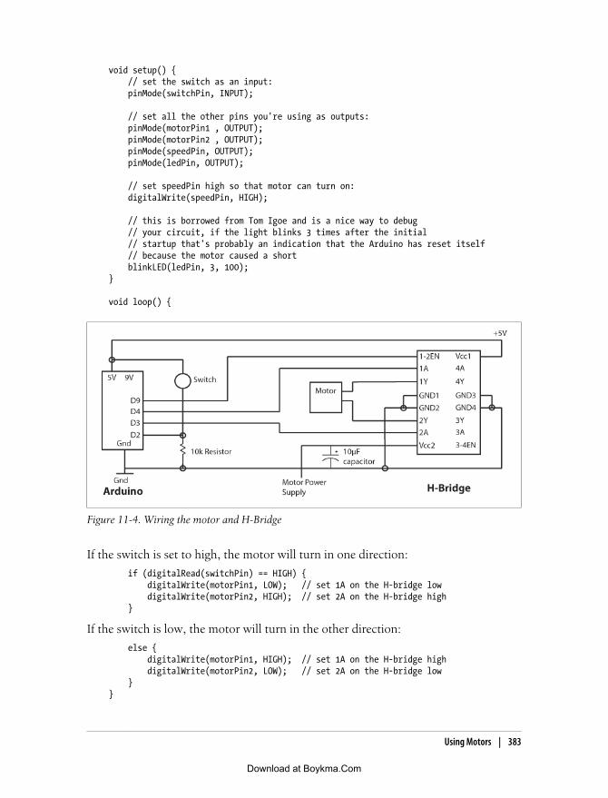
void setup() { // set the switch as an input: pinMode(switchPin, INPUT);
// set all the other pins you're using as outputs: pinMode(motorPin1 , OUTPUT); pinMode(motorPin2 , OUTPUT); pinMode(speedPin, OUTPUT); pinMode(ledPin, OUTPUT);
// set speedPin high so that motor can turn on: digitalWrite(speedPin, HIGH);
// this is borrowed from Tom Igoe and is a nice way to debug // your circuit, if the light blinks 3 times after the initial // startup that's probably an indication that the Arduino has reset itself // because the motor caused a short blinkLED(ledPin, 3, 100);}
void loop() {
Figure 11-4. Wiring the motor and H-Bridge
If the switch is set to high, the motor will turn in one direction:
if (digitalRead(switchPin) == HIGH) { digitalWrite(motorPin1, LOW); // set 1A on the H-bridge low digitalWrite(motorPin2, HIGH); // set 2A on the H-bridge high }
If the switch is low, the motor will turn in the other direction:
else { digitalWrite(motorPin1, HIGH); // set 1A on the H-bridge high digitalWrite(motorPin2, LOW); // set 2A on the H-bridge low }}
Using Motors | 383
Download at Boykma.Com

// this method just blinks an LEDvoid blinkLED(int whatPin, int howManyTimes, int milliSecs) { int i = 0; for ( i = 0; i < howManyTimes; i++) { digitalWrite(whatPin, HIGH); delay(milliSecs/2); digitalWrite(whatPin, LOW); delay(milliSecs/2); }}
Now that you know how to wire a motor, you can begin to use a motor to create motionin any of your projects. If you’re looking to use a motor to drive a more complex motion,you’ll probably need to use some gears or wheels in different kinds of configurations.A number of websites worldwide sell tracks, wheels, and gear and axle kits.
Stepper MotorsStepper motors operate differently from normal DC motors. Instead of just rotatingwhen voltage is applied to their terminals, they have multiple toothed electromagnetsthat are given power by an external control. To make the motor shaft turn, first oneelectromagnet is given power, which makes the gear’s teeth magnetically attracted tothe electromagnet’s teeth. When the gear’s teeth are thus aligned to the first electro-magnet, they are slightly offset from the next electromagnet. When the next electro-magnet is turned on and the first is turned off, the gear rotates slightly to align with thenext, and so on, all the way around the gear. Each rotation is called a step, with anintegral number of steps making a full rotation that lets you set the position of the motorto a precise angle.
To work with a Stepper motor and an Arduino, you’ll probably need to use a chip tocontrol a stepper, called a driver, like the one pictured in Figure 11-5.
Figure 11-5. A stepper motor driver and connecting it to the Arduino
384 | Chapter 11: Physical Feedback
Download at Boykma.Com

The driver lets the Arduino control the motion of the motor with pin 3 connected tothe Step input as marked on the diagram and pin 2 connected to the Dir input as markedin the diagram. To power your motor, you’ll send the current to the pin on theEasyDriver marked +V. How much current you’ll need to send is dependent on themotor that you’re using, so check the datasheet for your motor.
The Arduino code to control a stepper motor looks like this:
int dirPin = 2;int stepperPin = 3;
void setup() { pinMode(dirPin, OUTPUT); pinMode(stepperPin, OUTPUT);}
void step(boolean dir,int steps){ digitalWrite(dirPin,dir); delay(50); for(int i=0;i<steps;i++){ digitalWrite(stepperPin, HIGH); delayMicroseconds(100); digitalWrite(stepperPin, LOW); delayMicroseconds(100); }}
void loop(){ step(true,1600); delay(500); step(false,1600*5); delay(500);}
Another option is to use the Stepper library that comes with the Arduino IDE distri-bution. You can find examples of using this library both on the Arduino site and onthe MAKE magazine site at makezine.com. Anything that you need to move a verycontrolled amount, such as a camera, a light, a small door, a slide for a slide whistle,can all be controlled with a stepper motor.
In the next section, we’ll look at servo motors, which are quite similar but have a fewdifferences from a stepper motor. A servo is much smoother and better for continuousmotion, while stepper motors can much more easily lock into fixed positions and canhold those fixed positions with much greater torque than a servo, making them moreappropriate for moving into preset positions. You can see stepper motors at work inprinters, laser cutters, tool and die machines of all flavors, as well as throughout in-dustrial production lines.
Using Motors | 385
Download at Boykma.Com

Other OptionsAnother option for working with stepper motors is a motor shield from Adafruit In-dustries, shown on the right in Figure 11-6. As of the writing of this book, the motorshield supports two smaller (5V) servos, up to four bidirectional DC motors, and twostepper motors, as well as providing a block of connectors to easily hook up wires(10-22AWG) and power. These are worth looking into because they simplify workingwith multiple motors.
Pololu is a robotics supply company, which is also making motor drivers, as shown onthe left of Figure 11-6, that can be used to drive stepper and bidirectional motors. Whilethe boards made by Pololu are more versatile, the AdaFruit shield is much moreArdunio-ready. If any of these different tools is appropriate for your project, that isdependent of course on how much you can spend.
Figure 11-6. Two different motor driver shields
Using ServosThe motor is not, on the face of it, an interactive element; it is a reactive element. Forexample, I turn the key, and my car turns on. But motors are important and relevantto interaction and interactivity because working with motors and servos allows you tomake the first step into the one of the most important areas of human computer inter-action and computing: robotics. Now, given the space constraints that I frequentlymention, it’s impossible for us to delve too deeply into robotics, but it is quite easy toshow some of the basics of controlling a servo and creating programmable motion.
A servo is a type of motor but with a few added advantages. It, like the motor, receivesa PWM signal that it uses to power itself; however, a servo reads the amount of voltagepassed in to determine how far to rotate within a limited range. The most commonrange for a servo motor is 180 degrees, and the servo can move from any point in thatrange to any other point clockwise or counterclockwise, making it a powerful tool forcontrolling anything that needs a controllable, repeatable movement. Robots, puppets,cars, and in fact most automated machinery make extensive use of servos. For our
386 | Chapter 11: Physical Feedback
Download at Boykma.Com

purposes in this chapter, we’ll be looking at small servos, but you are encouraged tothink big. One of the really wonderful aspects of servos is that though there are manyto choose from with different sizes and performance, the signals used to control theservo are almost always the same, meaning that you could apply the same code to movea small hobbyist servo as you would to move a very large servo.
Now, although this won’t quite make sense until we look at code to control the servo,it’s worth mentioning here that the PWM pin on the Arduino control isn’t set at thecorrect frequency to control a servo motor. That means that we can’t write simpleinstructions to tell a servo to move to a certain position. We have to send the servo a5V pulse where the duration of the pulse tells the servo to move to a given position.This isn’t as difficult as it sounds, although it does make our code a little strange. Butdon’t worry, because it will be explained in full.
Connecting a ServoTo connect a servo motor to the Arduino controller, you need to provide the servo withpower from the 5V pin on the Arduino controller, to ground the servo, and to sendcommands to the servo PWM port. Now, as we mentioned, the PWM port of theArduino controller doesn’t operate at the proper frequency to communicate with aservo. If you’re savvy with AVR microcontrollers, the chip that the Arduino uses, andC programming, you can change it, but that’s beyond the scope of this book and isn’tnecessary to communicate with the servo.
Communicating with the ServoTo control the servo, you send it a command every 20 milliseconds. The servo respondsto a short pulse (1ms or less) by moving to one extreme, and it moves around 180degrees in the other direction when it receives long pulses (around 2ms or more). Theamount that the servo moves is determined by the length of time that the pulse is sentto the servo (Figure 11-7). You should be aware that there is no standard for the exactrelationship between pulse width and position; different servos may need slightly longeror shorter pulses.
Servo motors have three wires: power, ground, and signal, as Figure 11-8 shows. Thepower wire is typically red and should be connected to the 5V pin on the Arduino board,though some servo motors require more power than the Arduino can provide. Theground wire is typically black or brown and gets connected to a ground pin on theArduino board. The yellow (or white) wire of the servo goes to the digital pin that you’reusing to control the servo. In Figure 11-8 it’s pin 9, and the red and black wires go to+5V and ground, respectively.
Using Servos | 387
Download at Boykma.Com

Wiring a ServoAs you’ll see in the code snippet that follows, controlling a servo is really just a matterof determining how long in microseconds you need to send each command to the servo.Sending commands to the servo is a matter of writing a pulse to the motor that is thedesired length. In this example, a value between 0 and 180 degrees (followed by anondigit character) is sent using the serial connection to a computer to the servo. Forexample, 180 microseconds will move the servo fully in one direction, and 0 micro-seconds will move it fully in the other:
int refreshTime = 20;int command;int pulseWidth = 1500; // this is the default valuelong lastServoPulse;
Figure 11-7. Positioning a servo using the pulse width or duration
Figure 11-8. Connecting an Arduino to a servo motor
388 | Chapter 11: Physical Feedback
Download at Boykma.Com

int servoPin = 9;
void setup(){ pinMode(servoPin, OUTPUT);}
void loop(){ if(Serial.available()){ command = Serial.read(); // get the keyboard input if(command > '0' && command < '9') command = command - '0'; else{ pulseWidth = (command * 9) + 700; // get the right amount of time command = 0; // reset to get ready for the next command } } sendPulse();}
void sendPulse(){ if(millis() - lastServoPulse > refreshTime) { digitalWrite(servoPin, HIGH); delayMicroseconds(pulseWidth); digitalWrite(servoPin, LOW); refreshTime = millis(); // make sure we only update at the right moments }}
Many objects that you want to turn or rotate can be manipulated with a servo, cameras,mirrors, directed lighting etc. To control these kinds of movement there’s an easy cor-relation between a potentiometer and a servo; turn the potentiometer, and the servoturns. You can use buttons as well, both to set the servo to a preset position or byturning the servo as the button is held down. Other input devices that can be matchedto a servo are infrared and ultrasonic sensors, which were covered in Chapter 8.
Another way of programming the servo is to use the Servo library, which is includedwith the Arduino IDE. This library provides a somewhat easier way of communicatingwith the servo motor.
This library lets an Arduino board control one or two RC (hobby) servo motors on pins9 and 10. Servos have integrated gears and a shaft that can be precisely controlled.Standard servos let the shaft be positioned at various angles, usually between 0 and 180degrees. Continuous rotation servos let the rotation of the shaft be set to various speeds.
This library uses functionality built in to the hardware on pins 9 and 10 (11 and 12 forthe Mega) of the microcontroller to control the servos without interfering with othercode running on the Arduino. If only one servo is used, the other pin cannot be usedfor normal PWM output using analogWrite(). For example, you can’t have a servo onpin 9 and PWM output on pin 10.
The Servo library provides three methods:
Using Servos | 389
Download at Boykma.Com

attach()Starts reading the Servo instance on the pin passed in to the method and has thefollowing signatures:
servo.attach(pin)servo.attach(pin, min, max) // optionally set the min and max pulse widths
write()Writes a value to the servo. On a standard servo, this will set the angle of the shaft(in degrees). On a continuous rotation servo, this will set the speed of the servo(with 0 being full speed in one direction, 180 being full speed in the other, and avalue near 90 being no movement).
read()Reads the current angle of the servo (the value passed to the last call to write()).
To start the Servo library, declare an instance of it in your application code:
Servo servoInstance;
In this example, a potentiometer is attached to analog pin 0, and then the value fromthe potentiometer is used to set the position of the servo:
#include <Servo.h>Servo myservo; // create the servo object
int potpin = 0; // analog pin used to connect the potentiometerint val; // variable to read the value from the analog pin
void setup(){ myservo.attach(9); // attaches the servo on pin 9 to the servo object}
void loop(){ val = analogRead(potpin); // reads the value of the potentiometer //(value between 0 and 1023) val = map(val, 0, 1023, 0, 180);// scale it to use it with the servo //(value between 0 and 180) myservo.write(val); // sets the servo position according to the scaled value delay(15); // waits for the servo to get there}
One issue to keep in mind is that when you send a command to the servo, it takes amoment for the actual position of the arm to reach that point. If you want the servo togo from 0 degrees to 180 degrees, you’ll probably need to send the command multipletimes so that the motor can arrive at the position. In the following example by HernandoBarragan, the servo slowly rotates around its full range. Note the delay to allow themotor to move into the correct position:
#include <Servo.h>Servo myservo; // create servo object to control a servo
390 | Chapter 11: Physical Feedback
Download at Boykma.Com

int pos = 0; // variable to store the servo positionvoid setup() { myservo.attach(9); // attaches the servo on pin 9 to the servo object}
void loop(){ for(pos = 0; pos < 180; pos += 1) // goes from 0 degrees to 180 degrees { // in steps of 1 degree myservo.write(pos); // tell servo to go to position in //variable 'pos' delay(15); // waits 15ms for the servo to //reach the position } for(pos = 180; pos>=1; pos-=1) // goes from 180 degrees to 0 degrees { myservo.write(pos); // tell servo to go to old position delay(15); // waits 15ms for the servo to //reach the position }}
Lots of different types of servo motors are available. Most have only a 180-degree turn-ing range, but some have 1.5- and 3-turn radii. Others, like the Parallax ContinuousRotation Servo, allow for full and complete continuous rotation.
There are several different shields and boards to simplify the wiring for servo motors.The Adafruit stepper shield pictured in Figure 11-6 is among them. Driving multipleservos—for instance, to create a simple robotic arm or a piece of animatronics—canget complex quickly, and though using a board will increase the price of your project,it can also make your wiring cleaner and your assembly quicker.
Another option for working with servo motors that you may be interested in is theMegaServo Hardware Servo library developed by Michael Margolis that is available fordownload on the Arduino website. This library allows an Arduino board to control 1to 12 RC (hobby) servo motors on any digital pin on a standard Arduino board or upto 48 servos on an Arduino Mega. It can be used just like the Servo library. It also allowsyou to control up to 48 servos on the Arduino Mega or 12 servos on the other boards.Any digital pin can be used with any servo, and pulse widths can be written and readin degrees or microseconds that makes writing the pulse widths easier.
Some experiments with servos that you might be interested in trying are creating amotion detector using several infrared motion sensors and a servo to control a webcam.By using four infrared motion sensors pointed in each of the four cardinal directions,you can determine where motion is occurring and use a servo to point a camera in thatdirection. You’ll need a 360-degree servo to do this. Another interesting idea is creatinga drawing machine by using servos to control a pen or pencil. By pairing servos, youcan have one mechanical control to change the position of the pen and another tocontrol the location of the paper. In tandem, they would be able to draw pictures andwrite letters.
Using Servos | 391
Download at Boykma.Com

Using Household CurrentsThe Arduino controller can easily power a small LED light or a very small incandescentbulb, but to power up anything larger than that, you’ll need to use more current thanyou can safely run through the Arduino pins. This means that you’ll need to run thepower through a separate piece of hardware called a transistor and control that pieceof hardware using the Arduino controller. A transistor can act as a switch to a circuitthat carries a certain amount of current, in this case, way more current than you wantto allow near your Arduino pins. Normally the transistor doesn’t allow the circuit tocomplete, and no current flows through the high power circuit. But when the base ofthe transistor is turned on, the transistor completes the larger circuit, and whateveryou’re powering with the big circuit turns on.
In Figure 11-9, you can see the solid-state relay with its input and output posts labeled.The input posts are attached to the Arduino so that the switch inside can be thrown bythe 5V signal from the Arduino. The output posts are used to control the voltage forthe larger appliance, such as a light. You can control larger voltages using a combinationof a diode, a transmitter, and a relay, but an easier approach is to use a solid-state relay,which combines all three of these into a single unit and makes wiring substantially lessdifficult. Note that most of these are used to control AC current like household current,not DC current.
Figure 11-9. Using a solid-state relay with the Arduino controller
To control household AC voltages such as a standard household light, you need some-thing like a relay to switch the high voltage and isolate it from the Arduino.
You’ll need to be very careful when following along with these instruc-tions because you’re dealing with enough electrical current to hurtyourself and start a fire. This is important enough that it bears repeating:household current can hurt you and start fires.
392 | Chapter 11: Physical Feedback
Download at Boykma.Com

Figure 11-10 shows how to hook up a household AC light to the solid-state relay.
Figure 11-10. Connecting a lightbulb and a solid-state relay to the Arduino controller
The code for this can be quite simple:
int relayPin = 12; // choose the pin for the relayvoid setup() { pinMode(relayPin, OUTPUT); // declare relayPin as output}
void loop(){ digitalWrite(relayPin, LOW); // turn relay OFF delay(1000); digitalWrite(relayPin, HIGH); // turn relay ON delay(1000);}
Beware that turning lights on and off frequently in a short span of time could burn thebulb out quickly. However, you can do more than turn lights on and off with thiscontroller: you can control any household device as long as it does not exceed thecurrent capacity of the relay you use.
Working with AppliancesOne simple way to create physical feedback is to use preexisting appliances. There’s agreat device for doing this created by the guys at LiquidWare called the RelaySquid,shown in Figure 11-11. The RelaySquid is a board that has four relays, each of whichcontrols an extension cord with three outlets. Each relay can be individually controlledby the Arduino by sending it a digital signal.
The pins marked “Relay drive” should each be attached to the pins on the Arduino.The following bit of code assumes that relay drive pin 1 is attached to digital pin 4, thatrelay drive pin 2 is attached to digital pin 5, and so on. It will turn each outlet on theRelaySquid for one second and then go onto the next one:
void setup() {
pinMode(4, OUTPUT); pinMode(5, OUTPUT); pinMode(6, OUTPUT); pinMode(7, OUTPUT);
Working with Appliances | 393
Download at Boykma.Com

}
void loop() {
digitalWrite(HIGH, 4); delay(1000); digitalWrite(LOW, 4); digitalWrite(HIGH, 5); delay(1000); digitalWrite(LOW, 5); digitalWrite(HIGH, 6); delay(1000); digitalWrite(LOW, 6); digitalWrite(HIGH, 7); delay(1000); digitalWrite(LOW, 7);
}
Figure 11-11. The pins on the RelaySquid
So, beyond turning lights on and off, what can you do with the RelaySquid? For starters,you could attach a clock sensor to the Arduino and turn an appliance on or off at aspecific time for home security. You could program a schedule for grow lights to turnon and off for plants. You could turn a television, a generator, or any other applianceon or off. You need to take a few things into account: some devices work well withrapid cycling, and some do not. Some types of lights work well being turned on and offquickly. In my experience, halogen bulbs work particularly well, and incandescentbulbs burn out quickly when turned on and off in rapid succession. Televisions do notwork well when turned on and off quickly. A little bit of searching and asking questionson forums can save you unpleasant surprises later on.
394 | Chapter 11: Physical Feedback
Download at Boykma.Com

Other preassembled components are available for switching large loads like the oneshown in Figure 11-12 on the left from electronics-lab.com and the one shown on theright created at sparkfun.com.
Figure 11-12. Two shields for working with household currents: the anykit Solid State Relay Switchand the sparkfun Inline Power Control
Introducing the LilyPad BoardThere’s another Arduino-compatible board that has a particular relevance to providingphysical feedback: the LilyPad board shown in Figure 11-13 and developed by LeahBuechley. One of the challenges of providing physical feedback is always deciding onthe scale and scope of that feedback. A signal should be appropriate to its message andalso to the context in which the user finds themselves, which is why there’s a discretevibrate setting on almost all cell phones and mobile devices. Removing this would makesome signals inappropriate for their context, like a loud ringing during an opera. Andso it goes with interactive design: ensuring that the correct feedback is provided for thecontext is a vital affordance for the user. What does this have to do with the LilyPad?The LilyPad Arduino is a microcontroller board designed for wearables and e-textiles.It can be sewn to fabric and mounted to power supplies, sensors, and actuators withconductive thread. Leah Buechley has provided code and schematics and links to sev-eral projects on her website at web.media.mit.edu/~leah/, including a turn signal jacketfor bicyclists. So, the means of input and feedback can become much more subtle,becoming invisible or inaudible to anyone except the user. It also allows you to usepreexisting form factors. That is, you can simply sew the LilyPad into a shirt, a jacket,a bag, or any other common object and let that object create the form of your device.
The board is based on the ATmega168V, which is a slightly lower-power version of theATmega168 chip that the Arduino uses. It is programmed using the Arduino IDE justlike any other Arduino device and can be powered from a USB if you either get a USBconnector or use one of the USB modules for the Arduino Mini, as shown Figure 11-14.
Introducing the LilyPad Board | 395
Download at Boykma.Com

Figure 11-14. The LilyPad to a connected to a USB programmer
Figure 11-13. The LilyPad
396 | Chapter 11: Physical Feedback
Download at Boykma.Com

It has 14 pins; all can be used as digital outputs, 6 can be used for analog (PWM)outputs, and 6 can be used for analog inputs. The LilyPad is also a little more fragilethan a regular Arduino board, so you’ll need to be a bit careful when working with itand particularly when wiring it up. Also, the LilyPad is not particularly sensitive towater. If the LilyPad is not powered up, it can be washed with nonabrasive detergent.This doesn’t help when your project is caught in a sudden torrential rainstorm, but itdoes make the device a little less susceptible to the sweat, small spills, and environ-mental moisture that a wearable piece of technology will invariably encounter.
Using VibrationVibration is a simple and subtle signal that, given the correct contextualizing informa-tion, can be a great alert to a user. The LilyPad comes with a number of prebuilt com-ponents that can easily be connected either as inputs or as feedback devices, one ofwhich is the LilyPad Vibe Board shown in Figure 11-15. This small motor works inmuch the same way as the vibrate motor on a cell phone. A 5V signal is enough topower the vibration motor, alerting the user to whatever you’d like to alert them to.
Figure 11-15. LilyPad Vibe Board
Since the LilyPad is generally meant to be used in a completely mobile application,you’ll need to provide power to it. One AAA battery is enough to power the LilyPadfor a reasonable amount of time using the LilyPad power supply. You can also use theLiPower module with a Lithium Ion battery, shown in Figure 11-16.
The LiPower board is small, is inconspicuous, and lets you use a rechargeable LithiumPolymer battery like the one shown on the left in Figure 11-16. These batteries aresmaller, are flatter, and last much longer than AAA cells. Simply attach a single cell forLithium Polymer (LiPo) battery, flip the power switch, connect the LiPower battery tothe LilyPad, and you have a small, portable, short circuit–protected 5V supply.
The last part of the puzzle with the LilyPad is the connection between the LilyPad andall of its component pieces. When working with an Arduino Duemilanove, most ofyour connections are made with 22- or 24-gauge wire or with solder. This approachdoesn’t translate as well to clothing, so you might considering using a special kind ofconductive thread that can be used to connect the LiPower, the LilyPad, and the VibeBoard. Conductive thread is an excellent way to connect various electronics ontoclothing. It isn’t as conductive as traces on a printed circuit board, but it lets you createa complete circuit that remains flexible, near invisible, and, most important, wearable.
Using Vibration | 397
Download at Boykma.Com

Note that when designing applications with the LilyPad, you should always keep yourpower supply and LilyPad main board as close to each other as possible. If they are toofar apart, you are likely to have problems with your LilyPad resetting or just not workingat all because of the resistance in the conductive thread connecting the boards. Theresistance usually isn’t as big of a deal when it’s on the line connecting the LilyPad toa sensor or component, but between the LilyPad and its power supply, it makes a bigdifference in the reliability and durability of your project.
Figure 11-17 shows how to connect the LilyPad, LiPower, and Vibe Board.
Figure 11-17. Connecting the Vibe Board
Figure 11-16. Lithium Ion battery and the LiPower board
398 | Chapter 11: Physical Feedback
Download at Boykma.Com

The code to turn on the Vibe Board can be as simple as this:
void setup() {
pinMode(1, OUTPUT);
}
void loop() {
digitalWrite(HIGH, 1); delay(1000); digitalWrite(LOW, 1); delay(1000);
}
As of the writing of this book, the LilyPad has several other available types of compo-nents for input: an accelerometer, a light sensor, a temperature sensor, a button board,and an XBee-compatible breakout board for integrating an XBee antenna into a LilyPadsystem. Some of the other feedback options that the LilyPad provides are sound-generating buzzers and three-color LED components. At the moment, all LilyPad com-ponents are available through the Sparkfun website as well as other online retailers.
Interview: Troika Design StudiosTroika is a design studio based in London that works with graphic design, productdesign, technology development, sculptural projects, and interactive installations.Conny Freyer, Eva Rucki, and Sebastien Noel founded Troika in 2003. They are alsothe authors of the book Digital by Design (Thames and Hudson).
Where do you think the boundary between fine art and design is located with regard tonew media art or interactive art? Is this a relevant or important question for you?
Troika Design Studios: We describe ourselves as an art and design studio, butwouldn’t describe ourselves as new media artists or interactive artists. Although termslike new media art and interactive art are very vague, they seem rather limiting becausethey define the work you are making by the tools you are using.
Although any attempt to classify new movements is interesting, we enjoy being part ofa movement that has so far escaped any coinage and defines itself through blurring theboundaries between established genres and disciplines.
Can you address the notion of collaboration throughout the conception and execution ofa project? Is the collaboration something continuous or something more akin to a tradi-tional software development practice where each team does its part and hands it to thenext team? How do you handle communicating across disciplines?
Using Vibration | 399
Download at Boykma.Com

Troika: We are continuously working on a range of self-initiated and commissionedprojects, which follow similar processes from concept to design development to pro-duction and implementation.
All three partners take part in the concept stage after which the project is led by onepartner who is responsible for the planning, the communication with the client, andthe division of work between the partners as well as other collaborators. Tasks arenaturally distributed according to different skill sets. We collaborate with a close-knitnetwork of specialists, which we employ depending on the project. An iterative processis crucial to our way of working, which happens internally between the team membersas much as with our clients and manufacturers.
Communicating across disciplines takes time and practice. It’s literally like learning adifferent language. We were fortunate enough to follow each other’s developmentsthroughout the master’s degree program at Royal College of Art in London, whichhelped to develop a common vocabulary.
Can you give a little background on the history of Troika?
Troika: Conny Freyer, Sebastien Noel, and Eva Rucki founded Troika in 2003, afterwe graduated from the Royal College of Art. Since then we have worked for clients suchas MTV International, British Airways, the BBC, Warner Music UK, Thames and Hud-son, and the London Science Museum.
Although the work of our studio spans various disciplines from graphics to productsto installations, a lot of the themes—like creative use of technology and cross-fertilization between the art and design disciplines—are recurring subjects.
Since the beginning we have frequently taken part in national and international exhi-bitions and conferences, including Get it Louder (in 2007 in Guangzhou, Shanghai,and Beijing), Responsive (in 2007 in Tokyo), the Science of Spying (in 2007 at theScience Museum London), Noise of Art (in 2007 at Tate Britain, London), Design andthe Elastic Mind (in 2009 at the Museum of Modern Art in New York), Volume(s) (inCasino Luxembourg, Forum d’art contemporain), and ExperimentaDesign (in Am-sterdam in 2008).
Are there are good precedents for companies or collectives working across fine art anddesign that influenced you and the way that you structured Troika?
Troika: Collectives like Tomato and Antirom were certainly an influence during ourstudies, because of their multidisciplinary approach and because they were working ascollectives rather than presenting themselves as one person (who employs others tocomplement his or her skill set), as is often the case in the product design world. Buttheir mix of skills was quite different from ours, and the commercial landscape in whichthey started out had changed quite a bit when we set up our studio.
Troika’s structure developed naturally based on the backgrounds of the foundingmembers and a shared interest in the creative use of technology and cross-fertilizationbetween the art and design disciplines.
These interests are apparent in our work for the Science Museum (Identity for the Sci-ence Museum Art Projects galleries and concept products for the Spymaker exhibition,
400 | Chapter 11: Physical Feedback
Download at Boykma.Com

which examine the future of spy technologies) as much as in our forthcoming bookDigital by Design. It’s an overview of the fusion of digital technology and art and designproduction, as in our installation work for Terminal 5 of the Heathrow airport.
Do you consider yourselves part of a lineage of artists and designers or of a school of designin any way?
Troika: Troika is part of a generation of artists and designers who creatively engagewith technology in order to provoke questions, experiment, and explore its potentialsand impacts. A lot of these artists grew up during the transient phase where analogtechnologies were gradually replaced—the record players and View-Master. As such,they understand the benefits, appeal, and importance of the materiality and the tangiblecomponent of technologies versus the all-digital, immaterial, which prevailed at thestart of the digital era.
The influence of sci-fi—from films such as Kubrick’s 2001 Space Odyssey, Scott’s BladeRunner, Orwell’s novel 1984 (Plume), Gibson’s novel Neuromancer (Ace), Ballard’scollection of short stories, or the more popular Star Wars, to name but a few—sparkeda willingness to think and create in technological terms, finding new avenues and al-ternative futures. A lot of artists working in this field share a more or less intense fas-cination for technology itself, its potentials for artistic expression, and its social andcultural impacts. Other notable influences include kinetic and media art, the counter-culture of the ’80s and ’90s (more precisely in DJ culture, which influenced the processin terms of remixing), hacker communities (as the Berlin-based Computer Chaos Club),street art, and graffiti.
How do you view what I’ve been calling “the ecology of new media art,” by which I meaneconomic possibilities, exhibition opportunities, exchange of dialogue, and so on. Do yousee it forming interesting discussions and fueling work or not? Do you have a sense of howit this is different across different parts of the world?
Troika: The general approach of artist and designers working in this field is very col-laborative. Sharing knowledge as well as the joy of discovery online as well as at con-ferences is a common feature and encourages a constant exchange and debate. Part ofthe reason may be that a lot of small structures are operating in this field that haveadopted a flexible and associative process, pulling together the right competences whenneeded, rather than growing into a bigger apparatus in order to ensure their autonomy.
Who are the artists and designers working today that you are most interested in?
Troika: We have just written a book called Digital by Design that features artists anddesigners who employ technology in unexpected, playful, disruptive, functional, orcritical ways. What was most challenging, but also most interesting, to us when writingthe book was that the works we selected successfully escape any coinage such as mediaart or interactive design. The selected artists and designers have one thing in common:an eagerness to explore the intersection between science, art, design, and technologyin the search for humanist values, humor, magic, and sensory experiences.
We love Daniel Rozin’s Mechanical Mirrors for the tangible beauty, Dunne and Raby’swork for their critical approach toward design, and Ron Arad’s sense of exploring the
Using Vibration | 401
Download at Boykma.Com

new. What we look for in all the works we admire is the increasingly lacking desire forthought, enjoyment, quality, and craftsmanship.
A piece like Sonic Marshmallows appears at first very nontechnological, but it allows youto think about things that are enabled by technology without using any electronics orpower. Can you talk a little about how a piece like that fits in with the rest of your worksand how you see it functioning in relation to people’s desires to interact with things?
Troika: We are fascinated by technology—being kinetic, optical, sonic, orelectronic—and its impact on people. So, a lot of our work is informed by technology,but it is not a prerequisite. What we are striving for in our work is immediacy. We wantour works to trigger emotions or thoughts like a story or film might do, and we lovewhen art, magic, and science appear to be crossing paths. Sonic Marshmallows is a greatexample; it’s technology in its purest form. Older technologies, especially the onesdirectly linked to natural optical and acoustic phenomena, carry a very simple andinnate beauty that reveal their depth and magical surprise once you experience them.We see Sonic Marshmallows more as a manifestation of people’s desire to interact witheach other, rather than with things. Sonic Marshmallows can be used only in conjunc-tion with another user. Sound mirrors were originally used on the coast of Kent to detectincoming enemy planes, not far from the location were Sonic Marshmallows is installednow. We used the same technology in a way that enables people to communicate witheach other instead.
You’ve created the electroprobe, a device for listening to electrical currents that surroundus in our everyday environment. Can you talk a little bit about working with this tool andwhy you’ve come back to this theme several times?
Troika: We first exhibited the electroprobes as an exploration tool for the immediatesurrounding; for example, in galleries people could discover the sounds produced bythe radio magnetic radiations of the surrounding lamps, closed-circuit TV cameras,electricity wires, and so on.
We then became interested in the wide range of sounds that electroprobes can pick up,including sounds from objects, which might not appear in your common gallery con-text, such as LED boards, fans, fridges, and so on. In order to enable visitors to hearthe varied sounds of their radio magnetic environment, we curated installations ofelectronic objects.
When we were invited by the British Council to China, we decided to make a location-specific sculpture using only electronics from the Chinese markets. The objects werearranged according to the sounds they were producing to create one big electromagneticorgan. The user becomes in a certain sense the composer because he will determinewhich sounds become audible through navigating this electromagnetic soundscapewith the aid of the electroprobe.
Do you approach conceiving of a print work differently than you approach conceiving ofan interactive piece?
Troika: Projects that are most interesting to us are the ones where we can bring allmedia together: print, installation, product, and animation. The main difference be-tween one work or another is usually whether it is something that is applied or
402 | Chapter 11: Physical Feedback
Download at Boykma.Com

not—something that is about answering a brief or creating a work that is self-initiated.We approach all in the same way. We want to engage and surprise people throughsensory experiences or through making them think. And this counts for a piece of printas much as for an installation.
This is a very broad question, so feel free to answer however you like. What are thefundamental rules for designing an interaction?
In Troika’s practice, interaction design or experience design might have a very differentmeaning than, for instance, for an interaction designer working in productdevelopment.
Troika: Troika strives to engage people on more intuitive and emotional levels. A goodexample is our kinetic sculpture Cloud. Supported by the organic fluid movement ofits surface, it provokes associations of a living creature. The flicking sound of a flip dot,which is a small circle that is flipped over to create a sort of pixel and which was atechnology used in old airport displays, touches on memories of traveling when youwere a child.
Some people have asked us if Cloud is interactive—if it moves only when you walk by.Our answer to that is that interaction can mean many things and goes far beyondtouching a button and getting a response once you have done so. A sculpture such asCloud is not based on such a linear approach.
Nevertheless, designing interactivity is an interesting task. Martin Heidegger sums itup pretty well. He describes that the only time he really noticed his hammer was whenit was broken and that he was thinking about the nail instead of the hammer when thehammer was working properly. It is about making the interface or the object invisibleand tapping into what people already know, where they are able to recognize form andbehavior without having to think about it.
What software or hardware tools do you use, and how do you feel they shape your visionor your working process?
Troika: We use the common 2D, 3D, and animation software packages. We draw andwrite to formulate our ideas. We have a workshop in which we experiment and buildour prototypes and smaller pieces.
Our ideas and designs are to a great extent influenced by the tools we are using. Try toformulate a concept without words! We believe that good craftsmanship and intimateknowledge of your field is essential. This counts for digital/virtual solutions as muchas tangible solutions.
A piece like All the Time in the World has an extremely complicated technological ele-ment, a beautiful typeface, an element of motion graphics, and a conceptual element thatplays on locations well-known and well-known but rarely considered. How do all theseideas come together in a piece? Is it born more of necessity or a desire to be able to shapeall aspects of a piece?
Troika: Our approach is quite holistic, and we find it an enriching and creatively chal-lenging experience to develop the different aspects of a project.
Using Vibration | 403
Download at Boykma.Com

All the Time in the World developed—like many of our projects—in a nonlinear fashion.We had created the Firefly typeface after we learned about the possibilities of electro-luminescent technology. When British Airways commissioned for an art installationfor its reception hall in T5 using the Firefly display, we started from the semantics ofthe location to develop the content for the installation.
Troika: We are investigating possibilities for technological innovation—mainly in theform of reappropriating existing technologies—on an everyday basis. At the same time,we are very aware of the contexts in which these technologies were previously used ordeveloped, and this informs the way we will use it in our projects. For example, the flipdot technology used in Cloud stems from the signage boards used in the ’70s and ’80sin train stations and evokes notions of travel. When those little inventions and context-specific concepts come together in an installation, it creates a multilayered end result,which carries meaning on more than one level.
Using an LED MatrixA light-emitting diode (LED) can indicate something to a user, it can provide recogni-tion of a user action, or it can act as an alert. Using multiple LEDs in concert with anArduino is usually limited by the number of digital out pins that the Arduino has. Byusing an LED driver chip, though, you can control up to an 8 × 8 matrix of LEDs or aneight-digit LED display. This lets you draw simple shapes, characters, and digits tobegin creating simple animations.
This section is going to be rather long because of the great number of ways that youwork with LEDs and in particular with LED matrices (group LEDs arranged in rowsand columns). These are the three relevant libraries for working with LEDs in Arduino:
MatrixThis library enables you to work with a single LED driver.
LedControlThis library enables you to work with multiple LED drivers and newer drivers aswell.
SpriteThis library allows you to create image sprites to use with the Matrix library.
Using the Matrix LibraryWe’ll focus on the Matrix library first. The chip and the idea of an LED matrix requiresa bit of explanation. First the chip: the most common approach to drive an LED matrix,and the one that we’ll examine in this section, is to use a chip called the MaximMAX7221 to drive the LEDs.
Figure 11-18 shows the pins of the MAX7221.
404 | Chapter 11: Physical Feedback
Download at Boykma.Com

In Figure 11-19, you’ll see how it can be wired to an 8 × 8 LED matrix and an Arduino.
You’ll notice that the wiring from the MAX7221 looks a bit complex, but it’s actuallymade easier by the chip’s pin diagram in Figure 11-19. The pins on the LED matrix gofrom DIG 0 to DIG 7, left to right, and SEG DP (comes before SEG A) to SEG G, topto bottom.
The Matrix library allows you easily communicate with the MAX7221 chip. You canturn individual LEDs on or off, as well as setting the brightness or clearing the LEDmatrix. For example, to make a smiley face, you import the Matrix library and tell itwhich pins are connected to the MAX7221.
The constructor for the Matrix library looks like this:
Matrix mat = Matrix(2, 3, 4);
Those three parameters specify which pins are connected to the MAX7221 control pins.The first is which pin is connected to the data (din), then which pin is connected to theload (load), and lastly which pin is connected to the clock (marked clk on theMAX7221). These pins are used internally by the Matrix class to drive the chip:
#include <Matrix.h>
Matrix mat = Matrix(2, 3, 4);
void setup() { // nothing here at the moment
Figure 11-18. Pins on the MAX7221
Using an LED Matrix | 405
Download at Boykma.Com

}
void loop(){ myMatrix.clear(); // clear display delay(1000);
// turn some pixels on
Figure 11-19. Maxim7221 schematic
The write() method take two parameters, the first to indicate the row of the LED thatshould be turned on and the second to indicate the column of the LED that should beturned on. The following calls to the write() method will create a smiley face:
406 | Chapter 11: Physical Feedback
Download at Boykma.Com

mat.write(1, 5, HIGH); mat.write(2, 2, HIGH); mat.write(2, 6, HIGH); mat.write(3, 6, HIGH); mat.write(4, 6, HIGH); mat.write(5, 2, HIGH); mat.write(5, 6, HIGH); mat.write(6, 5, HIGH);
delay(1000);}
Aside from the tricky wiring situation, creating a single LED matrix isn’t too difficult.Creating multiple LED matrices is also fairly easy, but it requires that you use a differentArduino library: the LedControl library.
Using the LedControl LibraryThe LedControl library is quite similar to the Matrix library except that it allows youto easily work with multiple MAX7221 and LED matrix pairings. Note, though, thatfor each LED matrix that you want to use, you’ll need to have a driver chip for it. Youcan use up to eight driver and matrix pairs with this library. The constructor looks likethis:
#include "LedControl.h"
LedControl lc1=LedControl(12,11,10,1);
The initialization of the LedControl library takes four arguments. The first three argu-ments are the pin numbers on the Arduino that are connected to the MAX7221, justlike the Matrix library. You are free to choose any of the digital I/O pins on the Arduino,but since some of the pins are also used for serial communication or have an LEDattached to them, it’s best to avoid pins 0, 1, and 13. I chose pins 12, 11, and 10 in myexample.
The fourth argument for the LedControl constructor is the number of cascadedMAX72XX devices you’re using with this LedControl. Valid values can be between 1and 8. There is a little performance penalty implied with each device you add to thechain, but the amount of memory used by the library code will stay the same, no matterhow many devices you set. This is quite important with a limited memory device likethe Arduino. Here is the syntax for the constructor, followed by a description of thefour parameters:
LedControl(int dataPin, int clkPin, int csPin, int numDevices);
dataPinAn int that represents the pin on the Arduino where data gets shifted out
clockPinAn int that represents the pin for the clock
Using an LED Matrix | 407
Download at Boykma.Com

csPinAn int that represents the pin for selecting the device when data is to be sent
numDevicesAn int that represents the maximum number of devices that can be controlled
If you need to control more than eight driver and matrix pairings, you can always createanother LedControl variable that uses three different pins on your Arduino. This meansthat if you’re using the Arduino MEGA, you can have up to 17 MAX7221 driversconnected. Figure 11-20 shows how to connect the signal lines for multiple MAX7221chips.
Figure 11-20. Connecting multiple MAX7221 chips
Now you can create an LedControl for two devices:
LedControl lc1=LedControl(12,11,10, 2);
If you’ve attached multiple MAX7221 drivers to your LedControl, you can loop throughthem all using the getDeviceCount() method, as shown here:
for(int index=0;index<lc1.getDeviceCount();index++) { lc1.setLed(1, 0, 0, 1); }}
The setLed() method sets the LED value at the address indicated:
setLed(int addr, int row, int col, boolean state)
The setLed() method takes four parameters:
int addrThe address of the display to control, between 0 and 7.
int rowThe row in which the LED is located, between 0 and 7.
int colThe column in which the LED is located, between 0 and 7.
boolean stateIf true, the led is switched on; if false, it is switched off.
408 | Chapter 11: Physical Feedback
Download at Boykma.Com

To initialize the MAX7221, you may need to wake the device by calling theshutdown() method with false passed to the method instead of true:
shutdown(int addr, bool shutdown);
This method takes two parameters:
addrIndicates which MAX7221 should be altered.
shutdownIndicates whether the device should go into power-saving mode if true is passedor whether it should come out of power-saving mode if false is passed.
When a new LedControl is created, the library will initialize the hardware with thedisplay blanked, the intensity set to the minimum, the device in power-saving mode,and the maximum number of digits on the device activated. To completely initializethe LED, you’ll want to set the brightness on it so that it’s ready to display data as soonas the setup is complete on your Arduino. A common display sequence might look likethis:
void setup() { //wake up the MAX72XX from power-saving mode lc.shutdown(0,false); //set a medium brightness for the Leds lc.setIntensity(0,8); }
To clear a display, call the clear() method, and pass the address of the controller thatyou want to clear:
void clearDisplay(int addr);
I’ll mention two other useful methods in the LedControl library:
The setRow() method sets an entire row on or off and uses the following signature:
void setRow(int addr, int row, byte value)
The setRow() method takes three parameters:
int addrThe address of the display to control.
int rowThe row on which the LEDs are to be set. Valid values are between 0 and 7.
byte valueA bit set to 1 in this value will light up the corresponding LED.
The setColumn() method sets an entire column on or off and uses the followingsignature:
void setColumn(int addr, int col, byte value)
The setColumn() method takes three parameters:
Using an LED Matrix | 409
Download at Boykma.Com

int addrThe address of the display to control.
int colThe column on which the LEDs are to be set. Valid values are between 0 and 7.
byte valueA bit set to 1 in this value will light up the corresponding LED.
So, now that you have an understanding of how to use multiple LED devices, you canbegin creating small displays using multiple LED matrices. Some fun ideas might be aversion of the classic video game Pong controlled using potentiometers, small graphicsor animations, or a readout for an application.
You might be interested in working with three-color LEDs, that is, LED matrices whereeach LED segment contains three LEDs (red, green, and blue), meaning that each seg-ment can be adjusted to many different colors by turning the brightness up or downon each LED. These three-color LED matrices can be controlled using multipleMAX7221 controllers, or you can look at using the serial interfaced LED matrices fromSparkfun that include a logic board that handles connecting the logic controller andthe pins. To connect those, you’ll simply need to connect the Arduino to the backpackincluded with the Serial matrix and send commands to it using the spi_transfer()method. This is a pretty advanced technique that shifts data into the data register to beread by any device that communicates using the SPI protocol.
Using the SPI ProtocolThere’s only space for a very short tutorial on the Serial Peripheral Interface (SPI) pro-tocol. SPI is generally used to communicate with other microcontrollers. In an SPIconnection, there is always a master device that controls all the peripheral devices con-nected to it over three common lines:
Master in slave out (MISO)The line that the slave uses to send data to the master controller
Master out slave in (MOSI)The line that the master uses to send data to the slave devices
Serial clock (SCK)The clock pulses that synchronize data transmission generated by the master
The really tricky thing about SPI is that generally each device implements it a little bitdifferently. Information on the nuances for each will always be available on the data-sheet for the device in online documentation.
All SPI settings are determined by the Arduino controller’s SPI control register (SPCR).A register is just a byte of microcontroller memory that can be read from or written to.Registers generally serve three purposes: control, data, and status.
410 | Chapter 11: Physical Feedback
Download at Boykma.Com

Control registers control settings for various microcontroller functions. Usually eachbit in a control register affects a particular setting like the communication speed.
Data registers simply hold bytes. The SPI data register (SPDR) holds the byte that isabout to be shifted out the MOSI line for all the peripheral devices to receive and thedata that has just been shifted in the MISO line from any peripheral devices.
Status registers change their state based on various microcontroller conditions. Forexample, the seventh bit of the SPI status register (SPSR) is set to 1 when a value isshifted in or out of the SPI.
The SPI control register (SPCR) has 8 bits, each of which controls a particular SPIsetting:
7 SPIEEnables the SPI interrupt when set to 1.
6 SPEEnables the SPI when set to 1.
5 DORDSends data last bit first when set to 1 and sends the first bit first, usually the bit thatdetermines whether a number is negative or positive, when set to 0.
4 MSTRSets the Arduino in master mode when set to 1 and sets slave mode when set to 0.
3 CPOLSets the data clock to idle when high if set to 1 and to idle when low if set to 0.
2 CPHASamples data on the falling edge of the data clock when set to 1 and on the risingedge when set to 0.
1 and 0 SPR1 and SPR0Sets the SPI speed; 00 is the fastest (4MHz), and 11 is the slowest (250KHz).
This next example will help you understand what this method means when you en-counter it, such as if you try to control one of the Serial RGB LED matrices mentionedearlier in this chapter:
char spi_transfer(volatile char data){ SPDR = data; // Start the transmission while (!(SPSR & (1<<SPIF))) // Wait for the end of the transmission { }; return SPDR; // return the received byte}
The spi_transfer() function loads the output data into the data transmission register,thus starting the SPI transmission. It checks the value of the SPSR to detect when thetransmission is complete and, when it is, returns complete. This is how external
Using an LED Matrix | 411
Download at Boykma.Com

memory can be used with Arduino, such as when you need to write to external non-volatile memory. Here’s what setting an application up to use SPI looks like:
#define DATAOUT 11//MOSI#define DATAIN 12//MISO#define SPICLOCK 13//sck#define SLAVESELECT 10//ss
void setup(){ Serial.begin(9600);
Here, pin 13 will be the clock pin to connect to the SPIClock pin of the LED matrixcontroller, pin 12 will go to the DataOut pin, pin 11 to the DataIn, and pin 10 will goto the SlaveSelect pin.
pinMode(DATAOUT, OUTPUT); pinMode(DATAIN, INPUT); pinMode(SPICLOCK,OUTPUT); pinMode(SLAVESELECT,OUTPUT);}
Figure 11-21 shows how the peripheral devices are connected to the Arduino.
Figure 11-21. The Serial RGB LED matrices’ connections
There are dozens of kinds of SPI devices that you might encounter, from memory stor-age devices to GPS devices to LCD screens.
Using LCDsWe are surrounded by liquid crystal display (LCD) screens, and although what theyprovide is not necessarily a physical sort of feedback, a small screen is an important
412 | Chapter 11: Physical Feedback
Download at Boykma.Com

element of many small devices because it lets you return data that is more complex thanan analog range or a digital value. Although representing “Hello World” in sound is avery interesting exercise, it’s often a lot easier to simply get an LCD screen and printthe characters to it. Moreover, a small screen can be held in the hand, attached toanother object, and embedded in the environment in a way that provides supplemen-tary information to a user.
There are many kinds of LCD screens and no foolproof way to communicate with allof them. With that in mind, we’ll look at one of the more common types of LCDs thathas an Arduino library. LCD panels that are controlled by the Hitachi HD44780 LCDcontroller chip or equivalent can be used with the LCD Interface library, you can checkwhich chip a LCD uses online. This library has methods to initialize the screen, printcharacters and strings, and clear the screen, making your coding substantially easier.The library is included with the Arduino IDE, so to get started, simply import the libraryusing the Tools tab in the IDE, choose Import Library, and then choose LiquidCrystal.Figure 11-22 shows the next example.
Figure 11-22. A simple 16 × 2 LCD screen, a 20 × 4 LCD, and a Serial Miniature OLED
The LCD Interface library provides five main methods:
void clear()Clears out anything shown in the LCD screen.
void home()Sets the cursor back to the beginning of the display.
void setCursor(int row, int column)Sets the cursor to the position indicated by the row and column. So, in a displaywith 2 rows of 16 columns, to set the 19th character or the character in the 4thposition of the 2nd row, you would use this:
setCursor(1, 3); // rows and columns start from 0
void write(byte value)Writes the character to the current cursor position.
Using LCDs | 413
Download at Boykma.Com

void command(byte value)This method is a little trickier, but for the ambitious among you, it will be inter-esting. The HD44780 chip defines different commands that you can use to dothings like set the display in and out of display mode quickly, control whether thecursor blinks, and so on.
Table 11-1 shows how the Arduino pin maps to an LCD using the HD44780 chip.
Table 11-1. Arduino to LCD Panel Chip Pin Map
Arduino pin Pin on the LCD
2 14 (DB7)
3 13 (DB6)
4 12 (DB5)
5 11 (DB4)
6
7
8
9
10 Enable
11 Read/Write (RW)
12 Register Select (RS)
Keep in mind, though, that the pins might not be in the same order, so you’ll need tocheck the datasheet. Figure 11-23 shows how the HD44780 LCD screen is connectedto the Arduino controller.
Figure 11-23. Connected an LCD screen to the Arduino
414 | Chapter 11: Physical Feedback
Download at Boykma.Com

To control the contrast of the display, you will need to connect a 10k (or 20k) poten-tiometer to provide the voltage to LCD pin 3 because without the correct voltage onthis pin, you may not see anything displayed. As shown in the figure, one side of thepotentiometer connects to Gnd (ground), the other side connects to Arduino +5v, andthe center of the potentiometer goes to LCD pin 3. Many LCD screen have an internallamp called a backlight that illuminates the display. The datasheet for your LCD screenshould indicate whether the backlight needs a resistor. Many do; you can use 220 ohmsor so if you are not sure.
This allows you to use the LiquidCrystal library that is included with the Arduinodistribution:
You have two different versions of the constructor available. One lets you pass the pinsthat will be used for all seven control pins:
LiquidCrystal(rs, rw, enable, d0, d1, d2, d3, d4, d5, d6, d7)
Another lets you just pass four pins:
LiquidCrystal(rs, rw, enable, d4, d5, d6, d7)
Both options use the following three parameters:
rsSpecifies the number of the Arduino pin that is connected to the RS pin on the LCD
rwSpecifies the number of the Arduino pin that is connected to the RW pin on theLCD
enableSpecifies the number of the Arduino pin that is connected to the enable pin on theLCD
Whichever constructor version you decide to use, make sure that those pins are cor-rectly attached to the LCD device. Now, to test, you could do the following:
#include <LiquidCrystal.h>
LiquidCrystal lcd(12, 11, 10, 5, 4, 3, 2);
void setup(){ lcd.print("I'm in an LCD!");}
void loop() {}
You should see the words “I’m in an LCD!” printed to your screen.
Using LCDs | 415
Download at Boykma.Com

Serial LCDAnother option for working with LCD screens is the Serial LCD style. Some LCDscreens can be controlled simply by connecting them to the Arduinio’s RX and TX pins,which are the digital 0 and 1 pins on your controller. The Serial LCD works by havingcertain command bytes that indicate that the next byte will be a message. For instance,sending 0x01 over the Serial port to the LCD might clear it, but sending 0x10 wouldmove the cursor left one space.
To communicate with the Sparkfun LCD, you can use the SLCD library, written by IanMcDougall, which makes working with LCD screens a great deal easier. Differentmanufacturers use different commands. They aren’t standardized, so you’ll need tocheck the datasheet for your board if you’re using a different one. To use this library,download the SLCD library from the Arduino site, and place it in thehardware/libraries folder of your Arduino application. Next, you’ll need to load thefollowing code onto your Arduino:
#define numRows 2#define numCols 16
Pass the number of rows and columns to the library:
SLCD lcd = SLCD(numRows, numCols);
void setup(){
Now, call the init() method to initialize it:
lcd.init();}
void loop(){ lcd.clear(); // can use string, line, col lcd.print("Help I'm stuck", 0, 0); // or line, col, string lcd.print(1, 11, "in an LCD!"); delay(500); lcd.clear(); // can use string, line, col lcd.print("Just Kidding", 0, 0);}
As you can see, the print() method writes characters to the screen, and the clear()method erases the screen. The SLCD library also defines a few more methods for theSerial LCD:
brightness()This takes an integer to set the brightness of the display.
416 | Chapter 11: Physical Feedback
Download at Boykma.Com

lcd.flash(5, 500)The first parameter sets the number of times the screen should flash, and the secondis the length of time in milliseconds that the screen should flash.
vscroll(numCols, 100)This scrolls the text on the LCD screen to the right or left depending on whetherthe number passed is negative or positive.
setCursorPosition()The LCD screen has a small cursor that can be shown at the cursor position. Thisis especially useful if you want to prompt the user to enter something.
The Serial LCD enables a few other methods. You can find out more about these eitherby checking the datasheet available from an electronics supplier or by checking online.
Another option for working with the Serial LCD is to use the SoftwareSerial libraries.If you want to connect multiple LCD screens to your Arduino, take a look at Chap-ter 15 where we discuss these different approaches to sending and receiving serial data.
You can use the LCD screen in a few different ways; since it’s small, it can be embeddedin touchable devices to send messages or can be put in plain view in an interface. Sincethe LCD is such a common way of providing feedback, to make it noteworthy or playful,you’ll need to use it in a novel fashion, such as embedding it in novel location or usingits lightness and relative thinness to your project’s advantage. Of course, you can alwaysuse an LCD screen in a simple and straightforward manner: to provide simple textualfeedback to a user without requiring a large screen that consumes more power.
Using Solenoids for MovementThis section requires that a few terms be defined for you first, so let’s start at thebeginning.
A solenoid is a coil of wire with a magnetic core and usually with a rod resting insidethat coil of wire. It works by sending a current through the wire that either pushes orpulls the rod, depending on the type of solenoid. When the current triggers the solenoid,the rod moves in its primary direction, either pushing if it’s a push solenoid or pullingif it’s a pull solenoid (see Figure 11-24). The names simply indicate in which directionthe magnetic field tries to move the solenoid. When the current is off, then the rod inthe center of the solenoid returns to its resting position. Solenoids are used frequentlyin machines, in automobile transmissions, and in robotics.
Diodes are used to ensure current flows in only a single direction, acting almost like avalve that lets water flow in only one direction (see Figure 11-25). Diodes use a smallamount of voltage to operate, typically 0.7V, so a diode receiving the voltage from a7.2V battery would reduce it to 6.5V. They are used for many purposes in moreadvanced electronics, but the most common use for beginners is to protect a micro-controller from “noise” that could destroy the microcontroller or interfere with other
Using Solenoids for Movement | 417
Download at Boykma.Com

components. Diodes called Zener diodes are also useful for dropping high voltages toa lower voltage.
Transistors are, at the moment, probably the important electrical component ever in-vented. They may even be one of the most important inventions of all time (see Fig-ure 11-25). Almost everything that is electronic probably has at the very least one ofthem and, in the case of your computer, probably millions, if not billions, of them (inthe digital world). A transistor is not much different from a simple mechanical on/offswitch. Instead of flipping a switch, a signal is sent to the transistor telling it to connectthe circuit that runs through it from your microcontroller.
When you send 0 volts to the base of the transistor, the collector is turned off, andwhen you apply a signal of 5V, the transistor collector is turned on, which is why it’slike a light switch. Transistors can be used to control things other than lights. By sendinga small signal, you can control huge flows of water through a pipe. In the case of anArduino board, the transistor controls a larger flow of current by sending a digital onor off signal from one of the digital pins on the board. With the solenoid, the transistorwill be used to power the magnetic coil of the solenoid to push out. The Arduinocontroller wouldn’t have enough power on its own to power up the solenoid, but byfeeding the current through a transistor, you can use the small 5V signal of the Arduinoto control the 12V solenoid.
The circuit that you’ll be building to control the solenoid looks like Figure 11-26.
Figure 11-24. How a solenoid functions
Figure 11-25. Transistors and diodes
418 | Chapter 11: Physical Feedback
Download at Boykma.Com

Figure 11-26. A circuit to connect a Solenoid to the Arduino
The solenoid power is going to depend on the solenoid that you’re using. A 12V sole-noid will require a 12V power source. You’ll also want to make sure that the diode is“facing” the right direction, that is, that power from the solenoid power source is notflowing into your Arduino, because the solenoid won’t work and the solenoid powersource will be shorted when the transistor is turned on.
Another way to do this is to use a low power relay switch, like the one shown inFigure 11-27 on the left.
Figure 11-27. Connecting a solenoid using a relay
The relay functions in much the same way as the transistor and diode but integratesthe two devices into a single unit. The relay that you use will need to be rather specificbecause it needs to have a coil current of 40 milliamps and a coil voltage of 5V. Somemodels you can investigate are the JQ1AP-5V or the Panasonic Electric Works TQ2SA-L2-5V. You can now connect your solenoid to your Arduino in the way shown on theright of Figure 11-27.
Since solenoids can be used to push, one possibility is to use them to create a drumbeatof sorts. You can easily do this by purchasing two solenoids and attaching one of themto a cymbal and another to a snare drum with some tape or with small clamps. Thebeat would be defined in two arrays of Boolean values to save space. Your code couldbe as simple as this:
boolean hihats[] = {1, 0, 0, 0, 0, 1, 0, 1};boolean snare[] = {1, 0, 0, 0, 1, 0, 0, 0};
int hatPin = 2;
Using Solenoids for Movement | 419
Download at Boykma.Com

int snarePin = 3;int counter;
void setup() { counter = 0;}
void loop() {
digitalWrite(hatPin, hihats[counter]); digitalWrite(snarePin, snare[counter]);
if(counter == 7) { counter = 0; } else { counter++; } delay(200); // delay between beats}
You could, of course, make your rhythms much more complex and, if you wanted, useas many relays and solenoids as you have digital pins on your Arduino. Another optionis to have a button control a solenoid, making user-driven controls. Yet another optionis to drive the solenoids with a Processing or oF application by sending data over theSerial port. This, coupled with the computer vision techniques in Chapter 14 couldallow you to create a remote virtual drumming machine. Or, coupled with the networkcommunication techniques from Chapter 12 it could enable a user to remotely drumor control any other kind of movement. The difficult part of working with a solenoidis not the programming; it’s getting the power and wiring right. However, as mentionedearlier, using a relay switch can make that quite a bit easier for you.
What’s NextThis chapter mentioned a few different topics that you can explore further. Mechanicalengineering is a vast field that many of the devices here have touched on only just briefly.Working with several stepper motors or servos requires some engineering thinking toensure that equipment doesn’t fail or destroy other parts of the project. For instance,using multiple servos to create complex motion requires some careful planning; con-trolling multiple appliances or motors also requires a fair amount of planning and re-search. That said, there are plenty of resources to help. There are a few good introduc-tory texts on robotics that can be of great help. Practical Electronics for Inventors byPaul Scherz (McGraw Hill), Robot Building for Beginners by David Cook (Apress),Getting Started in Electronics by Forrest M. Mims III (Master Publishing), and PhysicalComputing by Tom Igoe and Dan O’Sullivan (Course Technology) are all resources thatwill help you. Also, the Arduino website contains a wealth of information in its Play-ground section. The Arduino community is also very prolific in publishing books, tu-torials, and libraries to make working with components easier. Another excellent book
420 | Chapter 11: Physical Feedback
Download at Boykma.Com

for learning more about hardware, electronics, and components is Designing EmbeddedHardware by John Catsoulis (O’Reilly).
You might also be interested in taking a look at some of the more far-out projects thatpeople in the Arduino community have been exploring. Some of my favorites are theRepRap Research Foundation’s self-replicating machines; the Asurino library and de-velopment project, which uses the Arduino to control the Asuro hobby robot; and theBraitenberg Vehicle, the light-seeking robot designed by Alexander Weber. Anotherfascinating breed of projects that has emerged in the Arduino community is researchinto unmanned autonomous vehicles (UAVs). There are already several small projectsunderway to provide componentry and drivers for UAV projects built with Arduinocontrollers, among them the ArduPilot. There are also non-Arduino UAV platform kitsavailable if the idea of creating things that run around is interesting.
ReviewDC motors come in several different kinds. Brushed DC motors, for example, are com-posed of two magnets and a core that spins as the voltage around the core changes. Toreverse a DC motor, you need to be able to reverse the direction of the current in themotor. The easiest way to do this is using an H-Bridge circuit.
In addition to buying an H-Bridge circuit, you can purchase several kinds of driverboards that will allow you to control motors with prebuilt kits. Several major suppliershave created different boards for running motors.
Another kind of motor is a stepper motor. Instead of spinning in one direction or an-other depending on the current, a stepper motor advances to predefined steps. Steppermotors can provide more torque than a servo. There are several different libraries, mostprominently the Stepper library, included with the Arduino IDE that can be used tocontrol stepper motors. As with DC motors, there are also driver shields that are readyto be fit onto an Arduino controller.
A servo allows for programmable motion. It receives a signal of varying pulse positionto determine how far to rotate within a limited range. The most common range for aservo motor is 180 degrees.
You can use the Servo library or control the servo using pulse width depending onwhich is more appropriate for your application.
To use household currents, you can either use a solid-state relay, or you can use a devicelike the RelaySquid from LiquidWare. It’s very important to check your circuit carefullywhen working with high voltage because you can hurt yourself or damage yourelectronics.
Using the Vibe Board in conjunction with the LilyPad is another interesting way toprovide feedback because it lets you send small vibratory signals to a user from a smallcontroller that can be sewn into clothing or carried.
Review | 421
Download at Boykma.Com

An LED matrix is an array of either 5 × 7 or 8 × 8 LED lights. They can be controlledusing a chip such as the MAX7721. To control a single LED matrix, you can use theMatrix library; to control up to eight LED matrices, you can use the LedControl library.
The spi_transfer() method is used to send and receive data from another microcon-troller or peripheral using the Serial Peripheral Interface protocol. This is a low-levelprotocol that lets you set other devices to be the slave devices for the Arduino controller,which will act as the master device.
LCD devices can be controlled by the LiquidCrystal library. This lets you write to theLCD screen using the print() method and lets you clear the screen using the clear()method. Most LCDs also support using cursors and scrolling.
Solenoids are magnetic devices that can push or pull depending on the kind of solenoidit is. These can be used in many different kinds of mechanical devices and are quitecommon in electrical engineering and robotics.
You’ll need to use a transistor and a diode to control a solenoid, or you can use a relayswitch to control whether the solenoid is powered on or off.
422 | Chapter 11: Physical Feedback
Download at Boykma.Com

CHAPTER 12
Protocols and Communication
Throughout this book, we’ve explored data and different conceptions of what data isand how it is understood in an application. A user gets data from an application thathelps them understand what the application is doing, how their actions have beeninterpreted, and how to get the application to do what they want it to do. This data iscalled the feedback. The data that the user sends to the application is called the input.The input tells the application what the user wants it to do, how it should do it, andwhat kind of feedback to provide. In this chapter, we’ll focus on a different sort ofexchange of data: exchanging data between an application and devices. This isn’t new;you’ve already looked at many different components that work with the Arduinocontroller: receiving commands from the Arduino, sending data to the Arduino, usingyour computer in tandem with the Arduino, and creating an exchange of informationand commands between the two of them. What you haven’t looked at yet are the waysthat communication between different machines and applications depends on the con-text, the means of communication, the machines used, and the amount of data beingexchanged.
Cell phones, communication over the Internet, and devices plugged into your computerall rely on protocols that dictate how devices communicate with one another. Enablingyour devices to communicate with other devices is really a matter of ensuring that yoursystem knows the protocol that the other devices speak. Think of it like a conversationbetween two people: they have to be speaking the same language to know what theother one is talking about. Without those protocols established, a conversation can’toccur, and your application and the devices it needs to communicate with need thesame kinds of protocols. There needs to be an understanding of what is being com-municated and how that communication is being encoded.
423
Download at Boykma.Com

When you allow your application or applications to communicate with one another,communicate with other devices, and communicate over common protocols, you en-able your applications to work remotely, get information from remote locations, andsend information to other devices, applications, and locations. You can sendcommands to a remote server, save data remotely, gather data from the Internet, net-work multiple devices and machines, communicate with other types of machines likeMIDI keyboards, send text messages, and even make phone calls.
How does this affect interaction? The interaction of your designs doesn’t always needto be a matter of the user interacting with the interface of your application. In fact, inmost interactive applications, a great deal of the communication goes on between theapplication and other devices or applications. Most of this communication is governedby protocols. However you use the input or data, the important thing when using aprotocol is making sure that any input is correctly translated into the protocol and thatany data coming in can be correctly translated from that protocol. Users probably don’tcare how you’re getting the data, and often the format of the data won’t be one thatyour users will want or be able to understand themselves.
What kinds of data can you receive? That ends up being a hardware question. Withouta something like a microphone, you can’t receive sound data. Without a network in-terface you can’t receive data over the Internet. So, you’ll have to rely on hardware toprovide access points between your system and the external world.
Think for a moment about the data that you receive from an accelerometer, namely,the x, y, and z data that reports movement of the accelerometer. If the only thing thatyou need to do with that data is send it to the Arduino controller, then you don’t needto convert the data; you can use it as received and be done with it. If you want to havethat accelerometer control MIDI commands, however, then you’ll need to not onlyprocess the data but also figure out a meaningful way to turn it into a different protocol,the MIDI protocol. If you want to send that information to a remote server and turn itinto a visualization or another transformation of data, then you’ll need to understandthe protocol that the server uses and the program that you’re using to provide thevisualization or other transformation. A great deal of effort in computation is spentensuring that data is correctly converted from one format to another and from oneprotocol to another.
The translation of data is more than a hidden computational matter. It can be relevant,interesting, and engaging for your users. A gesture can become a signal over the Internet.A sound in a remote location can become a mechanical motion in an installation. Acommand sent from a mobile device can become a message written on the side of abuilding.
In this chapter, you’ll learn about communicating over networks, both local networksand the Internet; communicating over the Bluetooth protocol with cell phones andother Bluetooth devices; and communicating with MIDI devices.
424 | Chapter 12: Protocols and Communication
Download at Boykma.Com

Communicating Over NetworksInteraction designers of all types have been excited about the possibilities of networkedcommunication for years. Since networked communication became affordable,accessible, and widespread, artists, designers, engineers, and dreamers of all types haveexperimented with the possibilities of remote data, remote access, and remote control.Nothing expands the place or location of an application like spreading it across theglobe via a network. Some of the most innovative and thought-provoking computer-aided artworks from the 1990s brought the possibilities of networked communicationinto sharp focus.
Now designers and artists can use networks to send a video feed across the AtlanticOcean as in the Telectroscope or mirror public benches in locations across the world asin the World Bench project by GreyWorld. Game designers like Area/Code can usenetworked mobile devices to create real-time locative games that track a user’s locationthrough their cell phone signals. Ken Goldberg’s classic Tele-Garden installation is agarden that is controlled remotely by thousands of remote gardeners from all over theglobe who operate robotic arms that arrange, light, and water the plants. Projects likeHeath Buntings Border Crossings can use the geolocation of the user to provide or denythem access to certain material on a site. Another project that uses the power and ideaof networking is Screening Circle by Andy Wilson that creates shared space where mul-tiple users can create images together in a sort of sewing-circle collaborative effort.Another common use of networking and networked capabilities is to mine the Internetfor data. Jonathan Wilson and Sep Kamvar built a project called I Want You To WantMe that mined data from online data sites to create beautiful representations of howusers of online data sites thought of themselves and what they wanted from a prospec-tive partner. All these projects use networks and networking in different ways, but allcommunicate with the outside world and outside applications.
Networks can be used to cover greater amounts of space between parts of an applicationby spreading an application over multiple machines, to gather data from anothersource, to allow access to users who aren’t physically present, to allow users to connectwith one another, or to pass processing off to more powerful computers. At this point,the question is not so much “What is networked?” as “What isn’t networked?” Mostapplications in some way or another use information from the Internet, whether togather data, check whether a serial number is valid, enable searching, or allow easycommunication. A rapidly increasing number of devices network as well, such as lap-tops, cell phones, and PDAs. All are beginning to blend into one another as the needfor computing power shrinks and the reliance on other networked computers for in-formation or processing increases.
For you the designer or artist, adding networking capability to your application is mucheasier with the tools that are provided in oF, Processing, and Arduino. The hardest partof networking and networks is making them efficient and fast, but if you’re makingsmall-scale projects, they may not need to be fast or efficient in the way that a large,
Communicating Over Networks | 425
Download at Boykma.Com

powerful site needs to be. That’s not to say there are not new things to learn, trickyconcepts to understand, and lots of new things to get your head around. In this chapter,you’ll be learning how to send and receive data from the Internet, send data to otherapplications that are local or remote, read wireless Internet signals, and use MIDI sig-nals to communicate between applications or over a network.
Using XMLExtensible Markup Language (XML) is a way of giving a document structure. It’s im-portant because XML is very commonly used by Internet web services like Twitter andRSS feeds, and it’s also a very common way to store and send data. Chances are thatat some point you’ll want to get some data from another source and that the data willbe in XML format. Things that you might want to represent as a piece of data have afew common characteristics. They have some specific traits, they have things that be-long to them, and they belong to other things. That’s a little overly abstract, so thinkof a library:
• Characteristics: street address, name
• Has: books, magazines, DVDs
• Belongs-to: library system, street, city
XML is a way to represent a structure in a document that is standardized so that anyapplication can read it. An XML document has to be well formed. This means thatevery opening tag <tag> must have a corresponding closing </tag>:
<book>Wuthering Heights</book>
The following is generally called a node, a single object within the document that hassome associated data, and this node is a well-formed one because the opening andclosing tags match:
<book>Wuthering Heights</magazine>
That is not a well-formed node, because the opening and closing tags don’t match.Some nodes don’t have a closing node and those are indicated like this:
<DVD/>
Usually a node that consists of a single tag will have attributes to describe its data. I’lldiscuss them later in this section. You can also have multiple nested nodes, like this:
<library> <book> <title>Great Expectations</title> <author>Charles Dickens</author> <publication_year>1883</publication_year> </book></library>
426 | Chapter 12: Protocols and Communication
Download at Boykma.Com

In this case, the library has a book and the book has an author and a title. This idea ofownership is expressed by nesting the nodes within one another.
XML documents sometimes have a declaration at the top of the document that lookssomething like this:
<?xml version="1.0" encoding="UTF-8"?>
This tells whatever is parsing the XML document what version of the XML specificationis being used and what encoding to expect. If you’re writing an XML document thatone of your own applications is going to read, then you probably don’t need to put adeclaration at the top of it. If you’re planning on sending the XML document to a serviceon the Internet to be read, then you probably do want to add one at the top of yourdocument to make sure that the other application reads it correctly. XML also allowsyou to add comments into the document, just like in any other code. XML commentsstart with <!-- and end with -->:
<!-- This is a comment. -->
Two consecutive dashes (--) may not appear anywhere in the text of the comment, orthe program reading the XML will most likely throw an error:
<!-- This comment –- will throw an error. -->
In addition to the values contained within the element, XML elements can have attrib-utes as well:
<state id="0"><name>Ohio</name></state>
The id property here gives another value to the state that you can use for sorting oraccessing the names more quickly than looking through all the names. Using IDs orother values in an XML node is a useful way to add extra data that describes the nodebut maybe doesn’t need a whole other child node. A common use for this is to add anid property. This is another example:
<site id="1" url="http://programminginteractivity.com"> Programming Interactivity</site>
So, what kinds of things can you store with XML? All sorts of data: dates, places, ZIPcodes, cities, states, and statistics of all sorts. XML is also a very common format forwebsites to return data. If you request something from another website, a series ofphotos from Flickr, stock quotes, or the weather, the results are often returned fromwebsites or from programs that have a publicly available service called a web service.In some cases, XML is used to store data on a computer as well as for an applicationto load configuration files.
Processing contains an XML library to make creating and parsing XML easier. Thisfunctionality is contained in the XMLElement class; it contains methods for loading XMLfiles, creating new XML files, looking through data for specific pieces of information,or setting new values in an existing XML file or dataset.
Using XML | 427
Download at Boykma.Com

The functionality of this class provides a good explanation of how you might work withXML data in an application. To load an XML file from the home folder of a Processingapplication, you would create a new XMLElement object as shown here:
XMLElement xml = new XMLElement(this, "xmlfile.xml");
Let’s take a look at a simple XML file of three states:
<?xml version="1.0" encoding="UTF-8"?><states><state id="0"> <name>Ohio</name></state><state id="0"> <name>Michigan</name></state><state id="0"> <name>Indiana</name></state></states>
To find out how many states are in the file, call the getChildCount() method. In thiscase, that method will return 3, since there are three state nodes. The following codesnippet gets the number of nodes and loops through them:
int stateCount = xml.getChildCount();for (int i = 0; i < stateCount; i++) { //do something with each node}
To get each state node of the XML file, call the getChild() method inside the for loop:
for (int i = 0; i < stateCount; i++) { XMLElement firstChild = xml.getChild(i);}
Notice in the previous code how both the main XML document and the individual<state> node of the file are represented by XMLElement objects. The value returned bythe getChild() call is another XMLElement object. This means that the getChild()method can be used to get any children of the <state> node as well. In the case of thestate node in the example XML file, the first child will be the name. You would grabthe name of a <state> node as shown here:
String name = firstChild.getChild(0).getContent();
The getContent() method returns the content of the node, that is, the data inside. Inthe case of the name of the state, it looks like so:
<state id="0"><name>Ohio</name></state>
So, looking at the previous snippet, the content of the name is “Ohio”:
String name = firstChild.getChild(0).getContent();
428 | Chapter 12: Protocols and Communication
Download at Boykma.Com

So, the <name> node, which is the first child of the <state> node, is returned by thegetChild() call; then the content of that node, which is the value inside the XML tags,is stored as a separate string.
To get the id of the state node, you need to read the attribute of the node. TheXMLElement class has three ways to read an attribute: getFloatAttribute(),getStringAttribute() and getIntAttribute(). If you want the value of the attribute asa float number, use getFloatAttribute(). If you want the value of the attribute returnedas a number so that you can compare it numerically, sort it, or perform other operationsthat aren’t available with a string, then use getIntAttibute(). If the attribute is a name,a URL, or another character-based data, then use the getStringAttribute() method:
int id = firstChild.getIntAttribute("id");
You’ll put this library to use in the next section when learning how to communicateover a network with a Processing application.
Understanding Networks and the InternetNetwork can mean many things: two computers linked together, hundreds of computerlinked together, computers attached to the Internet, machines connected to a wirelessrouter, and so on. All networks have a few things in common, though:
• Machines on the network need to be identifiable to each other and to themselves.
• Machines need to know how to connect with one another.
• Machines need to know what protocol the other machines are using.
Network OrganizationThere are few different ways of organizing a network. Figure 12-1 shows some of themost common setups that you might use.
Figure 12-1. Common network setups
Understanding Networks and the Internet | 429
Download at Boykma.Com

You’ve already used a sort of hub network when connecting multiple devices to yourArduino controller or when connecting your Arduino to your computer. Otherexamples of hub networks are Bluetooth-enabled networks (which you’ll learn aboutlater in this chapter) and a group of computers connected to a single central server thatsends commands out to each of the nodes on the networks. In a ring network, anymessage has two possible paths, but it also means, in a worst-case scenario, that to geta message from one machine to another, you might have to send n/2 messages wheren is the number of machines in your network. One simple example of a ring networkis a group of Arduino controllers connected together. A multitiered network is just acollection of single-hub networks that have ways to determine which of the centralnodes is acting as a hub to the desired child node. This is how the Internet is set up,with large relays bouncing traffic to its intended destination.
Network IdentificationOver a network, all the machines are identified by their Internet Protocol (IP) addresses.Most machines that connect to the Internet also use the Ethernet protocol. Finally,many devices have a Media Access Control (MAC) address that is burned into thedevices memory. This is similar to the way that devices using the I2C protocol (thatyou learned about in Chapter 7) have an address that is always associated with thatobject.
You’ve probably seen your computer’s IP address at some point. On Mac OS X youcan see it by opening your Preferences window and opening the Network pane. OnWindows Vista you can see it by going into your Control Panel, then selecting Prop-erties and then Manage Network Settings. You’ll see an IP address that might looksomething like this:
192.168.0.25
That number is the identifier of your computer, with four sets of numbers, each from0–255. The address shown here is a bit tricky to explain because it shows an IP of acomputer that is connected to a router. The value 192.168 at the beginning of the IPaddress indicates the mask and subnet of a local network. That means this numberwon’t mean anything to another computer outside your network, but to another com-puter inside your network this value specifies your computer on the local network andthe router will send information destined for that address to your computer. A com-puter that is publicly available outside of a local area network might have an IP addresslike 208.75.87.131.
Usually you won’t be typing in IP addresses to get to the server and website that it hosts,usually you type in something like http://programminginteractivity.com to get the serverwith that IP address. There’s a separate protocol called the Domain Name System thatis used to convert names into numbers. Domain Name System servers take the domainname and convert it to the IP address that will route the traffic to the correct server.Why do you need to remember all these acronyms? In short, when you send information
430 | Chapter 12: Protocols and Communication
Download at Boykma.Com

over the Internet, whether you know it or not, you’re using these protocols to send yourdata. You won’t need to worry a great deal about them and how they work, but it helpsto conceptually understand what’s going on when you are configuring your applicationto send or receive data from another networked machine.
So, what is the data being sent over the Internet? In short: packets. Packets are yourdata, broken into small pieces for easier sending. A way to see this at work is the pingcommand. Open a terminal, and type ping followed by the name of a web server. You’llsee something like the following:
64 bytes from 208.75.87.131: icmp_seq=1 ttl=47 time=60.217 ms64 bytes from 208.75.87.131: icmp_seq=2 ttl=47 time=66.809 ms64 bytes from 208.75.87.131: icmp_seq=3 ttl=47 time=70.654 ms64 bytes from 208.75.87.131: icmp_seq=4 ttl=47 time=62.126 ms
This says that 64 bytes were sent to IP address 208.75.87.131 and that the round-tripwas on average around 63 milliseconds. You’ll learn more about packets later, but forright now, just know that most messages you send will be broken into multiple smallerpackets that will be sent to the server or client your application is communicating with.
When you type the ping command, you put the name of a host that your computer isgoing to connect with. This hostname can be either an IP address (208.75.87.131) ora domain name (programminginteractivity.com). There is one reserved IP address andhostname that it’s good to know about: 127.0.0.1 or localhost. This is your computer,the local machine. You’ll notice that if you type ping localhost, the return times willbe extremely fast, since the computer is just pinging itself. When you’re building clientsand a server, it’s very helpful to have a local version of the server to test on. Usuallyaccessing this will involve using either the 127.0.0.1 or localhost, and it might involveputting a port number at the end so that the server name looks like this: 127.0.0.1:8080.
Any host has many ports that a client can connect on. For instance, HTTP web trafficgoes over port 80. File Transfer Protocol (FTP), used for uploading and downloadinglarge files, uses port 21. All the port numbers between 0–1023 are reserved for prede-fined uses, so sometimes you’ll see port numbers like 8080 or 4000 appended to theend of the IP address. You can think of the port as a way to ensure that all the messagesfor a certain type of traffic are grouped together.
Network Data FlowSo, how does a network request work if you want to get an HTML file, for example?Let’s say that your application is running on your local computer that is connected tothe Internet through a wireless router, which is a fairly common setup. First, yourapplication sends its data to the router. The router sends your message to your networkprovider. The message is routed to the correct network provider for the server you wantto make a request from. Finally, the server will receive the request for the file. Thisshould give you an indication of why so many different protocols are needed for Internetcommunication.
Understanding Networks and the Internet | 431
Download at Boykma.Com

Handling Network Communication in ProcessingCommunicating over a network is a very important capability in Processing. Your ap-plications can communicate with other Processing applications, download data fromthe Internet, send data to be stored or processed remotely, and even peek into databeing sent wirelessly. This is all done through the Network library. The Network libraryenables you to easily create clients to read data from other servers on local or remotenetworks as well as servers that can send data to remote clients or to other clients on alocal ring network. As with many networking libraries, there are two classes: theClient class and the Server class.
Client ClassThe Client class is used to create client objects that connect to a server to exchangedata. To create a client within a Processing application, import the Network library byincluding import processing.net.* at the top of your application, call the constructor,and pass in a server name that you would like to connect to and port number that youwant to use:
import processing.net.*Client networkClient = new Client(this, "www.oreilly.com", 80); // Connect to server on port 80
The next most important method to understand is the write() method. This allowsyou to make requests to a server. The most common method to send to a server is theGET command, which tells the web server that you’re simply asking for a web page. Ifyou’re curious about other commands, look around for information on Representa-tional State Transfer (REST), and you’ll learn about the POST, PUT, and DELETE com-mands. For the purposes of this introduction, the GET variable is perfectly sufficient.Here’s an example of writing a GET request:
networkClient.write("GET / HTTP/1.1\r\n");
This starts the request to the server, but it’s not enough. Most servers won’t respondto this because it’s not a complete request. You also need to add a server name:
networkClient.write("Host: oreilly.com\r\n");
The “Host:...” is required for reasons that are a little more complex than we need toget into here. If you want to read more about HTTP, check out the HTTP specificationat www.w3.org, the home of the World Wide Web Consortium, which writes andmaintains all the web specifications. You can write as many lines as you need in therequest, breaking it up over multiple calls or all as one call without affecting the requestthat the server will receive.
After you send the request, you’ll want to receive the response from the server. Thereare two methods that you’ll use to do this: the available() method that returns how
432 | Chapter 12: Protocols and Communication
Download at Boykma.Com

many bytes are being sent to the client and the readString() method that returns allthe data as a string:
if (networkClient.available() > 0) { // If any incoming data String data = networkClient.readString(); // store as a string}
The drawback of the available() method is that it requires that you poll it constantly.If you’re expecting a lot of data from a network connection, then this makes sense;otherwise, it can be excessive. If the communication between the network and yourapplication is going to be infrequent, you might want to add the clientEvent() eventhandler for the network events into your application to have a separate method whereyou can store all your logic for handling communications from a client:
// the ClientEvent is triggered whenever the server sends data to a client.void clientEvent(Client client) { String dataIn = client.readString(); println("Server data is:: " + dataIn); // do something else with the data}
Server ClassThe Server class is used to create server objects that can send and receive data to andfrom any client connected to it. You create a new server object by passing the portnumber that the server should be available on:
Server srv = new Server(this, 5204);
You might want to make your server available on port 80, the standard HTTP trafficport, but you’ll probably find that your computer doesn’t like that. That’s in all likeli-hood because another service is already on port 80. The simplest thing to do is to seta different port number, but if you want to use port 80, or another port number lowerthan 1023, and you run into problems, check on the Processing forums for instructionson how to get this working.
Once you’ve gotten the server started, you’ll want to listen for any client that connectsup to it. You can do this by using the available() method, which returns the clientsthat are connected to this server:
The available() method returns a client with updates, and if no clients have updates,then this returns null. The available() method can be done in the draw() loop of yourapplication; when it returns a value that is not null, use the readString() method toread any data sent from the client:
void draw() {Client client = myServer.available(); // is there a current client?if (client !=null) {String clientMsg = thisClient.readString(); if (clientMsg!= null) { //do something with the data
Handling Network Communication in Processing | 433
Download at Boykma.Com

}}
Just like the clientEvent() callback, the serverEvent() callback can be used to handleany new client connections to any server within the application:
// called when a new client connects to one of the servers in the application// the server and the client will both be passed in to the method// by the Processing frameworkvoid serverEvent(Server server, Client client) { print("New connection from IP :: " + someClient.ip());}
Now, by using XML parsing within a client-server setup, some reasonably complexdata can be exchanged. The following example has components. The server loads anXML file from Flickr (the popular photo-sharing site) using the ProcessingXMLElement object, which parses the XML into a simpler format and then sends all ofits clients the URLs of the pictures, along with the x, y locations to display the pictures:
import processing.net.*;
Server fsSrv;XMLElement flickrXML;XMLElement picList;PFont myFont;String lastmsg = "";
void setup() {
size(600, 300); fsSrv = new Server(this, 8180); flickrXML = new XMLElement(this, "http://api.flickr.com/services/rest/?method=flickr.photosets.getPhotos&api_key= 0367b4b7b7ab07af3c04d8d6d839467d&photoset_id=72157594290642861");
XMLElement pics = flickrXML.getChild(0); picList = new XMLElement("<pictures></pictures>"); // you could use them all, or only use 4 int totalPics = 4;//pics.getChildCount(); int xp = −400; int yp = 0;
for(int i = 0; i<totalPics; i++) {
Flickr uses picture URLs that look like this: http://farm{farm-id}.static.flickr.com/{server-id}/{id}_{secret}.jpg so you have to build the URL up from the XML file:
String url = "http://farm"+pics.getChild(i).getAttribute("farm")+ ".static.flickr.com/" +pics.getChild(i).getAttribute("server")+ "/"+pics.getChild(i).getAttribute("id")+"_"+ pics.getChild(i).getAttribute("secret")+".jpg"; if(xp > 399 ) { xp = 0; yp += 400; } else {
434 | Chapter 12: Protocols and Communication
Download at Boykma.Com

xp += 400; }
Now that it’s built, add it to the XML file to send to all the clients:
picList.addChild(new XMLElement("<pic id=\""+i+"\" url=\""+url+"\" x=\ ""+xp+"\" y=\""+yp+"\" />")); } myFont = createFont("Arial", 16); textFont(myFont);}
void draw() { background(0); text("ok", 10, 20); Client client = fsSrv.available();
If one of the clients has sent a message, read it, and write it to all the other clients:
if(client != null) { lastmsg = client.readString(); if(lastmsg != null) { fsSrv.write("<msg>"+lastmsg+"</msg>"); } } text(lastmsg, 30, 20);}void serverEvent(Server srv, Client clt) { fsSrv.write(picList.toString());}
Next, the client loads all the pictures sent in the file XML:
import processing.net.*;
Client fsClient;XMLElement picList;ArrayList picArray;
void setup() { size(800, 800); fsClient = new Client(this, "127.0.0.1", 8180); picArray = new ArrayList();
}
void draw() { background(0);
If data is sent to the client, then read it using the readServer() method:
if(fsClient.available() > 0) { readServer(); }
Handling Network Communication in Processing | 435
Download at Boykma.Com

Draw all the images to the screen:
int sz = picArray.size(); IImage fi; for(int i = sz-1; i >= 0; i-- ) { fi = (IImage)picArray.get(i); image(fi.img, fi.x, fi.y); }}
This next code is called when the client has data that has been sent to it:
void readServer() { if(picList == null) { picList = new XMLElement(fsClient.readString()); int totalPics = picList.getChildCount();
For each <pic> object in the XML, create a new IImage object and load the image speci-fied in the URL property of the XML:
for(int i = 0; i<totalPics; i++) { IImage fi = new IImage(); fi.setXMLData(picList.getChild(i)); PImage p = loadImage(picList.getChild(i). getStringAttribute("url")); fi.img = p;
Add it to the ArrayList so that it can be drawn later:
picArray.add(fi); } }}
class IImage{
PImage img; public int x; public int y;
public void setXMLData(XMLElement s) { x = s.getIntAttribute("x"); y = s.getIntAttribute("y"); }}
Now that you’re finished, you should have something that looks like Figure 12-2.
Sharing Data Across ApplicationsNext, you’ll use the same principle in a more dynamic way. The clients will be reactiveto the user’s actions and will send data up to the server whenever the user changessomething in the application. The server will then send the information to all the
436 | Chapter 12: Protocols and Communication
Download at Boykma.Com

listening clients, which will place the images according to the incoming data, as inFigure 12-3.
Figure 12-2. Synchronizing two applications
Figure 12-3. Sharing drawing data across applications
Handling Network Communication in Processing | 437
Download at Boykma.Com

Example 12-1 works similarly to previous example. The client opens a connection tothe server on a certain port and IP address and listens for any data coming from thatIP. The difference is that the server sends the client information only when one of theother clients has changed something and sends the information to the server.
Example 12-1. Server
import processing.net.*;
Server fsSrv;PFont myFont;String lastmsg = "";
void setup() { size(600, 300); fsSrv = new Server(this, 8180); myFont = createFont("Arial", 13); textFont(myFont);}
void draw() { background(0); text("ok", 10, 20); Client client = fsSrv.available(); if(client != null) {
The readStringUntil() method is used here to listen until the server receives the endof the message. Before that, it doesn’t do anything:
lastmsg = client.readStringUntil('>'); client.clear(); if(lastmsg != null) {
Once it receives the end of the message, it will send it to all its listening clients:
fsSrv.write("<msg>"+lastmsg+"</msg>"+'\0'); } } if(lastmsg != null) { text(lastmsg, 30, 20); }}
The client (see Example 12-2) is a little more complex because the client needs to tellthe server whether the user has dragged one of the shapes around, and it needs to makesure that it updates only if the information is coming from a different client. Since theserver sends information to all clients, without checking to make sure that it hasn’t senta message, the client would be stuck in a loop of updating its data with the data it justsent out. The Client uses an instance of the InteractiveImage class to draw into, whichhas been omitted to conserve space, but it’s available in the code downloads for thischapter.
438 | Chapter 12: Protocols and Communication
Download at Boykma.Com

Example 12-2. Client
import processing.net.*;
Client fsClient;ArrayList iiArr;
int millisSinceSent = 0;
void setup() { size(500, 500); fsClient = new Client(this, "127.0.0.1", 8180); iiArr = new ArrayList();
Using a slower frame rate helps make sure that you’re not sending too many messagesto the server:
frameRate(10); for(int i = 3; i>-1; i--) { // check in the downloads for this class InteractiveImage ii = new InteractiveImage(); ii.id = i; ii.colr = 30 + 40 * i; iiArr.add(ii); } background(0);}
void draw() { fill(0, 2); rect(0, 0, 500, 500);
If a message comes in from the server, the process waits until the \0 character is sentto read it. This character could be anything, but \0 is nice because it’s very unlikely toappear anywhere else. Once the client hears the \0 signal, it will send the message tothe readServer() method to process the data:
if(fsClient.available() > 0) { String msg = fsClient.readStringUntil('\0'); readServer(msg); }
Now draw all the circles in their correct locations:
int sz = iiArr.size(); InteractiveImage ii; for(int i = sz-1; i > −1; i-- ) { ii = (InteractiveImage)iiArr.get(i); fill(ii.colr); ellipse(ii.x, ii.y, 100, 100); }}
Handling Network Communication in Processing | 439
Download at Boykma.Com

The readServer() method is the most important method of this application. It readsthe string sent from the server and determines how long ago it sent a message to theserver. If it was more than 500 milliseconds, then it’s safe to assume that it wasn’t sentfrom this application. This requires that users take turns to an extent. If there weregoing to be more than a few clients connected to the server, you’d want to do somethingdifferent, but for this scenario it works well enough:
void readServer(String di) { int timing = millis() - millisSinceSent; if(timing < 500) { print(" too recent "+timing); return; } print(" not too recent "+timing);
if(di == null) { println(" di null "); return; }
XMLElement changedXML; fsClient.clear();
There’s a possibility that the XML might get mangled, so the conversion to XML iswrapped in a try/catch block. This shouldn’t happen very often, but if it does, thetry/catch block ensures that the application doesn’t throw an error:
try { changedXML = new XMLElement(di); } catch (Exception e) { println(" can't convert "); return; } println(changedXML); int inId; if(changedXML.getChildCount() > 0) { inId = changedXML.getChild(0).getIntAttribute("id"); } else { return; }
for(int i = 0; i<iiArr.size(); i++) { InteractiveImage fi = (InteractiveImage) iiArr.get(i); if(fi.id == inId) { int xv = changedXML.getChild(0).getIntAttribute("x"); int yv = changedXML.getChild(0).getIntAttribute("y"); fi.x = xv; fi.y = yv; } }
}
440 | Chapter 12: Protocols and Communication
Download at Boykma.Com

When the mouse is dragged, loop through all the InteractiveImage instances and findthe one that has been clicked. Once the image that has been clicked is found, then createXML with the data of that InteractiveImage instance:
void mouseDragged() {
for(int i = 0; i<iiArr.size(); i++) { InteractiveImage img = (InteractiveImage) iiArr.get(i); if(img.isClicked(mouseX, mouseY)) { img.x = mouseX; img.y = mouseY; try { fsClient.write(createXMLFromII(img)); } catch (Exception e) { return; }
Set the millisSinceSent to the current value of millis so that the application knowsthat it has recently sent data to the server and shouldn’t listen to data sent from theserver for the next half second:
millisSinceSent = millis(); return; } }}
The createXMLFromII() method simply takes the properties of the InteractiveImageinstance passed to it and creates XML from it:
String createXMLFromII(InteractiveImage i) {
String s = "<img x=\""+i.x+"\" y=\""+i.y+"\" id=\""+i.id+"\" />"; return s;}
Now, you have an application that maintains state across multiple clients using a serverthat dispatches XML. You can use these same methods to maintain multiple applica-tions throughout a room, a building, or on opposite ends of the world if you want.
Understanding Protocols in NetworkingThink for a moment about Internet communication: a machine makes a request to aserver for a particular file and the server responds with that file. That request uses acertain protocol to tell the server what file it wants, where the request is coming from,and how it would like the file returned. The response uses a similar protocol to tell theclient that is requesting the file how large the file is, what type of file it is, what kind ofencoding is used with the file, and other data that the client might want to know. Thisadditional data, the order in which it is placed in the file, and how the values are signifiedare all defined in the Hypertext Transmission Protocol (HTTP). I use that as an examplebecause it’s probably one that you’re familiar with. It’s only one of the many kinds of
Understanding Protocols in Networking | 441
Download at Boykma.Com

communication that your application can have with another computer using a network.HTTP is a protocol that uses another protocol: Transmission Control Protocol (TCP).Here’s how it works: a client establishes a TCP connection to a particular port on ahost. An HTTP server listening on that port waits for the client to send a request mes-sage. Upon receiving the request, the server returns a status line, such asHTTP/1.1 200 OK, and a message of its own, the body of which is perhaps the requestedresource, an error message, or some other information.
Later in this chapter, we’ll look at HTTP communication in greater detail. For themoment, though, let’s focus on TCP. TCP provides transmission control, presents thedata in order, and provides error correction when packets get out of order. In a largedocument where the order of all the bytes is important, this is very important. The plusside of TCP is that it is a way to connect a client to a server that ensures that all the datais in the correct order and notifies the client if something is broken in the message. Thedownside of TCP is that it can be comparatively slow because of this error checking.There is another connection protocol called the User Datagram Protocol (UDP). UDPis much faster than TCP, but it also has drawbacks: it has no concept of acknowledg-ment, retransmission, and timeout, and its messages aren’t ordered.
Using ofxNetworkThere are two key classes in the ofxNetwork add-on that enable you to work with TCPcommunication over the Internet. The first is ofxTCPClient, which is for creating clientsthat will connect to and read information from a server, and the second isofxTCPServer, which will send information to any listening client.
To make a client that can receive and send information to a server, create anofxTCPClient instance, and call the setup() method on the client. For instance, to con-nect to a server running on the same machine as the client that is listening for connec-tions on port 8180, you would call the setup() method like so:
ofxTCPClient client;client.setup("127.0.0.1", 8180);
To check at any time whether the client is connected, you can call the isConnected()method. This method returns true if the client is connected to server and returnsfalse if it isn’t connected. This is a good way to figure out whether your client hasconnected to the server before you try to run any other code and to set up a retry loopto try to connect to the server again.
To send information to the server, use the send() method, which returns true if themessage is successfully sent and false if it is not, as shown here:
If(client.send("hello")) { printf(" client sent hello ");} else {printf(" client didn't send hello ");}
442 | Chapter 12: Protocols and Communication
Download at Boykma.Com

The send() method sends only strings, so if you want to send another data type, forinstance, the bytes of an image or audio, you’ll need to use the sendRawBytes() method:
bool sendRawBytes(const char * rawBytes, const int numBytes)
This method allows you to send byte or unsigned char arrays without modifying orneeding to wrap the data. The numBytes parameter needs to be the length of the arraythat you’re sending.
To receive information from a server that the client is connected to, first check to seewhether anything has been sent using the receive() method. This gets the message sentfrom the server as a string. One thing to note is that this method works only withmessages sent using the server’s send() or sendToAll() methods or with messages ter-minating with the string "[/TCP]". If you want to send "Hello" from a server that isn’tan ofxTCPServer, you would send "Hello[/TCP]".
To check the number of bytes received, use getNumReceivedBytes(), which returns aninteger value.
When you want to load binary data, a video file, an image, an MP3, or any other kindof data that isn’t a string, use the receiveRawBytes() method.
int receiveRawBytes(char * receiveBytes, int numBytes).
You pass in a pointer to a buffer to be filled with the data, and the buffer will be loadedwith the incoming information. You need to make sure the buffer is at least as big asnumBytes.
A simple client application would have something like the following: in the update()method, check to see whether the client is connected. If not, connect, and then call thesetup() method of the client. If connected, then check for any data being sent from theserver:
void simpleClient::update(){ // store whether the client is connected to the server somewhere if(connected){ string str = tcpClient.receive(); if( str.length() > 0 ){ prtinf("From ther server:: %s",str); } }else{ // don't retry all the time, just every few hundred frames or so if( retryCounter > 500 ){ connected = tcpClient.setup("127.0.0.1", 11999); retryCounter = 0; } else { retryCounter++; } }}
void simpleClient::keyPressed(int key){
Using ofxNetwork | 443
Download at Boykma.Com

//you can only type if you're connected if(connected){ tcpClient.send("hello"); }}
Setting up an ofxTCPServer instance is fairly similar to how the Processing Networklibrary server is created. Declare an instance in the .h file of your application, and thenin the setup() method of your application call the setup() method of the ofxTCPServer:
ofxTCPServer server;server.setup(8180, true);
The second parameter, blocking bool value is a new one and indicates whether theserver should do one thing at a time, like write data to client or establish a new con-nection, or try to do multiple things at a time. You’re usually going to have this befalse, unless you need to write to a server that will be accepting lots of connections.
The ofxTCPServer has a connected() method that returns true if any clients are con-nected to the server. If there are no clients attached, then connected() returns false.It’s a good idea to use this to determine whether you need to run any client commu-nication logic and save processing time if you don’t. The TCP server gives every con-nected client a number that is simply a count starting with 0. The clientID in thesignatures of the methods that follow is just the index number of the connected client:
bool send(int clientID, string message)
This next line of code sends data to a client as a string, and there is also asendToAll() method that omits the clientID and just sends the message:
bool sendRawBytes(int clientID, const char * rawBytes, const int numBytes)
Using sendRawBytes() lets you send and receive byte (char) arrays without modifyingor appending the data and is the better option if you are trying to send something otherthan just ASCII strings. There is also a sendRawBytesToAll() method that omits theclientID.
To receive data from a client you can use the two following methods:
string receive(int clientID)This gets the message as a string, which will work only with messages coming viasend() and sendToAll() or from messages terminating with [/TCP].
int receiveRawBytes(int clientID, char * receiveBytes, int numBytes)To use this method, pass in a buffer to be filled, you’ll need to make sure the bufferis at least as big as numBytes. As an example:
char buffer[6000];receiveRawBytes(4, buffer, 6000);
As a demonstration of the ofxNetwork add-on, look at the following example, whichis an application to capture bytes from a camera on a server and send them to a client
444 | Chapter 12: Protocols and Communication
Download at Boykma.Com

application that will display them there (credit goes to Theo Watson for helping outwith this code).
An important concept that you’ll see used here is the idea of packets. All the pixels ofeven a small frame of video is a very big dataset. To make sure that the server and clientdon’t choke trying to read it all, you can write small bits of the data to the client, overand over, until it’s all written. Figure 12-4 is a diagram that shows how these differentclasses will work together.
Figure 12-4. Communication between the server and clients
Example 12-3. pixelClient.h
#include "ofxNetwork.h"#include "ofMain.h"
#define NUM_BYTES_IN_IMG (320 * 240 * 3)
enum clientState{ NONE, READY, RECEIVING, COMPLETE};
class pixelClient{ public:
pixelClient is going to store all the bytes received and know whether it is finishedreceiving bytes or should expect to receive more:
pixelClient(){ state = NONE; totalBytes = NUM_BYTES_IN_IMG; bytesRecieved = 0; memset(pixels, 255, totalBytes); }
int getState(){ return state; }
string getStateStr(){ if(state == NONE) { return "NONE"; } else if(state == READY) { return "READY"; } else if(state == RECEIVING) { return "RECEIVING"; }
Using ofxNetwork | 445
Download at Boykma.Com

else if(state == COMPLETE) { return "COMPLETE"; } else { return "ERR"; } }
void reset(){ state = READY; bytesRecieved = 0; }
Start the connection to the server:
void setup(string ip, int port = 11999){ TCP.setup(ip, port); state = READY; bytesRecieved = 0; }
The size of the packet here is 2,048 bytes. Each time, the client receives a packet anddetermines whether it still has more bytes to get:
void update(int bytesToGet = 2048){
if( state == READY || state == RECEIVING ){ if( bytesToGet + bytesRecieved >= NUM_BYTES_IN_IMG ){ bytesToGet -= ( ( bytesToGet + bytesRecieved ) - NUM_BYTES_IN_IMG ); }
char tmpBuffer[bytesToGet]; int numRecieved = TCP.receiveRawBytes(tmpBuffer, bytesToGet);
if( numRecieved > 0 ){ state = RECEIVING; memcpy(&pixels[bytesRecieved],tmpBuffer, numRecieved); bytesRecieved += numRecieved; }
if( bytesRecieved >= NUM_BYTES_IN_IMG ){ state = COMPLETE; } } }
clientState state; int bytesRecieved; int totalBytes; ofxTCPClient TCP; // the TCP client that handles the actual communication unsigned char pixels[NUM_BYTES_IN_IMG];};
The networkCamClient.h (Example 12-4) is the header file for the application that usesthe pixelClient and displays its bytes to the screen when the complete image hasloaded.
446 | Chapter 12: Protocols and Communication
Download at Boykma.Com

Example 12-4. networkCamClient.h
#ifndef _NETCAM_APP#define _NETCAM_APP
#include "ofMain.h"#include "pixelClient.h"
class NetworkCamClient : public ofBaseApp{
public:
void setup(); void update(); void draw(); void keyPressed (int key);
pixelClient client; ofTexture tex; bool pixelsLoaded;
};
#endif
Example 12-5. networkCamClient.cpp
#include "NetworkCamClient.h"
void NetworkCamClient ::setup(){ ofBackground(60,60,70);
Make sure to allocate the texture before trying to draw pixels into it:
tex.allocate(320, 240, GL_RGB); pixelsLoaded = false;}
void NetworkCamClient::update(){ client.update(2048);
if( client.getState() == COMPLETE ){ tex.loadData(client.pixels, 320, 240, GL_RGB); pixelsLoaded = true; }}
void NetworkCamClient::draw(){
string statusStr = "status: " + client.getStateStr();
ofSetColor(255, 0, 255); ofDrawBitmapString(statusStr, 10, 20); ofDrawBitmapString("client - launch server than hit c key to connect - r to reset the state", 10, ofGetHeight()-20);
Using ofxNetwork | 447
Download at Boykma.Com

ofSetColor(255, 255, 255);
If the pixels are all loaded, then they can be drawn into the ofTexture object so that itcan be displayed:
if( pixelsLoaded ){ tex.draw(0, 25); }}
void NetworkCamClient::keyPressed (int key){ if( key == 'c'){ client.setup("127.0.0.1", 44999); } if(key == 'r'){ client.reset(); }}
Now, take a look at the pixel server that handles writing all the bytes in small packetsover to the client (see Example 12-6). Note that the entire class is stored within the .hfile, there is no .cpp file used with this class.
Example 12-6. pixelServer.h
#include "ofxNetwork.h"#include "ofMain.h"
#define NUM_BYTES_IN_IMG (320 * 240 * 3)
serverState state;int numSentBytes;int totalBytes;ofxTCPServer TCP;unsigned char pixels[NUM_BYTES_IN_IMG];
An enum is used here to store all the different states that the pixelServer class can be in:
enum serverState{ NONE, READY, SENDING, COMPLETE};
class pixelServer{ public:
pixelServer(){ state = NONE; totalBytes = NUM_BYTES_IN_IMG; }
void pixelServer::setup(int port = 11999){ //setup the server to listen on 11999 TCP.setup(port);
448 | Chapter 12: Protocols and Communication
Download at Boykma.Com

state = READY; }
void pixelServer::sendPixels(unsigned char * pixelData) { if( state == NONE ) return;
Here, all the pixels are copied over to the new object to ensure that if the parent appli-cation wants to overwrite them by grabbing a new frame, then it doesn’t break thingswith the server:
memcpy(pixels, pixelData, totalBytes); state = SENDING; numSentBytes = 0; }
void update(int numToSend = 1024){ if( state == SENDING && numSentBytes < totalBytes ){ if( numToSend + numSentBytes > totalBytes ){ numToSend -= ( (numToSend + numSentBytes) - totalBytes ); }
Here’s the call to sendRawBytesToAll() to write the packet of bytes to all connectedclients:
TCP.sendRawBytesToAll( (char *)&pixels[numSentBytes], numToSend); numSentBytes += numToSend; }
if( numSentBytes >= totalBytes ){ state = COMPLETE; } }};
The networkCamServer that follows is a simple oF application that allows the user topress a key and capture an image from a webcam that will then be written to the clients(see Example 12-7).
Example 12-7. networkCamServer.h
#ifndef _NETCAMSRV#define _NETCAMSRV
#include "ofMain.h"#include "ofxThread.h"#include "ofxNetwork.h"#include "pixelServer.h"
class networkCamServer: public ofBaseApp{
public:
void setup(); void update(); void draw(); pixelServer server;
Using ofxNetwork | 449
Download at Boykma.Com

ofImage testImg; ofVideoGrabber grabber;};
#endif
In the implementation, all that’s left to do is start the videoGrabber and send the pixelsto the pixelServer instance when the user hits the spacebar (see Example 12-8).
Example 12-8. networkCamServer.cpp
#include "networkCamServer.h"
void networkCamServer::setup(){ ofBackground(20,20,20); server.setup(44999); grabber.initGrabber(320, 240, true);}
void networkCamServer::update(){ server.update(2048); grabber.grabFrame(); // grab a frame form the video}
void networkCamServer::draw(){ grabber.draw(0, 25);}
When the user hits the spacebar, start sending the pixels:
void networkCamServer::keyPressed (int key){ if( key == ' '){ unsigned char * pix = grabber.getPixels(); server.sendPixels(pix); }}
Now, you have an application that sends pixels across to another application, and witha little work you could create an application that sends images across the Internet toanother application that could be located in another room or in another state.
Creating Networks with the ArduinoYou can use the Arduino Ethernet Shield (Figure 12-5) with your Arduino controllerto send and receive data from a network. The shield has a chip called the Wiznet W5100that provides a network (IP) stack capable of both TCP and UDP communication andcan handle up to four simultaneous connections. The Arduino team has also createdthe Ethernet library to make connecting to the Internet using the shield simpler.
The shield connects to an Arduino board using the long pins called headers that yousee in the image. This keeps the pin layout intact and also allows another shield to bestacked on top if you need to attach another shield to your Arduino controller. The
450 | Chapter 12: Protocols and Communication
Download at Boykma.Com

Arduino uses the digital pins at 10, 11, 12, and 13 to communicate with the Ethernetshield chip so you can’t use these for anything else. The rest of the pins, even those thatthe Ethernet shield is connected to, are fine to use. The Ethernet jack on the shield isa standard Ethernet jack and will work with the same kind of cable you use for con-necting a computer to the network. The reset button on the shield resets both the chipon the shield and the Arduino board.
Initializing the Ethernet LibraryTo use the chip on the board, you’ll need to use the Arduino Ethernet library. Thereare a few things about the Ethernet library to note. All the communication with serversmust be done using the IP address. At present, the Ethernet library doesn’t work withdomain names, but this might change in the future. Also, the Ethernet shield needs aMedia Access Control (MAC) number. In computer networking, a MAC address is aquasi-unique identifier assigned to most network adapters or network interface cards(NICs) by the manufacturer for identification. Many times a MAC address uses themanufacturer’s registered identification number. In the case of the Ethernet shield, youcreate a unique MAC address with 6-byte hexadecimal values.
Use the following code to initialize the Ethernet library. Notice the MAC address inline 2 and the IP (not domain name) in line 3. Also, note that if you’re going to be usingmultiple Ethernet shields on a single network you’ll need to give each of them uniqueaddresses:
#include <Ethernet.h>byte mac[] = { 0xDE, 0xAD, 0xBE, 0xEF, 0xFE, 0xED };byte ip[] = { 10, 0, 0, 177 };
void setup(){ Ethernet.begin(mac, ip);}
Figure 12-5. The Arduino Ethernet Shield
Creating Networks with the Arduino | 451
Download at Boykma.Com

The begin() method in the code initializes the Ethernet library and network settingsand has three overloaded signatures:
Ethernet.begin(mac, ip);This is the simplest signature, using only the MAC and IP addresses.
Ethernet.begin(mac, ip, gateway);This signature also uses the gateway, which is the IP address of the network gate-way. In the case of a router, it is the IP address of the router. This is needed forcommunication on the Internet because the shield sends and receives Internetmessages through the router.
Ethernet.begin(mac, ip, gateway, subnet);This is the subnet mask of the network (array of 4 bytes). By default this is255.255.255.0. This tells the shield how to interpret IP addresses.
Creating a Client ConnectionTo make a client, you need to import the Ethernet library and then declare an instanceof the Client class. Remember that C++ constructors don’t use the new keyword:
#include <Ethernet.h>bool connected = false;
Next, these arrays of bytes are used to start up the client and initialize the Ethernetlibrary:
byte mac[] = { 0xDE, 0xAD, 0xBE, 0xEF, 0xFE, 0xED };byte ip[] = { 192,168,0,51 }; // make sure this address is free on your // network and is appropriate for your routerbyte serverIp[] = {64, 233, 187, 99}; // this is googles address
Now, create the new client using the serverIp array to connect to Google and port 80to make sure that you’re connecting to the standard HTTP port. Then call setup() toinitialize the Ethernet shield:
Client client(serverIp, 80);
void setup() { //initialize the Ethernet library Ethernet.begin(mac, ip); Serial.start(9600);
}
void loop(){
If the client hasn’t connected yet, try to connect again. When the connect() method ofthe client returns true, then send a search request to Google:
if(!connected) { if (client.connect()) { connected = true;
452 | Chapter 12: Protocols and Communication
Download at Boykma.Com

Serial.println("connected");
// you could also change this line to anything else // "GET /search?q=programming+interactivity HTTP/1.1" for example client.println("GET /search?q=arduino HTTP/1.1"); client.println("Host: www.google.com"); // say who you are, just like in the Processing example client.println("User-Agent: AVR ethernet"); client.println("Accept: text/html"); // then insert an empty line client.println(); } else { Serial.println(" can't connect "); delay(500); }
} else {
If the client has connected already, you can begin reading the bytes from the server.The read() method returns the char values one at a time. This means that you have tothink carefully about what data you’re reading from the server and how you’re goingto parse it to find the bits you want. Searching through a lot of HTML returned froman HTML page can be very time-consuming and inefficient on an Arduino:
if (client.available()) { char c = client.read(); Serial.print(c); }}
Creating a Server ConnectionYou might also want to connect an Arduino to your Internet connection to act like aserver, accepting requests from other clients and sending them data in response. TheEthernet library uses a class called Server to create servers. There’s a few things thatyou’ll need to decide on before using the Server class. Will your Arduino connect di-rectly to your modem? If you’re using a router, you’ll need to determine your routeraddress. You can use several web services, or you can go to your router’s admin pageto check. To find the admin page of your server, you can either try 192.168.1.1 (thedefault address for Linksys and several other brands of routers) or look up the IP anddefault username and password for your brand and model. Once you’ve determinedthat, you can set the IP of the Arduino. You may also need to enable the demilitarizedzone (DMZ) settings on your router to send traffic to the Arduino. By setting the DMZ,you’re telling your router to stop blocking traffic that tries to visit it and send them towhatever IP is set as the DMZ. Doing a web search on any combination of these termscan help you find good and thorough tutorial. It’s a bit simpler if you connect theArduino directly to the modem.
The quickest way to see how the server works is to look at a simple example:
Creating Networks with the Arduino | 453
Download at Boykma.Com

#include <Ethernet.h>
// network configuration. gateway and subnet are optional.byte mac[] = { 0xDE, 0xAD, 0xBE, 0xEF, 0xFE, 0xED };
You need a MAC address and an IP address to initialize the Ethernet library. Althoughthe client uses the IP address to connect to a server, in the case of the server, the IP isthe address that others will use to connect to your Ethernet Arduino. If you’re going toconnect your Arduino directly to your modem, you’ll need to know what IP addressyou’ll be connecting to. On Linux or Mac OS X, type ifconfig –a into a terminal, onWindows type ipconfig /all. This will spit out something that looks like this: inet192.168.1.100 netmask 0xffffff00 broadcast 192.168.1.255. On Windows, thebroadcast address will be the IP address with the last digits set to 255. You’ll want touse the broadcast address as the IP address:
byte ip[] = { 24, 189, 101, 90 };
An array of bytes for the gateway will be needed if you’re using a router to connect tothe Internet. Use the gateway address found on your router’s admin page and the net-mask from the ifconfig or ipconfig command for the subnet value. Pass these to thecall to the Ethernet begin() method. Also, if you’re using a router to connect, you’llneed the subnet address. Again, you can find this on the admin screen for your routeror by the using the ifconfig or ipconfig terminal commands. In our example, we areusing the simplest begin() method signature, so the gateway and subnet lines are shownfor you, commented out:
// byte gateway[] = { 10, 0, 0, 1 };//byte subnet[] = { 255, 255, 0, 0 };
Now, set up the server to communicate on port 80, handling HTTP requests:
// HTTP uses port 80 by defaultServer server = Server(80);
void setup(){ // initialize the ethernet device //Ethernet.begin(mac, ip, gateway, subnet); // with subnet, ie through router Ethernet.begin(mac, ip); // without subnet, ie directly to modemå // start listening for clients server.begin();}
void loop(){
Next, the available() method of the server gets the next client that’s trying to connectto the server:
Client client = server.available(); if (client) {
454 | Chapter 12: Protocols and Communication
Download at Boykma.Com

Now, print an HTTP response. HTTP uses codes to tell clients what the response isindicating. A 200 response means the request was all right and the server is responding.404 means the client is requesting a file that doesn’t exist. 500 indicates a server error,and 401 indicates a protected resource that the client doesn’t have permission to accessyet. There are quite a few more, but those are the most common ones. You’ll alwaysneed to include a response code as shown here in the first line of the println() methodsthat the server uses to reply to clients:
server.println("HTTP/1.1 200 OK"); server.println("Content-Type: text/html"); server.println(); server.println("Hello World!"); }}
And that’s it. Setting up clients and servers in Arduino is fairly easy. The most difficultpart of creating and connecting a client is ensuring that your addressing is correct andyour requests are properly formatted. The most difficult part of using a server is cor-rectly connecting to your server instance to your Internet connection and ensuring thatrequests to your modem’s IP address are correctly passed on to your Arduino.
In both of these examples, we’ve used HTTP requests over port 80. As mentionedearlier, there are quite a few different communication protocols that you can use toconnect and send and receive information. Another common protocol to use with amicrocontroller like the Arduino Ethernet is the Telnet protocol, which uses port 23.
So, what can you do with the Arduino Ethernet shield and the Ethernet library? At theeasiest, you can create a network between multiple Arduino Ethernet controllers usinga router. Since the router can enable available servers to assign themselves IP addresses,you could create a network of multiple Arduino Ethernet servers that could broadcastsignals and events to themselves all the time. An entire room or environment could beenabled to send and listen to events from Arduino controllers and physical controls.Since the Ethernet shields are not communicating with the Internet outside of the localnetwork, all that’s required is to set them all to IP addresses that the router doesn’treserve for itself (Figure 12-6).
Figure 12-6. Using a router to connect multiple Arduino Ethernet servers
Creating Networks with the Arduino | 455
Download at Boykma.Com

Another interesting use of the Arduino Ethernet is being explored at the Pachubeproject, initiated by Usman Haque. Pachube is a service that enables servers and clientsto send and receive data from all over the world in an XML-based format. They’reparticularly interested in enabling and sharing real-time sensor data from objects, de-vices, buildings, and environments around the world. If you’re looking for an interest-ing data feed to connect to, that’s a place to begin. Many other web services return datain a format that is too data heavy for the Arduino to parse and process correctly, butwith some work, you can use some of them.
There’s more plenty more information on using the Arduino Ethernet both on theArduino website and on the Pachube website. If you’re interested in learning moreabout networking, the World Wide Web Consortium has free tutorials. Network Know-How by John Ross (No Starch) is also a pretty useful book for learning the basics ofcreating networks and enabling networked devices. The Internet itself is also filled withtutorials, hints, tips, tricks, and forums where you can ask questions about these kindof topics; in particular the Processing, Pachube, and Arduino sites are good resources.
Using Carnivore to CommunicateLet’s look at another type of communication that occurs all around us in the city,particularly in any coffee shop or office building: wireless Internet. That communica-tion, as we mentioned in the section “Understanding Protocols in Network-ing” on page 441, on TCP and UDP, takes place using small packets of information.Those packets can, if they aren’t encrypted, be sniffed or intercepted and read as theytravel from a computer to a wireless router. This can be quite fun and can be quiteinteresting and is also in certain circumstances illegal, so caveat utilitor (user beware).
A packet itself is generally split into three different parts:
HeaderThe header contains information about the data carried by the packet. Usually itcontains the protocol that the packet is using, destination address (where thepacket is going), and originating address (where the packet came from). The headeris usually 96 bits (that’s not byte; that’s bit, of which there are 8 in a byte) long,though this is dependent on the protocol.
PayloadThis is the actual data that the packet is carrying. This is often 896 bits, but, aswith the header, it can be a different length.
TrailerThis is a few bits that tell the receiving device that it has reached the end of thepacket. It may also have some type of error checking.
456 | Chapter 12: Protocols and Communication
Download at Boykma.Com

Installing the Carnivore LibraryTo get started sniffing packets, you’ll of course need a computer with a wireless cardon it. To install the Carnivore library, go to http://r-s-g.org/carnivore/processing.php,and download the library. Drop it in your libraries folder of your main Processing folder.
If you’re on Mac OS X or Linux, you’ll need to run the following command every timeyou restart your computer before you start the Carnivore library to ensure that theCarnivore library can access and read the packets that the wireless card receives:
sudo chmod 777 /dev/bpf*
On Windows you’ll need to install the WinPcap library, which you can download fromwww.winpcap.org.
Once you have the library installed, restart Processing, and then you’re ready to begin.The Carnivore class is constructed like so:
CarnivoreP5 c = new CarnivoreP5(this); // this is your application
In your application, you can add the packetEvent() event handler that the Carnivorelibrary will call every time a new packet has been detected and sniffed:
void packetEvent(CarnivorePacket packet)
One of the most important classes in the Carnivore library is the CarnivorePacket. Onceyou’ve received a packet, you’ll want to get some of the information about that packet:
void packetEvent(CarnivorePacket packet){ println(" the packet is in this protocol : " + packet.strTransportProtocol); println( " the sender IP and socket is : " + packet.senderSocket()); println( " the receivers IP and socket is " + packet.receiverSocket());}
This will print something like this:
[CarnivoreP5] newCarnivorePacket from 192.168.1.100the packet is in this protocol : TCPthe sender IP and socket is : 192.168.1.100:61362the receivers IP and socket is 74.125.45.83:80
The packet can also be read using the data property of the CarnivorePacket, whichreturns an array of byte objects. There are a few interesting methods and properties ofthe CarnivorePacket that might be helpful to you:
String dateStamp()This method gets the date of the packet in the formathour:minute:second:millisecond.
int intTransportProtocolThis gets the packet type as an int, either 6 (TCP) or 17 (UDP).
IPAddress receiverAddressThis gets the packet’s receiver IP address. Use receiverAddress.ip to get the IPaddress as a string.
Using Carnivore to Communicate | 457
Download at Boykma.Com

IPAddress senderAddressThe packet’s sender IP address. Use senderAddress.ip to get the IP address as astring.
String toString()This method returns the entire packet as a String.
Creating a Carnivore ClientIn the next example, you’ll see how to build a full Carnivore client that detects anynetwork traffic around your computer and draws ellipses to represent the senders’ andreceivers’ IP addresses and connection lines to show the connections between thepackages. First, create a data object to represent the data about the client:
class Client {
String location; int id; int xPos; int yPos;
String port; String ip;
}
Here is the actual application. Note the import statements at the top of the applicationthat import the Carnivore library:
import org.rsg.carnivore.*;import org.rsg.lib.Log;
int clientCount = 0;Client clients[];
void setup(){ size(600, 600); clients = new Client[10]; background(0); //Log.setDebug(true); // Uncomment for verbose mode
Next is the constructor call to the Carnivore library, notice that the Processing versionof the library is actually called CarnivoreP5, so the constructor method isCarnivoreP5(). You can also set how much traffic you want to detect using thesetVolumeLimit() method, in case of very busy areas:
CarnivoreP5 c = new CarnivoreP5(this); //c.setVolumeLimit(4); //if there is too much traffic set this to 1 //too little 10}
void draw(){
458 | Chapter 12: Protocols and Communication
Download at Boykma.Com

fill(0, 2); rect(0, 0, 600, 600);
Simply draw an ellipse for each client that has connected:
for(int i = 0; i < 10; i++) { if(clients[i] != null) { fill(122); ellipse(clients[i].xPos, clients[i].yPos, 50, 50); } }}
Next, the packetEvent() method, which receives the packets and determines whetherthe sender and receiver of the packet have already been captured, then draws the con-nection between the two:
void packetEvent(CarnivorePacket packet){
int x1 = 0; int y1 = 0; int x2 = 0; int y2 = 0;
String firstip = packet.receiverAddress.ip.toString(); String secondip= packet.senderAddress.ip.toString(); boolean foundFirst = false; boolean foundSecond = false;
for(int i = 0; i < 10; i++) { if(clients[i] != null ) { if(firstip.equals(clients[i].ip)) { x1 = clients[i].xPos; y1 = clients[i].yPos; foundFirst = true; } if(secondip.equals(clients[i].ip)) { x2 = clients[i].xPos; y2 = clients[i].yPos; foundSecond = true; } } } if(foundFirst && foundSecond) { println(" draw "+x1+" "+y1+" "+x2+" "+y2); line(x1, y1, x2, y2); } if(!foundFirst && clientCount < 10){ clients[clientCount] = new Client(); clients[clientCount].ip = firstip;
String ip_as_array[] = split(firstip, '.'); // Scale to applet size clients[clientCount].xPos = int(ip_as_array[2]) * width / 255; // Scale to applet size clients[clientCount].yPos = int(ip_as_array[3]) * height / 255;
Using Carnivore to Communicate | 459
Download at Boykma.Com

clientCount++; } if(!foundSecond && clientCount < 10){ clients[clientCount] = new Client(); clients[clientCount].ip = secondip;
String ip_as_array[] = split(secondip, '.'); // Scale to applet size clients[clientCount].xPos = int(ip_as_array[1]) * width / 255; // Scale to applet size clients[clientCount].yPos = int(ip_as_array[3]) * height / 255;
clientCount++; }}
There’s quite a bit more you can do with the Carnivore library, but this simple exampleshould get you started working with it.
What other things can you do with the Carnivore library? The easiest answer is toinspect the traffic in a public place and inspect the destination of traffic. That data canbe used to create a world map using one of the many free IP-to-location services, asound, a map of activity, or any type of data visualization that you can imagine. Byinspecting the packet data of a wireless network computer further, you can determinewhat activity is being used and from there create a more specialized data set: searchengine terms, languages used, or any other special set of data that you can imagine. Itall comes down to a matter of parsing the data, stripping out what’s useful to you, andleaving behind what isn’t.
Next, you’ll learn about another way of transmitting data wirelessly: Bluetooth.
Communicating with BluetoothYou may have heard of Bluetooth already, because many cell phones, laptops, and otherdevices use it to enable communication between peripheral devices like headsets andcell phones or phones and computers. Bluetooth is basically a networking standard likethe 802.11 wireless Internet protocol that works at two levels: as a radio frequencystandard and as a data standard. Bluetooth is a protocol and that means it provides astandard for when bits are sent, how many will be sent at a time, and how the partiesin a conversation can be sure that the message received is the same as the message sent.The big benefits of Bluetooth are that it is wireless, inexpensive, and automatic. Blue-tooth sends out very weak signals of about 1 milliwatt (most cell phones can send asignal of about 3 watts), so the range of a Bluetooth device is about 10 meters. Despitethe relative weakness of the signal, Bluetooth is wireless and can transmit through walls,making the standard useful for controlling several devices in different rooms withoutneeding to run any wires. You can connect up to eight devices simultaneously in a singlearea.
460 | Chapter 12: Protocols and Communication
Download at Boykma.Com

There are two approaches to working with Bluetooth that will be covered in thischapter: the Bluetooth Arduino board and the Processing bluetoothDesktop library.
Using Bluetooth in ProcessingbluetoothDesktop allows Processing sketches to send and receive data via Bluetoothwireless networks on any computer that can support the Java Bluetooth library calledJSR-82, which is what Processing uses to facilitate Bluetooth communication. It is anadapted version of a Bluetooth library written by Francis Li for the Processing Mobileproject that enables you to run Processing on certain cell phones. Using this library, aProcessing sketch running on a computer with a JSR-82 implementation can connectto other Bluetooth devices as well as act as a service to which other devices can connect.
Installing Bluetooth on Linux and Windows
Download the library, unzip it, and place the bluetoothDesktop folder into the Pro-cessing libraries folder.
Installing Bluetooth on Mac OS X
Download the library and unzip it. The bluetoothDesktop library includes two differentlibraries that you can use to connect to BlueTooth devices: bluecove and avetana.bluecove is open source, free, and the generally preferred option. However, it mightnot work properly on your machine. If it doesn’t, you can use the commercial avetanalibrary instead. To start, you’ll need to remove one or other of the libraries to ensurethat the Processing application doesn’t initialize both. I’d recommend trying the blue-cove library first, so move the avetana.jar file to a separate folder outside your libraryfolder. If you run into problems with the bluecove library and you really want to useBluetooth, it might be worth looking into purchasing a license.
Using the bluetoothDesktop LibraryOnce you’ve installed bluetoothDesktop, you’re ready to look at the four main classesthat the bluetoothDesktop library uses: Bluetooth, Client, Device, and Service. Blue-tooth works a little differently than the server-client communication that we’ve beenlooking at so far. Any Bluetooth-enabled device can create a service that other clientscan connect to, and any Bluetooth-enabled device can connect to any other devices thathave made themselves available. The services that these devices create and connect toare simply referenced by strings in the bluetoothDesktop library, so you could createa service called myGreatService. Other devices that find this service can connect to it,or the service itself can actively look for clients with which to connect and attempt toconnect. That connection allows a service-providing device to send and receive bytes,strings, or integer values from a connected client device. Once the devices have finishedcommunicating, the client simply closes the connection.
Communicating with Bluetooth | 461
Download at Boykma.Com

With that high-level overview in mind, the four primary classes in thebluetoothDesktop library will make a little more sense. The primary interface for bothfinding other Bluetooth services that exist and creating new services is called Blue-tooth, and it, like many other Processing libraries, has five important methods that allowyou to start an action and use callback methods to tell your application when thoseactions have completed. For instance, to find other Bluetooth-enabled devices, createa new Bluetooth instance, and use the discover() method. The Bluetooth instance willcall the deviceDiscoverEvent() method whenever it finds a new device and thedeviceDiscoveryCompleteEvent() method when all devices that can be found have beenlocated:
import bluetoothDesktop.*
Bluetooth bluetoothInstance;
void setup() { bluetoothInstance= new Bluetooth(this); bluetoothInstance.discover(); noLoop(); // tell the Processing application that we don't need a loop}
void deviceDiscoverEvent(Device dev) { println(dev.name + " discovered.");}
void deviceDiscoveryCompleteEvent(Device[] devices) { println(" Found " + devices.length+ " devices."); for( int i = 0; i<devices.length; i++) { println("i: "+devices[i].name; }}
If you want to create a new service using your Bluetooth instance, use the start()method:
Bluetooth bluetoothInstance;String amazingService = "AMAZING";
void setup() { bluetoothInstance= new Bluetooth(this); bluetoothInstance.start(amazingService);}
To stop the service, simply pass the name of the service to the stop() method:
stop(amazingService);
The Bluetooth object can also call the following callback methods on a Processingapplication:
462 | Chapter 12: Protocols and Communication
Download at Boykma.Com

serviceDiscoverEvent()This method is triggered when a new service is found. If you’re creating a clientobject, you’ll use this method and the next quite frequently because it allows youto search out new services and discover information about them.
serviceDiscoveryCompleteEvent()This method is triggered when the Bluetooth object is finished searching for serv-ices and will pass an array of service objects to the method for you to use.
clientConnectEvent()This method is triggered whenever a new client connects to the service.
The Device class, which was used in the deviceDiscoverEvent() method in the previousexample, is used to represent any devices discovered on the Bluetooth network. TheDevice class has properties that give you its name and address, a discover() methodthat searches for available services, and a cancel() method that cancels the search fora service.
The service represents software running on devices that can be connected to via theBluetooth network. It, like the Device, has a name property but adds a device propertythat returns the device that hosts the service, as well as a connect() method that returnsa connected Client object.
The Client object is where the bulk of the actual reading and writing of data betweentwo devices takes place. There are a series of read methods for a client to read infor-mation from a server:
read()Reads one byte of data.
readBytes(buffer, offset, length)Reads information into an array of bytes that will hold the data. offset is the indexinto buffer to start storing data, and length is the maximum number of bytes tostore.
There are also methods for reading data with specific types:
readChar()Reads char values
readInt()Reads int values
readUTF()Reads String values
The write methods work similarly:
write(int value) or write(byte[] buffer)Writes information to a server that the client is connected to
Communicating with Bluetooth | 463
Download at Boykma.Com

writeBoolean()Writes Boolean values to a server that the client is connected to
writeChar()Writes char values to a server that the client is connected to
writeInt()Writes int values to a server that the client is connected to
writeUTF()Writes String values to a server that the client is connected to
Finally, the stop() method closes the connection and ends any communication thatthe client is conducting.
Using the Arduino BluetoothSo far, you’ve used only the USB cables to connect Processing applications and Arduinocontrollers. By using the Bluetooth library, you can have your Arduino communicatewith your Processing application wirelessly. There are two approaches to having yourArduino communicate wirelessly: the first is to use a Bluetooth broadcaster like theBlueSmirf Gold, and the other is to use the Arduino BT microcontroller. Figure 12-7shows both.
Figure 12-7. The Arduino BT module and a battery pack to power it
464 | Chapter 12: Protocols and Communication
Download at Boykma.Com

Unlike the other Arduino controllers, it doesn’t have a USB port. Arduino BT comeswith a bootloaded program that allows you to upload sketches to it via Bluetooth, soyou need to make sure that your computer has a Bluetooth modem enabled and work-ing on it.
The Arduino BT can’t be powered by more than 5.5V, which means thatplugging a 9V battery or other power source to it will fry it. The simplestway to get an Arduino BT powered up at first is to connect it to the 5Vpower port of an Arduino Decimilia or Duemilnove. You can also use a6V or 9V battery with a Rectifier Diode (they’re usually part number1N4001~7), which will reduce the voltage by about 0.7V per diode, sousing them in sequence will cut the voltage down to an amount thatwon’t destroy your Arduino BT. Another option is to use a device like5V DC to DC Step Up from Bodhilabs, which provides 5V of power tothe Arduino BT.
Once you have the Arduino powered up, you’ll need to be able to connect to it. Thiscan be a bit tricky and the instructions may change so take a look at the Arduino websitefor the most up-to-date documentation on how to get the Arduino BT running withyour particular operating system.
Once you have configured your Arduino BT and power it up, your Arduino is totallywireless and can transmit messages to a computer without needing to be physicallyconnected to the machine. All the pins on the Arduino work the same as on the Deci-milia with one exception. You’ll notice that on the Arduino BT that digital pin 7 ismarked with a dash (–) instead of a 7. This is because this pin is reserved for the Blue-tooth chip on the Arduino BT and causes the chip to reset.
So now, we’ll look at connecting the Arduino BT to a Processing application. There aretwo approaches. The first is to use the Firmata library. To do this, you’ll need to firstupload the Firmata library to your Arduino BT. You may find yourself getting messagesthat look like this:
avrdude: stk500_recv(): programmer is not responding
If you see these remember to press the Reset button on the Arduino BT (it looks thesame as the Reset button on the Decimilia) and then try uploading your sketch. Nowyou have the Firmata library loaded onto your Arduino, which means that you cancontrol your Arduino from a Processing or oF application. The next step is to run thefollowing code as a Processing application. This lets you open a connection to ArduinoBT:
import processing.serial.*;import cc.arduino.*;
String port = "/dev/tty.ARDUINOBT-BluetoothSeri-1";Arduino arduino;
Communicating with Bluetooth | 465
Download at Boykma.Com

void setup(){
The list() method gets a list of all the Arduino-enabled ports. From this, find the onethat matches the connection settings that you’ve used to upload code to the ArduinoBT in your Arduino IDE. In this example, it’s /dev/tty.ARDUINOBT-BluetoothSeri-1,but it might be different for you:
String arduinoList[] = Arduino.list(); size(512, 200); // find the port that you've configured your Arduino BT to use int correctPort = 0; for(int i = 0; i < arduinoList.length; i++) { if(arduinoList[i] == port) { correctPort = i; } } // once you find it, create a new Arduino instance arduino = new Arduino(this, arduinoList[correctPort ], 115200);}
void draw() { if(arduino != null) {
arduino.pinMode(12, Arduino.INPUT); int analogValue = 0;
Read the value of analog pin 0 using the analogRead() method. You could connect anycontrol that returns analog values—a potentiometer, distance sensor, and one pin ofan accelerometer, among others:
analogValue = arduino.analogRead(0); // mapping the analogSensor values (0-1023) to values between 0-255 int inByte0 = int(map(analogValue,0,1023,0,255)); println(" anlg "+analogValue);
int digitalValue = 0;
Read the value of pin 12. If it’s equivalent to Arduino.HIGH, then print the value. Youcan connect any control that returns digital values:
// mapping the analogSensor values (0-1023) to values between 0-255 if(digitalValue == Arduino.HIGH) { println(" dig "+digitalValue); } }}
Now you can receive data in a Processing application sent wirelessly from an Arduinocontroller. You can attach a battery to your Arduino BT, making sure not to run morethan 5.5V through the controller, and create an entirely wireless device that will broad-cast data to your Processing application.
466 | Chapter 12: Protocols and Communication
Download at Boykma.Com

You can also look at using a different Bluetooth module with your Arduino, some ofthe more common are shown in Figure 12-8.
Figure 12-8. Other Bluetooth modules
These have the advantage of being less expensive and more multipurpose, though theydo require some manual configuration. Both the Arduino website and Tom Igoe’sMaking Things Talk (O’Reilly) contain excellent resources for getting up and runningwith the Bluesmirf module pictured in Figure 12-8. Any of these modules can commu-nicate with the Arduino by connecting them to the TX and RX pins of the Arduino andusing the hardware serial and the Serial library.
Communicating Using MIDIIn interaction design, you always want to look for actions or paradigms of interactionthat users are already familiar with. Some of the richest examples of interfaces comefrom the world of music. Taking the piano keyboard as an example, you have twoapproaches for getting data from the interface into your application: by analyzing thenotes that are played on the piano or by using an electronic keyboard and reading thenotes that the user plays. Techniques, the first approach, were covered in Chapter 7.To use the second approach with an electronic device, you’ll want to use the MusicalInstrument Digital Interface (MIDI) protocol. This is an easy way to get an Arduino oryour laptop communicating with electronic musical instruments of all sorts, not justpianos.
If you decide to work with MIDI, two other elements are added to the system design.The first is the MIDI device itself, and the second is the data format that all MIDI devicesuse. The device can be any MIDI keyboard, mixing board, or even computer program.Which device and how to present it to the user is left up to you. The way that the MIDIcommunicates is quite straightforward. The MIDI specification consists of many dif-ferent signals. Like so many of the other protocols that have been discussed in thischapter, MIDI has a way of defining what devices should be listening to which signals.In MIDI, this is done by using a channel, which is sent in the last 4 bits of the message
Communicating Using MIDI | 467
Download at Boykma.Com

byte. In programming for audio, a device or program will respond to messages sentwith the channel ID that it is tuned to and will ignore all other channel messages. Themost relevant four are shown in Table 12-1.
Table 12-1. MIDI messages
Message Meaning First byte Second byte
0x80 or 128 Note Off Key Velocity
0x90 or 144 Note On Key Velocity
0xA0 or 160 Key Pressure Key Pressure
0xE0 or 224 Pitch Bend Least Value of Bend Maximum Value of Bend
A MIDI message from a keyboard will look like Figure 12-9, with each block repre-senting a byte of data.
Figure 12-9. A MIDI message block
If a MIDI device received the following message:
10000100 00000010 01111111
it would break it down like this: the first four bits of the status byte, 1,001 or 0x80, tellMIDI that the message is a “note on” command, and the last four bits of that first bytetell MIDI what channel the message is for (0000=MIDI channel #1, 1111=MIDI chan-nel #16). The first data byte tells MIDI what note to play, 00000010 is decimal 12, thelowest C on a piano; while the second data byte tells MIDI how loud to play the note,in this case the maximum velocity of 127. The device should play the note until a “noteoff” message on the same channel and with the same note is received. If you’re thinkingof communicating with an Arduino using MIDI devices, you’ll probably be most in-terested in the message indicating what the user has done and the note itself since itwould indicate what key the user has pressed on a MIDI device. Not all MIDI devicessend velocity, but if they do, then you can read that information too to create quiteinteresting and responsive interfaces.
Sending data from an Arduino to a MIDI device is considerably easier than receivingdata from a MIDI device. A good number of tutorials are available online to show youhow to produce MIDI data from an Arduino. In this next code example, you’ll see howto send data to an Arduino from a MIDI device like a keyboard. First, look at theschematic (Figure 12-10).
468 | Chapter 12: Protocols and Communication

Figure 12-10. Wiring a MIDI in connection
Notice in the schematic the box in the middle marked 4n28. This is an opto-isolatorthat is an electrical component made up of a light-emitting device and a light-sensitivedevice with no electrical connection between the two. An opto-isolator uses a beam oflight to tell a device on one side of the circuit that a certain amount of current has beenreached on the other side. The reason for this is that the MIDI connection uses a lot ofvoltage, enough to fry your Arduino at worst and interfere with it at best. The opto-isolator allows the MIDI signals to be sent to the Arduino without the dangerousamounts of voltage that they use. The other relevant part of the diagram is the MIDI 5pin DIN connector. This is what is used to connect to the MIDI device. Figure 12-11shows images of the two components.
Figure 12-11. Components for creating Arduino MIDI in
Adafruit also has created a MIDIsense Analog+Digital I/O kit that will save you needingto replicate the wiring described above. It has two MIDI ports that can be powered bya battery, and can easily to configured to communicate with an Arduino.
Now take a look at the code to read a MIDI in signal (special thanks to Stephan C. fromthe Arduino message boards for providing this code):
byte incomingByte;byte note;byte velocity;
Communicating Using MIDI | 469

int statusLed = 13; // select the pin for the LED
int action=2; //0 =note off ; 1=note on ; 2= nada#include <SoftwareSerial.h>
//setup: declaring iputs and outputs and begin serialvoid setup() {
Start the Arduino serial with a baud rate of 31250 or 38400 to read the MIDI signal.Since the MIDI cable is connected to the RX pin of the Arduino board, the data can beread via the serial port:
Serial.begin(31250); digitalWrite(statusLed,HIGH);}
//loop: wait for serial data, and interpret the messagevoid loop () { if (Serial.available() > 0) {
The serial port reads the incoming byte:
incomingByte = Serial.read();
Here, the application waits for a status byte at the beginning of the message to determinewhat action the MIDI message is indicating. If the message starts with 144, then it is a“note on” message, so the applications sets the action variable and expects that thenext bits sent will be the note that has been played:
if (incomingByte== 144){ // note on message starting starting action=1; }else if (incomingByte== 128){ // note off message starting action=0;
If the serial port has already received a “note off” message, then the incoming byte mustbe indicating which note has just been released:
}else if ( (action==0)&&(note==0) ){ note=incomingByte; playNote(note, 0); note=0; velocity=0; action=2;
If the serial port receives a “note on” message, then the incoming byte must be indi-cating which note has just been played:
}else if ( (action==1)&&(note==0) ){ note=incomingByte;
If both the action and the note have already been set, then the incoming byte must bethe velocity, so we can use that in playing the note:
}else if ( (action==1)&&(note!=0) ){ // ...and then the velocity velocity=incomingByte; playNote(note, velocity);
470 | Chapter 12: Protocols and Communication

note=0; velocity=0; action=0; } }}
This method is left blank for you to play around with how to handle the data. You canuse the data to control a servo or another machine; you can use the values to send toan oF or Processing application; or you can create a lightshow driven by a keyboard:
void playNote(byte note, byte velocity){ // play with the notes and velocities}
If you’re interested in sending this data to an oF or Processing application, you mightnotice a potential problem with this code. The serial port can do only one thing at atime. This isn’t quite true, but it’s true enough for the moment. If you’re interested inlearning more about creating software serials, look up the AFSoftwareSerial library, theNewSoftSerial library, or flip ahead to Chapter 15, Movement and Location, where bothof these libraries are discussed. It isn’t going to work for us now, but it is a solutionworth looking into. At the moment, for this example to communicate with Processingor oF, we need to have two hardware serial connections, so the easiest thing to do isconnect the digital pins to another Arduino and then write to a listening oF or Pro-cessing application from the second Arduino. There are a few different ways to do this.The easiest is to wire the digital pin set to OUTPUT of one Arduino to a digital pin setto INPUT on the second Arduino. Another approach is to use Inter Integrated Circuit(I2C), as discussed in Chapter 7. You might not be interested in sending this informa-tion on to another machine. You might want to drive a Piezo sensor used as a speaker,control servo motors or even home appliances with this information, drive LED dis-plays, or try any number of interesting ways of creating feedback.
ReviewXML is a hierarchical data format consisting of nested nodes that represent data andthe relationship of one piece of data to another. It’s often used to save or read data,particularly on the Internet.
All XML documents consist of nodes shaped like <node>Value</node>. Nodes can havechildren, defined like <parent>Value<child>ChildVal</child></parent>.
To send or receive information from a network in Processing, use the Processing Net-work library. This defines Client objects that can read information from local andremote servers and Server objects that can respond to requests from local or remoteclients.
Transmission Control Protocol (TCP) is a heavier and slower network protocol moreoften used for documents or text data. Universal Data Protocol (UDP) is a more
Review | 471

lightweight network protocol most often used for streaming video, audio, or otherbinary data where the bit order is not as important as the speed of communication.
To send or receive information from a network in oF, use the ofxNetwork add-on foropenFrameworks. This allows you to send or receive data via TCP or UDP. TheofxNetwork add-on defines an ofxTCPClient object for reading Internet data or otherTCP format communications, an ofxTCPServer for serving up data in the TCP, and anofxUDPServer and ofxUDPClient for using UDP.
To use Ethernet connections with an Arduino, you can use the Arduino Ethernet Shield,which allows you to send and receive both TCP and UDP message directly from anArduino controller. The Ethernet library for the Arduino provides the functionality thatyou need to read or write network data.
If you’re interested in gathering wireless data, you can use the Carnivore library forProcessing. This allows you to packet sniff data passing through a wireless networkand determine the origin and destination of the data. Bluetooth is a data and trans-mission protocol for low power wireless communication over short distances. It is oftenused in cellphones and electronic peripherals like ear-pieces and keyboards.
The Arduino BT board allows you to communicate with another Arduino BT board ora Processing application over Bluetooth.
MIDI is another useful data protocol that allows you to read data from a MIDI devicelike a keyboard and use it as input in an Arduino board.
472 | Chapter 12: Protocols and Communication

PART III
Explorations
In this part, you’ll look at some of the directions that you might be interested in ex-ploring further. This is only a small sampling of the range of how designers and artistsare using the tools you’ve learned about in this book, but it should give you some goodideas as you begin developing your own interactions.
Chapter 13, Graphics and OpenGL, covers 3D graphics both in Processing andopenFrameworks and introduces you to the graphics programming language OpenGLas well as to some additional libraries in oF and Processing for working with 3D graph-ics. In Chapter 14, Detection and Gestures, you’ll learn about OpenCV and computervision for openFrameworks and for Processing. Chapter 15, Movement and Location,explores ways of using location and movement for input into your application usingGPS, networks, and other tools. Chapter 16, Interfaces and Controls, discusses controlsand tools in greater depth and shows you how to integrate other tools and devices intoyour application to create richer interfaces. In Chapter 17, Spaces and Environments,you’ll learn about how to work with spaces and environments, about some techniquesfor monitoring environmental data, and about some potential applications for the Ar-duino in reactive architecture and smart environments.
The last chapter in the book, Chapter 18, Further Resources, points you to some of theother areas of research and exploration that you might find interesting and lists themost relevant texts that have been referenced throughout this book.

CHAPTER 13
Graphics and OpenGL
If you’re interested in displaying visual feedback or gathering input from a screen,learning how to create three-dimensional graphics is an important skill to learn. Wesee in three dimensions, we experience in three dimensions, and increasingly we expectour graphics to be in three dimensions. It’s not just a matter of attempting to mimicour experience of the world or meet the expectations of what something should looklike in a realistic depiction of a scene; it’s also a matter of providing more data in amanner that humans are accustomed to receiving information.
The ability to make accurate and precise 3D graphics is core to being able to representobjects in the world effectively. There’s a marked difference between making accurategraphics and realistic graphics. Most architectural drawings, diagrams, and visualiza-tions aren’t particularly realistic, but they are very data rich. They behave the way weexpect them to behave when we change the view, rotate the object, or change the dis-tance at which we view the object. When you’re creating an interface, this is far moreimportant than accurately replicating a real-world object. Many times, but not all times,creating a usable interface that provides legibility and usability trumps wowing a userthe first time they see something.
A lot of, but certainly not all, advanced graphics code in Processing is written inOpenGL. You can do a great deal with the core graphics classes that are provided inProcessing, but many times you’ll find that you need to create an effect or shape thatsimply runs too slowly or that you need more control over your graphics than is pro-vided in the default Processing libraries. By contrast, a lot of the visual code in oF iswritten directly using OpenGL commands and not library functions that wrap oF calls,though that of course depends on what the developer needs and the project demands.
What Does 3D Have to Do with Interaction?Since the design of an interaction is a matter of creating meaningful ways to input dataand meaningful ways of receiving feedback, the use of 3D graphics allows you to doboth effectively. We’re used to perceiving in three dimensions, so when we encountervisual information presented in three dimensions, it mirrors how we perceive the world.
475

Depth, scale, and distance can all become elements in the feedback loop that your usersperceive and hence change the way that they respond. Video games are a wonderfulexample of this. The two-dimensional scrolling game provided a vastly different rangeof information to a user than the three-dimensional first-person game. A user couldn’tperceive the depth, their own position, or the position of other elements in the gameproperly without a way of accurately representing three-dimensional space. Once three-dimensional space could accurately be mapped, the user could provide a whole rangeof different input to the game, new controllers were required, and games changeddramatically.
Games aren’t the only paradigms in which the ability to map 3D and graphics is amassive aid. Architectural walk-through applications are invaluable to architects, de-signers, and urban planners. Mapping applications provide vastly more useful data tousers when the data presented can simulate the 3D world in which we live. Accuratethree-dimensional mapping allows teams in all sort of different situations, from surgicalto military applications, to collaborate in real time. These sorts of spaces allow us tounderstand, move, and manipulate spaces the way we’re used to doing in real life.
We’re used to doing things in three-dimensional space: turning objects around, lookingat objects side by side, rotating objects, and placing things in 3D. When you allow for3D feedback, you create the possibility of 3D input and actions, turning things over,rotating them in space, stacking them, comparing them in 3D. This chapter is going tohave a lot more technical information and a lot less exposition than other chaptersbecause the technical challenges of getting you started with OpenGL and 3D are con-siderable, and many applications require the kinds of complex graphics that are bestdone in OpenGL.
Understanding 3DThere are a few important but simple concepts to understand about three-dimensionalobjects and three-dimensional space:
PointsAny object in 3D space will have x, y, and z coordinates; that is, the object will belocated at a 3D point. In OpenGL, points that connect multiple lines or objectstogether are called vertices. You can simply think of a vertex as a point that can beused to represent a location or a velocity.
VectorsAn object in 3D space can also have a heading, which is a direction that it is movingin or looking toward. This is represented by a three-dimensional vector, which isa vector with x, y, and z directions and a magnitude that describes how quickly itis moving in that direction. In the case of a simple heading or looking-at describedin a three-dimensional vector, then the magnitude is 0. Fundamentally, a point and
476 | Chapter 13: Graphics and OpenGL
a vector are the same thing: an array of values that represent data about a locationin space.
Lines and objectsAny line in 3D space will connect two 3D points. Any object will have two morepoints or vertices.
SurfacesSurfaces in 3D are made up of points that have a shader or texture assigned to themto fill the space between the points on the front of the surface. This is a little strangebecause although we generally expect a surface in real life to be more or less thesame on both sides, in computer 3D graphics surfaces often only one side. It’s asif when you looked at a table from the top, it was a table but when you looked atit from the bottom, it vanished. You can set the drawing mode to have two sideswhen you draw, but it’s an additional step.
MatricesMatrices are one of the most important things to understand when working with3D and in particular when working with OpenGL. Matrices were introduced inChapter 9, but it’s worth reviewing them again. A matrix is a mathematical struc-ture consisting of multiple columns and rows:
[m11] [m21] [m31] [m41][m12] [m22] [m32] [m42][m13] [m23] [m33] [m43][m14] [m24] [m34] [m44]
Most matrices that you’ll encounter in this chapter are 4 × 4 matrices, and most ofthe operations that you’ll see for manipulating how objects are drawn or how theyappear involve multiplying matrices. You can change either the matrix that repre-sents the world in which the objects are drawn or the matrix that represents theview onto that world.
TransformationsYou change matrices by using a transformation, which is simply the name for themathematical operation for modifying a matrix. The translate(), rotate(), orscale() methods are all examples from Processing of methods that change a matrix.You use transformations to change the matrices that represent the camera viewinto the 3D world, the locations that objects are drawn in the 3D world, or the waythat the world is projected into the camera. There’s plenty more on this later inthis chapter.
Working with 3D in ProcessingRendering graphics requires trade-offs between speed, accuracy, and general usefulnessof the available features. None of the renderers is perfect, so we’ll provide multipleoptions in the following sections so that you can decide what trade-offs make the mostsense for your project. It would be nice if all of them had perfect visual accuracy, to
Working with 3D in Processing | 477

have high performance, and to support a wide range of features, but that’s simply notpossible.
The examples in this chapter add the third parameter, P3D, to size() to draw in 3D inProcessing. All these examples can also run faster by importing the OpenGL libraryfrom the Import Library menu and using the constant OPENGL as the third parameter tosize().
P3D (Processing 3D)This is a faster 3D renderer for the web that sacrifices rendering quality for quick3D drawing.
OPENGLThis is a high-speed 3D graphics renderer that uses OpenGL-compatible graphicshardware if available. Keep in mind that OpenGL is not magic pixie dust that makesany sketch faster (though it’s close), so other rendering options may produce betterresults depending on the nature of your code. Also note that with OpenGL, allgraphics are smoothed: the smooth() and noSmooth() methods are ignored.
Lighting in ProcessingCreating the two simplest primitive types of 3D objects is quite easy: call either box()or sphere(). If you don’t want the box or sphere to have stroke lines, then call thenoStroke() method before the drawing calls; otherwise, leave it in:
void setup() { size(400, 400, P3D); // set up the 3D renderer}void draw() { noStroke(); // commenting this line out will show the lines in the sphere //lights(); // uncommenting this will show the model with lights fill(255); translate(100, 100, 0); sphere(40);}
Figure 13-1 shows the different ways that a sphere can be rendered depending on theoptions set.
Figure 13-1. Setting how a sphere will be rendered in Processing
478 | Chapter 13: Graphics and OpenGL

Notice that without calling the lights() method, the sphere looks suspiciously like aregular circle. Calling the lights() method makes the sphere look three-dimensionalbecause without any lights positioned anywhere, there’s no way for the renderer toknow which parts of the sphere are darker and which are lighter. Lighting is one of thekeys of representing three-dimensionality. Without it, there is no way for a viewer (orthe renderer, for that matter) to know what the three-dimensional shape of an object is.
Lights in Processing are created using a number of methods that let you create andcontrol the lighting in your scene:
lightFalloff()This sets how the light falls off, or dims, away from the source. Just like thefill() method, it affects only the elements created after it, not all elements in yourcode. If you wanted a region of your scene to be lit ambiently by one color andanother region to be lit ambiently by another color, you would use an ambient lightwith a specific location and falloff.
lightSpecular()Sets the specular color for lights. Specular refers to light that bounces off a surfacein a preferred direction and is used for creating highlights. Later in this sectionwhen you learn about the specular() and shininess() methods, you’ll see howlights interact with surfaces. For now just imagine that the specular quality of alight is the amount of reflectivity that a surface will have.
There are four kinds of lights that you can create in Processing. Remember that thelighting methods need to be called in the draw() method of your application so thatthey will be redrawn each time the program loops through the drawing method.
ambientLight()Adds an ambient light. Ambient light doesn’t come from a specific direction. Therays of light have bounced around so much that objects are evenly lit from all sides.Ambient lights are almost always used in combination with other types of lights.
directionalLight()Adds a light that comes from one direction without having a particular location.These lights are stronger if they hit a surface squarely and weaker if they hit at anangle. It is called as shown here:
directionalLight(v1, v2, v3, nx, ny, nz)
The color is set using the first three parameters: red, green, blue. The nx, ny, andnz parameters indicate the direction the light is facing.
pointLight()Adds an ambient light with a position. Lights need to be included in the draw()method to remain persistent in a looping program:
pointLight(v1, v2, v3, x, y, z)
The color is set using the first three parameters: red, green, blue. The x, y, and zparameters set the position of the light.
Working with 3D in Processing | 479

spotLight()Adds a spotlight that is like a directional light, except that it has a location that canbe altered:
spotLight(v1, v2, v3, x, y, z, nx, ny, nz, angle, concentration)
The x, y, and z parameters specify the position of the light, and nx, ny, nz specifythe direction or light. The angle parameter affects the angle of the cone of thespotlight and how wide it is, and the concentration parameter determines howmuch brighter the light is at the center of the cone.
Controlling the Viewer’s PerspectiveLights are only half the story. They are important to show how objects arethree-dimensional, but to make the world fully three-dimensional, you need to havecontrol over how the viewer perceives the world. In most 3D platforms, this is by pro-viding methods or access to an object that a programmer can modify to more easilymanipulate the point from which the viewer sees the scene. In Processing, this is justcalled the Camera. The lighting objects and the Camera interact in much the way thatlights and cameras do on a film set. The methods of the Camera class are also quitesimilar to the properties and operations of a real-life camera. The easiest way to add a3D camera to a scene is to call the camera() method. A camera actually has three vectors:its location, the position that it’s pointed at, and which direction is up. Figure 13-2shows how these three vectors relate.
Figure 13-2. Three vectors of a camera
Moving the eye position and the direction it is pointing allows the objects to be seenfrom different perspectives. The version without any parameters sets the camera to thedefault position, pointing to the center of the display window with the y-axis of theworld as the upY value.
You can also call the camera()method with the following optional parameters:
camera(eyeX, eyeY, eyeZ, centerX, centerY, centerZ, upX, upY, upZ)
One thing to remember is that the center coordinates and eye coordinates operateindependently of one another, so moving the camera does not change what the camerais looking at. You’ll usually want to do the two in tandem. The following small
480 | Chapter 13: Graphics and OpenGL

application draws a cube and moves the camera around depending on the user’s mouseposition:
float eyeX, eyeY, eyeZ;float centerX, centerY, centerZ;
boolean setCenter = false;
void setup() { size(300, 300, P3D); noFill(); eyeX = width/2.0; eyeY = height/2.0; eyeZ = 20; centerX = width/2.0; centerY = height/2.0; centerZ = 0;}
void draw() { lights(); background(255); camera(eyeX, eyeY, eyeZ, centerX, centerY, centerZ, 0.0, 1.0, 0.0); fill(122);
Draw a simple box so that there’s some reference for how the camera is moving:
box(45);}
void mouseMoved() {
eyeX = width/2 - mouseX; eyeY = height/2 - mouseY;}
void mouseDragged() { centerX += mouseX - pmouseX; centerY += mouseY - pmouseY;}
void mouseReleased() { setCenter = false;}
void mousePressed() { setCenter = true;}
void keyPressed() {
Here the printCamera() method prints the values of all the camera’s vectors. When yourun this code and press Enter, you’ll notice that 16 values are printed. This is becausethe camera’s matrix is actually a 4 × 4 matrix, not a 3 × 3:
Working with 3D in Processing | 481

if(keyCode == 10) { // enter button printCamera(); } if(setCenter) { if(keyCode == 38) { eyeZ++; } // up arrow if(keyCode == 40) { eyeZ--; } // down arrow } else { if(keyCode == 38) { centerZ++; } // up arrow if(keyCode == 40) { centerZ--; } // down arrow }}
This code could just as easily be changed to use an accelerometer (introduced in Chap-ter 7), a set of dials, a light, or another color source (as shown in Chapter 10); or agesture detection (as you’ll see in Chapter 14). The interesting part is how quickly mostusers will be able to figure out the view onto the 3D world.
There are three more advanced methods for changing the way that the camera behaves.The frustum() method allows you to change the perspective of the camera. This methodlets you set the locations and angles of the clipping planes that the camera uses. Theclipping plane is a somewhat mathematically complex topic, but understanding how touse it and how it functions is fairly simple. Take a look at the diagram in Figure 13-3.
Figure 13-3. Clipping plane and projection plane
You can see in the diagram that the two planes define what appears in the projectionthat’s created from the world and shown on the user’s screen. This is called the frus-tum. A frustum is the portion of a cone or pyramid that lies between two parallel planes.In computer graphics the term frustum describes the 3D area that is visible on the screenbecause the visible area is formed by a clipped pyramid. Calling the frustum() methodchanges the positions of the rear clipping and front clipping planes and hence changeswhat appears on the screen. Here are the parameters that the frustum() method takes:
frustum(float left, float right, float bottom, float top, float near, float far)
Figure 13-4 shows how the left, right, bottom, and top parameters correlate to thepositions where the new plane will be positioned. The near and far parameters controlthe positioning of the front and back of the frustum.
482 | Chapter 13: Graphics and OpenGL

Figure 13-4. The viewing frustum
If you want to experiment with the frustum() methods, try setting up different variablesfor the camera settings and then setting up keyPressed() event handler methods tochange each variable. What you’ll see is that the frustum formed by the front and rearclipping panes of the application is transformed by the values passed into thefrustum() method.
Another way of changing the perspective of the camera is to call the perspective()method. This simulates the perspective of the world more accurately than orthographicprojection. The perspective() method without parameters sets the default perspective,but with four parameters it lets you set the area precisely. Here is the signature of theperspective() method followed by the definition of the parameters:
perspective(fov, aspect, zNear, zFar)
fovThe field-of-view angle for vertical direction expressed in radians. This representsthe amount of angular shift that should be used to change what the user sees.
aspectThe ratio of width to height.
zNearThe z-position of nearest clipping plane, that is, the closest something can be andstill be seen.
zFarThe z-position of farthest plane, that is, the farthest something can be and still beseen.
Working with 3D in Processing | 483

Calling the perspective() method won’t change the object or camera, but it will changehow the viewer sees the object (Figure 13-5).
Figure 13-5. Changing the appearance of an object by setting the perspective view
Making Custom Shapes in ProcessingThe first element to understand in making three-dimensional shapes for Processing isthe vertex. A vertex is a point in 3D space that has x, y, and z properties that determinewhere it is in relation to the 0, 0, 0 point (you can think of this as the center) of theworld. A vertex might have the values 100, 100, 100. This means that it is 100 pixelson the x, y, and z coordinates from the center of the world in which it is located. InProcessing, all shapes are the result of the connections between vertices. A pyramid isa construction made of the connections between five vertices, a cube is made up of theconnections between eight vertices, a line is made up of the connections between twovertices. You create a vertex by using the vertex() method and passing in the coordi-nates. A 2D vertex looks like this:
vertex(x, y);
A 3D vertex looks like this:
vertex(x, y, z);
The x, y, and z parameters can be float or int values. It’s important to note that this calldoesn’t create anything, and there isn’t a “Vertex” class that you create instances ofand store. Instead, the vertex communicates with the underlying graphics engine ofyour Processing application, telling it where to place a vertex. Drawing a vertex in 3Dusing the z parameter requires the P3D or OPENGL parameter in combination with size.
The main use of the vertex() method is to set the points for drawing a 3D shape. Thereis another use that we’ll examine later in the section “Using Matrices and Transforma-tions in OpenGL” on page 493, in the discussion on textures and mapping them, butfor now, consider a vertex as the way to set the points to be used for the corners of a2D or 3D shape.
To create a custom 3D shape, you’ll need to tell the underlying graphics engine thatyou’re going to creating the points for shape first using the beginShape() method, then
484 | Chapter 13: Graphics and OpenGL

define all the points for the shape, and finally tell the graphics engine that you’re finishedsetting the points for the shape using the endShape() method.
So, the first step is to call the beginShape() method, then call the vertex() method asmany times as you need to set all the points for your shape, and then call theendShape() method. The call to the beginShape() method is what determines the waythat all the subsequent vertices will be connected. The following are the different modesfor this method. Figure 13-6 shows how these modes are used.
Figure 13-6. The GL modes that can be passed to the beginShape() method
POINTSCreates a shape without any connections in between the vertices.
LINESConnects the vertices with lines but no fill.
TRIANGLESConnects the vertices with triangles. Each vertex will be used to create one pointof a triangle.
TRIANGLE_FANConnects the vertices with multiple triangles. Each vertex will be connected withmultiple equilateral triangles.
TRIANGLE_STRIPConnects the vertices with multiple triangles. Each vertex will be connected withmultiple isosceles triangles.
QUADSConnects the vertices with as few quadrilaterals as possible.
Making Custom Shapes in Processing | 485

QUAD_STRIPConnects the vertices with as many quadrilaterals as possible, placing multiplequadrilaterals at each vertex.
The following code creates eight vertices and connects them according to the primitivemode passed to the beginShape() method:
void setup(){ size(640, 360, P3D);}
void draw(){ background(50, 50, 50); translate(width/2, height/2);
The default shape is POLYGON:
beginShape(); vertex(0, 0); vertex(0, 75); vertex(50, 75); vertex(50, 0); vertex(100, 0); vertex(100, 125); vertex(125, 125); vertex(125, 0); endShape();}
This will produce the drawing shown on the far left of Figure 13-7. Note that the dif-ference between the QUADS and the default beginShape() is the small connecting linebetween the two rectangles. The default drawing mode connects all vertices with linesand creates fills where the lines enclose an areas. The QUADS mode simply creates quadsand fills for all of the vertices.
Figure 13-7. How different drawing modes handle the same set of vertices
Note that you can’t use transformations like translate(), rotate(), and scale() insidea beginShape() block, nor can you use the shape drawing methods like ellipse() orrect(). Also, don’t forget to always finish with a call to endShape(). Only vertex callscan be used in that drawing block. After you’ve drawn the shape, then you can usetranslate(), rotate(), and scale() to change the position of the drawing objects.
486 | Chapter 13: Graphics and OpenGL

Using Coordinates and Transforms in ProcessingThe previous code snippets have touched on how to move objects and views aroundin 3D in a Processing application, but these all merit a closer examination.
There are two coordinate systems in Processing to consider: the coordinates of theworld and the coordinates of the screen. The difference is the location of the 0, 0, 0point. Although a model may have its 0, 0, 0 point in one location, because of rotationsand transformation applied to the model, it will appear in an entirely different locationon the screen as in Figure 13-8.
Figure 13-8. The model co-ordinate system and the screen co-ordinate system may not be the samevalues
Imagine that you have a cube you’ve drawn as shown in the code snippet below:
void setup(){ size(400, 400, P3D);}
void draw(){ pushMatrix(); translate(200, 200, 20); rotateY(PI/3.0); rotateZ(PI/3.0); box(100); popMatrix(); // not very exciting ☺ rect(100, 100, 100, 100);
}
After the call to popMatrix(), what is the screen position of the corner of the box? Whatis the actual position of the box relative to the point at the center of the world? Youcould do the math to get these, but there’s an easier way. Three methods return a
Using Coordinates and Transforms in Processing | 487

position in 3D space relative to a model: modelX(), modelY(), and modelZ(). These returnthe values for a given coordinate based on the current set of transformations (scale,rotate, translate, and so on). For instance, you transform the x value to be 200 pixelsto the right, then you tilt the world matrix a little. As soon as you call popMatrix(), thevalue of the 0 point of the model vanishes. You won’t be able to place something elseat that same value without calling all the same methods again and that might be aproblem. Luckily, if you store the value from modelX(), before you call popMatrix(),then you can use that value wherever you would like. If you want to place another cubein the same location as the first cube, before the call to popMatrix(), add the modelX(),modelY(), and modelZ() calls as shown here:
void draw(){ pushMatrix(); translate(200, 200, 20); stroke(255); fill(0); rotateY(PI/3.0); rotateZ(PI/2.0);
This next code gets the location of the models 0, 0, 0 point in screen coordinates withall the transforms applied:
float transX = modelX(0, 0, 0); float transY = modelY(0, 0, 0); float transZ = modelZ(0, 0, 0); box(50);
popMatrix();
translate(transX, transY, transZ); stroke(0); fill(255, 20); box(100);
}
In the code snippet, adding calls to modelX(), modelY(), and modelZ() methods recordsthe location of the box in space after being placed using a series of translate() androtate() commands. After popMatrix() is called, those transformations vanish alongwith any data about what would have been the 0 point within them, but those coor-dinates can be captured by the modelX(), modelY(), and modelZ() methods.
All three of those methods take the same parameters:
xint or float; 3D x coordinate to be mapped
yint or float; 3D y coordinate to be mapped
zint or float; 3D z coordinate to be mapped
488 | Chapter 13: Graphics and OpenGL

These enable another cube to be placed in the same location as the original cube usingall the original transform data, but this doesn’t always do what you might want. Forexample, while the world position of a cube might be in one location, it appears in anentirely different place on the screen because of camera movements, or rotations. Toplace an object based on another object’s position according to the screen coordinates,you’ll want to use the screenX(), screenZ(), and screenZ() methods. These take thesame parameters and are used in the same way as the model coordinate methods butuse the x-, y-, and z-positions of the screen instead of the world within the screen.
Working with 3D in OpenGLIf you’re not interested in Processing, you might have skipped the opening sections tothis chapter that discussed OpenGL. If you did, you might want to take a look at thosesections. Though they don’t explicitly discuss OpenGL, they do help you understandthe basics of how OpenGL works. If you’re using the OpenGL mode Processing meth-ods, simply call the underlying OpenGL methods that your graphics card uses to createthe graphics that you see on your screen. If you’re not using the OpenGL mode, thenthe Processing graphics methods don’t actually use OpenGL but they do mimicOpenGL calls. The graphics methods contained in ofGraphics class do the same things.Like the Processing calls, you can use the ofGraphics methods to do all your drawing,but if you’re looking to create something sophisticated and complex, you’ll very quicklyfind that you might need a little more control over and a better understanding of yourcode.
So, What Is OpenGL?OpenGL is an API written in a programming language that will look pretty familiar toyou from using Arduino and oF code in particular, because it’s loosely based on C. Atits core, OpenGL does one thing: it hides a lot of the complexities of interfacing withdifferent 3D drivers by making one way to program for any drivers that communicatebetween an operating system and a graphics card. There is another specification for avery similar language called DirectX that is used on Windows computers but since thatisn’t used by Processing or openFrameworks, it won’t be addressed in this book.
OpenGL’s core functionality is to help a programmer create code that creates points,lines, and polygons and then convert those objects into pixels. The conversion of ob-jects into pixels is called the pipeline of the OpenGL renderer. You’ll see that OpenGLis pretty low level, in much the same way that the Processing graphics API can createcomplex objects from sets of vertices and instructions on how to connect them.OpenGL is a low-level, procedural API, requiring the programmer to dictate the exactsteps to render a scene. This contrasts with descriptive approaches like the Processingdrawing API, where a programmer needs only describe a scene and can let the librarymanage the details of rendering it. OpenGL’s low-level design requires programmersto have a good knowledge of the graphics pipeline but also gives a certain amount of
Working with 3D in OpenGL | 489

freedom to implement novel rendering algorithms that can help your code run sub-stantially faster.
TransformationsTransformations are the modification of one of the coordinate systems, either the modelcoordinate system space as relative to a single object or the world coordinate systemspace relative to all the objects. They are performed using the translate() method ofProcessing. This section introduces you to something that is very important in OpenGL:the transformation stack. Let’s review. The translate() method moves the locationwhere objects will be drawn, so if you call the following:
translate(200, 200, 0);
and then the following:
rect(0, 0, 100, 100);
your rectangle will be drawn 200 pixels from the left and 200 pixels from the top of theapplication window. When you call pushMatrix(), you’re setting up a transform thatwill be used for all drawing operations until you call the popMatrix() method.
OpenGL uses the same ideas of transforms and a transformation stack. When youcreate a transform, it alters all the operations that follow it until it’s pushed off thestack. That stack can consist of multiple transforms that all affect any drawing opera-tion that follows it. The other way of drawing that you’ve seen in this chapter—creatingvertices and having the renderer generate shapes based on those vertices—are all basedon the way that OpenGL works.
OpenGL in ProcessingOpenGL in Processing uses a class called GL that provides access to all the OpenGLmethods. Now, there’s a few caveats to using OpenGL in Processing that make it ex-citing, interesting, powerful, and difficult, because the purpose of Processing and theintent of the designers of the language was to ensure that you, the Processing user,didn’t have to get into using OpenGL. There are things that may work in one releaseof Processing and suddenly break in another, there are things will work fine in oF codethat won’t work correctly in Processing, and there’s all kinds of hardware incompati-bilities and strangeness that you may encounter. That said, if you’re confident that youwant to work in Processing and you really need the power that the OpenGL rendereris going to provide you, read on. We’ll get you started, but because there are so manypotential pitfalls and problems, it doesn’t make sense to delve too deeply into OpenGLin Processing.
The first step in using OpenGL is making sure that the Processing application knowsto use the OpenGL renderer to create any graphics that are supposed to be displayed
490 | Chapter 13: Graphics and OpenGL

on the screen. You indicate that by passing OPENGL to the size() method when youinitialize your application:
size(800, 600, OPENGL);
Once you’ve done that, Processing uses the GL rendering engine to create all the graph-ics. That doesn’t mean that your calls to vertex(), color(), rotate(), or any otherProcessing 3D methods will change. You’ll still be using the same methods to createyour graphics. If you want to delve deeper into OpenGL in Processing, even morecaveats apply. If you glance at the reference page for the OpenGL library in the Pro-cessing documentation, you’ll see the following:
These were added against my better judgment and handle setting up the camera matrices(though still no lighting or other parameters). Many features still will not work, but itopens up lots of control for geometry. All the above caveats about “don’t cry when itbreaks” apply.
So, keep that in mind. That said, to get started, you’ll simply need to add the followingimport statements to the top of your application:
import processing.opengl.*;
This imports not only the Processing OpenGL library but also the underlying JavaOpenGL library called JOGL (Java OpenGL). The calls to the JOGL library are nestedbetween two calls to initialize and then finalize the JOGL drawing operations:beginGL() and endGL(). All Processing applications contain a PGraphics variable calledg, and that variable can be cast to the PGraphicsOpenGL variable type. You might re-member casting from Chapter 5. (If not, take a look back at it.) You should place thesetwo calls in the draw() method of your application:
void draw() {PGraphicsOpenGL pgl = (PGraphicsOpenGL) g;GL gl = pgl.beginGL();
GL is the Java media class that provides you with access to the raw OpenGL methods.Earlier in this chapter you saw how to pass the OPENGL renderer to the size() methodof your Processing application. That tells the Processing engine to turn your Processingcalls, like vertex(), into actual OpenGL calls, like glVertex3fv(). That might lookunfamiliar but it actually does the same thing as the vertex() call. You can only call anactual OpenGL method like glVertex3fv() on the PGraphicsOpenGL object.
Once you’ve made the GL object, you can call GL methods as shown here:
gl.glColor4f(1.0, 1.0, 1.0, 1.0);
Finally, the call to the endGL() method ends the OpenGL calls:
pgl.endGL();
Now, as mentioned, this is not necessarily the best way to create graphics for two orthree dimensions in Processing, but it does have some bonuses, and it does allow youto leverage OpenGL in a Processing application. For the rest of this chapter though,the OpenGL information will focus on openFrameworks.
Working with 3D in OpenGL | 491

Open GL in openFrameworksopenFrameworks uses OpenGL for all of its graphics drawing, but most of the calls arehidden. It actually uses an implementation of OpenGL called Graphics Language Util-ity Toolkit (GLUT) by default. However, if you want to change to a different GL im-plementation, you’re free to do so. All graphics calls in the ofGraphics class use callsto common OpenGL methods, which you can see if you open the class and take a lookat what goes on in some of the methods. For instance, the ofLine() method containsthe following lines:
glBegin( GL_LINES ); glVertex2f(x1,y1); glVertex2f(x2,y2);glEnd();
You’ll see something that should look familiar from other ways of drawing that you’veencountered earlier in this chapter. The method of connecting the vertices is set wheninitializing the drawing. Next, the vertices are set, and then a method is called to finishthe drawing. This looks pretty familiar. Using OpenGL with oF doesn’t come with anycaveats like Processing, since all the drawing code is, in fact, OpenGL, and the GLcontext isn’t dependent on JOGL like Processing. You don’t need to do anything specialto begin using OpenGL code in an oF application. openFrameworks does a lot of thework to initialize and set up the GL context: creating the 3D window for drawing,setting the initial size of that window. If you open ofAppGlutWindow.cpp and look atthe setupOpenGL() function, you’ll see the following:
glutInit(&argc, vptr);glutInitDisplayMode(GLUT_RGB | GLUT_DOUBLE | GLUT_DEPTH | GLUT_ALPHA );
When you start up an oF application that is going to use the GLUT mode, this is oneof the first functions that is called. You’ll see that this function calls glutInit() toinitialize the GLUT library, followed by glutInitDisplayMode() to set the mode of thedisplay.
The ofRunApp() method initializes what is called the OpenGL context. It calls a seriesof functions that set up the OpenGL window and indicates the GLUT callback func-tions that take place during the draw loop, first update() and then draw(). The ofAppGlutWindow class contains the critical GLUT functions that take place every frame thatyour application runs. If you look at the display() function, you’ll see that it sets upthe screen, calls your application’s draw() function, and increases the frame count. Theidle_cb() method is the idle function for GLUT, which is called after each frame isdrawn. Inside idle_cb(), you’ll see that it maintains your application’s frame rate andcalls its update() function before calling the draw() method. Understanding how allthese calls work isn’t vital to being able to use OpenGL, but it can be helpful to seewhat’s going on under the hood in the oF core.
492 | Chapter 13: Graphics and OpenGL

Using Matrices and Transformations in OpenGLThere are three important matrices that you’ll deal with in 3D. Two of them are shownin Figure 13-9.
Figure 13-9. How ModelView and Projection transforms change the models and view
ModelViewThis matrix defines the position and orientation of the camera and the world. Amodel is any object that you draw, and the view is defined by the position of theviewer. Changes made to this matrix alter the coordinates of the world in whichthe camera and objects are positioned. It is loaded by passing the GL_MODELVIEWconstant to the glMatrixMode() method. You need to call the glMatrixMode()method before you try and do any model transformations and then load the identityas shown here:
glMatrixMode(GL_MODELVIEW); // specify the modelview matrix stackglLoadIdentity(); // load it with an empty matrix
The identity matrix is like a blank slate matrix. It has an identical number of rowsand columns and all the elements in which i=j are set to 1 and all others are set to0. A 3 × 3 identity matrix looks like this:
| 1 0 0|| 0 1 0|| 0 0 1|
We’ll be talking more about the identity matrix and how it’s used later in thissection. To get back to the transformations, it’s a bit complex to understand howthe viewing and the modeling transformations act because in the end they have thesame effect: moving the view forward in the direction of the objects or moving allthe objects backward in the direction of the camera is more or less the same thing.The term ModelView indicates that there is no distinction between the modelingand the viewing transformations, and the principle behind which transformationit really is, is left to the programmer. So, the ModelView transformation can be usedto transform the camera position or the model, depending on how it is used.
Using Matrices and Transformations in OpenGL | 493

ProjectionThis defines how the camera, that is, the viewer, sees the world. Changing thismatrix alters how the “world” is seen for the viewer, though it does not change thepositions of any of the objects in the world including the view position. It is loadedby passing the GL_PROJECTION constant to the glMatrixMode() method and is the lasttransformation performed. It finalizes what you will see on the screen by estab-lishing the 2D view that the camera will see based on 3D coordinates of all visibleobjects and the camera position.
TextureThis is the matrix that defines the position of the texture that will be applied toshapes. For each texture, you’ll have a different texture matrix.
A transformation is the modification of one of the coordinate systems, and you’ll per-form these by either using the glTranslate(), glScale(), or glRotate() method. Forinstance, to change the positions of objects or the camera position, you load theModelView matrix as shown here and then set some transformations:
glMatrixMode(GL_MODELVIEW);glLoadIdentity(); // load the identity matrix to clear out the matrix valuesglTranslatef(230, 130, 0);
Once a transformation is performed, each new object you create is drawn according tothe position of the new coordinate system, which is what makes the objects appearfrom a different point of view. You’re not directly moving the camera; you’re simplycreating a mathematical model of how everything should be positioned when it’sdrawn. That’s the idea behind transformations: they are a mathematical shortcut thathelps imitate real-world movements and appearances.
As in Processing, once you modify the coordinate system, any objects created subse-quently will be modified. You can even save the current state of the coordinate systemusing glPushMatrix(), retrieve it later after more transformations are applied, and thenuse it as a starting point for subsequent transformations. This allows you to place ob-jects at any position and angle you want and be able to draw objects that rotate aroundother rotating objects (simulating orbiting planets, for example).
All transformations are consecutive. It is up to the programmer to come up with theright order of transformations to achieve a desired effect. For example, consider amodeling transformation of an object. Let’s say you have a sphere built around thecenter of its local coordinates. Take a look at Figure 13-10. In the diagram on the left,the position of the circle does not change with respect to the origin, only the rotationchanges. In the diagram on the right, both the position and the rotation change. Thisis because the order of the transformation and rotation calls are reversed.
To help you get a quick grasp on how these are used in an oF application, take a lookat the following draw() method from an oF application. This will place two ofImageobjects on the stage and modify them using the glTranslate() and glRotate() methods:
494 | Chapter 13: Graphics and OpenGL

void testApp::draw(){ // enable the tranformation matrix glMatrixMode(GL_MODELVIEW); // load the identity matrix glLoadIdentity(); glTranslatef(230, 130, 0); // start a new tranformation matrix (based on the state of the previous one) glPushMatrix(); // move 230-pixels across and 30-pixels up glTranslatef(130, 30, 0); // rotate the image 45 degrees along the z-axis glRotatef(90, 0, 0, 1); // draw an image img1.draw(0, 0); // jump to the previous transformation matrix (no rotation, no translation, no scaling) glPopMatrix(); // start a new tranformation matrix glPushMatrix(); // rotate the image 45 degrees along the z-axis glRotatef(90, 0, 0, 1); // draw the second image (translating 230-pixels across and 30-pixels up) img2.draw(130, 30); // go back to the previous transformation matrix glPopMatrix();}
Figure 13-10. How the order of transforms affects the result of a drawing operation in Processing
Note the explicit call to glMatrixMode() to set the GL_MODELVIEW as the current matrixstack. By default, the GL_MODELVIEW is the stack altered by transform methods, so if youwant to alter the view onto the world instead, you’ll use glMatrixMode(GL_VIEWPORT).In this case, though, it’s the model and the view that are being altered.
Using Matrices and Transformations in OpenGL | 495

Using Vertices in OpenGLIf you remember how the vertices in Processing work or how the ofPoint() method inoF works, you already understand a lot of what you need to know about making verticesin OpenGL. An OpenGL vertex is what you’re creating by using the Processing vertex() method or the oF ofPoint() method. It defines a point in space that will beconnected with other points by the renderer according to the primitive drawing modethat you indicate. Creating a simple square in OpenGL looks like this:
glBegin(GL_QUADS); glVertex2i(10, 10); // top left glVertex2i(100, 10); // top right glVertex2i(100, 100); // bottom right glVertex2i(10, 100); // bottom leftglEnd();
That probably looks quite familiar. Set the way that the vertices are going to be con-nected, create some vertices, and then signal the end of the drawing operation to con-nect them. Both in Processing and oF, the vertices can handle different values passedinto them. In OpenGL, you need to be more specific. You’ll notice that the vertexmethods in the previous code have the number of parameters and type appended tothem:
glVertex2i(100, 100);
This specifies that there are two parameters and that both are integers. To use threefloating-point variables, you would use the glVertex3f()method. To use four doublevariables, you would use glVertex4d().
The drawing modes that can be passed to the GL_QUADS, for example, works for drawingrectangles and squares, and GL_POLYGON works for drawing multisided shapes.GL_LINE works for drawing lines. See the The OpenGL Programming Guide (also some-times called “The Red Book”) by Mason Woo et al. (Addison-Wesley) for more infor-mation on primitives. The valid values to pass to the glBegin() method are GL_POINTS,GL_LINES, GL_LINE_STRIP, GL_LINE_LOOP, GL_TRIANGLES, GL_TRIANGLE_STRIP, GL_TRIANGLE_FAN, GL_QUADS, GL_QUAD_STRIP, and GL_POLYGON. These should look pretty familiarto you because they’re the same options that can be passed to the Processing beginShape() method except with a "GL_" appended to the front. These function in the sameway, too, so to avoid unnecessary repetition if you’re curious how each of these modeswork, glance back to the section “Making Custom Shapes in Processing”on page 484.
Drawing with Textures in oFIn pure OpenGL, if you want to draw a cube, there isn’t a convenience method like theProcessing box() method. However, drawing a cube is really just a matter of drawingsix planes and arranging them. In the following example, you’ll do just that. The header
496 | Chapter 13: Graphics and OpenGL

file (Example 13-1) defines an ofImage to load a picture and an ofTexture that will usethe image to create a texture.
Example 13-1. glCubeApp.h
#include "ofMain.h"
class glCubeApp: public ofBaseApp{
public:
ofTexture text; ofImage img;
float ang;
};
#endif
Next, the glCubeApp (Example 13-2) has a setup() method to load the image and createan ofTexture from it.
Example 13-2. glCubeApp.cpp
void glCubeApp::setup(){
img.loadImage("tmp2.jpg"); text.allocate(400, 400, GL_RGB, true); ang = 0;
There’s a slight problem with drawing six quadrilateral planes to represent a cube. Youhave no way to tell the graphics card which quads should be drawn in front of theothers. They’ll be shown in the order that they’re drawn, which is hard if you’re goingto turn the cube around because you would need to draw different sides in differentorders depending on which is facing the camera. There’s a concept that can help youwith this problem and save you some time: depth testing. Depth testing simply meansthat the graphics card will look at which quad should be placed in front, so it saves youthe trouble. To turn depth testing on, call the glEnable() method, and pass it theGL_DEPTH_TEST constant:
glEnable(GL_DEPTH_TEST); // enable depth testing, otherwise things will //look really werid glDepthFunc(GL_LEQUAL); // set the type of depth testing text.loadData(img.getPixels(), 400, 400, GL_RGB);}
void glCubeApp::update(){ ofBackground(122,122,122); ang+=0.2;}
void glCubeApp::draw() {
Drawing with Textures in oF | 497

You’ll need to enable the texture, telling the graphics card to use that texture for anydrawing operations that occur until the glDisable() method is called. Since drawingthe cube is the only drawing operation that will be performed in this section, there’sno need to call glEnable() multiple times:
glEnable(text.getTextureData().textureTarget); glTranslated(400, 150, 0); glRotated(ang, 1.0, 0.0, 0.0);
Tell the graphics card to connect all the vertices with quads:
glBegin(GL_QUADS);
Now, draw each side of the cube, one side at a time. As in the Processing exampleearlier, each vertex is defined, and then the position of the texture attached at thatvertex is set:
// left side glTexCoord3f(0.0, 0.0, 0.0); glVertex3f(0.0, 0.0, 20.0); glTexCoord3f(0.0, 200.0, 0.0); glVertex3f(0.0, 200.0, 20.0); glTexCoord3f(200.0, 200.0, 0.0); glVertex3f(0.0, 200.0, 200.0); glTexCoord3f(200.0, 0.0, 0.0); glVertex3f(0.0, 0.0, 200.0);
// bottom side glTexCoord3f(0.0, 0.0, 0.0); glVertex3f(0.0, 0.0, 20.0); glTexCoord3f(200.0, 0.0, 0.0); glVertex3f(0.0, 0.0, 200.0); glTexCoord3f(200.0, 200.0, 0.0); glVertex3f(200.0, 0.0, 200.0); glTexCoord3f(0.0, 200.0, 0.0); glVertex3f(200.0, 0.0,20.0);
// top side glTexCoord3f(0.0, 0.0, 0.0); glVertex3f(0.0, 200.0, 20.0); glTexCoord3f(200.0, 0.0, 0.0); glVertex3f(0.0, 200.0, 200.0); glTexCoord3f(200.0, 200.0, 0.0); glVertex3f(200.0, 200.0, 200.0); glTexCoord3f(0.0, 200.0, 0.0); glVertex3f(200.0, 200.0, 20.0);
// back side glTexCoord3f(0.0, 0.0, 0.0); glVertex3f(0.0, 0.0, 20.0); glTexCoord3f(0.0, 200.0, 0.0); glVertex3f(0.0, 200.0, 20.0); glTexCoord3f(200.0, 200.0, 0.0); glVertex3f(200.0, 200.0, 20.0); glTexCoord3f(200.0, 0.0, 0.0); glVertex3f(200.0, 0.0, 20.0);
// front side glTexCoord3f(0.0, 0.0, 0.0); glVertex3f(0.0, 0.0, 200.0); glTexCoord3f(0.0, 200.0, 0.0); glVertex3f(0.0, 200.0, 200.0); glTexCoord3f(200.0, 200.0, 0.0); glVertex3f(200.0, 200.0, 200.0); glTexCoord3f(200.0, 0.0, 0.0); glVertex3f(200.0, 0.0, 200.0);
// right side glTexCoord3f(0.0, 0.0, 0.0);glVertex3f(200.0, 0.0, 20.0); glTexCoord3f(0.0, 200.0, 0.0);glVertex3f(200.0, 200.0, 20.0); glTexCoord3f(200.0, 200.0, 0.0);glVertex3f(200.0, 200.0, 200.0); glTexCoord3f(200.0, 0.0, 0.0); glVertex3f(200.0, 0.0, 200.0);
498 | Chapter 13: Graphics and OpenGL

glEnd();
}
Your next question might be, how do I draw a sphere and apply a texture to it? Theanswer is not too difficult, but it involves touching on a lot of topics that we’re notgoing to be able to explore fully. In the spirit of this book, though, we’ll show placesyou can go for further research in the section “What to Do Next” on page 513. Creatinga sphere is as simple as calling the gluSphere() method. It has the following signature:
gluSphere (GLUquadric* quad, GLdouble radius, GLint slices, GLint stacks );
This method takes three parameters that should make sense and one that probablywon’t. radius is the size of the circle. slices is the number of vertical strips in the sphere,and stacks is the number of horizontal strips in the sphere, so the more stacks andslices, the slower the rendering but the smoother the sphere. The one element in therethat you’re not going to recognize is the GLUquadric object, and it’s a big topic. Basically,all these objects are created from groups of squares, called quads. A cube has six quads,a roughly drawn sphere might have 500 quads, and a smoothly drawn large spheremight have 4,000. The GLUquadric object is simply a pointer to the first element in anarray of GLUquadric objects, and each of those quadrics represents one quad in a 3Dobject like a sphere. To create a new GLUquadric pointer, you use the gluNewQuadric()method as shown here:
GLUquadric * sphere;sphere = gluNewQuadric();
To change the previous cube example to create a sphere, you’ll need to make a fewchanges. Add the following line to the .h file:
GLUquadric * sphere;
In the .cpp file, change the setup() method of the application to the following:
void glSphereApp::setup(){
img.loadImage("tmp2.jpg");
Usually—and this is important—this last parameter, the bUseARBExtention parameter,needs to be set to false:
text.allocate(512, 512, GL_RGBA, false); ang = 0;
glEnable(GL_DEPTH_TEST); // enable depth testing, otherwise //things will look really werid glDepthFunc(GL_LEQUAL); // set the type of depth testing
Make sure to enable the type of texture that you want to use. In this case, our textureis a 2D texture represented by the GL_TEXTURE_2D flag passed to the glEnable() method:
glEnable ( GL_TEXTURE_2D ); sphere = gluNewQuadric(); glPixelStorei ( GL_UNPACK_ALIGNMENT, 1 );
Drawing with Textures in oF | 499

gluQuadricDrawStyle( sphere, GLU_FILL); gluQuadricNormals( sphere, GLU_SMOOTH); gluQuadricTexture( sphere, GL_TRUE ); text.loadData(img.getPixels(), 512, 512, GL_RGB);
}
You’ll also need to change the draw() to draw the sphere:
void glSphereApp::draw() {
The image data is still loaded into the texture in the same way:
glRotated(ang, 1.0, 0.0, 0.0); glTranslatef(350, 250, 0); // enable texturing
The glEnable() call is necessary and tells the graphics card how to use the texture onthe sphere that will be drawn. In this case, the texture is a 2D image, so you’ll useGL_TEXTURE_2D:
glEnable(GL_TEXTURE_2D); glBindTexture(GL_TEXTURE_2D, text.getTextureData().textureID);
Finally, call the gluSphere() method to draw the sphere, and then call glDisable() tosignal that you’re finished with the texturing operation:
gluSphere(sphere, 200, 50, 50); glDisable(GL_TEXTURE_2D);}
Lighting in OpenGLLighting in OpenGL looks somewhat like lighting in Processing, but uses a slightlymore complex syntax. First, in what should be becoming a familiar pattern, to turn thelights on, you’ll need to call glEnable():
glEnable(GL_LIGHTING);
Then, you’ll need to set a light:
glEnable(GL_LIGHT0);
This creates a light that can be used when you assign the properties of those lights, likeso:
glLightf(GLenum light, GLenum pname, GLfloat param);
The first parameter, light, would be name of the light, in this case GL_LIGHT0. Thesecond, pname, would be the type of light, such as GL_AMBIENT or GL_DIFFUSE. The thirdparameter, param, is an array of four floats that set the color and brightness of the light.To add lighting to any of the previous oF examples, change the setup() method to looklike the following:
void lightingApp::setup(){ glEnable(GL_LIGHTING);
500 | Chapter 13: Graphics and OpenGL

glEnable(GL_LIGHT0);
glEnable(GL_DEPTH_TEST); // enable depth testing, otherwise things //will look really weird glDepthFunc(GL_LEQUAL); // set the type of depth testing
Create light components with 3-color floating point values and a fourth for brightness:
GLfloat ambientLight[] = { 0.2f, 0.2f, 0.2f, 1.0f }; GLfloat diffuseLight[] = { 0.8f, 0.8f, 0.8, 1.0f }; GLfloat specularLight[] = { 0.5f, 0.5f, 0.5f, 1.0f }; GLfloat position[] = { −1.5f, 1.0f, −4.0f, 1.0f };
// Assign created components to GL_LIGHT0 glLightfv(GL_LIGHT0, GL_AMBIENT, ambientLight); glLightfv(GL_LIGHT0, GL_DIFFUSE, diffuseLight); glLightfv(GL_LIGHT0, GL_SPECULAR, specularLight); glLightfv(GL_LIGHT0, GL_POSITION, position);}
Now you’ve added lighting to your application.
Blending Modes in OpenGLAt some point you’re going to want to blend your objects and images. You might wantto draw transparent 3D object, or you might want to overlay and blend multiple images,or you might want to filter out a certain color in an image. In OpenGL, this is done viablending, which combines the color data already in the graphics card with the incomingcolor data from the new object being drawn. If you’ve drawn one cube and are drawinganother, then the blendFunc() method tells the graphics card how to display the twocubes together. By default, the most recently drawn cube will be drawn over the othercube, but you can set how they appear using the blending modes. As with many otherthings, a number of constants are defined in OpenGL that allow you to select theblending mode. In this list, you’re going to find two terms: source, which means thecolor data from the objects already in the buffer, and destination, which means the newincoming colors from the object being drawn.
OpenGL thinks of colors as floating-point numbers, so adding them, subtracting them,and even multiplying them are all perfectly valid operations. Here’s the list of all thedifferent flags that you can pass to the blendFunc(), telling it how to handle both thesource and the destination data:
GL_ZEROTells the graphics card to set all the color data to which this flag is applied, eitherthe source or the destination, to zero.
GL_ONETells the graphics card to set this data to full.
Blending Modes in OpenGL | 501

GL_DST_COLORTells the graphics card to blend the destination color data into the incoming colordata.
GL_ONE_MINUS_DST_COLORTells the graphics card to invert the destination color data by subtracting it from1 and returning that value.
GL_SRC_ALPHATells the graphics card to use the source alpha values to determine which of thedestination colors will appear.
GL_ONE_MINUS_SRC_ALPHATells the graphics card to subtract the invert all the colors depending on thestrength of the sources alpha value.
GL_DST_ALPHAUses only the alpha values of the destination data.
GL_ONE_MINUS_DST_ALPHAUses the values of the destination minus 1.
GL_SRC_ALPHA_SATURATETakes the minimum value of each the two alpha values compared.
Each of these can be set to handle the incoming data and the existing data by passingit to the following method:
glBlendFunc( GLenum sfactor, GLenum dfactor );
The glBlenFunc() method takes two parameters:
sfactorSpecifies how the red, green, blue, and alpha source blending factors are computed.
dfactorSpecifies how the red, green, blue, and alpha destination blending factors arecomputed.
It’s quite difficult to visualize how these operate; perhaps the best way to do this is tocreate a simple application that will enable you to apply different blend modes to boththe source and destinations of the glBlendFunc() method. A short sample applicationthat does just this is shown here.
To the standard testApp.h file add the following, as in Example 13-3 (I’d like to thankIra Greenberg for providing the inspiration for this demo).
Example 13-3. blendApp.h
int limit;float ang;int blendL[14]; // an array to store all the blending valuesint blendR[14]; // an array to store all the blending valuesint currentL, currentR; // indexes to store the current blending value
502 | Chapter 13: Graphics and OpenGL

ofImage img; // an image to load a picture for a textureofTexture text; // a texture to useint cubePos[60]; // an array to store all the text values
The definition of the file contains only one new method, the drawCube() method. Thefollowing code listing is truncated to conserve space and avoid repetition, though it isavailable in full in the code downloads for this book:
#include "blendApp.h"
In the setup() method, you’ll simply set the values of two arrays to each possibleblending value. Each array will have an index integer stored that indicates which blend-ing mode should be used:
void blendApp::setup(){ limit = 20;
These are set to GL_ONE_MINUS_SRC_ALPHA for the source and GL_SRC_ALPHA for the des-tination since these are the most commonly used settings:
currentL = 7; currentR = 6; img.loadImage("tmp.jpg"); text.allocate(256, 256, GL_RGB, true); text.loadData(img.getPixels(), 256, 256, GL_RGB);
blendL[0] = GL_ZERO; blendL[1] = GL_ONE; blendL[2] = GL_SRC_COLOR ; blendL[3] = GL_ONE_MINUS_SRC_COLOR; blendL[4] = GL_DST_COLOR ; blendL[5] = GL_ONE_MINUS_DST_COLOR; blendL[6] = GL_SRC_ALPHA ; blendL[7] = GL_ONE_MINUS_SRC_ALPHA; blendL[8] = GL_DST_ALPHA ; blendL[9] = GL_ONE_MINUS_DST_ALPHA; blendL[10] = GL_SRC_ALPHA_SATURATE; blendL[11] = GL_CONSTANT_COLOR ; blendL[12] = GL_ONE_MINUS_CONSTANT_COLOR ; blendL[13] = GL_CONSTANT_ALPHA ; blendL[14] = GL_ONE_MINUS_CONSTANT_ALPHA;
blendR[0] = GL_ZERO; blendR[1] = GL_ONE; blendR[2] = GL_SRC_COLOR ; blendR[3] = GL_ONE_MINUS_SRC_COLOR; blendR[4] = GL_DST_COLOR ; blendR[5] = GL_ONE_MINUS_DST_COLOR; blendR[6] = GL_SRC_ALPHA ; blendR[7] = GL_ONE_MINUS_SRC_ALPHA; blendR[8] = GL_DST_ALPHA ; blendR[9] = GL_ONE_MINUS_DST_ALPHA; blendR[10] = GL_CONSTANT_COLOR ; blendR[11] = GL_ONE_MINUS_CONSTANT_COLOR ;
Blending Modes in OpenGL | 503

blendR[12] = GL_CONSTANT_ALPHA ; blendR[13] = GL_ONE_MINUS_CONSTANT_ALPHA ;
Here, we populate the cubePos array with random values to place each of the cubes:
for (int i = 0; i< limit * 5; i++){ cubePos[i] = ofRandom(-200.0, 200.0); printf("%i ", cubePos[i]); }
Don’t forget to enable depth testing using the glEnable() method:
glEnable(GL_DEPTH_TEST); // enable depth testing, otherwise //things will look really werid glDepthFunc(GL_LEQUAL); // set the type of depth testing ofSetFrameRate(20); // slow things down a little}
void testApp::update(){}
void blendApp::draw(){ ofBackground(122, 122, 122);
int w, h; h = ofGetHeight(); w = ofGetWidth();
To blend different objects, you need to enable blending by calling glEnable() with theGL_BLEND constant passed to it:
glEnable(text.getTextureTarget()); glEnable(GL_BLEND); glTranslated(w/2, h/2, −300+mouseX); //rotate around y and x axes glRotated(ang, 1.0, 1.0, 0.0);
The call to glBlendFunc() sets the blending mode to use on all the preceding drawingoperations:
glBlendFunc( blendL[currentL], blendR[currentR] );
for (int i = 0; i < limit * 3; i+=3) { drawCube(cubePos[i], cubePos[i+1], cubePos[i+2], cubePos[i+3]/2, cubePos[i+4]/2, cubePos[i+5]/2); }
Finally, indicate that the drawing and blending operation is finished:
glDisable(GL_BLEND); //used to rotate the view ang+=0.2;}
In the keyPressed() method, there is simply a listener that lets you or the user togglethrough the different blending modes available:
504 | Chapter 13: Graphics and OpenGL

void testApp::keyPressed (int key){ switch( key ){ case 'e': if(currentL > 13) currentL = 0; else currentL++; printf(" changed r to %i ", currentL); break; case 'd': if(currentL < 0) currentL = 13; else currentL--; printf(" changed r to %i ", currentL); break; case 'r': if(currentR > 13) currentR = 0; else currentR++; printf(" changed r to %i ", currentR); break; case 'f': if(currentR < 0) currentR = 13; else currentR--; printf(" changed r to %i ", currentR); break; }}
The drawCube() method draws a cube to the screen:
void blendApp::drawCube(int shiftX, int shiftY, int shiftZ, int h, int w, int d) { //front face glBegin(GL_QUADS); glTexCoord3f(0, 0, 0); glVertex3f(-w/2 + shiftX, -h/2 + shiftY, -d/2 + shiftZ); glTexCoord3f(256, 0, 0); glVertex3f(w + shiftX, -h/2 + shiftY, -d/2 + shiftZ); glTexCoord3f(256, 256, 0); glVertex3f(w + shiftX, h + shiftY, -d/2 + shiftZ); glTexCoord3f(0, 256, 0); glVertex3f(-w/2 + shiftX, h + shiftY, -d/2 + shiftZ); . . .}
To conserve space and avoid repetition, the rest of the method is omitted from thiscode listing but is available in the code downloads for this book.
Blending Modes in OpenGL | 505

Blending modes in Processing work much the same way as in oF, so with just a littlebit of tweaking you can turn the preceding example into a Processing application. Theonly major difference is that glBlendFunc() is a method of the Processing GL objectrather than a call like glBlendFunc() which is not called on an object.
Using Textures and Shading in ProcessingProcessing has a way of creating textures and shading that avoids a lot of the complex-ities of working with textures and shading in OpenGL. The idea of a texture is one thatyou’ve already encountered in Chapter 8, where you learned how bitmaps and bit-mapped textures are displayed. In this section, you’ll see how to apply those texturesto 3D objects created in Processing. The first step to understanding this is to revisit thevertex() method. Remember that the vertex() method creates a vertex by using threenumbers to define its location in space, but there are two additional parameters thatyou can pass to the vertex() method:
vertex(x, y, z, u, v); // note the u and v parameters
uCan be an int or float and designates the horizontal coordinate for the texturemapping.
vCan be an int or float and designates the vertical coordinate for the texturemapping.
In Figure 13-11, a 500 × 500 pixel image is used as a texture, which is then applied toa set of vertices. Notice, the u and v values are referring to the pixel position in theimage, so the full image is seen only in the final example where the values passed to theu and v parameters of the lower-right vertex are the same as the size of the image.
Figure 13-11. Applying an image as a texture
506 | Chapter 13: Graphics and OpenGL

Here is how you apply the image as a texture:
void setup() { size(200, 200, P3D);}
void draw() { noStroke(); PImage a = loadImage("tmp.jpg"); beginShape(); texture(a); vertex(10, 10, 0, 0); vertex(110, 10, 250, 0); vertex(110, 110, 250, 250); vertex(10, 110, 0, 250); endShape();}
You can’t simply apply the texture to a box or sphere created with the box() orsphere() methods. There is another method of setting the way that objects appear whendrawn: you can set the materials that will be applied as the texture and appearance ofthose objects.
Applying Material PropertiesYou can set a few different properties for any object that is drawn in Processing. Ifyou’ve added an ambient light component to an application using theambientLight() method, you can set the reflectiveness of an object by using theambient() method. There are two ways to call the method: ambient(R, G, B),ambient(gray), or ambient(color), where a color is passed in. These set how the objectssurface reflects the ambient light. Higher values mean it reflects more light and isbrighter, and lower values mean it reflects less light.
If you want your objects to emit light, like a light bulb, then use the emissive() methodto set the amount of brightness and color that the object emits. As with the ambient()method, the emissive() method can be called like so: emissive(gray),emissive(color) where a color object is passed in, or emissive(red, greed, blue) witheach of the values representing the channel.
To set the amount of gloss in the surface of shapes, use the shininess() method, whichis passed a floating-point value from 0.0 (no shine) to 1.0 (which reflects all light fromany directional light that touches it). It doesn’t, however, reflect other objects. To dothat, you’ll need to use a more powerful renderer, like the surfaceLib library by AndreasKöberle and Christian Riekoff.
Finally, you can use the specular() method to set the specular property of the materialfor an object. This sets how the material reflects a directional light, but unlike theshininess() method, the specular() method sets how a directional light is reflected inthe same direction that the light emanates from. It is called in the same way as the other
Using Textures and Shading in Processing | 507

methods: specular (grey), specular (color) where a Color object is passed in, orspecular (v1, v2, v3).
Using Another Way of ShadingGLSL (Graphics Language Shading Language) is an abbreviation for the officialOpenGL Shading Language. GLSL is a high-level programming language that’s similarto C/C++ for several parts of the graphics card. With GLSL, you can code short pro-grams, called shaders, which are executed on the GPU.
What Does GLSL Look Like?A shading language is a special programming language adapted to easily map on shaderprogramming. Those kinds of languages usually have special data types such as colorand normal. Because of the various target markets of 3D graphics, different shadinglanguages have been developed.
GLSL shaders themselves are a set of strings that are passed to the graphics card driversfor compilation from within an application using the OpenGL API’s entry points.Shaders can be created on the fly from within an application or read in as text files, butthey must be sent to the driver in the form of a text string.
There are two fundamental aspects of a shader: the vertex shader and the fragmentshader. The OpenGL shader pipeline works roughly as shown in Figure 13-12.
Figure 13-12. The steps in the shader pipeline
In step 2 of Figure 13-12, the vertex shader can be applied to alter the positions ofdifferent vertices. In step 5, the fragment shader is applied to control the shading ofeach pixel. We’ll look at each part of this process individually.
Vertex ShadersA vertex shader has attributes about a location in space or vertex, which means not onlythe actual coordinates of that location but also its color, how any textures should be
508 | Chapter 13: Graphics and OpenGL

mapped onto it, and how the vertices are modified in the operation. A vertex shadercan change the positions of each vertex, the number of lighting computations per ver-tex, and the color that will be applied to each vertex.
Your application certainly doesn’t need to do all of these operations to use a vertexshader. As you’ll see in the next code example, you don’t need to apply lights to yourobjects. Even though you don’t need to use all the functionality of the vertex shader,when you create and apply a vertex shader, your program will assume that you’rereplacing all the functionality of your other vertex transformations. If you apply changesto particular vertex, the vertex shader will probably change those according to theinstructions contained in the vertex shader. When a vertex shader is used, it becomesresponsible for replacing all the needed functionality of this stage of the pipeline.
The vertex processor processes each vertex individually and doesn't store any dataabout the other vertices that it has already processed or that it will process. It is re-sponsible for at least writing a variable, gl_Position, usually transforming the vertexwith the ModelView and Projection matrices. A vertex processor has access to OpenGLstate, so it can perform operations that involve lighting for instance, and use materials.It can also access textures.
So, what does a vertex shader look like? They can be quite simple. Take a look at thefollowing example. It’s a single function that sets the value of each vertex passed to it.That vertex can be accessed within that method as gl_Vertex, and its final position afterthe operation can be set using the gl_Position variable:
void main() {
Here the vertex that is currently being operated on is used to create a new vertex:
vec4 v = vec4(gl_Vertex);
As a quick example, the x position of the vertex is shifted over by 1 pixel:
v.x += 1;
Now the final position of the vertex is set:
gl_Position = gl_ModelViewProjectionMatrix * v;}
That’s a very simple vertex shader that doesn’t alter your image in any immediatelynoticeable way, but it does show you how the vertex shader functions.
Fragment ShaderThe fragment shader is somewhat misleadingly named because what it really allowsyou to do is to change values assigned to each pixel. The vertex shader operates on thevertices, and the fragment shader operates on the pixels. By the time the fragmentshader gets information passed into it by the graphics card, the color of a particularpixel has already been computed and in the fragment shader can be combined with an
Using Another Way of Shading | 509

element like a lighting effecting, a fog effect, or a blur among many other options. Theusual end result of this stage per fragment is a color value and a depth for the fragment.
The inputs of this stage are the pixel’s location and the fragment’s depth, whether itwill be visible or altered by an effect, and color values.
Just like vertex shaders, fragment shaders must also have a main() function. Just as thevertex shader provides you access to the current vertex using the gl_Vertex variable,the fragment shader provides you access to the current fragment, that is, the fragmentthat the fragment shader is working with when it is called, using the gl_FragColorvariable. Like the gl_vertex, this is a four-dimensional vector that lets you set the RGBand alpha properties of the fragment. In the following example, the color of the frag-ment is set to a medium gray with full alpha:
void main() { gl_FragColor = vec4(0.5, 0.5, 0.5, 1.0); }
Notice how each of the channels is set using a floating point number from 0.0 to 1.0.With this in mind, we can move on to the oF add-on for working with vertex andfragment shaders.
Variables Inside ShadersShaders can have three kinds of variables. Uniform variables are the same for all pixelsor vertices they describe, and attribute variables are calculated separately for each ver-tex. One way to think of a uniform variable is that it works in the same way that staticvariables work in C++ as discussed in Chapter 7: setting the uniform once sets it forall vertices. An attribute is calculated for each vertex. Finally, there are variables markedas varying variables, which are shared across both the shader and the fragment ren-dering stages of the pipeline. This means that if you have a 4D vector value declared asvarying in your vertex shader:
varying vec4 normalColor
then you’ll need to make sure that you have the same declaration in your fragmentshader. This is so that your graphics card can share the value of the variable througheach stage of the rendering process. A value can be set in the vertex rendering stage andthen used in the fragment rendering stage. Lots of complex lighting effects are donethis way.
Using an ofShader AddonAs with so many other things, if you’re looking to work with shaders in oF, there’s anadd-on for you to use. There’s no getting around the difficult nature of working withshaders, but they’re very interesting to play with and can be very powerful if you learn
510 | Chapter 13: Graphics and OpenGL

how to use them. It’s worth showing a simple example of how to use the ofShaderadd-on.
To get started with a using shaders in oF, you’ll need to define a vertex and fragmentshader file and save both of those in the data folder of your oF application. You canuse either the examples from later in this section or from the previous section. Onceyou’ve done that, you can download and then import the ofShader add-on the same asyou would with any other add-on file. Then declare an ofShader instance in your ap-plication’s .h file:
ofShader shader;
This won’t do anything until the loadShader() method of the ofxShader object is called:
shader.loadShader("color"); // this loads color.frag and color.vert
The string should be the name of both the fragment shader file and the vertex shaderfile. They both have to have the same name.
Once you’ve loaded a shader, you can decide whether you want to activate or deactivateit using the setShaderActive() method:
void setShaderActive(bool bActive);
There is a setUniform() method that allows you to set uniform variables in your shaders.Say you have a value that you want to be able to set in your shader, for instance red. Inyour color.frag file, you would have the uniform declared like in Example 13-4.
Example 13-4. color.frag
uniform float red;void main() { gl_FragColor = vec4(red, 1.0, 1.0, 1);
In your oF application can set this value by using the setUniform() method:
Shader.setUniform ("red", 100);
Here’s the signature of the method:
void setUniform (char * name, float v1);
The method also has overloaded versions to accept up to four floating-point values, upto four short values, or up to four double values. You can also set the attributes of theshader using the setAttribute() method.
You’re probably ready to see a working oF application that uses these methods. In thefollowing example, a fragment shader and a vertex shader are loaded into the applica-tion and then used to shade a cone created using glutSolidCone() and a cube usingglutSolidCube() as in Examples 13-5 and 13-6.
Example 13-5. color.vert
uniform float xTweak;uniform float yTweak;
Using an ofShader Addon | 511

void main(){ gl_FrontColor = gl_Color; vec4 v = vec4(gl_Vertex); v.x += xTweak; v.y += yTweak; gl_Position = gl_ModelViewProjectionMatrix * v;}
Example 13-6. color.frag
uniform float red;uniform float green;void main(){ gl_FragColor = vec4(sin(5.0 * red), sin(5.0 * green), 1.0, 1);}
These two files should be saved in the data folder of the application. Next is the oFapplication, which creates an ofShader object and loads the shader files using theloadShader() method, as shown in Example 13-7.
Example 13-7. shaderApp.h
#ifndef _SHADER_APP#define _SHADER_APP#include "ofMain.h"#include "ofShader.h"
class shaderApp : public ofBaseApp{
public:
void setup(); void update(); void draw();
void mouseMoved(int x, int y );
ofShader shader;};
#endif
Now the .cpp file for the application that handles actually loading and displaying theshader (Example 13-8).
Example 13-8. shaderApp.cpp
#include "shaderApp.h"
void shaderApp::setup(){
512 | Chapter 13: Graphics and OpenGL

Here is the call to actually load the shader and then to set it to active:
shader.loadShader("color"); shader.setShaderActive(true);}
void shaderApp::update(){}
Next, two shapes are drawn. The vertex shader file modifies the vertices of each shape,and the fragment shader file alters the pixel values of each shader:
void shaderApp::draw(){ ofSetupScreen(); // call this to do the plain vanilla GL environment setup ofBackground(255,255,255); glPushMatrix(); glTranslated(900, 400, 0); glutSolidCube(300); glPopMatrix();
glPushMatrix(); glTranslated(250, 400, 0); glRotatef(mouseX, 1.0, 0, 0); glutSolidCone(100, 200, 50, 50); glPopMatrix();}
The uniform values in the shaders can be set according to the mouse movement or anyother kind of input data or movement:
void shaderApp::mouseMoved(int x, int y ){ shader.setUniform("xTweak", float( sin(x / 50.0) * 20.0)); shader.setUniform("yTweak", float (cos(y / 50.0) * 20.0)); shader.setUniform("green", (float) x / ofGetWidth()); shader.setUniform("red", (float)y / ofGetHeight());}
That’s just the very tip of what you can do with shaders and GLSL, but it should be astart that will get you going.
What to Do NextIf you’re interested in learning more about OpenGL, you’ll want to pick up The OpenGLSuperBible by Richard Wright (Sams), which is also known as the “Blue Book” becauseof the color of its cover. This is the oldest and best way to learn all that you to knowabout OpenGL to become a proficient graphics programmer. Another useful text isThe OpenGL Programming Guide by Mason Woo et al., also called the “Red Book,”which is the resource for learning about the GL language. If you’re interested in shadingor working more with shaders, you’ll want to look at The OpenGL Shading LanguageGuide by Randi J. Rost (Addison-Wesley), also called the “Orange Book.” Both the RedBook and the Orange Book, as well as their code samples, are freely available online asof the writing of this book.
What to Do Next | 513

A lot of other books promise to teach you about graphics, but you’re probably betteroff buying one of the official OpenGL books, reading online tutorials, or picking upone of the Processing books that covers graphics in a more in-depth manner such asProcessing: Creative Coding and Computational Art by Ira Greenberg (Apress), The Na-ture of Code by Daniel Shiffman (http://www.shiffman.net/teaching/nature/), or Pro-cessing by Casey Reas et al. (MIT Press).
ReviewTo draw 3D in Processing, pass the P3D or OPENGL constant as the third parameter forthe size() method when starting your application.
If you’ve set up the rendering correct in Processing, you can create 3D points, shapes,and the sphere(), box(), and cone() methods.
In Processing, calling the lights() method sets up basic lights in your applications.You can change how the lighting appears by calling the lightFalloff() andlightSpecular() methods, and you can add new lights using directionalLighting(),pointLight(), spotLight(), or ambientLight().
Processing makes working with views easy by providing you with a camera() methodto set up a camera. You can also call the camera() method like so: camera(eyeX, eyeY,eyeZ, centerX, centerY, centerZ, upX, upY, upZ).
In Processing, vertices are 3D points created with the vertex() method that will beconnected to form a shape by the mode passed to the beginShape() method.
In Processing, to change the position or rotation of the viewer or the location of anobject to be drawn, use the pushMatrix() method to get a new matrix, and then use therotation() and transformation() methods to change the coordinates at which thingswill be drawn. Call popMatrix() when you are finished.
OpenGL can be used in Processing and oF applications, though it is somewhat morestandardized in oF applications. It communicates with the graphics card of yourcomputer.
OpenGL uses matrices and transformations quite similarly to Processing. OpenGL hasthree matrices: ModelView, Projection, and Texture. There are different transformationsthat allow you to work with these matrices easily: the Model transform, ModelView trans-form, Projection transform, and the Viewport transform.
To draw custom shapes with textures in oF, use the glTexCoord() method to set howan ofTexture will be mapped to a vertex created with glVertex().
You can set blending modes using the glBlendFunc() method, which takes two param-eters: a value for the existing data already rendered and a value for the incoming datafor all incoming activities.
514 | Chapter 13: Graphics and OpenGL

Processing lets you create materials by using the ambientLight(), emissive(),shininess(), and specular() methods. These determine whether an object emits lightand how it reacts to environmental light.
Graphics Language Shading Language (GLSL) can be used in oF by using the ofShaderadd-on. Shading happens in two distinct steps: the vertex shader creates values for eachvertex in the model, and the fragment shader creates values for each pixel in the ren-dered object. To define a shader, create a .frag file for the fragment shader and a .vertfile for the vertex shader.
Review | 515


CHAPTER 14
Detection and Gestures
This chapter is going to be largely about one tool, OpenCV, and will be quite heavy onopenFrameworks code. This is an important chapter because it is where you’ll learnhow to turn the gestures and movements of a user, or other kinds of movement in animage, into meaningful input for an application. As anyone paying attention to thedevelopment of devices and the advancement of user interface and experience conceptsover the past few years can tell you, this topic is one of the most interesting and im-portant ideas in contemporary device design. Surfaces, tangible interaction devices, andfree gesture interfaces have been incorporated in many different kinds of devices in thepast few years.
Computer vision is a field of computing concerned with creating “seeing” applicationsby feeding an application a series of images, like a video, or a single image. Usuallythese images are analyzed for something in particular, such as looking for a light or fora face. Unlike human sight, a computer needs a good deal of instruction on what itshould be looking for in an image. Computer vision techniques can be used to findfingertips, track gestures, find faces, or simply detect motion. Images are analyzed bylooking for patterns in color values of the pixels. Those changes can be grouped intoobjects and tracked over multiple images, or they can be analyzed using statistical al-gorithms to determine how likely something is to represent a certain object like a faceor other specific object.
This chapter talks about computer vision, recognition, and gestures together becauseone of the more interesting ways to create interaction using computer vision is to usegesture and recognition. This allows the user to input data into a program through animage given to the computer. Recognition is the detection of a particular kind of objectin an image, a face, a hand, or a particular image. A gesture is a pattern of movementover time. You can use both of these with Processing or oF applications by using theOpenCV library for computer vision. Gestures recognition and face recognition arereally a particular way of generalizing patterns from data, and in the case of computervision, that data is image data. Any system trying to use gestural input needs to accu-rately distinguish one gesture from another, determine the extent of each gesture, and
517

determine and communicate whether it is a gesture that communicates a range of inputvalues or functions as a binary input.
Computer VisionComputer vision (CV) is a massive and complex topic that ranges in the disciplines itdraws from. Statistical analysis, physics, and signal processing all are important con-tributors to the development of computer vision techniques and libraries. Some of themost important arenas where computer vision is being used are robotics, surveillancemachines, weapons systems, games, toys, and touchscreen interfaces. Computer visionallows interaction designers to do what seemed impossible: create interfaces from themovement of the human body, without a need for an interface that the user physicallymanipulates. For a long time, applying computer vision techniques to interactive ap-plications was unrealistic because the techniques were too time- andprocessor-intensive to allow real-time interaction and provide feedback quicklyenough. However, newer processors and better algorithms and techniques for imageprocessing have made it possible to analyze images from a video feed in near real time.
Artists and engineers have used gesture recognition and computer vision since the pio-neering work of Myron Krueger in the 1970s. Krueger often talked about an art thatwas fundamentally about interactivity, rather than art that used interactivity as a gim-mick. He focused on the idea of the interaction being the medium of communication,just like language, text, and pages are to a book or canvas and paint are to a painting.His ideas and work are worth a look for designers and for artists alike because even inthe 1960s and 1970s he had a clear vision of how to connect people and virtual spaces.
There are a few key areas of research in computer vision. Image processing and imageanalysis tend to focus on 2D images and deal with how to transform one image intoanother. Some techniques for altering images were covered in Chapter 10. Another areaof computer vision research focuses on the 3D scene projected onto one or severalimages and deals with reconstructing the scene from one or several images. Machinevision is concerned with processing of image data to control a robot or other kind ofmachine. It’s most often concerned with inspection or measurement and focuses onprecise calculations in controlled environments like factories. This gives the researchand algorithms used by machine vision a slightly different bend than those used inanalyzing uncontrolled situations where light changes quickly and unpredictably. Pat-tern recognition is another field that uses various methods to extract information fromimage data, looking for particular data that can represent a written letter or word, afingerprint, or a kind of airplane, to give some common examples.
Computer vision generally, though not always, follows a particular sequence. First, theprogram needs to acquire the image through some process of digitalization. A digitalimage is produced by one or several image sensor that might be a light-sensitive camera,a range sensor, a radar, or an ultrasonic device. The pixel values typically correspondto light intensity in one or several spectral bands (gray images or color images) but can
518 | Chapter 14: Detection and Gestures

also be related to various physical measures, such as depth, absorption, reflectance ofsonic or electromagnetic waves, or nuclear magnetic resonance. Next, the program willdo some kind of preprocessing, specifically, resampling the image, reducing noise inthe image, blurring it, increasing the contrast, or performing other kinds of changes.You’ll see this in the examples shown in this chapter; usually the images are convertedto grayscale or blurred, or both, before being processed. Next, the program will lookfor features that it’s interested in—lines, edges, ridges, corners, blobs, or points. Thisis often called feature extraction. Finally, the program will perform high-level processingon a small part of the data that it’s actually interested in. For instance, in an applicationlooking for faces, all things that could be faces are checked more closely to see whetherthey do or do not actually appear to be faces. In an application that finds a specific partof the body, an arm for instance, the actual processing of the shape of the arm will takeplace in this final step.
Interfaces Without ControlsOne of the wonders of working with OpenCV and computer vision is that the physicalinterface can become optional. There is no requirement that the user touch anything.This dramatically frees you as the designer, allowing you to literally create an interfaceout of air. With the recent emphasis on lighter, more transparent, and more minimalinterfaces using computer vision to capture user input seems thrilling. Before you gettoo excited by the concept, though, you need to consider the ramifications of that lackof interface. Interfaces are what they are because users require information about whatinformation they can send, what might be done with the information that they send,and how that system to which they are sending the information will use the information.
Your messages to the user about what they are doing and how the system receivesinformation about what they are doing becomes absolutely vital when making com-puter vision interfaces. You’ll want to avoid the vague “you do something, it doessomething back” mode of interaction. While this can be fun to experiment with and isan excellent way to learn about computer vision and test certain ideas, it doesn’t makefor a particularly rich experience. One of the great realizations that started the flurry oftouchscreen interfaces was the precise reactivity of the prototypes of Jeff Han’s MediaWall. These were touchscreens that reacted to user movements in real time and trackedfingertips and gestures with great precision, making the interaction both precise andnatural. Once the touchscreen started to become an interactive surface that was notonly dynamic but was precise as well, it became possible to develop new and differentkinds of applications with them. Touchscreens had been around for a long time before2004, but they were ATM screens or kiosks where the user touched a button much thesame way as if they clicked a mouse. When working with purely gestural interfaces, itbecomes even more important to ensure that the modes of input and the feedback tothe user are precise, timely, and intelligible. How you go about doing that is entirelyup to you.
Computer Vision | 519

Creating a gesture library, a set of specific gestures that your application will look forand react to, is important if you’re going to make an application that will use gestures,whether those gestures will be input into a touchscreen, will be in the air, or will be themovement of a body. Defining ahead of time what gestures your application will belooking for will make your decisions about how to structure your application and howto test it a great deal easier for you. With all the recent developments in touchscreens,there is an informal but growing library of recognized gestures: two fingers slide, pinch,tap to select, and so on. Dan Saffer wrote an excellent book called Designing GesturalInterfaces (O’Reilly) that details many of these gestures and what meaningful uses forthem might be.
You should think about how to signal what a device is interpreting a gesture to be byproviding either some textural feedback or some visual feedback. Many touchscreendevices draw a small white dot around the user’s finger so that the user can see wherethe application thinks their finger is located. A few other suggestions to think aboutinclude making an easy help gesture that users can call and making sure that users aregiven prompts. If you’re using gestures or specific actions, make sure you signal themclearly.
Example CV ProjectsThere are a wide range of projects that use motion tracking and computer vision tech-niques. The projects range from LaserTag, which tracks a laser pointer on a surfaceseveral meters away; to medical imaging, which helps detect cancerous tumors; tomilitary applications; to projects like the NOR_/D Touchscreen that will be exploredlater in this chapter. This notion of the computer-mediated environment has percolatedthroughout the design, architectural, and artistic communities. Public artists like Grey-world make frequent use of computer vision. Pieces like The Monument to the UnknownArtist use the gestures of passersby to pose a robotic sculpture, relying on computervision to determine the pose of the onlooker. Performance pieces like Messa di Voce byGolan Levin and Zachary Lieberman use computer vision to track the movements of aperformer on a stage and particularly the motion of their heads. Computer vision iswidely used in dance, in musical performance, and in video pieces in dance clubs towiden the physical space in a sense or to make a performer or a participant metaphor-ically “exist” in more than one place. Advertising or product demonstrations use com-puter vision to grab a viewer’s attention with graphics that mirror their movements.These computer vision techniques are becoming popular for video artists in danceclubs, as attention getters in shopping malls, in building lobbies, and on the street toattract attention for an advertisement, as well as being tools for artists.
Some of the most remarkable achievements in computer vision have been much moreoriented toward engineering. In 2005 a race called the Grand Challenge was held whereentrants equipped a car with a computer vision system to navigate desert terrain forseveral hours. Gary Bradski was a member of the winning team and used OpenCV inthe vision system. Almost all robots and robotics applications have some element of
520 | Chapter 14: Detection and Gestures

computer vision to help them navigate terrain or analyze objects. Several companiesare working with computer vision and gesture recognition to create gaming systemsthat operate without touch and without the need for a controller.
OpenCVA team of developers at Intel headed by Gary Bradski started developing OpenCV in1999. In 2007, Intel released version 1.0 as an open source project. Since it’s an opensource library, it’s free to download, and you can use and modify it for your own pur-poses. Some of the core features that it provides are an interface to a camera, objectdetection and tracking, and face and gesture recognition. The library itself is written inC and is a little tricky to get started using right away without another library or frame-work to interface with it. Luckily, there are libraries that you can use with both Pro-cessing and oF.
ofxOpenCV is an add-on for openFrameworks that Stefan Hechenberger and ZacharyLieberman developed to let people working with oF use OpenCV easily in their projects.For Processing, both the OpenCV library—developed by Stephane Cousot and DouglasEdric Stanley—and the FaceDetect library utilize the OpenCV library. BecauseOpenCV is so massive, all the libraries implement a portion of its functionality. TheofxOpenCV library focuses on contour detection, as well as blob tracking and detectionfunctionality. The Processing OpenCV library, as of the writing of this book, providesfor real-time capture, image manipulation, and face and blob detection. The FaceDetectlibrary for Processing is set up primarily to do face detection.
Using Blobs and TrackingMovement tracking in OpenCV is done through what is commonly called a blob, whichis a data object that represents a contiguous area of a frame. Blobs can be all sorts ofdifferent things: hands, faces, a flashlight, a ball. Blobs are usually identified by thecontrast caused by the difference between adjoining pixels. This is quite similar to howedge detection, which you saw in Chapter 9, is done. A group of adjoining pixels thathave the same relationship to another group of adjoining pixels, such as an area ofdarker pixels that is bordered by an area of whiter pixels, usually indicates a specificobject (Figure 14-1).
Behind all the ethereal magic of gestural interfaces, particularly in using multiple track-ing points, is the notion of a blob and of tracking. Tracking is the process of identifyingone or more objects that display consistent movement within the field of the computer’svision and identifying those objects over time. A hand is an excellent and commonlyused example. A finger pressed on a surface that is light reactive is another commonlyused concept in many surface-based interfaces. Colored objects, particularly those witha specific design that can be recognized by a computer vision system like those used intangible interfaces, are another common interface concept that makes use of the
Using Blobs and Tracking | 521

tracking of blobs. Once a blob has been found, let’s say a hand against a white wall,the next step is to track its movement over time and ensure that the blob’s position isconsistently updated to reflect the movement of the object throughout the images. Thisis what allows the movement of a single object in a visual field to be turned into agesture, that is, a movement over time. This is substantially easier when you’re dealingwith a single object, but when dealing with multiple blobs, it becomes mathematicallyand computationally more complex. The tracking of blobs is one of the difficult tasksin gestural interfaces that OpenCV makes a great deal easier. Later in this chapter you’lllearn how to track fingers in a controlled environment as well as learn how to use twodifferent simple gesture recognition libraries, one for Processing and one for oF.
Starting with ofxOpenCVofxOpenCV is an add-on, but it’s included with the “fat distribution,” the full distri-bution containing all of the add-ons, so you won’t need to download it separately. Takea look in the add-ons directory of your oF folder, and see whether the ofxOpenCVfolder is there. If so, you don’t need to do anything. If you don’t find it, you might needto download it from http://addons.openframeworks.cc or grab a different version of theoF download. As with other add-ons for oF, you’ll need to include the main file for theadd-on in an include statement:
Figure 14-1. Contour detection by examining pixel darkness
522 | Chapter 14: Detection and Gestures

include "ofxOpenCv.h"
Once you’ve done that, you should be ready to go. You may want to run the sampleapplication that comes with the ofxOpenCv add-on.
One of the most important aspects of this add-on is its contour finding capability. Thisis handled through the ofxContourFinder class that performs the blob findingand tracking task. In the .h file of your application, define an instance of theofxCvContourFinder class:
ofxCvContourFinder contourFinder;
You’ll see more about how to use this method in the following example, but for themoment, since this is one of the two key methods of ofxCvContourFinder, you shouldunderstand how the findContours() method works. Here is the signature followed bya description of the parameters:
virtual int findContours( ofxCvGrayscaleImage& input, int minArea, int maxArea, int nConsidered, bool bFindHoles, bool bUseApproximation = true);
inputThis is an ofxCvGrayscaleImage reference (this is written ofxCvGrayscaleImage&) toa grayscale image that will be searched for blobs. Note that grayscale images onlyare considered. So if you’re using a color image, you’ll need to highlight the par-ticular color that you’re looking for beforehand. You can do this by looping throughthe pixels and changing the color values of any pixel with the desired color to whiteor black, for instance.
minAreaThis is the smallest potential blob size as measured in pixels that will be consideredas a blob for the application.
maxAreaThis is the largest potential blob size as measured in pixels that will be consideredas a blob for the application.
nConsideredThis is the maximum number of blobs to consider. This is an important parameterto get right, because you can save yourself a lot of processing time and possiblyspeed up the performance of your application by pruning this number down. Aninterface that uses a user’s fingers, for instance, needs to look only for 5 points,one for each finger. One that uses a user’s hands needs to look only for two points.
bFindHolesThis tells the contour finder to try to determine whether there are holes within anyblob detected. This is computationally expensive but sometimes necessary.
bUseApproximationThis tells the contour finder to use approximation and to set the minimum numberof points needed to represent a certain blob; for instance, a straight line would berepresented by only two points if bUseApproximation is set to true.
Using Blobs and Tracking | 523

Once you’ve detected the blobs in an image, there are two useful properties ofofxContourFinder that you’ll use to determine what has been found in the contourfinding:
blobsThe vector ofxCvBlob blobs returns each blob that was found in the image. Theseshould, if all has gone well, correlate to the blobs in previous examples so that youcan begin to perform gesture detection.
nBlobsThis is an int that returns the number of blobs found by the contour finder.
Commonly after contour detection, you’ll want to use the nBlobs variable to loopthrough the blobs contained in the blobs vector:
for (int i = 0; i < contourFinder.nBlobs; i++){ contourFinder.blobs[i].draw(360,540);}
This merits a look at ofxCvBlobs. As mentioned earlier, a blob defines an area identifiedby the OpenCV plug-in as being a contiguous object in the scene. Here are some of theproperties of this class:
areaThis gives the size of the blob in pixels.
boundingRectThis is an ofRectangle instance that can be drawn to the screen and that shows theheight and width of the blob. This can be helpful to determine large regions ofinterest, or it can lead to some inaccurate results depending on the shape of yourobject. For instance, a squarish shape will be well represented by a rectangle,whereas a long thin shape with an angle in the middle will not.
centroidThis is an ofPoint instance with its x and y positions set at the center of the boun-daries of the blob.
holeThis is a Boolean value that indicates whether the blob contains a whole. This isalso dependent on whether the call to findContours() in ofxContourFinder has thefindHoles parameter set to true.
ptsThis is a vector of ofPoint objects that represent the contour of the blob. This isdifferent from the bounding rectangle. It’s listing the different points around theedge of the blob. The bounding rectangle is a rectangle around the extreme pointsof the blob.
524 | Chapter 14: Detection and Gestures

nPtsThis is an int that represents the number of points that are contained within thecontour.
void draw( float x, float y )This method draws the blob to the screen with the upper-left corner located at thepoint specified by the x and y values.
When contourFinder detects a contiguous contour, it stores the information about thatregion as a blob. Later in this chapter you’ll use those blobs to track objects over time.First, though, look at the code for reading the contours of an image, detecting blobs,and drawing them to the screen:
#ifndef _CTRS_APP#define _CTRS_APP
#include "ofMain.h"#include "ofxOpenCv.h"
class contoursApp : public ofBaseApp{
public:
void setup(); void update(); void draw();
void keyPressed (int key);
ofVideoGrabber vidGrabber; ofxCvColorImage colorImg;
The three ofxCvGrayscaleImage images are used together to determine what haschanged between the current frame and the background. The grayImage is used toconvert the color image from the video into grayscale, and the grayBg image stores animage of the background. These two are then compared using the absDiff() methodof the ofxCvGrayscaleImage object, which creates a new image based on the differencesbetween the current image and the image of the background and stores it in thegrayDiff image:
ofxCvGrayscaleImage grayImage; ofxCvGrayscaleImage grayBg; ofxCvGrayscaleImage grayDiff;
ofxCvContourFinder is the object that will detect the contours in the image, findingborders of objects or shifts in color and light:
ofxCvContourFinder contourFinder; int threshold; bool bLearnBackground;};#endif
Using Blobs and Tracking | 525

Here’s the .cpp file:
#include "contoursApp.h"
void contoursApp::setup(){
bLearnBackground = false;
vidGrabber.setVerbose(true); vidGrabber.initGrabber(320,240);
Now, allocate memory for the array of pixels that the image will use to save the incomingpixel data:
colorImg.allocate(320,240); grayImage.allocate(320,240); grayBg.allocate(320,240); grayDiff.allocate(320,240);}
void contoursApp::update(){ vidGrabber.grabFrame(); //do we have a new frame? if (vidGrabber.isFrameNew()){
Now ofxCvColorImage has all of its pixels set from the newest frame that the videocamera has captured. If you don’t have a camera attached to your computer when yourun this code, you can always use the ofVideoPlayer class to play back a video to usein contourDetection:
colorImg.setFromPixels(vidGrabber.getPixels(), 320,240); grayImage = colorImg; // convert our color image to a grayscale image if (bLearnBackground == true) { grayBg = grayImage; // update the background image bLearnBackground = false; }
Now, find the difference between the background and incoming image to look forchanges in the two images:
grayDiff.absDiff(grayBg, grayImage);
To ensure that the grayDiff image doesn’t contain too much noise, increase the contraston it. You might want to make this higher or lower depending on the lighting situationin the video image:
grayDiff.threshold(20);
Here’s the call to the findContours() method. In this case, the smallest blobs thatcontourFinder is looking for are 10 pixels, and the largest are one tenth the size of thescreen. contourFinder is looking for two blobs and for holes in those blobs:
contourFinder.findContours(grayDiff, 10, (340*240)/4, 2, true); }}
526 | Chapter 14: Detection and Gestures

void contoursApp::draw(){ colorImg.draw(0, 0, 32, 240); ofSetColor(0xffffff); ofRect(0, 0, 320, 240); ofSetColor(0x000000);
Now, loop through all the blobs that contourFinder has detected, and draw them:
for (int i = 0; i < contourFinder.nBlobs; i++){ contourFinder.blobs[i].draw(0, 0); }}
If the user hits a key, then set the learnBackground parameter to true, meaning that thebackground should be captured again so the new images will be compared with thecorrect background. This can be good to do if the light changes in a room or if thecamera moves. Otherwise, you’ll find too many false matches in your image:
void contoursApp::keyPressed (int key){ bLearnBackground= true;}
Now that you’ve seen the basics of detecting blobs, the next step is to track them overa period of time.
Tracking Blobs with ofxOpenCVNow that you have an understanding of both how to work with ofxOpenCV in oF andwhat blob tracking is, you can begin to look at tracking blobs over time. Tracking ablob or a shape across a surface is, at its core, a matter of comparing all the blobs foundin a scene with the blobs found in the previous frame of the scene. Just as in the earlierofxOpenCV examples, this can be done using the ofxContourFinder class within theapplication to detect the contours of the objects. The key difference is that once a blobhas been detected, then its data is stored in a vector. On the next frame, when theupdate method of the application is called, all the blobs are captured again and com-pared with the previous blobs to see which blobs from the previous frame best corre-spond to the blobs of the current frame. Figure 14-2 shows a single blob being trackedover several frames.
Figure 14-2. Tracking a hand over several seconds
Using Blobs and Tracking | 527

The 0 in the center of the blob indicates the position of the blob within the vector ofdiscovered blobs. That 0 is drawn at the centroid, or center point of the blob. Whenlooking through tracking code, you’ll often see references to the centroids of the blobs.This example makes the blob tracking easy because the object is in high contrast to itsbackground and there is really only one object of interest in the frame. Generally, themore objects there are to track, the less accurate the blob tracking becomes, and thelower the contrast between objects. The more precise the control that you need overthe tracking data, the more careful you’ll need to be when setting up your environmentto ensure that the images have the proper contrast.
Here is the general algorithm for blob tracking:
1. Compare the the incoming image against the previous image by getting the differentpixels between the two images.
2. Get the threshold of the image.
3. Find the contours of the thresholded image.
4. Compare the blobs from the previous image against the blobs from the currentimage to determine which blobs from the current image correlate reasonably wellto blobs from the previous image. Then mark them as being the same object.
The first three steps are handled by an instance of contourFinder, and the fourth stepis handled by a new file, the ofxCVBlobTracker. This file is available in the codedownloads for this chapter, so to conserve space, only the .h header file of the blobtracker is shown here:
#ifndef oF_CV_BLOBTRACKER_H#define oF_CV_BLOBTRACKER_H
#include <map>#include <vector>#include "ofMain.h"
#include "ofxCvTrackedBlob.h"#include "ofxCvConstants_Track.h"
class ofxCvBlobTracker { public: vector<ofxCvTrackedBlob> blobs; ofxCvBlobTracker(); void trackBlobs( const vector<ofxCvBlob>& blobs );
Determine the order by which the present blobs came into existence:
int findOrder( int id );
The getById() method returns a reference (note the & symbol) to the blob in the blobsvector that has the ID passed to the method:
ofxCvTrackedBlob& getById( int id );
528 | Chapter 14: Detection and Gestures

The draw() method draws all the tracked blobs, drawing the contour of the detectedblob and drawing the ID number at its center:
void draw( float x, float y );
The blobs’ history, that is, all the tracked and detected blobs, is stored in the historyvector, which is a vector of vectors. Each vector represents a capture of all the blobsfrom the screen, which are then compared to the newest blobs coming in to determinewhich ones most likely represent the same objects:
protected: vector<vector<ofxCvTrackedBlob> > history;
You can find the .cpp file of the ofxCvBlobTracker class in the downloads for thischapter.
Now, take a look at ofBaseApp, which uses ofxCvBlobTracker to find and track blobs ina live camera feed and draw them to the screen:
#include "ofMain.h"
#include "ofxCvBlobTracker.h"#include "ofxCvTrackedBlob.h"#include "ofxCvConstants_Track.h"
class trackerApp: public ofBaseApp {
public: int cwidth; int cheight;
Here is the ofVideoGrabber instance to capture video:
ofVideoGrabber vidGrabber;
As in the previous application, there are three images. The first stores bitmap data fromthe camera, the second is a grayscale image that will be thresholded to sharpen thecontrast of the changed pixels, and the third stores the background for comparisonagainst the incoming image:
ofxCvColorImage colorImg; ofxCvGrayscaleImage grayImg; ofxCvGrayscaleImage bgImg;
ofxCvBlobTracker doesn’t actually capture the blobs; it simply stores blobs detected bythe ofxCvContourFinder instance and compares them for similarities. In the .cpp file ofthe application, you’ll see how they are used together:
ofxCvContourFinder contourFinder; ofxCvBlobTracker blobTracker;
int threshold; bool bLearnBackground;};
Using Blobs and Tracking | 529

Here is the trackerApp.cpp file:
#include "trackerApp.h"
void trackerApp::setup() { ofSetFrameRate( 60 ); threshold = 60; bLearnBackground = true;
Start the videoGrabber, and allocate memory for all the images:
vidGrabber.initGrabber( 320, 240 ); colorImg.allocate( 320, 240 ); grayImg.allocate( 320, 240 ); bgImg.allocate( 320, 240 );
Since the blobTracker is set up to notify a listening application when detected blobshave been moved, the tracker is set to notify this application. You do this by passingthe blobTracker the this pointer so that it will call the blobMoved(), blobOn(), andblobOff() methods of the application:
blobTracker.setListener( this );}
In the application’s update() method, a new frame is grabbed from the videoGrabberand converted into a grayscale image:
void trackerApp::update() { ofBackground( 100, 100, 100 ); vidGrabber.grabFrame(); if( vidGrabber.isFrameNew() ) { colorImg = vidGrabber.getPixels();
The = here copies the color pixels of the colorImg variable into the ofxCvGrayscaleImage after converting them to grayscale. This uses something called operator over-loading that allows different operators, =, +, or –, for instance, to have different meaningsdepending on the class. It’s too advanced a topic for this book, but you can learn moreabout it in one of the more advanced C++ texts listed in Chapter 18:
grayImg = colorImg; if( bLearnBackground ) { bgImg = grayImg; bLearnBackground = false; } grayImg.absDiff( bgImg ); grayImg.blur( 11 ); grayImg.threshold( threshold );
contourFinder is passed the grayscale image, and then the discovered blobs are passedto ofxCvBlobTracker:
contourFinder.findContours( grayImg, 50, 20000, 10, false, true); blobTracker.trackBlobs( contourFinder.blobs ); }}
530 | Chapter 14: Detection and Gestures

void trackerApp::draw() { ofSetColor( 0xffffff ); colorImg.draw( 20,200 ); grayImg.draw( 360,200 );
This time, you draw from blobTracker so that all the blobs will be drawn to the screenrather than all the detected contours as you did in the previous example:
blobTracker.draw( 20,200 ); }
Taking a quick foray into virtual methods
The blob tracker can also work by using callback methods, which the introductorychapters to Processing and oF discussed. A callback is a method that is called in responseto a particular event like the mouseMoved() method in an oF application or thekeyPressed() method of a Processing application. By creating a class that will call amain application when an event occurs, you can save the processing time needed tocheck a class again and again and simply call a method on the main application to notifyit that something has happened. The downloads for this chapter contain a file calledofxCVTrackingConstants.h that contains the following class declaration:
class ofxCvBlobListener { public:
virtual void blobOn( int x, int y, int id, int order ) = 0; virtual void blobMoved( int x, int y, int id, int order ) = 0; virtual void blobOff( int x, int y, int id, int order ) = 0;
};
This declares some virtual methods that the class that extends this interface will haveto override. The reasons for this may seem a bit confusing at first, but imagine anabstract representation of a person. We know that (in our little example at least) peoplewill be able to speak, but we don’t really know what language they’ll be speaking. Ifwe were to make a person class, though, we wouldn’t really want to include that kindof information, so we’d just assume that once we made some more concrete people,we’d figure out how they would speak. So, the person would look like this:
class Person {
public: virtual void speak() = 0; // here's the virtual method
};
This says, in essence, all people will need to speak, but you can’t make a person withoutextending this class and creating an overridden version of this method. For example,if you wanted to make a French person, they might look like this:
class FrenchPerson : public Person {public:
Using Blobs and Tracking | 531

void speak() { printf(" Je parle Francais. "); }};
whereas an Argentine person might look like this:
class ArgentinePerson : public Person {public: void speak() { printf(" Hablo castellano "); }};
Both override the speak() method in their own ways, doing things that are particularto that class. The virtual method simply sets a method that all classes that extend itmust override, thereby creating their own versions.
Using the velocity of blobs
Let’s go back to the earlier example of the ofxCvBlobListener class. The ofBaseAppinstance that your application uses can extend multiple classes. Take a look at the classdeclaration for the following application that declares two different classes that it isextending:
class testApp : public ofBaseApp, public ofxCvBlobListener {
This means that this class will have the three additional methods of theofxCvBlobListener class, in addition to the methods of the ofBaseApp class. Addingthose three methods allows the blob tracking engine to notify the application when ablob has moved and allows the application to react to it. To do this, the applicationshould use the blobMoved() method to get information about the blob that has movedand use it. In the following example, the movement of the blob is used to change thevelocity of two objects in different ways: using the movement of the blob as a forceupon a small circle drawn on the screen and using the blob as an object that a ball cancollide with. Chapter 9 introduced a simple sprite class called Ball for drawing objectsthat can be affected by vector forces. This example reuses that class to draw the objectsaffected by the blob force:
#ifndef _TEST_APP#define _TEST_APP
#include "ofMain.h"#include "Ball.h"#include "ofxVectorMath.h"#include "ofxCvBlobTracker.h"#include "ofxCvMain.h"
#define APP_WIDTH 1000#define APP_HEIGHT 800
#define vid_width 640#define vid_height 480
532 | Chapter 14: Detection and Gestures

Notice that the ofBaseApp extends ofxCvBlobListener so that it will receive events fromthe blob tracker when they become available:
class blobForceApp : public ofBaseApp, public ofxCvBlobListener {
public:
void setup(); void update(); void draw();
Here are the two Ball objects that will be used by the forces in the simulation. The firstinstance will be affected by the hand that is detected and tracked, and the second in-stance will be affected by the other ball:
Ball pushedBall; Ball physicsBall;
int cwidth; int cheight; ofVideoGrabber vidGrabber; ofxCvColorImage colorImg; ofxCvGrayscaleImage grayImg; ofxCvGrayscaleImage bgImg;
ofxCvContourFinder contourFinder; ofxCvBlobTracker blobTracker;
int threshold; bool bLearnBackground;
ofxVec3f blobCenter; bool checkCollision();
void keyPressed( int key ); void blobOn( int x, int y, int id, int order ); void blobMoved( int x, int y, int id, int order ); void blobOff( int x, int y, int id, int order );
These are the two vectors that will track the directions and amount of force that shouldbe applied to the two Ball objects:
ofxVec3f gravityForce; ofxVec3f handForce;
};
#endif
Example 14-1 shows the .cpp file for the application:
Example 14-1. blobForceApp.cpp
#include "blobForceApp.h"
void blobForceApp::setup() {
Using Blobs and Tracking | 533

ofSetFrameRate( 60 ); threshold = 60;
blobCenter.x = 400; blobCenter.y = 500;
Initialize all the forces and objects:
gravityForce = ofxVec3f(0.0, 1.0f, 0.0); handForce = ofxVec3f(0.0, 0.0f, 0.0); pushedBall.bounce = 0.8; pushedBall.maximum_velocity = 2; physicsBall.bounce = 0.8; physicsBall.maximum_velocity = 2;
vidGrabber.initGrabber( vid_width, vid_height ); colorImg.allocate( vid_width, vid_height ); grayImg.allocate( vid_width, vid_height ); bgImg.allocate( vid_width, vid_height ); blobTracker.setListener( this );}
The update() method grabs the frame from the video, depending on the setting eitherfrom the camera or from a video. If the frame is new, then continue processing theimage:
void blobForceApp::update() {
bool bNewFrame = false; #ifdef _USE_LIVE_VIDEO vidGrabber.grabFrame(); bNewFrame = vidGrabber.isFrameNew(); #else vidPlayer.idleMovie(); bNewFrame = vidPlayer.isFrameNew(); #endif if( bNewFrame ) {
If you’re using live video, then set the color pixels from the videoGrabber; otherwise,set them from the vidPlayer:
#ifdef _USE_LIVE_VIDEO colorImg.setFromPixels(vidGrabber.getPixels(), 320,240); #else colorImg.setFromPixels(vidPlayer.getPixels(), 320,240); #endif
Set the grayscale image from the colorImg:
grayImg = colorImg;
if( bLearnBakground ) { bgImg = grayImg; bLearnBakground = false; } grayImg.absDiff( bgImg );
534 | Chapter 14: Detection and Gestures

grayImg.blur( 11 ); grayImg.threshold( threshold );
In this case, the application is looking for only one blob, the largest one. It will simplyreject all the blobs it finds until it finds one that is the appropriate size. Depending onthe relative position of the camera and where you’re tracking the blobs, you might wantto make this different:
contourFinder.findContours( grayImg, 200, 20000, 1, false, false ); blobTracker.trackBlobs( contourFinder.blobs ); }
Now, all the forces are added to the Ball instances:
pushedBall.addForce(gravityForce); pushedBall.addForce(handForce); pushedBall.updateBall(); physicsBall.addForce(gravityForce); physicsBall.updateBall();
Here, the force of the vector is reduced over time so that the results of actions arelessened over time:
float tampedVal; float absVal; absVal = fabs(handForce.x); if(absVal > 0) {
If the value of the handForce is bigger than you want, you can shrink it reasonably bytaking the square root of the value. This way, if it’s a value like 9 or 12, then it will veryquickly become a usable value, and if it’s a value like 3, it will reduce more gradually:
if(absVal > 2 ) { tampedVal = sqrt(absVal); } else { tampedVal = absVal - 0.1; } handForce.x = ( handForce.x > 0 ) ? tampedVal : −1 * tampedVal; } absVal = fabs(sqrt(handForce.y)); if(absVal > 0) { if(absVal > 2 ) { tampedVal = sqrt(handForce.y); } else { tampedVal = absVal - 0.1; } handForce.y = ( handForce.y > 0 ) ? tampedVal : −1 * tampedVal; } if( blobCenter.x == 0 && blobCenter.y == 0 ) { return; }
Here, the checkCollision() method looks to see whether the blob, in this case, theuser’s hand, has collided with the Ball instance. If it has, then determine what the resultof the collision should be:
if(checkCollision()) { physicsBall.collision(&blobTracker.blobs[0]);
Using Blobs and Tracking | 535

}}
void blobForceApp::draw() { ofSetColor( 0xffffff ); ofSetLineWidth(1); blobTracker.draw( 20,200 ); pushedBall.drawFrame(); physicsBall.drawFrame(); ofSetColor( 0xffffff ); ofSetLineWidth(3); ofLine(500, 400, 500+(handForce.x * 50), 400+(handForce.y * 50)); ofCircle(500+(handForce.x * 50), 400+(handForce.y * 50), 10);}
When the key is pressed, reset everything:
void testApp::keyPressed( int key ) { bLearnBackground = true; handForce.set(0.0, 0.0, 0.0); physicsBall.location.x = 400; physicsBall.location.y = 0;}
void testApp::blobOn( int x, int y, int id, int order ) {}
Whenever a blob moves, the blob tracker calls the blobMoved() callback method todetermine the amount of force that should be set on the handForce vector variable:
void testApp::blobMoved( int x, int y, int id, int order) { ofxCvTrackedBlob b = blobTracker.getById(id); handForce.set(0.5 * b.deltaLoc.x, 0.5 * b.deltaLoc.y, 0.0); blobCenter.x = ( APP_WIDTH / vid_width ) * b.centroid.x; blobCenter.y = ( APP_HEIGHT / vid_height) * b.centroid.y;}
void testApp::blobOff( int x, int y, int id, int order ) {}
bool testApp::checkCollision() { //difference vector of the 2 circles' positions ofxVec3f cDiff = physicsBall.location - blobCenter; float c = cDiff.dot( cDiff ) - 10000; if( c < 0 ) { return true; } return false;}
This example is a very simple example of how to generate forces from computer visionand how to add forces to drawings. Of course, you can improve this example in a greatnumber of ways or extend these basic techniques to create different kinds of reactivity,or different kinds of animations, from simple particle fields to games to watersimulations.
536 | Chapter 14: Detection and Gestures

Using OpenCV in ProcessingSo far in this chapter, you’ve looked only at OpenCV in oF applications, but as men-tioned earlier, there is an OpenCV library for Processing as well. The OpenCV libraryis made accessible to your Processing application through a class called OpenCV. Firstdownload the library from the Processing website, and then move the library to thelibraries folder of your Processing installation. Import the libraries by calling the fol-lowing import statement:
import hypermedia.video.*;
Create an instance of this class, and pass this reference to your application to the con-structor; you’re ready to go:
OpenCV opencv;opencv = new OpenCV(this);
To begin capturing video, call the capture() method, passing in the width and heightyou want to capture. This automatically reads from the first video camera attached toyour computer.
int IMG_WIDTH = 400;int IMG_HEIGHT = 300;opencv.capture(IMG_WIDTH, IMG_HEIGHT);
To capture a frame of video, in each draw() method of your application you’ll want tocall the read() method of the OpenCV library:
opencv.read();
Here is a simple example that captures, flips, blurs, inverts, and then redisplays thecaptured image. The resulting images are shown in Figure 14-3.
Figure 14-3. Capturing and displaying live video with the OpenCV library for Processing
Using OpenCV in Processing | 537

import hypermedia.video.*;
// OpenCV instanceOpenCV opencv;// blur valueint blurAmount = 17;
// image dimensionsint IMG_WIDTH = 200;int IMG_HEIGHT = 150;
int COLOR_SPACE = OpenCV.RGB;//final int COLOR_SPACE = OpenCV.GRAY;
void setup() {
size( IMG_WIDTH*2, IMG_HEIGHT*2 );
opencv = new OpenCV(this); opencv.capture(IMG_WIDTH, IMG_HEIGHT);
}
void draw() { // grab image opencv.read();
Here, create a blur by calling the blur() method and passing the type of blur. Theoptions as of this writing are BLUR for a simple blur, MEDIAN, GAUSSIAN, orBLUR_NO_SCALE. Experiment with the different options to see how they differ becausethey’re rather difficult to describe in print:
opencv.blur( OpenCV.GAUSSIAN, blurAmount );
Now, draw the image to the screen:
image( opencv.image(), IMG_WIDTH, 0 );
The restore() method is called to reload the original image data. This is quite importantbecause without calling this method, changes are applied sequentially. For instance, ifyou comment out the following call to restore(), the inverted image will have the blurapplied to it. With the call to restore, the original image captured by the camera is usedagain:
opencv.restore( COLOR_SPACE ); opencv.flip(OpenCV.FLIP_VERTICAL); image( opencv.image(), 0, IMG_HEIGHT);
opencv.restore( COLOR_SPACE ); opencv.invert(); image( opencv.image(), IMG_WIDTH, IMG_HEIGHT);
Another way to draw the original image is to call the image() method of the OpenCVlibrary and pass OpenCV.SOURCE to it. This returns the original pixels captured from the
538 | Chapter 14: Detection and Gestures

camera. In the following line, these are passed to the image() method of the Processingapplication to be drawn:
image( opencv.image(OpenCV.SOURCE), 0, 0 );}
Here, update the amount of blur when the mouse is dragged:
void mouseDragged() { blurAmount = (int) map(mouseX,0,width,0,255);}
When the application is stopped, make sure to call the stop() method of the opencvinstance:
public void stop() { opencv.stop(); super.stop();}
Now, let’s look at blob tracking using the OpenCV library. Like the ofxOpenCV add-on, the Processing version of this library includes a Blob class that used to define thearea of a tracked blob. The properties of this class should look familiar to you if youread the previous section:
float areaThis is the area of the blob in pixels.
float lengthThis is the length of the perimeter in pixels.
Point centroidThis is the binary center of the blob.
Rectangle rectangleThis is a Processing Rectangle instance that contains the blob, defined by itsboundaries.
Point[] pointsThis is the list of points defining the shape of the blob.
boolean isHoleThis returns true if the blob is determined to be a hole inside of another blob.
To capture the blobs, simply call the opencv.blobs() method, passing the followingparameters:
blobs( int minArea, int maxArea, int maxBlobs, boolean findHoles )
In the following example, the image from the camera will be captured and comparedwith a background image. One difference between the oF add-on and the Processinglibrary is that in Processing the remember() method is used to save the current image tomemory. Once the image is saved, it can then be accessed by using theopencv.image() method and passing OpenCV.MEMORY, as shown here:
Using OpenCV in Processing | 539

opencv.image(OpenCV.MEMORY)
The difference between the image in memory and the current image from the camerawill be used to find blobs in the image:
import hypermedia.video.*;OpenCV opencv;int w = 320;int h = 240;int threshold = 80;
boolean find=true;
void setup() {
size( w*2+30, h*2+30 ); opencv = new OpenCV( this ); opencv.capture(w,h);}
void draw() { background(0);
Read the latest image from the camera using the read() method. This saves the imageinto memory so it can be accessed later:
opencv.read(); image( opencv.image(), 10, 10 ); // RGB image image( opencv.image(OpenCV.GRAY), 20+w, 10 ); // GRAY image
Each time the image is altered, the image in memory is updated, allowing you to stackalterations to the image. The call to opencv.image(OpenCV.MEMORY) accesses the imagecaptured when the opencv.remember() method is called:
image( opencv.image(OpenCV.MEMORY), 10, 20+h ); // image in memory
Like in the previous oF examples, the difference of the background image and theincoming image is used to determine what pixels have changed between the two images.This is then drawn to the screen using the image() method:
opencv.absDiff(); opencv.threshold(threshold); image( opencv.image(OpenCV.GRAY), 20+w, 20+h ); // absolute difference image
Here, the blobs are detected in the image:
Blob[] blobs = opencv.blobs( 100, w*h/3, 20, true ); noFill(); pushMatrix(); translate(20+w,20+h);
Now, draw all of the blobs:
for( int i=0; i<blobs.length; i++ ) {
540 | Chapter 14: Detection and Gestures

The rectangle property of the Blob class can be used to draw a rectangle using therect() method:
Rectangle bounding = blobs[i].rectangle; noFill(); rect( bounding.x, bounding.y, bounding.width, bounding.height );
Now capture the rest of the properties of the blob:
float area = blobs[i].area; float circumference = blobs[i].length; Point centroid = blobs[i].centroid; Point[] points = blobs[i].points; // centroid stroke(0,0,255);
Draw a small cross at the center of the blob:
line( centroid.x-5, centroid.y, centroid.x+5, centroid.y ); line( centroid.x, centroid.y-5, centroid.x, centroid.y+5 ); fill(255,0,255,64); stroke(255,0,255);
Now, draw a simple shape to describe all the points of the blob:
if ( points.length>0 ) { beginShape(); for( int j=0; j<points.length; j++ ) { vertex( points[j].x, points[j].y ); } endShape(CLOSE); } } popMatrix();}
Listen for the spacebar being pressed to record a new background image:
void keyPressed() { if ( key==' ' ) opencv.remember();}
Drag the mouse to change the threshold:
void mouseDragged() { threshold = int( map(mouseX,0,width,0,255) );}
public void stop() { opencv.stop(); super.stop();}
Figure 14-4 shows this application running.
Using OpenCV in Processing | 541

Figure 14-4. Blob tracking in Processing with OpenCV
The Processing application is slightly more restrictive than the oF version because ofhow the core Java classes of the Processing version interact with the OpenCV core, butmuch of the basic functionality is available for you to use. Working with OpenCV inProcessing is an excellent way to get started with computer vision and tracking.
Exploring Further in OpenCVThere are many other topics that you can explore in OpenCV that there isn’t space inthis chapter to explain and explore properly. These are all used frequently and you canfind more information on using them in Gary Bradskis OpenCV, in the OpenCV doc-umentation, or on the oF forums at openframeworks.cc/forums.
Line fittingLine fitting is the process of examining an image to see whether it fits a certain line.A series of points can be “fitted” by examining the series and finding an equationthat creates a line that fits those points. This is rather complex mathematically, butit has some very practical applications. For instance, using the change in the rateof change around a contour, you can determine whether a blob has a finger con-tained within it. Several examples are available on the oF forums that use thistechnique to find and track hands or fingers in a video feed.
Convex hullsA convex hull is an object detection technique that attempts to determine theboundaries of an object given a set of points using an algorithm to determine theshortest distance between different points. Figure 14-5 shows an example.
Convex hulls are very useful for creating collision detection, For instance, you canuse a convex hull to determine whether a virtual object has collided with an objectdetected in an image or a video. You can find examples of creating and using aconvex hull in OpenCV on the oF forums.
542 | Chapter 14: Detection and Gestures

Optical flowOptical flow or optic flow is the pattern of apparent motion of objects, surfaces,and edges in a visual scene caused by the relative motion. It works by reading theapparent motion of brightness patterns in the image. Generally, optical flow cor-responds to the motion field, but not always, as shown in Figure 14-6.
Usually apparent motion matches actual motion, which can be helpful for detectingmotion where you don’t need to track blobs but simply want to detect movement. Forinstance, many reactive installations merely want to react to the general movement infront of the camera, not track blobs.
Figure 14-6. Detecting movement using apparent motion; on the left, apparent motion is detectedcorrectly, while on the right, you can see how apparent motion might not match actual motion
Detecting GesturesYou might have used a pen-driven interface at some point, and if you have, then you’reprobably familiar with how it detects what character you’re trying to write when youinput text. The characters are similar to the ones normally used but are simplified toreduce ambiguity for the program processing them. You might also be familiar withsome other more complex gestures from other devices. Those sorts of gestures are bestdone with a single point of input, a pen, or a single finger, but they can be done withmultiple points of input, though this is substantially more difficult. Often, gesturesaren’t the best and easiest ways to get user input. In the case of writing, it’s far less
Figure 14-5. Creating a convex hull from points and from the image of a body
Detecting Gestures | 543

efficient than typing on a keyboard. In some cases, though, they’re extremely effectiveand efficient ways for a user to input a simple command like clearing a grouping ofphotos, selecting an object or an area of an object, and doing some kinds of sign lan-guage recognition. The simplest way to detect gestures is by using a controller to actas an extension of the body so that the motion can be captured by software. Both mousegestures and the Wii Remote work very well as gesture controllers. In this chapter, we’lllook at using the mouse for gesture detection so that you can easily examine the fun-damentals of gesture detection.
Another object that works well for 2D gesture detection is a camera, as long as theenvironment is appropriate for using computer vision. An appropriate environment isbright and clear enough and has sufficient differentiation between the object of interestand the background. The object of interest can be a pen, a hand, or the user themselves.
To understand how gesture recognition is done, think about the gesture itself: a move-ment in a particular direction and with a certain pattern. Thinking about this in theway that a computational system could understand it, it would be a map of x, y, andpossibly z points across a surface. This map is called a gesture map. These gesture mapsare made by recording the vector of a movement to compare to all the gesture mapsthat the engine recognizes. Commonly, gesture recognition engines contain differentalgorithms to compare sets of movements to the gestures that they contain. One of thechallenges of working with gestures is determining whether a gesture is complete. Inthe following examples, since the mouse is used as the gesturing instrument, the mousebutton indicates the start and end of the gesture. In the case of a camera-based gesture,entering and leaving an area can indicate the beginning and end of a gesture, as cansimply holding the tracked object still for a predetermined length of time.
Using ezGestures in ProcessingOne way to use gestures in a Processing application is to use ezGestures, a gesturerecognition library. It analyzes mouse or Wiimote movements that you make whiledragging the mouse or while holding the A button of the Wiimote down. Then it com-pares the motion against a gesture map that you’ve created for all the gestures in whichyour application should be interested. It’s an excellent way to experiment and prototypegestural applications. The library understands four directions: UP, DOWN, LEFT, andRIGHT. Using these simple directions, the application can recognize, for instance, thedifference between a circle and an L shape or the difference between clockwise orcounterclockwise gestures. It can’t, however, tell the difference between a square anda circle or recognize diagonal gestures, and it doesn’t pay attention to how large an areais being covered, among other things.
There are two types of GestureListeners used in the ezGestures library. In the first type,concurrent listeners try to match the gesture to the pattern while the gesture is still beingperformed. This means that a gesture can be recognized and acted upon before thebutton is released. The second type starts with Post; for instance, PostVShakeListener
544 | Chapter 14: Detection and Gestures

tries to match the gesture to the pattern after the gesture is complete, which means afterthe button is released. This is how the following example works.
One thing to understand about the gesture detection library is that it uses a regularexpression to determine what gesture is being drawn. A regular expression is really justa way of making a pattern of letters. While they can be extremely complex and difficultto read, they can be powerful tools. You don’t need to understand too much about howthey work to use the gesture detection library. You’ll see a few strange symbols at thebeginning of the string that is passed to the PostGestureListener constructor method;for instance, a circle is described as LDRU, or left, down, right, up. To make sure thatany and all circles are found in the messages that are sent to the PostGestureListenermethod, you’d use the caret (^) to indicate that anything can come before the circlegesture and the dollar sign ($), which is the last thing in the string passed to thePostGestureListener. Here is an example of creating a gesture listener that listens fora circle gesture:
PostGestureListener pgl = new PostGestureListener(this, brain, "^(LDRU)$");
For each gesture that you want to listen for, you’ll need to create a newPostGestureListener object that will have the string that represents the gesture passedto it in the constructor for that object:
import net.silentlycrashing.gestures.*;
GestureAnalyzer brain;PostGestureListener boxListener;
void setup() { // initialize the gesture listeners size(500, 500);
brain = new MouseGestureAnalyzer(this); brain.setVerbose(true); boxListener = new PostGestureListener(this, brain, "^(RDLU)$"); boxListener.registerOnAction("drawBox", this);}
void draw() { line(pmouseX, pmouseY, mouseX, mouseY);}
void drawBox() { rect(mouseX, mouseY, 200, 200);}
The previous example used PostGestureListener, but there are four other classes thatuse concurrent gesture recognition:
ConcurrentHShakeListenerListens for a horizontal shake while the movement is being made
Detecting Gestures | 545

ConcurrentVShakeListenerListens for a vertical shake while the movement is being made
PostHShakeListenerListens for a horizontal shake while the movement is being made
PostVShakeListenerListens for a vertical shake while the movement is being made
In the following very simple example, the listeners will listen concurrently; that is, theywon’t wait for the gesture to be finished. Instead, they’ll simply call their action methodwhenever the gesture being listened for is heard. ConcurrentHShakeListener just listensfor a horizontal sweep back and forth, or in ezGestures terms RLRL or LRLR. In this simpleapplication, drawing the square gesture creates a new 3D box using the box() method,and the horizontal shake clears all the boxes:
import net.silentlycrashing.gestures.*;import net.silentlycrashing.gestures.preset.*;
GestureAnalyzer brain;ConcurrentGestureListener boxListener;ConcurrentHShakeListener shakeListener;
int numBoxes = 0;SimplePoint[] boxes;
void setup() { // initialize the gesture listeners size(500, 500, P3D); lights();
boxes = new SimplePoint[100];
As before, the MouseGestureAnalyzer is created and passed a reference to the applicationitself:
brain = new MouseGestureAnalyzer(this); brain.setVerbose(true);
ConcurrentGestureListener is initialized and given the box string as its gesture to listenfor:
boxListener = new ConcurrentGestureListener(this, brain, "(RDLU)$"); boxListener.registerOnAction("createBox", this);
ConcurrentHShakeListener is created and passed a reference to theMouseGestureAnalyzer instance. Since the gesture that it’s listening for, the horizontalshake, is already programmed, there’s no need to pass it another string to use as itsgesture:
shakeListener = new ConcurrentHShakeListener(this, brain); shakeListener.registerOnAction("shakeHeard", this);}
void draw() {
546 | Chapter 14: Detection and Gestures

// line(pmouseX, pmouseY, mouseX, mouseY); background(122); int i;
Using the camera() method as in Chapter 13, the camera is positioned based on theuser’s mouse position. This could, of course, be the relative position of a Wiimote oranother kind of accelerometer connected to the computer via an Arduino:
camera(0.0, mouseY, 0, // eyeX, eyeY, eyeZ width/2, height/2, 0.0, // centerX, centerY, centerZ 0.0, 1.0, 0.0); // upX, upY, upZ
Here, the translate() method sets the location where the box will be drawn, and thes property of the SimplePoint is used to determine the size of the box:
for( i = 0; i<numBoxes; i++) { pushMatrix(); translate(width/2 - 100, height/2 - 100, 0); translate(boxes[i].x, boxes[i].y, boxes[i].z); box(boxes[i].s); popMatrix(); }}
void createBox() { SimplePoint p = new SimplePoint(); p.x = random(100); p.y = random(100); p.z = random(50); p.s = random(40); boxes[numBoxes] = p; numBoxes++;}
When the horizontal shake gesture is heard, all the boxes will be cleared from thescreen:
void shakeHeard() { println(" shaken "); numBoxes = 0;}
This is a simple class to store the data about where the box should be drawn:
class SimplePoint { float x; float y; float s; float z;}
One of the great advantages of the ezGestures library is that it works well with theWiimote remote control. To help you work with the Wiimote, the ezGestures libraryhas several different listeners that listen for buttons and actions specific to the Wiimote.
Detecting Gestures | 547

Using Gestures in oFofxSimpleGesture is an add-on for openFrameworks that lets you do simple gesturerecognition using either a mouse or a video camera. To start, download the add-onfrom http://addons.openframeworks.cc. It’s loosely based on an algorithm developed byDidier Brun and was originally written in ActionScript for Flash Player. You can addyour own custom shapes to it or use a predefined alphabet. The ofxSimpleGesture plug-in has a createStandardAlphabet() method that creates the base alphabet using modi-fied shapes that can easily be recognized by the controller.
Figure 14-7 shows the shapes of each letter. The M, for instance, is broken into fourseparate gestures. As the user makes the shapes, the ofxSimpleGesture plug-in storesa record of the gestures and then attempts to determine what shape the user might betrying to make. The drawing that the user makes may be slightly different than themodel for that gesture. The ofxSimpleGesture plug-in will take a best guess as to whatthe intended gesture is.
As you can see from the letter shapes shown on the left, the strokes to create the lettersare simplified in a few cases to make it easier for the application to read the user’sgestures. You certainly don’t need to use these preprogrammed alphabetic gestures;you can easily create your own.
Figure 14-7. The ofxSimpleGesture plug-in uses simplified representations of letters to read gestures.
The ofxSimpleGesture requires that the application extend the IGestureListener class,in addition to the ofBaseApp class. This means that the application has a new method,onGesture(), that can be called by the ofxSimpleGesture plug-in when a gesture hasbeen detected.
The declaration for an application using the ofxSimpleGesture might look like this:
#ifndef _TEST_APP#define _TEST_APP#include "ofMain.h"#include "ofxGestures.h"
class gestureApp : public ofBaseApp, public IGestureListener {
548 | Chapter 14: Detection and Gestures

public:
void setup(); void update(); void draw();
void mouseDragged(int x, int y, int button); void mousePressed(int x, int y, int button); void mouseReleased();
Here’s the onGesture() method that the ofxGestureRecognizer instance uses to tell theapplication that it has detected a gesture:
void onGesture(const string& name);
Here’s the declaration of the ofxGestureRecognizer instance:
ofxGestureRecognizer ofxg; string gesture;
};
#endif
In the .cpp file of the gestureApp, the ofxGestureRecognizer instance calls thesetListener() method to set the callback methods of the application:
#include "gestureApp.h"
void gestureApp::setup(){ ofBackground(255,255,255); ofxg.setListener(this);
The createStandardAlphabet() method creates all the letters in the standard alphabet,as shown previously in Figure 14-7:
ofxg.createStandardAlphabet(); gesture = "";}
void gestureApp::update(){ // nothing here}
void gestureApp::draw(){ ofBackground(255,255,255); ofSetColor(0x000000); ofDrawBitmapString(gesture, 100, 100);}
void gestureApp::mouseDragged(int x, int y, int button){ ofxg.addMousePosition(x, y);}
Start the capture by calling the startCapture() method of the ofxSimpleGesture in-stance. This begins logging all the user’s actions to determine the gesture:
Detecting Gestures | 549

void testApp::mousePressed(int x, int y, int button){ ofxg.startCapture(x, y);}
The gesture recording stops when the mouse is released:
void gestureApp::mouseReleased(){ ofxg.endCapture();}
Next is the callback method for the ofxGestureRecognizer that indicates to the appli-cation that the gesture has been found:
void gestureApp::onGesture(const string& name) { gesture = "Your gesture was "; gesture += name;}
Implementing Face RecognitionFace recognition doesn’t mean recognizing a person’s face; it means recognizing thingsthat look like a face in an image. It’s accomplished by “training” a program to tell itwhat to look for in an image. The process of training applications to learn things iscalled machine learning and is a very interesting topic. In this section, you’ll learn abouta specific machine learning technique. The most commonly used approach for facedetection and recognition in OpenCV is based on a technique called the Haar Classi-fier. The Haar Classifier is a data file generated from a training process where an ap-plication is “taught” how to recognize something in different contexts. This can bethings like recognizing whether a certain sound is a word being spoken by a user,whether a gesture is a certain shape, or, in this case, whether a pattern of pixels is aface. If you’re interested in learning more about Haar Classifiers and how machinelanguages work in OpenCV, once again refer to Gary Bradski’s and Adrian Kaehler’sbook, Learning OpenCV (O’Reilly).
Creating a Haar Classifier is done by generating multiple images and setting the regionsof interest in the image. This is usually called training, and Figure 14-8 shows someexample images, generously donated by Todd Vanderlin.
Figure 14-8. Training and tracking images
550 | Chapter 14: Detection and Gestures

Notice how the three images to the left all show different variations of images containingthe same object. After correct training, an OpenCV application can properly track theobject in a video feed. Training and creating a Haar Classifier is beyond the scope ofthis book, but it’s helpful to understand roughly how the training works. In Fig-ure 14-8, the training is for the small card image. The characteristics of that card,meaning the size, shapes, and shading of it, are encoded into an XML file that theOpenCV engine can read and compare to the contours of images that it is sent. Intraining faces, hundreds or thousands of images of faces are used to create a data modelof what a face looks like, and then similar images of objects other than faces are usedto create a data model of what a face does not look like.
One of the things that OpenCV generously provided to the open source community isa few sample trained XML files that represent a Haar Classifier that can be used in afew general situations. For instance, in the following example, the haarcascade_fron-talface_alt_tree.xml file contains data about the characteristics of a face looking at thecamera. Other files included in the OpenCV training files help detect faces seen inprofile, full bodies, upper torsos, and lower torsos. In the downloads for this chapter,you’ll find the haarcascade_frontalface_alt_tree.xml file. If you open the XML file,you’ll see XML that defines information about the shapes that could potentially matchthe objects being defined. This XML file defines regions that contain certain attributesthat are common to faces. If you’re curious what it looks like, open the file up and takea look.
You’ll want to make sure that you add the Haar training file to the data folder of yourapplication and the ofxCvHaarFinder.h and ofxCvHaarFinder.cpp files to your appli-cation folder. The following application simply looks for faces in the images comingfrom the camera and draws a red rectangle wherever it detects a face using theofxCvHaarFinder object:
#ifndef _HAAR_APP#define _HAAR_APP
#include "ofxCvMain.h"#include "ofMain.h"
Since the HaarFinder isn’t part of the ofxOpenCV add-on, you’ll need to include itseparately in your application by including the .h file:
#include "ofxCvHaarFinder.h"
class haarApp : public ofBaseApp{
public:
void setup(); void update(); void draw();
void keyPressed (int key); ofVideoGrabber vidGrabber;
Implementing Face Recognition | 551

ofxCvColorImage colorImg;
ofxCvGrayscaleImage grayImage; ofxCvGrayscaleImage grayBg; ofxCvGrayscaleImage grayDiff;
As with the blob tracking example earlier in this chapter, the images are read from theofVideoGrabber instance and then converted to grayscale images. This is then passedto ofxCvHaarFinder, which contains an instance of the CvHaarClassifierCascade objectfrom the OpenCV library:
ofxCvHaarFinder haarFinder;
int threshold; bool bLearnBackground;};
#endif
Here’s the haarApp.cpp file:
#include "haarApp.h"
void haarApp::setup(){ vidGrabber.setVerbose(true); vidGrabber.initGrabber(320,240);
colorImg.allocate(320,240); grayImage.allocate(320,240); bLearnBackground = true; threshold = 80;
Now, the XML file is loaded into ofxCvHaarFinder so that it can use that data to analyzethe images passed into it:
haarFinder.setup("haarcascade_frontalface_default.xml");}
void haarApp::update(){ ofBackground(100,100,100);
bool bNewFrame = false; vidGrabber.grabFrame(); bNewFrame = vidGrabber.isFrameNew(); if (bNewFrame){ colorImg.setFromPixels(vidGrabber.getPixels(), 320,240); grayImage = colorImg; if (bLearnBackground == true){ grayBg = grayImage; bLearnBackground = false; }
Now the image is passed to the ofxHaarFinder instance that will try to find any objectsthat match the characteristics defined in the XML file that was loaded:
552 | Chapter 14: Detection and Gestures

haarFinder.findHaarObjects(grayImage, 10, 99999999, 10); }}
void haarApp::draw(){
The grayscale image is drawn, and then rectangles are drawn where ofxHaarFinder hasdetected faces:
ofSetColor(0xffffff); grayImage.draw(20, 20);
ofxHaarFinder contains the number of faces that it has discovered in the blobs vector.You can use the size() method of the blobs vector to create a loop to draw all thedetected faces:
int numFaces = haarFinder.blobs.size(); glPushMatrix(); glTranslatef(20, 20, 0);
Loop through all the faces, and draw their bound rectangles:
for(int i = 0; i < numFaces; i++){ float x = haarFinder.blobs[i].boundingRect.x; float y = haarFinder.blobs[i].boundingRect.y; float w = haarFinder.blobs[i].boundingRect.width; float h = haarFinder.blobs[i].boundingRect.height; float cx = haarFinder.blobs[i].centroid.x; float cy = haarFinder.blobs[i].centroid.y; ofSetColor(0xFF0000); ofRect(x, y, w, h); ofSetColor(0xFFFFFF); ofDrawBitmapString("face "+ofToString(i), cx, cy); } glPopMatrix();}
The keyPressed() method sets the background and will be stored again so that incomingframes can be compared to the backdrop of the image:
void haarApp::keyPressed (int key){ bLearnBackground = true;}
As shown in Todd Vanderlin’s example, anything can be trained for recognition, butsince the OpenCV download comes with pretrained Haar files, it makes sense to dem-onstrate how to use them. Face tracking can be a very interesting way of providingresponsiveness to an application. Since humans naturally tend to look at one another’sfaces as an important source of information, the interactive possibilities of having anapplication that does the same are worth exploring. Golan Levin’s Opto-Isolator is anexcellent example of an interactive art piece that uses face tracking, following the eyesof the viewer. Beyond face tracking, you can apply the same techniques to detect eyes,mouths, or noses, using the face recognition as a first pass and then determining withinthe face what shapes are most likely such as the eyes, mouth, and so on.
Implementing Face Recognition | 553

Exploring Touch Devices with oFIn 2007, the touch device was one of the most revolutionary concepts in interface de-sign. Two years later, it has become remarkably commonplace for phones, computerscreens, and interactive walls. Touchscreens have gone from being simple interfacesthat allowed simple dragging to being complex user interface tools where users canenter text, draw, and perform many tasks with both hands that could previously bedone only with a single mouse. There isn’t sufficient space in this book to cover thedesign and implementation of any of the touch devices, tools, or libraries that havebeen developed to help you in creating touch applications, but, as with so many thingsin this book, we’ll take a look at some of the projects that use similar techniques ortools as discussed in this chapter.
TouchKitTouchKit, shown in Figure 14-9, is a modular multitouch development kit with theaim to make multitouch readily available in an open source fashion. TouchKit is com-prised of software and a hardware component. The TouchKit team provides the sourcefiles and welcomes you to use, study, and appropriate the code and schematics for yourwork or projects. TouchKit is a plug-and-play solution for simple projects and an easilyextendable base for experimental and cutting-edge endeavors.
Figure 14-9. The NOR_/D TouchKit
554 | Chapter 14: Detection and Gestures

You can find more information on NOR_/D and its projects at touchkit.nortd.com/.TouchKit will also be explored in greater detail in Chapter 16.
TuioTuio is a protocol for tabletop tangible user interfaces that helps provide a commonway to describe events. It’s used in a few different existing table interfaces like thereacTable, developed in Barcelona, and the tDesk, developed in Germany. It definesinformation about objects on a table surface, such as finger and hand gestures per-formed by the user or the movement of controller objects with fiducial markers likethose shown in Figure 14-10.
Figure 14-10. Fiducial markers that can be tracked across a table and used as controls by a user
The Tuio protocol is implemented using the OpenSound Control (OSC) that was dis-cussed in Chapter 12, and is usable on any platform supporting this protocol. There isan ofxTuio add-on available for oF that lets a table interact with an oF application. TheTuio library can be used with the Touchlib library for Processing or oF as well. Youmight want to look into some of the development efforts around the Tuio implemen-tation if you’re interested in developing your own touchscreen devices.
TouchlibTouchlib is another library that can be used to create multitouch interaction surfaces.It tracks blobs of infrared light and sends your information about these blobs as events.These events are named things like finger down, finger moved, and finger released. Itincludes a configuration application and a few demos to get you started. It will interfacewith most types of webcams and video capture devices. It currently works only underWindows, but it is being ported over to other platforms.
reacTIVisionreacTIVision is another open source computer vision framework. It can be used fortracking fiducial markers and for multitouch finger tracking in table-based tangible userinterfaces (TUIs) and multitouch interactive surfaces. It is being developed by MartinKaltenbrunner and Ross Bencina at the Music Technology Group at the UniversitatPompeu Fabra in Barcelona, Spain, as part of the reacTable project. reacTable is a novelelectronic music instrument based using a tabletop multitouch tangible user interface.
Exploring Touch Devices with oF | 555

Martin Kaltenbrunner has created a library for working with reacTIVision that can beused for creating touchscreen applications using Processing.
What’s NextIf you’re really interested in using OpenCV, a great book to check out is LearningOpenCV by Gary Bradski and Adrian Kaehler (O’Reilly), one of the creators ofOpenCV. It’ll teach you a great deal about how to use OpenCV to its fullest potential,which is something that this chapter has barely begun to do. The OpenCV manual,while not light reading, is available online as well as a free PDF download.
A number of online resources are available for people interested in working with com-puter vision and gesture tracking online; the oF forums are a particularly active placeto get advice and ideas. The OpenCV project has its own mailing list and forum thatmight be an excellent resource for any one looking to troubleshoot a problem or comeup with an idea for how a certain image could be processed. A great number of coursesthat use the OpenCV library or other image and motion processing libraries have ma-terials online that you’ll be able to peruse.
The ARToolkit, developed at the University in Washington, is a library for developingaugmented reality applications. Augmented reality (AR) is the process of placing com-puter graphics images onto live feeds from a camera and is a very interesting way ofapproaching creating an interactive application, since a representation of the world canbe interwoven with computer synthesized images (Figure 14-11).
Figure 14-11. Some examples of ARToolKit in use
AR has been used in video tracking applications, children’s books, magic tricks, in-dustrial applications, and many other areas. There are efforts underway to develop add-ons for oF that use the ARToolkit, and currently several examples in the oF forums areavailable for download that show how the ARToolkit can be integrated into an oFapplication.
556 | Chapter 14: Detection and Gestures

ReviewComputer vision is the use of algorithms that help identify certain patterns in bitmapimages and track those objects over multiple frames. These can be used with live videofrom a camera or with video that has already been captured.
Tracking usually utilizes “blobs,” which are distinct areas within an image that theprogram identifies as being contiguous areas representing an object in the camera’sfield of view.
Most tracking in openFrameworks is done using the OpenCV library and engine. TheOpenCV project was initiated by Gary Bradski in 1999 and is a free and open sourceproject computer vision library. It provides tools for tracking bobs, finding faces inimages, and manipulating images among other things.
To use OpenCV in openFrameworks, use the ofxOpenCV add-on created by ZachLieberman and Stephan. To use OpenCV in Processing, you can use the OpenCV li-brary created by Douglas Edric Stanley.
The ofxOpenCV add-on allows you to create an instance of ofxContourFinder to detectcontours in an image passed to the plug-in. This class has a findContours() methodthat can be passed a grayscale image to detect contours as well as parameters todetermine the maximum and minimum size of blobs and the number of blobs that thecontour finder should look for in the image.
A virtual method is a method that is declared but not defined in a base class that mustbe defined in any class that extends the base class. This is often done to ensure that aclass has a particular method that can be called by another class, as in the case of theofxCvBlobListener class in this chapter. Creating an application that extendsofxCvBlobListener requires that the application can define the blobOn(), blobMoved(),and blobOff() methods that will be called when the application detects blobs moving.
To use OpenCV in Processing, create an instance of the OpenCV object in your appli-cation, and call its capture() method in the setup() method of your application. In thedraw() method of your application, call the read() method of the OpenCV object.
Blob detection using OpenCV in Processing is done using the blobs() method of theOpenCV library.
Gesture recognition is the process of checking the movement of an object, either themouse or a finger gesture. Gesture recognition in Processing can be done using theezGestures library. In oF, this can be done using the ofxSimpleGesture library.
Face detection can be done in OpenCV by using a Haar Classifier XML file that is loadedinto the application at runtime. The example shown in this chapter uses a Haar file thathas been set up to recognize faces that are looking directly at the camera. Other filesare available for full body tracking or tracking the sides of faces. Haar files can also betrained to find many other types of shapes as well.
Review | 557

Many touch devices use computer vision and blob tracking to create multitouch inter-faces, such as the reActivision project and the NOR_/D TouchScreen.
Tuio is protocol designed by Martin Kaltenberger that helps describe common prop-erties of controller objects on the table surface as well as of finger and hand gesturesperformed by the user. For instance, the number of objects on a table, the movementof touches, rotation, and gestures can all be communicated between applications usingTuio.
558 | Chapter 14: Detection and Gestures

CHAPTER 15
Movement and Location
Throughout this book we’ve examined the types of data that users can generate andways to use that data to help users perform certain tasks. In this chapter, we’ll look atusing movement and location as a dataset, creating what are often called locative ap-plications, that is, applications that are location aware.
One way of doing this is by using GPS data. GPS stands for Global Positioning System,and it relies on a system of satellites to provide triangulated data about the location ofa GPS device at a given time. Another way of doing this through an Internet connection.The GPS devices that you’ll be learning about in this chapter are quite small, some nomore than 2 inches square. This makes them appropriate for projects and devices thatneed to be embedded within another object or that need to be extremely small. Thereare other ways of getting location information than just using GPS. If a computer orbrowser-enabled device such as a mobile phone is connected to the Internet, we candetermine with some reasonable accuracy the location of the computer. This becomesan easy way to work with the tools that a user already has and is familiar with.
Using Movement As and in InteractionOur location is information—what does determining where someone is tell you?
We can look at how to use movement and location in interaction in two fundamentalways. The first is the notion of knowing where someone is. The ability to determineusers’ positions allows you to retrieve information relevant to their current locations.The weather is one easy piece of data that you can use once you know a user’s generallocation. If you know more precise information, such as the actual location with a fewhundred meters of accuracy, you can begin to provide many different kinds of infor-mation. Mobile device applications use location information to send relevant informa-tion about that particular location: public transport options for commuters, shops, andsites of historical significance for self-guided GPS tours are just some of the possibilities.However, these require a high degree of accuracy that isn’t always possible, though youcan use certain libraries to get exact location information. We’ll discuss these later in
559
this chapter. At their core, these sorts of applications use a user’s location as a parameterfor determining what data to retrieve.
Another very interesting genre of interactive applications that uses much the same idea,though in a much different paradigm, is location-based gaming. These types of appli-cations use the users’ positions to create positions in a game world that in some wayor another mirrors the actual world. Thinking about movement for a moment, it in-herently lends itself to games and to play, such as with races, games of movement,capture the flag, and tag. This is another theme that we’ve looked at again and againin this book: leveraging existing experiences and situations from life to create interac-tions that are intuitive and immediately understandable for the user. Locative and ge-olocative games also easily allow for very social game play that provides many differentsorts of experiences than those games that orient the user toward a screen or console.
Locative gaming has a rich and long history. One of the earliest locative games,BotFighters, was released in 2000 in Sweden. It was a mobile game developed by It’sAlive! It was revolutionary in mobile gaming for taking advantage of location-basedservices as a key element in the game play. This is a mode of game play that is justbeginning to be fully explored, both in terms of the geographical potential and in termsof the social interactions, the kinds of cooperation and competition that it enables, andin how the user perceives game play. It wasn't until recently that these sorts of gameswere possible. Mobile devices have only recently become powerful enough to run manykinds of games or interactive applications. Network strength in many areas was untilrecently insufficient for the real-time communication that this kind of game playrequires.
Some of the more famous uses of GPS positioning for games include Pac-Manhattan,which re-created the classic video game Pac-Man using actual players in WashingtonSquare Park in New York City. Area/Code, the principals of which are interviewed inthis chapter, also has created games that use the idea of location both in its more obviousimplementations, such as where the user is, and in more expected ways. Area/Code’sgame Shark Hunt used the actual locations of real sharks in the Atlantic and Pacificoceans mapped by GPS to drive the game play of the user. A great number of companies,artists, and designers have worked with the idea of location as a core element of playand games. The designer and theorist Thomas Dreyer identified seven fundamentalmodes of using locative data and locative devices in game play that provide a veryinteresting window into how to use this technology in play. Loosely paraphrased, theseseven approaches follow:
• The hardware or interface is how the players get information about what they cando and what their goals are.
• The hardware or interface augments the actual environment by adding game playelements that are visible or detectable only through the interface.
• The hardware or interface is a way to connect to other players.
560 | Chapter 15: Movement and Location

• The hardware or interface is a way to keep track of scores or changes in the gameplay via turns.
• The hardware or interface is a way to provide the players with directions or in-structions to facilitate game play.
• The virtual world and the physical world can be connected or disconnected by theplayers as elements of game play. When connected, the virtual world correlates insome way or another to the physical world.
• The movements of the player are in one way or another used as data to drive gameplay that happens in the virtual world.
The last approach points to another way to think of movement data: as a history of themovement of a device. In this way, the location data stops being simply an input intoa system and becomes instead a database to be mined. Movement can be a narrativeor a mapping. This requires storing, logging, and transmitting this data back to a ma-chine that can parse the data. There are a few different approaches to doing this thatwe’ll examine later in this chapter, but the core idea remains the same: instead of usingthe data to drive the nature of the feedback given to the user, the data is itself used asthe generation of a database that will then be parsed and used later. This lends itselfeasily to the idea of research, such as how people navigate a space, city, or a park, forinstance.
Many mapping applications like Google Maps can map this data to photographs or toterrain maps using a markup language called KML. The breadcrumbs project intro-duced later in this chapter will show you how to store GPS data in the memory of yourArduino and then write it back in KML format. Creating digital maps or mappingsoften relies on geographical data though in a much different sense. The Pastiche projectby Christian Marc Schmidt and Ivan Safrin is one such project that remaps New YorkCity using keywords found on blogs and newspaper articles and arranged around theneighborhoods they refer to creating a map of the impression of the neighborhood.Masaki Fujihata is another artist who has made great use of GPS devices and technologyin creating artwork using GPS and GPS data, working with ideas of location and ge-ography for almost 25 years.
Using Software-Based Serial PortsThe Arduino includes a hardware-based communication capability that you’ve beenusing throughout this book. This serial capability is actually a hardware device calleda UART. The nice thing about working with this device is that it allows your Arduinoto read data even while the processor is busy. The problem is that there are limitednumbers of UART ports on an Arduino. However, the Arduino also allows devicecommunication using software that emulates serial communications. One library to dothis, called SoftwareSerial, was developed for the Arduino controller and is included inthe standard Arduino download.
Using Software-Based Serial Ports | 561

Note that the read() method of the hardware Serial object asks the library to readinformation from the buffer; the buffer gets filled with data without software interven-tion. In the software version, only data received when the read() method is called willbe heard, and data sent while not explicitly reading will be lost.
Several other software-based serial libraries address certain limitations of theSoftwareSerial library. One other such library is AFSoftSerial developed by AdafruitIndustries. Another is the NewSoftSerial library developed Mikal Hart, who is also thedeveloper of the TinyGPS library that you’ll be using to parse GPS data in the nextsection.
The biggest advance in these two newer libraries is the introduction of interrupt-drivenreceives, which was a dramatic improvement over the polling (constant attention) re-quired by the native SoftwareSerial. Without interrupts, a program running on theArduino has to poll the serial port at very short, regular intervals. So, SoftwareSerialhas difficulty receiving GPS data and parsing it into a usable form because the programis too busy trying to keep up with characters as they arrive to actually spend timeassembling them into meaningful data. The AFSoftSerial or the NewSoftSerial librariescan process data while receiving information from a device like a GPS controller becauseof the hardware interrupts that they use. Both of these libraries are quite small as well;the NewSoftSerial library adds about 2,000 bytes to the size of an application, whileAFSoftSerial adds about 2,400.
All three libraries have similar interfaces, which makes it easy to switch between oneor the other. They all have roughly the same implementation. SoftwareSerial andNewSoftwareSerial use the constructor(uint8_t receivePin, uint8_t transmitPin)method. It sets up the library and sets the receive and transmit pins that the library willuse. The Arduino SoftwareSerial library is set up to call this as follows:
SoftwareSerial(2, 3);
while a new instance of the NewSoftwareSerial library is constructed like so:
NewSoftSerial nss = NewSoftwareSerial(2, 3);
All the libraries contain a begin() method to start the application listening at the baudrate passed to it:
nss.begin(9600);
All the libraries contain a read() method that reads 1 byte at a time from the serial portas an integer value:
int val = nss.read();
In this chapter, the examples will use the NewSoftSerial library because of a few ad-vantages that it has: it can have devices connected on all Arduino pins 0–19 (0–21 onArduino Mini), it supports multiple simultaneous software serial devices, and it sup-ports the ATmega328P chips that newer versions of the Arduino boards come with.NewSoftSerial is written on the principle that you can have as many devices connected
562 | Chapter 15: Movement and Location

as resource constraints allow, as long as you use only one of them at a time. This meansthat you need to read the devices serially, one after the other, as this small examplefrom Mikal Hart shows:
#include <NewSoftSerial.h>// Here's a GPS device connect to pins 3 and 4NewSoftSerial gpsDevice(4,3);// A serial thermometer connected to 5 and 6NewSoftSerial therm(6,5);// An LCD connected to 7 and 8NewSoftSerial LCD(8,7); // serial LCDvoid loop() { // collect data from the GPS unit for a few seconds read_gps_data(); // use gps as active device // collect temperature data from thermometer read_thermometer_data(); // now use therm // LCD becomes the active device here LCD.print("Data gathered...");}
The important thing to note is here that any time you call the begin(), available(), orread() method of one of the NewSoftSerial library instances, that instance becomes theactive instance, the previously active instance is deactivated, and any information in itsbuffer is thrown out. When you use the Serial library, you can often use theavailable() method of the Serial library to determine when the device is active bylooking at the integer value returned from the method like so:
if (arduinoSerial.available() > 0){int c = nssDevice.arduinoSerial();// do something with c;}
This doesn’t work the same way with the NewSoftSerial library. Instead, you need todo this:
if (nssDevice.available()){int c = nssDevice.read();// do something with c;}
Now that you have an overview of the alternative ways of reading serial communication,you’ll learn how to use those libraries to communicate via GPS.
Understanding and Using GPSGPS is a way of determining location that has become amazingly common. It is usedwith airplanes, cars, cyclists, and hikers, as well as to track animals and boats. Last butmost certainly not least, it can be used in creating games and designs. GPS is two things:a data format and a method of communicating with a network of satellites sendinginformation to devices that request it. Any device that sends a GPS signal is referred toas a GPS transmitter, and any device that receives a GPS signal is called a GPS
Understanding and Using GPS | 563

receiver. Most devices that you’ll be working with are receivers since they receiveinformation rather than explicitly requesting it. This requires far less power and feweradditional electronics.
The receiver calculates its position by precisely timing the signals sent by the GPS sat-ellites. Each satellite sends messages containing the time that the message was sent,information about its current location in orbit, and the general system health and roughorbits of all GPS satellites. When the receiver gets a message, it measures the transittime of the message and uses that to compute the distance to each satellite. The receiverused the calculated distances to create an accurate estimate of the current location,called the fix for the device.
The receiver uses triangulation, combining the distance that it took to receive the mes-sage with the location of the satellites to determine the receiver’s location. GPS receiversare usually composed of an antenna that is tuned to the frequencies transmitted by thesatellites, a processor, and a clock. Originally receivers monitored four or five channelsto receive messages, but this number has increased, and today most receivers typicallyhave between 12 and 20 channels on which they listen for messages.
GPS receivers send positional data to a PC or other device as strings of characters inthe National Marine Electronics Association (NMEA) protocol. Most receivers typi-cally send four different data strings:
• GPGGA: Global Positioning System Fix Data
• GPGSV: GPS satellites in view
• GPGSA: GPS DOP and active satellites
• GPRMC: Recommended minimum specific GPS/transit data
The strings containing the data are sentences. Each of these sentences contains a lot ofdata, but the most interesting part for the purposes of this chapter is the last one,GPRMC.
Let’s take a closer look at the sample GPRMC sentence in Figure 15-1.
Figure 15-1. GPRMC sentence
That’s a lot of data mashed into a tiny area. Table 15-1 shows just how much infor-mation is contained.
564 | Chapter 15: Movement and Location

Table 15-1. GPRMC sentence data breakdown
Segment Description
GPRMC The type of sentence
225446 Time of fix 22:54:46
A Navigation receiver warning. Valid values include: A = Valid position V = Warning
4916.45,N Latitude 49 degrees 16.45 minutes north
12311.12,W Longitude 123 degrees 11.12 minutes west
000.5 Speed over ground in knots
054.7 The heading in degrees
191194 UTC date of the fix, 19 November 1994. 2009 would be 09
020.3,E Magnetic variation, 20.3 degrees east
*68 Mandatory checksum
There is another variation of this string, actually just a new version of the protocol,called the NMEA 0183 version 3.00 that includes altitude data and a mode indicatorfield appended to the end of the string like so:
$GPRMC,hhmmss.ss,A,llll.ll,a,yyyyy.yy,a,x.x,x.x,ddmmyy,x.x,a,m*hh
When working with GPS data and an Arduino controller that are moving around, youprobably won’t be able to send the data to another computer, so you’ll probably wantto save the data for later use. This requires using the memory on the Arduino controller,which will be the next topic that you’ll look at. First, though, we’ll need to know howto read the GPS data.
Let’s look at the TinyGPS library designed by Mikal Hart that is a very elegant and easy-to-use library for parsing GPS signals. Since GPS tends to take a lot of memory andmemory is such a precious commodity when working with microcontrollers, TinyGPSis designed to be as small as possible. It provides position, date, time, altitude, speed,and course but ignores the rest to save space.
First you’ll need a GPS chip. There are several different ones (Figure 15-2) available ondifferent electronic supplier sites; the Parallax GPS chip is one of the more popular andwell tested.
GPS chips communicate with the Arduino library over its serial port, which means thatyou’ll need to use either the SoftwareSerial library or the NewSoftSerial library, alsodeveloped by Mikal Hart.
To get started with the TinyGPS library, download it from http://sundial.org/arduino/index.php/, place it in your Arduino libaries folder, and create an instance of the library:
#include "TinyGPS.h"TinyGPS tgps;
Understanding and Using GPS | 565

To feed the library data to parse, you pass one character at a time to the encode() methodof the TinyGPS instance. The way to do this is by reading all the bytes from the softwareserial port one at a time until none remain inside the loop() method, as the followingexample shows. When encode() returns true, the TinyGPS library has received a validNMEA string:
#define RXPIN 3 // connect digital pin 3 to the GPS output pin#define TXPIN 2 // input to the GPS (not used in this example)NewSoftSerial nss(RXPIN, TXPIN);void loop(){ while (nss.available()) {
Note that the data from the NewSoftSerial instance is an int rather than a char value:
int incoming = nss.read(); if (tgps.encode(incoming)) { // process the NMEA strings } }}
Now you can get the data from the TinyGPS instance using the following properties:
latLatitude as a long or 32 bit integer. The long is just like an int, but instead of beinglimited to 16 bits it’s a 32-bit representation, which means that it can store valuesup to 4,294,967,295 if it’s unsigned or 2,147,483,647 if it’s signed. The latitudevalue is a signed long, which means it can be positive or negative.
lonLongitude as a long integer.
TinyGPS objects depend on an external source, like the Arduino application that hascreated an instance of the TinyGPS, to feed valid and up-to-date NMEA GPS data. Thisis the only way to make sure that the TinyGPS notion of the fix is current. To test whetherthe TinyGPS object contains valid fix data, pass the address of an unsigned long variablefor the fix_age parameter in the methods that support it. If the returned value is
Figure 15-2. GPS chips
566 | Chapter 15: Movement and Location

TinyGPS::GPS_INVALID_AGE, then you know the object has never received a valid fix.Otherwise, the fix_age is the number of milliseconds since the last valid fix. If you aresending data to the TinyGPS instance regularly, the fix_age shouldn’t be more than1,000 milliseconds. Larger values may be a sign that the device had a fix but lost it. Thebest way to check, as shown in this code snippet by Mikal Hart, is to check thefix_age value every so often to ensure that the device fix is current:
float flat, flon;unsigned long fix_age;
gps.f_get_position(&flat, &flon, &fix_age);if (fix_age == TinyGPS::GPS_INVALID_AGE) { Serial.println("No fix detected");} else if (fix_age > 5000) { // last fix more than seconds ago? Serial.println("Warning: possible stale data!");} else { Serial.println("Data is current.");}
The time, date, speed, and course are all available as unsigned long values. There arealso a few methods that TinyGPS defines that you can use to get more general data:
gps.get_position(&lat, &lon, &fix_age)Retrieves +/– latitude and/or longitude in 100,000ths of a degree. Note that it takesa reference to the lat, lon, and fix_age parameters, which means that you wouldcall it like so:
long latVal, lonVal;unsigned long fixVal; // these are all null right nowget_position(&lat, &lon, &fixVal); //this method sets them to the correct values
gps.get_datetime(&date, &time, &fix_age);This method works in a similar way as get_position(). It sets the passed-in valuesto the time in hhmmsscc and to the date in ddmmyy. You can call this method likeso:
unsigned long dateVal, timeVal, fixVal;gps.get_datetime(&dateVal, &timeVal, &fixVal);
speed()This method returns an integer representing the speed in 100ths of a knot.
course()This method returns an integer representing the course in 100ths of a degree.
You might have noticed that all the values returned by the core TinyGPS methods areintegers or long integers, which means that get_position() returns a longitude valueof 10,050,000, or 100.5 degrees. This can seem odd at first, but it saves a lot of spacesince floating-point numbers such as 100.5 require another Arduino library. For ap-plications that don’t have strict size requirements and that can afford the extra 2,000or so bytes that these libraries add, it might be more convenient to use floating-point
Understanding and Using GPS | 567

numbers. If you enable floating-point libraries in your application, the following meth-ods are available and provide floating-point values:
f_get_position(&flat, &flon, &fix_age)Same as get_position but with floating-point values.
Latitude is available as a floating-point number in the parameter flat, and longi-tude is available as a floating-point number in the parameter flon.
f_altitude()Altitude in meters.
f_course()Course in degrees.
f_speed_knots()Speed in knots.
f_speed_mph();Speed in miles/hour.
f_speed_mps()Speed in meters/second.
f_speed_kmph()Speed in kilometers/hour.
Now that you see how the library works, you can connect a GPS unit to your Arduino.Now, we’ll look at an example connecting the Parallax breakout board to an Arduino.
With your Arduino connected to a computer, the following code will print the locationof the GPS device. You’ll need to make sure that both the TinyGPS and NewSoftSeriallibraries are included in your Arduino application’s hardware/libraries folder, or thecode won’t compile. Once it does, though, you should see the latitude, longitude, andage of the fix printed to the console:
// Use NewSoftSerial for greater reliability#include "NewSoftSerial.h"#include "TinyGPS.h"#define RXPIN 3#define TXPIN 2
NewSoftSerial nss(RXPIN, TXPIN);TinyGPS gps;
long lat, lon;unsigned long age;
void setup() { Serial.begin(9600);}
void loop(){
568 | Chapter 15: Movement and Location

while (nss.available()) { int c = nss.read(); if (gps.encode(c)) {
gps.get_position(&lat, &lon, &age); Serial.println(" ---------- "); Serial.println(" latitude "); Serial.println(lat); Serial.println(" longitude "); Serial.println(lon); Serial.println(" age "); Serial.println(age); } }}
Since most GPS devices don’t require any more power than the Arduino provides, bothunits can run from a battery and be completely mobile. So, what can you do with this?The distance to a particular location can be measured and used to drive behavior. Alight that brightens as the users get closer to a particular location and an LCD screenthat provides some feedback about the users’ distance are two easy examples that mimicthe play of hide-and-seek.
You can also aggregate the data that the movement of the device generates, creating arecord of the amount of movement or the total change in elevation over the course ofa journey. This sort of averaging creates a summed record of movement that can beinteresting for looking at hikes, the movements of animals or bicycle riders, the travelsof a balloon, or any other number of projects. This is different from logging the data,that is, creating a record of each movement. Logging requires a different approachbecause the Arduino does not have the memory necessary to store more than a fewGPRMC data strings. Later in this chapter, you’ll learn more about data logging.
Interview: Area/CodeArea/Code makes cross-media games and entertainment. Area/Code takes advantageof today’s environment of pervasive technologies and overlapping media to create newkinds of entertainment. Games and media define imaginary spaces to enter and explore.Area/Code highlights the connections between these imaginary spaces and the worldaround them.
These connections can take many forms: urban environments transformed into spacesfor public play, online games that respond to broadcast TV in real time, simulatedcharacters and virtual worlds that occupy real-world geography, game events driven byreal-world data, and situated media that corresponds to specific locations and contexts.Kevin Slavin, Frank Lantz, and Kevin Cancienne responded to these interview questionsand gave insight into their work.
Understanding and Using GPS | 569

Explain in broad terms what your company does.
Area/Code: When we started the company four years ago and took the nameArea/Code. We focused on the idea that there were connections between somethingdistinct and the cloud, the area, and the code. Four years ago when we were first talkingabout physical and locative media as a direction that this entertainment was going takeus, nobody had any idea what we were talking about, even to some degree us. Nowthere are so many examples of that the need for that conversation diminishes over time.Four years ago nobody knew what Nike+ was, the Wii hadn’t come out yet, and therewas no Guitar Hero. The idea of things that had hybrid physical and digital forms isnow much more present; we just spend less and less of our time having to explain thatpremise, which is great.
If you look at how we evolved over the years and how we’ve come to express or pursuethat premise, it’s an interesting metaphor for one of those challenges that you’ve saidyou’ve noticed, which is that people look at technology very deterministically. That is,“because my board can do this, my project or the thing I’m trying to express must looklike that.” We’ve always allowed creative to lead the technology, even if the technologyis sometimes the kernel and core inspiration around which we build the experience. Ithink that we’ve been lucky that we’ve been able to really pursue our crazy ideas andprinciples about game design and about interactivity as opposed to being beholden toexpressing every feature that this one buzzword or knickknack might afford you.
It’s using technology to inspire an idea for an experience, not to determine what theexperience is going to be.
What are the tools that you’re using and noteworthy things about those tools?
Area/Code: One of the challenges of Area/Code is that in every project that we do,part of its value—whether it’s for us or for the people who are funding it—is thatnobody has ever done it before, and that includes us. What that means is that we’renot really platform based. We don’t have the toolkits and the systems so that the nexttime we just reuse an existing game and alter it to use dogs that have GPS receiversattached to them instead of sharks. So, the portfolio of the technologies that we’ve usedis insanely diverse because the projects are so diverse.
I think another one of our tricks is that a lot of our technology is actually fairly mundanestuff, like LAMP (Linux, Apache, MySQL, PHP). PHP, MySQL, Flash, and other fairlyubiquitous technologies are already doing what we need to do. Interactivity has for uscome less from devices or technology as from data sources. In Shark Hunters or theSopranos games, it looked like a cool technology trick, but it was just clever data miningthat drove the behavior. That’s been one of our insights—that there’s all kinds of rawmaterial out there from which you can create interesting interactivity if you have theright eye for it and if you allow the creative side take the lead, instead of the technology.We’ve begun with a text file and turned it into a game that feels like augmented reality.
Provided you have the stuff that you’re interested in, you can create a project as a small-scale experiment. Or you can wait around for the technology to catch up with the idea.Or you can figure out how to do it for real, using the existing technology. We’ve takenthe third approach. Back when we were doing the location-aware gaming project with
570 | Chapter 15: Movement and Location

multiple teams running around New York City, we would use QR (Quick Response)codes, because it allowed us to rig a system that was location aware.
We didn’t know where the teams playing the game were, but we could get them to takepictures with cell phones by giving them points for doing that, but we knew that if aposter that contains the QR code is located in that photo we know where that QR codeis so we can figure out where they are without anything sophisticated. That’s not thebest example, but the point is that this was done in 2004 when every phone was locationaware, but we couldn’t get to that information as a third-party developer. So, we createda ground-up location-sensing system and mapped the codes to the location. Then weknew where the phone was when they sent us a picture. We knew where each of theseteams were, because the activity that those phones were engaging in was tied to places,which was a very kind of weird idea.
One of the things I keep trying to get people to think about is the relationship betweendata and feedback. What’s good and what’s bad input?
Area/Code: That’s one of the pitfalls of sight-based interactive art and physical com-puting projects: using an overambiguous form of interaction, where the users knowthey’re affecting the system in some way. They’re waving their hand, they’re enteringtheir Social Security number, or it’s scanning their DNA, and as a result, something ishappening but what that something is doesn’t get defined clearly enough. Game designis sort of the art form of the type of feedback system you’re describing. Making myinteraction with the system interesting and meaningful is the art form of a game design.Not that you can’t also do it in other projects that are not games, but it’s often not asessential. In games, you are forced to wrestle with making it clear to the player howthey’re affecting the system, what their choices are, why those choices are meaningful,what the result of their action is, how the system is behaving, and what all the variousramifications or possibilities are based on, why they should explore it, and which di-rection they’re moving in.
How do you describe what you do?
Area/Code: Well, we started out with games that took place in the real world with anelement of location awareness or physicality to them, and as we evolved, we started tobranch to other kinds of projects and games that cut across other media, such as gamesthat you play on your laptop while watching TV or Parking Wars on Facebook. There’sreally no physical location aware expectation at all, and the game has some of the sameflavor of inserting itself into your life in a weird way, into your relationship with yourfriends, into when you go to sleep, and into when you’re at work. Or when you’re onvacation. It has an intersection with your real life. The common thread between allthose things is that we make games that have some interesting relationships to the realworld outside of the game.
A lot of it is about taking the various aspects of ubiquitous computing and makinggames that aren’t happy to live in any one context or aren’t happy to live in just theconventions that you might assume when you think of video games. Now that we havea place like Facebook, a place where millions of people come together virtually, whatdoes a game look like there? We want to allow it to really seep out into those edges, asopposed to working within the box that Frogger was in.
Understanding and Using GPS | 571

That same thought process applies to all sorts of situations. If you have a laptop thatknows where it is, what kind of game would you like to play with that? What happenswhen millions of people tune into a really popular TV show at the same time? Imaginethat as a space where we create a game, and what does that look like?
There isn’t a neat box that we work within, but there is a neat box that we work outsideof, not in a cliché sense but in a sense of what video games have generally been about:setting up a fiction world, and the games take you into the fiction world, which isbounded on all sides. For us, what’s interesting about the stuff that we work on is thatthe system of the game starts to leak outside of the boundaries of the game itself.
We also draw a lot of inspiration from the history of games, from precomputer games,from sports, and from board games. The history of games is lighter on the pretendingaspect, lighter on the make-believe, and stronger on the social interaction. It’s a formof stylized social interaction. That’s a flavor we like, and we feel that the industry as awhole is going to move in that direction. I think there will be video games where therewill be virtual worlds that you can disappear in, but we’re more interested in, you know,other directions that the games can evolve.
What are your goals for the players of your games? What effect do you want to have?
Area/Code: I want people’s lives to be improved by interacting with stuff I make, byplaying the games. If you play one of my games, I want you to walk away having hadyour mind expanded, your soul enlarged, and your view of the world more interesting.I think there’s a deep relationship between the aesthetic goals and ethical questionsthat they kind of bring up. What are our responsibilities for any of those things? Youare creating a form of stylized social interaction.
It’s based on empathy. I ask, what are the types of games that when I played them I feltlike I benefited, my life has been made better, I’m glad that I played, and I’m glad thatI put tons of hours into them? That’s the kind of game that I want to make. I think it’srooted in that sort of empathy with the player. The person who’s going to be partici-pating with the system that you’re designing is a good compass.
One of the things that you’re doing when you’re creating a game is bounding people’sbehavior, creating rules, and in a sense restricting them. What is the design process foraccomplishing this?
Area/Code: Well, that’s the fundamental paradox of game design: when you’re de-signing a game system, you’re really designing separate rules that constrain the behaviorof the player. People think that rules are restricting, eliminating, fixed, and tell youwhat you can’t do. But when you submit yourself to the rules in a game system, youend up producing play, which is the opposite of the system. It’s spontaneous, creative,imaginative, and improvisational. So, by the same token in the creative process whenyou’re designing a game, we often struggle with constraints and the constraints of thetechnology. Wrestling with the material reality of the clay is what produces the dig.Sometimes it’s the client. When we’re doing a client-based project, it’s what they wantto say and what they want to express, and we wrestle with those things, and it’s useful.
In Parking Wars what’s unexpected is that it’s a game in which there’s almost nothingthat you can do. The only thing that you can do is park on somebody else’s street or
572 | Chapter 15: Movement and Location

ticket somebody who’s parked on your street. Those are the only rules of the game.And yet this produces such deep forms of engagement. You have 1.5 million players,one of them is going to die, and a woman who was a hardcore player of the game diddie. Her presence and subsequent absence were felt so strongly within the hardcoreplayers; just because she stopped parking on other people’s street, the other players feltthe loss, which means that she was that present. In the narrowest possible vocabulary,they found ways to express grief. They left one spot open all day on their street. Andin fact, if they could’ve done anything in the world, they might not have done anything,but because their vocabulary was so limited, it became wildly expressive. That’s whatstrange about this notion of bounding behavior.
It’s one of the things that games are good at doing—creating debates, drawing lines,and allowing us to think about our social behaviors. Like saying “You like the Red Sox,screw you!” And you can do that because it’s absurd, because it’s the weirdly expressiveabstract thing.
How do you approach thinking about the actual object with which users interface?
Area/Code: It’s a really interesting and important aspect of the design process to thedegree that it’s where, if what you’re designing is an interactive system that’s interestingand beautiful to interact with and participate in, communicating that to the player isthe most important thing. What is the state of the system, what can I do to change it?We just released our first iPhone game; it’s called Rock 7. During the design process, Ispent a lot of time fine-tuning the behavior of the animation, and I remember beingstruck by how much the underlying system, the actual rules of how the system behaved,was a really important aspect to it. It was almost like a discovery. We discovered thisset of behaviors that was inherently fascinating and deep and interesting. Then so muchof the design process was communicating that to the player: communicating what’shappening, why it’s interesting. We’re doing that by the rate at which animation plays,where we draw the viewer’s eye, we’re communicating about the system. Game designis so often the aesthetics of decision making, meaningful interaction, and these kindsof more crowd-sourced interactions.
One of the benefits we have that a lot of big mainstream people developing large-scaleprojects don’t is that they have to devote almost all their attention to constructing asimulacra reality that’s more and more realistic. What they’re doing is creating asimulated 3D space. You can devote so many resources to just polishing the kind ofrealism aspects of it. We get to devote all those resources to this question: what isinteresting and important for the user to know and understand at each point in orderto enhance their appreciation of what’s going on in the system? What we do has agreater range. Things can be more stylized and abstract. We can think more about theseissues and less just about making it look “more real.”
I think we’re lucky to have a pretty good rule of thumb about what constitutes goodfeedback and what constitutes knowing whether or not you’re doing your job and givingthe user all the information that they need to know. We have our aesthetics well defined,we know what makes one of these systems good, we know that we want you to knowwhat’s good in there, and we just check to make sure that we’re communicating that
Understanding and Using GPS | 573

clearly. I think that’s part of what attracts us to working in game design as opposed tosome broader form of interactivity.
What will a social or locative game look like in a few years?
Area/Code: I think what social games have done in part is to make it very clear ineverybody’s head that games are built out of people. For instance, the fundamentaldifference in the ethos about MySpace and Facebook is that MySpace was really builtaround the idea that there was content that had social activity around it, and there wasmedia and people would congregate around that. Facebook was the opposite of that.What people are going to congregate around is each other, and then there’s going tobe these things that hook on to the stuff that we do. Therefore, games that are emerging,for example on Facebook, are tapping into existing social activities rather than tryingto just produce them from scratch.
When creating social games, we’re exploring the ideas of ubiquitous computing andgameplay that is always on as you’re running around the world and we’re exploringhow that changes gameplay. I worry a little that it will take a direction that I’m not asinterested in seeing it go which is, taken to its logical extreme, a world where everythingyou’re doing is part of the game somehow, you’re pumping gas and getting points insome game. I feel like something is lost in there about the things we’ve been talkingabout, the good aesthetics of games.
We’re looking at things that are explicitly designed as game experiences and have areally interesting weird interaction with the real world. It’s not that it blurs what is thegame or isn’t a game, it’s just that it creates all kinds of connections that you haven’tthought up before. It could be representational, the way this game inverts my normalrelationship with my friends, or it can be in terms of making you aware of your habits,such as plotting my trip by air. I’m thinking about how I’m going to a place where Ican pick up some rare thing in this game I’m playing. There’s a concept referred to as“the magic circle.” The magic circle is the game that is stylized rituals of social inter-actions. You step into a game, and by doing so, you are able to participate in this reallyinteresting system.
We continue to be interested in getting people to realize or think about the idea thatthe magic circle doesn’t really happen on a TV screen or doesn’t just exist in a footballfield, and probably throughout human history. It might sound contradictory to say thatI don’t want to imagine a future where we’re constantly playing a game where everyactivity, where every real-world activity is imbued with this frivolous game meaning.However, I do think it’s interesting to have people continually engage with the ideathat games have this real value that’s nonfrivolous—that there’s a good reason to beinterested in playing a game. Most social games are built on ubiquitous technology andget different kinds of people interacting with each other and interacting with this stuffand engaging with issues that have value. That’s a good thing, and that’s what I wantmore of.
Genuinely interesting, genuinely good, mathematical models, and things that expandyour mind are worth spending time doing.
574 | Chapter 15: Movement and Location

Storing DataAs mentioned earlier, the Arduino can’t really store GPS data in its RAM memory. Youcan store some data but not enough to be useful. Another way to store the data withoutusing the RAM memory is to save the data to the EEPROM memory of the Arduino.EEPROM stands for Electrically Erasable Programmable Read-Only Memory and is atype of nonvolatile memory used in computers and other electronic devices to storesmall amounts of data that must be saved when power is removed, for example, datain calibration tables or device configuration data. The Arduino has an EEPROM librarythat you can use to store such data. This can be very important if you want to storevariables without taking up runtime space.
This requires a little explanation of how memory works. There are three types of mem-ory in the microcontroller (either the ATmega168, ATmega328, or ATmega1280, de-pending on which version of the Arduino you have) used on the Arduino boards.
The Flash memory is where your actual program is stored on the Arduino. This infor-mation is nonvolatile, which means that it exists after the power to the board is turnedoff. This is why you can turn the power to the board off and then on again with no illeffect. You can think of this as being like the hard disk of your desktop or laptopcomputer.
Static Random Access Memory (SRAM) is where the sketch creates and manipulatesvariables when it runs. This is volatile, which means that when the power is cut or anytime the program restarts, the values in memory are lost.
Finally, there’s EEPROM, memory space that programmers can use to store long-terminformation. It is space that is not needed to store the application or any variables thatthe application will create while running. This is nonvolatile, so values can be writteninto it and recovered later, even after multiple restarts. EEPROM is slower to read andwrite than SRAM, and it can be written only a fixed number of times before the memorycannot be reset again, though this does take about 100,000 cycles before that happens.
As of the writing of this book, a few different types of chips are used with the Arduinoand with Arduino-compatible devices. One thing to note is that 2 KB is used for thebootloader that starts up the application when the power is turned on. Without this,you wouldn’t be able to simply plug the Arduino in and have it respond to your PC forupdates over USB.
Right now, Arduino devices have either the ATmega168 or ATmega328 processors onthem. There are some other Arduino compatible boards, such as the Sanguino that hasan Atmega644 processor or the Illuminato board with a ATmega645 processor, thathave even more memory and EEPROM available. Table 15-2 compares the differentprocessor types that these boards have.
Storing Data | 575

Table 15-2. Chips and memory
Chip Flash memory SRAM memory EEPROM
ATmega168 16 KB 1 KB 512 bytes
ATmega328 32 KB 2 KB 1 KB
ATmega644 64 KB 4 KB 2 KB
ATmega645 64 KB 4 KB 2 KB
ATmega1280 128 KB 8 KB 4 KB
When you’re running a GPS sketch, one of the most important things to do is to getdata from a GPS unit and save it so it can be retrieved later. First, we’ll concentrate onhow to save the data; then, we’ll look at learning how to read GPS data from a GPS unit.
Writing into the EEPROM memory is done using the EEPROM library. You use thewrite() method:
void write(int location, uint8_t value)
The write() method takes two parameters: the location at which to write into thememory and the byte written into that location in memory. As shown in Table 15-2,the Atmega168 has 512 bytes of EEPROM memory, which means that you can writeup to 512 byte values into the memory, for instance:
void setup(){int i; for( i = 0; i< 512; i++) { EEPROM.write(i, i/2); }}
You would only want to run this in startup, not in the loop() method because, asmentioned previously, the EEPROM memory has a limited number of read/write cy-cles. This snippet of code would fill the EEPROM memory of an ATmega168 with thenumbers 0 to 255. On an ATmega328, you would be able to store up to 1,023 values;on an ATmega644, it would store up to 2,048.
To read the values back from the memory, you call the read() method:
uint8_t read(int location)
This returns the value in memory at the location passed as a parameter. In the followingexample, the serial port is used to set the mode of the microcontroller. The read()method is called on startup, and if a serial communication is sent, then the mode is setto that value using the write() method:
#include <EEPROM.h>
#define TEST_MODE 1#define DEMO_MODE 2#define DISPLAY_MODE 3// start reading from the first byte (address 0) of the EEPROM
576 | Chapter 15: Movement and Location

int address = 0;byte value;byte incoming;byte mode;
void setup() { Serial.begin(9600); mode = EEPROM.read(0);}
void loop() {
if(Serial.available() > 0 ) { incoming = Serial.read(); boolean diffd = false;
if(incoming == 1 && mode != TEST_MODE) { mode = TEST_MODE; diffd = true; } if(incoming == 2 && mode != DEMO_MODE) { mode = DEMO_MODE; diffd = true; } if(incoming == 3 && mode != DISPLAY_MODE) { mode = DISPLAY_MODE; diffd = true; }
if(diffd) { EEPROM.write(0, mode); }
// now do different things based on the mode
}}
You’ll notice in that example that some pains are taken to ensure that the EEPROMmemory is written to only if necessary. This is because there is a limit to the numberof times that this memory can be completely written to and then erased. After morethan 100,000 erase/write cycles, the EEPROM will stop working. This is a hardwarelimitation of the processor itself that you need to be aware of if you’re going to bemaking a project that needs to read and write very frequently over a long period of time.Take care to only write values that you need, and you’ll make your EEPROM writableand reliable for much longer.
Logging GPS Data to an ArduinoAs discussed earlier, aggregating GPS data on an Arduino controller is fairly easy. Log-ging data is another matter and is slightly more difficult. Luckily, as with so many
Logging GPS Data to an Arduino | 577

things, there’s an open source library that’s been developed that makes this task sub-stantially easier. There are also some open source hardware solutions.
Using the Breadcrumbs Librarybreadcrumbs is an Arduino GPS tracking project developed by Brian Griffin. Its goalis to log GPS position information to the Arduino’s onboard EEPROM. With only 512;1,024; or 2,048 bytes of storage, breadcrumbs stores only heading information. Thebreadcrumbs code saves space by scaling the heading value and only making ameasurement after a certain distance has been traveled and so can store several kilo-meters of GPS data.
breadcrumbs has the ability to read back stored GPS data, translating it to KML sen-tences via its serial port. This output can be stored in a file that Google Earth can directlyread.
The breadcrumb code is an Arduino sketch, which means that you simply upload it toyour board and run it.
These are the key methods of the breadcrumbs application:
void gpsEncodePosition(float lat, float lon)This method either erases the EEPROM memory if this is the first write operationfor a session or calculates the current direction based on the last latitude and lon-gitude position and saves it to the EEPROM in a condensed form.
void gpsDecodeEeprom(void)This method converts all the GPS data from the EEPROM data into KML andwrites it to the Serial port so that it can be seen in the data window of the ArduinoIDE.
If you find the variable selPin the breadcrumbs.pde file, you’ll see the following:
int selPin = 5; /* Mode select pin */
The breadcrumbs library expects that if pin 5 reads HIGH at any point that the Arduinoshould be put into decode mode and write all the GPS data to the Serial port. You canconnect a button to pin 5 or create another more appropriate way of setting the modeto decode if you like.
Once you receive the KML data from breadcrumbs, it will be something that looksmore or less like the following:
<kml><Placemark><Style id="lineStyle"><LineStyle><color>800000ff</color><width>10</width></LineStyle></Style>
578 | Chapter 15: Movement and Location

<Point><coordinates>-118.283638,34.150879</coordinates></Point><LineString><coordinates>-118.283676,34.151073 <!--29-->-118.283867,34.151134 <!--24-->-118.284012,34.151268 <!--26--></coordinates></LineString></Placemark></kml>
Breadcrumbs is a very useful way to log GPS data without needing to purchase extrahardware, and it’s also an excellent way to start thinking about how to log data yourselfto the EEPROM memory of your Arduino controller. There are other more powerfulways to log data using SD flash cards that allow you to store several megabytes of data.
Implementing Hardware-Based LoggingYou can consider a few different hardware-based logging strategies if you’re looking tolog more data than the breadcrumbs project or another EEPROM-based approachallows.
Adafruit industries, run by the prolific Lady Ada, has created the GPSShield, anArduino-compatible shield that can be used to log data to a flash memory card. Thisshield supports four different GPS modules and stores data on a standard SD flashmemory card. The Adafruit team has created a library to help simply plug it into yourcomputer when you’ve finished your data capture, and the plain-text files are ready forimporting into Google Earth, GPSvisualizer, or a spreadsheet. It’s quite light, with thetotal weight of shield, card, GPS module, and Arduino at only 75 grams. It also fitsnicely inside an Otter box or other waterproof case for all-weather logging. Their web-site www.adafruit.com, also includes some example sketches that show how to parseNMEA data and log data to a file on the SD card using the AF_SDLog library developedfor the GPSShield and the NewSoftSerial library. It can run for about 3 hours with a9V battery and up to 12 hours using the Adafruit MintyBoost power supply. TheGPSShield and the MintyBoost are both available from the ladyada store along with alot of other creations that extend the Arduino platform for all sorts of interestingprojects and applications.
Another powerful option is to use the microSD module for the Arduino controller builtby Libelium (Figure 15-3).
The SD socket is connected to SPI port. This module enables you to store a lot ofinformation, because a 1-gigabyte microSD card is included with the module, meaningthat you can store a massive amount of GPS data. The microSD module can be attachedto digital pins 8–13 on the Arduino. Pin 8 should be set as HIGH to output power to
Logging GPS Data to an Arduino | 579

the module. This means that you still have a good number of pins available to connecta GPS device and any other peripheral devices that you’d like to connect as well.
Since the SD card acts more or less like a hard drive, you’ll need some additional librariesthat have been developed by the Libelium team to help you create applications thatstore and read back substantial amounts of data. The example applications includedin the downloads for the microSD shield published by the Libelium team shows thewriting and reading of a text file.
Sending GPS DataSo far in this chapter, GPS and locational data has been either saved or sent over theserial port to a listening computer. There are some other options for sending data, eachof which has its own advantages and limitations.
There is an interesting module that Libelium developed for allowing an Arduino tosend SMS data and make phone calls, provided that you connect a valid SIM card fora phone network to it. It includes the HiLo SAGEM communication module that han-dles the communication with the SIM card and Arduino, but you need to provide aworking SIM and an antenna for the communication module to use to make calls.Figure 15-4 shows the Libelium GPS shield and its schematic.
As you can see from the following code snippet, the commands to instruct the GPRSshield to send an SMS message are a bit difficult to read and understand at first glance,but they are mercifully short and simple:
Serial.print("AT+CMGS="); // send the SMS the numberSerial.print(34,BYTE); // send the " charSerial.print("2125551212"); // you'll want to use an actual numberSerial.println(34,BYTE); // send the " chardelay(1500);Serial.println("hey"); // the SMS bodydelay(500);Serial.println(0x1A,BYTE); // end of message command 1A (hex)
As of the writing of this book, the Libelium store sells a kit that includes both its GPSmodule pictured in Figure 15-4 and the GPRS module as well as a demonstration of
Figure 15-3. microSD module for Arduino
580 | Chapter 15: Movement and Location

how to send GPS signals as SMS messages. Though this is a fairly inefficient way tohandle large amounts of data, such as data logging, it would be effective for notifyinga remote user or machine that a certain location has been reached or that the user wantsto notify the system of their location at that time. You can find more information onthe GPRS shield and information on how to purchase one of these devices on the Li-belium site at http://libelium.com.
A second option for wirelessly communicating is to send the location using a wirelesstechnology such as Bluetooth if you’re using either a Bluetooth Transmitter such as theBluesmirf Gold or the Arduino Bluetooth module. This would be practical for situationswhere you know that the Arduino will be making periodic contact with a Bluetoothnetwork, like a circuit race, or a controlled route where you know that the controllerswill be within a certain location for the several seconds necessary to initiate commu-nication with a Bluetooth network and send data from the EEPROM to the listeningnetwork. Using some the techniques for communicating with Bluetooth networks fromChapter 12, you could configure a Processing application to listen for the Bluetoothconnection. Making Things Talk by Tom Igoe contains a good example of a Processingapplication that is configured to listen for Bluetooth communication containing GPSdata.
A third option worth exploring is the Zigbee wireless radio transmitters. These have arange of 100 feet with some of the same limitations as sending data over Bluetooth, butthey’re slightly easier to use than Bluetooth because creating the connections is so muchsimpler. Again, if you knew that the GPS device would be regularly within range of aZigbee wireless radio at intervals short enough that the EEPROM data wouldn’t beoverflowed, then these provide an excellent way of setting up a data dump between aremote device and a listening application.
For instance, using the XBee Pro 900 you could send data up to 6 miles outdoors witha good line of sight between a receiver and another XBee to receive the data. Whilethese module are quite expensive, they are also quite powerful and paired with a
Figure 15-4. The Libelium GPS shield and schematic
Sending GPS Data | 581

controller like this, could make logging data from a moving GPS shield possible. TheXBee is covered in much greater detail in Chapter 17, so for the purposes of this dem-onstration, we’ll cover just the most basic details. You can use the Libelium Xbee Shieldto easily and compactly attach an XBee module to your controller and still have accessto all the pins except digital pins 0 and 1:
#include "NewSoftSerial.h"#include "TinyGPS.h"#define NSSRXPIN 3#define NSSTXPIN 2
The GPS connection will use the NewSoftSerial library because the XBee will be usingthe RX and TX pins and the hardware Serial connection:
NewSoftSerial nss(NSSRXPIN , NSSTXPIN );TinyGPS gps;
long lat, lon;char myName[] = "alberto c";
void setup() {
The XBee communicates at a rate of 9600 baud, so you’ll want to use that baud rate tosend messages over wireless:
Serial.begin(9600);}
void loop(){ while (nss.available()) { int c = nss.read(); if (gps.encode(c)) {
The XBee module will route any hardware Serial communications through the XBeeand send them out wirelessly, so print the name and then the position to any listeningXBee devices:
gps.get_position(&lat, &lon, 0); Serial.print(myName); Serial.print(':'); Serial.print(lat,DEC); Serial.print(','); Serial.print(lon,DEC); } } delay(60000); // send our name and location every minute;}
As a way to extend this further, you might want to consider storing the GPS data withthe method used in the breadcrumbs application until the receiver XBee sends an mes-sage indicating that it is within range and available, then dump the data to the receiver.
582 | Chapter 15: Movement and Location

Determining Location by IP AddressAnother way to get users’ location information is by their IP address. For instance, aProcessing or oF application can get information about the users’ location by deter-mining what network they are connected to and looking that IP address up in a listingof IP addresses. If you’ve ever visited a website that shows a map of users currentlyusing the website and their geographical locations, you’ve seen this technique used.You’ll need to be able to not only connect to the Internet but also to parse the datareceived from a website based on that IP address.
Once you can get the users’ location data, you can start to determine more things aboutthem, like what the weather is like where they are or sometimes even exactly wherethey are. In the following example, the location of the user is determined by using aweb service and then using another web service to determine the weather in that user’slocation. This is broken into a few different steps. The first step is to get the IP addressof the user and translate that into a physical address. That can be done with a singlecall to a web service, at http://infosniper.net. There are a number of other sites thatprovide similar services as well. The data will probably be more or less the same. Thisexample uses XML, which was explained earlier in Chapter 12, so you might want totake a look back at that chapter if you have any questions. The following is the XML Ireceive when requesting this data at the moment:
<?xml version="1.0" encoding="UTF-8"?><results> <result> <ipaddress>75.121.140.47</ipaddress> <state>Wisconsin</state> <city>La Crosse</city> <areacode>608</areacode> <postalcode></postalcode> </result></results>
Your results, most likely, will look different. You’ll notice that the postalcode propertyisn’t returned in the XML data, which is a problem, because you’ll need that to get thecurrent weather for your location. For this you can use the .csv file that is included inthe code downloads for this chapter. That file contains data like this:
35085, AL, 32.965120, −86.74405, Jemison, Alabama35087, AL, 34.303718, −86.58323, Joppa, Alabama35089, AL, 32.941708, −86.06098, Kellyton, Alabama35091, AL, 33.771090, −86.80672, Kimberly, Alabama35094, AL, 33.530698, −86.55506, Leeds, Alabama35096, AL, 33.605233, −86.12079, Lincoln, Alabama
There are of course other data files that you can use to parse the same data, but thiswill suffice. There are a few different approaches you can take to getting the ZIP code.If it’s important to be very accurate, then you’ll want to use the latitude and longitudeto determine what part of a city the user is in. In this case, though, since we’re looking
Determining Location by IP Address | 583

for weather, we can assume that the weather report is going to be pretty much the samefor any location in a city. That’s not always true, but it’s close enough for this example.It should be noted though that many web services will return the ZIP code, sothe .csv file is a backup.
Once you have the ZIP code parsed out, you can use that value to get the weather inan area. There are many different weather services you can use. This example uses theYahoo Weather API, though a little bit of web searching should point you to an ac-ceptable one if for some reason the one used here isn’t. The most important bit of datawill be the condition node that tells the temperature, the time, and a description:
<yweather:condition text="Light Snow" code="14" temp="29" date="Tue, 10 Mar 2009 8:53 pm CDT" />
The weather data returned from the Yahoo! Weather API is an RSS feed and looks likethis:
<?xml version="1.0" encoding="UTF-8" standalone="yes" ?><rss version="2.0" xmlns:yweather="http://xml.weather.yahoo.com/ns/rss/1.0" xmlns:geo="http://www.w3.org/2003/01/geo/wgs84_pos#"><channel><title>Yahoo! Weather - La Crosse, WI</title>...</rss>
There’s a lot of data in there that you won’t need, so you’ll need to parse through it toget to just the weather condition. Another option is to download the XML of the Na-tional Weather Service and parse through that to find the weather data for the currentweather in the given location. Now, look at the code:
import processing.net.*;
Client c;String locdata;String weatherdata;String weatherHost = "weather.yahooapis.com";String locHost = "www.infoSniper.net";
int appState = 0;XMLElement xml;XMLElement xmlChildren[];PFont font;
The different values retrieved from each web service are stored in the following stringvariables:
String city;String state;String country;String ip;String zipcode;String weather;
584 | Chapter 15: Movement and Location

The zips variable will store all the ZIP code data loaded from the .csv file in case theZIP code isn’t returned with the location data:
String[] zips;Hashtable zip;
void setup() {
size(1000, 200);
Initialize the zip Hashtable, and start parsing the .csv file:
zip = new Hashtable(); String[] lines = loadStrings("tmp.csv"); int i; for (i = 0; i < lines.length; i++) { String[] bits = split(lines[i], ",");
This grabs the name of the city and state and turns it in a single string that will be thekey for the key-value pair, so the name La Crosse, Wisconsin, for example, will becomethe key LaCrosseWisconsin, and the value will become 54601:
bits[4] = trimStr(bits[4]); bits[5] = trimStr(bits[5]); String fullname =bits[4]+bits[5]; zip.put(fullname, bits[0]); } fill(200);
Connect to the infoSniper server on port 80:
c = new Client(this, locHost, 80); font = createFont("FFScala", 32); textFont(font);}
The draw() method has a large switch statement that determines where the applicationis in the process of loading and processing data:
void draw() { background(0);
switch(appState) {
As of the writing of this book, the site http://infosniper.net is one source for this, thoughit cuts you off after 15 requests in a 24-hour period. You can find plenty of other serviceswith a quick web search. This service is being used to find the user’s IP address togeolocate them. There are other ways to do this, but they’re more complex. Take a lookin the earlier section “What to Do Next” on page 513 to find alternative methods.
The switch statement allows the application to use multiple steps to call the two dif-ferent servers, receiving and then parsing the data, by setting the appState variable todifferent values:
Determining Location by IP Address | 585

case 0: println(" connect "); createReq("/xml.php", "www.infosniper.net", "1.1"); appState = 1; // this gives a little more time to the client break; case 1: if (c.available() > 0) { // If there"s incoming data from the client... println(" available ");
If data hasn’t been received from the location server, that is, then the string storing thelocation data, called locdata will still be blank, so the application starts reading it;otherwise, it continues reading data from the server until the end of the XML file:
if(locdata == "") { locdata = c.readString(); // ...then grab it and print it } else { locdata+= c.readString(); } if(locdata.indexOf("</results>") == −1) { return; } else { appState = 2; } } break; case 2: try { xml = new XMLElement(locdata.substring(locdata.indexOf("<?xml"), locdata.length()−1)); } catch ( Exception e) { appState = 1; return; }
Here, all the location data properties are retrieved from the XML file:
city = findElementContent(xml.getChild(0), "city"); state = findElementContent(xml.getChild(0), "state"); country = findElementContent(xml.getChild(0), "country"); zipcode = findElementContent(xml.getChild(0), "postalcode"); if(zipcode.equals("") || zipcode.equals("null")){ String zipKey = new String(); zipKey+=city+state; zipcode = (String) zip.get(zipKey); } println("found the zipcode :: "+zipcode); appState = 3; break; case 3: c = new Client(this, weatherHost, 80); appState = 4; break; case 4:
586 | Chapter 15: Movement and Location

Now, fetch the weather information:
createReq("/forecastrss?p="+zipcode, weatherHost, ""); appState = 5; break; case 5: if (c.available() > 0) { //If there's incoming data from the client... println(" available "); if(weatherdata == "") { weatherdata = c.readString(); // ...then grab it and print it } else { weatherdata+= c.readString(); } if(weatherdata.indexOf("</rss>") == −1) { println(" not done w/weather "+weatherdata); return; } else { println(" done w/weather "); appState = 6; } } break;
Once all the weather data has returned, store it and display the information:
case 6: weather = getWeather(weatherdata); text("You're in "+city+" "+state+" "+country+" "+zipcode, 20, 40); text("The weather is "+weather, 20, 100); break;
}
}
This application has a few other utility methods. The createReq() method writes therequest to the server. You’ll notice a lot of calls to the write() of the Client class thatare writing information about the request. These aren’t always necessary, but serversrequire different parameters, and it can be helpful to see what a full request, like theone sent by a browser, looks like:
void createReq(String reqURL, String reqHost, String HTTPv){ if(HTTPv.equals("1.1")) { c.write("Get "+reqURL+" HTTP/1.1\r\n"); } else { c.write("Get http://"+reqHost+reqURL+" \r\n"); } c.write("Host: "+reqHost+"\r\n"); c.write("User-Agent: Processing \r\n"); c.write("Accept: text/html,application/xhtml+xml,application/xml; q=0.9,*//*;q=0.8\r\n"); c.write("Accept-Language: en-us,en;q=0.5\r\n"); c.write("Accept-Encoding: gzip,deflate\r\n"); c.write("Accept-Charset: ISO-8859-1,utf-8;q=0.7,*;q=0.7\r\n"); c.write("Keep-Alive: 300\r\n"); c.write("Connection: keep-alive\r\n");
Determining Location by IP Address | 587

Sometimes it helps a server to understand that a request is finished by sending it a blankline:
c.write("\r\n\r\n");}
Here, we search for the element specified in the name parameter of the findElementContent() method and return the content of that node as a string. It’s an easy way toget the value of a particular node in an XML file:
String findElementContent(XMLElement x, String name) { String s = ""; int len = x.getChildCount(); for(int i =0; i<len; i++) { if(name.equals(x.getChild(i).getName())) { if(x.getChild(i).getContent() != null) { s = x.getChild(i).getContent(); } return s; } } return s;}
String trimStr(String source) { return source.replaceAll("\\s+", "");}
Here the weather report is parsed. This could be done using XMLElement as well, butit’s just as easy to chop the string up:
String getWeather(String source) { int ind = source.indexOf("yweather:condition"); if(ind == −1) { return "Whoops. No weather for you."; } String report = source.substring(ind+18); String cond = report.substring(0, report.indexOf("/>")); String desc = cond.substring(cond.indexOf("text=")+6, cond.indexOf("code=")-3); String temp = cond.substring(cond.indexOf("temp=")+6, cond.indexOf("date=")-3); return desc+" "+temp+"F";}
You could, for example, leave messages at particular locations by only sending a mes-sage from a server to a user if they are in a certain location. Area/Code made a veryinteresting game called Plundr, which was the world’s first location-based PC game.Using Wi-Fi Positioning System (WPS) technologies, the game locates the user’s com-puter in physical space and uses the location as part of the game. The game itself is apirate adventure, in which players move from island to island to buy, sell, and fight forgoods. Depending on where you are in the physical world, you’ll find different islands,different market prices, and different ships to fight.
588 | Chapter 15: Movement and Location

If you’re interested in taking the idea further, you can look into some of the of the otherWPS libraries available. One example is the Skyhook Wireless library, which is quiteeasy to use and provides readings accurate to 20 meters in some cases and to about 100meters in rural settings. It, and most libraries like it, can be used on laptop computersas well as wireless-enabled mobile phones.
What to Do NextThere is some substantial bleed over from this chapter into almost every other chapter.GPS isn’t just a neat data format; it’s a way of understanding movement and locationand using that to generate location appropriate feedback as well as data for input. Onceagain, Tom Igoe’s Making Things Talk (Make Books) contains several examples of usingGPS data and locational data that are worth looking into if you’re curious about work-ing with location-aware applications and devices. Another project that might be ofinterest to you is the Mobile Processing project that was initiated by Francis Li thatallows you to create Processing sketches that will run on Windows or OS XJava-enabled mobile devices. There is a similar project in openFrameworks that hasported the oF architecture to the iPhone, enabling you to create oF applications thatcan run on the iPhone and take advantage of that platform.
As mentioned earlier, there is another group of microcontrollers that provide even morememory for storage of GPS data for instance and processing speed for generating thatdata. The Arduino MEGA has a great deal more space than the standard Arduino con-troller, though it is also substantially larger as well. The Sanguino developed by ZachHoeken is compatible with the Arduino operating system while providing more powerthan the basic Arduino controllers. You can find information on this controller at http://sanguino.cc. Another option developed by the people at Liquidware is the Illuminato,which is quite similar in capabilities and power to the Sanguino. You can find moreinformation on that controller at http://liquidware.com.
ReviewBoth the SoftwareSerial and NewSoftwareSerial libraries allow serial communicationon pins other than 0 and 1 with the Arduino. This is important because it means thatmultiple serial devices—for instance, a GPS device—can be connected to the Arduinoand information read at the same time.
GPS is a system of satellites and receivers that enable small receiving devices to calculatetheir positions based on their distance from multiple satellites that send out signals ata regular interval. The receivers use triangulation to determine how far they are fromeach satellite signal to determine their current position.
Review | 589

GPS devices send information in a format called NMEA. This contains informationabout the position of the device, the state of the network, and the current date andtime. Within an NMEA, a sentence is the GPRMC string that contains the locationalinformation in the following format:
$GPRMC,hhmmss.ss,A,llll.ll,a,yyyyy.yy,a,x.x,x.x,ddmmyy,x.x,a,m*hh
To parse NMEA string, you can use the TinyGPS library developed by Mikal Hart tosimplify reading the latitude, longitude, speed, direction, and other data from theNMEA sentences.
GPS devices can communicate with the Arduino using one of the software serial libra-ries. There are a few options that you can use: the SoftwareSerial library supplied withArduino or the NewSoftSerial developed by Mikal Hart.
EEPROM provides nonvolatile storage on the Arduino; that is, data is not lost whenthe device is powered down. It is between 512 and 4,096 bytes of data depending onthe microcontroller being used.
GPS logging can be written to either the EEPROM or to an SD card attached to theArduino using either the GPSShield from Adafruit or the microSD card from Libelium.
590 | Chapter 15: Movement and Location

CHAPTER 16
Interfaces and Controls
Creating controls is one of the most interesting and challenging tasks that an interactivedesigner can take on because the very nature of tools implies an application that isdefined by its use in a given task. A game or a toy or even a piece of art can all be definedby their playfulness, their aesthetic qualities, or their novelty. A tool will be judged byhow it aids the completion of a task, which is a much more severe test of the quality ofan application or system. As any industrial designer will tell you, creating a successfultool is one of the most challenging and rewarding tasks you can undertake. You needto have a good understanding you must have about a task, its context, and its chal-lenges, and it’s a different way to think about a task. When you see a task, you cananalyze the different aspects of it: the hard parts and the easy parts or the subtasks thattake a long time or those that don’t. To understand how that task is understood bythose who perform it and understand the needs that they have for a tool in that task isa different matter altogether.
However, this chapter is not just to introduce some of the things you have to thinkabout when creating tools; it’s about creating systems with which a user will interact.This can certainly be a tool, or it can be any object that a user will use for a long periodof time with a specific goal in mind. That includes controllers, instruments, and sys-tems. The kind of thinking required to successfully create a tool is invaluable whencreating interactive objects. It requires a level of thinking about the human mind andbody and how to adapt an object to them and for them. This process will teach youone of the fundamental aspects of all great design.
In this chapter, you’ll examine a few ready-built modules that let you use familiar in-terfaces in new and exciting ways. These are complex input interfaces; specifically,they’re complex in how the user can input information and complex in how the userperceives their input.
591

Examining Tools, Affordances, and AestheticsOne of the interesting successes in device design is the popularization of interface de-sign. In the same way that the design and aesthetics of the shape of an automobile ora fine shirt can be appreciated and understood, all the aesthetics of the interface havebecome popularized. Even nontechnical audiences are now regularly examining inter-faces in sophisticated and critical ways and thinking not only in terms of the way thatthe interface helps them to function but also about the interface as a design objectseparate from its use. To you, the designer, that means that novel and new interfacesare interesting to users not only for what they enable the user to do but in the way thatthe interface itself functions. The emotional relationship between users and the inter-faces of their machines has become more than a simple matter of inputting data toaccomplish a task. It can now be playful, fascinating, multivariate, and engaging.
This is not to say that the playfulness, aesthetic appearance, or other nonfunctionalaspects of an interface are the most important. Very often, those who use a tool mostunderstand and value its affordances most. Something that we use every day and thatwe have to use repetitively for important tasks should not surprise us or take us awayfrom performing our task. Those who either do not use a tool often or do not use it forits intended purpose understand its aesthetic affordances most. A beautiful violin thathas an imperfectly crafted neck is still beautiful when it is not being played, but theperson who plays music with it determines the value of the object as the user of thetool. Interfaces that are used for specific tasks have many of the same characteristics:they can have many secondary characteristics, but their core user base will judge themby how they perform their primary task.
This discrepancy between the different ways of valuing an interface sometimes leadsto an incorrect estimation of its value because the commercial value of something isoften determined by its popular appeal. The use value of an interface is different andshould never be underestimated. The aesthetics are important, and are in fact central,but the definition is in the functional affordances. That is what defines the tool orcontrol and separates it from a novel object that exists.
Think of an extremely simple object like a flute. It makes a specific set of tones whenit is blown into in a very particular way. Now think of how complex what we do withthat tone is and how many different factors can alter that tone and the way that itfunctions in how we experience it. From a very simple but somewhat difficult interface,we have a very wide range of potential uses and meanings and ranges of apparent ap-plication. Notice that I say “apparent applications.” These aren’t actual applications;a flute is designed only to facilitate making a certain set of tones. One interesting thingthat happens with well-designed and simple objects and interfaces that do interestingthings is that they allow for virtuosity. They let users become very good at using themin the way that some people are very good at video games or operating a backhoe orusing a piece of musical software. Because a user can become a virtuoso with a tool, itbecomes absolutely imperative that the tool be predictable even at the expense of
592 | Chapter 16: Interfaces and Controls

changes or new features or aesthetic considerations. If a user can’t predict how a toolor a control will behave, then they can’t practice because practice is repeating.
For artists, the notions of tools and controls are interesting elements to play with be-cause when a viewer “uses” an art piece, it means that not only will they be interactingwith it but that they will be trying to perform some action with it as well. That’s not acommon experience for viewers in a traditional museum, but artists like Amit Pitaru,Toshio Iwai, and Marianne Weems have all used this to great effect in installations andperformance. For interaction designers, the ability to think clearly about task perform-ance and the way to design for tasks is very important whether designing web interfaces,industrial objects, gadgets, games, or machinery. In part because this is such a funda-mental aspect of design and of being a designer, there are a number of wonderful booksthat address these designing interactions around tools. Again, I’ll reference Don Nor-man and two of his books: The Design of Everyday Things and The Design of FutureThings (both by Basic Books). In the book Where the Action Is (MIT Press), Paul Dourishexamines different ideas of rationality and also of tools and action in Western philos-ophy. He examines how thinking about tools is relevant to some of the most importantquestions in physical computing: What is embodiment? How does that change howwe think about interaction design? How do we help users act and perform? Anotherinteresting idea in describing and understanding how interactions work is a notioncalled activity theory, which originated in the Soviet Union but has become popularacross a range of disciplines, including design. The crux of thinking in this practicedraws heavily on psychology and tends to concentrates on interactions as being be-tween a “subject” and an “object” rather than a “user” and a “system.” Particularly inthe design of controls and tools, a book like Context and Consciousness (MIT Press),edited by Bonnie A. Nardi, might be of interest when designing tools and systems forusers.
The design of tools and creation of controls is probably the most complex and funda-mental task in interaction design, and it’s also the one that provides the greatest po-tential rewards. Whether you’re considering more artistically oriented projects or somemore practical ones, thinking clearly about an interaction in terms of it enabling a taskthat a user might want to perform and seeing how a good control can couple with asystem are important steps in designing an interaction. First, though, a short technicalreintroduction to accelerometers is needed to show an important detail.
Reexamining TiltFor technical reasons that will become apparent later in this chapter, it’s worth reex-amining the accelerometer that Chapter 8 introduced. It is also a good chance to reex-amine a very simple control, LIS3LV02DL (shown in Figure 16-1), that can provideinput for a tool and that has a great number of potential applications in controls andtools.
Reexamining Tilt | 593

The LIS3LV02DL is a more accurate sensor than the other accelerometers introducedin this book. However, it requires that you use the Wire library and I2C, which makesit a little more, but not a lot more, difficult to set up. Before we start looking at code,I should mention this code is inspired by the work of Julian Bleecker.
The Wire library allows you to communicate with I2C/TWI devices. On the Arduino,SDA (data line) is on analog input pin 4, and SCL (clock line) is on analog input pin 5.Since this section of Arduino code is a little longer, the code is going to be broken upinto little sections with explanations nested in between. The first bit defines a fewconstants that are going to be used throughout the application and that correlate to thehigh and low values of each of the different dimensions in which the accelerometer candetect changes:
#include <Wire.h>#define i2cID 0x1D#define outXhigh 0x29#define outYhigh 0x2B#define outZhigh 0x2D#define outXlow 0x28#define outYlow 0x2A#define outZlow 0x2C
Next, the setup() method starts the Wire library so that we can receive reports backfrom the accelerometer and the Serial library so we can print what’s happening on theserial monitor:
void setup()
{ Wire.begin(); // join i2c bus (address optional for master) Serial.begin(9600);
Serial.println("Wire.begin");
Figure 16-1. The LIS3V02D and connecting it to the Arduino board
594 | Chapter 16: Interfaces and Controls

The first message to the accelerometer sets the ID of the device that we’re going to belistening for information on. All devices have an ID that they use when communicatingover I2C so that the computer or processor can tell which device is sending a signal andwhich device a signal should be sent to. In the case of our accelerometer, it’s 0x1D or 29:
Wire.beginTransmission(0x1D);
The next message tells the accelerometer the destination of the message, that is, whichregister we want to send the message to. The register is a location in memory of theaccelerometer, and the register that we’re sending the message to here, 0x20, is the onethat determines what mode the device should be in: regular mode or testing. The nextmessage sets the device mode. If you’re interested in more about the messages for theaccelerometer, check the user manual for the accelerometer:
Wire.send(0x20); // Tell the device the next message will set up the control Wire.send(0x87); // Power up the device, enable all axes, don't self-test Wire.endTransmission(); // all done!
}// end of setup
void loop() {
Next, we create variables to hold all the different values that we’re going to be gettingback from the accelerometer:
byte z_val_l, z_val_h, y_val_l, y_val_h, x_val_l, x_val_h;
The x_val is being stored as a word, which is the same as an unsigned int:
word x_val;
There’s an important point to understand about the values that we’ll be getting backfrom the accelerometer: the messages are so small that in order to get a whole value,we have to put two messages together, the low part of the int, called x_val_l, and thehigh part of the int, called x_val_h, in the following example. We’ll be using this tech-nique for x, y, and z values, so we’ll see it again.
Here, we tell the accelerometer which value we want:
sendWireMessage(outXlow); // we want the low x value
if(Wire.available()) { x_val_l = Wire.receive();}sendWireMessage(outXhigh); // we want the high x value
if(Wire.available()) { x_val_h = Wire.receive();}
With this code, the value for the x value is assembled by bit-shifting the high and lowvalues into place. You could do this like so:
Reexamining Tilt | 595

x_val = x_val_h;x_val <<= 8;x_val += x_val_l;
Or, you can use the word() method. The word() method has the following signature:
word(h, l);
h is the high-order (rightmost) byte of the word, and l is the low-order (leftmost) byteof the word.
This simplifies the code greatly, as you can see here:
x_val = word(x_val_h, x_val_l);
Figure 16-2 shows what is going on.
Figure 16-2. Creating an integer from two different bytes
The rest of the code follows the same pattern for the y and z values:
int y_val;sendWireMessage(outYlow);while(Wire.available()) { y_val_l = Wire.receive();}
sendWireMessage(outYhigh);
if(Wire.available()) { y_val_h = Wire.receive();}
y_val = word(y_val_h, y_val_l);
// ------ read the z-axisint z_val;sendWireMessage(outZlow);while(Wire.available()) { z_val_l = Wire.receive();
596 | Chapter 16: Interfaces and Controls
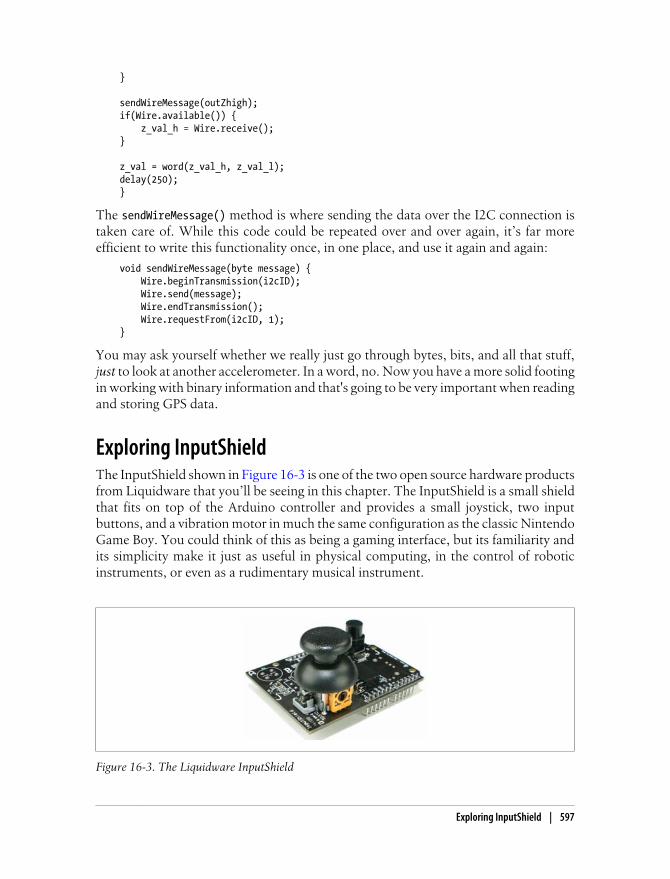
}
sendWireMessage(outZhigh);if(Wire.available()) { z_val_h = Wire.receive();}
z_val = word(z_val_h, z_val_l);delay(250);}
The sendWireMessage() method is where sending the data over the I2C connection istaken care of. While this code could be repeated over and over again, it’s far moreefficient to write this functionality once, in one place, and use it again and again:
void sendWireMessage(byte message) { Wire.beginTransmission(i2cID); Wire.send(message); Wire.endTransmission(); Wire.requestFrom(i2cID, 1);}
You may ask yourself whether we really just go through bytes, bits, and all that stuff,just to look at another accelerometer. In a word, no. Now you have a more solid footingin working with binary information and that's going to be very important when readingand storing GPS data.
Exploring InputShieldThe InputShield shown in Figure 16-3 is one of the two open source hardware productsfrom Liquidware that you’ll be seeing in this chapter. The InputShield is a small shieldthat fits on top of the Arduino controller and provides a small joystick, two inputbuttons, and a vibration motor in much the same configuration as the classic NintendoGame Boy. You could think of this as being a gaming interface, but its familiarity andits simplicity make it just as useful in physical computing, in the control of roboticinstruments, or even as a rudimentary musical instrument.
Figure 16-3. The Liquidware InputShield
Exploring InputShield | 597

One of the interesting transformations that has been going on in the Arduino com-munity is the move toward more and more sophisticated devices and configurations.When the Arduino, or its ancestor the Wiring board, were first introduced, the differ-ence between an embedded device and a laptop computer was much more pronouncedthan it is today. As users in the real world have become more familiar with small com-puters, the notion of what an embedded device can be and what an embedded com-puting platform can do has changed greatly. Liquidware is one group that is pushingthis the furthest, creating peripheral devices for the Arduino team that let you createdevices as complex as some PDA devices while still using the Arduino environment.There are other companies like Libelium and Adafruit that are pursuing similar projectsas well.
Reading data from the InputShield is quite easy. Depending on the mode, you simplyneed to read the pin mapped to the joystick and the button. Table 16-1 shows howthese are mapped.
Table 16-1. Arduino pin to mode map
Arduino pin Mode A Mode B
4 Button B None
5 Button A None
6 Joystick button None
7 Vibration enable None
8 None Button B
9 None Button A
10 None Joystick button
11 None Vibration enable
Analog 0 Joystick lateral movement None
Analog 1 Joystick vertical movement None
Analog 2 None Joystick lateral movement
Analog 3 None Joystick vertical movement
The different modes let you use the remaining pins on the Arduino for different pur-poses, such as controlling a servo motor, reading GPS data, sending data to an LCDdisplay, and so on.
A small vibration motor is attached to the bottom of the shield. The vibration motorwill vibrate when pin 7 (mode A) or pin 11 (mode B) is grounded. This lets you sendthe user physical feedback quickly and easily. The buttons output digital signals, andthe joystick output uses varying voltage based on the rotation angle in both lateral andvertical directions. For instance, in mode A, the following code checks and prints bothlateral and vertical values of the joystick:
598 | Chapter 16: Interfaces and Controls

void loop() { unsigned int joyLatValue; unsigned int joyVertValue; joyLatValue = analogRead(0); joyVertValue = analogRead(1); Serial.println(joyLatValue); Serial.println(joyVertValue);}
Now you can connect the InputShield to an Arduino and use the serial port to createa video game control. If you’re interested in using a regular video game controller usinga USB port, then you can look into a library like the proCONTROLL that allows you tocommunicate with joysticks and video game controllers in a Processing application.What might be more interesting is the easy control of robotics and physical computingthat the Arduino affords you. Using the InputShield to control multiple servo motors,for instance, is a excellent way to get fine-grained and natural control over some simplerobotics. To save a bit on space, the discussion on controlling multiple servos will waituntil later in this chapter, but rest assured that the code there can very easily be usedwith the InputShield as well.
Understanding TouchThe cultural moment of the touchscreen has most certainly arrived. By the time youread this book, it’s quite likely that many consumer laptops will be equipped withsophisticated touchscreens. The wild popularity of the iPhone, and indeed of its inter-face, have taken the touchscreen from a sophisticated tool seen in interface researchlabs and expensive trade demos to the primary interface for a tool that enables inter-action in a few different areas in contemporary society. It is soon to become as ubiq-uitous, as commonplace, and as well understood as the keyboard, the mouse, or eventhe dial. There is, however, quite a difference between these common input devices andthe touchscreen. The first factor is the multimodal data: we can evaluate the locationof the touch, the pressure on the screen, the relative distance of other touches in amultitouch environment, and, over time, the gestures consisting of one or many points.
There are also a great number of simple and common tasks that are difficult to do ona touchscreen. Typing, for instance, is an interesting challenge that a great number ofdifferent approaches and devices have attempted to simplify and standardize from theuse of swipe-based typing systems to projected keyboards. There are numerous ap-proaches and design philosophies that are tackling this problem. Another problem isthe language of touchscreen gestures. Since one of the strengths of the touchscreen isthe ability to use a gesture expressively, using two fingers to zoom in, for instance, thestandardization of these gestures and the way that they are used becomes important toconsider. A user will expect to use certain gestural behaviors across all systems andapplications; ensuring consistency is an important part of the designers’ job.
Understanding Touch | 599

Exploring Open Source Touch HardwareThe idea of open source software is a fairly simple one: When you allow an end userto see and modify the source code, your project is open source. In other words, thesource can be read and reused with some reservations. Open source hardware is a littledifferent. In one sense, hardware can’t be truly free and open source because, some-where, someone along the line will need to pay for materials and hardware. However,the schematics and the source code that runs on the hardware can be open source andavailable. This is the philosophy of two interesting touchscreen projects that arecurrently providing schematics and hardware, selling kits, and sharing source codeopenly. The first project is Nort_/D, a touchscreen project built on and aroundopenFrameworks. The other is the Liquidware TouchScreen built on the Arduinoplatform.
Nort_/DNort_/D is a design collective that creates hardware and software for multitouchscreens. The collective provides both instructions for creating touchscreens and alsokits that include screens, cameras, and supports. Its aim is to make multitouch readilyavailable in an open source fashion. Over the past few years, Nort_/D has created a fewdifferent multitouch systems: the CUBIT multitouch system, the TouchKit, and Tac-tility, which uses LCD screens. The TouchKit includes a Nort_/D Multitouch Screen,Nort_/D’s Multitouch Software (computer vision, calibration, API), and a camera(calibrated for use with the TouchKit).
The ofxTouchApp class is the main superclass for ofxTouch applications. It is a substi-tution for the typical openFrameworks ofBaseApp from which all applications usuallyinherit. The ofxTouchApp class adds to ofBaseApp multitouch-specific functionality.You’ll recall that all the event handlers in the ofxTouchApp class are sent a reference tothis object to notify the application of the position, side, and order of the finger touchingthe surface.
In the vector<ofxTouchFinger> fingers vector, fingers stores all the blobs, which areareas detected in the video of your application that are moving together, that are de-tected and tracked on the touchscreen. They are stored as the ofxTouchFinger type,which is a simple class that the ofxTouchApp uses to store information about the locationand movement of a finger on the touchscreen.
The class provides these event handlers to notify your application that a finger eventhas happened and pass the reference to the ofxTouchFinger instance representing theblob that triggered the event. The names are quite self-explanatory:
• fingerDragged( const ofxTouchFinger& )
• fingerPressed( const ofxTouchFinger& )
• fingerReleased( const ofxTouchFinger& )
600 | Chapter 16: Interfaces and Controls

The ofxTouchApp class also has some convenience methods that make it easier for youto test your application with stored video files:
setSimulationMode( bool value )Sets whether the application is going to be live (using a touchscreen) or a simulationusing the mouse instead of finger touches.
setVideoPlayerMode( bool value )Passes whether you want the application to be running from a camera or from atest video file that will be used for setup and demo purposes.
setVideoPlayerFile( string path )Passes a file that you would like the ofxTouchApp class to use in place of live fingerdetection. This is excellent for testing or configuring your touchscreen when youfirst set it up.
The other key component of the ofxTouch add-on is ofxTouchFinger, which is used tostore information about finger events. These are the two methods useful for keepingtrack of the fingers:
int id()Every finger object has an ID assigned to it.
int initialOrder()This is the order of the touches.
To determine information about the finger, there are four integer values about the finger(x, y, width, and height) and a float value (radius).
Your application’s .h file will look something like this:
class testApp : public ofxTouchApp {
Note that instead of extending the ofBaseApp class, the application extends theofxTouchApp class:
public: bool bDragging; void setup(); void update(); void draw(); void keyPressed (int key); void keyReleased (int key); void mouseMoved(int x, int y ); void mouseDragged(int x, int y, int button); void mousePressed(int x, int y, int button); void mouseReleased(); void fingerDragged( const ofxTouchFinger& finger ); void fingerPressed( const ofxTouchFinger& finger ); void fingerReleased( const ofxTouchFinger& finger );
};
Exploring Open Source Touch Hardware | 601

In the main.cpp file of an ofxTouchApp, instead of seeing the standard call toofRunApp(), you’ll see a call to ofxTouchAppRelay() wrapped inside the ofRunApp() call:
ofRunApp(new ofxTouchAppRelay(new testApp));
If you take a look at the ofxTouchApp.h file, you’ll see the following properties. If youread Chapter 14, the first two objects should be familiar to you.
ofxTouchContourFinder contourFinderThis is an instance of the ofxOpenCV contourFinder that you read about in Chap-ter 14.
ofxTouchBlobTracker blobTrackerThis is an instance of the blob tracker that you looked at Chapter 14.
ofxTouchGraphicsWarp graphicsWarpThis is an instance of the ofxTouchGraphicsWarp class that is used to calibrate thecamera and screen. This is a more advanced setting that allows you to configurethe application for specific camera types and screen configurations. There isn’tspace to cover it in full, but in short, combined with the ofxTouchVisionWarp classto set the properties of your particular screen and camera, you can set up the cameraand project in different configurations. By using ofxTouchGraphicsWarp instead ofmatching the camera and project perfectly to ensure that the projector covers theentire TouchKit, you can adjust graphics warp so the projector and the TouchKitscreen match.
Moving on, a very simple application might look like the following:
void fingerApp::setup() { setSetupMode( true ); cwidth = 800; cheight = 800;
//setSimulationMode( true ); //uncomment this to use mouse simulation setVideoPlayerMode( true ); //comment this out to run live from cam setVideoPlayerFile("touchkit-fingers.mov"); bDragging = false; ofEnableAlphaBlending();}
void fingerApp::update(){ // nothing here}
void fingerApp::draw() {
Since the fingers vector stores all the detected touch fingers, you can use this code todisplay the fingers:
for( int i=0; i<fingers.size(); i++ ) { ofSetColor( 255, 255, 255); ofCircle( fingers[i].x, fingers[i].y, 4*fingers[i].radius );
602 | Chapter 16: Interfaces and Controls

ofSetColor( 255, 0, 0 ); ofCircle( fingers[i].x, fingers[i].y, 3*fingers[i].radius ); ofSetColor( 255, 255, 255); ofCircle( fingers[i].x, fingers[i].y, 2*fingers[i].radius ); ofSetColor( 255, 0, 0); ofCircle( fingers[i].x, fingers[i].y, 1*fingers[i].radius ); ofSetColor( 255, 255, 255 ); ofCircle( fingers[i].x, fingers[i].y, 0.5*fingers[i].radius );
}}
This will create a simple bull’s-eye at the location of each detected finger touch. Thereare some other excellent examples for download from the Nort_/D site at http://touchkit.nortd.com. For information on their other projects, look at nortd.com.
Liquidware TouchShieldAnother much smaller touchscreen device that you might be interested in exploring isthe TouchShield developed by Liquidware (Figure 16-4). It plugs into the Arduino andlets you use small touchscreen devices both to send information to a listening laptopor desktop computer or to simply create a small device that relies entirely on the Ar-duino for its processing power. The TouchShield greatly simplifies working withresistive touch sensing and drawing.
Figure 16-4. The Liquidware TouchShield
To connect the TouchShield onto an Arduino Diecimila or Duemilanove, you simplymount it as shown previously in Figure 16-2 on the right. The TouchShield does quitedifferent things than the standard Arduino components. In addition to handling touchdata, the TouchShield also draws to its screen. The Liquidware team took a logicaldirection in how to best providing methods and a programming interface for the de-veloper to draw to the screen: they emulated the Processing language and applicationstructure.
The very simplest TouchShield application looks much like a Processing application.For instance, to draw a rectangle to the screen of the TouchShield, your applicationwould look like this:
Exploring Open Source Touch Hardware | 603

COLOR red = {255,0,0};COLOR blue = {0,0,255};
void setup() { rect(20,20,80,80, red, blue);}void loop(){}
To upload your code to the TouchShield, you’ll need to use a slightly modified versionof the Arduino IDE that the Liquidware team has put together and that is available fordownload on the Liquidware site. The only modifications that have been made are toallow for the uploading of code to the TouchShield. When you have an Arduino ap-plication that communicates with the TouchShield, you are in essence running twoapplications at the same time: one on the TouchShield and one on the Arduino. Youcould think of this metaphorically as being like the relationship between code runningon your central processor unit communicating with code running on your graphicsprocessor unit.
While the code for the TouchShield is quite similar to Processing, it is not actuallyProcessing, and so it has a few slightly different methods:
beginCanvas()This begins the drawing, allowing the TouchShield to accept drawing functionsfrom the Arduino. It starts the serial connection that the TouchShield uses to readdata from an Arduino at 9600 baud (the equivalent of calling Serial.begin(9600)in the Arduino) and sets up the TouchShield to receive drawing commands fromthe Arduino. These can be things like the following:
|RECT20208080
Note the pipe (|) at the beginning of the command. You would send this like so:
Serial.write("|RECT20208080");
This will draw a rectangle at 20, 20, with a width and height both of 80 pixels.Almost all the drawing commands for the TouchShield can be called in this wayvia the Serial port. These commands are documented on the Liquidware site ingreater detail.
delay()Like the Arduino version of this method, this delays for the specified millisecondamount of time passed to it.
random()This generates a random number (long number).
To read the input locations and information about the user touching the screen, theTouchShield library defines the following methods and variables:
604 | Chapter 16: Interfaces and Controls

gettouch()This checks the touchscreen for any registered touches. The OLED screen on theTouchShield is resistive, so a user will need to be pushing on it a little bit harderthan they would need to with a capacitive screen. Once the gettouch() method iscalled, the mouseX and mouseY variables will have values assigned to them for thatloop. The best way to do this is to call gettouch() in the loop() method of yourapplication and then do something with the newly updated position values:
void loop(){ gettouch(); ellipse(mouseX, mouseY, 20,20);}
mouseXThis stores the X location of the touch when the gettouch() method is called.
mouseYThis stores the Y location of the touch when the gettouch() method is called.
The TouchShield also defines quite a few different methods to draw on the canvas:
ellipse()Draws an ellipse with the first two parameters specifying the location of the ellipseand the second two determining the width and height, like so: ellipse(x, y,width, height).
line()Draws a line from point to point, like so: line(x1, y1, x2, y2).
point()Draws a single pixel.
rect()Draws a rectangle with a specified beginning point, width, and height, like so:rect(x, y, width, height).
triangle()Draws a triangle with three specified points, like so: triangle(x1, y1, x2, y2, x3,y3).
quad()Draws a polygon with four specified lines from four specified points, like so:quad(x1, y1, x2, y2, x3, y3, x4, y4).
To set the color properties and line properties when you’re drawing, you can use thefollowing methods (note that all the colors are passed as three values, red, green, andblue with values between 0–255):
background()Colors the whole screen with the color value passed to it. This also overwrites allthe graphics on the screen.
Exploring Open Source Touch Hardware | 605

fill()Sets the color used to fill the inside of shapes. This method takes a color value.
noFill()Allows a shape to be drawn with no fill color.
stroke()Stores the color of a shape’s outlines or of text. This method takes a color value.
noStroke()Allows a shape to be drawn without an outline around it, just like the Processingapplication.
strokeWeight()Changes the outline thickness of an ellipse or rectangle in pixels.
One of the great strengths of open source software is that it allows developers to altersome of the internals of the program or add new features to support different func-tionality. Since the TouchShield is in a sense like an Arduino controller, in that it hasits own processor that the Arduino IDE must compile and load code onto, you’ll needa version of the Arduino IDE that knows how to create and upload code from theTouchShield. Liquidware created a version of the IDE that adds this new board intothe available configurations and didn’t change anything else, so you can use the Touch-Shield as well as all your other Arduino boards with this altered Arduino IDE. Thosealtered IDEs are available on the Liquidware site, http://liquidware.com. To work withthe TouchShield, you’ll need to download and install the appropriate one for youroperating system. Once you’ve done that, you’ll see the TouchShield appear in yourArduino IDE (Figure 16-5).
Figure 16-5. Selecting the TouchShield in the modified Arduino IDE
In the Board menu, you’ll notice a couple new boards, the TouchShield Slide andTouchShield Stealth. There are currently two different touch-enabled shields thatLiquidware manufacturers; one is the TouchShield Slide and the other is the Touch-Shield Stealth. The workflow for uploading code to a TouchShield attached to a Due-milanove would look like this:
606 | Chapter 16: Interfaces and Controls

1. Select Tools→Boards→TouchShield Slide.
2. Write the TouchShield code.
3. Touch the programming button on the TouchShield.
4. Compile and upload the application code to the TouchShield from the ArduinoIDE by hitting the Upload button.
5. Select Tools→Boards→Arduino Duemilanove (or the name of your board).
6. Write Arduino code.
7. Compile and upload the application code to Arduino controller from the ArduinoIDE by hitting the Upload button.
That’s all there is to it. Let’s take a look at a couple of examples.
Drawing to the TouchShield ScreenThe following example shows how to draw different shapes and characters to thescreen:
#define SHAPE_SQUARE 0#define SHAPE_CIRCLE 1#define SHAPE_X 2#define SHAPE_TRI 3
int nextShape = SHAPE_SQUARE;
int pMouseX;int pMouseY;char xposStr[4];char yposStr[4];
void setup() { pMouseX = 0; pMouseY = 0;}
void loop(){
The getTouch() method polls the screen to see whether any touches have been regis-tered. When you want to detect touches on the screen, you’ll want to do this each timethe loop() is called:
gettouch();
if(pMouseX != mouseX || pMouseY != mouseY) touched(); // screen touched so draw new shape
delay(50);
} //end loop
Exploring Open Source Touch Hardware | 607

void touched()
{ nextShape++; if(nextShape > 3) { // shape 3 is the last shape nextShape = 0; }
Just as in a Processing application, this clears the stage by overwriting everything:
background(0);
Now the location of the touch is stored for comparison to the next time the loop()method is called:
pMouseX = mouseX; pMouseY = mouseY;
The text() method writes characters to the screen, the first parameter are the charactersto be written, and the next two are the x and y locations on the screen:
text(mouseX, mouseX, mouseY+20); text(mouseY, mouseX+30, mouseY+20);
Depending on the value of the nextShape variable, a different shape is drawn to the stage:
switch(nextShape) { case SHAPE_SQUARE: fill(0, 255, 0); rect(mouseX-20, mouseY-20, 30, 30); break;
case SHAPE_CIRCLE: fill(0, 0, 255); ellipse(mouseX-10, mouseY-10, 15, 15); break;
case SHAPE_X: stroke(255, 255, 255); line(mouseX - 10, mouseY, mouseX+10, mouseY); line(mouseX, mouseY - 10, mouseX, mouseY+10 ); break; case SHAPE_TRI: fill(255, 255, 0); triangle(mouseX+10, mouseY-10, mouseX-10, mouseY+10, mouseX+20, mouseY+10); break; }}
The application will look something like Figure 16-6.
Now that you’ve seen how to do simple drawing operations with the TouchShield, youcan use the touch information and send it to the Arduino to control other objects. Thefollowing example allows the user to select the color of the circle they are drawing,draw a circle, and send those values to the Arduino controller. From there, the Arduino
608 | Chapter 16: Interfaces and Controls

controller can, for example, use the x and y positions to set the rotation of a servo, relaythose values to another listening controller, or, as shown in the next example, positiona light.
Controlling Servos Through the TouchShieldIn this example, though, those values will be used to position two servo motors thatwill shine a three-color LED with the color selected by the user. Before putting this codeinto the Arduino IDE, make sure that you have the TouchShield board selected, or thecode won’t compile because the compiler will not have access to the right libraries:
COLOR curr;
Notice that the color is stored as a COLOR type. This is a struct that is defined in theTouchShield libraries and has red, green, and blue integer properties that can be readand written:
int redR[] = { 0, 0, 20, 20 }; // rectangle coordinatesint blueR[] = { 0, 20, 20, 40 };int yellowR[] = { 0, 40, 20, 60 };int greenR[] = { 0, 60, 20, 80 };int whiteR[] = { 0, 80, 20, 100 };int blackR[] = { 0, 100, 20, 120 };
COLOR red = {255,0,0};COLOR green = {0,255,0};COLOR blue = {0,0,255};COLOR yellow = {255,255,0};
boolean changedColor = false;
void setup() {
drawBackground(); Serial.begin(9600); delay(3000);
Figure 16-6. Drawing a circle and a triangle to the TouchShield
Exploring Open Source Touch Hardware | 609

Serial.print('U');}
The drawBackground() method draws six boxes on the left of the TouchShield that theuser can select. These will be used to set the color value of the color LED attached tothe two servo motors:
void drawBackground(){
Draw the first rectangle in the top left of the screen, first setting the fill using thefill() method. The fill() method takes the different values of the predefined colorvalues included in the TouchShield API:
fill(red.red, red.green, red.blue); rect(redR[0], redR[1], redR[2], redR[3]);
Now draw the other rectangles for blue, yellow, green, and white:
fill(blue.red, blue.green, blue.blue); rect(blueR[0], blueR[1], blueR[2], blueR[3]); fill(yellow.red, yellow.green, yellow.blue); rect(yellowR[0], yellowR[1], yellowR[2], yellowR[3]); fill(green.red, green.green, green.blue); rect(greenR[0], greenR[1], greenR[2], greenR[3]); fill(white.red, white.green, white.blue); rect(whiteR[0],whiteR[1], whiteR[2], whiteR[3]);}
void loop() {
The refresh rate on the TouchShield is quite a bit slower than a laptop computer. If youcall the background() method on a loop and then do a relatively expensive drawingoperation like the drawBackground(), then you’ll see the screen begin to flicker:
gettouch(); check_touch();
Serial.print(mouseX); Serial.print(mouseY);
If the color has changed, then send the values to over the hardware Serial port to theArduino controller:
if(changedColor) { Serial.print(curr.red); Serial.print(curr.green); Serial.print(curr.blue); }}
void check_touch(){ changedColor = true; // if the mouse is greater than 20, it's not on any of the rectangles if(mouseX > redR[0]) { return;
610 | Chapter 16: Interfaces and Controls

changedColor = false; } if(mouseY < redR[2]) { curr = red; } else if(mouseY > blueR[2] && mouseY < blueR[4]) { curr = blue; } else if(mouseY > yellowR[2] && mouseY < yellowR[4]) { curr = yellow; } else if(mouseY > greenR[2] && mouseY < greenR[4]) { curr = green; } else if(mouseY > whiteR[2] && mouseY < whiteR[4]) { curr = white; } else { changedColor = false; }}
Setting Up Communication Between Arduino and TouchShieldIn this example, you’ll see how the Arduino board and the TouchShield can commu-nicate. The principle idea in this example is to use two servos together to create ahemispheric range for a light, that is, to enable an LED to cover an area that more orless would look like the top half of a sphere. The way you do that is by combining twoservos and using one to provide 180 degrees of motion on the x-axis and the other toprovide 180 degrees of motion on the y-axis. There are quite complex ways to do this,but there are simple ones that work almost as well. You can simply attach one servo tothe other and then attach the LED to the second servo. This provides you with the rangeof motion to point the light. Using a “super-bright LED” means that you can attach asmall object to a small servo and still create a good amount of light.
Figure 16-7 shows a diagram of how to connect the two servos together and how theywould be wired to the Arduino.
Now, the Arduino code that receives the x and y values that will be used to set the twoservos and the color values to set the LED. This code is for the Arduino, so don’t forgetto make sure that you have the correct board selected in your Arduino IDE, or the codemay not compile:
#include <Servo.h>
// create servo object to control a servoServo xServo;Servo yServo;int redPin = 5;int greenPin = 6;int bluePin = 11;
Exploring Open Source Touch Hardware | 611

// variable to store the servo positionint xpos = 0;int ypos = 0;
void setup(){
Figure 16-7. Connecting the servos and LED to the Arduino
Here you start up the communication between the Arduino and the two servos bycalling the attach() method of the Servo instance:
xServo.attach(9); yServo.attach(10);
Serial.begin(9600);}
void loop(){ int tmpx, tmpy, tmpred, tmpblue, tmpgreen = 0;
Get all the available bytes from the TouchShield that have been sent over the Serialport. I’ve set my hardware up so this data is being sent from the TouchShield, but youcould also use the TouchShield and have the data be sent from a Processing or oFapplication with which the user is interacting. The positions and colors will be storedin the five integers:
if(Serial.available() > 4) { tmpx = Serial.read(); tmpy = Serial.read(); tmpred = Serial.read(); tmpblue = Serial.read(); tmpgreen = Serial.read();
612 | Chapter 16: Interfaces and Controls

After five values are received, set each respective color values, red, green, and blue, ofthe three color LED lights:
analogWrite(redPin, int(tmpred)); analogWrite(greenPin, int(tmpgreen)); analogWrite(bluePin, int(tmpblue));
Now, set the location of each servo. Since the locations are being sent as integers, they’llneed to be cut down into smaller values to set the rotation of the servo.
xpos = map(tmpx, 0,255, 0,180); ypos = map(tmpy,0,255,0,180); xServo.write(xpos); yServo.write(ypos); delay(15);
}}
You could use this same technique to position a camera, a microphone, or many otherkinds of devices. The pairing of multiple servos is one of the basics of complex me-chanical motion and is a very useful thing to look into. You might check out RobotBuilding for Beginners by David Cook (Apress). It is a good introduction to mechanicsand robotics that is aimed at newcomers.
Another approach to this is to use a pan and tilt servo unit like the one shown inFigure 16-8, made by Trossen Robotics. It’s actually just two servo motors with astronger mounting, which means you can attach larger lights or cameras to the servo.
The TouchShield is a wonderful tool for creating small touch-enabled applications.One thing to consider when working with the TouchShield is the relatively slow refreshrate of the drawing on the TouchShield. The code used with TouchShield is based onProcessing, but the hardware will not be like a laptop or desktop computer. So, you’llneed to consider what drawing functions to call and when to call them to ensure thatyou don’t overtax the hardware. Another issue to consider is the power that the
Figure 16-8. The Trossen pan-tilt servo
Exploring Open Source Touch Hardware | 613

TouchShield requires. If you’re going to use the TouchShield as a mobile device, thenyou might want to consider using something like the Lithium Backpack that providesa few extra hours of battery power.
Communicating Using OSCOpenSoundControl (OSC) was originally designed as a protocol for communicationbetween computers, sound synthesizers, and any other devices to be used in a net-worked setting. It allows any device that can send and receive OSC messages to sharemusic performance data in real time over a network. In this way it’s similar to MIDIbut is designed expressly for network communications, whereas MIDI was designedmore as a low-level way of communicating between devices that couldn’t be networked.This is largely because MIDI was developed in 1983 before networks were fast enoughto consider sending live, real-time audio and video data over them. Since it’s a networkprotocol, OSC allows musical instruments, controllers, and multimedia devices tocommunicate on any network, including over the Internet.
You may remember the UDP protocol for network communication that we mentionedearlier. OSC is communication over UDP just as sending and receiving web pages(HTTP) is communication over TCP. Now, there’s an important caveat here: nothingsays OSC has to be over UDP, that’s just the way most people use it. You might wantto make your OSC application communicate over TCP, and that’s perfectly valid aswell. The advantages of UDP being light, fast, and easy to parse all make it extremelyvaluable for real-time audio communication. OSC enables real-time interactions be-tween almost any kind of device that can be connected to a network and also allowsyou a lot of flexibility in terms of the data you can send over the wire. This means yourapplications or devices can communicate with each other at a high level or a low level,however you see fit for your application.
What can you use it for? Since OSC is a data protocol, any application that can sendOSC messages can use it to communicate with any other application that can under-stand OSC messages. You can use OSC to communicate between applications like oFand Processing. You can also use OSC to communicate between Processing or oF andanother platform like the Max/MSP, PureData, or Supercollider. Since OSC is reallyjust communication using the UDP protocol, by using an Ethernet shield an Arduinocan send and receive any OSC messages as well. So, what does an OSC message looklike? Usually something like this:
'/pitch', '122'
That looks a little strange, but it’s actually fairly straightforward. The message has atitle, in this case pitch, and a value, in this case 122. A message can have any numberof values attached to it, but generally the messages are quite short. They send thingslike a note, a change in pitch, a mouse location, a camera action, movement detection,
614 | Chapter 16: Interfaces and Controls

and so on. In practice, OSC isn’t all that well suited for sending massive amounts ofdata at a time; it’s far better at sending lots of small messages quickly.
For working with OSC in oF, you can use the ofxOSC library, created by DamianStewart and available from http://addons.openframeworks.cc. It is built on top anotherOSC library, called oscpack, that was built by Ross Bencina. It consists of three mainclasses that should have a familiar breakdown:
ofxOSCSenderThis is the object that dispatches messages. It doesn’t need to accept connectionsfrom a client. Instead, it simply dispatches the messages to anything listening onthe port that it uses.
ofxOSCReceiverThis is the object that receives and parses messages; it listens on a particular portnumber and then can parse messages by name and get their values.
ofxOSCMessageThis represents the message. OSC can have int, String, or Float values. TheOSCMessage class provides methods for adding all of these to a message.
For using OSC in Processing, check out oscP5, an OSC implementation for the pro-gramming environment processing developed by the prolific Andreas Schlegel. If youalready have been working with oscP5 in the past, please note that you will have toimport netP5.* in addition to importing oscP5.*:
OscP5This is the main class that enables you to initialize the oscP5 library and set up aserver that can send and receive messages. This class handles both sending andreceiving messages.
OscPropertiesThis is used to start oscP5 with more specific settings, and it is passed to the OscP5object in the constructor when initializing a new OscP5 object.
OSCArgumentThis represents the value of the message sent and allows you to read the messageback in several different formats: int, boolean, float, String, or char.
OscMessageLike the ofxOSCMessage class, this contains an address, a type, and multiple values.
Though space constraints don’t allow us to delve further into OSC, it might be worthchecking out the netP5 and the oscP5 libraries if you’re looking to share real-time dataacross several different machines. One immediately practical application for this pro-tocol is communication with the Wii Remote (unofficially nicknamed Wiimote), whichyou’ll learn how to do in the next section using the ofxOSC library.
Communicating Using OSC | 615

Using the WiimoteBy now most of you will have seen the Nintendo WiiMote controller, the small accel-erometer-driven controller for the Wii system. The Wii Remote is the primary controllerfor Nintendo’s Wii console. A main feature of the Wii Remote is its motion-sensingcapability, which allows the user to interact with and manipulate items on the screenvia movement and point toward objects through the use of accelerometer and opticalsensor technology. There are two different controllers, the Wii Remote and the WiiNunchuk, that attach to the Wii Remote to allow for two-handed control.
Using the Wii Nunchuck in ArduinoYou can communicate with the Wii in two ways, either by plugging it into an Arduinousing the Wii stick developed by Tod Kurt of Todbot or by using the Bluetooth con-nection on the Wii Remote. You can also connect the Nunchuck directly to the Arduinoby cutting off the connector and using the wiring, as shown in Figure 16-9.
Figure 16-9. Two ways of connecting the Nunchuck to the Arduino: on the left, the Nunchuck Adapterand, on the right, the Nunchuk with the connector removed and wires connected directly to the Arduino
The following Arduino code uses the values from the Nunchuck to control a servo andalso sends the accelerometer data from the Nunchuck to a Processing application:
#include <Wire.h>#include <Servo.h>
// create servo object to control a servoServo xServo;Servo yServo;
int angleX = 90; // angle to move the X servoint angleY = 90; // angle for the Y servo
int refreshTime = 20; // the time in millisecs between updatesint loop_cnt = 0;
int joy_x_axis;int joy_y_axis;int accel_x_axis;
616 | Chapter 16: Interfaces and Controls
int accel_y_axis;int accel_z_axis;
int z_button;int c_button;
void setup(){ Serial.begin(9600); xServo.attach(9); yServo.attach(10); nunchuck_init(); // send the initialization handshake to nunchuck}
void loop(){ checkNunchuck(); xServo.write(angleX); xServo.write(angleY); if( nunchuck_zbutton() ){ // light the LED if z button is pressed Serial.print(angleX,DEC); Serial.print(":"); Serial.print(angleX,DEC); Serial.print('\0'); } delay(refreshTime); // this is here to give a known time per loop}
void checkNunchuck(){ if( loop_cnt > 5) { // loop every 20msec, this is every 100msec
nunchuck_get_data(); nunchuck_print_data();
angleX = map(accel_x_axis,70,185,0,180); // nunchuck range is ~70 - ~185 angleY = map(accel_y_axis,70,185,0,180); // Arduino function maps this // to angle 0-180 loop_cnt = 0; // reset } loop_cnt++;}
The rest of the code defines the Nunchuck functions to initialize communication be-tween the Arduino and the Nunchuck and to send and receive data from the Nunchuck.These methods all use the Wire library to read the data. Credit for these methods goesto Tod Kurt:
static uint8_t nunchuck_buf[6]; // array to store nunchuck data,
// initialize the I2C system, join the I2C bus,// and tell the nunchuck we're talking to itvoid nunchuck_init(){ Wire.begin(); // join i2c bus as master
Using the Wiimote | 617

Wire.beginTransmission(0x52); // transmit to device 0x52 Wire.send(0x40); // sends memory address Wire.send(0x00); // sends sent a zero. Wire.endTransmission(); // stop transmitting}
// send a request for data to the nunchuck// was "send_zero()"void nunchuck_send_request(){ Wire.beginTransmission(0x52); // transmit to device 0x52 Wire.send(0x00); // sends one byte Wire.endTransmission(); // stop transmitting}
// receive data back from the nunchuck,// returns 1 on successful read. returns 0 on failureint nunchuck_get_data(){ int cnt=0; Wire.requestFrom (0x52, 6); // request data from nunchuck while (Wire.available ()) {
The Wire library will receive a byte that needs to be converted to an integer, by usingthe nunchuck_decode_byte() method, defined later in this application:
nunchuck_buf[cnt] = nunchuck_decode_byte(Wire.receive()); cnt++; } nunchuck_send_request(); // send request for next data payload // If we recieved the 6 bytes, then go print them if (cnt >= 5) { return 1; // success } return 0; //failure}
This method prints out the input data received from the Nunchuck:
void nunchuck_print_data(){ static int i=0; joy_x_axis = nunchuck_buf[0]; joy_y_axis = nunchuck_buf[1]; accel_x_axis = nunchuck_buf[2]; accel_y_axis = nunchuck_buf[3]; accel_z_axis = nunchuck_buf[4];
z_button = 0; c_button = 0;
The sixth byte of the data from the Nunchuck, nunchuck_buf[5], contains bits thatindicate whether the z or c buttons have been pressed:
// so we have to check each bit of byte outbuf[5] if ((nunchuck_buf[5] >> 0) & 1) z_button = 1;
618 | Chapter 16: Interfaces and Controls

if ((nunchuck_buf[5] >> 1) & 1) c_button = 1;
The sixth byte also contains the last bits of the accelerometer data for all the axes:
if ((nunchuck_buf[5] >> 2) & 1) accel_x_axis += 2; if ((nunchuck_buf[5] >> 3) & 1) accel_x_axis += 1;
if ((nunchuck_buf[5] >> 4) & 1) accel_y_axis += 2; if ((nunchuck_buf[5] >> 5) & 1) accel_y_axis += 1;
if ((nunchuck_buf[5] >> 6) & 1) accel_z_axis += 2; if ((nunchuck_buf[5] >> 7) & 1) accel_z_axis += 1;
i++;}
// encode data to format that most wiimote drivers except// only needed if you use one of the regular wiimote driverschar nunchuck_decode_byte (char x){ x = (x ^ 0x17) + 0x17; return x;}
// returns zbutton state: 1=pressed, 0=notpressedint nunchuck_zbutton(){ return ((nunchuck_buf[5] >> 0) & 1) ? 0 : 1; // voodoo}
The next step would be to use the progress of the two servo motors in a Processingapplication. This could be easily extended to update another set of servo motors in adifferent location using a network, to drive complex graphics, to control sounds orvideo, or to implement any number of other approaches. For the sake of brevity, in thisexample the Processing application simply draws current positions of the servo motors:
import processing.serial.*;Serial serial; // The serial portint firstAng = 0;int secAng = 0;byte[] inbyte = new byte[4];
void setup() { size(400, 400); String[] arr = Serial.list(); if(arr.length > 0) { serial = new Serial(this, Serial.list()[0], 9600); }
Using the Wiimote | 619

}
void draw() { background(122); int i = 0; boolean changed = false; if(serial != null) { while (serial.available() > 0) { inbyte[i] = byte(serial.read()); changed = true; i++; } if(changed) { firstAng = inbyte[0]; secAng = inbyte[2]; } }
ellipse(40, 40, 50, 50); line(40, 40, 40+(25*cos(firstAng)), 40+(25*sin(firstAng))); ellipse(120, 40, 50, 50); line(120, 40, 120+(25*cos(secAng)), 40+(25*sin(secAng)));
}
The Nunchuck is a very cool tool, but the Wii Remote is a far more versatile tool becauseit doesn’t require you to have your input device tethered to a laptop. The Wii Remotecan also communicate with your laptop or desktop over a Bluetooth connection. Oncethe remote and your computer are connected, you send OSC messages to an oF orProcessing application and use the accelerometer data from the remote in yourapplication.
Many times you’ll find yourself piecing together different libraries to create a workingsolution. In this case, creating a working solution that is truly cross-platform is difficultand involves using lots of libraries. Windows users should look into an applicationcalled GlovePIE, OS X users should look into an application called DarwiinOSC, andLinux users can utilize an application called WiiOSC.
Once the OSC messages are sent from the Wii controller to the oF application, you canuse the ofxOSC add-on to read the messages and use them for drawing, controllingvideo, and so on:
#ifndef _TEST_APP#define _TEST_APP
#include "ofMain.h"#include "ofxOSC.h"
class remoteApp: public ofBaseApp{
public:
void setup();
620 | Chapter 16: Interfaces and Controls

void update(); void updateOSC(); void draw();
void keyPressed(int key); void keyReleased(int key); void mouseMoved(int x, int y ); void mouseDragged(int x, int y, int button); void mousePressed(int x, int y, int button); void mouseReleased();
ofxOscReceiver receiver;
These are the variables that will be store the values received from the Wii Remote:
float pitch, roll, yaw, accel;};
#endif
Now on to the .cpp file, where the ofxOSC instance will read OSC messages from theapplication that handles the communication between the Wii Remote and the com-puter and then draws that data to the screen:
#include "remoteApp.h"void remoteApp::setup(){
receiver.setup( 9000 ); ofSetVerticalSync(true);
}void remoteApp::update(){
The call to the updateOSC() method ensures that the OSC listener grabs any new datain the OSC buffer:
updateOSC();}
void remoteApp::updateOSC() {
// check for waiting messages while( receiver.hasWaitingMessages() ) {
Get the next message:
ofxOscMessage m; receiver.getNextMessage( &m );
Check to make sure that the new message is from the Wii Remote. The getAddress()call here is using an OS X address. Depending on your operating system your addresswill look different:
if ( strcmp( m.getAddress(), "/wii/1/accel/pry" ) == 0 ) {
// verify the type if( m.getArgType(0) != OFXOSC_TYPE_FLOAT ) break;
Using the Wiimote | 621

if( m.getArgType(1) != OFXOSC_TYPE_FLOAT ) break; if( m.getArgType(2) != OFXOSC_TYPE_FLOAT ) break; if( m.getArgType(3) != OFXOSC_TYPE_FLOAT ) break; // get the new score pitch = m.getArgAsFloat( 0 ); roll = m.getArgAsFloat( 1 ); yaw = m.getArgAsFloat( 2 ); accel = m.getArgAsFloat( 3 ); } }}
void remoteApp::draw(){
Draw the background according to the pitch, and then use those values to create thebackground color of the application:
ofBackground(pitch*255, roll*255, yaw*255); ofSetColor(yaw*255,pitch*255,roll*255); ofFill();
Draw the two circles using the pitch, yaw, and roll values sent from the Wii Remote:
ofEllipse(pitch*ofGetWidth(), yaw*ofGetHeight(), 20, 20); ofEllipse(yaw*ofGetWidth(), roll*ofGetHeight(), 10, 10);
}
It’s important to remember that Wii data is, compared to the touchscreens discussedearlier, quite difficult data to work with; it’s erratic, and it’s often difficult to determinethe exact position of a cursor as one would with a mouse or a pair of potentiometers.For this reason, accelerometer-based controls like the Wii Remote are sometimes notappropriate for building applications that require cursor control. However, there isanother way to use the Wii Remote as an infrared pointing device. This is often moreappropriate than accelerometer data because it is so much more precise. Accelerometerdata can be used to position a cursor as well, but it requires some rather tricky calcu-lations that, although certainly within the realm of possibility, are outside of the scopeof this book.
Tracking Wii Remote Positioning in ProcessingThere’s another possibility for working with the Wii Remote that provides other sortsof opportunities to work with interaction: in addition to accelerometers, the Wii Re-mote can also calibrate its position using an infrared sensor (Figure 16-10). To use this,you need to get four small IR lights and put them in front of the Wii Remote where itwill be able to detect them. To create a 360-degree experience, you could use more IRlights and position them in multiple locations around the Wii Remote, though this issubstantially more complex.
622 | Chapter 16: Interfaces and Controls

The first step in using the Wii Remote as a pointer is to read the IR data sent from thecontroller. This is sent as 12 floating-point numbers. The oscP5 code calls ir when newIR data is received and gives us 12 parameters. Those are four times x, y, and brightnessvalues for each tracked LED. If the brightness value is bigger than 15, no point isrecognized. To get usable x and y position values, you will want to pass them througha method that might look like this:
float ir[12]void ir( float f10, float f11,float f12, float f20,float f21, float f22, float f30, float f31, float f32, float f40, float f41, float f42 ) { // first all the numbers ir[0] = f10; ir[1] = f11; ir[2] = f12; ir[3] = f20; ir[4] = f21; ir[5] = f22; ir[6] = f30; ir[7] = f31; ir[8] = f32; ir[9] = f40; ir[10] = f41; ir[11] = f42;
points = 0;
We want every third value for the x position and every fourth digit for the y position:
for (int i = 0; i < 4; i += 3) { if (ir[i+2] < 15) { x[points] = 0.5 - ir[i]; // average out the x values y[points] = 0.5 - ir[i+1]; // average out the y values points++; } }}
Figure 16-10. Creating an LED array to use with the Nunchuck
Using the Wiimote | 623

The trickiest part of getting and using the infrared data is correctly parsing out the xand y values. Once you’ve done that, it’s quite easy to use them in an oF or Processingapplication. Over OSC, the IR data will be passed as 12 floating-point values, and yousimply call this to have all the infrared data messages plugged into the ir array:
osc.plug(this,"ir","/wii/irdata");
This simple Processing application draws a rectangle to the screen at the locations ofthe infrared data:
import oscP5;
float ir[12];OscP5 osc;
void setup() { size(800,600);
// open an udp port for listening to incoming osc messages //from darwiinremoteOSC osc = new OscP5(this,5600);
osc.plug(this,"ir","/wii/irdata"); osc.plug(this,"connected","/wii/connected");}
void ir(float f10, float f11,float f12,float f20,float f21, float f22,float f30, float f31, float f32,float f40, float f41, float f42) { ir[0] = f10; ir[1] = f11; ir[2] = f12; ir[3] = f20; ir[4] = f21; ir[5] = f22; ir[6] = f30; ir[7] = f31; ir[8] = f32; ir[9] = f40; ir[10] = f41; ir[11] = f42;}
void draw() { for(int i=0;i<12;i+=3) {
Every third value in the array is the size, and a size of either 0 or 15 indicates that IRpoint is not available:
if(ir[i+2]<15 && ir[i+2]>0) { fill(255, 0, 0);
624 | Chapter 16: Interfaces and Controls

Now we’ll draw a rectangle at the point where the Wii Remote detected the light:
rect(ir[i] * width, ir[i+1] * height, 5, 5); } }}
What’s NextAs you’ve seen in this chapter, you can approach creating tools from so many differentangles that the unifying concept we’ve explored isn’t so much a technical idea but rathera design concept: that of carefully measured feedback and particularly controlled input.There are a number of really great controller technologies and designs out now thatmight be interesting to play with or use for inspiration.
The Monome project is a series of boards with extremely minimal interfaces that canbe used to create music, send MIDI and OSC messages, or do almost any other thingyou can imagine for a device with 64 soft buttons and very little extraneous hardware.The Monome creators provide both prebuilt boards in extremely small quantities orboards with instructions to build your own. They also have a small but active com-munity of developers, musicians, artists, and hackers working with the boards andcreating new applications. Take a look at http://monome.org/ for more information.
The Nintendo DS may seem to be an odd platform for a designer or artist to hack atbut the DS has a few aspects that might make it interesting to you. It’s has a fullyrewritable firmware, which means that like the Arduino you can completely rewriteand alter the core software running on the controller. It also has a WiFi connection anduses SD storage. There are also library and toolkits that allow you to program theDS in C++ or C as well as several tools to help you make games without heavyprogramming.
LadyAda and AdaFruit industries have created a tool called the x0xb0x, which is aboard that can act as both a synthesizer and a sequencer. It has a MIDI in, out, andthrough port; a CV and Gate (1/8-inch jacks); and an headphone, mix-in line, and line-level out port with 1/4-inch jacks; and finally a USB jack.
Another option is the Wacom drawing tablet. As a user interface, it can be instinctiveand very intuitive; the pressure sensitivity provides another range of input data as well.It can be inherently very controlled and precise but also playful, making it a great toolfor artists, as demonstrated by the Sonic Wire Sculptor by Amit Pitaru. There are a fewdifferent libraries that allow you to use Wacom with Processing and oF that you canfind by looking on the Processing website in the Libraries section or on the oF websitein the forums.
What’s Next | 625

ReviewOpen source hardware designs are where the schematics and the source code that runson the hardware schematics can be open sourced and made available.
The Liquidware InputShield allows you plug interface controls that are similar to theclassic video game controls into your Arduino controller.
The Liquidware TouchShield is a small Arduino-compatible shield that can be used tocapture touches and send and receive messages over a Serial port with an Arduino-compatible board.
To use the TouchShield Slide or Stealth, you’ll need to use a modified version of theArduino IDE.
The TouchShield is programmed using a language influenced by the Processing lan-guage, making it easier to write visual code to display on the TouchShield.
OpenSoundControl (OSC) is a protocol for communication between computers andother devices or for between applications. They are very simple messages that usuallyconsist of a key and value pair, like:
'/name', 'josh'
To work with OSC in oF, you can use the ofxOSC add-on developed by DamianStewart. To work with OSC in Processing, you can use the oscP5 library developed byAndreas Schlegel.
Another option for interaction is the Wii controllers. The Nunchuck can be pluggedin an Arduino, or you can use the Nunchuk Adapter developed by Tod Kurt. The tiltdata and the buttons of the Nunchuck can be read in an Arduino application.
The Wii Remote can be paired with a computer over Bluetooth using one of severallibraries and can send accelerometer data to a Processing or oF application over OSC.
By creating a grouping of four LED lights and shining them toward the Wiimote, youcan create an oF or Processing application that can read the positional data of theWiimote, where it is pointing in relation to the infrared sensors. This allows you tocreate a simple mouse-like pointer from the Wiimote.
626 | Chapter 16: Interfaces and Controls

CHAPTER 17
Spaces and Environments
In this book, we’ve covered a lot of different means of getting input and creating feed-back, but we haven’t discussed to a great extent where that feedback and input takesplace. The location of the interaction is a very important consideration, because itprovides context for that interaction. Using the user’s location as a data point is onething; using the location as an element of the interaction itself is a different proposition.Sculptors, architects, and installation artists have explored the notion of communicat-ing meaning through spatial relationships and architectural elements for many years.
You might want to sense data about an environment: reading the light in a room,listening to sound in a room, detecting motion in a room, or detecting gas with a sensor.This could mean making a smart environment or an enabled environment by allowingmultiple devices in an environment to communicate with one another. It could alsomean using space itself to communicate the message, as in the case of X10 communi-cation, which sends messages over the electrical lines of a building. It could meanthinking sculpturally and helping design space that reacts to users’ commands, likemaking a room that is reconfigurable from a remote control or that changes based onthe time of day, number of people in the room, or heat outside the room. There are somany different conceptions of space both in architectural senses and in aesthetic sensesthat it’s difficult to formulate any coherent meaning for how to approach space. In thischapter, the focus will be on technical strategies for using space in an interactive waythat allows engagement.
Using Architecture and SpaceOne of the primary questions of architecture is “How do we think about space in a waythat allows people to live, work, and play better in it?” This is not too dissimilar fromthe types of questions that you must ask yourself when designing an interface or controlfor a user, and in fact what many artists and designers have come to realize and exploreis that space and structures are, in many ways, tools that shape what we can do andhow we can do it.
627

In traditional architecture, the elements of a building are normally static and fixed attheir time of construction. By using interactive design techniques and technologies, youcan enhance and enable a building, making it transformable, reactive, and interactive.This is often called interactive architecture. The design approach of interactive archi-tecture is different from traditional architecture because interactive architectural ob-jects have behaviors and appearances that are molded together by the architect to createa reactive space and place. Creating successful architectural objects means designingtheir spatial characteristics and behavior in a way that fully opens up the possibilitiesof interaction with their environment. You can see hybrid uses of interactive architec-ture in product displays, trade show demonstrations, wall displays, sculptural pieces,installation pieces in galleries or museums that use multimedia equipment, and interiorarchitecture.
Many techniques and ideas discussed elsewhere in this book are very relevant to howyou might approach using space in your application. For instance, machinery can subtlychange the nature of a room; for example, with a strong enough motor you could shiftthe location of a façade or wall, or with a very small electric motor you could raise orlower curtains. Artists and architects like Usman Haque, Jason and Zena Bruges, andKas Oosterhuis, among others, have explored the overlap and potential of interactiveand transformative architecture. Sound shapes a space in subtle ways as well: echoes,soft hums, and sound reverberations all change the nature of how we perceive a space.Lighting is of course vital, too, and a great number of both artists and architects aredoing very interesting things with how lighting can transform spaces and objects; JamesTurrell, Pablo Valbuena, and H. C. Gilje have all used lighting and carefully controlledperceptual effects to sculpt spaces and re-create both rooms and outdoor areas.
Recent advances in materials for construction and fabrications mean that creatingreactive environments is becoming easier and more affordable. Light-conductive ma-terials and LEDs make lighting easier and more flexible, three-dimensional printingtechnologies mean that you can print plastic prototypes cheaply, and wireless control-lers like the XBee mean that you can easily send information from one sensor to anotherwithout needing to run wires through a space. Interaction design is very rapidly be-coming a valid way to approach design in the spaces in which people act.
Some excellent books are worth checking out if you’re interested in some of the thoughtaround architecture and computing or interactive architecture. Digital Ground by Mal-colm McCullough (MIT Press), Where the Action Is: The Foundations of Embodied In-teraction by Paul Dourish(MIT Press), Digital by Design by Troika, and ResponsiveEnvironments by Lucy Bullivant (Victoria and Albert Museum) are just a few.
Sensing Environmental DataYou can detect change in an environment to create a response for a user in many dif-ferent ways: detecting Bluetooth signals, heat, movement detected by ultrasonic sen-sors, computer vision techniques, weight sensors in a floor, the time of day, the amount
628 | Chapter 17: Spaces and Environments

of noise...the list is nearly endless. The idea of gathering ambient data about a space oran area and using that in an artwork or design object has been around for a long time.Audio artists have used ambient and environmental sound for a long time to createsound works. The techniques to create these works are vastly different and range fromJohn Cage’s use of the sound of the audience in his piece 4’33 to Barry Truax’sDominion to David Cunningham’s Listening Room.
The last 40 years have seen a steady architectural dialogue about how to shape envi-ronmental data to create a meaning or a particular sensation. The art and design col-lective Plaplax creates simple reactive spaces and spatial interfaces, children’s toys, andcollaborations with dance companies, always working with both installation space andthe body of movement of the user to create interaction. The group Random Interna-tionals has created pieces like Audience, which has several hundred small mirrors at-tached to servos that track people as they walk past, creating a kaleidoscopic reactivemirror. What makes this approach to artwork different from what you’ll be readingabout in this chapter is that in those works the processing of the environment data isdone by the person in the space rather than by a device. The things that we can perceivein a space can be very different from the things that a device perceives in a space or anenvironment.
The data of your application will depend on the physical relationship that the user hasto the space where the data is being gathered. It’s important to consider carefully howthe data that you’re sensing in an environment is being used, whether you’ll make theuser aware of what your system is detecting and what it will do with that data, howyou’ll alert them to that, and how you’ll allow them to control the system.
On a more pragmatic level, what are the easily available data points for a space orenvironment? The temperature is one; the amount of ambient light in the room can tellyou whether the lights are on or not, whether the room gets natural light, and whetherit’s day or night. The color of light in a room is another one, especially if the spacereceives some natural light. Magnetic sensors can detect direction or a change in thelocation of magnetic elements in a space. Ultrasonic, infrared, and PIR motion sensorscan all be used to detect movement; taken over time, this data indicates the amount ofmovement in a space as a whole or just as a detection that there is something in aparticular part of a space.
Using an XBee with ArduinoTo understand what the XBee is, we first have to talk about the ZigBee protocol. ZigBeeis a standard for communicating over wireless networks that is designed to be inex-pensive and not require a lot of power, making it perfect for small devices and ubiqui-tous computing. Its low cost means that you can deploy lots of devices cheaply to createa larger network, and its low power use means you can use small batteries and makedevices run for longer periods of time. ZigBee is particularly well designed for meshnetworks, which connect from node to node, rather than networks that are routed
Using an XBee with Arduino | 629

through a single router, like most wireless connections. Mesh networks are slower, butthey also are set up to allow many devices to communicate with many other devicesinstead of assuming that all devices want to connect to the same single device. Meshnetworks are very good at self-healing. That is, when one node goes down, the othernodes that are not down can redirect messages around that down controller. The goalof the ZigBee protocol is to have an inexpensive and general-purpose way to createmesh networks to use in many different settings. Just some of the applications whereZigBee can be used are the following: smart lighting, advanced temperature control,safety and security, movies and music, water sensors, power sensors, smoke and firedetectors, smart appliances, access sensors, industrial controls, and monitoring.
The XBee device is a ZigBee-enabled device commonly used with the Arduino. Thismeans that there are numerous good tutorials by Tom Igoe and other member of theArduino community; there are shields developed by Libelium; and if you’re workingwith the XBee controllers, you can count on being able to find someone in the Arduinocommunity who can help you answer questions that you might have. Depending onthe model, an XBee can communicate over distances up to 100 meters indoors. Usingthe XBee outdoors with line of sight between controllers, you can send and receivesignals at a distance of up to 2 kilometers; if you use high-gain antennas, you can sendsignals up to 6 kilometers. You can use the XBee as a serial replacement, or you canput it into a command mode and configure it for a variety of broadcast and meshnetworking options. You can do quite a number of things with such a small module.Figure 17-1 shows the different XBee options.
Figure 17-1. From left to right: the XBee Pro, an antenna for the XBee Pro, and XBee
The XBee does have some limitations. The XBee 900 and XBee DigiMesh 900 transmitand receive at 900MHz and cannot communicate with the 2.4GHz frequency XBeecontrollers. Table 17-1 lists some information about the capabilities of specific models.
630 | Chapter 17: Spaces and Environments
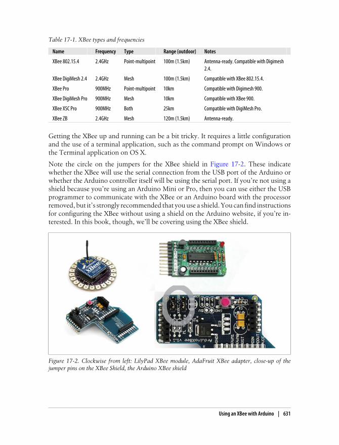
Table 17-1. XBee types and frequencies
Name Frequency Type Range (outdoor) Notes
XBee 802.15.4 2.4GHz Point-multipoint 100m (1.5km) Antenna-ready. Compatible with Digimesh2.4.
XBee DigiMesh 2.4 2.4GHz Mesh 100m (1.5km) Compatible with XBee 802.15.4.
XBee Pro 900MHz Point-multipoint 10km Compatible with Digimesh 900.
XBee DigiMesh Pro 900MHz Mesh 10km Compatible with XBee 900.
XBee XSC Pro 900MHz Both 25km Compatible with DigiMesh Pro.
XBee ZB 2.4GHz Mesh 120m (1.5km) Antenna-ready.
Getting the XBee up and running can be a bit tricky. It requires a little configurationand the use of a terminal application, such as the command prompt on Windows orthe Terminal application on OS X.
Note the circle on the jumpers for the XBee shield in Figure 17-2. These indicatewhether the XBee will use the serial connection from the USB port of the Arduino orwhether the Arduino controller itself will be using the serial port. If you’re not using ashield because you’re using an Arduino Mini or Pro, then you can use either the USBprogrammer to communicate with the XBee or an Arduino board with the processorremoved, but it’s strongly recommended that you use a shield. You can find instructionsfor configuring the XBee without using a shield on the Arduino website, if you’re in-terested. In this book, though, we’ll be covering using the XBee shield.
Figure 17-2. Clockwise from left: LilyPad XBee module, AdaFruit XBee adapter, close-up of thejumper pins on the XBee Shield, the Arduino XBee shield
Using an XBee with Arduino | 631

The jumper on the shield, shown in Figure 17-3, sets the mode of the XBee shield. Youset the shield to XBee mode to configure the XBee chip itself when you’re setting thebaud rate for communication or setting the names of the controller. You set the shieldto Arduino when you want to run the Arduino and have it communicate with the XBeeshield.
Figure 17-3. Jumpers on the XBee shield
When the jumpers are in the XBee position, data sent from the microcontroller will betransmitted to the computer via USB as well as being sent wirelessly by the XBee mod-ule. The Arduino microcontroller will be able to receive data only from the XBeemodule, not over USB from a computer.
When the jumpers are in the USB position and the microcontroller is left in the Arduinoboard, the Arduino will be able to talk to the computer normally via USB, but neitherthe computer nor the microcontroller will be able to talk to the XBee module. If themicrocontroller has been removed from the Arduino board, the XBee module cancommunicate directly with the computer. You’ll do this if you want to configure theXBee controller.
Creating a Simple TestTo upload an application to an Arduino board with an XBee shield, the shield needsto have its jumpers set to USB. This means ensuring that the two pins to the right ofthe jumper are connected, rather than the two pins on the left of the jumper. Now youcan upload an application from the Arduino IDE as you normally would. The XBeemodule on the shield is set up to work at 9600 baud by default, so unless you reconfigureit, you’ll need to make sure you’re passing 9600 to the Serial.begin() command inyour sketch (as shown in the following code). If your first Arduino doesn’t have an LEDon pin 13—that is, if it isn’t a Duemilanove—then connect an LED to pin 13 and uploadthe following sketch (code). This sketch reads a value sent over the XBee:
void setup() { Serial.begin(9600); pinMode(13, OUTPUT);}
632 | Chapter 17: Spaces and Environments

void loop() { if (Serial.available()) { byte val = Serial.read(); // this will read from the XBee if (val == 'X') { digitalWrite(13, HIGH); } if (val == '0') { digitalWrite(13, LOW); } }}
Now unplug the first Arduino board from the computer, and switch the jumpers toXBee with the center pin and the pin farthest from the edge of the board connected.On the second Arduino controller, make sure the jumpers are in the USB setting, andupload the following sketch to the board. This sketch is sending data over XBee thatthe receiving sketch will read:
void setup() { Serial.begin(9600);}
void loop() { Serial.print('X'); delay(1000); Serial.print('O'); delay(1000);}
Turn off the serial monitor, and unplug the board. Switch the jumpers to the XBeesetting. Now connect both boards to the computer to power them up. After a fewseconds, you should see the LED on the first board running the receiving program turnon and off, once every second. This means that your Arduino boards are communi-cating wirelessly. Now you can power the Arduinos using 9V batteries, taking care toconnect them correctly, and move them to different rooms in a house; you should seethem continue to communicate.
The jumpers are important because when they’re set to USB, the Arduino Serialprint() and println() methods will send and receive information over the USB port.When the jumpers are set to XBee, then those methods will send information over theXBee. The read() method of the Serial works the same way, so when the shield is setto XBee, you’ll find that the Arduino will communicate only with the XBee and notwith a computer attached to it. This is important to keep in mind when you’re workingwith the XBee shield: If things aren’t working, check your jumpers first. You can alsocommunicate directly with the XBee shield from a computer by connecting it to anArduino board whose microcontroller has been removed and placing its jumpers in theUSB configuration. This works only with Arduino controllers that use the Atmel 168or 328 like the Duemilanove and Decimilia. With this configuration, you can send datato and receive data from the XBee module with any terminal program (such as the
Using an XBee with Arduino | 633

HyperTerminal in Windows or the Terminal in Linux and OS X). This allows you tosee the data that the module is receiving from other XBee shields.
Configuring the XBee ModuleThe XBee is in some ways like the Arduino itself in that it is programmable using com-mands. Table 17-2 lists some of the most commonly used commands.
Table 17-2. XBee programming commands
Command Description Possible values Default
ID The network ID that the XBee will use. Only controllersthat have the same network ID can communicate.
Between 0 and 65,535 or between0x0 and 0xFFFF
3332 or0xD04
CH The channel of the XBee module. Between 0x0B and 0x1A 0x0C
MY The address of the module. Between 0 and 0xFFFF 0
DH and DL The destination address for the wireless communication(DH is the high 32 bits; DL is the low 32).
Between 0 and 0xFFFFFFFF Starts at 0
RE This restores the factory settings of the XBee. N/A N/A
WR This writes the parameter values to the memory of theXBee so that the next time it is powered up, the XBee willuse its new settings.
N/A N/A
BD This sets the baud rate that the shield will communicateat.
0 (1200 bps)
1 (2400 bps)
2 (4800 bps)
3 (9600 bps)
4 (19200 bps)
5 (38400 bps)
6 (57600 bps)
7 (115200 bps)
3
You can configure the XBee module with code running on the Arduino board or withsoftware on the computer. To configure it from the Arduino board, you’ll need to havethe jumpers in the XBee position. To configure it from the computer, you’ll need tohave the jumpers in the USB configuration and have removed the microcontroller fromyour Arduino board.
You’ll need to follow a few steps to configure your XBee. If you’re using the Libeliumshield, you’ll need to remove the processor from the Arduino module that the shield isconnected to and then connect the Arduino to a computer. If you’re using the AdaFruitshield, then you simply need to connect the shield to the FTDI cable that comes withthe shield. Now, you’re ready to get the module into configuration mode, which youcan do in the Arduino IDE by sending three plus symbols (+++).
634 | Chapter 17: Spaces and Environments

There’s one trick here: If you’re trying to configure the module from the computer, youneed to make sure your terminal software is configured to send characters as you typethem, without waiting for you to press Enter. Otherwise, it will send the plus signsimmediately followed by a newline (that is, you won’t get the needed one-second delayafter the +++). Make sure that when you type in the three +++ signs that you do itquickly; there can’t be more than a second delay in between each +, or it won’t workcorrectly. If you successfully enter configuration mode, the module will send back thetwo characters OK.
Now, you’re in configuration mode, and you can begin sending the commands listedin Table 17-2. Note, though, that all those commands are prefaced by the letters AT andthat no space is placed between the command and the value. For instance, to set theXBee to use a baud rate of 19200 instead of 9600, you would type the following:
ATBD19200
Then press Enter. The controller should respond with the characters OK. Take note,though, that if you change the baud rate, you’ll have to change the terminal baud ratetoo, or the terminal won’t be able to communicate with the XBee any longer. You mayneed to restart your terminal controller.
You can also use the commands to query the controller. To get the ID of the controller,send the ATID command without a value:
ATID
Then press Enter. The controller should respond with the values 3332 (the default),unless you’ve configured it to be something else.
It’s important to note that unless you tell the module to write the changes to nonvolatile(long-term) memory, the changes will be in effect only until you power off the module.To save the changes permanently, use the ATWR command followed by pressing Enterto which the module should respond with OK.
To reset the module to the factory settings, use the ATRE command, and then save thechanges using ATWR. Note that like the other commands, the reset won’t be saved intothe module unless you follow it with the ATWR command.
You can also use multiple commands like so:
ATID3333,BD4,WR
This sets the ID and the baud rate and then saves it to the module.
Addressing in the XBeeThe XBee uses a few different ways of addressing and finding objects in its network.There are three different kinds of values that can be used to define what can commu-nicate with a particular XBee module and what other modules that XBee module willlisten to messages from:
Using an XBee with Arduino | 635

Individual module addressesEach XBee controller has an address that is set at the factory. You can also set thevalue of the ID using the DL and DH commands. If a message is sent with a destinationID, the XBee whose address is this destination ID will hear the message.
Personal area network (PAN) IDsThis is another way that the XBee can be configured that has a coordinator sendingout signals to any device using a particular PAN ID and one or more end devices,like a broadcaster and listeners. If a message is sent with a PAN ID and that modulehas that PAN ID set, then it will hear the message.
ChannelsAny number of XBee modules can be set to use a certain channel, and that channeldetermines what messages the XBee module receives. If that module has the samechannel as a message, then it will receive and process the message.
For two modules to communicate, they must be on the same channel, they must havethe same PAN ID, and the destination address of the sender must match the addressof the receiver.
Each XBee module has its own unique address, as well as a destination address to whichit sends its messages. The destination address can specify a single destination, or it canbe a broadcast address, which will be received by all XBee modules within range. Thebroadcast address is 65535 (0xFFFF in hexadecimal).
Now, this may seem a bit complex, but if you have only a couple modules, you’llprobably never need to change the PAN ID or channel. But if you’re in an environmentwith lots of modules, you might want to be sure that nobody else’s messages are gettingmixed up with yours, so this offers a nice option to handle that.
If you’re on a Windows computer, then to configure your XBee controllers further,you’ll probably end up working with the XCTU terminal controller from Digi, availablefrom www.digi.com/, to configure your controller. If you’re on Linux or OS X, you’llopen a terminal and type something like the following.
First, list the serial ports, and find the one you want:
$ ls -l /dev/tty.*
This is what I use, but what you need to type will depend on the port you use. Thefollowing line of code opens a program called screen and tells it to open the USBport /dev/tty.usbserial-A9003QNn using 9600 baud:
$ screen /dev/tty.usbserial-A9003QNn 9600
Now enter command mode:
+++
Finally, get XBee firmware version; in screen, the ctrl-A b indicates a carriage returnindicating that the command is finished:
636 | Chapter 17: Spaces and Environments

ATVR ctrl-A b
If you’re not using screen, you won’t need to use the ctrl-A b command.
A tutorial on XCTU is out of the scope of this book and far better documented on theArduino forums and in Making Things Talk by Tom Igoe than I could do here, and theforums and Tom’s book are also substantially friendlier and easier to use.
So, what can you do now? Well, there are a few interesting ideas. If parts of a space cancommunicate with one another wirelessly, then opening a door could turn on the lightsin the kitchen quite easily; power usage for a house could be monitored; blinds couldbe raised at a certain time to wake someone; and a single command could customizethe temperature, lighting, and sound in a room for a particular user, all without runningwires throughout the space. Health care, education, and business are all fields whereways to integrate responsive and intelligent architecture with the social activities, en-vironmental concerns, and tasks in those fields are being explored in quite interestingways. Another option is to simply synchronize machines or components throughoutspace, making the movements of one small robotic instrument match another, syn-chronize behavior across machines, or discover new machines as they are introducedto the environment. You can also synchronize data-gathering behavior across ma-chines, creating simple networks that don’t require much power to communicate; sen-sors can communicate with a computer handling all the incoming data, and adjust-ments can be made to sensors.
Later in this chapter, you’ll look at an example of sending temperature data from mul-tiple sensors to an Arduino linked to a home automation system.
XBee Library for ProcessingAnother option for working with the XBee and the Arduino is the XBee library forProcessing that Rob Faludi, Daniel Shiffman, and Tom Igoe worked together to create.One of the difficulties in working with the XBee controller is parsing out the data fromthe messages sent by the XBee. By using Processing and the XBee library for Processing,you can parse out the data from a message quickly and easily. The following exampleassumes that you have two XBee modules that are sending messages to a receiver thatis connected to a computer via a Serial connection. This means either having an Arduinowith its chip removed, allowing it to communicate directly with the XBee, or alterna-tively using the following:
import processing.core.*;import processing.serial.*;import xbee.XBeeDataFrame;import xbee.XBeeReader;
Here is a Serial port that will communicate with the XBee module:
Serial port;
Using an XBee with Arduino | 637

An XBeeReader object will read the data from the XBee module and put it in a friendlyand easy-to-read format:
XBeeReader xbee; int[] analog; int[] digital;
public void setup() { size(400, 400);
Remember that the XBee will be using the 9600 baud rate unless you change the settingsof the module:
port = new Serial(this, Serial.list()[0], 9600); xbee = new XBeeReader(this, port); xbee.startXBee(); println("XBee Library version " + xbee.getVersion()); }
Chapter 8 introduced the Processing Serial library that allows a Processing applicationto read data from the serial port of your computer. The XBee library works quite sim-ilarly to the Serial library with an event handling function called xBeeEvent(), which,like the serialEvent() method of the Serial library, is called for you when new data isavailable to be read. Of course, the XBee library reads data only from the XBee and notfrom the Serial, but the concept is the same:
public void xBeeEvent(XBeeReader xbee) { println("Xbee Event!");
Next, grab a chunk of data from the XBee, often referred to as a frame:
XBeeDataFrame data = xbee.getXBeeReading();
The Processing library checks to make sure that the received data is in the correct series.The XBee library supports several different packet types, but each contains differentdata:
if (data.getApiID() == xbee.SERIES1_IOPACKET) {
Now, we want to loop through all the data received in the frame and determine whatdata has arrived in the packet:
int totalSamples = data.getTotalSamples(); for (int n = 0; n < totalSamples; n++) { print("Sample: " + n + " "); // Current state of each digital channel //(-1 indicates channel is not configured) digital = data.getDigital(n); // Current state of each analog channel //(-1 indicates channel is not configured); analog = data.getAnalog(n);
for (int i = 0; i < digital.length; i++) { print(digital[i] + " "); }
638 | Chapter 17: Spaces and Environments

for (int i = 0; i < analog.length; i++) { print(analog[i] + " "); }
} } else { println("Not I/O data: " + data.getApiID()); } }
public void draw() { background(0); fill(255);
Draw the data received in the last packet to the screen:
for (int i = 0; i < digital.length; i++) { ellipse(50, i* 20, digital[i]); } for (int i = 0; i < analog.length; i++) { ellipse(250, i* 20, analog[i]); } }
Now that you see how to get data from the XBee, you’ll probably want to send com-mands to it using the AT commands. The XBee library defines methods to send most ofthe primary XBee commands for getting and setting destinations and channels. To testsome of the key AT commands, you can run the This method to respond to key presseswhen the program window is active: These methods test a few of the different ATcommands:
public void keyPressed() {
switch (key) {
case '1': println(" Do node discovery and find any available nodes: "); xbee.nodeDiscover(); break; case '2': println("Set the destination node of the XBees "); // this can be whatever you would like, just make sure that // there is a valid node first xbee.setDestinationNode("205"); println(); break; case '3': println("Get the Channel of the XBee using the CH command"); xbee.getCH(); break; case '4': println(" Send a datastring over the XBee ");
Here, the XBee will send a data string out using the address passed in. The two hexa-decimal numbers that you see as the first two parameters are the high byte and low byte
Using an XBee with Arduino | 639

to send as the destination of the message. This way, an XBee can send a message withan address, and any other XBee can decide whether it wants to listen to the message.You can change these address values:
xbee.sendDataString(0x0013A200, 0x403E17E6, "Bonjour!"); break; case '5': println("Getting the high byte of the destination of the XBee"); xbee.getDH(); break; case '6': println("Getting the low byte of the destination of the XBee"); xbee.getDL(); break; case '7': println("Getting the ID of the XBee that sent data"); xbee.getID(); break; case '8': println("Get the Node Identifier using the NI command"); xbee.getNI(); break;
Another aspect of the XBee that we haven’t brought up yet is the ability of the XBee towrite digital or PWM data out via one of its digital input or output pins:
case '9': xbee.setIOPin(1, 5); break; case '0': xbee.setIOPin(1, 4); break; case '-': println("get the address of the XBee that sent data "); xbee.sendRemoteCommand(0x0013A200, 0x403E17E5,0xFFFE,"MY",-1); break; }}
Paired with a Processing application, the XBee is a very powerful way to send commandsremotely, across spaces such as a garden, field, or even, if you use a powerful enoughXBee, across a small town, and easily integrate that with a Processing application. Ofcourse, you can also use the XBee without connecting it to a Processing application.Paired with a relay like the RelaySquid or with a hand-built relay circuit as you saw inChapter 11, the XBee can be used to control lights, appliances, or other large devices.It could also be used to set the values on a servo, drive a LCD display, or do anythingelse that an Arduino can do.
With some careful planning, you can use the node discovery capabilities of the XBeeto create networks that configure themselves when new nodes are added or removed,with XBees on the network alerting other XBee controllers about the node’s capabilitiesare and what kind of information they expect.
640 | Chapter 17: Spaces and Environments

Placing Objects in 2DOne of the more common tasks that you might find yourself wanting to do whenworking with a space is to locate objects in two dimensions. You might want to deter-mine whether a person is in a room so that you can turn the lights on, whether someoneis approaching a doorway, or whether an object has been moved to a certain location.Behind a lot of complex reactive effects is the simple determination of where a personis in a room or space so that changes can be made to the environment.
Before you get started placing objects in two dimensions, it’s important to know howto place them in one dimension—the distance between a sensor and an object in astraight line. Here’s a simple piece of code to do just that with an ultrasonic sensor likethe ones discussed in Chapter 8:
unsigned long echo = 0;
Connect the PW pin on the ultrasonic sensor to pin 9 on the Arduino:
int ultraSoundSignal = 9;unsigned long ultrasoundValue = 0;
void setup(){ Serial.begin(9600); pinMode(ultraSoundSignal,OUTPUT);}
unsigned long ping(){ pinMode(ultraSoundSignal, OUTPUT); // Switch signalpin to output digitalWrite(ultraSoundSignal, LOW); // Send low pulse delayMicroseconds(2); // Wait for 2 microseconds digitalWrite(ultraSoundSignal, HIGH); // Send high pulse delayMicroseconds(5); // Wait for 5 microseconds digitalWrite(ultraSoundSignal, LOW); // Holdoff pinMode(ultraSoundSignal, INPUT); // Switch signalpin to input digitalWrite(ultraSoundSignal, HIGH); // Turn on pullup resistor echo = pulseIn(ultraSoundSignal, HIGH); //Listen for echo ultrasoundValue = (echo / 58.138); //convert to centimeters return ultrasoundValue;}
void loop(){ int x = 0; x = ping(); Serial.println(x);
Next, delay the next ping by one-fourth of a second to make sure that the signals don’tinterfere with one another:
delay(250); //delay 1/4 seconds.}
Placing Objects in 2D | 641

There are a few different strategies to place an object in space. This depends on whatyou are defining as “space.” You can always use a GPS for placing an object in geo-graphical space, but it doesn’t help when placing an object in a room. Using a pair ofcameras to position an object is an easy way to position an object in a room, but itrequires that you have multiple cameras and that the cameras are connected to a com-puter that can handle multiple input streams from cameras. This is more a matter ofpicking the right camera and configuring your hardware than programming, but it isquite possible to do in an oF application. You can find more information on how to dothis and what cameras would be best suited to your system on the oF forums andwebsite.
To locate the object in a room, you’ll probably want to use a set of sensors, such as inFigure 17-4, that will provide enough data for you to triangulate the position of theobject. You’ll need to determine the position of the object along at least two axes,usually the x and y. This presents a few problems, though, if you’re trying to trackmultiple objects through space or if the space that you’re interested in working withhas multiple obstructions in it.
Figure 17-4. Two strategies for determining the location of an object using ultrasonic sensors
Using ultrasonic sensors in tandem presents a challenge: Numerous sensors often in-terfere with each other when placed within “hearing” distance of each other. This isbecause each sensor has no way of knowing which short pulse of sound came fromwhich sensor and the data readings can get very unpredictable. The solution is to syn-chronize the sensors to prevent one sensor from listening while any other sensor isclicking. Infrared sensors present somewhat the same problem, except with lightinstead of sound; but they have an additional disadvantage: They cannot be easilysequenced, while the ultrasonic sensor manufactured by Maxbotix can.
To chain the Maxbotix ultrasonic sensors and have them to operate in sequential daisy-chained fashion (as in Figure 17-5), you link the TX pin of unit 1 to the RX pin of unit
642 | Chapter 17: Spaces and Environments

2, and so on. The BW pin is connected to +5 volts on each sensor. Then just set thepin connected to the first sensor’s RX pin to HIGH, (shown in Figure 17-5 as pin 6), tostart the chain reading, and all of the sensors will read in sequence. The analog valuescan then be read. In the example figure, you use one pin to command the chain andthree analog in pins to read the data from the sensors.
Figure 17-5. “Daisy-chaining” multiple ultrasonic sensors together
This chains the sensors together so that the values from each sensor will be sent to theanalog pin 1. You’ll need to add a resistor between the last sensor’s TX pin back to theRX pin of the first unit through a 1K resistor.
Now you can begin reading them in sequence. In your setup() method, you want tohave a delay of 250 milliseconds after powering on the sensors to give them time toboot up. Each time you want to read the ring of sensors, you have to “kick start” themby setting the RX pin HIGH on the first sensor for 20 microseconds. Now all of the sensorsin the chain will run in sequence. This “ring of sensors” will cycle around and around,constantly maintaining the validity of their analog values. You can then read the latestrange reading at any time. This is the easiest way to use them. After setting the pin onthe Arduino connected to the RX of the ultrasonic sensor to LOW, you should wait 100milliseconds for the sensor as it calibrates itself. After that you can read the analog pinroughly every 50 milliseconds. The most recent range reading is always ready to be readon the analog voltage pin, so once you start the chain and if you are using it in contin-uous mode, you can read the values at any time:
int ultraSoundSignalPins[] = {0,1,2}; // 3 Ultrasound signal pinsint ultraSoundTriggerPin = 6; // output pin to start Ultrasound signals
void setup() { Serial.begin(9600);
for(int i=0; i < 3; i++) { pinMode(ultraSoundSignalPins[i], INPUT); // Switch signalpin to input } pinMode(ultraSoundTriggerPin, OUTPUT); // set this pin to output //give the sensors time to boot up delay(250);
Placing Objects in 2D | 643

// send RX pin high to signal to chain to ping digitalWrite(ultraSoundTriggerPin, HIGH); delayMicroseconds(20); digitalWrite(ultraSoundTriggerPin, LOW); pinMode(ultraSoundTriggerPin, INPUT); // electrically disconnects the pin delay(50);}
void loop(){ unsigned long ultrasoundValue; unsigned long echo; delay(50); for(int i=0; i < 3; i++) {
Now the values from each sensor can be read:
echo = analogRead(ultraSoundSignalPins[i]); //Listen for echo ultrasoundValue = (echo / 58.138); delay(50); }}
The configuration shown in Figure 17-5 shows how multiple sensors could be config-ured. Setting them at the center of a room and reading them around from left to rightis probably the easiest option since it allows you to determine the location of a readingvery easily. Getting good coverage of a room requires quite a few sensors, though, andit can be less than optimal to put sensors in the middle of a room. Setting the sensorsto read across from one another is perhaps more precise because it allows you to actuallydetermine in two dimensions the location of an object, but it’s slightly trickier to putthe values together and easier to get false readings if the sensors are not timed correctlyor if there are multiple objects in the room. In either event, some planning ahead andexperimentation will successfully let you determine the location of one or more peopleor objects in a room to a fair degree of accuracy.
Interview: Usman HaqueUsman Haque is a London-based architect and artist who designs interactive architec-tural systems and develops both physical spaces and the software and systems thatbring them to life. He currently teaches at the Bartlett School of Architecture in London,England. His installations have been exhibited at the Institute of Contemporary Arts(London), the Hillside Gallery (Tokyo), the Tokyo Metropolitan Museum of Photog-raphy (Tokyo), and the Plymouth Arts Centre (Plymouth). His projects have been pub-lished in several magazines and journals including The Architects’ Journal, Artifice,Wallpaper, Wired Online, WebMaster magazine, .net magazine, Architectural Design,ZDNet, and the RIBA Journal.
For my readers who might not be familiar with you and your work, could you give a verybrief summary of the kinds of projects that you’re working on currently?
644 | Chapter 17: Spaces and Environments

Usman Haque: There have been three particular directions that my work in the pasthas taken, guided particularly by my background in architecture and general interestin how we relate to each other and to the space we form around ourselves: (1) thoseinvolving participation and interaction, often in large-scale productions in urban parks;(2) experiments exploring the process of perception, both in humans and machines;and (3) designing design systems, for example by finding ways to involve people whomight not otherwise call themselves “designers” in the processes of design.
The direction of the work I’m involved in these days has changed a little. I’ve becomeparticularly interested in tying together the previous strands, looking particularly atself-powered, dynamic, and permanent systems. I’m spending a lot of time nurturingPachube.com. I’m also getting much more rigorous about what I describe as“interactive.”
Can you explain a little bit about how you and your collaborators came to work togetherand provide a little insight into how your actual day-to-day collaborations on a projecttakes shape?
Usman: There’s no conscious process involved in developing a collaboration. I usuallyfind that I’m involved in a collaboration without specific planning. The project justtakes shape in conversation; by contrast, when I have a project already in mind and Ineed specific additional input from others, I get a little embarrassed asking peoplewhether they would like to work on it with me.
My favorite collaborations (and the usual way that these occur) are those that ensuefrom just hanging out with people I enjoy being with. The Evolving Sonic Environ-ment project developed from having lunch with Rob Davis one day and having a con-versation where we speculated about trying to go “totally analog”; the Wifi-Cameraproject came about when Adam Somlai-Fischer and Bengt Sjolen and I were huddledtogether at an exhibition opening; Seth Garlock got involved in Sky Ear during one ofour (quite frequent) three-hour phone calls. (This was in pre-Skype days, and up untilthat point we hadn’t talked about working together. Our conversations were usuallyabout books and politics and egg-cream sodas. We just slipped unknowingly into theworld of collaboration when he said, “Why don’t your balloons talk to each other?”).When Rolf Pixley and I started working together, I think it was largely because wemisunderstood each other, and the ongoing collaboration was a process of discoveringthat we might in fact be in agreement (!); working with Yu Nishibori on Infinitum AdNauseam came about because I really liked his meal recommendation after I met himin a restaurant (I also liked his rubber ducks); working with Despina Papadopoulos on1000 ensued after several years of being friends—partly we just wanted to find a wayto get funding to carry on the kinds of conversations we were having. Anyway, I workwith people I like. I don’t worry about how/whether our skills overlap, complement,or jar. That usually gets clarified in the process of collaborating.
Working with Rolf on Open Burble is something I consider very precious. Partly throughhis pressure and partly because I want to know and understand every part of the projectsI’m involved in, our conversations would swing rapidly from discussions on the timingof setting individual bits and registers within a microchip, all the way through concep-tual discussions about the way the human nervous system functions, up through the
Placing Objects in 2D | 645

perceptual mechanisms involved in looking at a lit balloon against the rapidly changingcolors of an evening sky. I do think it’s important for someone who is going to put hisor her name on a project, even in a collaboration, to understand exactly what’s goingon in the project at all levels.
I’m quite interested in the idea of architecture being something “no longer considered staticand immutable.” Can you elucidate this a little bit?
Usman: Architecture has long been considered something permanent, static, and un-changing—the walls, roofs, and floors that surround us and that condition the way werelate to space and to each other. In the last few decades, however, a new idea of ar-chitecture has come about (largely influenced by Cedric Price): one in which architec-ture is all the stuff in between; it’s ephemeral, permeable, and dynamic. I’ve sometimesdescribed this as the “software” of space, rather than the “hardware,” analogizingcomputer terminology. The point of this distinction is to say that there are bits thatappear to stay the same, and there are also bits that change in terms of their relationshipto the whole. I’m interested in the kind of architecture that is constantly constructed,something that is constantly responsive (even if that response is to “do nothing”),something that is constantly on the precipice of change.
Do you see parallels between developing a system that replicates life and a system thatintegrates with life?
Usman: The reason I undertake projects such as Evolving Sonic Environment is lessabout trying to make an “intelligent” space and more about trying to understand how“we humans” understand space. By attempting to build a space that “understands” us,I’m really trying to understand “understanding.”
When I say “a space that understands,” I mean one that modifies its perceptual pro-cesses and creates its own categories of occupancy. The point is not so much to integrateso-called “intelligent” systems with living systems but rather to develop an approachto environment design in which humans are not at the mercy of technology designedand determined by others—to develop adaptive, responsive, conversational systems,where the outcome is determined by both participants, not just the machine (which isthe usual determinant of outcome in human-machine relationships).
What sorts of strategies or thinking do you use to ensure that a participant is free toparticipate in the continued design and evolution of a space or project or structure?
There are two important limits to the idea of a collaborative design system inarchitecture.
Usman: First, the more “open” a system is, the more bewildering it is for those whoare introduced to it anew. In a design system in particular, people are often aided, nothindered, by having constraints applied to them—the real key is to find a way that theconstraints are not necessarily absolute. If the constraints themselves can be modifiedover time, then that really helps in fostering ongoing participation. It is, in a sense, whatlearning is all about.
Second, I don’t believe that it’s possible to construct a “totally open system”—the verynature of a “system” (which is a description of a set of relationships, dependent in allcases upon a particular subjective approach) precludes it. There will always be pro-
646 | Chapter 17: Spaces and Environments

cesses that involve “topdownness” and “bottomupness”—the key to helping perpetu-ate the design and evolution of the kinds of conversational environments we’re talkingabout is to ensure that the relationship between the two processes is not frozen.
It’s also important to ensure a varied “granularity” of participation: Different peoplehave different interests or skill sets, are willing to participate to a greater or lesser degree,or desire to have a smaller or larger impact on the entity being constructed. Everyonewill have their own point at which they wish to engage with something, so it’s vital thata wide variety of entry points and methods are available.
You’ve written before about Gordon Pask and his conversation theory; can you explaina little about how that’s useful to you?
Usman: In the context of architecture, conversation theory is useful in two ways: (1)in considering the architectural construct as an “individual” in conversation with an-other “individual” (often a human being, who happens to occupy the architecturalconstruct) and how these two can interact to their mutual benefit (and coherence); and(2) in considering an “environment” (such as architecture) as being something that isconstructed when two individuals interact (for example, a human and a machine) andcreate “coherence.” In this second example, interaction itself gives rise to architecture,and it is an arbitrary distinction whether the occupant is engaged with the “architec-ture” or the “computer-system-that-drives-the-architecture.”
For an understanding of how I define many different flavors of “interaction,” it mightbe useful to see the “What is Interaction? Are there different types?” article in January2009’s ACM Interactions, an article I coauthored with Hugh Dubberly and Paul Pan-garo, based largely on the Paskian cybernetic approach.
Who are some of the artists and thinkers that you refer to most in your own work andthinking about interactivity and architecture?
Usman: I tend to be influenced really easily. So, if I stand next to someone in thesubway, it probably affects the way I’m thinking about the world. However, apart fromGordon Pask, whom you have already mentioned, there are others who I look to often,including architect Cedric Price; Ross Ashby, a pioneer in systems theory; KennethCraik (who wrote The Nature of Explanation [Oxford University Press]); Stephen Groak(former director of “blue skies” research at Ove Arup and author of The Idea of Build-ing [Spon Press]); and Natalie Jeremijenko, whose work on the “structures of partici-pation” has been very influential. I often get lost in the mountainsides of the Pataphy-sicians (pataphysics being to metaphysics what metaphysics is to physics); my favoriteartists are probably the group Gelitin.
Do have a vision of the way that computing and computation will engage with the kindsof thinking and tasks that architecture and the design of spaces requires?
Usman: The vision I have is what I fear will happen: that our technological systemswill be designed and built by corporate entities with their own rationales for existing,that these systems will be imposed upon us, and that we will be unable to enter intothem in order to change the way they respond to us. They will be private, proprietary,unhackable, and unchallengeable. Imagine having a closed system, just like MicrosoftWindows, controlling your physical desktop, your thermostat, or your home life.
Placing Objects in 2D | 647

That’s the vision I’m trying to escape when thinking about ways to push the architectureand computation direction.
What I would like to head toward instead, and this comes out particularly inPachube.com, is an ecosystem of conversant devices, environments, architectural en-tities—an ecosystem that is open, constantly being reinvented and repurposed, andconstantly adjusting to new perturbations. The goal is not to make the world high-tech—rather, it’s to accept that the world is heading in a high-tech direction and to attemptto nudge it toward a more humanist outcome.
I’m curious how you see a viewer/participant’s perception of the kinds of spaces that yourprojects construct. Do you view the space that the viewer inhabits more like a medium inwhich you communicate with them, or do you see the space as a message unto itself?
Usman: The point is that the designer of any system is involved in a process of speci-fying things. If a designer specifies all parts of a design and hence all behaviors that theconstituent parts can conceivably have at the beginning, then the eventual identity andfunctioning of that design will be limited by what the designer can predict. This entityis therefore closed to novelty and can respond only to preconceptions that were ex-plicitly or implicitly built into it by the designer. If, on the other hand, a designedconstruct (say an environment) can choose what it senses (rather than having thatimposed by the designer), either by having ill-defined inputs/sensors or by dynamicallydetermining its own perceptual categories (that is, the means for comparing things),then it moves a step closer to true autonomy, which would be required in an authen-tically interactive system. In an environmental sense, the human component of inter-action then becomes crucial because a person involved in determining input/outputcriteria is productively engaging in collaborative “conversations” with his or her envi-ronment. Building on the rather prosaic model of the thermostat, imagine a tempera-ture-controlling system, which has the possibility of altering both inputs and outputsto the system (while always retaining the goal of “controlling the ambient tempera-ture”). Rather than solely measuring temperature as an input, and outputting instruc-tions to a heater to switch on, such a system might dynamically reconnect to differenttypes of input or output.
These input criteria might range from “energy consumption measurements over thelast month” to “the exterior temperature for this week last year” to “seasonal rainfall”to “the color of my clothes today” to “the fifth letter of the second paragraph on thefront page of today’s newspaper.” The system might try all of these inputs and continuemonitoring how much effect each appears to have on the goal (to control temperature).The system would evolve weightings for each of these input criteria in order to providesatisfactory output, again according to criteria determined dynamically with the person(who is controlling the goal of this super-thermostat). Output criteria might include“degree of thermal comfort,” “energy bill amount,” “neighbor’s energy bill amount,”“hot chocolate drinking tendency,” “number of friends who come to visit and how longthey stay.”
In all cases, both input and output criteria are dynamically constructed and continuallymonitored with respect to how well they achieve the goal set by the person. In thissituation we can imagine that the inhabitants and the environment are in some sense
648 | Chapter 17: Spaces and Environments

collaborating to develop a temperature-controlled system, because not only is the per-son contributing the input criteria, but they are also involved in influencing the outputcriteria. Such a calculation is complex enough as to be pretty much impossible withoutthe aid of the super-thermostat; but without the human contribution, it’s alsoimpossible.
Are you still working on the Low Tech Sensors and Actuators project?
Usman: The point of Low Tech Sensors and Actuators (a collaboration with AdamSomlai-Fischer) was to make it simple for nontechnical people (or people who thoughtthey were nontechnical) to get involved in hacking toys and gadgets, not being toorespectful of the packaging that a mechanism is found in, to be able to prototype re-sponsive systems relatively easily. We didn’t take it much further than the first manual(though we did hold, and occasionally continue to hold, low-tech workshops) mostlybecause it is now quite a popular concept, and so there are lots of such guides andworkshops available.
The manual has led us to create the Reconfigurable House (which amassed hundredsof low-tech gadgets, devices, and toys in a system where occupants could determinehow these devices were connected to each other, building interactive systems in which“they decide” how the house would respond to them—essentially a critique of theclosed nature of “smart homes”) and later Scattered House, which was like Reconfig-urable House but split across multiple cities and networked using Pachube.com (a sys-tem I have been developing to enable people from around the world to connect up andshare their devices and environments in real time in order to build planetary-scale in-teractive environments; it’s a little like YouTube, but for sharing real-time environ-mental data rather than videos). Pachube has evolved from these earlier systems:attempting to foster a reconfigurable planet, if you will, through a kind of globalgeneralized data brokerage.
Do you see architecture as a domain that is truly distinct from, say, designing an onlinecommunity space?
Usman: I’m not sure I agree necessarily that interaction or participation are moremeaningful when conducted solely in nonelectronic physical space; certainly, being inthe same room with someone offers a lot more bandwidth, and when time dimensionschange, it’s possible to drift in and out to greater or lesser degrees. In online situations,of course, it’s difficult to have degrees of opt out. Either you’re part of a conversationor you’re lurking (or you’re not even part of the community at all). Skype gets a littlecloser by having different status conditions you can assign yourself to, paralleling theability to be “in the next room” as it were. But participation is mostly provoked intobeing through systems that are open to be changed, and that’s why we have the richpossibilities of something like Wikipedia. There are certainly parallels between theprocesses involved in constructing architecture and processes involved in constructingonline spaces, though I’m hesitant to analogize since it feels as though there are alreadytoo many analogies used by each for the other. However, I’m not someone who believesin a great distinction between real and virtual—this distinction has been compared tothe now-quaint 19th-century distinction between mind and body.
Placing Objects in 2D | 649

Reading about your 1,000 (little tips of communication) project I came across a quotethat really struck me: “At a time when we can build whatever we imagine, device, building,or experience, it is vital to consider the wider aesthetic, ethical, and lyrical implicationsthat this condition affords us.” Do you have specific ideas on what those implications areand what they mean to an artist, architect, or designer?
Usman: The point is that when we can build/design almost anything, it becomes veryimportant to consider why it is that we choose to bring any particular thing into thisworld: Does the world really need another XYZ product? What does it mean to be ableto connect to more people? How can we continue to produce magic? In this statement,I was influenced a lot by Anthony Dunne’s Hertzian Tales (MIT Press), where he talksabout the “post-optimal” object (that is, objects you design once practicality and func-tionality can be taken for granted). In a world where anything is possible, poetry be-comes imperative for generating the unexpected. I’m not sure that I can respond morespecifically to your question, other than to say that that’s really the hope for most ofmy projects: to find an answer to the question!
What inspired you to design the EEML?
Usman: Ultimately, with Pachube and Extended Environments Markup Language(EEML), my goal is to have some little effect on the construction industry, which de-termines the kinds of spaces we inhabit and how we relate to them.
EEML came about for two reasons: (1) we needed something that would do what cur-rent construction industry modeling standards cannot do (such as describe buildingsthat are dynamic, responsive, networked), while still being able to operate alongsidethem; and (2) because Pachube.com needed a protocol that was able to describe boththe physical environments of buildings, devices, and human interaction and the virtualenvironments of Second Life and web browsers without predicating one upon the other.The point was to develop something that was robust enough to be used by buildingmanagement software and also flexible and simple enough that individual developersand nonprofessionals can use the format in their own smaller devices and projects. Thisfacilitates communication between all types of entity and therefore is exactly whatPachube.com requires, with its goal being to enable people to tag and share real-timesensor data between buildings, devices, and environments all over the world.
An understanding of what an environment actually constitutes is crucial to EEML’songoing development. I believe that one of the major failings of the usual ubicomp(ubiquitous computing integrates common, everyday computational devices and sys-tems, often without the user knowing) approach is to consider the connectivity andtechnology at the object level, rather than at the environment level. It’s built into muchof contemporary Western culture to be object-centric, but at the environment level, wetalk more about context, disposition, and subjective experience. An environment hasdynamic frames of reference, all of which are excluded when simply focusing on devices,objects, or mere sensors. If you really study deeply what an environment is (by this Imean more than simply saying that “it’s what things exist in”), you begin to understandthat an environment is a construction process and not a medium, not just a state andnot just an entity. In this I would refer to Gordon Pask’s phenomenally important text“Aspects of Machine Intelligence” in Nicholas Negroponte’s Soft Architecture Machine
650 | Chapter 17: Spaces and Environments

(MIT Press), which makes for extremely tough reading (Negroponte compared it inimportance to Alan Turing’s contributions to the discipline).
As a result of this conception of environment, we remove the need for a distinctionbetween real and virtual. We can consider equally as environments a mountainside,the interior of a building, the context of a web page, the internal status and externalcontext of a mobile device, the interactions within something like Second Life—all theseare environments and can communicate with each other on equivalent terms. Moreimportantly, a single environment can be expressed as a snapshot in time, or it can beexpressed as a sequence of many snapshots over several years. Chris Leung (who hasbeen working on this) and I have a very similar approach to systems design, but at thesame time we are looking for quite different things in the protocol. And so, in ensuringthat we are both happy with it, it has been useful to make sure that we cover a lot ofterritory—attempting to be all things to all people...and machines!
Using the X10 ProtocolX10 is a protocol used to send digital data between devices over household electricalwiring. This means that you can send data around a house using the wiring a little likeInternet cables are used for TCP or UDP communication. It works by sending a singledigit over the wire every time the waveform of the current hits 0 in its cycle, called thezero crossing. This looks like the images in Figure 17-6.
When the waveform is at 0, an X10 device can send a quick burst of data to any otherconnected X10 device. That data, once reassembled into a message, usually consists ofan address and a command sent from a controller to a controlled device. That commandcould be telling the device to turn on or off or checking status, such as the dimminglevel of lights, the temperature in a room, the state of the coffee maker, or other sensorreadings. Devices usually plug into the wall where a lamp, television, or other house-hold appliance plugs in; however, some built-in controllers are also available for wallswitches and ceiling fixtures.
The signal can’t pass through a power transformer or across the phases of a multiphasesystem, so more complex electrical systems might not work with X10 as expected.There are devices that will help you work around this, but for the purposes of this quickintroduction, we’ll assume that you’re in a space with a single-phase system whereyou’re not attempting to cross any transformers. Most X10 modules fall into a fewgeneral types. Controllers send out an address and a command to control the receivermodules. Controllers do things like work as timers and interface with computers, tel-ephone responders, universal transmitters, and alarm systems. Transceivers convert IR(infra red) or RF (radio frequency) signals to X10 signals, allowing you to easily set upcontrols using TV-style remote controls, wireless switches, motion detectors, and othermeans of wireless communication. There are also modules to control lights and equip-ment plug-in modules, built-in switches, micromodules, and modules for professionaluse.
Using the X10 Protocol | 651

The Arduino X10 library is built to send X10 commands through a unit that can beconnected to the Arduino and provide access to a X10 network. The X10 protocol usesa few different constant values to send commands from one module to another module,and the Arduino X10 library includes constants that make working with these com-mands easier. The names of the constants should give you a good idea of what they’resupposed to do.
ALL_UNITS_OFF BRIGHT PRE_SET_DIM
ALL_LIGHTS_ON ALL_LIGHTS_OFF EXTENDED_DATA
ON EXTENDED_CODE STATUS_ON
OFF HAIL_REQUEST STATUS_OFF
DIM HAIL_ACKNOWLEDGE STATUS_REQUEST
X10 also allows you to label and name different parts of an X10 circuit in a house, aswell as naming different modules on each circuit, so that you can communicate with
Figure 17-6. X10 sending data across the zero crossing of electrical current
652 | Chapter 17: Spaces and Environments

an individual module by name. To control specific devices, all modules are assignedan address, which consists of a House code and a Unit code. There are 16 House codes(A through P) and 16 Unit codes (1 through 16). Each House code has 16 Unit codes,so this means there are 256 possible addresses. House/Unit codes are referred to likethis: A5, C7, M13, P4, and so on.
In this book, we’re most interested in using the Arduino with an X10 module, and thatrequires a module that the Arduino can interface with like the TW523, which is shownin Figure 17-7.
Figure 17-7. The TW523 X10 module
The TW323 X10 module can be connected to the Arduino as shown in the small sche-matic to the right in the figure. The Arduino X10 library will work with the PL513 one-way X10 controller and the TW523 two-way X10 controller. They simply provide agateway into the X10 network that the Arduino can send signals to, much like a modem.
To make a simple application that writes an ALL_LIGHTS_ON message simply import theX10 library and call the constructor on the X10 object, passing the two pins that you’llbe using for communication with the X10 module:
#include <x10.h>#include <x10constants.h>
Call the constructor:
x10 myX10 = x10(8, 9);
int buttonPin = 5;void setup() {
Set pin 8 to read input from the X10 controller and pin 9 to write to it:
pinMode(8,INPUT); pinMode(9,OUTPUT); pinMode(buttonPin, INPUT); digitalWrite(buttonPin, HIGH); // turn on pull-up resistor}
Using the X10 Protocol | 653

void loop() { int val = digitalRead(buttonPin); if(val == LOW) { // turn lights on if switch is pushed myX10.write(A, ALL_LIGHTS_ON, 1); } else { myX10.write(A, ALL_LIGHTS_OFF, 1); }}
The possibilities that the X10 creates for you are in some ways similar to what the AC/DC switchers that you learned about in Chapter 7 enable, with a slight difference: X10doesn’t simply control devices that use household current; it uses household currentto communicate with devices. You can use a few ways to identify things of interestoccurring in a specific space: RFID tags, motion sensors, and pressure sensors in adoorway.
In the next section, you’ll learn about RFID and see how to create an X10 network thatsends signals when an RFID tag is read.
Setting Up an RFID SensorRadio Frequency Identification (RFID) is a technology that allows you to read and writeto tags that can be read from a distance. RFID is used in credit cards, books, shippingcontainers of all sorts, and many other places. RFID is really a way to tag objects andphysically port data. You can attach an RFID tag to any object to give it an ID, or if youare using an RFID writer, then you can both read and write to tags attached to an object.
Most RFID tags contain at least two parts. One is an integrated circuit for storing andprocessing information, modulating and demodulating an RF signal, and doing otherspecialized functions. The second is an antenna for receiving and transmitting thesignal.
Some RFID readers can read tags from 6 meters away or more, but most have a shortrange of 5–10 centmeters. There are two kinds of RFID devices: readers and readers/writers. Devices that can write RFID data are generally more expensive. The frequencythat a tag operates at is important because the reader and the tag need to be operatingat the same frequency, for instance, 125Hz or 13.56MHz.
The Parallax RFID reader is a less expensive option for reading 125Hz RFID tags thathas been used with the Arduino on many projects. Another Arduino-compatible optionusing the 125Hz tags is the Innovations ID-12 or ID-20 RFID readers. All of these canbe powered from the Arduinos +5Vcc pin. Both the Parallax reader and the Innovationschips are shown, along with a breakout board for the ID-12 to make connecting it toyour Arduino easier, in Figure 17-8.
654 | Chapter 17: Spaces and Environments

Figure 17-8. RFID readers from Parallax and Innovations
If you’re interested in working with writing RFID tags, less expensive RFID reader/writers are available. As of the writing of this book, APSX makes 13.56MHz reader/writers available for less than $100 that have been used with the Arduino.
To connect the Parallax reader or the ID2 breakout board to the Arduino, follow theschematic in Figure 17-9.
Figure 17-9. Connecting the Parallax RFID and ID-12 to the Arduino
Now you’re ready to read data from the RFID reader. In the case of the Parallax RFIDreader, this operates only at a baud rate of 2400:
int val = 0;char code[10];int bytesread = 0;
void setup() {
Start communication between the RFID reader and the Arduino at 2400:
Serial.begin(2400); pinMode(2,OUTPUT); // connected to the RFID ENABLE
Setting Up an RFID Sensor | 655

Digital pin 2 is connected to the RFID enable pin and sending it LOW activates the RFIDreader. If you wanted for any reason to deactivate the RFID reader, you would need tosend it HIGH:.
digitalWrite(2, LOW);}
void loop() { if(Serial.available() > 0) { // check if there's data
The beginning of RFID messages from the Parallax will contain a header, so you’ll knowto continue reading the message. The Parallax RFID reader sends 10-digit tags, so you’llknow that after 10 values, you’ve read the entire tag. There is also a stop byte sent as0x13 that is sent if the tag is complete, so the loop created checks for that value:
if(Serial.read() == 10) { // look for a linebreak bytesread = 0; while(bytesread<10) { // read 10 digit code if( Serial.available() > 0) { val = Serial.read(); if((val == 10)||(val == 13)) { // if header or stop bytes // before the 10 digit // reading break; } code[bytesread] = val; bytesread++;// ready to read next digit } } if(bytesread == 10) { // if 10 digit read is complete code(bytesread] = 0; // terminate the string Serial.print("RFID tags code is: "); Serial.println(code); } bytesread = 0; delay(500); } }}
If you’re using the ID-12, the code is almost the same but with one exception: Whenchecking the start and stop values for the ID-12, you’ll use 0x02 for the start and 0x03for the stop, so in the previous code you’ll want to check for that value instead:
if(Serial.read() == 2) { // do the rest of the reading
You also could add some constants to define these values:
#define RFID_START 2 // Parallax start is 10, ID12 is 2#define RFID_STOP 3 // Parallax stop is 13, ID12 is 3
One other thing to be aware of is that you’ll want to make sure that you disconnect theRX serial wire from the ID-12 when uploading the sketch.
656 | Chapter 17: Spaces and Environments

Now that you understand the basics of RFID, you can combine it with other technol-ogies. You can use Firmata library or serial communication to read and write RFID datafrom a tag and send it to Processing or oF applications, or an Arduino can use the RFIDdata directly. In the following example, you’ll combine RFID with X10 to turn the lightsin a house on when the correct RFID tag is read. You could set this up near the frontdoor of a house and turn your lights on simply by waving the tag in front of the reader.
This example uses one method that you probably have not seen before: the strcmp()method. This is a C method that is part of the standard C library, which means thatyou can use it in an Arduino application, an oF application, or any other C or C++application. The method has this signature:
int strcmp(const char *s1, const char *s2);
The strcmp() method returns 0 if the strings are equal and a nonzero value if they aredifferent. You’ll get a positive value if the s1 is greater than the second and a negativevalue if the s2 is greater. In this example, that method is used to compare the RFID tagvalues to the constant that we’re expecting. This example uses the following:
#include <x10.h>#include <x10constants.h>// RFID reader variables#define TAG_LEN 12#define RFID_START 2 // Parallax start is 10, ID12 is 2#define RFID_STOP 3 // Parallax stop is 13, ID12 is 3
This is the value for the RFID tag that I’m using, but you’ll need to change it to theRFID tag that you have:
char tag[12] = { "0F03037185"};char code[12];int bytesread = 0;int ledPin = 13; // Connect LED to pin 13int rfidPin = 2; // RFID enable pin connected to digital pin 2int val=0;
Now, add some variables for the X10 control:
int repeat = 1;boolean lightsOn = false;
x10 house = x10(8, 9);
void setup() {
Now, begin serial communications with the RFID reader. The SOUT pin of the RFIDreader should be connected to Serial RX (Digital Pin 1) at 2400 baud. If you want toconnect the RFID reader and a PC you can use the NewSoftSerial library to set upcommunication between the RFID reader and the Arduino and leave the hardwareserial for computer to Arduino communication:
Serial.begin(2400); // X10 Module house.write(A, ALL_UNITS_OFF, repeat);
Setting Up an RFID Sensor | 657

Set the pins that the X10 unit will use:
pinMode(8,INPUT); pinMode(9,OUTPUT);
Set the pins that the RFID reader will use:
pinMode(rfidPin,OUTPUT); // Set digital pin 2 as OUTPUT to connect it // to the RFID /ENABLE pin pinMode(ledPin,OUTPUT); // Set ledPin to output digitalWrite(rfidPin, LOW); // Activate the RFID reader}void loop() {
This RFID-reading code assumes that the ID-12 is being used, but you just need tochange the expected start and end values to use the Parallax RFID reader:
if(Serial.available() > 0) { if((val = Serial.read()) == 2) { bytesread = 0; while(bytesread<10) { if( Serial.available() > 0) { val = Serial.read(); if((val == RFID_START)||(val == RFID_STOP)) { break; } code[bytesread] = val; // add the digit bytesread++; // ready to read next digit } }
if(bytesread >= 10) { Serial.flush(); // clear out the serial code(bytesread] = 0; // terminate the string
Use the strcmp() method to figure out whether the string matches:
if(strcmp(code, tag) == 0) {
If lights are off, turn them on, and if they’re off, turn them on:
if (lightsOn == false) { house.write(A, UNIT_1, repeat); house.write(A, ON, repeat); lightsOn = true; } else { house.write(A, UNIT_1, repeat); house.write(A, OFF, repeat); lightsOn = false; }
After you’re done sending the X10 signal using the matched tag, turn the RFID readeron and off and then flush() the serial port:
658 | Chapter 17: Spaces and Environments

Serial.flush(); delay(1000); // prevent readings from the same tag. } else { Serial.flush(); delay(1000); Serial.flush(); } }
bytesread = 0; // clear system and prepare for next cycle delay(500); // wait } }}
Now you have an application that communicates with an X10 network as well as readsRFID tags. There’s much more that you can do with an X10 network, but this shouldget you started with the basic controllers.
Reading Heat and HumidityAnother interesting and meaningful data point in an environment is temperature. Hu-midity and temperature are both fairly easy data points to read with an appropriatesensor, and they tell you a lot about a place or environment. Although you learned howto grab weather from online services in Chapter 12, there’s another way that providesmore localized data: using a temperature sensor. We’ll look at two different sensors.First, the LM35 (Figure 17-10) is a heat detection chip that is inexpensive. It reads heatdata and is quite easy to use. It’s accurate within about 1.5 degrees C at the limits ofits ranges of –55C and 150C, and it’s accurate within about 0.5 degrees C between–25C and 100C.
Figure 17-10. LM35 temperature sensor
Reading Heat and Humidity | 659

The code to read the temperature is shown here and is based on some wonderful workby Daniel Andrade:
int pin = 0; // analog pinint tempCelsius = 0, tempFahrenheit=0; // temperature variablesint samples[8]; // average of readingsint i;
void setup(){ // this is where you'd start Serial communication if you want to use that}
The data from the LM35 can be a little bit dirty, so it’s best to take several readings andaverage them. This adds the values received from the sensor together and then dividesby the number of readings to ensure that any odd readings are averaged out:
void loop(){
for(i = 0;i< =7;i++){ samples[i] = ( 5.0 * analogRead(pin) * 100.0) / 1024.0; tempc = tempc + samples[i]; // add the eight samples together delay(1000); }
tempc = tempc/8.0; // this is the average of the eight samples tempf = (tempc * 9)/ 5 + 32; // converts to fahrenheit
delay(1000); // delay before loop}
To read both heat and humidity, a company called Sensirion makes a sensor called theSHT15 that can be used to read both temperature and humidity anywhere. It connectsto the Arduino using the I2C protocol, which was introduced in Chapter 8, using a pinto control the clock and another to read the data sent from the SHT15. The SHT15uses two commands, one to read temperature and another to read the humidity, sowhen you send the appropriate command, the chip will respond with the correct data.The trick is that these commands need to be sent in binary, as in the following code:
int temperatureCommand = B00000101; // command used to read temperatureint humidityCommand = B00000011; // command used to read humidity
Note the B in front of the binary numbers. This tells the compiler that you’re using abinary value to set the value of the integer. For the SHT15, the first three bits are theaddress, 000, and the last 5 bits are the command, so in the case of the temperaturecommand, the actual command is 00101.
Next, declare the pins that will be used to communicate with the chip:
int clockPin = 2; // clockint dataPin = 3; // dataint error; // to track whether any errors have occurredfloat temperature;float humidity;
660 | Chapter 17: Spaces and Environments

void setup() {
Open the Serial port for communication with a listening computer. If you’re not sendingthe data to a computer, then you don’t need to do anything in this method:
Serial.begin(9600); // open serial at 9600 bps}
void loop() {
I’m a firm believer in the metric system, and so is the SHT15, so this application willread the temperature value from the chip and convert it to Centigrade. A conversionto Fahrenheit just requires changing the received value and was shown in the previousexample:
sendCommandSHT(temperatureCommand, dataPin, clockPin); waitForResultSHT(dataPin); int val = getData16SHT(dataPin, clockPin); skipCrcSHT(dataPin, clockPin); temperature = (float)val * 0.01 - 40; Serial.print("temperature: "); Serial.print((long)temperature, DEC); //Now we read the humidity sendCommandSHT(humidityCommand, dataPin, clockPin); waitForResultSHT(dataPin); val = getData16SHT(dataPin, clockPin); skipCrcSHT(dataPin, clockPin);
The relative humidity is calculated by taking the returned value and tweaking the valuea bit to get a usable number that indicates the humidity in a percentage from 0 to 100:
humidity = −4.0 + (.0405 * val) + (-.0000028 * (val*val));
Serial.print("humidity: "); Serial.print((long)humidity, DEC);
delay(300000); // wait for 5 Minutes for next reading}
This reads the values from the dataPin in between flashing the clockPin. Setting a pinHIGH and then LOW again is called flashing and, in the shiftIn() method here, is used onthe clockPin to tell the SHT15 to send the next bit of data:
int shiftIn(int dataPin, int clockPin, int numBits) { int ret = 0;
for (int i=0; i<numBits; ++i) { digitalWrite(clockPin, HIGH); ret = ret*2 + digitalRead(dataPin); digitalWrite(clockPin, LOW); } return(ret);}
Reading Heat and Humidity | 661

This method sends a command to the SHT15 sensor:
void sendCommandSHT(int command, int dataPin, int clockPin) {
Set the mode on the pins and then flash both pins, setting them HIGH and then LOWquickly, so that the chip knows that the transmission is about to start. The clock pinis set HIGH and then LOW two times, and the data pin is set HIGH, then LOW, and then backto HIGH. Now the SHT15 is ready to have data shifted out to it:
pinMode(dataPin, OUTPUT); pinMode(clockPin, OUTPUT); digitalWrite(dataPin, HIGH); digitalWrite(clockPin, HIGH); digitalWrite(dataPin, LOW); digitalWrite(clockPin, LOW); digitalWrite(clockPin, HIGH); digitalWrite(dataPin, HIGH); digitalWrite(clockPin, LOW);
As mentioned earlier, the commands have 3 bits in the address section and 5 bits in thecommand section. This uses the shiftOut() command, which shifts out a byte of dataone bit at a time starting from either the most (left) or least (right) significant bit. Eachbit is written in turn to the dataPin, after which the clockPin is toggled to indicate thatthe bit is available. This is known as synchronous serial protocol and is a common waythat microcontrollers communicate with sensors and with other microcontrollers. Theadvantage of using this method of sending data is that the two devices always stayperfectly synchronized and communicate at very high speeds. In this code, the data isbeing sent with the most significant bit first. The third parameter, MSBFIRST, is anArduino-defined constant, which means that the bit that determines whether a valueis positive or negative is sent first:
shiftOut(dataPin, clockPin, MSBFIRST, command);
// check for errors digitalWrite(clockPin, HIGH); pinMode(dataPin, INPUT); error = digitalRead(dataPin); if (error != LOW) Serial.println("got an error 0"); digitalWrite(clockPin, LOW); error = digitalRead(dataPin); if (error != HIGH) Serial.println("got an error 1");}
In this next code snippet, the waitForResultSHT() method waits for the SHT15 to an-swer back by polling the data pin until it goes LOW. This is how the chip indicates to theArduino that it’s finished generating data and is ready to be read. If the pin does notgo LOW, after 1 second we can assume that there’s some sort of error with the chip andthe reading isn’t going to come back:
662 | Chapter 17: Spaces and Environments

void waitForResultSHT(int dataPin) {
pinMode(dataPin, INPUT); for(int i=0; i < 50; ++i) { delay(20); error = digitalRead(dataPin); if (error == LOW) break; } if (error == HIGH) Serial.println("got an error 2");}
Getting data back from the SHT15 is a bit tricky. This next example follows theexample code provided by Maurice Ribble and Hernando Berrigan to create and use ashiftIn() method, which more or less imitates how the Arduino shiftOut() methodworks except in reverse:
int getData16SHT(int dataPin, int clockPin) { unsigned int val;
// get the MSB (most significant bits) pinMode(dataPin, INPUT); pinMode(clockPin, OUTPUT); val = shiftIn(dataPin, clockPin, 8); val << 8;
pinMode(dataPin, OUTPUT); digitalWrite(dataPin, HIGH); digitalWrite(dataPin, LOW); digitalWrite(clockPin, HIGH); digitalWrite(clockPin, LOW);
// get the LSB (less significant bits) pinMode(dataPin, INPUT); val |= shiftIn(dataPin, clockPin, 8); return val;}
The SHT15 sends Cyclical Redundancy Check data. We don’t need this data, so wewant to tell the SHT15 that we don’t want it:
void skipCrcSHT(int dataPin, int clockPin) { pinMode(dataPin, OUTPUT); pinMode(clockPin, OUTPUT); digitalWrite(dataPin, HIGH); digitalWrite(clockPin, HIGH); digitalWrite(clockPin, LOW);}
Now you can check the temperature and humidity for both inside and outside envi-ronments and use that data in your Arduino applications. You could use this for smart-home projects where the temperature of a house is adjusted according to the weatheroutside or a certain room is kept at a certain temperature. Connecting an SHT15 to an
Reading Heat and Humidity | 663

X10 system allows you to engineer quite sophisticated reactions to shifts in temperatureor humidity. A few projects that become easier with temperature sensing include mon-itoring a wine cellar, detecting weather, or monitoring chemicals for photography.
There are other ways to sense temperature as well. There is a Lilypad-ready temperaturesensing module; there is also a One Wire Digital Temperature Sensor with the productnumber DS18B20 that uses the 1wire protocol to sense temperature data. If you don’tneed great precision, you can use very inexpensive 10k thermistors, a type of resistorthat returns temperature values as voltage, that can return temperature data.
What’s NextThere are a great number more environmental sensors to explore. To read the amountof light in a room, you can use a light intensity sensor to determine how much light isshining on the sensor, or you can use a light color sensor to determine what color thelight in a room is. Both of these can be quite useful for determining what’s happeningor what factors are changing in a certain environment. Tutorials are available on theArduino website for using the light color sensor. Another way to detect the color oflight in an area is by using a chip like the PICAXE color sensor, which is very widelyavailable online and gives you excellent readouts of light intensity and color.
You might want to look up the time in a location, which can be done using the DS1307clock that returns the date and time without requiring that the Arduino run expensivecalculations or that the Arduino always be connected to another computer.
If you’re interested in having control over lots of lights or other devices commonly usedin staging, there is a whole series of devices that use the Digital MultipleXed (DMX)protocol for controlling projectors, LED lighting arrays, dimmers, lighting boards, andother devices. DMX is commonly used in theater or dance productions where a singleoperator needs to have control over a large number of devices and there are manysophisticated lights and projectors that can be controlled via DMX. The Arduino canuse a driver chip like MAX485 or 75176 to talk to DMX enabled devices, sending andreceiving DMX commands. There are several tutorials posted on the Arduino websitethat include code, wiring diagrams, and more technical information on the DMXprotocol.
ReviewZigBee is a standard for communicating over wireless networks that is designed to beinexpensive and to not require a lot of power, making it perfect for small devices andubiquitous computing.
Depending on the model, an XBee can communicate up to 100 meters indoors or out-doors within line of sight, a maximum of about 2 kilometers, and if you use of the high-gain antennas, you can send signals up to 6Km.
664 | Chapter 17: Spaces and Environments

XBee controllers can be used for point-multipoint communication or for meshnetworks.
There are several different types of XBee units. Different XBee modules are not alwayscompatible, so make sure to either use the same type of module or check thecompatibility.
AT commands are used to set the destination, ID, or other properties on an XBee andcan be sent from the host computer or from an Arduino.
The XBee Processing library allows you to route information directly from an XBee toa Processing application and parse the information as well as send commands. It alsohelps you parse XBee data frames into all the respective parts.
Both ultrasonic and infrared sensors can be used to detect movement and the distancebetween an object and a sensor.
The Maxbotix ultrasonic sensor can be chained so that multiple sensors will read with-out causing interference with one another, which lets you use multiple sensors to placeobjects in two dimensions or to detect range over a larger part of a space or room.
X10 is a protocol used to send digital data between devices over household electricalwiring. The Arduino X10 library can be used to simplify sending and receiving data.
The X10 protocol can address different devices on a network and has specific com-mands to communicate with the system available.
RFID is a technology that can read tags that have a specific address written to themand send that information to an Arduino. There are also RFID writers that can writeto a tag.
RFID tags are often 10-digit ASCII values that can be used to identify a tag, if you’relooking for a specific tag, you simply need to read the 10 digits from the Serial port andcompare them to the value that you’re expecting.
You can read temperature using a device like the LM35 or a sensor like the SHT15 toread temperature and humidity data.
Review | 665


CHAPTER 18
Further Resources
Throughout this book, you’ve learned about the basics of code, hardware, and waysof designing and programming interactivity in applications, objects, and art pieces.Given the wide scope of this book and the limits of bookbinding, a great number oftopics were only cursorily introduced. You’ll almost invariably find yourself wantingmore, and you should; there is a world of programming techniques, components, anddifferent ideas to learn and explore. Your next steps are probably going to be driven bywhat you want to make and do with code and hardware. This last chapter includessome resources that you might be interested in exploring and some further ideas thatyou can use as a jumping-off point as you work on your projects. It also includes a shortlist of manuals and books that you might find beneficial in helping you understand atopic introduced in this book, that might inspire you, or that can help you find solutionsto a problem you’ve encountered.
What’s Next?This section contains pointers to topics you might be interested in exploring further.A lot of tools and projects exist for artists and designers working with code and hard-ware. We’ve covered the three platforms that I prefer and that I think have best usercommunities and are in most widespread use right now, but you might want be awareof others as well. Some of these are being integrated with the Arduino, Processing, oropenFrameworks projects, and some are entirely separate projects.
Software ToolsBeyond the tools that we’ve examined in this book, the following tools may be ofinterest to you.
667

ARToolKit
ARToolKit is a software library for building augmented reality (AR) applications. Theseare applications that involve the overlay of virtual imagery on the real world.Augmented reality composites real-time video and computer-generated imagery to cre-ate the appearance of an object that exists in the real world. ARToolKit was developedat the University of Washington and has already been successfully used in projectsmade with openFrameworks. The potential of AR as an assistive tool, as a tool forlearning, as a visualization aide, and as a way to perform tasks that are too small or toodangerous for a person to do has already been demonstrated in commercial, industrial,and educational applications. There is also a massive potential for using AR in gamingapplications, particularly in locative or physically reactive games, since a layer of com-puter graphics representing additional information or a virtual reality can be overlaidatop a player’s natural perception. You can find more info at www.hitl.washington.edu/artoolkit/. There are other AR projects currently in development like the Parallel Track-ing and Mapping (PTAM) project at Oxford University that you may be interested inlooking into as well.
PureData
PureData (PD) is an open source graphical programming environment for audio, video,and image processing that, instead of using text-based programming like Processing,C++, or Arduino, uses a visual patching environment to create applications. PD codingis done by connecting elements in a graphical environment rather than by text-basedinput. PD is often called a patching language because each application can be used inanother element or patch in another application. An application that reads the micro-phone of a computer, sends it through a series of filters, and then outputs it to thespeakers can be run alone, or it can be used as an element, or patch, in another appli-cation. This idea of patching means that Pd development often consists of developingmultiple patches and then combining them in different orders or with different param-eters to create an application. PD was originally developed by Miller Puckette andcompany at IRCAM and has an active development community that is building out thecore of PureData as well as plug-ins and extra patches for it. For instance, the devel-opment community has created a system of abstractions for building performanceenvironments, a library of objects for physical modeling, and a library of objects forgenerating and processing video in real time.
PD shares a lot of core concepts with Max/MSP. PD was created to explore ideas ofhow to further refine the Max paradigm while allowing data to be treated in a moreopen-ended way and opening it up to applications outside of audio and MIDI, such asgraphics and video. It is easy to extend PD by writing object classes (externals) orpatches (abstractions) in C. PD is free software and can be downloaded either as anOS-specific package or as source code. It’s also possible to write externals and patchesthat work with Max/MSP and PD (see Figure 18-1). You can find more info athttp://puredata.info.
668 | Chapter 18: Further Resources

Max/MSP
Max is a graphical development environment for music and multimedia developed andmaintained by San Francisco-based software company Cycling ’74. It is used bymusical composers, performers, software designers, researchers, and artists to createmusic, stand-alone applications to be used in live performance or as part of a largersystem. Max can use many different libraries and that creating and incorporating li-braries is quite easy. Like the other programming environments that we’ve explored,Max has a large community of programmers who enhance the software with commer-cial and noncommercial extensions. Like PD and vvvv, Max/MSP uses a graphical pro-gramming interface. There are many libraries that allow Max to be extended into realmsfar beyond music. Jitter for video processing, the Lemur panel allows you to createnovel musical interfaces, the Monome project can be integrated with Max; and a wholeseries of physical inputs and outputs can be integrated with Max/MSP applications.Unlike the other projects presented in this book, Max/MSP is not free and open source,but it does provide a level of support, libraries, and documentation that make it worthits price.
vvvv
vvvv is graphical programming project that shares a few similarities with both PureDataand Max/MSP in that it provides a visual programming interface rather than atext-based programming interface. It can be used to provide feedback for physical in-terfaces, generate real-time motion graphics, work with audio and video, and create
Figure 18-1. PD patch and a Max/MSP patch
What’s Next? | 669

high-performance applications that can interact with many users simultaneously. vvvvis also very powerful when used for live coding, that is, writing code as it is in front ofusers. This isn’t something that can be done as well in a platform like Processing wherethe code is compiled and then run, but since vvvv is always compiling its code intographics, it has one mode—runtime. Its primary limitation is that it runs only on Win-dows because the graphics code is built in the Windows graphical programming lan-guage DirectX. It’s a free and open source project and, if you’re working with Windowsapplications, you may find it an excellent tool.
Flash
Adobe Flash is a very popular tool mainly used for web applications and animations,but it can also be used for creating desktop applications. The name Flash refers to afew different things: a runtime player that plays Flash files once they’ve been compiledand an IDE that can be used to design animations and write code. Flash can createvector graphics; load, display, and manipulate images, videos, and other Flash anima-tions; play sound files; and communicate with other applications online and offline.Flash Player is widely used for watching videos online, creating web-based games, anddisplaying advertisements. Flash uses ActionScript, a programming language that hassome resemblance to Java. While you need to buy a copy of the Flash IDE to use theFlash animation tool, the Flash compiler that compiles ActionScript into Flash appli-cations is available for free from the Adobe website.
Construction ProcessesAny project that creates 2D images can transfer those images onto physical objectsranging from traditional printing on paper to laser cutting on wood to printing ontot-shirts. The Processing core libraries include tools for creating shapes, loading shapesfrom vector graphics files, and saving them back out so they can be used with mostgraphics programs and most types of printers. Laser cutters are other kinds of printerscan be used to etch graphics into wood, vinyl, or nearly any other kind of material bothin relief and in print. Graphics that are generated algorithmically in response to dataor user actions and modified as part of an interactive process can be used to createprints. These more traditional ways of creating 2D output are not the entire extent ofwhat can be done with 2D output, though. For instance, rAndom International createda project called PixelRoller that used the head of a printer to create a paint roller thatprints images as it runs over a surface.
Another technique being explored more and more frequently in art projects is 3Dprinting. 3D printing is a unique form of printing that is often used in rapid prototyping.A 3D model of an object can be created and used to “print” a 3D object by layering andconnecting successive cross sections of material. On a Windows computer, youcan use two libraries, OpenGLExtractor (OGLE) and GLIntercept, to export 3Dmodels from Processing and then have a 3D-enabled printer create models from your
670 | Chapter 18: Further Resources

application. Marius Watz and Casey Reas, among others, have explored generatingalgorithmic graphics and creating models from them. Another interesting extension ofthis technology is the RepRap project, which seeks to create machines that can repro-duce any part of themselves using 3D printing technology.
Artificial IntelligenceIn the 1970s, artificial intelligence made great and broad promises that computer sci-ence would deliver thinking machines that would learn, communicate, and considerjust like human beings. While these haven’t come to pass in quite the way originallyconceived, there are a still a great number of technical advances that involve the creationof programs that can come up with sophisticated ways of making decisions. If thisinterests you, then you can begin by looking into two libraries for Processing: the Alicelibrary and the AILibrary create by Aaron Steed. Here’s a look into a few of the technicaladvances in artificial intelligence.
Neural nets
Neural nets are a technique for creating decision-making engines. Neural nets functionin ways somewhat similar in the way that human brains function: As they attempt tasksand are corrected, they are told whether their actions are correct or incorrect, and theneural net instructs itself to make the correct decision given the same input the nexttime. This process is called training, and as the neural net is trained, it structures thenodes that the neural net is comprised of with prejudices towards a certain response.
Pathfinding
Pathfinding is another common task that artificial intelligence applications need toperform. Given a set of obstacles, an origin, and a destination, the program must finda path from one location to another. This is a very common task in games or applica-tions where there are sprites that act and move independently. While this isn’t pureartificial intelligence in the strict sense, algorithms like the AStar algorithm or the Diik-stra pathfinding algorithm provide ways for programs to make decisions. You can alsotake a look at the work that Daniel Shiffman has been publishing in advance of his bookNature of Code at http://www.shiffman.net/teaching/nature/.
Genetic algorithms
Genetic algorithms are a conception of programming and creating solutions to prob-lems inspired by Darwin’s theory of evolution. Solutions to a problem solved by geneticalgorithms are evolved over time by a program that checks which solutions come closestto solving the problem. Solutions that are selected to form new solutions (offspring) areselected according to their fitness—the more suitable they are, the more chances theyhave to reproduce.
What’s Next? | 671

Artificial life
AL is another area that falls roughly under the category of artificial intelligence appli-cations. AL has been used widely in biology and sociology to make predictive modelsof how different species will respond to different changes in climate, food supply, andpopulation. Many artists and engineers have used some of these algorithms and tech-niques to create ecosystems of independent agents that can be controlled or affectedby user input, environmental changes, or other stimuli. Some of the most interestingwork on this topic has been done by Karl Sims, his website www.karlsims.com/, is wortha look if you’re at all interested in this topic.
Interview: Daniel BisigDaniel Bisig received a Ph.D. in Protein Crystallography at the same university. In 2001,he joined the Artificial Intelligence Laboratory at the University of Zurich as a seniorresearcher. He has also been working as a research associate at the Department of Artand Design, University of Applied Sciences, Aargau in 2003 and at the Institute CulturalStudies, University of Art and Design, Zurich in 2004. Since 2006, he has an additionalresearch position at the Institute for Computer Music and Sound Technology in Zurich.
Some of his projects include the Interactive Swarm Orchestra installation that generatesartificial life and sound in response to user actions, the BioSonics, which also generatescomplex life systems, images, and sound in response to user movements.
Do you have a clear vision of how an interaction with a machine can help humans un-derstand themselves?
Daniel Bisig: The computer is a machine that excels in its capability to simulate reality.Simulations represent both abstracted and mediated forms of reality that mirror ournotions and preconceptions about reality. Simulations of living systems that are im-portant in the scientific field of artificial life confront us with our self-awareness as livingbeings. The observation of artificial creatures that seems to possess drives and fend forthemselves challenges our notions of what constitutes the peculiarities of natural or-ganisms. What is unique about being alive? What is unique about being human? Thesesimulated realities provide an excellent environment for interactive experimentationand exploration in order to help us understand the idiosyncrasies of our own naturalreality.
Can you explain a little bit about why you made all the code for ISO open source on thei-s-o.ch website? What sorts of things do you hope people will do with that code?
Daniel: The project Interactive Swarm Orchestra (ISO) attempts to establish a publicplatform for discussion, experimentation, and realization within the field of swarm-based art. I believe that swarm-based art still possesses a lot of untapped potential andthat the advancement of this field benefits from an open exchange of conceptual ideas,technical implementations, and artistic intentions. Making all ISO-related softwaredevelopments open source forms an important part of this strategy. The software li-braries that are available on the ISO website provide the necessary functionality torealize software applications for swarm-based art. ISO-Flock constitutes the most im-portant library in that it supports the implementation of swarm simulations. A swarm
672 | Chapter 18: Further Resources

simulation is supposed to act as a generative system that communicates with otherapplications that deal with interaction and feedback. It is possible to use the swarmsimulation library as a black-box system that provides standard swarm behaviors as anunderlying mechanism in a swarm-based art piece. Unfortunately, this form of appli-cation is not particularly interesting for the ISO project. I would prefer if artists deviseand implement new agent behaviors and swarm interactions that are specifically adap-ted to their own artistic goals. This form of software customization and developmentthat is driven by artistic ideas constitutes an important contribution and matches thetransdisciplinary scope of the ISO project.
Do you see the challenges for the design of the interaction in these sorts of situations aspresenting different design challenges than, say, a simpler system? What do you thinkabout how the participant/user understands what is occurring in the system?
Daniel: I believe that the design of autonomous artifacts should encourage collabora-tive forms of interaction that are based on an intuitive understanding of the artifact’sbehavior at the cost of the amount of control that the user can exert. Such an under-standing can arise via the creation of a language of interaction, a set of nonverbal cuesbased on the artifact’s appearance, and behavior that allows the users to deduce thesystem’s current internal state and activity. This design of a body language, and itspossibilities for interpretation, represents a novel form of affordance. The analysis ofinteraction between humans and their animal pets might provide an important sourceof inspiration for this design challenge.
In reading some of your writings, I get a very strong sense of this concept of a symbioticrelationship between humans and AI systems. Is that accurate, and if so, can you talk alittle bit about that?
Daniel: This impression is indeed correct. As design methodologies from AI and inparticular from AL become more prevalent in artifact design, these artifacts cease tofunction as mere tools but adopt characteristics of natural organisms and thereforepossess their very own needs, drives, and goals. For this reason, new forms of relation-ships between the AI systems and humans need to be explored, such as relationshipsthat no longer solely emphasize human interests but that also benefit the AI system.Such relationships possess aspects of symbiotic relationships known from biology.
Your primary academic studies were in natural sciences. Can you explain a little bit abouthow you began working with interactive art and systems design?
Daniel: It is true that my primary background is in the natural sciences, or more ac-curately in molecular biology. Throughout my PhD, I became interested in using soft-ware to model the structure and behavior of proteins, first as a user of such softwareand later when developing my own software. Once I finished my PhD, I acquired asecond background in web design. At that time, I was particularly interested in buildingdynamic websites to devise algorithms to automatically create designs and structurecontent. I believe that my involvement in interactive art and systems design is an at-tempt to combine these backgrounds. To me, computer simulations of natural systemsprovide interesting forms of interaction and exploration with mediated forms of reality.These simulations represent an algorithmic means to grasp some of the complexity anddiversity of natural systems. They can form an important part of an interactive and
What’s Next? | 673

dynamic artwork in that they serve as a source of richness and surprise. The aestheticoutput that is driven by these simulations exhibits a naturalness in behavior andspatiotemporal patterns that shows even through layers of abstraction.
You mention in your paper on ISO (iso_icmc_demo_2008.pdf) that you’re interested inworking with gestural interfaces and in connecting them with the ISO project. Do youhave any views on how this would change the project and the experience of it that a viewerwould have? Do you have any views on how this gestural interaction would be designedand implemented?
Daniel: While creating interactive simulations, I was constantly facing a similar chal-lenge: how to create an immersive experience and intuitive proximity between twototally separated worlds: the real world of the viewers and the digital world of thecomputer simulation. We had to confront how we would penetrate or remove thescreen that is a brick wall between user and simulation. Our current plan is to createinterfaces that possess both a physical presence and a virtual presence. They exist inthe real world of the user and in the virtual world of the simulation. The physicality ofthese interfaces provides feedback modalities that can help to merge the physical andvirtual. For example, the interface may resist being manipulated, and the amount ofresistance depends both on the interfaces physical properties (mass and friction) andon its virtual presence being blocked by an obstacle in the simulation such as a movingswarm. In addition, the interfaces should be realized as gestural interfaces that can beoperated via normal scale body movements (arm movements, walking, and so on). Ibelieve that interfaces that combine mixed feedback modalities and gestural charac-teristics increase the naturalness and intuitively of interaction. And this again serves aprerequisite for the creation of immersive spaces that promote a feeling of a sharedpresence between viewer and artificial system.
The contemporary notion of complexity is quite heavily rooted in biology, sociobiol-ogy, mathematics, particularly information sciences, and artificial intelligence studiesas well. Do you see working with these ideas more as a way to explore them further ormore as a way to explain them to an audience?
My main motivation is to explore complexity from the point of view of interactive artto complement the complexity sciences with an artistic research focus. This focus dealswith the following questions: what are appropriate forms of interaction with complexsystems? What is the aesthetic expressivity of complex systems? How do complex sys-tems and artificial forms of creativity interrelate? How can complex systems and hu-mans engage into shared forms of creativity?
But I have come to realize that most viewers are entirely unfamiliar with interactivesystems that behave in a complex fashion and whose response to user input is harderto predict and reproduce (as opposed to simple and purely reactive systems). For thisreason, the role of the interactive artworks that I’m creating has really become twofold.They possess educational aspects in that they let visitors explore and experiment withcomplex systems and thereby develop an awareness for the promising capabilities ofthese systems. And the installations are products of my artistically and scientificallymotivated research.
674 | Chapter 18: Further Resources

You’ve been working with flocking and swarming behaviors in several different projects.Can you explain a little bit about why you return to this theme again and again?
Daniel: I’m fascinated by swarm behavior since it represents one of the most funda-mental forms of group behavior and because it exemplifies very nicely how the com-bination of simple individual behaviors can give rise to complex phenomena. Theseindividual behaviors can in fact be abstracted to something so simple that they can evenbe exhibited by purely physical systems (a principle that is appreciated, for example,by physical models of social phenomena). Swarm simulations therefore create a fasci-nating link between physical and biological phenomena. Since swarm simulationsmodel social phenomena, they are particularly attractive for mixed reality applicationsthat combine real and simulated participants. Furthermore, swarm simulations are veryflexible. Swarms can be easily extended with novel behaviors and social relationships.Swarm simulations can therefore be adapted to achieve specific aesthetic and interactivecapabilities and functionality. So, to wrap it all up, swarm simulations are a paradig-matic example of a complex system, they lend themselves to interaction, and they caneasily be expanded and adapted for particular artistic goals.
What sorts of challenges do you face when trying to have an audience interact with sucha complete and complex system?
Daniel: Most visitors are not prepared to interact with autonomous systems. Complexsystems are driven by underlying processes that are active regardless of any interaction,and visitor input never dominates the system but rather constitutes only a single aspectin this web of interrelated processes. As a result, visitors are often baffled by the factthat the system might respond differently to the same repeated input or it might respondonly gradually and after some time has passed.
So, the challenge is to acknowledge these user expectations without sacrificing theunique potential for surprise and diversity that complex systems possess. I can’t reallyclaim that I have succeeded in this. I usually try to offer two levels of interaction to thevisitor: an interface-level interaction that provides immediate feedback via the handlingof the interface itself and a system-level interaction that emphasizes the autonomy andcomplexity of the system.
I’ve read that you had a difficult time getting the audience to use sounds to interact withthe system. Can you explain a little about how you’ve approached that?
Daniel: It seems that sound-based interaction is hampered both by the fact that audiois rarely used as interaction modality and that art exhibitions represent silence-inspiringenvironments. So far, I’ve shied away from the obvious but blunt solution, which wouldbe to hang some written instructions next to the installation. Rather, I try to realize anartwork in such a way that it combines several interaction modalities. For example, inmy piece BioSonics, interaction combines both camera-based tracking of the visitors’hands as well as audio capturing and analysis. By offering familiar forms of interaction,I hope to motivate visitors to spend some extended time exploring the behaviors of theinstallation and thereby help the visitors to discover by themselves the less conventionalbut more rewarding forms of interaction.
What’s Next? | 675

A very interesting idea to me is how you work with mutation and selection that is insome way driven by the interaction of the viewer. What kinds of modeling techniquesor ideas do you use to enable this kind of interaction and ensure that the user is awareof the system and their effect on it?
Traditionally, interactive evolutionary systems let the users manually assign fitnessvalues to individuals in an evolving population based on their subjective aesthetic pref-erences. I don’t like this approach very much since it creates a passive and user-drivenartificial system that demotes evolution to the level of a sophisticated randomizer.Much more interesting approaches implement principles of implicit natural selectionthat guide the evolution of an artificial biotope. Here, evolution is based on inherentand implicit processes that determine the probabilities of survival and adaptation ofartificial creatures. The probability that a virtual creature can produce offspring de-pends on how well it is able to cope with the artificial biotope environment. In such asystem, the user can interact in a much more intuitive and varied fashion than in anaesthetic selection system. By influencing the probability for change and survival (forexample by caring for particular creatures and breeding them), the user’s actions be-come part of the evolutionary process but don’t dominate it. Many of the most famousand impressive artworks that employ artificial evolution, such as early works by ChristaSommer, Laurent Mignonneau (A-Volve, LifeSpacies, PicoScan) and Mauro Annunziato(Relazioni Emergenti, E-Sparks), are based on this approach.
What artists or designers do you draw inspiration from? Is this somehow different fromthe sort of inspiration that you draw from research or more theoretical ideas?
Daniel: I’m very inspired by the artistic realizations and publications by several peoplewho are active at the intersection of artificial life and interactive art. Christa Sommerer,Laurent Mignonneau, Mauro Annunziato, Jeffrey Ventrella, and Jon McCormac arethe names that immediately come to my mind. Of particular interest are those people’scontribution to explore novel interaction concepts that relate simulated processes andaesthetic feedback and that establish mutual relationships between the inhabitants ofphysical and virtual spaces. It is interesting that all these people possess a backgroundin art and science/engineering. Accordingly, their projects are of equal relevance to meon conceptual, scientific, and artistic levels. While the activities of this mixed science/art communication are essential for my own work, I also maintain a keen interest inthe synthetic natural sciences (such as artificial intelligence and artificial life). I’m fas-cinated by their engineering-based approach to identify and model universal biologicaland social phenomena. And I’m also highly influenced by their research methodologythat interweaves conceptual and practical activities and therefore becomes a form ofexperimental philosophy.
What ultimately do you see as the limits of artificial life systems? What can we learn fromthem? Is there a limit to what can be modeled or what could emerge from a system?
Daniel: At the moment, all artificial life systems lack the diversity and adaptive capa-bilities of their natural counterparts. In the AL community, there is no agreement aboutwhat fundamental properties that natural organisms possess are missing in artificialsystems. With regard to simulation-based AL systems, one possible limitation mightresult from too simplistic modeling of the virtual habitat the artificial creatures exist
676 | Chapter 18: Further Resources

in. According to this explanation, simulations fail to mimic the biophysical world at asufficient level of richness and diversity that would be necessary to give rise to the widediversity of phenomena that we observe in nature. Rather, simulations tend to be toosimplistic and thereby restrict the potential of natural adaptive processes such as evo-lution and learning. For this reason, some groups in AL move into robotics or chemistryand therefore begin to create artificial systems that exist in the real world. It is still tooearly to say anything about fundamental limitations of these type of artificial systemssince this approach is at least for the moment very much hindered by technologicalrestrictions of challenges.
I believe that AL systems have been very instructive with regard to our understandingof the relationship between simplicity and complexity. They have shown us that simpleprocesses often give rise to very complex phenomena if these processes happen con-currently and influence each other. This principle of complexity from simplicityabounds both in the living and nonliving worlds. And it is this principle that revealsthe existence of a fundamental relationship between complex physical, biological, so-cial, and cultural phenomena. For this reason, AL is one of the most fascinating andpromising transdisciplinary enterprises that benefits from the contributions of bothscientists and artists.
PhysicsAny time you want to create physical interactions between elements in your applicationthat appear to be realistic, you’ll need something to mathematically calculate the resultsof those interactions, whether they’re gravitational effects, collisions between elements,or a complex combination of all of these. You can write that code yourself, but it’s ofteneasier to use an existing library and modify it to your needs or to at least base your codeon an existing library. A number of excellent physics libraries are available for bothProcessing and oF that you might want to investigate.
Chipmunk
Chipmunk is a 2D rigid body physics library created by Scott Lembcke. Rigid bodymeans that the library models interactions only between elements that do not bend ortransform when they collide with another element. It is fast, numerically stable, andeasy to use. For many of the most common tasks you’ll want to do in modeling physics,Chipmunk can be quite helpful. For example, rotating rigid bodies is quite easy inChipmunk. You can also model colliding shapes and define the shape of an element byattaching multiple shapes to it. You can attach many shapes to a single body to definea complex shape, or none if it doesn’t require a shape. You can attach joints betweentwo bodies to constrain their behavior, for modeling an object like an arm or leg. Thebasic simulation unit in Chipmunk is called a space, and you add bodies, shapes, andjoints to a space and then update the space as a whole, making the update process quitesimple.
What’s Next? | 677

Box2D
Box2D is a feature-rich 2D rigid body physics engine, which is used for modeling therigid body interactions in Chipmunk. It is written in C++ by Erin Catto so you couldplug it into an oF application with no changes required, and it has been ported and isavailable for Flash, Java, C#, and Python, among others. For Processing, you can usethe BoxWrap2D library, created by E. W. Jordan. As with Chipmunk, any time youwant to model interactions between rigid bodies, you might want to at least look at theBox2D engine. It is used widely in many games for many different platforms and inmany other interactive applications, including the award-winning and remarkably funCrayon Physics.
Other Processing physics libraries
For working with physics in Processing, you can use library called Physics that wascreated by Jeffrey Traer Bernstein and has been used in countless projects. At its core,it’s a simple particle system physics engine that generates particles, springs, gravity,and drag on the sprites. It is extremely simple to use and more than sufficient for manyuses. There is a port of this over to oF as well that you can use. In addition to this library,a quick glance at the Processing website will show you other libraries you can use tomodel physics.
ofAddons
Several add-ons for oF have been developed for working with physics in three dimen-sions in particular. The ofxMSAPhysics library is a powerful add-on developed byMemo Akten to help in modeling physics equations. There is also the ofxMSASplineadd-on and a series of fluid equation solvers that he has developed and shared with theoF community.
Hardware PlatformsArduino is not the only hardware prototyping platform available, there are otherprojects under development that you might be interested in exploring. Some of thefollowing projects provide similar functionality to the Arduino and others, like theFritzing project, can be used as a supplement to working with Arduino.
Phidgets
Phidgets are a line of plug-and-play building blocks for physical computing that can beplugged into a computer using a USB cable and set up to communicate with any ap-plication. All the USB complexity is handled by the Phidgets API, which enables youto create communication between applications with a minimum of fuss. Since Phidgetsare so simple to set up and use, you might consider working with them if you requireonly a single device for physical input or output. You can’t create physical computingapplications with the same complexity as you can with Arduino, but your project may
678 | Chapter 18: Further Resources

not require that level of sophistication. Phidgets provides Python, Java, and C APIs,which means that connecting the Phidgets API to a Processing or oF application canbe quite easy. The bottom level of the Phidgets stack is a cross-platform library, whichimplements the low-level protocols necessary to communicate with the Phidgets APIand exports a unified interface to the software programmer. Built upon this low-levellibrary are higher-level libraries that simplify using Phidgets for many more languages.These higher-level libraries contain logic for interfacing with the C library, thus makingmaintenance much easier.
Robotshop Rover
Robotshop Rover is a robot kit built to work with Arduino Duemilanove; it includesone robot in the kit as well the necessary electronics and hardware to build a fullyfunctional robot that can be programmed in Arduino. It does require some solderingto get the robot working, but you can easily create a fully functional robot with twoDC motors. You can also customize the robot by adding new electronic parts. Forexample, a pan and tilt kit is included with the kit and can be used to mount additionalsensors or a camera and can even act as the base for a multidegree-of-freedom roboticarm. The Pololu Servo Motor Controller mentioned in Chapter 11 can be used withRobotshop Rover to control Servos as well.
Fritzing
Fritzing is an open source initiative to help designers and artists create actual productsfrom their prototypes. Fritszing consists of software to help design and document cir-cuits and turn them into PCB Printed Circuit Boards (PCB) layouts for manufacturing.Fritzing is what is called electronic design automation software that helps create circuitboards. The interface of the software uses the metaphor of the breadboard, whichmakes it easier to sketch hardware to the software. You can create a prototype using abreadboard and Arduino, create it in Fritzing, and then create a file that can be sent toa manufacturer to produce a working PCB. While Arduino or some of the other physicalprototyping tools lets nonengineers quickly turn their ideas into functional interactiveprototypes, Fritzing aims to help the designer move to the next stage and create a fin-ished PCB of their individual circuit in the desired shape. This makes the circuit robustand is great for creating permanent installations or even batch production of a project.
AVR
You may remember from Chapter 4 that the Arduino uses a microcontroller calledAVR, but it’s not the only project or device that uses these controllers. In fact, if you’reinterested in working with different kinds of controllers other than the Arduino whileleveraging some of your Arduino knowledge, you might consider working with otherAVR controllers. The two libraries that you’ll probably want to look into first are theAVR Libc library, which contains the version of the C programming language that youcan use with AVR microcontrollers, and the AVRDUDE library, which is a program
What’s Next? | 679

for downloading and uploading programs onto AVR microcontrollers. You can com-pile C code for the AVR microcontroller using avr-gcc, which is a version of the GnuCompiler Collection that, depending on your OS, you might be using to compile an oFapplication. You can look at many of the electronics supplier sites and find differentAVR boards and programming kits that might be of interest to you.
ARM
ARM processors are increasingly being used in a wide range of platforms from netbooks (small computers meant for using the Internet or light word processing) to tinyembedded controllers. You can get ARM boards from many online electronics that willinclude pins for communicating with the microcontroller as well as documentation.Figure 18-2 shows two small examples.
For more information, you can look at www.arm.com or check an electronics supplierfor information on a particular chip or board.
PIC
The PIC is another series of chips that are power efficient, are simple to program, havemany tools, and are aimed at less experienced developers. PIC controllers are used ina very wide range of projects. The simplest chip to program, find code for, and learnon is the 16F84, but there are other chips as well, namely, the 16F877 and the 18Fseries. You can find tutorials online or in a book such as Physical Computing by TomIgoe and Dan O’Sullivan (Course Technology) that will show you some techniques touse. Designing Embedded Systems with PIC Microcontrollers by Tim Wilmshurst(Newnes) is an excellent text as well.
Figure 18-2. Two ARM development boards
680 | Chapter 18: Further Resources

BibliographyThroughout our time together I’ve mentioned different books that might be worthlooking into if you’re interested in exploring a certain idea further or understandingsomething in greater detail. Not all of the books mentioned throughout the chaptersare listed here, but the most general and useful are.
Interaction DesignData Flow: Visualising Information in Graphic Design by R. Klanten et al. (Die GestaltenVerlag)
Information Design Workbook by Kim Baer and Jill Vacarra (Rockport)
Envisioning Information by Edward R. Tufte (Graphics Press)
Visual Explanations: Images and Quantities, Evidence and Narrative by Edward R. Tufte(Graphics Press)
The Design of Everyday Things by Donald A. Norman (Basic Books)
Universal Principles of Design by William Lidwell (Rockport)
The Laws of Simplicity by John Maeda (MIT Press)
About Face 3: The Essentials of Interaction Design by Alan Cooper et al. (Wiley)
Designing for Interaction: Creating Smart Applications and Clever Devices by Dan Saffer(New Riders)
Sketching User Experiences: Getting the Design Right and the Right Design (InteractiveTechnologies) by Bill Buxton (Morgan Kaufmann)
Acting with Technology: Activity Theory and Interaction Design by Victor Kaptelininand Bonnie A. Nardi (MIT Press)
Human-Machine Reconfigurations: Plans and Situated Actions (Learning in Doing: So-cial, Cognitive and Computational Perspectives) by Lucy Suchman (Cambridge Univer-sity Press)
Where the Action Is: The Foundations of Embodied Interaction (Bradford Books) by PaulDourish (MIT Press)
Digital Ground: Architecture, Pervasive Computing, and Environmental Knowing byMalcolm McCullough (MIT Press)
Reassembling the Social by Bruno Latour (Oxford University Press)
Sweet Anticipation: Music and the Psychology of Expectation by David Huron (MITPress)
This Is Your Brain on Music: The Science of a Human Obsession by Daniel J. Levitin(Plume/Penguin)
Bibliography | 681

Gaming: Essays On Algorithmic Culture by Alexander R. Galloway (University of Min-nesota Press)
Persuasive Games: The Expressive Power of Videogames by Ian Bogost (MIT Press)
First Person: New Media as Story, Performance, and Game by Noah Wardrip-Fruin andPat Harrigan (MIT Press)
Second Person: Role-Playing and Story in Games and Playable Media by Pat Harriganand Noah Wardrip-Fruin (MIT Press)
ProgrammingProcessing: A Programming Handbook for Visual Designers and Artists by Casey Reaset al. (MIT Press)
Learning Processing: A Beginner’s Guide to Programming Images, Animation, andInteraction (Morgan Kaufmann Series in Computer Graphics) by Daniel Shiffman (Mor-gan Kaufmann)
Processing: Creative Coding and Computational Art (Foundation) by Ira Greenberg(Springer)
Making Things Talk: Practical Methods for Connecting Physical Objects by Tom Igoe(Make Books)
Algorithms for Visual Design Using the Processing Language by Kostas Terzidis (Wiley)
Visualizing Data: Exploring and Explaining Data with the Processing Environment byBen Fry (O’Reilly)
Analog In, Digital Out: Brendan Dawes on Interaction Design by Brendan Dawes (NewRiders)
The Computational Beauty of Nature by Gary William Flake (MIT Press)
Mathematics and Physics for Programmers by Danny Kodicek (Charles River Media)
OpenGL(R) Programming Guide: The Official Guide to Learning OpenGL(R) byOpenGL Architecture Review Board et al. (Addison-Wesley)
OpenGL(R) Shading Language by Randi J. Rost (Addison-Wesley)
OpenGL(R) SuperBible: Comprehensive Tutorial and Reference by Richard S. Wright etal. (Addison-Wesley)
C++ Primer Plus, Fifth Edition by Stephen Prata (Sams)
Learning OpenCV: Computer Vision with the OpenCV Library by Gary Bradski andAdrian Kaehler (O’Reilly)
682 | Chapter 18: Further Resources

HardwareGetting Started with Arduino (Make: Projects) by Massimo Banzi (Make Books)
Arduino Cookbook by Michael Margolis (Available 1/2010; O’Reilly)
Physical Computing: Sensing and Controlling the Physical World with Computers by TomIgoe and Dan O’Sullivan (Course Technology)
Getting Started in Electronics by Forrest M. Mims III (Master Publishing)
Electronic Sensor Circuits & Projects by Forrest M. Mims III (Master Publishing)
Handmade Electronic Music: The Art of Hardware Hacking by Nicolas Collins(Routledge)
Electronic Projects for Musicians by Craig Anderton (Music Sales Corp.)
Designing Embedded Hardware by John Catsoulis (O’Reilly)
Programming Embedded Systems in C and C++ by Michael Barr (O’Reilly)
ArtDesign and the Elastic Mind by Hugh Aldersey-Williams et al. (The Museum of ModernArt)
Relational Aesthetics by Nicolas Bourriaud (Les Presse Du Reel)
Musimathics, Volume 1 and Volume 2: The Mathematical Foundations of Music byGareth Loy (MIT Press)
Aesthetic Computing by Paul Fishwick (MIT Press)
Information Arts: Intersections of Art, Science, and Technology by Stephen Wilson (MITPress)
At the Edge of Art by Joline Blais et al. (Thames and Hudson)
Noise, Water, Meat: A History of Sound in the Arts by Douglas Kahn (MIT Press)
4dsocial: Interactive Design Environments (Architectural Design) by Lucy Bullivant(Wiley)
4dspace: Interactive Architecture (Architectural Design) by Lucy Bullivant (AcademyPress)
Database Aesthetics: Art in the Age of Information Overflow by Victoria Vesna (Uni-versity of Minnesota Press)
A Thousand Years of Nonlinear History by Manuel De Landa (Zone Books)
Materializing New Media: Embodiment in Information Aesthetics by Anna Munster(Dartmouth)
Bibliography | 683

Digital By Design by Troika (Thames and Hudson)
Atlas of Novel Tectonics by Jesse Reiser (Princeton Architectural Press)
Interaction of Color by Josef Albers and Nicholas Fox Weber (Yale University Press)
The Art of Color by Johannes Itten (Wiley)
ConclusionThroughout this book you’ve seen techniques for making interactive applications, waysof thinking of both code and hardware, libraries to use, and interviews with artists anddesigners who work with interaction as their primary medium. What’s more, all thecode that you’ve seen has been using open source projects that believe firmly in sharingcode, resources, and ideas with other artists, designers, and programmers like yourself.This will make it easier for you to find help when you need it, get ideas when you wantthem, and get feedback on your work when you want it.
In addition to the books and websites mentioned in this book, there are a growingnumber of conferences and exhibitions throughout the United States, Europe, and Asiahighlighting interaction design and artwork by design groups, students, and artists.Some of these are hosted at universities that offer courses and degrees in new mediastudies, and others are simply occasions for like-minded thinkers to gather, presenttheir own work, and look at the work of others. In the interest of not dating this booktoo greatly in the near future, I’ll direct you to sites like http://we-make-money-not-art.com or the websites of each of the three featured projects in this book for moreinformation.
I hope that, whatever your interests or reasons for picking up this book in the first place,you put this book down feeling prepared to begin your own exploration of the artisticand design potential in using technology to create meaningful, playful, or thought-provoking interactions.
684 | Chapter 18: Further Resources

APPENDIX
Circuit Diagram Symbols
Figure A-1 shows some of the most commonly used symbols in electrical diagrams.Understanding the symbols will help you interpret the diagrams in this book and themany schematic diagrams that you might find on the web or in other books. It’s alsouseful if you want to make your own diagrams for projects. You can find a more com-prehensive list at www.kpsec.freeuk.com/symbol.htm.
Figure A-1. Circuit notation
685


Programming Glossary
This programming glossary defines someof the most commonly used programmingterms throughout this book. It doesn’t in-clude operators and symbols.
#defineThe #define operator defines a value thatpersists throughout an entire application.For instance:
#define NUMBER 4
Now the constant NUMBER will represent thevalue 4 throughout the application.
#ifdefThe #ifdef operator checks whether some-thing has been defined using the #definekeyword. It must be followed by #endif.
#ifndefThe #ifndef operator checks whether some-thing has not been defined using the#define keyword. It must be followed by#endif.
ampThis is short for ampere and is a electricalmeasurement of how much electrical cur-rent is flowing in a circuit. It is equal to thevoltage divided by the resistance.
analog pinOn the Arduino, the analog pins enablereading of voltage. The voltage on the pin isinterpreted as an integer value in the rangeof 0 to 1,023.
arrayAn array is a collection of variables that areaccessed with an index number. An array isdeclared with a length or with initializersthat determine the length. The followingcode declares an array of six elements withthe first element at arr[0] and the last atarr[5]:
int arr[6];
Processing arrays are created like so:
int arr = new int[6];
In C++, declaring the array initializes eachelement in the array when the object is cre-ated only if the array is declared in the class:
class myClass {int arr[6]; // will be created when an instance of // myClass is created}
The elements would be accessed as follows:
int first = arr[0];int last = arr[5];
ASCIIAmerican Standard Code for InformationInterchange (ASCII) is a set of definitions for128 characters: 33 are nonprinting controlcharacters that affect how text is processed,94 are printable characters, and the space isconsidered an invisible graphic. Each char-acter is represented as a number; for in-stance, A is represented as 65, and a isrepresented as 97.
687

assignmentAssignment is when a value is given to a var-iable, like so:
int j;j = 5; // now j is assigned a value
bitwise operationsBitwise operations work at the bit level ofvariables. These are the AND (&) operator(not to be confused with the reference op-erator, which looks the same but is used dif-ferently), the OR (|) operator, the XOR (^)operator, and the two bitwise shift opera-tions (<< and >>).
Booleanboolean variables or bool hold one of twovalues: true and false represented as 1 and0, respectively. They are the same in C++,Arduino, and Processing.
byteIn both Processing and Arduino, the bytestores an 8-bit number, from 0 to 255. byteis an unsigned datatype, so it does not storenegative numbers.
capacitorCapacitors are another element used to con-trol the flow of charge in a circuit. The namederives from their capacity to store a charge.Capacitors consist of two conducting surfa-ces separated by an insulator; a wire lead isconnected to each surface.
castA cast translates one variable type intoanother and forces calculations to be per-formed in the cast type. It uses the () oper-ator and looks like this: (type)variable. Forinstance:
int i;float fl;fl = 5.5;i = (int) f; // i is the integer value of f, // so it will be equal to 5
Casts can also be done like so:
i = int(f);
charA char takes up 1 byte of memory and storesa character value written in single quotes,like 'A'. The char stores the characters inASCII as numbers, which means a char canbe used for arithmetic. The char datatype isa signed type, meaning that it encodes num-bers from –128 to 127. The unsigned charcan store numbers from 0 to 255 (and is ex-actly the same as the byte type).
classA class is a prototype for an object in Pro-cessing or C++. It can be used to create aninstance of that class that will have its con-structor called when it is created. In C++,for instance, class declarations look like this:
class Circle { int radius; int x; int y;};
In Processing, class definitions look thesame but do not require the semicolon (;) atthe end of the class.
commentComments help you understand (or remem-ber) how your program works or informothers how your program works. There aretwo different ways of marking a line as acomment:
// this is a single-line comment/* this is a multiline commentthat ends with a */
comparisonComparison operators are operators thatcompare two values, like != (not equal to) or== (equal to), for instance. 3 == 4 returnsfalse (because 3 is not equal to 4), while7.8 != 9 returns true (because the values arenot equal).
constantA constant is a value that does not changewithin a program. It cannot be reassociatedwith a different value like a variable can. Youdeclare a constant like this:
assignment
688 | Programming Glossary

const int constInt = 5; // Arduino and C++public static final int constInt = 5; // Processing
constructorThe constructor of a class is the method thatwill be called when an instance of that classis created. In both C++ and Processing, theconstructor has the same name as the class:
class Circle { Circle() { // do something on creation }}
cpp fileIn an oF or other kind of C++ class,the .cpp file is where all the definitions for aclass are stored.
dereferencingDereferencing a pointer returns the value ofthe variable that the pointer points to. Forinstance:
int* p;int j = 5;p = &I;int k = *p; // k is now 5
digitalIn the Arduino controller, the digital pinsaccept or send digital signals. The signal val-ues are either HIGH or LOW.
diodeThe diode acts like a one-way valve for cur-rent, and this is a very useful characteristic.One application is to convert alternatingcurrent (AC), which changes polarity peri-odically, into direct current (DC), whichalways has the same polarity.
doubleA double is a very large floating-point num-ber consisting of 8 bytes (64 bits) thatcan represent numbers as large as18,446,744,073,709,551,615. In Arduino, adouble is the same size as a float (4 bytes).
event handlerAn event handler is called when a certainevent happens. In Processing applications,the mouseMoved() method is an example of
an event handler. In an oF application, thereceivedSound() method is an event handlerthat indicates that the system has receiveddata from the sound card.
floatA float is a number that has a decimal point.Floating-point numbers can be as large as3.4028235E+38 and as low as –3.4028235E+38. They are stored as 32 bits (4 bytes) ofinformation.
forThe for loop repeats a block of statementsenclosed in curly braces until the conditionis met. An increment counter is usually usedto increment the loop counter and terminatethe loop, though there are other ways ofworking with for loops. There are threeparts to the for loop header:
for (initialization; condition; increment) {}
For example:
for (int i = 0; i < 10; i++) { doSomething(i); //call doSomething with values //from 0 to 9}
functionA function is a subroutine with a name thatoptionally takes parameters and returns avalue. For instance:
int square(int val) { return val*val;}
Functions that are defined within a class arecalled methods.
function callA function call is another way to refer tocalling a method that has been declared anddefined elsewhere. For instance:
methodName();
header file or .h fileIn an openFrameworks class or Arduino li-brary, the .h or header file is where the dec-larations of a method and a class are stored.
header file or .h file
Programming Glossary | 689

if/elseAn if is used with a comparison operatorand tests whether a certain condition is trueor false:
if (x > 50) { // do something here} else { // do something if x isn't > than 50}
inheritanceInheritance is the process of having one classextend another class. When a class extendsanother class, it inherits all the methods andproperties of its parent class. In C++, this isdone by writing the following:
class Circle : public Shape {};
In Processing, it’s done by writing thefollowing:
class Circle extends Shape {}
integerAn integer is a numerical value that does nothave a decimal point. It represents either ofthe following:
• A 2-byte (16-bit) number, with a valuebetween 0 and 65535 for an unsignedInteger and –32,768 and 32,677 for asigned integer. This is the size of an intin Arduino.
• A 4-byte (32-bit) number, with a valuebetween 0 and 4,294,967,295 for anunsigned Integer and –2,147,483,647and 2,147,483,647 for a signed integer.This is the size of an int in Processingand oF.
In other platforms not covered in this book,an int can be an 8-byte (64-bit) number.
longLong variables are extended-size variablesfor number storage, and on Arduino and oFthey can store 32 bits (4 bytes) from–2,147,483,648 to 2,147,483,647 or for anunsigned long from 0 to 4,294,967,295. InProcessing, a long stores values up to18,446,744,073,709,551,615.
methodA method is a function that is declaredwithin a class.
method declarationThis is the declaration of a function withina class, where its signature is defined. InC++, this is often done in the .h header file:
int charToInt(char ch);
In Arduino this is also sometimes done inan .h file, though it doesn’t always need tobe. In Processing, method declarations anddefinitions are done at the same time.
method definitionIn C++, this is done in the .cpp file and lookslike this:
void className::methodName() {}
Methods that are included in the .cpp file ofa class have to defined in the classes defini-tion in the .h file. In Processing and Arduino,the declaration and definition are done atthe same time, though sometimes .h fileswith declarations are used as well.
object-oriented programmingObject-oriented programming, or OOP, isthe process of using multiple classes to rep-resent different areas of functionality or dataobjects within your application.
OhmAn Ohm is an electrical measurement thatindicates the amount of resistance that cur-rent will encounter as it travels through acircuit. It is equal to the voltage divided bythe current.
opampAn opamp, or operational amplifier, is a DCdevice that amplifies signals.
operatorAn operator is a function that operates on ormodifies a value or function. +, =, and / aremathematical operators, while & and ? in Cand C++ are nonmathematical operators.
if/else
690 | Programming Glossary

pinOn the Arduino, the pins are the ports thatconnect into the microprocessor. There areanalog, digital, and PWM-enabled pins.
pointerA pointer is a type in C++ and C that pointsto a section in memory. They are most oftenused to pass to a method to ensure that theparticular variable being pointed to is modi-fied by the method, rather than any othervariable.
potentiometerA potentiometer is a resistor that is usuallycontrolled directly by the user, allowing theamount of voltage that it resists to be set bya dial or other physical control. This is com-monly used in knobs and dials.
PWMPulse Width Modulation (PWM) is a way ofsimulating an analog output by varyingHIGH and LOW signals at intervals propor-tional to the value.
recursionRecursion is a process by which a methodcalls itself over again until some process iscomplete or some condition is met.
referenceA reference is the location in memory that avariable points to. You can use references toset the value of a pointer. For instance:
int* p;int j = 5;p = &j; // p is now pointing at the location // in memory where j is stored
resistorResistors are electrical components that re-sist the flow of charge. The value of a resistoris measured in Ohms and represented by theGreek letter capital omega.
returnThis statement sets what a function returns.In C++ and Java, the return type is indicatedin the signature of the method like this:
int addNumbers()
scopeScope defines the area of an application ormethod in which a variable is accessible.Most variables are accessible only within thebrackets within which they are declared.
SerialSerial is a library in the Arduino core soft-ware that enables serial communication us-ing the RS232 protocol over a port openedbetween another serial device. You’ll mostoften hear the serial port discussed in settingup communication between the Arduinocontroller and another host computer.
shortA short is a datatype that represent a smallint, using 2 bytes instead of 4 like a C++ orJava int. Shorts are useful for calculationsthat need to be extremely fast where youknow that your data value will never exceedthe range of two bytes. Short is signed bydefault, but can also be declared asunsigned.
signedSigned numerical values can have negativenumbers assigned to them. This usuallymeans that the first bit of the number stateswhether the number is negative or positive.This means that signed variables representranges that start at the lowest possible num-ber, for instance –32,768 for a signed int (inArduino), and go to the highest number,which for a signed int is 32,677.
staticMarking a method as static means that it isavailable from a class whether or not an in-stance of that class has been created. For in-stance, in C++ you can call a static methodlike this:
ClassName::methodName();
In Processing or Java, static methods arecalled like so:
ClassName.methodName();
Declaring a variable as static means thatthe variable name refers to the same value
static
Programming Glossary | 691

throughout the application whether an in-stance has been created or not.
stringA string is construct available in Processingand C++, which represents a series of char-acters that can be split, looped through, oraccessed using methods that make workingwith a string easier than working with anarray of characters.
structA struct is a collection of variables, some-what like a simplified class. It cannot havemethods, but it can have properties. Forinstance:
struct { int radius; int x; int y;} Circle;
The struct can be used only in C++ andArduino.
switchswitch/case statements control the flow ofprograms by checking a list of “cases” insidea set of bracket. The program checks eachcase for a match with the test variable andruns the code if a match is found.
switch (var) { case 1: //do something when var == 1 break; // break is optional case 2: //do something when var == 2 break; default: // if nothing else matches, // do the default // default is optional}
typeType refers to what datatype a variable rep-resents. For instance, int, string, or char areall datatypes. All variables and methodsmust have a type even if that type is void,unless they are the constructor method of aclass.
unsignedDeclaring a variable as unsigned means thatit will store values only between 0 and theirmaximum value. For instance, in Arduino,an unsigned int stores 0 to 65,535. The firstbit of an unsigned datatype is not used todetermine whether the number is positive ornegative.
variable assignmentVariable assignment is the assignment of avalue to a variable. For instance:
int val;val = 5; // assign to val the value 5
Before a value is assigned, the variable isnull, which means it has no value and maycause errors if you try to read from it.
variable declarationVariable declaration is where a variable isfirst given a type and a variable name. Forinstance:
int j;char name[20];
In C++, the methods and variables that theclass will contain are declared in the .h file.
vectorA vector is an object in C++ that behavessomewhat like an array in that it containsmultiple elements that can be accessed withthe [] operators, but unlike arrays in C++ itcan be of a variable size.
voltageThis is the rate at which energy is drawnfrom a source that produces a flow of elec-tricity in a circuit. It is measured and ex-pressed in volts. The higher the voltage, themore current is flowing around a circuit. Itis equal to the current times the resistance.
whileThe while loop constructs a loop that exe-cutes until the statement in the condition ofthe loop is true. For example, the followingwill execute 10 times, as long as I is less than10:
int I = 0;While(i<10) { i++;}
string
692 | Programming Glossary

Index
Symbols! (exclamation mark)
!= (not equal to) operator, 35, 36" " (quotation marks, double)
in strings, 28% (percent sign)
modulo operator, 34, 36& (ampersand)
&& (logical and) operator, 36bitwise AND operator, 348
* (asterisk)*= (multiplication and assignment)
operator, 35, 36multiplication operator, 34, 36
+ (plus sign)++ (increment) operator, 34, 36+= (addition and assignment) operator, 34,
36, 272addition operator, 34, 36
- (minus sign)-= (subtraction and assignment) operator,
36subtraction operator, 36
. dot operator, 46calling functions, 47
/ (slash)/= (division and assignment) operator, 35,
36comments in Processing, 69division operator, 34, 36
3D, 475–484important concepts, 476interaction and, 476
making custom shapes in Processing, 484–486
printing, 671working with in OpenGL, 489–492working with in Processing, 478
controlling viewer’s perspective, 480–484
lighting, 478802.11 wireless Internet protocol, 460: (colon), :: (scope resolution) operator, 226< (less than) operator, 35, 36<< (bitwise left shift) operator, 272, 347<<= (bitwise left shift with assignment)
operator, 272<= (less than or equal to) operator, 36= (equals sign)
== (equal to) operator, 35, 36assignment operator, 34, 36
> (greater than) operator, 35, 36>= (greater than or equal to) operator, 36>> (bitwise right shift) operator, 272, 348>>= (bitwise right shift with assignment)
operator, 272[ ] (square brackets)
index operator, 30\ (backslash)
escape sequences in strings, 28escaping backslash in strings, 28
| (pipe symbol), || (logical or) operator, 36– (minus sign)
--(decrement) operator, 34, 36-= (subtraction and assignment) operator,
34subtraction operator, 34
We’d like to hear your suggestions for improving our indexes. Send email to [email protected].
693

AAC voltages (household), controlling from
Arduino, 392accelerated motion, 308accelerometers, 273–278
LIS3LV02DL, 593sending message from Arduino to
openFrameworks, 274Adafruit Industries, 579
AFSoftSerial library, 562GPSShield, 579MintyBoost power supply, 579motor driver shield, 386x0xb0x board, 625
addressing in XBee, 635Adobe Flash, 670aesthetics, 592affordances, 592AFSoftSerial library, 562AFSoftwareSerial library, 471AILibrary, 671algorithmic drawings, 291Alice library, 671alpha value, 63, 338alpha, red, green, blue (ARGB), 63, 338amp, 687analog data, configuring Arduino to read, 250Analog Pin 4 (SDA or data pin), 279Analog Pin 5 (SCK or clock pin), 279analog pins, 99, 687
Mini controller, 101analog to digital converter, 200analog values
reading from accelerometer in Arduino,274
reading from infrared sensor in Arduino,269
and operator (&&), 36AND operator (&), 348animation
basics of computer animation, 299creating motion, 308using vectors, 316–325
anticipatable experiences, 8Apple QuickTime video libraries, 81appliances (household), controlling from
Arduino, 393architecture
interactive and transformative, 628
uses of interaction, 18Arduino, 4, 91–128
application basics, 105loop statement, 106organization of more complex
application, 107organization of simple application, 106setup statement, 106
arrays, 31binary numbers, negative and positive, 273Bluetooth, 464–467
BT module, 465connecting Arduino BT to Processing
application, 465chips and memory, 575code to control servo, 388communicating with oF application, 263communicating with other applications,
259–262communicating with Processing
application, 262communication with TouchShield, 611configuring IDE, 96connecting components to the board, 115connecting potentiometer to board, 249connecting servo to, 387connecting solenoid to, 418connecting TouchShield to, 603controller, 91, 97controlling controls, 248creating networks with, 450–456
client connection, 452information on Arduino Ethernet, 456initializing Ethernet library, 451server connection, 453
datatypes and comparison of use with C++and Processing, 32
debugging application, 122detecting forces and tilt, 273
connecting and using accelerometer,274
distance sensing, 267–270using infrared sensor, 269using ultrasonic sensor, 268
function return types, different, 45gear for controls and components, 247global variables, 50GPS in, 565–569
connecting GPS device, 568
694 | Index

logging GPS data to Arduino, 578–580reading and saving data from GPS unit,
576sending GPS data, 580
Hello World (blinking LED), 117hub networks, 430I2C (Inter-Integrated Circuit), 278–283
requesting information from a device,280
setting up using Wire library, 280using BlinkM controller, 281
IDEcontrols, 103importing libraries, 103Sketch menu, 103Tools menu, 104version to work with TouchShield, 606
InputShield connected to, 599installing IDE and drivers, 93language features, 108
arrays, 111methods, 110Strings, 112variables, 109
LCDs, 413–417Arduino pin map to HD44780 chip,
414HD44780 screen connected, 414Serial LCD, 416
LED matrix, 404connections for Serial RGB LED
matrices, 412using LedControl library, 407–410using Matrix library, 404using SPI protocol, 410
LEDs, wiring to board, 251libraries for working with LEDs, 404LilyPad microcontroller board, 395memory, 575motion detection with PIR motion sensor,
265physical interfaces, 283physical manipulation of sound, 239pin to mode map, 598pulse width modulation (PWM), 239PWM pin, servos and, 387RFID sensor, using with, 654–659sending accelerometer message to
openFrameworks, 274
Servo library, using, 389–391stepper motor driver connected to, 384stepper motor, code to control, 385temperature and humidity sensor with, 659–
664TouchShield attached to Duemilanove,
uploading code to, 606ultrasonic sensors with, 641user community, help from, 379using BlinkM controller, 367using MAX7221 controller, 364using MIDI, 468using software-based serial ports, 561using solid-state relay with, 392using Wii Nunchuck in, 616–622using XBee with, 630–640
addressing in XBee, 635configuring XBee module, 634creating simple test, 632
wiring DC motor and H-Bridge to, 382working with appliances using RelaySquid,
393X10 library, 652X10 module, TW523, using with, 653
Area/Code, 569ARGB (alpha, red, green, blue), 63, 338arithmetic operators, 33
listed with descriptions, 36overridden in ofxVectorMath classes, 319
ARM boards, 680arrays, 29–33
Arduino language, 111C++, 157defined, 687errors in, 32using for drawing, 298–303
art and interaction, 14artificial intelligence, 671artificial life, 672ARToolKit, 556, 668ASCII, 27, 687ASCII representation of key pressed, 260assignment, 688assignment operators, 34
listed with descriptions, 36AT commands, sending commands to XBee,
639ATmega328P chips, 563attribute variables (in shaders), 510
Index | 695

audio, 200(see also sound)in Processing, 202–209uncompressed, sound representation, 201
audio artists, 629AudioOutput class (Minim library for
Processing), 204addSignal( ) and removeSignal( ) methods,
205getLineOut( ) method, 205
AudioPlayer class (Minim library forProcessing), 203
playing back and manipulating audio files,206
AudioSource objects (Minim library forProcessing), 236
augmented reality (AR), 556Auto-Illustrator, 16avetana library, 461AVR controllers, 680AVRDUDE library, 680
Bbackground( ) method in Processing, 65backlight, 415Banzi, Massimo, 98Bencina, Ross, 556, 615Bernsee, Stephen, 219Bernstein, Jeffrey Traer, 678Bezier curves, 175binary numbers, 270
represented using bit shifting, 271BioSonics, 672Bisig, Daniel, 672bit depth, 201bit shift operators, 272bit shifting, 271bitmaps
analyzing in openFrameworks, 349–361brightness, 351color, 350edge detection, 355–361motion detection, 353–355
defined, 337graphics, pictures, videos and, 338manipulating, 345–349
applying convolution filter to grayscaleimage, 345
color bytes, 347
performing image convolution, 345using convolution in full color, 348
pixels of 1280 x 853 bitmap, 339providing feedback with, 341saving, 375textures, 368–375using as input, 340
bitwise operations, 688blending modes in OpenGL, 501–506BlinkM, using with Arduino controller, 281–
283initializing BlinkM, 282sending hexadecimal-based RGB color to
BlinkM, 282setting BlinkM to desired color, 367
blobs, 521Blob class in OpenCV library, 539detecting in ofxOpenCV, 523–527tracking in Processing using OpenCV, 539–
542tracking with ofxOpenCV, 527
bluecove library, 461Bluesmirf module, 467Bluetooth, 460–467
Arduino Bluetooth, 464–467Arduino, other Bluetooth modules, 467sending GPS data, 581using bluetoothDesktop library, 461–464using in Processing, 461
Bluetooth class, 462callback methods, 462
blurring or sharpening filters for images, 345blurs, 538bool or boolean type, 27Booleans, 688Box2D rigid body physics engine, 678Bradski, Gary, 521breadboards (see prototyping boards)breadcrumbs library, 578break statements, 40brightness
analyzing in bitmaps, 340, 351setting for light-emitting objects, 507specifying for lights in OpenGL, 501
brushed DC electric motors, 381BT module (Arduino), 465buffering and buffers with audio files, 202buttons
Arduino controls, 248
696 | Index

reading in Arduino, 249byte type, 29, 338, 688bytes, creating integer from two different bytes,
596
CC language, 109C++, 156–160
arrays, 31, 157char type instead of byte type, 29classes and files, 139–144
.cpp and .h files, 140example of simple class, 142
classes and objects, 159constructors, new keyword and, 452function return types, different, 45mathematical methods, 295methods, 158pointers and references, 144–151
pointers and arrays, 149rules for pointers, 148uses of, 150when to use pointers, 147
strings, 28unsigned char for pixels of video frame or
picture, 338variables, basic types of, 157
callbacks, 531Camera class (Processing), 480
frustum( ) method, 482perspective( ) method, 483
cameras, 539(see also CV)interface provided by OpenCV, 521positioning based on user’s mouse position,
547capacitance, 382capacitors, 382, 688Carnivore library, 456–460
creating Carnivore client, 458–460CarnivoreP5 library, 458CarnivorePacket class, 457
interesting methods and properties, 457Cartesian coordinates, 293cast-based animation, 308casting, 33casts, 688chain of inheritance, 136channels, 636
chaotic motion, 308char type, 26, 688character escapes, 27Chipmunk 2D rigid body physics library, 677chips used with Arduino, 575classes, 130
C++, 159C++, class files and, 139–144
.cpp and .h files, 140simple C++ application, 142
constructors, 132declaring, 132defined, 688inheritance, 135methods, 134Processing, class files and, 138properties, 131public and private properties, 133review of important points, 151
Client class, 432, 452methods reading and writing data, 463
client/server communication, 445–450clipping plane, 482clock in device communication, 279clock pin (Analog Pin 5 in Arduino), 279code, definition of code and related concepts,
22Code::Blocks
compiling openFrameworks program, 184for Linux, 155using debugger in, 188for Windows, 155
collaboration between users, enabling, 17collision detection, adding to animated balls,
323color
analyzing in bitmaps in oF, 350in OpenGL, 501setting in openFrameworks applications,
172color bytes, manipulating, 347comments, 688communication, 6comparison operators, 35, 688
listed with descriptions, 36compilers, 23computer human interaction, 5computer vision, 11, 519
(see also CV)
Index | 697

defined, 517concurrent listeners (ezGestures library), 545ConcurrentHShakeListener class (ezGestures
library), 546ConcurrentVShakeListener class (ezGestures
library), 546constants, 688constants (Arduino language), 109construction processes, 670constructors, 131
defined, 689continue statements, 40contour finding in ofxContourFinder class,
523control of mechanics, 17control registers, 411control statements, 37–41
break, 40continue, 40for loops, 38if/then, 37while loop, 39
ControlEvent object, 326controllers, 651controllers, Arduino, 91, 97
attaching to LED, 117connecting to board, 115Duemilanove versus Mini controller, 97types other than Duemilanove and Mini,
101ControlP5 library, 325controls
controlling in Arduino, 248creating, challenges of, 591graphical controls, 325–328interacting with physical controls, 245using graphical controls
event handling, 326convex hulls, 542convolution kernel, 345
applying to grayscale image, 346using in full color image, 348
coordinate systems, 293coordinates
3D points and, 476using in Processing, 487
Cousot, Stephane, 521.cpp files, 140, 689critical design, 14
Csound, 243Cuartielles, David, 112cubes
connections between vertices, 484drawing in oF using textures, 497–499drawing in oF using textures/code example,
498drawing in Processing, 481transforms in Processing, 487
curved lines, drawing in openFrameworks,175
curvesdrawing in Processing, 66
CV (computer vision), 11, 517–543areas of research in, 518detecting gestures, 544–550example projects, 520face recognition, 550–553further exploration in OpenCV, 542general sequence of operations, 519interfaces without controls, 519movement tracking in OpenCV using blobs
and tracking, 521–542OpenCV, 521
CvHaarClassifierCascade object, 552
Ddata exchange and exploration, 15data registers, 411data visualization, 15
resources for, 290datatypes, 24, 692
array elements, 30arrays, 29–33basic variable types in C++, 157bool or boolean, 27byte, 29casting, 33, 688char, 26comparison of use in C++, Processing and
Arduino, 32float, 26Int, 24long, 29return type for functions, 42signed or unsigned, 25string, 28
Daventech Range Finder sensors, 267DC motors, 381–384
698 | Index

debuggingopenFrameworks application, 184using debugger in Code::Blocks, 188using debugger in Xcode, 186using GNU Debugger, 186
decimal numbers, 270declarations of methods in C++, 141#define operator, 687definitions of methods in C++, 141DELETE command, 432demilitarized zone (DMZ), 453depth testing, 497
enabling, 504dereferencing pointers, 146, 689destination, 501Device class (Processing), 463
deviceDiscoverEvent( ), 462Di Fede, Damien, 202diagrams, 290Digital by Design, 285, 399digital pins, 99, 689
Mini controller, 101diodes, 418, 689displacement, 316distance between points, calculating, 294distance sensing, 267
connecting infrared sensor to Arduinoboard, 269
reading input from infrared sensor, 269DMX protocol, 664DNS (Domain Name System), 431dot operator (.), 46double type, 689drawing
computer graphics, 296–303drawing only what's needed, 303using arrays, 298–303using loops, 296using sprites, 303
draw( ) method in oF, 170drawing polygons in oF, 174setting drawing modes in oF, 172
drawing tools, 292drawing with Processing, 60–68
background, 65curves, 66draw( ) method, 57filling shapes, 63rect( ), ellipse( ),a nd line( ) methods, 60
RGB versus hexadecimal numbers, 62setting line color and width using stroke( )
and strokeWeight( ), 65using line( ) method, 65using vertex( ) and curveVertex( ) methods,
67Dreyer, Thomas, 560Dreyfuss, Henry, 13drivers, 202Duemilanove controller, 92
attaching LED to, 117digital versus analog pins, 99Mini versus, 97pins, 98uploading code from IDE, 105wiring button to, 120
Eedge detection, 355–361EEPROM library, 126EEPROM memory, 575ellipses in Processing, 61else if statements, 38embodiment, 11environmental sensors, 664environments, 627
(see also spaces and environments)creating, 18
errors, 86(see also debugging)Processing applications, 85
escape sequences, 28Ethernet library, 451–456
Client class, 452Server class, 453
Ethernet shield (Arduino), 450event handlers, 326, 689executables, 23experiential model of interaction, 16ezGestues library, 544–547
Fface recognition, 550–553FaceDetect library, 521Faludi, Rob, 637fast Fourier transforms (see FFT)feature extraction, 519feedback, 423
Index | 699

providing with bitmaps, 341feedback loop, 5FFT (fast Fourier transforms), 234–239
using in image analysis, 342FFT object (Minim), 236fiducials, 367, 555File Transfer Protocol (FTP), 431files
code, 23reading and writing in Processing, 83
loadStrings( ) method, 84saveStrings( ) method, 84
fill( ) method in Processing, 63Firmata library, 465Flash, 670Flash memory, 575FlexiForce piezo sensor, 254float type, 26, 689FMOD Ex library, 221–228
vectors used to place sounds and listeners,224
fontsbitmapped, 161oFTrueTypeFont objects, 169
for loops, 38, 689using for drawing, 296
forces and tilt, detecting, 273fragment shaders, 508
definition and example of, 510frame-based animation, 308frameRate( ) method (Processing), 57Freyer, Conny, 399Fritzing project, 679frustum, 482Fry, Ben, 53, 73FTP (File Transfer Protocol), 431functions, 41–46
defined, 689defining, 41methods versus, 47overloading, 44passing parameters to, 42suggestions for writing, 44
Ggaming
Area/Code, 569location-based, 560
genetic algorithms, 671
gestures, 12computer vision, recognition, and gestures,
518detecting, 544–550
in openFrameworks, 548–550using exGestures in Processing, 544–
547GET command, 432GL class, 491Glassner, Andrew, 333GLIntercept, 671global variables, 50GLSL (OpenGL Shading Language), 508
fragment shaders, 510variables inside shaders, 510vertex shaders, 509
GLUquadric object, 499GLUT (Graphics Language Utility Toolkit),
368, 492GLUT library, initializing in openFrameworks
(oF), 492GNU Debugger, 186GPRMC sentence, 564GPS (Global Positioning System), 559, 564–
569logging GPS data to Arduino, 578–580positioning for games, 560reading and storing data from in Arduino,
576sending GPS data, 580
GPS chips, 565GPS receiver, 564GPS transmitter, 564GPSShield, 579graphics, 289–335
drawing strategies, 296–303using sprites, 303
importing and exporting, 328math, graphics, and coordinate systems,
293mathematical calculations for, 294Open Graphics Language (see OpenGL)Processing and transformation matrices,
304–307resources for information, 333screen graphics, types of, 290three-dimensional (see 3D)using graphical controls, 325–328using vectors, 315–325
700 | Index

visual thought, 292Graphics Language Utility Toolkit (GLUT),
368, 492grayscale images, 345
ofxCvGrayScaleImage objects, 525ofxGrayscaleImage reference, 523
H.h files (C++ class files), 140, 689H-Bridge circuit, 381Haar Classifier, 550Hague, Usman, 644Han, Jeff, 519haptic interfaces, 12hardware
determining needs and availability, 19information resources, 683
hardware platforms, 678hardware-based logging, 579Hart, Mikal, 562header file or .h file, 689Hechenberger, Stefan, 521“Hello oF World” application in oF, 168hexadecimal numbers
converting colors to, in Processing, 347representing pixel data, 338RGB versus in Processing, 62sending for RGB color to BlinkM from
Arduino, 282–283Hitachi HD44780 LCD controller chip, 413home automation, 92hostname, 431household currents
controllers for switching, 394switching from Arduino, 392
household electrical wiring, sending digital dataover with X10 protocol, 651
HTTP, 432, 442request/response cycle, 454
hub networks, 430human computer interaction, 5humidity and temperature, reading, 659–664
II2C (Inter-Integrated Circuit), 278
using Wire library for communications,594
IDEs (Integrated Development Environments)
Arduinocontrols, 103importing libraries, 103Sketch menu, 103Tools menu, 104writing code, 105
configuring Arduino IDE, 96installing Arduino IDE, 93openFrameworks, operating systems and
IDEs, 154Processing IDE, 54survey of contents, 102
if/else statements, 690if/then statements, 37#ifdef operator, 687#ifndef operator, 687#ifndef operator, 142IGestureListener class, 548Igoe, Tom, 17, 255, 467, 637Illuminato microcontroller, 589image analysis, 518image formats
in openFrameworks (oF), 375in Processing, 376
image processing, 518resources for information, 376
imagesapplying as textures in Processing, 506displaying in oF programs, 176loading and displaying in Processing, 79loading from file in openFrameworks, 177location, presence, and image, 11
index operator ([ ]), 30infrared distance sensors, 267, 269
reading input from, 269inheritance, 135
chain of, 136defined, 690public methods and variables, 137
Innovations RFID reader, 654input/output (Arduino controller), 97InputShield, 597integers
defined, 690int type, 24
Inter-Integrated Circuit (see I2C)interaction
3D and, 476movement as and in, 559
Index | 701

interaction design, information resources, 681interaction, nature of, 5interactive architecture, 628
interview with Usman Hague, 644Interactive Swarm Orchestra installation, 672interfaces
interaction and, 8physical, 283
IP addressesdetermining location by, 583–589for Ethernet Arduino, 454network machines, 430
ipconfig command, 454
J.jar (Java archive) files, 77Java OpenGL (JOGL), 491Java Runtime Engine (JRE), 95JOGL (Java OpenGL), 491JRE (Java Runtime Engine), 95JVM (Java Virtual Machine), 53
KKaltenbrunner, Martin, 556keyboard interaction in Processing, 73kinetics, 246KML markup language, 578Krueger, Myron, 518
Llarge data objects, using pointers with, 148Lazzini, Victor, 214LCD interface library, 413LCDs (liquid crystal displays), 413–417
Serial LCD, 416LedControl class
constructor and parameters, 407setLed( ) method, 408
LedControl library, 364, 407–410LEDs
BlinkM, using in Arduino, 281LED matrix, 364–367, 404–412lighting on Arduino controller for motion
detected by PIR sensor, 266wiring to Arduino board, 252
Libelium GPS shield, 580Libelium Xbee Shield, 582libraries
Arduino core libraries, 125importing into openFrameworks, 180Processing, 77
Lieberman, Zachary, 154, 163, 521lighting
application writing ALL_LIGHTS_ONmessage, using Arduino X10library, 653
controlling house lights from Arduino, 392controlling lights using X10 protocol, 651in OpenGL, 500
color and brightness values, 501names and types of lights, 500
in Processing, 478, 507creating lights, 479
lights as feedback in Arduino, 251turning house lights on using RFID sensor
and X10, 657LilyPad
microcontroller board, 395other input and feedback components, 399Vibe Board, 397
line fitting, 542lines
drawing in Processing, 61, 65setting color and thickness in Processing,
65in 3D, 477
LinuxCarnivore library, starting, 457displaying videos in Processing
environment, 81IDE and libraries to work with
openFrameworks, 155installing Arduino IDE, 95installing Bluetooth, 461ipconfig command, 454WiiOSC, 620
LiPower board, 397LiquidCrystal library, 415Liquidware InputShield, 597Liquidware TouchShield (see TouchShield)LIS3LV02DL accelerometer, 593–597lithium ion battery, 397LM35 temperature sensor, 660loading your image into a texture, 368localhost, 431location, 559
(see also movement and location)
702 | Index

location, presence, and image, 11location-based gaming, 560
by Area/Code, 588locative applications, 559Loewy, Raymond, 285long type, 29, 690loop( ) method (Arduino application), 106loops
looping through pixels, 342–344using for drawing, 296
MMAC (Media Access Control) address, 430,
451for Ethernet Arduino, 454
Mac OS XCarnivore library, starting, 457DarwiinOSC library, 620installing and configuring Arduino IDE, 94installing Bluetooth, 461IP address for computer, 430ipconfig command, 454Xcode IDE, 155
machine learning, 550machine vision, 518MAKE magazine site, 385makefiles, 156Making Things Talk, 467mapping applications, 561Margolis, Michael, 391material properties in Processing, 507matrices
convolution kernel, 345in 3D, 477in OpenGL, 493LED, 364, 404
Matrix class (Arduino)parameters specifying pins connected to
MAX7221, 405write( ) method, 406
Matrix library (Arduino), 404matrix stacks, 305Max/MSP, 668MAX7221 controller, 364, 404
connecting multiple to Arduino, 408Maxbotix ultrasonic sensors, 643McDougall, Ian, 416mechanics, controlling, 17MegaServo Hardware Servo library, 391
memory and location, storing data, 575memory in Arduino, 575mesh networks, 630messages, interaction and, 7method declaration, 690method definition, 690methods
Arduino language, 110C++, 158
declarations and definitions, 143callback, 531defined, 690defining for classes, 134definitions and declarations in C++, 141functions versus, 47inheritance, 136
microcontrollers, 97types other than Arduino, 102
microSD module for Arduino, 579MIDI (Musical Instruments Digital Interface)
protocol, 467–471messages, 468wiring in connection to Arduino, 468
MIDIsense Analog+Digital I/O kit, 469Mini controller, 92, 100
connecting to programmer, 117Duemilanove versus, 97pins, 101wiring button to, 120
Minim library, 202–209FFT object, 236filtering sounds, 208generating sounds, 204instantiating, 202
ModelView matrix, 493Monome, 625motion, 560
(see also movement and location)creating, 308–312
tweens, 310using Sine wave to draw, 309
programmable, 386tracking using vectors, 316types of, 309
motion detection, 265performing in openFrameworks, 353–355PIR motion sensor, 265pixel information for, 340
motors, using for physical feedback, 380–386
Index | 703

DC motors, 381–384stepper motors, 384
mouseanalysis of movements using ezGestures in
Processing, 544user interaction in Processing
mousePressed( ) method, 69mouseReleased( ) and mouseDragged( )
methods, 70mouseX and mouseY variables, 68
using mouse position in drawing, 297–303mouse manipulation, 11MouseGestureAnalyzer object, 546mouseX and mouseY variables (ofBaseApp),
168movement and location, 559–590
determining location by IP address, 583–589
GPS (Global Positioning System), 575–582movement as and in interaction, 559movement tracking using OpenCV in oF,
521–536movement tracking using OpenCV in
Processing, 537–542understanding and using GPS, 564–569using software-based serial ports, 561
Movie class (Processing), 81–83defining movieEvent( ) method, 82instantiating, 81
multitouch interfaces, 12Musical Instruments Digital Interface (see
MIDI protocol)
N\n (new line) character, 28narrative graphics systems, 291narratives, using interaction for, 19National Marine Electronics Association
(NMEA) protocol, 564netP5 library, 615network interface cards (NICs), 451Network library, 432networking
protocols in, 442resources for information, 456using ofxNetwork, 442–450
example application, 445–450networks
communicating over, 425
creating with Arduino, 450–456creating client connection, 452creating server connection, 453initializing Ethernet library, 451
data flow, 431definition and descriptions of, 429identification, 430mesh networks, 630network communication in Processing,
432–441Client class, 432Server class, 433–436sharing drawing data across
applications, 437–441ofxNetwork library, 182organization of, 429
neural nets, 671new media artists, 14NewSoftSerial library, 471, 562
advantages of, 563communications between RFID reader and
Arduino, 657using to send GPS data, 582using with Arduino and TinyGPS, 565
Nintendo DS, 625NMEA (National Marine Electronics
Association) protocol, 564NMEA 0183 version 3.00, 565nodes (XML documents), 426Noel, Sebastian, 399Norman, Don, 593Nort_/D, 600notes (piezo sensor), 239
Oobject-oriented programming (OOP), 129,
690objects
C++, 159defined, 46in 3D, 477
oF (see openFrameworks)ofApplication object, update( ) method, 264ofBaseApp class, 150, 166
audioReceived( ) method, 214audioRequested( ) method, 214methods, 166mouseX and mouseY variables, 168
ofGraphics class, 489
704 | Index

calls to common OpenGL methods, 492ofImage class, 177
draw( ) methods, 177editing pixels, 369saveImage( ) method, 375textures, 369
ofImage objectgetPixels( ) method, 338grabScreen( ) method, 344looping through pixels of an image, 343
ofSerial class, methods, 263ofSerial object, 261
setup( ) method, 264ofShader add-on, 511–513ofSoundPlayer class, 140, 221
FMOD_SYSTEM variable, 224ofSoundGetSpectrum( ) method, 235
ofSoundStream class, 214ofTexture object, 369, 448ofVideoGrabber object, 366ofVideoPlayer class, 178
loadMovie( ) method, 179ofxCvBlobs class, 524ofxCVBlobTracker class, 528ofxCvColorImage class, 526ofxCvContourFinder class, 523ofxCvGrayscaleImage class, 525ofxCvHaarFinder object, 551, 552ofxGestureRecognizer object, 549ofxMSAPhysics library, 678ofxMSASpline add-on, 678ofxNetwork library, 182, 442–450ofxOpenCV library, 180, 521, 522–536
starting with, 522–527tracking blobs, 527–536
ofxOsc library, 182ofxShader object, 511ofxSimpleGesture add-on, 548ofxSndObj class, 214, 229, 362
application using, 230createFFT( ) method, 237startProcessing( ) method, 231
ofxSOLoop object, 232ofxSOMixer object, 232ofxSOOscillator class, 230ofxSOTable object, 230
passing to createFFT( ) method, 237ofxSOWav object, 232ofxTCPClient class, 442
ofxTCPServer class, 442receiving data from client, 444sending data to client, 444
ofxTouchApp class, 600properties, 602
ofxTouchFinger object, 600ofxTouchGraphicsWarp class, 602ofxTouchVisionWarp class, 602ofxVectorGraphics object, 182, 330–333
drawing to screen using points set inmouseDragged( ), 332
methods for drawing simple shapes, 332writing to .ps file, 332
ofxVectorMath library, 182, 319Ohm, 690opamp (operational amplifier), 690Open Sound Control (see (OSC))OpenCV, 521–556
blobs and tracking, 521face recognition, 550–553further explorations in, 542in Processing, 537–542
openFrameworks (oF), 4, 129, 153–190analyzing bitmaps, 349–361
brightness, 351color, 350motion detection, 353–355using edge detection, 355–361
communication with Arduino board, 263compiling a program, 183compiling and running application, 170creating Hello World application, 168creating motion, using ofRandom( ), 308debugging an application, 184directory structure, 160displaying images using ofImage class, 176displaying videos, 178drawing in 2D, 171
drawing polygons, 174setting drawing modes, 172
drawing, using arrays, 299–303exploring touch devices, 554fast Fourier transform (FFT), 234, 235
using Sound Object library, 237–239FMOD Ex library, 221–228forums, topics to explore in OpenCV, 542gesture detection, 548–550getting pixels of video frame or picture,
338
Index | 705

IDE and your operating system, 154importing libraries, 180looping through pixels, 343
grabbing pixels of entire application,344
ofxTouch add-on, 600OpenGL in, 492OSC in, using ofxOSC library, 615OSC messages, reading with ofxOSC add-
on, 620physics, add-ons for, 678PostScript files, 330–333receiving accelerometer message from
Arduino, 276saving bitmaps, 375sending messages to Arduino controller,
261shaders, using ofShader add-on, 511–513sound in, 214–221Sound Object library, 228–233textures, 369
contained in ofImage class, 369drawing with, 497–500ofTexture object, 369using OpenGL, 371
tweening, 312using pixel data
LED matrix, 365–367to produce sound, 362–364
vectors, 319OpenGL, 174, 475, 489–496
blending modes, 501–506definition and description of, 489drawing techniques coupled with textures,
368in openFrameworks, 492in Processing, 490lighting in, 500modes passed to beginShape( ) method,
485resources for information, 513transformations, 490using in Processing for textures, 373using in texture application in oF, 370using matrices and transformations in, 493vertices in, 496
OpenGL Extractor (OGLE), 671OPENGL renderer, 478, 491OpenGL Shading Language (see GLSL)
operator overloading, 34, 530operators, 33–37
defined, 690listing of operators and their uses, 36
optical flow, 543opto-isolation, 469or operator (||), 36organization of tasks, 16OSC (Open Sound Control), 182, 555, 614
messages sent from Wii controller to oFapplication, 620
oscillators, 229oscP5 library, 615oscpack library, 615overloading a method, 44
PP3D (Processing 3D) renderer, 478Pac-Manhattan, 560Pachube project, 456packet sniffing, 456packets, 431
CarnivorePacket class, 457components of, 456
PApplet class (Java), 81Parallax PIR motion detector, connecting to
Arduino board, 266Parallax RFID reader, 654passive infrared (PIR) motion sensors, 265Pathfinding, 671pattern recognition, 518.pde files, 138performance, using tools for and as
performance, 18personal area network (PAN) IDs, 636perspective, controlling for viewer, 480–484PGraphics class, g variable, 491PGraphicsOpenGL variable type, 491Phidgets, 678physical computing, 245
resources for information, 285physical feedback, 379–422
LilyPad microcontroller board, 395using household currents, 392using LCDs, 413–417using LED matrix, 404–412using motors, 380–386
DC motors, 381–384stepper motors, 384
706 | Index

using servos, 386–391using solenoids for movement, 417–420using vibration, 397working with appliances, 393
physical interfaces, 283resources for information, 284
physical manipulation, 10physics, resources for, 677PIC controllers, 680pictures, 337piezo sensors, 239, 253
flexible pressure sensor, 254getting, 255reading, 254
piezoelectricity, 253PImage class, 46, 79
image( ) method, 80loadImage( ) method, 79textures, 368, 373
generating, 374ping command, 431pins, 691
defined, 98Duemilanove controller
digital versus analog pins, 99Mini controller, 101
PIR motion sensors, 265Pitaru, Amit, 209pitch, changing, using SMBPitchShift library,
219PixelRoller, 670pixels
defined, 337looping through, 342–344
reading pixels of an application, 343using as data, 338–340
numerical representations of pixel data,338
using as input, 340using pixel data, 362–367
BlinkM light, 367generating sound from pixels, 362–364LED matrix, 364–367
pointersarrays and, 149important rules for, 148in C++, 144
declaring and initializing, 146dereferencing, 146
relationship to references, 147using to get sound data with ofBaseApp,
150when to use, 147
points, 476distance between, 294
Pololu, motor driver shield, 386POST command, 432PostGestureListener class, 545PostHShakeListener class (ezGestures library),
546PostScript
using in oF, 330–333using in Processing, 329
PostVShakeListener class (ezGestures library),546
potentiometers, 249, 691soft potentiometer, 251
preprocessor instructions, 169presence detection, 340presence, location, and image, 11pressure and vibration, detecting, 239Prewitt edge detection algorithm, 355print( ) method (Processing), 57printf statement, using to debug oF application,
184printing
2D, 6703D, 671Arduino Serial.print( ) method, 123
private methods and variables, inheritance and,137
private properties, 133process of creating interactive work, 19Processing, 4, 53–90
applications, basics of, 56draw( ) method, 57setup( ) method, 56
arrays, 30audio, 202–209
instantiating Minim library, 202bitmap manipulation, 345–349bluetoothDesktop library, 461–464capturing simple user interaction, 68–77CarnivoreP5 library, 458classes and class files, 138connecting Arduino BT to, 465ControlP5 library, 325creating motion
Index | 707

tweens, 310using random( ) method, 308
datatypes and comparison of use withArduino and C++, 32
downloading and installing, 54drawing strategies for graphics, 296–298drawing with, 60–68exploring the IDE, 54exporting applications, 86fast Fourier transforms with Minim library
FFT object, 236function return types, different, 45gesture detection using ezGestures, 544–
547getting pixels of an image, 339global variables, 50handling network communication, 432–
441importing libraries, 77loading data, images, and movies, 79–84making custom shapes, 484–486manipulating colors in images, 347mathematical methods for graphics, 295Mobile Processing project, 589OpenCV, 537–542OpenGL in, 490OSC in, 615parsing through pixels of an image, 342Physics library, 678PImage copy function, documentation, 47pixel representation, 349public and private keywords, 134receiving messages from Arduino, 262running and debugging applications, 85saving bitmaps, 375sending message to Arduino board, 259servo motors progress, 619Strings, 28textures, 368, 373–375tracking Wii Remote positioning in, 622–
625transformation matrices, 304–307using coordinates and transforms, 487using PostScript for graphics output, 329using SVG files for graphics file imports,
329using textures and shading, 506vectors, 316working in 3D, 478–484
XBee library for, 637XML library, 427
programmable motion, 386programming, 21–51
bibliography, 682control statements, 37–41, 37functions, 41–46glossary, 687–692objects and properties, 46scope, 49variables, 23–37
casting, 33operators, 33–37
Projection matrix, 494projection plane, 482properties, 46, 131
public and private, 133prototyping boards
connecting Arduino components to, 115for Mini controller, 97
public properties, 133pulses, Arduino pulseIn( ) method, 268PureData (PD), 668push or pull solenoids, 417PVector class, 316PWM (pulse width modulation), 239, 691
signals to servos, 387
Qquads, 499
drawing modes in openFrameworks, 497drawing modes in Processing, 485
quantization, 362QuickTime video libraries, 81
Rradians, 295Radio Frequency Identification (see RFID
sensor)radius, 499randomness, using in creating motion, 308reactive architecture, 18reacTIVision, 556Reas, Casey, 53, 73, 292, 312rectangles, drawing in Processing, 60recursion, 691references
defined, 691
708 | Index

in C++, 144relationship to pointers, 147
reflectiveness of an object, 507regular expressions, use in gesture detection,
545relative humidity, 661relay switch, using in solenoid connection to
Arduino, 419RelaySquid, 393renderers in Processing, createGraphics( )
method and, 376RepRap project, 671resistors, 120
10 KiloOhm (10K) resistor for Arduino,248
REST (Representational State Transfer), 432return statements, 43, 691RFID (Radio Frequency Identification) sensor,
654Parallax RFID reader, 654using with Arduino, 655–659
RGB (red, green, and blue) values, 62RGBA (red, green, blue, alpha), 338ring networks, 430robotics, 386
(see also servos)computer vision in, 521Pololu supply company, 386
Robotshop Rover, 679rotating graphics, 295routers
determining router address, 453using to connect multiple Arduino Ethernet
servers, 455RS-232 protocol, 259RtAudio library, 214Rucki, Eva, 399
SSaffer, Dan, 520sampling audio, 201, 362Sanguino microcontroller, 589Scalable Vector Graphics (SVG), 329scenes, 291Schlegel, Andreas, 326, 615scope, 49
defined, 691scope resolution operator (::), 226screens
coordinates, Cartesian coordinates and,293
graphics, types of, 290self-healing networks, 630semitones, 219sensors
binary numbers, 270sharing data from, Pachube project, 456
sentences (GPS), 564serial communications
Arduino receiving signals from MIDI device,470
between Arduino board and oF application,261, 263
defined, 259reading serial buffer from Arduino message
in openFrameworks, 277Serial class, 259Serial object constructor, 260Serial object, available( ) method, 260setting up between Arduino and Processing,
259software that emulates, 561synchronous serial protocol, 662
Serial LCD, 416Serial library, 594, 691Serial Peripheral Interface (SPI) protocol, 410serial RGB LED matrices, 411Server class, 433–436, 453Servo library, 389–391servos, 386–391
communicating with, 387connecting to Arduino controller, 387controlling from Arduino, 388controlling through TouchShield, 609–611controlling using Arduino and TouchShield,
611progress of, tracking in Processing, 619Trossen pan-tilt servo, 613
setup statement (Arduino application), 106setup( ) method (Processing), 56shaders, 508shading
resources for information, 513using GLSL (OpenGL Shading Language),
508using in Processing, 506using ofShader add-on in openFrameworks,
511
Index | 709

ShapeTween library, 310Shark Hunt, 560Sharp Ranger distance sensors, 269Shiffman, Daniel, 637, 671shininess of objects, 507short type, 691SHT15 sensor, reading temperature and
humidity, 660signed or unsigned variables, 25, 691, 692Sims, Karl, 672sinusoidal waves, 234size( ) method, 57Skyhook Wireless library, 589SLCD library, 416
methods for Serial LCD, 416slices, 499smart house, 92smart rooms, 18SMBPitchShift library, 219SndObj class, 228Sobel edge detection algorithm, 355software tools, 667software-based serial ports, 561SoftwareSerial library, 417, 561solenoids, using for movement, 417–420sound, 193–202
analysis techniques, use in image analysis,342
audio artists, 629creating interactions with, 242as driver of interaction, 197as feedback, 194filtering using Minim library, 208generating using pixel data, 362–364how computers represent sound, 199in openFrameworks, 214–221physical characteristics of, 194physical manipulation with Arduino, 239using to drive interaction, 197
sound cards, 201Sound Object library, 214, 228–233sound wave patterns (Minim library), 204spaces and environments, 627–665
placing objects in 2D, 641–644reading heat and humidity, 659–664sensing environmental data, 629using architecture and space, 627
Sparkfun website, 399speech recognition, 12, 199
spherescreating in Processing, 478drawing in openFrameworks using textures,
499SPI (Serial Peripheral Interface) protocol, 410SPI control register (SPCR), 410sprites, 303
cast-based animation, 308pathfinding and, 671
SRAM (Static Random Access Memory), 575stacks, 499Stanley, Douglas Edric, 521static methods, 158static modifier, 691status registers, 411Steed, Aaron, 671Stepper library, 126, 385stepper motors, 384
other options for working with, 386Stewart, Damian, 615storytelling or narrative using interaction, 19strings, 28
Arduino language, 112c_str( ) method of string class, 185defined, 692
structs, 130defined, 692
subnet mask of network, 452SuperCollider, 243surfaces in 3D, 477SVG (Scalable Vector Graphics), 329switch/case statements, 692synchronous serial protocol, 662
T\t (tab) character, 28tasks, organizing, 16TCP (Transmission Control Protocol), 442
communication over Internet usingofxNetwork, 442
Telnet, 455temperature and humidity, reading, 659–664Texture matrix, 494textures, 368–375
drawing with textures in oF, 497in openFrameworks, 369–372in Processing, 373–375
generating, 374using in Processing, 506
710 | Index

thinking, visual, 292thresholded values, 359timing in devices, 279TinyGPS library, 565tools, 593
software tools, 667touch, 599–614
detecting touch and vibration, 253–255Liquidware TouchShield, 603open source touch hardware, 600
Nort_/D, 600touch devices, exploring with oF, 554TouchKit, 554, 600Touchlib, 555touchscreens, 519TouchShield, 603–614
communication with Arduino, 611controlling servos, 609–611drawing to TouchShield screen, 607–609methods, 604methods for drawing on canvas, 605methods setting color and line properties for
drawing, 605modified Arduino IDE for, 606reading input information, methods and
variables for, 604simple application, 603
tracking, 522Transceivers, 651transformation matrices, 304–307transformations, 477, 490
consecutive nature of, 494in OpenGL, 493methods for performing in OpenGL, 494
transforms in Processing, 487–489transistors, 392, 418transparency
controlling with alpha value, 63images saved in Processing, 376
Troika Design Studios, 399true and false values, 27Tuio, 555TW523X10 module, 653tweens, 310TWI/12C, 126two’s complement math, 25types (see datatypes)
UUART, 561UDP (User Datagram Protocol), 442
OSC communication over, 614ultrasonic distance sensors, 267ultrasonic sensors, 641–644
chaining, 643strategies for determining location of object,
642uniform motion, 308uniform variables (in shaders), 510unsigned variables, 25, 692URLs, Flickr pictures, 434USB cable for Arduino controller, 92USB connection, running Arduino board
without, 127User Datagram Protocol (UDP), 442
Vvariable assignment, 692variable declaration, 692variable scope, 49, 106variables, 23–37
Arduino language, 109arrays, 29–33C++, basic types, 157simple types, 24–29
varying variables (in shaders), 510vector graphics, 298
ofxVectorGraphics library, 182vectors, 315–325
calculating force and direction of movingobject, 316
defined, 692in 3D, 477ofxVectorMath library, 182three vectors of a camera, 480used by FMOD Ex to place sounds and
listeners, 224vertex shaders, 508
definition and example of, 509vertex, defined, 484vertices, 67, 476
3D, 484coordinates for texture, 506using in OpenGL, 496
Vibe board (LilyPad), 397vibration, using for feedback, 397
Index | 711

videodifferent meanings of, 337displaying in openFrameworks, 178displaying in Processing, 81
virtual methods, 531Visual Studio, 154visual thought, 292voice recognition, 12, 199voltage, 692
WW3C (World Wide Web Consortium), 432Wacom drawing tablet, 625Ward, Adrian, 16Watson, Theo, 154, 163while loops, 39, 692
using for drawing, 296Wi-Fi Positioning System (WPS), 588Wii Nunchuck, using in Arduino, 616–622Wiimote, 616
tracking movements with ezGesture, 544tracking positioning in Processing, 622–
625working with, ezGestures library, 547
windowing, 218Windows
Code::Blocks IDE, 155GlovePIE, 620installing and configuring Arduino IDE, 94installing Bluetooth, 461ipconfig command, 454Visual Studio IDE, 154WinPcap library, 457
wire for use with Arduino board, 248Wire library, 126, 594
communications between Wii Nunchuckand Arduino, 617
using in Arduino, 280requestFrom( ) method, 280
wireless networksBluetooth, 460–467sniffing or intercepting packets from, 456–
460worlds and narrative graphics systems,
designing, 291WPS (Wi-Fi Positioning System), 588ww graphical programming project, 670
XX10 protocol, 651
Arduino X10 library, 652combining with RFID sensor, 657TW523 module, using with Arduino, 653
XBee, 630jumpers on XBee shield, 631models, 630types and frequencies, 630using with Arduino
addressing in XBee, 635configuring XBee module, 634creating simple test, 632library for Processing, 637
XBee Pro 900, 582XBeeReader object, 638Xcode, 155
compiling openFrameworks program, 183using debugger, 186
XCTU terminal controller, 636XML, 426–429, 583–588
attributes of elements, 427comments, 427creating from InteractiveImage instance,
441document type declaration, 427well-formed, tags, 426
XMLElement class, 427methods to read attribute of a node, 429parsing XML within client-server setup,
434
ZZambetti, Nicolas, 279Zener diodes, 418zero crossing of electrical current, 651ZigBee protocol, 630Zigbee wireless radio transmitters, 581
712 | Index

About the AuthorJoshua Noble is a consultant, freelance developer, and Rich Internet Applicationdesigner based in Brooklyn, New York. He is the lead author of Flex 3 Cookbook(O’Reilly).
As a graduate student, Joshua Noble studied interactive art, teaching himself program-ming and electronics using available resources on the Internet. After school, he beganteaching coding to art and design students interested in interactive design at the Schoolof the Museum of Fine Arts in Boston.
He found an acute need for a book that taught the technical aspects of programmingand computing for interactive art and design as well as some of the theoretical andconceptual aspects of design interaction. He’s worked extensively with each of the toolsdiscussed in this book and has taught the subject at workshops, colleges, and to friends.
ColophonThe animals on the cover of Programming Interactivity are guinea fowl (familyPhasianidae, subfamily Numindinae). Sometimes known as guinea hen, wild guineafowl originally hail from western Africa. Featherless heads with black crests and darkgray or deep blue plumage distinguish guinea fowl from other birds.
Domesticated guinea fowl (descended from Numida meleagris) make popular additionsto farms, as farmers value the birds for their ability to control insects (guinea fowl dineon insects, leafy greens, and seeds). Farmers and other guinea fowl owners also appre-ciate the birds’ paranoid natures; guinea fowl will cry out at provocations as slight asthe bark of a dog, the beep of a horn, or a stranger’s footsteps.
Their distinctive cries provide an easy way to distinguish the gender of the birds. Whilefemales and males both make a piercing “ah, ah, ah” sound when provoked, only thefemale can produce a two-syllable call that sounds as if she is saying “come back, comeback, come back” or “buckwheat, buckwheat, buckwheat.”
Gourmands prize cooked guinea fowl for their lean, tender flesh, which possesses a lessgamy flavor than pheasant, while others say the prepared bird tastes like chicken (andalso a little bit like turkey).
The cover image is from The Riverside Natural History. The cover font is Adobe ITCGaramond. The text font is Linotype Birka; the heading font is Adobe Myriad Con-densed; and the code font is LucasFont’s TheSansMonoCondensed.