Forced Response Analysis APDL & WB
73
1 © 2020 ANSYS, Inc. Unauthorized use, distribution, or duplication is prohibited. 1 1 Forced Response Analysis APDL & WB Aeromechanics of Turbomachinery Blades Release 2019 R3 © 2020 ANSYS, Inc. Unauthorized use, distribution, or duplication is prohibited.
-
Upload
khangminh22 -
Category
Documents
-
view
2 -
download
0
Transcript of Forced Response Analysis APDL & WB

1 © 2020 ANSYS, Inc. Unauthorized use, distribution, or duplication is prohibited.11
Forced Response Analysis APDL & WB
Aeromechanics of TurbomachineryBladesRelease 2019 R3
© 2020 ANSYS, Inc. Unauthorized use, distribution, or duplication is prohibited.
2 © 2020 ANSYS, Inc. Unauthorized use, distribution, or duplication is prohibited.2
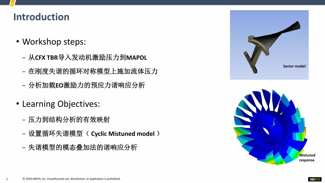
Introduction
• Workshop steps:
− 从CFX TBR导入发动机激励压力到MAPDL
− 在刚度失谐的循环对称模型上施加流体压力
− 分析加载EO激励力的预应力谐响应分析
• Learning Objectives:
− 压力到结构分析的有效映射
− 设置循环失谐模型( Cyclic Mistuned model )
− 失谐模型的模态叠加法的谐响应分析Mistuned response
Sector model

3 © 2020 ANSYS, Inc. Unauthorized use, distribution, or duplication is prohibited.3
Forced Response Analysis 受迫分析
• 确定由于相邻叶片排的激励而引起的叶片响应(运动和应力)。
• 激励发生在转子旋转频率的倍数处
• 必须确定激励(EO线)和模式频率之间的共振交叉点,并执行受迫响应分析
• 受迫响应-> 叶片疲劳,寿命分析
23 R 21 S
80%
X 1
X 2

4 © 2020 ANSYS, Inc. Unauthorized use, distribution, or duplication is prohibited.4
Forced Response of Cyclic Symmetric Model
• 循环模态叠加谐波(Cyclic Mode Superposition (MSUP) Harmonic )− 所有叶片假定是完全一致的 -> 对单个叶片建模
Reduced
mass
Excitation
frequency
Reduced
dampingReduced
stiffnessSingle sector engine
order forcing
Projection to modal
space and expansion
from cyclic domain
Transient R/S Pressure Signal

5 © 2020 ANSYS, Inc. Unauthorized use, distribution, or duplication is prohibited.5
Forced Response Analysis – Workflow MAPDL(在Workbench中采用插入命令的方式实现)
Mistuned blade stiffness
Tuned Blisk Mistuned Blisk
Nominal stiffness
Change

6 © 2020 ANSYS, Inc. Unauthorized use, distribution, or duplication is prohibited.6
Small Stiffness Mistuning in Cyclic MSUP analysis
• 循环模态叠加谐波(Cyclic Mode Superposition (MSUP) Harmonic )
− 采用调整后的响应加上每个叶片的失谐效应来做循环分析。
− 较小的失谐效应-叶片的刚度变化不应该超过10%
• 分析采用了应用CB方法的部件模态失谐理论(Component Mode Mistuning (CMM) )
Reduced
mass
Excitation
frequencyReduced
dampingReduced
stiffness
Single sector
engine order
forcing
Projection to
modal space and
expansion from
cyclic domain
Mistuning Aerodynamic
Damping

7 © 2020 ANSYS, Inc. Unauthorized use, distribution, or duplication is prohibited.77
Workshop Model Setup
Preprocessing and General Setup
Release 2019 R3
© 2020 ANSYS, Inc. Unauthorized use, distribution, or duplication is prohibited.

8 © 2020 ANSYS, Inc. Unauthorized use, distribution, or duplication is prohibited.8
Model workflow in Workbench (with APDL commands)
Prestress cyclic mode superposition harmonic analysis
Rotor Hub
Rotor blade

9 © 2020 ANSYS, Inc. Unauthorized use, distribution, or duplication is prohibited.9
Virtual Topology for Meshing
• 在轴和叶片表面创建虚拟拓扑(虚拟单元)Virtual Topology (virtual cells) ,以简化统一网格划分,如下所示。
Virtual cells merging the face splits in Mechanical

10 © 2020 ANSYS, Inc. Unauthorized use, distribution, or duplication is prohibited.10
Cylindrical Coordinate System for Cyclic Symmetry
• 定义该区域的循环对称性需要圆柱坐标系
• 如下所示创建了此坐标系(如右图所示):− 右键Coordinate System> Insert> Coordinate System
− Type of Coordinate System → Cylindrical
− Global Coordinates as the Origin of the system
11 © 2020 ANSYS, Inc. Unauthorized use, distribution, or duplication is prohibited.11
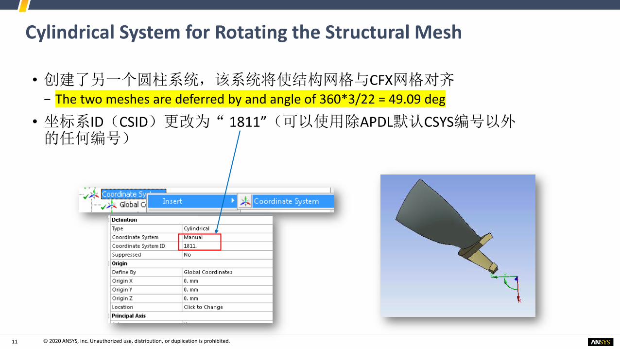
Cylindrical System for Rotating the Structural Mesh
• 创建了另一个圆柱系统,该系统将使结构网格与CFX网格对齐− The two meshes are deferred by and angle of 360*3/22 = 49.09 deg
• 坐标系ID(CSID)更改为“ 1811”(可以使用除APDL默认CSYS编号以外的任何编号)
12 © 2020 ANSYS, Inc. Unauthorized use, distribution, or duplication is prohibited.12
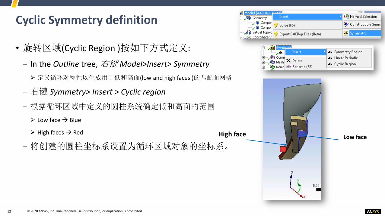
Cyclic Symmetry definition
• 旋转区域(Cyclic Region )按如下方式定义:
− In the Outline tree, 右键 Model>Insert> Symmetry
➢ 定义循环对称性以生成用于低和高面(low and high faces )的匹配面网格
− 右键 Symmetry> Insert > Cyclic region
− 根据循环区域中定义的圆柱系统确定低和高面的范围
➢ Low face → Blue
➢ High faces → Red
− 将创建的圆柱坐标系设置为循环区域对象的坐标系。Low faceHigh face

13 © 2020 ANSYS, Inc. Unauthorized use, distribution, or duplication is prohibited.13
Connection between Rotor Hub and Blade
• 转子叶片可以整体铸造/单晶材料/带有一些附加部件
• 作为模拟假设,叶片被认为与轴 bonded连接
• 接触设置如右图
• 接触算法:MPC

14 © 2020 ANSYS, Inc. Unauthorized use, distribution, or duplication is prohibited.14
Meshing of Geometry
• 网格控制− 叶片与轮毂网格对于压力数据的映射精度非常重要
− 网格设置如右图
• 全局网格设置− Adaptive Sizing设置为Yes,允许与默认控制参数和本地设置进行网格划分(在下一张幻灯片中讨论)

15 © 2020 ANSYS, Inc. Unauthorized use, distribution, or duplication is prohibited.15
Local Mesh Controls
• 轮毂扫略网格− 网格方法选择扫略(Sweep)➢ 均匀的扫略网格
− 手动选择Src/Trg 面
− 其余设置选择默认
• Edge Sizing线尺寸− 扫略方向上的边选择分为6(6 divisions)
Sweep Method
Edge sizing to control sweep division

16 © 2020 ANSYS, Inc. Unauthorized use, distribution, or duplication is prohibited.16
Local Mesh controls
• Sweep method for Blade − Observe the Sweep for the blade with 5 mm
element size as shown to right
• Edge sizing for Blade tip edge− Tip edges are divided in 18 segments for
proper sizing of the blade mesh
• Face Meshing for blade tip face:
− A mapped face meshing is defined

17 © 2020 ANSYS, Inc. Unauthorized use, distribution, or duplication is prohibited.17
Local Mesh controls
• Edge sizing of Blade tip short edges:− Divided in 2 segments
• Edge sizing for hub edges:− Divided in multiple segments as shown
below

18 © 2020 ANSYS, Inc. Unauthorized use, distribution, or duplication is prohibited.18
Named Selection for Pressure Mapping Surfaces
• 创建叶片5个面的Named Selection − 命名为“pressure_faces”
− 创建表面单元,在APDL命令中施加来自CFX TBR分析的压力载荷
Tip face (1)
Front and back faces (2)
Leading and rear faces (2)

19 © 2020 ANSYS, Inc. Unauthorized use, distribution, or duplication is prohibited.19
Named Selection of Blade Elements
• 创建叶片体的Named Selection− 命名为 “BladeElem”➢ 该 Named Selection 中的体单元可在APDL中被调用
▪ 这将用于失谐定于的叶片子结构

20 © 2020 ANSYS, Inc. Unauthorized use, distribution, or duplication is prohibited.20
Named Selection of Blade-hub Interface Nodes
• 叶片和hub连接面创建 Named Selection− 命名为 “InterfaceNodes”➢ 这些点将在APDL中被调用
▪ 这些节点将用于失谐定义时主节点的定义。
21 © 2020 ANSYS, Inc. Unauthorized use, distribution, or duplication is prohibited.21
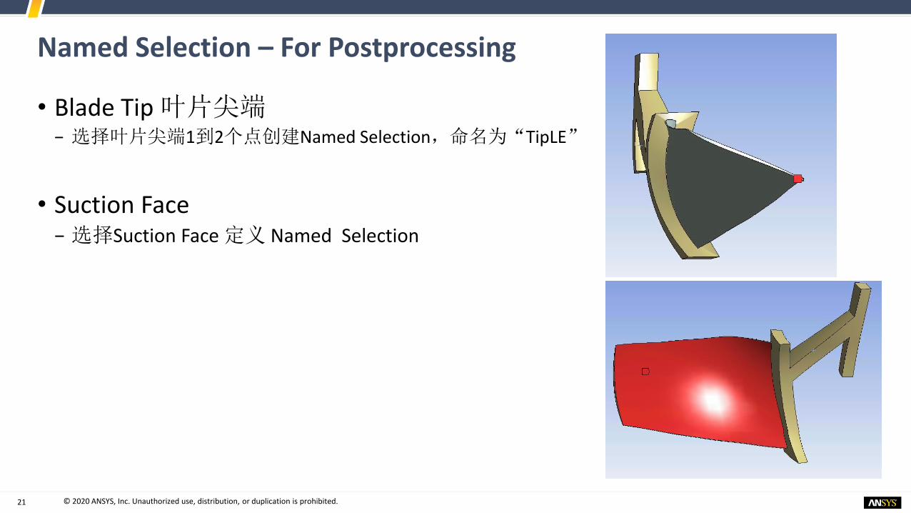
Named Selection – For Postprocessing
• Blade Tip 叶片尖端− 选择叶片尖端1到2个点创建Named Selection,命名为“TipLE”
• Suction Face − 选择Suction Face 定义 Named Selection

22 © 2020 ANSYS, Inc. Unauthorized use, distribution, or duplication is prohibited.2222
Analysis Setup
General Guidelines
Release 2019 R3
© 2020 ANSYS, Inc. Unauthorized use, distribution, or duplication is prohibited.

23 © 2020 ANSYS, Inc. Unauthorized use, distribution, or duplication is prohibited.23
Analysis Setup
− 预应力模态叠加谐响应受迫分析包括如下项目:
➢ 旋转速度载荷下非线性稳态分析( Nonlinear Static analysis with rotational velocity
load )
➢ 模态分析( Modal analysis as the base of the harmonic analysis )
➢ 谐响应分析(Cyclic MSUP Harmonic analysis )

24 © 2020 ANSYS, Inc. Unauthorized use, distribution, or duplication is prohibited.24
Determination of Excitation
• Note the harmonic excitation freq. for harmonic sweep
• Excitation freq. = 1679 rad/s*EO (2)/2π = 534 Hz
• But for resonance condition SAFE diagram will be referred later on.
• 2阶激励来自于CFX TBR分析
• 压力文件(csv file)的片段如下:

25 © 2020 ANSYS, Inc. Unauthorized use, distribution, or duplication is prohibited.2525
Analysis Setup
Static Structural Analysis-Prestressing
Release 2019 R3
© 2020 ANSYS, Inc. Unauthorized use, distribution, or duplication is prohibited.

26 © 2020 ANSYS, Inc. Unauthorized use, distribution, or duplication is prohibited.26
Static Analysis – Prestressing (Rotational velocity)
• 施加转速载荷
• Static Structural 右键>Insert>Rotational velocity
• In the Details of “Rotational Velocity” 具体设置如下
Properly orient the Rotational velocity vector as needed

27 © 2020 ANSYS, Inc. Unauthorized use, distribution, or duplication is prohibited.27
Applying Boundary Condition Fixed Support
• 施加Fixed边界条件至 hub底面

28 © 2020 ANSYS, Inc. Unauthorized use, distribution, or duplication is prohibited.28
Analysis Settings - Static
• Static Structural Analysis分析设置
• Large Deflection = OFF 关闭大变形
• 只会产生应力强化作用

29 © 2020 ANSYS, Inc. Unauthorized use, distribution, or duplication is prohibited.29
Mapping of CFD pressure to Structural Mesh
• 设置单位为:m,kg,N,S
• 使用新的APDL / MAP模块在静态结构分析中映射CFD压力,并写出映射文件
• But structural pressure loads are not applied in Static analysis但是结构压力载荷不适用于静力分析
30 © 2020 ANSYS, Inc. Unauthorized use, distribution, or duplication is prohibited.30
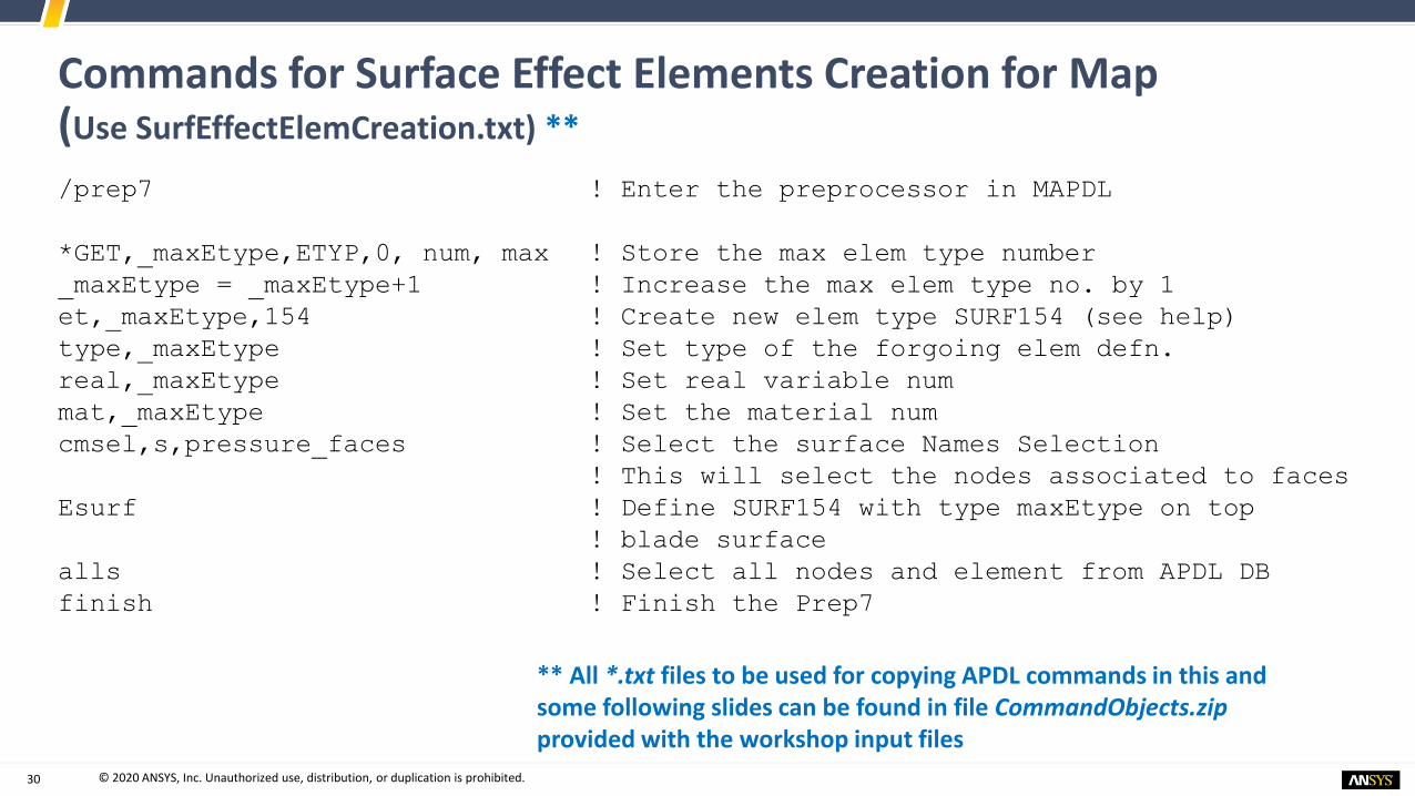
Commands for Surface Effect Elements Creation for Map(Use SurfEffectElemCreation.txt) **
/prep7 ! Enter the preprocessor in MAPDL
*GET,_maxEtype,ETYP,0, num, max ! Store the max elem type number
_maxEtype = _maxEtype+1 ! Increase the max elem type no. by 1
et,_maxEtype,154 ! Create new elem type SURF154 (see help)
type,_maxEtype ! Set type of the forgoing elem defn.
real,_maxEtype ! Set real variable num
mat,_maxEtype ! Set the material num
cmsel,s,pressure_faces ! Select the surface Names Selection
! This will select the nodes associated to faces
Esurf ! Define SURF154 with type maxEtype on top
! blade surface
alls ! Select all nodes and element from APDL DB
finish ! Finish the Prep7
** All *.txt files to be used for copying APDL commands in this and some following slides can be found in file CommandObjects.zipprovided with the workshop input files

31 © 2020 ANSYS, Inc. Unauthorized use, distribution, or duplication is prohibited.31
Commands for Mapping (Use Mapping.txt)
/map ! Enter the /MAP module (writes out a BeforeMapping.db)
! Write a separate Mapping.db file in work directory
target,pressure_faces ! Use the NS (nodes) pressure_faces as target nodes
ftype,cfxtbr ! Type of pressure file to be mapped (CFX TBR analysis)
read, ‘%_wb_userfiles_dir(1)%P_EO2.csv’ !read file
csys,1811 ! A cylindrical coord. Sys (1811) is created to rotate
the nodes so that source mesh and target mesh is aligned
ngen,2,0,all,,, 0,360*3/22 ! Rotate all FE nodes by sectors for correct alignment
(necessary on for this model as the structural mesh and
CFD mesh is not aligned correctly)
/show,png ! Create png files for the fore coming plotting commands
Plgeom ! Plot the geometry after rotation in png file
map,,2,,1, ! MAP command to map 2D surface interpolation (linear)
plmap,target ! Plot the mapped target pressure (real part)
plmap,target,,,1 ! Plot the mapped target pressre (imag part)
/show,close ! Close the png mode
! Write mapped pressure file in SFE commands format for structural mesh
writemap,’%_wb_userfiles_dir(1)%P_EO2.dat’
Finish ! Exit the /MAP module (resume BeforeMapping.DB)
32 © 2020 ANSYS, Inc. Unauthorized use, distribution, or duplication is prohibited.32
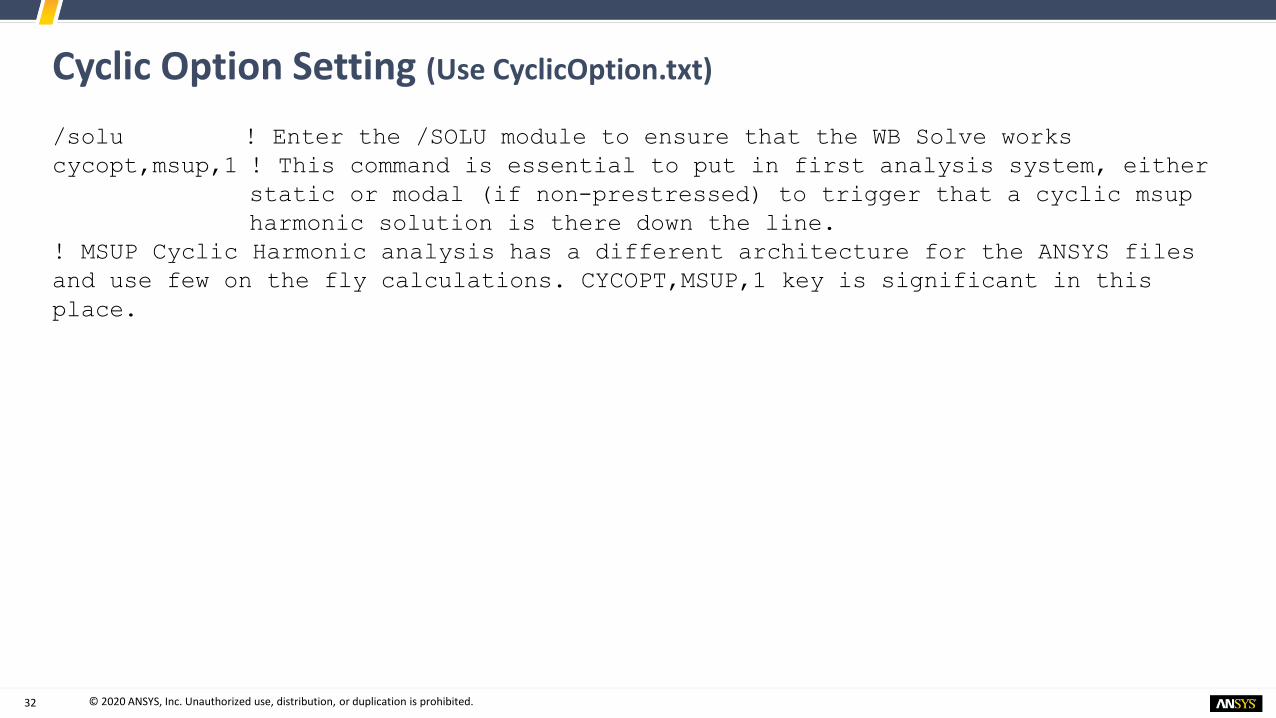
Cyclic Option Setting (Use CyclicOption.txt)
/solu ! Enter the /SOLU module to ensure that the WB Solve works
cycopt,msup,1 ! This command is essential to put in first analysis system, either
static or modal (if non-prestressed) to trigger that a cyclic msup
harmonic solution is there down the line.
! MSUP Cyclic Harmonic analysis has a different architecture for the ANSYS files
and use few on the fly calculations. CYCOPT,MSUP,1 key is significant in this
place.

33 © 2020 ANSYS, Inc. Unauthorized use, distribution, or duplication is prohibited.3333
Part 1: Analyze the Tuned system
Aeromechanics of TurbomachineryBladesRelease 2019 R3
© 2020 ANSYS, Inc. Unauthorized use, distribution, or duplication is prohibited.

34 © 2020 ANSYS, Inc. Unauthorized use, distribution, or duplication is prohibited.3434
Analysis Setup
Prestressed Modal Analysis - Cyclic
Release 2019 R3
© 2020 ANSYS, Inc. Unauthorized use, distribution, or duplication is prohibited.

35 © 2020 ANSYS, Inc. Unauthorized use, distribution, or duplication is prohibited.35
Prestressed Modal Analysis
• 当将“静力分析系统解”链接到“模态分析设置”时,模态解决方案将基于静态分析的变形状态(NLGEOM = ON),并且预应力效果会继续有效
Extracted modes up to 3200 Hz. which is more that 1.5 times the harmonic freq. Sweep around 534 Hz
It is important to extract all Harmonic Indices (HI or nodal diameter) for all the mistuned harmonic analysis. For Tuned system only HI = EO is sufficient; HI = 2 Here

36 © 2020 ANSYS, Inc. Unauthorized use, distribution, or duplication is prohibited.36
Extra Commands for Modal analysis (use ZeroRotVel.txt)
cgomega,0,0,0 ! To zero out the applied rotational velocity effect in Modal
analysis

37 © 2020 ANSYS, Inc. Unauthorized use, distribution, or duplication is prohibited.37
/post1 ! Enter /SOLU module
! Copy the RSTP file to file.rst in user files (RSTP is the results file
extension after Linear perturbation prestressed modal)
/COPY,file.rst,,,’%_wb_userfiles_dir(1)%file.rstp’
file,,rst ! Open file.rst in APDL
/show,png,rev ! Save plots in in png format from APDL
/yrange,0,3000, ! Set the Y range for the next plotting to 0-3000 Hz.
plzz,16043 ! Plots the speed lines (16043 RPM) in interference diagram
/show,close
fini
Post commands in Modal Analysis (Use PostModal_Tuned.txt)
• 利用如下APDL命令在Workbench中插入Command

38 © 2020 ANSYS, Inc. Unauthorized use, distribution, or duplication is prohibited.3838
Results
Static & Modal AnalysisGuidelines for Harmonic Setup
Release 2019 R3
© 2020 ANSYS, Inc. Unauthorized use, distribution, or duplication is prohibited.

39 © 2020 ANSYS, Inc. Unauthorized use, distribution, or duplication is prohibited.39
Results - Static Analysis • After Solving Static Structural, RMB Solution
− Insert>Deformation>Total
− Insert>Deformation>Directional ➢ Use Cylindrical system 2 and Set Orientation to X Axis (radial deformation)
Total deformationRadial displacement

40 © 2020 ANSYS, Inc. Unauthorized use, distribution, or duplication is prohibited.40
Pressure Mapping Results
• RMB Solution>Open Solver Files Directory
• PNG files can be seen, showing Source/Target nodes, Target Real and Imag mapped pressure plot as shown to the right
PLGEOM command

41 © 2020 ANSYS, Inc. Unauthorized use, distribution, or duplication is prohibited.41
Results – Modal Analysis
• Click on Solution to check the table of frequencies over all possible Harmonic Indices.
For 11 harmonic indices every set containing frequencies up to 3200 Hz
RMB to create mode shape of requested freq.
Resonance point discussed in the next slide

42 © 2020 ANSYS, Inc. Unauthorized use, distribution, or duplication is prohibited.42
Interference Diagram (SAFE Diagram)
PLZZ command (16043 RPM)
Speed lineω (Hz) = ND (HI)*Ω (rpm)/60
One possible location of resonance near 508 Hz
Note: Campbell diagram does not always guarantee the true resonance. Campbell diagram suggest that resonance will occur wheneverthe natural freq. of blisk matches the excitation freq. But due to cyclic nature of the structure, mode shape may not match the Engine Order excitation shape coming out of the nozzles for the Campbell diagram suggested critical speed. Hence SAFE or Interference diagram which relate the mode shapes with speed and natural freq. will predict the true resonance and used by industries for reliable design.

43 © 2020 ANSYS, Inc. Unauthorized use, distribution, or duplication is prohibited.4343
Cyclic MSUP Harmonic AnalysisTuned Forced Response Analysis
Forcing Function, Solution , Postprocessing
Release 2019 R3
© 2020 ANSYS, Inc. Unauthorized use, distribution, or duplication is prohibited.

44 © 2020 ANSYS, Inc. Unauthorized use, distribution, or duplication is prohibited.44
Forcing Function in Harmonic Analysis
• 对于(tuned blade analysis )调整后的叶片分析(所有叶片彼此相
同),仅第二谐波指数或节径的模式足以扩展谐波分析,以下公式是针对第n个叶片的以下力函数:
其中, 相位滞后角度:
N = 转子上叶片数量
• 调整后叶片的自然频率有着不同的节径
• 使用以下设置(如右图所示),可以为周期模型获得固有频率
𝐅𝑛 = 𝐅𝑒 ሻ𝑖𝜙(𝑛−1
𝜙 =2𝜋 ∗ 𝐸𝑂
𝑁

45 © 2020 ANSYS, Inc. Unauthorized use, distribution, or duplication is prohibited.45
Deactivation of the RST File Check by Workbench停止RST文件检查
• From within Mechanical:
• Files>Variable Manager
• Add the variable ‘skip resultfile check‘ = 1− Check the box to activate this Variable

46 © 2020 ANSYS, Inc. Unauthorized use, distribution, or duplication is prohibited.46
Cyclic Mode Superposition (MSUP) Harmonic Analysis –Setup (Use ApplyCFXPres_Tuned.txt)
• 通过下列APDL命令行施加CFX 映射压力
• 在“谐波分析”的“模态”分支中插入的以下命令允许在模态重新启动之前创建模型并创建模态载荷矢量。
sfedel,all,all,pres ! Delete all pressure load from DB (if anything is there)
fdele,all,all ! Delete all nodal load
cgomga,,0,0,0 ! Zero any rotational acceleration (sanity check)
! Input the SFE file written in Static analysis
/INPUT, '%_wb_userfiles_dir(1)%P_EO2',dat
allsel
Solve ! This solve will create the modal load vector to be used in msup (modal
restart)

47 © 2020 ANSYS, Inc. Unauthorized use, distribution, or duplication is prohibited.47
Analysis Settings – Harmonic
• 保留频率间隔的默认设置
• 在频率范围约为508 Hz(如上一张幻灯片所示),如右图所示设置值
• 设置Solution Interval = 200以捕获共振条件
• 分析数据管理中设置 ‘Save MAPDL DB = Yes’
• 瑞利阻尼比可用于谐波分析
• 也可以使用DMPSTR命令使用结构阻尼

48 © 2020 ANSYS, Inc. Unauthorized use, distribution, or duplication is prohibited.48
Necessary APDL Command for Harmonic forcing (Use HarmForcing.txt)
outres,all,all ! Write all results (can be limited users choice)
hrout,on ! Print harmonic displacement in real-imag format
cycfreq,eo,2 ! Engine order of excitation = 2
lvscale,1,1 ! Apply the cfx pressure load vector created in modal restart
kbc,1 ! Use stepped loading (no ramping)
dmpstr,.001 ! Use structural damping ratio = 0.001
• 利用如下APDL命令施加CFX压力

49 © 2020 ANSYS, Inc. Unauthorized use, distribution, or duplication is prohibited.49
Cyclic MSUP Harmonic Postprocessing – APDL (Use PostHarmo1.txt)
• 插入如下APDL命令在后处理中:
Resume,file,db
/copy,file,rfrq,,’%_wb_userfiles_dir(1)%file’,rfrq ! Copy the rfrq file to userfiles
/post1 ! Enter general post processing
! CYCFILES process modal rstp (result) and harmonic rfrq file to process the responses
on the fly. No RST from Harmonic analysis
cycfiles,’%_wb_userfiles_dir(1)%file’,rstp,’%_wb_userfiles_dir(1)%file’,rfrq
rsys,1811 !view the results in cylindrical system
mystep = 77 ! Substep number for results
set,1,mystep ! Set substep = 77 for processing freq = 503.7
/show,png,rev
/xrange,0,100 ! Set the X axis range for next plots
plmc,1,mystep,, ! Plot the modal coordinates from MSUP (Real)
plmc,1,mystep,,1, ! Plot the modal coordinates from MSUP (Imag)
/show,close
50 © 2020 ANSYS, Inc. Unauthorized use, distribution, or duplication is prohibited.50
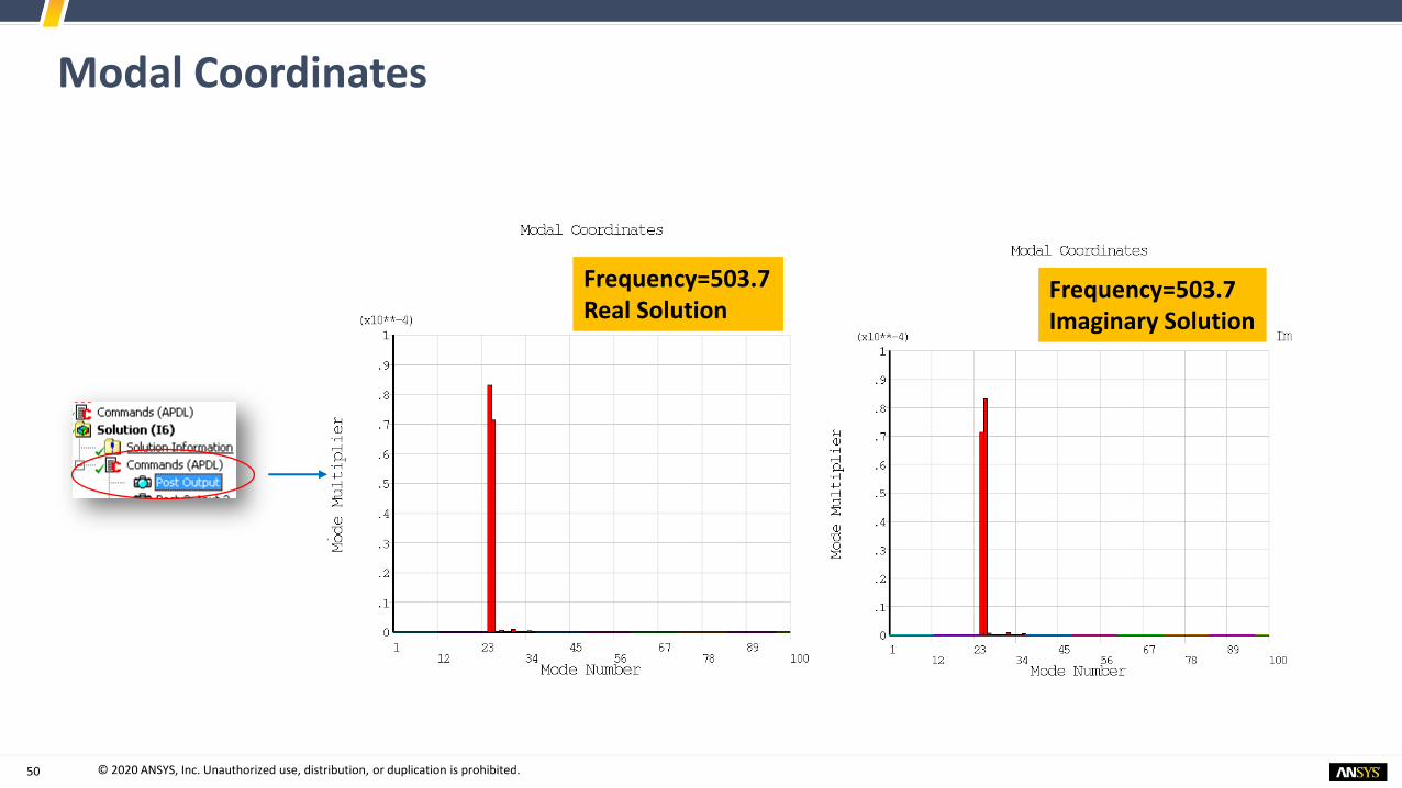
Modal Coordinates
Frequency=503.7Real Solution
Frequency=503.7 Imaginary Solution

51 © 2020 ANSYS, Inc. Unauthorized use, distribution, or duplication is prohibited.51
Plot of Response Quantities (Use PostHarmo2.txt)
/xrange,default
avprin,,0.3 ! Use poisson’s ratio = 0.3 for Eqv strain calculation
/cycexpand,,on ! Expand for full 360 model
/show,png,rev
esel,s,ename,,186 ! Select the solid elements only (no surf elem)
nsle,s,1
set,1,mystep,,0 ! Process real part :: 1 for Imaginary parts
/view,1,1,1,2
plns,u,z ! Plot UZ
plns,u,sum ! Plot USUM
plns,epel,1 ! Plot e1
plns,s,1 ! Plot S1
/view,1,0,0,1 ! Plot from different view
plns,u,sum
plns,epel,1
plns,s,1

52 © 2020 ANSYS, Inc. Unauthorized use, distribution, or duplication is prohibited.52
Example of Plots (After Harmonic Solve)
USUM (Real)
EPEL1 (Real)S1 (Real)
UZ (axial) (Real)

53 © 2020 ANSYS, Inc. Unauthorized use, distribution, or duplication is prohibited.53
Maximum Responses - Phase sweep over 360 deg (Use PostHarmo3.txt)
/cycexpand,,phaseang,360 ! Plots the amplitude of responses from Real and Imag
set,1,mystep,
/view,1,1,1,2
plns,u,z
plns,u,sum
/view,1,0,0,1
plns,u,sum
plns,u,z
/cycexpand,,phaseang,360! Plots the maximum quantities on each node after phase
sweep
set,1,mystep,
/view,1,1,1,2
plns,u,z
plns,u,sum
/view,1,0,0,1
plns,u,sum
plns,u,z

54 © 2020 ANSYS, Inc. Unauthorized use, distribution, or duplication is prohibited.54
Example of Max Plots

55 © 2020 ANSYS, Inc. Unauthorized use, distribution, or duplication is prohibited.55
Response of Tip of the Blade – APDL Commands (Use PostHarmo4.txt)
cmsel,s,TipLE ! Select the component
myid = ndnext(0) ! Store the node number in myid
alls
set,1,mystep ! Select freq. 503.7 Hz
cycspec,,SuctionFace,s,1 ! Specifies the cyclic calc nodes for suction face stress
cycspec,,myid,u,z ! Specify Cyclic calc for UZ of the suctionFace
cyccalc,R67s1,csv ! Calc quantities given in CYCSPEC and write in R67s1.csv for
all sectors
plcfreq,2,1,10 ! Plot the UZ of tip for 1-10 sector (max amplitude over phase)
plcfreq,2,11,20 ! From 11-20 sector
plcfreq,2,21,22 ! From 21-22 sector
plchist,2,mystep ! Histogram plot of tip UZ

56 © 2020 ANSYS, Inc. Unauthorized use, distribution, or duplication is prohibited.56
Sample Plots
CYCCALC UZ for Tip node(R67s1_Node1122_UZ.csv)
CYCCALC S1 for Suction face(R67s1_SUCTIONFACE_S1.csv)
Maximum stress for given set of nodes in SuctionFace

57 © 2020 ANSYS, Inc. Unauthorized use, distribution, or duplication is prohibited.57
Sample Plots (Contd.)
PLCFREQ for Tip node UZ for 1-10 Sector
PLCHIST for Tip node UZ for 1-10 Sector

58 © 2020 ANSYS, Inc. Unauthorized use, distribution, or duplication is prohibited.5858
Part 2: Including Mistuning
Aeromechanics of Turbomachinery Blades
Release 2019 R3
© 2020 ANSYS, Inc. Unauthorized use, distribution, or duplication is prohibited.

59 © 2020 ANSYS, Inc. Unauthorized use, distribution, or duplication is prohibited.5959
Analysis Setup
Prestressed Modal Analysis - Cyclic
Release 2019 R3
© 2020 ANSYS, Inc. Unauthorized use, distribution, or duplication is prohibited.

60 © 2020 ANSYS, Inc. Unauthorized use, distribution, or duplication is prohibited.60
Prestressed Modal Analysis
• 当将“静力分析系统解”链接到“模态分析设置”时,模态解决方案将基于静态分析的变形状态(NLGEOM = ON),并且预应力效果会继续有效
Extracted modes up to 3200 Hz. which is more that 1.5 times the harmonic freq. Sweep around 534 Hz
It is important to extract all Harmonic Indices (HI or nodal diameter) for all the mistuned harmonic analysis. If HI =2 for Tuned system, switch back to Program Controlled

61 © 2020 ANSYS, Inc. Unauthorized use, distribution, or duplication is prohibited.61
• Change from PostModal_Tuned.txt to PostModal_Mistuned.txt or paste the below commands at the beginning of the existing command object as file.r001, file.rdb and file.ldhi are required for mistuning
• At this point solve the Prestressed modal analysis before setting up Harmonic Analysis (because harmonic analysis inputs will come from here)
*DO,I,0,999
/INQUIRE,temp,EXIST,file%I%.r001
*IF,temp,EQ,1,THEN
/COPY,file%I%.r001,,,’%_wb_userfiles_dir(1)%file%I%.r001’
*ENDIF
*ENDDO
/COPY,file.rdb,,,’%_wb_userfiles_dir(1)%file.rdb’
/COPY,file.ldhi,,,’%_wb_userfiles_dir(1)%file.ldhi’
Post commands in Modal Analysis (Use PostModal_Mistuned.txt)

62 © 2020 ANSYS, Inc. Unauthorized use, distribution, or duplication is prohibited.6262
Cyclic MSUP Harmonic AnalysisMistuned Forced Response Analysis
Forcing Function, Mistuning, Solution Postprocessing
Release 2019 R3
© 2020 ANSYS, Inc. Unauthorized use, distribution, or duplication is prohibited.
63 © 2020 ANSYS, Inc. Unauthorized use, distribution, or duplication is prohibited.63
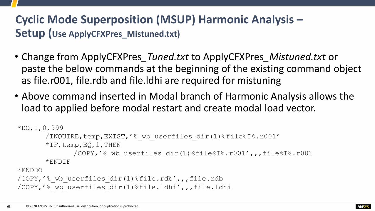
Cyclic Mode Superposition (MSUP) Harmonic Analysis –Setup (Use ApplyCFXPres_Mistuned.txt)
• Change from ApplyCFXPres_Tuned.txt to ApplyCFXPres_Mistuned.txt or paste the below commands at the beginning of the existing command object as file.r001, file.rdb and file.ldhi are required for mistuning
• Above command inserted in Modal branch of Harmonic Analysis allows the load to applied before modal restart and create modal load vector.
*DO,I,0,999
/INQUIRE,temp,EXIST,’%_wb_userfiles_dir(1)%file%I%.r001’
*IF,temp,EQ,1,THEN
/COPY,’%_wb_userfiles_dir(1)%file%I%.r001’,,,file%I%.r001
*ENDIF
*ENDDO
/COPY,’%_wb_userfiles_dir(1)%file.rdb’,,,file.rdb
/COPY,’%_wb_userfiles_dir(1)%file.ldhi’,,,file.ldhi

64 © 2020 ANSYS, Inc. Unauthorized use, distribution, or duplication is prohibited.64
Small Stiffness Mistuning Definition (Use Mistuning.txt)
!Mistuning commands
*dim,kmist,array,22,1 ! Stiffness deviation array
kmist(1,1) = 0.01,-0.02,0.01,0.04,-0.03,-0.01,-0.02,0.04,0.05
kmist(10,1) = -0.03,-0.02,0.03,-0.04,-0.01,-0.04,0.02,-0.03,0.01,
kmist(19,1) = -0.05,-0.03,0.01,0.01
! For mistuning definition blade root nodes are used as master dofs and blade
elements are substructure
cycfreq,blade,InterfaceNodes,BladeElem,6 ! Pass the interface node and blade
elements for internal substructuring
cycfreq,mist,k,kmist ! Pass the mistuning array

65 © 2020 ANSYS, Inc. Unauthorized use, distribution, or duplication is prohibited.65
Cyclic MSUP Harmonic Postprocessing – APDL (Use PostHarmo1.txt)
• RMB>Solution (Harmonic) > Insert> Commands – to add a post command object for APDL snapshots of harmonic results
• Paste the following commands.Resume,file,db
/copy,file,rfrq,,’%_wb_userfiles_dir(1)%file’,rfrq ! Copy the rfrq file to
userfiles
/post1 ! Enter general post processing
! CYCFILES process modal rstp (result) and harmonic rfrq file to process the
responses on the fly. No RST from Harmonic analysis
cycfiles,’%_wb_userfiles_dir(1)%file’,rstp,’%_wb_userfiles_dir(1)%file’,rfrq
rsys,1811 !view the results in cylindrical system
mystep = 77 ! Substep number for results
set,1,mystep ! Set substep = 77 for processing freq = 503.7
/show,png,rev
/xrange,0,100 ! Set the X axis range for next plots
plmc,1,mystep,, ! Plot the modal coordinates from MSUP (Real)
plmc,1,mystep,,1, ! Plot the modal coordinates from MSUP (Imag)
/show,close

66 © 2020 ANSYS, Inc. Unauthorized use, distribution, or duplication is prohibited.66
Modal Coordinates
Frequency=503.7Real Solution
Frequency=503.7 Imaginary Solution

67 © 2020 ANSYS, Inc. Unauthorized use, distribution, or duplication is prohibited.67
Plot of Response Quantities (Use PostHarmo2.txt)
/xrange,default
avprin,,0.3 ! Use poissons ratio = 0.3 for Eqv strain calculation
/cycexpand,,on ! Expand for full 360 model
/show,png,rev
esel,s,ename,,186 ! Select the solid elements only (no surf elem)
nsle,s,1
set,1,mystep,,0 ! Process real part :: 1 for Imaginary parts
/view,1,1,1,2
plns,u,z ! Plot UZ
plns,u,sum ! Plot USUM
plns,epel,1 ! Plot e1
plns,s,1 ! Plot S1
/view,1,0,0,1 ! Plot from different view
plns,u,sum
plns,epel,1
plns,s,1
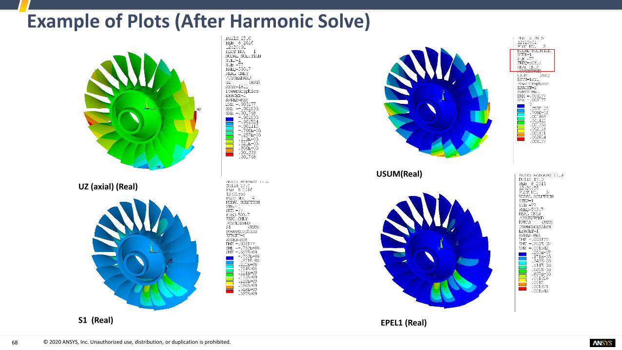
68 © 2020 ANSYS, Inc. Unauthorized use, distribution, or duplication is prohibited.68
Example of Plots (After Harmonic Solve)
USUM(Real)
EPEL1 (Real)S1 (Real)
UZ (axial) (Real)

69 © 2020 ANSYS, Inc. Unauthorized use, distribution, or duplication is prohibited.69
Maximum Responses - Phase sweep over 360 deg (Use PostHarmo3.txt)
/cycexpand,,phaseang,360 ! Plots the amplitude of responses from Real and Imag
set,1,mystep,
/view,1,1,1,2
plns,u,z
plns,u,sum
/view,1,0,0,1
plns,u,sum
plns,u,z
/cycexpand,,phaseang,360! Plots the maximum quantities on each node after phase
sweep
set,1,mystep,
/view,1,1,1,2
plns,u,z
plns,u,sum
/view,1,0,0,1
plns,u,sum
plns,u,z

70 © 2020 ANSYS, Inc. Unauthorized use, distribution, or duplication is prohibited.70
Example of Max Plots

71 © 2020 ANSYS, Inc. Unauthorized use, distribution, or duplication is prohibited.71
Response of Tip of the Blade – APDL Commands (Use PostHarmo4.txt)
cmsel,s,TipLE ! Select the component
myid = ndnext(0) ! Store the node number in myid
alls
set,1,mystep ! Select freq. 503.7 Hz
cycspec,,SuctionFace,s,1 ! Specifies the cyclic calc nodes for suction face stress
cycspec,,myid,u,z ! Specify Cyclic calc for UZ of the suctionFace
cyccalc,R67s1,csv ! Calc quantities given in CYCSPEC and write in R67s1.csv for
all sectors
plcfreq,2,1,10 ! Plot the UZ of tip for 1-10 sector (max amplitude over phase)
plcfreq,2,11,20 ! From 11-20 sector
plcfreq,2,21,22 ! From 21-22 sector
plchist,2,mystep ! Histogram plot of tip UZ

72 © 2020 ANSYS, Inc. Unauthorized use, distribution, or duplication is prohibited.72
Sample Plots
CYCCALC UZ for Tip node(R67s1_Node1122_UZ.csv)
CYCCALC S1 for Suction face(R67s1_SUCTIONFACE_S1.csv)
Maximum stress for given set of nodes in SuctionFace
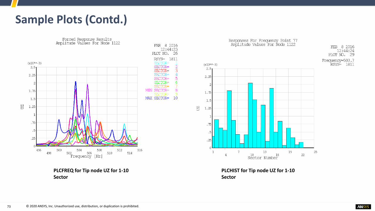
73 © 2020 ANSYS, Inc. Unauthorized use, distribution, or duplication is prohibited.73
Sample Plots (Contd.)
PLCFREQ for Tip node UZ for 1-10 Sector
PLCHIST for Tip node UZ for 1-10 Sector