
Follow us - ScienceServices.de
88
-
Upload
khangminh22 -
Category
Documents
-
view
3 -
download
0
Transcript of Follow us - ScienceServices.de


Our new academy is now open! Located minutes from Philadelphia, next to ourextensive warehouse in Hatfield, PA, we havemany offerings led by our certified faculty:• Ten Educational Workshops• Corporate Training• Group Training• Private Training• Equipment Demonstrations
Watch for our latest updated schedule!Plan to sign up and bring your career to the next level!
NEWEST WORKSHOPS:Aurion ImmunoGold Silver StainingAutomated Rapid ProcessingBiological SEMBiological TEMCryosectioning/ImmunogoldIntroduction to Microscopy Techniques Cryo SEMMaterials UltramicrotomyX-Ray Microanalysis
Electron Microscopy Sciences • 1560 Industry Road, Hatfield, PA 19440 • phone: 215-412-8400 • email: [email protected]
SIGN UP FOR A CLASS TODAY, OR SUGGEST A COURSE THAT YOU WANT...
...ENDLESS POSSIBILITIES
www.emsmicroscopyacademy.comP.O. Box 550 • 1560 Industry Rd.Hatfield, PA 19440Tel: (215) 412-8400Fax: (215) 412-8450email: [email protected]
www.emsdiasum.com
At Electron MicroscopySciences, we love sharingour knowledge andexperience with ourcustomers. And with socialmedia, there are even moreways to reach out. But wealso love hearing from YOU!Either way, there’s plenty tosee, share, and enjoy...• Trade Show Information• New Product
Announcements• News, Polls, & Contests• Technical Notes
from Stacie• Networking with fellow
researchers• Instructional Video• ...and lots more
We hope to see youthere!
Follow us on Social Media...
EMS_EquipmentCat2019_OBC_OFC_Layout 1 11/5/18 11:11 AM Page 3

1
PAGE NO.
COOLING STAGES .........................................................................2–3zzz THE EMS COOLSTAGE FOR SEM, LV OR VP...2-3
RECIRCULATING HEATERS AND CHILLERS .................................4zzzz EMS 4800 RECIRCULATING HEATER/CHILLERS...4
GLOW DISCHARGE SYSTEMS .....................................................5–7zzz EMS GLOQUBE™ GLOW DISCHARGE SYSTEM FOR TEM AND SURFACEMODIFICATION...5-7
SPUTTER COATERS, SEM/TEM CARBON COATERS ...........8–33zzz TECHNIQUES AND APPLICATIONS: SPUTTER COATING...8-13 zzz EMS 7620 “MINI” SPUTTER COATER/GLOW DISCHARGE...14-15zzz EMS 7620-CF CARBON ACCESSORY POWER SUPPLIES...15 zzz TECHNIQUES AND APPLICATIONS: CARBON COATING...16-17 zzz EMS 150R PLUS ROTARY PUMPED COATER ...18-21 zzz EMS 150T PLUS TURBOMOLECULAR PUMPED COATER...22–25 zzz EMS 150V PLUS AUTOMATIC COATER...26-29 zzz EMS150GB TURBO-PUMPED SPUTTER COATER/CARBON COATER — FOR GLOVE BOX...30–33
LARGE CHAMBER SPUTTER COATERS .................................34–51zzz EMS 300R T TRIPLE TARGET, LARGE CHAMBER, ROTARY-PUMPEDSPUTTER COATER...34–37 zzz EMS 300T T PLUS TRIPLE TARGET, LARGECHAMBER, TURBO-PUMPED SPUTTER COATER...38–41 zzz EMS 300T ESLARGE CHAMBER TURBO-PUMPED EVAPORATOR/SPUTTERCOATER...42–45 zzz EMS 975 LARGE CHAMBER TURBO EVAPORATOR & EMS 975S FOR SEMICONDUCTOR WAFER COATING...46–47 zzz EMS 300T D PLUS DUAL TARGET SEQUENTIAL SPUTTERING SYSTEM...48–51
FREEZE DRYERS .........................................................................52–55zzz TECHNIQUES AND APPLICATIONS: FREEZE DRYING...52-53 zzz EMS 750 FREEZE DRYER...54 zzz EMS 775 FREEZE DRYER...55
CRITICAL POINT DRYERS ........................................................56–63zzz TECHNIQUES AND APPLICATIONS: CRITICAL POINT DRYING...56-59 zzz EMS 3100 CRITICAL POINT DRYERS...60–61 zzz EMS 850 CRITICALPOINT DRYER WITH THERMOELECTRONIC HEATING AND ADIABATICCOOLING...62 zzz EMS 850WM LARGE CHAMBER CRITICAL POINT DRYER...63
PLASMA ASHERS .......................................................................64–71zzz TECHNIQUES AND APPLICATIONS: PLASMA ASHING...64-69 zzz EMS 1050 PLASMA ASHER...70–71
CRYO-SEM PREPARATION SYSTEMS ...................................72–77zzz TECHNIQUES AND APPLICATIONS: CRYO-SEM...72-73 zzz PP3010T CRYO-SEM/CRYO-FIB/SEM PREPARATION SYSTEM...74–77
SPECIMEN TRANSFER SYSTEMS............................................78–82zzz PP3004 QUICKLOK, PP3005 SEMCOOL, & PP3006 COOLLOK...78–82
REPLACEMENT PARTS .............................................................83–84zzz CARBON STRING, CARBON CORD...83 zzz SPUTTER TARGETS...83zzz SPECIMEN STAGE SELECTION GUIDE...84
P.O. Box 550 • 1560 Industry Rd.Hatfield, PA 19440Tel: (215) 412-8400Fax: (215) 412-8450email: [email protected]
EDITION III
TABLE OF CONTENTS NEW PRODUCTS...
NEW! EMS Plus SeriesSputter Coaters/Carbon CoatersTo offer improved ultra-fine coatingwe have introduced the NEWEMS150V Plus, which offers anultimate vacuum of 1 x 10⁻⁶mbar forsuperior results. Large chambersputter coaters are also availablefor specimens up to 200mm indiameter. Most coaters can also beconfigured for carbon evaporationusing easy-change carbon rod andcarbon fiber inserts.
See pages 18–29, 38–41, 48–51.
EQUIPMENT & ACCESSORIES CATALOG
EMS_EquipmentCat2019_01_EMS_Catalog 2018 Edition 11/2/18 4:10 PM Page 1

EQUIPMENT & ACCESSORIES CATALOG EDITION III
COOLING STAGES
Why cool?Low vacuum (LV) or variable pressure (VP)modes are now standard on most scanningelectron microscopes (SEMs). For this reasonit has become important to control waterevaporation from wet specimens. Coolingsuch specimens reduces the loss of water byevaporation, or - depending on chamberpressure - can prevent it altogether.
Saturated vapour pressure of water decreasesconsiderably with temperature. At roomtemperature, water will very quickly evaporate- causing considerable damage to specimencomposition and ultra-structure. This is due tohigh forces of surface tension at the dryingfront as it passing though the specimen. Inmost biological systems this will result indistortion and collapse of membranes andother structures.
At 300Pa, the specimen temperature needsto be less than -9.5°C, and at 85Pa less than-25°C to stop water evaporation. Therefore,by cooling a specimen to -25°C, chamberpressures up to 85Pa can be used with littleor no water loss by evaporation. In this way,changes in specimen structure can beminimised. In addition, being able to operateat higher vacuum gives a better signal-to-noise ratio and clearer images.
zzz The EMS Coolstage for SEM, LV or VPOverviewThe Coolstage is a Peltier-driven SEM coolingstage for scanning electron microscopy (SEM),low vacuum (LV) or variable pressure (VP)applications. The stage can be cooled to sub-zero temperatures for specimens that may besensitive at ambient temperature, subject tobeam damage, or may otherwise 'sublime' (lose water) at ambient temperatures.
There are three versions of coolstage -Standard, Enhanced and Ultra - to cover differing specimen requirements.
Features - Standard Coolstage
z Temperature range -30°C to +50°C at 300Pa
z Self contained cooling - no additionalexternal cooling water needed
z Temperature accuracy +/- 1.5°C or 2% -whichever is greater
z Minimal image driftz Cooling and heating rates of up to 30°Cper minute
z Keypad control - with simultaneous displayof actual and target temperature
z Supplied with SEM chamber port feed-though - specify when ordering
z One-year warranty
Features - Enhanced Coolstage
z Temperature range -30°C to +160°C at 300Paz All other specifications as per Standard Coolstage
Features - Ultra Coolstage
z Temperature range -50°C to +50°C at 300Paz All other specifications as per Standard Coolstage
Product DescriptionThe Coolstage is a temperature-controlled specimen stage that canbe fitted to any low vacuum (LV) or variable pressure (VP) scanningelectron microscope (SEM).
The Standard Coolstage consists of a single stage Peltier device,onto which a thermally isolated specimen holder and dualtemperature sensor is mounted. The Coolstage assembly ismounted onto the SEM stage using an adaptor plate specific to themicroscope. Cooling pipes and electrical wires connect to the SEMfeedthrough flange. External components are a recirculating water chiller and power supply case, and acompact keypad for digital temperature readout and control.
Compact, efficient cooling and temperature controlThe temperature range of the Standard Coolstage is -30°C to +50°C at 300Pa. The specimen holderis water-cooled using a small, self-contained closed loop recirculating chiller that is normally positionedapprox 2m from the SEM. A microprocessor controls and monitors the temperature of the cold stage. Asmall keypad is used to set the required temperature and display target and current temperatures.
The specimen holder has been designed to minimise image drift due to temperature change, giving astable image at high magnification. An integrated RS-232 interface allows temperature to be set andread from the SEM.
Ultra Coolstage. Range: -50ºC to +50ºC at 300Pa
Standard Coolstage. Range: -30°C to +50°C at 300Pa
2
EMS_EquipmentCat2019_02-07_EMS_Catalog 2018 Edition 11/2/18 4:07 PM Page 2

3
EQUIPMENT & ACCESSORIES CATALOG EDITION III
COOLING STAGES
zzz The EMS Coolstage (Continued)
Specimen Size 10mm Ø (adaptor stub for 12" Hitachi stubs can be supplied on request)
Stage Temperature Range Note: Higher vacuum will allow for cooler temperatures, compatible with high vacuum levels to 1x10⁻⁵PaStandard Coolstage: -30°C to +50°C at 300Pa with no external cooling water from SEM (at ambient +20°C)Enhanced Coolstage: 30°C to +160°C at 300Pa with no external cooling water from SEM (at ambient +20°C)Ultra Coolstage: -50°C to +50°C at 300Pa with no external cooling water from SEM (at ambient +20°C)
Temperature Display -0.1°CResolutionTemperature Stability +/- 0.2°CTemperature Accuracy +/- 1.5°C or 2% (whichever is greater)Stage Movement Normal x, y and z movements maintained.
Tilt maintained for X-ray analysis (up to 45°). No rotation
Working Distance As on SEM, Coolstage is set to the SEM Eucentric height
Operating Voltage 100V or 115V or 230V @ 100VA, voltage tolerance +/- 10%
Size and Weight Operation/display unit: 90mm L x 112mm W x 350mm H, 300gPower supply/cooling unit: 305mm L x 245mm W x 330mm H, 15kg
Packed Size and Weight 550mm L x 580mm W x 400mm H, 28kg
Supplied With: Operating manual, one set of interconnecting cables andmains supply lead, storage block for specimen cooling unit when not inuse, specimen holders: 15 x flat 10mm Ø stubs and 15 x dish 10mm ØOD stubs
ORDERING INFORMATION90100 EMS Standard Coolstage each 90101 EMS Enhanced Coolstage each 90102 EMS Ultra Coolstage each 90103 Flat specimen stubs, 10mm diameter 10/pk 90104 Dish style specimen stubs, 10mm external diameter 10/pk
SPECIFICATIONS
Dish-style specimen stub, showing flat bottom side (left) and dish side(right)
Coolstage and vacuum feed through connected to the storage block(with protection shutter open)
Coolstage and vacuum feed through connected to thestorage block (stage protected by plastic shutter)
Rapid specimen exchangeTo exchange a specimen it is necessary to increase the specimen stagetemperature to ensure that condensation does not form on the specimenor specimen stage. The keypad controller has a convenient 'exchange'button that will automatically take the specimen holder temperature to aprogrammable temperature from between +5°C to +20°C. Typicalcooling and heating rates are up to 30°C per minute.
When not in use, the major parts of the system can be left in situ andthe cooling stage is very easily removed when reverting to 'normal' use.A convenient storage block is provided for Coolstage stage assemblyand vacuum feedthrough for when the system is not in use.
EMS_EquipmentCat2019_02-07_EMS_Catalog 2018 Edition 11/2/18 4:07 PM Page 3

zzz EMS 4800 Recirculating Heater/Chillers
Some typical applicationsVacuum coating equipment
Critical point dryers (EMS 3100)
Electron microscopes
Chromatography equipment
Electrophoresis baths
Environmental chambers
Crystal growth apparatus
Fermentation equipment
Interferometers
Photographic baths
X-ray equipment
Polarimeters, refractometers
...and many others
z Precise temperature controlz Quiet, efficient operation
z Proven reliabilityz Low maintenance
z Environmentally friendly-avoids running water to waste
Features
Heat Extraction Rates (in Watts)- 20°C - 10°C 0°C +10°C + 20°C
EMS 4860 75W 105W 180W 300W 420WEMS 4870 125W 250W 500W 900W 1.2kWEMS 4880 200W 425W 700W 1.6kW 2.2kWEMS 4890 350W 600W 1.2kW 2kW 3kW4.5kW Recirculator 700W 1kW 2kW 3kW 4.5kW6kW Recirculator 800W 1.3kW 2.6kW 4.5kW 6kW
Model EMS 4860 EMS 4870 EMS 4880 EMS 4890Extraction rate at 20°C 400W 1.4kW 2.2kW 3kWTemperature range -20°C to +70°C -20°C to +70°C -20°C to +70°C -20°C to +70°CRefrigeration (HP) 1/5 1/2 3/4 1Heater rating 1kW 1.5/2.0kW 2.5kW 2.5kWMax pump flow 450L/h 450L/h 900L/h 900L/h200Gal/hr 200Gal/hr 275Gal/hr 275Gal/hrTank capacity 1.2L 1.7L 2.3L 3.0LMax pump pressure psi/bar 12/60psi 12/60psi 60psi 60psi0.7/3bar 0.7/3bar 1.5/3bar 1.5/3barHeight 37cm 45cm 50cm 50cmWidth 32cm 38cm 45cm 45cmDepth 46cm 61cm 62cm 62cmWeight 40kg 62kg 70kg 82kgWater connections 16mm hose 16mm hose 16mm hose 16mm hose
or 1/8 BSP or 1/8 BSP or 1/8 BSP or 1/8 BSPTemperature sensor R.T. Probe R.T. Probe R.T. Probe R.T. Probe
SPECIFICATIONS
ORDERING INFORMATION
Recommended for open and closed loop applications, offering simplicity, reliabilityand quiet operation. The range includes the EMS 4860, 4870, 4880 and 4890.
Temperature controlMany instruments measuring physical properties depend on accurate control of temperature and in someprocesses optimum temperature is essential. With the EMS 4800 series, over-cooling (which affectsefficiency) is prevented and the water temperature can be accurately controlled over the range -10 to +60°C.
A commonly misunderstood feature of refrigerated systems is in applications where the control temperature isother than at or near room temperature. When the instruments are to be operated at controlled temperaturesbelow ambient, the extraction deteriorates significantly and, as a guide, the compounded change is 4% perdegree Celsius. In practice, the refrigerant gas pressure has to be adjusted to optimize the performance at anyparticular temperature. However, the EMS 4800 series incorporate automatic adjustment valves in the systems.
The EMS 4800 series are of the ‘closed loop’ type and therefore efficiencies are dramatically improvedcompared with open bath models. They are simple to set up and to operate, and essentially maintenance free.
Choosing the correct heater/chillerIn order to optimize performance from a heater/chiller system, the correct specification must be selected for a particular application. To cool or heat any instrument or system it is important to obtain the followinginformation from the manufacturer:
z Heat load to be dissipated to water, eg for an electron microscope: diffusion pump heater, lenses, etcz Flow rate and size of tubing z Minimum pressureWith this information, consult the Specifications below and select the appropriate heater/chiller. The basic heat load calculation formula is as follows:
Flow rate x weight of fluid x specific heat x D T = Heat Extraction.
Optional Attachments• High pressure pump for EMS 4860 and
EMS 4870 (standard in EMS 4880 andEMS 4890)
• Water failure alarm
• Over and under temperature cut out
NOTE: Larger capacity heater/chillers (6kWand 12kW) are available on request - pleasecontact us for further information.
• Custom-made heater/chiller units
EQUIPMENT & ACCESSORIES CATALOG EDITION III
RECIRCULATING HEATERS & CHILLERS
4
Cat No. Description Qty.91098 EMS 4860 1/5 HP
Recirculating Heater/Chiller each91099 EMS 4870 1/2 HP
Recirculating Heater/Chiller each91090 EMS 4880 3/4 HP
Recirculating Heater/Chiller each91095 EMS 4890 1 HP
Recirculating Heater/Chiller each
EMS_EquipmentCat2019_02-07_EMS_Catalog 2018 Edition 11/2/18 4:07 PM Page 4

5
EQUIPMENT & ACCESSORIES CATALOG EDITION III
GLOW DISCHARGE SYSTEMS
Unique Dual ChamberProcessing, Safe Handling of ReagentsThe GloQube has two independent vacuumchambers: a clean chamber, designed forapplications requiring hydrophobic/hydrophilicconversion, typically using air as the processgas; and a vapor chamber, designed for usewith reagents such as methanol and alkylamine.With operator safety firmly in mind, reusableseptum-sealed reagent vials are used. Loadingand removing reagents is convenient andreliable – the vial, located in its holder, isinserted into a shielded needle using a simplebayonet fitting.
To prevent accidental damage, the high voltagelead is shielded. The plasma current is variableby adjustment of the vacuum level using anargon leak valve with the plasma voltage beingpreset. For maximum sputter coating efficiency,the gas injector system ensures that argon gasenters the chamber close to the plasmadischarge. Venting is to argon.
The primary application of the EMS GloQube™is the hydrophilization (wetting) of carbon-coated TEM support films and grids whichotherwise have the tendency to be hydrophobic.Glow discharge treatment with air will make filmsurfaces negatively charged and hydrophilicand allow the easy spread of aqueous solutions.This and other processes are outlined below.
Surface State Charge Atmosphere Typical Applications
Hydrophilic Negative Air Carbon coated TEM grids
Hydrophilic Positive Air – with magnesium acetate Nucleic acid adhesion to carbon filmspost-treatment
Hydrophilic Positive Alkylamine Proteins, antibodies and nucleic acids
Hydrophilic Negative Methanol Positively charged protein molecules (e.g. ferritin, cytochrome c)
Clean Chamber Vapor Chamber
Glow Discharge Process
z Dual independent chambersz Hydrophilic/hydrophobic and negative/positive modes
z Fully automatic, short process timesz Intuitive touch screen controlz Safe vapor delivery using septum-sealed vials
z Automatic valving between chambersto prevent cross-contamination
z Quick and easy sample loadingz Controlled venting to prevent sampledisturbance
z Consistent, reliable resultsz Three-year warranty
Rapid, reliable results...
zzz EMS GloQube™ Glow Discharge System for TEM and Surface Modification
OVERVIEWThe GloQube® is a compact, easy-to-use glow discharge system primarily used for thehydrophilisation (wetting) of TEM carbon support films and grids. Other applications includesurface modifications, for example for enhancing polymer bonding.
The GloQube has a convenient single drawer with two independent vacuum chambers: aclean chamber for glow discharge applications requiring hydrophobic/hydrophilic conversionand a vapour chamber designed for hydrophilic/hydrophobic (negative or positive) conversions.
FEATURES
Vapor Delivery System
EMS_EquipmentCat2019_02-07_EMS_Catalog 2018 Edition 11/2/18 4:07 PM Page 5

EQUIPMENT & ACCESSORIES CATALOG EDITION III
GLOW DISCHARGE SYSTEMS
Easy Sample Loading, FastTurnaround TimesEach chamber can accommodate two 25 x 75mm glass microscopes slides. Loading could notbe easier using draw-style chamber doors andspecimen stages. The stages are heightadjustable and fitted with removable glass slideholders. For additional convenience – and toallow easy access for chamber cleaning – thestages can be completely removed.
Vacuum, Automatic Valving and Controlled VentingThe GloQube™ has automatic valving betweenchambers which maintains cleanliness bypreventing cross-contamination. At the end of aprocess run, automatic soft venting to atmospherethrough filtered inlets ensures TEM grids are notdisturbed. The GloQube™ requires a singlevacuum pump working in the 0.1 to 1 mbarrange. A typical pump time to operational vacuumis 60 seconds.
zzz EMS GloQube™ (continued)What is...Glow Discharge?Electric glow discharge is a type of plasmaformed by passing a current at 100 V toseveral kV through a gas at low pressure(i.e. in a vacuum system). The mainapplication of glow discharge in electronmicroscopy (EM) is to convert naturallyhydrophobic ('water-hating') carbon-coatedtransmission electron microscopy (TEM)support grids into a hydrophilic ('water-loving') condition. Glow discharge treatmentwith air will make film surfaces negativelycharged and hydrophilic and allow the easyspread of aqueous solutions.
Other treatments include:
Hydrophilic-positive treatment in air withmagnesium acetate post-treatment to allownucleic acid adhesion to carbon films.
Hydrophobic-positive treatment with alkylaminefor proteins, antibodies and nucleic acids.
Hydrophobic-negative treatment in air forpositively charged protein molecules, (e.g.ferritin and cytochrome c).
Glow discharge can also be used formodifying surface, for example, to increasebond strength of polymers.
Glow discharges are sometimes considered tobe 'imperfect' plasmas and cannot be used toplasma etch or plasma ash specimens theiruse mainly being confined to altering surfaceenergies, not the removal of bulk material.For these applications the 1050X RF PlasmaBarrel Reactor is recommended.
EMS GloQube-D and Optional Pfeiffer DUO 6 Rotary PumpGloQube door and sample stage can be removed
for cleaning chamber
6
EMS_EquipmentCat2019_02-07_EMS_Catalog 2018 Edition 11/2/18 4:07 PM Page 6

7
EQUIPMENT & ACCESSORIES CATALOG EDITION III
GLOW DISCHARGE SYSTEMS
Touch Screen Control – RapidData Input, Simple OperationThe intuitive touch screen allows multiple usersto rapidly input and store preferred process"recipes". Typical default glow dischargeprotocols are loaded as standard. Additionally,help files and useful maintenance data such assystem on time and time since last clean arereadily available to the operator. An Ethernetcommunications port is included for softwareupdates.
Stored Profiles
Selecting a New Profile
A Typical Process Run
SPECIFICATIONSPower and ProcessesPlasma current 1-40 mAHV power supply 30 WMaximum voltage 800 VElectrode polarity – clean chamber DC glow positive DC glow negativevapor chamber DC glow positive DC glow negative
Sample stage 125 x 100 mm with location for two 25 x 75 mm (1" x 3") glass slidesSample stage operational height Adjustable 12.5 mm (0.5"), 22.5 mm (0.9") or 35 mm (1.38")Pump hold time requirement 0-24 hoursProcess time 1-600 secondsSafetyChamber vent inlets Filtered air inlets with slow vent to minimize sample disturbanceOn-board reagent storage Reagents (e.g. methanol or alkylamine) are contained in reusable
sealed glass vials to minimize exposure to hazards. (GloQube-D only)High voltage safety interlocks Hardware safety interlocked and software for process controlVacuumVacuum control Integrated pirani gaugeWorking vacuum range 0.1 to 1 mbarVacuum pump 6 m3/hr, 3600 l/m, 0.03 mbar ultimate vacuum. minimum requirements Inlet flange: KF 16Pumping time Typical pump time to an operational vacuum of 0.27 mbar in 60 sec.Vacuum isolation Isolation valves to switch vacuum and prevent
process chamber cross-contaminationUser InterfaceUser interface Full graphical interface with touch screen buttons and controls.
In addition to displaying profiles, parameters, help screen and maintenance information are available
Profiles and profile logging Capability to store 100 user profiles (name, date, time, vacuum, current and polarity)
Dimensions and CommunicationsChamber size 100 mm W x 100 mm H x 127 mm D (3.94" x 3.94" x 5")Instrument size 336 mm H x 364 mm D (13.2" x 14.3")Instrument weight 19.5 kg (42.9 lbs) (GloQube-D)Pump (optional) 391 mm W x 127 mm D x 177 mm H (15.4" x 5" x 7")Pump weight 16 kg (35.3 lbs)Footprint with optional pump 366 mm W x 600 mm D x 336 mm H (14.4" x 23.6" x 13.2")Power requirements 120 V 60 Hz, 15 A or 230 V 50 Hz, 10 AInstrument power rating 100-240 V AC 60/50 Hz 700 VA including pump, IEC inletOptional pump power rating 115/230 V 60/50 Hz 450 WCommunication port Ethernet port for instrument software updates
ORDERING INFORMATIONCat No. Description Qty.EMS-Glo-2 EMS GloQube, Dual chamber glow discharge system. Accessory kit, including:
mains power lead, rotary pump power lead, oil mist filter and clamp, 750 mm long flexible stainless steel vacuum tube with clamps, fuses, glass vials, vial caps and sealing washers, needle (spare). Vacuum pump to be ordered separately. each
Vacuum Pumping91003 5 m3/hr Pfeiffer DUO 6 two-stage rotary vacuum pump with oil mist filter each96000 Oil mist filter (spare) eachOptions, accessories and sparesEMS-Glo-11 Microscope Slide Tray eachEMS-Glo-12 Glass Vial 10/pkEMS-Glo-13 Glass Vial Caps 3/pkEMS-Glo-14 Needle eachEMS-Glo-15 Door Seal each
zzz EMS GloQube™ (continued)
EMS_EquipmentCat2019_02-07_EMS_Catalog 2018 Edition 11/2/18 4:07 PM Page 7

What is...Sputter Coating?When a glow discharge is formedbetween a Cathode and Anodeusing a suitable gas (typicallyArgon), and Cathode targetmaterial (commonly Gold) thebombardment of the target withgas ions will erode this targetmaterial, this process beingtermed ‘Sputtering’.
The resulting omni-directional deposition ofsputtered atoms will form an even coating onthe surface of the specimen. It will inhibitcharging, reduce thermal damage, andimprove secondary electron emission whichare beneficial for Scanning ElectronMicroscopy.
The Cathode target material is commonlyGold. However, to achieve finer grain size,and thinner continuous coatings, it isadvantageous to use cathode target materialssuch as Chromium. To achieve sputteringwith this target material requires vacuumssomewhat better than those achievable witha Rotary Vacuum Pump.
EQUIPMENT & ACCESSORIES CATALOG EDITION III
SPUTTER COATERS, SEM/TEM CARBON COATERS
Techniques and ApplicationsIntroduction When a target is bombarded with fast heavyparticles, erosion of the target material occurs.The process, when occurring in the conditions ofa gaseous glow discharge between an anode andcathode is termed sputtering. Enhancement ofthis process for scanning electron microscopy(SEM) sample coating is obtained by the choiceof a suitable ionization gas and target material. Sputtered metal coatings offer the followingbenefits for SEM samples:
• Reduced microscope beam damage. • Increased thermal conduction • Reduced sample charging (increasedconduction).
• Improved secondary electron emission • Reduced beam penetration with improvededge resolution
• Protects beam sensitive specimens
Increase in electrical conductivity of a sample isprobably the single most common requirementfor SEM, though all factors come into play withFEG SEM. Low voltage SEM operation can stillbenefit in many cases from a thin coating.
The development of Sputter Coater systemsembodies significant empirical design, however,an understanding in classical terms of glowdischarge characteristics enhance such designsand may assist in the comparison of differingsystems.
Gaseous ConditionIf an inert gas such as argon is included in acathode gas tube, the free ions and electrons areattracted to opposite electrodes and a smallcurrent is produced. See Figure 1.
As voltage is increased some ionization isproduced by collision of electrons with gasatoms, named the "Townsend" discharge. Whenthe voltage across the tube exceeds thebreakdown potential, a self sustaining glowdischarge occurs - characterized by a luminousglow.
The current density and voltage drop remainsrelatively constant, the increase in total currentbeing satisfied by the area of the glowincreasing. Increasing the supply voltageincreases current density and voltage drop, this isthe abnormal glow region.
Further increase in supply voltage concentratesthe glow into a cathode spot and arc discharge isapparent. The operating parameters of sputtercoaters are within the glow discharge regions ofthe characteristic described.
Glow Discharge Once the condition for a sustained discharge ismet, the tube exhibits the characteristic glowdischarge, so called because of the associatedluminous glow. It has been established that freeions and electrons are attracted to oppositeelectrodes producing a discharge - however for adischarge to be self-sustaining requiresregeneration of the electrons by the positive ion bombardment of the cathode.This produces secondary electrons and enhancesionization. The resulting positive ion excesscreates a positive space charge near the cathode.The voltage drop experienced is termed thecathode fall. If the discharge is established in along narrow tube it exhibits the characteristicsindicated.
The positive ion density in the "Crookes darkspace" is very high; as a result a significantvoltage drop is experienced between it and thecathode. The resulting electric field accelerates the positiveions which produce secondary electron emissionfrom the cathode.
These electrons accelerated in the direction ofthe anode cause ionixation, generating positiveions to sustain the discharge. Subsequently,excitation of the gas results in intense illumination
See how it works...Learn how to do it...We’ve added videocontent to our website to help you get to knowour latest products even better! Stop by and see what it’s all about.
8
Figure 1: Circuit to determine thecurrent-voltage characteristics of acold cathode gas tube
A = Ammeter V = Voltmeter
EMS_EquipmentCat2019_08-13_EMS_Catalog 2018 Edition 11/2/18 4:05 PM Page 8

9
EQUIPMENT & ACCESSORIES CATALOG EDITION III
SPUTTER COATERS, SEM/TEM CARBON COATERS
Techniques and Applications
The effectiveness is also dependent on the "mean free path" (m.f.p.) whichis inversely proportional to pressure. If the m.f.p. is too short, insufficientenergy will be gained for effective bombardment and will inhibit movementof sputtered material from the target.
If the m.f.p. is too long, insufficient collisions occur and, in addition, the flowof sputtered material may change from diffusion in the gas to free molecularflow with a reduction in the effectiveness of omni-directional deposition.
If these characteristics for sputter heads are achieved, then it should not benecessary to cool the specimen stage for the majority of applications. If not,however, such cooling will only serve to reduce the baseline temperature,the thermal conductivity of most specimens we are considering beingrelatively poor.
For sensitive specimens pre-cooling (Peltier, water or cryo cooled) andsubsequent reduction of the baseline may still be desirable and there is alsoevidence to suggest a reduction in grain size of the coating. It may beapparent that Scanning Electron Microscopy requires a versatile systemwithout compromising performance. Specifically, fine grain size, uniformcoating and low heat input. Consideration of these characteristics in designand development should enable a suitable coating system to be realised.
A major disadvantage of simple diode sputter coaters in SEM is theexcessive amount of heat generated in the sample. To overcome thisproblem, permanent magnets are utilized to deflect the high energyelectrons generated in the glow discharge away from the sample.
The magnetic lines of force cause enclosed loops at the target surface,
in the negative glow region. From this stage the electrons have insufficientexciting or ionizing energy, resulting in the "Faraday dark space". Towardsthe anode a small accelerating field can produce ionization and excitation,the gas again becoming luminous. See Figure 2.
Sputter Coating It has been indicated that under conditions of glow discharge, ionbombardment of the cathode will occur. This results in the erosion of thecathode material and is termed plasma sputtering, with the subsequentomni-directional deposition of the sputtered atoms forming coatings of theoriginal cathode material on the surface of the sample and work chamber.
This process is enhanced in sputter coaters for use in Scanning ElectronMicroscopy where one objective is to provide an electrically conductive thinfilm representative of the specimen to be viewed. Such films inhibit"charging", reduce thermal damage, and enhance secondary electronemission.
The most common arrangement for a D.C. (Direct Current) sputter coater isto make the negative cathode the target material to be sputtered (typicallygold, platinium or with high vacuum sputter coaters, metals such aschromium and iridium), and to locate the specimens to be coated on theanode (which is usually "earthed" to the system, so the specimens areeffectively at "ground" potential).
The desired operating pressure is obtained by a pump (usually a two-stagerotary vacuum pump, or a turbomolecular pumped “backed” by a rotarypump), with an inert gas, such as argon admitted to the chamber by a finecontrol (leak) valve.
Operating Characteristics The glow discharge in sputtering is significantly dependent on the workfunction of the target material and pressure of the environmental gas. Arange of target materials are used including gold, gold-palladium, platinumand silver. Although gold is still a common sputtering metal, having the mosteffective electrical conduction characteristics, it does however, have thelargest grain size and is not always suitable for high resolution coating. Forthis reason gold-palladium and platinum are now widely used as their grainssizes are smaller than gold. Films with even smaller grain sizes can beachieved using metals such as chromium and iridium, but both require theuse of a high vacuum (turbomolecular pumped) sputtering system.
The sputter head and sputter power supply should be effective over a rangeof anticipated target materials.
The deposition rate is current dependant, and if we operate in the correctglow region of the characteristic plasma discharge, as previously described,several fold changes in current should be available for a relatively smallchange in sputtering voltage. The deposition rate should not be sensitive tosmall changes in pressure which may be experienced in the system.
If the sputtering head is well designed and operating at low voltage and as aresult, low energy input, then radiant heating from the target and highenergy electrons (potentially the most significant sources of damage todelicate specimens) should be considerably reduced. There is also evidenceto suggest that such a sputter head system may also produce finer grainsize for a given target material.
The presence of an inert gas which will not decompose in the glowdischarge is obviously desirable. Argon, having a relatively high atomicweight, provides a suitable source of ions for effective bombardment of thetarget material. Sputtering in air is best avoided.
Figure 2
EMS_EquipmentCat2019_08-13_EMS_Catalog 2018 Edition 11/2/18 4:05 PM Page 9

Techniques and Applicationseffective deposition.
Application data collected has shown that a highquality well designed rotary pumped magnetronsputter coater, such as the EMS 550X, iscapable of producing a continuous Pt (platinum)film with a grain size in the order of 2 nm. It alsohas the benefit of being a good secondaryelectron emitter, unlike chromium. Some imagesof chromium show bright high contrast images.Many workers, and our own studies have led usto consider the possibility of each grain ofchromium being oxidised before sample iscoated and hence the film is not truly continuousand indeed each metal grain is individuallycharging. This is another reason to consideriridium as an alternative.
Silver as a sputter material is often ignored but isa very satisfactory method for ensuringconductivity of the SEM sample but has a majoradvantage the whole process is reversible as themetal may be removed by the neutral aqueousreagent known as "Farmers reducer". Thisenables many samples to be viewed and thenreturned to their original condition. Beware....Silver may form crystalline deposits on thesurface of the sample in the presence of activeHalogens
• Sputtered silver offers smaller grain sizethan evaporated silver.
• Sputtered Gold and Silver have similargrain size but the silver has largerreticulation after storage.
• Silver is the most conductive metal known. • Silver has a high secondary electroncoefficient.
• X-ray emission lines are well separatedfrom the biologically important sulphur andphosphorous.
• Cost effective.
Gold/Palladium (80:20) targets are now a popularstandard choice for the routine coating of a widerange of samples. The idea behind using thisalloy is that the palladium will act as a physicalbarrier to the gold which will attempt toconglomerate into large islands and restrictultimate resolution performance.
The minimal loss in secondary electron emissionperformance from the palladium is not seen assignificant with current SEMs.
Other target choices are generally made basedon the requirement for X-ray analysis of samplesor back scattered electron detection.
increasing the interaction path length of the highenergy electrons in the discharge. Deflection andretardation of electrons result in increased ionyield and sputtering efficiency.
It was indicated previously that while impericaldesign may be in evidence, it should now beapparent that effective production of positive ionsfor glow discharge is required. The sputter headand its associated power supply should be aprimary objective of design and development.
All modern SEM sputter coaters use heads fittedwith an arrangement of magnets and often anassociated shroud assembly, with a disc target.Power supplies generally employ solid stateswitching for applied voltage control. See Figure3.
The overall result is a low mean voltage headwith low energy input. The possibility of thermaldamage due to radiant heating and electronbombardment is considered negligible.
For a typical modern magnetron sputter coater
Vacuum 8 x l0-2 to 2 x l0-2 mbar
Sputtering Voltage 100V to 3Kv
Current 0 to 50mA
Deposition 0 to 25 nm/min
Grain size Less than 5nm
Temperature rise Less than 10C
It is, of course, possible to satisfy very preciseparameters by the selection of target material,'voltage' 'deposition'. 'current' and 'vacuum'.Under these conditions, it is possible to achievethin films to I0nm with grain sizes better than2nm and temperature rises of less than 1°C.
Choice of Sputtering MaterialAs stated many times, metal coating is anindispensable technique for SEM. Thedevelopment of high resolution FEG SEMs hasbrought about more wide spread use ofspecialized techniques such as Ion BeamSputtering, Penning Sputtering, E-BeamEvaporation and Planar magnetron ion-sputtering.
More lately Chromium coating has become the"fashionable" material to use. It offers a thincontinuous film and emits less back scatteredelectrons than other sputter materials. However itis not free of its own problems. To operate itrequires a high vacuum and ideally vacuumtransfer (or vacuum storage) of the sample toavoid oxidation problem. Cr coated samples mayoften have a "see through" look as there is thepossibility of images generated from electronsfrom sub surface structures. More recentlyiridium films have been shown to give excellentfine grain (sub nanometer) films that comparefavorably with those generated with Cr. Bothmetals require high vacuum sputter coaters for
10
EQUIPMENT & ACCESSORIES CATALOG EDITION III
SPUTTER COATERS, SEM/TEM CARBON COATERS
Figure 3 – Diagram of a “cool” sputtering head
EMS_EquipmentCat2019_08-13_EMS_Catalog 2018 Edition 11/2/18 4:05 PM Page 10

Techniques and Applications
Figure 4 - Sputtering Rates for the EMS 7620
Rates of SputteringA question regularly asked is what difference isthere in sputtering rates for each of the targetmaterials. The following list gives the variance ofthe materials in relation to gold, assuming gold tobe: 1, it is impossible to give actual coating ratesas this varies with sputtering conditions.
Au Gold 1.0 Ag Silver 1.2 Co Cobolt 0.5 Cr Chromium 0.5 Cu Copper 0.7 Fe Iron 0.5 Mo Molybdenum 0.3 Ni Nickel 0.5 Pd Palladium 0.85 Pt Platinum 0.6 Ta Tantalum 0.2 W Tungsten 0.2
Gold/palladium coating of 6" waferThis wafer was wafer-coated with 3nm ofgold/palladium (Au/Pd) using the EMS 7640Sputter Coater. Settings: 800V 12mA using argongas and vacuum of 0.004 bar. Further testsrevealed that coating was of an even thicknessright to the edge of the 6" wafer. Work was doneby Dr Jost Gabler of Gala Instrumente GmbH.
Platinum coating using SC7640Borosilicate glass with surface imperfections (darkspots). Coated with 3nm of platinum (Pt) using theEMS 7640 Sputter Coater. Settings: 800V 12mAusing argon gas and vacuum of 0.004 bar. Imageprovided by Gala Instrumente GmbH.
TEM image of 2nm sputtered platinum filmCarbon-coated Formvar film. Coated with 2nm ofplatinum (Pt) using the EMS 7640 Sputter Coater.Settings: 800V 10mA using argon gas and vacuumof 0.004 bar. Image courtesy of Topcon ElectronBeam Services Corporation.
Thickness of CoatingExperiments using interferometric techniqueshave shown that the thickness of Au/Pd coatingsputtered in argon gas can be calculated at2.5KV according to:Th = 7.5 I t (angstroms) (V = 2.5KV, target tospecimen distance = 50mm)t = time in minutesI = current in mATh = thickness in angstromsAverage coating times will be of the order of 2 -3minutes using V = 2.5KV and I = 20 mAPlatinum targets when fitted will giveapproximately half the deposition rate.
General Points for ImprovingPerformance1. Cleanliness, the work chamber must be keptclean! We advise that a separate carbon coaterbe used in applications where the maximumperformance of the sputter coater is required• Clean the glass chamber with hot soapy water
and dry thoroughly, solvents can be used butwe have found this unnecessary and havinggreater danger to health and safety. If thedeposit is stubborn, use a kitchen scouring padsuch as the green Scotch Bright variety.
• Use Isopropyl alcohol on metal surfaces, notacetone which has greater danger to healthand safety.It will also take longer to out gasand reduce the vacuum performance.
2. Vacuum, Never leave the chamber undervacuum without isolating the roughing pump fromthe coater, this is usually done with a manualvalve (Quorum high vacuum sputter coaters haveuseful “pump hold” facility that allows thevacuum chamber to be held under vacuum whenthe instrument is not in use). Failure to do so willincrease the risk of suck back of hydrocarbons(pump oil) in to the sputter chamber and increasecontamination.• Always ensure the system is dry and pumping
to its correct vacuum level before working withsamples, failure to do so will result in poorsputter rate and contamination.
• Ballast rotary pumps on a regular basis andensure they are serviced at regular intervals.
3. Sputter gas, Always use high purity argon gas of the grade known as “White spot” this will ensure fast sputter rate and good pumpdown time.
4. Rotary planetary specimen stages are essentialfor ensuring even coatings on specimens withirregular surfaces.
11
EQUIPMENT & ACCESSORIES CATALOG EDITION III
SPUTTER COATERS, SEM/TEM CARBON COATERS
EMS_EquipmentCat2019_08-13_EMS_Catalog 2018 Edition 11/2/18 4:05 PM Page 11

Techniques and Applications
Acknowledgement: The following abstract andmethod results (introduction only) is reproducedby kind permission of A.A. Mills, ScanningMicroscopy, Vol. 2, No.3, 1988 (Pages 1265-1271)
AbstractA thin film of silver, applied by sputtering orvacuum evaporation, provides an excellentconformal conductive coating for scanningelectron microscopy of insulating specimens.When no longer required it is easily removed withFarmer’s Reducer - a dilute aqueous solution ofpotassium ferricyanide and sodium thiosulphate.
No damage was apparent to fine structure in thecalcite matrix of ostracode shells, or to otherbiological tissues. No problems have beenencountered with grain in the silver film atmagnifications up to x15,000, or in the storage ofcoated specimens in a desiccator for periodsexceeding six months.
IntroductionMany specimens for which scanning electronmicroscopy (SEM) is invaluable are electricalinsulators, for example microfossils and driedbiological preparations. To promote the emissionof secondary electrons, and to prevent chargingof the surface (with consequent repulsion of bathincoming and secondary electrons) it is usual tocoat such specimens with a very thin layer ofmetal.
Nowadays gold (sometimes over a thin undercoatof carbon) is commonly employed for the majorityof work, although refractory metals have beenrecommended for the very highestmagnifications. These coatings are normallyapplied by sputtering in a glow discharge, for thistechnique is omni-directional and tends to give afine-grained deposit, while the apparatus requiredis comparatively simple and inexpensive since ahigh vacuum is not required.
An alternative, older technique (which also allowsaluminum to be deposited) is evaporation of amolten bead of the chosen metal in a highvacuum. The inherent directionality of thismethod means that specimens must generally bemoved continuously by a rotating/nodding table.
Problems arise when it is desired to return aspecimen to its original uncoated condition, forexample to allow successive treatments orbecause too thick a coating has been accidentallyapplied. Even specimens which have been
correctly coated may be rendered unsuitable forsubsequent optical and analytical examination,due to the highly reflective nature of the gold filmand its interference with x-ray emission. Forthese reasons there is frequently a reluctance toallow SEM examination of certain material, egtype specimens and archaeological artifacts.
Removal of Gold and AluminumCoatingsAttempts have therefore been made to removethe metal film by suitable reagents, which mustobviously not attack the substrate. It is well-known that gold is recovered from siliceous oresby complexing with aqueous cyanide underoxidizing (aerobic) conditions, and two groupshave independently utilized this reaction.
A major obstacle is the highly toxic nature ofcyanides, necessitating efficient fume hoods anda high degree of supervision and controlunwanted in most laboratories. A lessobjectionable reagent is ferric chloride in alcohol,but it requires some six hours on agold/palladium film from a smooth PTFE surface,and appears likely to attach many specimens.Mercury amalgamates gold, but does not removeit completely and adds its own background.
Aluminum dissolves in weak acids and alkalieswith the evolution of hydrogen. Sylvester andBradley therefore hoped that soaking in a dilutesolution of sodium hydroxide would enable thismetal to be removed from calcite microfossilswithout damage to the matrix. Unfortunately, theywere later obliged to acknowledge thatinsufficiently careful exposure to alkali couldresult in dissolution of fine structure.
Advantages of a silver filmSilver would appear to have much to commend itas an alternative to gold. It is the most conductivemetal known, possesses a high secondaryelectron coefficient, and is readily applied bysputtering or evaporation to follow irregularcontours better than any other material.
Unlike gold, its x-ray emission lines are well-separated from those of the biologically importantsulphur and phosphorus. Its cost is only a fractionof gold and the platinum metals. The uniqueapplicability of silver to photography has resultedin extensive research upon its complex ions andtheir solubility.
Quite early in the history of photography it wasfound that a dark, over-exposed negative could
be rendered less opaque (‘reduced’) by aqueousoxidizing agents in the presence of sodiumthiosulphate. The metallic silver forms the Ag ion,which is promptly complexed by the thiosulphateso that still more silver dissolves. No gas isevolved. The negative would be removed from thereagent and thoroughly washed when a sufficientamount of silver had been abstracted from theimage.
Materials and methodsOne of the mildest of these ‘reducers’ is thatformulated by Farmer in 1884, employing verydilute potassium ferricyanide as the oxidizingagent. As paper, albumen and gelatine wereapparently unaffected, it was thought that thisreagent might well prove suitable for dissolvingsilver from a variety of coated specimens withoutdamage to the matrix. Ferricyanides do notpossess the extreme toxicity of the simplecyanides, and may be purchased and used in the same way as ordinary laboratory andphotographic chemicals.
Farmer’s Reducer - the formulationused is based on that given byJacobson:
Solution A25g sodium thiosulphate (crystals)
250ml water
2 drops of Kodak ‘Photoflo’
Solution B10g potassium ferricyanide
100ml water
These solutions appear to be stable indefinitely atroom temperature if kept in securely stopperedamber glass bottles. Immediately before use, thefollowing mixture is to be prepared:
50ml water
50ml Solution A
3ml Solution B
Silver as a removable coating for scanning electronmicroscopy
12
EQUIPMENT & ACCESSORIES CATALOG EDITION III
SPUTTER COATERS, SEM/TEM CARBON COATERS
EMS_EquipmentCat2019_08-13_EMS_Catalog 2018 Edition 11/2/18 4:05 PM Page 12

It was found that the resulting pale yellowsolution had a pH of about 5, the same as theCO2-equilibrated tap water used for itspreparation. It was unstable, losing activity andcolor after about two hours at room temperature.
A neutral mixture may be prepared bysubstituting pH 7 phosphate buffer (convenientlyprepared from a BDH tablet) for water in theabove dilution. However, all the tests to bedescribed in the paper were conducted with theordinary solution prepared with tap water.
It should be noted that calcium carbonate has asignificant solubility in water. In nature, calcitemicrofossils are protected against percolatinggroundwater by the sacrificial dissolution offossils above and around them. Once removedfrom this environment to the laboratory, suchfossils should presumably be washed only withdistilled water that has been allowed to stand incontact with CaCO (eg marble chips) and filtered.Otherwise needles and similar fine structures willbe particularly at risk.
This equilibrated ‘hard’ water could be used toprepare and dilute the Farmer’s Reducer. A verybrief final rinse in distilled water is probablypermissible; the common practice of ‘soakingovernight’ is not.
Results — silver mirror on glassA silver mirror was made by evaporating themetal on to a microscope slide cleaned withchromic acid. Sufficient was deposited to give asemi-transparent film: silvery when placed on adark background and viewed by reflected light,but behaving as a blue filter when examined bytransmitted light.
The coated glass slide was immersed in freshly-prepared Farmer’s Reducer. The silver wasgently dissolved in a controlled manner, asshown by the gradual and uniform loss of color intransmitted light, until none remained after threeminutes. No gas was evolved. It was decided thata 10 minute immersion should allow an amplemargin to deal with specimens with convolutedsurfaces. The reagent had no effect upon goldfilms. Alloys of silver and gold have not beeninvestigated.
Comparative Sputter Data
Iridium and other materialsSamples were coated using an EMS 575X Sputter Coater and were examined using a Hitachi S-5200 FieldEmission SEM.
Gold
Magnification: 15,000 X 100,000 X 300,000 XCoating Time: 10 seconds 10 seconds 10 secondsCurrent Used: 20 mA 20 mA 20 mA
Gold/Palladium
Magnification: 15,000 X 100,000 X 300,000 XCoating Time: 10 seconds 10 seconds 10 secondsCurrent Used: 20 mA 20 mA 20 mA
Chromium
Magnification: 15,000 X 100,000 X 300,000 XCoating Time: 30 seconds 30 seconds 30 secondsCurrent Used: 100 mA 100 mA 100 mA
Iridium
Magnification: 15,000 X 100,000 X 300,000 XCoating Time: 10 seconds 10 seconds 10 secondsCurrent Used: 20 mA 20 mA 20 mA
No Coating
Magnification: 15,000 X 100,000 X 300,000 XCoating Time: N/A N/A N/ACurrent Used: N/A N/A N/A
Platinum
Magnification: 15,000 X 100,000 X 300,000 XCoating Time: N/A N/A N/ACurrent Used: N/A N/A N/A
Techniques andApplications
13
EQUIPMENT & ACCESSORIES CATALOG EDITION III
SPUTTER COATERS, SEM/TEM CARBON COATERS
EMS_EquipmentCat2019_08-13_EMS_Catalog 2018 Edition 11/2/18 4:05 PM Page 13

zzz EMS 7620 “Mini” Sputter Coater/Glow Discharge
Easy operationThe EMS 7620 is ideally suited to the budget-conscious user who none-the-less demands quality results from an easy-to-use instrument. Designed forroutine applications, the EMS 7620 uses a basic magnetron sputter head witha simple-to-replace disc target (gold/palladium (Au/Pd) as standard). Thehead is hinged for easy operation and fitted with electrical safety interlocks.
To prevent accidental damage the high voltage lead is shielded. The plasmacurrent is variable by adjustment of the vacuum level using an argon leakvalve with the plasma voltage pre-set. For maximum sputter coating efficiencythe gas injector system ensures that argon gas enters the chamber close tothe plasma discharge. Venting is to argon.
Fast cycle timesThe 100mm/4" diameter Pyrex cylinder is mounted on an aluminium collarand sealed with O rings. The small vacuum chamber means pump-downtimes and cycle times are fast; it also allows a small economical rotary pumpto be used.
The specimen stage is height-adjustable over a wide range and can easily beremoved to accommodate larger specimens. The system is controlledmanually by a 180-second timer with 15-second resolution. Pressure andplasma current are monitored by analogue meters.
Glow discharge (hydrophilization)A three-way switch on the front panel allows the EMS 7620 to be switched toglow discharge mode.
Freshly-made transmission electron microscopy (TEM) carbon support filmstend to have a hydrophobic surface that hinders the collection of TEMsections from the surface of water baths and prevents the spreading ofsuspensions of particles in negative staining solutions. However, after glowdischarge treatment with air, carbon film can be made hydrophilic andnegatively-charged, thus allowing collection of TEM sections and easyspreading of aqueous suspensions.
Other possible treatments include magnesium acetate treatment to createhydrophobic and positively-charged surfaces. If alkylamine is used as aprocess gas, the carbon film surface will become hydrophobic and positively-charged, while using methanol as a process gas results in the surfacebecoming hydrophobic and negatively-charged. Such treatments can allowthe optional absorption of selected biomolecules.
The EMS 7620 also comes complete with 1m x 12mm bore vacuum hoseand fittings, and requires only the addition of a rotary pump with a capacity of50L/m or greater - see Options and Accessories.
QUICK OVERVIEW The EMS 7620 is a compact, low cost SEM sputter coater that comes complete with a glow dischargeoption as a standard. When combined with the optional carbon attachment EMS 7640-CF it makes theideal low cost SEM sputtering and carbon coating system package. The EMS 7620 is robust, easy tooperate and is backed up with a three-year warranty.
z Low costz Simple operationz Magnetic deflection sputter coating headz Compact designz Carbon fiber evaporation optionz Adjustable height specimen stagez Easy to change sputter targets — gold/palladium (Au/Pd) standard
z Built to all the latest safety standards —including positive break electro-mechanicalinterlock which ensures the sputter coatinghead is electrically isolated when theoptional carbon attachment is in use
z Robust and reliablez Three-year warrantyz Glow discharge as a standard
FEATURES
Dimensions:........................340mm W x 130mm D x 250mm H (unpacked)excluding chamber
Site Requirements: Electrical: Ensure that a suitable mains electricity supply (110VAC - 20A or240VAC - 13A, frequency 50/60Hz) is available. Check that the voltage labelattached to the side of the cabinet is suitable for the local voltage and frequency.The units are supplied for either 230V or 110V operation at 50/60Hz. The powerrating is 250VA excluding the rotary pump. The rotary pump outlet is rated at230V at 10A or 110V at 16A. The 240V pump outlet uses either a three-pin plug(404440310) or 110V standard US plug - both supplied. Sputtering Gas: Ensure that a suitable gas supply is available, such as acommercial cylinder of argon gas (Zero Grade) fitted with a two-stage regulator, inorder to deliver gas at a pressure of around 5-10psi (0.5bar).Vacuum Pump: Ensure that a suitable vacuum pump is available. The workchamber has to be evacuated to less than 10-2mbar. This can be achieved in areasonable time (depending on the cleanliness of the chamber) using a floor-mounted 50L/m or 90L/m two-stage rotary pump. Alternatively you can use a30L/m desk-top mounted two-stage rotary pump, preferably incorporating an antisuck-back device and fitted with an oil mist filter on the exhaust port. Where arotary pump is used, ensure that it has been filled with oil, in accordance with themanufacturer’s instructions. The exhaust should be filtered or expelled to a safearea. All pumps we supply are fitted with an exhaust filter. Carbon evaporation attachment (optional):The EMS 7640-CF CarbonAccessory Power Supply can be used in conjunction with the EMS 7640 ‘Mini’Sputter Coater. The units are supplied for either 230V or 110V operation at50/60Hz. Ensure that a suitable mains electricity supply (110VAC - 20A or 240VAC- 13A, frequency 50/60Hz) is available. Check that the voltage label attached tothe side of the cabinet is suitable for the local voltage and frequency.
Space requirement: 340mm W x 320mm D x 310mm H (including chamber andsputtering head). Weight: 14kg. Additional space is required for the rotary pump,which can be located either on the floor or on the bench with the coater.
Options and AccessoriesA carbon coating accessory (EMS 7640-CF) which consists of anevaporation power supply and carbon fiber head is available. Fitting theoptional carbon evaporation attachment is simple. The normal sputteringhead is tilted back and replaced with the carbon fiber head. Connection isthen made to the power supply. To ensure that the exposed sputtering headcannot be powered when the add-on carbon head is under vacuum, apositive-break mechanical interlock ensures electrical isolation of thesputtering head. We also offer a ‘stand alone’ SEM carbon coater, see theEMS 450X.
SPECIFICATIONS
EQUIPMENT & ACCESSORIES CATALOG EDITION III
SPUTTER COATERS, SEM/TEM CARBON COATERS
14
EMS_EquipmentCat2019_14-33_EMS_Catalog 2018 Edition 11/2/18 4:51 PM Page 14

zzz EMS 7620 (continued)
Optional carbon fiber evaporation attachmentand controller
Specimen stage and sputtering head
Choosing a targetGold/Palladium (Au/Pd): Supplied as standard. Has the same properties (sputtering rate, secondaryelectron yield, cost) as gold but the sputtered grain size is smaller.
Gold (Au): Gold sputter coating is still widely used in many laboratories
Platinum (Pt): The sputtered grain size is smaller than gold or gold/palladium. Platinum has a slowersputtering rate and is more expensive than gold or gold/palladium.
Silver (Ag): Compared to the other metals, it is relatively easy to remove silver. Therefore it is useful formuseum and forensic specimens.
Palladium (Pd): Sometimes used instead of gold, gold/palladium and platinum for x-ray microanalysis.
All targets are 57mm Ø x 0.1mm thick (unless specified otherwise)
ORDERING INFORMATIONCat No. DescriptionEMS 7620 'Mini' Sputter Coater eachSupplied with: 91017-AP gold/palladium (Au/Pd) target, 1mlength of 12mm bore flexible vacuum hose, 1 x KF25 hoseadapter flange and fittings to fit a rotary pump, 1 x rotarypump plug, comprehensive operating instructions 91017-Au Gold (Au) target each91017-AP Gold/palladium (Au/Pd) target each91017-Pt Platinum (Pt) target each91017-Ag Silver (Ag) target each91017-Pd Palladium (Pd) target eacht91017-.2-Au Gold target (Au) 0.2mm thick each91017-.2-AP Gold/palladium (Au/Pd) target
0.2mm thick each
Cat No. Description91017-.2-Pt Platinum (Pt) target
0.2mm thick each 91003 RV-3 two-stage rotary pump
with oil mist filter (115/230V 50/60Hz) each
96000 Replacement compact oil mist filter each
96001 Replacement compact oil mist filter cartridge each
91040 Carbon evaporation attachment — EMS 7620 each
FEATURESz Carbon rod or fiberz Protection shutterz Modular control electronicsz Interlocking for safe operationz Three-year warranty
zzz EMS 7620-CF Carbon Accessory Power SuppliesThe 7620-CF carbon attachments are modular add-ons for our sputter coaters,allowing carbon fiber or carbon rod evaporation. Each attachment uses the existing chamber and vacuum system of the sputter coater and is therefore acosteffective and efficient method for the evaporation of carbon for SEM applications. Note that thediameter of the top plate will vary according to the chamber size of the sputter coater onto which it isbeing fitted. We also offer free-standing carbon evaporators - see the EMS 150R1 and EMS 150T.
The EMS 7640-CF, EMS 7640-CR and EMS 7620-CF can be used in conjunction with the EMS 7620 (EMS7620-CF), EMS 500X, EMS 550X, EMS 575X, EMS 650X and EMS 675X sputter coaters. Sometimes it is alsopossible to retrofit one of the above onto our older models, Please contact us for information on compatibility.
The attachment consists of two components - a free-standing power supply and a carbon fiber or carbon rodhead to suit the chamber size of the sputter coater onto which it is to be fitted.
The power supply is switchable between 10V/100A (for carbon rod evaporation) and 20V/50A (for carbon fiberevaporation). A vacuum interlock is provided to ensure safe operation of the sputter coater and carbonaccessory system. Out-gas and coat switches are provided for complete control of the evaporation sequence.
ORDERING INFORMATIONSputter Coater Attachment AttachmentEMS 7620 Sputter Coater Not Available EMS 7620-CF EMS 500X, EMS 550X, EMS 575X, EMS 675X EMS 7640-CR EMS 7640-CF
Carbon fiber cord91046-1 Carbon fiber cord - standard grade - 1m 91046-10 Carbon fiber cord - standard grade - 10m 91046-100 Carbon fiber cord - standard grade - 100m 91047-1 Carbon fiber cord - high purity - 1m 91047-5 Carbon fiber cord - high purity - 5m 91046 Carbon fiber cord - standard purity, fine strands - 1m91046-4 Carbon fiber cord - standard purity, fine strands - 10m91046-01 Carbon fiber cord - standard purity, fine strands - 100m70210-10 Shaped ('stepped') carbon rods - high purity - 3.05mm Ø x 50mm pack of 1070210-25 Shaped ('stepped') carbon rods - high purity - 6.15mm Ø x 50mm pack of 10NOTE: 3.05mm diameter carbon rods are used with the EMS 950X, EMS 450X and EMS 350. 6.15mm diametercarbon rods are used with the K975X and with most older Polaron-branded carbon evaporators.
SPECIFICATIONSDimensions 235mm W x 350mm D
x 175mm H. Weight 15kgCarbon Source Carbon fiber,
carbon cordAmmeter Gauge 0-50ALow Voltage 25VOut-gas current Selectable for
carbon fiber or carbon rod
Electrical Supply 230V/50Hz (3A max), 115V/60Hz (6A max)
15
EQUIPMENT & ACCESSORIES CATALOG EDITION III
SPUTTER COATERS, SEM/TEM CARBON COATERS
EMS_EquipmentCat2019_14-33_EMS_Catalog 2018 Edition 11/2/18 4:51 PM Page 15

Techniques and Applications
Section A. Preparation of normal carbon support filmsNOTE: Process uses a diffusion-pumped vacuum evaporator, forturbomolecular-pumped systems please modify the process as appropriate.For optimum results, vacuum levels in the range of 5x10⁻⁵mbar or better arerecommended. Step 1. Copper grids should be pre-cleaned by sonicating for 10 seconds inacetone, followed by 10 seconds of sonication in ethyl alcohol. Allow grids todry on filter paper in a dust-free environment before use.Step 2. Add 0.12g of formvar powder to 50ml of ethylene dichloride and mix wellon a magnetic stirrer until dissolved. Pour the solution into a clean coplin jar.Step 3. Clean a glass slide with water and detergent. Rinse well to makesure that all of the detergent is removed and finally rinse in de-ionized waterbefore drying with a paper towel. Blow off any lint on the slide withcompressed air. Place the slide in a dry, dust-free environment such as onfilter paper under an upturned beaker. If there are problems in getting theplastic film to be released from the slide (Step 5), using a slide that has notbeen as thoroughly cleaned might help.Step 4. Dip the cleaned slide into the formvar solution (step 1 in picture) andtouch edge to filter paper to drain off the excess fluid (step 2 in picture). Dryupright in a dust-free environment (this requires 5-10 minutes).Step 5. Score the edges of the formvar film with an acetone-cleaned razorblade (step 3 in picture). Breathe on the slide to loosen the film, and slowlyslide off onto a clean water surface by immersing the slide into the water ata -15° angle (step 4 in picture). Place grids, dull/rough surface down, ontogood (uniform, grey color, un-wrinkled) areas of the film. Place a small pieceof clean, white office paper onto the surface of the grids and film and allowthe paper to soak up water. Pick up the paper, grids and film and place in acovered petri dish to dry.Step 6. Carbon coat film according to directions (see Section C) to desiredthickness - a light-brown color indicates a thickness of 100Å.Step 7. Place the paper and coated grids onto a piece of filter paper that issoaked with ethylene dichloride in a covered petri dish. 30 minutes should besufficient time to dissolve the Formvar film and not damage the carbon support.Remove the grids and paper and allow them to dry in a dust-free area.
Section B. Preparation of perforated carbon support filmsStep 1. Copper grids should be pre-cleaned by sonicating for 10 seconds inacetone, followed by 10 seconds of sonication in ethyl alcohol. Allow grids todry on filter paper in a dust-free environment before use.Step 2. Add 0.17g of formvar powder to 50ml of chloroform and mix well ona magnetic stirrer until dissolved. Pour the solution into a clean coplin jar.Step 3. Clean a glass slide with water and detergent. Rinse well to makesure that all of the detergent is removed and finally rinse in de-ionized waterbefore drying with a paper towel. Blow off any lint on the slide withcompressed air. Place the slide in a dry, dust-free environment such as onfilter paper under an upturned beaker. If there are problems in getting theplastic film to be released from the slide (Step 6), using a slide that has notbeen as thoroughly cleaned might help.Step 4. Add about 50 drops of a 50% glycerol/water solution to the surface ofthe formvar solution. Place the tip of a probe sonicator onto the surface of thesolution and sonicate until mixed. Sonication intensity should be great enoughto ‘violently’ cause the solution to bubble. This often requires not much morethan about five seconds. This should produce numerous holes that are 1-2µmin diameter and suitable for use with frozen-hydrated specimens. Sonicatingfor longer periods of time produces smaller holes in the film.
Procedures for the preparation of TEM carbon support films
Pinus sylvestris (Scots pine)Transverse section of Pinus sylvestris (Scots pine)in the first image shows the latewood portion of thegrowth ring. This surface shows latewood tracheids(transportation and structural cells) and also part ofa ray (cells for storage of food substances). EDXspot analysis of the wood specimen using OxfordInstruments’ INCA Energy shows a small chlorinepeak, which results from treatment of the woodwith a preservative - shown in the graph. Thespecimen charges excessively unless carboncoated. Other types of coating cannot be used dueto the very low levels of chlorine used in thepreservative, with which the wood is treated. Withthanks to Oxford Instruments.
Figures from M. A. Hayatand S. E. Miller (1990).Negative Staining. McGrawHill Publishing Co. , N.Y.253pp.
What is...Carbon Coating?The use of carbon films in ElectronMicroscopy with their low background signaland relatively good electrical conductivity iswell known. Thin films, nominally 5nm or 50Angstroms, are used in TEM, while a range ofsomewhat thicker films, ranging from 50nmor 500 Angstroms, may be used in SEM forsuch applications as X-ray microanalysis.
Commonly, a high vacuum evaporator withcarbon rods is used to achieve these coatings,and still has preferential applications. The useof carbon fiber however, has allowed a flashevaporation technique to be developed whichcan be suitable for a number of general EMrequirements.
EQUIPMENT & ACCESSORIES CATALOG EDITION III
SPUTTER COATERS, SEM/TEM CARBON COATERS
16
EMS_EquipmentCat2019_14-33_EMS_Catalog 2018 Edition 11/2/18 4:51 PM Page 16

Step 5. Immediately after sonicating, dip the cleaned slide into the formvarsolution (step 1 in first diagram) and touch edge to filter paper to drain offthe excess fluid (step 2 in first diagram). Dry upright in a dust-freeenvironment for about 5-10 minutes.Step 6. Score the edges of the formvar film with an acetone-cleaned razorblade (step 3 in first diagram). Breathe on the slide to loosen the film, andslowly slide off onto a clean water surface by immersing the slide into thewater at a -15° angle (step 4 in first diagram). Place grids, dull/roughsurface down, onto good (uniform, grey colour, unwrinkled) areas of thefilm. Place a small piece of clean, white office paper onto the surface of thegrids and film and allow the paper to soak up water. Pick up the paper,grids and film and place in a covered petri dish to dry.Step 7. Place the paper with the film and grids onto a methanol-soakedpiece of filter paper in a covered petri dish for about 30 minutes. Thisshould perforate any pseudo-holes that may be in the films (these occurwhen a small drop of glycerol was present but it was not enough toperforate the film). After allowing the paper and film to dry, the grids may be examined in alight microscope under phase contrast to determine the quality of the films. Step 8. Carbon coat film according to directions (see Section C) to desiredthickness - a light-brown color indicates a thickness of 100Å.Step 9. Place the paper and coated grids onto a piece of filter paper that issoaked with ethylene dichloride in a covered petri dish. 30 minutes should besufficient time to dissolve the formvar film and not damage the carbon support.Remove the grids and paper and allow them to dry in a dust-free area.
Section C. Use of a shadow evaporator for carbon coatingplastic filmsStep 1. Turn shadow evaporator on: Turn both the main and mechanicalpump switches on. Move the black-knobbed, manifold valve handledownwards to ‘backing’ position. Open the air inlet valve and CAREFULLYremove the implosion shield and bell jar. Set the bell jar upside down on therest on the adjacent cabinet.Step 2. Set up carbon coating apparatus: Plug one lead to ground (‘E’) andthe other to ‘1’ (see second diagram). Remove the cylindrical glass shield.Release the tension spring that holds the right carbon rod in place andremove the rod. File the edge of the left carbon rod flat with a piece ofemery cloth. Replace the right rod with a fresh one or sharpen it by theprocedure described below.Step 3. Carbon rod sharpening procedure: Place the carbon rod in the chuckof the sharpener. Pull the rod out until its edge is aligned with the edge ofthe aligning arm and then tighten the chuck. Turn on the sharpener and runthe first sharpener tool against the rod until a conical point is formed. Thenrun the other sharpener tool against the rod until a narrow point is formed.Turn off the sharpener and clean off all carbon dust. Put the newlysharpened rod in the chuck of the carbon coater and tighten. Replace thetension spring and then the glass shield.Step 4. Set up grids: Place the grids and paper support on a piece of filterpaper on top of the base of the carbon coating apparatus (see seconddiagram). Place a thumbtack alongside the slide. This provides a ‘shadow’on the filter paper and helps you determine the relative thickness of thecarbon coating.Step 5. Diffusion pump warm up: Replace the bell jar and the implosionshield. Close the air inlet, and move the manifold valve handle slowlyupwards to the roughing position. Allow the vacuum to reach 0.04 Torr onthe bell jar gauge and then move the handle downwards to backing.IMPORTANT: Turn on the water supply. The water supply-line valve is located
on the wall behind the shadow evaporator. Turn on the diffusion pump switchand allow the pump to warm up for 15 minutes before continuing.Step 6. Obtaining a high vacuum: Move the manifold valve handle slowlyupwards to the roughing position and allow the vacuum to reach 0.04 Torron the bell jar gauge. While waiting for the vacuum to recover, fill the bafflewith liquid nitrogen. When the bell jar vacuum has reached 0.04 Torr, movemanifold valve handle down to the backing position. Depress the metalguard beneath the red mains valve knob and move the knob handleupwards to the open position Allow the vacuum to reach a minimum of2x10-5 Torr or better.Step 7. Carbon coating: Turn the electrode selector to #1. Turn the electrodeswitch on. Slowly turn the electrode current control knob until there is aslight glow at the point where the two carbon rods meet. Slowly increase thecurrent until the rods become white hot. The proper current setting shouldbe just before the point where the carbon starts to sputter. Frequentlymonitor the thickness of the carbon by turning down the current, checkingthe darkening of the filter paper and then turning the current back up again.Step 8. Diffusion pump cool down: Turn down the electrode current controlknob and turn off the electrode switch. Make sure the manifold valve is setto the backing position and close the mains valve. Open the air inlet, removethe implosion shield and bell jar and remove the grids. Then replace the belljar and implosion shield, close the air inlet and move the manifold valvehandle to the roughing position. Allow the vacuum to reach 0.04 Torr on thebell jar gauge, move the manifold valve handle to the backing position, turnoff the diffusion pump, and allow the pump to cool for 20 minutes.Step 9. Turn shadow evaporator off: Close the manifold and turn off themechanical pump and main power switches. Turn off the cooling water.
Section D. Glow discharging carbon filmsStep 1. NOTE: Place the very edge of your carbon coated grids along theedge of a piece of double-sided tape on a glass slide. This will help toprevent your grids from flying around inside the shadow evaporator whenthe air release switch is opened.Step 2. Turn shadow evaporator on: Turn the main power switch on, turn onthe mechanical pump and move the manifold valve handle (black knob)downwards to the backing position. Open the air inlet. CAREFULLY removethe implosion shield and bell jar.Step 3. Set up glow discharge unit: Plug the lead into the proper receptacle(BNC connector). Place the glass slide with your grids on the unit andreplace the bell jar and implosion shield. Close the air inlet, turn the butterflyswitch by the current gauges to glow discharge and move the manifold valvehandle slowly upwards to the roughing position. Allow the vacuum to reach0.2-0.15 Torr on the bell jar gauge. The manifold valve may be turned tothe closed position if the vacuum rises above 0.10 Torr.Step 4. Glow discharging: Turn the electrode selector to position #1 and turnthe electrode switch on. Slowly turn up the electrode current until there is abright purple glow surrounding the glow discharge unit. Maintain this settingfor approximately 10 seconds while monitoring vacuum. Turn off theelectrode current control knob and the electrode switch. Move the manifoldvalve handle to the backing position. Turn the butterfly switch back to theevaporator setting.Step 5. Turn shadow evaporator off: Slowly open the air inlet to prevent yourgrids from being blown around the bell jar. Remove the grids, replace theshields and then close the air inlet. Move the manifold valve to the roughingposition. Allow the vacuum to reach 0.04 Torr on the bell jar gauge beforemoving the manifold valve handle to the horizontal (closed) position. Turn offthe mechanical pump and the main switch.
Techniques and Applications
17
EQUIPMENT & ACCESSORIES CATALOG EDITION III
SPUTTER COATERS, SEM/TEM CARBON COATERS
EMS_EquipmentCat2019_14-33_EMS_Catalog 2018 Edition 11/2/18 4:51 PM Page 17

QUICK OVERVIEWThe EMS 150R Plus is suitable for use with Tungsten/LaB6 SEM andBenchtop SEM.
Typical usesSputter coating of noble metals using the EMS 150R S Plus & EMS150R ES Plus
Recommended for magnifications:• Up to x 50k using Au, Au/Pd• Up to x 100k using Pt (optional)
Carbon cord coating for elemental analysis using the EMS150R S Plus & EMS 150R ES Plus.
KEY FEATURESz Capable of achieving vacuum of 2 x 10⁻³ mbarz New touch and swipe capacitive screenz USB port for upgrades and download of log filesz Multiple-user profiles can be set up on one machinez New software sorts recipes per user, according to recent usez 16GB of memory can store more than 1000 recipesz New multi-color LED visual status indicatorz Interchangeable stage options and plug-in heads
PRODUCT DESCRIPTIONThe EMS 150R Plus is available in three configurations:• EMS 150R S Plus – An automatic sputter coater for non-oxidizingmetals. Available sputtering targets including gold, gold/palladium andplatinum.
• EMS 150R E Plus – An automatic carbon cord coater for SEMapplications such as EDS and WDS.
• EMS 150R ES Plus – A combined system system capable of bothsputtering and carbon coating. The deposition heads can be swapped inseconds.
Improved Interface• Capacitive touch screen is more sensitive for ease of use
• User interface software has been extensively revised, using a modernsmartphone-style interface
• Comprehensive context-sensitive help screen
• USB interface allows easy software updates and backing up/copying ofrecipe files to USB stick
• Process log files can be exported via USB port in .csv format for analysisin Excel or similar. Log files include date, time and process parameters.
• 16GB of flash memory can store more than 1000 recipes
• Dual-core ARM processor for a fast, responsive display
Allows multiple users to input and store coating recipes, with a newfeature to sort recipes per user according to recent use.
Intelligent system logic automatically detects which insert is in place anddisplays the appropriate operating settings and controls for that process.
System prompts user to confirm target material and it then automaticallyselects appropriate parameters for that material.
Intuitive software allows the most inexperienced or occasional operator torapidly enter and store their own process data. For convenience a numberof typical sputtering and carbon coating profiles are already stored but alsoallows the user to create their own.
Software detects failure to achieve vacuum in a set period of time andshuts down the process in case of vacuum leak, which ensures pumpprotection from overheating.
Automatic, controlled pulsed carbon cordevaporationThe carbon evaporation process can be terminated using the optional filmthickness monitor, which incorporates a quartz crystal monitor, fitted asstandard on E and ES models. This recipe ensures that carbon isevaporated in short controlled pulses, which has two effects: protecting thesample from heating and ensuring the accuracy of the film thicknessmonitor. Pulsing also significantly reduces the amount of debris (includinglarge carbon fragments) associated with traditional carbon "flash"evaporation. Pulsed and ramped carbon rod recipes are supplied asstandard.
Cool Magnetron SputteringSputter coating is a technique widely used in various applications; it ispossible to create a plasma and sputter metals with high voltage, poorvacuum and no automation. However, this is not suitable for electron
Recommended applications for EMS 150 R Plus: • Low and medium magnifications
• SE signal boost (1nm or less)
• Table-top SEM coating
• Elemental analysis
• Copper metallization layers
These products are for Research Use Only.
zzz EMS 150R Plus Rotary PumpedCoater
EQUIPMENT & ACCESSORIES CATALOG EDITION III
SPUTTER COATERS, SEM/TEM CARBON COATERS
18
EMS_EquipmentCat2019_14-33_EMS_Catalog 2018 Edition 11/2/18 4:51 PM Page 18

continued >>>>
microscopy applications because it will heat thesample and can result in damage when theplasma interacts with the sample. The EMS 150RPlus series uses low temperature enhanced-plasma magnetrons optimized for the rotarypump pressures, combined with low current anddeposition control, which ensures your sample isprotected and uniformly coated.
The EMS 150R S Plus and EMS 150R ES Plususe easy-change, 57 mm diameter, disc-styletargets which are designed to sputter non-oxidizing (noble) metals – ideal for W-SEMapplications. The EMS 150R S Plus and EMS150R ES Plus are fitted as standard with a gold(Au) sputter target.
Other targets options include Au/Pd, Pt/Pd, Pd,and Cu. Platinum (Pt) can also be sputtered withthe optional Pt coating vacuum hose assembly.
Interchangeable Plug-in HeadsThis allows the user to configure the system as asputter coater, evaporator or glow dischargesystem – all in one space saving format. Acarbon cord evaporation insert is available as anoption. Automatic detection of the head typewhen changed.
Detachable chamber with built-inimplosion guardRemovable glass chamber and easily accessiblebase and top plate allows for an easy cleaningprocess.
Users can rapidly change the chamber, ifnecessary, to avoid cross contamination ofsensitive samples.
Tall chamber option is available for carbonevaporation to avoid sample heating, to improveuniformity for sputtering and to hold tallersamples.
Multiple stage optionsThe EMS 150R Plus has specimen stages tomeet most requirements. All are easy-change,drop-in style (no screws) and are heightadjustable (except for the rotary planetary stage).Some examples:
• Rotation stage (supplied as standard): 50 mmØ can accommodate six standard stubs. Heightcan be pre-set.
• Rotate-tilt stage for improved uniform coating:50 mm Ø. Tilt and height can be pre-set.
• Variable angle, rotary planetary stage forheavily contoured samples
• Large flat rotation stage with offset gear box for4"/100 mm wafers
• Rotation stage for glass microscope slides
Other options are available on request.
zzz EMS 150R Plus (continued)
Pure silk coated 10nm Au x 18k magnification
Ladybird larvae hair coated 10nm Au x 2.5k magnification
19
EQUIPMENT & ACCESSORIES CATALOG EDITION III
SPUTTER COATERS, SEM/TEM CARBON COATERS
EMS_EquipmentCat2019_14-33_EMS_Catalog 2018 Edition 11/2/18 4:51 PM Page 19

SPECIFICATIONSInstrument Case 585mm W x 470mm D x 410mm H
Total height with coating head open is 650 mm
Weight 28.4 kg (Packed 42 kg)Packed Dimensions 725 mm W x 660 mm D x 680 mm HWork Chamber Borosilicate glass 150 mm ID
x 127 mm HDisplay 115.5 mm W x 86.4 mm H
(active area), 640 RGB x 480 (display format), capacitive touch color display
User Interface Full graphical interface with touch screen buttons, includes features such as a log of the last 1000 coatings and reminders for when maintenance is due
Sputter Target Disc-style 57 mm Ø 0.1 mm thick gold (Au) target is fitted as standard. R S and R ES versions only
Specimen Stage 50 mm Ø rotation stage with rotation speed of 8-20 rpm.Other stages available on request.Vacuum Rotary Pump Optional 5 m3/hr two-stage rotary pump
with oil mist filter (order separately)Vacuum Measurement Pirani gaugeUltimate Vacuum 2 x 10⁻² mbarTypical ultimate vacuum of the pumping system in a clean instrumentafter pre-pumping with dry nitrogen gasSputter Vacuum Range Between 7 x 10⁻³ and 1 x 10⁻¹ mbar
for goldProcessesSputter Deposition Current Single target: 1 - 140mA
All targets: 60 - 420mAVisual Status Indicator A large status multi-color indicator
light provides a visual indication of the state of the equipment, allowing users to easily identify the status of a process at distance.
The indicator LED shows the following states:• Initialization• Process running• Idle• Coating in progress• Process completed• Process ended in fault conditionAudio indication also sounds on completion of the process.
SafetyThe EMS 150R Plus meets key industry CE standards:
• All electronic components are protected by covers
• Implosion guard prevents user injury in event of chamber failure
• Vacuum interlocks remove power from deposition sources to prevent userexposure to high voltage in event of chamber being opened
• Electrical interlocks remove power when source head cover opened
• Overheating protection shuts down power supply
zzz EMS 150R Plus (continued)
Sputtering insert. Gold (Au) fitted asstandard, but other metals available
Carbon fiber evaporation insert andautomatic source shutter
10262 optional glow dischargeattachment (for R S and R ESversions)
Base plate. Standard specimenstage and optional film thicknessmonitor (FTM)
Optional rotation stage for glassmicroscope slides
Optional flat rotation stage for 100mm/4 wafers
EQUIPMENT & ACCESSORIES CATALOG EDITION III
SPUTTER COATERS, SEM/TEM CARBON COATERS
20
EMS_EquipmentCat2019_14-33_EMS_Catalog 2018 Edition 11/2/18 4:51 PM Page 20

EMS 150R S Plus4500 EMS 150R S Plus Fully automatic, capacitive touch-
screen controlled rotary-pumped sputter coater with status LED indicator.Including: quick-release sputter insert, one 57 mm diameter x 0.1 mm gold target, and 50 mm diameter rotating specimen stage.
EMS 150R E Plus4503 EMS 150R E Plus Fully automatic, capacitive touch-
screen controlled rotary pumped carbon fiber evaporation coater with status LED indicator. Including: quick-release carbon fiber insert for evaporation of carbon cord, carbon fiber cord, and 50 mm diameter rotating specimen stage.
EMS 150R ES Plus4507 EMS 150R ES Plus Fully automatic, capacitive touch-
screen controlled rotary pumped sputter coater and carbon evaporator with status LED indicator. Including: quick release sputter insert, one 57 mm diameter x 0.1 mm gold target, and carbon fiber evaporation coater, including quick-release carbon fiber insert for evaporation of carbon cord*, and 50 mm diameter rotating specimen stage.*Coating inserts are interchangeable and can be swapped in seconds. The intelligent system logic automatically recognises which insert is in place and displays the appropriate operating settings.
Options and AccessoriesRotary pump requirements – order separately91003 5m3 hr two-stage Pfeiffer Duo 6 rotary pump
with oil mist filter each
Head inserts and glow discharge4511 Additional sputter insert for quick metal change (R E and
R ES only). Note: this is an entire sputtering assembly – individual noble metal targets can also be purchased each
4512 Carbon rod evaporation insert for 3.05 mm Ø rods (R E and R ES only). Includes manual rod shaper and 3.05 mm Ø carbon rod each
4513 Glow discharge insert to modify surface properties (e.g. hydrophobic to hydrophilic conversion) or to clean surface residues (R S and R ES only). Can be retrofitted each
4514 Additional standard glass chamber assembly 4515 Extended height vacuum chamber (214 mm high – the
standard chamber is 127 mm high). For increased source to sample distance and for coating large specimens each
4516 Rotating vacuum spigot allows more convenient connectionof the vacuum hose to the rear of the EMS150R when bench depth is limited each
4517 Film thickness monitor (FTM) attachment. Consists of a built in chamber mounted quartz crystal oscillator (includes crystal). As sputtered or evaporated material is deposited onto the crystal, so its frequency of oscillation is modified. This "modification" is used to measure and control the thickness of material deposited each
4518 Spare quartz crystal each13530 Standard coating shield assembly each11880 Extended height coating shield assembly each1371 Platinum coating vacuum hose assembly each
Specimen stagesAll rotating stages have variable rotation of between 8 and 20 rpm.4519 50 mm Ø rotate-tilt specimen stage with adjustable tilt
(up to 90 degrees) and height (37 mm-60 mm). Has six stub positions for 15 mm or 6.5 mm or 1/8" pin stubs. Stage rotation speed variable between 8 and 20rpm each
4520 90 mm Ø rotating specimen stage for glass microscope slides (up to two x 75 mm x 25 mm slides). Stage rotation speed variable between 8 and 20rpm each
4521 Variable angle "Rotacota" rotary planetary stage with 50 mm Ø specimen platform. Has six stub positions for 15 mm or 6.5 mm or 1/8" pin stubs. Stage rotation speed variable between 8 and 20rpm each
4522 Flat rotation specimen stage for 100 mm/4" wafers, includes gearbox for increased coverage. Stage rotation speed variable between 8 and 20rpm each
23850 Tilt stage sub-assembly 4" each
Carbon Supplies4538 Carbon fiber cord – high purity – 1m each4539 Carbon fiber cord – high purity – 5m each4540 Carbon fiber cord – standard grade – 1m each4541 Carbon fiber cord – standard grade – 10m each4542 Carbon fiber cord – standard grade – 100m each4543 Carbon rods – 3.05 mm Ø x 50 mm length
(shaped) pack of 10 10/pk4544 Carbon rods 3.05 mm Ø x 300 mm length
(unshaped) pack of 10) 10/pk4546 Manual rod shaper for 3.05 mm Ø carbon rods each12097 Wedge Tool each
Sputtering Targets4523 57 mm Ø x 0.1 mm Gold each4524 57 mm Ø x 0.2 mm Gold each4525 57 mm Ø x 0.3 mm Gold each4526 57 mm Ø x 0.1 mm Gold/Palladium (80/20) each4527 57 mm Ø x 0.2 mm Gold/Palladium (80/20) each4528 57 mm Ø x 0.3 mm Gold/Palladium (80/20) each4529 57 mm Ø x 0.1 mm Platinum each4530 57 mm Ø x 0.2 mm Platinum each4531 57 mm Ø x 0.3 mm Platinum each4532 57 mm Ø x 0.1 mm Nickel each4533 57 mm Ø x 0.1 mm Silver each4534 57 mm Ø x 0.1 mm Palladium each4535 57 mm Ø x 0.1 mm Copper each4536 57 mm Ø x 0.1 mm Platinum/Palladium (80/20) each4537 57 mm Ø x 0.3 mm Platinum/Palladium (80/20) each
Spare Kits4547 Two-year spares kit for EMS150R S
Includes: 57 mm Ø x 0.1 mm gold target, standard glass chamber assembly quartz crystals, O-rings
4548 Two-year spares kit for EMS150R EIncludes: carbon fiber / cord, standard glass chamber assembly, quartz crystals, O-rings, springs
4549 Two-year spares kit for EMS150R ESIncludes: 57 mm Ø x 0.1 mm gold target, carbon fiber / cord, standard glass chamber assembly, quartz crystals, O-rings, springs
ORDERING INFORMATION
zzz EMS 150R Plus (continued)
21
EQUIPMENT & ACCESSORIES CATALOG EDITION III
SPUTTER COATERS, SEM/TEM CARBON COATERS
For our complete selection of specimen stages, please see theSpecimen Stage Selection Guide on page 84 >>>>
EMS_EquipmentCat2019_14-33_EMS_Catalog 2018 Edition 11/2/18 4:51 PM Page 21

QUICK OVERVIEWThe EMS 150T Plus is optimized for use with a turbomolecular pump,which gives a lower vacuum down to 5 x 10⁻⁵ mbar. This enables thesputtering of oxidizing metals, which have a lower grain size suitable forhigh-resolution imaging. Similarly, lower scattering allows for highpurity, amorphous carbon films of high density.
Typical usesSputter coating of noble and oxidizing metals using the EMS150T S Plus & EMS 150T ES Plus:
Recommended for magnifications::• Up to x 50k using Au, Au/Pd• Up to x 100k using Pt• above x 100k using Cr, Ir(optional)
Ideal for thin film applications such as coating with ITO, W, Al, Zn.
KEY FEATURESz New touch and swipe capacitive screenz USB port for upgrades and download of process log filesz Multiple-user profiles can be set up on one machinez New software sorts recipes per user according to recent usez 16GB of memory can store more than 1000 recipesz New multi-color LED visual status indicatorz Capable of achieving vacuum of 5 x 10⁻⁵ mbar
PRODUCT DESCRIPTIONThe EMS 150T Plus is available in three configurations:• EMS 150T S Plus – An automatic sputter coater for non-oxidizingmetals. Sputtering targets include; Cr, Ir, W, ITO, Al. Other targetsavailable.
• EMS 150T E Plus – An automatic carbon cord coater for SEMapplications such as EDS and WDS. Metal evaporation/aperture cleaningoption available.
• EMS 150T ES Plus – A combined system system capable of bothsputtering and carbon coating. The deposition heads can be swapped inseconds. Metal evaporation/aperture cleaning option available.
Improved Interface• Capacitive touch screen is more sensitive for ease of use
• User interface software has been extensively revised, using a modernsmartphone-style interface
• Comprehensive context-sensitive help screen
• USB interface allows easy software updates and backing up/copying ofrecipe files to USB stick
• Process log files can be exported via USB port in .csv format for analysisin Excel or similar. Log files include date, time and process parameters.
• 16GB of flash memory can store more than 1000 recipes
• Dual-core ARM processor for a fast, responsive display
Allows multiple users to input and store coating recipes, with a newfeature to sort recipes per user according to recent use.
Intelligent system logic automatically detects which insert is in place and
displays the appropriate operating settings and controls for that process.
System prompts user to confirm target material and it then automaticallyselects appropriate parameters for that material.
Intuitive software allows the most inexperienced or occasional operator torapidly enter and store their own process data. For convenience a numberof typical sputtering and carbon coating profiles are already stored but alsoallows the user to create their own.
Software detects failure to achieve vacuum in a set period of time andshuts down the process in case of vacuum leak, which ensures pumpprotection from overheating.
Controlled ramped carbon rod evaporationCareful evaporation allows precise control of carbon thickness (with orwithout the optional film thickness monitor). The quality of the resultingcarbon films is also enhanced by the eradication of "sparking" that is acommon feature of less advanced coaters.
For reproducible high-quality carbon films, we would recommend the useof shaped carbon rods. Rods are higher purity, less susceptible to debrisand easier to control. Pulsed and ramped carbon rod recipes are suppliedas standard.
Recommended applications for EMS 150 T Plus: • High-resolution magnification SEM
• Protective platinum layers for FIB
• R&D of corrosion-, friction-, and wear protective layers
• Protective layers on medical devices
• BSE imaging
• EDX, WDS, EBSD analysis
• Carbon coating of replicas
These products are for Research Use Only.
zzz EMS 150T Plus TurbomolecularPumped Coater
EQUIPMENT & ACCESSORIES CATALOG EDITION III
SPUTTER COATERS, SEM/TEM CARBON COATERS
22
EMS_EquipmentCat2019_14-33_EMS_Catalog 2018 Edition 11/2/18 4:52 PM Page 22

Cool Magnetron SputteringSputter coating is a technique widely used in various applications; it ispossible to create a plasma and sputter metals with high voltage, poorvacuum and no automation. However, this is not suitable for electronmicroscopy applications because it will heat the sample and can result indamage when the plasma interacts with the sample. The EMS 150T Plusseries uses low temperature enhanced-plasma magnetrons optimized forthe rotary pump pressures, combined with low current and depositioncontrol, which ensures your sample is protected and uniformly coated.
The EMS 150T S Plus and EMS 150T ES Plus use easy-change, 57 mmdiameter, disc-style targets which are designed to sputter oxidizing andnoble metals. The EMS 150T S Plus and EMS 150T ES Plus are fitted asstandard with a chromium (Cr) sputter target. Other targets options includeAu, Au/Pd, Pt/Pd, Pd, Pt, Cu, Ir, W, ITO and Al. Others are available onrequest.
Pulsed cleaning for Aluminum sputteringAluminum (Al) rapidly forms an oxide layer which can be difficult to remove,but the EMS 150T ES Plus & EMS 150T S Plus have special recipes for Althat reduce the oxide removal time and prevent excessive pre-sputtering ofthe target.
Interchangeable plug-in headsThis allows the user to configure the system as a sputter coater, evaporatoror glow discharge system – all in one space saving format. A carbon cordevaporation insert is available as an option. Automatic detection of the headtype when changed.
Detachable chamber with built-in implosion guardRemovable glass chamber and easily accessible base and top plate allowsfor an easy cleaning process. Users can rapidly change the chamber, ifnecessary, to avoid cross contamination of sensitive samples. Tall chamberoption is available for carbon evaporation to avoid sample heating,improved uniformity for sputtering and to hold taller samples.
Multiple stage optionsThe EMS 150T Plus has specimen stages to meet most requirements. Allare easy-change, drop-in style (no screws) and are height adjustable(except for the rotary planetary stage).
Some examples:
• Rotation stage (supplied as standard): 50 mm Ø can accommodate sixstandard stubs. Height can be pre-set.
• Rotate-tilt stage for improved uniform coating: 50 mm Ø. Tilt and heightcan be pre-set.
• Variable angle, rotary planetary stage for heavily contoured samples.
• Large flat rotation stage with offset gear box for 4"/100 mm wafers.
• Rotation stage for glass microscope slides.
Other options are available on request.
SafetyThe EMS 150T Plus meets key industry CE standards
• All electronic components are protected by covers
• Implosion guard prevents user injury in event of chamber failure
• Vacuum interlocks remove power from deposition sources to prevent userexposure to high voltage in event of chamber being opened
• Electrical interlocks remove power when source head cover opened
• Overheating protection shuts down power supply
zzz EMS 150T Plus (continued)
Pollen coated in 3nm Au x15k magnification on EMS 150T Plus
Sputter coater insert (standard withT S and T ES)
Metal evaporation insert (set up fordownwards evaporation)
Carbon cord evaporation insertoption
Optional glow dischargeattachment (for T S and T ESversions)
Metal evaporation insert (set up forupwards evaporation)
Carbon rod evaporation insert
23
EQUIPMENT & ACCESSORIES CATALOG EDITION III
SPUTTER COATERS, SEM/TEM CARBON COATERS
EMS_EquipmentCat2019_14-33_EMS_Catalog 2018 Edition 11/2/18 4:52 PM Page 23

EMS 150T S Plus3380 EMS 150T S Plus Sputter Coater. High resolution turbomolecular
pumped capacitive touch-screen controlled sputter coater withstatus LED indicator. Includes quick release sputter insert and one57 mm diameter x 0.3 mm chromium target. Rotating specimenstage, 50 mm diameter, supplied as standard.
EMS 150T E Plus3390 EMS 150T E Plus Carbon Evaporator. Turbomolecular pumped
capacitive touch-screen controlled carbon evaporator with statusLED indicator suitable for TEM and SEM applications. Fitted with acarbon rod evaporation head for 3.05 mm diameter carbon rods. Supplied with carbon rods (3.05 mm x 300 mm) and a carbon rodshaper (manual operation). Rotating specimen stage, 50 mmdiameter, supplied as standard.
EMS 150T ES Plus3400 EMS 150T ES Plus Combined Sputtering and Carbon Coating System.
The deposition heads can be swapped in seconds and the intelligentsystem logic automatically recognizes which head is in place anddisplays the appropriate operating settings. Consists of highresolution turbomolecular pumped capacitive touch-screencontrolled sputter coater and carbon evaporator with status LEDindicator, including quick release sputter insert and one 57 mmdiameter x 0.3 mm chromium target, and high vacuum carbon rodevaporation coater, including quick-release carbon rod insert for3.05 mm diameter carbon rods. Coating inserts are interchangeable.Rotating specimen stage, 50 mm diameter, supplied as standard.
Options and AccessoriesIncluding details of coating head inserts and specimen stages fitted as standard.Coating head optionsA range of interchangeable, plug-in style coating head inserts are available:3200 Sputtering head insert suitable for oxidizing and
non-oxidizing metals. Supplied with a 54 mm x 0.3 mm thick chromium (Cr) target as standard. For additional targets see Sputtering Targets section each
3210 Additional sputter insert for quick metal change. Note: this is an entire sputtering assembly. each
3230 Carbon rod evaporation head insert (for 3.05 mm Ø rods) each3240 Carbon rod evaporation head insert (for 6.15 mm Ø rods).
Note that EMS recommends 3.05 mm Ø rods as they offer greater process control and are more economical (less wastage). each
3250 Carbon fiber evaporation head insert each3260 Metal evaporation and aperture cleaning head insert,
including the ability to evaporate upwards or downwards (T E and T ES versions only). Supplied with a pack of ten tungsten filaments and a molybdenum boat. each
3270 Extended height vacuum chamber (214 mm high – the standard chamber is 127 mm high). For increased source to sample distance and for coating large specimens each
3280 Rotating vacuum spigot allows more convenient connection of the vacuum hose to the rear of the EMS 150T Plus when bench depth is limited each
3290 Film thickness monitor (FTM) attachment. Consists of a built in chamber mounted quartz crystal oscillator (includes crystal). As sputtered or evaporated material is deposited onto the crystal, so its frequency of oscillation is modified. This 'modification' is used to measure and control the thickness of material deposited each
3300 Spare quartz crystal for FTM. each13530 Standard coating shield assembly each27691 Extended glass cylinder assembly, 220 mm H each3320 Full range vacuum gauge for low and high vacuum
measurement (a low vacuum Pirani gauge is fitted as standard) each
SPECIFICATIONSInstrument Case 585mm W x 470mm D x 410mm H
Total height with coating head open is 650 mm
Weight 28.4 kg (Packed 42 kg)Packed Dimensions 725 mm W x 660 mm D x 680 mm HWork Chamber Borosilicate glass 150 mm ID
x 127 mm HDisplay 115.5 mm W x 86.4 mm H
(active area), 640 RGB x 480 (display format), capacitive touch color display
User Interface Full graphical interface with touch screen buttons, includes features such as a log of the last 1000 coatings and reminders for when maintenance is due
Sputter Target Disc-style 57 mm Ø 0.1 mm thick gold (Au) target is fitted as standard. R S and R ES versions only
Specimen Stage 50 mm Ø rotation stage with rotation speed of 8-20 rpm.Other stages available on request.Vacuum Rotary Pump Optional 5 m3/hr two-stage rotary pump
with oil mist filter (order separately)Vacuum Measurement Pirani gaugeUltimate Vacuum 2 x 10⁻² mbarTypical ultimate vacuum of the pumping system in a clean instrumentafter pre-pumping with dry nitrogen gasSputter Vacuum Range Between 7 x 10⁻³ and 1 x 10⁻¹ mbar
for goldProcessesSputter Deposition Current Single target: 1 - 140mA
All targets: 60 - 420mAVisual Status Indicator A large status multi-color indicator
light provides a visual indication of the state of the equipment, allowing users to easily identify the status of a process at distance.
The indicator LED shows the following states:• Initialization• Process running• Idle• Coating in progress• Process completed• Process ended in fault conditionAudio indication also sounds on completion of the process.
ORDERING INFORMATION
zzz EMS 150T Plus (continued)
EQUIPMENT & ACCESSORIES CATALOG EDITION III
SPUTTER COATERS, SEM/TEM CARBON COATERS
24
EMS_EquipmentCat2019_14-33_EMS_Catalog 2018 Edition 11/2/18 4:52 PM Page 24

4513 Glow discharge insert to modify surface properties (e.g. hydrophobic to hydrophilic conversion) or to clean surface residues (TS and T ES only). Can be retrofitted each
Specimen stagesThe EMS 150T Plus has specimen stages to meet most requirements. All are easy-change, drop-in style (no screws) and are height adjustable (except rotary planetary stage):3330 Rotation stage, 50 mm Ø (supplied as standard).
This stage only rotates – no tilt or height adjustment each3340 Rotate-tilt specimen stage with adjustable tilt (up to
90 degrees) and height (37 mm-60 mm). Tilt angle can be preset. 50 mm Ø specimen platform with six stub positions for 15 mm or 6.5 mm or ⅛" pin stubs. Stage rotation speed variable between 8 and 20rpm each
3350 Variable angle "Rotacota" rotary planetary stage with 50 mm Ø specimen platform. Has six stub positions for 15 mm or 6.5 mm or ⅛" pin stubs. Stage rotation speed variable between 8 and 20rpm each
3360 Flat rotation specimen stage for 100 mm / 4" wafers, includes gearbox for increased coverage. Stage rotation speed variable between 8 and 20rpm each
3370 Rotating specimen stage for glass microscope slides (up to two x 75 mm x 25 mm slides). Stage rotation speed variable between 8 and 20rpm. Includes gear box to allow optional FTM to be used each
23850 Tilt stage sub-assembly 4" each
Evaporation Supplies73830-SP Tungsten wire baskets – pack of 10 10/pk73810-SP Molybdenum boats – pack of 10 10/pkCarbon supplies3500 Carbon rods – 6.15 mm Ø x 100 mm length (unshaped)
pack of 10 10/pk3510 Carbon rods – 6.15 mm Ø x 50 mm length (shaped)
pack of 10 10/pk3520 Carbon rods – 3.05 mm Ø x 50 mm length (shaped)
pack of 10 10/pk
ORDERING INFORMATION (continued)
zzz EMS 150T Plus (continued)
3525 Carbon rods – 3.05 mm Ø x 100 mm length (unshaped) pack of 10 10/pk
3530 Carbon rods 3.05 mm Ø x 300 mm length (unshaped) pack of 10 10/pk
3540 Carbon fiber cord – high purity – 1m each3550 Carbon fiber cord – high purity – 5m each3560 Carbon fiber cord – standard grade – 1m each3570 Carbon fiber cord – standard grade – 10m each3580 Carbon fiber cord – standard grade – 100m each3590 Manual rod shaper for 6.15 mm Ø carbon rods each3595 Manual rod shaper for 3.05 mm Ø carbon rods each12097 Wedge Tool eachSputtering Targets3410 57 mm Ø x 0.1 mm Gold each3410-2 57 mm Ø x 0.2 mm Gold each3411 57 mm Ø x 0.1 mm Gold/Palladium (80/20) each3411-2 57 mm Ø x 0.2 mm Gold/Palladium (80/20) each3412 57 mm Ø x 0.1 mm Platinum each3413 57 mm Ø x 0.1 mm Nickel each3414 57 mm Ø x 0.1 mm Silver each3415 57 mm Ø x 0.1 mm Palladium each3416 57 mm Ø x 0.1 mm Copper each3417 57 mm Ø x 0.3 mm Chromium each3418 57 mm Ø x 0.5 mm Tungsten each3419 57 mm Ø x 1.5 mm Chromium each3420 57 mm Ø x 0.2 mm Tungsten each3421 54 mm Ø x 1.5 mm Carbon each3422 57 mm Ø x 0.1 mm Aluminum each3423 57 mm Ø x 0.1 mm Platinum/Palladium (80/20) each3424 57 mm Ø x 1.5 mm Titanium each3425 57 mm Ø x 0.3 mm Platinum/Palladium (80/20) each3426 57 mm Ø x 0.3 mm Gold each3427 57 mm Ø x 0.3 mm Gold/Palladium (80/20) each3428 57 mm Ø x 0.3 mm Platinum each3429 57 mm Ø x 0.5 mm Titanium each3430 57 mm Ø x 0.1 mm Iron each3431 57 mm Ø x 0.3 mm Iridium each3432 57 mm Ø x 0.1 mm Cobalt each3433 57 mm Ø x 0.1 mm Tin each3434 57 mm Ø x 0.1 mm Molybdenum each3435 57 mm Ø x 0.3 mm Magnesium each3436 57 mm Ø x 0.1 mm Tantalum each3437 57 mm Ø x 3 mm Indium Tin Oxide (90/10) eachOther consumables and spare kits3600 Metal evaporation basket – pack of 10
(for use with metal evaporation head) 10/pk07803 Basic Oil Mist Filter (spare) each13233 Rotary Pump Oil (spare), 1L each13235 Rotary Pump Oil (spare), 5L each27607 Non-seal L Gasket eachG6260 Glass cylinder 6" each10068 Additional glass cylinder assembly each10429 Extended glass cylinder assembly each3610 Two-year spares kit for EMS 150V S Plus
Includes: chromium (Cr) target, glass cylinder, carbon fiber cord, quartz crystals, O-rings kit
3620 Two-year spares kit for EMS 150V E PlusIncludes: chromium (Cr) target, glass cylinder,carbon fiber cord, carbon fiber – fine, carbon rods 3.05 mm, quartz crystals, O-rings kit
3630 Two-year spares kit for EMS 150V ES PlusIncludes: chromium (Cr) target, glass cylinder, carbon fiber cord, carbon fiber – fine, carbon rods 3.05 mm, quartz crystals, O-rings kit
Wafer stage Rotacota planetary stage
Microscope slide stage Rotation stage
25
EQUIPMENT & ACCESSORIES CATALOG EDITION III
SPUTTER COATERS, SEM/TEM CARBON COATERS
For our complete selection of specimen stages, please see theSpecimen Stage Selection Guide on page 84 >>>>
EMS_EquipmentCat2019_14-33_EMS_Catalog 2018 Edition 11/2/18 4:52 PM Page 25

Intuitive software allows the most inexperienced or occasional operator torapidly enter and store their own process data. For convenience a numberof typical sputtering and carbon coating recipes are already stored but alsoallows the user to create their own. Software detects failure to achievevacuum in a set period of time and shuts down the process in case ofvacuum leak, which ensures pump protection from overheating.
Automatic, controlled carbon rod evaporation forTEM applicationsCareful evaporation allows precise control of carbon thickness (with orwithout the optional film thickness monitor). The quality of the resultingcarbon films is also enhanced by the eradication of “sparking” that is acommon feature of less advanced coaters.
For reproducible high-quality carbon films, we would recommend the useof shaped carbon rods. Rods are higher purity, less susceptible to debrisand easier to control. Pulsed and ramped carbon rod recipes are suppliedas standard.
For ultra-fine coatings
QUICK OVERVIEWThe EMS 150V Plus is optimized for high-vacuum applications, with anultimate vacuum of 1 x 10⁻⁶ mbar. Together with the use of a wide-rangePenning/Pirani gauge, this enables the sputtering of oxidizing metals withultra-fine grain sizes, which are suitable for high resolution imaging.The lower background pressure removes oxygen nitrogen and watervapour from the chamber, avoiding chemical reactions during thesputter process, which could otherwise lead to impurities ordefects in the coatings. Similarly, lower scattering allows forhigh purity, amorphous carbon films of high density.
The EMS 150V Plus offers all the benefits of the EMS 150TPlus, but with a finer grain size and thinner coating, for ultra-high-resolution applications (above x 200,000 magnification).
KEY FEATURESz Ultimate vacuum of 1x10⁻⁶mbarz New multi-color LED visual status indicatorz 16Gb of flash memory can store more than 1000 recipesz New software sorts recipes per user according to recent usez Multiple-user profiles can be set up on one machinez New touch and swipe capacitive screen
PRODUCT DESCRIPTIONThe EMS 150V Plus is available in three configurations:
EMS 150V S Plus — an automatic sputter coater for oxidizing metals withultra-fine grain size. Available sputtering targets include chromium, iridiumand all noble metals
EMS 150V E Plus — an automatic carbon coater (rod/cord) for TEMapplications. For carbon coating TEM grids.
EMS 150V ES Plus — a combined system capable of both sputtering andcarbon coating. The deposition head inserts can be swapped in seconds.Metal evaporation/aperture cleaning option available.
New user interface has been thoroughly updated:• Capacitive touch screen is more sensitive for ease of use
• User interface software has been extensively revised, using a modernsmartphone-style interface
• Comprehensive context-sensitive help screen
• USB interface allows easy software updates and backing up/copying ofrecipe files to USB stick
• Process log files can be exported via USB port in .csv format for analysisin Excel or similar. Log files include date, time and process parameters.
• 16GB of flash memory can store more than 1000 recipes
• Dual-core ARM processor for a fast, responsive display
Allows multiple users to input and store coating recipes, with a new featureto sort recipes per user according to recent use.
Intelligent system logic automatically detects which insert is in place anddisplays the appropriate operating settings and controls for that process.
System prompts user to confirm target material and it then automaticallyselects appropriate parameters for that material.
zzz EMS 150V Plus Automatic Coater
Recommended applications for EMS 150 V Plus: • Ultra-high-resolution magnification SEM
• Carbon coating of TEM grids
• Protective platinum layers for FIB
• R&D of corrosion-, friction-, and wear- protective layers
• Protective layers on medical devices
• BSE imaging
• EDX, WDS, EBSD analysis
• Carbon coating of replicas
• Nano-technology e.g. Zeolites, polymer nanobrushes
These products are for Research Use Only.
EQUIPMENT & ACCESSORIES CATALOG EDITION III
SPUTTER COATERS, SEM/TEM CARBON COATERS
26
EMS_EquipmentCat2019_14-33_EMS_Catalog 2018 Edition 11/2/18 4:52 PM Page 26

zzz EMS 150V Plus Automatic Coater (continued)
Cool magnetron sputtering Sputter coating is a technique widely used in various applications; it ispossible to create a plasma and sputter metals with high voltage, poorvacuum and no automation. However, this is not suitable for electronmicroscopy applications because it will heat the sample and can result indamage when the plasma interacts with the sample. The EMS 150V Plusseries uses low temperature enhanced-plasma magnetrons optimized for theturbomolecular pump pressures, combined with low current and depositioncontrol, which ensures your sample is protected and uniformly coated.
The EMS 150V S Plus and EMS 150V ES Plus use easy-change, 57 mmdiameter, disc-style targets which are designed to sputter oxidizing and noblemetals. The EMS 150V S Plus and EMS 150V ES Plus are fitted as standardwith a chromium (Cr) sputter target. Other targets options include: Au, Au/Pd,Pt/Pd, Pd, Pt, Cu, Ir, W, ITO and Al. Others are available on request.
Pulsed cleaning for Al sputtering Aluminum (Al) rapidly forms an oxide layer, which can be difficult toremove, but the ES & S Plus have special recipes for aluminum that reducethe oxide removal time and prevent excessive pre-sputtering of the target.
Interchangeable plug-in heads This allows the user to configure the system as a sputter coater, evaporatoror glow discharge system - all in one space saving format. A carbon cordevaporation insert is available as an option. Automatic detection of the headtype when changed.
Detachable chamber with built-in implosion guard Removable glass chamber and easily accessible base and top plate allowsfor an easy cleaning process.
Users can rapidly change the chamber, if necessary, to avoid crosscontamination of sensitive samples.
Tall chamber option is available for carbon evaporation to avoid sampleheating, to improve uniformity for sputtering and to hold taller samples.
Multiple stage options The EMS 150V Plus has specimen stages to meet most requirements. Allare easy-change, drop-in style (no screws) and are height adjustable(except for the rotary planetary stage).
Some examples:
• Rotation stage (supplied as standard): 50 mm Ø can accommodate sixstandard stubs. Height can be pre-set.
• Rotate-tilt stage for improved uniform coating: 50 mm Ø. Tilt and heightcan be pre-set.
• Variable angle, rotary planetary stage for heavily contoured samples.
• Large flat rotation stage with offset gear box for 4”/100 mm wafers.
• Rotation stage for glass microscope slides.
Other options are available on request.
Safety The EMS 150V Plus meets key industry CE standards
• All electronic components are protected by covers
• Implosion guard prevents user injury in event of chamber failure
• Vacuum interlocks remove power from deposition sources to prevent userexposure to high voltage in event of chamber being opened
• Electrical interlocks remove power when source head cover opened
• Overheating protection shuts down power supply
Single electrospinning fiber tear coated with 1nm Au x 90k magnification
Wafer stage Rotacota planetary stage
Microscope slide stage Rotation stage
27
EQUIPMENT & ACCESSORIES CATALOG EDITION III
SPUTTER COATERS, SEM/TEM CARBON COATERS
Microsporangium, spore size 150nm, coated with 3nm of Au x 70kmagnification
EMS_EquipmentCat2019_14-33_EMS_Catalog 2018 Edition 11/2/18 4:52 PM Page 27

ORDERING INFORMATION
zzz EMS 150V Plus Automatic Coater (continued)
EMS 150V S Plus each5700 EMS 150V S Plus Sputter Coater optimized for high-vacuum
applications. High resolution turbomolecular pumped capacitivetouch-screen controled sputter coater with status LED indicator,including quick release sputter insert and one 57 mm diameter x0.3 mm chromium target. A rotating specimen stage, 50 mmdiameter, supplied as standard.
EMS 150V E Plus each5710 EMS 150V E Plus Carbon Evaporator optimized for high-vacuum
applications. Turbomolecular pumped capacitive touch-screencontroled carborn evaporator with status LED indicator suitable forTEM and SEM applications. Fitted with a carbon rod evaporationhead for 3.05 mm diameter carbon rods. Supplied with carbonrods (C5422 3.05 mm x 300 mm) and a carbon rod shaper(manual operation). A rotating specimen stage, 50 mm diameter,supplied as standard.
EMS 150V ES Plus each5720 EMS 150V ES Plus Combined Sputtering and Carbon Coating
System optimized for high-vacuum applications. The depositionheads can be swapped in seconds and the intelligent system logicautomatically recognizes which head is in place and displays theappropriate operating settings. Consists of high resolutionturbomolecular pumped capacitive touch-screen controled sputtercoater and carborn evaporator with status LED indicator, includingquick release sputter insert and one 57 mm diameter x 0.3 mmchromium target, and high vacuum carbon rod evaporation coater,including quick-release carbon rod insert for 3.05 mm diametercarbon rods. Coating inserts are interchangeable. A rotatingspecimen stage, 50 mm diameter, supplied as standard.
Rotary pump requirements (needs to be ordered separately)91003 Edwards RV3 50L/s two-stage rotary pump, with vacuum hose,
coupling kit and oil mist filter each6550-A Diaphragm pump. A "dry" alternative to the standard 91003 oil-
based rotary pump complete with vacuum hose, coupling kit andoil mist filter each
Options and AccessoriesIncluding details of coating head inserts and specimen stages that are fitted as standard.Coating head optionsA range of interchangeable, plug-in style coating head inserts are available:3200 Sputtering head insert suitable for oxidizing and
non-oxidizing metals. Supplied with a 54 mm x 0.3 mm thick chromium (Cr) target as standard. For additional targets see Sputtering Targets section each
3210 Additional sputter insert for quick metal change (V E and V ES versions only). Note: this is an entire sputtering assembly. each
3230 Carbon rod evaporation head insert (for 3.05 mm Ø rods) each3240 Carbon rod evaporation head insert (for 6.15 mm Ø rods).
Note that EMS recommends 3.05 mm Ø rods as they offer greater process control and are more economical (less wastage). each
3250 Carbon fiber evaporation head insert each3260 Metal evaporation and aperture cleaning head insert,
including the ability to evaporate upwards or downwards (V E and V ES versions only). Supplied with a pack of ten tungsten filaments and a molybdenum boat. each
3270 Extended height vacuum chamber (214 mm high – the standard chamber is 127 mm high). For increased source to sample distance and for coating large specimens each
SPECIFICATIONSInstrument Case 585 mm W x 470 mm D x 410 mm H
(total height with coating head open: 650 mm)
Weight 33.4 kg (packed: 42 kg)Packed Dimensions 725 mm W x 660 mm D x 680 mm HWork Chamber Borosilicate glass 150 mm ID
x 133 mm HDisplay 115.5mm W x 86.4mm H (active area),
640 RGB x 480 (display format), capacitive touch color display
User interface Full graphical interface with touch screen buttons, includes features such as a log of the last 1000 coatings and reminders for when maintenance is due.
Sputter Target Disc-style 57 mm Ø. A 0.3 mm thick chromium (Cr) is fitted as standard. V S and V ES versions only
Specimen stage 50 mm Ø rotation stage with rotation speed of 8-20 rpm. Other stages available on request.
VacuumRotary Pump 5 m3/hr two-stage rotary pump
with oil mist filter. Hydraulically-formed bellows stainless-steel backing line.
Turbo Pump Internally mounted 70 L/s air-cooledVacuum Measurement Wide range gauge (10428)Ultimate Vacuum 1 x 10⁻⁶ mbarTypical ultimate vacuum of the pumping system in a clean instrument after pre-pumping and venting with dry nitrogen gasPump Down Time 5x10⁻⁶ mbar in 30 mins* Sputter Vacuum Range Between 5 x 10⁻³ and 1 x 10⁻¹mbar
for gold targetsProcessesSputtering Sputter current 0-150 mA to a
predetermined thickness (with optional FTM) or by the built-in timer. The maximum sputtering time is 60 minutes (without breaking vacuum and with automatically built-in cooling periods)
Evaporation Carbon evaporation using rods/cord. Thermal evaporation of metals from filaments or boats. For cleaning TEM apertures a standard molybdenum boat (supplied) can be fitted
Visual Status IndicatorA large multi-colour status indicator light provides a visual indication ofthe state of the equipment, allowing users to easily identify the status ofa progress at a distance.
The indicator LED shows the following states:• Initialization• Process Running• Idle• Coating in Progress• Process Completed• Process Ended in Fault Condition
Audio indication also sounds on completion of the process.
EQUIPMENT & ACCESSORIES CATALOG EDITION III
SPUTTER COATERS, SEM/TEM CARBON COATERS
28
EMS_EquipmentCat2019_14-33_EMS_Catalog 2018 Edition 11/2/18 4:52 PM Page 28

ORDERING INFORMATION (continued)
zzz EMS 150V Plus Automatic Coater (continued)
3280 Rotating vacuum spigot allows more convenient connection of the vacuum hose to the rear of the EMS 150V Plus when bench depth is limited each
3290 Film thickness monitor (FTM) attachment. Consists of a built in chamber mounted quartz crystal oscillator (includes crystal). As sputtered or evaporated material is deposited onto the crystal, so its frequency of oscillation is modified. This 'modification' is used to measure and control the thickness of material deposited each
3300 Spare quartz crystal for FTM. each3320 Full range vacuum gauge for low and high vacuum
measurement (a low vacuum Pirani gauge is fitted as standard) each
4513 Glow discharge insert to modify surface properties (e.g. hydrophobic to hydrophilic conversion) or to clean surface residues (VS and V ES only). Can be retrofitted each
13530 Standard coating shield assembly each27691 Extended glass cylinder assembly, 220 mm H each11880 Extended height coating shield assembly each
Specimen stagesThe EMS 150V Plus has specimen stages to meet most requirements. All areeasy-change, drop-in style (no screws) and are height adjustable (except rotaryplanetary stage):3330 Rotation stage, 50 mm Ø (supplied as standard).
This stage only rotates – no tilt or height adjustment each3340 Rotate-tilt specimen stage with adjustable tilt (up to
90 degrees) and height (37 mm-60 mm). Tilt angle can be preset. 50 mm Ø specimen platform with six stub positions for 15 mm or 6.5 mm or ⅛" pin stubs. Stage rotation speed variable between 8 and 20rpm each
3350 Variable angle "Rotacota" rotary planetary stage with 50 mm Ø specimen platform. Has six stub positions for 15 mm or 6.5 mm or ⅛" pin stubs. Stage rotation speed variable between 8 and 20rpm each
3360 Flat rotation specimen stage for 100 mm / 4" wafers, includes gearbox for increased coverage. Stage rotation speed variable between 8 and 20rpm each
3370 Rotating specimen stage for glass microscope slides (up to two x 75 mm x 25 mm slides). Stage rotation speed variable between 8 and 20rpm. Includes gear box to allow optional FTM to be used each
23850 Tilt stage sub-assembly 4" each
Carbon supplies3500 Carbon rods – 6.15 mm Ø x 100 mm length (unshaped)
pack of 10 10/pk3510 Carbon rods – 6.15 mm Ø x 50 mm length (shaped)
pack of 10 10/pk3520 Carbon rods – 3.05 mm Ø x 50 mm length (shaped)
pack of 10 10/pk3530 Carbon rods 3.05 mm Ø x 300 mm length (unshaped)
pack of 10 10/pk3540 Carbon fiber cord – high purity – 1m each3550 Carbon fiber cord – high purity – 5m each3560 Carbon fiber cord – standard grade – 1m each3570 Carbon fiber cord – standard grade – 10m each3580 Carbon fiber cord – standard grade – 100m each3590 Manual rod shaper for 6.15 mm Ø carbon rods each3595 Manual rod shaper for 3.05 mm Ø carbon rods each12097 Wedge Tool each
Evaporation SuppliesThe EMS 150V S Plus and EMS 150V ES Plus are fitted as standard with a 0.3mm thick chromium (Cr) sputter target. Other optional targets:73830-SP Tungsten wire baskets – pack of 10 each73810-SP Molybdenum boats – pack of 10 each
Sputtering TargetsThe EMS 150V S Plus and EMS 150V ES Plus are fitted as standard with a 0.3mm thick chromium (Cr) sputter target. Other optional targets:3410 57 mm Ø x 0.1 mm Gold each3410-2 57 mm Ø x 0.2 mm Gold each3411 57 mm Ø x 0.1 mm Gold/Palladium (80/20) each3411-2 57 mm Ø x 0.2 mm Gold/Palladium (80/20) each3412 57 mm Ø x 0.1 mm Platinum each3413 57 mm Ø x 0.1 mm Nickel each3414 57 mm Ø x 0.1 mm Silver each3415 57 mm Ø x 0.1 mm Palladium each3416 57 mm Ø x 0.1 mm Copper each3417 57 mm Ø x 0.3 mm Chromium each3418 57 mm Ø x 0.5 mm Tungsten each3419 57 mm Ø x 1.5 mm Chromium each3420 57 mm Ø x 0.2 mm Tungsten each3421 54 mm Ø x 1.5 mm Carbon each3422 57 mm Ø x 0.1 mm Aluminum each3423 57 mm Ø x 0.1 mm Platinum/Palladium (80/20) each3424 57 mm Ø x 1.5 mm Titanium each3425 57 mm Ø x 0.3 mm Platinum/Palladium (80/20) each3426 57 mm Ø x 0.3 mm Gold each3427 57 mm Ø x 0.3 mm Gold/Palladium (80/20) each3428 57 mm Ø x 0.3 mm Platinum each3429 57 mm Ø x 0.5 mm Titanium each3430 57 mm Ø x 0.1 mm Iron each3431 57 mm Ø x 0.3 mm Iridium each3432 57 mm Ø x 0.1 mm Cobalt each3433 57 mm Ø x 0.1 mm Tin each3434 57 mm Ø x 0.1 mm Molybdenum each3435 57 mm Ø x 0.3 mm Magnesium each3436 57 mm Ø x 0.1 mm Tantalum each3437 57 mm Ø x 3 mm Indium Tin Oxide (90/10) each
Other consumables and spare kits3600 Metal evaporation basket – pack of 10
(for use with metal evaporation head) each3610 Two-year spares kit for EMS 150V S Plus
Includes: chromium (Cr) target, glass cylinder, carbon fiber cord, quartz crystals, O-rings each
3620 Two-year spares kit for EMS 150V E PlusIncludes: chromium (Cr) target, glass cylinder,carbon fiber cord, carbon fiber – fine, carbon rods 3.05 mm, quartz crystals, O-rings each
3630 Two-year spares kit for EMS 150V ES PlusIncludes: chromium (Cr) target, glass cylinder, carbon fiber cord, carbon fiber – fine, carbon rods 3.05 mm, quartz crystals, O-rings each
07803 Basic Oil Mist Filter (spare) each13233 Rotary Pump Oil (spare), 1L each13235 Rotary Pump Oil (spare), 5L each27508 O-ring (each) 2 required per coater each27607 Non-seal L Gasket each6413 Additional Standard Glass Cylinder Assembly each
29
EQUIPMENT & ACCESSORIES CATALOG EDITION III
SPUTTER COATERS, SEM/TEM CARBON COATERS
For our complete selection of specimen stages, please see theSpecimen Stage Selection Guide on page 84 >>>>
EMS_EquipmentCat2019_14-33_EMS_Catalog 2018 Edition 11/2/18 4:52 PM Page 29

EQUIPMENT & ACCESSORIES CATALOG EDITION III
SPUTTER COATERS, SEM/TEM CARBON COATERS
QUICK OVERVIEWThe EMS150GB is a modular glove box version of the highly successful EMS150T ES bench topturbomolecular-pumped coating system - suitable for SEM, TEM and many thin-film applications. TheEMS150GB comes as standard with sputtering and carbon rod evaporation inserts and a rotatingspecimen stage. Options include a metal evaporation insert, glow discharge, a film thickness monitor(FTM), aperture cleaning insert and special stages to suit a range of specimen types.
FEATURESz Modular construction for mounting in glove boxesz Integral glove box pressure monitoringz Remote operation from a touch screen control panelz Metal sputtering and carbon evaporation in one systemz Fine grain sputtering for advanced high resolution FE-SEM applicationsz High vacuum turbo pumping - allows sputtering of a wide range oxidising and non-oxidisingmetals
z High vacuum carbon rod coating - ideal for SEM and TEM carbon coating applications (car-bon fiber available as an option)
z Advanced "anti-stick" carbon rod evaporation gun – simple operation, reproducible resultsz Control of evaporation current profile - ensures consistently reproducible carbon filmsz Precise thickness control using the film thickness monitor optionz Fully automatic touch screen control – rapid data input, simple operationz Multiple, customer defined coating schedules can be stored - ideal for multi-user laboratoriesz Automatic vacuum control which can be pre-programmed to suit the process and material –no manual needle valve to adjust
z "Intelligent" recognition of system - automatically detects the type of coating insert fittedz Easy-to-change, drop-in style specimen stages (flat rotation stage as standard)z Vacuum shut down feature - leaves the process chamber under vacuum when not in use -improved vacuum performance
z Thick film capabilities - up to 60 minutes sputtering time without breaking vacuumz Power Factor Correction - complies with the current legislation (CE certification) - efficientuse of power means reduced running costs
z Three-year warranty
PRODUCT DESCRIPTIONThe EMS150GB is single platform for sputtering and carbon rod evaporation. Metal evaporation usingfilament or boat sources is possible using an optional insert.
Depending upon user preference, the EMS150GB can be a top-of-the-range sputter coater for highresolution scanning electron microscopy (SEM), or a high vacuum carbon coater suitable for SEM andtransmission electron microscopy (TEM). The flexibility of the system can be further expanded using arange of optional accessories.
The EMS150GB can rapidly sputter a wide selection of oxidising and non-oxidising metals making itideal for many thin film applications.
The EMS150GB has an integral turbomolecular pump and additionally requires a suitable rotary pumpor dry pump to "back" the turbomolecular pump (see Option and Accessories).
Flexible modular designA modular design enables the vacuum chamber to be mounted through the base of the glove box or -when modification to the glove box floor is not possible - inside the glove box (optional feedthroughsare required).
A separate power supply housed in a rugged case is designed to be floor mounted and can bepositioned conveniently beneath the glove box or bench. The touch screen user interface is housed in arobust stainless steel case and can be positioned outside of the glove box environment, if preferred.
zzz EMS150GB Turbo-Pumped Sputter Coater/Carbon Coater — For Glove Box
EMS150GB mounted in a glove box
Options for glove box mounting:Vacuum module mounted in the floor ofthe glove boxA cut-out is made in the floor of the glovebox and the vacuum chamber fitted andsealed with the gasket supplied. Externalconnections from the floor mounted powersupply, vacuum pump and argon gas canthen be made directly to the chamber.ORVacuum module placed inside the gloveboxThe chamber assembly is placed inside theglove box and the power supply, vacuumpump and argon gas connections are madethrough two KF40 feedthroughs in the rear ofthe glove box.
Note: each EMS150GB is supplied with anaccessory/configuration kit to suit eitherinternally or externally mounted vacuumchambers. Additional kits can be designed on acase-by-case basis to allow the system to beadapted to various manufacturers' glove boxes.Please contact EMS for more details.
30
EMS_EquipmentCat2019_14-33_EMS_Catalog 2018 Edition 11/2/18 4:52 PM Page 30

31
EQUIPMENT & ACCESSORIES CATALOG EDITION III
SPUTTER COATERS, SEM/TEM CARBON COATERS
Touch screen user interfaceEnclosed in a stainless steelcase and mounted at aconvenient position outside theglove box, the touch screenallows multiple users to inputand store coating protocols.
Vacuum module - including"vacuum shutdown" and glovebox pressure interlock
The vacuum module houses allthe working components, includingthe efficient 70L/s air-cooledturbomolecular pump. An automatic bleed control ensures optimumvacuum conditions during sputtering and a full range active gauge is fittedas standard to monitor the vacuum.
The EMS150GB includes "vacuum shutdown", a convenient feature whichenhances vacuum performance by allowing the chamber vacuum to bemaintained when the coater is not in use.
A unique feature of the EMS150GB is the integral pressure interlockswitch. This independently monitors the pressure inside the glove box andshuts off the vacuum pump if theglove box atmosphere isunacceptably reduced due to avacuum leak.
The vacuum chamber is 214mmhigh to allow for increased sourceto substrate distances required forcoating large specimens. It has anexternal diameter of 165mm andcomes with an integral implosionguard. The chamber assembly iseasily removed to allow specimenexchange and chamber cleaning.
A variable speed rotary specimenstage is fitted as standard, with fullheight adjustment from 0 to190mm above the base plate; otherstages are available as options.
Sputter coating and carbon coating as standard, plus an option for metalevaporation
"Intelligent" Quick-change deposition insertsThe deposition inserts can be swapped in seconds and the intelligentsystem logic automatically recognises which insert is in place and displaysthe appropriate operating settings.
High resolution sputter coatingThe EMS150GB features a high-resolution sputter coater insert (3200) foroxidising and non-oxidising (noble) metals. A wide selection of sputteringtargets is available, including iridium and chromium, which are highlyrecommended for FE-SEM applications. Please see Options andAccessories for details of available metal targets.
Carbon rod evaporationThe high vacuum carbon rod coatinginsert (3230) is ideal for theproduction of highly stable carbonfilms and surface replicas fortransmission electron microscopy(TEM). The system uses economical3.05mm diameter carbon rods andthe advanced “anti-stick” carbon rodevaporation gun offers simpleoperation and reproducible results. Acarbon fiber evaporation insert(3250) is available as an option (seeOptions and Accessories).
Metal evaporation/aperture cleaning optionA quick change insert (3260) allowsmetal evaporation from tungstenbaskets or molybedenum boats -ideal for thin film applications. Forease of set up in a glove box, themetal charge can be loaded into theevaporation source away from thevacuum chamber.
Each of the above configurations canbe used with a range of optionalaccessories. See options andAccessories for details.
Rapid data entryAt the operational heart ofEMS150GB is a simple colour touchscreen, which allows even the mostinexperienced or occasionaloperators to rapidly enter and storetheir own process data. To furtheraid ease of use a number of typicalsputtering and evaporation profilesare provided.
Additional InformationOptions and Accessories (including details the standard specimen stage)
Coating inserts included with the EMS150GB
A range of interchangeable, plug-in style coating head inserts are available:
• Sputtering head insert (3200) is suitable for oxidising and non-oxidisingmetals. Supplied with a 54mm Ø x 0.3mm thick chromium target (3417)as standard. For additional targets see "Ordering Information" section.
Note: changing sputtering targets is easy, but additional sputter head insertscan be purchased for even quicker coating material change - see (3210)
• Carbon rod evaporation head insert and accessories for 3.05mm Ø rods(3230)
Optional coating inserts
Carbon rod evaporation head insert for 6.15mm Ø rods (3240). Note that EMS recommends 3.05mm Ø rods as they offer greater processcontrol and are more economical (less wastage)
zzz EMS150GB Turbo-Pumped Sputter Coater/Carbon Coater — For Glove Box (continued)
Vacuum chamber assembly
Carbon rod evaporation insert
Carbon fiber evaporation insert option
Metal evaporation insert option
Touch screen control module
continued >>>>
EMS_EquipmentCat2019_14-33_EMS_Catalog 2018 Edition 11/2/18 4:52 PM Page 31

Vacuum module size 267mm W x 490mm D x 494mm H (total height with coating head open: 767mm)
Power supply size 310mm W x 357mm D x 262mm HUser interface size 160mm W x 157mm D x 42mm.& weight Weight: 40kgPacked dimensions 725mm W x 660mm D x 787mm H (44kg)Work chamber Borosilicate glass 152mm Ø (inside)
x 214mm HSafety shield Integral polyethylene terephthalate
(PET) cylinderDisplay 145mm 320 x 240 colour graphic TFT
(Thin Film Transistor) displayUser interface Intuitive full graphical interface with
touch screen buttons, includes features such as a log of the last 100 coatings carried out and reminders for when maintenance is due
Sputtering target Disc style 57mm Ø x 0.3mm thick chromium target is fitted as standard
Specimen stage 60mm Ø rotation stage. Rotation speed 8 ~ 20 rpm
For alternative stages see Options and AcessoriesSpecimen shutter An automatic shutter is fitted as standard to
shield specimens during pre-sputtering of oxidising metals and protection during evaporation outgassing procedures
VacuumTurbomolecular pump Internally mounted, 70L/s air-cooled
turbomolecular pumpRotary pump 5m3/hr-1 two-stage rotary pump
with oil mist filter (order separately: 91003)Vacuum measurement An active full-range gauge is fittedTypical ultimate vacuum 5x10⁻⁵mbarSputter vacuum range Between 5x10⁻³ and 5x10⁻¹mbar
InterlocksThe EMS150GB is interlocked to prevent continuous pumping of the glovebox in the event of a vacuum leakProcessesSputtering 0-150mA to a pre-determined thickness (with optional FTM) or bythe built-in timer. The maximium sputtering time is 60 minutes (without"breaking" vacuum and with built-in rest periods)Carbon evaporation A robust, ripple free, D.C. power supply featuring pulseevaporation ensures reproducible carbon evaporation from rod or fibersources. Current pulse: 1-90AMetal evaporation and aperture cleaning insert (option) For thermalevaporation of metals from filaments or molybdenum boat can be fitted. Themetal evaporation head is set up for downwards evaporation, but upwardevaporation can be achieved by fitting two terminal extensions (supplied).Evaporation times: up to four minutes
Services and other informationGases Quick-connect inlet for: argon sputtering
process gas, 99.999% ("zero grade")Nitrogen venting gas (no quick-connect – uses the glove box atmosphere as the sourceElectrical supply 90-250V ~ 50/60 Hz 1400 VA
including rotary pump power. 110/240V voltage selectable
Conformity CE conformity: Power Factor Correction. Complies with the current legislation (CE Certification) and ensures efficient use of power which means reduced running costs
• Carbon fiber evaporation head insert (3250)
• Metal evaporation and aperture cleaning head insert (3260), usingtungsten wire baskets and molybdenum boats. Includes electrodeextensions to allow upwards evaporation, if required. Note: when theelectrodes are fitted some stage options cannot be used
Specimen stages
The EMS150GB has specimen stages to meet most requirements. Allare easy-change, drop-in style (no screws) and are height adjustable(except rotary planetary stage).
• 6800-S rotation stage, 50mm Ø (supplied as standard). This stageonly rotates – no tilt or height adjustment.
• 6801 rotate-tilt stage, 50mm Ø with height adjustment (target tostage height variable between 37mm and 60mm). The tilt angle canbe pre-set.
• 6803 variable angle 'Rota-Cota' rotary planetary specimen stage with50mm Ø specimen platform with six stub positions for 15mm or6.5mm or 1/8" pin stubs.
• 3360 flat rotation stage for 4"/100mm wafers. Includes gear boxwhich needs to be fitted when the optional FTM is being used or for
standard rotating specimen stageand optional film thickness
monitor (FTM)
4” wafer stage option
zzz EMS150GB Turbo-Pumped Sputter Coater/Carbon Coater — For Glove Box (continued)
SPECIFICATIONS
coating over the full area of the stage.
• 6804 rotation stage for glass microscope slides. Allows two 75 x 25mmslides to be coated.
Note: all rotation stages have rotation speeds that can be variable between 8and 20 rpm.
EQUIPMENT & ACCESSORIES CATALOG EDITION III
SPUTTER COATERS, SEM/TEM CARBON COATERS
32
EMS_EquipmentCat2019_14-33_EMS_Catalog 2018 Edition 11/2/18 4:52 PM Page 32

EMS150GB A modular, high resolution turbomolecular-pumped sputter coater/carbon rod evaporator for glove boxes. Includes: sputtering insert, 54mm Ø x 0.3mm chromium target, carbon rod evaporation insert, carbon rods (3.05mm Ø x 300mm) and carbon rod shaper (manual operation). Fitted with a rotation stage each
Rotary pump requirements (needs to be ordered separately)91003 Edwards RV3 50L/s two-stage rotary pump,
with vacuum hose, coupling kit and oil mist filter each6550 Diaphragm pump. A "dry" alternative to the
standard 91003 oil-based rotary pump complete with vacuum hose, coupling kit and oil mist filter each
Options and accessories3230 Carbon rod evaporation head insert (for 3.05mm Ø rods each3240 Carbon rod evaporation head insert
(for 6.15mm Ø rods). eachNote that EMS recommends 3.05mm Ø rods as they offer greater process control and are more economical 3250 Carbon fiber evaporation head insert each3260 Metal evaporation and aperture cleaning head insert, each
including the ability to evaporate upwards or downwards. Supplied with a pack of ten tungsten filaments and a molybdenum boat.
3270 Extended height vacuum chamber (214mm high – the standard chamber is 127mm high). For increased source to sample distance and for coating large specimens each
3290 Film thickness monitor (FTM) attachment. eachConsists of a built in chamber mounted quartz crystal oscillator (includes crystal). As sputtered or evaporated material is deposited onto the crystal, so its frequency of oscillation is modified. This 'modification' is used to measure and control the thickness of material deposited
3300 Spare quartz crystal. each3320 Full range vacuum gauge for low and high vacuum
measurement (a low vacuum Pirani gauge is fitted as standard) each
4513 Glow discharge insert to modify surface properties (eg hydrophobic to hydrophilic conversion) or to clean surface residues each
3600 Metal evaporation basket - pack of 10 (for use with metal evaporation head) each
3630 Two-year spares kit for EMS150GB eachIncludes: chromium target, glass cylinder, carbon fiber cord, carbon fiber - fine, carbon rods 3.05mm, quartz crystals, O-rings each
Specimen stages6790-S Swinging arm stage drive,
a stage drive and positioning mechanism which positions the stage under the correct target. Also provides rotation drive to the stage. Rotation Speed Max 38 rpm Min 14 rpm each
6800-S Rotating specimen stage for 6" (152 mm) wafers, with rotation variable between preset limits. each
6801 Rotating 50 mm Ø specimen stage with adjustable tilt. eachThe platform has six specimen stub positions for 15 mm, 10 mm, 6.5 mm or 1/8" pin stubs. The stage rotation speed is variable between preset limits. The target to stage height is variable between 0 mm and 42 mm for the standard stage. When used with the extended height cylinder the target to stage height would be an additional 87 mm.
6802 50 mm Ø variable height specimen stage eachwith six stub positions for 15 mm, 10 mm, 6.5 mm disc stubs or 1/8" pin stubs. Stage rotation speed variable between preset limits.
Note: Target to stage height is variable between 10 mm and 53 mm for thestandard stage. The stage is supplied with two mounting pillars; one provides 10mm to 32 mm target to stage distance and the other 31 mm to 53 mm. Anadjustable stop is used to set the height. When used with the extended heightcylinder (optional accessory) the target to stage height would be an additional 87mm.6803 50 mm Ø rotary tilting stage. each
A rotary planetary style stage with a variable tilt angle from horizontal to 30 degrees. The platform has six positions for either 6.5 mm, 10 mm and 15 mm disc stubs or 1/8" pin stubs. Rotation speed is variable between preset limits.
Note: depending upon specimen height, this stage may require the optionalextended height cylinder. 6804 A 90 mm Ø specimen stage for glass each
microscope slides (up to two 75 mm x 25 mm slides or a single 75 mm x 50 mm slide). The stage can alternatively accommodate up to six 1/8" SEM pin stubs. The stage rotation speed is variable between preset limits. A gear box is included to allow the optional FTM to be used.
During sputtering, optional filmthickness monitor (FTM) shown
zzz EMS150GB Turbo-Pumped Sputter Coater/Carbon Coater — For Glove Box (continued)
Glow discharge attachment option
ORDERING INFORMATION
Other options, including FTM and glow discharge
• 3270 extended height chamber (87mm higher than the standardstage) For tall specimens.
• 3290 Film Thickness Monitor (FTM). Consists of a controller andquartz crystal oscillator built into the EMS150GB and a vacuum feedthough, chamber mounted crystal holder and quartz crystal. Assputtered or evaporated material is deposited onto the crystal, so itsfrequency of oscillation is modified. This 'modification' is used tomeasure and control the thickness of material deposited.
• 4513 glow discharge insert. Used to modify surface properties (eghydrophobic to hydrophilic conversion).
33
EQUIPMENT & ACCESSORIES CATALOG EDITION III
SPUTTER COATERS, SEM/TEM CARBON COATERS
For our complete selection of specimen stages, please see theSpecimen Stage Selection Guide on page 84 >>>>
EMS_EquipmentCat2019_14-33_EMS_Catalog 2018 Edition 11/2/18 4:52 PM Page 33

PRODUCTDESCRIPTIONIdeal for sputter coatinglarge specimens for SEM
The EMS300R T is suited forsputtering noble metals, such agold (Au) and platinum (Pt) for thepreparation of specimens forscanning electron microscopy(SEM).
Triple sputtering head The EMS300R T is fitted with threeindividual sputtering heads toensure even deposition ofindividual large specimens ormultiple smaller specimens. Pleasenote that it not possible tosequentially sputter three differentsputtering metals from eachsputtering head – for sequentialcoating please see EMS300T Ddual head coater..
For economical coating of smallspecimens “single target” modecan be selected.
Molded case with color touch screenThe EMS300R T is presented in acustom molded, one-piece case,allowing easy servicing access. Thecolor touch-screen allows multipleusers to input and store coating‘recipes’. The case houses all theworking components, with anautomatic bleed control valve thatensures optimum vacuum conditionsduring sputtering.
The vacuum chamber has an internal diameter of 283 mm/12” and comeswith an integral implosion guard. The EMS300R T also includes ‘vacuum
Triple sputtering head (closed)
Triple sputtering head (open)
EQUIPMENT & ACCESSORIES CATALOG EDITION III
LARGE CHAMBER SPUTTER COATERS
Innovative and versatile Sputter Coater and CarbonEvaporator for SEM Applications
QUICK OVERVIEWThe EMS300R T is a large chamber, rotary-pumped coating system ideallysuited for sputtering a single large diameter specimen (e.g. a wafer) up to8”/203 mm or smaller, multiple specimens over a similar diameter.
The EMS300R T is fitted with three individual sputtering heads to ensureeven deposition on a range of specimen types. The system is designed tosputter non-oxidizing (noble) metals, for example gold (Au), gold/palladium(Au/Pd) and platinum (Pt). It is fitted with three individual sputtering headsto ensure even sputtering deposition over a large diameter. Gold targetsare fitted as standard.
Note: for sputtering both non-oxidizing and oxidizing metals please see theEMS300T T Large Chamber Turbo-Pumped sputter coater. For sequentialsputtering of two different oxidizing or non-oxidizing metals please see theEMS300T D Large Chamber, Turbo-Pumped dual head sputter coater.
KEY FEATURESz Large area sputter coating – up to 8”/203 mm diameterz Triple sputtering head – ensures even coating deposition of largespecimens
z Single target selection – for economic coating of small speci-mens
z Sputtering of a range of non-oxidizing (noble) metals, such asgold (Au), platinum (Pt) and silver (Ag). For oxidising metals seeEMS300T T and EMS300T D
z Precise thickness control using the film thickness monitoroption
z Fully automatic touch-screen control – rapid data input, simpleoperation
z Multiple, customer-defined coating schedules can be stored –ideal for multi-user laboratories
z Coat logging – details of the last 100 coatings available on screen z Automatic vacuum control – can be pre-programmed to suit theprocess and material; no needle valve to adjust
z Easy-to-change, drop-in style specimen stages (rotation stageas standard)
z Vacuum shut-down option – leaves the process chamber undervacuum when not in use giving improved vacuum performance
z Thick film capabilities – up to 60 minutes sputtering time withoutbreaking vacuum
z Ergonomic one-piece molded case – allowing easy maintenanceand service access
z Ethernet with local FTP server connection - simple programmerupdates
z Power factor correction - complies with the current legislation (CE Certification), efficient use of power means reduced runningcosts
z Three-year warranty
zzz EMS300R T Triple Target, Large Chamber, Rotary-Pumped Sputter Coater
34
EMS_EquipmentCat2019_34-51_EMS_Catalog 2018 Edition 11/5/18 6:12 AM Page 34

shutdown’, which enhances vacuum performance by allowing the chambervacuum to be maintained when the system is not in use.
A variable speed rotary specimen stage is fitted as standard for 8”/203mm and 6”/152 mm wafers, with other stages available as options, pleasesee the Options and Accessories section below.
Rapid data entry At the operational heart of theEMS300R T is a simple color touchscreen, which allows even the mostinexperienced or occasional operatorto rapidly enter and store their ownprocess data. To further aid ease ofuse, a number of typical sputteringand carbon coating profiles arealready stored. For addedconvenience summaries of the last 100 coatings carried out can beviewed.
Maintenance The intuitive touch screen interface features maintenance prompts whichhighlight:
z Time of last cleanz Coating time since last cleanedz System ‘on time’z Time of last serviceImproved Tolerance to Out Gassing SubstratesThe pump time out has been moved to a new level defined by "safe outgasthreshold" parameter, this is user definable between 5 x 10⁻² and 2 mbar.
Until now the system would limit the time to achieve operational vac of 1 x10⁻³ to 10 minutes. With the new modification once the "Safe outgasthreshold" has been achieved the system will pump continuously.Implemented from software version 2-0042 onwards.
Controlled Evaporation ProcessThis process can automate a metal evaporation process when using lowpower evaporation sources. It can be used with the FTM.
The use of key properties about the source and required termination allowthe process to:
z Bring the source current up to the point of evaporation.z Ramp the current up at a controlled rate until evaporation is seen.z Close the shutter and shut the evaporation PSU down when thespecified thickness is seen.
z Check the source for open or short circuit when starting theprocess.
This process will be available on the EMS150T with software version 2-0048 or later. Consideration should be made to the thermal effects of theevaporation source when using the FTM to control the process.
Improvements to the Pulse Carbon Rod EvaporationContinued work on this process has found that the thickness deposited canbe variable if the power applied to the rods is either too high or too low.With the optimum current being a narrow margin between them. However,limiting the available voltage supplied to the rods increases this currentwindow. This coupled with reducing the spigot diameter to work at a moreoptimum point in the PSU operation produces a more continuous sparkwhich in turn produces a more repeatable thickness.
Glass microscope slide stage
Lockable emergency stop (e-stop)switch option. Note: Does not inhibit orreplace the normal on/off switchfunction
Standard specimen stage
Rotary planetary specimen stage
This improvement can be implemented by:
z Software version 2-0046 or later implements the voltage limit. Note all the carbon rod profiles should be deleted if a unit isupdated to this software version.
z The evaporation current should be set between 60 and 65A.z The reduced spigot diamter of 1.2mm can be produced with theblue handle rod shaper.
35
EQUIPMENT & ACCESSORIES CATALOG EDITION III
LARGE CHAMBER SPUTTER COATERS
zzz EMS300R (continued)
OPTIONS ANDACCESSORIESSpecimen stages The EMS300R T has specimenstages to meet most requirements.All are easy-change, drop-in style(no screws) and are heightadjustable (except for the rotaryplanetary stage). Rotation speed isvariable between preset limits:
z Flat rotation stage for wafers— for 8”/203 mm and 6”/152mm/wafers (fitted asstandard)
z Rotation stage – 50 mm Ø. This stage only rotates — no tilt or height adjustment is possible
z Rotate-tilt stage – 50 mm Øwith height adjustment (targetto stage height variablebetween 30-80 mm). Tilt anglecan be pre-set (horizontal to30 degrees)
z Rotation stage for glassmicroscope slides
EMS_EquipmentCat2019_34-51_EMS_Catalog 2018 Edition 11/5/18 6:12 AM Page 35

SPECIFICATIONSInstrument Case 585mm W x 470mm D x 410mm H
(total height with coating head open:650mm)
Weight 36.4kgPacked Dimensions 725mm W x 660mm D x 680mm H
(44.8kg)Work Chamber Borosilicate glass 283mm ID x 127mm HSafety Shield Integral polyethylene terephthalate (PET)
cylinderDisplay 145mm x 320mm x 240mm color
graphic thin film transistor (TFT) displayUser Interface Intuitive full graphical interface with
touch screen buttons, includes featuressuch as a log of the last 100 coatingscarried out and reminders for whenmaintenance is due
Sputter Targets Disc style 57mm Ø with thickdepending upon the targets fitted. Three 57 mm Ø x 0.1 mm thick gold(Au) targets are fitted as standard.
VacuumRotary Pump 50L/m two-stage rotary pump with oil
mist filter.Vacuum measurementPirani gauge
Typical Ultimate Vacuum 2 x 10⁻² mbar in a clean system after pre-pumping with dry nitrogen gas
Specimen Stage Flat rotation stage for 200mm/8” and 150mm/6” wafers fitted as standard.Rotation speed is variable betweenpreset options. For alternative stagessee Options and Accessories
ProcessesSputtering 0-80mA to a pre-determined thickness
(with optional FTM) or by the built-intimer. The maximum sputtering time is60 minutes (without ‘breaking’ vacuumand with built-in rest periods)
Services and other informationGases Argon sputtering process gas, 99.999%
Nitrogen venting gas (optional)Electrical Supply 90-250V 50/60Hz 1,400VA including
RV3 rotary pump power. 110/240Vvoltage selectable
Conformity CE conformity: Power factor correction.Complies with the current legislation(CE Certification) and ensures efficientuse of power, which means reducedrunning costs
EQUIPMENT & ACCESSORIES CATALOG EDITION III
LARGE CHAMBER SPUTTER COATERS
zzz EMS300R (continued)
Other optionsExtended height chamber – for taller specimens
Film thickness monitor (FTM) - this attachment consists of a controller andquartz crystal oscillator built into the EMS300R T and a vacuum feed-through, chamber-mounted crystal holder and quartz crystal. As sputtered or evaporated material is deposited onto the crystal, so its frequency of oscillation is modified. This ‘modification’ is used tomeasure and control the thickness of material deposited. Note: cannot beused when the coater is operated in “single target” mode.
EMS300R T standard specimen stage shown with a 4” wafer. Optional film thickness monitor (1152) fitted
36
EMS_EquipmentCat2019_34-51_EMS_Catalog 2018 Edition 11/5/18 6:12 AM Page 36

Terms and Techniques
Rotary PumpA type of vacuum pump where pumping is produced by moving air fromone side of a rotating cylinder to another by means of an eccentricdrum. Rotary pumps are used with all of our coaters, either to evacuateinstruments directly, or to rough pump and back high-vacuum sputtercoaters and vacuum evaporators.
Pirani Vacuum Gauge A gauge for measuring vacuum that uses a heated sensor wire.Pressure is determined by measuring the current needed to keep thewire at a constant temperature. A Pirani gauge will only measurevacuum levels in the lower range (down to 10-3mbar) and is typicallyused in low vacuum systems, such as rotary-pumped sputter coaters.
A Pirani gauge is sometimes used in conjunction with a high vacuumgauge, such as Penning, to measure vacuum in the low pressure range.Most of our high vacuum products now use full-range gauges — asingle gauge which measures vacuum from atmosphere to high vacuum.
37
EQUIPMENT & ACCESSORIES CATALOG EDITION III
LARGE CHAMBER SPUTTER COATERS
zzz EMS300R (continued)
EMS300R T Large-Chamber-Rotary-Pumped Sputter Coater, fitted with three sputtering heads to ensure even metal deposition.Include three 57mm Ø x 0.3mm gold (Au) sputter targets. A flat rotation stage for 8”/203 mm/ and 6”/152 mm wafers is fitted as standard each
91005 Rotary pump requirements (needs to be ordered separately)Edwards RV5 90L/s two-stage rotary pump, with vacuum hose, coupling kit and oil mist filter each
Specimen stages6400-S Rotating 50 mm Ø specimen stage with adjustable tilt.
The platform has six specimen stub positions for 6.5mm, 10 mm and 15 mm or 1/8" pin stubs. Stage rotation speed is variable between preset limits. No rotation is possible when in single target mode. Target to stage height is variable between 0 mm and 42 mm for the standard stage. When used with the extended height cylinder (optional accessory 10596) the target to stage height would be an additional 87 mm each
6401 50 mm Ø variable height specimen stage with six stub positions for, 6.5 mm 10 mm and 15 mm disc stubs or 1/8" pin stubs. Stage rotation speed is variable between preset limits each
6402 50 mm Ø rotary tilting stage. A rotary planetary style stage with variable tilt angle from horizontal to 30 degrees. The platform has six positions for either 6.5 mm 10 mm and 15 mm disc stubs or 1/8" pin stubs. Rotation speed is variable between preset limits. eachNote: depending upon specimen height, this stage may require the optional extended height cylinder
6403 A 90mm Ø specimen stage for glass microscope slides (up to two x 75mm x 25mm slides or a single 75 mm x 50 mm slide). The stage can alternatively accommodate up to six 1/8” SEM pins stub. Stage rotation speed variable between preset limits. Includes a gear box to allow the optional FTM to be used each
Options and Accessories6404 Film thickness monitor (FTM) attachment. Including
oscillator, feed-through, quartz crystal holder and one C5460 quartz crystal each
6405 Spare quartz crystal each6406 Extended height vacuum chamber (214 mm in height -
the standard chamber is 127 mm high). For increased source to specimen distance and for coating larger specimens each
6407 Vacuum spigot allows more convenient connection of the vacuum hose to the rear of the Q300R T when bench depth is limited each
6408 A lockable emergency stop (e-stop) switch which can be mounted on top of the system in a position easily accessible for the operator. It is provided with a key to release the knob after activation. Note: the addition of the e-stop does not inhibit or replace the normal On/Off switch function. The e-stop can be retrofitted to existing systems each
6409 Coating shields. Shields can be fitted to protect large surfaces from coating deposition, easily removable for ease of cleaning each
6410 Two-year spares kit for EMS300R T. Includes: 3 x 57mm Ø x 0.3mm gold (Au) target, standard glass chamber assembly, O-rings etc. each
6411 6” Wafer Specimen Stage: A flat adjustable stage capable of accepting 6” or 101.6 mm wafers each
6412 4” Wafer Stage : A flat 4 ½” 102mm flat, drop in wafer stage which accepts 2, 3, 4 “ Wafers each
6413 Additional Standard Glass Cylinder Assembly each
Sputter targetsNote: The EMS 300T T Plus is fitted as standard with three 0.3 mm chromium(Cr) targets (3417). Other optional targets are available (three required):NB: The EMS300R T is fitted as standard with three 0.3mm thick gold (Au)targets. Other optional targets are available (three required):
4523 57mm Ø x 0.1mm Gold each4524 57mm Ø x 0.2mm Gold each4525 57mm Ø x 0.3mm Gold each4526 57mm Ø x 0.1mm Gold/Palladium (80/20%) each4527 57mm Ø x 0.2mm Gold/Palladium (80/20%) each4528 57mm Ø x 0.3mm Gold/Palladium (80/20%) each4529 57mm Ø x 0.1mm Platinum each4530 57mm Ø x 0.2mm Platinum each4561 57mm Ø x 0.3mm Platinum each4532 57mm Ø x 0.1mm Nickel each4533 57mm Ø x 0.1mm Silver each4534 57mm Ø x 0.1mm Palladium each4535 57mm Ø x 0.1mm Copper each4536 57mm Ø x 0.1mm Platinum/Palladium (80/20%) each4537 57mm Ø x 0.3mm Platinum/Palladium (80/20%) each
ORDERING INFORMATION
For our complete selection of specimen stages, please see theSpecimen Stage Selection Guide on page 84 >>>>
EMS_EquipmentCat2019_34-51_EMS_Catalog 2018 Edition 11/5/18 6:12 AM Page 37

EQUIPMENT & ACCESSORIES CATALOG EDITION III
LARGE CHAMBER SPUTTER COATERS
QUICK OVERVIEWThe EMS300T T Plus is a large chamber, turbo-pumped coatingsystem, ideally suited for sputtering a single large diameterspecimen up to 8"/200mm or multiple smaller specimens over asimilar diameter. Ideal for thin-film applications and SEM/FE-SEM. It is fitted with three sputtering heads to ensure evendeposition of individual large specimens or multiple specimens.
Please note it is not possible to sequentially sputter threedifferent sputtering metals from each sputtering head. Forsequential coating, see the EMS300T D Plus.
KEY FEATURESz Ultimate vacuum of 1x10⁻⁶mbar or less possiblez New touch and swipe capacitive screenz USB port for upgrades and download of process log filesz Multiple-use profiles can be set up on one machinez New software sorts recipes per user according to recentuse
z 16GB of memory can store more than 1000 recipesz New multi-color LED visual status indicatorz Interchangeable stage optionsz Three sputter heads for larger area deposition of differentmaterials
PRODUCT DESCRIPTIONDetachable chamber with built-in implosion guard Removable glass chamber and easily accessible base and top plate allowsfor an easy cleaning process. Users can rapidly change the chamber, ifnecessary, to avoid cross contamination of sensitive samples. Tallchamber option is available for improved uniformity for sputtering and tohold larger substrates.
Triple Target Sputtering System The EMS 300T T Plus is fitted with three individual sputtering heads toensure even deposition of individual large specimens or multiplespecimens. For economical coating of small specimens, 'single target'mode can be selected. They are ideal coaters for the preparation of largespecimens for examination by SEM, FEG-SEM. To ensure even deposition,the EMS 300T T Plus coaters are fitted with a rotating specimen stage andthree individual magnetron target assemblies, which enhance theefficiency of the process by using low voltages.
Multiple stage options The EMS 300T T Plus has specimen stages to meet most requirements. Allare easy-change, drop-in style (no screws) and the rotation speed isvariable between pre-set limits. Flat rotation stage for 200 mm/8" and 150mm/6" wafers (fitted as standard).
Triple sputtering head with automaticshutter open
Triple sputtering head with automaticshutter closed
Standard specimen stage
Specimen stage for glassmicroscope slides (option)
rotary planetary specimen stage (option)
Recommended applications for EMS300T T Plus: • Wafer Inspection
• Multiple sample preparation for SEM
These products are for Research Use Only.
zzz EMS 300T T Plus Triple Target,Large Chamber, Turbo-PumpedSputter Coater
38
EMS_EquipmentCat2019_34-51_EMS_Catalog 2018 Edition 11/5/18 6:13 AM Page 38

39
EQUIPMENT & ACCESSORIES CATALOG EDITION III
LARGE CHAMBER SPUTTER COATERS
continued >>>>
Safety The EMS 300T T Plus meets key industry CE standards
• All electronic components are protected by covers
• Implosion guard prevents user injury in event of chamber failure
• Vacuum interlocks remove power from deposition sources to prevent userexposure to high voltage in event of chamber being opened
• Overheating protection shuts down power supply
Vacuum controlHigh vacuum turbo pumping allows sputtering of a wide range of oxidizingand non-oxidizing metals for thin film and electron microscopy applications.Automatic vacuum control which can be pre-programmed to suit theprocess and material, therefore removing the need for manual interventionor control.
Cool magnetron sputtering Sputter coating is a technique widely used in various applications; it ispossible to create a plasma and sputter metals with high voltage, poorvacuum and no automation. However, this is not suitable for electronmicroscopy applications because it can heat the sample and result indamage when the plasma interacts with the sample. The EMS 300T T Plususes low temperature enhanced-plasma magnetrons optimized for theturbomolecular pump pressures, combined with low current and depositioncontrol, which ensures your sample is protected and uniformly coated.
The EMS 300T T Plus uses easy-change, 57 mm diameter, disc-styletargets which are designed to sputter oxidizing and noble metals. The EMS300T T Plus is fitted as standard with a chromium (Cr) sputter target. Othertargets options include; Au, Au/Pd, Pt/Pd, Pd, Pt, Cu, Ir, W, ITO and Al, etc.
Pulsed cleaning for aluminum sputtering Aluminum (Al) rapidly forms an oxide layer which can be difficult to remove.The EMS 300T T Plus has a special recipe for Aluminum that reduces theoxide removal time and prevents excessive pre-sputtering of the target.
Film thickness monitorThe EMS 300T T Plus can be fitted with anoptional film thickness monitor (FTM), whichmeasures the coating thickness on a quartzcrystal monitor within the chamber, in order tocontrol the coating thickness of materialdeposited on to the sample.
Film thickness monitoroption
zzz EMS300T T Plus (continued) New user interface has been thoroughly updated:
z Dual-core ARM processor for a fast, responsive displayz Capacitive touch screen is more sensitive for ease of usez User interface software has been extensively revised,using a modern smartphone-style interface
z Comprehensive context-sensitive helpz USB interface allows easy software updates and backingup/copying of recipe files to USB stick
z Process log files can be exported via USB port in .csvformat for analysis in Excel or similar. Log files includedate, time and process parameters.
z 16GB of flash memory can store more than 1000 recipesz Quick and easy creation of process sequences with asimple copy, drag and drop operation
Allows multiple users to input and store coating recipes.
New feature to sort recipes per user according to recent use.
System prompts user to confirm target material and it thenautomatically selects appropriate parameters for that material
Intuitive software allows the most inexperienced or occasionaloperator to rapidly enter and store their own process data. Forconvenience a number of typical sputtering and carbon coatingprofiles are already stored but also allows the user to create theirown.
Software detects failure to achieve vacuum in a set period oftime and shuts down the process in case of vacuum leak, whichensures pump protection from overheating.
EMS300T T Plus has a 200 mm wafer capability
EMS_EquipmentCat2019_34-51_EMS_Catalog 2018 Edition 11/5/18 6:13 AM Page 39

EQUIPMENT & ACCESSORIES CATALOG EDITION III
LARGE CHAMBER SPUTTER COATERS
zzz EMS300T T Plus (continued)
SPECIFICATIONSInstrument Case 590mm W x 535mm D x 420mm H
(maximum height during the opening of the coating head: 772mm)
Weight 36 kg (packed: 59kg)Packed Dimensions 730 mm W x 630 mm D x 690 mm HWork Chamber Borosilicate glass with integral PET
implosion guard Size 300 mm outside diameter x 127 mm High
Display 115.5mm W x 86.4mm H (active area), 640 RGB x 480 (display format), capacitive touch color display
User Interface Full graphical interface with touch screen buttons, includes features such as a log of the last 1000 coatings and reminders for when maintenance is due
Specimen Stage A flat rotation stage for 6”(150mm) and 8” (200mm) wafers is fitted asstandard. A rotating/tilt stage and the ‘rota cota’ rotary tilt stage are also options Vacuum Rotary Pump 4 m3/hr, two stage rotary pump
with oil mist filter for the 300T T PlusTurbo Pump Internally mounted 70L/sec air cooled Vacuum Measurement Pirani gauge as standard, full range
gauge available as an optionUltimate Vacuum 5 x 10⁻⁵mbar*Sputter Vacuum Range 5x10⁻² to 5x10⁻³ mbar**Typical ultimate vacuum of the pumping system in a clean instrumentafter pre-pumping and venting with dry nitrogen gasProcessesSputter Deposition Current Single target: 1 - 140mA
All targets: 60 - 420mAVisual Status Indicator A large status multi-color indicator
light provides a visual indication of the state of the equipment, allowing users to easily identify the status of a process at distance.
The indicator LED shows the following states:• Initialization• Process running• Idle• Coating in progress• Process completed• Process ended in fault conditionAudio indication also sounds on completion of the process. Services Gases process gas argon,
99.999% Nominal 5 psi
Sea mineral sample 3nm Cr, Mag x 25k
10nm Au on Sugar
40
EMS_EquipmentCat2019_34-51_EMS_Catalog 2018 Edition 11/5/18 6:13 AM Page 40

41
EQUIPMENT & ACCESSORIES CATALOG EDITION III
LARGE CHAMBER SPUTTER COATERS
zzz EMS300T T Plus (continued)
EMS 300T T PlusTriple Target, Large Chamber, Turbo-Pumped Sputter Coater, fitted with three sputtering heads to ensure even metal deposition. Includes three 57 mm Ø x 0.3 mm chromium (Cr) sputter targets. A flat rotation stage for 200 mm/8" and 150 mm/6" wafers is fitted as standard. each
Rotary pump requirements (needs to be ordered separately)91003 Edwards RV3 50L/s two-stage rotary pump,
with vacuum hose, coupling kit and oil mist filter each6548 XDS 5 Scroll Pump each6550-A Diaphragm pump.
A "dry" alternative to the standard 91003 oil-based rotary pump complete with vacuum hose, coupling kit and oil mist filter each
Specimen stages6551 Rotating 50 mm Ø specimen stage with adjustable tilt.
The platform has six specimen stub positions for 15 mm, 10 mm, 6.5 mm or 1/8" pin stubs. Stage rotation speed is variable between preset limits. No rotation when in single target mode. Target to stage height is variable between zero and 42 mm for the standard stage. When used with the extended height cylinder (optional accessory) the target to stage height would be an additional 87 mm each
6552 50 mm Ø variable height specimen stage with six stub positions for 15 mm, 10 mm, 6.5 mm disc stubs or 1/8" pin stubs. Stage rotation speed variable between preset limits each
6553 50 mm Ø rotary tilting stage. A rotary planetary style stage with variable tilt angle from horizontal to 30 degrees. The platform has six positions for either, 6.5 mm, 10 mm, 15 mm disc stubs, or 1/8" pin stubs. Rotation speed is variable between preset limits. Note: depending upon specimen height, this stage may require the optional extended height cylinder each
6554 A 90 mm Ø specimen stage for glass microscope slides (up to two 75 mm x 25 mm slides or a single 75 mm x 50 mm slide). The stage can alternatively accommodate up to six �" SEM pins stub. Stage rotation speed is variable between preset limits. Includes gear box to allow optional FTM to be used. each
6547 6" Wafer Specimen Stage: A flat adjustable stage capable of accepting 6" or 101.6 mm wafers each
6549 A 4" 102 mm flat drop-in-wafer stage which accepts 2", 3", and 4" wafers each
Options and Accessories6555 Film thickness monitor (FTM) attachment. Including
oscillator, feed-through, quartz crystal holder and one quartz crystal each
6556 Spare quartz crystal each6557 Extended height vacuum chamber (214 mm in height –
the standard chamber is 127 mm high). For increased source to specimen distance and for coating large specimens each
6558 A lockable emergency stop (e-stop) switch which can be mounted on top of the system in a position easily accessible for the operator. It is provided with a key to release the knob after activation. Note: the addition of the e-stop does not inhibit or replace the normal On/Off switch function. The e-stop can be retrofitted to existing systems each
6559 Coating shields. Shields can be fitted to protect large surfaces from coating deposition – easily removable for ease of cleaning each
6560-A Vacuum spigot allows more convenient connection of the vacuum hose to the rear of the EMS 300T T Plus when bench depth is limited each
6561 Full range, active vacuum gauge capable of measurement over the range of 1000 mbar to 5 x 10⁻⁹ mbar. Typical ultimate vacuum of system is 5 x 10⁻⁵ mbar. Note: gauge must be factory fitted each
6562 Spares kit, including: spare standard glass cylinder, three 3417 chromium (Cr) sputtering targets, vacuum tubing with coupling insert, argon gas tubing, three sputter head magnets, rotary pump oil mist filter and fuses each
Sputter targetsNote: The EMS 300T T Plus is fitted as standard with three 0.3 mm chromium(Cr) targets (3417). Other optional targets are available (three required):3410 57mm Ø x 0.1mm Gold each3411 57mm Ø x 0.1mm Gold/Palladium (80/20) each3412 57mm Ø x 0.1mm Platinum each3413 57mm Ø x 0.1mm Nickel each3414 57mm Ø x 0.1mm Silver each3415 57mm Ø x 0.1mm Palladium each3416 57mm Ø x 0.1mm Copper each3417 57mm Ø x 0.3mm Chromium each3418 57mm Ø x 0.5mm Tungsten each3419 57mm Ø x 1.5mm Chromium each3420 57mm Ø x 0.2mm Tungsten each3421 54mm Ø x 1.5mm Carbon each3422 57mm Ø x 0.1mm Aluminium each3423 57mm Ø x 0.1mm Platinum/Palladium (80/20) each3424 57mm Ø x 1.5mm Titanium each3425 57mm Ø x 0.3mm Platinum/Palladium (80/20) each3426 57mm Ø x 0.3mm Gold each3427 57mm Ø x 0.3mm Gold/Palladium (80/20) each3428 57mm Ø x 0.3mm Platinum each3429 57mm Ø x 0.5mm Titanium each3430 57mm Ø x 0.1mm Ironeach each3431 57mm Ø x 0.3mm Iridium each3432 57mm Ø x 0.1mm Cobalt each3433 57mm Ø x 0.1mm Tin each3434 57mm Ø x 0.1mm Molybdenum each3435 57mm Ø x 0.3mm Magnesium each3436 57mm Ø x 0.1mm Tantalum each3437 57mm Ø x 3mm Indium Tin Oxide (90/10) each
ORDERING INFORMATION
For our complete selection of specimen stages, please see theSpecimen Stage Selection Guide on page 84 >>>>
EMS_EquipmentCat2019_34-51_EMS_Catalog 2018 Edition 11/5/18 6:13 AM Page 41

DNA strands
Thermal evaporation insert
Pseudomonas fluorescens
Spectrin molecules
What is...Carbon Evaporation?The use of Carbon Evaporation is well knownin Electron Microscopy for support films andreplicas in TEM, and X-Ray Microanalysisand conducting coatings in SEM.
The films are continuous for thicknesses of2nm (or 20 Angstroms) or more, and free ofsignificant structure.
The most common form of deposition isfrom resistance heated carbon, or graphiterods, spectrographically pure. The rods areshaped to achieve a high current density atthe point of contact of the rods withsufficient temperature being generated tocause the evaporation. At this point, theappearance being that of small, bright,glowing particles of carbon. To achieve therequired vacuum condition of 1x 10⁻⁴ mbar,or better, requires the use of Diffusion orTurbo Molecular Pumps.
QUICKOVERVIEWThe EMS 300T ES is alarge chamber,turbomolecular-pumpedcoating system ideallysuited to metalevaporation onto largediameter specimens up to6"/152 mm (for examplea wafer) or smallermultiple specimens. TheEMS 300T ES also comeswith interchangeablesputtering and carbonevaporation inserts toallow a coating radius ofup to 4"/102 mm.
KEY FEATURESz Metal evaporation,carbon evaporationand metal sputtering –in one space savingdesign
z Larger area metal evaporation – up to 6"/152 mmz Larger area sputter/carbon coating – up to 4"/102 mm diameterz High vacuum sputtering – oxidizing and non-oxidizing (noble) metals: suitable for SEM, highresolution FE-SEM and many thin film applications
z High vacuum carbon coater – ideal for SEM and TEM carbon coatingz Controlled, ramped carbon rod evaporation – precise control of carbon thickness. Non-sparking process gives superior quality films
z Up to 60 minutes sputtering time – thick films capabilitiesz Three-Year Warranty
PRODUCT DESCRIPTIONThe EMS 300T ES is a large chamber, turbomolecular-pumped coating system ideally suited to metalevaporation onto large diameter specimens up to 6"/152 mm (for example a wafer) or smaller multiplespecimens. The EMS 300T ES also comes with interchangeable sputtering and carbon evaporationinserts to allow a coating radius of up to 4"/102 mm.
The sputter coating insert will deposit both oxidizing metals, e.g. chromium and Aluminum and non-oxidizing (noble) metals such as gold and platinum. A chromium (Cr) target is fitted as standard.
The EMS 300T ES has a full range of optional accessories,including specimen stages and film thickness measurement whichmeans the system can be tailored to the precise requirements ofthe user.
Thermal evaporation of metalsThe EMS 300T ES allows controlled thermal evaporation of metalsonto large substrates (up to 6"/152 mm). For many evaporativeprocesses, tungsten filaments supplied with the system are used.However, some metals require the use of a molybdenum boat,which can also be used for heat-cleaning SEM and TEM apertures.
The evaporation head is normally positioned for downwardsevaporation, but for small specimens upward evaporation ispossible using two terminal extensions supplied with the system.
EQUIPMENT & ACCESSORIES CATALOG EDITION III
LARGE CHAMBER SPUTTER COATERS
zzz EMS 300T ES Large Chamber Turbo-PumpedEvaporator/Sputter Coater
42
EMS_EquipmentCat2019_34-51_EMS_Catalog 2018 Edition 11/5/18 6:13 AM Page 42

Sputter coating for highresolution FE-SEM andthin film applicationsThe advance design of sputteringhead, power supply and systemcontrol allows sputtering of bothoxidizing and non-oxidizing (noble)metals for thin film applications andfor scanning electron microscopy(SEM) coating. The full range of targetmaterials available is extensive anddetailed in the Ordering Informationsection.
For sputtering applications wherethick films are required, then the EMS300T ES can operate for up to 60minutes.
High vacuum carbonevaporation for SEM and TEMThe carbon rod evaporation insertallows high quality carbon films to bedeposited over a radius of up to4"/102 mm.
The EMS 300T ES uses controlledramped carbon rod evaporation toensure optimum control of theprocess and quality of results (with orwithout the optional film thicknessmeasurement system). In addition thequality of the resulting carbon films is enhanced by the eradication of"sparking" which is a common problem with less advanced coatingsystems.
High vacuum turbomolecular pumping and vacuummeasurementThe EMS 300T ES is fitted with an internally mounted 70 L/sturbomolecular pump backed by a 5m3 hr two-stage rotary pump (order
separately). A full range vacuum measurement gauge is included. Typicallyultimate vacuums of around 5 x 10⁻⁵ mbar can be expected in a cleansystem after pre-pumping with dry nitrogen gas. For details of pumpingoptions, see Ordering Information.
Touch-screen control andstored recipesAt the operational heart of the EMS300T ES is a color touch screenwhich allows users to rapidly enterand store their own process data. Arange of typical sputtering andevaporation profiles are pre-installed.The EMS 300T ES uses an'Intelligent' recognition system thatautomatically detects the type ofcoating insert fitted and "becomes"either an evaporator, carbon coater or sputter coater.
Vacuum chamber and specimen stagesThe EMS 300T ES is presented in a custom-molded, one-piece caseallowing easy servicing access. The case houses all the workingcomponents and includes an automatic bleed control that ensures optimumvacuum conditions during sputtering.
The vacuum chamber has an internal diameter of 283 mm/11" and comeswith an integral safety guard. The vacuum shutdown option enhancesvacuum performance by allowing the chamber vacuum to be maintainedwhen the coater is not in use.
A variable speed rotary specimen stage is fitted as standard andaccommodates specimens up to 4"/100 mm in diameter. For details ofother stages, see Ordering Information.
Pumping RequirementA suitable rotary vacuum pump is required. The Pfeiffer DUO 6 5m3/hrtwo-stage rotary vacuum pump (91003) is ideal for this purpose. Drypumping alternatives are also available. See Ordering Information for moredetails.
43
EQUIPMENT & ACCESSORIES CATALOG EDITION III
LARGE CHAMBER SPUTTER COATERS
Sun and planet-style stage withconductance film thickness monitor
Sputtering insert
Carbon rod evaporation insert
EMS_EquipmentCat2019_34-51_EMS_Catalog 2018 Edition 11/5/18 6:13 AM Page 43

zzz EMS300T ES (continued)
EQUIPMENT & ACCESSORIES CATALOG EDITION III
LARGE CHAMBER SPUTTER COATERS
SPECIFICATIONSDimensions 585 mm W x 470 mm D x 410 mm H,
total height with coating head open is 710 mm
Weight 37 kgPacked dimensions 725 mm W x 660 mm D
x 680 mm H (45 kg)Work chamber Borosilicate glass 283 mm ID x 215 mm HUser interface Intuitive full graphical interface
with touch-screen menus and buttonsSputter target Disc-style 57 mm Ø with thickness
depending upon the target fitted. One 0.3 mm thick chromium (Cr) target (3417) is fitted as standard
Pumping Internally-mounted 70 L/s turbomolecular pump
Rotary pump 5m3 hr two-stage rotary pump with oil mist filter. (Order separately: see 91003). Dry pumping option available.
Typical ultimate vacuum 5 x 10⁻⁵ mbar in a clean system after pre-pumping with dry nitrogen gas. Measurement using a full range Penning gauge
Specimen stage Stage for 4" wafer supplied as standard. For alternative stages, see Ordering Information
Services and other InformationGases Argon sputtering process gas, 99.999%.
Nitrogen venting gas (optional)Electrical supply 90-250 V 50/60 Hz 1,400 VA
including rotary pump, 110/240 V voltage selectable
Options and AccessoriesSpecimen stages and holders
The EMS 300T ES has additional specimen stages to meet mostrequirements. All are easy-change, drop-in style (no screws) and are heightadjustable (except for the rotary planetary stage). Rotation speeds arevariable between preset limits.
• Rotation stage for 4" wafers (supplied with system)• Rotation stage for 6" wafers• Flat rotation stage for SEM specimen stubs• Rotation stage with preset tilt for SEM specimen stubs• Rotate-tilt (rotary-planetary style) stage• Rotation stage for glass microscope slides• Eight-place stage for 25 mm or 30 mm embedded polished specimens• “Sun and planets” style rotary stage; Three platforms, each 92 mm Ø• Microscope coverslip stage for nine 20 mm x 20 mm coverslips• TEM grid holder
Other options
• Extended height chamber (supplied with the EMS 300T ES)• Standard height chamber• Film thickness monitor (FTM)• Conductance film monitor (CFM)
Terms and Techniques
Magnetron SputteringMagnetron sputtering using a crossed-field electromagneticconfiguration keeps the ejected secondary electrons near the cathode(target) surface and in a closed path on the surface. This allows a denseplasma to be established near the sputter target surface. The ions thatare accelerated from the plasma do not sustain energy loss by collisionbefore they bombard the sputter target.
For electron microscopy (EM) specimen coating, the magnetronsputtering head design ensures that minimal heat energy (electrons)reach the specimen surface. This is important as it reduces heatdamage to specimen and is a significant factor in ensuring the grain sizewithin the sputtered film is optimally small essential for high resolutionfield emission scanning electron microscopy (FE-SEM).
Film Thickness Monitor (FTM)A film thickness monitor can be used to monitor and control thethickness of sputtered and evaporated metal films. A gold-coated quartzcrystal is mounted in the vacuum chamber of the coating system, ideallyclose to the specimen or substrate. The quartz crystal is made tooscillate at a defined frequency, using an externally-mounted oscillator.As metal is deposited on the quartz crystal, the frequency of oscillationalters and the change is converted to a digital (eg LED) display on themonitoring unit.
Film thickness monitors are available for use with most of our coatingsystems and cryo preparation systems.
Turbomolecular PumpA turbomolecular (turbo) pump is a type of vacuum pump used to obtainand maintain high vacuum. The principle of operation is that gasmolecules within a vacuum chamber can be given momentum in adesired direction by repeated collisions with a rapidly spinning turbinerotor. The rotor hits gas molecules from the inlet of the pump towardsthe exhaust in order to create or maintain a vacuum. A turbo pumpnormally works in tandem with a low-vacuum pump, such as a rotaryvacuum pump, which is used to rough pump the vacuum system (egsputter coater or vacuum evaporator) during initial pump-down period,and to back the turbo pump (ie remove gases from the back of thepump) during high-vacuum operation.
Iridium Sputter CoatingSputtering with iridium (Ir) is increasingly popular for high resolutionsputter coating of field emission scanning electron microscopy (FE-SEM)specimens, because iridium will produce films with very small grainstructure and it is a non-oxidising metal. It is increasingly preferred tochromium (Cr) as a coating material for FE-SEM. Iridium-coatedspecimens can be stored at atmospheric pressure, compared tochromium - which readily oxidises on contact with air.
44
EMS_EquipmentCat2019_34-51_EMS_Catalog 2018 Edition 11/5/18 6:13 AM Page 44

zzz EMS300T ES (continued)
EMS 300T ES Turbomolecular-pumped sputtering, metal evaporation and carbon coating system with 300 mm Ø x 215 H mm work chamber. Consists of high quick release sputter insert with a 3417 57 mm Ø x 0.3 mm chromium (Cr) target. High vacuum carbon rod evaporation coater and metalevaporation head. Coating inserts are interchangeable. A 4" wafer stage supplied as standard. Integrated full range gauge assembly for high vacuum measurement. each
Rotary pump requirements – order separatelyPumps supplied with vacuum hose and coupling kit91003 5m3 hr two-stage Pfeiffer Duo 6 rotary pump
with oil mist filter each6550-A Diaphragm pump. A "dry" alternative to the standard
91003 oil-based rotary pump each6548 Edwards nXDS6i scroll pump. Lubricant-free and
hermetically sealed, giving totally clean and dry vacuum to prevent cross-contamination each
Options and Accessories – specimen stagesRotation stages rotation speed variable between preset limits6551 Rotating 50 mm Ø specimen stage with adjustable tilt.
The platform has six specimen stub positions for 15 mm, 10 mm, 6.5 mm or �" pin stubs. Stage rotation speed is variable between preset limits. No rotation when in single target mode. Target to stage height is variable between zero and 42 mm for the standard stage. When used with the extended height cylinder (optional accessory 10596) the target to stage height would be an additional 87 mm each
6552 50 mm Ø variable height specimen stage with six stub positions for 15 mm, 10 mm, 6.5 mm disc stubs or 1/8" pin stubs. Stage rotation speed variable between preset limits each
6553 50 mm Ø rotary tilting stage. A rotary planetary style stage with variable tilt angle from horizontal to 30 degrees. The platform has six positions for either, 6.5 mm, 10 mm, 15 mm disc stubs, or �" pin stubs. Rotation speed is variable between preset limits. Note: depending upon specimen height, this stage may require the optional extended height cylinder each
6554 A 90 mm Ø specimen stage for glass microscope slides (up to two 75 mm x 25 mm slides or a single 75 mm x 50 mm slide). The stage can alternatively accommodate up to six 1/8" SEM pins stub. Stage rotation speed is variable between preset limits. Includes gear box to allow optional FTM to be used. each
6547-SP Rotation stage for 4" or 6" wafers each6513 Sun and planet-style rotation stage (each stage is 92 mm Ø) each6549 Eight-place stage for 25 or 30 mm embedded, polished
specimens each6512 Nine-place TEM grid holder each
Other Options and Accessories6555 Film thickness monitor (FTM) attachment.
Including oscillator, feed-through, quartz crystal holder and one quartz crystal each
6556 Spare quartz crystal for FTM each6555-SP Conductance film monitor (CFM) attachment including housing,
feedthrough, glass slides and cable. A factory fitted only option for monitoring sheet resistance of evaporated films allowing termination at a known resistance each
6557 Extended height glass cylinder, 300 mm Ø x 215 mm high(supplied as standard) each
6557-10 Standard height glass cylinder, 300 mm Ø x 127 mm high each6558 A lockable emergency stop (e-stop) switch mounted
on top of the system for easy access each6559 Coating shields. Can be fitted to protect large surfaces
in the chamber from coating deposition – easily removable for ease of cleaning each
6560-A Vacuum spigot allows a more convenient connection of the vacuum hose to the rear of the EMS 300T ES when bench depth is limited each
Evaporation Supplies73830-SP Tungsten wire baskets – pack of 10 each73810-SP Molybdenum boats – pack of 10 each
Sputter targetsThe EMS 300T ES is fitted as standard with one 57 mm x 0.3 mm chromium (Cr)target. Other optional targets are available:3410 57mm Ø x 0.1mm Gold each4524 57mm Ø x 0.2 mm Gold each3411 57mm Ø x 0.1mm Gold/Palladium (80/20) each4527 57mm Ø x 0.2mm Gold/palladium (80/20) each3412 57mm Ø x 0.1mm Platinum each4530 57mm Ø x 0.2mm Platinum each3413 57mm Ø x 0.1mm Nickel each3414 57mm Ø x 0.1mm Silver each3415 57mm Ø x 0.1mm Palladium each3416 57mm Ø x 0.1mm Copper each3538 57mm Ø x 1.0mm Aluminum each3421 57mm Ø x 1.5mm Carbon each3417 57mm Ø x 0.3mm Chromium each3418 57mm Ø x 0.5mm Tungsten each3419 57mm Ø x 1.5mm Chromium each3420 57mm Ø x 0.2mm Tungsten each3424 57mm Ø x 1.5mm Titanium each3425 57mm Ø x 0.3mm Platinum/Palladium (80/20) each3426 57mm Ø x 0.3mm Gold each3427 57mm Ø x 0.3mm Gold/Palladium (80/20) each3428 57mm Ø x 0.3mm Platinum each3429 57mm Ø x 0.5mm Titanium each3430 57mm Ø x 0.1mm Ironeach each3431 57mm Ø x 0.3mm Iridium each3432 57mm Ø x 0.1mm Cobalt each3433 57mm Ø x 0.1mm Tin each3434 57mm Ø x 0.1mm Molybdenum each3436 57mm Ø x 0.1mm Tantalum each3437 57mm Ø x 3mm Indium Tin Oxide (90/10) each3539 57mm Ø x 0.5mm Magnesium each
ORDERING INFORMATION
45
EQUIPMENT & ACCESSORIES CATALOG EDITION III
LARGE CHAMBER SPUTTER COATERS
For our complete selection of specimen stages, please see theSpecimen Stage Selection Guide on page 84 >>>>
EMS_EquipmentCat2019_34-51_EMS_Catalog 2018 Edition 11/5/18 6:13 AM Page 45

EQUIPMENT & ACCESSORIES CATALOG EDITION III
LARGE CHAMBER SPUTTER COATERS
PRODUCT DESCRIPTIONCoating sourcesThe EMS 975 is fitted with a carbon rod gun and metal filament/boat source which can also be used forcleaning TEM and SEM apertures. An optional sputtering source is available.
Work chamberThe borosilicate glass work chamber is 250mm diameter x 300mm and mounted on an aluminiumsupport collar. A tough chamber implosion guard is included as standard. The chamber canaccommodate specimens up to 8"/200mm in diameter. A unique rack-out specimen loading systemgives the user easy specimen access and the hinged lid assembly makes other areas of the vacuumchamber readily accessible.
Menu-driven controlThe menu-driven microcontroller allows the user access to a range of options, but readily ‘defaults’ tooptimum operating conditions, allowing both fully-automatic and manual override as required.
Turbomolecular pumping and ventingThe EMS 975 uses a modern 100L/s turbomolecular pump backed up by an external rotary vacuumpump (not included, see 91005) with the complete pumping sequence being under fully-automatic
z Turbomolecular Pump.z Automatic pumping sequence.z Clean vacuum.z Variable outgas control.z Evaporation pulse button.z Unique “anti stick” carbon rod gunevaporation assembly (patent pending).
z Rack out drawer sample loading system.z Rotating plate specimen table with externalaccurate tilt control (option).
z Large sample capacity,150mm (6") usingdrawer with up 200mm (8") for top loading.
z Sample holders range of options, includinggrid holders, stub holders.
z Carbon and Carbon/Platinum evaporation.z Full range vacuum measuring system.
z Fast pumping cycle.z Protective Polycarbonate Implosion Shield.z Selectable evaporation supplies giving x 4evaporation settings.
z Restricted or full vent control to avoiddisturbances of samples.
z Microcontroller with LCD displays of statusand customer data entry for control ofsystems.
z Modular electronics.z Bench mounted unit.z Sputter coating (option) for range of metaltargets.
z Film thickness measurement for carbon andmetal depositions.
FEATURES
Typical chamber set up, showing carbon and metalevaporation sources, specimen stage and optionalfilm thickness monitor (FTM)
EMS 975 specimen drawer with stage in specimenexchange position
zzz EMS 975 Large Chamber Turbo Evaporator &EMS 975S for Semiconductor Wafer Coating
OVERVIEWThe EMS 975 Turbo Evaporator is a multiple application system to enable a range of preparationtechniques to be applied with the flexibility and module expansion capability to develop new methodsand prepare new specimens.The EMS 975 allows for carbon evaporation, metal evaporation from both baskets and crucibles andsputter coating option. A range of techniques can be practiced including carbon support films andreplicas for TEM, carbon/metal evaporation, low angle shadowing and sequential layer coating usingdual source evaporation and the sputter option can be used for a range of target materials.The system flexibility is further enhanced by the use of a microcontroller, which readily allows thecustomer access to a range of options, but readily 'defaults' to optimum operating conditions, allowingboth fully automatic and manual override as required. The unique loading rack out drawer system givesthe user easy sample access with good sample size and the hinged lid assembly makes any other areasof the system readily accessible.The unit has a turbo pump, externally mounted for convenience and easy exchange, and is backed upby a Rotary Vacuum Pump. The complete pumping sequence is under fully automatic control, achievinga high vacuum for evaporation.The unit is bench mounted, with easy to use controls, and cannot be damaged by inadvertent use.The EMS-975S is based on the EMS-975, however it has a special load lock door which allows theentry of 8" wafers with carbon coating, or other samples up to 140mm x 140mm square.
46
EMS_EquipmentCat2019_34-51_EMS_Catalog 2018 Edition 11/5/18 6:13 AM Page 46

47
EQUIPMENT & ACCESSORIES CATALOG EDITION III
LARGE CHAMBER SPUTTER COATERS
Dimensions and Weight 450mm (W) x 500mm (D) x 300mm (H). 65kgWork Chamber Borosilicate Glass 250mm (Dia.) x 300mm (H)
with hinged top plate (can accommodate samples to 200mm) (8") in Dia.
Implosion Guard Polycarbonate - readily removable for maintenance
Carbon Source Adjustable height with tilt control of 0-200°. Uses 6.15mm Ø carbon rods (source for 3.05mm Ø carbon rods can be fitted - please specify at time of ordering)
Metal Source Adjustable height with tilt control 0-200°. Supplied with pack of 10 B5230 tungsten specimen baskets
Specimen Stage With tilt facility 0-45°Vacuum Gauge Range Atm to 1 x 10⁻⁷ mbarOperating Vacuum Towards 1 x10⁻⁵ mbar,
typically achieved within 15 minutesLow Voltage Pulsed or variable control. Evaporation Supply Selectable: 0-5V-15V-25V,
out-gas current: 0-25AServices Nitrogen gas (if used for venting).
Argon gas (if the optional sputtering attachment is fitted)
Vacuum Pumping 100L/s turbomolecular pump. Requires a 50L/m 'backing' rotary pump with oil mist filter
Electrical Supply 230V/50Hz (8A max including pump), 115V/60Hz (16A max including pump)
Supplied with Accessory kit including: carbon rods (6.15mm x 100mm),evaporation filaments, manual rod shaper and operating manual
SPECIFICATIONS
91090-C EMS 975 Large Chamber Turbo eachEvaporator complete with carbon source
91090-S EMS 975S Turbo Evaporator for eachSemiconductor Wafer Coating
91005 Rotary Vacuum Pump each
Replacement Source91077 Carbon Rods (6.15mm Dia.) each
Replacement Parts91033 Glass Cylinder each91034 “L’’ Gaskets each
Optional Accessories91004-S EMS 105 Aperture Cleaning Head each92060 EMS 190 Low Angle Shadowing eachK-4175 Sputtering Module each410123 Manual Shutter Assembly each
ORDERING INFORMATION
zzz EMS 975 (Continued)control.
The vacuum pump-down sequence is automatically controlled by thesystem microprocessor. Vacuum measurement is by a combinedpirani/penning gauge and is displayed digitally.
Process gases (nitrogen for venting - if fitted - and argon for the optionalEMS 350 sputtering attachment) are automatically controlled and can beprogrammed for use during coating sequences. The vent valve has anadjustable restrictor and programmable vent time to prevent disturbingspecimens due to the inrush of gas at the end of the cycle.
A very useful feature of the EMS 975 is ‘vacuum shut-down’, whichallows the process chamber to remain under vacuum when not in use.This helps to maintain a high level of system cleanliness and vacuumperformance.
Specimen stagesThe EMS 975 is fitted with an80mm flat stage as standard, butthis may be exchanged foroptional holders, such as a 3mmgrid holder, low-angle shadowingattachment and a rotary planetarystage (see Options andAccessories). Specimen holdersare supplied with a bayonet fixingfor quick exchange.
The rotary stage is mounted on asliding access port on the side ofthe chamber. This allows the userto exchange specimens quickly without having to remove the glasschamber and disturb any coating set-up. The standard flat stage may betilted. For rotary shadowing techniques, the standard stage can be tiltedfrom 0° to +/- 180°.
Chamber base plate and evaporation power suppliesThe EMS 975 is fitted with a 0-100A evaporation power supply withbase plate terminals for carbon rod evaporation (14V/100A), evaporationfrom a metal filament (15V/35A), carbon string evaporation (25V/35A)and a terminal rated at 5V/35A for TEM and SEM aperture cleaningusing a molybdenum (Mo) boat. A wide range of add-on options isavailable - see Options and Accessories.
EMS 975S Thermal EvaporatorThe EMS 975S is based on the EMS 975, but a special load lock doorallows the loading of wafers up to 8"/200mm. Please contact us formore information.
EMS 975 specimen stage and optionalfilm thickness monitor (FTM)
EMS 975 metal evaporation source fitted.NB: Can also be use to evaporate carbonfiber string
Close up of EMS 975 carbonevaporation source. The ‘anti-stick’design ensures smooth movementof carbon rods during evaporation
6.15mm diameter rods (left) Carbon rod shaper supplied with the EMS 975 (above)
EMS_EquipmentCat2019_34-51_EMS_Catalog 2018 Edition 11/5/18 6:13 AM Page 47

EQUIPMENT & ACCESSORIES CATALOG EDITION III
DUAL TARGET SPUTTER COATERS
QUICK OVERVIEWSuitable for multi-layer sequential sputtering of two materials, theEMS300T D Plus has two independent sputtering heads, whichallows sequential sputtering of two metals without the need to breakvacuum. The system is fully automated with user defined recipescontrolling the pumping sequence, time, number of sputter cycles,and the current used during the process. Unlimited layers of varyingthickness from two target materials can be sputtered sequentially bycycling between both targets. When not in use the targets areshuttered for protection from contamination.
KEY FEATURESz Capable of achieving vacuum of 5 x 10⁻⁵ mbarz New touch and swipe capacitive screenz USB port for upgrades and download of process log filesz Multiple-user profiles can be set up on one machinez New software sorts recipes per user according to recent usez 16GB of memory can store more than 1000 recipesz New multi-color LED visual status indicatorz Interchangeable stage optionsz Three sputter heads for large area deposition of different materialsz Single head selection for small samples
PRODUCT DESCRIPTIONImproved Interface • Dual-core ARM processor for a fast, responsive display
• Capacitive touch screen is more sensitive for ease of use
• User interface software has been extensively revised, using a modernsmartphone-style interface
• Comprehensive context-sensitive help
• USB interface allows easy software updates and backing up/copying ofrecipe files to USB stick
• Process log files can be exported via USB port in .csv format for analysisin Excel or similar. Log files include date, time and process parameters.
• 16GB of flash memory can store more than 1000 recipes
• Quick and easy creation of process sequences with a simple copy, dragand drop operation
Allows multiple users to input and store coating recipes. New feature tosort recipes per user according to recent use.
System prompts user to confirm target material and it then automaticallyselects appropriate parameters for that material.
Intuitive software allows the most inexperienced or occasional operator torapidly enter and store their own process data. For convenience a numberof typical sputtering and carbon coating profiles are already stored but alsoallows the user to create their own.
Software detects failure to achieve vacuum in a set period of time andshuts down the process in case of vacuum leak, which ensures pumpprotection from overheating.
zzz EMS 300T D Plus Dual TargetSequential Sputtering System
continued >>>>
Detachable chamber with built-in implosion guardRemovable glass chamber and easily accessible base and top plate allowsfor an easy cleaning process. Users can rapidly change the chamber, ifnecessary, to avoid cross contamination of sensitive samples. Tall chamberoption is available for improved uniformity for sputtering and to hold largersubstrates.
Dual head sputtering – for sequential sputteringThe EMS 300T D Plus has two independent sputtering heads to allowsequential sputtering of two different metals without the need to 'break'vacuum, for example, a thin 'seeding' layer of chromium (Cr) followed bydeposition of gold (Au). An automatic shutter mechanism enables cleaningof oxidizing sputter targets and protects the second target and substrateduring coatings. For single metal applications one target can be selected.
Multiple stage optionsThe EMS 300T D Plus has substrate stages to meet most requirements. Allare easy-change, drop-in style (no screws) and are height adjustable(except the rotary planetary stage). A swinging arm stage drive is suppliedas standard, which is a stage drive and positioning mechanism thatpositions the stage under the correct target. Rotation speed is variablebetween 14-38 rpm.
In addition a flat, adjustable stage capable of accepting 4" (101.6 mm)wafers is supplied as standard with the EMS 300T D Plus.
As an accessory, a 6" wafer stage is available, which is a flat adjustablestage capable of accepting 6" or 150 mm wafers. The stage includes twomasks for improving uniformity of coating.
Recommended applications for EMS300T D Plus: • Ideal for multi-layer coating
• Adhesion studies
These products are for Research Use Only.
48
EMS_EquipmentCat2019_34-51_EMS_Catalog 2018 Edition 11/5/18 6:14 AM Page 48

49
EQUIPMENT & ACCESSORIES CATALOG EDITION III
DUAL TARGET SPUTTER COATERS
Rotation stage – 50 mm Ø. This stage only rotates and has no tilt or heightadjustment.
Rotate-tilt stage – 50 mm Ø. With height adjustment (target to stage heightvariable between 30-80 mm). The tilt angle can be pre-set (horizontal to30°).
Rotation stage for glass slides – 25 mm x 76 mm
SafetyThe EMS 300T D Plus meets key industry CE standards
• All electronic components are protected by covers
• Implosion guard prevents user injury in event of chamber failure
• Vacuum interlocks remove power from deposition sources to prevent userexposure to high voltage in event of chamber being opened
• Overheating protection shuts down power supply
Vacuum controlHigh vacuum turbo pumping allows sputtering of a wide range of oxidizingand non-oxidizing metals for thin film and electron microscopy applications.Automatic vacuum control which can be pre-programmed to suit theprocess and material, therefore removing the need for manual interventionor control.
Cool magnetron sputteringSputter coating is a technique widely used in various applications; it ispossible to create a plasma and sputter metals with high voltage, poorvacuum and no automation. However, this is not suitable for someapplications because it can heat the substrate and result in damage whenthe plasma interacts with the substrate. The EMS 300T D Plus uses lowtemperature enhanced-plasma magnetrons optimized for theturbomolecular pump pressures, combined with low current and depositioncontrol, which ensures your substrate is protected and uniformly coated.
The EMS 300T D Plus uses easy-change, 57 mm diameter, disc-styletargets which are designed to sputter oxidizing and noble metals. It is fittedwith gold (Au) and chromium (Cr) sputter targets as standard.
zzz EMS 300T D Plus (continued) New user interface has been thoroughly updated:
z Dual-core ARM processor for a fast, responsive displayz Capacitive touch screen is more sensitive for ease of usez User interface software has been extensively revised,using a modern smartphone-style interface
z Comprehensive context-sensitive helpz USB interface allows easy software updates and backingup/copying of recipe files to USB stick
z Process log files can be exported via USB port in .csvformat for analysis in Excel or similar. Log files includedate, time and process parameters.
z 16GB of flash memory can store more than 1000 recipesz Quick and easy creation of process sequences with asimple copy, drag and drop operation
Allows multiple users to input and store coating recipes.
New feature to sort recipes per user according to recent use.
System prompts user to confirm target material and it thenautomatically selects appropriate parameters for that material
Intuitive software allows the most inexperienced or occasionaloperator to rapidly enter and store their own process data. Forconvenience a number of typical sputtering and carbon coatingprofiles are already stored but also allows the user to create theirown.
Software detects failure to achieve vacuum in a set period oftime and shuts down the process in case of vacuum leak, whichensures pump protection from overheating.
Dual sputtering heads andautomatic shutter
Rotary planetary stage and dual-channel film thickness monitor -both Q300T D Plus option
Standard rotating specimen stagewith 4 wafer and optional dual-channel film thickness monitor
Optional specimen stage for glassmicroscope slides and dual-channel film thickness monitor
continued >>>>
EMS_EquipmentCat2019_34-51_EMS_Catalog 2018 Edition 11/5/18 6:14 AM Page 49

zzz EMS300T D Plus (continued)
SPECIFICATIONSInstrument Case 590mm W x 535mm D x 420mm H
(maximum height during the opening of the coating head: 772mm)
Weight 36 kg (packed: 59kg)Packed Dimensions 730 mm W x 630 mm D x 690 mm HWork Chamber Borosilicate glass with integral PET
implosion guard Size 300 mm outside diameter x 127 mm High
Display 115.5mm W x 86.4mm H (active area), 640 RGB x 480 (display format), capacitive touch color display
User Interface Full graphical interface with touch screen buttons, includes features such as a log of the last 1000 coatings and reminders for when maintenance is due
Specimen StageA flat adjustable stage capable of accepting either 4” or 6” wafers ismounted on a swinging arm stage, which rotates the stage under thetargets to optimise coating. Rotation speed is variable from 14rpm to 38rpmVacuum Rotary Pump 50L/min two stage rotary pump
with oil mist filterTurbo Pump Internally mounted 70L/sec air cooled Vacuum Measurement Pirani gauge as standard, full range
gauge available as an optionUltimate Vacuum 5 x 10⁻⁵mbar*Sputter Vacuum Range 5x10⁻³ to 5x10⁻² mbar**Typical ultimate vacuum of the pumping system in a clean instrumentafter pre-pumping and venting with dry nitrogen gasProcessesSputter Deposition Current 150 mAVisual Status Indicator A large status multi-color indicator light
provides a visual indication of the state of the equipment, allowing users to easily identify the status of a process at distance.
The indicator LED shows the following states:• Initialization • Process running • Idle • Coating in progress• Process completed • Process ended in fault conditionAudio indication also sounds on completion of the process. Services Gases process gas argon,
99.999% Nominal 5psiVent Gas Nitrogen (optional). Nominal 5psi
EQUIPMENT & ACCESSORIES CATALOG EDITION III
LARGE CHAMBER SPUTTER COATERS
10nm Au on Filter Paper
10nm Au on Salbutamol
Pulsed cleaning for Aluminum sputteringAluminum (Al) rapidly forms an oxide layer which can be difficult to remove.The EMS 300T D Plus has a special recipe for Aluminum that reduces theoxide removal time and prevents excessive pre-sputtering of the target.
Film thickness monitorThe EMS 300T D Plus can be fitted with an optional dual film thicknessmonitor (FTM), which measures the coating thickness on two quartz crystalmonitors located within the chamber. The thickness measured on themonitor can be correlated to the thickness on the substrate using amathematical formula built into the software; this allows the user to controlthe thickness of material deposited on to the substrate. For example, theEMS 300T D Plus can automatically terminate a coating profile when therequired thickness has been achieved. Alternatively, the process can beterminated by time.
50
EMS_EquipmentCat2019_34-51_EMS_Catalog 2018 Edition 11/5/18 6:14 AM Page 50

51
EQUIPMENT & ACCESSORIES CATALOG EDITION III
LARGE CHAMBER SPUTTER COATERS
EMS300T D Plus Dual Target Sequential Sputtering System; includes a 57 mm Ø x 0.3 mm chromium (Cr) target and a 57 mm Ø x 0.1 mm thick gold (Au) target . A flat rotation stage for 4"/100 mm wafers is included. each
Rotary pump requirements (needs to be ordered separately)91003 Edwards RV3 50L/s two-stage rotary pump,
with vacuum hose, coupling kit and oil mist filter each6548 XDS 5 Scroll Pump each6550-A Diaphragm pump. A "dry" alternative to the
standard 91003 oil-based rotary pump complete with vacuum hose, coupling kit and oil mist filter each
Specimen stages6790-S Swinging arm stage drive, a stage drive and positioning
mechanism which positions the stage under the correct target. Also provides rotation drive to the stage. Rotation Speed Max 38 rpm Min 14 rpm each
6800-S Rotating specimen stage for 6" (152 mm) wafers, with rotation variable between preset limits. each
6801 Rotating 50 mm Ø specimen stage with adjustable tilt. The platform has six specimen stub positions for 15 mm, 10 mm, 6.5 mm or 1/8" pin stubs. The stage rotation speed is variable between preset limits. The target to stage height is variable between 0 mm and 42 mm for the standard stage. When used with the extended height cylinder the target to stage height would be an additional 87 mm. each
6802 50 mm Ø variable height specimen stage with six stub positions for 15 mm, 10 mm, 6.5 mm disc stubs or 1/8" pin stubs. Stage rotation speed variable between preset limits. Note: Target to stage height is variable between 10 mm and 53 mm for the standard stage. The stage is supplied with two mounting pillars; one provides 10 mm to 32 mm target to stage distance and the other 31 mm to 53 mm. An adjustable stop is used to set the height. When used with the extended height cylinder (optional accessory) the target to stage height would be an additional 87 mm. each
6803 50 mm Ø rotary tilting stage. A rotary planetary style with a variable tilt angle from horizontal to 30 degrees. The platform has six positions for either 6.5 mm, 10 mm and 15 mm disc stubs or 1/8" pin stubs. Rotation speed is variable between preset limits. Note: depending upon specimen height, this stage may require the optional extended height cylinder. each
6804 A 90 mm Ø specimen stage for glass microscope slides (up to two 75 mm x 25 mm slides or a single 75 mm x 50 mm slide). The stage can alternatively accommodate up to six 1/8" SEM pin stubs. The stage rotation speed is variable between preset limits. A gear box is included to allow the optional FTM to be used. each
Options and Accessories6805 Dual channel film thickness monitor (FTM). A fully integrated
system using the EMS300T D Plus touch screen display for the control and display of all FTM functions. The FTM allows for the automatic termination of the metal sputtering process at a pre-selected thickness value. The rate for the sputtering processes is displayed in nm/min, with a resolution of 0.1 nm. Two FTM crystal holders are fixed in the chamber to give optimal position for both targets and to coat one material per crystal. Operating crystal frequency is in the 5 MHz to 400kHz operating range. Includes two spare quartz crystals each
6806 Spare quartz crystal. each6807 Extended height vacuum chamber (214 mm in height,
the standard chamber is 127 mm high). Ideal for increased source to specimen distance and for coating of larger specimens. each
6808 Vacuum spigot allows more convenient connection of the vacuum hose to the rear of the EMS300T D Plus when bench depth is limited. each
6809 A lockable emergency stop (e-stop) switch which can be mounted on top of the system in a position easily accessible for the operator. It is provided with a key to release the knob after activation. Note: the addition of the e-stop does not inhibit or replace the normal On/Off switch function. The e-stop can be retrofitted to existing systems. each
6810 Full range, active vacuum gauge capable of measurement over the range of 1000 mbar to 5 x 10⁻⁹ mbar. Typical ultimate vacuum of the EMS300T D Plus is 5 x 10⁻⁵ mbar. Note: this must be factory fitted. each
6811 Coating shields. Can be fitted to protect large surfaces from coating deposition and can be easily removable for cleaning. each
6812 Spares kit, including: spare standard glass cylinder, one chromium (Cr) and one (Au) sputtering target, vacuum tubing with coupling insert, argon gas tubing, two sputter head magnets, rotary pump oil mist filter, FTM quartz crystal and fuses. each
Sputter targetsNote: The EMS 300T D Plus is fitted with a 57 mm diameter 0.3 mm thickchromium (Cr) target and a 57 mm diameter 0.1 mm thick gold (Au) target asstandard. Other optional targets are available:3409 57mm Ø x 0.76mm Aluminum each3410 57mm Ø x 0.1mm Gold each3411 57mm Ø x 0.1mm Gold/Palladium (80/20) each3411-3 57mm Ø x 0.3mm Gold/Palladium (80/20) each3412 57mm Ø x 0.1mm Platinum each3413 57mm Ø x 0.1mm Nickel each3414 57mm Ø x 0.1mm Silver each3415 57mm Ø x 0.1mm Palladium each3416 57mm Ø x 0.1mm Copper each3417 57mm Ø x 0.3mm Chromium each3418 57mm Ø x 0.5mm Tungsten each3419 57mm Ø x 1.5mm Chromium each3420 57mm Ø x 0.2mm Tungsten each3421 54mm Ø x 1.5mm Carbon each3422 57mm Ø x 0.1mm Aluminium each3423 57mm Ø x 0.1mm Platinum/Palladium (80/20) each3424 57mm Ø x 1.5mm Titanium each3425 57mm Ø x 0.3mm Platinum/Palladium (80/20) each3426 57mm Ø x 0.3mm Gold each3427 57mm Ø x 0.3mm Gold/Palladium (80/20) each3428 57mm Ø x 0.3mm Platinum each3429 57mm Ø x 0.5mm Titanium each3430 57mm Ø x 0.1mm Ironeach each3431-2 57mm Ø x 0.2mm Iridium each3431 57mm Ø x 0.3mm Iridium each3432 57mm Ø x 0.1mm Cobalt each3433 57mm Ø x 0.1mm Tin each3434 57mm Ø x 0.1mm Molybdenum each3435 57mm Ø x 0.3mm Magnesium each3436 57mm Ø x 0.1mm Tantalum each3437 57mm Ø x 3mm Indium Tin Oxide (90/10) each
zzz EMS 300T D Plus (continued)
ORDERING INFORMATION
For our complete selection of specimen stages, please see theSpecimen Stage Selection Guide on page 84 >>>>
EMS_EquipmentCat2019_34-51_EMS_Catalog 2018 Edition 11/5/18 6:14 AM Page 51

Techniques and Applications
Sublimation consideration The Figure shows the phase diagram forthe ICE/WATER/WATER VAPOR system.The Curve A-B is termed the SublimationCurve, at which the Solid and Vapor firein equilibrium. Similarly for Curve B-C theMelting Curve and B-D the EvaporationCurve, terminating at C-P the CriticalPoint. The point of intersection of theCurves T-P is called the Triple Point, atwhich the three phases exist inequilibrium. It has a unique value forpressure and temperature, and is areference point, for which the Celsiustemperature scale is now defined.
It should now be apparent that for anypressure in a system below the Triplepoint pressure, we can change waterfrom the solid to vapor phase without theliquid phase being present, if thetemperature at which we are allowed todo this does not have any restrictions.
In the freeze drying of BiologicalSpecimens there are however limitationson the initial temperature to which thespecimen should be allowed to warmwhen drying is commenced.
What is...Freeze Drying?The application of freeze drying for specimen preparation for TEM and SEM is a well established practice.
Its application is to reduce the distortion which occurs when a wet specimen dries by normal evaporation.This distortion is due to the forces of surface tension going from a liquid to a vapor phase such as waterto water vapor, commonly the situation in a Biological Specimen. However, if we freeze the specimen andmaintain it frozen, then by applying a vacuum, we can obtain a situation where we can remove the frozenwater by sublimation, avoiding the liquid phase, and reducing the distortion. This rate of sublimation isvery much a function of temperature and vacuum, and associated drying time which is on the order ofseveral hours or longer. Ideally freeze drying could be carried out at temperatures below therecrystallization of ice, which will require an inordinately long drying period. In practice, temperatures of -60°C have been found to give reasonable results under vacuums achievable with two stage rotary pumps,having ensured that good, fast freezing of the specimen has been carried out initially.
For particular applications, however, it can be necessary to freeze dry at temperatures below -80°Cwith lower sublimation rates for delicate specimens. This requires a better vacuum than can beobtained using a rotary vacuum pump.
At normal temperatures and pressures the water in the specimen would dry by evaporation and wouldexperience forces due to the effects of surface tension between the liquid and vapor interface, howev-er, at pressures below the Triple Point, the solid phase can be changed to the vapor phase at a ratedepending on the temperature, without the liquid being present. In the case of a frozen BiologicalSpecimen where we are considering water (H2O) from solid to vapor phase the Triple Point pressure isa relative vacuum. There are notable exceptions such as Carbon Dioxide (CO2) where the Triple Point ishigher than atmospheric pressure.
Freeze DryingPrinciples
Freeze Dried Apple (Images courtesy of Dr.Eric Curry, USDA, ARS, Tree Fruit ResearchLaboratory, Wenatchee, WA US)
Human monocyte derived macrophages, freezedried and coated with carbon. (Imagescourtesy of Dr. Jeremy Skepper of the Multi-Imaging Centre, University of Cambridge)
EQUIPMENT & ACCESSORIES CATALOG EDITION III
FREEZE DRYERS
52
EMS_EquipmentCat2019_52-63_EMS_Catalog 2018 Edition 11/5/18 6:31 AM Page 52

Techniques and ApplicationsIn practice therefore, the system pressure (relative vacuum) used, is much lower than the Triple Pointpressure. The Fig. gives an indication of the sublimation pressure (Saturated Vapor pressure at differingtemperatures, and satisfactory freeze drying will be determined by this, and the partial pressure(Unsaturated Vapor pressure) of the water vapor in the vacuum system, which is required to be lower.The right hand scale gives an indication of Sublimation rates, (assuming partial pressure of H20 is notlimiting) which are totally temperature dependent.
Freezing Considerations The presentation and nature of a specimen prior to freeze drying depends on the user and theapplication. Irrespective of this, however, there is a pro-requisite for good (FAST) freezing, this isprobably the most singularly influential factor on the final result, within the limitations previouslyconsidered of the drying routine.
A range of cryogens and freezing techniques are being applied to the freezing of specimens, theunderstanding of the mechanisms of which, are still at an early stage. However, with exceptions,(Hyperbaric freezing containment of ice crystals is generally less than 20 micrometers from thesurface, and Liquid Nitrogen (LN2) usually readily available and unsophisticated in its application,should be satisfactory for a range of specimen freezing. The technique for its application is that ofplunge freezing by hand or mechanical device.
Cells of the petiole assumed their normalisodiametric shape after dying.
Scanning Micrograph of an Aphid, Freeze driedusing the EMS 750 system and Sputter Coatedwith Gold. Aphids secret wax ribbons of whichshow good preservation, normally 'Lost' inDrying methods involving solvents.
A. Preparation of ASM which has been cryo-sectioned and freeze dried at low vacuum,
note rehydrated appearance.
B. Preparation of ASM which has been freezedried under controlled conditions (using EMS775). subcellufar structures such as nucleus(n), michochondria (m) and PER can be seen,Marker=1.m
Photos courtesy of Dr. Alice Warlcy. Division ofOpthalmolgy, The Raines Institute, U.M.D.S.,Lambeth Place Road London, SE 17EH
Cross-sectional View of Peltier Cooled Stage
Shutter Assembly
Capsule Assembly
Specimen Capsules x 6
DC ElectricalSupply
Argon
Cooling Water
Peltier Stage
Dessicant Tray x 3
RotaryVacuumPump
53
EQUIPMENT & ACCESSORIES CATALOG EDITION III
FREEZE DRYERS
EMS_EquipmentCat2019_52-63_EMS_Catalog 2018 Edition 11/5/18 6:31 AM Page 53

EQUIPMENT & ACCESSORIES CATALOG EDITION III
FREEZE DRYERS
zzz EMS 750 Freeze Dryer
The EMS 750 Freeze Dryer operates at rotary pumpvacuum using a ‘Peltier’ Thermoelectric stage, withdrying temperatures of the order of -60°C, with back-upwater cooling at a nominal 15°C. Both the Temperatureand the Timer can be pre-selected, and the drying cyclewill be completed automatically.
Provision is made at the end of the drying cycle to allow the specimen toassume room temperature, or be subsequently warmed prior to embedding.Disposable desiccant containers are located in the preparation chamber toenhance the water vapor removal, and with a suitable container, thevacuum chamber can be utilized to prepare liquid nitrogen ‘slush’ for fastfreezing.
Cross-sectional View of Peltier Cooled Stage
z Thermoelectric cooling and heating.z Convenient to use cold stage.z Accurate temperature and time monitoring and control.z Automatic drying cycle.z Modular electronics.z Clean line design.z Polycarbonate safety shield.
FEATURES
Instrument Case 450mm(W) x 350mm(D) x 175mm(H)Work Chamber Borosilicate Glass 165mm(Dia.) x 125mm(H)Weight 18KgSpecimen Stage -60°C to +60°CVacuum Gauge ATM –1 x 10⁻² mbarTemperature Controller -90°C to +90°C& Monitor Display Resolution to 0.1°CTimer 0-999 HoursSupply 115V 60Hz (12 Amp Max incl pump)
230V 50Hz (6 Amp Max incl pump)Services Water Cooling at nominal 15°CVacuum Pump Complete with vacuum hose (Recommended) and oil mist filter 85L/MinSize 470mm(L) x 150mm(W) x 250mm(H)Weight 20Kg
SPECIFICATIONS
91080 EMS 750 Freeze Dryer eachcomplete with accessories
91005 Rotary Vacuum Pump each
Replacement Parts91013 Glass cylinder 165mm (6") each91014 “L” Gasket to suit 165mm (6") each
cylinder (1) pair91085 Desiccant Containers (set of 3) each91086 Polystyrene Slushing Pot each
Optional Accessories91040 EMS 7640 Carbon Coating Attachment each
ORDERING INFORMATION
54
EMS_EquipmentCat2019_52-63_EMS_Catalog 2018 Edition 11/5/18 6:31 AM Page 54

55
EQUIPMENT & ACCESSORIES CATALOG EDITION III
FREEZE DRYERS
zzz EMS 775 Turbo Freeze Dryer
The EMS 775 Turbo Freeze Dryer operates at temperaturesdown to -140°C and employs a Turbomolecular pumpingunit, backed by a Rotary Vacuum pump. The lowertemperatures are achieved by using a Liquid Nitrogen fedCold Stage.
The pre-frozen specimens are admitted into the cooled stage of the dryingchamber through a vacuum gate valve which interfaces to the specimentransfer chamber.
The system incorporates both Time and Temperature Control, and at the end ofthe drying period, the stage may be heated prior to specimen removal. Thesystem also has facilities for purging with Nitrogen Gas.
For extended drying periods, an auto top-up device can be provided as anoption to continuously ‘fill’ the chamber’s liquid nitrogen dewar.
The option of a custom designed specimen freezing chamber to produce‘slushy’ sub cooled liquid nitrogen is available which also interfaces to thespecimen transfer chamber.
The option for a carbon or sputter coating attachment without breaking vacuumis available.
z Programmable multi-segment sequence control with 10 times and 10 temperatures.
z Built-in penning head and gauge.z Liquid Nitrogen fed cold stage.z Vacuum gate valve to chamber.z Vacuum specimen transfer chamber.z Accurate time and temperature monitoring.z Modular electronics.z Clean line design.z Polycarbonate safety shield.
FEATURES
Instrument Case 450mm(W) x 350mm(D) x 175mm(H)Work Chamber Borosilicate GlassPlus 165mm(Dia.) x 125mm(H)Stainless Steel Base 110mm(Dia.) x 115mm(H)Weight 42KgSpecimen Stage -140°C to +40°CTemperature Monitor -140°C to +40°CSequence Controller 10 times and 10 temperaturesTimer 0 to 999 HoursVacuum Gauge Range 1 x 10⁻² mbar to 1 x 10⁻⁷ mbarOperating Vacuum 1 x 10⁻² mbar to 1 x 10⁻⁵ mbarTurbomolecular Pump 60 litres/Sec (Ultimate vacuum 1 x 10⁻⁶ mbar)Cooling By liquid nitrogen conductive cooling from 1
liter dewar fitted to the chamber of the unit. Chamber Dewar 1 Litre CapacitySupply 115V 60Hz (12 Amp Max incl pump)
230V 50Hz (6 Amp Max incl pump)Vacuum Pump Complete with vacuum
Hose and oil mist filter. 85L/MinSize 470mm(L) x 150mm(W) x 250mm(H)Weight 20Kg
SPECIFICATIONS
93123 EMS 775 Turbo Freeze Dryer complete each91005 Rotary Vacuum Pump each95126 Supply Dewar (25L) each
Replacement Parts91013 Glass Cylinder 165mm (6") each91014 “L” Gaskets to suit 165mm (6") each90032 Copper Discs each
Optional Accessories95128 EMS 170 Slushing Chamber each95127 EMS 175 Auto Top Up Unit +Controller each91040 EMS 7640 Carbon Coating Attachment each
ORDERING INFORMATION
EMS_EquipmentCat2019_52-63_EMS_Catalog 2018 Edition 11/5/18 6:31 AM Page 55

A summary of thecritical point dryingmethodCritical point drying is an established method ofdehydrating biological tissue prior to examinationin the Scanning Electron Microscope. Thetechnique was first introduced commercially forSEM specimen preparation by Polaron Ltd in1971. The original design concepts, whichincluded a horizontal chamber, are still embodiedin the design of the EMS 3000 and EMS 3100CPD models.
In recent years we have introduced two furthermodels: the EMS 850, which features built-inchamber cooling and heating, and the EMS850WM, which is designed for drying a 100mm/4"silicon wafer.
All three models have found general acceptancein many laboratories throughout the world.Together, these critical point dryers offer the usera choice most suited to the particular specimenpreparation requirements.
The phase diagram shows the pressure totemperature ranges where solid, liquid and vaporexist. The boundaries between the phases meetat a point on the graph called the triple point.Along the boundary between the liquid and vaporphases it is possible to choose a particulartemperature and corresponding pressure, whereliquid and vapor can co-exist and hence have thesame density. This is the critical temperature andpressure.
Critical point drying relies on this physicalprinciple. The water in biological tissue isreplaced with a suitable inert fluid whose criticaltemperature for a realizable pressure is justabove ambient. The choice of fluids is severelylimited and CO2 is universally used today, despiteearly work with Freon 13 and nitrous oxide.
With CO2 a critical point of approximately 35°Ccan be achieved at a pressure of around1,200psi. Therefore if the water is replaced withliquid CO2 and the temperature then raised toabove the critical temperature, the liquid CO2changes to vapor without change of density andtherefore without surface tension effects whichdistort morphology and ultra structure.
Since liquid CO2 is not sufficiently miscible withwater, it is necessary to use an intermediate fluidwhich is miscible with both water and liquid CO2. In practice intermediate fluids commonly used aremethanol, ethanol, amyl acetate and acetone.
The advent of Scanning Electron Microscopy(SEM) in the study of surface morphology inbiological applications made it imperative that thesurface detail of a specimen was preserved. Air(evaporative) drying of specimens can causesevere deformation and collapse of structure -the primary cause of such damage being theeffects of surface tension. The specimen issubject to considerable forces, which are presentat the phase boundary as the liquid evaporates.The most common specimen medium, water, hasa high surface tension to air; by comparison thatfor acetone is considerably lower. The surfacetension could be reduced by substitution of aliquid with a lower surface tension with therebyreduced damage during air-drying. However, theoccurrence of what is known as 'continuity ofstate' suggests a drying technique for which thesurface tension can be reduced to zero. If thetemperature of liquefied gas is increased themeniscus becomes flatter indicating a reductionin the surface tension. If the surface tensionbecomes very small the liquid surface becomesvery unsteady and ultimately disappears.
What is...Critical Point Drying?Critical Point Drying is so named as it includes,as part of its process, the occurrence knownas the continuity of state for which there is noapparent difference between the liquid and gasstate of a medium, the surface tensionbetween this interface reducing to zero. Thisoccurs at a specific temperature and pressurewith resulting density, and is known as theCritical Point. This condition of zero surfacetension can be used to dry BiologicalSpecimens, avoiding the damaging effects ofsurface tension.
In biological specimens we are mainlyconcerned with the removal of water.Unfortunately, the critical point for water of+374°C and 3212 p.s.i. is inconvenient, andwould cause heat damage to the specimen.The most common and convenient transitionalmedium for critical point drying is CarbonDioxide (CO2), which has a critical point at31°C and 1072 p.s.i. However, it is notmiscible with water, and therefore, we have toinvolve a third medium, commonly Acetone,which is termed the intermediate fluid. We cannow convert our transitional fluid, typically CO2,from liquid to gas without surface tension atthe critical point.
Mature Spruce WoodCritical point dried block of mature spruce woodblock, demonstrating transverse, tangential and radialviews of tracheids and vessels.
Stomatal Pore on Xerophyte Leaf SurfaceCritical point dried epidermis of a xerophyte (cactus),demonstrating raised stomatal pores.
Barley LeafTrichomes and stomatal pores on the epidermal surfaceof a barley (Hordeum vulgare) leaf. Some very fine waxcrystallites are also just visible on the surface of the leaf.
Techniques and Applications
EQUIPMENT & ACCESSORIES CATALOG EDITION III
CRITICAL POINT DRYERS
56
EMS_EquipmentCat2019_52-63_EMS_Catalog 2018 Edition 11/5/18 6:31 AM Page 56

When this 'critical point' is reached, it is possible to pass from liquid to gaswithout any abrupt change in state.
If a specimen had been in the liquid during this process it would haveexperienced a transition from a ‘wet’ to a 'dry' gas environment withoutbeing in contact with a surface, in this way avoiding the damaging effectsof surface tension.
This is termed Critical Point Drying (CPD), the basis of which are theclassic experiments carried out over 100 years ago during investigationson the liquification of gases.
The Critical PhenomenaThe principle of the experiments, which were initially carried out usingcarbon dioxide (CO2), was to measure the change in volume with theapplication of pressure, of a fixed mass of gas, while maintaining aconstant temperature. This was repeated for a range of differenttemperatures.
The results are best understood by considering the graph obtained fromplotting pressure (P) against volume (V) for the series. This is shown inFigure 1; the curves obtained are termed ‘isothermals’
Critical Point Drying Principles
Consider first the 10˚ C isothermal at low applied pressure. The CO2 isgaseous (vapor) and generally exhibits the characteristics of a gas (Boyle’sLaw) over the range from 'r' to 's'. From point 's' a very slight increase inpressure results in a change from vapor state to the liquid state. This is thephenomena of saturation. From 's' to 't' the pressure is virtually constantwhile the volume is decreasing and at 't' the substance is all liquid.
From point 't' the graph becomes almost vertical indicating significantapplication of pressures for very little change in volume, liquids beingvirtually incompressible.
The 20˚C isothermal has similar general characteristics, however there isless difference between points 'v' to 'w' compared to the differencebetween equivalent points 's' to 't' on the 10˚C isothermal; these pointsrepresenting the difference in volume occupied between the vapor phaseand the liquid phase.
This indicates that the densities of the saturated vapor and liquid areapproaching each other, also the slight departure from the vertical 'w'shows the compressibility is greater than that at higher pressures. Thisshows that the properties of the liquid and gas states of the substance arebecoming similar and will ultimately coincide. This in fact is realized at the31.1˚C isothermal, which does not show any horizontal discontinuity. Thetemperature at which this occurs is termed the Critical Temperature andhas an associated Critical Pressure and density and hence for a particularmass of gas, a Critical Volume. If a liquid was heated in a closed system sothat the critical pressure could be attained, at the critical temperature, anyvisible meniscus would disappear; the surface tension would be zero and itwould not be possible to distinguish between the properties of a liquid or agas. We therefore have continuity of state. Above this temperature the gascannot be liquified by the addition of pressure and strictly speaking asubstance should only be classified as a gas above its critical temperature,below this temperature where it could possibly be liquified by theapplication of pressure, it is more precisely termed a vapor.
The critical phenomena can be utilized as a drying technique as it achievesa phase change from liquid to dry gas without the effects of surfacetension and is therefore suitable for delicate biological specimens.
However, it is not surprising that the initial investigations were on CO2 aswill be apparent from Figure 2, showing a table of critical constants forsome common substances. Even the practical achievement of the criticalconditions would not assist the biologist, as the specimens would suffersignificant thermal damage if we attempted to apply the technique directfor the removal of water from specimens.
CRITICAL CONSTANTS
Substance Temp. C P.S.IHYDROGEN -234.5 294OXYGEN -118 735NITROGEN -146 485CARBON DIOXIDE +31.1 1072CARBON MONOXIDE +141.1 528WATER +374 3212
continues
Techniques and Applications
Fruit body neck with spores adhering
to the sides
Bacteria adhering tothe tip of a fungus.
Powdery Mildew,hyphal filament on leaf surface.
57
EQUIPMENT & ACCESSORIES CATALOG EDITION III
CRITICAL POINT DRYERS
EMS_EquipmentCat2019_52-63_EMS_Catalog 2018 Edition 11/5/18 6:31 AM Page 57
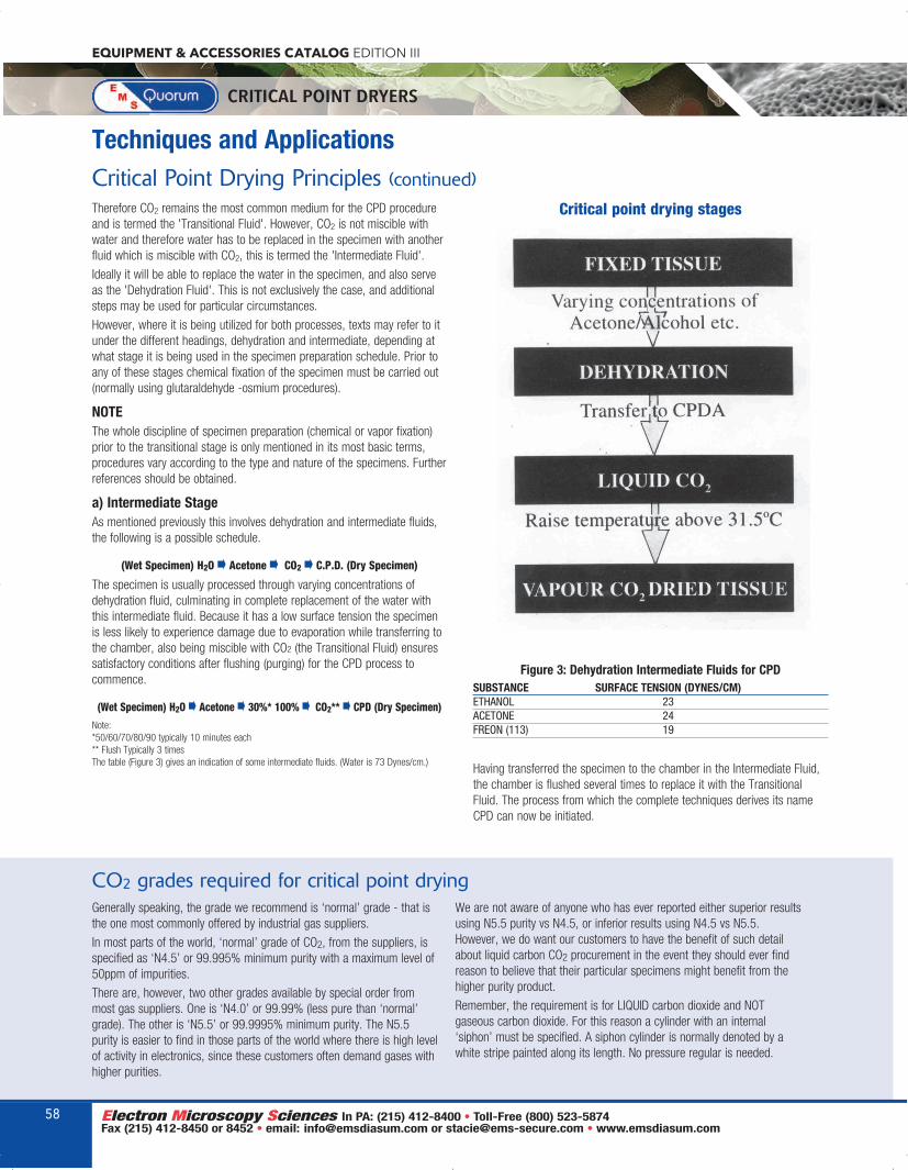
Techniques and ApplicationsCritical Point Drying Principles (continued)Therefore CO2 remains the most common medium for the CPD procedureand is termed the 'Transitional Fluid'. However, CO2 is not miscible withwater and therefore water has to be replaced in the specimen with anotherfluid which is miscible with CO2, this is termed the 'Intermediate Fluid'.
Ideally it will be able to replace the water in the specimen, and also serveas the 'Dehydration Fluid'. This is not exclusively the case, and additionalsteps may be used for particular circumstances.
However, where it is being utilized for both processes, texts may refer to itunder the different headings, dehydration and intermediate, depending atwhat stage it is being used in the specimen preparation schedule. Prior toany of these stages chemical fixation of the specimen must be carried out(normally using glutaraldehyde -osmium procedures).
NOTEThe whole discipline of specimen preparation (chemical or vapor fixation)prior to the transitional stage is only mentioned in its most basic terms,procedures vary according to the type and nature of the specimens. Furtherreferences should be obtained.
a) Intermediate StageAs mentioned previously this involves dehydration and intermediate fluids,the following is a possible schedule.
(Wet Specimen) H2O · Acetone · CO2 · C.P.D. (Dry Specimen)
The specimen is usually processed through varying concentrations ofdehydration fluid, culminating in complete replacement of the water withthis intermediate fluid. Because it has a low surface tension the specimenis less likely to experience damage due to evaporation while transferring tothe chamber, also being miscible with CO2 (the Transitional Fluid) ensuressatisfactory conditions after flushing (purging) for the CPD process tocommence.
(Wet Specimen) H2O · Acetone · 30%* 100% · CO2** · CPD (Dry Specimen)Note:*50/60/70/80/90 typically 10 minutes each** Flush Typically 3 timesThe table (Figure 3) gives an indication of some intermediate fluids. (Water is 73 Dynes/cm.)
Figure 3: Dehydration Intermediate Fluids for CPDSUBSTANCE SURFACE TENSION (DYNES/CM)ETHANOL 23ACETONE 24FREON (113) 19
Having transferred the specimen to the chamber in the Intermediate Fluid,the chamber is flushed several times to replace it with the TransitionalFluid. The process from which the complete techniques derives its nameCPD can now be initiated.
Critical point drying stages
Generally speaking, the grade we recommend is ‘normal’ grade - that isthe one most commonly offered by industrial gas suppliers.
In most parts of the world, ‘normal’ grade of CO2, from the suppliers, isspecified as ‘N4.5’ or 99.995% minimum purity with a maximum level of50ppm of impurities.
There are, however, two other grades available by special order frommost gas suppliers. One is ‘N4.0’ or 99.99% (less pure than ‘normal’grade). The other is ‘N5.5’ or 99.9995% minimum purity. The N5.5purity is easier to find in those parts of the world where there is high levelof activity in electronics, since these customers often demand gases withhigher purities.
We are not aware of anyone who has ever reported either superior resultsusing N5.5 purity vs N4.5, or inferior results using N4.5 vs N5.5.However, we do want our customers to have the benefit of such detailabout liquid carbon CO2 procurement in the event they should ever findreason to believe that their particular specimens might benefit from thehigher purity product.
Remember, the requirement is for LIQUID carbon dioxide and NOTgaseous carbon dioxide. For this reason a cylinder with an internal‘siphon’ must be specified. A siphon cylinder is normally denoted by awhite stripe painted along its length. No pressure regular is needed.
CO2 grades required for critical point drying
EQUIPMENT & ACCESSORIES CATALOG EDITION III
CRITICAL POINT DRYERS
58
EMS_EquipmentCat2019_52-63_EMS_Catalog 2018 Edition 11/5/18 6:31 AM Page 58

Techniques and ApplicationsCritical Point Drying Principles (continued)(b) Transitional StageAs discussed previously (see Figure 1) the conditions for which the critical point passage can be obtainedfor CO2 are 31.1°C and 1072 psi. However, it must be remembered that these isothermals are obtainedfrom a fixed mass of gas and an applied pressure for a series of constant temperatures.
In the laboratory application of CPD we have a fixed volumewhich is filled with the transitional fluid. Some typical examples ofwhich are given in figure 4.
Pressure is obtained by the effect of applying heat and while itcan be readily appreciated that we can take a liquid from belowits critical temperature and obtain the transition to gas above itscritical temperature, an understanding of the relevant 'start' and'end' points and the cycle involved is required in evaluating thedesign and performance of CPD equipment. It is still useful however, to utilize these CO2 isothermals asindicated in figure 5 with the Superimposed ‘arrows' showing differing conditions for the CPD device.
Starch Grains in Potato TuberCritical point dried fractured cell from the tuber ofpotato (Solanum tuberosum), demonstrating thin cellwalls starch grains (amyloplasts).
Glandular Trichomes on Modified LeafSurface of ButterwortAn insectivorous plant, the butterwort (Pinguiculavulgaris) has modified leaves which bear tiny granulartrichomes which trap insects. The capitate head ofthe trichome then secretes protease enzymes todigest the insect parts.
Barley Root TipCritical point dried tip of barley (Hordeum vulgare)root, demonstrating root cap cells (calyptra) andslightly deformed (compressed) root hairs (Pili).
Figure 4: Transitional Fluids for CPD
Substance Temp. C P.S.ICARBON DIOXIDE +31.1 1072FREON 13 +28.9 562FREON 23 +25.9 495WATER +374 3212
59
EQUIPMENT & ACCESSORIES CATALOG EDITION III
SUBSECTION
It is already acknowledged that these circumstances are not exactly comparable. For example, duringoperation of the CPD we would fill at CO2 cylinder pressure and at ambient temperature: not at saturatedvapor pressure. At a lower temperature decompression is as a result of venting and the subsequent reductionin mass of gas, not reduction in externally applied pressure. The relative volume is determined by the initiallevel of liquid in relationship to the total free volume available (this being the chamber plus sample “boat” etc.)
If we consider 'X' with the liquid CO2 more than half filling the total available volume and we heat from 10°Cto 35°C then we will make the transition from liquid to gas. The pressure rise will be rapid as the liquid willexpand and the level will increase before the critical temperature is reached. This is termed 'going around'the critical point. Usually (as in the case of instruments supplied by Electron Microscopy Sciences) apressure-bursting disc is employed to prevent excessive pressure increase.
For condition 'Y' with approximately a full pressure chamber, the liquid level will remain relatively constant,its density decreasing and that of the vapor increasing, and becoming the same when its critical temperaturehas been reached, together with the corresponding critical pressure.
Looking at condition 'Z' with the pressure chamber less than half full. The level will fall and vaporization willoccur before the critical temperature is reached, also the specimens may be uncovered and subjected tounwanted evaporation.
Ideally, we wish have a situation where the liquid fills the specimen chamber, while still only accounting forapproximately 50% of the total volume available. This will ensure that specimens are not uncovered during initialflushing stages and in addition this should enable critical constants of temperature, pressure, and density to beachieved relatively simultaneously without excessive pressure or evaporation conditions occurring.
It is also advisable to maintain a temperature somewhat above the critical temperature duringdecompression, this will avoid the possibility of gas recondensing. It is also important to control thedecompression rate itself as there is evidence that rapid pressure equalization can cause specimen.
EMS_EquipmentCat2019_52-63_EMS_Catalog 2018 Edition 11/5/18 6:31 AM Page 59

EQUIPMENT & ACCESSORIES CATALOG EDITION III
CRITICAL POINT DRYERS
Temperature controlDial gauges display pressure in the chamber and the temperature of watercirculating through the jacket. Three pressure valves permit easyconnection to the liquid CO2 cylinder and allow liquid agitation and ventingof the chamber.
A source of hot running water is essential. Cooling is also useful, especiallyfor sequential critical point drying process runs and/or in laboratories wherethe room temperature may be high.
The temperature of the E3100 chamber is raised with a hot water supply.Mains water can be used but a more elegant method involves the use ofthe optional E4860 Recirculating Heater/Chiller which can be used to pre-cool the chamber to below ambient temperature prior to loading specimensand then to heat the chamber to the critical temperature.
SafetyOperator safety is of course an important consideration with all pressurevessels. If during the critical point drying process the pressure andtemperature are inadvertently exceeded, a safety bursting disc isincorporated in the chamber support. The design has been independentlytype-tested to proof pressures in excess of the working pressure andbursting disc rupture pressure.
Specimen holder (boat)An important feature is the design of the E3100 transfer boat. This permitsspecimens in the intermediate fluid to be transferred to the chamber of thecritical point dryer. On sealing the chamber, the intermediate fluid begins to
drain and can be replacedwith liquid CO2. In thisway the specimens arenever allowed to dry outduring the loading andtransfer stage of thecritical point dryingprocess.
The E3100 is suppliedwith the E3100-01 tissueboat which has threeslots each with threetissue baskets, making atotal of nine. Optionalholders are available and are listed under Ordering Information.
Bonded chamber seals – Nitrile or EPDM?The EMS 3100 is fitted with a standard nitrile bonded window and doorseals. Nitrile is a good general material due to its ability to withstand attackby solvents, such as ethanol. However, if acetone is used as the transitionfluid then the EPDM seals have been found to be more resistant tochemical attack by that solvent.
If you are planning to use acetone as the transition fluid, please state thison the order and EPDM bonded seals will be fitted.
For existing instruments, both Nitrile and EPDM bonded seal can beordered as spare parts.
QUICK OVERVIEWThe E3100 large chamber critical point dryer has been an industrystandard for over 35 years and is used in numerous scanning electronmicroscopy (SEM) laboratories around the world. Primarily used for criticaldrying of biological and geological specimens, the E3100 can also used forthe controlled drying MEMs, aerogels and hydrogels.
The design of the E3100 features a large, horizontal pressure chambermeasuring 63.5 mm internal diameter x 82 mm in length. The chamberhas an external water jacket for temperature control and specimens areintroduced via a removable rear door. The front of the chamber is fittedwith a 25 mm diameter window which gives an unsurpassed view of theliquid level during the critical point drying process.
KEY FEATURESz Proven reliability - over 6,000 critical point dryer installationsworld-wide
z Simple robust construction - easy to maintain - many critical pointdryer users carry out their own routine maintenance
z Horizontal chamber and large viewing window - excellent visibilityof the fluid level and drying process
z Large robust valves for draining of fluids, ingress of CO2 and venting of gas - very durable; the rapid ingress of CO2 helps prevents pre-drying of specimens
z Safety - every critical point dryer unit is pressure tested to 2,500psiand a certificate is issued. A pressure bursting disc is also fitted tosafeguard against misuse
z Specimen handling - optional specimen holders for coverslips andTEM grids. Porous pots are available for fragile or very small speci-mens
z Three-year warranty
EMS 3100 Specimen Boat
zzz EMS 3100 Critical Point Dryer
60
EMS_EquipmentCat2019_52-63_EMS_Catalog 2018 Edition 11/5/18 6:31 AM Page 60

61
EQUIPMENT & ACCESSORIES CATALOG EDITION III
CRITICAL POINT DRYERS
EMS 3100 Large Chamber Critical Point DryerChamber dimensions: 63.5mm Ø x 82mm length each
Supplied with: EMS 3100-01 Specimen holder for tissue (boat)1m liquid CO2 delivery tubeO ring and L gasket set (including window and door
bonded seals)Spare bursting disc and retaining copper (Cu) washerSteel bar for tightening/untightening the doorFlat wrench (for removing the window retaining ring)Comprehensive manualPressure test certificate
E3100-061 Service Kit for EMS 3100 Kit
OPTIONS AND ACCESSORIES
ORDERING INFORMATION
Glass microscopecoverslip holder(option):Specially adapted boats allowglass coverslips to be held firmlyduring drying. The EMS 3000-02is designed for the EMS 3000 and has a maximumcapacity of seven coverslips. Likewise, thelarger EMS 3100-02 coverslipboat is available for the EMS3100 ‘Jumbo’ Critical Point Dryerand has a carrying capacity of 21coverslips.
TEM grid holder(option): The EMS 3000-1 holder for3.05mm grids and the EMS3000-2 grid holder for 2.3mmgrids can be used with allElectron Microscopy Sciencescritical point dryers. Maximumnumber of grids is three.
Porous pots with lids(option):EMS 800A solvent-resistantporous pots (12.7mm x 15.5mm)with lids are ideal for very smallor very delicate specimens.
Service Kits:Service kits are available; see theordering table below. Please callour service department forspecific questions.
EMS 3100-01 is included as standard):
z EMS 3100-1 Specimen hold-er for 3.05mm grids
z EMS 3100-2 Specimen hold-er for 2.3mm grids
z EMS 3100-01 Specimenholder for tissue (boat)
z EMS 3100-02 Specimenholder for coverslips
z EMS 800A Porous pots withlids 12.7mm x 15.5mm (packof 10) for micro-specimens
z EMS 4860 RecirculatingHeater/Chiller to controlheating and cooling cycle(please specify voltage)
For more information on the EMS 4860 RecirculatingHeater/Chiller, see page 4.
Site RequirementsSite selection: The apparatus should be positioned in the laboratory withconvenient access to:
z Hot and cold water supply (if the optional EMS 4860 RecirculatingHeater/Chiller are not used)
z Mains power supply (for EMS 4860 only)z Fume cupboard or window, or an area of good ventilationz Space for CO2 siphon cylinder
CO2 Cylinder: The EMS 3100 requires a cylinder of liquid CO2 fitted with asiphon tube (indicated by a vertical white stripe on the cylinder). If there isany doubt regarding the presence of a siphon tube, advice should be soughtfrom the gas supplier.
Cylinder connection threads vary from country to country and even betweenmanufacturers in the same country. For example, the transfer pipe suppliedis fitted with ¼" British Standard Pipe (BSP) and 0.86" x 14 TPI union.These are standard threads for the UK and generally in the rest of the world,but will not fit cylinders in the USA.
Heating and cooling: Use a mixer to the laboratory hot and cold wateroutlets, terminating with a 6mm/¼" hose connection for the PVC tubingsupplied. A ‘Y’ piece connected to the hot and cold water taps is alsosuitable.
The EMS 3100 requires both hot and cold water during the operating cycle.Cooling facilitates filling of the work chamber with liquid CO2, and heating isrequired to take the liquid above its critical point.
Good control of the water temperature is essential for good results, hencethe recommended use of the the EMS 4860 Recirculating Heater/Chillerwhich gives precise control of cooling and heating.
Space requirement: A minimum bench space of approximately 230 x230mm is required.
Coverslip Holder
Service Kit
TEM Grid Holder
Porous Pots
zzz EMS 3100 Critical Point Dryer (continued)
EMS_EquipmentCat2019_52-63_EMS_Catalog 2018 Edition 11/5/18 6:31 AM Page 61

The EMS 850 Critical Point Dryer is designed for use withCO2, having first replaced any water in the specimen bya series of dehydration, often in the same fluid such asAcetone, which will also be the intermediate fluid.
(Wet Specimen)–Water–Acetone–30%–100%–CO2–C.P.D.–(Dry Specimen)
The specimens for critical point drying are located in the pressure chamber ofthe EMS 850. The chamber is pre-cooled to allow it to be readily filled withliquid CO2 from a gas cylinder. The chamber is then heated to just above thecritical temperature with subsequent critical pressure being achieved. TheCO2 gas is vented through a needle valve, to avoid specimen distortion.
The EMS 850 is fitted with thermoelectronic Heating and Cooling andTemperature control of +5°C on Cooling, and +35°C on Heating. Thisensures the critical point is accurately obtained, avoiding excess pressuresor temperatures, or the need to rely on pressure relief valves to controlpressure during the heating cycle. The chamber is vertical, with toploading, to ensure specimens do not become uncovered during the dryingprocess, with a side viewing port to locate the miniscus for the correct levelwhen initially filling the chamber.
The EMS 850 is fitted with a fine let down needle as standard and flowgauge is no longer required.
Cross-sectional view of chamber, showing miniscus viewing position.
X = More than half fullY = Approximately half fullZ = Less than half full
z Vertical chamber with top filling and bottom draining.z Normal operating temperature 35°C pressure 1500 psi.z Thermoelectric Peltier cooling and heating.z Fine control needle valve pressure letdown.z Illuminated chamber with side viewing port and protective ‘Lexan’shield.
z Stirrer system for enhanced solvent exchange.z Temperature monitoring and control with thermal cut-out protection.z Pressure monitoring with pressure relief valve and rupture disc protection.
z Polycarbonate safety shield.
FEATURES
Instrument Case 450mm (W) x 350mm (D) x 175mm (H)Weight 12KgSpecimen Chamber 30mm (Dia.) x 40mm (H)
(Tested to 3000 psi)Temperature Gauge 0-120°CThermal Cut-Out 40°CPressure Gauge 0-3000 psiPressure Relief At 1500 psiRupture Disc At 1900 psiPeltier Cooling/Heating +5°C to +35°CTwo On/Off Valves Inlet/Outlet/Cool/Vent Needle Valve LetdownSupply 115V 60Hz (6 Amp Max)
230V 50Hz (3 Amp Max)Services Requires CO2 gas cylinder direct connection
by high pressure hose. (High pressure hose included with instrument.)
SPECIFICATIONS
91090 EMS 850 Critical Point Dryer complete each
Replacement Parts91091 Mesh Basket each91092 Porous Spec Pots 10/pack)
ORDERING INFORMATION
EQUIPMENT & ACCESSORIES CATALOG EDITION III
CRITICAL POINT DRYERS
zzz EMS 850 Critical Point Dryer with Thermoelectronic Heating and Adiabatic Cooling
62
EMS_EquipmentCat2019_52-63_EMS_Catalog 2018 Edition 11/5/18 6:31 AM Page 62

The EMS 850WM is compact,bench-top instrument designedto critical point dry a complete150mm/6" wafer. A convenientwafer holder allows rapidtransfer and ensures that pre-drying does not occur.
FEATURESz 170mm diameter chamber - optimized for wafer/MEMS dryingz Vertical chamber with top-loading and bottom draining - ensures specimens do notbecome uncovered during drying
z Thermoelectric heating - accurate temperature controlz Fine control needle valve pressure let down - precise controlz Temperature monitoring and control with thermal cut-out protectionz Pressure monitoring with safety cut-out for over pressurez Three-year warranty
91090-WM EMS 850WM Large Chamber Critical Point Dryer each
RequirementsEMS 4860 Recirculating Heater/Chiller (for cooling chamber) eachEMS 3102 Carbon Dioxide bottle heating system each
ORDERING INFORMATION
The EMS 850WM has built-in heating and water cooling using the EMS 4860 RecirculatingHeater/Chiller. This combination will give temperature control of +5°C cooling and +35°C duringheating. This ensures the critical point is accurately obtained, avoiding excess pressures ortemperatures, or the need to rely on pressure relief valves to control pressure during the heatingcycle.
The EMS 850WM has a vertical chamber which allows top-loading of specimens. A viewing port isfitted in the top plate for specimen observation. The specimen exchange mechanism is simple to useand ensures the specimen remains under liquid during loading.
Specimen handling100mm or 150mm diameter wafers are held in a PTFE holding tray. The tray including wafer isimmersed in acetone in order to remove all moisture from the specimen. After dehydration, thewafer and holder are transferred into the pre-cooled specimen chamber using the wafer transferdevice. On completion of the critical point drying process, the wafer is removed from the chamberusing the transfer device prior to further processing.
Mature Barley RootCritical point dried transverse fracture of a maturebarley (Hordeum vulgare) root, demonstrating centralstele and surrounding cortical cells. Root hairs (Pili)are also obvious.
AphidCritical point dried aphid on a leaf surface.
Bamboo StemTransverse fracture of the stem of young bamboo(Bambusa sp), demonstrating xylem and phloembundles and heavily thickened (lignified) epidermaland hypodermal cells.
63
EQUIPMENT & ACCESSORIES CATALOG EDITION III
CRITICAL POINT DRYERS
zzz EMS 850WM Large ChamberCritical Point Dryer
EMS_EquipmentCat2019_52-63_EMS_Catalog 2018 Edition 11/5/18 6:31 AM Page 63

Techniques and ApplicationsWhat is...The Plasma Process?The Plasma process is accomplished throughthe use of a low pressure, RF inducedgaseous discharge. The material or specimenis loaded into the reaction chamber. Thechamber is evacuated to a vacuum pressureof 0.1-0.2 torr by a mechanical vacuumpump. A carrier gas is introduced into thechamber, raising the chamber pressure to0.3-1.2 torr, depending on the application.
RF Power is applied around the chamber(13.56 MHz). This excites the carrier gasmolecules and dissociates it into chemicallyactive atoms and molecules. The mechanismemployed in this process is one of ionization.The combustion products, which arecompletely dissociated and harmless arecarried away in the gas stream. The uniqueproperty of this process is that it occurs nearlow temperatures without employing toxicchemicals.
ApplicationsAsbestos and man-made mineral fiber(MMMF) detection
Coal ashing
Detection of metals in blood
Ashing of biological material, food stuffs etc.
Organic and inorganic composites
Surface treatment of plastics
Plasma polymerization
Artificial weathering
Plasma etching and plasma ashing oforganic specimens for SEM and TEMexamination
Plasma Etching and Ashing
EQUIPMENT & ACCESSORIES CATALOG EDITION III
PLASMA ASHERS
What is a PlasmaA plasma is a partially-ionized gas consisting ofequal numbers of positive and negative chargesand a different number of unionized neutralmolecules. When a gas is subjected to a DC orradio frequency (RF) potential at reducedpressure this is usually accompanied by glow,which is known as glow discharge. The wordsglow discharge and plasma tend to be usedsynonymously, although glow discharges are notperfect plasmas - but for the purposes of this textthey will not be differentiated. The characteristicglow of these plasmas is due to electronicallyexcited species producing optical emission in theultraviolet or visible regions of the spectrum andis characteristic of the composition of the glowdischarge gas. For example, argon gives a brightblue color and air or nitrogen gives a pink colourthat is due to excited nitrogen molecules.
IonizationIn the context of plasma-enhanced chemistryreactors, the plasma is created in a vacuumchamber, which contains a constant flow of a gasat reduced pressure - typically in the order of1mbar. This gas is exposed to a radio frequency(RF) potential, which results in the partialionization of the gas. In the ionization process, abound electron in an atom is ejected from thatatom. For example, the ionization of an argonatom is expressed as follows: - Ar -> Ar+ + e
ExcitationA less dramatic transfer of energy allows theelectron to jump to a higher energy level withinthe atom. This process is known as excitation.The excited state of an atom is conventionallyshown by an asterisk: e + Ar -> Ar* = e
DissociationA further process that can occur is thedissociation of a molecule. If oxygen, forexample, is the gas subjected to the RF potential,the oxygen molecule can be dissociated into twooxygen atoms, whereas a monatomic gas suchas argon cannot be dissociated at all: e + 02 ->e + 0 + 0
A normal result of dissociation is anenhancement of chemical reactivity, since theproducts are usually more reactive than theparent molecule. Dissociation may or may not beaccompanied by ionization, for example: e + CF4-> e + CF3 + F (Dissociation) or e + CF4 -> 2e+ CF3+ + F (Dissociation)
SummaryExposing a gas to the RF potential at reducedpressure creates a plasma which contains activespecies - for example, in the case of oxygen,atomic oxygen. Oxygen atoms will oxidize organicmolecules more readily than oxygen molecules.So typically a cellulose material can be convertedto carbon dioxide, carbon monoxide and water atroom temperature, rather than at elevatedtemperatures (eg burning) and furthermore theoxidation is more controllable.
Types of Reactor SystemsThere are many types of reactors available. Theyare all glow discharge systems but varyconsiderably in terms of excitation frequency(5kHz - 5GHz), operating pressure (1mbar -atmospheric pressure) and electrodearrangement.
In addition to barrel systems there are parallelplate reactors; these usually consist of agrounded plate onto which the specimens areplaced and an insulated parallel plate to whichthe RF power is applied. The reverse of thisarrangement where the specimens are placed onthe non-grounded electrode is generally knownas ‘Reactive ion etching’ (RIE).
Etching in this type of reactor is inherentlydirectional, whereas the former can be bothdirectional (anisotropic) or isotropic. The barrelreactor usually etches isotropically and is favoredfor most plasma applications.
The barrel reactor, as the name implies, is acylindrical container, which can be evacuated. The RF power, usually at 13.56MHz frequency isapplied to the system via internal or externalelectrodes by capacitive or inductive coupling.This type of reactor is used for the plasma ashingprocess and also for the plasma etching process,although the disadvantage in the latter for someusers is that the process is not completelyisotonic so that undercutting can occur.
Barrel Reactor
64
EMS_EquipmentCat2019_64-71_EMS_Catalog 2018 Edition 11/5/18 6:41 AM Page 64

Techniques and ApplicationsPlasma Applications
65
EQUIPMENT & ACCESSORIES CATALOG EDITION III
PLASMA ASHERS
Plasma AshingThe process of plasma ashing, plasma strippingor micro-incineration is usually restricted to thetotal removal of organic matter by an oxygenplasma; the products being carbon oxides andwater vapor, which are volatile and pumped awayby the vacuum system. Historically, the firstapplication was for the removal of photoresist inthe microelectronics industry. Photoresist iscomposed of organic compounds, essentiallyconsisting of carbon, plus hydrogen and oxygen.Exposure to an oxygen plasma eventually removesall the photoresist as volatiles leaving no residues,unless there are inorganic contaminants in thephotoresist. The shows process is therefore totallydry and is also a means of concentratinginorganic contaminants in organic materials.
Asbestos and man-made mineralfiber (MMMF) detectionThis is a major application for RF plasmasystems. The exact protocols vary from country tocountry, but in the UK the following is a summaryof the recommended method. The techniquerequires that a specimen of filtered air (or water)is collected from a known volume on MF seriesfilter (mixed cellulose acetate and nitrate). Thefilter is then transferred to a microscope slide,treated with a clearing solution, dried and thentransferred to the plasma unit. The asbestosfibers are then exposed by partial ashing of thefilter by treatment in an oxygen plasma fortypically seven minutes. This removes surfacelayers of the filter, leaving the asbestos fibresexposed but still attached to the collapsed filtermatrix. The fibers can be counted and identifiedby light microscopy, light contrast microscopy,SEM and EDX. Some SEM and EDX protocolsrequire complete ashing of the filter.
Coal ashingSmall specimens can be ground and distributedin a petri dish to produce maximum surface area.The coal dust can be ashed by an oxygen (or air)plasma at low temperatures, compared to theextremely high temperatures generally used in amuffle furnace for this process. Volatile elements,such as selenium, are retained and therefore amore accurate calorific and ash value can beproduced. Problems in estimating the requiredvalues are a result of the structure of coal whichincludes organic materials (and hence convertiblematerial) together with inert inorganic materials inthe same overall matrix.
Plasma chemistry is a surface reaction, somethods such as the ashing of coal require theexposure of new surfaces. For this reasonphysical stirring of the specimen is recommendedevery 1-2 hours. The complete ashing of a 1gspecimen is typically completed in 12-24 hours.
Detection of metals in bloodPlasma ashing as a pre-treatment for atomicabsorption analysis (AAS) is another well-established application. In this case one isnormally looking for metals such as lead,cadmium, zinc and mercury in trace quantities inorganic materials such as vegetables, dairyproducts or animal tissue. A specific exampleinvolves the treatment of multiple specimens ofhuman blood exposed to a CF4/02 plasma. Theorganic materials in this application can beremoved in 15 minutes, leaving only the metalliccontaminants to be analyzed for cadmium.
Ashing of biological material, foodstuffs etcPlasma ashing has also been successfully usedto ash materials as varied as post-mortem lungtissue (for asbestos), bread (to determine typeand distribution or iron) and specimens ofprepared food (for asbestos and man mademineral fibers). Specimens need to be dried priorto ashing and their size kept to a minimum.
Organic and inorganic compositesSimilar problems are encountered in compositematerials such as paints, vehicle tires and brakelinings, contaminated oils and the application ofclays onto paper. In paints, the organic bindercan be removed to leave the inorganic pigment inits original distribution. In paper, the clay plateletdistribution and adhesion can be investigatedafter ashing of the paper and binder. Similarly,epoxy composite materials can be investigated.
Plasma etchingPlasma ashing and plasma etching rely on thesame basic principles. Plasma Etching is usuallyconfined to the semiconductor industry, and moreoften than not, uses carbon tetrafluoride (withoxygen) as the plasma process gas. Probably themost frequent application is the etching of silicon,silicon oxides, and silicon nitrate, as well as glasspassivation layers.
Failure analysis of integrated circuits is also animportant application of plasma processing.Oxygen gas is used to remove epoxyencapsulates, CF4/02 is also used to remove
glass filters in the encapsulants and so uncoverdevices which have failed. Inspection bymethods, such as SEM, is then possible.
When etching, it should always be rememberedthat not only the required surface will beremoved. Careful choice of gas is made so thatpreferential etching of the required surface isattained.
Plasma etching is a chemical process. The RFdischarge generates species which then reactwith the material being etched to form a volatileproduct. The resulting products are swept awayby the gas flow. Since reactive species are beingformed, the reactant gas is chosen to give thehighest concentration of the etching species. Forexample, CF4 and CF4/02 mixtures produce veryreactive fluorine and CF3 radicals and ions.Similarly, other gases and volatile compoundshave been investigated and used to etch a widevariety of materials. These include CCl4, CFCl3,C2Cl6, C2F6, SF6, SIF4, and mixtures of thesegases with H2, O2, Ar, He, CO2, CO, N2 etc.
Surface treatment of plasticsA number of applications of plasma involve thesurface treatment of plastic materials, prior to asubsequent process. An example is the treatmentof reinforcing fibres that are to be integrated intoan epoxy structure. Treatment in an oxygenplasma for say, five minutes at 50-100W,increases surface roughness. These pitted fibersenhance adhesion and a good mechanical bondis produced with enhanced rigidity and strength.
Plasma processing of plastics can also convert ahydrophobic surface to a hydrophilic surface. Thistype of treatment usually requires short exposure (3-5 minutes) at low power (50 watts). This sortof reaction has been applied to the assembly ofink pens to improve the speed of ink filling andtransfer. Other examples include the treatment ofelectrical wiring so that the insulation can beprinted upon with regular inks. Plasma treatmentof car bumpers allows simpler and more cost-effective painting schedules and the treatment oftextile fibers can improve water retention.
Plasma surface treatment in biomedicalapplications is expanding rapidly. For example,surface modifications of a polymer to improveblood compatibility. This involves tailoring thepolymer surface to minimize blood reaction.Similarly, the internal surfaces of tubing can bemodified, allowing pharmaceutical materials to bechemically bonded to the surfaces, thus allowingthe drug to be slowly dispensed in a localized area.
EMS_EquipmentCat2019_64-71_EMS_Catalog 2018 Edition 11/5/18 6:41 AM Page 65

EQUIPMENT & ACCESSORIES CATALOG EDITION III
PLASMA ASHERS
Plasma polymerisationPlasma polymerization refers to thepolymerisation of active species generated in aplasma. For example, the introduction ofpolysiloxanes onto hard contact lenses improvesthe hydrophilic nature of the surface. Anapplication in the soft drinks industry using CF4,to create a fluorinated surface on PET andpolypropylene bottles, making bottles lesspervious to carbon dioxide.
A porous surface can be produced on medicalequipment, this makes it possible to sterilise theequipment with nitrous oxide while remainingimpervious to air. Deposition of polymers onto thesurfaces of implants is also possible and can helpprevent rejection by improved bio-compatibility.
ReferencesAn important application of plasma technique isto improve the ‘wettability’ and adhesion ofpolymers for surface coatings, inks and dyes (1).Self-adhesion can also be markedly improved byplasma treatment (2, 3).
Plasma techniques are widely used in theelectronics industry (4) particularly for
microelectronics fabrication. Although most of thematerials involved in these applications areinorganic, they are of interest to polymerchemists because polymers can be use asresists, insulators or semiconductors. Operationscarried out by plasma techniques includephotoresist removal (5), etching siliconcompounds (6) and deposition of polymer films(7, 8). The chief virtue of plasma techniques inmicroelectronics fabrication is that it permitsautomated, multi-step processing of complexdevices (9).
Applications for plasma polymerization haveincluded the production of protective coatings formetals and other reactive surfaces (12),fabrication of reverse-osmosis membranes (13),coatings for optical plastics (14) and theformation of radiation resistant coatings (15).
Last and by no means least, is the application ofplasma ashing for the analysis of inorganicmaterials within an organic matrix. Primeexamples include the investigation of asbestosfibers in air and investigation of metalcontamination of food.
Frequently AskedQuestions...What is the difference between RFplasma etching or ashing and glowdischarge?Glow discharge is an ‘imperfect plasma’ usedto alter surface energies to turn hydrophobic(water hating) surfaces hydrophilic (waterloving). Glow discharge will also removeadsorbed gases from the chambers of vacuumsystems and in doing so improve pump downspeed and ultimate vacuum levels.
This is the limit of what glow discharge cando - it will not plasma ‘etch’ or ‘ash’specimens. RF plasma reactors can altersurface energies, de-gas and removematerials from specimens in a controlled way(etching or ashing).
What is the difference between etchingand ashing?Ashing is the total removal of organic matterusing oxygen plasma. Mineral components ofthe specimen will be left behind as a residue(ash). The by-products of this process -mainly carbon oxides and water vapor - arepumped away by the vacuum pump. Etchingis the controlled removal of layers or partlayers of material and is usually confined tosemiconductor applications.
How automated is the EMS 1050?After initial set up of the operating conditionsoperation is fully automatic (one-buttonoperation).
When must a fomblin vacuum pump bespecified?When oxygen is to be used as a process gasit has the potential to combine explosivelywith normal organic types of rotary pump oils.Fomblin is a synthetic oil and will not react inthis way. Fomblin is also resistant to most ofthe highly corrosive plasma process gases.
What is the capacitance manometer andwhen should it be specified as an option?The capacitance manometer measuresvacuum. The standard plasma system uses aconventional pirani gauge for this purpose.However, if corrosive halogenated gases areused on a regular basis, they have thepotential to attack (erode) the pirani vacuumgauge filament. In such cases (mainly insemiconductor conductor applications) thecapacitance manometer option is stronglyrecommended because it is resistant toattack by corrosive gases.
1. M. Hudis, Techniques and applications of plasma chemistry, Wiley-Interscience, New York, 1974 chap. 3.
2. M. Stradl and D. A. L. Goring, Can, J, Chem. Eng., 53, 427 (1975)
3. D. K. Owens, J. Appl, Polym, Sci., 19, 265, (1975)
4. R. W. Kirk, as (1) chap. 9.
5. S. M. Irving, Kodak Photoresist Seminar, 2, 26, (1968).
6. H. Abe, Y. Sonobe, and T. Enomoto, Jpn. J. Appl. Phys., 12, 154 (1973).
7. P. J. Ozowa, IEEE Trans, Parts Mater., Pachag., PMP-5, 112 (1969)
8. A. Chida, Jpn. Kokai Tokkyo Koho, 78,47, 393, (1978).
9. R. L. Bersin, Kodak Microelectronics seminar proc., San Diego, Calif., October 1-3 (1978).
10. P. Kassenbeck, Bull. Inst. Text, FR. 18, 7 (1963).
11. W. J. Tjhorsen, Text. Res J 38,644, (1968).
12. T. Williams J, Oil Colour Chem Assoc., 48,936 (1965).
13. H. Yasuda, Appl., Polym. Symp., 22,241 (1979).
14.1. R. M. Kubacki, US Patent 4096315 (1978).
14.2. Y. Masuda and Y. Nakagawa JPN, Kokai Tokkyo Koho 78, 56, 177, (1978).
15. M. Miyamura, JPN, Kokai Tokkyo Koho, 78, 120, 527 (1878).
66
Techniques and ApplicationsPlasma Applications (continued)
EMS_EquipmentCat2019_64-71_EMS_Catalog 2018 Edition 11/5/18 6:41 AM Page 66

67
EQUIPMENT & ACCESSORIES CATALOG EDITION III
PLASMA ASHERS
Photo resist removalThe removal of photo resist by plasma etching from silicon or GaAssemiconductor slices is a very safe and effective process. The thickness ofresist is normally 1-3 microns and has usually been baked on for about 1hour at 100°C. Using O2 at full power, 1 micron should disappear in about20-30 minutes. Ion implanted resist is very hard and in some cases willtake longer to etch, up to two hours. One way of reducing time is by fittinga larger rotary pump, therefore allowing more gas flow for the samepressure. Normal operating pressure is between 0.4-0.2mbar.
Silicon etchingTo etch silicon and silicon nitride from slices, a fluorinated gas is required,usually CF4. Films are normally in the order of 100-500 microns and arequickly removed; 2-5 minutes normally being sufficient. Visual colourchanges make complete removal obvious. CF4 will also attack the chamberand window. Quartz, which does not contain boron, is offered as standardinstead of glass to avoid boron contamination.
Asbestos detectionPlasma is now accepted as the standard process for SEM examination ofasbestos fibers caught in acetate filter papers. Filters are surface etched inO2 at approximately 100W for 2-8 minutes, this being sufficient to etchaway the filter surface, leaving the asbestos fibres for SEM examination.
Atomic absorption spectroscopy preparationPlasma is widely used in AAS as a convenient way of removing the organicbinder from a host of specimens making trace metal determination easier.Specimens are presented dry and crushed and etched in O2. Ashing timesvary but are usually 1-3 hours.
General cleaningCleaning of delicate parts, such as SEM gun assemblies or chamber parts,can be achieved using plasma. For super-clean surfaces 99.999% ultrapure argon or high purity oxygen is used.
Plastic treatmentThere are numerous applications being tried on plastic surfaces usingplasma, the most common being the requirement to convert hydrophobicsurfaces to be hydrophilic (surface ‘wettable’). The advantages being theease of printing, painting, marking etc and great improvement in the bondstrength of adhesives.
These reactions take place in high purity O2 at relatively low temperaturesand power input (10-40W). Process times are relatively short; 15 seconds –2 minutes usually being sufficient. Interest has been shown in putting down‘barrier layers’ on plastic containers to increase shelf life by stopping theingress of CO2 and stopping the contents of the container reacting with theplastic. The films are normally of inert fluorine and are produced using CF2.
Oil Generally in plasma environments the rotary pumps are required to pumplarge amounts of oxygen. As most rotary pump oils are organic based, there isa very remote chance of explosion. There are two ways to minimise this risk:
(a) Use a synthetic based oil - Fomblin is highly recommended.
(b) It is possible to break into the pipe between the plasma unit and pumpand dilute the oxygen with argon. However, this reduces the pumpingspeed of the pump, requires an argon supply which can be costly andwould be ineffective if the argon supply failed.
O2 100%• Asbestos and man-made mineralfiber detection
• Stripping photo resist• Removal of organic contamination• Removal of organic material (eg coal)
• Ageing paint (quick test for likelyageing characteristics)
• Degreasing of metals andpolymers
• Hydrophilation• General oxidation• Polymer activation
Ar 100 %• Degreasing and activation ofmetals
• Removal of epoxy bleed-out fromhybrid circuits without oxidation.Can be used with up to 3% O2for faster reaction
• Cleaning EM parts• Oxide removal• Hydrophilation
H2 100% • Used in with carrier gas in levelsof amp<10%
• Metals cleaning (withoutoxidation)
• Hydrophobation• Oxide removal
He 100%• Degreasing and activation ofmetals and polymers
• Hydrophilation• Cooling agent for O2
N2 100%• Polymer activation• Removal of epoxy bleed-out onhybrid circuits
• Removal of oxides
C2H4 100%• Polymerization
CH4 100%• Polymerization
C2H2 100%• Polymerization
CF4 100%• Epilamization• Silicon etchant
SF6 100%• Silicon etchant
FS-100 97% He 3% O2• Removal of thin film organiccontamination from easilyoxidised metals and synthetics
• Low temperature removal oforganics from metals withoutoxidation
• Low temperature ashing
FORM-ING GAS 90-95% N 5-10% H• Removing oxides; especiallyuseful as a follow up process inhybrid cleaning or other oxidisingprocesses as glass to metal seals
DS28 N2 with 2ppm water• Removal of organics fromsensitive substrates withoutoxidation
DS180 92% O2 8% CF4• Removal of thick layers of photoresist
DS300 97% O2 3% CF4• Photo resist removal inaluminium chambers or withfaraday insert in quartz chambers
• Removal of organic contamination
DS16281 99% N2 1% O2• Removes photo resists films overoxidising or with TCR and resistornetworks being unchanged (thinfilms only). May also haveincreased O2 as designated bythe last digit signifying thepercentage
IR101 70% EthyleneTrichloride 30% 1, 1, 2Trichlorotrifloroethane• Removal of inorganiccontamination, particularly tinfrom resist or contaminatedchambers (used in conjunctionwith O2). Will also remove windowoxide grown on exposed Si
FS100 97% He 3% O2 • Low temperature organic removal• Flash strip of photo masks
EXAMPLES OF PLASMA GASES AND THEIR APPLICATIONS
Techniques and ApplicationsPlasma Chemistry
EMS_EquipmentCat2019_64-71_EMS_Catalog 2018 Edition 11/5/18 6:41 AM Page 67

EQUIPMENT & ACCESSORIES CATALOG EDITION III
PLASMA ASHERS
Replica EM studies of polyamide structureUse of oxygen plasma for differential etching of ordered and disordered regionsin organic specimens. Rates of etching reduced from lower molecular weightsubstances through disordered (amorphous) regions to ordered (crystalline)regions. This allowed identification by replica EM of simultaneous presence ofsingle crystals and spherilites in Polamide 68.
Replica EM studies of latexes of acrylic copolymersUsing replica EM and oxygen ashing it was shown that latex particles ofPolyalkylacrylates and Alkylacrylate-Methacrylic Acid Copolymers are aggregatesof primary globules, the size of the globules depends upon the polymer.
EM studies of polyethylene tetraphthalates films and fibersOxygen ashing in conjunction with replica EM revealed supra molecular structurewith correlation between EM and x-ray diffraction data. Oxygen ashing followedby SEM examination allowed identification of three types of internal flaw in brightfibers. Results showed high concentrations of titanium dioxide in regionscontaining voids, and highly ordered polymers which had previously beenassumed to be defusants.
Quantitative bulk analysis by TEAM of biological microspecimens100um sections of Wistar rat hearts were oxygen plasma ashed and thendissolved and sprayed onto grids. The droplets were then individually analyzed.The method was found to retain volatiles such as sulphur and possibly chlorine.Ashing times when compared to high temperature ashing are considerablyreduced.
Microincineration for EM localization of biological materialsA review of high temperature ashing and plasma ashing of various materials.
Low temperature ultra microincineration of thin-sectioned tissuePlasma incineration used to determine the morphological localization of structurebound mineral and metallic elements within biological cells at TEM levels.
Ultrastructure of cell organelles in thick plasma-etched sections1um sections of fixed and embedded kidney tissue when surface etched byoxygen plasma, allowed etch resistant cell components to be imaged with clarity.Resolution was better that other preparation technique for SEM of internalstructures of cells and organelles in bulk specimens of tissue.
Review of techniques for SEM and electron probe microanalysisAmong many applications the following are highlighted: microelectronic failureanalysis; grain boundary composition in mineralogical specimens containingsilicates and carbonaceous material; discovery if microvoids and flaws in carbonreinforcing fibers; differential etching of polymers; formation of 3D ash skeletons;studies of modular graphite inclusions in cast iron; mineral staining of braintissue followed by oxygen ashing.
TEM-EDS of silica in cell walls of rye grassA comparison of preparation methods, including plasma ashing, to determineamounts of silicon in cell wall material.
Plasma ashing moths and insects prior to EM and XESOxygen ashing of insects allowed the removal of organic material but left thestructure intact. This allowed area sectioning for subsequent analysis.
X-ray microanalysis of Epon sections after oxygen plasma ashingImproved X-ray detectability of elements retained in ash by lowered backgroundcounts. Method removes osmium fixative and chlorine to reveal hiddenphosphorous peak; pattern fidelity allows micro analytical resolution of 0.1um.
Measuring the concentration of asbestos fibers in air specimensOxygen plasma used to remove high levels of airborne organic contaminants andto remove filter paper prior to TEM sizing.
SEM of embedded biological specimens that have been surface plasmaetchedAs a general technique for SEM, oxygen plasma etching thick sections of a widevariety of different types of embedded tissue yields specimens that show aresolution that is considerably better than that obtainable by most othermethods; particularly for viewing internal structure of cells and organelles in bulkstructure.
Identification second counting of asbestos fibers on membrane filtersMethods are described whereby asbestos fibers can be counted by phasecontrast microscopy and identified on the same membrane filter by optical andSEM techniques. Airborne concentration of different asbestos types in mixedclouds can therefore be estimated.
Improved gas-discharge etching techniques inthe Electron Microscope studies of Polyamidestructures.L I Bezruk. Vysokomol. Soyed. A10: No. 6 1434-1437, 1968Particle and film structures of films of somelatexes of acrylic copolymersV I Yeliseyeva. Vosokomol. Soyed A9: No 11 2478-2481, 1967Oxygen etching method of making an ElectronMicroscopy study of PolyethyleneTetraphthalate filmsK Z Gumargaliveva. Vosokomol. Soyed. 8: No. 101742-1744, 1966Studies of plasma-etched PolyethyleneTerephthalate fibres by SEM and energy-dispersive X Ray microanalysisP R Blakey & M O Alfy. Letter to Journal of TextileInstitute 1978 No 1Detection of inorganic materials in biologicalspecimensSource unknown
Microincineration techniques for electron-microscopic localization of biological mineralsRichard S Thomas. W Region Research Lab,Agricultural Research Service, US Dept, of Ag.Albany Ca. USAUse of chemically reactive gas plasma inpreparing specimens for SEM and ElectronProbe MicroanalysisRichard S Thomas. SE.M/1974 part I proc 7th SEMSymph –April/1974Low temperature ultra-microincineration ofthin section tissueWayne Hohman & Harold Shraer. Journal of CellBiology, Volume 55 1972 pp 328-354Ultra-microincineration of thin-sectionedtissuePrinciples and Techniques of EM-1976Ultrastructure of cell organelles by ScanningElectron Microscopy of thick sections surface-etched by an Oxygen plasmaW J Humphreys. Journal of Microscopy Vol 116 July1979.
Silica in the mesophyll cell walls of Italian RyeGrassD Dinsdale Ann. Bot 44 73-77 1979Ashing moths and various insectsJ Bowden (pr comm) Rothampstead ResearchStation. July 1979X-ray microanalysis of Epon sections afterOxygen plasma microincinerationTudor Barnard and R S Thomas Journal ofMicroscopy Vol 113 Pt 3 Aug 1978. pp269-276Scanning Electron Microscopy of biologicalspecimens surface-etched by an OxygenplasmaW J Humphreys. Scanning Electron Microscopy1979/11. Asbestos counting method using TEM.Ontario Research Foundation.In situ identification of Asbestos fibrescollected on membrane filters for countingN P Vaugham and S J Rooker. Ann. Occup. Hyg. Vol24 No 3 pp281-290 1981.
References:
68
Techniques and ApplicationsPlasma chemistry applied to electron microscopy (EM) preparation proceduresA selection of published work covering a range of applications using plasma chemistry as a preparation technique.
EMS_EquipmentCat2019_64-71_EMS_Catalog 2018 Edition 11/5/18 6:41 AM Page 68

69
EQUIPMENT & ACCESSORIES CATALOG EDITION III
PLASMA ASHERS
Enhanced cell culture techniques Using argon in a plasma barrel reactor, it is possible to treat glass or polymerdishes to achieve at least double the normal cell plating efficiency. Treatmentinvolves 3 minutes in an argon plasma which also ensures sterilization of thecontainers.
Quantitative gravimetric determination of silicon in organo siliconsA 5 minute exposure to an oxygen plasma of 3-5mg of various materials includingdyes, polymer films, plant oils, conserving agents and food concentrates allowedsubsequent gravimetric determination of silicon in the form of silicon dioxide.
Quantitative titrimetric determination of mercury in organicsA method whereby mercury is converted into mercury oxide in an oxygen plasmaand, the mercury content then evaluated by titrating the dissolved ash residuewith potassium iodide. The procedure takes only 15 minutes for one mercurydetermination.
Low temperature ashing of bituminous coalThe plasma ashing method is compared to the standard muffle furnace (700°C)method and concludes that it removed organic matter leaving relatively unalteredmineral residues. A number of elements are preserved which are volatilized inthe muffle furnace.
Quantitative determination of mineral content of coalRelates a standardized plasma ashing procedure to air oxidation method (370°C)and concludes that the plasma method has advantages in applied hours andelapsed time for processing specimens. Applicable to a wide range of coals,including anthracite and high pyrite coals.
nfrared spectrometry of minerals in coalDiscusses a quantitative technique as applied to a range of coals and syntheticspecimens after plasma ashing and concludes that minerals are preservedrelatively unaltered.
Recovery of radioactive tracers from various organic substancesA wide variety of organic materials including muscle tissue, fat, faecal matter,ion exchange resin, cellulose filters, activated charcoal and a rat were ashed toestablish optimum ashing conditions. Whole blood was treated with radioactivetracers to establish recovery in relation to muffle furnacing.
IAAS of tin, iron, lead and chromium in biological materialsAn investigation of trace metals in various canned foodstuffs usingoxygen/fluorine reagent gases for ashing. The procedure showed goodrecoveries of standards and also establish very real improvements in reducedman hours, reduced chemical cost, reduced hazards and lower contaminationlevels.
Cadmium in blood analysis using AASA method of the rapid preparation of whole blood prior to AAS. Specimen holdersmade from PTFE, blood then spread in holder, dried at 100°C for 2 minutes andashed for 15 minutes in 80/20 oxygen/carbon tetrafluoride. Ash dissolved innitric acid and transferred to AAS specimen cup for direct aspiration intofurnace.
Recovery of tracers from ashed bloodA listing of recoveries for 15 elements relating oxygen plasma ashing to mufflefurnacing at 700°C. The method shows vast improvements in recoverypercentages with only two exceptions, gold and silver, which are assumed tohave catalytic reactions with oxygen.
Destruction of organics prior to AAS of cadmium in bloodA method was established for the rapid destruction of organic material after aninvestigation into various mixtures of carbon tetrafluoride and oxygen as thereaction gas in a plasma. The method involves ashing blood in delves cups for12.5 minutes in a 1+1 mixture of the two gases. After ashing the cups weretransferred to an AAS for analysis of cadmium; the method provides a rapid andaccurate analysis.
Polarography and voltammetry for surveillance of toxic metalsVarious advanced methods are compared for the analysis of trace levels ofcadmium, lead and copper in blood and marine specimens using oxygen ashingas a pre-treatment for biometrics. Low temperature ashing gave greatlyimproved accuracy and reduced contamination levels when compared to aciddigestion and high temperature furnacing.
Glow discharge surface treatment forimproved cellular adhesionL Smith, Polymer Chem Div, 170th ACS meeting,Chicago 25.8.75.Quantitative determination of Silicon in OrganoSilicon compounds using low temperature RF-discharge Oxygen plasmaM Velodina, Analytical Letters 10 (14), 1189-1194(1977).Quantitative determination of Mercury inorganic materials by means of a lowtemperature, high frequency discharge plasmain OxygenM Velodina, ZhurnalPolarography and voltammetry inenvironmental research and surveillance oftoxic metalsH W Nurnberg. International Symposium onIndustrial Electro-Chemistry, Madras December1976.Trace chemistry of toxic metals in biometricsP Valenta, Z Anal Chem. Band 285 (1977)
Studies on ecotoxicological base lines andspeciation of heavy metals in natural watersand rainH W Nurnberg, Institute of Chemistry, NuclearResearch Centre (KFA), PO Box 1913, D-5170,Julich, F.R.G.Electronic low-temperature ashing ofbituminous coalH J Gluskoter, Illinois State Geological Survey,Urbana, III USA. March 1965.Quantitative determination of the mineralmatter content of coal by a radio frequency-oxidation techniqueFrank W Frazer. Fuel 1973.Quantitative infrared multicomponentdetermination of minerals occurring in coalP A Estep, Anal. Chem. Vol 34. No 11. Oct 1968Pp1454-1457Use of electrically excited Oxygen for the lowtemperature decomposition of organic substrateC F Gleit. Anal. Chem Vol 34. No 11. Oct 1968 pp1454-1457
Low temperature Oxygen-Fluorine RF ashingof biological materials in PTFE dishes prior todetermination of Tin, Iron, Lead and Chromiumby AASE V Williams. Analyst. Sept 1982. Vol 107. pp1006-1013Cadmium in blood analysisFrancois Claeys, Institute d’Hygiene andd’Epidemoloqie Bruxelles.Recovery of tracers from ashed bloodDr Piduttu, Catholic University, Rome, Dept ofIndustrial Hygiene.Determination of Cadmium in blood afterdestruction of organic material by low-temperature ashingG Carter and W Yeoman. Analyst. Vol 105. March1980 Pp 295- 297
References:
Techniques and ApplicationsPlasma chemistry applied to chemical analysis routinesA selection of published work applying plasma chemistry as a preparative technique to a range of chemical analysis procedures.
EMS_EquipmentCat2019_64-71_EMS_Catalog 2018 Edition 11/5/18 6:41 AM Page 69

EQUIPMENT & ACCESSORIES CATALOG EDITION III
PLASMA ASHERS
zzz EMS 1050 Plasma AsherThe EMS 1050 consists of a solid state RF Generator and associated tuningcircuits, a vacuum system with a solenoid controlled valve, a constantfeed gas supply system, and a reaction chamber system which includestwo semicircular electrodes and two piece pyrex chamber. The unit hasone gas control as standard.
The solid state RF Generator is a solid state crystal controlled oscillator designed toprovide up to 150 watts of continuous wave 13.56 MHz power to the reactionchamber. Maximum power transfer from the power supply to the reaction chamberis accomplished by matching the output impedance of the amplifier to the inputimpedance of the reaction chamber.
The gas supply system consists of the gas delivery system inside the reactionchamber. This delivery system is a glass tube sealed on the inner end andperforated along its bottom surface. Connections to the delivery tube are fastenedwith special clips to prevent the possible leakage of contaminants into the chamber.
The EMS 1050 is often used in Asbestos Specimen Preparation as a LowTemperature Ashing Technique.
Product DescriptionBuilt to withstand heavy use - 24 hours a day for some plasma ashing schedules - the EMS 1050features microprocessor control with automatic operation and offers durability and simplicity ofoperation. Barrel systems plasma etch or plasma ash isotropically (in all directions) and are suitable forthe majority of applications.
The EMS 1050 uses a low pressure, RF-induced gaseous discharge to modify specimen surfaces orremove specimen material in a gentle, controlled way. A significant advantage over alternative methodsis that the plasma etching and ashing processes are dry (no wet chemicals needed) and take place atrelatively low temperatures.
A wide range of surface modification methods are available, using a variety of process gases. Usingoxygen (or air) as the process gas, the molecules disassociate into chemically-active atoms andmolecules and the resulting ‘combustion’ products are conveniently carried away in the gas stream bythe vacuum system.
Chamber, specimen handling and gas controlThe EMS 1050 has a 110mm diameter x 160mm borosilicate glasschamber horizontally mounted with a slide-out specimen drawerand viewing window. Evacuation of the chamber is achieved by anoptional 50L/m mechanical rotary vacuum pump. Ingress of reactivegases is controlled by two built-in flow-meters backed by solenoidvalves.
NB: For applications where borosilicate glass needs to be avoided,the EMS 1050 can be fitted with a quartz chamber.
The EMS1050 can be used to remove theorganic content from coal, leaving a residue ofmineral and volatile components for subsequentanalysis. The advantage of low temperature RFplasma ashing over other methods, such asheating in a muffle furnace (typically at 700°C), isthat many more of the volatile components areretained.
In the following experiment oxygen gas was usedwith a forward power setting of 100W.
A thermocouple was introduced into the chambervia a vacuum feed through in the rear of theEMS1050 process chamber. The thermocouplewas fixed with high temperature resistant tape tothe base of a glass Petri dish and covered withapproximately 5g of coal granules ofapproximately 1-2mm3 in size, covering thethermocouple tip to a depth of 1.5mm.
After one hour it was apparent that thetemperature had reached a maximum 150°C.
z Automatic tuning of RF power.z Built-in rotary vacuum pump.z Barrel chamber with isotropic
etching.z Low temperature plasma ashing,
etching, and cleaning. (0-150 watts RF)
z Vacuum monitoring.z Dual flow gauge gas control.z Accurate process timer.z Needle valve vent control.z Micro controller, with default
settings programmable by the operator.z Indication of settings by LCD
display of status/entry.z Indication of conditions during cycle, vacu-
um, power, time.z Location bay for backing pump filled with
special “oil”.z Sample carrier for convenient loading.z Rack-out drawer loading door for ease of
sample access.z Polycarbonate safety shield.
FEATURES
“Rack Out” Specimen Stage
Application ExampleLow temperature plasma ashing of coal...
70
EMS_EquipmentCat2019_64-71_EMS_Catalog 2018 Edition 11/5/18 6:41 AM Page 70

71
EQUIPMENT & ACCESSORIES CATALOG EDITION III
PLASMA ASHERS
Instrument Case ..............................................450mm(W) x 350mm(D) x 300mm(H)Barrel Work Chamber ......................................‘Pyrex’ 160mm(L) x 110mm(Dia.)
(Borosilicate Glass as standard)Weight ..............................................................25KgPlasma Output ..................................................Solid State Power Supply: 0-150 watts
continuously variable at 13.56 MHz with Tuning Control of forward and reflected power to optimize RF power transfer
Vacuum Gauge..................................................ATM to 1 x 10⁻⁵ mbar Full scale normal 0.5 mbar to 1.0 mbar
Digital Timer Unit..............................................Displays elapsed time with range select: 0-99 min. 99 sec. 0-99 hours. Automatic termination of Ashing Process
Dual Gas Flow Gauge ......................................Dual Needle Valve flow control selectable for 1,2 or both gases
Supply ..............................................................115V 60Hz (6 Amp Max) 230V 50Hz (3 Amp Max)Services ............................................................Process Gas at nominal 5 psi (0.33 bar)
CAUTION: For Oxygen or Corrosive Process Gases Vacuum Pump should use a Synthetic Oil ‘Fomblin Oil’, or similar.
SPECIFICATIONS
93000 EMS 1050 Plasma Asher each91005-F Rotary Vacuum Pump (Fomblin) each6563 Capacitance Manometer each6564 Quartz Chamber and Door each
ORDERING INFORMATION
EMS 1050 during operation EMS 1050 during operation - close up
These two SEM micrographs show beforeand after results comparing identical areasof a metal photo litho plate on whichextraneous lines can be visualised.Treatment in a barrel plasma reactor, withoxygen as the process gas, removed the ink- which is essentially a carbon pigment in abinder - without disturbing anything thatwas present underneath. Subsequent SEMexamination shows a scattering ofparticulate material made up of irregularplatelets 0.2 to 2μm in diameter. X-raymicroanalysis gave a spectrumcharacteristic of a clay mineral.
This SEM micrograph shows a set of free-standing single crystal silicon wires forstudying thermal transport. The wires werefabricated in silicon-on-insulator materialusing electron beam lithography and CF4plasma etching in a barrel reactor. Thewires are 40μm long, 1μm wide and 0.5μm thick and are suspended above asilicon substrate. (Image courtesy of theMicroelectronics Research Centre,Cavendish Laboratory, University ofCambridge).
Power, tuning and vacuum monitoringRF power of up to 100W at 13.56MHz is available and can be infinitely controlled and pre-setto required values. Automatic tuning of forward and reflected power is standard. Forward powerand vacuum levels are indicated by the digital display.
Automated microprocessor controlThe EMS 1050 is fully automatic. Control parameters for time, power and vacuum are easy topreset and can be monitored and adjusted throughout the process run.
‘Autotuning’ of RF power for optimum control and reproducibility
During the plasma process the ‘autotune’ facility ensures that the RF power is automaticallyimpedance-matched to any variation in the system or loading. This means conditions in thechamber are maintained at their optimum - important as it gives faster reaction times, greaterreproducibility of results and protects the power supply during the RF cycle.
Pumping optionsA working system requires only the addition of a specified rotary pump. A fomblinised rotarypump (91005-F) is strongly recommended for safety reasons when applications involve the useof oxygen as a process gas. Where oil-based rotary pumps need to be avoided, we offer drypumping options (see Specifications).
EMS_EquipmentCat2019_64-71_EMS_Catalog 2018 Edition 11/5/18 6:41 AM Page 71

Techniques and ApplicationsWhat is... CryogenicSpecimen Preparation?In this instance we are referring to FrozenHydrated Bulk Specimens for Scanning ElectronMicroscopy, commonly termed L.T.S.E.M. (LowTemperature Scanning Electron Microscopy).When Biological specimens are prepared byconventional methods, they may collapse anddistort. In addition to which, there may be a lossof the diffusible elements that they may normallycontain, and therefore affecting the validity of theX-Ray Microanalysis.
The use of L.T.S.E.M. offers a solution to this,and in addition allows viewing and analysis of‘liquid’ specimens such as emulsions andsuspensions, which was not previouslypractical. In preparing the specimen, we firstwant to freeze it as quickly as possible. This willreduce the morphological distortion importantfor structural observations, and also minimizeany redistribution of solutes which is essentialfor X-Ray Microanalysis.
The aim of fast freezing is to reduce the size ofice crystals by reaching as quickly as possiblethe point at which recrystallization takes place,which is on the order of -130°C (for purewater), and maintaining the specimen belowthis temperature. Rapid freezing is commonlyobtained by plunging the specimen into acryogenic fluid. This is commonly liquidnitrogen, usually in the form of ‘slushy’ nitrogenat -210°C, and for the types of specimen weare considering, this has proved to be aneffective cryogen.
Having frozen the specimen, we need tomaintain it below -130°C (the recrystallizationtemperature) and prevent sublimation (below -130°C the rate of sublimation of ice is very low,of the order of 0.001nm/sec). We should,therefore, maintain the specimen withcryoprotection in a good clean vacuum to avoidcontamination. Frozen specimens cansubsequently be fractured, etched, coated with
The Scanning Electron Microscopist is faced withthe inescapable fact that liquid is a fundamentalpart of practically all lifesciences – and manymaterials – specimens. Since water occupies upto 98% of some animal and plant tissues itrepresents a most formidable specimen problemto most Scanning Electron Microscopists.
Cryo-SEM is a quick, reliable and effective way toover come these not inconsiderable SEMpreparation problems. Additionally the techniqueis widely used for observing ‘difficult’ samples,such as those with greater beam sensitivity andof an unstable nature. An important application,often overlooked, is the ability to use cryo-SEM tostudy dynamic processes (industrial or otherwise)by using a series of time resolved samples.
Naturally the advent of various “higher pressure”modes, such as VP, LV and ESEM has allowedsuch samples examined in SEM without resortingto freezing or drying methods. However, cryo-SEM is still by far the most effective method ofpreventing sample water loss, which will in factoccur at any vacuum level –even with Peltierstages fitted to the SEM and the careful additionof water vapor in the SEM chamber. Cryo-SEMalso a number of a additional advantages,including the ability to fracture and selectivelyremove surface water (ice) by controlledspecimen sublimation.
Chocolate BarFrozen hydrated aphidIn comparison with the critical point dried aphid, thisimage shows that there is no distortion of the abdomennor any other parts of the aphid following freeze drying.
Pollen of cactus Zygocactus truncatusGerminating pollen grains of Zygocactus truncatus.
Zoological Botanical Foodstuffs
Why choose cryo-SEM?The limitations of conventional ‘wet processing’include:
• Shrinkage and distortion
• Extraction of soluble materials
• Relocation of highly diffusible elements
• Mechanical damage (fragile specimens can bedamaged during conventional processing)
• Slow (24 hours or longer)
• Toxic reagents are required (fixatives, buffersetc)
Advantages of cryo-SEM:• Specimen viewed in fully hydrated state
• Soluble materials are retained
• Less relocation of highly diffusible elements
• Little or no mechanical damage
• Time lapse experiments and evaluatingindustrial processes at timed intervals
• Usually no exposure to toxic reagents
• Rapid process
• High resolution capability (compared to low-vacuum techniques)
• Extra information obtained by low-temperaturefracturing (compared with conventional andlow-vacuum methods)
• Good for liquid, semi-liquids and beamsensitive specimens
• Ability to selectively etch (sublimate to revealinformation)
• Ability to ‘rework’ specimen (eg re-fracture andcoat)
Cryo-SEM — the advantages
EQUIPMENT & ACCESSORIES CATALOG EDITION III
CRYO-SEM PREPARATION SYSTEMS
72
EMS_EquipmentCat2019_72-84_EMS_Catalog 2018 Edition 11/5/18 6:42 AM Page 72

Techniques and Applications
Some specimen mountingtechniques for cryo-SEMSurface mounting This technique is used forleaf specimens etc. Roughenstub surface with fine emerypaper. Specimen is laid ontop of mounting media.
Edge mounting This technique is used foredge observation andfracture. Roughen surface ofstub with fine emery paper.Specimen is placed on itsedge in a machined slot andsecured with mountingmedia.
Film emulsion mounting This technique is useful whena small specimen would beobscured by the Tissue-Tekmounting media, or when specimens need to berecovered. Specimens need to be slightly dampto use this method (good for nemotode worms).
The specimen is laid on surface so that itsdampness slightly dissolves the film emulsionallowing the specimen to adhere to the filmsurface. Exposed unused film with the emulsionside uppermost is secured to the stub withmounting media. It may be useful to scrape offthe protective coating of the film emulsion first toassist conductivity.
A summary of the cryo-SEM preparation techniqueCryo preparation techniques for scanning electronmicroscopy (SEM) have become essential for theobservation of wet or ‘beam sensitive’specimens. Using such techniques removes theneed for conventional preparation techniques,such as critical point drying or freeze-drying, andallows observation of the specimen in its ‘natural’hydrated state.
The specimen is rapidly cooled and transferredunder vacuum to the cold stage of thepreparation chamber, which is mounted onto theSEM chamber. The preparation chamber ispumped either with a rotary pump (PP2000) or bya specially designed turbomolecular pumpingsystem (PP2000T). The specimen can befractured, sublimated (‘etched’) to reveal greaterdetail, and coated with metal by sputtering orwith carbon by thermal evaporation.
Finally, the specimen can be moved under vacuuminto the SEM chamber where it is easily located ona cold stage specifically tailored to the SEM. At allstages of the procedure the specimen ismaintained at a ‘safe’ temperature of typically lowerthan -140°C.
Typical applicationsBiological sciences including botany, mycology,zoology, biotechnology and biomedical – pluseconomically import agricultural sciences.
More recently cryo-SEM is becoming an essentialtool for pharmaceutical, cosmetics and healthcareindustries, where it is used in basic appliedresearch and for routine QA of many products,such as creams, cosmetics and drug deliverysystems.
Cryo-SEM has long been a standard preparationmethod in the food industry. Of interest are multi-
phase products, such as ice cream, confectioneryand dairy products.
Botanical: Cryo-SEM is the perfect method forhighly hydrated botanical material.
Rivet mounting For liquids and for whenspecimens need to be frozen offthe stub to achieve fast freezingrates. The rivet is placed in thehole and filled with liquid prior tofreezing. If the specimen needs tobe frozen away from the stub, twoliquid-filled rivets are held togetherand then frozen prior to transferonto the stub.
Alternative rivet mounting method
Stable emulsion of a hydrophobic polymerThis image illustrates a stable emulsion of a syntheticliquid polymer dispersed in an aqueous continuousphase.
Wax crystals in gas oilWhen cooled to a temperature below about 2°C, thewaxes in fuel oils such as this tend to crystallize out.Wax crystal size and shape can be varied by alteringthe rate at which the oil is cooled.
Arabidopsis plantCryo-FIB/SEM. Image courtesy of Hannah Edwards andArabidopsis plants provided by Darren Wells, Centre forPlant Integrative Biology, School of Biosciences,University of Nottingham, UK.
Geological Cryo-DualBeam Polymers
Pipette liquid sample intohole in sample stub
Place metal rivet or small pieceof plastic tubing on top of hole(containing liquid sample).
Note: Small drop of “Super Glue”can be used to hold tube to stub.
Pipette liquid sample into tube
Result: clean surface fracture
Freeze & transfer ontopreparation chamber
cold stage
73
EQUIPMENT & ACCESSORIES CATALOG EDITION III
CRYO-SEM PREPARATION SYSTEMS
EMS_EquipmentCat2019_72-84_EMS_Catalog 2018 Edition 11/5/18 6:42 AM Page 73

PRODUCT DESCRIPTIONThe PP3010T is a highly automated, easy-to-use, column-mounted, gas-cooled cryo preparationsystem suitable for most makes and models of SEM, FE-SEM and FIB/SEM.
The PP3010T has all the facilities needed to rapidly freeze, process and transfer specimens. The cryopreparation chamber is turbomolecular pumped and includes tools for cold fracturing, controlledautomatic sublimation and sputter coating. After processing, the specimen is transferred from the cryopreparation chamber onto a highly stable SEM cold stage for observation. Cold trapping in the cryopreparation chamber and SEM chamber ensures the whole process is frost-free. Specimen processtimes are typically between five and ten minutes.
PRODUCT FEATURESMounting, Freezing and Transferring Specimens – Easywith the Prepdek™ WorkstationThe PP3010T Prepdek™ workstation is fitted with a slushynitrogen freezing station, connected to the pumping system. Rapidfreezing reduces ice crystal damage and results in improvedspecimen preservation. For handling pre-frozen material thePrepdek™ freezing system allows specimens that have beenfrozen by alternative freezing methods (or stored field specimens)to be manipulated – in or just above liquid nitrogen – and thentransferred under vacuum into the PP3010T preparation chamberfor subsequent processing and observation.
Additionally the TEM Prep Slusher and Glove Box Interface/Airlockoptions allow workflow amongst a range of other platforms,including cryo-TEM, cryoultramicrome, XPS and glove box.
Cryo Transfer Device – Including Vacuum StorageThe vacuum transfer device is compact (fits easily into one hand),reliably vacuum-tight and has a bayonet connection to thespecimen shuttle to ensure rapid pick up and transfer.
Set into the Prepdek™ work surface is a pumped storage tube forthe cryo transfer device (see Prepdek™ workstation sectionbelow).
Specimen Stubs, ShuttlesThe PP3010T is supplied with universal 10 mm specimen stubswith surface slots, holes and a flat area – useful for mostspecimen types. Blank and slotted stubs are also included. Inaddition a range of optional holders is available, including shuttlesfor large specimens and top-loading holders for high pressurefreezing, TEM Autogridstm (for cryo-FIB/SEM applications) andclamping shuttles for hard specimens.
Cryo Preparation ChamberThe cryo preparation chamber is connected directly to themicroscope and includes a highly efficient nitrogen gas cold stage,extensive cold trapping and facilities to fracture, sublimate andsputter coat specimens. The chamber is fitted with two fullyintegrated and interlocked gate valves. The outer load-lock valve includes a pumped airlock whichaccepts the cryo transfer device – the inner SEM valve ensures rapid high-vacuum to high-vacuumspecimen exchange.
Highly Efficient Gas Cooled Stage and Cold TrapsAt the heart of the cryo preparation chamber is a nitrogen gas cooled specimen stage. The stage hasa dovetail fitting to accept a cryo shuttle and can be precisely controlled over a temperature rangefrom 100°C to -190°C or lower. Large gas cooled cold traps located above, below and behind thespecimen stage ensure clean, high vacuum conditions in the chamber.
KEY FEATURESz High resolution performance on SEM, FE-SEM and FIB/SEMs
z Totally gas cooled, including cryopreparation chamber – no boiling nitrogenon the SEM
z Efficient cooling (down to at least -190°C)z 24 hours plus run times on one fill of LN2are typical – allowing unattended overnightoperation (at typical operating temperatures)
z Large recipe driven touch-screen interfacez Automated sublimation, coating and systemstart up
z Superb specimen visibility (includingpreparation chamber CCD camera)
z Fully compatible with SEM beamdeceleration/stage bias modes up to 5kV
z Off column cooling and pumping systems –minimum mass on the SEM
z On-screen data logging and diagnosticsz Pumped storage of the cryo transfer devicez Prepdek™ workstation – self containedwork area, extra bench space not required
z Cryo workflow optionsz Specialist support and three-year warranty
zzz PP3010T Cryo-SEM/Cryo-FIB/SEM Preparation System
Specimen transfer device
Slushy nitrogen freezing station
View during specimen transfer
74
EQUIPMENT & ACCESSORIES CATALOG EDITION III
CRYO-SEM PREPARATION SYSTEMS
EMS_EquipmentCat2019_72-84_EMS_Catalog 2018 Edition 11/5/18 6:43 AM Page 74

required. The pumping system is connected to the preparation chamber byflexible stainless-steel bellows, which allows flexible positioning of thepumping system.
A 5 m3/hr rotary vacuum pump is required to "back" the turbomolecularpump and for slushing and rough pumping operations. The rotary pump canbe located up to five meters from the system, allowing remote location ifrequired. Dry pumping alternatives are available – see Ordering Information.
Prepdek™ WorkstationThe Prepdek™ workstation has beendesigned to allow specimen mounting,freezing (plus pre-frozen specimenmanipulation) and transfer devicestorage on one ergonomically designedwork surface. The control electronicsare mounted in a sealed but accessiblecabinet beneath the Prepdek™.
Set into the work surface is a pumpedstorage tube which allows the cryotransfer device to be stored undervacuum conditions when not in use.
Panel PC Touch Screen User InterfaceThe PP3010T is controlledusing a large touch screenpanel PC, mounted on thePrepdek™ workstation.User-defined 'recipes' canbe entered and stored forinstant future access. Thescreen can be set to suitoperator preferences; forexample, vacuummeasurement can bedisplayed in millibar, Pascalor Torr.
Many of the key steps in the specimen preparation process are automated(system set up, gas flow control, sublimation and sputter coating).
SEM Cold Stage, Cold Trap andCooling SystemA highly stable, thermally isolated,nitrogen gas-cooled stage attaches tothe SEM stage. The SEM stage and coldtrap are cooled by separate cold gascircuits – both capable of reachingtemperatures of -190°C or lower. Thisconfiguration allows the operator toselect stage and cold trap temperaturesthat are optimized for specificspecimens. For example, for some non-biological materials, it is useful to holdthe specimen at very low temperatures– for example, a cold stage temperature of -175°C. This is possible withthe PP3010T, as cold trap temperatures of -190°C or lower can beselected, but not possible with conduction cooled systems. The SEM coldstage has a temperature range of down to -190°C and a temperaturestability of < 0.5°C.
When not in use, the cryo transferdevice can be stored under vacuumin the pumped storage tube, located
on the Prepdek™ work surface
Both the cold stage and cold traps are cooled with the fully integratedCHE3010 off-column cooling system (see below), which at normaloperating temperatures give typical hold times of at up to 24 hoursbetween fills (provided the nitrogen gas is dry).
High Visibility – Plus CCD CameraThere is superb visibility into the preparation chamber. In addition to thelarge front window (75 x 150 mm), there are two top viewing ports. Thechamber is lit by three LEDS and a CCD camera allows the specimen coldstage area to be viewed on the control screen and the images saved.
An optional stereo microscope can also be fitted to the cryo preparationchamber
Cold FracturingTwin fracturing tools manipulators(actively cooled) are available and allowa range of specimen types to be coldfractured.
The PP3010T is fitted as standard witha front mounted fracturing and manipu-lation device. The ball-jointed mountoffers flexible movement of the bladewhich can be used both as a surfacepick (probe) and a fracturing knife.
An optional micrometer-advanced fracturing tool with rigid blade isavailable, in addition to the standard front-mounted tool.
Fractured fragments are captured in the large cold trap located below thespecimen stage.
Automatic Sublimation and SputteringSublimation temperatures and times can be preset and stored for easyretrieval. The process is fully automatic and graphically displayed on thecontrol screen, showing the actual verses the predicted temperature curves.
The high resolution sputter coater is based on the market leading series ofbench top coaters. The coating systemwill give fine grain films essential forFE-SEM applications. A platinium targetis fitted as standard – optional metalsinclude gold, gold/palladium, chromiumand iridium. An optional fully integratedcarbon fiber evaporation head can alsobe fitted.
An optional terminating film thicknessmonitor is available.
Turbomolecular Pumping – High Vacuum PerformanceThe preparation chamber is pumped bya remotely-positioned 70 L/sturbomolecular pumping system.Typical preparation chamber vacuumswhen cold are in the region of 10-7mbaror better. Positioning the turbomolecularpump away from the SEM ensures totalelimination of mechanical vibration andhas the advantage of significantlyreducing the total cryo system massconnected to the SEM. A vacuum buffertank (remotely located in the Prepdek™) is automatically pumped when
Typical screen view during operation (withcamera image minimised)
zzz PP3010T Cryo-SEM/Cryo-FIB/SEM Preparation System (continued)
Front-mounted fracturing andspecimen manipulation tool
Remotely mounted turbomolecular pumping system
Gas-cooled SEM cold trap(temperatures down to -190°C).Tailor-made to suit each SEM
75
EQUIPMENT & ACCESSORIES CATALOG EDITION III
CRYO-SEM PREPARATION SYSTEMS
EMS_EquipmentCat2019_72-84_EMS_Catalog 2018 Edition 11/5/18 6:43 AM Page 75

OPTIONS ANDACCESSORIESSpecimen shuttles and stubsThe PP3010T is supplied with a selectionof holders, and a range of additionalspecimen shuttles and stubs is alsoavailable. (See Ordering Information fordetails).
Carbon Evaporation and FilmThickness MonitorA carbon evaporation attachment and aterminating film thickness monitor can befitted. Both are fully integrated (noexternal control boxes required).
Pressurized LN2 DewarThe PP7450/60L is a highlyrecommended option that generates drynitrogen gas used for cooling the SEMcold stage & cold trap and cryopreparation chamber and cold shields. Inaddition, LN2 can be decanted for
Compatibility with SEM Stage Bias ModeThe PP3010T cold stage is fully compatible with SEM stage bias/beamdeceleration modes of up to 5kV.
CHE3010 Off-Column CoolingThe CHE3010 is a fully integrated, remotely mounted cooling systemwhich comes as standard with every PP3010T. The CHE3010 is used tocool the SEM stage, SEM cold trap and cryo preparation chamber coldstage and cold traps and will typically reach temperatures down to -190°C or lower.
The CHE3010 is remotely positioned (typically on the floor behind themicroscope) and at normal operating temperatures can run for up to 24hours between fills. This greatly simplifies the cryo process (no morechecking on dewar status and topping off), but also allows overnight,unattended operation – particularly useful for some automated FIB/SEM"slice and view" protocols.
Single Port Interface to the SEM or FIB/SEMWhere SEM geometry allows, both the cryo preparation chamber and theSEM cooling system can be fitted to a single chamber port (theminimum port diameter is 38 mm). This gives a tidy installation andfrees up a valuable chamber port.
Gas cooling dewar and turbo pump
SPECIFICATIONS Standard? Standard?
Cryo Preparation Chamber (column-mounted)Gas cooled preparation chamber with a twenty-four hour run time between fills YesTwo integral gate valves (loading and SEM) with appropriate electrical interlocks YesVariable temperature gas-cooled specimen stage YesLarge cold shield above, below, behind the cold stage YesRobust micrometer-fed fracturing knife (actively cooled) OptionSide-mounted surface knife/probe (actively cooled). A range of scalpel blades can be fitted to suit different specimen requirements YesAutomatic sublimation (controlled and viewed on the touch screen) YesFully automatic, high resolution sputter coater with platinum (Pt) target. (Other targets,including gold (Au), gold/palladium (Au/Pd), chromium (Cr) and iridium (Ir), are availableas options.) Sputtering controlled and viewed on the user touch screen YesCarbon fiber evaporation head and power supply OptionLarge front viewing window (150 x 78mm) plus top viewing ports YesPreparation chamber camera (CCD) YesVacuum transfer device YesChamber illumination — three LEDs Yes
Pumping System and ControlsRemotely-mounted turbomolecular pumping system (70L/s). Includes: vacuum buffer tank, vacuum valves and stainless-steel bellows connection to the preparation chamber. Typical preparation chamber vacuum when cold: 10-7 mbar YesSingle 50L/m rotary pump required Order separately
SEM Cooling Dewar, SEM Cold Stage and Cold Trap (anticontaminator)Gas-cooled nitrogen cold stage assembly (-190°C). Temperature stability of >0.5°C YesSeparate gas-cooling circuits for SEM stage and SEM anti-contaminator Yes21L capacity, off-column cooling dewar with run time between fills of up to 24 hours YesSEM CCD camera-fitted when space allows YesLED lighting (interlocked) Yes
System Control and Specimen HandlingControl via a color user touch screen monitor (15") mounted on the Prepdek™ Yes• Multi-ability user interface screen• Quick, easy overview of system status• User-definable “recipes” can be stored• Quick access to videos outlining preparation techniques and system maintenance• Fully automatic sputtering• Automatic sublimation• Quick, easy overview of system status• CCD camera image of preparation chamber
Twin liquid nitrogen slushing and specimen handling system — ideal for handling pre-frozen specimens. Mounted on the Prepdek™ YesSystem electronics stored in a ventilated, sealed unit under the Prepdek™ Yes
Specimen Shuttles and Stubs (Others available — see Ordering Information)• (2) AL200077B specimen shuttles (to hold 10mm diameter cryo stubs)• E7402 blank 10mm stubs — pack of 10• E7449-5 multi-stubs 7mm high (with holes and slots) — pack of 5• 11541 multi-stubs 5mm high (with holes and slots) — pack of 5• 20529 Dovetail holder shuttle• 328116510 Brass rivets for fracturing liquids — pack of 100• E7406 Copper (Cu) stub with 3mm x 3mm slot — pack of 5• E7407 Copper (Cu) stub with 1mm x 3mm slot — pack of 5 Yes
Installation and TrainingInstallation and training at the customer site Contact EMS
Support and Other InformationComprehensive start-up kit with key spares YesThree-year warranty YesSEM column interfaces and SEM stage adaptor (tailored to each microscope) Yes
Some Options and Accessories (see Ordering Information for full list)Terminating film thickness monitor (FTM) OptionSelf-pressurizing LN2 dewar and regulator (for storage and venting) OptionCarbon fiber evaporation head OptionWide range of specimen holders and specimen stubs Option
Specimen shuttle
zzz PP3010T Cryo-SEM/Cryo-FIB/SEM Preparation System (continued)
76
EQUIPMENT & ACCESSORIES CATALOG EDITION III
CRYO-SEM PREPARATION SYSTEMS
EMS_EquipmentCat2019_72-84_EMS_Catalog 2018 Edition 11/5/18 6:43 AM Page 76

Cryo preparation chamber with cryo transfer device fitted
PP3010T Cryo-SEM Preparation System for SEM, FE-SEM and FIB/SEM applications. each
Includes: column-mounted cryo-preparation chamber with off-column turbopumping system. SEM cold stage and cold trap, Prepdek™ workstation with dualfreezing and specimen manipulation facilities, automatic sputtering andsublimation. Touch screen user interface mounted on the Prepdek™ workstation.Transfer device, (2) specimen shuttles, (10) blank 10 mm stubs, (5) multi-stubs 7mm high, (5) multi-stubs 5 mm high, Dovetail holder shuttle, (100) Brass rivets forfracturing liquids, (5) Copper (Cu) stub with 3 mm x 3 mm slot, (5) Copper (Cu)stub with 1 mm x 3 mm slot. Microscope interfaces, start-up kit, mounting mediaand operation manual.
Pumping The PP3010T requires one 50L/m rotary pump (dry pumps available on request).91005 50L/m 115/230V 50/60Hz rotary vacuum pump
with oil mist filter each
Options and AccessoriesPP7450 Pressurized dewar (60L) for LN2 storage
and venting gas supply each10996 Glove Box Interface/Airlock – for vacuum or inert gas transfer each10997 TEM Prep Slusher option for transporting pre-frozen
specimens to and from the PP3010T each10998 Carbon fiber evaporation head including 1m high purity
carbon fiber each10996 Film thickness monitor (FTM) each12145 Micrometer controlled fracturing device with tool steel blade.
Note: the standard ball-joint mounted fracturing tool is fitted as standard. The 12145 can be fitted in addition. each
13060 Two-years spare kit for PP3010T each
Specimen ShuttlesAL200077B Standard specimen shuttle with hole for 10mm stub,
two included as standard each12434 Specimen shuttle without 10mm hole (flat surface
22mm x 13mm) for large specimens each
13524 Shuttle for clamping hard, flat specimens. Suitable for flat specimens (front of shuttle with clamp lever) and cross-fracturing (sprung-loaded vice at rear of shuttle). each
10245 Top loading freeze-facture “Balzers” planchette holder shuttle each10246 Top loading specimen holder shuttle (similar to AL200077B
but stub clamping mechanism is located on the top – for handling pre-frozen specimens mounted on a stub), one included as standard each
10247 Top loading rivet holder shuttle (vice style). Holds two rivets eachE7433 Rivet holder stub, screw down style (for use with 10246). each12406 Special shuttle for cryo-FIB/SEM of TEM Autogrid™,
accepts two TEM Autogrid™ holders. Includes cryo shield each
Specimen Stubs (10mm diameter)E7449-5 Universal specimen stub with holes and slots (pack of 5)
(10mm dia. X 7mm high), two packs included as standard eachE7401 Specimen stub shuttle (spare) eachE7402 Aluminium (Al) stubs (pack of 10), one pack included
as standard eachE7403 Copper (Cu) stubs (pack of 10) eachE7405 Screw down stub for thin hard specimens (x1) eachE7406 Copper (Cu) stub with one 1mm wide x 3mm deep slot
(pack of 5), one packet included as standard eachE7407 Copper (Cu) stub with one 3mm wide x 3mm deep slot
(pack of 5), one packet included as standard each32816510 Brass rivets for fracturing liquids (pack of 100), one pack
included as standard each
Sputter Targets and Carbon Fiber (all targets 24.5mm diameter)E7400-314A Gold (Au) target 0.008” thick eachE7400-314B Gold/palladium (Au/Pd 80:20) target 0.2mm thick eachE7400-314C Platinum (Pt) target 0.2mm thick eachE7400-314IR Iridium (Ir) target 0.008” thick eachE7400-314Cr Chromium (Cr) target 0.3mm thick each91047-1 Carbon fiber cord, high purity — 100cm each91047-5 Carbon fiber cord, high purity — 10m each
ORDERING INFORMATION For a full quotation, including on-site installation and customer training, please contact us.
slushing (freezing). During normal operation the PP7450/60L will generate dry nitrogen gasfor up to eight days usage.
If the PP7450/60L is not included, appropriate, locally sourced, nitrogen gas cylinders can beused. It is important to ensure that it has low moisture content – if in doubt, please contact us.
Cryoflow Work Options
Glove Box Valve/Airlock InterfaceGlove Box Valve/Airlock InterfaceThe airlock is connected to a glove box using a generic NW fitting and for most applicationsrequires a suitable pumping system (rotary pump or turbomolecular plus diaphragm pumpingsystem).
The airlock is designed to accept the PP3010T vacuum transfer device.
For full details of this and other accessories please see Ordering Information.
TEM Prep Slusher OptionTEM Prep SlusherOffers an easy, convenient way of transporting pre-frozen specimens to and from the PP3010T.
• Conveniently locates into the Prepdek™
workstation of the PP3010T
• Freely transportable, e.g. between high pressurefreezer, cryoultramicrotome and the PP3010T
• Ideal for loading/unloading TEM grids and grid holders
• Tilting holder for cryo shuttles (holders). Allowsthe easy transfer of specimens from externalfreezers (e.g. high pressure, jet, slam etc)
• Option for PP3010T and previous PP3000Tand PP2000/PP2000T models
Glove box valve/airlock interface
zzz PP3010T Cryo-SEM/Cryo-FIB/SEM Preparation System (continued)
77
EQUIPMENT & ACCESSORIES CATALOG EDITION III
CRYO-SEM PREPARATION SYSTEMS
EMS_EquipmentCat2019_72-84_EMS_Catalog 2018 Edition 11/5/18 6:43 AM Page 77

PP3004 QuickLokAmbient temperature airlock for SEM, FIB/SEM,beamline and vacuum platformsQuick OverviewThe QuickLok provides a rapid way of transferring ambienttemperature specimens into SEM, FIB/SEM or other suitablevacuum systems. A key feature of the QuickLok is the abilityto vacuum transfer specimens that are sensitive to normalenvironmental conditions. The transfer device uses a sealedvacuum chamber which can be interfaced to a glove box forinert gas transfer or allow vacuum transfer from a wide rangeof platforms.
Key Featuresz Rapid specimen exchangez Vacuum and inert gas transferz Field-retrofittable to most systemsz Upgrade path to CoolLokz Custom designed holders availablez 3 year warranty
ComponentsMounted onto a suitable vacuum chamber port, the QuickLokconsists of a loading chamber body with integrated controlsfor pumping, venting and transfer. A custom-designedinterface flange and connections to the pumping system areincluded (see Pumping below).
The compact vacuum transfer device has an easy-releasebayonet fitting to a dovetail-profile specimen holder (shuttle).Standard shuttles are included, but optional holders allow arange of specimen types to be handled.
Inside the microscope is a stage to accept the specimenshuttle. To aid specimen exchange an interlocked LEDchamber light is mounted to the inside of the QuickLokinterface.
UseThe specimen is mounted on a suitable holder and thetransfer device fitted onto the QuickLok. The airlock andtransfer device are then evacuated to a pre-set vacuum andthe gate valve opened. The specimen is then guided onto themicroscope stage.
For transfer from other vacuum systems, or a glove box,additional interface flanges are available on request.
PumpingThe QuickLok requires either a rotary pump or oil-freevacuum turbomolecular pumping station (see Options).
Building on the success of thePP3010T cryo-SEM/FIB/SEMpreparation system, we are pleasedto announce three new relatedproducts for ambient and cryotemperature transfer.
zzz Cryo Transfer Systems
QuickLok and specimen transfer device
Simple controls for specimen exchange
PP3004 QuickLok
Specimen Holder Examples
Face CreamAnti-aging face cream. Specimen rapidly frozen inslushy nitrogen, fractured at -140°C and sputtercoated with 5nm of platinum
MayonnaiseImage courtesy of FEI Company.
Shaving CreamFractured at -140ºC, sublimated at -90ºC for 3minutes and coated with 5nm of platinum.
78
EQUIPMENT & ACCESSORIES CATALOG EDITION III
SPECIMEN TRANSFER SYSTEMS
QuickLok specimen stage and adaptor to SEM
EMS_EquipmentCat2019_72-84_EMS_Catalog 2018 Edition 11/5/18 6:43 AM Page 78

zzz Cryo Transfer Systems (continued)
PP3005 SEMCoolNon-airlock cryo cooling for SEM, FIB/SEM,beamline and vacuum platformsQuick OverviewThe SEMCool is based on the PP3006 CoolLok but without thePP3004 QuickLok components. It is designed for cryogenicapplications where airlock exchange of specimens into themicroscope is not required.
Key Featuresz Temperature range down to -190°C, withstability better than 0.5°C
z Off-column cooling with all-day runtimebetween fills
z Independent cooling of cold stage and cold trap
z Upgrade path to CoolLokz 3 year warranty
ComponentsSpecimen holders and transfer device: The compactvacuum transfer device has an easy-release bayonet fitting to adovetail-profile specimen holder (shuttle). Standard shuttles areincluded, but optional holders allow a range of different specimentypes to be handled.
Cold stage and cold trap: A highly stable, thermallyisolated, nitrogen gas-cooled cold stage attaches to themicroscope stage. The location and shape of the cold trap istailored to suit the internal geometry of the microscope. Bothcold stage and cold trap are capable of reaching temperaturesdown to -190°C with a stability of <0.5°C. For easy specimenexchange an LED chamber light is fitted.
The cold stage connects to the microscope stage using anadaptor and has a dovetail fitting to accept a specimen holder.When not in use the cold stage is uncoupled and stored withinthe chamber with the gas and electrical fittings connected.
Controller and cooling system
Cold trap - adapted to installation
Cooling dewar, trolley and controller: The cold stage and cold trap are cooled by a remotely-positioned, vacuum isolated 21 L dewar and heat exchanger assembly which at normal operatingtemperatures can run for up to 24 hours between fills. The gas lines between the dewar and themicroscope interface are vacuum isolated for maximum thermal efficiency.
The cooling dewar sits on a floor-mounted trolley which also houses the monitor/controller for coldstage and monitor for cold trap, plus nitrogen gas flow controllers.
UseVent the SEM, locate specimen holder on the cold stage, re-pump the SEM and then cool down tothe required temperature. To exchange specimen, warm to above 0°C and vent the SEM.
PumpingThe SEMCool requires a rotary pump to periodically evacuate the vacuum isolated lines (seeOrdering Information).
Temperature controller
Cross-section of oil/water/rock.
Cryo prepared image of blue stilton cheese(Penicillium roqueforti).
Cross-section through plant palisade cells.
Cross-section image through sunscreen
79
EQUIPMENT & ACCESSORIES CATALOG EDITION III
SPECIMEN TRANSFER SYSTEMS
EMS_EquipmentCat2019_72-84_EMS_Catalog 2018 Edition 11/5/18 6:43 AM Page 79

ComponentsVacuum airlock cold gas feedthrough Mounted onto a suitablevacuum chamber port, the CoolLok consists of a loading chamber bodywith built-in controls for pumping, venting and transfer. A custom-designed interface flange to the vacuum chamber and connections andfittings to the pumping system are included (see Pumping below). Theinterface has cold nitrogen gas feeds to and from the microscope coldstage and cold trap.
Specimen holders andtransfer device The compactvacuum transfer device has aneasy-release bayonet fitting to adovetail-profile specimen holder(shuttle). Standard shuttles areincluded, but optional holders allowa range of different specimen typesto be handled.
Load lock with vacuum isolated gas cooling lines
On-microscope components: airlock, cold stage, cold trap plus cryo transfer device
PP3006 CoolLokCryo transfer systemsfor SEM, FIB/SEM,beamline and vacuumplatformsQuick OverviewThe CoolLok offers rapidtransfer and cryotemperature observation ofspecimens for SEM,FIB/SEM, beamline or othervacuum systems.Applications include thermalprotection of beam-sensitive specimens and low temperature observationof materials such as plastics, polymers low-K dielectrics and hard-softmixtures. The system can also be used for inert gas transfer of ambienttemperature specimens from a glove box.
Please Note: The PP3006 is not a replacement for the PP3010T, which isa full cryo preparation system. The PP3006 does not have a cryopreparation chamber and is designed for materials applications where coldfracturing and sputtering are not required.
Key Featuresz Rapid specimen exchangez Temperature range down to -190°C with stability better than 0.5°Cz Off-column cooling with all-day runtime between fillsz Independent cooling of cold stage and cold trapz Vacuum or inert gas transferz Rapid specimen freezing optionz 3 year warranty
PP3006 CoolLok
PP3006 installation example
zzz Cryo Transfer Systems (continued)
80
EQUIPMENT & ACCESSORIES CATALOG EDITION III
SPECIMEN TRANSFER SYSTEMS
EMS_EquipmentCat2019_72-84_EMS_Catalog 2018 Edition 11/5/18 6:43 AM Page 80

Cold stage and coldtrap A highly stable,thermally isolated,nitrogen gas-cooled coldstage attaches to themicroscope stage. Thelocation and shape of thecold trap is tailored to suitthe internal geometry of themicroscope. Both cold stage and cold trap are capable of reaching temperatures down to -190°Cwith a stability of <0.5°C. For easy specimen exchange an LED chamber light is fitted.
The cold stage connects to the microscope stage using an adaptor and has a dovetail fitting toaccept a specimen holder. When not in use the cold stage is uncoupled and stored within thechamber with the gas and electrical fittings connected.
Cooling dewar, trolleyand controller The coldstage and cold trap arecooled by a remotely-positioned, vacuum isolated21L dewar and heatexchanger assembly whichat normal operatingtemperatures can run for upto 24 hours between fills.The gas lines between thedewar and the microscopeinterface are vacuumisolated for maximumthermal efficiency.
The cooling dewar sits on a floor-mounted trolley which alsohouses the monitor/controller for cold stage and monitor forcold trap, plus nitrogen gas flow controllers.
Rapid freezing station (24429) With the standard CoolLok,specimen freezing is by contact with the microscope cold stagefollowing transfer and therefore freezing rates are relativelyslowly. This is suitable for hard, non-hydrated specimens, butfor liquid-based material rapid freezing is essential to reducethe detrimental effects of ice crystal growth and to allowthrough-vacuum transfer onto the cold stage.
For these applications the optional nitrogen slush freezingstation is required. However, for many applications (especiallylifesciences) cold fracturing and sputter coating are essentialprocess steps and require the advanced capabilities of the EMSPP3010T – a full cryo preparation system.
UseThe specimen is mounted on a suitable holder (shuttle) and the transfer device fitted onto the airlockand the dead space evacuated to a pre-set vacuum level. The gate valve is opened and thespecimen guided onto the SEM stage.
For transfer from other vacuum systems, or a glove box, additional interface flanges are available onrequest. Vacuum transfers can be made from the optional 24429 trolley-mounted nitrogen slushfreezing station, if fitted.
PumpingThe QuickLok requires either a rotary pump or oil-free turbomolecular pumping station (see Options).
Plunge freezing in slushy nitrogen
Heat exchangerDewar and Controller
PP3006 CoolLok(continued)
Cold stage
zzz Cryo Transfer Systems (continued)
Cold trap - adapted to installationWax crystals in gas oilWhen cooled to a temperature below about 2°C, thewaxes in fuel oils such as this tend to crystallize out.Wax crystal size and shape can be varied by alteringthe rate at which the oil is cooled.
LatexLatex particles are very electron beam sensitive, socryo-SEM is an ideal method for there observation
Stable emulsion of a hydrophobic polymerThis image illustrates a stable emulsion of a syntheticliquid polymer dispersed in an aqueous continuousphase.
81
EQUIPMENT & ACCESSORIES CATALOG EDITION III
SPECIMEN TRANSFER SYSTEMS
EMS_EquipmentCat2019_72-84_EMS_Catalog 2018 Edition 11/5/18 6:43 AM Page 81

SPECIFICATIONS for PP3004, PP3005, PP3006PP3004 PP3005 PP3006
Temperature Ambient RT to -190°C RT to -190°CCooling Runtime N/A Up to 24 hours Up to 24 hoursLN2 Dewar Capacity N/A 21 liters 21 litersCool-Down Time to -190°C N/A Typically <15 minutes Typically <15 minutesRapid Freezing (slushy LN2) N/A Optional (24429) Optional (24429)Dewar Trolley Footprint N/A 50 x 50 cm 50 x 50 cmAirlock Weight 2.5 kg 2.5 kg 2.5 kgPumping Requirements Rotary pump or dry pump Rotary pump or dry pump Rotary pump or dry pumpNitrogen Gas For venting and valve operation Venting and cooling Venting and coolingPower Requirements (excluding pump) 300 W 300 W 300 WMaximum Specimen Size Flat specimens up to 23 x 26 mm. For taller specimens the maximum height will reduce from a mid-point of 9mm.
Please contact us for more details.
ORDERING INFORMATION For a full quotation, including on-site installation and customer training, please contact us.
zzz Cryo Transfer Systems (continued)
EQUIPMENT & ACCESSORIES CATALOG EDITION III
SPECIMEN TRANSFER SYSTEMS
82
PP3004 QuickLok Ambient Temperature Transfer SystemIncludes:Airlock assembly. Pump and vent and transfer controls, valve and fittings to the pumping system (see: Pumping below). Custom designed interface flange to the microscope vacuum chamberMicroscope dovetail stage to accept specimen shuttle. LED chamber light (interlocked)Specimen transfer device for vacuum or inert gas transferSpecimen holders. Specimen shuttle with holding clips, specimen shuttle blank, specimen shuttle (to hold a 10mm dia. specimen stub), blank 10 mm stubs – packet of 10 each
PP3005 SEMCool Non-Airlock Low Temperature SystemIncludes:Nitrogen gas cooled cold stage with heater and sensor and cold trap with temperature sensor. Temperature controllable with a range down to -190°C, 21 L liquid nitrogen dewar with trolley, heat exchanger and LED chamber light. Pump fittings (see: Pumping below).Temperature and nitrogen gas flow controller mounted on the dewar trolley.Specimen holders. 3 specimen shuttles (to hold 10 mm Ø cryo stubs), blank specimen shuttle, specimen shuttle with holding clips, blank 10 mm Ø stubs (packet of 10), 5 multi-purpose specimen stubs. Note: other holders availableSpecimen mounting compounds (colloidal graphite and Tissue-Tek®) each
PP3006 CoolLok Cryo Transfer SystemIncludes:Airlock assembly. Pump and vent and transfer controls, gate valve and fittings to the pumping system (see: Pumping below). Custom designed interface flange to the microscope vacuum chamber.Cooling system. Nitrogen gas cooled cold stage with heater and sensor and cold trap with temperature sensor. Temperature controllable with a range down to -190°C, 21 L liquid nitrogen dewar with trolley, heat exchanger and LED chamber light.Specimen transfer deviceSpecimen holders. 3 specimen shuttles (to hold 10 mm Ø cryo stubs), blank specimen shuttle, specimen shuttle with holding clips,blank 10 mm Ø stubs (packet of 10), 5 multi-purpose specimen stubs. Note: other holders availableSpecimen mounting compounds (colloidal graphite and Tissue-Tek®), interlock cable and pump fittings each
PumpingThe PP3004 QuickLok and PP3006 CoolLok require either a rotary pump or highvacuum turbomolecular pumping station (recommended). The PP3005 requires arotary pump for evacuating the vacuum isolated gas lines.13034 Pfeiffer Duo 6 — 5 m3/hr rotary vacuum pump
with oil mist filter each24426 Pfeiffer HiCube 80 turbomolecular and diaphragm
pumping system each
Options and Accessories24429 Rapid cooling station (for PP3006 only)
Consists of a floor-mounted trolley, liquid nitrogen freezing chamber mounted into the work surface which interfaces to the cryo transfer device, connections to vacuum pump (order separately) each
PP7450 Pressurized (60 L) LN2 dewar. Boil-off nitrogen gas is used for cooling the stage and cold trap (PP3005 and PP3006 only) each
13296 Sircal in-line gas dryer. Helps to reduce water content of nitrogen gas supply each
Specimen Holders10245 Top-loading specimen shuttle for planchettes each10246 Top-loading specimen shuttle, to take a 10mm stub each10247 Top-loading specimen shuttle for rivets (vice style) eachE7433 Rivet holder specimen stub, screw-down style
(for use with 10246) eachE7449-5 Universal specimen stub with surface holes and slots (5 pack) eachE7401 Specimen stub shuttle (spare) eachE7402 Aluminum (Al) stubs (10 pack) eachE7403 Copper (Cu) stubs (10 pack) eachE7405 Screw down stub for thin, hard specimens eachE7406 Copper (Cu) stubs with 3 x 3mm slots (5 pack) eachE7407 Copper (Cu) stubs with 1 x 3mm slot (5 pack) each32816510 Brass rivets for fracturing liquids (100 pack) each
Sputter Targets and Carbon FiberE7400-314A Gold (Au) target 0.008" thick eachE7400-314B Gold/palladium (Au/Pd) (80:20) target 0.2mm thick eachE7400-314C Platinum (Pt) target 0.008" thick eachE7400-314IR Iridium (Ir) target 0.008" thick eachE7400-314CR Chromium (Cr) target 0.3mm thick each91047-1 Carbon fiber cord — high purity — 1m each91047-5 Carbon fiber cord — high purity — 5m each
EMS_EquipmentCat2019_72-84_EMS_Catalog 2018 Edition 11/5/18 6:43 AM Page 82
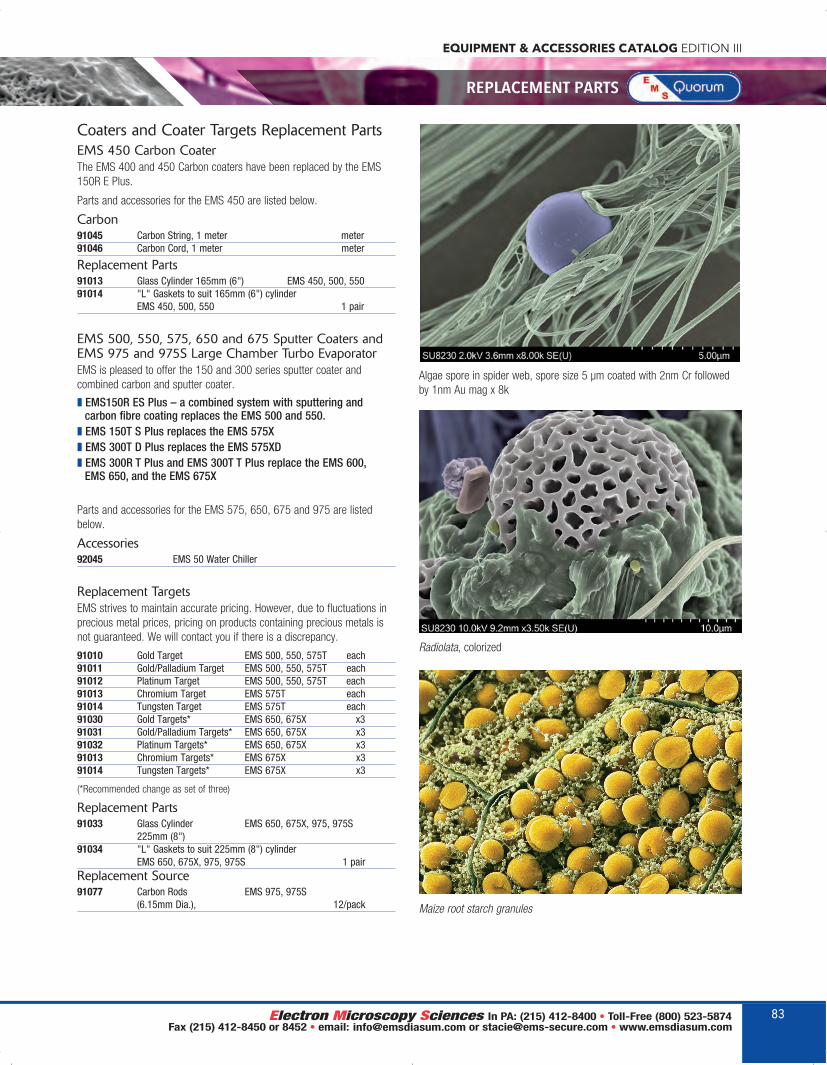
EQUIPMENT & ACCESSORIES CATALOG EDITION III
REPLACEMENT PARTS
Coaters and Coater Targets Replacement PartsEMS 450 Carbon CoaterThe EMS 400 and 450 Carbon coaters have been replaced by the EMS150R E Plus.
Parts and accessories for the EMS 450 are listed below.
Carbon91045 Carbon String, 1 meter meter 91046 Carbon Cord, 1 meter meter
Replacement Parts91013 Glass Cylinder 165mm (6") EMS 450, 500, 55091014 "L" Gaskets to suit 165mm (6") cylinder
EMS 450, 500, 550 1 pair
EMS 500, 550, 575, 650 and 675 Sputter Coaters andEMS 975 and 975S Large Chamber Turbo EvaporatorEMS is pleased to offer the 150 and 300 series sputter coater andcombined carbon and sputter coater.
z EMS150R ES Plus – a combined system with sputtering andcarbon fibre coating replaces the EMS 500 and 550.
z EMS 150T S Plus replaces the EMS 575Xz EMS 300T D Plus replaces the EMS 575XDz EMS 300R T Plus and EMS 300T T Plus replace the EMS 600, EMS 650, and the EMS 675X
Parts and accessories for the EMS 575, 650, 675 and 975 are listedbelow.
Accessories92045 EMS 50 Water Chiller
Replacement TargetsEMS strives to maintain accurate pricing. However, due to fluctuations inprecious metal prices, pricing on products containing precious metals isnot guaranteed. We will contact you if there is a discrepancy.
91010 Gold Target EMS 500, 550, 575T each91011 Gold/Palladium Target EMS 500, 550, 575T each91012 Platinum Target EMS 500, 550, 575T each 91013 Chromium Target EMS 575T each91014 Tungsten Target EMS 575T each91030 Gold Targets* EMS 650, 675X x3 91031 Gold/Palladium Targets* EMS 650, 675X x391032 Platinum Targets* EMS 650, 675X x391013 Chromium Targets* EMS 675X x391014 Tungsten Targets* EMS 675X x3
(*Recommended change as set of three)
Replacement Parts91033 Glass Cylinder EMS 650, 675X, 975, 975S
225mm (8") 91034 "L" Gaskets to suit 225mm (8") cylinder
EMS 650, 675X, 975, 975S 1 pairReplacement Source91077 Carbon Rods EMS 975, 975S
(6.15mm Dia.), 12/pack
Radiolata, colorized
Maize root starch granules
Algae spore in spider web, spore size 5 μm coated with 2nm Cr followedby 1nm Au mag x 8k
83
EMS_EquipmentCat2019_72-84_EMS_Catalog 2018 Edition 11/5/18 6:43 AM Page 83

EQUIPMENT & ACCESSORIES CATALOG EDITION III
SPECIMEN TRANSFER SYSTEMS
84
Selection Guide: Specimen Stages for EMS EquipmentThe EMS line of specimen stages meets most requirements. All are easy-change, drop-in style(no screws) and are height adjustable (except rotary planetary stage). Examples:
Cat # Stage Type Description Compatible Equipment4500-1 50mm Standard stage with six stub positions All EMS Series
for 15 mm or 6.5 mm or 1/8" pin stubs (same as #3330, 6401, 6552)
4500-2 Tilt Rotate-tilt stage with six stub positions All EMS Seriesfor 15 mm or 6.5 mm or 1/8" pin stubs. Tilts Up to 90° from horizontal (same as #3340, 4519, 6400-S, 6551)
4500-3 4" Wafer Adjusts to accept 2", 3", 4" wafers All EMS Seriescomes with 4500-6, a 4" stub holder to accept up to 18 1/8 pin stubs (same as #6549)
4500-4 6" Wafer Adjusts to accept 4" & 6" wafers EMS 300 comes with 4500-7, a 6" stub holder to accept up to 27 1/8 pin stubs (same as #6547)
4500-5 8" Wafer Adjusts to accept 6" & 8" wafers EMS 300T T Pluscomes with 4500-8, an 8" stub holder to accept EMS 300R Tup to 54 1/8 pin stubs
4500-6 4" Stub Holder A 4" stub holder to accept up to 18 1/8 pin stubs All EMS Series4500-7 6" Stub Holder A 6" stub holder to accept up to 27 1/8 pin stubs EMS 300T T Plus
EMS 300R TEMS 300T D Plus
4500-8 8" Stub Holder An 8" stub holder to accept up to 54 1/8 pin stubs EMS 300T T PlusEMS 300R T
4500-9 4" Wafer & A combination of 4500-3 and a small gearbox EMS 150T PlusOffset Gearbox to offset the sample position Enable even coating of EMS 150R Plus
up to a 4" sample size. (same as #3360, 4522) 4500-10 Fiber Stage A stage accept single fibers or pins up to 1 mm dia. EMS 150T Plus
rotating horizontally to achieve all round coating EMS 150R Plus4500-11 6" Square Wafer Stage to accept 6" square wafer or Masks EMS 300T T Plus
EMS 300R T4500-12 Rota Cota "Rota Cota" planetary stage with six stub positions EMS 150T Plus
for 15 mm or 6.5 mm or 1/8" pin stubs. Tilts up to EMS 150R Plus30° from horizontal (same as #4521, 6402, 6553)
4500-13 8 Place Stub 8 places for 25 or 30mm Polished embedded samples. All EMS SeriesIncludes a polished Brass Tally
4500-14 14 Place Stub 14 places for 25 or 30mm Polished embedded samples. All EMS SeriesIncludes a polished Brass Tally
4500-15 9 Place Coverslip A Stage to accept 9 20X20 cover slips. All EMS SeriesThe top part of stage lifts off and has a mechanism to lift the cover slips for easy removal
4500-16 4 Place 25mm Stub 4 Place 25mm Stub Stage with locking screws. All EMS SeriesMay be fitted to 4500-12 rota cota stage
4500-17 Slide Stage Microscope slide stage for up to two 75 mm x All EMS Series25 mm slides or eight stub positions for pin stubs. (same as #3370, 4520, 6403, 6554)
4500-2 Tilt Angle
4500-3 4" Wafer
4500-12 Rotary Planetary
4500-13 8 Place Stub
4500-14 14 Place Stub
4500-15 9 Place Coverslip
4500-16 4 Place 25mm Stub
4500-17 Glass Microscope
EMS_EquipmentCat2019_72-84_EMS_Catalog 2018 Edition 11/5/18 6:43 AM Page 84

Our new academy is now open! Located minutes from Philadelphia, next to ourextensive warehouse in Hatfield, PA, we havemany offerings led by our certified faculty:• Ten Educational Workshops• Corporate Training• Group Training• Private Training• Equipment Demonstrations
Watch for our latest updated schedule!Plan to sign up and bring your career to the next level!
NEWEST WORKSHOPS:Aurion ImmunoGold Silver StainingAutomated Rapid ProcessingBiological SEMBiological TEMCryosectioning/ImmunogoldIntroduction to Microscopy Techniques Cryo SEMMaterials UltramicrotomyX-Ray Microanalysis
Electron Microscopy Sciences • 1560 Industry Road, Hatfield, PA 19440 • phone: 215-412-8400 • email: [email protected]
SIGN UP FOR A CLASS TODAY, OR SUGGEST A COURSE THAT YOU WANT...
...ENDLESS POSSIBILITIES
www.emsmicroscopyacademy.comP.O. Box 550 • 1560 Industry Rd.Hatfield, PA 19440Tel: (215) 412-8400Fax: (215) 412-8450email: [email protected]
www.emsdiasum.com
At Electron MicroscopySciences, we love sharingour knowledge andexperience with ourcustomers. And with socialmedia, there are even moreways to reach out. But wealso love hearing from YOU!Either way, there’s plenty tosee, share, and enjoy...• Trade Show Information• New Product
Announcements• News, Polls, & Contests• Technical Notes
from Stacie• Networking with fellow
researchers• Instructional Video• ...and lots more
We hope to see youthere!
Follow us on Social Media...
EMS_EquipmentCat2019_OBC_OFC_Layout 1 11/5/18 11:11 AM Page 3