US 7667356 B2
27
US007667356B2 (12) Ulllted States Patent (10) Patent N0.: US 7,667,356 B2 Togare (45) Date of Patent: Feb. 23, 2010 (54) MAGNETIC PISTONS ENGINE 3,872,840 A 3/1975 Adragna 3,878,412 A * 4/1975 Kurpanek .................. .. 310/24 (75) Inventor: Radhakrishna Shesha Iyengar Togare, 3,952,709 A 4/ 1976 Riddle X on Labs 3500 SE' 175thAVe_ 4,012,675 A * 3/1977 SchulZe, Jr. ................ .. 318/37 ’ 4,129,040 A 12/1978 Hayden, Jr. VanC°uVer’WA(US)98683 4,368,396 A * 1/1983 Humphrey ................. .. 310/27 (73) Assignee: Radhakrishna Shesha Iyengar Togare, i glomton et al' , , emmner VanwuVer’WAwS) 4,631,455 A * 12/1986 Taishoff 318/37 * _ _ _ _ _ 4,749,893 A * 6/1988 Reynolds ................... .. 310/24 ( ) Not1ce: Subject to any disclaimer, the term of this 5,078,167 A 1/1992 Brandt et a1‘ patent is extended or adjusted under 35 5,219,034 A * 6/1993 Wortham ............... .. 180/6531 U.S.C. 154(b) by 344 days. 5,457,349 A * 10/1995 Gifford ...................... .. 310/24 5,469,004 A * 11/1995 Jachim ...................... .. 310/24 (21) App1.NO.Z 11/811,467 5,714,829 A 2/1998 Guruprasad 5,833,440 A * 11/1998 Berling ..................... .. 417/418 (22) Filed: Jun. 11,2007 7,025,036 B2 4/2006 Lampard 7,105,958 B1 9/2006 Elmaleh (65) Prior Publication Data 7,128,045 B2 10/2006 Roelofs 7,157,996 B2 1/2007 Enomoto et al. US 2008/0012432 A1 Jan. 17, 2008 7,163,003 B2 1/2007 Bradford Related US. Application Data * Cited by examiner (60) Provisional application No. 60/813,259, ?led on Jun. P 1’ imary ExamineriThanh Lam 12, 2006. (57) ABSTRACT (51) Int. Cl. _ _ _ _ H02K 7/06 (200601) The present 1nvent1on relates to the “Magnetic p1stons (52) U 5 Cl 3.10/24, 310/15 310/3 4 engine”, hereafter called “Maps engine” or “RAT engine” or “engine” that Works on the principle of magnetism. It can be used to perform various tasks and functions that involve application of force or displacement of objects. This method provides an environmental friendly, very high ef?ciency (56) References Cited engine that can complement or replace any engines that use fossil fuel, bio-fuel, solar poWer, Wind poWer, hydro poWer, electricity, stored energy, or other energy sources. (58) Field of Classi?cation Search ................. .. 310/ 15, 310/17*20,23*26, 31*35 See application ?le for complete search history. US. PATENT DOCUMENTS 3,676,719 A * 7/1972 Pecci ........................ .. 310/24 3,782,107 A 1/ 1974 Bendall 3 Claims, 17 Drawing Sheets - F1 ”/ 9 Power = Rechargeable 5 . battery generatlon 5 system i 4 III + RAT oontrol pulses RAT Plate .1 U U U L Central Driver Processor i l TDC/BDC pulse trains TDC/BDC l] l |] [1 position detector
-
Upload
khangminh22 -
Category
Documents
-
view
0 -
download
0
Transcript of US 7667356 B2

US007667356B2
(12) Ulllted States Patent (10) Patent N0.: US 7,667,356 B2 Togare (45) Date of Patent: Feb. 23, 2010
(54) MAGNETIC PISTONS ENGINE 3,872,840 A 3/1975 Adragna 3,878,412 A * 4/1975 Kurpanek .................. .. 310/24
(75) Inventor: Radhakrishna Shesha Iyengar Togare, 3,952,709 A 4/ 1976 Riddle X on Labs 3500 SE' 175thAVe_ 4,012,675 A * 3/1977 SchulZe, Jr. ................ .. 318/37
’ 4,129,040 A 12/1978 Hayden, Jr. VanC°uVer’WA(US)98683 4,368,396 A * 1/1983 Humphrey ................. .. 310/27
(73) Assignee: Radhakrishna Shesha Iyengar Togare, i glomton et al' , , emmner
VanwuVer’WAwS) 4,631,455 A * 12/1986 Taishoff 318/37 * _ _ _ _ _ 4,749,893 A * 6/1988 Reynolds ................... .. 310/24
( ) Not1ce: Subject to any disclaimer, the term of this 5,078,167 A 1/1992 Brandt et a1‘ patent is extended or adjusted under 35 5,219,034 A * 6/1993 Wortham ............... .. 180/6531 U.S.C. 154(b) by 344 days. 5,457,349 A * 10/1995 Gifford ...................... .. 310/24
5,469,004 A * 11/1995 Jachim ...................... .. 310/24
(21) App1.NO.Z 11/811,467 5,714,829 A 2/1998 Guruprasad 5,833,440 A * 11/1998 Berling ..................... .. 417/418
(22) Filed: Jun. 11,2007 7,025,036 B2 4/2006 Lampard 7,105,958 B1 9/2006 Elmaleh
(65) Prior Publication Data 7,128,045 B2 10/2006 Roelofs 7,157,996 B2 1/2007 Enomoto et al.
US 2008/0012432 A1 Jan. 17, 2008 7,163,003 B2 1/2007 Bradford
Related US. Application Data * Cited by examiner
(60) Provisional application No. 60/813,259, ?led on Jun. P 1’ imary ExamineriThanh Lam 12, 2006.
(57) ABSTRACT (51) Int. Cl. _ _ _ _
H02K 7/06 (200601) The present 1nvent1on relates to the “Magnetic p1stons (52) U 5 Cl 3.10/24, 310/15 310/3 4 engine”, hereafter called “Maps engine” or “RAT engine” or
“engine” that Works on the principle of magnetism. It can be used to perform various tasks and functions that involve application of force or displacement of objects. This method provides an environmental friendly, very high ef?ciency
(56) References Cited engine that can complement or replace any engines that use fossil fuel, bio-fuel, solar poWer, Wind poWer, hydro poWer, electricity, stored energy, or other energy sources.
(58) Field of Classi?cation Search ................. .. 310/ 15,
310/17*20,23*26, 31*35 See application ?le for complete search history.
US. PATENT DOCUMENTS
3,676,719 A * 7/1972 Pecci ........................ .. 310/24
3,782,107 A 1/ 1974 Bendall 3 Claims, 17 Drawing Sheets
- F1 ”/ 9 Power = Rechargeable 5 . battery
generatlon 5 system i 4 III
+
RAT oontrol pulses
RAT Plate .1 U U U L Central Driver Processor
i l
TDC/BDC pulse trains TDC/BDC l] l |] [1 position detector

US. Patent Feb. 23, 2010 Sheet 1 0f 17 US 7,667,356 B2
Power = Rechargeable ' . batte generation ry
? system i z
. III’ 4 I I r 5 + 1 + 9
, 1
;, RAT control pulses
W Central RAT Plate ‘1 Driver Processor
, g‘
4 a l i l 4 T I I 1
r V15 3 ? TDC/BDC pulse trains @ g TDCIBDC " || n n I I position
Z Z detector JLJLJLL I I 1111/,
FIG. 1

US. Patent Feb. 23, 2010 Sheet 2 0f 17 US 7,667,356 B2
NORTH
SOUTH
FIG. 2
SOUTH
NORTH
FORCE OF REPULSION (F)
SOUTH
NORTH
FIG. 4 FIG. 3

US. Patent Feb. 23, 2010 Sheet 3 0f 17 US 7,667,356 B2
FORCE OF REPULSION (F)
3 EXTERNAL DIRECT 1 FORCE (F')
FORCE OF REPULSION (F)
,/1 EXTERNAL DIRECT 3 FORCE (F')
FIG. 8 FIG. 7 FIG. 6 FIG. 5
FIG. 12 FIG. 1 1 FIG. 10 FIG. 9
US. Patent Feb. 23, 2010 Sheet 4 0f 17 US 7,667,356 B2
_ —>
Pulled ........................ FIG. 14
............. -. . ........ V I I I I I I I l I I I I l l I I l l | I l I l i l 1 I l l I l I l I II
FIG. 18 FIG. 16

US. Patent Feb. 23, 2010 Sheet 5 0f 17 US 7,667,356 B2
~ m2
Mia '22} mm

US. Patent Feb. 23, 2010 Sheet 6 6f 17 US 7,667,356 B2
1427543.?!
":35;
26mg

US. Patent Feb. 23, 2010 Sheet 7 0f 17 US 7,667,356 B2
Axle for loading 8 l!+_l Rechargeable
I T
Power battery I r’ generatlon (18) g a system (17)
I
12 7% % +
RAT control pulses Central
4 Processor (16)
12
TDC/BBC TDC/BDC pulse trains position _|l_Jl_ll_JL_ detector || |] [I |]
TDC
Repulsion pulse
5°C F F l l Attraction
pulse
0 1T 2T 3T : t
(T= Time taken for each revolution of the crankshaft 8)
FIG. 29

US. Patent Feb. 23, 2010 Sheet 8 0f 17 US 7,667,356 B2

US. Patent Feb. 23, 2010 Sheet 9 0f 17 US 7,667,356 B2
FIG. 36

US. Patent Feb. 23, 2010 Sheet 10 0f 17 US 7,667,356 B2
' Fig.
mgwmam

US. Patent Feb. 23, 2010 Sheet 11 0f 17
r mawaamem
&_
wig; 43
e
a???

US. Patent Feb. 23, 2010 Sheet 12 0f 17 US 7,667,356 B2
Nmwamm whiz
1551912211121:11661623121111;
was}??? zmgsiir?i?z'
, ........................ ................... E 2
' Qfé?'i??i?i?'

US. Patent Feb. 23, 2010 Sheet 13 0f 17 US 7,667,356 B2
34.54.54; H 62.12:...
9.2.920? ,
1%?
3% 3
, 33

US. Patent Feb. 23, 2010 Sheet 14 0f 17 US 7,667,356 B2
US. Patent Feb. 23, 2010 Sheet 15 0f 17 US 7,667,356 B2
{$2,395 $256M
.1;
8
FELL

US. Patent
mm
Feb. 23, 2010 Sheet 16 0f 17 US 7,667,356 B2
if
Fa:
M.

US. Patent Feb. 23, 2010 Sheet 17 0f 17 US 7,667,356 B2
|—r—>|'-_| [*1 DC Rechargeable
Generator battery
_ ‘ RAT plate
J
\ RAT control pulses
/ i Maps - 2 RAT plate I J‘uLrLrL Central
driver I processor a l A
RAT plate driver
Maps - 3
TDC/BDC position detector TDCIBDC pulse trains
FIG. 63
US 7,667,356 B2 1
MAGNETIC PISTONS ENGINE
CROSS-REFERENCE TO RELATED APPLICATION
This application claims the bene?t of US. provisional patent application Ser. No. 60/813,259 ?led Jun. 12, 2006.
FIELD OF THE INVENTION
The present invention relates to the “Magnetic pistons engine”, hereafter called “Maps engine” or “RAT engine” or “engine” that Works on the principle of magnetism. It can be used to perform various tasks and functions that involve application of force or displacement of objects. This method provides an environmental friendly, very high e?iciency engine that can complement or replace any engines that use fossil fuel, bio-fuel, solar poWer, Wind poWer, hydro poWer, electricity, stored energy, or other energy sources.
BACKGROUND OF THE INVENTION
Generating linear or circular motion poWer using different technologies is knoWn for centuries. There are many types of engines to accomplish this. Internal Combustion engines and Steam engines are feW examples of linear reciprocating engines. While Internal Combustion engines mainly use fos sil fuel steam engines use hydro poWer. In all such engines, the reciprocating motion generated by the linear movement of one or more pistons is converted to the circular motion With the help of a crankshaft assembly. The engine is generally integrated Within the main product (or machine) and serves as the heart of the equipment. Such an engine can be used as an automobile engine, aircraft engine, locomotive engine, ship engine, poWer generator engine, etc.
With the diminishing fossil fuel resources and unabated increase in energy costs and environmental concerns, engines using alternate energy sources such as bio-fuel, solar poWer, Wind poWer, electric poWer, stored poWer, etc. are being developed around the World. HoWever, such engines have many limitations. Production of bio-fuel takes enormous resources and they still pollute the environment. They do not meet the ever increasing energy demand as Well. Engines that use storage poWer sources like batteries or compressed air have energy density issues. Similarly, the solar poWer is not e?icient. Added to all, the initial capital and subsequent main tenance costs for machines that use alternate energy sources are very high. Further, the electricity that is used to charge the batteries or to re?ll the compressed-air tank may be produced from a thermal poWer plant that is again a concern for envi ronmental pollution. Hence, in the absence of a viable alter native, until noW, sWitching to neW technology by changing from traditional Internal Combustion engines has been a chal lenge.
BRIEF DESCRIPTION AND SUMMARY OF THE INVENTION
The invention of Magnetic pistons engine, also called Maps engine, RAT engine, or engine, shoWn in FIG. 1, gen erally relates to the reciprocating engine based on linear, back-and-forth movement of the pistons and the improve ments thereto. The uniqueness of this invention comes from the fact that Maps engine can be effectively integrated With equipments and machines that need engine to perform various tasks and functions. It can Work as an automobile engine, aircraft engine, locomotive engine, ship engine, laWn mover
20
25
30
35
40
45
50
55
60
65
2 engine, etc. depending on the requirement. In general, it can complement or replace existing engines that use fossil fuel, bio-fuel, electric poWer, solar poWer, Wind poWer or stored poWer, etc. Further, it can also be used to drive the poWer generators to produce the electricity. The use of Maps engine is limitless When the application area is considered.
Unlike Steam engines and Internal Combustion engines, Maps engine is environmentally very safe since it does not burn any fuel. Due to the rising fuel costs, environmental issues and diminishing natural fuel reserves, Maps engine can become a viable alternative to many existing engines.
Further, due to the principle of its operation, Maps engine uses very loW poWer (small force) to generate very high poWer (large force). Hence, Maps engine Works at very high e?i ciency With the possibility of reaching unity-over operation mode.
BRIEF DESCRIPTION OF THE DRAWINGS
FIG. 1 shoWs the basic con?guration of Magnetic pistons engine, also called Maps engine, RAT engine, or engine With closed loop control.
FIG. 2 shoWs a cylindrical shaped permanent magnet With its imaginary ?ux lines leaving-out from the north pole and entering-in from the south pole.
FIG. 3 shoWs the principle of force of attraction betWeen the unlike poles of tWo permanent magnets.
FIG. 4 shoWs the principle of force of repulsion betWeen the like poles of tWo permanent magnets.
FIG. 5 shoWs the principle of force of repulsion betWeen the like poles of tWo permanent magnets.
FIG. 6 shoWs tWo permanent magnets, Whose like poles are facing each other, brought near each other With the applica tion of external direct forces.
FIG. 7 shoWs tWo permanent magnets, Whose like poles are facing each other, being repelled the moment the external applied forces are removed.
FIG. 8 shoWs the repelling magnets stopped by the stoppers located at extreme ends While the magnets are still Within each others magnetic ?eld.
FIG. 9 shoWs the repelling magnets stopped by the stoppers located at extreme ends While the magnets are still Within each others magnetic ?eld.
FIG. 10 shoWs the tWo permanent magnets, Whose like poles are facing each other, being attracted by a ferromagnetic plate (sheet) such as iron placed in betWeen them.
FIG. 11 shoWs the tWo permanent magnets, Whose like poles are facing each other, attracted to the ferromagnetic plate (sheet) such as iron When placed in betWeen them.
FIG. 12 shoWs the tWo repelling magnets stopped by their stoppers after they are repelled due to the removal of ferro magnetic plate, While the magnets are still Within each others magnetic ?eld.
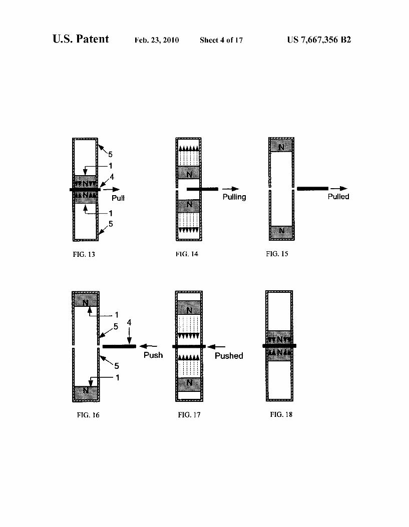
FIG. 13 shoWs the cross sectional vieW of tWo cylindrical magnets inside their respective non-magnetic (metallic or non-metallic) cylinders, Whose like poles are facing each other, attracted to the ferromagnetic plate placed in betWeen them.
FIG. 14 shoWs the cross sectional vieW of tWo repelling magnets moving aWay from each other inside their respective non-magnetic cylinders While the ferromagnetic plate that Was placed in betWeen them is being removed.
FIG. 15 shoWs the cross sectional vieW of tWo repelling magnets stopped at the end of their respective non-magnetic cylinders due to the removal of ferromagnetic plate While the magnets are still Within each others magnetic ?eld.

US 7,667,356 B2 3
FIG. 16 shows the cross sectional vieW of tWo repelling magnets, resting at their respective end of their non-magnetic cylinder, ready for attraction When the ferromagnetic plate is pushed in betWeen them.
FIG. 17 shoWs the cross sectional vieW of tWo repelling magnets that Were resting at their respective end of their non-magnetic cylinder, being attracted by a ferromagnetic plate placed in betWeen them.
FIG. 18 shoWs the cross sectional vieW of tWo repelling magnets in their respective non-magnetic attracted to the ferromagnetic sheet placed in betWeen them inside the cylin der.
FIG. 19 shoWs the cross sectional vieW of the basic Mag netic pistons engine With both the opposing pistons ready for repulsion from their Top Dead Centers When the iron plate placed in betWeen them is pulled out.
FIG. 20 shoWs the cross sectional vieW of the basic Mag netic pistons engine With both the opposing pistons ready for attraction from their Bottom Dead Centers When the iron plate is pushed in betWeen them.
FIG. 21 shoWs a general vieW of the basic Magnetic pistons engine With both the ?yWheels coupled by a common ?y Wheel rod.
FIG. 22 shoWs the cross sectional vieW of the basic Mag netic pistons engine, With both the opposing pistons at Top Dead Centers, ready for repulsion stroke When the ferromag netic (iron) plate placed in betWeen them is pulled out.
FIG. 23 shoWs the cross sectional vieW of the basic Mag netic pistons engine With both the opposing pistons being repelled during the repulsion stroke While the iron plate placed in betWeen them is being removed.
FIG. 24 shoWs the cross sectional vieW of the basic Mag netic pistons engine, With both the opposing pistons at their Bottom Dead Centers When they are fully repelled due to the removal of iron plate placed in betWeen them.
FIG. 25 shoWs the cross sectional vieW of the basic Mag netic pistons engine With both the opposing pistons at Bottom Dead Centers at the beginning of the attraction stroke after the iron plate is pushed in betWeen them.
FIG. 26 shoWs the cross sectional vieW of the basic Mag netic pistons engine With both the opposing pistons moving toWards their Top Dead Centers When the iron plate is pushed in-betWeen them during the attraction stroke.
FIG. 27 shoWs the cross sectional vieW of the basic Mag netic pistons engine With both the opposing pistons ready for the next RAT (repulsion-attraction) cycle.
FIG. 28 is the reproduction of FIG. 1, Which shoWs the basic con?guration of Magnetic pistons engine With closed loop control.
FIG. 29 shoWs the timing diagram of different events that occur during the operation of Maps engine.
FIG. 30 shoWs the top plan vieW of the magnetic piston shoWn in FIG. 32.
FIG. 31 shoWs the left side (crankshaft side) elevation vieW of the magnetic piston shoWn in FIG. 32.
FIG. 32 shoWs the front elevation vieW of a typical mag netic piston used in Magnetic pistons engine.
FIG. 33 shoWs the right side (Rat plate side) elevation vieW, Which is also the piston head’s vieW, of the magnetic piston shoWn in FIG. 32. Note that the thin non-magnetic protection layer that protects the piston head is not shoWn in the ?gure.
FIG. 34 shoWs the cross sectional vieW of magnetic piston (Without thin, non-magnetic protective layer that covers the piston head) shoWn in FIG. 32 as seen from AA’.
20
25
30
35
40
45
50
55
60
65
4 FIG. 35 shoWs the cross sectional vieW of magnetic piston
shoWn in FIG. 32, With the piston head covered by thin, non-magnetic protective layer of su?icient thickness (identi ?ed by arroW 21).
FIG. 36 shoWs the cross-sectional vieW of a typical non magnetic (but metallic) piston cylinder shoWn inside the cas ing of the Maps engine.
FIG. 37 shoWs the front and side elevation vieWs of a typical non-magnetic (but metallic), inner and outer tubes used in the construction of Maps engine cylinder.
FIG. 38 shoWs the front and side elevation vieWs of non magnetic (but metallic), semi-circular laminations used for making intermediate concentric tube used in the construction of Maps engine cylinder.
FIG. 39 shoWs the ferromagnetic laminations used in the construction of RAT plate.
FIG. 40 shoWs the front side elevation vieW of RAT plate constructed using the laminations shoWn in FIG. 39 for use in Maps engine.
FIG. 40a shoWs the top plan vieW of RAT plate shoWn in FIG. 40.
FIG. 41 shoWs the electromagnetic solenoid type direct linear driver used for driving RAT plate. The RAT plate, Which is operated by the movable plunger, is pushed in betWeen the like pole piston heads during the attraction stroke. Note that the dotted circle shoWs piston head on one side of the RAT plate.
FIG. 42 shoWs the electromagnetic solenoid operated RAT plate pulled-out from in-betWeen the like pole piston heads during the repulsion stroke.
FIG. 43 shoWs the electromagnetic solenoid operated RAT plate pushed-in betWeen the large, non-cylindrical like pole piston heads (only one side piston head is shoWn) during the attraction stroke.
FIG. 44 shoWs the electromagnetic solenoid operated RAT plate pulled-out from in-betWeen the large, non-cylindrical like pole piston heads (magaZine shoWn in ?gure) during the repulsion stroke.
FIG. 45 shoWs the operation of indirect, reciprocating type RAT plate driver. The RAT plate (that is operated by the reciprocating rod, identi?ed by arroW 36) is pushed-in betWeen the like pole piston heads during the attraction stroke.
FIG. 46 shoWs the indirectly driven RAT plate pulled-out from in-betWeen the like pole piston heads during the repul sion stroke.
FIG. 47 shoWs the indirectly driven RAT plate pushed-in betWeen large, non-cylindrical like pole piston heads during the attraction stroke.
FIG. 48 shoWs the indirectly driven RAT plate pulled-out from in-betWeen the large, non-cylindrical like pole piston heads (oval shoWn in ?gure) during the repulsion stroke.
FIG. 49 shoWs the pneumatic poWered RAT plate driver, identi?ed by block 14 in FIG. 28.
FIG. 50 shoWs the steam poWered RAT plate driver, iden ti?ed by block 14 in FIG. 28.
FIG. 51 shoWs CAM operated TDC/BDC (Top Dead Cen ter/Bottom Dead Center) position detection and pulse gen eration system When the piston is at Top Dead Center.
FIG. 52 shoWs CAM operated TDC/BDC (Top Dead Cen ter/Bottom Dead Center) position detection and pulse gen eration system When the piston is at Bottom Dead Center.
FIG. 53 shoWs separate TDC and BDC pulse trains gener ated using TDC/BDC position detector and pulse generator system shoWn in FIG. 51/52.
FIG. 54 shoWs optical-sWitch operated TDC/BDC position detection and pulse generation system.