FOCKE WULF TA152H
64
1 FOCKE WULF TA152H 1/5TH SCALE 114” span, 50 cc Video and plans are also available for free download at www.mnbigbirds.com Designed by David P. Andersen, November, 2008 CONSTRUCTION NOTES Table of Contents: Fuselage Assembly page 2 Stab & Fin Assembly page 24 Aileron Assembly page 27 Flap Assembly page 29 Main Landing Gear page 31 Wing Assembly page 34 Detailing page 41 Completed Aircraft Details page 49 Parts List & References 56 Markings page 59 Documentation and 3-views page 61 Flying the 1/5 th Scale Focke Wulf TA 152H page 63 Modelers’ Comments page 64 The email address that appears on the plans is no longer valid. See the Contact David Andersen notice on www.mnbigbirds instead.
-
Upload
khangminh22 -
Category
Documents
-
view
0 -
download
0
Transcript of FOCKE WULF TA152H

1
FOCKE WULF TA152H 1/5TH SCALE 114” span, 50 cc
Video and plans are also available for free download at www.mnbigbirds.com
Designed by David P. Andersen, November, 2008
CONSTRUCTION NOTES Table of Contents:
Fuselage Assembly page 2
Stab & Fin Assembly page 24
Aileron Assembly page 27
Flap Assembly page 29
Main Landing Gear page 31
Wing Assembly page 34
Detailing page 41
Completed Aircraft Details page 49
Parts List & References 56
Markings page 59
Documentation and 3-views page 61
Flying the 1/5th
Scale Focke Wulf TA 152H page 63
Modelers’ Comments page 64 The email address that appears on the plans is no longer valid. See the Contact David
Andersen notice on www.mnbigbirds instead.
2
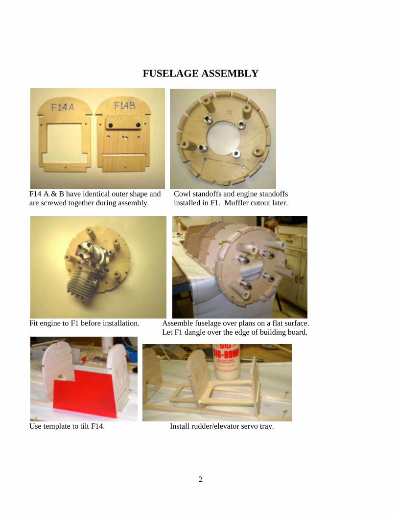
FUSELAGE ASSEMBLY
F14 A & B have identical outer shape and Cowl standoffs and engine standoffs
are screwed together during assembly. installed in F1. Muffler cutout later.
Fit engine to F1 before installation. Assemble fuselage over plans on a flat surface.
Let F1 dangle over the edge of building board.
Use template to tilt F14. Install rudder/elevator servo tray.

3
Trace & cut sheeting for stab saddle. Install sheeting on only one side for now for stiffness. Other side
later.
Install fuselage stringers. Bevel C1 canopy floor prior to sheeting
Install cockpit stuff before sheeting fuse. fuselage.
Tank box rear view. Separate F14A from F14B and remove.

4
Sheeting the upper fuselage.
Block-sand the sheeting around the canopy base. Carve the gun cover. A plastic
model reveals shape..
Hollowing the gun cover saves 2 ounces. Glue in place and filet the seam with spackle.

5
Carve F14-F15 block. Hollowing saves ½ oz. Form and paint instrument panel cover.
Assemble canopy frame. Headrest ready for covering.
Styrene headrest cover being glued in place. Shape headrest contour.

6
Fabricate REVI 16B gunsight from aluminum Forming leather headrest. Stuff it in
tube, flashlight bulb, clear tinted plastic, etc.. a balsa hole while the glue sets.
Installed oversized sheeting in instrument Use inst panel cover to mark trim line.
panel area.
Verify windscreen overlap with sheeting. Trim fuselage sides with razor blade.

7
Install instrument panel cover with Mold joystick from alum tube and epoxy.
clear canopy glue. Ready for carving.
Trial fit of pilot and seat. Install later. Install throttle cable tube before tank box.
Tailwheel fork secured with set screw. Completed tailwheel assembly.
8
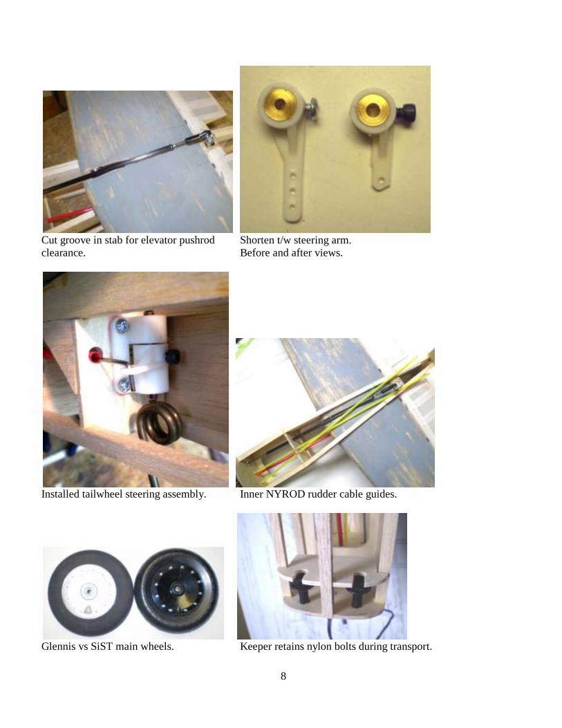
Cut groove in stab for elevator pushrod Shorten t/w steering arm.
clearance. Before and after views.
Installed tailwheel steering assembly. Inner NYROD rudder cable guides.
Glennis vs SiST main wheels. Keeper retains nylon bolts during transport.

9
Rough carve fairing. Verify t/w clearance. Rough sand tail with foamy sander.
Final sanding of tail. Note bolt access holes. T/w hole ready for glass.
Cut rudder cable guide flush with backless Tail ready for remaining glass.
razor saw. Masking tape protects surface.
10
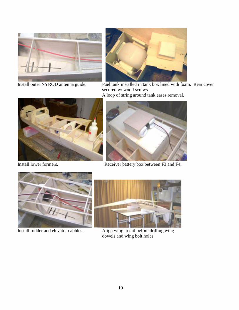
Install outer NYROD antenna guide. Fuel tank installed in tank box lined with foam. Rear cover
secured w/ wood screws.
A loop of string around tank eases removal.
Install lower formers. Receiver battery box between F3 and F4.
Install rudder and elevator cabbles. Align wing to tail before drilling wing
dowels and wing bolt holes.

11
Align, then drill holes for wing dowels. Install forward wing saddle doubler.
Install wing dowels.
Sheet fuselage bottom. Foot step cut from aluminum sheet (left)
Trimmed with aluminum duct tape (right).
Slot in fuselage is friction fit for removable Sheet the fuselage sides and bottom but…
foot step.
12
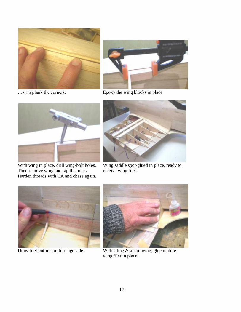
…strip plank the corners. Epoxy the wing blocks in place.
With wing in place, drill wing-bolt holes. Wing saddle spot-glued in place, ready to
Then remove wing and tap the holes. receive wing filet.
Harden threads with CA and chase again.
Draw filet outline on fuselage side. With ClingWrap on wing, glue middle
wing filet in place.

13
Mid filet glued in place, edge trimmed later. Moistened prebent rear wing filet.
Rear filet ready to be CA’ed in place. Fore filet fitted for forming.
Rough carving the fore filet. Shaping fore filet with woodcarver’s gouge.
Thumb injured in previous step.

14
Notch large stringer at F1. Block-sand nose stringers before sheeting.
Step 1: Pass muffler thru F1. Step 2: Turn manifold forward.
Step 3: Rotate into final position. Step 4: Install engine, attach muffler.

15
Step 5: Attach muffler to engine. Nose ready for sheeting.
Remove motor. Sheet bottom of nose. Use SeeTemp template to mark exhaust ports.
Cut exhaust ports. Trim with sanding tube. Final trimming of filet with wing in place.
Harden edge with CA.

16
Glue nosebowl quadrants together. Assemble the cowl form. Just spot-glue
Hold with masking tape and rubber bands. the base for later removal.
Soak cowl skin in hot water, wrap around Prebent cowl skin ready to be glued to
cowl frame. Let dry and remove. to cowl frame. Leave excess edge to be trimmed flush with
frame after drying.
Glue cowl skin to frame. Hold with #64 Rough-carve nose bowl using template
rubber bands. from plans.

17
Shape and sand inner surface of nose bowl. Trim cowl skin flush with frame.
Glue rough-carved nose bowl to frame. Wrap two layers of masking tape for cowl
flap clearance before final sanding of nose bowl.
Cut clearance in cowl for cylinder head. Make inner cowl fairing from 4 quadrants
of balsa.
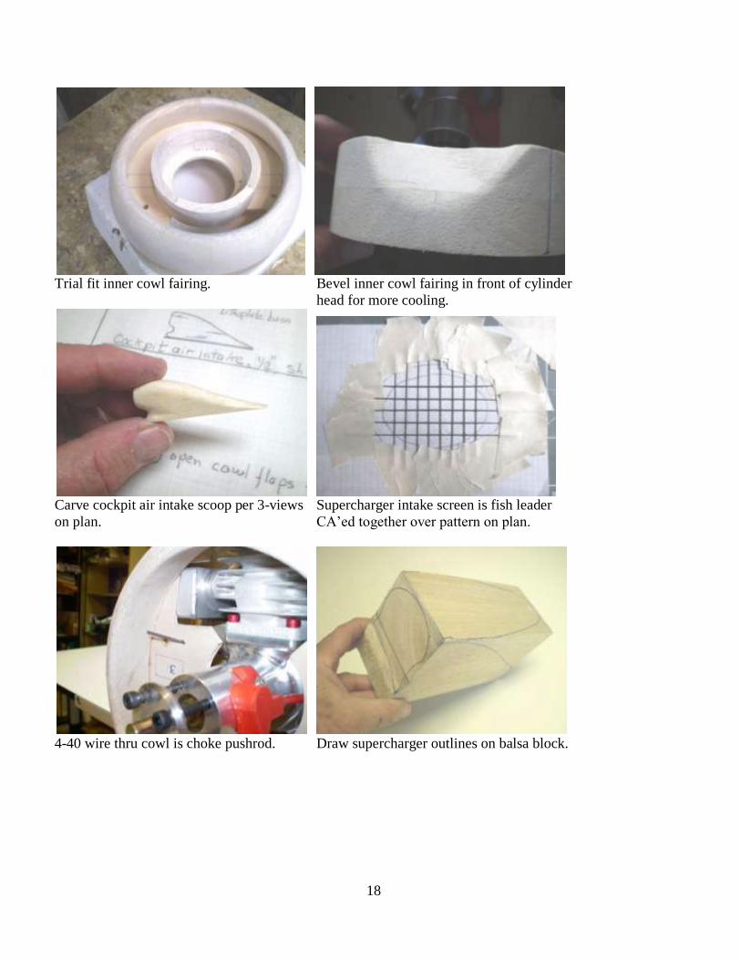
18
Trial fit inner cowl fairing. Bevel inner cowl fairing in front of cylinder
head for more cooling.
Carve cockpit air intake scoop per 3-views Supercharger intake screen is fish leader
on plan. CA’ed together over pattern on plan.
4-40 wire thru cowl is choke pushrod. Draw supercharger outlines on balsa block.

19
Cut top view, spot-glue back. Cut side Hollow out supercharger with a gouge and...
view, remove scrap. Round to final shape.
…smooth inside with a drum sander. Tape sandpaper to fuselage side and rub supercharger back and
forth for a flush fit.
Strange little hole in supercharger is Shape supercharger ring per photo while
aluminum tube CA’ed in place. it is pinned to supercharger.

20
Cover entire cabin air scoop with Cover supercharger ring with one piece of
one piece of fiberglass cloth and resin. fiberglass and resin.
Use SeeTemp template to mark exhaust Underside of vacuum-formed cannon covers
port openings. supported by ¼” x 1/8” balsa.
Vacuum form scale exhaust stack halves. Exhaust stacks airbrushed with copper, flat
Separate and assemble. Seam simulates black and light gray.
scale weld line.

21
Add 5/8”x1/4” TE stock to bottom of Cut and sand aufholen in rear fuselage.
exhaust stacks for proper angle.
Roughen inside canopy edge prior to gluing inplace, holding with tape and pins while
epoxy sets.
Using making tape as a guide, cut Trace canopy onto 1/8” ply to make a frame.
canopy loose from windscreen.

22
Canopy and windscreen frames, screwed Canopy alignment pin is woodscrew with
together, cut from stacked ply. with head removed. 1/8” ply backing.
Painted canopy and windscreen frames Clothes pins hold canopy frame while
ready for installation. epoxy sets.
Drywall patch aluminum screen in cowl AJAX #52 canopy hold-down spring.
kinda looks like a radiator.

23
Pull canopy spring thru the canopy floor Attach it to the canopy hook on the
with a loop of string. underside of the canopy.
Elevator and rudder-tailwheel servos. Ignition module installed on front of firewall.
Tank vent, fuel dot and ignition switch installed in scale exhaust area.

24
Stab and Fin Assembly
Assemble stab clam-shell halves over Gluing elevator ribs in place with CA.
stab plan on a flat surface.
Insert, but don’t glue Robart hinges in elev. Glue hinges in stab before combining
Use them to mark hinge positions in stab. stab clamshells.
Shape rudder w/ razorplane & sanding block. Final sanding with sanding block.
25
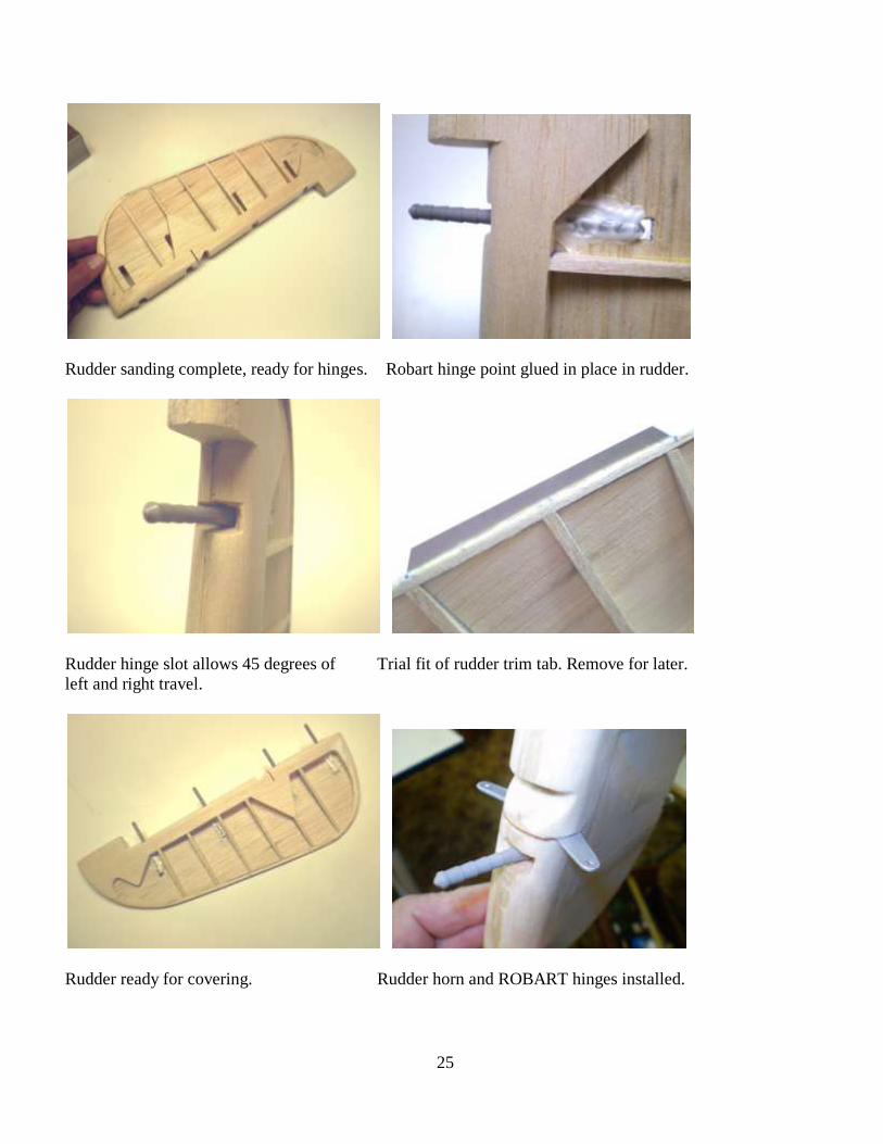
Rudder sanding complete, ready for hinges. Robart hinge point glued in place in rudder.
Rudder hinge slot allows 45 degrees of Trial fit of rudder trim tab. Remove for later.
left and right travel.
Rudder ready for covering. Rudder horn and ROBART hinges installed.

26
Fin structure being assembled on fuselage. Install fin sheeting—horizontal grain.
Stab/elevator already assembled and primed.
Ball driver access to tail bolts.

27
Aileron Assembly
Glue aileron skins to wing before Cut ailerons from wing with backless
sheeting wing. razor saw.
Trim aileron ribs back to fit aileron LE. Cut LE to fit aileron.
Install aileron leading edge. Drill centered holes for Robart himges.
28
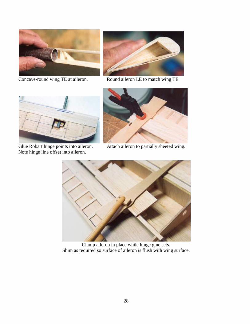
Concave-round wing TE at aileron. Round aileron LE to match wing TE.
Glue Robart hinge points into aileron. Attach aileron to partially sheeted wing.
Note hinge line offset into aileron.
Clamp aileron in place while hinge glue sets.
Shim as required so surface of aileron is flush with wing surface.

29
FLAP ASSEMBLY
Route balsa flap core for hinge. Glue flap hinges to balsa core.
Bevel flap core trailing edge. Attach ply flap skins with finishing resin.
Weight and clamp until resin is set.
Attach flap hinges to wing skin Install flap horn with epoxy and ¼” sq.
before installation. hard balsa supports.

30
Pin flap hinge to spar w/ lite ply backing. Cover flap hinge with 1/32” sheet balsa
and sand flush.
Install and test flap servo before sheeting upper wing surface.

31
Main Landing Gear
Replace this socket-head bolt with a hex bolt for better wheel hub clearance.
Lower door gear bracket is clamped to strut below scissor link.
Lower door is therefore adjustable and removeable.

32
Upper door is attached with brass tube spacers that also guide lower door travel.
Lower door bracket also shapes door.
Countersunk FH screw ready to be puttied.

33
Gear door cylinder on inner door is activated by an air micro switch contacted by the main strut. (See Parts
List.)
34
Wing Assembly
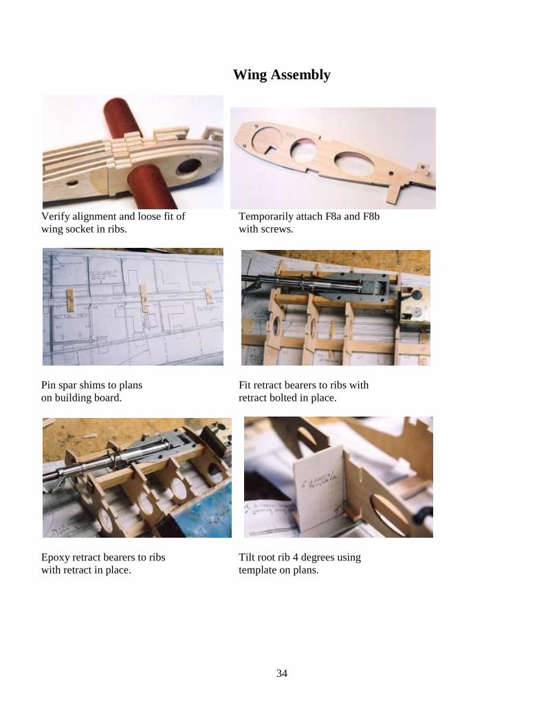
Verify alignment and loose fit of Temporarily attach F8a and F8b
wing socket in ribs. with screws.
Pin spar shims to plans Fit retract bearers to ribs with
on building board. retract bolted in place.
Epoxy retract bearers to ribs Tilt root rib 4 degrees using
with retract in place. template on plans.

35
Temporary 1/8” spacer between Subfloor sheeting on top
DB1 and R1 leaves space for surface. Slots await dihedral
later addition of DB2. braces.
Cut thru spars and tube at Remove screws at F8 before
F8 with backless razor saw. separating F8a and F8b.
Bevel lower spars at R1 and Inner wing section ready for
add spar doublers. sheeting. Air lines and retract gussets installed.

36
Top surface ready for Shear webs being installed in
sheeting, air lines installed. outer wing panel, lower aileron skin installed.
Start inner door assembly by Stack resin-wet door pieces
spot-gluing some sheet balsa together on wax paper on
in inner door area. wing. Clamp well until set.
Inner door, still on wax paper, Three-piece inner door
ready to be removed from wing. removed from wing.
37
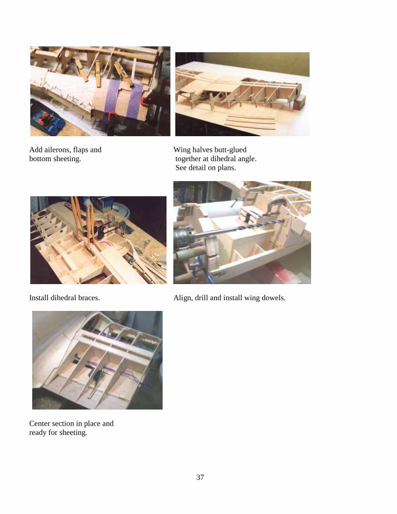
Add ailerons, flaps and Wing halves butt-glued
bottom sheeting. together at dihedral angle.
See detail on plans.
Install dihedral braces. Align, drill and install wing dowels.
Center section in place and
ready for sheeting.

38
Sheeting the center section Sheeting the center section
while in place on fuselage. flush with fuselage filet.
Drill and tap wing tubes after Leave a little gap between LE and fuselage
sheeting lower surface when sheeting lower wing.
Trim wing LE while wing is Fill wing LE with spackle
in place on fuselage. before adding inner doors.

39
Install doors first, then trim Contour spackle behind DB4 to
wing sheeting to match. wing and inner doors.
Mask flap and flap hinges Fill wing gap, if any, with microballoons
before glassing wing. & resin separated with wax paper. Then,
remove and trim.
Wing fairing molded from Rib stitching tool is squashed
microballoons & resin. aluminum tube.

40
Apply diluted white glue rib Rib tape in place over stitches.
stitches.

41
Detailing
42
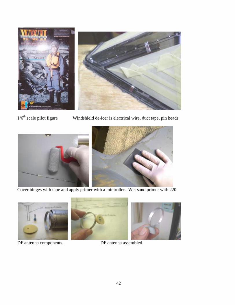
1/6th
scale pilot figure Windshield de-icer is electrical wire, duct tape, pin heads.
Cover hinges with tape and apply primer with a miniroller. Wet sand primer with 220.
DF antenna components. DF antenna assembled.

43
Attach canopy horns with methacrylate. Mask gun cover, apply auto body filler.
Body filler sanded to tape, tape removed. Completed gun cover.
Alum duct tape strips under cowl flap seams. Glue cowl flaps in place.

44
Red masking tape covers duct tape. Removing tape reveals duct tape between flaps.
Completed cowl. Mask off fuselage hatch.
Fuselage hatch covered with primer. Hatch sanded and mask removed.

45
Little hatch in back id 2 layers of duct tape. Micro Fasteners RVL104C alum rivets.
Tiny tail light in rudder. Removing Chart Pack 1/64
th panel line tape.
Removing tape reveals overlap style panel line. Duct tape hard points in bottom of wing.

46
Apply yellow glue drops to rivet tape. Remove rivet tape before the glue sets.
Round head rivets around exhaust ports. Panel lines, hatches ready for color paint.
Thin aluminum detail over wing joint. Pilot figure installed in seat, eager to fly.

47
Supercharger fishleader grill installed after painting. Completed supercharger intake.
Use paper pattern to trace Balken cross Masking the pinstripe around green 4.
before applying masking tape.
Long range VHF antenna for static display only. Rudder horn.

48
“Anzeigegerat”—incidence adjustment. JR HD ignition switch/charger.
Rudder rib stitching. Omni antenna screwed into wing.

49
Completed Aircraft Details.
Retractable step for static display only. Static display prop & spinner.

50

51

52
Open. Partly open. Fully closed.

53
At 2008 IMAA Ch 46 Fly-in in Minnesota.

54

55
Ready for flight on grass field.

56
Parts List & References
TA 152H Parts List :
Balsa unless otherwise stated.
Dimensions in inches.
3—3/32x4x36, 4-6 lb Filets, fin
1—3/8x3x36 Wing LE
38—1/8x3x36 Ribs(6), wing sht(18), fuse sht (10), other (4).
2—1/8x4x36 Formers
4—3/32x3x48 Aileron skins(2), flaps(2)
2—3/32x4x36 Shear webs
1—1x3x36 V2, guncover, fuse rear, wingtips
1—1/2x3x36 Rudderpost, rudder, s/charger intake, fairings
6—1/16x4x36 Fin, stab
1—2x2x12 block Fore filet
1—3/4x30x4 Stab
1—3x3x12 Supercharger
1—2x3x24 Nosebowl
2—1/32x4x36 Aileron ribs, inner doors
1—3/8x3x24 Aileron LE
10—1/4 sq x 36 Stringers
4—1/4x3/8x36 Stab
4—1/4x3/4x48 Headrest, spars
1—3/4x1/2x48 Upper wing spars
23—1/8x1/4x36 Fuse & wing stringers, shims, inner door support
3—1/2x1-1/2x48 Wing L.E.
2—1/2 triang x36 Gussets
1—1/2 sq.x24 Nose stringers
1—1/64x24x12 ply Flaps
1—1/8x12x48 ply Ribs, formers, dihedral braces
1—3/32x6x24 ply C1, windscreen frames, headrest
1—1/32x12x36 ply Wing saddle filet, aileron skins, inner doors
1—3/8x12x12 ply F1 (firewall)
1—1/8x12x48 liteply Formers, tankbox
1—1/4x12x12 liteply Cowl ring
1—1/8x1/4x36 h’wd Inner door support
1—1/2x3/4x18 maple Wing & tail mounting blocks
1—3/4 x36 dowel Cowl support
1—3/16x1/4x36 bass Elev T.E.
2—1/2x3/4x36 bass Lower wing spars
1—1/2x3/4x48 bass Retract bearers (4-4” lengths)

57
1—1/4 sq.x6 h’wd Canopy key.
1—3/8 birch dowel Wing rods
1—1/8 diax36 music wire Tailwheel strut
1—1/8” Nosegear bracket Tailwheel support
1—1/8” Nose gear steering arm Tailwheel.
1—12x24x0.016” sht aluminum LG doors (www.mcmaster.com)
4—SIG SH735 1/4x20 threaded inserts Cowl support
1—Hobby Lobby PP51041 Scale Cockpit kit or
1—IMP 1/5th
scale FW190 cockpit kit (www.impscale.com)
1—J’TEC 1/5th
scale instrument kit
1—AJAX #52 4-inch spring Canopy hold down
1---Pilot figure: Dragon Item 70632, WWII German Luftwaffe Ta 152 Pilot or
Dragon Item 70072, WW II German Luftwaffe Pilot, “Erich Hartmann”
2—Robart 165S 3/8” Gear Door Cylinder
2---Violett BVM #5753 Air Micro Switch Assembly
2—DJ Aerotech, SiST or Sierra 1/5th
scale FW 190D wheels
2—Sierra Giant Scale 1/5th
scale FW 190D/TA152H retracts and struts
4—Sierra Giant Scale 1/5th
scale door clamps
4—Sierra Giant Scale 1-1/4” Engine Standoffs
1—DJAerotech/SiST static display and flying f/g 5th
scale FW190D spinner or…
Sierra Giant Scale aluminum flying spinner.
Jeff Micko (vacuum formed canopy, exhaust stacks, gun covers, f/g cowl, f/g static prop blades)
http://www.mnbigbirds.com/Micko%20Products.htm
or email [email protected]
Wood kit available from Precision Cut Kits,
http://precisioncutkits.com/andersen-accessories/
1—1 ½” diameter TnT phenolic tube and socket
References:
http://www.mnbigbirds.com (free plan PDF files,
construction notes)
DML 5501 1:48 plastic model kit.
DML 5008 1:72 plastic model kit.
Focke Wulf TA 152 (history, drawings, markings)
Hitchcock, Eagle Editions
http://www.eagle-editions.com/Ta152.htm
Monogram Close-Up 24 TA152H.
German Aircraft Interiors, Vol 1. (cockpit details),
Merrick, Monogram Publications
Focke Wulf FW 190 (TA 152H isometric drawing, details),
Watenabe, Crown Publishers.
Complete Book of WWII Aircraft (color 3-view)
Angelucci, Military Press

58
Aero Detail 2, Focke Wulf 190D (markings)
Dai Nippon Kaiga, 1990
IPMS Color Cross-Reference Guide (FS colors)
David Klaus, PO Box 47110, Washington, DC 2005-7110
ProMark Graphics (dry transfer markings)
http://www.pro-mark.com/
Precision Cut Kits (wood kit, printed plans)
http://www.precisioncutkits.com/
Cornell Michael (wood kit)
http://www.kitcutter.com/
Belair Kits (wood kit, Europe)
http://www.belairkits.com/
RCScale Builder (forums, free plans)
http://www.rcscalebuilder.com/
SiST Modellflugzeuggebau (manufacturer of wheels and f/g spinner)
http://www.sist-modell.de/jagdflugz/a85/fw2.html
email: [email protected]
D J Aerotech (US distributer of SiST spinner and wheels)
http://www.djaerotech.com/dj_product/scale_fw190.html#opts
Sierra Giant Scale (retracts, wheels, engine standoffs, door clamps,
aluminum spinner)
http://www.sierragiant.com/
Desert Aircraft (DA 50 engine)
http://www.desertaircraft.com/
Bisson Custom Mufflers (custom FW190D/TA 152H muffler)
http://bissonmufflers.com/
TnT Landing Gear (wing tubes and sockets) http://www.tntlandinggear.com/

59
MV MV B4 B4 (on yellow triangles)
50 50 87 87 GM1 GM1
-- + + -- -- 0 Anzeigegerät (right) Anzeigegerät 0 -- (left) -- - - -- Nicht verstellen Nicht verstellen Nicht verstellen (top of aileron trim tabs)
Beim schlappen Beim schlappen Beim schlappen Höhenruder Höhenruder Höhenruder nach unten drücken nach unten drücken nach unten drücken
Sauerstoff Pressluft Sauerstoff Pressluft Hier aufholen Hier aufholen | |
Hier aufbocken Hier aufbocken Hier aufbocken Hier aufholen | | | | | | |
Reifendruck 4.5 atü Reifendruck 4.5 atü Reifendruck 4.5 atü (tailwheel) Reifendruck 5.5 atü Reifendruck 5.5 atü Reifendruck 5.5 atü (main wheels)
-72 72- -72 72- Federbein Solldruck
-64 64- -64 64- Federbein Solldruck
-54 54- -54 54- Federbein Solldruck
-46 46- -46 46-
-40 40- -40 40-
-35 35- -35 35-
-32 32- -32 32-
Print black on clear dry transfer graphics of this page TA 152H, D.P. Andersen, Jan 2008

60
Achtung ! Achtung !
Haubenabwurf Haubenabwurf durch Sprengladung durch Sprengladung
Nicht verstellen Nicht verstellen Nicht verstellen (Rudder trim tab) Nicht verstellen Nicht verstellen Nicht verstellen (Elevator trim tabs)
Achtung ! Achtung !
Haubenabwurf Haubenabwurf durch Sprengladung durch Sprengladung
Nicht verstellen Nicht verstellen Nicht verstellen (Rudder trim tab) Nicht verstellen Nicht verstellen Nicht verstellen (Elevator trim tabs)
Achtung ! Achtung !
Haubenabwurf Haubenabwurf durch Sprengladung durch Sprengladung
Nicht verstellen Nicht verstellen Nicht verstellen (Rudder trim tab) Nicht verstellen Nicht verstellen Nicht verstellen (Elevator trim tabs)
Change text to white and background to red. Then print this page on white sticky-back paper.
TA 152H, D.P. Andersen, January 2008

61
DOCUMENTATION
Green 4, postwar Green 4, German Aircraft Interiors
Squadron Signal Pubs Aces 2 Monogram Close-Up 24

62

63
Flying the 1/5th
Scale Focke Wulf TA 152H
The Focke Wulf TA 152H is a delight
to fly. It is the most interesting and dramatic
airplane that I have ever flown, scale or non-
scale, because of its large speed range. It is
sleek and fast, sinister while elegant, yet it can
float like a sailplane. I have actually gained
altitude in a thermal, throttle at idle, below a
bald eagle with a TA 152H. With its scale
speed of 95 MPH in sustained level flight, the
1/5th
scale TA 152H is the only scale airplane I
have ever flown in which I could not easily
exceed scale speed. But with its huge flaps and
a little headwind, it can easily land at the scale
speed of only 15 MPH.
The wide-apart landing gear provides
excellent ground handling. Only a little right
rudder is required for a perfectly straight take-off. Advance the throttle slowly and continue to hold right
rudder during the initial climb and keep the wings level with aileron. Some rudder is required for well-
coordinated turns, especially right turns.
The rather small elevator makes the center-of-gravity more critical. Keep the CG within ¾” of the
CG shown on the plans. Like a pattern plane, the TA goes where you point it; so don’t expect it to
automatically level out in the downside of a loop or stall turn. It will keep on going straight down unless you
use elevator to return it to level flight.
The long sailplane-like wings and light wing loading allow the TA 152H to fly very smoothly and
efficiently. Torque and P-factor effects are minimized by the long wings. Roll rate is not very fast due to the
long wings. But slow rolls are gorgeous. Very little if any down-elevator is required during the inverted
segment of a slow roll due to the large amount of washout.
When the landing gear is lowered, the center of drag is also lowered, dropping the nose slightly.
When the nearly 6-feet of flaps are lowered, the center of lift is shifted backward and drag is added that tends
to increase pitch stability and drop the nose even more—ideal for steep, slow short-field landing approaches.
Such an approach is rock-solid, but add a little throttle during the flair to prevent it from becoming too slow.
Keep the nose down when the flaps are down and the engine is at low power or else the plane will lose all
airspeed and a stall will occur. To flare, some throttle may be required. Some pilots might want to couple in
a click of up-trim with flaps with their computer radios to flatten the glide.
The forward landing gear prevents nose-over on rough fields but can provoke a bounce on hard
surface runways if the descent rate is too fast. If this happens, add a scosh of throttle to flatten the rebound.
I have never nosed-over or broken a prop with a TA 152H.
The major disadvantage of the TA is performance in a strong crosswind. The long wings tend to lift
in a crosswind gust and the light wing loading tends to jostle the ship in turbulence. But there is sufficient
control effectiveness to overcome the vagaries of the wind, especially if you anticipate them. Like getting to
Carnegie Hall, you must practice, practice, practice. But it’s so much fun.
I hope you enjoy your TA 152H as much as I have enjoyed mine.
--David P. Andersen

64
Modelers’ Comments
“Your plans are really well drawn and we have never had a problem
with customer's complaining about fit, etc.”
-- Leon Cole, Belair Kits, UK
“Plans are very well drawn.” --Bob Holman
“The disk is awesome and you have lots of details on the type there.”
—Stan Alexander
“I downloaded the plans from your website and they are great”
—Michael in Louisiana
“The plans are great” —Paco in Spain
“…real masterpiece! I congratulate you!!”—Zoltan in Hungary
“EXCELLENT SUPER HIGH QUALITY plus there is explanation on the plans...this
is top.!!!!!” --Gerrit in Belgium
“Plans are beautiful and the design of the plane really looks good !”
--Paulo in France
“The crowning jewel in the family”—Andrew in Australia
“I know your designs have been proven and tested before going in to print,
and the quality of the design is top notch as well.”—Cesar
“Deine Pläne sind perfekt.”—Max in Germany
“I'm under the great impression of it; Well calculated plans and excellent photo
report .-just PERFECT :) I'm lack of words!” —Artur in Poland
“All of your plans are amazing” –Christian
“I love flying this aircraft…it is a feast for the eyes.” —David Martinez Lopez in Spain


![Ana Verde Casanova: "Europäische Kolonien und ihre Kulturen: Iberoamerika und die Philippinen" [aus dem Spanischen ins Deutsche übersetzt und redigiert], in: Köpcke, Wulf & Bernd](https://static.fdokumen.com/doc/165x107/631b7dca93f371de1900fac3/ana-verde-casanova-europaeische-kolonien-und-ihre-kulturen-iberoamerika-und-die.jpg)