FLOW SWITCH SELECTION GUIDE - Thomas Products Ltd.
56
FLOW SWITCH SELECTION GUIDE
-
Upload
khangminh22 -
Category
Documents
-
view
1 -
download
0
Transcript of FLOW SWITCH SELECTION GUIDE - Thomas Products Ltd.
1 EASY ORDERING1-800-666-9101 LEVEL & FLOW SWITCHES
Copyright© Thomas Products, Ltd.
FLOW SWITCHSELECTIONGUIDE

2LEVEL & FLOW SWITCHES
Copyright© Thomas Products, Ltd.
EASY ORDERING1-800-666-9101
Pat. No.5,162,624
StandardProductSelectionGuide11001100M-SB
Bron
ze o
r SST
Bras
s, S
ST &
Cer
amic
or S
ST &
Cer
amic
& M
onel
1100
MSB
Lis
ted
QPL
160
32
3/4”
- 3
” NP
T
1100
MSB
SPS
T,1O
Wat
t Lam
ploa
d
.5 -
100
GPM
-20°
F to
+30
0°F
400
PSI @
100
°F o
pera
ting
800
PSI @
100
°F p
roof
load
Com
plem
ent o
f out
lined
sw
itche
s is
to s
how
pro
duct
line
bre
adth
. Our
in-h
ouse
man
ufac
turin
g ca
pabi
litie
s ca
n cu
stom
ize
any
unit
to s
uit.
1200Br
onze
or S
ST
True
glo
be b
ody
shap
e ho
usin
gs e
limin
ate
turb
ulen
ce &
redu
ce∆
P, 25
% h
eavi
er w
all t
hick
ness
app
rove
d te
sted
for s
hock
,vi
brat
ion,
sal
t spr
ay, a
ccel
erat
ed li
fe.
1” N
PT
20 V
A SP
DT
.75
- 15
GPM
1300
Bron
ze
Bras
s, S
ST, D
elrin
& C
eram
ic
3/4”
NPT
.75
- 10
GPM
1400.7
5 -
14 G
PM
1800
PVC
PVC
& Ce
ram
ic True
flow
sw
itch
oper
atio
n, re
mov
able
bo
nnet
ass
embl
y, ec
o -no
mic
al.
1” s
lip, a
ccep
tsst
anda
rd a
dapt
ers
20 V
A SP
ST, 2
0 VA
SPD
T
.5 &
1.0
GPM
6.0
GPM
Max
.
0°F
to +
140°
F
150
PSIG
Max
.
2600
Bypa
ss d
esig
n, lo
w ∆
P,ec
onom
ical
.
2” s
lip, a
ccep
tsst
anda
rd a
dapt
ers
.5, 1
.0 &
2.0
GPM
NAV SEA
Pat. No.5,162,624
Hous
ing
Mater
ialTri
m
M
ater
ials
Proc
ess
Conn
ectio
nsRe
ed
Switc
hSe
t
Po
ints
Oper
ating
Te
mpe
ratu
reOp
erat
ing
P
ress
ure
Note
s
Adva
ntag
es
TELEPHONE 860-621-9101 FAX 860-621-1470 1-800-666-9101www.thomasprod.com
3 EASY ORDERING1-800-666-9101 LEVEL & FLOW SWITCHES
Copyright© Thomas Products, Ltd.
StandardProductSelectionGuide1500
Bras
s or
316
Sta
inle
ss S
teel
Bras
s, 3
16 S
tain
less
Ste
el o
r Pol
ysul
fone
Fiel
d ad
just
able
or
fact
ory
set f
rom
eith
er s
ide,
ava
ilabl
egr
adua
ted
scal
e.
1/2”
NPT
Liqu
id: .
1 -
20.0
GPM
Gas:
1.0
- 2
50 S
CFM
-20°
F to
+30
0°F
1000
PSI
G M
ax.
Com
plem
ent o
f out
lined
sw
itche
s is
to s
how
pro
duct
line
bre
adth
. Our
in-h
ouse
man
ufac
turin
g ca
pabi
litie
s ca
n cu
stom
ize
any
unit
to s
uit.
1600
Long
-last
ing
pist
ons
with
wid
e la
nds.
Har
dene
d an
d la
pped
bor
e.Re
plac
emen
t par
ts.
1/4”
NPT
20 V
A SP
DT
20 V
A SP
ST
Liqu
id: .
1 -
1.5
GPM
Gas:
.5 -
40.
0 SC
FM
1700
Liqu
id: 2
.0 -
300
cc/
min
Gas:
2.0
to 5
0 SC
FH
1900
20 V
A SP
ST20
VA
SPDT
.1 -
1.5
GPM Br
ass
unit:
-20
°F to
+25
0°F;
SST
uni
t: -2
0°F
to +
300°
F
2300
Bras
s or
316
Sta
inle
ss S
teel
Self-
clea
ning
, 3 p
orts
,se
rvic
eabl
e w
hile
in li
ne.
20 V
A SP
DT
-20°
F to
+30
0°F
2000
Self-
clea
ning
,tr
ue 1
/2”
IPS,
sili
cone
potte
d, s
hock
&vi
brat
ion
resi
stan
t.
1/2”
NPT
20 V
A SP
ST
.5 -
3.0
GPM
Bras
s un
it: -
20°F
to+
250°
F; S
ST u
nit:
-20°
F to
+
300°
F
1500
PSI
G M
ax.
Patent Pending
Hous
ing
Mater
ialTri
m
M
ater
ials
Proc
ess
Conn
ectio
nsRe
ed
Switc
h
Set
Po
ints
Oper
ating
Te
mpe
ratu
reOp
erat
ing
P
ress
ure
Note
s
Adva
ntag
es
TELEPHONE 860-621-9101 FAX 860-621-1470 1-800-666-9101www.thomasprod.com
4LEVEL & FLOW SWITCHES
Copyright© Thomas Products, Ltd.
EASY ORDERING1-800-666-9101
StandardProductSelectionGuide2100
ULPo
lysu
lfone
Poly
sulfo
ne31
6 SS
T
Stro
nger
one
-pie
ce h
ousi
ng s
ilico
ne p
otte
d,sh
ock
& vi
brat
ion
resi
stan
t, re
vers
e ta
per b
ore,
self-
clea
ning
.
9/16
” -
18 U
NF 2
BAc
cept
s va
riety
of a
dapt
ers
15 V
A SP
ST o
r20
VA
SPDT
.1 -
1.5
GPM
Optio
nal 1
cc/
min
to 3
00
cc/m
in
-40°
F to
+22
5°F
700
PSI @
70°
F
Com
plem
ent o
f out
lined
sw
itche
s is
to s
how
sta
ndar
d pr
oduc
t lin
e br
eadt
h. O
ur in
-hou
se m
anuf
actu
ring
capa
bilit
ies
can
cust
omiz
e an
y un
it to
sui
t.
2200Po
lysu
lfone
All w
ette
d m
ater
ial P
SF.
20 V
A SP
DT
.1 -
.75
GPM
2400
Bras
s or
316
Stai
nles
s St
eel
316
Stai
nles
s St
eel
SPDT
reed
sw
itch
asse
mbl
y, al
l met
alw
ette
d pa
rts,
rugg
edin
vest
men
t cas
tco
mpo
nent
s.
1” N
PT
20 V
A SP
DT
4.0
GPM
Min
. -30°
F to
+30
0°F
850
PSIG
Max
.
2500
Poly
sulfo
ne
Poly
sulfo
ne31
6 SS
T
SPDT
reed
sw
itch
asse
mbl
y.
-40°
F to
+22
5°F 15
0 PS
IG M
ax.
5200
Bras
s or
316
Stai
nles
s St
eel
316
Stai
nles
s St
eel
Indi
cato
r use
inha
zard
ous
loca
tions
,2
colo
r flag
.
3/4”
NPT
N/A
1.5
- 5.
0 GP
M
400
PSI @
70°
F
Accessories
Expl
osio
n-pr
oof
junc
tion
boxe
s.
Rela
ys D
PDT
gene
ral p
urpo
se.
Rela
ys O
PDT
latc
hing
pum
pcon
trol
s.
Crim
p on
term
inal
s.
Term
inal
str
ips.
TFE
tape
& T
FE p
aste
.
Cabl
e Gl
ands
.
Pat. No.5,245,271
Hous
ing
Mater
ialTri
m
M
ater
ials
Proc
ess
Conn
ectio
nsRe
ed
Switc
hSe
t
Po
ints
Oper
ating
Te
mpe
ratu
reOp
erat
ing
P
ress
ure
Note
s
Adva
ntag
es
TELEPHONE 860-621-9101 FAX 860-621-1470 1-800-666-9101www.thomasprod.com

FLOW SWITCH SELECTION GUIDE
5LEVEL & FLOW SWITCHES
Copyright© Thomas Products, Ltd.
Typical Shuttle Type:
Model 1100
Model 2600
Serialization, documentationretained on purchased materials,processes, inspection, etc.
Replaceable switchcapsule.
Calibration: flow stands are calibrated to theNational Bureau of Standards and Thomas ProductsLtd. recalibration schedule.
Salt spray and acceleratedlife tested. Naval SeaSystems Command.
25% heavier wall thickness,published burst strength isderated.
Operational Q.C. system and manual, MIL I 45208 MIL STD 45662.
Raw materials inventoried in a controlledand segregated department under ThomasProducts, Lid. stock rotation program.
Call-outs presented are typical to theirrespective models.
Serialization, documentation retainedon purchased materials, processes,inspection, etc.
Removable bonnet assembly.Replacement parts available.
Accelerated lifetested in a variety offluids.
UL recognized.
Periodic destructive testing,i.e. verifying burst strengthratings.Patented design SST
clapper lowers ∆P andhelps pass particulates.
Patent Number 5,162,624
Injection molding in-house, ThomasProducts Ltd. can certify that onlyvirgin materials areused and noreprocessing is donenor has colorconcentrate beenadded duringmolding.
Welding: Thomas ProductsLtd. certified welders underrequalification system,performed in low hydrogenenvironment; processschedules revisioncontrolled. Inspection 100%bubble tight, hydrostaticfluorescent penetrant.
True globe shapedhousings yield lower ∆Pand minimizesturbulence.
High pressureSST welded endplugs.
Machining in-house,special modificationsavailable (i.e ., NPT,BSPT, SAE, Silver Braze,Socket, etc.).
Shock and vibrationapproved. Listed QPL16032 shipboard alarmsystems.
Inspection usingcalibrated toolsand gagestraceable toNational Bureau ofStandards underThomas Products,Ltd. recalibrationsystem.
Ideas
Solutions
Technical Support
On-Time Delivery
Quality
A magnet equipped shuttle is displaced at the proper calibrated flow of either liquid or gas to actuate the hermetically sealed reed switch.
At flow rates under the set point, clearance is provided for the liquid or gas to continue to flow.
When flow rates exceed the set point the shuttle or piston is displaced even further to reveal a smooth, clear opening for a low pressure drop.

6 EASY ORDERING1-800-666-9101 LEVEL & FLOW SWITCHES
Copyright© Thomas Products, Ltd.
Specifications:
Electrical:Reed switch shown in NO FLOW condition.
Switch Ratings... Max Resistive Load
Pressure Drop ∆p:
Applications:
Welding performed in lowhydrogen environment.
PRESSURE DROP PSI
PRESSURE DROP PSI
P/N 18211P/N 18255
P/N 18127
FLOW RATE-GPM
FLOW RATE-GPM Switch Rating 20 VA: 120-240 VAC Pilot Duty UL File E86797
1100
Dimensional Data: • “INDUSTRIAL STANDARD”
Rugged and accurate flow detection for most applications.
• Machine Tool Industry • HVAC Equipment
Factory replaceableswitch capsules.
Shock and vibrationapproved.
True globe-shaped housings yield lower ∆P and minimize turbulence.
NPT SIZEBOTH PORTSSee Note 10
STRAIN RELIEFSee Note 3
BLACK NO
NCRED
ORANGE
SPDT, SHOWN AT NO FLOW
Please turn to our Company Profile and Level Switch Selection Guide to learn more of the advantages in specifying Thomas Products Ltd.® sensors.
SIZENPT A B
HEX C
3/4”
1”11/4”11/2”2”
21/2”3”
27/8
31/4
441/2
53/8
65/16
73/8
13/8
125/32
23/16
21/2
33/32
35/8
43/8
23/4
333/16
31/2
441/2
55/32
Housing Shuttle Spring “O”Ring
ReedSwitch Wire Oper.
Temp.Oper.Pres.
ProofLoad
BrustStrenght
Set Pt.Accur.
Set. Pt.Diff.
Repeat-ability
Bronzeor
316 SST
TeflonSee Note 7
316 SSTViton“A”
20 WattSPDT
See Notes 4,5
18 AWG24” Lg.
PolymericSee Note 6
-20°Fto
+300°FSee Note 11
400 PSI@
100°F
800 PSI@
100°F
1200 PSI@
100°F
±10%MAX.
See Note 14
±10%1% Max.Deviation
V.A. VOLTS AMPS DC AMPS AC AMPS AC MAX
20
0-50 .4 .4
1.0120 .15 .16
240 .06 .08
FIXED SET POINTS, 3/4” - 3” NPT, BRONZE & SST
C
B
A
1/2” NPT
8
6
4
2
0 10 20 30 40 50 60 70 80 90 100 110 120
8
6
4
2
2 4 6 8 10 12 14 16 18 20 22 240
Page 1-2
7 EASY ORDERING1-800-666-9101 LEVEL & FLOW SWITCHES
Copyright© Thomas Products, Ltd.
Please turn to our Company Profile and Level Switch Selection Guide to learn more of the advantages in specifying Thomas Products Ltd.® sensors.1100
FIXED SET POINTS, 3/4” - 3” NPT, BRONZE & SST
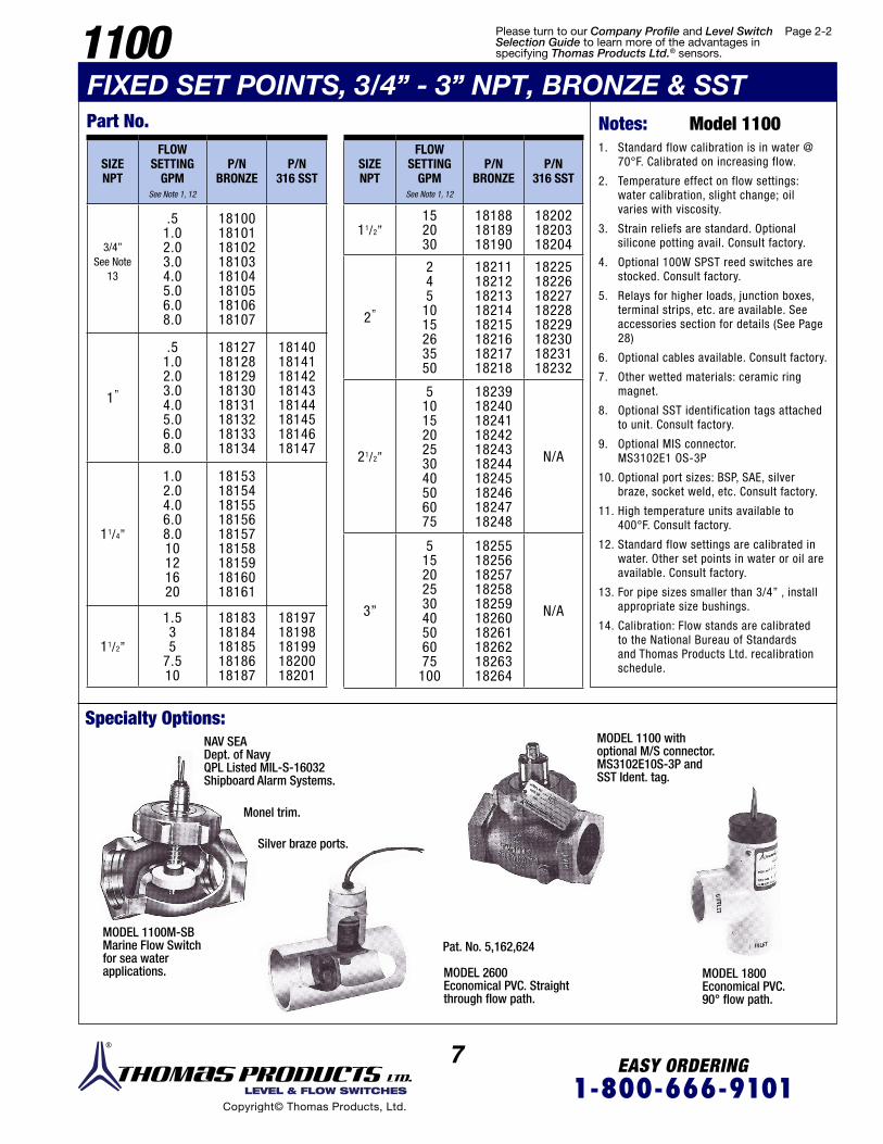
Specialty Options:NAV SEADept. of NavyQPL Listed MIL-S-16032Shipboard Alarm Systems.
MODEL 1100M-SBMarine Flow Switchfor sea waterapplications.
MODEL 1100 withoptional M/S connector.MS3102E10S-3P andSST Ident. tag.
MODEL 1800Economical PVC.90° flow path.
MODEL 2600Economical PVC. Straightthrough flow path.
Silver braze ports.
Monel trim.
SIZENPT
FLOWSETTING
GPMSee Note 1, 12
P/NBRONZE
P/N 316 SST
3/4”See Note
13
.51.02.03.04.05.06.08.0
1810018101181021810318104181051810618107
1”
.51.02.03.04.05.06.08.0
1812718128181291813018131181321813318134
1814018141181421814318144181451814618147
11/4”
1.02.04.06.08.010121620
181531815418155181561815718158181591816018161
11/2”
1.535
7.510
1818318184181851818618187
1819718198181991820018201
SIZENPT
FLOW SETTING
GPM See Note 1, 12
P/NBRONZE
P/N 316 SST
11/2”152030
181881818918190
182021820318204
2”
245
1015263550
1821118212182131821418215182161821718218
1822518226182271822818229182301823118232
21/2”
5101520253040506075
18239182401824118242182431824418245182461824718248
N/A
3”
51520253040506075
100
18255182561825718258182591826018261182621826318264
N/A
Part No.1. Standard flow calibration is in water @
70°F. Calibrated on increasing flow.
2. Temperature effect on flow settings: water calibration, slight change; oil varies with viscosity.
3. Strain reliefs are standard. Optional silicone potting avail. Consult factory.
4. Optional 100W SPST reed switches are stocked. Consult factory.
5. Relays for higher loads, junction boxes, terminal strips, etc. are available. See accessories section for details (See Page 28)
6. Optional cables available. Consult factory.
7. Other wetted materials: ceramic ring magnet.
8. Optional SST identification tags attached to unit. Consult factory.
9. Optional MIS connector. MS3102E1 OS-3P
10. Optional port sizes: BSP, SAE, silver braze, socket weld, etc. Consult factory.
11. High temperature units available to 400°F. Consult factory.
12. Standard flow settings are calibrated in water. Other set points in water or oil are available. Consult factory.
13. For pipe sizes smaller than 3/4” , install appropriate size bushings.
14. Calibration: Flow stands are calibrated to the National Bureau of Standards and Thomas Products Ltd. recalibration schedule.
Notes: Model 1100
Pat. No. 5,162,624
Page 2-2

8 EASY ORDERING1-800-666-9101 LEVEL & FLOW SWITCHES
Copyright© Thomas Products, Ltd.
Specifications:
Electrical:Reed switch shown in NO FLOW condition.
Switch Ratings...Max Resistive Load
PressureDrop ∆p:
Part No.
Dimensional Data:
Applications:
Added retainingring meansshuttle cannotjam in place.
PRESSURE DROP PSI
8
6-
4-
2-
0
P/N 18300M/N 1300
P/N 18127M/N 1100
FLOW RATE-GPM
1300Notes: Model 13001. Standard flow calibration is in water @
70°F. Calibrated on increasing flow.
2. Temperature effect on flow settings: water calibration, slight change; oil varies with viscosity.
3. Optional 100W SPST reed switches are stocked. Consult factory.
4. Relays for higher loads, junction boxes, terminal strips, etc. are available. See accessories section for details (See Page 28)
5. Optional cables available. Consult factory.
6. Other wetted materials: ceramic ring magnet.
7. Optional SST identification tags attached to unit. Consult factory.
8. Optional port sizes: BSPT, SAE, silver braze, socket weld, etc. Consult factory.
9. High temperature units available to 400°F. Consult factory.
10. Standard flow settings are calibrated in water. Other set points in water or oil are available. Consult factory.
11. Calibration: Flow stands are calibrated to the National Bureau of Standards and Thomas Products Ltd. recalibration schedule.
• Coolant Systems • HVAC Equipment • Machine Tool Industry
Shock and vibration approved.
Oper. Temp.to 300°F.
Factory replaceable switch capsules.
True globe-shaped housings yield lower ∆P and minimize turbulence.
Welding performedin low hydrogenenviroment.
HFX17/16”
37/8”
13/8”
13/8”
3/4” NPT BOTHPORTS
1/2” NPT
BLACK NO
NCRED
ORANGE
SPDT, SHOWN AT NO FLOW
SIZENPT
FLOW SETTING GPMSee Note 1, 2, 10
P/N
3/4”SeeNote
8
.751.52
2.55
7.510
18300183011830218303183041330518306
Housing Shuttle Spring “O”Ring
ReedSwitch Wire Oper.
Temp.Oper.Pres.
ProofLoad
BrustStrenght
Set Pt.Accur.
Set. Pt.Diff.
Repeat-ability
Bronze TeflonSee Note 6
316 SSTViton“A”
20 WattSPDT
See Note 3,4
18 AWG24” Lg
PolymericSee Note 5
-20°Fto
+300°FSee Note 9
400 PSI@
100°F
800 PSI@
100°F
1200 PSI@
100°F
±10%MAX.
See Note 11
±10%1% Max.Deviation
V.A. VOLTS AMPS DC
AMPS AC
AMPS AC MAX
20
0-50 .4 .4
1.0120 .15 .15
240 .06 .08
4 6 8 10 12 14 16 18 20 22 242
FIXED SET POINTS, 3/4” NPT, BRONZE
Switch Rating 20 VA: 120-240 VAC Pilot Duty UL File E86797
Please turn to our Company Profile and Level Switch Selection Guide to learn more of the advantages in specifying Thomas Products Ltd.® sensors.

9 EASY ORDERING1-800-666-9101 LEVEL & FLOW SWITCHES
Copyright© Thomas Products, Ltd.
Specifications:
Housing Piston Spring ReedSwitch Wire Oper. Temp.
Select Piston
Oper.Pres.
ProofLoad
BrustStrenght
Set Pt.Accur.
Set Pt.Diff.
Brassor
316 SST
PolysulfoneBrass, or316 SST
See Note 6,9
316 SST20 WattSPDT
See Note 3,4
18 AWG24” Lg
PolymericSee Note 5
w/Brass or SST PistonSee Note 7
-20°F to +300°F
1000PSIG*
2500PSIG*
5000PSIG* ±10%
MAX.See Note 10
±20%MAX.
W/Polysulfone Piston
-20°F to +225°F *Without use of optional Petcock
OPTIONS: BRASS PETCOCK
Electrical & Switch Ratings:
Part No.See Model 1300. Page 8
Pressure Drop ∆p:VERTICAL ATTITUDE,
LEAD WIRES UP AND 1st OUT PORT OPEN
Notes: Model 23001. Standard flow calibration is in water @
70°F with lead wires up. Calibrated on increasing flow.
2. Temperature effect on flow settings: water calibration, slight change; oil varies with viscosity.
3. Optional 100W SPST reed switches are stocked. Consult factory.
4. Relays for higher loads are available. See accessories section for details (See Page 28)
5. Optional cables available. Consult factory.
6. Other wetted materials: Hysol epoxy.
7. High temperature units available to 400°F. Consult factory.
8. Standard flow settings are calibrated in water. Other set points in water or oil are available. Consult factory.
9. Pistons: Brass for oil, polysulfone for water in either housing; SST in SST housing.
10. Calibration: Flow stands are calibrated to the National Bureau of Standards and Thomas Products Ltd. recalibration schedule.
Applications:
Dimensional Data:
• Designed to help pass 100 micron particulates.
• Serviceable in line. • Optional petcock to continually bleed out particles.
• High pressure applications.
Patent-pendingdesign.
Reverse taperrunning bore.
Piston landsare O.D. Ground.
3-port construction.
SIZENPT
FLOW SET GPM
BRASS PISTON Housing P/N Specify
316 SSConstruction
1/4”
.1 43253 - ___________________ 43259
.25 43254 - ___________________ 43260
.5 43255 - ___________________ 43261
.75 43256 - ___________________ 43262
1.0 43257 - ___________________ 43263
1.5 43258 - ___________________ 43264
PISTONS FOR BRASS OR 316 SST HOUSINGS:
PR
ES
SU
RE
DR
OP
(P
SI)
S E T P O I N T ( G P M )
Approx.installed length
1¼”
¼” NPT (3) Plcs.1st Out Port
IN
Lead wires Back View 2nd Out Port
BRASS316 SSTPOLYSULFONE
See Note 9
P/N 3699P/N 3700P/N 3701
P/N 36971/4” NPT
1”
1¼”
3/4”
13/4”
31/2”
1/2”
3/4”
1/2”
Patent Pending2300FIXED SET POINTS, 1/4” NPT, BRASS & SST
0
.5
1.0
.5 1.0 1.5 2.0

10 EASY ORDERING1-800-666-9101 LEVEL & FLOW SWITCHES
Copyright© Thomas Products, Ltd.
1600 & 1700FIXED SET POINTS, 1/4’’ NPT, BRASS & SST
SIZENPT
FLOW SET GPM
See Note 1-3, 9 ,10
BRASS PISTON Housing P/N Specify
316 SSTConstruction
1/4”
.1 12600 - _______________ 12609
.25 12601 - _______________ 12610
.5 12602 - _______________ 12611
.75 12603 - _______________ 12612
1.0 12604 - _______________ 12613
1.5 12605 - _______________ 12614
BLACK NO
NCRED
ORANGEElectrical:
Pressure Drop ∆p:Model 1600
Applications: • UL Recognized (Note 4) • Machine Tool Industry • Lubrication Systems • Lasers
• Set points in water from .1 GPM to 1.5 GPM. • Set points in airtrom .06 SCFM to 8 SCFM.
Factory replaceableswitch capsules.
Hardened and lappedrunning bore.
Increased piston lands are O.D. ground.
2 MOUNTING HOLES
1/2” NPTCONDUITCONNECTIONSTANDARD
1/4” NPTBOTHPORTS
1/4” 3/4”
13/16”
9/32” Dia.
Model 1600
Dimensional Data: Model 1600 & 1700
Specifications:
Part No.
PISTONS FOR BRASS OR 316 SST HOUSINGS:
Switch Rating of UL Recognized Unit 20 VA: 120-240 VAC Pilot Duty
POLYSULFONEBRASS316 SST
P/N 4054
P/N 4055
P/N 4056See Note 12, 14-17
SPDT, SHOWN AT NO FLOW
Reed switch shown inNO FLOW condition.
Switch Ratings... Max Resistive Load
PRESSURE DROP PSI
FLOW RATE GPM
V.A. VOLTS AMPS DC AMPS AC AMPS AC MAX
20
0-50 .4 .4
1.0120 .15 .16
240 .06 .08
23/8”
13/4” 5/8”
1”41/8”
11/4
1/2
Housing Piston Spring “O”Ring
ReedSwitch Wire Oper.
Temp.Oper.Pres.
ProofLoad
BrustStreng-
ht
Set Pt.Accur.
Set Pt.Diff.
Repeat-ability
Brassor
316 SST
PolysulfoneSee Note 15
316SST
Viton“A”
20 WattSPDT
See Notes4, 5
18 AWG24” Lg.Poly-meric
See Notes 6, 7
w/ Brass orSST Piston
-20°F to +300°FSee Note 8 1000
PSIG2500PSIG
5000PSIG
±10%MAX.
See Note 18
160015%MAX.
1%Max.
Devia-tion
BrassSee Notes 12,
14, 16
316 SSTSee Notes 12,
14, 17
w/ PolysulfonePiston
-20°F to +225°F
170020%MAX.
5
4
3
2
1
0 .25 .50 .75 1.0 1.25 1.50 1.75 2.0 2.5
Page 1-2Please turn to our Company Profile and Level Switch Selection Guide to learn more of the advantages in specifying Thomas Products Ltd.® sensors.

11 EASY ORDERING1-800-666-9101 LEVEL & FLOW SWITCHES
Copyright© Thomas Products, Ltd.
1600 & 1700Notes: Model 1600 & 17001. Standard flow calibration is in water @
70°F with lead wires up. Calibrated on increasing flow.
2. Temperature effect on flow settings: water calibration, slight change; oil varies with viscosity; gas, slight change.
3. Set point accuracy will change slightly in other than calibrated position.
4. Model 1600 is UL recognized with a SPST reed switch rated pilot duty 20 VA 120-240 VAC, 174°F.
5. Relays for higher loads, junction boxes, terminal strips, etc. are available. See accessories section for details (See Page 28)
6. Also available: leads in different lengths, cable, terminated ends, etc. Consult factory.
7. Optional 3 Pin M/S connector - MS3102E10S-3P. Consult factory.
8. High temperature units available to 400°F. Consult factory.
9. Standard flow settings are calibrated in water. Other set points in water or oil are available. Consult factory.
10. Optional air set points for Model 1600 are available. Consult factory with CFM and line pressure.
11. Optional air set points for Model 1700 are available. Consult factory with CFH and line pressure.
12. Other wetted materials: Hysol epoxy.
13. Model 1700 orifice dia. is 5/16”; inlet fitting supplied by customer must be 3/8” I.D. minimum.
14. All SST piston eliminating epoxy is available. Consult factory.
15. Polysulfone for water in brass housing.
16. Brass for oil in brass housing.
17. SST for SST housing.
18. Calibration: Flow stands are calibrated to the National Bureau of Standards and Thomas Products Ltd. recalibration schedule.
POLYSULFONEBRASS316 SST
P/N 4058
P/N 4059
P/N 4060See Notes 12, 14
PISTONS FOR BRASS OR 316 SST HOUSINGS:
Part No.
Specialty Options:
SIZENPT
FLOW SETTING cc/min See Note 1,
2, 3, 9, 10
EQUIV.GPM
APPX.
BRASS PISTON Housing P/N Specify
316 SSTConstruction
1/4”
50 .013 12618 - _______________ 12628
100 .026 12619 - _______________ 12629
150 .040 12620 - _______________ 12630
200 .053 12621 - _______________ 12631
250 .066 12622 - _______________ 12632
300 .079 12623 - _______________ 12633
Electrical & Switch Ratings: Page 10.
Pressure Drop ∆p: Model 1700
Model 1600 Air Flow Switchwith MS connector See Note 7.
• Water from 2 cc/min to 300 cc/min. • Air from 2SCFH to 50SCFH.
Model 1700:
Factory replaceableswitch capsules.
Increased piston landsare O.D. ground.
Hardened and lappedrunning bore.
Hardened and lappedrunning bore matched to acenterless ground orifice.See Note 13
Applications: • U.L. File E86797 • Accurate low flow applications. • Lubrication Systems
PRESSURE DROP-PSI
FLOW RATE CC/MIN.
FIXED SET POINTS, 1 /4’’ NPT, BRASS & SST
5
4
3
2
1
0 100
500
1000
1500
2000
2500
3000
Please turn to our Company Profile and Level Switch Selection Guide to learn more of the advantages in specifying Thomas Products Ltd.® sensors.

12 EASY ORDERING1-800-666-9101 LEVEL & FLOW SWITCHES
Copyright© Thomas Products, Ltd.
1900FIXED SET POINTS, 1/4” NPT, BRASS & SST
Applications: • The “mini” small and accurate in line flow switch detects low or high flow rates.
• Fixed actuations from .1 GPM to 1.5 GPM
• UL File No. E86797
Dimensional Data:
SIZENPT
FLOW SETTING GPM
See Note 1, 2, 3 ,9
P/N BRASSN.O. SPST SWITCH
P/N BRASS N.C. SPST SWITCH
P/N BRASS SPDT
SWITCH
P/N 316 SST SPDT SWITCH
1/4”
.1
.25
.5
.75
1
1.5
18321
18322
18323
18324
18325
18326
18327
18328
18329
18330
18331
18332
18350
18351
18352
18353
18354
18355
18360
18361
18362
18363
18364
18365
Housing Piston Spring Reed Switch Wire Oper. Temp.
See Note 8
Oper.Pres.
ProofLoad
BrustStrenght
Set Pt.Accur.
Set. Pt.Diff.
Repet- ability
BrassSee Note 10 316
SST
20 Watt316 SPSTor SPDTSee Note 7
18 AWG24” Lg.
PolymericSee Note 6
-20°F to+250°F 1000
PSIG2000PSIG
4000PSIG
±10%MAX.
See Note 12
±15%MAX.
1% Max.Deviation316 SST
See Notes 10, 11-20°F to+300°F
BLACK NO
NCRED
ORANGEElectrical: Specialty Options:
Specifications:
Part No.
SPDT, SHOWN AT NO FLOW
Pressure Drop ∆p:Switch Ratings...Max Resistive Load
V.A. VOLTS AMPS DC
AMPS AC
AMPS AC MAX
20
0-50 .4 .4
1.0120 .15 .16
240 .06 .08Switch Rating 20 VA: 120-240 VAC Pilot Duty
See Model 1700 forset points from 2 cc/min .to 300 cc/min.
Reed switchshown in NO FLOWcondition.
PRES
SURE
DR
OP P
SI
FLOW RATE GPM
Notes: Model 19001. Standard flow calibration is in water @
70°F with lead wires up. Calibrated on increasing flow.
2. Temperature effect on flow settings: water calibration, slight change; oil varies with viscosity.
3. Set point accuracy will change slightly in other than calibrated position.
4. Optional aluminum housings with SST trim are stocked. Consult factory.
5. Optional mounting holes available. Consult factory.
6. Also available: leads in different lengths, cable, terminated ends, etc. Consult factory.
7. Relays for higher loads are available. See accessories section for details (See Page 28)
8. High temperature units available to 400°F. Consult factory.
9. Standard flow settings are calibrated in water. Other set points in water or oil are available. Consult factory.
10. Other wetted materials: Hysol Epoxy
11. All SST piston for either brass or SST housing, eliminating hysol epoxy. Consult factory.
12. Calibration: Flow stands are calibrated to the National Bureau of Standards and Thomas Products Ltd. recalibration schedule.
Hardened and lapped bore.
Hardened piston lands aresized to the borefor smooth operation.
Piston retaining ringactually sits in its owngroove, not just in thethreads vanish point.
Switch assembly issilicone potted for shockand vibration deadening.
1/4” NPTBOTH PORTS
LEADWIRES
See Note 5
3/8”
3/823/4”
1”
1”
1”
RED
RED
RED
RED
SPST, NORMALLY CLOSED AT NO FLOW
SPST, NORMALLY OPEN AT NO FLOW
5
4
3
2
1
0 .1 .25 .50 .75 1.0 1.5 2.0 3.0
Please turn to our Company Profile and Level Switch Selection Guide to learn more of the advantages in specifying Thomas Products Ltd.® sensors.
13 EASY ORDERING1-800-666-9101 LEVEL & FLOW SWITCHES
Copyright© Thomas Products, Ltd.
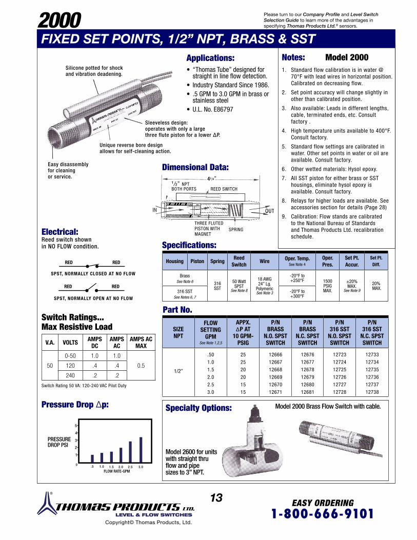
Applications: • “Thomas Tube” designed for straight in line flow detection.
• Industry Standard Since 1986. • .5 GPM to 3.0 GPM in brass or stainless steel
• U.L. No. E86797
Dimensional Data:
SIZENPT
FLOW SETTING
GPMSee Note 1,2,5
APPX. ∆P AT
10 GPM- PSIG
P/N BRASS
N.O. SPST SWITCH
P/N BRASS
N.C. SPST SWITCH
P/N 316 SST
N.O. SPST SWITCH
P/N 316 SST
N.C. SPST SWITCH
1/2”
.50
1.0
1.5
2.0
2.5
3.0
25
25
20
20
15
15
12666
12667
12668
12669
12670
12671
12676
12677
12678
12679
12680
12681
12723
12724
12725
12726
12727
12728
12733
12734
12735
12736
12737
12738
Housing Piston SpringReed
SwitchWire Oper. Temp.
See Note 4
Oper.Pres.
Set Pt. Accur.
Set Pt. Diff.
BrassSee Note 6 316
SST50 Watt SPST
See Note 8
18 AWG24” Lg.
PolymericSee Note 3
-20°F to+250°F 1500
PSIGMAX.
±20% MAX.
See Note 9
20% MAX.
316 SSTSee Notes 6, 7
-20°F to+300°F
RED
RED
RED
RED
Specialty Options:
Specifications:
SPST, NORMALLY CLOSED AT NO FLOW
SPST, NORMALLY OPEN AT NO FLOW
Model 2600 for unitswith straight thruflow and pipesizes to 3” NPT.
Model 2000 Brass Flow Switch with cable.
PRESSURE DROP PSI
FLOW RATE-GPM
Notes: Model 20001. Standard flow calibration is in water @
70°F with lead wires in horizontal position. Calibrated on decreasing flow.
2. Set point accuracy will change slightly in other than calibrated position.
3. Also available: Leads in different lengths, cable, terminated ends, etc. Consult factory .
4. High temperature units available to 400°F. Consult factory.
5. Standard flow settings are calibrated in water. Other set points in water or oil are available. Consult factory.
6. Other wetted materials: Hysol epoxy.
7. All SST piston for either brass or SST housings, eliminate hysol epoxy is available. Consult factory.
8. Relays for higher loads are available. See accessories section for details (Page 28)
9. Calibration: Flow stands are calibrated to the National Bureau of Standards and Thomas Products Ltd. recalibration schedule.
Easy disassemblyfor cleaningor service.
Unique reverse bore designallows for self-cleaning action.
Sleeveless design:operates with only a largethree flute piston for a lower ∆P.
1/2” NPTBOTH PORTS REED SWITCH
THREE FLUTEDPISTON WITH MAGNET
SPRING
45/8”
2000 Please turn to our Company Profile and Level Switch Selection Guide to learn more of the advantages in specifying Thomas Products Ltd.® sensors.
FIXED SET POINTS, 1/2” NPT, BRASS & SST
Switch Ratings...Max Resistive Load
Part No.
V.A. VOLTS AMPS DC
AMPS AC
AMPS AC MAX
50
0-50 1.0 1.0
0.5120 .4 .4
240 .2 .2
Switch Rating 50 VA: 120-240 VAC Pilot Duty
Pressure Drop ∆p:
Electrical:Reed switch shown in NO FLOW condition.
Silicone potted for shock and vibration deadening.
5
4
3
2
1
0 .5 1.0 1.5 2.0 2.5 3.0

14 EASY ORDERING1-800-666-9101 LEVEL & FLOW SWITCHES
Copyright© Thomas Products, Ltd.
2100 & 2200FIXED SET POINTS, 9/16’’ - 18’’ UNF-2B, PLASTIC
Applications: • Plastic configuration throughout. • Rugged yet economical flow switch for monitoring liquid flow or no flow conditions.
• FDA Approved Polysulfone • UL File No. E86797
Dimensional Data: Model 2100 & 2200
Specifications:
Part No. Electrical: Reed switch shown in NO FLOW condition.
Switch Ratings... Max Resistive Load V.A. VOLTS AMPS DC AMPS AC AMPS AC MAX
20
0-50 .4 .4
1.0120 .15 .16
240 .06 .08Switch Rating 20 VA: 50-240 VAC Pilot Duty
BLACK NO
NCRED
SPDT, SHOWN AT NO FLOW
RED
RED
RED
RED
SPST, NORMALLY CLOSED AT NO FLOW
SPST, NORMALLY OPEN AT NO FLOW
Full size out portminimizes turbulence
Large, full size reed switchsilicone potted for shockand vibration deadening.
One-piece housingyields burst strengthof 1500 ±PSI @ 70°.
Model 2100 Ryton R4 withSST low flow orifice assembly,
1 cc/min water set pointand cable.
Model 2100 Modified forstraight-thru flow and two¼” NPT adapters.
Unique reverse taper design helps passparticulates.
Pressure Drop ∆p:
Specialty Options
PRESSURE DROP PSI
FLOW RATE-GPM
9/16”18-UNF-2BBOTHPORTS
Dia.
35/8”11/4”
9/16”
7/8”
9/16”
1”
1”
Housing Piston Spring“O” Ring
Reed Switch
WireOper.Temp.
Oper. Pres.
Set Pt. Accur.
Set Pt.Diff.
Polysulfone 316SST
Viton “A”
20 WattSPDT
15 Watt SPST
See Note 6
18 AWG24” Lg.
Polymeric See Note 5
-20°F to
+225°F
250 PSIG @
70°F Max. See Note 7
15%MAX.
20%MAX.
SIZEPORT
FLOW SETTING GPM
See Note 1,2,8,9
P/N N.O. SPST
SWITCH
P/N N.C. SPST
SWITCH
P/N SPDT
SWITCH
9/16”- 18
.1.25.5.751
1.5
126861268712688126891269012691
126951269612697126981269912700
127041270512706127071270812709
Because we mold in-house, we can certify that our polysulfone flowswitches use only virgin material and runners are not introduced norhave color concentrates been added during processing that canhinder FDA requirements or additive leaching.
Model 2100
ORANGE
5
4
3
2
1
0 .25 .50 .75 1.0 1.25 1.50 1.75 2.0 2.5 3.0
UL
Please turn to our Company Profile and Level Switch Selection Guide to learn more of the advantages in specifying Thomas Products Ltd.® sensors.
15 EASY ORDERING1-800-666-9101 LEVEL & FLOW SWITCHES
Copyright© Thomas Products, Ltd.
2100 & 2200FIXED SET POINTS, 9/16”- 18” UNF-2B, PLASTIC
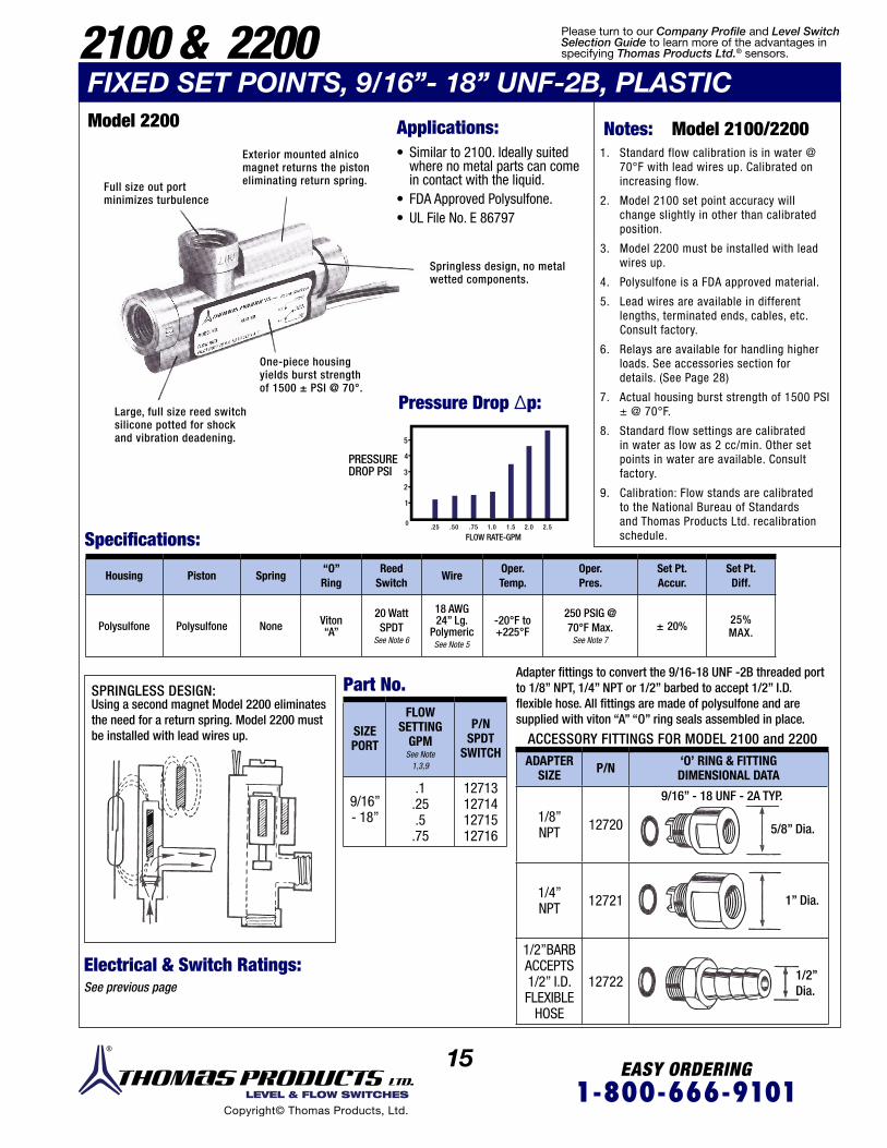
Applications: • Similar to 2100. Ideally suited where no metal parts can come in contact with the liquid.
• FDA Approved Polysulfone. • UL File No. E 86797
Springless design, no metalwetted components.
Large, full size reed switchsilicone potted for shockand vibration deadening.
One-piece housingyields burst strengthof 1500 ± PSI @ 70°.
Exterior mounted alnicomagnet returns the pistoneliminating return spring.Full size out port
minimizes turbulence
Model 2200
PRESSURE DROP PSI
Pressure Drop ∆p:
FLOW RATE-GPMSpecifications:
Part No.Adapter fittings to convert the 9/16-18 UNF -2B threaded portto 1/8” NPT, 1/4” NPT or 1/2” barbed to accept 1/2” I.D.flexible hose. All fittings are made of polysulfone and aresupplied with viton “A” “O” ring seals assembled in place.
9/16” - 18 UNF - 2A TYP.
5/8” Dia.
1” Dia.
1/2” Dia.
Using a second magnet Model 2200 eliminatesthe need for a return spring. Model 2200 mustbe installed with lead wires up.
SPRINGLESS DESIGN:
ACCESSORY FITTINGS FOR MODEL 2100 and 2200
Electrical & Switch Ratings:See previous page
Notes: Model 2100/22001. Standard flow calibration is in water @
70°F with lead wires up. Calibrated on increasing flow.
2. Model 2100 set point accuracy will change slightly in other than calibrated position.
3. Model 2200 must be installed with lead wires up.
4. Polysulfone is a FDA approved material.
5. Lead wires are available in different lengths, terminated ends, cables, etc. Consult factory.
6. Relays are available for handling higher loads. See accessories section for details. (See Page 28)
7. Actual housing burst strength of 1500 PSI ± @ 70°F.
8. Standard flow settings are calibrated in water as low as 2 cc/min. Other set points in water are available. Consult factory.
9. Calibration: Flow stands are calibrated to the National Bureau of Standards and Thomas Products Ltd. recalibration schedule.
Housing Piston Spring“O” Ring
Reed Switch
WireOper.Temp.
Oper. Pres.
Set Pt. Accur.
Set Pt.Diff.
Polysulfone Polysulfone None Viton “A”
20 WattSPDT
See Note 6
18 AWG24” Lg.
Polymeric See Note 5
-20°F to+225°F
250 PSIG @ 70°F Max.
See Note 7± 20% 25%
MAX.
SIZEPORT
FLOW SETTING
GPMSee Note
1,3,9
P/N SPDT
SWITCH
9/16”- 18”
.1.25.5.75
12713127141271512716
ADAPTERSIZE P/N ‘O’ RING & FITTING
DIMENSIONAL DATA
1/8”NPT 12720
1/4”NPT 12721
1/2”BARBACCEPTS1/2” I.D.FLEXIBLE
HOSE
12722
5
4
3
2
1
0.25 .50 .75 1.0 1.5 2.0 2.5
Please turn to our Company Profile and Level Switch Selection Guide to learn more of the advantages in specifying Thomas Products Ltd.® sensors.
16 EASY ORDERING1-800-666-9101 LEVEL & FLOW SWITCHES
Copyright© Thomas Products, Ltd.
1800FIXED SET POINTS, 1 /2’’ - 1 ‘’ PVC
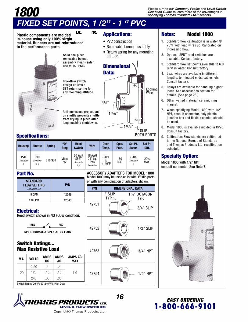
Solid one-pieceremovable bonnetassembly means saferuse to 150 PSIG.
True-flow switchdesign utilizes aSST return spring forany mounting attitude.
Anti-menscous projectionson shuttle prevents shuttlefrom drying in place afterlong machine shutdowns.
Applications:
Dimensional Data:
• PVC construction • Removable bonnet assembly • Return spring for any mounting attitude.
Locking Wire
1” SLIPBOTH PORTS
41/8”
113/16”
113/16”
Model 1800 may be used as is with 1” slip portsor with any combination of adapters shown.
ACCESSORY ADAPTERS FOR MODEL 1800
Specialty Option:
Specifications:
Part No.
Model 1800 with 1/2” NPTconduit connector. See Note 7.
Electrical:Reed switch shown in NO FLOW condition.
RED RED
SPST, NORMALLY OPEN AT NO FLOW
Switch Ratings...Max Resistive Load
Plastic components are moldedin-house using only 100% virginmaterial. Runners are not reintroducedto the performance parts.
Notes: Model 18001. Standard flow calibration is in water @
70°F with lead wires up. Calibrated on increasing flow.
2. Optional SPDT reed switches are available. Consult factory.
3. Standard flow set points available to 6.0 GPM in water. Consult factory.
4. Lead wires are available in different lengths, terminated ends, cables, etc. Consult factory.
5. Relays are available for handling higher loads. See accessories section for details. (See page 28.)
6. Other wetted material: ceramic ring magnet.
7. When specifying Model 1800 with 1/2” NPT, conduit connector, only plastic junction box and flexible conduit should be used.
8. Model 1800 is available molded in CPVC. Consult factory.
9. Calibration: Flow stands are calibrated to the National Bureau of Standards and Thomas Products Ltd. recalibration schedule.
Housing Shuttle Spring“O” Ring
Reed Switch
WireOper.Temp.
Oper. Pres.
Set Pt. Accur.
Set Pt.Diff.
PVCSee Note
8
PVCSee Note
8, 6316 SST Viton
“A”
20 WattSPST
See Note 2, 5
18 AWG24” Lg.
PVC See Note 4
-20°F to
+140°F
150 PSIG
±20%See Note
9
20%MAX.
STANDARD FLOW SETTING
See Notes 1, 9P/N
.5 GPM 42549
1.0 GPM 42545
P/N DIMENSIONAL DATA
42751
42752
42753
42754
11/2” OCTAGON TYP.
3/4” SLIP
1” SLIPTYP.
1/2” SLIP
3/4” NPT
1/2” NPT
V.A. VOLTS AMPS DC
AMPS AC
AMPS AC MAX
20
0-50 .4 .4
1.0120 .15 .16
240 .06 .08
Switch Rating 20 VA: 50-240 VAC Pilot Duty
UL
Please turn to our Company Profile and Level Switch Selection Guide to learn more of the advantages in specifying Thomas Products Ltd.® sensors.
17 EASY ORDERING1-800-666-9101 LEVEL & FLOW SWITCHES
Copyright© Thomas Products, Ltd.
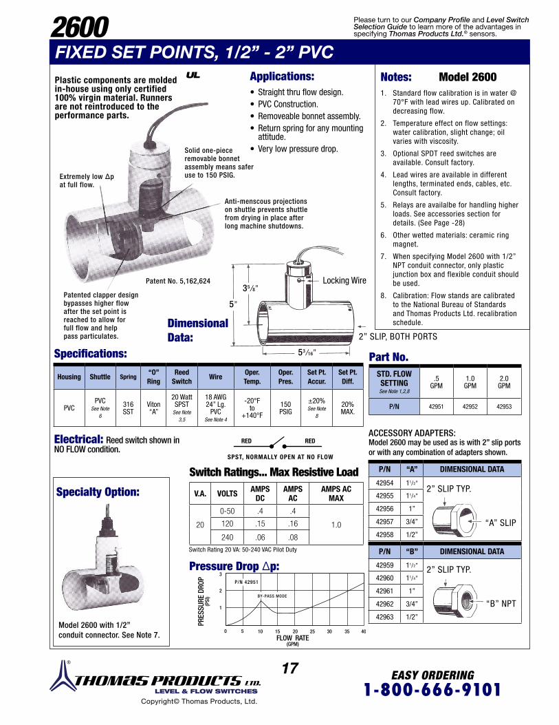
Solid one-pieceremovable bonnetassembly means saferuse to 150 PSIG.
Anti-menscous projectionson shuttle prevents shuttlefrom drying in place afterlong machine shutdowns.
Patented clapper designbypasses higher flowafter the set point isreached to allow forfull flow and helppass particulates.
Extremely low ∆p at full flow.
Patent No. 5,162,624
Applications:
Dimensional Data:
• Straight thru flow design. • PVC Construction. • Removeable bonnet assembly. • Return spring for any mounting attitude.
• Very low pressure drop.
2” SLIP, BOTH PORTS
Locking Wire
5”
35/8”
53/16”
Model 2600 may be used as is with 2” slip portsor with any combination of adapters shown.
ACCESSORY ADAPTERS:
Specialty Option:
Specifications: Part No.
Model 2600 with 1/2”conduit connector. See Note 7.
Electrical: Reed switch shown in NO FLOW condition.
Switch Ratings... Max Resistive Load
Notes: Model 26001. Standard flow calibration is in water @
70°F with lead wires up. Calibrated on decreasing flow.
2. Temperature effect on flow settings: water calibration, slight change; oil varies with viscosity.
3. Optional SPDT reed switches are available. Consult factory.
4. Lead wires are available in different lengths, terminated ends, cables, etc. Consult factory.
5. Relays are availalbe for handling higher loads. See accessories section for details. (See Page -28)
6. Other wetted materials: ceramic ring magnet.
7. When specifying Model 2600 with 1/2” NPT conduit connector, only plastic junction box and flexible conduit should be used.
8. Calibration: Flow stands are calibrated to the National Bureau of Standards and Thomas Products Ltd. recalibration schedule.
Housing Shuttle Spring“O” Ring
Reed Switch
WireOper.Temp.
Oper. Pres.
Set Pt. Accur.
Set Pt.Diff.
PVCPVC
See Note 6
316 SST
Viton “A”
20 WattSPST
See Note 3,5
18 AWG24” Lg.
PVC See Note 4
-20°F to
+140°F
150 PSIG
±20%See Note
8
20%MAX.
P/N “A” DIMENSIONAL DATA
42954 11/2”
42955 11/4”
42956 1”
42957 3/4”
42958 1/2”
STD. FLOWSETTINGSee Note 1,2,8
.5GPM
1.0GPM
2.0GPM
P/N 42951 42952 42953
P/N “B” DIMENSIONAL DATA
42959 11/2”
42960 11/4”
42961 1”
42962 3/4”
42963 1/2”
V.A. VOLTS AMPS DC
AMPS AC
AMPS AC MAX
20
0-50 .4 .4
1.0120 .15 .16
240 .06 .08Switch Rating 20 VA: 50-240 VAC Pilot Duty
2600
Plastic components are moldedin-house using only certified100% virgin material. Runnersare not reintroduced to theperformance parts.
RED RED
SPST, NORMALLY OPEN AT NO FLOW
PRES
SURE
DRO
P(P
SI)
FLOW RATE (GPM)
Pressure Drop ∆p:
“A” SLIP
“B” NPT
2” SLIP TYP.
2” SLIP TYP.
FIXED SET POINTS, 1/2” - 2” PVC
3
2
1
0 5 10 15 20 25 30 35 40
P/N 42951
BY-PASS MODE
UL
Please turn to our Company Profile and Level Switch Selection Guide to learn more of the advantages in specifying Thomas Products Ltd.® sensors.
18 EASY ORDERING1-800-666-9101 LEVEL & FLOW SWITCHES
Copyright© Thomas Products, Ltd.
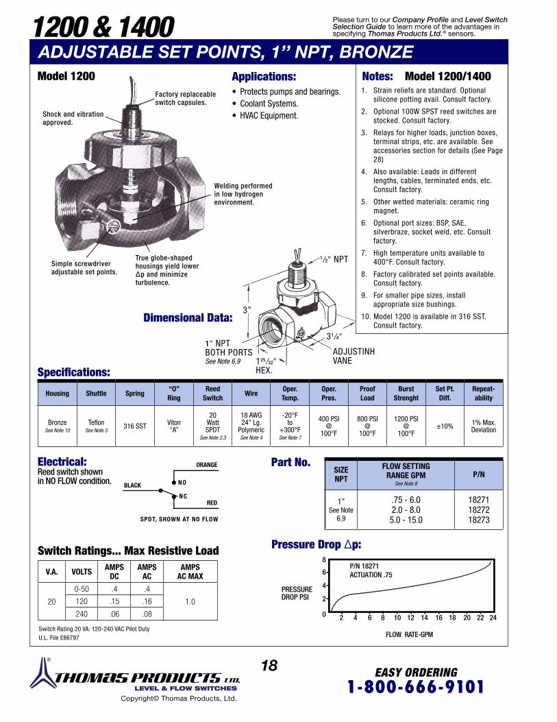
1200 & 1400ADJUSTABLE SET POINTS, 1’’ NPT, BRONZE
Applications:
Dimensional Data:
Specifications:
• Protects pumps and bearings. • Coolant Systems. • HVAC Equipment.
Notes: Model 1200/14001. Strain reliefs are standard. Optional
silicone potting avail. Consult factory.
2. Optional 100W SPST reed switches are stocked. Consult factory.
3. Relays for higher loads, junction boxes, terminal strips, etc. are available. See accessories section for details (See Page 28)
4. Also available: Leads in different lengths, cables, terminated ends, etc. Consult factory.
5. Other wetted materials: ceramic ring magnet.
6. Optional port sizes: BSP, SAE, silverbraze, socket weld, etc. Consult factory.
7. High temperature units available to 400°F. Consult factory.
8. Factory calibrated set points available. Consult factory.
9. For smaller pipe sizes, install appropriate size bushings.
10. Model 1200 is available in 316 SST. Consult factory.
Factory replaceableswitch capsules.
Welding performedin low hydrogenenvironment.
Simple screwdriveradjustable set points.
True globe-shapedhousings yield lower∆p and minimizeturbulence.
Shock and vibrationapproved.
Model 1200
BLACK
RED
ORANGE
NO
NC
SPDT, SHOWN AT NO FLOW
Electrical:Reed switch shownin NO FLOW condition.
Switch Ratings... Max Resistive Load
Part No.
Pressure Drop ∆p:
PRESSURE DROP PSI
FLOW RATE-GPM
V.A. VOLTS AMPS DC
AMPS AC
AMPS AC MAX
20
0-50 .4 .4
1.0120 .15 .16
240 .06 .08
Switch Rating 20 VA: 120-240 VAC Pilot DutyU.L. File E86797
Housing Shuttle Spring“O” Ring
Reed Switch
WireOper.Temp.
Oper. Pres.
Proof Load
Burst Strenght
Set Pt.Diff.
Repeat-ability
BronzeSee Note 10
TeflonSee Note 5
316 SST Viton “A”
20 WattSPDT
See Note 2,3
18 AWG24” Lg.
Polymeric See Note 4
-20°F to
+300°F See Note 7
400 PSI @
100°F
800 PSI @
100°F
1200 PSI @
100°F±10% 1% Max.
Deviation
SIZE NPT
FLOW SETTING RANGE GPM
See Note 8P/N
1” See Note
6,9
.75 - 6.02.0 - 8.05.0 - 15.0
182711827218273
1/2” NPT
1” NPTBOTH PORTSSee Note 6,9
31/4”
125/32”HEX.
ADJUSTINHVANE
3”
8P/N 18271ACTUATION .756
4
2
2 4 6 8 10 12 14 16 18 20 22 240
Please turn to our Company Profile and Level Switch Selection Guide to learn more of the advantages in specifying Thomas Products Ltd.® sensors.

19 EASY ORDERING1-800-666-9101 LEVEL & FLOW SWITCHES
Copyright© Thomas Products, Ltd.
Applications:
Applications: Dimensional Data:
Specifications:
• Machine Tool Industry • Waste Water Monitoring • H V A C
1. Close all flow control valves.
2. Open all flow switch set point adjusting vanes (alarms will turn on).
3. Turn on coolant.
4. Open each flow control valve to correct flow rate (starting at highest flow).
5. Close each flow switch set point adjusting vane until alarms just turn off.
Factory replaceableswitch capsules.
Shock and vibrationapproved.
Complete bonnetassembly andcomponents remainin tack duringremoval.
Added retainingring meansshuttle cannotjam in place.
Oper. temperatureto +300°F.
True globed-shapedhousings yield lower∆p and minimizeturbulence.
Simple screwdriveradjustable set points.
Electrical: See Model 1200
Part No.
Pressure Drop ∆p:
PRESSURE DROP PSI
FLOW RATE-GPM
Housing Shuttle Spring“O” Ring
Reed Switch
WireOper.Temp.
Oper. Pres.
Proof Load
Burst Strenght
Set Pt.Diff.
Repeat-ability
Bronze TeflonSee Note 5
316 SST Viton “A”
20 WattSPDT
See Note 2,3
18 AWG24” Lg.
Polymeric See Note 4
-20°F to
+300°F See Note 7
400 PSI @
100°F
800 PSI @
100°F
1200 PSI @
100°F±10% 1% Max.
Deviation
SIZE NPT
FLOW SETTING RANGE GPMSee Note 8
P/N
3/4”.75 - 4.02.0 - 8.07.0 - 14.0
183131831418315
13/8”
13/8”
37/8”
1/2” NPT
17/16” HEX
3/4” NPTBOTHPORTS
ADJUSTINGVANE
1200 & 1400ADJUSTABLE SET POINTS, 3/4’’ NPT, BRONZEModel 1400
Eliminate constant visual inspection of minimum coolant flow by using flow switches.You can be sure sufficient flow is automatically monitored. Flow switches activateaudible alarms, lights, etc., warning you of insufficient flow. Operation is simple:
While lube oil is pumping,open adjusting valveuntil min. flow. 75 GPM flowswitch turns off.
Max. flow: Set point1.25 GPM. LogicN.O. @ no flow .
Connected toauxilliary lights
on controlpanel, etc.
Min. flow:Set point .75 GPM.
Logic N.C. @ no flow.Whenever the flow rates dropunder that set point, your alarms will turn on. Whenever the flow rate rises or drops out of the set
point range, your alarm will turn on.
COOLANT MANIFOLD ON AN INJECTION MOLDING MACHINE: LUBE OIL MONITORING SYSTEM ON A ROLLINGMACHINE: 1 GPM is needed in the oil bath to lubricateand cool large bronze bearings.
8P/N 18313ACTUATION .75M/N 1400
P/N 18127M/N 1100
6
4
2
2 4 6 8 10 12 14 16 18 20 22 240
Please turn to our Company Profile and Level Switch Selection Guide to learn more of the advantages in specifying Thomas Products Ltd.® sensors.
20 EASY ORDERING1-800-666-9101 LEVEL & FLOW SWITCHES
Copyright© Thomas Products, Ltd.
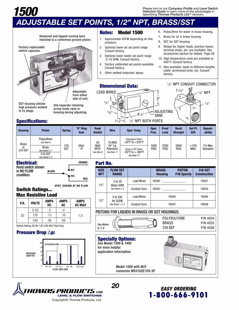
1500ADJUSTABLE SET POINTS, 1/2” NPT, BRASS/SST
Factory replaceableswitch capsules.
SST housing utilizeshigh pressure weldedin Cv plugs.
2nd separate retainingscrew holds vane inhousing during adjusting.
Adjustablefrom eitherside of unit.
Hardened and lapped running borematched to a centerless ground piston.
Notes: Model 1500 1. Approximate SCFM depending on line
pressure.
2. Optional lower air set point range. Consult factory.
3. Optional lower water set point range .2-10 GPM. Consult factory.
4. Factory calibrated set points available. Consult factory.
5. Other wetted materials: epoxy.
6. Polysulfone for water in brass housing.
7. Brass for oil in brass housing.
8. SST for SST housing.
9. Relays for higher loads, junction boxes, terminal strips, etc. are available. See accessories section for details. Page 28.
10. High temperature units are available to 400°F. Consult factory.
11. Also available: leads in different lengths, cable, terminated ends, etc. Consult factory.
Dimensional Data:1/2” NPT CONDUIT CONNECTOR
1/2” NPT BOTH PORTS
LEAD WIRES
ADJUSTINGVANE
1/2” NPT
1/2”
11/16”
41/8”
2”
11/4”
5/8”
3/4”
Housing Piston Spring“O” Ring
SealReed
SwitchWire Oper. Temp.
Oper. Pres.
Proof Load
Burst Strenght
Set Pt.Diff.
Repeat-ability
Brassor
316 SST
PolysulfoneSee Note 6
316 SST
Viton “A”
20 WattSPDT
See Note 9
18 AWG24” Lg.
Polymeric See Note 11
Polysulfone Piston-20°F to +225°F
1000 PSIG
2500 PSIG
5000 PSIG
±15%MAX.
1% Max.DeviationBrass
See NoteS 5, 7Brass or SST Piston
-20°F to + 300°FSee Note 10316 SST
See NoteS 5, 8
Specifications:
Electrical:Reed switch shownin NO FLOWcondition.
Part No.
Switch Ratings... Max Resistive Load
Switch Rating 20 VA: 120-240 VAC Pilot Duty
V.A. VOLTS AMPS DC
AMPS AC
AMPS AC MAX
20
0-50 .4 .4
1.0120 .15 .16
240 .06 .08
Pressure Drop ∆p:
BLACK
RED
ORANGE
NO
NC
SPDT, SHOWN AT NO FLOW
SIZENPT
FLOW SET RANGE
BRASS PISTON Housing P/N Specify
316 SSTConstruction
1/2”.5 to 20
Water GPMSee Notes 3, 4
Lead Wires 18540 - _______________ 18541
Conduit Conn. 18542 - _______________ 18543
1/2”2 to 200 Air SCFM
See Notes 1, 2, 4
Lead Wires 18545 18546
Conduit Conn. 18547 18548
PISTONS FOR LIQUIDS IN BRASS OR SST HOUSINGS:POLYSULFONEBRASS316 SST
P/N 4054P/N 4055P/N 4056
See Notes 6, 7, 8
Specialty Options:See Model 1200 & 1400for more helpfulapplication information
Model 1500 with M/Sconnector MS3102E1OS-3P
PRESSURE DROP PSI
FLOW RATE-GPM
10ACTUATION-GPM
8
6
4
2
0 0.5 3.0 2.0 6.0 8.0 20. 16.0 22.0
Please turn to our Company Profile and Level Switch Selection Guide to learn more of the advantages in specifying Thomas Products Ltd.® sensors.
21 EASY ORDERING1-800-666-9101 LEVEL & FLOW SWITCHES
Copyright© Thomas Products, Ltd.
Dimensional Data:
LEAD WIRES
Specifications:
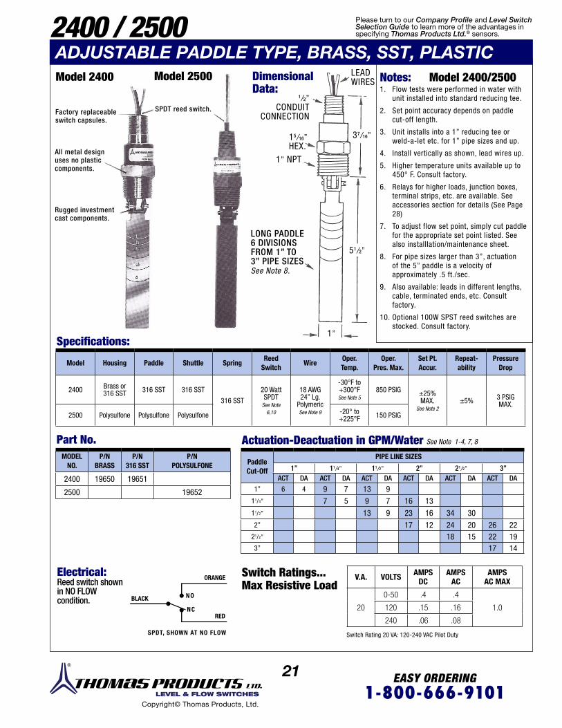
2400 / 2500ADJUSTABLE PADDLE TYPE, BRASS, SST, PLASTICModel 2400 Model 2500
Factory replaceableswitch capsules.
LONG PADDLE6 DIVISIONSFROM 1” TO3” PIPE SIZESSee Note 8.
All metal designuses no plasticcomponents.
Rugged investment cast components.
SPDT reed switch.
Notes: Model 2400/2500 1. Flow tests were performed in water with
unit installed into standard reducing tee.
2. Set point accuracy depends on paddle cut-off length.
3. Unit installs into a 1” reducing tee or weld-a-let etc. for 1” pipe sizes and up.
4. Install vertically as shown, lead wires up.
5. Higher temperature units available up to 450° F. Consult factory.
6. Relays for higher loads, junction boxes, terminal strips, etc. are available. See accessories section for details (See Page 28)
7. To adjust flow set point, simply cut paddle for the appropriate set point listed. See also installlation/maintenance sheet.
8. For pipe sizes larger than 3”, actuation of the 5” paddle is a velocity of approximately .5 ft./sec.
9. Also available: leads in different lengths, cable, terminated ends, etc. Consult factory.
10. Optional 100W SPST reed switches are stocked. Consult factory.
Model Housing Paddle Shuttle SpringReed
SwitchWire
Oper. Temp.
Oper.Pres. Max.
Set Pt.Accur.
Repeat-ability
Pressure Drop
2400 Brass or316 SST 316 SST 316 SST
316 SST
20 Watt SPDT
See Note 6,10
18 AWG 24” Lg.
PolymericSee Note 9
-30°F to +300°F See Note 5
850 PSIG ±25% MAX.
See Note 2±5% 3 PSIG
MAX.
2500 Polysulfone Polysulfone Polysulfone -20° to+225°F 150 PSIG
Part No. Actuation-Deactuation in GPM/Water See Note 1-4, 7, 8
Electrical:Reed switch shownin NO FLOWcondition. BLACK
RED
ORANGE
NO
NC
SPDT, SHOWN AT NO FLOW
Switch Ratings... Max Resistive Load
Switch Rating 20 VA: 120-240 VAC Pilot Duty
V.A. VOLTS AMPS DC
AMPS AC
AMPS AC MAX
20
0-50 .4 .4
1.0120 .15 .16
240 .06 .08
MODELNO.
P/NBRASS
P/N316 SST
P/NPOLYSULFONE
2400 19650 19651
2500 19652
PaddleCut-Off
PIPE LINE SIZES
1” 11/4” 11/2” 2” 21/2” 3”ACT DA ACT DA ACT DA ACT DA ACT DA ACT DA
1” 6 4 9 7 13 911/4” 7 5 9 7 16 1311/2” 13 9 23 16 34 302” 17 12 24 20 26 22
21/2” 18 15 22 193” 17 14
1/2”CONDUIT
CONNECTION
15/16”HEX.
37/16”
51/2”
1”
1” NPT
Please turn to our Company Profile and Level Switch Selection Guide to learn more of the advantages in specifying Thomas Products Ltd.® sensors.
22 EASY ORDERING1-800-666-9101 LEVEL & FLOW SWITCHES
Copyright© Thomas Products, Ltd.
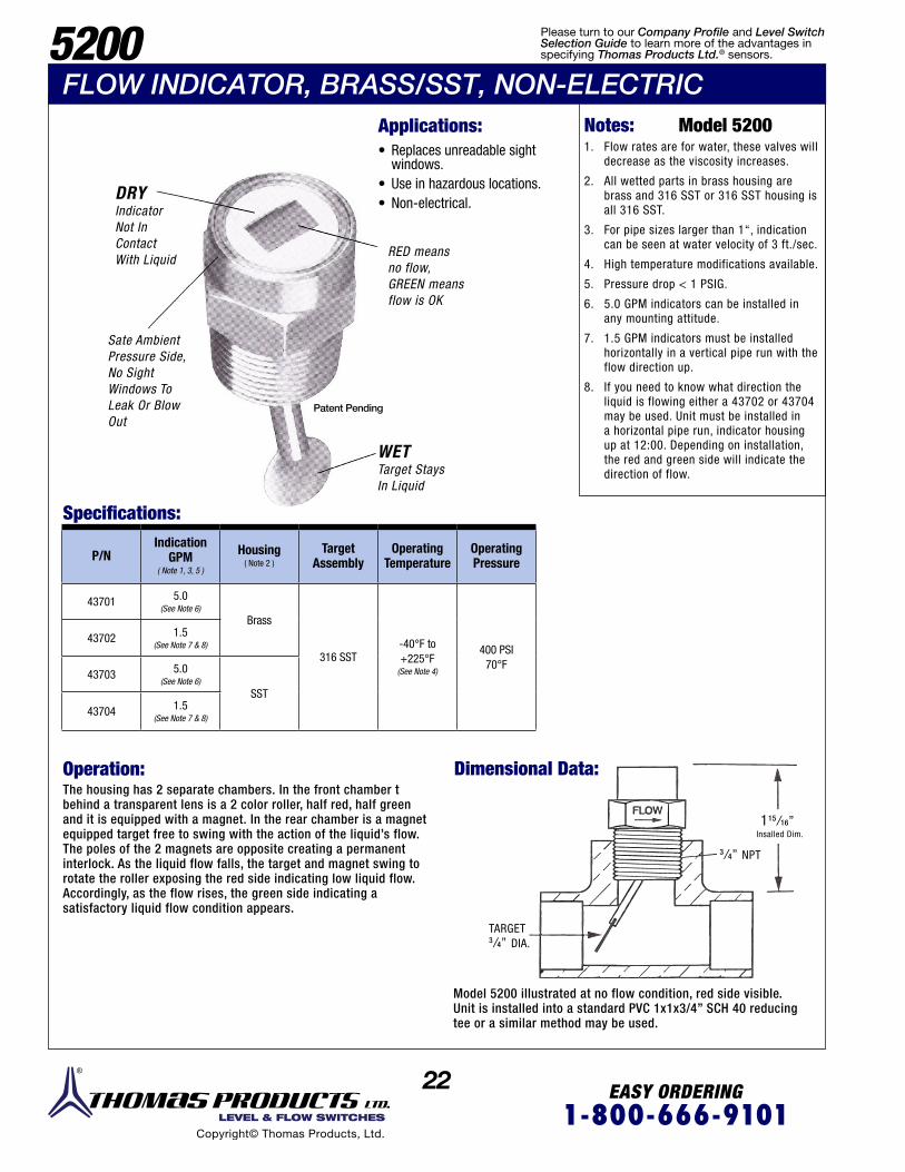
5200FLOW INDICATOR, BRASS/SST, NON-ELECTRIC
Applications: • Replaces unreadable sight windows.
• Use in hazardous locations. • Non-electrical.
RED meansno flow,GREEN meansflow is OK
Sate AmbientPressure Side,No SightWindows ToLeak Or BlowOut
DRYIndicatorNot InContactWith Liquid
WET Target StaysIn Liquid
Patent Pending
Notes: Model 52001. Flow rates are for water, these valves will
decrease as the viscosity increases.
2. All wetted parts in brass housing are brass and 316 SST or 316 SST housing is all 316 SST.
3. For pipe sizes larger than 1“, indication can be seen at water velocity of 3 ft./sec.
4. High temperature modifications available.
5. Pressure drop < 1 PSIG.
6. 5.0 GPM indicators can be installed in any mounting attitude.
7. 1.5 GPM indicators must be installed horizontally in a vertical pipe run with the flow direction up.
8. If you need to know what direction the liquid is flowing either a 43702 or 43704 may be used. Unit must be installed in a horizontal pipe run, indicator housing up at 12:00. Depending on installation, the red and green side will indicate the direction of flow.
The housing has 2 separate chambers. In the front chamber tbehind a transparent lens is a 2 color roller, half red, half greenand it is equipped with a magnet. In the rear chamber is a magnetequipped target free to swing with the action of the liquid’s flow.The poles of the 2 magnets are opposite creating a permanentinterlock. As the liquid flow falls, the target and magnet swing torotate the roller exposing the red side indicating low liquid flow.Accordingly, as the flow rises, the green side indicating asatisfactory liquid flow condition appears.
Model 5200 illustrated at no flow condition, red side visible.Unit is installed into a standard PVC 1x1x3/4” SCH 40 reducingtee or a similar method may be used.
Operation: Dimensional Data:
Specifications:
P/NIndication
GPM( Note 1, 3, 5 )
Housing( Note 2 )
Target Assembly
Operating Temperature
Operating Pressure
43701 5.0(See Note 6)
Brass
316 SST-40°F to+225°F
(See Note 4)
400 PSI70°F
43702 1.5(See Note 7 & 8)
43703 5.0(See Note 6)
SST
43704 1.5(See Note 7 & 8)
TARGET 3/4” DIA.
115/16”Insalled Dim.
3/4” NPT
Please turn to our Company Profile and Level Switch Selection Guide to learn more of the advantages in specifying Thomas Products Ltd.® sensors.
1 EASY ORDERING1-800-666-9101 LEVEL & FLOW SWITCHES
Copyright© Thomas Products, Ltd.
LEVEL SWITCHSELECTIONGUIDE

2 EASY ORDERING1-800-666-9101 LEVEL & FLOW SWITCHES
Copyright© Thomas Products, Ltd.
StandardProductSelectionGuide4000Style 1-4
Bras
s, B
ronz
e, S
tain
less
Ste
el, o
r PVC
Poly
sulfo
ne, B
UNA,
Sta
inle
ss S
teel
, Pol
ypro
pyle
ne, o
r PVC
Inst
alls
from
insi
de o
r ou
tsid
e of
tank
s. T
op o
r bo
ttom
, var
iety
of m
ount
-in
gs.
1/2”
, 1-1
/4”,
2”
NPT
and
3” 1
50#
ANSI
flan
ge.
1/2”
Dia
met
er.
20 V
A SP
ST 2
0-10
0 VA
SPS
T or
20
VA S
PDT
1 to
6
-40°
F to
+30
0°F
(Dep
endi
ng o
n st
yle
spec
ified
.)
750
PSIG
(Dep
endi
ng o
n flo
at s
peci
fied.
)
6 -
9
Com
plem
ent o
f out
lined
sw
itche
s is
to s
how
sta
ndar
d pr
oduc
t lin
e br
eadt
h. O
ur in
-hou
se m
anuf
actu
ring
capa
bilit
ies
can
cust
omiz
e an
y un
it to
sui
t.
4000Style 10
Exte
rnal
tank
mou
ntin
g to
sid
e of
tank
.
Port
siz
e 1”
NPT
.
4000Style 11
Side
of t
ank
mou
ntin
g.
2” ,
3” o
r 4”
150#
AN
SI fl
ange
.
4000Style 5-9
Poly
sulfo
ne, B
UNA,
Sta
inle
ss S
teel
and
Poly
prop
ylen
e
Inst
alls
from
insi
de o
r ou
tsid
e of
tank
s. T
op o
r bo
ttom
, var
iety
of m
ount
-in
gs.
1/8”
, 3/
4”, 1
” NP
T an
d 3-
5/8”
dia
met
er fl
ange
.
5/16
” Di
amet
er.
1 to
5
6 -
13
4000ADJ.
Adju
stab
le s
tem
.Cu
stom
er c
an ra
ise
entir
e st
em to
pos
ition
.
Any
Mod
el 4
000
met
al c
onst
ruct
ion.
5/16
” an
d 1/
2”
Diam
eter
.
1 to
6
5000StyleA-D
Poly
sulfo
ne
Poly
sulfo
ne,
Poly
prop
ylen
e, B
UNA
FDA
appr
oved
mat
eria
l ins
talls
top
or b
otto
m, v
arie
tyof
mou
ntin
gs.
1/8”
. 1”
NPT
.3/
8” -
16
Bulk
head
2” d
iam
eter
flan
ge.
5/16
” Di
amet
er.
Flut
ed.
20 V
A SP
ST
1 to
4
-40°
F to
+22
5°F
14, 1
5
Stea
m &
Mount
ingMat
erial
Float
M
ater
ial
Mou
nting
Si
zes
Stem
Diam
eter
Reed
Switc
hSw
itch
Po
ints
Oper
ating
Tem
pera
ture
sOp
erat
ing
Pr
essu
re
Note
s
Page
Adva
ntag
es
TELEPHONE 860-621-9101 FAX 860-621-1470 1-800-666-9101www.thomasprod.com
3 EASY ORDERING1-800-666-9101 LEVEL & FLOW SWITCHES
Copyright© Thomas Products, Ltd.
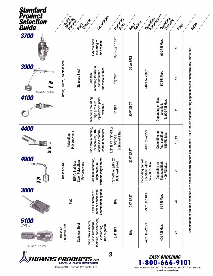
StandardProductSelectionGuide3700
Bras
s, B
ronz
e, S
tain
less
Ste
el
Stai
nles
s St
eel
Exte
rnal
tank
mou
ntin
g to
side
of t
ank.
Port
siz
e 1”
NPT
20 V
A SP
ST
-40°
F to
+30
0°F
900
PSI M
ax.
16
Com
plem
ent o
f out
lined
sw
itche
s is
to s
how
sta
ndar
d pr
oduc
t lin
e br
eadt
h. O
ur in
-hou
se m
anuf
actu
ring
capa
bilit
ies
can
cust
omiz
e an
y un
it to
sui
t.
3900
Side
tank
mou
ntin
g fo
r use
in
cont
amin
ated
and
visc
ous
fluid
s.
1/8”
NPT
50 P
SI M
ax.
17
4100Si
de ta
nk m
ount
ing,
high
pre
ssur
e.Re
plac
emen
t par
tsav
aila
ble.
1” N
PT
20 V
A SP
DT
Depe
ndin
g on
floa
t sp
ecifi
ed.
To 9
00 P
SI M
ax.
20
4400
Poly
sulfo
nePo
lypr
opyl
ene
Side
tank
mou
ntin
g,ec
onom
ical
, FDA
appr
oved
mat
eria
l,co
ndui
t con
nect
or.
1/2”
N P
T, 1/
2”-1
3 or
5/
8”-1
1Bu
lkhe
ad &
Nut
.
20 V
A SP
ST -40°
F to
+22
5°F
Depe
ndin
g on
float
spe
cifie
d.15
0 PS
I Max
.
18, 1
9
4900
Bras
s or
SST
BUNA
, Sta
inle
ssSt
eel,
Poly
sulfo
nePo
lypr
opyl
ene
Side
tank
mou
ntin
g,
high
pre
ssur
e,
varia
ble
leng
th s
tem
s.
1/8”
NPT
or 3
/8”-
24
Bulk
head
& N
ut.
Depe
ndin
g on
floa
t sp
ecifi
ed. -
40°F
to +
300°
F M
ax.
Depe
ndin
g on
float
spe
cifie
d.40
0 PS
I Max
.
21
3800
PVC
Lays
at b
otto
m o
f ta
nk o
r dou
ble
wal
l co
ntai
nmen
t sys
tem
.
N/A
10 V
A SP
ST
-30°
F to
140
°F
50 P
SI M
ax.
26
5100Style 3
Bras
s or
Sta
inle
ss S
teel
Stai
nles
s St
eel
Side
tank
indi
cato
r, us
e in
haz
ardo
us
loca
tion,
non
elec
tric
al,
2 co
lor fl
ag,
(red
& gr
een)
3/4”
NPT
N/A
-40°
F to
+25
5°F
400
PSI M
ax.
27
Stea
m &
Hous
ingMat
erial
Float
M
ater
ial
Mou
nting
Si
zes
Reed
Switc
h
Oper
ating
Tem
pera
ture
sOp
erat
ing
Pr
essu
re
Note
s
Page
Adva
ntag
es
Pat. No.5,425,271
Pat. No.5,117,693
TELEPHONE 860-621-9101 FAX 860-621-1470 1-800-666-9101www.thomasprod.com

4 EASY ORDERING1-800-666-9101 LEVEL & FLOW SWITCHES
Copyright© Thomas Products, Ltd.
4200
Poly
sulfo
neor
Poly
prop
ylen
e
OEM
larg
e vo
lum
eus
e, fl
uted
ste
m
1/8”
NPT
or 3
/8”
Bu
lkhe
ad
20 V
A SP
ST, 1
00 V
A SP
ST,
20 V
A SP
ST
N/A
-40°
F to
+22
5°F
Depe
ndin
g on
floa
t spe
cifie
d.
100
PSI M
ax.
22
Com
plem
ent o
f out
lined
sw
itche
s is
to s
how
sta
ndar
d pr
oduc
t lin
e br
eadt
h. O
ur in
-hou
se m
anuf
actu
ring
capa
bilit
ies
can
cust
omiz
e an
y un
it to
sui
t.
4200,4200H
Bras
s or
SST
4200
BUN
A or
SST
42
00H
SST
Com
pact
, haz
arou
slo
catio
ns
1/8”
NPT 42
00H
Clas
s I D
iv.| G
roup
s C
& D
Clas
s I D
iv. 2
Gr
oups
A, B
, C &
D
Depe
ndin
g on
float
spe
cifie
d.-4
0°F
to +
300°
F
400
PSI M
ax.
24
4500
BUNA
Com
patib
le w
ith fu
el, o
il, e
tc. S
ilico
ne
potte
d. S
hock
& v
ibra
tion
resi
stan
t. Fl
oat
inte
rfac
ing
20 V
A SP
ST, 1
00 V
A SP
ST, 2
0 VA
SPO
T,20
VA
SPST
N/A
-40°
to +
230°
F (D
epen
ding
on
med
ia.)
150
PSI M
ax.
25
4600
1/4”
NPT
25
4700,4700H
Bras
s or
SST
SST
High
pre
ss.,
haza
rous
loca
tions
, sili
cone
po
tted,
sho
ck &
vi
brat
ion
resi
stan
t
4700
H Cl
ass
I Div.
1
Grou
ps C
& D
Cl
ass
I Div.
2
Grou
ps A
, B, C
& D
-40°
to +
300°
F
750
PSI M
ax.
24
4800
PVC
Incr
ease
d flo
at
stre
ngth
, ec
onom
ical
N/A
-40°
to +
140°
F
100
PSI M
ax.
23
Accessories
Junc
tion
boxe
s ex
plos
ion
proo
f.
Rela
ys D
PDT
gene
ral p
urpo
se.
Rela
ys D
PDT
latc
hing
pum
pco
ntro
ls.
Crim
p on
term
inal
s.
Term
inal
str
ips.
TFE
Tape
&TF
E Pa
ste
Cabl
e Gl
ands
28
StandardProductSelectionGuide St
em
Mater
ials
Float
M
ater
ial
Mou
nting
Size
sRe
ed
Switc
h
Haza
rdou
s
Lo
catio
nsOp
erat
ing
Te
mpe
ratu
res
Oper
ating
P
ress
ure
Note
s
Page
s
Adva
ntag
es
TELEPHONE 860-621-9101 FAX 860-621-1470 1-800-666-9101www.thomasprod.com

LEVEL SWITCH SELECTION GUIDEModel 4000
Custom Level SwitchModel 5100
Liquid Level Indicator
Operation:
Typical Operation:
The housing has 2 separate chambers. In the front chamber behind a transparent lens is a 2 color roller, half red, half green and it is equipped with a magnet. In the rear chamber is a magnet equipped float free to swing with the action of the liquid’s level. The poles of the 2 magnets are opposite creating a permanent interlock. As the liquid level falls, the float and magnet swing to rotate the roller exposing the red side indication low liquid level. Accordingly, as the level rises, the green side indicatinga satisfactory liquid level condition appears.
A magnet equipped float moves directly with the liquids level to actuate the hermetically sealed reed switch within the stem.
Inspection using calibrated tools and gages traceable to National Bureau of Standards under Thomas Products, Ltd . recalibration system.
Serialization, documentation retained on purchased materials, processes, inspection, etc.
Factory replaceableswitch bundles.
Investment cast componentsmachined in-house.
Welding: Thomas Products Ltd.certified welders underrequalification system, performed in low hydrogen environment.Process schedules revisioncontrolled. Inspection 100%bubble tight, hydrostatic,fluorescent penetrant.
Approved packaging.
Switches shock and vibration tested.
Float
Magnet
ReedSwith
Stem
Automatedassemblyprocedures.
Operational Q.C. systems and manual, MIL | 45208 and MIL STD 45662.
Injection molding in-house, Thomas Products Ltd. can certify that only virgin materials are used and no reprocessing is done nor has color concentrate been added during molding.
Ideas
Solutions
Technical Support
On-Time Delivery
Quality
Indicator Turns Red When Liquid Is Low;
Green Means Liquid Is OK.
DRYIndicator Not In Contact With Liquid
Periodic destructive testing, i.e. verifying collapse pressure rating.
New technologypatent pendingdesign.
Accelerated life tested in a variety of fluids.
Call-outs providedare typical to theirrespective models.
Raw materials inventoried in a controlled and segregated department under Thomas Products, Ltd. stock rotation program.
UL recognized.
5LEVEL & FLOW SWITCHES
Copyright© Thomas Products, Ltd.
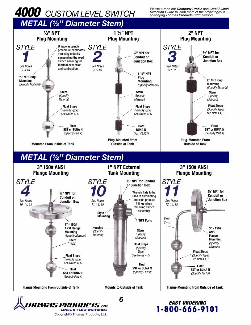
6 EASY ORDERING1-800-666-9101 LEVEL & FLOW SWITCHES
Copyright© Thomas Products, Ltd.
4000 CUSTOM LEVEL SWITCH
½” NPT Plug Mounting
3” 150# ANSIFlange Mounting
1” NPT External Tank Mounting
1 ¼” NPTPlug Mounting
2” NPT Plug Mounting
STYLE
1
STYLE
4
STYLE
2
STYLE
10
STYLE
3Unique assembly procedure eliminates stress by actually suspending the reed switch allowing for thermal expansion and contraction.
½” NPT forConduit orJunction Box
½” NPT forConduit orJunction Box
1 ¼” NPT PlugMounting (Specify Material)
½” NPT for Conduit or Junction Box
½” NPT forConduit orJunction Box
3” - 150#ANSI Flange Mounting(Specify Material)
Float Stops(Specify Type)See Notes 4, 5
FloatSST or BUNA N(Specify Part #)
Style 3Mounting
3” - 150#ANSIFlangeMounting(SpecifyMaterial)
Float Stops(Specify Type)See Notes 4, 5
Wrench flats to be used in eliminatingstress on process
fillings whenremoving switch
assembly
1”NPT Ports
2” NPT PlugMounting(Specify Material)
Stem(SpecifyMaterial)
Stem(SpecifyMaterial)
Stem(SpecifyMaterial)
Float Stops(Specify Type)See Notes 4, 5
½” NPT PlugMounting(Specify Material)
Float Stops(Specify Type)See Notes 4, 5
Float Stops(Specify Type)see Notes 4, 5
FloatBUNA N
(Part #3507)
FloatSST or BUNA N (Specify Part #)
FloatSST or BUNA N (Specify Part #)
Plug-Mounted FromOutside of TankMounted From Inside of Tank
Flange Mounting From Outside of Tank Mounts to Outside of Tank Flange Mounting from Outside of Tank
Plug-Mounted FromOutside of Tank
See Notes8 & 15
See Notes11, 13, 15
See Notes9 & 15
See Notes7 & 15
See Notes10, 14, 15
Stem(SpecifyMaterial)
Stem(SST) Float Stops
(SpecifyType)
See Notes 4, 5
FloatSST or BUNA N(Specify Part #)
METAL (½’’ Diameter Stem)
METAL (½’’ Diameter Stem)
STYLE
11See Notes12, 14, 15
½” NPT forConduit orJunction Box
FloatSST or BUNA N(Specify Part #)
3” 150# ANSIFlange Mounting
Stem(SST)
Housing(SpecifyMaterial)
Please turn to our Company Profile and Level Switch Selection Guide to learn more of the advantages in specifying Thomas Products Ltd.® sensors.
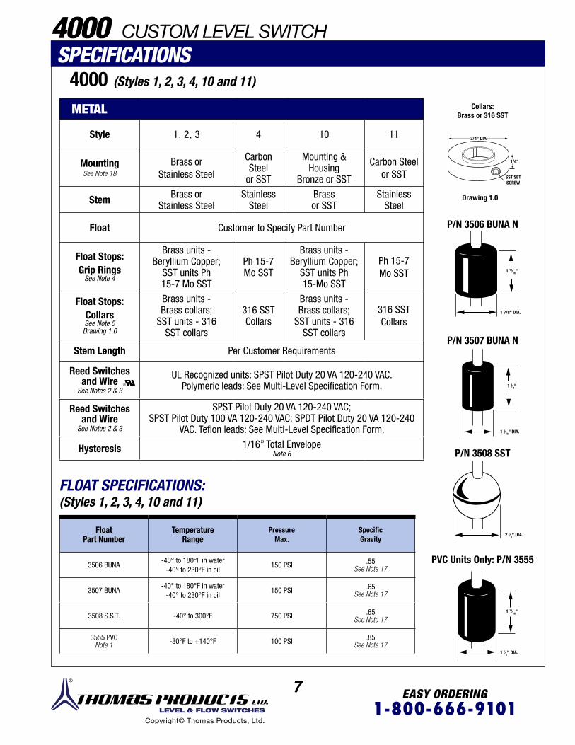
7 EASY ORDERING1-800-666-9101 LEVEL & FLOW SWITCHES
Copyright© Thomas Products, Ltd.
4000 CUSTOM LEVEL SWITCH
4000 (Styles 1, 2, 3, 4, 10 and 11)
SPECIFICATIONS
METAL
Style 1, 2, 3 4 10 11
MountingSee Note 18
Brass orStainless Steel
Carbon Steel
or SST
Mounting &Housing
Bronze or SST
Carbon Steelor SST
Stem Brass orStainless Steel
StainlessSteel
Brassor SST
StainlessSteel
Float Customer to Specify Part Number
Float Stops:Grip Rings
See Note 4
Brass units -Beryllium Copper;
SST units Ph15-7 Mo SST
Ph 15-7Mo SST
Brass units -Beryllium Copper;
SST units Ph15-Mo SST
Ph 15-7Mo SST
Float Stops:CollarsSee Note 5Drawing 1.0
Brass units -Brass collars;
SST units - 316SST collars
316 SSTCollars
Brass units -Brass collars;
SST units - 316SST collars
316 SSTCollars
Stem Length Per Customer Requirements
Reed Switchesand Wire
See Notes 2 & 3
UL Recognized units: SPST Pilot Duty 20 VA 120-240 VAC. Polymeric leads: See Multi-Level Specification Form.
Reed Switchesand Wire
See Notes 2 & 3
SPST Pilot Duty 20 VA 120-240 VAC; SPST Pilot Duty 100 VA 120-240 VAC; SPDT Pilot Duty 20 VA 120-240
VAC. Teflon leads: See Multi-Level Specification Form.
Hysteresis 1/16” Total EnvelopeNote 6
FloatPart Number
TemperatureRange
Pressure Max.
SpecificGravity
3506 BUNA-40° to 180°F in water
-40° to 230°F in oil150 PSI .55
See Note 17
3507 BUNA-40° to 180°F in water
-40° to 230°F in oil150 PSI .65
See Note 17
3508 S.S.T. -40° to 300°F 750 PSI .65See Note 17
3555 PVCNote 1 -30°F to +140°F 100 PSI .85
See Note 17
FLOAT SPECIFICATIONS:(Styles 1, 2, 3, 4, 10 and 11)
Collars:Brass or 316 SST
Drawing 1.0
3/4" DIA.
1 7/8" DIA.
1 1⁄2" DIA.
1 3⁄16" DIA.
2 1⁄8" DIA.
1/4"
1 13⁄16"
1 13⁄16"
1 3⁄4"
SST SETSCREW
P/N 3506 BUNA N
P/N 3507 BUNA N
P/N 3508 SST
PVC Units Only: P/N 3555

8 EASY ORDERING1-800-666-9101 LEVEL & FLOW SWITCHES
Copyright© Thomas Products, Ltd.
Unique assemblyprocedure eliminatesstress by actuallysuspending thereed switchallowing for thermalexpansion andcontraction.
Unique taper joints; not merely glued but an interference fit, solvent bonded means the plastic actually fuses together.
FloatPart
# 3555Only
P/N 3555 PVCSee Float
Specifications
1/2” NPT forConduit orJunction Box
Mounting(Specify
Style 1, 3,4 & 10)
Stem
HigherPressure FloatDue toInterference FitConstruction
SPECIFICATIONS:
Style Styles 1, 3, 4 & 10See Notes 1, 13, 15 & 16
Mounting PVC
Stem PVC. ¼” Schedule 80 Pipe
Float PVC. Part # 3555
Float Stops PVC. Solvent Bondedto Stem
Stem Length Per Customer Requirements
Reed Switches UL Recognized Units SPST Pilot Duty 20 VA
50 - 240 VAC
Reed Switches
Non UL Recognized UnitsSPST Pilot Duty 100 VA
50 - 240 VAC SPDT Pilot Duty 20 VA
50 - 240 VACSee Notes 6
Wire PVC 24’’ Long ExtendedSee Notes 2 & 3
Hysteresis 1⁄16” Total Envelope
See Notes 6
For Styles 2, 3, 4 & 10. Option for Model 4000 -1/2” Diameter StemCompressionNut
½” NPTConduit Connection
Specify at maximum length 1-6 sensing levels
Use Multi-Level Specification Form Model 4000 and notes for all other pertinent information.
Adjustable mountings/stems are not available in PVC.
when desired adjustment hasbeen determined, tightencompression nut. Stem thenbecomes permanently fixed.
CompressionFitting
Mounting
1 1⁄2" DIA.
1 3⁄16"
1. Part Number 3555 PVC float is used for PVC Model 4000. See specifications
2. Also available: leads in different lengths, cable, terminated ends, etc. consult factory.
3. Relays are available for handling higher electrical loads than allowed. See accessory section for details.
4. Grip rings come standard at no extra charge.
5. Optional collars are available from stock. See drawing 1.0.
6. Special reed switches are stocked to yield a hysteresis of 1/4”. Consult factory.
7. Style 1 mounting installs from the inside of the tank into a ½” NPT boss. Specify float part number: 3506, 3507, 3508, or 3555.
8. Style 2 mounting installs from the outside of the tank into a 1 1/4” NPT boss. Specify float part number 3507.
9. Style 3 mounting installs from the outside of the tank into a 2” NPT boss. Specify float part number: 3506, 3507, 3508, or 3555.
10. Style 4 flange mounting installs from the outside of the tank onto a 3” ANSI flange mating surface. Specify float part number 3506, 3507, 3508, or 3555.
11. Style 10 external tank mounting installs to the tank exterior. Bottom “run” port can be fabricated at branch position typical to top port. Thomas Products LTD. can machine ports on both bronze and stainless steel housings for silver braze or socket weld end connections. Consult factory. Specify float part number: 3506 or 3508.
12. Style 11 mountings install from the outside of the tank onto a 3” ANSI flange mating surface. Note: The bolt patterns angular position must be followed per drawing. See Multi-Level Specification Form 4000. Specify float part number: 3506, 3507 or 3508.
13. Style 10 external tank unit is available in all PVC construction. Consult factory.
14. Styles 4 & 11 flange mounting types are also available with a 1”, 2” or 4” 150# ANSI flanges.
15. Multi-level Specification Form 4000 must be used to ensure correct dimensional data.
16. All wetted parts PVC.17. Custom interface floats are available.
Consult factory.18. Materials of copper-nickel, titanium,
hastelloy and aluminum are stocked. Consult factory.
Notes:
ADJUSTABLE STEM
4000 CUSTOM LEVEL SWITCHPVC
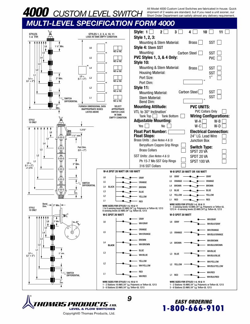
9 EASY ORDERING1-800-666-9101 LEVEL & FLOW SWITCHES
Copyright© Thomas Products, Ltd.
STYLES STYLES 1, 2, 3, 4, 10, 11LOGIC IN TANK EMPTY CONDITION1-4 TYP.
L6
L6
L6L6
L6
L6
L5
L5
L5
L4
L4
L4
L3
L3
L3
L2
L2
L2
L1
L1
L1
L6
L5
L5
L5
L5
BLACK
GRAY
GRAYGRAY
ORANGEORANGE
BROWNBROWN
BLUEBLUE
YELLOWYELLOW
REDRED
ORANGE
WH/GRAY
WH/GRAY
WH/ORANGE
WH/BROWN
WH/BLUE
WH/YELLOW
WH/RED
WH/BLK/GRAY
WH/BLK/ORANGE
WH/BLK/BROWN
WH/BLK/BLUE
WH/BLK/YELLOW
WH/BLK/RED
WH/ORANGE
WH/BROWN
WH/BLUE
WH/YELLOW
WH/RED
BROWN
GRAY GRAY
BLUE
RED
ORANGE ORANGE
BROWN BROWN
BLUE BLUE
YELLOW YELLOW
RED REDYELLOW
L4
L4
L4
L4
L6
L3L3
L3
L3
L3
L5
L2L2
L2
L2
L0 =(L1 + 2’’)
L0 =(L1 + 2’’)
L0 =(L1 + 2’’)
Part Dim.(L0 + 2’’)
1.215''
1 ½'' min.
L0 =(L1 + 2’’)+1.215
L2
L1
L1
L1
L1
L4
L1
NO or NC
NO or NC
NO or NC
NO or NC
NO or NC
NO or NC
WIRE SIZES FOR STYLES 1-4, 10 & 111 - 3 sensing levels 18 AWG 24” Lg. Polymeric or Teflon-UL 1213 4 - 6 sensing levels 22 AWG 24”Lg. Teflon-UL 1213
WIRE SIZES FOR STYLES 1-4, 10 & 111 to 5 sensing levels 22 AWG 24” Lg. Polymeric or Teflon-UL 12136 sensing levels 22 AWG 24’’ Lg. Teflon-UL 1213
WIRE SIZES FOR STYLES 1-4, 10 & 111 - 2 Stations 18 AWG 24’’ Lg. Polymeric or Teflon-UL 1213 3 - 6 Stations 22 AWG 24’’ Lg. Teflon-UL 1213
WIRE SIZES FOR STYLES 1-4, 10 & 111 - 2 Stations 18 AWG 24’’ Lg. Polymeric or Teflon-UL 1213 3 - 6 Stations 22 AWG 24’’ Lg. Teflon-UL 1213
W·C SPOT 20 WATT W-D SPDT 20 WATT
BLACK
W-A SPST 20 WATT OR 100 WATT W-B SPST 20 WATT OR 100 WATT
FURNISH DIMENSIONAL DATA INAPPROPRIATE BOXES
LISTED ABOVE
SWITCHDIFFERENTIAL
SWITCHDIFFERENTIAL
SWITCHDIFFERENTIAL
2''min.
2''min.
3'' min.
45°
1⁄16''
1⁄16''
1⁄16''
STYLE 10 ONLY
STYLE10 ONLY
BendDim. 3’’ Min.
3’’ Min.
3’’ Min.
1 ½’’ Min.
2’’ Min.
3’’ Min.
SELECTAPPROPRIATESWITCH LOGIC
IN TANKEMPTY CONDITION
MULTI-LEVEL SPECIFICATION FORM 4000 Style:Style 1, 2, 3:
Mounting & Stem Material:Style 4: Stem SST
Mounting:PVC Styles 1, 3, & 4 Only:Style 10:
Mounting & Stem Material:Housing Material:Port Size:Port Dim:
Style 11:Mounting Material:Stem Material:
Float Part Number:Float Stops:Brass Units : (See Notes 4 & 5)
Beryyllium Coppre Grip RingsBrass Collars
SST Units: (See Notes 4 & 5)
Ph 15-7 Mo SST Grip Rings316 SST Collars
PVC UNITS:
Wiring Configurations:
Electrical Connection:
Switch Type:
PVC Collars Only
Brass
Brass
Carbon Steel
Carbon Steel
W-A
24” LG. Lead WireJunction Box
SPST 20 VA SPDT 20 VA SPST 100 VA
W-CW-BW-D
SST
SST
SST
SST
SST
SST
1’’’’
’’
PVC
1 2 3 4 10 11
Bend Dim:Mounting Attitude:VTL to 30° Inclination`
Adjustable Mounting:Tank Top
Yes No
Tank Bottom
‘‘
‘‘
‘‘‘‘
‘‘
‘‘
‘‘
All Model 4000 Custom Level Switches are fabricated in-house. Quick shipment of 2 weeks are standard, but if you need a unit sooner, our Short Order Department can satisfy almost any delivery requirement.4000 CUSTOM LEVEL SWITCH
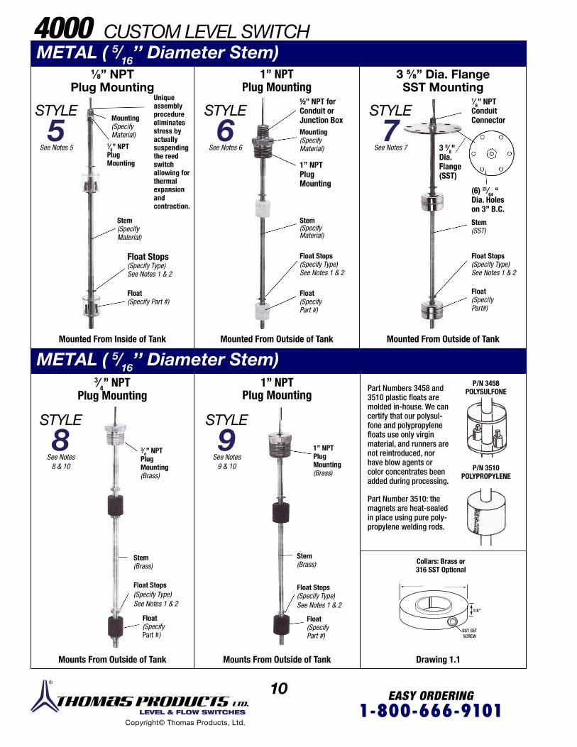
10 EASY ORDERING1-800-666-9101 LEVEL & FLOW SWITCHES
Copyright© Thomas Products, Ltd.
⅛” NPT Plug Mounting
STYLE
5Uniqueassemblyprocedureeliminatesstress byactuallysuspendingthe reedswitchallowing forthermalexpansionandcontraction.
1⁄8” NPTPlugMounting
Stem(SpecifyMaterial)
Mounting(SpecifyMaterial)
Float Stops(Specify Type)See Notes 1 & 2
Float(Specify Part #)
Mounted From Inside of Tank
See Notes 5
1’’ NPT Plug Mounting
STYLE
6½” NPT forConduit orJunction BoxMounting(SpecifyMaterial)
1’’ NPTPlugMounting
Stem(SpecifyMaterial)
Float Stops (Specify Type)See Notes 1 & 2
Float(SpecifyPart #)
Mounted From Outside of Tank
See Notes 6
3⁄4” NPTPlug Mounting
STYLE
8 3⁄4” NPTPlugMounting(Brass)
Float Stops(Specify Type)See Notes 1 & 2
Float(SpecifyPart #)
Stem(Brass)
See Notes8 & 10
Mounts From Outside of Tank
1” NPTPlug Mounting
STYLE
9See Notes
9 & 10
1’’ NPTPlugMounting(Brass)
Mounts From Outside of Tank
Stem(Brass)
Float Stops(Specify Type)See Notes 1 & 2
Float(Specify Part #)
3 5/8” Dia. Flange SST Mounting
STYLE
7
Mounted From Outside of Tank
See Notes 7
1⁄8” NPTConduitConnector
(6) 21⁄64 ‘‘Dia. Holeson 3” B.C.
3 5⁄8"Dia.Flange(SST)
Stem(SST)
Float Stops(Specify Type)See Notes 1 & 2
Float(SpecifyPart#)
Drawing 1.1
Collars: Brass or316 SST Optional
Part Numbers 3458 and3510 plastic floats are molded in-house. We can certify that our polysul - fone and polypropylene floats use only virgin material, and runners are not reintroduced, nor have blow agents or color concentrates been added during processing.
Part Number 3510: the magnets are heat-sealed in place using pure poly-propylene welding rods.
P/N 3510POLYPROPYLENE
P/N 3458POLYSULFONE
1/8"
SST SETSCREW
METAL ( 5⁄16’’ Diameter Stem)
4000 CUSTOM LEVEL SWITCHMETAL ( 5⁄16’’ Diameter Stem)
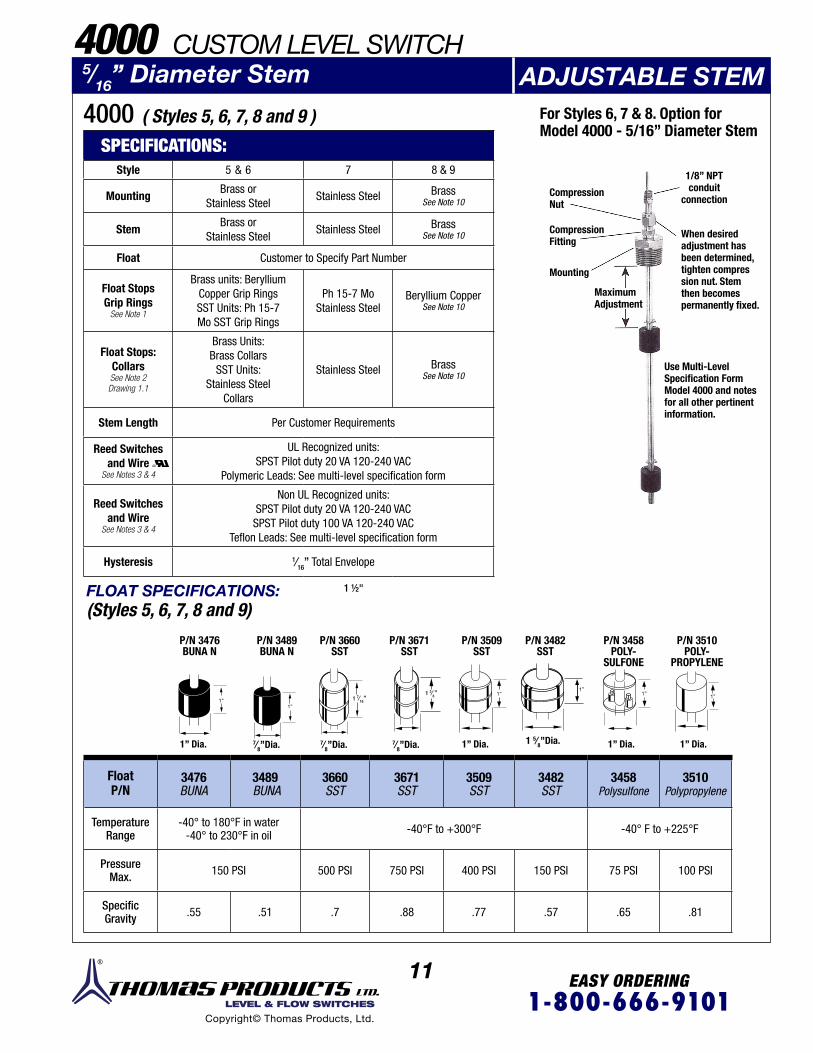
11 EASY ORDERING1-800-666-9101 LEVEL & FLOW SWITCHES
Copyright© Thomas Products, Ltd.
4000 ( Styles 5, 6, 7, 8 and 9 )
5⁄16” Diameter Stem ADJUSTABLE STEM
SPECIFICATIONS: Style 5 & 6 7 8 & 9
MountingBrass or
Stainless SteelStainless Steel Brass
See Note 10
StemBrass or
Stainless SteelStainless Steel Brass
See Note 10
Float Customer to Specify Part Number
Float StopsGrip Rings
See Note 1
Brass units: Beryllium Copper Grip Rings SST Units: Ph 15-7 Mo SST Grip Rings
Ph 15-7 Mo Stainless Steel
Beryllium CopperSee Note 10
Float Stops:CollarsSee Note 2Drawing 1.1
Brass Units:Brass Collars
SST Units:Stainless Steel
Collars
Stainless Steel BrassSee Note 10
Stem Length Per Customer Requirements
Reed Switchesand Wire
See Notes 3 & 4
UL Recognized units: SPST Pilot duty 20 VA 120-240 VAC
Polymeric Leads: See multi-level specification form
Reed Switchesand Wire
See Notes 3 & 4
Non UL Recognized units: SPST Pilot duty 20 VA 120-240 VAC SPST Pilot duty 100 VA 120-240 VAC
Teflon Leads: See multi-level specification form
Hysteresis 1⁄16” Total Envelope
FloatP/N
3476BUNA
3489 BUNA
3660SST
3671SST
3509SST
3482SST
3458Polysulfone
3510Polypropylene
TemperatureRange
-40° to 180°F in water-40° to 230°F in oil -40°F to +300°F -40° F to +225°F
PressureMax. 150 PSI 500 PSI 750 PSI 400 PSI 150 PSI 75 PSI 100 PSI
SpecificGravity .55 .51 .7 .88 .77 .57 .65 .81
FLOAT SPECIFICATIONS:(Styles 5, 6, 7, 8 and 9)
For Styles 6, 7 & 8. Option forModel 4000 - 5/16” Diameter Stem
CompressionNut
CompressionFitting
Mounting
MaximumAdjustment
1/8” NPTconduit
connection
When desired adjustment has been determined,tighten compres sion nut. Stemthen becomes permanently fixed.
Use Multi-Level Specification Form Model 4000 and notes for all other pertinent information.
1” Dia. 1” Dia. 1” Dia. 1” Dia.7⁄8”Dia. 7⁄8”Dia. 7⁄8”Dia. 1 5⁄8”Dia.
P/N 3476 BUNA N
P/N 3489 BUNA N
P/N 3660 SST
P/N 3671SST
P/N 3509SST
P/N 3482SST
P/N 3458POLY-
SULFONE
P/N 3510POLY-
PROPYLENE
4000 CUSTOM LEVEL SWITCH
1”1”
1”1”
1” 1”1 7⁄16”1 3⁄8”
1 ½"
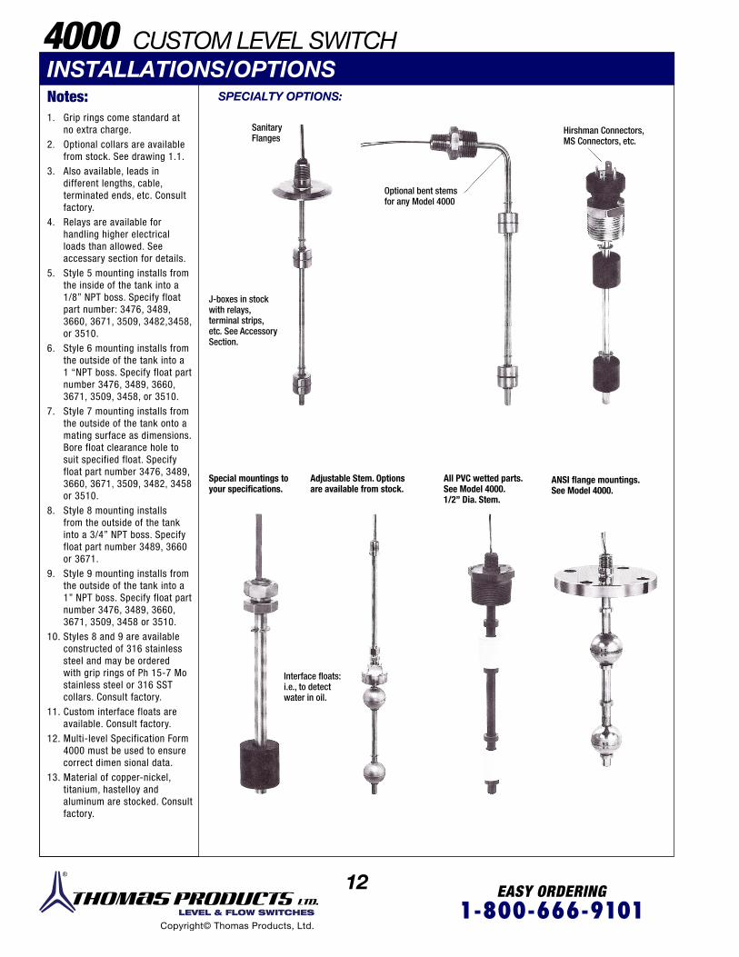
12 EASY ORDERING1-800-666-9101 LEVEL & FLOW SWITCHES
Copyright© Thomas Products, Ltd.
Special mountings to your specifications.
Adjustable Stem. Options are available from stock.
All PVC wetted parts.See Model 4000. 1/2” Dia. Stem.
ANSI flange mountings. See Model 4000.
Interface floats:i.e., to detect water in oil.
Hirshman Connectors,MS Connectors, etc.
J-boxes in stockwith relays,terminal strips,etc. See AccessorySection.
INSTALLATIONS/OPTIONS SPECIALTY OPTIONS:
SanitaryFlanges
Optional bent stemsfor any Model 4000
1. Grip rings come standard at no extra charge.
2. Optional collars are available from stock. See drawing 1.1.
3. Also available, leads in different lengths, cable, terminated ends, etc. Consult factory.
4. Relays are available for handling higher electrical loads than allowed. See accessary section for details.
5. Style 5 mounting installs from the inside of the tank into a 1/8” NPT boss. Specify float part number: 3476, 3489, 3660, 3671, 3509, 3482,3458, or 3510.
6. Style 6 mounting installs from the outside of the tank into a 1 “NPT boss. Specify float part number 3476, 3489, 3660, 3671, 3509, 3458, or 3510.
7. Style 7 mounting installs from the outside of the tank onto a mating surface as dimensions. Bore float clearance hole to suit specified float. Specify float part number 3476, 3489, 3660, 3671, 3509, 3482, 3458 or 3510.
8. Style 8 mounting installs from the outside of the tank into a 3/4” NPT boss. Specify float part number 3489, 3660 or 3671.
9. Style 9 mounting installs from the outside of the tank into a 1” NPT boss. Specify float part number 3476, 3489, 3660, 3671, 3509, 3458 or 3510.
10. Styles 8 and 9 are available constructed of 316 stainless steel and may be ordered with grip rings of Ph 15-7 Mo stainless steel or 316 SST collars. Consult factory.
11. Custom interface floats are available. Consult factory.
12. Multi-level Specification Form 4000 must be used to ensure correct dimen sional data.
13. Material of copper-nickel, titanium, hastelloy and aluminum are stocked. Consult factory.
Notes:
4000 CUSTOM LEVEL SWITCH
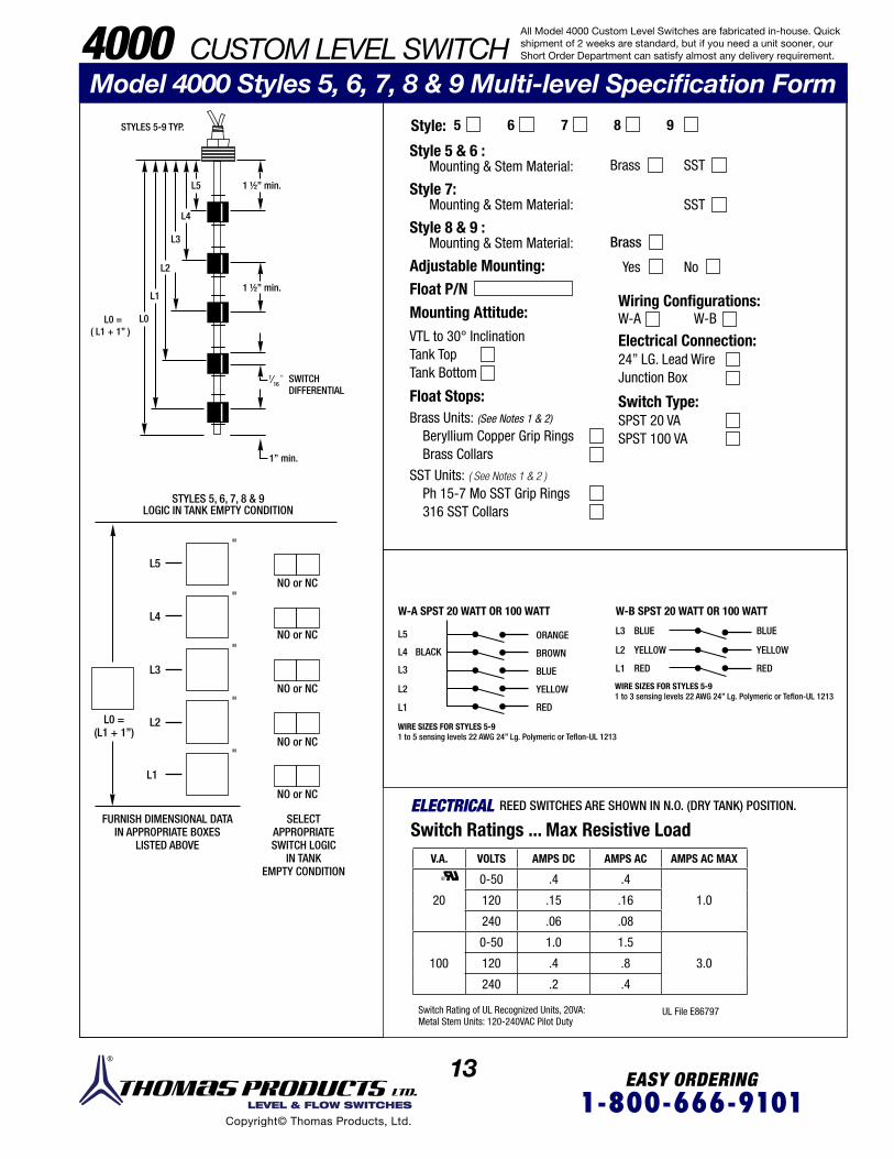
13 EASY ORDERING1-800-666-9101 LEVEL & FLOW SWITCHES
Copyright© Thomas Products, Ltd.
STYLES 5-9 TYP.
FURNISH DIMENSIONAL DATA IN APPROPRIATE BOXES
LISTED ABOVE
SELECTAPPROPRIATESWITCH LOGIC
IN TANKEMPTY CONDITION
L0 = L0
L1
L1
L2
L3
L4
L5
"
"
"
"
"
L2
L3
L4
L5
( L1 + 1” )
L5
L4 BLACK
ORANGE
BROWN
BLUE
BLUE BLUE
YELLOW
YELLOW YELLOW
RED RED
RED
L3
L3
L2
L2
L1
L1
Style:
Style 5 & 6 :Mounting & Stem Material:
Style 7:Mounting & Stem Material:
Style 8 & 9 :Mounting & Stem Material:
Adjustable Mounting:Float P/NMounting Attitude:VTL to 30° InclinationTank TopTank Bottom
Float Stops:Brass Units: (See Notes 1 & 2)
Beryllium Copper Grip RingsBrass Collars
SST Units: ( See Notes 1 & 2 )
Ph 15-7 Mo SST Grip Rings316 SST Collars
Wiring Configurations:
Electrical Connection:24” LG. Lead WireJunction Box
Switch Type:SPST 20 VASPST 100 VA
Brass
Brass
Yes
W-A W-B
No
SST
SST
5 6 7 8 9
WIRE SIZES FOR STYLES 5-91 to 3 sensing levels 22 AWG 24” Lg. Polymeric or Teflon-UL 1213
W-A SPST 20 WATT OR 100 WATT W-B SPST 20 WATT OR 100 WATT
WIRE SIZES FOR STYLES 5-91 to 5 sensing levels 22 AWG 24” Lg. Polymeric or Teflon-UL 1213
REED SWITCHES ARE SHOWN IN N.O. (DRY TANK) POSITION.
Switch Ratings ... Max Resistive Load
STYLES 5, 6, 7, 8 & 9 LOGIC IN TANK EMPTY CONDITION
Model 4000 Styles 5, 6, 7, 8 & 9 Multi-level Specification Form
ELECTRICAL
V.A. VOLTS AMPS DC AMPS AC AMPS AC MAX
20
0-50 .4 .4
1.0120 .15 .16
240 .06 .08
100
0-50 1.0 1.5
3.0120 .4 .8
240 .2 .4
1 ½’’ min.
1 ½’’ min.
SWITCHDIFFERENTIAL
1’’ min.
1⁄16 ''
L0 =(L1 + 1’’)
NO or NC
NO or NC
NO or NC
NO or NC
NO or NC
Switch Rating of UL Recognized Units, 20VA: Metal Stem Units: 120-240VAC Pilot Duty
UL File E86797
All Model 4000 Custom Level Switches are fabricated in-house. Quick shipment of 2 weeks are standard, but if you need a unit sooner, our Short Order Department can satisfy almost any delivery requirement.4000 CUSTOM LEVEL SWITCH

14 EASY ORDERING1-800-666-9101 LEVEL & FLOW SWITCHES
Copyright© Thomas Products, Ltd.
5000 CUSTOM LEVEL SWITCHESPLASTIC STEM (Polysulfone)
Note 11Note 10Note 9Note 8
P/N 3476BUNA N
P/N 3458POLY-
SULFONE
P/N 3510POLY-
PROPYLENE
Applications:• FDA approved polysulfone for
use in food and beverage control.
FloatP/N
3476BUNA
3458 Polysulfone
3510 Polypropylene
TemperatureRange
-40° to+180°F in Water
-40° to+230°F in Oil
-40°F to +225°F
PressureMax. 150 PSI 75 PSI 100 PSI
SpecificGravity .55 .65 .81
STYLE A STYLE B STYLE C STYLE D1⁄8” NPT
Plug Mounting3⁄8” Bulkhead
Mounting1” NPT
Plug Mounting2” O.D. Flange
Mounting
5/16’’ DIAMETER STEMSStyle A, B,C, D
Materials
PolysulfoneMounting
Stem Float Stops See Note 12
Floats Customer to specify. See Notes 1 - 5 & 12.
Stem Length Per customer requirements.
Reed Switchesand Wires
UL Recognized:SPST Pilot duty 20 VA 50-240 VAC
PVC Leads 24” Long. See Multi-level Specification Form. See Notes 6 & 7.
Temperature Polysulfone max. temp. range -40° to +225°F
Hysteresis 1/8” total envelope
Unique assembly procedure eliminates stress by actuallysuspending the reed switchallowing for thermal
expansion andcontraction.
Fluted stemto preventlime deposits.
Float stops withanti-meniscusprojections meansfloat cannot dry inplace after longmachine shut-downs.
Float(Specify Part #)
1” Dia. 1” Dia. 1” Dia.
Float(SpecifyPart #)
(4) 5⁄32"Dia. Holes
on 1 ½" B.C.
Float(SpecifyPart #)
SeeNote13
Float(SpecifyPart #)
3⁄8"-16 straightthread nut and
1⁄16" thick
silicone gasket
IntegralHexfor
installation
1⁄8" NPTconduit
connector
1⁄8" NPTconduit
connector
Float(SpecifyPart #)
1”1”
1”

15 EASY ORDERING1-800-666-9101 LEVEL & FLOW SWITCHES
Copyright© Thomas Products, Ltd.
5000 CUSTOM LEVEL SWITCHES
1. Unit’s maximum pressure rating is the lowest pressure rated component either mounting and stem pressure rating or float pressure rating.
2. Unit’s maximum temperature rating is the lowest temperature rated component either polysulfone temperature range or float tempera- ture range.
3. Pressure rating of styles A & B mounting and stem are 100 PSI @ 72°F. Also see float pressure rating. See Note 1.
4. Pressure rating of style C mounting and stem is 50 PSI @ 72°F. Also see float pressure rating. See Note 1.
5. Pressure rating of style D mounting and stem is 10 PSI @ 72°F. Also see float pressure rating. See Note 1.
6. Also available: leads in different lengths, cable, and/or terminated ends, etc. Consult factory.
7. Relays are available for electrical loads higher than allowed. See Accessories section for details.
8. Style A mounting installs from the inside of the tank into a 1/8”NPT boss.
9. Style B mounting installs from the inside of the tank through a 3/8” dia. hole.
10. Style C mounting installs from the outside of the tank into a 1’’ NPT boss.
11. Style D mounting installs from the outside of the tank onto a mating surface as dimensioned. Bore float clearance hole to suit specified float. Maximum float diameter 1’’.
12. Other floats than shown are available. See Model 4000, metal 5/16” diameter stem, styles 5 - 9 for details.
13. Request extra 1’’ stem length to attach guy wires (customer supplied) for exceptionally long stems or if unit will be subjected to turbulence.
14. Custom interface floats are available. Consult factory.
15. Multi-level Specification Form 4000 must be used to ensure correct dimensional data.
MULTI-LEVEL SPECIFICATION FORM 4000
V.A. VOLTS AMPS DC AMPS AC AMPS AC MAX
20
0-50 .4 .4
1.0120 .15 .16
240 .06 .08
Switch Ratings ... Max Resistive Load
W-A SPST 20 VA W-B SPST 20 VA
Switch Rating of UL Recognized Units20VA 50 - 240 VAC Pilot Duty UL File E86797
STYLES A - D STYLES A - DLOGIC IN TANK EMPTY CONDITION
FURNISH DIMENSIONAL DATAIN APPROPRIATE BOXES
LISTED ABOVE
SELECTAPPROPRIATESWITCH LOGIC
IN TANKEMPTY CONDITION
NO or NC
NO or NC
NO or NC
NO or NC
‘‘
‘‘‘‘
‘‘
‘‘
L4
L3
L2
L1
L1L0 =
(L1 + 1’’)Notes 13
L0 =(L1 + 1’’)
1’’ min.
1’’ min.
1 ½’’ min.L2
L3
L4
L1
L1
L2
L2
L3
L4
SWITCHDIFFERENTIAL
ELECTRICAL REED SWITCHES ARE SHOWN IN N.O. (DRY TANK) POSITION.
BLACK BROWN
BLUE
YELLOW
YELLOW YELLOW
RED
RED RED
WIRE SIZES FOR STYLES A - D1 or 2 sensing levels 22 AWG 24” Lg. PVC
WIRE SIZES FOR STYLES A - D1 or 4 sensing levels 22 AWG 24” Lg. PVC
Style: A B C D
Mounting Attitude:VTL to 30° InclinationTank TopTank BottomWiring Configurations:
Float P/N
W-A W-B
1⁄8 ''
All Model 4000 Custom Level Switches are fabricated in-house. Quick shipment of 2 weeks are standard, but if you need a unit sooner, our Short Order Department can satisfy almost any delivery requirement.
Notes:
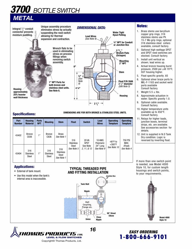
16 EASY ORDERING1-800-666-9101 LEVEL & FLOW SWITCHES
Copyright© Thomas Products, Ltd.
DIMENSIONAL DATA:
3700 BOTTLE SWITCHMETAL
Integral 1⁄2” conduitconnector preventsmoisture puddling.
Unique assembly procedure eliminates stress by actuallysuspending the reed switch allowing for thermal expansion and contraction.
Wrench flats to beused in eliminatingstress on processfillings when removing switchassembly.
DIMENSIONS ARE FOR BOTH BRONZE & STAINLESS STEEL UNITS.
Housingapproximately25% heavierwall thickness
1’’ NPT Ports forboth bronze andstainless steel units.See Note 6.
Specifications:
Applications: TYPICAL THREADED PIPEAND FITTING INSTALLATION
HalfCoupling
Flange etc.
Model 4000Style 10
Part Number
HousingMaterial
PortsNPT Mouning Stem Float Switch Lead
WiresOperatingTempture
OperatingTempture
43402 BronzeC836 1’’ Bronze
C836Brass
See Note 1316
StainlessSteel
See Note 5
20 VASPST
See Note 2, 11, & 12
18 AWGPolymeric24" Long
See Note 9
-40°F to +300°F
See Note 10
750 PSIMAX.(Float)
See Note 4
43404316
Stainless Steel
1’’316
Stainless Steel
316Stainless
SteelSee Note 1
• External of tank mount.
• Use this model when the tank’sinternal area is inaccessible.
If more than one switch point is needed, see Model 4000 Style 10, for custom length housings and switch points, to your requirements.
Lead Wires(See Note 9)
Float P/N 35082 1⁄8’’ diameter(See Note 5)
4 ¼"
2 3⁄8"
8"
½"(SeeNote8)
Water TightHysol Potting
2 23⁄32”Wrench Flats(Octagon)
Mounting2’’ NPT
Stem
Actuation
Housing
½’’ NPT for Conduit or Junction Box
Junction Box
Tank Wall
HalfCoupling,
Flange etc.
Nipple
90° StreetElbow
CloseNippleUnion
1. Brass stems use beryllium copper grip rings, 316 stainless stems use Ph 15-7 Mo grip rings, optional 316 stainless steel collars available, consult factory.
2. Optional high wattage SPST and SPDT reed switches are stocked. Consult factory.
3. Install unit vertical as shown; lead wires up.
4. Actual bronze housing burst pressure, 2500 psi ±@ 70°F; SST housing higher.
5. Float specific gravity .656. Optional silver braze ports to
MIL-F-1183 and socket weld ports available Consult factory.
7. Weight 5.5 ± lbs.8. Approximate actuation in
water. Specific gravity 1.0.9. Optional cable available.
Consult factory.10. Higher temperature units
available up to 450°F. Consult factory.
11. Relays for higher loads, junction boxes, terminal strips, etc. are available. See accessories section for details.
12. Unit is supplied in N.O Tank Dry condition. Logic is reversed by inverting float.
Notes:

17 EASY ORDERING1-800-666-9101 LEVEL & FLOW SWITCHES
Copyright© Thomas Products, Ltd.
1”
3900 SIDE MOUNTED Patent Number 5117693
Patented operation means: mechanism, includingmagnet, remains out ofcontaminated or problemliquids.
FLOAT: No magnetin float. Ferrousalloys are notattracted to floatwhich could jamother types of levelswitches.
Drawing 1.0
N.O. AT FULLOR EMPTY
RED RED
RED REDN.C. AT FULL
OR EMPTY
WIRING DIAGRAM FOR STANDARD SPST SWITCHES
Silicone potted forshock and vibrationdeadening.
Applications:• Ideal for dirty or
contaminated liquids.
• Viscous fluids.
• Only the float is incontact with the liquid.
• All metal design.
• Choice of N.O. or N.C.switch logic.
1. Other mounting styles available. Consult factory.
2. Float Sp. Gr. .5.3. Consult factory for operating
temperatures to 450°F.4. Switch logic in tank dry condition per
drawing 1.0.5. Optional 1OOW SPST reed switches are
stocked. Consult factory.6. Relays are available for handling higher
loads than allowed. See Accessories section for details.
METAL
The unique design permits only the float to come in contact with the liquid, thereby eliminating the possibility of jamming caused by the metallic chips collecting on the magnet.
P/N N.0.See Note 4
P/N N.C.See Note 4
Mount-ing Stem Float SwitchLeadWires
Oper.Temp.
Oper.Pressure
43031 430331/8’’ NPTSee Note 1
BrassSST
See Note 2
20VASPST
See Note5 & 6
18 AWGPoly-meric
-40°F to+300°FSee Note 3
50PSIG
43032 43034 SST
Specifications:
Electrical
V.A. VOLTSAMPS
DCAMPS
AC MAXAMPS
AC MAX
20
0-50 .4 .4
1.0120 .15 .16
240 .06 .08
Switch Ratings ... Max Resistive Loads
Switch Rating 20VA: 120-240VAC Pilot Duty
One level switch maintains the proper level of a viscous epoxy used in automatic coating machines.
By simply bending the float arm, tank top mounting may be used in lieu of side of tank installation.
Grinding fluid contaminated with metallic chips and lube oil.
Viscous epoxy.
Stem Magnet
Float arm alsoavailable in custombuilt lengths
1 ½"4 ½"5 ½"
Reed Switch
PermanentMagnet
Pump Off Pump On
Notes:

18 EASY ORDERING1-800-666-9101 LEVEL & FLOW SWITCHES
Copyright© Thomas Products, Ltd.
Strong Alnico bar magnethermetically sealed inside means no other wetted material to contaminate liquid or be attacked by a corrosive liquid.
Special molded thread helps when metal to plastic installations are used.
Unique assemblyprocedure eliminatesstress by actuallysuspending the reed switchallowing for thermalexpansion and contraction.
Unique assembly procedure eliminates stress by actually suspending the reed switch allowing for thermal expansion and contraction.
High wattage reed switch de-rated and matched to the strong Alnico bar magnet makes a superior match.
Anti-meniscus projection means float cannot dry in place after long machine shut-downs.
Plastic components are molded, in-house, using only certified 100% virgin material. Runners are not reintroduced to the performance parts.
Because Thomas Products Ltd.molds in-house, we can certifythat during the molding processcolor concentrates have not beenadded that hinder FDA require-ments of additive leaching.
Round pivot pins add bearing surface for smooth operation and due to design clearances, squeeze out the liquid from either side during operation to help eliminate build-up.
Float
Permanent Magnet
ReedSwitch
LeadWires
NPT
P/N Mounting Stem FloatSee Note 7 Switch Lead Wires
OperatingTemp.
OperatingPressure
24237
1/2” NPT
Poly-sulfone
Poly-sulfone 20VA
SPSTSee Note
2 & 3
20 AWGPVC 24’’
LONGSee Note 1
-40°F to+225°F
150 PSIGMax.
24250 Poly-propylene
Poly-propylene
100 PSIGMax.
P/N Mounting Stem FloatSee Note 7 Switch Lead Wires
OperatingTemp.
OperatingPressure
24238 1/2” - 13Bulkheadwith NutSee Note 4
Poly-sulfone
Poly-sulfone
20VASPST
See Note2 & 3
20 AWGPVC 24’’
LONGSee Note 1
-40°F to+225°F
150 PSIGMax.
42605 Poly-propylene
Poly-propylene
100 PSIGMax.
42603 5/8” - 11Bulkheadwith NutSee Note 5
Poly-sulfone
Poly-sulfone
150 PSIGMax.
42606 Poly-propylene
Poly-propylene
100 PSIGMax.
Specifications:
Specifications:
4400 SIDE MOUNTEDPLASTIC
DIMENSIONAL DATA
DIMENSIONAL DATA½ ” -13 or 5⁄8” -11 Bulkhead
½ ” NPT
Float ReedSwitch
Hex Nut
1’’ Dia.Flange
Bulkhead
2 11⁄16"
2 11⁄16"
11⁄16"
11⁄16"
1 1⁄8"
1 1⁄8"
21⁄8"½"
½"-13 or 5⁄8-11
1 ½"
Flat
5⁄16"
2 1⁄8"½"
Flat

19 EASY ORDERING1-800-666-9101 LEVEL & FLOW SWITCHES
Copyright© Thomas Products, Ltd.
4400 SIDE MOUNTEDPLASTIC
½” NPT1/2’’ NPT for conduit connectoror for use as a mounting frominside of tank.
Unique assembly procedure eliminates stress by actually suspending the reed switch allowing for thermal expansion and contraction.
316 SST stem assembly 1/2” NPT mounting with 1/2” conduit connector forJ-box, polysulfone float.
Quick disconnect connectors.
P/N Mounting StemFloat
See Note 7Switch
Lead Wires OperatingTemp.
OperatingPressure
42681
1/2’’ NPT
Poly-sulfone
Poly-sulfone 20VA
SPSTSee Notes
2 & 3
22 AWGPVC 24’’
LongSee Note 1
-40°F to+225°F
150 PSIGMax.
42682 Poly-propylene
Poly-propylene
100 PSIGMax.
Specifications:
SPECIALTY OPTIONS:
WIRING DIAGRAM FOR STANDARD SPST SWITCHES
Electrical Switch Ratings ... Max Resistive Loads
N.O. AT FULLOR EMPTY
RED RED
RED RED
N.C. AT FULLOR EMPTY
• Variations of standard unit can beeasily done in our tool room to provide you with samples before production starts.
V.A. VOLTSAMPS
DCAMPS
AC MAXAMPS
AC MAX
20
0-50 .4 .4
1.0120 .15 .16
240 .06 .08Switch Rating of UL Recognized Units, 50-240VAC Pilot Duty.
(With Conduit Connector)
Side mounted bentstem see Model4900.
Ryton® level switch with cable.
1. Lead wires are available in different lengths, terminated ends or cable. Consult factory.
2. 100 VA SPST non-UL reed switches are stocked. Consult factory.
3. Relays are available for handling higher loads than allowed. See Accessories section for details.
4. Optional silicone gasket P/N 3474 1/16” thick x 1” 0.D. x 1/2” I.D. 40 durometer. (Other materials are available - consult factory.
5. Optional silicone gasket P/N 3500 1/16” thick x 1” 0.D. x 5/8” I.D. 40 durometer. (Other materials are available - consult factory.
6. All Model 4400 level switches depicted are available with cable. All specifica ions are the same except foroperating temperature of -40°F to +176°F. Determine the length of cable required and contact factory sales department for pricing. UL recognized Model No. 4400L.
7. Float specific gravity .7
Notes:
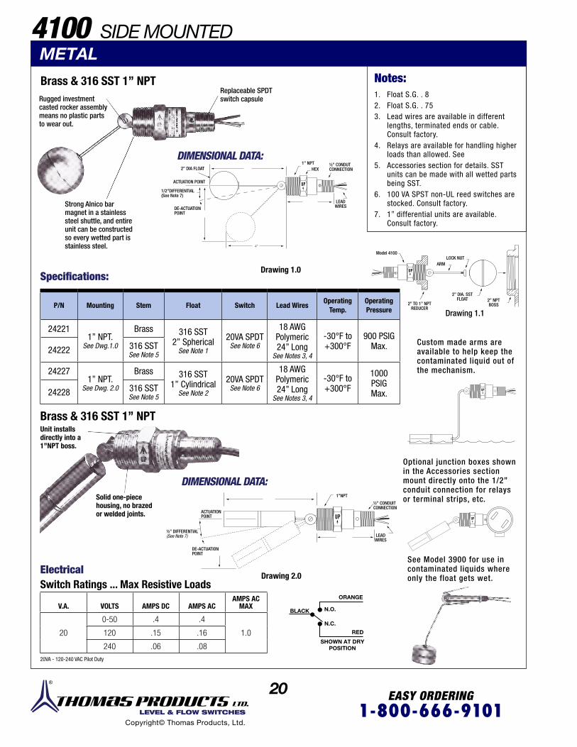
20 EASY ORDERING1-800-666-9101 LEVEL & FLOW SWITCHES
Copyright© Thomas Products, Ltd.
UP
UP
4”
4100 SIDE MOUNTEDMETAL
Brass & 316 SST 1’’ NPT
Strong Alnico bar magnet in a stainless steel shuttle, and entire unit can be constructed so every wetted part is stainless steel.
DIMENSIONAL DATA:
Drawing 1.0
Drawing 1.1
Specifications:
P/N Mounting Stem Float Switch Lead WiresOperating
Temp.OperatingPressure
242211’’ NPT.
See Dwg.1.0
Brass 316 SST2’’ Spherical
See Note 1
20VA SPDTSee Note 6
18 AWGPolymeric24” Long
See Notes 3, 4
-30°F to+300°F
900 PSIGMax.24222 316 SST
See Note 5
242271’’ NPT.
See Dwg. 2.0
Brass 316 SST1’’ Cylindrical
See Note 2
20VA SPDTSee Note 6
18 AWGPolymeric24” Long
See Notes 3, 4
-30°F to+300°F
1000 PSIGMax.24228 316 SST
See Note 5
Brass & 316 SST 1’’ NPT
DIMENSIONAL DATA:
Custom made arms are available to help keep the contaminated liquid out of the mechanism.
Optional junction boxes shown in the Accessories section mount directly onto the 1/2” conduit connection for relays or terminal strips, etc.
See Model 3900 for use in contaminated liquids where only the float gets wet. Drawing 2.0
V.A. VOLTS AMPS DC AMPS ACAMPS AC
MAX
20
0-50 .4 .4
1.0120 .15 .16
240 .06 .08
Electrical Switch Ratings ... Max Resistive Loads
20VA - 120-240 VAC Pilot Duty
ORANGE
BLACK
SHOWN AT DRYPOSITION
RED
N.O.
N.C.
Replaceable SPDT switch capsuleRugged investment
casted rocker assembly means no plastic parts to wear out.
DE-ACTUATIONPOINT
ACTUATION POINT
2’’ DIA FLOAT1’’ NPT
HEX½’’ CONDUTCONNECTION
LEADWIRES
1/2’’DIFFERENTIAL(See Note 7)
Model 4100LOCK NUT
ARM
2’’ DIA. SSTFLOAT
2’’ TO 1’’ NPTREDUCER
2’’ NPTBOSS
Solid one-piecehousing, no brazedor welded joints.
Unit installs directly into a 1”NPT boss.
ACTUATIONPOINT
½’’ DIFFERENTIAL(See Note 7)
½’’ CONDUITCONNECTION
LEADWIRES
1’’NPT
DE-ACTUATIONPOINT
1. Float S.G. . 82. Float S.G. . 753. Lead wires are available in different
lengths, terminated ends or cable. Consult factory.
4. Relays are available for handling higher loads than allowed. See
5. Accessories section for details. SST units can be made with all wetted parts being SST.
6. 100 VA SPST non-UL reed switches are stocked. Consult factory.
7. 1” differential units are available.Consult factory.
Notes:
UP
UP
UP

21 EASY ORDERING1-800-666-9101 LEVEL & FLOW SWITCHES
Copyright© Thomas Products, Ltd.
4900 SIDE MOUNTED
Collars: Brass or 316 SST Optional
P/N 3476 BUNA N
P/N 3509 SST
P/N 3482 SST
Electrical Switch Ratings ... Max Resistive Loads
V.A. VOLTS AMPS DC AMPS ACAMPS AC
MAX
20
0-50 .4 .4
1.0120 .15 .16
240 .06 .0820VA - 120-240 VAC Pilot Duty
Drawing 1.1
Float P/NSee Note 12
3476BUNA
3509SST
3482SST
TemperatureRange
See Note 5
-40° to 180°F in Water
-40° to 230°Fin oil
-40°F to +300°F
PressureMax. 150 PSI 400 PSI 150 PSI
SpecificGravity .55 77. .57
P/N Mounting Stem Float Switch Lead Wires
42867
1/8’’ NPTSee Note 10
Brass BUNAP/N 3476
20VA SPSTSee Note 3, 6
22 AWG24’’ LongPolymeric
See Notes 2
42868 SST
42869 Brass SSTP/N 350942870 SST
42875 Brass SSTP/N 348242876 SST
42882 3/8” - 24UNF 2A
BulkheadWith
Nut AndSiliconeGasket
See Notes 9, 11
Brass SSTP/N 347642883 SST
42884 Brass SSTP/N 350942885 SST
42886 Brass SSTP/N 348242887 SST
Specifications:
Float Specifications:
Notes:1. Teflon® coated stems and floats are
available. Consult factory.
2. Lead wires are available in different lengths, terminated ends or cable. Consult factory.
3. Relays are available for handling higher loads than allowed. See Accessories section for details.
4. Custom bend locations are avaiable per your specification. Consult factory.
5. High temperature units are avaiable up to 450°F. Consult factory.
6. 100 VA SPST non-UL reed switches are stocked. Consult factory.
7. Brass units use beryllium coppergrip rings. SST units use 15-7 Mo SST grip rings.
8. Optional collars are available from stock. See drawing 1.1. Consult factory.
9. Silicone gasket 1” 0.D. x 3/8” I.D.x 1/16” thick 40 durometer.
10. 1/8” NPT mounting installs from inside the tank into a 1/8” NPT boss.
11. 3/8”-24 UNF 2A mounting installs from the inside of the tank into a 13/32” dia. hole.
12. Interface floats are available.Consult factory.
METAL STEM
1⁄8”NPT
3⁄8’’
Thread WithNut AndSiliconeGasket
UNF-24 2AStraight
1” Dia. 1” Dia. 1” 5⁄8 ’’ Dia.
Unique assembly procedure eliminates stress by actually suspending the reed switch allowing for thermal expansion and contraction.
Mounting(SpecifyType &
Material)
Stem(SpecifyMaterial)
Float(SpecifyPart #)
See Model 4000 for other mountings, floats, stem lengths, etc. that can have their stems bent per your requirements.
See Model 3900 for usein contaminated fluids.
SeeNote 4
3 1⁄8’’2 1/4’’
LeadWires
ActuationPoint Float
3/4’’1
1”1” 1”

22 EASY ORDERING1-800-666-9101 LEVEL & FLOW SWITCHES
Copyright© Thomas Products, Ltd.
4200 SINGLE LEVELPLASTIC STEM
Plastic 1⁄8’’ NPTUnique assembly procedure eliminates stress by actually suspending the reed switch allowing for thermal expansion and contraction.
Optional siliconegasket P/N 3488. 1/16” thick 3/4” 0.D. 40 durometer.
Molded in-house. We can certify that our polypropy- lene floats use only virgin material, runners are not reintroduced, nor have blow agents or color concentrates been added during processing.
Fluted stem to prevent lime deposits.Internal lettering
to help preventbacterial growth.
Magnets are heat-sealed in place using pure polypropylene welding rods, not epoxy. Beverage control
food contact. Made of FDA approved material.
Anti-meniscus projec -tions mean float cannot dry in place after lengthy machine shut downs.
Fluted stem toprevent limedeposits.P/N 24251
P/N 24252
P/N 42654 All Model 4200 level switches depicted are available with cable. All specifications are the same except for operating temperatures of -40°F to + 176°F. Determine length of cable required and contact factory sales depart -ment for pricing. See Note 7.
When extending a level switch deep into a tank, configuration shown can mount, confine and protect the lead wires.
Specifications:
Specifications:
P/N Mounting Stem Float SwitchLead Wires Operating
Temp.OperatingPressure
24251
1/8’’ NPT.
Poly-sulfone
Poly-sulfone
See Note 3 20VA SPSTNote 2
22 AWGPVC 24’’
LongSee Note 1
-40°F to+225°F
75 PSIGMax.
42654 Poly-propylene
Poly-propyleneSee Note 4
100 PSIGMax.
P/N Mounting Stem Float SwitchLead Wires Operating
Temp.OperatingPressure
24252
3/8” - 16BulkheadWith Nut* Gasket P/N 3488See Dwg 1.0
Poly-sulfone
Poly-sulfone
See Note 3
20VA SPST
See Note 2
22 AWGPVC 24’’
LongSee Note 1
-40°F to+225°F
75 PSIGMax.
Plastic 3⁄8” -16 Bulkhead DIMENSIONAL DATA:
DIMENSIONAL DATA:
Drawing 1.0
Unique assembly procedure eliminates stress by actually suspending the reed switch allowing for thermal expansion and contraction.
Magnets hermetically sealed from the inside of the float means no polling is exposed to the media.
1⁄8" NPT
½" HEX
25⁄64 "
23⁄32
1" DIA.
24’’ LG MIN.LEAD WIRES
3⁄8-16’’ THREAD AND HEX NUT¼"
2 7⁄32"
3/4’’ FLANGE
2 MAGNETS
RETAINING RING

23 EASY ORDERING1-800-666-9101 LEVEL & FLOW SWITCHES
Copyright© Thomas Products, Ltd.
4800 SINGLE LEVELPLASTIC STEM¼ ” NPT
All PVCwettedmaterials.
Silicone potted for shockand vibration deadening
Molded in-house. We can certify that our PVC units useonly virgin material andrunners are not reintroduced.
White plastic helps in reducing UV absorptionand heat retention.
Higher pressure floats arenot just glued, but actuallysolvent bonded withinterference fits.
Anti-meniscusprojection meansfloat cannot dry inplace after longmachine shut downs.
When a plastic unit with a long stem or more than one switch point is needed, see Model 4000 PVC or Model 5000 Polysulfone.
LEAD WIRES
NOTE: Photo shownin black for clarity.
Specifications:
Specialty Option:
P/N Mounting Stem Float Switch Lead WiresOperating
Temp.OperatingPressure
41401 1/4’’ NPT PVC PVCSee Note 5
20VA SPST
See Note 2
18 AWGPVC 24’’
LongSee Note 1
-30°F to+140°F
100 PSIGMax.
WIRING DIAGRAM FOR STANDARD SPST SWITCHES
Electrical Switch Ratings ... Max Resistive Loads
Model 4000PVC
Model 5000Polysulfone
N.O. AT FULLOR EMPTY
RED RED
RED RED
N.C. AT FULLOR EMPTY
V.A. VOLTS AMPS DC AMPS AC AMPS AC MAX
20
0-50 .4 .4
1.0120 .15 .16
240 .06 .08
Switch Rating of UL recognized units 20VA- 50-240 VAC Pilot Duty Switch logic is changed by removing retaining ring and inverting float.
DIMENSIONAL DATA:
5⁄8" HEX
1/4" NPT
ACTU
ATIO
N
3³⁄16"
1 13⁄16"
1 ½" DIA
1. Lead wires are available in different lengths, terminated ends or cable. Consult factory.
2. 100 VA SPST reed switches is available non UL. Consult factory.
3. Float specific gravity .... 654. Float specific gravity .... 815. Float specific gravity .... 856. Custom interface floats are available.
Consult factory.7. PVC cable UL 2464 AWG #22 300V
80°C. Customer to specify length. Consult factory for pricing. UL recognized Model No. 4200L.
8. 100 VA SPST and 20 VA SPDT reed switches are available. Consult factory.
9. Relays are available for handling higher loads than allowed. See Accessories section for details.
Notes:

24 EASY ORDERING1-800-666-9101 LEVEL & FLOW SWITCHES
Copyright© Thomas Products, Ltd.
Models 4200H and 4700H have been tested and approved by Underwriters Laboratories for use in hazardous locations for:
Class I Div. 1 Groups C & D. Unit must beinstalled in accordance with articl 501-4(A) N.E.C. 1993.
Class I Div. 2 Groups A, B, C & D. Unit tobe mounted in a suitable enclosure andwiring to be installed in accordance with article 501-4 (B) N.E.C. 1993.
Class I Div. 1 Groups C & D.Class I Div. 2 Groups A, B, C & D.
4700 SINGLE LEVEL 4700H
METAL STEMBrass, 316 SST and BUNA N 1⁄8’’ NPT
Float P/N’s3476 & 3509
Internal ring magnetguarantes uniform
switch action.
Class I Div. 1 Groups C & D. Class I Div. 2 Groups A, B, C & D.
Class I Div. 2 Groups A, B, C & D.
Class I Div. 2 Groups A, B, C & D.
DIMENSIONAL DATA:
DIMENSIONAL DATA:
Specifications:
Specifications:
P/N Mounting Stem Float Switch Lead Wires OperatingTemp.
OperatingPressure
41001
1/8’’ NPT.See Note 6
BrassP/N 3476
BUNASee Notes
3 & 11
20VASPST
22 AWGPolymeric24” LongSee Notes
1 & 2
-40°F to+180°F in
Water
-40°F to+230°F in
Oils
150 PSIGMax.
41002
316 SSTSee Note 8
P/N 3476BUNA
See Notes3 & 11
41003P/N 3509316 SSTSee Notes5, 9, 11
-40°F to+300°FSee Note
10
400 PSIGMax.
41008P/N 3482316 SSTSee Notes9, 11, 14
150 PSIGMax.
P/N Stem Float P/N
43533Brass
3509
43534 3482
P/N Stem Float P/N
43529 316 SST
3509
43531 3482
P/N Stem Float P/N
43651 316 SST 3508
P/N Stem Float P/N
43653 Brass 3508
316 SST ¼’’ NPT
See Note 17P/N Mounting Stem Float
SwitchSPST
See Note 13Lead Wires
OperatingTemp.
OperatingPressure
41301
1/4’’ NPTSee Note 6
316 SSTSee Note 8
P/N 3508316 SSTSee Notes4, 9, 11
20 VA 18 AWGPolymeric24’’ LongSee Notes
1 & 2
-40°F to+300°F
See Note 10
750 PSIGMax.41302 100 VA
41321 Brass 20 VA
P/N 3482See Note 14
See Notes 15 & 16
METAL STEM
4200 SINGLE LEVEL 4200HHAZARDOUS LOCATIONS
HAZARDOUS LOCATIONS
Anti-meniscus retaining ring means float cannotdry in place after longmachine shut downs.
Silicone potting for shockand vibration deadening
Anti-meniscus retainingring means float cannotdry in place after longmachine shuts down.
Silicone potting for shockand vibration deadening.
ACTU
ATIO
N
LEAD WIRES
2 3⁄32"
1 5⁄8"Dia.
1⁄8" NPT
HEX.
1" DIA
2 1⁄8" DIA.
ACTU
ATIO
N
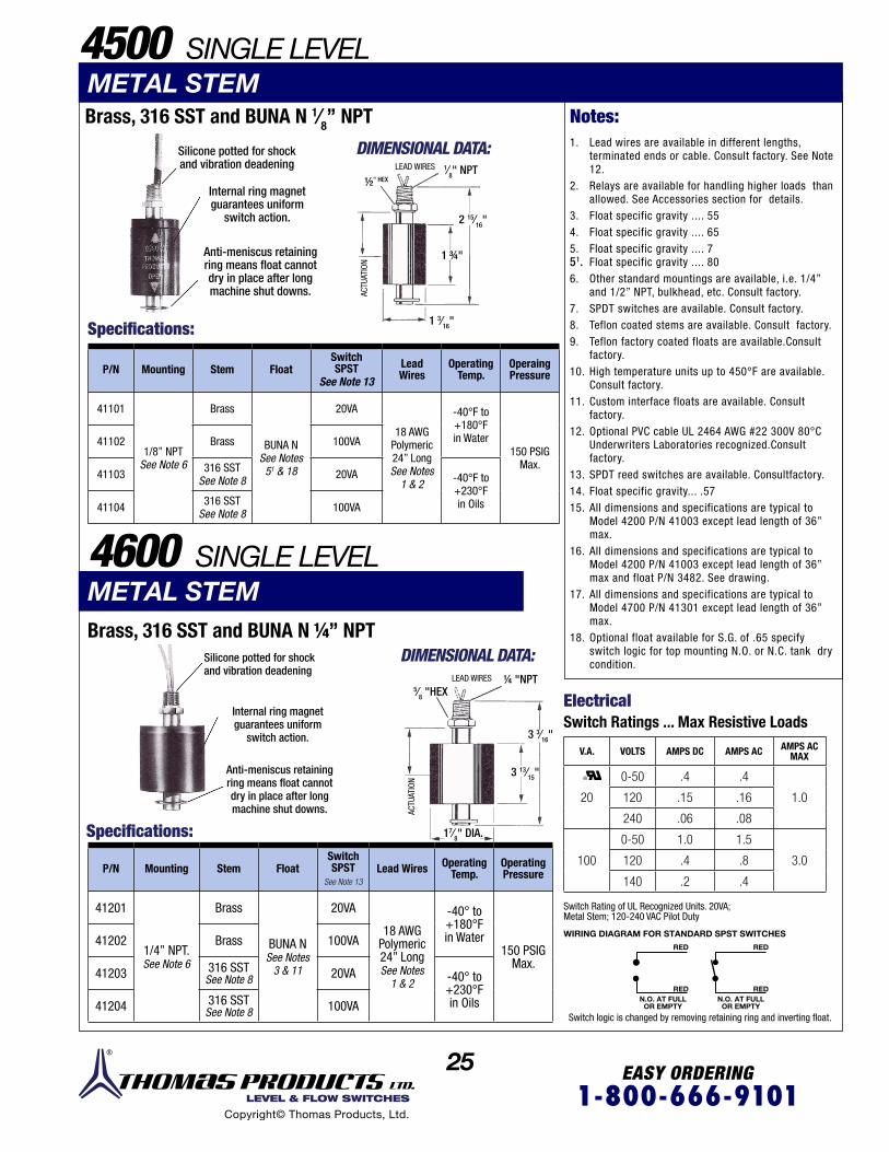
25 EASY ORDERING1-800-666-9101 LEVEL & FLOW SWITCHES
Copyright© Thomas Products, Ltd.
Brass, 316 SST and BUNA N 1⁄8’’ NPT
Brass, 316 SST and BUNA N ¼’’ NPT
Silicone potted for shockand vibration deadening
Silicone potted for shockand vibration deadening
Internal ring magnet guarantees uniform
switch action.
Internal ring magnet guarantees uniform
switch action.
Anti-meniscus retaining ring means float cannot dry in place after long machine shut downs.
Anti-meniscus retaining ring means float cannot dry in place after long machine shut downs.
Specifications:
Specifications:
Electrical
DIMENSIONAL DATA:
DIMENSIONAL DATA:
LEAD WIRES
LEAD WIRES
METAL STEM
Switch Ratings ... Max Resistive Loads
V.A. VOLTS AMPS DC AMPS AC AMPS AC MAX
20
0-50 .4 .4
1.0120 .15 .16
240 .06 .08
100
0-50 1.0 1.5
3.0120 .4 .8
140 .2 .4
METAL STEM4600 SINGLE LEVEL
P/N Mounting Stem FloatSwitch SPST
See Note 13Lead Wires Operating
Temp.OperatingPressure
41201
1/4’’ NPT.See Note 6
Brass
BUNA NSee Notes
3 & 11
20VA
18 AWGPolymeric24” LongSee Notes
1 & 2
-40° to+180°Fin Water
150 PSIGMax.
41202 Brass 100VA
41203 316 SSTSee Note 8 20VA -40° to
+230°Fin Oils41204 316 SST
See Note 8 100VA
P/N Mounting Stem FloatSwitchSPST
See Note 13
Lead Wires
OperatingTemp.
OperaingPressure
41101
1/8’’ NPTSee Note 6
Brass
BUNA NSee Notes
51 & 18
20VA
18 AWGPolymeric24” LongSee Notes
1 & 2
-40°F to+180°Fin Water
150 PSIGMax.
41102 Brass 100VA
41103 316 SSTSee Note 8 20VA -40°F to
+230°Fin Oils41104 316 SST
See Note 8 100VA
WIRING DIAGRAM FOR STANDARD SPST SWITCHES
N.O. AT FULLOR EMPTY
N.O. AT FULLOR EMPTY
RED
RED
RED
RED
Switch logic is changed by removing retaining ring and inverting float.
Switch Rating of UL Recognized Units. 20VA; Metal Stem; 120-240 VAC Pilot Duty
4500 SINGLE LEVEL
ACTU
ATIO
N
½" HEX
2 15⁄16"
1 3/4"
1 3⁄16"
1⁄8" NPT
ACTU
ATIO
N
1/4 "NPT5⁄8 "HEX
3 3⁄16"
3 13⁄15"
17⁄8" DIA.
1. Lead wires are available in different lengths, terminated ends or cable. Consult factory. See Note 12.
2. Relays are available for handling higher loads than allowed. See Accessories section for details.
3. Float specific gravity .... 554. Float specific gravity .... 655. Float specific gravity .... 7
Float specific gravity .... 806. Other standard mountings are available, i.e. 1/4”
and 1/2” NPT, bulkhead, etc. Consult factory.7. SPDT switches are available. Consult factory.8. Teflon coated stems are available. Consult factory.9. Teflon factory coated floats are available.Consult
factory.10. High temperature units up to 450°F are available.
Consult factory.11. Custom interface floats are available. Consult
factory.12. Optional PVC cable UL 2464 AWG #22 300V 80°C
Underwriters Laboratories recognized.Consult factory.
13. SPDT reed switches are available. Consultfactory.14. Float specific gravity... .5715. All dimensions and specifications are typical to
Model 4200 P/N 41003 except lead length of 36” max.
16. All dimensions and specifications are typical to Model 4200 P/N 41003 except lead length of 36” max and float P/N 3482. See drawing.
17. All dimensions and specifications are typical to Model 4700 P/N 41301 except lead length of 36” max.
18. Optional float available for S.G. of .65 specify switch logic for top mounting N.O. or N.C. tank dry condition.
Notes:
51.

26 EASY ORDERING1-800-666-9101 LEVEL & FLOW SWITCHES
Copyright© Thomas Products, Ltd.
3800 PANCAKE
Operation:
Cable to controls, Light, audiblealarms, etc.
String connected to pull eye
Cable
Reed Switch
Magnet
Housing
FloatStop
Float
PullEye
N.C. Dry Condition:the magnet in the float
holds the reed switch closed, completing the circuit.
Reed switch opens on increasing liquid level.
The float rises in direct response tothe rising liquid, opening the circuit.
Containmentarea
Non-Leaking Double Wall Tank Leaking Double Wall Tank
V.A. VOLTS AMPS DC AMPS AC AMPS AC MAX
10
0-50 .15 .2
.5120 .06 .08
240 .03 .04
Electrical
Specifications:
Switch Ratings ... Max Resistive Loads
Switch Rating - Pilot Duty 50 - 240 VAC
P/N Mounting FloatReed
SwitchCable Temperature Pressure
Mounting Attitude
43426 PVC PVCSee Note 1, 2 10 VA SPST
22 AWG UL 246425’ Lg.
-40°F to140°F Max
50 PSI @ 72° F Max. Horizontal
SPST TYPICAL WIRING DIAGRAM
N.C. TANK DRY CONDITION
PLASTIC
1. Specific gravity. 7 minimum.2. Operates in 5/8” envelope. Actuates in
approximately 1/4” of water level.3. Wetted parts: stainless steel, PVC, hysol
epoxy, and cunife magnet.4. Use in flammable environments. Should
only be used with an intrinsically safe barrier to make the sensor safe not posing a hazard.
5. Model 3800 switch logic is the same N.C. (normally closed) tank dry condition in either side unit is installed.
6. Switch logic N.C. (normally closed) tank dry. Switch opens on increasing level.
Notes:
• Double wall tanks.• Containment piping.• Ideal for leak detection systems.• Operates down to -40°F.• Positive signals.• Very economical.• Not affected by translucent films.• Can be immersed continuously in any
media compatible with wetted parts .• No special controls necessary.• No excitation voltage necessary.• No false indications.
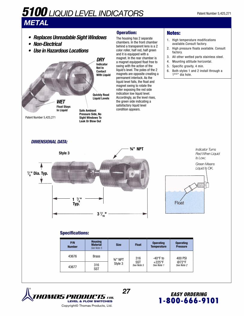
27 EASY ORDERING1-800-666-9101 LEVEL & FLOW SWITCHES
Copyright© Thomas Products, Ltd.
5100 LIQUID LEVEL INDICATORS
• Replaces Unreadable Sight Windows• Non-Electrical• Use in Hazardous Locations
Indicator Turns Red When Liquid Is Low;
Green MeansLiquid Is OK.
DIMENSIONAL DATA:
Specifications:
Operation:
P/N Number
HousingMaterialSee Note 5
Size Float Operating Temperature
Operating Pressure
43676 Brass3/4’’ NPTStyle 3
316SST
See Note 5
-40°F to+225°F See Note 1
400 PSI@72°F
See Note 243677 316SST
The housing has 2 separate chambers. In the front chamber behind a transparent lens is a 2 color roller, half red, half green and it is equipped with a magnet. In the rear chamber is a magnet equipped float free to swing with the action of the liquid’s level. The poles of the 2 magnets are opposite creating a permanent interlock. As the liquid level falls, the float and magnet swing to rotate the roller exposing the red side indication low liquid level. Accordingly, as the level rises, the green side indicating a satisfactory liquid level condition appears.
DRY
WET
IndicatorNot InContactWith Liquid
Quickly ReadLiquid Levels
Safe AmbientPressure Side, No Sight Windows To Leak Or Blow Out
Float StaysIn Liquid
Patent Number 5,425,271
Patent Number 5,425,271
METAL
Style 3
7⁄8’’ Dia. Typ.
1 7⁄8’’Typ.
NPT3/4’’
3 7⁄16"
1. High temperature modifications available.Consult factory.
2. High pressure floats available. Consult factory.
3. All other wetted parts stainless steel.4. Mounting attitude horizontal.5. Specific gravity. 4 min.6. Both styles 1 and 2 install through a
19⁄32” dia hole.
Notes:
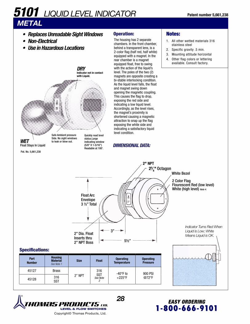
28 EASY ORDERING1-800-666-9101 LEVEL & FLOW SWITCHES
Copyright© Thomas Products, Ltd.
Specifications:
Part Number
HousingMaterialSee Note 1
Size Float Operating Temperature
Operating Pressure
45127 Brass2’’ NPT
316SST
See Note2
-40°F to+225°F
900 PSI@72°F45128 316
SST
5101 LIQUID LEVEL INDICATOR
• Replaces Unreadable Sight Windows• Non-Electrical• Use in Hazardous Locations
The housing has 2 separate chambers. In the front chamber, behind a transparent lens, is a 2-color flag (half red, half white) equipped with a magnet. In the rear chamber is a magnet equipped float, free to swing with the action of the liquid’s level. The poles of the two (2) magnets are opposite creating a bi-stable interlocking condition. As the liquid level falls, the float and magnet swing down opening the magnetic coupling. This causes the flag to drop, exposing the red side and indicating a low liquid level. Accordingly, as the level rises, the magnet’s proximity is shortened causing a magnetic attraction to snap up the flag exposing the white side and indicating a satisfactory liquid level condition.
DIMENSIONAL DATA:
METAL
DRYIndicator not in contact with Liquid.
5½”
3”
Pat. No. 5,661,238
WETFloat Stays In Liquid
Float ArcEnvelope3 ½” Total
2” Dia. FloatInserts thru2” NPT Boss
2" NPTOctagon
White Bezel
2 Color Flag Flourescent Red (low level) White (high level) Note 4.
25⁄8"
Indicator Turns Red When Liquid is Low; White Means Liquid is OK.
Safe Ambient pressure Side. No sight windowsto leak or blow out.
Quickly read levelstatus.Largeindicating window(5/8” X 1-5/16”)Readable at 100’.
1. All other wetted materials 316 stainless steel
2. Specific gravity .5 min.3. Mounting attitude horizontal4. Other flag colors or lettering
avail able. Consult factory.
Notes:
Patent number 5,661,238
Operation:

29 EASY ORDERING1-800-666-9101 LEVEL & FLOW SWITCHES
Copyright© Thomas Products, Ltd.
ACCESSORIES P/N 42755Junction Box
P/N 42761
P/N 42762
P/N 42756
Magnetic Latching Relays 2 Form C Contacts
Explosion Proof for Hazardous Areas, Wet Locations, Class I, Group C.D., Class II, Group E.F.G., Class Ill, and Nema 4. Junction Box is Supplied with 12 Closed End Crimp Connectors.
Junction box (P/N 42755) with general purpose relay (P/N 42756) and clamp
Junction box (P/N 42755) with 6 position terminal strip
Use to turn on and off pumps or other equipment and to maintain high and low levels or flows.
ACVoltage
50/60 Hz
DCVoltage
RELAY WIRING DIAGRAM SHOWN DE-ENERGIZED
LEVEL SWITCH N.O. TANK DRYORFLOW SWITCH N.O.NO FLOW120 VAC
Relay Specifications:
Junction Box(P/N 42755)
with latching relayand clamp Voltage
LatchingRelayOnly
42764
42765
42766
12 VAC
24 VAC
120 VAC
42770
42771
42772
ContactConfiguration
DPDT
Coil Voltage 120 VAC 50/60 Hz
Contact Ratings 12A 240 VAC1/2 HP 120 VAC10A 24 VDC
Contact Ratings lnternal Circuit
CSA 7.5 A 240 VAC
RES 10 A 30 VDC
General 7.5 A 120 VAC
Use 5 A 240 VAC
7.5 A 30 VDC
1/6 HP 120 VAC
1/3 HP 240 VAC
42767
42768
42769
6 VAC
12 VAC
24 VAC
42773
42774
42775
1
5 6 8
10 12
14
(+)
(+)
4
9
13 SET
RESET
( - )
( - )
General purpose relay only
12A DPDT and 8 Fully Insulted Push-On Crimp Terminals
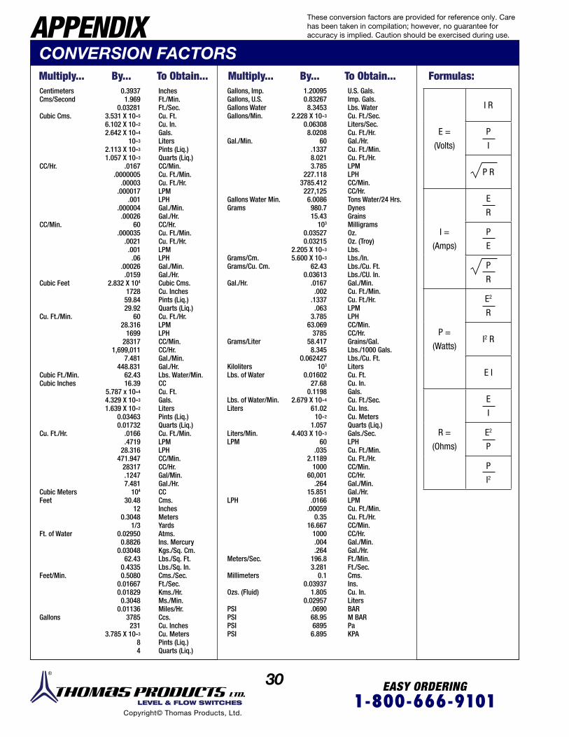
30 EASY ORDERING1-800-666-9101 LEVEL & FLOW SWITCHES
Copyright© Thomas Products, Ltd.
APPENDIX
0.39371.969
0.032813.531 X 10-5
6.102 X 10⁻²
2.642 X 10⁻⁴
10-3
2.113 X 10⁻³
1.057 X 10⁻³
.0167.0000005
.00003.000017
.001.000004.00026
60.000035
.0021.001.06
.00026.0159
2.832 X 10⁴
172859.8429.92
6028.316
169928317
1,699,0117.481
448.83162.4316.39
5.787 x 10⁻⁴
4.329 X 10⁻³
1.639 X 10⁻²
0.034630.01732
.0166
.471928.316
471.94728317.12477.481
104
30.4812
0.30481/3
0.029500.8826
0.0304862.43
0.43350.5080
0.016670.018290.3048
0.011363785231
3.785 X 10⁻³
84
Inches Ft./Min. Ft./Sec. Cu. Ft. Cu. In. Gals. Liters Pints (Liq.) Quarts (Liq.) CC/Min. Cu. Ft./Min. Cu. Ft./Hr. LPM LPH Gal./Min. Gal./Hr. CC/Hr.Cu. Ft./Min. Cu. Ft./Hr. LPM LPH Gal./Min. Gal./Hr. Cubic Cms. Cu. Inches Pints (Liq.) Quarts (Liq.) Cu. Ft./Hr. LPM LPH CC/Min.CC/Hr. Gal./Min. Gal./Hr.Lbs. Water/Min. CCCu. Ft.Gals. Liters Pints (Liq.) Quarts (Liq.) Cu. Ft./Min. LPM LPH CC/Min. CC/Hr. Gal/Min. Gal./Hr. CC Cms. Inches Meters Yards Atms. Ins. Mercury Kgs./Sq. Cm. Lbs./Sq. Ft. Lbs./Sq. In. Cms./Sec. Ft./Sec. Kms./Hr. Ms./Min. Miles/Hr. Ccs. Cu. Inches Cu. Meters Pints (Liq.) Quarts (Liq.)
U.S. Gals.Imp. Gals.Lbs. WaterCu. Ft./Sec.Liters/Sec.Cu. Ft./Hr.Gal./Hr.Cu. Ft./Min.Cu. Ft./Hr.LPMLPHCC/Min.CC/Hr.Tons Water/24 Hrs.DynesGrainsMilligramsOz.Oz. (Troy)Lbs. Lbs./ln.Lbs./Cu. Ft.Lbs./CU. In.Gal./Min.Cu. Ft./Min.Cu. Ft./Hr.LPMLPHCC/Min.CC/Hr.Grains/Gal.Lbs./1000 Gals.Lbs./Cu. Ft.LitersCu. Ft.Cu. In.Gals.Cu. Ft./Sec.Cu. Ins.Cu. MetersQuarts (Liq.)Gals./Sec.LPHCu. Ft./Min.Cu. Ft./Hr.CC/Min. CC/Hr. Gal./Min.Gal./Hr.LPMCu. Ft./Min.Cu. Ft./Hr.CC/Min.CC/Hr.Gal./Min.Gal./Hr.Ft./Min.Ft./Sec.Cms.Ins.Cu. In.LitersBARM BARPaKPA
Gallons, Imp.Gallons, U.S. Gallons Water Gallons/Min.
Gal./Min.
Gallons Water Min.Grams
Grams/Cm.Grams/Cu. Cm.
Gal./Hr.
Grams/Liter
KilolitersLbs. of Water
Lbs. of Water/Min.Liters
Liters/Min. LPM
LPH
Meters/Sec.
Millimeters
Ozs. (Fluid)
PSIPSIPSIPSI
Centimeters Cms/Second
Cubic Cms.
CC/Hr.
CC/Min.
Cubic Feet
Cu. Ft./Min.
Cubic Ft./Min. Cubic Inches
Cu. Ft./Hr.
Cubic Meters
Feet
Ft. of Water
Feet/Min.
Gallons
1.200950.83267 8.3453
2.228 X 10⁻³
0.06308 8.0208
60.1337 8.021 3.785
227.118 3785.412 227,1256.0086980.7 15.43
103
0.03527 0.03215
2.205 X 10⁻³ 5.600 X 10⁻³
62.43 0.03613
.0167 .002
.1337 .063
3.785 63.069
3785 58.417 8.345
O.062427103
0.0160227.68
0.11982.679 X 10-4
61.0210-2
1.0574.403 X 10-3
60.035
2.11891000
60,001.264
15.851.0166
.000590.35
16.6671000.004.264
196.8 3.281
0.1 0.03937
1.8050.02957
.069068.956895
6.895
Multiply... Multiply...To Obtain... To Obtain... Formulas:By... By...
E =
(Volts)
I R
P
I
P R
I =
(Amps)
E
R
P
E
P
R
P =
(Watts)
E2
R
I2 R
E I
R =
(Ohms)
E
I
E2
P
P
I2
These conversion factors are provided for reference only. Care has been taken in compilation; however, no guarantee for accuracy is implied. Caution should be exercised during use.
CONVERSION FACTORS

31 EASY ORDERING1-800-666-9101 LEVEL & FLOW SWITCHES
Copyright© Thomas Products, Ltd.
Condensation [Chem.]: Transformation of a gas to a liquid.
Conduit Connector: Threaded portion of unit specifically designed for the connection of a flexible conduit or junction boxes, etc.
Crazing [Eng.]: Network of fine cracks on or under the surface of amaterial; i.e., the crazing of certain plastics can be caused bychemical incompatibility.
Crimp on Connectors or Terminals: Male or female electricalcomponents that can be affixed to lead wired by pinching.
Cunife Magnet: Copper, nickel, and iron alloy magnet.
DC [Elec.]: (direct current) Electric current which flows in onedirection only, as opposed to alternating current.
Deactuation: To turn off.
Dead Band: The range between make and break.
Decreasing Set Point [Fl. Mech.]: Actuation set as the flowdecreases.
Differential [Cont. Sys.]: The difference between make and breakoperation in a control system.
Displacer: Flow detection device that relies on gravity to return theworking mechanism to the inactive position.
DPDT [Elec.]: (double-pole, double-throw) Six-terminal switch orrelay contact arrangement that simultaneously connects one pairof terminals to either of two other pairs of terminals.
Electrical Conversion Formula: See “Conversion Factors”.
Electrical Current Shock: Excessive electrical load; esp. to a reedswitch.
Envelope: The total amount of movement including its meandimension and tolerance.
Explosion Proof: Apparatus enclosed in a case that is capable ofboth withstanding an explosion of a specified gas or vapor thatmay occur within it, and preventing the ignition of a specifiedgas or vapor surrounding the enclosure by sparks, flashes, orexplosion of the gas of vapor within, and that operates at suchan external temperature that a surrounding flammable atmosphere will not be ignited thereby
Fahrenheit Conversion: See “Conversion Factors”.
Fixed Set Point: Factory set non-field-adjustable actuation point.
Flow Indicator: Nonelectrical device that indicates a predeteminedamount of flow or the lack thereof.
Flow Switch [Fl. Mech.]: Electromechanical device that will makeor break an electrical circuit at a given flow rate.
Fluted Stem: The tubing housing the reed switch that the floatrides on, having specially shaped grooves along its axis to allowparticulates to collect in them. Designed to help eliminate float jamming due to lime deposits.
APPENDIX A [Elec.]: Amp. See “Ampere”.
AC [Elec.]: (alternating current) Electrical current that reversesdirection periodically.
AC Field [Elec.]: The space around a magnet or magnetic circuitwhich is under the influence of magnetic forces.
Actuation [Elec.]: To turn on.
Adjustable Set Point: Actuation point that can be field adjusted, usually within a given range.
Alnico Magnet: Aluminum, nickel, and copper alloy magnet.
Ampere [Elec.]: (amp) Unit of electrical current.
Arcing [Elec.]: An electric current through air or across thesurface of an insulator associated with high voltage and usually occurs when a contact is opened, de-energizing an inductive load. Arcing of a contact will limit its life.
Beryllium Copper [Met.]: (BeCu) An alloy of copper and beryllium and not more than 3% beryllium.
Bonnet Assembly: The working mechanism in a shuttle type flow switch that contains the magnet and reed switch assembly.
Bulkhead Fitting: Straight thread with nut mounted through anunthreaded hole. Can be used with an 0-ring or gasket.
BUNA: A brand of synthetic rubber made by polymerizing orcopolymerizing butadiene with another material. Typical use carburtor floats.
Burst Strength [Mech.]: A measure of the ability of a material towithstand a given pressure without rupture.
Cable [Elec.]: A group of individually insulated conductors intwisted or parallel configuration under common sheath.
Cable Gland: Strain relief with integral waterproof seal.
Calibration: The act of determining by measuring with a standard;i.e., Thomas Products Limited’s flow stands are calibrated to the National Bureau of Standards.
Calibration Position: The position of the flow switch at the timeof setting the actuation point.
Capacitive Load [Electromag.]: The load in which the capacitivereactance exceeds the inductive reactance; the load draws a leading current.
CCM: Cubic centimeter per minute.
Celsius Conversion: See “Conversion Factors”.
CFM: Cubic foot per minute
Chemical Compatibility: A harmonious effect between a chemicaland the materials with which it comes in contact.
Collars: Tubular float stops equipped with set screws used tolimit float travel.
These conversion factors are provided for reference only. Care has been taken in compilation; however, no guarantee for accuracy is implied. Caution should be exercised during use.
GLOSSARY
32 EASY ORDERING1-800-666-9101 LEVEL & FLOW SWITCHES
Copyright© Thomas Products, Ltd.
GPM: (gallons per minute) Units of measuring liquid flow.
Grip Rings: Float stops used to limit float travel. Circular splitmetal rings whose fixation to the stem relies on its own tensilestrength alone.
Hermetically Sealed [Eng.]: Air tight seal; i.e. reed switches are hermetically sealed within a glass enclosure to isolate the contacts from the surrounding elements.
Hertz [Phys.]: Unit of frequency cycle per second.
Hirshman Connector: Brand name of quick disconnect electrical interface.
Housing [Eng.]: The body.
Hysteresis [Phys.]: See “Differential”.
Increasing Set Point [Fl. Mech.]: Actuation set as the flow increases.
Inductive Load [Elec.]: Alternating load current lags behind the alternating voltage of the load, i.e. coils, transformers, etc.
Interface Float: A float whose specific gravity (s.g.) is adjusted to be buoyant in a higher s.g. liquid, as water 1.0, but will sink in alower s.g. liquid, as oil.
Intrinsically Safe Barrier: A device which limits the power(energy) which can be delivered from a safe area into a hazardous area.
IPS: Inner pipe size.
J-box: (junction box) Electrical enclosure.
Lamp Load: A load that is of an incandescent lamp; any devicewhich consumes power that is connected to another device or circuit that supplies the power.
Level Indicator: Non-electrical float device that shows liquid levelat point of installation.
Level Switch: Electromechanical level detection device that willmake or break an electrical connection by the float’s rise or fall.
LO: (length overall) Used for stem length on Model 4000/4900/5000 custom level switches, etc.
Locking Wire: Wire or plastic filament used to lock bonnetassembly in place.
Magnetic Field [Electromag.]: Natural and artificial elementaryfields or forces found in the vicinity of magnetic bodies or current-carrying medium.
Mating MS Connector: Female connector that interfaces with malepin connector.
Max. Flow Rate: Maximum flow through the flow switch.
Max. PSI: (maximum pounds per square inch) Maximum pressurerecommended.
Max. Temp: Maximum temperature recommended.
Mechanical Shock [Mech.]: (impact shock) Forceful collisionbetween two bodies sufficient enough to cause change.
Micron: Unit of measure used in filtration. One micron = millionthmeter= .00003937 inches.
Micron Filter: Filter used to help maintain a predetermined amountof purity. Micron denotes minimum size of particulates filtered.
Mounting Attitude: The position in which a unit is mounted orinstalled; i.e., tank top, tank bottom or side mounted.
M-SB: (monel trim with silver brazed process connections) Available on our marine flow switch.
MS Connector: A male pin electrical connector.
N.C. [Elec.]: Normally closed. Electrical contact in closed conditionwhose system is inactive.
NEMA: National Electrical Manufacturers Association.
NEMA Rated: Rating or type given by NEMA which denotes a devicewill meet requirements for a given location or application; i.e.,NEMA 4-watertight and dusttight indoor and outdoor, etc.
90° Angle Flow: When in and out ports are at right angles to oneanother.
N.O. [Elec.]: Normally open. Electrical contact in open conditionwhose system is inactive.
NPT: National pipe thread (tapered thread) usually designated bynominal pipe size and number of threads per inch.
Ohm [Elec.]: Unit of measurement for resistance and impedance.See “Conversion Factors”.
Operating Pressure [Eng.]: The maximum working pressureallowed at that device.
Operating Temperature [Eng.]: The maximum working temperature allowed at that device.
Orifice: A device used to regulate flow through it to accuratelyachieve a specific set point.
Petcock: A small valve used to drain off excessive waste material;i.e., bleed systems, trapped air.
Ph 15-7 Mo: Basic 300 series stainless steel; 15% chromium, 7%nickel, and 2.5% molybdenum.
Pilot Duty: The rating assigned to a relay or switch that controlsthe coil of another relay or switch.
Piston: A cylindrically-shaped member housing a magnet whichrides in a bore that is displaced by the dynamic force in a flowswitch.The displacement will cause either actuation ordeactution,depending on the proximity of the reed switchassembly.
P/N: Part number.
These definitions are not to be construed as the only definitions available, but as a guide to understanding the terminology as it pertains to our products.
GLOSSARY APPENDIX

33 EASY ORDERING1-800-666-9101 LEVEL & FLOW SWITCHES
Copyright© Thomas Products, Ltd.
Polypropylene: A light weight plastic generally known for its highchemical resistance.
Polysulfone: A high performance thermoplastic known for its hightensile strength, temperature resistance and wide chemical compatibility.
Pressure Drop [Fl. Mech.]: The difference in pressure between twopoints in a flow system.
Proof Load [Eng.]: A predetermined test load, greater than theservice load.
PSI: (pounds per square inch) Unit of measuring pressure.
PSIG: (pounds per square inch gauge) Unit of measuring pressureabove “O” gauge. “O” gauge is equal to 14.7 PS I on the absolutescale.
PVC [Or. Chem.]: (polyvinyl chloride) Polymer of vinyl chloride;insoluble in most organic solvents.
Reed Switch [Electromag.J: A dry switch that has contactsmounted on ferromagnetic reeds hermetically sealed in a glasstube designed for actuation by an external magnetic field.
Repeatability: The percentage measurement derived from accuracy on a control, returning back to its original setting.
Reset Point: See “Reset Point Differential”.
Reset Point Differential [Fl. Mech.]: The difference between the setpoint and reset point.
Resistive Load [Elec.]: A load whose total reactance is zero, so thatthe alternating current is in a phase with the terminal voltage.
SCFH [Fl. Mech.]: Standard cubic feet per hour of gas flow at specified standard conditions of temperature and pressure.
SCFH [Fl. Mech.]: Standard cubic feet per minute of gas flow at aspecified standard conditions of temperature and pressure.
Set Point [Cont. Sys.]: The actuation or deactuation point at apredetermined flow rate at which the contacts will make or break.
Set Point Accuracy [Eng.]: A permissible deviation from a specifiedvalue, given in a percent.
Set Point Differential: See “Differential”.
Shuttle: Same as piston, except the shuttle housing the magnetrides on a stem instead of in a bore.
Silver Brazed Ports: Process connections with a grooved ring forinsertion of a silver brazing alloy.
Slip Ports: Smooth non-threaded process connections allowing forits mating part to be glued in place; i.e., PVC fittings.
Socket Weld Ports: Smooth non-threaded process connections.Bored to accept pipe fittings, etc., and made of material suitablefor welding.
Solid State [Eng.]: Pertaining to a circuit, device, or system thatdepends on some combination of electrical, magnetic and optical phenomena within a solid that is usually a crystalline.
Specific Gravity [Eng.]: (s.g.) The ratio of the density of a material to the density of some standard material, usually waterat a specified temperature.
SST: (stainless steel) Corrosion-resistant alloy.
SSU [Fl. Mech.]: (second, saybolt universal) Unit of measuringviscosity; the time in seconds for 60 milliliters of fluid to flowthrough a capillary tube in a saybolt universal viscosimeter at agiven temperature.
SPDT [Elec.]: (single-pole, double-throw) A three-terminal switchfor relay contact arrangement that connects one terminal toeither of two other terminals. Allows for achievement of N.O. orN.C. condition.
SPST [Elec.]: (single-pole, single-throw) A two-terminal switch orrelay contact arrangement that opens or closes a circuit.
Straight Thread: Uniform screw threads in which its pitch diameteris parallel.
Straight Through Flow: The flow path of a liquid or gas from the inport to the out port is in line to each other.
Stress Crack [Mech.]: (metal or plastic) An external or internalcrack in a solid body.
Turbulence [Fl. Mech]: (turbulence flow) Motion of fluids in whichlocal velocities and dynamic pressures fluctuate irregularly.
V [Elec.]: (volt) The practical unit of electric pressure (voltage). Thesymbol for voltage is E or V. See “Conversion Factors”.
VA [Elec.]: (volt amp. or volt- ampere) An electric measurementunit, equal to the product of one volt times one ampere, equivalent to one watt for direct current and a unit of apparentpower for alternating current.
VAC [Elec.]: Volts alternating current.
VDC [Elec.]: Volts direct current.
Viscosity [Fl. Mech.]: Internal resistance of a fluid whoseimpedance against flow rises as its viscosity rises. Can be measured in: 1.) poise (P); 2.) stokes (S); 3.) centipoise (cP); 4.) centistokes (cS); 5.) second saybolt universals (SSU), among others.
Viton: A fluorocarbon elastomer widely used in the making of0-rings. Recognized for its chemical compatibility and highertemperature use for a variety of applications.
Voids: Open passages through which liquid or gas can flow.
W [Phys.]: (watts) The unit of power in the meter-kilogram-secondsystem of units, equal to 1 joule per second and equal to thepower in a circuit in which a current of one ampere flows acrossa potential difference of one volt.
Watertight: Sufficiently sealed to prevent water from seepingthrough.
These definitions are not to be construed as the only definitions available, but as a guide to understanding the terminology as it pertains to our products.
GLOSSARY APPENDIX

EASY ORDERING1-800-666-9101 LEVEL & FLOW SWITCHES
Copyright© Thomas Products, Ltd.