Flight Motor Set 360L001 (STS-26R) Final Report
372
TWR-17272 - V_L-_ f, _c Flight Motor Set 360L001 (STS-26R) Final Report j Volume V (Nozzle Component) July 1989 Prepared for National Aeronautics and Space Administration George C. Marshall Space Flight Center Marshall Space Flight Center, Alabama 35812 Contract No. NAS8-30490 DR No. 3-5 WBS No. 4B601-03-08 ECS No. 956 SPACE OPERATIONS CORPORA T/ON PO Box 707, Bngham C_ty, UT 84302-0707 (801)863-351 l PuOhcatlons No. 89435 _H (,HA_A-C_-l_3771) FLI_ T MIJTUR get 3{_n,LC'O] (STS-_6,e). VOLUME 5: NOTZLL CQM_I)N_iNT Final _{eport (Thioko| Corp.) _71 i; C::ICL 2IH r, _ I ? n NqO- 13 5 _:]
-
Upload
khangminh22 -
Category
Documents
-
view
0 -
download
0
Transcript of Flight Motor Set 360L001 (STS-26R) Final Report

TWR-17272 - V_L-_
f,
_c
Flight Motor Set 360L001(STS-26R)Final Report
j Volume V (Nozzle Component)
July 1989
Prepared for
National Aeronautics and Space Administration
George C. Marshall Space Flight Center
Marshall Space Flight Center, Alabama 35812
Contract No. NAS8-30490
DR No. 3-5WBS No. 4B601-03-08
ECS No. 956
SPACE OPERATIONS
CORPORA T/ON
PO Box 707, Bngham C_ty, UT 84302-0707 (801)863-351 l
PuOhcatlons No. 89435
_H(,HA_A-C_-l_3771) FLI_ T MIJTUR get 3{_n,LC'O]
(STS-_6,e). VOLUME 5: NOTZLL CQM_I)N_iNT Final
_{eport (Thioko| Corp.) _71 i; C::ICL 2IH
r, _ I ? n
NqO- 13 5 _:]

TVR-17272
360L001 (STS-26R)
Final Report
Nozzle Component
July 1989
Prepared by:
/ R._/ Gefrge/
NozzN_/TVg Design
S. Graves, Manager
Non- Me ta Ii ic Component s
#._ '_, {,t'}f.<.-,r__
R. B._/Roth, MaNager
N_ Work Center
System_Safety I.' 0
Re14_se
Approved by: _ _ _,
J. E. Fonnesbeck, Supervisor
Nozzle/TVC Design
--_r. L. Diehl
SRM _z..leyrograms

_CORPORA_ON
SPACE OPERATTONS
TABLE OF CONTENTS
i.0 INTRODUCTION .................................................... 1
2.0 OBJECTIVES ...................................................... 2
3.0 SUMMARY/CONCLUSIONS ............................................. 2
4.0 RESULTS/DISCUSSION .............................................. 3
4.1 STS-26A (L_) Nozzle/Flex Bearing ........................... 4
4.1.1 STS-26A Nozzle Components ........................... 4
4,1.2 STS-26A Nozzle Internal Joints ...................... 15
4.2 STS-26B Nozzle Flex Bearing ................................ 21
4.2.1 STS-26B Nozzle Components ........................... 214,2.2 STS-26B Nozzle Internal Joints ...................... 33
4.3 Instrumentation ............................................ 38
5.0 DISCREPANCY REPORTS AND PROCESS DEPARTURES ...................... 38
5.1 STS-26A DRs and PDs ........................................ 38
5.2 STS-26B DRs and PDs ........................................ 41
6.0 NOZZLE COMPONENT PROGRAM TEAM (NCPT) RECOMMENDATIONS AND
REDESIGN PROGRAM REVIEW BOARD (RPRB) ASSESSMENT ................. 44
6,1 STS-26A Nozzle ............................................. 44
6,2 STS-26B Nozz]e ............................................. 45
APPENDIX A ........................................................... A-I
APPENDIX B ........................................................... B-I
.,v,s,o.__ ,,oc,o. TWR-17272 I vo,.
SEC I PAGE i

_ CORPORATION
SPACE OPERATIONS
LIST OF FIGURES
Figure I STS-26 Nozzle Components ..................................... 46
Figure 2a STS-26A Nozzle Material ...................................... 47
Figure 2b STS-26B Nozzle Material ...................................... 48
Figure 3 STS-26A Joint Flow Surface Gap Openings ...................... 49
Figure 4 STS-26A Forward Nozzle Assembly .............................. 50
Figure 5 STS-26A Forward Nozzle Assembly .............................. 51
Figure 6 STS-26A Forward Nozzle Assy (External) 0 o to 90 = to 180 °...52
Figure 7 STS-26A Forward Nozzle Assy (External) 180 o to 270 • to 0 °..53
Figure 8 STS-26A Forward Nozzle Assy (Internal) 0 o _ 90 o ............ 54
Figure 9 STS-26A Forward Nozzle Assy (Internal) 180 o to 270 o ........ 55
Figure 10 STS-26A Aft Exit Cone Fragment ............................... 56
Figure II STS-26A Aft Exit Cone Fragment ............................... 57
Figure 12 STS-26A Forward Exit Cone Dimpled Erosion (270 Degrees) ...... 59
Figure 13 STS-26A Forward Exit Cone BondlJne Separations ............... 60
Figure 14 STS-26A Forward Exit Cone Liner Section (0 Degrees) .......... 61
Figure 15 STS-26A Forward Exit Cone Liner Section (90 Degrees) ......... 62
Figure 16 STS-26A Forward Exit Cone Liner Section (180 Degrees) ........ 63
Figure 17 STS-26A Forward Exit Cone Liner Section (270 Degrees) ........ 64
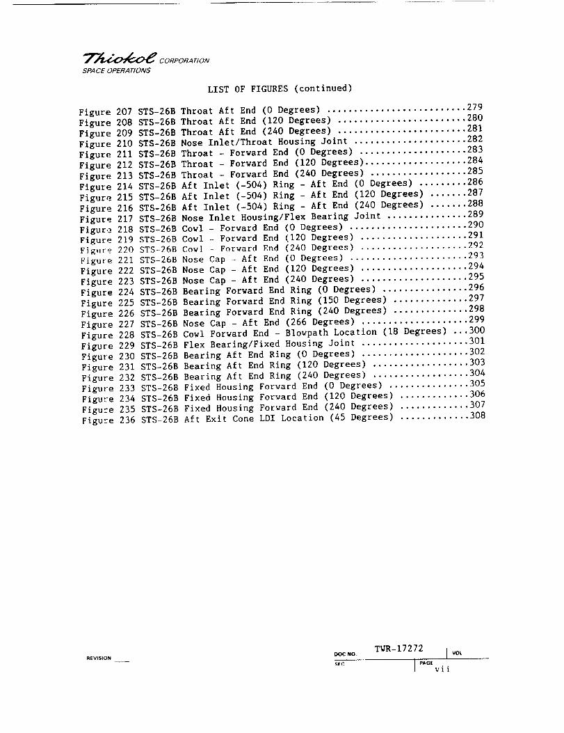
Figure 18 Forward Exit Cone Assembly Nozzle Stations ................... 66
Figure 19 STS-26A Throat Ring Impact Marks (130 Degrees) ............... 67
Figure 20 STS-26A Throat Assembly Bondline Separations ................. 68
Figure 21 STS-26A Throat/Throat Inlet Section (0 Degrees) .............. 69
Figure 22 STS-26A Throat/Throat Inlet Section (90 Degrees) ............. 70
Figure 23 STS-26A Throat/Throat Inlet Section (180 Degrees) ............ 71
Figure 24 STS-26A Throat/Throat Inlet Section (270 Degrees) ............ 72
Figure 25 Throat Inlet Assembly Erosion Measurement Stations ........... 74
Figure 26 STS-26A -503 Ring Impact Marks (3 Degrees) ................... 75
Figure 27 STS-26A -504 Rlng Impact Mark (85 Degrees) ................... 76
Figt_re 28 STS-26A Nose Cap Wedgeout (20 Degrees) ....................... 77
Figure 29 STS-26A Nose Inlet Assembly Bondline Separations ............. 78
Figure 30 STS-26A Forward Nose Ring and Aft Inlet Ring (-503 and -504)
Section (0 Degrees) .......................................... 79
Figure 31STS-26A Forward Nose Ring and Aft Inlet Ring (-503 and -504)
Section (90 Degrees) ......................................... 80
Figure 32 STS-26A Forward Nose Ring and Aft Inlet Ring (-503 and -504)
Section (180 Degrees) ........................................ 81
Figure 33 STS-26A Forward Nose Ring and Aft Inlet Ring (-503 and -504)
Section (270 Degrees) ........................................ 82
Figure 34 STS-26A Nose Cap Section (0 Degrees) ......................... 83
Figure 35 STS-26A Nose Cap Section (90 Degrees) ........................ 84
Figure 36 STS-26A Nose Cap Section (180 Degrees) ....................... 85
Figure 37 STS-26A Nose Cap Section (270 Degrees) ....................... 86
Figure 38 Nose Inlet Assembly Erosion Measurement Stations ............. 90
Figure 39 STS-26A Nose Inlet Housing Bonding Surfaces (0 Degrees) ...... 91
Figure 40 STS-26A Nose Inlet Housing Bonding Surfaces (90 Degrees) ..... 92
.Ev,s,o.__ ooc.o TWR- 17272 IvoL
sec ] pAo,ii

_'I'_;.4"..'(_).X--"*,.4r.._._ CORPORATION
SPACE OPERATIONS
LIST OF FIGURES (continued)
Figure 41 STS-26A Nose Inlet Housing Bonding Surfaces (180 Degrees) ..... 93
Figure 42 STS-26A Nose Inlet Housing Bonding Surfaces (270 Degrees) ..... 94
Figure 43 STS-26A Nose Inlet Housing (Nose Cap) Bonding Surface
(90 Degrees) .................................................. 95
Figure 44 STS-26A Nose Inlet Housing (Nose Cap) Bonding Surface
(180 Degrees) ................................................. 96
Figure 45 STS-26A Nose Inlet Housing (-504 Ring) Bonding Surface
(90 Degrees) .................................................. 97
Figure 46 STS-26A Nose Inlet Housing (-504 Ring) Bonding Surface
(270 Degrees) ................................................. 98
Figure 47 STS-26A CowI/OBR Closeup (0 Degrees) .......................... 99
Figure 48 STS-26A Cowl/OBR Closeup (160 Degrees) ........................ 100
Figure 49 STS-26A Cowl/OBR Closeup (180 Degrees) ....................... I01
Figure 50 STS-26A Cowl/OBR Closeup (320 Degrees) ....................... 102
Figure 51STS-26A Cowl Ring Section (0 Degrees) ........................ 103
Figure 52 STS-26A Cowl (90 Degrees) .................................... 104
Figure 53 STS-26A Cowl (180 Degrees) ................................... 105
Figure 54 STS-26A Cowl (270 Degrees) ................................... 106
Figure 55 Cowl Ring and Outer Boot Ring Erosion Measurement Stations ...III
Figure 56 STS-26A OBR Aft End Delaminations (260 Degrees) .............. 112
Figure 57 STS-26A Fractured OBR Aft Tip Adjacent to Flex Boot .......... 113
Figure 58 STS-26A Outer Boot Ring Section (0 Degrees) .................. 114
Figure 59 STS-26A Outer Boot Ring/Flex Boot (90 Degrees) ............... 115
Figure 60 STS-26A Outer Boot Ring/Flex Boot (180 Degrees) .............. 116
Figure 61STS-26A Outer Boot Ring/Flex Boot (280 Degrees) .............. 117
Figure 62 STS-26A Flex Boot (Cavity Side - 0 Degrees) .................. 118
Figure 63 STS-26A Flex Boot (Cavity Side - 120 Degrees) ................ 119
Figure 64 STS-26A Flex Boot (Cavity Side - 240 Degrees) ................ 120
Figure 65 STS-26A Fixed Housing Wedgeout (280 Degrees) ................. 122
Figure 66 STS-26A Fixed Housing Section (0 Degrees) .................... 123
Figure 67 STS-26A Fixed Housing Section (90 Degrees) ................... 124
Figure 68 STS-26A Fixed Housing Section (180 Degrees) .................. 125
Figure 69 STS-26A Fixed Housing Section (270 Degrees) .................. 126
Figure 70 Fixed Housing Liner Erosion Measurement Station .............. 128
Figure 71STS-26A Bearing Protector (0 Degrees) ........................ 129
Figure 72 STS-26A Bearing Protector (120 Degrees) ...................... 130
Figure 73 STS-26A Bearing Protector (240 Degrees) ...................... 131
Figure 74 STS-26A Flex Bearing (0 Degrees) ............................. 132
Figure 75 STS-26A Flex Bearing (180 Degrees) ........................... 133
Figure 76 STS-26A Forward Exit Cone-to-Aft Exit Cone Joint Interface ...134
Figure 77 STS-26A Aft Exit Cone Forward End (0 Degrees) ................ 135
Figure 78 STS-26A Aft Exit Cone Forward End (120 Degrees) .............. 136
Figure 79 STS-26A Aft Exit Cone Forward End (240 Degrees) .............. 137
Figure 80 STS-26A Forward Exit Cone - Aft End (0 Degrees) .............. 138
REV,S,O. ooc.o. TWR-17272 J voL
SEC I _AOEi i i

__--4_ CORPORAITON
SPACE OPERATIONS
LIST OF FIGURES (continued)
Figure 81STS-26A Forward Exit Cone - Aft End (120 Degrees) ............ 139
Figure 82 STS-26A Forward Exit Cone - Aft End (240 Degrees) ............ 140
Figure 83 STS-26A Forward Exit Cone Aft End Black Corrosion
(338 Degrees) ................................................ 141
Figure 84 STS-26A Forward Exit Cone Aft End White Corrosion
(45 Degrees) ................................................. 142
Figure 85 STS-26A Forward Exit Cone Aft End Scratch Mark (90 Degrees) ..143
Figure 86 STS-26A Throat/Forward Exit Cone Joint ....................... 144
Figure 87 STS-26A Forward Exit Cone - Forward End (0 Degrees) .......... 145
Figure 88 STS-26A Forward Exit Cone - Forward End (120 Degrees) ........ 146
Figure 89 STS-26A Forward Exit Cone - Forward End (240 Degrees) ........ 147
Figure 90 STS-26A Throat Aft End (0 Degrees) ........................... 148
Figure 91STS-26A Throat Aft End (120 Degrees) ......................... 149
Figure 92 STS-26A Throat Aft End (240 Degrees) ......................... 150
Figure 93 STS-26A Throat Aft End - Blowpath (310 Degrees) .............. 151
Figure 94 STS-26A Nose Inlet/Throat Housing Joint ...................... 152
Figure 95 STS-26A Throat Forward End (0 Degrees) ....................... 153
Figure 96 STS-26A Throat Forward End (120 Degrees) ..................... 154
Figure 97 STS-26A Throat Forward End (240 Degrees) ..................... 155
Figure 98 STS-26A Aft Inlet (-504) Ring Aft End (0 Degrees) ............ 156
Figure 99 STS-26A Aft Inlet (-504) Ring Aft End (120 Degrees) .......... 157
Figure I00 STS-26A Aft Inlet (-504) Ring Aft End (240 Degrees) ......... 158
Figure I01STS-26A Throat Forward End Blowpath (136 Degrees) ........... 159
Figure 102 STS-26A Aft Inlet (-504) Ring Aft End Blowpath (136 Degrees).160
Figure 103 STS-26A Nose Inlet Housing/Flex Bearing Joint ............... 161
Figure 104 STS-26A Cowl Forward End (0 Degrees) ........................ 162
Figure 105 STS-26A Cowl Forward End (120 Degrees) ...................... 163
Figure 106 STS-26A Cowl Forward End (240 Degrees) ...................... 164
Figure 107 STS-26A Nose Cap Aft End (0 Degrees) ........................ 165
Figure I08 STS-26A Nose Cap - Aft End (120 Degrees) .................... 166
Figure 109 STS-26A Nose Cap - Aft End (240 Degrees) .................... 167
Figure II0 STS-26A Bearing Forward End Ring (0 Degrees) ................ 168
Figure iii STS-26A Bearing Forward End Ring (120 Degrees) .............. 169
Figure 112 STS-26A Bearing Forward End Ring (240 Degrees) .............. 170
Figure ll3 STS-26A Cowl Forward End - Blowpath Location (216 Degrees) ..171
Figure 114 STS-26A Flex Bearing/Fixed Housing Joint .................... 172
Figure 115 STS-26A Fixed Housing Forward End (0 Degrees) ............... 173
Figure 116 STS-26A Fixed Housing Forward End (120 Degrees) ............. 174
Fig,lre 117 STS-26A Fixed Housing Forward End (240 Degrees) ............. 175
Figure I18 STS-26A Bearing A_t End Ring (0 Degrees) .................... 176
Figure 119 STS-26A Bearing Aft End Ring (120 Degrees) .................. 177
Figure 120 STS-26A Bearing Aft End Ring (240 Degrees) .................. 178
Figure 121STS-26A Bearing Aft End Ring (300 Degrees) .................. 179
Figure 122 STS-26A Fixed Housing Forward End Rust on Metal Surfaces
(15 Degrees) ................................................ 180
Figure 123 STS-26A Bearing Aft End Ring - White Corrosion Spot
(260 Degrees) ............................................... 181
..v,s,o.__ ooc .o. TWR-1727 2 I vo,
stc I PA6E iv

TJ_I_---_ CORPORATION
SPACE OPERATIONS
LIST OF FIGURES (continued)
Figure 124 STS-26B Joint Flow Surface Gap Openings ..................... 182
Figure 125 STS-26B Forward Nozzle Assembly ............................. 183
Figure 126 STS-26B Forward Nozzle Assembly ............................. 184
Figure 127 STS-26B Forward Nozzle Assembly (External) 0 o to 90 oto 180 o .................................................... 185
Figure 128 STS-26B Forward Nozzle Assembly (External) 180 o to 270 oto 0 o ...................................................... 186
Figure 129 STS-26B Forward Nozzle Assembly (Internal) 0 o to 90 oto 180 o .................................................... 187
Figure 130 STS-26B Forward Nozzle Assembly (Internal) 180 o to 270 oto 0 o ...................................................... 188
Figure 131STS-26B Aft Exit Cone Fragment .............................. 189
Figure 132 STS-26B Forward Exit Cone Dimpled Erosion ................... 191
Figure 133 STS-26B Forward Exit Cone Bondline Separations .............. 192
Figure 134 STS-26B Forward Exit Cone Liner Section (0 Degrees) ......... 193
Figure 135 STS-26B Forward Exit Cone Liner Section (90 Degrees) ........ 194
Figure 136 STS-26B Forward Exit Cone Liner Section (180 Degrees) ....... 195
Figure 137 STS-26B Forward Exit Cone Liner Section (270 Degrees) ....... 196
Figure 138 STS-26B Forward Exit Cone Corrosion (0 Degrees) ............. 198
Figure 139 STS-26B Forward Exit Cone Corrosion (80 Degrees) ............ 199
Figure 140 STS-26B Forward Exit Cone Corrosion (30 Degrees) ............ 200
Figure 141STS-26B Forward Exit Cone Corrosion (60 Degrees) ............ 201
Figure 142 STS-26B Forward Exit Cone Corrosion (120 Degrees) ........... 202
Figure 143 STS-26B Forward Exit Cone Corrosion (240 Degrees) ........... 203
Figure 144 STS-26B Forward Exit Cone Corrosion (270 Degrees) ........... 204
Figure 145 STS-26B Throat Inlet Ring Wedgeout (28 - 40 Degrees) ........ 205
Figure 146 STS-26B Throat Assembly Bondline Separations ................ 206
Figure 147 STS-26B Throat/Throat Inlet Sectiun (0 Degrees) ............. 207
Figure 148 STS-26B Throat/Throat Inlet Section (180 Degrees) ........... 208
Figure 149 STS-26B Throat/Throat Inlet Section (270 Degrees) ........... 209
Figure 150 STS-26B (-503) Ring Impact Marks (125 Degrees) .............. 211
Figure 151STS-26B (-503) Ring Impact Marks (185 Degrees) .............. 212
Figure 152 STS-26B Typical Nose Cap Aft End Wedgeout (Post-Burn)
(170 Degrees) ....................................... 213
Figure 153 STS-26B Nose Inlet Assembly Bondline Separations ............ 214
Figure 154 STS-26B Forward Nose Ring and Aft Inlet Ring (-503 and -504)
Section (0 Degrees) ................................. 215
Figure 155 STS-26B Forward Nose Ring and Aft Inlet Ring (-503 and -504)
Section (90 Degrees) ................................ 216
Figure 156 STS-26B Forward Nose Ring and Aft Inlet Ring (-503 and -504)
Section (180 Degrees) ............................... 217
Figure 157 STS-26B Forward Nose Ring and Aft Inlet Ring (-503 and -504)
Section (270 Degrees) ............................... 218
Figure 158 STS-26B Nose Cap Section (0 Degrees) ........................ 219
Figure 159 STS-26B Nose Cap Section (90 Degrees) ....................... 220
Figure 160 STS-26B Nose Cap Section (180 Degrees) ...................... 221
Fig,are 161STS-26B Nose Cap Section (270 Degrees) ...................... 222
.EV,S,ON_ OOCNO. TVR- 17272 IvoL
SEC { PAGE V

LIST OF FIGURES (continued)
Figure 162 STS-26B Nose Inlet Housing Bonding Surfaces (0 Degrees) ..... 226
Figure 163 STS-26B Nose Inlet Housing Bonding Surfaces (90 Degrees) .... 227Figure 164 STS-26B Nose Inlet Housing Bonding Surfaces (180 Degrees) ...228
Figure 165 STS-26B Nose Inlet Housing Bonding Surfaces (270 Degrees) ...229Figure 166 STS-26B Nose Cap Bonding Surface (0 Degrees) ................ 230
Figure 167 STS-26B Nose Cap Bonding Surface (180 Degrees) .............. 231
Figure 168 STS-26B Nose Inlet Housing Pitting (180 Degrees) ............ 232Figure 169 STS-26B Cowl/OBR Closeup (0 Degrees) ........................ 233
Figure 170 STS-26B Cowl/OBR Closeup (180 Degrees) ...................... 234Figure 171STS-26B Cowl/OBR Closeup (320 Degrees) ...................... 235
Fig.re 172 STS-26B Cowl Vent Hole Plugged with Slag (160 Degrees) ...... 236I;'ig. le 11_ STS 26B (:owl Ring Wedg(-out Containing Slag
(120 - 137 Degrees) ......................................... 23]Figure 174 STS-26B Cowl Ring Section (0 Degrees) ....................... 238
Figure 175 STS-26B Cowl Ring Section (45 Degrees) ...................... 239Figure 176 STS-26B Cowl Ring Section (180 Degrees) ..................... 240
Figure 177 STS-26B Cowl Ring Section (270 Degrees) ..................... 241Figure 178 STS-26B Outer Boot Ring Aft Tip Delamination (0 Degrees) .... 247
Figure 179 STS-26B Outer Boot Ring Section (0 Degrees) ................. 248
Figure 180 STS-26B Outer Boot Ring Section (100 Degrees) ............... 249Figure 181STS-26B Outer Boot Ring Section (160 Degrees) ............... 250
Figure 182 STS-26B Outer Boot Ring Section (280 Degrees) ............... 251
Figure 183 STS-26B Flex Boot (Cavity Side - 0 Degrees) ................. 252Figure 184 STS-26B Flex Boot (Cavity Side - 120 Degrees) ............... 253
Figure 185 STS-26B Flex Boot (Cavity Side - 240 Degrees) ............... 254Figure 186 STS-26B Fixed Housing Section (0 Degrees) ................... 256Figure 187 STS-26B Fixed Housing Section (90 Degrees) .................. 257
Figure 188 STS-26B Fixed Housing Section (180 Degrees) ................. 258Figure 189 STS-26B Fixed Housing Section (270 Degrees) ................. 259Fig.re 190 STS-26B Bearing Protector (O Degrees) ....................... 261}"ig_le 191STS-26B Bearing Protector (]20 Degrees) ..................... 262
|,'ig.[e 192 STS 26B Beai ing Pxotectot: (240 Degrees) ..................... 261_
Figure 193 STS-26B Flex Bearing (330 Degrees) .......................... 265Figure 194 STS-26B Aft Exit Cone-to-Forward Exit Cone Joint Interface ..266Figure 195 STS-26B Aft Exit Cone Forward End (0 Degrees) ............... 267
Fig,ire 196 STS-26B Aft Exit Cone Forward End (120 Degrees) ............. 268Figure 197 STS-26B Aft Exit Cone Forward End (240 Degrees) ............. 269
Figure 19B STS-26B Forward Exit Cone - Aft End (0 Degrees) ............. 270
Figure 199 STS-26B Forward Exit Cone - Aft End (120 Degrees) ........... 271
Figure 200 STS-26B Forward Exit Cone - Aft End (240 Degrees) ........... 272
Figure 201STS-26B Forward Exit Cone Aft End Corrosion ................. 273
Figure 202 STS-26B Forward Exit Cone Aft End Scuff Mark ................ 274
Figure 203 STS-26B Throat/Forward Exit Cone Joint ...................... 275
Figure 204 STS-26B Forward Exit Cone - Forward End (0 Degrees) ......... 276
Figure 205 STS-26B Forward Exit Cone - Forward End (120 Degrees) ....... 277
Figure 206 STS-26B Forward Exit Cone - Forward End (240 Degrees) ....... 278
'I'WR 11212
vi
_w.-_ CORPORATION
SPACE OPERATIONS
LIST OF FIGURES (continued)
Figure 207 STS-26B Throat Aft End (0 Degrees) .......................... 279
Figure 208 STS-26B Throat Aft End (120 Degrees) ........................ 280
Figure 209 STS-26B Throat Aft End (240 Degrees) ........................ 281
Figure 210 STS-26B Nose Inlet/Throat Housing Joint ..................... 282
Figure 211STS-26B Throat - Forward End (0 Degrees) .................... 283
Figure 212 STS-26B Throat - Forward End (120 Degrees) ................... 284
Figure 213 STS-26B Throat - Forward End (240 Degrees) .................. 285
Figure 214 STS-26B Aft Inlet (-504) Ring - Aft End (0 Degrees) ......... 286
Figure 215 STS-26B Aft Inlet (-504) Ring - Aft End (120 Degrees) ....... 287
Figure 216 STS-26B Aft Inlet (-504) Ring - Aft End (240 Degrees) ....... 288
Figure 217 STS-26B Nose Inlet Houslng/Flex Bearing Joint ............... 289
Figure 218 STS-26B Cowl - Forward End (0 Degrees) ...................... 290
Figure 219 STS-26B Cowl - Forward End (120 Degrees) .................... 291
Figure 220 STS-26B Cowl - Forward End (240 Degrees) .................... 292
Figure 221STS-26B Nose Cap - Aft End (O Degrees) ...................... 293
Figure 222 STS-26B Nose Cap - Aft End (120 Degrees) .................... 294
Figure 223 STS-26B Nose Cap - Aft End (240 Degrees) .................... 295
Figure 224 STS-26B Bearing Forward End Ring (0 Degrees) ................ 296
Figure 225 STS-26B Bearing Forward End Ring (150 Degrees) .............. 297
Figure 226 STS-26B Bearing Forward End Ring (240 Degrees) .............. 298
Figure 227 STS-26B Nose Cap - Aft End (266 Degrees) .................... 299
Figure 228 STS-26B Cowl Forward End - Blowpath Location (18 Degrees) ...300
Figure 229 STS-26B Flex Bearing/Fixed Housing Joint .................... 301
Figure 230 STS-26B Bearing Aft End Ring (0 Degrees) .................... 302
Figure 231STS-26B Bearing Aft End Ring (120 Degrees) .................. 303
Figure 232 STS-26B Bearing Aft End Ring (240 Degrees) .................. 304
Figure 233 STS-26B Fixed Housing Forward End (0 Degrees) ............... 305
Figure 234 STS-26B Fixed Housing Forward End (120 Degrees) ............. 306
Figure 235 STS-26B Fixed Housing Forward End (240 Degrees) ............. 307
Figure 236 STS-26B Aft Exit Cone LDI Location (45 Degrees) ............. 308
REVISION DOC NO
S£C
TWR-17272 i voL
IpAG,vi i

LIST OFTABLES
Table 1
Table 2Table 3
Table 4Table 5
Table 6
Table 7Table 8
Table 9
STS-26A Aft Exit Cone Post-Flight Polysulfide Groove RadialWidths ........................................................ 58STS 26A Forward Exit Cone Erosion and Char Data ............... 65
STS-26A Throat Assembly Erosion and Char Data ................. 73STS-26A Nose Inlet Rings (-503, -504) Erosion and Char Data ... 87
STS-26A Nose Cap Assembly Erosion and Char Data ............... 88STS-26A Cowl/OBR Erosion and Char Data ........................ 107
STS-26A Flex Boot Data Performance Margins of Safety .......... 121
STS-26A Fixed Housing Insulation Erosion and Char Data ........ 127STS-26B Aft Exit Cone Post-Flight Polysulfide Groove RadialWidths ........................................................ 190
Table 10 STS-26B Forward Exit Cone Erosion and Char Data ............... 197
Table 11STS-26B Throat Assembly Erosion and Char Data ................. 210Table 12 STS-26B Nose Inlet Rings (-503, -504) Erosion and Char Data ...223Table 13 STS-26B Nose Cap Assembly Erosion and Char Data ............... 224Table 14 STS-26B Cowl/OBR Erosion and Char Data ........................ 225
Table 15 STS-26B Flex Boot Data Performance Margins of Safety .......... 255
Table 16 STS-26B Fixed Housing Insulation Erosion and Char Data ........ 260
Table 17 STS-26B Maximum Bearing Protector Erosion in Line with CowlVent Holes .................................................... 264
T_R-17272
viii

"_'___ CORPORA T/ON
SPACE ,-)PERATIONS
1.0 INTRODUCTION
A review of the performance and post-flight condition of the STS-26
Redesigned Solid Rocket Motor (RSRM) nozzles is presented in this document.
Applicable Discrepancy Reports (DRs) and Process Departures (PDs) are
presented in Section 5.0. The Nozzle Component Program Team (NCPT)
performance evaluation and the Redesign Program Review Board (RPRB)
assessment is included in Section 6.0.
The STS-26 nozzle assemblies were flown on the RSRM First Flight (Space
Shuttle Discovery) on 29 September 1988. The nozzles were a partially
submerged convergent/divergent movable design with an aft pivot point
flexible bearing. The nozzle assembly (Figure 1) incorporated the
following features:
a. RSRM forward exit cone with snubbers
b. RSRM fixed housing
c. Structural backup Outer Boot Ring (OBR)
d. RSRM cowl ring
e. RSRM nose inlet assembly
f. RSRM throat assembly
g. RSRM forward [lose and aft inlet ring
h. RSRM aft exit cone assembly with Linear-Shaped Charge (LSC)
i. RTV backfill in joints 1, 3, and 4
j. Use of EA913 NA adhesive in place of EA913 adhesive
REVISION ooc NO.TvR-17272 I vot
SEC I PAGE1

_"_-4__ CORPORATION
SPACE 9PERATIONS
k. Redesigned nozzle plug
I. Carbon Cloth Phenolic (CCP) with 750 ppm sodium content
Figures 2a and 2b show the CCP material usage for the STS-26 forward nozzle
assemblies and aft exit cone assemblies.
2.0 OBJECTIVES
The RSRM First Flight test objectives, as outlined in TUR-17535 (MTI
Engineering Requirements Document for RSRM First Flight), are as follows
(CPW1-3600 paragraph numbers are in parentheses):
K. Demonstrate flex bearing system reusability (3.2.1.9.c).
Y. Post-flight inspection of flex bearing to determine sealing
performance in the flight environment (3.2.1.2.3.b).
Z. Post-flight inspection to verify no gas leaks occurred between
the flex bearing internal components (3.2.1.2.3.d).
AD. Post-flight inspection for flex bearing damage due to water
impact (3.2.1.4.6.a).
AE. Post-flight inspection to verify nozzle liner performance
(3.2.1.4.13).
AV. Post-flight inspection to verify remaining nozzle ablative
thicknesses (3.3.6.1.2.7).
Post-flight inspection to verify nozzle safety factors
(3.3.6.1.2.8).
3.0 SUMMARY/CONCLUSI ONS
Compliance to the objectives is discussed below.
K. Evaluation indicates no condition which would advernely at[ectthe reusability of the flex bearing system. Both flex bearings
TVR-17272 !
_EV,S,ON__ ooc ,,o. I vo=-
SEC I PAGE
m
2

_r_I_ CORPORATION
SPACE OPERATIONS
have met all of the refurbishment requirements and areacceptable for reuse.
Y. Preliminary inspection shows the flex bearings remained sealed
throughout all motor induced environments. Tensile leak tests
done during the refurbishment cycle indicated no leakage.
Z. Preliminary inspection shows the flex bearings maintained a
positive seal within the internal components. Tensile leak
tests done during the refurbishment cycle also indicated no
leakage.
AD. Both flex bearings have met all of the refurbishment
requirements indicating there was no damage due to water
impact.
AE. Evaluation of both nozzle liners revealed erosion profiles
similar to what has been observed on RSRM static test nozzles.
gedgeouts in the aft ends of the RH cowl (120 to 137 degrees)
and nose cap (5 to 20 degrees) contained small amounts of slag.
Sectioning of the liners showed that the wedgeouts occurred
post-burn.
AV. Measurements of the nozzle remaining ablative liner thicknesses
show that the design safety factors have been met.
Sectioning and measurement of the liners show that the
performance margins of safety are all positive.
4.0 RESULTS/DISCUSSION
All STS-26 post-flight nozzle observations are discussed in detail below.
CCP liner Performance Margins of Safety (PMS) are presented using measured
erosion, and corresponding measured char vah, es adjusted to the end of
action time.
TWR- 17272 IREVISION OOC NO. VOLI
$EC [ PAGE3

_ CORPORATION
SPACE OPERATIONS
4.1STS-26A (LH) Nozzle/Flex Bearin G
Overall erosion of the STS-26A forward nozzle assembly CCP ablative liner
was smooth and uniform. All CCP delamlnations, wedgeouts, and pop-ups were
determined to be post-burn occurrences resulting from cooldown of the
liners. Blowpaths were observed in joints I, 2, and 4, but there was no
blowby, erosion, or heat effect to the primary O-rings. Small amounts of
corrosion were found on the metal surfaces of joints i, 3, 4, and 5, but no
pitting was observed. Heavy corrosion and pitting was found on the nose
inlet housing bonding surfaces when the phenolics were washed off.
Post-flight subassembly flow surface gaps are shown in Figure 3. Overall
views of the nozzle are shown in Figures 4 through 9.
4.1.1STS-26A Nozzle Components
STS-26A Aft Exit Cone Assembly
Overall views of the STS-26A aft exit cone fragment are shown in Figures I0
and II.
The aft exit cone was severed aft of the compliance ring by the LSC. The
nozzle severance system performance was nominal. The exit cone cut was
clean, with no unusual tearing or breaking. The remaining aft exit cone
OOCNOTWR-17272REVISION . ] VOL
SEC I PAGE4

_ CORPORATION
SPACE C)PERA_ONS
fragment showed missing CCP liner 360 degrees circumferentially. This is a
typical post-flight observation and occurs at LSC firing and at splashdown.
Glass Cloth Phenolic (GCP) plies exposed by the missing liner showed no
signs of heat effect.
The polysulfide groove fill on the forward end of the aft exit cone shoved
no separations. Post-flight measurements of the polysulfide groove radial
width (Table 1) show that the GCP insulator did not pull away from the
aluminum shell during cooldown. The polysulfide shrank axially aft up to
0.12 in.
There were no separations observed within the GCP insulator on the forward
end.
STS-26A Forward Exit Cone Assembly
Overall views of the STS-26A forward exit cone are shown in Figures 8 and
9.
The forward exit cone showed missing CCP liner over the center portion of
the cone 360 degrees circumferentially. This is a typical post-flight
observation and occurs at splashdown and during Diver Operated Plug (DOP)
insertion. The GaP insulator exposed by the missing liner showed no signs
of heat effect. The CCP liner remained bonded on the forward 11 inches and
TI_R-17272 !
REV|SION DOC NO. | _k

__--_ CORPORATION
SPACE OPERA_ONS
on the aft 8 inches of the cone. These portions showed nominal erosion
with no major washing or pocketing. The aft 8 inches of the liner showed
the typical dimpled erosion pattern that has occurred on all flight and
static test forward exit cones (see Figure 12). The maximum radial depth
of the dimpled erosion was 0.15 inch.
The aft end of the forward exit cone showed bondline separations between
the EA946 adhesive and the steel housing from 30 to 60 degrees and from 124
to 148 degrees. The maximum radial width of the separations was 0.025
inch. The forward end o£ the forward exit cone showed bondline separations
between the GCP and CCP (0.04 inch maximum radial width), and cohesive
separations within the GCP (0.04 inch maximum radial width) intermittently
around the circumference. Figure 13 lists the location and radial width
measurements of all separations on the forward exit cone. These
separations are typical observations which have been seen on previous
static test and flight nozzles, and have been shown to occur post-burn.
Photographs of the sectioned forward exit cone liner are presented in
Figures 14 through 17. Char and erosion analysis of the sections is
presented in Table 2. Figure 18 shows the location of the measurement
stations. All margins of safety were positive, with a minimum of 0.01
occurring at station 28 (180 degrees).
R_V,S,O._ OOC"O TWR- 17 2 7 2 I voL
$EC I PAGE6

_ CORPORATION
SPACE OPERATIONS
STS-26A Throat Assembly
Overall views of the STS-26A throat assembly (throat ring and throat inlet
ring) are shown in Figures 8 and 9.
The post-fired mean diameter of the throat was 55.922 inches (erosion rate
of 8.42 mils/second based on an action time of 122.4 seconds). Nozzle
post-burn throat diameters have ranged from 55,787 to 56.38 inches. The
flow surface bondltne gap between the throat and throat inlet rings was
0.08 inch and is typical of past static test and flight nozzles.
Erosion of the throat and throat inlet rings was smooth and uniform with no
wedgeouts observed. Popped-up charred CCP material was observed on the
forward 1.5 inches of the throat ring at 10, 70, 210, 285, and 345 degrees.
Sharp edges indicate the popped-up material occurred after motor operation.
Impact marks were noted on the throat inlet ring and on the aft end of the
throat ring intermittently around the circumference. The largest was
located on the throat inlet ring at 130 degrees and measured 1 inch
circumferentially by 0.5 inch axially by 0.25 inch radially (Figure 19).
These marks most likely resulted from the loose aft and forward exit cone
CCP material inside the motor at splashdown.
Bondline separations between the EA913 NA adhesive and the steel throat
support housing were observed on the aft end circumferentially except from
.Ev,s,o_ _ ooc _o T_JR-17272 [ rot
SEC [ PAGE7

_ CORPORATION
SPACE 9PERA_ONS
0 to 25 degrees and at 335 degrees. The maximum radial width of these
separations was O.10 inch. Metal-to-adhesive bondline separations
measuring 0.03 inch wide radially were observed on the forward end of the
throat assembly clrcumferentlally except at 180 degrees. Separations
between the adhesive and GCP and within the adhesive were observed at 110,
and 180 degrees, respectively. These also measured 0.03 inch wide
radlally. Figure 20 lists the location and radial width measurements of
all separations on the throat assembly. These separations are typical
observations which have been seen on previous static test and flight
nozzles, and have been shown to occur post-burn.
Photographs of the sectioned throat assembly liner are presented in Figures
21 through 24. Char and erosion analysis of the sections is presented in
Table 3. Figure 25 shows the location of the measurement stations. All
margins of safety were positive, with a minimum of 0.06 occurring at
station 8 (0 degrees).
STS-26A Nose Inlet Assembly
Overall views of the STS-26A nose inlet asssembly (forward nose ring, aft
inlet ring, and nose cap) are shown in Figures 4 and 5.
The ply angle of the forward nose (-503) ring was checked and found to be
of the RSRM design. The flow surface bondline gap between the -503 ring
,EV,S,O,_-- OOC'+O.TWR- 17 2 7 2 I voL
SEC I PAGE8

_ CORPORATION
SPACE OPERA_ONS
and the aft Inlet (-504) ring was 0.15 inch. The flow surface bondline gap
between the -503 ring and the nose cap was 0.05 inch. These post-fired
measurements are typical of past static test and flight nozzles.
The
or
on
These marks most likely resulted from the loose
CCP material inside the motor at splashdown.
-503 and -504 rings showed smooth erosion with no pockets, wash areas,
wedgeouts. Impact marks occurring after motor operation were observed
both rings intermittently around the circumference (Figures 26 and 27).
aft and forward exit cone
The nose cap showed smooth erosion with no pockets or major washes
observed. The aft 2 to 3 inches showed popped-up charred CCP material at
137, 280, 310, and 332 degrees. Typical post-burn wedgeouts on the aft 2
to 3 inches (Figure 28) were noted from 14 to 26, 40 to 93, 110 to 122, 156
to 172, and 248 to 265 degrees. The maximum radial depth was 0.5 inch at
the cowl interface. Sharp edges indicate the popped-up material and the
wedgeouts occurred after motor operation. No wedgeouts were observed on
the forward end of the nose cap.
The aft end of the nose inlet assembly (-504 ring aft end) showed metal to
adhesive bondline separations (0.01 inch maximum radial width) occurring
intermittently around the circumference. Bondline separations between the
EA946 adhesive and the GCF (0.01 inch maximum radial width) were also
REV,SJON__ OOCNO.TWR- 17 2 7 2 I voL
$1EC I PAGE9

_ CORPORATION
SPACE OPERA_ONS
observed. Bondltne separations were observed on the aft end of the nose
cap between the metal and EA946 adhesive, and the adhesive and GCP
intermittently around the circumference. The maximum radial width of these
separations was 0.005 inch. One separation, 0.003 inch vide radially, was
noted within the adhesive from 26 to 28 degrees. Figure 29 lists the
location and radial width measurements of all separations on the nose inlet
assembly. These separations are typical observations seen on previous
static test and flight nozzles and have been shown to occur post-burn.
Photographs of the sectioned nose inlet assembly rings are presented in
Figures 30 through 37. Char and erosion analysis of the sections is
presented in Tables 4 and 5. Figure 38 shows the location of the
measurement stations. All margins of safety were positive, with a minimum
of 0.05 occurring at station 39.5 (180 degrees) for the -503/-504 rings,
and 0.04 occurring at station 24 (90 degrees) for the nose cap.
Following the washout of the phenolics, it was found that the aluminum nose
inlet housing had extensive corrosion and pitting on all bonding surfaces
360 degrees circumferentially (Figures 39 through 46). This was also
found on the STS-26B (RB) nose inlet housing. The cause of this corrosion
has been attributed to seawater which enters bondline separations during
splashdown and retrieval (Ref. Memo L231-FY89-M130). The metal bonding
surfaces were not accessible until phenolic washout at Clearfield
Operations. Therefore, corrosion protection was not applied to these
HEV,S,ON-- OOCNO TVR- 17272 I rot
SEC I PAGE10

_ CORPORATION
SPACEOPERAnONS
surfaces until approximately 4 months after flight. This hardware will be
inspected during refurbishment for compliance to ST_7-3434 (Refurbishment
Of And Acceptance Criteria For Space Shuttle SRM Nozzle Metal Hardware).
STS-26A Cowl Ring
Overall views of
Close-up views are shown in
appeared plugged with slag
Figure 48).
the STS-26A cowl ring are shown in Figures 6 and 7.
Figures 47 through 50. All cowl vent holes
on the Outer Diameter (OD) of the ring (see
Typical ridged erosion was observed intermittently around the cowl
circumference. The forward portion of the ring eroded a maximum of 0.15
inch greater than on the aft portion of the ring (Figure 47). This is a
result of the low ply angle of the cowl ring and has been observed on the
majority of flight and static test nozzles. There were no wedgeouts
observed on the cowl ring.
There were no bondline separations on the forward end of the cowl ring.
Photographs of the sectioned cowl ring are presented in Figures 51 through
54. Typical subsurface ply lifting was observed intermittently around the
circumference along the forward 2 inches of the cowl.
separation was 0.10 inch at 0 degrees (Figure 51).
of flow or erosion within the delaminations.
The largest ply lift
There was no evidence
REVISIONTNR-17272
OOC NO.VOL

_"___ CORPORAT/ON
SPACEOPERA_ONS
Char and erosion analysis of the sections is presented in Table 6 (Stations
0 through 7). Figure 55 shows the location of the measurement stations.
All margins of safety were positive, with a minimum of 0.19 occurring at
station 2 (90 degrees).
STS-26A Outer Boot Ring/Flex boot
Overall views of the STS-26A OBR and flex boot are shown in Figures 6 and
7. Close-up views of the OBR are shown in Figures 47 through 50. The
bondline between the OBR and cowl ring remained intact with no indications
of flow. The flow surface bondllne gap was 0.18 inch and is typical of
past static test and flight nozzles.
The structural backup 0BR was intact. The flow surfaces showed smooth
erosion with no pockets, major washes, or wedgeouts. Delaminations in the
charred CCP of the aft tip were observed 360 degrees circumferentially
(Figure 56). Charred CCP material on the aft tip adjacent to the flex boot
fractured and popped up over a majority of the circumference (Figure 57).
A large impact mark was located on the aft end of the OBR at 190 degrees
and measured 6 inches circumferentially (Figure 49). This may have been
due to the loose CCP material in the motor after splashdown. Sharp edges
on the surfaces indicate this occurred after motor operation.
REVtmON_ OOCNO.TNR- 17272 [vot
SEC [ PAGE12

_='__ C_ClPORATION
SPACE OPERATIONS
Photographs of the sectioned OBR are presented in Figures 58 through 61.
Char and erosion analysis of the sections is presented in Table 6 (Stations
8 through 12). Figure 55 shows the
All margins of safety were positive,
station 9 (90 degrees).
location of the measurement stations.
with a minimum of 0.58 occurring at
The flex boot remained attached to the outer boot ring 360 degrees
circumferentially, and showed no bonline separations. The cavity side of
the flex boot was evenly sooted and showed no evidence of flow or erosion
(Figures 62 through 64). It appeared typical of previous flight and static
test motor flex boots. A minimum of
circumference after motor burn. Table
affected depths and performance margins
PMS was 0.19 at 280 degrees.
3 NBR plies remained around the
7 presents the flex boot material
of safety (PHS). The worst case
STS-26A Fixed Housing
Overall views of the STS-26A fixed housing assembly are shown in Figures 6
and 7.
The fixed housing insulation erosion was smooth
wedgeouts of charred CCP material were observed
intermittently around the circumference
depth of these wedgeouts was 0.5 inch.
GCP.
and uniform. Post-burn
on the forward 2 inches
(Figure 65). The maximum radial
There was no heat effect to the
REVISION OOC NO.TWR-17272
J vOL
SEC I PAGE13

T_ CORPORATION
SPACE OPERATIONS
There were no bondltne separations observed on the forward or aft end.
Photographs
Figures 66 through 69.
presented in Table 8.
stations. All margins
of the sectioned fixed housing assembly liner are presented in
Char and erosion analysis of the sections is
Figure 70 shows the location of the measurement
of safety were positive, with a minimum of 0.56
occurring at station 11 (0 degrees).
STS-26A Bearing Protector
The bearing protector was sooted along the entire length and circumference
(Figures 71 through 73). Slightly heavier soot and erosion was observed in
line with the cowl ring vent holes at the thickened portion, but there was
no bearing protector burn-through. There was no evidence of heat effect on
the Inner Diameter (ID) surface of the bearing protector.
STS-26A Flex Bearing
Exami,at|o. ot tile flex bearing revealed no damage, soot, heat effect, or
flow indications (see Figures 74 and 75). All rubber pads, metal shims,
and end rings appeared to be in nominal condition. Subsequent
refurbishment and testing has verified that the flex bearing is acceptable
for reuse.
REV,S,ON DOC_O TWR- 17272 [ voL
SFC [ PAGF14

_ CORPORATION
SPACE OPERATIONS
4.1.2 STS-26A Nozzle Internal Joints
Descriptions of the STS-26A nozzle internal joints follows.
STS-26A Aft Exit Cone-to-Forward Exit Cone (Joint No. I)
A cross-sectioned view of the STS-26A aft exit cone/forward exit cone field
joint is presented in Figure 76. Photographs of the post-flight joint are
shown in Figures 77 through 82.
The backfilled RTV extended below the joint char line circumferentially
except at the 266.2-degree location. RTV filled the radial ID portion of
the joint except at 236.2, 266.2, 292.8, and 296.6 degrees where unfilled
void areas were located. The backfill also reached the high pressure side
of the primary O-ring from 38 to 185, and 314.4 to 356.2 degrees. One
blowpath 0.I0 inch wide circumferentlally was observed at the 266.2 degrees
unfilled void area. The primary O-ring saw pressure, but showed no signs
of blowby, erosion, or heat effect.
Examination of the joint showed a black residue and aluminum oxide
corrosion appearing on both metal surfaces of the joint between the primary
and secondary O-rings, and outboard of the secondary O-ring intermittently
around the circumference. The black residue was heaviest from 131 to 270
to 0 degrees (Figure 83). The aluminum oxide corrosion was heaviest from 0
TWR-17272 I
REVISION OOC NO. I _LJ

_ CORPORATION
SPACE OPERA_ONS
to 90 to 131 degrees (Figure 8_).
been determined that the black
aluminum oxide corrosion.
There was no pitting observed. It has
residue is the beginning stage of the
The aft flange of the forward exit cone was scratched
location by a guide pin during aft exit cone demate
scratch was approximately 0.002 inch deep axially,
circumferentially and 0.375 inch wide radially.
at the 90-degree
(Figure 85). The
3.5 inches long
STS-26A Throat-to-Forward Exit Cone (Joint No. 4)
A cross-sectioned view of the STS-26A throat/forward exlt cone joint is
presented in Figure 86. Photographs of the post-flight joint are shown in
Figures 87 through 92.
The RTV backfill extended below the joint char line and filled the axial
portion of the joint 360 degrees circumferentially. RTV reached the high
pressure side of the primary O-ring from 65 to 125, 195 to 210, and 312 to
350 degrees. One blow path measuring 1.0 inch circumferentially was found
at 310 degrees on the radial OD portion of the joint (Figure 93). The GCP
was sooted at this location, but not heat affected. The primary O-ring saw
pressure, but there was no evidence of blowby, erosion, or heat effect.
Soot was not evident on the radial ID or the axial portions of the joint.
REVISION °°c "°TNR-17272 I vot
_fC [ PAGF 16

_ CORPORATION
SPACE OPERATIONS
It is believed that the blow path extended cohesively through the RTV at
this location. White deposits, possibly salt, were found on the phenolic
radial ID portion of the joint intermittently around the circumference.
Corrosion was evident on both metal surfaces
25 to 125, and 190 to 330 degrees on
circumferentially on the forward exit cone.
on the metal surfaces.
of the joint, extending from
the throat and 360 degrees
There was no pitting observed
STS-26A Nose Inlet-to-Throat (Joint No. 3)
A cross-sectioned view of the STS-26A nose inlet/throat joint is presented
in Figure 94. Photographs of the post-flight joint are shown in Figures 95
through lO0.
The RTV backfill extended below the joint char line 360 degrees
circumferentially. RTV completely filled the radial ID portion of the
joint circumferentially except from 309 to 313 degrees. RTV also extended
onto the radial OD from 52 to 70, 146 to 149, 163 to 171, 174 to 190, 195
to 197, and 210 to 220 degrees, but did not reach the primary O-ring. One
blow path measuring 0.9 inch wide circumferentially and 1.2 inches deep
radially was observed at 136 degrees (Figures 101 and 102). The blow path
terminated within the RTV. The primary O-ring did not see pressure.
.ev,s,oN_ oocNo TNR- 17272 [ voL
$EC I PAGE17

_ CORPORATION
SPACEOPERA_ONS
Aluminum oxide corrosion was observed on both metal surfaces of the joint
inboard of the primary O-ring, but no pitting was observed. Rust was found
within the metal/adhesive separations on the forward end of the throat
support housing intermittently around the circumference.
Minor surface scratches were observed on the aft end of the nose inlet
housing (-504 ring aft end) where jacking screws were used to disassemble
the joint.
STS-26A Nose Inlet-to-Bearing Forward End Ring-to-Cowl (Joint No. 2)
A cross-sectioned view of the STS-26A nose inlet/forward end ring/cowl
joint is presented in Figure 103. Photographs of the post-flight joint are
shown in Figures 104 through 112.
The RTV extended below the joint char line and filled the axial portion of
the joint 360 degrees clrcumferentlally.
nose cap and cowl showed RTV mixed with
circumferentially. The adhesive was
The radial bondline between the
the EA913 NA adhesive 360 degrees
typically sandwiched between two
layers of RTV. There was no RTV extending to the primary O-ring. One blow
path was observed at 216 degrees. On the aft end of the nose cap, the blow
path measured 0.60 inch wide circumferentiaily and charred the GCP
approximately 0.005 inch deep axially. On the forward end of the cowl
ring, the blow path measured 0.40 inch wide circumferentially and charred
RI=VISlON-- OOCNO.T_,- 17 2 72 ] voL
sEc [ _8

_ CORPORATION
SPACEOPERAnONS
the sllica cloth phenollc (SCP) approximately 0.01 inch deep axially
(Figure 113). The EA913 NA adhesive on the cowl eroded approximately 0.1
inch deep axially (maximum) by 0.7 inch vide circumferentially at the blow
path location. Soot was observed on the nose cap/forward end ring
interface surfaces, reaching the primary O-ring from 156 to 162, and 180 to
240 degrees (Figure 112). There was no blowby, erosion, or heat effect to
the primary O-rlng. Soot also extended to midway between the bolt holes
around the remainder of the circumference.
Both the nose inlet housing and the cowl housing metal surfaces were
heavily sooted at the blow path location. Electrical conductivity tests
run on these parts showed that there was no heat damage. The bearing
forward end ring was also sooted, and the paint was chipped off in various
spots, but neither the end ring or the paint were heat affected.
Water was found on the nose housing aft face and in the bolt holes from 12
to 198 degrees. Aluminum oxide corrosion was observed on the forward face
of the cowl housing from 214 to 224 degrees and extended approximately 0.5
inch radially inward. Corrosion and salt deposits were also found on the
ID surface of the cowl housing
circumferentlally. This indicates water
and bearing protector during splashdown.
forward flange 360 degrees
leaked between the cowl housing
REVISJON °°c_TWR-17272 I_L
SEC I PAGE19

_'___ CORPORAT/ON
SPACE OPERATIONS
STS-26A Fixed Housing-to-Bearing Aft End Ring (Joint No. 5)
A cross-sectloned view of the STS-26A aft end ring/fixed housing joint is
presented in Figure 114. Photographs of the post-flight joint are shown in
Figures 115 through 121.
RTV filled approximately 80 percent of the axial portion of the joint and
reached the high pressure side of the primary O-ring at 25 to 30, 35 to 43,
55, 65 to 78, 240, and 308 to 313 degrees. Voids isolated within the RTV
were observed on the radial portion of the joint intermittently around the
circumference (Figure 121). The largest measured 0.9 inch deep radially by
1.7 inches wide circumferentially. None of the voids extended to the flex
boot cavity. There were no blow paths observed in the joint.
Water was found on the aft face of the aft end ring and in the bolt holes
intermittently around the circumference. Rust corrosion was observed on
both metal surfaces of the joint between the O-rings at 15 degrees (Figure
122), but there was no pitting. Rust corrosion was found on the aft end
ring inboard of the secondary O-ring intermittently around the
circumference. Again, no pitting was observed. A white corrosion spot
(0.10 inch in diameter) located at 260 degrees was also noted (Figure 123).
OOCNOTWR-17272REVISION " J
-- sEo I

w___ CORPORAT/ON
SPACE OPERATIONS
4.2 STS-26B Nozzle/Flex Bearing
Overall erosion of the STS-26B forward nozzle assembly CCP ablative liner
was smooth and uniform. All CCP delamlnations, wedgeouts, and pop-ups were
determined to be post-burn occurrences resulting from cooldown of the
liners. Blovpaths were observed in joints 2 and 4, but there was no
blowby, erosion, or heat effect to the primary O-rings. Small amounts of
corrosion were found on the metal surfaces of joints 1, 2, 3, and 4, but no
pitting was observed. Beavy corrosion and pitting was found on the nose
inlet housing bonding surfaces when the phenolics were washed off. The
forward exit cone also showed corrosion on the ID bonding surface.
Post-flight subassembly flow surface gaps are shown in Figure 124. Overall
views of the nozzle are shown in Figures 125 through 130.
4.2.1STS-26B Nozzle Components
STS-26B Aft Exit Cone Assembly
An overall view of the STS-26B aft exit cone fragment is shown in Figure
131.
The aft exit cone was severed aft of the compliance ring by the LSC. The
nozzle severance system performance was nominal. The exit cone cut was
clean, with no unusual tearing or breaking. The remaining aft exit cone
TWR-17272 i
R_V,S,ON_ Oo=,,o. I w-
SIEC I PAGE
B
21

"___ CORPORATION
SPACE OPERA_ONS
fragment showed missing CCP liner 360 degrees circumferentially. This is a
typical post-fllght observation and occurs at LSC firing and during
splashdown. GCP plles exposed by the missing liner showed no signs of heat
effect.
The polysulfide groove fill on the forward end of the aft exlt cone showed
one separation between the polysulfide and the GCP Insulator. The
separation was located at 211 degrees and measured 0.02 Inch wide radially,
0.04 inch deep axlally and 1.3 inches long circumferentlally. Post-flight
measurements of the polysulfide groove radial width (Table 9) show that the
GCP insulator did not pull away from the aluminum shell during cooldown.
The polysulfide shrank axially aft up to 0.I0 inch.
There were no separations observed within the GCP insulator on the forward
end.
STS-26B Forward Exit Cone Assembly
Overall views of the STS-26B forward exit cone ale shown in Figures 129 and
130.
The forward exit cone showed missing CCP liner over the center 14 inches of
the cone 360 degrees circumferentially. This is a typical post-flight
observation and occurs at splashdown and during Diver Operated Plug (DOP)
insertion. The GCP insulator exposed by the missing liner showed no signs
REV,S,ON__ OOCNO.TWR- 17 2 7 2 I voL
sEc I P'A_ 2

__--4_CORPORA_ON
SPACE OPERA_ONS
of heat effect. The CCP liner remained bonded on the forward 13 inches and
on the aft 9 inches of the cone. These portions showed nominal erosion
with no major washing or pocketing. The aft 9 inches of the liner showed
the typical dimpled erosion pattern that has occurred on all flight and
static test forward exit cones (Figure 132). The maximum radial depth of
the dimpled erosion was 0.15 inch.
The aft end of the forward exit cone showed no bondline or cohesive
_eparations. Bondline separations on the forward end of the forward exit
cone were noted between the steel shell and the EA946 adhesive
circumferentially except at 105 degrees. Separations were also found
between the GCP and CCP, within the GCP, and within the adhesive. Figure
133 lists the location and radial width measurements of all separations on
the forward exit cone. These separations are typical observations seen on
previous static test and flight nozzles and have been shown to occur
post-burn.
Photographs of the sectioned forward exit cone liner are presented in
Figures 134 through 137. Char and erosion analysis of the sections is
presented in Table 10. Figure 18 shows the location of the measurement
stations. All margins of safety were positive, with a minimum of 0.05
occurring at station 1 (0 and 180 degrees), and station 8 (270 degrees).
,EV,S,ON-- OOCNO TVR- 17272 IvoL
SEC [ PAGE23

_ CORPORA TI ON
SPAC£OPERA_ONS
Following washout of the pheno]ics, large areas of corrosion were noted
along the forward 5 to 12 inches of the ID bonding surface (Figures 138 and
139). This "band" of corrosion appeared aft of the forward shear pins.
hight and dark colored areas of corrosion as well as rust spots and pitting
were observed. Corroded areas were also found on the aft 7 inches of the
ID bonding surface centered around the aft shear pin holes (Figures 140
through 144). The largest area was at 120 degrees (Figure 142). Visual
inspections of these indicate that sea water may have leaked through the
shear pin holes where the lightning cables were attached (every 30
degrees). Light and dark areas of corrosion, rust spots, and pitting were
observed. Small rust spots were also noted intermittently around the rest
of the ID surface (Figure 142). These were typically 0.050 to 0.10 inches
in diameter. This hardware will be inspected during refurbishment for
compliance to STWT-3434 (Refurbishment Of And Acceptance Criteria For Space
Shuttle SRM Nozzle Metal Hardware).
STS-26B Throat Assembly
Overall views of the STS-26B throat assembly (throat ring and throat inlet
ring) are shown in Figures 125 and 126.
The throat post-flight mean diameter was 55.876 inches (erosion late ot
8.18 mils/second based on an action time of 123.2 seconds). Nozzle
post-burn throat diameters have ranged from 55.787 to 56.38 inches. The
.Ev,s,o.__ ooc.o TWR- 17272 I vot
SIEC I PAGE24

_ CORPORATION
SPACE OPERA_ONS
flow surface bondline gap between the throat and throat Inlet
0.10 inch and is typical of past static test and flight nozzles.
rinEs was
The throat and throat inlet rings eroded smoothly with no pockets or major
washes observed. The forward end of the throat inlet ring showed post-burn
wedgeouts of charred CCP material from 28 to 40, 95 to 105 and 355 to 0 to
5 degrees (Figure 145). The maximum axial width of the vedgeouts was 0.75
inch at the 28-to-40-degree location. Post-burn wedgeouts of the throat
inlet ring forward end have been observed on previous post-fllght nozzles.
The forward 1.5 inches of the throat ring showed popped-up charred CCP
material intermittently around the circumference. Sharp edges indicate the
popped-up material occurred after motor operation. Marks resulting from
DOP insertion were observed on the throat ring intermittently around the
circumference.
Bondline separations on the aft end of the throat ring between the EAgI3 NA
adhesive and the steel throat support housing were observed around the
majority of the circumference. Separations were also found between the
adhesive and GCP, within the GCP, and within the adhesive. There were no
separations between the GCP and CCP on the aft end.
throat inlet ring showed metal to adhesive
circumferentially except from 255 to 0 degrees.
observed between the GCP and CCP. Figure 146 lists the location and radial
width measurements of all separations on the throat assembly. These
The forward end of the
bondline separations
Separations were also
.,v,s,o. __ ooc .o. TWR- 17 2 7 2 ] vo.

_ CORPORAT/ON
SPACFOPERA_ONS
separations are typical observations seen on previous
flight nozzles and have been shown to occur post-burn.
static test and
Photographs of the sectioned throat assembly liner are presented in Figuze_
147 through 149. Char and erosion analysis of the sections is presented in
Table 11. Figure 25 shows the location of the measurement stations. All
margins of safety were positive, with a minimum of 0.07 occurring at
station 8 (180 degrees).
STS-26B Nose Inlet Assembly
Overall views of the STS-26B nose inlet assembly (forward nose ring, aft
inlet ring, and nose cap) are shown in Figures 125 through 128.
The ply angle of the forward nose ring was checked and found to be of the
RSRM design. The flow surface bondline gap between the forward nose (-503)
ring and the aft inlet (-504) ring was 0.18 inch. The flow surface bondline
gap between the -503 ring and nose cap was 0.05 inch. These post-flred
measurements are typical of past static test and flight nozzles.
The -503 and -504 rings showed smooth erosion with no pockets or major
washes observed. The -503 ring showed popped-up charred CCP material at
the nose cap interface from 155 to 165 degrees. The popped-up material was
0.08 inch wide axially and occurred ariel motor operation. Impact mark:;
TWR-17272!
REVISION DOC NO. _ VOLI

_ CORPORATION
SPACEOPERA_ONS
occurring after motor operation were observed on both rings inter_Jttently
around the circumference (Figures 150 and 151). The marks most likely
resulted from the loose aft and forward exit cone CCP material in the motor
at splashdown.
The nose
observed.
post-burn
cap showed smooth erosion with no pockets or major washes
The aft 2.0 to 3.5 inches of the nose cap showed typical
wedgeouts intermittently around the circumference (Figure 152).
These measured approximately 0.5 in. deep radially at the cowl interface.
One wedgeout location from 5 to 20 degrees showed slag covering exposed CCP
material. Sectioning of the liner determined that this wedgeout occurred
post-burn.
The aft end of the nose inlet assembly (-504 ring aft end) shoved metal to
adhesive bondline separations measuring 0.02 inch wide radially from 238 to
245 degrees, and at 250 degrees. There were no cohesive separations or
separations at the adhesive/GCP and GCP/CCP interfaces. Bondline
separations were observed on the aft end of the nose cap between the metal
and EA946 adhesive at 105, 135 to 255, 285 to 315, and 345 degrees. These
separations were typically 0.005 inch wide radially. There were no
cohesive separations or separations at the adhesive/GCP and GCP/CCP
interfaces. Figure 153 lists the location and radial width measurements of
all separations on the nose inlet assembly. These separations are typical
oh_ervatlons seen on previous static test and f]igh¢ nozzle_, and have been
shown to occur post-burn.
R£VISION-- OOCNO, T_R- 17 2 7 2 ] voL
s,c ]

_ CORPORA_ON
SPACEOPERAnONS
Photographs of the sectioned nose inlet assembly rings are presented in
Figures 154 through 161. Char and erosion analysts of the sections is
presented in Tables 12 and 13. Figure 38 shows the location of the
measurement stations. All margins of safety were positive, with a minimum
of O.O1 occurring at station 32 (180 degrees) for the -503/-504 rings, and
0.01 occurring at station 24 (225 degrees) for the nose cap.4
L_
Following the washout of the phenollcs, it was found that the aluminum nose
inlet housing had extensive corrosion and pitting on all bonding surfaces
360 degrees circumferentlally (Figures 162 through 167). Most of the
corrosion on the nose cap bonding surface was found on the aft 5 inches 360
degrees clrcumferentially. The forward edge of this corrosion was shaped
in a "saw tooth" pattern (Figure 166). The leading edge of the nose inlet
housing showed areas of pitting approximately 0.04 to 0.05 inch deep
(Figure 168). The entire -503 ring bonding surface was heavily corroded
and pitted 360 degrees clrcumferentially, and approximately 90 percent of
the -504 ring bonding surface showed various stages of corrosion and
pitting. This corrosion has been attributed to seawater which enters
bondline separations during splashdown and retrieval (Ref. Memo
L231-FY89-MI30). The metal bonding surfaces were not accessible until
phenolic washout at Clearfield Operations. Therefore, corrosion protection
was not applied to these surfaces until approximately 4 months after
flight. This hardware will be inspected during refurbishment for
compliance to STW7-3434 (Refurbishment Of And Acceptance Criteria For Space
Shuttle SRM Nozzle Metal Hardware).
TWR-17272 I
REVISION OOC NO_ J _Li I
.c I P'° 8

_ CORPORATION
SPACE OPERATIONS
STS-26B Cowl Ring
Overall views of the STS-26B cowl ring are shown in Figures 127 and 128.
Close-up views are shown in Figures 169 through 171. All cowl vent holes
appeared plugged with slag on the OD of the ring (Figure 172).
The cowl ring showed typical ridged erosion intermittently around the part
circumference. The forward portion of the ring eroded a maximum of 0.15
inch greater than the aft portion (Figure 169). This is a result of the
low ply angle of the cowl ring and has been observed on the majority of
flight and static test nozzles. One wedgeout was observed on the aft 3.5
inches of the cowl ring from 120 to 137 degrees (Figure 173). The maximum
radial depth of the wedgeout was 0.6 inch at the outer boot ring interface.
Slag coated the exposed CCP material at the wedgeout location. Sectioning
of the liner determined that this wedgeout occurred post-burn.
There were no bondline separations on the forward end of the cowl ring.
Photographs of the sectioned cowl ring are presented in Figures 174 through
177. Typical subsurface ply lifting was observed intermittently around the
circumference along
separation was 0.20
evidence of flow or
analysis
the length of the cowl. The largest ply lift
inch at 270 degrees (Figure 177). There was no
erosion within the delaminations. Char and erosion
of the sections is presented in Table 14 (Stations 0 through 7).
REVISION _CN°TVR-17272 I _L

_ CORPORATION
SPACE OPERA_ONS
Figure 55 shows the location of the measurement stations. All margins of
safety were positive, with a minimum of 0.04 occurring at station 0 (45
degrees).
STS-26B Outer Boot Ring/Flex Boot
Overall views of the STS-26B outer boot ring are shown in Figures 127 and
128. Close-up views are shown in Figures 169 through 171. The bondline
between the outer boot ring and cowl ring remained intact with no
indications of flow. The flow surface bondline gap was 0.20 inch and is
typical of past static test and flight nozzles.
The structural backup outer boot ring was intact. The flow surfaces showed
smooth erosion with no pockets, wedgeouts, or major washes. Minor wash
area_ extended from the cowl to the forward 1.5 inches of the OBR from 120
to 150, and 151 to 158 degrees, and measu[ed a maximum o_ 0.2 inch radially
deep. These have occurred on the majority of flight and static test
nozzles. Popped-up charred CCP material was observed on the forward 1.8
inches of the OBR intermittently around the circumference. The popped-up
material is a common observation and occurs after motor operation.
Delaminations in the charred CCP of the aft tip were observed 360 degrees
circumferentially (Figure 178). Charred CCP material on the aft tip
adjacent to the flex boot fractured and popped up over a majority of the
circumference.
TWR-17272 I
REYISION _C _. I rOE!
s,o 1"%o

T_'J__ CORPORATION
SPACE OPERATIONS
Photographs of the sectioned outer boot ring are presented in Figures 179
through 182. Char and erosion analysis of the sections is presented in
TabIe 14 (Stations 8 through 11.3). Figure 55 shows the location of the
measurement stations. All margins of safety were positive, with a minimum
of 0.59 occurring at station 10 (0 degrees).
The cavity side of the flex boot was evenly sooted and showed no evidence
of flow or erosion (Figures 183 through 185). It appeared typical of
previous flight and static test motor flex boots. A minimum of 3.0 NBR
plies remained around the circumference after motor burn. Table 15
presents the flex boot material affected depths and Performance Margins of
Safety. The worst case PMS was 0.19 at 280 degrees.
STS-26B Fixed Housing Assembly
Overall views of the STS-26B fixed housing assembly are shown in Figures
127 and 128.
The fixed housing insulation showed smooth erosion with no pockets or major
washing observed. Post-burn wedgeouts of charred CCP material were
observed on the forward 2.0 inches of the fixed housing insulation from 30
to 65, 135 to 145, and 165 to 180 degrees. The wedgeouts were a maximum of
0.5 inch deep radially. There was no heat effect to the GCP.
TUR- 17272 IREVISION DOC NO VOLI
SEC I PAGE31

_ CORPORAT/ON
SPACE OPERATIONS
There were no bondltne separations observed on the forward or aft end.
Photographs of the sectioned fixed housing assembly liner are presented in
Figures 186 through 189. Char and erosion analysis of the sections is
presented in Table 16. Figure 70 shows the location of the measurement
stations. All margins of safety were positive, with a minimum of 0.54
occurring at station 3 (270 degrees).
STS-26B Bearing Protector
The bearing protector was sooted along the entire length and circumference
(Figures 190 through 192). Heavier soot and erosion were observed in line
with the cowl ring vent holes at the thickened portion of the bearing
protector. Erosion depths at the vent hole locations are presented in
Table 17. There was no evidence of heat effect on the IO surface of the
bearing protector.
STS-26B Flex Bearing
Examination of the flex bearing revealed no damage, soot, heat effect, or
flow indications (Figure 193). All rubber pads, metal shims, and end rings
appeared to be in nominal condition. Subsequent rerfurbishment and testing
has verified that the £1ex bearing is acceptable [o[ reuse.
.,v,s,o.__ ooc.o TVR- 17272 IvoL

?='_-"_,_";'_'_O_ CORPORATION
SPACE OPERATIONS
4.2.2 STS-26B Nozzle Internal Joints
Descriptions of the STS-26B nozzle internal joints follows.
STS-26B Aft Exit Cone-to-Forward Exit Cone (Joint No. 1)
A cross-sectioned view of the STS-26B aft exit cone-to-forward exit cone
field joint is presented in Figure 194. Photographs of the post-flight
joint are shown in Figures 195 through 200.
The backfilled RTV extended below the joint char line 360 degrees
circumferentlally. RTV filled the radial ID portion of the joint except at
103 degrees where an unfilled void area approximately 1.0 inch wide
circumferentially was located. The backfill also extended to the high
pressure side of the primary O-ring from 0 to 81, 82 to i01, 103 to 123,
154 to 178, 182 to 237, 243 to 251, 258 to 265, and 268 to 0 degrees.
There were no blowpaths observed in the joint and the primary O-ring saw no
pressure. Char was observed on the RTV in the axial portion of the joint
at 237 degrees. The RTV was not eroded or heat affected at the charred
location. It is believed that the char penetrated the joint at splashdown.
Examination of the joint showed a black residue and aluminum oxide
corrosion appearing on both metal surfaces between the primary and
secondary O-rings, and outboard of the secondary O-ring intermittently
,,v,s,on__ oocNO TWR- 17272 IvoLSEC 1"PAGE
I 33

_ CORPORATION
SPACE OPERA_ONS
around the circumference (Figure 201).
heaviest from 112.6 to 143.2 degrees. There
was determined that the black residue is
aluminum oxide corrosion.
The aluminum oxide corrosion was
was no pitting observed. It
the beginning stage of the
One through hole on the forward exit cone housing aft flange was dinged by
a guide pin during the aft exit cone demate. The ding was approximately
0.02 inch deep and was located at 95.6 degrees (Figure 202).
STS-26B Throat-to-Forward Exit Cone (Joint No. 4)
A cross-sectioned view of the STS-26B throat-to-forward exit cone joint is
presented in Figure 203. Photographs of the post-flight joint are shown in
Figures 204 through 209.
The RTV backfill extended below the joint char line and filled the radial
ID portion of the joint circumferentially, except at 185 degrees. RTV
filled the axial portion of the bondline from 40 to 165 degrees, and 240 to
345 degrees. RTV did not reach the high-pressure side of the primary
O-ring.
185 deg.
resulting
ther was no evidence of blovby, erosion,
showed no signs of heat effect.
One blow path measuring 0.25 inch circumferentially was found at
Excess grease at this location inhibited the RTV backfill,
in an unfilled void area. The primary O-ring saw pressure, but
or heat effect. The GCP also
REVISIONTWR-17272
DOC NO.J VOL
.c I

_ CORPORATION
SPACEOPERAnONS
Rust corrosion was observed on both surfaces of the joint within the metal
housing�adhesive bondltne separations intermittently around the
circumference. Black corrosion was observed near the primary sealing
surface of the throat housing aft end from 80 to 85 degrees, and 345 to 0
to 4 degrees. There was no pitting on the metal surfaces.
STS-26B Nose Inlet-to-Throat (Joint No. 3)
A cross-sectioned view of the STS-26B nose inlet-to-throat joint is
presented in Figure 210. Photographs of the post-flight joint are shown in
Figures 211 through 216.
The RTV backfill extended below the joint char line 360 degrees
circumferentially. RTV filled the radial ID portion of the joint
circumferentially except at 50 degrees. RTV also extended onto the radial
OD up to the GCP/CCP interface at 35, 275, and 325 degrees. An unfilled
void area, 1.0 inch circumferentially, was located at 50 degrees. There
was no blow path to the void area. The primary O-ring did not see
pressure. Grease was observed on both sides of the joint 360 degrees
circumferentially extending 0.I to 1.0 inch inboard of the primary O-ring.
Minor surface corrosion was observed on the aft end of the nose inlet
housing inboard of the primary O-ring, but no pitting was observed. This
aluminum oxide corrosion extended approximately half way down the ID side
TWR-17272I
REVISION DOC NO I _Li I
sEc I P'%5

_'_'_ CORPORAT/ON
SPACEOPERA_ON$
Of the primary O-ring groove at 325 degrees. There was no corrosion
on the forward end of the throat housing.
STS-26B Nose Inlet-to-Bearing Forward End Ring-to-Cowl (Joint No. 2)
A cross-sectloned view of the STS-26B nose inlet-to-bearing forward end
ring-to-cowl joint is presented in Figure 217. Photographs of the
post-flight joint are shown in Figures 218 through 226.
The RTV extended below the joint char line and filled the axial portion of
the joint 360 degrees circumferentially. The radial bondline between the
nose cap and cowl showed RTV mixed with the EA913 NA adhesive
intermittently around the circumference, The adhesive was typically
sandwiched between two layers of RTV. RTV filled approximately 80 percent
of the axial bondline between the nose cap and bearing forward end ring.
No RTV extended to the primary O-ring. One blow path was observed at 266
degrees and measured 0.5 inch wide circumferentially (Figure 227). The
cowl SCP and nose cap GCP insulators showed no heat effect. The primary
O-ring saw pressure, but there was no evidence of blowby, erosion, or heat
effect. Soot was observed on the radial OD of the joint 360 degrees
circumferentially. Soot reached up to the axial bolt holes on the nose
inlet housing intermittently around the circumference, but did not reach
the primary O-ring. Salt deposits were also noted on the radial OD
surfaces.
TNR-17272REVISION _ DOC NO. I VOL
I "°%

_P__--4_ CORPORA T/ON
SPACE OPERAPONS
Both the aft face of the forward end ring flange and the forward face of
the cowl housing were sooted at 130 to 153, 165, 255, and 303 to 310
degrees, but were not heat effected. The paint on the forward end ring
OD flange surface was chipped off in various spots, but was not heat
affected. Minor rust spots were noted in areas where the paint was chipped
off. Aluminum oxide corrosion was observed on the forward end ring/nose
inlet housing interface surfaces, and on the cowl housing/forward end ring
interface surfaces intermittently around the circumference. Aluminum oxide
corrosion was also found intermittently on the forward flange ID surface of
the cowl housing (Figure 228).
STS-26B Fixed Housing-to-Bearing Aft End Ring (Joint No. 5)
A cross-sectioned view of the STS-26B aft exit cone/forward exit cone field
joint is presented in Figure 229. Photographs of the post-flight joint are
shown in Figures 230 through 235.
RTV filled approximately 75 percent of the axial portion of the joint and
reached the high pressure side of the primary O-ring from 75 to II0, 123 to
128, 135 to 148, and 195 to 218 degrees. Voids isolated within the RTV
were observed on the radial portion of the joint intermittently around the
circumference. The largest measured 0.45 inch deep radially by 0.30 inch
wide circumferentially. A void at 171 degrees extended onto the axial
portion of the joint, but terminated within the RTV. There were no blow
paths observed in the joint, and the primary O-ring did not see pressure.
.EV,S,ON-- OOCNO.TVR- 17 2 7 2 [ vol
SEC ] PAGE37

_ CORPORAT/ON
SPACE OPERATIONS
Rust corrosion was found on the aft end ring inboard of the secondary
O-ring intermittently around the circumference. No pitting was observed.
4.3 Instrumentation
There was no instrumentation installed on the STS-26 nozzles.
5.0 DISCREPANCY REPORTS AND PROCESS DEPARTURES
The STS-26 Nozzle DRs and PDs reviewed by the Morton Thiokol senior
material review board are included in Appendix A. These were presented in
the STS-26 RSRM Acceptance
descriptions of the DRs and
observations are discussed below.
Review Level IIl (TWR-18117A). Brief
PDs, and correlations to post-flight
5.1STS-26A DRs and PDs
Aft Exit Cone
DR 123524-01 (Waiver No. RW'_/404)
LDIs within the GCP were found at 240 degrees, 54 inches aft of the forward
end. This portion of the aft exit cone was severed by the LSC during
reentry and wa_ not recovered. Post-flight inspection of thi_ parr wa_ not
possible.
TWR-17272 I
REVt$_O_ DOC NO. I _I

_'/_M_ CORPORATION
SPACE OPERATIONS
DR 162635-01, -02 (Waiver No. RW-g 405)
LDIs within the GCP were found at 222 degrees (39.5 inches aft of the
compliance ring), and 240 and 243 degrees (4 inches aft of the compliance
ring). This portion of the aft exit cone was severed by the LSC during
reentry and was not recovered. Post-flight inspection of this part was not
possible.
Forward Exit Cone
DR 151717-O1 (Waiver No. RWW 387)
Eight LDIs within the GCP were found running 360 degrees circumferentially
along a full ply length. Post-fllght inspection of the exposed GCP did not
reveal any delaminations extending to the surface.
PD 150663-01
The white stripe (90-degree mark) on the phenolic liner was 1.75 inches
from the 90-degree reference pin (0.75 inch over maximum). The liner was
bonded at the same radial location as the dry fit. Orientation to
correlate post-flight performance with any pre-flight anomalies was not
affected.
Throat Assembly
RE VISION
TWR-17272DOC NO "COt

__/_--I_ CORPORATfON
SPACE OPERATIONS
DR 128578-01
Intermittent pitting, a maximum of 0.002 inch deep, was found on the aft
sealing surface. After being repaired, the joint was succesfully leak
tested. Post-flight inspection did not reveal any indications of blow-by.
Nose Inlet Assembly
DR 152142-01
Phosphoric Acid Anodization (PAA) and EA9228 Primer applied to the bonding
surfaces was not uniform (dark streaks and spots). The PAA and primer
system was deleted from the engineering design change. This part was grit
blasted and the phenolics bonded using 51-L surface preparation techniques.
All of the phenolics were intact and remained bonded to the housing.
PD 150024-01
The EA946 adhesive for the nose cap bond was not applied within 6 hours
from the grit blast requirement. This was reworked to blueprint
requirements. No post-flight anomamlies were noted.
PD 150024-02
The EA946 adhesive for the nose cap bond was not applied within 1 hour from
methylchloroform wipe. This was reworked to blueprint requirements. No
post-flight anomamlies were noted.
TUR-17272 I
REVISION _C NO J VOL!

T_-_O'_---O_ CORPORATION
SPACE ,OPEFiATIONS
Cowl Assembly
DR 126842-01
Intermittent pitting was found on the cowl housing (worst-case condition
was 0.180 inch in diameter by 0.039 inch deep on the ID flange. The pits
were honed out to remove sharp edges. No post-flight anomalies were noted.
Flex Bearing
DR 123208-01
One threaded hole (0.190-32 UNF) on the aft end ring accepted the no-go
threaded plug gage for 6.5 turns. Proper bolt torque was verified and
showed no damage. Post-flight inspection showed damage to the bolt hole.
DR 123439-01
The unbond area on pad ii exceeded the maximum
flex bearing passed all of the acceptance
refurbishment requirements.
allowable of 9 in2. The
test_ and post-flight
5.2 STS-26B DRs and PDs
Nozzle/A[t Segment Assembly
REVISION OOC NOTWR-17272
I VOL
SEC ] PAGE41

_ CORPORATION
SPACE OPERATIONS
DR 153960-01
A broken girth gage wire was found between the aft dome boss and nozzle
assembly. This did not affect O-ring gap openings. The joint successfully
passed leak check. Post-flight inspection showed no anomalies as a result
of this condition.
Aft Exit Cone
DR 123533-01, (Waiver No. RWW 406)
An LDI measuring 2.35 inches circumferentially, 1.2 inches axially, and
0.031 inch radially was found in the GCP 0.393 inch from the forward end at
45 degrees. Post-fllght inspection of the GCP after sectioning (Figure
236) did not reveal any delaminatlons.
Throat/Nose Inlet Joint Assembly
DR 150682-01, -02
The primary to secondary seal cavity was pressurized to
high pressure leak check (the requirement is 740 ± 15 psig),
during low pressure leak check (the requirement is 30 ± 3 psig).
passed leak check, and no anomalies were observed during
inspection.
1040 psig during
and 40 psig
The joint
post-flight
.EV,S,ON OOCNO.TWR- 17 2 7 2I VOL
SEC ] PAGE42

_"_.._r___ CORPORATIO N
SPACE OPERATIONS
Nose Inlet Assembly
PD 149145-01
This involved the forward first wrap of the nose ring during the carbon
hydroclave cure. While decreasing pressure, the pressure dropped to 168
psig for 4 minutes, then remained in tolerance during the remainder of the
cure. The CCP liner met all acceptance criteria. There were no anomalies
observed during post-flight inspection.
Cowl Assembly
DR 128474-01
Pitting was observed on the OD and ID surfaces of the cowl housing.
Maximum depths were 0.049 inch on the ID side, and 0.041 inch on the OD
side. These were blended out to remove sharp edges. Post-flight
inspection has not revealed any anomalies.
Flex Bearing
DR 123437-01
One threaded hole (0.750-16 UNF) on the aft end ring accepted the no-go
threaded plug gage for eight turns. A helical coil insert was used as a
standard repair. There was no damage noted during post-flight inspection.
The repair did not affect the flex bearing performance.
REV,S,ON__ OOCNO,TWR- 17 2 7 2 I voL
SEC I PAGE43

_ CORPORATION
SPACE ,C)PERATIONS
Bearing Protector
PD 127767-01
This involved the GCP autoclave cure for the bearing protector inner ring.
The autoclave vacuum dropped below the minimum of 15 in. Hg for a total of
177 minutes. The inner ring met all acceptance tests, and the bearing
protector assembly using this ring passed strength tests. There were no
anomalies observed during post-flight inspection.
6.0 NOZZLE
PROGRAM REVIEW BOARD (RPRB) ASSESSMENT
The NCPT reviewed all observations documented in this report. The
classified five Problem Reports (written at KSC) as minor anomalies.
internal nozzle joint inspections at Clearfield,
classified five observations as potential anomalies.
further classified as minor anomalies, and the
COMPONENT PROGRAM TEAM (NCPT) RECOMMENDATIONS AND REDESIGN
team
After
the team initially
Three of these were
other two remained
observations. These were presented to the RPRB on 9 and II November, 1988.
The RPRB agreed with all the classifications. These minor anomalies were
recorded on Post-Fire Anomaly Record (PFAR) forms and are included in
Appendix B. The PFARs contain detailed descriptions and corrective actions
as accepted and/or modified by the RPRB. A listing of the PFARs is listed
below.
6.1STS-26A Nozzle
PFAR NUMBER
360L001A-11
DESCRIPTION
Corrosion on aft exit cone metal between primary
and secondary O-rings.
RE VISION ooc No T_/R- 17272 .... ]_ voL
!;t ('- 7 PAG_ 44

T,#__--'_ CORPORATION
SPACE OPERATIONS
360L001A-12
360L00IA-43
6.2 STS-26B Nozzle
PFAR NUMBER
360L00IB-IO
360L00IB-38
360LOOIB-42
360LOOIB-44
360LOOIB-45
Corrosion on forward exit cone metal between
primary and secondary aft exit cone O-rings.
RTV and EA913 NA adhesive mixing in joint 2.
DESCRIPTION
Corrosion on aft exit cone metal between primary
and secondary O-rings.
Ding on forward exit cone aft flange.
Corrosion on forward exit cone metal between
primary and secondary aft exit cone O-rings.
RTV backfill in joint 4 inhibited by excessive
grease.
RTV and EA913 NA adhesive mixing in joint 2.
REVISION oocNo TUR-17272 I VO[
SEC I PAGE45

MORTON THIOKOL INC
Space Operations
Flex Bearing
Support Housing
Throat Inlet Housing
Throat Ring
Throat Inlet Ring
-504 Aft InletRing
-503Nose Ring
_ft End Ring
Snubber Assembly
Forward Exit Cone Liner
Forward ExitCone Housing
Nose InletHousing
FixedHousing
-402 Nose Cap Fixed Housing
Forward Insulation
End Ring Cowl
Flexible Boot Ring
Structural Backup OBR
Bearing Protector
Cowl Housing
r- Aft Exit Cone Jner
(carbon-cloth phenolic)
/ /-- Aft Exit Cone Shell
5-T73 aluminum)Q
r,,-_ 21_ _-,__ r- Aft Exit Cone'v "'" --___._ II_J_A__ / Structure
Actuator Bracket \ _-kin_r--C:;haoed Charae __(7075-T73 aluminum
• Compliance Ring(7075-T73 aluminum) A017773a
Figure 1 STS-26 Nozzle Components
oocNo TWR-17272 Ivo_
REVISION SEC ] PAGE 46

MORTONTHIOKOL. INC
Space Operations
°_
o
oZ
CO
I
c/'JI-u_
¢U
-I
REVISIONOOCNO TWR-17272 L"o_
sEc F.A(_,4;

MORTON THIOKOL INC_
Space Operations
©
oZ
c',qI
C'q
bO
°!o
REVISION oocNo TWR-17272SEC

MORON THIOKOL INC
Space Operations
f O.20 In.
0.22 in. "-I
_ --.....
STS-26A Joint Flow Surface Gap Openings
OOCNOTWR-17272
._v,_,o,. sEc I ,,GE
Figure 3
I VOL
49

MORTON THIOKOL INC
Space Operations
i=
r_
Neq0
Z
0
Ic_
c,
REVISION
ORIGINAL PAGE
BLACK AND WHITE PHOTOGRAPH
ooc.o TWR-17272SEC
I PAGE
rOt
50

MOIL'TON THIOKOL. INC.
Space OperationsORIGINAL PAGE
BL.AC,K AND WHITE PHOTOGRAPH
OOCNOTWR-17272 I VOL
.Ev.s,o.__ sEc I .,GE 51

MORTONTHIOKOL.INC_Space Operations
OR ,,:,N/'_L PAGE
BLACK AND WHITE PHOTOGRAPH
O
O
o
O
O
REVISION
DOCNO
$EC
TWR-17272 Ivo_
1pAG_ 52

MORTON THIOKOL. INC
Space Operations
ORIGINAL PAGE
BLACK AND WHITE PHOTOGRAPH
REVISION
OOCNOTWR-17272$EC

MORTON THIOKOL INC
Space Operations
REVISIONOOCNOTWR-17272SEC
J PAGE
I VOt
54
ORIGINAL PAGE
BLAC__ AND WHITE PHOTOGRAPH

MORTON THIOKOL INC
Space Operations
ORIG1NAE pAGE
BLACK AND V_!HITE p!_O-f-oGRAPH
AIEVISTON
IDO¢ NO
SEC
TWR-17272 I_°L
I "_' 55

MORTON THIOKOL INC.
Space Operations
ORIGINAL PAGE'
BLACK AND WHITE PHOTOGRAPH
Figure 10 STS-26A Aft Exit Cone Fragment
REVISIONoocNo TWR-17272 J voL
sEc I P'_ 56

MOFQ-ON THIOKOL. INC.-
Space Operations
BLACK AND wvlr'i-E PHOTOGRAPH
bid
L,
o
X
I
ooc.o TWR-17272 Iv°_
.E_,S,ON S_C IPAGE 57

MOI'(TONTHIOKOL INC
Space Operations
Carbon-ClothPhenolic(completely missing)
AngularLocation
C153045607590
10,5
120135159165180195
2102252402552702E53C03_53303,'-5
NominalPreflight--_ ._Radial Groove
Width 0.20 in.
--l-
Width(in.)
0.180.19
0.190.180.190.180.180.190.180.180.170.170.17
0.160.160,170.160.170.140.180.170,19
0.160.17
Polysulfide Groove Fill
AO17588a
Table 1
REVISION
STS-26A Aft Exit Cone Post-Flight Polysulfide Groove Radial Widths
oocNo TWR-17272 J vo_
sEc ( pAGE58

MORTON THIOKOL INC.
Space Ooerations
, r'_-.d_t,._tNAL PAGE
_L,_CK AND WHITE PHOTOGRAP_H
_J
I,-I
o
o
0L.
r._
o
0
I
REVISION
_oc.o TWR-17272 I vo_s_c I ._oE 59

MORTONTH_OKOLINC.
Space Operadons
Carbon-ClothPhenolic
Forward ExitCone
Carbon-ClothPhenolic
Glass-ClothPhenolic
EA 946Adhesive
Steel
Forward Exit ConeAssembly
EA 946Adhesive
Glass-ClothPhenolic
Steel
Location(deg)
310325332
182-192230-2522_5-3073"8-3253_2-0
Forward End
RadialSeparation
(in.)
0.0050.0400.040
0.0150.0300.0300.0300.040
SeparationType
GCP/CCPGCP/CCPGCP/CCP
Within GCPWithin GCPWithin GCPWithin GCPWithin GCP
A018663 a
Aft EndRadial
Location Separation Separation(deg) (in,) Type
30 0.015 Metal/Adhesive45 0.015 Metal/Adhesive60 0.002 Metal/Adhesive
124 0.025 Metal/Adhesive135 0.025 Metal/Adhesive148 0.025 Metal/Adhesive
REVISION
Figure 13 STS-26A Forward Exit Cone Bondline Separations
ooc_o TWR-17272 ] ,,oL
SEC IP,GE 60

MORTON THIOKOL INC
Space Operations ORIGINAL PAGE
BI.AC, I( AND WHITE PHOTOGRAPH
__i:_,_i_iI
I-i
Q,I
Ov
o
o
r_
}..iQ.Ie.
,,-1
Q;e_o
L)
x
o
I
t_
OOCNO TWR-17272 I VOL
.Ev,s,o._ sEc I PAOE61

MORTON THIOKOL INC
Space Operations
ORtG!NAL PACE
BLACK AND WHt/'E PHOTOGRAPH.
oo%v
o°_4-J
(J
oc.3
x
-oL,
c,0
XO
I
Lt_
L,
bO°_-_
REVISION
OOCNOTWR-17272SEC

MOI'<TON THIOKOL INC_
Space Cperations ORIGINAL PttCE
BLACK AND WHITE PHOTOGRAPH
#
@IIi,.iliGi
l:3
c)E),Pc
v
I=o
GIIll
II
o¢.)
Nr.z.1
L,
L,0
"C',,IDC'N
Ir_E_
e-4
REVISIONooc.o [WR- 17272 I vot
63SIEC I PAGE

MORTONTHIOKOL.I_r..
Space Cperations
ORIQtN._L PAGE'_
BLACK AND w'Hi[E PHOTOGRAPH
ILl
I.l
Or'_rMv
O._1
U
r_
1..i
e,.,.r,l,.-1
6J
Or_
N
0
I
t_
r_
i1[ VtNI(IN u,,,: .,, fWR-I/2/2SEC

MORTON THIOKOL. INC
Space Operations
ORIGINAL PAGE IS
Of POOR QUALITY
1::3
t,-I
oJ+-
r_
o._ o
O _
¢-o _
O
I
e_
o
._1
°°°°° .............
o
E_E_ E
°°..°° .°.°°. .°.**°
,.**** ...... o .....
RBUm.m R_E_'E Bmm_,R
_*_ _'_ _._
°..°°o ° .... ° °°,,,,
o°°... ° ...... °...,
__ _0 _0
_._ ............OOO_O ooo_o
U U U
o a.J o _J o 4-1
o . . I¢ • oj_._ I::.tt_ o el . e, .
I t t I ,*_1 bl I I t ,-,,4 _ 41'11 *'_
!,4 4-* •I:
G0 U
4a .18
_ 0 •
. _
ii
o _o,,,_ • i,_ iI
_, r'. U ,,'4Id U U _; ,..,1urt
I_ • II I_ *-,.I
I
I
u
I
N
÷
¢o
N
II0
U
o
o
m
M
Ib
0
g,
REVISION OOCNOTWR--17272 J VOL
SEC I P,GE 65
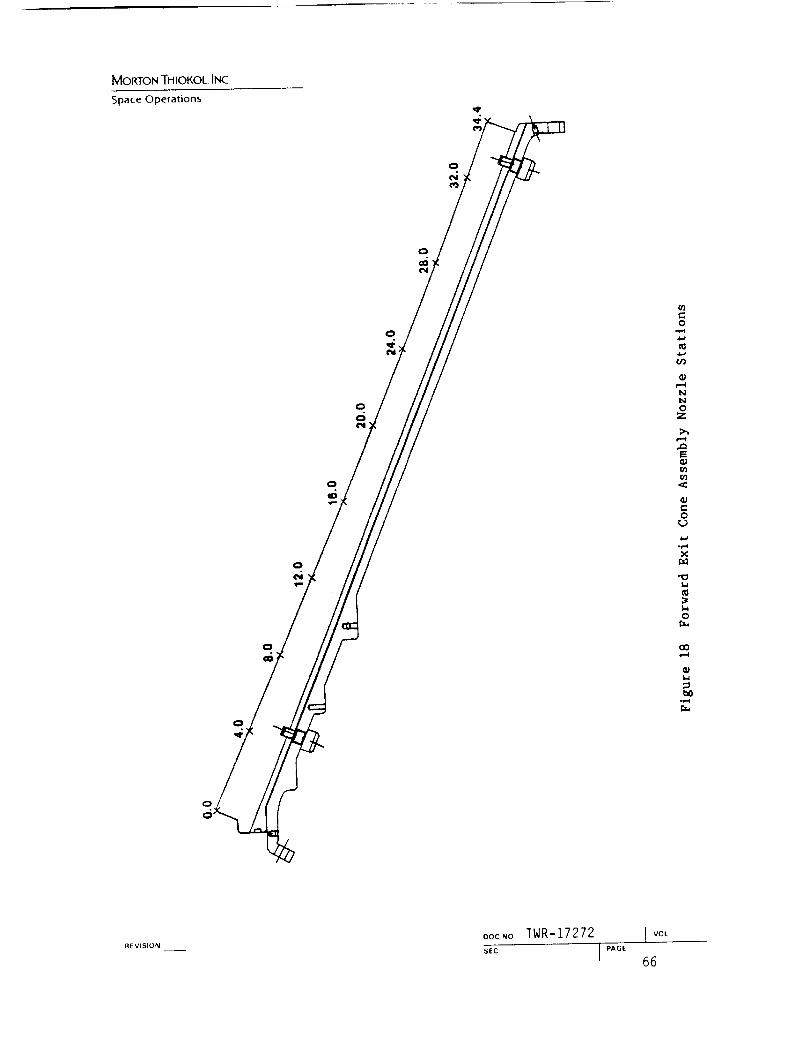
MORTON THIOKOL. INC
Space Operations
(/)
o,.e-i
4../¢/3
NN0
Z
=.-.-I
==
r_ra3
O
&.a°1-.tX
r.t.,1
KI
Or._
cot,-i
b0°_1
REVISION
oocNo TWR-17272SEC
I vot

MORTON THIOKOL INC.
Space Opefalions ORIGINAL PAGE
BLACK AND WHITE PHOTOGRAPH
0
v
m
e..or"l
e,-:
o
_D
!
REVISIONooc_o TWR-17272 l_OL
see I _GE 67

MORTON THK)KOL INC
SpaceOperations
Carbon-ClothPhenolic Carbon-Cloth
Phenolic
ThroatAft End
Throat InletForward End
EA 913NA
•Steel
Steel
/ EA 913NA
Glass-ClothPhenolic
A018692a-3 1
SeparationsBetween Adhesive
and Metal
Fwd EndBondline Separations
Location(deg)
RAdialSeparation
(in.)
Aft EndMetal-to-Adhesive
Bondline SeparationsRadial
,._=p=._inn Location SeparationType h_._..?a) (in,)
0153045607590
10511012013515016518018919521G22527028530O315330345
0,0300.0300.0300.0300.0300.0300.0300.0300.0300.0300.0300.0300.0300.0300.0300.0300.0300.0300.0300.0300.0300.0300.030O.030
Metal/Adhesive 30 0.100Metal/Adhesive 45 0,005Metal/Adhesive 60 O.100Metal/Adhesive 75 0.100Metal/Adhesive 90 0.100Metal�Adhesive 105 0.100Metal/Adhesive 120 0,100Metal/Adhesive 135 0.005GCP/Adhesive 150 0.005Metal/Adhesive 165 0,005Meta_l Adhesive 180 O.005Metal/Adhesive 195 0.003Metal/Adhesive 210 0.100Within Adhesive 225 0.100Metal�AdhesiveMetal/Adhesive 270 0.100Metal/Adhesive 285 0.100Metal/Adhesive 300 0.100Metal/Adhesive 315 0. I00Metal/Adhesive 330 O. 100Metal/Adhesive 345 O. 100Metal/AdhesiveMetal/AdhesiveMetat/Adhesive
REv($1ON
Figure 20 STS-26A Throat Assembly Bondline Separations
oocNo TWR-17272
SEC
VOL

MORTON THIOKOL INC.
Space Operations
L.
0v
o
P-I
oI-i
oI,.i
,,,D¢N
!
t--I
i.a
REVISIONoocNo TWR-17272 J vmSEC I P_GE 69
CRIGINAL PAGE
BLACK AND WHITE PHOTOGRAPN

MORON THIOKOL INC
Space Operalions
ORIGINAL PAGE
BLACK AND WHITE PHOTOGRAPH
REVISION ooc,_o TWR-17272I VOL
s_c I "_E 70

MORTON THIOKOL INC.
Space Operations
ORIGINAL PAG1Z-
BLACK AND WHITE PHOTOGRAP.H
IllI.i
I:
Ol:,-iv
o..1=1
I.-4
IiioL,
.,1:p'
a.i
iiioI-i
p,
<:
I
I'M
l,,.i
REVISION
oocNo TWR-17272S£C

MORTON THIOKOL INC.
Space OperationsORIGINAL pAGE
BLACK AND wHITE pHoTOGRAPH
R
Q;
0
O
t-o
,i.a
u
H
0
0I.i
.=
_D
I
°e-4
REVISION
OOCNO TWR-17272 I vo,
SEC I P,GE 72

MomoN THIOKOL INc
ORIGINAL PAGE IS
OF POOR QUALITY
Space Operations
..... _ 2
_ _ ......
o
I
r- r-
.... = ..... =o..... =
c)
,.a
O11• II ,11_ ,_ J:l IJ ,,-I Ul
•.I ,,,4 I.I •
REVISION
u
=;_ "l ....
G
g -
...... U
e
m
u
o
DOC NO
SEC
TWR-17272 J_o,I "_ 73
o
..I
. oe
o

Mor(roN THIOKOL INC
Space Operations
REVISIONDOC NO TWR-17272 I VOL
mt-o
Ii/
c-O
m0t_
E
fflul
0
u'3
I/
°r-I
sEc I _ 74

MORTON THIOKOL INC
Space Operations ORIGINAL PAGE
BLACK AND WHITE PHOTOGRAPH
t
Figure 26 STS-26A -503 Ring Impact Marks (3 Degrees)
REVISION
oocNo TWR-17272 I vo_sEC I P_GE75

MOIL'TON THIOKOL ]NC
Space Operations ORIGINAL PAGE
BLACK AND WHITE PHOTOGRAPH
i11
if3
v
I-I
E
i
!
RE VISIL_N
_o_o rWR-17272 I _°'
s_c I_G_ 76

MORTON THIOKOL ]NC
Space Operations ORIGINAl PAGE'
BLACK AND WHITE PHOTOGRAPH
Figure 28 STS-26A Nose Cap Wedgeout (20 Degrees)
REV_SlL)N
Doc.. TWR-17272SEC

MORTONTHIOKOL,INC
Space Operations
Nose InletAssembly
CCP
-504 Ring
GCP
P oe
A021881a
Separations atAd hes i re- t o-Hous i ng,Adhesive-to-GCP
Separations atAdhesive-to-Housing,Adhesive-to-GCP,and Within Adhesive
Location(deg)
015304575
165180195210240255270330345
Radial RadialSeparation Separation Location Separation
(in.) Type* (deg) (in.)
0.005 1 0 0.0050.005 1 0-6 0.0050.005 1 15 0.0050.005 1 24 0.0050.005 1 26-28 0.0030.005 1 28-36 0.0030.010 1 75 0.0030.010 2 114 0,0030.005 1 150 0.0030.005 1 185 0.0030.005 1 180 0.0030.005 1 228 0.0030.005 2 240 0.0030.005 2 250-256 0.005
258-267 0.003277-282 0.005282-285 0.003
300 0.003309-319 0.003
330 0.003336-342 0.003
345 0.003
SeparationType*
12213221122122212
1,22212
REVISION
Figure 29
*Type 1 = Metal/Adhesive
Type 2 = Adhesive/GCP
Type 3 = Within Adhesive
STS-26A Nose Inlet Assembly Bondline Separations
oocNo TWR-17272
$EC [ P_GE
J VOL
78

MORTON THIOI(OL INC
Space Operations
£)RIGINAE PAGI?-
BLACK AND WHITE PHOTOGRAPH
0
I
0
I
°_
°r,,4
m m
X •t_
_oo
.,_ e.
oo'3
REVISION
DOC.O TWR-17272 I,,o_
sEc IP_GE79

MORTON THIOKOL. INC.
Space Operations
ORIGINAL PAGE
BLACK AND WHITE PHOTOGRAPH
-_rO
I
t-
O_r3
Iv
b0
°_-I
I-4
(II
bO¢-
°_
oZ
)0I..i oxo
C_I -e-I
i,-I
L,
°P1
REVISION
ooc_o TWR-17272SEC
I PAGE
VOL
80

MORTON THIOKOL. INC
Space Operations ORIGINAL PAGE
BLACK AND WHITE PHOTOGRAPH
-,,I"ou_
I
.._
m
o'3
u'3I
v
bO¢-,
e.,
e.,-e,4
m
.._c_
mO
o£.T_ I
',D 0
rJ3
[--. (u
'L,
bOoi.-_
tL
_1 VI%t{INDO,:N,' TWR-17272 . .[,,:_,_ .............. lSt,: PA';' 81

MORTON THIOI(.OL INC.
Space OperationsORI_!_IAL PAGE
BLACK Ai'_D WHITE PHOTOGRAPH
I !!!i,....-__i¸
0i._
I
,,_
o
I
i-i
o lw
_r-.
o
.,_ ,.-,0
-_1I
("_
L,
REVISION
OOCNOTWR-17272 Iv°_
s_c I.A_,_82

MOI_ON THIOKOL INC
Space Operations
ORIGINAL PAGE
BLACK AND WHITE PHOTOGRAPH
4,11.4
0v
o
4.1
IJ
41
e_¢o
r.D
r_0
Z
,,.,o¢N
Ir./3E-ir.D
CU
t_o
ooc.o TWR-17272 I VOL
REVISION SEC I ':'AGE83

MORTON THIOKOL INC.
Space Opera_ions
ORIGINAL PAGE
BLACK AND WHITE F'HOTOGRAPH'
I..i
o
v
o
¢,1
,--.rLIll
r,D
l,I
oZ
,,,o
I
E_
Url
i.,a
bo
la..
REVISIONDOC NO
SEC
TWR-17272 I "°t
I PAGE84

MORTON THIOKOL. INC
Space Operations
BLACKORIGINAL PA[_E'
AND WHITE PHOTOGRAPH
_tQ,I
o
v
o
c3
0
Z
_D
I
r._
E_
bO
It| v l:_l(1 N_oc.o TWR- 17272 I_o,
- I

MORON THIOKOL INC.
Space Operations
ORIGINAL PAGE
BLACK AND WHITE PHOTOGRAPH
_J
0
G;
0Z
_D
I
E_rJ3
REVISIONooc.o TWR-17272 I _m
SEC I PAGE 86

MORTONTHIOKOLINCSpaceOpela.ons
Table 4 STS-26A Nose Inlet Rings (-503, -504) Rros_on and Char Data
Angular Location
0 degrees
Measured Erosion
Measured Char
Adjusted Char t
2E + 1.25AC
RSRM Kin Liner Thkns
Margin of Safety
Stations
28 30 32 34 36 38 39.5
1 19
0 7O
0 53
3 04
3 5O8
0 16
0.94 0.91 0.87 0.90 0.96 1.20
0.71 0.66 0.55 0.60 0.60 0.45
0.53 0.50 0.41 0.45 0.45 0.34
2.55 2.44 2.26 2.36 2.48 2.82
3.252 2.g50 3.182 3.200 3.026 2.981
0.28 0.21 0.41 0.35 0.22 0.06
90 degrees
Measured Erosion
Measured Char
Adjusted Char*
2E + 1.25AC
RSRM MAn Liser Thkns
Margin of Safety
1.09 0.83
0.70 0.70
0.53 0.53
2.84 2.32
3.508 3.252
0.24 0.40
0 86
0 64
0 48
2 32
2 950
0 27
0.83 0.85 0.94 1.15
0.63 0.61 0.62 0.44
0.47 0.46 0.47 0.33
2.25 2.27 2,46 2.71
3.182 3.200 3.026 2.981
0.41 0.41 0.23 O.10
180 degrees
Measured Erosion
Measured Char
Adjusted Char*
2E + 1.25AC
RSRM Min Liner Thkns
Margin of Safety
0.96 0.75 0.86 0.82
0.85 0,75 0.76 0.69
0.64 0.56 0.57 0.52
2.72 2.20 2.43 2.29
3.508 3.252 2.950 3.182
0.29 0.48 0.21 0.39
0 83
0 67
0 50
2 29
3 200
0 40
0.90 1.20
0.70 0.48
0.53 0.36
2.46 2.85
3.026 2.981
0.23 0.05
270 degrees
Measured Erosion
Measured Char
Adjusted Char*
2E + 1.25AC
RSRM Min Liner Thkns
Margin of Safety
1.08 0.87 0.94
0.88 0.72 0.67
0.66 0.54 0.50
2.99 2.42 2.51
3.508 3.252 2.950
0.18 0.35 0.18
0 87
0 58
0 44
2 28
3 182
0 39
0 86
0 69
0 52
2 37
3 200
0 35
0.94 NA
0.62 NA
0.47 NA
2.46 NA
3.026 2.981
0.23 NA
120 degrees
Measured Erosion 1.15 0.87 0.89 0.82 0.86 0.91 0.97
Measured Char 0.78 0.62 0.78 0.62 0.60 0.67 0.65
Adjusted Char" 0.59 0.47 0.59 0.47 0.45 0.50 0.49
2E + [.25AC 3.03 2.32 2.51 2-22 2.28 2.45 2.55
RSRM Min Liner Thkns 3.508 3.252 2.950 3.182 3.200 3.026 2.981
Margin of Safety 0.16 0.40 0.17 0.43 0.40 0.24 0.17
* Measured Char Adjusted to end of action tiae
Margin of Safety =
minimum liner thickness
2 X erosion + 1.25 X adj char*
- 1
Refer to Fiqure 38 for Station Locations
REVISION OOCNO TWR-17272 I vol
sEc IpA_E 87

r,.)
0
r_ 0
r._ ,u
tM
0
Z
I
e-t
o
IiiUo
el
C
..... . ............ Z_Z_ Z
°°°.0. .°°.0 ....... _ZZZ E
..° .... .°,. ...... ° ZZ_ Z
°°..°. . ..... . ..... ZZZZ
• .° ..... .,.. °,....
.°, .......... °°...
• °°..° °°.°° .......
0
_ZZE
_o_
...0 ..............
• ...... ,°.,. .... ..
.... _ ..... :_ _o:o.......... °. ......
.°...° ..°,., ,,.,.,
ZZZZ .Z ZZZZ .Z zZZZ .z
o
zZ_ZN
ZZZ_ Z
0 u
41
_ •0 _
..4
.,4
"r'_
0
U
0
I'¢ .I_
"_ 0
+ 0
o
o
0
O0o_
_J
_,_ e_".
m _
TWR-1727288

r..
o
o
v
r_
G
O
oO
.¢3
E
.¢
q)
01O
_D
Iu_
E'-*
u_
a)
r-q
.¢3
¢:o,,44.1
u
..... , ..0 .... _.,0, ...,,°
o**,., .,o°** ,,**.° , .....
,.,,,, .,0 ....... ,. ,.**.,
m_o_ _o_o_ m_o_ _m_o_
.,0,., ...,, ....... ,...,.
_ °°..*. °°.0.. ...... .. ....
................ .. ,o,..,
ooo_o ooo_ ooo_o ooo_o
...... ............ . .....
,.,,,. .°. .... ° .... ° .....
..... ° °°,., .......... ,.,
_._ ...... _,_
IA ul
u u u
_Z_,_
u
. ,..,q _ ®
0 _ • G m
M U U *¢ _..1
Q
.,4 m
o u
u
o
• I
0 I
-r.-_
U
e
®
U
+
0..4
0
I,¢
0
0
TWRII727289

MORTON TIdlOKOL. INC
Space Opera(ions
REVISION
DOCNO TWR-17272 J VOL
90SEC J PAGE

MoI_rON THIOKOL, INC.
Space Operations
oz
I
oocNO TWR-_
ORIGINAL PAGE
BLACK AND WH1TE PHOTOGRAPH

MORTON THIOKOL INC.
Space Operations
ORIG!NAL PAGE
BLACK AND W,_iIFE PHOTOGRAPH
REVISION Doc.o TWR-17272 I v°t
sec I_A_ 92

MORTON THIOKOL INC
Space Operations
REVISION
>
ORIGINAL PACE
BLACK AND WHITE PHOTOGRAPH
ooc.o TWR-17272 I _oL
sEc I *"G_ 93

MORTON THIOF, OL INC.
Space Operations
ORIGINAL PAGE
BLACK AND WHITE PHOTOGRAPH
£EVfS(C}N ooc_o TWR-17272I rot
s_c I ,,A_E 94

MOKTON THIOKOL, INc.
Space Operations
uJ_',t::lr,AL PAGE
BLACK AND WHITE PHOTOGRAPH
DOC NOTWR-17272
I VOL
sEc I"_E 95

MorcroN THIOKOL INC.
Space Operations
uR,,..:,INAL PAGE
BLACK AND WHITE PHOTOGRAPH
I
t..iIII
1,6.1
I,.i
1:o
mm
A
,m,ii:1
CD
OZv
t=
r_
o
e_
oz
I
m[...,
REVISIONOOCNOTWR--17272
I VOL
sEc I PA_E96

MORTON THIOKOL INC.
Space Operations
ORIGINAL _"_:'{]-
BLACK AND WHITE pHOTOGRAPH
j
_EVtSIONOOCNO TWR-17272 I VOL
97SEC I PAGE

MOf(TON THIOKOL, ]NC
Space Operations
ORIGINAL PAOIE"BLACK AND :,VHJI-C. _ ....
,, ,_;TOGRAPH
7
REVISION ooc_o TWR-17272VOL
SEC

MOlt[ON THIOKOL INC
Space Opera_ions
ORIGINAL PAGE
BLACK AND WHITE PHOTOGRAPH
Figure 47 STS-26A Cowl/OBR Closeup (0 Degrees)
Ill ',_ L',, I I I I_no_.. TWR-17272 I v,.,
99

MORTON THIOKOL INC.
Space Operations
ORIGINAL PAGE
BLACK AND WHITE PHOTOGRAPH
Figure 48 STS-26A Cowl/OBR Closeup (160 Degrees)
REVISION
OOCNOTWR-17272 I VOL
sEc 1_GE I00

MORTON THIOKOL. INC
Space Operations
,,v,,__rr,l.._.l'_i/_t-jb.r'_;'_
BLACK AIND WHtI-E PF_OTOGRAPH
Figure 49 STS-26A Cowl/OBR Closeup (180 Degrees)
REVISION
OOCNOTWR-17272 [_o,
sec I pA_e I01

Mor(ION THIOKOL INC
Space OperationsORIGINAL PAGE
BLACK AND WHITE PHOTOGRAPH
Figure 50 STS-26A CowI/OBR Closeup (320 Degrees)
REVISION OOCNO TWR-17272 I _o_
SEC I PAGE102

MORTON THIOKOL. INC
Space Operations
ORiGiNAL PAGE
BLACK AND WHITE PHOTOGRAPH
I11
0.lt",,
O
c-O
or-t
¢.1
r.4
o_,-I
i--I
0C.)
_D
!U3
bO
RE VtSPONDOC NO TWR-17272 vot
s_,: I _" 103

MoKIrON THIOKOL INC
Space Operations
ORI(:_;:':,,'\:_ r_,'_,O_
BLACK AND V,J;--;i-rE PrtOTOGRAPH
I-i
I11
0
i,-I
o
0.4I
u3E_u3
Q;
bO
r._
REVISION
ooc NO
SEC
TWR-17272 I v°L
I PAGE104

Mor_oNTHIOKOL INC
Space Operations
BLACK A/_L) _Fii_E phOTOGRApH
I,,abO
v
r"-I
0_,)
!
e"l
bO
REVISION OOCNO TWR--17272 I_O,
SEC I_GE 105

MORTON THIOKOL. INC
Space Operations
ORIg.3it'_AL PArlE
BLACK AND V_HIIIE PHOTOGRAPH
ii: ii
O
O
I
E-_
_0
REVISION
DOCNO TWR-17272t vot
106SEC J PAGE

t_
m
C.)
"0r-
e-
0
0
o1_ .,4
Q ,6
0
Im
m
_D
1IV
m
° o_
,,°oo,
oooo_o............ Z_.U ......
0000_0 OOQO_O _ 0000_0
o.,00,
,,oo.o
°°°°o,
00_0_
**,,,°
000_0
,..°..
°. ....
0000_0
..°***
ooo_o
.° ....
TWR-17272107
,-4
m "0 J
Z _ Z: Z _' ._ .,,-e0 C
® c"'-
,,-4 _ 'r'-
0
,_ _,,_ _ .,_
_d
® (2,_ t__
_, .c _J In "'

oooo_o
OOOO_O
...o,.
_ImB'B
_000_
0
Uv
m
O
D,...,
0
!
,,....
.... °°0000_0
.... ,°
OO00_O
°.°.°°
OOO0_
.... °o
ooo0_o
ZZZ_ Z
Q_
° .....
<<<<_<
.<,< <,<m < Ill •
,,,.,,4 4.1 .,xt.,
e_o 2:
,<< <_r.-,< I.,
,<,< <,<_ < • _
_.<,< <..,< e,
2_
u3
e"o
uloh_
@
®
_4
o

,.°,°.
0
,.°.,.
I
oooo_o
,,0,,.
,.°,,,
.°,..°
oooo_o
°°****
oooo_o
o
_._
_,_
• , . • . ,
°, ....
.° ....oooo_o
.***..
oooo_o
..°...
o-, r-
• . , . , ,O00Q_-eO
<<<<_<
<<<<_<ZZZZ
<<<<_<_ZZ Z
QOOO_O
,,,...
oo00_o
_Z_Z Z
• m
0 _
o
m
t.Cu
m
4.
e,o
o
dl
If
ul
o
G
m
,,'4
Ill m m 0 m m _ q
_ X:]l:,<r-*_;l:, _* l:":,<_m_l:
@G
0 _
o_ _
m
u)®G
U
r.
.,< _.l •
• i _ .l=I _r (j ...i ul
i31 • • • * -*
_n
.,4
0 _ q
• r..nu u ,_m_,.I
* .', _
TWR-17272109

• o_o_
ooo_o
°°00o°
0
U
....o.
_ q ......
0 m
0
O
0 ,,0°,,
000_0
000_0
_00_
000_0
,° ....
0_0,,,,,°
0000_
,,00,,
0000_0
_Mlm E
mmE_
EZ_Z B
_B_Z Z
_ZZ E
Z_Z_ Z
0000_
0 .....
0000_0
0_0• 0 ....
0000_
°°,o,,
ooo_o
,,,°°,
ooo_o _
o
• 0°',0 _ •000_0 _
ooo_o o
m
o
a
o,i
,-4
÷
e,o.4U'I
o
@
rq
r,
_n_u
o •
q o _J q
_ 4l @ @ ,.-4
_ .*a ,.-4 ]C I:
m t_m
U U.,14 .,14
@ (d_ o,,_ j ® t,J UU-C_
td "_'_ q2 r,t G 0 _ '_'_'_ r4 ,r' 0• @ O " "'* _ @ @ • • "_
0=,, ., _ _=_ ._w m
TWR-17272II0

MOI(ION THIOKOL. INC
Space Operations
REVISION DOCNO
SEC
TWR-17272 Jvot
I P_E 111
r,,,.je..o
4.a
N
t_
m
X
0
0t_
e.
00
°r"_
o
if3
t_

MORTON THIOKOL. INC.
Space Operations ORIGINAL PAGE
BLACK AND WHITE PHOTOGRAPH
Figure 56 STS-26A OBR Aft End Delaminations (260 Degrees)
OOCNO TWR-17272 J_o_
R_.,s.o,___ sec I ._e 112

MOr(TON THIOKOL INC
Space Operalions BLACK AND V_:I_t[E PHOTOGRAPH
REVISION
DOE NOTWR-17272
l RAGESEC
I VOL
113

MORTON THIOKOL INC
Space Opera(ionsORIGINAL PAGE
BLACK AND WHITE PHOTOGRAPH
411
Figure 58 STS-26A Outer Boot Ring Section (0 Degrees)
RE VISION OOCNOTWR-17272I VOL
s_c I _ACE 114

MORTON THIOKOL. IN(:.
Space Operations
ORIGINAL PAGE
:_._LACK AND WHITE PHOTOGRAPH
Figure 59 STS-26A Outer Boot Ring/Flex Boot (90 Degrees)
REVISIONooc.o TWR-17272
VOL
SEC I ,,_E I15

MORTON THIOKOL. INC.
Space Operations
ORIGINAL PAGE
BLACK AND WHITE PHOTOGRAPH
\
Figure 60 STS-26A Outer Boot Ring/Flex Boot (180 Degrees)
REVISION ooc.o TWR-17272 [ _o_sEc 1"_E 116

MORTON THIOKOL INC
Space Operations
ORIGt.tVAL PAGE
BLACK AND WHITE PHOTOGRAPH
Figure 61 STS-26A Outer Boot Ring/Flex Boot (280 Deg=ees)
REVISION
oocNo TWR-17272 I_o_
sEc I"_ 117

MORTON THIOKOL INC
Space Operationsu,_,,_ ! N,_,L PAGE
BLACK AND WHITE PHOTOGRAPH
1.i
o
I
>
oo
x
,=-I
!I.,o
,,,o
Rt VIF;II1N oo_No TWR-17272
I'A_ ,I

MOi'(rON THIOKOL INc_
Space OperationsORIGtNAL PAGE
BLACK AND WHFFE PF_OTOGRApH
0e_e-i
I
rj
o
N
_o
I
m
REVISION
ooc.o TWR-17272 I v°_
SEC I ._E 119

MORTON THIOKOL.INC
Space Operations
O?'IG_''I/' l PAGEE! ,_%L.
BLACK A_"ID _,_'HiTE PHOTOGRAPH
I,.i
0
I
"10
rv_
,.,,,,..ip,cO
r_v
oo
X¢1
¢",,,II
",,,1",,,0
bO
REVISIONooc_o TWR-17272SEC

MORTON THIOKOI.. INc.
Space Operations
Table 7 STS-26A Flex Boot Data Performance Margins of Safety
Max Material
Degree Remaining Affected DepthLocation Plles (in.)
0 3.6 1.20
20 3.9 1.11
40 3.9 1.11
60 3.7 1.17
90 3.5 1.24
100 3.7 1.17
120 3.9 1.11
140 3.9 1.11
160 3.9 I.Ii
180 3.8 1.14
200 4.0 1.08
220 3.9 1.11
240 3.8 1.14
270 3.8 1.14
280 3.0 1.40300 3.7 1.17
Margin
Of Safety*
0.39
0.50
0.50
0 42
0 34
0 42
0 50
0 50
0 50
0.46
0.54
0.50
0.46
0.46
0.19
0.42
* PMS -
minimum overall thickness
(1.5 x max material affected depth)-!
1.50-
1.45-
1.40
OE 1.35-
P
T 1.30H
, 1.25-
1.2G_
N 1.15-'
1.1(3
1.05
i. 00
MAX:MUM MATERIAL AFFECTE_ DEPTH
/ ,
.... _ _-- ---3-- --_ ', _..'..'3"
!
\
0 20 40 60 80 i00 120 140 160 180 200 220 240 260 280 300
CIRCUMFERENTIAL LOCATI0N (DEG.)
OOCNO TWR-17272 i v°lREVISION
SEe I ,,_E 121

MORTON THIOKOL. INC.
Space Operations
ORIGINAL PAGE
BLACK A_'D WHITE PHOTOGRAPH
Figure 65 STS-26A Fixed Housing Wedgeout (280 Degrees)
REVISION DOCNOTWR--17272 J VOt
SEC

MORTON THIOKOL. INC
Space Operations ORIGINAL PAGE
BLACK AND WHITE PHOTOGRAPN
o
o
¢:
o
"oG;x
_D
iU3E_U3
_D_D
bO°_1
I_| vl.'-,lq )N
u()! N()
SEC
IWR-LI2/2 .... L__::,....
T P"':;_ 123

MORTON THIOKOL. INC
Space Opera¢ions
i
ORIGINAL PAGE
BLACK AND WHITE PHOTOGRAPH
QJI.i
a,I
OO_
O
r.4
_0
o_,-I
o
aJX
!
E_
¢;
bO
E_
REVISION Doc.o TWR-17272SEC
I PAGE
j vot.
124

MORTON THIOKOL INC
Space Operations
ORIGINAL PAGE
BLACK AND WHITE PHOTOGRAPH
t,IL,
O
v
o
i,,i
Ill
o
a;x
r_
_D
I
E_U3
QJ
bO
REVISION --
OOCNOTWR-17272 J vo_
sEc I PA_E 125

MORTON THIOKOL. INC
Space Operations
ORIGINAL. PAGE
BLACK AND __'HIFE PHOTOGRAPH
o',,,.o
1-1
REVISION
OOCNOTWR-17272SEC
I PAGE
I VOL
126

4_
_S
f'_
..C:
e"
CU
t-O
0
r._
o
:3
bO
r_
0
"0
X-0-1
c_qI
cr_
c/3
cO
o
.Ma
qlP
G0
b.l
91
m
m
• ° ° * * °
,°,*,*
om• . . , . ,
oooo_
,,,.,,
o0oo_o
.,,.,.
oQoo_o
o..,,.
o_o_o
m
.... ,°
,,,,°,
U
0
• • q) • ..-'l
,,0,**
o_o
,,°,°,
,,,,,,
,,°,,,
,°,**°
,°,,°,
0_0_0
0_0_0
..,*°*
r_Ch cO0..... °
0 .-4 ¢:) _1 _1 *'_1
m
G
.¢
0
o m m G m_ ._ _ U ..'_ m
m _1U U ._ ,-.1
..... °
.**.**
.,,,,,
.,,°,,
oooo_o
..°,.°
..... °
o_o
u.,.te,
o _-_
@ @ @ *..-*
_._
..,,°°
°°.,,,
..... °
,,,,,,
_O_mO_
......
m
U
0 _S nS e_ _l
O_ ® @ ql -,._
ul m _ + :IE. I_
g
ann...4.,J
a:l0
u
o
"O
o4_
o
.r'._
U
e
q®
,-4
!
.=U
u.,.I M
.1=_r_r_
e.• ,.i _e
II 0
I!
r,I
II
e
c'-
0.r-
U
0.--J
0._n
¢0
r_
°r-
_D
ORIGINAL PAGE IS
OF. POOR QUALITY
TWR-17272127

MORTON THIOKOL INC.
Space Operations
o
E
i,a
e..o
(/'}
o
r_
L,
.--3
0
X
T._
0
t_°_,=Q
REVISION
0oc.o TWR-17272SEC

MORTON THIOKO/. IN(--
Space Opera[ionsORIGINAL PAGE
B,IJ_3K AND W_iTF. PHOTCK_RAPH
A
bO
r'_
v
O
U
OI-i
,,..,
l.lm
I
E-,t.y}
p...
L,
bO
REVISIONoocNo TWR-17272
VOL
s_c I ._GC 129

MORTON THIOKOL INC
Space Operalions
ORIGINAL PAGE
BLACK AND WHITE PHOTOGRAPH
t
o
v
O
o
°_=_
I
E.4
W
bO°,-.4
r._
REVLSION ooc,,o TWR-17272I VOL
sEc I p'_c 130

Mor<TON THIOKOL INC
Space Operadons
ORIGINAF PAGE'
BLACK AND _,,_'i41TE PHOTOGRAPH
it
,s
,A
!',4t_
O,,,.,,1"
I,,ao
G,I
oI,,a
¢,
',,,oe',,I
I
¢,_
l.I
°e,.I
REVISION
DOCNO
SEC
TWR-17272 I _°_
I _GE 131

MOfCFON THIOKOL. INC
Space Operations
ORIGINAL PAGE'
AND W_tlTE PHOTOGRAPH
m
i,.t
Q,I
ov
,r.,
1,-I
m
x
i
E-0
REVISION
OOC NO
SEC
TWR-17272 Ivo_
I''_ 132

MORTON THIOKOL INC.
Space Operadons ORIGINAL PAGE
BLACK AND WHITE PHOTOGRAPH
A
I-i
O
e.-i
v
bO
-1,-I
l,a
_p
x
,wD
i
(#
b0
REVISJONOOCNO TWR-17272
VOL
sEc I ._GE133

MORTONTHIOKOL INC
Space Operations
CarbonCloth
Phenolic "-7
/Fwd Exit Cone
Assembly. =/
;r---
Char/ _ _ t
_/Ra d ial _iI_:
/ ""-Axial
RTV Reached toHigh Pressure Side
of Primary O-ringFrom 38 to 185 deg;
and 314.4 to 356.2 deg Corrosionon MetalSurfaces
RTV Below Char Line
Circumferentially Exceptat 266.2 deg
Carbon (completelyCloth missing)Phenolic
PolysulfideGroove Fill
Aft Exit ConeAssembly
Figure 76 STS-26A--Forward Exit Cone-to-Aft Exit Cone Joint Interface
REVISION oocNo TWR-17272 I_'o_
sEc i _,c_ 134

Mof(roN THIOKOL. INC.
Space Operations
ORIGINAL PAGE
BLACK AND WHITE PHOTOGRAPH
0v
ra.1
¢I
O
orj
,i.,a
xr._
!r._
°e..,I
REVISION
OOCNO TWR-17272 IVOL
SEC iPAGE 135

MORTON THIOKOL. INC.
Space OperationsORIGINAL PAGE
BLACK AND "'" ";_,,--Ii, : PHOTOGRAPH
IAIil
1.1
e',,
O
.r.-I
"OL,
I,..,i
o
e.oc.J
x
I
bO
Doc.o TWR-17272 I VOL
._.s,o. sEc I "_E 136

MOffl-ON THIOKOL INC
Space Opera(ions
ORIGINAL PAGE
BLACK AND WHITE PHOTOGRAPH
!iiiii:i:,ii.....iiii
I.i
O
(,_
"o,,...
Ill
L,o
I
e,o
xf._
.<
<:
i
b0
ooc.o TWR-17272 I VOL
._v,s.o,'. s_c I P'oE 137

MORTON THIOKOL INC
Space Operadons
ORIGINAL PAGE
BLACK APeD Wi_fi-EPHOTOGRAPH
'i
I
6
l
b0(P
Ov
P_
I
o
Xr_
o
I
E_
oc_
bO°_
_t vision
_oc.o TWR-17272 _ _°_ ....
_;T_T-............. _ ';_;_ 138

MOt<TON THIOKOL INC
Space Operations
ORIG1NAL pAGE
BLACK AND 'v_',-t_TE.pHoTOGRAf_"I
I
O
r_
Iilj
o
i,o
N
o
I
e.',
oD
I....,
-,,,,I
REVISION
OOCNO TWR-17272 I vo_
sl:c 1PAGE139

MORTON THIOKOL INC.
Space Operations
'-- _, +_:7,' :'-__ L PAGE'
BLACK AND WHITE PHOTOGRARH
I
O
O
I/!¢1
I,.i
¢t
O
I
o¢._
X
o
Ird3E..-,
go
GJ
REVISION
OOC NO
SEC
TWR-17272 1,,o_
I p_E 140

MORTON THIOKOL INC
Space Operations _rdGtNAL VAGE.
aLACK AND WHITE PHOTOGRAPH
i /
/(I
/
/
i
f
REVISIONoocNo TWR-17272 I VOL
sEc ] "_'_ 141

MOIIlON THIOKOI. INC
Spa_:c Operalions
BLACK AND WHITE PHOTOGR/I_H
3/
\\
L,
,_rv
e,o
°r-I
o
o_D
oe,'l
r._
I
o
o_
x
o
c_i
[.-,
o0
REVISION
OOCNOTWR-17272 I VOL
SEC I _AGE 142

MORTON THIOKOL. ]NC
Space Operations O RI_-:t,,"4;,,L PAGE"
BLACK AND WHITE PHOTOGRAPH
O
I,.iIII
",Jr.
(,.,I41.,-'
IllL,
I"
I,I,,,I
I
I::=O
l.)
,,,e,.i
Nr,_
1,4o
I,Mi
[-i
co
lpi,..i=1
..t-I
REVISION
OOC NO
SEC
TWR-17272 I_o_
I PA_ 143

MORTONTHIOK__, INC
Space Operations
Radial ID _ //-- RTV Below Char Line
/// 360 deg Circumferentially
_ ___ _hro_t_s_e_,_ / /
Carbon Cloth Char / _"
Phenolic Line--/ _ /
Radial OD _ / Forward ExitCone
Glass-Cloth Phenolic
Steel
Corrosion on
l
I/ Carbon Cloth
Phenolic _ ,,_
I_ Char/
Glass-Cloth
_11 Phen°lic
Steel_
Metal Surfaces
m
RTV to High Pressure Side
A017705a--3
of Primary O-ring From65 to 125 deg, 195 to 210 deg,312 to 350 deg
Figxlre 86 STS-26A Throat/Forward Exit Cone Joint
REVISIONDOC NO TWR-17272 1_o_
SEC I ''GE 144

MOKTON THIOKOL INC
Space Operadons
r_
I=1bll
0v
G
I=l
m
i.do
fa_i
G)
otJ
*P4
xr._
I..I
o
It_[._f_
co
s-,
I=0°t-I
REVISION
ORIGINAL PAGE
BLACK AND WHITE PHOTOGRAPH
OOCNO TWR-17272 Lv°'
sEc ! _ 145

MORTON THIOKOL INC
Space Operations
ORIGINAL PAGE
BLACK AND WHITE PHOTOGRAPH
r/I
t,a
QI
0
"0
L,
0
I
0r_
Xt,l-1
l.a
0
I
QD
¢1L,
Ht v 1.%1_)N
DI,)C NI)
SEC
TWR- 172122_B____LZ,'_'....146

MORTON THIOKOL INC
Space Operations
ORIGINAL PAGE
BLACK AND WHITE PHOTOGRAPH
QI
O
r._
I.l
i,.iO
I8,1
O
4,.I
X
i,.i
ora.,
,,.o
I
oxco
i,-i
ooc.o TWR-17272 I VOL
.ev,_,o_ sEc I P_GE147

MomoN THIOKOL INC
Space OperationsORIGINAL PAGE
BLACK AhJD WHITE PHOTOGRAPH
G,I
beQ,I
0
r._
I,,I-I
o1,4
_D
!
[,-i
c)o',
be°f-4
r.z.,
REVISION
DOC NO
SEC
TWR-17272 l_ot
I "GE 148

MORTON THIOIZOL. INC
Space Operations
ORIGIN/_L PAGE
BLACK AND WHITE PHOTOGRAPH
0
v
r"
0
I
[-4
L,
REV(SION
TWR-17272OOC NO
SEC J PAGE
J VOL
149

MORTON THIOKOL INC.
Space Operaoons
ORIGINAL PAGE
BLACK AND WHITE PHOTOGRAPH
°
G,I
1,,,i
O
v
I=
I
o
[._
_D
I
r._
REVISION
ooc.o TWR-17272 i v°_
s_c I "A_ 150

MORTONTHIOKOLI_C
Space OperationsORIGINAL PAGE'
BLACK AND WHITE PHOTOGRAPH
W
v
el
0
I
el01..i
,.c:E_
_0
I
O_
REVISION
OOCNOTWR-17272 I V°L
sic I _GE 151

MORTON THIOKOL IN(:.
Space Operations
RTV Below Char
Line 360 deg
Line
JJ Radial
7Axial
Nose Inlet Assembly
J Radial
Carbon Cloth OD
Phenolic\
Carben ClethPhenelic
Steel
II
Aluminum
GCP
Phenolic
Cerrosien
"RTV filled radial ID circumferentially ewcept frem 309 dell te 313 dell*'RTV extended onto radial OD intermittently areund circumference
Figure 94 STS-2§A--Nese Inlet/Throat Heusinll Jeint
REVISIONDOCN,TWR-17272
SEC I P&OE

Mor([ON THIOKOL INc...
Space Operations
ORIGINAL PAGE
BLACK AND WHITE PHOTOGRAPH
i,ab0G;
O
,,_
"OI,.a
i,,a
o
I
o
[=,
Ir,,,3E--,
o_
a;I,.a
oocNo TWR-17272 I VOL

Morn-oN THIOKOL. INC
Space Operations
BLACK
PAGE"
PHOTOGRAPH
¢1I,,,,i
¢1
0
,,-Iv
,._
r.t.1
0
I
0
I
t_
-,r,.l
REVISI(1N
,_o,-,_,, TWR-17272 [ v'L' ................. 7 ;.,;r -
I 154

MORTON THIOKOL INC.
Space Operations
_1_ VISION
ORIGINAL PAGE
BLACK AND WHITE PHOTOGRAPH
ILl
O
v
!,-,
1-1
o
t
o
Lell
t.
ooc.o TWR-17272 .... _ _o__t_: l-T'_;'t ] 55

MORTON THIOKOL INC.
Space OperalionsORIG!_I,_[. PAGE
BLACK Ah;O '_-,:-:_;E P_OTOGRAPH
i!
1,.i
o
"oc
r,..,a
It_e"
Oif3
I
_D
Im
Illt_
ooc.o TWR-17272 J VOL
REVISION SEC J PAGE
-- _ 156

MOI_ON THIOKOL. INC
Space Operations
ORIGINAL PA-G'_
BLACK AND WHITE PHOTOGRAPH
• !
REVISION
OOCNO TWR-17272 1_ot
sEc I ''cE 157

NIOmONTHIOKOL,INC..
Space OperationsORIGINAL PAGE
BLACK AND WHITE PHOTOGRAPH
m@@
gO
,i,,a
I
O
Iv
i-I
,,D
It_
oO
REVISION --
OOCNOTWR-17272 I_0_sEc IPA_E 158

MORTON THIOKOL INC
Space Operations
b0
v
o,
o
:)
o
I
(uo
._=
,,o
ir._
{Jl
r-i
o
oJ
HEVISION
.j_IGINAL i_AG E
_LACK AND WHITE PHOTOGRAPHooc.o TWR-17272 Iv,,,
sEc _+A_- 159

MORTON THIOI(,OL INC
Space OperationsOR!G_' '
]BUNF..K /ktq.O ,_,/t-_ll.E pHOTOGRAPH
I
81811.1
81
,m,h
v
_L
0
r-r._
I
0if3
!
81e-te-
<
_D
I
0
81
REVISION
oocNo TWR=17272I VOL
s_c I PAGE 160

MORTON THIOKOL INC
Space Operations
Forward
End Ring
Soot --_
Nose Housing(aluminum)
U
Steel
Carbon Cloth 'henolic- Phenolic
._. Housing_- ....Radial ID
Cha= 7" "_ RTV
Line _/ Carbon-Cloth
Radial OD _. Phenolic
R'IV BelowChar Line
360 deg
/'-"- BearingProtectorOuter Ring
PrecastCowl
Segment
"Blowpath at 216 deg Erodedthe Adhesive and Charredthe SCP
Line
Adhesive
I
Silica-ClothPhenolic
Cowl
AO 17703a-2
FiEure 103 STS-26A Nose Inlet HousinE/Flex Bearin8 Joint
REVISION ooc.o TWR-17272 I voLsEc I P'GE161

MorcroN THIOKOL INc
Space Operations BLACK AND "vJiiit-E PHOTOGRAPH
I-i
Ov
I=
I-iIIS
L,O
tI"'1
Or_
,,D
I
[-i
-,1"O!-i
I-i
.p.i[a.,
_{:VISION
DOCNO TWR-17272 I _°_
s_c I "_E 162

MORTON THIOKOL. INC
Space Operalions
ORIGINAL PAGE
BLACK A;";D WHITE PHOTOGRAPH
8,1i-i
O
!,-,-I
"o,,,-,
iii
$,,iol,lr.i
I
Or.D
I
e.l
O1,,-I
I,.4
bO°l,-I
ooc.o TWR-17272 I VOL
.E..,S,ON SEC I pA=E 163

MORTON TIqlOKOL INc
Space Operations
ORIGINAL" PAGE"
BLACK AND WHITE PHOTOGRAPH
¢1
I.,,i
Q,I
O
,,,..Ii..1
I,..iIII
OI,I,.i
Ir-,I
Ot,.,,)
c",,II
O
I,.i
REVISION
ooc.o TWR-17272 I v°_
sEc I_AOE 164

MORTON THIOKOL INC.
Space Operations
1
ORIGINAL PAGE
BLACK AND WHITE PHOTOGRAPH
I,a
o
I=r.t.]
i
ID
oz
i
[.-i
c)
HE VI:_ IOl'_
OOC N(3
SEC
TWR- 17272 Ivo_
F"_ 165

MORTONTHIOKOL INC..
Space Operations
ORIGINAL PA(_E"
BLACK AND WHITE PHOTOGRAPH
I,.ibea,I
O
,,,.,
i_u
mo
Z
Im
O
REVISION
ooc.o TWR-17272 I VOL
s_c I "_E 166

MORTON THIOKOL. INC
Space OperationsBLACK AND WHITE PHOTOGRAPH
/
I.i
o
I
r_
oZ
¢',,,lI
0
REVISION
OOCNOTWR-17272SEC
I PAGE
I vot
167

MORTON THIOKOL. INC
Space Operations
_: ;_CK AND WHITE PHOTOGRAPH
A
D1I,IIUI-i
v
o
t_
_oc_
!_o
o
Q)
°_
DOCNOTWR-17272
I VOL
._v,s,o. s_c I P_G_ 168

MORrObl THIOff.OL INC.
Space Operations ORIGINAL PAGEBLACK Af..iD w.'_-_,TEF:4OTOGRAPH
L,
0
v
1=
Itl
I,,4o
I
REVISION
DOC NO
SEC
TWR-17272 Ivo_
I p,_e 169

MORTON THIOKOL INC
Space OperationsBLACK
ORJu_I.AL
AND WHITEPt, GE
PHOTOGRAPH
@@
I,I
0
I:.e..i
I:
l..l!II>I..I
o
I=
III
I
L,
°_,-I
REVISION
DOCNO
SEC
TWR-17272 Jvo_
I ,'_E 170

MORTON THIOKOL. IhlC
Space Operations oRiGiNAL PAGE
BLACK AND WHITE pHOTOGRAP_
o
b_@
(:
e=l
o
uo
,..3
,_
o
I
r-
"o
o
eM
o
_D
I_J3
u'3
QJ
REVISION
OOCNO TWR-17272 I _o_
sEc I'_E 171

MORTON THIOle,OL.INC.
Space Operations
RTV Reached to Primary O-ring at25 to 30, 35 to 43, 55, 65 to 78,240, and 308 to 313 deg
Aft End Ring (steel)
Voids Isolatedwithin RTV DidNot Extend to
Flex Boot Cavity
BearingProtector
Inner Boot Ring(Glass Cloth Phenolic)
A01927?a-3
REVISION
Figuce 114 STS-26A--Flex Bearing/Fixed Housing Joint
ooc_o TWR-17272 vOt
I ,,c,E 172

MORTON THIOKOL. INC.
Space OperationsORIGINAL PAGE
BLACK AND WHITE PHOTOGRAPH
°,*
,t.,
++
__..'_
.:_DI
0v
I-i
o
G
0U:
>¢
c_!
c_
u_
bO
fT.,
REVISION
OOC NO
SEC
TWR-17272 ivo_
I P'GE 173

MORTON THIOKOI-, I1_
Space OperationsORIGINAL PAGE
BLACK AND WHITE pHOTOGRAPM
o
I
,#
Q,I
0
L,
I,,I0
0
r,Z,,,
¢"4I
beo_1
REVISION
DOCNOTWR--17272SEC

Mor<TONTHIOKOLINC_
Space Operations OP,tGI h:AL. PAGE
liLA(_ _ _:_-_TE PHOTOGRAPH
Q_
I.i
Q;
O
v
e,.,
i.a
i.io
-r,-I
o
x
c_I
c/3
f_
REVISION
OOCNO TWR-17272I vOk
SEC I P,GE 175

MORTONTHIOKOL.INC..
Space Operations
ORIGINAL PAGE
:._._-_K AND WHITE PHOTOGRAPH
IP11I,a
IP
Ov
I:I
e.,
I:0
.e,,i
I..i
tllI11m
I
F-I
ooe-i
I-i
I:10
I:l.i
REVISION DOC NO TWR-17272 lvo[sEc I,,_GE176

MOr(TON THIOKOL INC.
Space Operations
ORIGINAL PAGE
BLACK AND WHITE PHOTOGRAPH
l,a
0¢',,,I
°r'4
t_
I1/
_ocM
I
[-i
°p-I
fa_
_EVISION
OOC NO
SEC
TWR-17272 Ivo_
I.,_.E177

MORTON THIOF, OL INC
Space Operations
ORIGINAL PAGE'
BLACK AND W?iliE PHOTOGRAPH
REVISION
DOC NO
SEC
TWR-17272 I,,o_
I pA_E 178

MORION THIC)K()I [NC
Siva( e Opera(ion_ ORIGINAL PAGE
BLAC_ AND WHITE PHOTOGRAPH
Oc)
e,.
IwIII
Ir_
i--I
R_VISIONDoc,,oTWR-17272
SEe

MORTON THIOKOL INC.
Space Operations
BLACK AND WHIT_ F'HOTOGRAPH
!
IIJu
o_3=
o
m
r,_
o
bOr=
m
o
x-r=i
r._
iu_
r._
REVISION
OOC NO
SEC
TWR-17272 I_o[
I _'G_ 180

MORTON THIOKOL. INC.
Space OperationsBLACK AND WHITE I-'HOTOGRAPH
i
OOCNOTWR--17272 I VOL
REVISION SEC I PAGE 181

MORTON THIOKOL liE-
Space Operations
0.20 in. f 0.22 in.
\
0.,_,no--/-_--_ _ -_A0176f_,a
REVISION
Figure 124 STS-26B Joint Flow Surface Gap Openings
OOCNO TWR-17272
$EC I PAGE
I VOL
182

MORTON TH IOKOL INC
Aerospace Group
SpaceOperations
BLACKPAGE'
PHOTOGRAPH
REVISI(}N
FORM TC 7994-310 (REV 2-88)
OOC
NO
SEC
TWR-17272

MOKqON THIOI<OL IIN!C
Space Operations
BLACK A;'iD W ....rt, i r_ P,"-IOTOGRAPH
/
REVISION
OOCNOTWR--17272 I VOL
SEC J PAGE184

MORTON THIOKOL INC_
Aerospace Group
Space Operations
BLACK
..,,:,,.J!, _AL
AND WHITE PHOTOGRAPH
REVISION
FORM TC 7994-310 (REV 288)
DOC
.o TWR-17272SEC
I PAGE
J VOL
185

MORON THIOKOL INC
Aerospace Group
Space Operations
ORIGINAL PAGE
BLACK AND WHITE PHOTOGRAPH
O
O
REVISION
FORM TC 7994-310 (REV 2 88|
OOCNO
SEC
TWR-17272 VOL

MOIGON THIOKOL. INc..
Aerospace Group
Space Operations BLACK
OR1GINAL PAGEAND WHITE PHOTOGRAPH
o
REVISION
FORM TC 7994-310 (REV 2 88)
OOC
NO,
SEC
TWR-17272
I F_,GE
I VOL
187

MORION THIOffOL INC
Aerospace Group
Space OperationsBLACK
ORIGINAL PAGE
AND WHITE PHOTOGRAPH
REVISION __
FORM TC 7994-310 (REV 2 88)
DOC
NO
SEC
TWR-17272 IvoL
_GE 188

MOI_ION THIOKOL INC_
Aerospace Group
Space Opera_ions8LACK
ORIGINAL
AND WHITEPAGE
PHOTOGRAPH
II
L
REVISION
FORM fC ;'994 310 IREV 2881
OOC
NO,
51EC
TIVR-17272

MORTON THIOKOL INC
Aerospace Group
Space Operations
Carbon-ClothPhenollc(completely missing)
AngularLocation
(deg)
NominalPreflight-_ __Radial Groove
Width 0.20 in.
--V
0 0.18
15 0.1830 0.1845 0.1860 0.1875 0.1890 0.18
ln5 0.17
120 0.17135 0.17150 0.18165 0.18180 0.17195 0.17210 0.18225 0.17
240 0.18255 0.18270 0.18285 0.173O0 0.18315 0.19330 0.19345 0.10
Polylulfide Groove Fill
Glass-ClothPhenolic
Aluminum
A017588,,
Table 9 STS-26B Aft Exit Cone Post-Flight Polysulfide Groove Radial Vldths
ooc TWR-17272 INO VOL
REVISION
SEC I ,,AGE 190
FORM TC 7994"310 (REV 2"88|

MORTON THIOKOL. INC__
Aerospace Group
Space OperaUons BLACK AP,_b ',-t !i ;_i Pt_OTOGRAPH
REVISION --
FORM TC 7994-310 (RIEV 2-881
_C
_o. TWR-17272SEC
I rot.

MORTON TfflOKOL INC
Space Operations
Carbon-ClothPhenolic
Forward ExitCone
Carbon-ClothPhenolic
Glass-ClothPhenolic
EA 946Adhesive
Steel
Forward Exit ConeAssembly
EA 946Adhesive
Glass-ClothPhenolic
Steel
Forward End
RadialLocation Separation Separation
(deg) (in.) Type
0 0.0515 0.0330 0.00545 0.00560 0.00560 0.0375 0.0275 0.0390 0.00590 0.04105 0.01105 0.02120 0.005135 0.005150 0.03165 0.005180 0.005195 0.005210 0.005225 0.005240 0.005255 0.005270 0.01285 0.005300 0.005315 0.005330 0.01345 0.02
Metal/AdhesiveMetal/AdhesiveMetallAdhesi,eMetal/AdhesiveMetal/Adhesive
GCPMetal/Adhesive
GCPMetal/Adhesive
CohesiveMetal/Adhesive
GCP/CCPGCP
Metal/AdhesiveMetal/AdhesiveMetal/AdhesiveMetal/AdhesiveMetal/AdhesiveMetal/AdhesiveMetal/AdhesiveMetal/AdhesiveMetal/AdhesiveMetal/AdhesiveMetal/AdhesiveMetal/AdhesiveMetal/AdhesiveMetal/AdhesiveMetal/Adhesive
Figure
REVISION
133 STS-26B ForvaJ_d Exit Cone Bondllne Sepacations
oocNo TWR-17272 I voL
sEc I PAGE 192
A018663a.-3

MORTON THIOKOL INC.
Aerospace Group
Space Opera_ons
,j,dGit"U\L PAGE
BLACK AND WHtTE PHOTOGRAPH
REVISION
FORM TC 7994. 310 (REV 2-881
OOC
NO.
SEC
TWR-17272 I VOL
_Ge 193

MORTONTHIOKOL INC
Aerospace Group
Space Operations
ORIGINAL PAGE
BLACK AND WHITE PHOTOGRAPH
REV1SION
FORM TC 7994-310 (REV 2-881
DOC
SEC
TWR-17272
I PAGE
I VOL
194

MORTONTHIOKOL INC_
Aerospace Group
Space Operations
REVISION
FORM TC 7994-310 (REV 288)
ORIGINAL PAGE
BLACK AND WHITE PHOTOGRAPH
:)
o
_ol'9
Iu_E_
_O
f_
.oc TWR-17272NO
$EC
I PAGE
I VOL
195

MorCrON TMIOKOL. INC_
Aerospace Group
Space Operations
BLACK
ORIGINAL
AND WHITE
PAGE
PHOTOGRAPH
REVISION
FORM TC 7994 310 IREV 2 88|
DO(:
NO.
SEC

MOIUON THIOKOI.. INC
Space Operations
a.i
c.)
= or- o
0
r.,o
t.._
x
I,-*
0F.L,
',0
04 _"
I
r_
,.1=
[-,
o,.4
4J
Uo
.,o,oo ,oo.,, .... , .... ,,,
**,,** .°,*** °**,.. .**.,.
_*_ _._
_'_ _Z_'_
.... °. °°°...
,°°.°. °°°.°.
_ m91• @
u O,,4 _
o ._ o t.J
" t "_" .... "
,.( ,.( ,,_ ,,(_ .,¢
,'4
• 0 , ° , °
• . . ° . .
m
u
.G
.,4 • _ (I'
ID_ Q • @ , ,-i
@ 0 "_I [,J Ul 9
,..#
u'1
•-_ 0 •
_ °
,-_ 0 fl
r,
B
...... •
m
U
U
4-
0
mos.,
v1
0
*r--
• ('J,. 0
c-
o .r-
,r"-
REVISIONOOCNOTWR-17272$EC

Morn-oN THIOKOI_. I!__.
Aerospace Group
Space Operations
ORIGINAL pAG::-
BLACK AND wHiTE pHOTOGRAPH
1
REVISION
FORM TC 7994-310 IREV 2 881
DOC
NO.
SEC
TWR-17272

MOI_ON THIOKOL INC
Aerospace Group
Space Operations
:!
REVISION
fORM TC 79'94310 (REV 2 88)
C'_'_P"_'^"PAGEvd', J ,_1t i_ t'_h
BLACK AI,,'D WH', FE PHOTOGRAPH
DOC
NO.
Sm=C
TWR-17272
I _GE
I VOL
199

MORTON THIOKOL. INC.
Aerospace Group
Space Operations
t
REVISION
FORMTC 7994-310 IREV288I
BLACK
ORIGINAL PAGE
AND WHITE PHOTOGRAPH
OOCNo.TWR-17272 ] vo,SEC

MORTON THIOKOL INC.
Aerospace Group
Space Operations
ORIGINAL PAGE
BLACK AND WHITE PHOTOGRAPH
(Mt'-,,
O,,,O
O
m0
0
0
I,¢ra.1
m
L,0
I
6'3
e-i
ra_
lit VISI(}N
FORM TC 7994-310 4REV 2-88)
ooc TWR-17272NO
SEC
VOL

MORTON THIOKOL. INC
Aerospace Group
Space OperaUons
REVISION
FORM TC 7994-310 (REV 2-881
ORIGINAL PAGE
BI.ACK AND wHiTE pHOTOGRAPH
I
_c lNO TWR-17272 vo,
sEc I_a_ 202

MORTONTHIOKOL. INC.
Aerospace Group
%lJa< e Operallons
ORIGINAL PAGE
BLACK AND WHITE PHOTOGRAPH
G,I
1-i
r_
v
r,0
0I,.i
00
r,D
X
,1o1,-i
Ill0
I
I'--I
1-1
°1--1
REVISION
FORM TC 7994-310 IREV 2 88)
ooc TWR-17272NO.
SEC
I VOL

MORTON THIOKOL INC_
AerosFace Group
Space Operations
ORIGINAL PAGE
BLACK AND WHITE PHOTOGRAPH
®
i +¸ + _
I-i
Ht VISION __
FO_M TC 7+94-310 IREV 28B)
[)OC
NOTWR-I/2/2
see I _o+ 204

MORTON THIOKOL INC
Aerospace Group
Space Or_erallons
ORIGINAL PAGE
BLACK AND WHII'E PHOTOGRAPH
Figure 145 STS-26B Throat Inlet Ring Wedgeout (28 - 40 Degrees)
REVISION __
FORM rc 7994 370 (REV 2 88_
ooc jNO TWR-17272 rotSEC

MORTON THIOKOL INC.
Space Operations
Carbon-ClothPhenolic Carbon-Cloth
Phenolic
Throat InletForward End
Steel
913NA
ThroatAft End
Glass-ClothPhenolic
Steel
EA 913NA
7::;:,,o°.1Between Adhesive
and MetalWithin GCP andWithin Adhesive
Fwd EndBondline Separations
LocationRadial
Separation(in.)
Aft EndBondline Separations
RadialSeparation Location Separation Separation
".'vPe (deg) (in.) Type
0!5_0_'5(_0"5.t0
lr_51.'01,:51:;01,;51,101t52_02_5240240255250
0.0300.0300.0300,0300.0300.0200.0300.0300.0300.0200.0300.0300.0200.0200.0200.030O.O200.0200.0200.020
Figure 146
Metal/Adhesive 0 0.030 Metal/AdhesiveMetal/Adhesive 15 0.030 GCPMetal/Adhesive 30 0.020 Metal/AdhesiveMetal/Adhesive 45 0,040 Within AdhesiveMetal/Adhesive 60 0,040 Metal/AdhesiveMetal/Adhesive 75 0,040 Metal/AdhesiveMetal/Adhesive 90 0.030 Metal/AdhesiveMetal/Adhesive 105 0,040 Within AdhesiveMetal/Adhesive 120 0.040 Metal/AdhesiveMetal/Adhesive 135 0.050 Metal/AdhesiveMetal/Adhesive 150 O.050 Metal/ADhesiveMetal/Adhesive 155 0.050 Metal/AdhesiveMetal/Adhesive 180 0.040 Metal/AdhesiveMetal/Adhesive 195 0,020 Metal/AdhesiveMetal/Adhesive 210 0.020 Metal/AdhesiveMetal/Adhesive 225 0.010 Metal/Adhesive
GCPICCP 240 0.030 Metal/AdhesiveMetal/Adhesive 255 0.010 Metal/Adhesive
GCP/CCP 270 0.020 Metal/AdhesiveGCP/CCP 285 0.010 Metal/Adhesive
300 0.030 Metal/Adhesive315 0.030 Metal/Adhesive330 0.030 Metal/Adhesive345 0.010 Metal/Adhesive345 0.010 Adhesive/GCP
STS-26B Throat Assembly Bondline Separations
REVISION DOCNO TWR-17272 }vo_
SEC I "_E 206

MORTON THIOKOL INC_
Aerosp.,ce Group
Space O_erations
BLACKORIQINAL
AND WHITE
ii: !_ :i: ¸ •
i::ii!i_I_il/ iill i
/-i_:iiii_i_i_i_i_ i __ :_!i!ii_
I,d
O
e,O
{UO1.4
.=
-%a.a
0
_D
I_0
FORM TC 7994-310 LREV 2-88)
DOC
NO
$EC
TWR-17272 I voL
I PAOE207

MORTON THIOKOL INC.
Space O_)eradonsORIGINAL PAGE
Ri. ACK AND WHITE PHOTOGRAR.H
l#1
GII-i
i.m
OCOt,-I
v
o
tj
r_
pl
I-4
.i..i
o
a.a
¢uola
!
oo..,,1"
_a
REVISION --
ooc,,o TWR-17272 I_o_
sEc I _'GE208

MORTON THIOKOL, INC
Space C)peralions
,-']4 ", JI_I /_. IOr,,C _,-'_ PAGE
BLACK AND WHITE PHOTOGRAPH
m
L,
O
V
r"O
UG,t
1'-4
a.a
O
[._
mOI-,I
E_
a__Dc'dI
E_
bO
r_
REVISION
TWR-17272DOC NO
SECJ PAGE
J VOL
209

.°.,,. °,,°°° °°,°., ,°°°,.
, , , . , • , ° • ° , , . ° , • , °o o o _¢ *'_l o o o o _.¢ r¢ o 0 0 0_'1._¢ 0
IN ° • • ° • * • * , • ° • • * ' * ° ° ,***o,
000_0
m
_¢
C_
r.o
e _
• =
U'I
n_
e-4
0
i0q
o
q
a=
°,,°,, ,°,,°° ,, ....
.°°°°, ,°,o.. ,**o.°
,°°,,, ,,°,,, ,,,,.,
°°.°°, ,.+,.° ., ....
°,.0,, ,°,,,. ,,°°°.
_,°°0,
o
,, ....
,**o**
_oo_o
,.,,o.
o o o
.... ,. .°.** .......
......... °** ,+,.,,
210

MORTON THIOKOL INC.
Space O_eralions
ORIGINAL PAGE
BLACK AND _,;;--;iFE P_--IOTOGRAPH
REVISI()N
ooc.o TWR- 17272 Ivo=
s_c I,,A_ 211

MOE"FONTHIOKOL INC
Space Operations
ORtC tr',!,._L PAGE
BLACK AND WHilE PHOTOGRAPH
Figure 151
REVISION
STS-26B (-503) Ring Impact Marks (185 Degrees)
DOC NO
SEC
TWR-17272 I_o_
I pACE2 12

MORTON THIOKOL INC
Space Operations BLACK AE'4D V,,'t-ii-iE r r_,OTuu RAPH
|
REVISIONOOC NO
SEC
TWR-17272 i vo_
I "GE 213

MORTON THIOKOL INc
Space Operations
Nose InletAssembly
CCP
-504 Ring
Separations atAdhesive-to-Housing,
Separations atAdhesive'--to-Housing
Nose Cap
A021881a
GCP
Location(deg)
238-245250
RadialSeparation Separation
(in.) Type"
0.020 MetallAdhesive0.020 Metal/Adhesive
RadialLocation Separation Separation
(deg) (in.) Type"
105 0,005 Metal/Adhesive135 0,005 Metal/Adhesive150 a. 005 Metal/Adhesive165 0.005 Metal/Adhesive180 0.005 Metal/Adhesive195 0.005 Metal/Adhesive210 0.005 Metal/Adhesive225 0.005 Metal/Adhesive240 0.005 Metal/Adhesive255 0.005 Metal/Adhesive285 0.005 Metal/Adhesive300 0.005 Metal/Adhesive315 0.005 Metal/Adhesive345 0.005 Metal/Adhesive
Fibre 153 STS-26B Nose Inlet Assembly Bondline Separations
REVISIONooc_o TWR-17272
J VOL
SEC IP'6E 214

MORTON THIOKOL INC
Space Operations ORIGINAL PAGE
BLACK AND WHITE PHOTOGRAPH
0ur_
I
,,_
Iv
bOe...
°_'1
r--I
I,-i
,,¢
bo=
I..i
D_
8
C/3 _
.4"
,r-I
bO
REVISIONOOCNO TWR-17272
I VOL
sEc J .,_GE215

MORTON THIOKOL INC
Space Operations
ORIGINAL PAGE
BLACK AND WHITE PHOTOGRAPH
o
Oi._
I
,._
I1:
Ou'3
I
l$1
i-.I
e"
Z _
u_u_
REVISION
OOCNOTWR-17272I VOL
SEC IPACE 216

MORTON THIOKOL INC_
Space Operations ORIGINAL PAGE
BLACK AND wHITE PHOTOGRAPH
oocNO. TWR-17272 Iv°LREVISION
SEC I'AGE 217

MornoNTHIOKOL. Ir,_._
Space Operations
ORIGIN/_L PAGE
BLACK AND WHITE PHOTOGRAPH
REVISION
OOCNO TWR-17272 I V°L
s,=c I _'AGE218

MoKroN THIOKOL INC
Space Operations
ORIGtNAL PAGE
BLACK A_',_D _.",'i_, r1 PHOTOGRAPH
\
I¢1
0v
¢.,o
llJ
m0
Z
Iu2
cOu_
1,4
bO
REVISIONOOCNO TWR-17272 Ivo_
sEc IPA_E 219

MOKTON TI-IIOKOL. INc
Space OperationsBLACK AND ,_,_!H;TE:PH_TCGRAPH
m
¢11-1
¢1I=1
O
v
t-O
-,i-I
rJ2
m0
Z
_D
I
u_
bO
REVISIONDOCNO
TWR-17272I VOL
sic J_cE 220

MORTON THIOKOL. INC
Space Operations
ORIGINAL PAGE
BLACK AND WHITE PHOTOGRAPH
(U
I,ab0_J
Q
v
eo
w,d4_
¢J0,1
r.)
_JO
Z
I
O,,D
i,a
l=o
REVISIONOOCNOTWR-17272 I VOL
sEc I P,_E221

Mor(ION THIOKOL. INC.
Space Operations
ORIGINAL PAGE
BLACK AND WHITE PHOTOGRAPH
IX)
O
v
e.o
4,,a
cJ
el
0
I
4;
ra.
REVISIONOOCNO TWR-17272 IvoL
SEC IPArE222

MomoN THIOKOL. INC
Space Operations
Table 12 STS-26B Nose Inlet Rings (-503,-504) Erosion and Char Data
Angular Location
0 degrees
Stations
28 30 32 34 36 38 39.5
Measured Erosion 0.97 0.81 0.88 0.80 0.88 0.92 0.95
Measured Char 0.95 0.77 0.73 0.64 0.62 0.72 0.68
Adjusted Char* 0.71 0.58 0.55 0.48 0.47 0.54 0.51
2E + 1.25AC 2.83 2.34 2.44 2.20 2.34 2.52 2.54
RSRM Min Liner Thickness 3.508 3.252 2.950 3.182 3.200 3.026 2.981
Mscgin of Safety 0.24 0.39 0.21 0.45 0.37 0.20 0.17
90 degrees
Measured Erosion
Measured Char
Adjusted Char*2E + 1.25AC
RSRM Min Liner Thickness
Margin of Safety
i 12
0 72
0 54
2 923 508
0 20
0.84 0.87 0.86 0.90 0.97 NA
0.76 0.76 0.68 0.70 0.65 NA
0.57 0.57 0.51 0.53 0.49 NA
2.39 2.45 2.36 2.46 2.55 NA
3.252 2.950 3.182 3.200 3.026 2.981
0.36 0.20 0.35 0.30 0.19 NA
180 degrees
Measured Erosion 1.38Measured Char 0.53
Adjusted Char* 0.402E + 1.25AC 3.26
RSRM Min Liner Thickness 3.508
Margin of Safety 0.08
0 850 76
0 57
2 41
3 252
0 35
1 28
0 37
0 282 91
2 950
0 01
0.86 0.87
0.66 0.58
0.50 0.44
2.34 2.28
3.182 3.200
0.36 0.40
0 92
0 63
0 47
2 43
3 0260 24
1.02
0 .49
0.37
2.50
2.981
0 .19
270 degrees
Measured Erosion 1.07
Measured Char 0.77
Adjusted Char* 0.58
2E ÷ 1.25AC 2.86
RSRM Min Liner Thickness 3.508
Margin of Safety 0.23
0.83 0.95 0.82 0.84 0.95 1.19
0.78 0.67 0.60 0.63 0.60 0.54
0.59 0.50 0.45 0.47 0.45 0.41
2.39 2.53 2.20 2.27 2.46 2.89
3.252 2.950 3.182 3.200 3.026 2.981
0.36 0.17 0.44 0.41 0.23 0.03
* Measured Char Adjusted to end of action time
Margin of Safety =
minimum liner thickness
2 X erosion + 1.25 X Adj char*
Refer to Figure 38 for Station Locations
- i
REVISIONDOC NO.
SEC
TWR-17272 I vo_
I'AGE-2_H 2-'_

4_
r_
c:
c:o
0
r_
e_I=
m
e_
m0
Z
c_I
E-
eel
e-4
Jr_
o
_4
0
4_4
r_
i-4
0
_a
U
0
I
e.*c
u'_0
,0,,0,
o_o_
,°,,0,
°,,,o0
0,.°0o
,°,°,°
oo0_o
,,°,,,
,,,,0,
ooo_o
,0°.,,
.,0o°0
,o,0°0
w
,,,,00
0o0_o
0°.,°°
t_
0 _ a,,a
019 I_ _1_ ,,_ .1:I U ._ m
• 0o0 ..,,_
"_ t ,11 "r"_ "_ _
_00o,.
,0o_°,
_oo_o
,°,,0,
,,,,r,
ooo_o
oo0_o
0,,°0,
°°,,0,
..,00.
0o,,0,
0o,0,0
,0o°,0
oo0_
0
0 • 4a
0 • _ e_ _I._ .,_ .,_ _.; .,,-,I _
• "_ "_ "_ r_ ," 0_ _ _ ._._
u'_ Eli • "_ ill gl
_oo_o
,,,,,0
_oo_o
,,,°,,
• o . • , 0
,°°Q00
°°°.o°
,.o,..
,,.,°,
000_0
.,,°.o
,.,.0°
,,o_oo
gl
®
.,,-I
e_
0 _ 4.a
"_ "_'_1 _ e_ 0
_ _ .r-,, _ I,,_
0_0_
0,,,°,
°,°,,.
0°o,,_
ooo_o
.,0000
0..,0,
°oo,,,
ooo_o
_._
m
m@
e- E'*
o _ _
_ _' ." U -,.._ _'1
"_'0'_ _ e, 0
0
-_4*a Q
e_ .._
0.-4 -_,1
_._ ®
0-,,4
e,
e tD
_.a .,4
0,la
.r"_
U
I
u
o
_..1
c-+ 0
._
o",'_
m0
s,.-o
w')I!
oV,4
m La_
o 4=a
•,..4 _j
q...
TWR-17272-240--
o, .

"O
4.a
O
(J
v
m
m
J:
r"
O
O
.JD
E
G;
m
0
!
°000°.
o
m
0
I
......
.o..00
.,°.00
000_o
°000°o
..°°0°
0..00,
,.o°.,
_oo_
.,°°.,
,,.°0°
..,,°0
0o0_o
w
°0°,.,
,,,°0,
O
U
0 0 a _,
4J t_ _ _ Oq,4
U _ _ _ _ U._ (/'I
,.3 • un
_ • • Q .._
®
o
oo°o°,
...,o,
_oo_o
.o,,°°
o_o_
,,,°.°
°,,,°,
.°,,.0
,0°,00
0,,,,,
0oo_
.,,,0°
ooo_
_o_o_
0°.0.0
_n
JdU
.,,4
J=
0 • 4,_
ra u U ,< ,-1
'o'o '0 _ _ o
_ _ _ "_,_
• O _ _lU_
,,,.,.
_oo_o
°°,..,
.,,..°
_oo_o
0,°,,°
_o0_o
...o,,
000_0
0,,.,°
°..°..
,,.°0,
,.,°,.
0.,.,,
,,,.,°
...°°0
ooo_o
ZZZ_.Z
t_
@
Um_
.¢
0 •
_, _'? ,f" U -,.¢Ul® ¢d r.j U <,.I
"0 "_1 "0 r',l e., 0• qP q) .-._
_ _ _ m_
r_ E :1: ,< r_ ¢; X
...o0.
_0_o
,.°.°.
..,,0.
_oo_o
,o.,,.
,o0.0°
000_0
00..,,
,0..°0
_..°,0
,°,.0,
,.0.°.
,0.,o°
m
ij.,4
o _• ,-q _ ®
r_ u u,<,..1
_ _ _ m_
q II'P ", _ i_.4 • O "¢I _._ (/'III
,,o.o.
,,,,.,
.,0.,,
,,0°oo
ooo_0
°.°,.,
,.,°,°
ooo_
°_°o°0
° .... _
,.000.
...0.0
..... °
<<<<_<
ZZZZ.Z
0
0 u
U
o _:
• I
0 •
•_ i..(
II
®
I
ul
gll®
e,
U.,.4
J:
" S* :>,o • ,I,J
,-_ _ Q
_ .¢ .¢: U ..-0 ull,,_ U u ,< ,J
I,,0 g • • "..'_
® _ _ _ .,._
TWR-17272_24t _
!
:>,4J
B_t4
ISUl
q-I
0
O_L.
J:L.)
"0
P4
+
o.,.._
0
®
r,4

MORTON THIOKOL. INC
Aerospace Group
Space Operations
ORIGINAL PA(_E
BLACK AI,_C, ',VHiTE PHOTOGRAPH
A
qJ
k_b0qJ
C)v
0J
C/)
b0
-m_
O
b0
OU_
e-Ne_
I--I
OZ
kid
IC/)
¢/)
(P
W
REVISION __
FORM TC 7994-310 (REV 2-88)
DOC
NO.
SEC
TWR-17272
J PAGE

MORION THIOKOL. INC.
Aerospace Group
Space Operations
ORIGINAL PAGE
BLACK AND WHITE PHOTOGRAPH
I-ibO
O
e
k'l,,4
¢=
0I=1
0[]
0Z
I
e'3
W-I,-I
I:i,,i
REVISION
FORM TC 7994-310 IREV 2-88}
DOC
NO,
SEC
TWR-17272 IVOL
I P_GE224--

MORTON THIOKOL INc..
Aerospace Group
Space Operations
BLACK PHOTOGRARH
REVISION
FORM TC 7994.-310 (REV 2-88|
OOC
NO,
SEC
TWR-17272 J vo,

MORTON THIOKOL INc
AerospaceGroup
Space Operations
ORIGtNAL PAGE
BLACK AND WHllE PHOTOGRAPH
REVISION
FORM TC 7994-310 IREV 2-88)
DOC
NO,
SEC
TWR-17272 VOL
I PAGE _ .:' 2'-':

MORTON THIOKOL INC-
Aerospace Group
Space OperationsORIGINAL PAGE
BLACK AND WHITE PHOTOGRAPH
REVISION
FORM TC 7994-310 (REV 2-88I
oocNO.
SEC
TWR-17272 I VOL

MORTONTHIOKOL.INc
Aerospace Group
Space Operations
ORIGINAL PAGE
BLACK AND WHITE PHOTOGRAPH
REVISION
FORM TC 7994-310 (REV 2-88)
OOC
NO.
SEC
TWR-17272 J vo,

MORTON THIOKOL. INC.
Aerospace Group
Space Operations
ORIGINAL PAGE
BLACK AND WHITE PHOTOGRAPH
m
I.i
REVISION
FORM TC 7994-310 (REV 2-881
DOC
NO.
SEC

MOffI-ON THIOKOL. IN(:
Space Operations
ORIGINAL PAGE
BLACK AND WHITE PHOTOGRAPH
Figure 169 STS-26B Cow1/OBR Closeup (0 Degrees)
REVISIONDOC NO
TWR-17272VOt.
SEC I PAGE _ '.:', ,'

MORTON THIOKOL INC
Space Operations ORIGINAL PAGE
BLACK AND WHITE PHOTOGRAPH
Figure 170 STS-26B Covl/OBR Closeup (180 Degrees)
R[VISION
TWR-17272DOC NO J VOL

MORTONTHIOKOL INC.
Aerospace Group
Space Operations
ORIGINAL PAGE
BLAC_ A_D t,"_.;;_C I++,HOTO(]RAPH
t
iL
!
!
r
+ii
Figure 171 STS-26B Cowl/OBR Closeup (320 Degrees)
REVISION __
FORM TC 7994-310 (REV 2-88)
DOC
NO+ TWR-17272SEC
I VOL
I PA(SE23,?. . -:--

MORTON THIOKOL INC_
Space Operations
ORIGINAL PAGE
BLACK AND _qi--lt+lE pHOTOGRAPH
@
l.i
Q;
O,,IDi1-,I
mP,,I
..=
Q,I
O==
Q;
0
IrJ3
p_
_0
r_.
REVISIONOOCNO TWR-'17272 I,,o_
SEC IPAGE233 _i-

MORTONTH_OKOL.INC
AerospaceGroup
Space Operations
uR,,__INAL PAGE
BLACK AND WHITE PHOTOGRAPH
VedgeoutContaining
Slag
Figure 173 STS-26B Cowl Ring Wedgeout Containing Slag (120 - 137 Degrees)
REVISION __
FORM TC 7994-310 IR|V 2-88)
ooc INO, TWR-17272 voL
SEC I P_GE-234

MORTON THIOKOL INC.
Aerospace Group
Space Operations
BLACK
ORIGINAL
AND WHITE
PAGE
PHOTOGRAPH
I-i
0v
o
u4,1
r,4
¢=
0_._
Iu3
u_
,4"p_
a;
bo
REVISION --
FORM TC 7994_310 (REV 2-88)
DOC
NO.
SEC
TWR-17272
+

MORTON THIOKOL INC
Aerospace Group
Space Operations
BLACKL,t_ . i'q/,,_
AND WHIrE
PAGE
PHOTOGRAPH
¢11.1
.,,,1"v
0-i,-I
tJ81
.,.i-t
o
o,4I
_P3
p_
REVISION __
FORM TC 7994-310 (REV 2-881
oocNO.
SEC
TWR-17272
i PAGE
I VOL
236

MORTON THIOKOL. INC
Aerospace Group
Space Operations O?IGI_'-_P,L PAGE
BLACK AND _;,_-_,_-E ?F, OTOGRAPH
0cO,,,,-I
v
c-O
-_,'t
e-
O
_D
Iu3E_u3
_D
G;
r_
REVISION
FORM TC 7994-310 (REV 2-88)
ooc INO, TWR-17272 vo,
SEC_cE 237 i_z,'

MORTON THIOKOL INC.
Aerospace Group
Space Operations ORtGINAL PAGE
BLACK AND WHITE PHOTOGRAPH
_: ii'_iil
" J_il__ i_:_ i_
Figure 177 STS-26B Covl Ring Section (270 Degrees)
REVISION __
FORM TC 7994-310 (RIEV 2-88)
DOC
NO. TWR-17272
SIEC

,,°,,,
,,-4 ° ° • ° * •
o o 0 w4 *-.4 o
**,,,°
ZZZZ.Z
,.,°o.
0
_ 9 ......
_ ,*°,,*
m
°..°,°
°,.0°°
.°,**,
o,°0°,.
°0.°..
0000_0
ZZZZ Z
ZZZZ Z
ZZ_Z Z
ZZZZ Z
oooo_o
,,,,,,
_ooo_
ZZZZ
ZZZZ Z
ZZZZ Z
ZZZZ Z
ZZZZ
<<<<_<
ZZZZ Z
ZZZZ Z
_._
ZZZZ'Z
_ZZZ.Z
,,,,.,
°.,.°,
,,,,,,
,,,,°,
,.°,,,
0 .....
.,°,,,
Z_ZZ
ZZZ_ Z
<<<<m<
ZZZZ Z
ZZZZ Z
ZZZZ Z
ZZ_Z
ZZZ_
_<<<+<
ZZZZ Z
It ®
U
o
U
o ,-4
.+.4o r,
IS
@
_s
e,
u
@
4_
®
r*
U
1"+4
i-.4
÷
r,
0.,.(
o
®
r_
#
o
L
e
C'r
C
C
-1
C
S
"r
C.4.
(r_
i.+ G
0 0 •
_ "4
ii o _ ii
s.i _ e • o •
• m m :I .I-_, q_l I_ II "l's
,x
0
o_
,.-1144
o
]CC_
_q m
0 m
_-_
_'_ _
G
u
0
Omm_._
_'_
0
q..,I
q,i0
e.
I,.i
9
iJ'l0
r".,X
U,,4
r,.
-+',1 _ @
I,,,+ 41 _ $ ,--I
_1 ml ",v's t_ t,+
'+ 3C 3C+<_ _ 3C
m
tn
r.
u
o • 4.#
_ .1_ t" L_ ,,,,i U]
_ _ m ++,,-+
"t_ m tn _ ÷ 31: I__ _'r_ _ _
TWR-17272
242

0
U
v
,.C
c_
t-
O
0
Cs3
CC
a=
0
C.)
C_
!
C.O
C_
Q_
..0
aS
,°o,0°
o0_,°o
_ _ L4D aO, 0 • ° 0 •
ZZ_ Z
Z_ZZ
ZmZZ
ZZZZ Z
Z_ZZ Z
°°°o°
,°.,,,
_'Z
°,,.,.
.°°,,.
,°.,.°
oo°°.,
.,,°°°
°o°°°°
_h
.,°,,.
o°°°,,
ZZZZ Z
ZZZZ
ZZZZ Z
Z_Z Z
_Z_Z
ZZZZ Z
ZZZZ Z
ZZZZ
ZZZZ Z
ZZZZ,_
ZZZZ'Z
ZZZZ'Z
ZZZZ'Z
• , ° ° ° °
..... ,
• , ° ° o °
,°,,°,
°,°,°,
,,.,°°
ZZZZ Z
ZZ_Z
ZZZZ
ZZZZ
_ZZZ
ZZZZ Z
.-4
4.) '_ "r"_
0 ._
.,..4 _
U _ t_t
÷
-,,4 ,4
e
41 -,,,¢
• !"
_QO
0 0 •
U_ ko I_ Qq_
U _ _._ U ,¢ vIo _e _UU_I
o
.,.¢
c: o • o_ul 4
0 e
_+
_om
of=
U
Q q.i
" e• .4 (/1
0
.wl
X =
_C a_
ul II
bqbl
eG
U-.4
0 • _ •
0 41 4) ..,-_
'_ :_ = _ .,._
u U
0 _ _ 0 •
_._ _ _ _'_
TWR-17272243

Q_
t-
O
CJ
0
0
Q
0
O_
I
E_
_3
Q;
.0
°..°0.
° .....
°°°,°°
oooo_o
ZZZZ Z
oZZZZ Z
ZZZZ
ZZ_Z Z
ZZZZ Z
ZZ_Z Z
Z_Z.Z
_Z_._
.,°...
.°oo°.
.,.,.,
°, ....
°,.°°°
.°,,o.
,,.,,,
,,,°°°
.°.°,°
0O00_
ZZZZ Z
ZZZZ Z
ZZZZ Z
_Z_Z
Z_ZZ Z
Z_ZZ'Z
_,_
ZZZZ.Z
Z_Z_.Z
ZZ_Z'Z
ZZ_Z'Z
ch
• ° ° o o o
,,°,,,
,,.,,,
,°°,°,
°°°°,,
, ° , . ° •
°o,,,,
°.,...
oooo_o
,,,,,.
oooo_o
ZZ_Z Z
_Z_Z Z
ZZZZ Z
ZZZ_ Z
@
II,,.I
o.,"I
aJ
o
"0
o
"0@
aJ
o
@
f,
U
o
I
m.,4I=
.;J
vI
v_a0
_a
C,
+
o
m
0
®
m
U
0 0 •
U _ _U._o • _UU_
o
U,,,4
C 6, :>,
.,.¢ _ ®
0 _ _ _
I_ .G .C: U .-I Ul® M U U ,<._
'0"0"0 _ = 0
,_1 3:3 ,,11 ,,.i
r_ @ ®'0 _ Ul q
t_
®
0 _ .I.I
.,_ _
'0 "0 "0 _ P 0_3_ @ @ @ • -,..I
_ ::u _ .,,,.q
TWR-17272244

r_,w.t
C
0
m
4_
1.0
.c:
r,..)
m
c
o
in
o
Dn_
aQ
_D
I
r.n
0--I
..d:
i-'
.°....
OOOQ_O
In
° • • ° , °
0000.'40
BBZm°B
m
o
_ZZZ._
MZZZ._
_ZZ.Z
0ooo_o
..°o..
Oooo_0
D,.,..
OoOO_Q
,....,
.,,,°,
,,...0
,,°,,,
00°°,0
0 .... °
.0o...
oo_o
°°,°,.
ooo0_o
°.,,..
oo_o_o
..°...
oooo_o
ZZ_Z
Z_Z_ Z
<<<<_<
ZMZZ
<<<<_<ZZZZ
ZZZZ
oooo_o
0000_0
o.,,..
Z_ZZ'_
• , ....
.... ,o
o_°°°_
..... °
°°°_°_
..... °
°°o_
<<<<m<
..°...
......f
0
_n
o
0_
r-
U
m
+
0.,,4
o
_4
r_
m
0
U.4
0 0 '_ ._
-.-o .,,q _o
a8 0 _I ql (: II
0 • _ U U _,.1
'_'_ _ _ 0
",4
0 q (ll 'r"_ _1(, I.o
U
0 _
_ e.,a _ g ',l.0
• • • .-,-q
_u _ _ .,,.,a
r_ ® O _ [m,1 U)
_q
_n
U
J:
-,.o _ •
'_ "_ "_ r_ ," 0
qlm qD _ Id u)
U
0 _ 4-)
_n _,., ,_: r" _ ._ U_
O_ _P ® Q ...'4
_ _ _ .,,,*_ _ :_ +_ _
OO _ m.r_ I_ _
m
0_ C_
_0
mm=+_m
TWR-17272245

GJ
c-
o
c_
M
¢.)
=
c-
o
o
_c
e_
0
o
I
u3
e,-I
QJ
r--I../3
E_
.°.,°.
oooo_o
.... o°
oooo_o
o
Z_ZZ Z
ZEZZ Z
,,°,.,
oooo_o
00001-,40
ZZZZ Z
<<<<_<
_ZZZ Z
<<<<_<
ZZZZ Z
_ZZZ Z
_ZZ Z
_ZZZ Z
ZZZZ Z
ZZZZ
w.4
I
tfl® to
.8; ,,_U
0 "
iiI
0 ,-I
o e,
II
e
.I=
U
®
e
e
u
>1
,-4
÷
0
0
®
¢,q
iJ®
iII
m
U
.,-4
.1=
0 0 • ._•,,4 .,-e _
4.1 611 I,,i _ _ q,,,I
0 • _ U U,_ _1
,_ ._ ._ _._ e_ 0
e
G
0 e
0_ _
ooo.._
TWR-17272246

MORTON THIOKOL INC.
Aerospace Group
Space OperationsORIGIHAL PAGE
BLACK AND V_H_TE. pHOTOGRAPH
A
r_Q,IQ,tL,bOQ;
r-,
Ov
o°el
e.
1=
P-iQ;
r-,
o.,-el
[-,
bid
oo
(1;
0
lz3_o
I
co
0J
bO
r._
REVISION
FORM TC 7994-310 (REV 2-88)
ooc INO. TWR-17272 vo,
SECI PAGE 247

MORON THIOKOL. INC
Aerospace Group
Space Operations
0RIP_Ir,JAL PACE
6LACK AND WHITE PHOTOGRAPH
Figure 179STS-26B Outer Boot Ring Section (0 Degrees)
REVISION
FORM TC 7994-310 (R IIV 2-88)
No. TWR-17272 vo_
sEc I _G, 248

MORTON THIOKOL. INC
Aerospace Group
Space Operations
ORIGINAL PAGE
BLACK AND VvI-IlTE PHOTOGRAPH
.
STS-26B Outer Boot Ring Section (I00 Degrees)
REVISION
FORM TC 7994-310 (REV 2-88)
DOC
NO. TWR-17272
SEC
I PAGE
I VOL
249

MORTON THIOKOL IN(:
AerospaceGroup
Space Operations
ORIGINAL PAGE
BLACK AND WHtFE PHOTOGRAPH
Figure 181
°
,,1
STS-26B Outer Boot Ring Section (160 Degrees)
•:o,
REVISION __
FORM TC 7994-310 IIIEV 2-881
ooc TWR-17272NO.
SEC
I VOL
_o_ 250

MORTON THIOKOL INc
AerospaceGroup
Space Operations BLACK AND WHITE YHOTOGRAPH
Figure 182 STS-26B Outer Boot Ring Section (280 Degrees)
REVISION
FORM TC 7994-310 IREV 2-U)
ooc INo. TWR- 17272 _"SEC

MOIEON THIOKOL INC-
Aerospace Group
Space Operations
ORIGINAL PAGE,--- PHOTOGRAPHBLACK AND _. H, L_.
T
REVISION
FORM TC 7994-310 IREV 2-88)
DOC
NO.
SEC
TWR-17272
I _GE
I VOL
252

MORTON THIOKOL INC
Aerospace Group
Space OperationsBLACK AND v,,i_iTi: i-:_HOTOGRAPH
A
IllL,
0
I
o_1
L)
4.,I
00
X
I
I.i
ra,
REVISION __
FORM TC 7994-310 (REV 288|
ooc TWR-17272NO. I VOL
sEc I _GE 253I

MORTON TH IOKOL INC
Aerospace Group
Space OperationsBLACK AND _,_Hi] L_ t-_HOTOGRAPH
u)
III1,.il:lO
0
iP4
I
or.,I
4.1
oF'I
:>Ill
rjv
4.1
0o
XG;
_Dc_
I
E_U3
u_¢0
Q;
bO
REVISION __
FORM TC 7994.-310 (REV 2-881
ooc TWR-17272 INO, VOL
s_c I_G'= 254

MORTON THIOKOL. INC.
Aerospace Group
SpaceOperadonsTable 15 STS-26B Flex Boot Data Performance Margins of Safety
Max Material
Degree Remaining Affected Depth MarginLocation Plies @in.) Of Safety*
0 3.9 1.11 0.50
20 3.9 1.11 0.50
40 3.9 1.11 0.50
60 3.5 1.24 0.34
80 3.7 1.17 0.42
100 3.9 1.11 0.50
120 3.9 I.II 0.50
140 3.9 1.11 0.50
160 3.8 1.14 0.46
220 3.9 1.11 0.50
240 3.8 1.14 0.46
260 3.7 1.17 0.42
280 3.0 1.40 0.19
300 3.2 1.34 0.24
320 3.7 1.17 0.42
340 3.9 i.ii 0.50
minimum overall thickness
* PMS -
(1.5 x max material affected depth)
- 1
I 50
I 45
I 40
OE 1 35
P
T 1 30H
i 25
I 20
I
N I 15
1 10
1.05
1 .OO
O
MAXIMUM MATERIAL AFFECTED DEPTH
iOO 150 200 250
CIRCUMFERENTIAL LOCATION (DEG.)
3OO
REVISION __
FORM TC 7994-310 (REV 2-88I
ooc INo. TWR-17272 vo,.SEC

MORTON THIOKOL INC
Aerospace Group
Space Operations
BLACK
r_R,_,,,IAL PAGE
AND VVHiTE PHOTOGRAPH
r/l
t.i
ov
0°e..l
Q,I
°e-I
O_3
X.el
_D
IrJ3E_
_DO0
G;
b0
r_
REVISION
FORM TC 7994-310 IREV 2-88l
ooc TWR-17272 JNO, VOL
SEC

MORTON THIOKOL INC_
Aerospace Group
Space Operations BLACK
.,R_,..:_;,'tAL
AN D V'.';.ItTE
PAGEt:q--iOTOGRAPH
e'_
O0_
I=0
°+-q
=
o
x
,:k
I
f_co+-4
I.a
AEVISION __
FORM TC 7994-310 (REV 2-88)
DOCNO.
SEC
TWR-17272

MORTON THIOKOL. INc_
Aerospace Group
Space Operations
BLACK AND \,Vi-lilE PHOTOGRAPH
A
r4
L,
0CO
P_0
_0
0
X
I
e_
REVISION
FORM TC 7994-310 (REV 2-88I
OOCNo.TWR-17272 I voL
s_c I _GE 258

MORON T_IOKOL INC
AerospaceGroup
Space Operations
BLACK
O IG NAL pAGEAND WHITE pHoTOGRAPH
i
A
L,
O
O
I=0
°_-_
o
_n_o
I
E_
cO
_0
REVISION
FORM TC 7994-310 IREV 2-881
DOC
NO.
SEC
TWR-17272 I vo,

al
(11J=(J
-o
(0
o
u_o
o-P4
4.a
0¢
{nP
b0
o_1
¢nDo
::=
-oq_X
r_
¢%
I
U_
u_
.om
E-4
MORTON THIOKOL INC
Space Operations
...... ... .... o.... .o°...
,i,.., ,,,.,, 0,,.,. ,,,,,,
• ,.,,, ,***o, .,,..° ,,....
o_ _ _._o_o oo_o_ _OO_O_ O O_O_ O_O OO_O_
*0..., °*°°,, ,,°°°o .0o°°°
• ,,,°o *,.,,, *°,... ,.,.°°
O
4J
°°,., ....... , ...... ,,°.°
°°0,,. ,,,,,, ,,,,., ..,,,°
,°°,,° ,,°,,° .°,,°° ,,,°.,
0_o_o 0_o_o oooo_0 o_o_o
• o..., ,...,, ,o..,0 ,,,..,
_ o_o_ o_o_o_ o_o_ o_o_.,,°,° ,,,,,0 ,,,°,, °°,,°,
,,,,.i .,..,, ..o.., ..,,,,
¢O
4.1
IIU
0
,<
m
II
U
O _a
*_ • w •
l) _.1 kl ¢1l _lla0"11 II ¢1
_1 U U ,< ,JII
"_1 II II "PI. _ W
• e'o IiI uI ii
G
U
_U._
O_*._
m
¢J.e
U,,,.g
0 .la
•,,,I ,L _ IllUl ka 1,* I1_10 al II Gill
m I.._ ,1= z'_ U -,-I I_1
O_ • • Q ,.,-I
O II _l "r"_ _ll I.*
Ill
@G
U
.,4 _1 ka •la ka •
0 m _1 G _l
¢,1 U U ,< .J
13_ ql' I • .-,i
'0 D _ _ .,-a
O Ill ill "t-,_ _ i.0
I.
II
4-/
l=0
U
0
0
U
II
mm
U
la
.,-.I
III
I,.-I
II
_-¢
I
U
<
+
0
0
I..pIll
n
®
O
1,4
II
I:
V'I
O
°r--
U
0
-J
t-
O
rO
O
qJ
0
OJ
RE VISION oocNo, TWR-17272 Ivo,
sEc I ,_GE 260

MORTON THIOKOL INC
Aerospace Group
Space Operations
O_,}GIS!AL PAGE
BLACK AND V+'i-illE PHOTOGRAPH
REVISION __
FORM TC 79_1-310 (RIEV 2-881
OOC
NO.
SEC
TWR-17272

MORTON THIOKOL. INC.
Aerospace Group
SpaceOperations
ORIGINAL PAGE
BLACK AND WHITE PHOTOGRAPH
e_
0
v
o
u
o
I
REVISION
FORM TC 7994-310 IREV 2-88)
oocNO,
SEC

MORTON THIOKOL. INc_
Aerospace Group
Space OperationsBLACK
ORIGINAL
AND WHITE
PAGE
PHOTOGRAPH
!!
REVISION
FORM TC 7994-310 (REV 2-88)
OOC
NO.
SEC
TWR-17272 lvo"
I_E 263

MORTON THIOKOL INC..
SpaceOperations Table 17
STS-26B Maximum Bearing Protector Erosion in Line with Covl Vent F[oles0.2400.2300.2200.2100.2000.1900.180
0.170
0.160
0.150ca
0.140J:u 0.130
0.1200.1100.1000.C900.0800.0700.0600.0500.0400.0300.0200.0100.000
0 50 100 150 200 250 300 350Degrees A0222e0a
Circumferential Erosion (In.)J,gJ_JU_M_£[_ In Line With Cowl vent Holes
0 0.08110 0.04020 0.05630 0.04540 0,07750 0,06960 0.13670 0.08180 0.15990 0.237
100 0.202110 0.152120 0.163130 0.096140 0.063150 0.066160 0.082170 0.118180 0.086190 0.092200 0.074210 0.067220 0.035230 0.102240 0.055250 0.098260 0.111270 0.090280 0.089290 0.045300 0.093310 0.106320 0,068330 0.067340 0.095350 0.070
REVISIONDOC NO. TWR-17272
I VOL
sEc I pAGE 264

Ivlor_ TH_KOt. INC.
AerospaceGroup
Space Operations
ORIGINAL PAGE
BLACK AND WHITE PHOTOGRAPH
A
r_(UQJ
I=OQJ
g3
O
v
l.lm
m
e-4
m_o¢N
i
E-,¢/)
¢.e3
e-i
ka
r.L
REVISION
FORM TC 7994-310 (REV 2-80)
ooc INo. TWR-17272 vo,
SEC

"___ CORPORATION
SPACE OPERATIONS
Char Line
CarbonClothPhenolic RTV Below Char Line 360-deg
Circumferentially.
Fwd Exit Cone
Assembly..,..
Radial jID Aft Exit Cone
Carbon Cloth Phenolic
Completely Missing
PolysuifideGroove Fill
Axial
GlassClothPhenolic--
Steel
PrimaryO-ringDid NotSeePressure
RTV Reached to High Pres-sure Side of Primary o-Ring From 0 to 81, 82 to101, 103 to 123, 154 to 178,182 to 237, 243 to 251, 258to 265, and 268 to 0 Deg.
MinorCorrosionon MetalSurfaces
GlassCloth
Phenolic
Aluminum
A018691a--5
REVISION
Figure 194 STS-26B--Aft Exit Cone-to-Forward Exit Cone Joint Interface
DOCNO.
SEC
TWR-17272 i voL
I PAaE 266

MORTON THIOKOL. I_-
Aerospace Group
Space OperationsBLACK AND vVHllE PHOTOGRAPH
REVISION __
FORM TC 7994-310 IREV 2-881
ooc TWR-17272 INO. VOL
SEC

MOIEON THIOKOL. INC..
Aerospace Group
Space Operations
BLACK A_',i;j ,,,+ :;;.: _', ,,2TOORAPH
t_
e_
0
v
e_r_
t_
o
orO
,<
u_
Ic_
o",
I..i
bO
REVISION __
FORM TC 7194-310 (REV 2-88)
oocNO. TWR-17272
SEC

MORT(_THIOKOL INc.
Aerospace Group
Space Operations
ORIG1HAL PAGE
BLACK AI'qD WHITE PHOTOGRAPH
!!
r_G,v
i,.i
0
I-io
81
0
4.a
4,a
<
I
o'_
I.i
REVISION __
FORM TC 7994-310 (REV 2-88)
OOC
NO.
SEC
TWR-17272I VOL

MOr<I"ON THIOKOL INC
Aerospace Group
Space OperationsBLACK A['JD Wi-IllE PHOTOGRAPH
I
RIEVlSION
FORM TC 7994-310 (REV 2-88)
oocNO.
SEC
TWR-172.72 Ivo,
I_GE 270

MORTON THIOKOL IN('.
Aerospace Group
Space Operations
BL.A,U,_ /",_ ___',_/, ti FE I-'i-',OTOGRAPH
A
I=i
O
1-1v
r,l,l
4--I
1,4-t
!
G;
0
0r_
WDc_
I
E_
O_O_
G;
bO°_
REVISION
FORM TC 7994-310 (REV 2-88)
_C
NO.
SEC
TWR-17272
I _GE
I VOL
271

MOIEON THIOKOL. INC
Aerospace Group
Space Operations
-"-'"',_.AL '?/kGE
BLACK Ai';O ;! I_
REVISION __
FORM TC 7994-310 tREV :1-8111
OOC
NO.
SEC
TWR-17272 Iv°"
I_GE 272

MORTON THIOKOL INC
Aerospace Group
Space Operations
_.,,,,,Ll, "_AL PAGE
_LACK AND WHITE PHOTOGRAPH
O-i,-I
o
0_J
oCJ
_ba
ra_
_a
0
I
0c_
b_
REVISION
FORM TC 7994-310 (REV 2-88)
No._CTWR-17272 lvo,
SEC

MORTON THIOKOL INC.
Aerospace Group
Space Opera{ions
OR!GI,,Ir, _-, -, ,,_,L ,-.AGL
BLACK AND WHITE PHOTOGRAPH
Figure 202 STS-26B Forvard Exit Cone Aft End Scuff Mark
REVISION
FORM TIC 7994-310 {REV 2-88)
INO. TWR-17272 voL
sic I raGE 274

SPACEOPERATIONS
\Radial ID
Throat Assembly
Carbon ClothPhenolic
Radial OD
Glass-Cloth Phenolic
Steel
RTV Below Char Line
Circumferentially except at185 deg"
RTV Filled Axial portionof joint from 40 to 165,and 240 to 345 deg
Forward ExitCone
Carbon Cloth "_
PhenolicLine
Glass-ClothPhenolic
Steel
Black Corrision From
345 to 0 to 4 degand 80 to 85 deg
A017705a-4
Rust Within Housing BondlineSeparations IntermittentlyAround Circumference
• Grease Inhibited R'rv Backfill at 185
deg. Blow Path observed, but noBlowby, Erosion, or Heat Effect toPrimary O-ring
Figure 203 STS-26B Throat/Forvard Exit Cone Joint
REVISIONoocNO. TWR-17272
VOL
275SEC I PAGE

MOIEON THIOKOL [NC
Aerospace Group
Space Operations
ORIGINAL P'_L"'""
BLACK AND WHITE PHOTOGRAPH
; \
• i
Q,I
\
I-i
Ov
1-i
L,
or_
I
0
m
o
_D
ir,_
-e,4
REVISION __
FORM TC 7994-310 (REV 2-88)
DOC
NO.
SEC
TWR-17272
I PAGE
VOL
276

Ivlomo_ TH_KOL. I_..
Aerospace Group
Space Operations
Bt.ACK
i_ _'_',J_ _-.
_, !,-_,,_,_D H
REVISION
FORM TC 7994-310 (RLrV 2-881
DOCNO.
SEC
TWR-17272
J PAGE
J VOL
277

MORTON THIOKOL. INC.
Aerospace Group
Space Operations
" 619LA_KORIGINAL" PAGE
AND WHITE PHOTOGRAPH
A
I,.i
O
r.r.,.l.1
,'l-ji,,.i
;3'L,
O
I
OO
xI;I.1
I.i
I,,aO
_D
I
[.-,
O
L.,=1
REVISION __
FORM TC 7994-310 (RL_ 2-88)
OOC
NO.
SEC
TWR-17272

MORTONTHIOKOL INC
Aerospace Group
Space Operations
BLACK AND WHITE PHOTOGRAPH
LI
0v
p.
IlloI-i
'T
O
I,.,i
r,l.t
REVISION
FORM TC 7994-310 IREV 2-88)
OOC
NO.
SEC
TWR-17272
I PAGE
I VOL
279

MORTONTHIOKOL INC.
Aerospace Group
Space Operations BLACK AND WHITE PHOTOGRAPH
O
v
m0
E_
IrJ3E_U3
O
oel
REVISION
FORM TC 7994-310 IREV 2JMl)
DOCNo. TWR-17272
SEC

MORTON THIOKOL INC.
Aerospace Group
Space Operations
BLACk PAGE
PHOTOGRAPH
I.i
0
4_
U_
4.a
o1.0
..=
I
E_
0
I..i
bO-el
r_
REVISION
FORM TC 7994-310 IREV 2-881
ooc TWR-17272NO.
SECJ PAGE
J VOL
281

_CORPORA_ON
SPACE OPERATIONS
RTVBelow Char
Line 360 degChar-
Assembly
Carbon ClothPhenolic
A017736a-4
Glass ClothPhenolic
Grease on Both Sides '
of Joint 360 Deg Cir-Cumferentially 0,1 to1.0 in. Radially
Minor Corrosion Half
Way Down ID Sideof Primary O-ringGroove at 325 Deg
Glass ClothPhenolic
Corrosion on Aft Face Inboard
of Primary O-ring 360 DegCircumferentially
Figure 210 STS-26B Nose Inlet/Throat Rousing Joint
REVISION oocNo. TWR-17272 I VOL
SiC

MORMONTHIOKOL. IN£.
Aerospace Group
Space OperationsBLAC_
ORIGI_'qAL
AND WHITE
PAGL.
PHOTOGRAPH
\
m
I,a
O_,.o"
i,a
k40
I
III0
[-I
I
I,-ii--I
iJ
REVISION
FORM TC 7994-310 UlEV 2-t111
oocNO.
SEC
TWR-17272I VOL

MORT(_ mfllOKO/. INC..
Aerospace Group
Space Operations
ORIGINAL
BLACK AI"D WHITE
PAGE
PHOTOGRAPH
bO
v
L,
O
!4W_mO1.4
Ir.t'J
REVISION
FORM TC 7994-310 |REV 2-88)
oocNo. TWR-17272
SECI PAGE
I rOE
284

MORTON THIOKOL. INC
Aerospace Group
Space Operations
ORIGINAL PAGE
BLACK AND wHiTE PHOTOGRAPH
r/}
bO
O
{'-.Iv
"l:}L,Ill;1II,.I0
IlL,I
4.1
{11oI.i
J_i-i
Ill
e,,II
[-,
(','1,i,.,.i
L.
Ill,.i-I
r.Iw
REVISION
FORM TC 7994-310 (REV241!
D_: TWR-17272 INO, VOL
s,c I _E 285

MORTON THIOKOL. INC_
Aerospace Group
Space Operations
ORI_NAL
BLACK AND WHITEPA_E
PHOTOGRAPH
I
REVISION __
FORM TC 7994-310 IREV 2-8 II]
DOC
NO.
SEC
TWR-17272 I VOL

MORTON THIOKOL INC
Aerospace Group
Space Operations
BLACk<PAG_?! _OTQGRAPFI
e'l
I..i
0
v
I
A
0url
Iv
I-I
',o
I
1,4
REVIStON __
FORM TC 7994-310 (REV 2-88)
DOCNO.
SEC
TWR-17272
I PAGE
I VOL
287

MoEroN THIOKOL INC.
Aerospace Group
Space Operations
ORIGINAL. PAGE
AIV4D _._T_ PHOTOGRAPH
e-
W-I
!bO
REVISION
FORM TC 7994-310 (REV 2-88}
_c iNo TWR-17272 vo_
s_c J _E 288

_ CORPORATION
SPACE OPERATIONS
ForwardEnd Ring
Soot and WhiteCorrosion
Nose Housing(aluminum)
Carbon Cloth Glass-ClothPhenolic Phenolic
Radial ID
Char Radial ODLine
*Soot observed at 130-i53,
165, 255, 303-310 deg."*Intermittent White Corrosion
S Bearing
ProtectorOuter Ring
Steel
Precast Cowl
Segment
Cowl Housing
RTV
Phenolic
EA913 NA AdhesiveMixed With RTV
360 deg
--Soot entered jointbetween R'IV andAdhesive 360-deg.Distinct Blowpaths WereObserved at 29, 289,296 and 348 deg
Silica-ClothPhenolic
Cowl
AO 17703a-2
Char Line
Figure 217 S¢S-26B Nose Inlet Housing/Flex Bearing Joint
REVISION OOCNO. TWR-17272 Jvo_
=c J PAaE 289

MORTON THIOKOL Ir, lc
Aerospace Group
Space Operations
BLAC._PACE
PHOTOGRAPH
: i¸
Q,I
0v
L,
0
I
0C.)
_D
Iu_
e-i
G;
bO
REVISION __
FORM TC 7994-310 IRIEV 2-881
ooc TWR-17272NO.
SECI PAGE
I VOL
290

MORTON THIOKOL. INC
Aerospace Group
Space Operations ,A;,_ _,i-li-iE
P ,_.L,,EL.
PHC)TOGRAPH
A
m
G,1I,,,,i
0
,r,=,,i
V
Ill
"¢1L,
>
0
Iiil==0rJ
I¢I
04I
u3piu3
o',,r--I
¢N
L.
REVISION
FORM TC 7994-310 (REV 2-88)
ooc
NO.
SEC
TWR-17272

MORTON THIOKOL. I1__
Aerospace Group
Space Operations
REVISION __
FORM TC 7994-310 (RIEV 2-881
BLACK
ORIGINAL PAGE
AND WHITE PHOTOGRAPH
TWR-17272 INO. VOL
SEC I_ai 292
bO
O
v
I.i0
Ir-I
0r_
Ir_
0
-i-I

MORTON THIOKOL. INC.
Aerospace Group
Space Operations
ORIGINAL PAGE
BLACK AND WHITE PHOTOGRAPH
L,
O
IT,
I
tO
qll
OZ
I
L,
REVISION
FORM TC 7984-310 (REV 2-88)
ooc TWR-17272 INO. VOL
SEC I _GE 293

MORTON THIOKOL. INC
Aerospace Group
Space Operations
BLACK
ORIGINAL PAGE
AND WHITE pHOTOGRAPH
m
L,
0,1
O
l--!V
a.I
<I
III
I,I
0Z
m
eqI
eq
REVISION__
FORM TC 7994-310 IIlEV 2-Sill
oOC.o.TWR-17272 Ivo,-
see I _E 294

MOIEON THIOKOL INC.
Aerospace Group
Space Operations
ORIC,!r,_'AL PAGE
BLACK AND WHITE PHOTOGRAPH
REVISION
FORM TC 7994-310 (REV 2-881
DOC
NO.
SEC
TWR-17272
I PAGE
I VOL
295

MORTON THIOKOL INC
AerospaceGroup
Space Operations
BLACK
ORIGINAL PAGE
AND WHITE PHOTOGRAPH
I.i.::}
REVISION
FORM TC 7994-310 IREV 2-881
DOC
NO.
SEC
TWR-17272VOL

MORTON THIOKOL. I_.
Aerospace Group
Space Operations
BLACK
C,;" _ I,_,,_ALPAGE
AND WHITE PHOTOGRAPH
r/l
L,
bO
O
v
bO
°_,-I
m=
,._
0
bO
e_
I
i.t"1
*F-I
REVISION
FORM TC 7994-310 (REV 2-88)
OOCNO,
SEC
TWR-17272 VOL

MORTONTHIOKOL INC.
Aerospace Group
Space Operadons
flEVtSION
FORM TC 7994-310 (REV2-88|
ORIGINAL PAGE
BLACK AI',iD WHITE PHOTOGI_/I,I_
I
bo
O
%.d
b0=:
O
_0
W
a_
t_I
_J3
bO
DOCNO.
SEC
TWR-17272

MOt<TONTHIOKOL INC.
Aerospace Group
Space Operations
ORIGINAL PAGE
BLACK AND Vi/HIT E PHOTOGRAPH
I_VISION __
FORM TC 7994-310 |REV 2-88)
_c TWR-17272 INO. _L
SEC

_)I'k'TON "FHIOKOL INC.
Aerospace Group
Space Operations BLACK
©_ _:, ,_,_,_ PACEhi" - I--A,,,D Wi-itlc PHOTOGRAPH
REVISION--
FORMTC 7994-310 Ill,IV 2-811l
ooc TWR-17272 JNO. VOL
sEc J PAGE300

_P--/__O_ CORPORAT/ON
SPACE OPERATIONS
Aft End Ring (steel)
RTV Extended to Primary O-ring at75 to 110, 123 to 128, 135to 148,
195 to 218 deg
JRTV filled - 75%
of axial portionof joint
,ids isolataedwithin RTV Did NotExtend to Flex
Boot Cavity
BearingProtector
Inner Boot Ring(Glass Cloth Phenolic)
A019277a-5
Figure 229 STS-26B Flex Bearing/Fixed Housing Joint
REVISIONoocNO. TWR-17272 I voLSEC

MOmON THIOKOL INC
AerospaceGroup
Space Operations BLACK AND WHi-iE F,_OTOGRAPH
q
!I
0
I.I
°_,-I
REVISION
FORM TC 7994-310 IREV 2-811)
DOC
NO.
SEC
TWR-17272 I VOL
I_GS 302

MORTON THIOKOL. INc
AerospaceGroup
Space Operations
REVISION
FORM TC 7994-310 IRIEV 2-881
ooc TWR-17272NO.
SEC
I VOL

MORTON THIOKOL INC
Space Opera_ions
ORIGINAL PAGE
BLACK AND WHITE PHOTOGRAPH
L,
O
v
W
I.i
I
L,
[.I.,
REVISION
OOCNOTWR-17272
SEC

MORION THIOKOL INC.
Aerospace Group
Space Operations
ORIGIN,nL . AL_r_.
BLACK AND WHITE PHOTOGRAPH
I
REVISION __
FORM TC 7994-310 (REV 2-88|
oocNO.
SEC

MOrm:::)NTHIOKOL. INC
Aerospace Group
Space OperationsBLACK
L_ _:.-,l',_.',L _:AGE
AND WI--_ITE pHOTOGRAPH
L_
C)
v
r_
0
bOr-
r_
0
Q;
_D
I_rjE_
Q;
bO
r_
REVISION
FORM TC 7994-310 (RLrV 2-88)
°oc INo, TWR-17272 voL
sEc I _Q_ 306

MoKroN THIOKOL INC_.
Aerospace Group
Space Operations
ORIGINAL i-.Au L.
BLACK AND WHITE PHOTOGRAPH
¢1
O,,1'
v
i,a
>I,ao
G
m
o:z:
G;x
a_
i
ta_
REVISION
FORM TC 7994-310 (REV 2-881
oocNO. TWR-17272
SEC

MORTON THIOKOL INC.
Aerospace Group
Space Operations
BLACK A_CD V.;_-u_:_,
'11
Figure 236 STS-26B Aft Exit Cone LDI Location (45 Degrees)
REVISION __
FORM TC 7994-310 (REV 2-88i
ooc INo TWR-17272 rot
sEc I _" 308

MORTONTH_OKOL.INC
Space Operations
Appendix A
REVISION
OOCNO.TWR-17272 I_o_
s_c I P_GEA-1

_ N
w
e,/
o
f,4
, ,_'D,,1:,
r,4;
_d
TWR-17272A-2
Z Z
Z
z_
m_'2
mQ
z_

oe,,i
o')
Z0I--4
I--I
C_
_D
0r_Z0
IZ0:Z
0
0
.CO
X
C0O¢)
00
-.-,I
X
,u
,-4oI
c4u_
c,4
0
:>I,.-{
o_
I--I
1--I
X
0I-I
Z
>iOC
O
.,-.4C_
I 0
_' _ .,_0 <
•,-4 rj_ ._I
0 .,-I
0
-.-I
>,,.-4
I,.-I
0
0
-,'-4
0.,-I
_n
o
>,
n.
u_
o
.,-,I
-,=4
0
u,,.l
"0
0
<
0.,=4
no
o_,-,I .,-,I
• ,-{
.,-4
-,-i
0
_ -,-.,I
¢) 0
o',
o6
_ e' .
0_
.,._ e_._
_.,._ _
• ,._ _ _e- e" _
_ .
.
_),-_
0
0 e__._ :_
e_
.,-4
_ .,-.I
--I
e- .,-.I
n.>,
o
,<oo
o•,,-.I
o
I"-C_
0
'_._
_m
•,-4 _1
-,-'4mm m_ m
m _
_ o
o
e'_ .,-.¢
[.-,_
TWR-17272A-3

c_
Z0
I--I
f_
0
Z0
I
Z0Z
o
o
U
X
0
0
X
X
0
Z
0I
O0
0
-,-I
o0
X
o,-t
U_0
,--I
TWR-17272A-4

ONf,O
O|m
|l
l=.
o
(}
TWR-17272A-5
Z Z
O_
Z
Z_
w,.

ONtO
Z0Ht_u_
(Jt_
e_
_UU
0
Z0U!Z0Z
0
0
=
I
0
,-4
•,-4_;X 0_Z
,-4oI
u_
_D
_D,-4
o,,_I
_U>
o_
_U
U
_n
0
Z_Uu_
>_0
m
0t_
r_
0.,_Z
o
.o0
0'1:1
_ C0 •
U
m __ o
_.,i Pl
°,=1
•,_ .c
C_0
.M
=e, lO.,,.4
m
.,..4
o'_
C
C
¢1,1_ o•,_ _ l--,-i _
I_ ,_ II0
0
0 0 ._
_ 0
.,._ ,_, _
On.,
,_ _ _; 0<_'0 Z
C0
r. _ .,-40 <
0 "'_
to
G0
t_-,-4
>_,-4
,-4
I
TWR-17272A-6

Z0h-I
h-I
0
Z0
IZ0Z
o
I
I,-I
I
r_ .I.)
¢I,,_
8
,1.1•,-,I NXO_Z 0
Z_Q
0!
_o
r_
A
00
0.,-I
_J
.,.._
4_-,-I
o
_.DO
u_
0 O_._,t
0
0
0
0
.8-}0
g_
X_
>
co
0
0
0
co
o_
o
u_0
,--t
TWR-17272A-7

ONr.O
ZO
olu]
OcnI-4C_
O
O
ZOOIZ0Z
O
=
_U
u_o
I
_U:>
!o_
iD I....4
tU
O
O
O _Z_Z O
I.-4ZtU
e_ u]OI
_o
_o
C]
>_OC
c_
0.,-4Z
o
,o0
O_C C
C0
=•,_ _,=
I/1 .,..I
O.,..4
_._ ,-4
•,._ 11
O
_ 0
C_
o_
=
C
O
O
°g
.,,-4
• .-I P'_
_1 I11
l.l
fN
4.1 _
I...4
e.O
.,-4
O
.,'-4
!ffl<I
D
C0
t_O
.,.-4
.,.._
0,._
I
r_
(_
O
O
t--,--4
"U
t-O
.,..4
O
OO
,
O tn.
Oo
,- >,•,-4 ,--I
4J .,-'1O• O
t_
O
O_.,._
O
O
m.,-I
ul.,-4
OO
m
• o
o,-_o
•,-I I.-.I
N _
N_
•,-4 _
-,-I
o_,o g]
.,-_
>_O
•IJ ,-_tu O
.,-4X.CO
tm.Ctm,otu O
ul O-,-4
O
>_
.1=:.,-4
.,..4
C
O
.,-'4
R.,-I 0
X t_ Ul
OO
._ CO
O.C
gl_L
O
,-4
Ul
O
O
O
Ul
.,.-4
O
Ot_
.,-4
.,-I
x
oo_Du_
.,,.4
.,.4
O
.C,uO
O
O
.C
O
O
TWR-17272A-8

oe4
co
Z0)=4
Uo'I)=,4
rj
0
Z00I
Z0Z
06(
o
I
!
I
m
I I-I
•,,,4 N
_Z 0l-IZ
0I
u_("I_0
_0e=4
4=)
4-)
h0))
-,=4
l". CO
0_ O_
Z
G
0
0 _J,0
TWR-17272A-9

o_I.DIv)
0
IJ|m
a
tOEI,=0
o
° //
1.0
ID
ID
_z
o
TWR-17272 _"
A-IO
Z Z
oo
T_
(3.
Z "_
rr
q_
N z u

(',1
Z0
cnu3
u3
_3
_U(J
0
Z0
IZ0Z
0
-..4
.=0
X
=
C0CJ
.,.,4
X
oIp.,-4r_,..4
r _co
>
o_
I-4
E_
CJ
Z:
0
Z
>._{JC
(J
-,-4
W
0C0C.C
0,--_C
.C0
e..t -_
mo
o o•,._ fl
_ ,-4
•,.i o .,-i
,_ .,.4c _
o.1_o
m
d.,.'4
0C0
.CC_
.C
0
0
C.,.._
_J
0
0.,.._
_J._-4
'0
.,-4
.p
ulC
'0
0
.,.._
CO
0DC0
0
0
.,.40
0
0
o
e-
,u
C
>,,--I
r"0
-,..4
0n_
.--4
_3
o_
I
<I
D
TWR-17272A-If

ONc,9
0I-Ir_
rO
I-4
0
Z0_JI
Z0Z
0
0X
Z
,,aU
X
"0
e_
0rO
*,-I
Xr_
r_
i-ioit_
q-i
,-4
co
oo
i.=l
E-,I=4
X
0h-4Z
u_
A
0
S
0
0
.,-I
O)
0.,.4
._1e
•_ 0.,..4
_ 0
0 •
0 _
_u_ 0
0
0
0
0
0
.,4
.,=.I
O__00 _-,90,_0.,
'ClO
,-4 e"_ .,.=I
o,.-qfl}
¢}
.,=I
co
3
0
u_
_3
0
.,-4
.,-I
:E
TWR-17272
A-12

|m
=I
|I
a
" o_:
ZTWR-17272
A-13

_-'¢0
ON
Z0
ol09
0
0
0
Z00I
Z0Z
0E_0X
Z<
b_
C0
.i.I0
0
X
oI
_D_,0o
PI
r.r.1zOZ
r.i.1
I-t
0I,-,IZ
0C
0
_J
o
0
C
I1,_¢)+C
•,..4 I_
O.i._•,,.i •,,.,I
0C
C 0O_
_0
o] C
_).i..1 ¢)-,-,I
ul
r,0
-,-I
'Ut-O
0
C-,,,,I
•,..4 I-I
'_ I11C _
I11
0_0
C
• 0
I11
,IJ -,'t
_m
°,.-t
0
I11
O m.
O
--4
O
O
R-4
t-O
0
0
0C
.,,-,I
m
o.,,"t
U0
,=4
.-,I
m
e"
e"0Xl
C
n.
"oco
OC
_,-_•_l e--I
0
C C0
0
0
0 •_.>
00
,--I -,-,t
o .m
0_•I_ .= 0
m _-,-,I
• II1
0 _ .1::•,-4-,-4 4.1
C 0-_
•,=1 _
0_m _
0 _._
•,-i I
,--_XOC
C
O_._i
O
Do
CO
>.,.,-I,-4._
O O'ID OC_
-,.,,I .,-4
C _
•,--t .r..4
m o•p,l o,-I
•,-I _
_ 0
"0
-,-I
_ C•,_ _
_-_ _._
TWR-17272A-14

ZOH
D
L)
0
Z0
I:z;0Z
:z:
.,-IW
4JI.t0
_n
0
[..,
,-40I
cor,...
coNe.4
e-4
e-i
>w
I--I
,<UI,-IE-,I-I
U
>.,
r.
_J
rJ
r-,
c-O
-,-I
(::00
4CtlJ
C.,.4
0
I1
0
r-t
o,,-I
o,-I
_u
0Z
0
I11
¢-
0
¢_.lJ_u
®,:4J'_4-)• ,-I ¢_i
C.,.4
.,___ 0
0
,,-4
e_
<¢u
e"0
-,-4
-,-I
>0
OM
COO
>
u_O
O
e-).
u}
C
.l-)(1)
Ou_
o_.,)
C_
{...
I
I:D
-,4
u_
o_o
c")
,-4
O
O
OO
OL".U¢-- r"
.,=(
O
Or" .l..)
C•,'=) l_
,-4
t_'_
O •
-_ (1}
O{..) t_
O
• C_
O OZ
C0
Ou_e_
ON
OO
t_u]
Oul
O
u_
O
ok-
o
I) ,o_o
O_o
• •O_
II
a@ u}OO
O r,
O
O O
u_ C_Q}
.,=.(
C
C
C.,_
0
o_
TWR-17272A-15

O__D
0
C0
im
C
0q,-
0
0Z
I .c
I_ o
T,=,
TWR-17272A-16
0
m
7 z
_5
Z
cg
_r

o_
ZO
D(2
O
Z0
IZ0Z
0
0X
Z
0
N0
Z
,--I
CI--I
0Z
I
C
0
,-.IoI
N
Z0
gO
I-4
I-4
C)
0I-4Z
U_
0
rO
0
.,-4
C_
0C_0
•,-I I_
_ m
'_0O_
--40_Z0
_ 0
0'_
0 _
.1.1111 ._-,-400
0 _
C _
e'N,_
0 _
•,._ _
e"0
.,-I
.,.-t
0m
-_-I
0
>0
0
-_1
0
._1
I C0
el
C
0
C
O
0
q-i
C
e_
O
.
O
_C.,-I
.,,-I
_O•,.4 -_'l
C_
OO
_.,.,-_-O
O
,.-1I
O
._.._
C
O
'ID Oo
OC_O_
O_
O e-.
O
-,-4 !
O_
O
TWR-17272A-17

o
00
ZO
u_
U_H
O
ZO_JIZOZ
,-4
NNO
I
0Z
PioI
(',,Ioou')PI
C_
ZOZ
>
o_
0
Z
o3
Cta
(/1
,,-4
Ul
C
Ul
O
O
C
• _,,I (/1
,,,,4
_4.J
>0°_
0
o,d
0 =°,-I
•,,,4 --4
I11
0 U_ 0
01
0
O
_o
C
•,-4 0
'_CU
-,.4 _
0 1.4_0
-_ _
Ol -,-I
<)-I
C
R
C
c_
O
O3
CO
OO_
CO
U
O_
O
O
O
O
>_
,-4
.,-4
C
O
O
.,_
CO
C
C
CO
O_
O
TWR-17272A-i8

004tO
Z0h.4
0
0
Z00I
Z0Z
0
0X
N
N
0Z
!
0Z
o_0!
o4o0un
a_
Z0Z
:>h-4
O_
r_
o
X
0
Z
OCmO_
0
>.
0
C
0
0
.CO
0
0O_
_00
O_
c_cz__0
0
0
C0
.,,.4
0
.,-,I
C
0
.,-t
O_
0
0
0
0
0C0
O._
C
0
0
0
0
0 •• 0
0
C
C
C C0
0
0 "_
0
,_ 0
O_
C
0 0:= Z
TWR-17272A-19

ONcD_3
ZO
r_
DO
C_
r_O
Ob_Z00!Z0Z
0
0X
_U
0
0
oI
CO_O
C_
E_b-4
O
O
0C
n_
0
.M
c,
0C
0
_4
0
6tll
d.,.,I
-=I
oO
1.I
I¢1,I_
_um •
•,.40
O
-M
CO
-,.4
.,-4
0
0
4J
0
M1
OO
•,-t _u
_ °°,,-I
QI
CO
.,-I
t_0
C0
0-,4
_0
>¢
ou_
X
o
C• 0>C
0
0
_J 3
0 C0.,_
0
C
>
4J.,-4
C0
_J
O_
o< •
,-I
4J
•t-_ $_ ",-4
_4J m
,M •
0_4J
._
mclll•,-i o
.,_N -,,,i
O_J
_._:
C_ 00-,-4
_J >_00 _-_J3 0_0
0 t't_
A
e
_JC0
0
00
gl
0
0
0e.
0
O
cD
TWR-17272A-20

CD
0
IN
Im
a
mE
0
COCDN
C3
.. • o oo
TWR-17272A-21
(I}
oo
0. _.}
o _

O__D
Z0
r_
0
Z0_JI
Z0Z
0
0X
Z
'0
4J
,=,1oI
coo
¢'x;f-I
_3
64I-I
I-I
I-.I
>,0
tO
lJ
°,,,,I
'0
¢)
0
I0Z
00
0 01
O_,,-4
,_0
r_I OJ
o_
E-,_
1.40
0
I0
.W
¢}0
¢1
,-40
o
0
0.,=1
o,..I
0_U
-,-I
I
Ir.z.1
0
0
q-4.,.,t
W0
0
_ o..-t
111,I_
0,-4_ 0
e- 0
n.o
oo_
o
•,.i o
o
u¢_ o
o
•,.t ._
_0
o
4Jo
to _0_J
o _"
.,-i e-3:: .,-i
mtM"
TWR-17272A-22

A
(,,t
0ill
O'lOI
li
im
ailii
0!
0e,,I
//
0
;i'4I
II
illm
0=
ql
iiIll
I--
0
TWR-17272 _.A-23
a'J
zzoo
w,,-
T=-o_
mr
u_C_
.9 z
_ _°

Z0
u_
CJ
_4
_UCJ
0
Z0CJIZ0
o
.,4
X
,-4
oI
f_
N,.-4
.-4
,-4
I-I
fJI-4
1.4
U
0
,-q
o
.,-'1
U
q3
CO
0 '_
00
,1_ ._',__ N
_,,,ito
I 0C u_ .-40 _.,4 I
•,..t r,_ .,-I
0 ._I
,-4
C_
< m
I
m o
_ .,..i
o
n.ul
_--I .,.4
ffl
me-
-0¢N
o 0
m
_ 0
TWR-17272A-24

o,_o__Dt_3
E
O
a
\

Cq
Z0
u_
_U
0
Z0(JiZ0Z
0
4J
I
,-4
N0Z
0I
c_
Z0Z
m:
I,-4
co
m_
0I-4
0
0o_
.,-ir_
,..q
1=
<
,...4
0Z
0
0
40
C
O_
t-
O
0
40
0C_
o_
I
Ir_
0
4_0r-.
.,..i
>,
.,..4
r-.-..4
,..-4
0
cooo
,..q
I:
,.-4
0
.,.4
C0
0_L
0
TWR-17272A-26

O(Nf,D
OO}
|I
e_G
bO
0
0
N
\\
\\\\
--p
O
_J
TWR-17272A-27
UZ
B
.9
z z
z
0
0 _
m'2__e
e_
m__u
z_

ON_DO3
ZO
DO_3
O
0
Z0
IZ0Z
0
0
Z,<=
=
h-t
t"
U
X
=0U
=0
U
--4
X
,<
r-I0I
f_
o
I--t
,<
I,,,,I
0
0H
Z
>_0C
1.4U
-,,,4
>
0:3
:3
0
C0
.,"I
u_0
-,-,I
I_0<I
ol0tN
TWR-17272A-28

0
Z0
IZ0Z
o_o_Z:
i
0
N
TWR-17272A-29

v-O
ON¢D¢_
014-,
0C_
0Z
diU
,,I' g'
,_ a m
._ U 0 •
i,O
<5
@
ll.=_
!
0
u
mO :_ 0G • g
l_=J
0 _ _ IN
• G It.* OZ ,-*
S _ .41
TWR-17272A-30
j-r
.,m
ZD
0v,o
0
z_0
0
zO0
z_

o
o'J
Z0
_O
D00_
_O0
0
Z0O!
ZOZ
X
Q;,-4
N
N
OZ
0
£-4I
0Z
e-Qo!
t_co_ooun
r_
Z0Z
:>F..I
co
I--4
h.q
0
0h.q
Z
P_DC
n,
O
.,..4
r_
r._
I
+
o
O.p
_J
p,
tO
,--.i
>1
'0 ..-.,
0 0
oao
.,_P.,O_w .r'._
.,.4
O; O;
I
0I'No
0.p
O;
c_
ao.,-4
>
ol
p.,
00Q;01
0aJo_
.,-I
°,-4 _'
_,.-4
r-e 0
0 ,_ .IJ•,-_ IaJ _ 0•,-_ _ -_
0 .,-4
r_
_JO
_JC0O
_-4
_J
O_J
_Jo_
Q;D
,-q
O
.,-4
.,-_
Q;C
C0
.O
>
_o
0.O
C0
0r-
-,,,,I
0C
0
n
>
0
J::rO
_.4
'0
n.
4.JC
.,-.i0
-r'_
t',,,0
TWR-17272A-31

CO
Z0
_J
0
Z0
IZ0Z
Z0Z
>
I{1
N _N0Z
m _
0
I
00Z Z
0,1oI
c_
oLF_
C_
0,
_J
.,,.._
.,,',1
+o
o '_
00
N
U
0 ,_ ',_U 0 >
U0
_0
0
O_0
o_ 0
O_ _ 0.,-4
,M
ul _-t I/10
,,,,I
!
!
0
0
_J
43c-O_J
0
_J
0
.,..4
O)
0
>.,,._
0
0
0
I/1
.2
o_
0
0
I/1
>
e
.,..{
_J
O)
o.
.,.._
0-r'_
0
TWR-17272A-32

Ot_l_D
ZOH_3_3D
r_rJ
0
Z0U!Z0Z
0
0X
=
=
I
0
_0rj
.laU_
.,-4
•,,,4 ,,-4_U
0
0 _Z_
oI
,,-.,
Z0Z
0h4Z
r_
0C
n,
.,4
0'0 0
0 0_J 0
_ 0
_0
W.,_ 0
I
+,-.I0
o_
•IJ ¢1 > .,,-I
_._ ,-4 I_I:: • ,.--I ._
,--I0 (1)O_ >o
.=_ O_
e.o o
(1)
0
•_ 0t_
COC
0 e
0
0
C
0
W _
I1 ._,1
_ C•,.4 .,-t
,-_ .,._ _
_uQI
0 _•_ _)
•,-I 0
0O_
C0
_3O.,-I
Ul
U_
C0
.,-I
0
'0_J
°,,,,I
._,,I
0
0
,=
_ C,-,I .,,..I0 _
•,.._ _> _
...4
0 _
•,_ _
e..
0"0
00
,-4
r_
(_>0
0
'0
0
C
C.,-t
0C
C_0
co
I_ "-"0
q_._l
(_
0
r,.)
_.,-I
._10._ 0
_,--4
-,,.,I
> _',_•,-4 0 N
•,-_ I_{/1 0""_OOm
Ill
e".,-I
_Ju_0
'0
_0
0
I=
W
e-..4,=
.,.4
.,,.4
1.4
n.0
e-
0
TWR-17272A-33
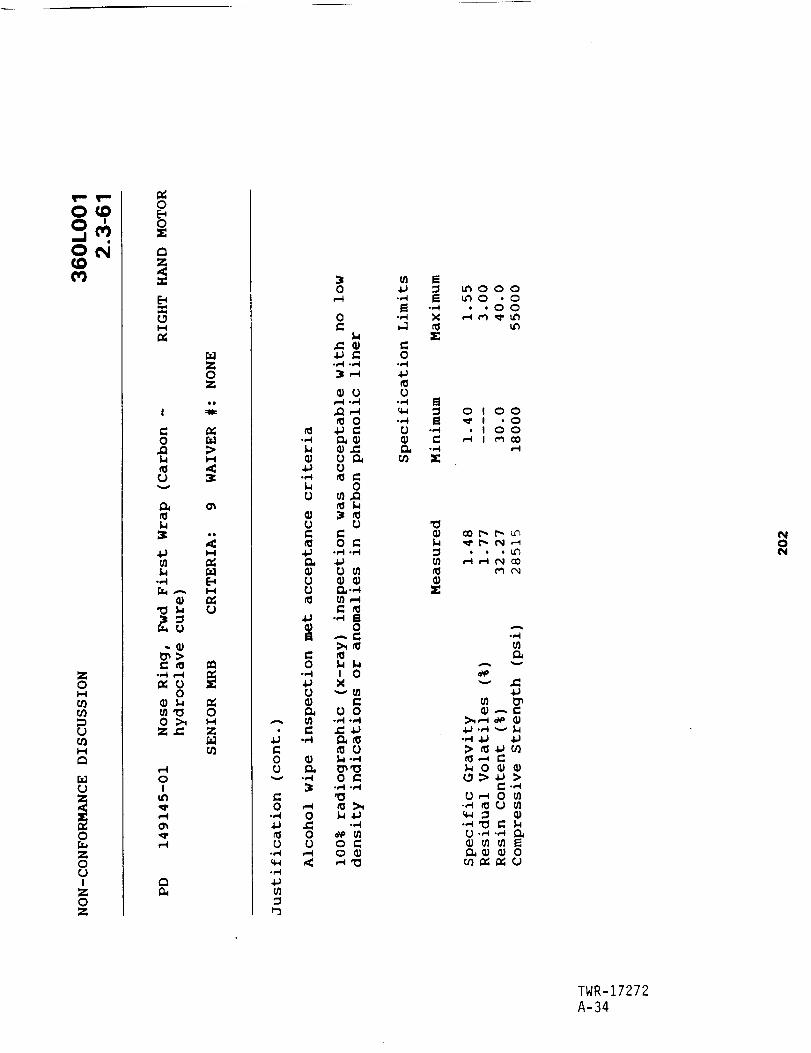
O_O
¢0
ZO
_0D
_0
O
O
ZOOI
ZOZ
0
Z0Z
0 _
61
0
,,. llJ
•O
_ OO >_
Z._ Z
_0
oI
tt_
o_
0_
A
COO
O.,..I
O
q_.,-_
u_
.,=l
.,.4
0
O
OOO
CO
.,.-I
OOo_
C-,.4
0o_
.,..I
O
OO
O
0
.,..i ._
0_.,-I
0C
0
0
0
0 C
i:%,.,-.I
0
I 0
0 0
0
0 C•,-I .,..I
.,.4
o Co
m_ _ooo
•_ _ _o.o•_ ,OO
C0
•_ _ _1.0O -_ • I oo
1:
me_
.,.-i
A
4JU} l_OJ ,-_ C
•,_ 4O 40
I_ 0 _ OJ
0,._ 0 _
0 ._ ._ O_
ul 0_ 0_ O
0
TWR-17272A-34

(D
3CJ(h
|U
a
(U
ORIGINAL PAGE |S
OF POOR QUALITY
0
!
t@Q}@@CW
U'J
............
i . • r !
"7 ........... : ......
I0
z _O0
Z _
Q.
_3
0
g;

Z0
0
0
0
Z00I
Z0Z
0
0X
rn
=
0=
0U
i-40I
QO
e-I
e-i
e.q
I,-4
0I,-4
0
0Cr_
0O1
.,=l
0
0
0
4_
g
Ol00rO
Ol
rO
1.41.4
.,.q
0
O1
O_
00
00
04_c-
.,-4
0Z
m
o
6
-,.4
,=
"0
.,,,,tX
6
o
,=
X
.,-4
66 0
.,,,4
.,..4Oi0
Ol
0
'0c.
O_"0
c_
rO
0>0
0
0
0
'0
o
0
I
I.-t
X •
0
4.1._
0 Ul
O_
•,.44,1
_ •
0
0
0
0 1
•,._ _ _X_
0 ° _
•tJ .1_ m•,-4 e-
e. N
_ m.,,-I
e- I1_
_ 0 0
-,..t -,-I
-,-,I
o 01
0
0
tn 0tO
TWR-17272A-36

Z0
r_
w.i
0
0
!Z0Z
0
oX
_9
,-4
,-4
.,.4
_U
oI
f-I
L)
m.
r.)
.,-I
=1,-4
,_ 0
0 _-4
.c:
0 0 rO
_ r_ 0
_,-_ 0
0 Z
0 O "_
Z__0 _
,-.q ,_-. 0I _ _ (I_
un_ _ 0
_-i I_) _ 0
_ ,-4 0
0
ul
c-O
0.,..I
o,.I
A
r-
'0
0
Z
Io
4.1 _
0
e"
0
_0
_0
0,._
QJ"0
_J
,._,l,J
0
o,,-i
u1
,.-4
0
e=,l
.,-i
TWR-17272A-37

Z0I-4
r_
o
zo
iZ0Z
0E_0X
I-4
I
-,.-4
l.l
I...4
0
0
0 0
.-I 0
oI
Z0Z
I--I
I-I
0
Z
0
,C
0,1
0
.,-4
0
-=.1
r"
r"
.,-4
0.,'4
,-4
0,c:
0r=t
I
+
or..I
0
O_O_0
'0
0
0
0
0-,-t
:=1-,..4
.,-I
0
>
,--I
.,-4
_0
0
¢)
0_o
0•_ 0
•..-t _)
0
_co
_Jh
U
h
q_o 0
0'_
_._
fl
0
°>e- 0
m 1,.I
e-
"_ _
0
0
01.,..,Ie_
_u
i11
0.,-I
-,-.I
O_
0
0
:r0
O_0
0 0_
•.-.i c.
'O
r-
r__r
r-
rUo
(J
:>
.,-.I
_J
r"
(J
0.,..I
U
n
n.,-,I
0r..0
...4
0
{J.,d
e--,-4
_J
.,._
0
E_
0
TWR-17272A-38

ON
Z0
I-I
Z
0
Z00I
Z0Z
0E_0
I--I
_UZ0Z
=_U>h_<
ch
!
v
C
0
0 0
•_ O0
_ 0
_ Z_U
oIf..
c4,-I
C_
A
0D
0
0
R-I
.-I
0_R,.I
Z
_0
C 0
0
,_0_
f,4I _._.0
m o
oe, l_•_ o
.,.._ _ _,_ i11,1:I
oI1/ m
-,-I
C0
0...,I
.,.'4rj
-,,'4
X
C
o
_1_
A
A
4_ ._ --_ _
>_
_0 • •
_.__,_ 0 _
_0
U_0
TWR-17272A-39

ONQD
0ll
ll
es
,,..o
in0't""
1
0rej
W"
ll
ees-O¢:
1
0
@
0It.,0,,
.[.mA
I",,,
__oo_o
ORIGINAL PAGE IS
OF POOR QUALITY
, ° ..... , .....
TWR-17272
A-40
{I}0e_
_" Z
O0
e,. ,j
Z _
o _
o1__I_ _ o
o_Z I

MORTON THIOKOL INC
Space Operations
Appendix B
REVISION
TWR-17272OOC NO.
SECI PAGE
I VOL
B-1

POSTFIRE ANOMALY RECORD (PFAR)
...................... . ............ . .... . .... . .... .°.. ......................... . ...................... . ...................
1. PFAR NUMBER I 3. INSPECTION LOCATION 4. REFERENCE SQUAWK NUMBER 5. REFERENCE PR _UMBER
36DLOO1A-11 t KSC X T-24/T-97 -.26"0045 . PV6-111293
........ °... .... • ......... . ..... . ... .......... ° ........................ , .... , .....
2 sRM,OTOR,UMBER ,7 ,2 6 IF,.O.BER 7 REFERENCESPRNUMBER36OLOO A ...... N/A f N/A
..................... . ............ . .... . .... . .... . ........................................... . ..........................
8. TITLECORROSION BETWEEN PRIMARY AND SECONOARY AFT EXIT CONE O-RINGS
........ o ................. ° ......................... . .............................. . ....................................
9. CLASSIFICATION
OBSERVATION MINOR ANOMALY X MAJOR ANOMALY CRITICAL ANOMALY.... , .......
........ . ....... . .... . ............ o .... . ......... °... ................. . .................................................
10. PART NUMBER I 11. SERIAL NUMBER I 12. PART DESCRIPTION
1U76039"01 I 0000001 I AFT EXIT CONE ASSY........ .°.. .... ° .... . ................. . ................. . .................................... .o. ............ • ..........
13. REPORTED BY (NAME / ORGANI_TION / OBSERVATION DATE)
K. B. NIELSEN / MTI QA / 10107/88................ ° ...................... . ............ ° ............ • .... ° ....... ° .... =... ................... ° .............
14. RESPONSIBLE C_PONENT TEAM / PROGRAM MANAGER
NOZZLE / E. L. DIENL................ o .... . ................. ° ........................................... ° ....... o ............................
15. RESPONSIBLE PROJECT ENGINEER (NAME / ORGANIZATION )D. J. _GNER / NOZZLE�FLEX BEARING PROJECT ENGINEERING
........... . ...................... ° .... ° ......................... . ......................... . ................. . ..........
16. RESPONSIBLE DESIGN ENGINEER (NAME / ORr..,ANI_TION)
S. A. MEYER / NOZZLE/FLEX BEARING DESIGN ENGINEERING
17. DESCRIPTION (ATTACH PFOR, FI_RES, PHOTOGRAPHS, ETC.)ALuminumoxiclecorrosionwas observecIbetweenthe primary and secondar"yo-rings, and outboard of the secondaryo-ring in the 360LOOIA (LN) aft exit cone field joint. No pitting was observed. Structural Al:_Lications inslccH:torsnoted that grease in both joints appeared lighter than required on STg7-2999,
Minor corrosion has I_ observed within past flight aft exit cone field joints, but has not been d_umented.
............................ • ......... ° ..................................................................... ° .... ° .....
18. JUSTIFICATION OF CLASSIFICATION (POSTFIRE ENGINEERING EVALUATION LIMITS)
This is not a flight issue. It is loeLieve<i that sea water entered past the primary o-ring at splashdown, resulting
in the minor corrosion observed. This is potentially a reuse issue if the grease application specification
(STW7-29_x_) is not followed........... • .... . ................. . .... ° ........................................................ • ............ ° ..........
19. CAUSE
Sea water entering past the primary o-ning at splashdown.
20. RECOMMENDED CORRECTIVE ACTION
1. Train arct certify SPC operators on grease aDpl(cation parSTW7-2999.
........... ° .... ° .... ° ............ o .....................................................................................
21. ANOMALY APPROVAL SIGNATURERPRB SECRETARY: DATE:
/S/T. L. JOHNSON 11/10/88
2. Do not write this minor corrosion up as a PR in the future.2Z. OB._RVATION/_NCW'4ALY APPROVAL SIGNATURES
PE:
................ ° .... ° ....... ° .... , .... = ................. . ....... = ......................................................
23. RESULTS OF RECO_ENDED CORRECTIVE ACTION1. Effective
2. Minor corrosion has been observed in this joint on the aft exitcone field joints of 360L002 and 360L003. Observed grease
al_oLications were nominal. This was not written uko as an observation.
26. REPORT RESULTS TO RPRB? YES X NO
................ . ................. ° ...........
25. RPRB CLOSURE SIGNATURE
(REQUIRED ONLY IF BLOCK 24 CHECKED "YES'*)RPRB SECRETARY: DATE:
26. OBSERVATION/ANOMALY CLOSURE SIGNATUREPM: DATE:
........... ° ............ ° .............. _ ....................................... • ............ ° ............................
27. ORIGINATION DATE I 28. REQUIRED STATUS DATE I 29. PR CLOSURE DATE J 30. PFAR CLOSURE DATE11109/88 J 11107188 J 01/1Z/B9 I
...................... °.°° .... o ......... . ......................... • ........................................... • ...........
REV. 3/28/89
ORIGINAL PAGE IS
OF POOR QUALITYTWR-17272B-2

POSTFIRE ANOMALY RECORD (PFAR)
1. PFAR NUMBER 3. INSPECTION LOCATION 4. REFERENCE SQUAWK NUMBER 5. REFERENCE PR _UMSER
360LOO1A-12 KSC X T.24/T-97 26-0046 , PV6-t11290...... . ............... . ............................. , ........................................
Z. aRM MOTOR HUMBER H-7 A-2 6. REFERENCE [FA _UMgER 7. _EFERENCE SPR NUMBER
360LOO1A ...... I _/A _/A
8. TITLECORROSION SETWEEN PRIMARY AND SECONDARY AFT EXIT CONE O-RINGS
...... ......o ......... . ........ • ...... . ...... • ............... . .................................................... . .....
9. CLASSIFICATION
OBSERVATION MINOR ANOMALY X MAJOR ANOMALY CRITICAL ANOMALY.... . .... ...
...o...... .... o•...o.........o.• .... ... ...... • ............... • ........ . ....................... .°.o. .....................
lo. PARTN_SER I 11. SERIALNUMBER I _Z. PARTDESCRIPTION1USZe39-01 I O00000S I FORWAROeXIT CONEASS_
... ..... . ..... ....... ...... . ....... °o. ............... • ............... • ........ . ...... . ...... . .........................
13. REPORTED BY (NAME /ORGANIZATION/ OOSERVATIOR DATE]K. B. NIELSEN / NTI QA / 10/0_88
....... • ...... °..° ..... . ...... . ...... . ............... . ........................ . .................................... •°.
16. RESPONSIBLE COMPONENT TEAN / PROGRAN MANAGER
HOZZLE / E. L. DIEHL....... . ...... °°. ...... ° .................................................................... ° ...... . ................. ,
15. RESPONSIBLE PROJECT ENGINEER iNANE / ORGANIZATION )
D. J. WAGNER / HOZZLE/FLEX BEARING PROJECT ENGINEERING....... °...o..... ...... °** .... _ .... .°•.°..... ............... .......... ...................... • ........................ ..
16. RESPONSIBLE DESIGN ENGINEER (NAHE / ORGANIZATION)S. A. NEYER / P_OZZLE/FLEX 8EARING DESIGN ENGINEERING
.......... . ...... . .... ... ...... . .......... . ........... . ............... . ............................. . ...................
17. DESCRIPTION (ATTACH PFOR, FIGURES, PHOTOGRAPHS, ETC.)
Aluminulloxidecorrosionwas observed between the primary and secondary o-rings, and outboard of the secorclary
o-ring, in the _L001A (LH) aft exit cone field joint. No pitting was _erv_. Structural apc_licatimsi_l:_tors _tN that grease in _th joints al=c_ear_ lighter than r_ir_ _ ST_7-29_.
Ni_r oorrosi_ has be_ ob_lerved _ithln l:_at flight aft exit c_ fleld joints, but has _t _n _t_.
.......... • ...... • ...... ° ...... °o° ......................................................................................
18, JUSTIFICATION OF CLASSIFICATION (POSTFIRE ENGINEERING EVALUATION LINITS)
This is not a flight issue. It is believed that sea water entered past the primary o-ring at splashdot_n, resultingin the minor corrosion observed. This is potentially a reuse issue if the grease application specificatio_(5TW7-2999) is not follc,_ed.
.......... • ...... ° ...... ° ........ . ...... ° ...... o ...... . ........ o ............................................. . ........ •.
19. CAUSE
Sea _eter entering past the primary o-ring at splashdown.
o°° ..... ° ...................................... . .................................................................... °.o
20. RECOIe4ENDED CORRECTIVE ACTION 21. ANOMALY APPROVAL SIGNATURE1. Train and certify SPC operators on greaae application per RPRS SECRETARY: DATE:
ST_7-2999. /S/T. L. JOHNSON 11/10/88
2. Do not wr_te th{s m_nor corrosion up as a PR in the future. - ............................................
22. OBSF,RVATION/kNOMALY APPROVAL SIGNATURES
re: _. _. (_..'_l_,""r,-,Q...'-- OATE:&J_..")/_',_
.......... ooo .................. o ............... o .................................................... o ............... o.o.
23. RESULTS OF RECOMNENDED CORRECTIVE ACTION 26. REPORT RESULTS TO RPRB? YES X NO1. Effective . - .....
2. Ninor corroSion has been observed in this joint on the aft exit 25. RPRB CLOSURE SIGNATURE
cone field joints of 360L002 and 360L003. Observed grease (REOUIRED ONLY IF BLOCK 26 CHECKED "YES")applications were nominal. This _aa not written up as an observation. RPRB SECRETARY: DATE:
26. OBSERVATION/ANOMALY CLOSURE S]GNATUREPI,I: OATE:
.................................... o .......... o .................................................... . ...................
27. ORIGINATION DATE I 2e° REOUIRED STATUS DATE I 29. PR CLOSURE DATE I 30. PFAR CLOSURE DATE
11/09/88 I 11/07/88 I 11/12/89 I
REV. 3/28189
TWR-17272B-3

POSTF[RE ANCNALY RECORD (PFAR)
............ o ................ " ................... ° .......................................... 4 ............. 4 ..............
I. PFAR NUMBER 3. INSPECTION LOCATION 4. REFERENCE SQUAWK NUMBER 5. REFERENCE PR NUMBER
360LOO1A-63 KSC T-26/T-97 N/A N/A........... . ............. _°.. ........ . ........................................................
2. SRM MOTOR NUMBER N-7 X k-2 6. REFERENCE IFA _UNBER 7. REFERENCE SPR _UNBER
]60LOO1A ...... M/A N/A........... 4 .... " ...... "°_ ........... °°4°°" ..... ° ................... * .................................... 4.--" ...........
8. TITLERTV/EA913 ADHESIVE MIXING IN JOINT 2
........... °.... ...... .°.4°°. .......... .°-..°. ................ 4 ........ . ............. ° ................... ..°4 ...........
9. CLASSIFICATIONOBSERVATION MINOR ANOMALY X MAJOR ANO/4ALY CRITICAL ANOMALY
.. ..........
.......... o .... .°.....°.o... ........ .°l...o...°. ............. _ ........ 4 ............. . ..... . ............. 4°°. ...........
N/A C_L/NOSE INLET JOINT (JOINT 2)..... ........................ ......... ..°........ .... °°°.°....° ..... ..°. ............. ° ..... ..................... ........
13. REPORTED BY (NAME /ORGANIZATION /OBSERVATION DATE_R. J. GEORGE / NOZZLE/FLEX BEARING DESIGN ENGINEERING / 10110/88
........ . .......... . ........ ..... ...... ......° .......... ......4...°.. ...................... 4.... ......... . ..... . ........
16. RESPONSIBLE COMPONENT TEN4 / PROGRAM MANAGERNOZZLE / E. L. DIEHL
15. RESPONSIBLE PROJECT ENGINEER (NAME / ORGANIT.ATION )O. J. WAGNER / NOZZLE/FLEX BEARING PROJECT ENGINEERING
..... ...4... ...... .. ................... .°..4.4.....4 .......... . ..... .°.. ............. .... ......... .. ..... 4...... ........
16. RESPONSIBLE DESIGN ENGINEER (NAME / ORCu_NIT,ATION)
S, A. MEYER / NOZZLE/FLEX BEARING DESIGN ENGINEERING........ = ............. ---- ............. ------- .......... - ..... o--- ................... --o---- ............. ° ..............
17. DESCRIPTION (ATTACH PFOR, FII3JRES, PHOTOGRAPHS, ETC.)See continuationsheet.
..... 4°°4.°" .... "°°Q°''''" ....... " ..... 0°''''" ............. 4 ..... ..°. ...... .. ........ °.°° ................ ..°. ...........
18, JUSTIFICATION OF CLASSIFICATION (POSTFIRE ENGINEERING EVALUATION LIMITS)
There is no aOheeion bet_.en the RTV and EA913 adhesive, reducing the capai=i[ity of the RTV to act as a thermalbarrier. The eroded EA913 NA edhesive has not previously been observed (significant departure from the historical
data base)........... °. ....... .°..°.. .... .°°.°...°.... ........ . ....... . ................ . ...................... .°°.... ..............
19. CAUSECurrent bottling and joint assembly procedures.
..... _ ....... ..°.°.°....°.°° ..... . ..... .°.....o.°.°...°......°. ............. ° ..... .°.. ............. °°..°.. ....... .°...°4
20. RECOI4_IENDED CORRECTIVE ACTION 21. ANOMALY APPROVAL SIGNATURE
At the time this us presented to the RPRB, the PV-1 nozzle Joint #2 RPRB SECRETARY: DATE:
had just been exmined. It _as recommended that we further evaluate , r,_, ¢_ 3"/c/c;"the new assemOLy procedure change on QN-8. It would then be
determined if the neu asselmly process would be incorporated into ........ 1 ..... y .........................
flight nozzleS. 22. OB.T_E.RVA'I_,zO.N,gANONALYAPPROVAL _IGNATURES
PE_/_/,_ _¢_ _,_ DATE: _-,/--_ "_
23. RESULTS OF RECONNENDED CORRECTIVE ACTION 26. REPORT RESULTS TO RPRB? YES X NO
See continuation sheet. - ......_......... .... ...°.......°. .......... °......
25. RPRB CLOSURE SIGNATURE
(RE_JIRED ONLY IF BLOCK 26 CHECKED "YES")RBRB SECRETARY: _ DATE:
........ -;. ..... _ ............... _- ...........Z6. OBSERVATIOM/.ENONAI.3 CLOSURE SIGNATURE
°...°.°°...°°..°_°.. ....... .....°. ....... . ..... ....°...°..°. .......... 4.°..°.°..°°. ........... .°.°.. .......... .-°. ......
..°_ ...... .°... ...... . ...... . ..... . ........... °°.°..... ................ °°..°°.... ................ 4... ...... _ ...... ° .......
REV. $/Z8/89
TWR-17272B-4

CONTINUATION SHEET FOR PFAR NUNEER 360LOO1A-63
17. DESCRIPTION (continuation)
The EA913 adhesive used to bond the cowl insulation to the cowl housing extrucied into the radial RTV bondLine
between the cowl tin9 an<:lnose cap 360-d_. oircumferentiatly. The a_=hesive that extr_ed into the raaial b_ndtine
was typically saOiched between t_o layers of RTV. Soot was observe_ over a majority of the joint circumference
and up to the primary o-ri_. A distinct blowpath was observed at 216 dq. Heat affected GCP ar_:lSCP _ere o_erv_,_:l
at the bLo_th location. The charred _teria( was aporoximately 0.01 in. deep. The EA913 NA _esive adjacent to
the cowl housing was erred a_roximately 0.1 in. axially x 0.7 in. wide circ. at the blow_th location. There was
no bloody, erosion or heat effect to the printmry o-ring. Electrical c_tivity measurements on the coul ar_ nose
inlet housings sho_ed no heat damage.
The mixing of the adhesive in the co.t/nose cap bondline and the presence of soot was documented on ETM-1A, DM-6,DM-9, OM-6 and ON-7. It is believed that the mixing has occurrea on all previous nozzles due _o assemDLy
proceoures. Charred GCP and SCP insulators have been observed at btowpath Locations in the ON-6, and PV-1 nozzleinternal Joint #2. Erocled EA913 HA aa_osive has not previously been observed.
23. RESULTS OF RECOMMENDED CORRECTIVE ACTZON (continuation)
1. The new assembly procedure _ms tested on PV-1 and QM-8 Joint #2's. Post-test inspections of these jointspromoted the decision to further evaluate and refine the ne_ asselmty procedure on TEN motors.
As of 360L002, there has never been Drimmry o-ring blo_nf, erosion or heat effect, or metal heat damage with Joint
#2. In the 360L002 RPRB, it was decided to close out all "minor a_lies" similar to this on all previous static
tests and flights. ALL future occurrences, fncl_i_ 300L002, _ld be ct_nsidered "observations,%
TWR-17198 Vo(. V has been uodated to include accept/reject criteria for RTV in nozzle joints. The condition notedin this "minor anomaly" is now an "acceptable" condition per this criteria.
TWR-17272B-5

POSTFIRE ANC_ALY RECORD (PFAR)
.................... • oo ...... • .......... • .................... .oo ............... ° ............... o ...... • ................. _.
1. PFAR NUMBER 3. INSPECT]ON LOCATION 4. REFERENCE SQUAWK NUMBER _. REFERENCE PR NUMBER
360LOOIB-IO KSC X T-26/T 97 26-0043 PV6-111312.o .............................. , .............................................................
2. SRM MOTOR NUMBER H-7 A-2 6. REFERENCE IFA NUMBER 7. REFERENCE SPR NUMBER
36GLOOIS ...... I N/A I NIA................... o.• ...... , ...........................................................................................
8. TITLECORROSION BETWEEN PRIMARY AND SECONOARY AFT EXIT CONE O-RINGS
................... ..• ........ . ...... ,.• ............. , ...................................... . ...........................
9. CLASSIFICATION
OBSERVATION MINOR ANOMALY X MAJOR ANOMALY CRITICAL ANOMALY.. .... .o. ...
.oo. ...... •.... .... ...o..oo., .... ...., .... .°..• ...... . ...... .....o..o, ........ o ............................... ° ........ o
10, PART NUMBER J 11. SERIAL NUMBER I 12. PART DESCRIPTION
1U76039"03 I 0000001 I AFT EXIT CONE ASSY................... ..o.. .... . .......... o ............................. . ...................... .o° .........................
13. REPORTED BY (NAME / ORGANIZATION / OBSERVATION DATE)K. B. NIELSEN / MT! QA I 10107188
.......... • .... .....o. ............... . ............................... . ........................................ . .........
14. RESPONSIBLE COMPONENT TEAM / PROGRAM MANAGERNOZZLE / E. L. DIEHL
.° ................. •.. ...... . ........ ° .... . .......... ° ........ o .................... o ........ ..° ...... , ........ . ........ °
15. RESPONSIBLE PROJECT ENGINEER (NAME / ORGANIZATION )
O. J. WAGNER / NOZZLE/FLEX BEARING PROJECT ENGINEERING................... • ........ . ........................ ° ...... •=° .... o ........ • ......... o ..... , ........................ ...
16. RESPONS!BLE DESIGN ENGINEER (NAME / ORGANIZATION)S, A. MEYER / NOZZLE/FLEX BEARING DESIGN ENGINEERING
........ • .......... ° ..... -o-o ........ • ...... . ........ ° ...... .., .... , ........ ° ...... . ........ . ........ • ............... °°°
17. DESCRIPTION (ATTACH PFOR, FIGURES, PHOTOGRAPHS, ETC.)
ALuminum oxide corrosionwaso_ervedbetweenthe primary ana secor_ry o-rings, and outboard of the secondaryo-ring, in the 360LOO1B (RN) aft exit cone fie{d joint. No pitting was observed. Structural Applicationsinspectors note¢_ that grease in both joints tpeared lighter than required on STWT-2999.
Minor cor-osion has been observed within past flight aft exit cone field joints, but has not been documented°
........ • ........ °=. ............... • .......... • ............. • ............... . ...... • ................. • ............... ..•
18. JUST%FICAT!ON OF CLASSIFICATION (POSTFIRE ENGINEERING E'VALUATION LIMITS)
This is not a flight issue. [t is believed that sea water entered past the primary o-ring at splashdown, resultingin the minor corrosion observed. This is potentially a reuse issue if the grease application specification(STWT-2999) ia not fo(lo_e¢l•
................ • .• ............................................... . ........ o ...... o ........ • ........................ °..
19. CAUSE
Sea water entering paat the primary o-ring at splashdown.
.................................... ° ...... o ............................... • .......................................... o
20• RECOMMENDED CORRECTIVE ACTION 21. ANOMALY APPROVAL SIGNATURE
I. Train and certify SPC operators on grease application per RPRB SECRETARY: DATE:
STW7-2999. /S/T. L. JOHNSON 11/10/88
2. Do not write this minor corrosion up al s PR in the future. - ............................................
2p21_: O_R_AT L%__PPROVAAL TS ! _N_
oo ......... . ..... •.. .... •.. ................. • ........ . ...... • ...... . ........ • ...........................................
23. RESULTS OF RECOMMENDED CORRECTIVE ACTION 24. REPORT RESULTS TO RPRB? YES X NOI. Effective
2. Minor corrosion hal b_ observed in this joint and on the aft
exit cone field joints of _._A_LO02 and 360L003. Observed greaseapplications were nominal. This was not written up as an ot_ervetion,
..... o
o• ...... o ....................................
25. RPRB CLOSURE SIGNATURE
(REQUIREO ONLY IF BLOCK 24 CHECKED "YES")RPRB SECRETARY: DATE:
26. OBSERVATION/ANOMALY CLOSURE SIGNATURE
PM: DATE:
................. oo• ........................................ • .......................................................... o
_7" OR I i_"I NAT !ON_)ATEII/09/88 I 28° REQUIRED STATUS DATE I _9" PR cLOSUREDATE!I/07188 01 / 12/89 J _0. PFAR _LOSURE DATE
.................. • .......................................................... • ...... • ................................. •ooo
REV. 3/28/89
TWR-17272B-6

POSTFIRE ANOMALY RECORD (PFAR)
.. ......... . ......... . ......... o ...... .o.oo.. ............. .... ............................................................
I. PFAR NUMBER 3. INSPECTION LOCATION 4. REFERENCE SQUAWK NUMBER 5. REFERENCE PR NUMBER
360LOOIB-38 KSC X T-E4/T-97 26-0048 _ PV6-11129Z.......... o ..................................................................................
2. SRM MOTOR NUMBER N-7 A-2 6. REFERENCE IFA NUMBER 7. REFERENCE SPR NUMBER
360LOO1B ...... I N/A N/A.............................. • ...... . ...................... • ...........................................................
8. TITLEDING ON F_JD EXIT CONE AFT FLANGE AT 97.6 DEG
.......... • ......... . ................... . ........................................................ . ......................
9, CLASSIFICATIONOBSERVATION MINOR ANOMALY X MAJOR ANO?4ALY CRITICAL ANOMALY
.................... . ....................................... . ...... . ......... . ..........................................
_o. PARTN_BER 11-OOO06 _2. PARTDESCRIPTZON1U52839-01 FORWARD EXIT CONE ASSY.......... ...o. .......... o .... . ......... . ...... .. .................. = ....................................................
13. REPORTED BY (NAME / ORGANIZATION / OBSERVATION DATE)
T. B. GREGORIO / MT% QA / 10/07/88.......... o ................... o .................................................................. o ......................
14. RESPONSIBLE COt41>(]NENT TEAM / PROGRAM MANAGER
NOZZLE / E. L. DIEHL.......... o ................... . ......... ° .......................... o ................... . ......... ° ......................
15. RESPONSIBLE PROJECT ENGINEER (NAME / ORGANIZATION )O. J. WAGNER / I_ZZLE/FLBX BEARING PROJECT ENGINEERING
.......... • ...... .=.. ...... .... ........................................................ o ...... .=.° ...... . ..............
16. RESPONSIBLE DESIGN ENGINEER (NAME / ORGANIZATION)S. A. MEYER / NOZZLE/FLEX SEARING DESIGN ENGINEERING
.......... o ......... . ....... ... ......... .°.o. ............ ..o. ...... o ......... ° ................ ° ............... . .........
17. DESCRIPTION (ATTACH PFOR, FIGURES, PHOTOGRAPHS, ETC.)
During the 360LOO1B (RH) eft exit corm dmte, I guide p(n dfnged the edge of e hole on the forward exit cone aftflange. The dine was ap_roximately 0.02 incn_ deep.
Damage his occurred during KSC aft exit cone demates on previous flight nozzles. SRM-15A and 23A forward exit coneaft flange seating surfaces were scratched by the joint alignment pin. The 360LOOIA (LH) forward exit corle aftflange was also scratched 0.002 inches deep during demate bye guide pin.
.......... . ...... o.°....°.°.o°..° .... °.°°.°°°°.. ............ ° ..... o ..... ° .... ° ...... °o°o.°°°°..°.. ...... . ..............
18. JUSTIFICATION OF CLASSIFICATION (POSTFIRE ENGINEERING EVALUATION LIMITS)
The current KSC aft exit col_ decmting procedure/tooling could cause dammge preventing reuse of hardware.
Requires corrective ection but has no impact on motor performance or program schedule....... .... .... ... ........ o.... .... o.. ......... . ................... ° ..... ..... .......................... . ..............
19. CAUSE
Current KSC aft exit cone dmting procedures and tooting.
20. RECOI4NENOED CORRECTIVE ACTION
See continuation sheet.
...... °°.° ................ °.°o ...... _..° ...... ° ....................................... ° ...... o .........................
21. ANOMALY APPROVAL SIGNATURE
RPRB SECRETARY : DATE :
/S/T. L. JOHNSON 11/10/8a
22. OBSF,_VATION/ANOMALY APPROVAL SIGNATURE3
PE: _,_. _J'_L,¢_ DATE: b/_.'_/_
............. . ............. .... ...... oo.. ...... . ............ . ...........................................................
23. RESULTS OF RECOMMENDED CORRECTIVE ACTION 2(*. REPORT RESULTS TO RPRB? YES X NO
See continuatiotl stleet. - ........ ......... ° ...... .... .....................
25. RPR8 CLOSURE SIGNATURE(REQUIRED ONLY IF BLOCK 2{* CHECKED "YES")RPRB SECRETARY : DATE :
26. OBSERVATION/ANOMALY CLOSURE SIGNATUREPM: DATE :
....... o.oo ...... . .......................................... o ...... o .......................... o .........................
27. ORIGINATION DATE I 28. REQUIRED STATUS DATE I 29. PR CLOSURE DATE I 30. PFAR CLOSURE DATElI/09/88 I 11/07/88 I _1122188 I
........ o... ...... ° .......................................................................................................
REV. 3128189
TWR-17272
B-7

CONTINUATION SHEET FOR PFAR NUMBER 360LOOIB-_8
20. RECONMENOED CORRECTIVE ACTION (continuation)
I. ELiminate guide pins. These just add more Oossibltit_es of scrstchlng the forward exit cone aft flange after
the joint serrates an recoils. ELiminating the guide pins leaves only the joint alignment pin to worry amour.
2. Wear term: Use anti-r_,4_oil toots to eliminate the recoil of the aft exit cone after joint se!_wlrstion. Thiswould not allow the atignfaent pin to contact the forward exit cone aft flange.
ASAP: Design and incorloorste a rail system disasseelioly tool similar to that used at MTI Wasatch T-24 arx:l T-97.
This tool su;:_oorts the aft exit cone assenibly so that there is no load on the joint alignn_t Din during seoaration.The tool also do. not recoil, eliminating any possibility of damage to the forward exit cone aft flange t_y the
aligrnent pin.
23. RESULTS OF RECOMMENDED CORRECTIVE ACTION (continuation)
I. Effective: RSRN Flight Z (360L002)
2. Anti-recoiL tooLs effective:
RaiL system tool effective:
KSC has incorporated a toed cell into the existing aft exit cone stub removaL tool. This Load ceil allows operatorsto monitor the load that is being suDDorted by the fork lift. If used correctly, the load on the joint aLigr_t
pin can be minimizad during seoaration. This would eliminate relative vertical dispkacen_-nts between the aft exitcone anct forward exit cone after joint set:station. The load cell was used on the aft exit cone Oemates of RSRM
Flights 2 and 3 (360L002 and 360L003). Only minor raisad metal was oioserved on the forward exit cone 91.8 degreealignment pin holes on the four joints where the load cell was usad. This does not violate refurbishment
requirements.
TWR-17272
B-8

POSTFIRE ANC_JALY RECORD (PFAR)
... .................................. .o ......... . ....... ..... ................. . .... .... ....... . .... . .................. ....
1. PFAR NUMBER I 3. INSPECTION LOCATION _ 4. REFERENCE SQUAWK NUMBER 5. REFERENCE PR _UMBER
360LOOIB-42 1 KS( X T-24/T-97 J 26-0044 _ PV6-111324
. ....... o... ....... . ....... o ....................... . .............. ° .... . .....................
2. SRM MOTOR NUMBER H-7 A-2 _ 6. REFERENCE IFA NUMBER 7. REFERENCE SPR _UMBER360LOD1B ...... _ N/A N/A
8. TITLECORROSION BETWEEN PRIMARY AND SECONOARY FORWARD EXIT CONE O-RINGS
.. .... o..oo.. ............ . ....... o... ........ ... ....... . .......... o .................. . ............ . .....................
9. CLASSIFICATION
OBSERVATION MINOR ANOMALY X MAJOR ANOMALY CRZTICAL ANOMALY
............ . ...... °. ....... . ....... o .......... . ............... o .................................. . .....................
lo PARTNUMBER I_1 SERIALUBER 1_2 PARTDESCRIPTZOR1U52839"01 I 0000006 J FORWARD EXIT CONE ASSY
.o ....... °o.. ....... . ......... . ..... ..°. ....... . ....... .o.. .............................................................
13. REPORTED BY (NAME / ORGANIZATION/OBSERVATION DATE)K. B. NIELSEN / MTI QA / 10/0_88
.. ....... . .......... . ....... . .................. . ....... . ............. . ..................................................
14. RESPONSIBLE COMPONENT TEAM / PROGRAM MANAGERNOZZLE / E. L. OlENL
.°o°. .... °o.. ....... ° ....... . ....... .. ......... ..o.o....... ....... o..° ....... ° ....... ° ............ . .....................
15. RESPONSIBLE PROJECT ENGINEER (NAME / ORGANIZATION )
O. J. WAGNER / NOZZLE/FLEX BEARING PROJECT ENGINEERING.... .... .... . ..... ..° ....... . ....... .... ....... ° .......... . ....... ........o.=. ....... ......o.. .... . ............. . .......
16. RESPONSIBLE DESIGN ENGINEER (NAME / ORGANIZATION)
S. A. MEYER / NOZZLE/FLEX BEARING DESIGN ENGINEERING......... .°.. ............... . ....... . ....................... . ........... . .... . ....... . ............ . ............. o .......
17. DESCRIPTION (ATTACH PFOR, FIGURES, PHOTOGRAPHS, ETC.)Al_in_ oxide corrosi_ was observed loetw_ the primary and s_ondary o-rings, and outboard of the secoc_ry
o-ring, in the 360LOOIB (RH) aft exit cone field joint. No pitting was o_ervea. StructurmL Applicationsinspectors noted that grease in both joints appeared lighter than required on STW7-29Q9.
Minor corrosion hal been ob6erved within past flight aft exit corNefield joints, but has not been documented.
........................... ° ....... o°o° ............... . ............. ° ....... ° ....... ° ............ ° ............. ° .......
18. JUSTIFICATION OF CLASSIFICATION (POSTFIRE ENGINEERING EVALUATION LIMITS)
This is not a flight issue. It is believed that see water entered past the primary o-ring at splashdown, resultingin the corrosion observed. This is potentially m rue issue if the grease al_olication specification (STW7-2999) isnot fol Lowed.
ooo. ....... o ....... o ...................................................................................................
19. CAUSE
Sel water angering past the primary o-ring at splashdown.
......... oo.o ....... o ..................................... o .................. o ............................... .o.o .......
20. RECOMMENDED CORRECTIVE ACTION 21. ANOMALY APPROVAL SIGNATURE
1. Train end certify SPC ol_ratorl on greaee application par RPRB SECRETARY: DATE:STW7-2999. /S/T. L. JONNSON 11/10/88
2. 0o not write this minor corrosion up mm a PR in the future. -............................................
22. OB_R_(ATION/_NOMALY APPROVAL SIGNATURES
=.°.. .... o... ....... o ....... o ....... o... ....... .=....... ..................................... . ..........................
;[3. RESULTS OF RECOMNIENOED CORRECTIVE ACTION 24. REPORT RESULTS TO RPRB? YES X NO1. Effective ......
2. Minor corrosion has been observed in this joint on the aft exitcone field joints of 360L002 and 360L003. Observed grease
applicationl were rmminet. This wee not written up el an o_=ervetion.
.......... o ............ o .................. oo.
25. RPRB CLOSURE SIGNATURE
(REQUIRED ONLY IF BLOCK 24 CHECKED "YES")RPRB SECRETARY: DATE:
26. OBSERVATION�ANOMALY CLOSURE SIGNATUREPM: DATE:
.... o ....... o ....................... oo.o ....... o .......... o .......................... . ....... o ..........................
27. ORIG|NATION DATE _ 28. REQUIRED STATUS DATE I 29. PR CLOSURE DATE I 30. PFAR CLOSURE DATE11/09/88 'l 11107/88 ) 01/12/S9 I
............. . ....... o. ...... °... .... ° ................................................ , ...................................
REV. 3/28/89
TWR-17272B-9

POSTFIRE ANOMALY RECORD (PFAR)
............................................................................ o .............................................
I. PFAR _UMBER I 3. INSPECTION LOCATION 4. REFERENCE SOUAWK NUMBER 5. REFERENCE PR NUMBER
360LOOIB-_4 1 KSC T-24/T.97 _/A N/A
............................................ .=oo. ........... • .................................
2. SRM MOTOR _L94BER H-7 X A-2 6. REFERENCE ]FA _UMBER 7. REFERENCE $PR NUMBER360LOOIB ...... _/A N/A
.................. • .o...°oo.. ....... o ...................................................... . ............................
8. TITLERTV 8ACKFILL IN JOINT _ INHIBITED SY EXCESSIVE GREASE
.................. o ........... ..°.• ..... o ...............................................................................
9. CLASSIFICATION
OBSERVATION MINOR ANI_ALY X MAJOR ANOMALY CRITICAL ANOHALY• ..... .°° ...
.................. • o... ..... . ........................................ o ................. • ................................
10. PART NUMBER 11. SERIAL NUMBER 12. PART DESCRIPTIONN/A I NIA 1 NIA
.................. o...• .............................................................. o ..................................
13, REPORTED BY (NAME / ORGANIZATION / OBSERVATION DATE)
R. J. GEORGE / NOZZLE/FLEX BEARING DESIGN ENGINEERING / 11/03/88.................. o.°.ooo.o.o ..... .=o.. .................................... • ............... .=. ....
14. RESPONSIBLE COMPONENT TEAM / PROGRAM MANAGER ......................
NOZZLE / E. L. DIEHL...................... • .°.o.° ..... = .................................................... •°o.. ...........................
15. RESPONSIBLE PROJECT ENGINEER (NAME / ORGANIZATION )O. J. WAGNER / NOZZLE/FLEX BEARING PROJECT ENGINEERING
.................................. • .............................. • ........................... =.. ........................
16. RESPONSIBLE DESIGN ENGINEER (NAME / ORGANIZATION)
S. A. MEYER / NOZZLE/FLEX BEARING DESIGN ENGrNEERING.................. • ..o° ........................................... o ...... ... ...........................................
17. DESCRIPTION (ATTACH PFOR, FIGURES, PHOTOGRAPHS, ETC.)See continuation sheet.
.................. °.°.°°°=o°o .................................... o ....... • ......... o°° ........ ..........................
18, JUSTIFICATION OF CLASSIFICATION (POSTFIRE ENGINEERING EVALUATION LIMITS)See continuation sheet.
o,°o ........ ° ..... °=ooo ..... *°.-*°q.°°.-°-. ................... o°°*°oo° ............. °o°°.....°° ..........................
19. CAUSE
Excess grease applied during joint assembly resulted because no application standards were in place°
.................. .°°oo°°o°.o.ooo ......... . .............................................. o ..............................
20. RECOMMENDED CORRECTIVE ACTTON Z1. ANOMALY APPROVAL SIGNATURE1. Set up TRACS class to train and qualify technicians, QA and AF on
grease appticatioq_.
2. Continue inspecting future post-test and flight nozzle joints for
excess grease problems.
3. Release and Incorporate Rev. C to STMT-Z999.
RPR8 SECRETARY : DATE :
............ ..o ..... .°° ......................
22. OBSERVATION/ANOMALY APPROVAL SIGNATURESPE: DATE:
PM; DATE :
.................. ° ......... °.°o°o•°°.o .................................... o ............. o°o ..... ° ......................
23. RESULTS OF RECOMMENDED CORRECTIVE ACTION Z4. REPORT RESULTS TO RPRB? YES X NOSee continuation sheet. - .....
........ °...°...o ............................
ZS. RPR8 CLOSURE SIGNATURE
(REOUIRED ONLY IF BLOCK 24 CHECKED "YES")RPRB SECRETARY: DATE :
.=.°• ....... •=oo° ............................
26. 08SERVATION/ANO_ALY CLOSURE SIGNATUREPM: DATE:
.......................... °o°oo .......................................................... • ..............................
27. ORIGINATIONDATE I 2e. REOUIREDSTATUSDATE I zg. Pe CLOSUREDATe I SO. PFARCLOSUREDATE11/3o/_ I N/A I N/A I
REV. 3128189
TWR-17272B-IO

CONTINUAT_OH SHEET FOR PFAR NUMBER 360LOOIB'44
17. DESCRIPTION (continuation)
The S60LOOIB nozzle forward exit cone/throat joint (Joint _z.) showed excessive grease. Grease was observeQ on the
radial O.O. and on the axial portions of the joint interface. It is believed that the oresence of the grease at 185
degrees inhibited the backfill of RTV, A bLowpath was Located at the 185 Oegree location. There was no OLowoy,erosion or heat effect to primary o'ring.
Joint #4 on the DM-9, QM-6, QM-7 and PV-1 tests showed excessive grease on phenolic interfaces. [t was believedthat the excess grease inhibite_l the RTV backfill in these joints (classified as Minor Anomalies).
Previous flight and static test forward exit cone/throat joints have shown grease on the _enolic joint interfaces.
[n order to hold the primary o-ring on the o-ring groove during assemoty, a thicker layer of grease is applies tothe o-ring and groove.
STgT-Z999 was released to control amounts of grease al_liecl to the nozzle internal joint o,rings and o-ring grooves.This specification was dOSed to engineering assembly drawings and will be effective RSRM flight 6 (360T004).
18. JUSTIFICATION OF CLA$SIFICATION (continuation)
The excess grease in joint #4 recluired corrective action but has no impact on motor performance or program schedule.
The excess grease inhibited the RTV backfill at the 185 degree location.
Grease on the joint phenolic interfaces could prevent the adhesion of the RTV to the phenolic. This would re_uce
the capability of the RTV to act as a thermal barrier.
25. RESULTS OF RECOMMENDED CORRECTIVE ACTION (continuation)
STW7-2999 was incorporetecl into nozzle joint assembly planning; effective QM-8 and RSRM flight 4 (360T004).
1. Effective
2, QM-8 showed excess grease inhibiting RTV backfill in joint #4. The grease ac_Lication specification did not
reduce the excess grease in this joint. Joint #4 will be monitored by structural applications until proper greaseapplications are being followed. Also, TRACS classes are being set up to train/qualify nozzle joint assermoLypersonnel (effective ).
S60LOO1A showed no excess grease in nozzle joints.
360LOOZA showed no excess grease in nozzle joints.
360LOOEB showed no excess grease in nozzle joints.
360LOO3A showed no excess grease in nozzle joints.
360LOO3B showed no excess grease in nozzle joints.
TWR-17272B-II

POSTFIRE ANOMALY RECORD (PFAR)
1, PFAR NUMBER 3. INSPECTION LOCATION _. REFERENCE SQUAWI_ _U_RER 5o REFERENCE PR _UMBER
36plOD. T2 ,T. I,!: N,A............................. . ........ o ........ ....oo..
2. SRM MOTOR NUMBER H-7 X A-2 _ 6. REFERENCE IFA NUMBER 7. REFERENCE SPR NUNBER360LDO1B ...... _ N/A _/A
..o ........ .o.o..oo ....... ... ........ . ..................... . ........ . ..................... o.... .........................
8. TITLERTVIEA913 ADHESIVE MIXING IM JOINT 2
......... o ..... ... .... ....... ........ . ........ . ............ . ............ . ................. ..... ........ . ................
9. CLASSIFICAT[ON
OBSERVATION MINOR ANOMALY X HAJOR ANOMALY CRITICAL ANOMALY...... ooo o..
..o ........ .o.o.oo.o .... ..... ........ o ..................... . ........ ..... ..................... . .........................
10. PART NUMBER I 11. SERIAL NUMBER I 12. PART DESCRIPTION
N/A I ./A I CO_L/_OSEINLETJOINT(JOiHT2)o.......o. .... ..... ..... ..................... ......... . .... o ........ o.o.. .... .. ........... ..o.. ............... .o=...o...
13. REPORTED BY (MANE / ORGANIZATION / OBSERVATION DATE)S. A. MEYER / NOZZLE/FLEX BEARING DESIGN ENGINEERING / 11/04/89
............... . ...... ....... ........ o... ..... ... .......... . .............................. ..... ........ . ................
14. RESPONSIBLE C_41_3NENT TEAM / PROGRAM MANAGER
NOZZLE / E. L. DIEHL... ........ ...o. ........ ...o. ........ ...o. ................. .. ............................. ..... ..................... o.
15. RESPONSIBLE PROJECT ENGINEER (NAME / ORGANIZATION )
O. J. WAGNER / NOZZLE/FLEX BEARING PROJECT ENGINEERINGo.= ........ ...o.........o.=.o ........ o .... . ............. .oo.oo.. ........ . ..................... .. ....... .... ..... ........
16. RESPONSIBLE DESIGN ENGINEER (NAME / ORGANIZAT%ON)
S. A. MEYER / NOZZLE/FLEX BEARING DESIGN ENGINEERING... ............ ..... .... ...._ ........ . ....... . ............. . ............ . ............... ......_ ........ _ ........ ........
17. DESCRIPTION (ATTACH PFOR, FIGURES, PHOTOGRAPHS, ETC.)The EA913 aOhesive used to bond the cowl insulation to the cowl housing extruded fOrD the radial RTV bondtinebetween the couL ring and nose cap 360-deg. circumferentiakly. The aOhesive that extrucJed into the r_liaL bondline
was typically sanOwiched between two Layers of RTV. Soot was observed over a ,mjority of the joint circumference
ana up to the axial bolt holes. There was no bloutw, erosio_ or heat effect to the primary o-ring.
The mixing of the ac_esive in the coul/nose cap bondline and the presence of soot was documented on ETM-1A, DR-S,ON-9, ON-6 and _N-7. It is believed that the mixing has occurred on all previous nozzles due to assemblyprocedures.
o.o ...... .......o ........... o ........ . ............ . ........ ..... ........ o ........ . ............ . ................... *.o...
18. JUSTIFICATION OF CLASSIFICATION (POSTFIRE ENGINEERING EVALUATION LIMITS)There is no a_i_esion between the RTV and EA913 aahesive, reclucing the capabitity of the RTV to act as a thermalbarrier.
........... . ...... oo........o ........ . ........... ** ........ . ............ * ........ . ............. . ....... . ................
19. CAUSE
Current bonding and joint assembly procedures.
..o ............ _o..o ...... ... o.... o....o..**.* o..*..o._ ........ .o. ...... . ........ _o... ........ _. .......... o .............
20. RECOMMENDED CORRECTIVE ACTION 21. ANOMALY APPROVAL SIGNATURE
1. At the time this was presented to RPRB, the PV-1 nozzle Joint #2 RPRB SECRETARY: DATE:
hed j=t been exmined. [ t was recoemended that . further eva,uatenew process _L _'-_-] ["-_./.ithe new asse_loty procedure change on ON*8. It would then be C_.-I " _ _ I/..x.zdetermined if the assecmty would be incorporated into ............. ; ............ _ .... ;-;---flight nozzles. 22. OBsJ_,_VATIOJr/ANOMALY APPROVA¢.=,IGNATURES
o...... ........ _....o......o..... ...... oo.o ....... ..... ........ o .... . ............ ..
23. RESULTS OF RE_NOED CORRECTIVE ACTION 24. REPORT RESULTS TO RPRB? YES X NOSee continuation sheet. - .....
........... ........ . ....... o .... ..... ........
_.._. RPRB CLOSURE SIGNATURE
(REQUIRED ONLY IF BLOCK .24 CHECKED "YES")R_P._I8SECRETARY: , DATE:
..26. ORSE'RVATIO_ANOMAL_ CLOSURE SIGNATURE
.......................... ...... ..o.o...o_._.o.. ...... o .... ....= ................ o..ooo ..... . ............... .o.._ ........
27. OR IGIRAT_O_ DATE11/30/88 I 2'" REQU|RED STATUB DATE I 29" PR CLOsuRE DATENJA N/A I 30 ° _)FAR cLO_JRE DATE
....... o ........ ..o..o.o. .... ..o.. ..... .o... .................... o ..................... o ........ ..... ..... ooo.o.o. ........ o
REV. 3128189
TWR-17272B-12

CONTINUATION SHEET FOR PFAR NUMBER 360LOO1R-45
2.3. RESULTS OF RECOMMENDED CORRECTIVE ACTION (continuation)
1. The new assembly procedure was tested on PV-I and QN-8 Joint #2's. Post-test inspections of these joints
prompted the decision to further eveluate and reffne the new assemOLy pnoceaure on TEM motors.
As of 360L002, there has never been primary o-ring btowby, erosion or hest effect, or metal heat damaqe within Joint#2. In the 360L002 RPR8, it was decided to close out all "minor anomalies- similar to this on all previous staictests and flights. ALL future occurrences, incluaing 360L002, would be considered ,,ol_ervstions,,.
TMR-17198 VoL. V has been updated to include accept/reject criteria for RTV in nozzle joints. The condition notedin this ,,minor an(_aLy" is no_ an '*acceptabLe '_ condition per this criteria.
TWR-17272B-13

Recipient
K. Baker
D. D. BrightF W. Call
M Clark
J DonatE L. DiehlT FrestonJ E. Fonnesbeck
R J. GeorgeS Graves
D. Harris
J. D. Leavitt
R. Loevy
S. A. MeyerG. Nielson
D. NisongerC. Olsen
S. Olsen
B. E. PhippsR. B. Roth
G. Snlder
R. K. Wilks
Print Crib
Vault
DISTRIBUTION
No. of Copies
1
1
15
1
1
1
1
1
1
1
1
1
1
1
1
1
1
11
1
1
1
5
5
Mail Stop
287L22
E05
427
L62A
El4
242
L62A
L62A
L52
L34
El4
L62A
L62A
811
M31
411EL35
L22
LlO
411
L23
K23B
K23E
TWR-17272
46