Flight 3 Specification Compliance and Calibration Databook Volume ...
145
-
Upload
khangminh22 -
Category
Documents
-
view
0 -
download
0
Transcript of Flight 3 Specification Compliance and Calibration Databook Volume ...


SBUV/2 Specification Compliance and Calibration Data Book B6802-106 Page ifor Flight Unit #3, (S/N 004) Mod 9, Volume I, Rev. C
bBall Aerospace& Technologies Corp.Aerospace Systems Division
Table of Contents
Table of Contents ______________________________________________________________iList of Tables _____________________________________________________________________ ii
List of Figures ___________________________________________________________________ iii
Section 1 - FLIGHT 3 TEST HISTORY 1985 – 1999 _______________________________1-1Section 2 - VIBRATION TEST _________________________________________________2-1Section 3 - THERMAL VACUUM TEST _________________________________________3-1Section 4 - MASS PROPERTIES _______________________________________________4-1Section 5 - TELEMETRY CALIBRATION _______________________________________5-1Section 6 - POWER PROFILE/INPUT VOLTAGE_________________________________6-1Section 7 - ELECTRICAL CALIBRATION AND STABILITY _______________________7-1Section 8 - SIGNAL-TO-NOISE RATIO AND STABILITY __________________________8-1Section 9 - BACKGROUND STABILITY _________________________________________9-1Section 10 - POLARIZATION_________________________________________________10-1Section 11 - DIFFUSER REFLECTIVITY ______________________________________11-1Section 12 - SHORT TERM STABILITY ________________________________________12-1Section 13 - RESPONSE REPEATABILITY _____________________________________13-1Section 14 - TIME RESPONSE _______________________________________________14-1Section 15 - CONTAMINATION MIRRORS_____________________________________15-1Section 16 - EMI/EMC TESTS ________________________________________________16-1

SBUV/2 Specification Compliance and Calibration Data Book B6802-106 Page iifor Flight Unit #3, (S/N 004) Mod 9, Volume I, Rev. C
bBall Aerospace& Technologies Corp.Aerospace Systems Division
List of Tables
Table 2-1 Acceptance Level Sinusoidal Vibration__________________________________________________2-2Table 2-2 Acceptance Level Random Vibration ___________________________________________________2-2Table 2-3 Low Level Vibration Levels___________________________________________________________2-4Table 3-1 Modified Thermal Vacuum Test Sequence---1994 _________________________________________3-4Table 4-1 INSTRUMENT WEIGHT ____________________________________________________________4-2Table 5-1 Temperature Sensor Conversions _______________________________________________________5-3Table 5-2 Temperature Sensors ________________________________________________________________5-4Table 5-3 Voltage Monitor Conversions_________________________________________________________5-12Table 5-4 Current Monitors __________________________________________________________________5-23Table 6-1 SBUV/2 Flight 3 Power Measurments ___________________________________________________6-2Table 7-1a Flight 3 Electronic Calibration (June - August 1997) (After changing the notch filter) _____________7-2Table 7-1b Flight 3 Electronic Calibration (March - April 1999) (After rinsing the instrument diffuser) ________7-2Table 7-2 Electronic Calibration Stability_________________________________________________________7-3Table 8-1 Measured Signal-to-Noise Ratio________________________________________________________8-2Table 8-2 252 nm, Signal-to-Noise Ratio Stability (Ch1)_____________________________________________8-3Table 9-1 Background Stability Data ____________________________________________________________9-2Table 9-2 Background Stability Tests____________________________________________________________9-3Table 10-1 SBUV/2 Flight 3 Depolarizer Transmission Measurements JUNE 18, 1982 ____________________10-2Table 10-2 SBUV/2 FLIGHT 3 Residual Polarization Response June 18, 1982 S/N 004___________________10-3Table 11-1 Diffuser Relative Reflectivity (Open/Closed Signal Ratio) _________________________________11-3Table 11-2 Flight 3 Relative Diffuser Reflectivity History___________________________________________11-4Table 11-2 Flight 3 Relative Diffuser Reflectivity History (Continued) ________________________________11-5Table 11-2 Flight 3 Relative Diffuser Reflectivity History (Continued) ________________________________11-6Table 11-2 Flight 3 Relative Diffuser Reflectivity History (Continued) ________________________________11-7Table 12-1 Short Term Stability Data___________________________________________________________12-2Table 12-2 Short Term Stability Calculations_____________________________________________________12-3Table 13-1 TEST CONTAINING RESPONSE REPEATABILITY DATA _____________________________13-2Table 13-2 Response Repeatability Data for FEL #190 _____________________________________________13-2Table 13-3 Percent Difference From Average Response for FEL #190 _________________________________13-3Table 15-1 Flight 3 Contamination Mirrors Summary Reflectances At 253.65 NM _______________________15-1Table 15-1 FM3 Contamination Summary Reflectances at 253.65 nm _________________________________15-2Table 15-2 FM3 Contamination Summary Reflectances at 160.80 nm _________________________________15-3

SBUV/2 Specification Compliance and Calibration Data Book B6802-106 Page iiifor Flight Unit #3, (S/N 004) Mod 9, Volume I, Rev. C
bBall Aerospace& Technologies Corp.Aerospace Systems Division
List of Figures
Figure 2-1 Qualification and Flight Level Shock Spectra_____________________________________________ 2-3Figure 2-2 Sine Waveform ____________________________________________________________________ 2-5Figure 3-1 Thermal Vacuum Acceptance Test Profile - 1988 _________________________________________ 3-5Figure 3-2 Modified Thermal Vacuum Test Profile - 1994 ___________________________________________ 3-6Figure 3-3 Thermal Vacuum Temperature Telemetry-1994 ___________________________________________ 3-7Figure 4-1a. Sensor Module Center of Gravity in X-Z Position ________________________________________ 4-3Figure 4-1b. Sensor Module Center of Gravity in X-Y Position________________________________________ 4-4Figure 4-2 Electronics and Logic Module Center of Gravity__________________________________________ 4-5Figure 4-3 Sensor Module Envelope ____________________________________________________________ 4-6Figure 4-4 Sensor Module Interface Footprint ____________________________________________________ 4-7Figure 4-5 Electronics and Logic Module Y-Z Dimension.___________________________________________ 4-8Figure 4-6 Electronics and Logic Module X-Y Dimension. __________________________________________ 4-9Figure 5-1 Type I Temperature Sensor Digital Telemetry____________________________________________ 5-5Figure 5-2 Type I Temperature Sensor Analog Telemetry ___________________________________________ 5-6Figure 5-3 Type 2 Temperature Sensor Digital Telemetry ___________________________________________ 5-7Figure 5-4 Type 2 Temperature Sensor Analog Telemetry ___________________________________________ 5-8Figure 5-5 Type 3 Temperature Sensor Telemetry _________________________________________________ 5-9Figure 5-6 Type 4 (Differential) Temperature Sensor Telemetry _____________________________________ 5-10Figure 5-7 Type 5 Temperature Sensor Telemetry ________________________________________________ 5-11Figure 5-8 5 Volt Monitor Telemetry __________________________________________________________ 5-13Figure 5-9 E-Cal Reference Voltage Monitor Telemetry ____________________________________________ 5-14Figure 5-10 10 Volt Monitor Telemetry ________________________________________________________ 5-15Figure 5-11 +15 Volt Monitor Telemetry _______________________________________________________ 5-16Figure 5-12 -15 Volt Monitor Telemetry ________________________________________________________ 5-17Figure 5-13 Voltage for –15V vs. 5V Telemetry __________________________________________________ 5-18Figure 5-14 24 & 25 Volt Monitor Telemetry ____________________________________________________ 5-19Figure 5-15 28 Volt Monitor Telemetry ________________________________________________________ 5-20Figure 5-16 HVPS Voltage Monitor Telemetry___________________________________________________ 5-21Figure 5-17 Chopper Phase Error Voltage Telemetry ______________________________________________ 5-22Figure 5-18 Calibration Lamp Current Monitor Telemetry __________________________________________ 5-24Figure 5-19 Chopper Current Monitor Telemetry__________________________________________________ 5-25Figure 5-20 Mechanism Motor Current Monitor Telemetry _________________________________________ 5-26Figure 5-21 Heater Current Monitor Telemetry___________________________________________________ 5-27Figure 7-1 Flight 3 ECAL Range 1 Step B _______________________________________________________ 7-4Figure 7-2 Flight 3 ECAL Range 1 Step D _______________________________________________________ 7-4Figure 7-3 Flight 3 ECAL Range 2 Step A _______________________________________________________ 7-5Figure 7-4 Flight 3 ECAL Range 2 Step B _______________________________________________________ 7-5Figure 7-5 Flight 3 ECAL Range 2 Step C _______________________________________________________ 7-6Figure 7-6 Flight 3 ECAL Range 2 Step D _______________________________________________________ 7-6Figure 7-7 Flight 3 ECAL Range 3 Step A _______________________________________________________ 7-7Figure 7-8 Flight 3 ECAL Range 3 Step B _______________________________________________________ 7-7Figure 7-9 Flight 3 ECAL Range 3 Step C _______________________________________________________ 7-8Figure 7-10 Flight 3 ECAL Range 3 Step D ______________________________________________________ 7-8Figure 7-11 Flight 3 ECAL CCR Step A _________________________________________________________ 7-9Figure 7-12 Flight 3 ECAL CCR Step B _________________________________________________________ 7-9Figure 7-13 Flight 3 ECAL CCR Step C ________________________________________________________ 7-10Figure 7-14 Flight 3 ECAL CCR Step D ________________________________________________________ 7-10Figure 7-15 Flight 3 ECAL Range 3 Sweep _____________________________________________________ 7-11Figure 7-16 Flight 3 ECAL CCR Sweep ________________________________________________________ 7-11Figure 8-1 Flight 3 Signal to Noise Ratio Stability 252 nm (Ch. 1)_____________________________________ 8-4Figure 9-1 SBUV/2 Flight 3 Background Stability - Range 1 _________________________________________ 9-4

SBUV/2 Specification Compliance and Calibration Data Book B6802-106 Page ivfor Flight Unit #3, (S/N 004) Mod 9, Volume I, Rev. C
bBall Aerospace& Technologies Corp.Aerospace Systems Division
Figure 9-2 SBUV/2 Flight 3 Background Stability - Range 2 _________________________________________ 9-5Figure 9-3 SBUV/2 Flight 3 Background Stability - Range 3 _________________________________________ 9-6Figure 9-4 SBUV/2 Flight 3 Background Stability – CCR ___________________________________________ 9-7Figure 10-1 SBUV/2 Flight 3 Residual Polarization Response _______________________________________ 10-4Figure 10-2 Test Setup______________________________________________________________________ 10-5Figure 11-1 Diffuser Reflectivity at 253.7 and 404.7 nm ___________________________________________ 11-8Figure 13-1 SBUV /2 Flight 3 Response Repeatability _____________________________________________ 13-4Figure 14-1 Channel 2 Corrected and Uncorrected Response ________________________________________ 14-3Figure 14-2 Channel 6 and Uncorrected Response ________________________________________________ 14-4Figure 14-3 Channel 12 Corrected and Uncorrected Response _______________________________________ 14-5Figure 14-4 Channel 12 Corrected and Uncorrected Response _______________________________________ 14-6Figure 14-5 PMT Corrected Mean Response _____________________________________________________ 14-7Figure 15-1 Contamination Mirror Reflectances – 253.6nm _________________________________________ 15-4Figure 15-2 Contamination Mirror Reflectances - 160.80nm ________________________________________ 15-5

SBUV/2 Specification Compliance and Calibration Data Book B6802-106, Page 1-1for Flight Unit #3, (S/N 004) Mod 9, Volume I, Rev.C
bBall Aerospace& Technologies Corp.Aerospace Systems Division
Section 1 - FLIGHT 3 TEST HISTORY 1985 – 1999
Flight Model 3 was delivered in June 1989, and the grating mechanism appeared to be workingproperly, but later that year the grating did not lock into position during NOAA-I spacecrafttests. Ball technicians investigated this problem with FM3 still on the spacecraft and found thatit affected both sweep and discrete modes with either primary or backup encoders.Consequently, we replaced FM3 with FM2 in June 1990. Despite thorough troubleshootingupon return to Ball, the grating servo mechanism refused to repeat the problem. Rather thandismantle the mechanism at that time, we decided to monitor its performance during the nextseries of instrument tests.
For the remainder of 1990, as well as 1991 and 1992, the instrument completed EMI testing,Dobson comparisons, rework to the on-board calibration lamp and power supply, radiometriccalibrations, and rework to the ELM. The grating mechanism continued to work until the end of1992. After additional troubleshooting in early 1993, we disassembled the mechanism andidentified contamination of the shaft bearings as the cause of loss of lock. An improved gratingshaft (from later instruments) replaces the obsolete FM3 design. New methods assure thecleanliness of the shaft bearings. We installed the old gratings into the new shaft, using specialprocedures to preserve the monochromator optical alignment. A Mini-Functional, Signal-to-Noise, Radiance/Irradiance and Field-of-View were performed to assure proper re-assembly ofthe hardware. Nevertheless, this rework requires some re-calibration. A workmanship vibrationwas performed on both the Sensor Module and Electronics Module in the 'Z' Axis. ThermalVacuum Calibration and Sphere Calibration were performed in late fall 1994 and spring 1995.Radiometric Calibration was not performed prior to Bench Test and delivery since delivery inMarch 1995 was requested without the calibration.
During the rework to the FM3 grating shaft, we modified all the SBUV/2 instruments byaugmenting the baffles around the solar diffuser.
FM3 was returned to BASD in November 1995. The instrument was returned primarily becauseit had not had a Radiometric Calibration and because of a CCR failure on the Flight 5 instrumentin orbit. The Cloud Cover Radiometer had a new Filter installed, Gain reset and Capacitor C-1changed per GSFC Task No. 30. The Grating Shaft Assembly got a new Motor Spacer andRetainer installed to eliminate the grating shaft tolerance buildup. The EMI Skirt was modifiedto facilitate easier installation of the spacecraft ground wire and maintain EMI integrity. In orderto make the diffuser reflectance measurements more consistent over time, the chromateconversion on the inside surface of the cal lamp cover was removed. A Grating Life Test wasperformed and the Instrument Calibrated prior to Bench Test and shipping in May 1996.
While in thermal vacuum at Lockheed Martin, a susceptibility to microphonic noise at 400 Hzwas noticed on Range 1 data. In March 1997, the instrument was shipped back to Ball Aerospacefrom Lockheed Martin. The susceptibility condition was reproduced at Ball, and a fix was

SBUV/2 Specification Compliance and Calibration Data Book B6802-106, Page 1-2for Flight Unit #3, (S/N 004) Mod 9, Volume I, Rev.C
bBall Aerospace& Technologies Corp.Aerospace Systems Division
designed (notch filter) and installed on the electrometer board. The notch filter reduced themicrophonic susceptibility around 400hz with only slight degradation of the Range 1 data.
There also existed a grating slow lock condition, which we analyzed and fixed at this time byreselecting and installing new components in the grating course loop servo circuit on the ELMA6 board.
A workmanship vibration was performed both on the ELM and on the electrometer. Theelectrometer was then re-installed on the sensor module. A special Out-of-Band test, SpecialCCR test, Temperature Response and Re-Calibration of the instrument were performed prior tothe Bench test and shipping back to Lockheed Martin in August 1997.
FM3 was returned to Ball Aerospace again in March 1999 to check whether the instrument wascontaminated. The reflectivity of four contamination mirrors was tested. The contaminationanalysis for the instrument diffuser was done. After rinsing the instrument diffuser, the diffuserreflectivity test and radiometric calibration with two lamps on the PTF were performed. Thesetests show no evidence indicating that the instrument was contaminated. In addition, the A10board was repaired. A floating I/O pin on the board was tied to ground. The instrument wasdelivered to Lockheed Martin in April 1999.
List “FLIGHT 3 TEST HISTORY” provides a history of system-level tests and other majorevents of the SBUV/2 Flight Model 3, Mod. 9, Serial 004 instrument. Test procedure numbershave been included for reference. These tests will be described in greater detail in later sectionsof this book. Some of the major subsystems of the instrument have been changed, as have someof the procedures for collecting and reducing instrument data; therefore, test data collected fromearlier tests is oftentimes not comparable to test data collected from later tests. This Data Bookincludes all sections required for two volumes. Since the instrument was reworked several times,we only report the data from the latest test.
At this time, there are no open issues with Flight Model 3. All out-of-specification measurementshave been addressed and are detailed in the relevant sections. A summary of all measurementsthat exceed specification is included below:
Instantaneous Field of View/Uniformity Volume II, Section 3.2Waiver SBUV-W-040
Pointing Error (horizontal)CCR Field Uniformity (horizontal)Squareness

SBUV/2 Specification Compliance and Calibration Data Book B6802-106, Page 1-3for Flight Unit #3, (S/N 004) Mod 9, Volume I, Rev.C
bBall Aerospace& Technologies Corp.Aerospace Systems Division
FLIGHT 3 TEST HISTORY
Year Julian Day Description
1984 032-121 Optical Alignment/68021
1984 245-366 Instrument Integration Completed, Including Signal-to-Noise and Preliminary Response Measurements/68025.Nearly all of these tests will be redone in the followingthree years.
1984 289-300 Dynamic Range and Linearity Tests/68029.
1984 305-307 Wavelength Calibration/68030.
1984 323 Field-of-View and Out-of-Field Tests/68027.
1984 348-352 Time Response Tests/68045.
1984 353 Pre-vibe Functional Performance Test/68042.
1984 354-355 Power Profile Test/68026 Para. 8.3.
1984 363 Electrical Functional Test, 28V/68033.
1985 002-008 3-Axis Vibration & Functional Performance Tests/68042,68038: The cal-lamp power supply fails after 3rd axis,testing continues with Flt. 2 CLPS until Flt. 3 CLPSrepaired 14 Jan. 85 (?). Ref. GSFCMalfunction Report(MR) No.F04125.
1985 032-059 "Flashlight" Time Response Tests Begin/68045: PMTresponse time still a problem with ITT Tube.
1985 073-074 SM & ELM Envelope Measurements/68037 Para.7.3.
1985 092-133 Engineering Tests/68044,68029: Time Response andLinearity with "off-the-shelf" Hamamatsu PMT. ITT PMTre-install after engineering tests completed.
1985 126 Power On, Grating Loses Lock During 68025/68042 Tests.
1985 135-147 Grating shaft shimmed to improve encoder signals, Ref.GSFC MR F04113.

SBUV/2 Specification Compliance and Calibration Data Book B6802-106, Page 1-4for Flight Unit #3, (S/N 004) Mod 9, Volume I, Rev.C
bBall Aerospace& Technologies Corp.Aerospace Systems Division
1985 148-150 Electrical Functional Tests 28, 27, 29V/68033.
1985 154 Diffuser Mechanism retest/68033 Para. 8.3.2.
1985 155-156 Center-of-Gravity Measurements for SM & ELM/ 68037Para. 7.2. Weights are measured also, but change with laterrework.
1985 176-200 Engineering Tests/68042, 68029: Time Response andLinearity of the ITT PMT with various modifications to thebleeder string. Improvements are marginal.
1985 203 Diffuser & Cal-lamp mechanisms reinstalled/68025.
1985 205 Functional Performance Test/68042.
1985 210-212 Power Profile Test/68026 Para.8.3.
1985 213 Light Leak Test/68031 Para. 8.4, Hg lamp only.
1985 217-218 Light Leak "Sun" Test, and Out-of-Band "Sky" Test/68031Para.8.3,68032.
1986 023-036 Engineering "Albedo" Tests: diffuser reflectance andposition repeatability per contract NAS5-26400modification #103.
1986 024 Mini- Functional/68042, Grating Loses Lock in Sweepmode.
1986 037-052 Heater added to cal-lamp housing, checked - out.
1986 052 Functional Performance Test/68042.
1986 060-090 SM structure reworked to provide attachment points fornew lifting fixture.
1986 091-120 ITT PMT removed for installation of prototype Hamamatsutube.
1986 121-151 Engineering tests of prototype Hamamatsu PMT: Linearity,Time Response and Gain-vs-Wavelength.
1986 152-181 Engineering albedo tests to develop "brassboard" lamphousing per contract mod. #110.

SBUV/2 Specification Compliance and Calibration Data Book B6802-106, Page 1-5for Flight Unit #3, (S/N 004) Mod 9, Volume I, Rev.C
bBall Aerospace& Technologies Corp.Aerospace Systems Division
1986 182-201 Flight Hamamatsu PMT installed.
1986 202-206 New SM alignment mirrors installed/68021 Para. 8.2.1.
1986 211-234 Measurement and selection of PMT gain (voltage)/68025Para.8.6, also anode preamp rework.
1986 225-230 Gain-vs-Wavelength measured and repeated with a "final"HVPS selection/68044.
1986 232-233 Baseline Radiance Response Test/68025 Para. 8.15. Thisdata is used simply to calculate minimum expected signalfor the SNR test which follows.
1986 234 Signal-to-Noise measurement/68025 Para. 8.16.
1986 232-235 Short Term Stability/68026 Para. 8.7.
1986 239-241 Dynamic Range and Linearity/68029 (three times).
1986 252-259 Temperature tests of brassboard cal-lamp housing.
1986 259-303 Rework to diffuser mechanism, and to ELM A10 & A11boards to improve repeatability of diffuser position, ref.GSFC Request for Deviation (DD1694) No. SBUV-D-031& SBUV-D-032.
1986 261-273 Range 3 linearity troubleshooting, no major improvements/68029.
1986 314-315 Functional Performance Test/68042.
1986 316-317 Linearity Equivalence Test/156184.
1986 323-325 Response Time Test/68045.
1986 330 Preliminary Field-of-View Measurement/68025 Para. 8.7.
1986 342-352 More brassboard albedo temperature tests.
1986 364 Engineering test with collimated source for goniometriccalibration, results unsatisfactory/68034.
1987 037-040 ELM (A10 & A11) rework completed.

SBUV/2 Specification Compliance and Calibration Data Book B6802-106, Page 1-6for Flight Unit #3, (S/N 004) Mod 9, Volume I, Rev.C
bBall Aerospace& Technologies Corp.Aerospace Systems Division
1987 041-043 Wavelength Calibration/68030.
1987 044-048 SM (diffuser & cal-lamp mechanisms) rework completed.
1987 050-057 Angle-of-Incidence Measurements/68025 Para. 8.14.
1987 075-077 Electrical Functional Tests, 28, 27, 29V/68033.
1987 078-079 Power Profile Test/68026 Para. 8.3, ref. GSFC Request forWaiver (DD1694) No. SBUV-W-018.
1987 082-084 Field-of-View & Out-of-View Tests/68027.
1987 085 Light Leak Test/68031, "fails" due to stray light reachingthe entrance aperture around (and through) the new cal-lamp door. It is decided that the door is not required to be aperfect shutter, and future tests will eliminate this straylight in order to check for leaks into the monochromator.
1987 087-089 Goniometric Calibration/68034 (twice).
1987 092 Rework cal-lamp housing finish (to bare A1) to improvereflectivity, ref. GSFC SBUV-D-034.
1987 098 Engineering evaluation of cal-lamp assy./6804 Para. 8.3.
1987 099-101 Diffuser Reflectivity Test/157372.
1987 102-105 Hg lamp determined to be unstable, replaced with goodlamp.
1987 106-107 Diffuser Reflectivity Test (with good lamp)/157372.
1987 107 Response Repeatability with FEL #131/68028.
1987 108-110 Pre-vibe Functional Performance Test/68042.
1987 111-113 Three Axis Vibration & Functional Tests/68042,68038; dueto redesign of cal-lamp and diffuser mechanisms, and newHamamatsu PMT.

SBUV/2 Specification Compliance and Calibration Data Book B6802-106, Page 1-7for Flight Unit #3, (S/N 004) Mod 9, Volume I, Rev.C
bBall Aerospace& Technologies Corp.Aerospace Systems Division
1987 114-118 Minivac test/68040/MDR A45893 & A45904, GratingLoses Lock, A6 Component Failure. Thermal-Vacuum testaborted during pre-pumpdown functional, due to failure(from ESD) in the grating backup encoder power. ELM A6board repaired, ref. GSFC MR F04118.
1987 119-120 Thermal-Vacuum test aborted during post-pumpdownfunctional, due to loss of lock in the grating servo loop.Failure is later found to be a cracked ball bearing retainer,ref. GSFC MR F04119.
1987 154-173 Troubleshooting of cal-lamp mechanism "hang-up"problem.
1987 233-240 Temperature tests of Flt. 3 depolarizer show no problems,Flt.3 depolarizer donated to save Flt. 4 instrument.
1987 296 Flt. 3 cal-lamp power supply donated to Flt. 4 (at GE), Flt.4 CLPS installed on Flt. 3 after repair.
1987 220-227 Installation & alignment of gratings on repaired shaftmechanism. G1 replaced due to scratches on grating.
1988 004-012 Flt.-2 Depolarizer installed into Flt.-3.
1988 012 ELM A8 Board reworked for new PROM.
1988 014-015 Re-integration turn-on and check-out, chopper alignment,etc./68025.
1988 014 Power On, PostñGrating Bearing Retainer Replacement andRework.
1988 015 Power On (Continued from "Day 14").
1988 018 Wave Cal Source PT.
1988 019 Wave Cal-Sources Hg, Mg-Ne, CU, CV, NE.
1988 020 Wavelength Calibration 68030, 114, 116, 206 PT ZN 11904 Wavelengths.
1988 021 Wavelength Calibration/68030.
1988 022 Linearity Set-Up.

SBUV/2 Specification Compliance and Calibration Data Book B6802-106, Page 1-8for Flight Unit #3, (S/N 004) Mod 9, Volume I, Rev.C
bBall Aerospace& Technologies Corp.Aerospace Systems Division
1988 025 Dynamic Range & Linearity 68029.
1988 026 Repeat Linearity Test (Start=7:56 - Stop=16:32)AfterDepolarizer Change.
1988 032 Cal Lamp & Diffuser Check/68025 Para. 8.13 &8.14.Diffuser assy. was pinned before removal to maintainalignment when re-installed.
1988 034-35 Field of View & OOF/68027.
1988 036 Prom Data SER #59 & 60.
1988 041 Test of Flight Prom 48 Installed and QC.
1988 042 Pre-Vibe Mini Fun & Mini SNR Response w/FEL#190 &191/68042 & 68028.
1988 043 Pre-Vibe Mini Fun & Mini SNR Response w/FEL #190 &191.
1988 044 Pre-Vibe Mini Fun & Mini SNR Response w/FEL #190 &191.
1988 046-047 SM & ELM Z-axis Vibration Test/68038 Para. 8.4.
1988 047 Post-Vibe 68042 Mini-Functional.
1988 048 Post-vibe/68042 Mini-Functional with FEL #191, alsograting encoder signals verified in six different orientations.
1988 052 Pre Vacuum Checkout.
1988 053 Procedure Restart - Procedure Mini Vac, Vac Check w/FEL #191.
1988 054 Labeled as Day 53- Thermal Vac - Zone 1.
1988 055 Thermal Vac Zone 3-6.
1988 056 Thermal Vac Zone 6-8.
1988 057 Thermal Vac Zone 9-11.
1988 058 Thermal Vac Zone 12-13.

SBUV/2 Specification Compliance and Calibration Data Book B6802-106, Page 1-9for Flight Unit #3, (S/N 004) Mod 9, Volume I, Rev.C
bBall Aerospace& Technologies Corp.Aerospace Systems Division
1988 059 Thermal Vac Zone 15.
1988 060 Thermal Vac Zone 16 Transition to 0∞.
1988 061 Thermal Vac Zone 17-19.
1988 062 Re-test Cal Lamp 20oC. Thermal-vacuum test has twominor problems: mechanical noise from heater/chiller unitsaffects radiometric data (until units are turned off); andoccasional loss of lock in the backup grating encoder at lowtemperatures, ref. GSFC SBUV-W-021.
1988 068 FOV 280 Post-Thermal Vac Elect. - Functional/68042 withFEL #191. Also R.F. antenna tests with foil shield.
1988 069 RF Noise Test - Range 3 Not Reading Properly.
1988 070 RF Noise Test (Foil Covered).
1988 071 Check & Radiometric Calib./68043 with FEL #191.
1988 074 Radiometric Calib./68043 with FEL #191, PTF.
1988 075 Radiometric Calib./68043 with FEL #190, PTF.
1988 076 Radiometric Calib./68043 with D2 Amp #YE 964.
1988 077 Radiometric Calib./68043 with PTF-Miniñarc II.
1988 078 Radiometric Calib./68043 Normal Incidence Test Fixturewith FEL #191.
1988 081 Radiometric Calib./68043 Normal Incidence Test Fixturewith FEL #190.
1988 082 Radiometric Calib./68043 Normal Incidence Test Fixturewith D2 #YE 964.
1988 089 Light Leak/68031 - Out of Band/68032.
1988 092 R.F. Test, Foil Covered .
1988 095 R.F. Test, Foil Covered @ 1, 2, 4, & 8 Watts.

SBUV/2 Specification Compliance and Calibration Data Book B6802-106, Page 1-10for Flight Unit #3, (S/N 004) Mod 9, Volume I, Rev.C
bBall Aerospace& Technologies Corp.Aerospace Systems Division
1988 103 Hg Portion (STRAYM) of Light Leak/68031.
1988 109 Range 3 Temperature Test Set-Up (Part 1).
1988 110 Range 3 Temperature Test Set-Up(Part 1, 2 & 3).
1988 131 Range 3 +20oC (Start=09:17 - Stop=22:37).
1988 132 Range 3 +20oC (Start=07:52 - Stop=21:43).
1988 133 Range 3 +30oC (Start=08:19 - Stop=22:57).
1988 134 Range 3 +30oC (Start=08:09 - Stop=13:53.
1988 136 Range 3 0o (Start=12:30 - Stop=20:10).
1988 137 Range 3 0o (Start=07:45 - Stop=22:41).k
1988 138 Range 3 20o (Start=07:44 - Stop=14:19).
1988 139 Range 3 20o (Start=08:18 - Stop=12:15).
1988 140-141 Flasher Test.
1988 178 Flasher Test.
1988 179 Range 3 Sweep Test Set-Up.
1988 180 Range 3 Sweep Test Data.
1988 181 Range 3 Sweep R1 Photo.
1988 182 Range 3 Sweep.
1988 183 Range 3 Sweep Instrument Upright on Table.
1988 210 STE Checkout 68016 (Start=209/14:27 - Stop=210/8:39).
1988 223 Pre-RF Screen Test (Start=14:35 - Stop=15:04).
1988 225 Pre-RF Screen Test (Part #1) (Start=9:34 - Stop=10:14)..1988 225 Pre-RF Screen Test (Part #2) Start=10:24 - Stop=13:32).
1988 226 RF Screen Test (Start=8:18 - Stop=10:24).

SBUV/2 Specification Compliance and Calibration Data Book B6802-106, Page 1-11for Flight Unit #3, (S/N 004) Mod 9, Volume I, Rev.C
bBall Aerospace& Technologies Corp.Aerospace Systems Division
1988 236 RF Tests EMI Tests W/Screen (Start=15:37 - Stop=17:40).
1988 263 R3 Noise & Offset Int. & Ext. 25V to HVPS(Start-09:03 -Stop=15:40).
1988 264 Ext. 28V Pulse Buss (Start=11:24 - Stop=12:03).
1988 265 External 28V Regulated Buss (Start=09:49 - Stop=10:35).
1988 267 Ext. Regulator on 25V Input to HVPS (Start= 9:09 -Stop=10:22).
1988 267 Ext. Regulator on HVPS Input Set at 23.5 Volts(Start=15:15 - Stop=16:51).
1988 270 STE R3 - Noise (Start=14:24 - 16:22).
1988 288 Regulator at input of HVPS (Start=16:14 - Stop=16:58).
1988 291 Regulator on HVPS Set at 23.32 Volts output (Start=14:41Stop=15:21).
1988 299 Range 1 Noise Test (Start=9:51 - Stop=17:05).
1988 300 Range 1 Noise Test (Start=13:36 - Stop=14:01).
1988 305 Range 1 Noise Test (Start=10:34 - Stop=15:16).
1988 306 Range 1 Noise Test (Start=13:55 - Stop=15:35).
1988 312 Range 1 Noise on 90o Fixture (Start=9:38 - Stop=9:52).
1988 342 (Start=15:37 - Stop=16:18).
1988 354 Electro/Optical Performance Turnon and Loss of Sync(Start=13:45 - Stop=15:35).
1988 354 DATA NO GOOD! Electro/Optical Performance Test68042 (Start=15:44 - Stop=355/9:11).

SBUV/2 Specification Compliance and Calibration Data Book B6802-106, Page 1-12for Flight Unit #3, (S/N 004) Mod 9, Volume I, Rev.C
bBall Aerospace& Technologies Corp.Aerospace Systems Division
1988 355 Electrical/Optical Performance (Mini functional Test)[Radiometric Data to be Reñtested] Start=10:45 -Stop=17:39).
1988 356 Electrical/Optical Performance (Mini functional Test)[Radiometric Data to be Re-tested] (Start=9:49 -Stop=14:18).
1988 357 Electrical/Optical Performance (Re-test) (Start=10:42 -Stop=15:30).
1989 045 Linearity Test (Start=13:38 - Stop=14:21).
1989 046 Linearity Test (Start=8:29 - Stop=15:10).
1989 048 Gain vs. Wavelength - DD68044 (Start=15:23-Stop=16:88)
1989 052-053 Electro/Optical Performance (Start=52/14:00Stop=53/16:58).
1989 053-054 Light Leak Hg Goniometric Lamp Test D2(Start=53/17:00 - Stop=54/18:24).
1989 096 Pre-EMI Turn-On (Start=9:05 - Stop=9:24).
1989 096 Pre-EMI Test (Start=10:39 - Stop=11:52).
1989 097 EMI Test with New Screen (Start=13:32 - Stop=16:09).
1989 101 EMI Test - Thermal Blanket Installed Dipole Antenna(Start=15:51 - Stop=16:24).
1989 102 Post-EMI Electrical - Optical Hi-Bay Light On (Start=9:50Stop=16:24).
1989 110 Goniometric Calibration per 68034 (Start=13:37 -Stop=19:56).
1989 111 Goniometric Calibration per 68034(Start=7:01 -Stop=20:38).
1989 113 Turn-on Data (Start=19:50 - Stop=20:15).
1989 114 Goniometric Test - FEL Lamp (Start=7:23 - Stop=20:02).

SBUV/2 Specification Compliance and Calibration Data Book B6802-106, Page 1-13for Flight Unit #3, (S/N 004) Mod 9, Volume I, Rev.C
bBall Aerospace& Technologies Corp.Aerospace Systems Division
1989 115 Post-"Gonio" Diff. Check (Start=11:00 - Stop=11:11).
1989 163 Pre-Ship BBench Test/69821 (Start=9:27 - Stop=14:20)
1989 170-171 Post-Delivery Bench Test/69821 (Start=13:35Stop=15:10) & (Start=9:50 - Stop=14:14).
1989 242 During SEPET Test of the TIROS Spacecraft, the GratingFailed to Lock..
1989 283-284 Ball Field Trip to GE, Grating Fails to lock in Sweep andDiscrete Modes using both Primary and Backup Encoders.
1990 157 Pre-Delivery to Ball, Bench Test/69821 & Grating Loss ofLock Troubleshooting.
1990 163 PostñDelivery to Ball, Bench Test & Troubleshooting(Start=11:17-Stop=11:44).
1990 164 Bench Test/69821& Troubleshooting (Start=9:38 -Stop=18:48)
1990 165 Bench Test/69821& Troubleshooting (Start=8:04 -Stop=8:48)
1990 166 Troubleshooting Grating (Start=13:28 - Stop=15:08)
1990 171-173 Grating Tests w/SM in 6 Different Orientations(Start=171/11:53 - Stop=172/08:45)(Start=172/14:17 - Stop=173/15:03)
1990 176-177 ELM & SM Temp. Tests (Start=176/10:32 -Stop=177/17:04).
1990 198 Grating Turn-on Test (Start=14:12 - Stop=15:40).
1990 199 Grating Test w/"G.E." Cables (Start=10:25 - Stop=15:56).
1990 242-243 BCU and NASTE Tests Also Playback AB(Start=242/15:44 - Stop=243/11:05).
1990 247 EMI Test (Start=10:46 - Stop=16:12).
1990 248 EMI Test 150 kHz - 10 MHz (Start=9:35 - Stop=16:04).
1990 249 Ground Plane Interference Test(Start=13:19 - Stop=14:12).

SBUV/2 Specification Compliance and Calibration Data Book B6802-106, Page 1-14for Flight Unit #3, (S/N 004) Mod 9, Volume I, Rev.C
bBall Aerospace& Technologies Corp.Aerospace Systems Division
1990 250 More EMI Ground Plane - No Problems(Start=14:00 - Stop=15:43).
1990 255 EMI Spark Test/SER SBUV-RL-90-634 Rev.A(Start=9:39 - Stop=17:29).
1990 270 Mini functional Test Aborted Due to Cal Lamp Problem(Start=14:03 - Stop=15:45).
1990 281-282 Mini functional Test with new CLPS and Lamp(Start = 281/10:52 - Stop=282/13:38).
1990 284-289 Diffuser Reflectivity Test Procedure 157372(Start = 284/14:16 - Stop = 289/07:07).
1990 292 Dobson Set-Up, No Data (Start = 8:55 - Stop = 15:22).
1990 295 Pre-Dobson Wavelength Check (Start = 8:55 -Stop = 11:38).
1990 296 Dobson Sun Test (Start = 15:31 - Stop = 18:53).
1990 297 Dobson Sun Test - Repeat (Start = 13:14 - Stop = 18:51).
1990 298 Dobson Sky Zenith and NOAA-11 Pass/Contract30355; Tech. Dir. #3 (Start = 12:40 - Stop=21:17).
1990 299 Dobson Zenith Sky - AM Data Only (Start =12:51 - Stop = 16:24).
1990 311-333 NASTE hardware and software test and troubleshooting.
1991 105-108 Fix-flex Memory Check.
1991 256 Albedo 69821.
1991 267 EMI Test/SER SBUV-RL-91-666.
1991 273 Angle of Incidence/68025 Para. 8.14.1.
1991 274 Albedo 69821.
1991 274 Radiometric Calibration/68043, PTF, Mini-Arc (Ball I),Collimating Mirror 'C', Flight Diffuser & 6061-T6 (TestDiffuser).

SBUV/2 Specification Compliance and Calibration Data Book B6802-106, Page 1-15for Flight Unit #3, (S/N 004) Mod 9, Volume I, Rev.C
bBall Aerospace& Technologies Corp.Aerospace Systems Division
1991 275 Radiometric Calibration/68043, PTF, FEL #190 & #257,Collimating Mirror 'C', Test Diffuser 6061-T6.
1991 276 Radiometric Calibration/68043, PTF, D2 #YE939 &#YE964, Collimating Mirror 'C', Test Diffuser 6061-T6.
1991 277 Radiometric Calibration/68043, PTF, D2 #YE959, TestDiffuser #6061-T6 & Spectralon 'H1'.
1991 280 Radiometric Calibration/68043, PTF, Spectralon Diffuser'H1'.
1991 281 Radiometric Calibration/68043 Para. 8.4.1, NITF,FEL #190 & #257, 12" Aluminum Test Diffuser.
1991 281 Radiometric Calibration/68043 Para. 8.4.2, NITF,D2 #YE939, 12" Aluminum Test Diffuser.
1991 282 Radiometric Calibration/68043 Para. 8.4.2, NITF,D2 #YE939 & #YE964, 12" Aluminum Test Diffuser.
1991 283 Radiometric Calibration/68043 Para. 8.4.2 , NITF,FEL #257, D2 #YE959, 12" Spectralon Test Diffuser 'D'.
1991 294-296 Dobson Comparison/Task assignment #10.
1992 029-051 Gain vs. Wavelength and Engineering Tests IRR23Depressed by High Light Levels.
1992 073 Gain Check/Gain Recovery Measurement.
1992 093-094 Gain Check/Gain Recovery Measurement.
1992 282 Gain Check/Gain Recovery Measurement.
1992 286 Dobson Zenith Data.1992 295 Sun Data.
1992 314-318 Grating Troubleshooting (Mini-Functional).
1992 321-358 Grating Troubleshooting.
1993 012-013 ELM Check/68017, Post-ELM Card Slot Rework.
1993 015-064 Grating Troubleshooting/Temperature Test of S/M.

SBUV/2 Specification Compliance and Calibration Data Book B6802-106, Page 1-16for Flight Unit #3, (S/N 004) Mod 9, Volume I, Rev.C
bBall Aerospace& Technologies Corp.Aerospace Systems Division
Post-Grating & Diffuser Baffle Rework
1994 032 Field-of-View/68042 Para.8.8 FOV 280.
1994 054 Angle of Incidence/68025 Para. 8.14.1.
1994 061 Functional Test/68042.
1994 062 S/M Vibration 'Z' Axis/68038.
1994 066 Functional Test/68042.
1994 074 Wavelength Calibration/157359.
1994 076 Functional Test/68042 Para. 8.2.1.
1994 091 Field of View/68027.
1994 095 Functional Test/68042 Para. 8.2.1.
1994 101 Functional Test/68042 Para. 8.2.1.
1994 104 Goniometric Test/68034.
1994 117 Functional Test/68042.
1994 123 EMI Test/SER SBUV-PM-94-729.
1994 131 Electronics Box Vibration 'Z' Axis/68038.
1994 137 Functional Test/68042 Para. 8.2.
1994 168 Temperature Response/1608591994 202 Weight S/M w/o Shield and Thermal Blanket =
59.19 Lbs./68037.
1994 266 Functional Test/68042 Para. 8.1 through 8.5,A6 Board Pre-Diode Installation.
1994 290 Functional Test/68042 Para. 8.1 through 8.5,A6 Board Post-Diode Installation.
1994 315 Thermal Vacuum/160861 and SER SBUV-KK-753.
SBUV/2 Specification Compliance and Calibration Data Book B6802-106, Page 1-17for Flight Unit #3, (S/N 004) Mod 9, Volume I, Rev.C
bBall Aerospace& Technologies Corp.Aerospace Systems Division
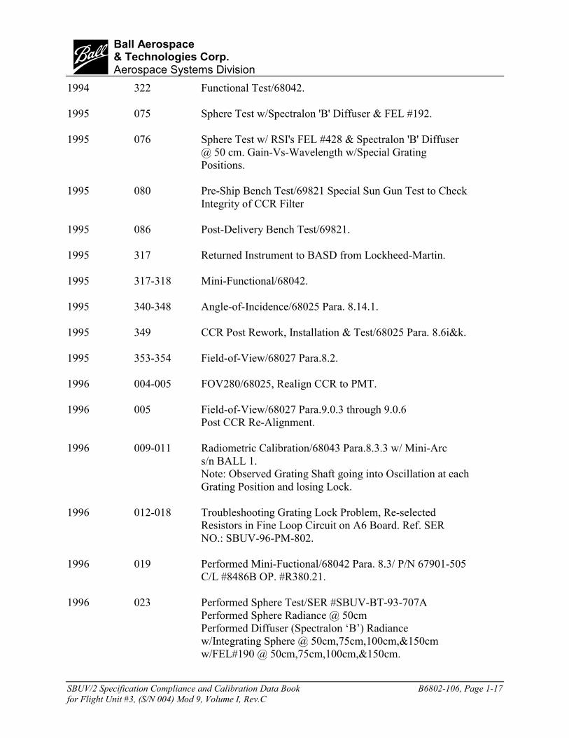
1994 322 Functional Test/68042.
1995 075 Sphere Test w/Spectralon 'B' Diffuser & FEL #192.
1995 076 Sphere Test w/ RSI's FEL #428 & Spectralon 'B' Diffuser@ 50 cm. Gain-Vs-Wavelength w/Special GratingPositions.
1995 080 Pre-Ship Bench Test/69821 Special Sun Gun Test to CheckIntegrity of CCR Filter
1995 086 Post-Delivery Bench Test/69821.
1995 317 Returned Instrument to BASD from Lockheed-Martin.
1995 317-318 Mini-Functional/68042.
1995 340-348 Angle-of-Incidence/68025 Para. 8.14.1.
1995 349 CCR Post Rework, Installation & Test/68025 Para. 8.6i&k.
1995 353-354 Field-of-View/68027 Para.8.2.
1996 004-005 FOV280/68025, Realign CCR to PMT.
1996 005 Field-of-View/68027 Para.9.0.3 through 9.0.6Post CCR Re-Alignment.
1996 009-011 Radiometric Calibration/68043 Para.8.3.3 w/ Mini-Arcs/n BALL 1.Note: Observed Grating Shaft going into Oscillation at eachGrating Position and losing Lock.
1996 012-018 Troubleshooting Grating Lock Problem, Re-selectedResistors in Fine Loop Circuit on A6 Board. Ref. SERNO.: SBUV-96-PM-802.
1996 019 Performed Mini-Fuctional/68042 Para. 8.3/ P/N 67901-505C/L #8486B OP. #R380.21.
1996 023 Performed Sphere Test/SER #SBUV-BT-93-707APerformed Sphere Radiance @ 50cmPerformed Diffuser (Spectralon ‘B’) Radiancew/Integrating Sphere @ 50cm,75cm,100cm,&150cmw/FEL#190 @ 50cm,75cm,100cm,&150cm.

SBUV/2 Specification Compliance and Calibration Data Book B6802-106, Page 1-18for Flight Unit #3, (S/N 004) Mod 9, Volume I, Rev.C
bBall Aerospace& Technologies Corp.Aerospace Systems Division
1996 024 Continued Sphere Test/SER #SBUV-BT-93-707APerformed Diffuser (Spectralon ‘B’) Radiancew/FEL#191 @ 50cm,75cm,100cm,&150cmw/D2#YE-964 @ 50cm,75cm,100cm,&150cm.
1996 025 Completed Sphere Test/SER #SBUV-BT-93-707Aw/ Sphere Radiance @ 50cm.
1996 026 Performed Bench Test/173786Calibration Lamp Closed Command FailureAB Report indicates noise on line caused Lamp Motor tostop, Ref: SER #SBUV-PM-96-808.
1996 029 Completed Bench Test/173786Primary & Backup Albedos and CCR Response Check.
1996 030 Performed Radiometric Calibratio/68043 Para. 8.3.3w/Mini-Arc S/N #Ball I, Test Diffuser Spectralon ‘H1’,Collimating Mirror S/N ‘C’.
1996 031 Performed Radiometric Calibration/68043 Para 8.3.2w/D2 Lamp S/N YE-959 and YE-964 w/Optronics P/S,YE-959, YE-964 w/Oriel P/S, Test Diffuser Spectralon‘H1’, Collimating Mirror S/N ‘C’.
1996 032 Performed Radiometric Calibration/68043 Para 8.3.2w/D2 Lamps S/N YE-959, S/N RC0863 and S/N RC0876w/Optronics P/S, Test Diffuser Spectralon ‘H1’,Collimating Mirror S/N ‘C’.
1996 033 Performed Radiometric Calibration/68043 Para 8.3.1bw/FEL S/N 191, S/N 257, Test Diffuser Spectralon ‘H1’,Collimating Mirror ‘C’.
1996 040 Performed Radiometric Calibration/68043 Para 8.4.2,w/D2 Lamps S/N YE-959 and S/N YE-964 w/Halon ‘D’Diffuser, NITF.
1996 043 Performed Radiometric Calibration/68043 Para 8.4.2,w/D2 Lamps S/N RC0863 and S/N RC0876 w/Halon ‘D’Diffuser, NITF.

SBUV/2 Specification Compliance and Calibration Data Book B6802-106, Page 1-19for Flight Unit #3, (S/N 004) Mod 9, Volume I, Rev.C
bBall Aerospace& Technologies Corp.Aerospace Systems Division
1996 044 Performed Radiometric Calibration/68043 Para 8.4.1,w/FEL Lamps S/N 190, S/N 191 and S/N 257 w/Halon ‘D’Diffuser, NITF.
1996 059-060 Performed Electrical/Optical Performance/68042 (Pre-Life Test)
1996 067 Started Grating Shaft LIFE TEST w/-Z Axis Up andGrating Shaft Vertical. Running Test using SWEETPcomputer. Performed “Procedure Great” and Photographedall 12 Discrete Channels.
1996 068 Performed “Procedure Great”. Running Test usingSWEETP.
1996 071 Performed “Procedure Great”. Running Test usingWIMPY.
1996 075 Performed “Procedure Great”.
1996 086 Performed “Procedure Great”.
1996 099 Shut off Life Test.Removed Calibration Lamp for Rework.Re-installed Calibration Lamp and staked wires.Restarted Life Test.
1996 100 Performed “Procedure Great”.Started Diffuser Reflectivity Test/157372, Completedthrough RUN #3.
1996 101 Performed “Procedure Great”.Completed Procedure Reflect/157372, RUNS #4 ThroughRUN #8.
1996 103 Completed LIFE TEST. Total Time ON is 822 hours 25minutes.
Performed Mini-Functional/173786 (Post-Lamp Rework)
1996 115 Pre-ship Bench Test/173786 Rev. A.
1996 116 Packaged SBUV/2 Instrument into Shipping Container.

SBUV/2 Specification Compliance and Calibration Data Book B6802-106, Page 1-20for Flight Unit #3, (S/N 004) Mod 9, Volume I, Rev.C
bBall Aerospace& Technologies Corp.Aerospace Systems Division
1996 124 Shipped SBUV/2 Instrument to Lockheed Martin in NewJersey.
1996 129 Opened SBUV/2 instrument at Lockheed Martin.Performed Bench Test/173786 Rev. A.
1996 130 SBUV/2 Sensor Module and Electronics ModuleDegaussed By Lockheed Martin.
1997 062 Returned SBUV/2 Instrument to BASD from Lockheed Martin.
1997 070 Performed Bench Test/173786 Post Delivery to BASD fromLockheed Martin.
1997 071-072 Performed STINGER Test SER # SBUV-M0-97-858 Part 1 Para. 2
1997 073 Mini-Functional Test/68042 Para. 8.2-8.5 at VacuumSER# SBUV-MO-97-858SER# SBUV-CS-97-856.
1997 076 Performed Stinger Test in Vacuum and Ambient TemperatureRepeat of Mini-Functional Test/68042 Para. 8.2-8.5
1997 078 Performed Mini-Functional Test/68042 at Vacuum and 0°C,SER# SBUV-MO-97-858 Part III Para. 3.Performed Stinger Test/SER # SBUV-MO-97-858 Part III Para. 5At Vacuum and 0°C.
1997 079 Performed Stinger Test at Vacuum and 10°C,SER# SBUV-MO-97-858 Part III Para. 5&6.
1997 080 Performed Stinger Test at Vacuum and 30° (twice)
1997 081-083 Repeated Stinger Test at 20° in Vacuum.
1997 084 Performed Stinger Test/SER# SBUV-MO-97-858 Part IV atAmbient Pressure and Temperature.Performed Mini-Function Test/68042 SER# SBUV-MO-97-858Part IV Step #3 Para. 8.2-8.5
1997 085 Performed Mini-Functional Test/68042 at Vacuum and AmbientTemperature/SER# SBUV-MO-97-858 Part VPerformed Stinger Test at Vacuum and Ambient Temperature.
1997 086 Performed Stinger Test/SER# SBUV-MO-97-858 Part VI atVacuum and 0°C.

SBUV/2 Specification Compliance and Calibration Data Book B6802-106, Page 1-21for Flight Unit #3, (S/N 004) Mod 9, Volume I, Rev.C
bBall Aerospace& Technologies Corp.Aerospace Systems Division
1997 087 Performed Stinger Test/SER# SBUV-MO-97-858 Part VIa atVacuum and 30°C.
1997 090 Performed Stinger Test at Ambient Temperature and PressureSER# SBUV-MO-97-858 Part VIa.
1997 104 Performed CCR Response Check/173786 Para. 8.6 with Flight 6Electrometer and Notch Filter Installed.
1997 105 Performed CCR Response Check/173786 Para. 8.6 with flight 3Electrometer Installed.
1997 106 Performed Special CCR Test/SER# SBUV-KK-97-862 (threetimes)
1997 107 Performed Special OOB Test/SER# SBUV-KK-97-861.
1997 175 Performed Mini-Functional Test/68042.
1997 176 Performed Mini-Functional Test/68042 Para. 8.2.
1997 178 Performed MiniSNR3/68042 Para. 8.6 with Collimating Mirror C,uncalibrated FEL Lamp and Both Flight and Test Diffuser (H1) onRed Bracket Lamp Rack #165.Performed Radiance, Irradiance Response/68042 Para. 8.7
1997 182 Performed Radiometric Calibration/68043 Para. 8.3.1 with H1Spectralon Test Diffuser on Red Bracket, Collimating Mirror C,and FEL Lamps, (S/N #190 & #191).
1997 183 Performed Radiometric Calibration/68043 Para. 8.3.1 with H1Spectralon Test Diffuser, Collimating Mirror C and FEL Lamp(S/N #257) and Deuterium Lamps (S/N #RC863 & #RC876).
1997 184 Performed Radiometric Calibration/68043 Para. 8.3.26 with H1Spectralon Test Diffuser on Red Bracket, Collimating Mirror C,and Deuterium Lamps (S/N #YE959 & YE964).
1997 188 Performed Continuity Check/173786 Para. 8.1.2
1997 189 Performed Mini-Functional Test/68042 Para 8.2/SER# SBUV-MO-97-881Performed Stinger Test/SER# SBUV-MO-97-881

SBUV/2 Specification Compliance and Calibration Data Book B6802-106, Page 1-22for Flight Unit #3, (S/N 004) Mod 9, Volume I, Rev.C
bBall Aerospace& Technologies Corp.Aerospace Systems Division
1997 190 Performed Stinger Test/SER# SBUV-MO-97-881 Part III atVacuum and Ambient Temperature.
1997 191 Performed Stinger Test/SER# SBUV-MO-97-881 Part III atVacuum and 0°C.
1997 192 Performed Stinger Test/SER# SBUV-MO-97-881 Part III atVacuum and 30°C.
1997 196 Performed Mini-Functional Test/68042Performed Stinger Test/SER# SBUV-MO-97-881 at AmbientTemperature and Pressure.
1997 203 Performed Spectral CCR Test/SER# SBUV-MO-97-884
1997 204 Performed Procedure “OOBGLASS”/SER# SBUV-MO-97-885with Uncalibrated FEL Lamp S/N B with No Filter (CCRMasked).Repeated Test with Uncalibrated FEL Lamp S/N B with FilterS/N #KG4-03FCG169
1997 205 Performed Procedure “OOBGLASS”/SER# SBUV-MO-97-885with Uncalibrated Deuterium Lamp S/N YE939 with CCR Maskedand No FilterRepeated Test with Uncalibrated Deuterium Lamp S/N YE939with Filter #KG403FCG169.
1997 218 Performed Procedure “TEMPRES” at 0°C/160859
1997 219 Performed Procedure “TEMPRES” at 30°C/160859
1997 220 Performed Procedure “TEMPRES” at 20°C/160859
1997 223 Performed Procedure “OOBGLASS” /SER# SBUV-MO-97-885with Frosted Uncalibrated FEL Lamp, No Filter, CCR Masked andClear Uncalibrated FEL Lamp S/N B with filter #KG4-03FCG169Performed Special CCR Test/SER# SBUV-MO-97-884 usingClear Uncalibrated FEL Lamp S/N B.
1997 224-225 Performed Dynamic Range & Linearity Test/157361
1997 227 Performed Out of Band Response Test/68032 in the Solarium withCCR masked and Filter #KG4-03FCG169 over the aperature.Removed the Filter and CCR Mask and Repeated Out of BandResponse Test.

SBUV/2 Specification Compliance and Calibration Data Book B6802-106, Page 1-23for Flight Unit #3, (S/N 004) Mod 9, Volume I, Rev.C
bBall Aerospace& Technologies Corp.Aerospace Systems Division
1997 231 Performed Continuity Test/173786
1997 232 Performed Pre-Ship Bench Test/173786
1997 234 Shipped SBUV/2 Instrument to Lockheed Martin.
1997 238 Performed Mini-Functional Test/173786 Post Delivery.
1999 054 Returned SBUV/2 Instrument to BASD from Lockheed Martin.
1999 061 Performed Receiving Bench Test /173786.
1999 068 Performed Minifunction Test/68042 Para. 8.2, 8.3, 8.4 and 8.5.
1999 069 Performed Diffuser Reflectivity Test Run #1 and #2 /157372.
1999 070 Performed Diffuser Reflectivity Test Run #3 and #4/157372.Performed Radiometric Calibration on PTF/68043 Para. 8.3.1 withH1 Spectralon Test Diffuser, Collimating Mirror C, FEL Lamp#257 and D2 Lamp #YE964.
1999 071 Performed Diffuser Reflectivity Test Run #4, #5 and #6/157372.
1999 074 Performed Diffuser Reflectivity Test Run #8/157372.Performed Radiometric Calibration on PTF/68043 Para. 8.3.1 withH1 Spectralon Test Diffuser, Collimating Mirror C and FEL Lamp#191.
1999 075 Performed H1 Diffuser Angle of Incidence Test/68025 Para. 8.14.
1999 083 Performed Pre-Ship Bench Test/173786.Performed Lamp Test for CCR per SER# SBUV/2-KK-99-945.
1999 096 Shipped SBUV/2 Instrument to Lockheed Martin.
1999 103 Performed Post-Delivery Bench Test/173786.

SBUV/2 Specification Compliance and Calibration Data Book B6802-106, Page 1-24for Flight Unit #3, (S/N 004) Mod 9, Volume I, Rev. C
bBall Aerospace& Technologies Corp.Aerospace Systems Division
Configuration Comparison for SBUV/2 Instruments
FM 2 FM 3 FM 5 FM 6 FM 7EMU FM 1 MOD 3 MOD 9 FM 4 MOD 4 MOD 8 MOD 10 FM 8S/N 1 S/N 2 S/N 3 S/N 4 S/N 5 S/N 6 S/N 7 S/N 8 S/N 9
CONFIGURATION ITEM 67901-1 -501 -503 -505 -507 -509 -511 -513 -513Hamamatsu Photomultiplier tube, Y N Y Y Y Y Y Y Y preamp, and bleeder string for 5 dynodesDiffuser drive at 80 Hz stepping N/A N Y Y Y Y Y Y Y frequency & mechanism modificationsRedesigned cal lamp housing N/A N Y Y Y Y Y Y Y & diffuser interlockS/M TIROS location change N/A N Y Y Y Y Y Y YChopper vibration clamps N N Y N N N N N NCCM Oscillation Fix N N N N N Y Y Y YCal lamp polarity switching added, N/A N Y Y N Y Y Y Y diffuser heater current tlm. deletedLVPS 25-volt regualtor Y N Y Y N Y Y Y YIncrease cal lamp door comparitor N N Y Y N Y Y Y Y reference currentAluminum foil EMI shield N/A N N N Y N N N NMesh EMI shield N/A N Y Y N Y Y Y YRedesigned grating shaft/housing N N N Y Y Y Y Y Y and encoder finger ringRedesigned grating bearing clamps N N N Y N Y Y Y YAlignment mirrors in place of cube N N Y Y Y Y Y Y YCal lamp heater added, N/A N Y Y Y Y Y Y Y baseplate heater deletedAdditional lift fixture attach points N N Y Y Y Y Y Y YBlacken Ebert cover N N Y Y Y Y Y Y YEnlarge shroud, +Y side N/A N Y Y Y Y Y Y YChange grating memory PROM, N N N Y Y Y Y N/A N/A from 6611 to 6641Grating Servo telemetry deleted N Y Y Y Y Y Y Y YAnode preamp (range 2) gain N N Y Y Y Y Y Y Y roll-off addedJ-Y Gratings, Max. Efficiency 250nm Y N N N N N N N NJ-Y Gratings, Max. Efficiency 180nm N Y Y Y Y Y Y Y YAir spaced depolarizer (not contacted) Y N N N N Y Y Y YSquare depolarizer N N N N N Y Y Y YHammerhead grating shaft stop Y N N N N N N N NShort arm grating shaft stop N Y Y N N N N N N
April 2000

SBUV/2 Specification Compliance and Calibration Data Book B6802-106, Page 1-25for Flight Unit #3, (S/N 004) Mod 9, Volume I, Rev. C
bBall Aerospace& Technologies Corp.Aerospace Systems Division
Configuration Comparison for SBUV/2 Instruments
FM 2 FM 3 FM 5 FM 6 FM 7EMU FM 1 MOD 3 MOD 9 FM 4 MOD 4 MOD 8 MOD 10 FM 8S/N 1 S/N 2 S/N 3 S/N 4 S/N 5 S/N 6 S/N 7 S/N 8 S/N 9
CONFIGURATION ITEM 67901-1 -501 -503 -505 -507 -509 -511 -513 -513
Motor rotor grating shaft stop N N N Y Y Y Y Y Y and Beryllium ShaftDiffuser radiator covered by N/A N Y Y Y Y Y Y Y thermal blanketElectrometer Radiation Shield N N Y Y N Y Y Y YGrating Servo DAC MOD N N N Y N Y Y Y YGrating Servo DAC Mod 1/2 gain N N Y N N N N N NDiffuser Baffle, +Y and +Z N/A N N Y N Y Y Y YBearing Contamination Trap N N N Y N N N Y YGrating Power Transistor Protection N N N Y N N Y Y YA-67510 Diode Protection N N N Y N N Y Y YELM Board Slots Enlarge N N N Y N Y Y Y YGrating Anti-contamination N N N Y N N N Y Y37o Diffuser N N N N N N Y Y YRange 3A N N N N N N Y Y Y2RAM (No PROM) N N N N N N N Y YGrating Motor Shaft New Stop N N N Y N N Y Y Y and StakingBall CCR Diode N N N N N N N Y YOCA CCR Filter N N N Y N N N Y NCCR Bias Cap Change N N N Y N N Y Y YDiffuser Encoder Radiation N/A N N N N N Y Y Y ProtectionDiffuser Link Fine Adjust N/A N N N N N Y Y YEMI Skirt Ground Wire Slot N/A N N Y N N Y Y YChromacoat off Cal Lamp Housing N/A N N Y N N Y Y YBarr CCR Filter N N N N N N Y N YMicrophonic Fix (Notch Filter added to N N N Y N N Y Y Y electrometer)Slow Lock Mod (A6 Board) N N N Y N N Y Y YA6 Minimum Voltage Cap N N N N N N Y Y YA3 Chip Floating Ground Fix (A10 Board) N N N N N N N Y YLooser Grating Bearing Conformance N N N N N N N N YRange 1 Digital Offset Increase (A2 Board) N N N N N N N N Y
(continued)April 2000

SBUV/2 Specification Compliance and Calibration Data Book B6802-106, Page 1-26for Flight Unit #3, (S/N 004) Mod 9, Volume I, Rev. C
bBall Aerospace& Technologies Corp.Aerospace Systems Division

SBUV/2 Specification Compliance and Calibration Data Book B6802-106, Page 2-1for Flight Unit #3, (S/N 004) Mod 9, Volume I, Rev. C
bBall Aerospace& Technologies Corp.Aerospace Systems Division
Section 2 - VIBRATION TEST(Reference Test Procedure 68038)
March and May 1994
Vibration and shock tests were performed on Flight Model 3 from April 21 through April 23,1987. After each axis, the instrument was returned to the clean room, and the Electrical/OpticalPerformance Functional Test (procedure 68042) was conducted.
After the Z-Axis of vibration (conducted on April 23, 1987), a significant increase in grating stepand settle time was observed.
During Thermal Vacuum testing, which followed Vibration testing, digital lock errors occurredin both sweep and discrete modes at less than five degrees centigrade. A broken bearing retainerwas subsequently found to be the cause, and the bearing was replaced. (See MDR-A45904.)
On February 15, and 16, 1988, after a new bearing was installed and all acceptance tests utilizingthe grating assembly were repeated, a Z-Axis workmanship vibration was conducted on both theSensor Module and the Electronics Module. The post vibration Electrical/Optical Functional Testwas performed, and all assemblies met specification.
Vibration and shock tests were performed on the Flight 3 Sensor module in the Z-Axis only onMarch 3, 1994. This test is considered a workmanship test performed after various rework. TheSensor Module was tested before the ELM in order to achieve an encoder “settle-in” and,subsequently, chose more accurate grating positions for the fix memory PROM. Then, afterPROM installations of the ELM were subjected to vibration and shock on May 11, 1994, theELM was also subjected to a one-axis only test.
Each test on the sensor module consisted of acceptance level sine, shown in Table 2-1, andrandom vibration, shown in Table 2-2. Acceptance level shock consisted of the spectra shown inFigure 2-1. The Electronics and Logic Module were tested to the same acceptance levelvibration and shock as the sensor module. In each axis of vibration for both the ELM and thesensor module, a low-level sinusoidal survey (shown in Table 2-3) was run before full levelswere applied. A Sine Burst Test (shown in Figure 2-4) was performed as part of all vibrationtests after November 1991.

SBUV/2 Specification Compliance and Calibration Data Book B6802-106, Page 2-2for Flight Unit #3, (S/N 004) Mod 9, Volume I, Rev. C
bBall Aerospace& Technologies Corp.Aerospace Systems Division
Table 2-1
Acceptance Level Sinusoidal Vibration
FLIGHT UNITFREQUENCY g LEVEL SWEEP RATE
AXIS RANGE (Hz) (0-PEAK) (OCT/MIN)Thurst 5-70* 3.2
(z) 70-110 0.8 4.0Lateral 5-70* 3.6
(x) 70-110 1.0 4.0Lateral 5-70* 4.0
(y) 70-110 2.0 4.0
*Limited to 0.50 D.A.
Table 2-2
Acceptance Level Random Vibration
FREQUENCY POWER SPECTRAL DURATIONRANGE (Hz) DENSITY (g^2/Hz) G-RMS (Min/Axis)
20-75 0.00575-150 +10dB/Oct.150-500 0.05 5.9 1.0
500-2000 -7dB/Oct.

SBUV/2 Specification Compliance and Calibration Data Book B6802-106, Page 2-3for Flight Unit #3, (S/N 004) Mod 9, Volume I, Rev. C
bBall Aerospace& Technologies Corp.Aerospace Systems Division
Figure 2-1 Qualification and Flight Level Shock Spectra

SBUV/2 Specification Compliance and Calibration Data Book B6802-106, Page 2-4for Flight Unit #3, (S/N 004) Mod 9, Volume I, Rev. C
bBall Aerospace& Technologies Corp.Aerospace Systems Division
Table 2-3Low Level Vibration Levels
INPUT 0.25gFREQUENCY RANGE 10-2000Hz
SWEEP RATE 2.0 oct/min.

SBUV/2 Specification Compliance and Calibration Data Book B6802-106, Page 2-5for Flight Unit #3, (S/N 004) Mod 9, Volume I, Rev. C
bBall Aerospace& Technologies Corp.Aerospace Systems Division
Figure 2-2 Sine Waveform

SBUV/2 Specification Compliance and Calibration Data Book B6802-106, Page 2-6for Flight Unit #3, (S/N 004) Mod 9, Volume I, Rev. C
bBall Aerospace& Technologies Corp.Aerospace Systems Division

SBUV/2 Specification Compliance and Calibration Data Book B6802-106, Page 3-1for Flight Unit #3, (S/N 004) Mod 9, Volume I, Rev. C
bBall Aerospace& Technologies Corp.Aerospace Systems Division
Section 3 - THERMAL VACUUM TEST(Reference SER SBUV-KK-94-753)
October-November 1994
SBUV/2 system-level thermal vacuum tests are performed in the Ball chamber named “Combo.”The instrument under test is operated in all four grating modes, and in the four scene modes, atboth high and low temperatures. Thermal vacuum tests are performed without the sensor moduleEMI shield or thermal blankets in order to shorten the interval between temperature plateaus.The sensor module is mounted onto the vacuum test fixture (VTF), and a “cold plate” is attachedto the fixture for temperature control. The electronics and logic module (ELM) is placed into theclosed end of the chamber, where the chamber shroud controls the ELM temperature.
At the beginning of the vacuum test, the instrument is placed in power on and power offconditions at hot and cold temperatures. At these plateaus, 0 and 30 degrees C, the instrument ispowered down and allowed to stabilize thermally (for at least four hours) before restarting. Theinstrument is then exercised by a functional test, and the telemetry is checked to verify correctoperation. An automated sequence collects wavelength calibration and diffuser reflectivity data,using the on-board mercury lamp. After the hot and cold functional tests, radiometric calibrationdata are collected at temperatures (10 and 20 degrees C) that are closer to the anticipated orbitconditions.
We attempted a thermal vacuum test with FM3 in April 1987, then discontinued the test due to acracked retainer in a bearing on the grating shaft. After rework to the grating mechanism, acomplete thermal vacuum test was done in February and March of 1988. There were twoanomalies in this test. First, when the instrument was operated in discrete mode with the backupencoders, the grating servo would not lock in below 4 degrees C. This condition is common tothe old grating shaft mechanisms, which have insufficient gain margins over the temperaturerange. The new grating mechanism with a beryllium shaft and titanium housing, installed in1993, has adequate gain margins. The second anomaly in the 1988 test was that instrument noiseon range 1 increased when the vacuum chamber heater – chiller mechanisms were running.Vibration profiles of the Combo chamber- with the heater-chiller units both on and off - showthat the range 1 noise was a microphonic effect. This problem was eliminated in the next vacuumtest by changing the heater-chiller plumbing.
Despite these difficulties, the FM3 instrument completed the test profile in Figure 3-1 andproduced a comprehensive set of calibration data. One repercussion of the rework in 1993 (andearlier) was that we needed another thermal vacuum test for FM3 to test the new grating shaftmechanism (and other components). Moreover, since the gratings themselves had to be removedfrom the old shaft and installed into the new shaft, the original radiometric calibrations becameunusable. We have also learned several important things about instrument calibrations in recentyears. Consequently, a new thermal vacuum test was performed from 31 October to 9 November

SBUV/2 Specification Compliance and Calibration Data Book B6802-106, Page 3-2for Flight Unit #3, (S/N 004) Mod 9, Volume I, Rev. C
bBall Aerospace& Technologies Corp.Aerospace Systems Division
1994, with three main objectives:
• Verification of the instrument rework
• New vacuum calibration data
• Comparison of instrument response in air and in vacuum
Test procedure 160861 is modified in SER SBUV-KK-94-753 to accomplish those ends. All testconfigurations are consistent with procedure 160861 and are controlled by lower level testprocedures. (160862-160866). These procedures contain specific software procedures, put to useas shown in Table 3-1 to collect appropriate data:
• MINIVAC – All modes of operation are functionally tested. Wavelength calibrationand diffuser reflectivity data are taken with the backup encoders.
• VACHECK – Discrete mode (only) radiometric data collected from an FEL lamp.Wavelength calibration and diffuser reflectivity data are taken with the primaryencoders.
• ORBIT & COLDORB – Data are collected from an uncalibrated FEL lamp, and fromthe on-board mercury lamp, during temperature transitions. This is not calibrationdata.
• VACZOOM – Discrete and sweep mode radiometric data collected from FEL andargon mini-arc lamps. Wavelength calibration and diffuser reflectivity data are takenwith the primary encoders.
The modified test profile is shown in Figure 3-2. Note that the total time in vacuum for the 1994test is the same as the 1988 test. Special calibration data are collected, with and without the portwindow, at ambient temperature (about 27oC) and pressure at the start of this test. One thermalcycle from 0-30 degrees is followed by radiometric calibrations at 10 and 20 degrees C. At theend of the vacuum portion of this test, instrument power is shut off, and the chamber filled withdry nitrogen at ambient pressure. With the chamber still closed, the instrument is powered up,and sweep and discrete mode responses to two lamps are recorded. Then, the chamber is allowedto fill with air, and data are collected again. Figure 3-3 is a plot of instrument temperaturetelemetry from the test. Breaks in this plot are from times when the instrument power is off.
On the VTF, mirror ‘C’ was adjusted to illuminate a test (radiance) diffuser with a collimatedbeam at a 71.6o angle of incidence. The test diffuser was a Spectralon plate, marked H2, identicalin size and shape to the flight (irradiance) aluminum diffuser. Sources for radiometric calibrationwere FEL lamps #191 and #192, and argon mini-arc lamp Ball #1. Another FEL lamp was usedto check response at 0 and 30 degrees, but this lamp (FEL #288) had been fluctuating, makingthis data questionable.

SBUV/2 Specification Compliance and Calibration Data Book B6802-106, Page 3-3for Flight Unit #3, (S/N 004) Mod 9, Volume I, Rev. C
bBall Aerospace& Technologies Corp.Aerospace Systems Division
Although we conduct a variety of calibrations to verify the data, in this test, our intention was toextend the instrument calibration to vacuum wavelengths. These wavelengths were much shorterthan the discrete wavelengths. Accordingly, the most significant information from the thermalvacuum test was the sweep mode data sets. See Table 3-2.
The enhanced thermal vacuum test of 1994 enables us to identify the causes of differencesbetween air and vacuum calibrations. Some of the differences are caused by changes in the VTFrelay optics that alter the irradiance that the instrument receives. There is still a remainingdifference, which is a change in instrument sensitivity in vacuum, and which is very similar todiscrepancies that have been noted in solar irradiance measurements by SSBUV and variousSBUV/2 instruments. An initial description of the problem by W.K. Fowler is found in SERSBUV-WF-94-747, while SER SBUV-WF-95-766 describes this test, the data analyses, andconclusions.

SBUV/2 Specification Compliance and Calibration Data Book B6802-106, Page 3-4for Flight Unit #3, (S/N 004) Mod 9, Volume I, Rev. C
bBall Aerospace& Technologies Corp.Aerospace Systems Division
Table 3-1 Modified Thermal Vacuum Test Sequence---1994
Hours Zone Time Activity Procedure-36 0 20 Pre-Pumpdown Power Up RESTART
Pre-Pumpdown Electrical Functional MINIVAC3Pre-Pumpdown Radiometric Data VACZOOM(FEL 191 with and w/o window, Ball #1)Power Down/QC Verification SHUTOFF
-16 n/z 16 Pump Down Chamber n/a0 1 16 QC Verification/Power Up RESTART
Post-Pumpdown Radiometric Data VACZOOM(FEL 191, Ball #1)Post-Pumpdown Electrical Functional MINIVAC3
16 2 2 Transition to 30° ORBIT18 3 16 30o Soak POWEROFF
30o Power Up RESTART30o Electrical Functional MINIVAC330o Radiometric Check (FEL 288) VACHECK
34 4 10 Transition to 0° ORBITCOLDORB
44 5 16 0° Soak POWEROFF0° Power Up RESTART0° Electrical Functional MINIVAC30° Radiometric Check (FEL 288) VACHECK
60 6 8 Transition to 10o COLDORB10° Radiometric Stabilization (FEL 288) VACHECK
68 7 16 10° Radiometric Calibration VACZOOM(FEL 191 & 192, Ball #1)
84 8 8 Transition to 20° COLDORB20° Radiometric Stab\ilization (FEL 288) VACHECK
92 9 16 20° Radiometric Calibration VACZOOM(FEL 191 & 192, Ball #1)
108 10 2 Transition to Ambient Temperature ORBIT110 11 70 Pre-Bleedup Radiometric Data (FEL 191, VACZOOM
repeat at 48 hours, no mini-arc lamp)Power Down/QC Verification SHUTOFFBleed-Up Chamber n/a
180 12 20 QC Verification/Power Up RESTARTRadiometric Data, in Nitrogen VACZOOM(FEL 191, Ball #1)
200 13 10 Radiometric Data in Air (FEL 191, Ball #1) VACZOOMPower Down, End of Test SHUTOFF

SBUV/2 Specification Compliance and Calibration Data Book B6802-106, Page 3-5for Flight Unit #3, (S/N 004) Mod 9, Volume I, Rev. C
bBall Aerospace& Technologies Corp.Aerospace Systems Division
Figure 3-1 Thermal Vacuum Acceptance Test Profile - 1988

SBUV/2 Specification Compliance and Calibration Data Book B6802-106, Page 3-6for Flight Unit #3, (S/N 004) Mod 9, Volume I, Rev. C
bBall Aerospace& Technologies Corp.Aerospace Systems Division
Figure 3-2 Modified Thermal Vacuum Test Profile - 1994

SBUV/2 Specification Compliance and Calibration Data Book B6802-106, Page 3-7for Flight Unit #3, (S/N 004) Mod 9, Volume I, Rev. C
bBall Aerospace& Technologies Corp.Aerospace Systems Division
Figure 3-3 Thermal Vacuum Temperature Telemetry-1994

SBUV/2 Specification Compliance and Calibration Data Book B6802-106, Page 3-8for Flight Unit #3, (S/N 004) Mod 9, Volume I, Rev. C
bBall Aerospace& Technologies Corp.Aerospace Systems Division

SBUV/2 Specification Compliance and Calibration Data Book B6802-106, Page 4-1for Flight Unit #3, (S/N 004) Mod 9, Volume I, Rev. C
bBall Aerospace& Technologies Corp.Aerospace Systems Division
Section 4 - MASS PROPERTIES(Reference Test Procedure 68037)
July 1994
The weight, center of gravity, and envelope dimensions have been determined for the Electronicsand Logic Module and for the Sensor Module. Table 4-1 and Figures 4-1 through 4-6 give theweight, show the location of the center of gravity, and give the envelope dimensions for both theSensor Module and the Electronics and Logic Module. All measurements are withinspecification.
The addition of a lead shield to the electrometer, new cal lamp switcher components, and newEMI shield to the SM,, increase its weight by approximately two pounds. Therefore, the totalweight would be approximately 86 pounds. CCR 1293 changes the specification weight to 88pounds.

SBUV/2 Specification Compliance and Calibration Data Book B6802-106, Page 4-2for Flight Unit #3, (S/N 004) Mod 9, Volume I, Rev. C
bBall Aerospace& Technologies Corp.Aerospace Systems Division
Table 4-1INSTRUMENT WEIGHT
WEIGHTASSEMBLY SPECIFICATION MEASUREMENT
Sensor Module 62 Pounds (Target) 60.83 Pounds(with thermal blankets
and EMI Shield)
Electronics and 26 Pounds (Target) 25.34 PoundsLogic Module
TOTAL 88 Pounds Maximum 86.17 Pounds

SBUV/2 Specification Compliance and Calibration Data Book B6802-106, Page 4-3for Flight Unit #3, (S/N 004) Mod 9, Volume I, Rev. C
bBall Aerospace& Technologies Corp.Aerospace Systems Division
Figure 4-1a. Sensor Module Center of Gravity in X-Z Position

SBUV/2 Specification Compliance and Calibration Data Book B6802-106, Page 4-4for Flight Unit #3, (S/N 004) Mod 9, Volume I, Rev. C
bBall Aerospace& Technologies Corp.Aerospace Systems Division
Figure 4-1b. Sensor Module Center of Gravity in X-Y Position

SBUV/2 Specification Compliance and Calibration Data Book B6802-106, Page 4-5for Flight Unit #3, (S/N 004) Mod 9, Volume I, Rev. C
bBall Aerospace& Technologies Corp.Aerospace Systems Division
Figure 4-2 Electronics and Logic Module Center of Gravity

SBUV/2 Specification Compliance and Calibration Data Book B6802-106, Page 4-6for Flight Unit #3, (S/N 004) Mod 9, Volume I, Rev. C
bBall Aerospace& Technologies Corp.Aerospace Systems Division
Figure 4-3 Sensor Module Envelope

SBUV/2 Specification Compliance and Calibration Data Book B6802-106, Page 4-7for Flight Unit #3, (S/N 004) Mod 9, Volume I, Rev. C
bBall Aerospace& Technologies Corp.Aerospace Systems Division
Figure 4-4 Sensor Module Interface Footprint

SBUV/2 Specification Compliance and Calibration Data Book B6802-106, Page 4-8for Flight Unit #3, (S/N 004) Mod 9, Volume I, Rev. C
bBall Aerospace& Technologies Corp.Aerospace Systems Division
Figure 4-5 Electronics and Logic Module Y-Z Dimension.

SBUV/2 Specification Compliance and Calibration Data Book B6802-106, Page 4-9for Flight Unit #3, (S/N 004) Mod 9, Volume I, Rev. C
bBall Aerospace& Technologies Corp.Aerospace Systems Division
Figure 4-6 Electronics and Logic Module X-Y Dimension.

SBUV/2 Specification Compliance and Calibration Data Book B6802-106, Page 4-10for Flight Unit #3, (S/N 004) Mod 9, Volume I, Rev. C
bBall Aerospace& Technologies Corp.Aerospace Systems Division

SBUV/2 Specification Compliance and Calibration Data Book B6802-106, Page 5-1for Flight Unit #3, (S/N 004) Mod 9, Volume I, Rev. C
bBall Aerospace& Technologies Corp.Aerospace Systems Division
Section 5 - TELEMETRY CALIBRATION
This section contains the conversion factors for both the analog and Digital “A” Sub-Multiplexertemperature, voltage and current monitors. The calibrations of telemetry from these sensors arebased on the circuit designs. No special tests are performed to calibrate these sensors, but dataare recorded from each monitor circuit during all instrument testing. This specific Flight 3telemetry data are presented here, along with conversions to the appropriate units.
The Digital “A” Sub-Multiplexer data points are sampled by the instrument every 16 seconds,and are included in the Digital “A” telemetry stream. Each value is an 8-bit binary number,ranging from 0 to 255 counts.
The Analog telemetry data points are voltages continuously available on discrete lines. TheSystem Test Equipment (STE) samples these voltages periodically and converts them to countsfor data processing. The data presented here are the actual voltage output by the instrument. Formore details, see the GE/Astro Space Division (RCA) “SBUV/2 Unique Instrument InterfaceSpecification,” document IS 2295548, Section 3.1.5.
TEMPERATURES
Only one thermistor component type is used for temperature monitoring with the SBUV/2instrument, but each sensor is wired into one of five different circuit types. The circuit types aredesigned to provide the best resolution and linear response over different nominal ranges. Table5-1 shows the conversions for these five types. Note the mixture of Analog and Digital telemetryfor the temperature data. The individual sensor temperatures are converted in only one kind oftelemetry, and these are listed in Table 5-2. Figures 5-1 through 5-7 show the conversionsgraphically. The temperature conversions have been extended beyond nominal ranges, in somecases, where the telemetry continues to supply useful data
The two differential monitors are intended to measure the temperature difference across theSensor Module (SM). The differential monitors consists of a pair of thermistors on opposite sidesof the SM. One is used as the reference; the other is used to calculate the difference:
If we call the reference telemetry (counts) A,then we use Table 5-1 to convert to temperature TA.But the differential telemetry (counts) BMust first be changed into corrected counts C,By the formula C = A + 0.107499B – 13.706C is now converted to temperature TCUsing the same column of Table 5-1.The temperature differential is TD = TC - TA
The nominal temperature range for the differential sensors is +/- 5 degrees C. Environmental testhave shown all of the temperature telemetry to be accurate and consistent.

SBUV/2 Specification Compliance and Calibration Data Book B6802-106, Page 5-2for Flight Unit #3, (S/N 004) Mod 9, Volume I, Rev. C
bBall Aerospace& Technologies Corp.Aerospace Systems Division
VOLTAGES
Table 5-3 lists the conversion factors for the voltage monitors, the nominal telemetry values, aswell as actual Flight 3 data. These actual data are included on the graphs of the conversions inFigures 5-8 through 5-17. Note that the -15 volt monitors (Servo and Sensor) are referenced tothe +5 volt line; therefore, the conversion requires both values.
CURRENTS
Table 5-4 lists the conversion factors, nominal and actual values for the current monitors.Figures 5-18 through 5-21 show the conversions and actual Flight 3 data. Both voltage andcurrent telemetry have been repeatable throughout the instrument tests.

SBUV/2 Specification Compliance and Calibration Data Book B6802-106, Page 5-3for Flight Unit #3, (S/N 004) Mod 9, Volume I, Rev. C
bBall Aerospace& Technologies Corp.Aerospace Systems Division
Table 5-1Temperature Sensor Conversions
SENSOR TYPE 1 TYPE 2 TYPE 3 TYPE 4 TYPE 5NOMINALRANGE: 0 TO 80 -15 TO 45 -5 TO 35 -15 TO 45 -30 TO 80TLM: DIGITAL ANALOG DIGITAL ANALOG DIGITAL DIGITAL ANALOGGRAPH: FIG. 5-1 FIG. 5-2 FIG. 5-3 FIG. 5-4 FIG. 5-5 FIG. 5-6 FIG. 5-7DEGREESCOUNTS VOLTS COUNTS VOLTS COUNTS COUNTS VOLTS
-30 4.74-20 5.15 4.57-15 250 5.01 179 4.45-10 5.513 242 4.84 170 4.32-5 247 161 4.160 249 4.98 221 4.42 235 150 3.995 140 3.7910 217 4.35 196 3.92 206 128 3.5715 117 3.3420 183 3.67 168 3.36 176 105 3.1025 167 3.33 154 3.08 94 2.8630 150 3.00 139 2.79 145 84 2.6135 130 74 2.3740 119 2.39 112 2.25 116 65 2.1445 100 2.01 57 1.9150 93 1.86 89 1.78 91 1.7160 72 1.44 69 1.396 70 1.3570 55 1.10 54 1.08 54 1.0580 42 0.085 41 0.831 0.81

SBUV/2 Specification Compliance and Calibration Data Book B6802-106, Page 5-4for Flight Unit #3, (S/N 004) Mod 9, Volume I, Rev. C
bBall Aerospace& Technologies Corp.Aerospace Systems Division
Table 5-2Temperature Sensors
SENSOR GRAPHTYPE TELEMETRY FIGURE
LOCATION (Table 5-1) TYPE NO.Calibraiton Lamp Housing 1 Digital 5-1Diffuser Plate 1 Digital 5-1Sensor Module Baseplate 1 Analog 5-2Sensor Module Baseplate (#2 sensor) 2 Digital 5-3Calibration Lamp Motor 2 Analog 5-4Calibration Lamp Power Supply 2 Analog 5-4Diffuser Motor 2 Analog 5-4Diffuser Radiator 2 Analog 5-4Chopper Motor 2 Analog 5-4Depolarizer Housing 2 Analog 5-4Grating Motor 2 Analog 5-4Electrometer 2 Analog 5-4High Voltage Power Supply 2 Analog 5-4Electronics & Logic Module 2 Analog 5-4Low Voltage Power Supply (in ELM) 2 Analog 5-4PMT Housing 3 Digital 5-5CCR Diode 3 Digital 5-5Sensor Module -Y Reference 4 Digital 5-6Sensor Module +Y Differential 4 See TextSensor Module -Z Reference 4 Digital 5-6Sensor Module +Z Differential 4 See TextSensor Module Shroud 5 Analog 5-7

SBUV/2 Specification Compliance and Calibration Data Book B6802-106, Page 5-5for Flight Unit #3, (S/N 004) Mod 9, Volume I, Rev. C
bBall Aerospace& Technologies Corp.Aerospace Systems Division
Figure 5-1 Type I Temperature Sensor Digital Telemetry

SBUV/2 Specification Compliance and Calibration Data Book B6802-106, Page 5-6for Flight Unit #3, (S/N 004) Mod 9, Volume I, Rev. C
bBall Aerospace& Technologies Corp.Aerospace Systems Division
Figure 5-2 Type I Temperature Sensor Analog Telemetry

SBUV/2 Specification Compliance and Calibration Data Book B6802-106, Page 5-7for Flight Unit #3, (S/N 004) Mod 9, Volume I, Rev. C
bBall Aerospace& Technologies Corp.Aerospace Systems Division
Figure 5-3 Type 2 Temperature Sensor Digital Telemetry

SBUV/2 Specification Compliance and Calibration Data Book B6802-106, Page 5-8for Flight Unit #3, (S/N 004) Mod 9, Volume I, Rev. C
bBall Aerospace& Technologies Corp.Aerospace Systems Division
Figure 5-4 Type 2 Temperature Sensor Analog Telemetry

SBUV/2 Specification Compliance and Calibration Data Book B6802-106, Page 5-9for Flight Unit #3, (S/N 004) Mod 9, Volume I, Rev. C
bBall Aerospace& Technologies Corp.Aerospace Systems Division
Figure 5-5 Type 3 Temperature Sensor Telemetry

SBUV/2 Specification Compliance and Calibration Data Book B6802-106, Page 5-10for Flight Unit #3, (S/N 004) Mod 9, Volume I, Rev. C
bBall Aerospace& Technologies Corp.Aerospace Systems Division
Figure 5-6 Type 4 (Differential) Temperature Sensor Telemetry
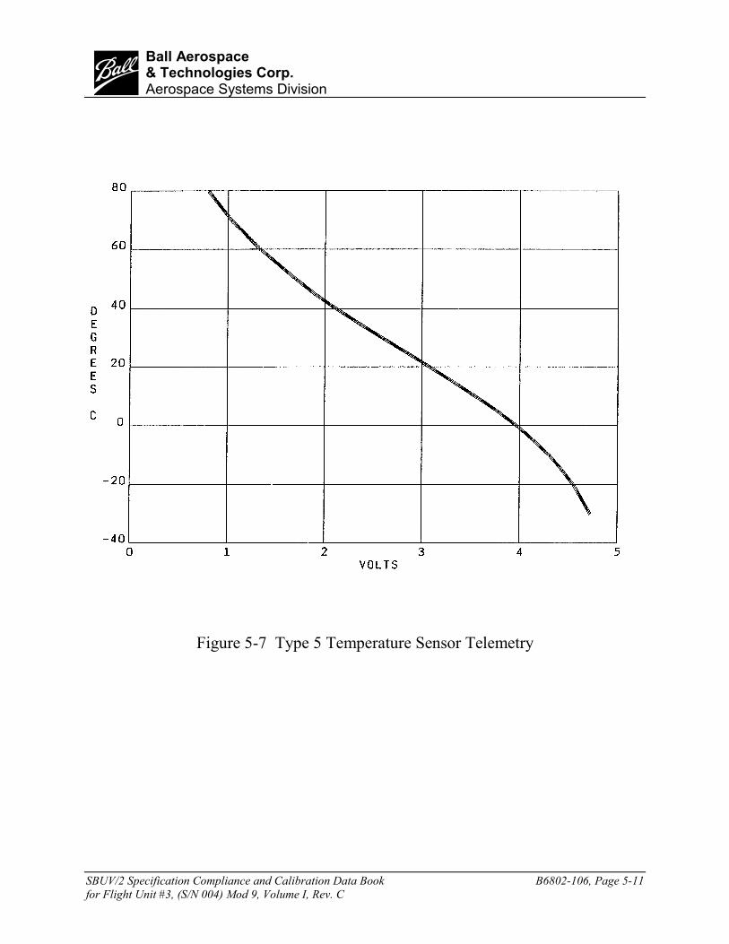
SBUV/2 Specification Compliance and Calibration Data Book B6802-106, Page 5-11for Flight Unit #3, (S/N 004) Mod 9, Volume I, Rev. C
bBall Aerospace& Technologies Corp.Aerospace Systems Division
Figure 5-7 Type 5 Temperature Sensor Telemetry

SBUV/2 Specification Compliance and Calibration Data Book B6802-106, Page 5-12for Flight Unit #3, (S/N 004) Mod 9, Volume I, Rev. C
bBall Aerospace& Technologies Corp.Aerospace Systems Division
Table 5-3Voltage Monitor Conversions
CONVERSION NOMINAL ACTUAL FLT.3TELEMETRY FACTOR TELEMETRY TELEMETRY FIGURE
VOLTAGE TYPE (N=COUNTS) VALUE VALUE NO.5V Digital 0.0333 V/N 150 146-148 5-8E-CAL Ref. (6.4V) Digital 0.04 V/N 160 160-161 5-910 V Logic, DigitalThermistor Bias Digital 0.667 V/N 150 149-152 5-1015 V Servo, Digital15 V Sensor Digital 0.1 V/N 150 146-149 5-11-15 V Servo 5-12-15 V Sensor Digital* V=0.6083N5-0.5059N-15 145-147 5-1324 V Motor Digital 0.198 V/N 121 129-132 5-1425 V Digital 0.198 V/N 126 121-122 5-1428 V Analog 9.912 V/V 2.82 V 2.88-2.96 V 5-15HVPS (750 V Flt. 3) Digital 6.0 V/N n/a 124-126 5-16Chopper PhaseError Voltage Digital 0.0985 V/N n/a 86-89 5-17
* The -15V conversion depends on the actual value of 5 V as well as -15V.

SBUV/2 Specification Compliance and Calibration Data Book B6802-106, Page 5-13for Flight Unit #3, (S/N 004) Mod 9, Volume I, Rev. C
bBall Aerospace& Technologies Corp.Aerospace Systems Division
Figure 5-8 5 Volt Monitor Telemetry

SBUV/2 Specification Compliance and Calibration Data Book B6802-106, Page 5-14for Flight Unit #3, (S/N 004) Mod 9, Volume I, Rev. C
bBall Aerospace& Technologies Corp.Aerospace Systems Division
Figure 5-9 E-Cal Reference Voltage Monitor Telemetry

SBUV/2 Specification Compliance and Calibration Data Book B6802-106, Page 5-15for Flight Unit #3, (S/N 004) Mod 9, Volume I, Rev. C
bBall Aerospace& Technologies Corp.Aerospace Systems Division
Figure 5-10 10 Volt Monitor Telemetry

SBUV/2 Specification Compliance and Calibration Data Book B6802-106, Page 5-16for Flight Unit #3, (S/N 004) Mod 9, Volume I, Rev. C
bBall Aerospace& Technologies Corp.Aerospace Systems Division
Figure 5-11 +15 Volt Monitor Telemetry

SBUV/2 Specification Compliance and Calibration Data Book B6802-106, Page 5-17for Flight Unit #3, (S/N 004) Mod 9, Volume I, Rev. C
bBall Aerospace& Technologies Corp.Aerospace Systems Division
Figure 5-12 -15 Volt Monitor Telemetry

SBUV/2 Specification Compliance and Calibration Data Book B6802-106, Page 5-18for Flight Unit #3, (S/N 004) Mod 9, Volume I, Rev. C
bBall Aerospace& Technologies Corp.Aerospace Systems Division
Figure 5-13 Voltage for –15V vs. 5V Telemetry

SBUV/2 Specification Compliance and Calibration Data Book B6802-106, Page 5-19for Flight Unit #3, (S/N 004) Mod 9, Volume I, Rev. C
bBall Aerospace& Technologies Corp.Aerospace Systems Division
Figure 5-14 24 & 25 Volt Monitor Telemetry

SBUV/2 Specification Compliance and Calibration Data Book B6802-106, Page 5-20for Flight Unit #3, (S/N 004) Mod 9, Volume I, Rev. C
bBall Aerospace& Technologies Corp.Aerospace Systems Division
Figure 5-15 28 Volt Monitor Telemetry

SBUV/2 Specification Compliance and Calibration Data Book B6802-106, Page 5-21for Flight Unit #3, (S/N 004) Mod 9, Volume I, Rev. C
bBall Aerospace& Technologies Corp.Aerospace Systems Division
Figure 5-16 HVPS Voltage Monitor Telemetry

SBUV/2 Specification Compliance and Calibration Data Book B6802-106, Page 5-22for Flight Unit #3, (S/N 004) Mod 9, Volume I, Rev. C
bBall Aerospace& Technologies Corp.Aerospace Systems Division
Figure 5-17 Chopper Phase Error Voltage Telemetry

SBUV/2 Specification Compliance and Calibration Data Book B6802-106, Page 5-23for Flight Unit #3, (S/N 004) Mod 9, Volume I, Rev. C
bBall Aerospace& Technologies Corp.Aerospace Systems Division
Table 5-4Current Monitors
CONVERSION NOMINAL ACTUAL FLT.3TELEMETRY FACTOR TELEMETRY TELEMETRY FIGURE
CURRENT TYPE (N=COUNTS) VALUE VALUE NO.Calibration Lamp Digital 0.00522 mA/N 192 196-197 5-18Chopper Motor Digital 0.002 A/N n/a 8-11 5-19Calibration Lamp Motor Digital 0.004 A/N n/a 34 5-20Diffuser Motor Digital 0.004 A/N n/a 69 5-20Calibration Lamp Heaters Analog 0.1 A/V 1.73 V 1.78-1.80 V 5-21

SBUV/2 Specification Compliance and Calibration Data Book B6802-106, Page 5-24for Flight Unit #3, (S/N 004) Mod 9, Volume I, Rev. C
bBall Aerospace& Technologies Corp.Aerospace Systems Division
Figure 5-18 Calibration Lamp Current Monitor Telemetry

SBUV/2 Specification Compliance and Calibration Data Book B6802-106, Page 5-25for Flight Unit #3, (S/N 004) Mod 9, Volume I, Rev. C
bBall Aerospace& Technologies Corp.Aerospace Systems Division
Figure 5-19 Chopper Current Monitor Telemetry

SBUV/2 Specification Compliance and Calibration Data Book B6802-106, Page 5-26for Flight Unit #3, (S/N 004) Mod 9, Volume I, Rev. C
bBall Aerospace& Technologies Corp.Aerospace Systems Division
Figure 5-20 Mechanism Motor Current Monitor Telemetry

SBUV/2 Specification Compliance and Calibration Data Book B6802-106, Page 5-27for Flight Unit #3, (S/N 004) Mod 9, Volume I, Rev. C
bBall Aerospace& Technologies Corp.Aerospace Systems Division
Figure 5-21 Heater Current Monitor Telemetry

SBUV/2 Specification Compliance and Calibration Data Book B6802-106, Page 5-28for Flight Unit #3, (S/N 004) Mod 9, Volume I, Rev. C
bBall Aerospace& Technologies Corp.Aerospace Systems Division

SBUV/2 Specification Compliance and Calibration Data Book B6802-106, Page 6-1for Flight Unit #3, (S/N 004) Mod 9, Volume I, Rev. C
bBall Aerospace& Technologies Corp.Aerospace Systems Division
Section 6 - POWER PROFILE/INPUT VOLTAGE(Reference Test Procedure 68026)
May 1987
POWER PROFILE
The instrument power is summarized in Table 6-1. It shows an average orbital power for thevarious buses as well as a maximum orbital average. For more detailed data, see Section 8.3 ofthe Baseline Functional (Power Profile) Procedure, number 68026.
NORMAL OPERATION/INPUT VOLTAGE RANGE
The instrument performed normally when operated from the main power bus and when thevoltage was varied from +27.00 to +29.00 volts. The complete Electrical Functional TestProcedure (68033) was run three time – at 27, 28, and 29 volts. All telemetry was within nominallimits, and instrument performance was within specifications.

SBUV/2 Specification Compliance and Calibration Data Book B6802-106, Page 6-2for Flight Unit #3, (S/N 004) Mod 9, Volume I, Rev. C
bBall Aerospace& Technologies Corp.Aerospace Systems Division
Table 6-1SBUV/2 Flight 3 Power Measurments
* During motor pulse turn-on, the 28 V pulse sustained a 5.5 Amp pulse. This was measured byconnecting a 10,000 µF electrolytic capacitor to the 28 V pulse bus at the ELM input.
** Turn-on pulse current generated by initial cal-lamp relay switching has excluded. With relayswitching, peak current is 1.55 amps.
+28 VOLT +28 VOLT +10 VOLTMAIN BUS PLUS TELEMETRY INTERFACE
SPECIFIC PARAMETER PULSE LOAD BUS BUS BUSMeasured Spec Measured Spec Measured Spec
TYPICAL AVERAGE POWER, WATTS 13.96 17.0 .056 None .060 NoneOperatingh in Discrete Mode with one
Discrete Sun Enable sequence.MAXIMUM ORBITAL AVERAGE POWER, WATTS 17.14 None .056 None .060 None
Operating in Discrete Mode with oneWavelength Cal Enable sequence.
PEAK CURRENT, AMPS * 1.28** 1.50 .002 0.010 .014 0.010

SBUV/2 Specification Compliance and Calibration Data Book B6802-106, Page 7-1for Flight Unit #3, (S/N 004) Mod 9, Volume I, Rev. C
bBall Aerospace& Technologies Corp.Aerospace Systems Division
Section 7 - ELECTRICAL CALIBRATION AND STABILITY(Reference Test Procedure 68026)
June 1997 – April 1999
Table 7-1-a and 7-1-b list the mean E-CAL counts and percent errors for both the Cloud CoverRadiometer and PMT ranges in Discrete and Sweep Modes, after changing the Notch filter in1997. Five data points were used from June through August 1997. Four data points were usedfrom March through April 1999. Table 7-2 lists the tests from which the data were gathered.Figures 7-1 through 7-16 illustrate the stability of the system.
The E-CAL voltage measurements show good stability over the course of the test program. Withthe exception of the zero voltage input, all deviations in the data are less than 2%. Normally,system noise at the very low count rates is responsible for the larger percent error.

SBUV/2 Specification Compliance and Calibration Data Book B6802-106, Page 7-2for Flight Unit #3, (S/N 004) Mod 9, Volume I, Rev. C
bBall Aerospace& Technologies Corp.Aerospace Systems Division
Table 7-1aFlight 3 Electronic Calibration (June - August 1997)
(After changing the notch filter)
MODE DISCRETE SWEEP2 Seconds 4 Seconds 6 Seconds 8 Seconds 10 Seconds
RANGE AFTER PERCENT AFTER PERCENT AFTER PERCENT AFTER PERCENT AFTER PERCENTRETRACE ERROR* RETRACE ERROR* RETRACE ERROR* RETRACE ERROR* RETRACE ERROR*
"A" "B" "C" "D" "E"1 Overrange N/A 8035.2 0.24 Overrange N/A 51.2 37.11** N/A N/A2 9438.2 0.06 145.4 0.69 711.4 0.14 48.6 2.06** N/A N/A3 65.4 3.06** 767.8 0.13 7219 0.04 37470.6 0.13 6087.8 0.03
CCR 44607 0.02 957.6 0.21 9136 0.04 47.6 2.1** 55954 0.04
* Percent Error = (Maximum - Minimum)*100 / Mean** Normal system noise is responsible for the large percent error at the low counts.
Table 7-1bFlight 3 Electronic Calibration (March - April 1999)
(After rinsing the instrument diffuser)
MODE DISCRETE SWEEP2 Seconds 4 Seconds 6 Seconds 8 Seconds 10 Seconds
RANGE AFTER PERCENT AFTER PERCENT AFTER PERCENT AFTER PERCENT AFTER PERCENTRETRACE ERROR* RETRACE ERROR* RETRACE ERROR* RETRACE ERROR* RETRACE ERROR*
"A" "B" "C" "D" "E"1 Overange N/A 8048.25 0.04 Overange N/A 50.50 25.74** N/A N/A2 9452.50 0.03 144.50 0.69 712.3 0.14 48.25 2.07** N/A N/A
3A 65.75 4.56** 768.50 0.26 7219.0 0.11 37477.00 0.02 6088.50 0.03CCR 44625.50 0.03 958.25 0.10 9141.5 0.04 47.00 0.00 46000.40 0.02
* Percent Error = (Maximum - Minimum)*100 / Mean** Normal system noise is responsible for the large percent error at the low counts.

SBUV/2 Specification Compliance and Calibration Data Book B6802-106, Page 7-3for Flight Unit #3, (S/N 004) Mod 9, Volume I, Rev. C
bBall Aerospace& Technologies Corp.Aerospace Systems Division
Table 7-2Electronic Calibration Stability
Run No. Procedure Date Name of Test
1 68042 6/24/97 Electrical/Optical performance, Minifunctional2 68042 6/25/97 Electrical/Optical performance, Minifunctional3 68042 7/15/97 Electrical/Optical performance, Minifunctional4 173786 8/20/97 Bench Test, Pre-Ship, CO5 173786 8/26/97 Bench Test, Post-Delivered, NJ6 173786 3/2/99 Bench Test, Post-Delivery, CO7 68042 3/9/99 Elect./Opt. Performance, Minifunctional8 173786 3/24/99 Bench Test, Pre-Ship, CO9 173786 4/13/99 Bench Test, Post-Delivered, CA

SBUV/2 Specification Compliance and Calibration Data Book B6802-106, Page 7-4for Flight Unit #3, (S/N 004) Mod 9, Volume I, Rev. C
bBall Aerospace& Technologies Corp.Aerospace Systems Division
F lig h t 3 E C A L R a n g e 1 S te p B
8 0 2 08 0 2 58 0 3 08 0 3 5
8 0 4 08 0 4 58 0 5 08 0 5 5
0 1 2 3 4 5 6 7 8 9 1 0
R u n N u m b e r
Cou
nts
Figure 7-1 Flight 3 ECAL Range 1 Step B
F lig h t 3 E C A L R a n g e 1 S te p D
303540455055606570
0 1 2 3 4 5 6 7 8 9 1 0
R u n N u m b e r
Cou
nts
Figure 7-2 Flight 3 ECAL Range 1 Step D

SBUV/2 Specification Compliance and Calibration Data Book B6802-106, Page 7-5for Flight Unit #3, (S/N 004) Mod 9, Volume I, Rev. C
bBall Aerospace& Technologies Corp.Aerospace Systems Division
F lig h t 3 E C A L R a n g e 2 S te p A
9 4 2 0
9 4 3 0
9 4 4 0
9 4 5 0
9 4 6 0
0 1 2 3 4 5 6 7 8 9 1 0
R u n N u m b e r
Cou
nts
Figure 7-3 Flight 3 ECAL Range 2 Step A
F lig h t 3 E C AL R a n g e 2 S te p B
14 2
14 3
14 4
14 5
14 6
14 7
14 8
0 1 2 3 4 5 6 7 8 9 10
R u n N u m b e r
Cou
nts
Figure 7-4 Flight 3 ECAL Range 2 Step B

SBUV/2 Specification Compliance and Calibration Data Book B6802-106, Page 7-6for Flight Unit #3, (S/N 004) Mod 9, Volume I, Rev. C
bBall Aerospace& Technologies Corp.Aerospace Systems Division
F lig h t 3 E C A L R a n g e 2 S te p C
7 00
7 05
7 10
7 15
7 20
0 1 2 3 4 5 6 7 8 9 10
R u n N u m b e r
Cou
nts
Figure 7-5 Flight 3 ECAL Range 2 Step C
F lig h t 3 E C AL R a n g e 2 S te p D
46
47
48
49
50
51
0 1 2 3 4 5 6 7 8 9 10
R u n N u m b e r
Cou
nts
Figure 7-6 Flight 3 ECAL Range 2 Step D

SBUV/2 Specification Compliance and Calibration Data Book B6802-106, Page 7-7for Flight Unit #3, (S/N 004) Mod 9, Volume I, Rev. C
bBall Aerospace& Technologies Corp.Aerospace Systems Division
F lig h t 3 E C A L R a n g e 3 S te p A
6 0
6 2
6 4
6 6
6 8
7 0
0 1 2 3 4 5 6 7 8 9 1 0
R u n N u m b e r
Cou
nts
Figure 7-7 Flight 3 ECAL Range 3 Step A
F lig h t 3 E C A L R a n g e 3 S te p B
7 6 5
7 6 6
7 6 7
7 6 8
7 6 9
7 7 0
7 7 1
0 1 2 3 4 5 6 7 8 9 1 0
R u n N u m b e r
Cou
nts
Figure 7-8 Flight 3 ECAL Range 3 Step B

SBUV/2 Specification Compliance and Calibration Data Book B6802-106, Page 7-8for Flight Unit #3, (S/N 004) Mod 9, Volume I, Rev. C
bBall Aerospace& Technologies Corp.Aerospace Systems Division
F lig h t 3 E C A L R a n g e 3 S te p C
7 2 1 2
7 2 1 4
7 2 1 6
7 2 1 8
7 2 2 0
7 2 2 2
7 2 2 4
0 1 2 3 4 5 6 7 8 9 1 0
R u n N u m b e r
Cou
nts
Figure 7-9 Flight 3 ECAL Range 3 Step C
F lig h t 3 E C AL R a n g e 3 S te p D
37 420
37 440
37 460
37 480
37 500
0 1 2 3 4 5 6 7 8 9 10
R u n N u m b er
Cou
nts
Figure 7-10 Flight 3 ECAL Range 3 Step D

SBUV/2 Specification Compliance and Calibration Data Book B6802-106, Page 7-9for Flight Unit #3, (S/N 004) Mod 9, Volume I, Rev. C
bBall Aerospace& Technologies Corp.Aerospace Systems Division
F lig h t 3 E C A L C C R S te p A
4 4 5 8 0
4 4 6 0 0
4 4 6 2 0
4 4 6 4 0
4 4 6 6 0
0 1 2 3 4 5 6 7 8 9 1 0
R u n N u m b e r
Cou
nts
Figure 7-11 Flight 3 ECAL CCR Step A
F lig h t 3 E C AL C C R S te p B
955
956
957
958
959
960
961
0 1 2 3 4 5 6 7 8 9 10
R u n N u m b er
Cou
nts
Figure 7-12 Flight 3 ECAL CCR Step B

SBUV/2 Specification Compliance and Calibration Data Book B6802-106, Page 7-10for Flight Unit #3, (S/N 004) Mod 9, Volume I, Rev. C
bBall Aerospace& Technologies Corp.Aerospace Systems Division
F lig h t 3 E C AL C C R S tep C
9120
9130
9140
9150
9160
0 1 2 3 4 5 6 7 8 9 10
R u n N u m b er
Cou
nts
Figure 7-13 Flight 3 ECAL CCR Step C
F lig h t 3 E C A L C C R S te p D
4 5
4 6
4 7
4 8
4 9
5 0
0 1 2 3 4 5 6 7 8 9 1 0
R u n N u m b e r
Cou
nts
Figure 7-14 Flight 3 ECAL CCR Step D

SBUV/2 Specification Compliance and Calibration Data Book B6802-106, Page 7-11for Flight Unit #3, (S/N 004) Mod 9, Volume I, Rev. C
bBall Aerospace& Technologies Corp.Aerospace Systems Division
F lig h t 3 E C AL R an g e 3 S w eep
6080
6085
6090
6095
6100
0 1 2 3 4 5 6 7 8 9 10
R u n N u m b er
Cou
nts
Figure 7-15 Flight 3 ECAL Range 3 Sweep
Flight 3 ECAL CCR 3 Sweep
55900
55920
55940
55960
55980
56000
0 1 2 3 4 5 6 7 8 9 10
Run Number
Cou
nts
Figure 7-16 Flight 3 ECAL CCR Sweep

SBUV/2 Specification Compliance and Calibration Data Book B6802-106, Page 7-12for Flight Unit #3, (S/N 004) Mod 9, Volume I, Rev. C
bBall Aerospace& Technologies Corp.Aerospace Systems Division

SBUV/2 Specification Compliance and Calibration Data Book B6802-106, Page 8-1for Flight Unit #3, (S/N 004) Mod 9, Volume I, Rev. C
bBall Aerospace& Technologies Corp.Aerospace Systems Division
Section 8 - SIGNAL-TO-NOISE RATIO AND STABILITY(Reference Test Procedure 68025)
August 1986 – November 1994
The signal-to-noise (SNR) was measured at signal levels which were approximately 0.8 times,1.2 times, and very near the required radiance level. With three data points, a curve is establishedand the signal-to-noise ratio at the required radiance level interpolated from it.
Table 8-1 gives the resulting values measured for signal-to-noise ratio, and describes how theratios were calculated. In all cases, the signal-to-noise ratios measured were greater than theminimum requirements.
Table 8-2 shows the signal-to-noise ratio stability for the discrete and sweep modes. These datawere taken during repeats of test procedure 68042. Figure 8-1 is a graph of the data points forboth modes. Only channel 1 data are presented since this is the best indication of the true SNR.The calculations are the same as for Table 8-1, since for other wavelengths, the SNR dependsentirely on background measurements.
Note that the initial points on the graph (Figure 8-1) are from the original Integration SNR TestProcedure 68025 (Table 8-1), and the remaining points are from the abbreviated SNR portion ofthe Electrical-Optical Performance Test 60842 (Table 8-2). Data collection is similar for thesetwo tests. The results are affected by noise in the lamp, as well as noise in the instrument.Therefore, the increasing SNR values could indicate a reduction in instrument noise, animprovement in the measurements, or a combination of both of these two causes.

SBUV/2 Specification Compliance and Calibration Data Book B6802-106, Page 8-2for Flight Unit #3, (S/N 004) Mod 9, Volume I, Rev. C
bBall Aerospace& Technologies Corp.Aerospace Systems Division
Table 8-1Measured Signal-to-Noise Ratio
Required Discrete SweepSource Required RequiredIntensity Minimum Measured Minimum Measured
Wavelength (Radiance) Signal-to-Noise Signal-to Noise Signal-to-Noise Signal-to-Noise252.0* 1.20X10-3 35 54.7 10 14.3273.5 4.98X10⁻³ 100 435.8 30 139.3283 9.78X10⁻³ 200 1014.2 60 284
287.6 1.30X10⁻² 260 1595 80 348292.2 2.39X10⁻² 400 2429 145 553297.5 3.48X10⁻² 400 2038.3 210 448.5301.9 3.48X10⁻² 400 3916.7 230 939.9305.8 6.72X10⁻² 400 7892.6 400 1533.4312.5 1.49X10⁻¹ 400 756.3 400 3348.1317.5 3.09X10⁻¹ 400 2095.1 400 7735.5
331.2** 2.08 400 3477.6 400 21407.7339.8** 4.12 400 6540 400 34969.2
CCR 1.25 100 134.3 --- ---
* The signal-to—noise ratio for 252nm was calculated as follows:
RatioNoisetoSignalDeviationdardS
CountsMean −−=tan
** The signal-to-noise ratio for 331.2 nm and 339.8 nm was calculated as follows:
( ) RadiancequiredtheatNoisetoSignalCountsforRadiance
RadiancequiredNoiseBackground
CountsMean ReRe −−=�
���
�
• The following calculation was used to determine the remaining signal-to-noise ratios:
NoiseBackgroundCountsMeanRatioNoisetoSignal =−−

SBUV/2 Specification Compliance and Calibration Data Book B6802-106, Page 8-3for Flight Unit #3, (S/N 004) Mod 9, Volume I, Rev. C
bBall Aerospace& Technologies Corp.Aerospace Systems Division
Table 8-2252 nm, Signal-to-Noise Ratio Stability (Ch1)
DATE DISCRETE SWEEP16-Aug-86 54.7 14.310-Apr-87 61.2 50.4721-Apr-87 50.44 50.3622-Apr-87 78.6 52.8423-Apr-87 49.35 43.1710-Feb-88 61.58 50.6512-Feb-88 65.77 41.8916-Feb-88 56.59 48.1321-Dec-88 87.3 72.322-Feb-89 77.6 53.62-Mar-94 61.38 44.317-Mar-94 67.61 46.6227-Apr-94 58.55 46.6715-Nov-94 52.2 48.9

SBUV/2 Specification Compliance and Calibration Data Book B6802-106, Page 8-4for Flight Unit #3, (S/N 004) Mod 9, Volume I, Rev. C
bBall Aerospace& Technologies Corp.Aerospace Systems Division
Figure 8-1 Flight 3 Signal to Noise Ratio Stability 252 nm (Ch. 1)

SBUV/2 Specification Compliance and Calibration Data Book B6802-106, Page 9-1for Flight Unit #3, (S/N 004) Mod 9, Volume I, Rev. C
bBall Aerospace& Technologies Corp.Aerospace Systems Division
Section 9 - BACKGROUND STABILITY(Reference Test Procedure 68027)
June 1997 – April 1999
A notch filter was installed in FM3 in June 1997. The background stability of SBUV/2 FM3instrument is tabulated from June 1997 through April 1999. The results of the 31 tests with theaverages and standard deviations are in Table 9-1. Table 9-2 lists the tests from whichbackground stability data was taken. Graphs of each range and of the CCR are shown in Figures9-1 through 9-4.

SBUV/2 Specification Compliance and Calibration Data Book B6802-106, Page 9-2for Flight Unit #3, (S/N 004) Mod 9, Volume I, Rev. C
bBall Aerospace& Technologies Corp.Aerospace Systems Division
Table 9-1Background Stability Data
Run Date Range 1 Range 2 Range 3 CCR1 6/24/97 63.22 65.58 65.44 64.362 6/25/97 63.22 65.48 64.97 64.363 7/1/97 63.83 65.54 65.25 64.254 7/1/97 64.46 64.56 64.99 64.455 7/1/97 64.44 65.37 64.76 64.376 7/2/97 64.46 65.46 64.60 64.507 7/2/97 64.49 65.42 64.86 64.578 7/2/97 63.97 65.24 65.18 64.479 7/3/97 64.24 65.71 65.39 64.37
10 7/3/97 64.25 65.80 64.85 64.4911 7/8/97 62.65 65.44 65.04 64.4012 7/9/97 63.40 65.47 65.51 64.3013 7/14/97 63.33 65.49 65.01 64.4914 7/15/97 63.18 65.32 64.83 64.5015 7/16/97 63.26 65.51 65.42 64.5016 7/22/97 64.00 65.51 64.41 64.4317 7/23/97 63.63 65.50 65.20 64.4018 8/12/97 63.97 65.57 64.99 64.3119 8/15/97 74.11 65.69 64.84 69.9320 8/20/97 63.26 65.53 65.21 64.3221 8/26/97 63.64 65.46 65.39 64.3622 3/2/99 63.91 65.46 65.19 64.2423 3/9/99 63.38 65.43 65.14 64.3524 3/10/99 63.57 65.37 65.11 64.3225 3/11/99 63.31 65.49 65.04 64.3626 3/11/99 65.53 65.43 65.51 64.2427 3/15/99 63.90 65.42 65.26 64.3128 3/15/99 63.60 65.50 65.15 64.3529 3/24/99 63.60 65.32 65.01 64.3630 4/13/99 63.17 65.57 64.92 64.5131 4/14/99 63.28 65.52 64.89 64.47

SBUV/2 Specification Compliance and Calibration Data Book B6802-106, Page 9-3for Flight Unit #3, (S/N 004) Mod 9, Volume I, Rev. C
bBall Aerospace& Technologies Corp.Aerospace Systems Division
Table 9-2Background Stability Tests
Run Date Procedure Test1 6/24/97 157358 Turn On Procedure (Mini Funcitonal)2 6/25/97 157358 Turn On Procedure (Mini Funcitonal)3 7/1/97 157358 Turn On Proc. (Radiometric Calibration)4 7/1/97 68043 Radiometric Calibration5 7/1/97 68043 Radiometric Calibration6 7/2/97 68043 Radiometric Calibration7 7/2/97 68043 Radiometric Calibration8 7/2/97 68043 Radiometric Calibration9 7/3/97 68043 Radiometric Calibration
10 7/3/97 68043 Radiometric Calibration11 7/8/97 157358 Turn On Procedure (Stinger Test)12 7/9/97 157358 Turn On Procedure (Stinger Test)13 7/14/97 157358 Turn On Procedure (Stinger Test)14 7/15/97 157358 Turn On Procedure (Stinger Test)15 7/16/97 157358 Turn On Procedure (Stinger Test)16 7/22/97 157358 Turn On Procedure (Special CCR Test)17 7/23/97 157358 Turn On Procedure (Special OOB Test)18 8/12/97 157358 Turn On Procedure (Linearity)19 8/15/97 157358 Turn On Procedure (Out of Band Test)20 8/20/97 157358 Turn On Proc. (Pre-Ship Bench Test)21 8/26/97 157358 Turn On Proc. (Post-Delivery Bench Test)22 3/2/99 173786 Post Delivery Bench Test23 3/9/99 68042 Minifunction 24 3/10/99 157358 Turn on procedure25 3/11/99 68043 Radiometric Calibration26 3/11/99 68043 Radiometric Calibration27 3/15/99 157358 Turn on procedure28 3/15/99 68043 Radiometric Calibration29 3/24/99 157358 Turn on procedure30 4/13/99 173786 Post Delivery Bench Test31 4/14/99 173786 Post Delivery Bench Test

SBUV/2 Specification Compliance and Calibration Data Book B6802-106, Page 9-4for Flight Unit #3, (S/N 004) Mod 9, Volume I, Rev. C
bBall Aerospace& Technologies Corp.Aerospace Systems Division
SBUV/2 FM3 Background Stability - Range 1
62
64
66
68
70
72
74
76
0 4 8 12 16 20 24 28 32
Test Number
Inst
rum
ent C
ount
s
Figure 9-1 SBUV/2 Flight 3 Background Stability - Range 1

SBUV/2 Specification Compliance and Calibration Data Book B6802-106, Page 9-5for Flight Unit #3, (S/N 004) Mod 9, Volume I, Rev. C
bBall Aerospace& Technologies Corp.Aerospace Systems Division
SBUV/2 FM3 Background Stability - Range 2
64.40
64.60
64.80
65.00
65.20
65.40
65.60
65.80
66.00
0 4 8 12 16 20 24 28 32
Test Number
Inst
rum
ent C
ount
s
Figure 9-2 SBUV/2 Flight 3 Background Stability - Range 2

SBUV/2 Specification Compliance and Calibration Data Book B6802-106, Page 9-6for Flight Unit #3, (S/N 004) Mod 9, Volume I, Rev. C
bBall Aerospace& Technologies Corp.Aerospace Systems Division
SBUV/2 FM3 Background Stability - Range 3
64.20
64.40
64.60
64.80
65.00
65.20
65.40
65.60
0 4 8 12 16 20 24 28 32
Test Number
Inst
rum
ent C
ount
s
Figure 9-3 SBUV/2 Flight 3 Background Stability - Range 3

SBUV/2 Specification Compliance and Calibration Data Book B6802-106, Page 9-7for Flight Unit #3, (S/N 004) Mod 9, Volume I, Rev. C
bBall Aerospace& Technologies Corp.Aerospace Systems Division
SBUV/2 FM3 Background Stability - CCR
63.00
64.00
65.00
66.00
67.00
68.00
69.00
70.00
71.00
0 4 8 12 16 20 24 28 32
Test Number
Inst
rum
ent C
ount
s
Figure 9-4 SBUV/2 Flight 3 Background Stability – CCR

SBUV/2 Specification Compliance and Calibration Data Book B6802-106, Page 9-8for Flight Unit #3, (S/N 004) Mod 9, Volume I, Rev. C
bBall Aerospace& Technologies Corp.Aerospace Systems Division
SBUV/2 Specification Compliance and Calibration Data Book B6802-106, Page 10-1for Flight Unit #3, (S/N 004) Mod 9, Volume I, Rev. C
bBall Aerospace& Technologies Corp.Aerospace Systems Division
Section 10 - POLARIZATION(Reference Test Procedure 68006)
June 18, 1982
Due to element separation of the original Flight 4 depolarizer (S/N 006a), the Flight 3depolarizer (S/N 006) was removed and placed into the Flight 4 instrument. The Flight 3instrument eventually had depolarizer, S/N 004, installed. After the problems experienced withelement separation of S/N 006a depolarizer, all depolarizers were thermally tested to ensure thatthere would be no element separation. The Flight 3 depolarizer (S/N 004) was thermally cycledthree times between -10 degrees C and 40 degrees C, (qualification temperatures), with aminimum one-hour soak at each temperature plateau. During the thermal test, the depolarizerwas visually inspected for evidence of fringe patterns or damage to its elements. The visualinspections were performed every 15 minutes throughout the test with no signs of separations. Inaddition to visual inspection, depolarizer transmission measurements were later performed ateach plateau with no apparent anomalies.
Depolarizer transmission and depolarization efficiency are determined with a component leveltest. Transmission of the depolarizer is measured over the spectral range from 160 nm to 400 nm.A McPherson, Model 225, Monochromator equipped with a Hinteregger-type gas dischargesource is used to make these measurements. The results ranged from 60.5 percent at 159.9 nm to91.9 percent at 366.3 nm. See Table 10-1 for transmission measurements.
The depolarization efficiency is a test to determine how well the depolarizer scrambles the stateof polarization of incident light. The test fixture consisted of one of two mercury line bandpassfilters (254 or 366 nm) and a 3M polaricoat polaroid filter in the incident beam. A secondpolaricoat Polaroid Filter was used as an analyzer in front of the photomultiplier tube detector.The source used was a mercury pen ray lamp. With the depolarizer removed from the test fixture,the polarizer and light source are rotated 180 degrees to determine the modulation of the fixture.
The depolarizer is then placed in the fixture, and again, the polarizer and light source are rotated180 degrees. The depolarizer is then rotated with respect to the analyzer, in 30-degreeincrements, for a total of 180 degrees, rechecking the modulation at each measurement. Theresidual polarization is determined from the ratio of these two measurements. See Table 10-2and Figure 10-1 for the results, and see Figure 10-2 for the schematic of the test fixture.

SBUV/2 Specification Compliance and Calibration Data Book B6802-106, Page 10-2for Flight Unit #3, (S/N 004) Mod 9, Volume I, Rev. C
bBall Aerospace& Technologies Corp.Aerospace Systems Division
Table 10-1SBUV/2 Flight 3
Depolarizer Transmission MeasurementsJUNE 18, 1982
S/N 004 S/N 006 RatioWavelength (nm) Transmission (%) Transmission (%) S/N 006 / S/N 004
159.9 60.5 63.5 1.050170.5 72.2 74.7 1.035179.3 79.6 76.5 0.999189.8 77.5 79.5 1.026204.7 82.7 83.1 1.005253.7 90.2 89.8 0.996313.2 91.4 91.4 1.000366.3 91.9 91.3 0.993
NOTE: S/N 006 was initially installed in Flight 3 and later removed from Flight 3 to be installed inFlight 4. S/N 004 was installed in Flight 3 in January of 1988.

SBUV/2 Specification Compliance and Calibration Data Book B6802-106, Page 10-3for Flight Unit #3, (S/N 004) Mod 9, Volume I, Rev. C
bBall Aerospace& Technologies Corp.Aerospace Systems Division
Table 10-2SBUV/2 FLIGHT 3
Residual Polarization ResponseJune 18, 1982 S/N 004
Residual ResidualPolarization Polarization
Angle at 254 nm (%) at 366 nm (%)0 1.25 1.3130 1.25 1.5460 1.40 1.7790 1.23 1.39
120 1.07 1.54150 1.54 1.83180 1.22 1.67
NOTE: S/N 006 was initially installed in Flight 3 and later removed form Flight 3 to beinstalled in Flight 4. S/N 004 was installed in Flight 3 in January of 1988.
These data are plotted on the following page.
This specification for sensitivity of the SBUV/2 instrument to polarized light is that it shall be no greaterthan 5%. The requirement for the component level test of the depolarizer is that residual polarizationshall be no greater than 2%.

SBUV/2 Specification Compliance and Calibration Data Book B6802-106, Page 10-4for Flight Unit #3, (S/N 004) Mod 9, Volume I, Rev. C
bBall Aerospace& Technologies Corp.Aerospace Systems Division
Figure 10-1 SBUV/2 Flight 3 Residual Polarization Response

SBUV/2 Specification Compliance and Calibration Data Book B6802-106, Page 10-5for Flight Unit #3, (S/N 004) Mod 9, Volume I, Rev. C
bBall Aerospace& Technologies Corp.Aerospace Systems Division
Figure 10-2 Test Setup

SBUV/2 Specification Compliance and Calibration Data Book B6802-106, Page 10-6for Flight Unit #3, (S/N 004) Mod 9, Volume I, Rev. C
bBall Aerospace& Technologies Corp.Aerospace Systems Division

SBUV/2 Specification Compliance and Calibration Data Book B6802-106, Page 11-1for Flight Unit #3, (S/N 004) Mod 9, Volume I, Rev. C
bBall Aerospace& Technologies Corp.Aerospace Systems Division
Section 11 - DIFFUSER REFLECTIVITY(Reference Test Procedure 157372)
October 1990 – April 1999
This test is done to measure the relative reflectivity of the instrument’s irradiance (solar) diffuserplate. Macro Albedo is the portion of the test software that retrieves diffuser reflectivity data.After a twenty-minute warm-up of the on board mercury lamp, this macro enables the automaticwavelength calibration sequence (WLCAL), which takes 10 sweeps of data with the diffuser inthe monitor position. Sweeps 1 through 4 are with the cal lamp door open, sweeps 5 and 6 withthe door closed, sweeps 7 and 8 with the door open, sweeps 9 and 10 with the door closed again.
The off-line utility program (Reflect) used to reduce the data, selects seven points on either sideof the peak of 10 spectral lines chosen. The counts from these data points are added, and thesum represents the area under the envelopes of each of the spectral lines. These areas are used tofind the ratios of consecutive lamp open to closed sweeps. The ratios or “albedos” are firstcalculated for each of the three open/closed pairs of sweeps, and the mean is calculated.
In the Diffuser Reflectivity Test Procedure, Macro Albedo is run eight consecutive times, and theaverage of these eight measurements is used as a baseline to measure future degradation of thediffuser. The test procedure requires that these averages have no more than 0.5 percent standarderror (except 184.9 nm). After rinsing the diffuser in 1999, we repeated the Diffuser ReflectivityTest. The standard error ranged between 0.10% at 253.7 nm and 0.36% at 313.2 nm, well withinthe required specification. Because this is a repeatability test, the setup is held constant. Themercury lamp is warmed up for 20 minutes before data is taken and is allowed to cool downbetween the eight runs. This test is done on the primary encoders. Table 11-1 contains theresults of the eight runs of the Diffuser Reflectivity Test in 1999.
In order to monitor diffuser reflectivity over time, Macro Albedo has also been incorporated intoseveral of our system level test procedures. Table 11-2 shows diffuser reflectivity at 184.9 nm,253.7 nm and 404.7 nm throughout the testing period of the FM3 instrument. Test conditionscan have a measurable effect on lamp output and reflectivity measurements. Note the change inthe 184.9 nm line at test number 43. This is due to the difference of air versus vacuum condition.Figure 11-1 also shows diffuser reflectivity at 253.7 nm and 404.7 nm tested in 1999 when FM3was reworked at BATC. A brief description of the various test setups (other than DiffuserReflectivity) follows:
Mini-functionals are run before vibration, after each axis of vibration, and after thermal vacuumtesting. Usually, the test is run with the instrument sitting in the primary test fixture. After a 20minute lamp warm-up, Macro Albedo is run with encoders in the primary and then in the backupmode.
Vacuum Functionals. Macro Albedo is tun during the Vacuum Functional and VacuumCalibration portions of thermal vac. Vacuum Functionals are run in zones 0, 1, 3, 5, 7, 9, and 11

SBUV/2 Specification Compliance and Calibration Data Book B6802-106, Page 11-2for Flight Unit #3, (S/N 004) Mod 9, Volume I, Rev. C
bBall Aerospace& Technologies Corp.Aerospace Systems Division
using backup encoders. Vacuum Calibration is run in zones 0, 1, 11, 13, 15, and 17 usingprimary encoders. Note that zone 0 is done before the chamber is pumped down. The lamp iswarmed up each time. The instrument is held in the vacuum test fixture, which has a similarorientation to that of the primary test fixture.
Radiometric Calibration. During Radiometric Calibration, Macro Albedo is run for each lampused. The first four runs are done on the primary test fixture, and the remaining runs are done onthe normal incidence test fixture, where the instrument is rotated 146 degrees about its axis. Allruns have a 20-minute lamp warm-up and are done using the primary encoders.
Bench Test. Similar to Mini-functional, the Bench Test collects two sets of data, using primaryand backup encoders, but the instrument is not in a test fixture. Test conditions at the deliverysite vary greatly.

SBUV/2 Specification Compliance and Calibration Data Book B6802-106, Page 11-3for Flight Unit #3, (S/N 004) Mod 9, Volume I, Rev. C
bBall Aerospace& Technologies Corp.Aerospace Systems Division
Table 11-1Diffuser Relative Reflectivity (Open/Closed Signal Ratio)
# of Run 184.9 nm 253.7 nm 265.2 nm 289.4 nm 296.7 nm 302.2 nm 313.2 nm 334.2 nm 365.0 nm 404.7 nm1 0.00498 0.01361 0.01514 0.01607 0.01625 0.01649 0.01664 0.01740 0.01818 0.018912 0.00510 0.01370 0.01535 0.01612 0.01645 0.01646 0.01697 0.01749 0.01833 0.019063 0.00493 0.01364 0.01512 0.01598 0.01625 0.01638 0.01660 0.01755 0.01818 0.018874 0.00524 0.01375 0.01551 0.01631 0.01646 0.01659 0.01697 0.01766 0.01833 0.019045 0.00548 0.01367 0.01523 0.01604 0.01630 0.01650 0.01654 0.01758 0.01819 0.018906 0.00553 0.01364 0.01520 0.01610 0.01632 0.01647 0.01649 0.01774 0.01821 0.018897 0.00507 0.01375 0.01533 0.01626 0.01646 0.01658 0.01696 0.01768 0.01831 0.018998 0.00539 0.01366 0.01528 0.01607 0.01628 0.01650 0.01646 0.01771 0.01818 0.01891
Average 0.00522 0.01368 0.01527 0.01612 0.01635 0.01650 0.01670 0.01760 0.01824 0.01895STD 2.30E-04 5.18E-05 1.27E-04 1.12E-04 9.44E-05 6.70E-05 2.25E-04 1.18E-04 7.10E-05 7.31E-05
Std err % 1.18047 0.10113 0.22297 0.18494 0.15435 0.10849 0.35991 0.17845 0.10404 0.10309

SBUV/2 Specification Compliance and Calibration Data Book B6802-106, Page 11-4for Flight Unit #3, (S/N 004) Mod 9, Volume I, Rev. C
bBall Aerospace& Technologies Corp.Aerospace Systems Division
Table 11-2Flight 3 Relative Diffuser Reflectivity History
Test TEST WAVELENGTH (nm)TEST # Procedure DESCRIBTION TEST TIME 184.9 253.7 404.7
1 68042 MINI-FUNCTION 10/9/90 11:34 0.00522 0.0158 0.018382 68042 MINI-FUNCTION 10/9/90 12:13 0.00524 0.01576 0.018153 157372 DIFF-REFLECT 10/12/90 9:06 0.00505 0.01584 0.018764 157372 DIFF-REFLECT 10/12/90 12:25 0.00506 0.01593 0.01885 157372 DIFF-REFLECT 10/12/90 15:36 0.005 0.01586 0.018826 157372 DIFF-REFLECT 10/15/90 9:08 0.0051 0.01594 0.018867 157372 DIFF-REFLECT 10/15/90 12:20 0.00505 0.01586 0.018848 157372 DIFF-REFLECT 10/15/90 15:09 0.00508 0.01596 0.018789 157372 DIFF-REFLECT 10/16/90 7:49 0.00511 0.01587 0.0187910 157372 DIFF-REFLECT 10/16/90 12:18 0.00506 0.01597 0.0188311 157372 DIFF-REFLECT 10/16/90 15:52 0.00504 0.01588 0.0188612 68043 RAD-CAL 10/1/91 10:39 0.00518 0.01562 0.0185413 68043 RAD-CAL 10/2/91 9:03 0.0052 0.01575 0.018614 68043 RAD-CAL 10/2/91 13:02 0.00507 0.01565 0.0185115 68043 RAD-CAL 10/3/91 9:08 0.00531 0.01575 0.0186316 68043 RAD-CAL 10/3/91 13:15 0.00518 0.01565 0.0184917 68043 RAD-CAL 10/3/91 17:22 0.00518 0.01575 0.0185618 68043 RAD-CAL 10/4/91 8:03 0.00545 0.01569 0.0185119 68043 RAD-CAL 10/4/91 12:24 0.00545 0.01583 0.0185620 68043 RAD-CAL 10/7/91 8:59 0.00497 0.01578 0.0184721 68043 RAD-CAL 10/8/91 8:49 0.0084 0.01568 0.0184722 68043 RAD-CAL 10/8/91 11:22 0.01034 0.01577 0.0185823 68043 RAD-CAL 10/8/91 14:06 0.01196 0.01565 0.0184224 68043 RAD-CAL 10/9/91 8:01 0.01087 0.01579 0.0185825 68043 RAD-CAL 10/9/91 10:50 0.01283 0.01569 0.0184326 68043 RAD-CAL 10/9/91 13:41 0.01259 0.01579 0.0185727 68043 RAD-CAL 10/10/91 7:51 0.00567 0.01568 0.0184328 68043 RAD-CAL 10/10/91 10:35 0.00549 0.0158 0.0185929 68042 MINI-FUN, PRE-S/M VIB. 3/1/94 15:30 0.00502 0.01487 0.0182630 68042 MINI-FUN, POST S/M VIB. 3/7/94 11:28 0.00492 0.01508 0.0182231 68042 MINI-FUN, PRE-ELM VIB. 4/27/94 12:21 0.00515 0.01489 0.0182132 68042 MINI-FUN, PRE-ELM VIB. 4/27/94 13:02 0.00496 0.01417 0.0175733 68042 MINI-FUN, POST ELM VIB. 5/17/94 10:37 0.00512 0.01475 0.0178934 68042 MINI-FUN, POST ELM VIB. 5/17/94 11:18 0.00512 0.01467 0.0175835 68042 MINI-FUN, PRE-A6 DIODES 9/23/94 12:27 0.005 0.01493 0.0181536 68042 MINI-FUN, PRE-A6 DIODES 9/23/94 13:08 0.00488 0.01501 0.0181237 68042 MINI-FUN, POST A6 DIODES 10/17/94 14:48 0.00477 0.01497 0.0181338 68042 MINI-FUN, POST A6 DIODES 10/17/94 15:28 0.00474 0.01491 0.0181739 68042 MINI-VAC, T/V ZONE 0 10/27/94 15:04 0.00515 0.01467 0.0180540 160866 VACCAL, T/V ZONE 0 10/27/94 16:32 0.00513 0.01455 0.018

SBUV/2 Specification Compliance and Calibration Data Book B6802-106, Page 11-5for Flight Unit #3, (S/N 004) Mod 9, Volume I, Rev. C
bBall Aerospace& Technologies Corp.Aerospace Systems Division
Table 11-2Flight 3 Relative Diffuser Reflectivity History
(Continued)
Test TEST WAVELENGTH (nm)TEST # Procedure DESCRIBTION TEST TIME 184.9 253.7 404.7
41 160866 VACCAL, T/V ZONE 0 10/28/94 7:39 0.00529 0.01469 0.0180842 160866 VACCAL, T/V ZONE 0 10/28/94 13:33 0.00517 0.01471 0.0181143 160866 VACCAL, T/V ZONE 1 11/1/94 11:27 0.01054 0.01465 0.0180544 160866 VACCAL, T/V ZONE 1 11/1/94 16:02 0.01056 0.01467 0.0181345 160863 MINI-VAC, T/V ZONE 1 11/1/94 21:43 0.01046 0.01455 0.0180246 160863 MINI-VAC, T/V ZONE 3 11/2/94 12:51 0.01049 0.01451 0.0181247 160864 VACHECK, T/V ZONE 3 11/2/94 13:59 0.01049 0.0145 0.0181348 160863 MINI-VAC, T/V ZONE 5 11/3/94 9:47 0.0105 0.01559 0.0182449 160864 VACHECK, T/V ZONE 5 11/3/94 10:54 0.01045 0.01528 0.0179750 160864 VACHECK, T/V ZONE 7 11/3/94 19:09 0.01056 0.01517 0.0183351 160864 VACHECK, T/V ZONE 7 11/4/94 0:55 0.01057 0.01522 0.0183552 160864 VACHECK, T/V ZONE 7 11/4/94 3:04 0.01045 0.01512 0.0182753 160864 VACHECK, T/V ZONE 7 11/4/94 5:13 0.01057 0.01522 0.0183654 160866 VACAL, T/V ZONE 7 11/4/94 7:20 0.01049 0.01515 0.0183255 160866 VACAL, T/V ZONE 7 11/4/94 11:17 0.01058 0.01526 0.0183256 160866 VACAL, T/V ZONE 7 11/4/94 15:33 0.01048 0.01516 0.0182257 160864 VACHECK, T/V ZONE 9 11/5/94 2:35 0.01052 0.01494 0.0183158 160864 VACHECK, T/V ZONE 9 11/5/94 4:41 0.01043 0.01481 0.0182559 160864 VACHECK, T/V ZONE 9 11/5/94 6:55 0.01052 0.01492 0.0183560 160866 VACAL, T/V ZONE 9 11/5/94 9:08 0.01043 0.01482 0.0182161 160866 VACAL, T/V ZONE 9 11/5/94 12:46 0.01049 0.01494 0.0183362 160866 VACAL, T/V ZONE 9 11/5/94 16:57 0.01041 0.01479 0.0182563 160866 VACAL, T/V ZONE 11 11/6/94 3:44 0.01033 0.01447 0.0180564 160866 VACAL, T/V ZONE 11+ 11/8/94 11:03 0.01033 0.01441 0.0180365 160866 VACAL, T/V ZONE 11+ 11/8/94 15:03 0.01038 0.01458 0.0181466 160866 VACAL, T/V ZONE 12 11/9/94 9:28 0.01028 0.01462 0.0181967 160866 VACAL, T/V ZONE 12 11/9/94 13:07 0.01022 0.01461 0.0181168 160866 VACAL, T/V ZONE 13 11/10/94 9:20 0.00468 0.01452 0.0180669 160866 VACAL, T/V ZONE 13 11/10/94 12:12 0.00472 0.01454 0.0179970 68042 MINI-FUN, POST T/V 11/15/94 12:50 0.00469 0.01464 0.0182171 68042 MINI-FUN, POST T/V 11/15/94 13:30 0.00459 0.01457 0.0180972 173786 PRE-SHIP BENCH TEST 3/21/95 11:20 0.00564 0.01456 0.0180273 173786 PRE-SHIP BENCH TEST 3/21/95 12:01 0.00596 0.01453 0.0178174 173786 POST-DELI. BENCH TEST 3/27/95 18:56 0.00412 0.01443 0.0181375 173786 POST-DELI. BENCH TEST 3/27/95 19:35 0.00404 0.01431 0.0180276 68042 PRE-SHIP BENCH TEST 11/14/95 8:21 0.00602 0.01419 0.0181177 68042 PRE-SHIP BENCH TEST 11/14/95 9:02 0.00569 0.01418 0.01878 68043 RAD-CAL 1/30/96 12:30 0.00576 0.01423 0.0181979 68043 RAD-CAL 1/31/96 6:57 0.00629 0.0143 0.0183680 68043 RAD-CAL 1/31/96 12:24 0.00552 0.01423 0.01823

SBUV/2 Specification Compliance and Calibration Data Book B6802-106, Page 11-6for Flight Unit #3, (S/N 004) Mod 9, Volume I, Rev. C
bBall Aerospace& Technologies Corp.Aerospace Systems Division
Table 11-2Flight 3 Relative Diffuser Reflectivity History
(Continued)
Test TEST WAVELENGTH (nm)TEST # Procedure DESCRIBTION TEST TIME 184.9 253.7 404.7
81 68043 RAD-CAL 1/31/96 17:02 0.00639 0.01431 0.0182682 68043 RAD-CAL 2/1/96 6:58 0.0058 0.01422 0.0182283 68043 RAD-CAL 2/1/96 11:52 0.00583 0.01432 0.0182584 68043 RAD-CAL 2/1/96 16:05 0.0055 0.01424 0.0181785 68043 RAD-CAL 2/1/96 19:45 0.00563 0.01431 0.0182586 68043 RAD-CAL 2/2/96 7:14 0.00599 0.01424 0.018287 68043 RAD-CAL 2/2/96 10:59 0.006 0.01432 0.0182488 68043 RAD-CAL 2/9/96 10:14 0.0049 0.01409 0.0177689 68043 RAD-CAL 2/9/96 13:14 0.0051 0.01441 0.0182790 68043 RAD-CAL 2/12/96 9:15 0.00489 0.01427 0.0181591 68043 RAD-CAL 2/12/96 12:16 0.00507 0.0144 0.0182692 68043 RAD-CAL 2/13/96 7:44 0.00484 0.01427 0.0181493 68043 RAD-CAL 2/13/96 13:02 0.005 0.01426 0.0181494 68042 MINI-FUN, PRE-LIHE TEST 2/29/96 9:31 0.00552 0.01429 0.0181495 68042 MINI-FUN, PRE-LIHE TEST 2/29/96 10:12 0.0058 0.01423 0.0180296 68043 E-O PERFORMANCE 2/29/96 13:46 0.00545 0.01432 0.0181697 68043 E-O PERFORMANCE 3/1/96 8:38 0.00558 0.01422 0.0180598 68043 E-O PERFORMANCE 3/1/96 10:46 0.00532 0.01422 0.0180599 68043 E-O PERFORMANCE 3/1/96 14:12 0.00574 0.01432 0.01812100 68043 E-O PERFORMANCE 3/1/96 15:47 0.00557 0.01423 0.01803101 68043 E-O PERFORMANCE 3/2/96 16:00 0.00542 0.01419 0.01812102 68043 E-O PERFORMANCE 3/4/96 10:24 0.00575 0.0142 0.01806103 68043 E-O PERFORMANCE 3/4/96 11:12 0.00591 0.0143 0.01817104 68043 E-O PERFORMANCE 3/4/96 12:21 0.00586 0.01422 0.01805105 68043 E-O PERFORMANCE 3/4/96 14:22 0.00547 0.01431 0.01816106 68043 E-O PERFORMANCE 3/4/96 15:30 0.00554 0.01423 0.01807107 68043 E-O PERFORMANCE 3/4/96 17:48 0.00542 0.01429 0.01815108 157372 DIFF-REFLECT 4/9/96 11:17 0.00559 0.01506 0.0191109 157372 DIFF-REFLECT 4/9/96 14:16 0.0059 0.01517 0.01922110 157372 DIFF-REFLECT 4/9/96 16:25 0.00578 0.01505 0.01911111 157372 DIFF-REFLECT 4/10/96 7:42 0.00624 0.01515 0.01919112 157372 DIFF-REFLECT 4/10/96 10:18 0.00591 0.01506 0.01905113 157372 DIFF-REFLECT 4/10/96 12:19 0.00585 0.01515 0.01917114 157372 DIFF-REFLECT 4/10/96 14:37 0.00568 0.01504 0.01906115 157372 DIFF-REFLECT 4/10/96 16:51 0.00638 0.01514 0.01922116 173786 BENCH TEST 4/12/96 11:49 0.00577 0.01517 0.0192117 173786 BENCH TEST 4/12/96 12:30 0.00591 0.01522 0.01926118 173786 PRE-SHIP BENCH TEST 4/24/96 15:33 0.00504 0.01476 0.01873119 173786 PRE-SHIP BENCH TEST 4/24/96 16:13 0.00511 0.01477 0.01846120 173786 POST-DELI. BENCH TEST 5/8/96 14:47 0.00451 0.01473 0.018

SBUV/2 Specification Compliance and Calibration Data Book B6802-106, Page 11-7for Flight Unit #3, (S/N 004) Mod 9, Volume I, Rev. C
bBall Aerospace& Technologies Corp.Aerospace Systems Division
Table 11-2Flight 3 Relative Diffuser Reflectivity History
(Continued)
Test TEST WAVELENGTH (nm)TEST # Procedure DESCRIBTION TEST TIME 184.9 253.7 404.7
121 173786 POST-DELI. BENCH TEST 5/8/96 15:29 0.00443 0.01465 0.01871122 173786 PRE-SHIP BENCH TEST 2/27/97 11:44 0.00431 0.01442 0.01871123 173786 POST-DELI. BENCH TEST 3/11/97 10:42 0.0063 0.01484 0.0194124 173786 POST-DELI. BENCH TEST 3/11/97 11:22 0.00611 0.01489 0.0192125 68042 MINI-FUN 6/25/97 15:49 0.00576 0.01381 0.01902126 68042 MINI-FUN 6/25/97 16:30 0.00579 0.01372 0.01891127 157372 RAD-CAL 7/1/97 10:42 0.0052 0.01374 0.01887128 157372 RAD-CAL 7/1/97 14:57 0.00502 0.01383 0.01906129 157372 RAD-CAL 7/2/97 6:21 0.00503 0.01375 0.0189130 157372 RAD-CAL 7/2/97 10:31 0.0051 0.01383 0.01903131 157372 RAD-CAL 7/2/97 14:37 0.00536 0.01372 0.0189132 157372 RAD-CAL 7/3/97 6:15 0.00541 0.01383 0.01908133 157372 RAD-CAL 7/3/97 10:24 0.00503 0.01373 0.01891134 68042 MINI-FUN 7/15/97 10:59 0.0071 0.01398 0.01958135 68042 MINI-FUN 7/15/97 11:39 0.00697 0.01402 0.01952136 173786 PRE-SHIP BENCH TEST 8/20/97 12:11 0.00725 0.01355 0.0189137 173786 PRE-SHIP BENCH TEST 8/20/97 12:51 0.00711 0.01357 0.01885138 173786 POST-DELI. BENCH TEST 8/26/97 11:46 0.00421 0.0135 0.01897139 173786 POST-DELI. BENCH TEST 8/26/97 12:27 0.004 0.01342 0.01881140 68042 MINI-FUN 3/9/99 15:55 0.00483 0.01369 0.01906141 68042 MINI-FUN 3/9/99 16:35 0.00484 0.01369 0.01889142 157372 DIFF-REFLECT 3/10/99 13:37 0.00498 0.01361 0.01891143 157372 DIFF-REFLECT 3/10/99 16:41 0.00510 0.01370 0.01906144 157372 DIFF-REFLECT 3/11/99 7:15 0.00493 0.01364 0.01887145 68043 RAD-CAL 3/11/99 8:36 0.00695 0.01377 0.01903146 68043 RAD-CAL 3/11/99 12:47 0.00535 0.01363 0.01891147 157372 DIFF-REFLECT 3/11/99 16:39 0.00524 0.01375 0.01904148 157372 DIFF-REFLECT 3/12/99 7:23 0.00548 0.01367 0.01890149 68043 RAD-CAL 3/12/99 9:02 0.00559 0.01376 0.01903150 157372 DIFF-REFLECT 3/12/99 11:23 0.00553 0.01364 0.01889151 157372 DIFF-REFLECT 3/12/99 14:44 0.00507 0.01375 0.01899152 157372 DIFF-REFLECT 3/15/99 9:37 0.00539 0.01366 0.01891153 68043 RAD-CAL 3/15/99 10:45 0.00503 0.01377 0.01907154 173786 PRE-SHIP BENCH TEST 3/24/99 12:53 0.00630 0.01358 0.01887155 173786 PRE-SHIP BENCH TEST 3/24/99 13:33 0.00603 0.0135 0.01879156 173786 POST-DELI. BENCH TEST 4/13/99 15:58 0.00551 0.01342 0.01906157 173786 POST-DELI. BENCH TEST 4/13/99 16:38 0.00523 0.01331 0.01889

SBUV/2 Specification Compliance and Calibration Data Book B6802-106, Page 11-8for Flight Unit #3, (S/N 004) Mod 9, Volume I, Rev. C
bBall Aerospace& Technologies Corp.Aerospace Systems Division
Flight 3 Diffuser Reflectivity (compared with baseline in 1999)
-0.15-0.125
-0.1-0.075-0.05
-0.0250
0.0250.05
140 145 150 155 160
Test Number
Perc
enta
ge C
hang
e Fr
om B
asel
ine
253.7 nm 404.7 nm
Figure 11-1 Diffuser Reflectivity at 253.7 and 404.7 nm

SBUV/2 Specification Compliance and Calibration Data Book B6802-106, Page 12-1for Flight Unit #3, (S/N 004) Mod 9, Volume I, Rev. C
bBall Aerospace& Technologies Corp.Aerospace Systems Division
Section 12 - SHORT TERM STABILITY(Reference Test Procedure 68026)
August 1986
The instrument short-term radiometric stability is specified in GSFC S-480-12, Para 4.4.3.3.1 asfollows:
“The radiometric response of the instrument shall meet the following stability requirements. Thecorrected mean response of the instrument shall not differ by more than one percent from aprevious or subsequent response measurement made while viewing the same source operating atequal intensity but separated in time by at least 24 hours for each wavelength in the DiscreteMode. The mean response is to be determined from at least 50 successive data samples takenwith the wavelength drive stopped at each Discrete Mode position. This instrument data is to becorrected for changes in instrument temperature and other response-dependent parameters, ifany, before comparisons are made.”
A short-term stability test was conducted 20-23 August 1986, using the Primary Test Fixture,Target Control Console, and an FEL light source calibrated by the National Bureau of Standards.Fifty samples of data for each wavelength were collected with the instrument in discrete modeusing the ‘flash-lite’ to stabilize the instrument. A second set of data was taken approximately 24hours later, a third set taken approximately 48 hours later, and a fourth set taken 72 hours later,with the instrument remaining on and with the ‘flash-lite’ operating for the duration of test.Table 12-1 lists the raw data and the day-to-day differences in counts. Table 12-2 lists theaverage counts of all data and the differences. The average short-term instability was found to be0.71 percent. No corrections to instrument data were required.

SBUV/2 Specification Compliance and Calibration Data Book B6802-106, Page 12-2for Flight Unit #3, (S/N 004) Mod 9, Volume I, Rev. C
bBall Aerospace& Technologies Corp.Aerospace Systems Division
Table 12-1Short Term Stability Data
∆1= C Baseline - C 24 hour
∆2= C 48 hour - C 24 hour
∆3= C 72 hour - C 48 hour
C C C CBASE- 24 48 72
NOMINAL LINE HOUR HOUR HOURWAVELENGTH DATA DATA ∆1 DATA ∆2 DATA ∆3
252.0 4393 4459 -66 4376 -83 4419 46273.6 16156 16381 -225 16118 -263 16257 139283.1 25640 25980 -340 25589 -391 25801 212287.7 31767 32220 -453 31712 -508 31962 250292.3 39070 39623 -553 39002 -621 39330 328297.6 49384 50082 -698 49273 -809 49690 417301.9 59641 60470 -829 59484 -986 59982 498305.9 756 766 -10 754 -12 760 6312.6 952 963 -11 949 -14 956 7317.6 1105 1119 -14 1102 -17 1110 8331.3 1573 1593 -20 1567 -26 1579 12339.9 1869 1892 -23 1861 -31 1875 14

SBUV/2 Specification Compliance and Calibration Data Book B6802-106, Page 12-3for Flight Unit #3, (S/N 004) Mod 9, Volume I, Rev. C
bBall Aerospace& Technologies Corp.Aerospace Systems Division
Table 12-2Short Term Stability Calculations
NOTE 1 NOTE2 NOTE3NOMINAL
WAVELENGTH
4C
3∆
C∆ REQUIREMENT
252.0 4412 -35.3 -7.86E-03 <0.01273.6 16228 -116.3 -7.16E-03 <0.01283.1 25752.5 -173 -6.72E-03 <0.01287.7 31915.3 -237 -7.43E-03 <0.01292.3 39256.3 -282 -7.18E-03 <0.01297.6 49607.3 -363 -7.32E-03 <0.01301.9 59894.3 -439 -7.33E-03 <0.01305.9 759 -5.3 -6.98E-03 <0.01312.6 955 -6 -6.28E-03 <0.01317.6 1109 -7.7 -6.94E-03 <0.01331.3 1578 -11.3 -7.16E-03 <0.01339.9 1874.3 -13.3 -7.10E-03 <0.01
Note 1: 44
724824 CCCCC Baseline +++=
Note 2: 33
321 ∆+∆+∆=
∆
Note 3:
4
3∆
=∆CC

SBUV/2 Specification Compliance and Calibration Data Book B6802-106, Page 12-4for Flight Unit #3, (S/N 004) Mod 9, Volume I, Rev. C
bBall Aerospace& Technologies Corp.Aerospace Systems Division

SBUV/2 Specification Compliance and Calibration Data Book B6802-106, Page 13-1for Flight Unit #3, (S/N 004) Mod 9, Volume I, Rev. C
bBall Aerospace& Technologies Corp.Aerospace Systems Division
Section 13 - RESPONSE REPEATABILITY(Procedure 68042 and 68028)
March – November 1994
The main purpose of the response repeatability test is to determine if the instrument has sufferedany response degradation after environmental tests have been performed. Hence, the pre- andpost-vibration and post-vacuum tests are the most critical. Since these responses are checkedduring the test program (and before the standards are re-calibrated), no corrections are made tothe data. Also, the calculation of percent difference in signal assumes a nominal offset of 64counts. Table 13-1 lists the tests by date.
Response repeatability data are taken from the Primary Test Fixture (PTF) in discrete mode. Twosets of data are taken, earth and sun, using a test diffuser and the flight diffuser. The data aretaken during the retrace portion of the discrete scan in the same manner as the radiometriccalibration data.
The Flight 3 instrument was reworked in 1993. New baselines were established in March of1994, and the instrument test and calibration sequence was terminated in November of 1994. Theraw data are presented in Table 13-2 and the normalized data are presented in Table 13-3.Figure 13-1 is a plot of the data presented in Table 13-2.

SBUV/2 Specification Compliance and Calibration Data Book B6802-106, Page 13-2for Flight Unit #3, (S/N 004) Mod 9, Volume I, Rev. C
bBall Aerospace& Technologies Corp.Aerospace Systems Division
Table 13-1TEST CONTAINING RESPONSE REPEATABILITY DATA
DATE PROCEDURE TEST DESCRIPTION2-Mar-94 68042 Baseline Data7-Mar-94 68042 S/M Post Z-axis Vibration27-Apr-94 68042 Pre ELM Vibration11-Nov-94 68042 Post Thermal Vacuum
Table 13-2Response Repeatability Data for FEL #190
Earth Data Sun Data252 nm 298 nm 340 nm 252 nm 298 nm 340 nm
Date Channel 1 Channel 6 Channel 12 Channel 1 Channel 6 Channel 12Range 1 Range 1 Range 2 Range 1 Range 1 Range 2
2-Mar-94 4550.20 54596.85 2021.40 5653.45 66224.60 2396.757-Mar-94 4577.50 54973.60 2027.55 5745.50 67182.95 2422.8527-Apr-94 4566.60 54648.05 2020.25 5721.65 66776.90 2414.8511-Nov-94 4523.30 54298.65 2008.05 5661.15 663331.00 2402.60
Mean 4554.40 54629.29 2019.31 5695.44 66628.86 2409.26Standard Dev. 23.57 276.45 8.16 45.21 440.11 11.79Standard Error 0.26% 0.25% 0.20% 0.40% 0.33% 0.24%

SBUV/2 Specification Compliance and Calibration Data Book B6802-106, Page 13-3for Flight Unit #3, (S/N 004) Mod 9, Volume I, Rev. C
bBall Aerospace& Technologies Corp.Aerospace Systems Division
Table 13-3Percent Difference From Average Response for FEL #190
Earth Data Sun Data252 nm 298 nm 340 nm 252 nm 298 nm 340 nm
Date Channel 1 Channel 6 Channel 12 Channel 1 Channel 6 Channel 12Range 1 Range 1 Range 2 Range 1 Range 1 Range 2
2-Mar-94 0.09% 0.06% -0.10% 0.74% 0.61% 0.52%7-Mar-94 -0.51% -0.63% -0.41% -0.88% -0.83% -0.56%27-Apr-94 -0.27% -0.03% -0.05% -0.46% -0.22% -0.23%11-Nov-94 0.68% 0.61% 0.56% 0.60% 0.45% 0.28%
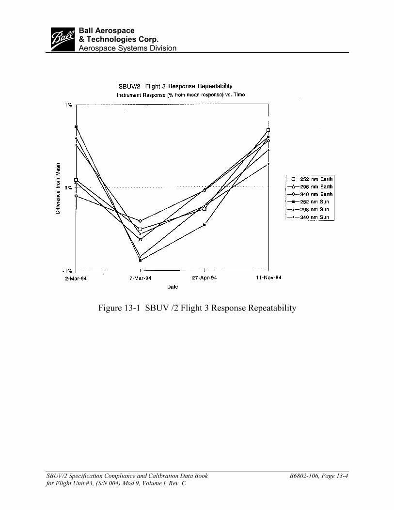
SBUV/2 Specification Compliance and Calibration Data Book B6802-106, Page 13-4for Flight Unit #3, (S/N 004) Mod 9, Volume I, Rev. C
bBall Aerospace& Technologies Corp.Aerospace Systems Division
Figure 13-1 SBUV /2 Flight 3 Response Repeatability

SBUV/2 Specification Compliance and Calibration Data Book B6802-106, Page 14-1for Flight Unit #3, (S/N 004) Mod 9, Volume I, Rev. C
bBall Aerospace& Technologies Corp.Aerospace Systems Division
Section 14 - TIME RESPONSE(Reference Test Procedure 68031)
February 1989
The response time test measures the instrument’s response to a changing light level, the samelevels it will encounter in flight. During an orbit, the maximum light level input from thedaylight portion of the test varies from approximately 1,000 to 16,000 counts on Range 3 at340nm. For this test the daylight portion of the orbit is divided into nine (9) zones of 6.4 minuteseach with the following maximum light levels:
Zone Counts Range1 1,0002 2,000 33 4,000 34 8,000 35 16,000 36 8,000 37 4,000 38 2,000 39 1,000 3
The photomultiplier tube is exposed to the maximum levels by the user of a “flashlite” (a bank ofLEDs turned on and off in phase with the chopper during the electronic calibration portion of thediscrete scan). The intensity of the “flashlite” is changed for each zone, thereby giving thedescribed counts.
The instrument is operated in discrete mode. It views a large diffuser plate illuminated by a FEL-type lamp. Each of the 12 discrete wavelength positions is set at a pre-selected wavelength whichwill give count levels covering Ranges 1,2, and 3 as follows:
Zone Counts Range1 900 12 5,000 13 7,500 14 16,000 15 31,000 16 64,000 17 800 28 3,000 29 15,000 210 30,000 211 60,000 212 900 3

SBUV/2 Specification Compliance and Calibration Data Book B6802-106, Page 14-2for Flight Unit #3, (S/N 004) Mod 9, Volume I, Rev. C
bBall Aerospace& Technologies Corp.Aerospace Systems Division
The test is set up and run in continuous operation with data collected during the daylight portionof the orbit (56 minutes in nine zones) and during the dark portion of the orbit (also 5 minutes).All the data are normalized to the first orbit, zone 1. The time response test procedure specifiesthat the mean response for all 12 discrete mode channels (when corrected for lamp drift) for sixsimulated orbits shall not vary more than +0.5%. Average Flight Model 3 instrument response is+0.13% to –0.34% maximum for all eight orbits (see Figure 14-5). The CCR data shows achange of 0.39% during this test. The CCR is used to measure lamp drift. PMT response iscorrected by this CCR data. (See Figures 14-1 through 14-5.) It can be seen from this data thatthe Flight Model 3 instrument shows almost no measureable time response effects. Thissignificant improvement over Flight Model 2 with the ITT PMT is due to the HamamatsuPhotomultiplier Tube used in the model.
The data reduction is accomplished for each orbit by the following:
N = zone number
S = signal in counts, S1 is the signal from orbit 1, zone 1
Normalized Response: ( ) channeleach for 6464
NR1
n −−
=SSn
Mean: =1 Channel
12 Channelnn /12NR)(NR
CCR Correction Factor ( ) zoneeach for 6464
Fn1 −
−=
SSn
Corrected Mean Response nn F*NR

SBUV/2 Specification Compliance and Calibration Data Book B6892-106, Page 14-3for Flight Unit #6, (S/N 007) Mod 9, Volume I, Rev. C
bBall Aerospace& Technologies Corp.Aerospace Systems Division
Figure 14-1 Channel 2 Corrected and Uncorrected Response

SBUV/2 Specification Compliance and Calibration Data Book B6892-106, Page 14-4for Flight Unit #6, (S/N 007) Mod 9, Volume I, Rev. C
bBall Aerospace& Technologies Corp.Aerospace Systems Division
Figure 14-2 Channel 6 and Uncorrected Response

SBUV/2 Specification Compliance and Calibration Data Book B6892-106, Page 14-5for Flight Unit #6, (S/N 007) Mod 9, Volume I, Rev. C
bBall Aerospace& Technologies Corp.Aerospace Systems Division
Figure 14-3 Channel 12 Corrected and Uncorrected Response

SBUV/2 Specification Compliance and Calibration Data Book B6892-106, Page 14-6for Flight Unit #6, (S/N 007) Mod 9, Volume I, Rev. C
bBall Aerospace& Technologies Corp.Aerospace Systems Division
Figure 14-4 Channel 12 Corrected and Uncorrected Response

SBUV/2 Specification Compliance and Calibration Data Book B6892-106, Page 14-7for Flight Unit #6, (S/N 007) Mod 9, Volume I, Rev. C
bBall Aerospace& Technologies Corp.Aerospace Systems Division
Figure 14-5 PMT Corrected Mean Response

SBUV/2 Specification Compliance and Calibration Data Book B6802-106, Page 15-1for Flight Unit #3, (S/N 004) Mod 9, Volume I, Rev. C
bBall Aerospace& Technologies Corp.Aerospace Systems Division
Section 15 - CONTAMINATION MIRRORSJanuary 1884 – March 1999
The four FM3 contamination mirrors were measured 30 times at 253.7 nm and 16 times at 160.8nm over the test period. Tables 15-1 and 15-2 show the reflectance data over this period.Figures 15-1 and 15-2 are plots of the data. Measurement uncertainty is 1% RMS.
Table 15-1Flight 3 Contamination Mirrors Summary Reflectances At 253.65 NM
DATE MIRROR 16 MIRROR 20 MIRROR 25 MIRROR 275-Jan-84 0.8590 0.8590 0.8650 0.8170
16-Aug-85 0.8550 0.8540 0.8590 0.816015-Oct-86 0.8620 0.8570 0.8630 0.823015-Dec-86 0.8610 0.8610 0.8640 0.816015-Apr-87 0.8620 0.8610 0.8640 0.820011-May-87 0.8580 0.8570 0.8600 0.81808-Sep-87 0.8600 0.8580 0.8620 0.82007-Dec-87 0.8610 0.8550 0.8620 0.821016-Feb-88 0.8592 0.8586 0.8637 0.821223-Mar-88 0.8601 0.8560 0.8630 0.817810-Jun-88 0.8593 0.8584 0.8621 0.81878-Sep-88 0.8590 0.8560 0.8610 0.8190
25-May-89 0.8580 0.8590 0.8580 0.815025-Apr-91 0.8589 0.8561 0.8606 0.815217-Jan-92 0.8557 0.8512 0.8599 0.819319-Feb-93 0.8625 0.8523 0.8559 0.820617-Mar-93 0.8633 0.8555 0.8607 0.824111-Aug-93 0.8516 0.8514 0.8586 0.815428-Oct-93 0.8548 0.8550 0.8593 0.817118-Mar-94 0.8577 0.8569 0.8597 0.817724-Jun-94 0.8574 0.8567 0.8608 0.820819-Sep-94 0.8625 0.8619 0.8642 0.821117-Nov-94 0.8579 0.8578 0.8601 0.819013-Mar-95 0.8641 0.8618 0.8639 0.8240

SBUV/2 Specification Compliance and Calibration Data Book B6802-106, Page 15-2for Flight Unit #3, (S/N 004) Mod 9, Volume I, Rev. C
bBall Aerospace& Technologies Corp.Aerospace Systems Division
Table 15-1FM3 Contamination Summary
Reflectances at 253.65 nm
DATE MIRROR 16 MIRROR 20 MIRROR 25 MIRROR 275-Jan-84 85.90% 85.90% 86.50% 81.70%
16-Aug-85 85.50% 85.40% 85.90% 81.60%15-Oct-86 86.20% 85.70% 86.30% 82.30%15-Dec-86 86.10% 86.10% 86.40% 81.60%15-Apr-87 86.20% 86.10% 86.40% 82.00%11-May-87 85.80% 85.70% 86.00% 81.80%8-Sep-87 86.00% 85.80% 86.20% 82.00%7-Dec-87 86.10% 85.50% 86.20% 82.10%16-Feb-88 85.92% 85.86% 86.37% 82.12%23-Mar-88 86.01% 85.60% 86.30% 81.78%10-Jun-88 85.93% 85.84% 86.21% 81.87%8-Sep-88 85.90% 85.60% 86.10% 81.90%
25-May-89 85.80% 85.90% 85.80% 81.50%25-Apr-91 85.89% 85.61% 86.06% 81.52%17-Jan-92 85.57% 85.12% 85.99% 81.93%19-Feb-93 86.25% 85.23% 85.59% 82.06%17-Mar-93 86.33% 85.55% 86.07% 82.41%11-Aug-93 85.16% 85.14% 85.86% 81.54%28-Oct-93 85.48% 85.50% 85.93% 81.71%18-Mar-94 85.77% 85.69% 85.97% 81.77%24-Jun-94 85.74% 85.67% 86.08% 82.08%19-Sep-94 86.25% 86.19% 86.42% 82.11%17-Nov-94 85.79% 85.78% 86.01% 81.90%13-Mar-95 86.41% 86.18% 86.39% 82.40%5-Jan-96 85.59% 85.45% 85.83% 81.92%7-Feb-96 87.05% 88.58% 87.53% 83.50%5-Mar-97 86.04% 86.15% 86.03% 81.98%4-Apr-97 86.19% 85.69% 85.98% 81.79%23-Jul-97 86.28% 86.31% 86.73% 82.24%
12-Mar-99 84.91% 85.43% 84.73% 81.35%AVG 85.93% 85.81% 86.13% 81.95%
STDEV 0.40% 0.61% 0.44% 0.40%

SBUV/2 Specification Compliance and Calibration Data Book B6802-106, Page 15-3for Flight Unit #3, (S/N 004) Mod 9, Volume I, Rev. C
bBall Aerospace& Technologies Corp.Aerospace Systems Division
Table 15-2FM3 Contamination Summary
Reflectances at 160.80 nm
DATE MIRROR 16 MIRROR 20 MIRROR 25 MIRROR 2725-Apr-91 70.64% 71.47% 70.15% 65.35%19-Feb-93 69.14% 71.38% 69.98% 64.13%
17-Mar-93 69.61% 71.18% 70.02% 65.07%11-Aug-93 70.65% 71.77% 70.60% 65.89%28-Oct-93 70.66% 71.83% 70.61% 65.67%18-Mar-94 70.64% 71.72% 70.46% 65.48%24-Jun-94 70.89% 71.87% 70.76% 66.04%19-Sep-94 71.25% 71.79% 70.92% 65.89%17-Nov-94 70.67% 71.68% 70.56% 65.57%13-Mar-95 71.32% 72.15% 70.75% 65.96%5-Jan-96 70.10% 71.37% 69.36% 65.34%7-Feb-96 72.22% 70.31% 70.50% 65.64%5-Mar-97 70.55% 71.56% 70.28% 65.51%4-Apr-97 70.80% 71.75% 70.41% 65.57%23-Jul-97 70.96% 71.92% 70.56% 65.71%
12-Mar-99 68.81% 70.49% 68.33% 64.29%AVG 70.56% 71.51% 70.27% 65.44%
STDEV 0.83% 0.50% 0.64% 0.54%

SBUV/2 Specification Compliance and Calibration Data Book B6802-106, Page 15-4for Flight Unit #3, (S/N 004) Mod 9, Volume I, Rev. C
bBall Aerospace& Technologies Corp.Aerospace Systems Division
CONTAMINATION MIRROR REFLECTANCE -- 253.65nm
81%
82%
83%
84%
85%
86%
87%
88%
89%
5-Jan
-84
15-O
ct-86
15-A
pr-87
8-Sep
-87
16-Feb
-88
10-Ju
n-88
25-M
ay-89
17-Ja
n-92
17-M
ar-93
28-O
ct-93
24-Ju
n-94
17-N
ov-94
5-Jan
-96
5-Mar-
97
23-Ju
l-97
DATE TESTED
REF
LEC
TAN
CE
MIRROR 16 MIRROR 20 MIRROR 25 MIRROR 27
Figure 15-1 Contamination Mirror Reflectances – 253.6nm

SBUV/2 Specification Compliance and Calibration Data Book B6802-106, Page 15-5for Flight Unit #3, (S/N 004) Mod 9, Volume I, Rev. C
bBall Aerospace& Technologies Corp.Aerospace Systems Division
CONTAMINATION MIRROR REFLECTANCE -- 160.80nm
64%
65%
66%
67%
68%
69%
70%
71%
72%
73%
25-A
pr-9
1
19-F
eb-9
3
17-M
ar-9
3
11-A
ug-9
3
28-O
ct-9
3
18-M
ar-9
4
24-J
un-9
4
19-S
ep-9
4
17-N
ov-9
4
13-M
ar-9
5
5-Ja
n-96
7-Fe
b-96
5-M
ar-9
7
4-A
pr-9
7
23-J
ul-9
7
12-M
ar-9
9
DATE TESTED
REF
LEC
TAN
CE
MIRROR 16 MIRROR 20 MIRROR 25 MIRROR 27
Figure 15-2 Contamination Mirror Reflectances - 160.80nm

SBUV/2 Specification Compliance and Calibration Data Book B6802-106, Page 16-1for Flight Unit #3, (S/N 004) Mod 9, Volume I, Rev. C
bBall Aerospace& Technologies Corp.Aerospace Systems Division
Section 16 - EMI/EMC TESTS(Test Procedure SER SBUV-PM-94-729)
May 5, 1994
The Flight 3 SBUV/2 was tested for EMI EMC to confirm that the SBUV/2 met the revisedEMI/EMC requirements for the TIROS spacecraft and SAR (Search and Rescue) signals.Reference Task Assignment #25 from Anthony Miller, Technical Officer, SBUV/2, NASAGoddard Space Flight Center, April 18, 1994. For the purpose of brevity, the Flight 3 EMI/EMCtest results are not published in this document, but are detailed in SER SBUV-RH-94-730. Notests of conducted emissions or conducted susceptibility were performed. It is assumed that theconducted emissions and susceptibility data would have agreed with the data presented in anearlier EMI/EMC test documented by SER SBUV-DY-83-394.
The Flight 3 SBUV/2 met the requirements of test procedure SBUV-PM-94-729 for radiatedemissions and radiated susceptibility with two exceptions:
• The 29 MHz signal in the radiated emissions test exceeded the limits defined for narrowbandemissions.
• The radiated susceptibility at 137 MHz did not meet the requirements of 12.8 V/m and wasfound to be susceptible at 10 V/m delineating to 3.2 V/m at 138 MHz. This susceptibilityoccurred only with vertical polarization. Susceptibility in the horizontal polarization test metthe 12.8 V/m requirement.
The Flight 3 EMI/EMC tests were performed per MIL-STD-462 from 14 kHz to 2 GHz withlimits per MIL-STD-461C at 29 MHz.