Flash Suppressor Comparisons and Analysis for the F89 and ...
30
ARMY RESEARCH LABORATORY Flash Suppressor Comparisons and Analysis for the F89 and M249 Machine Guns ARL-MR-45 Douglas S. Savick David W. Webb APPROVED FOR PUBUC RELEASE; DISTRIBtmON IS UNUMITED. February 1993
-
Upload
khangminh22 -
Category
Documents
-
view
3 -
download
0
Transcript of Flash Suppressor Comparisons and Analysis for the F89 and ...
ARMY RESEARCH LABORATORY
Flash Suppressor Comparisons and Analysis for the
F89 and M249 Machine Guns
ARL-MR-45
Douglas S. Savick David W. Webb
APPROVED FOR PUBUC RELEASE; DISTRIBtmON IS UNUMITED.
February 1993
NOTICES
Destroy this report when it is no longer needed. DO NOT return it to the originator.
Additional copies of this report may be obtained from the National Technical Information
Service, U.S. Department of Commerce, 5285 Port Royal Road, Springfield, VA 22161.
The findings of this report are not to be construed as an official Department of the Army position, unless so designated by other authorized documents.
The use of trade names or manufacturers' names in this report does not constitute indorsement of any commercial product.

REPORT DOCUMENTATION PAGE Form Approved
OMB No. 0704..()788
Public report1ng burden_ for this collection of information_ IS est1matO!d to average 1 hour per_ response, including the time for ~Iewing instructions. search1ng ex1st1ng data source, gath@rlng and ma1nta1n1ng the data n@O!dO!d, and compl@tlng and r@V1ew1ng the coii@Ctlon of 1nformat1on. ~comments r;7,arding th~ burden estimate or any oth@r aspect of th~ collection of information. 1ncluding suggestiOns for r@ducing this burden. to Wash.ngton Headquarters Services, Directorate or Information Operations and Reports, 1215 Jefferson DaviS Highway, Suite 1204. Arlington, VA 22202-4302. and to the Office of Management and Budget. Paperwork RO!duction Project (0704-0 188). Washington. DC 20503.
1. AGENCY USE ONLY (Leave blank) ,2. REPORT DATE ,3. REPORT TYPE AND DATES COVERED February 1993 Pinal, June 1992 - September 1992
4. TITLE AND SUBTITLE 5. FUNDING NUMBERS
~LASH SUPPRESSOR COMPARISONS AND ANALYSIS POR THE !'89 AHD ~2 4 9 MACHI HE GUHS PR: 1L162618AH80
6. AUTHOR(S) WO: 62618A-00-001 AJ
poUGLAS S. SAVICK and DAVID W. WEBB
7. PERFORMING ORGANIZATION NAME(S) AND ADDRESS(ES) 8. PERFORMING ORGANIZATION REPORT NUMBER
9. SPONSORING I MONITORING AGENCY NAME(S) AND ADDRESS(ES) 10. SPONSORING I MONITORING AGENCY REPORT NUMBER
ps Army Research Laboratory ~TTN: AMSRL-OP-CI-B (Tech Lib) .AJU.-MK-45 Aberdeen Proving Ground, Maryland 21005-5066
11. SUPPLEMENTARY NOTES
This report supersedes BRL-IMR-975, dated September 1992.
12a. DISTRIBUTION I AVAILABILITY STATEMENT 12b. DISTRIBUTION CODE
Approved for public release; distribution is unlimited.
-
13. ABSTRACT (Maximum 200 words)
The Defense Science and Technolog{ Organization (DSTO) re~orted a reduction in ~ispersion of 40% (single shot or burs ) for the !'89 light mac ine gun simply by ~hanging the standard Minim! flash suppressor to a MAG 58 flash supfressor. The ~eduction was first observed by the troo~s in the field and replica ed by DSTO in the
aboratory. This report documents a tes conducted at ARL usini an M249 SAW machine ~n to verify DSTO's results. The ARL study failed to show a s milar dispersion reduction.
14. SUBJECT TERMS
~achine Guns; suppressors; Dispersion; Targets; Weapons
17. SECURITY CLASSIFICATION 18. SECURITY CLASSIFICATION 19. SECURITY CLASSIFICATION OF REPORT OF THIS PAGE OF ABSTRACT
UNCLASSIFIED UNCLASSIFIED UNCLASSIFIED NSN 7540-01-280-SSOO
15. NUMBER OF PAGES 19
16. PRICE CODE
20. LIMITATION OF ABSTRACT
UL Standard Form 298 (Rev. 2-89) Prescnbed by ANSI Std. Z39·18 298-102

INTENTIONALLY LEFf BLANK.
ii
Acknowledgements
This program was made possible thanks to Mr. John Carnahan, Mr. Brendon Patton, Mr. Bill Thompson of ARL, Mr. Donald McClellan of Dynamic Science Inc., and Mr. Ken Paxton, student contractor for ARL, for their excellent efforts in instrumentation setup and operations.
Ill
INTENTIONALLY LEFr BLANK.
iv
TABLE OF CONTENTS Page
LIST OF FIGURES Vll
LIST OF TABLES . Vll
1. Introduction 1
2. Test Setup 1
3. Test Procedure 2
4. Statistical Analysis of Flash Suppressor Data 2 4.1 Azimuth TID Results . 2
4.2 Elevation TID Results 2
4.3 Radial TID Results . . 2 4.4 Additional Comments . 3
5. Conclusions . 3
6. References 9
LIST OF SYMBOLS . 11
APPENDIX: ANOVA 13
Appendix References . 16
Distribution List . . . 17
v
INTENTIONALLY LEFI' BLANK.
vi

LIST OF FIGURES Figure Page
1 U.S. Army M249 Squad Automatic Weapon 5
2 Flash Suppressors with Adaptors .. 5
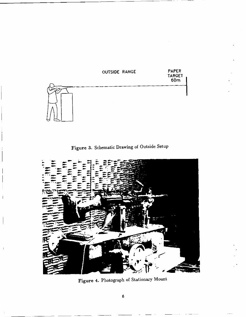
3 Schematic Drawing of Outside Setup 6
4 Photograph of Stationary Mount 6
5 Schematic Drawing of Indoor Setup 7
6 Summary of TID's Showing Significant Differences 8
LIST OF TABLES
1 Flash Suppressor Dispersion for Five 5-Round Bursts with Pooled Dispersion in Boldface (mils) . . . . . . . . . . . . . . . . . . . . . . . . . . . . . . 4
Vll
INTENTIONALLY LEFr BLANK.
viii
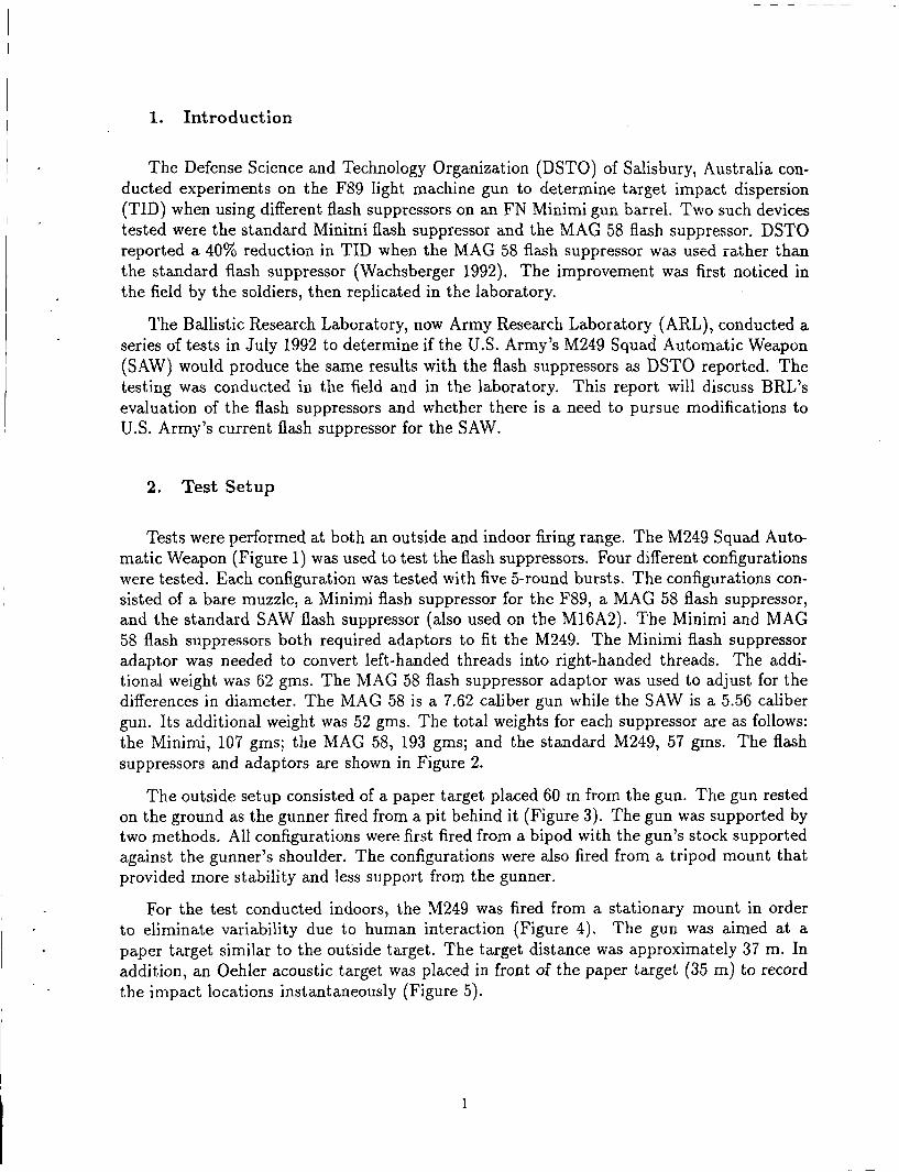
1. Introduction
The Defense Science and Technology Organization (DSTO) of Salisbury, Australia conducted experiments on the F89 light machine gun to determine target impact dispersion (TID) when using different flash suppressors on an FN Minimi gun barrel. Two such devices tested were the standard Minimi flash suppressor and the MAG 58 flash suppressor. DSTO reported a 40% reduction in TID when the MAG 58 flash suppressor was used rather than the standard flash suppressor (Wachsberger 1992). The improvement was first noticed in the field by the soldiers, then replicated in the laboratory.
The Ballistic Research Laboratory, now Army Research Laboratory (ARL), conducted a series of tests in July 1992 to determine if the U.S. Army's M249 Squad Automatic Weapon (SAW) would produce the same results with the flash suppressors as DSTO reported. The testing was conducted in the field and in the laboratory. This report will discuss BRL's evaluation of the flash suppressors and whether there is a need to pursue modifications to U.S. Army's current flash suppressor for the SAW.
2. Test Setup
Tests were performed at both an outside and indoor firing range. The M249 Squad Automatic Weapon (Figure 1) was used to test the flash suppressors. Four different configurations were tested. Each configuration was tested with five 5-round bursts. The configurations consisted of a bare muzzle, a Minimi flash suppressor for the F89, a MAG 58 flash suppressor, and the standard SAW flash suppressor (also used on the M16A2). The Minimi and MAG 58 flash suppressors both required adaptors to fit the M249. The Minimi flash suppressor adaptor was needed to convert left-handed threads into right-handed threads. The additional weight was 62 gms. The MAG 58 flash suppressor adaptor was used to adjust for the differences in diameter. The MAG 58 is a 7.62 caliber gun while the SAW is a 5.56 caliber gun. Its additional weight was 52 gms. The total weights for each suppressor are as follows: the Minimi, 107 gms; the MAG 58, 193 gms; and the standard M249, 57 gms. The flash suppressors and adaptors are shown in Figure 2.
The outside setup consisted of a paper target placed 60 m from the gun. The gun rested on the ground as the gunner fired from a pit behind it (Figure 3). The gun was supported by two methods. All configurations were first fired from a bipod with the gun's stock supported against the gunner's shoulder. The configurations were also fired from a tripod mount that provided more stability and less support from the gunner.
For the test conducted indoors, the M249 was fired from a stationary mount in order to eliminate variability due to human interaction (Figure 4). The gun was aimed at a paper target similar to the outside target. The target distance was approximately 37 m. In addition, an Oehler acoustic target was placed in front of the paper target (35 m) to record the impact locations instantaneously (Figure 5).
1
--------------------------------- -- -- -
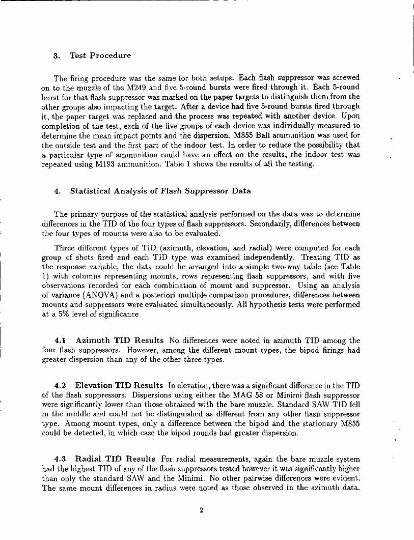
3. Test Procedure
The firing procedure was the same for both setups. Each flash suppressor was screwed on to the muzzle of the M249 and five 5-round bursts were fired through it. Each 5-round burst for that flash suppressor was marked on the paper targets to distinguish them from the other groups also impacting the target. After a device had five 5-round bursts fired through it, the paper target was replaced and the process was repeated with another device. Upon completion of the test, each of the five groups of each device was individually measured to determine the mean impact points and the dispersion. M855 Ball ammunition was used for the outside test and the first part of the indoor test. In order to reduce the possibility that a particular type of ammunition could have an effect on the results, the indoor test was repeated using M193 ammunition. Table 1 shows the results of all the testing.
4. Statistical Analysis of Flash Suppressor Data
The primary purpose of the statistical analysis performed on the data was to determine differences in the TID of the four types of flash suppressors. Secondarily, differences between the four types of mounts were also to be evaluated.
Three different types of TID (azimuth, elevation, and radial) were computed for each group of shots fired and each TID type was examined independently. Treating TID as the response variable, the data could be arranged into a simple two-way table (see Table 1) with columns representing mounts, rows representing flash suppressors, and with five observations recorded for each combination of mount and suppressor. Using an analysis of variance (ANOVA) and a posteriori multiple comparison procedures, differences between mounts and suppressors were evaluated simultaneously. All hypothesis tests were performed at a 5% level of significance
4.1 Azimuth TID Results No differences were noted in azimuth TID among the four flash suppressors. However, among the different mount types, the bipod firings had greater dispersion than any of the other three types.
4.2 Elevation TID Results In elevation, there was a significant difference in the TID of the flash suppressors. Dispersions using either the MAG 58 or Minimi flash suppressor were significantly lower than those obtained with the bare muzzle. Standard SAW TID fell in the middle and could not be distinguished as different from any other flash suppressor type. Among mount types, only a difference between the bipod and the stationary M855 could be detected, in which case the bipod rounds had greater dispersion.
4.3 Radial TID Results For radial measurements, again the bare muzzle system had the highest TID of any of the flash suppressors tested however it was significantly higher than only the standard SAW and the Minimi. No other pairwise differences were evident. The same mount differences in radius were noted as those observed in the azimuth data.
2
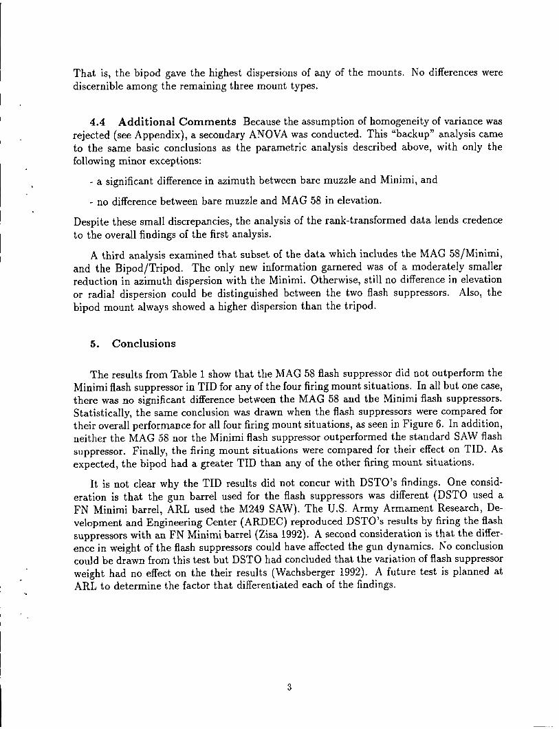
That is, the bipod gave the highest dispersions of any of the mounts. No differences were
discernible among the remaining three mount types.
4.4 Additional Comments Because the assumption of homogeneity of variance was
rejected (see Appendix), a secondary ANOVA was conducted. This "backup" analysis came
to the same basic conclusions as the parametric analysis described above, with only the following minor exceptions:
- a significant difference in azimuth between bare muzzle and Minimi, and
- no difference between bare muzzle and MAG 58 in elevation.
Despite these small discrepancies, the analysis of the rank-transformed data lends credence
to the overall findings of the first analysis.
A third analysis examined that subset of the data which includes the MAG 58/Minimi,
and the Bipod/Tripod. The only new information garnered was of a moderately smaller
reduction in azimuth dispersion with the Minimi. Otherwise, still no difference in elevation
or radial dispersion could be distinguished between the two flash suppressors. Also, the
bipod mount always showed a higher dispersion than the tripod.
5. Conclusions
The results from Table 1 show that the MAG 58 flash suppressor did not outperform the
Minimi flash suppressor in TID for any of the four firing mount situations. In all but one case, there was no significant difference between the MAG 58 and the Minimi flash suppressors.
Statistically, the same conclusion was drawn when the flash suppressors were compared for
their overall performance for all four firing mount situations, as seen in Figure 6. In addition,
neither the MAG 58 nor the Minimi flash suppressor outperformed the standard SAW flash
suppressor. Finally, the firing mount situations were compared for their effect on TID. As
expected, the bipod had a greater TID than any of the other firing mount situations.
It is not clear why the TID results did not concur with DSTO's findings. One consid
eration is that the gun barrel used for the flash suppressors was different (DSTO used a
FN Minimi barrel, ARL used the M249 SAW). The U.S. Army Armament Research, De
velopment and Engineering Center (ARDEC) reproduced DSTO's results by firing the flash
suppressors with an FN Minimi barrel (Zisa 1992). A second consideration is that the differ
ence in weight of the flash suppressors could have affected the gun dynamics. No conclusion could be drawn from this test but DSTO had concluded that the variation of flash suppressor
weight had no effect on the their results (Wachsberger 1992). A future test is planned at ARL to determine the factor that differentiated each of the findings.
3
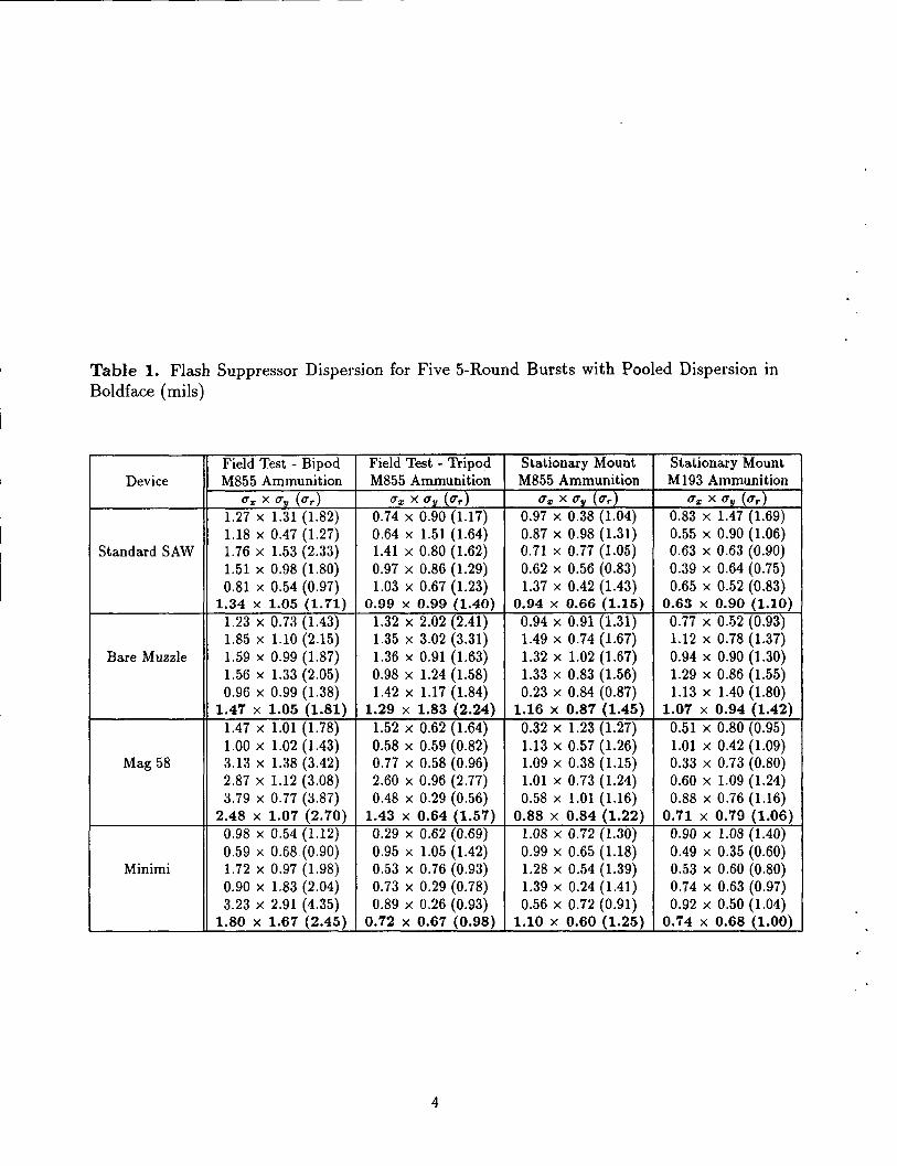
Table 1. Flash Suppressor Dispersion for Five 5-Round Bursts with Pooled Dispersion in Boldface (mils)
Field Test - Bipod Field Test - Tripod Stationary Mount Stationary Mount Device M855 Ammunition M855 Ammunition M855 Ammunition M193 Ammunition
u., X Uy (ur) u., X Uy (ur) u., X Uy (ur) u., X Uy (ur) 1.27 X 1.31 (1.82) 0.74 X 0.90 (1.17) 0.97 X 0.38 (1.04) 0.83 X 1.47 (1.69) 1.18 X 0.47 (1.27) 0.64 X 1.51 (1.64) 0.87 X 0.98 (1.31) 0.55 X 0.90 (1.06)
Standard SAW 1.76 X 1.53 (2.33) 1.41 X 0.80 (1.62) 0.71 X 0.77 (1.05) 0.63 X 0.63 (0.90) 1.51 X 0.98 (1.80) 0.97 X 0.86 (1.29} 0.62 X 0.56 (0.83) 0.39 X 0.64 (0.75) 0.81 X 0.54 (0.97) 1.03 X 0.67 (1.23) 1.37 X 0.42 (1.43) 0.65 X 0.52 (0.83)
1.34 X 1.05 (1. 71) 0.99 X 0.99 (1.40) 0.94 X 0.66 (1.15) 0.63 X 0.90 (1.10) 1.23 X 0.73 (1.43) 1.32 X 2.02 (2.41) 0.94 X 0.91 (1.31) 0.77 X 0.52 (0.93) 1.85 X 1.10 (2.15} 1.35 X 3.02 (3.31) 1.49 X 0.74 (1.67) 1.12 X 0.78 (1.37)
Bare Muzzle 1.59 X 0.99 (1.87) 1.36 X 0.91 (1.63) 1.32 X 1.02 (1.67) 0.94 X 0.90 (1.30) 1.56 X 1.33 (2.05) 0.98 X 1.24 (1.58) 1.33 X 0.83 (1.56) 1.29 X 0.86 (1.55) 0.96 X 0.99 (1.38) 1.42 X 1.17 (1.84) 0.23 X 0.84 (0.87) 1.13 X 1.40 (1.80)
1.47 X 1.05 (1.81) 1.29 X 1.83 (2.24) 1.16 X 0.87 (1.45) 1.07 X 0.94 (1.42) 1.47 X 1.01 (1.78) 1.52 X 0.62 (1.64) 0.32 X 1.23 (1.27) 0.51 X 0.80 (0.95) 1.00 X 1.02 (1.43) 0.58 X 0.59 (0.82) 1.13 X 0.57 (1.26) 1.01 X 0.42 (1.09)
Mag 58 3.13 X 1.38 (3.42) 0.77 X 0.58 (0.96) 1.09 X 0.38 (1.15) 0.33 X 0.73 (0.80) 2.87 X 1.12 (3.08) 2.60 X 0.96 (2.77) 1.01 X 0. 73 (1.24) 0.60 X 1.09 (1.24) 3.79 X 0.77 (3.87) 0.48 X 0.29 (0.56) 0.58 X 1.01 (1.16) 0.88 X 0.76 (1.16)
2.48 X 1.07 (2.70) 1.43 X 0.64 (1.57) 0.88 X 0.84 (1.22) 0.71 X 0.79 (1.06) 0.98 X 0.54 (1.12) 0.29 X 0.62 (0.69) 1.08 X 0.72 (1.30) 0.90 X 1.08 {1.40) 0.59 X 0.68 (0.90) 0.95 X 1.05 (1.42) 0.99 X 0.65 (1.18) 0.49 X 0.35 (0.60)
Minimi 1.72 X 0.97 (1.98) 0.53 X 0.76 (0.93) 1.28 X 0.54 (1.39) 0.53 X 0.60 (0.80) 0.90 X 1.83 (2.04) 0.73 X 0.29 (0.78) 1.39 X 0.24 (1.41) 0.74 X 0.63 (0.97) 3.23 X 2.91 ( 4.35) 0.89 X 0.26 (0.93) 0.56 X 0.72 (0.91) 0.92 X 0.50 (1.04)
1.80 X 1.67 (2.45) 0. 72 X 0.67 (0.98) 1.10 X 0.60 (1.25) 0.74 X 0.68 (1.00)
4
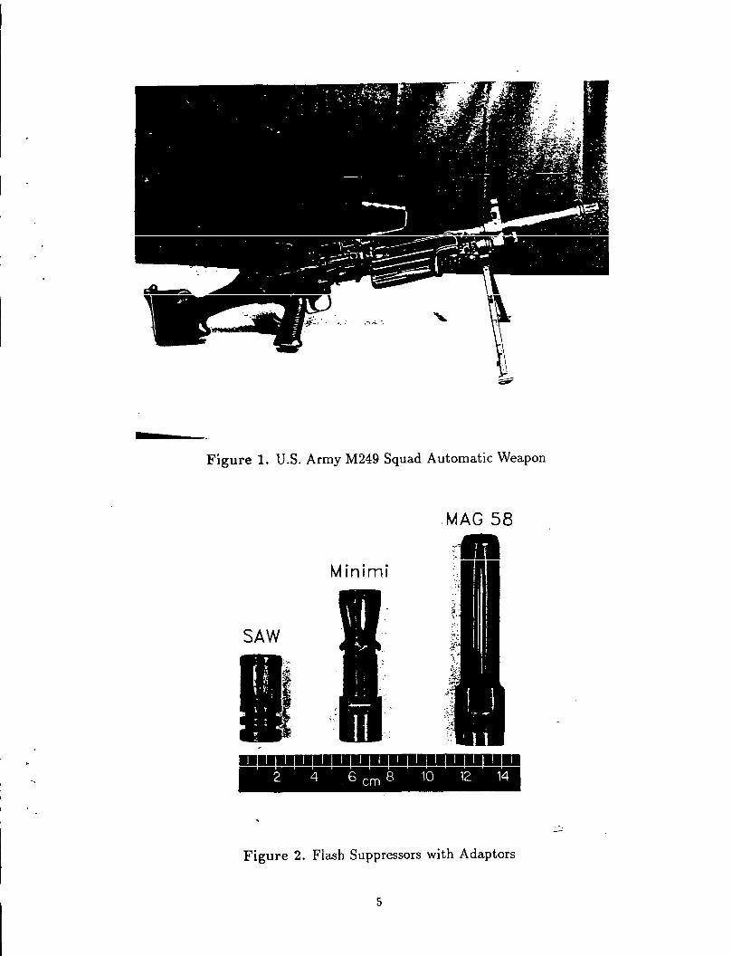
Figure 1. U.S. Army M249 Squad Automatic Weapon
.MAG 58
Minimi
SAW
I . II I I I I I I I I I I I I I I I I I
2 4 6 em 8 10 12 14
Figure 2. Flash Suppressors with Adaptors
5
OUTSIDE RANGE PAPER
->----......_-=.._ -·-·--·-·-·-·-·--·-·-·-·---·-·-·-·-r ~~~r~
Figure 3. Schematic Drawing of Outside Setup
Figure 4. Photograph of Stationary Mount
6

INDOOR RANGE
OEHLER ACOUSTIC TARGET "35m
PAPER TARGET
37m
BULLET TRAP
Figure 5. Schematic Drawing of Indoor Setup
7

AZIMUTH TID
(mils)
ELEVATION TID
(mils)
RADIAL TID
(mils)
2
0
2
0
FLASH SUPPRESSORS
no significant differences
n Std.
SAW
r--,_____
Bare MAG
muule S8
r--
Minimi
{Bare muzzle} > {Minimi}
,_____
n nn Std. Bare MAG
SAW muule Minimi
58
{Bare muzzle}> {Std SAW Minimi} . 2
t-- o---
o---r--
0 Std. Bare MAG
Minimi SAW munle 58
2
2
0
2
0
MOUNTS
(Bipod M85S} > {all others) r--
Bipod Tripod St'nary St'nary
M85li MSSS MSSS M1g3
{Bipod M855} > {St'na.ry M855}
,_____ r--
nn Bipod Tripod St'nary Sl'nary
MSSS MSSS M8SS M1g3
fBipod M855} > (a.ll others}
r--
o---
nn Bipod Tripod St'n&ry St'nary
M855 M855 MBSS Ml113
Figure 6. Summary of TID's Showing Significant Differences
8
--------------- ---------

6. References
Wachsberger, C., DSTO, personal communication to E.M. Schmidt, ARL-WTD, April1992.
Zisa, T., ARDEC, personal communication to Doug Savick, ARL-WTD, September 1992.
9
INTENTIONALLY LEfT BLANK.
10

LIST OF SYMBOLS
Standard deviation along horizontal axis
Standard deviation along vertical axis
Radial standard deviation Chi-square
11
INTENTIONALLY LEfT BLANK.
12
L __

APPENDIX:
AN OVA
13
INTENTIONALLY LEFI' BLANK.
14

One of the underlying assumptions behind the ANOVA is that the data are normally distributed. While this is reasonable to assume for impact locations, dispersions (which are computed as the sample standard deviation of the impact locations) are distributed as x2 random variables. To "normalize" a dispersion, the natural logarithm of its square is a commonly used transformation. Therefore the primary statistical analysis was performed not on the actual TID values (e.g., G-x), but with their log-transformed values (e.g., ln( G-x)).
A second assumption required for the ANOVA is homogeneity of variance; that is, the variance of observations within each combination of mount and flash suppressor should be a constant. To test this assumption Levene's test (Milliken & Johnson 1984) was performed for each of the three responses. In each case, the test concluded that homogeneity of variance did not hold. However, when cell sizes are equal, as is the case with this study, ANOVA procedures are fairly robust to moderate violations of the homogeneity of variance assumption (Kirk 1982). Therefore, the analysis resumed on the transformed TID values.
The four flash suppressors and the four mounts were not selected at random from larger populations of possible suppressors and mounts. Therefore, the type of flash suppressor and the type of mount are considered fixed effects, or fixed factors. For fixed-effect experiments, the ANOVA compares the sample variance of effect means to the pooled estimate of withincell variance. If this ratio is too large, then a difference is said to exist between the factor means.
Once a factor is found to be significant in the ANOVA, multiple comparison procedures indicate which levels of the factor differ. The particular procedure used for this analysis was a modification of Tamhane's procedure for evaluating pairwise comparisons when heterogeneity of variance and/or unequal sample sizes exist (Kirk 1982). Tamhane's critical difference for one-way fixed-effect designs with equal sample sizes reduces to
where tDS~;C,v' is obtained from the t distribution using the Sidak multiplicative inequality, a is the experiment-wise error rate, C = p(p-1)/2 is the total number of pairwise comparisons, p is the number of factor levels, u' = 2( n-1), n is the number of observations per cell, and ai is the cell standard deviation. Assuming a two-way fixed-effects design with Factors A ~having p levels) and B (having q levels), the modified critical difference for ai and aj means IS
with v' = 2(qn- 1).
u]+n2, l w(T2) = tDS£.c v'(....L___L.)2
2, ' qn
Because the assumption of homogeneity of variance failed, a supplementary analysis on rank-transformed TIDs was carried out. The rank-transformation converts the smallest of the original data values to "1", the next smallest to "2", and so on. This transformation is recommended as a backup to the parametric analysis since it has been shown to be robust to violations of the ANOVA assumptions (Conover 1980).
15

Appendix References
Conover, \V.J., Practical Nonparametric Statistics, 2nd ed., Wiley, New York, 1980.
Kirk, R.E., Experimental Design, 2nd ed., Brooks/Cole, Monterey, 1982.
Milliken, G.A. and D.E. Johnson, Analysis of Messy Data, Vol I, Van Nostrand Reinhold, New York, 1984.
16
No. of No. of Copies Organization Copies Organization
2 Administrator 1 Commander Defense Technical Info Center U.S. Army Missile Command ATTN: DTIC-DDA ATTN: AMSMI-RD-CS-R (DOC) Cameron Station Redstone Arsenal, AL 35898-5010 Alexandria, VA 22304-6145
1 Commander 1 Commander U.S. Army Tank-Automotive Command
U.S. Army Materiel Command ATTN: ASQNC-T AC-DIT {Technical ATTN: AM CAM Information Center) 5001 Eisenhower Ave. Warren, MI 48397-5000 Alexandria, VA 22333-0001
1 Director 1 Director U.S. Army TRADOC Analysis Command
U.S. Army Research Laboratory ATTN: ATRC-WSR ATTN: AMSRL-D White Sands Missile Range, NM 88002-5502 2800 Powder Mill Rd. Adelphi, MD 20783-1145 1 Commandant
U.S. Army Field Artillery School 1 Director ATTN: ATSF-CSI
U.S. Army Research Laboratory Ft. Sill, OK 73503-5000 ATTN: AMSRL-OP-CI-AD,
Tech Publishing (Class. only)} Commandant 2800 Powder Mill Rd. U.S. Army Infantry School Adelphi, MD 20783-1145 ATTN: ATSH-CD (Security Mgr.)
Fort Benning, GA 31905-5660 2 Commander
U.S. Army Armament Research, (Uncials. only) 1 Commandant Development, and Engineering Center U.S. Army Infantry School
ATTN: SMCAR-IMI-I ATTN: ATSH-CD-CSO-OR Picatinny Arsenal, NJ 07806-5000 Fort Benning, GA 31905-5660
2 Commander 1 WL/MNOI U.S. Army Armament Research, Eglin AFB, FL 32542-5000
Development, and Engineering Center ATTN: SMCAR-TDC Aberdeen Proving Ground Picatinny Arsenal, NJ 07806-5000
2 Dir, USAMSAA 1 Director ATTN: AMXSY-D
Benet Weapons Laboratory AMXSY -MP, H. Cohen U.S. Army Armament Research,
Development, and Engineering Center 1 Cdr, USATECOM ATTN: SMCAR-CCB-TL ATTN: AMSTE-TC Watervliet, NY 12189-4050
1 Dir,ERDEC (Unclass. only) 1 Commander ATTN: SCBRD-RT
U.S. Army Rock Island Arsenal ATTN: SMCRI-IMC-RT!l'echnical Library 1 Cdr, CBDA Rock Island, IL 61299-5000 ATTN: AMSCB-CI
1 Director 1 Dir, USARL U.S. Army Aviation Research ATTN: AMSRL-SL-1
and Technology Activity ATTN: SAVRT-R (Library) 10 Dir, USARL MIS 219-3 ATTN: AMSRL-OP-CI-B {Tech Lib) Ames Research Center Moffett Field, CA 94035-1000
17
No. of Copies Organization
1 Commander U.S. Army Armament Research,
Development, and Engineering Center ATIN: SMCAR-CCL-SD. Mr. T. Zisa Picatinny Arsenal, NJ 07806-5000
18

USER EVALUATION SHEET/CHANGE OF ADDRESS
This Laboratory undertakes a continuing effort to improve the quality of the reports it publishes. Your comments/answers to the items/questions below will aid us in our efforts.
1. ARLReportNumber_ARL __ -MR_-_4_5 _______ DateofReport February 1993
2. DateReportReceived ___________________________ _
3. Does this report satisfy a need? (Comment on purpose, related project, or other area of interest for
which the report will be used.)--------------------------
4. Specifically, how is the report being used? (Information source, design data, procedure, source of ideas, etc.) _______________________________ _
5. Has the infonnation in this report led to any quantitative savings as far as man~hours or dollars saved,
operating costs avoided, or efficiencies achieved, etc? If so, please elaborate. ----------
6. General Comments. What do you think should be changed to improve future reports? (Indicate changes to organization, technical content, fonnat, etc.)-----------------
CURRENT ADDRESS
Organization
Name
Street or P.O. Box No.
City, State, Zip Code
7. If indicating a Change of Address or Address Correction, please provide the Current or Correct address above and the Old or Incorrect address below.
OLD ADDRESS
Organization
Name
Street or P.O. Box No.
City, State, Zip Code
(Remove this sheet, fold as indicated, staple or tape closed, and mail.)

--------------------------- ~· -
------------------------------------------------------------------...... -------------------------------------------------------------------------------------
DEPARTMENT OF THE ARMY
OFRClAL BUSINESS BUSINESS REPLY ~L~ ARST CUSS PERMIT Iii 0001, .aJIG, MD
Posraoe will be patd by addtessee
Director U.S. Army Research Laboratory ATTN: AMSRL-OP-CI-B (Tech Lib) Aberdeen Proving Ground, MD 21005-5066
I NO POSTAGe NECESSARY IF MAILED
IN THE UNITED STATES
----------------------------------------------------- ... -------------------- ... -.. -.. ---- ... --- ........ -... ------ ---------- .. --- .. ------- ... ----------------------........... ____ .., ___ _


![0 [Type the document subtitle] [Pick the date] Dasar-Dasar Membuat Media Pembelajaran Dengan Dengan Dengan Dengan Flash Flash Flash Flash](https://static.fdokumen.com/doc/165x107/632259f164690856e109202b/0-type-the-document-subtitle-pick-the-date-dasar-dasar-membuat-media-pembelajaran.jpg)