Fish Dorsal Inspired Skew Turning Vanes for HVAC System ...
24
FISH DORSAL INSPIRED SKEW TURNING VANES FOR HVAC SYSTEM ALIF FALATIN BIN ABDUL LATIF 40493 SUPERVISOR: Jr. Dr. MOHD DANIAL IBRAHIM Bachelor of Engineering with Honour s (Mech anica l and Manufacturing Engine erIng) 2017
-
Upload
khangminh22 -
Category
Documents
-
view
0 -
download
0
Transcript of Fish Dorsal Inspired Skew Turning Vanes for HVAC System ...

FISH DORSAL INSPIRED SKEW TURNING VANES FOR HVAC SYSTEM
ALIF FALATIN BIN ABDUL LATIF 40493
SUPERVISOR: Jr. Dr. MOHD DANIAL IBRAHIM
Bachelor of Engineering with Honours (Mechanical and Manufacturing EngineerIng)
2017
APPROVAL SHEET
This project report which entitled "Fish Dorsal Inspired Skew Turning Vanes for HVAC System" was prepared by AlifFalatin bin Abdul Latif (40493) is hereby read and approved by:
Ir. Dr. ~lhdj~ral Date
)

UNIVERSITI MALAYSIA SARA W AK Grade:
A-Please tick (D)
Final Year Project Report B Masters D PhD D
DECLARATION OF ORIGINAL WORK
This declaration is made on the .................day of.................2017.
Student's Declaration:
I ALIF FALATIN BIN ABDUL LATIF (40493) FROM DEPARTMENT OF MECHANICAL AND MANUFACTURING ENGINEERING OF FACULTY OF ENGINEERING hereby declare that the work entitled FISH DORSAL INSPIRED SKEW TURNING VANES FOR HVAC SYSTEM is my original work. I have not copied from any other students' work or from any other sources except where due reference or acknowledgement is made explicitly in the text, nor has any part been written for me by another person.
Date su bmitted AlifFalatin Bin Abdul Latif (40493 )
Supervisor's Declaration:
I Ir. Dr. MOHD DANIAL BIN IBRAHIM hereby certifies that the work entitled FISH DORSAL INSPIRED SKEW TURNING VANES FOR HVAC SYSTEM was prepared by the above named student, and was submitted to the "FACULTY" as a * partial/full fulfilment for the conferment ofB. ENG. (HONS) IN MECHANICAL AND MANUFACTURING ENGINEERING, and the aforementioned work, to the best knowledge, is the said student's work.
Received for examination ~j!j~f!)D(Ir. D BIN IBRAHIM)
~QU;.I

Supervisor sig:naturef~~~:A~
I declare that Projectffhesis is classified as (Please tick (..J»:
o CONFIDENTIAL (Contains confidential infonnation under the Official Secret Act 1972)* n RESTRICTED (Contains restricted infonnation as specified by the organisation ~e research was done)*
OPEN ACCESS
Validation of Projecttrbesis
I therefore duly affinn with free consent and willingly declare that this said Projectffhesis shall be placed officially in the Centre for Academic Infonnation Services with the abiding interest and rights as follows:
D This Projectffhesis is the sole legal property of Universiti Malaysia Sarawak (UNIMAS).
D The Centre for Academic lnfonnation Services has the lawful right to make copies for the purpose of academic and research only and not for other purpose.
D The Centre for Academic Infonnation Services has the lawful right to digitalise the content for the Local Content Database.
D The Centre for Academic Infonnation Services has the lawful right to make copies of the Projectffhesis for academic exchange between Higher Learning Institute.
D No dispute or any claim shall arise from the student itself neither third party on this Projectffhesis once it becomes the sole property ofUNlMAS.
D This Projectffhesis or any material, data and infonnation related to it shall not be . distributed, published or disclosed to any party by the student except with UNIMAS pennlSSlOn.
Student signature: -C~~c:;;;;;;;~:=~~ 't
Current Address: Lot 76752, Lorong Pennatang Badak Maju 27 Kampung Pennatang Badak, Kuantan, 25150 Kuantan, Pahang
Notes: * Ifthe Projectffhesis is CONFIDENTIAL or RESTRICTED, please attach together as annexure a letter from the organisation with the period and reasons of confidentiality and restriction.
[The instrument is duly prepared by The Centre for Academic Infonnation Services 1
FISH DORSAL INSPIRED SKEW TURNING VANES FOR HVAC
SYSTEM
AUF FALATIN BIN ABDUL LATIF
A dissertation submitted in partial fulfillment
of the requirement ofthe degree of
Bachelor of Engineering with Honors
(Mechanical and Manufacturing Engineering)
Faculty of Engineering
Universiti Malaysia Sarawak
2017
r
Alhamdulillah
ACKNOWLEDGMENT
A special to thank Supervisor, Ir. Dr. Mohd Danial Ibrahim of Universiti Malaysia
Sarawak from Mechanical and Manufacturing department tor having me under his
supervisions and giving his boundless direction and support through this Final Year
Projects. This thesis could not have been finished without his supervision, inspiration
and motivation. I might likewise want to degree my appreciation to my family
particularly to my cherished father Mr. Abdul Latif Mohd Amin, my mother Mdm.
Farashida Kamaruddin, my lovely soulmates Sallehattun Binti Salleh. my childrens Izz
Imran Falatin, Izzah lwani Fala!in, lzz Ichsan Falatin, lzz lkhwan FaJatin and Izz Ilhan
Falatin tor their unbounded love. support and consolation to finish my four-year
undergrad. Extraordinary because my kindred companions particularly Ir. Dr. D's lab
members and my course mates who dependably remain by to help me specifically or in
a roundabout way end route may it be sharing satisfaction or misery. I couldn't offer
how much thanks towards the individuals who helped me however earnestly wishes
every one of them best of everything occasionally.

ABSTRACT
HVAC stands for Heating, Ventilation and Air Conditioning system which is utilized to
supply natural air into a building. The efficiency of the system is around 60 - 75 % and
it could reach up to 80% with appropriate installations and design. HVAC have a few
problems which happen at the bend of its ducting which create turbulence and create
vortex. This problem creates pressure drops brought on by the sudden changes in
course due to the bend. To overcome the problem, turning vane was introduced at the
bend areas. There are many type of turning vanes accessible in the market. Turning
vanes were intended for better flow of the fluids. The turning vanes was design in
AutoCAD and simulations was done by AnSys Workbench. The result of the
simulations was then analyzed between single turning vane, double turning vanes with
3 proposed turning vanes design and triple turning vanes with 3 proposed turning
vanes design. It was found that the proposed triple turning vanes from the first design
gave a great result as far as average outlet velocity and turbulence dissipations
compared to other designs. The resu It showed that the best turning vane was the first
design of triple vanes with mass flow average of velocity on the outlet of 3.19456 mls
and mass flow average of turbulence eddy dissipation of 1325.16 j/kg.s.
II
•

ABSTARK
HVAC bennaksud untuk Pemanasan, Pengudaraan dan sistem pendingin hawa yang
digunakan untuk membekalkan udara semula jadi ke dalam bangunan. Kecekapan
sistem ini adalah kira-kira 60 - 75% dan ia boleh mencecah sehingga 80% dengan
pemasangan dan reakabentuk yang baik. Sistem HVAC mempunyai beberapa masalah
terutama di selekoh sesalur yang mewujudkan pergolakan dan vorteks. Masalah ini
menghasilkan tekanan titik yang dibawa oleh perubahan secara mendadak ketika
melalui selekoh tersebut. Bagi mengatasi masalah ini, turning vanes dicadangkan di
kawasan selekoh tersebut. Terdapat pelbagai jenis turning vanes di pasaran. Turning
vanes bertujuan untuk membantu aliran udara yang lebih baik. Turning vanes direka
bentuk menggunakan aplikasi AUloCAD dan simulasi telah dilakukan menggunakan
aplikasi Ansys Workbench. HasH daripada anal isis simulasi diantara single turning
vanes, double turning vanes dengan 3 cadangan rekabentuk dan triple turning vanes
dengan 3 cadangan rekabcntuk. Berdasarkan hasH simulasi yang dijalankan, didapati
bahawa triple vanes daripada rcka bentuk pcrtama memberikan hasil yang terbaik
dcngan purata halaju keluar dan turbulence eddy dissipations bcrbanding reka bentuk
lain. Hasilnya menunjukkan bahawa triple vanes bagi rekabentuk pertama dcngan
mass average velocity of outlet adalah 3,19456 m ! 5 dan average turbulence ed(~v
dissipations adalah 1325,16 J I kg.s.
II!
TABLE OF CONTENTS
ACKNOWLEDGMENT ................................................................................................. I
ABSTRACT ................................................................................................................... II
ABSTARK u .................................U4 ...........u ......~•••••••••• .........u**.........................................III
TABLE OF CONTENTS ............................................................................................. IV
LIST OF FIGURES .................................................................................................... VII
LIST OF TABLES ..........................................................................................................X
LIST 01<' EQUATIONS ................................................................................................ XI
NOMENCLATURES ................................................................................................. XII
CHAPTER 1.................................................................................................................... 1
INTRODUCTION .......................................................................................................... 1
1.1 Impetus of the Project.. ....................................................................................... 1
1.2 Background study ............................................................................................... I
1.3 Type 0 f Dueting System ..................................................................................... 3
1.4 Objective ............................................................................................................. 7
1.5 Problems statement ............................................................................................. 7
IV
-
CHAPTER 2.................................................................................................................... 8
LITERATURE REVIEW .............................................................................................. 8
2.1 Overview of Heating. Ventilation and Air Conditioning (HVAC) ..................... 8
2.2 Factor that leads to energy loss ........................................................................... 9
2.3 Effect of turning vanes ..................................................................................... 12
2.4 Material cost and performance ......................................................................... 14
2.5 Effect offriction towards tlow rate .................................................................. 15
2.6 Pressure drop in HVAC .................................................................................... 18
CHAPTER 3.................................................................................................................. 21
METHODOLOGY ....................................................................................................... 21
3.1 Introduction ...................................................................................................... 21
3.2 AnSys Workbench ............................................................................................ 22
3.3 Governing equations and parameters ................................................................ 23
3.4 Navier·Stroke Equations ................................................................................... 29
3.5 Equations for turbulent Model Validation ........................................................ 30
3.6 Design of thermodynamic lab ........................................................................... 33
3.7 90° Bend Design ................................................................................................. 36
3.8 Turning Vanes ..................................................................................................... 38
3.9 Simulations oflhe project. .................................................................................. 51
v

CHAPTER 4••.....•......••••.••..••••...•••••.....••••.•••••••••••......•....•••••••.....••••..•.•......•••.•••...•••••.•••. 61
RESULT AND DISCUSSION...................................................................................... 61
4.1 Introduction ...................................................................................................... 61
4.2 Analysis ofdouble bend without and with turning vanes ................................. 61
CONCLUSION AND RECOMMENDATION .......................................................... 72
5.1 Conclusion .......................................................................................................... 72
5.2 Problem and Alternative Solutions .................................................................... 73
5.3 Recommendation for future works ..................................................................... 74
REFEREN CES ............................................................................................................. 7S
APPENDIX A. MODEL GEOMETRY ........................................................••••••••.......•. 78
APPENDIX B. MODEL SETUP..........••••••..............••.....••..•••••...•.........••...•••....••••........ 80
VI
~1
(it
61
61
72
72
73
74
75
78
80
LIST OF FIGURES
Figure I: Single zone Variable Air Volume (SZVAV) roof top unit ................................. 2
Figure 2 : Radial duct system ........................................................................................... 3
Figure 3: Extended Plenum duct system .......................................................................... 4
Figure 4: Reducing Plenum duct system .......................................................................... 4
Figure 5: Trunk reduced duct system ............................................................................... 5
Figure 6: Perimeter loop duct system ................................................ , .................... , ......... 5
Figure 7: Squared metal sheet insulated tiber glass dueting board installations roof top
unit .... ,', .... ,', ................ ,"", ............... , .... ,', ........................ ,', ................ """", ........... ,"'" .... 6
Figure 8: Mold problems ................. , ................................................................................ 9
Figure 9: Dueting leakage due to poor installation ........................................................... 9
Figure 10: Collapse duct work ....................................................................................... 10
Figure I I: SMACNA HVAC Duct Constructions Standards .......................................... 11
Figure 12: Duct leakage test Equipment... ...................................................................... 12
Figure 13; 90-degree bend with turning vanes ............................................................... 13
Figure 14: ASHREA Handbook ..................................................................................... 19
Figure 15: Pressure loss correction factor for flexible duct not fully extended ............. 20
Figure 16: AnSys Workbench logo ................................................................................. 21
Figure 17: AutodeskAutoCAD .\1echanieallogo ........................................................... 22
Figure 18: 3D Cartesian coordinates system ......................................................... , ........ 23
Figure 19: Fluids can pass through any face of the intinitesimal control volume .......... 24
Figure 20: Path trace by single fluid particle .................................................................. 25
Figure 2 I: A numbers of path by multiple particles ....................................................... 25
Figure 22: Eularian description ...................................................................................... 25
Figure 23 : Bernoulli's for stream line ........................................................................... 27
Figure 24: Control volume that encloses a region having a volume R ........................... 28
Figure 25: Moody diagram for Darcy friction factor value ............................................ 31
Figure 27: 3D CAD drawing of the Thermodynamics Laboratory ................................ 33
VII
Figure 28: Schematic diagram of Thermodynamic Lab ................................................. 34
Figure 29: Ventilations dueting number I ...................................................................... 34
Figure 30: Ventilations dueting number 2 ...................................................................... 35
Figure 31: Ventilation dueting number 3 ........................................................................ 35
Figure 32: Selected bending area of the dueting for the simulations from ventilation
dueling number 2 ............................................................................................................ 36
Figure 33: Aulodesk AutoCAD interface wilh AnSys Workbench ................................ 40
Figure 34: Dueling without vane model ......................................................................... 40
Figure 35: Dueling without vanes top view Wilh dimension .......................................... 41
Figure 36: Dueting without vanes side view with dimensions ....................................... 41
Figure 37: Dueting with single vane model ................................................................... 41
Figure 38: Single vane top view with dimensions .......................................................... 4\
Figure 39: Single vane side view with dimensions ........................................................ 42
Figure 40: Dueting with double vanes 1" design model ................................................ 42
Figure 41: Dueling with double vanes 2nd design model ............................................... 42
Figure 42: Dueting with double vanes 3rd design model ................................................ 43
Figure 43: Dueting with double vanes I" design with dimensions ................................ 43
Figure 44: Dueling wilh double vanes 2nd design with dimensions ............................... 43
Figure 45: Dueling with double vanes 3rd design with dimensions ................................ 43
Figure 46: Dueting with triple vanes I st design model ................................................... 44
Figure 47: Dueting with triple vanes 2nd design model .................................................. 44
Figure 48: Dueling with triple vanes 3mdesign modeL................................................ 44
Figure 49: Dueling with triple vanes 1 st design with dimensions .................................. 45
Figure 50: Dueting with triple vanes 2nd design with dimensions .................................. 45
Figure 51: Dueting with triple vanes 3rd design with dimensions ................................. 45
Figure 52: AnSys Workbench interface .......................................................................... 46
Figure 53: Design Modeler interface .............................................................................. 46
Figure 54: Unit system interface .................................................................................... 47
Figure 55; Fluid Flow Analysis System toolbox ............................................................ 48
viii
Figure 56: Meshing details set up ................................................................................... 48
Figure 57: Meshed model ............................................................................................... 49
Figure 58: Mesh skewness result.. .................................................................................. 49
Figure 59: Parameter set up ............................................................................................ 50
Figure 60: Residual graph obtained from the simulations .............................................. 51
Figure 61: Modeling setup interface in Design Modular ............................................... 52
Figure 62: Model attached in Design modular ............................................................... 52
Figure 63: Project Schematic intertace ........................................................................... 53
Figure 64: Meshed model ............................................................................................... 54
Figure 65: Mesh details setup ......................................................................................... 55
Figure 66: Generated Mesh model ................................................................................. 56
Figure 67: Meshing skewness ......................................................................................... 56
Figure 68: Fluent Launcher ............................................................................................ 57
Figure 69: Simulations setup interface ........................................................................... 57
Figure 70: Simulation model setup ................................................................................. 58
Figure 71: Viscous model interlace ................................................................................ 58
Figure 72: Material setup interface ................................................................................. 59
Figure 73: Inlet air velocity setup ................................................................................... 59
Figure 74: Reterence value setup ................................................................................... 60
Figure 75: Residual monitor controls the normalization and scaling of residual ........... 60
IX
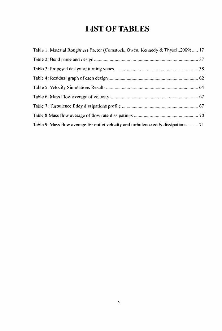
LIST OF TABLES
Table I: Material Roughness Factor (Comstock, Owen, Kennedy & Thysell,2009) ..... 17
Table 2: Bend name and design ...................................................................................... 37
Table 3: Proposed design of turning vanes ..................................................................... 38
Table 4: Residual graph of each design .......................................................................... 62
Table 5: Velocity Simulations Results ............................................................................ 64
Table 6: Mass Flow average of velocity ......................................................................... 67
Table 7: Turbulenee Eddy dissipations profile ............................................................... 67
Table 8:Mass flow average of flow rate dissipations ..................................................... 70
Table 9: Mass flow average for outlet velocity and turbulenee eddy dissipations ......... 71
x

LIST OF EQUATIONS
Equation I: Darcy's equations ............................................... ""."" ....... "",, ................... 16
Equation 2: Colebrook's Equations ............................................................... "" ............. 16
Equation 3: Power consumptions Equations ........ " .......... ,," " ........................................ 19
Equation 4: 3D Cartesian coordinate for square equations ............................................ 23
Equation 5: Equations of Streamline .............................................................................. 25
Equation 6: Fluids tlow variable express by Eularian terms of velocity ........................ 25
Equation 7: Bernoulli equations between two different point in stream line ................. 26
Equation 8: Bernoulli's equations for diving both side by "g" ...................................... 26
F:quation 9: Newton's Second law .................................................................................. 27
Equation 10: Newton's second law for velocity in direction .......................................... 28
Equation II: Bernoulli's equation with constant density ............................................... 28
Equation 12: Velocity component V n for Velocity component normal to the surface and
V, for velocity component tangent to the surface ............................ " ................. " .......... 29
Equation 13: Navier-Stroke equations ............................................................................ 29
Equation 14: Reynolds-average Navier-Stroke equations .............................................. 30
Equation 15: Friction factor ............................................................................................ 30
Equation 16: Entrance length for turbulence flow .......................................................... 3!
Equation 17: Non-dimensional radius and thickness ..................................................... 32
Equation 18: Diameter .................................................................................................... 32
Equation 19: Distance in m ............................................................................................ 32
XI
I
pr
f
L
v
p
Re
k- (()
HVAC
AHU
VOC
CV
VAV
SMACNA
ASHRAE
PVC
fpm
CFD
CAD
r
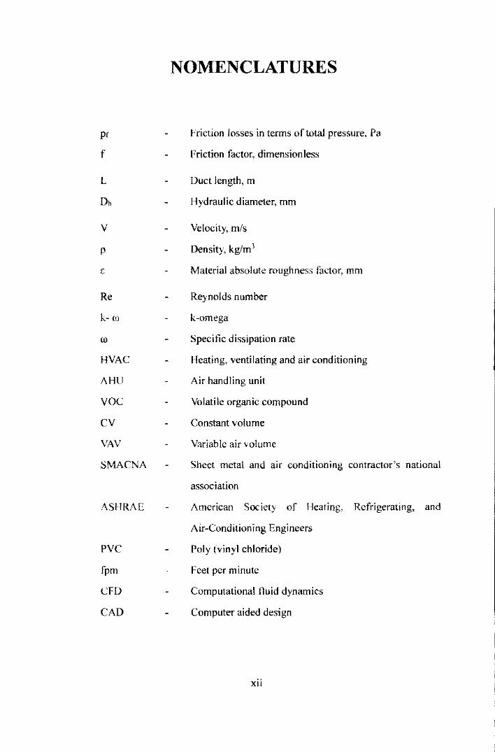
NOMENCLATURES
Friction losses in terms oftolal pressure, Pa
Friction factor, dimensionless
Duct length, m
Hydraulic diameter, mm
Velocity, m/s
Density, kglmJ
Material absolute roughness factor, mm
Reynolds number
k-omega
Specific dissipation rate
Heating, ventilating and air conditioning
Air handling unit
Volatile organic compound
Constant volume
Variable air volume
Sheet metal and air conditioning contractor's national
association
American Society of Heating, Refrigerating, and
Air-Conditioning Engineers
Poly (vinyl chloride)
Feet per minute
Computational f1uid dynamics
Computer aided design
xii
CHAPTER 1
INTRODUCTION
1.1 Impetus of the Project
Heating, ventilation and air conditioning (HYAC) is the technology of indoor
and vehicular environmental comfort that provide thermal comfort and acceptable
indoor air quality. Air distribution system consist of three segments which are Air
Handling Unit (AHU), ventilation and heating system, ventilation and cooling system.
Heating, ventilation and air conditioning (HY.4.C) system is a used to warmth or cool
private, business or industries. Air distribution systems are capable to provide fresh air
from the natural resources from the inside airborne contaminants, for example, smells
from natural resources, unpredictable natural mixes, volatile organic compound
(YOC's) comes from inside decorations and chemicals utilized for cleaning. The
systems comprise of numerous segments and component will expend energy usage and
extensive measure of vitality, the parts and component of the system should be design
and installed properly and efliciently. This will reduce unnecessary over design and
energy usage. Designers should always specify the highest efficiency fitting possible.
1.2 Background study
There are two types of air distribution systems, constant volume (CY) and
variable-air-volume (YAY). Constant volume type, the system will operate with a
constant airllow rate (Air Distribution System,2008) but the temperature may be varied
and normally used for single-zone and multi zone system.
'. - -.

--._-.........--..... ,..
I . ,
I
Figure 1: Single zone Variable Air Volume (SZVAV) rooftop unit
Single duct system consist ventilation and cooling air-conditioned system in a
s ingle ducting but some design there will be separated heating system. Dual-duct
system used a single fan to move air for both cooling and heating coils in the air
handlin g unit (AHU) and has separate ducts for hOI and co ld for the di stributing of air.
Multi zone unit is where the air supplies to several zones from a central ly located air
handling unit (AHU).
Variable-air-volume (VAV) is a system where the temperature is being
maintained whil e the fl ow of air varied . The benefits a re it has accurate temperature
control and has lower energy consumption. This system can be app lied for both
single-zone and multi zone system. For single-lone, the speed of tim vari es by the
ambient temperature and the set point temperature . The compressor modulates the
refrigerant flow and maintain constant supply of air temperature and give more
accurate temperature control.
2
1.3 Type of Dueling System
There are five types of supply and return duct system s in HVAC systems. The
types of duct systems are as follows:
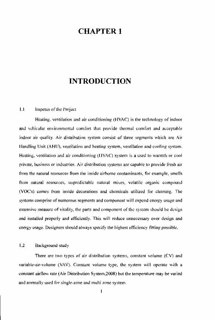
I. Radi al system
Radial duct system consists of central supply plenum with several numbers o f
s ingle branch duct arranged in radial pattern. The single branch duct is de signed and
sized whi ch can suppl y two or more outlets . Radial system can be used fo r up fl ow,
down flow o r horizonta l a ir handlers.
Figure 2 : Radial duct system
II. Extended plenum system
Exte nded plenum duct system has one or two box alike pieces of ductwork
extendin g from the main plenum at the indoor unit. It has the same dimension of ma in
duct ing. T he supply ouLiet ducting is tapped into the extended plenum that is being
feed by the branch.
3

Figure 3: Extended Plenum duct system
111. Reducing plenum system
Reducing plenum ducl system reduced the main ducling so that the air velocity
loss will regain and the air flow improved. Thi s type duct system is co mmon in HVA C
as it is easy to fabricate and install.
r
=
Figure 4: Reducing Plenum duct system
-- ..-
4
--------------------------------~.
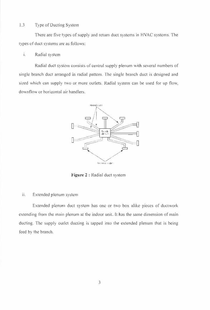
lV. Reducing trunk system
Reducing trunk ducL system minimized the ductin g s izes after th e ma in a nd
branches outlet. It can maintain the air velocity even the red ucti ons of a ir fl ow du e to
the supplied at each branch. Each of the trunks would have different cross-sectiona l
area.
Figure 5: Trunk reduced duct syste m
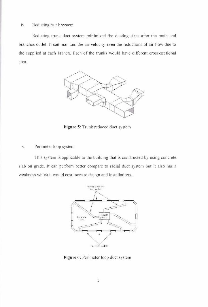
v. Pe rim ete r loop system
T hi s syste m is a pplicable to the building that is constructed by us in g concrete
s la b o n grade. It can perform better com pare to radial duct syste m but it a lso has a
weakness w hi ch it wo uld cost mo re to des ig n a nd in stallations.
- fCO:I':I ;: "1::,. .I.~u I' ,:~ ,,;I
.'1'-, :/ t '-''-''''
Figure 6: Perimeter loop duct system
5

/
Every HVAC ducting system should consider the return air ducting but it is
generally ignored or less critical considerations by engineers which creates defect on
the circulations ofthe HVAC systems overall.
The most commonly materials used as the ducting are sheets metal, rigid tiber
glass duel board and flexible duct board and flexible non-metallic ducting which each
material has its own advantage and disadvantage in term of price, installations and
performance.
Figure 7: Squared metal sheet insulated fiber glass ducting board installations rooftop
unit
6