Field Manual for Structural Welding - State of Michigan
80
Michigan Department of Transportation 2nd Edition – May 2022 Field Manual for Structural Welding
-
Upload
khangminh22 -
Category
Documents
-
view
3 -
download
0
Transcript of Field Manual for Structural Welding - State of Michigan
Michigan Department of Transportation
2nd Edition – May 2022
Field Manual for Structural Welding

Cover photo courtesy of Windsor-Detroit Bridge Authority and Bridging North America.
Field Manual for Structural Welding
Table of Contents......................................................................................1
Glossary.....................................................................................................6
Acknowledgement..................................................................................10
Introduction and Purpose......................................................................11
Governing Specifications.......................................................................11
Arc Welding Processes..........................................................................13 Shielded Metal Arc Welding (SMAW)...........................................13 Gas Metal Arc Welding (GMAW)..................................................14 Flux Cored Arc Welding (FCAW)..................................................14 Submerged Arc Welding (SAW)...................................................15 Process Selection.........................................................................16
Welded Structural Connections............................................................16 Joint Types....................................................................................17
Weld Types..............................................................................................17 Groove Welds...............................................................................17 Terminology for Groove Welds..........................................18 Complete Joint Penetration (CJP) Groove Weld................19 Partial Joint Penetration (PJP) Groove Welds...................21 PJPEffectiveWeldSize....................................................21 Fillet Welds...................................................................................22 MinimumFilletWeldSize.................................................23 MaximumFilletWeldSize................................................23 End Returns (Boxing).......................................................23 Fillet Weld Termination.....................................................24 Fillet Weld Considerations...............................................24 Plug and Slot Welds.....................................................................24 PlugandSlotWeldConsiderations..................................25
1

Field Manual for Structural Welding
General Weld Considerations and Terminology..................................25 Weld Tabs.....................................................................................25 Weld Access Holes.......................................................................26 Filler Metal Strength......................................................................26 Filler Metal Considerations................................................27 Welds and Bolts in Same Connection............................................27 Filler Plates...................................................................................27 Prohibited Joint Types and Welds................................................28 Hydrogen Embrittlement...............................................................28 MDOTRequirementsforElectrodes.................................29 Discontinuities...........................................................................29 Planar Discontinuities.......................................................30 VolumetricDiscontinuities.................................................31 Special Considerations for Lap Joints..........................................33 Special Considerations for Butt Joints.........................................34 Special Considerations for T-Joints..............................................34 Special Considerations for Corner Joints....................................35
Weld Cracking.........................................................................................35 Types of Weld Cracking................................................................35 Shrinkage and Restraint................................................................36 PracticestoReduceShrinkageStresses..........................36 PracticestoReduceRestraint...........................................37 Centerline Cracking......................................................................37 Segregation-Induced Cracking.........................................37 BeadShape-InducedCracking.........................................38 SurfaceProfile-InducedCracking.....................................38 Heat-AffectedZone(HAZ)Cracking.................................38 Transverse Cracking.....................................................................39 LimitingTransverseCracking............................................39 Lamellar Tearing...........................................................................40
2
Field Manual for Structural Welding
Distortion.................................................................................................40 Angular Distortion.........................................................................41 Transverse Shrinkage ..................................................................41 Longitudinal Shortening................................................................42 Twisting....................................................................................42 Longitudinal Sweep or Camber....................................................42 Buckling and Warping ..................................................................43 Rotational Distortion.....................................................................43 General Distortion Control Measures ..........................................43 Specialized Distortion Control Measures......................................44 AWS Distortion and Shrinkage Requirements..............................44 Allowable Dimensional Tolerances...............................................45
Fatigue.....................................................................................................45 Special Fabrication Requirements for Fatigue Resistance............46
Galvanized Steel.....................................................................................47 Hot-Dipped Galvanized (HDG) Structural Elements.....................47
General Welding Requirements.............................................................48 Base Metal Preparation................................................................48 Assembly.................................................................................49 Fillet Welds.......................................................................49 Plug,SlotandButtJoints.................................................49 Groove Welds...................................................................49 Peening...................................................................................50
3
Field Manual for Structural Welding
Shop Welding..........................................................................................51 Requirements for Shop Welding..................................................51 WeldingProcedureSpecification(WPS)......................................52 ProcedureQualificationTestRecord(PQR)................................54 Shop Welded Plate Girders and Rolled Beams...........................54 Shop Splices.................................................................................55 Weld Conditions...........................................................................55 Shop Weld Nondestructive Testing..............................................56 NondestructiveTesting–GrooveWelds...........................56 NondestructiveTesting–FilletWelds...............................57 Defective Welds............................................................................57
Field Welding..........................................................................................58 Requirements for Field Welding...................................................58 Field Welding Surface Requirements ...........................................58 Field Weld Nondestructive Testing................................................59 Defective Field Welds...................................................................60 Special Field Welding Cases........................................................60
Weld Positions........................................................................................61
Welder Certification and Endorsement................................................62 AWS Welder Endorsements........................................................62 AWSWelderCertification(AWSQC7-93)........................62 AWSPerformanceTest....................................................63 MDOT Welder Endorsements ....................................................63 MDOTWelderCertificationProgram(WCP)...................63 MDOT WCP Guidelines....................................................64 MDOTWelderQualificationProgram(WQP)...................64
4
Field Manual for Structural Welding
Economic Welding Practices................................................................65 Considerations Based on Weld Types..........................................65 CJP Groove Welds...........................................................65 PJP versus Fillet Welds...................................................66 Mixed PJP Fillet Welds....................................................66 Other Welding Considerations.....................................................66 CJP Groove Welds...........................................................66 PJP Groove Welds...........................................................67 Flare Groove Welds.........................................................67 Fillet Welds.......................................................................67
Welding Inspection................................................................................68 Visual Testing (VT).......................................................................68 Penetrant Testing (PT).................................................................69 Magnetic Particle Testing (MT)....................................................70 Radiographic Testing (RT)............................................................70 Ultrasonic Testing (UT)................................................................71
Weld Repair.............................................................................................72
Weld Symbols.........................................................................................72
MDOT Structural Fabrication Unit Contact Information......Back Cover
5
Field Manual for Structural Welding
Glossaryarc welding – A welding process that produces a coalescence of metals by heating them with an electric arc.
arc welding electrode – A part of the welding system that conducts current and ends at the arc.
back gouging – The removal of weld and base metal from the other side of a partially welded joint. The objective is to assure complete penetration upon subsequent welding from that side.
backing – A piece of material placed at the root of a weld joint for the purpose of supporting molten weld metal.
base metal – The metal to be welded.
bevel – An angled edge preparation.
butt joint – A joint between two members lying in the same plane.
complete fusion – Fusion over the entire fusion faces and between all adjoining weld beads.
CJP (complete joint penetration) – A groove weld condition in which weld metal extends through the joint thickness.
defect–Adiscontinuitythat,bynatureoraccumulatedeffect(forexample,total crack length or amount of porosity), renders a part or product unable tomeetminimumapplicableacceptancestandardsorspecifications.
depth of fusion – The distance that fusion extends into the base metal or previous bead from the surface melted during welding.
facing surface – The surfaces of materials in contact with each other and joined or about to be joined together.
filler material – The material to be added in making a welded, brazed, or soldered joint.
fillet weld – A weld of approximately triangular cross section that joins two surfaces approximately at right angles to each other in a lap joint, T-joint, or corner joint.
flat welding position – A welding position where the weld axis is approximately horizontal, and the weld face lies in an approximately horizontal plane.
6
Field Manual for Structural Welding
flux – Material used to prevent, dissolve, or facilitate removal of oxides and other undesirable surface substances.
FCAW (flux cored arc welding) – An arc welding process that produces coalescence of metals by means of a tubular electrode. Shielding gas may or may not be used.
FCAW-S (self-shielded flux cored arc welding)–Aflux-coredarcwelding process variation in which shielding gas is obtained exclusively fromthefluxwithintheelectrode.
fusion–Themeltingtogetheroffillermetalandbasemetal,orofbasemetal only, to produce a weld.
GMAW (gas metal arc welding) – An arc welding process where the arc isbetweenacontinuousfillermetalelectrodeandtheweldpool.Shieldingfrom an externally supplied gas source is required.
GTAW (gas tungsten arc welding) – An arc welding process where the arc is between a tungsten electrode (non-consumable) and the weld pool. The process is used with an externally supplied shielding gas.
groove weld – A weld made in a groove between two members.
HAZ (heat-affected zone) – That section of the base metal, generally adjacent to the weld zone, whose mechanical properties or microstructure have been altered by the heat of welding.
hot crack – A crack formed at temperatures near the completion of weld solidification.
incomplete fusion – A weld discontinuity where fusion did not occur between weld metal and the joint or adjoining weld beads.
incomplete joint penetration – A condition in a groove weld where weld metal does not extend through the joint thickness.
interpass temperature – In a multi-pass weld, the temperature of the weld area between passes.
joint – The junction of the edges of members that are to be joined or have been joined.
lap joint – A joint type in which the non butting ends of one or more workpieces overlap approximately parallel to one another.
7
Field Manual for Structural Welding
leg of fillet weld – The distance from the root of the joint to the toe of the filletweld.
MCAW (metal cored arc welding) – An arc welding process with a tubular electrode where the hollow electrode contains alloying materials.
metal cored electrode – A composite tubular electrode consisting of a metal sheath and a core of various powdered materials, producing no more than slag islands on the face of the weld bead. External shielding is required.
peening – The mechanical working of metals using impact blows.
PJP (partial joint penetration) – A groove weld condition in which weld metal extends partially through the joint thickness.
plug weld – A circular weld made through a hole in one member of a lap or T-joint.
porosity – A hole-like discontinuity formed by gas entrapment during solidification.
PWHT (post weld heat treatment) – Any heat treatment subsequent to welding.
preheating – The application of heat to the base metal immediately before welding, brazing, soldering, thermal spraying, or cutting.
preheat temperature – The temperature of the base metal immediately before welding is started.
PQR (procedure qualification record) – The demonstration that the use of prescribed joining processes, materials, and techniques will result in a jointexhibitingspecifiedsoundnessandmechanicalproperties.
reinforcement – Weld metal, at the face or root, in excess of the metal necessarytofillthejoint.
root opening – A separation at the joint root between the work pieces.
root crack – A crack at the root of a weld.
SMAW (shielded metal arc welding) – A process that welds by heat fromanelectricarcbetweenaflux-coveredmetalelectrodeandthework.Shielding comes from the decomposition of the electrode covering.
8

Field Manual for Structural Welding
shielding gas – Protective gas used to prevent atmospheric contamination.
SAW (submerged arc welding) – A process that welds with the heat produced by an electric arc between a bare metal electrode and the work. Ablanketofgranularfusiblefluxshieldsthearc.
tack weld – A temporary weld used to hold parts in place while more extensive,finalweldsaremade.
tensile strength – The maximum stress a material subjected to a stretching load can withstand without tearing.
weld bead–Themetaldepositedinthejointbytheprocessandfillerwire used.
welding leads – The work piece lead and electrode lead of an arc welding circuit.
weld metal – The portion of a fusion weld that has been completely melted during welding.
weld pass – A single progression of welding along a joint. The result of a pass is a weld bead or layer.
weld pool – The localized volume of molten metal in a weld prior to its solidificationasweldmetal.
weld puddle – A nonstandard term for weld pool.
welding sequence – The order in which weld beads are deposited in a weldment.
9
Field Manual for Structural Welding
AcknowledgementThe material presented herein was put together by Sherif El-Tawil and Jason McCormick of the Department of Civil and Environmental Engineer-ing at the University of Michigan (UM) under the auspices of the Michigan Department of Transportation (MDOT)-funded UM Bridges and Structures Research Center of Excellence. The UM Center is directed by Sherif El-Tawil and managed by MDOT’s Steve Kahl and Michael Townley. Matt Filcek,PeterJansson,andJeffWeiler,whoweremembersofMDOT’sBridge Field Services team, provided content and reviewed the materi-alforthefirstedition.ColeChristy,RickLiptak,BobOtremba,andMattFilcek, who are members of MDOT’s Bureau of Bridges and Structures team, provided changes for the second edition.
Content was taken from several sources, including:
•AASHTODesign:AASHTOLRFDBridgeDesignSpecifications,Customary U.S. Units, 7th Edition, with 2015 and 2016 Interim Revisions.
• AASHTO Construction: AASHTO LRFD Bridge Construction Specifications,3rdEdition,with2010,2011,2012,2014,2015and2016 Interim Revisions.
• MDOT BDM: Michigan Department of Transportation Bridge Design Manual, 2016 Revisions.
• MDOT SSC: 2020 Michigan Department of Transportation Standard SpecificationsforConstruction,2016Revisions.
• AWS A2.4: AWS A2.4:2012, Standard Symbols for Welding, Brazing, Nondestructive Examination.
•AWSA3.0:AWSA3.0:2010,StandardWeldingTermsandDefinitions.
• AWS D1.1: AWS D1.1:2020, Structural Welding Code - Steel.
• AWS D1.5: AASHTO/AWS D1.5:2020, Bridge Welding Code. Additional content was adapted from:
▪ American Institute of Steel Construction (AISC) Steel Design Guide 21: Welded Connections - A Primer for Engineers by Duane Miller.
▪ AISC Bolting and Welding Primer, Part 1: Welded Connection Design by Duane Miller (https://www.aisc.org/content.aspx?id=2174).
▪ AISC Bolting and Welding Course (https://www.aisc.org/WorkArea/showcontent.aspx?id=37216).
10
Field Manual for Structural Welding
Introduction and PurposeThe purpose of this Field Manual for Structural Welding is to summarize basicdefinitions,concepts,andproceduresforweldedjoints.Themanualaddressesgeneralconsiderationsforwelding,weldercertification,andinspection procedures. The intent of the manual is to assist engineers, construction workers, and inspectors with designing, constructing, and inspectingweldedjointstomeetcurrentspecifications,respectively.
Welding is the process of fusing multiple pieces of metal together by heatingthefillermetaltoaliquidstate.Weldscreatealoadpath,knownas a joint, between two pieces of metal. A properly welded joint is stronger thanthebasemetal.Weldingcanbeperformedintheshoporinthefield.
Welded joints are critical components of any structure. For many types of structural systems, failure of a welded joint can lead to collapse or extensivesystemwidedamage.Therefore,currentdesignspecificationsand construction procedures impose rigorous design, construction, and inspection practices to ensure that such joints can perform their function safely.
Governing Specifications The design of highway bridges in Michigan is based on AASHTO Design. The construction and fabrication of highway bridges is based on AASHTO Construction.Insomecases,theAASHTODesignspecificationsarevague or leave a decision to the judgment of the engineer. Guidelines in theMDOTBDMareprovidedasclarificationandthussupplementtheAASHTODesignspecifications.SomeminimumrequirementsintheAASHTODesignspecificationshavebeenfoundthroughexperiencetobeinsufficient.Intheseinstances,theMDOTBDMsupersedesAASHTODesign with more rigorous controls. Likewise, minimum requirements in AASHTO Construction have been found through experience to be insufficient.Intheseinstances,theMDOTSSCandothercontractdocuments supersede AASHTO Construction with more rigorous controls.
TheAmericanWeldingSociety(AWS)preparesspecificationsanddocuments related to welding. AWS has two documents that are relevant: AWS D1.1 and AWS D1.5. These documents are similar, but the latter isspecificallyfocusedonbridgesandisalsoanAASHTOdocument.Therefore, MDOT BDM supersedes AWS documents.
11
Field Manual for Structural Welding
The MDOT SSC is the standard for basic requirements governing materials, equipment and methods used in construction contracts administered by MDOT. MDOT BDM will primarily reference AASHTO specifications.MDOTSSCisforconstructionanddoesnotreferencetheMDOT BDM. Any references within MDOT SSC usually pertain to ASTM orAASHTOmaterialspecificationsandothersubsectionswithinitself.MDOT Special Provision for Structural Steel and Aluminum Construction [20SP-707(A)]containsspecificationsrequiredbyMDOTthatmodifytheAWS requirements. It supersedes MDOT SSC.
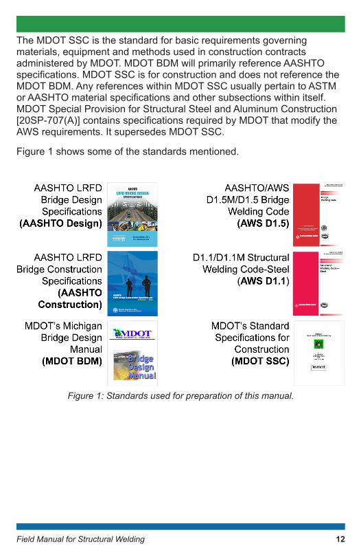
Figure 1 shows some of the standards mentioned.
Figure1:Standardsusedforpreparationofthismanual.
12
Field Manual for Structural Welding
Arc Welding ProcessesArc welding processes are based on fusion. Fusion requires closeness and cleanliness at the atomic level, both of which can be achieved by shielding the molten puddle with gas or slag. There are several types of arc welding processes as follows:
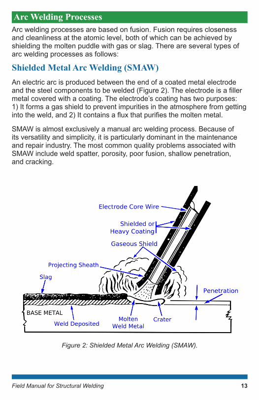
Shielded Metal Arc Welding (SMAW) An electric arc is produced between the end of a coated metal electrode andthesteelcomponentstobewelded(Figure2).Theelectrodeisafillermetal covered with a coating. The electrode’s coating has two purposes: 1) It forms a gas shield to prevent impurities in the atmosphere from getting intotheweld,and2)Itcontainsafluxthatpurifiesthemoltenmetal.
SMAW is almost exclusively a manual arc welding process. Because of its versatility and simplicity, it is particularly dominant in the maintenance and repair industry. The most common quality problems associated with SMAW include weld spatter, porosity, poor fusion, shallow penetration, and cracking.
Figure2:ShieldedMetalArcWelding(SMAW).
13
Field Manual for Structural Welding
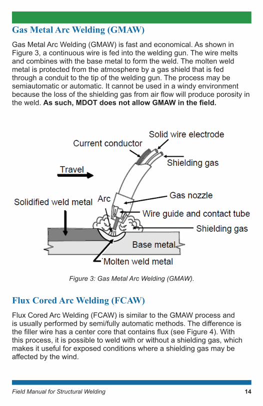
Gas Metal Arc Welding (GMAW) Gas Metal Arc Welding (GMAW) is fast and economical. As shown in Figure 3, a continuous wire is fed into the welding gun. The wire melts and combines with the base metal to form the weld. The molten weld metal is protected from the atmosphere by a gas shield that is fed through a conduit to the tip of the welding gun. The process may be semiautomatic or automatic. It cannot be used in a windy environment becausethelossoftheshieldinggasfromairflowwillproduceporosityinthe weld. As such, MDOT does not allow GMAW in the field.
Figure3:GasMetalArcWelding(GMAW).
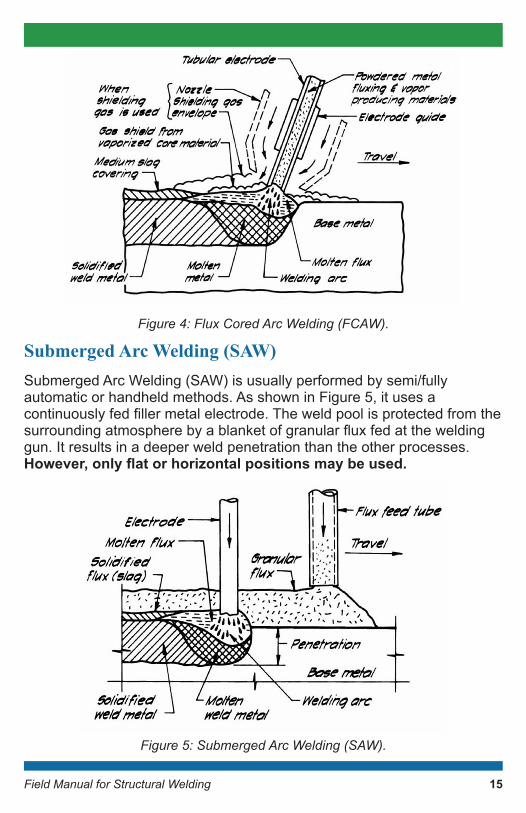
Flux Cored Arc Welding (FCAW)Flux Cored Arc Welding (FCAW) is similar to the GMAW process and isusuallyperformedbysemi/fullyautomaticmethods.Thedifferenceisthefillerwirehasacentercorethatcontainsflux(seeFigure4).Withthis process, it is possible to weld with or without a shielding gas, which makes it useful for exposed conditions where a shielding gas may be affectedbythewind.
14
Field Manual for Structural Welding
Figure4:FluxCoredArcWelding(FCAW).
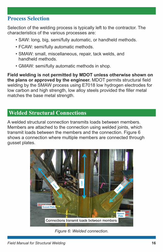
Submerged Arc Welding (SAW)Submerged Arc Welding (SAW) is usually performed by semi/fully automatic or handheld methods. As shown in Figure 5, it uses a continuouslyfedfillermetalelectrode.Theweldpoolisprotectedfromthesurroundingatmospherebyablanketofgranularfluxfedattheweldinggun. It results in a deeper weld penetration than the other processes. However, only flat or horizontal positions may be used.
Figure5:SubmergedArcWelding(SAW).
15
Field Manual for Structural Welding
Process SelectionSelection of the welding process is typically left to the contractor. The characteristics of the various processes are:
• SAW: long, big, semi/fully automatic, or handheld methods.• FCAW: semi/fully automatic methods.• SMAW: small, miscellaneous, repair, tack welds, and
handheld methods.• GMAW: semi/fully automatic methods in shop.
Field welding is not permitted by MDOT unless otherwise shown on the plans or approved by the engineer. MDOTpermitsstructuralfieldwelding by the SMAW process using E7018 low hydrogen electrodes for lowcarbonandhighstrength,lowalloysteelsprovidedthefillermetalmatches the base metal strength.
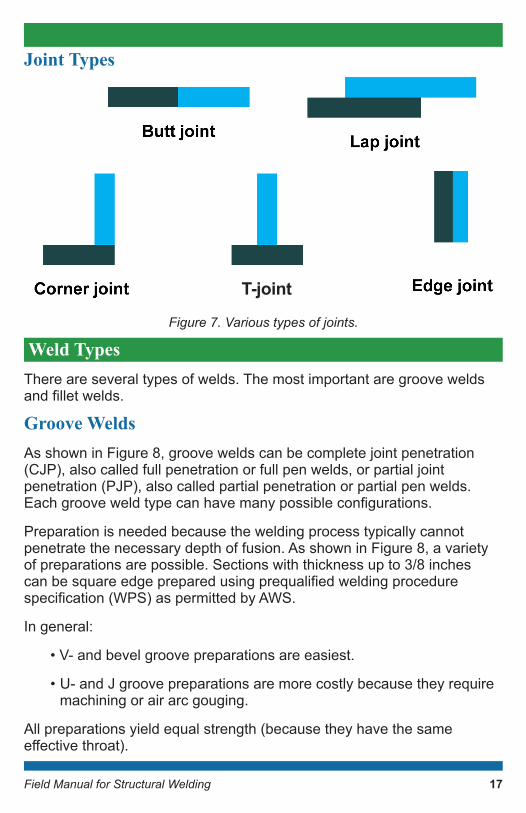
Welded Structural Connections A welded structural connection transmits loads between members. Members are attached to the connection using welded joints, which transmit loads between the members and the connection. Figure 6 shows a connection where multiple members are connected through gusset plates.
Figure6:Weldedconnection.
Gusset Plate
Gusset Plate
Load
Load
Load
16
Field Manual for Structural Welding
Joint Types
Figure7.Varioustypesofjoints.
Weld TypesThere are several types of welds. The most important are groove welds andfilletwelds.
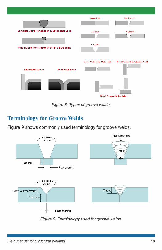
Groove WeldsAs shown in Figure 8, groove welds can be complete joint penetration (CJP), also called full penetration or full pen welds, or partial joint penetration (PJP), also called partial penetration or partial pen welds. Eachgrooveweldtypecanhavemanypossibleconfigurations.
Preparation is needed because the welding process typically cannot penetrate the necessary depth of fusion. As shown in Figure 8, a variety of preparations are possible. Sections with thickness up to 3/8 inches canbesquareedgepreparedusingprequalifiedweldingprocedurespecification(WPS)aspermittedbyAWS.
In general:
• V- and bevel groove preparations are easiest.
• U- and J groove preparations are more costly because they require machining or air arc gouging.
All preparations yield equal strength (because they have the same effectivethroat).
17
T-joint
Field Manual for Structural Welding
Figure 8: Types of groove welds.
Terminology for Groove WeldsFigure 9 shows commonly used terminology for groove welds.
Figure9:Terminologyusedforgroovewelds.
18
Field Manual for Structural Welding
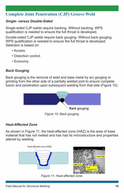
Complete Joint Penetration (CJP) Groove WeldSingle- versus Double-Sided
Single-sided CJP welds require backing. Without backing, WPS qualificationisneededtoensurethefullthroatisdeveloped.Double-sided CJP welds require back gouging. Without back gouging, WPSqualificationisneededtoensurethefullthroatisdeveloped.Selection is based on:
• Access.• Distortion control.• Economy.
Back Gouging
Back gouging is the removal of weld and base metal by arc gouging or grinding from the other side of a partially welded joint to ensure complete fusion and penetration upon subsequent welding from that side (Figure 10).
Figure10:Backgouging.
Heat-Affected Zone
AsshowninFigure11,theheat-affectedzone(HAZ)istheareaofbasematerial that has not melted and has had its microstructure and properties altered by welding.
Figure11:Heat-affectedzone.
19
Heat-affectedzone(HAZ)
Field Manual for Structural Welding
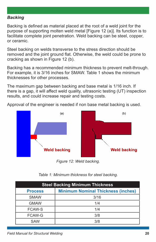
Backing
Backingisdefinedasmaterialplacedattherootofaweldjointforthepurpose of supporting molten weld metal [Figure 12 (a)]. Its function is to facilitate complete joint penetration. Weld backing can be steel, copper, or ceramic.
Steel backing on welds transverse to the stress direction should be removedandthejointgroundflat.Otherwise,theweldcouldbepronetocracking as shown in Figure 12 (b).
Backing has a recommended minimum thickness to prevent melt-through. For example, it is 3/16 inches for SMAW. Table 1 shows the minimum thicknesses for other processes.
The maximum gap between backing and base metal is 1/16 inch. If thereisagap,itwillaffectweldquality,ultrasonictesting(UT)inspectionresults, and could increase repair and testing costs.
Approval of the engineer is needed if non base metal backing is used.
Figure12:Weldbacking.
Table1:Minimumthicknessforsteelbacking.
Steel Backing Minimum ThicknessProcess Minimum Nominal Thickness (inches)
SMAW 3/16GMAW 1/4
FCAW-S 1/4FCAW-G 3/8
SAW 3/8
20
Field Manual for Structural Welding
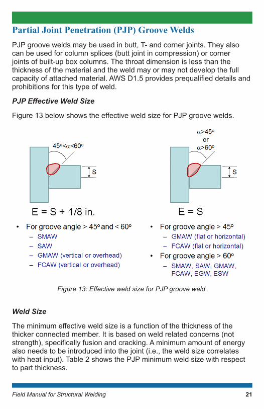
Partial Joint Penetration (PJP) Groove WeldsPJP groove welds may be used in butt, T- and corner joints. They also can be used for column splices (butt joint in compression) or corner joints of built-up box columns. The throat dimension is less than the thickness of the material and the weld may or may not develop the full capacityofattachedmaterial.AWSD1.5providesprequalifieddetailsandprohibitions for this type of weld.
PJP Effective Weld Size
Figure13belowshowstheeffectiveweldsizeforPJPgroovewelds.
Figure13:EffectiveweldsizeforPJPgrooveweld.
Weld Size
Theminimumeffectiveweldsizeisafunctionofthethicknessofthethicker connected member. It is based on weld related concerns (not strength),specificallyfusionandcracking.Aminimumamountofenergyalso needs to be introduced into the joint (i.e., the weld size correlates with heat input). Table 2 shows the PJP minimum weld size with respect to part thickness.
21
Field Manual for Structural Welding
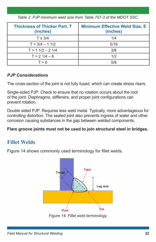
Table2.PJPminimumweldsizefromTable707-3oftheMDOTSSC.
PJP Considerations
The cross-section of the joint is not fully fused, which can create stress risers.
Single-sided PJP: Check to ensure that no rotation occurs about the root ofthejoint.Diaphragms,stiffeners,andproperjointconfigurationscan prevent rotation.
Double sided PJP: Requires less weld metal. Typically, more advantageous for controlling distortion. The sealed joint also prevents ingress of water and other corrosion causing substances in the gap between welded components.
Flare groove joints must not be used to join structural steel in bridges.
Fillet WeldsFigure14showscommonlyusedterminologyforfilletwelds.
Figure 14: Fillet weld terminology.
Thickness of Thicker Part, T (inches)
Minimum Effective Weld Size, E (inches)
T≤3/4 1/4T > 3/4 – 1 1/2 5/16
T > 1 1/2 – 2 1/4 3/8T > 2 1/4 – 6 1/2
T > 6 5/8
22
Field Manual for Structural Welding
Minimum Fillet Weld Size
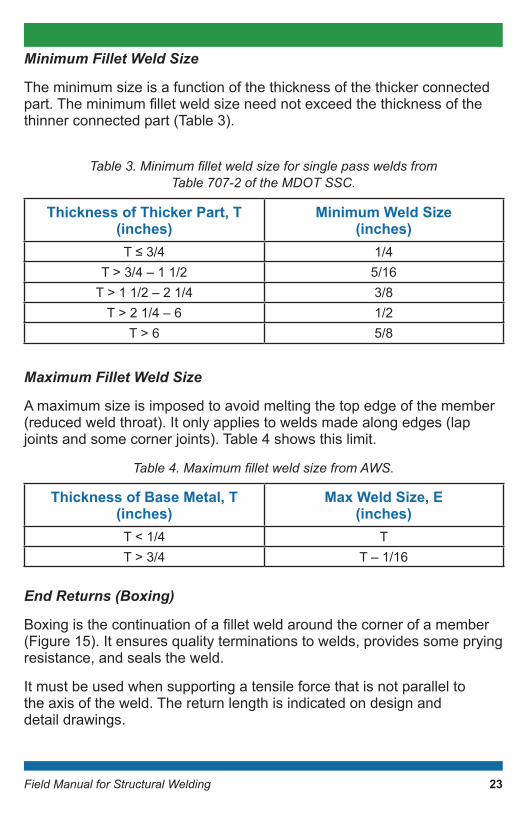
The minimum size is a function of the thickness of the thicker connected part.Theminimumfilletweldsizeneednotexceedthethicknessofthethinner connected part (Table 3).
Table3.Minimumfilletweldsizeforsinglepassweldsfrom
Table707-2oftheMDOTSSC.
Maximum Fillet Weld Size
A maximum size is imposed to avoid melting the top edge of the member (reduced weld throat). It only applies to welds made along edges (lap joints and some corner joints). Table 4 shows this limit.
Table4.MaximumfilletweldsizefromAWS.
End Returns (Boxing)
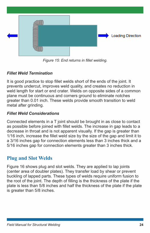
Boxingisthecontinuationofafilletweldaroundthecornerofamember(Figure 15). It ensures quality terminations to welds, provides some prying resistance, and seals the weld.
It must be used when supporting a tensile force that is not parallel to the axis of the weld. The return length is indicated on design and detail drawings.
Thickness of Thicker Part, T (inches)
Minimum Weld Size (inches)
T≤3/4 1/4T > 3/4 – 1 1/2 5/16
T > 1 1/2 – 2 1/4 3/8T > 2 1/4 – 6 1/2
T > 6 5/8
Thickness of Base Metal, T (inches)
Max Weld Size, E (inches)
T < 1/4 TT > 3/4 T – 1/16
23
Field Manual for Structural Welding
Figure15:Endreturnsinfilletwelding.
Fillet Weld Termination
Itisgoodpracticetostopfilletweldsshortoftheendsofthejoint.Itprevents undercut, improves weld quality, and creates no reduction in weld length for start or end crater. Welds on opposite sides of a common plane must be continuous and corners ground to eliminate notches greater than 0.01 inch. These welds provide smooth transition to weld metal after grinding.
Fillet Weld Considerations
Connected elements in a T joint should be brought in as close to contact aspossiblebeforejoinedwithfilletwelds.Theincreaseingapleadstoadecrease in throat and is not apparent visually. If the gap is greater than 1/16inch,increasethefilletweldsizebythesizeofthegapandlimitittoa 3/16 inches gap for connection elements less than 3 inches thick and a 5/16 inches gap for connection elements greater than 3 inches thick.
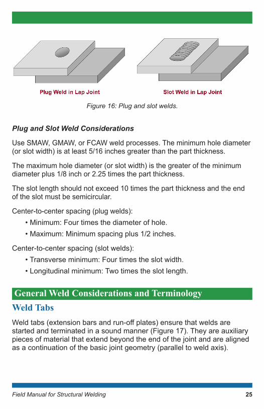
Plug and Slot WeldsFigure 16 shows plug and slot welds. They are applied to lap joints (center area of doubler plates). They transfer load by shear or prevent buckling of lapped parts. These types of welds require uniform fusion to therootofthejoint.Thedepthoffillingisthethicknessoftheplateiftheplate is less than 5/8 inches and half the thickness of the plate if the plate is greater than 5/8 inches.
24
Field Manual for Structural Welding
Figure 16: Plug and slot welds.
Plug and Slot Weld Considerations
Use SMAW, GMAW, or FCAW weld processes. The minimum hole diameter (or slot width) is at least 5/16 inches greater than the part thickness.
The maximum hole diameter (or slot width) is the greater of the minimum diameter plus 1/8 inch or 2.25 times the part thickness.
The slot length should not exceed 10 times the part thickness and the end of the slot must be semicircular.
Center-to-center spacing (plug welds):• Minimum: Four times the diameter of hole.• Maximum: Minimum spacing plus 1/2 inches.
Center-to-center spacing (slot welds):• Transverse minimum: Four times the slot width.• Longitudinal minimum: Two times the slot length.
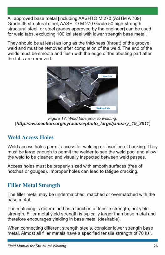
General Weld Considerations and TerminologyWeld TabsWeldtabs(extensionbarsandrun-offplates)ensurethatweldsarestarted and terminated in a sound manner (Figure 17). They are auxiliary pieces of material that extend beyond the end of the joint and are aligned as a continuation of the basic joint geometry (parallel to weld axis).
25
Field Manual for Structural Welding
All approved base metal [including AASHTO M 270 (ASTM A 709) Grade 36 structural steel, AASHTO M 270 Grade 50 high-strength structural steel, or steel grades approved by the engineer] can be used for weld tabs, excluding 100 ksi steel with lower strength base metal.
They should be at least as long as the thickness (throat) of the groove weld and must be removed after completion of the weld. The end of the weldsmustbesmoothandflushwiththeedgeoftheabuttingpartafterthe tabs are removed.
Figure17:Weldtabspriortowelding. (http://awssection.org/syracuse/photo_large/january_19_2011)
Weld Access HolesWeld access holes permit access for welding or insertion of backing. They must be large enough to permit the welder to see the weld pool and allow the weld to be cleaned and visually inspected between weld passes.
Access holes must be properly sized with smooth surfaces (free of notches or gouges). Improper holes can lead to fatigue cracking.
Filler Metal StrengthThefillermetalmaybeundermatched,matchedorovermatchedwiththebase metal.
The matching is determined as a function of tensile strength, not yield strength. Filler metal yield strength is typically larger than base metal and therefore encourages yielding in base metal (desirable).
Whenconnectingdifferentstrengthsteels,considerlowerstrengthbasemetal.Almostallfillermetalshaveaspecifiedtensilestrengthof70ksi.
Weld Tab
Backing Plate
26
Field Manual for Structural Welding
Filler Metal Considerations
Neverrequireovermatchedfillermetal.
Formatchedfillermetal,selectelectrodeorelectrode/fluxcombinationfrom AWS D1.5.
Forundermatchedfillermetal,undermatchbyupto10ksi.
Welds and Bolts in Same Connection Weldsincombinationwithboltsdonotshareload.Weldsarestifferandcarrytheloadfirst.Therefore,designconnectionsoweldscancarrythe entire load. Bolts used for assembly may be left in place (unless otherwisespecified).Theengineerwillspecifyifholesaretobefilledifassembly bolts are to be removed.
Filler PlatesFillerplates(alsoknownasfillers,jointfillers,orfillplates)arepermittedwhensplicingpartsofdifferentthicknessesandinconnectionsthataccommodateoffsetstoallowforsimpleframing.
They should be avoided when joining tension members and members subjecttoreversalofstress,specificallyFatigueCategoryE.
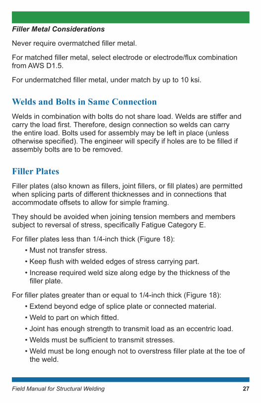
Forfillerplateslessthan1/4-inchthick(Figure18):• Must not transfer stress.•Keepflushwithweldededgesofstresscarryingpart.• Increase required weld size along edge by the thickness of the fillerplate.
Forfillerplatesgreaterthanorequalto1/4-inchthick(Figure18):• Extend beyond edge of splice plate or connected material.•Weldtopartonwhichfitted.• Joint has enough strength to transmit load as an eccentric load.•Weldsmustbesufficienttotransmitstresses.•Weldmustbelongenoughnottooverstressfillerplateatthetoeof
the weld.
27
Field Manual for Structural Welding
Figure 18: Filler plates.
Prohibited Joint Types and WeldsThe following joint types are prohibited:
• PJP welds in butt joints, except connections or splices in compression that are bearing and full-milled.
•CJPweldsmadefromonesidewithoutbacking(orwithunqualifiedbacking) under tension and load reversal.
• Intermittent groove welds.•Intermittentfilletweldsnotapprovedbytheengineer.• Flat position bevel- and J-groove welds in butt joints.• Plug or slot welds in members subject to tension and load reversal.
Hydrogen Embrittlement Hydrogen embrittlement is the process by which metals (such as steel) become brittle and fracture due to the introduction and subsequent diffusionofhydrogenintothemetal.Thisisoftenaresultofaccidentalintroductionofhydrogenduringformingandfinishingoperations.Inarcwelding, hydrogen is released from moisture, such as in the coating of welding electrodes. To minimize this, special low-hydrogen electrodes are used for welding.
28
Field Manual for Structural Welding
MDOT Requirements for Electrodes
• Dry electrodes in an oven at a temperature of at least 500 F for at least two hours before use unless they come from a hermetically sealed container.
• Store the electrodes at a temperature of at least 250 F after drying. Use E70XX electrodes within two hours of exposure to the atmosphere, or re-dry.
• Do not re-dry electrodes more than once. Do not use electrodes that have been wet.
Why all these restrictions? Because welding can strip hydrogen from water, which causes hydrogen embrittlement.
Also note that field welding is not permitted if the ambient air temperature falls below 40 F or during periods of precipitation, unless heating and housing the weld area as approved by the engineer (MDOT SSC).
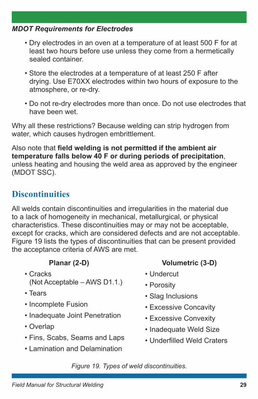
DiscontinuitiesAll welds contain discontinuities and irregularities in the material due to a lack of homogeneity in mechanical, metallurgical, or physical characteristics. These discontinuities may or may not be acceptable, except for cracks, which are considered defects and are not acceptable. Figure 19 lists the types of discontinuities that can be present provided the acceptance criteria of AWS are met.
Planar (2-D)• Cracks
(Not Acceptable – AWS D1.1.)• Tears• Incomplete Fusion• Inadequate Joint Penetration• Overlap• Fins, Scabs, Seams and Laps• Lamination and Delamination
Volumetric (3-D)• Undercut• Porosity• Slag Inclusions• Excessive Concavity• Excessive Convexity• Inadequate Weld Size•UnderfilledWeldCraters
Figure19.Typesofwelddiscontinuities.
29
Field Manual for Structural Welding
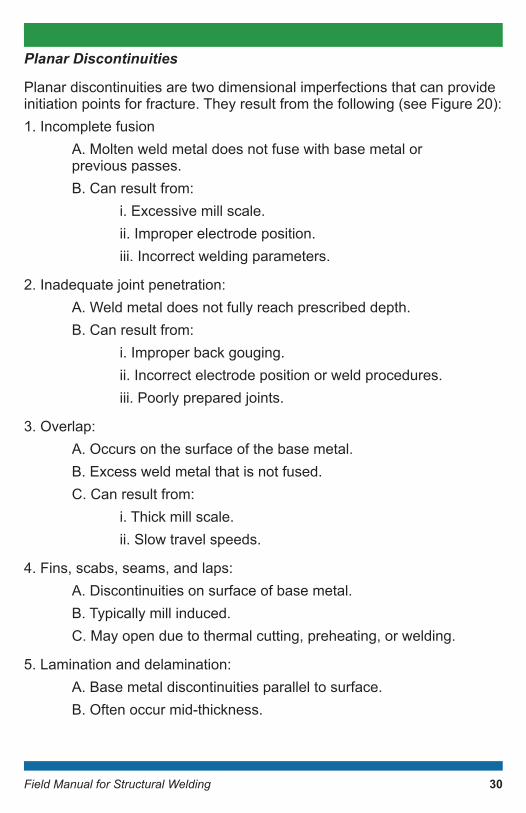
Planar Discontinuities
Planar discontinuities are two dimensional imperfections that can provide initiation points for fracture. They result from the following (see Figure 20):1. Incomplete fusion A. Molten weld metal does not fuse with base metal or previous passes. B. Can result from: i. Excessive mill scale. ii. Improper electrode position. iii. Incorrect welding parameters.
2. Inadequate joint penetration: A. Weld metal does not fully reach prescribed depth. B. Can result from: i. Improper back gouging. ii. Incorrect electrode position or weld procedures. iii. Poorly prepared joints.
3. Overlap: A. Occurs on the surface of the base metal. B. Excess weld metal that is not fused. C. Can result from: i. Thick mill scale. ii. Slow travel speeds.
4. Fins, scabs, seams, and laps: A. Discontinuities on surface of base metal. B. Typically mill induced. C. May open due to thermal cutting, preheating, or welding.
5. Lamination and delamination: A. Base metal discontinuities parallel to surface. B. Often occur mid-thickness.
30
Field Manual for Structural Welding
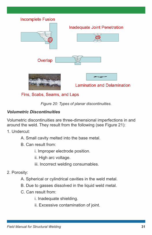
Figure20:Typesofplanardiscontinuities.
Volumetric Discontinuities
Volumetric discontinuities are three-dimensional imperfections in and around the weld. They result from the following (see Figure 21):1. Undercut: A. Small cavity melted into the base metal. B. Can result from: i. Improper electrode position. ii. High arc voltage. iii. Incorrect welding consumables.
2. Porosity: A. Spherical or cylindrical cavities in the weld metal. B. Due to gasses dissolved in the liquid weld metal. C. Can result from: i. Inadequate shielding. ii. Excessive contamination of joint.
31
Field Manual for Structural Welding
3. Slag inclusion: A. Non-metallic materials. B. Within weld metal or between base metal and weld metal. C. Can result from: i. Slag from previous weld pass not being removed completely.
4. Excessive concavity: A. Weld surface is concave. B. Reduced throat. C. Can result from: i. Low currents or voltages. ii. Improper weld procedures.
5. Excessive convexity: A. Weld surface exceeds acceptable limits. B. Typically associated with weld procedure problems.
6. Inadequate weld size: A. Weld too short or small. B. Also known as an undersized weld. C. Can result from: i. Procedural problems. ii. Too high travel speed.
7.Underfilledweldcrater: A. Concave depressions at the end of weld. B. Localized reduction in weld throat. C. Typically associated with welder technique.
32

Field Manual for Structural Welding
Figure21:Typesofvolumetricdiscontinuities.
Special Considerations for Lap JointsAvoid Fatigue Category E in members subject to tension and stress reversal.
Longitudinalfilletweldscanonlybeused.Thelengthmustbeatleasttheperpendicular distance between the welds, and transverse spacing must not exceed 16 times the thickness of the thinner connected part. The welds can be applied either at the edge of the members or in slots.
Theminimumoverlapofpartsmustbeatleastfivetimesthethicknessofthe thinner connected part. At least two transverse lines or two or more longitudinal welds must be used to prevent unacceptable rotation.
33

Field Manual for Structural Welding
Special Considerations for Butt Joints Specialrequirementsareneededfortransitionofdifferentplatewidths or thicknesses.
1. If subjected to tension or compression (unequal thickness): A.Smoothtransitionbetweenoffsetsurfaces. B. Slope of no more than one transverse to two-and-a-half longitudinal with the surface of either part: i. Slope weld surfaces. ii. Chamfer thicker part. iii. Combination of both.
2. If subjected to shear (unequal thickness): A.Sameastensionorcompressionrequirementwhenoffsetis greater than the thickness of the thinner part. B.Offsetlessthanorequaltothethicknessofthethinnerpart: i. Sloped no more than one transverse to two-and-a-half longitudinal from surface of thinner part. ii. Or sloped to the surface of thicker part if less of a slope.
3. If subjected to tension (unequal width): A.Smoothtransitionbetweenoffsetsurfaces. B. Slope of no more than one transverse to two-and-a-half longitudinal with the surface of either part. C. Or transitioned with 24 inches minimum radius tangent to the narrower part at the center of the butt joint.
Special Considerations for T-JointsSpecial consideration needed for joints where T joint does not intersect at 90 degrees.
For the acute side of the joint (Figure 22) where there is a small dihedral angle, there is a possibility for incomplete fusion to the weld root (reduced throat).
34
Field Manual for Structural Welding
For the obtuse side of the joint (Figure 22) where there is a large dihedral angle,thefilletweldthroatisdisproportionatelysmallcomparedtotheweld size.
Figure22:SpecialconsiderationsforT-joint.
Special Considerations for Corner JointsAccess for welding corners of box sections must be considered. This may eliminate two sided welds. The environmental conditions for the welder must also be considered. Laminar tearing requirements must be considered when welds are large.
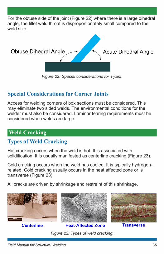
Weld CrackingTypes of Weld CrackingHot cracking occurs when the weld is hot. It is associated with solidification.Itisusuallymanifestedascenterlinecracking(Figure23).
Cold cracking occurs when the weld has cooled. It is typically hydrogen-related.Coldcrackingusuallyoccursintheheataffectedzoneoristransverse (Figure 23).
All cracks are driven by shrinkage and restraint of this shrinkage.
Figure23:Typesofweldcracking.
35
Field Manual for Structural Welding
Shrinkage and RestraintWeld metal and surrounding base metal expand during welding due to heating. These hot materials contract upon cooling. If materials are restrained from shrinking, then stresses will develop.
Colder base material resists contraction of the cooling hotter material. Resistance depends on the volume and strength of the colder material. Stiffnessofthecoldermaterialisassociatedwithitsgeometricconfiguration.Temperaturealsoaffectstheelasticmodulusofthematerial,whichdirectlyaffectsthestiffness.
Base metal thickness greater than 1.5 inches with yield strengths greater than 50 ksi lead to higher shrinkage stresses.
Members intersecting from all three geometric directions lead to higher constraint.
Practices to Reduce Shrinkage Stresses
1. Minimize weld material needed: A. Specify smallest weld possible. B. Use weld details that require least amount of weld metal. C.Controlfit-upandminimizegaps. D. Do not over weld. E. Limit weld reinforcement. F. Limit back gouging to only what is necessary.
2. Weld in fewest number of passes (larger weld beads).
3.Useloweststrengthfillermetalpossible.
4. Limit weld penetration.
5. Complete highly restrained weldments without interruption: A. Around-the-clock welding. B. Or maintain assembly at welding temperatures.
6. Only weld assembly once (requires proper planning).
36
Field Manual for Structural Welding
Practices to Reduce Restraint
1. Fabricate small assemblies when possible. 2.Weldcomponentswithexpectedgreatestshrinkagefirst. 3.Weldmostrigidcomponentsfirst. 4. Sequence welding so shrinkage movement in parts is all toward arelativelyfixedlocation. 5. Balance shrinkage on opposite sides. 6. Provide small gaps to help accommodate shrinkage. 7. Increase preheat and volume of preheated materials. 8. Preset members before welding and allow to move during welding.
Centerline CrackingSegregation-Induced Cracking
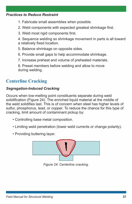
Occurs when low-melting point constituents separate during weld solidification(Figure24).Theenrichedliquidmaterialatthemiddleoftheweldsolidifieslast.Thisisofconcernwhensteelhashigherlevelsofsulfur, phosphorus, lead, or copper. To reduce the chance for this type of cracking, limit amount of contaminant pickup by:
• Controlling base metal composition.
• Limiting weld penetration (lower weld currents or change polarity).
• Providing buttering layer.
Figure24:Centerlinecracking.
37
Field Manual for Structural Welding
Bead Shape-Induced Cracking
Bead shape-induced cracking is associated with deep penetrating weld processes such as SAW and Gas Shielded FCAW. It occurs when the depth of the weld bead is greater than the width. Therefore, it is recommended the width-to-depth ratio of the bead be between 1:1 and 1.4:1. Joint design is important to prevent this type of cracking and the following must be observed:
•AWSprequalifiedjointshaveproperrootopeningsand included angles.
• For PJP welds made by SAW, 60 degree included angles are preferred.
• Fillet welds typically not a problem unless they have a skewed joint.
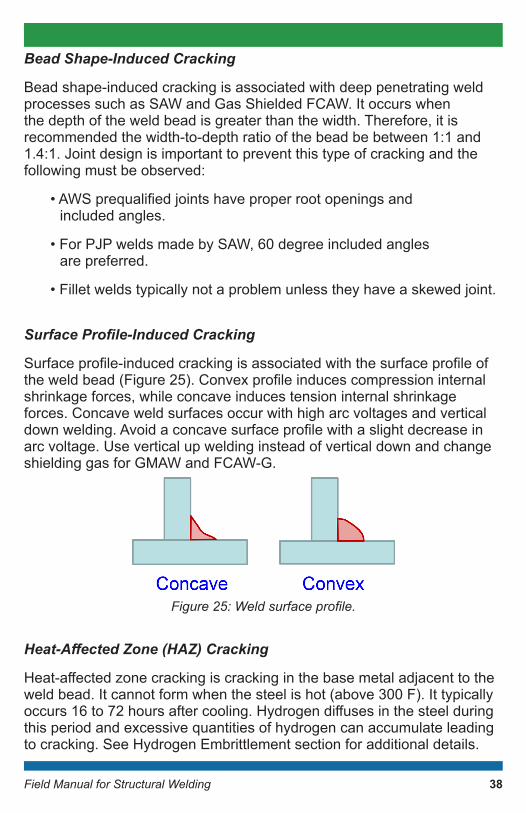
Surface Profile-Induced Cracking
Surfaceprofile-inducedcrackingisassociatedwiththesurfaceprofileoftheweldbead(Figure25).Convexprofileinducescompressioninternalshrinkage forces, while concave induces tension internal shrinkage forces. Concave weld surfaces occur with high arc voltages and vertical downwelding.Avoidaconcavesurfaceprofilewithaslightdecreaseinarc voltage. Use vertical up welding instead of vertical down and change shielding gas for GMAW and FCAW-G.
Figure25:Weldsurfaceprofile.
Heat-Affected Zone (HAZ) Cracking
Heat-affectedzonecrackingiscrackinginthebasemetaladjacenttotheweld bead. It cannot form when the steel is hot (above 300 F). It typically occurs16to72hoursaftercooling.Hydrogendiffusesinthesteelduringthis period and excessive quantities of hydrogen can accumulate leading to cracking. See Hydrogen Embrittlement section for additional details.
38
Field Manual for Structural Welding
To reduce the chance for this type of cracking, do not introduce hydrogen-bearing compounds. Ensure the following:
• Dry electrodes in an oven at a temperature of at least 500 F for at least two hours before use.
• Store the electrodes at a temperature of at least 250 F after drying. Use electrodes within two hours (or less as required per the project specifications)ofexposuretotheatmosphereorredry.
• Do not redry electrodes more than once. Do not use electrodes that have been wet.
• Heat weld area to between 400 and 450 F for an hour for each inch of weld thickness (post-heat); must not have reached room temperature.
• Use approved base metal (AASHTO M 270 Gr. 36; AASHTO M 270 Gr. 50; other steels approved by the engineer).
• Follow proper preheat and interpass temperature guidelines.• Reduce residual stresses.
Transverse CrackingThecontrollingfactorsarethesameasHAZcracking:
• Excessive hydrogen, where multi-pass welds inhibit hydrogen release. In this case, thinner weld beads may help hydrogen diffusefaster.
• Susceptible microstructure. In overmatched welds, the weld metal becomes the susceptible material.
• Stress due to longitudinal shrinkage of the weld.
Limiting Transverse Cracking
1. Use undermatched welds: A. Ensure weld strength is adequate for anticipated loads. B. Alloy pick-up may cause higher weld metal strength even for lower-strength electrodes. C.OftenusedforPJPgrooveweldsandfilletwelds.
39
Field Manual for Structural Welding
2. Increase preheat: A.Assistsindiffusinghydrogen. B. Weld metal and joint also can contract simultaneously.
3. Post-heat treatment.
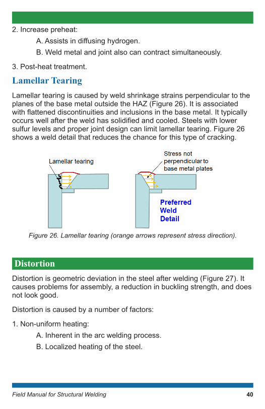
Lamellar TearingLamellar tearing is caused by weld shrinkage strains perpendicular to the planesofthebasemetaloutsidetheHAZ(Figure26).Itisassociatedwithflatteneddiscontinuitiesandinclusionsinthebasemetal.Ittypicallyoccurswellaftertheweldhassolidifiedandcooled.Steelswithlowersulfur levels and proper joint design can limit lamellar tearing. Figure 26 shows a weld detail that reduces the chance for this type of cracking.
Figure26.Lamellartearing(orangearrowsrepresentstressdirection).
DistortionDistortion is geometric deviation in the steel after welding (Figure 27). It causes problems for assembly, a reduction in buckling strength, and does not look good.
Distortion is caused by a number of factors:
1. Non-uniform heating: A. Inherent in the arc welding process. B. Localized heating of the steel.
40

Field Manual for Structural Welding
2. Have same constrained expansion and contraction that causes cracking: A. Rigid surrounding material leads to cracking. B. Flexible surrounding material leads to distortion. C.Moreflexiblesystemsaresusceptibletodistortion.
3. Distortion can be controlled by using more rigid parts. However, control measures do increase the tendency for cracking: A. Thicker members. B. External restraints.
Figure27:Distortioninweldedcomponents.
Angular DistortionAngular distortion (Figure 28) occurs due to transverse shrinkage of the weld. It can be caused by any type of weld and can occur in any type of joint. Its effectscanbeoffsetwithtwosidedwelding(mayrequireunevenwelds).
Figure28:Angulardistortion.
Transverse ShrinkageTransverse shrinkage occurs due to transverse shrinkage of the weld (Figure29).Itseffectsaredirectlyrelatedtovolumeofshrinkingweldmetal, and it occurs when the ends are free to move. This type of distortion is typically negligible.
41

Field Manual for Structural Welding
Figure29:Transverseshrinkage.
Longitudinal Shortening Longitudinal shortening occurs due to longitudinal shrinkage of the weld (Figure 30). The assembly generally shortens. It may also result in twisting, longitudinal sweep or camber, or buckling and warping. It is typically negligible, except with very long members such as long plate girders. In such cases, fabricate the girder longer than needed and cut to length.
Figure30:Longitudinalshrinkage.
TwistingTwisting occurs due to longitudinal shrinkage of the weld. It results when the weld region shrinks but the outside steel does not. It is often seen with open sections with little torsional rigidity and may occur in deep plate girders with thin webs. It can be countered by increasing the torsional rigidity of the member (i.e., use closed sections).
Longitudinal Sweep or CamberLongitudinal sweep or camber occur due to longitudinal shrinkage of the weld. Curvature occurs over the length of the part along the longitudinal axis. The center of gravity of the weld group in relationship with the neutral axis of the section dictates the direction of curvature.
42

Field Manual for Structural Welding
Buckling and WarpingBuckling and warping occur due to longitudinal shrinkage of the weld when the base metal surrounding the weld is thin. Buckling can occur in thewebofplategirdersbetweenstiffeners,whilewarpingiscommonifthere is a free edge.
These issues are often seen in open sections with little torsional rigidity. Their extent depends on the critical buckling stress of the section and can be countered by increasing the thickness and/or decreasing the length of the welded components.
Rotational DistortionRotational distortion occurs due to the transverse shrinkage of the weld (Figure 31). It is prominent in thin members (sheet metal) and members that are narrow compared to their length. The joint either opens or closes dependingonthespeedofweldingandheatinput.Itseffectscanbemitigated by clamping or back stepping.
Figure31:Rotationaldistortion.
General Distortion Control MeasuresMany of the following measures also lead to economical joints and maximize productivity.
1. Minimize the volume of localized metal that expands during welding: A. Minimize volume of weld metal. B. Minimize volume of heated base metal around the weld. C. Increase volume of base metal heated away from the weld.
43
Field Manual for Structural Welding
2. Reduction measures: A. Specify smallest weld size possible. B. Use intermittent welds. C. Select details that minimize weld material. D. Make multi-pass welds with the fewest possible passes. E.Controlfit-up. F. Limit weld reinforcement. G. Do not over weld. H. Limit back gouging to only required material. I. Limit weld penetration.
Specialized Distortion Control Measures1. Add restraint: A. Keep part from moving when hot: i. Tack welds. ii.Weldingfixtures. B. Will always have some elastic spring back.
2. Weld placement: A. Place welds on or near the neutral axis. B. Balance welds around the neutral axis.
3. Welding sequence: A. Minimize longitudinal weld sweep and camber with a properly planned weld pattern. B. Use subassemblies to weld closer to the neutral axis of each assembly.
AWS Distortion and Shrinkage Requirements1. Balance applied heating as welding progresses.
2. Welding sequence and distortion control program must be submitted to the engineer prior to the start of welding.
44
Field Manual for Structural Welding
3.Progressfrompointsthatarerelativelyfixedtowardthosethathavegreater freedom for movement.
4.Weldjointswithgreaterexpectedshrinkagefirstwithaslittlerestraintas possible.
5. All shop splices in each component part of a cover plated beam or built up member must be made prior to the component part being welded to other component parts.
6. For cases of severe external shrinkage restraint, welding must be carried out continuously.
7. Distorted members must be straightened through: A. Mechanical means, or B. Through application of a limited amount of localized heat.
Allowable Dimensional TolerancesDimensions of welded structural members must comply with the tolerancessetbythegeneralspecificationgoverningthework.
AWS D1.5, Clause 5.5 provides special dimensional tolerances that must also be met in the presence of distortion.
FatigueFatigue is cumulative damage caused by repeatedly applied cyclic loads. Fatigueisinfluencedbythefollowing:
1. Stress range: A. Fatigue design is based on live load stress range. B.Differencebetweentheminimumandmaximumliveloadstress applied cyclically over time. C. Reduce loads or increase material available to resist loads.
2. Number of load cycles: A. Live load cycles between maximum and minimum stress. B. Typically, not addressed by the engineer.
45
Field Manual for Structural Welding
3. Connection geometry: A. Dictates the nature and extent of stress raisers. B. Consider: i. Type of weld. ii. Weld orientation. iii.Weldprofile. iv. Length of weld. v. Weld reinforcement. vi. Quality of weld.
C. All welded connections fall into a “Detail Category”: i. Potential crack initiation point. ii.Thresholdfatiguestressrangeforinfinitedesignlife. iii.Frombesttoworst:A,B,B′,C,C′,D,E,E′.
Special Fabrication Requirements for Fatigue ResistanceSteel backing must be removed from the joint and the weld ground smooth.
ReinforcingorcontouringfilletweldsarerequiredontopofPJPorCJPgroove welds in T joint and corner joints: • Minimum size greater than or equal to T1/4. • T1 is the thickness of the member in which the groove weld is placed (need not exceed 3/8 inches). •Minimumfilletweldsizeis3/16inches.
Weld tabs must be removed after completion of welding and cooling.
Tack welds and temporary welds: •Subjecttosamequalityrequirementsasfinalwelds. •Ifincorporatedintofinalweld,thenuseelectrodethatmeetsfinal weld requirements. •Tackweldsnotincludedinfinalweldmustberemovedinan appropriate manner. • MDOT must approve tack welds that are not consumed by the root pass.
46
Field Manual for Structural Welding
Miscellaneous attachments can cause unintended load paths.
Use notch tough weld metal (allows larger crack sizes prior to fracture).
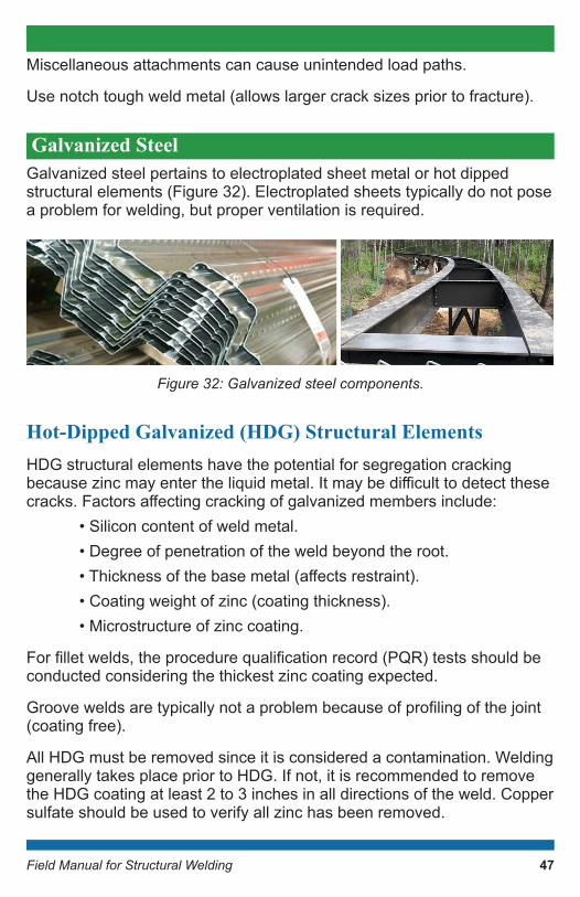
Galvanized Steel Galvanized steel pertains to electroplated sheet metal or hot dipped structural elements (Figure 32). Electroplated sheets typically do not pose a problem for welding, but proper ventilation is required.
Figure32:Galvanizedsteelcomponents.
Hot-Dipped Galvanized (HDG) Structural ElementsHDG structural elements have the potential for segregation cracking becausezincmayentertheliquidmetal.Itmaybedifficulttodetectthesecracks.Factorsaffectingcrackingofgalvanizedmembersinclude: • Silicon content of weld metal. • Degree of penetration of the weld beyond the root. •Thicknessofthebasemetal(affectsrestraint). • Coating weight of zinc (coating thickness). • Microstructure of zinc coating.
Forfilletwelds,theprocedurequalificationrecord(PQR)testsshouldbeconducted considering the thickest zinc coating expected.
Grooveweldsaretypicallynotaproblembecauseofprofilingofthejoint(coating free).
All HDG must be removed since it is considered a contamination. Welding generally takes place prior to HDG. If not, it is recommended to remove the HDG coating at least 2 to 3 inches in all directions of the weld. Copper sulfate should be used to verify all zinc has been removed.
47
Field Manual for Structural Welding
General Welding Requirements MDOT requires welding to be conducted at an ambient temperature of 40 F and above. The size and length of welds must be no less than those specified.Thelocationofweldsandweldtypemustnotbechangedwithout approval of the engineer.
Base Metal PreparationBase metal preparation ensures proper weld quality (no cracking or distortion) and minimizes objectionable fumes.Surfaces and edges to be welded must be: • Smooth. • Uniform. •Freefromfins,tears,cracks,millscale,pitting,irregularities,and other discontinuities.
Weld surfaces and adjacent surfaces must be free from loose or thick mill scale, slag, rust, moisture, grease, and other foreign materials. All edges must be conditioned by very shallow grinding to remove the hardened layer(martensite)leftbyre-solidification.
Edges of base metal must be inspected and repaired as early as feasible.
MDOT requires all weld repairs to be submitted in writing to the engineer and be approved prior to repairs taking place.
Re entrant corners of base metal cut edges must provide a smooth transition with a radius of not less than 1 inch unless the contract plans specify a larger radius due to fatigue.
Radii of beam copes and weld access holes also must provide a smooth transition between adjacent surfaces.
Joint and edge preparation can be done by: • Machining. • Thermal cutting. • Air carbon arc cutting and gouging. • Plasma arc gouging. • Chipping and grinding.
48
Field Manual for Structural Welding
AssemblyFillet Welds
The assembly process is as follows:
1. Bring parts to be welded into as close contact as possible.
2. The maximum root opening is 3/16 inches (except for members 3 inches thick or greater).
3. If 3 inches thick or greater and cannot close root opening: A. The maximum root opening is 5/16 inches. B. Employ suitable backing.
4. Root openings greater than 1/16 inch require an increase in the leg ofthefilletweldbytheamountoftherootopening(ordemonstrateappropriate weld size).
Plug, Slot and Butt Joints
Faying surface separation must not exceed 1/16 inch.
Groove Welds
The assembly process is as follows:
1. Maintain zero (or as small as practical) root opening for PJP welds parallel to the member length (except for bearing joints). Otherwise, PJP weldshavesamerequirementsasfilletwelds.
2. Carefully align parts joined by groove welds: A.Offsetfromtheoreticalalignmentmustnotexceed10percentof the thickness of the thinner part joined. B. Maximum of 1/8 inch.
3. Correction of misalignment must not cause a slope greater than 1/2 inch over 12 inches measured at the part centerline.
49

Field Manual for Structural Welding
The allowable groove weld root openings are shown in Table 5.
Table5:Allowablegrooveweldrootopenings.
PeeningPeening improves the material properties of the metal’s surface by inducing compressive stresses or relieving tensile stresses.
It must be approved by the engineer.
It is applied by mechanically striking the convex surface of intermediate weld beads using a specialized instrument, known as a ball peen hammer (see Figure 33).
Therootandfinalpassesshouldnotbepeened.However,thefinalpasses can be peened with excess weld metal with approval by the engineer and peening marks must be removed by grinding.
Peening must be conducted when the weld is at 150 to 500 F. MDOT does not permit peening.
Figure33:Ball-peenhammer.
Location Root Not Gouged (inches)
Root Gouged (inches)
Root Face of Joint ±1/16 No Limit
Root Opening of Joints Without Steel Backing ±1/16 +1/16
-1/8
Root Opening of Joints With Steel Backing
+1/4-1/16 Not Applicable
Groove Angle of Joint +10°-5°
+10°-5°
50
Field Manual for Structural Welding
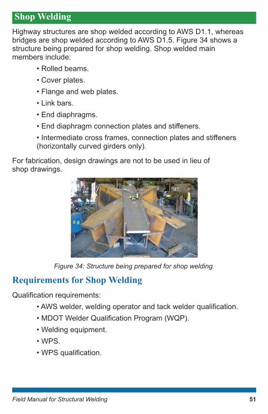
Shop WeldingHighway structures are shop welded according to AWS D1.1, whereas bridges are shop welded according to AWS D1.5. Figure 34 shows a structure being prepared for shop welding. Shop welded main members include: • Rolled beams. • Cover plates. • Flange and web plates. • Link bars. • End diaphragms. •Enddiaphragmconnectionplatesandstiffeners. •Intermediatecrossframes,connectionplatesandstiffeners (horizontally curved girders only).
For fabrication, design drawings are not to be used in lieu of shop drawings.
Figure34:Structurebeingpreparedforshopwelding.
Requirements for Shop WeldingQualificationrequirements: •AWSwelder,weldingoperatorandtackwelderqualification. •MDOTWelderQualificationProgram(WQP). • Welding equipment. • WPS. •WPSqualification.
51

Field Manual for Structural Welding
Welder must qualify for the welding process, welding position, material grade, and material thickness. Note that some positions, grades, and thicknesses qualify others.
MDOT WQP testing will be made under supervision of an MDOT representative.
Welding Procedure Specification (WPS)A WPS is a document that describes weld procedures and is supported by a PQR. It provides direction to the welder or weld operator to ensure soundness and quality of the weld. It ensures repeatable and trusted weldingtechniques.Itmustbequalifiedunlessusingaprequalifiedweld detail (AWS D1.5, Clause 4). Essential variable changes or owner toughnessrequirementsmayresultinaprequalifiedWPSrequiringqualificationtesting.
AWPSshowsthataweldpreparedunderthespecifiedvariableswillhave adequate properties and quality. It proves that standards regarding mechanical properties (strength, ductility, and toughness) can be met and ensures soundness.
TheWPSqualificationtestusesastandardgrooveweldtest(Figure35)to determine mechanical properties and soundness of the weld through nondestructive and destructive testing.
MDOT requires all WPS to be qualified, except SMAW. MDOT recognizes prequalified WPS for AWS D1.1 welding. All WPS to be approved by MDOT’s Structural Fabrication Unit.
52

Field Manual for Structural Welding
Figure35:WPSqualificationtestplate.
WeldingvariablesconsideredduringWPSqualificationare: • Welding process. • Base material. • Welding consumables. • Welding parameters and techniques: - Position. - Polarity. - Preheat. - Interpass temperature. - Back gouging. - Post-weld heat treatment.
53
Field Manual for Structural Welding
TestsconductedduringWPSqualificationinclude: • Mechanical: - Reduced section tension tests. - All weld metal tension tests. - Side bend tests. • Soundness: - Radiographic testing (RT) for welds to fracture critical members (FCM). - Macroetch tests. • Toughness: - Charpy V-notch tests.
MDOT does recognize AWS D1.1 and AWS D1.5 prequalified joints and procedures. Essential variable changes or owner toughness requirements may result in a prequalified WPS requiring qualification testing.
Procedure Qualification Test Record (PQR)AproductionWPS’squalificationisbasedonaPQRthatisproducedby the contractor in conformance with AWS D1.1 or AWS D1.5, based ontheprojectspecifications.MDOTreviewsthePQRassupportingdocumentation during WPS approval but does not approve the PQR.
Shop Welded Plate Girders and Rolled BeamsMDOT requires SAW for: • Flange to web groove welds using one of the following weld positions: - Flat (1F). - Flat (1G).
•Coverplatetobeamflangeweldsusingoneofthefollowing weld positions: - Flat (1F). - Horizontal (2F). -Stiffenersandconnectionplatestoweb. - Flange-to-web connection in box girders.
54
Field Manual for Structural Welding
UseSMAWforstiffenerandconnectionplatestorolledbeamsandgirders when automatic or hand held SAW cannot be used. Employ E7018 electrodes unless a higher tensile strength is required to match the base metal (i.e., AASHTO M270 Gr HPS70W).
Note that MDOT does not allow electroslag or electrogas welding.
Forfilletwelds: • Size by thicker of two joining parts (unless larger is required based on calculated stress). • Not required to exceed thickness of thinner part. • Preheat if smaller than minimum required. •Minimumforbeamflangeis5/16inches.
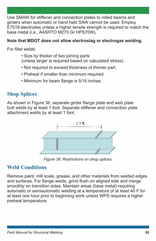
Shop Splices AsshowninFigure36,separategirderflangeplateandwebplatebuttweldsbyatleast1foot.Separatestiffenerandconnectionplateattachment welds by at least 1 foot.
Figure36:Restrictionsonshopsplices.
Weld ConditionsRemove paint, mill scale, grease, and other materials from welded edges andsurfaces.Forflangewelds,grindflushonalignedsideandmergesmoothly on transition sides. Maintain areas (base metal) requiring automatic or semiautomatic welding at a temperature of at least 40 F for at least one hour prior to beginning work unless WPS requires a higher preheat temperature.
55
Field Manual for Structural Welding
Shop Weld Nondestructive Testing for BridgesNondestructive testing (NDT) is required for all shop welds and is performedbythecontractor.Identificationmarksshouldbemadewithpaint on butt welds. Testing must be performed by an NDT technician qualifiedasAmericanSocietyforNondestructiveTesting(ASNT)LevelIIon Recommended Practice No. SNT TC 1A.
Nondestructive Testing – Groove Welds
• Visual test 100 percent of groove welds.
• PT in accordance with ASTM E 165:
• Inspect both ends of groove welds for surface defects.
•RequiredbecauseUTandRTaredifficultatedgesofaplate. Use RT in accordance with AWS D1.5, Clause 8 Part B: - Single-source X ray or gamma ray. - Use hole type or wire image quality indicators to judge sensitivity. -Doubleshootfilmforqualitycontrolandquality assurance records. -Forthicknesstransitions,placeradiographicfilmonboth sides of the joint, position the pack, and use tapered edge blocks. -Movefilmtoplanarsideifsubstandardresultswhenon transition side.
• For CJP groove welds at corner and T joints where RT is not possible: - Perform UT and agree on acceptance criteria. - Use glycerine as the coupling agent.
• UT all plug and slot welds.
• Test CJP groove welds of main members according to the following:
-100percentofflexuralmemberflangebuttjoint.
- 100 percent of splices subject to tension or stress reversal.
56
Field Manual for Structural Welding
- Web splices: 1/3 the length of all web splices beginning at the point of maximum tension, but not less than 12 inches. In addition, test 25 percent of the remainder of the web depth beginning at the point of maximum compression, but not less than 12 inches.
- 25 percent of each axial member subject to compression.
- 25 percent of each joint subjected to shear such as web toflangejointsinflexuralmembers.
- If unacceptable discontinuities are found in any of the above partial examinations, test the remainder of the weld and test 100 percent of similar welds.
Nondestructive Testing – Fillet Welds
Magneticparticletesting(MT)isrequiredforfilletweldsinaccordancewithAWSD1.5exceptasmodifiedherein.PerformMTinaccordancewithASTM E709 with dry powder using the yoke method.
Testtheentirelengthofthestiffenerorconnectionplatetotensionflangeofmainmembers.Testatleast12inchesinevery10feetofeachfilletweldforthejointsspecifiedinsection707oftheMDOTSCCandprojectspecial provision.
MDOT does not require the following members to be MT inspected: • Diaphragm assemblies. • Sway bracing.
If a defect is detected, then increase frequency to the least of either the full weld length or 5 feet on each side of the defect.
Defective WeldsReplace all welds that are rejected by any test method. Provide repair procedure for engineer’s approval and repair weld in accordance with AWS D1.5, Clause 5.7.
Retest at least 3 inches to either side of the repair. If second repair attempt fails, then remove and replace entire weld.
57
Field Manual for Structural Welding
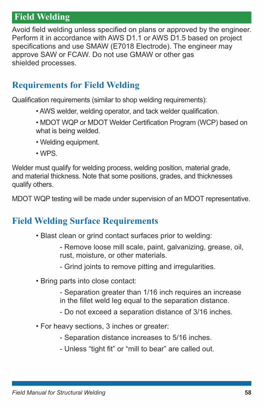
Field Welding Avoidfieldweldingunlessspecifiedonplansorapprovedbytheengineer.Perform it in accordance with AWS D1.1 or AWS D1.5 based on project specificationsanduseSMAW(E7018Electrode).Theengineermayapprove SAW or FCAW. Do not use GMAW or other gas shielded processes.
Requirements for Field WeldingQualificationrequirements(similartoshopweldingrequirements): •AWSwelder,weldingoperator,andtackwelderqualification. •MDOTWQPorMDOTWelderCertificationProgram(WCP)basedon what is being welded. • Welding equipment. • WPS.
Welder must qualify for welding process, welding position, material grade, and material thickness. Note that some positions, grades, and thicknesses qualify others.
MDOT WQP testing will be made under supervision of an MDOT representative.
Field Welding Surface Requirements • Blast clean or grind contact surfaces prior to welding: - Remove loose mill scale, paint, galvanizing, grease, oil, rust, moisture, or other materials. - Grind joints to remove pitting and irregularities.
• Bring parts into close contact: - Separation greater than 1/16 inch requires an increase inthefilletweldlegequaltotheseparationdistance. - Do not exceed a separation distance of 3/16 inches.
• For heavy sections, 3 inches or greater: - Separation distance increases to 5/16 inches. -Unless“tightfit”or“milltobear”arecalledout.
58
Field Manual for Structural Welding
• Consider environmental conditions: - Temperature must be above 40 F. - No precipitation (rain, snow, or heavy fog).
• Electrodes: - Dry in oven for two hours before use at 500 F or greater. - Store at 250 F after drying. - Use within two hours of exposure to atmosphere or redry. - Do not redry more than once. - Discard if wet.
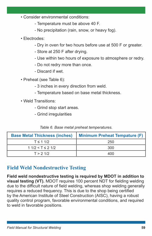
• Preheat (see Table 6): - 3 inches in every direction from weld. - Temperature based on base metal thickness.
• Weld Transitions: - Grind stop start areas. - Grind irregularities
Table6.Basemetalpreheattemperatures.
Field Weld Nondestructive TestingField weld nondestructive testing is required by MDOT in addition to visual testing (VT).MDOTrequires100percentNDTforfieldingweldingduetothedifficultnatureoffieldwelding,whereasshopweldinggenerallyrequiresareducedfrequency.Thisisduetotheshopbeingcertifiedby the American Institute of Steel Construction (AISC), having a robust quality control program, favorable environmental conditions, and required to weld in favorable positions.
Base Metal Thickness (inches) Minimum Preheat Tempature (F)T≤11/2 250
11/2<T≤21/2 300T > 2 1/2 400
59
Field Manual for Structural Welding
Therequiredpersonnelare(certificationmustbeprovided): •NDTLevelIIqualifiedperASNTSNTTC1Aforpenetrant testing (PT), magnetic particle testing (MT), ultrasonic testing (UT), and radiographic testing (RT). •AWSCertifiedWeldInspector(CWI)forVT.
Blast clean or grind all weld prior to NDT. The test must meet requirementsoftheprojectspecifications.BelowaretypicalNDTrequirementsforfieldwelding: •MT:filletandPJPgroovewelds. • UT: CJP groove welds, plug welds, and slot welds. Note base metal and weld repairs to make the section “whole again” are considered CJP groove welds. • PT: ends of CJP and PJP groove welds.
Defective Field WeldsReplace all welds that are rejected by any test method and repair in accordance with AWS D1.1 or AWS D1.5, based on the project specifications.Inspectandretestweldspriortoengineer’sacceptance.
Special Field Welding Cases • Welding for supports and accessories: - May be approved by engineer if no other alternative. - Plans must be submitted to engineer. - Only weld to compression areas of beams.
• Welding shear studs: - Do not weld if temperature is below 32 F. - Remove rust, mill scale, paint, and galvanizing from base metal. - Clean stud end. -Donotpreheattopflange. - Use automatically timed stud welding equipment. - Test stud welding in accordance with AWS D1.5, Clause 9. -Adda5/16inchfilletweldifstuddoesnothaveafull360 degreefilletweld.
60
Field Manual for Structural Welding
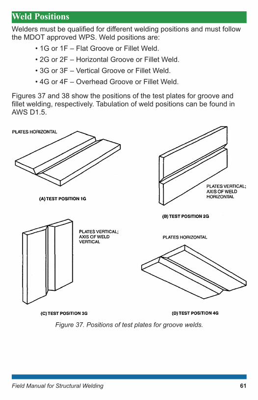
Weld Positions Weldersmustbequalifiedfordifferentweldingpositionsandmustfollowthe MDOT approved WPS. Weld positions are: • 1G or 1F – Flat Groove or Fillet Weld. • 2G or 2F – Horizontal Groove or Fillet Weld. • 3G or 3F – Vertical Groove or Fillet Weld. • 4G or 4F – Overhead Groove or Fillet Weld.
Figures 37 and 38 show the positions of the test plates for groove and filletwelding,respectively.TabulationofweldpositionscanbefoundinAWS D1.5.
Figure37.Positionsoftestplatesforgroovewelds.
61

Field Manual for Structural Welding
Figure38.Positionsoftestplatesforfilletwelds.
Welder Certification and EndorsementAWS Welder EndorsementsAWS Welder Certification (AWS QC7-93)
An accredited test facility must be used to test the welder in accordance withAWSforcertificationpurposes.Theapplicantselectstheperformancetestsneededforqualification.Notethat: • AWS QC7 93 Supplement G provides a list of performance requirements for each test. • The applicant must provide an employer supplied WPS or use AWS standard procedure. • The applicant’s test assemblies must pass the exam.
62

Field Manual for Structural Welding
If one or more weld fails, then rules for retesting must be followed. The periodofeffectivenessisconsideredindefinite,unless:1)thewelderwasnot involved in welding activities for six months or with that set procedure, or 2) there is a reason to question welder’s ability.
AWS Performance Test
The test follows the WPS or the AWS standard procedure and is associated with a particular weld type and position. The test assemblies must be in accordance with the WPS. Acceptance standards include: • VT inspection. - Fillet weld macroetch test (as applicable).
• Mechanical testing. - Bend test (as applicable, can be replaced with RT). - Fillet weld break test (as applicable).
• RT inspection.
MDOT Welder EndorsementsMDOT Welder Certification Program (WCP)
MDOT allows private testing agencies to perform MDOT welder certificationtesting.Contractorsselectfromalistofauthorizedtestingagencies located throughout the state and pay for the testing. The test plates may be welded under the authorized testing agency’s observation.
WeldercertificationallowsaweldertoperformAWSD1.1weldingonnonmainmembers,exceptanMDOTcertifiedweldermayweldcontractoraddonstomainmembersincompressionzonesonly.AnMDOTcertifiedwelder is not permitted to weld on highway structures in accordance with AWS D1.1 nor perform AWS D1.5 welding. See MDOT’s WCP for more information.
MDOT requirements are: • Meet authorized testing agency responsibilities. •Ensurecertifiedwelderguidelinesarefollowed. • Follow testing agency evaluation process.
63
Field Manual for Structural Welding
MDOT WCP Guidelines
• Field welding allowed by welders endorsed through MDOT’s WCP includes: - Pile welding (except main members). -Cofferdamsandsteelsheetpiling. - Temporary supports (except main members). - False work.
• MDOT welding restrictions include: -Weldersmustalwayshavecertificationsavailable when welding. -Certificationgoodforspecificrodsandpositions. - No welding below 0 F (heating and housing can be approved by the engineer). - No welding with precipitation or wet low hydrogen rods. - Preheat base metal 3 inches in each direction from weld when ambient temperature is between 0 and 32 F. - Welder is responsible for storage of electrodes.
MDOT Welder Qualification Program (WQP)
MDOT uses select third party laboratories to perform MDOT welder qualificationtestingandpaysfortheinitialweldtest.Thecontractorisresponsible for the cost of additional testing if the welder fails the initial weldtestorifthewelder’squalificationisrevokedbyMDOTpriortoexpiration of the original test.
AwelderendorsedthroughMDOT’sWQPcanperformfieldorshopwelding as follows: • Bridge welding to AWS D1.5. • Highway structure welding to AWS D1.1. • Main member pile welding to AWS D1.5. • Miscellaneous structures required by contract documents to use anMDOTqualifiedwelder.
64
Field Manual for Structural Welding
Welders that hold a MDOT WQP endorsement also have MDOT WCP privileges.QualificationtestingmustbedoneinaccordancewithAWSD1.5 and MDOT Special Provision 20SP-707 (A), Structural Steel and Aluminum Construction.
Thequalificationperiodisfortwoyearsforfieldweldingandthreeyearsfor shop welding unless: • The welder was not engaged with welding for three months. • There is reason to question welder’s ability.
Program guidelines include: • Similar to MDOT WCP guidelines. •Qualifyforfieldandshopweldingseparately. •Mustcompleteafieldweldingplan. • Do not weld below 40 F (heating and housing can be approved by engineer). • Preheat surface in accordance with section 707 of the MDOT SSC for AWS D1.5 and AWS D1.1 welding.
Economic Welding PracticesThe majority of welding costs are associated with labor. A reduction in weld metal volume typically leads to more economic welds. Quality welds that are free of defects avoid the need for repairs that cost time and money (i.e., weld once).
Considerations Based on Weld Types CJP Groove Welds
This is the most expensive type of weld, so reserve it for when it is the only viable option. It is generally advantageous with electroslag or electrogas welding; however, MDOT does not permit these welding processes.
65

Field Manual for Structural Welding
PJP Versus Fillet Welds
Can be used in T joints and inside corner joints. You can generally assume that PJP welds require half the volume of material for a given strength. You can also estimate the time to bevel a PJP joint as equal to asinglefilletweldpass.Ingeneral:1)afilletweldismoreeconomicalifitonlyrequiresasinglepass,2)PJPweldsareidealinaflatposition,and3)filletweldsareidealinflatorhorizontalpositions.Thegeneralruleofthumb is: •Iflegsizelessthan1inch,usefilletwelds. • If leg size more than 1 inch, use PJP groove weld.
Mixed PJP Fillet Welds
Figure39isanexampleofamixedPJPfilletweld,alsoknownasafilletreinforced PJP weld. It might be more economical than an individual PJP orfilletweld.ForTjoints,filletweldsontopofaPJPweldprovideabettercontour at the intersection. This type of weld is preferable for welds in positionsotherthanflat.
Figure39.MixedPJPfilletweld.
Other Welding Considerations CJP Groove Welds
Single-sided welds are easier to fabricate unless distortion control is needed. The typical 2 to 1 savings assumed for double sided welds are nottrueformanyprequalifiedjoints.
66
Field Manual for Structural Welding
The choice of root opening and included angle depends on throat dimension:
• If throat dimension is less than 1 inch, use the smallest permitted root opening with larger included angle.
• If throat dimension is greater than or equal to 1 inch, use the larger root opening and smaller included angle.
PJP Groove Welds
Single sided PJP groove welds typically require less than three weld passes and are more economical than double-sided. Double sided welds do prevent tearing of the unfused root region.
Flare Groove Welds
Youdonotalwayshavetofillflush.Youmustspecifytherequiredthroatto obtain required capacity.
Fillet Welds
Strength increases linearly with weld length and leg size. Note: • 1 to 1 increase in weld volume with weld length. • 4 to 1 increase in weld volume with weld leg size. • Continuous welds are often chosen over intermittent.
67
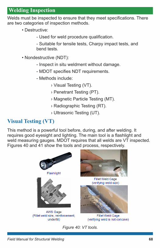
Field Manual for Structural Welding
Welding Inspection Weldsmustbeinspectedtoensurethattheymeetspecifications.Thereare two categories of inspection methods. • Destructive: -Usedforweldprocedurequalification. - Suitable for tensile tests, Charpy impact tests, and bend tests.
• Nondestructive (NDT): - Inspect in situ weldment without damage. -MDOTspecifiesNDTrequirements. - Methods include: › Visual Testing (VT). › Penetrant Testing (PT). › Magnetic Particle Testing (MT). › Radiographic Testing (RT). › Ultrasonic Testing (UT).
Visual Testing (VT)This method is a powerful tool before, during, and after welding. It requiresgoodeyesightandlighting.Themaintoolisaflashlightandweld measuring gauges. MDOT requires that all welds are VT inspected. Figures 40 and 41 show the tools and process, respectively.
Figure 40: VT tools.
68

Field Manual for Structural Welding
Figure41:VTmethod
Penetrant Testing (PT)This method uses capillary action to draw liquid into surface breaking discontinuities. The tester applies developer to make discontinuities visible and must provide adequate time for capillary action to draw in liquid (approximately 15 minutes). Figure 42 shows the process.
PTcanonlydetectsurfacebreakingdiscontinuities.Itiseffectiveataccentuating surface discontinuities that are hard to visually see. It is messy, slow, and not often used for magnetic materials such as steel.
Figure42:PTmethod.
Pre- Welding
– Review specifications– Check in compliance with WPS– Check welder’s AWS and MDOT endorsement– Review material certification– Inspect equipment– Check base metal for discontinuities and contaminates– Check fit-up and alignment– Check required preheat– Evaluate environmental condition– Record results
During Welding
– Ensure conformance with WPS procedures– Verify quality of weld root bead– Check joint root preparation prior to welding second side (two sided welds)– Check interpass temperature– Inspect after each weld pass (multi-pass welds)
Post- Welding
– Inspect for porosity, undercut, cracks and other discontinuities– Check final weld size– Inspect weld length– Ensure all welds are complete per drawings– Ensure no extra welds are present– Check for excessive distortion– Check for arc strikes
69
-
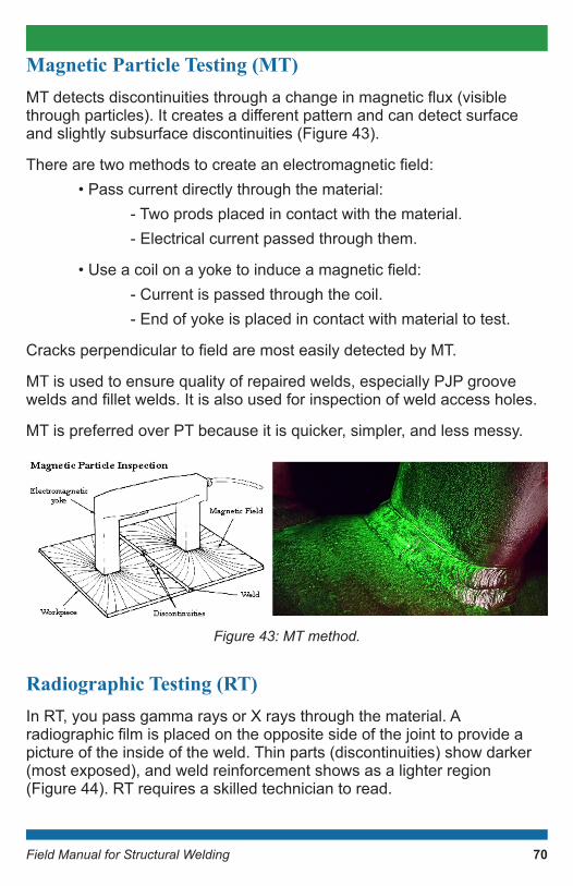
Field Manual for Structural Welding
Magnetic Particle Testing (MT)MTdetectsdiscontinuitiesthroughachangeinmagneticflux(visiblethroughparticles).Itcreatesadifferentpatternandcandetectsurfaceand slightly subsurface discontinuities (Figure 43).
Therearetwomethodstocreateanelectromagneticfield: • Pass current directly through the material: - Two prods placed in contact with the material. - Electrical current passed through them.
•Useacoilonayoketoinduceamagneticfield: - Current is passed through the coil. - End of yoke is placed in contact with material to test.
CracksperpendiculartofieldaremosteasilydetectedbyMT.
MT is used to ensure quality of repaired welds, especially PJP groove weldsandfilletwelds.Itisalsousedforinspectionofweldaccessholes.
MT is preferred over PT because it is quicker, simpler, and less messy.
Figure43:MTmethod.
Radiographic Testing (RT)In RT, you pass gamma rays or X rays through the material. A radiographicfilmisplacedontheoppositesideofthejointtoprovideapicture of the inside of the weld. Thin parts (discontinuities) show darker (most exposed), and weld reinforcement shows as a lighter region (Figure 44). RT requires a skilled technician to read.
70

Field Manual for Structural Welding
Figure44:RTmethod.
RT requires access to both sides of the joint. Cracks oriented perpendicular to the direction of the radiation source (i.e., parallel to the film)maygoundetected.Thismethodprovidesapermanentrecordandis ideally suited for CJP groove welds in butt joints. However, it is not suitableforPJPgrooveweldsorfilletweldsandisdifficulttointerpretresults from T joints and corner joints.
Ultrasonic Testing (UT)In UT (Figure 45), high frequency sound waves are transmitted through thematerial.Areceiverpicksupsoundwavesreflectedoffthebacksurface of the material. Discontinuities cause an interruption of the sound waves and result in an intermediate signal. It is read on a display screen.
The magnitude of a signal from a discontinuity is proportional to the amountofreflectedsound.Itprovidesinformationonthesize,type,andorientation of the discontinuity. It is sometimes too sensitive.
UT is most sensitive to planar discontinuities perpendicular to the sound path (such as cracks, laminations, and incomplete fusion). It is ideally suited for CJP groove welds (butt, corner, T joints). It can be used for inspectionofPJPweldsbutcannotbeusedforfilletwelds.
Figure45:UTmethod.
71
Field Manual for Structural Welding
Weld Repair A welder has the option to repair or replace unacceptable welds. Unacceptable welds represent cost to the contractor. When a weld is unacceptable, the fabricator is allowed to perform the repair without a nonconformance report (NCR) unless the engineer’s approval is required (i.e., fracture critical weld repairs or other weld repairs required by the contract). Although an NCR is not required to be submitted, MDOT does require the weld repair plan to be submitted prior to repair of the weld. The weld repair plan can be pre-approved for the project or blanket approved for the fabricator.
Material removal (weld metal or base metal) can be accomplished by machining, air carbon arc cutting and gouging, thermal cutting, chipping, or grinding. The remaining weld metal or base metal must not be nicked or undercut. Excess material beyond the unacceptable portion must not be removed and the surface must be cleaned prior to welding.
The repair procedures are as follows: 1. Remove excess weld metal for overlap or excessive convexity. 2. Add additional weld metal for excessive concavity, craters, undersized welds, and undercutting. 3. Remove unacceptable portions and reweld for excessive porosity, slag inclusions, and incomplete fusion. 4. For crack repair, remove full length of the crack plus 2 inches beyond each end, then reweld.
Weld SymbolsWeld symbols are a systematic means of communicating weld related information. Figure 46, which is adapted from AWS A2.4, shows how weld symbols are designated. Each symbol contains the following: • Reference line (required). • Arrow (required). • Tail (optional).
The symbol is always read right to left no matter what side of the reference line the arrow is on.
72

Field Manual for Structural Welding
Figure46:Weldsymbols.
73

Field Manual for Structural Welding
Notes:
________________________________________________________________________________________________________________________________________________________________________________________________________________________________________________________________________________________________________________________________________________________________________________________________________________________ ____________________________________________________________________________________________________________________________________________________________________________________________________________ ____________________________________________________________________________________________________________________________________________________________________________________________________________ ____________________________________________________________________________________________________________________________________________________________________________________________________________ ____________________________________________________________________________________________________________________________________________________________________________________________________________ ____________________________________________________________________________________________________________________________________________________________________________________________________________ ___________________________________________________

Providing the highest quality integrated transportation services for economic benefit and improved quality of life.
MDOT Structural Fabrication Unit’s E-mail Resource: [email protected]
Prepared by: GRAPHICS\BUREAUS\STATEWIDE SERVICES\CONSTRUCTION\C&T\Structural Welding Manual 2022 (5/22 CJ)