Fiber-length dependence of slow light with a swept-frequency source
7
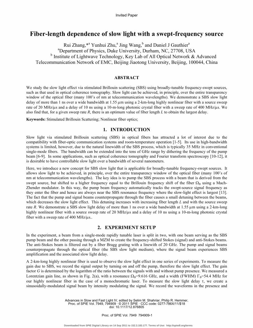
Fiber-length dependence of slow light with a swept-frequency source Rui Zhang,* a Yunhui Zhu, a Jing Wang, b and Daniel J Gauthier a a Department of Physics, Duke University, Durham, NC, 27708, USA b Institute of Lightwave Technology, Key Lab of All Optical Network & Advanced Telecommunication Network of EMC, Beijing Jiaotong University, Beijing, 100044, China ABSTRACT We study the slow light effect via stimulated Brillouin scattering (SBS) using broadly-tunable frequency-swept sources, such as that used in optical coherence tomography. Slow light can be achieved, in principle, over the entire transparency window of the optical fiber (many 100’s of nm at telecommunication wavelengths). We demonstrate a SBS slow light delay of more than 1 ns over a wide bandwidth at 1.55 μm using a 2-km-long highly nonlinear fiber with a source sweep rate of 20 MHz/μs and a delay of 10 ns using a 10-m-long photonic crystal fiber with a sweep rate of 400 MHz/μs. We also find that, for a given sweep rate R, there is an optimum value of fiber length L to obtain the largest delay. Keywords: Stimulated Brillouin Scattering; Nonlinear fiber optics; 1. INTRODUCTION Slow light via stimulated Brillouin scattering (SBS) in optical fibers has attracted a lot of interest due to the compatibility with fiber-optic communication systems and room-temperature operation [1-5]. Its use in high-bandwidth systems is limited, however, due to the natural linewidth of the SBS process, which is typically 35 MHz in conventional single-mode fibers. The bandwidth can be extended into the tens of GHz range by dithering the frequency of the pump beam [6-9]. In some applications, such as optical coherence tomography and Fourier transform spectroscopy [10-12], it is desirable to have controllable slow light over a bandwidth of several nanometers. Here, we introduce a new concept for SBS slow light that is applicable for broadly-tunable frequency-swept sources. It allows slow light to be achieved, in principle, over the entire transparency window of the optical fiber (many 100’s of nm at telecommunication wavelengths). The key idea is to pump the SBS process with a beam that is derived from the swept source, but shifted to a higher frequency equal to the Brillouin frequency shift of the fiber Ω Β using a Mach- Zhender modulator. In this way, the pump beam frequency automatically tracks the swept-source signal frequency as they enter the fiber and hence are always near the SBS resonance frequency where the slow-light effect is largest [13]. The fact that the pump and signal beams counterpropagate through the fiber causes a small detuning between the beams, which decreases the slow light effect. This detuning increases with increasing fiber length L and with the source sweep rate R. We demonstrate a SBS slow light delay of more than 1 ns over a wide bandwidth at 1.55 μm using a 2-km-long highly nonlinear fiber with a source sweep rate of 20 MHz/μs and a delay of 10 ns using a 10-m-long photonic crystal fiber with a sweep rate of 400 MHz/μs.. 2. EXPERIMENT SETUP In the experiment, a beam from a single-mode rapidly tunable laser is split in two, with one beam serving as the SBS pump beam and the other passing through a MZM to create the frequency-shifted Stokes (signal) and anti-Stokes beams. The anti-Stokes beam is filtered out by a fiber Bragg grating with a linewith of 20 GHz. The pump and signal beams counterpropagate through the optical fiber (the SBS slow light medium), where the signal beam experiences SBS amplification and the associated slow light delay. A 2-km-long highly nonlinear fiber is used to observe the slow light effect in one series of experiments. To measure the gain due to SBS, we record the signal output by turning on and off the pump, therefore the slow light effect. The gain factor G is determined by the logarithm of the ratio between the signals with and without pump presence. We measured a Lorentzian gain line, as shown in Fig. 2(a), with a resonance Ω B =9.616 GHz, and a width (FWHM) Γ B =54.4 MHz for our highly nonlinear fiber in the case of a monochromatic laser. To measure the slow light delay τ, we create a sinusoidally-modulated signal beam by intensity modulating the signal. We record the waveforms in the presence and Invited Paper Advances in Slow and Fast Light IV, edited by Selim M. Shahriar, Philip R. Hemmer, Proc. of SPIE Vol. 7949, 794909 · © 2011 SPIE · CCC code: 0277-786X/11/$18 doi: 10.1117/12.876805 Proc. of SPIE Vol. 7949 794909-1 Downloaded from SPIE Digital Library on 14 Sep 2011 to 152.3.183.177. Terms of Use: http://spiedl.org/terms
Transcript of Fiber-length dependence of slow light with a swept-frequency source
Fiber-length dependence of slow light with a swept-frequency source
Rui Zhang,*a Yunhui Zhu,a Jing Wang,b and Daniel J Gauthiera
aDepartment of Physics, Duke University, Durham, NC, 27708, USA b Institute of Lightwave Technology, Key Lab of All Optical Network & Advanced
Telecommunication Network of EMC, Beijing Jiaotong University, Beijing, 100044, China
ABSTRACT
We study the slow light effect via stimulated Brillouin scattering (SBS) using broadly-tunable frequency-swept sources, such as that used in optical coherence tomography. Slow light can be achieved, in principle, over the entire transparency window of the optical fiber (many 100’s of nm at telecommunication wavelengths). We demonstrate a SBS slow light delay of more than 1 ns over a wide bandwidth at 1.55 μm using a 2-km-long highly nonlinear fiber with a source sweep rate of 20 MHz/μs and a delay of 10 ns using a 10-m-long photonic crystal fiber with a sweep rate of 400 MHz/μs. We also find that, for a given sweep rate R, there is an optimum value of fiber length L to obtain the largest delay.
Keywords: Stimulated Brillouin Scattering; Nonlinear fiber optics;
1. INTRODUCTION Slow light via stimulated Brillouin scattering (SBS) in optical fibers has attracted a lot of interest due to the compatibility with fiber-optic communication systems and room-temperature operation [1-5]. Its use in high-bandwidth systems is limited, however, due to the natural linewidth of the SBS process, which is typically 35 MHz in conventional single-mode fibers. The bandwidth can be extended into the tens of GHz range by dithering the frequency of the pump beam [6-9]. In some applications, such as optical coherence tomography and Fourier transform spectroscopy [10-12], it is desirable to have controllable slow light over a bandwidth of several nanometers.
Here, we introduce a new concept for SBS slow light that is applicable for broadly-tunable frequency-swept sources. It allows slow light to be achieved, in principle, over the entire transparency window of the optical fiber (many 100’s of nm at telecommunication wavelengths). The key idea is to pump the SBS process with a beam that is derived from the swept source, but shifted to a higher frequency equal to the Brillouin frequency shift of the fiber ΩΒ using a Mach-Zhender modulator. In this way, the pump beam frequency automatically tracks the swept-source signal frequency as they enter the fiber and hence are always near the SBS resonance frequency where the slow-light effect is largest [13]. The fact that the pump and signal beams counterpropagate through the fiber causes a small detuning between the beams, which decreases the slow light effect. This detuning increases with increasing fiber length L and with the source sweep rate R. We demonstrate a SBS slow light delay of more than 1 ns over a wide bandwidth at 1.55 μm using a 2-km-long highly nonlinear fiber with a source sweep rate of 20 MHz/μs and a delay of 10 ns using a 10-m-long photonic crystal fiber with a sweep rate of 400 MHz/μs..
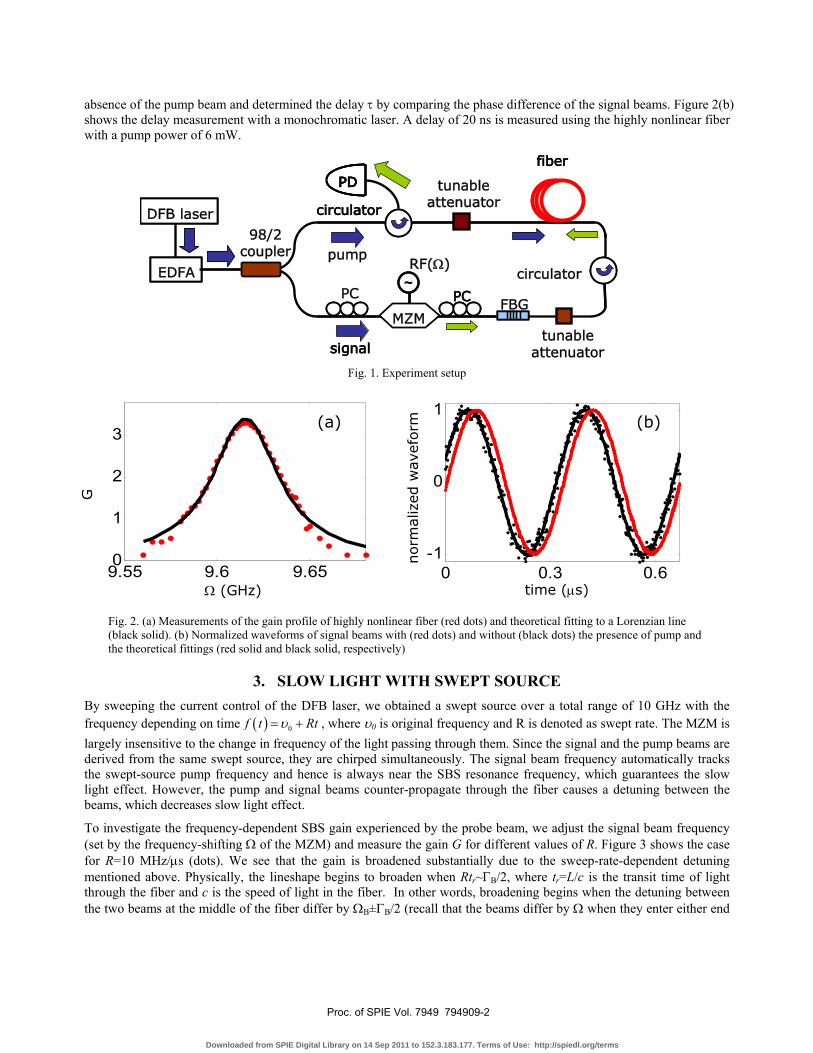
2. EXPERIMENT SETUP In the experiment, a beam from a single-mode rapidly tunable laser is split in two, with one beam serving as the SBS pump beam and the other passing through a MZM to create the frequency-shifted Stokes (signal) and anti-Stokes beams. The anti-Stokes beam is filtered out by a fiber Bragg grating with a linewith of 20 GHz. The pump and signal beams counterpropagate through the optical fiber (the SBS slow light medium), where the signal beam experiences SBS amplification and the associated slow light delay.
A 2-km-long highly nonlinear fiber is used to observe the slow light effect in one series of experiments. To measure the gain due to SBS, we record the signal output by turning on and off the pump, therefore the slow light effect. The gain factor G is determined by the logarithm of the ratio between the signals with and without pump presence. We measured a Lorentzian gain line, as shown in Fig. 2(a), with a resonance ΩB=9.616 GHz, and a width (FWHM) ΓB=54.4 MHz for our highly nonlinear fiber in the case of a monochromatic laser. To measure the slow light delay τ, we create a sinusoidally-modulated signal beam by intensity modulating the signal. We record the waveforms in the presence and
Invited Paper
Advances in Slow and Fast Light IV, edited by Selim M. Shahriar, Philip R. Hemmer,Proc. of SPIE Vol. 7949, 794909 · © 2011 SPIE · CCC code: 0277-786X/11/$18
doi: 10.1117/12.876805
Proc. of SPIE Vol. 7949 794909-1
Downloaded from SPIE Digital Library on 14 Sep 2011 to 152.3.183.177. Terms of Use: http://spiedl.org/terms
EDFA
DFB laser
signal
fiber
PD
circulator
PC
EDFAEDFA
DFB laserDFB laser
signal
fiber
PDPD
circulator
PC
98/2 coupler
circulatorpump
PC
RF(Ω)~~
tunable attenuator
FBG
tunable attenuator
MZM
absence of the pump beam and determined the delay τ by comparing the phase difference of the signal beams. Figure 2(b) shows the delay measurement with a monochromatic laser. A delay of 20 ns is measured using the highly nonlinear fiber with a pump power of 6 mW.
Fig. 1. Experiment setup
Fig. 2. (a) Measurements of the gain profile of highly nonlinear fiber (red dots) and theoretical fitting to a Lorenzian line (black solid). (b) Normalized waveforms of signal beams with (red dots) and without (black dots) the presence of pump and the theoretical fittings (red solid and black solid, respectively)
3. SLOW LIGHT WITH SWEPT SOURCE By sweeping the current control of the DFB laser, we obtained a swept source over a total range of 10 GHz with the frequency depending on time ( ) 0f t Rtυ= + , where υ0 is original frequency and R is denoted as swept rate. The MZM is largely insensitive to the change in frequency of the light passing through them. Since the signal and the pump beams are derived from the same swept source, they are chirped simultaneously. The signal beam frequency automatically tracks the swept-source pump frequency and hence is always near the SBS resonance frequency, which guarantees the slow light effect. However, the pump and signal beams counter-propagate through the fiber causes a detuning between the beams, which decreases slow light effect.
To investigate the frequency-dependent SBS gain experienced by the probe beam, we adjust the signal beam frequency (set by the frequency-shifting Ω of the MZM) and measure the gain G for different values of R. Figure 3 shows the case for R=10 MHz/μs (dots). We see that the gain is broadened substantially due to the sweep-rate-dependent detuning mentioned above. Physically, the lineshape begins to broaden when Rtr~ΓB/2, where tr=L/c is the transit time of light through the fiber and c is the speed of light in the fiber. In other words, broadening begins when the detuning between the two beams at the middle of the fiber differ by ΩB±ΓB/2 (recall that the beams differ by Ω when they enter either end
time (μs) 0 0.3 0.6
-1
0
1norm
aliz
ed w
avef
orm
9.55 9.6 9.650
1
2
3
Ω (GHz)
G
(a) (b)
Proc. of SPIE Vol. 7949 794909-2
Downloaded from SPIE Digital Library on 14 Sep 2011 to 152.3.183.177. Terms of Use: http://spiedl.org/terms
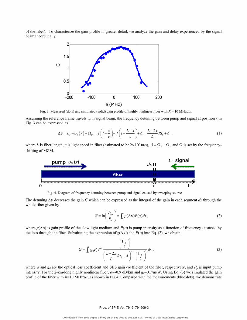
of the fiber). To characterize the gain profile in greater detail, we analyze the gain and delay experienced by the signal beam theoretically.
Fig. 3. Measured (dots) and simulated (solid) gain profile of highly nonlinear fiber with R = 10 MHz/μs.
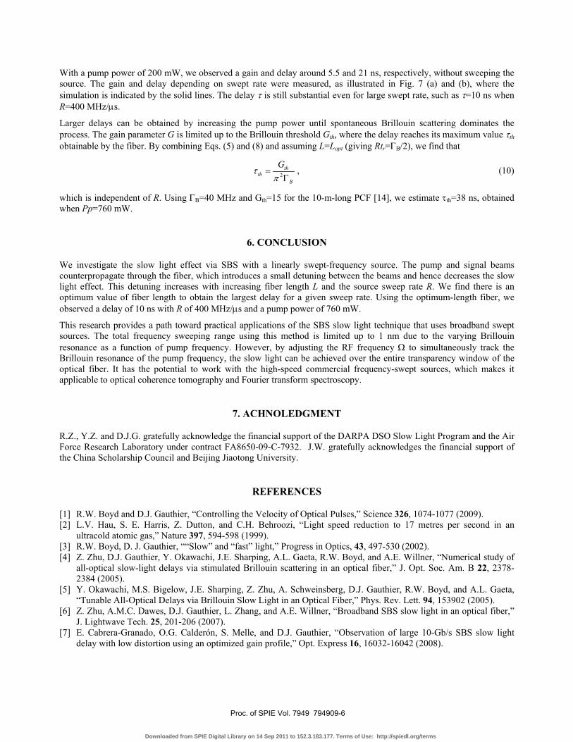
Assuming the reference frame travels with signal beam, the frequency detuning between pump and signal at position x in Fig. 3 can be expressed as
( ) 02
s p Bx L x L xx f t f t Rtc c L
υ υ υ δ δ− −⎛ ⎞ ⎛ ⎞Δ = − + Ω = − − − + = +⎜ ⎟ ⎜ ⎟⎝ ⎠ ⎝ ⎠
, (1)
where L is fiber length, c is light speed in fiber (estimated to be 82 10× m/s), Bδ = Ω − Ω , and Ω is set by the frequency-shifting of MZM.
Fig. 4. Diagram of frequency detuning between pump and signal caused by sweeping source
The detuning Δυ decreases the gain G which can be expressed as the integral of the gain in each segment dx through the whole fiber given by
0
ln ( ) ( )Lout
in
PG g P dx
Pυ υ
⎛ ⎞= = Δ⎜ ⎟
⎝ ⎠∫ , (2)
where g(Δυ) is gain profile of the slow light medium and P(υ) is pump intensity as a function of frequency υ caused by the loss through the fiber. Substituting the expression of g(Δ υ) and P(υ) into Eq. (2), we obtain
2
0 220
0
22
2
B
L xp
B
G g P e dxL x Rt
L
α
δ
Γ⎛ ⎞⎜ ⎟⎝ ⎠=
Γ− ⎛ ⎞⎛ ⎞+ +⎜ ⎟ ⎜ ⎟⎝ ⎠ ⎝ ⎠
∫ , (3)
where α and g0 are the optical loss coefficient and SBS gain coefficient of the fiber, respectively, and Pp is input pump intensity. For the 2-km-long highly nonlinear fiber, α=-0.9 dB/km and g0=0.7/m/W. Using Eq. (3) we simulated the gain profile of the fiber with R=10 MHz/μs, as shown in Fig.4. Compared with the measurements (blue dots), we demonstrate
ppuummpp dx
fiber
υp (x) υs ssiiggnnaall
0 L x
G
δ (MHz)
-200 -100 0 100 2000
0.5
1
1.5
2
Proc. of SPIE Vol. 7949 794909-3
Downloaded from SPIE Digital Library on 14 Sep 2011 to 152.3.183.177. Terms of Use: http://spiedl.org/terms

that the theory describes the experimental data very well. The gain profile shows an asymmetric characteristic for positive and negative frequency detuning, which is caused by the optical loss through the fiber. This can be understood by the following way. The signal meets the pump with varied frequencies through the fiber, and hence the signal experiences inhomogeneous amplification along the fiber. The most efficient amplification occurs in different region of the fiber for different frequency detuning δ. Since pump is depleted through the fiber, the signals with positive detuning δ and negative detuning - δ experience different amplification, which leads to the asymmetry of the gain profile.
Optical loss of the fiber is usually ignored in SBS slow light. However, with a swept source, it introduces an asymmetric structure of the gain profile.
To estimate the full line-width of the gain profile, we solved analytically Eq. (4) assuming α=0. We find:
0 0
00
2 2 2 2arctan arctan
2B B
p B
t R t R
G g P Lt R
δ δ⎛ ⎞ ⎛ ⎞+ −+⎜ ⎟ ⎜ ⎟Γ Γ⎝ ⎠ ⎝ ⎠= Γ . (5)
The full line-width (FWHM) is calculated to be 2 2 204B t RΓ = Γ + and estimated to be 2t0R in the case of R>>ΓB/(2t0).
To understand how the sweeping process influences the slow light effect, we investigated the dependence of the gain G and delay τ on the sweep rate R when Ω =ΩB. We find
0
00
2arctan
2B
p B
t R
G g P Lt R
⎛ ⎞⎜ ⎟Γ⎝ ⎠= Γ , (6)
and ( )
0 022 2 2
0 22 4p B p B
B
g P L g P Lt R
τππ
Γ Γ= =
Γ+ Γ, (7)
The gain and delay are measured through the highly nonlinear fiber with swept rates from 0 to 20 MHz/μs. Knowing that slow light effect varies inversely with R, we used higher pump power to observe noticeable gain and delay when operating at larger R. The slow light effect increases with the pump power but is limited to the point that spontaneous Brillouin scattering saturates the pump. At R=20 MHz/μs, a delay of 1.6 ns is observed with pump power of 13 mW. We plot the gain G and delay τ on the same scale by normalizing the pump powers to be equivalent to 13 mW, as shown in Fig. 5. The figure demonstrates that measurements (dots) agrees with the theory (solid) expressed by Eq. (6) and Eq. (7). By increasing R, the delay drops faster than the gain due to the broadened gain profile.
Fig. 5. (a) Measured (dots) and simulated (solid) gain as a function of sweep rate R. (b) Measured (dots) and simulated (solid) delay as a function of sweep rate R.
0 5 10 15 200
5
10
15
R (MHz/μs)
G
(a)
0 5 10 15 200
10
20
30
40
R (MHz/μs)
τ(n
s)
(b)
Proc. of SPIE Vol. 7949 794909-4
Downloaded from SPIE Digital Library on 14 Sep 2011 to 152.3.183.177. Terms of Use: http://spiedl.org/terms

4. OPTIMISM OF FIBER LENGTH TO ACHIEVE LARGE DELAY
Using the expression for the delay given in Eq. (7), we are able to design an optimal fiber length for a given sweep rate. We rewrite the delay in terms of fiber length and obtain
( ) ( )0 0
2 2 220
2 /2p B p B
BB
g P L g P L
RL cRtτ
Γ Γ= =
+ Γ+ Γ. (8)
Figure 6 (a), (b) and (c) show τ depending on fiber length L for sweep rates R of 0, 5, 100 MHz/μs, respectively, with Pp holds constant. The figures demonstrate that, for higher sweep rate, a shorter fiber is a better candidate to observe large delay. For a given swept rate, the maximal delay is obtained at L= cΓB/(2R) and equals to τ=g0Ppc/(4R), derived from Eq. (8). In case of R=100 MHz/μs, the delay through a 40-m-long fiber is 25 times larger than that through a 2-km-long fiber with the same pump power, for example. It is contrary with the understanding that the probe beam experiences larger delay when it passes through a longer fiber. This phenomenon is caused by the fact that longer fiber introduces a more broadened gain profile (~ 2RL/c) and hence leads to a smaller slow light delay on the resonance.
Fig. 6. (a), (b), and (c) Delay depending on fiber length for R=0, 5, 100 MHz/μs, respectively.
5. SLOW LIGHT DELAY THROUGH A 10-M-LONG PCF WITH SWEPT SOURCE
To exam the theory of fiber length optimization, we investigated the gain G and delay τ on sweep rate through a 10-m-long photonic crystal fiber (PCF). The PCF is made of pure silica with a core diameter of 2.1 μm and air-filling fraction of 84%. The Brillouin gain profile of the PCF was measured and fitted to a Lorenzian with g0=2.7/m/W, ΩB=9.782 GHz, and ΓB=40.8 MHz.
Fig. 7. (a) Measured (dots) and simulated (solid) gain as a function of sweep rate R. (b) Measured (dots) and simulated (solid) delay as a function of sweep rate R.
R (MHz/μs)
G
0 200 400 600 8000
2
4
6
(a)
R (MHz/μs)
τ (n
s)
0 200 400 600 8000
5
10
15
20
(b)
0 1 20
10
20
L (km)
τ (n
s)
0 1 20
2
4
L (km)
τ (n
s)
0 1 20
0.1
0.2
L (km) τ (n
s)
(a) (b) (c)
Proc. of SPIE Vol. 7949 794909-5
Downloaded from SPIE Digital Library on 14 Sep 2011 to 152.3.183.177. Terms of Use: http://spiedl.org/terms
With a pump power of 200 mW, we observed a gain and delay around 5.5 and 21 ns, respectively, without sweeping the source. The gain and delay depending on swept rate were measured, as illustrated in Fig. 7 (a) and (b), where the simulation is indicated by the solid lines. The delay τ is still substantial even for large swept rate, such as τ=10 ns when R=400 MHz/μs.
Larger delays can be obtained by increasing the pump power until spontaneous Brillouin scattering dominates the process. The gain parameter G is limited up to the Brillouin threshold Gth, where the delay reaches its maximum value τth obtainable by the fiber. By combining Eqs. (5) and (8) and assuming L=Lopt (giving Rtr=ΓB/2), we find that
2th
thB
Gτ
π=
Γ, (10)
which is independent of R. Using ΓB=40 MHz and Gth=15 for the 10-m-long PCF [14], we estimate τth=38 ns, obtained when Pp=760 mW.
6. CONCLUSION
We investigate the slow light effect via SBS with a linearly swept-frequency source. The pump and signal beams counterpropagate through the fiber, which introduces a small detuning between the beams and hence decreases the slow light effect. This detuning increases with increasing fiber length L and the source sweep rate R. We find there is an optimum value of fiber length to obtain the largest delay for a given sweep rate. Using the optimum-length fiber, we observed a delay of 10 ns with R of 400 MHz/μs and a pump power of 760 mW.
This research provides a path toward practical applications of the SBS slow light technique that uses broadband swept sources. The total frequency sweeping range using this method is limited up to 1 nm due to the varying Brillouin resonance as a function of pump frequency. However, by adjusting the RF frequency Ω to simultaneously track the Brillouin resonance of the pump frequency, the slow light can be achieved over the entire transparency window of the optical fiber. It has the potential to work with the high-speed commercial frequency-swept sources, which makes it applicable to optical coherence tomography and Fourier transform spectroscopy.
7. ACHNOLEDGMENT
R.Z., Y.Z. and D.J.G. gratefully acknowledge the financial support of the DARPA DSO Slow Light Program and the Air Force Research Laboratory under contract FA8650-09-C-7932. J.W. gratefully acknowledges the financial support of the China Scholarship Council and Beijing Jiaotong University.
REFERENCES
[1] R.W. Boyd and D.J. Gauthier, “Controlling the Velocity of Optical Pulses,” Science 326, 1074-1077 (2009). [2] L.V. Hau, S. E. Harris, Z. Dutton, and C.H. Behroozi, “Light speed reduction to 17 metres per second in an
ultracold atomic gas,” Nature 397, 594-598 (1999). [3] R.W. Boyd, D. J. Gauthier, ““Slow” and “fast” light,” Progress in Optics, 43, 497-530 (2002). [4] Z. Zhu, D.J. Gauthier, Y. Okawachi, J.E. Sharping, A.L. Gaeta, R.W. Boyd, and A.E. Willner, “Numerical study of
all-optical slow-light delays via stimulated Brillouin scattering in an optical fiber,” J. Opt. Soc. Am. B 22, 2378-2384 (2005).
[5] Y. Okawachi, M.S. Bigelow, J.E. Sharping, Z. Zhu, A. Schweinsberg, D.J. Gauthier, R.W. Boyd, and A.L. Gaeta, “Tunable All-Optical Delays via Brillouin Slow Light in an Optical Fiber,” Phys. Rev. Lett. 94, 153902 (2005).
[6] Z. Zhu, A.M.C. Dawes, D.J. Gauthier, L. Zhang, and A.E. Willner, “Broadband SBS slow light in an optical fiber,” J. Lightwave Tech. 25, 201-206 (2007).
[7] E. Cabrera-Granado, O.G. Calderón, S. Melle, and D.J. Gauthier, “Observation of large 10-Gb/s SBS slow light delay with low distortion using an optimized gain profile,” Opt. Express 16, 16032-16042 (2008).
Proc. of SPIE Vol. 7949 794909-6
Downloaded from SPIE Digital Library on 14 Sep 2011 to 152.3.183.177. Terms of Use: http://spiedl.org/terms

[8] M.G. Herráez, K.Y. Song, and L. Thévenaz, “Arbitrary-bandwidth Brillouin slow light in optical fibers,” Opt. Express 14, 1395-1400 (2006).
[9] K. Y. Song and K. Hotate, “25 GHz bandwidth Brillouin slow light in optical fibers,” Opt. Lett. 32, 217-219 (2007). [10] M.A. Choma, M.V. Sarunic, C. Yang, and J.A. Izatt, “Sensitivity advantage of swept source and Fourier domain
optical coherence tomography,” Opt. Express 11, 2183-2189 (2003). [11] Z. Shi, R.W. Boyd, R.M. Camacho, P.K. Vudyasetu, and J.C. Howell, “Slow-light Fourier transform
interferometer,” Phys. Rev. Lett. 99, 240801 (2007). [12] A.M. Rollins, M. D. Kulkarni, S. Yazdanfar, R. Ung-arunyawee, and J. A. Izatt, “In vivo video rate optical
coherence tomography,” Opt. Express 3, 219-229 (1998). [13] R. Zhang, Y. Zhu, J. Wang, D.J. Gauthier, “Slow Light With A Swept-Frequency Source,” Opt. Express 18, 27263
(2010). [14] W. Boyd, K. Rzazewski and P. Narum, “Noise initiation of stimulated Brillouin scattering,” Phys. Rev. A 42, 5514-
5521 (1990).
Proc. of SPIE Vol. 7949 794909-7
Downloaded from SPIE Digital Library on 14 Sep 2011 to 152.3.183.177. Terms of Use: http://spiedl.org/terms