FEDERATION INTERNATIONALE DE L'AUTOMOBILE - Index of
147
FEDERATION INTERNATIONALE DE L'AUTOMOBILE 99 Appendix J 32e édition/32nd edition L
-
Upload
khangminh22 -
Category
Documents
-
view
3 -
download
0
Transcript of FEDERATION INTERNATIONALE DE L'AUTOMOBILE - Index of

FEDERATION INTERNATIONALE DE L'AUTOMOBILE
99
Appendix J
32e édition/32nd edition
L

Appendix Jto the International Sporting Code, 1999 (classifications, definitions and specifications of cars)
In the case of differences of Interpretation as regards the terms used in the various tran^tlons of official FIA regulations, only the French text will be considered authentic, unless other formal and specific provisions are laid down.
TEXTS OF THE VARIOUS REGULATIONS DRAFTED BY THE FIA (International Sporting Code and its Appendices and regulations of the FIA International Championships) APPEARING IN THIS YEAR BOOK ARE THOSE DRAWN UP ON 8 OCTOBER 1998).
ANY AMENDMENTS WILL BE PUBLISHED AFTER THIS DATE IN THE FIA MONTHLY OFFICIAL BULLETIN.
€) 1999 Fédération Internationale de l'Automobile

r r APPENDIX j
r-,. ^ -
Annexe Jto the International Sporting Code
>■ i - i î -
T U ■CONTENTS
■t- i )r - ‘ ■ .n - ’. ■; , ■
A r t 2 5 1 - ' 'V -
Art 252 -
A lt 2 5 8 -*n
Art 259 -
Art 2 6 2 -
Art 2 8 5 - > -Art 286 -
Art 2 8 7 -
A r t2 9 0 - f f - - . *
■
Classification and Definitions
General Prescriptions for Production Cars (Group N), Touring cars (Group A), Grand Touring Cars (Group B)
Safety Equipment (Group N, A, B, ST)
Specific Regulations for Production (Group N)
Specific Regulations for Touting Cars (Group A)
Specific Regulations forGrand Touting (Group B)
Grand Touring and Prototype Grand Touting Car Technical Regulations
Technical Regulations for Production Sports Cars (Group CN)
Technical Regulations for Super Touting Cars (Group ST)
Formula 3 Technical Regulations
Free Formula Regulations (Group E)
National Formulae Technical Regulations
Technical Regulations for Rallycross and Autocross Cars
Classification and Definitions of Cross-Country Vehicles
General Prescriptions for Cross Country Cars
Safety Equipment fo r Cross Country Cars
Specific Regulations for Series Cross Country Cars (Group T1)
Specific Regulations for Improved Cross Country Cars (Group T2)
Specific Regulations for Prototype Cross Country Cars (Group T3)
Cross Country Truck Technical Regulations (Group T4)
Racing Trucks Technlcai Regulations (Groupe F)
Technical List
Drawings
List of FIA homologated vehicles and engines
i. ‘ - it
8
11
17
20
26
28
35
43
52
53
54
60
63
65
73
76
81
83
88' \
98
105
131■ Ï I ,
Appendix J Tecnical lists DrawingsList of homologated vehicles and engines
398
105131
£) 1999 Fédération Internationale de l’Automobile

Appendix Jto the International Sporting Code, 1999 (classifications, definitions and specifications of cars)
In the case of differences of interpretation as regards the terms used In the various translations of official FIA regulations, only the French text wilt be consider^ authentic, unless other formal and specific provisions are laid down.
TEXTS OF THE VARIOUS REGULATIONS DRAFTED BY THE FIA (International Sporting Code and its Appendices and regulations of the FIA International Championships) APPEARING IN THIS YEAR BOOK ARE THOSE DRAWN UP ON 8 OCTOBER 1998).
ANY AMENDMENTS WILL BE PUBLISHED AFTER THIS DATE IN THE FIA MONTHLY OFFICIAL BULLETIN.
€> 1999 Fédération Internationale de l'Automobile

APPENDIX J
Annexe J < ^
to the International Sporting Code
CONTENTS
Art 251 -
Art 252 -
Art 253 -
Art 2 5 4 -
Art 255 -
Art 256 -
Art 2 5 8 -
Art 259 -
Art 262 -
Art 275 -
Art 2 7 7 -
Art 278 -
Art 279 -
Art 281 -
Art 282 -
Art 2 8 3 -
Art 2 8 4 -
A r t2 8 5 -
A r t2 8 6 -
Art 287 -
Art 2 9 0 -
Classlfication and Definitions
General Prescriptions for Production Cars (Group N), Touring cars (Group A), Grand Touring Cars (Group B)
Safety Equipment (Group N, A, B, ST)
Specific Regulations for Production (Group N)
Specific Regulations for Touring Cars (Group A)
Specific Regulations forGrand Touring (Group B)
Grand Touring and Prototype Grand Touring Car Technical Regulations
Technical Regulations for Production Sports Cars (Group CM)
Technical Regulations for Super Touring Cars (Group ST)
Formula 3 Technical Regulations
Free Formula Regulations (Group E)
National Formulae Technical Regulations
Technical Regulations for Rallycross and Autocross Cars
Classification and Definitions of Cross-Country Vehicles
General Prescriptions for Cross Country Cars
Safety Equipment for Cross Country Cars
Specific Regulations for Series Cross Country Cars (Group T 1 )
Specific Regulations for improved Cross Country Cars (Group T2)
Specific Regulations for Prototype Cross Country Cars (Group T3)
Cross Country Truck Technical Regulations (Group T4)
Racing Trucks Technical Regulations (Groupe F)
Technical List
Drawings
List of FIA homologated vehicles and engines
8
11
17
20
26
27
28
35
43
52
53
54
60
63
65
73
76
81
83
88
98
105
131
i 4
X

A rticle 2 5 1 - Cla ssif ic a tio n a n d D e f in it io n s
1) CLASSIFICATION1.1 - Categories and groupsThe cars used in competition shall be divided up Into the following categories and groups;
Category I: - Group N: Production Cars- Group A: Touring Cars- Group B: Grand Touring Cars■ Group ST: Super Touring Cars- Group CLt : Class 1 Cars- Group Tt : Series Cross-Country Cars- Group T2: Improved Cross-Country Cars
Category II: - Group T3: Prototype Cross-Country Cars- Group GT: Grand Touring Sports Cars- Group C: Sports Cars- Group D: International Formula Racing Cars- Group E: Free Fomiula Racing Cars
Category III: - Group F: Racing Trucks- Group T4: Cross-Country Tmcks
t .2 - Cubic capacity classesThe cars will be divided up into the following classes according to their cubic capacity:
1. Up to 500 cm32. From 500 cm3 to 600 cm33. From 600 cm3 to 700 cm34. From 700 cm3 to 850 cm35. From 850 cm3 to 1000cm36. From 1000 cm3 to 1150 cm37. From 1150 cm3 to 1400cm38. From 1400cm3 to 1600 cm39. From 1600 cm3 to 2000 cm310. From 2000 cm3 to 2500 cm311. From 2500 cm3 to 3000 cm312. From 3000 cm3 to 3500 cm313. From 3500 cm3 to 4000 cm314. From 4000 cm3 to 4500 cm315. From 4500 cm3 to 5000 cm316. From 5000 cm3 to 5500 cm317. From 5500 cm3 to 6000 cm318. Over 6000 cm3
Unless otherwise specified in special provisions imposed by the FIA for a certain category of events, the organisers are not bound to include all the above-mentioned classes In the Supplementary Regulations and, furthermore, they are free to group two or more consecutive classes, according to the particular circumstances of their events.No Class can be subdivided.
2) DEFINITIONS2.1 - General conditions2.1.1) Series Production cars (Category I):Cars of which the production of a certain number of identical examples (see definition of this word hereinafter) within a certain period of time has been verified at the request of the manufacturer, and which are destined for normal sale to the public (see this expression).Cars must be sold In accordance with the homologation form.2.1.2) Competition cars (Category II):Cars bulk as single examples and destined solely for competition.2.1.3) Trucks (Category III)
2.1.4) Identical cars:Cars belonging to the same production series and which have the same bodywork (outside and inside), same mechanical components and same chassis (even though this chassis may be an integral part of the bodywork In case of a monocoque construction).2.1.5) Model of car:Car belonging to a production-series distinguishable by a specific conception and external general lines of the bodywork and by an identical mechanical construction of the engine and the transmission to the wheels.2.1.6) Normal sale:Means the distribution of cars to Individual purchasers through the normal commercial channels of the manufacturer.2.1.7) Homologation:Is the official certification made by the FIA that a minimum numtrer of cars of a specific model has been made on series-productlon terms to justify classification in Production Cars (Group 1 ), Touring Cars (Group A), Grand Touring Cars (Group B), Super Touring Cars (Group ST), Class 1 Cars (Group CL1), Series Cross-Country Cars (Group T1) of these regulations. Application for homologation shall be submitted to the FIA by the ASN of the country in which the vehicle is manufactured and shall entail the drawing up of a homologation form (see below). It must be established in accordance with the special regulations called “Regulations for homologation", laid down by the FIA, Homologation of a series-produced car will become null and void 7 years after the date on which the series-production of the said model has been stopped (series-production under 10 % of the minimum production of the group considered).The homologation of a model can only be valid in one group. Production Cars (Group N)/Touring Cars (Group A)/Series Cross- Country Cars (Group T1) or Grand Touring Cars (Group B). If a model already homologated In Grand Touring Cars (Group 6) passes into Production Cars (Group N)/Touring Cars (Group A)/Series Cross-Country Cars (Group T1), the first homologation is cancelled.2.1.8) Homologation forms:All cars recognised by the FIA will be the subject of a descriptive form called homologation form on which shall be entered all data enabling identification of the said model.This homologation form defines the series as indicated by the manufacturer. According to the group in which the competitors race, the modification limits allowed in international competition for the series are stated in Appendix J.The presentation of the forms at scrutineering and/or at the start may be required by the organisers who will be entitled to refuse the participation of the entrant In the event In case of non-presentation. Likewise, if a Group A car fitted with a kit variant (see below) concerning the chassis/shell is used, the original certificate supplied at the time of mounting by a centre approved by the manufacturer must be presented.Should the date for the coming into force of a homologation form fall during an event, this form will be valid for that event throughout the duration of the said event.With regard to Production Cars (Group N), apart from the specific form for this group, the Touring Cars (Group A) form must also be submitted.In case of any doubt remaining after the checking of a model of car against its homologation form, the scrutineers should refer ekher to the maintenance booklet published for the use of the make's distributors or to the general catalogue In which are listed all spare parts. In case of lack of sufficient accurate documentation, scrutineers may carry out direct scrutineering by comparison wkh an identical part available from a concessionaire. It will be up to the competitor to obtain the homologation form concerning his car from his ASN.

APPENDIX V DEFINITIONS
Description: A form breaks down in the following way:
1) A basic form giving a description of the basic model.2) At a later stage, a certain number of additional sheets describing ■homologation extensions", which can be "variants”, or “errata" or "evolutions".
a - Variants (VF, VO. VK)These are either supply variants (VF) (two suppliers providing the same part for the manufacturer and the client does not have the possibility of choice), or options (VO) (supplied on request and available at the concessionnaires), or “kits" (VK) supplied on request and available at the concessionnaires, b - Erratum (ER)Replaces and cancels an Incorrect piece of information previously supplied by the constructor on a form, c - Evolution (ET, ES)Characterises modifications made on a permanent basis to the basic model (complete cessation of the production of the car in its original form in the case of the evolution of the type (ET), or sporting evolution (ES) intended to render a model more competitive.
Use:
1) Variants (VF, VO, VK)The competitor may use any variant or any part of a variant as he \ wishes, only on condition that all the technical data of the vehicle, so designed, conforms to that described on the homologation form applicable to the car, or expressly allowed by Appendix J.The combination of several VOs on the following parts is prohibited: Turttocharger, brakes and gearbox.For example, the fitting of a brake calliper as defined on a variant form is only possible if the dimensions of the brake linings, etc. obtained in this way, are indicated on a form applicable to the car in question. (For Production Cars (Group N), see also Art. 254.2). As far as kit-variants (VK) are concerned, they may not be used only under the conditions indicated by the manufacturer on the homologation form. This concerns In particular those groups of parts which must be considered as a whole by the competitor, and the specifications which are to be respected, if applicable.2) Evolution of the type (ET)(For Production Cars - Group N, see also Art. 254.2)The car must comply with a given stage of evolution (independent of the date when it left the factory), and thus an evolution must be
V wholly applied or not at all.Besides, from the moment a competitor has chosen a particular evolution, all the previous evolutions should be applied, except where they are Incompatible: for example. If two brake evolutions happen one after another, only that corresponding to the date of the stage of evolution of the car will be used.3) Sporting evolution (ES)Since the ES form refers to a previous extension, or to the basic form, the car must correspond to the stage of evolution corresponding to this reference ; moreover, the Sporting Evolution must be applied In full.2.1.9) Mechanical components:All those necessary for the propulsion, suspension, steering and braking as well as all accessories whether moving or not which are necessary for their normal working.2.1.10) Original or series parts:A pari which has undergone all the stages of production foreseen and carried out by the manufacturer of the vehicle concerned, and originally fitted on the vehicle.2.1.11) Composite:Material formed from several distinct components, the association of which provides the whole with properties which none of the components taken separately possesses.2.2 - DimensionsPerimeter of the car seen from above:The car as presented on the starting grid for the event in question.
2.3 ■ Engine2.3.1) Cylinder capacity:Volume V generated In cylinder (or cylinders) by tfie upward or downward movement of the piston(s).V = 0.7854 X b2 X s X n ^ 'where: b = bore
s = stroke ' -n = number of cylinders Ï
2.3.2) Supercharging:Increasing the weight of the charge of the fuel-air mixture in the combustion chamber (over the weight induced by normal atmospheric pressure, ram effect and dynamic effects in the intake and/or exhaust systems) by any means whatsoever.The injection of fuel under pressure is not considered to be supercharging (see article 3.1 of the General Prescriptions for Groups N, A, B).2.3.3) Cylinder block:The crankcase and the cylinders.2.3.4) Intake manifold:- Part collecting the alr-fuel mixture from the carburettor(s) and extending to the entrance ports of the cylinder head, in the case of the carburettor induction system.- Part situated between the valve of the device regulating the air intake and extending to the ports on the cylinder head, in the case of an injection intake system.- Part collecting the air at the air filter outlet and extending to the cylinder head entrance ports in the case of a diesel engine.2.3.5) Exhaust manifold: -IPart collecting together the gases from the cylinder head and extending to the first gasket separating it from the rest of the exhaust system.2.3.6) For cars with a turbocharger, the exhaust begins after the turbocharger.2.3.7) Sump:The elements bolted below and to the cylinder block which contain and control the lubrlfying oil of the engine. These elements must not have any mounting part of the crankshaft.2.3.8) Engine compartment:Volume defined by the structural envelope closest to the engine.2.3.9) Lubrication by dry sump:Any system using a pump to transfer oil from one chamber or compartment to another, to the exclusion of the pump used for the normal lubrication of the engine parts.2.3.10) Engine joiniPoint of connection or articulation between two contiguous parts of an assembly which does not modify the overall geometry of this assembly in any way.2.4 - Running gearThe running gear includes all parts totally or partially unsuspended.2.4.1) Wheel:Flange and rim ; by complete wheel Is meant flange, rim and tyre.2.4.2) Friction surface of the brakes:Surface swept by the linings on the drum, or the pads on both sides of the disc when the wheel achieves a complete revolution.2.4.3) Mac Pherson suspension:Any suspension system In which a telescopic strut, not necessarily providing the springing and/or damping action, but incorporating the stub axle. Is anchored on the body or chassis through single attachment point at Its top end, and pivots at its bottom end either on a transversal wishbone locating It transversally and longitudinally, or on a single transversal link located longitudinally by an anti-roll bar, or by a tie rod.2.5 • Chassis - Bodywork2.5.1) Chassis:The overall stmcture of the car around which are assembled the mechanical components and the bodywork including any structural part of the said structure.2.5.2) Bodywork:- externally: all the entirely suspended parts of the car licked by the airstream.- internally: cockpit and boot.Bodywork is differentiated as follows:

APPENDIX V “ DEFINITIONS
1) completely closed bodywork2) completely open bodywork3) convertible bodywork with the hood in either supple (drop-head) or rigid (hard-top) material.2.5.3) Seat:The two surfaces making up the seat cushion and seatback or backrest. Seatback or backrest:Surface measured from the bottom of a normally seated person’s spine.Seat cushion:Surface measured from the bottom of the same person’s spine towards the front.2.5.4) Luggage compartment:Any volume distinct from the cockpit and the engine compartment inside the vehicle.These volumes are limited in length by the fixed structures provided for by the manufacturer and/or by the rear of the seats and/or, if this is possible, reclined at a maximum angle of 15 to the rear. These volumes are limited in height by the fixed structures and/or by the detachable partitions provided for by the manufacturer, or in the absence of these, by the horizontal plane passing through the lowest point of the windscreen.2.5.5) Cockpit:Structural inner volume which accommodates the driver and the passengers.
2.5.6) Bonnet:Outer part of the bodywork which opens to give access to the engine.2.5.7) Mudguard:A mudguard will be considered to be the area defined according to drawing 251-1.Front rnudguard: The area defined by the inner face of the complete wheel of the standard car (C1/C1), the front edge of the front door (81/81), and situated below the plane parallel to the door sills and tangent to the lower comers of the visible part of the windscreen(A1/A1).Rear Mudguard: the area defined by the inner face of the complete wheel of the standard car (02/02), the rear edge of the rear door (B2/B2), and situated below the lower edge of the visible part of the window of the rear side door, and below the tangent to the lower comer of the visible part of the rear windscreen and to the lower rear corner of the visible part of the side window of the rear door (A2/A2). In the case of a two-door car, 81/81 and 82/82 will be defined by the front and rear of the same door.2.6 - Electrical systemHeadlight: Any signal the focus of which creates an in-depth luminous beam directed towards the front.2.7 • Fuel tankAny container holding fuel likely to flow by any means whatsoever towards the main tank or the engine.

A r t ic le 2 5 2 - G e n e ra l p rescrip tio n s f o r p ro d u c tio n cars (g ro u p n ) , TOURING CARS (GROUP a ) , GRAND TOURING CARS (GROUP b)
1) GENERAL REMARKS1.1 - All modifications are forbidden unless expressly authorised by the regulations specific to the group in which the car is entered or by the general prescriptions below or imposed under the chapter “Safety Equipment”. The components of the car must retain their original function.1.2 - Application of the general prescriptionsThe general prescriptions must be observed in the event that the specifications of Ptoduction Cars (Group N), Touring Cars (Group A), Grand Touring Cars (Group B) do not lay down a more strict prescription.1.3- MagnesiumThe use of magnesium alloy sheet metal with a thickness less than 3 mm is prohibited.1.4 - it is the duty of each competitor to satisfy the Scrutineersand the Stewards of the meeting that his automobile complies with these regulations in their entirety at all times during the event.1.5 - Damaged threads can be repaired by screwing on a new thread with the same interior diameter (“helicoil” type).1.6 • Any Group A car, homologated after 01.01.99, with the exception of kit variants, and competing in rallies must not be wider than 1770 mm.Group N cars may compete in their integral version.
2) DIMENSIONS AND WEIGHT2.1 - Ground clearanceNo part of the car must touch the ground when all the tyres on one side are deflated. This test shall be carried out on a flat surface under race conditions (occupants on board).2.2 - BallastIt is permitted to complete the weight of the car by one or several ballasts provided that they are strong and unitary blocks, fixed by means of tools with the possibility to fix seals, placed on the floor of the c o (^ \, visible and sealed by the scrutineers.Application: Touring Cars (Group A), Grand Touring Cars (Group 8) ; no kind of ballast is authorised in Production Cars (Group N). In rallies, however, the carrying of tools and spare parts for the car will be allowed under the conditions laid down in article 253.
3) ENGINE3.1 - SuperchargingIn case of supercharging, the nominal cylinder-capacity wilt be multiplied by 1.7 and the car will pass into the class corresponding to the f i ^ e volume thus obtained. The car will be treated in all respects as if its cylinder-capacity thus increased were its real capacity.This shall particularly be the case for assigning the car to its cylinder- capacity class, its interior dimensions, its minimum number of places, its minimum weight, etc.3.2 • Equivalence formula between reciprocating
piston and rotary engines (of the type covered by the NSU Wankel patents)The equivalent cubic capacity is equal to the volume determined by the difference between the maximum and minimum capacities of the combustion chamber.3.3 - Equivalence formula between reciprocating
piston and turbine enginesThe formula is the following:
S(3.10xR)-7.63C ■ ------------------------
0.09625S » High pressure nozzle area - expressed in square centimetres by which is meant the area of the air-flow at the exit from the stator blades (or at the exit from the first stage if the stator has several stages). Measurement is done by taking the area between the fixed
blades of the high pressure turbine first stage. In cases where the first stage turbine stator blades are adjustable, they must be opened to their greatest extent.The area of the high pressure nozzle is thus the product of the height (expressed in cm) by the width (expressed in cm) and by the number of blades.R s The pressure ratio is the ratio of the compressor of the turbine engine. It is obtained by multiplying together the value for each stage of the compressor, as indicated hereafter:Subsonic axial compressor: 1.15 per stageTrans-sonic axial compressor: 1.5 per stageRadial compressor: 4.25 per stage.Thus a compressor with one radial and six axial subsonic stages will be designated to have a pressure ratio of:4.25 X 1.15 X 1.15 X 1.15x1.15x1.15x1.15 or 4.25 x (1.15)6.C = Equivalent cubic capacity for reciprocating piston engines in cm3.3.4 • All engines into which fuel is injected or In which fuel is bumed after an exhaust port are prohibited.3.5 - Equivalencies between reciprocating piston engines
and new types of engines The FIA reserves the right to make modifications on the basis of comparisons established between classic engines and new types of engines, by giving a two year notice from the 1st January following the decision taken.3.6 - Exhaust system and silencerEven when the specific provisions for a group allow the replacement of the original silencer, the cars competing in an open-road event shall always be equipped with an exhaust silencer complying with the traffic regulations of the country(ies) through which the event is run.For all cars used in Rallies and unless the limits Imposed by the local authorities are lower, the noise level on the open road must not exceed 103 dB(A) for an engine rotation speed of 3500 rpm.The orifices of the exhaust pipes shall be placed at a maximum of 45 cm and a minimum of 10 cm from the ground. The exit of the exhaust pipe must be situated within the perimeter of the car and less than 10 cm from this perimeter, and aft of the vertical plane passing through the centre of the wheelbase. Moreover, adequate protection must be provided in order to prevent heated pipes from causing burns.The exhaust system must not be provisional. Exhaust gas may only exit at the end of the system. Parts of the chassis must not be used to evacuate exhaust gasses.Catalytic exhausts: Should two possible versions of one car modelbe homologated (catalytic and other exhaust), the cars must comply with one or other version, any combination of the two versions being prohibited.3.7 - Starting on board the vehicleStarter with electric or other source of energy on board operable by the driver when seated in the seat.3.8 - CylindersFor non-sleeved engines, it will be possible to repair the cylinders by adding material, but not parts.
4) TRANSMISSIONAll cars must be fitted with a gearbox including a reverse gear which must be In working order when the car starts the event, and be able to be operated by the driver when he is normally seated.
5) SUSPENSIONSuspension parts made partially or entirely from composite materials are prohibited.

APPENDIX -J'aENERAL PRESCRIPTIONS
6) WHEELSWheels made partially or entirely from composite materials are prohibited.Measuring wheel width:The width Is to be measured with the wheel mounted on the car, on the ground, the vehicle In race condition, driver aboard, at any point along the circumference of the tyre, except In the area In contact with the ground. When multiple tyres are fitted as part of a complete wheel, the latter must comply with the maximum dimensions for the Group in which these tyres are used (see article 255.5.4 and article 256.5).
7) COACHWORK7.1 - Convertible vehicles must comply In all respects with thespecifications applying to open cars.7.2 - Minimum inside dimensionsif a modification authorised by Appendix J affects a dimension stated on the homologation form this dimension may not be retained as an eligibility criterion for the car.7.3 - CockpitOnly the following accessories may be Installed In the codait: spare wheels, tools, spare parts, safety equipment, communication equipment, ballast (If permitted), windscreen washer water container (Touring Cars (Group A) and Grand Touring Cars (Group B) only). The passenger area and seat of an open car must In no way be covered. Containers for helmets and tools situated In the cockpit must be made of non-lnfiammable material and they must not. In case of fire, give off toxic vapours.The original fitting of the air bags may be removed, without modifying the appearance of the bodywork.7.4 - All body panels of the vehicle must be at all times of the same material as those of the original homologated car and must be of the same material thickness as that of the original homologated car (tolerance ± 10 %).7.5 - Headlamp mounting and protectionThe boring of holes In the front bodywork for light brackets Is authorised, limited solely to mountings.In rallies, non-reflecting protectors made from flexible material may be mounted on the headlamps ; they must not protrude forwards beyond the headlamp glass by more than 10 cm.7.6 - Any object of a dangerous nature (battery. Inflammable products, etc.) must be carried outside the coclrplt.7.7 - Mud flaps (in Rallies only)if the supplementary regulations of the event authorise them or Impose them, transversal mud flaps will be accepted under the following conditions:- They must be made from flexible material.- They must cover at least the width of each wheel, but at least one third of the width of the car (see drawing 252-6) must be free behind the front wheels and the rear wheels.■ There must be a gap of at least 20 cm between the right and left mud flaps In front of the rear wheels.- The bottom of these mud flaps must be no more than 10 cm from the ground when the car Is stopped, with nobody on board.- In vertical projection, these mud llaps must not protrude beyond the bodywork.Mud flaps to prevent splashing towards the front, made from flexible material, may be Installed at the front of the vehicle. If the supplementary regulations of the event authorise them or Impose them. They must not protrude beyond the overall width of the vehicle, or beyond the original overall length by more than 10 cm, and at least one third of the width of the car must be free In front of the front wheels.
8) ELECTRICAL SYSTEM8.1 - LightingA fog light may be changed for another light, and vice versa, provided that the original mounting remains the same.8.2 - The mounting of the alternator Is free.
9) FUEL - COMBUSTiVE9.1 - The fuel must be commercial petrol which comes from a service station pump, without any additive other than that of a lubri
cant on current sale. The fuel must comply with the following specifications:- 102.0 RON and 90.0 MON maximum, 95.0 RON and 85.0 MON minimum for unleaded fuel.100.0 RON and 92.0 MON maximum, 97.0 RON and 86.0 MON minimum for leaded fuel.The measurements will be made according to the standards ASTM D 2699-86 and D 2700-86.- Specific gravity between 720 and 785 kg/m3 at 15°C (measured according to ASTM D 4052).- A maximum of 2.8 % oxygen (or 3.7 % If the lead content Is less than 0.013 g/i) and 0.5 % nitrogen by weight, the remainder of the fuel consisting exclusively of hydrocartrans and not containing any power-boosting additives.The measuring of the nitrogen content wlii be carried out according to the standard ASTM D 3228 and that of the oxygen content by elemental analysis with a tolerance of 0.2 %.- Maximum content of peroxides and nitrooxlde compounds: 100 ppm (ASTM D 3703 or In the case of Impossibility UOP 33-82).- Maximum lead content: 0.40 g/1 or the standard of the country of the event If It Is lower (ASTM D 3341 or D 3237).- Maximum benzene content: 5 % In volume (ASTM 0 3606).- Maximum Reid vapour pressure: 900 hPa (ASTM D 323).- Distillation at 70“C: 10 % -47 % (ASTM D 66).- Distillation at 100°C: 30 % - 70 % (ASTM D 86).• Distillation at 180° C: 85 % minimum (ASTM D 86).- Maximum final boiling point: 225°C (ASTM D 86).- Maximum residue: 2 % volume (ASTM D 86).The fuel being accepted or rejected according to the standard ASTM D 3244 with a confidence limit of 95 %. if the fuel available locally for the event Is not of a sufficient quality for use by competitors, the ASN of the organising country must ask the FIA for a waiver In order to enable the use of fuel not corresponding to the characteristics defined above.9.2 - DieselFor Diesel engines, the fuel must be gas oil corresponding to the following specifications:- Hydrocartwn level, % by weight 99.0 mln.- Specific gravity, kg/m3 860 max.- Cetane number (ASTM D 613) 55 max.- Calculated cetane number 55 max.(ASTM D 976-80)9.3 - Only air may tie mixed with the fuel as an oxidant.9.4 - Refuelling procedureStandardised coupling- In case of a centralised system provided by the circuit or a system provided by the competitors, the refuelling hose shall be provided with a leak-proof coupling to fit the standardised filler mounted on the car (In accordance with drawing 252-5; the Interior diameter D must not exceed 50 mm).- All cars must be provided with a fuel filler complying with this diagram. This leak-proof fitting must comply with the dead man principle and must not therefore Incorporate any retaining device when In an open position (spring-loaded, bayonet, etc.).- The air vent(s) must be equipped with non return and closing valves having the same closing system as that of the standard filler and having the same diameter. During refuelling the outlets of the alr- vents must be connected with the appropriate coupling either to the main supply-tank or to a transparent portable container with a minimum capacity of 20 litres provided with a closing system rendering It completely leak-proof. The venting catch tanks must be empty at the beginning of the refuelling operation.In the cases where the circuits are unable to provide the entrants with a centralised system, they will have to refuel according to the above procedure.The level of the reserve tank may In no case be more than 3 metres above the level of the track where the refuelling Is effected. This applies to the whole duration of the event.The overflow bottles must conform to one of the drawings 252-1 or 252-2. The reserve tank and all metal parts of the refuelling system from the coupling over the flow meter up to the tank and Its rack must be connected electrically to the earth.

APPENDIX V GENERAL PRESCRIPTIONS
The application of the following is recommended:1. Each pit should tie equipped with two aircraft type grounding connections.2. The refuelling system (including tower, tank. hose, nozzle, valves and vent Ixittle) should tie connected to one of the above grounding connections for the entire duration of the race.3. The car should be connected, at least momentarily, to the other grounding connection as soon as it stops in the pit.4. No fuel hose connection (fill or vent) unless and until conditions 2 and 3 have been fulfilled.5. All fuel-handling pit crew members should wear non-static protective clothing.The refuelling tank may be one of the following:• models made of rubber, of the type FT3, built by an approved manufacturer, or• tanks confoming to one of the drawings 252-3 or 252-4. Application: For Touring Cars (Group A), Grand Touring Cars (Group B), refer to the general prescriptions of the FIA Championships.
9.5 - Tank ventilationIt Is authorised to equip a tank with ventilation exiting through the car roof.9.6 - installation of the FT3 tankThe FT3 tank may be placed either in the original location of the tank or in the luggage compartment.There must be an orifice to evacuate any fuel which may have spread into the tank compartment.The position and the dimension of the filler hole as well as that of the cap may be changed as long as the new Installation does not protrude beyond the bodywork and guarantees that no fuel shall leak Into one of the interior compartments of the car.If the filler hole is situated inside the car. It must be separated from the cockpit by a liquid-tight protection.
10) BRAKESCartion brake discs are forbidden.
'■lA-'‘■.i.
■/I
.•1
■
•f- i
y

A rticle 2 5 3 - Safety e q u ip m e n t ( g r o u p n , a , b, st)
1) A car, the construction of which is deemed to be dangerous, may be excluded by the Stewards of the meeting.
2) If a device is optional, it must be fitted in a way that complies with regulations.
3) LINES AND PUMPS3.1 - ProtectionFuel, oil and brake lines must be protected externally against any risk of deterioration (stones, corrosion, mechanical breakages, etc.) and internally against all risks of fire.Application: Optional for Group N, obligatory for Group ST, obligatory for the other Groups if the series production fitting is not retained.In the case of fuel lines, the metal parts which are isolated from the shell of the car by non-conducting parts must be connected to it electrically. AppllcatiQn: All groups, unless the series production fitting is maintained.3.2 • Specifications and instaliationThe fittings must comply with the specifications concerning them below:- Fuel and lubricating oil lines: these must have a minimum burst pressure of 70 bar (1000 psi) and a minimum operating temperature of 135°C (250°F).When flexible, these lines must have threaded connectors and an outer braid resistant to abrasion and flame (will not sustain combustion).- Lines containing hydraulic fluid: with the exception of lines under gravity head only, these must have a minimum burst pressure of 70 bar (1000 psi) or higher according to operating pressure, and a minimum operating temperature of 232°C (450°F).When flexible, these lines must have threaded or self>seallng connectors and an outer braid resistant to abrasion and flame (will not sustain combustion).- Lines containing cooling water or lubricating oil; these must be outside the cockpit.- Lines containing fuel or hydraulic fluid: these may pass through the cockpit, but without any connectors inside except on the front and rear bulkheads according to drawings 253-1 and 253-2, and on the braking circuit.Application: Obligatory for Group ST, obligatory for the other Groups if the series fitting is not retained.3.3 • Automatic fuel cut-offAll fuel feed pipes going to the engine must be provided with automatic cut-off valves located directly on the fuel tank which automatically close ail the fuel lines under pressure if one of these lines in the fuel system is fractured or leaks.The vent lines must also be fitted with a gravity activated roll-over valve. All the fuel pumps must only operate when the engine is running, except during the starting process.Application: Recommended for all the groups and obligatory for Super Touring.
4) BRAKING SAFETY SYSTEMDouble circuit operated by the same pedal; the pedal shall normally control all the wheels ; in case of a leakage at any point of the brake system pipes or of any kind of failure in the brake transmission system, the pedal shall still control at least two wheels.If this system is fitted in series production, no modifications are necessary.
5) ADDITIONAL FASTENERSAt least two additional safety fasteners must be fitted for each of the bonnet and boot lids. The original locking mechanisms will be rendered inoperative or removed.Large objects carried on board the vehicle (such as the spare wheel, tool-kit, etc.) must be firmly fixed.Application: Optional for Group N, obligatory for the other Groups.
6) SAFETY BELTS6.1 - Wearing of two shoulder straps and one lap strap ; anchorage points on the shell: two for the lap strap, two or possibly one symmetrical about the seat for the shoulder straps.These belts must be homologated by the FIA and comply with FIA standard n°8854, 8853, 8854/98 or 8853/98. Furthermore, the belts used in circuit competitions must be equipped with tum buckle release systems. On the other hand, it Is recommended that for competitions which include public road sections, the belts be equipped with push button release systems.The ASNs may homologate mounting points on the roltcage when this cage is being homologated (see art 253.8.4), on condition that they are tested.6.2 - Installation- A safety harness must be installed on the anchorage points of the series car.The recommended geometrical locations of the anchorage points are shown in drawing n® 253-42.In the downwards direction, the shoulder straps must be directed towards the rear and must be installed in such a way that they do not make an angle of more than 45° to the horizontal from the upper rim of the backrest, although it is recommended that this angle should not exceed 10°.The maximum angles in relation to the centre-line of the seat are 20° divergent or convergent.If possible, the anchorage point originally mounted by the car manufacturer on the C-pillar should be used.Anchorage points creating a higher angle to the horizontal must not be used unless the seat meets the requirements of the FIA standard. In that case, the shoulder straps of 4-point safety harnesses must be installed on the rear seat lap strap anchorage points originally mounted by the car manufacturer.For a 4-point harness, the shoulder straps must be installed crosswise symmetrically about the centre-line of the front seat.A safety harness must not be installed on a seat having no head restraint or having a backrest with integrated head restraint (no opening between backrest and head restraint).The lap and crotch straps should pass not over the sides of the seat but through the seat, in order to wrap and hold the pelvic region over the greatest possible surface. The lap straps must fit tightly in the bend between the pelvic crest and the upper thigh. Under no conditions must they be worn over the region of the abdomen. Holes may be made in the series seat if this proves to be necessary in order to avoid such an occurrence. Care must be taken that the straps cannot be damaged through chafing against sharp edges.- If installation on the series anchorage points is impossible for the shoulder and/or crotch straps, new anchorage points must be installed on the shell or the chassis, as near as possible to the centreline of the rear wheels for the shoulder straps. The shoulder straps may also be fixed to the safety rollcage or to a reinforcement bar by means of a loop, and may also be fixed to the top anchorage points of the rear belts, or be fixed or leaning on a transversal reinforcement welded to the backstays of the rollbar. In this case, the use of a transversal reinforcement is subject to the following conditions:- The transversal reinforcement shall be a tube measuring at least 38 mm x 2.5 mm or 40 mm x 2 mm, made from cold drawn seamless carbon steel, with a minimum yield strength of 350 N/mm2.- The height of this reinforcement must be such that the shoulder straps, towards the rear, are directed downwards with an angle of between 10° and 45° to the horizontal from the rim of the backrest, an angle of 10° being recommended.- The straps may be attached by looping or by screws, but in the latter case an insert must be welded for each mounting point (see drawings 253-17C and 253-53 for the dimensions). These inserts will

APPENDIX V SAFETY
be positioned in the reinforcement tutre and the straps wiil be attached to them using boits of M12 8.8 or 7/16 UNF specification.- Each anchorage point must be abie to withstand a ioad of 1470 daN, or 720 daN for the crotch straps. In the case of one anchorage point for two straps, the ioad considered will be equal to the sum of the required loads.- For each new anchorage point created, a steel reinforcement plate with a surface area of at least 40 cm2 and a thickness of at least 3 mm must be used.- Principles of mounting to the chassis/monocoque:1) General mounting system: see drawing 253-43.2) Shoulder strap mounting: see drawing 253-44.3) Crotch strap mounting: see drawing 253-45.6 .3 - UseA safety harness must be used in its homologation configuration without any modifications or removal of parts, and in conformity with the manufacturer's instructions. The effectiveness and longevity of safety belts are directly related to the manner in which they are installed, used and maintained. The belts must be replaced after every severe collision, and whenever the webbing is cut, frayed or weakened due to the actions of chemicals or sunlight. They must also be replaced if metal parts or buckles are bent, deformed or rusted. Any harness which does not function perfectly must be replaced.
7) EXTINGUISHERS - EXTINGUISHING SYSTEMSAs from 01.01.2000, the use of the following products is prohibited: BCF, NAF.7.1 - In rallies ■ Group N:The systems mounted in accordance with Articie 7.3 are recommended for all cars homologated before 31.12.98.Cars homologated as from 01.01.99 must be equipped with an extinguishing system homologated by the FIA (Article 7.4).-Groups A and B:These systems are compulsory and must be homologated by the FIA (Article 7.4) for all vehicles homologated after 01.01.99. Furlhermore, hand-operated extinguishers are compulsory for all Groups (see Articie 7.5).7.2 - In circuit events, slaloms, hlllcllmbsHand-operated extinguishers are compulsory.An automatic extinguisher (see Articles 7.3 and 7.4) may replace the manual extinguisher. In ttris case, a single 4 kg bottle will be accepted, the extinguishing agent being shared between the cockpit and the engine In accordance with the directives given below.7.3 • Systems mounted (For ail vehicles homologated before
01.01.99 andupto31.12.2000J7.3.1) Ail cars must be fitted with two fire extinguisher systems, one which will discharge into the cockpit and one into the engine compartment. A single bottle may be used if the extinguishant is divided up in accordance with the directives given below.7.3.2) Permitted extinguishants:BCF (0 F2 01 Br)NAF S3 NAFFAny AFFF which has been specifically approved by the FIA (see Technical List n° 6").Dry powder is also permitted but only on cars being used in or coming from countries where national regulations preclude the use of the above products.7.3.3) Minimum extinguisher capacity:- For BCF, NAF S3, NAF P:
Cockpit: 1.65 litres.Engine: 3.30 litres.
- For AFFF: The capacity may vary according to the type used (see Technical List n° 6")7.3.4) Minimum quantity of extinguishant:BCF: Coclqjit: 2.5 kg
Engine: 5.0 kgNAF S3: Cockpit: 2.0 kg
Engine: 4.0 kgNAF P: Cockpit: 2.0 kg
Engine: 4.0 kg
Powder: Cockpit: 1.2 kgEngine: 2.4 kg
AFFF: The quantity may vary according to the type used (seeTechnical List n° 6")
7.3.5) Discharge time:Engine: 10 seconds minimum / 40 seconds maximum.Cockpit: 30 seconds minimum / 80 seconds maximum.Both extinguishers must be released simultaneously.7.3.6) Ail extinguishers must be pressurised according to thecontents:BCF:NAF S3:NAFP:Powder:AFFF:
7.0 bar7.0 bar7.0 bar 13.5 bar
The pressure may vary according to the type used (see Technical List n° 6")
Furthermore, in the case of an AFFF, each extinguisher must be equipped with a means of checking the pressure of the contents. 7.3.^ ITie following information must be visible on each extinguisher:- capacity- type of extinguishant■ weight or volume of the extinguishant- date the extinguisher must be checked, which must be no more than two years after either the date of filling or tfie date of the last check.7.3.8) All extinguishers must be adequately protected and must be situated within the cockpit. In ail cases their mountings must be able to withstand a deceleration of 25 g.Ail extinguishing equipment must withstand fire.It is strongly recommended that fire-resistant pipes are used: plastic pipes are discouraged and pipes made from metai are strongly recommended.7.3.9) Any triggering system having its own source of energy is permitted, provided it is possible to operate all extinguishers should the main electrical circuits of the car fail.The driver must be abie to trigger all extinguishers manually when seated nonnaily with his safety belts fastened and the steering wheel in place.Furthermore, a means of triggering from the outside must be combined with the drcuit-breaker switch, or situated close to it. It must be marked with a letter ‘ E’ in red inside a white d rde of at least 10 cm diameter with a red edge.7.3.10) The system must work in any position, even when the car is inverted.7.3.11) Extinguisher nozzles must be suitable for the extinguishant and be installed in such a way that they are not directly pointed at the occupants.7.4 - Systems mounted (For all vehicles homologated as from
01.01.99 and for ail vehicles as from 01.01.2001, including Group N cars)
7.4.1) Ail cars must be equipped with an extinguishing system homologated by the FIA in accordance with the following standard, in force on the date of homologation of the vehicle: ‘ FIA standard for plumbed-in fire extinguisher systems in competition cars’ .7.4.2) Ail extinguishers must be adequately protected and must be situated within the cockpit. In all cases their mountings must be abie to withstand a deceleration of 25 g.All extinguishing equipment must withstand fire.Plastic pipes are prohibited and metai pipes are obligatory.7.4.3) The driver must be abie to trigger ail extinguishers manually when seated normally with his safety belts fastened and the steering wheel in place.Furthermore, a means of triggering from the outside must be present. It must be marked with a letter ‘ E‘ in red inside a white drcie of at least 10 cm diameter with a red edge.7.4.4) The system must work in ail positions.7.4.5) Extinguisher nozzles must be suitable for the extinguishant and be installed in such a way that they are not directly pointed at the occupants' heads.7.5 - Manual extinguishers7.5.1) All cars must be fitted with one or two fire extinguishers.7.5.2) Permitted extinguishants:BCF (0 F2 01 Br)

APPENDIX -J" SAFETY
NAFS3NAFPAFFFPowder7.5.3) Minimum extinguisher capacity:In case of use of BCF, NAP Sill, NAF P, or powder:2.60 litres for the quantities specified hereafter.7.5.4) Minimum quantity of extinguishant:BCF: 4.0 kgNAF S3: 3.2 kg NAF P: 3.2 kg AFFF: 2.4 litresPowder: 2.0 kg7.5.5) All extinguishers must be pressurised according to the contents:BCF: 7.0 barNAF S3: 7.0 bar NAF P: 7.0 bar AFFF: 12.0 barPowder: 13.5 barFurthermore, each extinguisher when filled with AFFF must be equipped with a means of checking the pressure of the contents.7.5.6) The following infonnation must be visible on each extinguisher:- capacity■ type of extinguishant- weight or volume of the extinguishant- date the extinguisher must be checked, which must be no more than two years after either the date of filling or the date of the last check.7.5.7) All extinguishers must tie adequately protected. Their mountings must be able to withstand a deceleration of 25 g. Furthermore, only quick-release metal fastenings, with metal straps, will be accepted.7.5.8) The extinguishers must be easily accessible for the driver and the co-driver.
8) ROLLOVER STRUCTURES8.1 • Definitions8.1.1) Safety cage:A structural framework designed to prevent serious bodyshell deformation in the case of a collision or of a car turning over.8.1.2) Rollbar:Structural frame or hoop and mounting points.8.1.3) Rollcage:Structural framework made up of a main rollbar and a front rollbar (or of two lateral rollbars), their connecting members, one diagonal member, backstays and mounting points. (For example, see drawings 253-3 and 253-4).8.1.4) Main rollbar:Structure consisting of a near-vertical frame or hoop located across the vehicle just behind the front seats.8.1.5) Front rollbar:Similar to main rollbar but Its shape follows the windscreen pillarsand top screen edge.8.1.6) Lateral rollbar:Stnjcture consisting of a near-verticai frame or hoop located along the right or left side of the vehicle. The rear legs of a lateral rollbar must be just behind the front seats. The front leg must be against the screen pillar and the door pillar such that it does not unduly impede the entry or exit of driver and co-driver.8.1.7) Longitudinal member:Longitudinal tube which is not a part of the main, front or lateral rolltiar and linking them, together with the backstays.8.1.8) Diagonal member:Transverse tube between a top corner of the main rollbar or upper end of a backstay and a lower mounting point on the other side of the rollbar of backstay.8.1.9) Framework reinforcement:Reinforcing member fixed to the rollcage to improve its structural efficiency.8.1.10) Reinforcement plate:Metal plate fixed to the bodyshell or chassis structure under a rollbar mounting foot to spread load into the structure.
8.1.11) Mounting foot:Plate welded to a rollbar tube to permit its bolting or welding to the bodyshell or chassis structure, usually onto a reinforcement plate.8.1.12) Removable members:Stnjclural members of a safety cage which must be able to be removed.8.2 - Specifications8.2.1) General comments:8.2.1.1. Safety cage must be designed and made so that, when correctly installed, they substantially reduce bodyshell deformation and so reduce the risk of injury to occupants.The essential features of safety cages are sound construction, designed to suit the particular vehicle, adequate mountings and a close fit to the bodyshell.Tubes must not carry fluids. The safety cage must not unduly impede the entry or exit of the driver and co-driver.Members may intrude into the occupant's space in passing through the dashboard and front side-trim, as well as through the rear side- trim and rear seats. The rear seat may be folded down. Longitudinally, the safety cage must be entirely contained between the top mounting points of the front suspension and the top mounting points of the rear suspension.Any modification to a homologated safety cage is forbidden.8.2.1.2 - Basic safety cage:Only mileages must be used.8.2.1.3 - Compulsory diagonal member:Different ways of fitting the compulsory diagonal member: see drawings 253-3 to 253-5.The combination of several members is permitted.8.2.1.4 - Optional reinforcing members:Each type of reinforcement (drawings 253-6 to 253-17,253-17A and 253-17C) may be used separately or combined with others.8.2.2) Technical specifications:8.2.2.1 - Main, front and lateral rollbars:These frames or hoops must be made in one piece without joints. Their construction must be smooth and even, witfraut ripples or cracks. The vertical part of the main mllbar must be as straight as possible and as close as possible to the interior contour of the bodyshell.The front leg of a front rollbar or of a lateral rollbar must be straight, or if it is not possible, must follow the windscreen pillars and have only one bend with its lower vertical part. Where a main rollbar forms the rear legs of a lateral rollbar (drawing 253-4), the connection to the lateral rollbar must be at roof level.To achieve an efficient mounting to the bodyshell, the original interior trim may be modified around the safety cages and their mountings by cutting it away or by distorting it.However, this modification does not permit the removal of complete parts of upholstery or trim.Where necessary, the fuse box may be moved to enable a rollcage to be fitted.8.2.2.2 - Mounting of rollcages to the bodyshell:Minimum mountings are:-1 for each leg of the main or lateral rollbar ;-1 for each of the front rollbar ;-1 for each backstay (see 8.2.2.3).Each mounting foot of the front, main and lateral rollbars must include a reinforcement plate, of a thickness of at least 3 mm which must not be less than that of the tube onto which it is welded.Each mounting foot must be attached by at least three bolts on a steel reinforcement plate at least 3 mm thick and of at least 120 cm2 area which is welded to the bodyshell. Examples are shown in drawings 253-18 to 253-24. This does not necessarily apply to backstays (see below).Bolts must be of at least M8 size of ISO standard 8.8 or better. Fasteners must be self-locking of fitted with lock washers.These are minimum requirements. In addition to these requirements, more fasteners may be used, the rollbiar legs may be welded to reinforcement plates, the rollcage may be welded to the bodyshell. Rollbar mounting feet must not be welded directly to the bodyshell without a reinforcement plate.8.2.2 3 - Backstays:These are compulsory and must be attached near the roof line and near the top outer bends of the main rollbar on both sides of the car.

APPENDIX V SAFETY
They must make an angle of at least 30° with the vertical, must run rearwards and be straight and as close as possible to the Interior side panels of the bodyshell.Their materials specification, diameter and thickness must be as defined in 8.3.Their mountings must be reinforced by plates. Each backstay should be secured by bolts having a cumulative section area at least two thirds of that recommended for each rollbar leg mounting In B.2.2.2 above, and with identical reinforcement plates of at least 80 cm2 area (see drawing 253-25).A single bolt In double shear Is permitted, provided it is of adequate section and strength (see drawing 253-26) and provided that a bush is welded Into the backstay.5.2.2.4 - Diagonal members:At least one diagonal member must be fitted.Their location must be in aocordance with drawings 253-3 to 253-5 and they must be straight, not curved.The attachment points of the diagonal members must be so located that they cannot cause Injuries. They may be made removable but must be in place during events. The lower end of fhe diagonal must join the main rollbar of backstay not further than 100 mm from the mounting foot. The upper end must join the main rollbar not further than 100 mm from the junction of the backstay joint, or the backstay not more than 100 mm from its junction with the main rollbar.They must comply with the minimum specification set out In 8.3. Diagonal members fixed to the bodyshell must have reinforcement plates as defined in 8.2.2.3 above.5.2.2.5 - Optional reinforcement of the rollcage:The diameter, thickness and material of reinforcements must be as defined in 8.3.They shall be either welded in position or installed by means of demountable joints.8.2.2.5.1) Transverse reinforcing members:The fitting of two transverse members as shown in drawing 253-7 is permitted. The transverse member fixed to the front rollbar must not encroach upon the space reserved for the occupants. It must be placed as high as possible but Its lower edge must not be higher than the top of the dashboard.8.2.2.5.2) Doorbars (for side protection):One or more longitudinal memtiers may be fitted at each side of the vehicle (see drawings 253-7, 253-8, 253-12, 253-17). They may be removable. The side protection must be as high as possible, but its upper attachment points must not be higher than half the total height of the door measured from its base. If these upper attachment points are located in front of or behind the door opening, this height limitation is also valid for the corresponding intersection of the strut and the door opening. In the case of doorbars in the form of an ‘X" (cross-struts), it is recommended that the lower attachment points of the cross-struts be fixed directly onto the longitudinal member.8.2.2.5.3) Roof reinforcement:Reinforcing the upper part of the rollcage by adding members as shown in drawings 253-9 and 253-9A is permitted.8.2.2.5.4) Reinforcement of bends and junctions:It Is permitted to reinforce the junction of the main rollbar or the front rollbar with the longitudinal struts (drawings 253-10 and 253-16), as well as the top rear bends of the lateral rollbars and the junction between the main rollbar and the backstays.The ends of these reinforcing tubes must not be more than half way down or along the members to which they are attached, except for those of the junction of the front rollbar, which may join the junction of the door strut/front rollbar.A reinforcement as in drawing 253-17B may be added on each side of the front rollbar between the upper corner of the windscreen and the base of this rollbar.8.2.2.6 - Protective padding:Where the occupants' bodies or their crash helmets could come Into contact with the safety cage, non-flammable padding must be provided for protection.8.2.2.7 - Removable members:Should removable members be used in the construction of a rollcage, the demountatjie joints used must comply with a type approved by the FIA (see drawings 253-27 to 253-36). They must not be welded.
The screws and bolts must be of ISO standard 8.8 or better.It should be noted that demountable joints must not be used as part of a main, front or lateral rollbar because they act as hinges in the principal structure and allow deformation. Their use is solely for attaching members to the rollbars and for attaching a lateral rollbar to a main rollbar (drawing 253-4). In this last case, hinged joints illustrated In drawings 253-30,253-33 and 253-36 must not be used.8.2.2.8) Guidance on welding:All welding must be of the highest possible quality with full penetration and preferably using a gas shielded arc. Although good external appearance of a weld does not necessarily guarantee its quality, poor looking welds are never a sign of good workmanship.When using head-treated steel the special Instructions of the manufacturers must be followed (special electrodes, gas protected welding). It must be emphasised that the use of heat-treated or high cartion steels may cause problems and that bad fabrication may result In a decrease In strength (caused by brittle heat-affected zones) or inadequate ductility.8.3 - Material specifications Specifications of the tuties used:
Material Minimum tensile strength
Cold drawn 350 N/mm'seamlessunalloyedcarbonsteelcontaining a maximum of 0.22% of carbon
Dimensions (mm) Use
45(1.75'')x2 .5or 50(2.0") x2.0
38(1.5")x2 .5or 40(1.6") x2 .0
Main rollbar (drawing 253-38) and lateral rollbar and their connection (draw ii^ 253-39) according to construction.
Others parts of the safety cage
Note that these figures represent the minima allowed. In selecting the steel, attention must be paid to obtaining good elongation properties and adequate weld ability.The tubing must be bent by a cold working process and the centreline bend radius must be at least 3 times the tube diameter. If the tubing is ovalised during bending, the ratio of minor to major diameter must be 0.9 or greater.8.4 - Homologation by an ASNSafety cage manufacturers may submit a safety cage of their own design to an ASN for approval as regards the quality of steel used with or without welding, the dimensions of the tubes, the optional reinforcing members and the mounting to the vehicle, provided that the construction is certified to withstand the stress minima given hereafter in any combination on top of the safety cage:-1 .5 W* lateral ;- 5.5 W fore and aft ;- 7.5 W vertical.(*W = weight of the car + 150 kg).Longitudinal rollcage extensions are ailowed up to the level of the original suspension mounting points on the shell. There must not be direct connection between the top extension and tfie bottom extension.A homologation certificate, approved by the ASN and signed by qualified technicians representing the manufacturer, must be presented to the event's scrutineers. It must contain drawings or photos of the safety cage in question including its fixation and particularities, and must declare that the rollcage can resist the forces specified above.Any new cage which is homologated by an ASN and is on sale, as from 01.01.97, must be identified by means of an individual number affixed to it by the manufacturer; this number must be neither copied nor moved. A certificate bearing the same numtrer will be attached to each of the cages by the manufacturer. This certificate must also be presented to the event's scrutineers.These safety cages must not be modified in any way.

APPENDIX V SAFETY
To Obtain the ASN’s approval, a manufacturer must have demonstrated his consistent ability to design and manufacture rollcages which comply with the specifications approved by the FIA.Manufacturers approved tiy the ASN shall supply customers only with products designed and manufactured to the approved standards. Each ASN-approved manufacturer shall demonstrate to the ASN:- that the material he uses has a certificate of origin or of traceabilify, and is kept segregated from other batches or material ;■ that the welding methods he uses produce consistent and sound welds and are regularly checked by laboratory tests ;- that he operates and maintains auditable in-house quality standards and procedures, updated regularly.Rollcages made up of a basic sfructure as per articles 253.8.1 to 8.3, or of a structure already tested and homologated by the ASN concerned and coming from the same manufacturer, and on which the only modifications carried out will have been the addition of parts, may be homologated directly by the ASN concerned, once the resistance has been tested and the manufacturer has supplied a certificate. For the other rollcages, the ASNs may carry cut a static test as follows (see drawing 253-37):1 - Rollcage to be considered:As the total function of a rollcage must be considered only in Its entirety, the test must be carried out on the complete rollcage.2 - Testing device:This must be constructed in such a way that none of the loads has any influence on its structure.3 - Mountings:The rollcage must be fitted to the testing device by its original mountings.4 - Test:A vertical load of 7.5 w (W being the weight of the car + 150 kg) is to be applied with a stamp with minimum area 500 x 200 mm on the main rollbar behind the driver's seat.5 - Accepted distortion:This test must not produce, in the total safety structure, any breakage or any plastic distortion of more than 50 mm.8.5 - FIA homologationFIA suggests that each car manufacturer should recommend a type of safety cage complying with FIA standards, as defined in 8.4 above. This safety cage must be described on a homologation extension form presented to FIA for approval and the safety cage must not be modified (see 8.2.1.1 ) in any way.
9) REAR VIEWThis shall be provided by an inside mirror commanding a rear window with at least a 10 cm vertical opening, maintained along a width of at least 50 cm. However, if the straight line connecting the upper and lower edges of the rear window opening makes an angle Inferior to 20° with the horizontal, the rear view must be efficiently obtained by other means (two outside mirrors or any other system of equivalent efficiency). Furthermore, all these cars should be equipped with two outside mirrors for circuit events.Application: Groups N, A, B. For ST, see specific regulations.
10) TOWING-EYEAll cars will be equipped with a rear and front towing-eye for all events. This towing-eye will only be used if the car can move freely . If will be clearly visible and painted in yellow, red or orange.
11) WINDOWSThe windows must be certified for road use, their marking standing as proof. The windshield must be made of laminated glass.The use ot silvered or tinted films is aufhorised in rallies only, on the side and rear windows, and on the following conditions:- Openings in these films must allow a person outside the car to see the driver as well as the contents of fhe car.- This authorisation must be mentioned in the supplementary regulations of the event.Apolication: Groups N, A, 8. For ST, see specific regulations.
12) SAFETY FIXING DEVICES FOR WINDSHIELDSuch devices may be used freely.Application: Groups N, A, B. For ST, see specific regulations.
13) GENERAL CIRCUIT BREAKERThe general circuit breaker must cut all electrical circuits, battery, alternator or dynamo, lights, hooters, ignition, electrical controls, etc.) and must also stop the engine. It must be a spark-proof model, and will be accessible from inside and outside the car. As for the outside, the triggering system of the circuit breaker will compulsorily be situated at the lower part of the windscreen mounting of fhe driver’s side for closed cars. It will be marked by a red spark in a white-edged blue triangle with a base of at least 12 cm. This outside triggering system only concerns closed cars.Application: Compulsory fitting for all cars taking part in speed events on circuits or hill-cllmbs. The fitting is recommended for other events.
14) FIA APPROVED SAFETY FUEL TANKSWhenever a competitor uses a safety fuel tank, it must come from a manufacturer approved by the FIA.In order to obtain the FIA's agreement, a manufacturer must have proved the constant quality of its product and its compliance with the specifications approved by the FIA.Safety tank manufacturers recognised by the FIA must undertake to deliver to their customers exclusively tanks complying with the norms approved. To this end, on each tank delivered the name of the manufacturer, the model, the exact specifications according to which this tank has been manufactured, the date of the manufacturing, and the series number, shall be printed.14.1 ■ Technical specificationsThe FIA reserves the right to approve any other set of technical specifications after study of the dossier submitted by the manufacturers concerned.14.2 - Specifications FIA/FT3The technical specifications for these tanks are available, on request, from the FIA Secretariat.14.3 ■ Ageing of tanksThe ageing of safety tanks entails a considerable reduction in the strength characteristics after approximately five years.No bladder shall be used more than 5 years after the date of manufacture, unless inspected and recertified by the manufacturer for a period of up to another two years..14.4 - Applications of these specificationsGroup N, Group A and Group B cars may be equipped with an FT3 safety fuel tank if the modifications necessary do not exceed those allowed by the regulations. Group ST cars must be equipped with an FT3 tank.As far as Group N cars are concerned, the maximum capacity of the FT3 tanks must be that of fhe homologated tank, except for rallies (see article 254.6.8.), and the original tank must be removed.The use of safety foam in FT3 fanks is recommended.14.5 - Fuel tanks with filler necks, Groups A and N"All cars fitted with a fuel tank with a filler neck must be equipped with a non-return valve homologated by the FIA. This valve, of the type ‘with one or two flaps', must be installed in the filler neck on fhe tank side.”
15) PROTECTION AGAINST FIREAn efficient protective screen must tie placed between the engine and the occupant's seat, in order to prevent the direct passage of flames in case of fire.Should this screen be formed by the rear seats, it is advisable to cover them with a flameproof coating.
16) SEATS, ATTACHMENTS AND SUPPORTSIf the original seat attachments or supports are changed, the new parts must either be approved for that application by the seat manufacturer or must comply with the following specifications (see drawing 253-52):1) Supports must be attached to the shell/chassis via at least 4 mounting points per seat using bolts with a minimum diameter of 8 mm and counterplates, according to the drawing. The minimum area of contact between support, shell/chassis and

APPENDIX "J-SAFETY ■ - i f f ' 7
counterplate Is 40 cm2 for each mounting point. If quick release systems are used, they must capable of withstanding vertical and
' horizontal forces of 18000 N, applied non-slmultaneously. If rails for adjusting the seat are used, they must be those originally supplied with the homologated car or with the seat.2) The seat must be attached to the supports via 4 mounting points, 2 at the front and 2 at the rear of the seat, using bolts with a minimum diameter of 8 mm and reinforcements Integrated Into the seat. Each mounting point must be capable of withstanding a force of 15000 N applied In any direction.
,.r.v
1^'. .
IrîîV - . r.Ins's..;*- .. ■■ . ,
> . ' ■ ,,.C ... ■ s
ft
I ,
3) The minimum thickness of the supports and counterplates Is 3 mm for steel and 5 mm for light alloy materials.The minimum longitudinal dimension of each support Is 6 cm.All the occupants' seats must be either original, modified only through the addition of accessories with a registered trade mark, or . _homologated by the EEC, the FMVSS or the FIA, and not modified, nçt I In all these cases, a headrest must be present for each occupant. V
17) PRESSURE CONTROL VALVES r 1 ^Pressure control valves on the wheels are forbidden. ‘ .a, ;
" . '* r V ■
1 * ’ •' ' v •' *'
"ie
«p<t> .
'I''-.
v r - : -..r f t rA '
Ç i: <- _ j.ft.;.
• tjâT
'’ • f t ' . : i r :
■If -ift
.%'J
■* f t
■ ft
i i "' ■'
■■
’ >f 'V . . J
r '.V

A r t ic le 2 5 4 - Specific re g u la tio n s FOR PRODUCTION CARS (GROUP n )
1) DEFINmONLarge scale series production touring cars.
2) HOMOLOGATIONAt least 2500 identical units must have tteen produced in 12 consecutive months and homologated by the FIA in Touring Cars (Group A).The Supply Variants (VF) homologated in Touring Cars (Group A) are also valid in Production Cars (Group N).The Optional Variants (VO) of the Touring Cars (Group A) form shall not be valid in Production Cars (Group N), unless they refer fo:- fly-wheel for automatic geartxixes ;■ fuel tank ;■ automatic gearboxes ;- sun roof ;- safety rollcage ;■ seat supports and anchorages;- safety hamess mounting points;- 2/4 doors versions.The use of tanks homologated in VO on the Touring Car (Group A) form must be carried out under the conditions laid down in article 5.9.2 of the Touring Car (Group A) regulations, and article 254.6.8.Evolutions of the type (ET), kit variants (VK) or sporting evolutions (ES) homologated in Touring Cars (Group A) are not valid in production Cars (Group N).Nevertheless, evolutions of the type and the sporting evolutions homologated, as from 01.01.97 in Group A, are valid in Group N.
3) NUMBER OF SEATSCars must have at least four places, in accordance with the dimensions defined for Touring Cars (Group A).
4) MODIFICATIONS AND ADJUNCTIONS ALLOWED OR OBLIGATORY
All the modifications which are not allowed by the present regulations are expressly forbidden. The only work which may be carried out on the car is that necessary for its normal servicing, or for the replacements of parts worn through use or accident. The limits of the modifications and fittings allowed are specified hereinafter. Apart from these, any part worn through use or accident can only be replaced by an original part identical to the damaged one.The cars must be strictly series production models identifiable by fhe homologation form data.
5) MINIMUM WEIGHTCars must have at least the weight appearing on the homologation form plus the weight of the safety devices As far as rollcages which cannot be removed from the car and which were manufactured In accordance with articles 253.8.2 and 8.3 of Appendix J are concerned, the following weights wiil be taken as a basis;- Rollcage according to drawings 253-3/4: 30 kg- Rollcage according to drawings 253-5 to 17C: 35 kg- Rollcage according to drawing 283-5; 45 kgThis Is the real weight of the empty car (without persons or luggage aboard) without tools, jack. All the liquid tanks (lubrication, cooling, braking, heating where applicable) must be at the normal level foreseen by the manufacturer, with the exception of the windscreen wiper or headlight wiper, brake cooling system, fuel and water injection tanks, which shall be empty. Additional headlights which do not appear on the homologation form must be removed before weighing.
6 )6.1 - Engine- The accelerator cable may be replaced or doubled by another one regardless of whether it comes from the manufacturer or not.- Ignition: The make and type of fhe spark plugs, rev. limiter and high tension leads are free. The ignition components in the electronic control unit are free. Sensors and actuators on the input side must be standard, as must their function.- Cooling system: The thermostat is free as is the control system and the temperature at which the fan cuts in. Locking system for the radiator cap is free.- Carburettors: The original system must be retained. The components of the carburettor which control the quantity of petrol entering the combustion chamber may be modified, provided thaf they do not have any influence over the quantity of air admitted.Replacement air filter cartridges are accepted in the same way as the original ones.- lnjection:Jhe original system must be retained. Components of the injection system situated downstream of the air-flow measuring device, and which control the quantity of petrol entering the combustion chamber may be modified but not replaced, provided that they do not have any influence over the quantity of air admitted. The interior of the electronic control unit for the injection is free. Inputs to the electronic control unit (sensors, actuators, etc.), including their function, must remain as standard. Outputs from the electronic control unit must retain their original functions in accordance with the homologation form.The flow rate of injectors may be modified, but not their operating principle nor their mounting.Replacement air filter cartridges are accepted in the same way as the original ones.- Lubrication: Ttte fitting of baffles in the oil sump is authorised. Replacement oil filter cartridges are accepted in the same way as the original ones.- The material of fhe elasfic part of the engine mountings is free, but not the number of engine mountings.- Exhaust: It will be possible;. either to remove the inside of the original silencer ;. or to modify the exhaust from the first silencer to the exit, the maximum dimensions of the duct being those of the pipe situated upstream of the first silencer (see drawing 254-3). Should two inlets exist in the first silencer, the section of the modified duct must be less than or equal to the total of the two original sections. Only one pipe may be present at the exit, unless the original part is used. The exit should be situated in the same position as that of the series production exhaust system.These liberties must not entail any bodywork modifications and must respect the laws of the country in which the event is run with regard to noise levels.Additional parts for fhe mounting of fhe exhaust are authorised.If an exhaust silencer is added, it must be of the original type and must contain noise-absorbing material.If it is fixed directly onto the manifold, the catalyst may be replaced with a conicai part of the same length and with the same inlet and outlet diameters. After this part, the exhaust will be free with a tube diameter no greater than that of the outlet from the catalyst.The catalytic converter is considered as a silencer.- Cylinder head gasket: The material is free, but not the thickness.- Cruising speed controller: This controller may be disconnected.- In rallies only:The number of cylinders is limited to 6. The cubic capacity is limited as follows for normally aspirated engines:. 3 1 maximum for two valves per cylinder.. 2 .5 1 maximum for more than two valves per cylinder.

In the event o f supercharged engines tieing used:The nominal cylinder capacity Is limited to 2500 cm3 maximum.The supercharged system must comply with that of the homologated engine.All supercharged cars must t» fitted with a restrlctor fixed to the compressor fiouslng. All the air necessary for feeding the engine must pass through this restrlctor which must respect the following: The maximum Internal diameter of the restrlctor Is 32 mm, maintained for a minimum distance of 3 mm measured downstream of a plane perpendicular to the rotational axis situated at a maximum of 50 mm upstream of a plane passing through the most upstream extremities of the wheel blades (see drawing 254-4).This diameter must be compiled with, regardless of the temperature conditions.The external diameter of the restrlctor at Its narrowest point must tie less than 38 mm, and must tie maintained over a distance of 5 mm to each side.The mounting of the restrlctor onto the turbocharger must be carried out In such a way that two screws have to be entirely removed from the body of the compressor, or from the restrlctor. In order to detach the restrlctor from the compressor. Attachment by means of a needle screw Is not authorised.For the Installation of this restrlctor. It Is permitted to remove material from the compressor housing, and to add It, for the sole purpose of attaching the restrlctor onto the compressor housing.The heads of the screws must be pierced so that they can be sealed. The restrlctor must be made from a single material and may be pierced solely for the purpose of mounting and sealing, which must tie carried out between the mounting screws, between the restrlctor (or the restrlctor/compressor housing attachment), the compressor housing (or the housing/flange attachment) and the turbine housing (or the housing/flange attachment) (see drawing 254-4).In case of an engine with two parallel compressors, each compressor must be limited to a maximum Intake diameter of 22.6 mm. For vehicles with Diesel engines, the restrlctor must have a maximum Internal diameter of 40 mm and an external diameter of 46 mm. In the conditions set out above (this diameter may be revised at any moment without notice).This restrlctor, which Is compulsory In rallies and In the European Hlll-CIImb Championship, Is not prohibited In other events, should a competitor decide to use It.6.2 ■ Transmission- Clutch.Jhe disc Is free. Including the weight, with the exception of the number and diameter.6.3 ■ Suspension- Springs: The spring seats may be adjustable If the adjustable structural part Is a part of the spring seat and Is separated from the original s u ^ n s lo n parts/bodywork (It may be removed).Coil springs: The length Is free, as Is the numkier of colls, the wire diameter, the type of spring (progressive or not), the external diameter and the form of the spring seats.Leafsprings:The length, width, thickness and vertical cunrature are free. Torsion bars: The diameter Is free.These freedoms on the suspension springs do not authorise one to disregard article 205 of the homologation form (minimum height of the centre of the hubcap, wheel passage opening).- Shock absorbers: Free, provided that their number, their type (telescopic, arm, etc.), their working principle (hydraulic, friction, mixed, etc.), and their attachment points remain unchanged. The damper tanks may be attached onto the unmodified shell of the cars. A silent block may tie replaced by a “Unlbair joint, but only on condition that the shock absorber has no guiding function.Gas filled dampers, regarding their working principle, will be considered as hydraulic dampers.If, In order to change the damping element of a Mac Pherson suspension, or a suspension operating In an Identical manner. It Is necessary to replace the entire Mac Pherson strut, the replacement parts must be mechanically equivalent to the original ones and have the same mounting points.For McPherson suspensions, the shape of the spring seats Is tree. Their material Is free.The reinforcing of the suspension and Its anchorage points by the
addition of material Is allowed.In the case of oll-pneumatic suspension, the spheres may be changed as regards their dimension, shape and material, but not their number. A tap, adjustable from outside of the car, may be fitted on the spheres.6.4 - Wheels and tyresThe wheels are free, respecting the homologated diameter (article 801 .a), and the homologated width (article 801 .b) which Is considered as a maximum.They must be covered by the wings (same checking system as In Group A, article 255.5.4), and the maximum track given on the homologation form must be respected.Tyres are free provided that they can be mounted on those wheels. The spare wheel may be brought Inside the driving compartment, on condition that It Is firmly secured there and that It Is not Installed In the space reserved for the occupants.Wheels fixations by bolts may tie changed to fixations by pins and nuts provided that the number of attachment points and the diameter of the threaded parts as Indicated on drawing 254-1 are respected. Air extractors added on the wheels are forbidden.6.5 - Braking systemBrake linings are free, as well as their mountings (riveted, bonded, etc.) provided that the contact surface of the brakes Is not Increased. Protection plates may be removed or bent.In the case of a car fitted with senra-asslsted brakes, this device may be disconnected. The same applies for anti-lock braking systems. Brake lines may be changed for aviation type lines.A device for scraping away the mud which collects on the brake discs may be added.6.6 - Bod^ork6.6.1) Exterior:H u b e rs must be removed.Protective headlight covers may be fitted provided that their only function Is to cover the glass, and that they have no Influence on the car’s aerodynamics.The fitting of underbody protections Is authorised In rallies only, provided that these really are protections which respect the ground clearance, which are removable and which are designed exclusively and specifically In order to protect the following parts: engine, radiator, suspension, geartxix, tank, transmission, steering, exhaust, extinguisher bottles.Any locking system may tje used for the cap of the petrol tank.The fitting of external rear view mirrors Is authorised, as is the changing of the windscreen wiper blades both front and rear.6.6.2) Passenger space:All accessories which have no effect on the vehicle’s behaviour are allowed without restrictions, such as those conceming the aesthetics or Interior comfort (lighting, heating, radio, etc.), on the express condition that they do not Influence, even In a secondary manner, the efficiency of the engine, steering, strength, transmission, braking, or road-holdlng.Inversion of the driving side Is possible, on condition that the original car and the modified car are mechanically equivalent and that the parts used are foreseen by the manufacturer for such a conversion for the model In question.The carpeting must remain In place.All the controls must be those provided by the manufacturer and they must retain their original function but they can be worked on to make them more accessible or more easily usable ; for example, the addition of an extension to the handbrake lever, of an additional flange to the brake pedal, etc.The following Is allowed In particular:1) Additional measuring Instruments, counters, etc. may be freely Installed, provided that their fitting Is not likely to create any danger.2) The horn may be changed. Another one, possibly for the passenger’s use, may be added.3) The mechanism of the handbrake lever may be adapted In order to obtain Instant unlocking (fly-off handbrake).4) Seat-covers, Including those creating bucket seats, may be added to the original seats, respecting art. 253.16.5) Additional compartments may be added to the glove compartment as well as additional pockets to the doors.
18

6) The steering wheel is free. The locking system of the anti-theft steering lock may l)e rendered inoperative.7) It Is authorised to replace the electric window winders with manually-operated winders, using corresponding parts which are available for the model concerned. Ukewise, the inner door panel may be replaced. » i6.6.3) Reinforcements:Reinforcement bars may be fitted on the suspension mounting points to the txrdyshell or chassis of the same axle, on each side of the car's longitudinal axis, on condition that they are removable and are attacha i by means of bolts. The distance between a suspension attachment point and an anchorage point of the bar cannot be more than too mm, unless the bar is a transversal strut homologated with the rolibar, or unless It 'is an upper bar attached to a MacPherson suspension or similar, in the latter case, the maximum distance between an anchorage point of the bar and the upper articulation point will be 150 mm (drawings 255-4 and 255-2).Apart from these points, this bar must not be mounted on the bodyshell or the mechanical parts.Strengthening of the suspended part is allowed provided that the material used follows the original shape and Is In contact with it.6.6.4) When the spare wheel is originally set In a closed accommodation, and when this wheel is changed for a thicker one (see article 6.4), situated in this space, it is possible to remove from the cover of the location of the wheel the surface induced by the diameter of the new wheel (drawing 254-2).6.7 • Electrical system- Battery: The make, capacity, and battery cables are free. The tension and the site of the battery must be retained.- Generator: May be replaced by a more powerful one. A dynamo may not tie replaced by an alternator and vice-versa.- Lighting system: Additional headlights including the corresponding relays are allowed, provided that the total does not exceed eight (tail and parking lights not included) and that this is accepted by the laws of the country.They may not be housed within the bodywork. Headlights and other
exterior lights must always exist In pairs.The original headlights can be made Inoperative and covered with adhesive tape. They can be replaced by other headlights, in compliance with this article. A reversing light may be fitted provided it can only be used when the gear lever is in the “reverse" position, and provided that the police regulations on this subject are observed.- Fuses may be added to the electrical system.6.8 - Fuel circuitProviding the original tank Is equipped with an electric pump and an Interior filter. It is possible when using an FT3 tank or another tank homologated by the manufacturer on the car's homologation form to place a filter and a pump with identical characteristics to the homologated one outside. These parts must be protected in adequate fashion.The filler holes may not be located in the window panels.Fuel lines must be changed for aviation type lines if an FT3 tank is used, the route of these lines being free. Should a series production tank be used, this change is optional.The total capacity of the tanks must not exceed that indicated in article 401.d of the Group A homologation form, except for rallies. If the car is fitted with FT3 tanks. In this case, the total capacity of the tanks must not exceed the following limits, in relation to the engine capacity:Up to 700 cm3; 601From 700 cm3 to 1000 cm3; 70 iFrom 1000 cm3 to 1400 cm3: 801From 1400 cm3 to 1600 cm3: 901From 1600 cm3 to 2000 cm3: 100From 2000 cm3 to 2500 cm3: 110Over 2500 cm3; 120For cars homologated from 01.01.98, with a fuel tank Installed In the luggage compartment, a fire-proof and liquid-proof case must surround the fuei tank and its filler holes.6.9 - JackThe jacking points may be strengthened, moved and increased in number. These modifications are limited exclusively to the jacking points.

A rticle 2 5 5 - S pecific re g u la tio n s fo r t o u r in g cars ( g r o u p a )
1) DEFINITIONLarge scale series production Touring Cars.
2) HOMOLOGATIONAt least 2,500 identical examples of tftese cars must have tieen manufactured In 12 consecutive months.A “World Rally Car” (WR) is a variant of a fixed modei of car, previously homologated in Group A and must therefore be assembled like a Group A vehicle. All the parts homologated on the “World Rally Car" (WRC) form must be used in their entirety.
3) NUMBER OF SEATS ^Touring cars must have 4 seats minimum.
4) WEIGHT4.1. Cars are subject to the following scale of minimum weights in relation to their cubic capacity (see article 4.2 for exception):In rallies:Up to 1000 cm3:Above 1000 cm3 to 1400 cm3Atxjve 1400 cm3 to 1600 cm3Above 1600 cm3 to 2000 cm3Above 2000 cm3 to 2500 cm3Above 2500 cm3 to 3000 cm3Above 3000 cm3 to 3500 cm3Above 3500 cm3 to 4000 cm3Above 4000 cm3 to 4500 cm3Above 4500 cm3 to 5000 cm3Above 5000 cm3 to 5500 cm3Over 5500 cm3: For other events: Up to 1000 cm3:
700 kg 790 kg 880 kg 960 kg 1060 kg 1140 kg 1230 kg 1310 kg 1400 kg 1500 kg 1590 kg 1680 kg
Above 1000 cm3 to 1400 cm3Above 1400 cm3 to 1600 cm3Above 1600 cm3 to 2000 cm3Above 2000cm3 to 2500 cm3Above 2500 cm3 to 3000 cm3Above 3000 cm3 to 3500 cm3Above 3500 cm3 to 4000 cm3Above 4000 cm3 to 4500 cm3Above 4500 cm3 to 5000 cm3Above 5000 cm3 to 5500 cm3Over 5500 cm3:
670 kg 760 kg 850 kg 930 kg 1030 kg 1110 kg 1200 kg 1280 kg 1370 kg 1470 kg 1560 kg 1650 kg
4.2 In rallies, for 4-wheel drive cars with either a naturally aspirated engine with a cylinder capacity of between 1600 and 3000 cm3 or a turbocharged engine and a restrictor imposed by art. 5.1.8.3 and an su iva ient cylindar capacity of less than or equal to 3000 cm3, the minimum weight is set at 1230 kg.4.3 This is the real weight of the car, without driver nor codriver nor their equipment. In case of a dispute during weighing, the full equipment of the driver and co-driver will be removed: this includes the helmet, but the headphones may be left in the car. At no time during the event may a car weigh less than the minimum weight stated in this article. In case of doubt, and except In Rallies, the Scrutineers may drain the tanks containing consumable liquids to check the weight.The use of ballast Is permitted in the conditions provided for under article 252.2.2 of the “General Prescriptions".
5) MODIFICATIONS AND ADJUNCTIONS ALLOWED GENERAL CONDITIONSIrrespective of the parts for which the present article lays down freedom of modification, the original mechanical parts necessary for the propulsion as well as all accessories necessary for their normal
functioning, excepting any steering, braking, or suspension part, having undergone the normal machining operations laid down by the manufacturer for series production may be subjected to all tuning operations through finishing, saaping t)ut not replacement. In other words provided that the origin of the series production part may always be established, its shape may be ground, balanced, adjusted, reduced or modified through machining. Chemical and heat treatment are allowed, in addition to the above. However, the modifications defined by the above paragr^h are allowed on condition that the weights and dimensions mentioned on the homologation form are respected.Nuts and bolts: Throughout the car, any nut, bolt, screw may be replaced by any other nut, any other bolt, any other screw and have any kind of locking device (washer, lock nut, etc.).Additbn o f material and parts: Any addition of material or parts is forbidden unless it is specifically allowed by an article in these regulations. Any material removed is not to be reused. Restoration of b o ^ shape and chassis geometry, following accidental damage, is pemnissible by the addition of the materials necessary to effect the repairs (body filler, weld metal, etc.) ; other parts which are worn or damaged are not to be repaired by the addition or attaching of material unless an article in these regulations allows appropriate freedom.5.1 • Engine5.1.1) Cylinder-block - Cylinder-head:It is permitted to close the unused apertures in the cylinder block and cylinder head, if the only purpose of this operation is that of closing. A rebore of 0.6 mm maximum is allowed in relation to the original bore without this leading to the capacity dass limit being exceeded. The resleeving of the engine is allowed within the same conditions as for reboring, and the sleeve material may be modified.Planing of the cylinder-block and of the cylinder head is allowed.In the case of rotary engines, on condition that the original dimensions of the intake inlet ports and of the exit of the exhaust are respected, the dimensions of the inlet and exhaust ducts Into the engine block are free.5.1.2) Compression ratio: Free.5.1.3) Cylinder head gasket: Free.5.1.4) Pistons:Free as well as the piston-rings, gudgeon pins and their securing mechanism.5.1.5) Connecting rods, crankshaft:Apart from the modifications permitted by the above paragraph “General Conditions", additional mechanical treatments, different from those carried out on the series production part, are allowed to be made to the crankshaft and the con rods.5.1.6) Bearings shells:Make and material are free ; they must however retain their original type and dimensions.5.1.7) Flywheel:It may be modified in accordance with the above paragraph "General Conditions" provided that the original flywheel may still be identified.5.1.8) Fuel and air feed:Drawings I and II on the Group A/B homologation form must be respected.The accelerator cable and its cable sleeve stop are free.The air filter, including the filter box and the plenum chamber, is free. The air filter along witti its box may be removed, moved in the engine compartment or replaced by anottter (see drawing 255-1).The pipe between the air filter and the carburettor(s) or the air measuring device (injection) is free.Likewise, the pipe between the air measuring device and the intake manifold or the supercharging device is free.The air intake may be fitted with a grill.Anti-pollution parts may be removed provided that this does not lead
20

APPENDIX "J" TOURING CARS GROUPA
to an Increase in the quantity of air admitted.Fuel pum p are free. They may not tie fitted In the cockpit unless this Is an original fitting, In which case they must tie well protected. Petrol filters, with a maximum unit capacity of 0 .5 1 may be added to the fuel feed circuit.The accelerator linkage Is free.The original heat exchangers and Intercoolers, or any other device fulfilling the same function, must be retained, and remain In their original location, which means that their supports and position must remain original.The pipes between the supercharging device, the Intercooler and the manifold are free, but their only function must be to channel air.In the case of alr-water Intercoolers, the pipes connecting the Intercooler and Its radiator are free, but their only function must be that of channelling water.Any water Injection fitted must be homologated and must not be modified.The use of any other substance or device to reduce the temperature of the mixture Is forbidden.The Inner dimensions of the ports are free In the rotary chambers for rotary engines and for 2-stroke engines.The drive pulley of the “G" compressor Is free.For African rallies only: It Is possible to make a hole, with a maximum diameter of 10 cm, In the engine bonnet In order to provide air for the engine, and to place a pipe, with a maximum Intemal diameter of 10 cm. In this hole (see drawing 255-13).5.1.8.1 - Carburettor:The carburettors are free, but the original number of carburettors and their working principle must be retained and they must remain In their original location.Furthermore, the diameter and number of the butterflies as stated on the homologation form must be respected.5.1.8.2- Injection:The original system and Its type, as specified on the homologation form of the vehicle (such as K-Jetronic) must be retained, as must Its location.The elements of the Injection device regulating the metering of the quantity of fuel admitted to the engine may be modified, but not the diameter of the opening of the butterfly.The air measuring device Is free.The Injectors are free, except for their number, their position, their assembly axis and their operating principle.The petrol lines feeding them are free.The electronic box Is free. Insofar as It does not Incorporate more data. The fuel pressure regulator Is free.5.1.8.3- Limitation In rallies:The number of cylinders Is limited to 6.The cubic capacity Is limited as follows for normally aspirated engines:- 3 1 maximum for two valves per cylinder.- 2 .5 1 maximum for more than two valves per cylinder.In the event of supercharged engines treing used:The nominal cylinder capacity Is limited to 2500 cm3 maximum.The supercharged system must comply with that of the homologated engine.All supercharged cars must be fitted with a restrictor fixed to the compressor housing. All the air necessary for feeding the engine must pass through this restrictor which must respect the following: The maximum Intemal diameter of the restrictor Is 34 mm, maintained for a minimum distance of 3 mm measured downstream of a plane perpendicular to the rotational axis situated at a maximum of 50 mm upstream of a plane passing through the most upstream extremities of the wheel blades (see drawing 254-4).This diameter must be compiled with, regardless of the temperature conditions.The extemal diameter of the restrictor at Its narrowest point must be less than 40 mm, and must be maintained over a distance of 5 mm to each side.The mounting of the restrictor onto the turbocharger must be carried out In such a way that two screws have to be entirely removed from the body of the compressor, or from the restrictor, In order to detach the restrictor from the compressor. Attachment by means
of a needle screw Is not authorised.For the Installation of this restrictor. It Is permitted to remove material from the compressor housing, and to add It, for the sole purpose of attaching the restrictor onto the compressor housing.The heads of the screws must be pierced so that they can be sealed. The restrictor must be made from a single material and may be pierced solely for the purpose of mounting and sealing, which must be carried out between the mounting screws, between the restrictor (or the restrictor/compressor housing attachment), the compressor housing (or the housing/flange attachment) and the turbine housing (or the housing/flange attachment) (see drawing 254-4).For vehicles with Diesel engines, the restrictor must have a maximum Internal diameter of 42 mm and an external diameter of 48 mm. In the conditions set out above (this diameter may be revised at any moment without notice).
In case of an engine with two parallel compressors, each compressor must be limited by a restrictor with a maximum Intemal diameter of 24.0 mm and a maximum external diameter of 30 mm, In the conditions set out above..This restrictor, which Is compulsory In rallies and In the European Hlll-CIImb Championship, Is not prohibited In other events, should a competitor decide to use It.5.1.9) Gamshaft(s):Free, except the number and number of bearings. Timing Is free. The material, type and dimensions of the pulleys, chains and belts for driving the camshafts are free. The material of the gearing and sprockets associated with the camshaft Is free. The route and the number of belts and chains are free. The guides and tensloners associated with these chains or belts are also free, as are protective covers.5.1.10) Valves:The material and the shape of the valves are free, as Is the length of the valve stem.The characteristic dimensions, mentioned on the homologation form, must be retained. Including the respective angles of the valves axis. Valve lift Is free.With regard to the cylinder head orifices (Inner side of the engine). In the case of rotary engines, only those dimensions which have been entered on the homologation fomi have to be respected.The cups, cotters and guides (even If they do not exist as original parts) are not subject to any restriction. Shims may be added under the springs.The material of the seats Is free.5.1.11) Rocker amns and tappets:Rocker arms may only be modified In accordance with article 5 ‘General conditions’ above. The diameter of the tappets Is free.It Is possible to use backing plates to adjust them.5.1.12) Ignition:The Ignition coll(s), condenser, distributor, Interrupter and plugs are free subject to the Ignition system (battery/coll or magneto), remaining the same as provided by the manufacturer for the model concerned.The fitting of an electronic Ignition system, even without a mechanical Interrupter, Is allowed provided no mechanical part other than those mentioned here above Is modified or changed, with the exception of the crankshaft, the flywheel or the crankshaft pulley, for which modifications limited to the necessary additions will be ^ss lb le . In the same conditions. It shall be possible to change an electronic Ignition for a mechanical Ignition. The number of plugs may not be modified ; that of the colls Is free.5.1.13) Cooling:Provided the original fitting on the car Is retained, the radiator and Its fixation are free, as are the lines linking It to the engine. A radiator screen may be fitted. The fan and Its drive system can be changed freely, or be withdrawn. It Is allowed to add a fan per function. Thermostat Is free.Dimensions and material of the fan/turblne are free, as are their number. The fitting of a water catch tank Is allowed. The radiator cap may be locked.The water Injection devices may tie disconnected, but not removed. The expansion chamber may be modified ; If one does not exist originally, one may be added.

APPENDIX V TOURING CARS GROUPA
5.1.14) Lubrication:Radiator, oii/water exctianger, iines, ttiermostat, sump and pump filter are free, wittiouf modifying the bodyworlr.However, the fitting of an oil radiator outside the bodywork is only allowed below the horizontal plane passing through the hub in such a way that it does not protrude beyond the general perimeter of the car seen from above as it stands on the starting line, without modifying the bodywork.flitting an oil radiator in this manner does not allow the addition of an enveloping aerodynamic strucfure. Ail air openings must have the sole effect of inducing the necessary air for the cooling of the radiator, and must not have any aerodynamic effect.Oil pressure may be Increased by changing the discharge valve spring. If the lubrication system includes an open type sump breather, it must be equipped in such a way that the oil flows into a catch tank. This must have a capacity of 2 litres for cars with a cubic capacity equal to or below 2,000 cm3, and 3 litres for cars with a cubic capacity of over 2,000 cm3. This container shall be made either out of plastic or shall include a transparent window.An air/oii separator can be mounted outside the engine (maximum capacity 1 litre), in accordance with the drawing 255-3. Ttie oil must only flow from the oil catch tank towards the engine by the force of gravity alone.A fan may be fitted for cooling the engine oil, but must have no aerodynamic effect.5.1.15) Engine: Mountings - Angie and position:Mountings are free (but not their number) provided that the angle and position of the engine within its compartment are not modified, and that articles 5.7.1 and 5- General Conditions are respected. Supports may be welded to the engine and to the bodywork and their position is free.In Rallies only, it is possible to cut out a part of the bulkhead situated In the engine compartment for the fitting of one or more air filters or for the intake of air ; however, such cut-outs must be strictly limited to those parts necessary for this installation (see drawing 255-6). Furthermore, if the air intake ventilating the driving compartment Is in the same zone as the air intake for the engine, this zone must be isolated from the air filter unit, in case of fire.5.1.16) Exhaust:Drawings ill and IV on the Group A/B homologation form must be respected.Downstream the exhaust manifold exit the exhaust is free provided that the maximum sound levels permitted in the country(ies) crossed are not exceeded if it is an event on open roads. The exhaust exit must be inside the car's perimeter (see General Prescriptions, article 252.3.6).For cars with turbocharged engines the exhaust can only be modified after the turbocharger.In the case of rotary engines, and on condition that the original dimensions of the inlet ports of the exhaust manifold are respected, the dimensions of the ducts in the manifold are free.Thermal screens may be lifted on the exhaust manifold, the turbocharger and on the exhaust device, with, however, the sole function of thermal protection.5.1.17) Driving pulleys, belts and chains for anciilaries situafed outside the engine:The material, type and dimensions of the pulleys, chains and belts for driving the anciilaries are free. The route and the number of belts and chains are free.5.1.18) Gaskefs: Free.5.1.19) Engine springs:Springs are not sut^ect to any restrictions but they must keep their original functioning principle.5.1.20) Starter:It must be retained, but its make and type are free.5.1.21 ) Supercharging pressure:This pressure may be modified by article 5.1.19 and article 5-Generai Conditions. The connection between the housing and the waste-gate may be made adjustable if it is not originaiiy so. The original system of operation of the waste-gate may be modified and be renderoJ adjustable but this system must be retained. A mechanical system must remain mechanical, an electrical system must remain electrical, etc.
5.1.22) Locking screwFor the sole purpose of fixing a cover on the engine block, a locking screw may tie used. This screw must on no account be used to fix other parts.
5.2 - Transmission5.2.1) Clutch:Clutch is free, but the homologated bell-housing must be retained, together with the operation type.5.2.2) Gearbox:An additional lubrication and oil cooling device is allowed (circulation pump, radiator, and air intakes situated under the car) in the same conditions as for article 5.1.14, but the original lubrication principle must be retained.However, a gearbox homologated as an additional one with an oil pump can be used without this pump.A fan may be fitted for cooling the gearbox oil, but must have no aerodynamic effect.The gears of the additional geartxix on the homologation forni may be charged, provided that they respect the information given on this fomn. Gearbox supports are free, but not their number.May be used:- the series housing with series ratios or one of the two sets of additional ratios ;- one of the additional housings only with one of the additional sets of ratios.5.2.3) Final drive and differential:A iimited-siip differential is allowed provided that it can be fitted into the original housing without any modification other than those laid down in the above paragraph “General Conditions". The original differential may also lie locked.The original lubricating principle for the rear axle must be retained. However an additional lubricating and oil cooling device is allowed (circulation pump, radiator, and air intakes situated under the car) under the same conditions as for article 5.1.14.The differential supports are free.5.3 ■ SuspensionThe position of the rotational axles of the mounting points of the suspension to the wheel uprights and to the shell (or chassis) must remain unchanged.In the case of an oil-pneumatic suspension, lines and valves connected to the spheres (pneumatic parts) are free.5.3.1) Reinforcement bars may be fitted on the suspensionmounting points to the bodyshell or chassis of the same axle, oneach side of the car's longitudinal axis. The distance between a suspension attachment point and an anchorage point of the bar cannot be more than 100 mm, unless the bar is a transversal stmt homologated with the roiibar, or unless it is an upper bar attached to a MacPherson suspension or similar. In the latter case, the maximum distance between an anchorage point of the bar and the upper articulation point will tre 150 mm (drawings 255-4 and 255-2).Apart from these points, this bar must not be mounted on the bodyshell or the mechanical parts.5.3.2) Strengthening of the mounting points and of the mnning gear, by adjunction of material, is allowed.5.3.3) Anti-roll bar:The anti-roll bars homologated by the manufacturer may be replaced or removed, provided that their mounting points on the chassis remain unchanged.These anchorage points can be used for the mounting of reinforcement bars.5.3.4) The joints may be of a different material from the original ones.The suspension mounting points to the bodyshell or chassis may be modified:- by using a “Unibali" joint. The original arm can be cut and a new seat for the “Unibail” welded. Braces will be used next to the “Unibair itself.- by using a screw with a greater diameter.- by reinforcing the anchorage point through the addition of material. The position of the centre of the articulation cannot be changed (see drawing 255-5).
22

APPENDIX -J" TOURING CARS GROUPA
5.3.5) The material and main spring dimensions are free (but not the type). The spring seats may be made adjustable even If this Includes the adjunction of material.A coil spring may be replaced with two or more springs of the same type, concentric or in series, provided that they can be fitted without any modifications other than those specified in this article.5.3.6) Shock Absorbers:Make is free, but not the number, the type (arm, etc.), the system of operation (hydrauiic, friction, mixed, etc.) nor the supports.With regard to their principle of operation, gas-filled shock-absorbers will be considered as hydraulic shock-absorbers.If in order to change the damping element of a Mac Pherson suspension, or suspension working on an identical principle. It is necessary to replace the entire Mac Pherson strut, the replacement part must be mechanically equivalent to the original one, except for the damping element, and the spring cup.5.4 - Wheels and tyresComplete wheels are free provided that they may be housed within the original bodywork ; this means the upper part of the complete wheel, located vertically over ttie wheel hub centre, must be covered by the bodywork, when measured vertically. Wheel fixations by bolts may be freely changed to fixations by pins and nuts. The use of tyres intended for motor cycles Is forbidden. In no case may the width of the rim-tyre assembly in relation to the cubic capacity of the car.exceed the following:In rallies:Up to 1000 cm3: 6.5”“ 1400 cm3: r“ 1600 cm3: 8”“ 2000 cm3: 9”“ 2500 cm3: 9”" 3000 cm3: 9”“ 3500 cm3: 9”“ 4000 cm3: 9”“ 4500 cm3: 9”“ 5000 cm3: 9”Over 5000 cm3: 9”For other events:Up to 1000 cm3: 6.5”
1400 cm3: 7”" 1600 cm3: 8”“ 2000 cm3: 8.5”" 2500 cm3: 9”• 3000 cm3: 9”“ 3500 cm3: 10”“ 4000 cm3: 10”• 4500 cm3: 11”" 5000 cm3: 11”Over 5000 cm3: 12”For the World Rally Car and themust not exceed 18”.For the other cars, the rim diameter may be increased or reduced by up to 2 inches in relation to the original dimensions. However, the rim diameter must not exceed 18”.In rallies, the maximum diameter of the complete wheels is 650 mm, not including the studs if studded tyres are used.The wheels do not necessarily have to be of the same diameter. Should the wheel be fixed using a central nut, a safety spring must be in place on the nut throughout the duration of the event and must be replaced after each wheel change. The springs must be painted "Dayglo” red. Spare springs must be available at all times.5.5 - Braking system5.5.1) Brake linings:Material and mounting method (riveted or bonded) are free provided that the dimensions of the linings are retained.5.5.2) Servo brakes, braking force adjusters, anti-locking devices:Servo-brakes may be disconnected and removed; braking force adjusters and antilocking devices may be disconnected, but not removed. The adjusting device is free. The braking force adjusters may not be moved from the compartment In which they are originally situated (cockpit, engine compartment, exterior, etc.).
5.5.3) Cooling of brakes:Protection shields may be modified or removed, but material may not be added.Only one flexible pipe to bring the air to the brakes of each wheel is allowed, but Its Inside section must be able to fit into a circle with a 10 cm diameter. The air pipes must not go beyond the perimeter of the car, seen from above.5.5.4) Brake discs:The only operation allowed Is rectification.5.5.5) The handbrake device may be disconnected but only for closed course races (circuit, hill climiîs, slaloms).5.5.6) Hydraulic pipes:Hydraulic pipes may tie replaced by lines of aircraft quality.5.5.7) Brake calipers:“All brake calipers must be made from aluminium material with a modulus of elasticity no greater than 80 Gpa. Only one caliper Is authorised on each wheel. The section of each caliper piston must be circular.”5.6 - SteeringPower steering may be disconnected but not removed.5.7 - Bodywork - Chassis5.7.1) Lightening and reinforcements:Strengthening of the sprung parts of the chassis and bodywork Is allowed provided that the material used follows the original shape and Is In contact with It.Reinforcements by composite materials are allowed in accordance with this article, whatever their thickness, according to the drawing 255-8.Insulating materiai may be removed from under the car floor, from the engine compartment, the luggage boot, and the wheel arches. Unused supports (e.g. spare wheel) situated on the chassisAtody- work can be removed, unless they are supports for mechanical parts which cannot be moved or removed.It Is possible to ctose the holes In the cockpit, the engine and luggage compartments, and In the wings. The holes may be closed using sheet metal or plastic materials, and may be welded, stuck or riveted. The other holes In the bodywork may be closed, by adhesive tape only.5.7.2) Exterior:5.7.2.1 - Bumpers:Overriders may be removed.5.7.2.2 - Hub-caps and wheel embellishers:Hub-caps may be removed. Wheels embellishers must be removed.5.7.2.3 - Windscreen wipers:Motor, position, blades and mechanism are free but there should be at least one windscreen wiper provided for the windscreen. The windscreen washer device may be dismounted. The capacity of the washer tank may be increased and the tank may be moved inside the cockpit in accordance with article 252.7.3.5.7.2.4 - External decorative strips may be removed. Any parts following external contour of the bodywork and less than 25 mm high will be considered as decorative strips.5.7.2.5- Jacking points may be strengthened, moved, and Increased In number.5.7.2.6 - Headlight covers may be fitted provided their sole aim is to protect the headlight glass and they have no effect on the car's aerodynamics.5.7.2.7 - Taking into account the different police regulations in each country, registration plate locations and type are free.5.7.2.8 - The registration plate mountings may be dismounted but not their iighting system.5.7.2.9 - Additional safety fastenings for the windscreen and the side windows may be fitted provided they do not Improve the aerodynamic qualities of the car.5.7.2.10 - The fitting of undertxrdy protections is authorised in rallies only, provided that these really are protections which respect the ground clearance, which are removable and which are designed exclusively and specifically In order to protect the following parts: engine, radiator, suspension, geartjox, tank, transmission, exhaust, extinguisher bottles.5.7.2.11 - It Is permitted to fold back the steel edges or reduce the plastic edges of the wings and the bumpers if they protrude inside the wheel housing.
23

APPENDIX V TOURING CARS GROUPA
The plastic sound-proofing parts may be removed from the interior of the wheel passages. These plastic elements may be changed for aluminium elements of the same shape.It is possible to fit plastic protection parts in the wings, on the same ground as aluminium parts.The attachment of the wings by welding may be changed for attachment by bolts/screws.5.7.2.12 - Removable pneumatic jacks are permitted, but without the compressed air bottle on board (circuits only).5.7.2.13- “Skirts" are banned. Ail non-homologated devices or constructions designed so as to fully or partially fill the space between the sprung part of the car and the ground Is forbidden in all circumstances. No protection authorised by article 255.5.7.2.10 can play a role in the aerodynamics of the car.5.7.2.14 - It is authorised to remove or replace existing supports between the bodywork and the chassis, but it is not possible to change or add locations.5.7.2.15 - The external rear-vlew mirror are free, if they are only rearview mirrors. However, the external rear-view mirror on the driver’s side, if it is modified or changed, must have a reflecting surface of at least 90 cm2.5.7.3) Cockpit:5.7.3.1 - Seats:The front seats may be moved backwards but not beyond the vertical plane defined by the front edge of the original rear seat. The limit relating to the front seat is formed by the height of the seatback without the headrest, and if the headrest is incorporated into the seat, by the rearmost point of the driver’s shoulders.The passenger’s seat may be removed as well as the rear seats.5.7.3.2 - Should the fuel tank be Installed In the boot and the rear seats removed, a fireproof and liquid-proof bulkhead must separate the cockpit from the fuel tank.In the case of twin-volume cars it will be possible to use a non-struc- tural partition wall in transparent, non-flammabie plastic between the cockpit and the tank arrangement.For twin-volume cars homologated from 01.01.98, with a fuel tank Installed In the luggage compartment, a fireproof and liquid-proof case must surround the fuel tank and its filler holes.For three-volume cars homologated from 01.01.98, a fireproof and liquid-proof bulkhead must separate the cockpit from the fuel tank. Nevertheless, It is recommended that this liquid-proof bulkhead be replaced by a liquid-proof case as for twin-volume cars.5.7.3.3- Dashboard:The trimmings situated below the dashboard and which are not a part of it may be removed.It is permitted to remove the part of the centre console which contains neither the heating nor the instruments (according to the drawing 255-7).5.7.3.4- Doors - Side trim:It is permitted to remove the soundproofing material from the doors, provided that this does not modify the shape of the doors. In the case of a two-door car, the trim situated beneath the rear side windows is also subject to the above rule.It is permitted to remove the inferior trim from the door together with the side protection bar in order to install a side protection panel which Is made from composite materials. The minimum configuration of this panel must comply with that shown on drawing 255-14. The minimum height of this panel must extend from the base of the door to the maximum height of the door strut.II is permitted to replace electric winders with manual ones.5.7.3.5- FloorCarpets are free and may thus be removed.5.7.3.6 - Other sound proofing materials and trim:Other padding materials, except for those mentioned under articles 5.7.3.4 (Doors) and 5.7.3.3 (Dashboard), may be removed.5.7.3.7- Heating system:The original heating equipment may be replaced by another also provided by the manufacturer, and mentioned in his catalogue as supplied on demand.It Is permitted to blank off the water supply of the Intemal heating device, in order to prevent water spillage during an accident, providing an electric demist system or similar is available.
5.7.3.8- Air-condllloning:May be added or removeid but heating must be assured.5.7.3.9- Steering wheel:Free ; the anti-theft device may be removed. The steering can be on either the right or left provided that it is a question of a simple inversion of the steered wheels control, laid down and supplied by the manufacturer without any other mechanical modifications except those made necessary by the inversion.5.7.3.10 - A rollcage may be fitted (see article 253.8).5.7.3.11 - The rear removable window shelf in two-volume cars may be removed.5.7.3.12 - Air pipes:Air pipes may only pass through the cockpit if these are intended for the ventilation of the cockpit.5.7.3.13 - Inside rear view mirrors:If there are two efficient outside rear view mirrors (one on each side), the inside rear view mirror is optional.5.7.4) Additional accessories:All those which have no influence on the car’s behaviour are allowed, for example equipment which improves the aesthetics or comfort of the car interior (lighting, heating, radio, etc.). In no case may these accessories increase the engine power or influence the steering, transmission, brakes, or road holding even in an indirect fashion. All controls must retain the role laid down for them by the manufacturer. They may be adapted to facilitate their use and accessibility, for example a longer handbrake lever, an additional flange on the brake pedal, etc.The following is allowed:1 ) The original windows of the homologated vehicle may be modified but must be homologated by the FIA and form the subject of a homologation form.2) Measuring instruments such as speedometers etc. may be installed or replaced, and possibly have different functions. Such installations must not involve any risk. However, the speedometer may not be removed, if the supplementary regulations of the event prevent this.3) The hom may be changed or an additional one added, whhln reach of the passenger. The hom Is not compulsory on closed roads.4) Circuit breakers may be freely changed vis-à-vIs their use, position, or number in the case of additional accessories.5) A “fly -o ff hand brake may be installed.6) Spare wheel(s) is not compulsory. However if there are any, they must be securely fixed, and not installed in the s p ^ reserved for the occupants of the vehicle. No exterior modification of the bodywork must result from this installation.7) Additional compartments may be added to the glove compartment and additional pockets in the doors provided they use the original panels.8) Insulating material may be added to the existing bulkhead to protect the passengers from fire.9) It Is permitted to change the joints of geartxix change systems.5.8 ■ Eleclrlcal system5.8.1) The nominal voltage of the electrical system including that of the supply circuit of the ignition must be retained.5.8.2) The addition of relays and fuses to the electrical circuit Is allowed as is the lengthening or addition of electric cables. Electric cables and their sleeves are free.5.8.3) Battery:Tt>e make and capacity of the battery(ies) are free. Each battery must be securely fixed and covered to avoid any short circuiting or leaks. The numtier of batteries laid down by the manufacturer must be retained.Should the battery be moved from its original position, k must be attached to the body using a metal seat and two metal clamps with an insulating covering, fixed to the floor by bolts and nuts.For attaching these clamps, bote with a diarneter of at least 10 mm must be used, a r^ u n ^ r each bolt, a counterplate at least 3 mm thick and with a surface of at least 20 crti2 beneath the metal of the bodywork. The battery must be covered by a leak proof plastic box, attached independently of the battery. Its location is free, however if in the cockpit it will only be possible behind the front seals. In this case, the protection box must include an air intake with its exit outside the cockpit (see drawings 255-10 and 255-11).
24

APPENDIX V TOURING CARS GROUPA
If the battery situated in the cockpit Is a dry battery, it must be protected electrically by a cover which covers it completely.5.8.4) Generator and voltage regulator:Free, but neither the position nor the driving system of the generator may be modified. The position of the voltage regulator may be changed but It may not bis placed in the cockpit unless it was placed there originally.5.8.5) Lighting - Indicating:Ail lighting and signalling devices must comply with the legal requirements of the country of the event or with the intemationai Convention on Road Traffic. Taking this into account the location of the indicators and parking lights may be modified, but the original orifices must be sealed. The make of the lighting devices is free. Lighting devices which are part of the standard equipment must be those laid down by the manufacturer and must comply where their functioning is concerned with what the manufacturer has laid down for the model In question.Original headlamps can be replaced by others having the same lighting functions as long as there is no cut-out in the brrfywork and the original holes are completely dosed.The operating system of the retractable headlights, as well as its energy source, may be modified.Freedom is granted with regard to the frontal glass, the reflector and the bulbs. The mounting of additional headlights is authorised provided that the total number of headlights equipping the car does not exceed 8 (parking lights and side lights not included) and provided that the total is an even one. They may, if necessary, be fitted in the front part of the coachwork or in the radiator grille, but such openings as needed in this case must be completely filled by the headlights. Original headlights may be rendered inoperative and may be covered with adhesive tape.The replacement of a rectangular headlight by two circular ones, or vice-versa, fitted on a support corresponding to the dimensions of the aperture and sealing it completely is allowed.The fitting of a reverse-light is authorised, if necessary by embedding it into the coachwork, provided that it will only switch on when the reverse-gear is engaged and that the police regulations are respected, if a new registration plate support is provided for with lighting, the original system (support and lighting) may be removed. Except in rallies, plate lighting is not compuiso^.
The Supplementary Regulations of an event may give waivers to the above mentioned prescriptions.5.9 - Fuel tanks5.9.1) The total capacity of the fuel tanks must not exceed the following limits, in relation to the engine capacity:Up to From From From From From Over 5.9.2)
700 cm3: 700 cm3 1000 cm3 1400 cm3 1600 cm3 2000 cm3 2500 cm3:
601to 10(Xlcm3: 701to 1400 cm3: SOIto 1600 cm3: 901to 2000 cm3: 1001to 2500 cm3: 1101
1201The fuel tank may be replaced by a safety fuel tank homo
logated by the FiA (specification R 3 ) or by another tank homologated by the car manufacturer, in this case, the number of tanks is free and the tank must be placed inside the luggage compartment or in the original location.The construction of collector tanks with a capacity of less than 1 litre is free.The various homologated tanks and the FT3 tanks may also be combined (including the standard tank), insofar as the total of their capacities does not exceed the limits determined by article 5.9.1.The position of the original tank may only be modified in cars of which the tank has been placed by the manufacturer inside the cockpit or dose to the occupants. In this case it shall be permissible either to install a protective device between the tank and the occupants of the car, or to place the tank in the luggage compartment, and, if need be, to modify its supplementary accessories (refuelling orifice, petrol pump, overflow pipe), in any case, these changes of the position of the tanks should not give rise to any iightenings or reinforcements other than those provided for under article 5.7.1 but the opening remaining after the removal of the original tank may be dosed by flhe installation of a panel.The filler holes may be located in the window panels.It is possible to fit a radiator in the fuel circuit (maximum capacity one litre).5.9.3) The use of an increased-capadty fuel tank may be authorised by an ASN with the agreement of the FIA for events organised under special geographic conditions (aossing desert or tropical country for example).
25

'■ t .* ., (.'% 4,
. - r~ “ jV
A rticle 2 5 6 - S pecific r e g u la tio n s
FOR GRAND TOURING CARS (GROUP B)
1) B S W ra B H« Grand TewinE«
* ”"'2) HOMOLOGATION
' At least 200 identical units (minimum 2 seats) of tfiese cars must’ trave l>een built in 12 consecutive months.
. . I . j r
3) " " FITTINGS AND MODIRCATIONS ALLOWED* y All those ailowed for Touring Cars (Group A) with the following modi-
i fkations. However, articie 255.5.1.8.3 (Restrictor) has not to be, appiied, but these cars wiii be accepted in railies only on condition
4 ; . . ' ’ ' that their cylinder capacity, after correction if necessary (seetv r-“ article 252,3.1 to 3.5), is less than 1600 cm3. ‘
4 ) - WEIGHT/ ' Cars are subjected to the following minimum weight scale in relation
c • iw uiwii vuvivï Æ * i U pto 1000cm3 ï 620 kg
> From ‘i* 1000cm3 to 1400 cm3 700 kg.- M' From 1400 cm3 to’ ” ' 1600 cm3 780 kg
, From - , From
1600cm3 to 2000 cm3 860 kg ÿ 940 kg 42000 cm3 to 2500 cm3
A From 2500 cm3 to 3000 cm3 1020 kgFrom 3000 cm3 to 3500 cm3 1100 kg- , ;From 3500 cm3 to 4000 cm3 1180 k g . (i
, From 4000 cm3 ^ to 4500 cm3 1260 kgFrom 4500 cm3 to 5000 cm3 1340 kgFrom . 5000 cm3 to 5500 cm3 1420 kg
” 1 Over 5500 cm3: r. i 1500 kg^^
;'.W;
I # .
ï i i s M '
26
5)^'f? ? WHEELS AND TYRES ^ ^^ m e text as for Touring Cars (Group A - art. 5.4) except for the rfm j » diameter and the maximum widths (in rallies only). ,In relation to the cubic capacity, the total of the widths of two rim- - v f tyre assemblies on one and the same side of the car must be less ^ than or equal to:Up to 1000 cm3;From 1000 cm3 to 1400 cm3:From 1400 cm3 to 1600 cm3:From 1600 cm3 to 2000 cm3:From 2000 cm3 to 2500 cm3;From 2500 cm3 to 3000 cm3:From 3000 cm3 to 3500 cm3:From 3500 cm3 to > 4000 cm3:From 4000 cm3 . to 4500 cm3;From 4500 cm3,. to 5000 cm3:Over > h 5000 cm3:In rallies: The rim diameter cannot exceed 16' (ordimensions). -;.f' . I. , .
. n , . . . >
. ..J. ‘ . v - V V'
" » !r.t ' -t.';» ' ■ '''*■'•-1'WR■ - j' . J r . - . ' i T " ' ' T u
.“/Vî:
. . - ft

A rticle 2 5 8 - G r a n d t o u r in g car technical r eg u la tio n s
G r a n d t o u r in g car techn ic al r eg u la tio n sWILL BE PUBLISHED IN THE FIA OFFICIAL BULLETIN

A rticle 2 5 9 - T ech n ic a l r e g u la tio n s fo r p r o d u c t io n spo rts cars ( g r o u p c n )
1) DEFINITIONS1.1 - Production sports carTwo-seater competition automobile, open or closed, constructed especially for speed races.1 .2 - Automobileland vetiicle running on at ieast four non-aiigned compiete wtieeis, of wtrict) at ieast two are used for steering and two used for propuision.1 .3 - Land vehicleLocomotive device, propeiied by its own motive power by constantiy taking reai support from the ground surface, with propulsion and steering contrc^ied by a driver on board the vehicle.1 .4 - BodyworkAll those parts of the automobile which are wholiy sprung, in contact with the extemai airstream, excepting those parts dearly associated with the mechanical function of the engine, the transmission or the running gear. Aii air intakes shall be considered to be part of the bodywork.1.5 - Automobile makeAn automobile amake corresponds to a compiete vehicle. When a manufacturer fits an engine not manufactured by himself, the vehicle shall be considered as a hybrid and the name of the engine manufacturer shall be associated with the name of the car manufacturer. The name of the car manufacturer shall always precede that of the engine manufacturer. Should a hybrid win a Championship Title, Cup or Trophy, this will be awarded to the manufacturer of the automobile.1.6- EventAn event shall consist of the officiai practice sessions and the race itself.1.7- WeightThe weight is held to be that of the car without the driver at anymoment during the event.1.8- Wheel Flange and rim.Complete wheel: Flange, rim and tyre1.9- DoorThat part of the bodywork which opens to give access to the driver and passenger compartments.1.10- Cockpitinner structural volume used to accommodate the driver and passenger.1.11 - EngineAssembly constituted by the cylinder block, cylinders and cylinder heads.1.12- Cylinder capacityThe volume swept by the movement of the pistons inside the cylinders of the engine. In calculations of cylinder capacity, the number p is held to be 3.1416.1.13- Superchargingincreasing the weight of the charge of the fuei-air mixture in the combustion chamber (over the weight induced by nomiai atmospheric pressure, ram effect and dynamic effects in the intake and/or exhaust system) by any means whatsoever. The injection of fuel under pressure is not considered to be supercharging.1.14- Main structureThis is the fully sprung part of the stmcture to which the suspension and/or spring loads are transmitted, extending longitudinally from the foremost front suspension mounting on the chassis to the rearmost rear mounting.1.15- Mechanical elementsAil the elements necessary for propulsion, suspension, steering and braking, together with all the accessories, moving or not, which are necessary for the normal function of the above.
2) REGULATIONS2.1 - The following regulations governing the construction of Production Sports Car automobiles are issued by the FiA.
2.2 - In October each year, the FIA will publish any changes ^ made to these regulations. All such changes will take effect on the second January 1 following their publication. Changes made for safety reasons may come into force without notice.2.3 - Any automobile which is deemed to be dangerous may be excluded by the Stewards of the event.2.4 - It is the duty of each competitor to satisfy the Scrutineersand Stewards that his car compiles with the regulations in their entirety at aii times during the event. The competitor must be able to show the Scrutineers the Group A and N homologation form corresponding to the reference vehicle for the engine used, whenever the Scrutineers so request.2.5 - Ail measurements must be taken while the car is stationary on a flat horizontal surface.2.6 - The use of titanium is prohibited.2.7 - Only chassis made exclusively of metal, whether monocoque or tubular, are authorised; as far as the chassis is concemed, metai honeycomb constructions are authorised only for the fiat bottom (see article 3.7.4).2.8 - All modifications not explicitly authorised are prohibited.Apart from these authorisations, the engine must be strictly series production and identifiable from the information given in the corresponding articles of the FiA homologation form. Therefore, any engine part damaged through wear or through an accident may only be replaced with an original part identical to the damaged part.
3) BODYWORK AND EXTERIOR DIMENSIONS3.1 - LengthThe overall length of the car must not exceed 4800 mm.3.2 - WidthThe overall width of the car including the compiete wheels shall not exceed 2000 mm, when the steered wheels are in the straight ahead position.3.3 - HeightThe height measured vertically from the lowest point of the flat surface as defined in article 3.7.4 to the highest part of the vehicle, shall not exceed 1030 mm, except as regards the rollover bar which must not constitute an aerodynamic element.3.4 - OverhangsFront plus rear overhangs must not exceed 80 % of the wheelbase. The difference between the front and rear overhangs must not exceed 15 % of the wheelbase.3.5 - Doors3.5.1) Closed cars:Two doors are compulsory.The doors when opened must afford free access to the seats. No mechanical element may hinder access to the seats. The extemai door handle on closed cars must be clearly indicated.The dimensions of the lower panel (the part which is normally opaque) must be such as to allow a rectangle or a parallelogram at least 500 mm wide and 300 mm high, measured vetlicaily, to be affixed. The corners of this rectangle or parallelogram may be rounded with a maximum radius of 150 mm.Cars with sliding doors will be admitted only if they are fitted with a safety device enabling the occupants of the car to be evacuated quickly and easily.The doors must include a window distinct from the panel mentioned alxive, made of transparent material, and capable of containing a parallelogram with horizontal sides measuring at ieast 400 mm. The height measured on the surface of the window peqjendicular to the horizontal sides shall be at ieast 250 mm. The comers of the parallelogram may be rounded to a maximum radius of 50 mm. Measurements shall be taken on the chord of the arc. The doors must be designed in such a way that the lateral vision of ttie driver is never restricted.
26
APPENDIX V PRODUCTION SPORTS CARS
Each door must have only one outside handle which must be of a lever type, operated by being pulling upwards, and which must be clearly Indicated by an arrow In red or In another contrasting colour. Door hinges must be designed In the fomi of pins which can be removed, without using tools, from the outside of the car.3.5.2) Open cars:Doors are optional.If doors are fitted, they must comply with the dimensions stipulated In article 3.5.1 above (closed cars) as regards the opaque element.If doors are not fitted, the bodyvyork at the side of the cockpit must comply with these same dimensions.3.6 - Windscreen3.6.1) Closed cars:A windscreen made of one piece of laminated glass or equivalent FIA approved material Is compulsory.The shape of the windscreen must be such that at a distance of 50 mm measured vertically downwards from the highest point of the transparent part, the glazed surface Is at least 250 mm wide measured across the chord of the arc on either side of the longitudinal axis of the car.The shape of the windscreen must be such that Its upper edge forms a regular, continuous convex line.It must be possible to affix to the windscreen a vertical band 100 mm high and 950 mm long (measured horizontally) across the chord of the arc between the Inner faces of the windscreen, the centre of which shall be 300 mm (measured vertically downwards) from the highest point of the roof, excluding air Intakes.3.6.2) Open cars:The windscreen Is optional and dimensions are free, on condition that article 3.3 of these regulations Is compiled with.3.7 ■ Bodywork3.7.1) The use of carbon fibre and/or kevlar for the manufacturing of the bodywork Is prohibited.However, rear aerodynamic devices comprising a wing (thus If, and only If, there Is a flow of air between the bodywork and the device). Including the supports, may be made from composite materials. 3.72) The bodywork shall coverall the mechanical components; onlythe exhaust and air Intake piping, and the top of the engine, may project.3.7.3) On closed cars, the height of the air Intakes must not exceed that of the highest point of the roof; open cars must comply with article 3.3.3.7.4) The bottom of all cars, rearward of the vertical plane tangent to the rear of the complete front wheels, and forward of the vertical plane tangent to the complete rear wheels, must be fitted with a continuous solid, flat (tolerance ± 5 mm), hard. Impervious and rigid surface within which It would be possible to draw a rectangle 1000 mm (measured along the transverse axis of the car) by 800 mm (measured along the longitudinal axis of the car).The whole of this surface must form an Integral part of the chassis/body unit and must have no freedom of movement or provision for adjustment In relation to this unit. No space may exist between this “flat bottom" as defined above and the chassis/body unit. To help overcome any manufacturing difficulties, a tolerance of ± 5 mm will be pemnltted for the “flat bottom" defined above. The aim of this tolerance Is not to pemilt designs which go against the spirit of the Hat bottom".3.7.5) No part having an aerodynamic effect, and no part of the bodywork may under any circumstances be located below the geometric plane of the flat surface provided for In article 3.7.4.3.7.6) Any part having an aerodynamic effect, and all parts of the bodywork must be rigidly secured to the entirely sprung part of the car (chassis/body unit), must have no freedom of movement, must be solidly fixed and must remain Immobile In relation to this part while the car Is In motion.3.7.7) Any device or contrivance designed to bridge the gap between the sprung part of the car and the ground Is prohibited In all circumstances.3.7.8) Behind the rear wheels, the bodywork must descend below the rear axle.Any cooling holes In the bodywork which are directed reanvard must be fitted with louvres or other similar devices to ensure that the tyres will not at any time be visible from the rear.
The bodywork shall project over the complete wheels In such a way as to cover at least one third of their circumference and their entire width.3.7.9) All elements of the bodywork shall be completely and cleanly finished, with no temporary or makeshift elements.3.7.10) In the case of open cars, the opening above the seats must be symmetrical In relation to the longitudinal axis of the car.An open car must respect the following prescriptions;- The shape of the bodywork seen from one side must be Identical to the shape seen from the other side.- Seen from above, the existence of a central element separating the driver from the passenger, even If this element Is not connected to the bodywork at the backs of the seats, may be accepted as long as the cockpit opening Is of the same size for both driver and passenger.- The bodywork may be made of transparent material, but the mies regarding the windscreen must be complied with.(see also article 13.8)3.7.11) The clips fastening the front and rear covers must be clearly Indicated by arrows In red or In another contrasting colour, and It must be possible to manipulate them without using tools.3.7.12) The engine cover and its junction with the bodywork/cockpit must be designed so as to prevent any leakage of fuel Into the Interior of the engine compartment during refuelling.
4) WEIGHT4.1 - Cars must weigh at least the following weights, accordingto their engine capacity:Up to 1000 cm3: 460 kgFrom 1000 to 1300 cm3: 480 kgFrom 1300 to 1600 cm3: 500 kgFrom 1600 to 2000 cm3: 520 kgFrom 2000 to 2500 cm3: 560 kgFrom 2500 to 3000 cm3: 600 kg.4.2 - Ballast may be used provided that It Is secured In such a way that tools are required for Its removal. It must be possible to affix seals If this Is deemed necessary by the Scrutineers.4.3 - The adding of any solid material whatsoever to the car, or the replacement of any part of the car by a heavier part. Is strictly prohibited during the race.4.4 - The weight of the car may be checked at any time during the event with the quantity of fluids remaining In the tanks. In case of doubt, the Scrutineers may drain the fuel tanks to check the weight.
5) ENGINE5.1 - Type of engine allowedThe engine must come from a model of car homologated by the FIA In Group N.Cylinder capacity: less than or equal to 3000 cm3.Maximum numtjer of cylinders: 6.Cars with rotary piston engines covered by NSU-Wankel patents will be admitted on the basis of a piston displacement equivalence. This equivalence Is 1.5 times the volume determined by the difference between the maximum and minimum capacities of the working chamber.5.2 - Supercharging of any kind whatsoever Is prohibited.5.3 - Injection and spraying of waterIntemal and/or external spraying or Injection of water or any substance whatsoever Is prohibited (other than fuel for the normal purpose of combustion Inside the engine).5.4 - Temperature of the chargeAny device, system, procedure, construction or design the purpose and/or effect of which Is to decrease In any way the temperature of the Intake air and/or the charge (air and/or fuel) of the engine Is prohibited.5.5 - Engine mountings - PositionThe material, type and number of engine mountings are free, as are the position and Incline of the engine In Its compartment.5.6 - IgnitionThe original Ignition system (battery/coll or magneto) must be maintained. The make and type of plugs, the rev limiter and the high tension cables are free. Elerrtronic control of the engine Is free.
29

APPENDIX V PR œ UC TIO N SPORTS CARS
5.7 - LubricationThe lubrication system is free, on condition that It complies with articles 3.7.2 and 7,5.8 - CoolingThe cooling radiator and the lines connecting It to the engine are free, as are the thermostat and the fan, and their location. The water pump is free.5.9 • Fuel feedCarburettor parts or fuel Injection system parts regulating the quantity of fuel reaching the engine may be modified, provided that they have no influence on air admission. The original Injection system must be maintained. The injectors may be changed for Injectors which are Identical except with regard to the size of the pintle nozzle hole at the end. Electronic control of the engine is free.The air filter, along with its box, the plenum chamber and the lines connecting it to the engine, are free. The air filter and Its box may therefore be removed, moved to a different position, or replaced. The air measuring device is free.5.10- Exhaust5.10.1) The exhaust is free after the cylinder head, but the interior dimensions of the exit from the original manifold must be maintained, and the maximum interior dimensions of the duct must be those of the exit from the manifold. This freedom must not enable the maximum sound levels permitted by the laws of the country in which the event is run to be exceeded.5.10.2) The exhaust pipe outlets must be directed either rearwards or sideways. If the exhaust pipes are directed rearwards, their outlets shall be situated between 450 mm and 100 mm above the ground, if the exhaust pipes are directed sideways, their outlets must be located to ttie rear of a verbcai plane passing through the wheelbase centre plane and may not project beyond the bodywork in any way.5.11 - Cylinder head gasket The material is free, but not the thickness.5.12- The accelerator control cable may be replaced or doubled,using another of unrestricted origin.5.13 - The engine flywheel Is free.5.14 - Pulleys fitted outside the engine are free.
6) FUEL SYSTEM6.1 - Fuel specification6. t . 1 ) For petrol engines:The fuel must be commercial petrol which comes from a service station pump, without any additive other than that of a lubricant on current sale. The fuel must comply with the following specifications:-102.0 RON and 90.0 MON maximum, 95.0 RON and 85.0 MON minimum for unleaded fuel.■ 100.0 RON and 92.0 MON maximum, 97.0 RON and 86.0 MON minimum for leaded fuel.The measurements will be made according to the standards ASTM D 2699-86 and D 2700-86.• Specific gravity between 720 and 785 kg/m3 at t5°C (measured according to ASTM D 4052).- A maximum of 2.8 % oxygen (or 3.7 % if the lead content is less than 0.013 g/l) and 0.5 % nitrogen by weight, the remainder of the fuel consisting exciusiveiy of hydrocarbons and not containing any power-boosting additives.The nitrogen content will be measured according to standard ASTM D 3228, and the oxygen content by elemental analysis with a tolerance of 0.2 %.- Maximum content of peroxides and nitrooxide compounds: too ppm (ASTM D 3703 or In the case of impossibility UOP 33-82).- Maximum lead content: 0.40 g/l or the standard of the country of the event If this Is lower (ASTM D 3341 or ASTM D 3237).- Maximum benzene content: 5 % in volume (ASTM D 3606).- Maximum Reid vapour pressure: 900 hPa (ASTM D 323).- Distillation at 70°C: tO % - 47 % (ASTM D 86).- Distillation at tOOX: 30 % - 70 % (ASTM D 86).- Distillation at 180°C: 85 % minimum (ASTM D 86).- Maximum final boiling point: 225°C (ASTM D 86).- Maximum residue: 2 % volume (ASTM D 86).The fuel being accepted or rejected according to the standard ASTM D 3244 with a confidence limit of 95 %.
If the fuel available locally for the event Is not of a sufficient quality for use by competitors, the ASN of the organising country must ask the FIA for a waiver in order to allow the use of fuel not corresponding to the characteristics defined above.6.1.2) For diesel engines:Fuel must meet the following specifications:- hydrocarbon content, % in weight: minimum 99.0- density: maximum 0.860- cetane index (ASTM D 613) orcalculated cetane index (ASTM D 976/80): maximum 606.1.3) Storage of fuel on board the car at a temperature of more than tO°C below the ambient temperature is prohibited.The use of any device (whether on board the car or not) to reduce the temperature of the fuel below the ambient temperature Is prohibited.6.1.4) Only air may be mixed with the fuel as an oxidant.6.2 - Fuel lines, pumps and filters6.2.1) Must have a minimum burst pressure of 41 bars (600 psi) and a minimum operating temperature of t35"C (250°F).When flexible, these lines must have threarled connectors and an outer braid resistant to abrasion and flame (will not sustain comtxjstlon).6.2.2) No lines containing fuel may pass through tfie cockpit.6.2.3) No fuel pumps or fuel filters may be fitted inside the cockpit.6.2.4) Ail fuel lines, filters and pumps must be positioned in sucha way that any leakage cannot result in fuel entering the cockpit.6.2.5) Automatic fuel-flow cut-off:It Is recommended that all fuel feed pipes going to the engine and return pipes from the engine be provided with automatic cut-off valves located directly on the fuel tank which automatically close ail the fuel lines under pressure If one of these lines In the fuel system Is fractured or leaks.The vent lines should also be fitted with a gravity activated rollover valve.Ail the fuel pumps should only operate when the engine is mnning, or during the starting process.6.3 - Fuel tank6.3.1 ) Fuel tanks may not be positioned more than 65 cm from the longitudinal axis of the car and must be located within the limits defined by the front and rear wheel axes. The tank must be insulated by means of bulkheads preventing the fuel from passing into the cockpit or engine compartment or coming Into contact with exhaust piping, in the event of spillage, leakage or any other accident occurring to the tank. Fuel tanks must be properly protected (see articie 15.2).6.3.2) For hili-climbs and slaloms if the total capacity of the fuel tanks Is not greater than 2 0 1, the safety tank will not be compulsory on condition that the position of the tank does not protrude t>eyond 30 cm in any direction from the longitudinal axis of the car, and that it Is surrounded by a crushable structure 1 cm tWck. The safety tank Is also optional for circuit races of less than tOO km under the same conditions of installation.In other cases, cars must be equipped with fuel tanks which comply with or exceed FT3 safety specifications, and are supplied by an approved manufacturer.6.3.3) On ail tanks of this type, the name of the manufacturer, the specifications to which the tank has been manufactured and the date of manufacture must be printed.6.3.4) No tank of this type may be used more than 5 years after the date of manufacture, unless inspected and recertified by ttie manufacturer for a period of up to another two years.6.4 - Tank fillers and caps6.4.1 ) All filler and vent caps must be designed to ensure an efficient locking action which reduces the risks of accidental opening following a crash impact or incomplete closing after refuelling.6.4.2) The tank fillers, vents and caps must not protrude beyond the bodywork.6.4.3) The tank fillers, vents and breathers must be placed where they would not be vulnerable in the event of an accident.6.5 - Refuelling(Only for circuit races where refuelling is necessary)The refuelling hose must be provided with a leak proof coupling to fit the standardised filler mounted on the car (in accordance with drawing 252-5; the interior diameter D must not exceed 50 mm).
30
APPENDIX V PRODUCTION SPORTS CARS
Fillers and air vents must be equipped witti leak proof dry break couplings complying with the dead man principle and therefore not incorporating any retaining device when in an open position (spring loaded bails, bayonet, etc.).The air vent(s) must be equipped with non-retum and closing vaives having the same closing system as that of the standard filler, and the same diameter. During refuelling, the outlets of the air vents must be connected with the appropriate coupling, either to the main supply tank or to a transparent portable container with a minimum capacity of 20 litres provided with a closing system rendering It completely leak proof.Should the circuits be unable to provide the entrants with a centralised system, these will have to refuel according to the above procedure. In no case may the level of the reserve tank exceed two metres above the track where the refuelling takes place, for the entire duration of the event.The overflow bottles and the independent storage tanks must comply with drawings 252-1 or 252-2 and 252-3 or 252-4.All metal parts of the refuelling system from the coupling over the flow meter to the tank and its rack must be connected electrically to the earth.A 90° cut off valve situated close to the main supply tank, controlling the fuel flow, must be manned at all times during refuelling.All hoses, valves, fittings and couplings used must have a maximum Inner diameter of 1 1/2".6.6 - Fuel capacityThe maximum amount of fuel which may tie carried on board is 100 litres. Any device, system, procedure, construction or design the purpose and/or effect of which is to Increase In any way, even temporarily, the total fuel storage capacity beyond 100 litres, is prohibited.
7) OIL SYSTEM7.1 - Oil tanksThe quantity of oil carried on board must not exceed 20 litres.7.2 • No part of the car containing oil may be situated behind the complete rear wheels.7 .3 - All oil tanks must be property protected. All oil tanks situated outside the main structure of the car must be surrounded by a 10 mm thick cnjshable structure as defined In article 15.2.3.7.4 - Oil catch tankIf a car has a lubrication system which includes an open type sump breather, this must vent Into a catch tank of at least 3 litres capacity. The catch tank must either be made of transparent material or include a transparent panel.7.5 - Oil lines7.5.1) All lubricating oil lines must have a minimum burst pressure of 41 bars (600 psi) and a minimum operating temperature of 135°C (250°F).When flexible, these lines must have threaded connectors and an outer braid resistant to abrasion and flame (will not sustain combustion).7.5.2) No lines containing lubricating oil may pass through the cockpit.
8) ELECTRICAL EQUIPMENT8.1 - BatteriesBatteries must be iocated outside the cockpit. They must be securely fixed and compietely protected Inside a box made of insulating material.8.2 - Windscreen wiperIf the car has a windscreen, it must be fitted with at ieast one windscreen wiper which Is In working order throughout the event.8.3 - StartingA starter with an electrical or other power source must be carried on board the car: It must be possible for the driver to operate it when seated normaliy In the car. The starter must be capable of starting the engine at all times.8.4 - Lighting equipment8.4.1) All lighting equipment must be in working order throughout the event, even If the event is run entirely In daylight.8.4.2) All cars must be fitted with two red stop lights and two red rear lights. They must be located symmetrically on either side of the iongltudinal axis of the car and must be mounted in a visible position.
8.4.3) For night races, all cars must be fitted with at least two headlights, and with direction Indicators mounted at the front and rear of the vehicie (with side Indicators mounted to the rear of the front wheel axle).8.4.4) All cars must have at least one red rain light of at least 21 watts which must be in working order throughout the event, and which:. faces rearward and is dearly visible from the rear;. is mounted not less than 40 cm from the ground;. is mounted not more than 100 mm from the car centre-line or. In the case of two lights, are mounted symmetrically on either side of the longitudinal axis of the car on the bodywork behind the rear wheels in frontal projection;. has a minimum surface of 50 cm2;. can be switched on by the driver when he Is seated normally in the car. In addition, the lenses and reflectors must conform to standards EEC 77/538 or ECE 38 for rear fog lamps of motor vehicles and must carry the corresponding approval marking.8.5 • CablesAll electrical circuits must be enclosed in fire-resistant material.8.6 ■ Alternator The alternator is free.
9) TRANSMISSION9.1 - GearboxFree, but the maximum number of gearbox ratios is 5, not induding the reverse gear. All cars must have a reverse gear which must be In working order throughout the event. It must be possible for the driver to select reverse gear while seated nomially at the wheel and with the engine running. Transverse gearboxes and semi-automatic and automatic geartxjxes are prohibited.9.2 - ClutchFree, but with a maximum of two discs. These discs must not be made from carbon.9.3 - DifferentialFree, but electronically, pneumatically or hydraullcally controlled slip differentials are prohibited.9.4 - Four-wheel drive cars are prohibited.
10) SUSPENSION10.1 - All road wheels/axles must be suspended from the chassis/txxly unit by a springing medium (i.e. axles or wheels must not be conneded directly to the chassis/body unit). The springing medium must not consist of bolts located through flexible bushes or flexible mountings. There must be independent movement of the axles/hub carriers/stub axles giving suspension travel from “bump" to “droop" In excess of the flexibility of the mounting location attachments.10.2- Active suspensionActive suspension systems are prohibited, as are all systems enabling the flexibility of springs, shock absortiers and the ground clearance height of the car to be controlled while the car is in motion.10.3 - Chromium-plating of steel suspension elements is prohibited.10.4 - Suspension paris made partially or completely from composite materials are prohibited.
11) BRAKES11.1 - All cars must have a braking system which has at least two separate circuits operated by the same pedal. The system must be designed in such a way that In case of leakage or failure on one of ttie circuits, the pedal continues to operate the brakes on at least two wheels.11.2 - Carbon brake disks are prohibited.
12) WHEELS AND TYRES, STEERING12.1 - The maximum width of the complete wheel Is 16".This measurement shall be taken horizontally at the height of the axle with the tyre at normal mnning pressure and with the car in running order with the driver on board.12.2 - The number of wheels Is fixed at four.12.3 - A safety spring must be In place on the wheel nut throughout the duration of the event and must be replaced after each wheel change. These springs must be painted dayglo red or orange. Altematlvely, any other wheel-retaining device which has been approved by FIA must be used throughout the event.

APPENDIX V PRODUCTION SPORTS CARS
12.4 - Cars equipped with four-wheel steering systems are prohibited.12.5 - Pressure control valves on the wheels are prohibited.12.6 - The use ot wheels equipped with a tyre-retalning device Is recommended.12.7 - There must be a continuous mechanical connection between the steering wheel and the steered wheels.12.8 - Wheels made partially or entirely tram composite materials are prohibited.
13) COCKPIT13.1 - The structural volume ot the cockpit must tie symmetrical about the longitudinal centre-line ot the car.13.2 - Up to a height ot 300 mm tram the floor, the driver In his normal driving position must be located on one side ot the longitudinal centre-line ot the car.13.3- Eltiow widthThe minimum elbow width In the cockpit must be 110 cm, maintained over a height ot 10 cm and a length ot 25 cm. This measurement shall be taken horizontally, and perpendicular to the longitudinal centre-line ot the car.13.4) Footwells13.4.1) Thecarmust have two tootwells, defined as two tree symmetrical volumes on either side ot the longitudinal centre-line ot the car, each one having a minimum vertical cross-section of 750 cm2. This cross-section must be maintained from the pedal faces to the vertical projection ot the centre ot the steering wheel.13.4.2) The minimum width ot each tootwell Is 250 mm and this width must be maintained over a height ot at least 250 mm.13.5 • Equipment permitted In the cockpit13.5.1) The only components which can be fitted In the cockpitare the following:
Safety equipment and structures . Electronic equipment . Driver cooling system . Tool kit. Seat and controls required to drive the car.13.5.2) Each and all ot these elements must nevertheless respect the 750 cm2 free tootwell sections on each side ot the centre-line ot the car, and must not restrict access through the doors.13.5.3) These components must be covered by a rigid protection It they have sharp edges which may cause Injury. Their fastenings must be able to withstand a 25 g deceleration.13.6 - VentilationThe cockpits ot all closed cars must be fitted with a fresh air Inlet and a used air outlet.13.7 - PedalsThe soles ot the driver's feet, when he Is seated In the normal driving position with his feet on the pedals and with the pedals In the Inoperative position, shall not be situated forward ot the vertical plane passing through the centre-line ot the front wheels. Should the car not be fitted with pedals, the driver’s feet at the maximum forward extension shall not be situated tonvard ot the vertical plane mentioned above.13.8- Cockpit openingIn open cars, the openings which correspond to the driver and passenger seats must enable the horizontal template defined In drawing 259-2 to be placed vertically within the cockpit, with the steering wheel removed.It must be possible to lower the template to a point 25 mm below the lowest point ot the cockpit opening.13.9 - Lines In the cockpitNo lines containing fuel, cooling liquid, lubricating oil or hydraulic fluid may pass through the cockpit. Only brake lines with no connectors Installed within the cockpit may pass throuoh the cockpit.All lines containing hydraulic fluid, with the exception ot lines under gravity head only, must have a minimum burst pressure ot 70 bars (1000 psi) or higher according to the operating pressure, and a minimum operating temperature ot 232°C (450'’F).When flexible, these lines must have threaded connectors and an outer braid resistant to abrasion and flame (will not sustain combustion).
13.10- Steering wheelThe steering wheel must be fitted with a quick release mechanism. Its method ot release must be by pulling a concentric flange Installed on the steering column behind the wheel.
14) SAFETY EQUIPMENT14.1 - Fire extinguishers14.1.1) All cars must be fitted with two tire extinguishing systems, one which will discharge Into the cockpit and one Into the engine compartment.14.1.2) Permitted extlngulshants:BCF (C F2 a Br)NAFS3NAFPAny AFFF which has been specifically approved by the FIA (see Technical List n° 6').Dry powder Is also permitted but only on cars being used In or coming tram countries where national regulations preclude the use ot the above products.14.1.3) Minimum extinguisher capacity' ■- For BCF, NAF S3, NAF P: j
Closed cars: Open cars:Coclqjit: 1.65 litres 3.30 litresEngine: 3.30 litres 1.65 litres
- For AFFF: The capacity may vary according to the type used (seeTechnical List n° 6’i
14.1.4) Minimum quantity of extlngulshant:Closed Opencars: cars:
BCF: Cockpit: 2.5 kg 5.0 kgEngine: 5.0 kg 2.5 kg
NAF S3: Cockpit: 2.0 kg 4.0 kgEngine: 4.0 kg 2.0 kg
NAF P: Cockpit: 2.0 kg 4.0 kgEngine: 4.0 kg 2.0 kg
Powder: Cockpit: 1.2 kg 2.4 kgEngine: 2.4 kg 1.2 kg
AFFF: The quantity may vary according to the type used (seeTechnical List n“ 6”)
14.1.5) Discharge time:Engine: 10 seconds minimum / 40 seconds maximum.Cockpit: 30 seconds minimum / 80 seconds maximum.Both extinguishers must be released simultaneously.14.1.6) All extinguishers must be pressurised according to the contents:BCF: 7.0 barNAF S3: 7.0 barNAF P: 7.0 barPowder: 13.5 barAFFF: The pressure may vary according to the type used (see Technical List n'’ 6")Fur^ermore, In the case ot an AFFF, each extinguisher must be equipped with a means ot checking the pressure ot the contents.14.1.7) The following Information must be visible on each extinguisher:- capacity- type ot extlngulshant- weight or volume ot the extlngulshant- date the extinguisher must be checked, which must be no more than two years after the date ot tilling or the date ot the last check.14.1.8) All extinguishers must be adequately protected and must be situated within the sun/lval cell. In all cases their mountings must be able to withstand a deceleration ot 25 g.All extinguishing equipment must withstand tire.It Is strongly recommended that tire-reslstant pipes are used: plastic pipes are discouraged and pipes made from metal are strongly recommended.14.1.9) Any triggering system having Its own source ot energy Is permitted, provided It Is possible to operate all extinguishers should the main electrical circuits ot the car tall.The driver must be able to trigger all extlngulshets manually when seated normally with his safety belts fastened and the steering vrtieel In place.
32

APPENDIX V PRODUCTION SPORTS CARS
Furthertnore, a means of triggering from tfie outside must Ije combined witfi the circuit-breaker switch, or situated close to it. It must be marked with a letter “E” In red Inside a white circle of at least 10 cm diameter with a red edge.14.1.10) The system must work in any position, even when the car Is Inverted.14.1.11) Both extinguisher nozzles must be suitable for the extin- guishant and be installed in such a way that they are not directly pointed at the driver.14.2- Safety belts14.2.1) The wearing of a safety belt comprising two shoulder straps, one lap strap and two straps between the legs Is compulsory. These straps must comply with FIA standard n° 8853-85 or 8853/98.14.2.2) Points of anchorage to bodyshell: two anchorage points for the lap strap, two (or one anchorage point symmetrical about the seat) for the shoulder straps, two for the straps between the legs.14.3 - Rear view mirrorsThe car must be fitted with two rear-view mirrors, one fitted on each side of the car in order to give an effective view to the rear. Each mirror must have a minimum area of 1(X) cm2.14.4 - Headrest14.4.1) A headrest with a minimum area of 400 cm2 must be fitted to all cars. Its surface must be continuous, without any protmding parts.14.4.2) The headrest must not deflect more than 5 cm under an 85 kg rearward force.14.4.3) The headrest shall be located In a position such that It will be the first point of contact with the driver’s heimet in the event of an Impact projecting the driver’s head rearwards when he is in the normal driving position. The distance between the driver’s helmet and the headrest should be kept to a minimum so that the helmet will move less than 5 cm under the above-mentioned force.14.5 - Circuit breakerThe driver, when seated normaliy with his safety belts fastened and the steering wheel In place, must be able to shut off all the electrical circuits and stop the engine by means of a spark-proof circuit-breaker.The internal switch must be marked by a symbol showing a red spark in a white-edged blue triangle.There must also be a clearly indicated externai handle which emergency service personnel can operate from a distance by means of a hook. For closed cars, this handle must be located at the lower part of the windscreen pillar on the driver’s side, and for open cars, at the lower part of the pillar of the rollover structure on the driver’s side.14.6 - Towing eye14.6.1 ) A towing eye with minimum inner diameter of 80 mm must be securely fitted to the front and rear structures of the car.14.6.2) The towing eye must be placed in such a way that it can be used should the car be stopped in a gravel bed.14.6.3) The towing eye must be clearly visible and painted yellow, red or orange, and must be located within the contour of the bodywork as viewed from above.
15) SAFETY STRUCTURES15.1- Rollover structures15.1.1) Closed cars:The car must be fitted with two rolibars, one to the front and one behind the chest of the driver and passenger. Both rolibars must correspond in shape to the inner profile of the upper part of the cockpit, and must be connected at the top by at least one tubular member (preferably two, with junctions as far apart as possible) or a box member. In addition, the rear rollbar shall comprise at least one diagonal reinforcing member and two backstays directed reanivards (see drawing 259-3).The various authorised diagonai members are MQ, MS, NP, and NR, but it Is preferable that the upper extremity of the diagonal of the main rollbar should be situated on the driver's side.This structure must be made exclusively of steel tubing with the following minimum characteristics:
Cold drawn seamless cartxjn steel Diam. 45 x 2.5 mm
Minimum yield: 350 N/mm2 for cars built after 01.01.98.Minimum yield: : 300 N/mm2 for the other cars.
Alloy steel type 25 CD4 DIam. 40 x 2.5 mm SAE 4125, SAE 4130, CDS 110 Yield strength: 500 N/mm2
Rolibars must be covered with protective fire-resistant anti- shock foam.15.1.2) Open cars:Included as open cars, are all cars which do not possess a supporting stnjcture between the top of the windscreen pillars and those of the rear window (If fitted).The main rollbar behind the front seats must be symmetrical about the longitudinal axis of the car, and meet the following dimensional criteria:- Height: the top of the rollbar must be 5 cm higher than the top of the driver’s helmet when the driver is seated normally at the wheel.- Width: measured between the inside faces of the vertical members of the rollbar, the width should be at least 20 cm measured 60 cm above the driver’s and passenger’s seats (on a straight line perpendicular to the vertebral column) from the longitudinal axis of the seat towards the outside.- Longitudinal position: the longitudinal distance between the top of the rollbar and the helmet of the driver seated normally at the wheel must not exceed 25 cm.The rollbar stnrcture should conform to drawing 259-1, to the table given in article 15.1.1, to the specifications relevant to removable connections and to the general remarks, as well as to those concerning the diagonal strut of the main rollbar and the presence of anti- shock foam. The fitting of frontal struts directed forward and designed to protect the driver Is authorised for open cars, provided that the stmts are removable.15.1.3) The manufacturer of the car may submit a safety cage of his own design to an ASM for approval as regards the quality of steel used, the dimensions of the tubes, the optional reinforcing members and the mounting to the vehicle, provided that the constmction is certified to withstand the stress minima given hereafter in any combination on top of the safety cage:-1 .5 W* lateral;- 5.5 W fore and aft;- 7.5 W vertical.(*W = weight of the car + 75 kg).A homologation certificate, approved by the ASN and signed by qualified technicians representing the manufacturer, must be presented to the event’s scrutineers. It must contain drawings or photos of the safety cage In question including its fixation and particularities, and must declare that the rollcage can resist the forces specified above.Any new cage which is homologated by an ASN and is on sale, as from 01.01.97, must be identified by means of an Individual number affixed to it by the manufacturer; this number must be neither copied nor moved. A certificate bearing the same number will be attached to each of the cages by the manufacturer. This certificate must also be presented to the event’s scrutineers. These safety cages must not be modified in any way.15.2- Crushable structures15.2.1) The bottoms of fuel tanks must be protected by a crushable structure at least 1 cm thick.15.2.2) If the fuel tank is situated less than 20 cm from the sides of the car, the entire lateral surface must be protected by a crushable stmcture at least 10 cm thick.15.2.3) The crushable stmcture must be of a sandwich construction incorporating a fire-resistant core with a minimum cmsh strength of 18 N/cm2, and of two sheets at least 1.5 mm thick, one of which is made from aiuminium alloy with a minimum tensile strength of 225 N/mm2 and minimum elongation of 5 %, or, altemativeiy, two sheets at least 1.5 mm thick with a minimum tensile strength of 225 N/mm2.15.2.4) Only water pipes may pass through the cmshable stmc- tures; fuel or oil lines or electrical cables must not.
33
r ' jy i w r 'j w * * ~ ■
f - • 'APPENDIX V PRODUCTION SPORTS CARS
15.3 ■ Firewall and floor15.3.1) Cars must be fitted witti a firewall placed between the driver and the engine to prevent flames passing from the engine
■* compartment into the cockpit. Any openings made in the firewall must be the minimum size necessary to allow the passage of controls and cables, and must subsequently be completely sealed.15.3.2) The floor of the cockpit must be designed in such a way as to protect the driver against gravel, oil, water or any other debris thrown up from the road or coming from the engine.15.3.3) Ttie floor panels or separation bulkheads must be properly vented to avoid the accumulation of fluids.15.4 - . Frontal protectionThe chassis must include an impact-absorbing st'mcture installed in front of the driver’s and passenger's feet. This stmcture must be Independent of the bodywork and, if it Is removable, it must be secu-r o lu f iV û H tK â K a w
w m
I » , . . w x » V I >1 av V w j I I wa 1» u< iWf II l i Ii9 1911 lwVCU/19, I I I IIU 9 1 UX3
*})t, rely fixed to the edges of the side box members of the main chassis/ l A Kl# nn A A A A a 4 üAHiiaaMMM aikak i . ^ ^ A . . . ! . . X__ __________a\(i.e. by means of bolts requiring the use of tools for removal).
' -x"
X ' ' .'0
* ■ It-
The structure must have a minimum length of 30 cm, a minimum height of 15 cm at any verlicai cross section and a minimum total section of 800 cm2.
, The stnjcture must be made from a metallic material with a minimum tensile strength of 225 N/mm2; construction should be of the sandwich and honeycomb type with a skin thickness of at least 1.5 mm. It must constitute a box the panels of which must be at least 15 mm thick, or, if the radiator(s) Is (are) incorporated Into the structure, two continuous box members with a minimum section of 100 cm2 on either side of the radiator(s). All holes and cutouts in this structure must be strongly reinforced and all material sections through these holes must still comply with the minimum material area requirements. .. . • -,
16) • FINAL TEXT , ï 3The final text of these regulations Is the French text, which shall be referred to In the event of any disagreement as to interpretation. » v
C |
mI.il

A rticle 2 6 2 - T echnical r eg u la tio n s for super t o u r in g cars ( g r o u p st)
1 DEFINITIONS1.1 Land vehicle ;A locomotive device propelled by Its own means, moving by constantly taking real support on the earth’s surface, of which the propulsion and steering are under the control of a driver aboard the vehicle.1.2 Super Touring CarLarge-scale series production touring cars of a minimum overall length of 4,20 metres and a maximum engine capacity of 2 litres, and having the engine installed in the front part of the car, driving two wheels and steering two wheels only. These cars must be homologated In Super Touring by the FIA.1.3 AutomobileA land vehicle running on at least four non-aligned complete wheels, of which at least two are used for steering and at least two for propulsion.1.41.4.1 BodyshellThe major structural part of the homologated vehicle, constructed of all parts which are permanently attached (by welding, brazing, bonding etc.) including ail modifications to it allowed by these regulations (e.g. safety cage ) around which are assembled the mechanical components and the bodywork. Components or panels which are attached by means of removable fasteners are not considered to be part of the bodyshell.1.4.2 BodyworkAll parts homologated with the series production vehicle that are licked by the airstream, except those parts which are considered part of the bodyshell, or for which freedom of replacement is given within these regulations,1.4.3 SubframePart screwed to the bodyshell to which are attached parts of the suspension.1.5 Wheels Wheel: Flange and rimComplete wheel: Flange, rim and tyre1.6 Event:An event shall consist of official practice and the race.1.7 WeightIs the weight of the car with the driver and his equipment, at ail times during the event.1.8 Cubic capacityThe volume swept In the cylinders of the engine by the movement of the pistons. This volume shall be expressed in cubic centimetres. In calculating engine cubic capacity, the number p shall be 3.1416.1.9 SuperchargingIncreasing the weight of the charge of the fuel/air mixture in the corn- bustion chamber (over the weight induced by normal atmospheric pressure, ram effect and dynamic effects in the intake and/or exhaust system) by any means whatsoever. The injection of fuel under pressure is not considered to be supercharging.1.10 CockpitThe volume which accommodates the driver.1.11 Decorative stripsAny parts following the external contour of the bodywork and with a perpendicular section of less than 25 mm.1.12 Active systemAny system that senses one or more continuously varying parameters, and uses the measured vaiue(s) in the control of one or more actuators that Influence the dynamic characteristics of the car. t.13 Semi-automatic gearboxOne which, when the driver calls for a gear change, takes over the control of one or more of the engine, dutch and gear selectors momentarily to enable the gear to be engaged.
1.14 Automatic gearboxOne which is able to change gear without any Input from the driver.1.15 Ferrous materialA material containing at least 80% of pure Iron by weight.1.16 ToolsItems designed to help or enable the hand(s) to apply force in industrial operations ( e.g. spanner, socket driver etc.)
2 FIA Approval2.1 The vehicle must comply with ail the dimensional andother FIA Super Touring homologation requirements, except for those additional modifications allowed In these regulations. All modifications not allowed by these regulations are expressly forbidden. In particular, this car must belong to a family produced in a quantity of at least 25,000 units with identical external silhouettes and shells.2.2 Homologation of a car will become null and void 7 yearsafter the date on which the series production of the said model has been stopped.Only engines In current production may be homologated and that homologation will become null and void 10 years after the date on which series production of the said engine has been stopped.2.3 Homologation forms (available from the ASN) must be presented, describing the vehicle and engine used.2.4 Dangerous constructionIf an automobile Is deemed to be dangerous, it may be excluded by the Stewards of the Meeting.2.5 Compliance with the regulations2.5.1 Automobiles must comply with these regulations In theirentirety at ail times during an event.2.5.2 The FIA and/or ASN may permit cars to compete thatcomply with the 1998 technical regulations for Super Touring Cars and have already been used In Super Touring races in 1998. For these cars, the entrant must present, at scrutineering, a technical passport and/or a certificate issued by an ASN to verify that the car has competed in 1998. These cars will be valid until the end of 2001 on the basis of the 1998 regulations. The ASN or the FiA may require that the car is updated to comply with the latest safety requirements, and may also permit the car to be used with any homologated aero kit.2.6 MeasurementsAll measurements must be made while the car is stationary on a flat surface with a minimum area of 4.5m x 2.5m with an out of plane tolerance of ±2m m .2.7 Duty of competitorIt Is the duty of each competitor to satisfy the scrutineers and the Stewards of the Meeting that his automobile compiles with these regulations in their entirety at all times during an event.2.8 Computer systemsit must be possible to upload machine code and relevant data areas from all onboard computer systems. The method of uploading must be compatible with Scrutineer’s equipment. See Appendix 1.
3 WEIGHT3.1 Minimum weight/til cars using front wheel drive only must not weigh less than 975 kg excluding the driver and 1055 kg including the driver and his equipment. All cats using rear wheel drive only must not weigh less than 1000 kg excluding the driver and 1080 kg including the driver and his equipment. Weight is the only controlling element between front and rear wheel drive cars.3.2 BallastBallast can be used In accordance with Art. 252.2.2 and provided it is secured in such a way that tools are required for its removal, it must be possible to fix seals if deemed necessary by the scrutineers.

APPENDIX -J-SUPER TOURING CARS
4 MODIFICATIONS ALLOWED4.1 General conditions:4.1.1 Any nut, t» lt or screw throughout the car may 1» replacedby any other nut, bolt or screw and have any kind of locking device (washer, lock-nut, etc.). Nuts, bolts and screws made of titanium are not permitted except In the engine.4.1.2 Apart from the parts for which the present regulation laysdown freedom of modification, the original mechanical parts necessary for the propulsion, suspension as well as all accessories necessary for their normal functioning, excepting any steering or braking part, having undergone the normal machining operations laid down by the manufacturer for series production may be subjected to all tuning operations through finishing, scraping but not replacement.In other words provided that the origin of the series production part may always be established, Its shape may be ground, balanced, adjusted, reduced or modified through machining. Chemical and lieat treatment are allowed. In addition to the above. However, the modifications defined by the above paragraph are allowed on condition that the weights and dimensions mentioned on the homologation form are respected.4.1.3 Addition of material and parts:Any addition of material or parts Is not permitted unless It Is specifically allowed by an article In these regulations. Any material removed Is not to be reused.Restoration of body shape and chassis geometry, following accidental damage. Is permissible only using original panels or parts or try the addition of the materials necessary to effect the repairs (body filler, weld metal, etc.); other parts which are worn or damaged are not to te repaired by the addition or attaching of material unless an article In these regulations allows appropriate freedom.4.1.4 Trtanlum :Titanium Is prohibited other than for components within the engine, with the exception of the oonrods and crankshaft as defined In Article 4.2.7, and within the brake calipers and their fixings.4.2 Engine4.2.1 The engine must be of the same make as the car andmust te homologated by the FIA In Super Touring. The direction of the axis of the original engine relative to the homologated bodyshell must be retained. The engine revolution direction Is free.Only 4-stroke, normally aspirated, reciprocating piston engines are permitted.Any device to artificially limit the engine speed/power below the peak of the engine power curve will be deemed to be artificially controlling power and Is therefore prohibited with the exception of a rev limiting device whose sole purpose Is to control the engine below an FIA approved limit. The device may be set no more than 300 rpm below the FIA approved limit. For the purpose of changing a gear ratio only It Is momentarily permitted to take the control of the propulsion system away from the driver. It Is permitted to have a sensor on the gear lever to Initiate a power cut, to have a single, unique timed cut for all the gears In the ECU and to have a sensor In the gear box to Indicate the successful selection of the gear.4.2.2 Engine block:The engine must have no more than 6 cylinders. Bore and stroke may te chariged to achieve a maximum capacity of 2(XX) cm3. The bore Is required to te cylindrical. The axis of the cylinders may te moved, but they must remain parallel to the original ones.Sleeving or resleeving of the cylinder bores Is allowed; material of the sleeves Is free. Machining of all surfaces Is allowed; material may be added. Steel, or other material, main caps are allowed, as are ladder reinforcement frames. Inside the block and following the tearing supports.4.2.3 Cylinder head:The position and the axis of the cylinders and ports must be retained, as must the axis and angle of the valves. Port sizes may be changed, but the port centres at the manifold face must remain original (± 2 mm). The addition or removal of material Is allowed subject to the restrictions In these regulations (see In particular art 4.2.t1).The cylinder head covers (txrcker covers) are free. Including their material. If these parts have no other function than covering the cylinder head, and possibly that of attaching the engine.
4.2.4 Compression ratio;Free.4.2.5 Cylinder head gasket:Free.4.2.6 Pistons: ' -i ‘Free, as well as the piston rings, gudgeon pins and their securing mechanism.4.2.7 Connecting rods. Crankshaft:Free, but they must be made of ferrous materials. The use of non- ferrous materials for balancing the crankshaft Is not permitted.The make, dimensions and material of connecting rod and crank- stiaft bearings are free; but the original type must be retained (e.g. thin wall shell or roller tearings), as well as their number (see art. 4.2.11 for exception).4.2.8 Flywheel:Free.4.2.9 Fuel feed and Induction system:Free, except It Is forbidden to use any type of water Injection system. The use of any other substance or device to reduce the temperature of the mixture Is forbidden (other than the fuel radiator permitted by art. 4.10.1). The Induction system, location of the Injectors, number of Injectors, air filter assemblies and pipes are free to be changed or modified. Fuel electronics and Injector types are free. It Is not permitted to Inject any fuel or additive other than that specified under art. 4.2.23.Any system that varies the geometry (length or cross-section) of either the Intake ports. Induction system or exhaust system, other than the throttles. Is forbidden.4.2.10 Camshaft(s):Free, except position and number which must remain as for the original head. Number of bearings Is free. Belts, pulleys, chains are free, as are their layout and protection. A belt may therefore be changed for a chain, and vice versa.Any systems that modulate the valve timing or lift, while the engine Is running, are forbidden.4.2.11 ValvesThe material, dimensions and the shape of the valves are free, but the system for closing the valves must be by coll springs alone. Cups, cotters, guides and springs are all free. Shims may be added under the springs. Hydraulic cam followers may be changed for solid ones. Valve lift Is free. The material of the seats Is free. The number of valves cannot be changed from that homologated.4.2.12 Rocker arms and tappets:Free, Including the respective leverages of the rocker arms.4.2.13 IgnWon:Free, but must Include the FIA approved RPM limiting device which must be Installed so as to limit engine RPM to 8,500 maximum. A rev logger approved by the FIA may be used In place of an RPM limiter.In this case. It Is the competitor’s responsibility to ensure that the engine RPM does not exceed 8,500 under It’s own power.This RPM limiting device must be Installed In such a manner as to provide direct and easy access to It, to facilitate inspection and testing procedures which are to be carried out by the Technical Scrutineer or other approved FIA personnel. It must be placed either on the dashboard, or on the floor on the passenger side If a camera Is present In the cockpit. The RPM limiter or logger must be Installed and wired up strictly In accordance with the limiter manufacturer’s Instructions and any wiring diagrams Issued. The regulation wiririg plug seal must always be Intact. The RPM limiter or logger will t>e checked and certified as and when deemed necessary throughout the event.The numter of spark plugs may not be modified.4.2.14 Cooling:The method of cooling must be as on the homologated car (I.e. air cooled/water cooled). Provided the original location In the car. Is retained, the radiator and Its attachments are free, as are all Its connections to the engine, but It must be rigidly secured at all times apart from the provision for vibration Isolation. Within these conditions one radiator may therefore be replaced by several. A radiator screen may be fitted within 20mm of the radiator face, but It must not be adjustable while the vehicle Is moving. Ducting to channel air to
36

APPENDIX V SUPER TOURING CARS
and from tfie radiators Is permitted, provided it does not extend tieyond ttie periphery of the front aerodynamic device.Cooling fans and their method of operation are free. Thermostats are free, as well as their housings and the lines situated between the thermostat body and the water pump on the one hand, and between the thermostat body and the cylinder head on the other hand. The water pump is free, including with regard to Its location in its original compartment. A water catch-tank may be fitted. The expansion chamber is free.4.2.15 Lubrication:Lubrication is free. A dry sump system is permissible.The position of the oil tank is free other than it must not be located within the cockpit, unless positioned in the luggage area of a hatchback car and then enclosed within a fiuid/fiame-proof bulkhead. Additional oil pumps, fans and coolers are allowed, but no aerodynamic benefits may be derived from them. Air ducts and mounting brackets under the car to these coolers and pumps are allowed, but no aerodynamic benefits may be derived from them, and the external appearance of the car must remain unchanged; oil pumps and ducts must not protrude beyond the perimeter of the bodywork as seen from above. Oil coolers must be contained within the volume left free under the car when a template with an angle of 45° to the horizontal is introduced along the ground around the perimeter of the car touching the bodywork (see drawing 262-1 ). If the lubrication system includes an open type sump breather, it must be equipped in such a way that the oil can flow into a catch-tank of at least 2 litres capacity. This catch-tank must be made out of plastic or must include a transparent window.4.2.18 Engine mountings:The engine position and its mountings are free, provided the crankshaft retains its same orientation within the engine bay as in the homologated car, and the metal sheet forming the engine/gearbox bay remains as in the FiA homologated car. The bulkhead must be capable of preventing the passage of fluid or flame into the cockpit.4.2.17 Exhaust:Exhaust manifold and system are free but the noise from the car is not to exceed 110 dB(A) at 6300 RPM when measured at 0.5 metres distance and at a 45 degrees angle to the point of exit of the exhaust. The local (ASN) regulations governing the area in which the event takes place may supercede this requirement. No exhaust-pipe or pipes may protrude beyond the perimeter of the car's bodywork as seen from atrove; furthermore the outlet for the exhaust-pipe must be at the rear of the car, not more than 10 cm from the perimeter of the car. The exhaust system must incorporate one or more homologated catalytic converters, which must be functioning at ail times and through which all exhaust gases must pass.It is permitted to modify the floor pan for the purposes of providing exhaust-pipe clearance, but at no point may this result in a duct larger than 21 cm diameter, and only one such duct, which is open at the txjttom, per vehicle is allowed; this tunnel must not include any closed section and must contain only the exhaust. If this tunnel passes through a structural element, this element must not be reconstituted. Any cutting of the bumper in order to provide clearance for the exhaust is forbidden. The maximum height of this tunnel must not exceed 400 mm (see drawing 262-7 and 262-9).All measures which are taken to ensure that the maximum noise limit is not exceeded, must be permanent in nature, and must not be removed by the exhaust gas pressure. For example a butterfly valve in the exhaust manifold is prohibited.44.2.18 Driving belts and pulleys for ancillaries;These are free, in number, location and design.4.2.19 Gaskets;
4.2.20 Starter:An electric starter must be present, its make and type being free; it must be capable of starting the engine at any time using energy stored on board.4.2.21 Supercharging:Supercharging is forbidden.4.2.22 Fuel:The fuel must be commercial petrol which comes from a senrice station pump, without any additive other than that of a lubricant on cur
rent sale. The fuel must be approved by the ASN and must have the following characteristics:- 102.0 RON and 90.0 MON maximum, 95.0 RON and 85.0 MON minimum for unleaded fuel.- 100.0 RON and 92.0 MON maximum, 97.0 RON and 86.0 MON minimum for leaded fuel.The measurements will be made according to the standards ASTM D 2699-86 and D 2700-86.- Specific gravity between 720 and 785 kg/m3 at 15°C (measured according to ASTM D 4052).- A maximum of 2.8 % oxygen (or 3.7 % if the lead content is less than 0.013 g/l) and 0.5 % nitrogen by weight, the remainder of the fuel consisting exclusiveiy of hydrocarbons and not containing any power-boosting additives.The measuring of the nitrogen content will be carried out according to the standard ASTM D 3228 and that of the oxygen content by elemental analysis with a tolerance of 0.2 %.- Maximum content of peroxides and nitroxide compounds: 100 ppm (ASTM 0 3703 or in the case of impossibility UOP 33-82).- Maximum lead content: 0.40 g/i or the standard of the country of the event, if it is lower (ASTM D 3341 or D 3237).- Maximum benzene content: 5 % volume (ASTM D 3606).- Maximum Reid vapour pressure: 900 hPa (ASTM D 323).- Distillation at 70°C: 10 % - 47 % (ASTM D 86).- Distillation at 100°C: 30 % - 70 % (ASTM D 86).- Distillation at 180°C: 85 % minimum (ASTM D 86).- Maximum final boiling point: 225°C (ASTM D 86).- Maximum residue: 2 % volume (ASTM D 86).The fuel being accepted or rejected according to the standard ASTM D 3244 with a confidence limit of 95 %.If the fuel available locally for the event is not of a sufficient quality for use by competitors, the ASN of the organising country must ask the FIA for a waiver in order to enable the use of fuel not corresponding to the characteristics defined above.4.2.23 Only air may be mixed with the fuel as an oxidant.4.3 Transmission:4.3.1 Clutch:The clutch and its control are free but automatic operation of the dutch is not allowed and, in the case of a hydraulic dutch, the liquid tank must not be situated in the cockpit. The dutch must be adi- vated by the driver's foot.4.3.2 Geart)ox:Considering the following restridions, the geartrax is free.Gears must be seleded by the driver via a direct, mechanicaijin- kage system between the gear lever and the gearbox, (electric, hydraulic or pneumatic mechanisms are not permitted). The maximum number of forward gears allowed is 6. Semi-automatic and automatic geartxrxes are forbidden. The drive train concept, i.e. FWD or RWD must be retained.A reverse gear must be retained and be operationai at ail times. Additional oil pumps and coolers are allowed, but no aerodynamic benefits may be derived from them. Air duds and mounting brackets under the car to these coolers and pumps are allowed, but no aerodynamic benefits may be derived from them, and the external appearance of the car must remain unchanged; oil pumps, coolers and ducts must not protrude beyond the perimeter of the bodywork as seen from above. Oil coolers must be contained within the volume left free under the car when a template with an angle of 45° to the horizontal is introduced along the ground around the perimeter of the car touching the bodywork (see drawing 262-1 ). Gearbox supports are free. The gearttox location relative to the other transmission/drive train components must be retained, and it will have to remain in the half of the wheelbase in which it was originally located. The making of a hole with a maximum diameter of 80 mm is authorised in order to allow the passage of the geartxix lever, but the assembly must be impenetrable by gases.Continuously variable transmissions (CVT) are forbidden.4.3.3 Finai-drive assembly, differentials , prop-shafts and drive-shafts;Free, subject to art. 4.3.2 and to the following:.Differentials with any means of varying the slip characteristics, by either automatic (including electric, pneumatic and hydraulic) or
APPENDIX -J" SUPER TOURING CARS
manual means, other than those Inherent In the mechanical arrangement, are forttldden. Viscous and hydraulic differentials are not considered to have hydraulic slip control, provided outside control is not possible when the car is in motion.Any outside control of the differential is prohibited whilst the vehicle Is In motion. However cooling and lubrication systems external to the differential are permitted provided that there Is no potential for control.4.3.4 Propulsion:Traction control is forbidden.4.4 Suspension:4.4.1 Type:The generic type must remain the same as the homologated car. Anti-roli bars, fitted to the homologated car, may tie removed. Mechanically adjustable anti-roll bars are permitted and these may be adjusted from the cockpit.The bars, their levers and linkages may pass through the luggage compartment, engine bay and wheel arches but only the adjustment cables or rods may pass through the cockpit.The removal or the addition of anti-roll bars must not change the generic type of suspension. The competitor must submit to the FIA a scheme and explanation of the operating principle and design layout of the racing suspension showing that the generic type is respected, and receive written approval. All existing suspensions raced prior to 01.01.97 must be submitted through the ASN for automatic approval.4.4.2 Pivot points:The inboard points of all linkages, McPherson strut mounting points and spring and/or damper mounting points must lie within a sphere of radius :- 20 mm for ail points below the upper line of the wheel rim- 75 mm for all points above the upper line of the wheel rim.With its centre at the original equivalent point of the homologated car's suspension.The position of the wheel rim relative to the body sheii (or chassis) is as per the homologated car, when at its unladen static height. Modifications to the sheH (or chassis), to accommodate the changed position of pivot and mounting points, are limited to that necessary to provide clearance for suspension components, drive shafts, and wheel arxi tyre.The type and material of suspension joints are free.4.4.3 Materials :The materials from which the suspension components are made, and their design, within the limitations of art. 4.4.1., is free, except that composite materials are not pemnitted.4.4.4 Reinforcement :Strengthening of the mounting points, suspension parts, and running gear is allowed.Reinforcing bars on the suspension mounting points of the bodysheii (or chassis) may be installed as follows : the distance betweenthe suspension attachment point and the attachment point of the reinforcing bar must not exceed 100 mm, unless the bar is a transverse, tensile/compression member homologated with the roilcage, or unless there is an upper bar attached to the top mounting of a strut suspension. In the latter case, the maximum distance between the attachment point of the reinforcement bar and the upper articulation point of the strut must not exceed 150 mm. The attachment points at not more than 100 mm/150 mm are the only points on or within the car to which the reinforcing bars are to be fixed.4.4.5 Active systems:Active systems that control any part or characteristic of the suspension or steering are not permitted, except power steering systems, as defined in art. 4.7.4.4.6 Springs:The front and rear spring types (coil, torsion bar, rubber, pneumatic, etc.), must retain the same principle as the respective spring types on the homologated car.The number of springs is free, provided that they can be fitted without any modifications other than those specified in these regulations. Combined coll spring/shock atrsoiber units are permissible and may be used in conjunction with the original spring type subject to art. 4.4.7. The material and main spring dimensions are free.The spring seats may be made adjustable and Include the addition of material.
4.4.7 Shock absorbers:The number of shock absortrers fitted to each wheel suspension must be the same as the homologated car.The make and type are free.It Is permissible to replace the strut, including spring seats, of a strut type suspension with another make or type but this must not result in a change of working principle.4.4.8 - Adjustment of springs and/or shock absorbersThe adjustment of springs a ri^or shock absorbers from Inside the car is not permitted.4.5 Wheels and tyres:4.5.1 The maximum width of the complete wheel Is of 9 inches;the complete wheel diameter is not to exceed 650 mm.The front track, measured at the widest part of the complete wheel, in the straight ahead position at static ride height, must be witfrin the following limits :- minimum: the homologated front bodywork width- maximum: the homologated front bodywork width -t- 2%.The rear track, measured at the widest part of the compiete.wheel at static ride height, must be within the following limits :- minimum: the homologated rear bodywork width- maximum: the homologated rear bodywork width + 2%.The complete wheel above the hub centre-line must be able to be housed within the wheel arch. No part of the stub axle or hub assembly is permitted to extend beyond the outside plane of the complete wheel.The internal arch may be modified minimaily to accommodate the complete wheel (diameter 650 mm) as long as it does not affect the structural Integrity of the vehicle does not contravene art. 4.4 and allows the nomnal operation of the suspension, transmission and steering, with no possible contact between the wheel and the wheel arch. For those parts of the inside of the wfieel arch which may be changed In this way, the material shall be free within the same family (steel remaining steel, plastic remaining plastic). Rastic components may be changed to composites.In order to achieve a minimum steering lock of +/- 15 degrees without the complete wheel fouling the fender it is permitted to modify the fenders as follows :The aperture of the front fender may be increased by removing material up to a maximium radius of the maximum permitted radius of the tyre -r20mm ( I.e. 345mm ), measured at the wheel hub centre. It is permitted to biend this radius to the existing aperture using a line tangent to both curves (see drawing 262-8). It is permitted to stretch the remaining panel, or re-manufacture or add material (provided It is in the same material and of the same thickness as the original) to achieve the maximum allowable width, in order that the fender covers the complete wheel.To achieve cosmetic sympathy with the front , it Is permitted to modify the aperture of the rear fender in a similar fashion, excepting that the maximum height of the aperture is 60% of the maximum radius of the front aperture.The fender modification must tie homologated as part of the aero package.All measurements permitted in this article will tie taken In race condition without the driver on board.Where the inner wheel arch Is adjacent to the inner rear door skin, it is permitted to modify this door skin if the wheel arch has been modified In accordance with this article.4.5.2 Wheels:The design and diameter are free, as Is the type of attachment, but wheels made partially or entirely from composite materials are prohibited. If the wheel is of the centre lock type using a central nut, then a safety spring must be in place on the nut at ail times during the event. These springs must be painted “dayglo red* and each car must have spare springs available at all times.4.5.3 Ground clearance:At any time during an event no part of the car must touch the ground when both the tyres on one side are deflated.A test may be carried out on a flat surface, in race trim, with the driver on board.Any system or device that enables the control of the ride heights of the car, while the car is in motion, is fortxdden.
38

APPENDIX‘T SUPER TOURING CARS
4.6 Brakes:4.6.1 Drum brakes must be changed for disc brakes. Brake fluid tanks must not be situated in the cockpit,4.6.2 Brake calipers:All brake calipers bodies must be made from aluminium materials with a modulus of elasticity no greater than 80 Gpa,4.6.3 Brake discs:No more than one brake disc is pemnitted on each wheel.Brake discs must be made from a ferrous material.4.6.4 Brake linings:Material, dimensions and mounting method are free,4.6.5 Brake senros and brake pumps are free,4.6.6 Brake cooling:Only air may be used to cool brake discs and pads.It Is permitted to use closed loop liquid cooled calipers.At the front: The openings homologated with the front aerodynamic device may be used, as may those corresponding to the holes for the additional headlamps in the original front face. From these openings, flexible ducts to bring the air to the brakes of each wheel are allowed, but Its cross-sectional area must total less than 80 cm2 per wheel and the maximum dimension less than 25 cm. The air ducts must not protrude beyond the perimeter of the car seen from above. At the rear: Flexible ducts to bring the air to the brakes of each wheel are allowed, but its cross-sectional area must total less than 80 cm2 per wheel and the maximum dimension less than 25 cm. The air ducts must not protrude beyond the perimeter of the car seen from above, and the air intakes must be situated within the rear half of the wheelbase of the car,4.6.7 Handbrake:Free,4.6.8 Hydraulic lines:Hydraulic lines may be replaced by lines of aircraft quality,4.6.9 Brake modulation:Anti-lock brakes are forbidden.It is permitted for the driver to modify the fore and aft brake balance, using a cockpit mounted, purely mechanical manuel adjuster. Ail other methods of adjusting brake balance are forbidden. In other words, no type of pneumatic, additional hydraulic, electric or electronic control (analogue and digital) may be connected to the braking system (e,g, simple electric switches, solenoid valves, etc). Apart from the manual adjuster mentioned above, the front and rear braking circuit must have fully closed lines without the possibility of modulating the braking pressure on one side or the other,4.7 Steering:Free on condition ttiat the type of steering fitted to the homoiogated vehicle is retained and that tfie steering mechanism only operates ttie front wheels and provided art,4,5,1 is respected. The steering wheel must be fitted with a quick release mechanism. Its method of release must be by pulling a concentric flange installed on the steering column behind tfie wheel. Power steering may be disconnected removed, or added, but the power steering pump must not be placed in the cockpit. The anti-theft steering-iock device must be made inoperative. The steering may t>e either right or left-hand, provided this is achieved by a simple inversion of the steering wheel controls, specified and supplied by the manufacturer, without any other mechanical modifications except those made necessary by the inversion,A iimited cutting of the bulkhead is permitted for the passage of a new steering column (see art, 4,8,4,2), with no deformation of this bulkhead.Power steering systems which do anything other than reduce the physical effort required to steer ttie car are not permitted,4.8 Bodywork - Bodyshell:4,8,1 Lightening and reinforcement:All bodywork panels of the vehicle must be of the same shape, material and thickness (thickness tolerance ±5%) as the original homoiogated car. Strengthening of the bodyshell and bodywork is allowed provided that the material used is the same as the original material, foliows the original shape, is in direct contact with it, and that the original material is fully presenred under the reinforcement.Subframes may freely be removed or changed and further attachments may be added. The use of composites for these components is not permitted.
New supports and mounting brackets may be added as required subject to art, 4,4, insulating material may be removed from under the car floor, from the engine compartment, the luggage boot and the wheel arches. Unused supports (e,g, for spare wheel) situated on the bodysheii/bodywork may be removed.When the upper and lower front cross-rails are welded at both ends to the shell, they may be made detachable.In so far as it affects driver protection in the event of an accident, the frontal impact, energy absorbing perfomiance of the car must be unaffected by any modifications made to it. If parts of the structure that influence the energy absorbing performance (including bodyshell iongtitudinais, cross frames and subframes) are removed or modified, justification for the modifications, showning that the overall stmcture’s performance is equal to that of the series production car, or improves upon it must be submitted to the FIA for approval and homologated by the manufacturer,4.8.2 Any holes in the cockpit, engine bay and luggage compartment, must be closed in such a way as to prevent the passage of fluid or flame. The use of adhesive tape on the exterior surface of the car is prohibited, except for the use of decals which must not cover, even partially, any hole and/or gap,4.8.3 Exterior:4.8.3.1 - Except In the case of explicit allowance by this regulation, ail external bodywork must remain as on the original homologated vehicle.It is permitted to close air intakes and exhausts, joints in front bodywork and aerodynamic device a minimum 10 mm behind the exterior surface of the opening,4.8.3.2 - The front bumper may be incorporated into the homologated front aerodynamic device, subject to the restrictions thereof. The cutting of the bumper, iimited to what is strictly necessary, will be authorised for access to the towing eye. The interior reinforcements of the bumpers may be removed, and the means of attaching the bumpers is free.It is authorised to reduce the plastic edges of the bumpers when they protrude inside the wheel housing in accordance with article 4,5,1 and drawing 262-8,4.8.3.3 - Windscreen wipers and washers:The wiper is free but it must be operationai and clear the screen directly in front of the driver. The capacity of the washer tank may be increased and It may be moved In position or removed,4.8.3.4 - External decorative strips and mud flaps may be removed,4.8.3.5 - Jacking points may be strengthened, moved and increased in number,4.8.3.6 - Registration plates and registration plate mountings may be dismounted as well as their lighting system,4.8.3.7 - Windows may be replaced with components made from polycarbonate or a glass polycarbonate composite. The windscreen, if replaced with polycarbonate, must be hardcoated, and appropriately marked. The minimum thickness for polycarbonate windows is : front screen 6mm, rear screen 4mm, side windows 3mm, Additionai safety fastenings for the windows may be fitted provided that they do not improve the aerodynamic qualities of the car.These additionai safety fastenings must be situated at the edges of the glass or polycarbonate where it meets the bodywork, “Nascat' style supports through the glass or polycartxinate are not allowed. The window opening mechanisms are free,4.8.3.8 - The fitting of any undertiody protection is prohibited except for undertrays installed as original equipment on the homoiogated car, if they are in contact with the external airstream, the engine and geartx>x supports must be perforated with 50 mm diameter holes with centres 150 mm apart,4,8,3,9- The plastic sound-proofing parts may be removed from the interior of the wheel bays (see also art, 4,5,1),4.8.3.10 - Pneumatic jacks are pemiitted, but compressed air bottles are not to be carried on board,4.8.3.11 - “Skirts” are banned. Ail non-homoiogated devices or constructions designed so as to fiii, fully or partially, the space between the sprung parts of the car and the ground are forbidden in all circumstances,4.8.3.12 - it is authorised to remove or replace existing supports between the bodywork and the bodyshell, but it is not possible to

APPENDIX ‘T SUPER TOURING CARS
change or add locations.4.8.3.13 - Aerodynamic devices: Only homologated devices may 1» used, fitted, In their homologated positions throughout the duration of the event. Furthermore, if a front device and a rear device are homologated together, on the basic form or on a variant, they must be used simultaneously, as variations or different combinations are not permitted.The front aerodynamic devices must have no radiators visible from outside the car. The original non-structurai parts covered by the front device may be removed.At no time during the event may the lowest point of the front device be situated less than 45 mm from the ground.The rear aerodynamic device must be situated entirely. Including its supports, with it's trailing edge between two vertical planes perpendicular to the longitudinal centre-line of the car situated 100 and 120 mm ahead of the rearmost point of the car.4.8.3.14 - External rear-view mirrors: The reflecting part may be replaced with another possessing the same qualities of reflection arid of which the basis is composed of plastic. The electrical defrosting and adjustment systems may be removed.4.8.3.15 - Hang on body panels:Ail parts of the bodywork which are licked by the external airstream and are movable in relation to the bodyshell (i.e. the boot-iid, bonnet, doors, sun roof, tank filler flap) must be In the fuiiy-ciosed-posltlon at all times while the car is in motion under its own power.The fuiiy-ciosed-posltlon of these parts relative to the bodyshell must be exactly the same In the homologated production car.4.8.4 Cockpit:4.8.4.1 - Seats:The driver’s seat must be homologated by the FIA (standard 8855- 1992), with an extension padded with energy-absorbing and non- inflammable material around the driver's head, and must not be modified, it is recommended that the seat attachments should be homologated on the car's form, in this case, these attachments must be used. The seat must Include a head-restraint. its dimensions must be such that the driver's head with Its helmet is retained and cannot move past It under rearward acceleration, or be trapped between the roll-over bar and the head restraint, it is recommended that the distance between the sides of the head restraint should not exceed 400mm and that there should be a minimum of 20mm of energy absorbing material on either side. The driver's seat may be moved backwards, but not beyond the vertical plane defined by the front edge of the original rear seat. The limit Is formed by the rearmost point of the driver's shoulders. Lateral positioning as close as possible to the longitudinal centre-line of the car Is recommended, but at the level of thüe “H” point the driver's seat must be situated entirely to one side of this centre-line (drawing n° 262-6). Passengers' seats are to be removed to reduce combustible material.4.8.4.2 - Dashboard:The trim situated below the dashboard, and which Is not part of It, may be removed, it Is also permitted to remove the part of the centre console which contains neither the heating nor the Instruments. The limited cutting of the dashboard is permitted for the passage of ttie gear lever and steering (see drawing 255-7). if moved towards the driver, the instmments must be contained In a housing which is an extension of the original instrument binnacle.4.8.4.3 - Doors:On the condition that the original bodywork Is respected, the door locking system may be modified.it must be possible to remove the doors completely from the car without the use of tools.All door interior-trim and sound-proohng material may be removed and replaced with panels of non-combustible material (e.g. aluminium carton and/or aramid based composites) in order to obscure the door and window mechanisms.Driver's side:The Inside of the front doors on the driver's side must be filled with energy-absorbing material, the reinforcement bars positioned inside the doors, together with the interior trim and the sound-proofing material, may be removed.4.8.4.4 - Roof:All padding, insulating material and roof lining are to be removed
from the underside of the roof. Sun roofs are not permitted. Therefore, a sun roof may be riveted or welded, on condition that It is Integrated into the structure of the car. A glass sun roof may also be replaced with a metal sheet if the thickness of the metal Is the same as for the rest of the roof.4.8.4.5 - Floor:insulating and padding materials and carpets are to be removed. For cars with rear-wheei drive, part of the floor may be displaced within a maximum volume of 30 dm3 and a maximum height of 20 cm. In relation to the original floor.Floors made from composite materials may be fitted to the driver's and passenger's side of the cockpit between the front bulkhead (but not on It) and the front of the rear seat as defined In Art. 255.5.7.3.1. These floor panels must be retained by attachments no larger than 5mm with a minimum of 150mm between each attachment point. Bonding to the shell is prohibited4.8.4.6 - Any other padding and interior trim may be removed.4.8.4.7 - The cockpit heating system may be removed.4.8.4.8 - Air conditioning may lie added or removed.4.8.4.9 - Pedals:Pedals are free, and their installation may entail a limited cutting of the englne/cockpit bulkhead, but there must be no deformation of this bulkhead. The pedals may be either right or left provided this is achieved by a simple Inversion of the pedals controls, specified and supplied by the manufacturer, without any other mechanical modifications except those made necessary by the Inversion.4.8.4.10 - The removable rear window shelf in two volume cars may be removed together with its supports.4.8.4.11 - Air pipes:Air and ventilation pipes may pass through the cockpit If these are intended for the ventilation of the cockpit or air jacks, or If they meet safety criteria In Art: 253.3.2.4.8.4.12 - in addition to the outside rear-view mirrors, rear vision must be ensured by an Inside mirror commanding the rear window completely.4.8.5 Additional accessories:Ail those which have no Influence on the car's behaviour are allowed, e.g. equipment which Improves the aesthetics or comfort of the car interior (lighting, radio, etc.). in no case are these accessories permitted to increase the engine power or influence the steering, transmission, brakes or road holding, even In an Indirect fashion. Ail controls must retain the role laid down for them by the manufacturer. They may be adapted to facilitate their use and accesslblilty, e.g. a longer hanbdbrake lever, an additional pad on the brake pedal, etc. The following are allowed:1 - Ail windows with the exception of the rear side windows must be capable of being demisted.2 - Measuring instruments such as speedometer, etc. may be installed, replaced, or removed, in this last case the original holes must be sealed.Data iogging/tlme-keeping equipment. Including the necessary sensors, may be fitted outside the field of view of any on-board camera.3 - The horn is not compulsory.4 - Circuit breakers and switches on the dashboard may be freely changed, on condition that the original shape and appearance of the dashboard remain the same.Circuit breakers may be freely changed regarding their use, position or number In the case of additional accessories.5 - insulating material may be added to the existing bulkheads to provide additional protection for the driver from fire.6 - It Is authorized to replace the boot and bonnet hinges with ones of an alternative design provided the fit of the boot and bonnet Is not compromised in any way and that the replacement hinges serve no other function, it must be possible to open the boot and bonnet without the use of tools.4.8.6 - Towing eyeThe towing eye must have a hole of minimum dimensions of 25 X 40 mm, situated 25 mm fonvard of the adjacent bodywork. Along 100 mm above and below this hole, there must be a clearance to enable the recovery crews to attach straps and shackles. The Inner part must be flexible or deformable in order to be retractable In the bodywork.
40

APPENDIX "X SUPER TOURING CARS
4.9 Electrical system:4.9.1 The nominal voltage of the electrical system. Includingthat of the supply circuit of the Ignition, must be retained.Relays, circuit breakers, fuses and cables are free.4.9.2 Battery:The make, number and capacity of the batteries are free. Each battery must be securely fixed and covered to avoid any short-circuits or leaks. The location of each battery Is free, however If In the cockpit It will only be possible behind the front seats or, tailing this, at the side of these seats. In this case, the protection box must Include an air Intake with Its exit outside the cockpit (see drawings 255-10 and 255-11). Should the battery be moved from Its original position. It must be attached to the body using a metal seat and two metal clamps with an Insulating covering, fixed to the floor by bolts and nuts.For attaching these clamps, bolts with a diameter of at least 10 mm must be used, and under each bolt, a counterplate at least 3 mm thick and with a surface of at least 20 cm2 beneath the metal of the bodywork.The battery, If It Is not of the dry battery type, must be covered by a leak proof plastic box, attached Independently of the battery (see drawing 255-11).4.9.3 Generator and voltage regulator:Free, Including position and drive system.4.9.4 Lighting and Indicating:All lighting and signaling devices, as homologated, must be operational (with the exception of the number-plate lights, reversing lights, front fog lights, high-level brake lights and side repeaters) In order to preserve vehicle Identity. The make of the lighting devices Is free. Original headlights may be replaced by others having the same lighting functions as long as there Is no cutout In the bodywork, the original holes are completely closed, and the shape of the headlights and their operation remain unchanged. The operating system of the retractable headlights, as well as Its energy source, may be modified. If a reversing light Is operational. It must only operate when reverse gear Is selected. Fog lights may be removed and the subsequent apertures must be blocked off If they are not used according to art. 4.6.6.The headlamps must be capable of providing effective Illumination.4.10 Fuel circuit:4.10.1 The fuel tank must be replaced by one or several safety fuel tanks homologated by FIA (specification FT3). Each tank must be placed Inside the luggage compartment, or In Its original location, provided that It Is not In the cockpit. It Is permitted to make holes In the bottom of the luggage compartment to allow the refueling pipes to reach the tank If this Is situated beneath the luggage compartment.The construction of collector-tanks with a capacity of less than 1 litre Is free. A fluid/flame-proof bulkhead Is to be installed between the tank compartments and the cockpit, and If needs be, suitable protection provided for the supplementary accessories (refueling orifice, petrol pump, overflow pipe). The changes of the position of the tanks should not give rise to any lightening or reinforcement other than provided for under this article and art. 4.8.1. In the case of a fuel tank being fitted below the floor of the car, It must be contained In a close fitting flame proof housing that adds no aerodynamic advantage nor have any other mechanical function. This housing must Include a crushable structure as defined for F3 fuel tanks and be secured using a minimum of two metal clamps 30 mm x 3 mm, fixed to the floor pan by bolts and nuts. For attaching these clamps, bolts with at least 10 mm must be used, and under each bolt a counterblow at least 3 mm thick and with a surface of at least 20cm2 above the metal of the floor pan. The opening remaining after the removal of the original tank may be closed by the Installation of a panel of the same dimensions as the fuel tank aperture.Where the exhaust system passes through a fuel tank, the entire exhaust system must be visible from directly underneath the car. The position and the dimension of the filler hole, as well as that of the cap may be changed as long as the new Installation does not protrude beyond the bodywork, and Is effected In such a way that no fuel will leak Into the Interior compartments of the car. If the filler hole Is situated Inside the car. It must be separated from the cockpit by a
llquld-tlght protection.Fuel lines are permitted through the cockpit, on condition that they are protected with a llquld-tlght and flame proof cover, or comply with Art. 253.3.2.It Is permitted to fit a radiator In the fuel circuit.The total capacity of the fuel tanks must not exceed 100 litres.4.10.2 All cats must be fitted with a self sealing connector which can be used by the scnrtlneers to obtain fuel from the tank. This connector must be of a type approved by the FIA.4.11 General prescriptions and safety:4.11.1 Cars must comply with the following requirements of Appendix J, article 252 - General Prescriptions and article 253 - Safety, as published In the FIA Yearbook and Sporting Bulletin, and which are not already covered In these regulations:-252.1.1 - Prohibited modifications -252.1.3 - Magnesium■ 252.2.2 - Ballast- 252.6 - Wheels- 252.9.4 - Refueling procedure- 252.9.5 - Tank ventilation- 253.1 - Dangerous car -253.3.1 - Protection of lines■ 253.3.2 - Specifications and Installation of lines- 253.3.3 - Automatic fuel cut-off- 253.4 - Braking safety system- 253.5 - Additional fasteners- 253.6 - Harness- 253.7 - Extinguishers- 253.8.5 - Safety cage: must be homologated by the FIA for any car
built after 01.01.97.■253.10 -Towing eye- 253.13 - General circuit breaker -253.14 -FT3tank-253.15 - Protection against fire -253.16 - Seat attachments and supports- 253.17 - Pressure control valves4.11.2 Moreover, safety cages must comply with the followingmeasures:- They must be described on the car’s homologation form (art.253.8.5 of Appendix J).- The tubes close to the driver must be padded with CF 42 or CF 45 “Confor” foam, or with foam of the “KOLBERMOOR Oldopur 1000" type. This foam must not tie Inflammable.■ Energy-absorbing material must be placed between the tubes on the side of the cage, to the front and to the rear on the driver's side (see drawing n° 262-5). This material must be Installed mechanically, ensuring that the cage remains Intact, without piercing, bonding or welding, and must not be Inflammable.- Panels of energy-absorbing material must be placed between the cage and the front and rear doors on the driver’s side, and between the cage and the seat on the driver’s side. This material must not be Inflammable.It Is prohibited to place parts between these panels and the seat. The lateral protection of the driver’s seat must be homologated.4.11.3 - The safety harness shoulder straps homologated Içn accordance with the FIA standard 8853 or 8854 must be 76 mm (3") vride.4.11.4 The use of NASCAR type nets affixed to the safety cage Is obligatory.
5 FINAL TEXTThe final text for these regulations shall be the English version which will be used should any dispute arise over their Interpretation.
Appendix 1 : Computer systems
All reprogrammable computers used on a car should have an upload mechanism that allows scrutineers to take a copy of all programmed memory areas and selected data memory areas. The scrutineer will use a standard ‘ IBM compatible’ laptop computer njnning the Windows 95 operating system. Teams (or equipment suppliers) must provide cabling, Interface equipment and communication software

APPENDIX V ’ SUPER TOURING CARS
that matches these requirements. The FIA will provide procedural. programs, manuals and training to local scrutineers. -
■A‘ Selected data memory areas" will be specific to particular units and are to be decided in consultation with the FIA. n
The mechanism chosen should be from an FIA approved list. Any other methods will be given individual approval - The system must give a complete and true upload and be simple to use. ^ .
The FIA will examine In detail all the software used on the car and the lap top computer In order to establish that the upload mechanism has been implemented conectly. .
There will be an option to check that the uploaded program area Is equivalent to a previously inspected and approved software version. In this case, the FIA must examine every computer program prior to use on a car.
M r '
& iti(^ y ' -. i iâfrr- r:^v Ml. ...
if-.' •• '
"I
V .s Jn,- ■■ .'V - ' ■ •t r - ' . y , . . . .
42
Very email computers and some categories of programmable silicon devices may be exempted from the upload requirement provided ttre supplier can demonstrate to the satisfaction of the FIA that they can not be reprogrammed by the team. „ .1 X
• ..«H f-ri.f-Jk ’fk-The approved upload mechanisms are ; > i ,jt, . / r t . , i4 ( ^ '^
Direct copying via PCMCIA memory cards. ' .Cable connection by serial link with communication using the Z ^ j i modem protocol.’ ?Cable connection via parallel, CAN or ethernet link. Communication software to be individually examined. , ,. Æ i
r i tUnits with programs held In volatile memory will be subject to extra ~ checks. In this case, the car should also provide a computer power reset switch which forces such units to clear the volatile memory. ‘
- fO,'
* -
%
’'V

A rticle 2 7 5 - Fo r m u l a 3 technical r eg u la tio n s
SUMMARY
ARTICLE 1; DEFINITIONS1.1) Formula 3 car1.2) Automobile1.3) Land vehicle1.4) Bodywork1.5) Wheel1.6) Automobile make1.7) Event1.8) Weight1.9) Racing weight1.10) Cubic capacity1.11) Supercharging1.12) Intake system1.13) Main structure1.14) Sprung suspension1.15) Active suspension1.16) Cockpit1.17) Sun/ivalcell1.18) Composite structure1.19) Telemetry1.20) Semi-automatic gearbox1.21) Cockpit padding
ARTICLE 2: REGULATIONS2.1) Role of the FIA2.2) Publication date for amendments2.3) Notice for change In the air restrictor2.4) Permanent compliance with the
regulations2.5) Measurements2.6) Technical passport2.7) Changes to car design
ARTICLE 3: BODYWORK AND DIMENSIONS3.1)3.2)3.33.4)
3.5)
3.6)3.7)3.83.9)3.10)3.11)the complete rear wheels3.12) Bodywork around the front wheels3.13) B o d ^o rk facing the ground3.14) Overhangs3.15) Aerodynamic Influence3.16) Wheelbase and track
ARTICLE 4: WEIGHT4.1) Minimum weight4 .2 ) Ballast4 .3 ) Adding during the race
ARTICLE 5: ENGINE5.1) Types of engine permitted5 .2 ) Maximum capacity5.3) Supercharging5 .4 ) Engine modifications5.5) Control of the Intake system5.6) Exhaust system5.7) Telemetry5.8) Clutch5 .9 ) Oil and water pumps5.10) Inlet trumpets
ARTICLE 6: PIPING AND FUEL TANKS6 .1)6.2)6.3)6.4)6.5)
Fuel tanks Fittings and piping Cmshable structure Tank fillers Refuelling
ARTICLE 7: OIL SYSTEM
Wheel centre line Height measurements Overall widthWidth ahead of the rear edge of the front wheelsWidth between the rear edge of the front wheels and rear wheel centre lineWidth behind the rear wheel centre lineOverall heightFront bodywork heightHeight In front of the rear wheelsHeight between the rear wheelsBodywork behind the front edge of
Location of oil tanks2) Longitudinal location of oil system3) Catch tank4 ) Transversal location of oil system5 ) Oil replenishment
ARTICLE 8: STARTING8.1) Starter8 .2 ) Starting the engine
ARTICLE 9: TRANSMISSION TO THE WHEELS9.1) Four wheel drive9 .2 ) Type of gearbox9 .3 ) Reverse gear9.4) Traction control
ARTICLE 10: SUSPENSIOIN AND STEERING10.1)10.2)10.3)10.4)10.5)
Active suspension Chromium plating Suspension members Sprung suspension
ARTICLE 11: BRAKES11.1) Separate circuits11.2) Brake discs11.3) Brake calipers11.4) Air ducts11.5) Liquid cooling11.6) Brake pressure modulation
ARTICLE 12: WHEELS AND TYRES12.1) Location1 2 .2 ) Wheel material12.3) Dimensions12.4) Maximum number of wheels12.5) Wheel attachment12.6) Pressure control valves
ARTICLE 13: COCKPIT13.1) Cockpit opening13.2) Steering wheel13.3) Internal cross section
ARTICLE 14: SAFETY EQUIPMENT14.1) Fire extinguishers14.2) Master switch14.3) Rear view mirrors1 4 .4 ) Safety belts14.5) Rear light14.6) Headrest
ARTICLE 15: SAFETY STRUCTURES15.1) Materials used for car construction15.2) Rollover structures15.3) Sunrlval cell and frontal protection15.4) Lateral protection structures
ARTICLE 16: FUEL16.1) Fuel16.2) Air
ARTICLE 17: FINAL TEXT
ARTICLE 18 : CHANGES FOR 200018.1) Create an Article 10.5.3
ARTICLE 19 : CHANGES FOR 200119.1) Create an Article 5.11

APPENDIX V FORMULA 3
ARTICLE 1: DEFINITIONS1.1) Formula 3 carAutomobile designed solely for speed races on circuits or closed courses.1.2) AutomobileLand vehicle running on at least four non aligned complete wheels, of which at least two are for steering and at least two for propulsion.1.3) Land vehicleA locomotive device propelled by Its own means, moving by constantly taking real support on the earth’s surface, of which the propulsion and steering are under the control of a driver aboard the vehicle.1.4) BodyworkAll entirely spmng parts of the car In contact with the external air stream, except the rollover structures and the parts definitely associated with the mechanical functioning of the engine, transmission and running gear. Alrtxjxes and radiators are considered to be part of the bodywork.1.5) WheelFlange and rim. Complete wheel: Flange, rim and tyre.1.6) Automobile MakeIn the case of Fonnula racing cars, an automobile make Is a complete car. When the car manufacturer fits an engine which It does not manufacture, the car shall be considered a hybrid and the name of the engine manufacturer shall be associated with that of the car manufacturer. The name of the car manufacturer must always precede that of the engine manufacturer.Should a hybrid car win a Championship Title, Cup or Trophy, this will be awarded to the manufacturer of the car.1.7) EventAn event shall consist of official practice and the race.1.8) WeightIs the weight of the car with the driver, wearing his complete racing apparel, at all times during the event.1.9) Racing weightIs the weight of the car In running order with the driver aboard and all fuel tanks full.1.10) Cubic capacityThe voiume swept In the cylinders of the engine by the movement of the pistons. This volume shall be expressed In cubic centimetres. In calculating engine cubic capacity, the number shall be 3.1416.1.11) SuperchargingIncreasing the weight of the charge of the fuel/air mixture In the combustion chamber (over the weight Induced by nomnal atmospheric pressure, ram effect and dynamic effects in the Intake and/or exhaust system) by any means whatsoever. The Injection of fuel under pressure Is not considered to be supercharging.1.12) intake systemAll the elements between the cylinder head and the external side of the air restrlctor.1.13) Main structureThe tully sprung structure of the vehicle to which the suspension and/or spring loads are transmitted, extending longitudinally from the foremost front suspension on the chassis to the rearmost one at the rear.1.14) Sprung suspensionThe means whereby all complete wheels are suspended from the body/chassis unit by a spring medium.1.15) Active suspensionAny system which allows control of any part of the suspension or of the trim height when the car Is moving.1.16) CockpitThe volume which accommodates the driver.1.17) Survival ceilA continuous closed stmcture containing all fuel tanks and the cockpit.1.18) Composite structureNon-homogeneous materials which have a cross-section comprising either two skins bonded to each side of a core material or an assembly of plies which fomn one laminate.1.19) TelemetryThe transmission of data between a moving car and anyone connected with the entry of that car.
1.20) Semi-automatic gearboxOne which, when the driver calls for a gear change, takes over the control of one or more of the engine, clutch and gear selectors momentarily to enable the gear to Ije engaged.1,21 ) - Cockpit padding :Non-stmctural parts placed within the cockpit for the sole purpose of Improving driver comfort and safety. All such material must be quickly removable without the use of tools.
ARTICLE 2; REGUUTiONS2.1) Role of the FiAThe following technical regulations for Formula 3 cars are Issued by the FIA.2.2) Publication date for amendmentsEach year In October at the latest, the FIA will publish all changes made to these regulations. All such changes will take effect on the third 1st January following their publication.Changes made for safety reasons may come Into force without notice.2.3) Notice for change in the air restrlctorThe FIA resenres Its right to modify the dimensions of the air restrlctor with one year’s notice.2.4) Permanent compliance with regulations Automobiles must comply with these regulations In their entirety at all times during an event.2.5) MeasurementsAll measurements must be made while the car Is stationary on a flat horizontal surface.2.6) Technical passportAll competitors must be In possession of a technical passport for their car which will tie Issued by the relevant ASN and must accompany the car at all times.No car will be permitted to take part In an event unless the passport Is available for Inspection at Initial scoitlneering.2.7) Changes to car design2.7.1 The survival cell, the frontal Impact absorbing structure, the collapsible steering column (see Article 18.1 ), the front wing main plane, the englne-geartrox assembly, the steering rack assembly, the front and rear uprights Including hubs, the fuel system and the fire extinguishing system must be homologated by the rolling chassis manufacturer. The rolling chassis manufacturer must supply detailed drawings to Identify the homologated parts In addition to a commercial price list.2.7.2 From the date of homologation the survival cell, the frontal Impact absorbing structure and the collapsible steering column (see Article 18.1) must remain unchanged for three complete seasons.2.7.3 From the date of homologation, the front wing main plane, the engine-geartxrx assembly, the steering rack assembly, the front and rear uprights Including hubs, the fuel tank and the fire extinguishing system must remain unchanged for a complete season. After this time, these parts may be changed after re-homologatlon. in this case, the rolling chassis manufacturer must supply detailed drawings to Identify these re-homologated parts In addition to a price list. The manufacturer must also offer an upgrade kit which Includes all the rehomologated parts and the price of the re-homologated parts may not differ from the price of the previously homologated parts.
ARTICLE 3: BODYWORK AND DIMENSIONS3.1) Wheel centre lineThe centre line of any wheel shall be deemed to be half way between two straight edges, perpendicular to the surface on which the car Is standing, placed against opposite sides of ttie complete wheel at the centre of the tyre tread.3.2) Height measurementsAll height measurements will be taken with the car In normal racing trim with the driver aboard seated normally.3.3) Overall widthThe overall width of the car Including complete wfieels shall not exceed 185 cm, with the steered wheels In the straight ahead position.3.4) Width ahead of the rear edge of the front wheels3.4.1. The bodywork ahead of the rear edge ot the completefront wheels Is limited to a maximum width of 130 cm.

APPENDIX V" FORMULA 3
3.4.2 Except for fixation, ttie iateral extremities of any bodywork forward of the front wheeis must be flat and, in order to prevent tyre damage to other cars, at least 10 mm thick within a radius of 5 mm on all edges.3.5) Width between the rear edge of the front wheeis and
rear wheel centre lineThe maximum width of the bodywork behind the rear edge of the complete front wheels and in front of the centre line of the rear wheels is 130 cm.3.6) Width t>ehlnd the rear wheel centre line3.6.1 Bodywork behind the centre line of the rear wheeis must not exceed 90 cm in width.3.6.2 Except for fixation, the iateral extremities of any bodywork behind the rear wheel centre line must be flat.3.7) Overall heightExcept for the rollover structures, no part of the car can be higher than 90 cm from the ground. However, any part of the rollover structures more than 90 cm from the ground must not be shaped to have a significant aerodynamic influence on the performance of the car.3.8) Front bodywork heightNo part of the bodywork in front of the rear edge of the complete front wheels and more than 25 cm from the longitudinal centre line of the car may be closer than 40 mm to the reference plane referred to in Article 3.13. or above the height of the front wheel rims.3.9) Height in front of the rear wheelsWHh the exception of engine airtxixes, no part of the bodywork forward of the front edge of the complete rear wheeis and extending above the height of the complete rear wheels may project beyond 45 cm each side of the longitudinal axis of the car.3.10) Height between the rear wheelsNo part of the bodywork between the front edge of the complete rear wheels and 25 cm behind the rear wheel centre line and higher than the complete rear wheeis may be more than 15 cm from the centre line of the car.3.11) Bodywork behind the front edge of the complete rear
wheelsBehind the front edge of the complete rear wheeis, a maximum of three aerofoil sections may be used. All aerofoil sections used in this area must conform to one of the three sets of dimensions given in Appendix 1 of these Technical Regulations. Each of the dimensions given must remain nominally at the same height above the reference plane over the entire width of the relevant aerofoil section.No trim tabs may be added to any of these aerofoil sections. However, devices to keep the space between sections constant may be used provided it is clear that this is their only purpose.A tolerance of ( 1.0 mm will be permitted on any stated dimension.3.12) Bodywork around the front wheeisWith the exception of brake cooling ducts, in plan view, there must be no bodywork in the area formed by two longitudinal lines parallel to and 40 cm and 90 cm from the car centre line and two transversal lines, one 5 cm forward of the front edge and one 20 cm behind the rear edge of the complete front wheel.3.13) Bodywork facing the groundBetween the rear edge of the complete front wheels and the front edge of the complete rear wheels, all sprung parts of the car visible from underneath must lie on one of two parallel planes, the reference plane or the step plane. The step plane must tœ 50 mm atiove the reference plane. This distance may be reduced by up to 5 mm if wear occurs to the surface lying on the reference plane after contact with the ground.The surface formed by ail parts lying on the reference plane must extend from the rear edge of the complete front wheeis to the front edge of the complete rear wheels, have a minimum width of 30 cm (+/■ 3 mm), a maximum width of 50 cm and must be symmetrical about the longitudinal centre line of the car.All parts lying on the reference and step planes, in addition to the transition between the two planes, must produce uniform, solid, hard, continuous, rigid (no degree of freedom in relation to the body/chassis unit), impervious surfaces under all circumstances. The peripheries of the surfaces formed by the parts lying on the reference and step planes may be curved upwards with maximum radii of 25 and 50 mm respectively. The surface formed by the parts lying
on the reference plane must be connected at its extremities vertically to the parts lying on the step plane and any radius which forms the transition tetween the two planes may have a maximum radius of 25 mm. To help overcome any possible manufacturing problems, a tolerance of 5 mm is permissible across these surfaces.Ail sprung parts of the car behind tfie front edge of the complete rear wheels visible from underneath and mote than 15 cm (+/-1.5 mm) from the longitudinal centre line must be at least 50 mm above the reference plane.3.14) OverhangsNo part of the car shall be more than 50 cm behind the centre line of the rear wheeis or more than 100 cm in front of the centre line of the front wheels.No part of the bodywork more than 20 cm from the longitudinal centre line of the car may be more than 90 cm in front of the front wheel centre line.3.15) Aerodynamic influenceAny specific part of the car influencing its aerodynamic performance:- Must comply with the mles relating to bodywork.- Must be rigidly secured to the entirely sprung part of the car (rigidly secured means not having any degree of freedom).- Must remain immobile In relation to the spnjng part of the car.Any device or construction that is designed to bridge the gap between the sprung part of the car and the ground is prohibited under ail circumstances.No part having an aerodynamic influence and no part of the bodywork may under any circumstances be located below the reference plane described in Article 3.13.3.16) Wheelbase and track Minimum wheelbase: 200 cm.Minimum track: 120 cm.
ARTICLE 4: WEIGHT4.1) Minimum weightThe weight of the car must not be less than 530 kg.4.2) BallastBallast can be used provided it is secured in such a way that tools are required for its removal, it must be possible to fix seals if deemed necessary by the scmtineers.4.3) Adding during the raceThe adding to the car during the race of any liquid or other material whatsoever or the replacement during the race of any part with another materially heavier is forbidden.
ARTICLE 5: ENGINE5.1) Tÿpes of engine permitted5.1.1 - Engines with reciprocating pistons:The maximum number of cylinders is 4.Two stroke engines are forbidden.5.1.2- Engines with rotary pistons:Cars with rotary piston engines covered by NSU-Wankel patents will be admitted on the basis of a piston displacement equivalence. This equivalence is 1.5 the volume determined by the difference between the maximum and minimum capacity of the working chamber.5.1.3 - The use of magnesium is forbidden in any engines homologated after 01.01.94.5.2) Maximum capacityEngine capacity must not exceed 2000 cm3.5.3) Supercharging Supercharging is forbidden.5.4) Engine modifications5.4.1 - The engine block and engine head castings, machining completed, must be those of a car engine equipping a car model of which the FIA has ascertained the series production of at least 2500 units in 12 consecutive months.Each engine must be homologated by the FIA, and described on an homologation form for Formula 3 engines.5.4.2 - The original engine block and cylinder head may be modified by the removal of material, but addition of material is not permitted. However, it is permitted to sleeve an engine block, by welding if necessary, that originally is not fitted with sleeves, to modify or close the lubrication holes in the cylinder head, close standard

APPENDIX "J" FORMULA 3
injector holes or to use hellcoils.Unused apertures in the cylinder head or block may be closed provided the only purpose Is that of closing.Any parts added to the intake system must be permanently attached only to the intake manifold, not to the cylinder head.5.4.3 • The type of crankshaft bearings may not be modified.5.4.4 - Mechanical components from the original engine do nothave to be used.5.4.5 • The intake system is free but must be fitted with an air res- trictor 3 mm long and havir^ a maximum diameter of 26 mm.All the air feeding the engine must pass through this air restrictor, which must be made of metal or metal alloy.5.4.6 - The material of the air box Is free, provided that It is notporous.The entire intake system including manifolds. Injectors, alrbox and restrictor must fit Into a box 100 cm long x 50 cm wide x 50 cm high. It must be possible to remove the entire intake system from the engine as one unit with the cylinder head.5.4.7- Provided Article 5.2 is respected, the bore and stroke are free.5.4.8 - Internal and/or extemal spraying or injection of water or any substance whatsoever for the purpose of assisting combustion Is forbidden (other than fuel for the normal purpose of combustion in the engine).5.4.9 - Inlet and exhaust valves must be the conventional poppet type and controlled by coil springs.5.4.10 - The use of ceramic materials is forbidden.5.4.11 - Connecting rods must be made from a conventional steel alloy.5.4.12 - Inlet and exhaust valves must be made from a conventional steel alloy.5.4.13 - No more than one fuel Injector per cylinder is permitted.5.4.14 - Variable valve timing Is forbidden.5.5) Vacuum tightness control of the Intake system5.5 - Control of the intake system :With at least one valve in each cylinder shut and the engine throttles open, the complete intake system must be capable of sustaining a vacuum of 0.2 bar.Altematively. If all the valves are shut, either by removing the cam- shaft(s) or following a repair carried out under the supervision of the scrutineers, a vacuum of 0.267 bar must be sustained.Any device used for checking the vacuum must have a maximum nominal output of 35 litres per minute and be capable of obtaining a vacuum of 0.734 bar to 0.867 bar for zero airflow.5.6) Exhaust system5.6.1 - Variable length exhaust systems are forbidden.5.6.2 - The outlet orifices of the exhaust pipes, when directed to the rear, must be less than 60 cm from the ground.5.6.3- The exhaust system must Incorporate at least one approved and functioning catalytic converter through which all exhaust gases must pass. The matrix of each converter must have at least 100 cpsi. be 105 mm In diameter and 120 mm long.Each type of converter must be specifically approved by the FIA before use in an event.N.B.: The application of this Article Is left to the discretion of each ASN.5.6.4 - The noise generated by the car must not exceed 98 dbA at 3800 rpm measured at 0.5 m and 45° to the exhaust outlet.All measures which are taken to ensure that the maximum noise limits are not exceeded must be permanent In nature, and must not be removed by the exhaust gas pressure.N.B.: the application of this article Is left to the discretion of each ASN.5.7) TelemetryThe use of telemetry is forbidden.5.8) ClutchThe diameter of the clutch assembly must not be less than 165 mm.5.9) Oil and water pumps:Electrically driven engine oil and water pumps are forbidden.5.10) Inlet trumpetsAny system modifying the geometry (length or section) of the intake orifices, of the intake system or of the exhaust system, is prohibited, with the exception of the throttle valve.’
ARTICLE 6: PIPING AND FUEL TANKS6.1) Fuel tanks6.1.1 - The fuel tank must be a single rubber bladder conforming to or exceeding the specifications of FIA/FT3.6.1.2- All the fuel stored on board the car must be situated between the front face of the engine and the driver's back when viewed in lateral projection.Furthemrore. no fuel can be stored more than 30cm fonvard of the highest point at which the driver’s back makes contact with his seat. However, a maximum of 2 litres of fuel may be kept outside the survival cell, but only the quantity which is necessary for the nonnal running of the engine.6.1.3 - Fuei must not be stored more than 40cm from the longitudinal axis of the car.6.1.4 - The fuel bladder must be fitted with the fuel resistant polyurethane foam baffling with which It Is supplied.6.1.5 - All rubber tiadders must be m ^ by manufacturers recognised by the FI A. In order to obtain the agreement of the FIA. the manufacturer must prove the compliance of his product with the specifications approved by the FIA. These manufacturers must undertake to deliver to their customers exclusively tanks complying with the j^jproved standards. A list of approved manufacturers is available from the FIA.6.1.6 - All rubber bladders shall be printed with the name of the manufacturer, the specifications to which the tank has been manufactured and the date of manufacture.6.1.7- No rubber bladders shall be used more than 5 years after the date of manufacture, unless inspected and recertified by the manufacturer for a period of up to another 2 years."6.2 Fittings and piping6.2.1 - All apertures In the fuel tank must be closed by hatches or fittings which are secured to metallic or composite bolt rings bonded to the Inside of the biadder.The bolt holes edges must be no less than 5mm from the edge of the bolt ring, hatch or fitting.All hat(5res and fittings must be sealed with the gaskets or “0 ” rings supplied with the tank.6.2.2 - All fuel lines between the fuel tank and the engine must have a self sealing breakaway valve. This valve must separate at less than 50% of the load required to break the fuel line fitting or to pull It out of the fuel tank.6.2.3 - No lines containing fuel, cooling water or lubricating oil may pass through the cockpit.6.2.4 - Ail lines must be fitted in such a way that any leakage cannot result in the accumulation of fluid in the cockpit.6.2.5 - No hydraulic fluid iines may have removable connectors inside the cockpit.6.2.6 - When flexible, all lines must have threaded connectors and an outer braid which Is resistant to abrasion and flame.6.2.7 - All fuel and lubricating oil lines must have a minimum burst pressure of 41 bar at the maximum operating temperature of 135 degrees centigrade.62.8 - All hydraulic fluid lines wtiich are not subjected to abrupt changes in pressure, with the exception of lines under gravity head, must have a minimum burst pressure of 408 bar at the maximum operating temperature of 204 degrees centigrade when used with steel connectors and 135 degrees centigrade wtien used with aluminium connectors.6.2.9 - Ali hydrauiic fluid lines subjected to abrupt changes In pressure must have a minimum burst pressure of 816 bar at the maximum operating temperature of 204 degrees centigrade.'6.3) Crushable structureThe chassis must include a crushable structure surrounding tfie fuel tank with the exception of the access hatches, this structure being an integral part of ttie car main structure and of the survival cell, and conforming to the following specifications:6.3.1 - The crushable stmcture must be a honeycomb sandwich construction based on a fire resistant core of a minimum crushing strength of 18N/cm2 (25lb/in2). It shall be pemiitted to pass water pipes through this core, but not fuel, lubricating oil or electrical lines. The sandwich construction must include two skins of 1.5 mm thickness having a tensile s t re n ^ of minimum 225N/mm2 (14 tons/in2).6.3.2 - The minimum thickness of the sandwich construction must be 1 cm.
46

APPENDIX V FORMULA 3
6.4) Tank fillers6.4.1 • Tank fillers must not protrude beyond the bodywork. Any breather pipe connecting the fuel tank to the atmosphere must be designed to avoid liquid leakage when the car Is running and Its outlet must not be less than 25 cm from the cockpit opening.All tank fillers must be designed to ensure an efficient locking action which reduces the risk of accidental opening folloviring a crash Impact or Incomplete locking after refuelling.6.4.2 - All cars must be fitted with a self sealing connector which can be used by the scmtlneers to obtain fuel from the tank.This connector must be the type approved by the FIA.6.5) Refuelling6.5.1 - Refuelling during the race Is forbidden.6.5.2 - Refuelling the car on the grid by any other means than by gravity from a maximum head of 2 metres aliove the ground Is forbidden.6.5.3 - Any storage of fuel on board the car al a temperature of more than ten degrees centigrade below the ambient temperature Is forbidden.6.5.4 - The use of any specific device, whether on board or not,to decrease the temperature of the fuel below the ambient temperature Is forbidden.
ARTICLE 7: OIL SYSTEM7.1) Location Of oil tanksAll oil storage tanks must be situated between the front wheel axis and the rearmost gearbox casing longitudinally, and If situated outside the main structure of the car they must be surrounded by a to mm thick crushable structure.7.2) Longitudinal location of oil systemNo other part of the car containing oil may be situated behind thecomplete rear wheels.7.3) Catch tankWhen a car’s lubrication system Includes an open type sump breather, this breather must vent Into a catch tank of at least 2 litres capacity.7.4) Transversal location of oil systemNo part of the car containing oil may be more than 55 cm from thelongitudinal centre line of the car.7.5) Oil replenishmentNo oil replenishment Is allowed during a race.
ARTICLE 8: STARTING8.1) StarterA starter must be fitted with electrical or other source of energy carried aboard the car, and able to be controlled by the driver when seated nonnally.The starter must be capable of starting the engine at all times.8.2) Starting the engineA supplementary device temporarily connected to the car may be used to start the engine tioth on the grid and In the pits.
ARTICLE 9: TRANSMISSION TO THE WHEELS9.1) Four wheel driveFour wheel drive cars are forbidden.9.2) Type of geartx>xAll cars must have no more than five fonivard gears.Transversal geartxjxes, sequential gearboxes or gearboxes forward of the rear wheel axis are forbidden.Semi automatic and automatic gearboxes and differentials with electronic, pneumatic or hydraulic slip control are forbidden.Viscous differentials are not considered to have hydraulic slip control, provided outside control Is not possible when the car Is In motion.9.3) Reverse gearAll cars must have a reverse gear which, at any time during the event, can be selected while the engine Is mnning and used by the driver when seated normally.9.4) Traction controlThe use of traction control Is forbidden.
ARTICLE 10; SUSPENSION AND STEERING10.1) Active suspensionActive suspension Is forbidden.
10.2) Chromium platingChromium plating of any steel suspension components Is forbidden.10.3) Suspension members10.3.1 All suspension members must be made from an homogeneous metallic material.10.3.2 In order to prevent Intrusion of suspension parts Into the sunrival cell during a side Impact, each member of every front suspension component with two Inboard mountings must be joined by a link as close to the survival cell as practical. This link must be circular with a minimum diameter of 10 mm, and any slip joint must be bolted or pinned and located In the centre of the span.”10.4) Sprung suspensionCars must be fitted with sprung suspension.The springing medlam must not consist solely of bolts located through flexible bushes or mountings.There must be movement of the wheels to give suspension travel In excess of any flexibility In the attachments.10.5) Steering10.5.1 - The steering must consist of a mechanical link between the driver and the wheels.10.5.2 - Four wheel steering Is forbidden.
ARTICLE 11: BRAKES11.1) Separate circuitsAll cars must have a brake system which has at least two separate circuits operated by the same pedal. This system must be designed so that If leakage or failure occurs In one circuit, the pedal shall still operate the brakes on at least two wheels.11.2) Brake discs11.2.1 - Brake discs must be made from ferrous material.11.2.2 - Brake discs must not be drilled, and must have a maximumof 4 grooves per side. Additionally, all solid discs must have a minimum thickness of 9.5 mm and ventilated discs 15.0 mm when new.11.3) Brake calipers11.3.1 - All brake calipers must be made from an homogeneous metallic material.11.3.2 - There must be no more than four brake caliper pistons on each wheel.11.4) Air ductsAir ducts for the purpose of cooling the front brakes shall not protrude beyond:- A plane parallel to the ground situated at a distance of 140 mm above the horizontal centre line of the wheel.- A plane parallel to the ground situated at a distance of 140 mm below the horizontal centre line of the wheel.- A vertical plane parallel to the Inner face of the front rim and displaced from It by 120 mm toward the centre line of the car.- The periphery of the tyre forwards or the wheel rim backwards, when viewed from the side of the car.11.5) Liquid coolingLiquid cooling of any part of the braking system Is forbidden.11.6) Brake pressure modulation Anti-lock brakes and power braking are forbidden.
ARTICLE 12: WHEELS AND TYRES12.1) LocationComplete wheels must be external to the bodywork In plan view, with the rear aerodynamic device removed.12.2) Wheel materialAll wheels must be made from homogeneous metallic materials.12.3) Dimensions12.3.1 - Maximum complete wheel width: 11.5 Inches.Compulsory wheel diameter: 13.0 Inches.12.3.2 - These measurements will be taken horizontally at axle height.12.4) Maximum number of wheels The number of wheels Is fixed at four.12.5) Wheel attachmentA safety spring must be In place on the wheel nut throughout the event and must be replaced after each wheel change. These springs must be painted dayglo red or orange.Alternatively, another method of retaining the wheels may be used, provided It has been approved by the FIA.

APPENDIX "S FORMULA 3
12.6) Pressure control valvesPressure control valves on ttie wheels are forbidden,
ARTICLE 13: COCKPIT13.1) Cockpit opening , w .The opening giving access to the cockpit must allow the horizontal template, shown in Appendix J Drawing 274-5, to be inserted vertically, from above the car into the survival cell and bodywork, with the steering wheel, steering column, seat and all padding removed.The front tip of the template must be no less than 625mm from the front wheel centre line and it must be possible to lower the template 25mm below the lowest point of the cockpit opening.Furthermore, the forward extremity of the cockpit opening, even if structural and part of the sunrival cell, must be at least 5cm in front of the steering wheel.The driver must t)e able to enter and get out of the cockpit without it being necessary to open a door or remove any part of the car other than the steering wheel or cockpit padding. Sitting at his steering wheel, the driver must be facing forward.The cockpit must be so conceived that the maximum time necessary for the driver to get out from his normal driving position does not exceed 5 seconds with ail driving equipment being wom and starting with the safety belts fastened.13.2) Steering wheel13.2.1 - The steering wheel must be fitted with a quick release mechanism, its method of release must be by pulling a concentric flange installed on the steering column behind the wheel.13.2.2 - The steering wheel rim must be continuously closed but the shape is free.13.3) Internal cross sectionThe internal cross section of the cockpit from the soles of the driver's feet to behind his seat shall at no point be less than 700cm=.A free vertical cross section which allows the template shown in Appendix J Drawing 274-6 to be passed vertically through the cockpit, must be maintained over its entire length.The only things that can encroach on these two areas are the steering wheel and padding.The driver, seated normally with his seat belts fastened and with the steering wheel removed must be able to raise both legs together so that Ns knees are past the plane of the steering wheel in the rearward direction. This action must not be obstructed by any part of the car.
ARTICLE 14; SAFETY EQUIPMENT14.1) Fire extinguishers14.1.1 - Ail cars must be fitted with a fire extinguishing system which must discharge into the cockpit and into the engine compartment.14.1.2- Permitted extinguishants:BCF (C F2 01 Br)NAFS3NAFFAny AFFF which has been specificaiiy approved by the FiA (see Technicai List n° 6")Dry powder is also permitted but only on cars being used in or coming from countries where national regulations preclude the use of the above products.14.1.3 - Minimum extinguisher capacity:- For BCF, NAF S3, NAF P:
Cockpit: 1.65 litres.Engine: 3.30 litres.
• For AFFF: The capacity may vary according to the typeused (see Technical List n° 6")
14.1.4 - Minimum quantity of extinguishant:BCF: Coclqjit 2.5 kg
Engine: 5.0 kgNAF S3: Cockpit 2.0 kg
Engine: 4.0 kgNAF P: Cockpit 2.0 kg
Engine: 4.0 kgPowder: Cockpit 1.2 kg
Engine: 2.4 kgAFFF: The quantity may vary according to the type used (see
Technicai List n° 6”)
14.1.5- Discharge time:Engine: 30 secs minimum / 60 secs maximum.Cockpit: 10 secs minimum / 40 secs maximum.Both extinguishers must be released simultaneously.14.1.6- Ail extinguishers must be pressurised according to the contents:BCF: 7.0 barNAF S3: 7.0 bar NAF P: 7.0 bar Powder: 13.5 barAFFF: The pressure may vary according to the type used (see
Technical List n° 6'^Furthermore, each extinghisher when fiiied with an AFFF must be equipped with a means of checking the pressure of the contents.14.1.7 - The following infomnation must be visible on each extinguisher:a) Capacityb) Type of extinguishantc) Weight or volume of the extinguishantd) Date the extinguisher must be checked, which must be no more than two years after the date of filling or the date of the last check.14.1.8 - All extinguishers must be adequately protected and must be situated within the sun/ival ceil, in all cases their mountings must be able to withstand a deceleration of 25g.Ail extinguishing equipment must withstand fire.14.1.9 - Any triggering system having its own source of energy is pemiitted, provided it is possible to operate all extinguishers sfrouid the main electrical circuits of the car fail.The driver must be able to trigger all extinguishers manually when seated normally with his safety belts fastened and the steering wheel in place.Furthermore, a means of triggering from the outside must be combined with the circuit breaker switch. It must be marked with a letter “E" in red inside a white circle of at least 10 cm diameter with a red edge.14.1.10 - The system must work in any position, even when the car is inverted.14.1.11 - Extinguisher nozzles must be suitable for the extinguishant and be installed in such a way that they are not directly pointed at the driver.14.2) Master switch14.2.1 - The driver, when seated normally with safety belt fastened and steering wheel In place, must be able to cut off all electrical circuits to the ignition, ail fuel pumps and the rear light by means of a spark proof circuit breaker switch.This switch must be located on the dashboard and must be clearly marked by a symbol showing a red spark in a white edged blue triangle.14.2.2 - There must also be an exterior switch, with a horizontal handle, which is capable of being operated from a distance by a hook. This switch must be situated at the base of the main rollover structure on the right hand side.14.3) Rear view mirrorsAll cars must have at least two mirrors, each with a minimum surface area of 55 cm2, mounted so that tfie driver has visibility to the rear and both sides of the car.14.4) Safety beltsThe wearing of two shoulder straps, one abdominal strap and two straps between the legs is mandatory. These straps must be securely fixed to the car and must comply with FiA standard 8853-1985 or 8853/98.14.5) Rear lightAil cars must have a red light of at least 21 watts, in working order throughout the event, which:- Is a model approved by the FIA. ■ .- Faces rearwards at 90° to the car centre line.- is clearly visible from the rear.- Is not mounted more than 10cm from the car centre line.- Is at least 35 cm above the reference plane.- Is no less than 45 cm behind the rear wheel centre line, measured to the face of the lens and parallel to the reference plane.- Can be switched on by the driver when seated nomnally in the car.
48

APPENDIX V FORMULA 3
The three measurements being taken to the centre of area of the lens.14.6) HeadrestAll cars must be equipped with headrests made from a material specified by the FIA.The headrests must consist of one at least 75mm thick over an area of 400cm= behind the driver's helmet and one at least 75mm thick over an area of 400cm=> along each side of the driver’s helmet.The headrests must be so installed that if movement of the driver’s head was to fully compress the foam at any point over their area, his helmet would not make contact with any structural part of the car. They must be so positioned as to be the first point of contact for the driver’s helmet in the event of an impact projecting his head backwards or sideways when he is seated normally.
ARTICLE 15: SAFETY STRUCTURES15.1 ) Materials used for car construction15.1.1- The use of magnesium sheet less than 3 mm thick is forbidden.15.1.2 - The use of titanium is forbidden.15.1.3- Within composite structures, the strain-to-failure of any fibrous reinforcing material must not be less than 1.5 %.15.1.4 - The use of carbon or aramid fibre reinforcing materials in composite structures is forbidden except in the survival cell, frontal impact absorbing structure, roll over structures, non-structural components on the engine, bodywork ahead of the front edge of the complete front wheels and bodywork more than 20 cm behind the rear wheel centre line.15.1.5 - The surface fonned by all the parts lying on the reference plane referred to in Article 3.13 must be made of wood.15.1.6 - Any repairs to the survival cell or nosebox must be carried out in accordance with the manufacturer’s specifications, in a repair facility approved by the manufacturer.15.1.7 - The car may not be used in another event until the technical passport has been completed satisfactorily.15.2) Rollover structures15.2.1 - The basic purpose of safety stmctures is to protect the driver. This purpose is the primary design consideration.15.2.2 - All cars must have at least two rollover structures.The first stnjcture must be in front of the steering wheel, not more than 25 cm forward of, and at least as high as the top of the steering wheel rim. The second structure must not be less than 50 cm behind the first and high enough for a line extended from the top of the first structure to the top of the second to pass 5 cm over the driver’s helmet when he is seated normally in the car with his helmet on and seat belts fastened.15.2.3 - Both rollover structures required by Article 15.2.2 must, when attached to the car, be capable of withstanding three loads applied simultaneously to the top of the structure which are 1.5 w iaterally, 5.5 w longitudinally, and 7.5 w vertically, w being 560 kg.15.2.4 - The second rollover structure shall be subjected to a static load test by applying the combined loads described in 2.3. On top of the stnJCture through a rigid flat pad perpendicular to the loading axis. During the test, the rollover structure must be attached to the survival cell which is supported on its underside on a fiat piate, fixed to it through its engine mounting points and wedged lateraliy, but not in a way as to increase the resistance of the stmcture being tested. Under the load, the deformation must be less than 50 mm, measured along the loading axis and any structural failure limited to 100 mm below the top of the rollover structure, measured vertically. This test must be carried out in the presence of an FiA technical delegate and using measuring equipment verified by the FIA.15.2.5 - The design concept of the rollover structures required by Article 15.2.2 shall be free. However, the second rollover structure must have a minimum stnjctural cross section, in vertical projection, of too cm2, across a horizontal plane passing 5 cm lower than the highest point of the second rollover structure.15.3) Survival cell and frontal protection15.3.1 - The sunrival cell must extend from behind the fuel tank in a rearward direction to a point at least 15cm in front of the driver’s feet, with his feet resting on the pedals and the pedals in the inoperative position.The survival cell must have an opening for the driver, the minimum dimensions of which are given in Article 13.1. Any other openings in the sun/ival cell must be of minimum size to allow
access to mechanical components.The safety structures described in Article 15.2 must be a part of the survival cell or solidly attached to it.15.3.2 - When he is seated normally, the soles of the driver’s feet, resting on the pedals in the inoperative position, shall not be situated to the fore of the vertical plane passing through the centre line of the front wheels.Should the car not be fitted with pedals, the driver's feet at their maximum forward extension shall not be situated to the fore of the above mentioned vertical plane.15.3.3 - In front of the sunrival cell, an Impact absorbing stnjcture must be fitted. This stmcture need not to be an integral part of the sunrival cell but must be solidly attached to it.15.3.4 - The minimum external width of the sunrival cell is 34cm. This width must be maintained for a minimum height of 25cm along the whole length of the survival cell. The minimum height of the survival cell between the two rollover structures is 55cm.Furthermore, the parts of the sunrival cell which are situated each side of the driver’s helmet must be no more than 550mm apart and at least as high as a line parallel to and 220mm below the line between the tops of the two roil stnictures.in order to maintain good lateral visibility, the driver when seated normally with his seat belts fastened and looking straight ahead must have his eyes above the top of the sides of the survival cell.15.3.5 - Furthermore, at least that part of the sun/ival cell forward of a transversal section 20cm to the rear of the front wheel axis, shall be subjected to an impact test against a solid vertical barrier placed at right angles to the centre line of the car.If such a part is tested separately from the rest of the sunrival cell it must be attached to the trolley in such a way that it does not increase the impact resistance of the structure being tested.For the purposes of this test, the total weight of the trolley and test stmcture shall be 560kg and the velocity of impact 10 metres/sec. The resistance of the test structure must be such that during the impact the average deceleration of the trolley does not exceed 25g. Furthermore, all stmctural damage must be contained in the zone ahead of the front wheel axis.This test must be carried out in the presence of an FIA technical delegate in an approved testing centre.15.3.6 - In addition, the survival cell must be subjected to three separate static lateral load tests :1) In the cockpit area on a vertical plane passing through the centre of the seat belt lap strap fixing.2) In the fuel tank area on a vertical plane passing through the centre of area of the fuel tank in side elevation.3) On a vertical plane passing halfway between the front wheel axis and the top of the first rollover stmcture.
For the tests described above, a pad 10cm long and 30cm high, with a maximum radius on all edges of 3 mm and confonning to the shape of the survival cell, shall be placed against the outennost sides of the sun/ival cell with the lower edge of the pad at the lowest part of the survivai cell at that section. Rubber 3 mm thick may be used between the pads and the survivai cell.A constant transverse horizontal load of 2000daN shall be applied, in iess than 3 minutes, to the pads at their oentre of area through a ball jointed junction, and maintained for a minimum of 30 seconds. Under these load conditions, there shali be no stmctural failure of the inner or outer surfaces of the survival cell and pemnanent deformation must be less than 1 mm after the load has been released for 1 minute. The deformation will be measured at the top of the pads across tlie inner surfaces. In test 1, deflection across the inner surfaces of the sun/ival cell must not exceed 2cm.15.3.7 - To test the attachments of the frontal impact absorbing stmcture to the sunrivai celi, a static side load test shall be performed on a vertical plane passing 40cm in front of the front wheei axis.A constant transversal horizontal load of 2000daN must be applied to one side of the impact absorbing structure using a pad identicai to the one used in the lateral tests in Article 15.3.6. The centre of area of the pad must pass through the plane mentioned above and the mid point of the height of the structure at that section.After 30 seconds of application, there must be no failure of the struc
49

APPENDIX V FORMULA 3
ture or of any attachment between the structure and the sun/ival cell. During the test the survival cell must tie resting on a flat plate and secured to It solidly but not In a way that could increase the strength of the attachments being tested.15.3.8 - A further static load test must be carried out on the survival cell from beneath the fuel tank. A pad of 20 cm diameter must be placed In the centre of area of the fuel tank and a vertical upwards load of lOOOdaN applied In less than 3 minutes through a ball jointed junction. The load must be maintained for a minimum of 30 seconds.Under these loads conditions, there must be no stnjctural failure of the inner or outer surfaces of the survival cell and pemianent deformation must be less than 0.5mm after the load has been released for 1 minute the measurement being taken at the centre of area of the pad.15.3.9 - Two further static load tests must be carried out on the survival cell on each side of the cockpit opening. A pad of 10cm diameter must be placed with its upper edge at the same height as the top of the cockpit side with its centre at a point 200mm forward of the rear edge of the cockpit opening template longitudinally. A constant transverse horizontal load of lOOOdaN will then be applied at 90° to the car centre line, in less than 3 minutes, through a ball jointed junction. The load must be maintained for a minimum of 30 seconds.Under these load conditions, there must be no structural failure of the Inner or outer surfaces of the survival cell, there must be no more than 10mm total deformation and pemnanent deformation must be less than 1,0mm after the load has been released for 1 minute, the measurements being taken at the centre of area of the pad.15.3.10- The static load tests in Article 15.2.4; 15.3.6; 15.3.7,15.3.8 and 15.3.9 must be carried out in the presence of an FiA technical delegate and using measuring equipment verified by the FIA.Any significant modification introduced into any of the structures tested shall require that part to undergo a further test.15.3.11 - In order to ensure all survival cells are manufactured In the same way, each constructor must submit the weight of every survival ceil produced. These weights will be compared with that of the survival cell which was subjected to the tests in 15.3.6; 15.3.7,15.3.8 and 15.3.9. If any sun/ivai ceil weighs less than 95% of the one previously tested, it will then have to be subjected to the tests above. The FIA reserves the right to carry out the static load tests in Article 15.2.4, 15.3.6, 15.3.7, 15.3.8 and 15.3.9 at random on any other chassis produced by the manufacturer.These tests will be carried out with 80% of the load referred to in these Articles and during these tests the deflection of the reference chassis may not be exceeded by more than 20%.15.4) Lateral protection structures15.4.1 - Continuous paneis whose projections on a vertlcai piane parallei to the longitudinal axis of the car shall be at least 15 cm high, shall extend on either side of the car, at a minimum distance of 55 cm from the car's longitudinai centre line between at least the transversal planes passing through the fuel tank rear face and the frontal extremity of the minimum cockpit opening (Art. 13.1), and at a minimum distance of 35 cm from the car’s iongitudinai centre line between at ieast the transversai planes passing through tfie above extremity and ttie front rollover bar hoop.15.4.2 ■ These paneis shaii be made from a composite materiai of 30 cm2 minimum cross section with a honeycomb core in metal or nomex giving adequate resistance to compression. Tbe extemal skins shali be of aluminium alloy, plastic, or carbon fibre of a minimum thickness of 0.5 mm or made up of another assembiy of materiais of equivaient efficiency.The panels must be securely attached to the flat bottom and at their upper extremity to the main structure of the car in such a manner as to ensure absorption of a lateral impact.The radiators may play the role of protective panels or of transversal struts.
The fuel must have the following characteristics:- 102 RON/90 MON maximum; 95 RON/85 MON minimum for unleaded fuels and 100 RON/92 MON maximum; 97 RON/86 MON minimum for leaded fuels, the measurements being made according to the standards ASTM D 2699-86 and 0 2700-86, the fuel being accepted or rejected according to ASTM 0 3244 with a confidence limit of 95 %.- Specific gravity between 720 and 785 kg/m3 at 15 degrees C (measured according to ASTM 0 4052).- A maximum of 2.8 % oxygen for leaded fuel or 3.7 % if the lead content is less than 0.013 and 0.5 % nitrogen by weight, the remainder of the fuel consisting exclusively of hydrocarbons and not containing any power boosting additives.The measurement of the nitrogen content will be carried out according to the standard ASTM D 3228, and that of the oxygen by elemental analysis with a tolerance of 0.2%.- Maximum content of peroxides and nitrooxide compounds: lOOppm (ASTM D 3703).- Maximum lead content; 0.40g/l or the standard of the country of the event, if this is lower (ASTM D 3341 or D 3237).- Maximum benzene content: 5 % in vol. (ASTM D 3606)- Maximum Reid vapour pressure: 900 hPa (ASTM D 323)- Distillation at 70°C; 10 % - 47 % (ASTM D 86)- Distillation at 100°C; 30 % - 70 % (ASTM D 86)- Distillation at 180°C: 85 % min (ASTM D 86)- Maximum final boiling point: 225°C ASTM D 86)- Maximum residue: 2 % volume (ASTM D 86)16.2) AirOnly air may be mixed with the fuel as an oxidant
ARTICLE 17: FINAL TEXTThe final text for these regulations shall be the English version which will be used should any dispute arise over their interpretation. Headings and typeface in this document are for ease of reference only and do not form part of these Technical Regulations.
ARTICLE 18 : CHANGES FOR 200018.1 ) Create an Article 10.5.310.5.3 The steering wheel, steering column and steering rack assembly must be subjected to an impact test.For the purposes of this test, these parts must be fitted to a representative test structure, any other parts which could materially affect the outcome of the test must also t)e fitted. The test structure must be solidly fixed to the ground and a solid object, having a mass of 8kg and travelling at a velocity of 7m/s, will be projected into it.The object used for this test must be hemispherical with a diameter of 165mm.For the test, the centre of the hemisphere must strike the structure at the centre of the steering wheel along the same axis as the main part of the steering column.During the test the striking object may not pivot in any axis and the test structure may be supported in any way provided this does not increase the impact resistance of the parts being tested.The resistance of the test structure must lie such that during the impact the peak deceleration of the object does not exceed 8 (^ for more than 3ms.After the test the steering wheel quick release mechanism must still function normally.
ARTICLE 19 : CHANGES FOR 200119.1) Create an Article 5.115.11 The only engine control unit which may be used for enginemanagement is that specified by the FIA and supplied by the appointed manufacturer. This engine control unit must be used in accordance with the manufacturer's instructions.
ARTICLE 16: FUEL16.1) FuelThe fuel must be commeicial petrol which is available from service stations and must contain no additive other than that of a lubricant on current sale.

APPENDIX -J’ FORMULA 3
APPENDIX 1 (ALL DIMENSIONS ARE IN MILLIMETERS)
(see drawings 274-1, 274-2 and 274-3)
1 94.44 -01.37 1 14.78 -02.902 93.90 -00.00 2 16.66 -02.673 91.57 -00.89 3 18.80 -02.414 89.20 -01.78 4 23.34 -01.935 86.84 -02.64 5 28.12 -01.456 84.48 -03.51 6 32.87 -01.047 83.67 -03.73 7 37.34 -00.718 82.86 -03.91 8 40.62 -00.539 82.02 -03.99 9 43.89 -00.3610 81.18 -03.99 10 47.17 -00.2311 03.84 -00.03 11 50.44 -00.1012 02.90 -00.10 12 53.67 -00.0513 02.01 -00.43 13 56.79 00.0014 01.22 -00.97 14 59.79 00.0015 00.61 -01.68 15 62.66 00.0016 00.20 -02.54 16 65.84 00.0017 00.00 -03.48 17 69.72 -00.0518 00.08 -04.42 18 74.32 -00.1019 00.41 -05.28 19 79.60 -00.2020 00.84 -06.10 20 85.24 -00.3621 01.27 -06.81 21 90.88 -00.5322 01.91 -07.62 22 96.52 -00.7623 02.97 -08.81 23 102.13 -01.0224 04.22 -10.08 24 107.77 -01.3225 05.49 -11.23 25 113.41 -01.6526 06.78 -12.27 26 119.02 -02.0127 08.18 -13.18 27 124.66 -02.4128 09.80 -14.02 28 130.28 -02.8529 11.81 -14.86 29 135.89 -03.3330 14.38 -15.70 30 138.58 -03.5631 17.65 -16.53 31 140.97 -03.7932 21.51 -17.22 32 143.53 -04,0133 25.76 -17.65 33 145.80 -04.1934 30.18 -17.78 34 151.41 -04.4735 34.62 -17.60 35 154.10 -04.5036 39.04 -17.17 36 155.07 -04.2737 43.43 -16.56 37 155.91 -03.7838 47.83 -15.80 38 160.99 00.0039 52.17 -14.91 39 161.75 -00.9440 56.49 -13.87 40 139.24 -15.6041 60.76 -12.68 41 114.15 -25.6342 65.02 -11.43 42 98.96 -29.1643 69.27 -10.11 43 83.67 -30.9144 73.48 -08.76 44 72.57 -31.3245 77.70 -07.37 45 61.44 -31.2746 81.92 -05.94 46 50.34 -30.7147 86.11 -04.45 47 39.27 -29.6748 90.27 -02.92 48 27.15 -27.1849 94.44 -01.37 49 15.49 -22.56
50 10.01 -19.4151 05.41 -15.7752 02.67 -12.9053 00.53 -09.9154 00.13 -08.9455 00.03 -07.9356 00.18 -06.9657 00.56 -06.2058 01.25 -05.5459 02.29 -04.9560 04.01 -04.4561 06.78 -03.9462 10.44 -03.4363 14.78 -02.90
1 163.07 00.002 164.08 -01.193 160.86 -03.914 157.66 -06.635 154.56 -09.146 151.54 -11.467 147.47 -14.308 143.26 -16.999 138.86 -19.5610 134.26 -22.0211 128.27 -24.9412 122.10 -27.6913 116.76 -29.7914 111.38 -31.7015 103.48 -34.1116 95.48 -36.2217 87.17 -37.9218 78.77 -39.1219 71.75 -39.7820 64.72 -40.1321 59.33 -40.2122 53.95 -40.1123 48.67 -39.8524 43.43 -39.4525 38.20 -38.8126 33.00 -37.9527 27.53 -36.7828 22.17 -35.3829 17.32 -33.8630 12.55 -32.1631 09.50 -30.9632 06.55 -29.6933 05.08 -29.0334 03.71 -28.4035 02.34 -27.5136 01.22 -26.2937 00.43 -24.8238 00.05 -23.2239 00.13 -21.2940 00.76 -19.4841 01.91 -17.9142 03.45 -16.7643 06.86 -15.0444 10.31 -13.3945 15.32 -11.2046 20.42 -09.2247 24.00 -07.9548 27.58 -06.8149 33.35 -05.1850 39.14 -03.7351 46.86 -02.2152 54.64 -01.1253 60.71 -00.5354 66.80 -00.2055 73.18 -00.0356 79.55 00.0057 86.31 -00.1058 93.09 -00.3359 100.10 -00.6660 107.16 -01.1461 113.59 -01.7062 120.07 -02.3363 126.34 -03.0264 132.59 -03.7865 137.90 -04.4766 143.20 -05.1867 147.47 -05.7768 151.77 -06.3869 151.94 -06.4070 152.12 -06.4271 153.01 -06.5072 153.90 -06.4373 154.76 -06.2574 155.60 -05.9475 156.39 -05.5176 157.12 -05.0077 163.07 00.00

u
A rticle 2 7 7 - Free fo r m u la re g u la tio n s ( g r o u p e)
It Is permitted to organise sporting competftions open to other racing cats than those defined in one of the Groups of Appendix J.Ail specifications conceming the vehicies and particularly the limitations of the cylinder-capacity are in this case at the discretion of promoters and it rests with them to list clearly these specifications in the Suppiementary Regulations of the event, which anyway have to be approved by the Nationai Sporting Authority answerable to the FIA. The cars must, for safety reasons, comply with the foiiowing articles depending on whether they are comparabie to cars of category I, il or not (see article 251,1.1):
CARS COMPARABLE TO CATEGORY I: CARS COMPARABLE TO CATEGORY II: OTHER TYPE:
Braking safety:Circuit breaker:Safety tank:
Fuei pipes, pumps and filters:
Openings for refueiling and caps: Oil catch tank:Electric cables:
Safety belts:
Longitudinal localisation of the oil system:
Reverse gear:Suspension arm:
1 - 2 - 3 : 253.4 1 -2 - 3 :253.131 :253.142 - 3 : 259.6.31 :253.3.1 and 253.3.22 - 3 : 259.6.21 - 2 - 3 : 259.6.4 1 - 2 - 3 : 259.7.41 :283.3.12 - 3 : 259.8.51 :253.6.12 - 3 : 259.14.2.1
1 - 2 - 3 : 275.7.2 (except for rear-engined cars).1 - 2 - 3 : 275.9.3 1 -2 -3 :2 7 5 .1 0 .3
Wheel material: 1 - 2 - 3 : 275.12.2Extinguishers(cylinder capacity < 2000 cm3) : 1 : 253.7.2
2 - 3 :and 253.7.4 253.7.2
Extinguishers(cylinder capacity > 2000 cm3) : 1 :
and 253.7.4
253.7.2
2 - 3 :and 253.7.4 275.14.1
Rear-view mirrors : 1 : 253.92 - 3 : 275.14.3
Rear light : 1 - 2 - 3 : 275.14.5Headrest : 1 - 2 - 3 : 275.14.6Towing eye 1 : 253.10
2 - 3 : 259.14.6Firewall 1 : 253.15
2 - 3 : 259.15.3Seats 1 : 253.16
Safety structures:Cars comparable to Category I must comply with article 253.8, and those comparable to Category III must comply with article259.15.1. Cars comparabie to Category II must comply with the following prescriptions, according to their type:
Cross-Country type: Article 283.8
Track-car type with more than one seat: Article 259.15.1
Single-seater track type : at least two roiiover stmctures. Dimensions and positions for singie sealer track type :The first structure must be in front of the steering wheel, not more than 25 cm forward of, and at least as high as, the top of the steering wheel rim.The second stmcture must be at least 50 cm behind the first, and high enough for a line extended from the top of this structure to the top of the first structure to pass 5 cm over the driver’s helmet when he Is seated normally in the car with his helmet on and seat belts fastened.The minimum height of this second structure must be at least 92 cm measured along the straight line following the driver’s spine, from the seat’s metal shell to the top of the rollbar.The width must be at least 38 cm measured inside the rollbar between the two vertical pillars of the sides. It must be measured at a height of 60 cm above the seat’s metai shell on the perpendicular to the straight line following the driver’s spine.Strength:in order to obtain a sufficient strength for the rollbar, two possibilities are left to the manufacturers: a - The rollbar, of entirely free structural conception, must be capable to withstand the stress minima indicated in article 275.15.2.3. This must be certified on a form approved by an ASN and signed by a qualified person, b - The tuties and brace(s) must have a diameter of at least3.5 cm and at least 2 mm wall thickness. The material should be molybdenum chromium SAE 4130 or SAE 4125 (or équivalent in DIN, NF, etc.).There must be at least one brace from the top of the bar rearwards at an angle not exceeding 60° to the horizontal.The diameter and material of the brace must tre the same as those of the rollbar itself.in the case of two braces, the diameter of each of them may be reduced to 20/26 mm.Removable connections between the main hoop and the brace must comply with drawings 253-27 to 253-36.Forward fitted stays are allowed.
52

A r t ic le 2 7 8 - N a t io n a l fo rm u la e te c h n ic a l re g u la tio n s
REGISTRATION OF NATIONAL FORMULAEThe FIA will accept to study the registration of "National” fomiuiae, in order to have their technical prescriptions known at an international level and to ensure a certain stability and a standardisation of the regulations which rule them.1) In presence of article 251, any ASN has the right to define regulations applying to given types of Free Formula racing cars denominated hereafter “National Formulae".2) Are eligible for registration only the applications presented by at least two National Sporting Authorities and concerning a National Formula used In at least two countries.3) The FIA will accept, in compliance with the preceding article 2 to register on a voluntary basis any set of prescriptions defining such National Formulae.The regulations thus registered by the FiA will be applicable in countries the ASNs of which have declared to abide by them.The declaration made by the National Sporting Authority to adopt the regulations of a determined National Formula is exclusively valid for the regulations such as they were originaiiy deposited at the FIA, and this National Sporting Authority is entitled to withdraw this declaration if the regulations are altered afterwards.The withdrawal of a declaration for another reason that the one here above mentioned, must compuisoriiy be communicated to the FIA
before December 31 st in order to be valid as frrjm the following year.4) From the time when such National Formula is registered, its appellation can be used in those countries where the ASNs have adopted the registered regulations, only for cars entirely complying with the regulations deposited at the FIA.6) Any application for the registration of regulations for a National Formula should be addressed to the FiA at the latest on October 1 st, to be valid as from January 1st of the following year. The National Formulae can (but is not compulsory) form the subject of restrictions as regards the engine or other manufacturing elements, in order to allow exclusively the use of parts of a given make. Such a one-make Fonnula may have a distinct commercial name related to the imposed design restrictions.6) The National Sporting Authorities which have adopted a determined National Formula may file an application at the FiA in view of the organisation of an ward including several countries.Any application of that kind will be submitted to the appreciation of the FiA whose decision will depend on the number of countries interested by the organisation of an event included in that award and on the advisability or the necessity, for the general interest of Automobile Sport, to introduce such a form of competition.7) The organisation of any type of international award without the FiA’s agreement will entail the application of penalties.

A r t ic le 2 7 9 - T ech n ica l re g u la t io n s f o r ra lly c ro s s AND AUTOCROSS CARS
1) GENERALITIES
1.1) Definition Division 1: Touring cars:Homologated In Group A (kit car and world rally car included) or in Supertouring and conforming to Appendix J Group A (Articles 251 to 255), the modifications listed In Articles 2 and 3 below are permitted. Cars must be rigidly-closed non-convertible models.For 1999 only: cars which took part in a championship in 1998 will be accepted on the following conditions:- that they respect the 1998 regulations- that they respect the new scale of weights in the present regulations (article 3.1) plus 50 kg- that they respect the present regulations concerning the aerodynamic devices (article 3.3).Division 2: Production cats:Homologated In Group N and conforming to Appendix J Group N (Articles 251 to 254) including the Rally requirements, but the modifications listed in Article 2, and 4 below are permitted. Cars must be rigidty-ctosed non-converttbte rrmdets. The maximum cylinder authorised is 2000 cmO.normaty aspirated Vehicles authorised : maximum 2 tilers and 2 Wheel Drive.Division 3: Autocross Single-seaters:4-wheeled vehicles designed and buiit specifically for participating in Autocross. The vehicles shall have 2- or 4- wheel drive. They must comply with Article 5 below.1.2) Noise- ExhaustA limit of 100 dB/A is imposed for all cars. The noise will be measured in accordance with the FIA noise measuring procedure using a sonometer regulated at “A” and “SLOW” , placed at an angle of 45° to and a distance of 50 cm from the exhaust outlet, with the car’s engine running at 4500 rpm.A carpet of minimum 1.50 x 1.50 m musf be placed over the relevant area of ground.The exhaust system must include one or more homologated catalytic converters, which must work at all times and through which all the exhaust gases must pass.The exhaust pipe must finish at the rear end of the car.1.3) Fuel • Oxidant:The cars must use unleaded fuel only (maximum 0.013g/l) complying with articles 252.9.1 and 252.9.2.1.4) Tyres and wheels For Division 1 vehicle:The complete wheel (flange + rim + inflated tyre) must always fit inside a U-shaped gauge of which the extremities are 250 mm apart, the measurement to be made on an unloaded part of the tyre. The rim diameter may be increased or reduced by up to 2” in relation to the original dimension.
Division 2 must comply with the article 254.6.4 of appendix J.
Slick tyres are prohibited. Grooved tyres are authorised on the basis of a design homologated by the FIA.
For tyres with a grooving rate of less than 25 %, the FIA will publish in his monthly bulletin the tyre designs which may be used. These tyres may be moulded or grooved by hand to achieve an identical reproduction of the grooving design.For tyres with a grooving rate of over 25 %, fhe design is free.
The grooving rate will be calculated in accordance with the following rule: 1. Definition of the control surface
Tread paftem with a width of 170 mm (85 mm each side of the tyre centre line) and a circumference of 140 mm. In this area, the surface taken up by grooves at least 2 mm wide must occupy at least 17 % of the total surface. The
depth of the grooves must be at least 5.5 mm for moulded tyres when new.
Width X iength Surface 25% rate 9.5” 180x140 25200 63009" 170x140 23800 59508.5” 161x140 22540 5635 f8" 148x140 20720 51807.5" 142x140 19880 4970r 133x140 18620 46556.5" 124x140 17360 4340The sum of the width of the grooves encountered by a circumferential line in tfie area descritied above must be at least 4 mm.The sum of the width of the grooves encountered by a radial line must be at least 16 mm.The bridge blocks and sipes must be considered as part of the tread pattern if fhey are iess fhan 2 mm. Hand-cutting is authorised on the basis of a moulded tyre homologated by the FIA.At any time during the race, the depth of the grooves must be at least 2mm regardless of the type of tyres used and must cover minimum 75% of the surface.
MODIFICATIONS ALLOWED AND PRESCRIPTIONS APPLICABLE TO CARS OF DIVISIONS 1 AND 2
The following prescriptions apply to all cars in addition to the prescriptions of /Qipendix J.2.1 - Rear lights:Each car will tie fitted with two red rear lights of the fog lamp type (minimum illuminated area of each light: 60 cm2; pulbs of minimum 15 watts each) working with or replacing the car’s original brakelights. They must be positioned between 1.50 m and 1.15 m above ground level. They must be placed symmetrically in relation to the longitudinal axis of the car and in a transversal plane.2.2 - Towing eye:Must be fitted at the front and at the rear. These eyes must not protrude beyond the perimeter of the bodywork seen from above. They should be painted a bright yellow, red or orange, and must be fitted so as to be easy to find for the rescue in case of emergency.2.3 - Seats, attachments and supportsAll the occupants' seats must be either original, modified only fhrough the addition of accessories with a registered trade mark, or homologated by the EEC, the FMVSS or the FIA, and not modified. In all these cases, a headrest must be present for each occupant. The passenger seats may be removed.If fhe original seat attachments or supports are changed, the new parts must either be approved for that application by the seat manufacturer or must comply with the following specifications (see drawing 253-52):1- Supports must be attached to the shell/chassis via at least 4 mounting points per seat using bolts with a minimum diameter of 8 mm and counterplates, according to the drawing. The minimum area of contact between support, sheil/chassis and counterplate is 40 cm2 for each mounting point, if quick release systems are used, they must be capable of withstanding verticai and horizontai forces of 18000 N, applied non-simultaneously. If rails for adjusting the seat are used, they must be those originally supplied with the homoio- gated car or with the seat.2- The seat must be attached to the supports via 4 mounting points, 2 at the front and 2 at the rear of the seat, using bolts with a minimum diameter of 8 mm and reinforcements integrated into the seat. Each mounting point must be capable of withstanding a force of 15000 N applied in any direction.

APPENDIX V RALLYCROSS AND AUTOCROSS
3- The minimum thickness of the supports and counterplates is 3 mm for steel and 5 mm for light alloy materials.The minimum longitudinal dimension of each support is 6 cm.2.4 - Windscreens and windows:Must be of laminated giass or of a polycarbonate, and the windows must be of safety glass or plastic. If of plastic, the thickness shall not be less than 5 mm. Cars with laminated windscreens which are damaged to such an extent that visibility is seriously impaired or that there is a likelihood of their breaking further during the event, will be rejected.Films, stickers and spraying are not allowed, except those authorised by the sporting code chapter 17, article 211.Synthetic screens must not be tinted. Tinted glass screens, e.g. heat shield screens, are only permitted if they are original for this car.2.5 - Spare wheels:Prohibited.2.6 - Fuel tank:If a non-original tank is fitted, it must be a safety tank homologated by the FIA (minimum FT3 speoification) in accordance with the specifications of article 253.14. The tank shall be located at least 30 cm from the bodyshell in both lateral and longitudinal directions, outside the driver's compartment. In all cases, the tank, including the filler pipe must be isolated by a firewall or by a container, both of which shall be flameproof and fire-resistant, preventing any fuel from infiltrating the cockpit and any contact with the exhaust pipes.Should the fuel tank be installed in the boot and the rear seats removed, a fire-proof and liquid-proof bulkhead must separate the cockpit from the fuel tank.In the case of twin-volume cars, it will be possible to use a non-stmc- tural partition wall in transparent, non-flammable plastic between the cockpit and the tank arrangement.The tanks must be protected effectively and securely attached to the shell or the chassis of the car.The use of safety foam in tanks is recommended.All the fuel pumps should only operate when the engine is running, or during the starting process.2.7 - Steering column:Anti-theft devices must be removed.2.8 - Safety harness:Compulsory, with at least six points conforming to the specifications of Article 253.6 of Appendix J. The two shoulder straps shall have separate anchorage points.2.9 - Water radiator:The water radiator and its capacity are free; its location may not be changed. The fitting of extra cooling fans is permitted. A radiator screen may be fitted, provided that no reinforcement of the bodyshell results.2.10- External lights:May be removed provided any resultant openings in the bodywork are covered and that the prescriptions of Articie 2.1 are respected. Covers must conform to the original general silhouette.2.11 - Safety rollcage:Must be fitted, as defined in Appendix J article 253.8.2.12 - Carpets:Caqjets may be removed.2.13- Extinguisher systems:Installed automatic systems are recommended and complusory for car homoiogated as from 01.01.99. They must be produced in accordance with art. 253.7 of Appendix J.
3) PRESCRIPTIONS APPLICABLE TO AND MODIFICATIONS PERMITTED FOR CARS OF DIVISION 1, INADDITION TO THE PRESCRIPTIONS OF ARTICLE 2 ABOVE
3.1 - Minimum weights:Cars will weigh at least the following weights in relation to their cubic capacity:<1000 cm3 640 kg <1400 cm3 730 kg <1600 cm3 805 kg <2000 cm3 880 kg <2500 cm3 960 kg
<3000 cm3 1040 kg <3500 cm3 1120 kg <4000 cm3 1190 kg <4500 cm3 1260 kg <5000 cm3 1325 kg <5500 cm3 1390 kg >5500 cm3 1460 kg3.2 - Bodywork - Chassis3.2.1 - Bodywork:The original bodywork must be retained, except as concerns the wings and the aerodynamic devices allowed. Trim strips, mouldings, etc., may be removed. Windscreen wipers are free, but there must be at least one in working order.3.2.2 - Bodyshell-Chassis:The series-produotion bodyshell and chassis must be retained but the original basic structure may be reinforced in accordance with article 255.5.7.1.In order to accommodate four-wheel drive, the bodywork may be modified in accordance with drawing 279-1. All the measurements will be taken in relation to the middle of the front and rear axles of the homologated bodywork.The materials added must be ferrous and must be welded to the bodywork.In order to put the catalytic converter, it is allowed to make a hollowing out in the central tunnel as described in drawing 279-23.2.3 - Doors, bonnets and boot lids:Except for the driver’s door, the material is free, provided that the original outside shape is retained. Door hinges and outside door handles are free. The original locks may be replaced but the new ones must be efficient. The original driver’s door must be retained, trim may be removed. The rear doors may tie sealed shut by welding, The locking devices on the bonnet and boot lid, as well as the hinges, are free, but each lid must be fixed at four points, and opening from the outside must be possibie. The original dosing systems must be removed. Openings may be made in the bonnet for ventilation, provided that they do not allow mechanical components to be seen. In all circumstances, the bonnets and tioot iids must be interchangeable with the original homologated ones.It is pemnitted to remove the window opening mechanisms from all four doors or replace electric winders with manuai winders.3.2.4 - Cockpit ventilation openings:Openings may be made in the bodywork for ventilating the cockpit, provided:- that they are placed in front of the rear roof edge above the rear window and/or in the area between the rear side window and the rear window:- that they do not protrude beyond the originai line of the bodywork, seen from the front.3.2.5 - Underbody protectionThe use of undertxtdy protection is authorised in accordance with article 255.5,7.2.10.3.3 - Aerodynamic devices:3.3.1- Front aerodynamic device:The material and shape are of free design, limited by:
the vertical plane passing through the axis of the front wheels and the horizontal plane passing through the lowest point of the door opening (drawing 279-3).
the overall length of the homologated car. to the front, by the vertical projection of the ljumper of the
homologated car.The material of the bumper must remain unchanged (plastic remaining plastic, including composite materials).The safety elements allowing the absorption of impacts between the bumper and the chassis must be kept.
Modification of the lateral part of the front bumper: according to the definition of the wing given by appendix 1 of the “Homologation Regulations for Group A and B Cars".One or more openings may be made in the bumper (the part situated above the plane passing through the lowest point of the door opening). but the total surface of openings in the front shield must be no more than 2500 cmA,These openings must not affect the structural integrity of the bumper.

APPENDIX V ” RALLYCROSS AND AUTOCROSS
The thickness of the front aerodynamic devices must tie 2mm minimum and 5mm maximum,3.3.2 - Rear aerodynamic device:It must have the maximum dimensions defined in dravring 279-4.At its extremities, this device must join the bodywork, and it must be entirely contained within the frontal projection of the car without its rear-view mirrors.The base of the box including the drawing must be the one with the largest dimensions. It must tie positioned horizontally.Further, this volume may be extended section by section, which means that at any point of the rear aerodynamic device, each section must not exceed the section 450 x 290 x 190, supports included. This aerodynamic device must be contained within the frontal projection of the oar, and within the projection of the car seen from above. The thickness of the rear aerodynamic devices must be 2mm minimum and 5mm maximum.3.4 - Mudguards:The definition of “mudguard” is that given in Article 251.2.5.7. of Appendix J. The material and shape of the mudguards are free, but the shape of the wheel arches must be retained. This does not imply that their original dimensions must be retained.Any additional mudflaps must have a minimum thickness of 0.5 mm and a maximum thickness of 2 mm.In all cases, the maximum extension authorised at the level of the front and rear wheel axis is 140 mm in relation to the dimensions given on the homologation form of the homologated car.The mudguards shall project out over the wheels and provide efficient coverage over at least one third of their circumference and at least the entire width of the tyre.Openings for cooling may be made in the mudguards. However, should they be made behind the rear wheels, louvres must make it impossible to see the tyre from the rear along a horizontal plane. It is pemiitted to install mechanical components within the mudguards, but their installation shall under no circumstances be used as a pretext for reinforcing the mudguards.3.5 - Lights:Pursuant to Article 2.10, in each cover a hole with an area of 30 cm2 may be left for cooling purposes.3.6 - Engine:The engine is free but the engine block must be from a homologated engine of the same original trademark as the car’s original bodywork and must have the same number of cylinders as the engine originally homologated for that car. The engine must be located in the original engine compartment. Twin engine configurations are not permitted unless homologated in that form.Variable valve timing is not permitted. Variable length inlet trumpets are forbidden. Titanium is not permitted except in connecting rods, valves, valve retainers and heat shields. The use of magnesium is not permitted in moving parts. The use of any ceramic component is forbidden.Internal and/or external spraying or injection of water or any substance whatsoever is forbidden (other than fuel for the normal purpose of combustion in the engine).The use of carbon or composite materials is restricted to clutches and non-stressed covers or ducts.Only a direct mechanical linkage between the throttle pedal and the engine is permitted.The tunnels used for the passage of the exhaust must remain open to the outside along at least two thirds of their length.In Autocross only, exhaust pipe outlets which point downwards are prohibited.If supercharging is used, the exhaust gases from the waste-gate must exit into the vehicle’s exhaust system.Water injection is prohibited, even if it originally exists on the homologated block. Spraying of the intercooier is prohibited. Tuitocharged cars must not be equipped with any device which allows the boost pressure or the electronic management system controlling the boost pressure, to be adjusted by the driver while the car is in motion. Ceramic components, variable diameter inlets and adjustable internal vanes on turtwchargers are forbidden.3.7 - Supercharged engines:All supercharged cars must be fitted with a restrictor fixed to the
compressor housing. All the air necessary for feeding the ermine must pass through Siis restrictor which must respect ttie following: The maximum internal diameter of the restrictor is 45 mm. This must be maintained for a minimum distance of 3 mm measured downstream of a plane perpendicular to the rotational axis situated at a maximum of 50 mm upstream of a plane passing through the most upstream extremities of the wheel blades (see drawing 254-4).This diameter must be complied with, regardless of the temperature conditions.The external diameter of the restrictor at its narrowest point must be less than 51 mm and must be maintained over a distance of 5 mm to each side.The mounting of the restrictor onto the turtxtcharger must be carried out in such a way that two screws have to be entirely removed from the body of the compressor, or from the restrictor, in order to detach the restrictor from the compressor. Attachment by means of a needle screw is not authorised.For the installation of this restrictor, it is permitted to remove material from the compressor housing, and to add it, for the sole purpose of attaching the restrictor onto the compressor housing.The heads of the screws must be pierced so that they can be sealed. The restrictor must be made from a single material and may be pierced solely for the purpose of mounting and sealing, which must be carried out between the mounting screws, between the restrictor (or the restrictor/compressor housing attachment), the compressor housing (or ttie housing/flange attachment) and the turbine housing (or the housing/flange attachment) (see drawing 254-4).In case of an engine with two parallel compressors, each compressor must be limited to a maximum internal intake diameter of 32mm (internal diameter), 38 mm for the external diameter.3.6 - Interior:The trimmings situated below the dashboard and which are not a part of it may be removed.It is permitted to remove the part of the centre console which contains neither the heating nor the instruments (according to drawing 255-7).The dashboard must have no protruding angles. The complete seat must be located entirely on one side or the other of the vertical plane of the longitudinal centre line of the car.The bulkheads separating the cockpit from the engine compartment and the boot must retain their original place and shape. Their material must be the same as or stronger than the original material. Installing components up against or passing through one of these bulkheads is, however, permitted, provided that they do not protmde into the cockpit by more than 20 cm (as measured horizontaiiy from the original bulkhead). This possibility does not apply to the engine block, sump, crankshaft or cylinder head.In addition, the floor may be modified to house the four-wheel drive in accordance with article 3.2.2.3.9 • Fuel, oil and cooling water tanks:Shall be isolated from the driver’s compartment by means of bulkheads so that in the case of spillage, leakage or failure of a tank, no liquid wiil pass into the driver’s compartment. The same appiies to the fuel tanks vis-à-vis the engine compartment and exhaust system. The fuei tank filler cap shall not protrude tieyond the bodywork and shall be leakproof.The storing of fuel on board the car at a temperature of more than 10 degrees centigrade below the ambient temperature is forbidden.3.10 - Suspension:Cars must be fitted with a sprung suspension.The operating method and the design of the suspension system are free. Modifications to the shell (or chassis), to accommodate the changed position of pivot and mounting points, are limited to those necessary to provide clearance for suspension components, drive shafts, and wheel and tyre.With the exception of subframes connecting the front to the rear, the front subframe is free as regards the material and the shape, provided that:- it is interchangeable with the original port- it can tie dismounted (no welding).The springing medium must not consist solely of bolts located through flexible bushes or mountings but may be of fluid type.
56

APPENDIX - j ' RALLYCROSS AND AUTOCROSS
There must be movement of the wheels to give suspension travel in excess of any flexibility in the attachments.The use of active suspension is forbidden.Chromium plating of steel suspension members Is forbidden.All suspension members must be made from a homogeneous metallic material.Hydropneumatic suspension systems are permitted, on condition that they do not have active control.3.11 - Transmission:Free, but traction control Is prohibited; conversion to four-wheel drive Is pemrltted.3.12 - Water radiator:its location is free, provided that it does not encroach upon the driver’s compartment.The air Intake and outlet of tlie radiator through the bodywork may have, as a maximum, the same surface as the radiator.3.13- Brakes:Free, but there must be a double circuit operated by the same pedal and complying with following: the pedal shall nonnally control all the wheels. In case of a leakage at any point of the brake system pipes or of any kind of failure in the brake transmission system, the pedal shall still control at least two wheels. Anti-lock brake systems are not permitted. The brake discs must be made from ferrous material.A handbrake is obligatory; It must be efficient and simultaneousiy control the two front wheels or the two rear wheels.3.14 - Mechanical components:No mechanical component may protrude beyond the car’s original bodywork, except inside the wings.3.15- Steering:Oniy a direct mechanical linkage between the steering wheel and the steered wheels Is permitted.Four-wheei steering is forbidden.3.16 - Type of gearbox:Semi-automatic or automatic gearboxes with electronic, pneumatic or hydraulic slip control are forbidden.Differentials with electronic, pneumatic or hydraulic slip control which are adjustable by the driver whiie the car Is in motion are forbidden.3.17 - Magnesium sheet:The use of magnesium sheet less than 3 mm thick is forbidden.3.18 - Teiemetry:The use of telemetry Is forbidden.
4) PRESCRIPTIONS APPLICABLE TO AND MODIFICATIONS PERMITTED FOR CARS OF DIVISION 2, INADDITION TO THE PRESCRIPTIONS OF ARTICLE 2 ABOVE
4.1 - Minimum weight
Cylinder capacity Front wheel Rear wheel driven car driven car
Up to 1000 cm3 760 kg 800 kgfrom 1000-1400 cm3 850 kg 900 kgfrom 1400-1600 cm3 950 kg 1000 kgfrom 1600-2000 cm3 1050 kg 1100 kgAll weight are checked with car in race condition without driver and driver equipment. Ballast will be permitted according to appendix J article 252.2.2(first paragraph).4.2 - BrakeThe brake must comply with article 254.6.5 of appendix J.4.3 - CamshaftThe camshaft Is free but the dimensions A and B of the homologation fonii article 325 must be retained.4.4 - Transmission4.4.1- ClutchAccording to the group N regulations, article 254.4.4.2 - GearboxThe material of the gearing Is free.The series housing of the geartwx must be retained but the ratios are free.The dogbox (geartxrx without synchronising) is forbidden.The maximum number of gears must be retained.
4.4.3 - Final drive and differentialA limited slip differential is allowed provided that it can be fitted Into the original housing without any modification other than those laid down In paragraph “general conditions" article 252. The original differential may also be locked. The ratios in the original housing are free. The material of the gearing Is free.4.4.4 - DriveshaftThe series driveshaft type must de retained, but the material Is free except that composite Is forbidden.
5) PRESCRIPTiONS FOR CARS OF DIViSiON 3 (AUTOCROSS SiNGLE-SEATERS)
These cars must comply with the following articles of Appendix J; ARTiCLE 251 (Ciassification and definitions);
2.1.9 Mechanical components2.2 Dimensions2.3.1 Cylinder capacity2.3.8 Engine compartment2.5.1 Chassis2.5.2 Bodywork2.5.3 Seat2.5.5 Cockpit2.7 Fuel tank
ARTiCLE 252 (Générai prescriptions):1.3 Magnesium1.4 Conformity of the car1.5 Damaged threads2.1 Ground clearance2.2 Ballast3.1 Supercharging3.2 Equivalence fonnula between reciprocating
piston and rotary engines3.3 Equivalence formula between reciprocating
piston and turtrine engines3.4 Fuel Injection3.5 Equivalence formula between reciprocating
piston engines and new types of engines3.7 Starting on board the vehicle4 Transmission5 Suspension7.6 Dangerous objects9.1 Fuel9.3 Air10 Brakes
ARTICLE 253 (Safety equipment);1 Dangerous constnictions2 Optional devices3 Lines and pumps8.3 Material specifications
(1993or1995App.J)8.4 Homologation by an ASN13 Circuit breaker14 FIA approved safety fuel tanks15 Protection against fire17 Pressure control valves
Moreover, these cars must compiy with Articles 1.2,2.1,2.2,2.3,2.8 and 3.13 of the “Technical Regulations for Rallycross and Autocross cars", and with the following;5.1 - Cylinder capacity:The maximum corrected cylinder capacity is 3500 cm3.5.2 - Engine protection:A protective hoop is obligatory for rear-englnes. The rear part of this hoop must entirely envelope the engine Including the exhaust and its outlet.This hoop must be braced in its centre. This may be connected to the underneath of the vehicle or to the main roil bar. The tubes used will have a minimum wall thickness of 1.5 mm. The protective hoop for the engine may be in several detachable parts, but In this case the joined tubes must be sleeved and the assembly effected by a bolt of 6 mm minimum diameter on each end of the sleeve, positioned at 90” the one to the other, separated by at least 30 mm. The diameter of the bolts to be used is at least 6 mm.

APPENDIX V RALLYCROSS AND AUTOCROSS
5.3 • Lateral protection:This will consist of composite honeycomb structures solidly attached to steel tube structures on each side of the car. These tube structures must conform to the material specifications given in article253.8.3. of Appendix J, with the exception of the dimensions of the tubes, which must measure at least 30 x 2 mm. These structures must be fixed to the main structure of the car.The minimum thickness of the composite panels is 15 mm, and they may be mounted on either side of the tubes (see drawing 279-5). The outermost part of the protection shall be situated at the level of the centre of the wheel hubs, over a minimum length of 60 % of the wheelbase. This protection shall extend outwards on both sides at least as far as the vertical planes passing through the middle of the foremost part of the rear tyres and through the middle of the rearmost part of the front tyres, but not further than the vertical planes passing through the outside of the foremost part of the rear tyres and through the outside of the rearmost part of the front tyres. The space between this protection and the bodywork must be covered, to prevent wheels penetrating it.5.4 - Bodywork:This must be impeccably finished. In no way of a makeshift nature. It must not have any sharp angles or sharp-edged or pointed parts, and angles or comers must be rounded with a radius of not less than 15 mm. At the front and at the sides there must be hard, opaque bodywork providing protection against stones. At the front, this bodywork must rise at least to the level of the centre of the steering wheel, and its height must not be less than 42 cm measured from the driver’s seat mounting. The height of the side bodywork must not be less than 42 cm, measured in relation to the plane passing through the driver’s seat mounting.All mechanical elements necessary for propulsion (engine, transmission) must be covered by the bodywork or mudguards.Seen from above, all parts of the engine must be covered by sturdy, hard and opaque bodywork; the sides of the engine may be left uncovered. The panels used must not be more than 10 mm Ihick. An external rear-vlew mirror must be present on each side of the car. The reflecting surface of each of these rear-view mirrors must not be less than 90 cm2, and It must be possible to fit Into this surface a square with sides measuring 6 cm.5.5 - Cockpit:The width of the cockpit, maintained over 50 cm from the most rearward point of the seat in a horizontal plane towards the front, shall not be inferior to 60 cm. No part of the cockpit, or situated in the cockpit, may have sharp or pointed parts. Particular care must be taken to avoid any protmsion which could injure the driver. The two safety rollbars must be high enough for a line extended from the top of the main rollbar to the top of the front rollbar to pass at least 5 cm over the top of the driver’s helmet when he Is seated normally in the car with his helmet on and his safety harness fastened.A rigid roof panel above the driver is permitted.Any transmission shaft joint situated beneath the floor of the cockpit must be enveloped by a band of mild steel at least 3 mm thick over a length of at least 25 cm, securely fixed to the chassis, in order to prevent the shaft from penetrating the cockpit or hitting the ground in case of failure of the joint.No mechanical part other than the controls necessary for driving the vehicle may be situated in the cockpit.It is obligatory that lateral protection tie provided as follows for the two side openings of the cockpit:These openings must be closed completely to prevent the passage of a hand or arm. This dosing must be effected:- either by netting with a mesh of 6 cm x 6 cm made from cords of at least 3 mm In diameter or with a mesh between 10 mm x 10 mm and 25 mm x 25 mm, the minimum diameter of the wire of vdiich the mesh is formed shall be 1 mm. This netting is to be fixed pemianently at the top and rapdly detachable at the bottom from Inside or outside;- or by a wire grille with a maximum mesh of 6 cm x 6 cm, the wire being at least 2 mm In diameter or with a mesh between 10 mm x 10 mm and 25 mm x 25 mm, the minimum diameter of the wire of which the mesh is formed shall be 1 m m . This grille is to be attached by two hinges at the top and having an external quick release device at the bottom, also accessible from inside the car (an opening may
be made for this purpose), allowing the grille to be swung upwards to a verticai position.- or by side windows made from polycarbonate, of a minimum thickness of 5 mm.5.6 - Weight:The minimum weight of the vehicle, without the driver on board, must at all times during the event comply with the following scale of minimum weights according to the cylinder capacity, the number of cylinders, the type of engine and the type of transmission:
Cylinder 2WD 4WD-4cyl 4WO-6cyl 4WD-8cyiCapacity norm.asp. + +
4WD-4cyi 4WD-6cyl superch. superch.
< 1,300 cm3 440 kg 490 kg -<1,600cm3 450kg 500 kg 550 kg 600 kg< 2,000 cm3 500 kg 550 kg 600 kg 650 kg< 2,500 cm3 550 kg 600 kg 650 kg 700 kg<3,500 cm3 600 kg 650 kg 700 kg 750 kg5.7 ■ Fire-proof bulkhead:A metallic fire-proof, flame-proof and liquid-tight bulkhead must be fixed to the floor of the car and to the two rear uprights of the roll- cage. It must extend over the whole width of the rollcage; its upperedge will be at least 50 cm from the floor. The floor will be closed.5.8 - Mudguards:They must be firmly fixed. The mudguards must project over the wheels, and provide efficient covering of at least one third of their circumference and at least the entire width of the tyre, and descend towards the rear to at least 5 cm below the axis of the wheels. In those cars where the mudguards form part of the bodywork or are entirely or partly overhung by parts of the txrdywork, the mudguards- body combination or the body alone shall nevertheless meet the above-mentioned protection requirements. Mudguards must have no perforations or sharp angles. Should It be necessary to reinforce the mudguards, this may be done with iron rod of 10 mm maximum diameter, or with tubing with a maximum diameter of 20 mm.Under no circumstances may the mudguard reinforcement be used as a pretext for the construction of crash bars.5.9 ■ Suspension:The axles must be sprung. The mounting of axles directly onto the chassis is not allowed.5.10 - Steering:The system is free.5.11 - Throttle:There shall be a positive means of closing the throttle in the event of failure of the throttle linkage, by means of an external spring operating on each throttle spindle or slide.5.12 ■ Fuel, oil and cooling water tanks:They shall be Isolated from the driving compartment by means of bulkheads so that in the case of spillage, leakage or failure of a tank, no liquid will pass Into the driving compartment. The same applies to the fuel tanks vis-à-vis the engine compartment and exhaust system. The fuel tank must be an FT3 type and be situated behind the seat. It must be mounted in a sufficientty protected location and be firmly attached to the car. It must not be In the driver's compartment, and must be separated from It by a fire-wall. Unless the fuel tank is Isolated from the engine and the exhaust by a leak-proof, non-inflammable bulkhead, this tank must be situated at least 40 cm away from the cylinder head and the exhaust system.The filler caps of this fuel tank must be leak proof and must not ptt)- trude beyond the bodywork. The capacity of the fuel tank must not exceed 20 litres.5.13 - Dynamos, alternators, batteries:Dynamos and alternators may be removed, but each car must have a fully charged battery.The use of any outside source of energy to start the engine of the car on the grid or during a race is forbidden.5.14 ■ Fuel lines and pumps:Fuel lines, oil lines and brake lines must be protected externally against any risk of deterioration (stones, corrosion, mechanical breakages, etc.), and inside the coclmit, as far as the fuel circuit Is concerned, against all risks of fire, there must be no connections on
58

APPENDIX V" RALLYCROSS AND AUTOCROSS
the lines situated In the cockpit.Automatic fuel-flow cut-off: It Is recommended that all fuel feed pipes going to the engine be provided with automatic cut-off valves located directly on the fuel tank which automatically close all the fuel lines under pressure If one of these lines In the fuel system Is fractured or leaks. The vent lines should also be fitted with a gravity activated roll-over valve. *'All the fuel pumps should only operate when the engine Is running, or during the starting process.5.15- Wheels and tyres:The maximum diameter permitted for wheels Is 18 Inches. Tyres manufactured specifically for agricultural use or marked for use at limited speeds are prohibited.If wheels made from a material other than steel are used, the competitor must provide documentary evidence that these wheels have been supplied for a series production car either as original equipment or as alternative equipment. Home-made constructions are prohibited.The complete wheel (flange -r rim + Inflated tyre) must always fit Inside a U-shaped gauge of which the extremities are 250 mm apart (200 mm for 4-wheel drive cars of Division 2), the measurement to be made on an unloaded part of the tyre. The rim diameter may be Increased or reduced by up to 2” In relation to the original dimension. Twin wheels and wheels fitted with chains are forbidden.Studded tyres are forbidden.Tyres fitted with “knobbly” treads or rubber studs are not permitted unless by decision of the stewards of the meeting when the weather conditions are unfavourable and thus compromise the good running of the race.Tyres with the following characteristics are not considered as “knobbly" or with rubtier studs:- no gap between two blocks measured perpendicularly or parallel to the tread may exceed 15 mm. In the case of wear or tear of the corners, the measurement will be taken at the base of the block. In the case of circular or oval blocks, the measurement Is taken at the tangent of the blocks;- the depth of the tread may not exceed 15 mm. These measurements do not apply over a width of 30 mm at the edge on each side of the tread, but the blocks may not extend beyond the vertical plane of the tyre walls.Spare wheels Is prohibited.5.16 - Parking brake:Obllgatoty; it must be efficient and simultaneously control the two front wheels or the two rear wheels.5.17- Rear light:Each car must be fitted with one red rear light of the fog lamp type (bulb of minimum 21 watts), clearly visible from the rear. It must be positioned between 1.50 m and 1.15 m above ground level. It must be possible for the driver sitting at his steering wheel to switch It on.5.18 - Competition number:This must be displayed once on each side of the car and on each side of a panel on the roof or on the engine bonnet. The car must
bear no other number likely to be confused with It. The roof number must be permanently fixed on a vertical support, 24 cm x 35 cm, with no sharp edges and must be positioned along the longitudinal axis of the car. The number must be 18 cm high and the strokes forming It must be 4 cm thick.5.19 • Windscreen:This must be made of laminated glass, or of a polycattx)nate at least 5 mm thick. Scrutineers will not accept cars whose windscreen shows traces of collision or cracks to such an extent that visibility Is seriously Impaired or that there Is a likelihood of their breaking further during the event.Films, stickers and spraying are not allowed. Synthetic screens must be tinted. Tinted glass screens, e.g. heat shield screens, are only pemiltted If they are original for this car.The windscreen may be replaced, or protected, by a metal grille covering the entire surface of the windscreen opening. The mesh size shall be between 10 mm x 10 mm and 25 mm x 25 mm, and the minimum diameter of the wire of which the mesh Is formed shall be 1 mm.In cars which have a laminated glass windscreen or which have the metal grille defined above and no polycartwnate windscreen, motorcycle type goggles or a visor fitted on the helmet must be worn by the driver.Apertures of a total area not exceeding 64 cm2 may be made In the windscreen.5.20 - Safety cage:It Is obligatory and must comply with articles 253.8.1, 8.2, 8.3, 8.4. Nevertheless, for cars built before 01.01.95, In accordance with articles 253.8.1, 8.2,8.3, the minimum dimensions of the tubes making up the cage are 38 x 2.5 mm or 40 x 2 mm.5.21 • Mudflaps:It Is obligatory to fix mudflaps behind the driven wheels, made of a flexible material and with a minimum thickness of 5 mm. The mudflaps must be situated no more than 5 cm above the ground and cover at least the whole width of the complete wheel and must not exceed this width by more than 5 cm. With the exception of a transversal mudflap In front of the rear wheels, to protect the engine, any other system of mudflaps or protection under the car Is forbidden.5.22 - Driver’s seatA complete, FIA-homologated seat Is recommended. This seat may not be modified In any way.A seat which has not been homologated by the FIA may be pierced to allow straps to be passed through It. These straps must comply with the traction angles shown In drawing 253-42.The shell of the seat must then be reinforced locally so that It at least retains Its original resistance, and the trim must protect the straps from any risk of deterioration.The seat must be securely fixed; If It Is mounted on rails, or If It has an adjustable back rest. It must be additionally secured so as to be absolutely Immovable and rigid. The seat shall Include a headrest. The dimensions of the headrest shall be such that the driver’s head cannot be trapped between the rollbar and the headrest.

A rticle 2 8 1 - Cla s s if ic a tio n a n d d e f in it io n s OF CROSS-COUNTRY VEHICLES
1) CLASSIFICATION1.1 Categories and Groups:The vehicles used in cross-country rallies will be divided up into the following categories and groups:Catégorie I : ■ Group T1
■ Group T2 Catégorie II: - Group T3 Catégorie ill: - Group T4
Series Cross-Country Cars Improved Cross-Country Cars Prototype Cross-Country Cars Cross-tDountry Trucks
1.2 Cubic capacity classes:The cars will be divided up into the following classes according to their cubic capacity.
1. Up to 500 cm32. From 500 cm3 to 600 cm33. From 600 cm3 to 700 cm34. From 700 cm3 to 850 cm35. From 850 cm3 to 1000cm36. From 1000 cm3 to 1150 cm37. From 1150 cm3 to 1400 cm38. From 1400 cm3 to 1600 cm39. From 1600 cm3 to 2000 cm310. From 2000 cm3 to 2500 cm311. From 2500 cm3 to 3000 cm312. From 3000 cm3 to 3500 cm313. From 3500 cm3 to 4000 cm314. From 4000 cm3 to 4500 cm315. From 4500 cm3 to 5000 cm316. From 5000 cm3 to 5500 cm317. From 5500 cm3 to 6000 cm318. Over 6000 cm3
Unless otherwise specified in special provisions imposed by the FIA for a certain category of events, the organisers are not bound to include ail the above-mentioned classes in the Supplementary Regulations and, furthermore, they are free to group two or more consecutive classes, according to the particular circumstances of their events.No class can be subdivided.
2) DEFINITIONS2.1 General conditions:2.1.1) Series Production cars (Catégorie I):Cars of which the production of a certain number of identicai examples (see definition of this word hereinafter) within a certain period of time has been verified at the request of the manufacturer, and which are destined for normal sale to the public (see this expression).Cars must be sold in accordance with the homologation form. These cars will have a maximum of six wheels and a minimum of four driven wheels.2.1.2) Competition cars (Catégorie II):Cars built singly and intended solely for competition.2.1.3) Trucks (Catégorie ill):Trucks will be considered to mean vehicles with a gross weight exceeding 3500 kg, with a maximum of eight wheels and a minimum of four driven wheels.2.1.4) identical cars:Cars belonging to the same production series and which have the same mechanical components and same chassis (even though this chassis may be an integral part of the bodywork in the case of a monocoque construction).2.1.5) Model of car:Car belonging to a production-series distinguishable by a specific conception and external general lines of the bodywork and by an identicai mechanical construction of the engine and the transmission to the wheels, with the same wheelbase and the same cubic capacity.
2.1.6) Normal sale:Means the distribution of cars to individual purchasers through the nomnal commercial channels of the manufacturer.2.1.7) Homologation:is the official certification made by the FIA that a minimum number of cars of a specific model has been made on series-production terms to justify classification in Series Cross Country Cars (Group T1) of these regulations.Application for homologation shall be submitted to ttie FIA by the ASN of the country in which the vehiole is manufactured and shall entail the drawing up of a homologation form (see betow). it must be established in accordance with the special regulations called “Homologation Regulations”, laid dovm by the FIA. Homologation of a series-produced car will become null and void 7 years after the date on which ttie series- production of the said model has been stopped (series-production under 10 % of the minimum production of the group considered).2.1.8) Homologation forms:Ail cars recognis^ by the FIA will be the subject of a descriptive form called homologation form on which shall be entered ail data enabling identification of the said model.This homologation form defines the series as indicated by the manufacturer. According to the group in which the competitors race, the modification limits allowed in international competition for the series are stated in Appendix J.The presentation of the forms at scrutineering and/or at the start may be required by the organisers who will be entitled to refuse the participation of the entrant in the event in case of non-presentation.Should the date for the coming into force of a homologation form fail during an event, this form will be valid for that event throughout the duration of the said event.Should any doubt remain after the checking of a model of car against its homologation form, the scrutineers should refer either to the maintenance booklet published for the use of the make's distributors or to the general catalogue in which are listed ail spare parts, in the case of a lack of sufficient accurate documentation, scrutineers may carry out direct scnjtineering by comparison with an identicai part available from a concessionaire, it will be up to the competitor to obtain the homologation concerning his car from his ASN. Description: A form breaks down in the following way: t ) A basic fomn giving a description of the basic model.2) At a later stage, a certain number of additional sheets describing “homologation extensions”, which can be “variants", or “errata” or “evolutions”. 'a - Variants (VF, VO)These are either supply variants (VF) (two suppliers providing the same part for the manufacturer and the client does not have the possibility of choice), or options (VO) (supplied on request and available at the concessionaires), b - Erratum (ER)Replaces and cancels an incorrect piece of information previously supplied by the constructor on a form, c - Evolution (ET)Characterises modifications made on a permanent basis to the basic model (complete cessation of the production of the car in its origina] form). Use:1) Variants (VF, VO)The competitor may use any variant or any part of a variant as he i f . wishes, only on condition that ail the technical data of the vehicie, so designed, conforms to that described on the homologation form applicable to the oar, or expressly allowed by Appendix J. For example, the fitting of a brake calliperas defined on a variant fomi is only possible if the dimensions of the brake linings, etc. obtained in this way, are indicated on a form applicable to the car in question. i

APPENDIX V DEFINITIONS OF CROSS-COUNTRY VEHICULES
2) Evolution of ttie type (ET)The car must comply with a given stage of evolution (Independent of the date when it left the factoiy), and thus an evolution must tie wholly applied or not at all. Besides, from the moment a competitor has chosen a particular evolution, all the previous evolutions should lie applied, except where they are incompatltile: for example. If two brake evolutions happen one after another, only that corresponding to the date of the stage of evolution of the car will be used.2.1.9) f^echanlcal components:All those necessary for the propulsion, suspension, steering and braking as well as all accessories whether moving or not which are necessary for their normal working.2.2 Dimensions:Perimeter of the car seen from above:The car as presented on the starting grid for the event in question.2.3 Engine:2.3.1) Cylinder capacity:Volume V generated In cylinder (or cylinders) by the upward or downward movement of the plston(s).V = 0.7854 X b2 X s X n where b = bore s = stroke
n = number of cylinders2.3.2) Supercharging:Increasing the weight of the charge of the fuei-air mixture in the combustion chamber (over the weight Induced by normal atmosphericpressure, ram effect and dynamic effects In the Intake and/orexhaust systems) by any means whatsoever. The Injection of fuel under pressure is not considered to be supercharging (see article3.1 of the General Prescriptions).2.3.3) Cylinder block:The crankcase and the cylinders.2.3.4) Intake manifold:- Part collecting the alr-fuel mixture from the carburettor(s) and extending to the entrance ports of the cylinder head, in the case of the carburettor induction system.- Part situated between the valve of the device regulating the air Intake and extending to the ports on the cylinder head. In the case of an Injection Intake system.- Part collecting the air at the air filter outlet and extending to the cylinder head entrance ports In the case of a diesel engine.2.3.5) Exhaust manifold:Part collecting together the gases from the cylinder head and extending to the first gasket separating it from the rest of the exhaust system.2.3.6) For cars with a turtiocharger, the exhaust begins after the turbocharger.2.3.7) Sump:The elements bolted below and to the cylinder block which contain and control tfie lubricating oil of the engine. These elements must not include any mounting part of the crankshaft.2.4 Running gear:The running gear Is made up of all parts of the car which are totally or partially suspended.2.4.1) Wheel:Flange and rim ; by complete wheel Is meant flange, rim and tyre.2.4.2) Friction surface of the brakes:Surface swept by the linings on the drum, or the pads on both sides of the disc when the wheei achieves a complete revolution.2.4.3) Mac Pherson suspension:Any suspension system in which a telescopic strut, not necessarily providing the springing and/or damping action, but incorporating the stub axle. Is anchored on the body or chassis through a single attachment point at Its top end, and is pivoted at Its bottom end either on a transversal wishbone locating it transversally and longitudinally, or on a single transversal link located longitudinally by an anti-roll bar, or by a tie rod.2.4.4 Closed loop electronic control system:Electronically controlled system In which an actual value (controlled variable) is continuously monitored, the feedback signal is compared with a desired value (reference variable) and the system is then automatically adjusted according to the result of this comparison.
2.5 Chassis - Bodywork:2.5.1) Chassis:The overall structure of the car around which are assembled the mechanical components and the bodywork including any structural part of the said structure.2.5.2) Bodywork:- externally: all the entirely suspended parts of the car licked by the air stream.- Internally: cockpit and boot.Bodywork Is differentiated as follows:1) completely closed bodywork2) completely open bodywork3) convertible bodywork with the hood In either supple (drop-head) or rigid (hard-top) material.2.5.3) Seat:The two surfaces making up the seat cushion and seatback or backrest. Seatback or backrest:Surface measured from the base of a nomially seated person's spine, towards the top.Seat cushion:Surface measured from the base of the same person's spine towards the front.2.5.4) Luggage compartment:Any volume distinct from the cockpit and the engine compartment Inside the vehicle.This volume Is limited In length by the fixed structure provided for by the manufacturer and/or by the rear of the seats and/or, If this Is possible, reclined at a maximum angle of 15° to the rear.This volume is limited In height by the fixed structure and/or by the detachable partition provided for by the manufacturer, or In the absence of these, by the horizontal plane passing through the lowest point of the windscreen.2.5.5) Cockpit:Structural inner volume which accommodates the driver and the passengers.2.5.6) Bonnet:Outer part of the bodywork which opens to give access to the engine.2.5.7) Mudguard:A mudguard Is the part defined according to drawing 251-1.
The area defined by the inner face of the complete wheel of the standard car (01/01) and the lower edge of the side wlndow(s) (A/A) and the front edge of the front door (B1/B1).Rear mudguard:The area defined by the Inner face of the complete wheel of the standard car (02/02) and the lower edge of the side wlndow(s) (A/A) and the rear edge of the rear door (B ^ 2 ) .In the case of two-door cars (B1/B1) and (B2/B2) will be defined by the front and rear of the same door.2.5.8) Engine compartment:Volume defined by ttie first structural envelope surrounding the engine.2.5.9) Bodyshell:Structure made up of bodywork parts and having the functions of a chassis.2.5.10) Cow-catcher:Part designed to protect the front of the vehicle, the headlights and the radiators.2.5.11) Main structure:- FIA-homologated vehicle: volume contained within the bodywork and situated:- in frontal projection, within the outermost side members and crossrails of the original shell.- in lower longitudinal projection, within and above the original bodywork parts forming the shell or chassis shell.- In upper longitudinal projection, below the projection of the original shell or bodywork without boot- or bonnet lids, tailgate or doors.- Non-homologated vehicle: volume contained within the bodywork and situated:- in vertical projection, in length, between the planes passing through the outer edges of the wheels and in width between the planes pas-

APPENDIX -J" DEFINITIONS OF CROSS-COUNTRY VEHICULES
Sing through the centre of the complete wheels with a tolerance of 3 %, on condition that these planes pass through the shell or chassis shell, tulxilar or semi-tubular. . <If this Is not the case, the maximum width shall be defined by the vertical projections of the parts of tfie structure receiving the suspension loads. ''- In longitudinal projection, the volume shall be defined In Its lower part by the longitudinal projections of the lower parts of the structure receiving the suspension loads, and In Its upper part, at the front, by the planes passing through the highest points of the front safety rollbar and the highest points of the structure receiving the suspension loads or, altematlvely, the upper edges of the front wheels.
^,1,
62
To the rear It shall be defined by the planes passing through the highest points of the main safety rollbar and the highest points of the structure receiving the suspension loads or, altematlvely, the upper " . edges of the rear wheels. ,Between the main and front rollbars. It shall be defined by the planes 9 joining their upper parts. , —2.6 Electrical system: ij; M -Headlight: any signal the focus of which creates an In-depth lumi- ^ nous beam directed towards the front.2.7 Fuel tank: VAny container holding fuel likely to flow by means of lines towardsthe main tank or the engine.
•■X' 3*
I

A rticle 2 8 2 - G eneral pr esc r iptio n s for cross c o u n tr y cars
1) GENERAL REMARKS1.1 All modifications are forbidden unless expressly autfro- rised by tfie regulations specific to ttie group in wtiich the car Is entered or by the general prescriptions below or Imposed under the chapter 'Safety Equipment” .The components of the car must retain their original function.The cars must respect the national road trafic regulations of the countries crossed.1.2 Application of the general prescriptions:The general prescriptions must be obsen/ed in the event that the specitications of Cross Country cars (Groups T1, T2, T3) do not lay down a more strict prescription.1.3 Magnesium • Titanium:The use of magnesium and titanium is prohibited, other than for the wheel rims or if a component effectively exists on the homologated vehicle.1.4 It Is the duty of each competitor to satisfy the Scrutineersand the Stewards of the Meeting that his automobile complies with these regulations In their entirety at all times during the event.1.5 Damaged threads can be repaired by screwing on a new thread with the same interior diameter (“helicoir type).
2) DIMENSIONS AND WEIGHT2.1 Ground clearance:No part of the car must touch the ground when all the tyres on one side are deflated. This test shall be carried out on a flat surface under race conditions (occupants on board).2.2 Ballast:No kind of ballast is authorised on Series Cross Countiy (Group T1 ). The carrying of tools and spare parts for the car will be allowed under the conditions laid down in article 283.
3) ENGINE3.1 Supercharging:For diesel engines and in the event of In the event of supercharging, the nominal cylinder-capacity will be multiplied by 1.7 and the car will pass Into the class corresponding to the fictive volume thus obtained. The car will be treated In all respects as If Its cylinder-capacity thus Increased were Its real capacity. This shall particularly be the case for assigning the car to Its cyllnder-capadty dass. Its interior dimensions, its minimum number of places, its minimum weight, etc.3.2 Equivalence formula between reciprocating piston
and rotary engines:(of the type covered by the NSU Wankel patents)The cubic capacity equivalent is 1.8 times the volume determined between the maximum and minimum capacities of the combustion chambers.3.3 Equivalence formula between reciprocating piston
and turbine engines:The formula is the following:
S (3 .10xR )-7 .63C = ______________________
0.09625S = High pressure nozzle area - expressed In square centimetres by which is meant the area of the air-flow at the exit from the stator biades (or at the exit from the first stage if the stator has several stages). Measurement is done by taking the area between the fixed blades of the high pressure turbine first stage. In cases where the first stage turbine stator biades are adjustable, they must be opened to their greatest extent. The area of the high pressure nozzle Is thus the product of the height (expressed in cm) by the width (expressed in cm) and by the number of blades.R = The pressure ratio is the ratio of the compressor of the turbine engine, it is obtained by multiplying together the value for each stage
of the compressor, as indicated hereafter:Subsonic axial compressor: 1.15 per stageTrans-sonic axial compressor: 1.5 per stageRadial compressor: 4.25 per stage.Thus a compressor with one radial and six axial subsonic stages will be designated to have a pressure ratio of:4.25 X 1.15 X 1.15 X 1.15 X 1.15 X 1.15 X 1.15 or 4.25 x (1.15)6.C = Equivalent cubic capacity for reciprocating piston engines in cm3.3.4 Ail engines into which fuel is injected or in which fuel Is burned after an exhaust port are prohibited.3.5 Equivalences between reciprocating piston engines
and new types of engines:The FIA reserves the right to make modifications on the basis of comparisons established between classic engines and new types of engines, by giving a two year notice from the 1st January following the decision taken.3.6 Exhaust system and silencer:Even when the specific provisions for a group allow the replacement of the original silencer, the cars competing in an open-road event shall always be equipped with an exhaust silencer complying with the traffic regulations of the country(ies) through which the event is run. The exhaust system must not pass through the cockpit.The exhaust outlet must be horizontal or directed upwards.The orifices of the exhaust pipes shall be placed at a maximum of 80 cm and a minimum of 10 cm from the ground. The exit of the exhaust pipe must be situated within the perimeter of the car and less than 10 cm from this perimeter, and aft of the vertical plane passing through the centre of the wheelbase. Moreover, adequate protection must be provided in order to prevent heated pipes from causing burns.The exhaust system must not be provisional. Exhaust gas may only exit at the end of the system. Parts of the chassis must not be used to evacuate exhaust gases.Catalytic exhausts: Should two possible versions of one car model be homologated (catalytic and other exhaust), the cars must comply with one or other version, all combinations of the two versions being prohibited.3.7 Starting on board the vehicle:Starter with electric or other source of energy on board operable by the driver when seated In the seat.3.8 Accelerator controls of the "fly-by-wlre” type are forbidden, unless they exist on the homologated vehicles.In this case, only the series device may be used, wittKxit modification.3.9 Air restrictor:All normally aspirated petrol engines for Groups T1, T2, T3 and score regulations must be equippied with an air restrictor. It must not be possible to detach the restrictor without using tools.The air intake system must be fitted with an air restrictor at least 3 mm long and with a maximum diameter of:
32 mm for vehicles up to 4000 cm 335 mm for vehicles up to 6000 cm 338 mm for vehicles over 6000 cm3,
for engines with more than two valves per cylinder.For engines with two valves per cylinder and rotary valve engines, apply the following formulae:D2V = [ (D - 1 ) X 1.066 ] + 1, the result being rounded up to the nearest 0.1 mm.Drotary = [ (D - 1) x 1.10 ] -r 1, the result being rounded up to the nearest 0.1 mm.
It will be possible to use 2 air restrictors provided that the diameter normally used for one restrictor Is divided by 1.4142.
All air supplying the engine must pass through this restrictor, which
APPENDIX V GENERAL PRESCRIPTIONS CROSS COUNTRY CARS
must be made of metal or of a metal alloy.This restrictor must be situated between the air filtering system and the Intake manifold.It must be easy to Inspect and to seal.The tube between the air restrictor and the engine must be airtight so that If this restrictor becomes totally blocked, the engine will be stifled.
4) TRANSMISSIONAll cars must be fitted with a gearbox including a reverse gear which must be In working order when the car starts the event, and be able to be operated by the driver when he Is normally seated.
5) SUSPENSIONSuspension parts made partially or entirely from composite materials are prohibited.
6) WHEELSWheels made partially or entirely from composite materials are prohibited.Measuring wheel width:The width Is to be measured with the wheel mounted on the car, on the ground, the vehicle In race condition, driver aboard, at any point along the circumference of the tyre, except In the area In contact with the ground.When multiple tyres are fitted as part of a complete wheel, the latter must comply with the maximum dimensions for the group In which these tyres are used.
7) COACHWORK7.1 Convertible vehicles must comply in all respects with thespecifications applying to open cars.7.2 Minimum inside dimensions:If a modification authorised by Appendix J affects a dimension stated on the homologation form, this dimension may not be retained as an eligibility criterion for the car.7.3 Cockpit:Only the following accessories may be Installed In the cockpit: spare wheel(s), spare parts, tools, safety equipment, electronic equipment, materials and controls necessary for driving, windscreen washer water container, ballast (If permitted).The passenger area and seat of an open car must In no way be covered.Containers for helmets and tools situated In the cockpit must be made of non-inflammable material and they must not. In case of fire, give off toxic vapours.In the case of a car with a crew of three and In which the back of ttie rearmost seat Is situated more than 20 cm to the rear of the back of the seat which Is furthest forward, the car must respect the following conditions:■ It must have four side doors equipped with transparent windows and allowing free access to the seats.- It must have a specific rollbar as defined In article 283.8.- the front of the rear seat(s) must be positioned more than 20 cm to the rear of the back(s) of the front seat(s).7.4 All body panels of the vehicle must be at all times of the same material as those of the original homologated car and must be of the same material thickness as that of the original homologated car (tolerance ± 10 %).7.5 Headlamp mounting and protection:The boring of holes In the front bodywork for light brackets Is authorised, limited solely to mountings.Non-reflecting protectors made from flexible material may be mounted on the headlamps ; they must not protrude fonivards beyond the headlamp glass by more than 10 cm.7.6 Any object of a dangerous nature (Inflammable products, etc.) must be carried outside the cockpit.7.7 Flexible shielding may be used to protect the external switches or attachments of the compulsory safety equipment.
8) ELECTRICAL SYSTEM8.1 Lighting:A fog light may be changed for another, and vice versa, provided that the original mounting remains the same.8.2 The mounting of the alternator Is free.8.3. It Is prohibited to use any electronic driving aids, or closedloop electronic systems.
9) FUEL - COMBUSTIVE9.1 For petrol engines the fuel must be commercial petrolwhich comes from a service station pump, without any additive other than that of a lubricant on current sale. The fuel must comply with the following specifications:■ 102.0 RON and 90.0 MON maximum, 95.0 RON and 85.0 MON minimum for unleaded fuel.- 100.0 RON and 92.0 MON maximum, 97.0 RON and 86.0 MON minimum for leaded fuel.The measurements will be made according to the standards ASTM D 2699-86 and D 2700-86.- Specific gravity between 720 and 785 kg/m3 at 15°C (measured according to ASTM D 4052).- A maximum of 2.8 % oxygen (or 3.7 % If the lead content Is less than 0.013 g/l) and 0.5 % nitrogen by weight, the remainder of the fuel consisting exclusively of hydrocarbons and not containing any power-boosting additives.The measuring of the nitrogen content will be carried out according to the standard ASTM D 3228 and that of the oxygen content by elemental analysis with a tolerance of 0.2 %.- Maximum content of peroxides and nitrooxlde compounds: 100 ppm (ASTM D 3703 or In the case of Impossibility UOP 33-82).- Maximum lead content: 0.40 g/l or the standard of the country of the event. If this Is lower (ASTM D 3341 or D 3237).- Maximum benzene content: 5 % In volume (ASTM D 3606).- Maximum Reid vapour pressure: 900 hPa (ASTM D 323).- Distillation at 70“C: 10 % - 47 % (ASTM D 86).- Distillation at 100°C: 30 % - 70 % (ASTM D 86).- Distillation at 180°C: 85 % minimum (ASTM D 86).- Maximum final boiling point: 225°C (ASTM D 86).- Maximum residue: 2 % volume (ASTM D 86).The fuel being accepted or rejected according to the standard ASTM D 3244 with a confidence limit of 95 %.If the fuel available locally for the event Is not of a sufficient quality for use by competitors, the ASN of the organising country must ask the FIA for a waiver In order to enable the use of fuel not corresponding to the characteristics defined above.9.2 Diesel oil:For Diesel engines, the fuel must be gas oil corresponding to the following specifications:- Hydrocarbon level, % by weight 99.0 mln.- Specific gravity, kg/m3 860 max.- Cetane number (ASTM D 613) 55 max.- Calculated cetane numtrer 55 max.(ASTM D 976-80)9.3 Only air may be mixed with the fuel as an oxidant.9.4 Refuelling:Prior to any refuelling operation, it Is necessary to establish earthing common to the vehicle and to the refuelling device.9.5 Tank ventilation:The tank must be equipped with ventilation complying with article 283.14.4, unless the series production tank, fuel feed circuit and ventilation are retained.
10) BRAKESCartion brakes discs are forbidden.
64

A rticle 2 8 3 - Safety e q u ip m e n t fo r cross c o u n tr y cars
1) A car, the cortstruction of which is deemed to be dangerous, may be exciuded by the Stewards of the meeting.
2) If a device is optional, it must be fitted in a way that compiles with regulations.
3) LINES, FUEL PUMPS AND ELECTRIC CABLES3.1 Group T1:Series production fittings may be retained. If they are modified, they must comply with the paragraphs concerning them below.Additional protections are authorised on the inside against risks of fire or of the projection of fluids.3.2 Groups T2 and T3;3.2.1) Fuel and lubricating oil lines must have a minimum burst pressure of 70 bar (1000 psi) and a minimum operating temperature of 135°C (250°F).Vl/hen flexible, these lines must have threaded connectors and an outer braid resistant to abrasion and flame (will not sustain combustion).in the case of fuel lines, the metal parts which are isolated from the shell of the car by non-conducting parts must be connected to it electrically.3.2.2) Lines containing hydraulic fluid, with the exception of lines under gravity head only, must have a minimum burst pressure of 70 bar (1000 psi) or higher according to operating pressure, and a minimum operating temperature of 232°C (450°F).When flexible, tliese lines must have threaded connectors and an outer braid resistant to abrasion and flame (will not sustain combustion).3.2.3) Lines containing cooling water and lubricating oil must be outside the cockpit. Lines containing fuel or hydraulic fluid may pass through the coci^ it but without any connections except on the front and rear bulkheads in accordance with the diagrams 253-1 and 253- 2, and on the braking circuit. Only the tank for the hydraulic fluid and the master cylinder for the handbrake circuit will be accepted in the cockpit.3.2.4) Fuel pumps and taps must be outside the cockpit.3.2.5) Only the intakes, exits and lines for air for ventiiating the cockpit are allowed inside the cockpit.3.2.6) The electrical cables must be protected by coverings which do not sustain combustion.3.2.7) Seif-seaiing fast connectors of the same make as the flexible lines on which they are fitted may be installed on ail the lines excepting the brake lines.3.3 All groups:The lines must be protected externally against any risk of deterioration (stones, corrosion, mechanical breakage, etc.).Automatic fiiei-fiow cut-off: it is recommended that all fuel feed pipes going to the engine and return pipes from the engine be provided with automatic cut-off valves located directly on the fuel tank which automatically close all the fuel lines under pressure if one of these lines in the fuel system is fractured or leaks. The vent lines should also be fitted with a gravity activated roll-over valve.Ail the fuel pumps should only operate when the engine is running, or during the starting process.
4) BRAKING SAFETY SYSTEMDouble circuit operated by the same pedal:The pedal shall normally control ail the wheels ; in the event of a leakage at any point of the brake system pipes or of any kind of failure in the brake transmission system, the pedal shall still control at least two wheels.The vehicle may be fitted with a handbrake system acting on the brakes of one and the same axle and completely independent of the main system (hydraulic or mechanical).
5) ADDITIONAL FIXATIONSAt least two additional fasteners must be fitted for each of fhe bonnet and boot lids. This measure also applies to tailgates, but not to doors. The original locking mechanisms may be rendered inoperative or removed. These fasteners must be ‘American fasteners", a bayonet passing through the lid, and the latter being locked by a pin also attached to the lid. if plastic parts are used, metal reinforcements must be provided for, to prevent wrenching. Large objects carried on board the vehicle (such as the spare wheel, tool kit, etc.) must be firmly fixed. The use of elasticated cord is forbidden.
6) SAFETY BELTS6.1 The wearing of two shoulder straps and one lap strap iscompulsory. These belts must comply with FIA standard n° 8854, 8853, 8854/98 or 8853/98. Furthemtiore, it is recommended that for competitions which include public road sections, the belts be equipped with push-button release systems.Anchorage points on the shell or the chassis: 2 for the lap strap, 2 (or possibly one symmetrical about the seat) for the shoulder straps. A hole may be made in a series production seat to allow the passage of a safety belt.The anchorage points of the series car (Groups T1 and T2) must be used. If the installation on the series anchorage points is impossible, new anchorage points must be installed on the shell or the chassis, a separate one for each strap and as near as possible to the centreline of the rear wheels for the shoulder straps. The shoulder straps may also be fixed to the safety roiicage or to a reinforcement bar by means of a loop, and may also be fixed to the top anchorage points of fhe rear belts, or be fixed or leaning on a transversal reinforcement welded to the backstays of the roiibar. in this case, the use of a transversal reinforcement is subject to the following conditions:- The transversal reinforcement shall be a tube measuring at least 38 mm X 2.5 mm or 40 mm x 2 mm, made from cold drawn seamless carbon steel, with a minimum yield strength of 350 N/mm2.- The height of this reinforcement must be such that the shoulder straps, towards the rear, are directed downwards with an angle of between 10° and 45° to the horizontal from the rim of the backrest, an angle of 10° being recommended.- The straps may be attached by looping or by screws, but in the latter case an insert must be welded for each mounting point (see drawings 253-17C and 253-53 for the dimensions). These inserts will be positioned in the reinforcement tube and the straps will be attached to them using bolts of M l 2 8.8 or 7/16 UNF specification. The ASNs may homologate mounting points on the roiicage when this cage is being homologated (see art. 283.8.4), on condition that they are tested.6.2 Installation:- The recommended geometrical locations of the anchorage points are shown in drawing n° 253-42.In the downwards direction, the shoulder straps must be directed towards the rear, and must be installed in such a way that they do not make an angle of more than 45° to the horizontal from the upper rim of the backrest, although it is recommended that this angle should not exceed 10°.The maximum angles in relation to the centre-line of the seat are 20° divergent or convergent.If possible, the anchorage point originaiiy mounted by the car manufacturer on the C-piiiar should be used./bichorage points creating a higher angle to the horizontal must not be used unless the seat meets ttie requirements of the FIA standard. In that case, the shoulder straps of 4-point safety harness must be installed on the rear seat lap strap anchorage points originaiiy mounted by the car manufacturer. For a 4-point harness, the shoulder straps must be installed crosswise symmetrically about the centre-line of the front seats.
65

APPENDIX "J" SAFETY CROSS COUNTRY CARS
A safety harness must not tie Installed on a seat having no head restraint or having a backrest with integrated head restraint (no opening between backrest and head restraint).The lap and crotch straps should pass not over the sides of the seat but through the seat, in order to wrap and hold the peh/ic region over the greatest possible surface. The lap straps must fit tightly in the bend between the peMc crest and the upper thigh. Under no conditions must they be worn over the region of the abdomen. Holes may be made in the series seat if this proves to be necessary in order to avoid such an occurrence. Care must be taken that the straps cannot be damaged through chafing against sharp edges.- If installation on the series anchorage points is impossible for the shoulder and/or crotch straps, new anchorage points must be installed on the sheli or the chassis, as near as possible to the centreline of the rear wheels for the shoulder straps, if this latter mounting is impossible, the shoulder straps may be fixed or leaning on a rear transversal tube fixed to the rolibar or to the top anchorage points of the front belts.- Each anchorage point must be able to withstand a load of 1470 daN, or 720 daN for the crotch straps. In the case of one anchorage point for two straps, the load considered will be equal to the sum of the required loads.- For each new anchorage point created, a steel reinforcement plate with a surface area of at least 40 cm2 and a thickness of at least 3 mm must be used.- Prindpies of mounting to the chassls/monocoque:1) General mounting system: see drawing 253-43.2) Shoulder strap mounting:see drawing 253-44.3) Crotch strap mountingisee drawing 253-45.6.3 Use:A safety harness must be used in its homologation configuration without any modifications or removal of parts, and in conformity with ttie manufacturer's instructions. The effectiveness and longevity of safety belts are directly related to the manner In which they are installed, used and maintained. The belts must be replaced after every severe collision, and whenever the webbing is cut, frayed or weakened due to the actions of chemicals or sunlight. They must also be replaced if metal parts or buckles are bent, deformed or msted. Any harness which does not function perfectly must be replaced.
7) EXTINGUISHERS7.1 Manual extinguishers:7.1.1 ) Ail cars must be fitted with one or two fire extinguishers.7.1.2) Permitted extinguishants:BCF (C F2 Cl Br)NAFS3NAFPAFFFPowder7.1.3) Minimum extinguisher capacity:In case of use of BCF, NAF SHI, NAF P, or powder:2.60 litres for ffte quantities specified hereafter.7.1.4) Minimum quantity of extlnguishant:BCF: 4.0 kgNAF S3: 3.2 kg NAF P: j.3 .2 kg AFFF: '^2.4 litres Powder: 2.0 kg7.1.5) All extinguishers must be pressurised according to thecontents: ^BCF: 7.0 barNAF S3: 7.0 bar NAF P: 7.0 bar AFFF: 12,0 barPowder: 13.5 barFurthermore, in the case of AFFF, each extinguisher must be equipped with a means of checking the pressure of the contents.7.1.6) The following information must be visible on each extinguisher:- capacity- type of extlnguishant- weight or volume of the extlnguishant >
- date the extinguisher must be checked, which must be no more than two years after either the date of filling or the date of the last check.7.1.7) All extinguishers must be adequately protected. Their mountings must be able to withstand a deceleration of 25 g. Furthermore, only quick-release metal fastenings, with metal straps, will be accepted.it is strongly recommended that fire-resistant pipe are used : plastic pipes are discouraged and pipes made from metal are strongly recommended.7.1.8) The extinguishers must be easily accessible for the driver and the co-driver.7.2 Mounted systems:Obligatory for Improved Cross-Country Cars (Group T2) and Prototypes (Group T3), optional in the Series Cross-Country Group (Group T1).7.2.1) Ail cars must be fitted with two fire extinguisher systems, one which will discharge into the cockpit and one Into the engine compartment. A single bottle may be used if the extlnguishant is divided up in accordance with the directives given below.7.2.2) Permitted extinguishants:BCF (C F2 Ci Br)NAF S3 NAFPAny AFFF which has been specificaiiy approved by ttie FiA (see Technical List n° 6”)Dry powder is also permitted but only on cars being used in or coming from countries where national regulations preclude the use of the above products.7.2.3) Minimum extinguisher capacity: v- For BCF,NAF S3, NAF P:
Closed cars Open cars:(Inci. covered cars):
Coclqjit: 1.65 litres 3.30 litresEngine: 3.30litres 1.65 litres
- For AFFF: The capacity may vary according to ttie typeused (see Technical List n° 6'^
7.2.4) Minimum quantity of extlnguishant:Closed cars: Open cars:(Ind. covered cars)
BCF: Cockpit: 2.5 kg 5.0 kgEngine: 5.0 kg 2.5 kg
NAF S3: Coclqilt: 2.0 kg 4.0 kgEngine: 4.0 kg 2.0 kg
NAF P: Coclqiit: 2.0 kg 4.0 kgEngine: 4.0 kg 2.0 kg
Powder: Coclqilt: 1.2 kg 2.4 kgEngine: 2.4 kg 1.2 kg
AFFF: The quantity may vary according to the type used (seeTechnical List n° ST)
7.2.5) Discharge time:Engine: 10 seconds minimum / 40 seconds maximum.Cockpit: 30 seconds minimum / 80 seconds maximum, s,Both extinguishers must be released simultaneously.7.2.6) All extinguishers must be pressurised according to the contents:BCF: 7.0 barNAF S3: 7.0 bar ; KNAFP: 7 .0 bar - 'Powder: 13.5 bar , ' • •AFFF: The pressure may vary according to the type used (see
Technical List n° 6^Furthermore, In the case of an AFFF, each extinguisher must be equipped with a means of checking the pressure of the contents.7.2.7) The following information must be visible on each extinguisher:- capacity- type of extlnguishant- weight or volume of the extlnguishant- date the extinguisher must be checked, which must be no mote than two years after either the date of filling or the date of the last check.7.2.8) All extinguishers must be adequately protected and must be situated within the cockpit. In all cases their mountings must be

APPENDIX V SAFETY CROSS COUNTRY CARS
able to withstand a deceleration of 25 g.All extinguishing equipment must withstand fire.7.2.9) Any triggering system having its own source of energy is pennitted, provided it is possible to operate all extinguishers should the main electrical circuits of the car fail.The driver must be aljle to trigger all extinguishers manually when seated normally with his safety belts fastened and the steering wheel in place. Furthermore, a means of triggering from the outside must t)e situated near to the circuit-breaker switch, and not combined with It.It must be marked writh a letter “E” In red inside a white circle of at least 10 cm diameter with a red edge.A single external switch Is obligatory for T 1 and 12 vehicles using an installed system, but Group T3 cars must be equipped with two external switches, one each side of the windscreen.7.2.10) The system must work in any position, even when the car is inverted.7.2.11) Extinguisher nozzles must be suitable for the extingui- shant and be installed In such a way that they are not directly pointed at the occupants.
Article 7 : EXTINGUISHERS - EXTINGUISHING SYSTEMS As from 01.01.2000, the use of the following products is prohibited: BCF, NAF7.1 Manual extinguishers:7.1.1) All cars must be fitted with one or two fire extinguishers.7.1.2) Permitted extlnguishants:BCF (0 F2 Cl Br)NAF S3 NAFP AFFF Powder7.1.3) Minimum extinguisher capacity:In case of use of BCF, NAF SHI, NAF P, or powder:2.60 litres for the quantities specified hereafter.7.1.4) Minimum quantity of extinguishant:BCF: 4.0 kgNAF S3: 3.2 kg NAF P: 3.2 kg AFFF: 2.4 litresPowder: 2.0 kg7.1.5) All extinguishers must be pressurised according to the contents:BCF: 7.0 barNAF S3: 7.0 bar NAF P: 7.0 bar AFFF: 12.0 barPowder: 13.5 barFurthermore, in the case of AFFF, each extinguisher must be equipped with a means of checking the pressure of the contents.7.1.6) The following Information must be visible on each extinguisher:- capacity• type of extinguishant- weight or volume of the extinguishant- date the extinguisher must be checked, which must be no more than two years after either the date of filling or the date of the last check.7.1.7) All extinguishers must be adequately protected. Their mountings must be able to withstand a deceleration of 25 g. Furthermore, only quick-release metal fastenings, with metal straps, will be accepted.7.1.8) The extinguishers must be easily accessible for the driver and the co-driver.7.2 Mounted systems (for vehicles homologated before
01.01.99 and up to 31.12.2000)Obligatory for Improved Cross-Country Cars (Group T2) and Prototypes (Group T3), optional in the Series Cross-Country Group (Group T1).7.2.1) All cars must be fitted with two fire extinguisher systems,one which will discharge into the cockpit and one into the engine compartment. A single bottle may be used if the extinguishant is divided up in accordance with the directives given below.
7.2.2) Permitted extinguishants:BCF (C F2 Cl Br)NAF S3 NAFPAny AFFF which has been specifically approved by the FIA (see Technical List n° 6")Dry powder Is also permitted but only on cars being used in or coming from countries where national regulations preclude the use of the above products.7.2.3) Minimum extinguisher capacity:- For BCF, NAF S3, NAF P:
Closed cars Open cars:(incl. covered cars):
Cockpit: 1.65 litres 3.30 litresEngine: 3.30 litres 1.65 litres
- For AFFF: The capacity may vary according to the typeused (see Technical List n” 6")
7.2.4) Minimum quantity of extinguishant:Closed cars: Open cars:(incl. covered cars)
BCF: Cockpit: 2.5 kg 5.0 kgEngine: 5.0 kg 2.5 kg
NAF S3: Cockpit: 2.0 kg 4.0 kgEngine: 4.0 kg 2.0 kg
NAF P: Cockpit: 2.0 kg 4.0 kgEngine: 4.0 kg 2.0 kg
Powder: Cockpit: 1.2 kg 2.4 kgEngine: 2.4 kg 1.2 kg
AFFF: The quantity may vary according to the type used (seeTechnical List n° 6”)
7.2.5) Discharge time:Engine: 10 seconds minimum / 40 seconds maximum.Cockpit: 30 seconds minimum / 80 seconds maximum.Both extinguishers must be released simultaneously.7.2.6) All extinguishers must be pressurised according to the contents:BCF: 7.0 barNAF S3: 7.0 barNAF P: 7.0 barPowder: 13.5 barAFFF: The pressure may vary according to the type used (see
Technical List n° 6”)Furthermore, in the case of an AFFF, each extinguisher must be equipped with a means of checking the pressure of the contents.7.2.7) The following information must be visible on each extinguisher:- capacity- type of extinguishant■ weight or volume of the extinguishant- date the extinguisher must be checked, which must be no more than two years after either the date of filling or the date of the last check.7.2.8) All extinguishers must be adequately protected and must be situated within the cockpit or in a protected place. In all cases their mountings must be able to withstand a deceleration of 25 g.All extinguishing equipment must withstand fire.7.2.9) Any triggering system having its own source of energy is pemnitted, provided it is possible to operate all extinguishers should the main electrical circuits of the car fail.The driver must be abie to trigger all extinguishers manually when seated normally with his safety belts fastened arid the steering wheel In place. Furthermore, a means of triggering from the outside must be situated near to the circuit-breaker switch, and not combined with It. It must be marked with a letter “E” in red Inside a white circle of at least 10 cm diameter with a red edge.A single extemal switch is obligatory for T1 and T2 vehicles using an installed system, but Group T3 cars must be equipped with two extemal switches, one each side of the windscreen.7.2.10) The system must work in any position, even when the car is inverted.7.2.11) Extinguisher nozzles must be suitable for the extinguishant and be installed in such a way that they are not directly pointed at the occupants.
APPENDIX V SAFETY CROSS COUNTRY CARS
7.3 - Systems mounted (For all vehicles homologated as from01.01.99 and for all vehicles as from 01,01.2001, including Group T1 carsj
7.3.1) All cars must be equipped with an extinguishing system homologated by the FIA in accordance with the following staridard, in force on the date of homoiogation of the vehicie: “FIA standard for plumbed-in fire extinguisher systems in competition cars".7.3.2) Aii extinguishers must be adequateiy protected and must be situated within the cockpit, in aii cases their mountings must be able to withstand a deceieration of 25 g.Ail extinguishing equipment must withstand tire.Plastic pipes are prohibited and metai pipes are obligatory.7.3.3) The driver must be abie to trigger aii extinguishersmanually when seated normally with his safety belts fastened andthe steering wheei In place.Furthemnore, a means of triggering from the outside must be present. It must be marked with a ietter “E" in red inside a white circle of at least 10 cm diameter with a red edge.7.3.4) The system must work In all positions.7.3.5) Extinguisher nozzles must be suitable tor the extingui-shant and be installed In such a way that they are not directly pointed at the occupants' heads."
8) ROLLOVER STRUCTURES8.1 Definitions:8.1.1) Safety cageA structural framework designed to prevent serious bodyshell deformation In the case of a collision or of a car turning over.8.1.2) RoilbarStructural frame or hoop and mounting points.8.1.3) RolicageStmcturai framework made up of a main roiibar and a front roilbar (or of two lateral tollbars), their connecting members, one diagonal member, backstays and mounting points. (For example, see drawings 253-3 and 253-4).8.1.4) Main roilbarStructure consisting of a near-verticai frame or hoop located across the vehicle just behind the front seats.8.1.5) Front roiibarSimilar to main roilbar but Its shape follows the windscreen pillars and top screen edge.8.1.6) Lateral roilbarStructure consisting of a near-verticai frame or hoop located along the right or left side of the vehicle. The rear legs of a lateral roilbarmust be just behind the front seats. The front leg must be against thescreen pillar and the door pillar such that it does not unduly impede the entry or exit of the driver and co-driver.8.1.7) Longitudinal memberLongitudinal tube which is not a part of the main, front or lateral roilbar and linking them, together with the backstays.8.1.8) Diagonal memberTransverse tube between a top comer of the main roiibar or upper end of a backstay and a lower mounting point on the other side of the roiibar of backstay.8.1.9) Framework reinforcementReinforcing member fixed to the rolicage to improve its structural efficiency.8.1.10) Reinforcement plateMetal plate fixed to the bo^sheii or chassis structure under a roilbar mounting foot to spread load into the structure.8.1.11) Mounting footPlate welded to a roilbar tube to permit Its bolting or welding to the bodyshell or chassis structure, usually onto a reinforcement plate.8.1.12) Removable membersStructural members of a safety cage which must be able to be removed.8.2 Specifications:8.2.1) General comments8.2.1.1 - Safety cage must be designed and made so that, when correctly Installed, they substantially reduce bodyshell deformation and so reduce the risk of injury to occupants.The essential features of safety cages are sound construction, desi
gned to suit the particular vehicle, adequate mountings and a close fit to the bodyshell.Tubes must not carry fluids. The safety cage must not undulyimpede the entry or exit of the driver and co-driver.Members may intmde into the occupant’s space in passing through the dashboard and front side-trim, as well as through the rear skte-trim and rear seats. The rear seat may be folded down.The safety cage must be entirely contained :
at the front : 200mm in front of the front wheel axis at the rear : at the level of the rear wheel axis.
Nevertheless, the backstays may extend beyond this plane to be attached to the chassis. The rear backstays on a monocoque chassis may extend beyond the rear suspension mounting points, provided that they are fixed or welded onto a hollow body of the monocoque chassis.
Any modification to a homologated safety cage Is forbidden. The rear face of the headrest subjected to the regulation load viriil define the position of the tube of the main roilbar which may not protrude beyond it in vertical projection. The minimum free height below the roilbar tube will be 9(X) mm, measured vertically from the bottom of the uncrushed seat.8.2.1.2- Basic safety cage:Only rollcages must be used, completed by a front transversal strut and two door struts (see drawing 283-6).In the case of a car with a crew of three, the safety cage must comply with drawing 283-5, with a second main roilbar situated close to the back(s) of the rear seat(s).With regard to pick-up vehicles, the cockpit of which is not large enough to allow the fitting of the compulsory basic safety cage, it shall be possible to mount the rollbar(s) as per one of the drawings 283-1 to 283-4. This possibility is open to pick-ups only, to the exclusion of all other types of bodywork and all the points of the installation must comply with the prescriptions of the other paragraphs (including the material specifications of art. 8.3).Drawing 283-1: One diagonal strut compulsory.Drawing 283-2: Two diagonal struts compulsory, one for the four- point roilbar Inside the cockpit (according to drawing 253-4), one for the four points outside roilbar (according to drawing 253-3 or 253-4). Drawing 283-3: One diagonal strut compulsory (according to drawing 253-3 or 253-4).Drawing 283-4: Two diagonal struts compulsory, one for the interior four-point roiibar, one for the exterior six-point roilbar.8.2.1.3 - Compulsory diagonal member:Different ways of fitting the compulsory diagonal member: see drawings 253-3 to 253-5.The combination of several members is permitted.8.2.1.4- Optional reinforcing members:Each type of reinforcement (drawings 253-6 to 253-17,253-17A and 253-17C) may be used separately or combined with others.8.2.2) Technical specifications8.2.2.1 - Main, front and lateral rollbars:These frames or hoops must be made in one piece without joints. Their constmction must be smooth and even, without rippies or cracks. The vertical part of the main roiibar must be as straight as possible and as close as possible to the interior contour of the bodyshell. The front leg of a front roilbar or of a lateral roilbar must be straight, or if it is not possible, must follow the windscreen pillars and have only one bend with Its lower vertical part. Where a main roilbar fomis the rear legs of a lateral roilbar (drawing 253-4), the connection to the lateral roilbar must be at roof level.To achieve an efficient mounting to the bodyshell, the original interior trim may tre modified around the safety cages and their mountings by cutting it away or by distorting it.However, this modification does not pemilt the removal of complete parts of upholstery or trim.Where necessary, the fuse box may be moved to enable a rolicage to be fitted.8.2.2.2 - Mounting of roiicages to the bodyshell:Minimum mountings are:-1 for each leg of the main or lateral roilbar ;-1 for each of the front roilbar ;-1 for each backstay (see 8.2.2.3).
68

APPENDIX V SAFETY CROSS COUNTRY CARS
Each mounting foot of the front, main and laterai roilbars must inciude a reinforcement piate, of a thickness of at least 3 mm which must not be less than that of the tube onto which it is welded.Each mounting foot must be attached by at least three bolts on a steel reinforcement piate at least 3 mm thick and of at least 120 cm2 area which Is welded to the bodyshell. Examples are shown In drawings 253- 18 to 253-24. This does not necessarily apply to backstays (see below). Bolts must be of at least MB size of ISO standard 8.8 or better. Fasteners must be self-locking of fitted with lock washers.These are minimum requirements. In addition to these requirements, more fasteners may be used, the rolibar legs may be welded to reinforcement plates, the rollcage may be welded to the bodyshell. Rolibar mounting feet must not be welded directly to the bodyshell without a reinforcement piate.The safety rollcages must be fixed directly to the steei bodyshell or the main chassis. I.e. onto the structure to which the suspension loads are transmitted (with if necessary additional reinforcement at the joint between the chassis and the foot of the roilbar).Rolicages equipping vehicles with a tubular or semi tubular space frame (T3) must be Integrated where the tubes join above the sill of the entrance to the cockpit. At least one tube of the same section and quality as thoseof the chassis must extend each foot of the roilbar downwards. Another diagonal Is recommended, as well as a horizontal tube at floor level.The tubes making up the roilbar above the level of the entrance to the cockpit must have at least all the parts making up the minimum rolicage, as well as the dimensions recommended.B.2.2.3 - Backstays:These are compulsory and must be attached near the roof line and near the top outer bends of the main roilbar on both sides of the car. They must make an angie of at ieast 30° with the verticai, must run rearwards and be straight and as close as possible to the Interior side panels of the bodyshell.Their materials specification, diameter and thickness must be as defined in 8.3.Their mountings must be reinforced by plates. Each backstay should be secured by bolts having a cumulative section area at least two thirds of that recommended for each roilbar leg mounting in B.2.2.2 above, and with identicai reinforcement plates of at least 60 cm2 area (see drawing 253-25).A single bolt In double shear is permitted, provided it is of adequate section and strength (see drawing 253-26) and provided that a bush is weided into the backstay.8.2.2 4 - Diagonal members:At least one diagonal member must be fitted.Their location must be in accordance with drawings 253-3 to 253-5 and they must be straight, not cunred.The attachment points of the diagonai members must be so iocated that they cannot cause injuries. They may be made removable but must be In place during events. The lower end of the diagonal must join the main roiibar of backstay not further than 100 mm from the mounting foot. The upper end must join the main rolibar not further than 100 mm from the junction of the backstay joint, or the backstay not more than 100 mm from its junction with the main rolibar.They must comply with the minimum specification set out in 8.3. Diagonai members fixed to the bodysheii must have reinforcement piates as defined in S.2.2.3 at>ove.B.2.2.5 - Optional or compulsory reinforcements of the rollcage: The diameter, thickness and material of reinforcements must be as defined in 8.3.They shall tre either weided in position or instalied by means of demountabie joints.Reinforcement tubes must be straight and not bent.8.2.2.5.1 ) Transverse reinforcing members:The fitting of two transverse members as shown in drawing 253-7 Is pennltted. The transverse member fixed to the front roilbar Is obligatory and must not encroach upon the space reserved for the occupants. It must be placed as high as possible but its lower edge must not be higher than the top of the dashboard.8.2.2.5.2) Doorbars (for side protection):At least one longitudinal stmt must be fitted on each side of the vehicle at door level. The tube(s) making up this reinforcement must be built Into the rollcage and its(thelr) angle with the horizontai tube
must not exceed 15° (angied downwards towards the front). The lateral protection must be as high as possibie and, if it comprises a single bar, at ieast 10 cm from the bottom of the seat, but In ail cases its upper attachment points must not be higher than haif the totai height of the door measured from its base. If these upper attachment points are iocated In front of or tiehind the door opening, this height iimltatlon is aiso valid for the corresponding intersection of the strut and the door opening. In the case of doorbars In the form of an “X" (cross-struts). It Is recommended that the lower attachment points of the cross-stmts be fixed directly onto the longitudinal memlier.8.2.2.5.3) Roof reinforcement:Reinforcing the upper part of the rollcage by adding members as shown in drawings 253-9 and 253-9A is permitted.8.2.2.5.4) Reinforcement of bends and junctions:It Is permitted to reinforce the junction of the main roilbar or the front roilbar with the longitudinal struts (drawings 253-10 and 253-16), as well as the top rear bends of the lateral roilbars and the junction between the main roilbar and the backstays.The ends of these reinforcing tubes must not be more than haif way down or along the members to which they are attached, except for those of the junction of the front roilbar, which may join the junction of the door strut/front pillar.A reinforcement as In drawing 283-17B may be added on each side of the front roilbar between the upper comer of the windscreen and the base of this roilbar.8.2.2.6 - Protective padding:Where the occupants’ bodies or their crash helmets could come into contact with the safety cage, non-flammable padding must be provided for protection.B.2.2.7 - Removable members:Should removable members be used in the constroction of a rolicage, the demountable joints used must comply with a type approved by ttie FIA (see drawiings 253-27 to 253-36). They must not be welded.The screws and bolts must be of ISO standard 8.8 or better.It should be noted that demountable joints must not be used as part of a main, front or lateral roilbar trecause they act as hinges in the principal stnicture and allow deformation. Their use is solely for attaching members to the roilbars and for attaching a lateral roilbar to a main rolibar (drawing 253-4). In this last case, hinged joints illustrated in drawings 253-30, 253-33 and 253-36 must not be used. The removable connections must be fitted within the extension of the axis of the tubes, and must not be offset.B.2.2.8) Guidance on welding:All welding must be of the highest possible quality vrith full penetration over the entire perimeter of the tube and preferably using a gas shielded arc. Alfhough good external appearance of a weid does not necessarily guarantee its quality, poor looking welds are never a sign of good workmanship.Wten using head-treated steel the special instructions of the manufacturers must be followed (special electrodes, gas protected welding). It must be emphasised that the use of heat-treated or high cartron steeis may cause problems and that bad fabrication may result in a decrease in strength (caused by brittle heat-affected zones). Inadequate ductility and internal stress.8.3 Material specifications:Specifications of the tubes used:Material Minimum Dimensions (mm) Use
tensile strength
Cold drawn 350 N/mm2 45(1.75”) Main roilbarseamless x 2.5 or (drawing 253-38)unalloyed 50(2.0”) and lateralcarbon x 2.0 roilbar and theirsteel connectioncontaining a (drawing 253-39)maximum according toof 0.22 % constructionof cartron
38(1.5”) Others partsX 2.5 of the safetyor 40(1.6”) cagesx2.0

APPENDIX •J’ SAFETY CROSS COUNTRY CARS
Note tfiat these figures represent the minima aiiowed. In selecting the steel, attention must l>e paid to obtaining good elongation properties and adequate weld ability.The tubing must be bent by a cold working process and the centreline bend radius must be at least 3 times the tube diameter. If the tubing is ovalised during bending, the ratio of minor to major diameter must be 0.9 or greater.8.4 Itomologation by an ASN;Safety cage manufacturers may submit a safety cage of their own design to an ASN for approval as regards the quality of steel used, the dimensions of the tubes, the optional reinforcing members and the mounting to the vehicle, provided that the construction is certified to withstand the stress minima given hereafter in any combination on top of the safety cage:-1 .5 W* lateral;- 5.5 W fore and aft ;- 7.5 W vertical.(*W = weight of the car + 500 kg).A homologation certificate, approved by the ASN and signed by qualified technicians representing the manufacturer, must be presented to the event's scrutineers. It must contain drawings or photos of the safety cage in question including its fixation and particularities, and must declare that the roilcage can resist the forces specified above. Any new cage which is homologated by an ASN and is on sale, as from 01.01.97, must be identified by means of an individual number affixed to it by the manufacturer; this number must be neither copied nor moved. A certificate bearing the same number will be attached to each of the cages by the manufacturer. This certificate must also be presented to the event’s scrutineers.These safety cages must not be modified in any way.To obtain the ASN’s approval, a manufacturer must have demonstrated his consistent ability to design and manufacture roilcages which comply with the specifications approved by the FIA. Manufacturers approved by the ASN shall supply customers only with products designed and manufactured to the approved standards.Each ASN-approved manufacturer shall demonstrate to the ASN:- that the material he uses has a certificate of origin or of traceabiiity, and is kept segregated from other batches of material ;- that the welding methods he uses produce consistent and sound welds and are regularly checked by laboratory tests ;- that he operates and maintains auditable in-house quality standards and procedures, updated regularly.Roilcages made up of a basic structure as per articles 283.8.1 to 8.3, or of a structure already tested and homologated by the ASN concerned and coming from the same manufacturer, arid on which the only modifications carried out will have been the addition of parts, may be homologated directly by the ASN concemed, once the resistance has been tested and the manufacturer has supplied a certificate. For the other rxjilcages, the ASNs may carry out a static test as follows (see drawing 253-37):1 - Roilcage to be considered:As the total function of a roilcage must be considered only in its entirety, the test must be carried out on the complete roilcage.2 - Testing device:This must be constmcted in such a way that none of the loads has any influence on its structure.3 - Mountings:The roilcage must be fitted to the testing device by its original mountings.4 - Test:A vertical load of 7.5 W (W being the weight of the car + 500 kg) is to be applied with a stamp with minimum area 500 x 200 mm on the main rollbar behind the driver's seat.5 - Accepted distortion:This test must not produce, in the total safety structure, any breakage or any plastic distortion of more than 50 mm.8.5 FIA homologation:FIA suggests that each car manufacturer should recommend a type of safety cage complying with FIA standards, as defined in 8.4 above. This safety cage must be described on a homologation extension form presented to FIA for approval and the safety cage must not be modified (see 8.2.1.1) in any way.
9) REAR VIEWThe rear view must be efficiently obtained by means of two outside mirrors (one on each side of car).
10) TOWING-EYEAll cars will be equipped with a rear and front towing-eye. Thistowing-eye must be very firmly fixed and it must not be used to lift the car. It will be clearly visible and painted in yellow, red or orange, and must be located within the perimeter of the car. Minimum inside diameter: 50 mm.
11) WINDSCREEN, WINDOWS, APERTURESA windshield made of laminated glass is compulsory, in the event of breakage of a windscreen, the wearing of a crash helmet with a visor (or motor-cyde type goggles) shall be compulsory, othemHse the vehicle shall not be admitted to the start. If, after an accident, the deformation of the bodywork will not allow the replacement of the windscreen by a windscreen made from laminated glass, it may be replaced by a windscreen made from polycartxjnate with a minimum thickness of 5 mm. The rear and side windows, if transparent, must be made from a homologated material or from polycarbonate with a minimum thickness of 3 mm.NASCAR-type protection nets are authorised over all the apertures.
12) SAFETY FIXING DEVICES FOR WINDSHIELDSuch devices may be used freely.
13) GENERAL CIRCUIT BREAKERThe general cirouit breaker must cut ail electricai circuits, battery, alternator or dynamo, lights, hooters, ignition, electrical controls, etc.) and must also stop the engine. It must be a spark-proof model, and will be accessible from inside and outside the car. A i for the outside, the triggering system of the circuit breaker will compulsorily be situated at ttie lower part of the windscreen mounting of the driver's side. It will be marked by a red spark in a white-edged blue triangle with a base of at least 12 cm.One single external switch is compulsory in Groups T1 and T2, but Group T3 cars must be equipped with two external switches, one on either side of the windscreen.For Diesel engines, the circuit breaker must be coupled with a device cutting off the intake into the engine.
14) FIA APPROVED SAFETY FUEL TANKSWhenever a competitor uses a safety fuel tank. It must come from a manufacturer approved by the FIA.In order to obtain the FIA's agreement, a manufacturer must have proved the constant quality of its product and its compliance with the specifications approved by the FIA. Safety tank manufacturers recognised by the FIA must undertake to deliver to their customers exclusively tanks complying with the norms approved. To this end, on each tank delivered, the name of the manufacturer, tfte exact specifications according to which this tank has been manufactured, the date of the manufacturing, and the series number, shall be printed.14.1 Technical specifications:The FiA reserves the right to approve any other set of technical specifications after study of the dossier submitted by the manufacturers concemed.14.2 Specifications FIA/FT3:The Technical specifications for these tanks are available, on request, from the FIA Secretariat.14.3 Ageing of tanks:The ageing of safety tanks entails a considerable reduction in the strength characteristics after approximately five years.No bladder shall be used more than 5 years after the date of manufacture, unless inspected and recertified by the manufacturer for a period of up to another two years.A leak proof window made from non-flammable material, installed in the protection for FT3 tanks must make it possible to check the use-by date.14.4 Installation o f tanks:The tank may be replaced by a safety tank homologated by the FIA (FT3 specification), or by another tank homologated by the manufacturer of the car. In this case a panel may be used to dose off the
70

APPENDIX ‘X SAFETY CROSS COUNTRY CARS
opening left by the removal of the original tank. The number of tanks Is free. It Is also possible to combine the various homologated tanks (Including the standard tank) and FT3 tanks.Any tank which is not homologated must be an FT3 tank. The competitor must submit the certificate of conformity or FIA approval certificate, bearing the tank number and the year of manufacturer (maximum 5 years).Collecting tanks with a capacity of less than 1 litre are of free constnjctlon, but their number Is limited by that of the main tanks equipping the vehicle.The original tank may be conserved In Its original position. An Increased capacity FT3 tank may be fitted In the position of the original tank.For cars in respect of which the manufacturer has provided for a closed compartment for luggage (front or rear luggage space) which Is an Integral part of the bodywork, this compartment must be used to house the additional tank. Holes must be provided for in the floor of the boot In order to allow the outflow of the fuel In the event of a leak. For cars in respect of which the manufacturer has not provided for a specific luggage compartment, as an Integral part of the bodywork, the additional tank may be situated inside the cockpit to the rear of the rearmost seat.In all cases, the tank Including the filling pipes, must be totally Insulated by means of flameproof and liquid-tight bulkheads, preventing the Infiltration of fuel Into the cockpit or contact with the exhaust pipes. Should the tank be installed In the luggage compartment, and when the rear seats are removed, the cockpit must be separated from the tank by a fire- resistant, flameproof and liquid-tight bulkhead. In the case of a two-volume car. It will be possible to use a non-structural, non-flammable bulkhead made from transparent plastic between the cockpit and the location of the tank. Tanks must be efficiently protected and very firmly attached to the bodyshell or the chassis of the car.The use of safety foam In FT3 tanks Is recommended.The location and dimension of the filler hole and cap may be changed on condition that the new Installation does not protrude beyond the bodywork and gives every guarantee against a possible leakage of fuel Into one of the Inner compartments of the car. These holes may be situated In the location of the rear windows.The filler hole and the air vent must always be situated outside the cockpit on a metal part. If there Is a filler hole Inside the bodywork. It must be surrounded by a receptacle with outflow to the outside. The air vent must either come out on the roof of the vehicle or make a loop as high as possible Inside the vehicle and come out under the vehicle on the opposite side to Its connection to the tank. These air vents must be fitted with self-sealing valves. For pick-up cars In T1 or T2, the cockpit of which Is totally separated from the rear platform (completely closed metal cabin), the tank must either originate of a series production vehicle, or be an FT3- type tank and the platform must be modified In order to allow the outflow of the fuel in the event of a leak.14.5 - Fuel tanks with filler necksAll cars fitted with a fuel tank with a filler neck must be equipped with a non-return valve honxtlog^ted by the FIA. This valve, of the type one or two flaps’, must be Installed In the filler neck on the tank side.
15) PROTECTION AGAINST FIREAn efficient protective screen must be placed between the engine and all the mechanical parts on the one hand, and the occupant’s seats on the other hand. In order to prevent the direct passage of flames In case of fire.
16) LIGHTING EQUIPMENTThe lighting equipment must comply on all points with the International Convention on Road Traffic.Each car must be fitted with at least:- 2 headlights (combined passing llghts/headllghts)- 2 front lamps- 2 rear lamps and number plate lighting- 2 stop lights- 2 flashing indicators at the front and at the rear- distress lights.
Each ’stop’ light will have a minimum surface of 50 cm2. The two headlamps and the additional lamps must be located in front of the axis of the front wheels, at a maximum height corresponding to that of the line of the bonnet/bottom of the windscreen (8 lamps maximum).Each car must also be equipped with two red rear fog lamps, twinned or placed side by side with two “stop" lights. Each of these lamps will have a power between 21 and 55 watts. They will be situated at a minimum height of 1.50 m from the ground, visible from the rear and attached to the outside of the vehicle. They must tse fixed to both rear sides of the vehicle or, for pick-up type vehicles, to the upper angles of the rear part of the cabin. They will each have a working surface area of 50 cm2, or must have been approved by the FIA having been proved to be at least as effective. These lights must be constantly switched on during the running of the selective section upon the directions of the Clerk of the Course.All the lighting equipment must be maintained In perfect working order throughout the entire duration of the event. A crew may not be allowed to start a stage until the electric circuit has been mended should It have been ascertained as being faulty.The fitting of a reverse light Is authorised, provided that It only operates when the gear lever is in the reverse position.
17) AUDIBLE WARNING DEVICEEach car must be equipped with a compressor audible warningdevice, in worfdng order throughout the entire duration of the event.
18) SPARE WHEELSEach vehicle shall include at least two spare wheels. Identical to those with which the car Is fitted, which must be very fimnly secured throughout the entire duration of the event.
19) MUDFLAPSTransversal mud fiaps will be accepted under the following conditions:- they must be made from flexible material.- they must cover at least the width of each wheel, but at least one third of the width of the car (see drawing 252-6) must tie free behind the front wheels and the rear wheels.- there must be a gap of at least 20 cm between the right and left mud flaps In front of the rear wheels.- the bottom of these mud flaps must be no more than 10 cm from the ground when the car Is stopped, with nobody on board.- in vertical projection, these mud flaps must not protrude beyond the bodywork.These mud flaps are compulsory to the rear of the rearmost wheels and to the rear of the driven wheels ; they must fulfil the preceding conditions, must be made from rubberised canvas or plastic (minimum thickness 5 mm) and be continuous with the bodywork. Mud flaps to prevent splashing towards the front, made from flexible material, may be Installed at the front of the vehicle. They must not protrude beyond the overall width of the vehicle, or beyond the original overall length by more than 10 cm, and at least one third of the width of the car must be free In front of the front wheels.
20) SEATSIn T3, and In T1 and T2 If the original seat attachments or supports are changed, these parts must either be made by a FIA ^p roved manufacturer or must comply with the following specifications (see drawing n° 253-52):1) Supports must be attached to the shell/chassis via at least 4 mounting points per seat using bolts with a minimum diameter of 8 mm and counterplates, according to the drawing. The minimum area of contact between support, shell/chassis and counterplate will be 40 cm2 for each mounting point. If quick release systems are used, they must be capable of withstanding vertical and horizontal forces of 18000 N, applied non-simultaneousiy. If rails for adjusting the seat are used, they must be those originally supplied with the homologated car (T1, T2) or with the seat.2) The seat must be attached to the supports via 4 mounting points, 2 at the front and 2 at the rear of the seat, using bolts with a minimum diameter of 8 mm and reinforcements Integrated Into the seat. Each mounting point must be capable of withstanding a force of 15000 N applied In any direction.

; ' ' 'V-y *' • 'I
APPENDIX •J 'SAFETY CROSS COUNTRY CARS
3) The minimum thickness of the supports and counterpiates wili be 3 mm for steel and 5 mm for light alloy materials.
' The minimum longitudinal dimension of each support will be 6 cm.1 . Ail the occupants’ seats must be either original, modified only^ ^ through the addition of accessories with a registered trade mark,
or homologated by the EEC, the FMVSS or the FiA, and not modified. In ail these cases, a headrest with a minimum surface area
& of 400 cm2 must be present for each occupant. The surface mustP be continuous and have no protnjding parts, its position will be
.t ■
such that it wili be the first point of contact with the driver’s or passenger’s helmet in the event of an impact projecting the heads of f the vehicle’s occupants rearwards, when they are seated in their J normal position. . ^This headrest must not deflect by more than 5 cm wtien a reanvard force of 850 N is applied to it. The distance between the helmet and the headrest must be minimal, such that the distance moved by the helmet, when the above-mentioned force is applied and the occupant is in his nomnal driving position, is less than 5 cm. t.
*1* > ’■
4k. ^ ' h i
... ÿ -” .j'.r ■ - I • • ■i ■ ;
-• : If' A ■■■■■ ' ;l
i ' . . »-> ' ><: .-
. . ' i., {■' r- -1.- ■ ■
■{/' ' -• V V.
‘ j
. »l’ -
-C ' .
'
1.' ■ '■ ' r*'
-.-r ■ , '- I f . . i i ; • . 1: • * ' - 't' ' \ . .-i.. .- ' ,
■
-V " 'f» ' . r’i-' ; .'k,. •* • .>••’> • 1 •.'A
' ■ “V. '
»•■ -V;' ; ■ - , ■ t '
-
,. .U |
■ ■• t ■
■ ’ -.r:-.’A
J j- I - ' -
. , . ,1, ■... R g . . ; '* ’./ r-•».<>,«•. -
. J v . ■ ■ Ù,’ - • ■ ..-v. V ■ '
C'’ »
t e - - , - .'• 'W : . -
' i f \ i . , , . '
■-■-.y
T|
, V ^ : - . . ■
i k •
I

A rticle 2 8 4 S pecific r eg u la tio n s for series cross c o u n tr y cars
( g r o u p t 1 )
1) DEFINITIONSeries production Cross Country cars.
2) HOMOLOGATIONAt least 1000 Identical units must have tieen produced In 12 consecutive months and homologated by the FIA In Series Cross Country Cars (Group T1).
3) NUMBER OF SEATSCars must have room to accommodate at least two persons.
4) MODIFICATIONS AND ADJUNCTIONS ALLOWED OR OBLIGATORY
All the modifications which are not allowed by the present regulations are expressly forbidden.The only work which may be carried out on the car Is that necessary for Its normal servicing or for the replacement of parts worn through use or accident. The limits of the modifications and fittings allowed are specified hereinafter. Apart from these, any part worn through use or accldeni can only be replaced by an original part Identical to the damaged one.The cars must be strictly series production models Identifiable by the homologation form data.
5) MINIMUM WEIGHTCars must have at least the weight appearing on the homologation form plus the weight of the safety equipments.As far as rollcages or rollbars which cannot be removed from the car and which were manufactured in accordance with Article 283.8.2,8.3 and 8.4 are concerned, the following weight will be taken as a basis for the safety cage:- Rollcage according to drawings 253-3/4: 30 kg- Rollcage according to drawings 253-5 to 17C: 35 kg- Rollcage according to drawings 283-5: 45 kgThis Is the weight of the car Including the weight of the safety equipment, but without persons, luggage, tools, jack, spare parts, portable sunrival, navigation or communication equipment, provisions, etc. All the liquid tanks (lubrication, cooling, braking, heating where applicable) must be at the normal level foreseen by the manufacturer, with the exception of the windscreen wiper or headlight wiper, brake cooling system, fuel and water Injection tanks, which shall be empty. Additional headlights which do not appear on the homologation form must be removed before weighing.
6.1 Engine;Supercharged petrol engines are prohibited (even If the basic vehicle Is fitted with such an engine).- The accelerator cable may be replaced or doubled by another one regardless of whether It comes from the manufacturer or not.- Ignition: Make and type of plugs are free as are rev-llmlters and high tension cables.- Cooling circuit: The capacity of the tank containing the coolant Is free, as is the type of thennoslat which may be removed. The original location and attachment points of the series production radiator must be conserved.- Fuei and air feed: Carburettor parts or fuel Injection system parts regulating the quantity of fuel reaching the engine may be modified, provided that they have no Influence on air admission.The original Injection system must be maintained. The Injectors may be changed for Injectors which are Identical except with regard to the size of the pintle nozzle hole at the end.The air filter. Its housing and the lube between this housing and the atmosphere are free, but the housing must remain In Its original loca
tion, the air must not be taken from the cockpit, modifications must not affect the structure of the car, and the Installation must be situated entirely In the engine compartment.Restrictor (normally aspired petrol engines):All normally aspired petrol engines must be equipped with an air restrictor In accordance with article 282.3.9. For the sole puqtose of attaching this obligatory restrictor, the tube between the filter and the butterfly valve may be modified.Restrictor (Diesel engine):All supercharged diesel cars must be fitted with a restrictor fixed to the compressor housing. All the air necessary for feeding the engine must pass through this restrictor, which must respect the following: The maximum Internal diameter of the restrictor Is 45 mm, maintained for a minimum length of 3 mm measured downstream of a plane perpendicular to the rotational axis situated at a maximum of 50 mm upstream of a plane passing through the most upstream extremities of the wheel blades (see drawing 254-4).This diameter must be complied with, regardless of the temperature conditions.The external diameter of the restrictor at Its narrowest point must be less than 51 mm, and must be maintained over a length of 5 mm to each side.The mounting of the restrictor onto the turtxx;harger must be carried out In such a way that two screws have to be entirely removed from the body of the compressor, or from the restrictor. In order to detach the restrictor from the compressor. Attachment by means of a needle screw Is not authorised.For the Installation of this restrictor, It Is permitted to remove material from the compressor housing, and to add It, for the sole purpose of attaching the restrictor onto the compressor housing.The heads of the screws must be pierced so that they can be sealed. The restrictor must be made from a single material and may be pierced solely for the puqxjse of mounting and sealing, which must be carried out between the mounting screws, between the restrictor (or the restrlctor/compressor housing attachment), the compressor housing (or the housing/flange attachment) and the turbine housing (or the houslng/flange attachment) (see drawing 254-4).In case of an engine with two parallel compressors, each compressor Is limited by a restrictor with a maximum Intemal diameter of 32 mm, and a maximum external diameter of 38 mm, within the conditions specified above.- Timing: The springs and play of the valves are free, but the camshafts (Including the profile of the cams) must remain as In the series.- Feed pump: The number and the operating principle of the feed pumps are free.- The elastic material of the engine mountings Is free, but not the number of the engine mountings.- Exhaust: It will be possible:. either to remove the Inside of the original silencer ;. or to modify the exhaust from the first silencer to the exit (drawing 254-3), the maximum dimensions of the duct being those of the pipe situated upstream of the first silencer. The exit should be situated either to the rear or to the side.Should two Inlets exist In the first silencer, the section of the modified duct must be less than or equal to the total of the two original sections. These liberties must not entail any bodywork modifications and must respect the laws of the country In which the event is run with regard to noise levels.If an exhaust silencer Is added. It must be of the original type and must contain noise-absorbing material. Additional parts for the mounting of the exhaust are authorised.- Cwising speed controiler This controller may be disconnected.- Soundproofing paneis: These panels may be removed.
73

6.2 Transmission:- Clutch: The disc Is free, including the weight, with the exception of the numtier and diameter.6.3 Suspension:- Springs:Coil springs: The length is free, as Is the numtrer of coils, the wire diameter, the external diameter, the type of spring (progressive or not), the external diameter and the form of the spring seats.Leaf springs: The length, width, thickness and vertical curvature are free. The fitting of shackle protection pads Is strongly recommended. The number of leaves Is free.Torsion bars: The diameter is free.- Shock absortiers: free, provided that their type (telescopic, ann, etc.), their working principle (hydraulic, friction, mixed, etc.) and their attachment points remain unchanged.Nevertheless, If a replacement shock absorber Is manufactured with an operating principle different from that of the series one. It requires the approval of the FIA.
The manufacturer or the competitor must provide the FIA with a dossier of acceptance containing:- the retail price of the replacement shock absorbers;- their new operating principles.
Provided that the costs of T1 vehicles are respected and that they do not stray too far from the original principle, these shock absorbers will be accepted.
If, In order to change the damping element of a McPherson suspension, or a suspension operating in an identical manner. It Is necessary to replace the entire McPherson strut, the replacement parts must be mechanically equivalent to the original ones and have the same mounting points. The form of the spring seats In McPherson suspensions Is free.The number of shock absorbers is limited to two per wheel. No other part, apart from those whose only function Is to permit the fitting of an additional shock absorber, may be added to or removed from the suspension.In tlie case of a vehicle which has only one shock absortrer per wheel, the mounting of this shock absortrer Is free provided that no part other than those exclusively allowing the attachment of an additional shock absortrer can be added to and/or removed from the suspension.The fluid tanks for the shock absorbers may be attached In the wheel arches as well as to the chassis.- Straps: Suspension travel straps are allowed at the front and rear.- Rigid axle: If a rigid axle Is used, the original parts may be strengthened In such a way that the original part can be still recognised.
It is possible to change the material of the suspension wishbones of a T1 vehicle for steel, since the weight of the new wishtene Is greater than the weight of the original wishbone, all other things being equal.
6.4 Wheels and tyres:The wheels are free, respecting the homologated width (Article 801 .b) which Is considered as a maximum, and the homologated diameter with. In the latter case, a tolerance of 1 inch.They must be covered by the wings, and the maximum track given on the homologation form must be kept.Tyres are free provided that they can lie mounted on these wheels, but studded tyres are forbidden.The spare wheel may be brought Inside the driving compartment, on condition that It Is firmly secured and that It Is not installed In the space reserved for the occupants.Wheel fixations by bolts may be changed to fixations by pins and nuts provided that the number of attachment points and the diameter of the threaded parts as Indicated on the drawing 254-1 ate respected.6.5 Braking system:Brake linings are free, as well as their mountings (riveted, bonded, etc.) provided #iat the contact surface of the brakes Is not Increased. Protection plates may be dismantled or bent. In the case of a car fitted with senro-assisted brakes or an anti-locking device, this device may be disconnected. The same applies for anti-lock braking systems.
Brake lines may be changed for aviation type lines.In the case of a vehicle which has a homologated antilock braking system, this system may be removed In its entirety from the competition vehicle.6.6 Bodywork:6.6.1) Exterior:Hubrâps must be removed.Protective headlight covers may be fitted provided that their only function Is to cover the glass, and that they have no Influence on the car’s aerodynamics.The fitting of underbody protections is recommended but only authorised provided that these really are protections which respect the ground clearance, which are removable and which are designed exclusively and specifically In order to protect the following parts; engine, radiator, suspension, gearbox, tank, transmission, exhaust. A cow-catcher is recommended. In addition to the bumper. This protective grill must be independent of the structure of ttie car and musf not reinforce it or contribute to its rigldlficatlon. This cow-catcher must be made up of tubes and Its mountings are situated on the original b u n ^ rs . It must have no significant function other than tliat of protection and mounting of additional headlights. The side and rear windows situated behind the driver may be made from non-transparent material or replaced by transparent material with a minimum thickness of 3 mm. The profile of the bodywork must not be modified as a result of these freedoms. Their fixation is free, the mechanisms may be removed, several panes filling an opening may be replaced by just one panel, and the same applies for the windows of the side doors.The glass panel of a sun roof may be replaced by a metal sheet with a minimum thickness of 1.5 mm, w ift additional attachments if necessary.Any locking system may be used for the cap of the petrol tank.If the original spare wheel support constitutes a hazard on the outside of the b o d ^ o rk and If this wheel Is brought inside the cockpit (see art. 6.4), it may be removed. The fitting of external rear-vlew mirrors is permitted, as is the changing of the windscreen wiper blades, front and rear.Only electric winches, fitted without making any modification* to the structure of the vehicle other than a modification allowing the winch to be attached by means of bolts, are authorised.6.6.2) Passenger space:All accessories which have no effect on the vehicle’s behaviour are allowed without restrictions, such as those concerning the aesthetics or Interior comfort (lighting, heating, etc.), on the express condition that they do not influence, even on a secondary manner, the efficiency of the engine, steering, strenÿh, transmission, braking, or road-holding. All the passenger seats, if occupied, must be fitted with a headrest.The cockpit carpeting situated behind the front seats may be removed in the event of an FT3 tank being fitted in this area.All the controls must be those provided by the manufacturer and they must retain their original function but they can be worked on to make them more accessible or more easily usable ; for example, the addition of an extension to the handbrake lever, of an additional flange to the brake pedal, etc.The following is allowed in particular:1) Additional measuring instruments, counters, etc. may be freely installed, provided that their fitting is not likely to create any danger.2) The hom may be changed. Another one, possibly for the passenger’s use, may be added.3) The mechanism of the handbrake lever may be adapted In order to obtain instant unlocking (fly-off handbrake).4) Seat-covers, Including those creating bucket seats, may be added to the original seats, respecting art. 253.16. The rear seats may be removed on condition that a liquid-tight bulkhead separates the cockpit from the engine compartment and/or the fuel tank.5) Additional compartments may be added to the glove compartment as well as additional pockets to the doors.6) Steering wheel Is free.7) It Is authorised to replace the electric windows by manually-operated windows.6.6.3) Reinforcements:Strenghtening of the suspended part is allowed provided tfrat the

material used follows the original shape and Is In contact with it.It Is permitted to fit front reinforcement bars, on condition that they are removable and are bolted onto the attachment points of the suspension to the bodyshell or onto the suspension spring mounts. A hole may also be bored In the upper suspension trim to fit these rods.These bars may also be fitted at the rear, on each side, at a maximum of two points. The distance between these two points must be Inferior to 10 cm. The distance between one of these points and the suspension attachment Is at most 10 cm.6.6.4) When the spare wheel Is originally placed In a closed housing and when this wheel Is changed for a wider one from the mn- nlng gear (see Article 6.4), situated In this space, It Is possible to remove from the cover of the location of the wheel the surface Induced by the diameter of the new wheel (drawing 254-2).6.7 Electrical system:- Battery: The make, capacity, and battery cables are free. The tension and the site of the battery must be retained.- Generator May be replaced by a more powerful one. A dynamo may not be replaced by an alternator and vice-versa.- Lighting sysfem; Additional headlights Including the corresponding relays are allowed, on condition that the total does not exceed eight (tall and parking lights not Included) and provided that this Is
accepted by the laws of the country. They may not be housed within the bodywork.*Headlights and other exterior lights must always exist In pairs. The original headlights can be made Inoperative and covered with adhesive tape. They can be replaced by other headlights, In compliance with this article. A reversing light may be fitted provided It can only tie used when the gear lever Is In the “reverse" position, and provided that the police regulations on this subject are obsen/ed.- Fuses may be added to the electrical system.- Flashing lights are forbidden.6.8 Fuel circuit:Fuel lines must be changed for aviatlon-type fuel lines If an FT3 tank Is used, the route of these lines tieing free. Should a series production tank be used, this change Is optional. It Is permitted to fit an FT3 tank and its accessories (In conformity with the various articles of the regulations) feeding the original tank via a connector on the original filler pipe. In this case, the air vent of the original tank must pass through the FT3 tank, all the original fuel lines must be retained, and the new lines and accessories equipping the R 3 tank must be In conformity with art. 283.3.2.6.9 Jack:The jack is free and the jacking points may be changed for others which have no other function.

A rticle 2 8 5 S pecific re g u la tio n s fo r im p r o v e d cross c o u n tr y cars( g r o u p t2 )
1) DEFINITIONSCars derived from cars homologated In the Series Cross Country Group.
2) HOMOLOGATIONAt least 1000 Identical examples of these cars must have been manufactured In 12 consecutive months.The up-to-date homologation form must be presented at scrutl- neeting.
3) NUMBER OF SEATSImproved Cross Country cars must have room to accommodate at least two persons.
4) WEIGHTThe cars are subject to the following scale of minimum weights In relation to t 'Cylinder capacity Weight (Kq) Weight
4 valves 1450
(cm3)èooo 2 valves/cyllnder
13752500 1450 15253000 1525 16003500 1600 16754000 1675 17504500 1750 18255000 1825 19005500 1900 19756000 1975 20506500 2050 21257000 2125 22007500 2200 22758000 2275 23508500 2350 2425
a
If an engine with more than 2 valves per cylinder Is used, the weight band Immediately above that corresponding to the cylinder capacity will apply.This weight scale may be revised on an annual basis without notice. This Is the weight of the car Including the weight of the safety equipment, but without persons, luggage, tools, jack, spare parts, portable sunrlval, navigation or communication equipment, provisions, etc. At no time during the event may a car weigh less than the minimum weight stated In this article. In case of doubt, the Scnjtineers may drain the tanks to check the weight.It Is permitted to complete the weight of the car by one or several ballasts provided that they are strong and unitary blocks, fixed by means of tools, with the possibility to fix seals, placed on the floor of the cockpit, visible and sealed by the scrutineers.
5) MODIFICATIONS AND ADJUNCTIONS ALLOWED GENERAL CONDITIONS:Irrespective of the parts for which the present article lays down freedom of modification, the original mechanical parts necessary for the propulsion, suspension as well as all accessories necessary for their normal functioning, excepting any steering or braking part, having undergone the normal machining operations laid down by the manufacturer for series production may be subjected to all tuning operations through finishing, scraping but not replacement. In other words provided that the origin of the series production part may always be established. It may be grounded, balanced, adjusted, reduced or modlfred through machining. Only chemical and heat treatment are allowed. In addition to the above. However, the modifications defined by the above paragraph are allowed on condition that the weights and dimensions mentioned on the homologation fomn are respected.
Nuts and tiolts: Throughout the car, any nut, bolt, screw may be replaced by any other nut, any other bolt, any other screw and have any kind of locking device (washer, lock nut, etc.).Adjunction of material:Any adjunction of material or parts Is forbidden unless It Is specifically allowed by an article In these regulations. Any material removed Is not to be reused.All modifications authorised for Series Cross Country Cars (article 284 - Group T1) are authorised.5.1 Engine:The supercharging of petrol engines Is forbidden (even If the basic vehicle Is thus equipped).The engine must originate from the homologated base car or from a car of the same make homologated In Group A (Touring Cars) or In the Series Cross Country Group (Group T1). For engines homologated In Group A, evolutions of the type (ET) valid In rallies will be accepted, but not sporting evolutions (ES) or the (VK)s and (WR)s. The eligible engines must be In their Integral and complete homologated versions, according to article 3 of the homologation form.The nominal cubic capacity of the engines Is limited to:For petrol engines:■ 5000 cm3 for normally aspirated engines with 2 valves per cylinder, homologated In Group T1 and defined as In article 3 of the homologation form, with modifications strictly limited to those authorised for Group T1 (see article 284.6.1).“Modifications strictly limited to those authorised for Group T1":This means that all articles In paragraph 3 “ENGINE” of the T1 homologation form must be respected, except for articles 301,320, 328p, 332 and 333 and photos C and D (light and left profiles of the dismounted engine) which may follow the regulations below.- 4000 cm3 for engines with 2 valves per c^lnder, homologated In Group T1.• 3500 cm3 for engines with more than 2 valves per cylinder, homologated In Group I I and defined by article 3 of the homologation form, with modifications strictly limited to those authorised for Group T1 (see article 284.6.1).- 3000 cm3 for engines homologated In Group T1 with more than 2 valves per cylinder, and engines homologated In Group A.For Diesel engines:- 6000 cm3 for normally aspirated engines with 2 valves per cylinder, homologated In Group T1 and defined by article 3 of the homologation form, with modifications strictly limited to those permitted for Group T1 (p e article 284.6.1).- SOtX) cm3 for engines with 2 valves per cylinder, hotnologated In Group T1.- 4000 cm3 for engines with more than 2 valves per cylinder, homologated In Group T1.5.1.1) Cyllnder-block - Cylinder head:It Is pemnltted to close the unused apertures In the cylinder block and cylinder head. If the only purpose of this operation Is that of closing. A rebore of 0.6 mm maximum Is allowed In relation to the original bore, as long as the original cylinder block Is retained. The reslee- vlng of the engine Is allowed within the same conditions as for relx>- ling, and the sleeve material may be modified.Planing of the cyllnder-block and of the cylinder head Is allowed.In the case of rotary engines, on condition that the original dimensions of the Intake Inlet ports and of the exit of the exhaust are respected, the dimensions of the Inlet and exhaust ducts Into the engine block are free.5.1.2) Compression ratio: Free.5.1.3) Cylinder head gasket: Free.5.1.4) Pistons: Free as well as the piston-iings, gudgeon pins and their securing mechanism.
76

APPENDIX "X IMPROVED CROSS COUNTRY CARS
5.1.5) Connecting rods, crankshaft:Apart from the modifications permitted by the above paragraph ■General Conditions', the original crankshaft and connecting rods may receive additional mechanical treatment, different from that laid down for series production parts.5.1.6) Bearings shells:Make and material are free ; they must however retain their original type and dimensions.5.1.7) Flywheel:It may be modified in accordance with the above paragraph “General Conditions” provided that the original flywheel may still be identified.5.1.8) Fuel and air feed:Drawings I and II on the Group A/B homologation form must be respected.The accelerator cable and retainer sleeve are free.The air filter, including the filter box and the plenum chamber, is free. The air filter along with its box may be removed, moved in the engine compartment or replaced by another (see drawing 255-1).The pipe between the air filter and the carburettor(s) or the air measuring device (injection) is free.Likewise, the pipe between the air measuring device and the intake manifold or the supercharging device is free.The air filter may be fitted with a grill.Anti-pollution parts may be removed provided that this does not lead to an increase in the quantity of air admitted.Fuel pumps are free. They may not be fitted in the cockpit unless this is an original fitting, in which case they must be well protected.It is possible to fit a radiator in the fuel circuit.Petrol filters, with a maximum unit capacity of 0 .5 1 may be added tothe fuel feed circuit.The accelerator linkage is free.The exchangers for Diesel engines are free in the engine compartment, but the bodywork must not be modified.The pipes between the supercharging device, the intercooler and the manifold are free, but their only function must be to channel air.Any water injection fitted must be homologated and must not be modified.The use of any other substance or device to reduce the temperature of the mixture is forbidden.The inner dimensions of the ports are free in the rotary chambers for rotary engines and for 2-stroke engines.It is possible to make a hole, with a maximum diameter of 10 cm, in the engine bonnet in order to provide air for the engine, and to place a pipe, with a maximum internal diameter of 10 cm, in this hole (see drawing 255-13).Intake manifolds are free for petrol engines witiv- a nominal cylinder capacity of under 2000 cm3,- a rocker-arm engine with a camshaft in the engine block.- two valves per cylinder5.1.8.1 - CarburettorThe carburettors are free, as long as their number, their operating principle and their position are respected. Moreover, the diameter and the number of butterfly valves, as indicated on the homologation form, must be retained.However, for engines with two valves per cylinder and rocker-arm engines with a camshaft in the engine block, the diameter and number of butterfly valves are free.5.1.8.2 - InjecfionThe original sysfem and its type, as specified on the homologation form of the vehicle (such as K-Jetronic) must be retained, as must its location.The elements of the injection device regulating the metering of the quantity of fuel admitted to the engine may be modified.The air measuring device is free.The injectors are free, except for their number, their position, their assembly axis and their operating principle.The petrol lines feeding them are free.The electronic box is free, insofar as it does not incorporate more data. The fuel pressure regulator is free. In the case of a Diesel engine, the injection pump is free.5.1.8.3 - Restrictor (Diesel engines only)All supercharged diesel cars must be fitted with a restrictor of 45 mm
diameter fixed fo the compressor housing. Ail the air necessary for feeding the engine must pass through this restrictor, which must comply with article 284.8.1.5.1.8.4 - Restrictor (normally aspired petrol engines)All normally aspired petrol engines must be equipped with an air restrictor in accordance with article 282.3.9.5.1.9) Camshaft(s):Free, whatever the type of engine, (except the number and number of bearings). Timing is free. The maferial, type and dimensions of the pulleys, chains and belts for driving the camshafts are free. The material of the gearing and gear wheels associated with the camshaft is free. The route and the number of belts and chains are free. The guides and tensioners associated with these chains or belts are also free, as are the protective covers.5.1.10) Valves:The material and the shape of the valves are free, but their characteristic dimensions (mentioned on the homologation form) must be retained, including the respective angles of the valve axis. Valve lift
With regard to the cylinder head orifices (inner side of the engine), in the case of rotary engines, only those dimensions which have been entered on the homologation form have to be respected.The cups, cotters or guides (even if they do not exist as original parts) are not subject to any restriction. Shims may be added under the springs.The material of the seats is free.5.1.11 ) Rocker arm and tappets, push rods:Rocker arms may only be modified in accordance with article 5 ■General Conditions' above. Tappets are free, provided they are interchangeable with the original ones ; the same applies to push rods, it is possible to use bracking plates to adjust them.5.1.12) ignition:The ignition coil(s), condenser, distributor, interrupter and plugs are free subject to the ignition system (battery/coii or magneto) remaining the same as laid down by the manufacturer for the model concerned.The fitting of an electronic ignition system, even without a mechanical interrupter, is allowed provided no mechanical part other than those mentioned above is modified or changed, with the exception of the crankshaft, the flywheel or the crankshaft pulley, for which modifications limited to the necessary additions will be possible. In the same conditions it shall be possible to change an electronic ignition for a mechanical ignition. The number of plugs may not be modified ; that of the coils is free.5.1.13) Cooling:Provided the original fitting on the car is retained, the radiator and its fixations are free, as are the lines linking it to the engine. A radiator screen may be fitted. The fan and its drive system can be chan^d freely, or t)e withdrawn. It is allowed to add a fan per function. Thermostat is free. Dimensions and material of the fan/turbine are free, as are their number.The fitting of a water catch tank is allowed. The radiator cap may be locked.The water injection devices may be disconnected, but not rernoved. The expansion chamber may be modified ; if one does not exist originally, one may be added.5.1.14) Lubrication:Radiator, oii/water exchanger, lines, thermostat, sump and pump filter, are free, on condition that the bodywork is not modified.The use of a system of lubrication by dry sump is authorised. The oil chamber together with the lines must not be located in the cockpit or in the baggage compartment.Nevertheless, the fitting of an oil radiafor on fhe outside of the bodywork is only permitted below the horizontal plane passing through the wheel hubs and in such a way that it does not extend beyond the overall perimeter of the car when viewed from above, as presented on the starting line, without any modification of the bodywork.Fitting an oil radiator in this manner does not allow the addition of an enveloping aerodynamic structure.All air openings must have the sole effect of inducing the necessary air for the cooling of the radiator, and must not have any aerodynamic effect.

APPENDIX V IMPROVED CROSS COUNTRY CARS
Oil pressure may be increased by changing the discharge valve spring. If the lubrication system includes an open type sump breather, it must be equipped in such a way that the oil flows Into a catch tank. This must have a capacity of 2 litres for cars with a cubic capacity equal to or below 2,000 cm3. and 3 litres for cars with a cubic capacity of over 2,000 cm3. This container shall be made either out of plastic or shall Include a transparent window. An air/oil separator can be mounted outside the engine (maximum capacity 1 litre), in accordance with the drawing 255-3. The oil must flow from the oil catch tank towards the engine by the force of gravity alone.The fitting of a ventilator for cooling the engine oil is authorised, provided that this does not have any aerodynamic effect.5.1.15) Engine: Mountings - Angle and position:Mountings are free (except for their number).The engine position is free while remaining in its original compartment provided that articles 5.7.1 and 5-general are respected.The Supports may be welded to the engine and to the bodywork and their position is free.It Is possible to cut out a part of the bulkhead situated in the engine compartment to install one or more air filters or to receive the intake air; nevertheless, these cuts must be strictly limited to the parts necessary for this assembly (see drawing 285-6).Furthermore, if the air intake ventilating the driving compartment is in the same zone as the air intake for the engine, this zone must be isolated from the air fitter unit, in case of fire.5.1.16) Exhaust:Downstream of the exhaust manifold exit the exhaust is free provided that the maximum sound levels permitted in the country(ies) crossed are not exceeded if it is an event on open roads. The exhaust exit must be inside the car’s perimeter (see General Prescriptions, article 282.3.6).For cars with turbocharged diesei engines the exhaust can only be modified after the turbocharger.Iri the case of rotary engines, and on condition that the original dimensions of the iniet ports of the exhaust manifold are respected, the dimensions of the ducts in the manifoid are free.Thermal screens may be fitted on the exhaust manifold, the turbocharger and the exhaust device, with, however, the sole function of thennal protection.5.1.17) Driving pulleys and belts for ancillaries situated outside the engine:The material, type and dimensions of the pulleys, chains and belts for driving the ancillaries are free. The route and the number of belts and chains are free.5.1.18) Gaskets: free.5.1.19) Engine springs:Springs are not subject to any restrictions but they must retain their original functioning principle.5.1.20) Starter:It must be retained, but Its make and type are free.5.1.21 ) Supercharging pressure:This pressure may be modified by articie 5.1.19 and article 5 - General Conditions.The connection between the housing and the waste-gate may be made adjustable if it is not originally so. The original system of operation of the waste-gate may be modified and be rendered adjus- tabie, but this system must be retained. A mechanicai system must remain mechanical, an electrical system must remain electricai, etc.5.2 Transmission:The number of driven wheels of the homologated base car must be retained.5.2.1) Clutch:Clutch is free.5.2.2) Geartxjx and transfer tiox:The car may be equipped with either :
a transfer and geartjox housing from a modei homologated In T1 with a maximum of 5 gears. In this case, the gear wheels are free and the transfer ratio is free or
a transfer and gearbox housing from a model homologated In T1 comprising more than 5 gears. In this case, the gear wheels of the box are free but the transfer ratio must be
as per the original or
a different gearbox from the model homologated In T1. In this case, the box may only comprise 6 gears, ^u s a reverse gear, and the use of a transfer box is prohibited.
A member with a maximum thickness of 2 cm is authorised between the engine and the gearbox.The use of titanium and magnesium is forbidden.“Sequentiai” type boxes are prohibited.Only automatic boxes using a torque converter are authorised.An additional lubrication and oil cooling device is allowed (circulation pump, radiator, and air intakes situated under the car) in the same conditions as for article 5.1.14.5.2.3) Final drives, differentials and their casings:Free. An additional lubricating and oil cooHng device is allowed (circulation pump, radiator, and air intakes situated under the car) under the same conditions as for article 5.1.14. The drive shafts are free.5.2.4) Front and rear running gearThe transmission system fitted In the vehicle homologated In T1 must be retained at both the front and the rear.
For rigid axles, the body of the axle must originate from a vehicle homologated in T1. The original parts may be reinforced, in such a way that the parts can always be recognised. The gear wheels are free. The body may be extended by 50 mm at each end, that Is by 100 mm In total.
For the other systems, the housings and ttie gear wheels are free.
The number and the type of transmission mounting points are free.5.3 Suspension:The suspension system fitted in the vehicle homologated in T1 must be retained.
For vehicles with 2 rigid axies, the maximum suspension travel authorised is 300mm (Drawing 285-3)
For the other systems, the maximum suspension travel at the front and the rear is limited to 250mm.
The shock absorbers, the number of which is free, must not be connected to any moving parts, other than the suspension arm or the axle.For vehicles with independent wheels, the attachment points of the lower original wishbones, on the chassis side (to +/- 20mm), must be retained.Only reinforcements of these points will be authorised.Reinforcement bars on the suspension mounting points to the body sheii (or chassis) may be instaiied. The distance between a suspension fixation point and the anchorage point of the bar cannot be more than too mm, unless the bar Is a transversal strut homologated with the rollbar, and unless there Is an upper bar fixed to a MacPherson suspension or similar. In the latter case the maximum distance between the anchorage point of the bar and the upper articulation point wili be 150 mm (drawing 255-4).Apart from these two points, this bar must not be mounted on the bodysheii or the mechanical parts. One and the same tiar may only be fixed to two of these points situated on the originai chassis (bodyshell) (drawing 255-2).The method for measuring suspension travei is as follows:- for independent wheel susoensions: measurement taken per wheel, with the vehicle mounted on stands, from steel bump stop to steel bump stop, with the spring/shock absorber unit having been dismantled.- for rigid axle suspensions: an upper suspension stop to the vertical of each of the members of the original chassis is obligatory. The suspension travel will be measured vertically from this point between the lower mounting point of the shock absorber and the upper bump stop, with the vehicle mounted on stands, with both the wheels raised simultaneously to rest on a horizontal plane.The lower mounting point of the shock absortwr may not be moved inwards in relation to its original attachment.It Is obligatory to affix straps limiting the suspension travel at the level of the shock absorber.These suspension travel values may be revised on an annual basis without notice.The lower mounting point of the shock absorber may not be moved
78

APPENDIX "S IMPROVED CROSS COUNTRY CARS
inwards in relation to its original attachment.The upper suspension mounting points are free. The upper suspension mounting points are considered as being situated above the axle of the rim of the homologated vehicle.5.4 Wheels and tyres:Complete wheels are free provided that they may be housed within the original bodywork, with the authorised wing extensions (see art. 5.7.2.11).The use of fyres intended for motor cycles is forbidden.The fitting of intermediary parts between the wheels and the tyres is forbidden.The wheels do not have to be of the same diameter.Wheel fixations by bolts may be freely changed to fixations by pins and nuts.Should the wheel be fixed using a central nut, a safety spring must be in place on the nut throughout the duration of the event and must be replaced after every wheel change. The springs must be painted “Dayglo” red. Spare springs must be available at all times.5.5 Brakes:Free, except with regard to the following point:5.5.1) Cooling of brakes:Only one flexible pipe to bring the air to the brakes of each wheel is allowed, but its inside section must be able to fit into a circle with a 10 cm diameter. The air pipes must not go beyond the perimeter of the car, seen from above.5.6 Steering:Steering is free.5.7 Bodywork - Chassis:5.7.1) Lightening and reinforcementsit is prohibited to modify, cut or extend the chassis.The maximum number of original struts must be retained.
If the original chassis comprises more than 7 struts, only three of these struts may be modified, moved or removed.If the original chassis comprises 7 struts or less, only two of these struts may be modified, moved or removed.The mountings of the new struts on the chassis must not exceed 220 mm in width as shown in drawing 285-4.
The struts forming the shell of a monocoque chassis must be kept. Nevertheless, it is pemnitted to fabricate front and rear subframe assemblies bolted to the shell, provided that the mounting points of these subframes are modified only within a sphere of 20 mm. Several bolts within a radius of 20 mm shall be considered as a single mounting point.It is authorised to fit a tubular wire mesh able to be dismounted and made of 5 bars with a maximum diameter of 16 mm, with the only view to reinforce the attachment of the front part and/or the radiator (see drawing 285-2).Modifications to the bodyshell/interior bodywork made necessary exclusively by the installation of modified parts such as the engine (art. 5.1.15), transmission (art. 5.2) and suspension (art. 5.3) are allowed through isolated deformation only, but the number of gearbox support struts located on the chassis must remain as per the original homologated car in T1. Fixed bulkheads may be rendered movable on condition that this does not modify their capacity to prevent the passage of liquids and flame.Additional attachments are authorised between the chassis and the bodywork, but the distance between the chassis and the bodywork must not be modified.Strengthening of the sprung parts of the chassis and bodywork is allowed provided that the material used follows the original shape and is in contact with it. Reinforcements by composite materials are allowed in accordance with this article, whatever their thickness, according to the drawing 285-6.Insulating material may be removed from the car floor, from the engine compartment, the luggage boot, and the wheel arches. Unused supports (e.g. spare wheel) situated on the chassis/bodywork can be removed.It is recommended that the holes in the cockpit, the engine and luggage compartment, and in the wings be closed. The holes may be closed using sheet metal or plastic materials, and may be welded, stuck or riveted. The other holes in the bodywork may be closed by adhesive tape oniy."
5.7.2) Exterior:The external contour and shapes of the car must be conserved in their entirety, except in the cases mentioned below.5.7.2.1 - Bumpers, cow-catcherThe material of the bumpers is free, but their shape and the original mountings must be retained. It is possible to add mountings for the sole purpose of improving the attachment of the bumper. These additional mountings must not serve to strengthen the chassis. A cow-catcher may be mounted if it is made up of tubes and if its mountings are situated on the bumper. It must have no significant function other than that of protection and mounting of additional headlights.5.7.2.2 - Flub-caps and wheel embellishersHub-caps may be removed. Wheels embellishers must be removed.5.7.2.3 - Windscreen wipersMotor, position, biades and mechanism are free but there should be at least one windscreen wiper provided for the windscreen. The windscreen washer device may be dismounted. The capacity of the washer tank may be increased and the tank may be moved inside the cockpit in accordance with article 282.7.3.5.7.2.4 - External decorative strips may be removed. Any parts following external contour of the bodywork and less than 25 mm high wiil be considered as decorative strips.5.7.2.5 - Jacking points may be strengthened, moved, and increased in number, but points which have been changed or created must have no other function.5.7.2.6 - Light covets may be fitted provided their sole aim is to protect the glass of the lights and that they have no effect on the car’s aerodynamics.5.7.2.7 - Taking into account the different poiice regulations in each country, registration plate locations and types are free.5.7.2.8 - The registration plate mountings may be dismounted but not their lighting system. If a new mounting is provided for with iigh- ting, the original system (mounting and lighting) may be removed.5.7.2.9 - Additionai safety fastenings for the windscreen and the side windows may be fitted provided they do not improve the aerodynamic qualities of fhe car.5.7.2.10-The fitting of underbody protections is authorised, provided that these really are protections which respect the ground ciearance, which are removable and which are designed exclusively and specifically in order to protect the following parts: engine, radiator, suspension, gearbox, tank, transmission, exhaust.5.7.2.11 - The fitting of wing extensions or of new wings made of identical material to the original wing is authorised.New wings may only be fitted if they are detachable in relation to the bodywork. They must cover the wheels over their entire width and at least one third of their circumference (including the hub disconnecting device if there is one).These wing extensions will consist of deflectors of at least 120°.The total width of the vehicle at the level of these wings must not exceed the width of the vehicle by more than 10 cm.They will cover the rearward opening of the wheel passage over at least 60° in relation to the vertical, passing through the hub. The piastic sound-proofing parts may be removed from the interior of the wheel passages. These plastic parts may be changed for aluminium parts of the same shape. It is possible to fit plastic protection parts in the wings, on the same ground as aluminium parts.Only the wheel arches may be modified in order to house the wheels authorised but must not give rise to any additionai aerodynamic effect. Modifications within the wheel arches are authorised in order to allow the installation of the suspension parts.The material of the wheel arches must not be modified.The crossrails and side members must under no circumstances be modified or cut except within the context of article 5.7.1.5.7.2.12 - Removable pneumatic jacks are penoitted.5 .7.2.13-“Skirts" are banned. All non-homologated devices or constructions designed so as to fully or partially fill the space between the sprung part of the car and the ground is forbidden in ali circumstances.5.7.2.14 -The outer part of the side doors, over which smali currents of air pass, must be made of the same material as the homologated vehicle.

APPENDIX "J" IMPROVED CROSS COUNTRY CARS
The material of the doors, bonnet and boot-llds, tiandles and hinges is free, but their external appearance and operation must be retained.The material of the front lateral windows Is free, but it must be transparent and at least 3 mm thick.Their opening systems are free.5.7.2.15 - Rear-view mirrorsThe external rear-view minors are tree, if they are only rear-view minors. However, the extemal rear-view mirror on the driver's side, if it is modified or changed, must have a reflecting surface of at least 90 cnÏ2.5.7.3) Cockpit:No mechanical part may protrude into the interior of the cockpit. Modifications to the cockpit must not be dangerous for the occupants of the vehicle, especially in the event of a crash,5.7.3.1 - SeatsOccupants' seats and their mountings are free, provided that they compiy with articie 283.20, but they must include a headrest. The front seats may be moved backwards but not beyond the vertical plane defined by the front edge of the original rear seat. The limit reiating to the front seat is fonned by the height of the seatback without the headrest, and If the headrest is incorporated into the seat, by the rearmost point of the driver's shoulders.If they are not occupied, the passenger's seat and the rear seats may be removed.5.7.3.2 - Dash boardT l^ d^hbœ rd is free, but its parts must not have any projecting angles.
All padding and insuiating materiai may be removed from the underside of the roof.5.7.3.4- FloorInsulating and padding materiais may be removed. Carpets are free and may thus be removed.It is prohibited to cut the gearbox tunnei inside the cockpit. The passage of the axis of the gearbox control may be removed in the event of the box being changed, if this is required by the position of the new control. Bosses may be made, without the addition of any materiai.5.7.3.5 - Other insuiating and padding materials May be removed.5.7.3.6 - Heating systemThe originai heating equipment may be removed or replaced by another. It is permitted to blank off the water supply of the intemal heating device in orxler to prevent water spillage during an accident, provided that an electric demist system or simiiar is available.5.7.3.7 - Air-conditioning May be added or removed.5.7.3.5- Steering wheeiFree; the anti-theft device may be removed. The steering can be on either the right or left provided that it is a question of a simple inversion of the steered wheeis control, laid down and supplied by the manufacturer without any other mechanicai modifications except those made necessary by the inversion.5.7.3.9 - The rear removabie window shelf in two-voiume cars may be removed.5.7.3.10 - it is permitted to instali one or two ventiiation flaps in the roof of the car, in the foliowing conditions:- maximum height 10 cm- displacement contained within the front third of the roof- hinges on the rear edge- total maximum width of the openings : 500 mm.5.7.4) Additionai accessories:Ali those which have no influence on the car's behaviour are allowed, for example equipment which improves the aesthetics or comfort of the car interior (lighting, heating, etc.). In no case may these accessories increase the engine power or influence the steering, transmission, brakes, or roadholding even in an indirect fashion. Ali controls must retain the role laid down for them by the manufacturer. They may be adapted to faciiitate their use and accessibiiity, for example a longer handbrake lever, an additional flange on the brake pedal, etc.The following is allowed:1 ) The original windscreen may be replaced by a laminated windscreen with defrosting equipment incoqxjrated. It may also be mounted on the bodywork with a seal if it is not originally fitted with one.2) Measuring instruments such as speeclometers, etc. may be installed
or replaced, and possibly have diflerent functions. Such installations must not involve any risk. However, the speedometer may not be removed.3) The hom may be changed and/or an additional one added, within reach of the passenger.4) Circuit breakers may be freely changed vis-à-vis their use, position, or numtter in the case of additionai arxessories.5) A Tly-ofT hand brake may tre installed.6) The spare wheeis must be securely fixed, and not installed in the space reserved for the occupants of the vehicle. No exterior modification of the bodywork must result from their installation.7) Additional compartments may be added to the glove compartment and additional pockets in the doors.8) Insulating material may be added to the existing bulkhead to protect the passengers from fire.9) It is permitted to change ttie joints of geartrox change systems.5.8 Electrical system:5.8.1) The nominal voltage of the electrical system including that of the supply circuit of the ignition must be retained.5.8.2) The addition of relays and fuses to the electrical circuit is allowed as is the lengthening or addition of electric cables. Electric cables and their sleeves are free.5.8.3) Battery:The make and capacity of the battery(ies) are free. Each battery mustbe securely fixed and covered to avoid any short circuiting or leaks. The number of batteries laid down by the manufacturer must be retained. Should the battery be moved from its originai position, it must be attached to the body using a metai seat and two metal darnps with an insulating covering, fixed to the floor by bolts and nuts. For attaching these clamps, securing bolts with a diameter of at least 10 mm must be used, and under each bolt, a counterplate at least 3 mm thick and with a surface of at least 20 cm2 beneath the metai of the bodywork.It will be possible to place the battery in the cockpit txjt only behind ttte front seats. In ttiis case, ttie battery must be covered by a leak-proof plastic box with its own attachment «rhich must include an air intake with its exit outside the cockpit (see drawings 255-10 and 255-11).5.8.4) Generator and voltage regulator:Free, but neither the position nor the driving system of the generator may be modified. The position of the voltage regulator may be changed but It may not be placed in the cockpit unless it was placed there originally.5.8.5) Lighting - Indicating:All lighting and signalling devices must compiy with the legal requirements of the country of the event or with the Intematiorial Convention on Road Traffic.Taking this into account, the location of the indicators and parking lights may be modified, but the original orifices must be sealed. The make of the lighting devices is free.Lighting devices which are part of the standard equipment must be those laid down by the manufacturer and must comply where their functioning is concerned with what the manufacturer has laid down for the model in question. However, the operating system of the retractable headlights, as well as its energy source, may be modified.Freedom is granted with regard to the frontal glass, the reflector and the bulbs. The mounting of additional headlights is authorised pro- vrded that the total number of headlights equipping the car does not exceed 8 (parking lights and side lights not included) and provided that the total is an even one. They may, if necessary, be embedded in the front part of the coachwork or in the radiator griiie, but such openings as needed in this case must be completely filled by the headlights. Additional original headlights may be rendered inoperative and may be covered by adhesive tape.The replacement of a rectangular headlight by two circular ones, or vice-versa, fitted on a support corresponding to the dimensions of the aperture and sealing it completely is allowed.The fitting of a reverse-li^ is authorised, if necessary by embedding it into ttie coachwork, provided that it will only svritch on wtien the reverse- gear is engaged and that the police regulations are respected, if a new registration plate support is provided for with lighting, the original system (support and lighting) may be removed.5.9 Fuel tanks:5.9.1) The changes In the position of the tanks should not give rise to any tightenings or reinforcements other than those provided for under article 5.7.1.
80

A rticle 2 8 6 - S pecific r eg u la tio n s FOR PROTOTYPE CROSS COUNTRY CARS (GROUP t3 )
Mechanical propelled single-engined land vehicles with 4 to 8 wheels, propelled by their own means, taking continually a real bearing on the ground, and of which the propeiiing device and steering are controlled by a driver on board each vehicle. These cars may be unit-built, but must comply with the international Convention on Road Traffic, particularly with regard to the foliowing points; windscreen wipers and washers, speedometer.Automobile Make: an “automobiie make” corresponds to a complete car. When the car manufacturer fits an engine which it does not manufacture, the car shail be considered a hybrid and the name of the engine manufacturer shail be associated with that of the car manufacturer. The name of the car manufacturer must aiways precede that of the engine manufacturer.Shouid a hybrid car win a Championship Title, Cup or Trophy, this wiii be granted to the manufacturer of the car.
1) OBLIGATIONSGroup T3 cars must comply with the general prescriptions and with the safety equipment defined in articles 282 and 283 respectively. Furthermore, they must comply with article 285.5.1.14, 5.2.2, 5.2.3,5.4, 5.7.2.13 and 5.8.3.Any tank containing oil or fuel must be situated in the main structure of the vehicle.Only fuel tanks conforming to the FT3 standards wiii be allowed.The maximum diameter of the wheels is 890 mm for two-wheel drive vehicles and 810 mm for four-wheel drive vehicles.
2) BODYWORK2.1 Exterior:The materials are free.A windscreen is optional. However, shouid it be provided for, it must be of laminated glass regardless of its shape and surface. In the event of the breakage or absence of a windscreen, the wearing of a crash helmet with a visor (or motorcycle type goggles) shall be compulsory, otherwise the vehicle shall not tie admitted to the start. All parts of the bodywork must be carefully and fully finished, with no temporary or makeshift parts and no sharp comers.No part of the bodywork may present sharp edges or points. The minimum radius of the angles and comers must not be less than 15 mm. The front bodywork of each car must be made from a hard, non-transparent material extending upwards to at least the centre of the steering wheel without being less than 42 cm above the plane determined by the fixation of the driver’s seat, and providing protection against loose stones.Seen in vertical projection, the bodywork shall cover all the mecha- nicai components; only the exhaust pipes may project rearwards. The bodywork must terminate at, or be extended rearwards to, at least the level of the upper edge of the rim.An opening for cooling the engine transmission unit may be made in the rear or in the side.The width of the bodywork may not exceed 210 cm.Ail parts having an aerodynamic influence and ail parts of the bodywork must be rigidly secured to the entirely sprung part of the car (chassis/body unit), must not have any degree of freedom, must be securely fixed and remain immobile in relation to this part when the car is in motion.2.2 Maximum width
For 4-wheel drive vehicles, the maximum width is t .90 m. Cars wider than t .90 m but less than t .96 m, derived from a car with full EEC road homologation or the equivalent, may be accepted by the FIA.
“Amateur” vehicles with a technical passport dated before Ot/Ot/97 may exceed this width until 31/12/99.
For 2-wheel drive vehicles, the maximum width is 2.10 m.
2.3 Interior:The bodywork shall be designed so as to provide the driver and possible co-drivers with comfort and safety. No part of the bodywork may present sharp edges or points.No meqhanicai part may protrude into the interior of the cockpit.Any equipment which could involve a risk must be protected or insulated and must not be situated in the cockpit. The cars must have lateral openings allowing the exit of the driver and possible co-drivers. The dimensions of these openings must be such that it is possible to fit into them a rectangle at least 50 cm wide and 50 cm high, measured vertically, the corners of which may be rounded with a maximum radius of 15 cm. The cockpit must be designed so as to allow an occupant to exit it from his normal position in the vehicle in 7 seconds through the door on his side and in 9 seconds through the door on the other side.For the purpose of the above tests, the occupant must be wearing ail his normal equipment, the seat belts must be fastened, the steering wheel must be in place in the most inconvenient position, and the doors must be closed. These tests will be repeated for all the occupants of the car.
- .Ringle-seater cars: The location provided for the seat must have a minimum width of 45 cm maintained over the complete depth of the seat.The minimum vertical protected height shall be 80 cm between the bottom of the flattened seat and a line joining (on the outside) the two main roiibars or the inside of the roof.The minimum width of the footvreii must be 25 cm, maintained to a height of 25 cm, measured horizontaiiy and perpendicuiariy to the longitudinal axis of the chassis, plumb with the pedals.For cars built after 31.12.96, the dimensions of the cockpit must comply with the minimum volume indicated on the drawing 286-2.- Two-seater cars: Each location provided for each seat must have a minimum width of 45 cm maintained over the complete depth of the seat. The distance between the lengthwise centrelines of the two seats of the car must not be less than 50 cm. If the two centre-lines are not parallel, the measurement must be taken from the hollow of each of the two seats.The minimum interior width for the front seats shall be 110 cm, maintained freely over at least 25 cm in height and 40 cm in length. The minimum vertical protected height shall be 80 cm between the bottom of the flattened seat and a line joining (on the outside) the two main roiibars or the inside of the roof.The minimum width of each footweil must be 25 cm, maintained to a height of 25 cm, measured horizontally and perpendicularly to the longitudinal axis of the chassis, plumb with the pedals.
The axis of the pedal box must be situated behind or plumb with the axis of the front wheels.Cars without side windows must be fitted with lateral protection nets which unfasten at the bottom.Doors with windows must have an opening made of transparent material and into which it is possibie to fit a paraiieiogram with horizontal sides measuring at least 40 cm. The height measured on the surface of the window perpendicuiariy to the horizontal sides shall be at least 25 cm. The angles may be rounded in accordance with a maximum radius of 5 cm. The measurements shail be taken acrtjss the chord of the arc. Inspection hatches, allowing neither the installation nor the removal of mechanical parts, are authorised in the structural bulkheads of the cockpit.
3)3.1
MINIMUM WEIGHT
Cars built before the 01.01.97 (according to the technical passport) are subject to the following scale of minimum weights ;

• For a corrected cylinder capacity less tfian or equal to 2000 cm3:. , 2 w tie^ drive cars: «.i
,V ' ' VK - ’'9- • Vtij.. ' 4 wtieel drive cars: “ . ,/■
1000 kg.- For a corrected cylinder capacity greater than 2000 cm3; .
2 wheel drive cars: '" 1200 kg, ■ i v ' - j ,
4 and more wheel drive:1300 kg,
• For cars equipped with a normally aspirated engine with a cylinder capacity between 4000 and 5000 cm 3:1400 kg,- For cars equipped with a normally aspirated engine with a cylinder capacity of more than 5000 cm3: 1600 kg.Cars built after the 01,01,97 (according to the technical passport) are subject to the following scale of minimum weights in relation to cylinder capacity
a.. Weight In kg Weight in kgCylinder capacity incm 32000250030003500
- 4000450050005500600065007000750080008500
I t
4x413751450152516001675175018251900197520502125220022752350
2WD920980104011001160122012801340140014601520158016401700
If the driver Is alone In the car, take off 60kg from the class corresponding to the cylinder capacity of the car.For engines with more than 2 valves per cylinder, add 60kg to the dass corresponding to the cyiinder capacity of the car,K, in race conditions, three spare wheels are carried on board a vehicle which has front and rear wheels with different diameters, this vehicle may be weighed with the three spare wheels,3.2 This is the minimum weight of the car Including the weight of the safety equipment, but without persons, luggage, tools, jack, spare parts, p o rt^ le survival, navigation or communication equipment, provisions, etc. At no time during the event may a car weigh
, less than the minimum stated in this article. In case of doubt, the Scnjtlneers may drain the tanks to check the weight. It is permitted
> to complete the weight of the car by one or several ballasts provided :tha t they are strong and unitary blocks, fixed by means of tools with
ttie possibility of affixing seals, and placed on the floor of the cockpit, visible and sealed by the Scrutineers,
ENGINESupercharged petrol engine prohibited,
■ ' n 3 ):f■ Engine up to 2000 cm3): free (,fiRocker-ann engine (camshaft In the engine block): free.
Engine from a vehicle homologated in groups A, B, T1 or GT2: 1, ; i group T2 tuning,
- Engine up to 2 valves per cylinder : free, provided there is evidence
an air res
1 that an engine block and the cylinder head have come from series- produced vehicle. - ’ ^For two-wheel drive vehicles with the engine situated befiind the middle of the wheelbase, the cylinder capacity is limited to 4000 cm ^
> Air restrictor for normally aspired petrol engines: ®All normally aspired petrol engines must bi trictor in accordance with article 282,3,9, . , .Restrictor for diesel engine : ;All supercharged diesel cars must have a restrictor with a 45 mm • diameter fixed to the compressor housing. All the air necessary for feeding the engine must pass through ttils restrictor, which must ,œmply with article 284,6,1, ^
5) CHASSIS ’The car must have a structure Immediately behind the driver’s seat which Is wider and extends above his shoulders when he Is seated normally in the car with his seat belts fastened. This structure must be capable of withstanding a sustained lateral load of 1,5 w applied to its top, w being the racing weight of the car, i.e. with persons, fuel and equipment, ÿ ’ *
6) GEARBOX AND TRANSFER BOX ‘ ^ "The design of the gearbox Is free. It Is restricted to 6 gears, without the possibility of changing by any other means in the transmission chain, î j iIf the gearbox has 5 gears or less, it will be possible to add an addi- .tional speed-reducing gear by means of a transfer box, ; , . * ^The use of titanium and magnesium is forbidden. f ^•Séquentiel” type boxes are prohibited.Only automatic boxes using a torque converter are authorised.
7) SUSPENSIONSuspension is free, but suspension travel for 4-wheel drive’vehicles will be limited to:- 320 mm for a “banjo” type rigid axle; the axis of the differential outlet merging with the centre line of the wheels,- 280 mm for the other types of transmission.These values will be measured from steel bump stop to steel bump stop at the level of the shock absortier attachments, ,
8) MISCELLANEOUS8.1) Special casesA 4-wheel drive series production vehicle with a weight of between 2500 and 3500 kg and a width of over 1.9 m may be accepted in T3, ”If the manufacturer sends a written request to the FIA,In a Cross-Country event, the weight of this vehicle must not be less j than 2800 kg, and the vehicle may retain its original width,8.2) Sœre RegulationsWith the exception of the Trophy Truck” category, these regulations are approved, on the condition that evidence can be provided of a vehicle’s participation in the Score or another Championship, and that the regulations are accepted by the R A cross-country commission,
The cars must respect the national road trafic regulations of th e '^ ^ countries crossed.All normally aspired petrol engines must be equipped with an air res-~ trictor In accordance with article 282,3,9,

A r t ic le 2 8 7 > C ross c o u n try t ru c k te c h n ic a l re g u la tio n s ( g r o u p t 4 )
1) GENERAL1.1 Definitions1.1.1) The definitions featured in arlicie 281 of Appendix J mustbe applied to these technicai regulations.1.1.2) The expression ■Constructor' (of vehicles) must be considered as covering only those fimns who hold or virho have held a coded “world constructor identification” for identifying the vehicle (V.i.N.).1.2 Authorised modificationsAll modifications which are not expressly authorised are forbidden. The only work which may be carried out on the vehicle is that which is necessary for its normal maintenance, or in replacement of damaged parts. The limits of the authorised modifications and assemblies are specified below. Outside these authorisations, any damaged part may only be replaced by an original part identical to the damaged part. The vehicles must be strictly series production and identifiable from the information given in the articles of the documents listed in article 2.3.1.3 Traffic1.3.1) The vehicles must comply with the international Road Traffic Convention.1.3.2) The vehicles submitted for examination must be dean, dry and free of grease.
2) ELIGIBILITY2.1 GeneralThe present technical regulations govern competitions between 2- to 4-axie trucks. With the exception of the authorised modifications specified in these regulations, the vehicles must comply with a FIA homologation form for Group T4. Optional equipment or additional accessories which do not modify the vehicle’s performance are authorised.2.2 Eligible vehiclesSeries production 2- to 4-axle tmcks (chassis-cab) produced by a recognised constmctor, with a permissible total laden weight of minimum 3,500 kg and fitted with conventional bodywork are eligible. The competitor is responsible for providing ail the proof requested by the scrutineers, such that they may check that the submitted vehicle is or has been produced in series and that it is on normal sale to the public, and is homologated in Group T4.2.3 Documentation2.3.1) The following documents must be presented by the competitor:1) FIA homologation form.2) Report of the annual technicai inspection.3) Registration certificate (provisional or temporary registrations are forbidden).4) Certificate of "homologation" of the conventional type bodywork in the case of a separate homologation.2.3.2) Homologation:is the official certification made by the FiA that a sufficient number of trucks of a specific model has been made on series-production terms to justify classification in Group T4. The application for homologation shall be submitted to the FiA by an ASN of the country in which the vehicle is manufactured and shall entail the drawing up of a homologation form (see below).it must be established in accordance with the special regulations called “Homologation Regulations”, laid down by the FiA.The homologation of a series-produced model will become null and void 7 years after the date on which the series-production of the said model has been stopped (annual production below 10 % of the minimum production of Group T4).2.3.3) Homologation forms:Ail models of T4 trucks homologated by the FIA will be the subject of a descriptive form called homologation form on which shall be
entered ail the data enabling identification of the said model.This homologation form defines the series as indicated by the manufacturer. The modification limits allowed in international competition for the series are stated in Appendix J.The presentation of the forms at scmtineering and/or at the start may be required by the organisers who will be entitled to refuse the participation of the entrant in the event in the case of non-presentation. Should any doubt remain after the checking of a model of truck against its homologation form, the scrutineers should refer either to the maintenance tiookiet published for the use of the make’s distributors or to the general catalogue in which are listed ail spare parts, ih the case of a lack of sufficiently accurate documentation, scrutineers may carry out direct scrutineering by comparison with an identical part available from a concessionaire, or with a vehicle of the same type, it will be up to the competitor to obtain the homologation form conceming his vehicle from his ASN.Description-. A fomi breaks down in the following way:1) A basic form giving a description of the basic model.2) At a later stage, a certain number of additional sheets describing “homologation extensions”, which can be “variants", "errata” or “evolutions” .a - Variants (VF, VO)These are either supply variants (VF) (two suppliers providing the same part for the manufacturer and the client does not have the possibility of choice), or options (VO) (supplied on request and available from the concessionaire), b - Erratum (ER)Replaces and cancels an incorrect piece of information previously applied by the constructor on a form, c - Evolution (ET)Characterises modifications made on a permanent basis to the basic model (complete cessation of the production of the vehicle in its original form).Use:1) Variants (VF, VO)The competitor may use any variant or any part of a variant as he wishes, only on condition that ail the technical data of the vehicle, so designed, conforms to that described on the homoiogatioh form applicable to the truck, or expressly allowed by Appendix J.2) Evolution of the type (ET)The truck must comply with a given stage of evolution (independent of the date when it left the factory), ahd thus ah evolution must be wholly applied or not at ail.Furthermore, from the moment a competitor has chosen a particular evolution, all the previous evolutions should be applied, except where they are incompatible, for example, if two brake evolutions happen one after another, only that corresponding to the date of the stage of evolution of the truck will be used.”
3) SAFETY REQUIREMENTS3.1 Rollcage3.1.1) Cab:An internal cab roiicage must be fitted. The basic purpose of such a roiicage is to protect the driver and passengers if the vehicle is involved in a serious accident.Minimum acceptable roiicage requirements are detailed in these regulations but the following obsen/ations should be noted:The essential characteristics of a roiicage come from a finely detailed construction, suitable fixation to the cab and snug fitting against the bodywork, it is recommended that mounting feet be made as large as possible in order to spread loads over the maximum area, it is also advisable to attach the cage to the cab structure (e.g. to the screen and door pillars) wherever possible. This greatly increases strength and rigidity. Ail welding should be of the
83

APPENDIX V CROSS COUNTRY TRUCK
highest quality possible, with full penetration (preferably arc welding and In particular under protecting gas).A longitudinal member (door reinforcement) must be fitted at each side of the vehicle. These members may be removable. This lateral protection must as high as possible but not higher than one third of the total height of the door measured from its base.The requirements are a minimum. It is permitted to fit extra elements or reinforcements in addition to the basic requirements (see Appendix J article 283.8 and drawings 287-1 and 287-2).In addition to the internal rollcage, it is permitted to fit an external rollcage, subject to the following conditions:- To the front, no part of the cage may extend beyond the projection of the base vehicle over the ground.■ No part of the external cage may project beyond the side and the upper extremities of the load-bearing bodyworir of the base vehicle.- To the rear, no part of the external cage may be located more than 0.5 metres behind the back of the bodywork of the cab.3.1.2) Load-bearing bodywork:(see drawing 287-3)The rear part of the vehicle (the part intended to carry the merchandise) must be reinforced in front (the panel of the bodywork situated behind the cab) by a completely closed rollbar ABCD made rigid by a diagonal AD or BC which must follow exactly the contour of the Inside of the bodywork and its minimum height must be at least equal to that of the highest part of the cab or of its external rollbar (air Intakes and exhaust outlets are not taken into consideration). This rollbar will be fixed on the one hand by steel plates welded to the tube and bolted to counterplates at floor level, as near as possible to comers C and D, and on the other hand. In the same fashion, to the vertical wall of the bodywork (except in tarpaulin type trucks) near corners A and B. If the floor is not strong enough, this attachment must be carried out on the chassis. The rollbar must be held up by two rectilinear tension rods fixed at A and B and bolted to the floor of the vehicle with piates and counterplates (AE and BF). If the floor is not sufficiently resistant, these rods must be bolted onto the chassis.The plates and counterplates used above must have a surface area of 2CI0 cm2 and a minimum thickness of 3 mm, and be fixed by bolts of 12 mm diameter.3.1.3) Minimum specifications:The minimum acceptable rollcage Is shaped as shown In drawing 287-1. Each rollbar must be In one piece and must be free from unevenness and cracks. All the parts of the rollcage must be welded together or be connected by the connections defined in article 283.8 of Appendix J. Note: The rear diagonal must have Its top fixing on the driver’s side of the cab.It is permissible, and even recommended, to fit additional struts to the rollcage. An example is shown in drawing 287-2. Such additional struts may be welded, or fixed by removable connections.
■ The minimum fixation of the cage to the cab consists of four moun- I ting plates, one for each vertical pillar of the cage. Each mountingI . foot must have an area of at least 200 cm2 and a thickness of 3 mm.
Reinforcing plates with an area of at least 200 cm2 and a minimum thickness of 3 mm must be fitted such that the cab floor is sandwiched between the mounting feet and the reinforcing plates. At least three bolts must clamp each mounting foot to its reinforcing plate,
I ^ such bolts to have a minimum specification of 8.8 (“S" Grade) and ÿ diameter of 12 mm. This mounting represents a minimum. It is per
mitted to increase the number of bolts and to attach the rollcage to the cab shell, (e.g. to windscreen and door pillars), (see texts and drawings in Appendix J, art. 283.8).Minimum material specification for all mandatory tubes is as follows: Cold drawn seamless steel tube with a minimum tensiie strength of 340 N/mm2.Minimum permitted tube sizes are as follows:57 mm outside diameter x 4.9 mm wall thickness or60 mm outside diameter x 3.2 mm wall thickness or70 mm outside diameter x 2.4 mm wall thickness.Every tube in drawing 287-1 must have an inspection hole of 5 mm diameter, drilled In an easily visible position.Note: The tube sizes quoted above are standard sizes which should
be easily available. However if one of these sizes cannot be obtained, the tube will be acceptable If its dimensions exceed the dimensions shown above ; for example 60 mm x 4.9 mm or 57 mm X 5.0 mm are acceptable in place of the 57 mm x 4.9 mm tube.3.2 Seat belts3.2.1) General:They must be securely attached to the vehicle's cab structure or roll cage (it is nal acceptable for seat belts to be anchored to seats). Anchorage points on the cab structure must be reinforced to ensure adequate strength.The wearing of at least two shoulder straps and one lap strap Is compulsory. The lap strap must be attached to the cab by two mounting points, and the shoulder straps also by two mounting points situated behind the driver’s seat. These belts must comply with FIA standard n°8854, 8853, 8853/98 or 8854/98. Furthermore, It Is recommended that for competitions which Include public road sections, the belts be equipped with oush-button release systems.Note: It is not allowed to mix parts of seat belts. Only complete sets, of proprietary manufacture, may be used.3.2.2) Installation and use:The effectiveness and longevity of safety belts are directly related to the manner In which they are installed, used and maintained.The belts must be replaced after every severe collision.Seat belts must be replaced immediately whenever the webbing is cut, frayed or weakened due to the actions of chemicals or sunlight. They must also be replaced if hardware or buckles are bent, deformed or rusted, or if the seat belt does not function property. Shoulder straps must not be mounted so as to make an angle of more than 20" to the horizontal from the wearer’s shoulders.The shoulder straps must be fixed or supported on a rear transversal tube fixed to the rollbar or to the top anchorpolnts of the front belts. The lap and crotch straps must be located in such a way that they wrap and hold the pelvic region over the greatest possible surface, the lap straps crossing it below the antero-superior iliac spines. Under no conditions must they be worn over the region of the abdomen. Holes may be made in the seat if this proves necessary in order to avoid such an occurrence.Care must be taken that the belts cannot be damaged through chafing against sharp edges.3.2.3) Principles of mountings to the monocoque:1) General fixing system: see drawing 253-43.2) Shoulder straps mounting: see drawing 253-44.3) Cmtch strap mounting: see drawing 253-45.3.3 Fire extinguishers3.3.1) Each truck must be fitted with two fire extinguishers.3.3.2) Permitted extinguishants:BCF (C F2 01 Br)NAFS3NAFPAFFFPowder3.3.3) Minimum extinguisher capacity:In case of use of BCF, NAF SMI, NAF P, or powder:2.60 litres for the quantities specified hereafter.3.3.4) Minimum quantity of extinguishant for each bottle:BCF: 4.0 kgNAF S3: 3.2 kg NAF P: 3.2 kg AFFF: 2.4 litresPowder: 2.0 kg3.3.5) All extinguishers must be pressurised according to the contents:BCF: 7.0 barNAF S3: 7.0 bar NAF P: 7.0 bar AFFF: 12.0 barPowder: 13.5 barFurthermore, in the case of AFFF, each extinguisher must be equipped with a means of checking the pressure of the contents.
84

APPENDIX -J" CROSS COUNTRY TRUCK
3.3.6) The following information must be visibie on each extinguisher:- capacity- type of extinguishant- weight or voiume of the extinguishant- date the extinguistier must be checked, which must be no more than two years after either the date of filiing or the date of the iast ctieck,3.3.7) Aii extinguishers must be firmiy attached inside the cab and must be adequateiy protected. Their mountings must be abie to withstand a deceleration of 25 g. Furthermore, oniy quick-reiease metai fastenings, with metai straps, wili be accepted, it is strongiy recommended that fire-resistant pipes are used: piastic pipes are discouraged and pipes made from metai are strongiy recommended,3.3.8) The extinguishers must be easiiy accessibie for the driver and the co-driver,3.3.9) in piece of one of the two extinguishers mentioned atxrve, it is permitted to fit an automatic extinguisher system which conforms to the specifications of articie 283.7 - Cross-Country Cars of Appendix J,3.4 Circuit breakerVehicles must be fitted with a circuit breaker and a choker device which shuts down the engine and disconnects the batteries from aii eiectricai circuitry (except any automatic fire extinguisher system). This switch must be painted yeiiow and identified by a red spark on a white edged, blue triangle, A prominent notice not less than 20 cm in width should be affixed to indicate the location of the switch. The circuit breaker and the choker device must be placed on the outside, in the middle of the front face of the cab, beneath the windscreen. The circuit breaker must be easiiy accessible at all times, even if the vehicle is lying on its side or roof.In addition, an engine shut-down switch must be fitted in the cab, with its on-off positions clearly marked. It must be operable by the driver when normally seated and wearing his seat belt. The switch must also isolate any electric fuel pumps.Note: in the case of vehicles which use a mechanical engine shutdown system, a shut-down device may be fitted on the outside, separate to the electrical circuit breaker. However, the device must be fitted close to the circuit breaker, be clearly marked and have clear operating instmctions (e.g. pull knob to stop engine).3.5 Rear warning lightsEach vehicle must be equipped with two red rear fog lights, of a minimum power of 21 watts and a maximum of 55 watts, situated at a minimum height of 1.5 m from the ground, visible from the rear and attached to the outside of the vehicle, to the left and right rear of the truck.Two other "stop" lights of a minimum power of 21 watts and a maximum of 55 watts must be situated at the same position and the same height as the red rear fog lights, in order to indicate braking in the dust.The lighted area of these lamps must not exceed 100 cm2.3.6 Head restraintThe driver's and passengers' seats must be equipped with a head restraint, capable of supporting a 17 kg mass under a reanivard acceleration of 5 g. Its dimensions must be such that the driver's head is restrained and cannot move to the rear under this acceleration, or be trapped between the head restraint and the rolicage,3.7 Cab and bonnet lock downVehicles with tilt cabs must have an additional device which bridges the normal tilt lock mechanism and will prevent cab tilt in the event of that mechanism disengaging. The weakest part of the device will be either one steel bolt or pin of at least 16 mm diameter or two steel bolts or pins of at least 12 mm diameter.Steel cables are allowed on each side of the cab, with a minimum diameter of 12 mm (or equivalent section). They will be of a sufficient length to allow movement between the cab and the chassis. Vehicles with bonnets must be fitted with an additional locking device, in addition to the normal bonnet lock, to prevent the bonnet from opening in case of failure of the normal lock (attachment by means of “American" steel pins).These additional devices must be positively engaged while the vehicle is in motion,3.8 Propeller shaftFor each longitudinal transmission stiaft over 1 m long, a rollbar or a safety loop made from steel must be installed dose to the front extremity.
3.9 Wheels and tyres3.9.1) Wheel rims, spacers:The size of the rims is limited to 14 x 20 inches and the total diameter of the wheel when mounted and inflated to 5 bar must not exceed 1300 mm.Split rim wheels are forbidden.It is prohibited to fit any spacers or adaptors between the road wheels and the hub,3.9.2) Wheel nut covers:Wheel nut covers must be fitted to aii wheels if nuts or studs extend beyond the complete wheel.3.9.3) Wheel balance weights:It is prohibited to have removable balance weights fitted to any wheel,3.9.4) Tyres:Any tyre which the scrutineers consider to be dangerous or in breach of ttie regulations, for one reason or another, shall be refused,3.9.5) Spare wheei/tyre:Two wheels or two tyres, depending on the type of wheels used, are compulsory,3.10 Isolation from engine and transmission(Firewall)Ail vehicles must have a protective bulkhead of non-fiammabie material between the engine/transmission and the driver’s compartment capable of preventing the passage of fluid or flames in the event of fire. Gaps must be sealed with glass fibre.Magnesium is prohibited for bulkheads,3.11 Lines3.11.1) Fuel lines:It is prohibited to run any fuel lines within the cab.3.11.2) Oil lines:The oniy oil lines which may run within the cab are those leadingsolely to temperature and pressure gauges. Such lines must bemetallic, or be aviation type lines,3.11.3) Coolant lines:The oniy coolant lines which may run within the cab are those leading to temperature/pressure gauges or the cab heater,3.12 Windscreen and body glazingA windscreen of laminated glass must be fitted, bearing a mark to verify the fact, Aii other windows may be of any type of homologated safety glass. All window operating mechanisms must function as designed by the manufacturers (e.g. manufacturers' wind-down windows must remain as wind-down windows).The wearing of visors or motorcycle type goggles is compulsory for all members of the crew, in case the windscreen breaks,3.13 Steering lockAny steering lock system fitted to the vehicle may be removed.3.14 Parking brakeThe location of the parking brake control must be clearly indicated by a notice inside the cab at least 20 cm in width. The parking brake control must be operable by the driver while normally seated with the seat belt fastened.3.15 Windscreen wiper and washerAll vehicles must be fitted with at least one windscreen wiper and a washer. These must be maintained in a vrotking condition at all times,3.16 Oil catch tankAil engine breathers venting to the atmosphere must lead into a catch tank, arranged in such a way as to prevent oil from spilling onto the ground. If a single catch tank is used, it must have a voiume of at least four litres. It is permitted to use multiple tanks, but each tank must be at least two litres. Tanks may be made of any material, but it must be possible to view the contents of the tank (e,g, a sight glass is required in a metal tank, and plastic tanks must be translucent), All tanks must be capable of being readily emptied,3.17 Towing eyeAll vehicles must be fitted with a front towing attachment of strength and size adequate for towing the vehicle on ttie itinerary of the event. It must be painted in a contrasting colour (yellow, red or orange) for easy identification and be available for immediate use when required. It must not project forward beyond the front face of the bumper,3.18 LampsThe number of headlamps is limited to 8, Ttiey must t)e fitted in accordance with the intemationai Road Traffic Convention, at a maximum
85

APPENDIX V CROSS COUNTRY TRUCK
height not exceeding that of tfie lowest part of the windscreen.All forward facing lamps of more than 32 cm2 surface area must t)e adequately protected and secured in case of glass breakage, by a grille or additional translucent panel.3.19 Warning triangleThis is compulsory, in case of a breakdown or an unscheduled stop. The triangle must be placed on the track, in such a way that it is clearly visible, 100 m before the immobilised vehicle.3.20 Audible signalling devicesEach vehicle must be equipped with a powerful audible signalling device, in working order throughout the event.3.21 Mud flapsThe fitting of efficient mud flaps behind every virheel of the vehicle is com- putsory : they must be fixed as far back as possible. Each flap must stop at most 10 cm above ttie ground and it must be wider than the tyres.For vehicles with more than 4 driven wheels, the only wheels to be taken Into consideration will be the rearmost wheels on the front and rear axles.3.22 Rear view m irrorsIt is permitted to fit additional rear view mirrors, but the standard mirrors must be retained and kept in working order, at all times.
4) CHASSISOnly local modifications of the chassis frame are permitted in order to comply with the safety requirements described in art. 3 of these regulations.With the exception of the items covered in art. 7.1, the chassis frame must be exactly to manufacturer’s standard specification. Manufacturers’ options on chassis shape and material are prohibited.
5) BODYWORK5.1 Cab interior5.1.1) Door locks:Door locks must be kept in the unlocked position while the vehicle Is on the route.5.1.2) Toolkits:All tool kits and other equipment not rigidly secured must be removed from Inside the cab.5.1.3) Seats:All the occupants’ seats must be either original, modified only through the addition of accessories with a registered trade mark, or homologated by the EEC, the FMVSS or the FIA, and not modified. The occupants’ seats may be removed.In all these cases, a headrest with a minimum surface area of 400 cm2 must be present for each occupant. The surface must be continuous and have no protnjding parts. Its position will be such that It will be the first point of contact with the driver’s or passenger’s helmet in the event of an impact projecting the heads of the vehicle’s occupants reanwards, when they are seated in their normal position. This headrest must not deflect by more than 5 cm when a reanvard force of 850 N is applied to it. The distance between the helmet and the headrest must lie minimal, such that the distance moved by the helmet, when the above-mentioned force is applied and the occupant is in his normal driving position. Is less than 5 cm.If the original seat attachments or supports are changed, these parts must either be made by an FIA-approved manufacturer or must comply with the following specifications (see drawing 253-52):1) Supports must be attached to the shell/chassis via at least 4 mounting points per seat using bolts with a minimum diameter of 8 mm and counterplates, according to the drawing. The minimum area of contact between support, shell/chassis and counterplate will be 40 cm2 for each mounting point. If quick release systems are used, they must be capable of withstanding vertical and horizontal forces of 18000 N, applied non-simultaneously. If rails for adjusting the seat are used, they must be those originally supplied with the homologated car or with the seat.2) The seat must be attached to the supports via 4 mounting points, 2 at the front and 2 at the rear of the seat, using twits with a minimum diameter of 8 mm and reinforcements integrated into the seat. Each mounting point must be capable of withstanding a force of 15000 N applied in any direction.3) The minimum thickness of the supports and counterplates will be
3 mm for steel and 5 mm for light alloy materials.The minimum longitudinal dimension of each support will be 6 cm.”5.1.4) Trim:Carpet and floor coverings may tw removed. Any loose floor coverings must be removed.5.1.5) Steering wheel:A non-standard steering wheel of proprietary manufacture may be fitted.5.1.6) Pedals:The pads of the pedals may be modified as long as this does not involve any lessening to their resistance.5.1.7) Apertures:NASCAR-type protection nets are authorised over all the apertures.5.2 Cab Interior5.2.1) Mudguards:All vehicles must be equipped with mudguards on the rear wheels. They must have no sharp edges and must cover the full width of the tyre over a continuous arc of 120°. This minimum coverage must be achieved with a continuous surface of rigid material uninterrupted by any gaps, holes, slots or vents.The mudguards must extend forward of the relevant axle centre line in vertical projection. The trailing edge of the mudguard must be no higher than the top of the corresponding rim. The front mudguards will remain those of the cabin of the homologated vehicle.5.2.2) Winches:Only winches, fitted without making any modifications to the structure of the vehicle other than a modification allowing the winch to be attached by means of bolts, are authorised.5.3 Load-bearing bodywork5.3.1) Outside:Modifications or adjustments earned out after homologation (article 2) must respect the road regulations and the present regulations.5.3.2) Inside:The transporting of "merchandise" is entirely the responsibility of the competitor. However, the Scrutineers may check ttie quality of the load, with regard to safety.The transporting of certain quantities of dangerous materials Is governed by official regulations. Any dangerous liquids must be held in tanks similar to those of the vehicle (FT3 safety tank or truck tank).
6) ENGINE6.1 GeneralWith the exception of permitted modifications detailed thereunder the engine and all anclllaries must be exactly to manufacturer’s standard specification.6.2 Engine speedMaximum engine speed may be changed.6.3 Water cooling systemThe original number of water cooling radiator units must be retained. They must be fitted to their original mounting points on the chassis. However, it is permitted to change the size and shape of these radiators, and associated piping, as long as this does not cause any change in body or chassis shape.6.4 Air Induction systemThe air filter(s) and tubing upstream of it(them) may be modified.No part of the air induction system may project more than 300 mm beyond the side or top extremities of the cab.- no more than two air induction pipes may be fitted.- the total cross-sectional area of the air induction pipes or ram air collector boxes must not exceed 1,000 cm2.6.5 Fuel injection systemOnly the settings on the fuel Injection pump may be modified.6.6 Fuel ;The fuel must be gas oil with the following specifications: ■■■' f- Hydro-cartxjn content, % w/w 99.0 min,- Specific gravity, kg/ms 860 max.- Cetane number (ASTM D613) 55 max. ■ '- Calculated Cetane number (ASTMD976/80) 55 max.Only atmospheric air may be mixed with fuel as an oxidant.6.7 SmokeIt Is forbidden to produce excessive smoke from the engine. Smokelevels will be measured to E.E.C. standards or equivalent and a yJudge of Fact wHI detennine unacceptable smoke levels. >.• *

APPENDIX V CROSS COUNTRY TRUCK
6.8 ExhaustAfter the final muffler, the exhaust pipe may be modified. A vertical exit pipe, or two at the most, may be Installed without exceeding by more than 300 mm the top of the cab, or of the load-bearing bodywork If this Is higher.6.9 Fly-by-wireAccelerator controls of the "fly-by-wIre” type are forbidden.
7) SUSPENSION7.1 DampersA maximum of four damper units are allowed per axle. Their make and type are free, but they must have no other function than that of dampers. If hydraulic damper units are used, there must be no Interconnection between the circuits.The damper supports are free on condition that they have no other function than that of support.7.2 Rigid axlesRigid axles may be strengthened, but In such a manner that the original parts may be recognised.7.3 SpringsThe number of spring leaves is free.7.4 Travel limitation Travel straps may be fitted.
8) TRANSMISSION8.1 ClutchThe clutch plates are free.
9) ELECTRICS9.1 Lighting systemAll lamps required for normal legal road use must be functional at all times and must not be concealed.No lamp other than those provided for by the Intematlonal Road Traffic Convention and the present regulations (article 3.18) may be fitted.9.2 BatteriesVehicle batteries must be to original specification or equivalent. They must not be positioned Inside the cab. They must be securely fastened, each battery to be held down by at least two steel bolts of 10 mm minimum diameter. They must be protected to prevent short circuiting of terminals.Batteries must not be visible from outside the vehicle.
10) BRAKES10.1 Braking systemThe entire braking system must remain original (except for art. 5.1.1.6-Pedals).The material and attachment system of the brake linings are free.10.2 Brake coolingBrake cooling Is permitted using ducted air only. Cooling ducts must be fed by air Intakes (one per wheel) which can fit within a circle of 150 mm diameter, fixed below the axis of the wheels and not extending beyond the vertical projection of the vehicle.
11) WHEELS11.1 SpecificationThese must be of unmodified proprietary manufacture and must be such that no part of a rim or tyre fouls on any part of the vehicle under extremes of steering or suspension movements.The wheel nuts and studs must match the wheel rims being used, to ensure adequate fixing strength. Wheel nuts must be of unmodified proprietary manufacture.11.2 Rim dimensionsMaximum allowed wheel rim width Is 14*.Different rims from the original ones may be authorised by the supplementary regulafions of the event, according to the type of terrain.11.3 Wheel track and vehicle widthThe combination of axles and wheels/tyres fitted must not cause the vehicle width to exceed 2,500 mm, nor Increase the front or rear wheel track by more than 150 mm beyond manufacturer's standard spedfica- tron.Note also the requirements of article 11.1 conceming wheels/tyres fouling on the bodywork.
12) TYRES ... *.12.1 SpecificationMaximum permitted section width: 19”.All tyres fitted to the vehicle must have a tread depth complying with relevant national legal requirements for the duration of the event. Re-cut and/or hand grooved tyres are not permitted.Tyres fitted must be available through normal retail outlets for all- weather use on roads and/or tracks. Special tread compounds and/or patterns are not allowed, nor are any externally applied chemical compounds which may affect tyre grip.All tyres must have a speed Index of "P or more.No carcass may have undergone serious repairs.12.2 Approved manufacturersAll tyres used must be to E.E.C. Type Approval standard (E.E.C. regulation 54) or equivalent.12.3 Retreated tyres Retreated tyres are forbidden.
13) VEHICLE WEIGHTThe minimum allowed vehicle weight at any time Is the weight of the vehicle, emptied of fuel, without persons, luggage, tools, jack, spare parts, portable survival, navigation or communication equipment, provisions, etc., but with the safety devices, and Its bodywork as defined here above. It must not be less than the weight of the chassls-cab stated In the certificate of receipt by type modified by the multlpllcating coefficient 1.33.
14) FUEL TANK14.1 TypeAdditional fuel tanks are free In respect of capacity. They must be of unmodified proprietary manufacture, of a type normally used In trucks ; they must be without modification, and fully proofed against accidental fuel spillage or leakage from fillers and vents. Filler caps must have a positive closure action and must not project beyond the line of the vehicle’s bodywork.Note; It Is recommended to fit FIA/FT3 safety fuel tanks as described In article 253.14, Cross Country Cars, of Appendix J.14.2 PositionSubject to the following requirements, fuel tank position Is free:- Tank(s) must be firmly fixed to the chassis. They must have undertxxiy protection against flying stones and lateral protection against Impact.- Tank(s) may not be fitted Inside the cab.14.3 Additional tanks(Other than those feeding the vehicle)No reserves containing fuel may be situated on the outside of the vehicle (jerrycans or other cans). Containers for water or lubricants will be tolerated on the outside of the vehicle, must be firmly secured and must not project beyond the perimeter of the vehicle.
15) TACHOGRAPHSThe tachographs record vehicle speed. Competitors are reminded that any change to the vehicle which may affect the calibration of the tachograph (e.g. a change of tyre make or tyre size) must be approved by the Scrutineers.It Is specifically forbidden to conceal, or Interfere In any way with, the approved tachograph or any associated wiring, cable drive or sender units.If any change Is made to the vehicle specification which may affect tachograph calibration, or If the system Is Interfered with In any way. It Is the competitor’s responsibility to have the tachograph re-callbrated and re-certlfled. Failure to comply with this requirement may cause the vehicle to be rejected at Scrutlneerlng.Competitors are reminded that tachographs are extremely accurate measuring devices.
16) FINAL TEXTIn the event of any dispute over the Interpretation of the terms used In the various translations of these regulations, the French version will be used.

A rticle 2 9 0 - Ra c in g trucks tec h n ic a l re g u la tio n s ( g r o u p f)
Super race trucks Race trucks
SUMMARY
ARTICLE 1 - DEFINITIONS 3.6) Fuel - Oxidant1.1) General 3.7) Fuel system1.2) Super Race Truck 3.8) Cooling systems1.3) Race Truck 3.9) Exhaust system1.4) Manufacturer 3.10) Air Induction system1.5) Traclor/Semi-traller combination 3.11) Transmission1.6) Cab 3.12) Steering1.7) Chassis 3.13) Suspension1.8) Closed loop 3.14) Wheels
3.15) TyresARTICLE 2 - SAFETY EQUIPMENT 3.16) Brakes2.1) General 3.17) Cab2.2) Tachographs 3.18) Bodywork2.3) Cables, lines and electrical equipment 3.19) Windscreen and body glazing2.4) Braking safety system 3.20) Batteries2.5) Additional fasteners 3.21) Telemetry and radio2.6) Seat belts 3.22) Accessories2.7) Fire extinguishers2.8) General circuit breaker - Engine shutdown ARTICLE 4 - REGULATIONS FOR RAC2.9) Roll cage 4.1) General2.10) Side, front and rear guards 4.2) Dimensions2.11) Towing eye 4.3) Weight2.12) Windscreen and windows 4.4) Chassis2.13) Rear view mirrors 4.5) Engine2.14) Fire protection 4.6) Fuel - Oxidant2.15) Wheels and tyres 4.7) Fuel system2.16) Propeller shafts 4.8) Cooling system2.17) Rear warning light and braking lights 4.9) Exhaust system2.18) Cab 4.10) Air Induction systems2.19) Englne-oll catch tank 4.11) Transmission2.20) Lamps 4.12) Steering2.21) Exhaust pipes 4.13) Suspension2.22) Mudguards 4.14) Wheels
4.15) TyresARTICLE 3 - REGULATIONS FOR 4.16) BrakesSUPER RACE TRUCKS 4.17) Cab3.1) General 4.18) Bodywork3.2) Dimensions 4.19) Windscreen and body glazing3.3) WeighI 4.20) Batteries3.4) Chassis 4.21) Telemetry and radio3.5) Engine 4.22) Accessories

APPENDIX V RACING TRUCKS
These technical regulations govern competitions run on circuits tiet- ween two-axie heavy tractor units from tractor/semi-traiier combinations only.In the event of any dispute over the interpretation of the tenns used in the various translations of these regulations, the English version will be used.Racing trucks will be divided up into the following 2 groups:Super race tnjcks Race trucks
ARTICLE 1 : DEFINITIONS1.1) GeneralThe definitions given in Article 251 of Appendix J shall apply to these Technicai Regulations, except with regard to articles 2.1.7 and 2.1.8 which are replaced by 2.3 and 2.4 respectively)Any reference to standard specification and/or parts and/or materials in these regulations shall be interpreted as a reference to the manufacturer's listed items only.1.2) Super race truckTwo-axie road tractor units. The general shape of the tractor unit must correspond to the shape of a road-going tractor unit homologated for the transportation of merchandise. Super race trucks must be in conformity with articles 2 and 3 of these regulations.1.3) Race truckTwo-axle road tractor units. The general shape of the tractor unit must correspond to the shape of a road-going tractor unit homologated for the transportation of merchandise.The mechanlcai components must be derived from a road-going tractor unit homologated for the transportation of merchandise. Race trucks must be in conformity with articles 2 and 4 of these regulations.1.4) ManufacturerThe expression “Manufacturer” (of vehicles) must be considered as covering only those finns who hold or who have held a coded “world manufacturer identification' for identifying the vehicle (V.I.N.).When the truck manufacturer fits an engine which it does not manufacture, the truck shall be considered a hybrid and the name of the engine manufacturer shall be associated with that of the tnick manufacturer. The name of the truck manufacturer must always precede that of the engine manufacturer.Should a hybrid truck win a championship title, cup or trophy, this will be awarded to the manufacturer of the truck.1.5) Tractor/Seml-trailer combinationArticulated vehicle: tractor with semi-traiier exerting an appreciable vertical force on the coupling device.1.6) CabStructure defining the volume which accommodates the driver and the passenger(s).1.7) ChassisAssembly of memtiers accommodating the various mechanical parts of the truck.1.8) Closed loopElectronically controlled system in which an actual value (controlled variable) is continuously monitored, the feedback signal is compared with a desired value (reference variable) and the system is then automatically adjusted according to the result.
ARTICLE 2 : SAFETY EQUIPMENT2.1) GeneralAny truck, the construction of which is deemed to be dangerous, may be excluded by the Stewards of the Meeting.2.2) TachographsThe speed is limited to 160 kphAll competing vehicles must be fitted with a conectty calibrated and functioning tachograph of an approved type. Any vehicle which is not fitted with an approved tachograph will not be eligible for racing. (However, the FIA resenres the right, at the beginning of each year, to impose any other device which may prove more efficient.)Note : In addition to the fitting of the approved tachograph, each vehicle must be fitted with a working cigar/cigarette lighter socket of an approved type, to supply power for checking the tachograph. This socket must be inside the cab, visible from the driver’s seat and less
than 1 metre (40 inches) from the tachograph. It must be electrically connected to the same battery supply as the tachograph and must be protected by a 2 ampere continuously rated fuse. It must be wired as negative earth (e.g. HELLA part n° 8 E Z 100 LS 241, or equivalent). The tachographs record road speed.It is specifically fortiidden to conceal, or to interfere in any way wiith, the approved tachograph or the associated wiring, drive shaft or sender units.If any change is made to the vehicle specification which may affect tachograph calibration, or if the system is interfered with in any way, it is the competitor’s responsibility to have the tachograph re-calibrated and re-certified. I^aiiure to comply with these requirements may cause the vehicle to be rejected at scrutineering.Competitors are reminded that tachographs are extremely accurate measuring devices, if the road speed could possibly exceed the values allowed in these regulations, it is recommended to fit road speed governors to prevent any accidental infringement of these regulations. Any infringement, even an unintentional one, will be penalised. It is the competitor’s responsibility to comply with the regulations.2.3) Cables, lines and electrical equipmentIt is recommended that there be no connections in the cab, apart from on the front bulkhead and the rear bulkhead.If the series production fitting is retained, no additional protection is necessary.2.3.1 - Fuel linesIt is prohibited to mn any fuel lines inside the cab.2.3.2 - Oil linesThe only oil lines which may run inside the cab are those leading to temperature or pressure gauges. Such lines must be metallic.2.3.3 - Coolant linesThe only coolant lines which may run inside the cab are those leading to temperature/pressure gauges or to the cab heater.Ail such lines must be painted red and, if non-metallic, must be enclosed in a solid metal cover or an intemaily/extemally metal braided hydraulic pressure hose.2.4) Braking safety systemDouble circuit operated by the same pedal: the pedal must normally control all the wheels. In case of leakage anywhere in the brake system piping or of any kind of failure of tlie brake transmission system, the pedal must still control at least two wheels.2.5) Additional fasteners2.5.1 - Cab lock-downVehicles with tilt cabs must have an additional device which bridges the nonnal tilt lock mechanism and will prevent cab tilt in the event of that mechanism disengaging.The weakest part of the device must be either one steel bolt or pin of at least 16 mm diameter or two steel bolts or pins of at least 12 mm diameter.Note : wire cables and/or chains are not acceptable.2.5.2 - Bonnet lock-downVehicles with an extemal/intemal bonnet must be fitted with an additional locking device, as well as the normal bonnet lock, to prevent the bonnet from opening should the nonnal lock fail.'These additional devices must be In the locked position while the vehicle is on the circuit.2.6) Seat beltsAll seat belts must be securely attached to the vehicle’s cab structure or roll cage, but not to the seats. Anchorage points on the cab structure must be reinforced to ensure adequate strength.The safety belts must comprise at least two shoulder straps and one lap strap and they must comply with FIA standard n° 8854 or 8854/98 or, preferably, standard n° 8853 or 8853/98. Belts used in circuit competitions must be equipped with a tum buckle release system. The lap strap must be attached to the cab by two mounting points. The shoulder straps must be parallel and must also be attached by two mounting points, situated behind the seat.Seat belts which have been involved in a serious accident, or which are showing signs of wear, should be discarded. Combinations of parts from different seat belts are not allowed. Only complete sets, as supplied by the manufacturer, may be used.Shoulder straps must be mounted so as to make an angle of not

APPENDIX "T RACING TRUCKS
more than 20° to the horizontal from the wearer’s shoulders.The shoulder straps must be fixed or supported on a rear transversal tube attached to the roll bar or to the upper anchorage points of the front belts.The lap and crotch straps must be fitted In such a way that they wrap and hold the pelvic region over the greatest possible surface, the lap straps crossing it beiow the anterior-superior iliac spines. Under no conditions must they be worn over the region of the abdomen. Holes may be made in the seat if this proves necessary In order to avoid such an occurrence.Care must be taken that the beits cannot be damaged through chafing against sharp edges.2 .^ Fire extinguishers2.7.1 - All trucks must be fitted with one or two fire extinguishers.2.7.2 - Permitted extingulshants:BCF (C p2 Cl Br)NAFS3NAFPAny AFFF which has been specifically approved by the FIA (see “Technical List n° 6" of the Appendix J).Dry powder is also permitted but oniy on trucks being used in or coming from countries where nationai reguiations preclude the use of the above products.2.7.3 - Minimum extinguisher capacity:BCF, NAF S3, NAF P:
2.72 litres.AFFF: The capacity may vary according to the type used (see
Technicai List n° 6" of the Appendix J and take the same capacity as category GT engine)
2.7.4 - Minimum quantity of extinguishant:BCF: 4.0 kgNAF S3: 3.2 kg NAF P: 3.2 kg Powder: 2.0 kgAFFF: The quantity may vary according to the type used (see
Technical List n° 6" of the Appendix J and take the same quantity as category GT engine)
2.7.5 - All extinguishers must be pressurised according to the contents:BCF: 7.0 barNAF S3: 7.0 bar NAF P: 7.0 bar Powder: 13.5 barAFFF: The pressure may vary according to the type used (see
Technical List n° 6” of the Appendix J)Furthermore, if fiiied with an AFFF, each extinguisher must be equipped with a means of checking the pressure of the contents.2.7.6 - The foilowing information must be visible on each extinguisher:- capacity- type of extinguishant- weight or voiume of the extinguishant- date the extinguisher must be checked, which must be no more than two years after the date of filling.2.7.7 - Aii extinguishers must be adequately protected and must be situated within the sun/ival celi. In all cases their mountings must be abie to withstand a deceleration of 25 g. Furthermore, only quick- release metal fastenings, with metai straps, wili be accepted.2.7.8 - The extinguishers must be easiiy accessibie for the driver.2.7.9 - Automatic systemsAs an alternative to the above, it is permitted to fit an automatic extinguishing system compiying with articie 253.7 of Appendix J to the FIA Intemational Sporting Code.2.8) Circuit breaker - Engine shutdown Vehicles must be fitted with a circuit breaker and a choker device which shuts down the engine and disconnects the batteries from all electrical circuitry (except that of the automatic fire extinguisher system). This switch must be painted yeliow and identified by a red spark on a white-edged, biue triangie. A prominent notice not iess than 20 cm in width shouid be affixed to each side of the vehicie to indicate the iocation of the switch. The circuit breaker and the choker device must be placed on the outside of the cab, between the chassis side
raiis, behind the rear axle. The circuit breaker must be easiiy accessible at all times, even If the vehicle is iying on its side or roof.In addition, an engine shut-down switch must be fitted inside the cab, with its on-off positions dearly marked. It must be operable by the driver when normaily seated and wearing his seat belt. The switch must also isolate any electric fuel pumps.Note : In the case of vehicles which use a mechanical engine shutdown system, a shut-down device may be fitted on the outside, separate from the eiectrical circuit breaker. However, the device must be fitted ciose to the circuit breaker, be dearly marked and have clear operating instructions (e.g. puii knob to stop engine).2.9) Roll cage2.9.1 - GeneralThe driver's cab must be fitted with an internai roll cage.The basic purpose of such a roii cage is to protect the driver and passenger(s) if the vehicle is involved in a serious accident.The minimum acceptabie roll cage requirements are detaiied In these regulations, but the following obsen/ations should be noted: The essential charaderistics of a roll cage are first and foremost the result of a finely detailed construction, suitable attachment to the cab and snug fitting against the bodywork. It is recommended that the mounting bases be made as large as possible in order to spread loads over the maximum area. It Is also advisable to weld the cage to the cab structure (e.g. to the windscreen and door pillars) wherever possible. This greatly increases strength and rigidity. Aii welding should be of the highest quality possible, with full penetration (preferably arc welding and in particular under protecting gas). The requirements are a minimum. It Is permitted to fit extra elements or reinforcements in addition to the basic requirements (See Appendix J Article 253.8 and drawings 287-1 and 287-2).2.9.2 - Minimum specificationsThe minimum acceptable roll cage shape Is as shown in drawings 287-1 and 287-2 of the Appendix J. It must follow the interior shape of the cab as closely as possible, and must be free from unevenness or cracks. The rollbars must be in one piece, i.e. aii the parts must be welded together or be connected by the connections defined in Articie 253.8 of Appendix J.Note : The attachment of the upper extremity of the rear diagonal must be on the driver’s side of the cab.It is permissible, and even recommended, to fit additional struts to the roii cage. An example is shown in drawing 287-2. Such additional struts may be welded, bolted or clamped in place. The minimum mounting of the cage to the cab consists of four mounting bases, one for each vertical pillar of the cam. Each mounting base must have an area of at least 200 cm^ and a thickness of 3 mm. Reinforcing plates with an area of at least 200 cm2 and a minimum thickness of 3 mm must be fitted such that the cab floor is sandwiched between the mounting bases and the reinforcing plates. At least three bolts must clamp each mounting base to its reinforcing plate, such bolts to have a minimum specification of 8.8 ("S" grade) and a minimum diameter of 12 mm. This mounting represents a minimum. It is permitted to increase the number of bolts and to weld the roll cage to the cab shell (e.g. to the windscreen and door piiiats). Minimum material specification for all mandatory tubes is as follows : Cold drawn seamless steel tube with a minimum tensile strength of 340 N/mm2.Minimum permitted tube cross sections are as follows:57 mm external diameter x 4.9 mm wall thickness OR63.5 mm external diameter x 3.2 mm wall thickness OR70 mm external diameter x 2.4 mm wail thickness.Each tube in drawing 287-1 must have an inspection hole of 5 mm diameter, drilled in an easily visible position.Note : The tube sizes quoted above are examples of standard sizes which shouid be easiiy available. However, if one of these sizes cannot be obtained, the tube size will tie acceptabie If it exceeds the dimensions shown above, for example 60 mm x 4.9 mm or 57 mm x 5.0 mm is acceptabie In place of the specified 57 mm x 4.9 mm. However, it should be noted that 57 mm Is the minimum acceptabie diameter, and that 2.4 mm is the minimum acceptabie wall thickness for a minimum diameter of 70 mm.

APPENDIX “X RACING TRUCKS
2.10) Side, front and rear guards2.10.1 - Side guardsMetal side guards must be fitted between the wings of the front and driven axles to prevent wheels Interlocking and to protect fuel tanks and other external parts. The side guards may be made with any of the following :-1 steel channel 100 mm high x 50 mm x 5 mm wall thickness OR-1 steel box section 100 mm high x 50 mm x 3 mm wall thickness OR-1 steel tube 65 mm diameter x 3 mm wall thickness OR- 2 Steel tubes 50 mm diameter x 3 mm wall thickness.Aluminium may be used In place of steel, but In that case the material thickness must be doubled. Outriggers from the chassis to the side guards must be made from material at least equal in strength to the side guard material. All tubes and box sections must have a 5 mm hole drilled in a visible position for inspection purposes. Maximum spacing between any two outriggers is 1.5 metres. Maximum unsupported sideguard overhang is 500 mm. Maximum pemnitted gap (in side view) between the front or rear wing and the sideguard is 100 mm. Outriggers must be mounted to the chassis using spreader plates of at least 100 cm2 area and 5 mm thickness. These plates must be welded to the outriggers and bolted to the chassis. At least 4 x 8 mm diameter bolts must be used for each outrigger; these bolts must be at least grade 8.8 (“S“ grade). It is per- m lt t^ to drill holes in the chassis for the attachment of the side guards. The bottom of the side guards must be at least 500 mm atrove the ground. The top must be no more than 1 metre from the ground. The sideguards must extend outward so that they are within 300 mm of the extremities of the vehicle in plan view. They may not project beyond the extremities of the vehicle In plan view. Ail welding must be of the highest quality, with full penetration, it must be possible to inspect ail welds.The side guards must not present any sharp angles or corners on the vehicle in plan view. It is permitted to cover the side guards with fairings as described in section 8, but all such fairings must be readily detachable to allow for inspection of the side guards.Note : This regulation describes the minimum requirements, it is permitted to fit extra guards If desired, so long as they do not project beyond the extremities of the vehicle In plan view or extend forward beyond the perimeter of the vehicle In plan view.2.10.2- Front and rear guardsGuards must be fitted to the front and rear of the vehicle to prevent it from driving over the top of “armco" safety barriers, and to assist with “suspended tow” vehicle recovery. These guards must meet the following requirements:Front guard only:- The front face of the guard must be vertical and in line with the front face of the standard bumper.- The top face of the guard must be In line with the top face of the standard bumper.Rear guard only:■ The rear face of the guard must be vertical.- No part of the rear guard may extend more than 200 mm behind the end of the chassis side rails.- The top face of the guard must not be higher than the top flange of ttie main ctiassis side rails, measured at the extreme rear of the vehicle.- The overall width of the rear guard must not exceed 2300 mm. Front and rear guards:- The bottom face of each guard must be between 300 mm and 400 mm above the ground.- The bottom face of each guard must be between 1800 mm and 2300 mm wide.- All exposed parts of the guards which are not part of the standard bumper must be made of tubing. The tubing material Is free, but It Is recommended that roll cage or side guard tubing is used.- Ends of tubes must not be left exposed. Bottom tubes must be joined to top tubes/bumper and there must be no sharp edges or exposed comers or angles.- It is permitted to cover all or part of the guards with securely attached metal panels.
- Each guard must be able to withstand a load equal to the vehicle weight on the rear axle, applied horizontally to the bottom tube, along the axis of the vehicle. It must also be capable of supporting the weight of the rear end of the vehicle. These loads must not cause permanent distortion of the guards.2.11) Towing eyeAll vehicles must be fitted with a towing attachment at both front and rear. The strength and size of these towing eyes must be sufficient to allow the vehicle to be towed under all circumstances. They must be painted In a contrasting colour (yellow, red or orange) for easy identification and be available for Immediate use when required. They must not project beyond the front face of the front bumper or the rear face of the rear bumper.2.12) Windscreen and windowsA windscreen of laminated glass must be fitted, bearing a mark to verify the fact. All other windows may be of any type of safety glass, or transparent plastic of at least 4.8 mm thickness.Note : If side and/or rear windows are made of safety glass. It is recommended that they be covered with self-adhesive plastic film In order to prevent possible Injury from broken glass.A protective net or mesh must be fitted to the inside of the driver’s door, covering the area of the window. It must not impede vision, but must be able to prevent any part of the driver’s hand or arm from falling out of the (broken) window If the vehicle rolls over.For safety reasons. It Is mandatory that tlie windscreen be backed by one or more bars to prevent the windscreen from collapsing into the cabin during an accident. Each bar must be vertical, made in metal and must have a section of 45mm2 minimum.2.13) Rear view mirrorsThe truck must be fitted with two external rear view mirrors, one fitted on each side of the truck, In order to give an efficient view to the rear.2.14) Fire protectionAil vehicles must have a protective bulkhead of non-flammable material between the engin^ransmission and the driver’s compartment, oapable of preventing the passage of fluid or flames in the event of fire. Ail gaps must be sealed with glass fibre.It is forbidden to use magnesium for the bulkheads.2.15) Wheels and tyres2.15.1 - Wheel rimsSpilt rim wheels are forbidden.The rear external rims must be made from magnetic steel.2.15.2 - Wheel nut coversWheel nut covers must be firmly affixed to ail wheels on steering axles. No part of the wheel nuts or studs may project through these covers, which must be fixed to the rims by means of at least 4 separate attachments.2.15.3 - Wheel balance weightsIt Is prohibited to have removable balance weights fitted on any wfieel. Balance weights must be welded or screwed onto tfie rim.2.15.4 - TyresAny tyre which the scrutineers consider to be dangerous or In breach of the regulations, for one reason or another, will be rejected. Any vehicle fitted with such a tyre will not be allowed on the circuit.2.15.5- SpacersIt Is prohibited to fit any spacers or adapters between the wheels and the hub/drum.2.16) Propeller shaftsA minimum of two strong, steel, safety loops must be fitted to each propeller shaft, to prevent It hitting the ground In case of breakage. They must be fitted so that they are positioned one on either side of the midpoint of the propeller shaft.2.17) Rear warning light and braking lightsA rearward facing red warning light of at least 20 watts (maximum 30 watts) must be mounted on the rear panel of the cab. It must be situated as high as possible on the vehicle centreline. It must be switched on throughout ail practice sessions and races. The lighted area of this lamp must not exceed 100 cm2 but must be greater than 80 cm*. La puissance des feux arrières de freins doit être d'au moins 20 W (maximum 30 W).2.18) Cab2.18.1 - ConstructionThe cab must retain its original strength and integrity. Any corrosion

APPENDIX "J" PACING TRUCKS
of the cab staicture or mountings will cause the vehicle to be rejected at scmtineeiing.2.18.2 - Head restraintA head restraint must be fitted on the driver’s seat. This head restraint must be capable of restraining a 17 kg mass under a reanivard acceleration of 5 g. Its dimensions must be such that the driver's head is restrained and cannot move past It under rearward acceleration, or be trapped between the head restraint and tfre roll cage.2.18.3- Door locksDoor locks musi be kept In the unlocked position while the vehicle Is on the circuit. Door catches must be fully operable from both Inside and outside the vehicle.2.18.4- ToolsAll t(X)ls and other loose equipment must be removed.2.18.5 - SeatsAll the occupants’ seat must be homologated by the FIA (standard 8855- 1992), with an extension padded virlth energy-absorbing and non-lnflam- mabte material around the driver’s head, arid must not be modified.All seats fitted must be firmly attached and must not slide, tilt, hinge or fold. The driver’s seat must support the driver and hold him In position Inside the cab.All seats must face fonivard. Passenger seats may be removed. All joints between any seat and the cab (I.e. seat to subframe (If fitted) and subframe to floor) must have at least 4 x 8 mm diameter or 6 x 6 mm diameter bolts, minimum grade 8.8 (“S’ grade), with counterplates. The minimum area of contact between support, cab and counterplates Is 40cm2 for each mounting point (See Appendix J drawing 253-52). Sliding seat runners must be locked and bolted In position by a system requiring the use of tools.2.18.6- Steering IrxrkAny steering lock system fitted to the vehicle must be removed.2.18.7 - Parking brakeThe location of the parking brake control must be clearly Indicated by a notice at least 20 cm In width placed Inside the cab. The parking brake control must be operable by the driver while nonnally seated and with the seat belt fastened.2.18.8- Windscreen wipers and washersAll vehicles must be fitted with windscreen wipers and washers.These must be maintained In working order at all times.2.19) Engine - Oil catchtankAll engine breathers venting to atmosphere must lead Into a catch tank, arranged In such a way as to prevent oil from spilling onto the track. If a single catch tank Is used, It must have a capacity of at least four litres. It Is permitted to use multiple tanks, but each tank must be able to hold at least two litres.Tanks may be made of any material, but It must be possible to view the contents of the tank (e.g. a sight glass Is required In a metal tank, and plastic tanks must be translucent). All tanks must be capable of being easily emptied.2.20) LampsAll forward facing lamps with a surface area of more than 32 cm2 must be adequately protected and secured In case of glass breakage.2.21) Exhaust pipesIn order to minimise the risk of hot parts of a broken englne/turbo- charger being blown onto the circuit, a protection device must be fitted to the end of all exhaust pipes. This device must be made so that any part with a diameter of more than 40 mm cannot pass directly out of the exhaust pipe. An example of a suitable protection device Is : strips of metal, 1.6 mm thick x 25 mm wide, welded Into the end of the exhaust, edge-on to the exhaust gas flow, at less than 40 mm spacing.2.22) MudguardsAll wheels must be equipped with mudguards. They must have no sharp edges and must cover the full width of the tyre over a continuous arc of 120°.The mudguards must extend fonvard of the relevant axle centre line In vertical projection. The trailing edge of the mudguard must be no more than 75 mm above the relevant axle centreline.The mudguard must be situated not more than 200 mm from the outside of the tyre.The front mudguards will remain those of the homologated cab of the vehicle.
ARTICLE 3: REGULATIONS FOR SUPER RACE TRUCKS3.1) GeneralAll modifications are forbidden unless expressly authorised by the regulations below or Imposed under the chapter “Safety Equlpmenf. The components of the truck must retain their original function.It Is the duty of each competitor to satisfy the Scrutineers and the Stewards of the Meeting that his truck complies with these regulations in their entirety at all times during the event.All vehicles must be presented at scrutlneering In a clean and dry condition.3.2) Dimensions (See drawing 290-3)3.2.1 - Overall widthThe overall width of the vehicle Is limited to 2550 mm3.2.2 - HeightThe height of the vehicle at the highest point of the cab must not be less than 2500 mm measured vertically over a width of 1800 mm. This measurement must be taken 50 mm In front of the rearmost point of the cab.3.2.3 - Ground clearanceGround clearance must at all times be greater than 180 mm, with the exception of the front and rear axles which must not be situated less than 150 mm from the ground and must not generate any aerodynamic effect.No part of the vehicle must touch the ground when all the tyres on one side are deflated.This test shall tie carried out on a fiat surface under race conditions (driver(s) on board).In the case of adjustable suspension, these measurements shall be made with the suspension In Its lowest position.3.2.4 - Ride attitudeThe chassis must not slope downward towards the rear of the vehicle when measured at the midpoint of the wheelbase.3.3) WeightThe minimum allowed vehicle weight at any time during the event Is the weight of the vehicle, emptied of fuel and of the water for the windscreen and headlight wipers and system for cooling the mechanical parts, with nobody on board but with the safety devices. The minimum allowed weight for Super Race Trucks Is 5000 kg.It Is permitted to make up the weight of the vehicle with one or several ballasts, provided that they are strong and unitary blocks, attached by means of tools, easily accessible for affixing seals, placed between the chassis rails, between the cab and the fifth wheel.3.4) Chassis3.4.1 - GeneralThe chassis frame must be made of a ferrous material.3.4.2 - Fifth wheel (see drawing 290-3)Regardless of manufacturer’s specification, the seml-traller pin coupling (fifth wheel) must be situated forward of the drive axle centreline. It must be possible for the vehicle to couple to a normal seml-traller. The fifth wheel must be a commercial model homologated for a load of 17 tonnes, with an opening of 50 mm.It must be made of ferrous material and have a minimum weight of 100 kg.The fifth wheel must be situated between 1200 mm and 1300 mm from the ground at all times.For taking this measurement, the fifth wheel shall be horizontal.No other part, within a circle of 2040 mm radius, the centre of this circle being the kingpin axis of the fifth wheel, may be situated less than too mm below the upper surface of the fifth wheel.3.5) Engine3.5.1 - GeneralWith the exception of the permitted modifications detailed In the present article 3.5, the engine and all anclllaries must be exactly to manufacturer’s standard specification.The reamiost pari of the (single) engine block must be situated forward of the centreline of the wheelbase.3.5.2 - BlockThe bore and stroke may be changed In order to obtain a maximum cylinder capacity of 12000 cc.In the case of supercharging, the nominal cylinder capacity will be multiplied by 1.

APPENDIX V RACING TRUCKS
In the case of two-stroke engines, the nominal cylinder capacity will be multiplied by 1.4.In the case of nomnally aspirated engines, the nominal cylinder capacity will be multiplied by 0.6.The bore must be cylindrical and the stroke linear. Lining or reiining of the cylinders is authorised, the material of the linings is free. All surfaces may be machined; material may be added.3.5.3 - Cylinder head The cylinder head is free.3.5.4 - Compression ratio The compression ratio is free.3.5.5 - Cylinder head gasket The cylinder head gasket is free.3.5.6 - PistonsThe pistons are free, as are the rings, ttreir pins and retaining method.3.5.7 - Connecting rodsThe connecting rods are free, but they must be made from material consisting of at least 80% pure iron by weight.The crankshaft is free but must be made from ferrous material.The use of non-ferrous materials for balancing the crankshaft is prohibited.3.5.8 - Bearings The bearings are free3.5.9 - Fuel feed and induction systemIt is prohibited to inject fuel or additives other than those specified in these regulations.3.5.10 - CamshaftThe camshaft is free, but must be made from ferrous material.3.5.11 - Valves The valves are free.3.6) Fuel - OxidantThe term “fuel’ shall Include all substances fed into the combustion chambers of the engine, excepting only atmospheric air and the water vapour contained naturally therein.The only fuel authorised is diesel fuel corresponding to the following specifications:- hydrocarbon content, % w/w : 99.0 min.- density, kg/litre : 0.860 max.- cetane number (ASTM D613) : 60 max.- calculated cetane number (ASTM D976/80): 60 max.Oxidant:Only air may be mixed with the fuel as an oxidant.Any chemical additive which increases the power is forbidden.3.7) Fuel system3.7.1- Fuel tank typeFuel tanks are free in respect of capacity, design and material. However, they must be of unmodified proprietary manufacture and must be fully proofed against accidental fuel spillage or leakage from fillers and vents. Filler caps must have an efficient closing action. Note : It is recommended to fit FIA/FT3 safety fuel tanks as described in Article 253 of Appendix J to the FIA Intemational Sporting Code.3.7.2 - Fuel tank positionThe position of the fuel tank is free, subject to the foilowing requirements:- The tank must be securely mounted on the chassis and must be adequately protected from impact.- The tank must be mounted between the internal faces of the chassis rails (or their verticai projections), in front of the fifth wheei but behind ttie cab.3.8) Cooling systems3.8.1 - Fuel/oil cooling systemFuel and oil coolers must be fitted within the periphery of the bodywork when viewed from any angle.3.8.2 - Water and charge cooling systemThe water and cftarge cooling system is free, on condition that it is fitted within Itie periphery of the bodvwotk when viewed from any angle. Water injection on the radiators is authorised on condition that this water contains no power-boosting additives.3.9) - Exhaust system3.9.1 - TurtxxrhargerThe number of turbochargers is limited to two. it is permitted to change the make and type of the turbocharger(s) insofar as this does not cause any change in body or chassis shape.
Turtrocharger wastegates may be fitted.The turbo i^rgers must be single stage compression and expansion.3.9.2 - SmokeThe engine must not produce visible exhaust emissions under race conditions.3.9.3 - Exhaust pipesExhaust components after the cylinder head may be modified, but must terminate within the perimeter of the vehicle (in plan view) and below the level of the bottom rail Of the chassis.3.10) • Air induction systemComponents of the air induction system may be modified or replaced. No part of the air induction system may project more than 200 mm beyond the sides or roof of the cab.The total cross-sectional area of the air induction pipes or ram air collector boxes must not exceed 1,000 cm2.Air induction pipes must not pass inside the cab.3.11) Transmission3.11.1 - GeartxixThe geartrox is free, but it must have a working reverse gear.3.11.2- Clutch The clutch is free.3.11.3- AxlesOnly rigid axles are authorised.Only the rear wheels may be driven.Electronic traction control is prohibited.Transmission and final drive ratios may be changed.3.12) SteeringIt is not permitted to use the rear axle for active steering.3.12.1- Camber angleThe camber angle on the steering axle may not be negative. Zero or positive camber is allowed, but with no tolerance.3.12.2- Castor angle The castor angle is free.3.13) SuspensionThe suspension and shock absortjers are free, with the exceptions that :- in the case of pneumatic suspension, the tanks must be of unmodified proprietary manufacture. It is forbidden for the vehicle’s air system pressure to exceed 12 bar.- it is forbidden for suspension components, other than bearing bushes, which have any axle locating function to be made of non-ferrous material (e.g. spring hangers, shackles, springs, “U" bolts).3.14) Wheels3.14.1 - SpecificationsThe choice of the size and material of the wheel rims is free, on condition that the safety equipment specified in article 2.15) is respected. The wheels must be of unmodified proprietary manufacture arid must be such that no part of the rim or tyre fouls on any part of the vehicle under extreme conditions of traffic, steering or suspension movement. The maximum aliowed wheel rim width is 229 mm (9.0 inches). No part of any wheei rim fitted to a steering axle may project outward past the plane of the wheel nut/rim interface.The wheei nuts and studs used must match the wheel rims used, to ensure adequate fixing strength. Wheei nuts must be of unmodified proprietary manufacture.Ail the complete wheels of a tmck must be interchangeable (i.e. a rear wheel may be mounted on a front hub with no special tools or accessories). Thus, it must be possible to fit two front wheels to a rear hub in twin wheel configuration. The measurement “a" of the drawing 290-6 must be respected.3.14.2- Spare wheeiAny spare wheei must be removed.3.15) Tyres3.15.1 - Specifications- The maximum permitted section width is 315 mm.- All tyres fitted to the vehicle must have a tread depth of 2 mm minimum measured at the beginning of each race or practice.- Re-cut and/or hand grooved tyres are not pemiitted, except for the tread patterns authorised by the general prescriptions below.- The vehicle must be fitted with ail-weather tyres designed for road use and available through nomtal retail outlets. Special tread compounds and/or patterns are not allowed, nor are any externally applied chemical compounds which may affect tyre grip.

APPENDIX V RACING TRUCKS
- The maximum cold inflation pressure must not exceed the tyre manufacturer’s permitted pressure.- All tyre carcasses must tie of tubeless radial steel construction.- Tyre carcasses must not have undergone any major repairs.- Ail tyres must have a speed rating of “L" or higher, and a load index of minimum 3.5 tons.3.15.2- Tread patternsa - Non-driven axles : steer ribtied pattern only, b - Driven axles: steer or drive pattern, important : Note that the following concessions on hand cut treads are granted for safety reasons. It is absolutely forbidden to make any other modifications to standard tread patterns, a - Driven axles : hand cut treads may be added in any of the configurations shown in drawing 290-1, but ail such treads must strictly comply with the dimensions shown in drawing 290-2. b - Non-driven axles : no hand cut tread patterns allowed.3.15.3- Approved manufacturersAll tyres used must be to E.E.C. type approval standard (E.E.C. regulation 54) or equivalent.3.15.4- Retreaded tyresRetreaded tyres must not be fitted to any steering axles.Note : it is recommended that all worn-out racing tyre carcasses be destroyed and not retreaded for either race or road use.3.16) Brakes3.16.1- Braking systemThe braking system is free but of proprietary manufacture.The braking of the vehicie must be activated by the driver alone, electronic assistance is forbidden (ABS or similar system is forbidden).An effective parking brake system must be fitted, operated mechani- caiiy (i.e. not by air pressure, but by springs).3.16.2- CoolingBrake cooling is permitted using water and/or ducted air only. Cooling ducts must comply with the bodywork regulations given in Art. 3.17).Any water tanks must be securely attached to the chassis.3.16.3- Air tanks and air pressureBrake air tanks must be of unmodified proprietary manufacture. It is forbidden for the vehicle's air system pressure to exceed 12.0 bar. Any air tanks must be securely attached to the chassis and must be approved as being equal to or greater than the working pressure of the system.3.17) CabThe cab must come from a series in which at least 100 units have been built. The truck manufacturer must be able to justify this number at any time using official documentation from the cab manufacturer.3.17.1 - Cab dimensions (see drawing 290-3)The width of the cab must not be less than 1800 mm.The lowest point of the floor of the cab must be at least 1000 mm above the ground.3.17.2- Cab materialThe extemai surface of the cab including the floor must be made from the material of the original cab. The form of the cab floor is free.3.17.3- Dashboard The dashboard is free.3.17.4- TrimThe interior of the cab is free.3.17.5- Steering wheelThe steering wheel is free, on condition that it comes from a recognised manufacturer of this type of accessories.3.17.6- Trailer susiesTrailer susie pipes must be removed.3.17.7 - Lighting systemAil lamps required by law for normal road use, excepting sidelights, must be functional at all times and must not be obscured. Generators must remain In circuit. No lights other than those authorised in the international Convention on Road Traffic may be lit when the vehicie is on the circuit, excepting the rear light as described in Art. 2-17).3.18) Bodywork3.18.1- Aerodynamic devicesStandard or optional aerodynamic devices listed by the manufacturer may be removed. They may be fitted only if they do not contravene the requirements of point 3.18.2.3.18.2- Body fairingsSide and top fairings may be fitted subject to the following provisions:- All fairings must be firmly affixed and made of rigid material.
- No fairing may impede access to safety devices, e.g. fuel and electrical cut-off switches.- if fairings impede inspection of the side guards, they must be removable for scrutineering purposes.- Top fairings must be able to support the weight of a person walking on them.- No fairing may extend fora/ard of the front wings or rearward of the end of the chassis rails. No wheel/tyre may be otiscured by a side fairing.- When viewed from the side, all parts of ail fairings must be parallel to the chassis rails for their entire length.- No fairing may extend more than 100 mm above the top face of the chassis rails; fairings must not impede the connection of a semitrailer to the trailer coupling plate.- Fairings may not extend beyond the unfaired vehicle outline (in plan view).- Rear axle mudguards may be Integral with fairings.- Undetbody fairings are forbidden.3.19) Windscreen and body glazingAil window operating mechanisms must function as designed by the manufacturer (in particular, the window-opening system envisaged by the manufacturer must remain identical).3.20) BatteriesVehicle batteries must be of at least 55 Ah capacity. They must not be positioned inside the cab. They must be securely fastened, each battery to be held in place by at least two steel bolts of 10 mm minimum diameter, and must tie protected to prevent short-circuiting of terminals.Batteries must not be visible from outside the vehicle.3.21) Telemetry and radioThe transmission of data between the moving truck and any person or instrument exterior to the truck is forbidden. Only vocal radio transmission is authorised3.22) AccessoriesSupplementary accessories which do not affect the performance or the handling of the vehicle are permitted (e.g. air homs).
ARTICLE 4: SPECiFIC REGULATIONS FOR RACE TRUCKS4.1) GeneralAll modifications are forbidden unless expressly authorised by the regulations below or imposed under the chapter “Safety Equipment". The components of the tnrck must retain their original function.Unless specifically prohibited by these regulations, it is permitted to use “pattern parts” as direct replacement of manufacturer’s parts, provided such parts are commercially available as direct replacements and are of the same design as the vehicle manufacturer’s parts. Repair of components may be effected using accepted repair methods such as welding. Competitors’ attention is drawn to the limitations of such action : the addition of gussetts, additional welding or material, the change of shape, design, material, surface finish or removal of material constitute a “modification".Any reference to standard specification and/or parts and/or materials in these regulations shaii be interpreted as a reference to the manufacturer’s listed standard item(s) only as set down in the appropriate type approval. It shall not include manufacturer’s options.Apart from the engine management systems, closed loop systems are prohibited.It is the duty of each competitor to satisfy the Scrutineers and the Stewards of the Meeting that his truck complies with these regulations in their entirety at ail times during the event. Ail vehicles must be presented at scrutineering in a clean and dry condition.4.2) Dimensions (See drawing 290-3)4.2.1- Overall widthThe overall width of the vehicle is limited to 2550 mm4.2.2 - HeightThe height of the vehicle at the highest point of the cab must not be less than 2500 mm measured vertically over a width of 1800 mm. This measurement must be taken 50 mm in front of the rearmost point of the cab.4.2.3 - Ground clearanceThe minimum ground clearance is 200 mm.No part of the vehicle must touch the ground when ail the tyres on one side are deflated.

APPENDIX V" RACING TRUCKS
This test shall be carried out on a flat surface under race conditions (driver(s) on board).In the case of adjustable suspension, these measurements shall be made with the suspension In Its lowest position.No mechanical part must generate an aerodynamic effect.4.2.4 - Ride attitudeThe chassis must not slope downward towards the rear of the vehicle when measured at the midpoint of the wheelbase.4.3) WeightThe minimum allowed vehicle weight at any time during the event Is the weight of the vehicle, emptied of fuel and of the water for the windscreen and headlight wipers and system for cooling the mechanical parts, with nobody on board but with the safety devices. The minimum allowed weight for Race Trucks Is 5800 kg, of which 3600 kg measured at the front wheels.It Is permitted to make up the weight of the vehicle with one or several ballasts, provided that they are strong and unitary blocks, attached by means of tools, easily accessible for affixing seals, placed between the chassis rails, between the cab and the fifth wheel.4.4) Chassis4.4.1- GeneralIt Is permitted to locally modify the chassis frame in order to comply with the safety requirements specified within these regulations.The chassis frame must be made of a ferrous material and must consist of two members forming a “U” shape (drawing 290-5).It will not be permitted to weld anything whatsoever to tfiese members. It Is essential that the minimum dimensions set out in drawing 290-5 are respected between the front and rear axles. A tolerance of -1500mm will be applied to the length of chassis between front and rear axles requiring a 'U' section of the dimensions shown in drawir^ 290-5.The members must not be modified or cut at any point and must form a symmetrical “LT shape.They may only be pierced so that various parts may be affixed. Regardless of manufacturer’s specification the semi-trailer pin coupling position must be forward of the drive axle(s) centreline. Manufacturer’s options on chassis shape and material are prohibited.4.4.2 - Fifth wheel (see drawing 290-3)Regardless of manufacturer’s specification, the seml-traller pin coupling (fifth wheel) must be situated forward of the drive axle centreline. It must be possible for the vehicle to couple to a normal seml-traller. The fifth wheel must be a commercial model homologated for a load of 17 tonnes, with an opening of 50 mm.It must be made of ferrous material and have a minimum weight of 100 kg.The fifth wheel must be situated between 1200 mm and 1300 mm from the ground at all times.For taking this measurement, the fifth wheel shall be horizontal.No other part, within a circle of 2040 mm radius, the centre of this circle being the kingpin axis of the fifth wheel, may be situated less than 100 mm below the upper surface of the fifth wheel.4.4.3 - Wheel trackThe combination of axles, wheels and tyres fitted must not Increase the front or rear track by more than 150 mm beyond the vehicle manufacturer’s standard specifications.4.5) Engine4.5.1 - Modifications permittedThe engine and Its anclllaries may only be modified within the limitations of the following regulations. It Is permitted, unless specifically disallowed by these regulations, for Internal engine components to be substituted by alternative components sourced from the same engine manufacturer.Camshaft timing and profile may be modified but valve lift must remain as standard.4.5.2 - Modifications prohibitedUnless specifically permitted by these regulations, the engine and all, anclllaries must be exactly to manufacturer’s standard specification.It Is not pemnltted to substitute other engine blocks or cylinder head castings for those which are the manufacturer's standard for the specified engine.4.5.3 - Engine location The engine location Is free.
4.6) Fuel - OxidantThe term “fuel” shall Include all substances fed Into the combustion chambers of the engine, excepting only atmospheric air and the water vapour contained naturally therein.The only fuel authorised Is diesel fuel corresponding to the following specifications:- hydrocarbon content, % w/w : 99.0 mln.- density, kg/litre : 0.860 max.- cetane number (ASTM D613) : 60 max.- calculated cetane number (ASTM 0976/80): 60 max.Oxidant:Only air may be mixed with the fuel as an oxidant.Any chemical additive which Increases the power Is forbidden.4 .^ Fuel system4.7.1 - Fuel tank4.7.1.1 - TypeFuel tanks are free In respect of capacity, design and material. However, they must be of unmodified proprietary manufacture and must be fully proofed against accidental fuel spillage or leakage from fillers and vents. Filler caps must have an efficient closing action. Note : It Is recommended to fit FIA/FT3 safety fuel tanks as described In Article 253 of Appendix J to the FIA Intematlonal Sporting Code.4.7.1.2- PositionThe position of the fuel tank is free, subject to the followirig requirements:- The tank must be securely mounted on the chassis and must be adequately protected from Impact.- The tank must be mounted between the Internal faces of the chassis rails (or their vertical projections), In front of the fifth wheel but behind the cab.4.7.2 - Fuel delivery systemsFuel Injection system parts regulating the quantity of fuel to the engine may be changed, provided that the new parts fit the original location without any modification. The original fuel system designed must be retained In Its entirety as the manufacturer envisaged e.g. Cummins PT. The maximum engine free run out speed may be changed.4.8) Cooling system4.8.1 - Oil cooling systemLubrication oil sumps may be baffled Internally, but the standard sump casing must be retained. Fuel and oil coolers may be fitted within the periphery of the bodywork.4.8.2 - Water ctxriing systemRadiators may be enlarged, replaced by alternative specification Items, or supplemented by additional radiators, provided that all radiators are fitted within the periphery of the bodywork.4.9) Exhaust system 4.9.1.- Exhaust pipesExhaust components after the cylinder head may be modified, but must terminate within the perimeter of the vehicle (In plan view) and below the level of the bottom rail of the chassis.It Is permitted to fit a ‘hvastegate" or “pop-off valve” provided such a component Is of proprietary manufacture.4.9.2 - SmokeThe engine must not produce visible exhaust emissions under race conditions4.10) Air Induction systems4.10.1- Air Induction systemAir Induction system components up to the turbocharger or supercharger may be modified or replaced. No part of the air Induction system may project more than 200 mm beyond the side or top extremities of the cab.The total cross-sectional area of the air Induction pipes or ram air collector boxes must not exceed 1,000 cm2.Air Induction pipes must not pass Inside the cab.4.10.2- TurbochargersIt Is permitted to change the type of turbocharger(s) provided that the Induction system components (I.e. the pipework and fittings between the turt)ocharger(s) and englne(s) ) are standard components manufactured by the relevant engine manufacturer. It Is permitted to fit an air to air Intercooler provided that all relevant components are standard production parts. The manufacturer’s standard number of turbocharger units and stages must be fitted In the original posltlon(s).

APPENDIX V RACING TRUCKS
4.10.3- Restrictors (forced induction engines only)All forced induction race tnicks must be fitted with a restrictor fixed to the compressor housing. All the air necessary for feeding the engine must pass through this restrictor, which must respect the foliowing: The maximum internai diameter of the restrictor is 65 mm, maintained for a minimum distance of 3 mm measured downstream of a plane perpendicular to the rotational axis situated at a maximum of too mm upstream of a plane passing through the most upstream extremities of the wheel blades (drawing 290-4).This diameter must be complied with, regardless of the temperature conditions.The external diameter of the restrictor at its narrowest point must be less than 7t mm, and must be maintained over a distance of 5 mm to each side. The mounting of the restrictor onto the turtxxiharger must be carried out in such a way that two screws have to be entirely removed from the body of the compressor, or from the restrictor. In order to detach the restrictor from the compressor. Attachment by means of a needle screw is not authorised.For the instailation of this restrictor. It is permitted to remove material from the compressor housing, and to add it, for the soie purpose of attaching the restrictor onto the compressor housing.The heads of the screws must tie pierced so that they can be sealed. The restrictor must be made from a single material and may be pierced solely for the purpose of mounting and sealing, which must be carried out between the mounting screws, between the restrictor (or the restrictor/compressor housing attachment), the compressor housing (or the housing/flange attachment) and the turbine housing (or the housing/flange attachment).In case of an engine with two parallel compressors, each compressor must be limited by a restrictor with a maximum intemal diameter of 46mm, and a maximum external diameter of 52 mm, within the conditions specified above.For the tmcks racing for the FIA European tmck racing cup a restrictor will be supplied by the FIA. (see article 7.6 of the European Truck Racing Cup regulations for its mounting).4.11) Transmission4 .t t . t - GearboxThe geartxix is free but must be of a direct manual lever actuated type normally fitted to heavy trucks and must have a working reverse gear. The fitment of automatic geartxixes of any type is not allowed.It must only be possible to activate the 3 or 4 main gears by means of a mechanical lever, without exerting any power other than that of the driver. The distance from the rear of the engine to the front of the geartrax must not be altered from that specified with the original gearbox. Fluid couplings between engine and gearbox are not allowed, regardless of the manufacturer's specification.4.11.2- ClutchThe clutch is free, but must be of the friction type.4.11.3- Final driveDifferentials may be locked by any means.Electronic traction control is forbidden.Transmission and final drive ratios may be changed.4.11.4- RatiosTransmission and drive ratios may be changed.4.11.5- AxlesThe front axle assembly cannot be driven.Axles (both driven and steering) may be replaced by any suitable alternative but must be rated by the relevant axle manufacturer as having an on-road weight rating equal to, or greater than, the vehicle's original axles. They must be fixed to the recipient vehicle’s attachment points only.4.12) SteeringIt is not permitted to use the rear axle for active steering.4.12.1 - Castor angle The castor angle Is free.Castor angle adjusting wedges may be fitted to any axie but must be securely located either by tieing welded to the axle spring pad or so that it is impossible for such wedges to be removed without first removing at least two axle/spring clamping bolts.4.12.2- Camber angleThe camber angle on the steering axle may not be negative. Zero or positive camber is allowed, but with no tolerance.
4.13) Suspension4.13.1 - ModificationsWith the exception of the pemnitted modifications iisted, it is forbidden to add any components to the suspension or to relocate/realign standard components such as location devices or any device which allows alteration of chassis ride height.Air suspensions are not authorised.4.13.2- Ride heightRide height may be adjusted by the re-setting of manufacturer’s specification road springs to lower the ride height to the minimum manufacturer's specification for the vehicle laden to design weight. In the case of multi-leaf steel springs this may tie achieved by the removal of one or more leaves from the unit.4.13.3- Shock absorbersShock absorber units may be of any proprietary make and type, provided that their number, their type, their working principle remain unchanged. The attachment points are free Shock absorbers which can be adjusted when the truck is in motion are forbidden.4.13.4- Anti-roll barsAnti-roll bars may be added to the vehicle or standard items modified, as long as they perform no function except for the control of relative iateral roll between axles and chassis and as long as they are not adjustable while the truck is in motion. They must not affect axle location or geometry in any way.4.14) WheelsAll the complete wheels of a truck must be interchangeable (i.e. a rear wheel may be mounted on a front hub with no special tools or accessories). Thus, it must be possible to fit two front wheels to a rear hub in twin wheel configuration. The measurement “a" of the drawing 290-6 must be respected.4.14.1 - Permitted optionsWheeis are free within the limitations imposed by the following regulations.4.14.2 - Prohibited optionsNo part of any wheel rim or tyre fitted to a steering axle may project outward past the plane of the wheel nut/wheel rim interface. Thus it must be possible to fit two front rims to a rear hub in a twin wheel configuration. The use of wheels and wheel nuts of nonproprietary manufacture is prohibited, as is the modification of proprietary manufacture wheels. No part of the wheel rim or tyre must foul any part of the vehicle under extremes of steering or suspension movement. Wheel nuts and studs must match the wheel rims being used, to ensure adequate fixing strength. The use of any spacers or adapters between the road wheeis and the hub/drum is prohibited.4.14.3- Construction and materialsThe use of split rim wheels is prohibited. Outer wheels on twin wheel installations must be of metallic steel construction. There is no restriction in respect of wheel material for the remaining road wheels.4.14.4 - DimensionsWheel diameter Is unrestricted, wheel rim width is limited to a maximum of 230 mm.4.14.5- Spare wheelAny spare wheel must be removed.4.15) ly re s4.15.1 - Specifications- The maximum permitted section width is 315 mm.- All tyres fitted to the vehicle must have a tread depth of 2 mm minimum measured at the beginning of each race or practice.- Re-cut and/or hand grooved tyres are not permitted, except for the tread patterns authorised by the general prescriptions below.- The vehicle must be fitted with all-weather tyres designed for road use and available through normal retail outlets. Special tread compounds and/or patterns are not allowed, nor are any externally applied chemical compounds which may affect tyre grip.- The maximum cold inflation pressure must not exceed the tyre manufacturer's permitted pressure.- All tyre carcasses must be of tubeless radial steel construction.- Tyre carcasses must not have undergone any major repairs.- All tyres must have a speed rating of T ’ or higher, and a load index of minimum 3.5 tons.
96

APPENDIX "J" RACING TRUCKS
4.15.2 - Tread patterns a - Non-driven axles : steer ribtred pattern only, b - Driven axles: steer or drive pattern.Important : Note that the following concessions on hand cut treads are granted for safety reasons. It Is absolutely forbidden to make any other modifications to standard tread patterns, a • Driven axles ; hand cut treads may be added in any of the configurations shown in drawing 290-1, but all such treads must strictly comply with the dimensions shown In drawing 290-2. b - Non-driven axles ; no hand cut tread patterns allowed.4.15.3- Approved manufacturersAil tyres used must be to E.E.C. type approval standard (E.E.C. regulation 54) or equivalent.4.15.4- Retreaded tyresRetreaded tyres must not be fitted to any steering axles.Note : It Is recommended that all wom-out racing tyre carcasses be destroyed and not retreaded for either race or road use.4.16) Brakes4.16.1 - Modifications pemiittedThere are no restrictions other than as set out in 4.16.2. Brake cooling is permitted using ducted air or water. Cooling ducts must comply with the bodywork regulations in Art.) 4.18. Brake air tanks may be repositioned to allow the fitment of safety devices and/or fuel tank. An effective parking brake system must be fitted which is held on by mechanical energy. The parking brake must be operable by the driver sitting normally with safety belts fastened.The braking of the vehicle must solely be driven by the foot of the driver, electronic assistance is forbidden.4.16.2- Modifications prohibitedBrake air tanks must be of unmodified proprietary manufacture. It is forbidden for the vehicie’s air system pressure to exceed 12.0 bar. Any air tanks must be securely attached to the chassis and must be approved as being equal to or greater than the working pressure of the system.The use of any brake system components which are not of proprietary manufacture is prohibited. Disc brakes may not be fitted. Anti-lock braking systems (e.g. ABS) are forbidden.4.17) Cab4.17.1 - Cab dimensions (See drawing 290.3)The width of the cab must not be less than 1800 mm.The lowest point of the floor of the cab must be at least 1000 mm above the ground.4.17.2- Cab materialThe external surface of the cab including the floor must be the original cab. The tunnel which is the portion of the floor inside the edges of the chassis rails, may be modified in form only. The tunnel material must be the same as the floor material4.17.3- DashboardDashboards may be deleted or modified as long as this does not cause any modification to the structure of the cab.4.17.4- TrimThe interior of the cab is free.4.17.5- Steering wheelThe steering wheel is free but it is strongly recommended that a nonstandard steering wheel of proprietary manufacture be fitted. It is recommended that a soft rim type be used.4.17.6- Trailer susiesTrailer susie pipes must be removed.4.17.7- Lighting systemAll lamps required by law for normal road use, excepting sidelights, must be functional at all times and must not be obscured. Generators
must remain in circuit. No lights other than ttiose authorised in the International Convention on Road Traffic may be lit when the vehicle is on the circuit, excepting the rear light as described in article 2-17.4.17.8- ControlsAll controls must be those provided by the manufacturer and they must retain their original function but they can be worked on to make them more accessible or more easily usable.4.17.9- SeatThe driver’s seat, and the fitting of a passenger seat are free, but must comply with 2.18.5.4.18) Bodywork4.18.1 - GeneralIt is permitted to make modifications under the general restriction that the appearance of the vehicle bears a close resemblance to the standard vehicle, including radiator grill and other trim. The cab must retain its original strength and integrity.4.18.2- Aerodynamic devicesStandard or optional aerodynamic devices listed by the manufacturer may be removed. They may be fitted only if they do not contravene the requirements of point 4.18.3.4.18.3 - Body fairingsSide and top fairings may be fitted subject to the foliowing provisions:- Ail fairings must be finniy affixed and made of rigid material.- No fairing may impede access to safety devices, e.g. fuel and electrical cut-off switches.- If fairings impede inspection of the side guards, they must be removable for scrutineering puqroses.- Top fairings must be able to support the weight of a person walking on ftem.- No fairing may extend forward of the front wings or rearward of the end of the chassis rails. No wheel/tyre may be obscured by a side fairing.- When viewed from the side, all parts of all fairings must be parallel to the chassis rails for their entire length.- No fairing may extend more than 100 mm above the top face of the chassis rails; fairings must not impede the connection of a semitrailer to the trailer coupling plate.- Fairings may not extend beyond the unfaired vehicle outline (in plan view).- Rear axle mudguards may be integral with fairings.- Undertrody fairings are forbidden.4.18.4- SilhouetteThe only modifications pemiitted are those which do not infringe the above regulations.4.19) Windscreen and body glazingAll window operating mechanisms must function as designed by the manufacturer (in particular, the window-opening system envisaged by the manufacturer must remain identical).4.20) BatteriesVehicle batteries must be of at least 55 Ah capacity. They must not be positioned inside the cab. They must be securely fastened, each battery to be held in place by at least two steel bolts of 10 mm minimum diameter, and must be protected to prevent short<ircuiting of terminals.Batteries must not be visible from outside the vehicie.4.21) Telemetry and radioThe transmission of data between the moving truck and any person or instrument exterior to the tmck is forbidden. Only vocal radio transmission is authorised4.22) AccessoriesSupplementary accessories which do not affect the performance or the handling of the vehicle are permitted (e.g. air horns).
97

L ist of t a n k m a n ufac turers r ec o g n ised by the f ia
T ech n ic a l list n °1
1. TANK MANUFACTURERS RECOGNISED UNTIL 31.12.2003
FT3 TANKS ^
Brasil (BR)1. Pirelli Componentes Industrials LTDA,
Alamada Araguaia 3787 06400 Baruerl Sao Paulo
Germany (D)1. Continental AG
Werk Unlroyal Aactien, Abt, Betialtertjau,Postfaot) 410, Hüttenstr. 752068 AachenUNA-2047GA Georg AltterKarl Beck Strae 7D-84533 Marktl. a. InnTel : (086 78) 246Fax : (086 78) 70 13
France (F)1. Aerazur, 58, Boulevard GalllénI,
92137 Issy-les-Moullneaux Cedex Tel. 01 45.54.92.80 - Tlx 270.887 Fax 01 45.54.92.80 Poste 465 Ets J. RICHE, 48, rue de Vire,14110 Conde sur Noireau.Telex 170794Société Lyonnaise des Réservoirs Souples, 18, me Gulllaume-Tell, 75017 Paris PRONAL’S,Rue du Trieu du Quesnoy ZI de Roubaix-Est 59115 LeersTel. 03 20.99.75.00 - Fax 03 20.99.75.20
Great Britain (GB)1. Aero Tec Labs, 40 Clarke Road,
Mount Farm Industrial Estate,Bletchley, Milton Keynes, MK1-1LG Tel. (0908) 270590 - Fax (0908) 270591 FPT Industries Ltd, The Airport,Portsmouth, Hants P03 5PE Premier Fuel Systems Ltd, Willow Road, Trent Lane Industrial Estate, Castle Donington, Derby DE7 2NP Tel. (0332) 850515 - Fax (0332) 850749
.Italy (I)1 .
2 .TORINO
M.E.RIN s.r.l.,Vla R. Lepetit n“21, 00155 ROMA Tél : 06 90 74 553 Fax: 06 90 74 553MOMO CORSE S.R.L., Sir. del Francese 97/50/C, 10156
Tel : (39) 11 47 05 05 7 Fax : (39) 11 47 01 50 7 SEKUR/IRVINVia delle valll snc, 04011 APRILIA (Latina)Tel : (39) 69 28 28 46 - 69 27 53 65 Fax : (39) 69 27 27 16 5 SPARCO, Via Lombardi 5/7,10071 BORGARO T.SE (Torino)Tel : (39) 11 46 11 91 1 Fax : (39) 11 46 11 90 1
Japan (J)Fujikura Rubber Works Ltd, N°20, 2-Chome, NIshigotandu, Shinagawa-ku, Tokyo Kojima Press Ltd, 3-30 Shlmoichibacho Toyota, Alchiken Sakurra Rubber Co Ltd, 48-14-1 Chôme Sasazuka, Shlbuya Ku, TokyoSumitomo Electric Industries Ltd, 15-5 Chôme Katahama, MIgashI ku, Osaka Yokohama Rubber Corporation Ltd 36-11, ShinbashI, 5-Chome,Minato-ku, TokyoTel. 03-3432-7111 - Fax 03-3431-4820 - Tlx : J 24673 YOKORUCO
United States (USA)1 . Don W. Allen Inc, 401 Agee Road, Grants Pass,
Oregon 97526 'Aero Tec Labs, Spear Road Industrial Park, Ramsey, , N.J. 07446Tel. (201) 825 1400 - Fax (201) 825 1962.Fuel Safe Systems, Aircraft Rubber Manufacturing,18062 Redondo Circle, Hutington Beach,California 92648Tel. (714) 842 2211 - Fax (714) 842 6622
FT5 TANKSThe following manufacturers are approved, subject to the use of the following bladder materials :
United Kingdom (GB)1 . Aero Tec Labs
Material :645D728D760CFPT Industries Ltd Material CR1060 Cure 3015Premier Fuel Systems LtdMaterial109/MM/K208F205F206
United States (USA)1. Aero Tec Labs
Material 6450 7280 760C
France (F)2. Pronal’s
Material 243 5 3 -2 plis CT2006
- 1ti-'• • ;. 51
>' ■* >*

APPENDIX 'J ' TECHNICAL N°2
2. FUEL TANKS APPROVED IN ACCORDANCE WITH THE NEW FIA SPECIFICATIONS
The following manufacturers are approved, subject to the use of the following bladder materials : - "
FT3 TANKS
United States (USA)1 Aero Tec Labs, Spear Road Industrial Park, Ramsey,
N.J. 07446Tel. (201) 825 1400 - Fax (201) 825 1962.Material :ATL-565ATL-810-C
2. Fuel Safe Systems, Aircraft Rubber Manufacturing18062 Redondo Circle, Hutlngton Beach, Callfomla 92648 Tel. (714) 842 2211^- Fax (714) 842 6622.Material :Cross linked polyethylene CL100 (CONST 871)
Great Britain (GB)1. Aero Tec Labs, 40 Clarke Road,
Mount Farm Industrial Estate,Bletchley, Milton Keynes, MK1-1LG Tel. (0908) 270590 - Fax (0908) 270591 Material :ATL-565ATL-810-C
Italy (I)GIPI Cars Via Abruzzo,7 20090 Opera, (Ml)Tel/Fax : (39) 2 57600 279. Material :GPRNN009
FT 3-5 TANKS United States (USA)
Aero Tec Labs, Spear Road Industrial Park, Ramsey, N.J. 07446Tel. (201) 825 1400 ■ Fax (201) 825 1962.Material :ATL-514-DATL-797-B
Great Britain (GB)Aero Tec Labs, 40 Clarke Road,Mount Farm Industrial Estate,Bletchley, Milton Keynes, MK1-1LG Tel. (0908) 270590 - Fax (0908) 270591 Material :ATL-514-DATL-797-B

vV.-
L ist of fuel a n a lysis labo rato ries r ec o g n ised by the fia
TECHNICAL LIST N°2
Austria (A)
institut für Vebrennungskraftmaschlnen und Kraftfahrzeugtrau der Technischen Universitât Wien Vorstand Prof. Lenz, GetreidemarW 9,1060 WIEN (Pour détennination du taux d'octane /For determination of octane rate)
Institut für Cftemiscfte Tecftnologie fût Erdôiproduide der Universitât Wien,Votstand Prof. Schindlbauer, GetreidemarW 9,1060 WIEN
Mr. Mark Giroietti - Ctiief CtiemistBMP Petroleum Laboratory245 Wellington Road, Muigrave 3170, VICTORIATei. : 61 3 566 7349 - Fax : 61 3 560 8576
SGS Australia Pty. Ltd1/33 Hurrel 121 Way, Rockingtram WA 6168Tel : (61 9) 592 62 22 - Fax : (61 9) 592 60 55
Belgium (B>
SGS Depauw & Stokoe N.V.Haven 407, Poiderdijkweg 16, 2030 ANTWERPEN Tei. : (03) 545 84 11 - Fax : (03) 545 84 19
EMPA - Service/Abteilung N° 133 Ueberiandstrasse 139 - 8600 OClBENOORF Tei. : 1/823.41.33 - Tlx. : 825.345 Fax : 1/821.62.44
Ctiemopetrol, Korytna 47, PRAHA 10 ■ Strasnice
Germany (D)
1. PHLVortioeizerstr.3, 8000 MÜNCHEN 71 Postfact) 710 626Tel. : 089/79 89 77 - 089/3 54 25 41 Fax ; 089/7 91 88 89
SGS Control ■ COMBH Petrocfiemiscftes Labor Am Neuen Rtreinafen 12A 6720 SPREYER - Tel. : 06232 /130140
PHLVorhoeizerstr.3,8000 MÜNCHEN 71 Postfacti 710 626Tei. : 089/79 89 77 - 089/3 54 25 41 Fax : 089/7 91 88 89
r v .
SGS tJontroi - Co.mbH Betiringstr. 154 22763 HAMBURGTel. : (040) 88 30 71 12 - Fax : (040) 88 02 653
>100
SGS Control - Co.mbH Friedricti Albert Lange Platz 1 47051 DUISBURGTei. : (0203) 92 98 850 - Fax : (0203) 92 98 845
TÜV Hannover •>Am TÜV 130175 HANNOVER DÛHRENTei. : (0511) 986 15 21 - Fax : (0511) 986 12 37
TÜV Bayern Sactisen e.V.Abgasprüfstelle (G4-FBF/E)Ridierstr. 5780674 MÜNCHENTel. : (089) 51 90 31 52 - Fax : 51 90 32 33
PETROLAB GmbH Brunckstr. 12 67346 SPEYERTel. : (06232) 33 O il - Fax : (06232) 33 015
DEKRAAGSctiulze Delizsch. Sir. 49, 70565 Stuttgart Tei : 071 17 86 10 - Fax : 071 17 86 12 506
France (F)
1. ATEPE Parc d’Activité de la Tuilerie
Saint Benoît AUFFARGIS78610 LE PERRAY EN YVELINES
PCASZi La Vigne aux Loups 23, rue Bossuet 91160 LONGJUMEAU
BSi Testing Mayland AvenueHemel Hempstead, Hertfordstiire, HP2 4SQ Tel. : (0442) 230442 - Tlx. : 82424 Fax : (0442)231442
Caleb Brett international LimitedLaboratory and Tecftnical SenricesUnit “A", 734 London Road, West Thurrock, Essex,RM161HNTei. : (0708) 869960Fax : (0708)861496
SGS Redwood Ltd.Old Station ApproachLondon Road, PURTLEET, Essex, RM16 IQS Tei. : 0708 866 855 - Tlx. : 897 361 Fax : 0708 864 137
Ricardo Consulting Engineers Ltd Shoreham by Sea West Sussex, BN43 FG Tei. : 0273 455 611 - 87 383 Fax : 0273 464 124

APPENDIX V TECmCAL N°2
Greece (GRl Poland (PL)
Générale Chimie de l'Etat t RueA. Tsoha16
Italy (!)
1,
Ampelokipi - ATHENES
Stazione Sperimentale Combustibili Via Galiieo Gaiilei 1 20097 SAN DONATO MILANESE - Mi Tei. : 02/510031
EcocontrolVia délia Scafa 12100054 FlUMINCINO (ROMA)Tel. : 06/6453840
S.E.LM,Uloranea Priolese ■ Stataie 114 96010 PRIOLO (SIRACUSA)Tel. : 0931/731111
EcocontrolVia P.P. Caivi, 400040 POMEZIA (ROMA)Tel : 39 6 91 60 13 33 - Fax : 39 6 91 60 13 00
Instytui Chemil Technologii NAFTY I WEGLA Politechniki Wroclawskiej ul. Gdanska 7/9 53-344 WROCLAW
Faculdad de Ingeniera, 47 y 1 LA PLATA, Provincia de Buenos Aires
Indonesia (Rit
SUCOFINDOCiiandak Commercial Estate Bld 110 S Jalan Ciiandak KKO Jakarta 12560Tei : (62-21) 7801975 - Fax : (62-21) 7800913
Sweden (S)
1. Chemcontroi AB Ryahamnen, 41722 GôteborgTel. : (46) 31 54 57 70 - Fax : (46) 31 53 77 07
2. ODAB Svensk Oljedistribution AB Pc Box 27127 - 10252 STOCKHOLM Tei. : 08 67 99 80 - Tlx. : 13786
Japan (J)
Shin Nihon Kentei KyokaiShinken Buiiding 12-13, Shin Yokohama2 Chôme, Kohoku-ku, YOKOHAMA 222
Finland (SF)
Netherlands (NL)
1. Caleb Breti Nederland BV Po Box 74553000 HL ROTTERDAM/HOOGVLIET Tel. : 10-4902702 - Fax : 10-4723225 Tlx : 62090
2. Laboratory SGS Redwood Nederland B.V. Homweg 8,1045 AR AMSTERDAMTel. : (20)6114848 Fax : (20)6118963
VTT - Technical research Center of FinlandLaboratory of Fuel and Process TechnologyP.O. Box 205, SF-02151 ESPOOFax ; +358 0 460493 - Tel. : +358 0 4561 - Tlx. : 122972
Rock island Refining CorporationPo Box 6B007, INDIANAPOLIS, Indiana 46268-0007Tei. : (317)872-3200
South Africa (ZA)
New Zealand (NZ)
South African Bureau of Standards (SABS)Private Bag X191, Pretoria 0001Tei. : (012) 428 79 11 - Fax : (012) 344 15 68
New Zealand Refining Co. Ltd. Marsden Point Whangarei
101

A FFF EXTINGUISHING PRODUCTS APROVED BY THE FIA T echnica l list n °6
EXTINGUISHANTS ;
Company Product Company Product
SPA Design Lifeline Chubb Fire OMPTotal Walther
^ HiTech Safety Devices Kingdragon
SPA Lite Zero 2000 Spray Lance EcolifeMicrodrop Arc 3x6AFFFAFFFHydralAFFF
Wemer GmbH Sparco AP Sport TaifunBRB/QUELLFEVMistec
Wema AFFFEco-SirExtecoSafetydrive III3M Light WaterAFFFAFFF
CAPACITE MINIMALE D’EXTINCTEUR (litres) / MINIMUM EXTINGHISHER CAPACITY (litres) :
0 : SPA Lite - Zero 2000 - Spray Lance • Eco-Sir - Ecolife - FEV - Safely Devices 0: HiTech ■* Mislec
CatégorlG / CatGgory0
WemaAFFF
Exteco Safety drive 3
Arc3x6
3 M LWater
Hydra!A ^ F e
Fw^acte/cockpit1.65 4.7 1.65 4.8 5 8
moteur+habit.4.7 2.20
N, A .Bmoteur/engine
3.30 4.7 3.3 4.8 5 engine -K»ckp. 4.7 3.30
T 1 .T 2 .T 3vohure fermée/dosed car habtaeta/cockprt
1.65 4.7 1.65 4.8 5 idem same 4.7 2.20
T 1 ,T 2 ,T 3vorture fermée/doaed carmoteur/engine
3.30 4.7 3.3 4.8 5 idem same 4.7 3.30
T1, T2, T3voiture ouverte/open car habrtade/cockpit
3.30 4.7 4 4.8 5 idem same 4.7 3.30
T 1 ,T 2 ,T 3voiture ouverte/open car moteur/engine
1.65 4.7 2 4.8 5 idem same 4.7 220
CN.C3voiture fermée/dosed car habitadG/cockpit
1.65 4.7 1.65 4.8 5 idem same 4.7 2.20
CN.C3voiture fermée/doeed car môteur/eogine
3.30 4.7 3.3 4.8 5 idem same 4.7 3.30
CN.C3voiture ouverte/open car habitade/cockpit
3.30 4.7 2 4.8 5 idem same 4.7 3.30
CN,C3voiture ouvert^open car moteur/engine
1.65 4.7 2 4.8 5 idem same 4.7 2.20
F1, F3. F3000haortade/cockpit
1.65 4.7 2 4.8 moteur •fhalxt.
5 idem same 4.7 2.20
F I, F3, F3000 moteur/engine
3.30 4.7 4 engine -KX)ckp. 5 idem same 4.7 3.30
QThabitade/codqxt
1.65 4.7 1.65 4.8 5 idem same 4.7 2.20
GTmoteur/engine
3.30 4.7 3.3 4.8 5 idem same 4..7 3.30
102

QUANTITE MINIMALE DE PRODUIT EXTINCTEUR (litres) / MINIMUM EXTINGHISHANT QUANTITY (litres) :
O: SPA Lite - Zero 2000 - Spray Lance - Eco-Sir - Ecollfe - FEV - Safety Devices © : HiTech - Mistec
Catégorto / Category0
WemaAFFF
Exteco Safety drive 3
Arc3x6
3M L Water
HydralAFFF e
N ,A .Bhabitade/cocKpit
1.12 4 1.12 4 4 8moteur+habit.
4 1.75
N, A, B moteur/engine
2.25 4 2.25 4 4 engine -fcockp. 4 3.0
T1 .T 2 .T 3voiture fermée/ctosed car habitade/cockprt
1.12 4 1.12 4 4 idem same 4 1.75
T1jT2, T3v<xture fermée/ciosed car moteur/engine
2.25 4 2.25 4 4 idem same 4 3.0
T1 T2, T3voiture ouverte/open car habitade/cockpit
2.25 4 2.3 4 4 idem same 4 3.0
T1 ,T 2 ,T3voiture ouverte/open car n>oteur/engine
1.12 4 1.15 4 4 idem same 4 1.75
ON. 03voiture fermée/ciosed car habitade/cockpit
1.12 4 1.12 4 4 Idem same 4 1.75
ON. 03voiture fermée/ciosed car moteur/engine
2.25 4 2.25 4 4 idem same 4 3.0
ON 03voikire ouverte/open car habHade/cockpit
2.25 4 2.3 4 4 idem same 4 3.0
ON, 03voiture ouverte/open car moteur/engine
1.12 4 1.15 4 4 idem same 4 1.75
F I. F3, F3000habitade/cockpit
1.12 4 1.15 4 moteur ■f habit.
4 idem same 4 1.75
F I, F3, F3000 moteur/engine
2.25 4 2.3 engine +cockp. 4 idem same 4 3.0
GThabitade/cockpit
1.12 4 1.12 4 4 idem same 4 1.75
GTnwteur/engine
2.25 4 2.25 4 4 idem same 4 3.0
4) FILL PRESSURE - TEMPERATURE CONDITIONS :
Product FIN Pressure Temperature lim its
SPA Lite 7.0 bars -15°C /+60°C *Zero 2000 12.0 bars -5°C / + 45'“C *Spray Lance 10.0 bars - i r c / + 5 5 ° c *Wema AFFF A l, B1 14,0 bars -15“C /+60°CWema AFFF A2, B2 14.0 bars +4°C / i-OO'CEco-Sir 12.0 bars +20°C /Ecolife 12.0 bars -20°C/Exteco 12.0 bars -20°C/+100“CSafetydrive III 15.0 bars 0”C / +50°CArc 3x6 16.0 bars +4°C / tOO^C ( whitout antifreeze)
-20°C / +60°C (with antifreeze)3M Light Water 10.3 bars +4°C / +60°CHiTech 12.0 bars -6”C / tOO'CFEV 9.0 bars -5°C/+60°C
-10°C/+60°CSafety Devices 9.0 bars -5°C / +60°C
- lo 'c z + e o 'cMistec 12.0 bars -6°C / +60°CHydral AFFF 14.0 bars -15°C/+60°C* : options spéciaies possibles / spécial options avaliabie
103

Drawings
0 1999 Fédération Internationale de l'Automobile

APPENDIX‘J-
I .
\ i~
F*. ' i ■’
►St.. " •
’V
"TVi‘i - , .'■ I ^ ' ^ \. . .,1
VT
DrawingNo 2 5 1 -1
flexifle pipe internol 0 :2 0 m m
ontîdoeh plotes
Drawing No 2 5 2 -1
lo lyeth^ene -
tonk foom
explosive ond long burning proof cop
olr went filing hole no overpressure
Drawing No 2 5 2 -2 hole forl im ite d filin g
ollowed
90% o f m oxim um volume
I
• h
V ’f'.
•i-i
-4 ? '
Drawing No 2 5 2 -J
filing hole
air vent
explosive ond long burning proof vent cop
> r
Drawing No 2 5 2 -4

APPENDIX V
Drawing No 2 5 2 -5
01 02 03 04 LI
PP20M 2.0" 2.5" 1.25’ 3.7" 6.3"
3P20MR 1.5" 2.5” .75" 3 .r 6.3"
9F20MS 1.5" 2.5” 3.7" 6.9’
PP15M 1.5” 2.0" 1.75“ 3.3" 5 . r
PF30M 1.25" 1.85’ .45" 2.68" L64"
PF40M 1.25" 1.65’ .45" 2.6B" k64"
PP129M 1.25" 1.75' 1.5" 2.9" 5.1"
PP20F
PP20FR
PF31F
PF41F
PP15F
PP125F
D1 02 L5 L4
2.0" 2.5" 6.75’ Î.2 5 ’
2.0" 2.5" 6.75’ 3.25’
1.75" 2.12" 5.J" 3"
1.75" 2.12" 5.7" 3.38’
1.5" 2.0" 6.75’ 5.25’
1.25‘ 1.75" 6.25’ 3.1"
Front > = q /3
> = o /3
>=20 cm
R e ar
0 3
0 2
04
Push pull series mole
Push pull series femole
Drowing No 2 5 2 -6

APPENDIX -X
« * T î '
I I I 'e @ © V ,^ :<l ' - - ^ . ■,.'. .

APPENDIX V
bulkheodbulkhead
Drawing No 2 5 3 -2Drawing
No 2 5 3 -1
^
Drawing No 2 5 3 -5Drawing No 2 5 3 -4Drawing No 25 3 —3
Drawing No 2 5 3 -7Drawing No 2 5 3 - Drowing No 2 5 3 —8
Drawing No 2 5 3 -1 0Drawing No 2 5 3 -9 ADrawing No 2 5 3 -9
suspension onch o rog e
p o in ts
Drawing No 2 5 3 -1 3Drawing No 2 5 3 -1 2Drawing No 2 5 3 -1 1

APPENDIX V
■■■■■■■
..- <v
A■%>\
"1:^1 ''Sér*. -*^ '
>
f la f j A
Drawing No 2 5 3 -1 4 Drowing No 2 5 3 -1 5
^ Ay
Drowing No 2 5 3 -1 7
I 4i7
Drawing No 2 5 3 - 17A
Drowing No 2 5 3 -1 6
nDrowing No 2 5 3 - 17B
<S) m ounting holes for harnesses
0 minimum ongie: 30*
12, 5 rrm7 /1 6 UNF
Drowing No 2 5 3 —17C Mogni f î c o t i on o f a
. 'rü B- r l j. . . 1 Ji n_,
■■ ^ Fo ^ n j s a
i r
Drowing No 2 5 3 -1 8 Drowing No 2 5 3 -1 9

APPENDIX V '
_ a i L
Drawing No 2 5 3 -2 0
Drawing No 2 5 3 -2 3
Drawing No 2 5 3 -2 6
Drawing No 2 5 3 -2 2Drawing
No 2 5 3 -2 1
^ F
d ire c tio n o f opp lied
lood
Drawing No 2 5 3 -2 4
Drawing No 2 5 3 -2 5
25
Drawing No 2 5 3 -2 7
111

r ^ . ^
— rjw ji n.'f.'.i<iyr!c^y7«qM, 'MS y j*^4; A9^,' T
APPENDIX V
•'i«* ■.
yti-.- ,
p .■K . - . . .,
Ï Ï ' " :
u . .
r " .ü k - ••ÎT - , . <5 ? - . .
* r - i ,
f e ' > - I
, , . r
■ V 4 . -
É L 4 -
■jf
- e
Drawing No 2 5 3 -2 8
i^ un."
L>*D It D>»10mm<3/8*) e > = 5 m m ( 3 / 1 6 " )
Drawing No 2 5 3 -3 0
r
L1«L3>36mm D>10mm
rrfn n+n
--------- -— i —— ■| —- J— .
— 1—— f— — 1-----
---------
dffll i t
J l - - 3
c } jJ U
'
• i‘-<M tr*- lb t -
Drawing No 2 5 3 -3 2
e > = e
y . !.<
> = 1 0 m m
>Q L m utt be minimum I'll Ihe clomp width muet
be ot le n t 25mm Drawing No 2 5 3 -3 3
'à- ‘ '
'*1
:
- t r ' - — - ^ ------------- t t -------------
Drawing No 253 -*29
D"8mm w'n:
—■'-— — Kp-t-
0 - - t— I
--------
H|J i,L 3 ‘ f
L1 ■ H -
!
tj '
> .
welding
Drawing No 2 5 3 -3 4
.■ 1 -
■j'K
: . x '
1.1^Î/V
f '
Dimensions in mm
T8. 36 .18
cl)i g r
, ' ■ *

APPENDIX V
e‘>=e [ trn
welding
10mm
Drawing No 2 5 3 -3 5
36 .36 .
1
(d^ (...... .5 ^
> = 1 0 m m
> -1 0 m r n '
Drawing No 2 5 3 -3 7
Drawing No 2 5 3 -3 6
Drawing No 2 5 3 -3 8
Drawing No 2 5 3 —39

APPENDIX %r
> i ' -. .■' i f i M
.,>51
l?f
i vi»--
■ ' «•K-
Drawing No 2 5 3 - 4 2
7/16“
•*» X.
th e bo lt should p re fe ro b ly
work in shearing s tress
end n o t in tra c tio n
s te e l re in fo rc in g p lo te fixed
to th e c a r 's chassis
Drawing No 2 5 3 -4 3
7 /1 6 " 20 UNT

APPENDIX V"
p la te f ix e d to th e c h a s s is a nd
s tre n g th e n e d b y o re in fo rc e d
p lo te on th e o th e r s id e
Drawing No 2 5 3 -4 4
re in fo rc in g p io te
f ix e d t o th e
c a r 's c h a s s is
Drowing No 2 5 3 -4 5
re in fo rc e m e n t
s e a t she ll
^ c o n te rp la te
c o n te rp lo te
Drawing No 2 5 3 -5 2
20mm
12.5mm -7 /1 6 UNT
Mogni f i c o t i on o f A
m o u n t in g h o le s fo r h a rn e s sDrawing No 2 5 3 -5 3
115
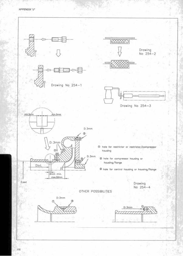
1 :' APPENDiX'J“
•tt'.
A / ' - A.
I-
■^4 h
0
■ E f S K H g -
Drawing No 2 5 4 -1
Ï . " . .
/,/hln.3mm
< A yD: 3mm
3mm m»n. mo*. 50mm
D:3mm
Drawing No 2 5 4 -2
Drowing No 2 5 4 -3
0 hole for restrictor or restrlctor/compressor housing ^
0 hole for compressor housing or houslng/fionge
0 hole for centrgl housing or housing/flongt
4-Drawing No 2 5 4 -4
OTHER POSSIBILITIES
0 :3mm
-2L3D22!----------
p - y y y y y y y y / / / ^ 7 ^
m116
k '.V'j
1.
,s. ..•-••ftVi!
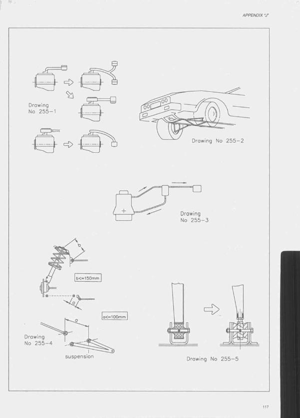
APPENDIX "J"
d B
Drawing No 2 5 5 -1
lEJZ = Q
/ +
b<” 150mm
□rowing No 2 5 5 - 4
suspension
□rowing No 2 5 5 - 2
□rowing No 2 5 5 - 3
□rowing No 2 5 5 - 5

iT : APPENDIX "J"
■>, ■
ù .
■■
r » ' .
air filterhole in the
bulkhead
Drawing No 2 5 5 -6 '
Drawing No 2 5 5 -7
Drowing No 2 5 5 -8
Drawing No 2 5 5 -1 1
Drawing No 2 5 5 -1 0
Hi
ISi--'f -
H Im .
3 ply corbon 280g
. A ê
> ."
'É l
23mm Aluminium honeycomb
Corbon 4 /4 twin 280gms E620 ^ ‘
, ■ ■"* "
' , ‘1 J*■ ■ - . : - P M
Orowing No 2 5 5 -1 5
3 ply carbon 280g~ ' w rvwiiXI••UKI i iw iiu rw K iw (.f'
Aluminium honeycomb 23mm 1 /8" cei4.5 or 6.35 ^ 'Jp , ^
, ,■ > ' r ' ' ' 4 i. . s; f
S'»!"!Drawing No 2 5 5 -1 4
■J- jf/5t
' m.*?. - 118
y/.TüLjdri^.

APPENDIX V '
8 0 m m m ax.
oxis
80m m
180m m
Drawing No 2 5 8 -1 Drawing No 2 5 8 -2
Drawing No 2 5 8 -3
D = 3 3 rn m mox.
h « 2 m m mln.
h » 5 0 m m mox.
Drowing No 2 5 8 -4For quoter
turn volve
Hole d iom eter 8 0 3 5 0
200
^ — 1
I-----------------------------------1-----2 0 0 ------------------------------!• -T ( )■ -----------------------------------------
6 0 0
D /2
6 00
15Front wheel edge
Dimensions in m m
Drowing No 2 5 8 -5
119

' r - j - :
APPENDIX V
'^ - - . ■ .
. - -
}■45mm
IrOmm
60mm
Drawing No 2 5 9 —3Drawing No 2 5 9 -2Drawing No 2 5 9 -1
Drawing No 2 6 2 -1 .
T , 4 5 ‘
A>*A standard
B > /B stondord
C ^ C standard
Drawing No 2 6 2 -2
Drawing No 2 6 2 -t
Drawing No 2 6 2 -3

APPENDIX V ’
E X H A U S T , a r t ic le 2 6 2 .4 .2 .1 7 E c h a p p e m e n t, a r t ic le 2 6 2 .4 .2 .1 7
NO T ALLOM C O N O N AUTOfRSC N O T A LLOM C D N O N AUTO RISE
1/N O T ALLOW EO NO N AUTORISE
A O O W E O AUTO RISE ALL O R C D AUTO RISE
m fALLOW ED AUTO RISE ALLOW ED AUTO RISE
origin*
R » D /S m e a , Ru p o a u n o t l^ M
R -0/2Dessin 2 6 2 - 8
Drowina 2 6 2 -8

r ' l ’;*-- •'.-1 ' ■ V '- ^ - .•
APPENDIX V
Cor s axis
e » ■ -.V ,
■ • { j ' - K I
Drowmg No 2 6 2 - 5 Drowing No 262
A - 1 0 5 m a x .
400m m mox
Drawing No 2 6 2 - 7

APPENDIX •jr
Dimensions in m illim etres.
200
JOO400
Reor wheels■400
550
1000^Oo
Drawing 279
O f
500'OOr
[280
755
315
100
700
Drowing 2 7 9 -2
123

APPENDIX V
Level
Door
Drowing 2 7 9 -3
290 mm
.H
Drawing 2 7 9 - 4 ■ J.
450 mm *à1360 mm
; ■
\ .'jsi
■ '4-’
± j

APPENDIX ‘T
9 4 ,4
Drowing No 2 7 4 -1
775.0
R200.0 520.0
R200.0 R100.G
(os from 0 1 .0 1 .9 9 )
31 .4
_ L
161.7
Drawing No 2 7 4 -2
164.1
4 0 .2
Drawing No 2 7 4 -3
2 5 0 .0 J ! _I
2 5 0 .0
(os from
0 1 .0 1 .9 9 )
R50.0
Drawing No 2 7 4 -6
3 0 0 .0
cor center line
6 0 0 .0Plan view
Drawing No 2 7 4 -5
(until 3 1 .1 2 .9 8 )
Drawing No 2 8 3 -1 Drawing No 2 8 3 -2 Drawing No 2 8 3 -3 Drawing No 2 8 3 -4
< 3 0 c m
Drawing No 2 8 3 -5
oil dimensions in mm
Drawing No 2 8 3 —6

• • .. » "iy3 r *•.
'V ••APPENDIX V v .’U ’«v- xi*
" " A , •-’
•V’ )
y ///v ///7 /\ ^
c3m m nln. 0
50m mm ax.
Tubular wire m esh
Max d iam eter : 16m m
.4
Drawing No 2 8 5 -2il
)rawing No 2 8 5 -1Hole in the
butkheod \
- IA- "
J & y SAir filter % Vj
D r a w in g iPS. N o 2 8 5 - 6
: V •> ^ '■ f ■
. j ’- ■ ~.üi!»J-
Position o f the tower T io u n tin g po in t o f the s h o ck obeorber
1
_^Axis for the m eosurem ent o f the deflection
< 2 2 0 m rr^
* rf-
r
r i )
Rigid stop
Chassis Drowing No 2 8 5 - 4
Ancroge des nouvelles troverses sur le châssis f ' t ' i Mounting o f the new struts on the chassis
Axis o f the m eosurem ent o f the deflection
- I
Drawing No 2 8 5 -3
'128
r ; . ..
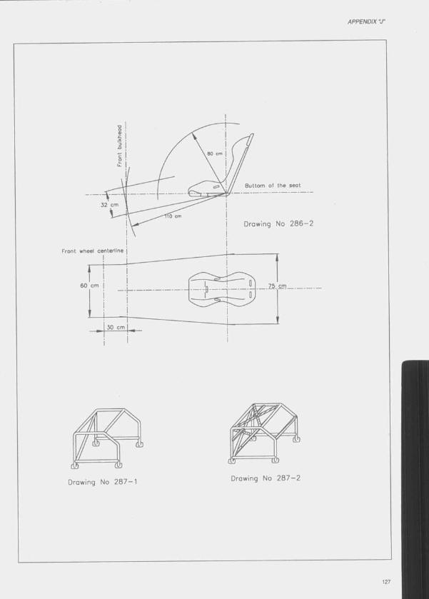
APPENDIX ‘X
Drawing No 2 8 7 -1
80 cm
Buttom o f the seot
32 cm
fb cm
Drawing No 2 8 6 -2
Front wheel centerline
60 cm
30 cm
Drawing No 28 7 —2

;■• *■
APPENDIX V,iW'^
■ v r ■
5* .'~ r *',:r ■ ^ ''
• • t
i
'■ a
L'k- .
r> *
I
! . v ^K--, . ''0.4^**“ .
M .
Drawing No 2 8 7 -34 '
V»t
. ,r ■■
r : •.
Drawing No 2 9 0 -2
hand cut treadI' 2mm min.
tread weor indicotor
Drawing No 2 9 0 -1
ALL DIMENSIONS IN MM
4- ■»■ * - I . + '
2550 max.
1,— y . * *_
/ + + + /+ + +
+ + +-. + +
+ + +
min./ + + +[♦■ + + + I + + +y + + +
| r ^■
\ + + + \ + +
± __±__±+ + H
+ + ++ + ’
+ + + \
2500m in.
1200 min 1300 mox.
centre line o f fifth wheel
Drawing No 2 9 0 -3
ip:
m •

/ I ' \
W z W
D.exlD.int
mOK. 1Q0mm_
D: 3mm
\
(D Hole fo r re s t r ic to f o r re s tr ic to r /c o m p re s s o r
housirrg
(2) Hole fo r c o m p re sso r hous ing o r h o u s in g /f lo n g e
® Hole fo r tu rb in e hous ing o r h o u s in g /f lo n g e
D: 3mm
/ Drowing No 2 9 0 -4
Drawing
No 2 9 0 -5
=70 . e=d=6
c = 2 5 0
d
b=64
MiddleMiddle o f rim
c /2q / 2
Middle o f rim
Drawing No 2 9 0 -6
129

List of FIA homologated vehicles and engines
- This list is classified by country.
- The letter Immediately preceding the homologation number Indicates the Group In which the vehicle o r engine Is homologated ;
GroupGroupGroupGroup
Group
NABT
STC2F3G1G2
Production Cars (N)Touring Cars (A)Grand Touring Cars (B)Series Cross-Country Cars (T1) Cross-Country Trucks (T4) Super Touring Cars Super Touring Engines Formula 3 engines Grand Touring Cars C lass i Grand Touring Cars Class 2
Group Group
- The date mentioned after the commercial denomination Indicates the beginning of the homologation of the vehicle o r engine.
- The num ber In brackets gives the last year for which the vehicle o r engine Is homologated, e.g.(99) homologation valid until 31/12/99. If the sign + Is added, this means that the homologation Is likely to be extended.
- The sign ★ Indicates Homologations Including a VK (Kit variant)
- The sign 0 Indicates Homologations Including a WRC (World Rally Car)
NB. : The present list o f vehicles and engines was etabllshed on 16 November 1998. The periodical addenda to th is list will be published In the FIA Official Bulletin.
e 1999 Fédération Internationale de l’Automobile 131

f * - ' ’ ' :f -’ ’ I .
HOMOLOGATED VEHICLES AND ENGINES
★ Voitures com portant une VK (Variante-Kit)
0 Voitures com portant une W RC (Word Raiiy Car)'•
Homol
I* ÿ. •, '
L? ” OAFT4 4035
Toyota Motor Corp. Austral
A ! - .
Liaz S.A. Jablonec T4T414
Skoda,i>.
l ' # ' ★
★
■ ★
Tatra S.A. Koprivnice T4 T4 T4 T4 T4 14 T4
> -ff-"
rA udI
55425542
401640174018
53735528
5551
55735373552855515573
4003400440114012 4021 4026 4037
i,)
■ ■ < 'fr f .s jr>' •' rfii . -
Descriptif
A u s tr ia
OAF30 - 502 VFAEG 18273cc
I A u s tra lia
ni,-’ COROLLA SECA RV 1762 oc
COROLU SECA RV 1762 cc
y jf..
’ C zech Rep.
111.154 11946CC151.154 11946CC111.154 D 11946 00
FAVORiT 136 L 1289.400
FELiCiA 1289,4 00
FELICIA 1,6 1598 CO
OCTAVIA1,8 20V1781oo FAVORIT 136 L 1289.4oo FELICIA 1289,4 oo FELiCiA 1.6 1598 00 OCTAViA 1,8 2 0 V 1781 oc
T 815 PR1 6x6.1 19000CO T 815 P27 4x4.1 19000 0 0
T815P17 6x6.1 19000 0 0
T 815 P28 4x4.1 19000 0 0
T815-290R75 4x4.1 19000 CC
T815 290R75/01 4x4.1 19000OO T815 2ZER55.16.400 4x4.1 15874 0 0
G erm any
Début
1/9/19951/9/1995
1/1/19931/1/19931/1/1993
1/8/19921/8/19921/1/19931/1/19931/1/19941/1/19951/1/1998
■ '?.t L'P' w T rr< ,A
>. . * ■ ' . 5 A
Fin V
1/4/1997
2002 S
1/1/19891/12/1994
1/3/1996
1/9/19971/3/19891/12/19941/3/19961/9/1997
v 2 0 0 0 L
A 5409 AUDI V8 QUATTRO 3561.800 1/4/1990 2001A . 5457 80 2.0 E B4 1984.3 00 1/7/1992 2001A 5467 AUDI COUPE S2 2226 X 1.7 = 3784.2 00 1/1/1993 2000A 5479 80 QUATTRO 2.8 E 2771 oo 1/4/1993 2001A 5515 80 COMPETITION 1984.5 oc 1/4/1994 2001 ^ -02 5 C.BLOCK 80 16V / C.HEAD V8 QUAT 1983 00 1/4/1993 7 2005+ ,C2 21 AUDI R4 2.0L16V1984CO 1/4/1994 2005+N 5467 AUDI COUPE 82 2226 X 1.7 = 3784.2 oo 1/1/1993 2000ST 6 AUDI 80 1/3/1995 2003ST 17 AUDI A4 1/4/1995 2004+
ys. L

HOMOLOGATED VEHICLES AND ENGINES
Bitter & Co. Automobile GmbHGT1 10 GT1 1/4/1998 2005+
B.M.W.A 5440 3251 (E36) 2494CC 1/11/1991 2002
A 5441 3201 (E36) 1991CC 1/11/1991 2004+
A 5454 3251 (E36/2) 2494cc 1/3/1992 2002
A 5490 M3 (E36) 2990,5 cc 1/6/1993 2002
A 5500 3181 (E36) 1796 CC 1/11/1993 2004+
A 5526 318 IS-4 (E36) 1796 cc 1/7/1994 2001
A 5562 M3 - 3,2 (E36) 3201 CC 1/3/1997 2004+
02 2 814 (BMW M3) 2302.1 cc 1/1/1993 2005+
02 3 M42 (31818) 1796 CC 1/1/1993 2005+02 26 M42 (3181s) 1796 CC 1/3/1995 2005+N 5440 3251 (E36) 2494CC 1/11/1991 2002
N 5441 320! (E36) 1991CC 1/11/1991 2004+
N 5454 3251 (E36/2) 2494CC 1/3/1992 2002
N 5490 M3 (E36) 2990,5 CC 1/6/1993 2002N 5562 M3 - 3,2 (E36) 3201 cc 1/3/1997 2004+
ST 8 3201 1/3/1995 2004+
Daimler-BenzA 5269 190 E 2.3-16 (W201) 2302.2CC 1/5/1985 2000A 5498 MERCEDES 0220 (W202) 2199.2 cc 1/8/1993 2003
01 1 MERCEDES-BENZ C 220 D 1/4/1996 2004
02 12 MERCEDES 220E (W124) 2201.4 cc 1/8/1993 2005+GT1 5 MERCEDES CLK-GTR 1/4/1997 2004+
GT1 11 MERCEDES CLK-LM 1/7/1998 2005+
N 5269 190 E 2.3-16 (W201) 2302.2CC 1/5/1985 2000T 1051 MERCEDES-BENZ 300 GD (BM 463) 2996CC 1/8/1991 2003I 1052 MERCEDES-BENZ 300 GE (BM 463) 2960CC 1/8/1991 2003I 1060 MERCEDES 300 GE 2960 cc 1/10/1993 2003T4 4007 1935 AK 14618 cc 1/8/1992 2003T4 4008 UNIMOG U 1550 L37 5958 cc 1/8/1992 200314 4009 1936AK 18273 cc 1/8/1992 1999
14 4013 2635 AK 14618 CC 1/1/1993 2003T4 4014 2636 AK 18273 cc 1/1/1993 2004+14 4034 1844 AK 14618 cc 1/1/1997 2004+
M.A.N.T4 4019 19.422 FA 11967 cc 1/1/1993 2004+
14 4038 SX 90 DFAEG 12763 CC 1/1/1998 2005+
A 5375 NOVA GTE / CORSA GS11598cc 1/1/1989 2000A 5426 OMEGA-A 3.0 24V/ CARLTON-A 3.0 24V 2969 1/3/1991 2001A 5430 OPELA/AUXHALL CALIBRA 16V 1998CC 1/3/1991 2004+
A 5431 OPEL VECTRA 16VA/AUXH. CAVALIER 16V 1998 1/3/1991 2002
A 5452 OPEL/VAUXH ASTRA-F GSi/GTE 16V 1998 1/2/1992 2004+A 5477 OP/VAUX CALIBRA-ATU 4x4 1998x1.7=3396.6 1/1/1993 2004A 5484 OPEL/VAUXHALL ASTRA 2.0 1998 cc 1/4/1993 2004+A 5516 OPELA/AUXHALL CORSA-B 1.61 1598 CC 1/4/1994 2004+
A 5589 OPEL/VAUXHALL ASTRA-G-CC 1998 cc 1/7/1998 2005+C l 4 OPELA/AUXHALL CALIBRA COLOR EDITION 1/4/1996 2004C2 6 OP/VAUXH ASTRA-F 2.0 C20XE 16V 1998 cc 1/4/1993 2005+F3 310 OPEL/VAUXHALL ASTRA-A16V 1998 CC 1/4/1993 2005+N 5375 NOVA GTE / CORSA GSi 1598cc 1/1/1989 2000N 5426 OMEGA-A 3.0 24V/CARLTON-A 3.0 24V 2969CC 1/4/1991 2001N 5430 OPEL/VAUXHALL CALIBRA 16V 1998CC 1/4/1991 2004+N 5431 OPEL VECTRA 16V/VAUXH. CAVALIER 16V 1998 1/4/1991 2002N 5452 OPEL/VAUXH ASTRA-F GSi/GTE 16V 1998 1/2/1992 2004+N 5477 OP/VAUX CALIBRA-ATU 4x4 1998x1.7=3396.6 1/1/1993 2004N 5516 OPELA/AUXHALL CORSA-B 1.611598 cc 1/4/1994 2004+ST 15 OPEL VECTRA-A/VAUXHALL CAVALIER-A 1/4/1995 2004+
ST 16 OPELA/AUXHALL ASTRA-F 2.0 1/4/1995 2004+
133

?v >.•
HOMOLOGATED VEHICLES AND ENGINES
Porsche
Volkswagen
, *■-'
1?
ST 27 OPEL/VAUXHALL VECTRA 1/12/1995 2004+2005+^'ST 39 OPEL VECTRA CD 1/4/1998
ST 40 OPEL VECTRA GL PLUS 1/4/1998 2005+ . ÿ *
B 283 928 S 4957CC 1/6/1986 19991999 ? ; : iB 284 944 TURBO 2479x1.7=4214.3cc 1/6/1986
B 294 911 CARRERA 4 3600.27CC 1/9/1990 2001B 295 911 CARRERA 2 3600.27CC 1/9/1990 2001B 296 911 CARRERA RS3600.5CC 1/3/1992 2001B 298 911 TURBO 2 3299 x 1.7 = 5608.3 cc 1/4/1993 2001GTl 3 911 GTl 1/3/1997 2004+ *GTl 9 911 G T l /9 8 1 1/4/1998 2005+GT2 2 911 CARRERA RS 3.8 1/8/1995 2004GT2 3 911 TURBO GT2 1/1/1996 2004 »GT2 4 911 CARRERA RS 3.8 (993) 1/4/1996 2004 {
AAAAA
AAAC2C2F3F3F3NNNNNN
51755314543854395482
5483 5568 55847830230931153145438543954825483 5568
SCIROCCO GTl 1800 1781CC53 SCIROCCO 16V 1781.3CCPOLO COUPE G40 (860) 1272.5x1.7=2163cc86 POLO COUPE 1275.5CCVENTOGT 2.0,1984 ccGOLF GTl 16V'2.0 1984 ccPOLO 16V 1.41390 CCGOLF 1.8 -20V 1781 ccGOLF GTI16V1.8L 1781 ccGOLF GTl 16V 2.0L 1984 ccPASSAT 1984 cc19 GOLF GTl 1781 CC17 GOLF GTl 1588 cc53 SCIROCCO 16V 1781.3CCPOLO COUPE G40 (860) 1272.5x1.7=2163cc86 POLO COUPE 1275.5CCVENTOGT 2.0 1984 ccGOLF GTl 16V 2.0 1984 ccPOLO 16V 1.4 1390 cc
1/11/1983 1999 f1/11/1986 19991/10/1991 . t 20011/10/1991
i1/4/1993 ,ip. 2004 ,
1/4/1993 , ^ 2004 '1/3/1997 2004+
1/4/1998 2005+1/4/1993
2005+1/4/19931/8/1991 2005+1/4/1993 2005+ A '1/4/1993 2005+1/11/1986 19991/10/1991 2001 i1/10/1991 20011/4/1993 20041/4/1993 20041/3/1997 2004+
Miranda A lonso Fernandez S.A.
' Nissan Motor Iberica S.A.TTT ni T T
Seat
*rk.-
AAAAA
A
A02NNNN
4020
10811082108310841085
■t--
5358536854785504
5517
5563
5586305368547855045517
Spain
IP V -180 R 17680cc
TERRANO II LONG BODY 2389 ccTERRANOII2389CCNEW TERRANO II 2389 CCNEW TERRANO II LONG BODY 2389 ccNEW TERRANO II LONG BODY 2664x1.7=4528.8
MARBELLA GL 5vel 902,58ccIBIZA 1.5 S X I1461CCTOLEDO GT16V 1781.32ccIBIZA GTl 2.0 1984,5 cc ? ' .IBIZAGTI16V1781.32CC
IBIZA GTl 2.0 16V 1989,1 cc
CORDOBA 1595,4 ccTOLEDO GT -IBIZA 1.5 SXI 1461CCTOLEDO GT 16V 1781.32ccIBIZA GTl 2.0 1984,5 ccIBIZA GTl 16V 1781.32 cc
1/1/1994 2001
1/7/1996 '■ * '2 0 0 3 ^ - “ ''1/7/1996 2003 « J ,1/1/1997 2004+ ’1/1/1997.^4 *2004+ 1/1/1997 / ’ 2004+
1/4/1988 1/10/1988 1/1/1993 1/1/1994 1/7/1994
1/3/1997
1/4/1998 1/8/1995 1/1/1990 1/1/1993 1/1/1994 1/7/1994
2005+
2004+ «
2005+
2001 * ^
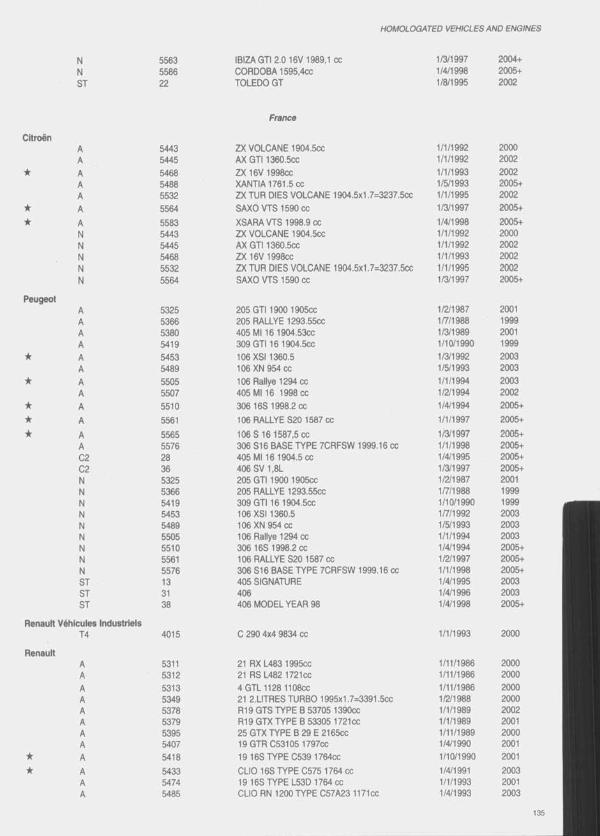
HOMOLOGATED VEHICLES AND ENGINES
N 5563 IBIZA GTI 2.0 16V 1989,1 cc 1/3/1997 2004+N 5586 OORDOBA 1595.4CC 1/4/1998 2005+
ST 22 TOLEDO GT
France
1/8/1995 2002
CitroënA 5443 ZX VOLOANE 1904.5CC 1/1/1992 2000A 5445 AX GTI 1360.5CC 1/1/1992 2002
★ A 5468 ZX 16V 199800 1/1/1993 2002A 5488 XANTIA 1761.5 CO 1/5/1993 2005+A 5532 ZX TUR DIES VOLOANE 1904.5x1.7=3237.500 1/1/1995 2002
★ A 5564 SAXO VTS 1590 00 1/3/1997 2005+
★ A 5583 XSARAVTS 1998.9 00 1/4/1998 2005+N 5443 ZX VOLOANE 1904.5CC 1/1/1992 2000N 5445 AX GTI 1360.5CC 1/1/1992 2002N 5468 ZX 16V 1998CC 1/1/1993 2002N 5532 ZX TUR DIES VOLOANE 1904.5x1.7=3237.5cc 1/1/1995 2002N 5564 SAXO VTS 1590 00 1/3/1997 2005+
PeugeotA 5325 205 GTI 1900 1905CC 1/2/1987 2001A 5366 205 RALLYE 1293.5500 1/7/1988 1999A 5380 405 Ml 16 1904.53CC 1/3/1989 2001A 5419 309 GT116 1904.5CC 1/10/1990 1999
★ A 5453 106 XSI 1360.5 1/3/1992 2003A 5489 106 XN 954 CO 1/5/1993 2003
★ A 5505 106 Rallye 1294 cc 1/1/1994 2003A 5507 405 Ml 16 1998 00 1/2/1994 2002
★ A 5510 306 16S 1998.2 00 1/4/1994 2005+
★ A 5561 106 RALLYE S20 1587 00 1/1/1997 2005+
★ A 5565 106 S 16 1587,5 00 1/3/1997 2005+A 5576 306 S16 BASE TYPE 7CRFSW 1999.16 co 1/1/1998 2005+02 28 405 Ml 16 1904.5 00 1/4/1995 2005+02 36 406SV1,8L 1/3/1997 2005+N 5325 205 GT11900 1905CC 1/2/1987 2001N 5366 205 RALLYE 1293.5500 1/7/1988 1999N 5419 309 GT116 1904.5CC 1/10/1990 1999N 5453 106 XS11360.5 1/7/1992 2003N 5489 106 XN 954 00 1/5/1993 2003N 5505 106 Rallye 1294 cc 1/1/1994 2003N 5510 306 16S 1998.2 00 1/4/1994 2005+N 5561 106 RALLYE S20 1587 cc 1/2/1997 2005+N 5576 306 S16 BASE TYPE 7CRFSW 1999.16 00 1/1/1998 2005+ST 13 405 SIGNATURE 1/4/1995 2003ST 31 406 1/4/1996 2003ST
Renault Véhicules Industriels
36 406 MODEL YEAR 98 1/4/1998 2005+
T4 4015 0 290 4x4 9834 0 0 1/1/1993 2000
RenaultA 5311 21 RX L483 1995CC 1/11/1986 2000A 5312 21 RS L482 172100 1/11/1986 2000
A 5313 4GTL1128 1108CC 1/11/1986 2000A 5349 21 2.LITRES TURBO 1995x1.7=3391.500 1/2/1988 2000A 5378 R19 GTS TYPE B 53705 1390CC 1/1/1989 2002A 5379 R19 GTX TYPE B 53305 1721CC 1/1/1989 2001A 5395 25 GTX TYPE B 29 E 2165CC 1/11/1989 2000A 5407 19 GTR 053105 1797cc 1/4/1990 2001
★ A 5418 1916STYPE C539 1764CC 1/10/1990 2001
•k A 5433 CLIO 16S TYPE 0575 1764 cc 1/4/1991 2003A 5474 19 16S TYPE L53D 1764 cc 1/1/1993 2001A 5485 CLIO RN 1200 TYPE C57A23 1171CC 1/4/1993 2003

H O M O LO Q ATED VEHICLES A N D E NG IN ES
f i ' I J
Renault SportGT2
Ford
★
0
• K ★
r .i^j
AAA
AAAAC2C2C2F3NNNNNNNSTST
STSTT
S'*'-
.<)' Honda Motor Europe Ltd
ANSTST
Jaguar cara LtdGT1
taa i j '
551155482992738314321531153125313 534953785379 5418 5433 5474 5485 5548 14 411054
54045414
5450
5466549755675578
3435 317 5404 5414 5450 5466 5497 5567 557819203435 1067
55885588133
LAGUNA B56 1998 ccMEGANE COUPE 1995 ccALPINE A610 TURBO 2975x1,7=5057.50ccCLIO WILLIAMSCLIO WILLIAMSCLIO WILLIAMS 1998 ccMEGANE COUPE21 RXL483 1995cc^. -21 RS L482 1721CC4GTL11281108CC21 2.LITRES TURBO 1995x1.7=3391.5ccR19 GTS TYPE B 53705 1390ccR19 GTX TYPE B 53305 1721 cc1916STYPE C5391764CCCLIO 16S TYPE C575 1764 cc19 16S TYPE L53D 1764CCCLIO RN 1200 TYPE C57A23 1171ccMEGANE COUPE 1995 ccUGUNAB56LAGUNA B56 Ml 9821 2L TURBO QUADRA 1995x1.7=3391.5
1/4/1994
1/3/19961/4/19931/4/19951/3/19971/3/19941/3/19981/11/19861/11/19861/11/19861/2/19881/1/19891/1/19891/10/19901/4/19911/1/19931/4/19931/3/19961/4/19951/4/19981/1/1992
2005+
2005+^
SPIDER TYPE EFOH 1/5/1997 2005+
G. B rita in
FIESTA 1.4 S 1392CC 1/2/1990 2000SIERRA COSWORTH 4x4 1994.5x1.7=3390.5cc 1/8/1990 1999ESCORT RS 2000 MK.3 1998cc 1/1/1992 2004 •Jr.. N+ ^
ESCORT RS COSWORTH 1994.5x1.7=3390.5cc 1/1/1993 2000MONDEO2.0L Si 1998 cc 1/7/1993 , 2002KA1298CC 1/3/1997 2004+
PUMA 1679 cc 1/2/1998 2005+ "s;2.5L PROBE ENGINE 2497 cc 1/4/1993 2005+COSWORTH YB 1/11/1996 2005+ZETECESCORT RS COSWORTH 1994.5 cc
1/12/19961/1/1995
2005+2005+
Jt :
FIESTA 1.4 S 1392CC 1/2/1990 2000SIERRA COSWORTH 4x4 1994.5x1.7=3390.5CC 1/8/1990 1999
-ESCORT RS 2000 MK.3 1998cc 1/1/1992 A 2004ESCORT RS COSWORTH 1994.5x1.7=3390.5cc MONDEO 2.0LSI 1998CC
1/1/1993 1/7/1993 ^
2000 - 2 002*’
KA1298CC 1/3/1997 I f 2004+PUMA 1679 CC 1 /2 /1998ÏH .A 2005+MONDEO 4 DOOR 1/4/1995 2002 .MONDEO 5 DOOR 1/4/1995 2002
MONDEO 97MY (4 DOOR) 1/3/1997 2004+MONDEO 97MY (5 DOOR) 1/3/1997 2004+MAVERICK 2389 CC 1/4/1994 2002
CIVIC 5 DOOR (MB86) 1797.5 cc CIVIC 5 DOOR (MB86) 1797.5 cc ACCORD LS (CC756)ACCORD LS (CE 856)
1/6/19981/6/19981/3/19951/3/1997
JAGUAR XJ-220 1/1/1996
2005+2005+
2004+

HOMOLOGATED VEHICLES AND ENGINES
Land Rover
Lotus
TT
GT1
10611071
McLaren Cars Limited GT1
Panoz M otorsport LtdGT1
Rover Cars
Vauxliall
AAAANNNN
C2ST
54475475550255605447547555025560
4136
RANGE ROVER 4278 cc DISCOVERY 3955 cc
GT1 TURBO
MCLAREN FI
PANOZ GTR
METRO GTI 1396 CC
220 GTI 1996.5CC MINI COOPER 1.311274 cc MINI COOPER 1.311274 cc METRO GTI 1396CC 220 GTI 1996.5CC MINI COOPER 1.311274 cc MINI COOPER 1.311274 cc
VAUXHALL C20XE 16 VALVE ENGINE VAUXHALL VECTRA
1/12/19931/4/1995
1/4/1997
1/1/1995
1/4/1997
1/1/19921/1/19931/1/19941/1/19971/1/19921/1/19931/1/19941/1/1997
1/3/19981/11/1997
20002002
2004+
2004+
2004+
2002200320032004+2002200320032004+
2005+2004+
I ta ly
Alfa RomeoA 5256 ALFA 33 QUADRIFOGLIO VERDE 1489.5CC 1/2/1985 2000A 5264 ALFA33 4x4-1.5 1489.5cc 1/4/1985 2000
A 5300 ALFA 75 QUADRIFOGLIO 2492.5CC 1/5/1986 1999
A 5307 ALFA 75 TURBO 1762x1.7=3024.98cc 1/8/1986 1999A 5326 ALFA 75 2.0 SUPER 1962CC 1/2/1987 1999
A 5350 ALFA 75 6V 3.0 2959CC 1/2/1988 1999
A 5362 33 1.7 QUADRIFOGLIO VERDE 1712.1CC 1/5/1988 2000
A 5392 33 1.7 QUADRIFOG.VERDE (MOD89) 1712.1cc 1/10/1989 2000
A 5413 ALFA3316V1.71712CC 1/7/1990 2000A 5432 164 3.0 QV 2959CC 1/4/1991 2000
A 5449 ALFA 33 1.5 I.E. 1489CC 1/1/1992 2000A 5456 33S 16V PERMANENT 4 1712 cc 1/4/1992 2000
A 5460 164 V 6 TURBO 1996x1.7=3393.2cc 1/7/1992 2000A 5471 155T. SPARK 2.0 1995CC 1/1/1993 2002
A 5472 155 V6 2492.4CC 1/1/1993 2003A 5476 155 QUADRIFOGLIO 4 1995x1.7=3391.5cc 1/1/1993 2003
A 5503 164 QUADRIFOGLIO 3.0 V6 24V 2959 cc 1/1/1994 2004+
A 5513 155 T.SPARK 1.8 1773 CC 1/4/1994 2001A 5544 155T.SPARK2.0S16V 1969.46 cc 1/12/1995 2003A 5549 145 T.SPARK 2.0 16V QUADRIFOGLIO 1969.46 1/4/1996 2003
A 5574 156 T.SPARK 2.0 16V 1969.46 cc 1/1/1998 2005+
B 297 SZ 2959 CC 1/11/1992 2000
Cl 2 155 T.SPARK 2.0 S 16V 1/4/1996 2003
Cl 3 155 T.SPARK 2.0 S 16V 1/4/1996 2003
C2 4 C.BLOCK 164 2.0 TU/C.HEAD 155 QUA 4 1995 1/1/1993 2005+C2 29 155 2.0 T.SPARK SUPER 16V 1/6/1995 2005+C2 39 T.SPARK 1.8 16V 1/7/1997 2005+
C2 42 T.SPARK 1.8 16V 1/3/1998 2005+
F3 304 TWIN SPARK 2.0 1995 cc 1/1/1993 2005+
F3 318 155 2.0 T.SPARK SUPER 16V 1/6/1995 2005+
F3 322 T.SPARK 1.4/1 .616V 1/3/1998 2005+N 5256 ALFA 33 QUADRIFOGLIO VERDE 1489.5CC 1/4/1985 2000
137

HOMOLOGATED VEHICLES AND ENGINES
. i t »■
r'.V
vjr Ferrari
N 5264 ALFA33 4x4-1.5 1489.5cc 1/7/1985 2000N 5307 ALFA 75 TURBO 1779.4x1.7=3024.98cc 1/10/1986 1999N 5326 ALFA75 2.0 SUPER 1962CC 1/4/1990 1999N 5350 ALFA 75 6V 3.0 2959CC 1/2/1988 1999N 5362 33 1.7 QUADRIFOGLIO VERDE 1712.1CC 1/5/1988 . 2000N 5413 ALFA3316V1.71712CC 1/7/1990 2000N 5432 164 3.0QV2959CC 1/4/1991 2000N 5449 ALFA 33 1.5 I.E. 1489CC 1/1/1992 2000N 5456 33S 16V PERMANENT 4 1712cc 1/6/1992 2000N 5460 164 V 6 TURBO 1996x1.7=3393.2cc 1/7/1992 2000N 5471 155 T. SPARK 2 .01995CC 1/1/1993 2002N 5472 155 V6 2492.4CC 1/1/1993 2003N 5476 155 QUADRIFOGLIO 4 1995x1.7=3391.5cc 1/1/1993 2003N 5503 164 QUADRIFOGLIO 3.0 V6 24V 2959 cc 1/1/1994 2004+N 5544 155 T.SPARK 2.0 S 16V 1969.46 cc 1/12/1995 2003N 5549 145 T.SPARK 2.0 16V QUADRIFOGLIO 1969.46 1/4/1996 2003.N 5574 156 T.SPARK 2.0 16V 1969.46 cc 1/1/1998 2005+ST 7 155 (M.Y. 1994) 1/3/1995 2002ST 9 155 (M.Y. 1995) ^ 1/3/1995 2003ST 37 156 (M.Y 1997) {'■ f 1/1/1998 2005+ST 43 1561.6 (M.Y 1998) 1/11/1998 2005+
293 F 40 2936.24x1.7=4991.60cc
L Iv e c o S .p AT4 4027
Automobill Lamborghini S.p.A. *■ GT1 •
135E23W /R S 5861 cc
■ft132 GT1
54485448
HF INTEGRALE 1995x1.7=3391.5cc HF INTEGRALE 1995x1.7=3391.5cc
138
1/12/1989
1/8/1995
1/4/1998
1/1/19921/1/1992
2000
A 5207 UNO 70 S I 301.5CC 1/4/1984 1999A 5278 UNO TURBO IE 1300.9x1.7=2211.53cc 1/10/1985 1999A 5402 UNO TURBO IE 1372.1x1.7=2332.6cc 1/2/1990 2003A 5406 TlPO I.e. 16V 1755.6CC 1/4/1990 2000
A , 5428 U NO 70XSi.e . 1372.1CC 1/4/1991 2000A 5436 TlPO 2.0/16V 1995CC 1/10/1991 2003
r A 5463 CINQUECENTO 902.6CC 1/10/1992 2004+
A V 5529 CINOUECENTO SPORTING 1108.3 cc 1/1/1995 2004+A 5530 ' COUPE 2.0 16V 1995 cc 1/1/1995 2004+A 5531 COUPE 2.0 16V TURBO 1995x1.7=3391.5cc 1/1/1995 2004+
A 5558 BRAVO HGT 2.0 20V 1997.5 cc 1/1/1997 2004+
A ' 5593 i SEICENTO SPORTING 1108.3 cc 1/10/1998 2005+A • 5595 SEICENTO SPORTING ABARTH 1108.3 cc 1/12/1998 2005+
‘ F3 303 TlPO l.e. 16V 1755.6 cc 1/10/1992 2005N 5207 UNO 70 S 1301.6CC 1/4/1984 1999
'•.jri/ N 5278 UNO TURBO IE 1300.9x1.7=2211.53cc 1/10/1985 1999N ' 5402 UNO TURBO IE 1372.1x1.7=2332.6cc 1/2/1990 2003
« N ' 5406 TlPO l.e. 16V 1755.6CC 1/4/1990 2000N 5428 UNO 70 XS i.e. 1372.1CC 1/4/1991 2000
•S', Nn ”
5436 TIPO2.0/16V1995CC 1/10/1991 20035463 CINQUECENTO 902.6CC 1/10/1992 2004+ i
N +. 5529 CINQUECENTO SPORTING 1108.3 cc 1/1/1995 2004+N , 5530 COUPE 2.0 16V 1995 cc 1/1/1995 2004+N -1 5531 COUPE 2.0 16V TURBO 1995x1.7=3391.5cc 1/1/1995 ^ 2004+
'•’r . ' N ..... ^ ’ 5558 BRAVO HGT 2.0 20V 1997.5 cc 1/1/1997 2004+N -r- 5593 SEICENTO SPORTING 1108.3 cc 1/10/1998 r 2005+ ■H.N 5595 SEICENTO SPORTING ABARTH 1108.3 cc 1/12/1998 2005+
2002
2005+" ' y m
20002000

HOMOLOGATED VEHICLES AND ENGINES
India
Maruti Udyog Ltd A
M/S. Premier Automobiles Ltd A N
Daitiatsu
FujiAAAAAAAA
0 AAABC2C2NNNNNNNNNT
Hino Motors, LtdT4T4T4T4
Honda
5371 MARUTi 800 796 CC 1/10/1988 2001
5283 PREMIER PADMINI 1089.5CC 1/12/1985 20015283 PREMIER PADMINI 1089.5CC
Japan
1/12/1985 2001
5343 CHARADE 3 DOOR (G100S) 993cc 1/1/1988 19995374 CHARADE 1.31 (G102S) 1295.6cc 1/1/1989 19995494 CHARADE (G200) 1295.5 cc 1/7/1993 2005+5509 CHARADE GTI (G201) (DETOMASO) 1589.5 cc 1/4/1994 2005+5541 MIRA(L210) PORODUA KANCIL 659x1.7=1120.5 1/7/1995 20025374 CHARADE 1.3i (G102S) 1295.6CC 1/1/1989 19995494 CHARADE (G200) 1295.5 cc 1/7/1993 2005+5509 CHARADE GTI (G201) (DETOMASO) 1589.5 cc 1/4/1994 2005+5541 MIRA(L210) PORODUA KANCIL 659x1.7=1120.5 1/7/1995 20021009 ROCKY WAGON (F75V) 2765.4x1.7=4701.2cc 1/1/1989 20011010 ROCKY HARD TOP (F70V) 2765.4x1.7=4701.2 1/1/1989 20011018 FEROZA RESIN TOP(F300G)(Carb.Mod)1589.58 1/4/1989 2005+1019 FEROZA RESIN TOP(F300G)(EFImod) 1589.58 1/4/1989 2005+1066 ROCKY HARD TOP (F73) 2765.5x1.7=4701.5cc 1/4/1994 2005+
5259 SUBARU 4WD TUR SEDAN 1782x1.7=3029.4cc 1/3/1985 19995302 SUBARU 1.8 4WD S/W ALAN 1782CC 1/7/1986 19995397 SUBARU 4WD (1.2) SEDAN, KA 1189.2CC 1/11/1989 19995399 SUBARU LEGACY 4WD TUR 1994.3x1.7=3390.3 1/1/1990 20015420 SUBARU LEGACY SEDAN 2.2 4WD BC 2212.4CC 1/11/1990 20015421 SUBARU LEG W 2.0 4WDBF 1994.4x1.7=3390.5 1/11/1990 20015422 SUBARU LEGACY SEDAN 2.0 4WD.BC 1994.4CC 1/11/1990 20015464 SUBARU VIViO SEDAN 4WD SUPER.KK 1118.5CC 1/11/1992 2005+
5480 SUBARU IMPREZA555 GC8 1994.4x1.7=3390.5 1/4/1993 2005+5575 SUB FOR 2.0 4WD T SF 1994.4x1.7=3390.5CC 1/1/1998 2005+
5591 SUB LEG 2.0 4WD TUR BH 1994.4x1.7=3390.5 1/10/1998 2005+259 SUBARU MP-1 (1.8)1781 cc 1/3/1984 199910 EJ20 ENGINE (A-5422) 1994.4 cc 1/4/1993 2005+11 EJ20 ENGINE 1994.4 cc 1/4/1993 2005+5259 SUBARU 4WD TUR SEDAN 1782x1.7=3029.4cc 1/8/1986 19995397 SUBARU 4WD (1.2) SEDAN, KA 1189.2CC 1/11/1989 19995399 SUBARU LEGACY 4WD TUR 1994.3x1.7=3390.3 1/1/1990 20015420 SUBARU LEGACY SEDAN 2.2 4WD BC 2212.4CC 1/11/1990 20015421 SUBARU LEG W 2.0 4WDBF 1994.4x1.7=3390.5 1/11/1990 20015422 SUBARU LEGACY SEDAN 2.0 4WD.BC 1994.4CC 1/11/1990 20015464 SUBARU VIViO SEDAN 4WD SUPER.KK 1118.5CC 1/7/1993 2005+5480 SUBARU IMPREZA 555 GC8 1994.4x1.7=3390.5 1/4/1993 2005+5575 SUB FOR 2.0 4WD T SF 1994.4x1.7=3390.5cc 1/1/1998 2005+1090 SUBARU SF 4WD, SF 3390.5 cc 1/1/1997 2005+
4002 HINO RANGER FT, U-FT3HGA-LH 11026.2CC 1/5/1992 20004025 RANGER FT U-FT3HGA-LS 11026.2 CC 1/1/1995 20024030 RANGER FT, FT1JGB-LU 1962x1.7=13535.5 1/1/1996 20034033 RANGER FT, FT1JGB-LD 13535.5 CC 1/1/1997 2004+
5444 CIVIC 3 DOOR SIR.il (EG6) 1596cc 1/1/1992 20015487 CIVIC FERIO 4 DOOR SIR (EG9) 1596 cc 1/4/1993 20015499 DOMANI (MA5) 1834CC 1/10/1993 20025552 CIVIC 3 DOOR SIR (EK4) 1596 cc 1/4/1996 2005+
139

•t X- ’
HOMOLOGATED VEHICLES AND ENGINES
t :
ê t i i -’ y f :
)»>
' ■>
A 5590 INTEGRA TYPE-R (QC2) European 1797.2cc 1/7/1998 2005+02 13 B18B ENGINE 1834 cc 1/10/1993 2005+
. , C2 14 B16A ENGINE (A-5487) 1596 cc 1/10/1993 2005+' C 2" 15 B18C ENGINE 1798 cc 1/10/1993 2005+
C2 23 H22A ENGINE 2156 CC 1/1/1995 2005+F3 301 .) B21A1 ENGINE 2056 cc 1/7/1991 . 2005+F3 306 ' CIVIC 3 DOOR SIR.II (A-5444) 1596 cc 1/1/1993 2005+F3 307 PRELUDE 4WS(BA5) (A-5357) 1958 cc 1/1/1993 2005+F3 308 PRELUDE 4WS(BA5) (A-5357 04/01 ET) 1958 1/1/1993 2005+F3 313 B18C ENGINE 1798 cc 1/10/1993 2005+F3 319 H22A ENGINE 2156 cc 1/1/1997 2005+F3 323 H22A/F20B ENGINE 1/7/1998 2005+N 5444 CIVIC 3 DOOR SIR.II (EG6) 1596cc 1/1/1992 2001N 5552 CIVIC 3 DOOR SIR (EK4) 1596 cc 1/4/1996 2005+N 5590 INTEGRA TYPE-R (DC2) European 1797.2cc 1/7/1998 2005+ST 11 CIVIC FERIO 4 DOOR 1/4/1995 2002
, Isuzu1057 BIGHORN (UBS69GW) 3059.3x1.7=5200.8cc 1/7/1992 2005+ï1058 ^ BIGHORN (UBS25D1A0 3165.5 00 1/4/1993 2005+
T
Mazda Motor Co
1092 VehiCROSS (UGS250) 3165.5 cc 1/10/1997 2004+
,4 A 5415 FAMILIA4WD (BG8) 1939.6x1.7=3127.3CC 1/8/1990 2000A 5473 FAMILIA GT-R 4WD 1839.6x1.7=3127.5cc 1/1/1993 2000
■ A 5495 XEDOS6 2.01995.5ce 1/7/1993 2000" - « A 5496 626 2.5 SEDAN 2496.5 CC 1/7/1993 2000
A 5514 LANTIS COUPE 2.0 1995.5 cc 1/4/1994 2001C2 24 KL 2496,5 cc 1/3/1995 2005+N 5415 FAMILIA 4WD (BG8) 1839.6x1.7=3127.3cc 1/8/1990 2000N 5473 FAMILIA GT-R 4WD 1839.6x1.7=3127.5cc 1/1/1993 2000ST 4 U N TIS COUPE 2.0 1/3/1995 2002ST 5 XEDOS 6 2.0 1/3/1995 2002
MitsubishiAAAF3F3NNN
J 4 0
‘ 5469'->5559
55853153245469555955851044104510461047 1062 1063 107310791080 1086 1094 4031 4036
LANCER EV CD9A(PR0T0N WIRA)1997.5x1,7=33 UNC ER EVOLUTION (CN9A)1997.5x1.7=3395.5 LANCER EV (CP9A) 1998.8x1,7=3398 CC 4G93 ENGINE 1834 cc 4G93 (GDI) ENGINELANCER EVOLUTION CD9A 1997.5x1.7=3395.5 LANCER EVOLUTION (CN9A)1997.5x1.7=3395.5 UNC ER EV (CP9A) 1998.8x1,7=3398 oc PAJERO 3000 (V23) 2972.3CC PAJERO WAGON 3000 (V43) 2972.3CC PAJERO TURBO (V24) 2476.8x1.7=4210.6cc PAJERO WAGON TU (V44) 2476.8x1.7=4210.6 PAJERO 3500 (V25) 3497 ce PAJERO WAGON 3500 (V45) 3497 cc RVR (N23) 1997.5 x 1.7 = 3395.5 cc PAJERO W TUR 2800(V46) 2835.2x1.7=4819.8 PAJERO TURBO 2800(V26) 2835.2x1.7=4819.8 CHALLENGER 2835.2 x 1.7 = 4819.8 cc *PAJERO EVOLUTION (V55) 3947 cc FUSO FR415 16031.5 x 1.7 = 27253.5 CC FUSO FR415 16031.6 x 1.7 = 27253.7 cc
1/1/19931/1/19971/4/19981/3/19941/7/19981/1/19931/1/19971/4/19981/7/19911/7/19911/7/19911/7/19911/1/19941/1/19941/1/19961/1/19961/1/19961/1/19971/1/19981/1/19961/1/1998 2 0 0 5 + ^
A 5405 SKYLINE GTR TUR(BNR32) 2568.7x1.7=4366.8 1/3/1990 2001 *■A 5427 PULSAR GTI-R (RNN14) 1998.2x1.7=3396.9cc 1/3/1991 2001A 5461 PRIMERA (HP10) 1998 cc 1/7/1992 .2 0 0 2A 5470 SUNNY GTI (N14) 1998CC 1/1/1993 2001 + !A 5501 SKYLINE GTS25 (ER33) 2499 cc 1/1/1994 2005+A 5523 SUNNY (FB14) 1498 cc 1/7/1994 2005+A 5546 MICRA 1.3 SUPER S (K11) 1275 cc 1/1/1996 2005+
A 5570 ALMERAGT1(N15) 1998CC 1/4/1997 2005+

HOMOLOGATED VEHICLES AND ENGINES
A 5582 MAXIMA OX (A32) 2987.4 cc 1/3/1998 2005+
A 5592 CEDRIC (HY33) 2987.5 cc 1/10/1998 2005+
C2 16 SR20DE ENGINE (A-5427) 1998.2 cc 1/10/1993 2005+
C2 17 SR20DE ENGINE (A-5461) 1998 cc 1/10/1993 2005+
02 18 SR20DE ENGINE 1998 cc 1/10/1993 2005+
C2 19 SR20DE ENGINE 1998 cc 1/10/1993 2005+
N 5405 SKYLINE GTR TUR(BNR32) 2568.7x1.7=4366.8 1/3/1990 2001
N 5427 PULSAR GTI-R (RNN14) 1998.2x1.7=3396.9cc 1/3/1991 2001
N 5461 PRIMERA (HP10) 1998 CC 1/7/1992 2002
N 5470 SUNNY GTI (N14) 1998cc 1/1/1993 2001
N 5546 MICRA 1.3 SUPER S (K11) 1275 CC 1/1/1996 2005+
N 5570 ALMERAGTl(N15)1998cc 1/4/1997 2005+
N 5582 MAXIMA QX (A32) 2987.4 cc 1/3/1998 2005+
ST 10 PULSAR (FN14) 1/4/1995 2005+
ST 21 PRIMERA (HP10) 1/4/1995 2002
ST 23 SUNNY (FBI 4) 1/10/1995 2005+
ST 29 PRIMERA (HP11) 1/4/1996 2005+
T 1016 PATROL (Y60) 4169.2CC 1/1/1989 2005+
T 1017 PATROL DIESEL (RY60) 4169.2CC 1/1/1989 2005+
T 1036 PATHFINDER MPI (WD21) 2960.5cc 1/1/1990 2002
T 1037 PATROL DIES TUR (YY60) 2825.9x1.7=4804.0 1/1/1990 2005+
T 1059 PATROL (GY60) 4169.0 cc 1/7/1993 2005+
T 1076 TERRANO (LR50) 3274 cc 1/1/1996 2005+
T 1093 PATROL (TBSY61) 4478.8 cc 1/1/1998 2005+
T 1095 PATROL (KASY61) 4169.2 CC 1/4/1998 2005+
Suzuki
Toyota
AAAA
ANNNNN
AAAAAAAAAAAC2C2C2C2C2F3F3F3F3N
53825545555555565557 5382 5545555555565557 1005104810491050 1072
533453545429543754515465548155215566557255941202233403053123163205354
SUZUKI SWIFT 1300 (AA34S) 1298.8cc BALENO 1300 (GA11S) 1299 CC
BALENO 1600 (GC31S) 1590.5 cc BALENO 1600 (GA31S) 1590.5 cc BALENO WAGON 1800 (GC41W) 1839.6 cc SUZUKI SWIFT 1300 (AA34S) 1298.8CC BALENO 1300 (GA11S) 1299 CC
BALENO 1600 (GC31S) 1590.5 CC
BALENO 1600 (GA31S) 1590.5 cc BALENO WAGON 1800 (GC41W) 1839.6 CC
SUZUKI VITARAfTAOW) 1590.4cc SAMURAI (SJ70) 1298.8cc VITARA4V LONG (TD01) 1590.4CC VITARA 4V (TA01) 1590.4CC VITARAfTDI 1W) 1998.5 cc
SUPRA TURBO MA70 2954.2x1 7=5022.14ccCOROLLA 3 DOOR SEDAN GT AE92 1587ccSTARLET (EP81) 1295.8CCCOROLLA LEVIN (AE101) 1587.1CCCE.T.4WD/2000GT-F(ST185)1998.2x1.7=3397cCARINA E (ST191) 1998CCCOROLLA (AE101) 1587 ccCELICA GT-FOUR 1998.2 X 1.7 = 3397 ccSTARLET 3 DOOR (EP91 ) 1331.5 CC
COROLLA 3D00R HATCHBACK (EE111) 1331.5ccCELICA ST202 1998.2 cc3S-GE ENGINE 1998 cc3S-GE ENGINE 1998 cc3S-GE ENGINE 1998 cc3S-GTE ENGINE3S-GE ENGINE 1998 cc3S-GE ENGINE 1998 cc3S-GE ENGINE 1998 cc3S-GE ENGINE 1998 cc3S-GE ENGINE 1998 ccCOROLLA 3 DOOR SEDAN GTAE92 1587CC
1/4/1989 20021/1/1996 2005+1/7/1996 2005+1/7/1996 2005+
1/10/1996 2005+1/4/1989 20021/1/1996 2005+1/7/1996 2005+1/7/1996 2005+1/10/1996 2005+1/1/1989 2005+1/8/1991 20011/8/1991 2005+1/8/1991 2005+1/7/1995 2005+
1/7/1987 19991/2/1988 19991/4/1991 20011/10/1991 20011/1/1992 20011/1/1993 2005+1/4/1993 20011/5/1994 20011/3/1997 2005+1/8/1997 2005+1/10/1998 2005+1/1/1993 2005+1/10/1993 2005+1/7/1994 2005+1/10/1996 2005+1/10/1997 2005+1/1/1993 2005+1/10/1993 2005+1/7/1994 2005+1/10/1997 2005+1/2/1988 1999

H O M O LO G ATED VEHICLES A N D EN G IN ES
f? '. '
■** >•■ ■
V ■
i }V ...
T'-'Hr ":. '*•
■MY
'¥
' *■
"■'*i
N 5429 STARLET (EP81)1295.8cc 1/4/1991 2001N ■ •" ' 5451 CE.T.4WD/2000GT-F(ST185)1998x1.7=3397c 1/1/1992 2001N 5521 CELICA GT-FOUR 1998.2 x 1.7 = 3397 cc 1/5/1994 2001N 5566 STARLET 3 DOOR (EP91) 1331.5 cc 1/4/1997 2005+ST 2 CARINA E(ST191) 1/3/1995 2005+ST , 3 COR O LU(AEIO I) 1/1/1995 2002ST 24 CORONA EXIV (ST202) 1/10/1995 2005+ST 25 COROLU(AEIIO ) 1/1/1996 2003ST 26 CAMRY(SXVII) 1/1/1996 2005+ST 42 COROLLA 5D00R LIFTBACK (EE111) 1/7/1998 2005+
1008 U N D CRUISER (FJ73V) 3955.7cc 1/1/1989 20001032 U N O CRUISER (U70LV) 2446.3x1.7=4158.7 1/1/1990 2000
T 1 1035 LAND CRUISER (U73LV) 2446.3x1.7=4158.7 1/1/1990 20001040 LAND CRUISER (HDJ81V) 4163.9x1.7=7078.6 1/10/1990 20011041 LAND CRUISER (HDJ80) 4163.9x1.7=7078.6cc 1/10/1990 2001
r 1042 LAND CRUISER (HZJ73V) 4163.9cc 1/10/1990 2005+1064 LAND CRUISER (KZJ70) 2982x1.7=5069.5cc 1/4/1994 2005+1065 LAND CRUISER (KZJ73) 2982x1.7=5069.5cc 1/4/1994 2005+1077 LAND CRUISER (HDJ81V) 4163.9x1.7=7078.6c 1/1/1996 2005+1078 LAND CRUISER (HDJ80) 4163.9 x 1.7=7078.6 1/1/1996 2005+1087 LAND CRUISER (VZJ95) 3378 cc 1/1/1997 2005+1088 LAND CRUISER (K2U90) 2982x1.7=5069.4cc 1/1/1997 2005+1089 LAND CRUISER (KZJ95) 2982x1.7=5069.4cc 1/1/1997 2005+1091 RAV4(SAX11) 1998.0 cc 1/7/1997 2005+1096 LAND CRUISER (HDJ100) 4163.9x1.7=7078.6 1/7/1998 2005+1097 LAND CRUISER (HDJ101) 4163.9x1.7=7078.6 1/7/1998 2005+
A
■■J'
Proton
55475547
(r r " - 'V
' J - . - i V { GInaf Trucks B.V.
,-t' T4 4028
ScaniaT4 4005
•iM t- . ..
vMiF.S .O .»(.. .' A
y^-H i ■■>'.■ ■
5359
142 !►:'
[ÉÉÏ55*i
M a lay s ia
5524 WIRA/PERSONA 1.6LXI (C98S) 1597 cc5553 WIRA 1.8EXI/PERS0NA 1.8EXI 1834cc
jv '' , N \+ 5524 WIRA/PERSONA 1.6U I (C98S) 1597cc5553 WIRA 1.8EXi/PERS0NA 1.8EXI 1834cc
H ' Proton> ,+' '/ ■7’
1/7/1994 20011/4/1996 2004+1/7/1994 20011/4/1996 2004+
PROTON SATRIA 1.6 GU 1597,4 cc PROTON SATRIA 1.6 GU 1597,4 cc
1/1/19961/1/1996
N e th e rlan d s
2004+2004+
■ V .
GINAF TYPE F2222 4x4 11631.3 cc.+
P 113 HK 4x4 11021 cc
1/12/1995 + 2002
1/8/1992 2003 ;+-i
P o la n d
POLSKI FIAT 126 BIS 703,7ce
r . ■ 1
-... . . ^ 'J,'T’
1/4/1988 Î 1999

HOMOLOGATED VEHICLES AND ENGINES
Autolatina Argentina S.A.A
Renault
Sevel Argentina S.A.A
5462
5160
5459
Argentina
FORD ESCORT 1.8 1781 cc
R 18GTX 1995CC
FIAT REGATTA 2000 1995.2 cc
1/7/1992 2000
1/8/1983 2001
1/7/1992 2001
Intreprinderea de Auto. PitestA
Automobile Dacia S.A.A
Oitcit
5408
55795579
5298
Rumania
DACIA 1320 1397CC
DACIA NOVA R524 1557 CC
DACIA NOVA R524 1557 CC
OLTCIT CLUB 12TRS 1299.25 cc
1/4/1990
1/2/19981/4/1998
1/4/1986
2002
2005+2005+
1999
DaewooA 5537A 5550A 5580A 5581N 5537N 5550N 5580N 5581
Hyundai Motor CompanyA 5492A 5508A 5540A 5554
★ A 5571N 5492N 5508N 5554
Kla Motors CorporationA 5458A 5538A 5539N 5538N 5539T 1056
Ssangyong Motor CompanyT 1075
Korea
CIELO (NEXIA) 1.5D H/B 4DR 1498.5CC NEXIA(CIELO) 1.5D0HC H/B 3D 1498.4 NUBIRA2.0 DOHC H/B 5 DOOR 1998 CC LANOS 1.6 DOHC H/B 3 DOOR 1598 CC CIELO (NEXIA) 1.5D H/B 4DR 1498.5CC NEXIA(CIELO) 1.5D0HC H/B 3D 1498.4 NUBIRA 2.0 DOHC H/B 5 DOOR 1998 cc LANOS 1.6 DOHC H/B 3 DOOR 1598 cc
LANTRA(ELANTRA) 1.8 16V 1836 CC PONY 1500 GS11468 cc NEW LANTRA(ELANTRA) 18.8 16V 1795 cc PONY EXCEL (ACCENT) 1.5 16V 1495.3 cc COUPE TIBURON 1975.2 cc LANTRA(ELANTRA) 1.8 16V 1836 CC PONY 1500 GS11468 cc PONY EXCEL (ACCENT) 1.5 16V 1495.3 CC
SPORTAGE 1998 cc SEPHIA1793CC SEPHIA1.6D (TIMOR) 1598 cc SEPHIA1793CC SEPHIA1.6D 1598CC SPORTAGE 1998CC
MUSSO 3199 cc
1/4/19951/4/19961/2/19981/2/19981/4/19951/4/19961/2/19981/2/1998
1/7/19931/4/19941/7/19951/5/19961/7/19971/7/19931/4/19941/5/1996
1/7/19921/7/19951/7/19951/7/19951/7/19951/7/1992
1/1/1996
200220042005+2005+200220032005+2005+
20002001200220032004+200020012003
19992004+2004+20042004+1999
2003
Kamaz inc. Naberezhnye Tchelny4001402240234024 4032
Russia
KAMAZ-431010 11756 CC KAMAZ-49250 11756 cc KAMAZ 49252 17241 CC
KAMAZ 49251 14016 cc KAMAZ-49255 25862CC
1/5/19921/1/19941/11/19941/11/19941/10/1996
19992001200120012003
143

HOMOLOGATED VEHICLES AND ENGINES
Moskvltch
The Ural Automobile Works T4
5361
4010
AZLK 2141 ALEKO-RALLY 1568.5CC
Ural-43223 16730cc
Vaz
517453085345538155871039
LADA 2105 1295CC LADA 2108 1288CC LADA-SAMARA 21083 1500cc LADA (BA3-21074) 1588.5CC LADA 110-2,0 (VAZ-21108) 1998.2 cc LADANIVAVAZ-2121 1588.5CC
Usine Autom. De Zaporojie A
Saab
: » x
Volvo
'f:
. . jM „
Oyak-Renault
5424 TAVRIA(ZAZ-1102) 1092CC
Sweden
5393539853935398
RENAULT 11 TXE B37N 1721cc RENAULT 12 TOROS R 1179 1397cc RENAULT 11 TXE B37N 1721cc RENAULT 12 TOROS R 1179 1397cc
1/4/1988
1/9/1992
1/1/1991
2002
1/11/19831/8/19881/1/19881/4/19891/5/19981/4/1990
1/10/1989 1/11/1989'V 1/10/1989 1/11/1989
1999
20022002200220022005-f2002
2002
■V
A 5293 900 TURBO 18 1985 x 1.7 = 3374.5 CC 1/2/1988 2000A 5304 9000 TURBO 18 1985 x 1.7 = 3374.5 cc 1/7/1988 1999A 5321 900 S 18 SEDAN 1985 cc 1/1/1987 2000A 5322 900 S 16 COMBI COUPE 1985 cc 1/1/1987 2000A 5455 9000 OS 2.3 TURBO 2290x1.7=3893cc 1/4/1992 2001A 5525 900 TURBO 1985 X 1.7 = 3374.5 cc 1/7/1994 2001A 5577 SAAB 900 2.011985 cc 1/2/1998 2005+N 5293 900 TURBO 18 1985 X 1.7 = 3374.5 CC 1/8/1986 2000N 5304 9000 TURBO 18 1985 x 1.7 = 3374.5 cc 1/1/1988 1999N 5455 ' 9000 CS 2.3 TURBO 2290x1.7=3893cc ' 1/4/1992 2001N 5525 900 TURBO 1985 X 1.7 = 3374.5 cc 1/7/1994 2001N 5577 SAAB 900 2.0 11985 cc
A'1/2/1998 2005+
A 5112 244 B23E 2318CC 1/2/1983 1999A 5493 850 SE/GLT 2.0 1984 cc 1/7/1993 2002A 5512 850 SE/GLT 2.0 1984 cc 1/4/1994 2002A 5534 850 T-5 SEDAN 2319 X 1.7 = 3942.3 cc 1/2/1995 2002A 5535 850 T-5 ESTATE 2319 x 1.7 = 3942.3 cc 1/2/1995 2002A t 5589 S40 2.0 1948 CC 1/4/1997 2005+02 25 850T-5B5234FT1 1/3/1995 2005+N 5534 850 T-5 SEDAN 2319 X 1.7 = 3942.3 cc 1/2/1995 2002N 5535 850 T-5 ESTATE 2319 x 1.7 = 3942.3 cc 1/2/1995 2002N 5589 S40 2.0 1948 CC .i 1/4/1997 2005+ST <*. 12 850 T-5 ESTATE 1/4/1995 2005+ST 18 850 T-5 SEDAN 1/4/1995 2005+ST 32 VOLVO S40 * 1/1/1997 i 2005+
k
Turkey

HOMOLOGATED VEHICLES AND ENGINES
ChryslerC2 3202 37GT2 5ST 30
AM General Corporation14 4029
General Motors CorporationT 1074
Jeep Eagle CorporationT 1055
Saleen Mustang SRGT2 6
U n ite d S tates
NEON 2 LITRE NEON 2.0 L DODGE VIPER GTS DODGE/CHRYSLER - STRATUS J.A.
HUMMER WAG0N7TRUCK 6453.04 CC
CHEVROLET BLAZER 4302 cc
JEEP CHEROKEE XJJL72 3964CC
SALEEN MUSTANG SR
1/3/19961/3/19971/4/19961/4/1996
1/1/1996
1/1/1996
1/4/1992
1/4/1997
2005+2005+2004+2004+
2004+
2003
1999
2004+
ZavodI Crvena Zastava A A N N
5245538752455387
Y ugoslavia
YUG0 55 1116CC Y UG01.3 1289.6cc YUG0 55 1116CC YUGO 1.3 1289.6CC
1/11/1984 2004+1/5/1989 2004+1/10/1987 2004+1/5/1989 2004+


m. K