
Fast AF power amplifier Portable MIDI keyboard Bus interface ...
64
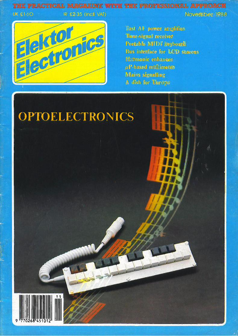
UK £1.60 IR £2.35 (incl. VAT) November 1988 Fast AF power amplifier Time -signal receiver Portable MIDI keyboard Bus interface for LCD screens Harmonic enhancer itP-based multimeter Mains signalling A dish for Europe
-
Upload
khangminh22 -
Category
Documents
-
view
0 -
download
0
Transcript of Fast AF power amplifier Portable MIDI keyboard Bus interface ...
UK £1.60 IR £2.35 (incl. VAT) November 1988
Fast AF power amplifierTime -signal receiverPortable MIDI keyboardBus interface for LCD screensHarmonic enhanceritP-based multimeterMains signallingA dish for Europe

EE
November 1988
BBC Micro Computer SystemARCHIMEDES305 basic £699310 basic £799 fal440 basic E2429 lalPlease ask for full details on add-ons andsoftwareBBC MASTER SERIES:AMB15 BBC MASTER 128K.. £356ADC06 Turbo 165C102) Card . E115ADF10 Econet Card £40ADJ22 Ref. Manual I £14ADJ23 Ref. Manual Pan II £14UPGRADE KITS:1.2 OS ROM E15DNFS ROM £19BASIC II ROM (BBC E22.50ADFS ROM E261770 DFS Kit E49Econet Kit (B&B+) £55
(al(dl(dl
(c)(C)
(dl
(dl(d)(d1(dl(d)
ACORN ADD-ON PRODUCTS:Torch ZEP 100 E229 la)512 2nd Processor E249 (b)IEEE Interface £265 (b)Teletext Adapter £95 (b)32016 Co Proc £949 la)X25 Gateway E2.175 (a)Ask for full details on our full range of software
WORD PROCESSOR ROMs:VIEW 2.1 £35 Id) VIEW 3.0 .. £48 Ic)SpetImaster (49 (d) VIEW INDEX £12 (d)WORDW1SE £24 (dl WORDW1SE E38 (d)
SPELLCHECK IIIWYSIW1G+ £21 Id) E31INTERWORD £46 (dl EDWORD II £4.3 (al
LANGUAGE ROMS:Micro Prolog E62 (c) Microtext ... £52 lc)ISO PASCAL £51 (c) LOGOTRON £55 (c)LOGO £46 (CI fAACROM E33 (dlLISP £39 (dl COMAL _ £43 Id)
Oxford Pascal £36 Ic)
COMMUNICATIONS ROMS:TERMULATOR £25 (d)MASTER TERMULATOR £34.75 (dlCO/AMSTAR (I E28 Id)MODEM MASTER Ell Id)COMMAND E34 Id)
UTILITY ROMs:DOTPRINT PLUS for FX/RX compatiblesDOTPRINT DUAL for MX rangeAcorn Graphics Extension Rom £28Merlin with 57 disc utility commands100 page manual E37.50 (c)
MULTIFORM Z80 2nd Processor for the BBCThis urioue Z80 3rd Processor nmang OS M will allow use of almost arty standard CP,M soft-ware on the BBC micro. It is supplied with a number of different CPM formats and includes autility to configure it to read other formats. This is particularly useful in environments where com-puters with different CP.M formats are used and the data cannot be easily exchanged betweenthem. Mains powered (includes Pocket Wordstar & MSDOS RN/ uuTttyl E249 lb)MS DOS ReadWrne £49 (c)
META Version 3 ASSEMBLERAssembles 17 of the popular processors. Over 70K long program on two toms and a disc aridprovides complete Editing and Assembly fealties. It uses appropriate mnemonics for differentprocessors. Fully nestable macros. nestable conditional assembly IIFILSEENDIF). modularsource code, true local arid global labels. 32 bit labels and arithmetic. 30 ways to send objectcode and 50 directives.A powerful editor with many features. Send for detailed leaflet. £145 (b)
BBC DISC DRIVES5.25" Single Drive:1 x 400K 40,807 DS: TS400 E90 (o) PS400 with zmu £101 1015.25" Dual Drive:2 x 400K 40;801 DS: TD800 .... £170 lai PD800 with psu E190 Ia)2 x 400K 40:807 DS with psis arid bt:it in monitor stand PDBOOP E209 la)3.5" Drives:1 400K 80T DS TS35 1 £69 (b) PS35 1 with psu E851 x 400K 80T DS with psu TD35 2 E126 (b) P035 2 with psu £149 (b)
Combo drives (5.25" & 3.5"):PSU £175 Ia) PD853P with inteorat PSU E195 la)
3M FLOPPY DISCSIndustry standard floppy discs with a life time guarantee. Discs in packs of 10:
5% DISCS 3% DISCS40T SS DD £6.50 (dl 40T DS DD. £8.00 (dl 80T SS DD £13.50 (dl80T SS DDE12.00 (d) 80T DS DD.E11.00 Id) 80T DS DD £15.00 (dl
DISC ACCESSORIESSingle Disc Cable E6 Idl Dual Disc Cable E8.50 ICU10 Disc Library Case E1.80 Id 30 Disc Storage Box E6 (c)40 Disc Lockable Box E8.50 Id 100 Disc Lockable. Box £13 (c1Roppicierte Drivehead Cleaning Kit with 20 disposable cleaning kits 5'..i" E14.50 Iol: 31i" £16 (di
BT APPROVED MODEMSMIRACLE TECHNOLOGY WS Range
WS4000 V21123.Mayes Compatible, Intelligent. Auto Dial,Auto Answer) E129WS3000 V21/23 ProfessionalAs WS4000 and with BELL standards andbattery back up for memory £244 IblWS3000 V22 ProfessionalAs WS3000 V21i23 but with 1200 baud fullduplex £379 (a)
WS3000 V22 his ProfessionalAs V22 and 2400 baud full duplex E495 la)WS3000IBBC Data Lead E10 (diWS2000 V21N23Manual Modem £92 tb)WS 2000 Auto Dial Card E27 (d)WS 2000 Auto Answer E27 (dlWS 2000 SKI Kit £5 (d)WS 2000 User Port Lead £5 (di(Offer ilmited to current stocks)
SPECIAL OFFEREPROMs/RAMS
2764-25 £2.80 (d)27256 £6.00 (d)27512 £9.00 (dl6264LP-15 £6.00 (dl27128-25 (12.5 Vpp) £4.50 (d)27128-25 (21.0 Vppl £6.00 (dl
PROJECTS:Junior Computer Kit £86 (b)Housekeeper kit £58 (b)Elekterminal Kit 11980) £50 (b)ASCII Keyboard kit £75 (b)J C Books 1, 2, 3, & 4E6.90 (c) eaUniversal Terminal (65021 Kit £75 lb)Elekterminal Kit (1983)... £70 (b)
EPSONLX800FX800FX1000EX800EX1000GO 3500LQ500L0850 (80 col)
PRINTERS£179 (al TAXAN KP815 (BO con . . . E159 (al£309 (al KP915 1156 cell E275 fa?£419 (a) BROTHER HUD £349 la)(429 (a) STAR LC10 E175 tai£579 (al JUKI 6100 (Daisy Wheel) E295 (a)
laser) £1249 (a) INTEGREX (Colour) E529 (a)E285 (a) NAT PANASONIC KX P 1081 E149 (al£489 (al NAT PANASONIC KX P 3131. £245 (a)
(.01050 (136 colt E599 (al NAT PANASONIC KX P1082 . E172 falWe hold in stock a large variety of printer attaelnients, interfaces and consumabks.FUase write or phone for deter: s.
ACCESSORIESBUFFALO 32K Buffer for Epson printers £75 (d); FX80 plus sheet feeder E129EPSON Serial Interface: 8143 £30 (bl; 8148 with 2K buffer E65 (P).EPSON Paper Roil Holder £17 (b); FX80:80+:85 Tractor Attach £37 lb); RXFX60Dust Cover £4.50 (d): LX80 Tractor Unit £20 (c); L0800 Tractor Feed E47 ib).EPSON Ribbons: MX,FIX;FX80 £5; MX.RkFX100 EIO (d); LX80 £4.50JUKE Serial Interface £65 (dl: Tractor Attach. £149 (a); Sheet Feeder £219 fat:Ribbon £2.50 (a): Spare Daisy Wheel £14 (d).BROTHER HR20: Sheer Feed £229; Ribbons - Carbon or Nylon £3; Tractor FeedE116 (a): 2000 Sheets Fanfold with extra fine perf. 9.5" - £13.50: 15" E17.50 (b).BBC Parallel Lead £6; Serial Lead E6 (dl: IBM Parall& Lead 12m) E12
MONITORSMICROVITEC 14" RGB1431 Standard Resolution E179 la)1451 Medium Resolution E2251441 Hi Res E359MICROVTIEC 14" RGB/PAL & Aucio1431 AP Standard Resolution £199 (a)1451 AP Medium Resolution E255 (alMICROVITEC 20" RGBIPAL/Audio2030 CS std Res E380 (a)2040 CS Hi Res £675 (alKrtsubishi 14" RGB Med Res 188C1BM)
E219 (al
TAXAN Supervision 620 E269 (alTAXAN Supervision 625 E319TAXAN Supervision 770+
(with swnei stand) £485
12" MONOCHROME MONITORS:PHILIPS:
7502 Green Screen E 72 la)7522 Amber Screen E 79 (a)4752 £ 85 (a)
Fhlips Monitors supplied withswivel stand
BOOKSNo VAT
LANGUAGES:6502 Assy Lang Prog8086 BookAcorn BCPL User GuideAcorn FORTHAcorn LISPAcorn ISO Pascal Ref ManualIntro to COMM_Intro to LOGOkficro Prolog Ref ManualIntroduction to Turbo Pascal..Prog the Micro with Pascal .
The UNIX BookUnix User GuideUnderstanding Unix
£19.95£23.95£15.00
E7.50(7.50
£10.00(10.00
E7.50£10.00£14.95
(8.50£7.50
£18.45BBC MICRO GUIDE BOOKSBBC User Guide Acorn £15.00BBC Plus User Guide £15.00Drawing your Own BBC Prograrns£6.95inside Information £8.95Math Prog in BBC BasicToolbox 2 E10.95VIA 6522 Book 4 50
PROGRAMMING/UTMTYAdvanced Sideways Ram UserGuide £9.95Advanced User Guide (BBC) .. £12.50Applied Ass./Lang on the BBC E9.955BC Micro Sideways ROM's RAM s£9.95Guide to the BBC ROM . E9.95Beginners Gtncle to IN.P £7.95
on books; Carriage (c)i.fieei 3.0 User GuideViewstoreViewsheetWordwise Plus
SOUND & GRAPHICS:Mastering Music
DISC DRIVE SYSTEMS:Advanced Disc User Guide .... £14.95Disc Book £3.50Disc Programming Techniques E7.95Disc Systems E6.95Fie Handing on the BBC £6.95
APPLICATIONS:Interfacing Proj for BBC £6.95BBC and Small Business E5.75
PROFESSIONAL SOFTWAREWordstar made easy £16.95Introduction to Wordstar E17.95Wordstar Handbook £11.95dBase-1 for the first time user E16.95Understanding dBase-III £22.95Multiplan Made Easy E18.95Multimate Complete Guide £16.95ABC of LOTUS 123 £17.451-2-3 for Business....£16.95Adv Tech in dBase ILIn £22.95Mastering CP,M £17.95CPt Bible £16.50Introducing CP.M on BBC & 280 E9.95MS -PC DOS Prompt E10.95
£9.00£9.00E9.00£9.95
E6.95
PROGRAMMED ROMS FOR ELEKTORPROJECTS
503-N Jnr. Computer Monitor 516 Talking Dice 2716 E 7.302708 £ 4.80 521 CharGen & Video Routine for
504 Disco lights 2708 E 4.80 DOS Junior _ _ 2732 2716 £16.40505 Chess Intelekt . 2x 2716 E14.60 522 CharGen & video: Routine for ex506 J C Tape Monitor 2716E 7.30 tended junior 2732 + 2 x 2716507-N J C Printer Mon & PME £24.00
2716 £ 7.30 523 Char. Generator .. 2732 E 9.00508 J C Bus Control 82523 . E 4.80510 150 MHz Freq Meter 2.82523
E 9.60514 Dark Room Computer 2716 E 7.30
524 Ouantisizer 2732 E 9.00525 Universal Term 2732 E 9.00526 Wind Dir Ind 2716E 7.30527 Elabyrinth 2716E 7.305..V:IDarsyttthetel (face 2 x 2716 E11.00
ALL PRICESEXCLUDE VA T.Please add carriage 50p unless
indicated as follows-
ta1f8 Ity)f2.50 (0E1.501 (d1f1.00
TECHNOLINEVIEWDATA SYSTEM
Tel 01-450 9764Using 'Nester type protocols.
For information and ordersavaliale 24 hours. 7 days
a week
SEE OUR PAGE 5 ADVERTISEMENT FOR COMPONENT PRICES
TECHNOMATIC LTDMAIL ORDERS TO: 17 BURNLEY ROAD, LONDON NW10 1ED
SHOPS AT: 17 BURNLEY ROAD, LONDON NW10(Tel: 01 208 1177, Telex 922800)
305 EDGWARE ROAD, LONDON W2, Tel: 01 723 0233
PLEASE ADD CARRIAGE AS PER CODE & 15% VAT
{Export: no VAT, p&p at Cost)Orders from Government Depts. 8 Colleges etc welcome
Minimum telephone order (5Cie:ailed Price list on request.
Prices subject to change without notice LAM'
Please mention ELEKTOR ELECTRONICS when contacting advertisers
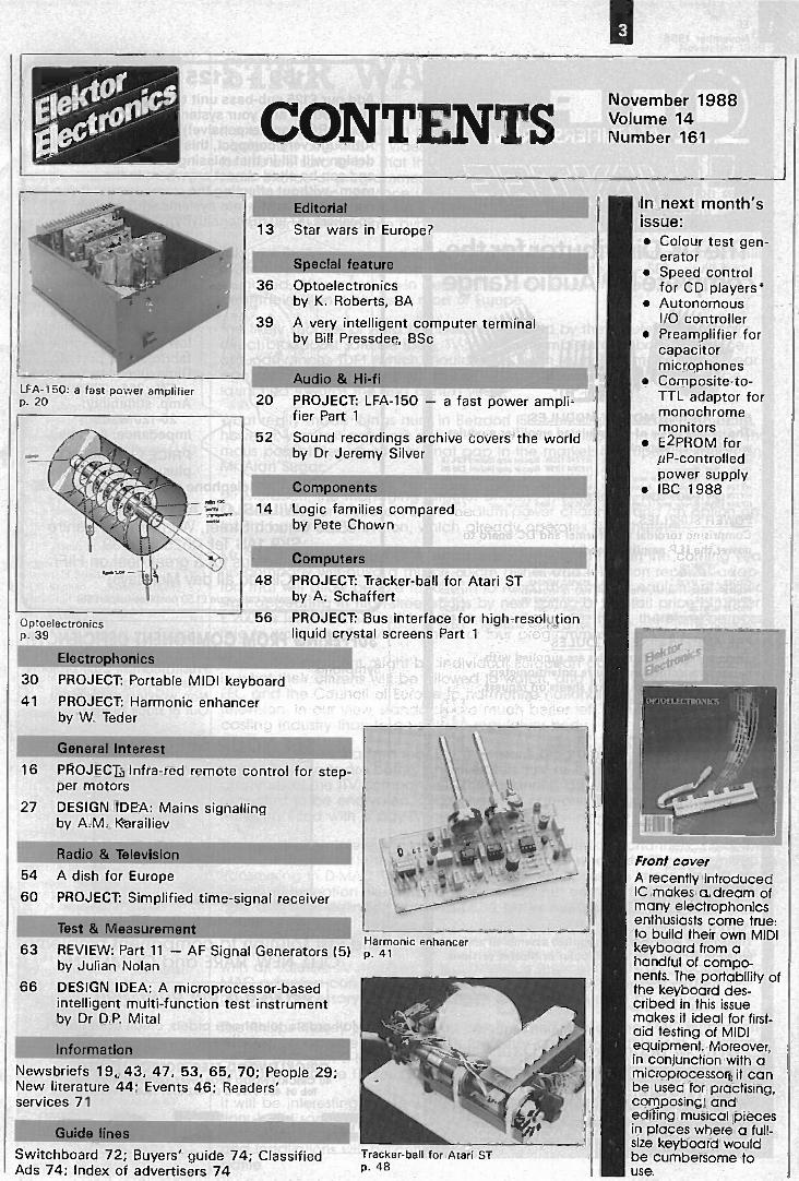
CONTENTSNovember 1988Volume 14Number 161
LFA-150: a fast power amplifierp. 20
Optoelectronicsp. 39
Electrophonics
Editorial
13 Star wars in Europe?
Special feature36 Optoelectronics
by K. Roberts, BA39 A very intelligent computer terminal
by Bill Pressdee, BSc
Audio & Hi-fi20 PROJECT: LFA-150 - a fast power ampli-
fier Part 1
52 Sound recordings archive covers the worldby Dr Jeremy Silver
Components 1111111.1".14 Logic families compared
by Pete Chown
Computers.19
48 PROJECT: Tracker -ball for Atari STby A. Schaffert
56 PROJECT: Bus interface for high -resolutionliquid crystal screens Part 1
1111111IL30 PROJECT: Portable MIDI keyboard41 PROJECT: Harmonic enhancer
by Teder
General Interest16 PROJECT: Infra -red remote control for step-
per motors
27 DESIGN IDEA: Mains signallingby A.M. Karailiev
Radio & Television54 A dish for Europe60 PROJECT: Simplified time -signal receiver
Test & Measurement63 REVIEW: Part 11 - AF Signal Generators (5)
by Julian Nolan
66 DESIGN IDEA: A microprocessor -basedintelligent multi -function test instrumentby Dr D.P. Mital
Information
Newsbriefs 19, 43, 47, 53, 65, 70; People 29;New literature 44; Events 46; Readers'services 71
Guide lines
Switchboard 72; Buyers' guide 74; ClassifiedAds 74; Index of advertisers 74
L vVasV4P6 _\
s.
Harmonic enhancerp. 41
Tracker -ball for Atari STp. 48
In next month'sissue: Colour test gen-
erator Speed control
for CD players' Autonomous
I 0 controller Preamplifier for
capacitormicrophones
Composite-to-TTL adaptor formonochromemonitors
E2PROM foruP-controlledpower supply
IBC 1988
1
Front coverA recently introducedIC makes a dream ofmany electrophonicsenthusiasts come true:to build their own MIDIkeyboard from ahandful of compo-nents. The portability ofthe keyboard des-cribed in this issuemakes it ideal for first -
aid testing of MIDIequipment. Moreover,in conjunction with amicroprocessor, it canbe used for practising,composing, andediting musical piecesin places where a full-size keyboard wouldbe cumbersome touse.
EE
November 1988
®M FIFILERS FROM
The UK Distributor for thecomplete ILP Audio Range
BIPOLAR AND MOSFET MODULESThe unique range of encapsulated amplifier moduleswith integral heatsink.-- 20 15W E _ _ _ £11.30-=£0 374 e: £1130£11.30-sE060 31719 _ am £23.65 ,'124 60N amp (4orun) £18.50-71128 B amp (Bohm) £18.50vi -s244 12(72 8 pstar amp 14orun1 £24.15
POWER SUPPLIES
HY248 1212A Bcolar amp iflorun) E24.15NV3E418019 Bipolar amp (itohm) £36.00f4Y368 18001 Bipolar amp (Bohm) E3755MOS128 SEM Mosfet amp £40.707408248 12059 Model amp £46.35M0S364 160N Mode amp £75.75
Comprising toroidal transformer and DC board topower the I LP amplifier modules.
Appl zar,o-PSu30 Pre -3,701,f, 9.75
5,.532 MOS12812,PSU 542 HY248
£25.40£25.40
P514212 1 or 2 HY30 £17.70 PSU552 1405248 £27.45PSU412 HY6060,HY124.14- 2 rrs 60 £19_95 PSU712 HY244 (21 E29.20PS0422 HY 128 £22.00 P51.1722 HY248 (2) £30.20PSU4 32 M0S128 £23.00 PSU732 HY364 E30.20PSU512 HY244.HY128121 E24.40 PSU742 HY368 £32.20P554522 HY174 171 £24.40 PS11752 MOS354' . M05248 121 £32.20
PRE -AMP and MIXER MODULESThese encapsulated modules are supplied within -line connectors but require potentiometers,switches etc. Individual data sheets on request.
Mono c4e, amp Atil oars _
Mono mixer 8 channelStereo moxer 5 channelStereo pre -amp
£ 9 258.75
E 8.75£ 9.30
- 11 Mono minor 5 dsannel with bass & treble E 9.75- 12 Mono pre -amp 4 channel with bass. mid & treble £ 9.30
- 13 Mono VU meter driver E 8.75- Ed Stereo pre -amp with bass & Petite £15.00
57 Stereo headphone driver £16.60- 58 Stereo mixer 10 thannei £11.30
59 Mono pre -amp 2 channel with bass & treble E15.40- 71 Dual pre -amp E14.95- 73 Guitar preamp with bass & ueble £15.00
- 74 Stereo mixer 5 dsannel with bass & treble £15.95-.25 Stereo pre -amp with bass, mid & treble E15.40-. 76 Stereo switch matrix £19.50- 77 Stereo VU meter driver E14.35
78 Stereo pre -amp E14.700, r,, pre -amp with special effects £18.95
_ rig board E 1.15tai-;bcr'd £ 1.75
LOUDSPEAKERS1728 12 - Bats Water £78.65312W8 200.9 12- Wideband bass lotedsp-,, - - £78.65
POWER SLAVESThese cased amplifiers are supplied assembled andtested in 60 and 120 watt Bipolar or Mosfet versions.
i.72 60 watt SP, 1:- ,M) £75.00 US32 IX) watt Mosfet £9355_722 120 watt Bite cbrrs) £83.75 US42 120 watt &toilet £10835
irclude VAT and carriage
Quantity prices available on requestWrite or phone for free Data Pack
NSA
Jaytee Electronic Services143 Reculver Road, Beltinge, Herne Bay, Kent CT6 6PL
Telephone: (0227)375254 Fax: 0227 365104
£150 + £125 = E1000?Add our £125 sub -bass unit to your £150 -per -pair"Best Buys" and your system will sound as if ithas LARGE (and expensive!) speakers.Although very compact. this ingenious Push -Pulldesign will fill-in that missing "Bottom Octave"and can be sited almost anywhere in theroom -without affecting the stereo image. It can beconnected directly into systems with medium sizedspeakers (87-90 dB sensitivity).
The Wilmslow AudioCPP sub -bass speakerkit contains 2 10" driveunits. flatpack cabinetkit (inc. stand)machined from smooth
I MDF for easy assembly,_$,S_&. low pass filters. grille
fabric, reflex port etc.Dims. (inc stand):
571x366x336mmAmp. suitability:
20-120 wattsImpedance: 8 ohmsPRICE £125 inc. VATplus carr/ins £11
telephone credit card orders =
WILMSLOW AUDIO LTD.35/39 Church Street. Wilmslow, Cheshire
SK9 lAS Tel: 0625 529599Call and see us for a great deal on HiFi
(Closed all day Mondays)DIY Speaker catalogue £1.50 post free (export S6) 1
SUFFERING FROM COMPONENT DEFICIENCY?
Symptoms: Frustrated half built projectsSleepless nightsNon working equipmentOut of stock blues
SEE YOUR SPECIALIST!
The components stock centre
The fast solution to component problemsOLD, NEW, RARE and COMMON
Service is our obsession
Mail orders, telephone orders, credit card orders.callers welcome.
CRICKLEWOOD ELECTRONICS LIMITED40 CRICKLEWOOD BROADWAY, LONDON NW2 3ET
Tel: 01 450 0995 & 01 452 0161 Telex: 914977
VISA. °47ea Er3 SZ 70
Please mention ELEKTOR ELECTRONICS when contacting advertisers

,:biters K"uv.er Compan;Managing Editor: Len SeymourPersonal Assistant: L. VousdenTechnical Editor: J BuitingAdvertisement executive:Pauline O'Rourke
Editorial offices:1 Harlequin AvenueBRENTFORD TW8 9EWEnglandTelephone: 01-847 2618 (National)or +44 1847 2618 (International)Advertising: 01-847 2619Telex: 917490 Ielektr g)Fax: 01-847 2610
European offices:Postbus 756190 AB BEEK (L)The NetherlandsTelephone: +31 4490 89444Telex: 56617 felekt nilFax: + 31 4490 70161
Overseas editions:Publitron Publicacoes Tecnicas LtdaAv Ipiranga 1100, 9' andarCEP 01040 Sao Paulo - BrazilEditor: Juliano BarsaliElektor sariRoute Nationale; Le Seau; B.P. 5359270 Bailleul - FranceEditors: D R S Meyer;G C P Raedersdorf
Elektor Verlag GmbHSUsterfeld-StraRe 255100 Aachen - West GermanyEditor: E J A KrempelsauerElektor EPEKaraiskaki 1416673 ;joule - Athens - GreeceEditor: E Xanthoulis
Elektor Electronics PVT Ltd.Chhotani Building52 C, Proctor Road, Grant Road lE1Bombay 400 007 - IndiaEditor: Surendra lyer
Elektuur By.Peter Treckpoelstraat 2-46191 VK Beek - the NetherlandsEditor: P E L Kersemakers
Ferreira & Bento Lda.R.D. Este -far -lie, 32-1°1000 Lisboa - PortuaalEditor: Jorge GoncalvesIngelek S.A.Plaza Republica Ecuador2-28016 Madrid - SpainEditor: A M Ferrer
Electronic Press ABBox 63182 11 Danderyd - SwedenEditor: Bill Cedrum
International co-ordinating& technical manager:K S M Wa'ravenInternational editorial secretariat:G W P v Linden; M Pardo
Distribution:SEYMOUR334 Brixton RoadLONDON SW9 7AG.
Typeset & composed in theNetherlands by GBS, Beek (LI.Printed in the Netherlands byNDB, Zoeterwoude.
Copyright 1988 Elektuur
ABC1.1aIKR3310E111 QT
ember 19:E8
STAR WARS IN EUROPE?It is alleged that the British public is as keen to invest in satellite televisionequipment as it was in video recorders a decade or more ago. The reasonsfor this are said to be that the public wants more TV channels and, above all,more choice of programmes. Whether this keenness is real or just a ruse ofmanufacturers to convince us all (and themselves) that it exists will be seenearly next year when more programmes and inexpensive equipment to re-ceive them will become available.
This month, Arianespace willing and able, Astra, the communications satelliteowned by Luxembourg's Societe Europeenne des Satellites-SES - will belaunched. After a settling -in period, this satellite will, from early February,beam television pictures to most of Europe.
The likely success of Astra has been enhanced by the failure of Germany'sdirect broadcast satellite (DBS), TV-SAT1, the complete and baffling silencearound France's TDF1 (which should have been launched more than a yearago), and the lateness of Britain's high -power BSB satellite (now due to belaunched towards the end of next year).
What really made things hum in Betzdorf (SES's headquarters in Luxemburg),however, was last summer's action by two men of vision who realized the enor-mous possibilities on offer by that gap in the market: Mr Rupert Murdoch andMr Alan Sugar.
Mr Murdoch, the managing director of News International, has taken a10 -year lease on three of Astra's medium -power channels, and an option on afourth, for his Sky Television, which already operates Sky Channel.
Mr Sugar, the chairman of Amstrad, has announced that in the coming yearhis company will build a million 60 -cm dishes and television receiver adap-tors that will allow people to tune in to Astra. The Amstrad equipment shouldstart appearing in high -street shops by next spring at a retail price of under£ 200. Its installation should cost not more than £ 50. It will, therefore, be poss-ible to watch Sky Television's three or four programmes for under £ 250.
Flies in the ointment might be individual European governments' interferencein what their citizens will be allowed to watch, and the endeavours by theEEC and the Council of Europe to harmonize national regulations governingtelevision. In our view, standards are much better left to the television broad-casting industry than to an outside regulatory body.
It should be emphasized that Sky Television's programmes will be free to re-ceive. Their costs are borne by advertisers, just as those of the terrestrial pro-grammes of the ITV companies. Other channels beamed down by Astra areexpected to be encrypted. Such channels can only be watched on televisionreceivers fitted with a pay -TV decoder.
Technically, the interesting point about the Sky Television channels is that theywill be transmitted in the now ageing PAL format, whereas BSB is committed totransmitting in D -MAC. The MAC format will make possible improvements totelevision reception like stereo sound, additional commentary and data chan-nels, and high -definition (larger picture, better resolution).
It is as well to forget the myth, engendered by some marketing people, that toreceive MAC format transmissions a new type of television set is needed. Aswith all satellite TV reception, an adaptor is required, that's all. Production ofMAC adaptors can commence soon, since Philips and Plessey expect tohave the necessary decoding chip in volume production by January.
The Philips -Plessey decoding chip can be used with all the MAC formats en-visaged so far, whereas that of ITT, the other company in this field, is designedfor use only with D -MAC and D2 -MAC. It remains a mystery that BSB has com-mitted itself to the ITT set.
It will be interesting to see which way the British public wil go: the conven-tional and somewhat dated way with Sky Television, or the progressive, new -technology way of BSB. Both will be possible with existing sets. Adaptors, dishesand installations will be comparable in cost. It will, no doubt, be a revealingbattle.
14 EE
November 1.98E
LOGIC FAMILIES COMPAREDby Pete Chown
A brief look at the most important characteristics of recentlyintroduced logic families, and the way in which they can be
interfaced to one another.
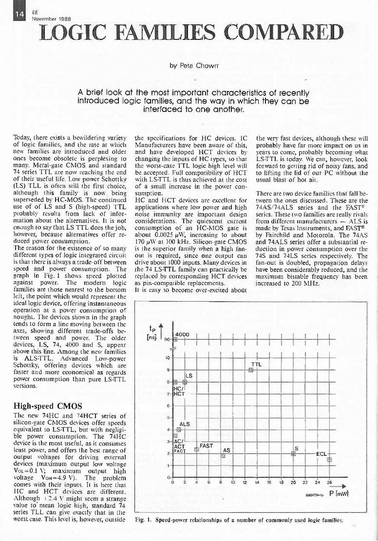
Today, there exists a bewildering varietyof logic families, and the rate at whichnew families are introduced and olderones become obsolete is perplexing tomany. Metal -gate CMOS and standard74 series TTL are now reaching the endof their useful life. Low power Schottky(LS) TLL is often still the first choice,although this family is now beingsuperseded by HC-MOS. The continueduse of of LS and S (high-speed) TTLprobably results from lack of infor-mation about the alternatives. It is notenough to say that LS TTL does the job,however, because alternatives offer re-duced power consumption.The reason for the existence of so manydifferent types of logic integrated circuitis that there is always a trade-off betweenspeed and power consumption. Thegraph in Fig. 1 shows speed plottedagainst power. The modern logicfamilies are those nearest to the bottomleft, the point which would represent theideal logic device, offering instantaneousoperation at a power consumption ofnought. The devices shown in the graphtends to form a line moving between theaxes, showing different trade-offs be-tween speed and power. The olderdevices, LS, 74, 4000 and S, appearabove this line. Among the new familiesis ALSTTL, Advanced Low -powerSchottky, offering devices which arefaster and more economical as regardspower consumption than pure LS TTLversions.
High-speed CMOSThe new 74HC and 74HCT series ofsilicon -gate CMOS devices offer speedsequivalent to LS-TTL, but with negligi-ble power consumption. The 74HCdevice is the most useful, as it consumesleast power, and offers the best range ofoutput voltages for driving externaldevices (maximum output low voltageVoL=0.1 V; maximum output highvoltage Von = 4.9 V). The problemcomes with their inputs. It is here thatHC and HCT devices are different.Although +2.4 V might seem a strangevalue to- mean logic high, standard 74series TLL can give exactly that in theworst case. This level is, however, outside
the specifications for HC devices. ICManufacturers have been aware of this,and have developed HCT devices bychanging the inputs of HC types, so thatthe worst -case TTL logic high level willbe accepted. Full compatibility of HCTwith LS-TTL is thus achieved at the costof a small increase in the power con-sumption.HC and HCT devices are excellent forapplications where low power and highnoise immunity are important designconsiderations. The quiescent currentconsumption of an HC-MOS gate isabout 0.0025 1.4W, increasing to about170 ONT at 100 kHz. Silicon -gate CMOSis the superior family when a high fan -out is required, since one output candrive about 1000 inputs. Many devices inthe 74 LSTTL family can practically bereplaced by corresponding HCT devicesas pin -compatible replacements.It is easy to become over -excited about
the very fast devices, although these willprobably have far more impact on us inyears to come, probably becoming whatLS TTL is today. We can, however, lookforward to getting rid of noisy fans, andto lifting the lid of our PC without theusual blast of hot air.
There are two device families that fall be-tween the ones discussed. These are the74AS/74ALS series and the FASTSseries. These two families are really rivalsfrom different manufacturers - ALS ismade by Texas Instruments, and FAST! -by Fairchild and Motorola. The 74ASand 74ALS series offer a substantial re-duction in power consumption over the74S and 74LS series respectively. Thefan -out is doubled, propagation delayshave been considerably reduced, and themaximum bistable frequency has beenincreased to 200 MHz.
tp[n s] 93
13
9
8
7
6
5
4
3
2
0
4UUUI
-,--I II
TTL03
LS'M
HC/-HCT
ALSM
',...
- AC/ACTFACT
,FASTAS S
ECL
I
10 2 4 6 8 10 12 11 16 18 20 22 2.1 26_pp
E8+3175-10 P fmwl
Fig. 1. Speed -power relationships of a number of commonly used logic families.

EE 1111November 1988
Interfacing logic familiesOne of the reasons that designers havebeen reluctant to use the new logicfamilies is that they are worried about in-terfacing these devices to existing cir-cuits. The rules for interfacing are quitesimple. Many devices are designed to becompatible without any external device.Most others simply need a resistor. Theoverview in Table 1 gives information oninterfacing a number of logic families.The actual value of the pull-up resistor(when required) is chosen to lie roughlybetween the low value and the highvalue, which are calculated as follows:
Its Vcc-Voumax)- igiIoL±n1a.
whereVcc = supply voltage;Iowan) = maximum output low voltage;lots = maximum sink current of drivingdevice;n = number of device inputs beingdriven;In = input current to driven devicewhen input is low.
Vcc-VIII(min) [Q]Rhigh
a 11H - 1.0H
whereVaionin, = minimum input high voltage;In! = input high current;IoH = output high current.
It will be found that NMOS does notnormally need a resistor because thiswould have a very high value. Not sur-prisingly, therefore, circuits work wellwithout one. Table 2 lists some com-monly used logic families and theirparameters, allowing resistance values tobe worked out. The resistor should ob-viously be inserted pulling up to Vcc. Tochoose the correct values to use in theabove formulae, take the outputparameters for the driving gate, and theinput parameters for the driven gate.
ConclusionIf you think the logic market is complexnow, it will be even more so in a fewyears' time, because gallium -arsenide(Ga-As) devices promise operatingspeeds of around 4 GHz. These newdevices will be around in parallel withFACT (Fairchild Advanced CMOSLogic) and existing TTL for a good time,because they will initially be so expens-ive. The ACT family, like HCT, is fullyLS-TTL compatible, while AC givesbasically the same drive problems asHC. Both new series are typically 2 to 3times faster than LS TTL or HCMOS. Itshould be noted that AC and ACT
Table 1. Interfacing guidelinesVcc (Vdd) of driving and driven device is assumed equal.
Any two bipolar families:HC to any bipolar;Bipolar to HC:HCT to bipolar:Bipolar to HCT:HCT to NMOS:NMOS to HCT:
should be compatibleshould be compatiblepull-up required'should be compatibleshould be compatibleshould be compatiblenormally compatible,but should be checked.
'Calculate value of pull-up resistor from formulae in text.
Table 2.
Parameter 74 74HC 74LS 74AS 74ALS Unit
VIH(min) 2.0 3.5 2.0 2.0 2.0 VVIL(max) 0.8 1.0 0.8 0.8 0.8 VVommin) 2.4 4.9 2.7 2.7 2.7 VVOL(max) 0.4 0.1 0.4 0.4 0.4 VIimmax) 40 1 20 200 20 µAIn(max) -1.6 -0.001 -0.4 -2 -0.1 mAIommax) -0.4 -4 -0.4 -2 -0.4 mAIOL(mat) 16 4 8 20 4 mA
devices have a different supply pinningthan LS-TTL, while the number of logicfunctions currently available is limited tocertain bus drivers, and encoders/
decoders. The range of AC/ACT devicesis expected to entend considerably, how-ever, in the next year or so.
Good documentation is essential for anyone designing, analyzing and testing circuits basedon devices from the new logic families.

16 EE
INFRA-RED REMOTE CONTROLFOR STEPPER MOTORS
Many audio purists balk at the use of an electronic volume con-trol, but would still like to upgrade a home-made preamplifier with
remote control. This can be accomplished by using a good -quality potentiometer, a stepper motor, and the simple, yetversatile, infra -red transmitter and receiver described here.
One particularly interesting applicationof the proposed infra -red remote controlsystem is the actuating of the volume po-tentiometer in a high -quality audio pre-amplifier, such as the one described lastmonth. Basically, the potentiometer isoperated by a small stepper motor,whose direction of travel is controlled bymeans of pulses emitted by a hand-heldinfra -red transmitter.
Infra -red transmitterThe circuit diagram of this part of theremote control system is shown in Fig. 1.Simple data encoding is used to keep thecost of the circuit as low as possible. Thedirection of travel of the stepper motorfitted at the receiver side is determinedby the width of the pulses supplied bytwo monostable multivibrators, MMVI(70 ps) and MMV2 (470 ps). The pulsefrequency, and hence the motor speed, isset with Pt in oscillator N3 -N4. ButtonsSi and S2 form the volume up/downcontrols because they determine whetherMMV, or MMV2 drives the output tran-sistor, Ti. The pulsating infra -red lightbeam is emitted by series -connectedIREDs Di -D2 -D3.
Receiver and motor driverPhotodiode D4 in Fig. 2 was selectedfor optimum sensitivity in the part of theinfra -red spectrum covered by the senderdiodes (see also Ref. 1.) The photo -current generated by the incident infra-red light is magnified and converted to avoltage by opamp A2, which drivesdetector Ai via high-pass C3 -R13. Thisfilter serves to eliminate interference
Features:
Infra -red remote control link with a range ofup to 8 metres.
Forwardireverse control of stepper motors. Adjustable motor speed. Drives a variety of 2 -stator, unipolar. motors. Maximum drive capability: 4 A per phase. Supply voltages:
receiver logic: 9.5-18 VDC;stepper motor: max. 18 VDC;transmitter: 9 V PP3 battery.
Simple, low-cost design.
-r9V
.134 14II+,
ssy
IC1 IC2
0
NEIlem
RC CX
WAY t
13
CA
t2
Cl
310c
RC CIT
MMV2
a
7
0-9
3xLD 271
BC557 B
Fig. 1. Circuit diagram of the hand-held infra -red transmitter.
caused by sunlight and hum superimpos-ed on light by electric bulbs. The detec-tion threshold of comparator At is keptlow at about 10 mV (Rio -R12) to ensureadequate sensitivity. Feedback resistorRim provides the necessary hysteresis toprevent jitter and spurious step pulsesbeing generated when Al toggles.Each received pulse triggers both MMV3and MMV4, and is compared to refer-ence pulses of 220 ps supplied byMMV.I. Received pulses are applieddirect to the clock input of steppermotor driver ICs, whose DIR (direction)input is controlled by the output ofMMV4. This makes the direction oftravel of the stepper motor dependent onthe length of the received pulses, relativeto that of the reference pulses.
Although the stepper motor driver TypeSAAI027 (SGS/Philips Components) iscapable of supplying stator currents ofup to 500 mA, power drivers (T34-6) areadded to prevent excessive dissipation,and to allow the use of motors that re-quire more current. The flyback diodesin the power stage should be fast -recovery types (1N493x series, orBYV27). The use of the ubiquitous1N4001 is not recommended unless thetotal stator current is known to remainwell under 1 A. Power resistors R16 andR.- may be used to achieve a rudimen-tary kind of current drive of the statorwindings in the motor - more on thisunder 'The power supply'.Provision has been made for manual op-eration, at the receiver, of the volumecontrol. This is achieved by T2 -R14 auto-matically interrupting the base currentfor the driver stage in the SAA1027 whenno pulses have been received for about0.1 s. Series transistor T2 then interruptsthe hold torque for the motor, so thatthe potentiometer spindle can be oper-ated manually. This type of controlguarantees low overall dissipationbecause there is no quiescent hold cur-rent. Certain motors do require a con-tinuous hold current, however. Thesecan still used with the present circuitsimply by omitting T2 and fitting a wirelink between the connections providedfor its collector and emitter terminals.
EE 111November 1988
JP1
BP104
0880161-10
*see text
R11
512
RC CS
WAYS
-2 a 07
BC 557B
14 I13
R19
3
MMV 4
a 5 °9
N 1...N 4 = IC 2 = 4001HMV 3, HMV 4 = IC 3 = 4538A 1, A 2= IC 4= TLC 272, CA 3240IC5 = SAA 1027
01
IC 5
3 CAR 03
2 Oa10.1 14,2
5
fn
I°7
R2 RW3
LW
R17SW
A
ME 18V
0
11
C111=1MEI
.00,292
05...06= 1/14913... 1N 3937. BYY 27
T 3...T 6 = 130 438
C0M20
BO
C0COM1
Fig. 2. Circuit diagram of the infra -red receiver, pulse decoder and stepper motor driNer.
The power supplyThe IR transmitter is powered by a 9 VPP3 battery. An on/off switch is not re-quired because the quiescent currentconsumption of the circuit is negligibleat a few nano -amperes. This rises to afew milli -amperes when either of the twobuttons is pressed. The actual currentconsumption then depends on the set-ting of Pi.The type of supply required for the re-ceiver depends mainly on the environ-ment in which this circuit is used. Thelogic circuitry can operate from a supply
voltage between 9.5 V and 18 V. It willbe clear that the supply for the motor islaid out in accordance with the typeused. A 12 V motor is ideal because itallows powering the driver stage and thelogic circuitry from a common supply,connected to terminals UM and ground(fit jumper JP1). The logic supply isdecoupled with the aid of 12,5-C6. Fitwire links in positions R16 and R17 whenthe motor used requires voltage drive.Many stepper motors are 5 V types.Where a relatively powerful type is used,it is recommended to dimension themotor supply for 5 V (connect to Um
Fig. 3. Printed circuit board for the trans-mitter. Together with a PP3 battery, it fitsexactly in a Type 222 enclosure from Heddic.Motorized volume control built into the high -quality preamplifier described last month.
18 EENovember 1988
Fig. 4. Printed for the receiver.
Fig. 5. Two suggestions for coupling the stepper motor spindle to that of the potentiometer.
Parts list
Resistors (±5%):RI =22RAz:Rs:Re:RI = I MOR3;R4;Fita=100KRe=47KRe:117=22KRto=560KRte= -390RR14 =120RRte= 100R1116;11.17= 4'N resistor; value depends on
stepper motor used.Ris=22KR19 . . .R22 incl. =4K7Pt =100K preset H
Capacitors:Ct =330nC2=10y; 16 VC3;C5;C7= 10f1C4= 3n3C6= 10;4; 25 VCs;Cio= 100nCe=4p7Cit=100,,c 25 V
Semiconductors:1302;D3=11/271.D4=BP104.Ds...D8 incl.=1N4933/4+/5/6/7 or BYV27'Ta:T2=SC557BT3 . . .T6 incl.=BD438ICOC3=45381C2=4001IC4-=TLC272 or CA3240ICs=SAA1027
Miscellaneous:St;S2= Digitast switch (ITV,/ or ITTISchadow).3 off plastic reflectors' for 01-03.PCB Type 880161 (not available ready-madethrough the Readers Services).
*Listed by ElectroValue Limited 28 St JudesRoad Englefield Green Egham SurreyTW20 OHB. Telephone: (0784) 33603. Telex:264475. Fax: (0784) 35216. Northern branch:680 Burnage Lane Manchester M19 1NA.Telephone: (061 432) 4945.
-Listed by Universal Semiconductor DevicesLtd.
and ground). Fit wire links for Rio andRr, but do not fit JP! - connect the12 V supply to terminals + and 0 (closeto D4 on the PCB). Where a relativelysmall stepper motor is used, R16 and RI -are dimensioned to reduce Usi from12 V to the voltage required. This is con-venient because it allows the completereceiver plus motor driver to be poweredfrom a single supply. Small, 200 -step,5 V motors used in disk drives are some-times offered by surplus stores. Thesemotors give excellent results withRi6=121-=39 Q; 4 W (stator current =200 mA).It shoud be noted that the circuit canonly drive unipolar motors. These nor-mally have 6 connecting wires, but thereare also 5 -wire types in which the centretaps of the two stator windings (CON,11;COM2) have been connected internally.
EE
November 198819
Constructional hintsConstruction of the transmitter and re-ceiver on the printed circuit boardsshown in Figs. 3 and 4 should not causeproblems. The transmitter is fitted in ahand-held ABS enclusure with integralbattery compartment. The 3 IREDs arefitted with ready-made reflectors to in-crease the range of the transmitter.To prevent it seeing light from bulbs orfluorescent tubes fitted to the ceiling, thephotodiode in the receiver should bemounted in a short tube whose inside ispainted matt black. If the diode is fittedon to the front panel of the audio equip-ment, it should be connected to the re-ceiver board by means of shielded wire.In some cases, it may be necessary todecrease the sensitivity of the receiver toprevent it being triggered by ambientlight. This can be achieved by increasingthe value of R12 to, say, 560 Q.The use of a stepper motor that drawsmore than about 1 A necessitates cool-ing of the power transistors in the re-ceiver by clamping them together withthe aid of 3 small, 2.5 mm thick, piecesof aluminium and a central M3 bolt.Figures 5a and 5b provide suggestionsfor coupling the stepper motor spindleto that of the potentiometer. Cog -wheelsystems should not be used because theyare damaged quite easily by the vibrationof the stepper motor. A rubber or nylonbelt as used in cassette recorders, or astrengthened 0 -ring, is perfect because itallows manual control of the poten-tiometer as discussed earlier.
Fig. 6. Modifications to transmitter and receiver to enable manual volume control when thestepper motor and potentiometer spindles are coupled as shown in Fig. 5b.
The stepper motor and the volume po-tentiometer may also be secured on to acommon U-shaped piece of aluminiumas shown in Fig. 5b. In this arrange-ment, the spindles are coupled direct.Manual control is still possible, however,when the transmitter is duplicated andfitted close to the receiver. The modifica-tions to the transmitter and the receiverto achieve local control are shown inFigs. 6a and 6b. In the transmitter, the(shaded) IREDs are replaced with a wirelink, Ri is replaced with a 10 kQ type,and the points marked A in the trans-mitter and receiver are interconnected.
Diode D9 is inserted between the com-parator output and the trigger inputs ofthe monostables. Together with the Tiin the transmitter, it forms a wired -ORfunction. The 'local' volume up/downcontrols, Si and S2, are fitted on to thefront panel of the equipment.
References:1. Long-range infra -red transceiver.Elektor Electronics November 1987, p.36-45. Contains a useful backgroundto infra -red light communication.
NEWS
Anglo-US transatlantic pagingBritish Telecom's 80 per cent stake in theUS Metrocast national paging companywill not only give it access to the majorUS paging networks, but will also leadto a transatlantic Anglo-US paging ser-vice being established next year.British Telecom 81 Newgate Street LONDONEC1A 7AJ.
Tape circuits simplify boardproductionMarconi Electric Devices has startedpilot production with a higher yielding,low-cost method of making hybrid cir-cuits, the miniature electronic assembliescarrying chips and other components.The new method enables circuit boardsup to 15 cm wide to be built from layersof glas ceramic tape with componentsmoulded inside recesses to provide toughsolid circuits that do not need expensivemetal protection.Marconi Electronic Devices Hargreaves RoadGroundwell Industrial Estate SWINDONSN2 5BE.
Telephone interfaceA cost-effective, easy -to -use telephonesystem, capable of interfacing up to 16lines with up to 16 consoles (allowing a
N;*1-- \__
. '
Lo.410:06,.., <-1.
All 49- ....s.'N'...%.N.,,,,
.../
HTEC's electronic, microprocessor -con-trolled replacement of the electromechan-ical key -and -lamp telephone s)stem.
choice of telephone instrument) hasbeen introduced by HTEC. It is an elec-tronic, microprocessor -controlled re-placement for the electromechanical key-and -lamp system.Ideal for emergency control rooms, salesorganizations, travel agents, financialand dealing rooms, the system allowsany one extension to answer calls on anyone of 16 lines, with multiple line -holdand transfer, extension -status indication,ground loop/timed break, recall, and in-dication of longest call waiting.HTEC 303-5 Portswood RoadSOUTHAMPTON SO2 1LD.
Audio-visual control unitElectrosonic have introduced the APUTurbo, a compact audio-visual presen-tation control unit capable of controll-ing up to 24 projectors. It combines a hi-fi stereo sound replay system with amulti -image dissolve unit that controlsthe projectors and auxiliary functions,such as houselights.Electrosonic 815 Woolwich Road LONDONSE7 8LT.
20 EE
November 1988
LFA-150: A FAST POWERAMPLIFIER (PART 1)
from a basic idea by A. Schmeets
This first of a two-part article describes the design of a poweramplifier that makes use of very fast ring -emitter transistors anddelivers up to 150 watts into 8 ohms. A feature of the design is
the low negative -feedback factor.
Although commercial high -qualityaudio power amplifiers have made use ofmultiple -emitter and ring -emitter tran-sistors for some time, these devices havenot been easily obtainable for privatepurposes. That situation has changed,fortunately, and a number of importerscan now supply them on a small -quantity basis.Multiple -emitter transistors consist of anumber of identical transistors connec-ted in parallel on one chip. The ring-emitter transistor is a power transistorwith a special chip structure for the base,collector and emitter regions. Thesetransistors are the fastest and most lineardevices for use in audio poweramplifiers.High -quality audio power amplifiers arestill based on discrete designs, althoughgood -quality power amplifier moduleshave become available over the past yearor so. However, where absolute top qual-ity is wanted, based on an uncoventionaldesign, there is no other way than the useof discrete transistors.The present design hinges on low open -loop gain, which guarantees minimaltransient-intermodulation (TIM) distor-tion and thus the best possible soundquality. The bandwidth is sufficientlylarge to ensure minimal phase shift overthe entire audio range, which again aidsthe sound quality.
Design philosophyThe design of an AF power amplifiercan go two ways. The first uses a veryhigh open -loop gain combined with avery large negative -feedback factor; thesecond, a low open -loop gain and aconsequent smaller negative -feedbackfactor. Most audio power amplifiersbelong to the first category, because inthat design it is easy to achieve low har-monic distortion. However, that designalso has a serious shortcoming. Whenthe input signal is fairly large and of afrequency that lies outside the open -loopbandwidth of the amplifier, there is a
Power output 150 W into 8 ohms(20 Hz -20 kHz; THD =0,5%) 200 W into 4 ohms
THD (1 kHz) < 0.01% (1 W)< 0.01% (10 W)< 0.04% (100 W)
(20 Hz -20 kHz) < 0.025% (1 W)
Frequency response (1 W)
Power bandwidth
Phase error (20 Hz -20 kHz)
TIM (75 W; 50 Hz: 7 kHz; 4:1)
Slew rate
Open -loop bandwidth
Open -loop amplification
Output impedance
Input sensitivity
Signal-tonoise ratio
1 Hz - 1 MHz (unweighted)
1 Hz -350 kHz (unweighted)
< 50
< 0.05%
> 50 V/ps (unweighted)
10 kHz
2,300
< 0.05 ohm
1.1 V r.m.s.
> 110 dB
likelihood, owing to the high open -loopgain, of some of the internal amplifierstages becoming saturated. This resultsin strong bursts of intermodulation thatare clearly audible and sound likecrossover distortion. Note that the audiosignal variations are maximum aroundthe zero crossing points, so that satu-ration is most likely about these points.These problems may be avoided by re-ducing the open -loop gain. This in-creases the open -loop bandwidth, sothat the likelihood of the frequency ofthe input signal lying outside the open -loop bandwidth is much smaller. Ofcourse, this also causes an increase in thetotal harmonic distortion (THD), butthat is not really a serious problem. The
human ear is nowhere near as sensitiveto THD as to TIM and crossover distor-tion. In other words, an amplifier with0.3% THD and 0.003% TIM will inpractice always sound better than onewith 0.003% THD and 0.3% TIM.Apart from low open -loop gain, thevarious stages of a good -quality ampli-fier need to have a large bandwidth toensure, if possible, an open -loop band-width greater than the audio range. It is,fortunately, possible to optimize boththe bandwidth and the phase behaviourwhere necessary in the amplifier with theaid of lead -compensation (networks thatlocally increase the amplification abovea given frequency).Another important aspect is the fre-

EE
November 1988quency compensation that limits theopen -loop bandwidth (the so-called lag -compensation). This compensationdetermines the slew rate of the amplifierand must, therefore, be applied as closeto the input as possible to ensure that theinput signal is limited before it is fed tothe amplifier stages.In many amplifiers, the negative -feedback factor for a.c. signals is differ-ent from that for d.c. signals, which isnormally achieved with the aid of a ca-pacitor. It is true that this puts less of anonus on the stability of the circuit, but itmay give rise to problems, particularlysince the capacitor often has such a largevalue that an electrolytic type (!) is used.With correct design and good tempera-ture stability throughout the amplifier,there is no need for the two factors to bedifferent.
Practical considerationsAlthough the foregoing, on the face ofit, would lead to a near -ideal design,there are some practical problems. Tostart with, it is difficult to achieve lowTHD and low TIM in the same design:in practice, a compromise has to besought. In the present design, this isfound in an open -loop amplification of2,300 and an open -loop bandwidth of10 kHz. The amplification is sufficientto achieve acceptable THD figures. Thegoal of an open -loop bandwidth of20 kHz or more proved impossible toachieve, however, in spite of extensivelead -compensation. Furthermore, thestability requirements meant severelimiting of phase shifts and this provedonly possible by restricting the open-loop bandwidth to around 10 kHz. Itshould be noted, of course, that this isstill an outstanding bandwidth: mostcommercial amplifiers with a high open-loop amplification (100,000 to1,000,000) have an open -loop bandwidthof 30 to 50 or 60 Hz!The lag -compensating network, whichdetermines the bandwidth, is located be-tween the branches of the first differen-tial amplifier. It would have been poss-ible to locate it between the inputs ofthat amplifier, but that would havemeant taking back the feedback to theinput also. And that in turn would resultin the amplification becoming depen-dent, partly at least, on the characteris-tics of the preceding preamplifier.To make it possible for the amplifier tobe DC -coupled throughout (to keep thea.c. and d.c. gains equal), a double FETwas found necessary at the input: not aninexpensive solution, but one resulting invery good stability. It is true that thegain of a FET combination is on the lowside, but in this particular design thatdoes not matter.The slew rate in the practical design iskept to 50 Wps. Again, this is on thesafe side, because in the prototypes slewrates of around 100 V/ps were attainable.
Fig. 1. General view of the LFA-150.
+70V
regulation
voltage amplifier -TO Y
r -
protection circuit
-0-0-0- - - -'I.I I
+56V I
OiO I
c- urrent amplifier
1
-1t
Fig. 2. Simplified circuit diagram of the LFA-150.
EE
November 1988
The designThe basic design may be assessed fromthe simplified circuit diagram in Fig. 2.It is split into two parts: a voltage ampli-fier and a current amplifier. The input ofthe voltage amplifier is formed by thedual FET already mentioned. Thecascode circuit connected to the drainsof the FETs not only enables the drain -source voltage of the FETs to be kept ata reasonable value, but also, more im-portantly, to eliminate to a large extentthe internal drain -gate capacitance ofthe FETs, resulting in a substantial band-width.The first differential amplifier is fol-lowed by another, which is, however,constructed from discrete transistorsand, moreover, is provided with a cur-rent mirror, Tio and Tn. The currentmirror serves to provide a signal at Bthat is in phase with that at A.Network Rs -C3 provides lag compen-sation, while Cs and C9 provide leadcompensation.The current amplifier consists of aquiescent -current control around T20and a symmetrical dual output stage,comprising a driver and two parallel -connected output transistors.Noteworthy in the output stage is thatthe output transistors are not connectedas emitter followers but in a so-calledcompound configuration. In this, a sortof darlington is created which, due to alarge amount of internal negative -feedback, combines very low distortionwith a low output impedance.The stabilized power supply to thevoltage amplifier is 4 V higher than thatto the current amplifier, so that thevoltage drop across the output tran-sistors remains small, even at maximumdrive.Finally, the protection circuit serves tomonitor the setting of the quiescent cur-rent level, the loudspeaker impedance,and the output current.
Circuit descriptionEach of the four unshaded parts inFig. 3 is housed on a separate PCB. Atthe left is the voltage amplifier; beside itthe current amplifier and protection cir-cuit; and at the top right the auxiliarypower supply.
Voltage amplifier. The input signal is ap-plied to differential amplifier Ti -T2 viaCI (the only capacitor in the entiresignal path) and low-pass filter R2 -C2.The filter has a cut-off frequency ofabout 200 kHz. It serves to limit thebandwidth, and thus the slew rate,before the signal is amplified.The differential amplifier is a dual FEThoused in a metal case. The negativefeedback voltage is applied to the gate ofT2.Transistors Ti and T4 and the FETs
0)
fl
_60V 0-
CI CIL R Ct9
EV=T60,ty 47n63V
T16
R34
2152R
EIC556B
11
10ya40V
C21
680MMIn
100V
Fig. 3. Circuit diagram of the LIA-150.
EE E1BNovember 1988
LK2
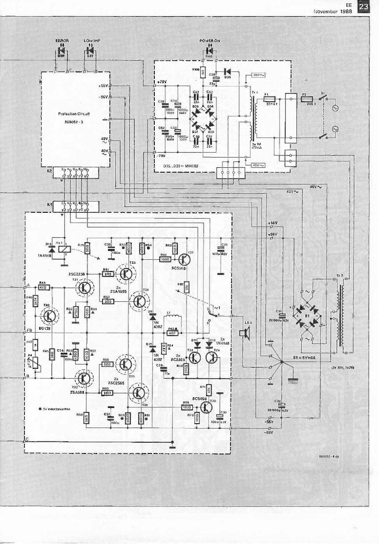
ERROR LOW 114P
4f ft
Protection Circuit
880092 - 3
4-56V 01
-56V 0
-60
40V Itit0
,20 40 60 80100
10 3° 5 7 90V
J
I +704
0
C56 C54
880n 1000210439 1002
0571 C55
POWER ON
ft
040_0 _ 00106
C543D39
C52 C53
F.1F22n 22n
D35 D36
1037 038MI=660n 10002 C50 C511002 1002 FA F
22n 22n
-70V
835_1339 =1714002-
0
20 40 6
103 5
100
70 90
Tr t
2.x 92177rnA
97
51
013 Ref
LZI1144148 2
R48
0
049
2502238T21 . \
./
T20
8D139
\ 052
R52
680n
051 /_123
1.,
2x2SA1095
053 Is
klOr\/
1N4002
Ll
063
04
P4045
flC25 055
IMn A)00n
1
1-22'-'-2SA.168
752121..tanste4ree
056
R58 /I
.,1125
2x2SC2565
060
DIO
\ \T25
064
1N 2x4002 8C54613
028 068min1.2.7n
L
125
C29
1002 632
129
R71
8C546BR89
IUD070
C
0
+56V0
+56V
C31
200002 eav
B1 =SYW66
NM,200000 632
-56V0--56V
Tt 2
12:402; 3075)
880092 -1.11
24 EE
November 1988Fig. 4. PCB for the voltage amplifier.
Parts list
VOLTAGE AMPLIFIER BOARD
Resistors:RI =100K'R2= 1K0'R3= 33K2+R4=56213+R5= 8R2R6= 18K2 -R7 = 392R -Re =374R -
o = 18R2Rit=82RR12= 1K8R13= 15K; 1.5 W1114=33K; 1.5 W typeR15= t1711
Flia:Riz=4R7Ris=3K9; 1.5 WR19;R22= 100R'R2o;R21=4K7; 1.5 WR23= 2K2R24 = 10R; 1.5 WR25= 3K32R26;R34= 15KR27;R33= 12KR28;R31;R35;R36=10KR2s;R3e= 1RO; 1.5 WR3o;R37 =100RR32;R39= 5K6P1 =50R muititurn preset (Cermet)P2;P3=2K5 preset H
÷Metal film resistor
Capacitors:CI =447; MKTC2=820p polystyrenelstyroflexC3= 22nC4 =100nC5;C7=-47;i; 63 VCa;Ct t;Ciz =10y; 40 VCa=10nCs= 68p; 160 V; polystyrene/styroflexCio;Ct5=680nC12;Cia=1110; 63 VC13;C1s=47nC1e;C2o= 100pC15;C21 =680n; 100 V
Semiconductors:D1;D2=1N414803;04=33V; 1.4 W zener diodeTi;T2=2SK146VT3;T4 = BC550CT5= 8C6391-6;77 = 8C560CT8;Ts=BF762Tio;Ti t = BF759T12...114 incl.=BC5468Tia=BD139Tla...Tta incl.=BC556BTis=BD140
Miscellaneous:PCB Type 880092-1 (see Readers Services
page).
Fig. 5. PCB for the current amplifier.
Parts list
CURRENT AMPLIFIER BOARD
Resistors:R45= 39RR46= 2K74R47= 1K0+R48= 47R
1145;1156=56R
R5o;R57= 100R; 1.5 WR51;R53;R58;R60=2R2R52;R54;F155;Rs1 =0R22 non -inductive resistorR55;R62=470R; 1.5 WR63=4R7; 1.5 WRea= 22R; 1.5 WR85= 15ORFlee= 100RR87= 18KR68= 270RRe9;R7o= 12ORR71=47KPa = 1K0 multitum preset (Cermet)
- Metal film resistor
Capacitors:C25= 100nC26;C27= 680nC2E3= 27n; 250 VC29;C3o=100;1; 63 VC31;C32 = 20,000y; 63 V (can -type capacitor;
not on PCB)
Semiconductors:Bt =BYW66 (not on PCB)09;D to = 1N4002DI t;(712;Di3=1N4148T2o=80139T21= 2SC2238T22= 2SA968 T23;724= 2SA1095T25;726=2SC2565T27=BC556B725;T29;T30= BC54613
Miscellaneous:K 1= 10 -way straight header.Li= 12 turns enamelled copper wire, dia. 1.5mm; internal diameter approx. 15 mm.
Ref = V23127 -80006-A201 (24 V change -overrelay; Siemens)
PCB 880092-2 (see Readers Services page).
form a cascode circuit: T3 and T4 main-tain the drain potential, derived fromdivider 1212 -R13 -R14 -Di -D2, at about 20 V.The amplification of the input stage isrestricted to 3.5 by resistors R9 and Rio.To keep the bandwidth at the output ofthe cascode circuit as large as possible,the values of collector resistors R7 andRs -Pi are fairly low. The preset, Pi,serves to eliminate any inequalities in thed.c. operating points.Lag compensation is provided by Rs -C3.The capacitor determines the open -loopcrossover point, while the resistor keepsthe phase shift down.The d.c. operating point of the FETs isset by a constant -current source aroundTs.Differential amplifier T6 -T7, togetherwith T8 and T9, also form a cascode cir-cuit to keep the bandwidth as large aspossible.The output of Ts is fed to the currentamplifier via current mirror Tio-Tii andterminal B. The signals at terminals Aand B are, therefore, in phase with oneanother.Lead -compensation capacitors Cs andC9 serve to maximize the bandwidth ofthe second cascode circuit.
Current amplifier. The current amplifierconsists of drivers T2I and T22 followedby power transistors T23, T24, T25 andT26, which, as already mentioned, areconnected in a compound configuration.This section also provides a smallvoltage amplification due to resistorsR57 and Re.The power transistors are protected bydiodes D9 and Duo against any largenegative voltage surges that mayoriginate in the loudspeaker system. Thed.c. operating point is provided by tran-sistor T20, which acts as an adjustablezener diode. This stage enables the set-ting of the voltage drop across T2I, Rso,R55, and T22, and thus that across
EE
November 1988
resistors R49 and R56, which determinethe quiescent current of the power tran-sistors.Transistor T20 is mounted on the heat -sink for the drivers and power transistorsto guarantee good thermal feedback:this ensures that the quiescent current re-mains steady even when the temperaturerises. The quiescent current is about100 mA per transistor, so that the outputstages can comfortably handle smallsignals in class A.Boucherot network Res -C25 ensures thatthe output is loaded even at high fre-quencies.Inductor Li limits current surges causedby predominantly capacitive loads at theoutput.The signal at the collectors of the powertransistors is fed back to the gate of T2in the voltage amplifier via R6. Theratio R6:R4 determines the voltage am-plification: with values as shown, thisamounts to 3.5. The input sensitivity ofthe voltage amplifier is then 1.1 V r.m.s.
Power supply. The power supply usestwo mains transformers in series, Triand Tr2. Note that Fig. 3 shows thepower supply for a mono amplifier.Transformer Tr2 is a heavy-duty toroidaltype with a centre -tapped secondary:each half delivers about 40 V a.c. Full-wave rectification is effected by bridgerectifier Bt and smoothing of the d.c.voltage is carried out by four 10,000 µFelectrolytic capacitors: Cat and C32. Theopen -circuit supply voltage for thepower transistors is about ±57 V; at fullload, this drops to around ±51 V.The series connection of In and Tr2provides a supply voltage of ±70 V forthe voltage amplifier. This supply isregulated at ±60 V by discreteregulators 112 to T15 and Tie to T19 re-spectively.A differential amplifier in each regulatorcompares the output voltage with a
T23E
C
B.(R51
R52
R54
R80R62-0
4P49
+56v
FB 0 litC A E C 0 BCE 2 C B B0 .1_1_1_ LI 'FI 1_1_1 0P4 a F iirc2111-
-11=zets j- I II -fp(47I - -
L__ .JVT22- T20 L.
-10-F011 012
5
C31C32
P55Y
4R56
R59
48701- --4R89
861
26 EE
November 1988
zener-derived reference potential; anydifferences are eliminated by a darling-ton series regulator in the two supplylines. Presets P2 and P3 facilitate the set-ting of the respective voltage to their cor-rect level.
Protection circuit. The protection circuitwill be described next month, but itsconnections to the other parts of the cir-:uit are already shown in Fig. 3.The output relay is located on the cur-rent amplifier board to ensure theshortest possible loudspeaker connec-tions.Transistors T27 and T30 monitor the cur-rent through emitter resistors R54 andRs9 respectively and, if necessary, actu-ate the protection circuit via Tzs andT29. This happens when the output cur-rent exceeds 10 A.
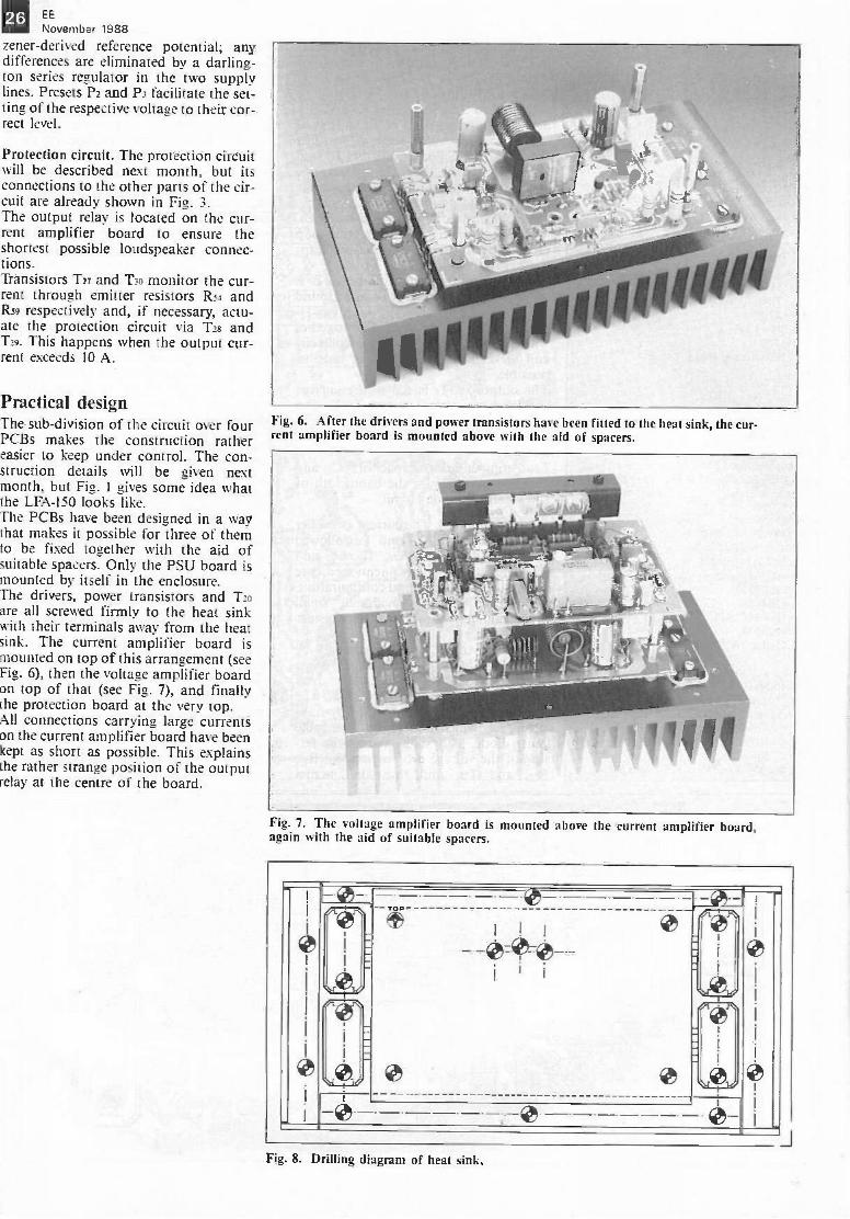
Practical designThe sub -division of the circuit over fourPCBs makes the construction rathereasier to keep under control. The con-struction details will be given nextmonth, but Fig. 1 gives some idea whatthe LFA-150 looks like.The PCBs have been designed in a waythat makes it possible for three of themto be fixed together with the aid ofsuitable spacers. Only the PSU board ismounted by itself in the enclosure.The drivers, power transistors and T20are all screwed firmly to the heat sinkwith their terminals away from the heatsink. The current amplifier board ismounted on top of this arrangement (seeFig. 6), then the voltage amplifier boardon top of that (see Fig. 7), and finallythe protection board at the very top.All connections carrying large currentson the current amplifier board have beenkept as short as possible. This explainsthe rather strange position of the outputrelay at the centre of the board.
Fig. 6. After the drivers and power transistors have been fitted to the heat sink, the cur-rent amplifier board is mounted above with the aid of spacers.
Fig. 7. The voltage amplifier board is mounted ahme the current amplifier hoard.again with the aid of suitable spacers.
-- ....
1
I
,- \Vor
I I I-,--_-45:-.4Ni i i
-
.t
I
I
1
Qt'
,04: i
--- I
45iV' 01
i-
i
Fig. 8. Drilling diagram of heat sink.
MAINS SIGNALLINGEE
November 1988
by A.M. Karailiev
Mains signalling is a method by which signals can besuperimposed on mains wiring for remote control of electrical
equipment. Typical applications are the control of street lighting,space heating, energy management systems and many other
control switching applications in domestic, commercial andindustrial premises.
The operating principle of the proposedmodulator is shown in Fig. 1. Twothyristors, Thi and Th2, are connectedin parallel across a variable inductor.Thi and Th2 are controlled via opticalfibres connected to the control centre.Normally, the thyristors are open, sothat the total alternating supply currentpasses through them and the inductor.In this state, there is no modulation,since the modulation voltage, UQ. isnought. This changes when one of thethyristors is closed, since thenUga0.01U- - the transmitter is sen-ding a signal into the mains network. Inthe simplest case, the receiver detectsUQ, and switches on a certain load, orgroup of loads. The second thyristor isincluded to provide a complementary -phase signal UQ that can be used forswitching off the load(s). The mainfunction of the variable inductance is toensure that the amplitude of UQ is virtu-ally independent of the load current. Toachieve this, the control centre sets therequired inductance with the aid of aservo -motor.
Modulation typeThe modulation voltage should be notsmaller than 0.01U- to allow a suitable
noise margin for the receiver, and notgreater than about 0.05U- to prevent itdisturbing the operation of certainloads. In analogy with ordinary ampli-tude modulation, the modulation depth,or relative amplitude of UQ with respectto U-, is expressed as
m - Uchrnax)
U=(max)
The modulation method used in theabove control system is less simple toqualify than would be expected. It couldbe called a special form of amplitudemodulation, since the modulationvoltage is unipolar, causing amplitudevariation of either the positive ornegative half cycles of the carriervoltage, but not both simultaneously.The system could also be considered asbased on phase modulation, because itinvolves the sum of two amplitude -
Readers are advised that Mains Signallingin the UK is subject to the provisions ofBritish Standards BS6839. Further infor-mation on the subject may be obtainedfrom BIMSA (BEAMA Interactive andMains Systems Association), LeicesterHouse, 8 Leicester Street, LONDON\VC2H 7BN, telephone 01-437 0678.
modulated voltages of equal frequencybut opposite phase. Waveform modu-lation may be a suitable qualificationbecause the modulation voltage, UQ, ef-fectively changes the waveform of thesinusoidal carrier voltage.Mathematical and experimental analysesof the spectrum of the modulatedvoltage supplied by the proposed systemshow that it consists mainly of even har-monics, among which the second, 2f,dominates. In this regard, the change ofthe carrier waveform caused by themodulation could be qualified as distor-tion, and can be expressed as a distor-tion factor, k. It can be shown that thisis roughly equal to the previously men-tioned modulation depth:
1/U22 + U4Ul U
But this is not a pure type of modu-lation. In order to improve the noise re-sistance of the receiver, the maximumpositive and negative excursions of thecarrier voltage have to be decreased in analternative fashion, which has the basicelements of phase modulation.Being able to bring about a differencetlUg between the positive and negativemaximum excursions of U- by means
.._14..J3_.1
ThlTb2
1'
13 .-32.49. Lis 10sgs
Wv(VNAAPeeesAielevtThlTIs2
F5.6g4__/V94-0
MA666661.4
yr. 20sec
ti=t2=kiT. mama period ; k; 3= (random integer number)
Fig. 1. Series connection of a modulator ina high -voltage line. Fig. 2. Thyristor timing diagrams: load on (2a) and load off (2b).
28 EE
November 1988
Fig 3. Block diagram of the selective receiver.
of a modulator in a high -voltage line isessentally the same as injecting a signalof amplitude 0.5AUa and of frequency2f - the frequency of the second har-monic.Normally, odd -numbered harmonicswith k=0.03-0.04 are permanently pres-ent in many mains networks, while even -numbered harmonics appear only fromtime to time when large loads areswitched on or off. Their total durationis relatively short at about 5% of the`quiet' periods.
Encoding systemEncoding of the modulation signal isessential in view of the relatively high
noise level on most mains networks. Thetiming diagrams of Fig. 2a and 2b showhow the control centre sends triggerpulses to the thyristors to switch a loadon and off respectively. The load, orgroup of loads, controlled is selected byassigning a corresponding value to k.The block diagram of the receiver isgiven in Fig. 3, and the practical circuitin Fig. 4. A full -wave rectifier drives anactive filter. In the absence of a modu-lation voltage, all maximum excursionsof the rectified voltage are of equal am-plitude, and there is no voltage at theoutput of the filter. When the mains net-work is modulated, the filter supplies asinusoidal output voltage, whose phaseshifts 180° when the thyristors in the
transmitter change state (on/off con-trol). A phase detector compares thephase of the filter output signal withthat of the mains voltage. One of its out-puts supplies the demodulated signal,UQ. Bistables, a load addressdecoder/filter and delay networks arethen used to achieve reliable control ofthe power switch for the load. The filteris laid out in accordance with the loadselection frequency:
f=2/(k T)
The possible number of load selectionfrequencies is more than ten, but practi-cal needs normally seldom exceed aboutfive.
Fig. 4. Circuit diagram of the receiver.

EE
November 198829
a?..0172-14
Fig. 5. Eight high -voltage diodes as a re-placement for the variable inductor in thetransmitter.
The cost of the transmitter and receivercompares favourably with existing unitsbased on so-called ripple control of themains voltage.
Fig. 6. Basic layout of a parallel modulator.
Finally, Fig. 5 shows a suitable replace-ment for the variable inductor in thetransmitter. It should be noted that thediodes have to be capable of handling
the total current demand of the load orgroup of loads. The block diagram of analternative, parallel, modulator is shownin Fig. 6.
PEOPLESamuel Ruben, who died recently at theage of 88, was the inventor of the dry -plate rectifier and the dry -electrolytic ca-pacitor. In association with P.R.Mallory, the founder of Duracell, healso developed the first practical designfor an alkaline cell. This cell was readyjust in time for World War II, duringwhich its consistent voltage and its re-sistance to deterioration under adverseconditions made it the preferred powersource for battery -powered militaryequipment.
Cliff Wyatt
Cliff Wyatt is the Business Manager ofthe OEM Products and Service Grouprecently established by Base Ten Systemsof Farnborough. Richard Nussey is theProduct Manager of the new group andChris van Koutrik has been appointedSales Engineer.
Richard Nussey
In addition to providing wide-rangingmanufacturing services for the elec-tronics industry, the group will be in-volved in the introduction of new hightechnology products and will seek jointbusiness opportunities with otherorganizations for this purpose.
Mr M.K. Williams has been appointedResearch Associate for Dataquest'sEuropean Semiconductor Industry Ser-vice. At the same time, Mr W. Turnbullhas been appointed Industry Analyst forthe organization's Western EuropeanPrinter Industry Service.
Bob Hawkins has joined STC Instru-ment Services as a field sales executive.
Andrei Vladimirescu, internationallyrecognized as an expert on the subject of
circuit simulation, has joined AnalogDesign Tools as director of simulationtechnology.
Ray Rees has been appointed director ofLSI Logic Export Ltd, part of LSI LogicEurope PLC, manufacturers of CMOSASICs and market leader in CMOS gatearrays. LSI Logic has also announcedthe appointment of Simon Calder asProduct Marketing Manager.
Roy Home has been appointed Manag-ing Director of Parker-Digiplan, a div-ision of the Parker Hannifin Corpor-ation and Europe's leading manufac-turer of servo drives, motors, and con-trol systems.
Liz Hindley has joined Alpha Elec-tronics as internal Sales Manager.
30 EE
November 1988
PORTABLE MIDI KEYBOARD
A recently introduced integrated citcuit makes a dream of manyelectrophonics enthusiasts come true: to build one's own MIDI
keyboard around a handful of electronic components.The portability of the keyboard described makes it ideal for 'first -
aid testing of MIDI equipment. Moreover, in conjunction with amicrocomputer, it can be used for practising, composing andediting musical pieces in places where a full-size keyboard is
cumbersome to use.
The Type E510 is a recently introducedintegrated circuit that reduces the com-plexity of a MIDI keyboard to the extentthat home construction of such a unit isat last within reach. Until recently,building one's own MIDI keyboard wasway of out reach of the average elec-trophonics enthusiast because of costand complexity. At that time, even thesimplest of do-it-yourself MIDIkeyboard required building blocks suchas a processor, random-access memory,read-only memory, high -precision mech-anical parts to ensure good dynamic keyresponse (velocity), a musical keyboard,and a data entry keyboard, to mentionbut a few.
The E510 can be used with a musicalkeyboard of ten octaves (128 keys) whosekeys are suitable for providing the vel-ocity information. The only auxiliarycomponents needed are an EPROMloaded with transposition data, twobinary decoders, and, of course, keycontacts.The benefits of a portable keyboard areobvious: quick testing of MIDI instru-ment arrangements, practising and com-posing (parts of) musical pieces, par-ticipating in workshops, and trying outchords or tone combinations in situ-ations where a full-size keyboard simplytakes up too much space. The miniaturekeyboard is also very useful forsimulating a temporarily absent instru-ment or full-size keyboard for editing se-quences loaded in a sequencer, sounds inan expander, or scores in a computer sys-tem.Apart from its function as a versatile ac-cessory in the musical education field,the keyboard will also prove useful forexperienced musicians whose principalinstrument is, for example, the sax-ophone, the guitar or percussion - inany case, not the piano. Even if the minikeyboard serves as a mere gadget, it stilldeserves its very own place among farmore complex MIDI equipment.
MIDI KEYBOARD
Overall size geared to portable appli-cations.
Electronic circuit complies withMIDI standard (incl. velocity).
Miniature keys and control circuit oncompact double -sided PCB.
Range: 2 octaves and 1 note(25 keys); from C to C.
Switch -controlled transpose functionover ±1 octave.
Switch -controlled MIDI channelselection (channel I or 2).
Simple to power from mains adaptorwith DC output.
Low chip -count.
MIDI keyboard: principle ofoperationThe task of the MIDI keyboard is todetect the individual states of the'keys toenable polyphonic playing. This meansthat a number of notes can simul-
taneously appear or disappear, notes canlast when others stop, and notes can ap-pear before others have dissappeared. Itis the aspect of polyphony that makes amusical keyboard functionally com-pletely different from, say, a computeror data entry keyboard.The 'key state' means that it is either re-leased (the corresponding contact is inthe non -actuated, or rest position),pressed (the corresponding contact is ac-tuated), or in between these extremes.The time that lapses between the instantwhen a key is no longer in the rest pos-ition, and the instant it reaches the workposition, is translated into a VELOCITYvalue. Evidently, the velocity at whichthe key is pressed is proportional to the
Switch pole in the rest(non -actuated) position.
o
128 ps later, the pole hasjust left the rest position,and counter decrementingcommences.
After 256 is, the pole hasnot yet reached the workcontact, so counterdecrementing continues(VELOCITY=VELOCITY-I).
After a clock cycles, the polehas reached the work contact.Counter decrementing stops,the VELOCITY value isknown, and MIDI codeNOTE ON can be trans-mitted.
Fig. 1. The main functions of the electronicsin the MIDI keyboard are to analyse the pos-ition of the keys, and to measure the timethat lapses between the opening and closingof the contacts, for both directions of travelof the switch pole. Although in principleavailable on the small MIDI keyboard dis-cussed here, the latter function is, unfortu-nately, of no use because the relevantswitches are of a type whose pole travel is vir-tually instantaneous rather than continuous.
EE
November 1988intensity with which the player strikes it.The softer the key is struck, the moretime will lapse before the pole of the keyhas travelled from the rest contact to thework contact. This time is measured bycounting down from 127 to 1 (see Fig. 1);the smaller the final count, the softer thekey -touch.When it is detected that a key is nolonger in the non -actuated position,nothing happens on the MIDI output ofthe keyboard. Counting down, however,commences or continues. CodeNOTE ON is not transmitted until thepole reaches the work contact. If theminimum VELOCITY value is reachedby decrementing before the pole reachesthe work contact, it is assigned thelowest value, 1. Basically the same hap-pens when a key pole leaves the workposition to return to the rest position.The scanning of a MIDI keyboard thusentails the fastest possible analysis of thestate of each key. In practice, this isachieved by an electronic circuit thatworks in combination with mechanicalchange -over (toggle) switches to derivekey on/off and velocity information.
MIDI keyboard controllerType E510Figure 2 shows the internal structure andpinning of the programmed MIDIkeyboard controller Type E510. Thepower supply is conventionally connec-ted to pins 8 and 16. The keyboard scan-ning signal and the timing of the serialMIDI data are derived from an on -chipclock oscillator that operates with an ex-ternal 4 MHz quartz crystal connectedto pins 14 and 15 (pin 15 may be used forapplying an external clock signal). Thedata rate at the MIDI output may bedoubled by fitting an 8 MHz crystal.Pin 13 should always be connected to thepositive supply line.Chip outputs AO to A6 allow the con-troller to scan up to r =128 addresses(=keys). The MIDI data is available atoutput SO (pin 9). This output can beused in two ways: it can be made TTL-compatible by fitting a pull-up resistor,or it can function as a current -source byfitting a series resistor. The latter optionis used here to give a MIDI -compatiblecurrent loop output.Input BE is connected to the 'bused' restcontacts of the switches. Similarly, inputBS is connected to the work contacts ofthe switches.
The pole of a switch addressed by theE510 is made logic low. During scan-ning, when the pole is at the rest pos-ition, the level of line BE is logic low in-stead of logic high (normal state due topull-up). When the key pole has reachedthe work contact, BS goes logic low.Neither BS nor BE is low when the poleis anywhere between the rest and the
Iv
Oyer,. Cff= = KEY OM
THE MIDI STANDARD: A BRIEF RECAPITULATION
The acronym MIDI stands for Musical Instrument Digital Interface. This standard hasbeen designed to allow digitally -controlled musical instruments to communicate in asystem (note that digital control often implies the use of a microprocessor or microcon-troller, although this is, of course, not always necessary). The MIDI interface is basical-ly a serial data link, based on a current loop. The data format is: I start bit, 8 databits, and 1 stop bit. The data speed, 31.25 kilobits per second, is high relative to thatused for many types of computer peripherals, but may still be too slow for real-timeoperations of a complexity beyond that of the most rudimentary types. The bulk ofMIDI data is formed by the notes (events), played on a keyboard, or transmitted by aninstrument. This recapitulation covers only MIDI events such as the NOTE ON andNOTE OFF messages.
Of the three bytes in a 'NOTE ON' message, the second one carries the note value.With the MSB (most significant bit) set to 0 to indicate that the byte is a data type,this leaves only seven bits to carry the note value. This gives a range of 2' values, andthese are assigned numbers from 1 to 127. The value of 60 is equivalent to the middleC. The interval between any two adjacent numbers is a semitone, so that a totalcompass of about ten and a half octaves is available.
MIDI VALUES: NOTES0 12 24 36 48 60 72 84 96 108 120 127
Cl C2 C3 C4 C5 C6 C7 C8
1 range of piano
In addition to PITCH, the MIDI standard uses parameters NOTE ON and NOTE OFF(or KEY ON and KEY OFF). The first corresponds to the actuation of a key (or, inmore general terms, to the start of the note), the second to the release of the key (endof the note). In reality, the relation between the duration of the note and the trans-mission of data NOTE ON and NOTE OFF is much more complex. Although the startof a note usually coincides with the transmission of code NOTE ON, the complemen-tary code, NOTE OFF, rarely marks the end of the note - usually, by the timeNOTE OFF is transmitted, the note is already ended (in the case of a percussion soundwithout sustain), or it still sounds (long sustain).
The third byte in the 'NOTE ON' message provides keyboard velocity information.Ranged in values from 1 to 127, the velocity is normally used to control the loudnessof the notes (0= 'key off' ; 1= pianissimissimo - ppp; 127= fortissimissimo - If!). Itshould be borne in mind, however, that there is no specified relationship between thevelocity value and the loudness. If a MIDI instrument is not designed to handle velocityinformation, it adopts a default value (usually 64).
MIDI VALUES: VELOCITY0 1 64 127
OFF ppp pp p mp mf f ff fff
Since a single MIDI interface can be used for connecting several MIDI devices, pro-vision has been made to identify data to ensure it is correctly routed in multi -instrumentset-ups. This data marking allows individual addressing of any instrument connectedto a single MIDI interface. The MIDI standard specifies up to 16 channels, numbered0 through 15 (sometimes 1 through 16), which means that any one of up to 16 instru-ments can be controlled independently and individually. In the case of the NOTE ONand NOTE OFF information, the channel number forms part of the ON or OFF code.
0 1 2 3 4 5 5 7 0 1 2 3 4 5 6 7 0 1 2 3 4 5 6 7
.....I s I
r; ONEft
I I 1=2. al as I I 0=.....%04 Ds OS I I
LIUSPT
It, 5Us t5. 510-127 5.5 OL
14II1
54
467,155
The above diagram shows a MIDI message sent by a keyboard when a a key is actuated.The start bit is followed by an 8 -bit word, in which the first 4 bits (0 through 3; leastsignificant nibble) indicate the channel number (the keyboard described in this articlecan drive only two channels). The last bit, (number 7; most significant bit) is logic highto indicate that the byte sent represents status information, i.e., it is not, strictly speak-ing, adataword. The logic level of bit 4 provides the KEY ON/OFF (NOTE ON/OFF)information: O=OFF; 1=0N.The six bits that indicate the key number follow the start bit of the second byte. Bit 7of a databyte is always logic low. The six bits of the third byte (second databyte) holdthe velocity information. Bit 7 is logic low to mark that the byte it forms part of is stilla databyte. In the present case, the MIDI message is terminated with the stop bit ofthe third byte.
EE
November 1988
Table 1.
rPAR
121 3 I
00C1-11rePle
-
sl
L330113 - I?
55: 31
Fig. 2. Internal structure and pinning of the polyphonic MIDI keyboard controller TypeE510. This chip supports the use of a 128 -key keyboard with up to 10 octaves, and transmitsMIDI values for VELOCITY, NOTE ON and NOTE OFF.
work contact. The above arrangement issummarized in Table 1.The logic level at chip input CO (pin 12)determines the current MIDI channel:CO=0=channel 0; CO=1=channel 1.
Circuit descriptionThe crucial components in the circuitdiagram of Fig. 3 are controller IC,(E510) and decoders/demultiplexers IC3and ICs. EPROM IC' has the auxiliary
key BE BS function
1 x x not analyzed0 0 1 pole at rest contact0 1 0 pole at work contact0 1 1 pole travelling0 0 0 Impossible
x = irrelevant
function of code converter.The operation of the circuit is bestunderstood if IC2 is initially ignored. Itis assumed, therefore, that the addressoutputs of ICI drive IC3 and ICs direct.On its outputs AO to A6, the E510counts from 0 to 127. Each rime thecounter is incremented, another outputon 1C3, and then 1C4, goes low. Thiscyclic counting up forms the scanning ofthe keyboard. Each time the E510 pullsone of its address lines logic low, it readsback the logic levels of lines BS and BEto determine the current state of the ad-dressed key. This state is combined withthat read during a previous scan (i.e.,128 pts earlier at f3-rAL=4 MHz). The
5v
12
NEM
20
PEN
CE22 et
P.4
V
412
410
4344
IC2 A?
EPROM2764
MEI4
ECM
23
21
25
525
12
5
MIN
5V
0
2
6 3
4102
8 2 2 a 2
7 4
a 5
B 6
10 7
11 1213 15T11191
181;9 2372
4645
4443
42AI
AO
EX
CO
E510
x
TST
BE
BS
13
11
10
Is
22/9
2120,
IC474 HCT 154
7. 7.
161 151 141 131 121 111 101 91 8 3 1
IDADI._025-, 1N4146 Iii IX=
$251 IMhhO
16 14 2022.
4
4111-14
C2
72p
74; 2 2 2
IC374HCT 154
15 14 13 7 6 5 412 1 10 9- 2
21 to 10 w0 I<< (.3 u. w O Ct U 0 I < < w 0 0 (-)_" vl 13, 7.3 E.° e 4 4 o 11 "a 741 n7-;
O<< t7 C7 u- u_ wquCI Cif.30 03 <<OL9 u.u.tu0000
5v
0R7
g R6 gMIDI.Out
660168 -15
Fig. 3. Circuit diagram of the small MIDI keyboard.
EE
November 1988result of the combination is deduced asshown in Table 2.That the keyboard described here has 25instead of the maximum number of 128matters very little as far as the elec-tronics are concerned, since BE and BSsimply remain logic high simultaneouslyfor the 103 non -existing keys, and stateBE = BS =1 is effectively ignored by theE510. Although the contact travel timeof the Digitast keys used in the MIDIkeyboard can be measured with someprecision, it will be found that this islargely constant, i.e., hardly subject toapplied force. This is because Digitastkeys have tactile feedback (they producea click when pressed). The upshot of itis that the VELOCITY value transmittedby the standard version of the keyboardis of no practical use.
As already noted, EPROM IC2 func-tions as a code converter in the presentcircuit. The E510 counts cyclically from0 to 127. In the absence of the EPROM,the two octaves of the keyboard Wouldbe comprised in the lowest range of thescale covered by the PITCH parameter,i.e., between note 0 and 24. Also, doubleaddressing of the decoders in the circuitwould cause a single key to provideseveral, different, MIDI codes simul-taneously. The task of the EPROM is,therefore, to ignore the lowest of the ad-dress codes, and to activate the twodecoders (74HCT154) only once whenthe counting has reached a value thatcorresponds to audible notes in the mid-dle of the useful range.The second duty of the EPROM is toswitch between two address ranges,which results in the transpose function.This is effectively done with the aid of atoggle switch with a centre contact, S26,that determines the logic level onEPROM address inputs A7 and A8. TheEPROM converts the addresses suppliedby the E510 by adding or subtracting theequivalent of one octave. For example,when the address of note 60 is applied,the EPROM converts this to an addressthat corresponds to note 72, one octavehigher. The contents of the EPROM arelisted in Table 3. A Type 2764 is usedhere because this is currently the least ex-pensive EPROM.
Split programming extensionSwitch Sr determines the channel selec-tion by controlling the logic level apliedto input CO of the E510.Instead of manually giving a channelselection command, it is also possible todo this via the keyboard by splitting thisinto zones. Figure 4 shows the circuitdiagram of the optional extension toachieve this. Notes played to the left orthe right of the split go to MIDI chan-nel 1 or 2 respectively. The split is defin-ed by pressing the PROGRAM switchtogether with the desired key on the
Table 2.
Previous state New state Event Key state
restBE=O; BS=1
restBE=O; BS=1
intermediaryBE=1; BS=1
intermediaryBE=1; BS=1
workBE=1; BS=O
intermediaryBE=1; BS=1
intermediaryBE=1; BS=1
restBE=O; BS=1
intermediaryBE=1; BS=1
intermediaryBE=i; BS=1
workBE=1; BS=O
intermediaryBE=1; BS=1
intermediaryBE=1; BS=1
restBE =0: BS =1
none
start count
continue count(to 11
end of countmessage MIDI NOTE ON
start count
continue count(to 1)
end of countmessage MIDI NOTE OFFCO = MIDI CHANNELA6...A0 = PITCHcount = VELOCITY
e -l=1 -*---E'- °
e-14-----4`
°er-r-i ES -
*--0 -=- Er- t-
oIMII . -ES'
0 MI E: -
a 44-......:E) -4--1-L-=9- ,
-0 ---=--.-EZ= 1
i 4----1,()-{=1---zs_ e
(D -4=1 ---*-BE = i
e-1-4-...... I)
0-1=1-1-- BS -"I'
0 =0 BE -"10
e
0
0 MN Es= -1
0 NM BE -.0
a --14-.--s-il
--1=-- :et -.s,
0 = activecount = decrement counter
<c <<t0
CODD/E510
BE
keyboard
A>8
174r2 :I<in <tD
VIII<4 000000el V WI t0
BO 0081 01
823
HCT688 84 HCT373
A7
B5 0586 0687 -
(71 L,Split 820p
programming
CLK OE D7
88016E -14
Fig. 4. Optional add-on circuit to achieve programmable split zoning.
34 EE
November 1988
01
il
r S
u
R2
Da
.1.
+47 DINx
At I49+40
111
0 VI000 0
Fig. 5. Component mounting plan of the printed circuit board for the MIDI keyboard.
keyboard. The corresponding key num-ber is then latched into the 74HCT373octal bistable. Byte comparator74HCT688 drives input CO of the E510logic low when the current key code isgreater than that of the split, which isread from the latch. The programmablesplit option is not supported on theprinted circuit board for the MIDI
keyboard, since this was desired to re-main as small as possible.
ConstructionThe following constructional descriptionis slightly more elaborate than usual toenable anyone, even those with onlylimited experience in the electronicsfield, to build the keyboard successfully.
Parts fist
Resistors (±5%):RI ... R5 inc).=1K0Rs;Rz = 220R
Capacitors:CI;C2=22pC3;C5;C6=2p2; 25 V; tantalumC4 = 100n
Semiconductors:Di... D25 incl.=1N4148ICI=E510-IC2=2764 IESS567; see Readers Services
page)IC3;1C4 = 74HCT154ICs= 7805
Miscellaneous:St . . .S25 incl.= miniature Digitast toggle
(SPDT) key.S26 = miniature toggle (SPOT) switch withcentre position.
S27= miniature SPDT switch.Xi = quartz crystal 4.00 MHzPCB Type 880168 (see Readers Services page).
Prototype of the MIDI keyboard
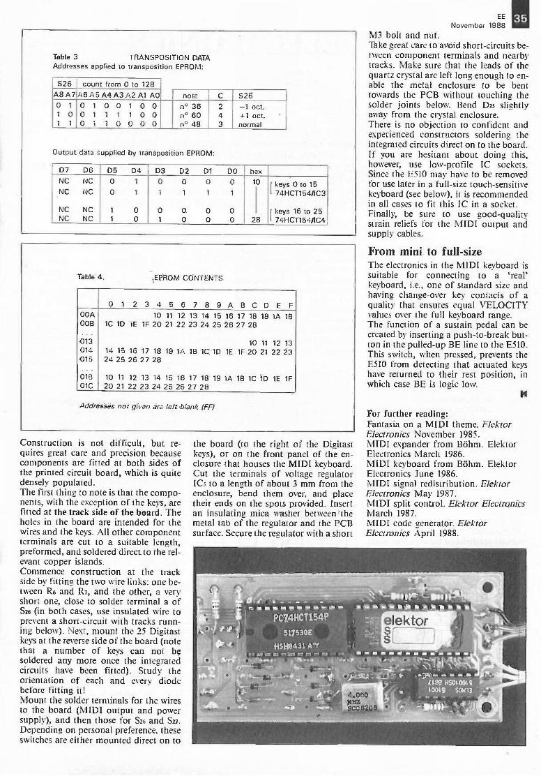
EE 1111November 1988
Table 3 TRANSPOSITIONAddresses applied to transposition
DATAEPROM:
S26 count from 0 to 128A8 A7 A6 A5 A4 A3 A2 Al AO note C S260 1 0 1 0 0 1 0 0 n° 36 2 -1 oct.1 0 0 1 1 1 1 0 0 n° 60 4 +1 oct1 1 0 1 1 0 0 0 0 n° 48 3 normal
Output data supplied by transposition EPROM:
D7 D6 D5 D4 D3 D2 D1 DO hexNC NC 0 1 0 0 0 0 10 r keys 0 to 15NC NC 0 1 1 1 1 1 1 74HCT154/1C3
NC NC 1 0 0 0 0 0 [ keys 16 to 25NC NC 1 0 1 0 0 0 28 1 74HCT154/IC4
Table 4. .EPROM CONTENTS
0123 4 56789 ABCDEF00A 10 11 12 13 14 15 16 17 18 19 lA 1500B 1C 1D lE 1F 20 21 22 23 24 25 26 27 28...013 10 11 12 13014 14 15 16 17 18 19 1A 1B 1C 1D 1E 1F 20 21 22 23015 24 25 26 27 28
01B 10 11 12 13 14 15 16 17 18 19 lA 1B 1C 1D 1E 1F01C 20 21 22 23 24 25 26 27 28
Addresses nor given are left blank IFF)
Construction is not difficult, but re-quires great care and precision becausecomponents are fitted at both sides ofthe printed circuit board, which is quitedensely populated.The first thing to note is that the compo-nents, with the exception of the keys, arefitted at the track side of the board. Theholes in the board are intended for thewires and the keys. All other componentterminals are cut to a suitable length,preformed, and soldered direct to the rel-evant copper islands.Commence construction at the trackside by fitting the two wire links: one be-tween R6 and R7, and the other, a veryshort one, close to solder terminal a ofSz6 (in both cases, use insulated wire toprevent a short-circuit with tracks runn-ing below). Next, mount the 25 Digitastkeys at the reverse side of the board (notethat a number of keys can not besoldered any more once the integratedcircuits have been fitted). Study theorientation of each and every diodebefore fitting it!Mount the solder terminals for the wiresto the board (MIDI output and powersupply), and then those for S26 and S27.Depending on personal preference, theseswitches are either mounted direct on to
M3 bolt and nut.Take great care to avoid short-circuits be-tween component terminals and nearbytracks. Make sure that the leads of thequartz crystal are left long enough to en-able the metal enclosure to be benttowards the PCB without touching thesolder joints below. Bend Des slightlyaway from the crystal enclosure.There is no objection to confident andexperienced constructors soldering theintegrated circuits direct on to the board.If you are hesitant about doing this,however, use low -profile IC sockets.Since the E510 may have to be removedfor use later in a full-size touch -sensitivekeyboard (see below), it is recommendedin all cases to fit this IC in a socket.Finally, be sure to use good -qualitystrain reliefs for the MIDI output andsupply cables.
From mini to full-sizeThe electronics in the MIDI keyboard issuitable for connecting to a 'real'keyboard, i.e., one of standard size andhaving change -over key contacts of aquality that ensures equal VELOCITYvalues over the full keyboard range.The function of a sustain pedal can becreated by inserting a push -to -break but-ton in the pulled -up BE line to the E510.This switch, when pressed, prevents theE510 from detecting that actuated keyshave returned to their rest position, inwhich case BE is logic low.
For further reading:Fantasia on a MIDI theme. ElektorElectronics November 1985.MIDI expander from BOhm. ElektorElectronics March 1986.MIDI keyboard from Bohm. ElektorElectronics June 1986.MIDI signal redistribution. ElektorElectronics May 1987.MIDI split control. Elektor ElectronicsMarch 1987.MIDI code generator. ElektorElectronics April 1988.
the board (to the right of the Digitastkeys), or on the front panel of the en-closure that houses the MIDI keyboard.Cut the terminals of voltage regulatorICs to a length of about 3 mm from theenclosure, bend them over, and placetheir ends on the spots provided. Insertan insulating mica washer between themetal tab of the regulator and the PCBsurface. Secure the regulator with a short
PC74HCT154P
511530E
H5118431 A Y
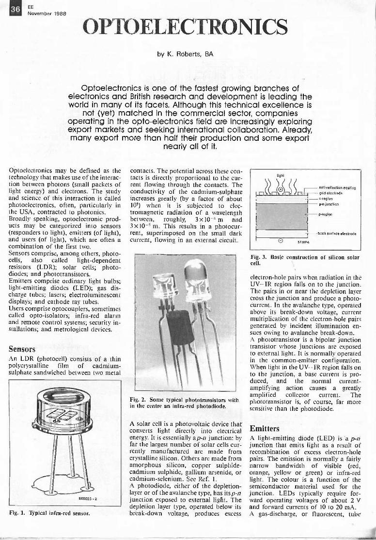
36 EE
November 1988
OPTOELECTRONICSby K. Roberts, BA
Optoelectronics is one of the fastest growing branches ofelectronics and British research and development is leading theworld in many of its facets. Although this technical excellence is
not (yet) matched in the commercial sector, companiesoperating in the opto-electronics field are increasingly exploringexport markets and seeking international collaboration. Already,many export more than half their production and some export
nearly all of it.
Optoelectronics may be defined as thetechnology that makes use of the interac-tion between photons (small packets oflight energy) and electrons. The studyand science of this interaction is calledphotoelectronics, often, particularly inthe USA, contracted to photonics.Broadly speaking, optoelectronic prod-ucts may be categorized into sensors(responders to light), emitters (of light),and users (of light), which are often acombination of the first two.Sensors comprise, among others, photo-cells, also called light -dependentresistors (LDR); solar cells; photo -diodes; and phototransistors.Emitters comprise ordinary light bulbs;light -emitting diodes (LED); gas dis-charge tubes; lasers; electroluminescentdisplays; and cathode ray tubes.Users comprise optocouplers, sometimescalled opto-isolators; infra -red alarmand remote control systems; security in-stallations; and metrological devices.
SensorsAn LDR (photocell) consists of a thinpolycrystalline film of cadmium -sulphate sandwiched between two metal
Fig. 1. Typical infra -red sensor.
contacts. The potential across these con-tacts is directly proportional to the cur-rent flowing through the contacts. Theconductivity of the cadmium -sulphateincreases greatly (by a factor of about105) when it is subjected to elec-tromagnetic radiation of a wavelengthbetween, roughly, 3 x10⁻⁸ m and3 x10-5 m. This results in a photocur-rent, superimposed on the small darkcurrent, flowing in an external circuit.
Fig. 2. Some typical phototransistors within the centre an infra -red photodiode.
A solar cell is a photovoltaic device thatconverts light directly into electricalenergy. It is essentially ap-n junction: byfar the largest number of solar cells cur-rently manufactured are made fromcrystalline silicon. Others are made fromamorphous silicon, copper sulphide -cadmium sulphide, gallium arsenide, orcadmium -selenium. See Ref. 1.A photodiode, either of the depletion -layer or of the avalanche type, has itsp-njunction exposed to external light. Thedepletion layer type, operated below itsbreak -down voltage, produces excess
light
anlireftecl$cn coating- grid electrode
n -region
p -n junction
O 67107-6
p -region
back surface electrode
Fig. 3. Basic construction of silicon solarcell.
electron -hole pairs when radiation in theUV-IR region falls on to the junction.The pairs in or near the depletion layercross the junction and produce a photo -current. In the avalanche type, operatedabove its break -down voltage, currentmultiplication of the electron -hole pairsgenerated by incident illumination en-sues owing to avalanche break -down.A phototransistor is a bipolar junctiontransistor whose junctions are exposedto external light. It is normally operatedin the common -emitter configuration.When light in the UV- IR region falls onto the junction, a base current is pro-duced, and the normal current -amplifying action causes a greatlyamplified collector current. Thephototransistor is, of course, far moresensitive than the photodiode.
EmittersA light -emitting diode (LED) is a p -njunction that emits light as a result ofrecombination of excess electron -holepairs. The emission is normally a fairlynarrow bandwidth of visible (red,orange, yellow or green) or infra -redlight. The colour is a function of thesemiconductor material used for thejunction. LEDs typically require for-ward operating voltages of about 2 Vand forward currents of 10 to 20 mA.A gas -discharge, or fluorescent, tube

EE 111November 1988
normally contains a small amount ofargon togethei with a little mercury. Ithas two electrodes (filaments) that arecoated with a mixture of barium andstrontium oxides. The resistance betweenthe electrodes is high until the gas isionized. Gas ionization is usuallybrought about by the application of avery high voltage (of the order of1500-2000 V) across the two electrodes.
Fig. 4. Circuit of conventional low-pressure fluorescent tube.
The high voltage is normally inducedacross a starter choke by the suddendisruption of the current through thechoke.The laser was developed by TheodoreMaiman in 1960. Light emitted by alaser differs from normal light in twoimportant respects: it is coherent, i.e., allthe photons are in phase; and it is of onefrequency only.There are many types of laser: small out-put He-Ne lasers, primarily intended foruse in laboratories; argon -ion lasers formedical applications; carbon -dioxidelasers for industrial uses; dye lasers foruse in spectroscopy; high outputNd/YAG lasers for surgical applicationsexcimer lasers for use in chemicalanalysis and semiconductor processing;and, most common of all, semiconduc-tor, or injection, lasers. The semicon-ductor laser is of prime importance inmodern (fibre optic) communications,optical memories, and compact discplayers. See Ref. 2 and 3.
Fig. 5. Artist's impression of the construction of a ruby laser.
Electroluminescent displays make use ofthe ability of phosphorus to emit lightcontinuously when a voltage is appliedto it. The most commonly found appli-cation of this phenomenon is in thescreen of a cathode ray tube as used inmany hundreds of millions of TV setsthe world over, not to mention themillions of computer monitors andoscilloscopes. Such a display consists ofa sandwich of a luminescent-phophoruslayer and two transparent metal films.When an a.c. voltage is applied to thefilms, the phosphorus glows through thefilms.
Light rays
iti
: ;;::?;;-. \!il.
1= glass layer2 = transparent metal film3 = electroluminescent phosphorus
Fig. 6. Basic construction of electrolumi-nescent display.
beam exit4
partlytransparentmirror
anode terminal capillaries
. .
He-Ne gas mixture
capillary hole
outer glass shell
length of resonant cavity
cathode
glass -metal
weld
87128-9
cathode terminal
Brewster winda.r(only in polarizedlasers)
totallyreflectingmirror
mirror holder
Fig. 7. Cross-sectional view of a He -tie laser (courtesy of Siemens).
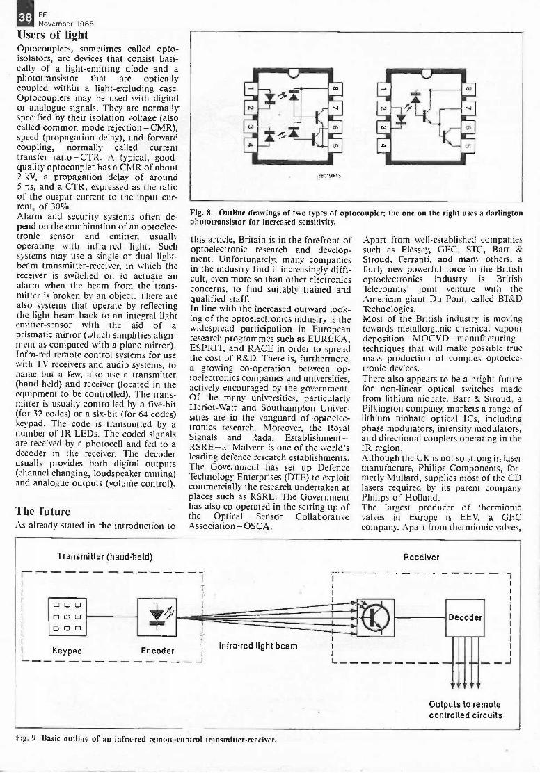
38 EE
November 1988
Users of lightOptocouplers, sometimes called opto-isolators, are devices that consist basi-cally of a light -emitting diode and aphototransistor that are opticallycoupled within a light -excluding case.Optocouplers may be used with digitalor analogue signals. They are normallyspecified by their isolation voltage (alsocalled common mode rejection - CMR),speed (propagation delay), and forwardcoupling, normally called currenttransfer ratio - CTR. A typical, good -quality optocoupler has a CMR of about2 kV, a propagation delay of around5 ns, and a CTR, expressed as the ratioof the output current to the input cur-rent, of 30%.Alarm and security systems often de-pend on the combination of an optoelec-tronic sensor and emitter, usuallyoperating with infra -red light. Suchsystems may use a single or dual light -beam transmitter -receiver, in which thereceiver is switched on to actuate analarm when the beam from the trans-mitter is broken by an object. There arealso systems that operate by reflectingthe light beam back to an integral lightemitter -sensor with the aid of aprismatic mirror (which simplifies align-ment as compared with a plane mirror).Infra -red remote control systems for usewith TV receivers and audio systems, toname but a few, also use a transmitter(hand held) and receiver (located in theequipment to be controlled). The trans-mitter is usually controlled by a five -bit(for 32 codes) or a six -bit (for 64 codes)keypad. The code is transmitted by anumber of IR LEDs. The coded signalsare received by a photocell and fed to adecoder in the receiver. The decoderusually provides both digital outputs(channel changing, loudspeaker muting)and analogue outputs (volume control).
The futureAs already stated in the introduction to
Fig. 8. Outline drawings of two types of optocoupler; the one on the right uses a darlingtonphototransistor for increased sensitivity.
this article, Britain is in the forefront ofoptoelectronic research and develop-ment. Unfortunately, many companiesin the industry find it increasingly diffi-cult, even more so than other electronicsconcerns, to find suitably trained andqualified staff.In line with the increased outward look-ing of the optoelectronics industry is thewidespread participation in Europeanresearch programmes such as EUREKA,ESPRIT, and RACE in order to spreadthe cost of R&D. There is, furthermore,a growing co-operation between op-toelectronics companies and universities,actively encouraged by the government.Of the many universities, particularlyHeriot-Watt and Southampton Univer-sities are in the vanguard of optoelec-tronics research. Moreover, the RoyalSignals and Radar Establishment -RSRE- at Malvern is one of the world'sleading defence research establishments.The Government has set up DefenceTechnology Enterprises (DTE) to exploitcommercially the research undertaken atplaces such as RSRE. The Governmenthas also co-operated in the setting up ofthe Optical Sensor CollaborativeAssociation- OSCA.
Apart from well -established companiessuch as Plessey, GEC, STC, Barr &Stroud, Ferranti, and many others, afairly new powerful force in the Britishoptoelectronics industry is BritishTelecomms' joint venture with theAmerican giant Du Pont, called BT&DTechnologies.Most of the British industry is movingtowards metallorganic chemical vapourdeposition - MO CVD - manufacturingtechniques that will make possible truemass production of complex optoelec-tronic devices.There also appears to be a bright futurefor non-linear optical switches madefrom lithium niobate. Barr & Stroud, aPilkington company, markets a range oflithium niobate optical ICs, includingphase modulators, intensity modulators,and directional couplers operating in theIR region.Although the UK is not so strong in lasermanufacture, Philips Components, for-merly Mullard, supplies most of the CDlasers required by its parent companyPhilips of Holland.The largest producer of thermionicvalves in Europe is EEV, a GECcompany. Apart from thermionic valves,
r-Transmitter (hand-held)
Keypad EncoderL
Receiver
Infra -red light beam
L
Decoder
Outputs to remotecontrolled circuits
J
Fig. 9 Basic outline of an infra -red remotecontrol transmitter -receiver.
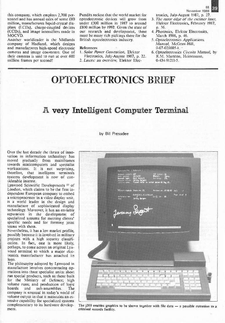
this company, which employs 2,700 per-sonnel and has annual sales of some f80million, manufactures liquid -crystal dis-plays (LCDs), charge -coupled devices(CCDs), and image intensifiers made inMOCVD.Another worldleader is the Midlandscompany of Hadland, which designsand manufactures high-speed electroniccameras and image converters. One oftheir cameras is said to run at over 600million frames per second!
Pundits reckon that the world market foroptoelectronic devices will grow from 3.under £300 million in 1987 to around£800 million by 1992. Given the state ofour research and development, there 4.must be many rich pickings there for theBritish optoelectronics industry. 5.
References1. Solar Power Generation, Elektor 6.
Electronics, July -August 1987, p. 22.2. Lasers: an overview, Elektor Elec-
EENovember 1988
tronics, July -August 1987, p. 27.The razor edge of the excimer laser,Elektor Electronics, February 1987,p. 36.Photonics, Elektor Electronics,March 1986, p. 46.Optoelectronics ApplicationsManual, McGraw-Hill,0-07-028605-1.Optoelectronics Circuits Manual, byR.M. Marston, Heinemann,0-434-91211-5.
39
OPTOELECTRONICS BRIEF
A very Intelligent Computer Terminal
Over the last decade the thrust of inno-vation in information technology hasmoved gradually from mainframestowards minicomputers and specialistworkstations. It is not surprising,therefore, that intelligent terminalssystems development is now of con-siderable interest.Lynwood Scientific Developments ") ofLondon, which claims to be the first in-dependent European company to embeda microprocessor in a video display unit,is a world leader in the design andmanufacture of sophisticated displaytechnology. Moreover, it has an enviablereputation in the development ofspecialized systems for meeting clients'specific needs and for forming jointteams with them.Nevertheless, it has a low market profile,possibly because it is involved in militaryprojects with a high security classifi-cation. In fact, one is more likely,perhaps, to come across an original Lyn-wood terminal to which a major elec-tronics manufacturer has attached itslogo.The philosophy adopted by Lynwood inmanufacture involves concentrating op-erations into three specialist units: shortrun special products, such as those builtfor the Ministry of Defence; highvolume runs; and production of logicboards and sub -assemblies. Thecompany is unusual in today's world ofvolume output in that it maintains an ex-tensive capability for specialized systemscomplementary to its hardware develop-ment.
by Bill Pressdee
leant elder, SP t'Ir -..ftv : ILIell :wed . 12/11/V frvr: tawsktv.trt tot. Call Scositt C.rre.:,r. 111.
keatrt MI*, 'smog frostInitnttlo...s. 1W. mph, to linty WM In Sas P.
:r4ter.:Crvet Icy,
:any &vont
The j300 enables graphics to be shown together with file datacriminal records facility.
a possible extension to a
40 EE
November 1988
Sophisticated communicationssoftwareThe successful Lynwood Alpha and Betaterminals have now been superseded bythe latest range: the j102, j300, j500 andj700. Based on the Alpha terminal, thesenew displays represent an updating witha large number of systems uses in mind.The new Lynwood j300 high definition,intelligent display has an embeddedZilog Z8001 processor and 256k of dis-play memory that enables sophisticatedvideo and communications software tobe used. Programs can be supplied fortwo or three emulators to operate withinthe same terminal concurrently, usingsplit or virtual screens. Other programscan support a variety of communi-cations protocols.Through multiple ports, simultaneouscommunications can be maintained withseparate host computers. Attachedperipherals which make up the work-station for a system-such as varioustypes of reader, letter quality printers,security devices and dispensers-can becontrolled by the terminal, and the dis-play can be used for local calculations orto execute terminal resident tasks.The unit is compact and great attentionhas been paid to sound ergonomicdesign. Considerable care has also beentaken in the placement of componentswhich, coupled to the optional provisionof fibre optic interfaces, is a clue that thecompany also supplies a version of thej300 to full Tempest security specifi-cation.
Banking applicationsThe largest terminal is a 482 mm colourdisplay with a resolution of 1280 by 10244 -bit pixels. Graphics functions are ex-ecuted by a powerful controller assistedby the terminal's Motorola 68010 pro-cessor incorporating a 2 Mb memory.Optionally, a Motorola 68020 and a4 Mb memory can be provided. A largeframe buffer can hold three 1280 by 1024displays and the screen image may bebuilt from selected parts of the framebuffer. This arrangement is designed forcommand and control applicationswhere a static 16 -colour geographicbackground can be overlaid withanother 16 -colour plane of dynamic in-formation.A system developed by Lynwood, in-itially in conjunction with the UnitedBank of Kuwait, has recently beenadopted by a number of other banks inthe Middle East. This sophisticated on-line teller system can display at a tellerposition all relevant account details andauthorized signatures appropriate to anaccount.The records are created via the signaturecapture station, using a facsimile readerin conjunction with a j300 which has asecurity badge reader so that an audit
trail of signature entry and authoriza-tion can be recorded. The informatiin issent as an ASCII alpha string to adatabase held on a separate processorthat interfaces to whatever host pro-cessor the bank may use.In another application Lynwood is pro-viding integrated dealer workstations tovarious banks including the UnitedBank of Kuwait. These provide a num-ber of screens controlled by a singlekeyboard and by virtue of its excellentemulation and communications pro-grams, information from a plethora ofsources can be co-ordinated and cor-related.They may be from in-house computerssuch as IBM, DEC, DG, Tandem, ICLand NCR or external networks, fromTelex, via service gateways, and externalservices, such as Reuters, Telerate, Topicand Datastream while a page cache canbe held within the workstation. Text andgraphics can also be displayed on a com-mon screen and controlled from thekeyboard.
Machine-readable passportsAnother interesting use for the terminalsis a machine-readable passport systemdeveloped in conjunction with De LaRue, the leading currency and passportprinter, and marketed by De La RueIdentity Systems (2) of Basingstoke. Itenables laborious manual infilling to bereplaced by a flexible issuing systemwhich is much faster and automaticallylogs the number of passports issued. Atthe point of entry to a country, immi-gration throughput is greatly improvedand monitored information may beautomatically recorded leading to im-proved security and control of visitors.Lynwood terminals have enjoyed con-siderable popularity with metropolitanpolice forces in the United Kingdom andother parts of the world. The terminalsused in the London police system havebeen upgraded to interface with the X25networking protocol of METNET.The facility for multi -emulation enablesthe terminals to tap a number ofresources to provide a criminal record in-formation system with inputs from thePolice Command network, the PoliceNational Computer, and HOLMES, theHome Office serious crime investigationmatching profiles dossier. These can becorrelated on a single video display unit(VDU). At present, photographs ofcriminals have not yet been introducedinto such system but it is only a matterof time as the technology is there to beused.Terminals such as the j300 contain suf-ficient memory and processing power tohave a significant effect on the overallsystem design. Not only can they help toreduce some of the problems, mainlyconcerned with real time, that are associ-ated with certain types of computer sys-
tern, but they can also provide a muchmore effective man -machine interfacethat can be tailored to the needs of in-dividual users.To harness the hardware, the companyhas developed a range of software that isflexible in its approach to both com-munications and emulations. In ad-dition, the company has examinedspecific applications to determinewhether generalized packages can bedeveloped that are project independentand capable of handling the hardware ina very flexible manner.One of these, TRAPS, is a terminal -resident software package that enables aformat -driven dialogue to be generatedat the terminal. With the use of its pro-cessing power and memory, the most ef-fective dialogue is produced whileminimizing the demands on the hostprocessor and communications network.Format -driven dialogues are particularlysuccessful because they enable the userto be led through a set procedure withthe input data being validated at allstages. Keystrokes and entry time are re-duced by using prediction tables that an-ticipate character string matching withinthe validation.
References.41) Lynwood Scientific Developments
Ltd, Unit Five, Bowling Green Lane,London ECAR OBD.
12) De La Rue Identity Systems Ltd, DeLa Rue House, Basing View, Bas-ingstoke RG21 2EL.

41
HARMONIC ENHANCER 19::
by W. Teder
An harmonic enhancer, or exciter, generates harmonics from, andsuperimposes these on to, a music signal that has none, or few, ofthese overtones. In that sense, it is a sound -correcting device that
adds warmth to a sound.
The principle of the operation of an ex-citer is shown in Fig. 2. Part of theoriginal signal is fed to a variable clip-per, whose cut-off frequency can be setfrom 1-5 kHz. The filter output, whoseamplitude should not exceed 10% ofthat of the original signal, is then recom-bined with the original signal.The basic set-up in Fie. 2 may bemodified and refined in various ways. Itis, for instance, possible to make severalof the filter parameters adjustable exter-nally, but for most relatively simpleneeds this sophisticated approach is notreally necessary. Moreover, the filtermight be preceded by a compressor cir-cuit and followed by an expander circuit.This method obviates the serious distor-tion caused by short signal peaks andalso ensures that the harmonic contentdoes not vary too greatly with the inputlevel. Whatever refinements or modifi-cations are introduced, they lead to aunit with may operational possibilities,all of which have to be set up carefully.The enhancer described here is intendedas an experimental unit for use by theconstructor to become acquainted withthe basics of the harmonic enrichmenteffect. None the less, the unit may, ofcourse, be expanded as required at alater date.The harmonics caused by the clippingare mainly odd -order ones. After theyhave been recombined with the originalsignal, the resulting sound is only littlelouder (about + 1 dB), but, as alreadystated, it is warmer, more mellow. Thenew sound may, however, just be dis-torted if, for instance, the cut-off fre-quency of the clipper is set low, i.e., at1 kHz, and the level of the harmonics ismuch higher than 10% of that of theoriginal signal. Used with electricguitars, this may not be unacceptable,but it certainly would be with a goodaudio amplifier.
Circuit descriptionThe circuit of the basic enhancer isshown to the right of the dashed line inFig. 3. It is based on two integrated cir-
Fig. 1. General view of the Harmonic Enhancer.
Fig. 2. Block schematic of the Harmonic Enhancer.
42 EE
November 1988
15V
15V
C23id 1 .1.1 IC2 IC3
100n
Ryan,
15V
Input amplifier Enhancer R11
15V
0 ID5Ewa ir R2101
11V4148 T2C1222a
i25V
BC550C j
R22 C13 220n
D6
15V
BC560C
1N4148
BC264A
IC1 = NE5534AN
Al; A2 = IC3 = TL072
C14
C1622v25V
Pll
0
R2
R12
R13
15Ve
R4
Enhance( Gain
R3
70n
RS
C2 R6
11- 33k33p 0
D1 Slo
Cut Enhancer
D27
10ktz.g
1N4148
C8,787=3
4VA.
2x PeakEnhancer
R15 R16 TA
ME EMIBC547B
C5
TL071CP
Enhance Level
R9 C6
I-010y
550167 - 12
I
Fig. 3. Circuit diagram of the enhancer (to the right of the dashed line), and the impedance inverter for use with guitars.
Fig. 4. The PCB can accommodate both the enhancer and the input amplifier.
Parts list
Resistors I ± 5%):Rt =2K2R2= 56K113;f:112:R15= IKOR4 = 22KRs;PI to;F1 1;R13;R 2;F121;F123;R24 = 10K
Re;R2:Rs=33KRs= 100RRiclilia= 100K1318=82ORR19= 10K; metal filmR20= IMOR22= 3K9Pi = 22K or 25K logarithmic potentiometerP2 =10K logarithmic potentiometer
Capacitors:Ci=1n2C2=33pC3= 150nC4=2n2Ce;Cs;Cto=6811C6 =1011; bipolar; radialC7=1110; 40 V; radialC8 =1011; 40 V; radialCii=47nC12;C16= 22g; 25 V; radialC a;C = 220nCi4;C21;C22=1;40; 63 VC17= 100pC is = 220pC s = 330pC2o=390pC23= 100n
Semiconductors:DI;D2;133;D5;De=1N4148D4= red LEDTi =BC264A ' (Philips Components)T2=BC550CT3=BC560CTd=BC547BICI =NE5534PIC2=T1.071CPIC3=TU372CP
'Listed by Cricklewood Electronics.
Miscellaneous:Li = max. 1mHO (see text)Si = miniature SPST switch. S2= 4 -way OILswitch block.
PCB Type 880167 (see Readers Services pagis.-1.
cuits, ICI and IC2.The signal is applied to low -noise ampli-fier ICI via CI and RI, which form ahigh-pass section with a cut-off fre-quency of 2.4 kHz. Further attenuationof frequencies below 1 kHz is providedby high-pass section R3 -C3.After amplification (gain is set by Pi),the high -frequency part of the signal isclipped asymmetrically by R5 -Di. Thedistorted (i.e., rich in harmonics) signalis applied to the inverting input of IC2via P2 and a further low-pass section,R7 -C4. The effect signal may beswitched off by Si.Also applied to the inverting input of1C2 is the original signal (via R4).Since a too high amplification of the ef-fect signal leads to audible distortion, a
peak meter has been added. This con-sists of opamps Ai and A2, which forma window discriminator, and T4. Thereference voltages for the window (pins 3and 6 of IC2) are derived from dividerRii-R12-R13. The output voltage of ICI ismonitored via Rio. If this lies outsidethe window potentials, capacitor C7 ischarged via Ris and transistor Tiswitches on peak warning light D4. Ca-pacitor C. in the collector circuit of T4extends the operation of D4, so thateven short peaks are indicated. The set-ting of PI is optimum when D4 flickersduring signal peaks.The cut-off points of high-pass sectionsRI -C1 and R --C7 have been determinedemperically with the aid of an electricguitar.The harmonic content can be controlledsatisfactorily when the unit is used withan electric guitar. If the enhancer is foruse with hi-fi or PA equipment, thevalues of CI, C3 and C4 should behalved. It is, of course, also possible toexperiment with a high -order variablefilter at the input circuit of ICI.If the threshold of operation of D4 isfound too high, the value of Rte may bereduced as required. This is convenientlydone with a 500 -ohm potentiometer inseries with a 470 -ohm fixed resistor.If the enhancer is intended for use as aguitar effects unit, the amplifier to theleft of the dashed line in Fig. 3 is rec-ommended. Strictly speaking, this is animpedance inverter, based on a FET,which has been designed specifically for
EENovember 1988
use with a guitar pick-up.The input consists of two low -pas sec-tions, L9 -C9 and Ri9-Cio, which effec-tively prevent interference from HFequipment. In a non -critical environ-ment, Li -C9 may be omitted.Diodes Ds and D6 protect the inputagainst too high voltages.The signal is taken from the low -impedance source of Ti and applied tothe enhancer via C14.The circuits around T2 and T3 providefurther smoothing and filtering of thepower supply lines.DIP switch S2 facilitates matching tovarious cable lengths, which, of course,is a boon for many musicians. Withvalues of capacitors Ci7 to C20 asshown, cable lengths of I to 10 m maybe accommodated.
43
FinallyThe enhancer and input amplifier forguitars may be conveniently constructedon the PCB shown in Fig. 4.Although the circuit shows a mains-operated power supply, a ± 9 V batterysupply may also be used if only theenhancer and input amplifier are used.Rechargeable 9 V batteries will giveabout 6 hours continuous use, while twoPP9 batteries will give about 25 hours.It should, however, be borne in mindthat in view of the supply current ofaround 20 mA it is advantageous to usea mains supply. This is even more so ifother modifications are incorporated.
NEWS
Display for clearer outdoorviewingThe first high -contrast reflective elec-tronic display for outdoor use has beenintroduced by Racal MicroelectronicSystems. Using a new LCD technology,developed by Racal, it offers a wideviewing angle and is designed to be setup on station platforms, in highly glazedareas in airports, and other locationswhere there is a high ambient light level.Unlike conventional LCD technologies,the new display does not require polariz-ing films. It also dispenses with back-lighting and operates at a low power level(less than 10 watts for a six -line, 30 -character sign).Racal Microelectronic Systems Worton Drive Worton Grange Industrial Estate READINGRG2 OSB.
£1 million MoD order forSchlumbergerSchlumber Instruments has won anorder valued at more than £1 million forthe supply of multimeters from theMinistry of Defence.
alumbe150p1
umb7150plu
phIUMber
John Emerson (left), managing director ofSchlumberger Instruments, is seen here withMr John Surtees, a representative of theMoD, at the acceptance meeting ar Farn-borough.
Schlumberger Instruments Victoria Road FARNBOROUGH GUI4 7PW.
Tripods for video camerasA range of lightweight tripods and as-sociated pan -and -tilt heads for use withnews and field -production videocameras has been introduced by W.Vinten.The innovaroty two -stage ENG tripodprovides a quick -action rigid platformwith a heigt range of 42 to 157 cm, yetfolds to a length of only 68 cm. It weighsonly 3 kg.
Vinten Western N% BURY ST ED-MUNDS IP33 3TB.
1553B field bus in operationAs part of a world-wide initiative to es-tablish an international field bus stan-dard, ERA Technology has completedthe first phase of a 1553B Field Bus trialsystem. This is installed and operating ata Severn Trent Water Authority watertreatment plant.The ERA development, supported by acollaborative group of 17 companies,demonstrates the capabilities of the1553B Field Bus in meeting the re-quirements of the ISA SP50 functionalguidelines for the emerging H2 field busstandard.ERA Technology Cleeve RoadLEATHERHEAD KT22 7SA.

44 EE
November 1988
New LiteratureElectronics IIFourth Editionby D C GreenISBN 0 582 01308 9167 pages - 246 x 189 mmPrice £ 7.95 (soft cover)The fourth edition of this popular bookprovides an up-to-date text for studentsof electrical engineering at craft andtechnician level. It has been revisedthoroughly to provide coverage of thenew BTEC Electronics II unit and will besuitable also for advanced CGLI coursesin electronics and related studies, such aselectrical installation, and the electronicscomponents of mechanical engineeringcourses.
Electronics IIIFourth Editionby D C GreenISBN 0 582 01309 7153 pages - 246 x 189 mmPrice £ 7.95 (soft cover)This successful textbook, now in itsfourth edition, is essential reading forstudents of the new BTEC ElectronicsHI unit and those taking the exami-nations of the CGLI or studying relateddisciplines. Moreover, anyone requiringa comprehensive introduction to modernanalogue electronics-hobbyists andthose whose jobs require someknowledge of this field-will benefitfrom the information contained in thisbook.
INTRODUCTION TO ELECTRICALENERGY SYSTEMSby A.C. WilliamsonISBN 0 582 46237 1210 pages - 215 x 137 mmPrice £ 8.95 (paperback)Although the trend in most courses inElectrical Engineering is an increasingemphasis on electronics, many institu-tions recognize the importance of whatmight be termed basic electricalengineering. Consequently, an attempt ismade at an early stage in almost everycourse to acquaint students with thebasic tools of appropriate mathematics,circuit analysis, and some field theorybefore narrowing the treatment intospecialist topics.This book contains certain importantaspects of electrical engineering thatcomplement the basic tools referred toabove, and presents them in a style thatshould remain acceptable for some timeto come.The mathematics used is kept to aminimum and at a low level, but is never-theless rigorous; consequently, the bookdoes not sacrifice validity of treatmentto avoid, for instance, a differentialequation.
Of great help is the inclusion of a list ofstandard nomenclature, units and ab-breviations (SI system).This is a book that should prove usefulfor students in their first year of an elec-trical engineering course leading to ahigher diploma or degree. It will also bea useful reference work for all studentsneeding an appreciation of some of theimportant aspects of general electricalengineering.
Digital Electronics forTechniciansThird Editionby D.C. GreenISBN 0 582 99474 8126 pages - 246 x189 mmPrice £ 7.95 (soft cover)This book provides a comprehensive in-troduction to modern digital electronicsfor electrical, electronic, and telecom-munication technicians of BTEC Elec-tronics II and III units, as well as relatedCity and Guilds of London Institutecourses.First published under the title DigitalTechniques and Systems in 1980, thework has been extended and revisedcompletely to provide up-to-datecoverage of the principles and operationof ssi circuits and their interconnectionto form various combinational logic cir-cuits. There are frequent references tomsi circuits-counters, multiplexers, andbinary adders-as well as chapters onother important logic circuits such asdisplay devices, semiconductor memor-ies, and both analogue -to -digital anddigital -to -analogue conversion.Longman Scientific & Technical LongmanHouse Burnt Mill HARLOW CM20 2JE.
EXPERT SYSTEMSby Anna HartISBN 1 85091 368 4208 pages - 240x 160 mmPrice £ 18.00 (hardback)This book is not intended for technicalexperts but for managers. Mostmanagers will be aware of what may becalled a new kind of computer program,the expert system. But what exactly is anexpert system? Many, including AnnaHart and this reviewer, prefer the name`knowledge -based system (KBS)'.An expert system may be defined as acomputer system that is organized torepresent facts, inferential knowledge,and methods of deduction. It is nor-mally presumed to capture the essentialcompetence of an expert and is a practi-cal example of applied epistemics. Com-petence consists of knowledge about atask and the skill to perform the task.Expert systems were derived to a largeextent from work that was concernedwith emulating human intellectualbehaviour. It was meant to represent thecomplete and ideal expert within a nar-
row field of knowledge who could notforget, draw illogical conclusions, bebiased, or need sleep.The book does not show how to designan expert system, nor does it teach pro-gramming: there is already a plethora ofbooks published on these subjects. Itdoes, however, consider practical prob-lems based on case studies and actual ex-periences of system development. Majorinterests are the production of high -quality goods within reasonable budgetsand timescales; the similarities and dif-ferences between conventional projectsand expert system projects; the commit-ment that is needed; and the benefitswhich you can reasonably expect.Apart from to managers, the bookshould also be of interest to anyone in-volved in expert system projects.
Principles of CADby A.J. Medland and G. MullineuxISBN 1 85091 534 2310 pages - 216 x 138 mmPrice £ 14.95 (soft cover)No matter in what context a student isintroduced to computer -aided design(CAD), he must grasp certain basic prin-ciples. Without an understanding ofthese fundamentals, a student will beable neither to take full advantage of thetechnology nor to make best use of hisor her own skills and talents.Principles of -.CAD is a thorough,authoritative and well -planned course ofinstruction that not only looks at model-ling and industrial applications, but alsoprovides a sound introduction to relateddesign principles and methodology.Based on material used by the authorsfor both undergraduate courses in CADat Brunel University and seminars givento industrial users, the text is presentedin the form of a series of self-containedmodules that will enable the reader todesign a course of direct relevance to hisor her interests and needs.Kogan Page 120 Pentomille Road LONDONNi 9JN.
Sensors and Transducersby Ian R. SinclairISBN 0 632 02069 5153 pages - 235x155 mmPrice 22.50 (hardback)Because of the inexorable spread of elec-tronic circuits into all aspects of controltechnology, the importance of sensorsthat can detect, as electrical signals,changes in various physical quantitieshas increased greatly. Moreover, the con-version by transducers of physical quan-tities into electronics signals and viceversa has become an important part ofelectronics.Most textbooks that deal with the inter-faces between electronic circuits andother devices tend to be concerned withonly relatively few types of sensor for

specific purposes. The present bookgives a very large range of devices, someused industrially, some domestically,some employed in teaching to illustrateeffects, some used only in research lab-oratories. Therefore, the book givesreferences to a very wide range of devicesand should thus be useful to anyone whoworks with sensors and transducers,whether in design, servicing, or edu-cation.Blackwell Scientific Publications Ltd OsneyMead OXFORD OX2 OEL.
KEY TECHNIQUES FOR CIRCUITDESIGNby GC LoredayISBN 1 871047 00 5120 pages - 210x 145 mmPrice £ 6.95 (paperback)This is the first book in a new series en-titled The Successful Design of Elec-tronic Hardware from the BenchmarkBook Company. It tackles the problemsof designing circuits and systems fromscratch, introducing concepts of targetspecifications, the design sequence,device selection and the use of equiv-alent circuits.To aid the reader, several design tasks areset with solutions provided at the end ofthe book.This book is intended for the advancedbeginner in electronics. Some under-standing of basic electrical and elec-tronic theory is assumed.
DESIGNING DC POWERSUPPLIESby G.C. LovedayISBN 1 871047 01 3131 pages - 210x 145 mmPrice £ 6.95 (paperback)Since the power supply is a vital part ofan electronic system, its design needscareful consideration if excessive noise,poor stability, crosstalk, and other faultconditions are to be avoided.This second book in The SuccessfulDesign of Electronic Hardware seriesdeals with all the aspects of the design ofd.c. regulated power supply, both linearand switched mode types, and is aimedat those who wish to carry out their owndesign work.The first chapter discusses specifi-cations, design methods, test strategies,and circuit options. Later chapters dealwith the transformer, rectifier, filterdesign, regulators, reference supplies,and protection circuits. Several completedesign problems are described andreader exercises, all with solutions, areprovided at the end of each chapter.A welcome book that deals in a logicaland fruitful manner with a subject that,at this level, is not too well served byexisting literature.Since many college courses in electronics
rightly put great emphasis on practicaldesign, this reviewer expects that thesetwo books will be found attractive tomany students; they should, however,also prove useful for many hobbyists.The Benchmark Book Company 59 Waylands SWAN -LEY BR8 8TN.
Photo -electronic ImageDevicesedited by B.L. MorganISBN 0 12 014674 6508 pages - 235x 155 mmPrice £ 61.00 (hardback)This work contains the Proceedings ofthe Ninth Symposium in the series Ad-vances in Electronics and ElectronPhysics held at Imperial College, Lon-don, from 7 to 11 September 1987. Thesesymposia are held every three or fouryears: the first was inaugurated by Pro-fessor J.D. McGee in 1958. The tenth inthe series is planned for September 1991.These proceedings contribute greatly tothe ever advancing science of photo -electronics and are, therefore, indispens-able reading for anyone involved with, orinterested in, this science or its associ-ated technology: optoelectronics.The proceedings consist of over fiftypapers presented by scientists from allover the world. They range from ad-vances in sensors, image intensifiers,charge -coupled devices and high -definition television to the use of elec-tronic cameras in astronomy and inphoton counting.Harcourt Brace Jovanovich Ltd Foots CrayHigh Street SIDCUP DA14 5HP
Electronic Alarm CircuitsManualby R.M. MarstonISBN 0 434 91214 X124 pages - 213x 136 mmPrice £ 9.95 (soft cover)Electronic alarms have many appli-cations in the home, in industry, and inthe car. They can be designed to be ac-tuated by physical contact or by bodyproximity, or by variations in light orheat levels, or in voltage, current, resist-ance, or some other electrical property.This book contains 140 alarm circuits,all of which have been designed, builtand evaluated by the author. They aredesigned around a variety of types ofreadily available semiconductor devices.Most are designed around standardbipolar transistors, or an 8 -pin Type 741operational amplifier, or a Type 4001B(or CD4001) quad 2 -input CMOS(COS/MOS) NOR gate digital IC.The outlines and pin connections of allsemiconductors mentioned in the bookare given in an appendix.Heinemann Professional Publishing 22 BedfordSquare LONDON WC1B 3HH.
November 198c,
VIDEOCASSETTE RECORDERSA servicing guide - third editionby Steve BeechingISBN 0 434 90123 7221 pages - 248x 185 mmPrice £ 20.00 (hardback)Since the second edition of this veryuseful servicing guide was publishednearly three years ago (reviewed in thismagazine in May 1986), the world ofvideo has changed considerably. In theintervening years, the Philips N seriesvideorecorders has become obsolete,while the Philips/Grundig V2000 seriesand Sony's Betamax have becomelargely obsolescent. At the same time,new techniques (and equipment) havebeen introduced in that same period: the8 mm video format (Video 8); HQ VHS;and Super VHS (S -VHS).Notwithstanding obsolescence, the bookretains all the necessary information onthe older Philips and Sony equipment,which is very useful, because manufac-turers's manuals on recent or later ver-sions of models often do not contain theoriginal circuit descriptions or infor-mation on VCR technology.Since a large part of the video market isnow taken by camera -recorder combi-nations (camcorders), the book includesa complete chapter on these and on thetechnologies behind camera tubes andcharge -coupled devices (CCDs).As the previous edition, the book is nota service manual, but rather a referencebook for use alongside the manufac-turer's service manual. As such, it re-mains indispensable for the video servic-ing engineer, those studying radio andtelevision engineering, and makes in-teresting reading for anyone interested inobtaining a good knowledge of video re-cording techniques.Heinemann Professional Publishing 22 BedfordSquare LONDON WCIB 3HH.
Programming in Fortran 77by Noel KantarisISBN 0 85934 195 X140 pages - 198x 128 mmPrice £ 4.95 (paperback)This book is a guide to programming inFortran, which, after BASIC, is the mostpopular language in use today. It is apowerful general-purpose programminglanguage especially suited to complexscientific, mathematical, engineeringand financial algorithms.Although similarities between Fortrancommands or statements and those ofother languages are occasionallyhighlighted in the text, the reader is notexpected to have any knowledge of theother languages.Fortran statements are introduced andexplained with the help of simple pro-grams. The user is encouraged to typethese into his computer, save them, andkeep on improving them as more com-

46 EE
November 1988plex language statements and commandsare encountered. Graded problems areset througout the book: workingsolutions are given at the end of thebook.Bernard Babani (publishing) Ltd The Gram-pians Shepherds Bush Road LONDON W67NF.
BRITISH STANDARDSBS 4783 Storage, transportation,
and maintenance of mag-netic media for use indata processing and in-formation storage.
Part 1:1988 Recommendations fordisk packs, storagemodules, and disk car-tridges.
Part 2:1988 Recommendations formagnetic tape on openspools.
Part 3:1988 Recommendations forflexible disk cartridges.
Part 4:1988 Recommendations formagnetic tape cartridgesand cassettes.
New British Standard BS 4783 isavailable either in individual parts, or ina package of all four parts.
BS 5057:1988IEC 760:1988
This new British Standard Flat quick -connect terminations supersedesBS 5057:1973 and aims at establishinguniform requirements for the dimen-sions and the performancecharacteristics of flat, quick -connect ter-minations.British Standard may be ordered from: The SalesDepartment BSI Linford Wood MILTONKEYNES MK14 6LR.
New CataloguesA new surface -mount resistive productsbrochure from WELWYN RESISTORSillustrates the company's capabilities ofsupplying virtually every type of discreteresistor and resistor network available ina surface -mount package.Welwyn Resistors BEDLINGTON NE22 7AA Telephone (0670) 822181.
SCHLUMBERGER TECHNOLOGIES'ATE Division has published a newbrochure that describes the company'sopen -architecture approach to test gen-eration. The brochure highlights theproblems that many electronicsmanufacturers face when attempting tocapitalize on design data, and discussesa number of ways in which data fromdigital fault simulators can be transpor-ted across to the test environment.Schlumberger Technologies Automatic Test Equip-ment Division Ferndov, n Industrial Estate WIMBORNE BH21 7PP Telephone (0202)893535.
New from BRUEL & KJAER is an in-formative brochure describing thecompany's Type 2231 Modular PrecisionSound Level Meter.Bruel & Kjaer 92 Uxbridge Road HARROWHA3 6BZ Telephone 01-954 2366.
STC ELECTRONIC SERVICES hasproduced a full -colour product selectionguide on its entire range of PMI oper-ational amplifier and conversion items.STC Electronic Services Edinburgh Way HARLOW C11120 2DF Telephone (0279)626777.
EVENTS
An exhibition on Drives, Motors, Con-trols, Programmable Controllers and In-terface Systems will be held at theNational Exhibition Centre, Birm-ingham, from 29 November to 1
December. Details from Evan Steadman(Services) Ltd The Hub 9 EmsonClose SAFFRON WALDENCBIO 1HL Telephone (0799) 26699.
A Technology Transfer Exhibition is tobe held at the National ExhibitionCentre, Birmingham, from 15 to 18November. Details from National Exhi-bition Centre Ltd Exhibitions Div-ision National Exhibition Centre BIRMINGHAM B40 INT Telephone021-780 4141.
The Annual General Meeting of theBritish Amateur Radio TeleprinterGroup will be held at The ChurchillRoom, London House, MecklenburghSquare, London, on 5 November. One ofthe topics to be discussed will be thegroup's change of name. Further infor-mation from lan Brothwell 56 ArnotHill Road Arnold NOT-TINGHA1v1 NG5 6LQ Telephone(0602) 262360.
Communications Turkey will be held atthe Instanbul Hilton Convention andExhibition Centre from 2 to 6November. Details from Overseas Exhi-
bition Services Ltd 11 ManchesterSquare LONDON WIM 5AB Tele-phone 01-486 1951.
The Which Computer? Show will beheld at the National Exhibition Centre,Birmingham, from 21 to 24 February1989. Details from Cahners Exhibitions Chatsworth House 59 LondonRoad TWICKENHAM TWI 3SZ Telephone 01-891 5051.
An International Computermunications Exhibition willBuenos Aires from 18 to 21Details from Media Plus 01-977 3474.
and Corn -be held inNovember.Telephone
This year's Computers in the City exhi-bition and conference will be held at theBarbican Centre, London, from 14 to 17November. Details from BlenheimOnline Pinner Green House AshHill Drive PINNER HAS 2AE Telephone 01-868 4466.
The Image Processing '88 exhibition andconference will be held at the KensingtonExhibition Centre, London, on 15-17November. Details from BlenheimOnline (Debbie Gales) BlenheimHouse Ash Hill Drive PINNERHAS 2AE Telephone 01-868 4466.
The Fourth International Conference on
Electrical Safety in Hazardous Areaswill be held at the IEE Headquarters inLondon from 22 to 24 November. Detailsfrom IEE Savoy Place LONDONWC2R OBL Telephone 01-240 1871.
An International System Security Con-ference will take place at the Tara Hotel,London, on 22-24 November.
A Cellular & Mobile CommunicationsConference will be held at BAFTA, Lon-don, on 29-30 November.
The European Satellite CommunicationsConference will be held at BAFTA, Lon-don, on 1-2 December.
Details on these three conferences fromBlenheim Online Blenheim House Ash Hill Drive PINNER HA5 2AE Telephone 01-868 4466.
The Third Annual Computer and Tech-nology Show organized by SATRO(Science & Technology Regional Organ-ization) will be held at the Music Hall,Aberdeen, on Sunday 11 December.Details from SATRO (Dr Lesley Glasser) Marischal College University ofAberdeen Broad Street ABER-DEEN AB9 1AS Telephone (0224)273161.
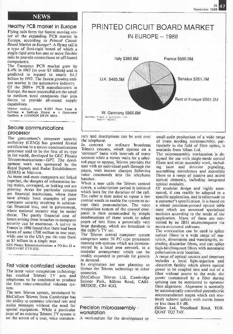
NEWS
EE
November 198847
Healthy PCB market in EuropeFlying tails form the fastest moving sec-tor of the expanding PCB market inEurope, according to Printed CircuitBoard Market in Europe*. A flying tail isa type of flexi-rigid board of which asingle rigid area has one or more flexibletails to provide connections to off -boardcomponents.The European PCB market grew by8.40/o in 1987 (to over S3 billion) and ispredicted to expand to nearly S4.5
billion by 1992. The fastest growing end-use market is the automotive industry.Of the 2000+ PCB manufacturers inEurope, the most successful are the smallto medium sized companies that joinforces to provide all-round supplycapabilities.Market analysis report E1023 from Frost &Sullivan Sullivan House 4 GrosvenorGardens LONDON SW1W ODH.
Secure communicationsprocessorThe government's computer securityauthority (CESG) has granted formalcertification to a secure communicationsprocessor said to be the first of its typein the world, developed by GEC PlesseyTelecommunications - GPT. The devel-opment work was sponsored by theRoyal Signals and Radar Establishment(RSRE) at Malvern.As more and more computers are linkedtogether, the dangers of information be-ing stolen, corrupted, or leaking out aregrowing. Areas for particular concernare financial institutions, where therehave already been examples of poorcomputer security resulting in substan-tial financial loss, and in government,where national security may be underthreat. The purely financial cost oflosses arising from breaches in computersecurity can be enormous. A survey inFrance in 1986 found that there had beenlosses of some £700 million in one year,while one in the USA put the cost thereat $5 billion in a single year.GEC Plessey Telecommunications PO Box 53COVENTRY CV3 1HJ.
First voice controlled videotexThe latest voice recognition technologyhas enabled Teletext TV sets andtelephones to be combined to producethe first voice -controlled videotex sys-tem.The new Televox system, introduced byMcCallum Televox from Cambridge hasthe ability to combine televised text andaudio messages without the need forspecial equipment. While a particularpage of an existing Teletext TV system ison the screen of a user, voice commen-
PRINTED CIRCUIT BOARD MARKETIN EUROPE -- 1988
Italy S386.8tyl
U.K. S485.5M
W. Germany $966.8MFros: -.n.Repo,:
France S590.9M
Benelux S261.7M
Rest of Europe S501.5M
tary and descriptions can be sent overthe telephone.In contrast to ordinary broadcastTeletext systems, which operate on a`carousel' basis with intervals of manyseconds while a viewer waits for a selec-ted page to appear, Televox provides theuser with an individual path through thepages, with instant changes followingvoice commands into the telephonehandset.When a user calls the Televox controlcentre, a subscription period is initiatedwhich lasts for the duration of the call.The caller is then asked to repeat a fewcontrol words to enable the system to ac-cept their pronunciation. The voicerecognition system of the control com-puter is then commanded by simplecombinations of these words to selectpages of text from a potentially verylarge database, which are broadcast tothe caller's TV set.The Televox central computer systemcomprises some 50 PC -type processorsrunning sub -systems which are intercon-nected by a local area network, in amodular arrangement which can bereadily expanded to provide for growthin demand.Its originators are now planning tolicence the Televox technology in othercountries.(McCallum Televox Ltd, CambridgeScience Park, Milton Road, CAM-BRIDGE, CB4 4GG.
Precision microassemblyworkstationA workstation for the development or
small-scale production of a wide rangeof items needing microassembly, par-ticularly in the field of fibre optics, isavailable from Sifam Ltd.The microassembly workstation is de-signed for use with single -mode opticalfibres and other assembly work, includ-ing laser and detector pigtailing,assembling microlenses and mountingfibres to a range of passive and activeoptical elements, including integratedoptical modules.Of modular design and highly auto-mated, it can readily be adapted to aspecific application, and is tailormade toa customer's specification. It is based ona robust precision -ground optical tableonto which are mounted specialisedmodules according to the needs of theapplication. Many of them are con-trolled by an IBM microcomputer viamenu -structured software.The workstation can be used to spliceoptical fibres in a wide range of ma-terials, dimensions and wavelengths, in-cluding dissimilar fibres, and can splicehigh -birefringence fibres with automaticpolarisation -axis location.A range of optical sources and detectorsincludes a local light -injection and-detection facility which allows opticalpower to be coupled into and out of afibre without access to the ends: thepower transmitted by a fibre duringsplicing can be monitored to optimisefibre alignment. Alignment is normallyby automatically controlled piezoelectricmicrotranslation stages which can rou-tinely achieve splices with excess lossesor less than 0.1 dB.(Sifam Ltd, Woodland Road, TOR-QUAY TQ2 7AY.
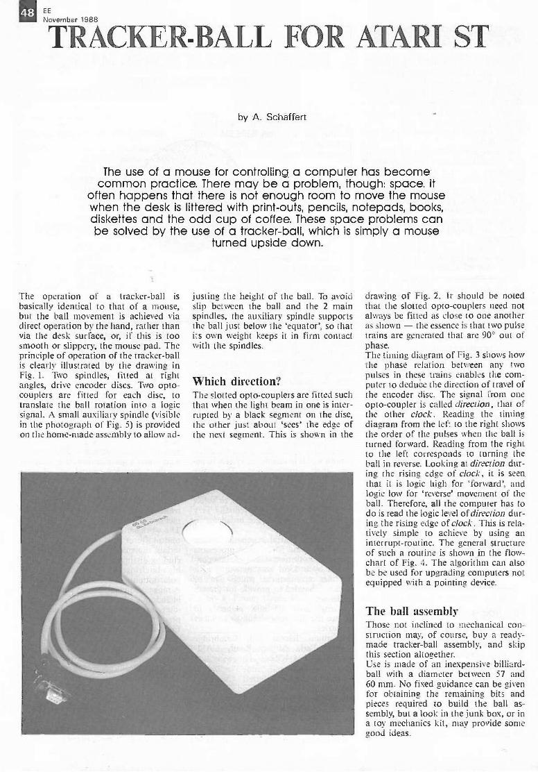
j . 713,,ember 1988
TRACK -BAIL FOR ATARI ST
by A. Schaffert
The use of a mouse for controlling a computer has becomecommon practice. There may be a problem, though: space. It
often happens that there is not enough room to move the mousewhen the desk is littered with print-outs, pencils, notepads, books.diskettes and the odd cup of coffee. These space problems canbe solved by the use of a tracker -ball, which is simply a mouse
turned upside down.
The operation of a tracker -ball isbasically identical to that of a mouse,but the ball movement is achieved viadirect operation by the hand, rather thanvia the desk surface, or, if this is toosmooth or slippery, the mouse pad. Theprinciple of operation of the tracker -ballis clearly illustrated by the drawing inFig. I. Two spindles, fitted at rightangles, drive encoder discs. Two opto-couplers are fitted for each disc, totranslate the ball rotation into a logicsignal. A small auxiliary spindle (visiblein the photograph of Fig. 5) is providedon the home-made assembly to allow ad-
justing the height of the ball. To avoidslip between the ball and the 2 mainspindles, the auxiliary spindle supportsthe ball just below the `equator', so thatits own weight keeps it in firm contactwith the spindles.
Which direction?The slotted opto-couplers are fitted suchthat when the light beam in one is inter-rupted by a black seement on the disc,the other just about 'sees' the edge ofthe next segment. This is shown in the
drawing of Fig. 2. It should be notedthat the slotted opto-couplers need notalways be fitted as close to one anotheras shown - the essence is that two pulsetrains are generated that are 90° out ofphase.The timing diagram of Fig. 3 shows howthe phase relation between any twopulses in these trains enables the com-puter to deduce the direction of travel ofthe encoder disc. The signal from oneopto-coupler is called direction, that ofthe other clock. Reading the timingdiagram from the left to the right showsthe order of the pulses when the ball isturned forward. Reading from the rightto the left corresponds to turning theball in reverse. Looking at direction dur-inc.., the rising edge of clock, it is seenthat it is logic high for 'forward', andlogic low for `reverse' movement of theball. Therefore, all the computer has todo is read the logic level of direction dur-ing the rising edge of clock. This is rela-tively simple to achieve by using aninterrupt -routine. The general structureof such a routine is shown in the flow-chart of Fig. 4. The algorithm can alsobe be used for upgrading computers notequipped with a pointing device.
The ball assemblyThose not inclined to mechanical con-struction may, of course, buy a ready-made tracker -ball assembly, and skipthis section altogether.Use is made of an inexpensive billiard -ball with a diameter between 57 and60 mm. No fixed guidance can be givenfor obtaining the remaining bits andpieces required to build the ball as-sembly, but a look in the junk box, or ina toy mechanics kit, may provide somegood ideas.
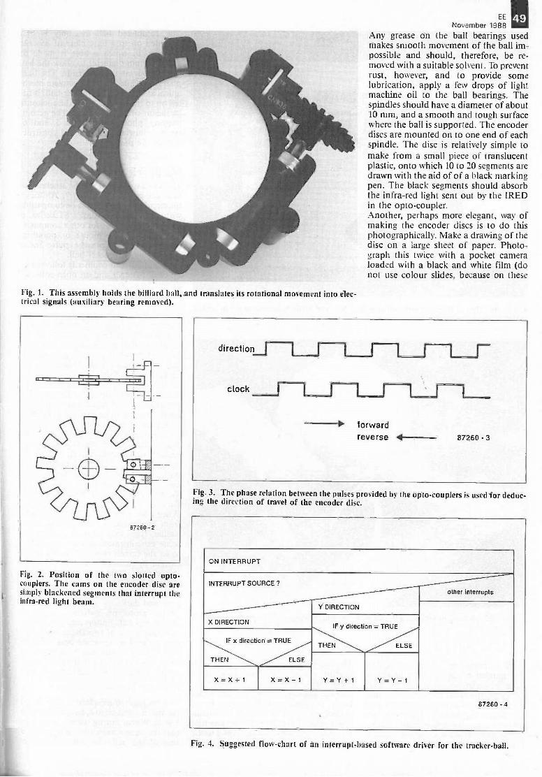
Fig. 1. This assem1)1 holds the billiard ball, and translates its rotational movement into elec-trical signals (auxiliar) bearing removed).
Fig. 2. Position of the two slotted opto-couplers. The cams on the encoder disc aresimply blackened segments that interrupt theinfra -red light beam.
EE
November 1988Any grease on the ball bearings usedmakes smooth movement of the ball im-possible and should, therefore, be re-moved with a suitable solvent. To preventrust, however, and to provide somelubrication, apply a few drops of lightmachine oil to the ball bearings. Thespindles should have a diameter of about10 mm, and a smooth and tough surfacewhere the ball is supported. The encoderdiscs are mounted on to one end of eachspindle. The disc is relatively simple tomake from a small piece of translucentplastic, onto which 10 to 20 segments aredrawn with the aid of of a black markingpen. The black segments should absorbthe infra -red light sent out by the IREDin the opto-coupler.Another, perhaps more elegant, way ofmaking the encoder discs is to do thisphotographically. Make a drawing of thedisc on a large sheet of paper. Photo-graph this twice with a pocket cameraloaded with a black and white film (donot use colour slides, because on these
49
Fig. 3. The phase relation between the pulses provided by the opto-couplers is used for deduc-ing the direction of travel of the encoder disc.
ON INTERRUPT
INTERRUPT SOURCE ?
X DIRECTION
other interrupts
Y DIRECTION
IF x direction = TRUE
THEN ELSE
IF y direction = TRUE
THEN ELSE
X = X + I X = X - 1 Y= Y+ 1 Y= Y- I
87260 - 4
Fig. 4. Suggested flow -chart of an interrupt -based software driver for the tracker -ball.
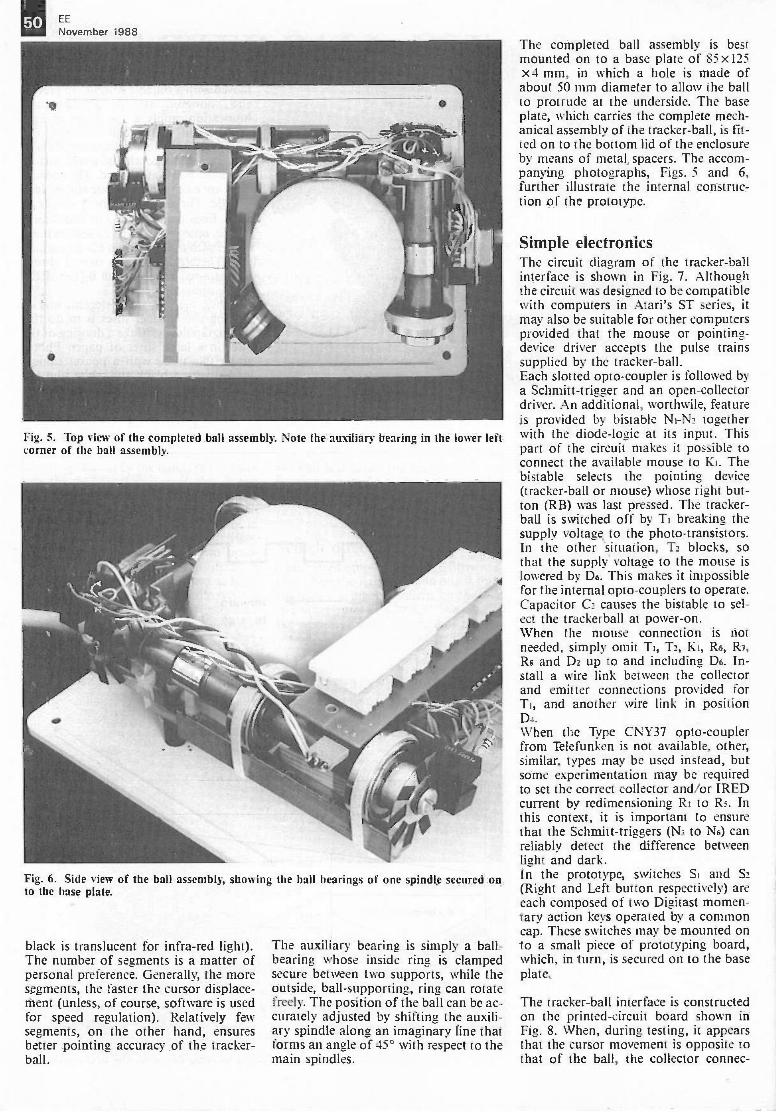
50 EE
November 1988
Fig. 5. Top view of the completed ball assembly. Note the auxiliary bearing in the lower leftcorner of the ball assembly.
Fig. 6. Side view of the ball assembly, showing the ball bearings of one spindle secured onto the base plate.
black is translucent for infra -red light).The number of segments is a matter ofpersonal preference. Generally, the moresegments, the faster the cursor displace-ment (unless, of course, software is usedfor speed regulation). Relatively fewsegments, on the other hand, ensuresbetter pointing accuracy of the tracker -ball.
The auxiliary bearing is simply a ball -bearing whose inside ring is clampedsecure between two supports, while theoutside, ball -supporting, ring can rotatefreely. The position of the ball can be ac-curately adjusted by shifting the auxili-ary spindle along an imaginary fine thatforms an angle of 45° with respect to themain spindles.
The completed ball assembly is bestmounted on to a base plate of 85 x125x4 mm, in which a hole is made ofabout 50 mm diameter to allow the ballto protrude at the underside. The baseplate, which carries the complete mech-anical assembly of the tracker -ball, is fit-ted on to the bottom lid of the enclosureby means of metal, spacers. The accom-panying photographs, Figs. 5 and 6,further illustrate the internal construc-tion of the prototype.
Simple electronicsThe circuit diagram of the tracker -ballinterface is shown in Fig. 7. Althoughthe circuit was designed to be compatiblewith computers in Atari's ST series, itmay also be suitable for other computersprovided that the mouse or pointing -device driver accepts the pulse trainssupplied by the tracker -ball.Each slotted opto-coupler is followed bya Schmitt -trigger and an open -collectordriver. An additional, worthwile, featureis provided by bistable Ni-N2 togetherwith the diode -logic at its input. Thispart of the circuit makes it possible toconnect the available mouse to Ki. Thebistable selects the pointing device(tracker -ball or mouse) whose right but-ton (RB) was last pressed. The tracker -ball is switched off by Ti breaking thesupply voltage to the photo -transistors.In the other situation, T2 blocks, sothat the supply voltage to the mouse islowered by De. This makes it impossiblefor the internal opto-couplers to operate.Capacitor C2 causes the bistable to sel-ect the trackerball at power -on.When the mouse connection is notneeded, simply omit Ti, T2, Ki, R6, R7,Rs and D2 up to and including D6. In-stall a wire link between the collectorand emitter connections provided forTi, and another wire link in positionD4.When the Type CNY37 opto-couplerfrom Telefunken is not available, other,similar, types may be used instead, butsome experimentation may be requiredto set the correct collector and/or IREDcurrent by redimensioning R to Rs. Inthis context, it is important to ensurethat the Schmitt -triggers (N3 to N6) canreliably detect the difference betweenlight and dark.In the prototype, switches Si and S2(Right and Left button respectively) areeach composed of two Digitast momen-tary action keys operated by a commoncap. These switches may be mounted onto a small piece of prototyping board,which, in turn, is secured on to the baseplate.
The tracker -ball interface is constructedon the printed -circuit board shown inFig. 8. When, during testing, it appearsthat the cursor movement is opposite tothat of the ball, the collector connec-
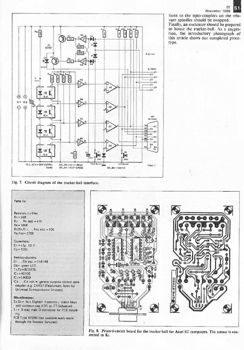
O 0
RI
2.80557
72
1=1H1 RaRimf]mh
EMI
tmRq
;1 I:31/.12
03
06
*Al P4 *95 *93
IC6
0 N6
5
ct=IIC 1 IC 2
479 Iart
IC4
3 H4
3
IC 3
6
M10
N312
3
IC5
N5
a 3 a
A2
5
4
a
Al
MS)
A3
ATAPJ
01
03
03
XS
03
K116 masse
LB
ICA
.53YA
Y3
O
0.12.1
IC 3-IC 6 = CNY 37(TFK) N1._N6 =1C 1 = 40106KVA Boll. Let
(41310) A 1._A4 = IC 2 = LM339 D1_05 =1114145
01
0
03
0
03
173E:-7
Fig. 7. Circuit diagram of the tracker -ball interface.
Parts list
Resistors I=5 isRI= 56R82 .. .R5 incl. = 47KR6 =100KR7;116;1311. . R15 incI.=10KR9;111o= 270K
Capacitors:CI =47p; 10VC2=100n
Semiconductors:Di ...Do incl.=1N4148De= green LEDT1;T2=BC55713ICI =40106IC2=LM339IC3...ICe incl.= general-purpose slotted opto-coupler; e.g. CNY37 (Telefunken; listed byUniversal Semiconductor Devices).
Miscellaneous:S1;S2= two Digitast momentary action keyswith common cap (ITW or ITTISchadow).
Kt = 9 -way male 0 -connector for PCB mount-ing.
PCB Type 87260 (not available ready-madethrough the Readers Services).
EE
November 1988tions to the opto-couplers on the rela-vant spindles should be swapped.Finally, an enclosure should be preparedto house the tracker -ball. As a sugges-tion, the introductory photograph ofthis article shows our completed proto-type.
11Q 0
bt
Fig. 8. Printed -circuit board for the tracker -hall for Atari ST computers. The mouse is con-nected to Ki.
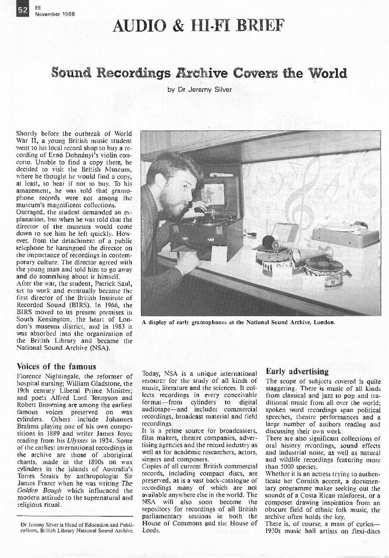
EE
November 1988
AL DI & HI-FI BRIEF
Sound Recordings Archive Covers the World
Shortly before the outbreak of WorldWar II, a young British music studentwent to his local record shop to buy a re-cording of ErnO Dohnanyi's violin con-certo. Unable to find a copy there, hedecided to visit the British Museum,where he thought he would find a copy,at least, to hear if not to buy. To hisamazement, he was told that gramo-phone records were not among themuseum's magnificent collections.Outraged, the student demanded an ex-planation, but when he was told that thedirector of the museum would comedown to see him he left quickly. How-ever, from the detachment of a publictelephone he harangued the director onthe importance of recordings in contem-porary culture. The director agreed withthe young man and told him to go awayand do something about it himself.After the war, the student, Patrick Saul,set to work and eventually became thefirst director of the British Institute ofRecorded Sound (BIRS). In 1966, theBIRS moved to its present premises inSouth Kensington, the heart of Lon-don's museum district, and in 1983 itwas absorbed into the organization ofthe British Library and became theNational Sound Archive (NSA).
Voices of the famousFlorence Nightingale, the reformer ofhospital nursing; William Gladstone, the19th century Liberal Prime Minister;and poets Alfred Lord Tennyson andRobert Browning are among the earliestfamous voices preserved on waxcylinders. Others include JohannesBrahms playing one of his own compo-sitions in 1889 and writer James Joycereading from his Ulysses in 1924. Someof the earliest international recordings inthe archive are those of aboriginalchants, made in the 1890s on waxcylinders in the islands of Australia'sTorres Straits by anthropologist SirJames Frazer when he was writing TheGolden Bough which influenced themodern attitude to the supernatural andreligious ritual.
Dr Jeremy Silver is Head of Education and Publi-cations, British Library National Sound Archive.
by Dr Jeremy Silver
A display of early gramophones at the National Sound Archive, London.
Today, NSA is a unique internationalresource for the study of all kinds ofmusic, literature and the sciences. It col-lects recordings in every conceivableformat-from cylinders to digitalaudiotape-and includes commercialrecordings, broadcast material and fieldrecordings.It is a prime source for broadcasters,film makers, theatre companies, adver-tising agencies and the record industry aswell as for academic researchers, actors,singers and composers.Copies of all current British commercialrecords, including compact discs, arepreserved, as is a vast back -catalogue ofrecordings many of which are notavailable anywhere else in the world. TheNSA will also soon become therepository for recordings of all Britishparliamentary sessions in both theHouse of Commons and the House ofLords.
Early advertisingThe scope of subjects covered is quitestaggering. There is music of all kindsfrom classical and jazz to pop and tra-ditional music from all over the world;spoken word recordings span politicalspeeches, theatre performances and alarge number of authors reading anddiscussing their own work.There are also significant collections oforal history recordings, sound effectsand industrial noise, as well as naturaland wildlife recordings featuring morethan 5000 species.Whether it is an actress trying to authen-ticate her Cornish accent, a documen-tary programme maker seeking out thesounds of a Costa Rican rainforest, or acomposer drawing inspiration from anobscure field of ethnic folk music, thearchive often holds the key.There is, of course, a mass of curios -1930s music hall artists on flexi-discs
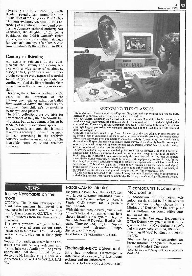
EE
November 1988advertising BP Plus motor oil; 1960sBeatles sound-alikes promoting thepossibilities of working as a Post Officetelephone exchange operator; a 1903 re-cording of a geisha -girl brass band play-ing the Japanese national anthem; andChristabel, the daughter of EmmelinePankhurst, the British women's rightspioneer, insisting on a militant strugglefor women's suffrage after her releasefrom London's Holloway Prison in 1909.
Century of listeningAn extensive reference library com-plements the listening and viewing ser-vice with a wide range of catalogues,discographies, periodicals and mono-graphs covering every aspect of recordedsound. Anyone tracing a particular re-cording will find the library invaluable inresearch as well as fascinating in its ownright.This year, the archive is celebrating 100years of the invention of thegramophone with an exhibition 'calledRevolutions in Sound that traces its de-velopment from children's toy machinesto today's disc players.The NSA collections are available forany member of the public to consult freeof charge, but an appointment has to bemade to listen to something special.It was recently estimated that it wouldtake over a century of non-stop listeningto hear everything in the archive'scollections-that is an indication of theincredible range of sound artefactsavailable.
NEWSTalking Newspaper on themoveQTI-TNA, The Talking Newspaper forblind radio amateurs, has moved to anew base in Lancaster, where it will berun by Harry Longley, GOJKT, with thehelp of students from the University ofLancaster.The service provides readings of techni-cal items selected from current radiomagazines to more than 120 blind radioamateurs worldwide on a fortnightlybasis.Support from radio amateurs in the Lan-caster area will be very welcome, andfurther help with funding will be greatlyappreciated. All these should be ad-dressed to H. Longley QTI-TNA 7Anderson Close LANCASTER LAI3JE.
RESTORING THE CLASSICSOur inheritance of rare sound recordings on film, disc and wax cylinder is often painfullymarred by a background of scratches, crackles and whistles.This new system, developed by the British Library National Sound Archive in London, canproduce major improvements in audio quality at a fraction of the cost of today's digital audiocontrol desks. Known as CEDAR (Computer Enhanced Digital Audio Restoration), it is a low-cost digital signal processing hardware and software package and is compatible with standarddesk -top computers.CEDAR, it is claimed, is able to perform all the tasks of the latest digital processors, and togo beyond them in eliminating the sounds of scratches and crackle produced by wear and tearwhich have previously been impossible to mask successfully. By operating out of real time, athree -minute 78 rpm disc treated to reduce severe surface noise is easily handled overnight;once programmed the system operates automatically. Dramatic improvements to the qualityof film sound -track or discs can be achieved.The system includes programmes emulating features of signal processors, such as a spectrumanalyser able to display a section of sound on the computer screen, as shown in the picture.It also has a filter capable of removing not only the pure tones of a mains hum but impuretones like heterodyne whistles. A special advantage of the equipment, however, is that, for thefirst time, it provides a satisfactory means of filling the gap left when a click or scratch hasbeen removed. This is done by putting "white noise" through a filter that had been designedby the system to match the characteristics of the sound either side of the gap. This facility isparticularly useful for maintaining music tempos and for film synchronisation.CEDAR has been developed by the British Library National Sound Archive in collaborationwith the Engineering Department of Cambridge University and Cambridge Electronic Design.
Racal CAD for AlcatelBelgium's .Alcatel NV, the world's sec-ond largest telecommunications manu-facturer, is to standardize on Racal'sVisula CAD system for its printed -circuit boards.With this contract, Alcatel joins a hostof international companies that havechosen Racal's CAD system. They in-clude McDonnell Douglas, Hughes Air-craft, Thomson-CSF, Fujitsu, NipponTelephone and Telegraph, Philips,Siemens, and Plessey.Racal-Redac TEWKESBURY GL20 8HE.
Electrovalue-Iskra agreementIskra has appointed Electrovajue adistributor of its range of surface -mountresistors and potentiometers.Iskra Ltd Redlands COULSDON CR3 2HT
BT consortium's success withMoD contractA consortium of information tech-nology specialists led by British Telecomis one of two suppliers chosen by theMinistry of Defence for the next phaseof its multi -million pound office auto-mation system.Known as the Corporate HeadquartersOffice Technology System (CHOTS), thesystem will be installed during the 1990sand will eventually serve 24,000 users inmore than 40 MoD buildings throughoutthe UK.Other members of the consortium areSecure Information Systems, HoneywellBull, and Nixdorf Computer.British Telecom 81 Newgate Street LONDONECIA 7AJ.
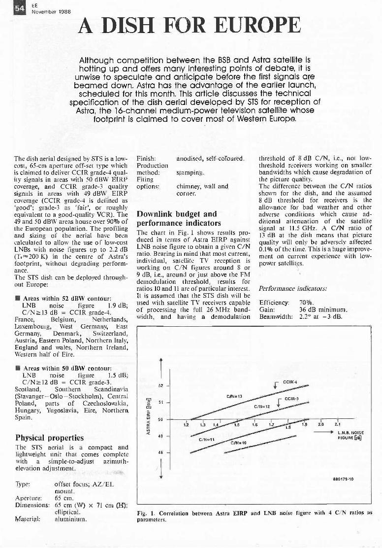
54 EE
November 1988
A DISH FOR EUROPEAlthough competition between the BSB and Astra satellite ishotting up and offers many interesting points of debate, it is
unwise to speculate and anticipate before the first signals arebeamed down. Astra has the advantage of the earlier launch,scheduled for this month. This article discusses the technical
specification of the dish aerial developed by STS for reception ofAstra, the 16 -channel medium -power television satellite whose
footprint is claimed to cover most of Western Europe.
The dish aerial designed by STS is a low-cost, 65 -cm aperture off -set type whichis claimed to deliver CCIR grade -4 qual-ity signals in areas with 50 dBW EIRPcoverage, and CCIR grade -3 qualitysignals in areas with 49 dBW EIRPcoverage (CCIR grade -4 is defined as`good'; grade -3 as 'fair', or roughlyequivalent to a good -quality VCR). The49 and 50 dBW areas house over 90% ofthe European population. The profilingand sizing of the aerial have beencalculated to allow the use of low-costLNBs with noise figures up to 2.2 dB
K) in the centre of Astra'sfootprint, without degrading perform-ance.The STS dish can be deployed through-out Europe:
MI Areas within 52 dBW contour:LNB noise figure 1.9 dB;C/N a.13 dB = CCIR grade -4.
France, Belgium, Netherlands,Luxembourg, West Germany, EastGermany, Denmark, Switzerland,Austria, Eastern Poland, Northern Italy,England and wales, Northern Ireland,Western half of Eire.
III Areas within 50 dBW contour:LNB noise figure 1.5 dB;C/N dB = CCIR grade -3.
Scotland, Southern Scandinavia(Stavanger-Oslo-Stockholm), CentralPoland, parts of Czechoslovakia,Hungary, Yugoslavia, Eire, NorthernSpain.
Physical propertiesThe STS aerial is a compact andlightweight unit that comes completewith a simple -to -adjust azimuth -elevation adjustment.
Type: offset focus; AZ/ELmount.
Aperture: 65 cm.Dimensions: 65 cm (W) x 71 cm (H);
elliptical.Material: aluminium.
Finish:Productionmethod:Fitingoptions:
anodised, self -coloured.
stamping.
chimney, wall andcorner.
Downlink budget andperformance indicatorsThe chart in Fig. 1 shows results pro-duced in terms of Astra EIRP againstLNB noise figure to obtain a given C/Nratio. Bearing in mind that most current,individual, satellite TV reception isworking on C/N figures around 8 or9 dB, i.e., around or just above the FMdemodulation threshold, results forratios 10 and 11 are of particular interest.It is assumed that the STS dish will beused with satellite TV receivers capableof processing the full 26 MHz band-width, and having a demodulation
Fig. 1. Correlation between Astra E11213parameters.
threshold of 8 dB C/N, i.e., not low -threshold receivers working on smallerbandwidths which cause degradation ofthe picture quality.The difference between the C/N ratiosshown for the dish, and the assumed8 dB threshold for receivers is theallowance for bad weather and otheradverse conditions which cause ad-ditional attenuation of the satellitesignal at 11.5 GHz. A C/N ratio of13 dB at the dish means that picturequality will only be adversely affected0.1% of the time. This is a huge improve-ment on current experience with low -power satellites.
Performance indicators:
Efficiency:Gain:Beamwidth:
70%.36 dB minimum.2.2° at -3 dB.
L.N.B. NOISEFIGURE DO
and LNB noise figure with 4 C/N ratios as
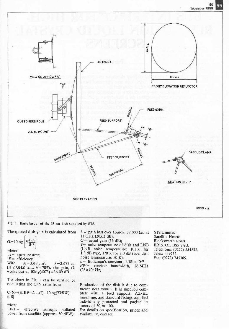
EE 113November 1988
VIEW ON ARROW "A"
CUSTOMERS POLE
AZ/EL MOUNT
"A"
sk
- ANTENNA
A
SIDE ELEVATION
FEED SUPPORT
FRONT ELEVATION REFLECTOR
FEEDHORN
\ Ha
\1:cFEED SUPPORT tP
so*SECTION "8 - 5"
880179-11
Fig. 2. Basic layout of the 65 -cm dish supplied by STS.
The quoted dish gain is calculated from
G=101og [E4T-t-11.172
whereA = aperture area;E= efficiency.With A =3318 cm2, A=2.677 cm(11.2 GHz) and E=7007o, the gain, G,works out at 10log(4073)=36.09 dB.
The chart in Fig. 1 can be verified bycalculating the C/N ratio from
C/N=(EIRP-L +G)-10log(TkB1V)[dB]
whereEIRP= effective isotropic radiatedpower from satellite (approx. 50 dBW);
L = path loss over approx. 37.000 km at11 GHz (205.2 dB);G= aerial gain (36 dB);T= noise temperature of dish and LNB(LNB noise temperature: 101 K for1.3 dB type, 170 K for 2.0 dB type; dishnoise temperature: 50 K);k= Boltzman's constant, 1.381x10⁻²³BIV= receiver bandwidth, 26 MHz(26 x HP Hz).
Production of the dish is due to com-mence next month. It is supplied com-plete with a feed support, AZ/ELmounting, and standard fixings suppliedindividually protected and packed inouters of 50 or 100.For details on specification, prices andavailability, contact
STS LimitedSatellite HouseBlackswarth RoadBRISTOL BS5 8AU.Telephone: (0272) 554535.Telex: 449752.Fax: (0272) 745365.
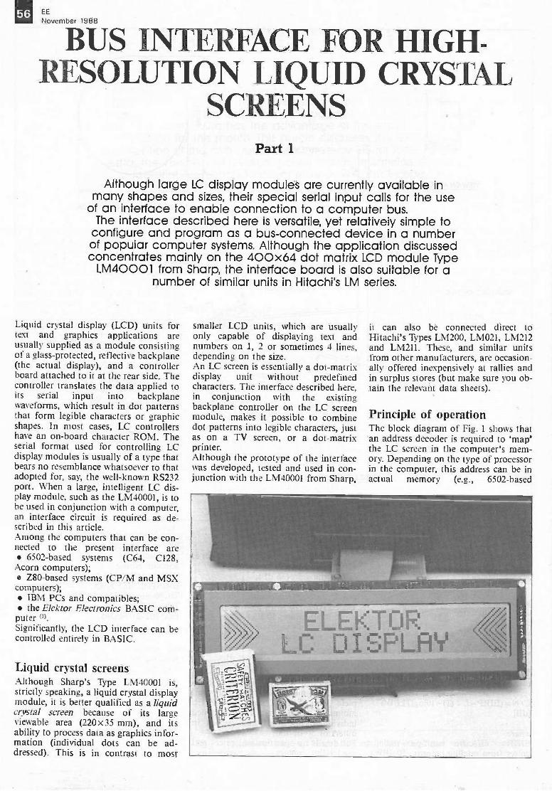
56
ENEovemiiitS INTERFACE FOR HIGH-
RESOLUTION LIQUID CRYSTALSCREENS
Part 1
Although large LC display modulet are currently available inmany shapes and sizes, their special serial input calls for the use
of an interface to enable connection to a computer bus.The interface described here is versatile, yet relatively simple to
configure and program as a bus -connected device in a numberof popular computer systems. Although the application discussedconcentrates mainly on the 400x64 dot matrix LCD module Type
LM40001 from Sharp, the interface board is also suitable for anumber of similar units in Hitachi's LM series.
Liquid crystal display (LCD) units fortext and graphics applications areusually supplied as a module consistingof a glass -protected, reflective backplane(the actual display), and a controllerboard attached to it at the rear side. Thecontroller translates the data applied toits serial input into backplanewaveforms, which result in dot patternsthat form legible characters or graphicshapes. In most cases, LC controllershave an on -board character ROM. Theserial format used for controlling LCdisplay modules is usually of a type thatbears no resemblance whatsoever to thatadopted for, say, the well-known RS232port. When a large, intelligent LC dis-play module, such as the LM40001, is tobe used in conjunction with a computer,an interface circuit is required as de-scribed in this article.Among the computers that can be con-nected to the present interface are 6502 -based systems (C64, CI28,Acorn computers); Z80 -based systems (CP/M and MSXcomputers); IBM PCs and compatibles; the Elektor Electronics BASIC com-
puter ").Significantly, the LCD interface can becontrolled entirely in BASIC.
Liquid crystal screensAlthough Sharp's Type LM40001 is,strictly speaking, a liquid crystal displaymodule, it is better qualified as a liquidcrystal screen because of its largeviewable area (220 x35 mm), and itsability to process data as graphics infor-mation (individual dots can be ad-dressed). This is in contrast to most
smaller LCD units, which are usuallyonly capable of displaying text andnumbers on 1, 2 or sometimes 4 lines,depending on the size.An LC screen is essentially a dot-matrixdisplay unit without predefinedcharacters. The interface described here,in conjunction with the existingbackplane controller on the LC screenmodule, makes it possible to combinedot patterns into legible characters, justas on a TV screen, or a dot-matrixprinter.Although the prototype of the interfacewas developed, tested and used in con-junction with the LM40001 from Sharp,
it can also be connected direct toHitachi's Types LM200, LM021, LM212and Liv1211. These, and similar unitsfrom other manufacturers, are occasion-ally offered inexpensively at rallies andin surplus stores (but make sure you ob-tain the relevant data sheets).
Principle of operationThe block diagram of Fig. 1 shows thatan address decoder is required to 'map'the LC screen in the computer's mem-ory. Depending on the type of processorin the computer, this address can be inactual memory (e.g., 6502 -based
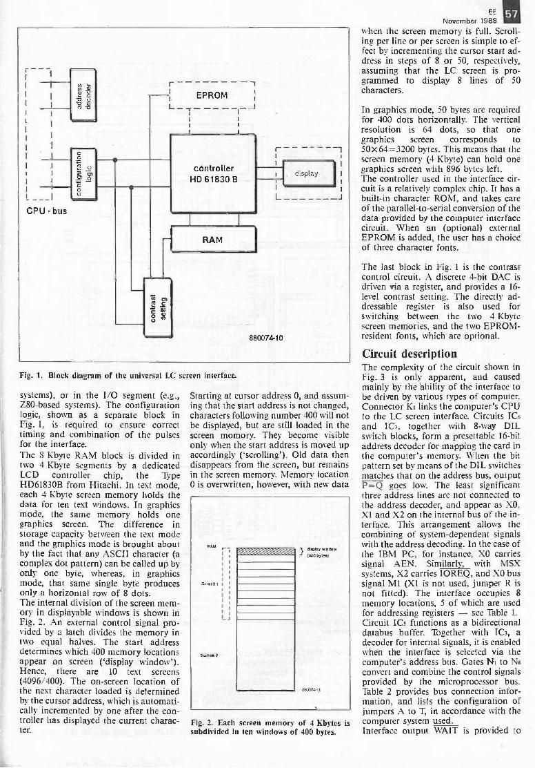
_ ___ICPU - bus
0
0
L _EPROM
7 - -
controllerHD 61830 B
RAM
880074-10
display
Fig. 1. Block diagram of the universal LC screen interface.
systems), or in the I/O segment (e.g.,Z80 -based systems). The configurationlogic, shown as a separate block inFig. 1, is required to ensure correcttiming and combination of the pulsesfor the interface.The 8 Kbyte RAM block is divided intwo 4 Kbyte segments by a dedicatedLCD controller chip, the TypeHD61830B from Hitachi. In text mode,each 4 Kbyte screen memory holds thedata for ten text windows. In graphicsmode, the same memory holds onegraphics screen. The difference instorage capacity between the text modeand the graphics mode is brought aboutby the fact that any ASCII character (acomplex dot pattern) can be called up byonly one byte, whereas, in graphicsmode, that same single byte producesonly a horizontal row of 8 dots.The internal division of the screen mem-ory in displayable windows is shown inFig. 2. An external control signal pro-vided by a latch divides the memory intwo equal halves. The start addressdetermines which 400 memory locationsappear on screen (`display window').Hence, there are 10 text screens(4096/400). The on -screen location ofthe next character loaded is determinedby the cursor address, which is automati-cally incremented by one after the con-troller has displayed the current charac-ter.
Starting at cursor address 0, and assum-ing that the start address is not changed,characters following number 400 will notbe displayed, but are still loaded in thescreen momory. They become visibleonly when the start address is moved upaccordingly ('scrolling'). Old data thendisappears from the screen, but remainsin the screen memory. Memory location0 is overwritten, however, with new data
RJA1
screen 2
Mohr 1.0.4j
1.bit.
SICG74-11
Fig. 2. Each screen memory of 4 Kbytes issubdivided in ten windows of 400 bytes.
EE 111November 1988
when the screen memory is full. Scroll-ing per line or per screen is simple to ef-fect by incrementing the cursor start ad-dress in steps of 8 or 50, respectively,assuming that the LC screen is pro-grammed to display 8 lines of 50characters.
In graphics mode, 50 bytes are requiredfor 400 dots horizontally. The verticalresolution is 64 dots, so that onegraphics screen corresponds to50x64=3200 bytes. This means that thescreen memory (4 Kbyte) can hold onegraphics screen with 896 bytes left.The controller used in the interface cir-cuit is a relatively complex chip. It has abuilt-in character ROM, and takes careof the parallel -to -serial conversion of thedata provided by the computer interfacecircuit. When an (optional) externalEPROM is added, the user has a choiceof three character fonts.
The last block in Fig. 1 is the contrastcontrol circuit. A discrete 4 -bit DAC isdriven via a register, and provides a 16 -level contrast setting. The directly ad-dressable register is also used forswitching between the two 4 Kbytescreen memories, and the two EPROM -resident fonts, which are optional.
Circuit descriptionThe complexity of the circuit shown inFig. 3 is only apparent, and causedmainly by the 'ability of the interface tobe driven by various types of computer.Connector Kr links the computer's CPUto the LC screen interface. Circuits IC6and IC7, together with 8 -way DILswitch blocks, form a presettable 16 -bitaddress decoder for mapping the card inthe computer's memory. When the bitpattern set by means of the DIL switchesmatches that on the address bus, outputP=Q goes low. The least significantthree address lines are not connected tothe address decoder, and appear as X0,X1 and X2 on the internal bus of the in-terface. This arrangement allows thecombining of system -dependent signalswith the address decoding. In the case ofthe IBM PC, for instance, XO carriessignal AEN. Similarly, with MSXsystems, X2 carries IOREQ, and X0 bussignal M1 (X1 is not used, jumper R isnot fitted). The interface occupies 8memory locations, 5 of which are usedfor addressing registers - see Table 1.Circuit ICs functions as a bidirectionaldatabus buffer. Together with IC3, adecoder for internal signals, it is enabledwhen the interface is selected via thecomputer's address bus. Gates Ni to N6convert and combine the control signalsprovided by the microprocessor bus.Table 2 provides bus connection infor-mation, and lists the configuration ofjumpers A to T, in accordance with thecomputer system used.Interface output WAIT is provided to
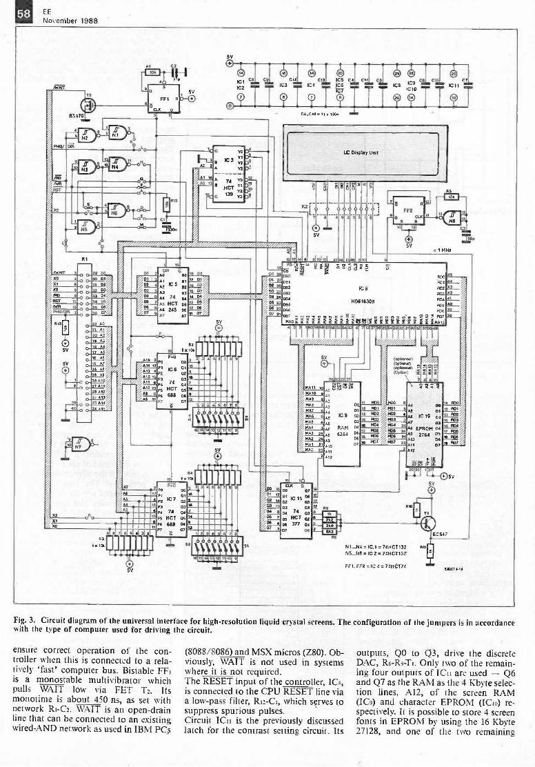
58 EE
November 1988
0
85170
rep
XI 6fQnar 9RST 1.2
MR 13
PtCLDIR
0
By
0
I C2
r -I H3 "'
FF1
CLX
At202219 AI
A417 AS16 A615 1.7
AA
AS
ASO
7 All9:12
1113
73 AU4 Al
XI
C1
TT
S
IC 3
A Y3
er,
A 74I Hai
139
Yt
II
G_,
AA.; SRI
A3 53At 74 64
IICT CS
255 E.5
All 772.13 4Al2All 6AIDA9Mn
63
05V
;'17
23
as 74A_ MCI
TI
688
77 DI0203
811 06
0606
II UT
R2
86I
07
0MI
0
GUCOIEQV
I L11:5 1114J) ICti C13 IC5 C4; Cil C5IC9 CION ClNow ImoICs
:,!_?; c_s),TC -C,! = 1, 1M.
LC Cis -y
iii/iiiiiiiiii
00
102
r-0
mi=
5.5tY
009 311-
11111121 -. 1 eta
0
FF2 0nlel ni
CID5V
re
el I
I MHz
,ot -7RS
- VIV S13;aiFCC
061 POI 44032 IC 8 Fc2 9.-202 F00 4_2__
511234 *--OBI23 0,6E.H561830 Fel 4°CE 22 D., ME n---
e , ... . -- f= :2 2 pc? 7.3067 Z"r.i - c.-gE6 .MA3x 2 X IkSrLIII X X x 2 k I X Z 2 2 VtAi7
11
D] 2OF 2C5
07 21
4
iirisrarrr4
elle A
MA i1
r/ RASO11A9
MAC
1413
DVS
2642
KAI
5V
0
24
21
1.9 37,43.
23
00
tt SO
Di 17
02 sa
03Oa
05 7
0507 3
0-4 G00 07
DiIC 11
62 Di03 or04 74 03 905 HCT 0206 377 0107 00 2
A.4
45IC 9
AaRAM
As 6264
AliAltAl2
3100152istf5gay
nnzs
2 2 7c a
111:0*32.Mic 5.75
n_L..532 202* 103 mar 3 AT
io
)424 70443 EPRO14 0.117 105A' vs71136106 2764At- C.61437 zi.:1107 All 0717
02
23
05
07
IS
S
Fal
282349
R6
5V
SV
0
711-/i4 = IC 1 = 74HCT132 611
= IC 2 = 74HCT132
FF 1, FF2 = IC 4 = 74HCT74
85547
SICC7614
Fig. 3. Circuit diagram of the universal interface for high -resolution liquid crystal screens. The configuration of the jumpers is in accordancewith the type of computer used for driving the circuit.
ensure correct operation of the con-troller when this is connected to a rela-tively 'fast' computer bus. Bistable FF1is a monostable multivibrator whichpulls WAIT low via FET T2. Itsmonotime is about 450 ns, as set withnetwork Itt-C2.. WAIT is an open -drainline that can be connected to an existingwired -AND network as used in IBM PCs
(8088/8086) and MSX micros (Z80). Ob-viously, WAIT is not used in systemswhere it is not required.The RESET input of the controller, ICs,is connected to the CPU RESET line viaa low-pass filter, 1212 -CI, which serves tosuppress spurious pulses.Circuit ICii is the previously discussedlatch for the contrast setting circuit. Its
outputs, QO to Q3, drive the discreteDAC, R6 -R9 -Ti. Only two of the remain-ing four outputs of ICI, are used - Q6and Q7 as the RAM as the 4 Kbyte selec-tion lines, Al2, of the screen RAM(IC9) and character EPROM (ICio) re-spectively. It is possible to store 4 screenfonts in EPROM by using the 16 Kbyte27128, and one of the two remaining
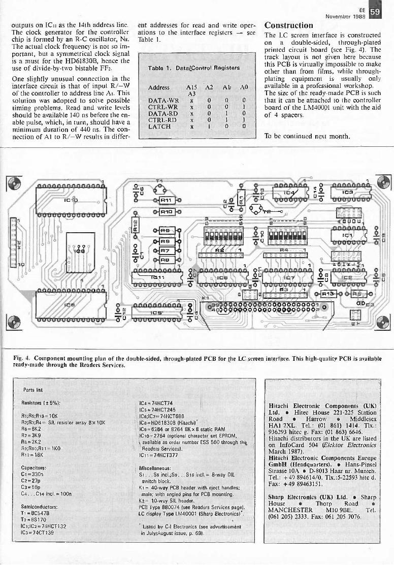
EE
November 198859
outputs on ICu as the 14th address line.The clock generator for the controllerchip is formed by an R -C oscillator, Ns.The actual clock frequency is not so im-portant, but a symmetrical clock signalis a must for the HD61830B, hence theuse of divide -by -two bistable FF2.
One slightly unusual connection in theinterface circuit is that of input R/-Wof the controller to address line Ai. Thissolution was adopted to solve possibletiming problems. Read and write levelsshould be available 140 ns before the en-able pulse, which, in turn, should have aminimum duration of 440 ns. The con-nection of Al to R/-W results in differ-
ent addresses for read and write oper-ations to the interface registers - seeTable I.
Table 1. DataiControl Registers
Address A15 A2 Al AOA3
DATA-WR x 0 0 0CTRL-WR x 0 0 1
DATA -RD x 0 1 0CTRL -RD x 0 1 1
LATCH x I 0 0
ConstructionThe LC screen interface is constructedon a double -sided, through -platedprinted circuit board (see Fig. 4). Thetrack layout is not given here becausethis PCB is virtually impossible to makeother than from films, while through -plating equipment is usually onlyavailable in a professional workshop.The size of the ready-made PCB is suchthat it can be attached to the controllerboard of the LM40001 unit with the aidof 4 spacers.
To be continued next month.
I
TI
2
trri
ocuanoor) 9Ta4
atr,
R41 I
0
aeaooaaa
u. 0 I
d
oar:0000000000000000000023900000000000000000001 Clbc3
!
Fig. 4. Component mounting plan of the double -sided, through -plated PCB for the LC screen interface. This high -quality PCB is availableready-made through the Readers Services.
Parts list
Resistors 1- 55):
RI;Re;R13=10KR2;Ra;Re= SIL resistor array 8 <10K68= 8K2R; =3K9Ra=2K2Re:Rio:M.1=1K°1112=18K
Capacitors:Ci =330nC2=27pC3=5613C4...C14 inc1=100n
Semiconductors:T1=8C5478T2=BS170IC1;1C2=74HCT132ICa=74CT139
IC4 = 74HCT74(Cs= 74HCT245ICOC2=74HCT688IC8=HD61830B (Hitachi).IC9=6264 or 8264 8Kx 8 static RAMICto=2764 (optional character set EPROM, available as order number ESS 560 through the
Readers Services).IC11= 74HCT377
Miscellaneous:St ...Se incl.:Ss...516 incl.= 8 -way DILswitch block.
Kt = 40 -way PCB header with eject handles;male; with angled pins for PCB mounting.
K2= 10 -way SIL header.PCB Type 880074 (see Readers Services page).LC display Type LM40001 (Sharp Electronics).
Listed by C -I Electronics (see advertisementin JulyiAugust issue, p. 69).
Hitachi Electronic Components (UK)Ltd. Hitec House 221-225 StationRoad Harrow MiddlesexHA' 2XL. Tel.: (01 861) 1414. TLx.:936293 hitec g. Fax: (01 863) 6646.Hitachi distributors in the UK are listedon InfoCard 504 (Elektor ElectronicsMarch 1987).Hitachi Electronic Components EuropeGmbH (Headquarters). Hans-PinselStrasse 10A D-8013 Haar nr. Munich.Tel.: +49 894614/0. Tlx.:5-22593 hitc d.Fax: +49 89463151.
Sharp Electronics (UK) Ltd. SharpHouse Thorp RoadMANCHESTER M10 9BE. Tel.(061 205) 2333. Fax: 061 205 7076.
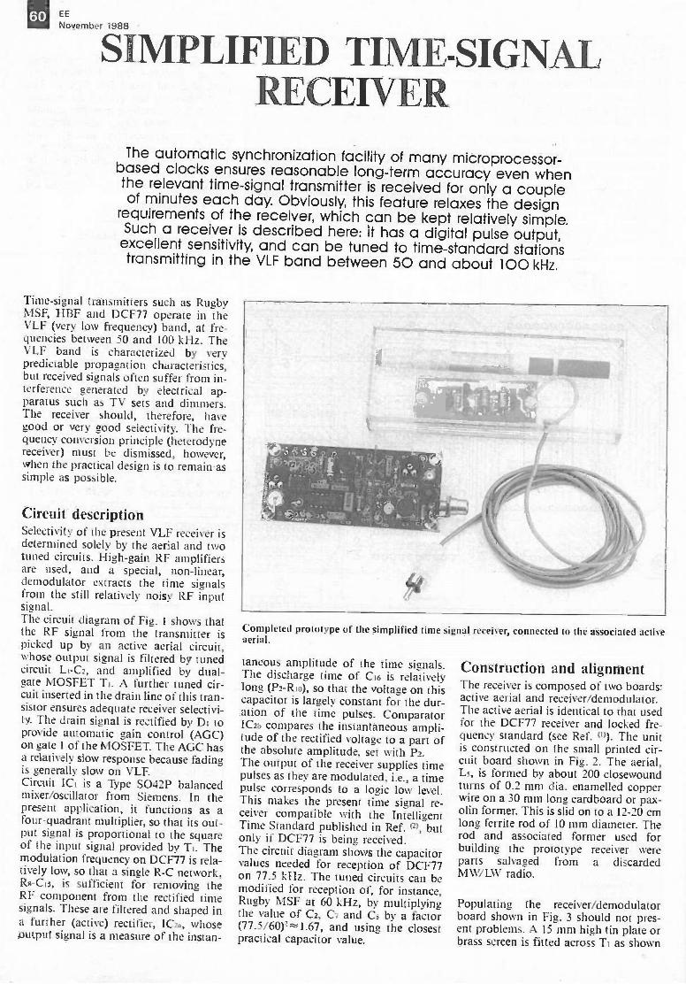
60 EE
November 1988
SIMPLIFIED TIME-SIGNALRECEVER
The automatic synchronization facility of many microprocessor-based clocks ensures reasonable long-term accuracy even whenthe relevant time -signal transmitter is received for only a coupleof minutes each day. Obviously, this feature relaxes the design
requirements of the receiver, which can be kept relatively simple.Such a receiver is described here: it has a digital pulse output,
excellent sensitivity, and can be tuned to time -standard stationstransmitting in the VLF band between 50 and about 100 kHz,
Time -signal transmitters such as RugbyMSF, HBF and DCF77 operate in theVLF (very low frequency) band, at fre-quencies between 50 and 100 kHz. TheVLF band is characterized by verypredictable propagation characteristics,but received signals often suffer from in-terference generated by electrical ap-paratus such as TV sets and dimmers.The receiver should, therefore, havegood or very good selectivity. The fre-quency conversion principle (heterodynereceiver) must be dismissed, however,when the practical design is to remain assimple as possible.
Circuit descriptionSelectivity of the present VLF receiver isdetermined solely by the aerial and twotuned circuits. High -gain RF amplifiersare used, and a special, non-linear,demodulator extracts the time signalsfrom the still relatively noisy RF inputsignal.The circuit diagram of Fig. 1 shows thatthe RF signal from the transmitter ispicked up by an active aerial circuit,whose output signal is filtered by tunedcircuit Li -C2, and amplified by dual -gate MOSFET Ti. A further tuned cir-cuit inserted in the drain line of this tran-sistor ensures adequate receiver selectivi-ty. The drain signal is rectified by Di toprovide automatic gain control (AGC)on gate 1 of the MOSFET. The AGC hasa relatively slow response because fadingis generally slow on VLF.Circuit ICI is a Type S042P balancedmixer/oscillator from Siemens. In thepresent application, it functions as afour -quadrant multiplier, so that its out-put signal is proportional to the squareof the input signal provided by Ti. Themodulation frequency on DCF77 is rela-tively low, so that a single R -C network,Rs -Cis, is sufficient for removing theRF component from the rectified timesignals. These are filtered and shaped ina further (active) rectifier, IC23, whoseoutput signal is a measure of the instan-
Completed prototype of the simplified time signal receiver, connected to the associated activeaerial.
taneous amplitude of the time signals.The discharge time of C16 is relativelylong (P2 -Rio), so that the voltage on thiscapacitor is largely constant for the dur-ation of the time pulses. ComparatorIC2b compares the instantaneous ampli-tude of the rectified voltage to a part ofthe absolute amplitude, set with P.The output of the receiver supplies timepulses as they are modulated, i.e., a timepulse corresponds to a logic low level.This makes the present time signal re-ceiver compatible with the IntelligentTime Standard published in Ref. o', butonly if DCF77 is being received.The circuit diagram shows the capacitorvalues needed for reception of DCF77on 77.5 kHz. The tuned circuits can bemodified for reception of, for instance,Rugby MSF at 60 kHz, by multiplyingthe value of C2, C7 and Cs by a factor(77.5/60)2r---=1.67, and using the closestpractical capacitor value.
Construction and alignmentThe receiver is composed of two boards:active aerial and receiver/demodulator.The active aerial is identical to that usedfor the DCF77 receiver and locked fre-quency standard (see Ref. 0)). The unitis constructed on the small printed cir-cuit board shown in Fig. 2. The aerial,Ls, is formed by about 200 closewoundturns of 0.2 mm dia. enamelled copperwire on a 30 mm long cardboard or pax-olin former. This is slid on to a 12-20 cmlong ferrite rod of 10 mm diameter. Therod and associated former used forbuilding the prototype receiver wereparts salvaged from a discardedM NV/ LW radio.
Populating the receiver/demodulatorboard shown in Fig. 3 should not pres-ent problems. A 15 mm high tin plate orbrass screen is fitted across Ti as shown
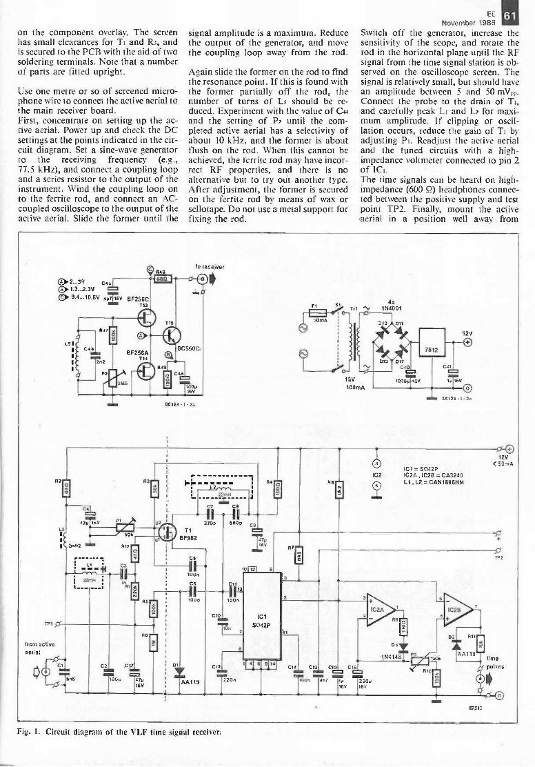
on the component overlay. The screenhas small clearances for Ti and R3, andis secured to the PCB with the aid of twosoldering terminals. Note that a numberof parts are fitted upright.
Use one metre or so of screened micro-phone wire to connect the active aerial tothe main receiver board.First, concentrate on setting up the ac-tive aerial. Power up and check the DCsettings at the points indicated in the cir-cuit diagram. Set a sine -wave generatorto the receiving frequency (e.g.,77.5 kHz), and connect a coupling loopand a series resistor to the output of theinstrument. Wind the coupling loop onto the ferrite rod, and connect an AC -coupled oscilloscope to the output of theactive aerial. Slide the former until the
signal amplitude is a maximum. Reducethe output of the generator, and movethe coupling loop away from the rod.
Again slide the former on the rod to findthe resonance point. If this is found withthe former partially off the rod, thenumber of turns of L5 should be re-duced. Experiment with the value of C44and the setting of P2 until the com-pleted active aerial has a selectivity ofabout 10 kHz, and the former is aboutflush on the rod. When this cannot beachieved, the ferrite rod may have incor-rect RF properties, and there is noalternative but to try out another type.After adjustment, the former is securedon the ferrite rod by means of wax orsellotape. Do not use a metal support forfixing the rod.
EE
November 1988Switch off the generator, increase thesensitivity of the scope, and rotate therod in the horizontal plane until the RFsienal from the time signal station is ob-served on the oscilloscope screen. Thesignal is relatively small, but should havean amplitude between 5 and 50 mViv.Connect the probe to the drain of Ti,and carefully peak LI and L2 for maxi-mum amplitude. If clipping or oscil-lation occurs, reduce the gain of Ti byadjusting Pi. Readjust the active aerialand the tuned circuits with a high -impedance voltmeter connected to pin 2of ICI.The time signals can be heard on high -impedance (600 52) headphones connec-ted between the positive supply and testpoint TP2. Finally, mount the activeaerial in a position well away from
61
TP1
from activeaerial
00
C> 2...3'1 c451C> 1.3...2.3V 1=1
4p7116V BF25 6 Cimm T13
124 -1 - 2a
to receiver
lJ
min.:7016v
L3'c.
1`(
R5
T1BF982
CItttTn6
R6
C2. C171M
Top770
16V
01
C5
loo
117p16V
C6 C1111-1 r1009 100n
IAA119
CIO
C12
T20n
5042P
R7
Tr I4x
1N4001
12V
1C1= 5042Ple2 1C2A ,1C2B = CA3240
R8 ,1_2=CAN18961-114
012V
< 50mA
p.
if#44148
C14 C13 C15 CO6MN =
Trt7
16V 161/
T2Op
IGOk
RIO
67513
Fig. I. Circuit diagram of the VLF time signal receiver.
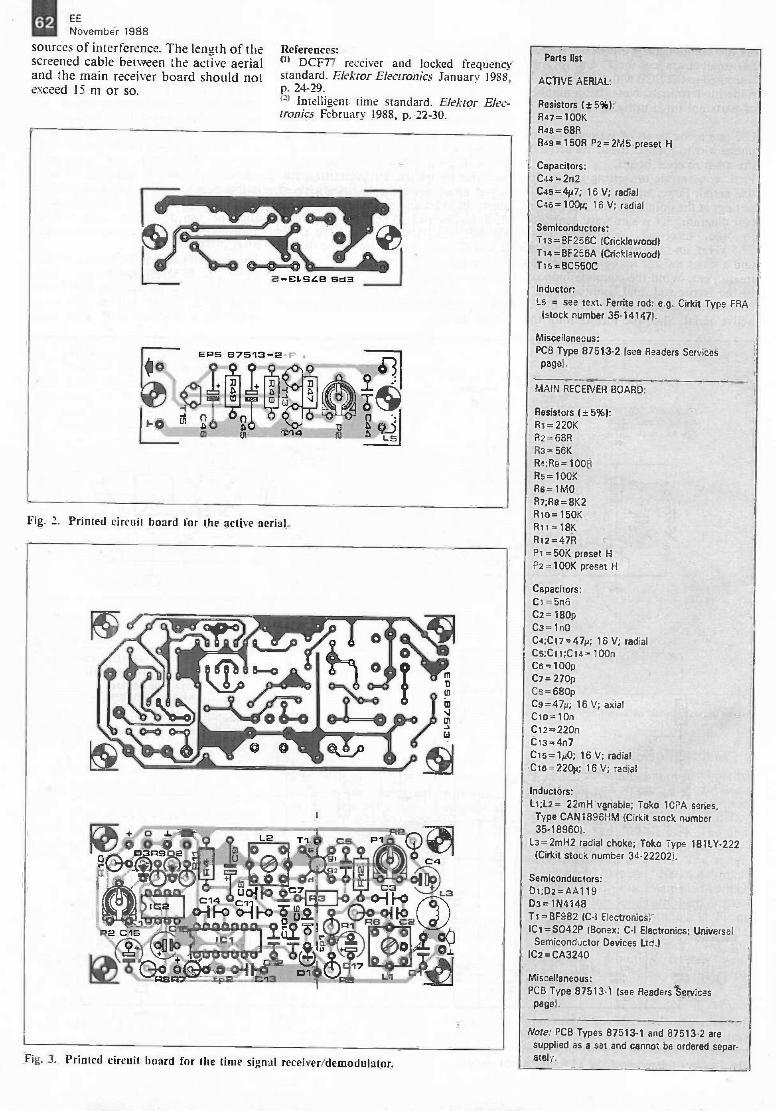
62 EE
November 1988
sources of interference. The length of thescreened cable between the active aerialand the main receiver board should notexceed 15 m or so.
References:(I' DCF77 receiver and locked frequencystandard. Elektor Electronics January 1988,p. 24-29.(21 Intelligent time standard. Elektor Elec-tronics February 1988, p. 22-30.
2-CL2L8 Sd3
279
Lej
Fig. 2. Printed circuit board for the active aerial.
+ oiv) 0 0 020
Re°0(grn 'ir
L20 0
0 0
R3 Fo oTri01 2,Cji -1F?o o
0.410 Fo asi eg.ci toP2 CIS
IC1irttri
rII° iviacructuu
wk7)..L .1 7itWG64
RS t -P2 C13 RS
Fig. 3. Printed circuit board for the time signal receiver/demodulator.
Parts list
ACTIVE AERIAL:
Resistors ( 5%):R47 =100KR48 = 68R
R49=150R P2=2M5 preset H
Capacitors:C44 = 202C45 = 4p7; 16 V; radialC46= 100p; 16 V; radial
Semiconductors:T13= 8F 256C (Cricklewood)Tt4=8F256A (Cricklewood)T15 = BC 550C
Inductor:La = see text. Ferrite rod: e.g. Cirkit Type FRA(stock number 35-14147).
Miscellaneous:PCB Type 87513-2 (see Readers Services
page).
MAIN RECEIVER BOARD:
Resistors (±5%):R i = 220KR2= 68RR3= 56KR.:;Re =100RRs= 100KRe= WOR7;Re=8K2Rto=150KRir=18KRi2=47RPa =50KP2 =100K preset H
Capacitors:CI =5n6C2= 180pC3= 1n0C4;C17=470; 16 V; radialCs;CI I;Cia = 100nCs= 100pC7 = 270pCs = 680pC9=47p; 16 V; axialCto= 10nC12 = 220nC13 = 4n7
C15 = 100; 16 V; radialCie= 220p; 16 V; radial
Inductors:L1;l2= 22mH variable; Toko 10PA series,Type CAN1896HM (Cirkit stock number35-18960).
L3= 2mH2 radial choke; Toko Type 181LY-222(Cirkit stock number 34-22202).
Semiconductors:DI;D2=AA119D3 = 1N4148TI=BF982 (C -I Electronics)IC1 =S042P (Bonex; C -I Electronics; Universal
Semiconductor Devices Ltd.)IC2=CA3240
Miscellaneous:PCB Type 87513-1 (see Readers Services
page).
Note: PCB Types 87513-1 and 87513-2 aresupplied as a set and cannot be ordered separ-ately.

November
TEST & MEASURING F UIPMENT
Part 11: AF Sicq-na_ Geeat© (5)
GE GFG-813 AF SignalGeneratorMade by GW of Taiwan, the GFG-813has a frequency range of 0.1 Hz to13 MHz, a built-in digital frequencycounter, and comprehensive modu-lation/sweep facilities. Its recommendedretail price- RRP- is £795, excl VAT.For an instrument in its class, the GFG-813 is relatively compact and light-weight. Its dimensions are 310 x 99 x380 mm (Wx H x D) and its weight is5 kg.The instrument may operate from 100-120-220-240 V 50 or 60 Hz a.c. mainssupplies.The instrument comes with a number ofaccessories, including three high -qualityBNC-alligator connecting leads, IECterminated mains lead, spare fuses, andan instruction manual.The instrument is fitted with a single -
position swivel stand, which allows theGFG-813 to be operated either at anangle or horizontally.The appearance of the GFG-813 isdominated by the frequency counter,which is grouped with the main outputcontrols. The modulation and sweepgenerator controls are laid out clearly ina separate section at the right of the gen-erator.
Main generator. A single linear controlsets the output frequency with the aid ofthe frequency counter, although roughgradations are also furnished. The out-put frequency can, therefore, be set veryaccurately, although the limitations ofthe resolution of the single rotary con-trol, and of drift, should not be ignored.Fine and coarse controls for frequencysetting, as provided on a number ofother signal generators with a similarkind of frequency display, might havebeen useful.The frequency range may be selected ineight decade ranges from 0.1 Hz to13 MHz (the review model covered0.05 Hz to 13.2 MHz). Symmetry maybe adjusted over a range of 80:20 and20:80 to 1 MHz.The output level may be set up to20 Vpp at the main output. Low-level
by Julian Nolan
performance of the GFG-813 is good.The -20 dB and -40 dB attenuatorsmake accurate setting of low-level out-puts an easy task. The maximum attenu-ation is -60 dB.Noise levels at low-level outputs are goodand compare well with those that may beexpected from much dearer instruments.Since a TTL output is not provided, it isjust as well that an off -set control is pro-vided. This omission is surprising, par-ticularly in view of the other facilities,which include, for instance, a synchron-ization output with a non-adjustablelevel of 1 Vpp.Triggering facilities are good; the exter-nal trigger input allows single or mul-tiple cycles (burst mode), and triggerphase control. Overall, this operateswell; the burst mode is particularly effec-tive for measurements on a.f. equip-ment. Owing to the crowded front panel,the controls for external triggering aremounted on the rear panel, as is the VCFinput.A gate mode is also available.Preset output waveforms are limited tothe conventional sine, triangle, andsquare waves, although these may bemodified, of course, by the symmetrycontrol.Output level flatness on sine wave isreasonable: < ±3% to 100 kHz and< ± 8% to 13 MHz on the reviewmodel. Because of this, the output levelmay need adjusting if a fairly large fre-quency change is made.Distortion is what may be expected:0.5% from 10 Hz to 50 kHz and
> 33 dB below the fundamental to13.2 MHz.Linearity of the triangle output is goodup to 3 MHz, after which some distor-tion becomes noticeable.Square -wave symmetry and rise/falltimes are also good, with the latter< 18 ns on the main output.
Modulation generator. The modulationfacilities and performance of the GFG-813 are excellent. Three modulationmodes are available: FM, AM, andsweep. Modulation may be provided in-ternally or externally. Internal functionsare sine, square, and triangle. The sym-metry of all three may be varied by theseparate symmetry control.Frequency setting is by three rangeswitches and an uncalibrated, continu-ously variable control. These afford afrequency range of 0.1 Hz to 10 kHz(0.06 Hz to 11.3 kHz on the reviewmodel).The modulating signal is available as anoutput, and may be used to drive thedigital frequency counter. It may alsoserve as a separate function generatoroutput. The level of this signal is vari-able to give modulation depths fromzero to 100% on AM or from zero to±5% on FM.The performance of this secondary gen-erator, in terms of distortion, linearity,and so on, is understandably not up tothe standards of the main generator.Some users may find the THD figures ofup to 2% at 10 kHz unacceptable forsome applications.
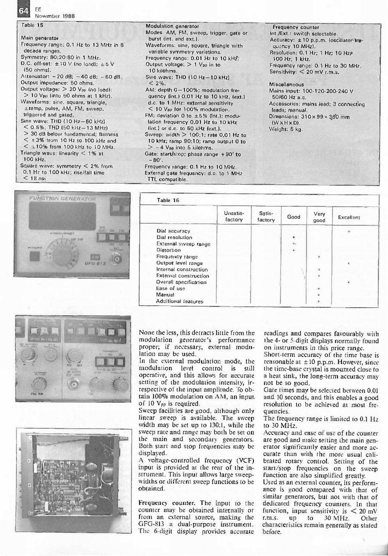
64 EE
November 1988
Table 15
Main generatorFrequency range: 0.1 Hz to 13 MHz in 8decade ranges.
Symmetry: 80:20:80 in 1 MHz.D.C. off -set: ± 10 V (no load); ± 5 V(50 ohms).
Attenuator: -20 dB; -40 dB; -60 dB.Output impedance: 50 ohms.Output voltage: > 20 Vpp (no load):
> 10 Vpp (into 50 ohms at 1 kHz).Waveforms: sine, square, triangle,
7... -ramp, pulse, AM, FM, sweep,triggered and gated.
Sine wave: THD (10 Hz -50 kHz)< 0.5%; THD (50 kHz -13 MHz)> 30 dB below fundamental; flatness< ±3% from 10 Hz to 100 kHz and< ± 10% from 100 kHz to 10 MHz.
Triangle wave: linearity < 1% at100 kHz.
Square wave: symmetry < 2% from0.1 Hz to 100 kHz; rise/fall time< 18 ns.
Modulation generatorModes: AM, FM, sweep, trigger, gate orburst (int. and ext.).
Waveforms: sine, square, triangle withvariable symmetry variations.
Frequency range: 0.01 Hz to 10 kHz.Output voltage: > 1 Vpp in to
10 kilohms.Sine wave: THD (10 Hz -10 kHz)< 2%.
AM: depth 0-100%; modulation fre-quency (int.) 0.01 Hz to 10 kHz, (ext.)d.c. to 1 MHz: external sensitivity< 10 Vpp for 100% modulation.
FM: deviation 0 to ±5% (int.); modu-lation frequency 0.01 Hz to 10 kHz(int.) or d.c. to 50 kHz (ext.).
Sweep: width > 100:1; rate 0,01 Hz to10 kHz; ramp 90:10; ramp output 0 to> -4 Vpp into 5 kilohms.
Gate: start/stop; phase range +90' to-80'.
Frequency range: 0.1 Hz to 10 MHz.External gate frequency: d.c. to 1 MHzTTL compatible.
Frequency counterInt./Ext.: switch selectable.Accuracy: ± 10 p.p.m. (oscillator fre-quency 10 MHz).
Resolution: 0.1 Hz; 1 Hz; 10 Hz;100 Hz; 1 kHz.
Frequency range: 0.1 Hz to 30 MHz.Sensitivity: < 20 mV r.m.s.
MiscellaneousMains input: 100-120-200-240 V50/60 Hz a.c.
Accessories: mains lead; 3 connectingleads; manual.
Dimensions: 310 x 99 x 380 mm(WxHxD).
Weight: 5 kg.
Table 16
Unsatis-factory
Satis-factory Good
Verygood
Excellent
Dial accuracyDial resolutionExternal sweep range .DistortionFrequency rangeOutput level rangeInternal constructionExternal constructionOverall specificationEase of useManualAdditional features
None the less, this detracts little from themodulation generator's performanceproper; if necessary, external modu-lation may be used.In the external modulation mode, themodulation level control is stilloperative, and this allows for accuratesetting of the modulation intensity, ir-respective of the input amplitude. To ob-tain 100% modulation on AM, an inputof 10 VI., is required.Sweep facilities are good, although onlylinear sweep is available. The sweepwidth may be set up to 130:1, while thesweep rate and range may both be set onthe main and secondary generators.Both start and stop frequencies may bedisplayed.A voltage -controlled frequency (VCF)input is provided at the rear of the in-strument. This input allows large sweep -widths or different sweep functions to beobtained.
Frequency counter. The input to thecounter may be obtained internally orfrom an external source, making theGFG-813 a dual-purpose instrument.The 6 -digit display provides accurate
readings and compares favourably withthe 4- or 5 -digit displays normally foundon instruments in this price range.Short-term accuracy of the time base isreasonable at ±10 p.p.m. However, sincethe time -base crystal is mounted close toa heat sink, the long-term accuracy maynot be so good.Gate times may be selected between 0.01and 10 seconds, and this enables a goodresolution to be achieved at most fre-quencies.The frequency range is limited to 0.1 Hzto 30 MHz.Accuracy and ease of use of the counterare good and make setting the main gen-erator significantly easier and more ac-curate than with the more usual cali-brated rotary control. Setting of thestart/stop frequencies on the sweepfunction are also simplified greatly.Used as an external counter, its perform-ance is good compared with that ofsimilar generators, but not with that ofdedicated frequency counters. In thatfunction, input sensitivity is < 20 mVr.m.s. up to 30 MHz. Othercharacteristics remain generally as statedbefore.

Construction. The external constructionis based on a steel chassis with pressedstell covers. With the steel front panelsurround and rear cover, this gives theGGF-813 a very solid construction andshould enable it to operate under widelyvarying conditions. Even considering theinstrument's price, the finish is good,although some of the metal casing (atleast on the review model) could have fit-ted better together.The front panel is plastic and provides aclear an unambiguous indication of thecontrols. The area around the LED dis-play of the counter is very flexible, how-ever, and as a result of this only slightpressure here visibly moves the display.A carrying strap is fitted at one side ofthe instrument.Internal construction is good and isbased on a number of double -sidedfibre -glass PCBs that contain the maingenerator, modulation generator, andfrequency counter. The boards are easilyaccessible for servicing.Heat dissipation throughout the instru-ment is low and should not cause anyproblems.The 27 -page manual provides detailedoperating and setting up information, aswell as a description of the theory of op-
eration of the instrument. Detailed cir-cuit diagrams are not supplied, only anumber of sections of these diagrams toillustrate the text.
Conclusion. The GFG-813 providesgood performance and quality at a verycompetitive price. Its wide frequencyrange, modulation facilities, and trigger-ing options are particularly impressive.It would have been helpful if a TTL out-put had been provided. A lower level ofdistortion on the modulation generatorwould also have been welcome. Thesedeficiencies, however, do not really marthe instrument's overall performance.Consequently, the GFG-813 is ideal foruse in applications where normallymuch more expensive generators wouldhave to be used. It is a particularly goodchoice for users in the educational sec-tor.
The review model of the GFG-813 wassupplied by Flight Electronics Ltd,Flight House, Ascupart Street,Southampton SO1 1LU, Telephone(0703) 227721. This company distributes
EE
November 1988
a wide array of products, ranging from atransputer add-on board for BBC andIBM micros, and a series of logicanalysers, to a range of test equipmentmade by GW, a Taiwanese manufacturer.
The GW range of function generators in-cludes:GFG-8015F: 0.2 Hz to 2 MHz; variabled.c. off -set; symmetry control; distortion< 1%; RRP £139, excl. VAT.
65
GFG-2D: 0.2 Hz to 2 MHz; digital fre-quency read-out; other characteristicssimilar to those of GFG-8015F; RRP£165, excl. VAT.
GFG-8016D: similar specification toGFG-8015F but with 6 -digit counter;RRP £215, excl. VAT.
GFG-8016S: 0.2 Hz to 2 MHz; fre-quency modulation; independent settingof modulation time and frequency;built-in sweep function; distortion< 1%; RRP £180, excl. VAT.
GFG-8019: similar to GFG-8016S butwith 6 -digit frequency counter and inter-nal/external AM or FM; RRP £259, excl.VAT.
NEWSLucas acquires DataLaboratoriesLucas CEL Instruments has acquiredData Laboratories, the Mitcham -basedmanufacturer of Digital WaveformRecorders.The acquisition is in line with thestrategic growth objectives in electronicmeasurement and control and in fluidpower distribution of Lucas IndustrialSystems, the parent company of LucasCEL Instruments. Through internalgrowth and acquisitions, the annualsales of the Lucas Group have increasedthreefold to over £150 million in the pastthree years.Lucas Industrial Systems Edgbaston House 3Duchess Place Hagley Road Edgbaston BIRMINGHAM BI6 8NH.
Eurologic SystemsA new Dublin -based company,Eurologic Systems, has been formed toincrease the presence of, and support to,American companies importing their Q -bus board -based products into Europe.John Maybury, managing director of thenew company, believes that the growth indemand for board -based products hadled to an influx of equipment intoEurope by companies that do not havethe capability of providing the necessarysupport.Eurologic Systems Chamco HouseSHANK1LL Co. Dublin Ireland.
IMAGE PROCESSING MARKETIN EUROPE - 1988
U.K. $52.2M
W. Germany $47.6M
SOURCE: FrostReport 7'
France $49.8M
Benelux S16.1M
.Other S53.OM
Image processing marketgrowingFrom checking facial wrinkles, beforeand after treatment with creams, tochecking size and number of asbestosfibres caught by filters: uses for imageprocessing are increasing rapidly.Researchers can now study in detail theshape and density of cancer cells. Anadvertising agency can manipulate theimage of a young woman in a swimsuit
from resting in a curved hammock toshow her prone on the beach.Commercial Image Processing Market inEurope* states that the hardware andsoftware for image processing andanalysis constituted a £100 millionmarket in western Europe in 1987. Itpredicts that this market will rise toaround £275 million by 1992.Market analysis report E1016 from Frost &Sullivan Sullivan House Grosvenor Gardens LONDON SW IW ODH.
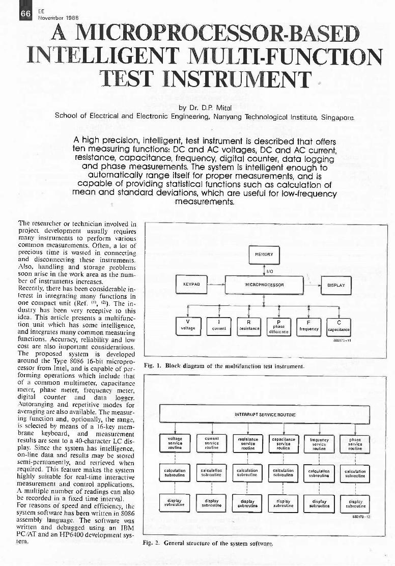
66 EE
November 1988
A MICROPROCESSOR -BASEDINTELLIGENT MULTI -FUNCTION
TEST INSTRUMENTby Dr. D.P. Mital
School of Electrical and Electronic Engineering, Nanyang Technological Institute, Singapore.
A high precision, intelligent, test instrument is described that offersten measuring functions: DC and AC voltages, DC and AC current,resistance, capacitance, frequency, digital counter, data logging
and phase measurements. The system is intelligent enough toautomatically range itself for proper measurements, and is
capable of providing statistical functions such as calculation ofmean and standard deviations, which are useful for low -frequency
measurements.
The researcher or technician involved inproject development usually requiresmany instruments to perform variouscommon measurements. Often, a lot ofprecious time is wasted in connectingand disconnecting these instruments.Also, handling and storage problemssoon arise in the work area as the num-ber of instruments increases.Recently, there has been considerable in-terest in integrating many functions inone compact unit (Ref. '", 'n). The in-dustry has been very receptive to thisidea. This article presents a multifunc-tion unit which has some intelligence,and integrates many common measuringfunctions. Accuracy, reliability and lowcost are also important considerations.The proposed system is developedaround the Type 8086 16 -bit micropro-cessor from Intel, and is capable of per-forming operations which include thatof a common multimeter, capacitancemeter, phase meter, frequency meter,digital counter and data logger.Autoranging and repetitive modes foraveraging are also available. The measur-ing function and, optionally, the range,is selected by means of a 16 -key mem-brane keyboard, and measurementresults are sent to a 40 -character LC dis-play. Since the system has intelligence,on-line data and results may be storedsemi -permanently, and retrieved whenrequired. This feature makes the systemhighly suitable for real-time interactivemeasurement and control applications.A multiple number of readings can alsobe recorded in a fixed time interval.For reasons of speed and efficiency, thesystem software has been written in 8086assembly language. The software waswritten and debugged using an IBMPC/AT and an HP6400 development sys-tem.
KEYPAD
MEMORY
tI/O
MICROPROCESSOR DISPLAY
Vvoltage current
Rresistance phase
difference
Ffrequency
C
capacitance
EZ3173 11
Fig. 1. Block diagram of the multifunction test instrument.
INTERRUPT SERVICE ROUTINE
voltageserviceroutine
calculationsubroutine
displaysubroutine
currentserviceroutine
calculationsubroutine
displaysubroutine
resistanceserviceroutine
calculationsubroutine
displaysubroutine
capacitanceserviceroutine
calculationsubroutine
displaysubroutine
frequencyserviceroutine
calculationsubroutine
displaysubroutine
phaseserviceroutine
calculationsubroutine
displaysubroutine
Eat73 12
Fig. 2. General structure of the system software.
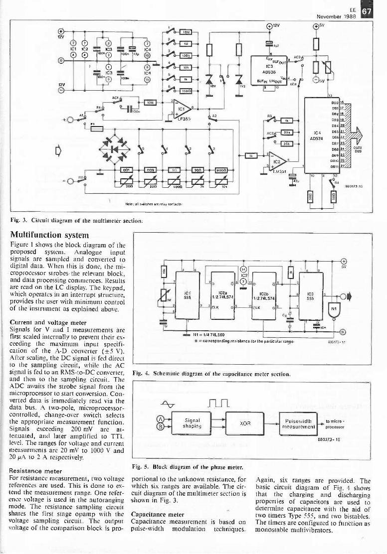
EE
November 198867
0
0 000
Its000
4
12V
0
On
0IC3
0 On
01 C 4
0
0 Ft
AC1
IL -11 117:Trfin
NEM
c.-71
LF355A2
4kW 200 W 200 =V' 5000 w 2k 10k
1V2
Note t aA santens are re ay ccntacts.
5
( 75V12V
CAVEOUT
IC3AD536
Y1211.1504 L114001IN
OMB
AC
r
4 C 2
CI
05v
13
IC4AD574
DSO
Del
032
DB3
Da4
085DB5
DB7
OBB
069DB10
DB11
2
54
U
16
DATABUS
240173 -13
Fig. 3. Circuit diagram of the multimeter section.
Multifunction systemFigure 1 shows the block diagram of theproposed system. Analogue inputsignals are sampled and converted todigital data. When this is done, the mi-croprocessor strobes- the relevant block,and data processing commences. Resultsare read on the LC display. The keypad,which operates in an interrupt structure,provides the user with minimum controlof the instrument as explained above.
Current and voltage meterSignals for V and I measurements arefirst scaled internally to prevent their ex-ceeding the maximum input specifi-cation of the A -D converter (±5 V).After scaling, the DC signal is fed directto the sampling circuit, while the ACsignal is fed to an RMS-to-DC converter,and then to the sampling circuit. TheADC awaits the strobe signal from themicroprocessor to start conversion. Con-verted data is immediately read via thedata bus. A two -pole, microprocessor-controlled, change -over switch selectsthe appropriate measurement function.Signals exceeding 200 mV are at-tenuated, and later amplified to TTLlevel. The ranges for voltage and currentmeasurments are 20 mV to 1000 V and20 I.LA to 2 A respectively.
Resistance meterFor resistance measurement, two voltagereferences are used. This is done to ex-tend the measurement range. One refer-ence voltage is used in the autorangingmode. The resistance sampling circuitshares the first stage opamp with thevoltage sampling circuit. The outputvoltage of the comparison block is pro-
t4 1 = 1/4 741.500
* = corresponding resistance for the particular range 630173.14
Fig. 4. Schematic diagram of the capacitance meter section.
Signalshaping XOR Pulsewidth to micro -k
measurement processor
560173 - 15
Fig. 5. Block diagram of the phase meter.
portional to the unknown resistance, forwhich six ranges are available. The cir-cuit diagram of the multimeter section isshown in Fig. 3.
Capacitance meterCapacitance measurement is based onpulse -width modulation techniques.
Again, six ranges are provided. Thebasic circuit diagram of Fig. 4 showsthat the charging and dischargingproperties of capacitors are used todetermine capacitance with the aid oftwo timers Type 555, and two bistables.The timers are configured to function asmonostable multivibrators.
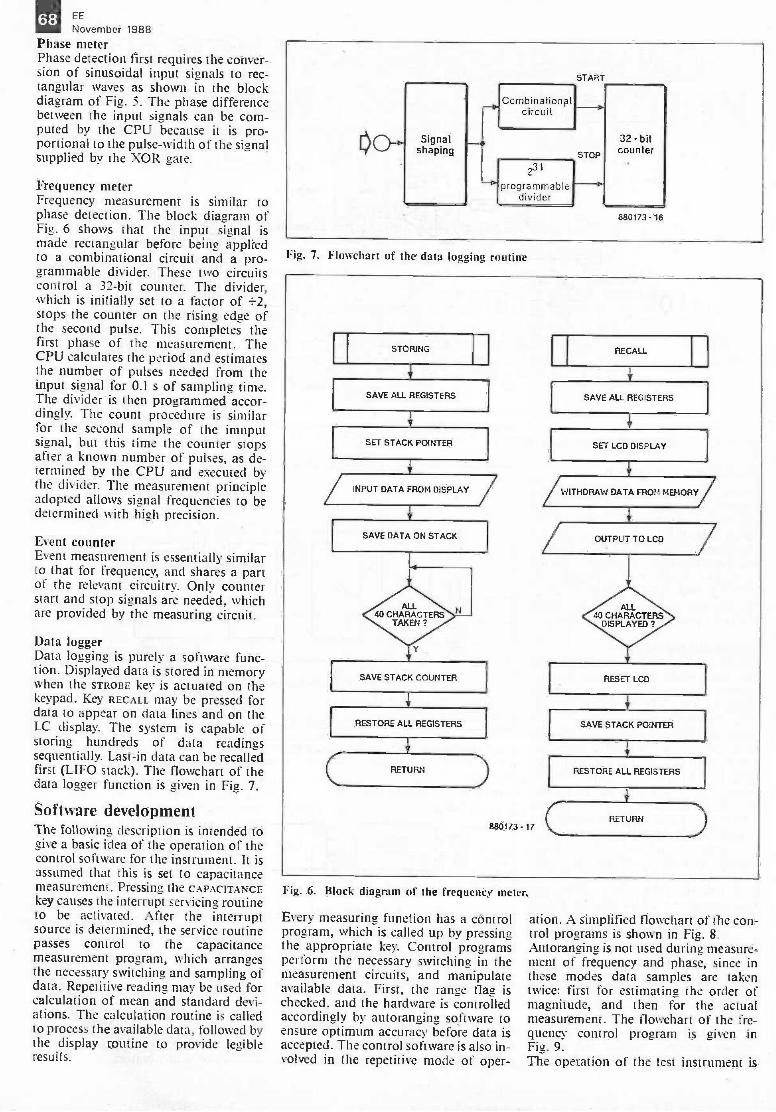
68 EE
November 1988Phase meterPhase detection first requires the conver-sion of sinusoidal input signals to rec-tangular waves as shown in the blockdiagram of Fig. 5. The phase differencebetween the input signals can be com-puted by the CPU because it is pro-portional to the pulse -width of the signalsupplied by the XOR gate.
Frequency meterFrequency measurement is similar tophase detection. The block diagram ofFig. 6 shows that the input signal ismade rectangular before being appliedto a combinational circuit and a pro-grammable divider. These two circuitscontrol a 32 -bit counter. The divider,which is initially set to a factor of +2,stops the counter on the rising edge ofthe second pulse. This completes thefirst phase of the measurement. TheCPU calculates the period and estimatesthe number of pulses needed from theinput signal for 0.1 s of sampling time.The divider is then programmed accor-dingly. The count procedure is similarfor the second sample of the imnputsignal, but this time the counter stopsafter a known number of pulses, as de-termined by the CPU and executed bythe divider. The measurement principleadopted allows signal frequencies to bedetermined with high precision.
Event counterEvent measurement is essentially similarto that for frequency, and shares a partof the relevant circuitry. Only counterstart and stop signals are needed, whichare provided by the measuring circuit.
Data loggerData logging is purely a software func-tion. Displayed data is stored in memorywhen the STROBE key is actuated on thekeypad. Key RECALL may be pressed fordata to appear on data lines and on theLC display. The system is capable ofstoring hundreds of data readingssequentially. Last -in data can be recalledfirst (LIFO stack). The flowchart of thedata logger function is given in Fig. 7.
Software developmentThe following description is intended togive a basic idea of the operation of thecontrol software for the instrument. It isassumed that this is set to capacitancemeasurement. Pressing the CAPACITANCEkey causes the interrupt servicing routineto be activated. After the interruptsource is determined, the service routinepasses control to the capacitancemeasurement program, which arrangesthe necessary switching and sampling ofdata. Repetitive reading may be used forcalculation of mean and standard devi-ations. The calculation routine is calledto process the available data, followed bythe display routine to provide legibleresults.
Signalshaping
Combinational
START
circuit
231
programmabledivider
32 bitcounter
Fig. 7. Flowchart of the data logging routine
STORING
SAVE ALL REGISTERS
SET STACK POINTER
INPUT DATA FROM DISPLAY
RESTORE ALL REGISTERS
EE0173 - 17
RECALL
SAVE ALL REGISTERS
1...ITHCRAV: DATA FROM MEMORY
RESET LCD
SAVE STACK PUNTER
RESTORE ALL REGISTERS
RETURN
Fig. 6. Block diagram of the frequency meter.
Every measuring function has a controlprogram, which is called up by pressingthe appropriate key. Control programsperform the necessary switching in themeasurement circuits, and manipulateavailable data. First, the range flag ischecked, and the hardware is controlledaccordingly by autoranging software toensure optimum accuracy before data isaccepted. The control software is also in-volved in the repetitive mode of oper-
ation. A simplified flowchart of the con-trol programs is shown in Fig. 8.Autoranging is not used during measure-ment of frequency and phase, since inthese modes data samples are takentwice: first for estimating the order ofmagnitude, and then for the actualmeasurement. The flowchart of the fre-quency control program is given inFig. 9.The operation of the test instrument is
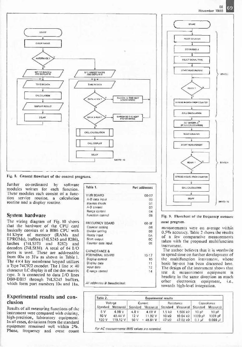
EE
November 198869
START
CHECK FLANGE
N
SET TO nAND DISPLAY TT
V
CALCUUlTKA
DISPLAY FV_SULT
DaAY
SET 1-0M-IEST FLAPIGEMar) DISPLAY IT
TAKE 14 DATA
CALL DLE..LAY
Fig. 8. General flowchart of the control programs.
further co-ordinated by softwaremodules written for each function.These modules each consist of a func-tion service routine, a calculationroutine and a display routine.
System hardwareThe wiring diagram of Fig. 10 showsthat the hardware of the CPU cardbasically consists of a 8086 CPU with64 Kbyte of memory (RAMS andEPROMs), buffers (74LS245 and 8286),latches (74LS373 and 8282) anddecoders (74LS138). A total of 64 I/Oports is used. These are addressablefrom 00H to 3FH as shown in Table I.The 4x4 key membrane keypad utilizesa Type 74C922 encoder. The I line x 40character LC display is of the dot-matrixtype. It is connected to data I/O linesDBO-DB15 through 74LS245 buffers,which form port numbers 10H and 11H.
Experimental results and con-clusionResults of all measuring functions of theinstrument were compared with existing,high -precision, laboratory equipment.In all cases, deviations from the standardequipment remained well within 2%.Phase, frequency and event count
Table 1.
ViliR BOARDA -D data inputstautus checkA -D controlRange controlFunction control
FREQUENCY BOARDCounter settingDivider settingReady inputStart outputCounter data input
CAPACITANCE &PERIPHERAL. BOARD
Display controlDisplay dataInput dataC range control
All addresses in hexadecimal.
Port addresses
00-070001
020406
08 -OF
0809OA
OC
OE
10.1710
11
12
14
4
SET DCADER
SELECT SIGNAL TYPE
START WAS/REMIT
4
STFOSE IN DATA FROM COUNTER
CALL CALCULATION
3
SET WIDER = 2N(N torn CALCULAT1004
4
RESET CCUNTER
ART
STRCRE IN DATA FROM COUNTER
CALL CALCULATICA
DaAY
SISAL
SIASE
aaoin - 19
Fig. 9. Flowchart of the frequency measure
ment program.
measurements were on average within0.5% accuracy. Table 2 shows the resultsof a few comparative measurementstaken with the proposed multifunctioninstrument.The author believes that it is worthwile
to spend time on further development ofthe multifunction instrument, whosebasic lay -out has been discussed here.The design of the instrument shows thattest & measurement equipment isheading in the same direction as muchother electronics equipment, i.e.,towards high-level integration.
Table 2. Experimental results
VoltageStandard Measured
CurrentStandard Measured
ResistanceStandard Measured
CapacitanceStandard Measured
5V 4.98V50 V 49.44 V120 V 119.12 V
4.8V 4.68V12 V 11.92 V50 V 48.81 V
1.5 kg 1.506 kg10 kg 10.04 kg47 kg 47.02 kg
10 pF 10 pF1000 pF 1001 pF0.1 ;IF 0.09914F
For AC measurements RMS values are recorded.
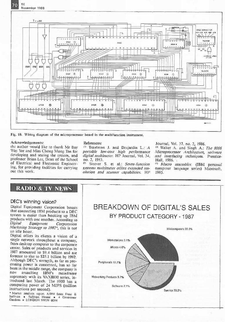
70 EE
November 1988
t -+5V
V 31S T 3
6282 ®131991711691172
/
riI I ic 9 31 17 9 n n 33 IS 3? 33 a n 17 Pt 33 34 33 ii
SO%it 2 af TES onun et es e 4-11 673
2 311107 -eat* ®
33T. *313 yII TT
1
r1 2 2243171
13232 0nessesontu one,
J.
I 1
11
wikik
IT9139393v 6
82842231113.
EINX C0874ECTORA24 825 A26 £27 12844,\I /V
"66 961371Et742.5138
1134543f-ft -Fr
33 AS
MNIES511488A7.AT8
1 2 3 5 3 371*ens (:)
? 3
eass 0nn.secnssenten
uuan631413.7
1 337 0 9120.6
27128 C
13 3E 23 3.4 tf 33 31 30 111 9
r 13 11 12 C13
2/128 (I)
fi A 3/121213 6 3 9 16
;
6263
6 v e n
i I 9/ eattnn 6 la
uss 03)37.4.43.3333135 SC s v is
Fig. 10. Wiring diagram of the microprocessor board in the multifunction instrument.
Acknowledgements:the author would like to thank Mr BayWay Yee and Miss Chong Mong Tan fordeveloping and testing the system, andprofessor Brian Lee, Dean of the Schoolof Electrical and Electronic Engineer-ing, for providing facilities for carryingout this work.
References:(" Trautman J. and Desjardin L.: Aportable low-cost high performancedigital multimeter. HP Journal, Vol. 34,no. 2, 1983.(2) Steever S. et al.: Seven -functionsystems multimeter offers extended res-olution and scanner capabilities. HP
Journal, Vol. 37. no. 2, 1986.0) Walter A. and Singh A.: The 8086Microprocessor Architecture, softwareand interfacing techniques. Prentice -Hall, 1986.(4) Macro assembler. (IBM personalcomputer language series) Microsoft,1985.
RADIO & TV NEWS
DEC's winning vision?Digital Equipment Corporation boaststhat connecting IBM products to a DECsystem is easier than hooking up IBMproducts with one another. According toDigital Equipment CorporationMarketing Strategy to 1992*, this is notan idle boast.Digital offers its clients a vision of asingle network throughout a company,from desktop computer to the corporatecentre. Sales of products and services in1987 amounted to $9.4 billion and areforecast to rise to $25.1 billion by 1992.Although DEC's strength, as far as pro-cessing power is concerned, has so farbeen in the middle range, the company isnow assaulting IBM's mainframesupremacy with its VAX8800 series, in-troduced last March. The 8800 has acomputing power of 24 MIPS (millioninstructions per second).* Market analysis report A1944 from Frost &Sullivan Sullivan House 4 GrosvenorGardens LONDON SWIW ODH
BREAKDOWN OF DIGITAL'S SALESBY PRODUCT CATEGORY - 1987
Workstations 3.1%
Micros 4.6%
Peripherals 127%
Networking Products 3.7%
Software 7.1'=
Minicomputers 35.5%
Service 33.2%

EE
November 1988
POWER CONDITIONERFEATURED IN OrJANUARY 1988
T.< utree ',erePere raVaia rarre
caer,-; ,e,ieaov a -C -eWar,Te-ky-T,e :VT .% reer C.Xicar, atTap cxpe-1 rearral rC=r1 rcerw rn a tan/ Cr V.rTRir:rt-c.ere"Y ay.;reel:nem* **ILO W:5141,,,c dr:te,' woe; asee= re .1-0.1-4 11 r;e'ereve,,t--e-yet
0./ leer:,,e2 arts svara.- ?5e PO3 a?C0e0C0e,t1 ro-Orc n7' pa-n*4...r
CatS s Y
a -a r1.7.1:10.3
PARTS MT E28.50
Sr. sea. S. 7SAE: - 7. 7.,ra.rc =Tam VC astern.Tie .7:4, Pr
THE DREAM
MACHINEFEATURED IN EliDECEMBER 1987
J41-5 re a,frol S:Sui yal raza a -a elrerawy sare &ft pa, Airs 'A-
sa' erre an:M.1,05in tees Saws...p..0;ere saPo 07.a1 roc raS4PaCry ere aoeaa ,L1 ratesnrgSete
F7 -. o arwrg ara ern_ fears .s ermr ray
r. ae.sr,Lr3-1 SO.iarert at aTrce as_ .1- erteaxces assre, Tr a ...C.C.S -re,
naa-ca .-afire cen; n =on. C ao.r cres,a a -c zeeoe- at autC i7ll.t tarar.e3
1,1`fr. re Cream Uacnne 3 ssare
agenn_ reo pars se. carat -% ctPE at ea -co -ensconros CLOweaken erctre Wro kiecafers ,arsMaar 5.47, CYtiAge Cale Ira LI m^.,---cr1PARTS SET C16.50 YA-1
taaa galFA17110tft CASE FOR ONLY E11.90 e VAT
MAINS
CONDITIONERFEATURED IN ET!SEPTEMBER 1986
Pr arw .--ard porLioleast, erreceraseyYou B ta-a, terve Pe69eeence n rers IleFe. TV. YOLo.iro AL Cre"eQ-pre-A
PMTS SET £4.90. WT
PrigMO PLASM CASE £1.65
POWERFUL AIR
IONISERS
-z
err ar-052 ra.?Ga
The, re lac z nor:se m-Penrs.-ex red.ce :Kozo -ass -aret soaseM h -C raw yor a7 Arcur sOre
re orals nee oe foxeserc re -e cottr.vair ;5 Ce_tv- .ar brad a -c r,ICy rar; a,WarA-rfe rie-Oirea Graie Ac-Avvor sa,et reareal ere'
Tre Drece-tw cased a sesea, art,: e apeea-so es aer-pee: r Ell Tad Ma -a-er C[See- IBM f< Lay--a all-
f3,03 s7- re W,13IG arttO no va Dr=' an Cr re ECTMMEC re CO-7-1,Setains, 7-e crexe s yeLes'
USTGV- CAUSER PARTS SET £24.60- ,4.7
DiFECT-Vi PARTS SET i SAC( ME, £11.50 -ORECT-Vi PARTS MI ,*AWTE CAH £11.80 - .
KNIGHT RAIDERETI JULY 1987
--..c fax l_a,cerpr. Irsrat WI. :- 1,8 1,1111+,2 Kra t:
. -. CEVT 307; rem 17,14. !WC. W. VC1 ..r4 3 port 3' R7C er.
: s ?r`wc ;lore war re recc, ' ;-42 a mrcrc rao,...1Mire War=re re ore.. paeans
es ya. S. Weir eel,. 1973
;saw ce ?tienl t rx nue ar ilPTrear -se tr--. ary V.:, Ma :a.7
WeCa.i. TY-V.7`7} P:9 re xreceerea,7
a C Cr sea.irce :car: aELarCsYT
PARTS SET E19.90 -
ANALY FR OSLICSS.PC-er-
RAINY DAY
PROJECTS
All can be built in an afternoon!
JULIPIN JACK FLASHracer,:_.:. ; LLB, -.-
CREDIT CARD CASINO 5. :,':COE ;:.,tIrc,l,r4
. MAINS CONTROLLERaaar: ape t ^a7s r:rerraMATCHBOX AMPLIFIERS r t. i*
: 17"
'..r :Es re -
TACHO DWELL METER Tr :.s.armr to a =vs^e EGA
HI-FI POWER METER r v. LA-
trees_rw m -C, 1405 1: St- ,e3,143-0 MSG -S13I,C.04.5 rat- DIS
GLIAtsumerre
EROPH8CS08SPLaOFFERTiae beaufOil act. -11:18rnantteri mar.L.F.
_ .7!bebe they eisi Aso- ,r1C115!
-- - sxse -WES rEtliart&firs an vird s a.,. good. Because
OiLket bad thahagment. you vow ha*ft chance kr ce,
;-1,1-rhicS &Veyrrrdle era b -vi tract
a/ the normal prkeIS £35r
fear ridE
E..312 ea:7 -sssFrom us. tit*?
stxcks tag_ [repriceThe 11123B tisp4y
mOlk, has a 9',eacti peel can be amessedspectrum analyser cftg8y. a
er.7iP- up of 640 x 200 Pzet. Sitehiss; as a stop; screen a
T: -c.unWi
La aboard Atti 20 LSI ics
:a:Cf0.3 a-13
srreen W)e filed ria a serveTo tse re display ):- need te be tF.rty 139cesto-mutuowtbEvitoorganise a trequerl.
,:er and ser'..P.reaa:cart from awe basks Medea sticaai
earl modure a - up and rtrivri2
LM2917
EXPERIMENTER SET
Ccnsys ra 1.912917 LC. szeog ormo0M-if Weed alasPealed n5.-caces wendea as Ewa iea egg GS.-erseiV.D.eas n Pset Can Ide Lae° ear ea:erre-a seri re proses
re New G-eg Lefe IC scatae tETi. Dece,- twei1.12917 EXPERMENITER SET £5.80 zis
LEDs
Grwn5_,Kaals
SO ta C3-50 goDfacE2S100 aY CS s:CO Ida US
DIGITAL AS4 ALDO eaolaPrr LED?
&mooed We LEDs_ red gem TeX. and carce24 eW- EDO:a MAO
4.v -a, eark..s-re X18! :LP.. 40X1f.,. re7Dr 1=- 1.1 pota,,,, s 74 r. a", V.:4ccs.Erce s7,Ner3as 7are Ea E, Pere ala..0 r urs
.t. -a,
LI MITEID
SALES DEPT., ROOM 110. FOUNDERS HOUSE. REDBROOK. MONMOUTH. GWENT
rEAMPEDIII ETI
-.err -ce,4 AUGUST IBB-Baa;F rsane.re I: 1 -a -v -g errs f -17
VD/ 13V5 ,tr,ra and It irate K1311 0grc Mita 7 Ea! Vranra -er It ,Xt el rXreestres. - -=:;er 7 at an re 5":. ra.
777-n9 A 2,Ers,a,c a Merant 12C Sa Ocea..x .;ce-.C Doa' .=:ae1.et.
co-oes WI rm.:=am a1 m,oreas aeoro-{ CS eara
rersoos 3szoa ften rasa.r.Nr p.q roe% Item re Li ,_.7.1.7.3
03-sr=a,
PARTS SET £33.60 - VAT
son ete aT a-eere err-, 'sus ere Pe,Ski - e rer,xr wees I7
ARMSTRONG 75W
AMPLIFIERFEATURED IN PEJULY *ea
Armsm9'a milksnew said artpldler=dole is here al last'Detverg a cod 7SN imreseeel'etf ree -WOWmare :070.1 715110SIET &sr. m-oxfeste ireRrrihn-aAg TAcY esonno.es res.n.rc , a ere.
vedweei _ - - : : usLedCan see._, . FE t;La aty
:ere. a -r 1711 a -en ra.r eari an; ra yrs:SOMA:AVete,Panama -rates ,race PC8 axe al col:were&
SPECIAL INTRODUCTORY PRICE FOR FULLYUPGRADED MODULES.
Sda.F. RATS SET£14.90 . SAT
STEREO PASR £25.90bee Her,. me, a.' la, we, ro..re
ra;neeserrecee 71-0-C10.7wrigses 30,0usr.,¢77 KO* - et arseteat Ws art
BIO
FEEDBACKFEATURED IN ETIDECEMBER 1986
Do-seectaa caws or ageerne Rs r.74moors -et
,-ralaerzeg ranresponsera:ria.10 Treposeni vat Nassond Kt- : :
as we! as on re bo-Stectesc. sea, fo_re, a,,ar GS9 ascenceaes ere rea
Thecr..-,Pet arts see cca-Ors case. F-ZEarose -se Wads. co-Ce.ceee ge. and
FARTS SET £13.95. VAT
PEELSACK EOK£3.65 t-aCTI
xer, Ran re Rt, tat 8.11.0 'bee gJoteoena erop-C.-±eor wo-noa a a rasa ram, us'..
ac ed 7r, 3f 1.31f.t rrteswt an -43.
Tee nos ano-rinec oweasr wee ea ^de- r anVeer -arcs rr-4;arre Sftear, pvccgru a reocar EEG
alea-S er. X hearse aVraVenac,,,race U r;,c.r., nK T.e ac,a W -E a -C re:a S7 --s cir
st.e:Ma i7 are re rraelnaft9-eveficrree.7.3.7.t..-41-7.reacer:sca Cloin
teaS S 17 Pe- re nova., te3dJ V ' rer-SreY-is X °ex crleeet rCC CL? sa-ancro ire tsar er..rSef t ela3 i< rase O er.1eC. Wee a
Oar Accrzwn.aes sal Co -tars case PC -Ss saterwspc,....rca,e, 077p7*..; net aft CreW.I.
archers? ear Piss erecroses We!. rSneto-sPAWS SFr £36.90 No.T s.1514.4 PLAN BCOa £2.50st).E.P. 5C UT) £3.60 - CAT
3p3 SF'ntrate +era rel 1115: .141,9e J1.7.1.7.17.11. St.0 SAC
Sal - II ta asa xrarW. Sea,. re ...ire rte-ser Tee erre -k
Please mention ELEKTOR ELECTRONICS when contacting advertisers

s,r
CO
b.N
o:a.'vd
-koctiott
AV
C70.1. A
cI00 11110A 110d O
NS
IS
UM
SIN 10 IR
O S,11
111501Y1Y
3 MIM
I MN
1111