Team Learning as a Model for Facilitating Entrepreneurial ...

Extrapolative Delay Compensation ThroughFacilitating Synapses and Its Relation to the
Flash-lag EffectHeejin Lim and Yoonsuck Choe
Department of Computer ScienceTexas A&M University
College Station, TX 77843, [email protected], [email protected]
Abstract— Neural conduction delay is a serious issue fororganisms that need to act in real time. Various forms of Flash-lag effect (FLE) suggest that the nervous system may performextrapolation to compensate for delay. For example, in motionFLE, the position of a moving object is perceived to be ahead ofa brief flash when they are actually co-localized. However, theprecise mechanism for extrapolation at a single-neuron level hasnot been fully investigated. Our hypothesis is that facilitatingsynapses, with their dynamic sensitivity to the rate of changein the input, can serve as a neural basis for extrapolation. Inorder to test this hypothesis, we constructed and tested models offacilitating dynamics. First, we derived a spiking neuron model offacilitating dynamics at a single-neuron level, and tested it in theluminance FLE domain. Second, the spiking neuron model wasextended to include multiple neurons and spike-timing-dependentplasticity (STDP), and was tested with orientation FLE. Theresults showed a strong relationship between delay compensation,FLE, and facilitating synapses/STDP. The results are expected toshed new light on real-time and predictive processing in the brain,at the single neuron level.
Keywords: delay compensation, dynamic synapses, flash-lageffect, spike timing dependent plasticity (STDP), computationalneuroscience
I. INTRODUCTION
Flash-lag effect (FLE) refers to the phenomenon in visual(and other forms of) perception where the state of a changingstimulus such as luminance [1], position of a moving object[2], or orientation of a rotating bar [3] is perceived ahead ofits current state. Fig. 1–2 illustrate examples of the flash-lageffect. The various perceptual effects relating to FLE are quiteextensive, and detailed reviews can be found in [4], [5], [6].
There are several competing theories regarding the underly-ing mechanism of FLE: extrapolation for delay compensation[3], [7], [8] (see Fig. 1c), differential latency [9], [10], [11],[12], temporal averaging [13], [14], and postdiction [15],[16], to list just a few. It seems that not one theory canaccount for the complete gamut of FLE phenomena, witheach theory having its own strengths and weaknesses, andthus the debate is still on-going (see e.g., [4] vs. [5], and[17]). We are inclined toward the extrapolation hypothesis
Heejin Lim is now at the Department of Neurobiology and Anatomy,University of Texas Medical School at Houston.
because this account links FLE to behavioral performance(such as interceptive behavior) directly linked to survival, andknown limitations can be overcome through mechanisms likebackward masking [4] (see Sec. IV for details). For example,our previous computational evolution simulations have shownthe effectiveness of extrapolative neural dynamics in delayedcontrol tasks [18], [19].
Our main concern in this paper is about the possible neuralmechanisms of extrapolation, in relation to FLE. The pre-cise neural mechanism responsible for such an extrapolatoryeffect, especially at the single-neuron level, has not beenfully investigated. The main hypothesis of this paper is thatfacilitating synapses [20], [21] help perform extrapolation inorder to compensate for neural conduction delay, and FLE isa resulting phenomenon. There are existing previous workson the neural basis of extrapolation. However, they were allbased on some form of population code, i.e., the mechanismswere not at a single neuron level. For example, Berry etal. [22] and Fu et al. [23] showed that biphasic temporalresponses subsequently read out from a population code canaccount for perceptual effects similar to the FLE; and Baldoand Caticha [6] demonstrated how the patterns of activationon a feedforward network of leaky integrate-and-fire neuronscan predict a wide range of FLE phenomena. In contrast, ourfocus is on single-neuron mechanisms of extrapolation (andFLE), although the explanatory range of our model is limitedcompared to the more complex network-level models, e.g., [6].One thing we wish to mention at this point is that our earlierwork on delayed control tasks showed that extrapolation at asingle-neuron level can be more resilient than network-leveldynamics [18], [19].
In the following, first, we will derive a spike-based single-neuron model for facilitating activity, followed by test resultsin luminance FLE (Sec. II). The single-neuron-level facilita-tion model will be extended to cross-neuronal facilitation toaccount for flash-lag effects that involve a changing stimulusnot representable by a single neuron. We will provide detailsof our model and how cross-neuronal facilitation can beimplemented by combining facilitating synapses and Spike-Timing Dependent Plasticity (STDP), and present computa-tional results for orientation FLE (Sec. III). Finally, we will

2
(a) Physical (b) Perceived
time = 1
time = 2
time = 3
....
....
time = n
time = 1 Neural conducti
on delay
Mismatchtime = n
(c) Problem caused by neural conduction delay
Fig. 1. Orientation Flash Lag Effect. (a) Physical condition: Twoflanking bars are flashed when the long rotating bar in the middle is alignedhorizontally. The gray scale indicates bar orientation over time (dark = present,light = further into the past). (b) Perceived condition: The rotating bar isperceived to be tilted in the direction of motion. (c) Various events duringthe perception of the FLE stimulus is shown. At time t = 1, the physicalstimulus is received at the periphery (retina). By time t = n, the horizontallyaligned stimulus is received in the central visual area, with a delay. By thattime, the environment’s state has changed (flashing bars are gone, and thelong bar has rotated further). Without FLE, the external state and the internalperception would mismatch (as indicated).
address potential issues in the discussion section (Sec. IV)before concluding (Sec. V).
II. SINGLE-NEURON FACILITATION MODEL
In this section, we will describe a spike-based single-neuronmodel of facilitation grounded in known neurophysiologicalmechanisms. The main mechanism we will adopt is that offacilitating synapses [20], [21]. In facilitating synapses, theexcitatory postsynaptic potential (EPSP) amplitude is dynami-cally increased when a high-frequency barrage of presynapticspikes arrive. Such an increased level of activation mayimplement an extrapolatory function.
Below, we will extend previous models of facilitatingsynapses by Markram et al. [20], [24], [25] to derive a spike-based model of facilitation. The model will be tested withluminance FLE which is simple enough to be modeled at asingle-neuron level.
A. Model description
One potential cellular process that can implement extrap-olation in spiking neurons is the synaptic dynamics foundin facilitating synapses. These synapses generate short-termplasticity showing activity-dependent decrease (depression)or increase (facilitation) in synaptic transmission occurringwithin several hundred milliseconds from the onset of activity(for reviews see [26], [27]). Especially, facilitating synapsescause augmentation of postsynaptic response by increasingsynaptic efficacy (probability of neurotransmitter release) withsuccessive presynaptic spikes.
According to the dynamic synapse model by Markram etal. [20], [24], [25] synaptic efficacy U of facilitating synapsesevolves over time as follows:
dU
dt= −U
τf+ C(1− U)δ(t− ts), (1)
where τf is the time constant for the decay of U ; C aconstant determining the increase in U when a successiveaction potential arrives at the synaptic terminal at time ts; andδ(·) the Dirac delta function. This equation is already suitableenough to model the facilitating dynamics when the activationlevel is increasing. However, it is not capable of handling caseswhere the activation level is decreasing. Ideally, extrapolationshould work for both increasing and decreasing directions (seeSec. II-B and Fig. 2).
To address this issue, the equation can be altered to make Ca dynamic variable which is varied in proportion to the changein input firing rate:
C = Sign (I(n− 1)− I(n))(
I(n− 1)I(n)
)r, (2)
where Sign(·) is the sign function, and I(n) is the interspikeinterval between the n-th and the (n − 1)-th spike which re-flects whether a spike train consists of high-frequency or low-frequency action potentials. The first term in Eq. 2 determinesthe sign of C: “+” for increase or “−” for decrease in firingrate. The second term represents the ratio of the change infiring frequency, and the third term r is a gain parameter.As the input firing rate increases, C becomes positive and itincreases proportional to the rate of change in firing frequency.On the contrary, as the firing rate decreases, I(n) becomeslarger which results in a negative C and thus leads to adecrease in the synaptic efficacy U .
With this, we can now fully describe an updated membranepotential model (cf. [20], [24], [28]). The time course ofpostsynaptic current P (t) at time t triggered by incomingspikes is defined as follows:
P (t) = Ee− t
τp , (3)E = wAU, (4)
where E is the excitatory postsynaptic potential (EPSP) ampli-tude; τp the time constant of decay in P (t); A a constant formaximum postsynaptic response amplitude; w the weight orscaling factor of A (note that w is constant in a single neuronmodel); and U the synaptic efficacy as defined above.
Finally, according to a standard leaky integrate-and-fireneuron model [29], the membrane potential Vm(t) at time tcan then be calculated as follows:
Vm(t) = Vm(t− 1)e−t
τm + P (t)(1− e−t
τm ). (5)
The membrane potential is determined by the membranecurrent P (t) at time t and the previous membrane potentialVm(t − 1), both of which are regulated by a membrane timeconstant τm. The last part of the spiking neuron model isthe spike generation mechanism. Once Vm exceeds the spikethreshold θ, a spike is generated, and the membrane voltagereturned to Vrest (∼ −70 mV) after an absolute refractoryperiod of τrefrac during which spikes cannot be generated.

3
Increasing Luminance
time
flash!
(a) Physical
(b) Perceived
Decreasing Luminance
time
flash!
(c) Physical
(d) Perceived
Fig. 2. Luminance flash-lag effect. Flash-lag effect is also observed in aspatially stationary time-varying stimulus. A stationary visual patch becomesbrighter over time (a, left), and at a random time a patch with equal luminance(a, right) is flashed next to the changing patch. (a) Physically, the two objectshave the same brightness. (b) However, the time-varying patch appears brighterthan the flashed patch. (c and d) When the patch becomes darker, it isperceived darker than the flashed one.
After the refractory period, membrane potential Vm(t) risesagain by facilitated postsynaptic current P (t) and generatessubsequent spikes in the postsynaptic neuron.
B. Experiments and results: Luminance FLE
In luminance FLE, a stationary object continuously becom-ing brighter appears brighter than a neighboring flashed objectof equal luminance (and analogously, darker for an objectbecoming darker) [1] (Fig. 2). It has been shown that neuronsin the primary visual cortex respond in a manner correlatedwith perceived brightness rather than responding strictly to thelight level in the receptive field [30], [31]. This finding showsthat what we perceive is not the same as the physical stimulus.Such perceptual phenomena in luminance FLE, expressingextrapolation (brighter than bright and darker than dark), canbe modeled at a single-neuron level using facilitating synapses.
Sensory signals such as photons hitting the retina areconverted into spikes (or action potentials) through sensorytransduction. These spikes cause a chain reaction throughthe sensory pathway to reach the primary sensory area (theprimary visual cortex, in case of vision). Let us focus onthe last part of the journey of these spikes, where the tha-lamocortical input spike train releases neurotransmitters fromthe presynaptic neurons to a postsynaptic neuron throughfacilitating synapses. Further simplifying this, let us assumethat there is only one synapse. With this setup, we can modelthe extrapolatory phenomenon described above, by varying thespike firing rate in the presynaptic neuron (i.e., the brighter themore action potentials, the darker the less action potentials).
We tested two types of input: (1) increasing firing rate (vi-sual stimulus becoming brighter) and (2) decreasing firing rate(visual stimulus becoming darker). The parameters used for thesimulation below were as follows: initial value for synapticefficacy U = 0.3; U -recovery time constant τf = 220 ms;postsynaptic potential time constant τp = 30 ms; membranecurrent time constant τm = 250 ms; spike threshold θ = 175mV; Vrest = 0 mV; duration of absolute refractory periodτrefrac = 5 ms; maximum postsynaptic response amplitudeA = 300; and C-gain r = 0.35.
The results are shown in Fig. 3. The facilitating synapsemodel generated extrapolatory neural activity for both increas-ing and decreasing firing rate conditions. Dynamic changein the synaptic efficacy U caused the postsynaptic neuron togenerate more spikes than the input when the input firing ratewas increasing (Fig. 3a). On the other hand, the postsynapticneuron generated less spikes than what it received when theinput firing rate was decreasing (Fig. 3b).
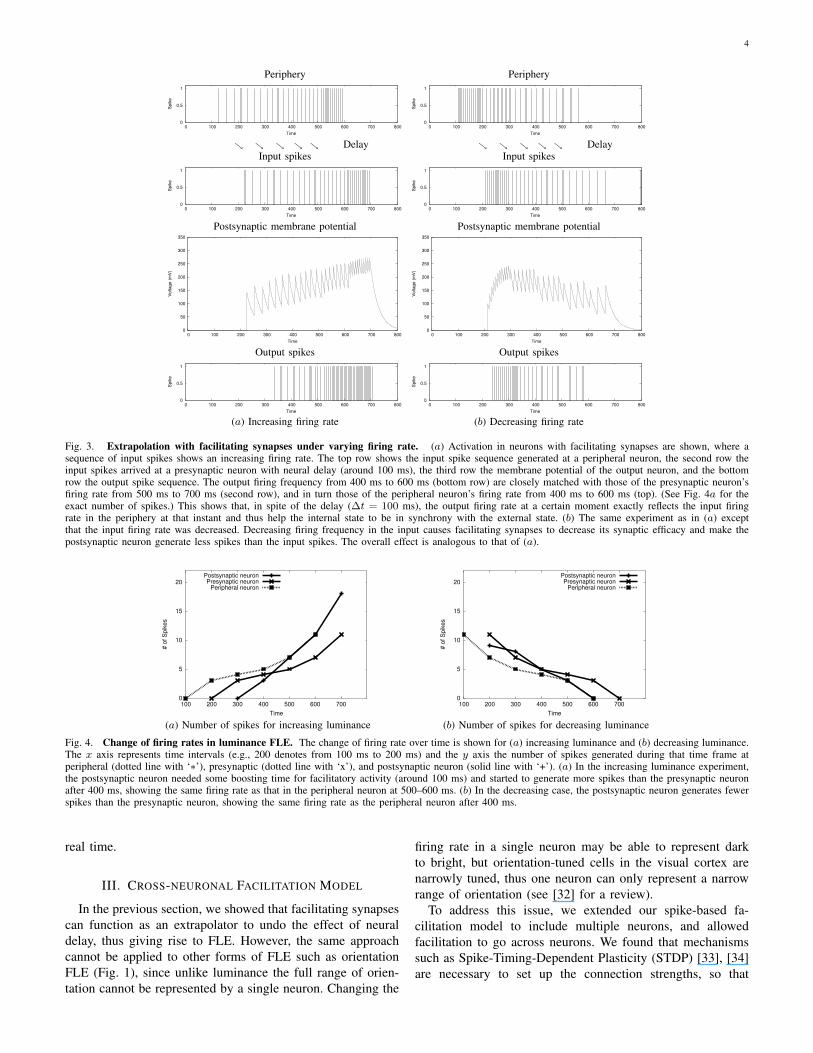
This kind of behavior is quite reasonable if we considerconduction delay. Suppose the spikes in the presynaptic neuron(the second row in Fig. 3a) originated earlier (about 100 ms) inperipheral sensors (the top row). Here is an example sequenceof events. (1) Peripheral spiking at 400 ms would be replicatedat 500 ms in the presynaptic neuron in the second row, dueto the 100 ms delay. (2) The postsynaptic neuron (bottomrow) receiving input from the presynaptic neuron (second row)at 500 ms fires based on information from 400 ms in theperiphery. (3) However, the postsynaptic neuron’s firing rateat 500 ms (bottom row) is the same as that of the presynapticneuron’s firing rate at 600 ms (second row) which representsa peripheral event at 500 ms. This means that the postsynapticneuron, at time 500 ms, is exactly firing at the same frequencyas the peripheral neuron at time 500 ms (refer to (1) above),precisely reflecting the present environmental state. Note thatthe presynaptic (second row) and the postsynaptic (bottomrow) neuron in Fig. 3a are both located in the central nervoussystem. The changes of firing rates from the three neurons(peripheral, presynaptic, and postsynaptic neuron) are plottedin Fig. 4a. Around 500 ms to 600 ms, the number of spikesin the postsynaptic neuron becomes the same as that of theperipheral neuron.
In case of decreasing firing rate (Fig. 3b), all the ex-perimental conditions and notations were the same as theincreasing case except that the input spike frequency wasdecreasing. According to Eq. 1 and Eq. 2, the constant C fordetermining the increase in synaptic efficacy becomes negativewhich leads to a gradual decrease in membrane potential ofthe postsynaptic neuron. The third row in Fig. 3 shows thedecreasing membrane potential, and the bottom row the outputspikes generating fewer spikes than that of the input spikes. Asshown in the increasing case, the postsynaptic neuron’s firingrates are closely matched with those of the peripheral neuronin spite of neural delay. (See Fig. 4b for the precise firing ratefrom the three neurons.)
In contrast with the previous models by Markram et al. [20],[24], [25], the modified equation (Eq. 1 and Eq. 2) was ableto generate extrapolated neural activity under decreasing, aswell as increasing, firing rate conditions. These experimentssuggest that facilitating synapses can implement a generalextrapolatory neural mechanism.
In sum, the time-varying stationary stimuli (brighter ordarker in luminance) were extrapolated to be perceived closeto the present luminance, while that of the abrupt stimulus (i.e.,flashed patch) was the same as the luminance 100 ms in thepast (no time for facilitation to build up). Such a differencein the perceived luminance of the two stimuli might causeFLE. With such a mechanism, organisms can keep the innerstate synchronized with that of the physical environment in
4
Periphery
0
0.5
1
0 100 200 300 400 500 600 700 800
Spi
ke
Time
↘ ↘ ↘ ↘ ↘ DelayInput spikes
0
0.5
1
0 100 200 300 400 500 600 700 800
Spi
ke
Time
Postsynaptic membrane potential
0
50
100
150
200
250
300
350
0 100 200 300 400 500 600 700 800
Vol
tage
(mV
)
Time
Output spikes
0
0.5
1
0 100 200 300 400 500 600 700 800
Spi
ke
Time
Periphery
0
0.5
1
0 100 200 300 400 500 600 700 800
Spi
ke
Time
↘ ↘ ↘ ↘ ↘ DelayInput spikes
0
0.5
1
0 100 200 300 400 500 600 700 800
Spi
ke
Time
Postsynaptic membrane potential
0
50
100
150
200
250
300
350
0 100 200 300 400 500 600 700 800
Vol
tage
(mV
)
Time
Output spikes
0
0.5
1
0 100 200 300 400 500 600 700 800
Spi
keTime
(a) Increasing firing rate (b) Decreasing firing rate
Fig. 3. Extrapolation with facilitating synapses under varying firing rate. (a) Activation in neurons with facilitating synapses are shown, where asequence of input spikes shows an increasing firing rate. The top row shows the input spike sequence generated at a peripheral neuron, the second row theinput spikes arrived at a presynaptic neuron with neural delay (around 100 ms), the third row the membrane potential of the output neuron, and the bottomrow the output spike sequence. The output firing frequency from 400 ms to 600 ms (bottom row) are closely matched with those of the presynaptic neuron’sfiring rate from 500 ms to 700 ms (second row), and in turn those of the peripheral neuron’s firing rate from 400 ms to 600 ms (top). (See Fig. 4a for theexact number of spikes.) This shows that, in spite of the delay (∆t = 100 ms), the output firing rate at a certain moment exactly reflects the input firingrate in the periphery at that instant and thus help the internal state to be in synchrony with the external state. (b) The same experiment as in (a) exceptthat the input firing rate was decreased. Decreasing firing frequency in the input causes facilitating synapses to decrease its synaptic efficacy and make thepostsynaptic neuron generate less spikes than the input spikes. The overall effect is analogous to that of (a).
0
5
10
15
20
100 200 300 400 500 600 700
# of
Spi
kes
Time
Postsynaptic neuronPresynaptic neuron
Peripheral neuron
(a) Number of spikes for increasing luminance
0
5
10
15
20
100 200 300 400 500 600 700
# of
Spi
kes
Time
Postsynaptic neuronPresynaptic neuron
Peripheral neuron
(b) Number of spikes for decreasing luminance
Fig. 4. Change of firing rates in luminance FLE. The change of firing rate over time is shown for (a) increasing luminance and (b) decreasing luminance.The x axis represents time intervals (e.g., 200 denotes from 100 ms to 200 ms) and the y axis the number of spikes generated during that time frame atperipheral (dotted line with ‘∗’), presynaptic (dotted line with ‘x’), and postsynaptic neuron (solid line with ‘+’). (a) In the increasing luminance experiment,the postsynaptic neuron needed some boosting time for facilitatory activity (around 100 ms) and started to generate more spikes than the presynaptic neuronafter 400 ms, showing the same firing rate as that in the peripheral neuron at 500–600 ms. (b) In the decreasing case, the postsynaptic neuron generates fewerspikes than the presynaptic neuron, showing the same firing rate as the peripheral neuron after 400 ms.
real time.
III. CROSS-NEURONAL FACILITATION MODEL
In the previous section, we showed that facilitating synapsescan function as an extrapolator to undo the effect of neuraldelay, thus giving rise to FLE. However, the same approachcannot be applied to other forms of FLE such as orientationFLE (Fig. 1), since unlike luminance the full range of orien-tation cannot be represented by a single neuron. Changing the
firing rate in a single neuron may be able to represent darkto bright, but orientation-tuned cells in the visual cortex arenarrowly tuned, thus one neuron can only represent a narrowrange of orientation (see [32] for a review).
To address this issue, we extended our spike-based fa-cilitation model to include multiple neurons, and allowedfacilitation to go across neurons. We found that mechanismssuch as Spike-Timing-Dependent Plasticity (STDP) [33], [34]are necessary to set up the connection strengths, so that

5
cross-neuron facilitation can carry out extrapolation in thedirection of change. STDP refers to a synaptic plasticitymechanism where the order of presynaptic and postsynapticspike determines the sign of the adaptation: either increased ordecreased synaptic efficacy. STDP favors the causal direction,as postsynaptic firing after presynaptic firing would increasethe synaptic strength.
In this section, we will first provide details of our modeland explain how cross-neuronal facilitating dynamics can beimplemented by including STDP, and test the model withorientation FLE.
A. Model description
In order to represent the full range of orientation, we mod-eled twelve orientation-sensitive neurons at a 15o increment.Fig. 5a shows the arrangement of the neurons, and their lateralexcitatory connectivity (connections are only between imme-diate neighbors). Each neuron fires according to a distributioncentered around its preferred orientation, maximally firingwhen the preferred orientation is present in the input, andgradually less as the input veers away (Fig. 5b, “No FLE”).Note that during orientation FLE, the distribution shifts towardthe direction of rotation (Fig. 5b, “FLE”). Each neuron has afacilitating dynamic, and the lateral connections are trainedusing STDP.
To allow for cross-neuronal interaction, we extended thesingle neuron model in Sec. II-A to include synaptic inputfrom neighboring neurons, as shown in Fig. 5a. Each cell inFig. 5a can receive spikes from other neurons to the left andto the right as well as input spikes delivered from peripheralneurons. Through the sequence of spikes, facilitating activitypropagates to neighboring neurons and increases the postsy-naptic neurons’ responses. At the same time, the connectionweights w are updated through STDP. Note that cross-neuronalfacilitating dynamic follows the single facilitation dynamicsas described in Sec. II-A. The only difference here is that win Eq. 4 is a variable, not a constant. As a result of STDP,facilitating activity propagates only to the neurons located inthe direction of rotation.
B. Spike-Timing-Dependent Plasticity (STDP)
The lateral connections in our model (Fig. 5a) are initiallydirectionally symmetric, meaning that there is no preferentialactivation in the clockwise or the counter-clockwise direction.However, for extrapolation to happen in a particular direction,there needs to be directionality. A learning process that givesrise to such a directionality can be found in Spike-Timing-Dependent Plasticity (STDP). STDP changes the synapticweight between two neurons when they fire together withina small time interval [33], [34]. When the presynaptic neuronfires first (firing time tpre), and then the postsynaptic spike(firing time tpost), then the difference ∆t = tpost − tpre > 0,since tpost > tpre. On the other hand, if the postsynapticneuron fires first, ∆t < 0. The synapse will be strengthenedif ∆t > 0, and weakened if ∆t < 0.
To include STDP in our model, we used the synapticmodification function in [34]:
F (∆t) =
{A+e
−∆tτ+ if ∆t > 0
−A−e∆tτ− if ∆t < 0
, (6)
where A+ and A− are constants determining the maximumrange of modification, and τ+ and τ− the time constants ofexponential decay. For our simulations, we used the followingvalues: A+ = 5.0, A− = 3.7, τ+ = 80, and τ− = 105.
The weight adaptation of the connection from neuron j toneuron i, with firing time tj and ti, respectively, was carriedout as follows:
wij ← wij + αF (∆t); (7)
where α is the learning rate (= 0.02) and ∆t = ti − tj . Incase wij reached zero, it was not decreased any further.
Fig. 6 in the next section shows the evolution of theconnection weights toward or against the direction of inputrotation. When a particular target (postsynaptic) neuron hasorientation preference that is in the rotating direction relativeto the source (presynaptic) neuron, the source neuron firesfirst and then the target neuron fires, so STDP strengthensthe connection. STDP weakens the connection in the oppositecase (i.e. the postsynaptic neuron fires first). A critical factorin this experiment is that the input rotation should not be toofast nor too slow, so that neighboring neurons can fire withinthe STDP adaptation window (≈ ±80 ms [36]). Also note thatthe parameters τ+ and τ− in Eq. 6 affect the width of positiveand negative adaptation windows, respectively. Interestingly,this timing roughly corresponds to the timescale of orientationFLE. For example, as the orientation of the stimulus sweepsby at 100 ms per neuron (i.e. 25 rotations per minute (RPM)),the neurons generate several spikes while the input is attheir preferred orientation. With this, the bilaterally connectedpresynaptic and postsynaptic neurons fire together within ashort time interval (about 80 ms) and ∆t will fall withinthe STDP range. Under this condition, the synaptic weightsbetween the neurons can be adapted.
C. Experiments and results: Orientation FLE
To test, in a multi-neuron environment, the contributionof facilitating dynamics and STDP in delay compensation,we used a network of neurons arranged as in Fig. 5a. Theexperiments were carried out in the orientation FLE domain,illustrated in Fig. 1. We conducted three separate experiments:orientation perception with (1) STDP only, (2) facilitatingsynapses only, and (3) both STDP and facilitating synapses.In all experiments, the input was rotated in the clockwisedirection, at a speed of 25 RPM, and the input firing ratewas set to 1 spike/10 ms.
1) STDP only: First, we tested our model with only STDP,without facilitating synapses. The connection weights wereallowed to adapt according to Eq. 7. Fig. 6 shows the results.For those connections pointing toward the direction of inputrotation, the weight increased (Fig. 6, solid curve) sincepresynaptic spike preceded postsynaptic spike within the smalltime interval. On the other hand, for the connections pointing

6
Lateralconnections
Input
Orientation−tuned cells
FLE
No FLE
Physical Input
. . . . . .
(a) Network (b) Response with/without FLE
Fig. 5. Bilaterally connected orientation-tuned cells and FLE. (a) Twelve orientation-tuned neurons are shown, with excitatory lateral connections betweenimmediate neighbors. The connectivity shown here is a simplification of similar arrangements near orientation pinwheels in the primary visual cortex [35],[32]. (b) The spike responses (vertical bars) and firing-rate distributions (curves) are shown, with (top, dashed) and without (bottom, solid) Flash-Lag Effect.The x-axis represents the spatial span across the connected orientation-tuned cells in (a). Without FLE (solid), the firing-rate distribution is centered aroundthe middle, coinciding with the physical input shown below (cf. Fig. 1a). With FLE (dashed), the distribution is shifted toward the direction of input rotation(cf. Fig. 1b).
0
0.5
1
1.5
2
2.5
3
0 20 40 60 80 100 120 140
Syn
aptic
wei
ght (
w)
Time (x 1000 ms)
Toward Direction of RotationAway from Direction of Rotation
Fig. 6. Adaptation of synaptic weights using STDP. The synaptic weightsw (y-axis) in the connections from neuron 2 to its two immediate neighborsare shown over time (x-axis). The weight to the neuron in the direction ofinput rotation increases (solid curve), while that in the opposite directiondecreases (dotted curve).
in the opposite direction, the weight decreased (Fig. 6, dottedcurve).
To calculate the firing rate at any given moment, we used afixed sliding window with a width of 100 ms. We measured thefiring rate when the input was oriented to optimally stimulateneuron 2. Fig. 7a shows the results. Initially, when the weightshave not adapted much, the firing-rate distribution is peakedat neuron 2 and is symmetric. After the weights have reacheda stable state, the distribution becomes asymmetric, with ashift toward the right, which is the direction of input rotation.However, the location of the peak did not change (neuron 2).The results can be interpreted as no orientation FLE occurring.
2) Facilitating synapses only: In this experiment, we usedonly facilitating synapses, without STDP. All weights were ini-tialized to 1.0, and remained fixed throughout the experiment.Since the weights did not have any directionality, we expectedthat no orientation FLE would occur, which turned out to bethe case. The only changing quantity in this experiment wasthe synaptic efficacy in the facilitating synapses (Eq. 1). As aresult, the U value increases while the input bar is optimallystimulating the neuron, and decays as soon as the input barrotates out of the optimal range.
As expected, the firing rate distribution did not changefrom its symmetric peaked distribution centered around theoptimally tuned neuron, for the given input orientation (Fig.7b). The results suggest that, again, orientation FLE didnot occur, and facilitating synapses alone are not enough toaccount for cross-neuronal facilitation (or extrapolation acrossneurons).
3) STDP with facilitating synapses: The final experimentcombined STDP and facilitating synapses. Other experimentalconditions were the same as in the two experiments abovefor the STDP and the facilitating synapse parameters. In thisexperiment, two factors contributed to synaptic transmissionbetween two neurons: the very short-term increase in synapticefficacy due to facilitating dynamics, and the longer-termincrease in synaptic strength due to STDP. The graduallyincreasing long-term trend in STDP weight amplified therapidly changing facilitating dynamics. Fig. 8a–b shows thatthe adaptation of synaptic efficacy from the initial state (Fig.8a: no directionality) to the final state (Fig. 8b: with direction-ality).
The combined effect of these two factors (STDP and facil-itating synapses) over time is shown in Fig. 8c. STDP givesthe model directionality, and facilitating dynamics providesextra influence in the direction of input rotation, thus allowingthe model to shift its firing rate distribution significantly.Fig. 7c shows that the peak in the firing rate distributionshifts toward the direction of input rotation (to the right) bytwo steps (neuron 4), when the actual input at that momentoptimally stimulates neuron 2. This shift (indicated by thearrow) suggests that orientation FLE occurred.
The results showed that STDP or facilitating synapses alonecannot serve as a robust mechanism for delay compensation,as shown in their lack of ability to give rise to orientationFLE in a multi-neuron setting. Only when both are combined,delay compensation can work properly, thus giving rise toorientation FLE. See Table I for a summary of experiments,results, assumptions, and proposed neural bases.

7
0
1
2
3
4
5
0 1 2 3 4 5 6 7 8 9 10 11
Firin
g Ra
te (1
00 m
s)
Neuron Index
InitialFinal
0
1
2
3
4
5
0 1 2 3 4 5 6 7 8 9 10 11
Firin
g Ra
te (1
00 m
s)
Neuron Index
InitialFinal
0
1
2
3
4
5
0 1 2 3 4 5 6 7 8 9 10 11
Firin
g Ra
te (1
00 m
s)
Neuron Index
InitialFinal
(a) STDP only (b) Faciltating synapses only (c) STDP+Facilitating synapses
Fig. 7. Firing rate distributions. Firing rate distributions under different experimental conditions are shown. (a) Results from the STDP-only simulationsare shown. The dotted line with ‘×’ represents the initial firing rates of the neurons. The solid line with ‘◦’ denotes the changed firing rate after the synapticweights reached a stable state through STDP. This is a snapshot of firing rates (i.e. number of spikes during a 100 ms interval) when the actual inputorientation was neuron 2’s preferred stimulus. With STDP, the firing rates of the neurons were skewed toward the direction of rotation due to the synapticweight modification. However, the maximally firing neuron (neuron 2) did not change (i.e., no FLE). (b) Results from the facilitation-only experiments areshown (the plotting conventions are the same as in a). Because the synaptic efficacy U is rapidly changed by a small amount, facilitating synapse alonedid not affect the firing rate of the neighboring neurons. Thus, the maximally firing neuron (neuron 2) did not change (i.e., no FLE). (c) Results from theSTDP+facilitation experiments are shown (the plotting conventions are the same as in a). The distribution of firing rates significantly shifted toward therotating direction (as indicated by an arrow). The position of maximally firing neuron changed from neuron 2 to neuron 4. After training with STDP, andfacilitating synapses added, when the neuron 2’s preferred orientation was given in the input, neuron 4 showed maximum firing rate instead of neuron 2. Thisresult indicates that the perception of the rotating bar shifted, just like in orientation FLE.
0.05
0.1
0.15
0.2
0.25
0.3
0.35
0.4
0 1000 2000 3000 4000 5000 6000 7000
Syn
aptic
effi
cacy
(u)
Time (ms)
0.05
0.1
0.15
0.2
0.25
0.3
0.35
0.4
0 1000 2000 3000 4000 5000 6000 7000
Syn
aptic
effi
cacy
(u)
Time (ms)
0.2
0.25
0.3
0.35
0.4
0.45
0.5
0.55
0 100 200 300 400 500 600 700
Syna
ptic
Stre
ngth
(U x
w)
Time (x 100 ms)(a) Initial U (b) Final U (c) Evolution of U · w
Fig. 8. Adaptation of synaptic efficacy through STDP + facilitating synapses. The evolution of synaptic efficacy U in a single neuron is shown. (a)Neuron 2 shows rapid increase of synaptic efficacy during the presence of a preferred input orientation. (b) After training under STDP + facilitation synapses,the dynamics of synaptic efficacy highly increases. Note that synaptic efficacy starts boosting up earlier than in the initial state (compare the parts indicatedby arrows). The strengthened connections allowed the neighboring neurons in the direction of rotation to generate predictive spikes. (c) Adaptation of synapticstrength (U ·w in Eq. 4) through STDP plus facilitating synapses (along the direction of rotation) is shown. Synaptic strength (U ·w) dynamically increasesbecause of the gradually increasing synaptic weight w and the fast changing synaptic efficacy U .
TABLE ISUMMARY OF ASSUMPTIONS AND RESULTS
Experiments Results Assumptions Neural basis
Luminance FLE:increasing luminance
Higher output firing rate than inputfiring rate for increasing luminanceinput
Facilitation is needed for single-neuron-level extrapolation
Facilitating synapses[20]
Luminance FLE:decreasing luminance
Lower output firing rate than inputfiring rate for decreasing luminanceinput
The factor C in the facilitatingsynapse equation (Eq 1) is a vari-able quantity depending on the his-tory of input spikes
Facilitating synapses[20], with modificat-ions (Sec. II-A)
Orientation FLE Shifted response distribution towardthe direction of rotation
Facilitation, as well as STDP, isneeded for cross-neuronal extrapo-lation
Facilitating synapses[20] and STDP [33],[34]
IV. DISCUSSION
A. Contributions
The main contribution of this paper is to relate facilitatingsynapses, delay compensation (through extrapolation), andFLE; thus linking neurophysiology, computational function,and psychophysics. Unlike previous models of FLE and related
phenomena [22], [23], [6], our model provides extrapolation ata single-neuron level. Another contribution of our work is thatwe have shown STDP alone may not be sufficient for effectiveextrapolation/delay compensation, and facilitating synapsescan again play an important role (cf. Rao and Sejnowski [37]where STDP alone was proposed as a predictive mechanism).

8
B. Notes on Model Parameters
In our paper, the values of synaptic parameters were tuned,within reasonable range, to derive the desired behavior. Allthe parameter values for the facilitating synapse model werewithin the range of empirical data found in neurophysiol-ogy [24], [20], [38]. We also referenced STDP related lit-eratures [34], [39], [40] to set the STDP model parameters,again within in known ranges.
C. Limitations
Being an extrapolation model of FLE, our approach suffersfrom the same potential shortcomings of Nijhawan et al.’sextrapolation theory [4]. As pointed out by Krekelberg andLappe [5], the extrapolation theory’s weakness is in not beingable to account for (1) the lack of FLE in motion terminationand motion reversal [11], and (2) reversal of FLE in low-luminance condition (low luminance supposedly causes longerlatency, thus a stronger FLE is predicted by the extrapolationtheory) [10] (also see [14]). Nijhawan proposed a backward-masking solution for issue (1) [4] (also see the next paragraph),however, it is unclear so far how issue (2) can be resolved.One potential explanation could be related to facilitatingdynamic’s dependence on high-frequency input [27]. Underlow luminance, firing rate may become generally lower, andthe extrapolation mechanism in facilitating synapses may fail(i.e., no FLE). It would be interesting to find the perceptual(luminance) threshold where FLE disappears, and the firingrate at which facilitating dynamic disappears and find anycorrelation between the two. One interesting behavior weobserved in our model in relation to the above discussion iswhen the input firing rate was lowered in the orientation FLEexperiment (e.g. less than 10 spikes per 100 ms). Note that 1spike/10 ms was used in the other experiment in Sec. III-C. Asthe input spike frequency decreases (which can happen whenthe oriented bar gets fatter or thinner than the optimal thickness[41]) the shift in the firing rate distribution was reduced (i.e.,weaker or no FLE). The reason is that to make facilitatingdynamics to be activated, the neuron should receive highfrequency input spikes [27]. Results show that the adaptationof synaptic efficacy through STDP and facilitating synapsesunder low firing rate (7 and 5 spikes/100 ms) is significantlyreduced compared to the high firing rate condition. With thesame connections set up through STDP, suboptimal inputcould not invoke dynamic change of synaptic efficacy, i.e.,it was not enough to shift the firing rate distribution (Fig. 9).
Another complex issue arises when we consider the vari-ability in response latency. For example, the latency betweenstimulus onset and neural response in various loci in the visualpathway are known to show a range of variability [42]. Ifthis is the case, compensation for such latency may becomevery difficult, since at every moment an accurate estimationof the latency needs to be in hand, which may be hard toobtain. One counter argument to this is that in most cases, thelatency variability is exhibited at the population level, thus thelatency may be fixed at a single-neuron level, and in this caseit could be compensated. However, it turns out that latencyvariability exists even at the single-neuron level, for example
5
4
3
2
1
0 11 10 9 8 7 6 5 4 3 2 1 0
Firin
g R
ate
(100
ms)
Neuron Index
10 spikes/100 ms7 spikes/100 ms5 spikes/100 ms
Fig. 9. Change in the distribution of firing rate depending on the inputfrequency. The effects of decreasing the input spike frequency (e.g., fatterinput bar) on the response distribution are shown. As the number of inputspikes decreases (line with ‘×’ represents 10 spikes/100 ms, � for 7, and◦ for 5 spikes/100 ms), the shift of firing rate distribution is reduced (i.e.,weaker FLE). Also, the overall magnitude of firing rate decreases as the inputfrequency gets smaller.
in the simple cells in the primary visual cortex [43]. Onepossibility is that such response latency is mostly due to thevariability in the integration time in the membrane potential(see [44]), and not in the axonal conduction delay (which weare trying to compensate). In this case, the relatively fixedaxonal conduction delay will dictate the mean of the latencydistribution (which can be compensated), and the integrationtime variability will account for the variance (which may behard to compensate). More theoretical investigation is neededto unequivocally determine if compensation can be done forsuch a variable component in the latency.
Finally, our model of FLE introduced in this paper ispurely bottom-up. A question here is whether such a modelshould include top-down influence. In top-down processing, aperceiver’s concept and higher level knowledge also influencethe visual perception. Eagleman et al.’s approach (postdiction)can be thought of as a first step toward top-down processing[15]. Their main idea is that visual perception is not onlyfeedforward processing: Current visual information can becorrected by future information and the result of integration iswhat we perceive. It would be interesting to extend our low-level neuronal model to include higher level feedback whichcan account for such an integration process. For example,backward masking suggested by Nijhawan [4] can come fromhigher level intervention.
D. Relation to Other Works
The view presented in this paper provides new insights on analternative role of facilitating synapses—that of extrapolatorydelay compensation. Existing theories regarding facilitatingsynapses included sensitization and habituation [45], [46],or temporal information processing [24], [20], [27], [47],[48]. Synaptic plasticity (including facilitating synapses) aretypically related to memory functions, but our results indicateit could be more about prediction. However, note that theseviews are ultimately compatible: As Hawkins argued, memorymay be explicitly linked to predictive functions [49].
There are various existing theories on the role of STDP.For example, STDP is supposed to help reduce spike trainvariability [50]. It was also shown that STDP may be involved

9
in topology-preserving mapping [51]. Others suggested STDPas a neural mechanism for cortical orientation tuning [52].The perspective closest to ours is that of Rao et al. [37]:They argued that STDP may implement a predictive function,where what is to occur next in an input sequence is predicted.(See [49] and [53] for a general discussion of the role ofprediction in brain function.) However, they did not relate thispredictive ability to the idea of delay compensation. From ourperspective, these predictive mechanisms may have started outas prediction of the present, not prediction of the future. Also,our work further combines facilitating synapses with STDP,to give the predictive mechanism a faster and more dynamictimescale, which turned out to be necessary to account forperceptual phenomena such as orientation FLE.
Our dynamic account of extrapolation and the proposedfacilitating dynamics is interestingly related to perceptualphenomena due to spatial extrapolation on static stimuli. Forexample, Changizi presented a theory that angle misperceptionin static images is due to what he calls ‘perceiving the present’[54]. The basic argument is that what we perceive is what thestimulus would look like right now in an ‘ecological’ context(e.g., as if the perceiver has been moving forward), given theinput stimulus from a short while in the past (due to conductiondelay). Although the end result looks like there is spatialextrapolation (since you are only looking at a static stimu-lus), the whole idea depends on a more dynamic argument(movement). Only through a history of movement in the past,such extrapolations could be set up. The work we presented inSec. III-C with its cross-neuronal facilitation may be closelylinked to Changizi’s account. Mechanisms like STDP can setup the causal link, and facilitating synapses can carry out thepredictive projection of activity through a previously exercisedmotor-induced perceptual change cycle (see [55] for how thethalamocortical loop can play a role in such a predictivepreactivation). It is no coincidence that Changizi’s frameworkis called ‘perceiving the present’. Similar arguments can linkour dynamic account of extrapolation and other extrapolativephenomena involving discretely presented sequences of sta-tionary stimuli, such as representational momentum [56] (see[57] for a review).
Finally, we would like to compare our model with that ofBaldo and Caticha [6] which seems to be the most com-prehensive neural model of FLE. Their model consists ofthree layers (input, hidden, and output) of leaky integrateand fire neurons, with on-center/off-surround receptive fields.Thus, their model includes inhibitory connections, as well asexcitatory connections. Also, they have facilities for attentionalmodulation by forceful activation in the output layer targetedat the locus of attention. Their model is capable of replicating(1) the standard FLE, (2) Frolich effect ([58]; when a movingobject appears abruptly, the initial segment of the object’strajectory is not perceived), (3) luminance-ratio-dependenceof FLE, (4) speed-dependence of FLE magnitude, (5) flash-initiated cycle, (6) flash termination and flash reversal, (7)absence of Frolich effect when flashed object is shown,removed, and shown again, and (8) attentional modulationof FLE. Our current model can deal with (1), (2), (4), and(5). With the addition of inhibitory influence, effectively a
backward masking influence proposed by Nijhawan [4], weexpect our model can account for (6). (Note that our modelonly has excitatory influence.) If we add forced attentionalactivation as in Baldo and Caticha’s experiments, we expectour model can also handle (8). Our model cannot physicallyrepresent the stimulus condition of (3), and we are not certainhow our model will behave in case (7). In sum, consideringthat our model does not have additional features like inhibitoryconnections and forced attentional activation, it fares wellcompared to Baldo and Caticha’s model.
E. Predictions
We expect that our approach can be extended to explainother extrapolatory phenomena such as flash-lag effects incolor, pattern entropy, or localization. Moreover, we expectthat the extended cross-neuronal facilitation model may be ableto account for other visual illusions such as the Frohlich effect.Note that the facilitating mechanism generated the first outputspike train after a certain amount of delay (see Figures 3aand 3b, bottom rows): In addition to the neural transmissiondelay from peripheral neurons to visual cortex neurons, thepostsynaptic neuron needed boosting time to respond to theinitial input spike train. This is consistent with the Frohlicheffect [59], in which the moving object may be invisible duringthe initial period due to the silence of neurons.
Another prediction is that the time-frame for orientationFLE should be within the time-frame of the STDP adaptationwindow, as suggested in Sec. III. This is because STDP needsto set the directionality for the propagation of facilitatingactivity, and synaptic change can only happen when the pre-and post-synaptic neurons fire within the STDP window.Also, in relation to the orientation FLE experiments, theresults presented in Fig. 9 forms a direct prediction regardingsuboptimal orientation stimuli, such as fatter or thinner input.
Our model makes neurophysiological predictions as well. Iffacilitating synapses indeed function as delay compensators,facilitating synapses should be found more often in placeswhere delay compensation is needed more, for example, atthe end of long, slow axons, or where precise real-timeinformation is needed. Also, the term C defined in Eq. 2 couldchange over time, unlike the original model first proposed byMarkram et al. [20] where it is constant. There are some cluesthat suggest this could be the case: It is known that facilitationis driven by elevated calcium levels in presynaptic terminals.Recent neurophysiological findings such as the involvement ofcalcium chelator BAPTA, playing a role of Ca2+ buffer [60],can be one potential basis of the variance in C.
V. CONCLUSION
In this paper, we have shown that dynamics found infacilitating synapses can serve as a neural basis of extrapo-lation. Experiments with our spike-based facilitating model inluminance FLE showed that facilitating postsynaptic activitycan generate extrapolated neural activity under both increas-ing and decreasing firing rate conditions. Going beyond thesingle neuron model, we showed that facilitating synapses, if

10
combined with STDP, can allow extrapolation based on cross-neuronal facilitation and may give rise to orientation FLE. Insum, we showed that facilitating synaptic dynamics can serveas a delay compensation mechanism, which can give rise tothe various flash-lag effects, and help biological organismsto perceive the present environmental state in real time. Thesingle-neuron-level extrapolative mechanism proposed in thispaper have general utility beyond the flash-lag effect, and weexpect the framework to be more widely applied in interpretingexperimental data and in engineering applications (e.g., as in[61]).
ACKNOWLEDGMENTS
We would like to thank B. Sheth and R. Nijhawan forhelping us interpret their FLE results more clearly; HarelShouval for his suggestion regarding Ca2+ dynamics and C;David Mayerich and Andrew Jones for initial implementationof the STDP model; and the anonymous reviewers for helpfulsuggestions and references. The extended results and analysesin this paper is partly based on our previous reports in [62],[63].
REFERENCES
[1] B. Sheth, R. Nijhawan, and S. Shimojo, “Changing objects lead brieflyflashed ones,” Nature Neuroscience, vol. 3, pp. 489–495, 2000.
[2] D. M. MacKay, “Perceptual stability of a stroboscopically lit visual fieldcontaining self-luminous objects,” Nature, vol. 181, pp. 507–508, 1958.
[3] R. Nijhawan, “Motion extrapolation in catching,” Nature, vol. 370, pp.256–257, 1994.
[4] ——, “Neural delays, visual motion and the flash-lag effect,” Trends inCognitive Sciences, vol. 6, pp. 387–393, 2002.
[5] B. Krekelberg and M. Lappe, “Neural latencies and the position ofmoving objects,” Trends in Neurosciences, vol. 24, pp. 335–339, 2001.
[6] M. V. C. Baldo and N. Caticha, “Computational neurobiology of theflash-lag effect,” Vision Research, vol. 45, pp. 2620–2630, 2005.
[7] R. Nijhawan, “Visual decomposition of color through motion extrapo-lation,” Nature, vol. 386, pp. 66–69, 1997.
[8] W. Erlhagen, “The role of action plans and other cognitive factors inmotion extrapolation: A modelling study,” Visual Cognition, vol. 11, pp.315–340, 2004.
[9] M. V. C. Baldo and S. A. Klein, “Extrapolation or attention shift?”Nature, vol. 378, pp. 565–566, 1995.
[10] G. Purushothaman, S. S. Patel, H. E. Bedell, and H. Ogmen, “Movingahead through differential visual latency,” Nature, vol. 396, p. 424, 1998.
[11] D. Whitney and I. Murakami, “Latency difference, not spatial extrapo-lation,” Nature Neuroscience, vol. 1, pp. 656–657, 1998.
[12] D. H. Arnold, S. Durant, and A. Johnston, “Latency differences and theflash-lag effect,” Vision Research, vol. 43, pp. 1829–1835, 2003.
[13] B. Krekelberg and M. Lappe, “A model of the perceived relativepositions of moving objects based upon a slow averaging process,”Vision Research, vol. 40, pp. 201–215, 2000.
[14] B. W. Roulston, M. W. Self, and S. Zeki, “Perceptual compression ofspace through position integration,” Proceedings of the Royal Society B:Biological Sciences, vol. 273, pp. 2507–2512, 2006.
[15] D. Eagleman and T. J. Sejnowski, “Motion integration and postdictionin visual awareness,” Science, vol. 287, pp. 2036–2038, 2000.
[16] R. P. Rao, D. M. Eagleman, and T. J. Sejnowski, “Optimal smoothing invisual motion perception,” Neural Computation, vol. 13, pp. 1243–1253,2001.
[17] R. Nijhawan, “Visual prediction: Psychophysics and neurophysiology ofcompensation for time delays,” Behavioral and Brain Sciences, 2008, inpress.
[18] H. Lim and Y. Choe, “Compensating for neural transmission delayusing extrapolatory neural activation in evolutionary neural networks,”Neural Information Processing–Letters and Reviews, vol. 10, pp. 147–161, 2006.
[19] ——, “Facilitating neural dynamics for delay compensation and predic-tion in evolutionary neural networks,” in Proceedings of the Genetic andEvolutionary Computation Conference, GECCO-2006, M. Keijzer, Ed.,2006.
[20] H. Markram, Y. Wang, and M. Tsodyks, “Differential signaling viathe same axon of neocortical pyramidal neurons,” Proceedings of theNational Academy of Sciences, USA, vol. 95, pp. 5323–5328, 1998.
[21] A. Reyes and B. Sackmann, “Developmental switch in the short-termmodification of unitary EPSPs evoked in layer 2/3 and layer 5 pyramidalneurons of rat neocortex,” Journal of Neuroscience, vol. 19, pp. 3827–3835, 1999.
[22] M. J. Berry, I. H. Brivanlou, T. A. Jordan, and M. Meister, “Anticipationof moving stimuli by the retina,” Nature, vol. 398, 1999.
[23] Y.-X. Fu, Y. Shen, and Y. Dan, “Motion-induced perceptual extrapolationof blurred visual targets,” The Journal of Neuroscience, vol. 21, pp.RC172 (1–5), 2001.
[24] G. Fuhrmann, I. Segev, H. Markram, and M. Tsodyks, “Coding oftemporal information by activity-dependent synapses,” Journal of Neu-rophysiology, vol. 87, pp. 140–148, 2002.
[25] W. Maass and H. Markram, “Synapses as dynamic memory buffers,”Neural Networks, vol. 15, pp. 423–431, 2002.
[26] J. Liaw and T. W. Berger, “Dynamic synapse: Harnessing the computingpower of synaptic dynamics,” Neurocomputing, vol. 26-27, pp. 199–206,1999.
[27] E. S. Fortune and G. J. Rose, “Short-term synaptic plasticity as atemporal filter,” Trends in Neurosciences, vol. 24, pp. 381–385, 2001.
[28] R. Legenstein, C. Naeger, and W. Maass, “What can a neuron learnwith spike-timing-dependent plasticity?” Neural Computation, vol. 17,pp. 2337–2382, 2005.
[29] F. Gabbini and C. Koch, “Principles of spike train analysis,” in Methodsin Neural Modeling, C. Koch and I. Segev, Eds. Cambridge, MA: MITPress, 1999, pp. 313–360.
[30] M. Kinoshita and H. Komatsu, “Neural representation of the luminanceand brightness of a uniform surface in the macaque primary visualcortex,” Journal of Neurophysiology, vol. 86, pp. 2559–2570, 2001.
[31] A. F. Rossi, C. D. Rittenhouse, and M. A. Paradiso, “The representationof brightness in primary visual cortex,” Science, vol. 273, pp. 1104–1107, 1996.
[32] R. Miikkulainen, J. A. Bednar, Y. Choe, and J. Sirosh, ComputationalMaps in the Visual Cortex. Berlin: Springer, 2005.
[33] G.-Q. Bi and M.-M. Poo, “Activity-induced synaptic modifications inhippocampal culture: Dependence on spike timing, synaptic strength andcell type,” Journal of Neuroscience, vol. 18, pp. 10 464–10 472, 1998.
[34] S. Song, K. D. Miller, and L. F. Abbott, “Competitive hebbian learn-ing through spike-timing-dependent synaptic plasticity,” Nature Neuro-science, vol. 3, pp. 919–926, 2000.
[35] W. H. Bosking, Y. Zhang, B. Schofield, and D. Fitzpatrick, “Orientationselectivity and the arrangement of horizontal connections in tree shrewstriate cortex,” The Journal of Neuroscience, vol. 17, pp. 2112–2127,1997.
[36] B. Berninger and G.-Q. Bi, “Synaptic modification in neural circuits: atimely action,” BioEssays, vol. 24, pp. 212–222, 2002.
[37] R. P. Rao and T. J. Sejnowski, “Predictive sequence learning in recurrentneocortical circuits,” in Proceedings of the Advances in Neural Informa-tion Processing Systems (NIPS 2000). MIT Press, 2000, pp. 164–170.
[38] W. Gerstner and W. Kistler, Spiking Neuron Models. Cambridge, UK:Cambridge University Press, 2002.
[39] R. C. Froemke and Y. Dan, “Spike-timing-dependent synaptic modifi-cation induced by natural spike trains,” Nature, vol. 416, pp. 433–438,2002.
[40] H. Yao and Y. Dan, “Stimulus timing-dependent plasticity in corticalprocessing of orientation,” Neuron, vol. 32, pp. 315–323, 2001.
[41] R. M. Everson, A. K. Prashanth, M. Gabbay, B. W. Knight, L. Sirovich,and E. Kaplan, “Representation of spatial frequency and orientation inthe visual cortex,” Proceedings of the National Academy of Science,USA, vol. 95, pp. 8334–8338, 1998.
[42] L. G. Nowak and J. Bullier, “The timing of information transfer in thevisual system,” Cerebral Cortex, vol. 12, pp. 205–239, 1997.
[43] T. J. Gawne, T. W. Kjaer, and B. J. Richmond, “Latency: Anotherpoential code for feature binding,” Journal of Neurophysiology, vol. 76,pp. 1356–1360, 1996.
[44] J. Bolz, G. Rosner, and H. Wassle, “Response latency of brisk-sustained(X) and brisk-transient (Y) cells in the cat retina,” Jounral of Physiology,vol. 328, pp. 171–190, 1982.
[45] R. S. Zucker, “Short-term synaptic plasticity,” Annual Review of Neuro-science, vol. 12, pp. 13–31, 1989.

11
[46] S. A. Fisher, T. M. Fisher, and T. J. Carew, “Multiple overlappingprocesses underlying short-term synaptic enhancement,” Trends in Neu-rosciences, vol. 20, pp. 170–177, 1997.
[47] T. Natschlager, W. Maass, and A. Zador, “Efficient temporal processingwith biologically realistic dynamic synapses,” Network: Computation inNeural Systems, vol. 12, pp. 75–87, 2001.
[48] M. Tsodyks, K. Pawelzik, and H. Markram, “Neural networks withdynamic synapses,” Neural Computation, vol. 10, pp. 821–835, 1998.
[49] J. Hawkins and S. Blakeslee, On Intelligence, 1st ed. New York: HenryHolt and Company, 2004.
[50] S. M. Bohte and M. C. Mozer, “Reducing spike train variability: Acomputational theory of spike-timing dependent plasticity,” in Advancesin Neural Information Processing Systems, L. K. Saul, Y. Weiss, andL. Bottou, Eds. Cambridge, MA: MIT Press, 2005, vol. 17, pp. 201–208.
[51] C. Panchev and S. Wermter, “Hebbian spike-timing dependent self-organization in pulsed neural networks,” in World Congress on Infor-matics: Part II, Proceedings, F. Rattay, Ed. Vienna: ARGESIM/ASIM-Verlag, 2001, pp. 378–385.
[52] H. Yao, Y. Shen, and Y. Dan, “Intracortical mechanism of stimulus-timing-dependent plasticity in visual cortical orientation tuning,” inProceedings of the National Academy of Sciences, USA, vol. 101, 2004,pp. 5081–5086.
[53] R. R. Llinas, I of the Vortex. Cambridge, MA: MIT Press, 2001.[54] M. A. Changizi, “‘perceiving the present’ as a framework for ecological
explanations of the misperception of projected angle and angular size,”Perception, vol. 30, pp. 195–208, 2001.
[55] Y. Choe, “The role of temporal parameters in a thalamocortical modelof analogy,” IEEE Transactions on Neural Networks, vol. 15, pp. 1071–1082, 2004.
[56] J. J. Freyd and R. A. Finke, “Representational momentum,” Journal ofExperimental Psychology: Learning, Memory, and Cognition, vol. 10,pp. 126–132, 1984.
[57] T. L. Hubbard, “Environmental invariants in the representation ofmotion: Implied dynamics and representational momentum, gravity,friction, and centripetal force,” Psychonomic Bulletin and Review, vol. 2,pp. 322–338, 1995.
[58] F. W. Frohlich, “Uber die messung der empfindungszeit,” Zeitschrift furSinnesphysiologie, vol. 54, pp. 57–78, 1923.
[59] ——, “Die empfindungszeit,” Verlag von Custav Fischer, vol. 10, pp.1–10, 1929.
[60] A. Rozov, N. Burnashev, B. Sakmann, and E. Neher, “Transmitterrelease modulation by intracellular ca2+ buffers in facilitating anddepressing nerve terminals of pyramidal cells in layer 2/3 of therat neocortex indicates a target cell-specific difference in presynapticcalcium dynamics,” Journal of Physiology, vol. 531, pp. 807–826, 2001.
[61] H. Lim and Y. Choe, “Facilitating neural dynamics for delay com-pensation and prediction in evolutionary neural networks,” in Geneticand Evolutionary Computation Conference (GECCO), Seattle, WA, Jul.2006, pp. 167–174.
[62] ——, “Facilitatory neural activity compensating for neural delays as apotential cause of the flash-lag effect,” in Proceedings of the Interna-tional Joint Conference on Neural Networks (IJCNN), Montreal, QC,Canada, Aug. 2005, pp. 268–273.
[63] ——, “Delay compensation through facilitating synapses and stdp: Aneural basis for orientation flash-lag effect,” in Proceedings of theInternational Joint Conference on Neural Networks (IJCNN), Vancouver,BC, Canada, Jul. 2006, pp. 8385–8392.
Copyright © 2022 FDOKUMEN