Expressive expression mapping with ratio images
6
Expressive Expression Mapping with Ratio Images Zicheng Liu Ying Shan Zhengyou Zhang Microsoft Research ∗ Abstract Facial expressions exhibit not only facial feature motions, but also subtle changes in illumination and appearance (e.g., facial creases and wrinkles). These details are important vi- sual cues, but they are difficult to synthesize. Traditional ex- pression mapping techniques consider feature motions while the details in illumination changes are ignored. In this pa- per, we present a novel technique for facial expression map- ping. We capture the illumination change of one person’s expression in what we call an expression ratio image (ERI). Together with geometric warping, we map an ERI to any other person’s face image to generate more expressive facial expressions. Keywords: Facial animation, Morphing, Animation 1 Introduction Facial expressions exhibit not only facial feature motions, but also subtle changes in illumination and appearance (e.g., facial creases and wrinkles). These details are important visual cues, but they are difficult to synthesize. One class of methods to generate facial expressions with details is the morph-based approaches and their exten- sions [2, 14, 16, 3]. The main limitation is that this ap- proach can only generate expressions in-between the given expressions through interpolation. If we only have someone’s neutral face, we would not be able to generate this person’s facial expressions using morph-based methods. Another popular class of techniques, known as expression mapping ( performance-driven animation) [4, 10, 20, 13], does not have such limitation. It can be used to animate 2D drawings and images, as well as textured or non-textured 3D face models. The method is very simple. Given an image of a person’s neutral face and another image of the same person’s face with an expression. The positions of the face features (eyes, eye brows, mouths, etc.) on both images are located either manually or through some automatic method. The difference vector is then added to a new face’s feature posi- tions to generate the new expression for that face through geometry-controlled image warping [21, 2, 10]. One problem ∗ [email protected],[email protected],[email protected] with such geometric-warping-based approach is that it only captures the face feature’s geometry changes, completely ig- noring illumination changes. The resulting expressions do not have the expression details such as wrinkles. These de- tails are actually very important visual cues, and without them, the expressions are less expressive and convincing. Figure 1: Expression mapping with expression details. Left: neutral face. Middle: result from geometric warping. Right: result from our method. As an example, Figure 1 shows a comparison of an expres- sion with and without the expression details. The left image is the original neutral face. The one in the middle is the ex- pression generated using the traditional expression mapping method. The image on the right is the expression generated using the method to be described in this paper. The feature locations on the right image are exactly the same as those on the middle image, but because there are expression de- tails, the right image looks much more convincing than the middle one. In this paper, we present a novel technique to capture the illumination change of one person’s expression and map it to any different person to generate more expressive facial ex- pressions. The critical observation is that the illumination change resulting from the change of surface normal can be extracted in a skin-color independent manner by using what we call an expression ratio image (ERI). This ERI can then be applied to any different person to generate correct illumi- nation changes resulted from the geometric deformation of that person’s face. The remainder of this paper is organized as follows. We describe the related work in next section. We then introduce the notion of the expression ratio image (ERI) in Section 3. In Section 4, we describe techniques to filter ERI to remove the noises caused by pixel mis-alignment. Some experimen- tal results are shown in Section 5. We conclude the paper with a discussion of the limitations of our approach and a proposal for future research directions.
-
Upload
independent -
Category
Documents
-
view
1 -
download
0
Transcript of Expressive expression mapping with ratio images
Expressive Expression Mapping with Ratio Images
Zicheng Liu Ying Shan Zhengyou Zhang
Microsoft Research∗
Abstract
Facial expressions exhibit not only facial feature motions,but also subtle changes in illumination and appearance (e.g.,facial creases and wrinkles). These details are important vi-sual cues, but they are difficult to synthesize. Traditional ex-pression mapping techniques consider feature motions whilethe details in illumination changes are ignored. In this pa-per, we present a novel technique for facial expression map-ping. We capture the illumination change of one person’sexpression in what we call an expression ratio image (ERI).Together with geometric warping, we map an ERI to anyother person’s face image to generate more expressive facialexpressions.
Keywords: Facial animation, Morphing, Animation
1 Introduction
Facial expressions exhibit not only facial feature motions,but also subtle changes in illumination and appearance (e.g.,facial creases and wrinkles). These details are importantvisual cues, but they are difficult to synthesize.
One class of methods to generate facial expressions withdetails is the morph-based approaches and their exten-sions [2, 14, 16, 3]. The main limitation is that this ap-proach can only generate expressions in-between the givenexpressions through interpolation. If we only have someone’sneutral face, we would not be able to generate this person’sfacial expressions using morph-based methods.
Another popular class of techniques, known as expressionmapping ( performance-driven animation) [4, 10, 20, 13],does not have such limitation. It can be used to animate 2Ddrawings and images, as well as textured or non-textured 3Dface models. The method is very simple. Given an image of aperson’s neutral face and another image of the same person’sface with an expression. The positions of the face features(eyes, eye brows, mouths, etc.) on both images are locatedeither manually or through some automatic method. Thedifference vector is then added to a new face’s feature posi-tions to generate the new expression for that face throughgeometry-controlled image warping [21, 2, 10]. One problem
∗[email protected],[email protected],[email protected]
with such geometric-warping-based approach is that it onlycaptures the face feature’s geometry changes, completely ig-noring illumination changes. The resulting expressions donot have the expression details such as wrinkles. These de-tails are actually very important visual cues, and withoutthem, the expressions are less expressive and convincing.
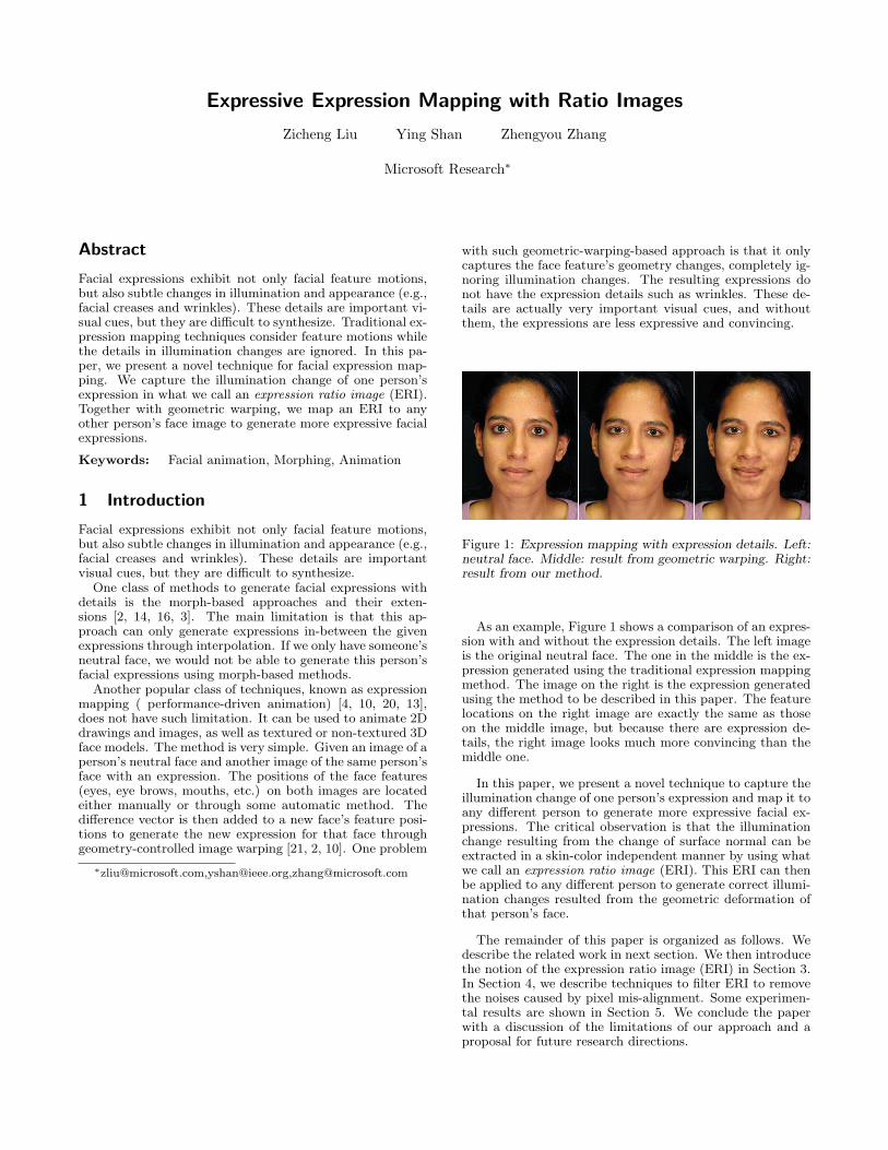
Figure 1: Expression mapping with expression details. Left:neutral face. Middle: result from geometric warping. Right:result from our method.
As an example, Figure 1 shows a comparison of an expres-sion with and without the expression details. The left imageis the original neutral face. The one in the middle is the ex-pression generated using the traditional expression mappingmethod. The image on the right is the expression generatedusing the method to be described in this paper. The featurelocations on the right image are exactly the same as thoseon the middle image, but because there are expression de-tails, the right image looks much more convincing than themiddle one.
In this paper, we present a novel technique to capture theillumination change of one person’s expression and map it toany different person to generate more expressive facial ex-pressions. The critical observation is that the illuminationchange resulting from the change of surface normal can beextracted in a skin-color independent manner by using whatwe call an expression ratio image (ERI). This ERI can thenbe applied to any different person to generate correct illumi-nation changes resulted from the geometric deformation ofthat person’s face.
The remainder of this paper is organized as follows. Wedescribe the related work in next section. We then introducethe notion of the expression ratio image (ERI) in Section 3.In Section 4, we describe techniques to filter ERI to removethe noises caused by pixel mis-alignment. Some experimen-tal results are shown in Section 5. We conclude the paperwith a discussion of the limitations of our approach and aproposal for future research directions.
2 Related work
Besides the work mentioned in the introduction, there hasbeen a lot of other work on facial expression synthesis. Foran excellent overview, see [13]. The physically-based ap-proach is an alternative to expression mapping. Badler andPlatt [1] used a mass-and-spring model to simulate the skinand muscles. Extensions and improvements to this techniquehave been reported in [19, 18, 9].
Marschner et al. [11] used the color ratio between the ren-dered image pairs under the old and new lighting conditionsto modify photographs taken under the old lighting condi-tion to generate photographs under the new lighting condi-tion. In a similar spirit, Debevec [5] used the color difference(instead of ratio) between the synthesized image pairs withand without adding a synthetic object to modify the originalphotograph.
Given a face under two different lighting conditions andanother face under the first lighting condition, Riklin-Ravivand Shashua [15] used color ratio (called quotient image)to generate an image of the second face under the secondlighting condition. Stoschek [17] combined this techniquewith image morphing to generate the re-rendering of a faceunder continuous changes of poses or lighting directions.
The work reported in this paper handles geometrical de-formations under constant lighting rather than changinglighting condition with fixed geometry as in the previousworks. As far as we know, this is the first technique that iscapable of mapping one person’s facial expression details toa different person’s face.
3 Expression ratio image
For any point p on a surface Π, let n denote its normal.Assume there are m point light sources. Let li,1 ≤ i ≤ m,denote the light direction from p to the ith light source, andIi its intensity. Suppose the surface is diffuse, and let ρ beits reflectance coefficient at p. Under the Lambertian model,the intensity at p is
I = ρ
m∑
i=1
Iin · li (1)
After the surface is deformed, the intensity at p becomes
I ′ = ρ
m∑
i=1
Iin′ · l′i (2)
where n′ is the normal at p after deformation, and l′i is thelight direction after deformation.
From Equations (1) and (2), we have
I ′
I=
∑mi=1 Iin′ · l′i∑mi=1 Iin · li (3)
We denote
� ≡∑m
i=1 Iin′ · l′i∑mi=1 Iin · li . (4)
�, which is a real function defined over Π, is called the ex-pression ratio image (ERI) of Π. From (3), we have
I ′ = �I (5)
for each point on the surface Π.
Notice that � is independent of the reflectance coefficients.Equation (5) holds for any reflectance function of the sur-face Π. So for any unknown reflectance function, if we knowthe illumination before deformation, then we can obtain itsillumination after deformation by simply multiplying the ex-pression ratio image � with the illumination before deforma-tion.
Let us now consider how to map one person’s expressionto another. Given two people’s faces A and B, assume forevery point on A, there is a corresponding point on B whichhas the same meaning (eye corners, mouth corners, nose tip,etc). By applying Equation (3) to A and B at each point,we have
I ′a
Ia=
∑mi=1 Iin′
a · l′ia∑mi=1 Iina · lia (6)
and
I ′b
Ib=
∑mi=1 Iin′
b · l′ib∑mi=1 Iinb · lib (7)
Since human faces have approximately the same geometri-cal shape, if they are in the same pose, their surface normalsat the corresponding positions are roughly the same, that is,na ≈ nb and n′
a ≈ n′b, and the lighting direction vectors are
also roughly the same, that is, lia ≈ lib and l′ia ≈ l′ib. Underthis assumption, we have
I ′a
Ia≈ I ′
b
Ib(8)
Of course, if A and B have exactly the same shape, the aboveequation is exact, not approximate. The approximation er-ror increases with the shape difference between two faces andwith the pose difference when the images are taken.
Let A and A′ denote the images of A’s neutral face and ex-pression face, respectively. Let B denote the image of personB’s neutral face, and B′ the unknown image of his/her facewith the same expression as A′. Furthermore, if we assumethese images have been aligned, then by (8), we have
B′(u, v)B(u, v)
=A′(u, v)A(u, v)
(9)
where (u, v) are the coordinates of a pixel in the images.Therefore, we have
B′(u, v) = B(u, v)A′(u, v)A(u, v)
(10)
More realistically, the images are usually taken in differentposes with possibly different cameras, and so are usually notaligned. In order to apply the above equations, we haveto align them first. In summary, given images A, A′, Bwhich have not been aligned, we have the following algorithmfor facial expression mapping which captures illuminationchanges.
Step 1. Find the face features of A, A′ and B (either man-ually or using some automatic method)
Step 2. Compute the difference vector between the featurepositions of A′ and A. Move the features of B alongthe difference vector, and warp the image accordingly.Let Bg be the warped image. This is the traditionalexpression mapping based on geometric warping.
Step 3. Align A and A′ with Bg through image warping,and denote the warped images by A and A′.
Step 4. Compute ratio image �(u, v) = A′(u,v)A(u,v) .
Step 5. Set B′ = �Bg for every pixel.
This algorithm requires three warping operations for eachinput image B. When applying the same expression to manypeople, we can save computation by pre-computing the ratioimage with respect to A or A′. During expression mappingfor a given image B, we first warp that ratio image to Bg
and then multiply the warped ratio image with Bg. In thisway, we only perform warping twice, instead of three times,for every input image.
3.1 Colored lights
In the above discussion, we only considered the monochro-matic lights. For colored lights, we apply exactly the sameequations to each R, G and B component of the color im-ages, and compute one ERI for each component. Duringexpression mapping, each ERI is independently applied tothe corresponding color component of the input image.
If all the light sources have the same color but only differin magnitude, it is not difficult to find that the three ERIsare equal to each other. To save computation, we only needto compute one ERI in this case.
3.2 Comments on different lighting conditions
If the lighting conditions for A and B are different, Equation(10) does not necessarily hold. If, however, there is only anintensity scaling while the light directions are the same, theequation is still correct. This probably explains why ourmethod works reasonably well for some of the images takenunder different lighting environment.
In other cases, we found that performing color histogrammatching [8] before expression mapping is helpful in reducingsome of the artifacts due to different lighting conditions. Inaddition, we found that the result is noisy if we directly applythe three color ERIs. A better solution that we use is tofirst convert RGB images into the YUV space [7], computethe ratio image only for the Y component, map it to theY component of the input image, and finally convert theresulting image back into the RGB space.
An even better solution would be to use sophisticated re-lighting techniques such as those reported in [6, 12, 15].
4 Filtering
Since image alignment is based on image warping controlledby a coarse set of feature points, misalignment between Aand A′ is unavoidable, resulting in a noisy expression ratioimage. So we need to filter the ERI somehow to clean upthe noise while not smoothing out the wrinkles. The ideais to use an adaptive smoothing filter with little smoothingin expressional areas and strong smoothing in the remainingareas.
Since A and A′ have been roughly aligned, their intensitiesin the non-expressional areas should be very close, i.e., thecorrelation is high, while their intensities in the expressionalareas are very different. So for each pixel, we compute anormalized cross correlation c between A and A′, and use1 − c as its weight.
After the weight map is computed, we run an adaptiveGaussian filter on the ERI. For pixels with a large weight,we use a small window Gaussian filter so that we do notsmooth out the expressional details. For pixels with a small
weight, we use a large window to smooth out the noise inthe ERI.
We could descretize the weights into many levels and as-sign a different window size for each level. But in practicewe found that it is enough to use just two levels.
5 Results
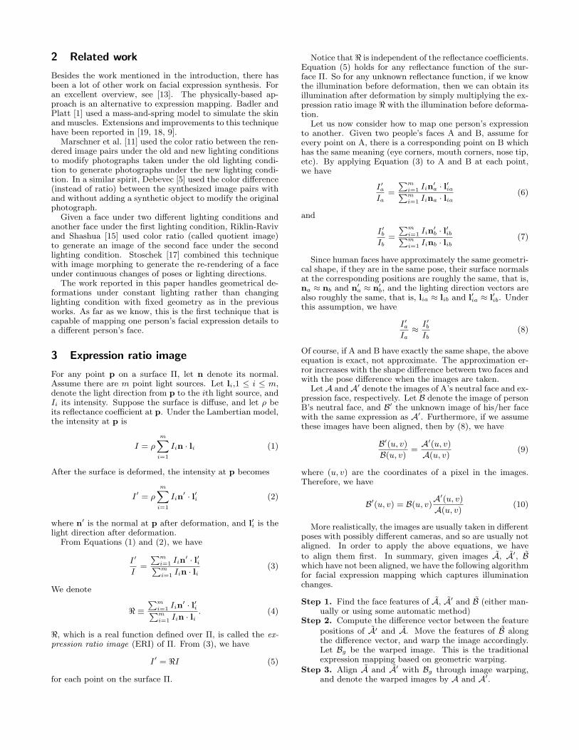
In this section, we show some test results. For each image,we manually put mark points on the face features. Figure 2shows an example of the mark points. Currently only thepoints are used as features for image warping while the linesegments in the figure are only for display purpose. Weuse the texture mapping hardware to warp an image fromone set of markers to another by simply applying Delauneytriangulation to the mark points. This method is fast butthe resulting image quality is not as good as with other moreadvanced image warping techniques [2, 10].
Figure 2: The mark points.
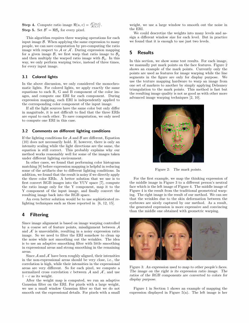
For the first example, we map the thinking expression ofthe middle image in Figure 3 to a different person’s neutralface which is the left image of Figure 4. The middle image ofFigure 4 is the result from the traditional geometrical warp-ing. The right image is the result of our method. We can seethat the wrinkles due to the skin deformation between theeyebrows are nicely captured by our method. As a result,the generated expression is more expressive and convincingthan the middle one obtained with geometric warping.
Figure 3: An expression used to map to other people’s faces.The image on the right is its expression ratio image. Theratios of the RGB components are converted to colors fordisplay purpose.
Figure 1 in Section 1 shows an example of mapping theexpression displayed in Figure 5(a). The left image is her
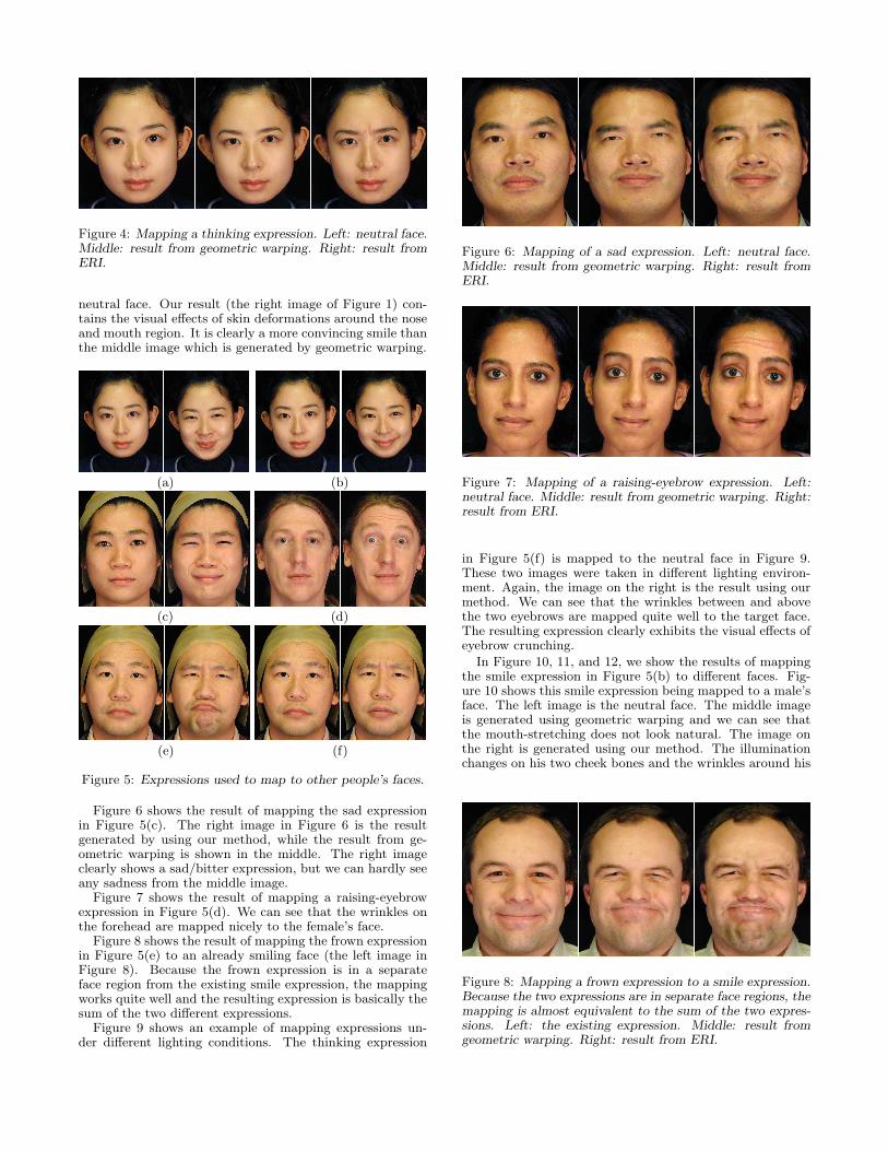
Figure 4: Mapping a thinking expression. Left: neutral face.Middle: result from geometric warping. Right: result fromERI.
neutral face. Our result (the right image of Figure 1) con-tains the visual effects of skin deformations around the noseand mouth region. It is clearly a more convincing smile thanthe middle image which is generated by geometric warping.
(a) (b)
(c) (d)
(e) (f)
Figure 5: Expressions used to map to other people’s faces.
Figure 6 shows the result of mapping the sad expressionin Figure 5(c). The right image in Figure 6 is the resultgenerated by using our method, while the result from ge-ometric warping is shown in the middle. The right imageclearly shows a sad/bitter expression, but we can hardly seeany sadness from the middle image.
Figure 7 shows the result of mapping a raising-eyebrowexpression in Figure 5(d). We can see that the wrinkles onthe forehead are mapped nicely to the female’s face.
Figure 8 shows the result of mapping the frown expressionin Figure 5(e) to an already smiling face (the left image inFigure 8). Because the frown expression is in a separateface region from the existing smile expression, the mappingworks quite well and the resulting expression is basically thesum of the two different expressions.
Figure 9 shows an example of mapping expressions un-der different lighting conditions. The thinking expression
Figure 6: Mapping of a sad expression. Left: neutral face.Middle: result from geometric warping. Right: result fromERI.
Figure 7: Mapping of a raising-eyebrow expression. Left:neutral face. Middle: result from geometric warping. Right:result from ERI.
in Figure 5(f) is mapped to the neutral face in Figure 9.These two images were taken in different lighting environ-ment. Again, the image on the right is the result using ourmethod. We can see that the wrinkles between and abovethe two eyebrows are mapped quite well to the target face.The resulting expression clearly exhibits the visual effects ofeyebrow crunching.
In Figure 10, 11, and 12, we show the results of mappingthe smile expression in Figure 5(b) to different faces. Fig-ure 10 shows this smile expression being mapped to a male’sface. The left image is the neutral face. The middle imageis generated using geometric warping and we can see thatthe mouth-stretching does not look natural. The image onthe right is generated using our method. The illuminationchanges on his two cheek bones and the wrinkles around his
Figure 8: Mapping a frown expression to a smile expression.Because the two expressions are in separate face regions, themapping is almost equivalent to the sum of the two expres-sions. Left: the existing expression. Middle: result fromgeometric warping. Right: result from ERI.
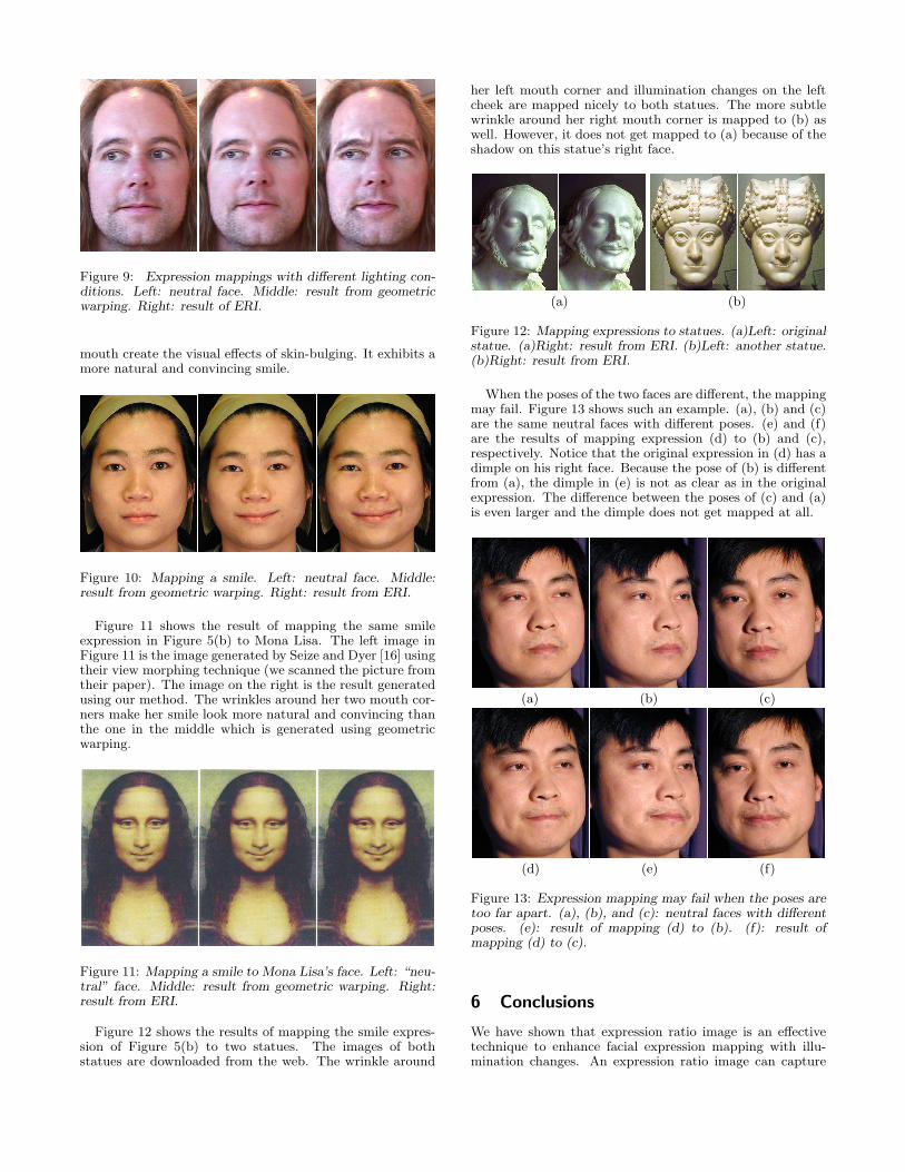
Figure 9: Expression mappings with different lighting con-ditions. Left: neutral face. Middle: result from geometricwarping. Right: result of ERI.
mouth create the visual effects of skin-bulging. It exhibits amore natural and convincing smile.
Figure 10: Mapping a smile. Left: neutral face. Middle:result from geometric warping. Right: result from ERI.
Figure 11 shows the result of mapping the same smileexpression in Figure 5(b) to Mona Lisa. The left image inFigure 11 is the image generated by Seize and Dyer [16] usingtheir view morphing technique (we scanned the picture fromtheir paper). The image on the right is the result generatedusing our method. The wrinkles around her two mouth cor-ners make her smile look more natural and convincing thanthe one in the middle which is generated using geometricwarping.
Figure 11: Mapping a smile to Mona Lisa’s face. Left: “neu-tral” face. Middle: result from geometric warping. Right:result from ERI.
Figure 12 shows the results of mapping the smile expres-sion of Figure 5(b) to two statues. The images of bothstatues are downloaded from the web. The wrinkle around
her left mouth corner and illumination changes on the leftcheek are mapped nicely to both statues. The more subtlewrinkle around her right mouth corner is mapped to (b) aswell. However, it does not get mapped to (a) because of theshadow on this statue’s right face.
(a) (b)
Figure 12: Mapping expressions to statues. (a)Left: originalstatue. (a)Right: result from ERI. (b)Left: another statue.(b)Right: result from ERI.
When the poses of the two faces are different, the mappingmay fail. Figure 13 shows such an example. (a), (b) and (c)are the same neutral faces with different poses. (e) and (f)are the results of mapping expression (d) to (b) and (c),respectively. Notice that the original expression in (d) has adimple on his right face. Because the pose of (b) is differentfrom (a), the dimple in (e) is not as clear as in the originalexpression. The difference between the poses of (c) and (a)is even larger and the dimple does not get mapped at all.
(a) (b) (c)
(d) (e) (f)
Figure 13: Expression mapping may fail when the poses aretoo far apart. (a), (b), and (c): neutral faces with differentposes. (e): result of mapping (d) to (b). (f): result ofmapping (d) to (c).
6 Conclusions
We have shown that expression ratio image is an effectivetechnique to enhance facial expression mapping with illu-mination changes. An expression ratio image can capture
subtle but visually important details of facial expressions.The resulting facial expressions are significantly more ex-pressive and convincing than the traditional expression map-ping based on geometric warping.
The proposed approach can be extended to facial expres-sion mapping for 3D textured face models. In this case, weonly need to apply ERIs to the texture image, and we canobtain more expressive facial expressions for 3D facial ani-mation.
This technique also applies to shaded 3D face models.One could map expressions between synthetic face models,as well as map between real face expressions and syntheticface models.
7 Limitations and future directions
One limitation of this method is in dealing with differentlighting conditions. Even though we had some success ofapplying ERI to expressions under different lighting envi-ronment with the help of histogram matching, a more gen-eral solution is to use advanced relighting techniques suchas [6, 12, 15].
Currently the image marks are very sparse. It is desir-able to add line and curve features for better facial featurecorrespondences. We are planning to implement better im-age warping techniques such as those reported in [2, 10].Better image warping should reduce the artifacts of thetriangulation-based warping method that we currently use.We also hope that better image warping technique togetherwith line and curve features will improve pixel correspon-dences. High-quality pixel correspondences could reduce theneed of ratio image filtering, thus allowing more expressiondetails to be captured in an ERI.
Acknowledgements
We would like to thank Ko Nishino for helpful discussionsand many helps with image acquisition. We would like tothank Conal Elliott for carefully reading our manuscriptsand providing valuable comments. We would like to thankAlex Colburn, Steve Harris, Chuck Jacobs, Brian Meyer,Sing Bing Kang, Sashi Raghupathy, and Emiko Unno fortheir help with image acquisition. We would like to thankMichael Cohen for his support.
References[1] N. Badler and S. Platt. Animating facial expressions. In Com-
puter Graphics, pages 245–252. Siggraph, August 1981.
[2] T. Beier and S. Neely. Feature-based image metamorphosis. InComputer Graphics, pages 35–42. Siggraph, July 1992.
[3] C. Bregler, M. Covell, and M. Slaney. Video rewrite: Drivingvisual speech with audio. In Computer Graphics, pages 353–360. Siggraph, August 1997.
[4] S. E. Brennan. Caricature Generator. M.S. Visual Studies, Deptof Architecture, Massachusetts Institute of Technology, Cam-bridge, MA., Sept. 1982.
[5] P. E. Debevec. Rendering synthetic objects into real scenes:Bridging traditional and image-based graphics with global illu-mination and high dynamic range photography. In ComputerGraphics, Annual Conference Series, pages 189–198. Siggraph,July 1998.
[6] P. E. Debevec, T. Hawkins, C. Tchou, H.-P. Duiker, W. Sarokin,and M. Sagar. Acquiring the reflectance field of a human face. InComputer Graphics, Annual Conference Series, pages 145–156.Siggraph, July 2000.
[7] J. Foley, A. van Dam, S. Feiner, and J. Hughes. ComputerGraphics: Principles and Practice. Addison-Wesley PublishingCompany, 1992.
[8] R. Gonzalez and R. Woods. Digital Image Processing. Addison-Wesley Publishing Company, 1992.
[9] Y. Lee, D. Terzopoulos, and K. Waters. Realistic modeling forfacial animation. In Computer Graphics, pages 55–62. Siggraph,August 1995.
[10] P. Litwinowicz and L. Williams. Animating images with draw-ings. In Computer Graphics, pages 235–242. Siggraph, August1990.
[11] S. R. Marschner and D. P. Greenberg. Inverse lighting for photog-raphy. In IST/SID Fifth Colort Imaging Conference, November1997.
[12] S. R. Marschner, B. Guenter, and S. Raghupathy. Modelingand rendering for realistic facial animation. In Rendering Tech-niques, pages 231–242. Springer Wien New York, 2000.
[13] F. I. Parke and K. Waters. Computer Facial Animation.AKPeters, Wellesley, Massachusetts, 1996.
[14] F. Pighin, J. Hecker, D. Lischinski, R. Szeliski, and D. H. Salesin.Synthesizing realistic facial expressions from photographs. InComputer Graphics, Annual Conference Series, pages 75–84.Siggraph, July 1998.
[15] T. Riklin-Raviv and A. Shashua. The quotient image: Classbased re-rendering and recongnition with varying illuminations.In IEEE Conference on Computer Vision and Pattern Recog-nition, pages 566–571, June 1999.
[16] S. M. Seize and C. R. Dyer. View morphing. In ComputerGraphics, pages 21–30. Siggraph, August 1996.
[17] A. Stoschek. Image-based re-rendering of faces for continuouspose and illumination directions. In IEEE Conference on Com-puter Vision and Pattern Recognition, pages 582–587, 2000.
[18] D. Terzopoulos and K. Waters. Physically-based facial modelingand animation. Journal of Visualization and Computer Ani-mation, 1(4):73–80, March 1990.
[19] K. Waters. A muscle model for animating three-dimensional fa-cial expression. Computer Graphics, 22(4):17–24, 1987.
[20] L. Williams. Performace-driven facial animation. In ComputerGraphics, pages 235–242. Siggraph, August 1990.
[21] G. Wolberg. Digital Image Warping. IEEE Computer SocietyPress, 1990.