Experimental measurement of the effects of torque on the dynamic behavior and system parameters of...
20
Experimental measurement of the effects of torque on the dynamic behavior and system parameters of planetary gears Tristan M. Ericson a , Robert G. Parker b, ⁎ a Assistant Professor, Department of Physical Sciences, York College of Pennsylvania, York, PA 17403, United States b L. S. Randolph Professor and Head, Department of Mechanical Engineering, Virginia Tech, Blacksburg, VA 24061, United States article info abstract Article history: Received 22 February 2013 Received in revised form 23 September 2013 Accepted 18 December 2013 Available online xxxx Experiments designed to capture the independent motion of spur planetary gear components show the influence of mean operating torque on system parameters and dynamic response. All natural frequencies increase with higher torque, but the natural frequencies of modes with significant planet bearing deflection are particularly sensitive to torque. Current lumped-parameter models do not consider the anisotropic nature of planet bearing stiffnesses, but this research shows that the accuracy of these models is increased when the radial and tangential planet bearing stiffness components are calculated separately. These bearing stiffnesses depend on the mean bearing forces in the two directions. A finite element/contact mechanics model provides accurate calculation of the anisotropic, load-dependent planet bearing stiffnesses and the load-dependent mesh stiffnesses. An analytical model using these values accurately predicts changes in the experimentally measured natural frequencies of modes with high strain energy in the planet bearings for varying mean torque. Experiments also show changes in the mode shapes and damping ratios with changing torque. © 2013 Elsevier Ltd. All rights reserved. Keywords: Planetary gear Vibration Torque Gear dynamics 1. Introduction Planetary gears are used in many industrial applications because their multiple load paths increase power density through load sharing. The noise and vibration generated by the many gear meshes, however, is one drawback. The complexity of planetary gears increases modeling difficulty for gear designers interested in accurate prediction of dynamic response. Lumped-parameter models can quickly and efficiently predict dynamic behavior. These models, however, require accurate estimation of system parameters to correctly obtain natural frequencies and peak response amplitudes. Bearing stiffnesses and damping parameters in these models are often roughly estimated. The anisotropic nature of planet bearing stiffnesses is often neglected, so the bearings are typically assumed to be isotropic. Cunliffe et al. [1], Botman [2], August and Kasuba [3], and Lin and Parker [4] presented models to analyze the in-plane vibration of planetary systems with spur gears. Other models have included the three-dimensional motion of helical gears [5–7]. Abousleiman and Velex [8] added the elasticity of the carrier and ring gear in a hybrid finite element/lumped-parameter model. Wu and Parker [9–11] presented an analytical model that considers the elastic deformation of the ring gear coupled to the lumped-parameter motion of the sun gear, carrier, and planet gears. Other advanced models consider compound planetary gears [12–14], nonlinearities [15–19], and gyroscopic effects [20,21]. The influence of planetary gear parameters on natural frequencies has been considered in the literature, but no experimental work has tied stiffness variation to system torque. Some studies [22,23] examine the sensitivity of natural frequencies and vibration modes to system parameters. Velex and Flamand [6] showed that mesh stiffness is a critical parameter affecting natural frequencies, but Saada and Velex [24] found planet pin stiffness to be less influential. Botman [2], however, saw that certain Mechanism and Machine Theory 74 (2014) 370–389 ⁎ Corresponding author. E-mail addresses: [email protected] (T.M. Ericson), [email protected] (R.G. Parker). 0094-114X/$ – see front matter © 2013 Elsevier Ltd. All rights reserved. http://dx.doi.org/10.1016/j.mechmachtheory.2013.12.018 Contents lists available at ScienceDirect Mechanism and Machine Theory journal homepage: www.elsevier.com/locate/mechmt
Transcript of Experimental measurement of the effects of torque on the dynamic behavior and system parameters of...

Mechanism and Machine Theory 74 (2014) 370–389
Contents lists available at ScienceDirect
Mechanism and Machine Theory
j ourna l homepage: www.e lsev ie r .com/ locate /mechmt
Experimental measurement of the effects of torque on thedynamic behavior and system parameters of planetary gears
Tristan M. Ericson a, Robert G. Parker b,⁎a Assistant Professor, Department of Physical Sciences, York College of Pennsylvania, York, PA 17403, United Statesb L. S. Randolph Professor and Head, Department of Mechanical Engineering, Virginia Tech, Blacksburg, VA 24061, United States
a r t i c l e i n f o
⁎ Corresponding author.E-mail addresses: [email protected] (T.M. Ericson)
0094-114X/$ – see front matter © 2013 Elsevier Ltd. Ahttp://dx.doi.org/10.1016/j.mechmachtheory.2013.12.
a b s t r a c t
Article history:Received 22 February 2013Received in revised form 23 September 2013Accepted 18 December 2013Available online xxxx
Experiments designed to capture the independentmotion of spur planetary gear components showthe influence of mean operating torque on system parameters and dynamic response. All naturalfrequencies increase with higher torque, but the natural frequencies of modes with significantplanet bearing deflection are particularly sensitive to torque. Current lumped-parametermodels donot consider the anisotropic nature of planet bearing stiffnesses, but this research shows that theaccuracy of these models is increased when the radial and tangential planet bearing stiffnesscomponents are calculated separately. These bearing stiffnesses depend on themean bearing forcesin the two directions. A finite element/contact mechanics model provides accurate calculation ofthe anisotropic, load-dependent planet bearing stiffnesses and the load-dependent meshstiffnesses. An analytical model using these values accurately predicts changes in theexperimentally measured natural frequencies of modes with high strain energy in the planetbearings for varying mean torque. Experiments also show changes in the mode shapes anddamping ratios with changing torque.
© 2013 Elsevier Ltd. All rights reserved.
Keywords:Planetary gearVibrationTorqueGear dynamics
1. Introduction
Planetary gears are used in many industrial applications because their multiple load paths increase power density throughload sharing. The noise and vibration generated by the many gear meshes, however, is one drawback. The complexity of planetarygears increases modeling difficulty for gear designers interested in accurate prediction of dynamic response. Lumped-parametermodels can quickly and efficiently predict dynamic behavior. These models, however, require accurate estimation of systemparameters to correctly obtain natural frequencies and peak response amplitudes. Bearing stiffnesses and damping parameters inthese models are often roughly estimated. The anisotropic nature of planet bearing stiffnesses is often neglected, so the bearingsare typically assumed to be isotropic.
Cunliffe et al. [1], Botman [2], August and Kasuba [3], and Lin and Parker [4] presentedmodels to analyze the in-plane vibrationof planetary systems with spur gears. Other models have included the three-dimensional motion of helical gears [5–7].Abousleiman and Velex [8] added the elasticity of the carrier and ring gear in a hybrid finite element/lumped-parameter model.Wu and Parker [9–11] presented an analytical model that considers the elastic deformation of the ring gear coupled to thelumped-parameter motion of the sun gear, carrier, and planet gears. Other advanced models consider compound planetary gears[12–14], nonlinearities [15–19], and gyroscopic effects [20,21].
The influence of planetary gear parameters on natural frequencies has been considered in the literature, but no experimentalwork has tied stiffness variation to system torque. Some studies [22,23] examine the sensitivity of natural frequencies andvibration modes to system parameters. Velex and Flamand [6] showed that mesh stiffness is a critical parameter affecting naturalfrequencies, but Saada and Velex [24] found planet pin stiffness to be less influential. Botman [2], however, saw that certain
, [email protected] (R.G. Parker).
ll rights reserved.018

Shaker
LoadCell
Stinger
Planetary Gear
A B
CD
(a)
AB
C
D
Planetary Gear
Sun Gear ShaftCarrier Shaft
CarrierInertia
SunInertia
(b)
Fig. 1. Planetary gear modal testing setup (a) photograph and (b) schematic diagram showing (A) the load cell arm fixing the input shaft to the bedplate througha load cell, (B) an excitation arm, and (C) a compliant coupling that isolates the gearbox from (D) the torque actuator.
371T.M. Ericson, R.G. Parker / Mechanism and Machine Theory 74 (2014) 370–389
natural frequencies were more sensitive to planet pin stiffness than others. Through two orders of magnitude of planet pinstiffness variation, these natural frequencies moved from 1000–2000 Hz to 6000–7000 Hz.
Several papers consider the relationship between manufacturing errors and loading. Singh [25] showed that manufacturingerrors can change the individual planet gear load sharing factors, which may cause premature wear and failure. Unequal loadsharing can alter the mesh and bearing stiffnesses at the different planets. Frater et al. [26] considered unequal planet stiffnessesby comparing a nominal parameter set to a system with one mesh stiffness reduced by 50%. Toda and Botman showed thatplanetary gear vibration also increases with planet pin position errors [27]. Gu and Velex used a lumped-parameter model tostudy the dynamic effects of planet position errors [28] and eccentricity errors [29], which significantly affect the dynamicbehavior.
This research experimentally investigates how the anisotropic nature of planet bearings and the load-dependent bearing andmesh stiffnesses affect the natural frequencies, mode shapes, and damping ratios of a spur planetary gear. Increasing systemtorque causes complex changes in dynamic behavior. Accurate estimation of the load-dependent radial and tangential planetbearing stiffnesses–which are not equal–and the load-dependent mesh stiffnesses is performed by a finite element/contactmechanics method [30]. A lumped-parameter model [4,31] using these load-dependent stiffnesses more accurately predicts thenatural frequencies of the experimental system than a model with isotropic planet bearings.
Fig. 2. Planetary gear modal testing setup photographs showing (a) the planetary gear excited by the modal shaker and (b) the shaker stinger attached to a planetgear parallel to the ring–planet line of action with a force sensor and a driving point accelerometer.
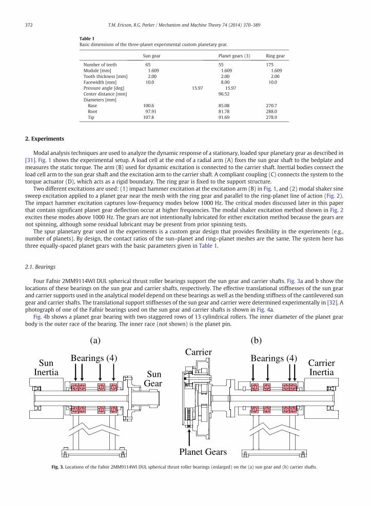
Table 1Basic dimensions of the three-planet experimental custom planetary gear.
Sun gear Planet gears (3) Ring gear
Number of teeth 65 55 175Module [mm] 1.609 1.609 1.609Tooth thickness [mm] 2.00 2.00 2.00Facewidth [mm] 10.0 8.00 10.0Pressure angle [deg] 15.97 15.97Center distance [mm] 96.52Diameters [mm]
Base 100.6 85.08 270.7Root 97.91 81.78 288.0Tip 107.8 91.69 278.9
372 T.M. Ericson, R.G. Parker / Mechanism and Machine Theory 74 (2014) 370–389
2. Experiments
Modal analysis techniques are used to analyze the dynamic response of a stationary, loaded spur planetary gear as described in[31]. Fig. 1 shows the experimental setup. A load cell at the end of a radial arm (A) fixes the sun gear shaft to the bedplate andmeasures the static torque. The arm (B) used for dynamic excitation is connected to the carrier shaft. Inertial bodies connect theload cell arm to the sun gear shaft and the excitation arm to the carrier shaft. A compliant coupling (C) connects the system to thetorque actuator (D), which acts as a rigid boundary. The ring gear is fixed to the support structure.
Two different excitations are used: (1) impact hammer excitation at the excitation arm (B) in Fig. 1, and (2) modal shaker sinesweep excitation applied to a planet gear near the mesh with the ring gear and parallel to the ring-planet line of action (Fig. 2).The impact hammer excitation captures low-frequency modes below 1000 Hz. The critical modes discussed later in this paperthat contain significant planet gear deflection occur at higher frequencies. The modal shaker excitation method shown in Fig. 2excites these modes above 1000 Hz. The gears are not intentionally lubricated for either excitation method because the gears arenot spinning, although some residual lubricant may be present from prior spinning tests.
The spur planetary gear used in the experiments is a custom gear design that provides flexibility in the experiments (e.g.,number of planets). By design, the contact ratios of the sun–planet and ring–planet meshes are the same. The system here hasthree equally-spaced planet gears with the basic parameters given in Table 1.
2.1. Bearings
Four Fafnir 2MM9114WI DUL spherical thrust roller bearings support the sun gear and carrier shafts. Fig. 3a and b show thelocations of these bearings on the sun gear and carrier shafts, respectively. The effective translational stiffnesses of the sun gearand carrier supports used in the analytical model depend on these bearings as well as the bending stiffness of the cantilevered sungear and carrier shafts. The translational support stiffnesses of the sun gear and carrier were determined experimentally in [32]. Aphotograph of one of the Fafnir bearings used on the sun gear and carrier shafts is shown in Fig. 4a.
Fig. 4b shows a planet gear bearing with two staggered rows of 13 cylindrical rollers. The inner diameter of the planet gearbody is the outer race of the bearing. The inner race (not shown) is the planet pin.
Bearings (4)
SunGear
SunInertia
(a)
Bearings (4)
Planet Gears
CarrierCarrierInertia
(b)
Fig. 3. Locations of the Fafnir 2MM9114WI DUL spherical thrust roller bearings (enlarged) on the (a) sun gear and (b) carrier shafts.

Fig. 4. Experimental planetary gear bearings supporting (a) the sun gear and carrier shafts (four each, as in Fig. 3), and (b) the planet gears.
373T.M. Ericson, R.G. Parker / Mechanism and Machine Theory 74 (2014) 370–389
2.2. Instrumentation and data acquisition
Four tangentially-mounted uniaxial accelerometers with 100 mV/g sensitivity (PCB model J352C66) measure rotational andtranslational vibration of the carrier, sun gear, and two of the planet gears. Fig. 5b shows the tangentially-mounted sun gearaccelerometers. Fig. 5c shows the tangentially-mounted planet gear accelerometers. The sensors are rigidly connected to the gearbodies near the meshing teeth to ensure measurement reliability.
Sampling parameters were selected based on the experimental testing method. Impulse tests targeting the low-frequency rangeuse an average of five impacts, eachwith 8192 data points sampled at 15,000 Hz. Shaker sine sweep frequency tests were conductedin 5 Hz increments with 256 data points per frequency step sampled at steady state with 25,600 Hz sampling frequency.
Coherence is used to evaluate repeatability of the experimental data. The coherence is typically above 0.95 for all impulse tests.Coherence is not calculated directly from the shaker sweep tests, but it is calculated from other chirp and random excitationexperiments not presented in this paper. These other tests show similar results as the shaker tests with coherence typically above0.90. Confidence in the shaker sweep tests is at least this high because the quality of data is generally better (less noise).
3. Analytical lumped-parameter model
Fig. 6a shows the lumped-parameter model, referred to as the analytical model, in [4]. Fig. 6b shows an extended model that,in addition to the planetary gear model in Fig. 6a, considers additional degrees of freedom associated with the experimentalfixtures. The rotational and two-dimensional translational motions of all components are considered. All stiffness parameters in
Fig. 5. Accelerometers mounted (a) directly to the carrier (tangentially) and the ring gear (radially), (b) to the sun gear (with one carrier and one ring gearaccelerometer), and (c) to the planet gears through rigidly mounted adapter flanges.

(a)
(b)
Fig. 6. Analytical lumped-parameter model compared against experiments with (a) the detailed planetary gear model showing system coordinates and (b)additional components and parameters associated with the experimental fixtures.
374 T.M. Ericson, R.G. Parker / Mechanism and Machine Theory 74 (2014) 370–389

375T.M. Ericson, R.G. Parker / Mechanism and Machine Theory 74 (2014) 370–389
Fig. 6 and the masses and moments of inertia of each component (two inertias, sun gear, carrier, ring gear, and planet gears) aregiven in [31] (denoted as Gear B in that paper). These parameters were physically measured or estimated by analytical software.
The prior research in [31] compared the analytical model against experiments for two different planetary gears with the sameplanet bearings. The analytical model accurately estimated all experimentally measured natural frequencies for a gearset with fiveplanets using isotropic bearing stiffness values of 315 × 106 N-m provided by the manufacturer. This isotropic assumption,however, produced poor results when studying a three-planet gearset with higher planet bearing reaction forces. Modelingaccuracy was improved by decreasing the planet bearing stiffness in the radial xp-direction, and increasing it in the tangentialyp-direction. These changes are reasonable considering the direction of the bearing reaction force, but they were chosen to matchthe measured natural frequencies, which are rarely available in practice. A bearing model was not used to obtain them. In thepresent work, a finite element bearing modeling gives the load-dependent planet bearing stiffness to resolve the issue of radialand tangential bearing anisotropy in the analytical model.
4. Finite element bearing model
The computational software Calyx used to construct the finite element model was developed by Vijayakar [33]. It allows efficientstatic and dynamic contact analysis of precisely machined components such as gears and bearings. The program uses an analyticalcontact mechanics model at the tooth meshes and bearing roller–race contact locations to avoid the need for a highly-refined meshalong these surfaces [34]. This approach gives an accurate, computationally efficient calculation for elastic contact problems comparedto conventional finite element analysis. This method has been benchmarked against spur gear experiments [35]. The software wasused to analyze a helicopter planetary gear and compare natural frequency predictions against an analytical model [36]. Ambarishaand Parker [16] used this finite element tool and an analytical model to analyze nonlinearities caused by contact loss. It has also beenused to study elastic ring gear deformation [37] and planet load sharing [38]. Liu and Parker [39,40] compared its results againstanalytical models for two-stage idler and counter-shaft systems. Cooley et al. [41] developed a frequency based algorithm with thisprogram to analyze three-dimensional geared systemswith shafts, bearings and housings with significantly increased computationalefficiency.
This finite element tool has been utilized more recently by Guo and Parker [30] to accurately estimate the stiffnesses of avariety of bearing types and configurations. Their method gives the fully-populated stiffness matrices without assumptionscommon to analytical models. It accounts for the geometry of the bearing (including roller/race crowning, internal clearances,contact angle, roller and raceway parameters, etc.). It is used in this paper to calculate the load-dependent anisotropic planetbearing stiffnesses. The model considers the elasticity of the bearing rollers, inner race (which is the planet pin), and the outerrace (which is the planet gear rim). All of these bearing components are considered deformable, as they contribute to planetbearing compliance. Stiffness is obtained by constraining the outer edge of the gear blank (near the teeth) and applying a load tothe center of the planet pin. The deflection of the planet pin is calculated to estimate the bearing stiffness by the followingprocedure.
Figs. 6a and 7 show the planet coordinates (xp and yp) and the mesh/bearing forces in the free body diagram. The pressureangles αsp and αrp of the sun–planet and ring–planet meshes are the same, so the bearing reaction force is along the yp-direction.Without misalignment or manufacturing errors, there will be zero mean force in the xp-direction. Realistically, there will be somenonzero radial force in the xp-direction in any physical system due to small manufacturing errors and misalignment, but it is lowcompared to the tangential force along the yp-direction (Fig. 7).
The method in [30] yields all five non-zero diagonal terms and the off-diagonal elements of the planet bearing stiffness matrix.For the two-dimensional analytical model, however, we are only concerned with the stiffnesses in the xp- and yp-directions in
xpyp
FoFsp
Frp
α
α
(tangential) (radial)
rp
sp
Fig. 7. Planet gear free body diagram illustrating the bearing reaction force Fo and the planet translational xp- and yp-coordinates with reference to the carrier. Fspand Frp are mesh forces, and αsp and αrp are pressure angles.

376 T.M. Ericson, R.G. Parker / Mechanism and Machine Theory 74 (2014) 370–389
Figs. 6a and 7. The bearing stiffness depends on bearing force, so the bearing stiffness matrix K¼∂F∂q is calculated about a nominal
mean force Fo, which is the bearing reaction force in Fig. 7 due to the applied torque.The bearing stiffness is calculated numerically by the second order finite difference [30]
Fig. 8. Fdistribu
K¼∂F∂q ¼ F qo þ δqð Þ−F qo−δqð Þ
2δq; ð1Þ
qo is the bearing deflection at Fo and δq ¼ δqx; δqy; δqz; δqθx ; δqθyn o
is a small disturbance vector at qo. One element of δq is
wherevaried to obtain a single column of K. For this analysis, we consider deflections in the radial xp and tangential yp directions inFig. 6a. The δqx and δqy displacement elements in δq are varied independent of each other, one at a time, to give two differentcolumns of K, although we focus on the diagonal terms in this analysis. They are specified about the nominal deflection generatedby the preload torque. The specified deflection δqy is greater because it aligns with the force Fo in Fig. 7, while δqx is specified as asmaller amount to account for radial loads caused by manufacturing errors and preload deflections. The step size used for thefinite difference is δqk kqok k ¼ 1:0� 10−6 , which is within the range suggested in [30]. Three calculations are needed to determine asingle column in the bearing stiffness matrix at bearing force Fo. The first calculation determines the nominal deflection qo due toforce Fo. Two more calculations are needed to determine the forces F(qo + δq) and F(qo − δq) after introducing the disturbanceδq.
Fig. 8 shows the finite element model von Mises stress distribution of the planet roller bearing in Fig. 4b. The applied bearingforce is 4626 N, which corresponds to 363 N-m of torque on the sun gear for the three-planet gearset with pressure angles αrp =αsp = 15.97° (Table 1). Five rollers are in contact at this load. The angular orientation of the bearings will have some effect on thecalculated stiffness, depending on whether the load direction is toward a roller or between rollers. Although the actual angularposition of the rollers is unknown in the experiments due to limited visibility of the planet bearings, the loaded axis in the finiteelement model is directed through a roller.
5. Effects of torque on dynamic response
The magnitude of mesh and bearing stiffness sensitivity to torque is largely unquantified in planetary gears. No experiments inthe authors' knowledge show the extent of the impact of torque on the natural frequencies and vibration modes of planetarygears. Therefore, there has been little guidance for analytical models to use load-dependent, anisotropic bearing stiffnesses.Previous research discusses the existence of two frequency ranges in planetary gear dynamic response [1,31,42]. Low-frequencyfixture modes are characterized by kinetic energy in the central members (sun gear, carrier, and ring gear) and strain energy inthe connecting fixtures. They have small strain energy in the gear meshes. High-frequency gear modes have kinetic energy in theplanet gears and strain energy in the tooth meshes and planet bearings. These modes have small strain energy in the shafts andconnecting fixtures.
5.1. Low-frequency fixture mode range
Fixture modes in the low-frequency range are excited by an impact hammer at the excitation arm B in Fig. 1b and directly onthe central members. Fig. 9 shows the planetary gear frequency response due to impact hammer excitation with varying torques.For the sampling parameters given earlier, the frequency resolution is 1.83 Hz. Natural frequencies of both rotational (f3, f6, f8, f10)and translational (f5, f7, f9, f11, f12) modes increase with torque. The natural frequency enumeration corresponds with [31].Rotational, translational, and planet mode types are described in [4,43]. Modes 1, 2, and 4 (not shown in Fig. 9) are characterizedby motion of the inertias (Figs. 1b and 6b). The response at these degrees of freedom is not studied here to keep the focus on theplanetary gear components. Mode shapes of all natural frequencies observed in Fig. 9 are given in [31]. The measured sensitivity
inite element model of the planet cylindrical roller bearing in Fig. 4b with the planet pin (inner race) removed to increase visibility. The von Mises stresstion is shown for a 4626 N bearing force.

100 200 300 400 500 600 7000
0.01
0.02
0.03
0.04
0.05
0.06
Frequency [Hz]
Car
rier
Rot
atio
n [g
/N]
75 N-m150 N-m400 N-m
f3f5
f8
f10
(a)
75 N-m150 N-m400 N-m
100 200 300 400 500 600 7000
0.01
0.02
0.03
0.04
0.05
0.06
Frequency [Hz]
Sun
Gea
r R
otat
ion
[g/N
]
f3
f5
f6
f8
f10
(b)
100 200 300 400 500 600 7000
0.01
0.02
0.03
0.04
0.05
0.06
Frequency [Hz]
Plan
et R
otat
ion
[g/N
]
75 N-m150 N-m400 N-m
f3
f5
f6
f8
f10
(c)
100 200 300 400 500 600 7000
0.01
0.02
0.03
0.04
0.05
0.06
Frequency [Hz]
Plan
et T
ange
ntia
l Tra
nsla
tion
[g/N
]75 N-m
150 N-m400 N-m
f3
f8
f10
(d)
81 N-m150 N-m162 N-m
100 200 300 400 500 600 7000
0.01
0.02
0.03
0.04
0.05
0.06
Frequency [Hz]
Sun
Gea
r T
rans
latio
n [g
/N] f7
f9
(e)
81 N-m162 N-m
500 600 700 1,300 1,400 1,500 1,6000
0.01
0.02
0.03
0.04
0.05
0.06
Frequency [Hz]
Rin
g G
ear
Tra
nsla
tion
[g/N
]
f11
X-Translation Y-Translation
f12
(f)
Fig. 9. Planetary gear frequency response in the low-frequency fixture mode range from experiments on the three-planet gear system with (–) low torque, ( )medium torque, and ( ) high torque in (a) carrier rotation, (b) sun gear rotation, (c) planet gear rotation, (d) planet gear translation, (e) sun gear translation,and (f) ring gear translation. The applied torque is given at the sun gear. Impact hammer excitation is applied at the top of the load cell arm in (a)–(d), at the sungear body in the xs-direction (Fig. 6a) in (e), and on the ring gear housing in xr- and yr-directions in (f).
377T.M. Ericson, R.G. Parker / Mechanism and Machine Theory 74 (2014) 370–389
of both rotational and translational fixture modes shows that both the torsional stiffnesses of the connecting shafts and thetranslational stiffnesses of the central member bearings are load-dependent.
The five modes (numbered 3, 5, 6, 8, and 10) with response in multiple degrees of freedom in Fig. 9a–d are considered further.Table 2 shows the change in the response characteristics of these modes from doubling the applied torque from 75 N-m to150 N-m. The natural frequencies and damping ratios are obtained from the frequency response functions of several degrees of

Table 2Natural frequency, damping, and peak resonant amplitudes in the low-frequency fixture mode range for 75 N-m and 150 N-m applied torque at the sun gear. Thelast column shows the range of amplitude changes for multiple degrees of freedom.
Mode Frequency [Hz] Damping ratio Peak amplitude Change
75 N-m 150 N-m Increase 75 N-m 150 N-m
3 174 178 2.1% 2.8% 2.3% −6.1%5 211 214 1.7% 1.6% 1.7% +44%6 247 253 2.2% 2.6% 2.8% −4.9–11%8 384 394 2.6% 1.9% 1.5% +12–40%10 573 586 2.2% 2.5% 1.4% +23%
378 T.M. Ericson, R.G. Parker / Mechanism and Machine Theory 74 (2014) 370–389
freedom at each load level. Damping ratios are calculated from the half-power frequencies [44]. Among all frequency responsecurves and resonant frequencies, the natural frequency standard deviation was within 3% of the mean and the damping ratioswere within 0.2% of the mean. Natural frequencies increase by 2.2% on average. The natural frequencies at both torques areconfirmed in all degrees of freedom that exhibit significant response in each mode.
The resonant peaks show monotonic amplitude changes with increased torque, suggesting that the mode shapes and/ordamping ratios depend on the mean load. Gunduz et al. [45] also observed increasing or decreasing peak resonant amplitudes ofthe natural frequencies of a shaft-bearing system with increased applied force in experiments. The half-power frequencies showthat the damping is changing with torque, but so are the mode shapes. For example, the damping ratio of mode 3 decreases withadded torque but so does the peak vibration amplitude. Damping and peak amplitude both increase in mode 5. If only dampingratios are affected by changes in torque, the peak amplitude should decrease when the damping ratio increases and vice versa.The results here suggest that the mode shapes change with increased torque. In another case, consider modes 6 and 8. The peakamplitudes of these modes do not increase or decrease uniformly across all degrees of freedom with higher torque. For example,the 12% amplitude increase of f8 in sun gear rotation (Fig. 9b) is less than the 40% increase in carrier rotation (Fig. 9a). Thisindicates that the proportion of energy within each mode is shifting among the degrees of freedom, which further demonstratesthat the mode shapes change with torque.
Variation in torque causes changes in the natural frequencies, mode shapes, and damping in the low-frequency fixture moderange because higher torque increases the contact, and ultimately stiffness, at the sun gear and central member bearings. Thesebearings store much of the strain energy in the low-frequency modes. Natural frequencies always increase with torque. Dampingdecreases in modes 3, 8, and 10, but it increases slightly in modes 5 and 6. Disproportionate changes in resonant peak amplitudesor amplitude changes counter to damping variations indicate that the mode shapes change as well. This implies that increasedtorque affects multiple stiffness and damping parameters of the planetary gear system through central member stiffness.Increased torque levels, however, have a more profound effect on the high-frequency modes through planet bearing stiffness.
5.2. High-frequency gear mode range
High frequency gearmodes, as described earlier [31], are the primary concern for planetary gear noise and tooth cracking becausethey involve deflection of the tooth meshes [1]. These modes also have significant strain energy in the planet bearings, which areprone to failure. Natural frequencies in the gearmode range are grouped together into three clusters, with each cluster containing onerotationalmode, one translationalmode, and (for systemswithmore than three planet gears) one planetmode [42]. For systemswithfour or more planets, each cluster contains three modes, whichmay be degenerate. The natural frequencies within each cluster haveseparation on the order of tens of Hz, while the separation between different clusters is in the hundreds or thousands of Hz.
Fig. 10 shows the measured dynamic response of the high-frequency gear modes for varying mean torque in the three-planetsystem. Each cluster increases in frequency with increasing torque. Consider cluster 1. Doubling the applied torque from 68 N-mat the sun gear to 136 N-m increases the rotational natural frequency by 1.4% (from 1405 Hz to 1425 Hz) while the translationalnatural frequency increases by 2.8% (from 1580 Hz to 1625 Hz). For a 542 N-m applied torque, the rotational natural frequencyincreases by another 3.2% to 1470 Hz and the translational natural frequency increases by an additional 3.6% to 1685 Hz.
There is a greater increase in the natural frequencies of the third cluster of high-frequency gear modes under the sameincreases in torque. Fig. 10 shows that the main resonant frequency in cluster 31 increases by 3.1% (from 3350 Hz to 3455 Hz)from 68 N-m applied torque at the sun gear to 136 N-m and by another 5.2% to 3635 Hz when the torque increases to 542 N-m.
6. Sensitivity of gear mode clusters to planet parameters
The two modes, one rotational and the other translational, in each of the three clusters share similar energy distributionproperties despite their separate classification into rotational and translational mode types [4,42]. Fig. 11 shows the kineticenergy distribution [22,23] from the analytical model among planetary system components in the three clusters ofhigh-frequency gear modes in the three-planet gearset with the nominal parameters of the experimental gearset at low torque.
1 There is a rotational and a translationalmode in cluster 3, but they are spaced closely together and difficult to differentiate in the frequency response plots at higher torques.

1000 1500 2000 2500 3000 3500 4000Frequency [Hz]
Plan
et R
otat
ion
[g/N
]
10
10
10
10
-2
-1
0
1
68 [N-m]
136 [N-m]
542 [N-m]
3.1% 5.2%
Cluster 1
Cluster 2
Cluster 3
Rot. Trans.
Fig. 10. Planet rotational acceleration in the high-frequency gear mode range from experiments on the three-planet gear system with (–) 68 N-m, ( )136 N-m, and ( ) 542 N-m applied torque at the sun gear. Modal shaker excitation is applied to a single planet gear body parallel to the ring–planet line ofaction as shown in Fig. 2b.
379T.M. Ericson, R.G. Parker / Mechanism and Machine Theory 74 (2014) 370–389
The planet gears have the majority of deflection in these modes. One of the three degrees of freedom dominates the kinetic energydistribution in each of the three separate clusters. The rotational and translational modes in cluster 1 have at least 80% of theirkinetic energy in planet gear radial motion (xp-direction). Similarly, modes in cluster 2 have more than 85% of their kinetic energyin planet rotational motion, and 90% of the kinetic energy in cluster 3 modes is confined to planet tangential motion(yp-direction). Therefore, at the nominal parameter values for the experimental system, clusters 1, 2, and 3 will be particularlysensitive to planet radial bearing stiffness, gear mesh stiffnesses, and planet tangential bearing stiffness, respectively [22].
For systems with four or more planets, the kinetic energy in the planet modes (one in each cluster) is similar to thedistribution in the rotational and translational modes in that cluster. In addition, cluster 1 is still marked by radial motion, cluster2 by rotational motion, and cluster 3 by tangential motion for systems with more than three planets.
7. Anisotropic planet bearing stiffness
A single value is typically used for both the radial and tangential components of planet bearing stiffness in analytical models[46,47,4,8]. Modeling accuracy is improved by considering how torque affects the natural frequencies through load-dependentanisotropic bearing stiffnesses obtained with the finite element bearing model. The kinetic energy distributions in Fig. 11a and cshow that the gear modes in clusters 1 and 3 are predominantly affected by planet radial (xp-direction) and tangential(yp-direction) bearing stiffnesses, respectively. The three-planet gearset is used to investigate this phenomenon in all results thatfollow. Experiments conducted at six different torques show that the natural frequencies in high-frequency gear mode clusters 1and 3 increase significantly with applied load.
7.1. Natural frequency variation of clusters with torque
Fig. 12 focuses on cluster 1 in Fig. 10 and illustrates the sensitivity of this cluster to changing torque. Only three (of the six)torque levels are shown for clarity. Cluster 1 is particularly sensitive to radial bearing stiffness. Subsequent results from the finite
Central Members Planet Gears
Rot. Radial Tang.Rot. Trans.
% K
inet
ic E
nerg
y
20
40
60
80
100
0
% K
inet
ic E
nerg
y
20
40
60
80
100
0
% K
inet
ic E
nerg
y
20
40
60
80
100
0
Cluster 1
Rot
atio
nal
Tra
nsla
tion
al
(a)
Central Members Planet Gears
Rot. Radial Tang.Rot. Trans.
Cluster 2
Ro t
atio
nal
Tr a
nsl a
tion
al
(b)
Central Members Planet Gears
Rot. Radial Tang.Rot. Trans.
Cluster 3
Rot
atio
nal
Tra
nsla
tion
al
(c)
Fig. 11. Kinetic energy distribution from the analytical model of rotational (red/left), and translational (blue/right) modes in the high-frequency gear modes ofthe three-planet gearset in the three gear mode clusters observed in experiments (Fig. 10): (a) cluster 1, (b) cluster 2, and (c) cluster 3.

Frequency [Hz]
Plan
et R
otat
ion
[g/N
]
0
0.1
0.2
0.3
0.4
0.5
0.6
0.7
34 [N-m]68 [N-m]
136 [N-m]
1300 1400 1500 1600 1700
Rot. Trans.
Fig. 12. Planet rotational acceleration in gear mode cluster 1 from experiments on the three-planet gear system with (●) 34 N-m, ( ) 68 N-m, and ( ) 136 N-mapplied torque at the sun gear. Modal shaker excitation is applied to a single planet gear body parallel to the ring-planet line of action as shown in Fig. 2b.
380 T.M. Ericson, R.G. Parker / Mechanism and Machine Theory 74 (2014) 370–389
element bearing model show that the stiffness changes sharply at low reaction forces, so small force differences meaningfullyaffect stiffness and measured natural frequencies because radial bearing forces are small. These results agree with previousresearch showing greater changes in natural frequency with small variations at light loads [48]. Fig. 12 also shows that torqueaffects the natural frequency peak amplitudes. It would be unlikely to have decreased damping in one mode and increaseddamping in another so close to each other. The peak amplitude changes are most likely caused by changes in the mode shapeswith torque.
Fig. 13 focuses on cluster 3 in Fig. 10 and illustrates its torque sensitivity. The main resonant frequency increases by 405 Hzthrough the range of torques from 34 N-m to 524 N-m. These modes are primarily affected by tangential bearing stiffness(Fig. 11c). The letters A–F indicate the natural frequencies (and later the bearing stiffnesses) at the six torque values.
7.2. Load-dependent planet bearing stiffness
The finite element model calculates the bearing stiffnesses across the range of bearing forces (0–7000 N) corresponding to theexperimental torque range. Using this model and the experiments, Fig. 14a shows that the stiffness more than doubles from thetorque at A to that at F. There are three distinct regions of data points from the finite element model, each beginning with a sharpincrease in stiffness that tapers off with increasing load. These three regions, numbered in Fig. 14a, correspond to differentnumbers of rollers in contact (Fig. 14b). Bearings are known to have a higher rate of stiffness change with increasing force at
3200 3300 3400 3500 3600 37000
0.5
1.0
1.5
2.0
2.5
3.0
3.5
Frequency [Hz]
Plan
et R
otat
ion
[g/N
]
34 [N-m]68 [N-m]
136 [N-m]271 [N-m]407 [N-m]542 [N-m]
A
B
CD
E
F
Fig. 13. Planet rotational acceleration in gear mode cluster 3 from experiments on the three-planet gear system with (○) 34 N-m, (●) 68 N-m, ( ) 136 N-m, ( )271 N-m, ( ) 407 N-m, and ( ) 542 N-m applied torque at the sun gear. Modal shaker excitation is applied to the planet gear body parallel to the ring–planet lineof action as shown in Fig. 2b.

0 1000 2000 3000 4000 5000 6000 7000100
200
300
400
500
600x 106
Bearing Load [N]
Tan
gent
ial S
tiffn
ess
[N/m
]
AB
C
D E F
ExperimentsFinite Element
1 Region 2 Region 3
(a)
Region 1 Region 2 Region 3
SevenRollerContact
ThreeRollerContact
FiveRollerContact
(b)
Fig. 14. (a) In situ experimental estimation (squares) of tangential bearing stiffness from natural frequencies in modal testing experiments compared to finiteelement analysis (circles) and (b) the finite element model von Mises stress distribution in each region depicted in (a).
381T.M. Ericson, R.G. Parker / Mechanism and Machine Theory 74 (2014) 370–389
lower loads [49], but previous work [50,48,51,52] does not discuss the repeated nature of this pattern in higher load regionsseparated by the number of rollers in contact observed in Fig. 14a.
Fig. 15 shows the von Mises stress distribution in the bearing rollers near the transition between three-roller contact in region1 and five-roller contact in region 2 of Fig. 14. The applied bearing force is 1112 N, corresponding to a sun gear torque of 88 N-m.The three central rollers have relatively high loads, while the next two (one on each side) are lightly loaded. These two rollershave just come into contact at the low end of region 2 near the boundary with region 1. The pattern repeats at the boundarybetween regions 2 and 3 in Fig. 14 where contact expands to seven rollers.
Fig. 14a also compares the finite element model bearing stiffness to an in situ experimental estimation of tangential bearingstiffness from points A–F in Fig. 13. The bearing stiffness in the analytical model is adjusted to match the natural frequencies in theexperiments. This technique of applying a mathematical model to modal vibration experiments to determine bearing stiffnesswas used by Kraus et al. [53] and more recently by Tiwari and Chakravarthy [54] and Ali and Garcia [55]. The angular position ofthe bearings at torques A–F, though unknown, is constant; the gears did not rotate between experiments.
The resolution of data points from experiments does not show different regions of changing bearing stiffness, but the overalltrend is confirmed. The unknown angular position of the bearings in the experiments also limits the ability to measure clearlydefined regions in the bearing stiffness curve (Fig. 14a). If the bearing is positioned such that the load is not directly on a roller(as assumed in the finite element analysis), the number of rollers in contact would increase by single integers (from two to three

Light contact inrollers at boundary ofregion 1 (three roller contact) andregion 2 (five roller contact)
Fig. 15. Finite element calculation of the von Mises stress distribution of the planet bearing with 1112 N force at the transition between three-roller contact inregion 1 to five-roller contact in region 2 (near point B in Fig. 14).
382 T.M. Ericson, R.G. Parker / Mechanism and Machine Theory 74 (2014) 370–389
to four, etc.) rather than in pairs (from three to five to seven, etc.). In this case, the regions in Fig. 14a would be more frequent andless pronounced. In the experiments, the actual number of rollers in contact at points A and B may be four, not three, which couldexplain the greater difference at these torques. The finite element analysis computes the bearing stiffness with a force actingthrough a roller, but if the position of the bearing, which is unknown in practice, is such that the force acts between rollers, it ispossible that there are four rollers in contact. If this is true, rotating the bearings in the finite element model to that positionwould increase the model stiffness at those loads, producing better agreement with the experiments.
Table 3 collects the loading and cluster 3 resonance data from Figs. 13 and 14 at the six experimental torques A–F and gives thedifference between the experimental bearing stiffness calculation and the finite element model. Half of the data points agreewithin 10%. This is encouraging because the nominal, isotropic, non-load-dependent bearing stiffness from the manufacturer(kpx = kpy = 315 × 106 N-m) does not agree with any of these experimental data points within 10%.
7.3. Analytical model natural frequencies with anisotropic planet bearing stiffnesses
Another way to illustrate the advantage of using the load-dependent, anisotropic bearing model to calculate planet bearingstiffnesses is to compare its performance to an analytical model using the isotropic bearing stiffness typical of planetary gearmodeling. Table 4 compares the natural frequencies obtained from experiments to the analytical model using: (a) the nominalisotropic planet bearing stiffness supplied by the manufacturer, and (b) the load-dependent, anisotropic stiffnesses obtained fromthe finite element model. Results are presented for experiments with 136 N-m torque at the sun gear, point C in Fig. 13 andTable 3.
Table 3Sun gear torque, cluster 3 resonant frequency, and planet tangential bearing stiffness values calculated in situ experimentally and from the finite element bearingmodel for the three-planet gearset.
Torque [N-m] Bearing load [N] Frequency (Exp.) [Hz] Bearing stiffness [N/m] Difference
Experiments Finite element
A 34 431 3235 376 × 106 245 × 106 −35%B 68 863 3350 404 × 106 293 × 106 −27%C 136 1726 3460 444 × 106 401 × 106 −10%D 271 3456 3625 519 × 106 433 × 106 −17%E 407 5182 3635 521 × 106 530 × 106 2%F 542 6913 3640 524 × 106 558 × 106 6%

Table 4Experimentally measured natural frequencies of the three-planet gear system compared to the analytical model using the nominal isotropic planet bearingstiffness and the load-dependent planet bearing stiffnesses from the finite element bearing model. The applied torque is 136 N-m at the sun gear.
Mode Type Cluster Experiments Isotropic modela Diff. Anisotropic modelb Diff.
Rotational 1 1425 Hz 2155 Hz 51% 1574 Hz 10%Translational 1625 Hz 2204 Hz 36% 1625 Hz 0%Translational 2 2595 Hz 2698 Hz 4% 2547 Hz −2%Rotational 2770 Hz 2678 Hz −3% 2548 Hz −8%Translational 3 3400 Hz 3074 Hz −10% 3310 Hz −3%Rotational 3460 Hz 3089 Hz −11% 3338 Hz −2%
a Isotropic planet bearings: kpx = kpy = 315 × 106 N/m (from the manufacturer).b Load-dependent planet bearings: kpx (radial) = 151 × 106 N/m, kpy (tangential) = 401 × 106 N/m.
383T.M. Ericson, R.G. Parker / Mechanism and Machine Theory 74 (2014) 370–389
There is significant improvement with the anisotropic bearing stiffness model, particularly in clusters 1 and 3. There is lessdifference in cluster 2 because this cluster is characterized by rotation of the planet gears and is therefore only slightly affected byplanet bearing stiffness (Fig. 11b). The model using anisotropic planet bearing stiffnesses predicts four natural frequencies within5% and all within 10%. The maximum difference assuming isotropic planet bearing stiffness is 51%, but the maximum with theanisotropic model is 10%.
In previous work [31], planet bearing stiffness was tuned to show that increasing tangential stiffness and decreasing radial stiffnessimproves modeling accuracy. That finding has no predictive ability and requires experiments. Now a finite element model gives theload-dependent, anisotropic bearing stiffness and compares favorably to experiments without any tuning or reliance on experiments.
The analytical model is used in Fig. 16 to illustrate the effect of bearing stiffness on the natural frequencies and the improvement inmodel accuracy noted in Table 4. The sensitivities to planet radial bearing stiffness (Fig. 16a) and tangential bearing stiffness (Fig. 16b)are considered by varying these parameters in the analytical model. The nominal bearing stiffnesses for the isotropic and theload-dependent, anisotropic planet bearing stiffnesses from the finite element model are given by the vertical lines. The naturalfrequencies in the first and third gear mode cluster identified in the experiments (Table 4) are indicated by the horizontal lines inFig. 16a and b, respectively. The assumption of isotropic planet bearing stiffness causes increased error in the first and third gear modeclusters because they are particularly sensitive to radial and tangential bearing stiffnesses (Fig. 11). The single stiffness value of315 × 106 N/m falls between the actual radial and tangential stiffnesses, causing the model to overestimate the natural frequencies inthe first cluster with significant radial deflection and underestimate the natural frequencies in the third cluster with significanttangential deflection. The planet radial bearing stiffness (151 × 106 N/m, which is lower than the isotropic estimate) and tangentialbearing stiffness (401 × 106 N/m,which is higher than the isotropic estimate) calculated by the finite elementmodel givemuch betternatural frequency accuracy. The same axis limits are shown for the numerical analysis in Fig. 16a and b for comparison and perspective.Realistically, radial stiffness will be at the lower end of this range and tangential stiffness at the higher end.
The preceding analysis shows that accurate load-dependent anisotropic modeling of planet bearing stiffnesses significantlyincreases the accuracy of an analytical model for the three-planet gearset. The five-planet gearset studied in [31] was lesssensitive to the error associated with the isotropic planet bearing assumption for the same torque variations. The increased
50 150 250 350 450 5501000
1500
2000
2500
3000
3500
4000
Nat
ural
Fre
quen
cy [
Hz]
1000
1500
2000
2500
3000
3500
4000
Nat
ural
Fre
quen
cy [
Hz]
x106 x106
Planet Radial Bearing Stiffness [N/m]50 150 250 350 450 550
Planet Radial Bearing Stiffness [N/m]
isot
ropi
c
315 x 106315 x 106k =
151 10radial
x6
fini
te Rot. ModeTrans. Mode
cluster 1
cluster 2
cluster 3
elem
ent
experiments (cluster 1):Trans: 1,625 Hz
Rot: 1,425 Hz
(a)
isot
ropi
c
fini
tee l
emen
t
experiments (cluster 3):
Trans: 3,400 HzRot: 3,460 Hz
cluster 1
cluster 2
cluster 3
Rot. ModeTrans. Mode
(b)k =401 10
tangentialx
6
Fig. 16. Natural frequency sensitivity from the analytical model of rotational ( ) and translational ( ) gear modes in the five-planet gear system to (a) radialplanet bearing stiffness and (b) tangential planet bearing stiffness. The nominal planet bearing stiffnesses and load-dependent anisotropic stiffnesses from finiteelement modeling are shown by the vertical lines, and experimentally measured natural frequencies are indicated by the horizontal lines (Table 4).

Fig. 17. Three-dimensional finite element model showing the von Mises stress distribution of (a) the sun–planet gear mesh and (b) the ring–planet gear meshused to obtain mesh stiffnesses.
384 T.M. Ericson, R.G. Parker / Mechanism and Machine Theory 74 (2014) 370–389
number of planets under the same applied torque variations lessens changes in planet bearing forces. This lessens the stiffnesschanges at each planet and thus the significance of the asymmetry of radial and tangential bearing stiffness.
The speed-dependence of the bearings was not considered, although bearing stiffness could increase at higher operatingspeeds [56] and fluctuate with the ball pass period [57].
7.3.1. Mode degeneracy with anisotropic planet bearingsAnisotropic bearing stiffness affects the fixture modes and gear modes in different ways. The analytical model shows that one
pair of degenerate translational modes are separated when the translational bearing stiffnesses of one central member are notequal. This is demonstrated experimentally in Fig. 9f where the x- and y-translational modes are split because the components ofthe ring gear translational stiffnesses krx and kry are different due to the asymmetry of the ring gear housing support. Translationalfixture modes 7 and 9 in Fig. 9e are characterized by motion in the sun gear and carrier. These modes are degenerate because thesun gear and carrier bearing stiffnesses are isotropic. Unequal bearing stiffness in a central member disrupts the cyclic symmetryand degeneracy of translational fixture modes with meaningful translations of the central member having the anisotropic bearingstiffness. On the other hand, unequal radial and tangential bearing stiffnesses in the planet bearings do not separate degeneratetranslational mode pairs of high frequency gear modes. The analytical model shows that the two mode shapes associated with arepeated pair of translational gear modes exhibit motion that is concentrated in the same planet degree of freedom. For example,both mode shapes in the translational gear mode pair in cluster 1 are characterized by radial motion. Similarly, clusters 2 and3have primarily rotational and tangential deflection, respectively. Repeated translational gear mode pairs have motion confined toone degree of freedom (Fig. 11). Anisotropic planet bearing stiffness does not break the symmetry in these modes nor splitdegenerate translational gear mode pairs.
8. Sensitivity of mesh stiffness to torque
The finite element program Calyx is also used to obtain the stiffness of the sun-planet and ring-planet meshes at the variousexperimental torques. Mesh stiffness is calculated from the torque-dependent transmission error [58]. Previous work [31] used atwo-dimensional plane strain model to estimate the mesh stiffness at the operating torque. A three-dimensional model is usedhere to increase accuracy and include any effects of the 4 μm lead crown on all gear teeth. Fig. 17a and b show the loaded sun–planet and ring–planet finite element tooth mesh models, respectively.
Individual sun–planet and ring–planet gear pairs are analyzed. The applied torque in the gear pair model is adjusted so thatthe mesh forces match the experimental conditions. The model calculates the static rotational deflection of the planet gear whilefixing the sun gear (Fig. 17a) or ring gear (Fig. 17b). The inner rims of each gear in both simulations were constrained to remaincircular and held rigid to facilitate accurate calculation of mesh stiffness without introducing additional compliance into the finiteelement analysis. This static calculation is repeated at 50 points in a mesh cycle. Both gears are supported by rigid bearings toproduce only rotational motion. The torque and the rotational displacement of the planet gear gives the static mesh stiffness at 50points through one mesh cycle. The mesh stiffness profiles calculated at the experimental torque levels are given in Fig. 18a and bfor the sun–planet and ring–planet meshes, respectively. Table 5 gives the mean mesh stiffness and operating contact ratio forboth meshes at all torque levels obtained from the average number of teeth in contact for the 50 points analyzed through a meshcycle in the finite element analysis. The mean mesh stiffness is used in the analytical model simulations at the various torquelevels. The gears are not rotating in the experiments, so the mesh stiffness is time invariant. The best estimate for each individual

0 0.2 0.4 0.6 0.8 160
70
80
90
100
110
130
140x106
Mesh Cycle0 0.2 0.4 0.6 0.8 1
Mesh Cycle
Sun-
Plan
et M
esh
Stif
fnes
s [N
/m]
Sun-
Plan
et M
esh
Stif
fnes
s [N
/m]
120
34 [N-m]
68 [N-m]
136 [N-m]
271 [N-m]
407 [N-m]542 [N-m]
(a)
70
80
90
100
110
130
140
x 106
120
140
150
34 [N-m]
68 [N-m]
136 [N-m]
271 [N-m]
407 [N-m]542 [N-m]
(b)
Fig. 18. Mesh stiffness profiles of (a) the sun–planet gear mesh and (b) the ring–planet gear mesh from finite element analysis at the experimental torque levelsindicated.
385T.M. Ericson, R.G. Parker / Mechanism and Machine Theory 74 (2014) 370–389
mesh stiffness would depend on the actual number of teeth in contact in the experiments. This information, however, is notavailable due to limited visibility and difficulty in determining which tooth pairs are actually in contact.
The large jump in contact ratio from an unloaded condition to the maximum load is an artifact of the unusual gear toothgeometry. The gear teeth were designed for experimental (not practical) purposes, so they have a low tooth thickness, facewidth,and pressure angle. This results in more compliant gears with lower natural frequencies. The high compliance of the teeth alsocauses a greater increase in operating contact ratio for increased torque. Higher contact ratios can cause forces in the off line ofaction direction, resulting in nonzero radial bearing forces. This effect is consistent with the previous assumption that bearingloads in the xp-direction are small but nonzero.
9. Gear mode resonant frequency variation with torque
The analytical model uses the torque-dependent bearing and mesh stiffness models presented in the previous sections toestimate resonant frequencies in all three gear mode clusters for the six experimental torque levels in the experiments (Figs. 10,12, 13, and Table 3). Four parameters are varied according to the applied load: tangential planet bearing stiffness kpy, radial planetbearing stiffness kpx, sun–planet mesh stiffness ksp, and ring–planet mesh stiffness krp. Tangential planet bearing stiffness iscalculated by the bearing model according to the tangential force as in Table 3. The radial planet bearing force is theoretically zero(Fig. 7), but there will be some inevitable radial loads due to manufacturing imperfections, assembly errors, and inequality in sun–planet and ring–planet mesh stiffnesses. The radial force is assumed to be 18 N plus 0.5% of the tangential force (Table 3) at eachtorque. Radial planet bearing stiffness kpx is then calculated by the bearing model according to this load. Torque-dependent meshstiffnesses from the finite element model are given in Table 5.
There are two natural frequencies in each gear mode cluster of the three planet system (Fig. 10), but they are often spacedclosely together and contribute to one primary resonance in the dynamic response. The frequency of the peak amplitude in eachcluster in the dynamic response is referred to as the resonant frequency; it contains the response from the closely-spaced naturalfrequencies of the rotational mode and translational mode in the cluster.
Fig. 19 gives the main resonance peak frequency in the dynamic response in the three clusters of gear modes at the six torquesfrom the experiments and the analytical model with torque-dependent mesh stiffnesses and planet bearing stiffnesses. Fig. 19a
Table 5Mean mesh stiffness and operating contact ratio (OCR) for sun-planet and ring–planet mesh stiffness profiles in Fig. 18. The applied torque is given at the sungear.
Torque[N-m]
Sun–planet mesh Ring–planet mesh
Mean mesh stiffness [N/m] OCR Mean mesh stiffness [N/m] OCR
34 73.05 × 10⁶ 2.18 89.84 × 10⁶ 2.3068 84.41 × 10⁶ 2.24 101.6 × 10⁶ 2.38136 93.94 × 10⁶ 2.28 115.0 × 10⁶ 2.48271 106.5 × 10⁶ 2.36 117.9 × 10⁶ 3.26407 114.2 × 10⁶ 2.40 129.7 × 10⁶ 3.36542 119.2 × 10⁶ 2.46 138.4 × 10⁶ 3.44

1000
1500
2000
2500
3000
3500
4000
Cluster 1
Cluster 2
Cluster 3
Ftre
quen
cy [
Hz]
Ftre
quen
cy [
Hz]
Ftre
quen
cy [
Hz]
Ftre
quen
cy [
Hz]
ExperimentsModel
34 [N-m]68 [N-m]
136 [N-m]271 [N-m]407 [N-m]542 [N-m]
(a)
1450
1500
1550
1600
1650
1700
1750
1800
1850
-0.2%
-3%
-1%-7%
-3%
+2%
Cluster 1Exp. Model
(b)
2200
2300
2400
2500
2600
2700
2800
2900
3000
-17%
-12%
-8%
-6%
-4%
-1%
Cluster 2Exp. Model
(c)
2400
2600
2800
3000
3200
3400
3600
3800
4000
-17%
-13%
-5%-6%
+2%+5%
Cluster 3Exp. Model
(d)
Fig. 19. Comparison of gear mode resonant frequencies from experiments and the analytical model with the percent error in the model with the associatedexperimental data point for the three-planet gear system using the torque dependent mesh stiffnesses and anisotropic planet bearing stiffnesses with (○)34 N-m, (●) 68 N-m, ( ) 136 N-m, ( ) 271 N-m, ( ) 407 N-m, and ( ) 542 N-m applied torque at the sun gear showing (a) the entire gear mode range and thepercent difference in (b) cluster 1, (c) cluster 2, and (d) cluster 3 for varying torques.
386 T.M. Ericson, R.G. Parker / Mechanism and Machine Theory 74 (2014) 370–389
shows the overall spread of resonant frequencies for the three gear mode clusters with increased torque. Fig. 19b, c, and d focuson clusters 1, 2, and 3, respectively, and give the error in the model's prediction of the resonant frequencies at each torque level.
The model reflects good overall agreement with the experiments. Ten of the eighteen resonant frequencies across all torquelevels are predicted within 5%, fourteen are predicted within 10%, and all within 17%. The spread of resonant frequencies,however, is greater in the model than in the experiments in clusters 2 and 3. This is primarily caused by an under-prediction ofthe resonant frequencies at the two lowest torques (34 N-m and 68 N-m) in these clusters (Table 3 shows that the finite elementbearing stiffness calculation is below the in situ experimental estimation at these torques.) Potential sources of error at thesetorques were discussed previously.
The greater range of resonant frequencies predicted by the analytical model in clusters 2 and 3 in Fig. 19c and d may also relateto the finite element mesh stiffness calculation in Fig. 18 and Table 5. Fig. 11b and c show that these clusters contain kineticenergy in the rotational and tangential degrees of freedom. Motion in these degrees of freedom activates mesh deflection, so meshstiffness influences these modes. Cluster 1 (with less error between the experiments and model in Fig. 19b) is characterized byplanet radial motion, and modes in this cluster are less sensitive to mesh stiffness because planet deflections are perpendicular tothe line of action.
10. Effect of torque on planet orbits, mode shapes, and damping
In previous sections, the low-frequency fixture modes showed changes in natural frequency, mode shape, and damping withincreased torque. The effect of torque on damping and mode shape geometry in the shaker experiments for the high-frequencygear modes is now considered. Fig. 20 shows the geometry of the excited planet gear's motion at the resonance of cluster 3 fromexperiments throughout the torque range. The dashed outline shows the nominal planet position, and the horizontal dashed lineindicates the nominal planet position angle pointing in the xp-direction, as shown in Fig. 6a, for θp = 180°. The solid gear shapeindicates the position of the planet gear when its rotational vibration is a maximum (Fig. 13). The solid line orbiting the nominalplanet position gives the steady state trajectory of the planet gear center at the resonant frequency. This curve is produced by theactual planet position from experimental time data through several dozen excitation cycles. A sampling rate of 25,600 Hz wasused in these experiments, generating seven data points per oscillation period for mesh frequencies in Fig. 10 ranging from 3200to 3700 Hz. Fig. 20 gives results from the same experiments reported in Figs. 10 and 13. Experiments performed with a 64,000 Hzsampling rate giving higher spatial resolution (19 data points per oscillation) show negligible differences in the trajectory path.
The six trajectories shown in Fig. 20 correspond to points A–F in Table 6 and Fig. 13. The rotational vibration amplitudecontinues to increase, more sharply in A–C and less sharply in D–F, as in Fig. 13. The trajectories also undergo a steady change,starting with a more circular counterclockwise (CCW) orbit, then flattening out and moving into a clockwise (CW) orbit. Themode shapes are clearly changing in the high-frequency gear mode range (as well as the low-frequency fixture modes notedpreviously). As torque increases, this mode shape in cluster 3 is more active in the rotational and xp-translational degrees offreedom and less active in the yp-translational component, principally because of the increased planet bearing stiffness in theyp-direction.
System damping gives rise to the open orbit paths in Fig. 20. Without damping, the trajectories would move back and forth instraight lines. Table 6 shows that the damping ratios obtained from the half-power points of the shaker experiments decrease

68 N-mCCW
34 N-mCCW
136 N-mCCW
407 N-mCW
271 N-mCW
542 N-mCW
(a) (b) (c)
(d) (e) (f)
xp
yp
Fig. 20. Experimentally measured trajectories of the directly excited planet's motion for the three-planet gear system in the third gear mode cluster resonance(Fig. 13) for the applied torques (labeled A–F) in Table 6. The clockwise (CW) or counterclockwise (CCW) direction of the translational trajectory is given at eachtorque. Dashed lines indicate the nominal planet position.
387T.M. Ericson, R.G. Parker / Mechanism and Machine Theory 74 (2014) 370–389
from A–B, then jump back up before decreasing from D–F. The damping ratios do not change monotonically, but the amplitudepeaks continue to increase with torque in Fig. 13. There are several possible explanations for this behavior.
• The calculation of modal damping using the half-power points is not reliable because there are two natural frequenciesassociated with cluster 3 contributing to the response at this resonant frequency.
• Modal damping is not the best model for this system using rolling element bearings. Previous research by Cheon et al. [59]shows nonlinear damping in an epicyclic gear with journal bearings.
• The mode shapes are changing enough to cause continual amplitude increases regardless of damping.• The increase in damping from point B to point D may take place as additional rollers come into contact. The bearing may not beoriented such that the load is directly on a roller, as in Fig. 14. If directed between rollers, the applied radial load could cause thenumber of rollers in contact to increase from four to six between points C and D.
It is difficult to know whether the modal damping model is a good assumption for this system because multiple modalparameters (natural frequencies, peak amplitudes, and damping) are affected by torque. Table 6 shows that torque affectsdamping in the high-frequency gear modes, but the magnitude of the change in damping ratio may not be relevant in someapplications. The data does, however, show that the mode shapes undergo significant changes as torque is increased.
The mode shape does not change much from D–F in Fig. 20, consistent with the small changes in natural frequency andtangential bearing stiffness in Table 3. It does, however, undergo a steady transformation through the entire torque range, asnoted. Fig. 20 shows that the mode shape in the resonant frequency of the third cluster has more deflection in the tangentialyp-component than the radial xp-component at the lowest torque. The xp- and yp-coordinates are shown in the planet mode shapeat point A with 34 N-m torque at the sun gear. The planet position angle, identified in Fig. 6a, is θp = 180° in this figure. The
Table 6Damping ratios of the high-frequency gear mode resonant peak in cluster 3 calculated from the experimental half-power pointfrequencies [44].
Point Torque [N-m] Frequency [Hz] Damping ratio
A 34 3235 2.09%B 68 3350 1.34%C 136 3460 1.74%D 271 3625 2.00%E 407 3635 1.38%F 542 3640 1.31%

388 T.M. Ericson, R.G. Parker / Mechanism and Machine Theory 74 (2014) 370–389
higher tangential (yp) deflection seen in point A is expected at this resonant frequency considering the kinetic energy distributionin cluster 3 in Fig. 11c. At higher torque, however, the mode shape changes and the xp-component has greater deflection, contraryto our expectations from the analytical model in Fig. 11c. Increasing the tangential planet bearing stiffness kpy in the analyticalmodel according to the finite element bearing model does not capture this shift from tangential deflection to radial deflectionobserved experimentally in Fig. 20. Thus, the mode shapes obtained experimentally and analytically agree well at low torque, butless so at high torque. This observation suggests that there is an unmodeled effect at high torque, which likely relates to elasticdeformation of the gears from the applied torque that is not considered in the analytical model.
11. Conclusions
Modal testing experiments are performed on a stationary spur planetary gear through a range of applied torques. Theindependent vibrations of each gear component are measured by accelerometers mounted directly to the gear bodies near themeshing teeth. Natural frequencies are compared to the predictions of an analytical lumped-parameter model. Planet bearingstiffnesses and the mesh stiffnesses significantly affect the high-frequency gear modes. A finite element/contact mechanics modelgives the load-dependent anisotropic planet bearing stiffnesses and the load-dependent mesh stiffnesses. Several experimentalresults are explored using these analytical and finite element models.
1. A finite element/contact mechanics bearing model gives the load-dependent anisotropic planet bearing stiffness components.These greatly increase the analytical model's ability to predict natural frequencies compared to a model with isotropic planetbearing stiffnesses. The improvement is particularly evident in the first and third gear mode clusters, which heavily depend onthese planet bearing parameters.
2. Natural frequencies in the low-frequency fixture mode range and in the high-frequency gear mode range are all sensitive tothe applied torque and its impact on bearing and mesh stiffness. Natural frequencies always increase with higher torque.
3. Changes in the peak resonant amplitudes for multiple degrees of freedom show that mode shapes also change with torque, asdoes damping.
4. When the torque-dependent sun–planet and ring–planet mesh stiffnesses are combined with the load-dependent, anisotropicplanet bearing model, the analytical model tracks the changes in resonant frequencies of all three gear mode clusters. Throughthe six experimental torque levels, the model predicts 14 of the 18 gear mode resonant frequencies within 10%.
5. The finite element bearing model shows a continual increase in planet bearing stiffness with radial load. When the torque isincreased by an order of magnitude, the planet bearing stiffness doubles. Distinct regions in the bearing stiffness curvecorrespond to the number of rollers in contact. Each region begins with a sharp increase in stiffness with torque as rollers comeinto contact, then tapers off until another roller or pair of rollers comes into contact.
6. Planet bearing loads are maximized in the tangential direction and minimized in the radial direction with respect to theplanet's position on the carrier. Because bearing stiffness depends on load, the difference in the two planet translationalbearing stiffness components is substantial.
7. Natural frequencies in the three gear mode clusters show modal energy concentration in different planet degrees of freedom.The first cluster is characterized by planet radial motion, the second by planet rotational motion, and the third by planettranslational motion. Accordingly, natural frequencies in the first, second, and third clusters are particularly sensitive to planetradial bearing stiffness, mesh stiffnesses, and planet translational bearing stiffness, respectively.
8. The trajectory of the excited planet gear's orbit and its mode shape change with increased torque in the high-frequency gearmodes. This shows complex changes in planetary gear dynamic behavior with applied torque, including increased naturalfrequency, changes in the geometry of the mode shape, and variations in damping.
Acknowledgment
The authors thank Dr. Yi Guo for the advice in setting up the finite element planet bearing model.
References
[1] F. Cunliffe, J.D. Smith, D.B. Welbourn, Dynamic tooth loads in epicyclic gears, J. Eng. Ind. Trans. 95 (1974) 578–584.[2] M. Botman, Epicyclic gear vibrations, J. Eng. Ind. Trans. 98 (1976) 811–815.[3] R. August, R. Kasuba, Torsional vibrations and dynamic loads in a basic planetary gear system, J. Vib. Acoust. Stress. Reliab. Des. 108 (1986) 348–353.[4] J. Lin, R.G. Parker, Analytical characterization of the unique properties of planetary gear free vibration, J. Vib. Acoust. 121 (1999) 316–321.[5] A. Kahraman, Planetary gear train dynamics, J. Mech. Des. 116 (1993) 713–720.[6] P. Velex, L. Flamand, Dynamic response of planetary trains to mesh parametric excitations, J. Mech. Des. 118 (1996) 7–14.[7] T. Eritenel, R.G. Parker, Modal properties of three-dimensional helical planetary gears, J. Sound Vib. 325 (2009) 397–420.[8] V. Abousleiman, P. Velex, A hybrid 3d finite element/lumped parameter model for quasi-static and dynamic analyses of planetary/epicyclic gear sets, Mech.
Mach. Theory 41 (2006) 725–748.[9] X. Wu, R.G. Parker, Modal properties of planetary gears with an elastic continuum ring gear, J. Appl. Mech. 75 (2008) 1–10.
[10] R.G. Parker, X. Wu, Vibration modes of planetary gears with unequally spaced planets and an elastic ring gear, J. Sound Vib. 329 (2010) 2265–2275.[11] R.G. Parker, X. Wu, Parametric instability of planetary gears having elastic continuum ring gears, J. Vib. Acoust. 134 (2012) 041011.[12] A. Kahraman, Free torsional vibration characteristics of compound planetary gear sets, Mech. Mach. Theory 36 (2001) 953–971.[13] D.R. Kiracofe, R.G. Parker, Structured vibration modes of general compound planetary gear systems, J. Vib. Acoust. 129 (2007) 1–16.[14] Y. Guo, R.G. Parker, Purely rotational model and vibration modes of compound planetary gears, Mech. Mach. Theory 45 (2010) 365–377.[15] T. Sun, H. Hu, Nonlinear dynamics of a planetary gear system with multiple clearances, Mech. Mach. Theory 38 (2003) 1371–1390.

389T.M. Ericson, R.G. Parker / Mechanism and Machine Theory 74 (2014) 370–389
[16] V.K. Ambarisha, R.G. Parker, Nonlinear dynamics of planetary gears using analytical and finite element models, J. Sound Vib. 302 (2007) 577–595.[17] A. Al-shyyab, K. Alwidyan, A. Jawarneh, H. Tlilan, Non-linear dynamic behaviour of compound planetary gear trains: model formulation and semi-analytical
solution, Proc. Inst. Mech. Eng. K J. Multi-body Dyn. 223 (2009) 199–210.[18] C.-J. Bahk, R.G. Parker, Analytical solution for the nonlinear dynamics of planetary gears, J. Comput. Nonlinear Dyn. 2 (2011) 021007.[19] Y. Guo, R.G. Parker, Dynamic analysis of planetary gears with bearing clearance, J. Comput. Nonlinear Dyn. 7 (2012) 041002.[20] V. Abousleiman, P. Velex, S. Becquerelle, Modeling of spur and helical gear planetary drives with flexible ring gears and planet carriers, J. Mech. Des. 129
(2007) 95–106.[21] C.G. Cooley, R.G. Parker, Vibration properties of high-speed planetary gears with gyroscopic effects, J. Vib. Acoust. 134 (2012) 061014.[22] J. Lin, R.G. Parker, Sensitivity of planetary gear natural frequencies and vibration modes to model parameters, J. Sound Vib. 228 (1999) 109–128.[23] Y. Guo, R.G. Parker, Sensitivity of general compound planetary gear natural frequencies and vibration modes to model parameters, J. Vib. Acoust. 132 (2010)
011006.[24] A. Saada, P. Velex, An extended model for the analysis of the dynamic behavior of planetary trains, J. Mech. Des. 117 (1995) 241–247.[25] A. Singh, Epicyclic load sharing map—development and validation, Mech. Mach. Theory 46 (2011) 632–646.[26] J. Frater, R. August, F.B. Oswald, Vibration in Planetary Gear Systems with Unequal Planet Stiffness, NASA, 1982.[27] A. Toda, M. Botman, Planet indexing in planetary gears for minimum vibration, ASME Design Engineering Technical Conference, ASME, St. Louis, 1979,
pp. A80–A15730.[28] X. Gu, P. Velex, A dynamic model to study the influence of planet position errors in planetary gears, Journal of Sound and Vibration 331 (2012) 4554–4574.[29] X. Gu, P. Velex, On the dynamic simulation of eccentricity errors in planetary gears, Mech. Mach. Theory 61 (2013) 14–29.[30] Y. Guo, R.G. Parker, Stiffness matrix calculation of rolling element bearings using a finite element/contact mechanics model, Mech. Mach. Theory 51 (2012)
32–45.[31] T.M. Ericson, R.G. Parker, Planetary gear modal vibration experiments and correlation against lumped-parameter and finite element models, J. Sound Vib.
332 (2013) 2350–2375.[32] T.M. Ericson, R.G. Parker, Design and conduct of precision planetary gear vibration experiments, SAE 2009 Noise and Vibration Conference and Exhibition,
SAE, St. Charles, IL, 2009, (No. 2009-01-2071).[33] S.M. Vijayakar, A combined surface integral and finite-element solution for a three-dimensional contact problem, Int. J. Numer. Methods Eng. 31 (1991)
525–545.[34] S.M. Vijayakar, Planetary2D User's Manual, Advanced Numerical Solutions LLC, Hilliard, Ohio, 43026 USA, 2006.[35] R.G. Parker, S.M. Vijayakar, T. Imajo, Non-linear dynamic response of a spur gear pair: modelling and experimental comparisons, J. Sound Vib. 237 (2000)
435–455.[36] R.G. Parker, V. Agashe, S.M. Vijayakar, Dynamic response of a planetary gear system using a finite element/contact mechanics model, J. Mech. Des. 122
(2000) 304–310.[37] A. Kahraman, S.M. Vijayakar, Effect of internal gear flexibility on the quasi-static behavior of a planetary gear set, J. Mech. Des. 123 (2001) 408–415.[38] A. Singh, A. Kahraman, H. Ligata, Internal gear strains and load sharing in planetary transmissions: model and experiments, J. Mech. Des. 130 (2008) 072602.[39] G. Liu, R.G. Parker, Dynamic modeling and analysis of tooth profile modification for multimesh gear vibration, J. Mech. Des. 130 (2008) 121402.[40] G. Liu, R. Parker, Nonlinear, parametrically excited dynamics of two-stage spur gear trains with mesh stiffness fluctuation, J. Mech. Eng. Sci. 226 (2012)
1939–1957.[41] C.G. Cooley, R.G. Parker, S.M. Vijayakar, A frequency domain finite element approach for three-dimensional gear dynamics, J. Vib. Acoust. 133 (2011) 041004.[42] T.M. Ericson, R.G. Parker, Natural frequency clusters in planetary gear vibration, J. Vib. Acoust. 135 (2013) 061002.[43] J. Lin, R.G. Parker, Structured vibration characteristics of planetary gears with unequally spaced planets, J. Sound Vib. 233 (2000) 921–928.[44] W.T. Thomson, M.D. Dahleh, Theory of Vibration with Applications, 5th edition Prentice Hall, Upper Saddle River, NJ, 1998.[45] A. Gunduz, J.T. Dryer, R. Singh, Effect of bearing preloads on the modal characteristics of a shaft-bearing assembly: experiments on double row angular
contact ball bearings, Mech. Syst. Signal Process. 31 (2012) 176–195.[46] D.L. Seager, Conditions for neutralization of excitation by teeth in epicyclic gearing, J. Mech. Eng. Sci. 17 (1975) 293–298.[47] A. Kahraman, Natural modes of planetary gear trains, J. Sound Vib. 173 (1994) 125–130.[48] M. While, Roller element bearing vibration transfer characteristics: effect of stiffness, J. Appl. Mech. 46 (1979) 677–684.[49] T.A. Harris, Rolling Bearing Analysis, 4th edition John Wiley, 2001.[50] E. Gargiulo, A simple way to estimate bearing stiffness, Mach. Des. 52 (1980) 107–110.[51] B.J. Stone, The state of the art in the measurement of the stiffness and damping of rolling element bearings, Ann. CIRP 31 (1982) 529–538.[52] T.L.H. Walford, B. Stone, Some damping and stiffness characteristics of angular contact bearings under oscillating radial load, Proc. Inst. Mech. Eng. C247
(1980) 157–162.[53] J. Kraus, J.J. Blech, S.G. Braun, In situ determination of rolling bearing stiffness and damping by modal analysis, J. Vib. Acoust. Stress. Reliab. Des. 109 (1987)
235–240.[54] R. Tiwari, V. Chakravarthy, Simultaneous estimation of the residual unbalance and bearing dynamic parameters from the experimental data in a
rotor-bearing system, Mech. Mach. Theory 44 (2009) 792–812.[55] N.J. Ali, J.M. Garcia, Experimental studies on the dynamic characteristics of rolling element bearings, J. Eng. Tribol. 224 (2010) 659–666.[56] T.L.H. Walford, B.J. Stone, The measurement of the radial stiffness of rolling element bearings under oscillating conditions, J. Mech. Eng. Sci. 22 (1980)
175–181.[57] H.-V. Liew, T.C. Lim, Analysis of time-varying rolling element bearing characteristics, J. Sound Vib. 283 (2005) 1163–1179.[58] R.W. Gregory, S.L. Harris, R.G. Munro, Dynamic behavior of spur gears, Proc. Inst. Mech. Eng. 178 (1963) 207–226.[59] G.J. Cheon, D.H. Lee, H.T. Ryu, J.H. Kim, D.C. Han, A study on the dynamic characteristics of an epicyclic gear train with journal bearing, Transmission and
Driveline Symposium, 1999-01-1052, SAE International, 1999.