Experiences with Linux Mobile - NTNU Open
169
June 2007 Van Thanh Do, ITEM Ivar Jørstad, ITEM Master of Science in Communication Technology Submission date: Supervisor: Co-supervisor: Norwegian University of Science and Technology Department of Telematics Experiences with Linux Mobile Frode Sivertsen
-
Upload
khangminh22 -
Category
Documents
-
view
1 -
download
0
Transcript of Experiences with Linux Mobile - NTNU Open

June 2007Van Thanh Do, ITEMIvar Jørstad, ITEM
Master of Science in Communication TechnologySubmission date:Supervisor:Co-supervisor:
Norwegian University of Science and TechnologyDepartment of Telematics
Experiences with Linux Mobile
Frode Sivertsen


Problem Description
As open source software, Linux has become a major operating system for personal computersboth stationary and portable. It is hence not surprising to see Linux appearing in the mobileterminal domain. With the standardisation of hardware of mobile phones, Linux has the potentialto be a de-facto standard operating system for mobile phones that promotes an open architectureof the mobile phone. The goal of this project is to perform a detailed study of Linux for mobilephones, and specifically the new opportunities brought along with the introduction of this OS formobile phones.
Assignment given: 17. January 2007Supervisor: Van Thanh Do, ITEM


I
Abstract
Mobile phones are becoming more and more complex in terms of both hardware and
software. Linux Mobile, as a term covering both the kernel and its surrounding components
that together form the operating system, is said to have the potential to become the de-facto
standard operating system for mobile phones and an enabler for advanced future mobile
services. This master thesis evaluates key aspects and central mechanisms of the Linux kernel
and how it supports its surrounding hardware and software components in a flexible manner.
The main work consisted of investigating the necessary kernel subsystems, with focus
on the latest major kernel release for as being able to provide the demanded real-time
responsiveness for mobile phones. Further, the typical hardware architecture for this form
factor is examined and discussed with focus on the important aspects of responsibility, power
management, and memory. The combination of the hardware and the flexibility of Linux is
demonstrated through the booting process. Both major commercial and open source
development platforms are investigated to elaborate on the opportunities of employing Linux
as an enabler for advanced mobile services. The attempt of building a cross platform tool
chain as a basis for a development platform was carried out with only partial success. It is
described with the results achieved and steps planned. Based on the topics discussed and the
results achieved the thesis is concluded with a discussion of whether Linux Mobile has the
potential to become the de-facto standard mobile operating system, and what challenges and
opportunities that are brought along with it.


III
Preface
This is a master thesis of the Master of Science in Communications Technology
program at the Norwegian University of Technology and Science. It has been carried out
during the spring of 2007 at the Department of Telematics and at Telenor Fornebu in
collaboration with Telenor R&I.
I would like to thank Dr. Ivar Jørstad and Professor Do van Thanh for excellent
guidance for my work. Also I would like to thank Pål Løkstad at Telenor R&I for some useful
tips.
Fornebu, June, 2007.
Frode Sivertsen


V
Contents
Chapter 1 INTRODUCTION ................................................................................................................. 1
1.1 Background.................................................................................................................. 1 1.2 Motivation.................................................................................................................... 2
1.3 Problem Definition....................................................................................................... 2 1.4 Methodology................................................................................................................ 3
1.5 Organisation of the Report............................................................................................ 3 1.6 Limitation of scope....................................................................................................... 4
Chapter 2 INTRODUCING LINUX....................................................................................................... 5
2.1 The Generic Linux Model ............................................................................................ 6 2.2 The Monolithic Linux Kernel ....................................................................................... 8
2.2.1 User Mode and Kernel Mode............................................................................... 10 2.2.2 Re-entrancy ......................................................................................................... 11
2.2.3 Process Address Space......................................................................................... 12
Chapter 3 LINUX AS A SOFT REAL-TIME OPERATING SYSTEM................................................ 13
3.1 The Soft Real-Time 2.6 Kernel................................................................................... 13 3.1.1 The Pre-emptive 2.6 Kernel ................................................................................. 14 3.1.2 Synchronization................................................................................................... 15
3.2 The Subsystems.......................................................................................................... 16 3.3 The Scheduler ............................................................................................................ 17
3.3.1 Threads and Processes ......................................................................................... 18 3.3.2 Parent and Child Processes .................................................................................. 18
3.3.3 Zombie Processes ................................................................................................ 19 3.3.4 Kernel Failure...................................................................................................... 20
3.3.5 The New O(1) Scheduler ..................................................................................... 20 3.3.6 Symmetric Multi-Processing and Symmetric Multi-Threading............................. 21
3.4 Memory Manager....................................................................................................... 21 3.4.1 Virtual Memory................................................................................................... 22
3.4.2 System Memory Usage........................................................................................ 24 3.4.3 Memory Mapping................................................................................................ 26
3.4.4 Buffer Cache ....................................................................................................... 26 3.4.5 Page Cache .......................................................................................................... 27

VI
3.4.6 Hardware Cache .................................................................................................. 27
3.4.7 Swap Cache ......................................................................................................... 27 3.5 Inter-process Communication..................................................................................... 28
3.5.1 Signals................................................................................................................. 29 3.5.2 Pipes.................................................................................................................... 30
3.5.3 Shared Memory ................................................................................................... 31 3.5.4 Semaphore........................................................................................................... 31
3.5.5 Message Queues .................................................................................................. 31 3.5.6 Sockets ................................................................................................................ 32
3.6 The Virtual File System and File System Types.......................................................... 32 3.6.1 CRAMFS ............................................................................................................ 33
3.6.2 SQASHFS ........................................................................................................... 33 3.6.3 RAM Disk ........................................................................................................... 34
3.7 I/O Subsystem............................................................................................................ 34 3.7.1 Device Drivers..................................................................................................... 34
3.7.2 Device Files in Older Kernels .............................................................................. 35 3.7.3 The 2.6 Kernel and Udev ..................................................................................... 36
3.7.4 Sysfs vs. Procfs.................................................................................................... 37 3.7.5 Interrupt Driven Driver Architecture.................................................................... 37
3.7.6 Direct Memory Access ........................................................................................ 38 3.8 The MTD Subsystem.................................................................................................. 38
3.8.1 The Flash Transition Layer and the NAND Flash Transition Layer User Modules40 3.8.2 The Char Device User Module............................................................................. 41
3.8.3 The Block Device User Module ........................................................................... 41 3.8.4 The Journaling Flash File System Version 2 (JFFS2) ........................................... 41
3.9 Libraries ..................................................................................................................... 42 3.9.1 Static Libraries .................................................................................................... 42
3.9.2 Shared Libraries................................................................................................... 42 3.9.3 Dynamically Loaded (DL) Libraries .................................................................... 44
3.9.4 Tools to make libraries: The binutils .................................................................... 44 3.9.5 Creating and using static libraries ........................................................................ 45
3.9.6 Creating and using shared libraries ...................................................................... 45 3.9.7 Making and using DL Libraries ........................................................................... 46
3.10 The Graphical System .............................................................................................. 46 3.10.1 The Console....................................................................................................... 46
3.10.2 The Graphical System structure ......................................................................... 47 3.10.3 Display Hardware .............................................................................................. 49
3.10.4 Linux Frame Buffer Driver and Interface ........................................................... 49 3.10.5 The X Window System...................................................................................... 51
3.10.6 Embedded Window Systems and Nano-X.......................................................... 51 3.11 Summary.................................................................................................................. 53
Chapter 4 THE MOBILE PHONE HARDWARE ................................................................................ 55
4.1 Hardware Abstraction Layer and Board Support Package ........................................... 56 4.1.1 The ARM Processor ............................................................................................ 57
4.1.2 Onboard Boot Loader .......................................................................................... 58 4.1.3 Memory Map....................................................................................................... 58
4.1.4 Timers ................................................................................................................. 59 4.2 An ARM System........................................................................................................ 59
VII
4.3 Buses and Interfaces................................................................................................... 63
4.3.1 JTAG................................................................................................................... 64 4.3.2 UART ................................................................................................................. 64
4.3.3 EMIF................................................................................................................... 65 4.3.4 I2C ...................................................................................................................... 65
4.3.5 GPIO................................................................................................................... 65 4.3.6 LPG, PWT, PWL, and HDQ. ............................................................................... 65
4.3.7 USB OTG............................................................................................................ 66 4.3.8 SPI ...................................................................................................................... 66
4.4 Power Management .................................................................................................... 66 4.4.1 Power Management Standards ............................................................................. 67
4.4.2 Power Management on Linux .............................................................................. 68 4.5 Storage and Memory Requirements............................................................................ 69
4.5.1 Storage and Memory Requirements ..................................................................... 70 4.6 Summary.................................................................................................................... 71
Chapter 5 BOOTING LINUX .............................................................................................................. 73
5.1 Host/Target Development and Debug Set-up.............................................................. 73 5.2 Booting the Board ...................................................................................................... 74
5.2.1 Boot Configurations ............................................................................................ 75 5.2.2 Boot Configurations and Das U-boot Boot Loader............................................... 76
5.3 First Boot Stage.......................................................................................................... 77 5.4 Second Boot Stage ..................................................................................................... 77
5.5 Third Boot Stage ........................................................................................................ 78 5.6 Fourth Boot Stage ...................................................................................................... 79
5.7 Standard System V init ............................................................................................... 80 5.8 BusyBox init .............................................................................................................. 81
5.9 Faster Booting ............................................................................................................ 82 5.10 Summary.................................................................................................................. 83
Chapter 6 COMMERCIAL AND OPEN SOURCE DEVELOPMENT SOLUTIONS .......................... 85
6.1 Trolltech..................................................................................................................... 85 6.1.1 Qt ........................................................................................................................ 86
6.1.2 Qtopia Core ......................................................................................................... 86 6.1.3 Qtopia Phone Edition........................................................................................... 87
6.1.4 Qtopia Greensuite #1 and Greenphone................................................................. 88 6.1.5 Qtopia IPC and Inter-object Communication ....................................................... 89
6.2 MontaVista................................................................................................................. 91 6.2.1 Mobilinux............................................................................................................ 92
6.3 The OpenMoko strategy ............................................................................................. 93 6.3.1 OpenMoko Development Environment................................................................ 94
6.4 Ubuntu Mobile and Embedded Edition....................................................................... 96 6.5 Summary.................................................................................................................... 96
6.5.1 Reduced Costs, Reduced Time-To-Market, and Reduced Risks ........................... 98 6.5.2 To Choose a Pre-Built Distribution or not............................................................ 98

VIII
Chapter 7 CREATING A CROSS PLATFORM TOOL CHAIN .......................................................... 99
7.1 What is the Tool Chain? ............................................................................................. 99 7.1.1 Binutils .............................................................................................................. 100
7.1.2 The Gnu Compiler Collection ............................................................................ 100 7.1.3 The C Library .................................................................................................... 100
7.2 Steps for Building a Cross Tool Chain...................................................................... 102 7.2.1 Build Process Overview and Workspace Set-up................................................. 103
7.2.2 Package Choices and Additional Tools .............................................................. 104 7.3 Kernel Headers Set-up.............................................................................................. 104
7.4 Binutils Set-up.......................................................................................................... 105 7.5 Bootstrap Compiler Set-up ....................................................................................... 106
7.5.1 Using Gcc 3.2 and Above .................................................................................. 107 7.6 C Library Set-up....................................................................................................... 109
7.7 Full Compiler Set-up ................................................................................................ 110 7.8 Kernel Set-up ........................................................................................................... 110
7.9 Evaluation of the Cross Tool Chain Installation Process ........................................... 110
Chapter 8 EVALUATION ................................................................................................................. 113
8.1 Related Work/Future Work ...................................................................................... 115
Chapter 9 CONCLUSION.................................................................................................................. 117
Apendix A OMAP 730......................................................................................................................... 127
Apendix B NECESSARY GLIBC COMPONENTS ............................................................................ 129
Apendix C PAPER FOR WINSYS 2007.............................................................................................. 131
Apendix D PAPER FOR ICIN 2007 .................................................................................................... 139

IX
List of Figures
Figure 1: The architecture of a generic Linux system. [7] ....................................................... 7 Figure 2: A monolithic kernel (on the left) and a microkernel (on the right). .......................... 9
Figure 3: Execution States.................................................................................................... 10 Figure 4: A comparison between the task response time of the 2.4.18 Linux kernel and the 2.6
kernel. [11] .......................................................................................................................... 15 Figure 5: The concrete decomposition of the Linux kernel. [13] ........................................... 16
Figure 6: Paged virtual memory [10 b] ................................................................................. 23 Figure 7: Physical and virtual memory maps for the Compaq iPAQ. [7]............................... 25
Figure 8: Device drivers and device files, managed by the Virtual File System. [10a] .......... 36 Figure 9: The generic graphics system architecture [9:chap.9].............................................. 47
Figure 10: A comparison of different graphics layers within different operating systems [9:chap.9]............................................................................................................................. 48
Figure 11: Embedded Linux graphics system [9:chap.9]....................................................... 49 Figure 12: A generic ARM system design. [38].................................................................... 60
Figure 13: A detailed ARM System-On-Chip design. [38] ................................................... 61 Figure 14: The OMAP730 Digital Baseband [34 (b)] ........................................................... 62
Figure 15: The solid-state media configuration [7] ............................................................... 75 Figure 16: The Qtopia Core Architecture [69] ...................................................................... 86
Figure 17: Qtopia Phone Edition diagram [72] ..................................................................... 88 Figure 18: The Qtopia Greensuite #1 Architecture [73] ........................................................ 89
Figure 19: The MontaVista Mobilinux 4.1 [84] .................................................................... 93 Figure 20: The OpenMoko Platform. [91] ............................................................................ 95


XI
List of Tables
Table 1: Linux Runlevels ..................................................................................................... 80
Table 2: BusyBox init actions [7:195] .................................................................................. 82 Table 3: Primary cross tools chain package combination.................................................... 104
Table 4: Considered cross tools chain packet combinations known to build correctly ......... 107 Table 5: New selected cross tools chain packet combination .............................................. 108


XIII
Abbreviations
ACPI Advanced Configuration and Power Interface
ADK Applications Development Kit
A-GPS Assisted Global Positioning System
API Application Program Interface
APM Advanced Power Management
ARM Advanced RISC Machine
ASIC_ID Application Specific Integrated Circuit Identity
BDM Board Debug Module
BIOS Basic Input/Output System
CFI Common Flash-memory Interface
CPU Central Processing Unit
CRAMFS Compressed RAM File System
DEC Digital Equipment Corporation
DOC Disk-On-Chip
DLL Dynamic Link Library
DMA Direct Memory Access
DRM Digital Rights Management
DSP Digital Signal Processor
DVFS Dynamic Voltage and Frequency Scaling
EFD Embedded Flash Drive
ELF Executable Linking Format
EPL Eclipse Public License
FLTK Fast Light Toolkit
FLNX Fast Light Toolkit for Nano X
GCC Gnu Compiler Collection

XIV
GID Group Identity
GNU GNU’s Not Unix
GPIO General Purpose Input/Output
GPL GNU General Public License
GPRS General Packet Radio Service
GSM Global System for Mobile Communications
GTK GimpToolkit
I2C Inter-Integrated Circuit
ICE In-Circuit Emulator
IEM Intelligent Energy Manager
InitRAMFS Initial RAM File System
IPC Inter-Process Communication
JTAG Joint Test Action Group
JFFS2 Journaling Flash File System version 2
LGPL GNU Lesser General Public License
LPG Led Pulse Generator
MIT Massachusetts Institute of Technology
MLC Multi-Level Cell
MLI Mobile Linux Initiative
MTD Memory Technology Devices
MMU Memory management unit
NDA Non Disclosure Agreement
NFS Network File System
NXLIB Nano-X/X-Lib Compatibility Library
OpenGL ES Open Graphics Language for Embedded System
OSDL Open Source Development Labs
PCMCIA Personal Computer Memory Card International Association
PDK Platform Development Kit
PIT Programmable Interval Timer
POSIX Portable Operating System Interface for UNIX
POST Power-On Self Test
PROCFS Process File System
PROM Programmable Read-Only Memory
PWL Pulse-Width Light
PWT Pulse-Width Tone

XV
QCOP Qtopia Communications Protocol
RAMFS RAM File System
RISC Reduced Instruction Set Computer
ROM Read-Only Memory
RTC Real-Time Clock
SCSI Small Computer System Interface
SDRAM Synchronous Dynamic RAM
SPI Service Provider Interface
TFTP Trivial File Transfer Protocol
UART Universal Asynchronous Receiver Transmitter
UID User Identity
UMTS Universal Mobile Telecommunications System
USB OTG USB On-The-Go
VFS Virtual File System
WINSYS International Conference on Wireless Information Networks and Systems
XIP Execute In Place


XVII
Definitions
Atomic operation A set of operations that can be combined so that they appear to
the rest of the system to be a single operation with only two
possible outcomes: success or failure.
ASIC A chip that is custom designed for a specific application rather
than a general-purpose chip such as a microprocessor.
Callback Executable code that is passed as an argument to other code. It
allows a lower-level software layer to call a subroutine (or
function) defined in a higher-level layer.
Common File Model Provided by VFS. Capable of representing any conceivable file
system’s general features and behaviour in terms of an inode,
super block, file, and dentry.
Context switch Involves saving a CPU’s register state and load a new state,
cache flushing, and changing the current virtual memory map.
Critical region A piece of code that accesses a shared resource (data structure or
device) that must not be concurrently accessed by more than one
thread of execution. A critical section will usually terminate in
fixed time, and a thread, task, or process will only have to wait a
fixed time to enter it. Some synchronization mechanism is
required at the entry and exit of the critical section to ensure
exclusive use, for example a semaphore.

XVIII
Dirty page Pages that contain data that has been modified but has not yet
been written to disk/permanent storage.
Kernel The kernel is the heart of an operating system. It is the part of
the operating system that controls the hardware and gives
interfaces to the user.
Kernel Control Path The sequence of instructions executed by the kernel to handle a
system call, an exception, or an interrupt.
Pipe A pipe is defined with its output from one process and its input
into another process. It can also be used to link external devices
or files to processes.
POSIX conformance The POSIX.1 standard is followed in its entirety, possibly with
subsets.
POSIX compliance Only partial POSIX support is provided, but conformance is
usually strived for.
Race condition A race condition or race hazard is a flaw in a system or process
whereby the output of the process is unexpectedly and critically
dependent on the sequence or timing of other events.
Starvation A multitasking-related problem, where a process is perpetually
denied necessary resources. Without those resources, the
program can never finish its task. Starvation is similar in effect
to deadlock.
Virtual File System An abstraction layer on top of more concrete file systems. A file
system is the way the operating system organises, manages and
maintains the file hierarchy into mass-storage devices. The
purpose of a VFS is to allow for client applications to access
different types of concrete file systems in a uniform way.

1
Chapter 1
INTRODUCTION
1.1 Background
Embedded systems are all around us: in the house, in the workplace, and in the car.
One of the embedded systems used most frequently, is the mobile phone. The mobile phone
has gone from being owned only by few, to be owned by virtually everyone in the
industrialised world. The functionality has gone from just ringing to taking pictures or videos,
and sending them to another mobile phone with MMS, or with e-mail on the Internet.
Information about attractions is given on site, the phone can work as an electronic wallet and
ticket, and unknown numbers are being looked up as it is ringing. In addition, it is supposed to
work as a “dongle” through high-speed communications protocols and wireless Personal Area
Networks. The mobile phone’s functionality and capacity has grown to become more and
more similar to a personal computer in many ways, yet including its mobile specific services.
Therefore it is not surprising to see many operating system vendors turning to this new market
as well. Whereas many operating system vendors have only been developing for the computer
market up until now, Linux has the advantage that it already has been ported between many
hardware architectures during its lifetime. Some of those architectures are used in embedded
systems, where Linux has become a key player in the market already. Because of this, it is not
strange to see Linux appearing in the mobile phone operating system market. It has been
developed for both personal computers and embedded systems, and should therefore have an
outstanding opportunity to become the de-facto operating system for mobile phones.

2
1.2 Motivation
It is possible to define three main players in the mobile phone world: the users, the
carriers, and the handset makers. All of these have or will invest in the latest technology, and
everyone expects something out of it in return.
There are many reasons why one would want Linux as a de-facto operating system on
mobile phones. An open-source platform as Linux will first of all probably cut the costs of
both deployment and development of the mobile operating system for the handset makers. In
addition it lets this be done on a number of development platforms.
Second, Linux has the ability to become a “can-opener” for value-added service
delivery on a platform that is portable to a wide range of architectures and can promise
performance. An open-source platform opens for a greater number of applications and a faster
development where the users may contribute to form a new multi-billion dollar industry.
More applications and faster networks may increase the revenues for the carriers in form of
increased data traffic.
For the handset manufacturers it matters how the operating systems take advantage of
the hardware. The more possibilities the operating system can support, the more they will be
able to push the technology forward. Thus, Linux Mobile has the potential to add value to all
three players in this market, and perhaps more than its competitors.
1.3 Problem Definition
The main goal of the master thesis is to verify the suitability of Linux as an operating
system for mobile phones and address the benefits that come along with it. There are 7
problems that must be addressed to achieve this goal:
1. How is the generic Linux built?
2. What are the latest enhancements to the kernel that makes it suited as a Mobile
Operating System?
3. What need to be changed or added to make Linux fit a mobile phone?
4. How does the mobile phone hardware typically stand out from a regular computer?
5. What kind of software on top of the kernel is required and what kind of programs
provide the key features that must be supported?
6. What have Linux Mobile Operating System vendors done to address these
3
problems?
7. How do mobile phone development platforms work, and what do they consist of?
1.4 Methodology
The following methodology will be used to achieve the mentioned goals:
1. Study and understand the generic Linux kernel on a conceptual and a concrete
level
2. Elaborate on the Linux 2.6 enhancements
3. Identify the hardware differences between the mobile phone and the PC
4. Point out the extra features the mobile phone requires of its operating system,
exemplified by Linux
5. Demonstrate the flexible booting framework of Linux
6. Study the enhancements done by some vendors
7. Study the vendors’ development platforms
8. Show the steps completed of building of a cross tool chain as the basis for a
development platform
1.5 Organisation of the Report
First, Linux will be introduced on a conceptual, layered basis to see how the kernel
and its surrounding systems are built up to form an operating system. Next, the core
functionalities will be discussed in a more concrete manner, with a focus on the latest kernel
release and the requirements of a mobile phone. The fourth chapter will discuss the hardware
of mobile phones with a focus on how the architecture stands out from that of a regular PC.
Chapter 5 will describe the flexible booting of Linux and how this can be improved, while
chapter 6 discusses more of the software system requirements of a mobile phone. Chapter 7
presents and discusses the implementations of platform development environments provided
by MontaVista, Trolltech, and OpenMoko. At last the failed building process of a cross tool
chain is demonstrated with its findings, before a discussion and a conclusion ends the thesis.
The appendices are the hardware specification of an OMAP730 digital baseband, core
C libraries, and two papers. The paper in appendix C is accepted as a poster presentation for
the WINSYS 2007 conference in Barcelona, while the paper in appendix D is accepted as a

4
poster presentation for the ICIN 2007 conference in Bordeaux.
The references are given with page numbers or chapter numbers where this is relevant.
To all references it applies that a lot of the information and concepts described here are
interpreted and described in different ways in the books and articles. Therefore a lot of the
concepts are described on the general notion picked up from several of the sources that are
provided all together, but also from mailing lists, Linux glossary definitions on Internet, and
computer related articles that are not necessary provided as references. The literature is up to
date when it comes to ongoing projects, while some of the material regarding unchanged
concepts of the Linux kernel may be a few years old.
1.6 Limitation of scope The thesis covers a broad range of topics due to its broad problem definition given in
the text. The whole picture is important, and therefore most of the time has been spent on
elaborating on key aspects from the various topics. More time was wanted spent on testing the
OMAP1610 P2 board at Telenor R&I, Fornebu. However, since most of the thesis was
written in Trondheim and the tried building of the cross tool chain took way more time than
expected, only some short testing of the modem with a SIM card through microcom and
booting with a 2.4 kernel and a simple NFS file system with U-boot was carried out. This
thesis serves as a very good base for understanding such a board and all its components, and it
will explain all the concepts mentioned above. Further, the kernel configuration is not
discussed in detail, as it is case dependent and covered in the kernel documentation. Rather
than repeating already existing documents a thorough understanding of the kernel for as being
able to make the right configuration choices is given in this thesis.

5
Chapter 2
INTRODUCING LINUX
Linux already exists in several commercial distributions targeted for embedded
platforms. Every day, major embedded Linux vendors such as MontaVista and Trolltech are
serving more and more customers with mobile phone operating system solutions and
development environments. These are partially based on proprietary software. During May
2007 one of the most anticipated releases of a Linux driven mobile phone was ready for
shipping; the Neo1973 from First International Computing, FIC. Its name it gets from the first
mobile phone made in 1973. Linux is nothing new as a mobile phone operating system, but
this is the first mobile phone that will be shipped with completely open source software, based
on the OpenMoko platform. [1, 2] Currently, Linux has about 23% of the world market share
on mobile phone operating systems, even though this number provided by The Diffusion
Group can be disputed. [3, 4] With the development of the handheld device hardware, Linux
is of particularly interest. It has been ported to several hardware architectures for years, it has
one of the most stable kernels, and the functionalities of the handheld devices are growing to
be more and more similar to that of a “regular” PC.
Many in the handheld operating system community favours Linux as the de-facto
operating system for handheld devices to become, because of its openness, flexibility, broad
developer base, and its modularity. They predict a new value added feature in the next
generation of mobile phones where the applications may become the ringing tones of today.
[5]
With the major release of the 2.6 kernel version of Linux, it has gone further in
providing real-time services but yet keeping its advanced features compared to regular real-
time operating systems. Linux positions itself with the advantages from both the real-time
operating systems and the microkernel operating systems, thus targeting itself especially for

6
smartphones. Compared to its major competitors, being Symbian and Windows, it has its
already mentioned advantages, but also the performance is just as good as that of the mobile-
targeted operating system of Symbian. [6]
These are just some of the reasons why it is believed that Linux actually has the
potential to become the de-facto mobile operating system of the future phones.
2.1 The Generic Linux Model
To understand the possibilities brought along with Linux as a mobile phone operating
system, it is required to get a broad understanding of its inner functions. As seen on Figure 1,
the kernel sits immediately above the hardware. The kernel is the core component of the
operating system, and is supposed to provide familiar high-level abstractions to user-level
programs through its management of the hardware. Linux drives devices, manage I/O
accesses, manages memory, controls process scheduling, handles the distribution of signals,
and tends to other administrative tasks. These are cores task that will be described in detail
later on. This chapter provides a more conceptual description of Linux.
The components that form the generic architecture of Linux do not change much
whether they run on a server, a workstation, or a mobile phone. This is true at a certain level
of abstraction, represented by the figure below. Basically, the kernel is divided into two main
service layers, which provide the required functionality to the applications above. The first
layer consists of architecture-dependent low-level interfaces that interact with the hardware.
The lower part of this layer typically controls CPU-specific operations, architecture-specific
memory operations, and basic interfaces to devices. Regardless of the hardware they control,
for instance the memory, this layer provides the low-level interfaces that are accessible from
the second layer, the high-level abstractions. Because the APIs provided by the first layer are
common among the different architectures, the high-level abstractions can have a constant
code base. This is true, except for some rare cases. Further the kernel provides hardware-
independent abstractions through the second layer to the higher layers (i.e. to the application
layer and libraries). The high-level components provide the abstractions that are common to
all UNIX systems: the processes, files, sockets, and signals.
7
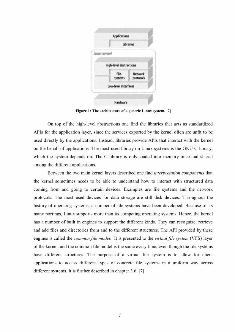
Figure 1: The architecture of a generic Linux system. [7]
On top of the high-level abstractions one find the libraries that acts as standardized
APIs for the application layer, since the services exported by the kernel often are unfit to be
used directly by the applications. Instead, libraries provide APIs that interact with the kernel
on the behalf of applications. The most used library on Linux systems is the GNU C library,
which the system depends on. The C library is only loaded into memory once and shared
among the different applications.
Between the two main kernel layers described one find interpretation components that
the kernel sometimes needs to be able to understand how to interact with structured data
coming from and going to certain devices. Examples are file systems and the network
protocols. The most used devices for data storage are still disk devices. Throughout the
history of operating systems, a number of file systems have been developed. Because of its
many portings, Linux supports more than its competing operating systems. Hence, the kernel
has a number of built in engines to support the different kinds. They can recognize, retrieve
and add files and directories from and to the different structures. The API provided by these
engines is called the common file model. It is presented to the virtual file system (VFS) layer
of the kernel, and the common file model is the same every time, even though the file systems
have different structures. The purpose of a virtual file system is to allow for client
applications to access different types of concrete file systems in a uniform way across
different systems. It is further described in chapter 3.6. [7]
8
2.2 The Monolithic Linux Kernel
It is possible to put the different kernel architectures into different camps based on
their characteristics: real-time kernels, micro-kernels, and monolithic kernels. Therefore, to
see how the Linux kernel stands out from other kernels, some of its main characteristics will
be gone through.
Regular real-time operating systems are mainly made for MMU-less (Memory
Management Unit) processors with a flat address space with no memory protection between
the kernel and its running applications. This means that the kernel, the kernel subsystems, and
the applications share the same memory address space and they all must therefore be made
foolproof to avoid crashing the system. This makes adding new software difficult. The system
must also be brought down to do this.
A microkernel provides a very small operating system footprint. Also, microkernel
operating systems are said to make a better use of the RAM than monolithic ones, since the
parts that are implementing functionality that are not needed at the moment, may be swapped
out or destroyed. Only a few essential functions are implemented in the microkernel: interrupt
handling, message passing, and scheduling. The microkernel implements a modularised
approach with “servers” where the rest of the operating system, such as file systems, device
drivers, and networking stack, run as applications with their own private address space. That
requires that the different layers of the operating system must have very well defined and
clean software interfaces for communication with the operating system and robust message-
passing schemes between processes. That is the only way real-time services and modularity
can be ensured.
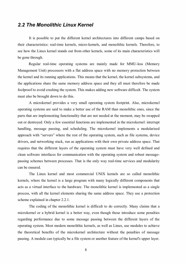
The Linux kernel and most commercial UNIX kernels are so called monolithic
kernels, where the kernel is a large program with many logically different components that
acts as a virtual interface to the hardware. The monolithic kernel is implemented as a single
process, with all the kernel elements sharing the same address space. They use a protection
scheme explained in chapter 2.2.1.
The coding of the monolithic kernel is difficult to do correctly. Many claims that a
microkernel or a hybrid kernel is a better way, even though those introduce some penalties
regarding performance due to some message passing between the different layers of the
operating system. Most modern monolithic kernels, as well as Linux, use modules to achieve
the theoretical benefits of the microkernel architecture without the penalties of message
passing. A module can typically be a file system or another feature of the kernel's upper layer.

9
The dynamically loadable kernel modules are pieces of kernel code that are not directly
included in the kernel, but can be inserted and removed from the running kernel at almost any
time to save memory. The linking and unlinking can be made transparent to the user, as the
kernel can perform it automatically. It acts as any other part of the kernel that is statically
linked. This, however, do not make it a microkernel-based operating system. The kernel still
interacts with the drivers on the lower layer using direct function calls, and not through
message passing between processes. Message passing between processes can be very resource
consuming and is regarded as one of the major drawbacks of microkernel operating systems.
Message passing is not a POSIX standard inter-process communication technique.
The modular structure of the monolithic kernel forces the system developers to
program well-defined interfaces to access the data structures handled by the modules. This
makes it easy to develop new modules. Further, the modules are arranged in a hierarchy,
where individual stackable modules can serve as libraries when they are addressed by
modules higher up in the hierarchy and the other way around. This reduces code replication
since drivers for similar hardware can be moved into a single module and the kernel can have
a simple checking whether the needed modules are present or not. Figure 2 represents a
comparison of a monolithic kernel and a microkernel. [8]
Figure 2: A monolithic kernel (on the left) and a microkernel (on the right).
Any new code intended for the Linux kernel goes through a great deal of testing
regarding design, functionality, and performance before it gets accepted into the mainline
kernel releases. Hence, this trying process has looked after the advantages of “regular” real-
time operating systems and made it to be known one of the most stable pieces of software. It
stability it has inherited from UNIX. At the same time it has kept the advantage of the
memory protection to individual kernel subsystems provided in micro-kernels, but avoided
the resource-consuming message passing. These are some the reasons why Linux have
10
become so popular. [9]
2.2.1 User Mode and Kernel Mode
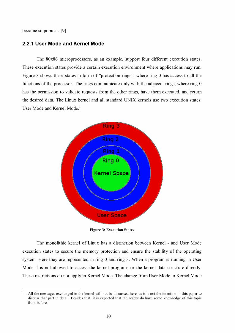
The 80x86 microprocessors, as an example, support four different execution states.
These execution states provide a certain execution environment where applications may run.
Figure 3 shows these states in form of “protection rings”, where ring 0 has access to all the
functions of the processor. The rings communicate only with the adjacent rings, where ring 0
has the permission to validate requests from the other rings, have them executed, and return
the desired data. The Linux kernel and all standard UNIX kernels use two execution states:
User Mode and Kernel Mode.1
Figure 3: Execution States
The monolithic kernel of Linux has a distinction between Kernel - and User Mode
execution states to secure the memory protection and ensure the stability of the operating
system. Here they are represented in ring 0 and ring 3. When a program is running in User
Mode it is not allowed to access the kernel programs or the kernel data structure directly.
These restrictions do not apply in Kernel Mode. The change from User Mode to Kernel Mode
1 All the messages exchanged in the kernel will not be discussed here, as it is not the intention of this paper to
discuss that part in detail. Besides that, it is expected that the reader do have some knowledge of this topic
from before.

11
is hardware dependent, meaning each CPU model has its own set of instructions for switching
between the two modes. Usually, a program that is running in User Mode issues a system call
and after some time the process switches to Kernel Mode and the system call is serviced.
Linux is POSIX compliant (see definitions), and therefore implements system calls such as
open, read, write, close, wait, exec, fork, exit, and kill among 310 others. System calls issued
to the kernel are UNIX systems and Linux’ way of communicating with hardware devices
from User Mode. The time before a system call is being served depends on the interrupt signal
sent from the process to the CPU and its actions according to the interrupt. Such an interrupt
signal may be a request for attention, a status change, or the completion of an I/O operation.
Since interrupts come at unpredictable times from the different peripheral devices, it is the
interrupt handler that takes care of these messages. Interrupts will be discussed in chapter
3.7.5. The kernel also handles exceptions caused by invalid instructions. In short, the kernel is
not a process itself, but a process manager. How the processes are treated depends on the
scheduler and Memory Management Unit, which will be described in chapter 3.3 and 3.4.
[10a: page 1-34]
2.2.2 Re-entrancy
The Linux kernel is re-entrant, meaning that several processes may be executing in
Kernel Mode at the same time. Only one process can progress at the time in a uniprocessor
system, but others may be waiting for the completion of some I/O request or the CPU. To
provide re-entrancy, the functions must only modify local variables, not global ones that
might be used by other resources as well.
The kernel may also include non-re-entrant functions that use locking to ensure that
only one process can execute that function at a time. These processes may then modify global
variables. If an interrupt occurs, the kernel is able to suspend the running process even if it is
in Kernel Mode. This ensures a higher throughput for the device controllers that issue
interrupts. While the kernel handles the interrupt, the device controller may perform other
tasks.
The re-entrancy influences the organisation of the kernel and its kernel control path,
which denotes the sequence of instructions executed by the kernel, being an interrupt, a
system call, or an exception. Normally the kernel would execute these tasks one by one, from
the first to the last. However, during handling interrupts and exceptions, the kernel can
interleave one process in Kernel Mode to run a process required by the first one or run another

12
process until the first one can be continued due to waiting on an I/O operation. Re-entrancy
requires the implementation of inter-process communication, which will be described shortly.
[10 b: page 1-34]
2.2.3 Process Address Space
On Linux, each process runs in its private address space. This is referred to as private
memory mapping. When a process is running in User Mode it has its own private stack, data,
and code areas. When operating in Kernel Mode, those are different in terms of a kernel mode
stack per process and an interrupt stack for all interrupts.
Since the kernel is re-entrant, several different processes may be executed in turn, each
with its own kernel control path. These paths have their own stack. But processes may also
share address space. This is done automatically by the kernel to save memory. For instance,
when two different users use the same editor, the program is only loaded into memory once.
This is called shared memory mapping and is discussed in chapter 3.4. The data are not shared
in this case, so it must not be confused with IPC shared memory, which will be described 3.4
as well. [10 b: page 1-34]

13
Chapter 3
LINUX AS A SOFT REAL-TIME
OPERATING SYSTEM
In this chapter, major interdependent subsystems of Linux will be presented. There are
many subsystems within the Linux kernel, but some are more important in relations to mobile
phones. Chapter 3.1 discusses the most important improvements to the 2.6 kernel and why it
is now said to be a soft real-time kernel. The rest of the chapter deals with the subsystems that
relates to the administration of processes, before chapter 3.10 discusses libraries, and chapter
3.11 discusses the window manager.
3.1 The Soft Real-Time 2.6 Kernel
It is possible to categorize real-time operating systems into two camps: those that
support soft real-time responsiveness and those that support hard real-time responsiveness.
Real-time responsiveness can be defined as “the ability of a system to respond to external or
clock events within a bounded period of time.”[11] The 2.6 kernel of Linux is regarded as a
soft real-time operating system, where determinism is not critical. That is, a fast response is
desirable, but an occasional delay does not cause malfunction. This is the contrary to a hard
real-time operating system, such as a flight control system, where a deadline never may be
missed. Soft real-time responsiveness is a requirement to mobile phones. Even though there
are requirements for multiprocessing, it is still a mobile phone and the phone specific services
such as calls and messages will have to be prioritised with regards to applications and events.
Before the 2.6 kernel release, special patches were necessary to achieve sufficient
responsiveness. The improved responsiveness of the 2.6 kernel is mostly due to three

14
significant improvements: a pre-emptive kernel, enhanced synchronization and a new efficient
scheduler. These improvements have contributed to make Linux an even better suited
operating system for mobile phones. The scheduler will be discussed in chapter 3.3.
3.1.1 The Pre-emptive 2.6 Kernel
Even though most UNIX kernels used to implement non-pre-emptive kernels as a
solution to synchronization problems, the Linux 2.6 kernel implements pre-emption. In earlier
releases of the Linux kernel, and like most general-purpose operating systems, the task
scheduler was prohibited from running when a process was executing in a system call. The
task would control the processor until the return of the system call, no matter how long that
would take. Hence, the kernel in a mobile phone could not interrupt a process to handle a
phone call within an acceptable time limit.
The 2.6 kernel is to some degree pre-emptive, meaning that a kernel task may be pre-
empted with a low interrupt latency to allow the execution of an important user application.
The pre-emption is triggered by the use of interrupts. This means that a kernel task may be
pre-empted with a low interrupt latency to allow the execution of an important user
application, typically a phone call. The interrupt latency is the time it takes from the device
raises the interrupt to the device driver’s interrupt handling routine is finished. A
microprocessor typically has a limited number of interrupts, but an interrupt controller allows
the multiplexing of interrupts over a single interrupt line. There also exist priorities among the
interrupts. [10b] This means that a process that is executing in Kernel Mode can be suspended
and substituted by another process because it has higher priority. The operating system must
be able to handle multiple applications and processes. For a mobile phone with soft real-time
requirements such functionality is essential, as it must be able to handle important tasks such
as an incoming phone call while the user is filming a video etc. Compared to a PC, the
processing power is reduced, but the requirements to responsiveness are higher. The kernel
code is therefore laced with pre-emption points allowing the scheduler to run and possibly
block a running process so as to schedule a higher priority process. Linux is still not a true
real-time operating system, but it is certainly less jumpy than before and considerable faster
than its predecessors, as seen in Figure 4.

15
Figure 4: A comparison between the task response time of the 2.4.18 Linux kernel and the 2.6 kernel. [11]
3.1.2 Synchronization
By implementing a re-entrant kernel, one also introduces the need for synchronization
among kernel control paths. One must ensure that while acting on a kernel data structure, no
other kernel control path is allowed to act on the same data structure, even if the first one
suspend the data structure. The data structure must be put back into a consistent state.
Given that one have one global variable V representing available items of some
system resource. If a first kernel control path reads V, it sees that it is 1. Another kernel
control path reads the same variable, and decreases it to 0. When A resumes its action, it has
already read V as 1 and decreases it. As a result, the value of V is now -1. The two kernel
control paths are using the same resource, which could result in serious errors.
When the outcome of a computation depends on how the processes are scheduled (i.e.
which goes first), one has a race condition and thus a non-deterministic behaviour. Using
atomic operations ensures safe access to global variables, which refers to combining the
operations from two or more kernel control paths so they appear as one to the rest of the
system. Any section of code that cannot be entered by a process before another one has
finished it is called a critical region.
The 2.6 kernel implements something that is referred to as futex – fast user-space
mutexes. It is a new implementation of the mutex previously implemented as system calls to
check that only one task is using a shared resource at a time. This time-consuming system call
to the kernel to see whether block or allow a thread to continue was often unwarranted and
unnecessary. Futex checks user-space to see whether a blocking is necessary, and only issues
16
the system call when blocking the thread is required. This saves time. The function also uses
the scheduling priority to decide which thread is allowed to execute in case of a conflict.
Later it will be shown how other techniques also influence inter-process
communication. [11, 12]
3.2 The Subsystems
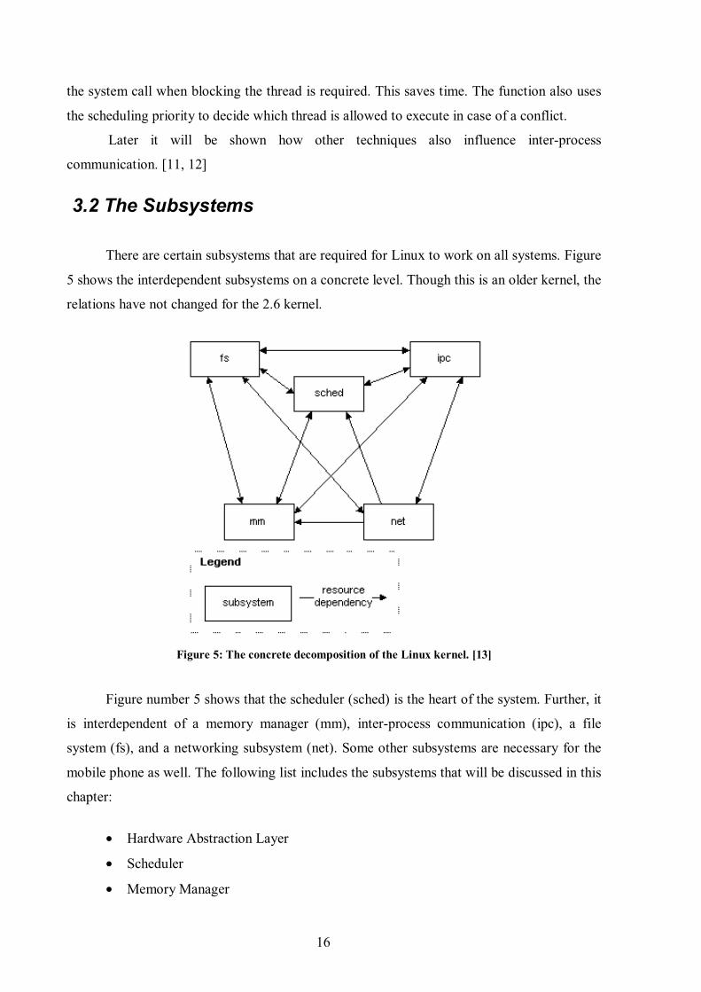
There are certain subsystems that are required for Linux to work on all systems. Figure
5 shows the interdependent subsystems on a concrete level. Though this is an older kernel, the
relations have not changed for the 2.6 kernel.
Figure 5: The concrete decomposition of the Linux kernel. [13]
Figure number 5 shows that the scheduler (sched) is the heart of the system. Further, it
is interdependent of a memory manager (mm), inter-process communication (ipc), a file
system (fs), and a networking subsystem (net). Some other subsystems are necessary for the
mobile phone as well. The following list includes the subsystems that will be discussed in this
chapter:
• Hardware Abstraction Layer
• Scheduler
• Memory Manager

17
• Inter-process Communication
• IO subsystem
• File System
• Memory Technology Devices (MTD) subsystem
The phone specific hardware will be dealt with in chapter 4.
3.3 The Scheduler
The scheduler is the heart of the Linux operating system. The scheduler provides an
interface to the rest of the kernel and a limited system call interface to user processes. It has
the following responsibilities:
• Determine which tasks will have access to the CPU and effect the transfer
between running tasks (context switch)
• Allow processes to create new copies of themselves (fork() or spawning)
• Send signals to user processes (signalling)
• Manage the timer hardware (calculate time slices)
• Clean up process resources when a process finishes executing (exit())
It also provides for dynamically loaded kernel modules. In short, the scheduler allocates
tasks to the CPU in quantities of time, time slices, to be able to execute multiple programs at
the “same” time. At least the tasks experience it so. The scheduler uses a timer to decide how
long each task can use the CPU. This timer uses the CPU clock to decide the time. The
process data structure uses a field for holding the number of clock ticks that the process can
continue executing without being forced to reschedule. [13]
The scheduler enforces a policy on when and for how long processes may execute. In
other words it tries to avoid starvation and it enforces fairness, interactivity, and efficiency.
The important thing for a mobile phone is to do this in the most efficient possible way and
thus provide a responsive user experience and meet real-time requirements for prioritised
tasks.

18
3.3.1 Threads and Processes
A process may have multiple threads of execution that work together to accomplish its
goal. This is called multithreading. Threads are much similar to processes, except that they
often share address spaces and data of its common process. The threads “own” only a stack
and a copy of the processor registers, including the program counter. Processes only share
data through shared memory or similar explicit methods commonly known as inter-process
communication (IPC). It is therefore interdependent of this subsystem. Only one thread within
a process, and one in total on a single processor system, may run in the CPU at a time.
Another way to put it is that a process in Linux is a group of threads with the same
thread group ID (TGID). Threads are said to be “lighter” than processes, and a context switch
between threads are said to be cheaper than a context switch between processes. Context
switches involves saving a CPU’s register state and load a new state, cache flushing, and
changing the current virtual memory map. It is therefore interdependent of the memory
manager subsystem and obviously the file system to load new data. In embedded systems, the
implementation of dedicated registers for the threads may increase the real-time
responsiveness even further, as will be discussed in chapter 4. Whereas some operating
systems differ between threads and processes and the spawning/forking (explained shortly) of
them, Linux do not. Threading has been, and maybe still is, one of the most difficult and poor
developed part of the Linux kernel. While earlier kernels implemented LinuxThreads, the 2.6
kernel uses the Native POSIX Thread Library (NPTL) to implement multithreading. One of
the already mentioned mechanisms implemented in the 2.6 kernel is futex. The LinuxThread
implementation had several issues with true POSIX compliance to IPC, signal handling and
scheduling.
From now on a task will be used as a common term on both a thread and a process
unless specified regarding the scheduler. Scheduling tasks requires the avoidance of race
conditions and hence the implementation of synchronization techniques through IPC
mechanisms such as signals and semaphores. These will be discussed in chapter 3.5.
Generally the implementation of pre-emption is regarded as the best implementation of
multithreading. [14]
3.3.2 Parent and Child Processes
Linux and UNIX operating systems make a difference between the processes and the

19
programs they are executing. A system uses fork() and _exit() respectively to create and end a
process. The point of forking for a process is to split itself into multiple running tasks. To load
a new program, an exec()-like system call is used. The process then continues with the loaded
program in a new address space. A process that invokes a fork-call is the parent of a new
process, called the child. They can easily find each other because the data structure that
describes each process includes a pointer to its immediate parent and pointers to its immediate
children. The naive approach to the forking would be to duplicate the data and code of the
parent process and copy this to the child process' address space. However, Linux implements
a Copy-On-Write approach that defers page duplication until the last moment (i.e. until one of
the processes is required to write into a page.) Paging and the use of the swap cache will be
described in chapter 3.4. Finally, every process is a child of the init process. The init process
will be described in the chapter about the boot process. [7, 9, 10a, 14]
The tasks may go to “sleep” by executing system calls. This is because they are
waiting for an I/O operation or similar, and they then are added to a wait queue. Wait queues
are a part of the inter-process communication subsystem. Tasks have to different sleep states:
TASK_INTERRUPTABLE and TASK_UNINTERRUPTABELE. Generally, sleeping tasks
will not be scheduled before they receive a signal from a try_to_wake_up() function. The
function make the tasks in the wait queue test if the condition the task was waiting for have
been is true. If so, it will then be marked with TASK_RUNNING and will be scheduled as
normal when calling the schedule() function. The waking of tasks usually happens because an
I/O operation is waiting for the process or similar. The TASK_INTERRUPTABLE tasks can
be woken up on other signals as well, such as kill from the user, which issues the SIGTERM
signal to the task. The task can decide how to react on the signal, but the
TASK_UNINTERRUPTABELE task will not even react to this signal. [14]
3.3.3 Zombie Processes
A parent process may ask the kernel to check whether a child process has terminated
or not, issuing a wait() system call. If the child process is not terminated, the parent process is
put in a wait state until that happens. If the child process already has terminated, that child
process was put in a zombie state, and data is extracted when the wait() system call is
received. It is normal, good practice of a kernel to keep around information from child
processes until the system call is made. But if the parent process terminates without issuing
the wait() call, the child process is occupying valuable memory slots. This may be a problem
20
to resource-constrained devices.
The solution to this lies in a special process called init, which is created during system
set-up. When a parent process terminates, the kernel changes the process descriptor pointers
of the children. Processes that are still running or are in a zombie state are set to point to the
init process, resulting in that they become children of the init process. This process runs wait()
system calls to get rid of the zombies. This mechanism is therefore especially valuable to
embedded devices with limited memory capacities.
Processes may also operate in process groups. For instance, may several processes
entered in one command line act as one process, in accordance with the POSIX standard. [10
b]
3.3.4 Kernel Failure
If the kernel experiences some kind of fatal error, it issues a panic() system call. For
instance, if the location of the root file system has been forgotten to be specified to the kernel,
the kernel will panic. The only way to recover from a kernel panic is to reboot.
3.3.5 The New O(1) Scheduler
The Linux 2.6 kernel has a totally new task scheduler that replaces the slow algorithms
of earlier kernels. The pre-emption was mentioned in chapter 3.1.1 and will not be discussed
further, even though it is one of the major improvements. Earlier, the scheduler would have to
look at each ready task and score its relative importance to decide which task to run next. The
new scheduler no longer scans every task every time, but uses two queues. When a task is
ready to run, it will be sorted and placed in a queue, called the current queue. The scheduler
then chooses the most favourable one in this queue to run next, giving each task a specified
time to occupy the processor. Opposite to earlier, this is done in a constant amount of time,
and not relative to the number of tasks. After its time in the processor expires, the task is
placed in the other queue, called the expired queue. The task is then again placed according to
its priority. When all the tasks in the current queue are done, the scheduler once again starts
its simple algorithm of picking tasks from the expired queue, which now is called the current
queue. This new scheduler works substantially faster than the previous scheduler, and it
works just as fast with many tasks as with few. [12]
Another example of improvement from the new scheduler is its policy to increase
responsiveness through dynamic task prioritisation. The 2.6 kernel has 140 priority levels. It

21
prioritises (rewards) tasks that are I/O-bound in contrary to CPU-bound tasks by adding or
subtracting from a task’s static priority. This is done on user tasks, and not on real-time tasks.
For future kernel task schedulers, a way to choose between different scheduler policies
and algorithms would be ideal. For example, a scheduler that enforces interactive tasks for
embedded and perhaps desktop users, while a strict efficient task scheduler favouring server
usage could be chosen for servers.2 This resembles the swappable scheduler of the GNU
HURD kernel. [16]
3.3.6 Symmetric Multi-Processing and Symmetric Multi-Threading
As it will be come evident in chapter 4, the mobile phones intended for high-level
operating systems usually uses several processors. There is usually one main applications
processor running the operating system and applications. This is connected to a Digital Signal
Processor, which in turn may be a combination of a DSP combined with another processor or
microcontroller unit (MCU) as a modem digital baseband. This will be further discussed in
chapter 4. How Linux deals with multiple processors normally, is either by the
implementation of Symmetric Multi-Processing (SMP) or Symmetric Multi-Threading
(SMT).
SMP is the technique used to divide the processes on several processors with one
process in each processor. It is the scheduler’s job to delegate the different processes to the
different processors.
SMT refers to the technique of simulating several processors. However, the boards
that have been studied in this project support the high level operating systems by appearing as
uniprocessor systems.
3.4 Memory Manager
The task of the memory manager is to control memory access to the hardware memory
resources on a fair basis. The memory manager is highly dependent on the MMU. It provides
protection by letting only the correct process read and modify its data, and it prevents
processes from overwriting code and read-only data. While executing processes, the processor
2 There has been developed an anticipatory and a deadline I/O scheduler to reduce queuing time and to ensure that processes get I/O time
when necessary. These, however, are not discussed here since they address problems related to the scheduling of I/O access to disks. The
kernel supports both I/O schedulers and they have been tested to perform way better that the Linux 2.4 scheduler. [15]

22
read instructions from memory and decodes them. The instruction may require fetching or
storing data to memory before moving on to the next instruction in the program. The
processor is therefore always accessing the memory to fetch the next instruction or to fetch or
store data. The instructions and data may also be fetched or stored to by the use of cache. [17]
3.4.1 Virtual Memory
In Linux the memory manager implements a logical layer for as the Memory Manager
Unit being able to provide virtual memory to drivers, file systems, and networking stack. But
also it provides virtual memory to user applications.
The advantages of virtual memory can be summarized with these points:
• Several processes can be executed concurrently
• It is possible to run applications whose memory need are larger than the available
physical memory. (Up to 4GB with a 32-bit address space)
• Processes can execute a program whose code is only partially loaded in the
memory.
• Each process is allowed to access a subset of the available physical memory.
• Processes can share a single memory image of a library or a program.
• Programs can be relocatable – that is, they can be placed anywhere in physical
memory.
• Programmers can write machine-independent code, since they do not need to be
concerned about physical memory allocation.
All this is solved by the use of a virtual address space, which is representation of
physical locations located by the MMU and the kernel. The virtual address space is also
referred to as a linear address space. The virtual addresses are divided by the kernel into page
frames with a size of 4 or 8 KB, which result in that a request for contiguous virtual address
space can be satisfied by allocating a group of page frames that do not necessarily have
contiguous physical addresses. All the pages are accessible by the kernel, but only some of
them get used by the kernel. The actual data may actually be located in RAM, cache, or on a
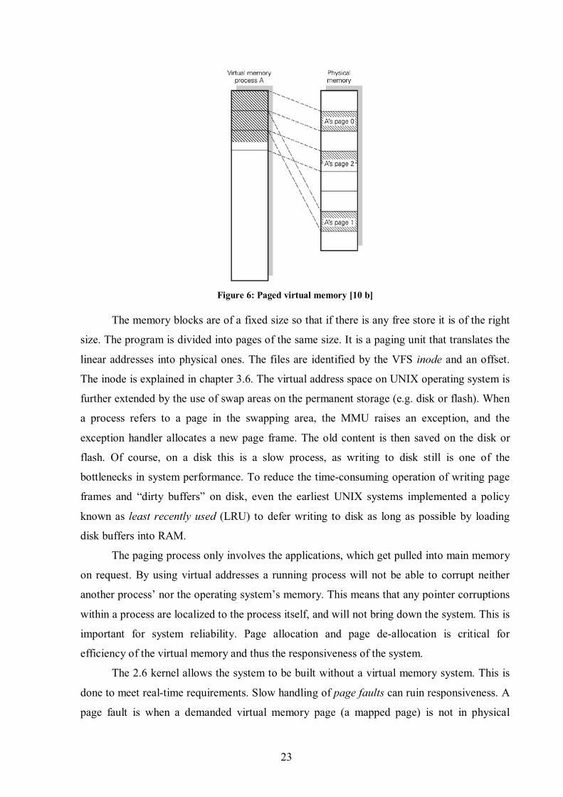
non-volatile storage, depending on when it was last used. A paged memory is seen in Figure
6. [10 a]
23
Figure 6: Paged virtual memory [10 b]
The memory blocks are of a fixed size so that if there is any free store it is of the right
size. The program is divided into pages of the same size. It is a paging unit that translates the
linear addresses into physical ones. The files are identified by the VFS inode and an offset.
The inode is explained in chapter 3.6. The virtual address space on UNIX operating system is
further extended by the use of swap areas on the permanent storage (e.g. disk or flash). When
a process refers to a page in the swapping area, the MMU raises an exception, and the
exception handler allocates a new page frame. The old content is then saved on the disk or
flash. Of course, on a disk this is a slow process, as writing to disk still is one of the
bottlenecks in system performance. To reduce the time-consuming operation of writing page
frames and “dirty buffers” on disk, even the earliest UNIX systems implemented a policy
known as least recently used (LRU) to defer writing to disk as long as possible by loading
disk buffers into RAM.
The paging process only involves the applications, which get pulled into main memory
on request. By using virtual addresses a running process will not be able to corrupt neither
another process’ nor the operating system’s memory. This means that any pointer corruptions
within a process are localized to the process itself, and will not bring down the system. This is
important for system reliability. Page allocation and page de-allocation is critical for
efficiency of the virtual memory and thus the responsiveness of the system.
The 2.6 kernel allows the system to be built without a virtual memory system. This is
done to meet real-time requirements. Slow handling of page faults can ruin responsiveness. A
page fault is when a demanded virtual memory page (a mapped page) is not in physical
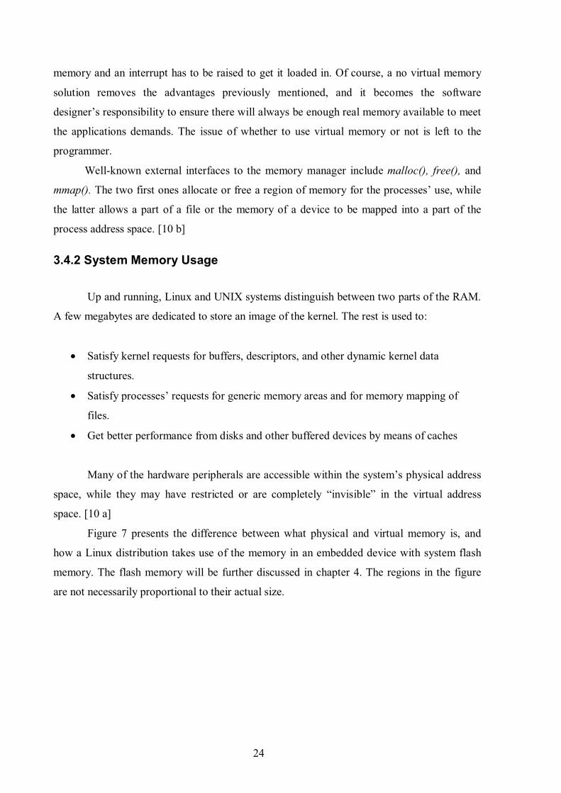
24
memory and an interrupt has to be raised to get it loaded in. Of course, a no virtual memory
solution removes the advantages previously mentioned, and it becomes the software
designer’s responsibility to ensure there will always be enough real memory available to meet
the applications demands. The issue of whether to use virtual memory or not is left to the
programmer.
Well-known external interfaces to the memory manager include malloc(), free(), and
mmap(). The two first ones allocate or free a region of memory for the processes’ use, while
the latter allows a part of a file or the memory of a device to be mapped into a part of the
process address space. [10 b]
3.4.2 System Memory Usage
Up and running, Linux and UNIX systems distinguish between two parts of the RAM.
A few megabytes are dedicated to store an image of the kernel. The rest is used to:
• Satisfy kernel requests for buffers, descriptors, and other dynamic kernel data
structures.
• Satisfy processes’ requests for generic memory areas and for memory mapping of
files.
• Get better performance from disks and other buffered devices by means of caches
Many of the hardware peripherals are accessible within the system’s physical address
space, while they may have restricted or are completely “invisible” in the virtual address
space. [10 a]
Figure 7 presents the difference between what physical and virtual memory is, and
how a Linux distribution takes use of the memory in an embedded device with system flash
memory. The flash memory will be further discussed in chapter 4. The regions in the figure
are not necessarily proportional to their actual size.

25
Figure 7: Physical and virtual memory maps for the Compaq iPAQ. [7]
The physical memory map usually follows the technical literature of the hardware and
defines how the system sees the total memory layout. The physical memory map seen on the
left is important, because it provides information on how to configure the kernel and how to
develop custom drivers.
As seen in this picture, the system flash storage on the bottom is divided in two. The
lower part of the flash contains the boot loader. This part has also the lower range of the
physical address space, and the boot loader required must therefore support bottom booting.
This region is rather small and may by mounted with a separate file system during booting.
The second part consists of the root file system. In this example the Linux distribution is a
Familiar Linux, which uses the JFFS2 file system. The boot loader can read from the JFFS2
file system, and therefore the kernel is stored in the root file systems /root directory in this
case. The kernel image is loaded into the RAM upon start-up by the boot loader, and jumps
into the kernels start routines. After that, the Linux kernel runs the rest of the start-up in
RAM. The start-up will be described in detail chapter 5.
With the system up and running, the programs use the virtual address space seen on
the right. The virtual memory map is of secondary importance for kernel configuration or
device driver development. According to [7, page 56] it is sufficient regarding device driver
development to know that “some information is located in kernel space and some other
information is located in user space, and that appropriate functions must be used to properly

26
exchange data between the two.”
In the figure one can see that the kernel occupies the virtual address space from
0xC0000000 and out, known as “kernel space”, while the rest, which is occupied by
application-specific text, data, and library mappings is called “user space”. The memory map
will be further discussed in chapter 4.1.3.
3.4.3 Memory Mapping
Memory mapping is the linking of an image into a process’ virtual address space.
When executing an image, the contents of the executable image and any shared libraries to be
used by the executable image must be brought into the process’ virtual address space. The
executable file itself is not yet brought into physical memory, but rather linked to in the
virtual memory by the running application. When the running application is requiring the
linked image, it is loaded into memory by the use of exceptions.
There are two kinds of memory mapping: private and shared. The first is used when processes
creates the mapping just to read the file, and not to write to it. Changes made to any page of
the memory region will not be reflected in the file on the permanent storage nor will it be
visible to other processes that map the same file. Moreover, a write operation on a private
mapped page will use Copy-on-write if it is written to, which duplicates the page. The
original page no longer belongs to the memory mapping. On the other hand, any write
operation to a shared memory mapping will be reflected in the file on the permanent storage.
It is also visible to all other processes that map the same file. This is therefore dependent on
the IPC subsystem. It is the mmap() system call that creates a memory mapping. [10b]
3.4.4 Buffer Cache
The memory manager uses several types of cache to speed up the system by the well-
known principle of locality.
The buffer cache is a collection of data buffers in RAM used by block device drivers.
Block devices will be explained in chapter 3.7.1. Each of the fixed size buffers contain data of
a disk block going to and from block devices, typically a hard disk. The block in the cache
therefore refers to physically adjacent bytes on the device. The block devices are always
accessed via the buffer cache and are used to access the disks piecemeal at regular intervals to
have minimal impact on the speed of user processes and on response latency experienced by
the user. The size of the block depends on the file system being used. The buffer cache

27
necessitates the introduction of the Memory Technology Devices subsystem (MTD) on
embedded devices, which will be described later.
3.4.5 Page Cache
The page cache is used to store the logical contents of file pages. Memory mapped
files split into pages are being read one at a time into memory from disk and stored in the
page cache. Therefore, as opposed to the buffer cache, the page frames in this cache do not
necessarily contain data that are physically adjacent on the device. This is done to speed up
access to paged data in I/O operations.
3.4.6 Hardware Cache
There is one typical hardware cache that is used; the processor cache. The processor
uses this to cache Page Table Entries. The page table holds the mapping between a virtual
address of a page and the address of a physical frame in form of a page number and an offset.
Caching this means that the processor will not have to read the mapping directly from the
page table, but may read cached translations for pages. The buffers used for this are called
Translation Look-aside Buffers (TLB). The processor can then use the cache to calculate the
physical address from references to virtual pages instead of calculating them by getting info
from disk.
3.4.7 Swap Cache
Swapping is the process where some page needs to be removed from physical memory
to make room for another page from virtual memory that is to be used. One way to see it is
that is the opposite of RAM. In this case the kernel uses some space on the non-volatile
storage device as an extension to the RAM, whereas RAM is the extension of the non-volatile
storage device to reduce the number of disk accesses. In earlier kernels, it was a rule of thumb
that the size of the swap space should be set to two times the RAM-size. That was because the
first part of the swap space was a direct mapping of the RAM itself. This no longer applies.
Now it is said that the size depends on the speed of the hard drive. This is a topic for further
study. [18]
More concrete, the swapping works like this: If an old page has been changed, it is
referred to as dirty and must be swapped out to the swapping area to be used later. The

28
memory manager must efficiently deal with the swap space and know when to write pages to
permanent storage and when to retain them in memory because they are soon to be used
again. Only dirty pages are saved in the swap file. If a used page is not altered it will not be
written back to the swap cache. It can be discarded, and this saves many unnecessary disk
operations. The swapping can be turned off if wanted. The implementation of shared memory
mapping and IPC shared memory complicates the swapping.
The swapping is not as beneficial for the overall system performance as it reduces
access speed. The policy of when to swap a page in to RAM and when to swap a page out to
the swap cache is difficult to implement, but generally swapping out pages should be avoided
as long as possible. On the other hand swapping expands the address space that is effectively
usable by a process, and the amount of dynamic RAM to load processes. The dynamic RAM
is the RAM available to load processes. Thus when running multiple applications
simultaneously, swapping is useful. On a mobile phone, swapping may want to be avoided,
since the flash has limited erase and write cycles. Swapping will accelerate the wear on the
device.
The 2.6 kernel implements the use of swap files instead of the earlier swap partitions
that was used to secure non-fragmented swap areas. This does not longer apply since modern
hard-disks can re-map physical partitions and therefore do not guarantee that any partition
will be contiguous anyway, and further, file swapping in the 2.6 kernel woks just as fast as
swapping to a partition. [19]
Additionally, some experimental improvements to the 2.6 Linux kernel swapping have
been made by Con Kolivas through the CK patch-set. The improvements are called Swap
Prefetch, and employ a mechanism of pre-fetching previously swapped pages back to physical
memory even before they are actually needed, as long as the system is relatively idle (not to
impair performance) and there is available physical memory to use. This gives several orders
of magnitude faster access to the affected pages when their owning process needs access to
them, since they are effectively not swapped out by then. [10a, 19, 20]
3.5 Inter-process Communication
Linux uses IPC techniques such as wait queues, file locks, signals, pipes, shared
memory, semaphores, message queues, and sockets to exchange information between
processes in some synchronized manner. However, these operate only in User Mode and not
with kernel control paths as actors. Inter-process communication in User Mode supports

29
sharing of data without having to access the file system. The only exception to this is network
sockets, which are presented as file descriptors to processes.
Wait queues are simply linked lists of pointers to task structures of processes that are
waiting for kernel events, such as the completion of an I/O operation. File locks are used to
implement exclusion. The process that holds the lock will be the only one with write-access to
the locked portion of the file, which may be the entire file. Other processes may have read-
only access. This will not be discussed further.
Shared memory, semaphores, and message queues are commonly known as System V
IPC, and are implemented in many UNIX kernels and are POSIX standard techniques. System
V IPC is dependent on the kernel IPC mechanisms wait queues and signals. Semaphores are
for example implemented with wait queues. [13]
3.5.1 Signals
Linux use signals to notify processes about system events, either signalled from the
user or because of an error condition. Process scheduling relies on signals. The POSIX.1
standard defines about 20 different “regular” signals, two of which are user definable. Signals
have existed more or less unchanged for about 30 years, and are still being used due to their
simplicity. Here is a list from the 2.6.17.11 kernel, seen by typing kill –l in a shell:
Some of the 31 first signals are not POSIX standard signals, but implemented by
Linux. The last ones are POSIX real-time signals. The main difference from the other signals
is that the real-time signals of the same kind may be queued. The signals have no predefined
meaning - except the three first ones, which are being used in LinuxThreads - so it is up to the
applications to define their purpose. The real-time signals are delivered in a guaranteed order.
Signals of the same type are delivered in the order they were sent, while low-numbered real-
time signals have a higher priority if they are different.
1) SIGHUP 2) SIGINT 3) SIGQUIT 4) SIGILL 5) SIGTRAP 6) SIGABRT 7) SIGBUS 8) SIGFPE 9) SIGKILL 10) SIGUSR1 11) SIGSEGV 12) SIGUSR2 13) SIGPIPE 14) SIGALRM 15) SIGTERM 16) SIGSTKFLT 17) SIGCHLD 18) SIGCONT 19) SIGSTOP 20) SIGTSTP 21) SIGTTIN 22) SIGTTOU 23) SIGURG 24) SIGXCPU 25) SIGXFSZ 26) SIGVTALRM 27) SIGPROF 28) SIGWINCH 29) SIGIO 30) SIGPWR 31) SIGSYS 34) SIGRTMIN 35) SIGRTMIN+1 36) SIGRTMIN+2 37) SIGRTMIN+3 38) SIGRTMIN+4 39) SIGRTMIN+5 40) SIGRTMIN+6 41) SIGRTMIN+7 42) SIGRTMIN+8 43) SIGRTMIN+9 44) SIGRTMIN+10 45) SIGRTMIN+11 46) SIGRTMIN+12 47) SIGRTMIN+13 48) SIGRTMIN+14 49) SIGRTMIN+15 50) SIGRTMAX-14 51) SIGRTMAX-13 52) SIGRTMAX-12 53) SIGRTMAX-11 54) SIGRTMAX-10 55) SIGRTMAX-9 56) SIGRTMAX-8 57) SIGRTMAX-7 58) SIGRTMAX-6 59) SIGRTMAX-5 60) SIGRTMAX-4 61) SIGRTMAX-3 62) SIGRTMAX-2 63) SIGRTMAX-1 64) SIGRTMAX

30
There are two kinds of system events that are being signalled: Asynchronous
notifications and Synchronous errors or exceptions. The former may be represented by an
interrupt signal sent to a foreground process by pressing the interrupt key code, for example
CTRL+C. This results in a SIGINT-signal. The latter may be represented by a signal sent to a
process from the kernel when the process tries to access a memory location at an illegal
address. In this case that will be a SIGSEGV-signal. For a complete definition see [21].
Signals can usually only be sent to processes within the same user-id (uid) and group-id (gid),
which is two attributes of a files inode.
The processes may respond to a signal in two ways; ignore it or asynchronously
execute a specified procedure. If the process doesn’t specify one of these alternatives, the
kernel performs a default action. The default actions are:
• Terminate the process
• Write the execution context and the contents of the address space in a file (core dump)
and terminate the process
• Ignore the signal
• Suspend the process
• Resume process' execution, if it was stopped
[10a, 21, 22]
3.5.2 Pipes
Pipes can be considered as a one-way inter-process mechanism between processes.
One process writes data to the pipe, and the kernel routes the pipe to another process that can
read the data. For a user in a command shell, a pipe is created with the | operand or the < and
> operators. An example is $ ls | more. The pipe, or actually the shell program on behalf of
the pipe command, connect the standard output of ls and more by giving the standard output
of the ls command to the more command. The result from the first command is stored in a
temporary file with a common inode for the two commands. The second command uses this
as an input, where the inode addresses the same physical page. This obviously simplifies the
working process, as the machine uses two or more programs with one issued command and
only gives the final result. There exist two kinds of pipes: temporary pipes and named pipes.
The example mentioned here is called temporary pipes, which can be created on the fly by the

31
user in a shell or by a program. The other type is a more permanent form of pipes, often
referred to as a FIFO. They are stored in the file system as an entity and used as files. They
are specially indicated with the ls –l command. Processes can use these as long as they have
the proper rights to do so. [23]
3.5.3 Shared Memory
IPC shared memory is the fastest way for data sharing and data exchange between
processes, especially when large amounts of data must be shared. Hence, the processes read
from and write to the same data pages. An example can be the amount of money in a bank
account that needs to be accessed by several processes. It is done by sharing memory blocks
to which several processes can write to and read from. The access to the shared memory is
controlled with the use of keys and access right checking, and the use is controlled by for
example System V semaphores. The set-up of shared memory is controlled by the memory
manager and is the fastest way of IPC. The system calls related to shared memory are shmat(),
shmget(), and shmdt(). [20]
3.5.4 Semaphore
Semaphore is a mechanism for restricting access to critical sections of code to one
process at a time. Semaphores are controlled by "wake up" and "sleep" commands. One
process can be forced to stop at one place, and woken up again when the other process or
processes are finished with the data. This introduces the need for implementing mutual
exclusion, mutex. Linux usually did this by a system call to the kernel, determining whether
to block a thread or allow it to continue. In the 2.6 kernel it can be done in user space by the
use of futex, explained in chapter 3.1.2. The mechanisms are widely described in literature
and will not be treated further here. It is widely accepted that IPC can be implemented
significantly faster in a microkernel environment. [8]
3.5.5 Message Queues
Message queuing is an asynchronous IPC mechanism that uses queues to place
messages on. The different processes may place messages on the queue, but they do not need
to wait for a response. The message will at some point be read by one or more processes,
which receive the message and process the message in some appropriate manner. Qtopia
32
Core, which will be discussed in chapter 5, uses this mechanism for inter-object
communication. [20]
3.5.6 Sockets
A socket is an identifier that the application uses to uniquely identify an end point of
communications. The user associates a protocol address with the socket by associating a
socket address with the socket. Typically this is used on network connections. Sockets operate
very much like pipes, except that they have a separate buffer for each communication
direction. [13]
3.6 The Virtual File System and File System Types
There are many file system types that can run on Linux. Ext2, CRAMFS, ROMFS,
RAMFS, NFS, and JFFS2 are often used on embedded systems through different hardware
solutions. As a general point, the hardware memory/storage technology used on the device
may set limitations to the choice of file systems. The kernel supports them all through a
concept called the Virtual File System (VFS), which has the control over its mounted file
systems. The VFS handles all the system calls related to all the different file systems. The
device drivers must translate their physical organisation into a common file model, which can
represent all the supported logical file systems. Through this, the POSIX system calls like
open(), write(), read(), close(), seek(), and tell() for files, and system call like readdir(),
creat(), unlink(), and chmod() for directories are provided to user processes. In that way, to
interact with the different file systems the kernel (i.e. the VFS) has only one common
interface to relate to. The device driver layer will be described shortly. The flexibility of
choice of physical devices and logical file systems is one of the important factors why Linux
has had such a success. [10a]
In Linux, everything is a file, even the directories and the I/O devices. On a low level,
the file system (i.e. common file model) is represented by three data structures that are
accessible for the other kernel subsystems: a super-block, an inode, and a file. The super-
block contains info about the entire mounted logical file system. For disk-based file systems
this is typically which blocks are in use, what size the blocks are, etc. An inode is an in-
memory data structure that represents the file information needed by the kernel. Each inode
object is associated with an inode number, which uniquely identifies the file within the file

33
system. Accounting, buffering, and memory mapping information is stored in the inode. The
file structure represents files currently opened by processes. The files opened by the processes
are stored in a doubly linked list. [13]
The nature of file systems will not be discussed in great detail. In short they can be
characterized on basis whether they can be written to, if they are persistent, if they can
recover from power failure, if they use compression, and if they live in RAM. On a mobile
phone a combination of the CRAMFS and the JFFS2 file systems is a well-known working
combination for the root file system; CRAMFS for the non-changing parts, and JFFS2 for the
writable persistent file system. [7] In chapter 3.6.3, RAMdisk, another RAM file system used
during booting will be discussed. More about the JFFS2 file system will be discussed in
chapter 3.8.2.
3.6.1 CRAMFS
CRAMFS is a compressed non-writable file system living on non-volatile storage (i.e.
not RAM). However, a couple of directories may be located to RAM and thus be writable, but
still un-storable. Like JFFS2, it keeps it metadata uncompressed. It has a maximum file
system size of 256 MB, a maximum file size of 16 MB, and only supports a 4096-byte page
size. Further, it supports a 16 bits wide uid field, and an 8 bit wide gid field. Hence it has a
maximum gid at 255. It uses the mkcramfs tool to make the file system and cramfsck tool to
verify the content of the file system. It uses the buffer cache to talk to the device in a block
device manner. This has implications for the MTD driver that will be discussed later.
CRAMFS is suitable as a file system for initial RAM disks. This will be discussed in chapter
4. [7]
3.6.2 SQASHFS
SQUASHFS is pretty new a compressed, read-only file system intended for Linux,
with its alpha release in 2004. It is well suited for archival use, but also in embedded systems.
SQUASHFS compresses files, inodes, and directories, and supports block sizes up to 64K for
greater compression. It is generally faster and uses a better compression than CRAMFS.
[24]

34
3.6.3 RAM Disk
The RAM disk is similar to a block device living in RAM, and it is therefore not
suited as the only root file system for embedded devices that needs permanent, writable
storage. However, the content that does not change (i.e. just needs read access, such as init)
may be stored on the RAM disk, while the rest of the root file system may contain the rest of
the directories that needs both read and write access, using another file system that is mounted
later on. This will further be explained in chapter 5.5.
3.7 I/O Subsystem
For the high-level programmer, the I/O subsystem provides a simple and uniform
interface to onboard devices. The most difficult part of porting Linux to a mobile phone is not
the main configuration of the kernel, but the programming of the low-level interfaces that are
special for this kind of embedded devices. Special or not, on a mobile phone, I/O devices will
typically involve devices such as keypad, camera, Bluetooth, LCD screen, and non-volatile
storage in some form, but also the drivers for the GSM/GPRS Digital Baseband Subsystem
related functions. Those are often provided by the board manufacturers, such as Texas
Instruments, or by the operating system vendors, such as MontaVista. These must be custom
made to the hardware architecture and this is a process that may be troublesome.
The I/O subsystem supports three kinds of devices:
• Character devices for supporting sequential devices.
• Block devices for supporting randomly accessible devices. Block devices are
essential for implementing file systems on disk.
• Network devices that support a variety of link layer devices. [9:chap.2&5]
3.7.1 Device Drivers
The kernel interacts with the I/O devices by means of device drivers. These consist of
data structures and functions that are included in the kernel. The device drivers interact with
the I/O devices through a common interface and make them respond correctly. The device
drivers can be built in modules that are loaded in and out of the kernel without the necessity to
reboot the system. This is called module-based driver architecture. By dynamically unloading
a module no longer needed, this helps reducing the size of the kernel image stored in RAM.

35
Furthermore, the device drivers can be built without vendors needing to know the kernel
source code. They just need to know the interface specifications. These drivers are invoked by
the kernel to do some requested work on the hardware. All device drivers are dealt with in a
uniform way by the kernel.
In Linux even the I/O devices are stored as files. This way the system can issue the
same write() command to both a file and an I/O device. Device files are normally found in the
/dev directory on a UNIX system, and they refer to specific drivers in the kernel and represent
a user-visible portion of the device driver interface. The device manager that handles these
files and the user space actions of adding and removing devices is called udev in the 2.6
kernel, which is the successor of devfs. Opposite to earlier, this manager now only provides
the nodes present on the system. Udev also only operates in user space, while devfs operated
in kernel space. Udev runs as a daemon that reacts to uevents from the kernel.
According to the characteristics of the underlying device driver, device files are
divided into two types: Block or character. Block devices are typically hard disks, DVD
players etc., and can have their data addressed randomly. The time needed to transfer data to
them, are relatively slow and equal from a human point of view. Therefore the fore-mentioned
buffer cache is used to improve their performance speed. Char devices are typically the mice,
sound cards, modems etc. They must be accessed sequentially. [20:chap.8]
The VFS hide differences between regular files and the device files from the
application programs by changing the default file operations when accessing device files. The
memory-based file system that exports information present in the device tree is called sysfs in
Linux. Devices are accessed by polling and interrupts or by Direct Memory Access (DMA),
which will be described shortly.
3.7.2 Device Files in Older Kernels
There exist two kinds of device files from Linux 2.4: old-style device files and devfs
device files. The first ones are found in the /dev directory and are “real” files. The second ones
are virtual files. The old-style device files address hardware devices through their inodes. The
files have two main attributes: a Major number and a Minor number. The Major number,
ranging from 1 to 254, identifies the device type. The Minor number identifies a specific
device within the devices with the same Major number. The mknod() system call is used to
create old-style device files. A graphical representation of this can be seen in Figure 8.

36
Figure 8: Device drivers and device files, managed by the Virtual File System. [10a]
Devfs device files were introduced to solve some problems that shortly will be
described, with the old-style files. The old-style files all appear in the /dev directory so
administrators would not need to create them. Since there are quite a few, it makes the process
of searching in them slow. In addition the Major and Minor numbers are only 8-bit long,
making it a limiting factor for several newer hardware devices. Therefore, the devfs device
files let the devices be registered with names instead of numbers. The kernel has a naming
scheme which will make a /dev/had to a /dev/discs/disc0, for instance. However are the device
numbers required by the POSIX standard, so almost all device drivers associate the devfs file
with the same major and minor numbers as the corresponding old-style file. [7]
3.7.3 The 2.6 Kernel and Udev
As mentioned is udev the device manager in the 2.6 kernel. It supports persistent
naming of devices moving around the system. For example can the first CD-ROM drive
detected one time be the second CD-ROM drive detected next time, which will give those
different names or entries the second time. Another problem with the /dev directory was that
it grew awfully big, and it was “impossible” to keep track of the devices actually present on
the system. The RAM-based file system devfs sought to solve this problem by letting the
kernel itself handle the /dev directory. This solved many problems, but an unsolved problem
was that it had not the ability to create device nodes with persistent names.
The goals of udev were therefore to run in user space, create a dynamic /dev directory,
provide consistent device naming, and, if wanted, create a user-space API to access
information about the devices currently on the system. The first problem was solved by the
use of the event generated by /etc/hotplug every time a device is added or removed from the
37
system, in combination with sysfs’ ability to show the necessary information about a device.
The second problem was solved by catching the events from /etc/hotplug and create or
remove an entry in the /dev directory with a name assigned by the kernel as the device was
added or removed.
In the /etc/udev/rules.d udev’s rules for naming devices can be found and edited after
ones own choice, thus solving the last two problems. If a rule is not found, the kernel uses a
default naming-scheme. This rules will not be discussed in details, but they can use any data
extracted from the devices to create naming rules (for example with the use of scripts) and
simplify the /dev directory. This is perhaps not useful for the average PC user, but it shows
the power and flexibility of the system. [25]
3.7.4 Sysfs vs. Procfs
With the advents of sysfs some of the other old directory layout was altered as well.
The PROCFS or /proc file system, is a special file system as it is a virtual file system that
resides in memory and is created every time the system is rebooted. The /proc directory
reveals important data on the running processes and the state of the system itself. UNIX
systems also implement a current working directory for every process. Examples of system
state info can be CPU speed and power management. IPC mechanisms such as shared
memory, message queues and semaphores are also visible in /proc. Proc acts as an interface to
kernel data structures. Many commands use these structures to see the status of devices. It is
readable by the owner of the processes and the root. This openness and access to devices is
very useful for programming.
In Linux kernel 2.6, much of the non-process related files under /proc are moved to
sysfs, mounted under /sys. Information on the CPU and memory etc. are still kept in the /proc
directory. More information about the meaning of the files in proc is obtained by entering the
command man proc in a terminal window. The file proc.txt discusses the virtual file system
in detail. [25]
3.7.5 Interrupt Driven Driver Architecture
As mentioned in chapter 3.4.1 interrupts need to be raised when the memory manager
discovers that some needed page is not in memory. This applies to all situations when some
data is missing or some data for example arrives from the network to the hardware, such as a
phone call. The kernel must deliver an interrupt from the hardware device to the correct
38
device driver to notify about the occurred situation. This is referred to as en interrupt driven
driver architecture. It requires the different device drivers to register the address of an
interrupt handling routine and their wanted interrupt number with the kernel (IRQ).
How the interrupt is delivered to the CPU itself depends on the architecture of the
system, but as a general point it is wise that the interrupt handling routine of the device driver
should do as little as possible. That way it will not occupy too much resources and the kernel
can dismiss the interrupt and continue its previous work. If a lot work needs to be done
because of an interrupt, the first task can be queued to be handled later on. [20:chap.8]
3.7.6 Direct Memory Access
The use of interrupt-driven device drivers works well as long the amount of
transferred data to and from devices is reasonably low. If the transfer rate is bigger, for
example for a SCSI device, high interrupt latency will impact the overall system. The
interrupt latency is the time it takes from the device raises the interrupt to the device driver’s
interrupt handling routine is finished.3 DMA was invented to handle this problem. The DMA
controller allows devices transfer data to memory without the intervention of the CPU. The
DMA only uses some parts of physical memory and knows nothing about the virtual memory.
Usually there are only 7 DMA channels, making it a scarce resource. They cannot be shared,
so device drivers must be able to operate without them. [20:chap.8]
3.8 The MTD Subsystem
The Memory Technology Devices (MTD) subsystem is a module of the Linux kernel.
On Linux, memory technology devices are all kinds of memory devices: RAM, ROM, flash,
and DiskOnChip (DOC) from M-Systems. M-Systems are now acquired by SanDisk. Linux
imposes greater requirements on the storage hardware compared to traditional embedded
software. The MTD subsystem intends to provide a uniform and unified access to memory
devices for the VFS. In that way it avoids having different tools for different technologies.
Normal file systems cannot be used on top of a flash because they, as mentioned, go through
the buffer cache. Also, the flash chips have a larger sector size than the regular disks sector
size, on which the buffer cache is based. In addition to this, flash chips have a limited lifetime
and the memory blocks have to be erased before written to.
3 Interrupt latency can be measured with a tool named intlat. It is made of Andrew Morton and can be
downloaded from ww.zipworld.com

39
The MTD subsystem consists of low-level chip drivers and high-level interfaces called
MTD user modules. The user modules are software modules in the kernel that enables access
to the chip drivers through recognizable interfaces and abstractions. The interfaces and
abstractions are then provided to the higher levels of the kernel (e.g. to the VFS as the
common file model) and in some cases to user space.
The typical operations the MTD subsystem has to carry out is erase, read, write, and
sync. The system works in a manner where the chip drivers register sets of predefines
callbacks, which is executable code, and properties with the MTD subsystem. The callbacks
and properties are defined in an mtd_info structure, which is provided to the
add_mtd_device() function. These chip driver callbacks are then called through the user
modules.4
The following MTD chip drivers are some of the most important ones available:
• DiscOnChip (DOC) for M-Systems’ DOC-technology
• Common Flash Interface (CFI) onboard NOR flash
• Onboard non-DOC NAND flash
• Uncached RAM
• PCMCIA flash
• RAM, ROM, and absent chips
• Virtual devices for testing and evaluation
The CFI specifications are standardized and developed by Intel, AMD, and other flash
manufacturers. The chips have their configuration directly stored on the chip. The kernel
includes code to detect and support them. The Non-DOC NAND flash driver is for NAND
flash that is not M-Systems DOC devices. The MTD subsystem also provides drivers for
accessing conventional RAM and ROM chips, which are mapped in a system’s physical
address space as MTD devices. Absent chips are chips that can be removed from a socket to
be flashed. The uncached RAM driver is for systems not providing cache.
There is no “standard” physical address location for the MTD devices, and therefore
they need a customized mapping driver. The kernel contains a generic driver for accessing
CFI flash chips on systems without a specific mapping driver. In addition, some systems and
development boards have known MTD device configurations. The kernel therefore contains a
4 See Definitions for a definition on callbacks.

40
number of specific drivers for these systems. The drivers are found in the drivers/mtd/maps/
directory of the kernel sources. If a driver is not found there, it may have to be created with
the existing ones as examples.
The MTD chip drivers can handle multiple instances of the same MTD device.
Identical chips can be arranged to appear as one chip and the MTD subsystem also allows the
division of storage space into partitions with different file systems.
The storage space is, as mentioned, managed by a user module. The user module
enforces a storage format on the device and provides interfaces and abstractions recognized
by higher-level kernel components. This can be the virtual file system directly, or a disk-style
file system. Disk-style file systems may for example be applied on top of the block device
user modules. It is important to notice that some chip drivers and user modules are not
compatible. This was the case for JFFS2 (described below) and NAND flash for instance.
According to [26] however, JFFS2 was included in the official kernel since the 2.4.10 release,
and has a preliminary support for NAND flash available from the MTD CVS tree at [27].
Other sources say it is only included in the 2.6 version. [28a, 28b] At least it is supported with
the current kernel versions in one way or another.
The MTD user modules earlier had to be registered with the /dev directory, but this is
now handled through sysfs. The kernel configuration has a submenu for the configuration of
the MTD driver support, except for the JFFS2, which is located under file systems. Note that
the JFFS2 also requires enabling of the MTD subsystem. The MTD submenu further has four
submenus with configuration options for the drivers. There one also can choose to build them
as modules, but they must be built as a part of the kernel (image) to be able to mount the root
file system. The MTD subsystem includes a toolset - MTDutils - to be installed on the host,
and on the target. This supports things like creating a file system on the devices, and must be
handled with care.
3.8.1 The Flash Transition Layer and the NAND Flash Transition Layer
User Modules
The flash transition layer (FTL) implements a virtual block device on flash chips with
the NOR technology. That way regular block oriented file systems may be applied on top of it
to be read by the VFS. The NFTL does the same for flash devices with the NAND
technology. Both technologies will be discussed in chapter 4.

41
3.8.2 The Char Device User Module
This user module enables a character-like access to the MTD device. A character
device must typically be erased before written to.
3.8.3 The Block Device User Module
The caching block device user module - as its name implies – uses a cache, which is
the RAM in this case. It uses the RAM to cache blocks while the content is modified, its flash
regions are deleted, and then it is re-written to. It has therefore no power failure reliability. A
variant of this is the read-only block device user module. They are both accesses as block
devices, hence through the cache buffer. This one is likely to be used in the initial set-up of an
MTD device. CRAMFS uses this module.
3.8.4 The Journaling Flash File System Version 2 (JFFS2)
Contrary to many other memory device storage schemes, the JFFS2 user module does
not act as a transition layer to traditional file systems, which is an old technique where flash
devices appears as block devices. It operates with a log-structured file system directly on the
MTD device. The file system structure is recreated in RAM at mount time by JFFS2 through
a scan of the MTD device’s log content.
JFFS2 also implements power down reliability and wear levelling. Power down
reliability means that that JFFS2 can recuperate even if the device suddenly looses power. The
only failure that might occur is that data might be lost if a write() operation to overwrite old
data, is in action. Both the new and old data might then be lost. This kind of failure should be
checked during start-up.
Wear levelling is implemented by JFFS2 to avoid that some blocks are written to,
more often than others. Flash devices usually have a limited number of erases per block
guaranteed from the manufacturer. After that limit is reached, the manufacturer do not
guarantee for the block’s operations. Therefore, one must consider the use of swap as well, as
this further reduces the lifetime.
Flash hardware is usually slower to operate than RAM hardware. Because of this,
JFFS2 is constructed to be able to compress data stored on flash devices and decompress it
into RAM before using it. The side effect of this is that it render impossible the use of eXecute
In Place (XIP), which is the ability to execute code directly from ROM – or some other

42
permanent storage – without copying it to RAM. Another side effect of JFFS2 is that it
requires empty space on the device for garbage collection. Hopefully this will be resolved
with JFFS3. The Memory Technology Device Subsystem project website is found at [28a]
and [28b]. It contains documentation regarding the API for implementing MTD user modules
and MTD chip drivers. It must be noted that the JFFS2 user module is configured as a part of
“File systems” submenu in the kernel configuration, as opposed to the others.
3.9 Libraries
Moving a bit out from the kernel, the first layer one meet is the library layer. “A
''program library'' is simply a file containing compiled code (and data) that is to be
incorporated later into a program; program libraries allow programs to be more modular,
faster to recompile, and easier to update.” [29]
There are three kinds of libraries: static libraries, shared libraries, and dynamically
loaded (DL) libraries. A static library is installed into a program executable before the
program can be run. These kinds of libraries are quite troublesome to upgrade and are not
recommended for general-purpose. A shared library is loaded into memory at program start-
up and is shared between programs. The DL libraries may be loaded and used at any time
while a program is running. DL libraries are not of another format than the others, they are
just used in another way by programmers. The most used format for libraries is Executable
and Linking Format (ELF), which is used by nearly all Linux distributions today.
Both static and shared libraries can be used as DL libraries. DL libraries require a little
more work to use than shared libraries, and often their flexibility is not needed.
3.9.1 Static Libraries
Static libraries are simply ordinary object files. They have .a suffix. They are not used
as often as before, because of the shared libraries and their advantages. The benefit of static
libraries is that they permit users to link programs without having to compile the code of the
library, saving recompilation time. Now, this is not as important as it once was, due to the
computers of today, but it is still a security for programmers not wanting to share their code.
3.9.2 Shared Libraries
Shared libraries are loaded by programs when they start. All programs that start

43
afterwards also use that library, in other words it is loaded only once. The C library, for
instance, is a shared library. Linux permits updating of libraries and support for programs that
want to use older, non-backwards compatible versions of that library. Linux also supports
overriding libraries and even specific functions inside a library when executing a particular
program. All this may be done while programs are running and using the existing libraries.
Shared libraries have two kinds of names: a soname (shared object name) and a real
name. The soname has a “lib” prefix and a “.so” phrase followed by a period and the version
number. An example is libexample.so.1. The lowest C libraries however do not start with
“lib”, as an exception. A fully qualified soname includes the directory of the library as a
prefix, so that the soname acts as a symbolic link to the libraries real name.
The real name file is the file with the actual library code, and adds to the soname a
period, a minor number, another period and the release number, where the last two are
optional. In addition there is a “linker name”, which is the soname without the version
number.
Programs should internally only list the sonames. When one creates a library, one
creates it with a specific filename and detailed version information. Libraries are installed in
one of a few special directories and afterwards one run the ldconfig tool to examine old files
and to create sonames as symbolic links to the real names. To find out where the libraries
should be installed one should consult The File System Hierarchy Standard on [30] or the
GNU standard, issuing $ info standards#Directory_Variables.
Starting up an ELF executable automatically causes the program loader to load and
run. This loader is usually named /lib/ld-linux.so.x, where x is the version number, which task
is to find and load all other shared libraries used by the program. Which directories to search
are listed in /etc/ld.so.conf.5 One may also override functions in libraries, by using overriding
libraries (.o files). These must be listed in /etc/ld.so.preload, which is normally only used for
emergency patches and is normally not included in distributions. Which libraries to use, is
cached in /etc/ld.so.cache, which is used by the programs. This is done to avoid the need to
run the costly ldconfig command every time. However, this must be done every time the set
of DLL directories changes, whenever a DLL is added or whenever a DLL is removed in the
/etc/ld.so.conf file. Package managers normally run ldconfig when installing a library. During
booting, the loader uses the cache file to load the needed libraries, which naturally reduces
boot-time.
5 A usual fix to do in Red Hat based distributions is to add the /usr/local/lib directory in this file.

44
When overriding a library, which directories to search, are stored in the
LD_LIBRARY_PATH variable. These directories are then searched before the “normal”
ones. The variable LD_PRELOAD lists shared libraries with functions that override the
standard set. All other variables controlling the loader process also begin with LD_ or
RTLD_, but few are well documented.
3.9.3 Dynamically Loaded (DL) Libraries
As mentioned, DL libraries are loaded at times other than during start-up. They are
particularly useful for implementing modules and plug-ins that permits loading when they are
actually needed. Other than that, they are of the same format as other libraries. They use an
API for opening and closing libraries, and to handle errors and looking up symbols. In C, the
header file <dlfcn.h> must be included to use the API. To support wide portability it is
possible to use the glibc library with its support for Dynamic Loading of Modules. It uses the
underlying dynamic linking routines of the platform to implement a portable interface to these
functions. It acts as a wrapper that hides the differences between the different platforms, for
example Windows and Linux. To create really small executables one should read the paper
Whirlwind Tutorial on Creating Really Teensy ELF Executables for Linux. [31]
It should be noted that some people refer to dynamically linked libraries (DLLs) when
they actually are referring to shared libraries, DL libraries, or some other variant. The process
of pulling executable images into process virtual memory space memory resembles the
memory mapping defined earlier, and this is the task of the loader. It makes the code ready to
run. A DL library has the ability to be loaded and unloaded on request during runtime of an
application, but this is not a request to a dynamically linked library; it just does the linking
part dynamically. The linker only records what library routines that are needed, while the
actual data is loaded by the loader. That is; a dynamically linked library refers to a separate
file on disk that is not copied (loaded) into an executable or another library at compile time,
but at runtime (during execution when the function is needed) or load time (when the
application is loaded). The DL library does this on request.
3.9.4 Tools to make libraries: The binutils
So how does one create libraries for Linux? As seen, the linker is an important part of
the binary utilities, or binutils, which must be installed together with other components known
as a tool chain: a compiler and a C library, together with kernel header files. The compiler is
45
usually the GNU C compiler/GNU Compiler Collection. The linker is used to link the
different files that together make a complete program. The tool chain gets it name because the
components rely on each other, like a chain. Some other important binutils are as, ar, ranlib,
strip, objdump, and strings.
They first four are the assembler, archive creator, library content indexer, and
stripping tools, listed respectively. The objdump tool can be used to display all the
information in an object binary file, while strings list all printable strings in a binary file. Run
on a developer host with a different architecture than the target platform, this tool chain is
referred to a cross tool chain. The process of trying to build a GNU cross tool chain was tried
carried out in this master project, and is explained in chapter 7.
3.9.5 Creating and using static libraries
Static libraries are created by compiling one or more real .c-files. This gives them an
.o ending. These files can be archived by using the ar command. This will create a static
library with the suffix .a. The library needs an index, which will be stored in the library itself.
This is for the linker to find the library’s routines. The ranlib command creates the index.
Further, header files with the .h suffix need to be created so programs can be linked against
the libraries. The library can then be given as an input to the GNU compiler with -L when
compiling the program that wants to use the library. The compiler automatically calls ld when
it is given a library as input, which links them together. The library will then be loaded on
program execution.
3.9.6 Creating and using shared libraries
Shared libraries are created by using gcc with either the -fPIC or the -fpic flag when
compiling them to object files, the former creating more code than the latter because it is
platform independent. They both enable “Position Independent Code” generation, which is a
requirement for shared libraries. They do not use an index. To generate the shared library an
example can be:
$ gcc -shared –Wl,soname,your_soname -o [library_name -c_file(s) \
> -library_file(s)]
46
The –Wl,soname flag in the library generating command passes the soname option
along to the linker, making sure the name is stored inside the library. Other options may be
passed to the linker as well, such as a library directory. Installing the shared library is usually
done by placing it in one of the standard directories, but one may use ldconfig to set up the
necessary symbolic links, in particular from a soname to the real name. This will refresh the
linker system cache:
It could also be done with the ln command.
Compiling the program, one need to specify which static and shared libraries that are
being used. This is done by using the -l or -L option as usual. It is possible to see which
libraries a program is using by giving the ldd command, for example:
In almost all cases one will see two dependencies: /lib/ld-linux.so.N, which loads all
other libraries, and libc.so.N, which is the C library.
3.9.7 Making and using DL Libraries
As mentioned are the DL libraries made as either a statically or shared library. The
usage of DL libraries requires the inclusion and usage of an ldl library that has functions for
loading libraries. These functions are called in the program, typically dlopen(),
dlsym(),dlclose(), and dlerror(). The first call is issued to make the library be loaded, the
second to use the library, and the third to unload it. The dlerror() function returns errors. [29]
3.10 The Graphical System
Besides the kernel core components described so far, there are two more important
utilities included in a basic Linux system that are visible for the user: a console and a Window
manager/system.
3.10.1 The Console
A command line interpreter in the UNIX world is called a shell. It is a textual user
interface where one can type commands for the shell to execute. The commands typed in here
$ ldd /bin/ls
$ ldconfig -n directory_with_shared_libraries

47
will cause the shell process to create a new process for the corresponding program, passing
along any given parameters. These are given to the main function in the program.
During start-up, the boot loader, init program, kernel, and system log initiate a console
to display messages. The shell got it s name from hiding the console behind the shells
interface. On UNIX systems, the shell program language is used as an interactive command
language and as the scripting language for the system. Scripts are used for starting the system,
including the graphical user interface. The GUI (i.e. the Window System) is therefore said to
run on top of the console. On Windows, Windows Explorer is the GUI and it has no console
between it and the kernel. Linux implements several virtual consoles, where the Window
System is the last one that is started and usually shown to the user.
3.10.2 The Graphical System structure
The graphical user system on an embedded device is responsible for managing the
display hardware, manage one or more user input interfaces, provide an abstraction layer to
the underlying hardware for applications, and manage different applications at the same time
so they can co-exist and share the use of input devices.
Figure 9: The generic graphics system architecture [9:chap.9]
The layered generic graphics system architecture can be seen in Figure 9. Layer 1 is
the hardware layer, composed of a screen for output and an input device of some sort: touch
screen, keypad, remote control, etc. Layer 2 is the driver layer. Layer 3 is the windowing

48
environment layer, which consists of a drawing engine, and a font engine. The drawing engine
provides geometric drawing services. Those are in charge for graphics rendering and font
rendering and export their services through an API. Layer 4 is the toolkit layer, which
provides APIs for applications to use on top of the windowing environment. It is responsible
for drawing buttons, boxes, lists, and so on, creating a common look and feel across different
applications. Layer 5 is the Graphics Application Layer, which not always needs a toolkit and
a windowing environment. Rather it can communicate with hardware via the drivers interface.
Some applications may also require an accelerated interface to bypass the two mentioned
layers and interface with the driver directly. Direct-X in Windows, as an example, allows this.
Figure 10: A comparison of different graphics layers within different operating systems [9:chap.9]
In Figure 10 a comparison of different graphics layers across the main mobile
operating systems can be seen. All the layers of Linux can be supported by open source
projects as opposed to the others. A thorough comparison is however not the intention of this
thesis.

49
3.10.3 Display Hardware
The basics of display graphics will not be covered here, as things such as pixels, RGB
or YUV, refresh rates, etc. are expected to be known by the reader. Only a few concepts
necessary for the further reading will be presented. Basically, the screen shows images. In this
context the images consists of horizontal lines, called scan lines. They are displayed one by
one from the right to the left, from the top to the bottom. (Not taking progressive
scan/interlacing into account.) The image is stored in a frame buffer. The frame buffer is
hardware and/or software implementation that has the size of the screen multiplied with the
byte-size per pixel:
It is the content of the frame buffer memory area the video controller displays on the
screen. The 2.6 kernel has a well-developed input device layer that can handle all kinds of
input devices.
3.10.4 Linux Frame Buffer Driver and Interface
Figure 11: Embedded Linux graphics system [9:chap.9]
Figure 11 shows the graphical system as implemented on embedded devices by Linux.
The Linux frame buffer, fbdev, is a graphic hardware-independent abstraction layer to show
graphics on a console without relying on system-specific libraries. It was first implemented in
Frame Buffer-Memory = Display width * Display Height *Bytes-per-pixel

50
the 2.1 kernel. It has an easy-to-use interface, and today it is “more of a video hardware
abstraction layer that provides a generic interface for graphical applications.” Almost every
graphical application on embedded Linux devices makes use of the kernel frame buffer
support. Some of the advantages are:
• Ease of use
• Simple interface
• Depends on the most basic principle of graphics hardware; a Linear Frame Buffer
• Direct User Space access to video memory
• No dependency of legacy display architecture, no network, no client-server model;
simple single-user, direct display applications
• Provides graphics on Linux without consuming too much memory and system
resources
The frame buffer is implemented as a char device, where the corresponding system
calls such as open(), read(), write(), and ioctl() applies. The last command is a command for
setting the video mode, to query chipset information, etc. However, what makes the frame
buffer interface on Linux unique, is the mmap() system call.
If one considers a standard write() call from a user process to a char device, it consists
of passing the data in the user buffer in the user space memory to the driver. The driver needs
to locate a buffer in kernel space and copy the data there. Then the required operation can be
carried out. If the write() call is for the display the content needs to be copied to the actual
frame buffer memory for output. For a graphical application only searching to redraw some
part of the screen, the cursor, or even the whole screen, this is very costly. This is because the
application may have to write over a specified offset in the buffer, and this requires calling
seek() followed by write(). The seek() and write() calls will then be repeated every time for
every change in the picture. The mmap() system call is made to be used in such cases. It
allows the application to obtain a user-space memory-mapped equivalent of the frame buffer
hardware address, possibly with the use of DMA to a dedicated memory. To use the frame
buffer the application simply call open() of dev/fb, one issues ioctl() to set resolution, pixel
width, refresh rate and so on, and then calls mmap(). Any changes made to the applications
version of the frame buffer will then be directly reflected on the screen. [9:chap.9]

51
3.10.5 The X Window System
Linux supports several window systems and graphical libraries for the graphical user
interface. It is possible to write applications that use the frame buffer directly, but as the GUI
grow complex some form of abstraction is necessary. The window system of a Linux
distribution for desktops is called the X Window System, and is being used on all Linux
desktop distributions. It was originally developed by MIT, DEC, and others in the early
1980's. It is actually a client/server application that allows the desktop of the client to be
displayed on any X based server. The server part is in charge of communicating with the
standardized display and input hardware. Further it provides an API for the clients to use, the
X-lib, which is linked with the client application. The server and client can communicate
through any IPC. X uses the X Protocol, which is based on sockets. It can therefore run over
networks and provide remote graphics. Most often today, both the server and client normally
run on the users desktop. To handle multiple client windows there is a need for a window
manager. The X Window Manager provides the windowing capabilities such as resizing,
moving, minimizing, and maximizing.
To provide boxes, buttons, and so on X uses the X-toolkit. The GUI toolkits are used
on embedded devices as on desktops to overcome disadvantages of lower libraries. The APIs
exported by the window system itself are often too simple to provide widgets with a common
look and feel. GUI toolkits therefore often provide theme support and also Rapid Application
Development tools. This will be discussed further in chapter 6.
The client/server functionality together with complex drawing functions makes the X
Window System quite large. It also requires 8 MB of RAM to run.
3.10.6 Embedded Window Systems and Nano-X
An embedded system does not have the need for all these network-oriented services
provided by the X Window System. It rather needs a quick, close to real-time-response
system with a small toolkit library. Because of this, the Microwindows Project was initiated to
create a window system for embedded devices. It runs in only 50 – 250 KB of memory and
has a 100 KB library. It mainly consists of 3 layers; a device driver layer, a device-
independent graphics engine, and an API layer. The device driver interface layer supports the
different input and output devices, thus making hardware porting simple. The screen driver
part of this layer supports all possible pixel formats. The graphics engine is the core of Nano-

52
X. It has the geometric graphics routines for lines, circles, and polygon drawing. The font
engine-part of this layer has support for both true-type and bitmapped fonts. This architecture
makes it easy to add or remove image or font support almost instantaneously. Nano-X
supports both an X Lib-like API referred to as Nano-X and a Microsoft API. Nano-X, as well
as “standard” X, runs as a client/server model as it is based on the X framework. They can
also be linked together to form a single application, thus speeding up things by removing the
IPC.
Nano-X, formerly known as Microwindows, and Matchbox are now the most used
open source window systems for handheld devices. In contrast to their “big brother” X11,
they have reduced resource requirements. Starting with Linux version 2.2.0, the kernel
contains code to allow user applications to access graphical display memory as a frame buffer.
As explained earlier, this ends up being a memory-mapped region in a user process space that,
when written to, controls the display appearance. This allows graphics applications to be
written without having to have knowledge of the underlying graphics hardware, or use the X
Window System. This is the way that Microwindows typically runs on embedded systems. It
also supports development on a host without the need for cross compiling. [32] It should be
noted here that the 2.4 kernel frame buffer info structures store pointers to the console driver
data, whereas the 2.6 kernel - and subsequent kernels - avoid this dependency and separates
the console from the graphical interface completely.
The embedded window systems usually use libraries such as Nano-X, Qt/Embedded,
and GTK+ possibly to provide the windowing environment with the drawing engines. Qt,
pronounced cute, is now known as Qtopia Core. Further, Qt also offers a toolkit through
Qtopia, whereas others are GTK-DFB, and FLNX. The latter is a port for Nano-X from
FLTK(Fast Light Tool Kit). There also exist a NXLIB (Nano-X/X-Lib Compatibility
Library), which lets X11 binaries run unmodified, or with little change on the Nano-X server,
since it supports a subset of X-lib. Trolltech, the makers of Qt, have a rather complex license
model while GTK+ is completely GPL licensed. The window manager is typically loaded by
the init program, which will be described in chapter 5.
Many other window managers intended for embedded devices exist as well. Some are
open source, some are just available in commercial solutions, while some are dual licensed.
Some of the projects/solutions are just graphical library layers, while some are complete
window systems with a stack ranging from hardware interfacing to a full GUI toolkit. As a
summary one can say that the Linux frame buffer provides a good solution for all kinds of
embedded devices. For the mobile phone with its calendar, phone book, and the like, Nano-X

53
with Qtopia Core or FLNX running on top will be a good solution to provide a user-friendly
menu-driven GUI. This will be an open source solution. [9:chap.9, 33] This topic will be
discussed further in chapter 6.
3.11 Summary
This pretty detailed description of the inner workings of Linux is given to show the
ease of access to inner system structures and functions that make it such a powerful operating
system. The layered architecture is also highly flexible. For example, at any particular layer
there can be more than one subsystem, each of which operates in somewhat different way. For
example, in the file system layer there are handlers for the different file systems. These
handlers know nothing about device drivers, and can create and manage a file system on
almost any block device. As it appears to the user and to applications other storage devices
can be accessed as any other disk storage through the MTD subsystem. Through its device
files the Linux kernel provides a common interface to the I/O devices of the system. This
makes it easy to develop applications since device drivers can be built just by knowing the
interface specifications. The device files are easy accessible and acts as easy interfaces to the
underlying kernel and I/O structures. The flexible, layered architecture has the disadvantage,
however, of making it very difficult to build up a mental picture of the entire system.
The real-time responsiveness functionality of the 2.6 kernel is well described and
backed up through descriptions of the interdependent subsystems, with especially emphasis
on the scheduler and the memory manager. A Mobile Linux implementation and all
embedded solutions in general, have especially constraints due to the low amount of memory.
Linux has proven to be very flexible to configure, and supports a wide range of memory
architectures/setups. Further, since it only loads modules when needed this helps to keep the
amount of code running in kernel space to a minimum.


55
Chapter 4
THE MOBILE PHONE HARDWARE
Adapting Linux for mobile phones requires a thorough study of the similarities and
differences between the two hardware platforms, i.e. between the ordinary computer and the
mobile phone. Understandably, the mobile phone is a bit different than the computer on the
inside. Not just in size or form factor, but in components as well. This is naturally the main
reason why it not is possible to “transfer” a regular Linux distribution to a mobile phone. The
inner functions of a regular PC will not be discussed here, as this topic is expected to be
known by the reader.
The heart of the mobile phone is the microprocessor. The processor in a mobile phone
is of course somewhat slower than the “regular” processor, but it is also less power
consuming. The processor is usually measured in terms of speed, power usage, and the kind
of technology used. The processor technology is measured in nanometres to indicate the
degree of state-of-art.
There exist several different set-ups for the processor(s) on a board. On a single-
processor board the general-purpose microprocessor is coupled with a Digital Signal
Processor (DSP) modem to some degree. On an ultra-low to entry level telephone the DSP
(Digital Signal Processor) is usually a sub-chip and the general-purpose processor is usually
not the fastest, up-to-date kind, or an MCU. Normally, this type of phones only supports the
GSM standard and polyphonic ringing tones. Other “standard” hardware architectures that
aim to be entry phones usually have the DSP tightly coupled or integrated in a general-
purpose processor, together referred to as the modem digital baseband.
Smartphones or feature phones, which are most common today, further have a
dedicated applications processor that runs a high-level operating system. High-end,
multimedia-intensive smartphones even provide several processors dedicated to applications,

56
images, etc. Further they provide different hardware accelerators and they can be paired with
wireless chipsets. The processors and DSP can have separated memory or shared in terms of
physical hardware.
The aforementioned components, together with an applications processor and some
other components that will be discussed in this chapter, form what in the following will be
referred to as the digital baseband, and is to what the operating system will relate. The digital
baseband is connected to an analogue baseband that contains voltage regulators, different
codecs, SIM-card interface, battery charger interface, oscillator, etc., which in many cases are
controlled in hardware on behalf of the digital baseband. The analogue baseband is further
connected to a Radio Frequency Transceiver, which does the actual physical interfacing with
the radio signals. This will not be discussed further here, but these components specifications
must naturally be studied closely in terms of power usage and radio frequency band support.
Either way, the constraints to the mobile phone and its operating system is mainly
related to the battery capacity and power management, memory capacity, and general
performance and architecture of the applications processor.
In addition to the processor architecture, chapter 4 will deal with these main
components that will put constraints to the set-up of a system: the typical buses and interfaces,
the power management, choices of storage and memory types, and their general size and
speed requirements. The chapter will show why the operating system architecture presented
up until this point can utilize these ever performance-increasing boards to a better degree than
its competitors. Linux has, as an example, a very flexible bootstrap and power management
architecture due to its embedded legacy. [34a] The booting process will be discussed in
chapter 5.
4.1 Hardware Abstraction Layer and Board Support
Package
A Board Support Package (BSP) is a more concrete name as an example of the
underlying low-level interfaces mentioned in chapter 2 that are supposed to give higher level
languages the ability to communicate with lower level components, such as directly with
hardware. This is often a package that follows each development board. The BSP is also often
referred to as a Hardware Abstraction Layer (HAL) in the UNIX world. While the BSP
concerns the board-specific code, the HAL is also concerned about the processor architecture.
The HAL could be said to be a superset of all the supported BSPs within a processor-specific

57
architecture.
The function of both the HAL and the BSP are to hide differences in hardware from
most of the operating system kernel so that most of the kernel-mode code does not need to be
changed to run on systems with different hardware. In other words it is used to give a simpler
direct access to the hardware for the kernel and the drivers. The software that is used to
initialise the hardware devices on the specific board will have an impact on the functionalities
discussed later on in this chapter. Together the BSP and HAL support these hardware
components:
• Processor, cache, and MMU
• Onboard Boot Loader
• Setting up the memory map
• Exception and interrupt handling support
• DMA
• Timers
• System Console
• Bus Management
• Power Management
Some of these points have been discussed, while some will be discussed in this chapter
and later chapters. [9:chap.3]
4.1.1 The ARM Processor
The most significant difference between a computer and a mobile phone is usually the
processor architecture, where x86 is the most common one on regular PCs, and ARM is the
most common one on mobile phones. The Linux HAL source code for the ARM processor
can be found in the subdirectories arch/arm/kernel and arch/arm/mm. The ARM architecture
is generally better on performance, power, and integration for mobile phones, as will be
shown.
ARM stands for Advanced RISC Machine, which is a family of processors promoted
by ARM Holding Ltd. They do not produce the processors themselves, but licence their
design to manufacturers such as Intel and MSI. This open architecture allows other processors
to be tightly coupled via a co-processor interface and it has several MMU variations.

58
The most useful resource regarding this topic on the hardware side will have to be
[34a] where one can find which ARM CPUs, platforms and boards that are supported, in
addition to the ARM instruction set(s) found at
http://www.arm.com/documentation/Instruction_Set/index.html and the www.arm.com sites
in general. Even though there are many producers of the ARM processors, and that they may
need to be set up in different ways, they all share the same simple instruction set. Hence, the
assembly codes and the binary codes are the same for all ARM processors.
The 32 bit long instructions of the ARM processor are simple load and store
instructions that load a value from memory, perform an operation, and store the result back
into memory. Every instruction to the processor is conditional. That means that the value of a
register can be tested in hardware on behalf of the instruction itself, before executing the
operation defined by the instruction. In addition most instructions can be executed in a single
cycle. This make the ARM architecture very well suited for mobile phones, and it is reported
that ARM’s market share of the embedded RISC microprocessor market is approximately 75
%. [35, 36, 9:chap.13]
There exists no special kernel debugger for the architecture, since most developers use the
JTAG debugger. This debugger will be explained in chapter 4.3.1. Thanks to the work of the
JTAG project, the Linux kernel is now portable to the ARM architecture, in contrary to the
kernel at the time of the project start-up in 1994. The history of the project, which can be
found on the web page, is quite interesting. [37a] Also the config (configuration) details for
the different CPUs can be found on this site. The layout of the hardware on a mobile phone
board will be further discussed throughout this chapter.
4.1.2 Onboard Boot Loader
The boot loader that follows the BSP is usually used to load an intermediate boot
loader or the kernel itself directly. The latter solution is sometimes used in real-time operating
systems, but it complicates the entire development process. This onboard boot loader is often
stored in a Programmable ROM, PROM, of some form. The booting process and intermediate
boot loaders will be discussed in chapter 4.5.
4.1.3 Memory Map
The memory map was introduced in chapter 3.4.2. It is highly dependent on the
specific board and its available memory. It first of all defines the layout of the CPU’s

59
addressable space, in terms of how to handle User Mode and Kernel Mode, caching, and so
on. The processor’s address space will be divided into different areas where some is used to
cache, some to the kernel and I/O peripherals that need to bypass the cache, some to user
programs, and some to the kernel functions that need translation in the TLBs. With the
processor’s address spaces set, the rest of the various onboard devices can have their address
spaces set. This requires an understanding of addresses and how the devices and buses use
them. At last this will decide where to put the boot loader and the kernel image.
The memory map freezes the address space allocated for RAM, flash, and memory-
mapped I/O peripherals. In other words, this defines how the CPU, the memory devices, and
the I/O peripherals can communicate. The physical addresses often resemble the addresses
used on the busses, but this is not always true. [9:chap.3, 20:chap.3]
4.1.4 Timers
On Linux there is one timer that is mandatory; the Programmable Interval Timer
(PIT). The timer provides the system with the system pulse. These ticks determine when an
interrupt is to be sent to interrupt a task in the CPU. As a rule of thumb it should be set to an
as long period as possible, given that the system still has a good response time. Otherwise too
much of the CPU cycles would be used to task switching.
There is also often a Real-Time Clock (RTC) on the system. This is often an external
chip that offers time of day services, even with the main power switched off. Understandably
it runs on an external power source. [9:chap.3, 10a]
4.2 An ARM System
Figure 12 shows a generic ARM based design. It has an ARM core together with a
number of system dependant peripherals. It further has an interrupt controller, which receives
interrupts from peripheral devices. The controller raises IRQ or FRQ (fast interrupt) inputs to
the ARM as appropriate. This interrupt controller may also provide hardware assistance for
prioritising interrupts. Next, there are some form of off-chip ROM - or flash - to boot the
system from, using the aforementioned boot loader, and at last 16-bit wide RAM to store
runtime data. On the chip there will be 32-bit memory for interrupt handlers and stacks. [38]

60
Figure 12: A generic ARM system design. [38]
Figure 13 represents a more concrete diagram of an ARM chipset with its
interconnected subsystems and bus structure. ARM develops technologies to assist with their
licensed processor architecture; boards, debug hardware, application software, and bus
architectures. The on-chip bus on mobile phones, and other embedded devices, is typically the
AMBA (Advanced Microcontroller Bus Architecture) High-Speed Bus. It is developed for
ARM architectures and is the de-facto standard for 32-bit embedded platforms. It introduces
four busses/interfaces:
• Advanced eXtensible Interface (AXI)
• Advanced High-performance Bus (AHB)
• Advanced System Bus (ASB)
• Advanced Peripheral Bus (APB)
In addition, the PrimeCell peripherals are a set of AMBA-compliant peripherals that are
available for licensing from ARM. They include a UART, a real-time clock, a keyboard &
mouse interface, a GPIO, and a generic IR interface. The ARM926 architecture in Figure 14
uses the AHB with a 32-bit address and data bus width. [39]
16 bit RAM
8 bit ROM
32 bit RAM
ARMCore
I/O
Peripherals
Interrupt
Controller
nFIQnIRQ

61
Figure 13: A detailed ARM System-On-Chip design. [38]
An often-used applications processor in mobile phones is an ARM926. Figure 14
represents the digital baseband and applications processor board, OMAP730, from Texas
Instruments.6 As a part of the TCS2600 Wireless Chipset it is intended for multimedia
smartphones running high-level operating systems such as Linux. [37b] In addition to the
components shown in Figure 14, the TCS Chipset will in its full consist of a Radio Frequency
(RF) subsystem which is the circuit for GSM/GPRS communication, and a power
management subsystem (the analogue baseband) as mentioned earlier. [40] Some of the key
characteristics are:
Low-Power, High-Performance CMOS Technology
• Low-voltage 130 nm technology
o - 1.5V cores, 1.8 - 2.75V IO
• Extremely low power consumption: less than 10 µA in standby mode
• Split power supplies for application processing, digital baseband and real-time clock
enable precise control over power consumption
• Optimized clocking and power management: Only two clocks required at 13 MHz and
32 kHz
ARM926TEJ Core Subsystem
• ARM926EJ-S V5 architecture up to 200 MHz (maximum frequency)
• 16 kB I-cache; 8 kB D-cache
6 For an unofficial list of Nokia mobile phones running the OMAP chipset, please refer to
http://pantosh.com/?p=26. For all machines supported by Linux ARM, please refer to [37a].
Bridge
Timer
On-chip
RAM
ARM
Interrupt
Controller
Remap/
Pause
TIC
Arbiter
Bus InterfaceExternal
ROM
External
RAM
Reset
System Bus Peripheral Bus
AHB or ASB APB
External
Bus
Interface
Decoder
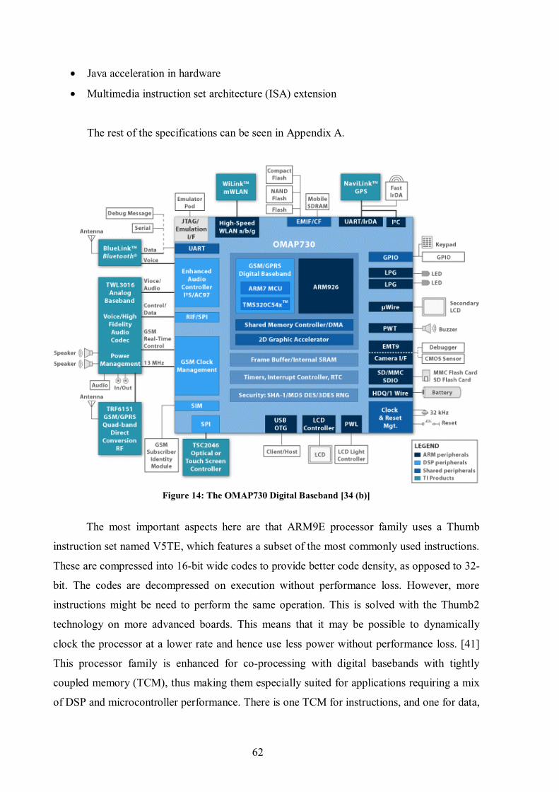
62
• Java acceleration in hardware
• Multimedia instruction set architecture (ISA) extension
The rest of the specifications can be seen in Appendix A.
Figure 14: The OMAP730 Digital Baseband [34 (b)]
The most important aspects here are that ARM9E processor family uses a Thumb
instruction set named V5TE, which features a subset of the most commonly used instructions.
These are compressed into 16-bit wide codes to provide better code density, as opposed to 32-
bit. The codes are decompressed on execution without performance loss. However, more
instructions might be need to perform the same operation. This is solved with the Thumb2
technology on more advanced boards. This means that it may be possible to dynamically
clock the processor at a lower rate and hence use less power without performance loss. [41]
This processor family is enhanced for co-processing with digital basebands with tightly
coupled memory (TCM), thus making them especially suited for applications requiring a mix
of DSP and microcontroller performance. There is one TCM for instructions, and one for data,

63
referred to as the Harvard architecture. [42] Here, the microcontroller unit is an ARM7, and
the DSP is a TMS320 developed by Texas Instruments. This communication here is done
through DSP extensions to the instruction set. According to Flynn’s Taxonomy from 1966
this is referred to as Single Instruction, Multiple Data (SIMD). [43] The SIMD instruction set
is as an extension to the regular instruction set, but this is on most boards superseded by the
NEON technology – both proprietary –, which deals with the shared instruction set. It is
intended to “accelerate the performance of multimedia and signal processing applications
including video encode/decode, 3D graphics, speech processing, compressed audio decoding,
image processing, telephony and sound synthesis.” [44] ARM has also developed an own
compiler to let programs make better use of this instruction set. There are four broad
categories of instructions: data processing instructions, load and store instructions, branch
instructions, and co-processor instructions which take care of giving the coprocessors their
proper data and instructions.
All this is handled “automatically” and need not to be worried about for the Linux
implementation, which can contain a single-processor software structure. However, a Co-
processor Shared Memory Interface, CSMI, is implemented as a driver for Linux on the
OMAP boards to provide communication between the ARM7 and the ARM 9 cores. This is
intended for communication with the phone-specific and/or network specific parts, and Linux
communicates with the interface through an abstraction layer as a TTY device or through the
TCP/IP stack.
Further, the board has hardware Java acceleration through the Jazelle technology,
which allows execution of Java byte-codes in hardware. At last, this processor family
supports Embedded ICE-RT logic, which is enhanced JTAG-based software debug facilities
that better meet the needs of real-time system development.
A contradiction in the specifications from TI here is that they claim first that it has an
ARM926TEJ core subsystem, which implies that it has a Thumb® instruction set. They do
however not mention this feature in the text and the referred architecture in the list is the
ARM926EJ. This is because it is the ARMv5TEJ instruction set that is used which include the
16-bit fixed point DSP instructions. [45]
4.3 Buses and Interfaces
Linux supports a number of buses and interfaces. Some of the interfaces in Figure 14
are used of the ARM processor, some of the DSP, and some of both. The AMBA bus

64
architecture has already been mentioned, but as seen in the figure there also are many more.
Here is a brief introduction to some of them. Some of the names are self-explanatory or not of
great importance and will not be discussed further.
4.3.1 JTAG
When porting Linux to a new board or when debugging the kernel itself, this is not
possible to do on the device. Some kind of debugging interface that provides direct hardware
control over the software is needed. The solutions to this are usually quite expensive. [7]
suggests a BDM (Board Debug Module) or a JTAG (Joint Test Action group, an IEEE
standard) interface that rely on special BDM or JTAG functionality embedded in the CPU's
silicon. The debugger is connected to special pins of the processor, which allows complete
control over the CPU. The PCI bus connector has pins for JTAG, and there also exist open
source JTAG software. JTAG is the name commonly used, while the real standard name is
Standard Test Access Port and Boundary-Scan Architecture. JTAG and BDM are much less
expensive and much less complicated than In-Circuit Emulators (ICE), but ICEs do require
the purchase of special hardware and software. Since CPU manufacturers do not like to give
away their secrets, this equipment is also expensive. Some BDM and JTAG debuggers require
specially modified version of the gdb debugger. Either way, the debugger should be able to
deal with the standard GNU development tool chain and the binaries generated using it
transparently.
4.3.2 UART
UART is a Universal asynchronous receiver/transmitter, which can translate between
parallel and serial interfaces. For that it uses a shift register. UART is often used for
communication with embedded systems through RS-232, which is the standard computer
serial port. It may be used as the system console to display boot messages or as a standard
TTY device. It may also be used as a kernel debugger interface.
On the example board here it is an Embedded ICE-RT solution that is chosen on the
main board to better meet the real-time requirements. ICEs also use JTAG as the transport
mechanism. The debug board is connected through UART. In general the solution chosen
depends on what is offered by the board vendors.

65
4.3.3 EMIF
The External Memory Interface, EMIF is an interface found on TMS Digital Signal
Processor (DSP) devices or applications processor, such as the one in Figure 14. Normally,
the EMIF connects the processor to different types of memory devices such as SRAM, flash
memory, DDR-RAM, etc. The data bus is typically 64 bits, 32 bits, or 16 bits wide. The
OMAP 730 supports to kinds of EMIF: EMIF Fast (EMIFF) and EMIF Slow (EMIFS), which
both are 16 bits. EMIFF supports SDRAM as an SDRAM controller. It can support one 16-bit
device or two 8-bit devices, but the external interface data bus is always 16 bits. A number of
devices can be connected with the EMIFS interface, for instance NOR flash, 8-bit NAND
flash and 16-bit NAND flash. The NOR flash is controlled by EMIFS directly, where as the
NAND flash is controlled by a software controller. [46, 47]
4.3.4 I2C
I2C, Inter-integrated circuit, is used to attach low-speed peripherals to a mobile phone.
It is typically used to turning on and turning off the power supply of system components,
changing contrast, hue, and colour balance settings in monitors, changing sound volume in
intelligent speakers, and controlling LED displays. This will be activated through the drivers
to support different operation modes, further discussed in chapter 4.4.
4.3.5 GPIO
GPIO is an acronym for General Purpose Input/Output. GPIO devices provide a set of
IO ports that can be configured for either input or output. GPIO chips may support the
common bus protocols like I²C, SPI and EMIF.
4.3.6 LPG, PWT, PWL, and HDQ.
Further there are four basic interfaces: The Led Pulse Generator (LPG) explains itself.
The Pulse-Width Tone (PWT) generates a modulated frequency signal and is for driving an
external buzzer. The Pulse-Width Light (PWL) can be used to save battery through switching
of the backlight to the LCD display, while HDQ is a battery communication protocol. [48]

66
4.3.7 USB OTG
USB OTG is an acronym for USB On-the-go. It is an extension to the USB 2.0
standard. It introduces two new protocols: the host negotiation protocol and the session
request protocol. It allows transfer between USB devices, where one part acts as a host and
the other as a client.
4.3.8 SPI
Service Provider Interface (SPI) is a software mechanism to support replaceable
components.
4.4 Power Management
The power requirements of embedded devices depend on their usage. For the mobile
phone it is about keeping the power consumption as low as possible to extend the battery life.
The most power consuming components of the mobile phone is the LCD display, processor,
and the different types of memory – in that order. Many of these components have different
operation modes to satisfy the power requirements. The device drivers for these devices
therefore need to take that into account. For the LCD screen unit, as an example, the solution
will be to turn off the backlight to various extents for standby mode, operation mode, idle
mode etc. For the processor it usually applies that the power consumed is directly
proportional to the clock frequency, and further the power consumed by the processor is
directly proportional to the square of the voltage. Embedded processors take this into account
by offering dynamic frequency scaling and dynamic voltage scaling.
On a laptop distribution the frequency is typically controlled by the operating system,
which measures the system load. As an example is this thesis written on an Intel Pentium M
processor 1, 70 GHz PC with a Kubuntu 6.10 Edgy Eft distribution with the 2.6.17.11 kernel,
offering dynamic frequency scaling with the levels 1700000, 1400000, 1200000, 1000000,
800000, 600000 Hz. This is found with the following command:
Often, a sleep mode is also supported by the boards, where the power to the processor
and most peripherals is turned off. This is the lowest power consuming mode, and requires
$ cat /sys/devices/system/cpu/cpu0/cpufreq/scaling_available_frequencies

67
some precautions to make it work properly:
• The state of the system (CPU, peripherals) must be saved in memory to be able
to restore the state of the system on wake-up.
• The wake-up latency must so short that real-time requirements are met.
• Some clock (usually external hardware clock) must run during sleep mode to
keep track of time.
• The wake up procedure must be appropriately incorporated into software (i.e.
the operating system). For example, if it exist any dependencies, the devices
must wake up in the correct order.
The operating system provides the mechanisms for enabling dynamic scaling of
frequency and voltage. It decides when various modes can be entered and how to support
wake-up. This is done through a power management framework where applications can use
different custom fitted policies to the embedded device, rather than policies implemented in
the operating system itself. In other words, it is controlled in User Space rather than in Kernel
Space. This is important since the various embedded devices have different requirements.
Also, the different device drivers must be able to exploit the power-saving modes of the
peripherals.
4.4.1 Power Management Standards
Linux mainly supports two different power management standards on laptops: ACPI
and APM, both these with roots in the x86 architecture. Some sources say ACPI lets the
operating system have more control as opposed to APM where the BIOS have more control.
Other sources say it is the other way around. The choice of which standard to support in the
kernel is done during configuration, and corresponding applications must be chosen as well.
The disadvantages by letting the BIOS control the power management can be
summarized in three points:
• The BIOS may for example look at the I/O devices to measure the activity,
thus it might set the system into a too low power mode when there are
complicated tasks running on the system not involving the I/O devices.
• It only detects activity on devices directly connected to the motherboard, and
not on the USB bus as an example.

68
• The standard is dependent on the BIOS, which can have different limitations,
interfaces, and bugs across the different systems.
ARM has developed a technology called IEM, ARM Intelligent Energy Manager
Technology. The technology uses a technique called Dynamic Voltage and Frequency Scaling
(DVFS) and an Adaptive Power Controller.
MontaVista uses something called Dynamic Power Management on OMAP boards. It
responds to system changes in the CPU core and on buses, and this open core project aims to
further develop the things achieved with ACPI. It is also partially compatible with IEM. How
Linux supports these drivers – as ARM show that Linux does – and how this comply with the
aforementioned standards is a subject for further research. Most probably they register with
the frequency scalar core as explained below. [49, 50]
4.4.2 Power Management on Linux
Linux offers a frequency scaling mechanism, which - as many other subsystems -
consists of two layers. The frequency scalar core in the file linux/kernel/cpufreqd.c is the
generic code that implements the platform independent framework. The platform specific
code to make the hardware do frequency transitions is implemented through frequency
drivers. All device drivers that need to be informed of frequency changes, as they also depend
on it, may register to the core. Included in the power management, the drivers must use a core
interface called pmaccess before operating on the hardware. This is to avoid operations being
done on a device that is not in the running state. The interface pm_dev_idle is used to put
devices to sleep. There exist various applications to control the frequency in user space.
Cpufreqd is a daemon that monitors battery level, AC state, and running programs, and
adjusts the frequency governor according to the specified requirements in the configuration
file. The ACPI daemon acpid listens to the file /proc/acpi/event for events to occur, and then
executes programs configured through configuration files to handle the events. [9:chap.3, 51]
The power management is some of the most crucial points on a mobile phone for
keeping a soft real-time responsiveness. It must by all means respond fast enough when
exiting from sleep mode or some other power saving mode that has switched off some
devices. Further, it must be able to deal with a task switch when the user is using a demanding
application and a real-time demanding task occurs, such as a phone call. The prioritised
interrupts in the 2.6 kernel are well suited to deal with this.
69
4.5 Storage and Memory Requirements
There are different kinds of memory and storage in multiple “levels” on a telephone,
as seen in board figures and as discussed earlier in the chapter. High-end feature phones,
smartphones, or music-centric phones as seen in the market today have various memory
requirements, both in terms of the amount of memory/storage space they need and the type
best suited to meet their usage schemes. First of all, the phones usually have a removable
storage, which can be used to store images, music, videos, applications, and so on. This is
referred to as the Memory-Stick. This can typically be 1Gigabyte and up to 4 Gigabytes.
Second, they have a semi-removable memory offered in the SIM card, which now offer up to
1 Gigabyte of storage. [52] This is typically used to store contacts etc., but the range of use is
expanding. This also requires the implementation of some security measures, but it is not the
scope of this thesis to discuss this.
The embedded memory and storage, however, cannot be removed. Nor can it be
replaced or upgraded after the handset has left the factory. This memory is often referred to as
external memory, as it is external to the ARM chip. It is the flash that mainly will be used as
the non-volatile storage. 16 to 32 MB is a typical size for that matter, which is enough for the
operating system and some other file storage for all the different phone categories mentioned
above. For example is the bzImage, vmlinuz, that contains a partially (big) compressed kernel
image on a laptop only 1.8 MB, but this depends on the compressing used. It could be as
small as around 512 KB. On a mobile phone it will probably be around 1 MB.
Before 2001, the flash type used in embedded systems was usually NOR flash. NAND
flash is known to be more error prone and use a different and more complicated processor
interface than NOR flash. This had made it “unusable” in mobile handsets. However, these
shortcomings have been overcome, and NAND flash is becoming more and more dominant.
The NAND technology is often called Multi-Level Cell (MLC) NAND, because two bits,
instead of one, can be stored in each cell. It is smaller, therefore more cost-effective than
NOR technology. In addition the prices on raw materials are dropping. The NOR technology
is said to have its upper limit as a competitive media at 32MB.
When NAND flash first was adopted, it was used in addition to NOR flash. This was
because NAND could not support eXecute In Place because of the MLC technology, and
hence it was only used as storage for user media. This was however overcome with the use of
DiscOnChip, which includes a small XIP boot block. From there the RAM can be initialised
and the kernel image can be copied and decompressed into SDRAM. This required SDRAM

70
of course. Either way, this task can be solved in Linux by the use of JFFS2 and initframs in
the 2.6 kernel’s MTD subsystem. Hence, it supports NAND memory as the only non-volatile
memory. Still, boards often support the use of NOR-NAND combinations to be able to
provide XIP, which JFFS2 does not.
In the years to come, built-in, high-density embedded flash drives (EFDs) will
probably be the state of art to handle the problems with the NAND flash, as it offers the flash
media and flash controller on the same chip, and sometimes even on the same die. The
technology of EFDs is evolving fast, and it is hard to keep up for the software world. The
paper where this last info is taken from is written on behalf of M-Systems, so the statement
must been viewed in the light of this. [52, 53, 54, 55, 56]
4.5.1 Storage and Memory Requirements
The memory requirements on a mobile phone are obviously highly dependent on the
type of phone one wants to build: storage capacity, different requirements to peripherals, the
operating system configuration, etc. On the example board presented here, an internal SRAM
is 384 KB, where 192 KB are dedicated to an internal frame buffer. This is used by the digital
baseband subsystem.
There further is 16 KB internal secure RAM where a part of it – usually 13-15 KB –
may be used by the secondary boot loader image during booting. One must take care not to
supersede that size. Most probably it will be a U-boot image on this board, so it is usually not
a problem. The other part is used by the primary manufacturer boot loader, loaded in from
ROM. This is a concept known as shadowed ROM; the content from the relatively slow ROM
is loaded in to a faster internal RAM and masks itself as the ROM with the initial start-up
code. The secure part of the RAM and ROM, as specified in appendix A, is that the secondary
boot loader image must be digitally signed so the primary boot loader can verify it. This RAM
space will be reclaimed by the operating system when it boots.
Up and running the external RAM required by a full Linux will lie in the range of 16-
32 MB. It is the applications that will require most RAM, so again this is case dependent.
Viewing the different alternatives on the market however, the OMAP730 is a very good
example board with representative memory sizes that will be used these days.
The OMAP 730 board has support for 128 MB of mobile SDRAM (SDR or DDR),
and 256 MB Flash which may be both NOR and NAND. When it comes to the Linux image
the compressed image has already been discussed, and does not need more than 2Mb of flash

71
storage, but this will also be copied and extracted to the external RAM. The image may be
loaded in from various locations in various ways during development and debugging. Jumper
settings on the boards can “remove” memory and thus change the physical memory map.
In addition which file systems - such as JFFS2 and CRAMFS - that are being used also
influences the use of storage and memory. The secondary boot loader is instructed
accordingly as will be discussed. In addition space is required for the compressed root file
system image, memory map, boot loader image, and other booting parameters.
The board is also equipped with dedicated cache for the different processing units. The
memory architecture for the applications subsystem follows the Harvard architecture for the
cache and internal memory, as opposed to the von Neumann architecture for the external
memory. In the Harvard architecture there are physically different paths and storages for
instructions and data to the applications processor. The Instruction cache – I-cache – is 16
KB, and the data cache – D-cache – is 8 KB on this board. The addresses to the data and
instructions in these caches are the ones that are located in the data – and instruction TLBs.
The von Neumann architecture makes no difference of data and instruction and the board does
not have a tightly coupled memory to the external memory. [57]
4.6 Summary
One of the main differences between the mobile phone hardware and the PC hardware
is typically the memory, the power, the interfaces and buses, the telephone part, and the size.
This may seem like pretty much everything. But besides the fact that considerations regarding
the composition of memory types and amount, power managing standard, etc. must be taken
up front, the configuration of the kernel is pretty easy. Because Linux is used so much on both
embedded systems in general and mobile phones in particular, it has a well-developed support
for the buses and interfaces discussed in this chapter. These work very well with the system
layout discussed in chapter 3.
Further, the display technology for embedded devices is evolving quickly to support 3-
D, and the need for integrated 3-D graphic engines will soon appear among applications as
well. An example can be the MALI technology developed at NTNU, which today is acquired
by ARM. This will further increase the need for memory and a fast operating system. Video
conversations are already a feature that is in use, so to be able to establish it as a de-facto
operating system for mobile phones, Linux will have to be on top of the emerging technology.
Linux has an advantage through its virtual frame buffer here. As mentioned has the 2.6 kernel

72
shown in tests to be closer to a real-time operating system than the 2.4 kernel.
Externally there are many of the devices that are getting the same interfaces as those
that already are on the computer: the USB, Ir, Bluetooth, and WiFi. In many ways the phone
is getting more and more like an ordinary mini computer combined with a “dongle”. Linux
has an advantage as a mobile phone operating system in that manner since the different
drivers are already well developed for those interfaces. The exception lies within the fact that
it still is a mobile phone, so that it has to connect with the GSM/UMTS network. The DSP
and the RF interfaces etc. will still remain present for the conventional conversations, though
with added features and increased speed. But one must remember the mobile phone is unique,
and will never be a clean merge of a computer and a phone. It will rather develop to a
powerful device that opens up completely new areas of usage. [58] By focusing on getting
reliable, well defined, and portable modules for the basic functions that are likely not to
disappear, Linux can be able to get a head start on other operating systems. The modules
should then be independent of certain hardware on the higher-level abstractions, so that the
services provided by the kernel stays the same without, or with very little, modifications.
Very much like the MTD subsystem and the VFS does today. This will further increase the
portability among applications.

73
Chapter 5
BOOTING LINUX
Linux has proven to have a very flexible booting process. This is much due to the
secondary boot loaders that are being used, and because Linux was designed to boot in
environments with multiple operating systems or kernels. This has given it a well-suited boot-
design for mobile phones as well, especially during development. In this chapter the
development- and debug set-ups will be discussed, before the boot process is discussed
together with some key elements. Finally it will be discussed how the boot process can be
improved.
5.1 Host/Target Development and Debug Set-up
Before transferring anything to the target hardware in a development project, the
host/target development environment and thereafter a debugging environment must be set up.
There are mainly three host/target development architectures. The first is a linked set-up
where the host and the target are permanently linked together. This link is typically a serial
cable or/and an Ethernet crossover cable. In this set-up, the host contains the cross-platform
development environment. The target contains a boot loader, booting parameters, a functional
kernel, and a minimal file system. A cross development tool chain to be used for development
will be discussed in chapter 7. The target components may also be reachable through remote
components, for instance via the Trivial File Transfer Protocol (TFTP). Further, a Network
File System (NFS) using the mount command in the target is preferred during development as
the root file system. That way it is not necessary to transfer files between the host and the
target after every change. Then the target can access the files as if they were stored locally by
running the nfsd daemon on the host, and making the appropriate files available for the target.

74
This is the most common development set-up. The NFS requires a booted kernel to operate. A
possibility during development is to use NFS, and then copy the final root file system image
to the target from the NFS.
It is also possible to use a removable storage set-up where the storage device is written
to by the host and then transferred into the target to boot the device. Then the target only
needs to contain a boot loader. Another variant of this is where the target does not contain any
boot loader, but where the host could write to a flash chip, which has a socket in the target. It
could then be written to by the host and afterwards inserted into the target. This is a popular
set-up during the initial set-up of an embedded system. Later, one can switch to a linked set-
up.
The third variant is a standalone set-up where the development is carried out on the
device itself. This is mainly done on larger PC-based embedded systems and will not be
considered here.
For the host/target debug set-up there exist three different kinds as well: A serial line,
a networking interface, and special debugging hardware. The serial line is the simplest, but it
has limited speed. The use of a networking interface solves this problem and provides the use
of many network connections over the same physical network link. Of course, this requires
the presence of a network stack, such as TCP/IP. Since the networking stack is found in the
kernel, it cannot be used to debug the kernel itself. This must then be carried out over a serial
link. The two first methods mentioned above do require a minimum of software to control the
primitive I/O hardware. When porting Linux to a new board, or when debugging the kernel
itself, the third and preferred method is by the use of UART and a debug board.
The software used in the early stages to communicate with the board is known as
terminal emulators. The most common one used is the Minicom, which uses the serial port.
The only precaution to take is that the rights to the port are correct, and installing the program
if it not already is. It is started with the command minicom. [59]
5.2 Booting the Board
With the basic operating system functionality and the basic hardware architecture
discussed, the process of booting up the Linux system can finally be described. The booting
process of all operating systems depends on a boot loader which task is to load software for
the operating system being able to start, where the last software loaded is the kernel or
operating system itself. The kernel then conducts initialisation of its own before it set up a

75
proper environment for the C code to run. The hardware cannot do this by itself. As the
loading of a program needs an operating system, a boot loader resembles an operating system
to the extent that it can load programs into memory. Thus the system “pulls itself up by the
bootstraps”. The boot loader is highly dependent on the target’s hardware, as it is the first
software to run. The boot process can be divided into stages, which will be described in the
following.
During the system start-up there are usually four main components in use: a primary
boot loader (bootstrap loader), a secondary boot loader, the kernel, and the init process.
5.2.1 Boot Configurations
On an embedded device there are three configurations used to bootstrap the system
during development: the solid storage media configuration, the disk configuration, and the
network configuration.
Figure 15: The solid-state media configuration [7]
In the solid-state media configuration, as seen in Figure 15, there are 4 separated parts.
The boot loader is often contained in a protected area of the media. However, whether this
area has the lowest address range or the highest address range is dependent on the device.
Because of this, many flash devices are provided in both top boot and bottom boot
configurations. The kernel may also be located in the root file system as long as the boot
loader can read from it. The kernel and root file system can also be packaged as a single
image that is uncompressed in RAM before being used. Everything is dependent on the
configuration of the boot loader, which is dependent on the hardware, but usually all the
configurations can be categorized using the following criteria: flash memory use, RAM use,
ease of upgrading, and boot-up time. Initially, the boot storage is programmed using a device
programmer or through the CPUs built in debugging capabilities such as JTAG or ICE.
Commercial boards usually come with appropriate pins for these debuggers, and this can also
be seen in the OMAP730. Once that a boot loader is programmed the system can be
reprogrammed/upgraded at a later time. This will be done either be by the use of the boot
loader, or through Linux’ MTD subsystem.

76
A disk configuration is mainly attractive for the development phase of an embedded
system. If a device mimicking a hard disk is being used in the target, such as Compact Flash,
this configuration is probably the best choice. Also if customisation of a mainstream
distribution to fit the target device is wanted, the disk configuration is helpful.
The network configuration is, as mentioned, especially a good choice in the early
stages of the development. It gives the developer the ability to exchange data and software
between the workstation and the target rapidly, without having to reprogram the target. This is
done either by having both the kernel and root file system or just the root file system on a
solid-state storage device, which is loaded via a network link. If the kernel is stored on a
network media, the kernel is downloaded using TFTP. In either case, the root file system is
mounted via NFS. To locate the TFTP server the boot loader may use BOOTP/DHCP. In that
way it avoids the need of a preset IP or to find either the TFTP server or the NFS server. The
“problem” of this configuration is the need of a server. In the Linux world, such a server is
normally not a problem. [7]
5.2.2 Boot Configurations and Das U-boot Boot Loader
The type of boot configuration influences the choice of the boot loader. It is needed to
identify the boot configurations that are likely to be used during the development of the
system and in the final product. Then, the boot loaders that will satisfy the chosen boot
configurations must be selected. For example, not all boot loaders can boot kernels from a
disk device. There are many boot loaders available, but there are one particular alternative
that works with most embedded ARM systems and stands out as a “standard” ARM boot
loader: U-Boot.
U-Boot is a universal loader based on earlier PPCBoot and ARMBoot. It also includes
a monitor, which is a command line interface used for debugging, reading/writing memory,
flash reprogramming, configuring etc. It is the richest, most flexible, and actively developed
open source boot loader available. It supports booting of the kernel through TFTP, from an
IDE or SCSI disk, and from a DOC. U-Boot supports JFFS2 reading as well. [7]
Many hardware manufacturers provide their products with their own boot loader. It is
later possible to replace this with a custom-built boot loader, i.e. the boot loader binary, of
own choice. Whether the boot loader binary will be transferred to the phone with a custom
built boot loader, or by the use of JTAG, will not be covered here. This process consists of
replacing whatever is in the boot section of the memory. [60]

77
5.3 First Boot Stage
For an embedded device there are 4 main stages in the booting process. In the first
stage the ROM stored code does some initialisation on low-level hardware by polling the
connected ports. It does this by sending its ASIC_ID (see definition) symbols through the
UART and USB interfaces in this case. This is to see if any external device is connected –
typically a developer host – which then is signalling constantly. The code (i.e. the primary
boot loader) stored in the designated boot address on a device is board specific. All CPUs
fetch their first instruction from an address pre-assigned by their manufacturer. This address
refers to a solid-state storage device where this primary, fabric-included bootstrap loader is
located. The storage devices used here was discussed in chapter 4.7. On the x86 architecture
this stage is when the BIOS runs the Power-On Self Test (POST). This storage is not
necessarily the same location as where the secondary boot loader is stored. During
development the secondary boot loader can be fetched from a number of places, as described
above. The software in this location is responsible for bootstrapping Linux, usually from
RAM. RAM is usually remapped to the physical address 0x00000000 at this point, as the
ROM will not be used until next boot. From here the secondary boot loader can run.
5.4 Second Boot Stage
During the second stage the boot loader invoked in stage one verifies the system
components, uses the memory map and locates the different kernel images. The boot loader
then sets up its own user interface. On a regular pc with several operating systems, this is
when one can choose which operating system – or kernel version – to run. On Linux it is all
about telling the boot loader where to go next, since it was designed to coexist with other
operating systems.
The boot loader then loads the chosen kernel image and possibly the root file system
image into RAM. This is because RAM is quicker than the permanent storage. The kernel
image may be stored in various places. It may for instance be located on the root file system
itself if the boot loader supports reading from it, such as with U-boot. U-boot can read from
JFFS2 by using an fsload command. In that case the kernel image will usually be located on
the under /boot. Further, the kernel image is in a compressed file system, and must be
extracted to RAM. The kernel image is still compressed, as the zImage (max 512 KB) or
bzImage (more than 512 KB) contain certain hard coded parts that are un-compressed
78
assembly code that will be used before the entire image is uncompressed.7
5.5 Third Boot Stage
In the third stage the kernel is called, possibly with special booting parameters such as
where to find its root file system. It is necessary for every Linux system to have a root file
system for the kernel to mount, as this will contain the init program to be used in the last
stage. If a RAMdisk is used as the root file system, that image is loaded in the previous stage
at the “same” time as the kernel. The kernel has code to detect this. In that case the kernel
image will not be stored on the file system. The two images may be stored as a single boot
image for the boot loader to use, though the most usual solution is to store them in separate
images. This is a concept called initrd, which can make better use of a RAM disk on an
embedded system like a mobile phone. An initial RAM disk image, initrd.img, can be used
for a root file system for example based on EXT2 or CRAMFS, and possibly SQUASHFS.
The kernel will find this with the “root=” boot parameter passed in the third stage, and later
mount it. Thus, in that case the boot loader will have loaded the RAMdisk image in the
previous stage.
In the 2.6 kernel some of this changes, and the following scheme is most efficient to
use: The root file system image that will be extracted into RAM may be a file system only to
be used only during booting, and can be used to mount a definitive root file system using the
pivot_root() system call once initialisation is done. This is an initial RAM disk file system,
intitramfs.
The 2.6 kernel can have the content built in the kernel by placing the content in the
place directed to by CONFIG_INITRAMFS_SOURCE during the kernel configuration.
Usually the content will be the code discussed in the following, such as init. The content can
very well be custom-fitted (not general purpose) to be used with a mobile phone that usually
requires a lot of security measures taken. This makes Linux suitable with any kind of
encrypting schemes used during booting. To build it in the kernel there are three ways. The
content is either way pointed to by a CONFIG_INITRAMFS_SOURCE config option to the
kernel. The content can be a cpio.gz file, which the kernel will link to, a directory that the
kernel build will create a cpio.gz file from, or it can be a configuration file that tells the kernel
what to do. The latter is most flexible.
7 It was widely discussed in various mailing lists and on the MTD web pages whether JFFS2 supports XIP.
This is however rather pointless since it will operate really slowly due to the relatively slow flash.

79
The content can also be supplied in an external file that is not built in the kernel. To
avoid any GPLv2 violations, this content can be stored in a cpio.gz file, which the kernel will
auto detect if it has initrd enabled and extract into the initramfs to be run. It will overwrite any
built in equal code, which by default is run first.
It must be emphasized that this is not the same file system such as CRAMFS or ext2 in
RAMdisk, as that imitates a disk and is used for root file systems living in RAM. Initramfs is
an instance of what is referred to as tempfs, which originally was intended for the cache to be
mounted in RAM and flushed on reboot. The initramfs file system cannot be moved or
unmounted when running, as Linux do not allow its root file system to be unmounted. It is a
fully functional RAM file system. [61, 62]
Back on track, the loaded kernel runs the setup() function and reinitialises the
hardware devices, as Linux do not rely on the BIOS initialisation. This also enhances
robustness and portability. The kernel then jumps to a first startup_32() function, which
decompresses the kernel, and shows the well-known “Uncompressing Linux ...”-message
during start-up. A second startup_32() function initialises high-level kernel functionality and
mounts the root file system through Process 0. This will then be a mounted uncompressed
RAMdisk or an initramfs, or possibly another file system.
Finally the start_kernel() function is run, which in turn does a lot of initialisation and
shows the “Linux version 2.6.xx . . .” –message on the screen. It is start_kernel() that
initialises the earlier discussed subsystems such as the paging (page_init()), memory manager
(mem_init()), interrupts (init_irq()), cache(kmem_cache_init()), system time and
date(time_init()), and threading(kernel_thread()). After a cpu_idle() call, the scheduler takes
control and the kernel thread then creates the init process, which runs as long the system is
running.
5.6 Fourth Boot Stage
The init process takes care of the rest of the start-up in User Mode. It calls the init()
function, which issues the execve() system call. This runs the executable init program, which
is controlled by the inttab file. The program is then referred to as Process 1, and is the first
regular C application to run. The task of this program is to start various applications and some
key software components through rc.sysinit and other rc-scripts related to different runlevels.
Process 1 can mount the real root file system if initramfs was used.
The kernel has no requirement to the init program, so it is possible to set any program

80
desired as init. This is done with an init=PATH_TO_THE_INIT boot parameter. This is not
recommended in most cases however, since it might result in a kernel panic and perhaps a
useless system. [9:chap.4, 10a, 63]
5.7 Standard System V init
There is an init program that follows most Linux distributions that is named Standard
System V Init.8 It resembles the init found in UNIX and gives a great flexibility to configure
the start-up of a system. The package includes the following commands: halt, init, killall5,
last, mesg, runlevel, shutdown, sulogin, utmpdump, and wall. The package cross-compiles
easily and is available at ftp://ftp.cistron.nl/oub/people/miquels/sysvinit/.
System V init introduces runlevels in /etc/inittab, and /etc/rc.d defines which services
that will run on each level. When going from one runlevel to the next, the services started in
the first shuts down, and the ones in the next runlevel are started.
The different runlevels are represented in Table 1.
Table 1: Linux Runlevels
On workstations the runlevel is usually 5 at system start-up. If no access control is
necessary, it can be set to 1 on embedded devices.9 The runlevel can be changed later on using
either init or telinit, which is a symbolic link to init. This will communicate with the original
init through a /dev/intitctl FIFO. However, in a mobile phone, which seldom is run as a multi-
user system, such flexibility is overkill. Therefore BusyBox init is more usual on embedded
systems. [7:chap.6]
8 System V is a name used because of the UNIX legacy, as it was one oft the more important UNIX releases.
Many programs on a UNIX system run on Linux, and the other way around.
9 Setting the runlevel to 1 is an easy trick for being able to change the root password if it has been forgotten.
0 System is halted
1 Only one user on system, no need for login
2 Multi-user mode without NFS, command-line login
3 Full multi-user mode, command-line login
4 Unused
5 X11, graphical user interface login
6 Reboot the system

81
5.8 BusyBox init
BusyBox provides most of the init functionality an embedded systems need. It also
saves the developer from keeping track on an additional package, since it is included in the
BusyBox package.10 However, it does not include runlevel support.
/sbin/init is a symbolic link to /bin/busybox, and therefore BusyBox is the first
application to run on the system. The init routine of BusyBox does the following:
1. Sets up signal handlers for init.
2. Initialises the console(s).
3. Parses the inittab file, /etc/inittab.
4. Runs the system initialisation script. /etc/init.d/rcS is the default for BusyBox.
5. Runs all the inittab commands that block (action type: wait).
6. Runs all the inittab commands that run only once (action type: once).
7. Once it has done this, the init routine loops forever carrying out the following tasks:
8. Runs all the inittab commands that have to be respawned (action type: respawn).
9. Runs all the inittab commands that have to be asked for first (action type: askfirst).
At point number 2, BusyBox determines whether the system was configured to run the
console on a serial port, for instance by passing console=ttyS0 as a kernel boot parameter.
If no /etc/inittab file exists, BusyBox uses a default inittab configuration. This means
that it sets up default actions for system reboot, system halt, and init restart. In addition it will
start shells on the first four virtual consoles /dev/tty1 through /dev/tty4. If the /etc/inittab
exists, BusyBox will parse it and store the commands inside internal structures so that they
can be carried out at appropriate times. There is an example inittab file in the documentation
that follows BusyBox. Each line of the file follows this format:
This is actually the same format as in System V init, but here the runlevel field is
ignored and can be left blank. In addition the id field has a different meaning. Here it refers to
which TTY is responsible for starting the process. This field can be left blank if the process is
not to be started in an interactive shell, but for the sh shell it must be specified. The process
10 The BusyBox package contains a reduced set of file, shell, and text manipulation utilities that are found on
every Linux host.
id:runlevel:action:process

82
field specifies the path of the program to run and its command-line options. Table 2 specifies
the eight actions to be applied to the processes. [7:chap.6, 64]
Table 2: BusyBox init actions [7:195]
5.9 Faster Booting
For a mobile phone it is important to get the hardware responsive to user input as fast
as possible. This requires that the window manager and everything related to user interfaces
are up and running. As opposed to a router, for example, the networking stack need not be
running at this point, and may be initialised at a later point. There are mainly three booting
stages that may be considered when one look at the booting time:
• Boot loader: POST, locating kernel image, copy (and uncompress) kernel image into
RAM.
• Kernel turn-on: Driver initialisation, set up subsystems, file system mounting, transfer
control to user space
• User-Space turn-on: Sequentially starting of services, loading of kernel modules
The copying and uncompressing of the kernel is dependent on the kernel image size, if
one ignores the technological issues. Naturally, it is more time consuming copying and
uncompressing a large kernel image than a small one. This could also be avoided by
implementing XIP. As described earlier it means that instead of copying the kernel image to
RAM, it is run directly from flash memory. However, the downside by this is that this slows
the execution of the kernel as flash operates slower than RAM. One also needs more
expensive flash storage space, as the image cannot be compressed. Further, changes to the
Action Effect
sysinit Provide init with the path to the initialisation script.
respawn Restart the process every time it terminates.
Askfirst Similar to respawn, but is mainly useful for reducing the number of terminal applications running on the system. It prompts init to display "Please press Enter to activate this console." at the console and wait for the user to press Enter before restarting the process.
Wait Tell init that it has to wait for the process to complete before continuing.
once Run process only once without waiting for them.
ctrlaltdel Run process when the Ctrl-Alt-Delete key combination is pressed.
shutdown Run process when the system is shutting down.
restart Run process when init restarts. Usually, the process to be run here is init itself.
83
flash drivers must be made, as they cannot operate from flash. They may run out of RAM.
However, this can be avoided with the use of CRAMFS and a XIPed solution. This will then
save some RAM space. If a XIP solution is not chosen, copying-time can be reduced by using
DMA to transfer the image from flash to memory.
In the second stage a simple trick is to use the quiet mode, which disables kernel prints
during booting. This is done with a –quiet to the command line. The messages can either way
be viewed later using the dmesg command. Another trick is to hard-code known system
values in the kernel, such as loops_per_jiffies, where jiffy is a time period that depends on the
processor clock frequency. The system uses this to calculate how long tasks take to complete.
Other known values can be hard-coded in the drivers. Finally, a proper root file system must
be used. For example, it is known that JFFS2 is slow to boot whereas CRAMFS and ROMFS
are faster. JFFS2 also requires 4 MB of RAM for indexing for a 128 MB flash.
In the third stage it is possible to making kernel modules into a single module since it
takes shorter time to load one than many. Here concerns must be taken to the performance of
the running system. All modules might not need to be loaded at this point. Finally, the RC
scripts that start system services sequentially may be tuned to run in parallel, further reducing
the booting time. This may result in a significant reduction, but care must be taken regarding
possible dependencies between services. [9:Appendix A]
There exist several methods to measure the system boot-up time, easily found on the
Internet.
5.10 Summary
This chapter has shown the details of the flexible Linux boot process both regarding
development and debugging hardware, and how Linux cooperates with the hardware. Special
emphasis was put on the improvements of the 2.6 kernel. This flexibility especially eases the
development phase of a Linux driven mobile phone, but also the choices of solutions for file
system and memory combinations as shipped from the fabric.


85
Chapter 6
COMMERCIAL AND OPEN SOURCE
DEVELOPMENT SOLUTIONS
In this chapter two more or less commercial solutions in addition to two open source
solutions will be investigated in terms of development environment and other libraries on a
theoretical level. This will show the potential of Linux on both a commercial and an open
source level as a mobile operating system. Trolltech will be discussed primarily on an
application level and MontaVista on kernel enhancements. An insight into the broad IPC
mechanisms provided by Trolltech is also provided. OpenMoko will be discussed with a focus
on drivers and libraries, whereas the information on Ubuntu Open and Embedded is still
scarce due to the recent start-up, so there is not much information to be found.
6.1 Trolltech
Trolltech is a Norwegian company with two product lines: Qt and Qtopia. They were
one of the first companies in the world to use a dual licensing model. The business model
allows software companies to provide their products for two distinct uses - both commercial
and open source software development. This type of licensing is based on Quid Pro Quo –
something for something. Either the customers of Trolltech may release their software under
the GNU Public License, GPL, or they may purchase the appropriate number of commercial
licenses from Trolltech and release the software under a license of choice. Trolltech claim that
this strategy will make them able to provide the best cross-platform development tools in the
world. The commercial license makes the money, and the open source licenses ensure quality
and stability of the products delivered by Trolltech. Further, they claim their open source and

86
commercial developer ecosystem has as many as 150,000 developers worldwide. [65, 66, 67]
6.1.1 Qt
Qt is a cross-platform C++ application development platform. Qt includes the Qt Class
Libraries, which is a collection of over 400 C++ classes. Further it includes Qt Designer for
rapid GUI and forms development, and other tools as well. “The Qt class libraries aim to
provide a near-complete set of cross-platform application infrastructure classes for all types of
C++ applications.” [68]
6.1.2 Qtopia Core
Qtopia Core is a version of Qt that is a C++ application development framework
intended for single-application devices powered by embedded Linux. It provides the same
API and tools as other versions of Qt, but it also includes classes and tools to control an
embedded environment that will be discussed in the subsequent parts.
Qtopia Core, as with Nanowindows does not need the X Window System opposite to
Qt/X11, as it also may provide an entire window system of its own. This is one of its primary
strengths. It can use the Linux virtual frame buffer or it can use graphical interfaces to the
devices directly. It also support accelerated graphics. The Qtopia Core library replaces the X
Window Server, X-lib, and Qt/X11 as seen in Figure 16. This window system also uses a
server, where the clients communicate with the server using shared memory (i.e. both parties
read and write to it). It supports raster and vector graphics, and 3D graphics through the
OpenGL ES API. Qtopia Core does further provide non-graphical components such as
networking and database interaction. Unwanted or unused features of Qtopia Core can be
excluded to further reduce the footprint. [69]
Figure 16: The Qtopia Core Architecture [69]

87
6.1.3 Qtopia Phone Edition
Qtopia Phone Edition is the phone intended version of Qtopia Core and Qtopia
Platform. The Core provides the windowing system, core widgets, and operating system
abstraction, while the Platform includes the telephony library and the PIM-library (Personal
Information Manager). A part of Qtopia Platform is the application manager system Qtopia
Server/Launcher. It controls the multi-application environment, which handles the telephone
related tasks in addition to other applications and is always running. The device must always
be able to receive a call, and this is also supported further down, in the kernel, as discussed in
earlier chapters. It controls IPC and application life-cycle management including multi-
tasking. Qtopia Core IPC will be explained in chapter 6.1.5.
The Qtopia Phone Edition is in other words an application platform and user interface
for Linux-based mobile phones that in addition to the Qtopia Core and Qtopia Platform
functionality comes equipped with pre-integrated applications such as a PIM, calendar,
messaging for SMS, MMS and mail, games, clock, camera, and SIP based VoIP. It further
includes a HELIX DNA multimedia framework for support of playback and streaming of
MP3 and other audio and video formats such as AAC, WAV, H263, and MPEG4, all with and
without DRM. For the audio it uses the Advanced Linux Sound Architecture, ALSA. It
implements a safe execution environment (SXE) for the device and network when
downloading and running native applications, such as Java. SXE gives user applications
limited access to the system resources, and typically access is only given to the display,
network, and keyboard. Further, Qtopia Phone Edition supports most wireless standards, and
it has support for non-western writing system, predictive keypad-based typing, customisable
full-screen handwriting recognition, and on-screen keyboard input. The user interface is
customized and personalized through a theming engine.
Trolltech claims that Qtopia Phone Edition is the de-facto standard application
development platform and user interface for Linux-based mobile phones. The main
advantages are that it is platform and device independent with a straightforward development
environment. It has the source code available and open for customisation, of course depending
on the kind of licensing chosen from their product line. Up and running it requires between 24
and 32 MB RAM on a Linux platform. [70, 71, 72]

88
Figure 17: Qtopia Phone Edition diagram [72]
The hardware requirements of Qtopia Phone edition are listed below.
Development environment:
Linux kernel 2.4 or higher
GCC version 3.3.5 or higher
Footprint:
Standard build targets 32MB Flash ROM, 32MB RAM (including Linux)
Hardware platform:
All processors supported by Linux with a C++ compiler and frame buffer driver.
Verified on x86® and ARM® 9 & 11 chipsets, e.g. Marvell®, Freescale®, NXPTM and
NEC®.
6.1.4 Qtopia Greensuite #1 and Greenphone
The Greensuite #1 solution of Trolltech is a solution built on top of Qtopia Phone
Edition that includes software such as web browsers, media players, messaging client, and
video telephony from third parties. The Qtopia platform architecture provides a plug-in
framework with dynamic linked libraries that can also be used of second and third parties.
The Document API will not be discussed here. The product launch for Greensuite #1 will be
first half of 2007. [73]

89
Figure 18: The Qtopia Greensuite #1 Architecture [73]
Also, Trolltech have developed a dual licensed hardware component of the
Greenphone SDK. This SDK provides a complete environment for developing and modifying
application software for Qtopia Phone Edition on the Greenphone.
6.1.5 Qtopia IPC and Inter-object Communication
The Qtopia IPC is based on channels and messages in a modern Service-Oriented
Architecture manner. Objects or applications offer services that are published or can be
looked up and used by other objects or applications using loose couplings with the QCOP as
the base messaging protocol. “QCOP is a many-to-many communication protocol for
transferring messages on various channels. A channel is identified by a name, and anyone
who wants to can listen to it as well as send messages to it. The QCOP protocol allows clients
to communicate both within the same address space and between different processes.” [74]
Applications can send messages to and listen for messages by connecting to the receive()
signal on a QCopChannel. As it will be shown, it is a flexible protocol.
Within a mobile phone, Qtopia’s signals and slots (described shortly) are used for
sending simple messages between applications with QCOP as the communications protocol,
for example from Qtopia Platform services to user applications. This resembles the message

90
and queue mechanism discussed under the IPC section of chapter 3, and is called Qtopia
Services. Qtopia Services let all applications access generic services supplied by other
applications, such as the PIM, and may be used by an application to invoke a requested
service in the remote application. The application that shall provide a service can be chosen
by the system integrator or the end-user. “Each new service must be carefully specified as it
provides a system- wide API that can be invoked by other applications and the user. A service
should only be added if it:
• Provides new functionality not already provided by a pre-defined service.
• Is useful to other applications.
• Is well defined within the scope of the application type, e.g. openURL(QString
<url>) for a web browser.
• Avoids adding unnecessary functionality which could complicate the user
interface.”
[75]
Further, the IPC system consists of three major classes; The QtopiaIpcAdaptor,
QtopiaChannel, and QtopiaIpcEnvelope. The QtopiaIpcAdaptor is the preferred way to
interface with the system, while the QtopiaChannel and QtopiaIpcEnvelope classes are
provided to ease the transition between the Qtopia QCopChannel based systems. [76]
The signal and slot API first of all supports inter-object communication within an
application or program. An object uses a connect() call to relate a signal issued by another
object to a slot that treats the signal in some appropriate manner. An example can be where a
Quit-widget which signal clicked() is connected to an application’s quit()-slot. The
programmer can choose what to do with the signal, which here most naturally is to quit the
application:
Connections can also be made between different threads, since Qtopia Services also
uses the signal and slot mechanism as a basis for communication. Then it is used on different
applications, and hence it can be used on different mobile phones as well, for example in a
game where one can play against each other. Summarized, the QCop protocol supports the
signal and slot mechanism for inter-object communication between applications, within an
application, and between handsets.
Qtopia Data Sharing (QDS), is a form of remote procedure call implemented on top of
Connect(button, SIGNAL(clicked()), qApp, SLOT(quit()));

91
Qtopia IPC, which as its name implies provides data sharing. As an example, an application
can search for a (advanced) Qtopia Data Sharing service converting a jpeg image to bitmap
using the following code:
It uses SQL as the standard database for data sharing and increased performance,
though any other database engine may be used. The result given from the remote service will
give a key, which locates the data stored in the database. [77]
Another way of sharing data is Qtopia Data Linking (QDL), which link data across
applications with the use of globally unique references to objects. Links in an event calendar,
as an example, will when activated send a message to the Contacts application that displays
the contact data. The QDL requires no knowledge of the Contacts application, which may be
chosen by the end-user. Qtopia Data Sharing is more efficient than Qtopia Data Linking. [70,
78]
Another implemented IPC mechanism abstraction is pipes, found in the subclasses of
QIODeivce. The QIODevice class is the base interface class of all I/O devices in Qt. It can
handle data inputs and outputs as explained in chapter 3 and reads data from cache, files, and
sockets. All the IPC mechanisms are also accessible through command line commands and
hence scripts. [78, 79]
Qtopia Core also support something referred to as implicit sharing, using a form of
copy-on-write, which without the programmers notice shares classes used by multiple
processes to save memory. [70]
6.2 MontaVista
MontaVista offers an optimised Linux operating system and development environment
through their MontaVista Linux Consumer Electronics Edition. It is made for wireless
handsets and mobile phones with requirements for power management, hard real-time
performance, fast start-up, and small footprint, and is called Mobilinux. MontaVista a similar
solution to that of Trolltech, except that they also offer their own kernel. Therefore they also
are in close collaboration with board vendors, and offer solutions shipped with a board and all
the software. They collaborate with Texas Instruments for commercial Linux offerings on the
QDSServices service( "image/jpeg", "image/bmp" )
if ( service.count() == 0 )
qWarning() << "No jpeg to bitmap image conversion service
available";

92
OMAP platform and have other projects related to low-level issues such as Dynamic Power
Management focusing on improved power management for consumer devices such as mobile
phones. They also have a project on Variable Scheduling Timeouts that focuses on extending
the stand-by time of battery powered devices, and they have designed the Protected RAM File
System (PRAMFS).
For the Open Source Community they have contributed with much work where now
some of it has been incorporated in the official kernel release. An example is their work with
the Open Source Real-Time Project which goal was to reduce interrupt latency and task pre-
emption latency. Both the O(1) scheduler and the pre-emptive patch are now implemented in
the 2.6 kernel, as discussed in earlier chapters. Though they claim maybe too much of the
credit for these kernel additions, there is no doubt that they participated. MontaVista claims
to be the leading provider of commercial grade Linux for intelligent devices. [80, 81, 82]
6.2.1 Mobilinux
The current version of Mobilinux, version 4.1, is based on the Linux 2.6.10 kernel.
MontaVista has developed it with enhanced core capabilities, reduced footprint, rich
networking capabilities, advanced real-time support, and MontaVista’s own dynamic power
management. Their goal is, as expected, to reduce RAM and ROM requirements and
maximize battery and size performance. The core capabilities are enhanced with an event
broker, faster booting, and improved stability and reliability. Mobilinux has improved real-
time support and implements a fully pre-emptive kernel. It uses the reduced C library uClibc,
DirectFB on top of the Linux frame buffer, and supports SQASHFS as the compressed read-
only file system to be able to provide a reduced footprint. Other supported file systems are
PRAMFS, and JFFS2 and YAFFS with support for both NOR and NAND flash. It has ARM
Thumb support and implements application XIP. Mobilinux comes as a complete
development platform with a platform development kit (PDK) and an application
development kit (ADK). The platform development kit consists of Eclipse-based analysis
tools, CPU architecture cross tool chains, a Linux (board) support package with pre-built and
tested drivers, and target application packages. [83]
The ADK includes DevRocket, which is integrated development environment
delivered as standard Eclipse plug-ins, and contains much of the same analysis tools as in the
PDK. In addition to the features delivered by the PDK, the ADK has a virtual target
environment. The debug set-up is further made easy by automating the edit/compile/debug

93
cycle in one click.
Figure 19: The MontaVista Mobilinux 4.1 [84]
All in all, it offers a complete mobile phone software environment together with
Openwaves’ Phone Suite Version 7, as seen in Figure 19. [84]
6.3 The OpenMoko strategy
The OpenMoko camp, with its NEO1973 mobile phone, has taken on another business
strategy than Trolltech and MontaVista. They favour a complete open strategy, as any regular
PC intended open source Linux distribution.
The software of the mobile phone is based on the 2.6.20 kernel. It runs on a Samsung
board with 64 MB NAND flash and 128 MB RAM. At the moment it has GSM/GPRS, USB,
and Bluetooth support. It is equipped with a touch screen, and only two buttons for power and
for auxiliary devices. It uses U-boot as boot loader.
The only two components that not are free software are the GSM/GPRS Modem and
the AGPS (Assisted GPS). The AGPS chip gets it assistance via GPRS from an Assistance
Server which helps cut down the time used to determine the position of the mobile phone.
This is useful for emergency calls dispatchers, and in near future it might be required by law
to be able to access the mobile phone’s position in relation to emergency calls. [85] The
Hammerhead AGPS used in the Neo 1973 connects to the UART-1 and the UART-2 bus on

94
the board and uses a gspd daemon as plug-in driver. [86] It can also be used with I2C and SPI.
[87] The following information is available to the high-level software:
• Position data
• Library status
• Time-out and Packet Available
The high level software sends the following messages to the plug-in:
• Assistance data
• Positioning Commands
• Configuration Command
The AGPS driver has to be closed source by U.S. law, and thus the phone is only
delivered that way. If it is not, it is regarded as munitions (weapon or related to weapon). [88]
The GPS/GPRS Modem is Texas Instruments Calypso based, but not much info on it is
provided due to Non Disclosure Agreements (NDAs). It uses the UART interface however,
with standardized protocols. The software of the GSM/GPRS Modem and the A-GPS are
delivered as binaries. [89, 90]
6.3.1 OpenMoko Development Environment
This open source project also provides a development environment, namely the Open
Mobile Communications Platform (OpenMoko). The project intends to provide a completely
open standard framework for developing mobile phone applications, much like Trolltech's
solution. The phone comes shipped with a package manager to be able to take full advantage
of the all ready large Linux application community. “The Development Environment consists
of the Build Environment, the Development Tools, Development Server, Build Server, and
Development Workstations.” [91] The build environment to build the OpenMoko distribution
is made by using OpenEmbedded, which is a popular open source build system. [92] The
development tools are open source tools like Git (tree), Bugzilla (bug tracking), etc. All
components of the build server and development workstations are also based on open source
projects.
The key of OpenMoko’s business strategy is to trigger the open source community
first. With them they will be able to ensure increased revenues for both carriers and handset
developers. The idea is to let the users control their own environment of applications. The
handset manufacturers can get a reduced time to market and the carriers will experience a
large increase in data traffic. Applications may form the next generation of multi billion

95
industry similar to that of ringing tones. It’s a win-win situation for all three parts: users,
carriers, and handset manufacturers. [4]
The OpenMoko Platform is based mostly on libraries from existing open source
projects, such as GTK+. In addition to the closed source drivers, OpenMoko have added four
components to form the application framework: libmokocore, libmokonet, libmokopim, and
libmokoui. Figure 20 shows the complete OpenMoko platform, with the licensing on the left.
Figure 20: The OpenMoko Platform. [91]
Libmokocore aims to provide messaging between applications, switching on and off
devices, controlling light, volume, etc. through the dbus, which is a high-level interface to
IPC. The core also uses Gconf, which stores application preferences. [93] Libmokonet
provides high-level connection functionality, such as for the GSM and GPS, but also
Bluetooth etc. Libmokopim provides a high-level API to query the Personal Information
Manager. Finally, libmokoui provides API for providing UI events, such as playing an alarm
tone with the ALSA driver, but also GTK+ derived high-level widgets. [94]

96
6.4 Ubuntu Mobile and Embedded Edition
May the 5th, 2007, Matt Zimmerman, the CTO of Ubuntu announced on the Ubuntu
development mailing list, that there has been started an Ubuntu Mobile and Embedded
project. It is to be developed together with Intel due to their “new low-power processor and
chipset architecture.” [95] This is a tiny, low-energy chip designed for embedded devices such
as the mobile phone. It has the codename Silverthorne. It is a chip that will be one-seventh the
size of conventional processors and consume just 10% of the power, according to Intel. [96]
Further, according to [95], “the first release of this edition will be in October with Ubuntu
7.10.”
6.5 Summary
The solution offered by MontaVista as presented in this chapter resembles the
solution offered by Trolltech to a certain degree. However, it is very common to use the
Qtopia solution on top of the MontaVista kernel, as it is better for application development.
Trolltech do not touch the kernel, and by combining the two solutions, one combines the best
commercial developed solutions in the market. There is, however, not so much info to be
found on the details of the MontaVista solution. It proves that their “open source” is not as
open source as they claim it to be. One can easily find out what their solutions do, but not
necessarily how they do it. Their solutions such as DevRocket are delivered as pre-installed
plug-ins in the open source Eclipse, which is delivered under the Eclipse Public Licence
(EPL). Such plug-ins may either be derivative work or not. If it is not derivative, that is if it
just uses the interfaces or interact with the existing Eclipse, the “new” code can be licenced
under whatever licence chosen, as long as the existing code still is under EPL. This means
that the new source code do not have to be open source. This gives MontaVista the possibility
to charge money for their solutions. Further, EPL and GPL do not allow one to distribute a
combination of EPL and GPL licensed code (derived work), since EPL does not allow another
license to be applied to it, and GPL does require that all the derived work have to be released
under GPL. This means that if the plug-ins are considered to be derivative work, they cannot
be GPL’ed at all, neither the plug-ins nor the combination. [97, 98]
There could be written tons of books on the legal issues to these licensing issues, and
this will not be treated in detail here. However a few points are worth mentioning: There are

97
usually two main licenses used in open source project: GPL and LGPL. The Linux kernel is,
as known, distributed under GPL. So, one would expect the MontaVista kernel modules also
to be licensed under GPL, as it is a derived work of the kernel. However, common practice is
that the linking of binary modules is allowed, even though they are incorporated to the kernel
upon linking. This is a legal grey area, but this practice is allowed as long the modules can be
shown only to use standard services exported to modules by the kernel. That is, it must be
shown that the functionality implemented is not Linux specific. Therefore, MontaVista and
others can deliver non-GPL’ed binary modules.
The LGPL allows one to use an unmodified LGPL licensed program with any other
code, without having to distribute that combined program under LGPL. Thus linking
something proprietary with the C library, which is LGPL licensed, is perfectly acceptable.
The kernel is however not where MontaVista receive their major return-of-investment
(ROI). They make their money on services: the development framework solutions and their
customer support. Many of their improvements are shared with the open source community.
Further, Trolltech allows their customers to either use the open source version if they whish to
deliver their self-made solutions under GPL as well. Otherwise, Trolltech can sell a
commercial version, which is where they earn their money. If their open source version were
LGPL’ed, then they would have no source of income.
OpenMoko also offers much of the same, but then as completely open except a couple
of drivers. The advantages that the other vendors offer also apply for OpenMoko, but in
addition they take into account that there should be nothing hidden from the open source
community in accordance with trying to make their solution become a de-facto development
platform. This will be done through GPL’ing their development platform. Now, it must be
taken into account that the NEO1973 and OpenMoko are hyped by the community, and that
the project is already 5 months late. They have not completely revealed their planned business
strategy, and might have something hidden up their sleeve since they do exactly the opposite
of what Trolltech use as the key to their existence; they do not use a double license. Further, it
will certainly be interesting to see what the Ubuntu Mobile and Embedded project comes up
with.
Either way, these solutions provide pretty much the same advantages for the
developer: Reduced cost, reduced time-to-market, and reduced risks.

98
6.5.1 Reduced Costs, Reduced Time-To-Market, and Reduced Risks
As it will be shown in chapter 7, the start out of a self-made Linux embedded
operating system, may be more time consuming then one might think. Therefore, the
statements of the discussed vendors about their products leading to reduced costs do stick.
First of all, the use of Linux cuts the Bill of Material (BOM) due to a smaller footprint, less
use of memory, etc. Software projects costs, however, do not stop there: there are huge costs
related to development, maintenance, and testing as well.
For GPL and LGPL licensed code the runtime or distribution fees adds up to 0 dollars.
However, the time spent on collecting matching packages, making sure they interact correctly,
and then building applications usually take weeks and months, and naturally this cost a lot. As
will be concluded later, the money should be spent on developing applications. In addition the
components are depending on the board used, and the work might have to be done all over
again when a new component or completely new board is required. Further, as opposed to
competing operating systems, the commercial Linux vendors can take part in the open source
community and share and develop solutions there. Either they can develop, test and deliver
community-started initiatives, or they can start them themselves and trust the further
development and testing with the community. Either way it is beneficial for all parts.
All the time saved on a pre-built distribution can be used on developing applications.
Further, these vendors often collaborate with board producers, thus one can further reduce
time-to-market by not having to use so much time on choosing the correct board. This again
results in reduced risk. The product is pre-tested, the support can help one solve technical
issues quickly, and also legal issues in many cases.
6.5.2 To Choose a Pre-Built Distribution or not
Of course there are downsides by choosing a pre-built distribution. It costs some
money, it does not give a complete control of all the packages, it gives a dependency relation
ship to some degree, etc. In addition one needs to watch ones back to not to fall in a lock-in. If
one does need a very high degree of control over the contents of the system, a roll-out-you-
own solution might be advisable. Besides that, there is no straight answer to whether one
should choose a pre-built distribution or not. If one is chosen, there are many considerations
to take, and again they are case specific.
99
Chapter 7
CREATING A CROSS PLATFORM
TOOL CHAIN
One of the goals of this master project was to gain some experience with Linux
Mobile. There are two ways to do that; either one use something pre-built, or one roll out ones
own operating system. Having no experience at all with this in the beginning, it was therefore
chosen to experiment a little with both methods for as to being able to have an opinion on the
implications of them. As mentioned earlier is the tool chain creation vital for the system
development, as it used to compile all the programs and libraries intended for the target. There
exist pre-built tool chains as well, and in case one of those is to be chosen for a project, the
versions and possible patches applied must be evaluated in advance, as with all the
components of the system.
This chapter shows the work of trying to build a cross tool chain for an ARM target
architecture on a Linux Kubuntu 6.10 Edgy distribution with a 1.70GHz Intel Pentium M
processor. The intention was to complete that, and use it for a Linux 2.6 kernel with Qtopia
Core on top on an emulator. This proved to be an extremely difficult task, as warned by many
sources.
7.1 What is the Tool Chain?
The building blocks of a cross tool chain traditionally consist of three main elements:
binutils, a gcc version, and a C library version, usually GNU’s glibc. Other C libraries may be
used as well. Either way, they are all developed and released independently of each other,
which sometimes sadly introduces a lot of problems when it comes to building a cross tool

100
chain. A cross tool chain is built on one specific architecture, while the content built by it is to
be used on another architecture. The cross compiler can also be used to cross compile gcc
itself if one wish to build natively on the target. That may be required for some packages that
do not cross compile easily, for example made easier in combination with a NFS set-up. In
addition are the make command - or actually program, the GNU debugger, gdb, and a text
editor to write the code to be used in the process as well. The make program is in short a
script program that tells the compiler which source code files to process. Gcc is dependent on
make.
7.1.1 Binutils
As explained are binutils related to the process of linking compiled files, binary object
code, together. The small programs share a common library called the Binary File Descriptor
Library, libbfd, as they often passes arguments between them. [99]
7.1.2 The Gnu Compiler Collection
The Gnu Compiler Collection is not just a C and C++ compiler as it was in its first
releases, but a set of compilers. It can also handle Fortran, Pascal, Objective-C, Java, and Ada
through added front ends. The front end is the language specific part of the compiler, and they
are maintained in separate projects. Each language shares a common back end for each of the
processor architectures, which generate the machine code. Gcc is the official compiler for
Linux, but it is also used a number of other systems as well. [100]
7.1.3 The C Library
The C library is basically a standardized collection of header files and library routines
for implementing standard operations such as input/output and string handling. These
operations are used by the C programming language, which the Linux kernel is written in. The
header files characterize the functions implemented in the library files. The two C libraries
most probable to be used on a Linux mobile phone is glibc or uclibc.
The glibc package is a collection of many libraries, where one of them is the actual C
library. The package contains four different file types: actual shared libraries, major revision
version symbolic links, version-independent symbolic links to the major revision version
symbolic links, and static library archives. The ones needed for the embedded system are
usually just the actual shared libraries and the major revision version symbolic links.
101
The uClibc package consists of the same four file types as the glibc package and is
supposed to be a replacement of the glibc package. However, it does not contain all the
libraries that the glibc package does, and may therefore be better suited for a mobile phone
with strict storage limitations. uClibc implements only ld, libc, libcrypt, libdl, libm,
libpthread, liresolv, and libutil. The components needed can be identified and copied in the
same manner as for glibc. [101]
The table in Appendix B provides an overview of which glibc components that are
mainly required for the target system. In addition to the ones in the table, specific programs
may need other components, dependent on their linking.
The actual shared library file names have the format libLIBRARY_NAME-
GLIBC_VERSION.so, where LIBRARY_NAME is the name of the library and
GLIBC_VERSION is the version of the used glibc package. For example, the name of the
math library for glibc 2.4 is libm-2.4.so.
The names of the major revision version symbolic links are formatted as
libLIBRARAY_NAME.so.MAJOR_REVISION_VERISION. Even though the actual shared C
library of the glibc may be 2.4, the major revision may be 6. The math library will then have
the symbolic link libm.so.6. A program uses this link to refer to a library, once it has been
linked. During start-up, the loader will therefore look for this file before loading the program.
In addition to these files, the dynamic linker and its symbolic link will need to be
copied to the target file system. The linker usually follows glibc standard naming convention
with a name ld-GLIBC_VERSION.so. The symbolic link to the dynamic linker however, is
dependent on the architecture for some reason. The name of the symbolic link for ARM
architecture is usually ld-linux.so.MAJOR_REVISION_VERSION.
By the use of binutils, there are two ways one can find out which libraries that an
application depends on in a cross-platform development environment. Either one can use
readelf or the ldd-like command installed by uClibc. To show the dependencies of BusyBox,
the following can be retrieved using readelf:
With uClibc, the command will be the following:
Having determined this, the library components with their symbolic links can be
$ arm-uclibc-ldd ${PRJROOT}/rootfs/bin/busybox Libc.so.6 => ${PRJROOT} /tools/uclibc/lib/libc.so.6 /lib/ld-uClibc.so.6 => /lib/ld-uClibc.so.6
$ arm-linux-readelf –a ${PRJROOT}/rootfs/bin/busybox | grep “Shared library”
0x00000001 (NEEDED) Shared Library: [Libc.so.6]

102
copied into the /lib directory of the targets root file system. Some of the libraries are large,
but can be reduced using the strip utility. Here it is important to strip the libraries in the
/rootfs directory that are to be used on the target, and not the original ones. The directory size
may be reduced with as much as 75% with this command:
7.2 Steps for Building a Cross Tool Chain
To build a cross tool chain, one first and foremost is dependent on a functional native
tool chain and make program. This should be no problem on a Linux host, since it is included
in all Linux distributions. This whole process is sort of a chicken and the egg-problem, which
complicates the building process. First, the C library is dependent on some target-specific
kernel header files from the target kernel it will be built for. Further is the cross compiler
dependent on binutils that are built for the target architecture. The gcc compiler is written in
C, which it is supposed compile programs for, and will depend on the headers from that
library. Luckily is gcc able to be built as a bootstrap loader for cross compiling for itself,
which solves the whole problem. In addition to the components already mentioned, other
packages proved to be necessary as well.
Before choosing the tool chain packages to build, the kernel version should be chosen.
To decide on what kernel to choose it is important to thoroughly go through the required
components of the target system, both regarding hardware and the proper software to support
the hardware. In the case presented here, the hardware is more or less set, and hence limits the
task of finding the software components that fits this scheme. When choosing a kernel, it is
advised to get the latest stable version of the kernel. One should also update the kernel to the
latest stable version throughout the project up until the beta release. By keeping up to date on
the latest kernel developments, one can decide whether or not an upgrade is necessary. This
will avoid the situation of trying to fix bugs in the kernel that is already fixed in a more recent
stable version. However, the configuration of the kernel should be kept constant throughout
the development of the target system. Then there is no risk to break completed parts of the
system. The task of choosing a kernel involves studying the configuration of the kernel
closely, and to make sure that all developers in a project are aware of the choices that are
made.
When it comes to choosing the tool chain packages, this is an extremely delicate
process since they all have dependencies between them. A very useful site for this is the build
$ arm-linux-strip ${PRJROOT}/rootfs/lib/*.so

103
matrix at http://kegel.com/crosstool/crosstool-0.43/buildlogs/. This site was used as a source
for choosing the packages for this project, as no official sources on what packages that fit
together for cross platforms exist. This site only presents glibc as the C library, and this was
therefore used. To demonstrate the difficulty of this process, this site lists the combinations of
“gcc, glibc, binutils, and Linux kernel headers, lightly patched, that can build a cross-
toolchain and compile a kernel for the given CPUs. (It doesn't say anything about whether the
resulting toolchain works!)” [102] The crosstool-script, which this project is developing, is
supposed to provide a successfully built cross tool chain. Even that proved to be difficult.
7.2.1 Build Process Overview and Workspace Set-up
The build process has five main steps, each of them with the usual four iterations.
Tool chain build overview:
1. Kernel headers set-up (May be done just before the C library set-up)
2. Binary utilities set-up
3. Bootstrap compiler set-up
4. C library set-up (glibc, uClibc, or some other variant)
5. Full compiler set-up
Individual package iteration:
1. Unpack the package (tar)
2. Configure the package for cross-platform development (config)
3. Build the package (make)
4. Install the package (make install)
The working directory was set as the following: The PRJROOT variable was set as the
project root workspace directory. Further were the bootldr, build-tools, debug, images, kernel,
project, rootfs, sysapps, tmp, and a tools directories created as subdirectories to
${PRJROOT}. To set the environment variables that would be used as inputs to the
configuration of the different packages and to set the PATH variable for the host being able to
find the correct binaries the following shell script was used:

104
7.2.2 Package Choices and Additional Tools
In accordance with the matrix presented on the Crosstool pages, the following
packages were chosen and matched against signature files:
Kernel: linux-2.6.19.2
Binutils: binutils-2.17,
GCC: gcc-4.1.1
Glibc: glibc-2.5
Table 3: Primary cross tools chain package combination
The matrix lists all these components, but some also uses other kernel headers and/or
other native gcc. This combination was chosen as it was fairly new, was reported to work on
many platforms, and used only four packages.
7.3 Kernel Headers Set-up
The kernel was extracted to its subdirectory under the kernel directory in the
workspace. The configuration of a kernel will result in a .config file, which in turn will be
used to generate a number of file headers and symbolic links to be used during the rest of the
building process. For the configuration of an ARM kernel, patches to the kernel from the
http://arm.linux.org.uk/delveoper/ site are often necessary. The stable version of the kernel
downloaded from kernel.org must then be patched with the patches. Any errors during the
patching will be found in files with a .rej extension in the usr/src/linux directory. The kernel
was chosen not to be patched at this point.
There are four different configuration methods for the kernel: make config, make
oldconfig, make menuconfig, and make xconfig. The first provides a command-line interface
where each configuration option is chosen one by one. It uses a .config file to set defaults.
export PROJECT=frodux
export PRJROOT=/home/frodux/os_devel/${PROJECT}
export TARGET=arm-linux
export PREFIX=${PRJROOT}/tools
export TARGET_PREFIX=${PREFIX}/${TARGET}
export PATH=${PREFIX}/bin:${PATH}
cd $PRJROOT

105
The second method will only configure those options previous not configured in a .config file.
The third method is a cursor-based terminal that works as the make config method. The final
method is an X Windows menu that works in a similar manner as the first and third method.
They may all be used to configure the kernel, and they all result in a .config file stored in the
root directory of the kernel sources. The make menuconfig, however, is the preferred method
of developers. To view the kernel configuration menu the command may for instance be:
The configuration itself is not important at this point. The only variables that must be
set are the processor and architecture, since only the header files are to be used. It is not the
scope of this thesis to cover the configuration in detail.
The graphical configuration of the kernel showed, after searching lots of forums, that
it was depending on a package named ncurses-devel installed on the host. According to the
packet manager “This package contains the header files, static libraries and symbolic links
that developers using ncurses will need. It also includes the libraries' man pages and other
documentation.” It was found as libncurses5-dev using $ apt-get install ncursees-devel.
The configuration was tried again, and seemed to work. According to [7:119] a check
to see everything went fine is to verify that the /include/linux/version.h file exists. It did not.
After searching lots of forums again the, make include/linux/version.h command and make
prepare command were tried. [103, 104] The first resulted ok, but to be certain the last one
was also tried. It resulted in some errors but they did not seem to matter too much at the
moment as version.h finally appeared during the first. It was chosen to continue and copy the
header files as planned with the following commands:
7.4 Binutils Set-up
The set-up of binutils is pretty straightforward. The package was extracted under the
build-tools directory and the following command was issued from the build-binutils directory:
$ make ARCH=arm CROSS-COMPILE-arm-linux- menuconfig
sudo cp -r include/asm-arm/ ${TARGET_PREFIX}/include/asm
sudo cp -r include/asm-generic/ ${TARGET_PREFIX}/include
sudo cp -r include/linux/ ${TARGET_PREFIX}/include
$ ../binutils-2.17/configure --target=arm-linux --prefix=${PREFIX}

106
After days of trouble because an error in the shell script sat a variable wrong, the
configuration, make, and make install worked fine. During this and the following step it
proved that certain tools on the host were needed: Bison, Gm4, Flex, Info, Gawk, Gmp.h,
MPFR, automake, gperf, dejagnu, expect, tcl, autotext etc., are packages who’s presence are
checked during configuration. After weeks of trying and failing, searching forums, and talking
to people with similar problems it was learned, as a rule of thumb, that if the answer to any of
the questions asking for a component are “no”, they should be installed to cause less trouble
in the next steps. They are checking for resources on the host and should not cause much
trouble by not existing, but this project proved the opposite. Details on these tools can be
found on the documentation in the gcc package in the INSTALL directory.
The success of the building of binutils was verified by checking the tools directory
with the following command and results:
7.5 Bootstrap Compiler Set-up
The compiler set-up is done in two steps. First, an initial bootstrap cross compiler is
built by the native compiler. It supports only the C language and it is based on no target
system header files, since they are built in the next major step. The compiler used to build gcc
for cross compilation has to be gcc itself, since parts of it can only be built by gcc. The
compilation of a native non-cross compiling gcc can be any compiler following the ISO C90
standard. This scheme may seem pretty easy, but as warned and as this project proved; it is
the most difficult and erroneous step.
The command for configuring the bootstrap gcc was the following to begin with:
The target and prefix options are already set. The --with-newlib option tells the
compiler not to use the native glibc because the new libraries intended for the target
architecture will be provided in the full compiler build. The result presented below proved
$ ls ${PREFIX}/bin
arm-linux-addr2line arm-linux-gcc arm-linux-nm arm-linux-size
arm-linux-ar arm-linux-gcc-3.4.5 arm-linux-objcopy arm-linux-strings
arm-linux-as arm-linux-gccbug arm-linux-objdump arm-linux-strip
arm-linux-c++filt arm-linux-gcov arm-linux-ranlib arm-linux-cpp
arm-linux-ld arm-linux-readelf
frodux@frodux-laptop:~/os_devel/frodux/build-tools/build-boot-gcc$ ../gcc-4.1.1\
> /configure --target=$TARGET --prefix=${PREFIX} -without-headers --with- \
> newlib --enable-languages=c

107
that gcc seemed to request a lot of headers, which led to the discovery of needing to install
glibc headers for all gcc versions above 3.2. The --without-headers option is broken and not
yet fixed.
7.5.1 Using Gcc 3.2 and Above
Discovering that new headers were needed, further errors lead to new packet
combinations were chosen on the basis that it - according to the Crosstools’ matrix - worked
on many platforms, thus seeming quite stable. This new step leads to additional
complications: The native gcc version needed for building an older gcc bootstrap compiler
should be old as well, as they “go better along”. This is the core gcc, referred to as cgcc in
Table 4. Further, the kernel headers needed to build the C library had to be provided in a
package since the combinations listed in the matrix used headers from other kernel versions.11
They would be used when installing only the glibc headers. At this point Crosstools was tried
out in a bit of desperation, but this proved to be just as much to understand as the whole
process since none of the examples even worked. As all recommendations say that one have
to keep trying changing packet-combinations, the process was started over (and over) again.
For the new packet combination was the following choices were tried:
Table 4: Considered cross tools chain packet combinations known to build correctly
11 Some of the kernel headers used here was found on http://ep09.pld-linux.org/~mmazur/linux-libc-headers/ to
save downloading time.
gcc-3.3.6 cgcc-3.3.6 glibc-2.3.2 binutils-2.15 linux-2.6.9 hdrs-2.6.12.0 tls
gcc-4.1.1 cgcc-3.3.6 glibc-2.3.2 binutils-2.16.1 linux-2.6.15.4 hdrs-2.6.12.
gcc-4.1.1 cgcc-2.95.3 glibc-2.2.2 binutils-2.16.1linux-2.6.15.4 hdrs-2.6.12.0
(…) In file included from ./gthr-default.h:1, from ../../gcc-4.1.1/gcc/gthr.h:114, from ../../gcc-4.1.1/gcc/unwind-dw2.c:42: ../../gcc-4.1.1/gcc/gthr-posix.h:43:21: error: pthread.h: No such file ordirectory ../../gcc-4.1.1/gcc/gthr-posix.h:44:20: error: unistd.h: No such file ordirectory In file included from ./gthr-default.h:1, from ../../gcc-4.1.1/gcc/gthr.h:114, from ../../gcc-4.1.1/gcc/unwind-dw2.c:42:

108
They all failed, and the following combination was tried:
Kernel: linux-2.6.9
Kernel headers: hdrs-2.6.12.0
Binutils: binutils-2.15
GCC: gcc-3.4.5
Glibc: glibc-2.3.6
Table 5: New selected cross tools chain packet combination
The kernel headers were as usual copied to the ${TARGET_PREFIX}\include
directory. In addition a packet that may be needed by glibc may be added: linuxthreads. It is
not strictly necessary, but it is recommended for the 2.4 kernel. As NPTL did not seem to
work, linuxthreads was used. The package is extracted to the same directory as the glibc
directory. The commands for this additional step should be:
The --enable-add-ons is used to enable linuxthreads, and possible other additions. It
was therefore later changed to --enable-add-ons=linuxthreads, as it was the only one
working. Cross-compiling=yes is set in the next command to avoid building the headers
natively. This should install the proper glibc headers.
After this, the stubs.h file must be touched to avoid that it appears missing, as it will be
built correctly later:
Then the following commands should install gcc:
--disable shared was set to avoid scripts for creating shared libraries, as the build
$ ../gcc-3.4.5/configure --target=$TARGET --prefix=${PREFIX} --disable-shared \
> --with-headers=${TARGET_PREFIX}/include --with-newlib --enable-languages=c
$ make all-gcc
$ make install-gcc
$ mkdir –p ${TARGET_PREFIX}/include/gnu
$ touch ${TARGET_PREFIX}/include/gnu/stubs.h
$ mkdir build-glibc-headers
$ cd build-glibc-headers
$ ../glibc-2.3.6/configure --host=$TARGET --prefix="/usr" --enable-add-ons \
> --with-headers=${TARGET_PREFIX}/include/
$ sudo make cross-compiling=yes install_root=${TARGET_PREFIX} prefix="" \
> install-headers

109
would fail on that according to [7:124] The new step did not work, however. Therefore some
hacks were tried. If a similar message to the one below appears, the inhibit-libc hack may
solve the problem. The hack may be implemented in two ways: by setting an option or editing
the config file.
The option is set by adding –with-inhibit-libc to the configure command for the glibc.
If this does not seem to work, it can be done manually by editing the config file the following
way: The lines -Dinhibit_libc and -D__gthr_ posix_h must be added to
TARGET_LIBGCC2_CFLAGS. That is, the line TARGET_LIBGCC2_CFLAGS = -fomit-
frame-pointer–fPIC must be changed to TARGET_LIBGCC2_CFLAGS = -fomit-frame-
pointer -fPIC -Dinhibit_libc -D__gthr_posix_h. Then configure must be rerun. [9:54]
Further, the --disable-threads could be used when configuring gcc to specify that the
system should be configured without support for threading. This was also tried without luck.
Though not seen reported in any mail archives or on the net, an stdio_lim.h file was touched
in a similar manner as stubs.h, as it appeared missing. This finally solved the problems of
building the bootstrap gcc, and it was installed.
7.6 C Library Set-up
With the binutils and gcc in place, the full C library can be built. The following
command was used:
At this point a crt1.o file that is needed appeared missing. It is a C runtime file that is
used when typing just the program name to run a program, and it is necessary for the system.
Few people report this bug and no workarounds were found. The following commands are the
next ones:
The install-root is set to specify the directory where the library should be installed.
This is set to the ${TARGET_PREFIX}\lib directory, instead of ${TARGET_PREFIX}\usr\lib.
$ make
$ make install_root=${TARGET_PREFIX} prefix=”” install
./libgcc2.c:41: stdlib.h: No such file or directory
./libgcc2.c:42: unistd.h: No such file or directory
make[3]: *** [libgcc2.a] Error 1
$ CC=arm-linux-gcc ../glibc-2.3.6/configure --host=$TARGET --prefix=/"usr" \
> --enable-add-ons=linuxthreads --with-headers=${TARGET_PREFIX}/include

110
After this, the libc.so configure script must be modified accordingly, since the library is not
installed in a default path. The linker will then use these files instead of the native library
files.
7.7 Full Compiler Set-up
As the process stopped at the C library installation, some mail archives suggest that
the binutils or bootstrap gcc installation was not good, though neither explained why. Either
way, the commands for installing the full compiler are:
This will provide support for C and C++ in this case, but other languages are
supported as well, as mentioned earlier.
7.8 Kernel Set-up
The final kernel set-up is the first real test for the cross tool chain. If it successfully
compiles a functional kernel, other programs should work as well. Though it will not be tested
on real before it is downloaded to the target, but a successful build is a good indicator that it
will work. The following commands will build the kernel image and the kernel modules:
It should be noted that the 2.6 kernel is not dependent on the make dep command as
with earlier kernels to create dependencies for the build process. The files that should be
copied to the images directory in the workspace to be used on the target are the zImage
(vmlinuz), vmlinux, System.map, and .config. They are the compressed kernel image,
uncompressed kernel image, kernel symbol map, and configuration file, respectively.
7.9 Evaluation of the Cross Tool Chain Installation Process
Even though all packages downloaded were checked for bit errors by the use of their
$ make ARCH=arm CROSS_COMPILE=arm-linux- zimage
$ cd ${PRJROOT}/build-tools/build-gcc
$ ../gcc-3.4.5/configure --target=$TARGET --prefix=${PREFIX} --enable- \
> languages=c,c++
$ make all
$ make install

111
hash keys, the process was surprisingly difficult as opposed to the expectations. As
mentioned, this is regarded as an extremely difficult process to get right. At every point it was
difficult to know whether it was a minor bug or a bigger bug that stopped the process, thus not
knowing if it was better to keep searching for a bug or changing one packet, the entire packet
combination, or even the host’s operating system. A huge amount of project mail threads were
read, many leading to very narrow areas of the cross tool chain building “science”, and thus
not finding many people knowing anything about the topic. Many of them lead to the same
conclusion: “use Crosstools”. This would sort of be a defeat, and not knowing if the bugfix
was around the next corner, Crosstools was only looked at in a moment of desperation and
interest. It seems like a good option since so many are referring to it, but it requires another
project to try it out.
As with many open source projects in the Linux world, the building of a cross tool
chain also seems to suffer from a lack of a standard and/or centralized documentation library.
The Linux Documentation Project is too young for it to provide any useful sources that are
detailed enough. Further, the site http://cs.uml.edu/~cgould/ has a lot of useful resources on
Linux and Windows, but mostly this is related to kernel issues. Several consortiums aim to
build standard for Linux Mobile. The Open Source Development Lab (OSDL) has merged
with The Linux Foundation in 2007. [105] The former started the Mobile Linux Initiative
(MLI) which together with members such as ARM, Intel, MontaVista, Wind River Systems,
and many others will try to accelerate the adoption of Linux on next generation handsets.
Further, the Limo foundation aims to build an open mobile communication device software
platform. [106] Hopefully, these and similar projects will contribute to fill the gaps in the
Linux platform with some concrete solutions, such as for the cross tool chain.


113
Chapter 8
EVALUATION
As mentioned in the introduction there are 3 important players in this market: the end
user, the handset manufacturer, and the carrier. They can all benefit from Linux as the de-
facto standard mobile phone operating system, where the aforementioned advantages of a
flexible, open, stable operating system, are preferable. It is flexible in a manner of freedom of
choice in components. It is open in a manner of user space accessibility to kernel functions.
Last, it is stable, because of the open source community’s contributions. New drivers can be
supported fast, and bugs are fixed even faster. However, the most obvious benefit is the cost
reduction due to the open source code. There are no restraints to the use of the Linux source
code as long as it follows the agreements of GPL and LGPL. Further, the flexibility of choice
of physical devices and logical file systems is one of the important factors why Linux has had
such a success on different devices in the past. [10a] Linux has been used and suited to both
embedded devices and regular PCs for years, and the kernel is well known for being very
stable with lower resource requirements than its competitors.
Together with the necessary additions from third parties in form of the GSM driver, or
whatever standard the phone is using (CDMA2000, UMTS, etc.), and possible other closed
source drivers, it is possible to build a full scale mobile phone operating system based on
open source code. With the latest enhancements included in the 2.6 kernel presented here,
Linux has the possibility to become the de-facto standard mobile operating system that
corresponds with the responsiveness requirements of such a device. This applies especially to
smartphones and similar phones where the crossing of a PC and mobile phone is most
evident.
In this thesis it has been shown how the core functionalities of the Linux kernel with a
focus on the basics and the very latest improvements in the 2.6 kernel can take advantage of

114
the continuous improving mobile phone boards. The boards are getting smaller and smaller,
and faster and faster. In addition they are improved with increased power management in
terms of better-suited power modes and reduced current by shutting down certain devices in
active mode. Further they have increased memory functionality in terms of configurability,
speed, size, and usability. There is also seen a lot of integration of different devices and
communication standards on the boards, making them highly flexible to be used whatever
services the operating system (i.e. developer) allows them to. Linux can take advantage of this
by combining a better resource utilization, for example in terms of memory because of a
smaller footprint than its competitors and flexible booting architecture, and it has shown to
perform as well as, and even better than other soft real-time mobile phone operating systems.
The consumers will want a mobile phone that can perform a variety of functions
including, voice, multimedia messaging. They will want to take photos or video and email the
photos and messages. The phone should also synchronize with a PC, perform mobile
commerce, and of course, play games. However, to get consumers to use any of these services
they have to be easy, quick, and simple to use. For example, if it takes ten steps to take a
photo and email it to someone, it will not be adopted easily or broadly. Applications must be
developed to do this in two or three steps. There, Linux has its core advantage in addition to
the obvious that comes along with the GPL and other licensing standards such as LGPL.
Linux itself offers standardized APIs to be used by programmers. It is already well known
that the Unix/Linux community has one of the largest service/application developer bases.
This is where the key to Linux’ success will lie; With an open kernel, already used for years
on both PCs and embedded devices, with developers knowing it inside out, they have the
potential to extract the money from this industry’s future main income: up-to-date services
and applications built for mobile phones that are running high-level operating systems.
Windows became the de-facto standard operating system for regular PCs because they
gave them a common look and feel. The graphical user interface with the same look and feel
made it accessible and easy to use for everyone and the PC industry became the industry it is
today. Commercial vendors such as Trolltech and MontaVista recognize this, and try to do the
same thing on mobile phones as Windows did on regular computers. In addition they partially
want it to be open source as opposed to Symbian and also Windows Mobile. By providing
handset vendors with a development environment, they can significantly reduce time to
market for handset vendors. Earlier these vendors might have had to make their own
development platforms, maybe based on Linux and other open source projects. However, then
there was used effort on developing that platform, instead of what the end-user ends up

115
seeing: the GUI and the applications.
There is no doubt that in the mobile phone world the kernel is regarded as less
important to the user. It is the services and applications that the user sees that give him, or her,
the true value. In the PC market, the operating systems services in terms of running multiple
applications, file management, etc., are just as important as the user interface. This does not
apply to the mobile phone market. Thus operating system vendors will not gain much, at least
not their major share, of money from their investments in developing the “invisible” kernel
and/or development platform, even though this has to be done to support the always evolving
technology. Here the open source consortiums may play their role by combining the best of
the different actors in the market, thus creating a standard for Linux Mobile.
The handset vendors will have to shift their offerings to become value added suppliers
to the Linux ecosystem. As in any high-tech market, the crucial point is time-to-market. By
making Linux the easy choice, MontaVista, Trolltech, completely opens source solutions
from OpenMoko, Ubuntu, and the likes, can contribute to make Linux the de-facto standard
mobile phone operating system.
Many are reserved to the idea of Linux taking over the mobile phone world, while
those with a solid experience of using Linux show that these perceived pitfalls often are
constructed on the basis of fear, uncertainty, and doubt. Often this is true. There is however
no point not to be critical to the Linux solution as well, since there as demonstrated may be
many pitfalls along the way. There still seems to be a lack of a common ground for the mobile
Linux forces in terms of open source projects that provide different drivers and modules for
the kernel to use. This is both an advantage and a disadvantage. The advantage is that it gives
the developers and users flexibility in the choice of components for the whole system, not just
the kernel. The disadvantage is incompatibility and dependencies, as seen with the cross
platform tool chain. The kernel supports it, but the components become the obstacle. In the
end, such dependencies become the users problem and thus removes his or hers advantages to
some degree.
8.1 Related Work/Future Work
This master project started out with virtually no experience with Linux and mobile
hardware. However, such thorough knowledge of the operating system and the hardware is
required to be able to choose between different hardware and software components – in terms
of Linux configurations, third party additions, and development environments – for a
116
development process. Future work should involve a process of exploring Linux as the base
platform with different development environments, with this thesis as background knowledge.
Further, a comparison of Linux and its major mobile operating system competitors, Windows
Mobile and Symbian, in terms of real-time responsiveness, memory requirements, power
management, and perhaps usability, should be carried out. Therefore the knowledge of
hardware on a level as presented here is required. A last, it will be exiting to see the true
effects on the market of OpenMoko, Ubuntu Mobile and Embedded, but also the GPLv3
license and new technologies in relations to this. It has been very interesting to see the FAQ at
OpenMoko’s website, [90], evolving from virtually nothing to a very up to date insight in
many of the things discussed in this thesis. Sadly, most of it was added too late to be
discussed in this thesis. It can be a source for a future project.
Further, there was no discussion on testing Linux Mobile on an emulator even though
the Qtopia Greenphone demonstration running on VMware was briefly looked at. It is known
that this is a very useful method for testing both kernel configuration and applications.

117
Chapter 9
CONCLUSION
What have been presented in this thesis are the fundamental mechanisms of Linux
targeted for a mobile phone, with a focus on the latest kernel release. The most important,
main components that must be included in an embedded environment are discussed, and the
thesis clearly describes how a standard Linux kernel can be adapted to fit the mobile device.
Further, some of the important differences between the hardware platform of the
computer and the hardware platform of a typical mobile phone are shown.
At last, the thesis has elaborated the challenges and opportunities of employing Linux
as an enabler for advanced mobile services through a flexible booting process and various
development environments. This was also demonstrated through the process of attempting to
build a cross platform tool chain as the basis for an effective development environment.
Linux has a flexible, modular structure with independent functions in interdependent
subsystems. It has, with the latest major kernel release, a soft real-time responsiveness suited
for mobile phones. The changes needed to make it fit a mobile phone mostly regard the
memory, power, and the low-level drivers. The hardware has a different architecture than the
regular PC with enhancements for embedded devices that Linux can use through already
existing interfaces. There is a rich flora of window systems to be used on the flexible, yet
stable, base that Linux provides. Further, there exist vendor solutions, or one can roll out
one’s own development environment with different advantages and disadvantages.
It is safe to say that Linux has the potential to become the de-facto standard mobile
phone operating system. However, the kernel’s surrounding systems that completes the kernel
to form a mobile operating system would benefit from joint forces through opens standards,
which is the cause of Linux kernel’s undisputable success.


119
References
[1] Cheap, hackable Linux smartphone due soon, 2006, November 7.
http://www.linuxdevices.com/news/NS2986976174.html
[2] OpenMoko: The World’s First Integrated Open Source Mobile Communications
Platform, (n.d.). Retrieved 2007, March 28, from: www.openmoko.org
[3] The Diffusion Group, 2006, February 7. Windows & Linux to Displace Symbian as Dominant Force in Advanced Mobile Operating Systems. http://www.tdgresearch.com/press066.htm
[4] Blandford, R., 2006, February 8. TDG claim Symbian will be behind Linux and Microsoft by 2010. Retrieved 2007, March 28, from All About Symbian web site:
http://www.allaboutsymbian.com/news/item/TDG_claim_Symbian_will_be_behind_L
inux_and_Microsoft_by_2010.php
[5] Purdy, J. G., 2007, January. Mobile Linux: Why it will become the dominant mobile OS. http://www.fiercewireless.com/story/feature-mobile-linux-why-it-will-become-
the-dominant-mobile-os/2007-01-03
[6] Benchmark clocks OMAP2420 graphics on Linux, Symbian, 2006, February 2.
http://linuxdevices.com/news/NS6023095418.html
[7] Yaghmour, K., 2003, Building Embedded Linux Systems, Sebastopol, CA: O’Reilley
[8] Stallings, W., 2000, Operating Systems: internals and design principles, 4th edition,
Upper Saddle River, N.J: Prentice Hall
[9] Raghavan P., Lad A. and Neelakandan S., 2006. Embedded Linux system design and development, Boca Raton, FL: Auerbach Publications
[10 a] Bowet, D P. and Cesati, M., 2001, Understanding the Linux Kernel, 1st edition,
Bejing: O’Reilly.
[10 b] Bowet, D P. and Cesati, M., 2003, Understanding the Linux Kernel, 2nd
edition,
Bejing: O’Reilly.
[11] Singh, I. M., 2004, Embedded Linux: The 2.6 kernel is ideal for specialized devices of all sizes. http://www.lynuxworks.com/corporate/news/2004/linux-kernel-2.6.php

120
[12] Deshpande A. R., 2004, March 4, Linux Kernel 2.6: the Future of Embedded Computing, Part I. Retrieved 2007, March 28, from the Linux Journal Web site:
http://www.linuxjournal.com/article/7477
[13] Bowman, I., Siddiqi, S., Tanuan, M. C., 1998, February 12, Concrete Architecture of the Linux Kernel. http://plg.uwaterloo.ca/~itbowman/CS746G/a2/
[14] Aas, J., 2005, February 17, Understanding the Linux 2.6.8.1 CPU Scheduler. http://josh.trancesoftware.com/linux/linux_cpu_scheduler.pdf
[15] Love, R., 2004, February 2, Kernel Korner - I/O Schedulers. Retrieved 2007, May 23,
from the Linux Journal web site: http://www.linuxjournal.com/article/6931
[16] The GNU HURD. http://www.gnu.org/software/hurd/
[17] Bowman I., 1998, January, Conceptual Architecture of the Linux Kernel. http://plg.uwaterloo.ca/~itbowman/CS746G/a1/
[18] Ck kernel wiki – FAQ. Retrieved 2007, June 3, from: http://ck.wikia.com/wiki/Faq
[19] Juhl, J, 2006, May 29. Subject Re: How to send a break? - dump from frozen 64bit linux. Retrieved 2007, May 23, from The Linux Kernel Mailing List Archive:
http://lkml.org/lkml/2006/5/29/3
[20] Rusling, D. A., 1999, The Linux Kernel. http://en.tldp.org/LDP/tlk/tlk.html
[21] Linux Programmer's Manual SIGNAL(7). Retrieved 2007, May 23, from http://unixhelp.ed.ac.uk/CGI/man-cgi?signal+7
[22] Linux man pages. http://www.die.net/doc/linux/man/
[23] fifo(7) - Linux man page. http://www.die.net/doc/linux/man/man7/fifo.7.html
[24] SQUASHFS - A squashed read-only filesystem for Linux. http://squashfs.sourceforge.net/
[25] Kroah-Hartman, G., 2004, June 1, Kernel Korner - udev—Persistent Device Naming in User Space. Retrieved 2007, March 28, from the Linux Journal web site:
http://www.linuxjournal.com/node/7316/
[26] JFFS2: The Journalling Flash File System, version 2. http://sourceware.org/jffs2/
[27] MTD git site. http://git.infradead.org
[28a] MTD Subsystem for Linux website:
http://www.linux-mtd.infradead.org/source.html#kernelversions
[28b] MTD Subsystem for Linux website:
http://www.linux-mtd.infradead.org/archive/index.html

121
[29] Wheeler, D. A., 2000, Program Library HOWTO. http://www.dwheeler.com/program-library/Program-Library-HOWTO.pdf
[30] Filesystem Hierarchy Standard. Announced 2004, January 29. Retrieved 2007, March,
from: www.pathname.com/fhs
[31] Raiter, B., (n.d.), Whirlwind Tutorial on Creating Really Teensy ELF Executables for Linux. http://www.muppetlabs.com/~breadbox/software/tiny/teensy.html
[32] The Nano-X Window system. www.microwindows.org
[33] Embedded Linux Graphics Quick Reference Guide, (n.d.).
http://linuxdevices.com/news/NS6023095418.html
[34a] TI Wireless solutions for all Mobile Market Segments. Retrieved 2007, March 28, from
the Texas Instruments website:
http://focus.ti.com/general/docs/wtbu/wtbugencontent.tsp?templateId=6123&
navigationId=11956&contentId=4644
[34b] OMAP 730. Retrieved 2007, March 28, from the Texas Instruments website:
http://focus.ti.com/general/docs/wtbu/wtbuproductcontent.tsp?templateId=6123&navi
gationId=12003&contentId=4676
[35] ARM Product Backgrounder, 2005, January. http://www.arm.com/miscPDFs/3823.pdf
[36] Weiss, R., 2001, February 5, Hardware Directory. Retrieved 2007, March 28, from
the Linux Journal Web site:
http://www.elecdesign.com/Articles/Index.cfm?AD=1&ArticleID=4238
[37a] The ARM Linux Project, 2006. http://www.arm.linux.org.uk/developer/machines/
[37b] The ARM Linux Project, 2006. http://www.arm.linux.org.uk
[37c] The ARM Linux Project, 2006. http://www.arm.linux.org.uk/developer/memory.txt
[38] The ARM architecture, 2004, September 9.
ftp://download.intel.com/education/highered/Embedded/02_ARM_Architecture.ppt.
[39] AMBA Overview – AMBA System Architecture, 2006.
http://www.arm.com/products/solutions/AMBAHomePage.html
[40] Poole, I., 2006, What exactly is inside… your mobile phone? From Communications
Engineer, April/may, Volume 4, Issue 2, pages: 44 – 45.
http://ieeexplore.ieee.org/iel5/8515/34346/01638226.pdf?isnumber=34346&arnumber
=1638226
[41] Phelan, R., 2003, June, Improving ARM Code Density and Performance, New Thumb Extensions to the ARM Architecture. http://www.arm.com/products/CPUs/architecture.html

122
[42] Harvard architecture. http://en.wikipedia.org/wiki/Harvard_architecture
[43] Hord, R. M., 1993, Parallel Supercomputing in MIMD Architectures, CRC Press.
[44] The ARM Instruction Set Architecture. Retrieved 2007, May 2, from:
http://www.arm.com/products/CPUs/architecture.html
[45] ARM9E Family - ARM926EJ-S, 2006.
http://www.arm.com/products/CPUs/ARM926EJ-S.html
[46] Texas Instruments, 2004, OMAP5912 Multimedia Processor Memory Interfaces Reference Guide. http://focus.ti.com/lit/ug/spru756c/spru756c.pdf
[47] Interfacing Xilinx FPGAs to TI DSP Platforms Using the EMIF. From the Xilinx.com
website, 2005. http://www.xilinx.com/bvdocs/appnotes/xapp753.pdf
[48] Texas Instruments, 2003. OMAP5910 Dual-Core Processor PWL, PWT, and LED Reference Guide.
http://focus.ti.com/lit/ug/spru689/spru689.pdf
[49] ARM Intelligent Energy Manager (IEM) Technology.
http://www.arm.com/products/esd/iem_home.html
[50] Weinberg, B., 2006, July 1, Mobile Phones: the Embedded Linux Challenge. Retrieved
2007, May 23, from the Linux Journal web site:
http://www.linuxjournal.com/node/8762
[51] acpid - the ACPI event daemon. http://acpid.sourceforge.net/
[52] M-Systems, 2005, December, Flash Memory in Mobile Handsets: Balancing the Equation. http://www.m-systems.com/NR/rdonlyres/692BE1C4-FF8E-48A3-97A3-
B39B45AE4CCC/0/FlashMemory_in_Mobile_Handsets_Balancing_Equation_Rev11
_SD.pdf
[53] Chen, P., 2006, November 11, The case for a standard mobile memory interface for flash/DRAM. http://www.mobilehandsetdesignline.com/howto/storagearchitecture/193700728
[54] Semiconductor Insights, 2006, Q2/2006 Flash Memory Component Executive Summary Report. Available through:
http://www.semiconductor.com/products_and_services/subscription/flash/
[55] Kaplan, F., 2005, May, Standardizing NAND Flash for Use in Mobile Handsets.
http://www.m-systems.com/NR/rdonlyres/BE31E55A-BEE2-407C-A8E5-
0FFD3662B4FD/0/EFDs_Standardizing_NAND_Flash_for_Use_in_Mobile_Handsets
[56] M-Systems, 2005, Meeting Multimedia Requirements for Memory in Mobile Handset.
123
http://www.m-systems.com/NR/rdonlyres/ECE1D4BA-84E3-4638-8AD7-3EE9BD
754685/0/Meeting_Multimedia_Requirements_with_Flash_Memory_SD.pdf
[57] Francis, H., 2001, May, ARM DSP-Enhanced Extensions.
http://www.arm.com/pdfs/ARM-DSP.pdf
[58] Barton J. J., Zhai, S., Cousins, S. B., 2005, Mobile Phones Will Become The Primary Personal Computing Devices. http://domino.watson.ibm.com/library/CyberDig.nsf/7d11afdf5c7cda94852566de006b
4127/b7c1a5efdf560a708525709f006f00cb?OpenDocument
[59] Minicom project website. http://freshmeat.net/projects/minicom/
[60] U-Boot project website. http://sourceforge.net/projects/u-boot
[61] Landley, R., 2005, March, Introducing initramfs, a new model for initial RAM disks. http://linuxdevices.com/articles/AT4017834659.html,
[62] http://www.timesys.com/timesource/initramfs.htm
[63] Boone, K., (n.d.) The K-Zone: Understanding the Linux boot process.
http://www.kevinboone.com/PF_boot.html
[64] BusyBox Project website. http://www.busybox.net/
[65] Brenna, A., 2007, March 29, Trolltechs toppsjef Haavard Nord: Trolltech mener de er et åpent Microsoft. (Norwegian) http://www.digi.no/php/art.php?id=375117
[66] Brenna, A., 2006, Feruary 16, Ikke bare tilleggstjenester: Slik kan penger tjenes på åpen kildekode. (Norwegian) http://www.digi.no/php/art.php?id=375117
[67] Brenna, A., 2006, May 30, Trolltech Åpen kildekode, men tar betalt: Trolltech forklarer sin rare forretningsmodell. (Norwegian)
http://www.digi.no/php/art.php?id=375117
[68] Qt - Cross-Platform C++ Development. http://www.trolltech.com/products/qt/features/index
[69] Trolltech, 2006, November, Qtopia® Core 4.2 Whitepaper. http://www.trolltech.com/pdf/Qtopia-Core-42-Whitepaper-A4-web.pdf
[70] Trolltech, 2006, November, Qtopia® Platform 4.2 Whitepaper. http://www.trolltech.com/pdf/qtopia-wp-platform42.pdf
[71] Trolltech, 2006, November, Qtopia® Phone Edition 4.2 Whitepaper. http://www.trolltech.com/pdf/qtopia-wp-phone42.pdf
[72] Trolltech, 2006, Qtopia® Phone Edition. http://www.trolltech.com/pdf/Qtopia_Phone_Edition_4_ds_web_A4.pdf

124
[73] Trolltech, 2006, Qtopia® Greensuite #1Fact Sheet. http://www.trolltech.com/pdf/Greensuite_FactSheet.pdf
[74] Qt 4.2: QCopChannel Class Reference. Retrieved 2007, May, from:
http://doc.trolltech.com/qtopia4.2/qcopchannel.html
[75] Services. Retrieved 2007, May, from: http://doc.trolltech.com/qtopia4.2/services.html
[76] Qtopia IPC Layer. Retrieved 2007, May, from: http://doc.trolltech.com/qtopia4.2/qtopiaipc.html
[77] QDSServices Class Reference. Retrieved 2007, May, from:
http://doc.trolltech.com/qtopia4.2/qdsservices.html
[78] QDataStream Class Reference. Retrieved 2007, May, from: http://doc.trolltech.com/qtopia4.2/qdatastream.html#public-functions
[79] QIODevice Class Reference. Retrieved 2007, May, from: http://doc.trolltech.com/qtopia4.2/qiodevice.html
[80] MontaVista Software – Platform to innovate, (n.d.). http://www.mvista.com
[81] MontaVista® Software: Corporate Overview, 2004, September 20. http://www.mvista.com/downloads/ds_company.pdf
[82] Commitment & Leadership in the Open Source Community, (n.d.). http://www.mvista.com/opensource.php
[83] MontaVista Mobilinux 4.1, (n.d.). http://www.mvista.com/product_detail_mob.php
[84] Building Advanced Mobile Phones With Linux - MontaVista Linux Consumer Electronics Edition And Openwave Phone Suite Version 7, 2004, December 14. http://www.mvista.com/downloads/sb_mobile.pdf
[85] Everything you want to know about E911 and E112, (n.d.). Retrieved 2007, May,
from:
http://www.globalocate.com/RESOURCES/RESOURCES_MAIN_Frameset.htm
[86] gpsd — a GPS service daemon, (n.d.). Retrieved 2007, May, from:
http://gpsd.berlios.de/
[87] Global Locate / Hammerhead™ Single Chip A-GPS Solution, (n.d.). Retrieved
2007, May, from:
http://www.globalocate.com/SEMICONDUCTORS/SEMI_HAMMER_Frameset.htm
[88] International Traffic In Arms Regulations - PART 121-THE UNITED STATES MUNITIONS LIST, (n.d.). Retrieved 2007, May, from: http://www.fas.org/spp/starwars/offdocs/itar/p121.htm
[89] Category:Neo1973 Hardware, (n.d.). Retrieved 2007, May, from:

125
http://wiki.openmoko.org/wiki/Category:Neo1973_Hardware
[90] FAQ – OpenMoko, (n.d.). Retrieved 2007, May, from:
http://wiki.openmoko.org/wiki/FAQ
[91] OpenMoko, (n.d.). Retrieved 2007, April, from:
http://wiki.openmoko.org/wiki/OpenMoko
[92] OpenEmbedded | Metadata for building Distributions - preferably Embedded target platforms, (n.d.). Retrieved 2007, May, from: http://www.openembedded.org/node
[93] GConf configuration system, (n.d.). Retrieved 2007, May, from:
http://www.gnome.org/projects/gconf/
[94] OpenMokoFramework, (n.d.). Retrieved 2007, May, from:
http://wiki.openmoko.org/wiki/OpenMokoFramework
[95] Zimmerman, M., 2007, May 5, Ubuntu Mobile and Embedded Edition. https://lists.ubuntu.com/archives/ubuntu-devel-announce/2007-May/000289.html
[96] BBC News, 2007, May 5, Linux evolves for mobile devices.
http://news.bbc.co.uk/1/hi/technology/6634195.stm
[97] Eclipse Public License (EPL) Frequently Asked Questions, (n.d.).
http://www.eclipse.org/legal/eplfaq.php
[98] The Open Source Definition (Annotated), 2006, June 24.
http://www.opensource.org/docs/definition.php
[99] GNU Binary Utilities, (n.d.). Retrieved 2007, May, from: http://en.wikipedia.org/wiki/Binutils
[100] GCC, the GNU Compiler Collection. Retrieved 2007, January, from: http://gcc.gnu.org/
[101] The Embedded Linux/Microcontroller Project website.
http://uclinux.org/
[102] Crosstool build results, (n.d.). http://kegel.com/crosstool/crosstool-0.43/buildlogs/
[103] Klein, K, 2003, February 6, no version.h in linux2.4.19.tar.bz2. http://linuxfromscratch.org/pipermail/lfs-support/2003-February/014847.html
[104] Holmes, S., 2004, December 30, version.h. http://braille.uwo.ca/pipermail/speakup/2004-December/031727.html
[105] Mobile Linux Initiative, (n.d.).
http://old.linux-foundation.org/lab_activities/mobile_linux
[106] Limo Foundation, (n.d.).http://www.limofoundation.org


127
Appendix A
OMAP 730
Low-Power, High-Performance CMOS Technology
Low-voltage 130 nm technology
1.1 - 1.5V cores, 1.8 - 2.75V IO
Extremely low power consumption: less than 10 µA in standby mode
Split power supplies for application processing, digital baseband and real-time clock enable
precise control over power consumption
Optimized clocking and power management: Only two clocks required at 13 MHz and 32 kHz
ARM926TEJ Core Subsystem
ARM926EJ-S V5 architecture up to 200 MHz (maximum frequency)
16 kB I-cache; 8 kB D-cache
Java acceleration in hardware
Multimedia instruction set architecture (ISA) extension
GSM/GPRS Digital Baseband Subsystem
Class 12 GPRS ROM-based DBB
E-GPRS interface for EDGE co-processor
384 K-bytes internal SRAM
E-OTD and TTY support
Quad vocoder with EFR, FR, HR, AMR
GSM ultra-low power device (ULPD)
SIM interface
Application Subsystem
Supports all leading operating systems
DMA with 4 physical and 17 logical channels and a dedicated 2D graphics engine
Programmable GPIO keyboard interface
54-Mbps WLAN interface
Security acceleration in hardware:
- Secure bootloader
- 48 kB of secure ROM
- 16 kB of secure RAM
- Hardware acceleration for security standards and random number generator
- Unique die ID cell

128
- Third-party Security software library
Enhanced audio controller (EAC)
Comprehensive memory controller for interfaces to:
- 128 MB of mobile SDRAM
- 256 MB Flash
- NAND Flash controllers
- 1.6 Mb ISRAM
SD/MMC/SDIO interface
Enhanced Trace Module for debug
LCD controller
uWire
SPI
1-wire and HDQ interface
Bluetooth data/audio interface
USB On-the-Go
Two high-speed 3.68 MHz UARTs
Fast IrDA (FIR)
Two 32-bit timers
Parallel camera port
Programmable three-color LED pulse generation
I²C master/slave controller
SmartCard interface
289-ball, 12 mm x 12 mm MicroStar BGA™ Package

Appendix B
NECESSARY GLIBC COMPONENTS
Library component Content Inclusion guidelines
ld Dynamic linker.[1] Compulsory.
libBrokenLocale
Fix up routines to get applications with broken
locale features to run. Overrides application
defaults through preloading. (Need to use
LD_PRELOAD).
Rarely used.
libSegFault Routines for catching segmentation faults and
doing backtraces.
Rarely used.
libanl Asynchronous name lookup routines. Rarely used.
libc Main C library routines. Compulsory.
libcrypt
Cryptography routines. Required for most
applications involved in
authentication.
libdl Routines for loading shared objects dynamically. Required for applications
that use functions such
as dlopen( ).
libm Math routines. Required for math
functions.
libmemusage Routines for heap and stack memory profiling. Rarely used.
libnsl NIS network services library routines. Rarely used.
Libnss_compat
Name Switch Service (NSS) compatibility
routines for NIS.
Loaded automatically by
the glibc NSS.[2]
libnss_dns NSS routines for DNS. Loaded automatically by
the glibc NSS.
libnss_files
NSS routines for file lookups. Loaded automatically by
the glibc NSS.
libnss_hesiod NSS routines for Hesiod name service. Loaded automatically by
the glibc NSS.
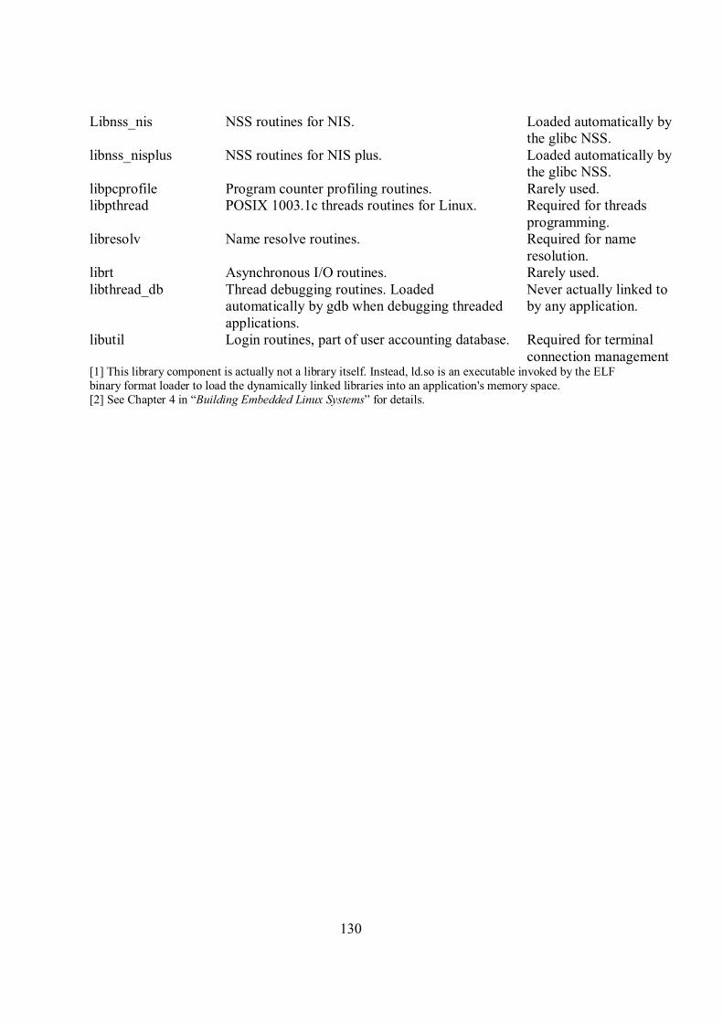
130
Libnss_nis
NSS routines for NIS. Loaded automatically by
the glibc NSS.
libnss_nisplus
NSS routines for NIS plus. Loaded automatically by
the glibc NSS.
libpcprofile Program counter profiling routines. Rarely used.
libpthread
POSIX 1003.1c threads routines for Linux. Required for threads
programming.
libresolv
Name resolve routines. Required for name
resolution.
librt Asynchronous I/O routines. Rarely used.
libthread_db Thread debugging routines. Loaded
automatically by gdb when debugging threaded
applications.
Never actually linked to
by any application.
libutil Login routines, part of user accounting database. Required for terminal
connection management [1] This library component is actually not a library itself. Instead, ld.so is an executable invoked by the ELF
binary format loader to load the dynamically linked libraries into an application's memory space.
[2] See Chapter 4 in “Building Embedded Linux Systems” for details.

131
Appendix C
PAPER FOR WINSYS 2007
Keywords: Linux Mobile, Embedded Systems, Soft Real-Time kernel, Application Development Platforms
Abstract: Linux has for some time been the operating system of choice for many types of embedded devices (e.g.
network devices like routers, as well as multimedia devices like set-top-boxes). Currently, Linux is also
gaining momentum as an operating system for mobile phones. This paper studies what it takes to make Linux
"go mobile", i.e., what adaptations are necessary to make the Linux kernel fit as a mobile operating system,
what is the architecture of such a platform, and what are the major benefits.
1 INTRODUCTION
Linux already exists in several commercial distributions targeted for embedded platforms and currently has about 23% of the world market share on mobile phones, even though this number provided by The Diffusion Group can be disputed. (The Diffusion Group, 2006) (Blandford, 2006) With the
development of the handheld device hardware, Linux is of particularly interest. It has been ported to several hardware architectures for years, it has one of the most stable kernels, and the functionalities of the handheld devices are growing to be more and more similar to that of a “regular” PC. Major embedded Linux vendors such as MontaVista, and Trolltech are serving more and more customers with development
LINUX MOBILEA Platform for Advanced Future Mobile Services
Frode Sivertsen Dept. of Telematics, Norwegian University of Science and Technology, O.S. Bragstads Plass 2E, N-7491 Trondheim,
Norway
Ivar Jørstad Ubisafe, Bjølsengata 15, N-0468 Oslo, Norway
Do van Thanh Telenor R&D, Snarøyveien 30, N-1331 Fornebu, Norway

132
environments partially based on proprietary software every day.
During the first half of 2007 one of the most anticipated releases of a Linux driven mobile phone will be ready for shipping, the Neo1973 from First International Computing, FIC. Linux is nothing new as a mobile phone operating system, but this is the first mobile phone which will be shipped with completely open source software based on the OpenMoko platform. (Cheap, hackable Linux smartphone due soon, 2006) (OpenMoko: The World’s First Integrated Open Source Mobile Communications Platform (n.d.).)
Many in the handheld operating system community favours Linux as the de-facto operating system for handheld devices to be, because of its openness, flexibility, broad developer base, and its modularity. They predict a new value added feature in the next generation of mobile phones where the applications may become the ringing tones of today. (Purdy, 2007)
With the release of the 2.6 kernel of Linux, it has gone further in providing real-time services but yet keeping the advances features compared to regular real-time operating systems. Linux positions itself with the advantages from both the real-time operating systems and the microkernel operating systems. Compared to its major competitors, being Symbian and Windows, it has its already mentioned advantages, but the performance is just as good as that of the mobile targeted operating system of Symbian. (Benchmark clocks OMAP2420 graphics on Linux, Symbian, 2006)
These are just some of the reasons why it is believed that Linux actually has the potential to become the de-facto mobile operating system of the future phones.
2 INTRODUCING LINUX
The components that form Linux do not change much whether they run on a server, a workstation, or a mobile phone. The Linux kernel is what is referred to as a monolithic kernel. Basically it consists of an architecture-dependent low-level interface that interacts with the hardware. However, it provides a hardware-independent API to the higher layers (i.e application layer and libraries) through high-level abstractions which can have a constant code base. The high-level abstractions are processes, files, sockets, signals etc.
Figure 1: The architecture of a generic Linux system. (Yaghmour, 2003)
The interpretation components such as file systems and network protocols are used to understand how to interact with the devices present on the platform. Many standards have been developed throughout the years, and because of its many portings, Linux supports more than its competing operating systems.
On top of the high-level abstractions one find the libraries that acts as standardized API’s for the application layer, since the services exported by the kernel are often unfit to be used directly by the applications. (Yaghmour, 2003) This is, as already mentioned, one of the areas where Linux has its strength. C, C++, Perl, Java etc. are languages easily supported by the Linux kernel through various libraries. This can be custom fit, regulating the size of the operating system footprint.
For the graphical user interface Linux supports several window managers and graphical libraries. The X Window System, X11, which usually runs on most desktop distributions is quite large, requires 8 MB of RAM and was originally made as a client/server application. The most used open source window managers for handheld devices are Nanowindows, formerly known as Microwindows, and Matchbox. In contrast to their “big brother” X11, they have reduced resource requirements. Other window managers intended for embedded devices exist as well. (Embedded Linux Graphics Quick Reference Guide, (n.d.).)
The window managers usually use graphical libraries such as Nano-X, Qt/Embedded, and GTK+ possibly with GTK-DFB and GTK-X, to provide the GUI. Trolltech, the makers of Qt, have a rather complex license model while GTK+ is completely GPL licensed.

133
3 LINUX AS A SOFT REAL-TIME
OPERATING SYSTEM
Regular real-time operating systems are mainly made for MMU-less processors with a flat address space with no memory protection between the kernel and its running applications. This means that the kernel, the kernel subsystems, and the applications share the same address space and must therefore be made foolproof to avoid crashing the system. This makes adding new software difficult. The system must also be brought down to do this.
A microkernel provides a very small operating system footprint which offers only the most basic services such as scheduling, interrupt handling, and message passing. The rest of the operating system, such as file systems, device drivers, and networking stack, runs as applications with their own private address space. The microkernel is dependent on well defined APIs for communication with the operating system and robust message-passing schemes between processes. Only that way might real-time services and modularity be ensured.
Linux is built up by several subsystems that can be dynamically loaded into the kernel, such as the file systems. This, however, do not make it a microkernel-based operating system. The kernel still interacts with the drivers using direct system calls, and not through message passing between processes. Message passing between processes can be very resource consuming and is regarded as one of the major drawbacks of microkernel operating systems. The dynamically loadable kernel module are pieces of kernel code that are not directly included or linked in the kernel, but can be inserted and removed from the running kernel at almost any time.
Any new code intended for the Linux kernel goes through a great deal of testing regarding design, functionality, and performance before it gets accepted into the mainline kernel releases. Hence, this trying process has looked after the advantages of “regular” real-time operating systems and made it one of the most stable pieces of software. At the same time it has kept the advantage of the memory protection to individual kernel subsystems provided in microkernels, but avoided the resource consuming message passing. These are some the reasons why Linux have become so popular. (Raghavan, Lad and Neelakandan, 2005)
3.1 User mode and Kernel mode
The monolithic kernel of Linux has a distinction between kernel and user mode execution states to secure the memory protection. A process in User mode can not enter kernel programs or kernel data structures directly. The User mode programs issue system calls to enter Kernel mode. The time before a system call is being served depend on the interrupt signal sent from the process to the CPU and its actions according to the interrupt. (Bowet and Cesati 2001:1-34)
3.2 Re-entrancy
The Linux kernel is re-entrant, meaning that several processes may be executing in Kernel Mode at the same time. Only one process can progress at the time in a uniprocessor system, but others may be waiting for the completion of some I/O request or the CPU. To provide re-entrancy, the functions must only modify local variables, not global ones.
The kernel may also include non-re-entrant functions that use locking to ensure that only one process can execute that function at a time. These processes may then modify global variables. If an interrupt occurs, the kernel is able to suspend the running process even if it is in Kernel Mode. This ensures a higher throughput for the device controllers that issue interrupts. While the kernel handles the interrupt, the device controller may perform other tasks.
The re-entrancy influences the organization of the kernel and its kernel control path which denotes the sequence of instructions executed by the kernel, being an interruption, a system call or an exception. Normally the kernel would execute these tasks one by one, from the first to the last. However, during handling interrupts and exceptions, the kernel can interleave one process in Kernel Mode to run a process required by the first one or run another process until the first one can be continued due to waiting on an I/O operation. Re-entrancy requires the implementation of interprocess communication, which will be described shortly. (Bowet, D P. and Cesati, M., 2001:1-34)
3.3 Process Address Space
Each process runs in its private address space. When a process is running in User Mode it has its own private stack, data, and code areas. When operating in Kernel Mode, those are different.
Since the kernel is re-entrant, several different processes may be executed in turn, each with its own kernel control path. These paths have their own stack. But processes may also share address space. This is done automatically by the kernel to save memory. For instance, when two different users use the same editor, the program is only loaded into memory once. The data are not shared in this case, so it must not be confused with shared memory, which will be described later. (Bowet and Cesati 2001:1-34)
3.4 The Soft Real-Time 2.6 Kernel
It is possible to categorize Real-Time operating systems into two camps; those which support Soft Real-Time responsiveness and those which support Hard Real-Time responsiveness. Real-Time responsiveness can be defined as “the ability of a system to respond to external or clock events within a bounded period of time.”(Singh, 2004) The 2.6 kernel of Linux is regarded as a Soft Real-Time operating system, where determinism is not critical. That is, a fast response is desirable, but an occasional

134
delay does not cause malfunction. This is the contrary to a Hard Real-Time operating system, such as a flight control system, where a deadline never may be missed.
Soft Real-Time responsiveness is a requirement to mobile phones. Even though there are requirements to multiprocessing, it is still a mobile phone and the phone specific services such as calls and messages will have to be prioritized before other applications and events. Before the 2.6 kernel release, special patches were necessary to achieve sufficient responsiveness. The improved responsiveness of the 2.6 kernel is mostly due to three significant improvements: a preemptible kernel, a new efficient scheduler, and enhanced synchronization. These improvements have contributed to make Linux an even better suited operating system for mobile phones.
3.4.1 The Pre-emptive 2.6 Kernel
Even though most UNIX kernels used to implement non-pre-emptive kernels as a solution to synchronization problems, the Linux 2.6 kernel implements pre-emption. In earlier releases of the Linux kernel, and like most general-purpose operating systems, the task scheduler was prohibited from running when a process were executing in a system call. The task would control the processor until the return of the system call, no matter how long that would take. Hence, the kernel could not interrupt a process to handle a phone call within an acceptable time limit. The 2.6 kernel is to some degree preemptive, meaning that a kernel task may be preempted with a low interruption latency to allow the execution of an important user application. The preemtion is triggered by the use of interruptions. A microprocessor typically has a limited number of interrupts, but an interrupt controller allows the multiplexing of interruptions over a single interrupt line. There also exist priorities among the interrupts. (Bowet, and Cesati, 2001)
This means that a process that is executing in Kernel Mode can be suspended and substituted by another process because it has higher priority. The operating system must be able to handle multiple applications and processes. For a mobile phone with soft Real-Time requirements such functionality is essential, as it must be able to handle important tasks such as an incoming phone call while the user is filming a video etc.
Figure 2: A comparison between the task response time of the 2.4.18 Linux kernel and the 2.6 kernel. (Singh, 2004)
Compared to a PC, the processing power is reduced, but the requirements to responsiveness are higher. The kernel code is laced with preemption points allowing the scheduler to run and possibly block a running process so as to schedule a higher priority process. Linux is still not a true Real-Time operating system, but it is certainly less jumpy than before and considerable faster than its predecessors, as seen in figure 2.
3.4.2 The new O(1) scheduler
The 2.6 kernel has a totally new process scheduler that replaces the slow algorithms of earlier kernels. Earlier, the scheduler would have to look at each ready task and score its relative importance to decide which task to run next. The new scheduler no longer scans every task every time, but uses two queues. When a task is ready to run, it will be sorted and placed in a queue, called the current queue. The scheduler then chooses the most favourable one in this queue to run next, giving each process a specified time to occupy the processor. Opposite to earlier, this is done in a constant amount of time, and not relative to the number of processes. After its time in the processor expires, the process is placed in the other queue, called the expired queue. The process is then again placed according to its priority. When all the tasks in the current queue are done, the scheduler once again starts its simple algorithm of picking tasks from the expired queue, which now is called the current queue. This new scheduler works substantially faster than the previous scheduler, and it works just as fast with many tasks as with few. (Deshpande, 2004)
3.4.3 Synchronization
By implementing a re-entrant kernel, one also introduces the need for synchronization among kernel control paths. One must ensure that while acting on a kernel data structure, no other kernel control path is allowed to act on the same data structure, even if the first one suspend the data structure. The data structure must be put back into a consistent state.
Let’s say that we have one global variable V representing available items of some system

135
resource. If a first kernel control path reads V, it sees that it is 1. Another kernel control path reads the same variable, and decreases it to 0. When A resumes its action, it has already read V and decreases it. As a result, the value of V is now -1. The two kernel control paths are using the same resource, which could result in serious errors.
When the outcome of a computation depends on how the processes are scheduled, the code will be incorrect and we have a race condition. Safe access to global variables is ensured by using atomic operations, which refers to combining the operations from two or more kernel control paths so they appear as one to the rest of the system. Any section of code that can not be entered by a process before another one has finished it is called a critical region.
The 2.6 kernel implements something that is referred to as futex – fast user-space mutexes. It is a new implementation of the mutex previously implemented as system calls to check that only one task is using a shared resource at a time. This time-consuming system call to the kernel to see whether block or allow a thread to continue was often unwarranted and unnecessary. Futex checks user-space to see whether a blocking is necessary, and only issues the system call when blocking the thread is required. This saves time. The function also uses the scheduling priority to decide which thread is allowed to execute in case of a conflict. (Singh, 2004)(Deshpande, 2004)
4 COMPUTER VERSUS MOBILE
PHONE
Adapting Linux for mobile phones first requires a thorough study of the similarities and differences between the two hardware platforms, i.e. between the ordinary computer and the mobile phone. The most significant difference is usually the processor architecture, where x86 is the most common on regular PCs and ARM is the most common on mobile phones. The ARM architecture is generally better on performance, power, and integration for mobile phones. But the choice of a non-x86 architecture, which Linux was originally built for, first of all results in necessary porting of some low-level drivers.
4.1 Necessary subsystems
There are certain subsystems that are required for Linux to work on all systems. Generally the kernel can be split into these following subsystems:
• Hardware Abstraction Layer • Memory Manager • Scheduler • File System • IO subsystem • Networking subsystem
The scheduler has already been discussed, but the Hardware Abstraction Layer, Memory Manager, File Systems, and IO subsystem will be described briefly.
4.1.1 Hardware Abstraction Layer
A Hardware Abstraction Layer (HAL) is a more concrete name of the underlying low-level interfaces that are supposed to give higher level languages the ability to communicate with lower level components, such as directly with hardware.
Its function is to hide differences in hardware from most of the operating system kernel, so that most of the kernel-mode code does not need to be changed to run on systems with different hardware. The HAL supports these hardware components, which are usual on both platforms:
• Processor, cache, and MMU • Setting up the memory map • Exception and interrupt handling support • DMA • Timers • System Console • Bus Management • Power Management
4.1.2 Memory Manager
The task of the memory manager is to control memory access to the hardware memory resources. In Linux the memory manager implements a logical layer for as the Memory Manager Unit being able to provide virtual memory to kernel subsystems such as drivers, file systems, and networking stack. But also it provides virtual memory to user applications. The advantages of virtual memory can be summarized with these points:
• Several processes can be executed
concurrently • It is possible to run applications whose
memory need are larger than the available physical memory.
• Processes can execute a program whose code is only partially loaded in the memory.
• Each process is allowed to access a subset of the available physical memory.
• Processes can share a single memory image of a library or a program.
• Programs can be relocatable – that is, they can be placed anywhere in physical memory.
• Programmers can write machine-independent code, since they do not need to be concerned about physical memory allocation.
All this is solved by the use of a virtual address
space, which is representation of physical locations located by the MMU and the kernel. The virtual address space is also referred to as a linear address space. The virtual addresses are divided by the kernel into page frames with a size of 4 or 8 KB, which

136
result in that a request for contiguous virtual address space can be satisfied by allocating a group of page frames that do not necessarily have contiguous physical addresses. All the pages are accessible by the kernel, but only some of them get used by the kernel. The paging process only involves the applications, which get pulled into main memory on request. By using virtual addresses a running process will not be able to corrupt neither another process’s nor the operating system’s memory. This means that any pointer corruptions within a process are localized to the process itself, and will not bring down the system. This is important for system reliability.
On the other hand, the 2.6 kernel allows the system to be built without a virtual memory system. This is often to meet real-time requirements. Slow handling of page faults can ruin responsiveness. A page fault is when a demanded page is not in physical memory and an interruption has to be raised. Of course, a no virtual memory solution removes the advantages previously mentioned, and it becomes the software designer’s responsibility to ensure there will always be enough real memory available to meet the applications demands. The issue of whether to use virtual memory or not is left to the programmer.
4.1.3 File Systems
There are many file systems that can run on Linux. Ext2, CRAMFS, ROMFS, RAMFS, NFS, DEVFS, and JFFS2 are often used on embedded systems. As a general point, the hardware memory/storage technology used on the device may set limitations to the choice of file systems. The kernel supports them all through a concept called the Virtual File System (VFS). VFS handles all the system calls related to the file systems. The file systems must translate their physical organization into a common file model which can represent all the supported file systems. In that way, to interact with the different file systems the kernel (i.e. the VFS) has only one interface to relate to.
It is necessary for every Linux system to have a root file system. This is the master file system which gets mounted during start-up. In Linux, everything is a file, even the directories and the I/O devices. UNIX systems also implement a current working directory for every process.
The PROCFS or /proc file system, is a special file system as it is a pseudo file system that resides in memory and is created every time the system is rebooted. The /proc directory reveals important data on the running processes and the state of the system itself. It is readable by the owner of the processes and the root. This openness and access to devices is very useful for programming.
4.1.4 I/O subsystem
The most difficult part of porting Linux to a mobile phone is not the main configuration of the kernel, but the programming of the low-level
interfaces which are special for this kind of embedded devices. For the programmer, the IO subsystem provides a simple and uniform interface to onboard devices. Special or not, on a mobile phone I/O devices will typically involve devices such as keypad, camera, Bluetooth, LCD screen, and non-volatile storage in some form, but also the drivers for the GSM/GPRS Digital Baseband Subsystem related functions. Those are often provided by the board manufacturers, such as Texas Instruments, or by the operating system vendors, such as MontaVista. These must be custom made to the hardware architecture and this is a process that may be troublesome. (Raghavan, Lad and Neelakandan, 2005)
The I/O subsystem supports three kinds of
devices: • Character devices for supporting
sequential devices • Block devices for supporting randomly
accessible devices. Block devices are essential for implementing file systems.
• Network devices that support a variety of link layer devices.
4.2 The MTD subsystem
In Linux, memory technology devices are all kinds of memory devices: RAM, ROM, and Flash in different technological solutions. The Memory Technology Devices (MTD) subsystem is a module of the Linux kernel. The MTD subsystem intends to provide a uniform and unified access to memory devices for the VFS. In that way it avoids having different tools for different technologies. The MTD subsystem consists of low-level chip drivers and high-level interfaces called MTD user modules. The user modules are software modules in the kernel that enables access to the chip drivers through recognizable interfaces and abstractions, which in turn are provided to the higher levels of the kernel and in some cases to user space.
The typical operations the MTD subsystem has to carry out is erase, read, write, and sync. The system works in a manner where the chip drivers register sets of predefines call-backs and properties with the MTD subsystem. The call-backs and properties are defined in an mtd_info structure, which is provided to the add_mtd_device() function. These call-backs are then called through this function.
There is no “standard” physical address location for the MTD devices, and therefore they need a customized mapping driver. In addition, some systems and development boards have known MTD device configurations. The kernel therefore contains a number of specific drivers for these systems. The drivers are found in the drivers/mtd/maps/ directory of the kernel sources.
On a mobile phone a combination of the CRAMFS and the JFFS2 file systems is a well known working combination. CRAMFS for the non changing boot image which is extended into RAM on

137
start-up and JFFS2 for the writable persistent file system. (Yaghmour, 2003)
5 SERVICE DEVELOPMENT FOR
LINUX MOBILE
5.1 Trolltech
Trolltech is a Norwegian company with two product lines; Qt (pronounced cute) and Qtopia. They were one of the first companies in the world to use a dual licensing model. The business model allows software companies to provide their products for two distinct uses - both commercial and open source software development. This type of licensing is based on Quid Pro Quo – Something for something. Either the customers of Trolltech may release their software under the GNU Public License, GPL, or they may purchase the appropriate number of commercial licenses from Trolltech and release the software under a license of choice.
Trolltech means that this strategy will make them able to provide the best cross-platform development tools in the world. The commercial license makes the money, and the open source licenses ensure quality and stability of the products delivered by Trolltech.
5.1.1 Qtopia Core
Qt is a cross-platform application development platform. Qt includes the Qt Class Libraries, which is a collection of over 400 C++ classes. Further it includes Qt Designer for rapid GUI and forms development, and other tools as well. “The Qt class libraries aim to provide a near-complete set of cross-platform application infrastructure classes for all types of C++ applications.” Qtopia Core is the application framework for single-application devices powered by embedded Linux. It provides the same API and tools as other versions of Qt, but it also includes classes and tools to control an embedded environment
5.1.2 Qtopia Phone Edition and Greenphone
Qtopia Phone Edition is the phone intended version of Qtopia Core. It is an application platform and user interface for Linux-based mobile phones. Trolltech claims that Qtopia Phone Edition is the de-facto standard application development platform and user interface for Linux-based mobile phones.
Also, Trolltech have developed a dual licensed hardware component of the Greenphone SDK. This SDK provides a complete environment for developing and modifying application software for Qtopia Phone Edition on the Greenphone. (Trolltech: Code less – Create More (n.d.).)
Figure 3: Qtopia Phone Edition diagram (Trolltech: Code
less – Create More (n.d.).)
5.2 MontaVista
MontaVista offers an optimized Linux operating system and development environment for both wireless handsets and mobile phones with requirements for power management, hard real time performance, fast start-up, and small footprint, called Mobilinux.
5.2.1 Mobilinux
The current version of Mobilinux is based on the Linux 2.6 kernel. It uses the reduced C library uClibc, DirectFB on top of the Linux Framebuffer Device, and SquashFS as the compressed read-only file system to be able to provide a reduced footprint. The Linux framebuffer, fbdev, is a graphic hardware-independent abstraction layer to show graphics on a console without relying on system-specific libraries. Further, Mobilinux has improved Real-Time support and implements a fully preemptible kernel through MontaVista’s enhancements. (Montavista Software – Platform to innovate (n.d.).)
5.3 The OpenMoko strategy
The OpenMoko camp, with its NEO1973, has taken on another business strategy than Trolltech and MontaVista. They favour a complete open strategy, as any regular PC intended open source Linux distribution.
The software of the mobile phone is based on the 2.6.20 kernel. It runs on a Samsung board with 64 MB NAND flash and 128 MB RAM. At the moment it has GSM/GPRS, USB, and Bluetooth support. It is equipped with a touch screen, and only two buttons for power and for auxiliary devices. It uses U-boot as boot loader.
Further this open source project provides a development framework, namely the Open Mobile Communications Platform (OpenMoko). The project intends to provide a completely open standard framework for developing mobile phone applications, much like Trolltech. The phone comes shipped with a package manager to be able to take full advantage of the all ready large Linux application community.

138
The key of OpenMoko’s business strategy is to trigger the open source community first. With them they will be able to ensure increased revenues for both carriers and handset developers. The idea is to let the users control their own environment of applications. The handset manufacturers can get a reduced time to market and the carriers will experience a large increase in data traffic. Applications may form the next generation of multi billion industry similar to that of ringing tones. It’s a win-win situation for all three parts; users, carriers, and handset manufacturers. (OpenMoko: The World’s First Integrated Open Source Mobile Communications Platform (n.d.).)
6. CONCLUSION
What have been presented in this paper are the fundamental mechanisms of Linux, with a focus on the latest major kernel release. The most important, main components that must be included in an embedded environment are discussed, and the paper clearly describes how a standard Linux kernel may be adapted to fit the mobile device.
Further, some of the important differences between the hardware platform of the computer and the hardware platform of a typical mobile phone are shown.
In addition, the paper has elaborated the challenges and opportunities of employing Linux as an enabler for advanced services on mobile phones.
REFERENCES
The Diffusion Group, 2006, February 7. Windows & Linux to Displace Symbian as Dominant Force in Advanced Mobile Operating Systems. http://www.tdgresearch.com/press066.htm
Blandford, R., 2006, February 8. TDG claim Symbian will be behind Linux and Microsoft by 2010. Retrieved March 28, 2007, from All About Symbian Web site:
http://www.allaboutsymbian.com/news/item/TDG_claim_Symbian_will_be_behind_Linux_and_Microsoft_by_2010.php
Cheap, hackable Linux smartphone due soon, 2006, November 7. http://www.linuxdevices.com/news/NS2986976174.html
OpenMoko: The World’s First Integrated Open Source
Mobile Communications Platform, (n.d.). Retrieved March 28, 2007, from www.openmoko.org
Purdy, J. G., January, 2007. Mobile Linux: Why it will become the dominant mobile OS. http://www.fiercewireless.com/story/feature-mobile-linux-why-it-will-become-the-dominant-mobile-os/2007-01-03
Benchmark clocks OMAP2420 graphics on Linux,
Symbian. February 2, 2006. http://linuxdevices.com/news/NS6023095418.html
Yaghmour, K., 2003. Building Embedded Linux Systems, Sebastopol, CA: O’Reilley
Embedded Linux Graphics Quick Reference Guide, (n.d.).
http://linuxdevices.com/news/NS6023095418.html Raghavan P., Lad A. and Neelakandan S., 2005. Embedded
Linux system design and development, Boca Raton, FL: Auerbach Publications
Bowet, D P. and Cesati, M., 2001, Understanding the Linux Kernel, 1st edition, Bejing: O’Reilly.
Singh, I. M., 2004, Embedded Linux: The 2.6 kernel is ideal for specialized devices of all sizes,
http://www.lynuxworks.com/corporate/news/2004/linux-kernel-2.6.php
Deshpande A. R., 2004, March 4, Linux Kernel 2.6: the Future of Embedded Computing, Part I. Retrieved March 28, 2007, from the Linux Journal Web site: http://www.linuxjournal.com/article/7477
The OMAP 730 Digital Baseband (n.d.). Retrieved March 28, 2007, from http://focus.ti.com/general/docs/wtbu/wtbuproductcont
ent.tsp?templateId=6123&navigationId=12003&contentId=4676
Trolltech: Code less – Create More. (n.d.). Retrieved April 3, 2007, from www.trolltech.com
Montavista Software – Platform to innovate. (n.d.). Retrieved April 3, 2007, from www.mvista.com

139
Appendix D
PAPER FOR ICIN 2007
Linux for Advanced Future Mobile Phones 1Frode Sivertsen, [email protected], 2Ivar Jørstad, [email protected], 1,3Do van Thanh, thanh-
1Norwegian University of Science and Technology, Dept. of Telematics, O.S. Bragstads Plass 2E, N-7491
Trondheim, Norway, 2Ubisafe, Bjølsengata 15, NO-0468 Oslo, Norway, 3 Telenor R&D, Snarøyveien 30, N-
1331 Fornebu, Norway
Abstract Linux has for some time been the operating
system of choice for many types of embedded
devices (e.g. network devices like routers, as well as
multimedia devices like set-top-boxes). Currently,
Linux is also gaining momentum as operating
system for mobile phones. This paper examines
whether Linux is suitable for mobile phones, and
what it takes to make Linux "go mobile", i.e., what
adaptations are necessary to make the Linux kernel
fit as a mobile operating system, what is the
architecture of such a platform and what are the
major benefits. The paper summarises the major differences between desktop platforms and mobile
devices, which has to be taken into account when
introducing Linux on mobile phones.
TOPIC: Network Infrastructure and Device
Technology
1 Introduction Linux already exists in several commercial
distributions targeted for embedded platforms and
currently has about 23% of the world market share
on mobile phones, even though this number
provided from The Diffusion Group can be disputed.
With the development of the handheld device
hardware, Linux is of particularly interest since it has been ported to several hardware architectures for
years, has one of the most stable kernels, and
because the functionalities of the handheld devices
are growing to be more and more similar to that of a
“regular” PC. Major embedded Linux vendors such
as MontaVista and Trolltech are serving more and
more customers with complete mobile phone
operating system solutions and development
environments partially based on proprietary software
every day. During May 2007 one of the most
anticipated releases of a Linux driven mobile phone will be ready for shipping, the Neo1973 from First
International Computing, FIC. Linux is nothing new
as a mobile phone operating system, but this is the
first mobile phone that will be shipped with
completely open source software based on the
OpenMoko platform. [1, 2, 3, 4]
Further, May the 5th, 2007, Matt Zimmerman,
the CTO of Ubuntu announced on the Ubuntu
development mailing list that there has been started
a Ubuntu Mobile and Embedded project. It is to be
developed together with Intel for their “new low-
power processor and chipset architecture.” [5] This is a tiny, low-energy chip designed for embedded
devices such as the mobile phone. It has the
codename Silverthorne. It is a chip that will be one-
seventh the size of conventional processors and
consume just 10% of the power, according to Intel.
[6] Further, according to Zimmerman [5], “the first
release of this edition will be in October with
Ubuntu 7.10.”
Many in the handheld operating system
community favours Linux as the de-facto operating

140
system for handheld devices to become, because of
its openness, flexibility, the broad developer base,
and its modularity. They predict a new value added
feature in the next generation of mobile phones
where the applications may become the ringing
tones of today. [7]
With the release of the 2.6 kernel of Linux, it
has gone further in providing real-time services but
yet keeping the advanced features compared to
regular Real-Time operating systems. Linux
positions itself with the advantages from both the real-time operating systems and the microkernel
operating systems. Compared to its major
competitors, namely Symbian and Windows, it has
its already mentioned advantages, but also the
performance is just as good as that of the mobile
phone targeted operating system of Symbian. [8]
These are just some of the reasons why it is
believed that Linux actually has the potential to
become the de-facto mobile operating system of the
future phones.
2 Adapting Linux to mobile phones
2.1 Computer versus Mobile Phone
The most difficult part of porting Linux to a mobile phone is not the main configuration of the
kernel, but the programming of the low-level
interfaces, which are special for this kind of
embedded devices. On a mobile phone these will
typically involve the I/O devices such as keypad,
camera, Bluetooth, LCD screen, and non-volatile
storage in some form, but also the drivers for the
phone specific, GSM/GPRS Digital Baseband
Subsystem related functions. Those are often
provided by the board manufacturers, such as Texas
Instruments, or by the operating system vendors,
such as MontaVista. On the NEO 1973, the GSM/GPRS driver (due to Non Disclosure
Agreements) and the GPS driver (due to legal
restrictions) are the only components that are closed
source code. These must be custom made to the
hardware architecture and this process may be
troublesome. [9]
Adapting Linux for mobile phones first requires
a thorough study of the differences between the two
hardware platforms, i.e. between the ordinary
computer and the mobile phone. There are three
main differences that will be described in detail: Real-Time requirements, multiprocessing
requirements, and memory requirements.
2.2 The Soft Real-Time 2.6 Kernel
It is possible to categorize Real-Time operating
systems into two camps; there are those that support
Soft Real-Time responsiveness and those that
support Hard Real-Time responsiveness. Real-Time
responsiveness can be defined as “the ability of a
system to respond to external or clock events within
a bounded period of time.”[10] The 2.6 kernel of Linux is regarded as a Soft Real-Time operating
system, where determinism is not critical. That is, a
fast response is desirable, but an occasional delay
does not cause malfunction. This is the contrary to a
Hard Real-Time operating system, such as a flight
control system, where a deadline never may be
missed.
Soft Real-Time responsiveness is a requirement
to mobile phones. Even though there are
requirements for multiprocessing, it is still a mobile
phone and the phone specific services such as calls and messages will have to be prioritized with
regards to other applications and events. Before the
2.6 kernel release, special patches were necessary to
achieve sufficient responsiveness. The improved
responsiveness of the 2.6 kernel is mostly due to
three significant improvements: a pre-emptive
kernel, enhanced synchronization, and a new
efficient scheduler. These improvements have
contributed to make Linux an even better suited
operating system for mobile phones.
2.2.1 The Pre-emptive Kernel In earlier releases of the Linux kernel, and like
most general-purpose operating systems, the task
scheduler was prohibited from running when a
process was executing in a system call. The task
would control the processor until the return of the
system call, no matter how long that would take.
Hence, the kernel could not interrupt a process to
handle a phone call within an acceptable time limit.
The 2.6 kernel is to some degree pre-emptive. The
pre-emption is triggered by the use of interruptions.
This means that a kernel task may be pre-empted with a low interruption latency to allow the
execution of an important user application, typically
a phone call. The interrupt latency is the time it takes
from the device raises the interrupt to the device
driver’s interrupt handling routine is finished.
A microprocessor typically has a limited
number of interrupts, but an interrupt controller
allows the multiplexing of interruptions over a single
interrupt line. There also exist priorities among the
interrupts.
Interruptions need to be raised whenever the memory manager discovers that data is missing, or
some data for example arrives from the network to
the hardware, such as the phone call. The kernel
must deliver an interrupt from the hardware device
to the correct device driver to notify about the
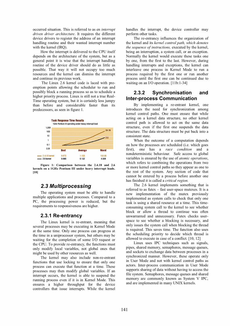
141
occurred situation. This is referred to as en interrupt driven driver architecture. It requires the different
device drivers to register the address of an interrupt
handling routine and their wanted interrupt number
with the kernel (IRQ).
How the interrupt is delivered to the CPU itself
depends on the architecture of the system, but as a
general point it is wise that the interrupt handling
routine of the device driver should do as little as
possible. That way it will not occupy too much
resources and the kernel can dismiss the interrupt and continue its previous work.
The Linux 2.6 kernel code is laced with pre-
emption points allowing the scheduler to run and
possibly block a running process so as to schedule a
higher priority process. Linux is still not a true Real-
Time operating system, but it is certainly less jumpy
than before and considerable faster than its
predecessors, as seen in figure 1.
Figure 1: Comparison between the 2.4.18 and 2.6
kernels on a 1GHz Pentium III under heavy interrupt loads.
[10]
2.3 Multiprocessing The operating system must be able to handle
multiple applications and processes. Compared to a
PC, the processing power is reduced, but the
requirements to responsiveness are higher.
2.3.1 Re-entrancy
The Linux kernel is re-entrant, meaning that
several processes may be executing in Kernel Mode
at the same time. Only one process can progress at
the time in a uniprocessor system, but others may be waiting for the completion of some I/O request or
the CPU. To provide re-entrancy, the functions must
only modify local variables, not global ones that
might be used by other resources as well.
The kernel may also include non-re-entrant
functions that use locking to ensure that only one
process can execute that function at a time. These
processes may then modify global variables. If an
interrupt occurs, the kernel is able to suspend the
running process even if it is in Kernel Mode. This
ensures a higher throughput for the device controllers that issue interrupts. While the kernel
handles the interrupt, the device controller may
perform other tasks.
The re-entrancy influences the organization of
the kernel and its kernel control path, which denotes the sequence of instructions, executed by the kernel,
being an interruption, a system call, or an exception.
Normally the kernel would execute these tasks one
by one, from the first to the last. However, during
handling interrupts and exceptions, the kernel can
interleave one process in Kernel Mode to run a
process required by the first one or run another process until the first one can be continued due to
waiting on an I/O operation. [11b:1-34]
2.3.2 Synchronisation and Inter-process Communication
By implementing a re-entrant kernel, one
introduces the need for synchronization among
kernel control paths. One must ensure that while
acting on a kernel data structure, no other kernel
control path is allowed to act on the same data
structure, even if the first one suspends the data
structure. The data structure must be put back into a
consistent state.
When the outcome of a computation depends
on how the processes are scheduled (i.e. which goes first), one has a race condition and a
nondeterministic behaviour. Safe access to global
variables is ensured by the use of atomic operations,
which refers to combining the operations from two
or more kernel control paths so they appear as one to
the rest of the system. Any section of code that
cannot be entered by a process before another one
has finished it is called a critical region.
The 2.6 kernel implements something that is
referred to as futex – fast user-space mutexes. It is a
new implementation of the mutex previously
implemented as system calls to check that only one task is using a shared resource at a time. This time-
consuming system call to the kernel to see whether
block or allow a thread to continue was often
unwarranted and unnecessary. Futex checks user-
space to see whether a blocking is necessary, and
only issues the system call when blocking the thread
is required. This saves time. The function also uses
the scheduling priority to decide which thread is
allowed to execute in case of a conflict. [10, 12]
Linux uses IPC techniques such as signals,
pipes, shared memory, semaphores, message queues, and sockets to exchange data between processes in a
synchronized manner. However, these operate only
in User Mode and not with kernel control paths as
actors. Inter-process communication in User Mode
supports sharing of data without having to access the
file system. Semaphores, message queues and shared
memory are commonly known as System V IPC,
and are implemented in many UNIX kernels.

142
2.3.3 The Scheduler
The 2.6 kernel has a totally new process
scheduler that replaces the slow algorithms of earlier
kernels. In short, the scheduler allocates tasks to the
CPU in quantities of time, time slices, to be able to
execute multiple programs at the “same” time. At
least the tasks experience it so. Earlier, the scheduler
would have to look at each ready task and score its
relative importance to decide which task to run next.
The new scheduler no longer scans every task every time, but uses two queues. When a task is ready to
run, it will be sorted and placed in a queue, called
the current queue. The scheduler then chooses the
most favourable one in this queue to run next, giving
each process a specified time to occupy the
processor. Opposite to earlier, this is done in a
constant amount of time, and not relative to the
number of processes. After its time in the processor
expires, the process is placed in the other queue,
called the expired queue. The process is then again
placed according to its priority. When all the tasks in the current queue are done, the scheduler once again
starts its simple algorithm of picking tasks from the
expired queue, which now is called the current
queue. This new scheduler works substantially faster
than the previous scheduler, and it works just as fast
with many tasks as with few.
Another example of improvement from the new
scheduler is its policy to increase responsiveness
through dynamic task prioritization. The 2.6 kernel
has 140 priority levels. It prioritizes (rewards) tasks
that are I/O-bound in contrary to CPU-bound tasks by adding or subtracting from a task’s static priority.
This is done on user tasks, and not on real-time
tasks. The scheduler enforces a policy on when and
for how long processes may execute. In other words
it tries to avoid starvation and it enforces fairness,
interactivity, and efficiency. The important thing for
a mobile phone is to do this in the most efficient
possible way and thus provide a responsive user
experience and meet real-time requirements for
prioritized tasks.
For future kernel task schedulers in Linux, a
way to choose between different scheduler policies and algorithms would be ideal for the different
devices it runs on. For example, a scheduler that
enforces interactive tasks for embedded and perhaps
desktop users, while a strict efficient task scheduler
favouring server usage could be chosen for servers.
This resembles the swappable scheduler of the GNU
HURD kernel. [13, 14]
2.4 Memory requirements
2.4.1 Memory Hardware Issues
High-end feature phones, smartphones, or
music-centric phones as seen in the market today
have various memory requirements, both in terms of the amount of memory space they need and the
memory type best suited to meet their usage
schemes. First of all, the phones usually have a
removable memory, which can be used to store
images, music, videos, applications, and so on. This
is referred to as the Memory-Stick. This can
typically be 1Gigabyte and up to 4 Gigabytes.
Second, they have a semi-removable memory
offered in the SIM card, which now offer up to 1
Gigabyte of storage. [15] This is typically used to
store contacts etc., but the range of use is expanding.
The embedded memory, however, cannot be removed. Nor can it be replaced or upgraded after
the handset has left the factory. This is the memory
that is mainly used by the operating system and its
internal processes. 32 MB is a typical size, which is
enough for the operating system in all phone
categories mentioned above, leaving some space to
user applications as well. Before 2001, the flash type
used in embedded systems was usually NOR flash.
NAND flash is known to be more error prone and
use a different and more complicated processor
interface than NOR flash. This had made it “unusable” in mobile handsets. However, these
shortcomings have been overcome, and NAND flash
is becoming more and more dominant. It is smaller,
therefore more cost-effective than NOR technology.
In addition the prices on raw materials are dropping.
The NOR technology is said to have its upper limit
as a competitive media at 32MB. The NAND
technology is often called Multi-Level Cell (MLC)
NAND, because two bits, instead of one, can be
stored in each cell.
When NAND flash first was adopted, it was
used in addition to NOR flash. This was because NAND could not support eXecute In Place due to
the compression of stored data, and hence it was
only used as storage for user media. This was
however overcome with the use of DiscOnChip,
which includes a small XIP boot block. From there
the RAM can be initialized and the kernel image can
be copied into SDRAM. This required SDRAM of
course.
This task can easily be solved in Linux by the
use of JFFS2 (Journaling Flash File System Version
2) and the 2.6 kernel’s MTD subsystem (explained shortly), and hence it supports NAND memory as
the only non-volatile memory. But it can also use the
NOR-NAND combination.
In the years to come, built-in-high-density
embedded flash drives (EFDs) will probably be the
state of art to handle the problems with the NAND
flash, as it offers the flash media and flash controller
on the same chip, and sometimes even on the same
die. The technology of EFDs is evolving fast, and it
is hard to keep up for the software world. [15, 16,
17, 18, 19]
2.4.2 Memory Manager It is the memory manager which task is to
control memory access to the hardware memory

143
resources on a fair basis. The memory manager is
highly dependent on the hardware Memory
Management Unit, MMU. It provides protection by
letting only the correct process read and modify its
data, and it prevents processes from overwriting
code and read-only data. While executing processes
the processor read instructions from memory and
decodes them. The instruction may require fetching
or storing data to memory before moving on to the
next instruction in the program. The processor is
therefore always accessing the memory to fetch the next instruction or to fetch or store data. The
instructions and data may also be fetched or stored
to by the use of cache. [20]
2.4.3 MTD
On Linux, memory technology devices are all
kinds of memory devices: RAM, ROM, flash, and
DiskOnChip (DOC) from M-Systems. For the
record, M-Systems are now acquired by SanDisk.
The Memory Technology Devices (MTD)
subsystem is a module of the Linux kernel. Linux imposes greater requirements to the storage
hardware compared to traditional embedded
software, and the MTD subsystem intends to provide
a uniform and unified access to memory devices for
the Virtual File System, VFS. In that way it avoids
having different tools for different technologies.
The VFS handles all the system calls related to
all the different file systems. The device drivers
must translate their physical organization into a
common file model that can represent all the
supported logical file systems. In that way, to interact with the different file systems the kernel (i.e.
the VFS) has only one common interface to relate to.
The buffer cache is data buffers used by block
device drivers. The fixed size buffers contain data
going to and from block devices, typically a hard
disk. Block devices are always accessed via the
buffer cache.
Flash devices need other policies of use due to
their physical properties. As an example, flash chips
have a larger sector size than the regular disks sector
size, on which the buffer cache is based. In addition
to this do flash chips have a limited lifetime and the memory blocks have to be erased before written to.
This means that “normal” file system drivers,
based on block devices, cannot be used on top of
flash devices because they go through the buffer
cache. This necessitates the introduction of the
Memory Technology Devices subsystem (MTD) on
embedded devices.
The MTD subsystem consists of low-level chip
drivers and high-level interfaces called MTD user modules. The chip drivers are of course technology
dependent. The user modules are software modules in the kernel that enables access to the chip drivers
and thus the storage space through recognizable
interfaces and abstractions. The interfaces and
abstractions are then provided to the higher levels of
the kernel (e.g. the VFS as the common file model)
and in some cases to user space. [21]
2.4.4 Virtual Memory
In Linux the Memory Manager implements
a logical layer for as the Memory Manager Unit
being able to provide virtual memory to drivers, file
systems, and networking stack. But also it provides
virtual memory to user applications. The virtual
address space is also referred to as a linear address
space. The virtual addresses are divided by the kernel into page frames with a size of 4 or 8 KB,
which result in that a request for contiguous virtual
address space can be satisfied by allocating a group
of page frames that do not necessarily have
contiguous physical addresses. The actual data may
actually be located in RAM, cache, or on a non-
volatile storage, depending on when it was last used.
Many of the hardware peripherals are
accessible within the system’s physical address
space, while they may have restricted or are
completely “invisible” in the virtual address space. [11 a]
The 2.6 kernel may be built without virtual
memory. Virtual memory may reduce system
responsiveness because of demand paging and the
following slow handling of page fault. A page fault
is when the system is trying to access a memory-mapped page that is not in physical memory and
therefore must be loaded in. This may be of use on a
mobile phone to ensure a faster operating system,
but the lack of virtual memory requires that the
software programmer ensure that there is enough real physical memory present on the platform to
meet application demands.
2.4.5 Physical Memory Addressing
The memory map (i.e. how the system sees the
total memory layout) is highly dependent on the
specific board and its available memory. It first of
all defines the layout of the CPU’s addressable
space, in terms of how to handle User Mode and
Kernel Mode, caching, and so on.
On a generic ARM1 based design, a mobile
phone usually has an ARM core together with a
number of system dependent peripherals. It further
has an interrupt controller that receives interrupts
from peripheral devices. The controller raises inputs to the processor as appropriate. This interrupt
controller may also provide hardware assistance for
prioritizing interrupts. Next, there are some form of
off-chip ROM or flash to boot the system from, and
1 ARM is by far the most used processor
design used on mobile phone. Latest reports
show that ARM’s market share of the
embedded RISC microprocessor market is
approximately 75 percent. [26]

144
a 16-bit wide RAM to store runtime data. On the
chip there will be 32-bit memory for interrupt
handlers and stacks. [22]
The memory map freezes the physical address
space allocated for RAM, flash, and memory-
mapped I/O peripherals. In other words, this defines
how the CPU, the memory devices, and the I/O
peripherals can communicate. The physical
addresses often resemble the addresses used on the
busses, but this is not always true. During system
configuration, the processor’s address space will be divided into different areas where some is used to
cache, some to the kernel and I/O peripherals that
need to bypass the cache, some to user programs,
and some to the kernel functions that need
translation in the Translation Look-aside Buffers.
With the processor’s address spaces set, the rest of
the various onboard devices (RAM, I/O devices,
etc.) can have their address spaces set. This requires
an understanding of addresses and how the devices
and buses use them. At last this will decide where to
put the boot loader and the kernel image, which is necessary to get the system booted.
Up and running, Linux and UNIX systems
distinguish between two parts of the RAM. A few
megabytes are dedicated to store an image of the
kernel. The rest is used to:
• Satisfy kernel requests for buffers,
descriptors, and other dynamic kernel
data structures.
• Satisfy process requests for generic
memory areas and for memory
mapping of files. (User Space)
• Get better performance from disks and
other buffered devices by means of
caches
The system flash storage is also divided in two
or more parts. Usually the lower part of the memory
contains the boot loader and maybe some boot
parameters. This may also be stored in ROM. This
part usually has the lower range of the physical
address space, and the boot loader required must
therefore support bottom booting. This region is rather small and may by mounted with a separate file
system during booting. The second part of the
system flash consists of the root file system. The
kernel image can either be stored in an own section
of the flash, or in the root file system, if the boot
loader supports reading from it. [9:chap.3,
23:chap.3]
2.4.6 DMA
The use of interrupt-driven device drivers
works well as long the transferred data to and from devices is reasonably low. If the transfer rate is
bigger, for example as for a SCSI device, high
interrupt latency will impact the overall system. The
interrupt latency is, as mentioned, the time it takes
from the device raises the interrupt to the device
driver’s interrupt handling routine is finished. DMA
was invented to handle this problem. The DMA
controller allows devices transfer data to memory
without the intervention of the CPU. The DMA only
uses some parts of physical memory and knows
nothing about the virtual memory. Usually there are
only 7 DMA channels, making it a scarce resource.
They cannot be shared, so device drivers must be
able to operate without them. [9:chap.8]
2.5 The General Mobile Linux Platform
The generic architecture of a Linux mobile
phone platform is a monolithic, layered architecture.
It consists of low-level interfaces that provide
uniform interfaces to high-level abstractions. The
low-level interfaces are architecture-dependent,
where their lower part communicates with the
hardware through device drivers. The upper parts of
the low-level interfaces provide APIs, which are common across the different hardware architectures
to the high-level abstractions. These high-level
abstractions can then have a constant code-base in
most cases. The high-level abstractions visible to
User Space are well-known abstractions such as
processes, files, sockets, and signals. Because the
services exported by the kernel are not always fit to
be used directly by applications, libraries often
provide such an API and communicate with the
high-level abstractions on behalf of the user
applications.
2.5.1 Frame Buffer The Linux frame buffer, fbdev, is a graphic
hardware-independent abstraction layer to show
graphics on a console without relying on system-
specific libraries. The frame buffer is a memory area
that has the size of the screen multiplied with the
byte-size per pixel and usually it has a fixed memory
address range of the internal memory that uses
DMA. Linux uses the virtual frame buffer solution
for portability, which then is an interface that is easy
for programmers to access. On a mobile phone the display procedure
will often include a 2D accelerator, and 3D
accelerators are also on its way. The graphics library
issues commands to the accelerator, which write the
results to the frame buffer, thus speeding up things
even more.
2.5.2 Application Layer & UI
Linux supports several window systems and
graphical libraries for the graphical user interface. It
is possible to write applications that use the frame buffer directly, but as the GUI grows complex some
form of abstraction is necessary. The graphical
system on an embedded device is responsible for

145
managing the display hardware, manage one or more
user input interfaces, provide an abstraction layer to
the underlying hardware for applications, and
manage different applications at the same time so
they can co-exist and share the use of input devices.
The X Window System, X11, which
usually runs on most desktop distributions, is quite
large. An embedded system does not have the need
for all these network-oriented services provided by
the X Window System. It rather needs a quick, close
to real-time-response system with a small toolkit library. The most used open source window
managers for handheld devices are Nano-X,
formerly known as Microwindows, and Matchbox.
In contrast to their “big brother” X11, they have
reduced resource requirements. Other window
managers intended for embedded devices exist as
well. [24]
The embedded window systems usually use
libraries such as Nano-X, Qt/Embedded (Qt
pronounced cute, now known as Qtopia Core), and
GTK+ possibly with GTK-DFB (GTK on Direct Frame Buffer) to provide the windowing
environment with the drawing engines. Further, Qt
also offers a toolkit through Qtopia, whereas others
are GTK-DFB, and FLNX. The latter is a port for
Nano-X from FLNK (Fast Light Tool Kit). There
also exist a NXLIB (Nano-X/X-Lib Compatibility
Library) that lets X11 binaries run unmodified or
with little change on the Nano-X server, since it
supports a subset of X-lib. Trolltech, the makers of
Qt, have a rather complex license model while
GTK+ is completely GPL licensed. The window
manager is loaded by the init program. Many other window managers intended for
embedded devices exist as well. Some are open
source, some are just available in commercial
solutions, while some are dual licensed. Some of the
projects/solutions are just graphical library layers,
while some are complete window systems with a
stack ranging from hardware interfacing to a full
GUI toolkit. As a summary one can say that the
Linux frame buffer provides a good solution for all
kinds of embedded devices. For the mobile phone
with its calendar, phone book, and the like Nano-X with Qtopia Core or FLNX running on top will be a
good solution to provide a user-friendly menu-
driven GUI. This will be an open source solution.
[9:chap.9, 24]
3 The Benefits of Mobile Linux
Chapter 2.2, 2.3, and 2.4 explained the main
differences from the regular PC in terms of Real-
Time requirements, multiprocessing requirements,
and memory requirements. In the light of the Linux
2.6 kernel it was shown how Linux deals with these
challenges regarding mobile phone systems. In
chapter 2.5 a general mobile Linux platform was
discussed on a more architectural level.
So what are the benefits of Linux as
opposed to other mobile phone operating systems?
The most obvious benefit is the cost reduction due to
the open source code. There are no restraints to the
use of the Linux source code as long as it follows the
agreements of GPL and LGPL. The flexibility of
choice of physical devices and logical file systems is
one of the important factors why Linux has had such
a success on different devices in the past. [11a] Further Linux has been used and suited to both
embedded devices and regular PCs for years, and the
kernel is well known for being very stable with
lower resource requirements than its competitors.
Together with the necessary additions in form
of the GSM driver, or whatever standard the phone
is using (CDMA2000, UMTS), and possible other
closed source drivers, it is possible to build a full
scale mobile phone operating system based on open
source code. With the latest enhancements included
in the 2.6 kernel presented here, Linux has the possibility to become the de-facto standard mobile
operating system.
In the previous it was shown how the core
functionalities of the Linux kernel with a focus on
the basics, and the very latest improvements in the
2.6 kernel, can take advantage of the continuous
improving mobile phone boards. The boards are
getting smaller and smaller, and faster and faster. In
addition they are improved with increased power
management in terms of better-suited power modes
and reduced current by shutting down certain
devices in active mode, and increased memory functionality in terms of configurability, speed, size
and usability. There is also seen a lot of integration
of different devices and communication standards on
the boards, making them highly flexible to be used
whatever services the operating system (i.e.
developer) allows them to.
The consumers will want a mobile phone
that can perform a variety of functions including,
voice, multimedia messaging, and take photos or
video and email the photos and messages. The phone
should also synchronize with a PC, perform mobile commerce, and of course, play games. However, to
get consumers to use any of these services they have
to be easy, quick and simple to use. For example, if
it takes ten steps to take a photo and email it to
someone, it won't be adopted easily or broadly.
Applications must be developed to do this in two or
three steps. There, Linux has its core advantage in
addition to the obvious that comes along with the
GPL and other licensing standards such as LGPL.
[25]
Linux itself offers standardized APIs to be used
by programmers. It is already well known that the Unix/Linux community has one of the largest
service/application developer bases. This is where
the key to Linux’ success will lie; With an open
146
kernel, already used for years, with developers
knowing it inside out, they have the potential to
extract the money from this industry’s future main
income: services and applications.
Windows became the de-facto standard
operating system for regular PCs because they gave
them a common look and feel. The graphical user
interface with the same look and feel made it
accessible to everyone and the PC industry became
the industry it is today. Vendors such as Trolltech
and Montavista recognize this, and try to do the same thing on mobile phones as Windows did on
regular computers. There is no doubt that in the
mobile phone world the kernel is regarded as less
important to the user. It is the services and
applications that the user sees that give him, or her,
the true value. In the PC market, the operating
systems services in terms of running multiple
applications, file management, etc. just as important
as the user interface. This does not apply to the
mobile phone market. Thus operating system
vendors will not gain much, at least not their major share, of money from their investments in
developing the “invisible” kernel, even though this
has to be done to some degree. They will have to
shift their offerings to become value added suppliers
to the Linux ecosystem.
4 Conclusion and Future Work
This paper has studied the challenges and
opportunities brought with Linux as an enabler for
advanced services on mobile phones. The paper
clearly describes how a standard Linux kernel may
be adapted to fit the mobile device, and shows the important differences between the hardware
platform of the computer and the hardware platform
of a typical mobile phone. The emerging
architecture of the future mobile phone is discussed,
and the benefits of employing Linux on mobile
phones are elaborated.
5 References [1] The Diffusion Group, February 08, 2007. The
Windows & Linux to Displace Symbian as Dominant
Force in Advanced Mobile Operating Systems
http://www.tdgresearch.com/press066.htm
[2] Blandford, R., February 08, 2007. TDG claim Symbian
will be behind Linux and Microsoft by 2010.
http://www.allaboutsymbian.com/news/item/TDG_clai
m_Symbian_will_be_behind_Linux_and_Microsoft_b
y_2010.php
[3] Cheap, hackable Linux smartphone due soon.
November 07, 2006.
http://www.linuxdevices.com/news/NS2986976174.ht
ml
[4] OpenMoko: The World’s First Integrated Open Source
Mobile Communications Platform, (n.d.)
www.openmoko.org
[5] Zimmerman, M., May 5, 2007. Ubuntu Mobile and
Embedded Edition.
https://lists.ubuntu.com/archives/ubuntu-devel-
announce/2007-May/000289.html
[6] BBC News, May 5, 2007. Linux evolves for mobile
devices.
http://news.bbc.co.uk/1/hi/technology/6634195.stm
[7] Purdy, Ph.D. J. G., January 03, 2007. Mobile Linux:
Why it will become the dominant mobile OS.,
http://www.fiercewireless.com/story/feature-mobile-
linux-why-it-will-become-the-dominant-mobile-
os/2007-01-03
[8] Benchmark clocks OMAP2420 graphics on Linux,
Symbian. February 02, 2006.
http://linuxdevices.com/news/NS6023095418.html
[9] Raghavan, P., Lad, A., and Neelakandan, S., 2006.
Embedded Linux system design and development, Boca
Raton, FL: Auerbach Publications
[10] Dr. Inder M. Singh, September, 2004. Embedded
Linux: The 2.6 kernel is ideal for specialized devices of
all sizes.
http://www.lynuxworks.com/corporate/news/2004/linu
x-kernel-2.6.php
[11a] Bowet, D P. and Cesati, M., 2001. Understanding the
Linux Kernel, 1st edition, Bejing: O’Reilly.
[11b] Bowet, D P. and Cesati, M., 2003. Understanding the
Linux Kernel, 2nd edition, Beijing: O’Reilly.
[12] Aseem R. Deshpande, March 26, 2004. Linux Kernel
2.6: the Future of Embedded Computing, Part I.
http://www.linuxjournal.com/article/7477
[13] Aas, J., February 17, 2005. Understanding the Linux
2.6.8.1 CPU Scheduler.
http://josh.trancesoftware.com/linux/linux_cpu_schedu
ler.pdf
[14] The GNU HURD. http://www.gnu.org/software/hurd/
[15] M-Systems, December, 2005. Flash Memory in Mobile
Handsets: Balancing the Equation. http://www.m-
systems.com/NR/rdonlyres/692BE1C4-FF8E-48A3-
97A3-
B39B45AE4CCC/0/FlashMemory_in_Mobile_Handse
ts_Balancing_Equation_Rev11_SD.pdf
[16] Chen, P., November 11, 2006. The case for a standard
mobile memory interface for flash/DRAM.
http://www.mobilehandsetdesignline.com/howto/stora
gearchitecture/193700728
[17] Semiconductor Insights, 2006. Q2/2006 Flash Memory
Component Executive Summary Report. Available
through:
http://www.semiconductor.com/products_and_services
/subscription/flash/
[18] Kaplan, F., 2005, May, Standardizing NAND Flash for
Use in Mobile Handsets.
http://www.m-systems.com/NR/rdonlyres/BE31E55A-
BEE2-407C-A8E5-
0FFD3662B4FD/0/EFDs_Standardizing_NAND_Flas
h_for_Use_in_Mobile_Handsets.pdf
[19] M-Systems, 2005. Meeting Multimedia Requirements
for Memory in Mobile Handset.

147
http://www.m-
systems.com/NR/rdonlyres/ECE1D4BA- 84E3-
4638-8AD7-3EE9BD
754685/0/Meeting_Multimedia_Requirements_with_F
lash_Memory_SD.pdf
[20] Bowman I., January, 1998. Conceptual Architecture of
the Linux Kernel.
http://plg.uwaterloo.ca/~itbowman/CS746G/a1/
[21] Yaghmour, K., 2003. Building Embedded Linux
Systems, Sebastopol, CA: O’Reilley
[22] The ARM architecture. September 9, 2004.
ftp://download.intel.com/education/highered/Embedde
d/02_ARM_Architecture.ppt.
[23] Rusling, D. A., 1999. The Linux Kernel.
http://en.tldp.org/LDP/tlk/tlk.html
[24] Embedded Linux Graphics Quick Reference Guide
http://www.linuxdevices.com/articles/AT9202043619.
html
[25] Five New OMAP Processors from TI Increase
Wireless Application Performance as Much as 8x and
Extend Battery Life of Handsets. February 24, 2003.
http://archive.chipcenter.com/wireless/parch.html
[26] The ARM Architecture. January, 2005.
http://www.arm.com/miscPDFs/3823.pdf