
EXP232TF - Expansion Communications Port RS-232 Board
32
Bristol Babcock EXPANSION COMMUNICATIONS PORT RS-232 BOARD Part No. 392970-01-5 (For Models 3530-XXX) For The Following BBI Instruction Manuals: CI-3530-10B, CI-3530-15B, CI-3530-20B, CI-3530-25B, CI-3530-35B, CI-3530-40B, CI-3530-45B & CI-3530-50B Product Information Package PIP-EXP232TF – December, 2003
-
Upload
khangminh22 -
Category
Documents
-
view
1 -
download
0
Transcript of EXP232TF - Expansion Communications Port RS-232 Board

Bristol Babcock
EXPANSION COMMUNICATIONSPORT RS-232 BOARDPart No. 392970-01-5
(For Models 3530-XXX)
For The Following BBI Instruction Manuals:CI-3530-10B, CI-3530-15B, CI-3530-20B, CI-3530-25B,CI-3530-35B, CI-3530-40B, CI-3530-45B & CI-3530-50B
Product Information Package PIP-EXP232TF – December, 2003

NOTICECopyright Notice
The information in this document is subject to change without notice. Every effort has beenmade to supply complete and accurate information. However, Bristol Babcock assumes noresponsibility for any errors that may appear in this document.
Request for Additional Instructions
Additional copies of instruction manuals may be ordered from the address below perattention of the Sales Order Processing Department. List the instruction book numbers orgive complete model number, serial or software version number. Furnish a return addressthat includes the name of the person who will receive the material. Billing for extra copieswill be according to current pricing schedules.
TeleFlowTM, TeleRTUTM and TeleRecorderTM are trademarks of Bristol Babcock. Othertrademarks or copy-righted products mentioned in this document are for information only,and belong to their respective companies, or trademark holders.
Copyright (c) 2003 Bristol Babcock, 1100 Buckingham St., Watertown, CT 06795. No part ofthis manual may be reproduced in any form without the express written permission ofBristol Babcock.

IMPORTANT! READ INSTRUCTIONS BEFORE STARTING!
Be sure that these instructions are carefully read and understood before anyoperation is attempted. Improper use of this device in some applications may resultin damage or injury. The user is urged to keep this book filed in a convenient locationfor future reference.
These instructions may not cover all details or variations in equipment or coverevery possible situation to be met in connection with installation, operation ormaintenance. Should problems arise that are not covered sufficiently in the text, thepurchaser is advised to contact Bristol Babcock for further information.
EQUIPMENT APPLICATION WARNING
The customer should note that a failure of this instrument or system, forwhatever reason, may leave an operating process without protection. Dependingupon the application, this could result in possible damage to property or injury topersons. It is suggested that the purchaser review the need for additional backupequipment or provide alternate means of protection such as alarm devices, outputlimiting, fail-safe valves, relief valves, emergency shutoffs, emergency switches, etc. If additional information is required, the purchaser is advised to contact Bristol Babcock.
RETURNED EQUIPMENT WARNING
When returning any equipment to Bristol Babcock for repairs or evaluation,please note the following: The party sending such materials is responsible to ensurethat the materials returned to Bristol Babcock are clean to safe levels, as such levelsare defined and/or determined by applicable federal, state and/or local law regulationsor codes. Such party agrees to indemnify Bristol Babcock and save Bristol Babcockharmless from any liability or damage which Bristol Babcock may incur or suffer dueto such party’s failure to so act.
ELECTRICAL GROUNDING
Metal enclosures and exposed metal parts of electrical instruments must begrounded in accordance with OSHA rules and regulations pertaining to "DesignSafety Standards for Electrical Systems," 29 CFR, Part 1910, Subpart S, dated: April16, 1981 (OSHA rulings are in agreement with the National Electrical Code).
The grounding requirement is also applicable to mechanical or pneumaticinstruments that include electrically-operated devices such as lights, switches, relays,alarms, or chart drives.
EQUIPMENT DAMAGE FROM ELECTROSTATIC DISCHARGE VOLTAGE
This product contains sensitive electronic components that can be damaged byexposure to an electrostatic discharge (ESD) voltage. Depending on the magnitudeand duration of the ESD, this can result in erratic operation or complete failure of theequipment. Read BBI supplemental document S14006 for proper care and handlingof ESD-sensitive components.
Bristol Babcock 1100 Buckingham Street, Watertown, CT 06795Telephone (860) 945-2200

WARRANTY
A. Bristol warrants that goods described herein and manufactured by Bristol are freefrom defects in material and workmanship for one year from the date of shipmentunless otherwise agreed to by Bristol in writing.
B. Bristol warrants that goods repaired by it pursuant to the warranty are free fromdefects in material and workmanship for a period to the end of the original warrantyor ninety (90) days from the date of delivery of repaired goods, whichever is longer.
C. Warranties on goods sold by, but not manufactured by Bristol are expressly limitedto the terms of the warranties given by the manufacturer of such goods.
D. All warranties are terminated in the event that the goods or systems or any partthereof are (i) misused, abused or otherwise damaged, (ii) repaired, altered ormodified without Bristol’s consent, (iii) not installed, maintained and operated instrict compliance with instructions furnished by Bristol, or (iv) worn, injured ordamaged from abnormal or abusive use in service time.
E. THESE WARRANTIES ARE EXPRESSLY IN LIEU OF ALL OTHERWARRANTIES EXPRESS OR IMPLIED (INCLUDING WITHOUT LIMITATIONWARRANTIES AS TO MERCHANTABILITY AND FITNESS FOR A PARTICULARPURPOSE), AND NO WARRANTIES, EXPRESS OR IMPLIED, NOR ANYREPRESENTATIONS, PROMISES, OR STATEMENTS HAVE BEEN MADE BYBRISTOL UNLESS ENDORSED HEREIN IN WRITING. FURTHER, THERE ARENO WARRANTIES WHICH EXTEND BEYOND THE DESCRIPTION OF THEFACE HEREOF.
F. No agent of Bristol is authorized to assume any liability for it or to make any writtenor oral warranties beyond those set forth herein.
REMEDIES
A. Buyer’s sole remedy for breach of any warranty is limited exclusively to repair orreplacement without cost to Buyer of any goods or parts found by Seller to bedefective if Buyer notifies Bristol in writing of the alleged defect within ten (10) daysof discovery of the alleged defect and within the warranty period stated above, and ifthe Buyer returns such goods to Bristol’s Watertown office, unless Bristol’s Water-town office designates a different location, transportation prepaid, within thirty (30)days of the sending of such notification and which upon examination by Bristolproves to be defective in material and workmanship. Bristol is not responsible forany costs of removal, dismantling or reinstallation of allegedly defective or defectivegoods. If a Buyer does not wish to ship the product back to Bristol, the Buyer canarrange to have a Bristol service person come to the site. The Service person’stransportation time and expenses will be for the account of the Buyer. However,labor for warranty work during normal working hours is not chargeable.
B. Under no circumstances will Bristol be liable for incidental or consequential damagesresulting from breach of any agreement relating to items included in this quotationfrom use of the information herein or from the purchase or use by Buyer, itsemployees or other parties of goods sold under said agreement.

How to return material for Repair or Exchange
Before a product can be returned to Bristol Babcock for repair, upgrade, exchange, or toverify proper operation, form (GBU 13.01) must be completed in order to obtain a RA(Return Authorization) number and thus ensure an optimal lead time. Completing the formis very important since the information permits the Bristol Babcock Repair Dept. toeffectively and efficiently process the repair order.
You can easily obtain a RA number by:
A. FAXCompleting the form (GBU 13.01) and faxing it to (860) 945-3875. A BBI RepairDept. representative will return call (or other requested method) with a RA number.
B. E-MAILAccessing the form (GBU 13.01) via the Bristol Babcock Web site(www.bristolbabcock.com) and sending it via E-Mail to [email protected] BBI Repair Dept. representative will return E-Mail (or other requested method)with a RA number.
C. MailMail the form (GBU 13.01) to
Bristol Babcock Inc.Repair Dept.1100 Buckingham StreetWatertown, CT 06795
A BBI Repair Dept. representative will return call (or other requested method) witha RA number.
D. PhoneCalling the BBI Repair Department at (860) 945-2442. A BBI Repair Departmentrepresentative will record a RA number on the form and complete Part I, then sendthe form to the Customer via fax (or other requested method) for Customercompletion of Parts II & III.
A copy of the completed Repair Authorization Form with issued RA number should be in-cluded with the product being returned. This will allow us to quickly track, repair, andreturn your product to you.

�������������� ����������������������������(Providing this information will permit BBI to effectively and efficiently process your return. Completion is required to
receive optimal lead time. Lack of information may result in increased lead times.)
Date___________________ RA #___________________SH_ Line No.____________
Form GBU 13.01 Rev. A
Standard Repair Practice is as follows: Variations to this ispractice may be requested in the “Special Requests” section.• Evaluate / Test / Verify Discrepancy• Repair / Replace / etc. in accordance with this form• Return to Customer
Please be aware of the Non warranty standard charge:• There is a $100 minimum evaluation charge, which is
applied to the repair if applicable (√ in “returned” B,C,or D of part III below)
Part I Please complete the following information for single unit or multiple unit returns
Address No. (office use only) Address No. (office use only)
Bill to : Ship to:
Purchase Order: Contact Name:____________________________________
Phone: Fax: E-Mail:
Part II Please complete Parts II & III for each unit returned
Model No./Part No. Description
Range/Calibration S/N
Reason for return : Failure Upgrade Verify Operation Other
1. Describe the conditions of the failure (Frequency/Intermittent, Physical Damage, Environmental Conditions,Communication, CPU watchdog, etc.)
(Attach a separate sheet if necessary)
2. Comm. interface used: Standalone RS-485 Ethernet Modem (PLM (2W or 4W) or SNW) Other:______________
3. What is the Firmware revision? _____________________ What is the Software &version?
Part III If checking “replaced” for any question below, check an alternate option if replacement is not available
A. If product is within the warranty time period but is excluded dueto BBI’s warranty clause, would you like the product: repaired returned replaced scrapped?
B. If product were found to exceed the warranty period,would you like the product: repaired returned replaced scrapped?
C. If product is deemed not repairable would you like your product: returned replaced scrapped?
D. If BBI is unable to verify the discrepancy, would you like the product: returned replaced *see below?
* Continue investigating by contacting the customer to learn more about the problem experienced? The person to contact thathas the most knowledge of the problem is: _______________________________ phone
If we are unable to contact this person the backup person is: _________________________ phone
Special Requests:
Ship prepaid to: Bristol Babcock Inc., Repair Dept., 1100 Buckingham Street, Watertown, CT 06795Phone: 860-945-2442 Fax: 860-945-3875

Bristol BabcockTraining
GET THE MOST FROM YOUR BRISTOLBABCOCK INSTRUMENT OR SYSTEM
● Avoid Delays and problems in getting your system on-line
● Minimize installation, start-up and maintenance costs.
● Make the most effective use of our hardware and software.
● Know your system.
As you know, a well-trained staff is essential to your operation. Bristol Babcock offers a fullschedule of classes conducted by full-time, professional instructors. Classes are offeredthroughout the year at three locations: Houston, Orlando and our Watertown, CTheadquarters. By participating in our training, your personnel can learn how to install,calibrate, configure, program and maintain any and all Bristol Babcock products and realizethe full potential of your system.
For information or to enroll in any class, contact our training department in Watertown at(860) 945-2269. For Houston classes, you can also contact our Houston office, at (713) 685-6200.

A Few Words About Bristol Babcock
For over 100 years, Bristol7 has been providing innovative solutions for the measurementand control industry. Our product lines range from simple analog chart recorders, tosophisticated digital remote process controllers and flow computers, all the way to turnkeySCADA systems. Over the years, we have become a leading supplier to the electronic gasmeasurement, water purification, and wastewater treatment industries.
On off-shore oil platforms, on natural gas pipelines, and maybe even at your local watercompany, there are Bristol Babcock instruments, controllers, and systems running year-inand year-out to provide accurate and timely data to our customers.
Getting Additional Information
In addition to the information contained in this manual, you may receive additional assis-tance in using this product from the following sources:
Contacting Bristol Babcock Directly
Bristol Babcock's world headquarters are located at 1100 Buckingham Street, Watertown,Connecticut 06795, U.S.A.
Our main phone numbers are:
(860) 945-2200(860) 945-2213 (FAX)
Regular office hours are Monday through Friday, 8:00AM to 4:30PM Eastern Time,excluding holidays and scheduled factory shutdowns. During other hours, callers may leavemessages using Bristol's voice mail system.
Telephone Support - Technical Questions
During regular business hours, Bristol Babcock's Application Support Group can providetelephone support for your technical questions.
For technical questions about TeleFlow� products call (860) 945-8604.
For technical questions about ControlWave call (860) 945-2244 or (860) 945-2286.
For technical questions regarding Bristol’s OpenEnterprise product, call (860) 945-3865 ore-mail: [email protected]
For technical questions regarding ACCOL products, Open BSI Utilities, as well asBristol's Enterprise Server7/Enterprise Workstation7 products, call (860) 945-2286.
For technical questions about Network 3000 hardware, call (860) 945-2502.
You can e-mail the Application Support Group at: [email protected]

The Application Support Group maintains an area on our web site for software updates andtechnical information. Go to: www.bristolbabcock.com/services/techsupport/
For assistance in interfacing Bristol Babcock hardware to radios, contact Bristol Babcock’sCommunication Technology Group in Orlando, FL at (407) 629-9463 or (407) 629-9464.
Telephone Support - Non-Technical Questions, Product Orders, etc.
Questions of a non-technical nature (product orders, literature requests, price and deliveryinformation, etc.) should be directed to the nearest sales office (listed on the rear cover) or toyour Bristol-authorized sales representative.
Please call the main Bristol Babcock number (860-945-2200) if you are unsure which officecovers your particular area.
Visit our Site on the World Wide Web
For general information about Bristol Babcock and its products, please visit our site on theWorld Wide Web at: www.bristolbabcock.com
Training Courses
Bristol Babcock’s Training Department offers a wide variety of courses in Bristol hardwareand software at our Watertown, Connecticut headquarters, and at selected Bristol regionaloffices, throughout the year. Contact our Training Department at (860) 945-2269 for courseinformation, enrollment, pricing, and scheduling.

PIP-EXP232TF Page 0-1 Table Of Contents
PIP-EXP232TF
EXPANSION COMMUNICATIONS PORTRS-232 BOARD
PT. Number 392970-01-5
Product Information Package
TABLE OF CONTENTS
SECTION TITLE PAGE #
Section 1 - INTRODUCTION
1.1 DESCRIPTION................................................................................................................... 11.1.1 Function .............................................................................................................................. 11.1.2 Features............................................................................................................................... 21.2 COMPONENT IDENTIFICATION................................................................................... 21.3 INSTALLATION COMPATIBILITY................................................................................ 21.3.1 Restrictions ......................................................................................................................... 2
Section 2 - INSTALLATION & SERVICE
2.1 EXPCOM232 REMOVAL/REPLACEMENT & INSTALLATION................................. 32.1.1 Installation/Removal of the EXPCOM232 Board .............................................................. 32.1.1.1 Installation/Removal for Models 3530-10B, -15B, -40B, -45B & -50B ............................ 32.1.1.2 Installation/Removal for Models 3530-20B & -25B ........................................................ 102.1.1.3 Installation/Removal for Models 3530-35B ..................................................................... 112.2 RS-232 WIRING............................................................................................................... 12
Section 3 - SPECIFICATIONS
3.1 PERFORMANCE SPECIFICATIONS ............................................................................ 153.2 ENVIRONMENTAL SPECIFICATIONS ....................................................................... 15
SUPPLEMENTS
Special Instructions for Class I, Division 2 Hazardous Locations ..............................................Appendix ASpecial Instructions for Class I, Division 1 Hazardous Locations ..............................................Appendix B
PIP-EXP232TF Page 1 EXPCOM232 Option
Section 1INTRODUCTION
1.1 DESCRIPTION
1.1.1 Function
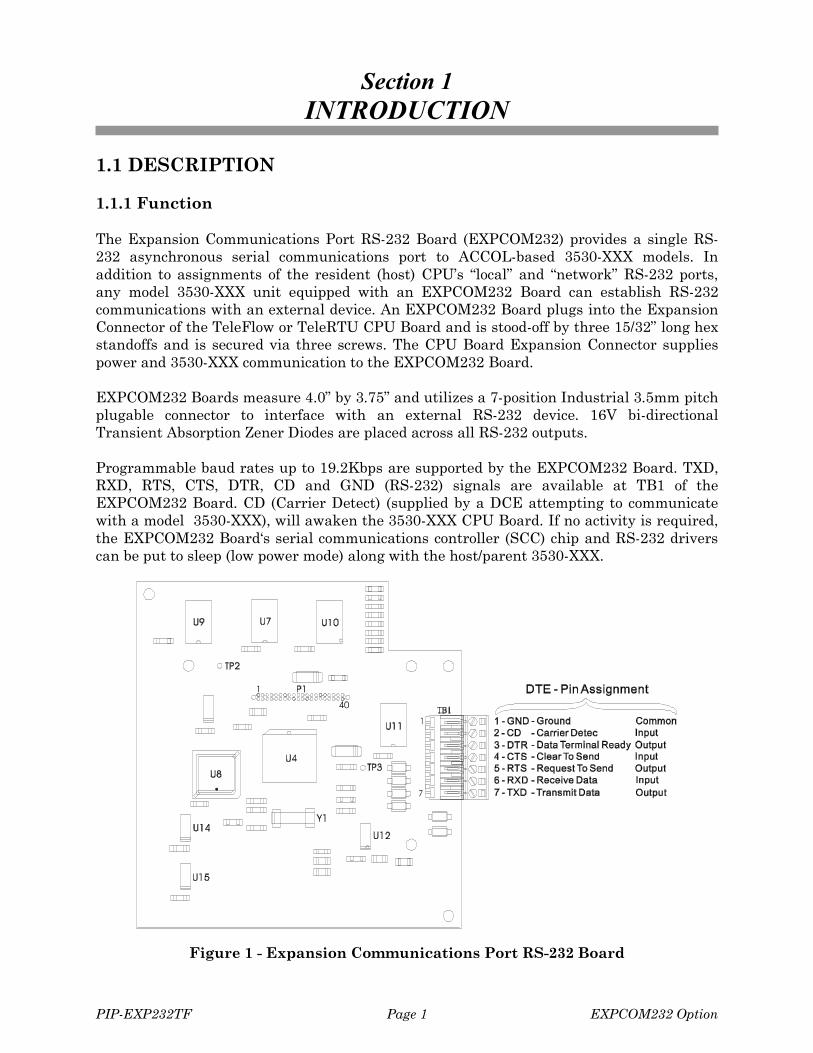
The Expansion Communications Port RS-232 Board (EXPCOM232) provides a single RS-232 asynchronous serial communications port to ACCOL-based 3530-XXX models. Inaddition to assignments of the resident (host) CPU’s “local” and “network” RS-232 ports,any model 3530-XXX unit equipped with an EXPCOM232 Board can establish RS-232communications with an external device. An EXPCOM232 Board plugs into the ExpansionConnector of the TeleFlow or TeleRTU CPU Board and is stood-off by three 15/32” long hexstandoffs and is secured via three screws. The CPU Board Expansion Connector suppliespower and 3530-XXX communication to the EXPCOM232 Board.
EXPCOM232 Boards measure 4.0” by 3.75” and utilizes a 7-position Industrial 3.5mm pitchplugable connector to interface with an external RS-232 device. 16V bi-directionalTransient Absorption Zener Diodes are placed across all RS-232 outputs.
Programmable baud rates up to 19.2Kbps are supported by the EXPCOM232 Board. TXD,RXD, RTS, CTS, DTR, CD and GND (RS-232) signals are available at TB1 of theEXPCOM232 Board. CD (Carrier Detect) (supplied by a DCE attempting to communicatewith a model 3530-XXX), will awaken the 3530-XXX CPU Board. If no activity is required,the EXPCOM232 Board‘s serial communications controller (SCC) chip and RS-232 driverscan be put to sleep (low power mode) along with the host/parent 3530-XXX.
Figure 1 - Expansion Communications Port RS-232 Board

EXPCOM232 Option Page 2 PIP-EXP232TF
1.1.2 Features
� Low Power+5V @ 20mA (Max) regulated power is supplied by the host/parent 3530-XXX via the40-pin Expansion Interface Connector P1.
� ESD & Transient SusceptibilityThe RS-232 I/O circuitry has been designed to meet the requirements of IEC 801-2for ESD withstand capability up to 10KV and the requirements of ANSI/IEEEC37.90.1-1989 (formerly IEE 472) for surge withstand capability.
� EMI CompatibilityEXPCOM232 Boards have been designed to coexist inside a shielded enclosure withthe TeleFlow� electronics. EMI radiation is insignificant and susceptibility iscomparable or superior to associated electronics.
� MountingThe EXPCOM232 Board measures 3.75” (9.525cm) in width x 4.0” (10.160cm) inheight and mounts piggy-back on a TeleFlow or TeleRTU CPU Board.
� RS-232 Serial PortEXPCOM232 Boards provide an additional RS-232 serial port that is programmablefor rates up to 19.2Kbps. 3530-XXX units equipped with the EXPCOM232 Board cancommunicate with a local RS-232 device even though a radio or modem may beinstalled on the CPU Board’s network port.
1.2 COMPONENT IDENTIFICATION
EXPCOM232 Boards do not contain LEDs, switches or configuration jumpers. Two con-nectors are provided; 40-pin connector P1 mates with the host 3530-XX-X (connector J4 -TeleFlow CPU or J18 - TeleRTU CPU) and accommodates the TTL interface between thetwo entities, while 7-pin connector TB1 mates with the RS-232 device that is beinginterfaced to the 3530-XXX. Additionally, the 3.5mm pitch plugable connector TB1 isremovable from its mating EXPCOM232 Board socket.
1.3 INSTALLATION COMPATIBILITY
An EXPCOM232 Board can be installed into any of the following 3530-XXX models:
3530-10B - TeleFlow 3530-35B - TeleRTU Module3530-15B - TeleRTU 3530-40B - TeleFlow ECR3530-20B - TeleFlow Plus 3530-45B - TeleRecorder3530-25B - TeleRTU Plus 3530-50B - TeleFlow Corrector
1.3.1 Restrictions
The 3530-XXX in question must be equipped with ACCOL application software. 3530-XXXunits support installation of only one optional piggyback mounted Expansion Board (I/O,Comm. or TIB).

PIP-EXP232TF Page 3 EXPCOM232 Option
Section 2INSTALLATION & SERVICE
2.1 EXPCOM232 REMOVAL/REPLACEMENT & INSTALLATION
2.1.1 Installation/Removal of the EXPCOM232 Board
In addition to hardware normally contained within the 3530-XXX in question, units with aninstalled EXPCOM232 Option will contain the following major parts.
1. Expanded Communications Port RS-232 Board (EXPCOM232)2. Three #4-40 x 15/32” Standoffs (Note: Models 3530-10B, - 15B, -40B, -45B & -50B will
also contain Three (3) #4-40 x .188” Standoffs & Two (2) #4-40 x 1/8” SEM Screws)3. Modified PC Shield Assembly (for models 3530-10B, -15B, -40B, -45B & -50B)
WARNING
Never attempt to service a TeleFlow, TeleRTU,TeleRecorder or TeleFlow Corrector while it is poweredand operating in a hazardous environment. Either thearea must be made safe or the unit must be powereddown, unwired, unmounted, and taken to a safe, non-hazardous area.
WARNING
Never attempt to install or remove any components(PCBs, Field Wiring, Transducers, etc.) while the unit ispowered and running. Doing so can cause suddenelectrical transients or imbalances that are capable ofcausing damage to the module or component in question,as well as other associated circuit boards. Always turnoff the external/internal power source, including anyadditional supply sources used for externally-poweredI/O circuits, before changing or adding any components.
CAUTION
Place any related critical processes under manual orauxiliary control prior to shutting down or performingany of the steps discussed herein.
2.1.1.1 Installation/Removal for Models 3530-10B, -15B, -40B, -45B & -50B
To install the optional EXPCOM232 Board into a model 3530-10B, -15B, -40B, -45B or -50B, follow steps 1 through 14 below. To remove the optional EXPCOM232 Board, see step15. Note: The Instrument Front Cover must be open.
1. To open the Instrument Front Cover, remove the lock if present and turn each of thethree captive screws a quarter (1/4) turn counterclockwise.

EXPCOM232 Option Page 4 PIP-EXP232TF
Note:The CPU Board is not to be removed under anycircumstances unless the unit has been moved to an ESDsafe area (see ESDS Manual - S14006).
2. Remove the Power Plug(s), Solar Panel Power Plug, and the Auxiliary Power Plug asrequired, from the CPU Board in question.
3. Remove the optional radio or modem if installed.To remove an optional modem:Disconnect the phone wires. Loosen the four (4) screws that secure the Modem/RadioMounting Plate (with modem) to the Battery Mounting Bracket. Slide the modem tothe left and remove it and then disconnect the D-Type connector from the modem.To remove an optional radio:Disconnect the Radio/TeleFlow Interface Cable from the bottom of the Radio. Unplugthe 2-wire power connector associated with the 2-wire Radio Power Interface Cablefrom the bottom of the Radio. Loosen the four (4) screws that secure the Modem/RadioMounting Plate (with radio) to the Battery Mounting Bracket. Slide the radio to theleft and remove it.
4. Remove the Battery(s) (if present).To remove the battery(s) from units without an optional modem or radio:Hold the battery securely and remove the Left Battery Mounting Bracket (securedwith 2 screws. Loosen the screws which secure the Right Battery Mounting Bracket(Carefully remove the battery (with wiring harness). Remove the Right BatteryMounting Bracket.To remove the battery(s) from units with an optional modem or radio:Carefully remove the battery (with wiring harness). Note: You may have to loosen thetwo left 1/4-20 x 3/8” screws that secure the left side of the Battery Mounting Bracketand the Main Mounting Bracket to the rear of the unit. While holding the MainMounting Bracket, remove the four (4) 1/4-20 x 3/8” screws and lock washers thatsecure the Battery Mounting Bracket and Main Mounting Bracket to the rear of theunit. Remove the Battery Mounting Bracket and temporarily reinstall the four screwsto secure the Main Mounting Bracket to the 3530-10B, 15B, -45B or -50B.
5. Disconnect the Local Port, Network Port, RTD, and Field I/O wires from the CPU Bd.connectors by unplugging their associated Term. Plugs on the front edge of the CPU.
6. Carefully remove the PC Shield which is secured to the Main Mounting Bracket by 2(#4-40 x 1/4”) screws and to the CPU Board by 2 (#4-40 x 1/4”) screws.
7. Remove the screw (location ‘A’ in Figures 2 & 3) and the two (2) #4-40 x 5/8” Standoffs(location ‘B’ in Figures 2 & 3) which secure the CPU Board to the Main MountingBracket. Replace these items with the three new #4-40 x 15/32” Standoffs.
Note:This operation should only be performed in an ESD safe area.
8. Align the EXPCOM232 Board Connector P1 with CPU Board Connector J4 (for 3530-10B, 40B or -50B) or J18 (for 3530-15B & -45B). Push the EXPCOM232 Board towardthe CPU Board until Connector P1 is fully seated.

PIP-EXP232TF Page 5 EXPCOM232 Option
Figure 2 - TeleFlow CPU Board – Installation Drawing #1
9. Secure the EXPCOM232 Board to the CPU Board by installing three (3) #4-40 x .188”Standoffs at locations ‘A’ and ‘B’ (see Figures 2 & 3).
10. Carefully install the Modified PC Shield, securing it to the Main Mounting Bracket (atlocations ‘C’) with two #4-40 x 1/4” screws and to the CPU Board (at locations ‘B’) withtwo (2) #4-40 x 1/8” SEM screws (see Figures 4, 5, 6 & 7).
11. Follow steps 2 through 6 in reverse order, replacing rather than removing the item inquestion.

EXPCOM232 Option Page 6 PIP-EXP232TF
12. Connect wiring between the EXPCOM232 Board and the DTE/DCE device to which itis to be interfaced (see Section 2.2).
13. Configure the new network port in the ACCOL Load resident in the host 3530-XXXdevice.
Figure 3 - TeleRTU CPU Board – Installation Drawing #1
14. Close and secure the Instrument Front Cover.
15. To remove an optional EXPCOM232 Board, follow steps 1 through 6 (unplug the RS-232 cable during step 5). Remove the PC Shield along with the three Standoffs that

PIP-EXP232TF Page 7 EXPCOM232 Option
secure the EXPCOM232 Board to the CPU Board. Then unplug the EXPCOM232Board from the CPU Board in question.
Figure 4 - TeleFlow CPU Board (with EXPCOM232 Installed)Installation Drawing #2

EXPCOM232 Option Page 8 PIP-EXP232TF
Figure 5 - TeleRTU CPU Board (with EXPCOM232 Installed)Installation Drawing #2

PIP-EXP232TF Page 9 EXPCOM232 Option
Figure 6 - 3530-10B, 3530-40B & 3530-50B (with EXPCOM232 Installed)
Figure 7 - 3530-15B & 3530-45B (with EXPCOM232 Installed)

EXPCOM232 Option Page 10 PIP-EXP232TF
2.1.1.2 Installation/Removal for Models 3530-20B & -25B
To install the optional EXPCOM232 Board into a model 3530-20B or 3530-25B, follow steps1 through 11 below. To remove the optional EXPCOM232 Board, perform steps 1 and 2 andthen follow steps 4 through 9 in reverse order, removing rather than installing the item inquestion after the system has been shut down. Note: The Instrument Front Cover must beopen.
1. Open the Instrument Front Cover
2. Disconnect power by removing harness connector plug (P8 for TeleFlow - P2 forTeleRTU) from the CPU Board edge connector (J8 for TeleFlow – J2 for TeleRTU).
Figure 8 - 3530-20B CPU (with EXPCOM232 Installed)
3. Unplug the remaining removable Terminal Blocks (with wiring harnesses installed)from the CPU Board’s front edge connectors.
4. Remove the two screws that secure the CPU Board’s Sliding Mounting Bracket to theFixed Bracket on the bottom of the Battery Bracket. Carefully slide the CPU Board(and optional EXPCOM232 Board) toward the front of the unit. Remove harnessconnections from the Front Panel Switch (J12 on the TeleFlow CPU - J14 on TeleRTUCPU), the Display Module (J2 on TeleFlow CPU - J16 on TeleRTU CPU), the WakeupSwitch (J3 on TeleFlow CPU - J16 on TeleRTU CPU), and for TeleFlow CPU Boardsconnector J1 (associated with the Multivariable Transducer).
5. Remove the three screws (of five) that secure the CPU Board to the Sliding MountingBracket (locations ‘A’ & ‘B’ in Figures 2 & 3) and replace these items with the threenew #4-40 x 15/32” Standoffs.
Note:This operation should only be performed in an ESD safe area.
6. Align the EXPCOM232 Board Connector P1 with CPU Board Connector J4 (for 3530-20B) or J18 (for 3530-25B). Push the EXPCOM232 Board toward the CPU Board untilConnector P1 is fully seated.
7. Secure the EXPCOM232 Board to the CPU Board by installing three (3) #4-40 x 1/4”SEM screws as illustrated in Figures 8 & 9.

PIP-EXP232TF Page 11 EXPCOM232 Option
Figure 9 - 3530-25B CPU (with EXPCOM232 Installed)
8. Route the RS-232 cable through a ¾” conduit fitting (user installed) on the bottom ofthe enclosure.
9. Connect wiring between the EXPCOM232 Board and the DTE/DCE device to which itis to be interfaced (see Section 2.2).
10. Configure the new network port in the ACCOL Load resident in the host 3530-XXXdevice.
11. Close and secure the Instrument Front Cover.
2.1.1.3 Installation/Removal for Models 3530-35B
To install the optional EXPCOM232 Board into a model 3530-35B, follow steps 1 through 8below. To remove the optional EXPCOM232 Board, perform step 1 and then follow steps 5through 7 in reverse order, removing rather than installing the item in question after thesystem has been shut down.
1. Disconnect power by removing harness connector plug P2 from the CPU Board edgeconnector J2.
2. Unplug the remaining removable Terminal Blocks (with wiring harnesses installed)from the CPU Board’s front edge connectors.
3. Remove harness connections from the Front Panel Switch (J14), the Display Module(J16) and the Wakeup Switch (J16).
4. Remove the three screws (of five) that secure the CPU Board to the RTU MountingBracket (locations ‘A’ & ‘B’ in Figures 2 & 3) and replace these items with the threenew #4-40 x 15/32” Standoffs.
Note:This operation should only be performed in an ESD safe area.
5. Align the EXPCOM232 Board Connector P1 with CPU Board Connector J18. Push theEXPCOM232 Board toward the CPU Board until Connector P1 is fully seated.

EXPCOM232 Option Page 12 PIP-EXP232TF
6. Secure the EXPCOM232 Board to the CPU Board by installing three (3) #4-40 x 1/4”SEM screws as illustrated in Figure 10.
7. Connect wiring between the EXPCOM232 Board and the DTE/DCE device to which itis to be interfaced (see Section 2.2).
8. Configure the new network port in the ACCOL Load resident in the host 3530-XXXdevice.
Figure 10 - 3530-35B (with EXPCOM232 Installed)
2.2 RS-232 WIRING
Table 2-1 and Figure 11 must be referenced to configure the RS-232 cable. Pin 2 of TB1 =DCD (Data Carrier Detect - DCD). DCD can be used to awaken the 3530-XXX in questionfrom power conservation (sleep) mode. This signal is not supplied by DTE equipment.

PIP-EXP232TF Page 13 EXPCOM232 Option
Figure 11 - EXPCOM232 Wiring Diagrams

EXPCOM232 Option Page 14 PIP-EXP232TF
Either an RS-232 level control signal (high) can be supplied to TB1-2, or TB1-2 may beconnected to the EXC signal on the CPU Board. It must be noted that as long as TB1-2(DCD) remains HIGH, the 3530-XXX in question will remain awake. Therefore, if TB1-2 isconnected to an EXC signal on the resident CPU Board, power conservation will bedefeated, thus reducing the battery back-up time.
RS-232 cables are typically short (20’ or less in length). When significant distances are afactor (i.e., between an EXPCOM232 Board and the remote Data Terminal Device (DTE) towhich it is desired to communicate), the RS-232 Port (TB1) cable can be connected to theRS-232 Port of a modem or that of a BBI Isolated RS-485 Board (see Table 2-1).
Table 2-1EXPCOM232 Board (DTE) & DCE/DTE - RS-232 Port Pin Assignments
EXPCOM232RS-232 – TB1
EXPCOM232RS-232 TB1 or3530 NetworkPort J13/J8
Modem9-Pin – J4
PC(RS-232)
3310/30/3533053332
Notes 1 & 2
BBIIsolated RS-485Board Option
J1DTE DTE DCE DTE DTE DTE
2 - DCD (In) - 1 - DCD (Out) - - -6 - RXD (In) 7 - TXD (Out) 2 - RXD (Out) 3 - TXD (Out) 2 - TXD (Out) 7 - TXD (Out)7 - TXD (Out) 6 - RXD (In) 3 - TXD (In) 2 - RXD (In) 4 - RXD (In) 6 - RXD (In)3 - DTR (Out) - 4 - DTR (In) - - -1 - GND 1 - GND 5 - GND 5 - GND 9 - GND 1 - GND
- - 6 - DSR (Out) - - -5 - RTS (Out) 4 - CTS (In) 7 - RTS (In) 8 - CTS (In) 6 - CTS (In) 4 - CTS (In)4 - CTS (In) 5 - RTS (Out) 8 - CTS (Out) 7 - RTS (Out) 5 - RTS (Out) 5 - RTS (Out)
- - 9 - N/A - - -
Note 1: Ports BIP1 & BIP2BIP1 and BIP2 are RS-562 Ports (RS-232 compatible.
Note 2: 3310 Ports A & C (MFIB Board)A & C are RS-423 Ports (RS-232 compatible).
3330 Ports A, B, C, D, G, H, I & J (Enhanced Comm. Boards)ECB’s 392587-01-7, 392587-02-5, 392587-03-3 & 392903-01-6A, B, C, D, G, H, I & J are RS-562 Ports (RS-232 compatible).
3335 Ports A, B, C, D, I & J (Enhanced Comm. Boards)ECB’s 392589-01-0 & 392589-02-8A, B, C, D, I & J are RS-232 Ports
3335 Ports A, B, C & D (Comm. Engine Boards)CEB’s 392043-01-7 & 392058-01-4A, B, C & D are RS-423 Ports (RS-232 compatible)
The device uses compression-type terminals that accommodate up to #14 AWG wire. Aconnection is made by inserting the bared end (1/4 inch Max.) into the clamp beneath thescrew and then securing the screw. Insert the bared end fully to prevent short circuits.
Allow some slack in the wires when making terminal connections. The slack makes theconnections more manageable and minimizes mechanical strain on the printed circuitboards and harnesses.

PIP-EXP232TF Page 15 EXPCOM232 Option
Section 3SPECIFICATIONS
3.1 PERFORMANCE SPECIFICATIONS
Baud Rate (Max.): 19.2K Asynchronous
Power Requirements: +5Vdc @ 20mA Max. (Regulated)
Transient Protection: 16V Bi-directional Transient Absorption Zeners across allRS-232 outputs
RS-232 Outputs: TXD (TB1-7)DTR (TB1-3)RTS (TB1-5)
RS-232 Inputs: DCD (TB1-2)RXD (TB1-6)CTS (TB1-4)
RS-232 Ground: GND (TB1-1)
RS-232 Interface Connector: 7-Pin Industrial 3.5mm Pitch Plugable Connector
3.2 ENVIRONMENTAL SPECIFICATIONS
Operating Temperature: -40� to +60� (C) [-40� to 140� (F)]
Storage Temperature: -40� to +85� (C) [-40� to 185� (F)]
Humidity: 15% to 90% RH (Non-Condensing)
ESD Susceptibility: Meets the requirement of IEC 801-2 for ESD withstandCapability up to 10KV.
EMI Compatibility: Designed to coexist inside a shielded enclosure with theTeleFlow electronics. EMI radiation is insignificant andSusceptibility is comparable or superior to associatedElectronics.
Transient Susceptibility: Designed to meet the requirements of ANSI/IEEEC37.90.1-1989 (Formerly IEEE 472) for surge withstandCapability.

07/17/2000 Appendix A of PIP-EXP232TF - EXPCOM232 Board Page 1 of 1
Expansion Communications Port RS-232 BoardSpecial Instructions for Class I, Division 2 Hazardous Locations
1. The BBI Expansion Communications Port RS-232 Board is listed by UnderwritersLaboratories (UL) as nonincendive and is suitable for use in Class I, Division 2, GroupsA, B, C and D hazardous locations or non-hazardous locations only. Read this documentcarefully before installing a nonincendive BBI Expansion Communications Port RS-232Board. In the event of a conflict between the Expansion Communications Port RS-232Board User Manual (PIP-EXP232TF) and this document, always follow the instructionsin this document.
2. Wiring must be performed in accordance with Class I, Division 2 wiring methods asdefined in Article 501-4 (b) of the National Electrical Code, NFPA 70 for installationswithin the United States, or as specified in Section 18-152 of the Canadian ElectricalCode for installation in Canada.
3. WARNING: EXPLOSION HAZARD - Substitution of components may impairsuitability for use in Class I, Division 2 environments.
4. WARNING: EXPLOSION HAZARD - When situated in a hazardous location,turn off power before servicing/replacing the unit and before installing orremoving I/O wiring.
5. WARNING: EXPLOSION HAZARD - Do Not disconnect equipment unless thepower has been switched off or the area is known to be nonhazardous.

Expansion Communications Port RS-232 Board for 3530-XXXSpecial Instructions for Class I, Division 1 Hazardous Locations
12/12/03 Appendix B - Document PIP-EXP232TF Page 1 of 3
1. A version of the Expansion Communications Port RS-232 Board is available that islisted by Underwriters Laboratories (UL) as intrinsically safe for use in Class I, Division1, Groups C and D hazardous locations. Read this document carefully before installingan intrinsically safe Expansion Communications Port RS-232 Board. Refer to theExpansion Communications Port RS-232 Board User’s Manual (PIP-EXP232TF) forgeneral information. In the event of a conflict between the Expansion CommunicationsPort RS-232 Board User’s Manual and this document, always follow the instructions inthis document.
2. Unless the Expansion Communications Port RS-232 Board is used in conjunction withan IStran Communications Interface Assembly (see CI-3530-Istran) it may not be usedin a Class I, Division 1 hazardous location.
3. When a TeleFlow equipped with an Expansion Communications Port RS-232 Board isused in a Class I, Division 1 location, it must be used in conjunction with a BBI IStranCommunications Interface and installed per instruction manual CI-3530-IStran andPIP-EXP232TF.
4. The IStran and Expansion Communications Port RS-232 Board can be located in anonhazardous or Division 2 rated area, while the TeleFlow can reside in a Division 1, 2or nonhazardous area.
A suitable enclosure must be provided for the IStran. When the IStran is mounted in aDivision 2 area, the nonhazardous interface connections shall be made in accordancewith Article 501-4(b) of the National Electrical Code NFPA 70.
CAUTION
When connecting the IStran and Expansion CommunicationsPort RS-232 Board to a TeleFlow that is mounted in a Division1 area, wire all circuits using wiring methods specified inarticle 504 of the National Electrical Code NFPA 70. Contactyour IStran supplier for assistance.
When installing an Expansion Communications Port RS-232Board in a TeleFlow that is mounted in a Division 2 area,ensure that the area is nonhazardous before connecting ordisconnecting the nonhazardous interface.
5. Figures B1 through B4 show variations of approved connections to the ExpansionCommunications Port RS-232 Board via a BBI IStran Communications InterfaceAssembly.

Expansion Communications Port RS-232 Board for 3530-XXXSpecial Instructions for Class I, Division 1 Hazardous Locations
12/12/03 Appendix B - Document PIP-EXP232TF Page 2 of 3
Figure B1 - Intrinsically Safe System with Radio and EXPCOM232 Board(with Single Power Source)
Figure B2 - Intrinsically Safe System with Modem and EXPCOM232 Board(with Single Power Source)

Expansion Communications Port RS-232 Board for 3530-XXXSpecial Instructions for Class I, Division 1 Hazardous Locations
12/12/03 Appendix B - Document PIP-EXP232TF Page 3 of 3
Figure B3 - Intrinsically Safe System with Modem and EXPCOM232 Board(with Independent Power Sources)
Figure B4 - Intrinsically Safe System with Radio and EXPCOM232 Board(with Independent Power Sources)

READER RESPONSE FORM
Please help us make our documentation more useful to you! If you have a complaint, asuggestion, or a correction regarding this manual, please tell us by mailing this page with yourcomments. It's the only way we know we're doing our job by giving you correct, complete, anduseful documentation.
DOCUMENT NUMBER: PIP-EXP232TFTITLE: EXPANSION COMMUNICATIONS PORT RS-232 BOARD (for Models 3530-XXX)
Product Information PackageISSUE DATE: DEC., 2003COMMENT/COMPLAINT:
______________________________________________________________________________
______________________________________________________________________________
______________________________________________________________________________
______________________________________________________________________________
______________________________________________________________________________
______________________________________________________________________________
______________________________________________________________________________
______________________________________________________________________________
______________________________________________________________________________
______________________________________________________________________________
______________________________________________________________________________
______________________________________________________________________________
______________________________________________________________________________
Mail this page to:Bristol Babcock Inc.1100 Buckingham StreetWatertown, CT 06795Attn: Technical Publications Group, Dept. 315

U.S.A. Locations:
Northern RegionBristol Babcock Inc.1100 Buckingham StreetWatertown, CT 06795Phone: +1 (860) 945-2381Fax: +1 (860) [email protected]
Gulf Coast RegionBristol Babcock Inc.2000 Governor's CircleSuite FHouston, TX 77092-8731Phone: +1 (713) 685-6200Fax: +1 (713) [email protected]
Western RegionBristol Babcock Inc.1609 South Grove AvenueSuites 106 & 107Ontario, CA 91761Phone: +1 (909) 923-8488Fax: +1 (909) [email protected]
Southeast RegionBristol Babcock Inc.317 S. North Lake Blvd.Suite 1016Altamonte Springs, FL 32701Phone: +1 (407) 740-7084Fax: +1 (407) [email protected]
Helicoid Instruments1100 Buckingham StreetWatertown, CT 06795Phone: +1 (860) 945-2218Fax: +1 (860) [email protected]
Central RegionBristol Babcock Inc.777 South CentralExpresswaySuite 1-CRichardson, TX 75080Phone: +1 (972) 238-8197Fax: +1 (972) [email protected]
Rocky Mountain RegionBristol Babcock Inc.906 San Juan Blvd., Suite AFarmington, NM 87401Phone: +1 (505) 320-5046Fax: +1 (505) [email protected]
CommunicationsTechnology GroupBristol Babcock Inc.317 S. North Lake Blvd.Suite 1016Altamonte Springs, FL 32701Phone: +1 (407) 629-9464Fax: +1 (407) [email protected]
International Affiliates:
CanadaBristol Babcock, Canada234 Attwell DriveToronto, Ont. M9W 5B3CanadaPH: 416-675-3820FAX: [email protected]
Calgary OfficeBristol Babcock, Canada3812 Edmonton Trail N.E.Calgary, Alberta T2E 5T6CanadaPH: 403-265-4808FAX: [email protected]
MexicoBBI, S.A. de C.V.Homero No. 1343, 3er PisoCol. Morales Polanco11540 Mexico, D.F.MexicoPH: (52-55)-52-81-81-12FAX: (52-55)[email protected]
Villahermosa OfficeBBI, S.A. de C.V.Av. Plomo No.2Bodega No. 1 - CiudadIndustrialVillahermosa, Tabasco 86010MexicoPH: 52-993-353-3142FAX: [email protected]
United KingdomBristol Babcock Ltd.Blackpole RoadWorcester, WR3 8YBUnited KingdomPH: +44 (0) 1905 856950FAX: +44 (0) 1905 [email protected]
Middle EastBristol Babcock Ltd.Blackpole RoadWorcester, WR3 8YBUnited KingdomPH: +44 (0) 1905 856950FAX: +44 (0) 1905 [email protected]
Asia PacificBristol Babcock, Inc.PO Box 1987Bunbury, Western Australia6231PH: +61 (0) 8 9791 3654FAX: +61 (0) 8 9791 [email protected]
Victoria, AustraliaPH: +61 (0) 3 9384 2171FAX: +61 (0) 3 8660 2501
RC Rev: 13-Jun-03
Bristol Babcock1100 Buckingham StreetWatertown, CT 06795Phone: +1 (860) 945-2200Fax: +1 (860) 945-2213Website: www.bristolbabcock.com

Return to CI-3530-20B Table of Contents
Return to CI-3530-35B Table of Contents
Return to CI-3530-10B Table of Contents
Return to CI-3530-15B Table of Contents
Return to CI-3530-25B Table of Contents
Retrun to CI-3530-45B Table of Contents
Return to the List of Manuals
Return to CI-3530-50B Table of Contents
Return to PIP Table of Contents


![INSTALL GUIDE OL-NI(RS)-NI5-[OL-RS-NI5]-EN - iDatalink](https://static.fdokumen.com/doc/165x107/633aa8bc006fce433007d856/install-guide-ol-nirs-ni5-ol-rs-ni5-en-idatalink.jpg)