Executive Desk - Teknik Office
36
NOTE: THIS INSTRUCTION BOOKLET CONTAINS IMPORTANT SAFETY INFORMATION. PLEASE READ AND KEEP FOR FUTURE REFERENCE. Executive Desk Elstree | Model 5426484 Sit and surf.
-
Upload
khangminh22 -
Category
Documents
-
view
0 -
download
0
Transcript of Executive Desk - Teknik Office

NOTE: THIS INSTRUCTION BOOKLET CONTAINS IMPORTANT SAFETY INFORMATION.
PLEASE READ AND KEEP FOR FUTURE REFERENCE.
Executive DeskElstree | Model 5426484
Sit and surf.

Table of Contents Assembly Tools Required
Part Identifi cation
Hardware Identifi cation
Assembly Steps
Français
Español
Safety
Warranty
No. 2 Phillips ScrewdriverTip Shown Actual Size
HammerNot actual size
2-3
4-5
6-40
41-46
47-52
53-54
55
Page 2
Part Identifi cation
å While not all parts are labeled, some of the parts will have a label or an inked letter on the edge to help distinguish similar parts from each other. Use this part identifi cation to help identify similar parts.
A RIGHT END (1)
B LEFT END (1)
B56 PENCIL DRAWER BOTTOM (2)
C RIGHT UPRIGHT (1)
D LEFT UPRIGHT (1)
D77 DRAWER BACK (2)
D78 FILE DRAWER BACK (2)
D133 RIGHT DRAWER SIDE (2)
D139 LEFT DRAWER SIDE (2)
D429 FILE LEFT DRAWER SIDE (2)
D430 FILE RIGHT DRAWER SIDE (2)
D565 PENCIL RIGHT DRAWER SIDE (2)
D566 PENCIL LEFT DRAWER SIDE (2)
D567 PENCIL DRAWER BACK (2)
D568 PENCIL DRAWER BOX FRONT (2)
D708 DRAWER BOTTOM (4)
E BOTTOM (2)
G LONG BASE (4)
H SHORT BASE (4)
J FILE DRAWER FRONT (1)
K DRAWER FRONT (2)
L MODESTY PANEL (1)
M FRONT MOLDING (1)
N PENCIL DRAWER FRONT (2)
O LOUVERED BACK (2)
P TOP (1)
W LOCKING DRAWER FRONT (1)
Adjustable Wrench
Tape Measure

Part Identifi cation Now you knowour ABCs.
Page 3
B56
D77
D565
D566
D567D568
D133
D708D139
D78 D430
D708D429
D78 D430
D708D429
A
B
C
D
E
HG
W
J
K
L
M
NO
P
H
G
E
O
HG
HG

Hardware Identifi cation
å Screws are shown actual size. You may receive extra hardware with your unit.
FILE ROD - 48BFILE GLIDE - 46B
(EXTENSION SET SHOWN SEPARATED)EXTENSIONSLIDE - 440MCEXTENSION
RAIL - 440MA 10A SLIDECAM - 8
HIDDEN CAM - 81F CAM
DOWEL - 82F 36F
TWIST-LOCK® FASTENER - 18
METAL BRACKET - 8
4G
31G CORNERBRACKET - 8
76G L - LOCKBRACKET - 1
77G Z - LOCKBRACKET - 1
ANGLE BRACKET - 627G
40CA CABINET RIGHT - 4 40CB CABINET LEFT - 4 40CC DRAWER RIGHT - 4 40CD DRAWER LEFT - 4
Page 4
Hardware Identifi cation
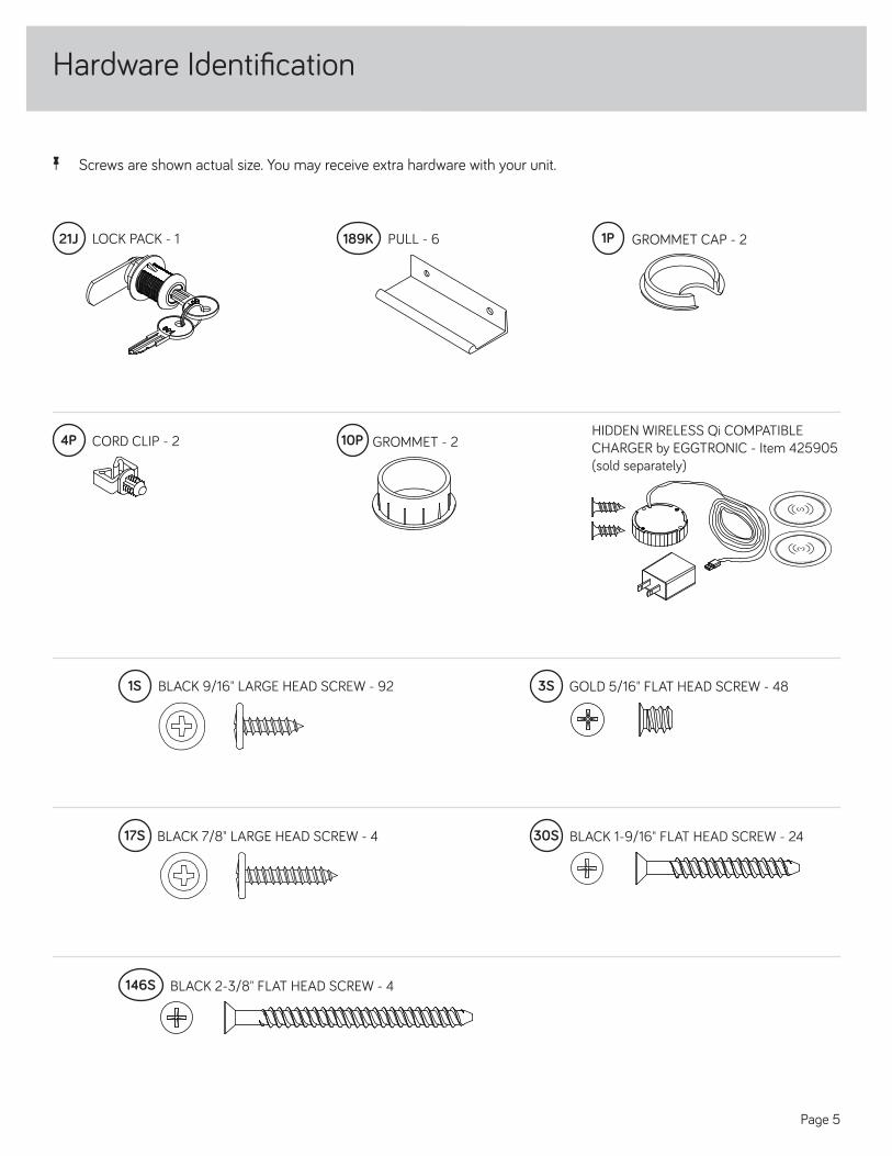
å Screws are shown actual size. You may receive extra hardware with your unit.
LOCK PACK - 121J PULL - 6189K GROMMET CAP - 21P
BLACK 9/16" LARGE HEAD SCREW - 921S 3S GOLD 5/16" FLAT HEAD SCREW - 48
BLACK 7/8" LARGE HEAD SCREW - 417S 30S BLACK 1-9/16" FLAT HEAD SCREW - 24
146S BLACK 2-3/8" FLAT HEAD SCREW - 4
Page 5
GROMMET - 210PCORD CLIP - 24PHIDDEN WIRELESS Qi COMPATIBLE CHARGER by EGGTRONIC - Item 425905 (sold separately)
powered by EGGTRONIC
powered by EGGTRONIC
powered by EGGTRONIC
powered by EGGTRONIC
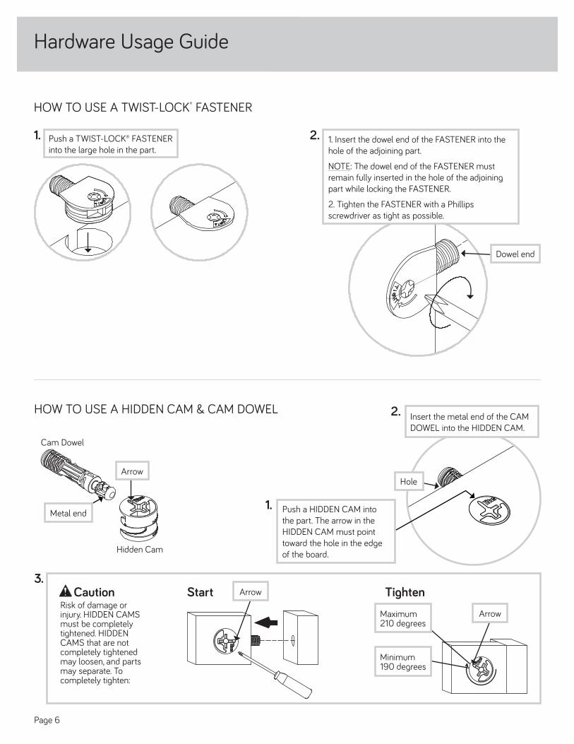
Hardware Usage Guide
1. Insert the dowel end of the FASTENER into thehole of the adjoining part.
NOTE: The dowel end of the FASTENER must remain fully inserted in the hole of the adjoining part while locking the FASTENER.
2. Tighten the FASTENER with a Phillipsscrewdriver as tight as possible.
Dowel end
2.Push a TWIST-LOCK® FASTENER into the large hole in the part.
1.
HOW TO USE A TWIST-LOCK® FASTENER
Page 6
HOW TO USE A HIDDEN CAM & CAM DOWEL 2. Insert the metal end of the CAMDOWEL into the HIDDEN CAM.
1. Push a HIDDEN CAM intothe part. The arrow in theHIDDEN CAM must pointtoward the hole in the edgeof the board.
HoleArrow
Metal end
Hidden Cam
Cam Dowel
Start TightenArrow
Minimum190 degrees
CautionRisk of damage or injury. HIDDEN CAMS must be completely tightened. HIDDEN CAMS that are not completely tightened may loosen, and parts may separate. To completely tighten:
Arrow
Maximum210 degrees
3.

36F
L
å Assemble your unit on a carpeted fl oor or on the emptycarton to avoid scratching your unit or the fl oor.
å Push two SAUDER TWIST-LOCK® FASTENERS (36F) intothe large holes in the MODESTY PANEL (L).
å Fasten the MODESTY PANEL (L) to the TOP (P). Tightentwo TWIST-LOCK® FASTENERS.
å Push two CORD CLIPS (4P) into the holes in the TOP (P).
å NOTE: The CORD CLIPS are used to hold the optionalHIDDEN WIRELESS CHARGER cord.
Step 1
LSurface with TWIST-LOCK® FASTENERS
P
Meet Part (P). This component has been engineered to be lighter, stronger, faster… well ok. Not technically faster. But defi nitely makes for a sturdier Executive Desk that’s easier to assemble and friendlier to the environment.
Page 7
4P

å Push four SAUDER TWIST-LOCK® FASTENERS (36F) intothe large holes in the UPRIGHTS (C and D).
Step 2
D
C
Do not tighten the TWIST-LOCK® FASTENERS in this step.
36F
These holes must be here.
Page 8

Step 3
Open end
å Separate the EXTENSION SLIDES (40MC) from the EXTENSION RAILS (40MA) asshown in the upper diagram below. Be prepared, the parts are greasy.
å Fasten two EXTENSION RAILS (40MA) to the UPRIGHTS (C and D). Use four GOLD5/16" FLAT HEAD SCREWS (3S) through holes #1 and #4.
å NOTE: For each EXTENSION RAIL, turn a SCREW into the hole shown in the enlargeddiagram. Then, slide the inner cartridge of the EXTENSION RAIL in to fi nd the other hole that lines up with the hole in the UPRIGHT. Turn a SCREW into this hole.
å NOTE: The EXTENSION SLIDES will be used later for the FILE DRAWERS.
Push the black lever in and pull the SLIDE from the RAIL.
40MA40MC
Open end
32
1
1
23
4
4D
C
GOLD 5/16" FLAT HEAD SCREW(4 used for the RAILS)
3S
Page 9

å Fasten two CABINET RIGHTS (40CA) to the LEFTUPRIGHT (D) and two CABINET LEFTS (40CB) to the RIGHT UPRIGHT (C). Use eight GOLD 5/16" FLAT HEAD SCREWS (3S) through holes #1 and #4.
å Fasten the L-LOCK BRACKET (76G) to the LEFTUPRIGHT (D) exactly as shown. Use two BLACK 9/16" LARGE HEAD SCREWS (1S).
Step 4
12
34
12
34
Roller end
GOLD 5/16" FLAT HEAD SCREW(8 used for the RAILS)
3S
BLACK 9/16" LARGE HEAD SCREW(2 used for the BRACKET)
1S
D
C
Roller end76G
Page 10

å Fasten the UPRIGHTS (C and D) to the TOP (P). Tighten fourTWIST-LOCK® FASTENERS.
å Fasten the UPRIGHTS (C and D) to the MODESTY PANEL (L).Use four BLACK 2-3/8" FLAT HEAD SCREWS (146S).
å NOTE: You should start each SCREW a few turns beforecompletely tightening any of them.
Step 5
D
C
P
L
The BRACKET must be here.
BLACK 2-3/8" FLAT HEAD SCREW(4 used in this step)
146S
Page 11

Step 6
å Push eight SAUDER TWIST-LOCK® FASTENERS (36F)into the large holes in the LOUVERED BACKS (O).
Do not tighten the TWIST-LOCK® FASTENERS in this step.
O
O
36F
36F
(8 used)
Page 12

Step 7
å Fasten the LOUVERED BACKS (O) to the UPRIGHTS (C and D).Tighten four TWIST-LOCK® FASTENERS.
D
C
O
Surface with
TWIST-LOCK®
FASTENERS
O
Surface with
TWIST-LOCK®
FASTENERS
Page 13

å Push eight HIDDEN CAMS (1F) into the BOTTOMS (E).Then, insert the metal end of a CAM DOWEL (2F) into each HIDDEN CAM.
Step 8
E
E
(8 used)
Do not tighten the HIDDEN CAMS in this step.
1F
2FArrow
Metal end
1F
2F
Metal end
Arrow
Page 14

å Fasten the BOTTOMS (E) to the UPRIGHTS (C and D).Tighten four HIDDEN CAMS.
Step 9
D
C
ESurface with
HIDDEN CAMS
ESurface with
HIDDEN CAMS
Page 15

Step 10
A
B
å Push four SAUDER TWIST-LOCK® FASTENERS (36F) intothe large holes in the ENDS (A and B).
Do not tighten the TWIST-LOCK® FASTENERS in this step.
36F
Page 16

Step 11
Open end
å Fasten two EXTENSION RAILS (40MA) to the ENDS (A and B). Usefour GOLD 5/16" FLAT HEAD SCREWS (3S) through holes #1 and #4.
å NOTE: For each EXTENSION RAIL, turn a SCREW into the holeshown in the enlarged diagram. Then, slide the inner cartridge of the EXTENSION RAIL in to fi nd the other hole that lines up with the hole in the END. Turn a SCREW into this hole.
Open end
32
1
1
23
4
4
A
B
GOLD 5/16" FLAT HEAD SCREW(4 used for the RAILS)
3S
Page 17
These holes must be here.
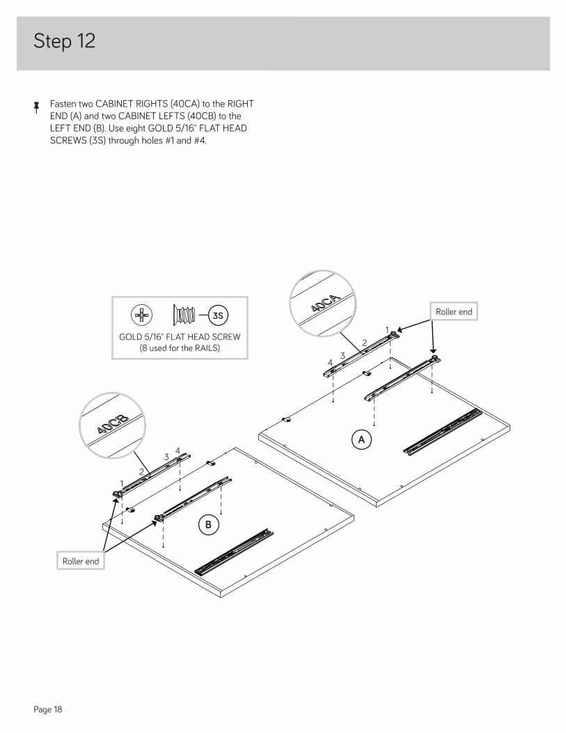
Step 12
å Fasten two CABINET RIGHTS (40CA) to the RIGHTEND (A) and two CABINET LEFTS (40CB) to the LEFT END (B). Use eight GOLD 5/16" FLAT HEAD SCREWS (3S) through holes #1 and #4.
12
34
12
34
Roller end
GOLD 5/16" FLAT HEAD SCREW(8 used for the RAILS)
3S
A
B
Roller end
Page 18

å Fasten the ENDS (A and B) to the BACKS (O) and TOP (P).Tighten eight TWIST-LOCK® FASTENERS.
å Fasten the ENDS (A and B) to the BOTTOMS (E). Tightenfour HIDDEN CAMS.
Step 13
A
B
E
E
P
Page 19
O
O

å Fasten six ANGLE BRACKETS (27G) to the FRONT MOLDING (M).Use six BLACK 9/16" LARGE HEAD SCREWS (1S).
å NOTE: Be sure the edges of the ANGLE BRACKETS are even withthe edges of the FRONT MOLDING.
Step 16
M
BLACK 9/16" LARGE HEAD SCREW(6 used in this step)
1S
27G
27G
27G
Page 20

Step 17
å Fasten the FRONT MOLDING (M) to the UPRIGHTS (C and D)and TOP (P). Use six BLACK 9/16" LARGE HEAD SCREWS (1S) through the ANGLE BRACKETS on the FRONT MOLDING and into the holes in the UPRIGHTS and TOP.
BLACK 9/16" LARGE HEAD SCREW(6 used in this step)
1S
P
M
D
C
Page 21

å Fasten the CORNER BRACKETS (31G) to the BOTTOMS (E).Use sixteen BLACK 9/16" LARGE HEAD SCREWS (1S).
Step 18
BLACK 9/16" LARGE HEAD SCREW(16 used in this step)
1S
E
E
31G(8 used)
31G
31G
31G
Page 22

å Fasten the SHORT BASES (H) to the CORNER BRACKETSon the BOTTOMS (E). Use sixteen BLACK 9/16" LARGE HEAD SCREWS (1S).
Step 19
BLACK 9/16" LARGE HEAD SCREW(16 used in this step)
1S
E
H
Page 23
H
E
H
H

å Fasten eight METAL BRACKETS (4G) to the LONG BASES (G).Use eight BLACK 9/16" LARGE HEAD SCREWS (1S).
å NOTE: Be sure the BRACKETS are even with the edge of eachLONG BASE.
å Fasten the LONG BASES (G) to the CORNER BRACKETS onthe BOTTOMS (E). Use sixteen BLACK 9/16" LARGE HEAD SCREWS (1S).
å Fasten LONG BASES (G) to the BOTTOMS (E). Use eightBLACK 9/16" LARGE HEAD SCREWS (1S) through the METAL BRACKETS on the LONG BASES and into the holes in the BOTTOMS.
Step 20
BLACK 9/16" LARGE HEAD SCREW(32 used in this step)
1S
E
E
G
4G
(8 used)
GG
G
G
G
G
G
Page 24

Step 21
å Fasten the PENCIL DRAWER BACK (D567) to the PENCILDRAWER SIDES (D565 and D566). Use two BLACK 1-9/16" FLAT HEAD SCREWS (30S).
å Slide the PENCIL DRAWER BOTTOM (B56) into thegrooves in the PENCIL DRAWER SIDES (D565 and D566) and PENCIL DRAWER BACK (D567).
å Fasten the PENCIL DRAWER BOX FRONT (D568) to thePENCIL DRAWER SIDES (D565 and D566). Use two BLACK 1-9/16" FLAT HEAD SCREWS (30S).
å Repeat this step for the other PENCIL DRAWER.
B56
D565
D566
D567
D568
Groove
BLACK 1-9/16" FLAT HEAD SCREW(8 used in this step)
30S
Finished surfaceBe sure the DRAWER BOTTOM inserts into the DRAWER BOX groove.
30S
30S
Page 25
D567
D565
D566

å Fasten the PENCIL DRAWER FRONT (N) to the PENCILDRAWER BOX FRONT (D568). Use two BLACK 7/8" LARGE HEAD SCREWS (17S).
å Fasten one PULL (189K) to the PENCIL DRAWER FRONT (N).Use two BLACK 9/16" LARGE HEAD SCREWS (1S).
å Repeat this step for the other PENCIL DRAWER.
Step 22
189K
D568
N
Page 26
BLACK 9/16" LARGE HEAD SCREW(4 used for the PULLS)
1S
BLACK 7/8" LARGE HEAD SCREW(4 used for the DRAWER FRONTS)
17S

å Fasten a DRAWER RIGHT (40CC) to the PENCIL RIGHTDRAWER SIDE (D565) and a DRAWER LEFT (40CD) to the PENCIL LEFT DRAWER SIDE (D566). Use four GOLD 5/16" FLAT HEAD SCREWS (3S) through holes #1 and #4.
å Repeat this step for the other PENCIL DRAWER.
Step 23
GOLD 5/16" FLAT HEAD SCREW(8 used for the SLIDES)
3S Drawer Slide
Center the screw in the oval hole.
Roller end
Roller end
12
34
12
34
D565
D566
Page 27

Step 24
With the palm of your hand, tap the DRAWER BOTTOM down into the groove.
å Fasten the DRAWER BACK (D77) to the DRAWER SIDES (D133 and D139). Use four BLACK 1-9/16" FLAT HEAD SCREWS (30S).
å NOTE: Be sure the DRAWER BOTTOM (D708) inserts into the groove of the DRAWER BACK (D77).
å Repeat this step for the other drawer.
å Fasten the Z-LOCK BRACKET (77G) to one of the DRAWER FRONTS (K) exactly as shown. Use two BLACK 9/16" LARGEHEAD SCREWS (1S).
1 2
3
å Insert the DRAWER SIDES (D133 and D139) at an angleinto the slot at each end of the DRAWER FRONT (K). å Slide the DRAWER BOTTOM (D708) into the
grooves in the DRAWER SIDES (D133 and D139) and DRAWER FRONT (K).
The tabs should insert freely into the slots. Gently tilt the DRAWER SIDES side to side until the tabs slip into the slots.
Groove
30S
Start each screw a few turns before completely tightening any of them.
BLACK 1-9/16" FLAT HEAD SCREW(8 used in this step)
Be sure the DRAWER BOTTOM inserts into the DRAWER FRONT groove.
K
D139
D708
D139
D139D708
D133
D133
D133
K
D77
Unfi nished surface
Be sure the DRAWER BOTTOM inserts into the DRAWER BACK groove.
77G
K
BLACK 9/16" LARGE HEAD SCREW(2 used for the BRACKET)
1S
Page 28

å Insert a SLIDE CAM (10A) into the DRAWER SIDES (D133 and D139).
å Fasten a DRAWER RIGHT (40CC) to the RIGHT DRAWER SIDE (D133)and a DRAWER LEFT (40CD) to the LEFT DRAWER SIDE (D139). Use four GOLD 5/16" FLAT HEAD SCREWS (3S) through holes #1 and #4.
å NOTE: The screw head in the CAM must be visible through the slottedhole in the SLIDE.
å Fasten one PULL (189K) to the DRAWER FRONT (K). Use two BLACK9/16" LARGE HEAD SCREWS (1S).
å Repeat this step for the other DRAWER.
Step 25
D139
D133
GOLD 5/16" FLAT HEAD SCREW(8 used for the SLIDES)
3S
Drawer Slide
Center the screw in the oval hole.
10A
Screw head - turn CAM to line up holes in the SLIDES with holes in DRAWER SIDES
10A
Roller end
Roller end
12
34
12
34
K
189K
Page 29
BLACK 9/16" LARGE HEAD SCREW(4 used for the PULLS)
1S

Step 26
With the palm of your hand, tap the DRAWER BOTTOM down into the groove.
å Fasten the FILE DRAWER BACK (D78) to the FILE DRAWER SIDES (D429 and D430). Use four BLACK 1-9/16"FLAT HEAD SCREWS (30S).
å NOTE: Be sure the FILE DRAWER BOTTOM (D708) inserts into the groove of the FILE DRAWER BACK (D78).
1 2
3
å Insert the FILE DRAWER SIDES (D429 and D430)at an angle into the slot at each end of the FILE DRAWER FRONT (J).
å Slide the FILE DRAWER BOTTOM (D708) into thegrooves in the FILE DRAWER SIDES (D429 and D430) and FILE DRAWER FRONT (J).
The tabs should insert freely into the slots. Gently tilt the DRAWER SIDES side to side until the tabs slip into the slots.
Groove
30S
Start each screw a few turns before completely tightening any
of them.
BLACK 1-9/16" FLAT HEAD SCREW (8 used in this step)
Be sure the DRAWER BOTTOM inserts into the DRAWER FRONT groove.
J
D429
D708
D429
D429D708
D430
D430
D430
J
D78
nisheUnfisurfaced
Be sure the DRAWER BOTTOM inserts into the DRAWER BACK groove.
å Repeat this step for the LOCKING DRAWER FRONT (W).
Page 30

Step 27
å Insert a SLIDE CAM (10A) into the FILE DRAWER SIDES (D429 and D430).
å Fasten the EXTENSION SLIDES (40MC) to the FILE DRAWER SIDES (D429 and D430).Use four GOLD 5/16" FLAT HEAD SCREWS (3S) through holes #1 and #4.
å NOTE: The screw head in the CAM must be visible through the slotted hole in the SLIDE.
å Fasten one PULL (189K) to the FILE DRAWER FRONT (J). Use twoBLACK 9/16" LARGE HEAD SCREWS (1S).
å Repeat this step for the other FILE DRAWER.Screw head - turn CAM to line up holes in the SLIDES with holes in DRAWER SIDES
10A
10A
Open end
GOLD 5/16" FLAT HEAD SCREW(8 used for the SLIDES)
3S Drawer Slide
Center the screw in the oval hole.
Open end
J
D429
D430
12
34
12
34
189K
Page 31
BLACK 9/16" LARGE HEAD SCREW(4 used for the PULLS)
1S

Step 28
D429
D430
å Push a FILE GLIDE (6B) onto the FILE RIGHT DRAWER SIDE (D430).
å Slide the FILE RODS (8B) into the FILE GLIDE (6B) on the FILE RIGHTDRAWER SIDE.
å Slide another FILE GLIDE (6B) onto the other end of the FILE RODS (8B),then press this FILE GLIDE over the FILE LEFT DRAWER SIDE (D429).
å Repeat this step for the other FILE DRAWER.
Insert the FILE RODS into the holes of your choice in the FILE GLIDES, depending on your fi le sizes.
6B
8B
6B
8B
Page 32
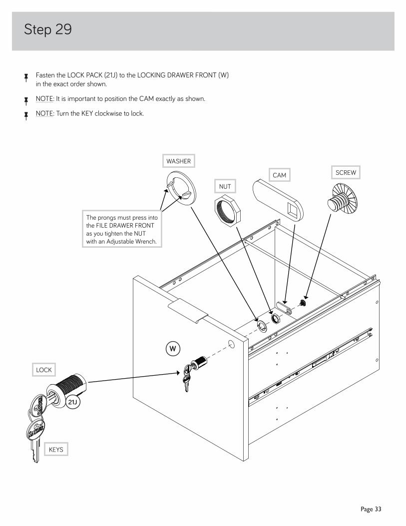
å Fasten the LOCK PACK (21J) to the LOCKING DRAWER FRONT (W)in the exact order shown.
å NOTE: It is important to position the CAM exactly as shown.
å NOTE: Turn the KEY clockwise to lock.
Step 29
W
21J
SCREWCAM
NUT
WASHER
LOCK
The prongs must press into the FILE DRAWER FRONT as you tighten the NUT with an Adjustable Wrench.
KEYS
Page 33

å Carefully stand your unit upright.
å To insert the PENCIL DRAWERS (N) into your unit, tip the front of the drawer down and drop the rollers on the
drawer behind the rollers on the unit. Lift the front of the drawer up and slide it into the unit. Repeat this step to insert the DRAWERS (K).å To insert the DRAWERS (J and W) into your unit, line up the EXTENSION SLIDES on the drawer with the
EXTENSIONRAILS on the unit and push the drawer into the unit until the drawer is fully inserted. The drawer will push in hard until it is all the way in, then it will slide in and out easier.
å Insert the GROMMETS (10P) and GROMMET CAPS (1P) into the large holes in the TOP (P).
å If you did not install the optional Hidden Wireless Qi Compatible Charger by Eggtronic, go to
Step 32. å If you installed the optional Hidden Wireless Qi Compatible Charger by Eggtronic, go
to the next step.
Step 30
W
N
K
J
N
K
This drawer must have the Z-LOCK
BRACKET.
1P
10P
P
Page 34
NOTE: Insert the PENCIL DRAWERS (N) fi rst.

å To make adjustments to the FILE DRAWER loosen SCREW #4 inthe SLIDES a 1/4 turn, then turn the cam clockwise or counter-clockwise. Notice how the drawer raises or lowers as you turn the cam. By adjusting the drawer this way, it will help the DRAWER FRONT line up better when closed. Tighten the SCREWS when fi nished with adjustments.
å If needed, repeat this step for the middle DRAWER.
Step 32
CamThe higher the screw in the oblong hole, the higher your drawer front will be. The lower the screw, the lower the drawer front.
Loosen screw #4 a 1/4 turn, turn the cam a 1/4 turn maximum in both the clockwise and counter-clockwise directions to make adjustments, and then tighten screw #4.
Page 35

Step 33
å NOTE: Please read the back pages of the instruction booklet for important safety information.
å This completes assembly. Clean with a damp cloth. Wipe dry.
60 lbs.
20 lbs.
10 lbs.
35 lbs. each
20 lbs.
10 lbs.
Page 36