
Exciting Surface Plasmons with Transformation Media
11
1 Exciting surface plasmons with transformation media Carlos García-Meca * , Rubén Ortuño, Javier Martí, and Alejandro Martínez Nanophotonics Technology Center, Universidad Politécnica de Valencia, Camino de Vera s/n 46022, Valencia, Spain * E-mail: [email protected] Abstract. We present a way of exciting surface plasmon polaritons along non-patterned metallic surfaces by means of a flat squeezing slab designed with transformation optics. The slab changes the dispersion relation of incident light, enabling evanescent coupling to propagating surface plasmons. Unlike prism couplers, the proposed device does not introduce reflections at its input interface. Moreover, its compact geometry is suitable for integration. A feasible dielectric implementation of the coupler is suggested. Finally, we show that the angular response of the device can be engineered by using a non-uniform compression factor. As an example, we design a coupler with a half-power angular bandwidth 2.5 times higher than that of a conventional dielectric coupler. Keywords: Surface plasmon polaritons; Transformation optics; Metamaterials; Couplers; Broadband Published in: Plasmonics 7, 701-707 (2012). The final publication is available at Springer via http://dx.doi.org/10.1007/s11468-012-9361-5 Introduction Surface plasmon polaritons (SPPs) are hybrid electron-photon excitations that are trapped at the interface between a dielectric and a conductor [1-3]. This property of SPPs allows us to concentrate electromagnetic fields at the nanoscale by using subwavelength metallic structures. The branch of plasmonics exploits this unparalleled light-concentration ability of metals for a wide range of applications [2-5]. These include the miniaturization of photonic circuits, modulators and photodetectors, the enhancement of non-linear phenomena, the realization of extremely sensitive biosensors, and the improvement of the efficiency of photovoltaic cells. Recently, the use of transformation optics (TO) has been proposed to fully control the propagation of SPPs [6-9]. This technique enables us to engineer electromagnetic space by implementing arbitrary geometries and coordinate transformations with suitable media [10-12]. This way, TO makes it possible to design a variety of devices for SPPs such as cloaks, beam shifters, extreme bends, lenses, and wave adapters [6-9]. Although all these works have focused on flow control, SPPs need to be excited before they can be manipulated. Due to their bound nature, the momentum of SPPs is always higher than that of free-space photons of the same frequency [1-3]. Therefore, it is not possible to directly excite SPPs with free-space light. There exist several techniques to provide the required additional momentum for far-field excitation of SPPs. The most important ones are
-
Upload
independent -
Category
Documents
-
view
5 -
download
0
Transcript of Exciting Surface Plasmons with Transformation Media
1
Exciting surface plasmons with transformation media
Carlos García-Meca*, Rubén Ortuño, Javier Martí, and Alejandro Martínez Nanophotonics Technology Center, Universidad Politécnica de Valencia, Camino de Vera s/n
46022, Valencia, Spain
*E-mail: [email protected]
Abstract. We present a way of exciting surface plasmon polaritons along non-patterned metallic
surfaces by means of a flat squeezing slab designed with transformation optics. The slab changes the
dispersion relation of incident light, enabling evanescent coupling to propagating surface plasmons.
Unlike prism couplers, the proposed device does not introduce reflections at its input interface.
Moreover, its compact geometry is suitable for integration. A feasible dielectric implementation of
the coupler is suggested. Finally, we show that the angular response of the device can be engineered
by using a non-uniform compression factor. As an example, we design a coupler with a half-power
angular bandwidth 2.5 times higher than that of a conventional dielectric coupler.
Keywords: Surface plasmon polaritons; Transformation optics; Metamaterials; Couplers; Broadband
Published in: Plasmonics 7, 701-707 (2012). The final publication is available at Springer via http://dx.doi.org/10.1007/s11468-012-9361-5
Introduction
Surface plasmon polaritons (SPPs) are hybrid electron-photon excitations that are trapped at
the interface between a dielectric and a conductor [1-3]. This property of SPPs allows us to
concentrate electromagnetic fields at the nanoscale by using subwavelength metallic
structures. The branch of plasmonics exploits this unparalleled light-concentration ability of
metals for a wide range of applications [2-5]. These include the miniaturization of photonic
circuits, modulators and photodetectors, the enhancement of non-linear phenomena, the
realization of extremely sensitive biosensors, and the improvement of the efficiency of
photovoltaic cells. Recently, the use of transformation optics (TO) has been proposed to
fully control the propagation of SPPs [6-9]. This technique enables us to engineer
electromagnetic space by implementing arbitrary geometries and coordinate transformations
with suitable media [10-12]. This way, TO makes it possible to design a variety of devices
for SPPs such as cloaks, beam shifters, extreme bends, lenses, and wave adapters [6-9].
Although all these works have focused on flow control, SPPs need to be excited before they
can be manipulated. Due to their bound nature, the momentum of SPPs is always higher than
that of free-space photons of the same frequency [1-3]. Therefore, it is not possible to
directly excite SPPs with free-space light. There exist several techniques to provide the
required additional momentum for far-field excitation of SPPs. The most important ones are
2
based on gratings or prism couplers [1-3,13]. The former consists of structuring periodically
the metal surface or surrounding dielectric. If the gratings are sufficiently deep, the SPP
dispersion relation (DR) can be significantly altered by the periodic pattern and photonic
bandgaps and localized modes may appear [2,3]. The latter is based on the use of a prism
placed next to a thin metal film. For instance, in the Kretschmann configuration, light
entering the prism at a right angle increases its momentum by a factor equal to the prism
index. When light reaches the prism-metal interface, total internal reflection occurs and the
wave evanescently tunnels to the other metal side (in contact with air), where the SPP is
excited [3,13]. The prism shape imposes a minimum size for the coupler that may not be
suitable for integration. Here we propose an alternative way to excite SPPs with the help of
TO. Specifically, we show that a properly-designed flat slab that performs a spatial
compression can play the role of a prism coupler with important advantages.
Theory
Light squeezers based on TO have been extensively studied from the spatial viewpoint [14-
18]. However, although there exist some works that link Fourier optics and TO [19], little
attention has been paid to the properties of squeezers in the Fourier domain. We begin by
analyzing this kind of devices regarding them as k-space filters. For simplicity, we will
focus on a two-dimensional problem (invariant in the y-direction), although the results could
be extended to three dimensions. In flat-space TO, one starts from a virtual space and
performs a certain coordinate transformation in such a way that electromagnetic fields are
distorted in the desired manner. It is possible to implement this deformation in real physical
space by filling it with the appropriate relative permittivity ij and permeability ij [10,12].
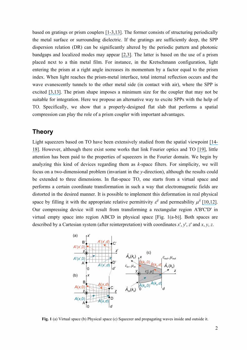
Our compressing device will result from transforming a rectangular region A'B'C'D' in
virtual empty space into region ABCD in physical space [Fig. 1(a-b)]. Both spaces are
described by a Cartesian system (after reinterpretation) with coordinates x', y', z' and x, y, z.
z
x
0
y
out μoutε ,
dA (k )
s μsε ,ij ij
INˆ
x
z’
x’
d ’0
y’
z
x
0 d
A’
B’ C’
D’
A
B
C
D
A’(x’,0)
A(x,0) A(x,d)
A’(x’,d)
A(x,d)A(x,0)
A’(x’,d)
A’(x’,0)
A(k ,0)xˆ
B(k ,d)xˆ A (k )T x
A (k )Rˆ
x
in μinε ,
A(k ,d)xˆ
B(k ,0)xˆ
(a)
(b)
(c)
y
Fig. 1 (a) Virtual space (b) Physical space (c) Squeezer and propagating waves inside and outside it.
3
The squeezer is placed between isotropic media characterized by relative constitutive
parameters in = in = 1 and out, out. The field A is polarized along the y-direction (A =
Ayy), with A being the electric (magnetic) field E (H) for TE (TM) waves. We denote the
Fourier transform of Ay(x,z) in the x-variable as ˆ ,y xA k z , where kx is the transverse
component of the wavevector k. Our aim is to obtain the relation between incident, reflected
and transmitted waves ˆIN xA k , ˆ
R xA k and ˆT xA k [see Fig. 1(c)]. A general transformation
is given by x = x (x',z'), y = y' and z = z(x',z'). The transformation can be whatever, except at
the boundaries. In particular, we want the identity transformation at z' = 0 in order to avoid
reflections at the input boundary, i.e., x(x',0) = x' and z(x',0) = 0. At z' = d', we want the
transformation to satisfy ∂x/∂x' = 1/F (F is the compression factor along the x-direction) and
z(x',d') = d. The first condition implies that the compression is uniform at the output
interface. The second ensures that the output boundary is flat. With these simplifications, it
can be shown that (derivation details are given in the appendix):
2ˆ ˆ
1ˆ ˆ
R x IN x x x
T x IN x x x
A k A k R k F M k
A k A k F T k M k FF
, (1)
with M(kx) = 2 2exp 'xi k k d . For TM polarization:
2 2 2 2 20 0
2 2 2 2 20 0
( ) out x out out xx
out x out out x
k F k k kR k
k F k k k
. (2)
T(kx) can be obtained from the relation T(kx) = 1 + R(kx). The coefficients R2(kx) and T2(kx)
for light impinging from the right at z = d are given by R2(kx) = -R(kx) and T2(kx) = 1 +
R2(kx). To choose a specific transformation, we gave priority to those requiring only
dielectric media, as the main difficulty at optical frequencies lies on achieving magnetic
materials. Since we are dealing with a two-dimensional problem, only some components of
the constitutive parameters need to be implemented. For TE polarization the tensor
components that affect the fields are yy, tt and ll, being t and l the in-plane tensor principal
directions. In this case, the problem can be solved by using quasi-conformal mappings,
which give rise to tt ≈ ll ≈ 1 [18,20]. In the geometrical optics regime, such a medium
should work for both polarizations. Nonetheless, an exact realization for TM waves involves
the implementation of yy, tt and ll. It can be shown that yy = 1 if we use a transformation
of the form x = x'f1(z'), z = f2(z'), with f1(z') = (df2(z')/dz')-1. Here we will employ the
functions f1(z') = 1/(1+Cz') and f2(z') = z'(1+Cz'/2). This way, the exact realization of the
squeezer only requires an anisotropic dielectric. For a squeezer length d as small as 3 μm,
only moderate refractive indices, approximately ranging from 0.5 to 2, are required. These
values can be relaxed by using a lower compression factor or longer lengths. Moreover, f1(z')
4
and f2(z') could be optimized to further adjust this range. The implementation of anisotropic
dielectrics is feasible with the use of multilayer structures [9,19]. Remarkably, an exact
dielectric realization of a compressing device working simultaneously for both polarizations
could be achieved, since we only need to implement tt and ll for TM polarization and yy
for TE polarization.
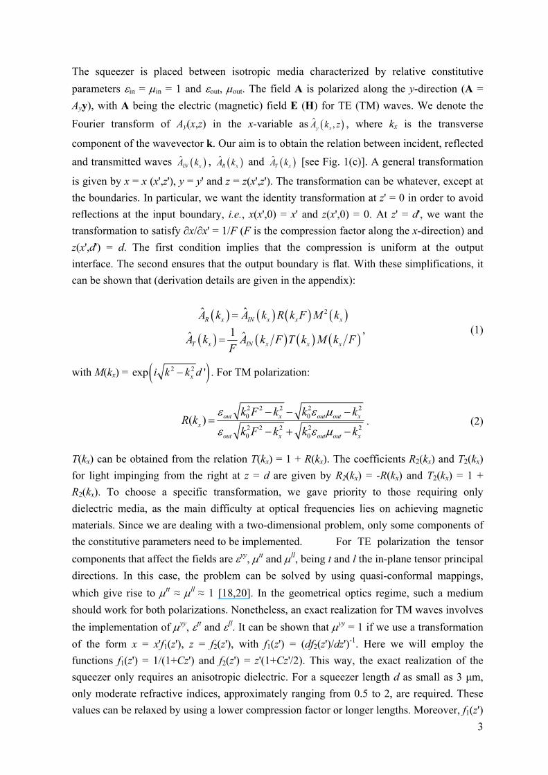
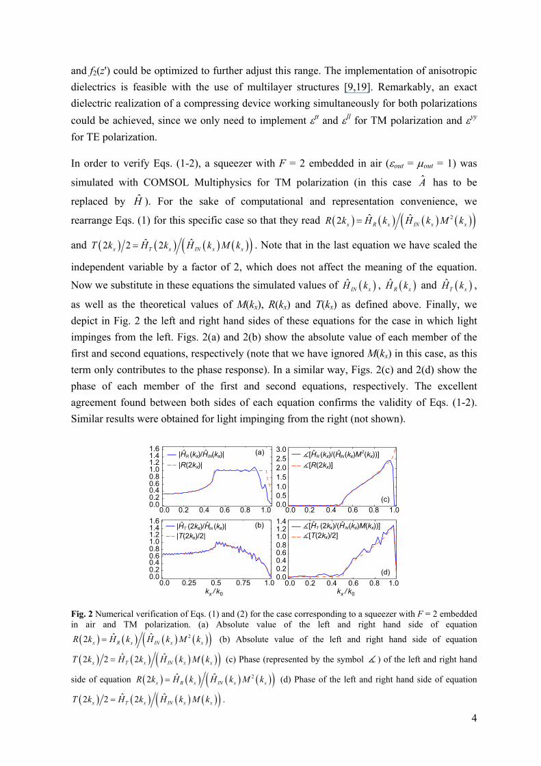
In order to verify Eqs. (1-2), a squeezer with F = 2 embedded in air (out = out = 1) was
simulated with COMSOL Multiphysics for TM polarization (in this case A has to be
replaced by H ). For the sake of computational and representation convenience, we
rearrange Eqs. (1) for this specific case so that they read 2ˆ ˆ2 x R x IN x xR k H k H k M k
and ˆ ˆ2 2 2x T x IN x xT k H k H k M k . Note that in the last equation we have scaled the
independent variable by a factor of 2, which does not affect the meaning of the equation.
Now we substitute in these equations the simulated values of ˆIN xH k , ˆ
R xH k and ˆT xH k ,
as well as the theoretical values of M(kx), R(kx) and T(kx) as defined above. Finally, we
depict in Fig. 2 the left and right hand sides of these equations for the case in which light
impinges from the left. Figs. 2(a) and 2(b) show the absolute value of each member of the
first and second equations, respectively (note that we have ignored M(kx) in this case, as this
term only contributes to the phase response). In a similar way, Figs. 2(c) and 2(d) show the
phase of each member of the first and second equations, respectively. The excellent
agreement found between both sides of each equation confirms the validity of Eqs. (1-2).
Similar results were obtained for light impinging from the right (not shown).
(a)
(b)
0.0 0.25 0.5 0.75 1.0
0.0 0.2 0.4 0.6 1.00.8
0.00.20.40.60.81.01.21.41.6
0.00.20.40.60.81.01.21.41.6
|R(2k )| x
|H (k )/H (k )| x xR IN
0.0 0.2 0.4 0.6 1.00.8
0.0 0.2 0.4 0.6 1.00.8
(c)
(d)
0.0
0.5
1.0
1.5
2.0
2.5
3.0
0.00.20.40.60.8
1.01.21.4
ˆ ˆ
|T(2k )/2| x
|H (2k )/H (k )| x xT INˆ ˆ
k / kx 0
�[R(2k )] x
�[H (k )/(H (k )M (k ))]x xR INˆ ˆ x2
�[T(2k )/2] x
�[H (2k )/(H (k )M(k ))] x xT INˆ ˆ x
k / kx 0
Fig. 2 Numerical verification of Eqs. (1) and (2) for the case corresponding to a squeezer with F = 2 embedded in air and TM polarization. (a) Absolute value of the left and right hand side of equation
2ˆ ˆ2 x R x IN x xR k H k H k M k (b) Absolute value of the left and right hand side of equation
ˆ ˆ2 2 2x T x IN x xT k H k H k M k (c) Phase (represented by the symbol ) of the left and right hand
side of equation 2ˆ ˆ2 x R x IN x xR k H k H k M k (d) Phase of the left and right hand side of equation
ˆ ˆ2 2 2x T x IN x xT k H k H k M k .
5
Excitation of SPPs with a squeezing flat slab
As shown by Eq. (1), in addition to changing the amplitude of incident waves, the squeezer
performs an expansion in kx by a constant factor F, whilst frequency is conserved. This
change in the DR suggests that the squeezer could be used to excite SPPs. To illustrate this
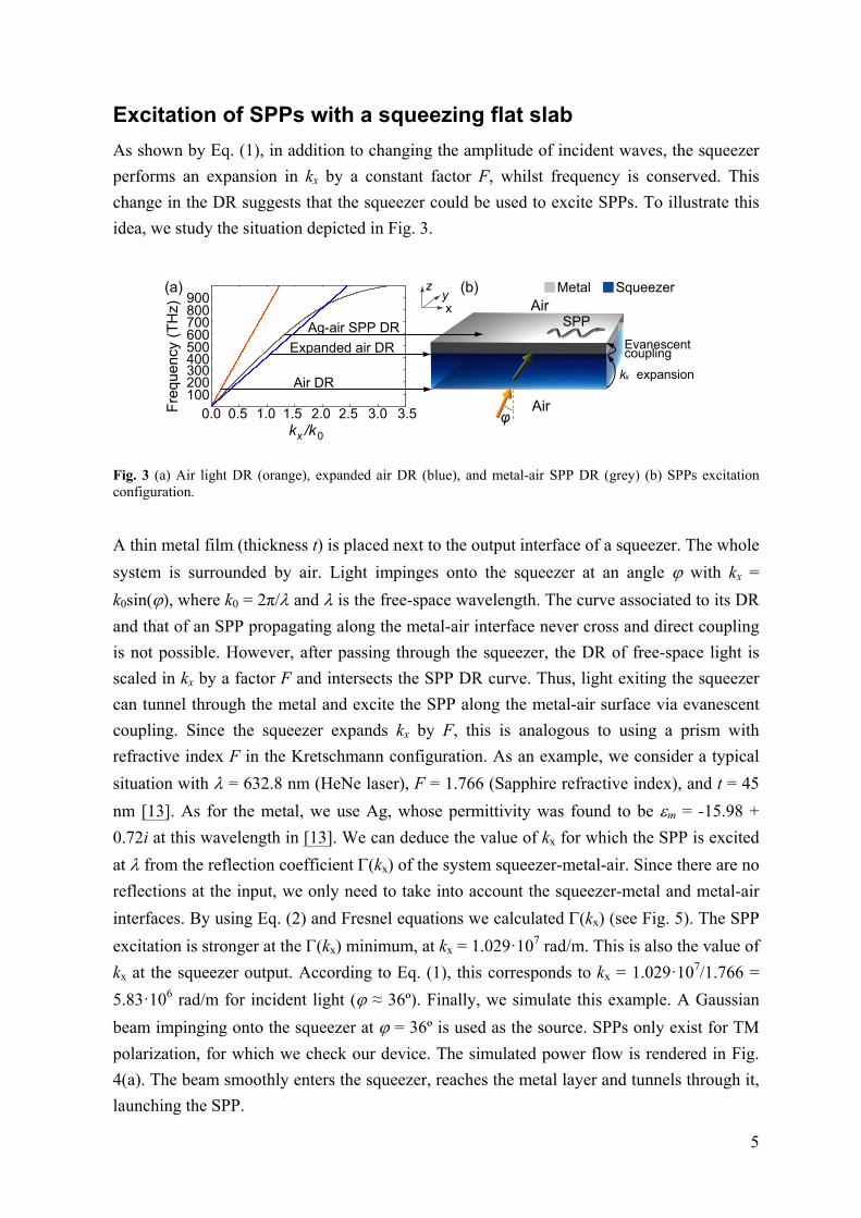
idea, we study the situation depicted in Fig. 3.
0.0 0.5 1.0 1.5 2.0 2.5 3.0 3.5
100200300400500600700800900
Fre
qu
en
cy (
TH
z)
k expansion
Evanescent coupling
SPPAg-air SPP DR
Air DR
Expanded air DR
k /kx 0
φ
Metal Squeezer
Air
Air
xy
z(a) (b)
x
Fig. 3 (a) Air light DR (orange), expanded air DR (blue), and metal-air SPP DR (grey) (b) SPPs excitation configuration.
A thin metal film (thickness t) is placed next to the output interface of a squeezer. The whole
system is surrounded by air. Light impinges onto the squeezer at an angle with kx =
k0sin(), where k0 = 2π/ and is the free-space wavelength. The curve associated to its DR
and that of an SPP propagating along the metal-air interface never cross and direct coupling
is not possible. However, after passing through the squeezer, the DR of free-space light is
scaled in kx by a factor F and intersects the SPP DR curve. Thus, light exiting the squeezer
can tunnel through the metal and excite the SPP along the metal-air surface via evanescent
coupling. Since the squeezer expands kx by F, this is analogous to using a prism with
refractive index F in the Kretschmann configuration. As an example, we consider a typical
situation with = 632.8 nm (HeNe laser), F = 1.766 (Sapphire refractive index), and t = 45
nm [13]. As for the metal, we use Ag, whose permittivity was found to be m = -15.98 +
0.72i at this wavelength in [13]. We can deduce the value of kx for which the SPP is excited
at from the reflection coefficient (kx) of the system squeezer-metal-air. Since there are no
reflections at the input, we only need to take into account the squeezer-metal and metal-air
interfaces. By using Eq. (2) and Fresnel equations we calculated (kx) (see Fig. 5). The SPP
excitation is stronger at the (kx) minimum, at kx = 1.029·107 rad/m. This is also the value of
kx at the squeezer output. According to Eq. (1), this corresponds to kx = 1.029·107/1.766 =
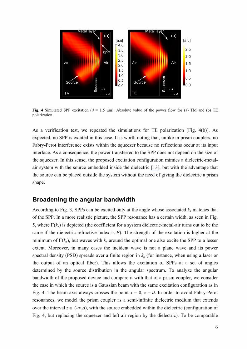
5.83·106 rad/m for incident light ( ≈ 36º). Finally, we simulate this example. A Gaussian
beam impinging onto the squeezer at = 36º is used as the source. SPPs only exist for TM
polarization, for which we check our device. The simulated power flow is rendered in Fig.
4(a). The beam smoothly enters the squeezer, reaches the metal layer and tunnels through it,
launching the SPP.
6
Fig. 4 Simulated SPP excitation (d = 1.5 μm). Absolute value of the power flow for (a) TM and (b) TE polarization.
As a verification test, we repeated the simulations for TE polarization [Fig. 4(b)]. As
expected, no SPP is excited in this case. It is worth noting that, unlike in prism couplers, no
Fabry-Perot interference exists within the squeezer because no reflections occur at its input
interface. As a consequence, the power transferred to the SPP does not depend on the size of
the squeezer. In this sense, the proposed excitation configuration mimics a dielectric-metal-
air system with the source embedded inside the dielectric [13], but with the advantage that
the source can be placed outside the system without the need of giving the dielectric a prism
shape.
Broadening the angular bandwidth
According to Fig. 3, SPPs can be excited only at the angle whose associated kx matches that
of the SPP. In a more realistic picture, the SPP resonance has a certain width, as seen in Fig.
5, where (kx) is depicted (the coefficient for a system dielectric-metal-air turns out to be the
same if the dielectric refractive index is F). The strength of the excitation is higher at the
minimum of (kx), but waves with kx around the optimal one also excite the SPP to a lesser
extent. Moreover, in many cases the incident wave is not a plane wave and its power
spectral density (PSD) spreads over a finite region in kx (for instance, when using a laser or
the output of an optical fiber). This allows the excitation of SPPs at a set of angles
determined by the source distribution in the angular spectrum. To analyze the angular
bandwidth of the proposed device and compare it with that of a prism coupler, we consider
the case in which the source is a Gaussian beam with the same excitation configuration as in
Fig. 4. The beam axis always crosses the point x = 0, z = d. In order to avoid Fabry-Perot
resonances, we model the prism coupler as a semi-infinite dielectric medium that extends
over the interval z (-,d), with the source embedded within the dielectric (configuration of
Fig. 4, but replacing the squeezer and left air region by the dielectric). To be comparable
7
with the squeezer, the dielectric refractive index is taken to be equal to the compression
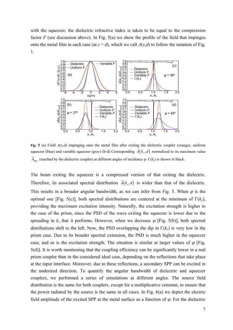
factor F (see discussion above). In Fig. 5(a) we show the profile of the field that impinges
onto the metal film in each case (at z = d), which we call A(x,d) to follow the notation of Fig.
1.
0.0 0.5 1.0 1.5 2.0
0.10.20.30.40.50.60.70.80.9
0.0
1.0
0.10.20.30.40.50.60.70.80.9
0.0
1.0
-6 -4 -2 4 6x(μm)
0 2
Γ(k )x
DielectricUniform FVariable F
DielectricUniform F
Variable F
φ = 27º
φ = 36º
φ = 45º
|A (
x,d)
| [
a.u
.]
|A(k
,d)
/A
|x
ˆm
ax
ˆ
(a)
(b)
(c)
(d)
0.0 0.5 1.0 1.5 2.0k /kx 0
0.10.20.30.40.50.60.70.80.9
0.0
1.0
|A(k
,d)
/A
|x
ˆm
ax
ˆΓ(k )x
DielectricUniform FVariable F
0.0 0.5 1.0 1.5 2.0
0.10.20.30.40.50.60.70.80.9
0.0
1.0
|A(k
,d)
/A
|x
ˆm
ax
ˆ
Γ(k )x
DielectricUniform FVariable F
k /kx 0
k /kx 0
1
2
Fig. 5 (a) Field A(x,d) impinging onto the metal film after exiting the dielectric coupler (orange), uniform
squeezer (blue) and variable squeezer (grey) (b-d) Corresponding ˆ ,xA k d normalized to its maximum value
maxA (reached by the dielectric coupler) at different angles of incidence . (kx) is shown in black.
The beam exiting the squeezer is a compressed version of that exiting the dielectric.
Therefore, its associated spectral distribution ˆ ,xA k d is wider than that of the dielectric.
This results in a broader angular bandwidth, as we can infer from Fig. 5. When is the
optimal one [Fig. 5(c)], both spectral distributions are centered at the minimum of (kx),
providing the maximum excitation intensity. Naturally, the excitation strength is higher in
the case of the prism, since the PSD of the wave exiting the squeezer is lower due to the
spreading in kx that it performs. However, when we decrease [Fig. 5(b)], both spectral
distributions shift to the left. Now, the PSD overlapping the dip in (kx) is very low in the
prism case. Due to its broader spectral extension, the PSD is much higher in the squeezer
case, and so is the excitation strength. The situation is similar at larger values of [Fig.
5(d)]. It is worth mentioning that the coupling efficiency can be significantly lower in a real
prism coupler than in the considered ideal case, depending on the reflections that take place
at the input interface. Moreover, due to these reflections, a secondary SPP can be excited in
the undesired direction. To quantify the angular bandwidth of dielectric and squeezer
couplers, we performed a series of simulations at different angles. The source field
distribution is the same for both couplers, except for a multiplicative constant, to ensure that
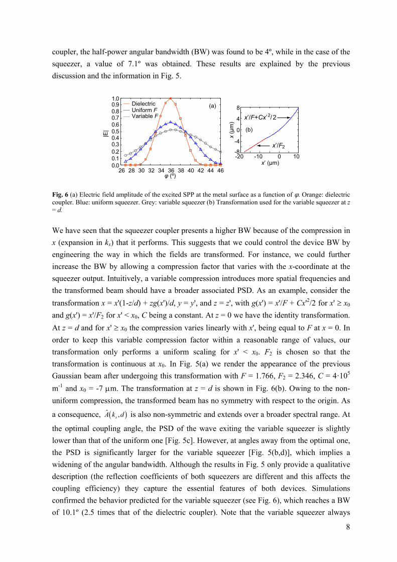
the power radiated by the source is the same in all cases. In Fig. 6(a) we depict the electric
field amplitude of the excited SPP at the metal surface as a function of . For the dielectric
8
coupler, the half-power angular bandwidth (BW) was found to be 4º, while in the case of the
squeezer, a value of 7.1º was obtained. These results are explained by the previous
discussion and the information in Fig. 5.
26 28 30 32 34 36 38 40 42 44 46
0.1
0.2
0.30.40.5
0.6
0.70.8
0.9
0.0
1.0
φ (º)
|E|
DielectricUniform FVariable F
-20 -10 0 10-8
-4
0
4
8
x’ (μm)
x (μ
m)
x’/F2
x’/F+Cx’ / 22
(a)
(b)
Fig. 6 (a) Electric field amplitude of the excited SPP at the metal surface as a function of φ. Orange: dielectric coupler. Blue: uniform squeezer. Grey: variable squeezer (b) Transformation used for the variable squeezer at z = d.
We have seen that the squeezer coupler presents a higher BW because of the compression in
x (expansion in kx) that it performs. This suggests that we could control the device BW by
engineering the way in which the fields are transformed. For instance, we could further
increase the BW by allowing a compression factor that varies with the x-coordinate at the
squeezer output. Intuitively, a variable compression introduces more spatial frequencies and
the transformed beam should have a broader associated PSD. As an example, consider the
transformation x = x'(1-z/d) + zg(x')/d, y = y', and z = z', with g(x') = x'/F + Cx'2/2 for x' x0
and g(x') = x'/F2 for x' < x0, C being a constant. At z = 0 we have the identity transformation.
At z = d and for x' x0 the compression varies linearly with x', being equal to F at x = 0. In
order to keep this variable compression factor within a reasonable range of values, our
transformation only performs a uniform scaling for x' < x0. F2 is chosen so that the
transformation is continuous at x0. In Fig. 5(a) we render the appearance of the previous
Gaussian beam after undergoing this transformation with F = 1.766, F2 = 2.346, C = 4·105
m-1 and x0 = -7 m. The transformation at z = d is shown in Fig. 6(b). Owing to the non-
uniform compression, the transformed beam has no symmetry with respect to the origin. As
a consequence, ˆ ,xA k d is also non-symmetric and extends over a broader spectral range. At
the optimal coupling angle, the PSD of the wave exiting the variable squeezer is slightly
lower than that of the uniform one [Fig. 5c]. However, at angles away from the optimal one,
the PSD is significantly larger for the variable squeezer [Fig. 5(b,d)], which implies a
widening of the angular bandwidth. Although the results in Fig. 5 only provide a qualitative
description (the reflection coefficients of both squeezers are different and this affects the
coupling efficiency) they capture the essential features of both devices. Simulations
confirmed the behavior predicted for the variable squeezer (see Fig. 6), which reaches a BW
of 10.1º (2.5 times that of the dielectric coupler). Note that the variable squeezer always
9
broadens the angular bandwidth (even if the source is a plane wave). This technique not only
allows us to broaden the BW, but also to achieve other coupler angular responses by using
different mappings that properly transform the source PSD. Although we cannot use the
previous dielectric implementation for the variable squeezer [the transformation is not of the
form x = x'f1(z')], a dielectric realization could still be possible, for instance, by allowing a
curved output boundary.
Conclusions
In summary, we have presented an alternative way of exciting SPPs with the help of TO. To
this end, we exploit the modification in the DR introduced by a squeezing device. The
squeezer plays the role of a prism coupler but is more suitable for integration because of its
flat geometry and small dimensions. Moreover, it does not introduce reflections at its input
interface, preventing the appearance of Fabry-Perot resonances and the excitation of SPPs in
the undesired direction. The implementation of the squeezer can be achieved with dielectric
anisotropic materials. Finally, we have shown that the coupler angular bandwidth can be
broadened by using a variable compression. As an example, we have designed a device with
a BW 2.5 times higher than that of a conventional dielectric coupler. This technique could
pave the way for engineering SPP couplers with tailor-made angular responses.
Acknowledgements Financial support by Spanish Ministerio de Ciencia e Innovación (contracts
CSD2008-00066 and TEC2008-06871-C02, and FPU grant) is gratefully acknowledged.
Appendix
A detailed derivation of Eq. (1) is provided next. The fields propagating in physical space
can be expressed as a function of those in virtual space. In component notation:
'', ' , , ' ,i
i i iA x z A x x z z x z , (3)
with ''
ii i ix x , i = 1, 2, 3, and x1 = x, x2 = y, x3 = z, with analogous expressions for
primed coordinates. Since we have the identity transformation at z' = 0, then x(x',0) = x' and
z(x',0) = 0. Therefore, using Eq. (3) and taking into account that the only non-vanishing
component of A is A2 = Ay:
'2 ' ',0 ' ,0 , ' ,0 ,0i
y i yA x A x x z x A x . (4)
At z' = d' we also have the restrictions ∂x/∂x' = 1/F and z(x',d') = d. The first condition
implies that the compression is uniform at the device output interface, leading to x = x'f(z') at
z' = d', i.e., x(x',d') = x'/F, if there is no translation in x at this point. With these
simplifications, we can write:
10
'2 ' ', ' , , ' , 'i
y i yA x d A x x d z d A xF d . (5)
Our goal is to relate the fields transmitted and reflected by the squeezer with the
corresponding incident field as a function of kx. For this purpose, we will first calculate in
Fourier space the relation between the fields at z = 0 and z = d inside the device. In virtual
space (empty flat space), the relation between the fields at z' = 0 and z' = d' is well known.
Specifically, ' ' ' ' 'ˆ ˆ, ' ,0 ( )y x y x xA k d A k M k when propagation is towards increasing values
of z [blue arrows in Fig. 1(a)] and ' ' ' ' 'ˆ ˆ,0 , ' ( )y x y x xA k A k d M k when propagation is towards
decreasing values of z [orange arrows in Fig. 1(a)]. M(kx) is the transfer function of a free
space slab of thickness d', i.e., M(kx) = 2 2exp 'xi k k d . With the aid of Eqs. (4-5), we find
for waves propagating towards increasing values of z [blue arrows in Fig. 1(b)]:
'
'
ˆ , , , '
1 1ˆ ˆ / , ' / ,0 /
x xik x ik xy x y y
y x y x x
A k d A x d e dx A xF d e dx
A k F d A k F M k FF F
. (6)
For waves propagating towards decreasing values of z [orange arrows in Fig. 1(a-b)]:
'
'
ˆ ˆ,0 , 'ˆ ˆ,0 ,1ˆ ˆ, / , '
y x y x x
y x y x x
y x y x
A k A k d M kA k FA k F d M k
A k d A k F dF
. (7)
Now we consider the squeezer as a block that returns two outputs (reflected and transmitted
waves AR and AT) under an input (incident wave AIN). The relation between ˆIN xA k ,
ˆR xA k and ˆ
T xA k can be obtained with the help of Fig. 1(c). As mentioned in the main
text, the squeezer is placed between isotropic media characterized by relative constitutive
parameters in, in (input medium) and out, out (output medium) and we consider the input
medium to be the same as in virtual space (in = in = 1). This way, the transformation is
continuous at z = 0 and there occur no reflections at this interface. Thus, ˆ ˆ ,0IN x xA k A k
and ˆ ˆ ,0R x xA k B k . However, the transformation discontinuity at z = d introduces
reflections at the (squeezer)-(output medium) interface. The relation between a wave
impinging from the left at z = d and the transmitted and reflected waves can be characterized
by a pair of reflection and transmission coefficients R(kx) and T(kx), in such a way that
ˆ ˆ , ( )T x x xA k A k d T k and ˆˆ , , ( )x x xB k d A k d R k . Moreover, we know that
1ˆ ˆ, / ,0 /x x xA k d F A k F M k F from Eq. (6), and that ˆ ˆ,0 ,x x xB k FB k F d M k
from Eq. (7). According to these relations:

11
2ˆ ˆ
1ˆ ˆ
R x IN x x x
T x IN x x x
A k A k R k F M k
A k A k F T k M k FF
. (8)
References
[1] Raether H (1988) Surface Plasmons on Smooth and Rough Surfaces and on Gratings. Springer-Verlag, Berlin
[2] Barnes WL, Dereux A, Ebbesen TW (2003) Surface plasmon subwavelength optics. Nature 424:824–830
[3] Maier SA (2007) Plasmonics: Fundamentals and applications. Springer, New York
[4] Schuller JA, Barnard ES, Cai W, Jun YC, White JS, Brongersma ML (2010) Plasmonics for extreme light concentration and manipulation. Nat Mater 9:193–204
[5] Brongersma ML, Shalaev VM (2010) The case for plasmonics. Science 328:440–441
[6] Liu Y, Zentgraf T, Bartal G, Zhang X (2010) Transformational Plasmon Optics. Nano Lett 10:1991–1997
[7] Huidobro PA, Nesterov ML, Martín-Moreno L, García-Vidal FJ (2010) Transformation Optics for Plasmonics. Nano Lett 10:1985–1990
[8] Kadic M, Guenneau S, Enoch S (2010) Transformational plasmonics: cloak, concentrator and rotator for SPPs. Opt. Express 18:12027–12032
[9] Zhang J, Xiao S, Wubs M, Mortensen NA (2011) Surface Plasmon Wave Adapter Designed with Transformation Optics. ACS Nano 5:4359–4364
[10] Pendry JB, Schurig D, Smith DR (2006) Controlling Electromagnetic Fields. Science 312:1780–1782
[11] Leonhardt U (2006) Optical conformal mapping. Science 312:1777–1780
[12] Leonhardt U, Philbin TG (2006) General Relativity in Electrical Engineering. New J Phys 8:247
[13] Sambles JR, Bradbery GW, Yang F (1991) Optical excitation of surface plasmons: an introduction. Contemp Phys 32:173–183
[14] Rahm M, Roberts DA, Pendry JB, Smith DR (2008) Transformation-optical design of adaptive beam bends and beam expanders. Opt. Express 16:11555–11567
[15] Vasic B, Isic G, Gajic R, Hingerl K (2009) Coordinate transformation based design of confined metamaterial structures. Phys Rev B 79:85103
[16] Tichit P, Burokur SN, Lustrac A (2009) Waveguide taper engineering using coordinate transformation technology. Opt Express 18:767–772
[17] Zang X, Jiang C (2010) Manipulating the field distribution via optical transformation. Opt Express 18:10168–10176
[18] García-Meca C, Tung MM, Galán JV, Ortuño R, Rodríguez-Fortuño FJ, Martí J, Martínez A (2011) Squeezing and expanding light without reflections via transformation optics. Opt Express 19:3562–3575
[19] Li J, Han S, Zhang S, Bartal G, Zhang X (2009) Designing the Fourier space with transformation optics. Opt Lett 34:3128-3130
[20] Li J, Pendry JB (2008) Hiding under the Carpet: A New Strategy for Cloaking. Phys Rev Lett 101:203901