Intra-Panthalassa Ocean subduction zones revealed by fossil arcs and mantle structure
Upload
independentCategory
view
1download
0
INSTITUTE OF PHYSICS PUBLISHING JOURNAL OF PHYSICS D: APPLIED PHYSICS
J. Phys. D: Appl. Phys. 36 (2003) 3138–3143 PII: S0022-3727(03)65917-6
Evidence of columnar diamond growthstructures within cathode spot craters ofvacuum arcs on carbonJ-L Meunier1, M Campbell1 and M Kandah2
1 Plasma Technology Research Center, Department of Chemical Engineering,McGill University, 3610 University St, Montreal, Quebec, H3A 2B2, Canada2 Department of Chemical Engineering, Jordan University of Sciences and Technology, Irbid,Jordan
Received 9 July 2003Published 25 November 2003Online at stacks.iop.org/JPhysD/36/3138
AbstractCross-sections of erosion craters formed by vacuum arc discharges ongraphite cathodes are examined using electron microscopy. These revealerosion craters that are covered with a growth layer forming a continuousfilm on the arced surface. The film surface is composed of sphere-likestructures similar to cauliflower diamond and to the emitted macro-particles(MPs) observed in coating experiments using graphite vacuum arc sources.The film thickness within the cathode erosion craters evolves with the meanvalues of the MP diameter and mean crater depth for four graphite materialmorphologies. These two parameters increase with a decrease in arc spotvelocity. The growth layer shows a relatively porous columnar structure,with micro-Raman spectroscopy indicating an evolution from amorphouscarbon (cathode base), to graphitic (middle), to diamond dominating the toplayer.
1. Introduction
Low-pressure electric arc discharges on graphite are often usedas a source of carbon ions for physical vapour deposition(PVD) of diamond-like and amorphous carbon films [1–8].These sources operate in the thermo-field (T-F) mode ofelectron emission. The carbon cathode surface at low pressureshows very localized arc spot craters acting as the plasmasource for deposition. These so-called cathodic arc plasmadeposition (CAPD) systems based on graphite unfortunatelyalso generate macro-particles (MPs) in the micrometre sizerange [9]. Although the MP emission process may be veryspecific in the case of carbon cathodes, liquid metal dropletsejected from metallic electrodes and generating MPs are acommon feature of vacuum arc sources [3, 4, 10]. The MPsconstitute an important fraction of the net mass lost from theelectrode, and MP filters preventing degradation of the coatingare essential components in CAPD deposition systems basedon graphite sources for diamond-like carbon films [10–15].Series of preliminary experiments have showed that the arcdischarge parameters play an important role in the quantity andsize distribution of the emitted particle [9], whereas the carbon
material morphology strongly influences the residence time ofa cathode spot on local sites of the electrode [16]. Modellingof the interaction of a T-F emitting arc spot with the cathode(see extended review [17]) and more recently with graphitecathodes [18, 19] have yielded indications on the local surfacetemperature and pressure to be expected within the area of thecathode spot. These conditions and the observed morphologyof the MPs emitted from the cathode spot seem to indicatethat local conditions in the arc spot could very well imply asmall volume of the graphite cathode might go through a phasechange, forming a liquid state, as speculated by Kandah andMeunier [9]. The MP emission processes would in this casebe similar to those observed on metallic electrodes.
A liquid volume generating MPs of several micrometresin diameter should produce observable changes within thecathode material microstructure upon the very rapid coolingof this zone at spot extinction. Scanning electron microscopy(SEM) observations on cross-sections of the graphite cathodein the arcing zone are presented in this paper to evaluate anychange in morphology of the electrode. One objective of thiswork was to evaluate if some liquid volume may have existedwithin the cathode spot during its lifetime through observation
0022-3727/03/243138+06$30.00 © 2003 IOP Publishing Ltd Printed in the UK 3138
Diamond growth within vacuum arc cathode spot
of the resulting surface structures. The observations in effectreveal some unexpected growth structures within the spot.These are characterized using Raman spectroscopy and growthdependence, based on known parameters of the arc discharge.
2. Experiment
The experimental set-up is based on a cylindrical vacuumchamber of 25.4 cm diameter and 55 cm length, maintainedat a pressure of 10−6 Torr. One end of the chamber containingthe cathode assembly is insulated from the remaining groundedchamber. Graphite discs (6.35 cm diameter, 5 cm diameter ofexposed area, 3.2 mm thickness) are used as cathodes on awater-cooled support. Four graphite morphologies are used inthis paper, these being characterized by their apparent density,mean grain size, mean pore size and electrical resistivity asgiven in table 1 following supplier data. Commercial namesare used, with Pyroid standing for oriented pyrolytic graphiteformed using CVD by Specialty Minerals Inc. (USA), whilethe other three materials are isotropic and obtained fromPoco Graphite Inc. (USA). A water-cooled and groundedstainless-steel ring anode (OD 16 cm, ID 5 cm) faces thecathode assembly at an axial distance of 4 cm. The arc istriggered mechanically and typically runs in continuous DCcurrent operation for deposition and erosion studies. Thearc current value is 80 A throughout this study. For thepurpose of this study, however, the arc discharges were stoppedafter a few seconds of operation in order to yield isolatedarc traces with no overlap on the cathode surface. The arc
Table 1. Properties of the various graphite cathodes used in thisstudy.
Cathode Density Grain size Pore size El. resist.material (g cm−3) (µm) (µm) (µ� cm)
Pyroid 2.2 — 0 250a
PGCS-1 1.79 15 3 1500ZXF-5Q 1.8 1 0.2 1650PS 1.33 5 1.2 2900
a Indicates in a direction parallel to the cathode surface
Figure 1. Arc trace corresponding to a simple arc passage, viewed in a direction perpendicular to the surface.
is brought into rotation on the graphite disc using a seriesof samarium/cobalt permanent magnets placed behind thecathode within the water-cooling cavity. These permanentmagnets are fixed in a way such as to provide a radial magneticfield component (0.03 T at radial position of arc rotation)that is parallel to the eroded surface of the cathode. Theplasma in the inter-electrode section of the chamber is placedwithin a Helmholtz coil magnetic field arrangement providinga constant magnetic field of 0.14 T in the axial direction ofthe discharge. This arrangement improves the stability of thedischarge, enables continuous operation over long dischargetimes without the need for re-triggering and strongly reducesvoltage fluctuations. The arc movement is also stabilizedwith this magnetic configuration, showing a very smooth andconstant rotation velocity. The number of MPs generated bythis arc source in coating applications is also minimized in thisdouble magnetic field configuration [20].
The arc velocity on the cathode is measured optically byprojecting the image of the arc spot onto a plane containingphotodiodes. Following the experiments, the brittle cathodesare simply broken in sections to allow SEM observation ofthe arc trace. Both the cathode spot crater surface and cross-sections of the craters perpendicular to the electrode surfaceare observed. Finally, micro-Raman spectroscopy was used toevaluate the morphology of the carbon material present withinthe spot craters.
3. Results
Typical examples of the arc spot traces created in thesedischarges are seen in the SEM micrographs of figure 1. Onecan see the arc movement resulting from an overlap of a seriesof emission sites. A relatively smooth transition is observedbetween the emission sites, showing a continuous arc trace withpossible branching. Figure 2(a) shows the typical canyon-like structure of an isolated arc trace on graphite viewed inan oblique direction, and the darker zone at the forefrontcorresponds to the cross-section of the cathode perpendicularto the arced surface. One can see the cathode surface beingaffected very locally with no surface modifications outside the
3139

J-L Meunier et al
(a) (b)
Figure 2. (a) Arc trace in the form of a canyon observed at an oblique angle, showing both the cathode surface (clear area) and theperpendicular cross-section of the cathode (dark area). (b) Close-up of a crater cross-section.
arced zone. The depth of the canyon structure is generallyof the same order as the canyon width. The carbon sourcematerial being very brittle, it was found easier to prepare cross-sections of the arc trace by simply breaking the samples ratherthan cutting and risking some degradation of the bottom cratersurface morphology. Figures 2(a) and (b) show this cross-section at two different magnifications and the capability toobserve any possible structure modification in the bottom floorof the cathode spots.
Observation of the crater floor viewed from the usualdirection, normal to the cathode surface, typically reveals acauliflower-like appearance formed by sphere-like structurescovering the entire zone affected by the arc, as shown infigure 3. These spherical structures were shown in a previousstudy to be similar to the structure of the MPs observed in thedeposits formed on surfaces facing the cathode [9]. In viewof local pressure–temperature estimations in the cathode spotarea and the spherical morphology of the MPs, it was argued[9] that one possible explanation of MP formation on graphitecould be a melting phenomenon similar to the case of metallicelectrodes. Figure 4 showing this same structure in cross-section through the cathode reveals a very different originand morphology. One can see the cauliflower structureforming a layer on top of the crater floor, and regions wherethis layer was removed, probably as a result of the cuttingprocess. Figure 5 clearly shows this layer occurring as afree-standing structure following the cutting operation, thelayer showing a smooth and conformal mapping with thecrater floor. It is worth noting the similarity of the surfacemorphology of these layers to the cauliflower structures that arecommonly observed in CVD deposition of diamond films usinga hydrocarbon precursor and hydrogen. In CVD depositionsystems, high carbon to hydrogen ratios (C/H), will tend togenerate some over-nucleation of very small diamond crystalnuclei and the formation of a cauliflower deposit [21, 22]. Thesimilarity of the structures observed here within the vacuumarc cathode spot to CVD diamond growth patterns, and thelayered structure observed on the bottom floor of the crater,
Figure 3. Inside surface of arced crater.
both reveal a process of film growth on the graphite cathodespot surface during arcing.
The following section provides some characterization ofthis cathode spot layer as a first step in trying to understandthe physical processes leading to film growth within a systemshowing strong net erosion. Measurements of the thickness ofthe growth layer are made for a series of electrodes and canyontraces. These are given in figure 6 for the four materials listedin table 1. Given in this figure are the mean depth of theerosion craters, the mean diameter of the surface ‘particles’ onthis growth layer (assumed here to be representative of the MPdiameter) and the velocity of the cathode spot attachment onthe carbon surface. This last parameter provides indicationson the residence time of the spot plasma on the surface, andhence on the time available for growing a deposit of some giventhickness. The measurements were made on a series of cross-sections produced on five cathodes for each material. All theselength parameters showed strong reproducibility in the data,with the standard deviations always below 10%. One can seethat the mean depth of the craters, which is representative of the
3140

Diamond growth within vacuum arc cathode spot
Figure 4. Cross-section of arced craters.
Figure 5. Cross-section of arced crater showing de-lamination ofthe film structure covering the cathode spot surface. Smoothsections of the film corresponding to the film–cathode spot craterinterface can be observed.
material volume eroded, and the thickness of the growth layerin the cathode spot both vary in a similar way with graphitematerial. Similarly, the diameter of the MPs at the surface ofthe growth layer also shows a similar evolution for the first threegraphite materials. This same trend is observed when lookingat the arc velocity on the surface. One should note that thePS graphite material is distinctive in showing the lowest soliddensity and largest electrical resistivity. With the exceptionof PS graphite, the deepest craters and thickest growth layerscorrespond to the smallest arc velocity, i.e. to longer residencetimes of the arc attachment in a local region.
Graphite cathode type
Pyroid PGCS-1 ZXF-5Q PS
Cra
ter
dep
th, 1
0-6
m
0
50
100
150
200
Th
i ckness&
diam
eter, 10-6
m
0
5
10
15
20
Velo
city, m s
–1
0.05
0.10
0.15
0.20
0.25
0.30
Mean crater depthGrowth layer thicknessMP diameterArc root velocity (B=0.14 T)
Figure 6. Mean values of the crater depth, growth layer thickness,MP diameter and cathode spot velocity on the four types of cathodesdescribed in table 1.
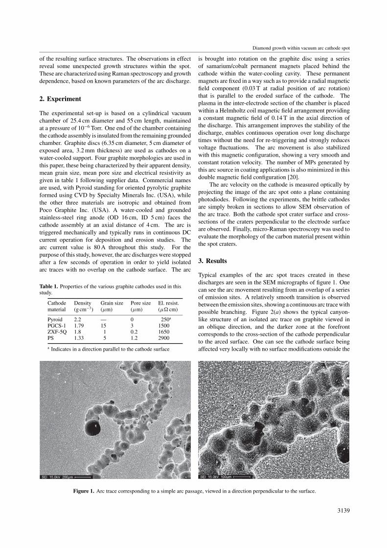
Figures 4 and 5 indicate the occurrence of a sub-structurewithin the growth region. This is revealed in mode detailson the SEM micrographs of figure 7. One can see a columnargrowth layer being transformed in its final stage of growth to thecauliflower structure observed previously. Important porosityand gaps are seen between the columns. Again we can makereference to film deposition techniques in which columnarmorphologies are often observed. Such growth structuresare seen to occur when geometric effects play an importantrole. Columnar structures are typically the result of line ofsight deposition during growth with low adatom mobility.This is usually the case when the substrate temperature is asmall fraction of the melting point of the material or whenthe pressure during deposition is high enough to inducecollisions preventing re-deposition of the sputtered atoms inthe valleys between the columns [23]. The growth structuresobserved here may thus provide a new experimental tool togain knowledge on the conditions existing within the cathodespot plasma.
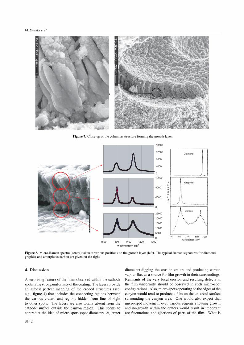
In order to evaluate the micro-structure within thegrowth layer, micro-Raman spectroscopy was used at differentpositions in the layer cross-section. Figure 8 shows threemicro-Raman spectra and the corresponding locations of thesespectra in the growth structure. Also given are the typicalRaman peaks corresponding to the crystalline structure ofgraphite (1581 cm−1) and diamond (1331 cm−1) [24, 25]. Onecan see an evolution of the crystalline structure in the layerfrom typically an amorphous carbon structure at the initialstages of growth (bottom), passing through a more graphiticstructure towards the centre of the cross-section, to a diamond-like structure dominating the top (surface) layers. The spatialresolution corresponding to these curves induces some overlapof the regions observed and on the bare cathode surface. Oneshould also note that the scattering cross-section of diamondin the Raman spectra is much smaller than that of graphite(factor ≈50), indicating that the diamond structure may bedominating, particularly in the top section of the film. Thesespectra indicate an evolution during the growth process andshould again be reflective of the evolution of the cathode spotplasma parameters producing this layer.
3141
J-L Meunier et al
Figure 7. Close-up of the columnar structure forming the growth layer.
0
4000
8000
12000
16000
0
4000
8000
12000
0
5000
10000
15000
20000
25000
10001200140016001800
Wavenumber, cm-1
Diamond
Graphite
Carbon
Figure 8. Micro-Raman spectra (centre) taken at various positions on the growth layer (left). The typical Raman signatures for diamond,graphite and amorphous carbon are given on the right.
4. Discussion
A surprising feature of the films observed within the cathodespots is the strong uniformity of the coating. The layers providean almost perfect mapping of the eroded structures (see,e.g., figure 4) that includes the connecting regions betweenthe various craters and regions hidden from line of sightto other spots. The layers are also totally absent from thecathode surface outside the canyon region. This seems tocontradict the idea of micro-spots (spot diameters � crater
diameter) digging the erosion craters and producing carbonvapour flux as a source for film growth in their surroundings.Remnants of the very local erosion and resulting defects inthe film uniformity should be observed in such micro-spotconfigurations. Also, micro-spots operating on the edges of thecanyon would tend to produce a film on the un-arced surfacesurrounding the canyon area. One would also expect thatmicro-spot movement over various regions showing growthand no-growth within the craters would result in importantarc fluctuations and ejections of parts of the film. What is
3142

Diamond growth within vacuum arc cathode spot
observed is rather (a) a very smooth and slow (<30 cm s−1) arcmovement in the form of an arc spot forming a continuous trace(see figure 1), (b) the MPs emitted having the spherical shapeof the cathode film top layer and (c) a very uniform cathodedeposit as discussed above. Considering the morphology of theeroded canyons, which somewhat confines the eroded plasmaflux, and the added confining effects of the magnetic fieldgeometry, we may speculate at this time that the current-carrying arc plasma covers the full surface area of a crater.Such a situation may lead to an ion bombardment on thecathode surface that, besides acting as the major heat sourceon the surface and important arc current transfer, may alsocontribute to the film growth in a PVD scheme on the cathodeitself.
The measured dimension of the columns in the growthlayer (diameter ∼1 µm, thickness τc ∼ 10 µm) and timescaleof arc passage over some given area (tspot ∼ 10−3–10−4 s)can be used to estimate the number of carbon atoms in thecolumn and the minimum flux needed to achieve this growth.Assuming ion bombardment is the main growth mechanism,this estimation leads to a minimum carbon ion current densityneeded for the growth of the layer (assuming singly chargedions and either graphite or diamond solid density) in the rangeji ∼ 107–109 A m−2. This current density range is well belowthe ion current densities estimated in cathode spots, which varybetween 109 and 1013 A m−2 [17]. This indicates that carbonions, which strongly dominate the cathode spot plasma, canbe the main growth precursor species. The mechanisms andthe actual sequence of phenomena responsible for this growthare still unknown, and growth during the spot extinction stageis also a possibility to consider.
It is finally interesting to note that the top layer of the filmcorresponds to a shift in growth characteristics favouring thecauliflower structure. Such structures are observed in CVDdeposition systems characterised by a lower energy of theprecursor species compared with PVD growth. One can in factexpect this final growth layer to be formed at spot extinction, amoment in cathode spot lifetime that also corresponds to stronglocal pressure changes and MP emission.
5. Summary
The magnetically driven arc movement on graphite cathodespresented here shows slow but very uniform arc velocity,with relatively constant residence time over given areas ofthe cathode. These graphite cathode vacuum arcs inducea growth layer within the cathode spot itself. This growthlayer covers the entire surface affected by the arc erosion onthe electrode, while no growth is observed outside the arcedregions. The films are relatively uniform in thickness and showa conformal mapping of the overlapping crater structures. Thethickness of the film translates into an ion flux requirementthat is well below the ion flux values estimated for carboncathode spot plasma. The internal structure of the film shows arelatively porous columnar structure with the Raman signatureof diamond-like carbon. An evolution of the structure isobserved from graphitic at the base of the films to micro-diamond crystals at the top surface. This top surface showsa cauliflower morphology similar to the structure of the MPsobserved in the coatings produced with a graphite arc ion
source. It is believed that the MPs emitted from such carbonsources are produced through a route that is entirely differentfrom the MPs ejected from metallic electrodes. In the case ofcarbon, MPs are believed to be generated by the film growthprocess towards the end of the cathodic plasma lifetime. TheseMPs formed through a growth of diamond micro-crystals showless adherence at the surface of the columnar film structure.One plausible mechanism for the ejection of some of theseparticles could again be the release of the cathode spot plasmapressure at the end of a spot life.
Acknowledgments
The authors acknowledge the financial contributions of theNatural Sciences and Engineering Research Council of Canada(NSERC), the Fonds quebecois de recherche sur la natureet les technologies (FQRNT) and the support of the JordanUniversity of Sciences and Technology (JUST).
References
[1] Aisenberg S and Chabot R 1971 J. Appl. Phys. 42 2953–8[2] Aksenov I I, Vakula S I, Padalka V G, Strel’nitskii V E and
Khoroshikh V M 1980 Sov. Phys. Tech. Phys. 251164–6
[3] Johnson P C 1989 Phys. Thin Films 14 130–99[4] Sanders D M, Boercker D B and Falabella S 1990 IEEE Trans.
Plasma Sci. 18 883–93[5] McKenzie D R et al 1991 Diamond Rel. Mater. 1 51–9[6] Rother B, Siegel J, Muhling I, Fritzdch H and Breuer K 1991
Mater. Sci. Eng. A 140 780–3[7] Coll B F, Sathrum P, Aharonov R and Tamaor M A 1992 Thin
Solid Films 209 165–73[8] Boxman R L and Goldsmith S 1989 IEEE Trans. Plasma Sci.
17 705–12[9] Kandah M and Meunier J-L 1995 J. Vac. Sci. Technol. A 13
2444–50[10] Martin P J 1995 Handbook of Vacuum Arc Science and
Technology Fundamentals and Applications ed R L Boxmanet al (USA: Noyes Publications) chapter 6, p 391
[11] Aksenov I I, Belous V A, Padalka V G and Khoroshikh V M1978 Sov. J. Plasma Phys. 4 425–8
[12] Storer J, Galvin J E and Brown I G 1989 J. Appl. Phys. 665245–50
[13] Bilek M M and Anders A 1999 Plasma Sources Sci. Technol. 8488–93
[14] Falabella S and Karpov K A Review in monograph [10]chapter 6, p 412
[15] Lossy R, Pappas D L, Roy R A, Cuomo J J and Sura V M 1992Appl. Phys. Lett. 61 171–3
[16] Kandah M and Meunier J L 1996 IEEE Trans. Plasma Sci.24 2
[17] Juttner B, Puchkarev V F, Hantzsche E and Beilis I Inmonograph [10] chapter 3
[18] Beilis I I 1999 IEEE Trans. Plasma Sci. 27 821–6[19] Meunier J L, Coulombe S and Kandah M IEEE Trans. Plasma
Sci. submitted[20] Meunier J L and Kandah M 2001 US Patent No
US 6,261,421 B1[21] Girshick S L, Li C, Yu B W and Han H 1993 Plasma Chem.
Plasma Process 13 169–87[22] Lu Z P, Heberlein J and Pfender E 1992 Plasma Chem. Plasma
Process 12 35–53[23] Thornton J A 1974 J. Vac. Sci. Technol. 11 666–70[24] Tuinstra F and Koenig J L 1970 J. Chem. Phys. 53
1126–30[25] Knight D S and White W B 1989 J. Mater. Res. 4 385–93
3143
Copyright © 2022 FDOKUMEN