Evaluation study on structural fault of a Renaissance Italian palace
14
This article appeared in a journal published by Elsevier. The attached copy is furnished to the author for internal non-commercial research and education use, including for instruction at the authors institution and sharing with colleagues. Other uses, including reproduction and distribution, or selling or licensing copies, or posting to personal, institutional or third party websites are prohibited. In most cases authors are permitted to post their version of the article (e.g. in Word or Tex form) to their personal website or institutional repository. Authors requiring further information regarding Elsevier’s archiving and manuscript policies are encouraged to visit: http://www.elsevier.com/copyright
Transcript of Evaluation study on structural fault of a Renaissance Italian palace

This article appeared in a journal published by Elsevier. The attachedcopy is furnished to the author for internal non-commercial researchand education use, including for instruction at the authors institution
and sharing with colleagues.
Other uses, including reproduction and distribution, or selling orlicensing copies, or posting to personal, institutional or third party
websites are prohibited.
In most cases authors are permitted to post their version of thearticle (e.g. in Word or Tex form) to their personal website orinstitutional repository. Authors requiring further information
regarding Elsevier’s archiving and manuscript policies areencouraged to visit:
http://www.elsevier.com/copyright

Author's personal copy
Engineering Structures 32 (2010) 1801–1813
Contents lists available at ScienceDirect
Engineering Structures
journal homepage: www.elsevier.com/locate/engstruct
Evaluation study on structural fault of a Renaissance Italian palaceMichele Betti ∗, Gianni Bartoli, Maurizio OrlandoDepartment of Civil and Environmental Engineering (DICeA), University of Florence, Via di Santa Marta, 3, I-50139 Firenze, Italy
a r t i c l e i n f o
Article history:Available online 3 April 2010
Keywords:Masonry buildingsDamage assessmentFinite element analysisLimit analysis
a b s t r a c t
This paper discusses the cracking pattern in a historical Italian palace proposing a diagnosis for the originof the actual damage state. The analyzed building, which dates back to the seventeenth century, is amasonry building with a rectangular plan section located in Piancastagnaio (South Tuscany, Italy). Thebuilding exhibits a severe and variegated vertical and horizontal cracking pattern mainly affecting thesouthern and eastern façades. Due to the damage, the palace was evacuated by the Public Authoritiesduring the 1980s and a series of provisional remedies (mainly steel chains) was added. Through the useof the finite element technique, the paper provides an interpretation of the manifested damage. The aimof the diagnosis, supported by the numerical results, is to design an extensive in-situ investigation onthe palace. Moreover, the paper aims at evaluating the effectiveness of the actual temporary retrofitting(mainly steel chains) used to freeze the present damage. At the end of the paper the in-situ investigationis presented and discussed.
© 2010 Elsevier Ltd. All rights reserved.
1. Introduction
In civilized countries the exploitation of the historical builtheritage is a key issue, as it represents an economic concernespecially in contexts where tourism has become a major sourceof wealth. Normally the conservation or rehabilitation of ahistoric masonry building requires a deeper knowledge of theunderstanding of the historical process. While the structuralbehaviour of a new masonry construction is a relatively simpletask (due to the presence of standard codes, inherent literatureand accurate knowledge of material properties), the predictionof the structural response of monumental buildings is still achallenging task [1,2]. As a matter of fact, historic buildings cannotbe easily reduced to standard structural schemes because ofthe uncertainties affecting both the structural behaviour and themechanical properties [3]. Due to these aspects, the maintenanceof historical buildings has become in the last decades a very topicalscientific issue that has attracted the interest of a plethora ofresearchers all over the worldwide community. Nowadays severalcomputational and theoretical approaches are available both in thespecialized scientific literature and in the National Standards [4,5].As to the numerical developments, in particular the last few
decades have seen the growth in the scientific literature of bothnew numerical tools [6–9] and illustrative case studies for theanalysis of the structural response of historic masonry structures.These case studies are significant for both the research community
∗ Corresponding author.E-mail addresses:[email protected] (M. Betti), [email protected]
(G. Bartoli), [email protected] (M. Orlando).
and the practitioners as they represent a wide state-of-the-artof the engineering approach to the evaluation of safety andassessment of historical buildings. Lourenço et al. [10] discuss thecase study of the Monastery of Jerónimos in Lisbon (Portugal). Theauthors show how, by means of advanced numerical analyses, itis possible to reach an understanding on both the behaviour andthe damage of a complex historical construction. The numericalmodelling strategies, combined with a sensitivity analysis of theresults, allow for a proper design of the remedial measures.Moreover the authors show that the numerical model is aninvaluable tool in the conception and understanding of in-situtesting and monitoring. The importance of a numerical iterativeapproach to the analysis of historic masonry constructions is alsopointed out by Antonelli et al. [11] discussing the case study ofthe Cappella dei Principi in Firenze (Italy). The authors, with theaim to assess the causes of the failure of an internal stone arch,build a numerical model of the masonry dome whose complexity(geometrical and mechanical) has been progressively increasedin different steps. Firstly, simplified elastic linear models havebeen used to obtain information (mainly stress concentration)for both the planning of a subsequent experimental campaignand the position of monitoring instruments (mainly temperatureand displacement transducers). Secondly, results of the in-situexperimental campaign have been used to fit the properties of thenumerical model. The authors show how by means of an iterativenumerical modelling it is possible to obtain a proper identificationof the structural behaviour of the analysed building. A successfuland illustrative employment of the finite element method in theassessment and strengthening of a historic building (a masonrychurch) is proposed in [12] where the author shows how advancedstructural analyses are a reliable tool that offers both a clear
0141-0296/$ – see front matter© 2010 Elsevier Ltd. All rights reserved.doi:10.1016/j.engstruct.2010.03.001

Author's personal copy
1802 M. Betti et al. / Engineering Structures 32 (2010) 1801–1813
understanding of the structural behaviour and a minimum andadequate design of strengthening. Betti & Vignoli [13], by meansof a finite element model, analyse the structural behaviour of aRomanesque church to assess the origin of the actual damage andthe seismic vulnerability of the church. The finite element modelhas been used to evaluate the benefit of different strengtheningrestoration proposals, offering an insight into an understandingof the minimum and adequate design of strengthening. Cardosoet al. [14,15] propose an iterative method for the seismicassessment of old masonry buildings: in each iteration damagein the structural elements (or connections between them) isidentified and the structural system changed accordingly. Eachiteration comprises only a linear elastic analysis and that allows itsuse in current design practice. Themethod has been applied by theauthors to an old masonry building (named ‘Pombalino’, typical indowntown Lisbon). Discussion of the results shows the method’seffectiveness and its limitations. Recently Mallardo et al. [16]discuss the seismic behaviour of a Renaissance palace in Ferrara(Italy). Firstly a full 3D non-linear model of the palace is discussedto obtain an insight into the structural performance of the palace.Next, by means of three reduced 2D non-linear models, a detailedstudy of the main façade of the palace is presented. The combiningof different modelling strategies allows a critical evaluation of theseismic vulnerability of the main elements.Nevertheless, despite the significant development of strate-
gies or adequate tools for the numerical analyses of masonrybuildings [17,18], the conservation and restoration of historicalstructures still remain a challenge to modern engineering since acorrect structural evaluation ofmasonry buildings should be basedon a deep knowledge of: (i) the building’s history and evolution,(ii) geometry, (iii) structural details, (iv) crack patterns and mate-rial damage map, (v) masonry construction techniques and ma-terials, and (vi) material properties [19]. This knowledge can bereached combining in-situ and laboratory experimental investi-gations jointly with structural analyses with appropriate models.Since it is extremely difficult to get all the information necessaryfor a correct definition of a numerical (non-linear) model it is nec-essary to have a simplified, often iterative, procedure for the eval-uation of the static and seismic reliability. Taking into account onlya reduced amount of information this procedure should be ableto address the relevant aspects of the problem and provide guid-ance in analyses and experiments. As a general remark, it is pos-sible to state that when dealing with historic masonry buildingsdifferent approaches are needed to analyse different aspects, andthat the analysis of an ancient structure asks for amultidisciplinarystudy [20,21].The paper illustrating a significant case study deals with
the above-mentioned problems. Results are reported of researchaimed to assess the damage caused on a historical Italian palaceand to plan an effective experimental investigation. In the first partof the paper a description of the building together with a reviewof the main historical steps and the actual damage is reported.A topographic survey performed over the whole palace is usedto build a 3D finite element model, and the numerical modelis then used to discuss the damage causes. The second aim ofthe modelling strategies is to offer indication for the design ofa subsequent effective in-situ experimental campaign that is acrucial point since an erroneous design might compromise a studyand excessive in-situmeasurements have high costs. In the secondpart of the paper the benefits have been discussed derived bythe temporary provisional measures (mainly steel chains installedduring the 1980s) to prevent the ruin of the palace. Global out-of-plane mechanisms of the main façades in the case of seismic load(as the palace was built in a seismic area) have been analysed. Thebenefits are estimated by comparing the casewith andwithout thesteel chains. Results are used to evaluate if additional provisional
A
N
5m
A
MONUMENTALROOM
C
A
D
B
10.50 432
Fig. 1. First floor layout (‘‘piano nobile’’).
measures are necessary to ensure the stability of the main façadesin case of a seismic event, before planning a global retrofitting.This paper contributes to the issue of modelling and analysis
of historic masonry buildings of cultural importance, presenting acareful use of numerical analyses to dealwith practical engineeringproblems in the field. The study suggests that the comprehensionof the structural behaviour of historic buildings is an iterativeprocedure that starts from preliminary simplified modellingstrategies (i.e. not computationally expensive, compared to theavailable experimental data). The comprehension of the staticbehaviour (and proposal for remedial measures) of culturalheritage buildings requires an iterative approach, aimed atgathering all the information (numerical and experimental)necessary to issue a proper and critical judgment.
2. The case study
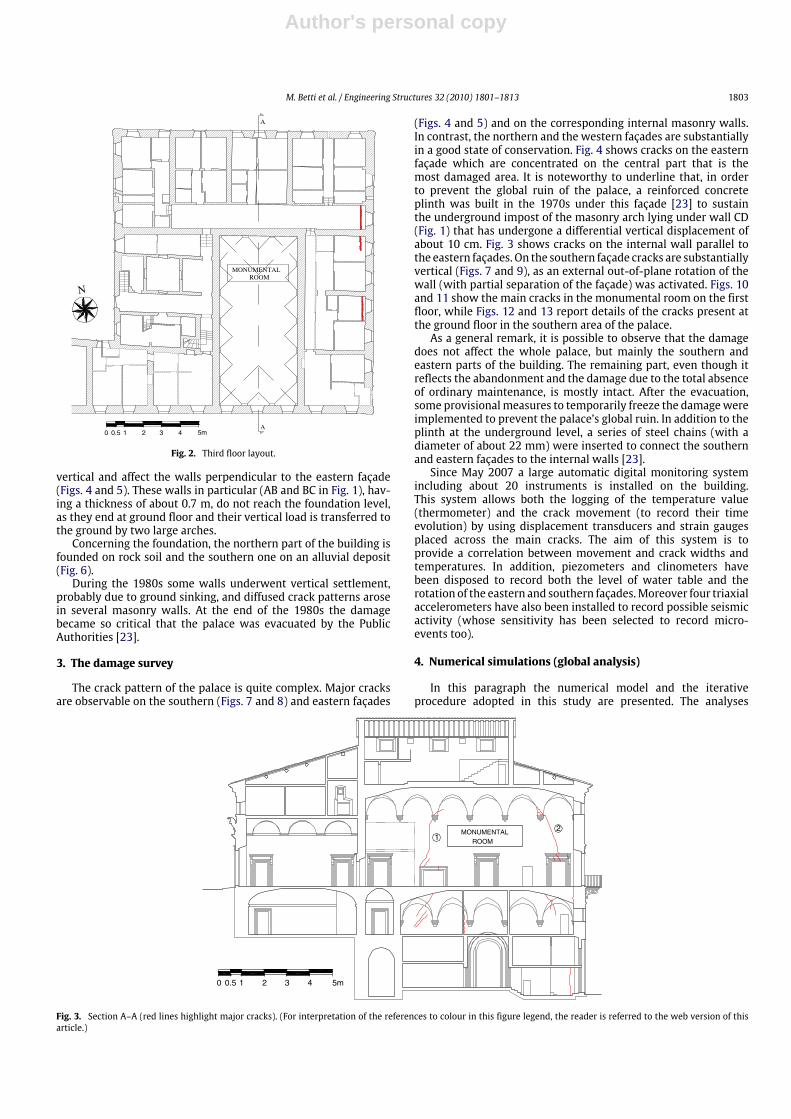
The analysed building is located in Piancastagnaio (South Tus-cany, Italy). The original structure dates back to the beginning ofthe seventeenth century and it was built under the supervision ofthe architect Valentino Martelli (about 1550–1630), a Michelan-gelo disciple [22]. The palace was edified by the family Bourbon-Del Monte, feudatory of the Grand Duke Ferdinando I Medici, torepresent its political and economical importance in the area, withdimensions and architectural details reflecting such an intent. Thebuilding is a rectangular three-story masonry construction, with alength of about 34 m and a width of about 31 m (Figs. 1 and 2) andan external masonry wall thickness of about 1.2 m. At the level ofthe first floor (the so-called ‘‘piano nobile’’) there is a large monu-mental room (Fig. 3). Amonumental stone stair connects each levelof the palace. The foundations of the palace are not at the samelevel and an underground level (a storage basement) is present inthe southern area (Fig. 3), as part of the building (the northern part)was partially built over the old city walls. The floor levels are madeof several types of masonry vaults, depending on the dimensionand importance of the room (Figs. 1 and 2). Smaller rooms are usu-ally covered by cross vaults, while the monumental room is roofedby a cloister vault. Noteworthy is the regularity of the geometri-cal configuration of the building characterized by well connectedorthogonal masonry walls. The only geometrical irregularities are
Author's personal copy
M. Betti et al. / Engineering Structures 32 (2010) 1801–1813 1803
N
A
A
MONUMENTALROOM
5m 10.50 432
Fig. 2. Third floor layout.
vertical and affect the walls perpendicular to the eastern façade(Figs. 4 and 5). These walls in particular (AB and BC in Fig. 1), hav-ing a thickness of about 0.7 m, do not reach the foundation level,as they end at ground floor and their vertical load is transferred tothe ground by two large arches.Concerning the foundation, the northern part of the building is
founded on rock soil and the southern one on an alluvial deposit(Fig. 6).During the 1980s some walls underwent vertical settlement,
probably due to ground sinking, and diffused crack patterns arosein several masonry walls. At the end of the 1980s the damagebecame so critical that the palace was evacuated by the PublicAuthorities [23].
3. The damage survey
The crack pattern of the palace is quite complex. Major cracksare observable on the southern (Figs. 7 and 8) and eastern façades
(Figs. 4 and 5) and on the corresponding internal masonry walls.In contrast, the northern and the western façades are substantiallyin a good state of conservation. Fig. 4 shows cracks on the easternfaçade which are concentrated on the central part that is themost damaged area. It is noteworthy to underline that, in orderto prevent the global ruin of the palace, a reinforced concreteplinth was built in the 1970s under this façade [23] to sustainthe underground impost of the masonry arch lying under wall CD(Fig. 1) that has undergone a differential vertical displacement ofabout 10 cm. Fig. 3 shows cracks on the internal wall parallel tothe eastern façades. On the southern façade cracks are substantiallyvertical (Figs. 7 and 9), as an external out-of-plane rotation of thewall (with partial separation of the façade) was activated. Figs. 10and 11 show the main cracks in the monumental room on the firstfloor, while Figs. 12 and 13 report details of the cracks present atthe ground floor in the southern area of the palace.As a general remark, it is possible to observe that the damage
does not affect the whole palace, but mainly the southern andeastern parts of the building. The remaining part, even though itreflects the abandonment and the damage due to the total absenceof ordinary maintenance, is mostly intact. After the evacuation,some provisionalmeasures to temporarily freeze the damagewereimplemented to prevent the palace’s global ruin. In addition to theplinth at the underground level, a series of steel chains (with adiameter of about 22 mm) were inserted to connect the southernand eastern façades to the internal walls [23].Since May 2007 a large automatic digital monitoring system
including about 20 instruments is installed on the building.This system allows both the logging of the temperature value(thermometer) and the crack movement (to record their timeevolution) by using displacement transducers and strain gaugesplaced across the main cracks. The aim of this system is toprovide a correlation between movement and crack widths andtemperatures. In addition, piezometers and clinometers havebeen disposed to record both the level of water table and therotation of the eastern and southern façades.Moreover four triaxialaccelerometers have also been installed to record possible seismicactivity (whose sensitivity has been selected to record micro-events too).
4. Numerical simulations (global analysis)
In this paragraph the numerical model and the iterativeprocedure adopted in this study are presented. The analyses
21
MONUMENTALROOM
5m 10.50 432
Fig. 3. Section A–A (red lines highlight major cracks). (For interpretation of the references to colour in this figure legend, the reader is referred to the web version of thisarticle.)

Author's personal copy
1804 M. Betti et al. / Engineering Structures 32 (2010) 1801–1813
Fig. 4. Eastern façade (red lines highlight the crack pattern). (For interpretationof the references to colour in this figure legend, the reader is referred to the webversion of this article.)
Fig. 5. Eastern façade.
herein discussed have a double aim: (i) to assess the potentialcauses of the palace’s damage and (ii) to plan a subsequent in-situ experimental campaign (both on the masonry wall textureand on the ground). To this end, the finite element techniquehas been used. A finite element model of the whole palace hasbeen intentionally built with the commercial code SAP2000 [24], aprogram that performs essentially linear analyses. However sincethe study asks us to model a historic masonry building this choiceled to the need of a step-by-step iterative procedure to simulate,even if in an approximate manner, the non-linear behaviour of theentire masonry structure. By introducing a number of changes inthe structural configuration it is possible to simulate the principalsources of non-linear material behaviour (i.e. cracking of themasonry elements and failure of the connections betweenmasonrywalls). It is also possible, if relevant, to simulate the respectivesequence of ruptures [25]. This approach could be consideredquite reasonable, given the variability of material properties andthe unknowns at the present time. Despite its disadvantages(for example the selection of the damaged elements is madeby a visual inspection of the element stress state) the approachhas the main advantage that it can be easily implemented incommercial codes (such as the one used in this study) as it basicallyrequires us to develop a series of linear analyses. This methodhas been used successfully in the past (starting from the 1980s)with reduced computer power, and the corresponding scientificliterature reports both the theoretical basis of the approach andmany illustrative case studies. Today, with more computer powerand sophisticated numerical tools, is possible to model a widerange of non-linear phenomena (including cracking and crushing
L
Ls
Sa
3-5-5
1
R
1/2 15-19-RIF
4
R
Sa+Tra
Tra
Tra
L
I
I
715
720
760
725
730
735
740
745
755
750
715
720
760
725
730
735
740
745
755
750
rock area
alluvial deposit
Fig. 6. Cross section of the palace and subsoil profile: geological characteristics ofthe ground (R, Sa: superficial soil; Sa + Tra: sand with trachyte; Tra: trachyte; Ls:sandy silt; SI: silty sand; L: silt).
Fig. 7. Southern façade (red lines highlight the crack pattern). (For interpretationof the references to colour in this figure legend, the reader is referred to the webversion of this article.)
that occurs in masonry under severe loads). It is then obvious thatthe procedure is not competitive (in a general sense) if aimed ata concluding diagnosis. Nevertheless, in the authors’ opinion thefinite element procedure remains competitive if used, as in theproposed case study, to obtain preliminary results to address thesubsequent steps of the research. Next a preliminary discussionon the adopted mesh is reported before specifying the applicationof the iterative procedure with respect to the case study anddiscussing the adopted parameter value (both for the masonrymaterial and for the ground).The finite element model, built at this step of the investigation
by two-dimensional shell elements, aims to reproduce accuratelythe geometry of the structure. The results of a topographicsurvey performed over the whole palace [26] have been used tobuild a first (not computationally expensive) numerical modelof the building. All the variations in wall thickness, geometricalirregularities and wall connections were taken into account.The major openings in the building are reproduced. Windowshave been modelled taking into account their actual dimensions

Author's personal copy
M. Betti et al. / Engineering Structures 32 (2010) 1801–1813 1805
Fig. 8. Southern façade.
Fig. 9. Southern façade (cracks details).
(Fig. 12). Vaults have been modelled (assuming the fill materialas a dead load) to consider their thrust effect on the confiningwalls. Masonry walls and vaults were modelled by means linearelastic shell elements. In contrast the roof’s timber trusses werenot modelled and their self-weight was applied to the modelas vertical loads acting directly on the corresponding masonrywalls. The final model is able to reproduce, with acceptableconfidence (i.e. compared to the available data), the overallspatial configuration of masonry walls together with the entireset of architectural elements that are of structural relevance.This attention is particularly required in historic buildings wheredifferences between architectural and structural elements are notalways clear. A preliminary study on the mesh size of the shellelements has also been made. This preliminary study has led us todecide the mesh size for masonry elements. It was concluded thatit was not worth refining the mesh more than the one reportedin Fig. 14 (with a refinement around windows and doors) fortwo major reasons: (i) the main objective in studying cracking inmasonry elements was to evaluate the trend in the location ofmasonry damage rather than its exact position and (ii) the level ofaccuracy does not need to go beyond the knowledge of materialproperties. The adopted mesh size seems to be appropriate forthese purposes; moreover the results obtained with the adoptedmesh are similar to those obtained with a preliminary local modelwhere a more refined mesh was assumed.
Fig. 10. Monumental room (#1 in Fig. 3).
Fig. 11. Monumental room (#2 in Fig. 3).
To have a preliminary evaluation of the load transfer mech-anisms from the building to the ground taking into account theeffects of the soil–structure interactions, a simplified iterative pro-cedure, as previously introduced, has been intentionally applied.The proposed iterative procedure, needed to consider the non-linear material behaviour of masonry (mainly the low tensile re-sistance of the masonry), has been applied as follows: (a) a linearmodel of the whole structure is built bymeans of 2D isoparametricshell elements; (b) a linear static analysis is performed consideringthe own weight (and the service loads); (c) for each structural ele-ment (or connection) the design action effects F (principal tensilestresses on masonry walls) will be compared with respective re-

Author's personal copy
1806 M. Betti et al. / Engineering Structures 32 (2010) 1801–1813
Fig. 12. Internal room (and windows detail).
Fig. 13. Eastern–southern edge (internal view).
Fig. 14. Global view of the numerical model of the palace.
sistances R (tensile strength of masonry) identifying their rupture(cracking if F > R); (d) the damage state is modelled by reduc-ing the stiffness of the collapsed elements (or connections) whichsuffered significant cracking. The number of elements where thestiffness is reduced at each time depends on the precision requiredin the analysis; (e) the process is repeated (i.e. changes in Young’sstiffness of the elements of the structural model) and it stops if forall the elements F < R. The structural elements where damagewas analyzed aremasonrywalls and connections of masonrywallswith vaults. In this study, a reduction of about a tenth of the elas-tic modulus was considered to model the cracking damage on ma-sonry elements. However a designer may wish to adopt a differentcriterion for the stiffness reduction for higher or lower precision.Concerning the masonry properties, as no in-situ tests are
available at this step (the results herein obtained will be used toplan the experimental campaign), assumptions on the masonrymaterial properties have been made taking into account literature
data for historic masonry (i.e. buildings with similar masonrytexture [27,28]) and normative reference [4] deriving conservativevalues from these experiences. In particular, since the masonrytexture seems to be an infilled one, typical values of infilledmasonry have been assumed: the Young’s modulus of masonry Emhas been assumed equal to 15, 000 N/mm2 (considering a range ofvariation between 1440 and 1980 N/mm2); its own weight γm hasbeen assumed equal to 20 kN/m3 (considering a range of variationbetween 19 and 21 kN/m3). The Poisson coefficient was assignedthe value 0.2.In the present case study a parametric study varying the
properties of the masonry (mainly the Young’s modulus) was notplanned. In the absence of experimental results that can accountfor the spatial distribution of the building’s masonry typologiesit is, at this step, only rational to assume a uniform distributionof masonry properties (i.e. without differentiating the masonryparameters along the main elements of the building) as anyvariation could be totally arbitrary. Being the non-linear analysesconducted as a sequence of linear ones, a scaling on the Young’smodulus could produce only a scaling on the corresponding results.A test was made assuming Em equal to 20, 000 N/mm2, and noappreciable differences were observed in the building behaviour.Masonry strength (R) has been assumed about 0.2 N/mm2(considering a range of variation between 0.1 and 0.4 N/mm2 assuggested by [4]).Due to the variability in the properties of structural materials
and due to the variety of structural solutions that is possible tofind in an oldmasonry building, strength values are always averagevalues. Designers could adopt different values but a definitivedecision can be delivered only after experimental tests.With respect to the foundation soil modelling, due to the
differences in mechanical properties [29], different values havealso been considered for ground characteristics. In the southernpart of the building, where the ground is characterized by thepresence of silty sand and sandy silt, a linear elasticWinkler modelhas been considered by means of spring elements whose stiffnesschanges according to the corresponding ground properties. Incontrast, in the northern area, a layer of membrane elements hasbeen inserted at the foundation level under the masonry walls, inorder to take into account the high cohesion (about 200 kPa, seeTable 1) of the rocky ground (Fig. 6). Additional elements have beeninserted underneath the walls, whose vertical stiffness R∗ is givenby:
R∗ =E · Ah=E · i · smh
(1)
where E is the elastic modulus, h is the height of the element;sm is the thickness of the masonry and i is the reference lengthof each node of the element. By using a linear elastic model thestiffness of each spring is given by R = ks · sm · i (where ks is theWinkler assumed constant and equal to 0.20 N/mm3 as suggestedin [29]); therefore the expression to evaluate the vertical stiffnessE becomes:
R = R∗ ⇒ E = ks · h [N/mm3] (2)
Finally the numerical model has been built to account for boththe geometric irregularities (using the results of the geometricsurvey [26]) and the differential ground settlements (using theresults of a geological/geotechnical survey [29]). The final three-dimensional model consists of 16,210 shell elements, 832 springelements and 16,486 joints (Fig. 14). The model has been used toassess the influence on the actual damage of both the differentialsettlements of foundations and the vault thrusts. Due to thedifferences in shape and dimension and as the imposts of the vaultsare not at the same level, these elements produce an unbalancedthrust on the supporting walls (especially in correspondence of

Author's personal copy
M. Betti et al. / Engineering Structures 32 (2010) 1801–1813 1807
Table 1Geotechnical characterization of ground (R, Sa: superficial soil; Sa+ Tra: sand withtrachyte; Tra: trachyte; Ls: sandy silt; SI: silty sand; L: silt).
LithotypeR Sa Sa+Tra Tra Ls SI L
Weight (kN/m3) 17.5 18 18.5 22 20 19 21Friction angle (°) 28° 32° 33° 40° 30° 29° 28°Cohesion (kPa) 0 0 0 200 1 0 5
Fig. 15. Fixed-base model, principal tensile stresses on masonry [N/mm2].
the monumental room). The effect of the differential settlementsof the foundations has been taken into account by a series ofparametric analyses, where the ground stiffness of the alluvialdeposit (mainly characterized by the Winkler constant valuereported in the geotechnical survey [29]) has been changedwithin a physical range. In particular, assuming as a mean valuefor ks the value reported in [29], a range of variation between0.10 N/mm3 (corresponding to 1/2 of the experimental value) and0.40N/mm3 (corresponding to double the experimental value) hasbeen considered.To identify the damage state, the following models have been
analysed: (i) model A is the model of the building with fixedbase assumption; (ii) model B is the model that accounts for thesoil–structure interaction and (iii) model C is similar to model Bbut with the addition of a localized ground sinking. They are nextdescribed.
4.1. Model A. Fixed base model
The first series of analyses have been performed assuminga rigid ground foundation, i.e. a fixed base model has beenconsidered under vertical loads mainly due to its own weight(masonrywalls, vaults and fillings, wooden roof). The service loadshave also been taken into account assuming a uniform load at eachlevel equal to 2 kN/m2. Results of these preliminary analyses arereported in Figs. 15 and 16. The figures show the principal tensilestresses which are relatively low except for a limited zone (circledin Fig. 16). This means that the ownweight and service loads alonecannot account for the damage on the building; results do notchange even if the masonry strength is reduced by one-half to takeinto account the degradation of masonry properties with time.
4.2. Model B. Soil–structure interaction
Results from model A suggest that the effect of the differentialground settlements should be introduced in the F.E. analysis.To evaluate the effects of the soft properties of the ground,parametric variations of the Winkler constant on the alluvialdeposit have been taken into account. A range of variation between0.10 N/mm3 (corresponding to 1/2 of the experimental value) and0.40 N/mm3 (corresponding to double the experimental value)has been considered, but the results of the analyses don’t show
Fig. 16. Fixed-base model, principal tensile stresses on East façade [N/mm2].
Fig. 17. Soil–structure interaction, model without reduced modulus. Principaltensile stresses on masonry [N/mm2].
Fig. 18. Soil–structure interaction, model without reduced modulus. Principaltensile stresses on eastern façade [N/mm2].
appreciable variability in the building response. Consequently thevalue of theWinkler constant reported in [29] has been used, sinceto justify different values it is necessary to have, e.g., informationabout the shape of the foundations.Fig. 17 reports the principal tensile stresses on the masonry
at the start of the iterative procedure; in particular Fig. 18 showsa high tensile stress state on the masonry in the eastern façade.In order to consider the no tensile resistance of masonry, theoriginal model has been consequently modified by following thepreviously described step-by-step procedure. In the elementswhere tensile stresses exceed the masonry strength (assumed tobe equal to 0.2 N/mm2) the elastic modulus has been fictitiouslyreduced (of a tenth). This reduction has been made iterativelyuntil the redistribution of the internal stresses allows acceptablevalues of tensile stresses (lower or equal to 0.2 N/mm2) on allthe masonry walls. Seven steps are enough to reach a stableconfiguration. Fig. 19 shows the elements where the stiffness hasbeen reduced (grey elements) at the end of the iterative stiffness

Author's personal copy
1808 M. Betti et al. / Engineering Structures 32 (2010) 1801–1813
Fig. 19. Soil–structure interaction, model with reduced modulus. Element withreduced modulus (dark).
Fig. 20. Soil–structure interaction, model with reduced modulus. Principal tensilestresses on East façade [N/mm2].
reduction; Fig. 20 reports the corresponding tensile stresses on theeastern façade of the palace. As stated before several models havebeen analysed opportunely changing the ground stiffness on thealluvial area based on the indication reported in [29], but all ofthem led to the same damage pattern, identified by the elementswith the reduced modulus (Fig. 19). The damage configurationobtained considering only the different spatial distribution ofground properties does not account for the actual damage; thismeans that also taking into account the ground properties it is notpossible to explain the present damage state.
4.3. Model C. Soil–structure interaction with local sinking
Taking into account the results of the diagnosis made in thelate 1980s (when a differential movement on the eastern façade ofabout 100mmwas found between the internal and external walls)a new series of analyses has been performed removing the springsunder the central part of the eastern façade (Fig. 21)with the goal ofsimulating a local sinking. The tensile stress state obtained at thestart of the iterative procedure is reported in Fig. 22. This stressmap is characterized by the presence of a high level of tensilestress, much higher than the adopted tensile strength. As in theprevious analyses the iterative procedure has been repeated untilin all the elements tensile stresses were lower than the masonrystrength. The damage pattern obtained at the end of the procedure,after 11 iterations, is shown in Fig. 23 while the correspondingtensile stress state in the masonry is shown in Fig. 24. The elementpattern with reduced elastic modulus in Fig. 23 moves to the leftembracing the area of the present damage on the eastern façade.
4.4. FEM: key point results
The finite element analyses highlight some points. The first isthat its ownweight alone (Model A) induces a very localized stress
Fig. 21. Global view of the numerical model of the palace (view of the assumedboundary condition).
Fig. 22. Soil–structure interaction, model without reduced modulus. Principaltensile stresses on East façade [N/mm2].
Fig. 23. Soil–structure interaction, model with reduced modulus. Element withreduced modulus (dark).
state, while models accounting for differential ground settlementsreproduce a damage state that do not match the present one.Model B, which accounts for the different soil properties underthe palace in the alluvial area, is not able to justify the actualdamage. The palace dates back to the seventeenth century, and themajor effects of the damage were recorded during the 1980s. Itis reasonable to expect that accidental effects due to differencesin ground properties took place during, or immediately after, theconstruction of the palace. This is confirmed by the numericalresults (Model B). On the other hand, researches on the historicalseismicity of the area do not show significant earthquake eventsin the past 200 years. The last strong earthquake in the area wasrecorded in 1919 (with an intensity IS = 7 according to MercalliIntensity Scale), but it is not believed to be the cause of the actualdamage of the palace since the building continued to be used asprivate houses and a public gymnasium. This means that at that

Author's personal copy
M. Betti et al. / Engineering Structures 32 (2010) 1801–1813 1809
Fig. 24. Soil–structure interaction, model with reduced modulus. Principal tensilestresses on eastern façade [N/mm2].
time the present damage was not present. The time during whichthe damage of the palace has developed is quite short, probablyless than 4–5 years [23]. Previous observations, along with theresults obtained with the last numerical analyses (Model C), seemto suggest that the origin of the present damage is due to a localcollapse of the ground under the central part of the eastern façade.Moreover, historic literature data report that all the area wherethe palace is built is characterized by the presence of undergroundcavities [22]; it is then reasonable to suppose that local sinking hashappened under the eastern façade due to the collapse of one ofthese cavities. Nevertheless this hypothesis must to be confirmedby a new soil investigation campaign, which has been alreadydesigned considering the results of this study.As an additional result the numerical analyses show a high
value of the vertical (compressive) stresses under the eastern andsouthern façades. In particular the average compressive stressesat the base of the western and northern façades, founded on rock,are about 0.3 N/mm2, while on the eastern and southern façade,founded on the alluvial deposit (Fig. 6), are about 0.5 N/mm2.These values seem very high if compared with the alluvialdeposit resistance, so that a deeper investigation on both soiland overlaying walls and corresponding foundation typologies isplanned to confirm and check the numerical results. Coring testsand single/double flat-jack tests are planned in this area to assessthe exact composition of masonry walls and to evaluate both thestress state and the masonry Young’s modulus.Hence the applied iterative approach, making use of accessible
computational tools, has the advantage of identifying the weakestand critical parts of the structure providing useful information toplan effective investigation.
5. Limit analysis (local analysis)
Results of previous analyses allow us to exclude that the originof the present damage is due to the different soil properties underthe palace or to a seismic event. At the same time they suggest thatthe origin of the damage is due to a local ground sinking (probablya local collapse of an underground cavity) in the middle part of theeastern façade. Even if it is possible to exclude the earthquake asthe cause of the present damage, the palace is built in a seismicarea (classified with respect to the Italian Recommendation inmedium seismicity [4]) then evaluation of its seismic safety shouldbe a primary concern. In order to evaluate the safety levels of thepalace some representative macro-elements have been analyzed.The attention has been paid to the area where damage is presentto assess the effectiveness of the temporary retrofitting with steelchains made in the 1980s. The out-of-plane collapse multipliersof the macro-elements were compared with and without theprovisional steel chains.
Fig. 25. Partial collapse of foundation under the eastern façade.
Fig. 26. Mechanism #1: partial overturning of the eastern façade.
Fig. 27. Mechanism #2: overturning of the eastern façade.
To this end is verified if horizontal load multipliers for out-of-plane mechanisms are higher than the corresponding thresholdproposed by the Italian Recommendations [4,5]. Previous researchworks [30,31] show the validity of a limit-state approach in theassessment of the seismic behaviour of unreinforced masonrybuildings. When analyzing out-of-plane mechanisms (the so-called first type mechanisms), masonry walls are modelled as asystem of rigid bodies, articulated by hinges, whose geometry anddistribution are defined according to potential failure mechanism.Substantially the structure is considered as the assemblage ofa certain number of components depending on the structuralcompound geometry and shape (e.g. the whole façade) and on thedetails (e.g. quality of existing connections) whose behaviour issimilar to that of analogous macro-elements in similar buildings.In this study, several possible out-of-planemechanismswhich bestrepresent the surveyed damage patterns have been taken intoaccount (Figs. 25–30). All of the mechanisms herein consideredtake into account global overturning of masonry façades.After the selection of the elementary macro-elements, the
collapse multiplier (λ) can be evaluated by applying the Theoremof VirtualWork (TVW) on the rigid-body system,where the seismicload is assumed as an overturning force while the gravity load is
Author's personal copy
1810 M. Betti et al. / Engineering Structures 32 (2010) 1801–1813
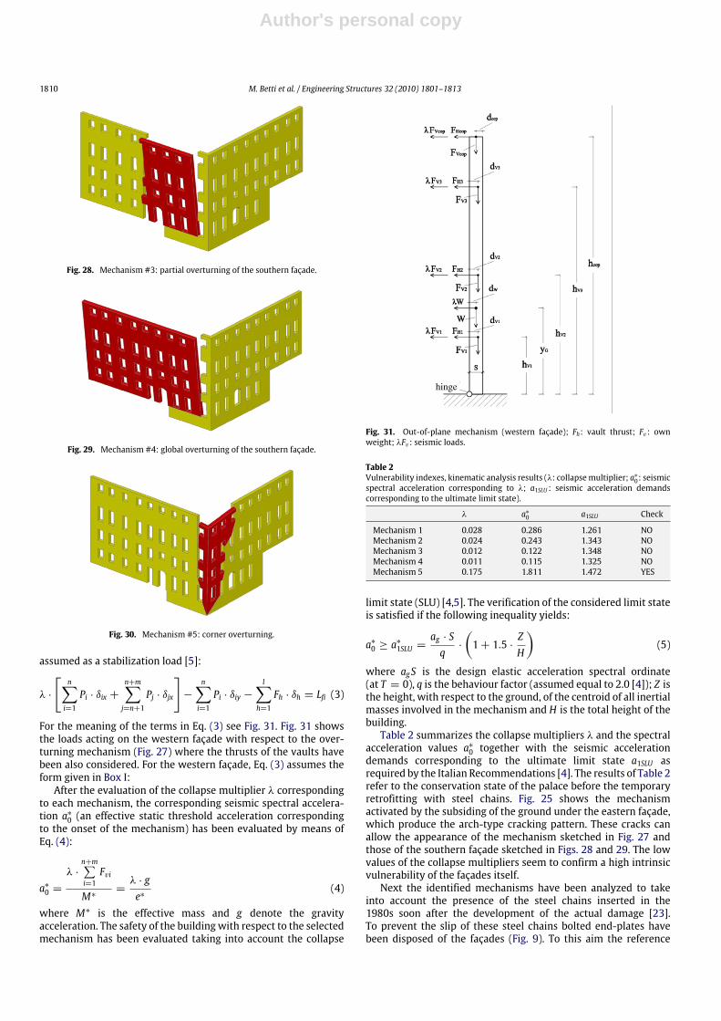
Fig. 28. Mechanism #3: partial overturning of the southern façade.
Fig. 29. Mechanism #4: global overturning of the southern façade.
Fig. 30. Mechanism #5: corner overturning.
assumed as a stabilization load [5]:
λ ·
[n∑i=1
Pi · δix +n+m∑j=n+1
Pj · δjx
]−
n∑i=1
Pi · δiy −l∑h=1
Fh · δh = Lfi (3)
For the meaning of the terms in Eq. (3) see Fig. 31. Fig. 31 showsthe loads acting on the western façade with respect to the over-turning mechanism (Fig. 27) where the thrusts of the vaults havebeen also considered. For the western façade, Eq. (3) assumes theform given in Box I:After the evaluation of the collapse multiplier λ corresponding
to each mechanism, the corresponding seismic spectral accelera-tion a∗0 (an effective static threshold acceleration correspondingto the onset of the mechanism) has been evaluated by means ofEq. (4):
a∗0 =λ ·
n+m∑i=1Fvi
M∗=λ · ge∗
(4)
where M∗ is the effective mass and g denote the gravityacceleration. The safety of the building with respect to the selectedmechanism has been evaluated taking into account the collapse
hinge
Fig. 31. Out-of-plane mechanism (western façade); Fh: vault thrust; Fv : ownweight; λFv : seismic loads.
Table 2Vulnerability indexes, kinematic analysis results (λ: collapsemultiplier; a∗0: seismicspectral acceleration corresponding to λ; a1SLU : seismic acceleration demandscorresponding to the ultimate limit state).
λ a∗0 a1SLU Check
Mechanism 1 0.028 0.286 1.261 NOMechanism 2 0.024 0.243 1.343 NOMechanism 3 0.012 0.122 1.348 NOMechanism 4 0.011 0.115 1.325 NOMechanism 5 0.175 1.811 1.472 YES
limit state (SLU) [4,5]. The verification of the considered limit stateis satisfied if the following inequality yields:
a∗0 ≥ a∗
1SLU =ag · Sq·
(1+ 1.5 ·
ZH
)(5)
where agS is the design elastic acceleration spectral ordinate(at T = 0), q is the behaviour factor (assumed equal to 2.0 [4]); Z isthe height, with respect to the ground, of the centroid of all inertialmasses involved in the mechanism and H is the total height of thebuilding.Table 2 summarizes the collapse multipliers λ and the spectral
acceleration values a∗0 together with the seismic accelerationdemands corresponding to the ultimate limit state a1SLU asrequired by the Italian Recommendations [4]. The results of Table 2refer to the conservation state of the palace before the temporaryretrofitting with steel chains. Fig. 25 shows the mechanismactivated by the subsiding of the ground under the eastern façade,which produce the arch-type cracking pattern. These cracks canallow the appearance of the mechanism sketched in Fig. 27 andthose of the southern façade sketched in Figs. 28 and 29. The lowvalues of the collapse multipliers seem to confirm a high intrinsicvulnerability of the façades itself.Next the identified mechanisms have been analyzed to take
into account the presence of the steel chains inserted in the1980s soon after the development of the actual damage [23].To prevent the slip of these steel chains bolted end-plates havebeen disposed of the façades (Fig. 9). To this aim the reference

Author's personal copy
M. Betti et al. / Engineering Structures 32 (2010) 1801–1813 1811
λ =(W · dW )+ (FV1 · dV1)+ (FV2 · dV2)+ (FV3 · dV3)+ (FVcop · dcop)− (FH1 · hV1)− (FH2 · hV2)− (FH3 · hV3)− (FHcop · hcop)
(W · yG)+ (FV1 · hV1)+ (FV2 · hV2)+ (FV3 · hV3)+ (FVcop · hcop)
Box I.
hinge
Fig. 32. Out-of-plane mechanism (western façade); Fh: vault thrust; Fv : ownweight; λFv : seismic loads; Ti: chain forces.
TVW scheme has been modified (Fig. 32) to take into accountthe chain forces Ti. The evaluation of the collapse load multiplierλ has been made, considering several possible configurations ofthe mechanism (Fig. 33). To this aim the progressive modificationof the external chain forces acting at each level during thedevelopment of the mechanism has been taken into accountconsidering the elongation of the chains and assuming an elastic-perfectly plastic behaviour. The analyses have been carried outuntil the chains at the last level are yielded. Fig. 33 reports thedevelopment of the considered mechanism for a generic wall asa function of the angle θ ;∆Li denotes the elongations of the chains
at the different levels. At each∆θ both the∆Li and the deformationεi in the chains (Fig. 33) have been calculated. Figs. 34 and 35 reportthe diagrams of the collapse multiplier λ (expressed as spectralacceleration a∗0) at varying rotation angle θ for the mechanismsshown in Figs. 27 and 29. These diagrams show for both the easternandwestern façades that very small rotations are required tomakethe seismic capacity higher than the seismic demand. It is thenpossible to state that, for the considered mechanisms, the steelchains seem to offer a proper (but provisional) remedial in thecase of a seismic event. It seems that the temporary retrofitting isable to ensure the stability of the palace with respect to a globaloverturning of the main walls and consequently it is possible toexclude additional provisionalmeasures to ensure the safety of thepalacewhile awaiting an effective global retrofitting. Nevertheless,an exhaustive study of the overall stability of masonry walls withrespect to the seismic loads needs to consider that, after preventingthe original mechanism, it is still possible that other mechanismswill develop with hinges in different positions. These analyseswill be developed in parallel with the investigation campaignwhen the exact internal composition of the masonry walls will beinvestigated.
6. Conclusions and future works
In this paper, themain results of research aiming at interpretingthe cracking pattern on an historic Italian palace have beenpresented. After a discussion on the building geometry, groundtypology and the present cracking pattern, the diagnosis hasbeen presented together with the adopted procedure for staticassessment. The approach includes the use of a commercialcode that performs basically linear analyses. Consequently aniterative procedure has been applied, and in each iteration theYoung’s modulus of the damaged elements (i.e. the elementwhere the tensile strength exceeds the selected tensile strengthof the masonry) is reduced and the structural system changedaccordingly. The analysis is then repeated until a distributionof admissible principal tensile stresses is obtained on thebuilding. Despite the method’s disadvantage since each step
Fig. 33. Mechanism configuration at varying rotation angle θ .

Author's personal copy
1812 M. Betti et al. / Engineering Structures 32 (2010) 1801–1813
0 0.1 0.2 0.3 0.4 0.5 0.6 0.7 0.8 0.9 1 1.1 1.2 1.3 1.4 1.50
0.5
1
1.5
2
2.5
3
spec
tral
acc
eler
atio
n a 0*
angle [θ°]
Eastern façade
a0*
a1SLU
Fig. 34. Spectral acceleration evolution eastern façade.
0 0.1 0.2 0.3 0.4 0.5 0.6 0.7 0.8 0.9 1 1.1 1.2 1.3 1.4 1.50
0.5
1
1.5
2
2.5
3
spec
tral
acc
eler
atio
n a 0*
angle [θ°]
Southern façade
a0*
a1SLU
Fig. 35. Spectral acceleration evolution southern façade.
of the procedure is only a linear analysis the method is notcomputationally expensive and could be reasonably proposed asan effective instrument to identify the weakest or critical area ofthe building. Results of the analyses offer effective information fora subsequent investigation (and more refined analyses with morepowerful tools). In this case study, the effects of differential groundsettlements have been considered and the analyses indicate thatthe damage in the palace is due to a local failure of an undergroundcavity under the middle part of the eastern façade of the palace.The activation of an arch-type cracking pattern on this wall canbe responsible for a sequence of mechanisms that might accountfor the present damage. The procedure is effective especially ifcompared with the available experimental data and allows usto have engineering results in a few iterations. The second partof the paper provides an estimation of the seismic safety of thesouthern and western façades (the damaged area) with respectto the limit analysis scheme. The palace is in a seismic area andthe effectiveness of the temporary measures positioned duringthe 1980s has been evaluated to assess the need of additionalretrofitting. Results show that the temporary retrofitting canensure the stability of the façades with respect to a globaloverturning.
The next steps of the research will include an in-situ survey onthe ground andmasonry texture. The ground survey aims to checkthe presence of underground cavities (to verify the hypothesisherein developed) and it will be realized by geo-electrical or geo-seismic methods. The masonry survey will include single/doubleflat-jack tests aiming at evaluating both the elastic modulus ofmasonry and the compressive stress state. Investigation is plannedon the masonry walls’ foundation due to the high compressionsfound in the numerical models.Analyzing an illustrative case study, the importance is stressed
of using simple (i.e. not computationally expensive) but effectiveinstruments to evaluate the structural state of historic masonrybuildings. The complexity of the instruments used to assess thestructural behaviour of masonry buildings needs necessarily to becompared with the quality and quantity of available information(i.e. experimental results). Sophisticated analyses may producemeaningless results if not supported by a properly designedinvestigation; on the other hand, the applied approach when noexperimental results are available can be a very useful instrumentfor a first assessment of both the building’s behaviour and theexperimental demands.
Acknowledgement
The authors kindly acknowledge the Municipality of Pi-ancastagnaio, who supported the research through financial sup-port.
References
[1] Croci G. The conservation and structural restoration of architectural heritage.Southampton: Computational Mechanics Publications; 1998.
[2] Lourenço PB, Oliveira DV. Improving the seismic resistance of masonrybuildings: concepts for cultural heritage and recent developments instructural analysis. In: Proceeding of XII Convegno Nazionale ANIDIS‘‘L’Ingegneria Sismica’’ in Italia, 2007. Pisa.
[3] Antonelli A, Bartoli G, Betti M. Experimental analyses, numerical analyses andretrofitting proposal for the Cappella dei Principi in Firenze. In: Workshop ondesign for rehabilitation of masonry structures, Firenze, Italy, 2006. p. 277–94[in Italian].
[4] OPCM n. 3431 (03.05.2005). Further modifications and integrations to OPCMn. 3274 (20.03.2003): first elements regarding general criteria for theseismic classification of the national territory and technical norms for theconstructions in seismic zone [in Italian].
[5] DPCM 02.07.2008. Evaluation and reduction of the seismic hazard on theCultural Heritage. GU n. 24 (29.01.2008) [in Italian].
[6] Calderini C, Cattari S, Lagomarsino S. In-plane strength of unreinforcedmasonry piers. Earthq Eng Struct Dyn 2009;38(2):243–67.
[7] Calderini C, Lagomarsino S. A micromechanical inelastic model for historicalmasonry. J Earthq Eng 2006;10(4):453–79.
[8] Gambarotta L, Lagomarsino S. A microcracked damage model for brittlematerials. Int J Solids Struct 1993;30(2):177–98.
[9] Lourenço PB, Zucchini A. A micro-mechanical model for the homogenisationof masonry. Int J Solids Struct 2002;39(12):3233–55.
[10] Lourenço PB, Krakowiak KJ, Fernandes FM, Ramos LF. Failure analysis ofMonastery of Jerónimos, Lisbon: how to learn from sophisticated numericalmodels. Eng Failure Anal 2007;14(2):280–300.
[11] Antonelli A, Bartoli G, Betti M. Experimental and numerical analyses for staticretrofitting intervention on the ‘‘Cappella dei Principi’’ in Firenze. In: Proc.VI international conference on structural analysis of historical constructions.2008. pp. 899–907.
[12] Lourenço PB. Assessment, diagnosis and strengthening of Outeiro Church,Portugal. Constr Build Mater 2005;19(8):634–45.
[13] Betti M, Vignoli A. Modelling and analysis of a Romanesque church underearthquake loading: Assessment of seismic resistance. Eng Struct 2008;30(2):352–67.
[14] Cardoso R, LopesM, Bento R. Seismic evaluation of oldmasonry buildings. PartI: method description and application to a case-study. Eng Struct 2005;27(14):2024–35.
[15] Cardoso R, LopesM, Bento R. Seismic evaluation of oldmasonry buildings. PartII: analysis of strengthening solutions for a case study. Eng Struct 2005;27(14):2014–23.
[16] Mallardo V, Malvezzi R, Milani E, Milani G. Seismic vulnerability of historicalmasonry buildings: a case study in Ferrara. Eng Struct 2008;30(8):2223–41.
[17] Leftheris BP, Stavroulaki ME, Sapounaki AC, Stavroulakis GE. Computationalmechanics for heritage structures. Southampton: WIT Press; 2006.

Author's personal copy
M. Betti et al. / Engineering Structures 32 (2010) 1801–1813 1813
[18] Del Piero G. Constitutive equations and compatibility of the outer loads forlinear elastic masonry-like materials. Meccanica 1989;24:150–62.
[19] Siviero E, Barbieri A, Foraboschi P. Structural lecture of constructions, 1997.Milano: CittàStudiEdizioni [in Italian].
[20] Bartoli G, Betti M, Spinelli P, Tordini B. An ‘innovative’ procedure for assessingthe seismic capacity of historical tall buildings: the ‘Torre Grossa’ masonrytower. In: Proceeding of the V international conference on structural analysisof historical constructions, SAHC, New Delhi, India, 2006. p. 929–37.
[21] Antonelli A, Bartoli G, Betti M. Experimental and numerical analyses for staticretrofitting intervention on the ‘‘Cappella dei Principi’’ in Firenze. In: DinaD’Ayala, Enrico Fodde, editors. Proceedings of the VI international conferenceon structural analysis of historical constructions. vol. 2. 2008. p. 899–907.
[22] Repetti E. 1989, Dizionario Geografico Fisico Storico della Toscana. Volume III.Tipi Allegrini e Mazzoni. Firenze [in Italian].
[23] Chiarugi A, Blasi C. 1989, Technical report on the static safety of PalazzoBourbon Del Monte in Piancastagnaio (SI), Firenze (internal report, in Italian).
[24] SAP2000, Analysis reference manual. Version 11. Berkeley (CA, USA):Computers and Structures Inc.; January 2007.
[25] Betti M, Orlando M, Vignoli A. Assessment of the static behaviour of heritagemasonry buildings using numericalmodelling. In: Topping BHV, CostaNeves L,
Barros RC, editors. Proceeding of the twelfth international conference on civil,structural and environmental engineering computing. vol. 1. Glasgow: Civil-Comp Press; 2009. pp. 1–18.
[26] Paganini S. 2006, Architectonical relief of Palazzo Bourbon Del Monte inPiancastagnaio (SI), Siena [internal report, in Italian].
[27] Chiostrini S, Galano L, Vignoli A. In situ tests and numerical simula-tions on structural behaviour of ancient masonry. In: Workshop on seis-mic performance of monuments, Monument-98, Lisbon, Portugal, 1998.p. 197–206.
[28] Corradi M, Borri A, Vignoli A. Experimental study on the determination ofstrength of masonry walls. Constr Build Mater 2002;17(5):325–37.
[29] Baldi AM. 2007, Preliminary geological and geotechnical report for theretrofitting of Palazzo Bourbon Del Monte in Piancastagnaio (SI). Siena[internal report, in Italian].
[30] Betti M, Vignoli A. Assessment of seismic resistance of a basilica church:modelling, analysis and strengthening proposal. In: Dina D’Ayala, EnricoFodde, editors. Proceedings of the VI international conference on structuralanalysis of historical constructions. vol. 1. 2008. p. 601–9.
[31] D’Ayala D, Speranza E. Definition of collapse mechanisms and seismic vulner-ability of historic masonry buildings. Earthq Spectra 2003;19(3):479–509.