
Magnetocaloric properties of rapidly solidified Dy 3 Co alloy ribbons

lable at ScienceDirect
Applied Thermal Engineering 31 (2011) 1176e1183
Contents lists avai
Applied Thermal Engineering
journal homepage: www.elsevier .com/locate/apthermeng
Evaluation of fundamental performance on magnetocaloric cooling withactive magnetic regenerator
Tsuyoshi Kawanami a,*, Shigeki Hirano a, Koji Fumoto b, Shigeki Hirasawa a
aDivision of Mechanical Engineering, Graduate School of Engineering, Kobe University, 1-1, Rokkodai-cho, Nada-ku, Kobe 657-8501, JapanbDepartment of Mechanical Engineering, Kushiro National College of Technology, Otanoshike-Nishi 2-32-1, Kushiro 084-0916, Japan
a r t i c l e i n f o
Article history:Received 11 November 2009Accepted 7 December 2010Available online 23 December 2010
Keywords:Heat pumpRegenerative cycleMagnetocaloric effectMagnetic refrigerator
* Corresponding author. Fax: þ81 78 803 6119.E-mail address: [email protected] (T.
1359-4311/$ e see front matter � 2010 Elsevier Ltd.doi:10.1016/j.applthermaleng.2010.12.017
a b s t r a c t
This paper deals with the cooling characteristics of a magnetocaloric cooling technique refrigerator anactive magnetic regenerator (AMR). The AMR-based refrigeration cycle, which has a thermal storageprocess and a regeneration process, realizes a practical magnetic refrigerator running near room tem-perature. The AMR cycle has four sequential processes: adiabatic magnetization, fluid flow, adiabaticdemagnetization, and fluid flow. We devise an appropriate simulation model of the cyclic heat transferprocess inside the particle bed as the target AMR. Then, the temperature profile inside the AMR particlebed and the cooling characteristics of the room-temperature magnetic regenerator are studied analyti-cally. In addition, the validity of the analytical model by molecular field approximation theory is verifiedby comparing the experimental results with the analytical results. The results show that, when a highermagnetic field is applied to the magnetocaloric material, a greater temperature difference is obtained.
� 2010 Elsevier Ltd. All rights reserved.
1. Introduction
Magnetocaloric cooling technique is a cooling method that isbased on the magnetocaloric effect, which is an entropy changecaused by a change in the magnetic field in a particular kind ofmagnetic material. Although magnetocaloric cooling techniqueshave been used limitedly for the purpose of generating an extremelylowtemperature, their application to thepurpose of air conditioningnear room temperature is expected in order to create a system freeof F-gases in the present day. A drawback of the magnetocaloriccooling technique is that an effective temperature change cannot beobtained around room temperature because of an increase in thelattice heat capacity of magnetic materials. However, since Barclayet al. [1] suggested a cooling cycle, commonly called activemagneticregenerator (AMR), based on cooling storage and regenerationprocesses, various kinds of research and development [2e6] havebeen conducted, and a 500-W prototype room-temperature mag-netocaloric refrigerator, has already been developed.
On the other hand, although it is important to understand andcontrol the heat transfer phenomena during each process of thecycle because the performance of an AMR-based magnetocaloricrefrigerator strongly depends on the heat transfer phenomena
Kawanami).
All rights reserved.
between the magnetic material and the heat transfer fluid, it canhardly be said that even the fundamental characteristics of thetemperature change in the AMR cycle have been studied enough.We have already developed the test system of the room-tempera-ture magnetocaloric heat pump, applied the AMR cycle, and con-ducted the experimental study [7,8] on the fundamental heattransfer characteristics between themagneticmaterial and the heattransfer fluid and on the cooling characteristics of the system. Theexperimental data indicates that the AMR is effective for the oper-ation of the magnetocaloric heat pump near room temperature.
The primary aim of the present study is to obtain fundamentalknowledge about an improvement in the efficiency of the magne-tocaloric cooler. In this study, the estimation of the coolingperformance of the magnetocaloric cooling technique on the basisof a numerical simulation is focused upon.
2. Experimental apparatus and magnetocaloric cooling cycle
2.1. Apparatus
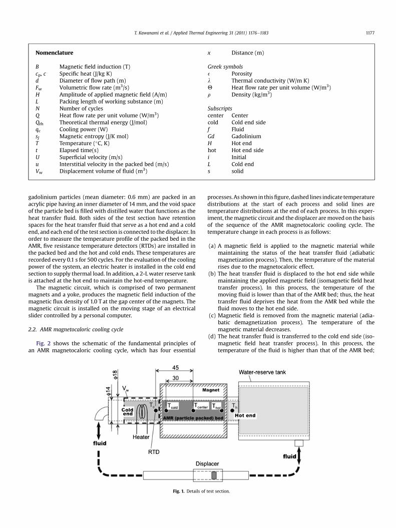
The details of the test section are shown in Fig. 1. The test AMR-based cooling system comprises a test section packed with themagnetic materials and the heat transfer fluid, a permanentmagnetic circuit, a displacer that drives the heat transfer fluidreciprocately, and a platinum-resistance temperature detector forthe measurement of temperatures. As for the test section, spherical
Nomenclature
B Magnetic field induction (T)cp, c Specific heat (J/kg K)d Diameter of flow path (m)Fw Volumetric flow rate (m3/s)H Amplitude of applied magnetic field (A/m)L Packing length of working substance (m)N Number of cyclesQ Heat flow rate per unit volume (W/m3)Qth Theoretical thermal energy (J/mol)qc Cooling power (W)sJ Magnetic entropy (J/K mol)T Temperature (�C, K)t Elapsed time(s)U Superficial velocity (m/s)u Interstitial velocity in the packed bed (m/s)Vw Displacement volume of fluid (m3)
x Distance (m)
Greek symbolse Porosityl Thermal conductivity (W/m K)Q Heat flow rate per unit volume (W/m3)r Density (kg/m3)
Subscriptscenter Centercold Cold end sidef FluidGd GadoliniumH Hot endhot Hot end sidei InitialL Cold ends solid
T. Kawanami et al. / Applied Thermal Engineering 31 (2011) 1176e1183 1177
gadolinium particles (mean diameter: 0.6 mm) are packed in anacrylic pipe having an inner diameter of 14 mm, and the void spaceof the particle bed is filled with distilled water that functions as theheat transfer fluid. Both sides of the test section have retentionspaces for the heat transfer fluid that serve as a hot end and a coldend, and each end of the test section is connected to the displacer. Inorder to measure the temperature profile of the packed bed in theAMR, five resistance temperature detectors (RTDs) are installed inthe packed bed and the hot and cold ends. These temperatures arerecorded every 0.1 s for 500 cycles. For the evaluation of the coolingpower of the system, an electric heater is installed in the cold endsection to supply thermal load. In addition, a 2-L water reserve tankis attached at the hot end to maintain the hot-end temperature.
The magnetic circuit, which is comprised of two permanentmagnets and a yoke, produces the magnetic field induction of themagnetic flux density of 1.0 T at the gap center of the magnets. Themagnetic circuit is installed on the moving stage of an electricalslider controlled by a personal computer.
2.2. AMR magnetocaloric cooling cycle
Fig. 2 shows the schematic of the fundamental principles ofan AMR magnetocaloric cooling cycle, which has four essential
Fig. 1. Details of
processes. As shown in thisfigure,dashed lines indicate temperaturedistributions at the start of each process and solid lines aretemperature distributions at the end of each process. In this exper-iment, themagnetic circuit and the displacer aremoved on the basisof the sequence of the AMR magnetocaloric cooling cycle. Thetemperature change in each process is as follows:
(a) A magnetic field is applied to the magnetic material whilemaintaining the status of the heat transfer fluid (adiabaticmagnetization process). Then, the temperature of the materialrises due to the magnetocaloric effect.
(b) The heat transfer fluid is displaced to the hot end side whilemaintaining the applied magnetic field (isomagnetic field heattransfer process). In this process, the temperature of themoving fluid is lower than that of the AMR bed; thus, the heattransfer fluid deprives the heat from the AMR bed while thefluid moves to the hot end side.
(c) Magnetic field is removed from the magnetic material (adia-batic demagnetization process). The temperature of themagnetic material decreases.
(d) The heat transfer fluid is transferred to the cold end side (iso-magnetic field heat transfer process). In this process, thetemperature of the fluid is higher than that of the AMR bed;
test section.
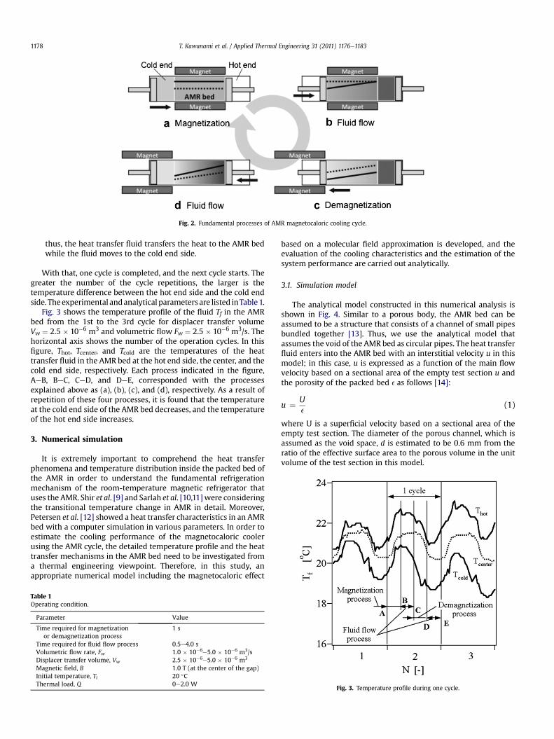
Fig. 2. Fundamental processes of AMR magnetocaloric cooling cycle.
T. Kawanami et al. / Applied Thermal Engineering 31 (2011) 1176e11831178
thus, the heat transfer fluid transfers the heat to the AMR bedwhile the fluid moves to the cold end side.
With that, one cycle is completed, and the next cycle starts. Thegreater the number of the cycle repetitions, the larger is thetemperature difference between the hot end side and the cold endside. Theexperimental andanalytical parametersare listed inTable1.
Fig. 3 shows the temperature profile of the fluid Tf in the AMRbed from the 1st to the 3rd cycle for displacer transfer volumeVw ¼ 2.5 � 10�6 m3 and volumetric flow Fw ¼ 2.5 � 10�6 m3/s. Thehorizontal axis shows the number of the operation cycles. In thisfigure, Thot, Tcenter, and Tcold are the temperatures of the heattransfer fluid in the AMR bed at the hot end side, the center, and thecold end side, respectively. Each process indicated in the figure,AeB, BeC, CeD, and DeE, corresponded with the processesexplained above as (a), (b), (c), and (d), respectively. As a result ofrepetition of these four processes, it is found that the temperatureat the cold end side of the AMR bed decreases, and the temperatureof the hot end side increases.
3. Numerical simulation
It is extremely important to comprehend the heat transferphenomena and temperature distribution inside the packed bed ofthe AMR in order to understand the fundamental refrigerationmechanism of the room-temperature magnetic refrigerator thatuses the AMR. Shir et al. [9] and Sarlah et al. [10,11]were consideringthe transitional temperature change in AMR in detail. Moreover,Petersen et al. [12] showed a heat transfer characteristics in an AMRbed with a computer simulation in various parameters. In order toestimate the cooling performance of the magnetocaloric coolerusing the AMR cycle, the detailed temperature profile and the heattransfer mechanisms in the AMR bed need to be investigated froma thermal engineering viewpoint. Therefore, in this study, anappropriate numerical model including the magnetocaloric effect
Table 1Operating condition.
Parameter Value
Time required for magnetizationor demagnetization process
1 s
Time required for fluid flow process 0.5e4.0 sVolumetric flow rate, Fw 1.0 � 10�6e5.0 � 10�6 m3/sDisplacer transfer volume, Vw 2.5 � 10�6e5.0 � 10�6 m3
Magnetic field, B 1.0 T (at the center of the gap)Initial temperature, Ti 20 �CThermal load, Q 0e2.0 W
based on a molecular field approximation is developed, and theevaluation of the cooling characteristics and the estimation of thesystem performance are carried out analytically.
3.1. Simulation model
The analytical model constructed in this numerical analysis isshown in Fig. 4. Similar to a porous body, the AMR bed can beassumed to be a structure that consists of a channel of small pipesbundled together [13]. Thus, we use the analytical model thatassumes the void of the AMR bed as circular pipes. The heat transferfluid enters into the AMR bed with an interstitial velocity u in thismodel; in this case, u is expressed as a function of the main flowvelocity based on a sectional area of the empty test section u andthe porosity of the packed bed e as follows [14]:
u ¼ Ue
(1)
where U is a superficial velocity based on a sectional area of theempty test section. The diameter of the porous channel, which isassumed as the void space, d is estimated to be 0.6 mm from theratio of the effective surface area to the porous volume in the unitvolume of the test section in this model.
Fig. 3. Temperature profile during one cycle.
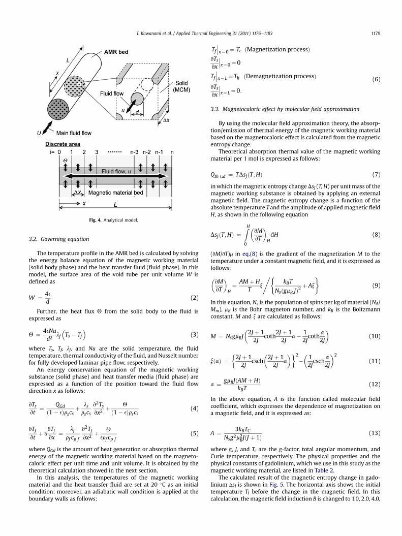
Fig. 4. Analytical model.
T. Kawanami et al. / Applied Thermal Engineering 31 (2011) 1176e1183 1179
3.2. Governing equation
The temperature profile in the AMR bed is calculated by solvingthe energy balance equation of the magnetic working material(solid body phase) and the heat transfer fluid (fluid phase). In thismodel, the surface area of the void tube per unit volume W isdefined as
W ¼ 4ed
(2)
Further, the heat flux Q from the solid body to the fluid isexpressed as
Q ¼ 4eNud2
lf
�Ts � Tf
�(3)
where Ts, Tf, lf, and Nu are the solid temperature, the fluidtemperature, thermal conductivity of the fluid, and Nusselt numberfor fully developed laminar pipe flow, respectively.
An energy conservation equation of the magnetic workingsubstance (solid phase) and heat transfer media (fluid phase) areexpressed as a function of the position toward the fluid flowdirection x as follows:
vTsvt
¼ QGd
ð1� eÞrscsþ lsrscs
v2Tsvx2
þ Q
ð1� eÞrscs(4)
vTfvt
þ uvTfvx
¼ lfrf cp f
v2Tfvx2
þ Q
erf cp f(5)
where QGd is the amount of heat generation or absorption thermalenergy of the magnetic working material based on the magneto-caloric effect per unit time and unit volume. It is obtained by thetheoretical calculation showed in the next section.
In this analysis, the temperatures of the magnetic workingmaterial and the heat transfer fluid are set at 20 �C as an initialcondition; moreover, an adiabatic wall condition is applied at theboundary walls as follows:
Tf���x¼0 ¼ Tc ðMagnetization processÞ
vTsvx
���x¼0 ¼ 0
Tf���x¼ L ¼ Th ðDemagnetization processÞ
vTsvx
���x¼ L ¼0:
(6)
3.3. Magnetocaloric effect by molecular field approximation
By using the molecular field approximation theory, the absorp-tion/emission of thermal energy of the magnetic working materialbased on the magnetocaloric effect is calculated from the magneticentropy change.
Theoretical absorption thermal value of the magnetic workingmaterial per 1 mol is expressed as follows:
Qth Gd ¼ TDsJðT ;HÞ (7)
inwhich themagnetic entropy change DsJ (T,H) per unit mass of themagnetic working substance is obtained by applying an externalmagnetic field. The magnetic entropy change is a function of theabsolute temperature T and the amplitude of applied magnetic fieldH, as shown in the following equation
DsJðT ;HÞ ¼ZH0
�vMvT
�HdH (8)
(vM/vT)H in eq.(8) is the gradient of the magnetization M to thetemperature under a constant magnetic field, and it is expressed asfollows:
�vMvT
�H¼ AM þ H
Tx
,(kBT
NsðgmB JÞ2þ Ax
)(9)
In this equation, Ns is the population of spins per kg of material (NA/Mm), mB is the Bohr magneton number, and kB is the Boltzmannconstant. M and x are calculated as follows:
M ¼ NsgmBJ�2J þ 12J
coth2J þ 12J
a� 12Jcoth
a
2J
�(10)
xðaÞ ¼�2J þ 12J
csch�2J þ 12J
a
��2
��12Jcsch
a
2J
�2
(11)
a ¼ gmBJðAM þ HÞkBT
(12)
In the above equation, A is the function called molecular fieldcoefficient, which expresses the dependence of magnetization ona magnetic field, and it is expressed as:
A ¼ 3kBTCNsg2m2BJðJ þ 1Þ (13)
where g, J, and Tc are the g-factor, total angular momentum, andCurie temperature, respectively. The physical properties and thephysical constants of gadolinium, which we use in this study as themagnetic working material, are listed in Table 2.
The calculated result of the magnetic entropy change in gado-linium ΔsJ is shown in Fig. 5. The horizontal axis shows the initialtemperature Ti before the change in the magnetic field. In thiscalculation, themagnetic field induction B is changed to 1.0, 2.0, 4.0,
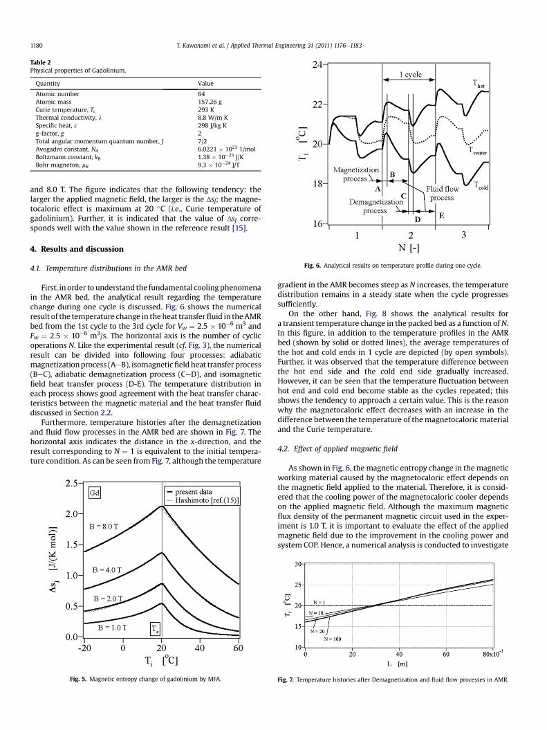
Fig. 6. Analytical results on temperature profile during one cycle.
Table 2Physical properties of Gadolinium.
Quantity Value
Atomic number 64Atomic mass 157.26 gCurie temperature, Tc 293 KThermal conductivity, l 8.8 W/m KSpecific heat, c 298 J/kg Kg-factor, g 2Total angular momentum quantum number, J 7/2Avogadro constant, NA 6.0221 � 1023 1/molBoltzmann constant, kB 1.38 � 10�23 J/KBohr magneton, mB 9.3 � 10�24 J/T
T. Kawanami et al. / Applied Thermal Engineering 31 (2011) 1176e11831180
and 8.0 T. The figure indicates that the following tendency: thelarger the applied magnetic field, the larger is the ΔsJ; the magne-tocaloric effect is maximum at 20 �C (i.e., Curie temperature ofgadolinium). Further, it is indicated that the value of ΔsJ corre-sponds well with the value shown in the reference result [15].
4. Results and discussion
4.1. Temperature distributions in the AMR bed
First, in order to understand the fundamental coolingphenomenain the AMR bed, the analytical result regarding the temperaturechange during one cycle is discussed. Fig. 6 shows the numericalresult of the temperature change in the heat transferfluid in theAMRbed from the 1st cycle to the 3rd cycle for Vw ¼ 2.5 � 10�6 m3 andFw ¼ 2.5 � 10�6 m3/s. The horizontal axis is the number of cyclicoperations N. Like the experimental result (cf. Fig. 3), the numericalresult can be divided into following four processes: adiabaticmagnetizationprocess (AeB), isomagneticfieldheat transfer process(BeC), adiabatic demagnetization process (CeD), and isomagneticfield heat transfer process (D-E). The temperature distribution ineach process shows good agreement with the heat transfer charac-teristics between the magnetic material and the heat transfer fluiddiscussed in Section 2.2.
Furthermore, temperature histories after the demagnetizationand fluid flow processes in the AMR bed are shown in Fig. 7. Thehorizontal axis indicates the distance in the x-direction, and theresult corresponding to N ¼ 1 is equivalent to the initial tempera-ture condition. As can be seen from Fig. 7, although the temperature
Fig. 5. Magnetic entropy change of gadolinium by MFA.
gradient in the AMR becomes steep as N increases, the temperaturedistribution remains in a steady state when the cycle progressessufficiently.
On the other hand, Fig. 8 shows the analytical results fora transient temperature change in the packed bed as a function ofN.In this figure, in addition to the temperature profiles in the AMRbed (shown by solid or dotted lines), the average temperatures ofthe hot and cold ends in 1 cycle are depicted (by open symbols).Further, it was observed that the temperature difference betweenthe hot end side and the cold end side gradually increased.However, it can be seen that the temperature fluctuation betweenhot end and cold end become stable as the cycles repeated; thisshows the tendency to approach a certain value. This is the reasonwhy the magnetocaloric effect decreases with an increase in thedifference between the temperature of themagnetocaloric materialand the Curie temperature.
4.2. Effect of applied magnetic field
As shown in Fig. 6, the magnetic entropy change in themagneticworking material caused by the magnetocaloric effect depends onthe magnetic field applied to the material. Therefore, it is consid-ered that the cooling power of the magnetocaloric cooler dependson the applied magnetic field. Although the maximum magneticflux density of the permanent magnetic circuit used in the exper-iment is 1.0 T, it is important to evaluate the effect of the appliedmagnetic field due to the improvement in the cooling power andsystem COP. Hence, a numerical analysis is conducted to investigate
Fig. 7. Temperature histories after Demagnetization and fluid flow processes in AMR.
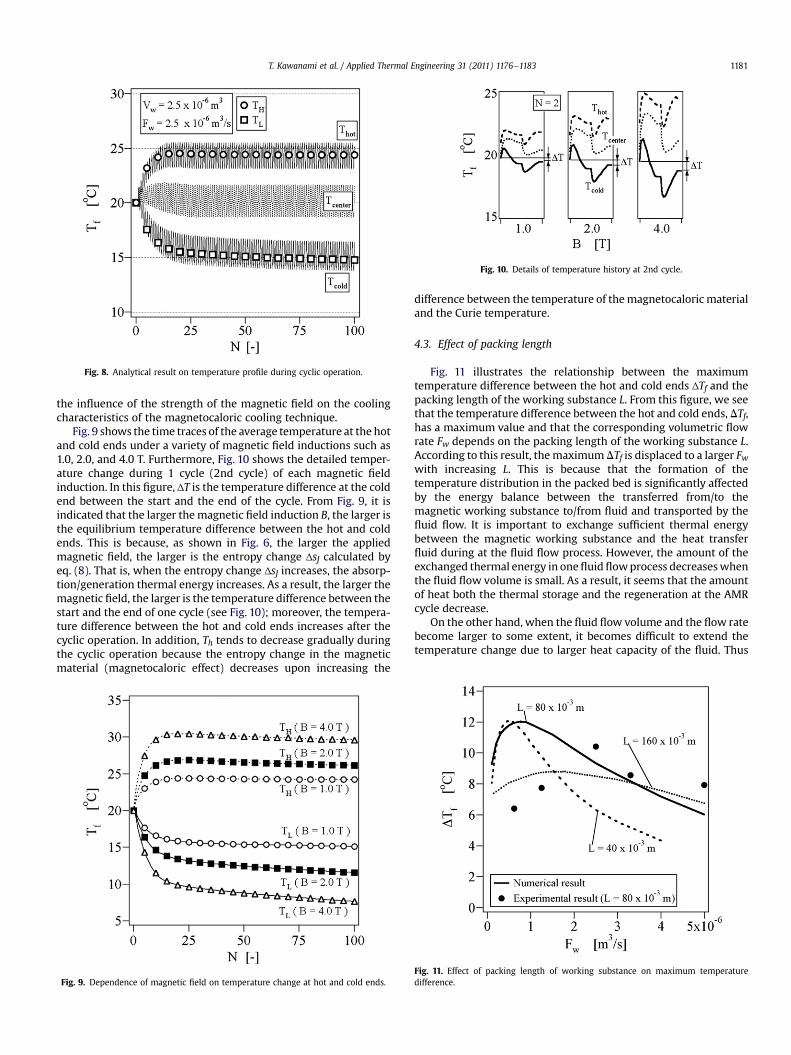
Fig. 10. Details of temperature history at 2nd cycle.
Fig. 8. Analytical result on temperature profile during cyclic operation.
T. Kawanami et al. / Applied Thermal Engineering 31 (2011) 1176e1183 1181
the influence of the strength of the magnetic field on the coolingcharacteristics of the magnetocaloric cooling technique.
Fig. 9 shows the time traces of the average temperature at the hotand cold ends under a variety of magnetic field inductions such as1.0, 2.0, and 4.0 T. Furthermore, Fig. 10 shows the detailed temper-ature change during 1 cycle (2nd cycle) of each magnetic fieldinduction. In this figure, ΔT is the temperature difference at the coldend between the start and the end of the cycle. From Fig. 9, it isindicated that the larger themagnetic field induction B, the larger isthe equilibrium temperature difference between the hot and coldends. This is because, as shown in Fig. 6, the larger the appliedmagnetic field, the larger is the entropy change ΔsJ calculated byeq. (8). That is, when the entropy change ΔsJ increases, the absorp-tion/generation thermal energy increases. As a result, the larger themagnetic field, the larger is the temperature difference between thestart and the end of one cycle (see Fig. 10); moreover, the tempera-ture difference between the hot and cold ends increases after thecyclic operation. In addition, Th tends to decrease gradually duringthe cyclic operation because the entropy change in the magneticmaterial (magnetocaloric effect) decreases upon increasing the
Fig. 9. Dependence of magnetic field on temperature change at hot and cold ends.
difference between the temperature of themagnetocaloric materialand the Curie temperature.
4.3. Effect of packing length
Fig. 11 illustrates the relationship between the maximumtemperature difference between the hot and cold ends ΔTf and thepacking length of the working substance L. From this figure, we seethat the temperature difference between the hot and cold ends, DTf,has a maximum value and that the corresponding volumetric flowrate Fw depends on the packing length of the working substance L.According to this result, themaximum DTf is displaced to a larger Fwwith increasing L. This is because that the formation of thetemperature distribution in the packed bed is significantly affectedby the energy balance between the transferred from/to themagnetic working substance to/from fluid and transported by thefluid flow. It is important to exchange sufficient thermal energybetween the magnetic working substance and the heat transferfluid during at the fluid flow process. However, the amount of theexchanged thermal energy in onefluidflowprocess decreaseswhenthe fluid flow volume is small. As a result, it seems that the amountof heat both the thermal storage and the regeneration at the AMRcycle decrease.
On the other hand, when the fluid flow volume and the flow ratebecome larger to some extent, it becomes difficult to extend thetemperature change due to larger heat capacity of the fluid. Thus
Fig. 11. Effect of packing length of working substance on maximum temperaturedifference.
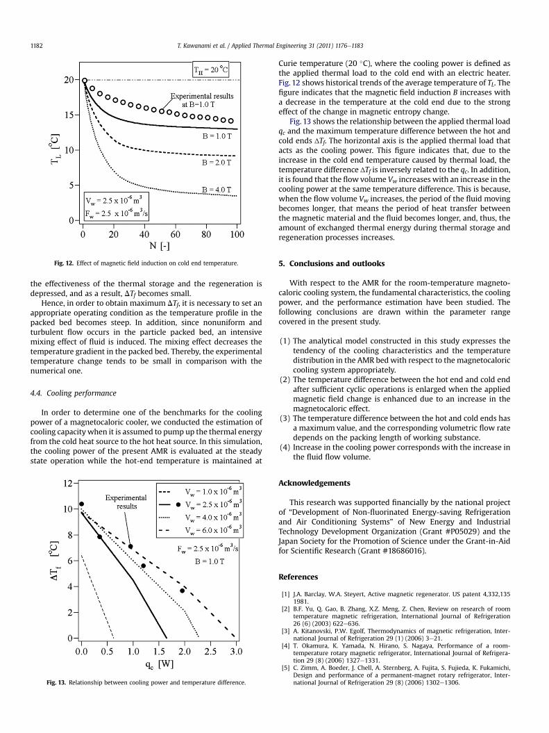
Fig. 12. Effect of magnetic field induction on cold end temperature.
T. Kawanami et al. / Applied Thermal Engineering 31 (2011) 1176e11831182
the effectiveness of the thermal storage and the regeneration isdepressed, and as a result, DTf becomes small.
Hence, in order to obtain maximum DTf, it is necessary to set anappropriate operating condition as the temperature profile in thepacked bed becomes steep. In addition, since nonuniform andturbulent flow occurs in the particle packed bed, an intensivemixing effect of fluid is induced. The mixing effect decreases thetemperature gradient in the packed bed. Thereby, the experimentaltemperature change tends to be small in comparison with thenumerical one.
4.4. Cooling performance
In order to determine one of the benchmarks for the coolingpower of a magnetocaloric cooler, we conducted the estimation ofcooling capacity when it is assumed to pump up the thermal energyfrom the cold heat source to the hot heat source. In this simulation,the cooling power of the present AMR is evaluated at the steadystate operation while the hot-end temperature is maintained at
Fig. 13. Relationship between cooling power and temperature difference.
Curie temperature (20 �C), where the cooling power is defined asthe applied thermal load to the cold end with an electric heater.Fig. 12 shows historical trends of the average temperature of TL. Thefigure indicates that the magnetic field induction B increases witha decrease in the temperature at the cold end due to the strongeffect of the change in magnetic entropy change.
Fig. 13 shows the relationship between the applied thermal loadqc and the maximum temperature difference between the hot andcold ends ΔTf. The horizontal axis is the applied thermal load thatacts as the cooling power. This figure indicates that, due to theincrease in the cold end temperature caused by thermal load, thetemperature difference ΔTf is inversely related to the qc. In addition,it is found that the flow volume Vw increases with an increase in thecooling power at the same temperature difference. This is because,when the flow volume Vw increases, the period of the fluid movingbecomes longer, that means the period of heat transfer betweenthe magnetic material and the fluid becomes longer, and, thus, theamount of exchanged thermal energy during thermal storage andregeneration processes increases.
5. Conclusions and outlooks
With respect to the AMR for the room-temperature magneto-caloric cooling system, the fundamental characteristics, the coolingpower, and the performance estimation have been studied. Thefollowing conclusions are drawn within the parameter rangecovered in the present study.
(1) The analytical model constructed in this study expresses thetendency of the cooling characteristics and the temperaturedistribution in the AMR bed with respect to the magnetocaloriccooling system appropriately.
(2) The temperature difference between the hot end and cold endafter sufficient cyclic operations is enlarged when the appliedmagnetic field change is enhanced due to an increase in themagnetocaloric effect.
(3) The temperature difference between the hot and cold ends hasa maximum value, and the corresponding volumetric flow ratedepends on the packing length of working substance.
(4) Increase in the cooling power corresponds with the increase inthe fluid flow volume.
Acknowledgements
This research was supported financially by the national projectof “Development of Non-fluorinated Energy-saving Refrigerationand Air Conditioning Systems” of New Energy and IndustrialTechnology Development Organization (Grant #P05029) and theJapan Society for the Promotion of Science under the Grant-in-Aidfor Scientific Research (Grant #18686016).
References
[1] J.A. Barclay, W.A. Steyert, Active magnetic regenerator. US patent 4,332,1351981.
[2] B.F. Yu, Q. Gao, B. Zhang, X.Z. Meng, Z. Chen, Review on research of roomtemperature magnetic refrigeration, International Journal of Refrigeration26 (6) (2003) 622e636.
[3] A. Kitanovski, P.W. Egolf, Thermodynamics of magnetic refrigeration, Inter-national Journal of Refrigeration 29 (1) (2006) 3e21.
[4] T. Okamura, K. Yamada, N. Hirano, S. Nagaya, Performance of a room-temperature rotary magnetic refrigerator, International Journal of Refrigera-tion 29 (8) (2006) 1327e1331.
[5] C. Zimm, A. Boeder, J. Chell, A. Sternberg, A. Fujita, S. Fujieda, K. Fukamichi,Design and performance of a permanent-magnet rotary refrigerator, Inter-national Journal of Refrigeration 29 (8) (2006) 1302e1306.

T. Kawanami et al. / Applied Thermal Engineering 31 (2011) 1176e1183 1183
[6] G.H. Yao, M.Q. Gong, J.F. Wu, Experimental study on the performance ofa room temperature magnetic refrigerator using permanent magnets, Inter-national Journal of Refrigeration 29 (8) (2006) 1267e1273.
[7] T. Kawanami, K. Chiba, K. Sakurai, M. Ikegawa, Optimization of a magneticrefrigerator at room temperature for air cooling systems, International Journalof Refrigeration 29 (8) (2006) 1294e1301.
[8] T. Kawanami, Heat transfer characteristics and cooling performance of an activemagnetic regenerator, in: Proceedings of the 2nd IIF-IIR International confer-ence of magnetic refrigeration at room temperature (2007), pp. 23e34.
[9] F. Shir, C. Mavriplis, L.H. Bennett, E.D. Torre, Analysis of room temperaturemagnetic regenerative refrigeration, International Journal of Refrigeration28 (4) (2005) 616e627.
[10] A. Sarlah, A. Kitanovski, A. Poredos, P.W. Egolf, O. Sari, F. Gendre, Ch. Besson,Static and rotating active magnetic regenerators with porous heat exchangers
for magnetic cooling, International Journal of Refrigeration 29 (8) (2006)1332e1339.
[11] A. Sarlah, Thermo-hydraulic properties of heat regenerators in magneticrefrigerator. Ph.D. dissertation. University of Ljubljana; 2008.
[12] T.F. Petersen, N. Pryds, A. Smith, J. Hattel, H. Schmidt, H.-J.H. Knudsen, Two-dimensional mathematical model of a reciprocating room-temperature activemagnetic regenerator, International JournalofRefrigeration31(3) (2008)432e443.
[13] S. Kotake, K. Hijikata, Y. Matsumoto, Handbook of thermofluid analysis.Maruzen Publishing Co. Ltd, 1994, [in Japanese].
[14] S. Ergun, Fluid flow through packed columns, Chemical Engineering Progress48 (2) (1952) 89e94.
[15] T. Hashimoto, T. Numasawa, M. Shino, T. Okada, Magnetic refrigeration in thetemperature range from 10 K to room temperature: the ferromagneticrefrigerants, Cryogenics 21 (11) (1981) 647e653.
Copyright © 2022 FDOKUMEN