
Evaluation of Bonding Gap Control Methods for an Epoxy ...
13
materials Article Evaluation of Bonding Gap Control Methods for an Epoxy Adhesive Joint of Carbon Fiber Tubes and Aluminum Alloy Inserts Witold Rz ˛ adkowski * , Jan Tracz * , Adam Cisowski , Kamil Gardyjas , Hubert Groen, Marek Palka and Michal Kowalik Citation: Rz ˛ adkowski, W.; Tracz, J.; Cisowski, A.; Gardyjas, K.; Groen, H.; Palka, M.; Kowalik, M. Evaluation of Bonding Gap Control Methods for an Epoxy Adhesive Joint of Carbon Fiber Tubes and Aluminum Alloy Inserts. Materials 2021, 14, 1977. https:// doi.org/10.3390/ma14081977 Academic Editor: Marco Alfano Received: 1 March 2021 Accepted: 12 April 2021 Published: 15 April 2021 Publisher’s Note: MDPI stays neutral with regard to jurisdictional claims in published maps and institutional affil- iations. Copyright: © 2021 by the authors. Licensee MDPI, Basel, Switzerland. This article is an open access article distributed under the terms and conditions of the Creative Commons Attribution (CC BY) license (https:// creativecommons.org/licenses/by/ 4.0/). Institute of Aeronautics and Applied Mechanics, Warsaw University of Technology, 00-665 Warsaw, Poland; [email protected] (A.C.); [email protected] (K.G.); [email protected] (H.G.); [email protected] (M.P.);[email protected] (M.K.) * Correspondence: [email protected] (W.R.);[email protected] (J.T.) Abstract: The aim of this paper is to compare two methods of epoxy adhesive bond gap control: one with a geometrical (mechanical) solution and the other with glass beads, which have the diameter of the desired bond gap and are mixed with an epoxy adhesive. The adhered materials were carbon fiber composite tubes and aluminum alloy inserts, which were used as wishbones in a suspension system of a motorsport vehicle. It was assumed that the gap thickness would be equal to 0.2 mm and the length of a bond would be 30 mm. The internal diameter of the tubes was 14 mm and 18 mm, whereas the inserts’ external diameter was 13.6 mm and 17.6 mm. Their surface has been subjected to mechanical treatment with sand paper starting from 240 grit up to 400. The adhesives used were EA 3425 and EA 9466 cured at 80 ◦ C for 2 h. The results showed that the glass beads method provides more consistent and better results as compared to the geometrical (mechanical) method. Further study in the area of fatigue and interfacial failure modes could be useful. Keywords: adhesive joint; bond gap control; epoxy adhesive; glass beads; carbon fiber tubes; aluminum alloy inserts 1. Introduction This paper discusses and validates the design process of an adhesive connection between two engineering materials: carbon fiber composite tubes and aluminum alloy inserts, which create wishbones of a motorsport vehicle. The technological aspects of the connection will be addressed, especially the method of controlling the gap and different adhesive products used to bond the parts together. The design of the wishbones will not be discussed fully; however, one of the main design features is that the loads in the system occur only in the axis of the tubes, i.e., the tubes and inserts are only subjected to tension or compression along the axis. Such design can be obtained by careful geometrical design of the whole suspension system. There were many approaches to such designs made by other motorsports teams [1–4]; more general knowledge about such systems is available in [5,6]. The connection of reinforced polymers to metals can be realized in a various ways. One of them is a bolted connection or riveted connection type, which is applicable for some cases. However, as discussed in a review [7,8], there are some downsides to this solution such as delamination during drilling of the holes, which could lead to failure of heavily loaded components such as wishbones discussed in this paper. Therefore, an adhesive connection will be used, since the axial forces present in the design will result in shearing of the adhesive bond, which is the optimum working direction of adhesive. Usually, the adhesive connection between carbon and metal is performed using epoxy-based adhesives, which are cured to obtain full strength. This paper focuses on two epoxy adhesives: EA 9466 and EA 3425 and their applicability for final wishbone structure. Materials 2021, 14, 1977. https://doi.org/10.3390/ma14081977 https://www.mdpi.com/journal/materials
-
Upload
khangminh22 -
Category
Documents
-
view
6 -
download
0
Transcript of Evaluation of Bonding Gap Control Methods for an Epoxy ...
materials
Article
Evaluation of Bonding Gap Control Methods for an EpoxyAdhesive Joint of Carbon Fiber Tubes and AluminumAlloy Inserts
Witold Rzadkowski * , Jan Tracz * , Adam Cisowski , Kamil Gardyjas , Hubert Groen, Marek Palkaand Michał Kowalik
�����������������
Citation: Rzadkowski, W.; Tracz, J.;
Cisowski, A.; Gardyjas, K.; Groen, H.;
Palka, M.; Kowalik, M. Evaluation of
Bonding Gap Control Methods for an
Epoxy Adhesive Joint of Carbon Fiber
Tubes and Aluminum Alloy Inserts.
Materials 2021, 14, 1977. https://
doi.org/10.3390/ma14081977
Academic Editor: Marco Alfano
Received: 1 March 2021
Accepted: 12 April 2021
Published: 15 April 2021
Publisher’s Note: MDPI stays neutral
with regard to jurisdictional claims in
published maps and institutional affil-
iations.
Copyright: © 2021 by the authors.
Licensee MDPI, Basel, Switzerland.
This article is an open access article
distributed under the terms and
conditions of the Creative Commons
Attribution (CC BY) license (https://
creativecommons.org/licenses/by/
4.0/).
Institute of Aeronautics and Applied Mechanics, Warsaw University of Technology, 00-665 Warsaw, Poland;[email protected] (A.C.); [email protected] (K.G.); [email protected] (H.G.);[email protected] (M.P.); [email protected] (M.K.)* Correspondence: [email protected] (W.R.); [email protected] (J.T.)
Abstract: The aim of this paper is to compare two methods of epoxy adhesive bond gap control: onewith a geometrical (mechanical) solution and the other with glass beads, which have the diameter ofthe desired bond gap and are mixed with an epoxy adhesive. The adhered materials were carbonfiber composite tubes and aluminum alloy inserts, which were used as wishbones in a suspensionsystem of a motorsport vehicle. It was assumed that the gap thickness would be equal to 0.2 mm andthe length of a bond would be 30 mm. The internal diameter of the tubes was 14 mm and 18 mm,whereas the inserts’ external diameter was 13.6 mm and 17.6 mm. Their surface has been subjected tomechanical treatment with sand paper starting from 240 grit up to 400. The adhesives used were EA3425 and EA 9466 cured at 80 ◦C for 2 h. The results showed that the glass beads method providesmore consistent and better results as compared to the geometrical (mechanical) method. Furtherstudy in the area of fatigue and interfacial failure modes could be useful.
Keywords: adhesive joint; bond gap control; epoxy adhesive; glass beads; carbon fiber tubes;aluminum alloy inserts
1. Introduction
This paper discusses and validates the design process of an adhesive connectionbetween two engineering materials: carbon fiber composite tubes and aluminum alloyinserts, which create wishbones of a motorsport vehicle. The technological aspects of theconnection will be addressed, especially the method of controlling the gap and differentadhesive products used to bond the parts together. The design of the wishbones will notbe discussed fully; however, one of the main design features is that the loads in the systemoccur only in the axis of the tubes, i.e., the tubes and inserts are only subjected to tension orcompression along the axis. Such design can be obtained by careful geometrical design ofthe whole suspension system. There were many approaches to such designs made by othermotorsports teams [1–4]; more general knowledge about such systems is available in [5,6].
The connection of reinforced polymers to metals can be realized in a various ways.One of them is a bolted connection or riveted connection type, which is applicable for somecases. However, as discussed in a review [7,8], there are some downsides to this solutionsuch as delamination during drilling of the holes, which could lead to failure of heavilyloaded components such as wishbones discussed in this paper. Therefore, an adhesiveconnection will be used, since the axial forces present in the design will result in shearingof the adhesive bond, which is the optimum working direction of adhesive. Usually, theadhesive connection between carbon and metal is performed using epoxy-based adhesives,which are cured to obtain full strength. This paper focuses on two epoxy adhesives: EA9466 and EA 3425 and their applicability for final wishbone structure.
Materials 2021, 14, 1977. https://doi.org/10.3390/ma14081977 https://www.mdpi.com/journal/materials
Materials 2021, 14, 1977 2 of 13
The design process consisted of determining the geometry of the adhesive bondbasing both on available adhesive models as well as real life testing and the technologicalsolutions applied. This means that the area that will be focused on in this research ispractical adhesion. This involves many issues, which need to be addressed in an adhesivebond for it to fulfil its goal. The mentioned issues are, e.g., surface treatments, adhesive type,and the curing process. Some of these have been described in a guide [9,10] together withother aspects of adhesion. The key conclusion is that the adhesion is a property of a system;thus, results obtained from other geometries and designs might not be comparable. Thisis crucial since the strength values given by manufacturers are based on tests performedwith given standards, which are accurate yet might not produce the same results on othergeometries. Therefore, the design must be validated by real life testing, which shouldanswer the question which epoxy adhesive is optimal for the final wishbone as well asdetermine the proper gap control method. Having said that, the results obtained fromexperiments will be contrasted with the achievements of other teams in wishbone designand testing [11,12].
The aim of this study is to determine which of two bond gap control methods will bemore suitable for the designed bond used in the wishbone project of a motorsport vehicle.The two investigated methods of controlling the gap were the following:
• The geometrical method (also referred as mechanical) is based on two surfaces with aradius increased by 0.2 mm at the end and beginning of the insert adhesive surface,which results in a grove for the adhesive surface on the aluminum insert.
• Glass beads added to the adhesive, which have a diameter of 0.2 mm and fill the gapbetween adherends, consequently locking the radial movement.
There are also other methods of bond gap control [13] such as wire spacers and filmadhesives, yet they cannot be applied in this design as inserts must be slid into the tubes.The method used in both [11,12] was a geometrical (mechanical) method which is based onadditional surfaces to control the bond gap. In this research, a novel approach will be usedwith glass beads mixed with the adhesive. This approach might compromise the bondperformance slightly, but overall it can be superior to a mechanical solution as it couldresult in a lower mass of a joint as the additional surfaces are no longer necessary.
There have been studies on the gap control methods and adhesives containing ad-ditives such as particles of nano-Al2O3 [14], but in this case the particles are larger andare not added to increase the strength of a bond. As far as a geometrical solution is con-sidered, there has been research on geometrical patterns [15] which impact the fracturetoughness of a joint, which is important, although there the focus is on the technologicalaspect rather than the pattern or surface preparation. The value of the bond gap thicknessand its influence on strength was a topic of discussion in a few studies [16–18], and themain conclusion was that the increased thickness of a gap decreases the strength of a bond,which contradictory with the analytical models such as that of Goland-Reisner. In general,the topic is still controversial and further studies are necessary. Thus, in this study it wasdecided to set the bond thickness to 0.2 mm based on some recommendations from thetechnical support of the adhesive manufacturer as well as the results of similar researchperformed [11,12]. This is due to the fact that the scope of this research is not to determinethe optimum bonding gap, but rather to focus on the technological aspect of bond controlas well as to determine the adhesive which will perform the best out of the two selected.
2. Materials and Methods2.1. Materials Used
Two adhered materials were carbon fiber tubes and aluminum alloy inserts. The tubesare commercially available woven composite rods acquired from [19]. Although they werebought, it is also possible to manufacture them by using preimpregnated fabrics of carbonfiber and glass fiber as seen in the tutorial in [20]. The carbon fiber used in the tubes isTorray 700 high modulus unidirectional fiber (Easy composites Ltd., Stoke-on-Trent, UK),and the glass fiber is unidirectional glass (Easy composites Ltd., Stoke-on-Trent, UK). It is
Materials 2021, 14, 1977 3 of 13
important to notice that the tube layup consists of 5 layers of plies. The axial layers (carbonfiber) are made from unidirectional material as they carry the main loads. The radial layers(glass fiber) are oriented at about 90 degrees and improve the crush strength of the finalproduct. All parameters of the tubes are stored in the Table 1.
Table 1. Parameters of carbon fiber-wrapped tubes [19].
Outside OD (Inside ID) Diameter (mm) 16.7 (14) 20.8 (18)
Tensile Strength (Axial) (MPa) 750 750Youngs Modulus (Axial) (GPa) 90 90
Tensile Strength (Radially) (MPa) 600 600Youngs Modulus (Radially) (GPa) 19 19
OD Tollerance (mm) 0.3 0.3ID Tollerance (mm) 0.2 0.2
Major Poisson’s Ratio 0.14 0.14
The aluminum inserts are machined out of stock 7075 aluminum alloy rods (Oberon,Warsaw, Poland). This kind of aluminum should be commercially available in most ofmaterial suppliers. The thermal treatment type was T-651, but it should not influence any ofthe adhesion properties, only mechanical properties such as ultimate tensile strength, etc.
The epoxy adhesives used were two commercially available products: EA 9466 andEA 3425 (Henkel-Adhesives, Warsaw, Poland). They are typical 2-part adhesives (resinand hardener), which require mixing before application. Both EA 9466 and EA 3425 canbe cured at room temperature, yet elevated temperature increases their final strengthproperties by approximately 10% if cured for 2 h at 80 ◦C [21,22]. Some of the parameters,important from the point of view of this study, were stored in Table 2. The full range ofproperties can be found in the technical data sheets of the products.
Table 2. Properties of adhesives used in the experiments taken from datasheets [21,22].
Adhesive EA 3425 EA 9466
Tensile Modulus, ISO 527-3 (MPa) 1350 1718Elongation ISO 527-3, % 3 3
Lap Shear Strength ISO 4587On Aluminum (abraded) (MPa) 7–13 26
On Glass reinforced Polymer (MPa) 0.6–1.2 5On Glass Fiber Reinforced Epoxy (MPa) - -
Lastly, the method of controlling the bond gap was realized with 0.2 mm commerciallyavailable glass beads acquired from [23]. The recommended mass ratio of beads to adhesiveis about 2%. The beads were added to mixed adhesive and stirred in a small container thatwas later placed in a vacuum chamber to degas the mixture. However, for an industrialscale of application the method should be changed to a premixed solution of hardener andbeads as it would not decrease the working time (pot life) of the adhesive.
2.2. Designing Bond Geometry
The forces acting on the structure were calculated from vehicle kinematics. Thelimiting condition in case of connecting rods was the buckling condition. With all thesafety coefficients, the diameter of the upper wishbone tubes must be at least 15 mmwith a wall thickness of 1 mm and for the lower wishbone where the forces are higher—20 mm × 1.2 mm. However, such diameters are not available commercially; thus, theclosest to them were chosen, i.e., 16.7 mm × 1.35 mm and 20.8 mm × 1.4 mm. Thisresults in an inner diameter (ID) of the tube to be equal to 14 mm and 18 mm, respectively.Consequently, it establishes the radial dimension of a designed bond, leaving the lengthand gap to be determined.
Materials 2021, 14, 1977 4 of 13
2.2.1. Adhesive Bond Models
To determine the length and gap of a bond, adhesive models can be used as well as ex-perimental results. As described in the Introduction, there are some discrepancies betweenthem as real-life testing does not match the theoretical assumptions [13]. Nevertheless, it isgood to know them for design purposes, especially their advantages and disadvantageswhich will be described later. The first of the models is the Kendall Model [24], whichis possibly the most basic one as it does not even consider the adhesive. It allows one todetermine the force needed to peel the joint apart. It assumes that only the surface energyis holding the joint together; thus, the results are underapproximated.
A more sophisticated bond model is needed to approximate the initial geometry of abond. This can be carried out with the Goland-Reissner bond model. The model is morecomplicated in terms of mathematics, yet there are very good calculators created by [9,25],which can visualize the stresses in the joint. Looking at them, it can be noticed that thereare a few parameters that influence the strength of the design:
• Adherend material height, stiffness, and Poisson ratio. Higher values of both parame-ters cause less peel stress at the end of a bond since stiffer material deflects less whenloaded with a force or bending moment. Therefore, there is less off-plane loadingof adhesive joints (i.e., peeling of a bond). Fortunately, the stiffness of a compositetube is around 90GPA, which is a relatively high value, yet its thickness is quitesmall—1.35 mm.
• Adhesive height (bond gap). Higher values of bond gap result in smaller values moresmooth distribution of both shear and peel stresses. This would indicate that thebonding gap should be as large as possible. This, however, contradicts some of theexperimental research.
• Adhesive stiffness (E) and Poisson ratio. Higher stiffness of the epoxy increases thevalues of stresses at the joint ends. Thus, it would be reasonable to use as compliantan epoxy as possible. On the other hand, such epoxy leads to higher deformations,which is not ideal in a suspension system of a vehicle.
• Finally, the length of the adhesion does not influence the strength as much as thewidth, since most of the stress is concentrated at the beginning and end of a joint.Thus, increasing this parameter adds a lot of mass into the final structure without avaluable increase in bond strength. Thus, it is better to design a wider joint instead.
2.2.2. Adhesive Bond Model—Experimental Results
The last step of the theoretical design focused on researching the results obtainedby other teams. There has been an interesting approach made by the Harbin RacingTeam [11], where the results showed that the ultimate tensile force for a tested bondwas at maximum when the bond gap was 0.2 mm. Additionally, the length of a bondincreased its strength linearly. Similar results were obtained by the Massachusetts Instituteof Technology Team [12], where the optimum bonding gap was about 0.2 mm (0.008 inchto be exact). Both studies used a geometrical method of bond control, where there wasa surface which determined the bond gap thickness. For this research, we decided touse the findings of those two teams in terms of the gap thickness, yet we changed themethod of controlling it to beads with a diameter equal to the desired bond gap thickness.Although the adhesive used was different, it can be assumed that it was an equivalent ofEA9466 based on the performance stated by the manufacturer. Additionally, the controlsamples with a geometrical method of controlling the gap will be created to be able tocompare the adhesives. The value of a 0.2 mm gap is also recommended by the glass beadmanufacturer for epoxy-based adhesives. The length of a bond was set to 30 mm for allsamples at it was reported to have the ultimate strength needed for the project and couldbe compared to other results. All models used can be summarized using their advantagesand disadvantages as described in Table 3.
Materials 2021, 14, 1977 5 of 13
Table 3. Adhesion models comparison.
Model Advantage Disadvantage
Kendall Simple, few data required toobtain result
Inaccurate, predicts only peelstrength/stress
Golland-ReissnerPredicts peel and shear
strength/stress, good forinitial design purposes
Complicated, does not match some ofthe experimental results correctly
Experimental Probably best accuracy Expensive as samples of the exactgeometry must be prepared and tested
2.3. Bond Gap Control
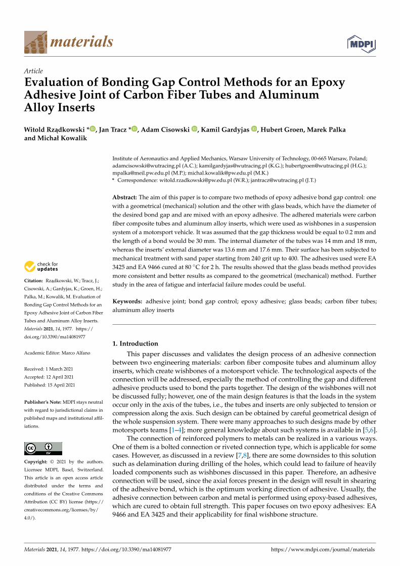
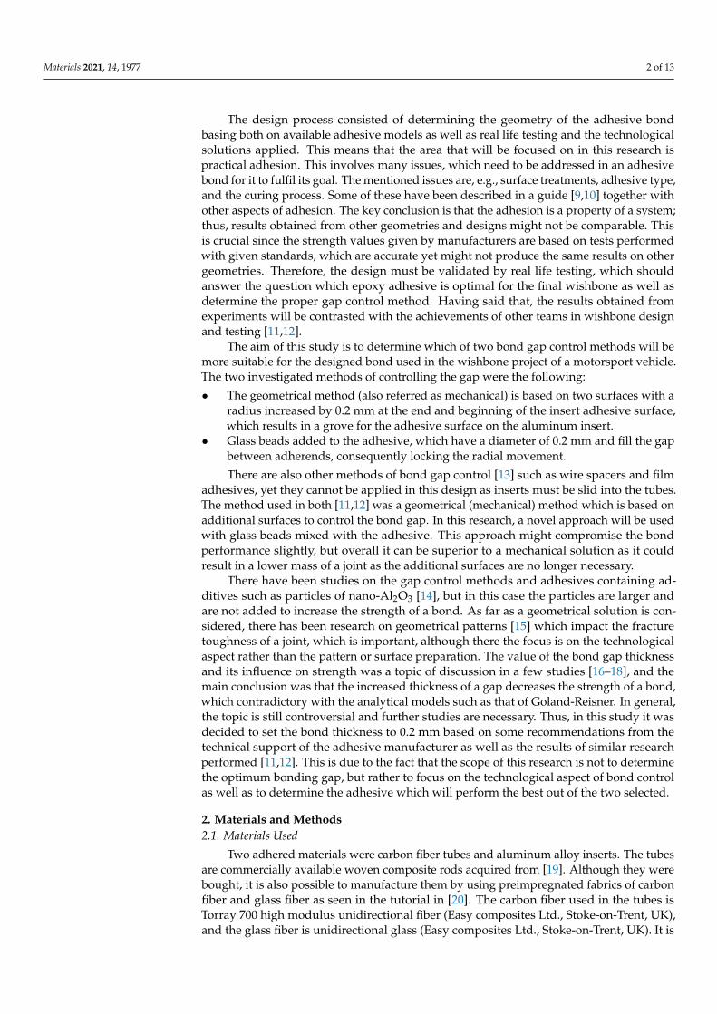
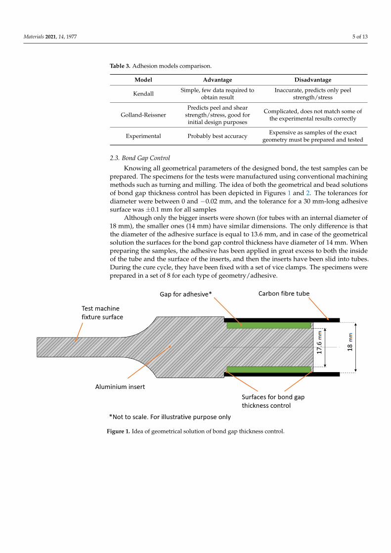
Knowing all geometrical parameters of the designed bond, the test samples can beprepared. The specimens for the tests were manufactured using conventional machiningmethods such as turning and milling. The idea of both the geometrical and bead solutionsof bond gap thickness control has been depicted in Figures 1 and 2. The tolerances fordiameter were between 0 and −0.02 mm, and the tolerance for a 30 mm-long adhesivesurface was ±0.1 mm for all samples
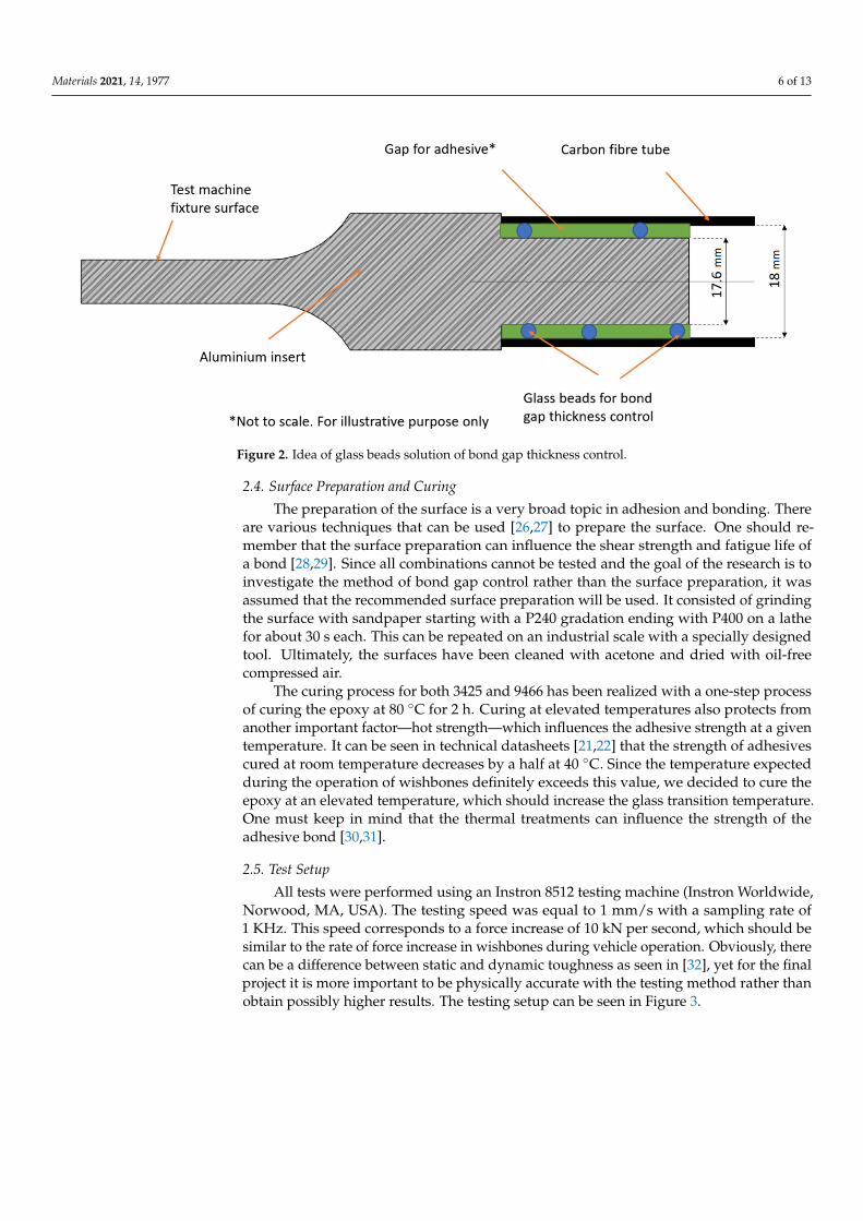
Although only the bigger inserts were shown (for tubes with an internal diameter of18 mm), the smaller ones (14 mm) have similar dimensions. The only difference is thatthe diameter of the adhesive surface is equal to 13.6 mm, and in case of the geometricalsolution the surfaces for the bond gap control thickness have diameter of 14 mm. Whenpreparing the samples, the adhesive has been applied in great excess to both the insideof the tube and the surface of the inserts, and then the inserts have been slid into tubes.During the cure cycle, they have been fixed with a set of vice clamps. The specimens wereprepared in a set of 8 for each type of geometry/adhesive.
Materials 2021, 14, x FOR PEER REVIEW 5 of 13
manufacturer for epoxy-based adhesives. The length of a bond was set to 30 mm for all samples at it was reported to have the ultimate strength needed for the project and could be compared to other results. All models used can be summarized using their advantages and disadvantages as described in Table 3.
Table 3. Adhesion models comparison.
Model Advantage Disadvantage
Kendall Simple, few data required to obtain result
Inaccurate, predicts only peel strength/stress
Golland–Reissner Predicts peel and shear
strength/stress, good for initial design purposes
Complicated, does not match some of the experimental results
correctly
Experimental Probably best accuracy Expensive as samples of the exact geometry must be prepared and
tested
2.3. Bond Gap Control Knowing all geometrical parameters of the designed bond, the test samples can be
prepared. The specimens for the tests were manufactured using conventional machining methods such as turning and milling. The idea of both the geometrical and bead solutions of bond gap thickness control has been depicted in Figures 1 and 2. The tolerances for diameter were between 0 and −0.02 mm, and the tolerance for a 30 mm-long adhesive surface was +/−0.1 mm for all samples
Although only the bigger inserts were shown (for tubes with an internal diameter of 18 mm), the smaller ones (14 mm) have similar dimensions. The only difference is that the diameter of the adhesive surface is equal to 13.6 mm, and in case of the geometrical solution the surfaces for the bond gap control thickness have diameter of 14 mm. When preparing the samples, the adhesive has been applied in great excess to both the inside of the tube and the surface of the inserts, and then the inserts have been slid into tubes. During the cure cycle, they have been fixed with a set of vice clamps. The specimens were prepared in a set of 8 for each type of geometry/adhesive.
Figure 1. Idea of geometrical solution of bond gap thickness control.
Figure 1. Idea of geometrical solution of bond gap thickness control.
Materials 2021, 14, 1977 6 of 13Materials 2021, 14, x FOR PEER REVIEW 6 of 13
Figure 2. Idea of glass beads solution of bond gap thickness control.
2.4. Surface Preparation and Curing The preparation of the surface is a very broad topic in adhesion and bonding. There
are various techniques that can be used [26,27] to prepare the surface. One should remember that the surface preparation can influence the shear strength and fatigue life of a bond [28,29]. Since all combinations cannot be tested and the goal of the research is to investigate the method of bond gap control rather than the surface preparation, it was assumed that the recommended surface preparation will be used. It consisted of grinding the surface with sandpaper starting with a P240 gradation ending with P400 on a lathe for about 30 s each. This can be repeated on an industrial scale with a specially designed tool. Ultimately, the surfaces have been cleaned with acetone and dried with oil-free compressed air.
The curing process for both 3425 and 9466 has been realized with a one-step process of curing the epoxy at 80 °C for 2 h. Curing at elevated temperatures also protects from another important factor—hot strength—which influences the adhesive strength at a given temperature. It can be seen in technical datasheets [21,22] that the strength of adhesives cured at room temperature decreases by a half at 40 °C. Since the temperature expected during the operation of wishbones definitely exceeds this value, we decided to cure the epoxy at an elevated temperature, which should increase the glass transition temperature. One must keep in mind that the thermal treatments can influence the strength of the adhesive bond [30,31].
2.5. Test Setup All tests were performed using an Instron 8512 testing machine (Instron Worldwide,
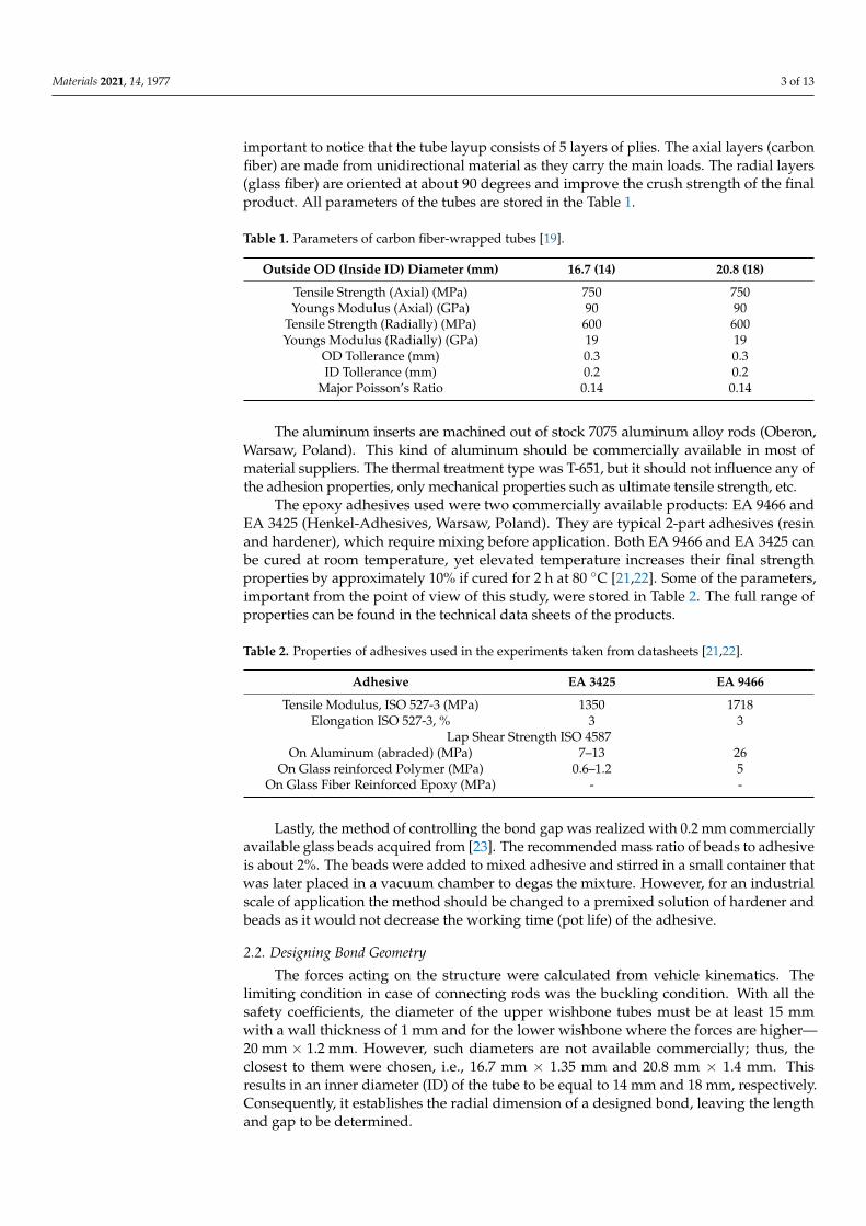
Norwood, MA, USA). The testing speed was equal to 1 mm/s with a sampling rate of 1 KHz. This speed corresponds to a force increase of 10 kN per second, which should be similar to the rate of force increase in wishbones during vehicle operation. Obviously, there can be a difference between static and dynamic toughness as seen in [32], yet for the final project it is more important to be physically accurate with the testing method rather than obtain possibly higher results. The testing setup can be seen in Figure 3.
Figure 2. Idea of glass beads solution of bond gap thickness control.
2.4. Surface Preparation and Curing
The preparation of the surface is a very broad topic in adhesion and bonding. Thereare various techniques that can be used [26,27] to prepare the surface. One should re-member that the surface preparation can influence the shear strength and fatigue life ofa bond [28,29]. Since all combinations cannot be tested and the goal of the research is toinvestigate the method of bond gap control rather than the surface preparation, it wasassumed that the recommended surface preparation will be used. It consisted of grindingthe surface with sandpaper starting with a P240 gradation ending with P400 on a lathefor about 30 s each. This can be repeated on an industrial scale with a specially designedtool. Ultimately, the surfaces have been cleaned with acetone and dried with oil-freecompressed air.
The curing process for both 3425 and 9466 has been realized with a one-step processof curing the epoxy at 80 ◦C for 2 h. Curing at elevated temperatures also protects fromanother important factor—hot strength—which influences the adhesive strength at a giventemperature. It can be seen in technical datasheets [21,22] that the strength of adhesivescured at room temperature decreases by a half at 40 ◦C. Since the temperature expectedduring the operation of wishbones definitely exceeds this value, we decided to cure theepoxy at an elevated temperature, which should increase the glass transition temperature.One must keep in mind that the thermal treatments can influence the strength of theadhesive bond [30,31].
2.5. Test Setup
All tests were performed using an Instron 8512 testing machine (Instron Worldwide,Norwood, MA, USA). The testing speed was equal to 1 mm/s with a sampling rate of1 KHz. This speed corresponds to a force increase of 10 kN per second, which should besimilar to the rate of force increase in wishbones during vehicle operation. Obviously, therecan be a difference between static and dynamic toughness as seen in [32], yet for the finalproject it is more important to be physically accurate with the testing method rather thanobtain possibly higher results. The testing setup can be seen in Figure 3.

Materials 2021, 14, 1977 7 of 13Materials 2021, 14, x FOR PEER REVIEW 7 of 13
Figure 3. Test setup.
3. Results The results were presented for each adhesive separately. Four types of samples were
tested for each adhesive. The four samples type were: 1. Inserts with 14 mm tubes utilizing geometrical solution of bond gap control; 2. Inserts with 14 mm tubes utilizing glass beads solution of bond gap control; 3. Inserts with 18 mm tubes utilizing geometrical solution of bond gap control; 4. Inserts with 18 mm tubes utilizing glass beads solution of bond gap control;
The results of average force as a function of displacement for the two types of epoxy adhesive can be seen in Figures 4 and 5. The results are presented for the samples closest to the average result in each group. This, however, does not depict the variation of the results, which will be presented later using whiskers boxplots in Figures 6 and 7. They present the dispersion of ultimate tensile strength, and the average values are stored in Table 4. It is crucial to remember that the given values of “stress” are calculated as force per bond area, which is not the real stress which occurs in the bond. This is performed to compare the results to the values given in the technical datasheets and to give a general reference of results.
Figure 3. Test setup.
3. Results
The results were presented for each adhesive separately. Four types of samples weretested for each adhesive. The four samples type were:
1. Inserts with 14 mm tubes utilizing geometrical solution of bond gap control;2. Inserts with 14 mm tubes utilizing glass beads solution of bond gap control;3. Inserts with 18 mm tubes utilizing geometrical solution of bond gap control;4. Inserts with 18 mm tubes utilizing glass beads solution of bond gap control;
The results of average force as a function of displacement for the two types ofepoxy adhesive can be seen in Figures 4 and 5. The results are presented for the samplesclosest to the average result in each group. This, however, does not depict the variationof the results, which will be presented later using whiskers boxplots in Figures 6 and 7.They present the dispersion of ultimate tensile strength, and the average values arestored in Table 4. It is crucial to remember that the given values of “stress” are calculatedas force per bond area, which is not the real stress which occurs in the bond. This isperformed to compare the results to the values given in the technical datasheets and togive a general reference of results.

Materials 2021, 14, 1977 8 of 13Materials 2021, 14, x FOR PEER REVIEW 8 of 13
Figure 4. Force as a function of displacement for samples with EA 9466 adhesive.
Figure 5. Force as a function of displacement for samples with EA 3425 adhesive.
Table 4. Average results of ultimate “stress”.
Adhesive 14 mm Geometrical
14 mm Beads
18 mm Geometrical
18 mm Beads
Average stress EA 9466 (MPa) 5.65 12.05 4.95 14.01 Average stress EA 3425 (MPa) 4.62 9.18 10.07 16.80
Figure 4. Force as a function of displacement for samples with EA 9466 adhesive.
Materials 2021, 14, x FOR PEER REVIEW 8 of 13
Figure 4. Force as a function of displacement for samples with EA 9466 adhesive.
Figure 5. Force as a function of displacement for samples with EA 3425 adhesive.
Table 4. Average results of ultimate “stress”.
Adhesive 14 mm Geometrical
14 mm Beads
18 mm Geometrical
18 mm Beads
Average stress EA 9466 (MPa) 5.65 12.05 4.95 14.01 Average stress EA 3425 (MPa) 4.62 9.18 10.07 16.80
Figure 5. Force as a function of displacement for samples with EA 3425 adhesive.
Materials 2021, 14, 1977 9 of 13Materials 2021, 14, x FOR PEER REVIEW 9 of 13
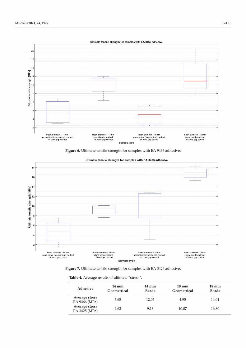
Figure 6. Ultimate tensile strength for samples with EA 9466 adhesive.
Figure 7. Ultimate tensile strength for samples with EA 3425 adhesive.
The failure mode identification of a designed bond is also a key element of the design validation. Figure 8 shows four samples chosen from samples of EA 3425, which failed during testing. The two on the right side represent tests performed on the beads solution of gap thickness control, and the two on the left represent the geometrical solution. What can be noticed is that in the first case (right), there is a layer of carbon fiber left on a sample. This would suggest that the samples failed in the adherend failure mode, meaning that the strength of the carbon fiber layers in the tube was insufficient to withstand the stress and broke off from the laminate. In second case (left) the failure mode was most likely
Figure 6. Ultimate tensile strength for samples with EA 9466 adhesive.
Materials 2021, 14, x FOR PEER REVIEW 9 of 13
Figure 6. Ultimate tensile strength for samples with EA 9466 adhesive.
Figure 7. Ultimate tensile strength for samples with EA 3425 adhesive.
The failure mode identification of a designed bond is also a key element of the design validation. Figure 8 shows four samples chosen from samples of EA 3425, which failed during testing. The two on the right side represent tests performed on the beads solution of gap thickness control, and the two on the left represent the geometrical solution. What can be noticed is that in the first case (right), there is a layer of carbon fiber left on a sample. This would suggest that the samples failed in the adherend failure mode, meaning that the strength of the carbon fiber layers in the tube was insufficient to withstand the stress and broke off from the laminate. In second case (left) the failure mode was most likely
Figure 7. Ultimate tensile strength for samples with EA 3425 adhesive.
Table 4. Average results of ultimate “stress”.
Adhesive 14 mmGeometrical
14 mmBeads
18 mmGeometrical
18 mmBeads
Average stressEA 9466 (MPa) 5.65 12.05 4.95 14.01
Average stressEA 3425 (MPa) 4.62 9.18 10.07 16.80

Materials 2021, 14, 1977 10 of 13
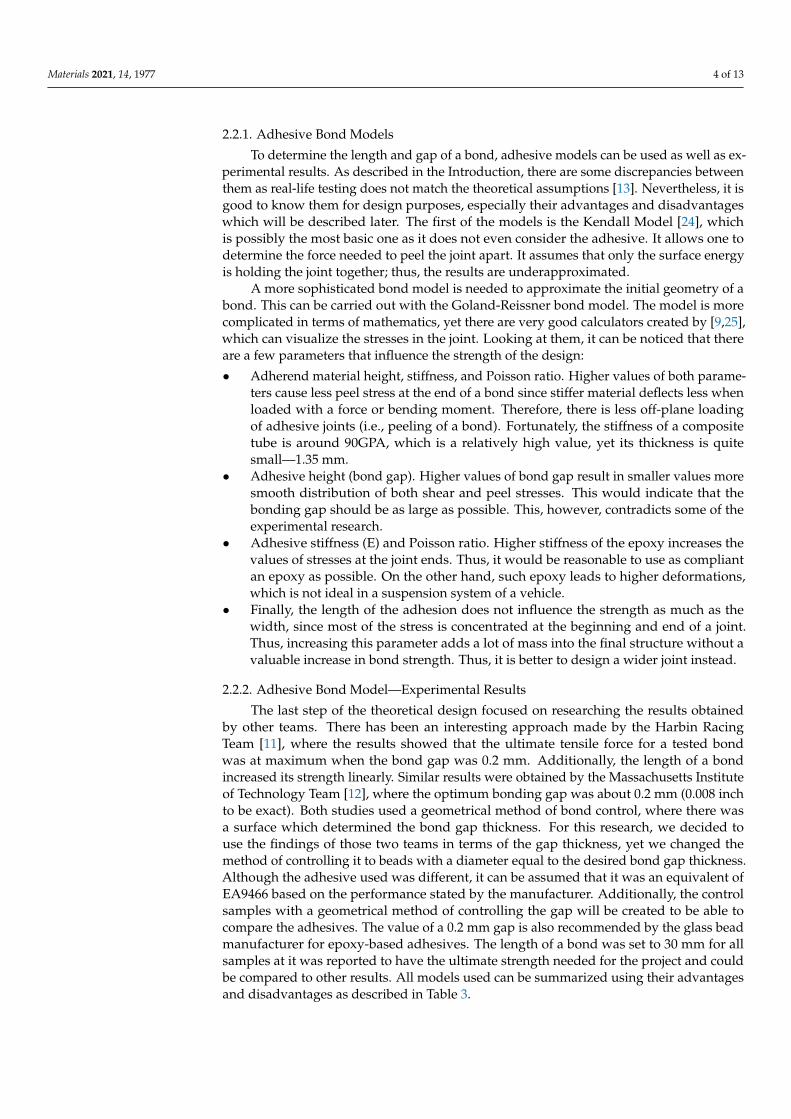
The failure mode identification of a designed bond is also a key element of the designvalidation. Figure 8 shows four samples chosen from samples of EA 3425, which failedduring testing. The two on the right side represent tests performed on the beads solutionof gap thickness control, and the two on the left represent the geometrical solution. Whatcan be noticed is that in the first case (right), there is a layer of carbon fiber left on a sample.This would suggest that the samples failed in the adherend failure mode, meaning thatthe strength of the carbon fiber layers in the tube was insufficient to withstand the stressand broke off from the laminate. In second case (left) the failure mode was most likelyinterfacial or adhesive failure as the inserts were pulled out of the tubes, with adhesivestuck to the aluminum insert.
Materials 2021, 14, x FOR PEER REVIEW 10 of 13
interfacial or adhesive failure as the inserts were pulled out of the tubes, with adhesive stuck to the aluminum insert.
Figure 8. Failure modes of the adhesive bond—for geometrical solution on 3425 (two on the left) and beads solution (two on the right).
4. Discussion The results obtained using the EA 9466 show that the adhesive joint is stronger in
case of the beads gap control method. However, the spread of the results suggests that the performance of the bond is highly influenced by the quality of the manufacturing method. Of course, the samples were prepared with the same surface treatment and assembly methods, yet since the process is carried out by hand, it is obvious that some errors might occur.
The results obtained with EA 3425 indicate that the beads gap control method pro-vides much better and repeatable results in comparison to the geometrical method. The spread of results is smaller relative to the geometrical method, and the obtained mean values are about twice as high. It would seem that the 3425 adhesive is better suited for the beads method of bond gap control. The authors’ explanation is that the viscosity of this adhesive, which causes it to be thixotropic, helps the epoxy to stay attached to the walls of the cylinder. This provides more adhesive in the bond and, in general, a better bond. The EA9466 has better results when the bond is properly filled with adhesive (even reaching 35 kN), but due to the low viscosity it is prone to escaping from the bond gap. Obviously, this is only a theory; there are more factors than can play a significant role such as the repeatability of the assembly method, etc.
Another important factor to consider was the failure mode of the joint. The preferred failure mode in engineering is the adherend failure mode [33] as it means that the bond is stronger than the material itself. Proper identification of the failure mode is crucial as it determines whether the design is valid [34]. As was seen in Figure 8, the interfacial layer of carbon in the tube was not strong enough and failed in case of the beads solution. This probably means that the interfacial stresses were very high locally, thus causing a failure. Future designs (to optimize the structure) should probably focus on developing a double lap joint and pay more attention to interfacial shear stress analysis as carried out in [35].
5. Conclusions The research allowed us to determine the best adhesive and bond gap control method
for a given design of an adhesive joint. This does not mean it will be optimal for all other adhesive joints, yet it gives some idea as to which system could be used for similar pro-jects. The design loads of 8 kN and 12 kN for the 14 and 18 mm insert, respectively, are met with a safety coefficient for the manufacturing process of about 2. Obviously, the
Figure 8. Failure modes of the adhesive bond—for geometrical solution on 3425 (two on the left) andbeads solution (two on the right).
4. Discussion
The results obtained using the EA 9466 show that the adhesive joint is stronger incase of the beads gap control method. However, the spread of the results suggests thatthe performance of the bond is highly influenced by the quality of the manufacturingmethod. Of course, the samples were prepared with the same surface treatment andassembly methods, yet since the process is carried out by hand, it is obvious that someerrors might occur.
The results obtained with EA 3425 indicate that the beads gap control method providesmuch better and repeatable results in comparison to the geometrical method. The spreadof results is smaller relative to the geometrical method, and the obtained mean valuesare about twice as high. It would seem that the 3425 adhesive is better suited for thebeads method of bond gap control. The authors’ explanation is that the viscosity of thisadhesive, which causes it to be thixotropic, helps the epoxy to stay attached to the walls ofthe cylinder. This provides more adhesive in the bond and, in general, a better bond. TheEA9466 has better results when the bond is properly filled with adhesive (even reaching35 kN), but due to the low viscosity it is prone to escaping from the bond gap. Obviously,this is only a theory; there are more factors than can play a significant role such as therepeatability of the assembly method, etc.
Another important factor to consider was the failure mode of the joint. The preferredfailure mode in engineering is the adherend failure mode [33] as it means that the bond isstronger than the material itself. Proper identification of the failure mode is crucial as itdetermines whether the design is valid [34]. As was seen in Figure 8, the interfacial layerof carbon in the tube was not strong enough and failed in case of the beads solution. Thisprobably means that the interfacial stresses were very high locally, thus causing a failure.Future designs (to optimize the structure) should probably focus on developing a doublelap joint and pay more attention to interfacial shear stress analysis as carried out in [35].
Materials 2021, 14, 1977 11 of 13
5. Conclusions
The research allowed us to determine the best adhesive and bond gap control methodfor a given design of an adhesive joint. This does not mean it will be optimal for all otheradhesive joints, yet it gives some idea as to which system could be used for similar projects.The design loads of 8 kN and 12 kN for the 14 and 18 mm insert, respectively, are met witha safety coefficient for the manufacturing process of about 2. Obviously, the structure couldbe optimized further in terms of mass by decreasing the bond length. Another possibility isto use the double lap joint method by adding external bushing. This approach to adhesivejoints results in no peeling stress as the joint is loaded symmetrically and no momentis created.
The geometrical method of bond gap control could be improved by inserting theadhesive externally under pressure by some opening in a tube or channels inside the insert.This would unfortunately also increase the cost of the manufacturing process. Additionally,the geometrical solution is harder to manufacture as some inserts in the final design requiremachining on five-axis milling machines, since the inserts are at some angles relative toreach other, which limits the possibility of using lathes.
The influence of testing the surface preparation was not investigated as it will becarried out using the adhesive manufacturers’ recommended process, which includes usingsandpaper and thoroughly cleaning the surface. Obviously, the etching of the aluminumsurface could be performed as it was reported to bring additional performance [12]. Thiscan potentially increase the bonding strength to the aluminium surface, yet it is not wherethe debonding takes place as it happens at the interface between the adhesive and carbonfiber tube.
Comparing the results to [12], it can be seen that the beads method has slightly betterresults. Of course, the geometry was slightly different, yet if average “stress” is comparedthe results slightly better. On the other hand, the results obtained in [11] are higher by about10% than the results obtained in this research. Again, it is difficult to directly compare asthe geometries were slightly different and the used adhesives were not the same (althoughsimilar). The most important finding is that the method of glass beads can produce morestable results for a given bond, which allows for less safety coefficients as the worst-casescenarios are very close to average results.
To conclude, a few words about the final design of the wishbones should be said.Although they were not included in the Results section, they have been prepared using the3425 and beads method of gap control. They have been assembled using a simple 10-mm-thick plate with machined holes for the positioning of shoulder screws. The whole assemblyhas been cured together, and then the wishbones were removed for final inspection. Sinceit is crucial that the wishbones do not fail during operation in the vehicle, some non-destructive testing would be helpful. To perform this, the wishbones were mountedin the machine used during the testing of the specimens and loaded to the maximumexpected load value during operation. All the wishbones passed the proof test successfully.Other NDT methods are also available, such as those described in [36], yet this one hasbeen chosen as the wishbones will experience very few cycles (one short race), but ofhigh amplitude.
Author Contributions: Conceptualization, J.T., M.P., M.K., and W.R.; data curation, J.T., A.C. andK.G.; formal analysis, A.C.; funding acquisition, W.R.; investigation, H.G.; methodology, J.T.; projectadministration, M.K. and W.R.; resources, M.P.; Software, K.G. and H.G.; supervision, M.K. andW.R.; validation, J.T., A.C., K.G. and H.G.; visualization, K.G.; writing—original draft, J.T. and M.P.;writing—review and editing, J.T. and W.R. All authors have read and agreed to the published versionof the manuscript.
Funding: This research received no external funding.
Institutional Review Board Statement: Not applicable.
Informed Consent Statement: Not applicable.

Materials 2021, 14, 1977 12 of 13
Data Availability Statement: The data presented in this study are available on request from thecorresponding author.
Acknowledgments: The authors would like to thank Jan Filipiak for helping with the curing process.
Conflicts of Interest: The authors declare no conflict of interest.
References1. Niessen, K.; Notenboom, P.; van der Pas, H.; Scharrenberg, R. Design of a Formula Student Racecar Suspension Link for the URE08;
TU Eindhoven, Department of Mechanical Engineering: Eindhoven, The Netherlands, 2013.2. Olsen, R.; Bookholt, A.; Melchiori, E. Composite Suspension for Formula SAE Vehicle; Faculty of the Mechanical Engineering
Department, California Polytechnic State University: San Luis Obispo, CA, USA, 2010.3. Li, J.; Yu, S.; Zhang, N.; He, H.; Yang, Z.; Jia, Y. Formula SAE Racecar Suspension System Design. Appl. Mech. Mater. 2013,
416–417, 1840–1844. [CrossRef]4. Saurabh, Y.S.; Kumar, S.; Jain, K.K.; Behera, S.K.; Gandhi, D.; Raghavendra, S.; Kalita, K. Design of suspension system for formula
student race car. Procedia Eng. 2016, 144, 1138–1149. [CrossRef]5. Milliken, D. Race Car Vehicle Dynamics: Problems, Answers and Experiments; SAE International: Warrendale, PA, USA, 2003.6. Pacejka, H.; Besselink, I.J.M. Tire and Vehicle Dynamics; Elsevier Science & Technology: Oxford, UK, 2012.7. Galinska, A. Mechanical Joining of Fibre Reinforced Polymer Composites to Metals—A Review. Part I: Bolted Joining. Polymers
2020, 12, 2252. [CrossRef] [PubMed]8. Galinska, A.; Galinski, C. Mechanical Joining of Fibre Reinforced Polymer Composites to Metals—A Review. Part II: Riveting,
Clinching, Non-Adhesive Form-Locked Joints, Pin and Loop Joining. Polymers 2020, 12, 1681. [CrossRef] [PubMed]9. Abbott, S. Practical Adhesion. Available online: https://www.stevenabbott.co.uk/practical-adhesion/g-rlap.php (accessed on
1 April 2021).10. Abbott, S. Adhesion Science: Principles and Practice; DEStech Publications, Inc.: Lancaster, PA, USA, 2015.11. Wang, J.; Gao, H.; Ding, L.; Hao, Y.; Wang, B.; Sun, T.; Liang, Y. Bond strength between carbon fiber–reinforced plastic tubes and
aluminum joints for racing car suspension. Adv. Mech. Eng. 2016. [CrossRef]12. Cobi, A.C. Design of a Carbon Fiber Suspension System for FSAE Applications; Massachusetts Institute of Technology, Department of
Mechnical Engineering: Cambridge, MA, USA, 2012.13. Duncan, B. 14-Developments in testing adhesive joints. In Woodhead Publishing Series in Welding and Other Joining Technolo-
gies, Advances in Structural Adhesive Bonding; Dillard, D.A., Ed.; Woodhead Publishing: Sawston, UK, 2010; pp. 389–436.ISBN 9781845694357. [CrossRef]
14. Saraç, I.; Adin, H.; Temiz, S. Experimental determination of the static and fatigue strength of the adhesive joints bonded by epoxyadhesive including different particles. Compos. Part B Eng. 2018, 155, 92–103. [CrossRef]
15. Sun, F.; Pruncu, C.I.; Penchev, P.; Jiang, J.; Dimov, S.; Blackman, B.R.K. Influence of surface micropatterns on the mode I fracturetoughness of adhesively bonded joints. Int. J. Adhes. Adhes. 2020, 103, 102718. [CrossRef]
16. Adams, R.; Peppiatt, N. Stress Analysis of Adhesive-Bonded Lap Joints. J. Strain Anal. Eng. Des. 1974, 9, 185–196. [CrossRef]17. Silva, L.F.M.; Rodrigues, T.; de Figueiredo, M.; De Moura, M.; Chousal, J.A.G. Effect of Adhesive Type and Thickness on the Lap
Shear Strength. J. Adhes. 2006, 82, 1091–1115. [CrossRef]18. Da Silva, L.F.M.; Campilho, R.D.S.G. 2-Design of adhesively-bonded composite joints. In Fatigue and Fracture of Adhesively-Bonded
Composite Joints; Vassilopoulos, A.P., Ed.; Woodhead Publishing: Sawston, UK, 2015; pp. 43–71. ISBN 9780857098061. [CrossRef]19. Easy Composites. Available online: https://www.easycomposites.co.uk/#!/cured-carbon-fibre-products/carbon-fibre-tube/
roll-wrapped-carbon-fibre-tube/carbon-fibre-tube-roll-wrapped-14mm.html (accessed on 1 April 2021).20. Easy Composites. How to Make a Roll Wrapped Carbon Fibre Tube. Available online: https://www.youtube.com/watch?v=
vqlR74PlVgM&ab_channel=EasyCompositesLtd (accessed on 1 April 2021).21. Henkel Adhesive Technologies. “Loctite–9466 TDS“, Henkel. Available online: http://tds.henkel.com/tds5/Studio/ShowPDF/
243%20NEW-EN?pid=EA%209466&format=MTR&subformat=REAC&language=EN&plant=WERCS (accessed on 1 April 2021).22. Henkel Adhesive Technologies. “Loctite–3425 TDS“, Henkel. Available online: http://tds.henkel.com/tds5/Studio/ShowPDF/
243%20NEW-EN?pid=EA%203425&format=MTR&subformat=HYS&language=EN&plant=WERCS (accessed on 1 April 2021).23. Rockwest Composites. “Bond Line Controller/Glass Beads for Bonding,” Rockwest Composites. Available online: https:
//www.rockwestcomposites.com/bond-line-controller (accessed on 1 April 2021).24. Kendall, K. Molecular Adhesion and Its Applications; Springer: Boston, MA, USA, 2001.25. Da Silva, L.F.; Lima, R.F.; Teixeira, R.M. Development of a Computer Program for the Design of Adhesive Joints. J. Adhes. 2009,
85, 889–918. [CrossRef]26. Kopeliovich, D. Surface Preparation for Adhesive Bonding. Available online: https://www.substech.com/dokuwiki/doku.php?
id=surface_preparation_for_adhesive_bonding (accessed on 1 April 2021).27. Wegman, F.; Van Twisk, J. Surface Preparation Techniques for Adhesive Bonding; Elsevier Science: Amsterdam, The Netherlands, 2012.28. Musiari, F.; Moroni, F. Experimental Study of the Influence of the Surface Preparation on the Fatigue Behavior of Polyamide
Single Lap Joints. Materials 2021, 14, 1008. [CrossRef] [PubMed]
Materials 2021, 14, 1977 13 of 13
29. Schweizer, M.; Meinhard, D.; Ruck, S.; Riegel, H.; Knoblauch, V. Adhesive bonding of CFRP: A comparison of different surfacepre-treatment strategies and their effect on the bonding shear strength. J. Adhes. Sci. Technol. 2017, 31, 2581–2591. [CrossRef]
30. Kłonica, M. Comparative analysis of effect of thermal shock on adhesive joint strength. Adv. Sci. Technol. Res. J. 2016, 10, 263–268.[CrossRef]
31. Kubita, A.; Trzepiecinski, T.; Kłonica, M.; Hebda, M.; Pytele, M. The influence of temperature gradient thermal shock cycleson the interlaminar shear strength of fibre metal laminate composite determined by the short beam test. Compos. Part B Eng.2019, 176, 1–6. [CrossRef]
32. Skoczylas, J.; Samborski, S.; Kłonica, M. Experimental Study on Static and Dynamic Fracture Toughness of Cured Epoxy Resins.Adv. Sci. Technol. Res. J. 2019, 13, 122–127. [CrossRef]
33. Rans, C. Adhesive Bonding as an Aerospace Joining Method. 9 October 2018. Available online: https://www.youtube.com/watch?v=dWAvPH8aACs& (accessed on 1 April 2021).
34. Davis, M.J.; Bond, D.A. “The Importance of Failure Mode Identification in Adhesive Bonded Aircraft Structures and Repairs,”Aircraft Structural Integrity Section, Directorate General of Technical Airworthiness, Royal Australian Air Force, AmberleyDetachment, 501 Wing, RAAF Amberley 4306, Australia; RAAF Williams, Melbourne 3027, Australia, 2010. Available on-line: http://www.adhesionassociates.com/papers/46%20Importance%20of%20Failure%20Mode%20Indentification%20ICCM%2012%20Paris.pdf (accessed on 1 April 2021).
35. Her, S.-C.; Chan, C.-F. Interfacial Stress Analysis of Adhesively Bonded Lap Joint. Materials 2019, 12, 2403. [CrossRef] [PubMed]36. Khosravani, M.R. Influences of Defects on the Performance of Adhesively Bonded Sandwich Joints. Key Eng. Mater. 2018, 789,
45–50. [CrossRef]