European Technical Approval ETA-07/0219
24
Diese Zulassung umfasst This Approval contains 24 Seiten einschließlich 13 Anhänge 24 pages including 13 annexes Diese Zulassung ersetzt This Approval replaces ETA-07/0219 mit Geltungsdauer vom 17.09.2007 bis 17.09.2012 ETA-07/0219 with validity from 17.09.2007 to 17.09.2012 Europäische Organisation für Technische Zulassungen European Organisation for Technical Approvals Deutsches Institut für Bautechnik Anstalt des öffentlichen Rechts Kolonnenstr. 30 L 10829 Berlin Germany Tel.: +49(0)30 787 30 0 Fax: +49(0)30 787 30 320 E-mail: [email protected] Internet: www.dibt.de Mitglied der EOTA Member of EOTA European Technical Approval ETA-07/0219 English translation prepared by DIBt - Original version in German language Handelsbezeichnung Trade name Hilti Rahmendübel HRD Hilti frame anchor HRD Zulassungsinhaber Holder of approval Hilti Aktiengesellschaft Business Unit Anchors 9494 Schaan FÜRSTENTUM LIECHTENSTEIN Zulassungsgegenstand und Verwendungszweck Kunststoffdübel als Mehrfachbefestigung von nichttragenden Systemen zur Verankerung im Beton und Mauerwerk Generic type and use of construction product Plastic anchor for multiple use in concrete and masonry for non-structural applications Geltungsdauer: Validity: vom from 12 August 2010 bis to 17 September 2012 Herstellwerk Manufacturing plant Hilti, Werk 9
-
Upload
khangminh22 -
Category
Documents
-
view
1 -
download
0
Transcript of European Technical Approval ETA-07/0219

Diese Zulassung umfasst
This Approval contains
24 Seiten einschlieszliglich 13 Anhaumlnge 24 pages including 13 annexes
Diese Zulassung ersetzt This Approval replaces
ETA-070219 mit Geltungsdauer vom 17092007 bis 17092012 ETA-070219 with validity from 17092007 to 17092012
E u r o p auml i s c h e O r g a n i s a t i o n f uuml r T e c h n i s c h e Z u l a s s u n g e n
E u r o p e a n O r g a n i s a t i o n f o r T e c h n i c a l A p p r o v a l s
Deutsches Institut fuumlr Bautechnik Anstalt des oumlffentlichen Rechts
Kolonnenstr 30 L 10829 Berlin Germany
Tel +49(0)30 787 30 0 Fax +49(0)30 787 30 320 E-mail dibtdibtde Internet wwwdibtde
Mitglied der EOTA Member of EOTA
European Technical Approval ETA-070219
English translation prepared by DIBt - Original version in German language
Handelsbezeichnung Trade name
Hilti Rahmenduumlbel HRD Hilti frame anchor HRD
Zulassungsinhaber
Holder of approval Hilti Aktiengesellschaft Business Unit Anchors 9494 Schaan FUumlRSTENTUM LIECHTENSTEIN
Zulassungsgegenstand und Verwendungszweck
Kunststoffduumlbel als Mehrfachbefestigung von nichttragenden Systemen zur Verankerung im Beton und Mauerwerk
Generic type and use of construction product
Plastic anchor for multiple use in concrete and masonry for non-structural applications
Geltungsdauer
Validity vom from
12 August 2010
bis to
17 September 2012
Herstellwerk
Manufacturing plant Hilti Werk 9
Page 2 of ETA-070219 issued on 12 August 2010 English translation by Deutsches Institut fuumlr Bautechnik (DIBt)
Z3283810 D e u t s c h e s I n s t i t u t f uuml r B a u t e c h n i k 80604-26308
I LEGAL BASES AND GENERAL CONDITIONS
1 This European technical approval is issued by Deutsches Institut fuumlr Bautechnik in accordance with - Council Directive 89106EEC of 21 December 1988 on the approximation of laws
regulations and administrative provisions of Member States relating to construction products1 modified by Council Directive 9368EEC2 and Regulation (EC) Ndeg 18822003 of the European Parliament and of the Council3
- Gesetz uumlber das In-Verkehr-Bringen von und den freien Warenverkehr mit Bauprodukten zur Umsetzung der Richtlinie 89106EWG des Rates vom 21 Dezember 1988 zur Angleichung der Rechts- und Verwaltungsvorschriften der Mitgliedstaaten uumlber Bauprodukte und anderer Rechtsakte der Europaumlischen Gemeinschaften (Bauprodukten-gesetz - BauPG) vom 28 April 19984 as amended by law of 31 October 20065
- Common Procedural Rules for Requesting Preparing and the Granting of European technical approvals set out in the Annex to Commission Decision 9423EC6
- Guideline for European technical approval of Plastic Anchors for Multiple Use in Concrete and Masonry for Non-structural Applications ndash Part 1 General ETAG 020-01
2 Deutsches Institut fuumlr Bautechnik is authorized to check whether the provisions of this European technical approval are met Checking may take place in the manufacturing plant Nevertheless the responsibility for the conformity of the products to the European technical approval and for their fitness for the intended use remains with the holder of the European technical approval
3 This European technical approval is not to be transferred to manufacturers or agents of manufacturers other than those indicated on page 1 or manufacturing plants other than those indicated on page 1 of this European technical approval
4 This European technical approval may be withdrawn by Deutsches Institut fuumlr Bautechnik in particular pursuant to information by the Commission according to Article 5(1) of Council Directive 89106EEC
5 Reproduction of this European technical approval including transmission by electronic means shall be in full However partial reproduction can be made with the written consent of Deutsches Institut fuumlr Bautechnik In this case partial reproduction has to be designated as such Texts and drawings of advertising brochures shall not contradict or misuse the European technical approval
6 The European technical approval is issued by the approval body in its official language This version corresponds fully to the version circulated within EOTA Translations into other languages have to be designated as such
1 Official Journal of the European Communities L 40 11 February 1989 p 12 2 Official Journal of the European Communities L 220 30 August 1993 p 1 3 Official Journal of the European Union L 284 31 October 2003 p 25 4 Bundesgesetzblatt Teil I 1998 p 812 5 Bundesgesetzblatt Teil I 2006 p2407 2416 6 Official Journal of the European Communities L 17 20 January 1994 p 34
Page 3 of ETA-070219 issued on 12 August 2010 English translation by Deutsches Institut fuumlr Bautechnik (DIBt)
Z3283810 D e u t s c h e s I n s t i t u t f uuml r B a u t e c h n i k 80604-26308
II SPECIFIC CONDITIONS OF THE EUROPEAN TECHNICAL APPROVAL
1 Definition of product and intended use
11 Definition of the construction product The Hilti frame anchor HRD in the range HRD 8 and HRD 10 is a plastic anchor consisting of
a plastic sleeve made of polyamide and an accompanying specific screw of galvanised steel or stainless steel
The plastic sleeve is expanded by screwing in the specific screw which presses the sleeve against the wall of the drilled hole
The installed anchor is shown in Annex 1
12 Intended use The anchor is intended to be used for anchorages for which requirements for safety in use in
the sense of the Essential Requirement 4 of Council Directive 89106EEC shall be fulfilled and failure of the fixture represents an immediate risk to human life
The anchor is to be used only for multiple fixing for non-structural applications in concrete and masonry The base material shall consist of reinforced or unreinforced normal weight concrete of strength class C1215 at minimum and C5060 at maximum according to EN 206-12000-12 and of masonry walls according to Annex 9 to 12 The anchor may be used in cracked and non-cracked concrete The mortar strength class of the masonry has to be M25 according to EN 998-22003 at minimum
The anchor HRD 10 may also be used in masonry walls made of (non-cracked) autoclaved aerated concrete blocks (AAC) according to Annex 13
The anchor HRD 10 may also be used in concrete with requirements related to resistance to fire according 422
Specific screws of electro galvanised steel and stainless steel (14301 and 14567) The specific screw made of galvanised steel or stainless steel (14301 and 14567) may only
be used in structures subject to dry internal conditions These screws may also be used in structures subject to external atmospheric exposure if
the area of the head of the screw is protected against moisture and driving rain after mounting of the fixing unit in this way that intrusion of moisture into the anchor shaft is prevented Therefore there shall be an external cladding or a ventilated rainscreen mounted in front of the head of the screw and the head of the screw itself shall be coated with a soft plastic permanently elastic bitumen-oil-combination coating (e g undercoating or body cavity protection for cars)
Specific screws of stainless steel (14362 14401 14404 and 14571) The specific screw made of stainless steel (14362 14401 14404 and 14571) may be
used in structures subject to dry internal conditions and also in structures subject to external atmospheric exposure (including industrial and marine environment) or exposure in permanently damp internal conditions if no particular aggressive conditions exist Such particular aggressive conditions are e g permanent alternating immersion in seawater or the splash zone of seawater chloride atmosphere of indoor swimming pools or atmosphere with extreme chemical pollution (e g in desulphurization plants or road tunnels where de-icing materials are used)
The anchor may be used in the following temperature range Temperature range -40 degC to +80 degC (max long term temperature +50 degC and
max short term temperature +80 degC)
Page 4 of ETA-070219 issued on 12 August 2010 English translation by Deutsches Institut fuumlr Bautechnik (DIBt)
Z3283810 D e u t s c h e s I n s t i t u t f uuml r B a u t e c h n i k 80604-26308
The provisions made in this European Technical Approval are based on an assumed working life of the anchor of 50 years The indications given on the working life cannot be interpreted as a guarantee given by the producer but are to be regarded only as a means for choosing the right products in relation to the expected economically reasonable working life of the works
2 Characteristics of the product and methods of verification
21 Characteristics of the product The anchor corresponds to the drawings and information given in Annex 2 and 3 The
characteristic material values dimensions and tolerances of the anchor not given in these Annexes shall correspond to the respective values laid down in the technical documentation7 of this European Technical Approval
The characteristic values for the design of the anchorages are given in Annex 7 and 9 to 13 Each anchor is to be marked with the identifying mark the type the diameter and the length
of the anchor according to Annex 2 The minimum embedment depth shall be marked The anchor shall only be packaged and supplied as a complete unit
22 Methods of verification The assessment of the fitness of the anchor for the intended use in relation to the
requirements for safety in use in the sense of the Essential Requirement 4 has been made in compliance with the Guideline for European Technical Approval of Plastic Anchors for Multiple Use in Concrete and Masonry for Non-structural Applications ETAG 020
- Part 1 General - Part 2 Plastic Anchors for Use in Normal Weight Concrete - Part 3 Plastic Anchors for Use in Solid Masonry Materials - Part 4 Plastic Anchors for Use in Hollow or Perforated Masonry and - Part 5 Plastic Anchors for Use in Autoclaved Aerated Concrete (AAC) based on the use categories a b c (HRD 8) and a b c d (HRD 10) In addition to the specific clauses relating to dangerous substances contained in this
European Technical Approval there may be other requirements applicable to the products falling within its scope (e g transposed European legislation and national laws regulations and administrative provisions) In order to meet the provisions of the Construction Products Directive these requirements need also to be complied with when and where they apply
7 The technical documentation of this European Technical Approval is deposited at the Deutsches Institut fuumlr
Bautechnik and as far as relevant for the tasks of the approved bodies involved in the attestation of conformity procedure is handed over to the approved bodies
Page 5 of ETA-070219 issued on 12 August 2010 English translation by Deutsches Institut fuumlr Bautechnik (DIBt)
Z3283810 D e u t s c h e s I n s t i t u t f uuml r B a u t e c h n i k 80604-26308
3 Evaluation and attestation of conformity and CE marking
31 System of attestation of conformity According to the decision 97463EG of the European Commission8 the system 2(ii) (referred
to as system 2+) of attestation of conformity applies This system of attestation of conformity is defined as follows
System 2+ Declaration of conformity of the product by the manufacturer on the basis of (a) Tasks for the manufacturer
(1) initial type-testing of the product (2) factory production control (3) testing of samples taken at the factory in accordance with a prescribed test
plan (b) Tasks for the approved body
(4) certification of factory production control on the basis of ndash initial inspection of factory and of factory production control ndash continuous surveillance assessment and approval of factory production
control 32 Responsibilities 321 Tasks of the manufacturer 3211 Factory production control The manufacturer shall exercise permanent internal control of production All the elements
requirements and provisions adopted by the manufacturer shall be documented in a systematic manner in the form of written policies and procedures including records of results performed This production control system shall insure that the product is in conformity with this European Technical Approval
The manufacturer may only use raw materials stated in the technical documentation of this European Technical Approval
The factory production control shall be in accordance with the control plan which is part of the technical documentation of this European Technical Approval The control plan is laid down in the context of the factory production control system operated by the manufacturer and deposited at Deutsches Institut fuumlr Bautechnik9
The results of factory production control shall be recorded and evaluated in accordance with the provisions of the control plan
3212 Other tasks of manufacturer The manufacturer shall on the basis of a contract involve a body which is approved for the
tasks referred to in section 31 in the field of anchors in order to undertake the actions laid down in section 322 For this purpose the control plan referred to in sections 3211 and 322 shall be handed over by the manufacturer to the approved body involved
The manufacturer shall make a declaration of conformity stating that the construction product is in conformity with the provisions of this European Technical Approval
322 Tasks of approved bodies The approved body shall perform the
- initial inspection of factory and of factory production control - continuous surveillance assessment and approval of factory production control
in accordance with the provisions laid down in the control plan 8 Official Journal of the European Communities L 198 of 25071997 9 The control plan is a confidential part of the documentation of the European Technical Approval but not
published together with the ETA and only handed over to the approved body involved in the procedure of attestation of conformity See section 322
Page 6 of ETA-070219 issued on 12 August 2010 English translation by Deutsches Institut fuumlr Bautechnik (DIBt)
Z3283810 D e u t s c h e s I n s t i t u t f uuml r B a u t e c h n i k 80604-26308
The approved body shall retain the essential points of its actions referred to above and state the results obtained and conclusions drawn in a written report
The approved certification body involved by the manufacturer shall issue an EC certificate of conformity of the factory production control stating the conformity with the factory production control of this European Technical Approval
In cases where the provisions of the European Technical Approval and its control plan are no longer fulfilled the certification body shall withdraw the certificate of conformity and inform Deutsches Institut fuumlr Bautechnik without delay
33 CE marking The CE marking shall be affixed on each packaging of the anchor The letters CE shall be
followed by the identification number of the approved certification body where relevant and be accompanied by the following additional information - the name and address of the producer (legal entity responsible for the manufacturer) - the last two digits of the year in which the CE marking was affixed - the number of the EC certificate for the factory production control - the number of the European Technical Approval - the number of the guideline for European Technical Approval - use categories a b c (HRD 8) and a b c d (HRD 10)
4 Assumptions under which the fitness of the product for the intended use was favourably assessed
41 Manufacturing The European Technical Approval is issued for the product on the basis of agreed
datainformation deposited with Deutsches Institut fuumlr Bautechnik which identifies the product that has been assessed and judged Changes to the product or production process which could result in this deposited datainformation being incorrect should be notified to Deutsches Institut fuumlr Bautechnik before the changes are introduced Deutsches Institut fuumlr Bautechnik will decide whether or not such changes affect the ETA and consequently the validity of the CE marking on the basis of the ETA and if so whether further assessment or alterations to the ETA shall be necessary
42 Design of anchorages 421 General Fitness for the intended use of the anchor is given under the following conditions - The design of anchorages is carried out in compliance with ETAG 020 Guideline for
European Technical Approval of Plastic Anchors for Multiple Use in Concrete and Masonry for Non-structural Applications Annex C under the responsibility of an engineer experienced in anchorages This design method applies to plastic anchors subject to static or quasi-static actions in tension shear or combined tension and shear or bending it is not applicable to plastic anchors loaded in compression or subject to fatigue impact or seismic actions
- Verifiable calculation notes and drawings shall be prepared taking account of the loads to be anchored the nature and strength of the base materials and the dimensions of the anchorage members as well as of the relevant tolerances
Page 7 of ETA-070219 issued on 12 August 2010 English translation by Deutsches Institut fuumlr Bautechnik (DIBt)
Z3283810 D e u t s c h e s I n s t i t u t f uuml r B a u t e c h n i k 80604-26308
- The anchor is to be used only for multiple fixing for non-structural applications Therefore the design of the fixture may specify the number n1 of fixing points to fasten
the fixture and the number n2 of anchors per fixing point Furthermore by specifying the design value of actions NSd on a fixing point to a value le n3 (kN) up to which the strength and stiffness of the fixture are fulfilled and the load transfer in the case of excessive slip or failure of one anchor need not to be taken into account in the design of the fixture
The following default values for n1 n2 and n3 may be taken n1 ge 4 n2 ge 1 and n3 le 45 kN or n1 ge 3 n2 ge 1 and n3 le 30 kN Shear loads acting on an anchor may be assumed to act without lever arm if both of the
following conditions are fulfilled - The fixture shall be made of metal and in the area of the anchorage be fixed directly to
the base material either without an intermediate layer or with a levelling layer of mortar with a thickness le 3 mm
- The fixture shall be in contact with the anchor over its entire thickness (Therefore the diameter of clearance hole in the fixture df has to be equal or smaller than the values given in Annex 4 Table 3)
If these two conditions are not fulfilled the lever arm is calculated according to ETAG 020 Annex C The characteristic bending moment is given in Annex 7 Table 7
422 Resistance in concrete (use category a) The characteristic values of resistance of the anchor for use in concrete are given in
Annex 7 Table 8 The design method is valid for cracked and non-cracked concrete According to the Technical Report TR 020 Evaluation of anchorages in concrete concerning
resistance to fire it can be assumed that for fastening of facade systems the load bearing behaviour of the HRD 10 with hnom ge 50 mm has a sufficient resistance to fire at least 90 minutes (R90) if the admissible load [FRk (γMγF)] is le 08 kN (no permanent centric tension load)
423 Resistance in solid masonry (use category b) The characteristic values of resistance of the anchor for use in solid masonry are given in
Annex 7 Table 7 and Annex 9 Table 11 These values are independent of the load direction (tension shear or combined tension and shear) and the mode of failure
The characteristic resistances given in Annex 9 Table 11 for use in solid masonry are valid for the base material and the bricks according this table or larger brick sizes and larger compressive strength of the masonry unit
If smaller brick sizes are present on the construction site or if the mortar strength is smaller than the required value the characteristic resistance of the anchor may be determined by job site tests according to 44
424 Resistance in hollow or perforated masonry (use category c) The characteristic resistances given in Annex 10 to 12 for use in hollow or perforated
masonry are only valid for the bricks and blocks according this table regarding base material size of the units compressive strength and configuration of the voids
These values are independent of the load direction (tension shear or combined tension and shear) and the mode of failure and are valid for hnom = 50 mm (HRD 8) and hnom1 = 50 mm or hnom2 = 70 mm (HRD 10) only
Page 8 of ETA-070219 issued on 12 August 2010 English translation by Deutsches Institut fuumlr Bautechnik (DIBt)
Z3283810 D e u t s c h e s I n s t i t u t f uuml r B a u t e c h n i k 80604-26308
The influence of larger embedment depths [hnom gt 50 mm (HRD 8) and hnom1 gt 50 mm or hnom2 gt 70 mm (HRD 10)] andor different bricks and blocks (according Annex 10 to 12 regarding base material size of the units compressive strength and configuration of the voids) has to be detected by job site tests according to 44
425 Resistance in (non-cracked) autoclaved aerated concrete blocks (AAC use category d) The characteristic values of resistance of the anchor for use in masonry made of (non-
cracked) autoclaved aerated concrete blocks (AAC) are given in Annex 13 Table 14 These values are independent of the load direction (tension shear or combined tension and shear) and the mode of failure
The anchor shall not be installed and used in water saturated aerated concrete 426 Specific conditions for the design method in solid masonry hollow or perforated masonry
and AAC blocks The mortar strength class of the masonry has to be M25 according to EN 998-22003 at
minimum The characteristic resistance FRk for a single plastic anchor may also be taken for a group of
two or four plastic anchors with a spacing equal or larger than the minimum spacing smin The distance between single plastic anchors or a group of anchors should be s ge 250 mm If the vertical joints of the wall are designed not to be filled with mortar then the design
resistance NRd has to be limited to 20 kN to ensure that a pull-out of one brick out of the wall will be prevented This limitation can be omitted if interlocking units are used for the wall or when the joints are designed to be filled with mortar
If the joints of the masonry are not visible the characteristic resistance FRk has to be reduced with the factor αj = 05
If the joints of the masonry are visible (eg unplastered wall) following has to be taken into account - The characteristic resistance FRk may be used only if the wall is designed such that the
joints are to be filled with mortar - If the wall is designed such that the joints are not to be filled with mortar then the
characteristic resistance FRk may be used only if the minimum edge distance cmin to the vertical joints is observed If this minimum edge distance cmin can not be observed then the characteristic resistance FRk has to be reduced with the factor αj = 05
427 Characteristic values spacing and dimensions of anchorage member The minimum spacing and dimensions of anchorage member according to Annex 6 Table 6 Annex 8 Table 10 and Annex 13 Table 13 shall be observed depending on the base material
428 Displacement behaviour The displacements under tension and shear loading in concrete masonry and AAC are given in Annex 8 Table 9
43 Installation of anchor The fitness for use of the anchor can only be assumed if the following conditions of
installation are met - Anchor installation carried out by appropriately qualified personnel under the supervision
of the person responsible for technical matters on site - Use of the anchor only as supplied by the manufacturer without exchanging any
component of the anchor - Anchor installation in accordance with the manufacturers specifications and drawings
using the tools indicated in this European Technical Approval
Page 9 of ETA-070219 issued on 12 August 2010 English translation by Deutsches Institut fuumlr Bautechnik (DIBt)
Z3283810 D e u t s c h e s I n s t i t u t f uuml r B a u t e c h n i k 80604-26308
- Checks before placing the anchor to ensure that the characteristic values of the base material in which the anchor is to be placed is identical with the values which the characteristic loads apply for
- Observation of the drill method according Annex 10 to 12 (Drill holes in some hollow or perforated masonry may only be drilled using the rotary drill Other drilling methods may also be used if job-site tests according to 44 evaluate the influence of hammer or impact drilling)
- Placing drill holes without damaging the reinforcement - Observation of the different overall plastic anchor embedment depths (compare 424)
HRD 8 hnom ge 50 mm [for concrete solid and hollow or perforated masonry]
HRD 10 hnom1 ge 50 mm [for concrete solid and hollow or perforated masonry]
hnom2 ge 70 mm [for concrete solid hollow or perforated masonry and AAC]
hnom3 ge 90 mm [for AAC only]
- The anchor shall not be installed and used in water saturated aerated concrete - Holes to be cleaned of drilling dust - In case of aborted hole New drilling at a minimum distance away of twice the depth of
the aborted hole or smaller distance if the aborted drill hole is filled with high strength mortar
- The plastic sleeve is inserted through the fixture by slight hammer blows and the special screw is screwed in until the head of the screw touches the sleeve The anchor is correct mounted if there is no turn-through of the plastic sleeve in the drill hole and if slightly move on turning of the screw is impossible after the complete turn-in of the screw
- Temperature during installation of the anchor ge -10 degC (plastic sleeve and base material)
44 Job site tests according to ETAG 020 Annex B 441 General In the absence of national requirements the characteristic resistance of the plastic anchor
may be determined by job site tests if the plastic anchor has already characteristic values given in Annex 9 to 12 for the same base material as it is present on the construction works
Furthermore job site tests for use in (different) solid masonry are possible only if the plastic anchor has already characteristic values given in Annex 9 for use in solid masonry
Job site tests for use in (different) hollow or perforated masonry are possible only if the plastic anchor has already characteristic values given in Annex 10 to 12 for use in hollow or perforated masonry
Job site tests are also possible if another drill method is been used as it is given in Annex 10 to 12
The characteristic resistance to be applied to a plastic anchor should be determined by means of at least 15 pull-out tests carried out on the construction work with a centric tension load acting on the plastic anchor These tests may also performed in a laboratory under equivalent conditions as used on construction work
Execution and evaluation of the tests as well as issue of the test report and determination of the characteristic resistance should be supervised by the person responsible for execution of works on site and be carried out by a competent person
Page 10 of ETA-070219 issued on 12 August 2010 English translation by Deutsches Institut fuumlr Bautechnik (DIBt)
Z3283810 D e u t s c h e s I n s t i t u t f uuml r B a u t e c h n i k 80604-26308
Number and position of the plastic anchors to be tested should be adapted to the relevant special conditions of the construction work in question and for example in the case of blind and larger areas be increased such that a reliable information about the characteristic resistance of the plastic anchor embedded in the base material in question can be derived The tests should take account of the unfavourable conditions of practical execution
442 Assembly The plastic anchor to be tested shall be installed (e g preparation of drill hole drilling tool to
be used drill bit type of drilling hammer or rotation thickness of fixture) and as far as spacing and edge distances are concerned be distributed in the same way as foreseen for the intended use
Depending on the drilling tool hard metal hammer drill bits or hard metal percussion drill bits respectively according to ISO 5468 should be used New drill bits should be used for one test series or drill bits with dcutm = 83 mm lt dcut le 845 mm = dcutmax (HRD 8) or dcutm = 1025 mm lt dcut le 1045 mm = dcutmax (HRD 10)
443 Execution of test The test rig used for the pull-out tests shall provide a continuous slow increase of the load
controlled by a calibrated load cell The load shall apply perpendicular to the surface of the base material and shall be transmitted to the anchor via a hinge The reaction forces shall be transmitted into the base material such that possible breakout of the masonry is not restricted This condition is considered as fulfilled if the support reaction forces are transmitted either in adjacent masonry units or at a distance of at least 150 mm from the plastic anchors The load shall be increased continuously in a way that the ultimate load is reached after about 1 minute The load is measured when the ultimate load (N1) is achieved
If no pull-out failure occurs other test methods are needed eg proof-loading 444 Test report The test report shall include all information necessary to assess the resistance of the tested
anchor It shall be given to the person responsible for the design of the fastening and shall be included in the construction dossier
The minimum data required are - Name of product - Construction site owner of building date and location of the tests air temperature - Date and place of tests - Test rig - Type of structure to be fixed - Masonry (type of brick strength class all dimensions of bricks mortar group if
possible) visual assessment of masonry (flush joints joint clearance regularity) - Plastic anchor and special screw - value of the cutting diameter of hard metal hammer-drill bits measured before and after
drilling if no new drill bits are used - Results of tests including the indication of value N1 mode of failure - Tests carried out or supervised by hellip signature
Page 11 of ETA-070219 issued on 12 August 2010 English translation by Deutsches Institut fuumlr Bautechnik (DIBt)
Z3283810 D e u t s c h e s I n s t i t u t f uuml r B a u t e c h n i k 80604-26308
445 Evaluation of test results The characteristic resistance FRk1 is derived from the measured values N1 as follows
FRk1 = 05N1
The characteristic resistance FRk1 has to be equal or smaller than the characteristic resistance FRk which is given in the ETA for similar masonry (bricks or blocks)
N1 = the mean value of the five smallest measured values at ultimate load In absence of national regulations the partial safety factors for the resistance of the plastic
anchor may be taken as γM = 25 for use in masonry
5 Indications to the manufacturer
51 Responsibility of the manufacturer It is in the responsibility of the manufacturer to ensure that the information on the specific conditions according to 1 and 2 including Annexes referred to 4 is given to those who are concerned This information may be made by reproduction of the respective parts of the European Technical Approval In addition all installation data shall be shown clearly on the packaging andor on an enclosed instruction sheet preferably using illustrations The minimum data required are
- base material for the intended use - ambient temperature of the base material during installation of the anchor - drill bit diameter - overall anchor embedment depth in the base material - minimum hole depth - information on the installation procedure - identification of the manufacturing batch All data shall be presented in a clear and explicit form
52 Packaging transport and storage The anchor shall only be packaged and supplied as a complete unit The anchor shall be stored under normal climatic conditions in its original light-proof
packaging Before installation it shall not be extremely dried nor frozen Georg Feistel beglaubigt Abteilungsleiter Scheller Berlin 12 August 2010
Page 12 of European Technical Approval ETA-070219 issued on 12 August 2010
Hilti frame anchor HRD Annex 1
Intended use of European Technical Approval ETA-070219
Z4079910
Hilti frame anchor HRD Intended use with different embedment depth in concrete solid brick hollow brick and autoclaved aerated concrete
hnom = overall plastic anchor embedment depth in the base material hmin = minimum thickness of base material tfix = thickness of fixture ttol = thickness of non-load-bearing layer
hnom1
hmin
ttol
tfix
hnom2
hmin
ttol
tfix
Page 13 of European Technical Approval ETA-070219 issued on 12 August 2010
Hilti frame anchor HRD Annex 2
Anchor types and dimensions of European Technical Approval ETA-070219
Z4079910
HRD 8
HRD 10
Anchor sleeve
dnom
hnom1 tfix1
hnom2 tfix2
dpw
la
MarkingProducer Type Size eg
HRD 10x100
ds
lt
ls
Special screw
Marking ldquoHRDrdquo-Type eg HRD-C
dsc
tpw
dsw
dsw
hnom31) tfix3
1)
1) for AAC only
hnom tfix
dnom
Marking of embedment depth Anchor sleeve
Special screw
ds
lt
ls
Marking Producer Type size eg
HRD 8x80
dsc
Marking HDS-U
ls
Page 14 of European Technical Approval ETA-070219 issued on 12 August 2010
Hilti frame anchor HRD Annex 3
Anchor types and dimensions Materials
of European Technical Approval ETA-070219
Z4079910
Product naming
Table 1 Anchor types and dimensions [mm]
Anchor type HRD 8 HRD 10
Sleeve diameter dnom [mm] 8 10
min la [mm] 60 60 Length of sleeve
max la [mm] 140 310 Diameter of plastic washer dpw [mm] - 175
Plastic sleeve
Thickness of plastic washer tpw [mm] - 2 Screw diameter ds [mm] 6 7
Length of screw ls [mm] la + 5 la + 5
Length of thread lt [mm] 53 70 Countersunk screw dsc [mm] 11 14
Special screw
Head diameter Hexhead screw dsw [mm] - 175
Table 2 Materials
Element Material
HRD 8 HRD 10
Plastic sleeve Polyamide colour red
Steel electro galvanised ge 5 μm blue passivated coated fyk = 480 Nmm2 fuk = 600 Nmm2 Stainless steel 14301 14567 (eg A2 acc ISO 3506) coated fyk = 450 Nmm2 fuk = 580 Nmm2 fyk = 480 Nmm2 fuk = 600 Nmm2 Stainless steel 14362 14401 14404 14571 (eg A4 acc ISO 3506) coated
Special screw
fyk = 450 Nmm2 fuk = 580 Nmm2 fyk = 480 Nmm2 fuk = 600 Nmm2
Head configuration C + H + K + P +
H R D - C R 2 1 0 x 1 8 0 Product family Hilti frame anchor
Screw material _ galvanised carbon steel R stainless steel 14362 14401 14404 14571 R2 stainless steel 14301 14567
Anchor hole diameter [mm]
Overall length of the anchor [mm]
Page 15 of European Technical Approval ETA-070219 issued on 12 August 2010
Hilti frame anchor HRD Annex 4
Installation parameters Relations for tfix in concrete and masonry
of European Technical Approval ETA-070219
Z4079910
Table 3 Installation parameters
Anchor type HRD 8 HRD 10
Drill hole diameter d0 [mm] 8 10 Cutting diameter of drill bit dcut le [mm] 845 1045
h11 ge [mm] 60 60
h12 ge [mm] - 80 Depth of drilled hole to deepest point
h13 ge [mm] - 100 1)
hnom1 ge [mm] 50 50
hnom2 ge [mm] - 70 Overall plastic anchor embedment depth in base material
hnom3 ge [mm] - 90 1)
Countersunk screw df le [mm] 85 11 Diameter of clearance hole in the fixture Hexhead screw df le [mm] - 12 Installation temperature [degC] -10 - +40 Service temperature [degC] -40 - +80
maximum long term [degC] +50
maximum short term [degC] +80 1) for AAC only Table 4 Relation of hnom la and tfix for use in concrete and masonry
Anchor type HRD 8 x la HRD 10 x la hnom ge 50 mm1) hnom1
ge 50 mm1)hnom2
ge 70 mm2)
la tfix tfix1 tfix2 [mm] [mm] [mm] [mm]
60 le 10 le 10 --- 80 le 30 le 30 le 10 100 le 50 le 50 le 30 120 le 70 le 70 le 50 140 le 90 le 90 le 70 160 --- le 110 le 90 180 --- le 130 le 110 200 --- le 150 le 130 230 --- le 180 le 160 270 --- le 220 le 200
Use category ldquoa b crdquo
310 --- le 260 le 240 1) In hollow masonry (bricks and blocks) the influence of hnom gt 50 mm or hnom1 gt 50 mm has to be checked by job-
site testing according chapter 424 and 44 2) In hollow masonry (bricks and blocks) the influence of hnom2 gt 70 mm has to be checked by job-site testing
according chapter 424 and 44
hnom1 tfix1
hnom2 tfix2
la
hnom tfix
ls
HRD 10
HRD 8
Page 16 of European Technical Approval ETA-070219 issued on 12 August 2010
Hilti frame anchor HRD Annex 5
Relations for tfix in AAC Setting instruction
of European Technical Approval ETA-070219
Z4079910
Table 5 Relation of hnom la and tfix for use in autoclaved aerated concrete (AAC)
Anchor type HRD 10 x la hnom2
ge 70 mmhnom3
ge 90 mmla tfix2 tfix3
[mm] [mm] [mm] 60 --- --- 80 le 10 --- 100 le 30 le 10 120 le 50 le 30 140 le 70 le 50 160 le 90 le 70 180 le 110 le 90 200 le 130 le 110 230 le 150 le 130 270 le 180 le 160
Use category ldquodldquo
310 le 220 le 200 Setting instruction
HRD 10
hnom2 tfix2
hnom3 tfix3
la
Page 17 of European Technical Approval ETA-070219 issued on 12 August 2010
Hilti frame anchor HRD Annex 6
Minimum thickness edge distance and spacing in concrete
of European Technical Approval ETA-070219
Z4079910
Table 6 Minimum thickness of member edge distance and anchor spacing in concrete
HRD 8 HRD 10 Overall plasic anchor embedment depth in the base material hnom ge [mm] 50 50 70
Minimum thickness of member hmin [mm] 100 100 120
ge C1620 smin [mm] 100 50 if c ge 100 1)
Minimum allowable spacing C1215 smin [mm] 140 70
if c ge 140 1)
ge C1620 cmin [mm] 50 50 if s ge 150 1)
Minimum allowable edge distance C1215 cmin [mm] 70 70
if s ge 210 1) ge C1620 ccrN [mm] 100 100
Characteristic edge distance C1215 ccrN [mm] 140 140 ge C1620 scrN [mm] 62 80 125
Characteristic spacing2) C1215 scrN [mm] 68 90 135
1) Linear interpolation allowed 2) Spacing at which a fixing point that consists of more than 1 anchor can be calculated with the characteristic
resistance NRkp of each anchor (NRkp see Annex 7 Table 8)
Scheme of distances and spacing
s
c
s h
s
s
Page 18 of European Technical Approval ETA-070219 issued on 12 August 2010
Hilti frame anchor HRD Annex 7
Characteristic bending moment characteristic resistance in concrete (use category ldquoardquo)
of European Technical Approval ETA-070219
Z4079910
Table 7 Characteristic bending moment of screw for use in concrete masonry and AAC
HRD 8 HRD 10
Screw material galvanised steel
stainless steel
galvanised steel
stainless steel
Characteristic bending resistance MRks [Nm] 111 108 213
Partial safety factor γMs 1) 125 128 125 125 1) In absence of other national regulations Table 8 Characteristic resistance for use in concrete (use category ldquoardquo)
HRD 8 HRD 10 Failure of expansion element (steel failure of special screw)
galvanised steel
stainless steel
galvanised steel
stainless steel
Characteristic tension resistance NRks [kN] 109 105 175
Partial safety factor γMs 1) 150 154 150 150
Characteristic shear resistance VRks [kN] 69 66 106
Partial safety factor γMs 1) 125 128 125 125
Pull-out failure (plastic sleeve)
Embedment depth hnom ge [mm] 50 50 70
ge C1620 NRkp [kN] 30 45 85 Characteristic resistance
C1215 NRkp [kN] 20 30 60
Partial safety factor γMc 1) 18
Concrete cone failure and concrete edge failure for single anchor and anchor group
Tension load 2)
Ncrc
cpRkN
Ncrc
c15efhcubeckf72cRkN sdot=sdotsdotsdot= with
cubeckf72
pRkN15efh
sdot=
Shear load 2)
( )05
1c15
h05
1c15
2c151ccubeckf
02nomdnomhnomd045cRkV ⎟⎟
⎠
⎞⎜⎜⎝
⎛⎟⎟⎠
⎞⎜⎜⎝
⎛sdotsdotsdotsdotsdotsdot= with 1
05
1c15
2cle⎟⎟
⎠
⎞⎜⎜⎝
⎛
1
05
1c15
hle⎟⎟
⎠
⎞⎜⎜⎝
⎛
c1 edge distance closest to the edge in loading direction c2 edge distance perpendicular to direction 1 fckcube nominal characteristic concrete compression strength (based on cubes) values for C5060 most
Partial safety factor γMc 1) 18 1) In absence of other national regulations 2) The design method according to ETAG 020 Annex C is to be used
Page 19 of European Technical Approval ETA-070219 issued on 12 August 2010
Hilti frame anchor HRD Annex 8
Displacements in concrete masonry and AAC minimum thickness spacing and edge distance in masonry
of European Technical Approval ETA-070219
Z4079910
Table 9 Displacements under tension and shear loading in concrete masonry and ACC
HRD 8 HRD 10 Embedment depth hnom ge [mm] 50 50 70
F [kN] 12 18 33 δNO [mm] 03 05 09 Displacement under tension load
δNinfin [mm] 06 10 18 F [kN] 12 18 33 δVO [mm] 10 15 28 Displacement under shear load
δVinfin [mm] 15 23 42 Table 10 Minimum thickness of member edge distance and anchor spacing in masonry
HRD 8 HRD 10 Minimum thickness of member hmin [kN] 110 See Table 121ndash123Minimum allowable edge distance cmin [mm] 100 (60 1)) 100 Minimum allowable spacing (single anchor) smin [mm] 250 250
perpendicular to free edge smin1 [mm] 200 (120 1)) 200 Minimum allowable spacing (anchor group) parallel to free edge smin2 [mm] 400 (240 1)) 400
1) only for brick ldquoDoppio Unirdquo and ldquoMattonerdquo Scheme of distances and spacing
s2 s
c
s1 h
s
s
Page 20 of European Technical Approval ETA-070219 issued on 12 August 2010
Hilti frame anchor HRD Annex 9
Characteristic resistance in solid masonry (use category ldquobrdquo) of European Technical Approval ETA-070219
Z4079910
Table 11 Characteristic resistance for use in solid masonry (use category ldquobrdquo) 1)
HRD 8 HRD 10 FRk
5) FRk 5)
[kN] [kN]
hnomge50 hnom1ge50 hnom2ge70
30 fb ge 20 6) 15
453)
4)
20
Clay brick
Mz 20-2DF DIN V 105-100 EN 771-1 Manufacturer Augsburger Ziegel LxWxH [mm] 240x115x113 hmin [mm] 115
fb ge 10 6) 12 303)
4)
30 fb ge 20 6) 25
453)
4)
20
Sand-lime solid brick
KS 20-2DF Manufacturer Werk Derching DIN V 106-100 EN 771-2 LxWxH [mm] 240x115x113 hmin [mm] 115
fb ge 10 6) 20 303)
4)
35 fb ge 20 6) -
603)
4)
25 fb ge 10 6) -
453)
4)
Lightweight concrete solid block
Vbl V Manufacturer KLB DIN V 18152 EN 771-3 LxWxH [mm] 240x300x115 hmin [mm] 240
fb ge 2 6) 05 - -
Partial safety factor γMm 2) [-] 25 1) Drilling method hammer drill 2) In absence of other national regulations 3) Valid for edge distance c ge 150 mm intermediate values can be interpolated 4) Data can be determined by job-site testing data for hnom = 50 mm can be applied 5) Characteristic resistance for tension shear or combined tension and shear loading
The characteristic resistance is valid for single plastic anchor or for a group of two or four plastic anchors with spacing equal or larger than the minimum spacing smin according to Table 10 The specific conditions for the design method have to be considered according to chapter 426 of the ETA
6) Mean compressive strength [Nmm2]
Page 21 of European Technical Approval ETA-070219 issued on 12 August 2010
Hilti frame anchor HRD Annex 10
Characteristic resistance in hollow masonry for HRD 8 (use category ldquocrdquo)
of European Technical Approval ETA-070219
Z4079910
Table 121 Characteristic resistance for use in hollow masonry (use category ldquocrdquo)
for HRD 8 Base material Brick dimensions Compressive
strengthndashclass FRk
4)
Specifications Drilling method [Nmmsup2] [kN] hnom=50 1)
Vertically perforated clay brick
HLz B 1212 DIN V 105-100 EN 771-1 LxWxH [mm] 300x240x248 hmin [mm] 240
rotary drilling only
ge 12 05
Vertically perforated sand-lime brick
KSL 1214 DIN V 106 EN 771-2 LxWxH [mm] 240x248x248 hmin [mm] 240
hammer drilling
ge 12 075
Lightweight concrete hollow block
Hbl 208 DIN V 18151-100 EN 771-3 LxWxH [mm] 497x240x248 hmin [mm] 240
hammer drilling
ge 2 03
Ital Hollow brick
Doppio Uni EN 771-1 LxWxH [mm] 230x120x100 hmin [mm] 120
rotary drilling only
fb ge 25 5) 09
Ital Hollow brick
Mattone EN 771-1 LxWxH [mm] 240x180x100 hmin [mm] 180
rotary drilling only
fb ge 22 5) 15
Span Ladrillo cara vista
Rojo hydrofugano EN 771-1 LxWxH [mm] 240x115x50 hmin [mm] 115
rotary drilling only
fb ge 40 5) 06
French Hollow brick
Brique Creuse C EN 771-1 LxWxH [mm] 210x198xhellip hmin [mm] 210
rotary drilling only
fb ge 6 5) 05
Partial safety factor γMm 2) 25 Footnotes see Annex 12
11
120
11 28
230
180
240 12
12
25
17
240
29
35 115
17
198
10
210
10 52
34
40
36
497
36
240
240
20 52
52
248
240
300
15
15
Page 22 of European Technical Approval ETA-070219 issued on 12 August 2010
Hilti frame anchor HRD Annex 11
Characteristic resistance in hollow masonry for HRD 10 (use category ldquocrdquo)
of European Technical Approval ETA-070219
Z4079910
Table 122 Characteristic resistance for use in hollow masonry (use category ldquocrdquo)
for HRD 10 Base material Brick dimensions Compressive
strengthndashclass FRk
4)
Specifications Drilling method [Nmmsup2] [kN] hnom1=50 1) hnom2=70 1)
ge 8 04 075
ge 10 05 09
ge 12 06 09
Vertically perforated clay brick
Hlz 10-2DF Manufacturer Ott Ziegel DIN V 105-100 EN 771-1 LxWxH [mm] 240x115x113 hmin [mm] 110
hammer drilling ge 20 09 15
Vertically perforated clay brick
Poroton T8 Manufacturer Wienerberger Z-171-982 LxWxH [mm] 248x365x249 hmin [mm] 365
rotary drilling only
ge 6 075 15
ge 28 20 25
Vertically perforated clay brick
VHlz 16-2DF Manufacturer Wienerberger DIN V 105-100 EN 771-1 LxWxH [mm] 240x115x113 hmin [mm] 115
hammer drilling
fb ge 50 5) 30 35
ge 8 09 12
ge 10 12 15
ge 12 15 20
Vertically perforated sand-lime brick
KS L R 16-16DF Manufacturer Werk Derching DIN V 106-100 EN 771-2 LxWxH [mm] 480x240x248 hmin [mm] 240
rotary drilling onlyge 16 20 25
ge 2 05 075 Lightweight concrete hollow block
Hbl 12-12DF Manufacturer KBL DIN V 18151 EN 771-3 LxWxH [mm] 497x175x238 hmin [mm] 175
rotary drilling only
ge 6 12 20
Partial safety factor γMm 2) 25 Footnotes see Annex 12
50
50
75
180 35 42
497
180
23
74
55
60
60 25
480
38
22
25
17
12 10
12
26
240
115
15
107
35
12
10
3510
107
365
245
34
12
15
13
7
34
13
5
13
240
115
Page 23 of European Technical Approval ETA-070219 issued on 12 August 2010
Hilti frame anchor HRD Annex 12
Characteristic resistance in hollow masonry for HRD 10 (use category ldquocrdquo)
of European Technical Approval ETA-070219
Z4079910
Table 123 Characteristic resistance for use in hollow masonry (use category ldquocrdquo)
for HRD 10 Base material Brick dimensions Compressive
strengthndashclass FRk
4)
specifications Drilling method [Nmmsup2] [kN] hnom1=50 1) hnom2=70 1)
Ital Hollow brick Doppio Uni Manufacturer Danesi EN 771-1 LxWxH [mm] 250x120x190 hmin [mm] 120
rotary drilling only
fb ge 25 5) 3) 15
Ital Hollow brick Poroton P700 Manufacturer Danesi EN 771-1 LxWxH [mm] 225x300x190 hmin [mm] 300
rotary drilling only
fb ge 15 5) 3) 06
Span Hollow brick Ladrillo perforado Manufacturer La Oliva EN 771-1 LxWxH [mm] 240x110x100 hmin [mm] 110
rotary drilling only
fb ge 26 5) 3) 20
Span Hollow brick Clinker mediterraneo Manufacturer - EN 771-1 LxWxH [mm] 240x113x50 hmin [mm] 113
hammer drilling
fb ge 75 5) 3) 15
Partial safety factor γMm 2) 25 1) The influence of hnom gt 50 mm or hnom1 gt 50 mm or hnom2 gt 70 mm has to be checked by job-site testing according
chapter 424 and 44 2) In absence of other national regulations 3) Data can be determined by job site tests 4) Characteristic resistance for tension shear or combined tension and shear loading
The characteristic resistance is valid for single plastic anchor or for a group of two or four plastic anchors with a spacing equal or larger than the minimum spacing smin according to Table 10 The specific conditions for the design method have to be considered according to chapter 426 of the ETA
5) Mean compressive strength [Nmm2] Displacements see Annex 8 Table 9
9 36
14
8 16
36
18
28
240
113
36
307
7 12
307
25
110
240
10
10
10
each 10
45
25
45
10
300
45
10
235
25
25
25
12
9 10
10
2510
13
120
250
Page 24 of European Technical Approval ETA-070219 issued on 12 August 2010
Hilti frame anchor HRD Annex 13
Minimum thickness spacing and edge distance characteristic resistance in AAC (use category ldquodrdquo)
of European Technical Approval ETA-070219
Z4079910
Table 13 Minimum thickness of member edge distance and anchor spacing in AAC
HRD 8 HRD 10 AAC 2 hmin [kN] - 200
Minimum thickness of member AAC 6 hmin [kN] - 240
Minimum allowable edge distance cmin [mm] - 100 Minimum allowable spacing (single anchor) smin [mm] - 250
perpendicular to free edge smin1 [mm] - 200 Minimum allowable spacing (anchor group) parallel to free edge smin2 [mm] - 400
Scheme of distances and spacing
Table 14 Characteristic resistance for use in autoclaved aerated concrete (AAC use category ldquodrdquo) 1)
HRD 8 HRD 10 - hnom2ge70 hnom3ge90
AAC 2 FRk 2) [kN] - 09 09
30 30 Autoclaved aerated concrete EN 771-4 AAC 6 FRk
2) [kN] - 35 4) 45 4)
Partial safety factor γMAAC 3) 20 1) Drilling method rotary drilling only 2) Characteristic resistance for tension shear or combined tension and shear loading
The characteristic resistance is valid for single plastic anchor or for a group of two or four plastic anchors with spacing equal or larger than the minimum spacing smin according to Table 10 The specific conditions for the design method have to be considered according to chapter 426 of the ETA
3) In absence of other national regulations 4) Valid for edge distance c ge 150mm intermediate values can be interpolated Displacements see Annex 8 Table 9
s2 s
c
s1 h
s
s
- HRD_4pdf
- HRD_5pdf
-
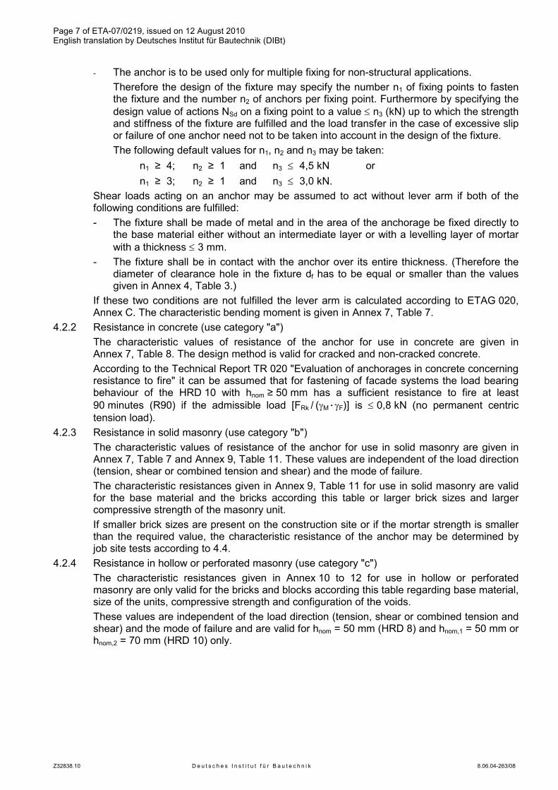
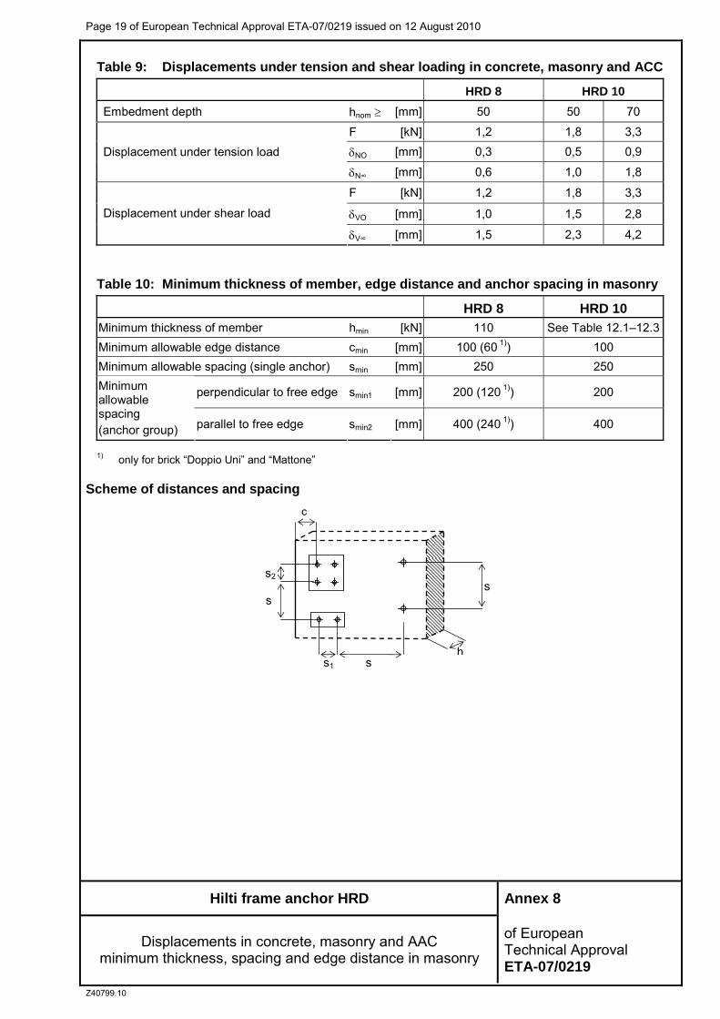