
EUROPEAN PRODUCTS CATALOGUE 2019 - AlterGrupa
467
EUROPEAN PRODUCTS CATALOGUE 2019 CONTROLS, FIELD DEVICES AND COMMERCIAL REFRIGERATION PRODUCTS
-
Upload
khangminh22 -
Category
Documents
-
view
2 -
download
0
Transcript of EUROPEAN PRODUCTS CATALOGUE 2019 - AlterGrupa

Euro
pean
pro
duct
s ca
talo
gue
2019
www.johnsoncontrols.com
EUROPEAN PRODUCTS CATALOGUE 2019CONTROLS, FIELD DEVICES AND COMMERCIAL REFRIGERATION PRODUCTS

Johnson Controls is a global diversified technology and multi industrial leader serving a wide range of customers in more than 150 countries.
Our 120,000 employees create intelligent buildings, efficient energy solutions, integrated infrastructure and next generation transportation systems that work seamlessly together to deliver on the promise of smart cities and communities. Our commitment to sustainability dates back to our roots in 1885, with the invention of the first electric room thermostat. We are committed to helping our customers win and creating greater value for all of our stakeholders through strategic focus on our buildings and energy growth platforms.

A SAFE, COMFORTABLE, AND SUSTAINABLE WORLD
g ACTUATORS AND VALVES
g SENSORS
g THERMOSTATS
g PNEUMATIC AND TRANSDUCERS
g BUILDING AUTOMATION PRODUCTS
g PENN® COMMERCIAL REFRIGERATION

HVAC CONTROL PRODUCTS
I
European Products Catalogue 2019
INDEX
ACTUATORS AND VALVES
ACTUATORS PAGE
TERMINAL UNIT VALVE ACTUATORSThermal ON/OFF control VA-7080 1
Thermal 0...10 V control VA-7090 4
Motorized floating and proportional control VA-7480 6
Non-spring return rotary actuator VA9905 8
NON-SPRING RETURN PLANT VALVE ACTUATORS
Floating and proportional control
VA-7150 9
VA-7200 10
VA-7700 11
VA7810 13
VA1125 15
FA-3000 17
RA-3000 19
ON/OFF, floating and proportional control rotary actuators for ball valves
4 Nm VA9104 21
8 and 10 Nm VA9300 23
ON/OFF, floating and proportional control rotary actuators for butterfly valves 68 - 2430 Nm VA-9070 25
VAP linear actuators for VPA pressure independent flanged valves VAP1000 - VAP3000 28
SPRING RETURN PLANT VALVE ACTUATORS
Floating and proportional control
VA7820 - VA7830 30
VA1220 - VA1420 32
FA-2000 34
ON/OFF, floating and proportional control rotary actuators for ball valves
3 Nm VA9203 36
8 Nm VA9208 38
NON-SPRING RETURN DAMPER ACTUATORS
ON/OFF, floating and proportional control
2 and 4 Nm M9102 - M9104 40
4 Nm M9304 42
8, 10, 20 and 35 Nm M9300 44
8, 16, 24 and 32 Nm M9108, M9116, M9124 and M9132 46

HVAC CONTROL PRODUCTS
II
European Products Catalogue 2019
INDEX
ACTUATORS AND VALVES
ACTUATORS PAGE
SPRING RETURN DAMPER ACTUATORS
ON/OFF, floating and proportional control
3 Nm M9203 49
8 Nm M9208 52
20 Nm M9220 54
SAFETY DAMPER ACTUATORSON/OFF control 8 Nm S9208 56
PNEUMATIC VALVE ACTUATORSMP8000 58
PA-2000 60

HVAC CONTROL PRODUCTS
III
European Products Catalogue 2019
INDEX
ACTUATORS AND VALVES
VALVES PAGE
Valves and Actuators combinations 62
TERMINAL UNIT VALVESDN10...25, PN16 VG3000 63
DN15...20, PN16 VG1600 69
DN15...20, PN16 V6W0000 71
PLANT VALVES
DN15...50, PN16VGS800 72
VG7000 74
DN15...100, PN6 and PN10 VG9000 80
DN15...150, PN16 VG8000N 83
DN15...150, PN25 VG8000H 87
DN40...150, PN16 Pressure Balanced VG8300N 91
DN15...50, PN40 VG1000 Threaded 93
DN65...150, PN16 VG1000 Flanged 96
DN25...500, PN16 VFB Butterfly Valves 100
PRESSURE INDEPENDENT VALVESDN15...32, PN25 DN40...50, PN16 VP1000 108
DN50...150, PN16 VPA 115

HVAC CONTROL PRODUCTS
IV
European Products Catalogue 2019
INDEX
SENSORS
CARBON DIOXIDE PAGE
Wall mount - CO2 and temperature transmitter CD-2xx-E00-00 117
Wall mount - CO2, relative humidity and temperature transmitter CD-3xx-E00-00 119
Duct mount - CO2 and temperature transmitter CD-Px000 121
DEW POINTHX-9100 123
DIFFERENTIAL PRESSUREDP7000 - DP2500 - DP0250 124
PLANT HUMIDITYDuct mount HT-1300 127
PLANT TEMPERATURETS-6300 129
PRESSURELiquid or air pressure transmitter PT-5217 134
ROOM HUMIDITYWall mount HT-1000 136
FLUSH MOUNT SENSORSNetwork Sensors RS-7000 138
Analog Sensors NSA-7000 140
ANALOG SENSORS
Room command module
RS-1100 142
TM-1100 144
TM-2100 146
TM-3100 148
TE-7000 150
NETWORK SENSORSNetwork room command module NS 152
WIRELESS SENSORSZigBee wireless protocol WRZ 159

HVAC CONTROL PRODUCTS
V
European Products Catalogue 2019
INDEX
THERMOSTATS
ELECTRIC FANCOIL THERMOSTAT PAGE
Stand-alone fancoil thermostatsT125-E 162
T7200 163
Modbus® fancoil thermostats T7600 165
BACnet® MS/TP thermostats T8800 167
SMART THERMOSTAT CONTROLLERSStand-alone, BACnet® MS/TP or N2 networked TEC3000 169
ANALOG ROOM CONTROLLERRoom thermostats TC-8900 - PM-8900 172
ELECTRONIC HEATING CONTROLLERDigital controller hot water and air units ER65-DRW 175
PNEUMATIC AND TRANSDUCERS
ELECTRO-PNEUMATIC TRANSDUCERS PAGEEP-1110 177
EP-2000 178
EP-8000 180

HVAC CONTROL PRODUCTS
VI
European Products Catalogue 2019
INDEX
BUILDING AUTOMATION PRODUCTS
SUPERVISOR SOFTWARE AND TOOLS PAGE
METASYS® SOFTWAREExtended Data Engine (EDE) EDE Software 182
Metasys Server Lite ADS-Lite 185
Metasys Server ADX - ADS 187
Metasys Export Utility MEU 202
System Configuration Tool SCT 204
Generator Express VMD 209
Controller Configuration Tool CCT 210
Central Plant OptimizationTM CPO10 213
SUPERVISORY AND NETWORK CONTROLLERS PAGE
METASYS® NETWORK ENGINE Network Automation Engine NAE 215
Network Integration EngineNIEx9 for Third-Party Integrations 236
NxE to NIE Migration kit 243
PROGRAMMABLE CONTROLLERS PAGE
METASYS® CONTROLLERS
Field Equipment ControllersFEC 245
FAC 252
VAV Box Controllers CVM 260
General Purpose Application Controller CGM 267
Variable air volume Modular Assembly VMA16 / VMA18 / VMA19 273
Input/Output modulesIOM 282
Romutec 288

HVAC CONTROL PRODUCTS
VII
European Products Catalogue 2019
INDEX
BUILDING AUTOMATION PRODUCTS
CONFIGURABLE FIELD CONTROLLERS PAGE
TERMINAL UNIT CONTROLLERSTerminal Unit Controller TUC03 292
Terminal Unit Controller Plus TUC03+ 295
INTEGRATED ROOM CONTROLIntegrated Room Controller IRC 3rd Edition 297
SMART EQUIPMENT CONTROLLERS PAGE
PEAKTM CONTROLLERSHVAC/R Controllers PEAKTM 301
SMART TERMINAL UNIT CONTROLLERSAdvanced Terminal Unit Controller ATC 308
VERASYS APPLICATION CONTROLLERSVAC 311
VERASYS® CONTROL SYSTEM PAGE
SUPERVISORY CONTROLLERSSmart Building Hub SBH200 317
NETWORK DISPLAYS, WEBSERVER AND GATEWAYS PAGE
MAP GATEWAYSMobile Access Portal Gateway MAP 319
FIELD ADVANCED DISPLAYFAD 323
TOUCH ADVANCED DISPLAYTAD 325

HVAC CONTROL PRODUCTS
VIII
European Products Catalogue 2019
INDEX
TEMPERATURE CONTROLS PAGE
MECHANICAL THERMOSTATSFreeze protection IP30 270XT 328
Capillary and space thermostatIP30 A19 330
IP65 A19 334
2-stage capillary and space thermostat IP30 / IP65 A28 337
3- or 4-stage thermostat A36 339
Stage room thermostat, line voltage IP20 T22 - T25 341
Rod and tube sensing element IP30 A25 343
FLOAT AND FLOW CONTROLS PAGE
MECHANICAL LIQUID FLOW SWITCH
Flow switch for liquidF61 346
F261 348
Mechanical air flow switch
Air flow switchF62 351
F262 353
MECHANICAL LIQUID LEVEL SWITCH
Liquid level float switchF63 356
F263 358
PRESSURE CONTROLS PAGE
ADJUSTABLE DIFFERENTIAL PRESSURE SWITCH
Sensitive differentialP232 360
P233 362
Differential pressure P74 364
ADJUSTABLE PRESSURE SWITCHFor air-conditioning and heat pump applications P20 366
Single pressure P735 368
Dual pressure P736 370
Single pressure IP54 P77 372
Dual pressure IP54 P78 375
PENN® COMMERCIAL REFRIGERATION

HVAC CONTROL PRODUCTS
IX
European Products Catalogue 2019
INDEX
PENN® COMMERCIAL REFRIGERATION
PRESSURE CONTROLS PAGE
FIXED SETTING PRESSURE SWITCHDirect mount pressure switch P100 378
PRESSURE SWITCHES ACCESSORIESSynthetic flexible hose H735 383
ADJUSTABLE OIL PROTECTION SWITCH
Oil protectionP28 385
P45 387
ADJUSTABLE STEAM PRESSURE SWITCHSteam pressure P48 389
MODULATING WATER VALVES PAGE
PRESSURE ACTUATED WATER VALVESRegulating valves V43/V243 391
2-way pressure actuated water valves - Commercial applications V46 394
Pressure actuated water valves, low flow V46SA 401
3-way pressure actuated water valves V48 403
Water regulating valves for high pressure refrigerants V246 - V248 405
TEMPERATURE ACTUATED WATER VALVESV47 409
ELECTRONIC EXPANSION VALVES PAGEQuick Response Expansion Valve QREV - PSHC 411

HVAC CONTROL PRODUCTS
X
European Products Catalogue 2019
INDEX
PENN® COMMERCIAL REFRIGERATION
HUMIDITY CONTROLS PAGE
MECHANICAL HUMIDITY STATRoom Humidistats W43 414
CONDENSER FAN SPEED CONTROLLERS PAGE
1-PHASE CONDENSER FAN SPEED CONTROLDirect-mount single phase controller P215PR 415
Remote-mount single phase controller P215RM 417
Condenser fan speed controller P216 419
Pressure actuated single phase digital controller P266 421
Direct-mount pressure actuated for EC motors P315PR 424
3-PHASE CONDENSER FAN SPEED CONTROLVariable Frequency Drivers VFD68 426
FIELD AND COLD ROOM CONTROLLERS PAGE
MODULAR ELECTRONIC CONTROL SYSTEMModular electronic controls System 450TM 429
ELECTRONIC CONTROL DEVICESElectronic refrigeration line ER line 432
Electronic refrigeration controllers with adaptive defrost A525 438
MULTI-STAGES CONTROL DEVICESGeneral purpose and multi-stages MS line 440
TRANSDUCERS AND SENSORS PAGE
PRESSURE TRANSDUCER
Electronic pressure transducer
P499 443
P598 445
P599 448
LEAK DETECTIONLeak detectors 452

1
European Products Catalogue 2019
ACTUATORS
ACTUATORSAND VALVES
VA-7080 THERMAL ON/OFF CONTROL
The VA-7080 Terminal Unit Valve Actuators series provide ON/OFF and DAT control in HVAC application.The compact design of these actuators make them suitable for installations in confined spaces, such as fan-coil applications.The VA-7080 Actuators are designed for field mounting onto all Johnson Controls Terminal Unit Valves: VG3000, VP1000 (see pertinent Product Bulletins).
FEATURES 24 VAC/DC and 230 VAC power supply
ON/OFF or DAT controls
NC version (stem retracts when energized)
NO version (stem extends when energized)
Easy mounting solution
Factory mounted cable 1,5 m
Models with auxiliary switch
DIMENSIONS (in mm)
47.5
52.2
44.1
50.3
7.0
VA-708x
48.4
52.2
44.3
50.3
7.0
VA-7088-2xC
TERMINAL UNIT VALVE ACTUATORS

2
European Products Catalogue 2019
ACTUATORS
ACTUATORSAND VALVES
VA-7080 TERMINAL UNIT VALVE ACTUATORS
ORDERING INFORMATION
CODES SUPP
LY V
OLT
AG
E
ACTI
ON
CO
NTR
OL
FORC
E
STRO
KE
FACTORY SETTING M
OU
NTI
NG
TH
REA
D
PRO
TECTI
ON
CLA
SS
PACK
AG
ING
POWER CONSUMPTION
AU
XIL
IARY
SW
ITCH
ES
Cont
inuo
us
Start-up
VA-7081-21
24 VAC/VDC
ON/OFF or DAT 100 N 5.0
mm
Normally closed (stem retracts
when energized) 2 m cable lenght
M28x1.5
IP54
Single packaged in carton
box
1 W
<300 mA during max 2 min.
---
VA-7088-21 M30x1.5
VA-7081-23
230 VAC
M28x1.5<550 mA during
100 ms. maxVA-7088-23 M30x1.5
VA-7080-21
24 VAC/VDCNormally open(stem extends
when energized) 2 m cable lenght
M28x1.5<300 mA during
max 2 min.VA-7087-21 M30x1.5
VA-7080-23
230 VAC
M28x1.5<550 mA during
100 ms. maxVA-7087-23 M30x1.5
VA-7088-21C 24 VAC/VDC Normally closed (stem retracts
when energized) 2 m cable lenght
M30x1.5
<300 mA during max 2 min.
VA-7088-23C 230 VAC <550 mA during 100 ms. max
ACCESSORIES (ORDER SEPARATELY)CODES DESCRIPTIONVA50 Adapter for VG6000VA64 Adapter for VP1000
SPARE PARTSCODES DESCRIPTIONVA80 Standard adapter M30 x 1.5 for VG3000 and V5000, included in the product packageVA17 Standard adapter M28 x 1.5 for VG5000 and VG4000, included in the product package

3
European Products Catalogue 2019
ACTUATORS
ACTUATORSAND VALVES
VA-7080 TERMINAL UNIT VALVE ACTUATORS
ADAPTER SELECTION GUIDE FOR JOHNSON CONTROLS VALVES
VALVE ACTUATOR ADAPTER NOTE
VG3000VA-7087-2x --- Included in the actuator packaging
VA-7088-2x --- Included in the actuator packaging
V5000VA-7087-2x --- Included in the actuator packaging
VA-7088-2x --- Included in the actuator packaging
VG6000VA-7087-2x VA50 To be ordered separately
VA-7088-2x VA50 To be ordered separately
VP1000VA-7087-2x VA64 To be ordered separately
VA-7088-2x VA64 To be ordered separately
VG5000VA-7080-2x --- Included in the actuator packaging
VA-7081-2x --- Included in the actuator packaging
VG4000VA-7080-2x --- Included in the actuator packaging
VA-7081-2x --- Included in the actuator packaging

4
European Products Catalogue 2019
ACTUATORS
ACTUATORSAND VALVES
VA-7090THERMAL 0...10 V CONTROL
The VA-709x Series Terminal Unit Valve Actuators provides Proportional Control in HVAC application.The compact design of these actuators make them suitable for installations in confined spaces, such as fan-coil applications.The VA-709x Actuators are designed for field mounting onto all Johnson Controls terminal unit valves: VG3000 and VP1000 (see pertinent bulletins). Moreover, thanks to an innovative fixing system, the VA-709x is suitable for almost all the terminal unit valves in the market.
FEATURES 24 VAC power supply
0...10 V control signal
NC version (stem retracts when energised)
NO version (stem extends when energized)
Easy mounting solution
Factory mounted cable 2 m
DIMENSIONS (in mm)
61
Ø 44
h (min)h (max)
TERMINAL UNIT VALVE ACTUATORS
H (max) H (min)
Normally closed 66 mm 59 mm
Normally open 64 mm 59 mm

5
European Products Catalogue 2019
ACTUATORS
ACTUATORSAND VALVES
VA-7090 TERMINAL UNIT VALVE ACTUATORS
ORDERING INFORMATION
CODES SUPP
LY V
OLT
AG
E
ACTI
ON
CO
NTR
OL
FORC
E
STRO
KE
FACTORY SETTING
MOUNTING THREAD PR
OTE
CTI
ON
CLA
SS
PACKAGING
POWER CONSUMPTION
Cont
inuo
us
Star
t-up
VA-7090-21
24 VAC 0...10 V 125 N 4.5 mm
Normally openM28x1.5
IP54Single
packaged in carton box
2 W 250 mAVA-7091-21 Normally closed
VA-7097-21 Normally openM30x1.5
VA-7098-21 Normally closed
ACCESSORIES (ORDER SEPARATELY)CODES DESCRIPTION PACKAGING
0550390001 Elevated Bayonet Nut M30x1.5 with normal and short insert
Single packaged in Plastic Bag0550390101 Elevated Bayonet Nut M28x1.5 with normal and short insert
0550390201 Elevated Bayonet Nut M30x1 with normal and short insert

6
European Products Catalogue 2019
ACTUATORS
ACTUATORSAND VALVES
VA-7480 MOTORIZED FLOATING AND PROPORTIONAL CONTROL
The VA-748x series provides Floating, Proportional or Proportional control with 0-10 V position feedback signal in HVAC applications. The compact design of this actuator makes it suitable for installation in confined spaces, such as fan coil, chilled ceiling, manifolds, etc.The VA-748x series actuator is designed for field mounting onto VG3000 and VP1000 terminal unit valves (see pertinent bulletin).Due to the innovative concept of different strokes setting the VA-748x can be installed over most of the terminal unit valve in the market.
FEATURES 24 VAC/VDC and 230 VAC power supply
Floating and Proportional control
Threaded nut M28x1.5 and M30x1.5
Auto stroke detection
Configurable stroke
Configurable to direct and reverse action
Configurable analog inputs
Max mechanical stroke 6.3 mm
Feedback Control
DIMENSIONS (in mm)
73.6
4980
TERMINAL UNIT VALVE ACTUATORS

7
European Products Catalogue 2019
ACTUATORS
ACTUATORSAND VALVES
VA-7480 TERMINAL UNIT VALVE ACTUATORS
ORDERING INFORMATION
CODESCONTROL
TYPEPOWER SUPPLY
RUNNING TIME
NOMINAL FORCE FA
CTO
RY S
TRO
KE
CON
FIG
URA
TIO
N
CA
BLE
LEN
GTH
MO
UN
TIN
G
THREA
D N
UT
UPP
ER M
ECH
AN
ICA
L EN
D S
TRO
KE
FEED
BACK
VA-7480-0011
Floating
24 VAC
13 sec/mm
120 N
---
1.5 m(PVC)
M28x1.5
16.3
---
VA-7481-0011 8 sec/mm
VA-7480-0001 13 sec/mm
M30x1,5VA-7481-0001 8 sec/mm
VA-7480-4001 13 sec/mm14.5
VA-7480-4003
230 VAC
13 sec/mm
VA-7480-0013 13 sec/mmM28x1.5
16.3
VA-7481-0013 8 sec/mm
VA-7480-0003 13 sec/mmM30x1,5
VA-7481-0003 8 sec/mm
VA-7482-0011
Proportional 24 VAC/VDC 8 sec/mm
M28x1.5
VA-7482-1001 3.2 mm
M30x1,5
VA-7482-2001 4.3 mm
VA-7482-3001 6.0 mm
VA-7482-5001 2.8 mm
14.5VA-7482-6001 5.3 mm
VA-7482-7001 5.8 mm
VA-7482-8201
160 N Auto stroke detection
2 m(Halogen
Free)
16.3
VA-7482-9201 14.5
VA-7483-8201 16.3
VA-7483-9201 14.5
NoteModels available with special cable lenght and reverse action factory set (Please refere to the Product Bulletin)

8
European Products Catalogue 2019
ACTUATORS
ACTUATORSAND VALVES
VA9905 NON-SPRING RETURN ROTARY ACTUATOR
This Electric Non-Spring Return Valve Actuators is designed for use with Proportional controls, and it is available for AC/DC 24 V power supplies at 50/60 Hz. The VA9905 delivers 5 Nm of running torque, and provides 60 seconds of rotation time for 90° of travel (constant for all operating conditions). VA9905 features a compact NEMA 5/IP54 actuator enclosure and dual proportion input signal.
FEATURES Proportional AC/DC 24V
Dual 0...10 Analog Input (one for cooling / one for heating)
Fool-proof mounting system ensures no mistake in installation
Pointer/handle system to manually shut off the valve for commissioning or maintenance
DIMENSIONS (in mm)
ORDERING INFORMATION
CODESCONTROL
TYPEPOWER SUPPLY
RUNNING RATE INPUT SIGNAL ENCLOSURE
VA9905-KGA-1 Proportional AC/DC 24 V 1,5°/sec 2x 0(2) to 10 V DC or 0(4) to 20 mA with field furnished 500 ohm 1/4 W resistor IP54
TERMINAL UNIT VALVE ACTUATORS

9
European Products Catalogue 2019
ACTUATORS
ACTUATORSAND VALVES
VA-7150 FLOATING AND PROPORTIONAL CONTROL
The VA-7150 series Synchronous Motor Driven Actuator provides Floating or Proportional control of valves with up to 19 mm stroke in heating, ventilation and air conditioning applications. This compact, Non-Spring Return Actuator has 500 N nominal thrust and responds to a variety of input signals. The VA-7150 series can be easily installed on site or ordered pre-fitted to VG7000 and VGS800 valve series in accordance with the specified maximum close-off pressure ratings.
FEATURES 500 N force output in a compact unit
Magnetic clutch
Unique Yoke design
Coupler for simple Actuator attachment to Flanged Valves
Positioner with adjustable starting point and span, reverse and direct action modes
“Signal fail” safe position
DIMENSIONS (in mm)
IP40
153
80 Ø 97.5
NON-SPRING RETURN PLANT VALVE ACTUATORS
ORDERING INFORMATION
CODESSUPPLY VOLTAGE
(50/60 Hz) ACTION CONTROLPROTECTION
CLASSCOUPLER
TYPE
VA-7150-1001 24 VACFloating
IP40 ThreadedVA-7150-1003 230 VAC
VA-7152-1001 24 VAC Proportional 0...10 V

10
European Products Catalogue 2019
ACTUATORS
ACTUATORSAND VALVES
VA-7200 FLOATING AND PROPORTIONAL CONTROL
The VA-720x Series Synchronous Motor Driven Actuator provides Floating or Proportional control of valves, with up to 19 mm stroke in heating, ventilation and air conditioning applications.This compact Non-Spring Return Actuator has a 1000N nominal force and responds to a variety of input signals. The VA-7200 series can be easily field mounted or ordered factory coupled to VG7000 series valves in accordance with the specified maximum close-off pressure ratings.
FEATURES 1000N force output compact unit
Magnetic clutch
Signal fail ”safe position”
DIMENSIONS (in mm)
IP42 IP40
106 100
120
78
106 100
147
78
ORDERING INFORMATION
CODESSUPPLY VOLTAGE
(50/60 Hz) CONTROL MOTOR RATING PROTECTION CLASS
VA-7200-100124 VAC
Floating 5 W IP42
VA-7202-1001 Proportional 0...10 VDC / 0(4)...20 mA
NON-SPRING RETURN PLANT VALVE ACTUATORS

11
European Products Catalogue 2019
ACTUATORS
ACTUATORSAND VALVES
VA-7700 FLOATING AND PROPORTIONAL CONTROL
The VA-7700 series provides Floating and Proportional control and can be mounted onto VG7000, VGS800 and VG9000 valves.
FEATURES 24 VAC and 230 VAC power supply
Floating and proportional control
Manual override
LED operating status display
Self calibrating
IP54 enclosive protection
DIMENSIONS (in mm)
NON-SPRING RETURN PLANT VALVE ACTUATORS

12
European Products Catalogue 2019
ACTUATORS
ACTUATORSAND VALVES
VA-7700 NON-SPRING RETURN PLANT VALVE ACTUATORS
ORDERING INFORMATION
MOUNTING ONTO VG7000 SERIES VALVES
CODES
SUPPLY VOLTAGE (50/60HZ)
ACTION CONTROL FORCE STROKE
FULL STROKE
TIMEPROTECTION
CLASSPOWER
CONSUMPTIONVA-7700-1001 24 VAC
Floating
500 N 20 mm 190 s IP54
2.4 VAVA-7700-1003 230 VAC
VA-7740-1001 24 VAC
VA-7740-1003 230 VAC
VA-7706-100124 VAC Proportional 4.4 VA
VA-7746-1001
MOUNTING ONTO VGS8000 AND VG9000 SERIES VALVES
CODES
SUPPLY VOLTAGE (50/60 Hz)
ACTION CONTROL FORCE STROKE
FULL STROKE
TIMEPROTECTION
CLASSPOWER
CONSUMPTION
VA-7700-8201 24 VAC
Floating
500 N 20 mm 190 s IP54
2.4 VAVA-7700-8203 230 VAC
VA-7740-8201 24 VAC
VA-7740-8203 230 VAC
VA-7706-820124 VAC Proportional 4.4 VA
VA-7746-8201

13
European Products Catalogue 2019
ACTUATORS
ACTUATORSAND VALVES
VA7810 FLOATING AND PROPORTIONAL CONTROL
The VA7810 Non Spring Return Actuator with 1000 N thrust for valves in heating, ventilation and air conditioning applications is available for Floating or Proportional control. All models have manual override as standard and provide stroke capabilities of 7 mm to 25 mm. Proportional models are self-calibrating. The actuator is intended for use with Johnson Controls VG7000 and VGS800 threaded valves as well as VG8000 and VG9000 flanged valves. All valves should be fitted in accordance with the maximum close-off pressure ratings specified. Valve/actuators can be ordered as separate units or as a factory fitted valve/actuator combinations.
FEATURES Proportional Actuators are self calibrating
All models can also be used as floating and ON/OFF Actuators
Force controlled motor shut-off
Manual override as standard
IP54 enclosure protection
Delivered with fitted 1.5 m cable and wire terminals
Status LED
Models with optional aux. switches or 2 kΩ feedback potentiometer
Control-Signal failure - stem to pre-determined position
Stroke position indicator
NON-SPRING RETURN PLANT VALVE ACTUATORS

14
European Products Catalogue 2019
ACTUATORS
ACTUATORSAND VALVES
VA7810 NON-SPRING RETURN PLANT VALVE ACTUATORS
DIMENSIONS (in mm)
231
150 min.212 115
ORDERING INFORMATION MOUNTING ONTO VG7000 AND VGS800 THREADED VALVES
CODES
SUPPLY VOLTAGE (50/60 Hz)
ACTION CONTROL FORCE STROKE
FULL STROKE TIME PR
OTE
CTI
ON
CLA
SSPO
WER
CO
NSU
MPT
ION
SPRING RETURN ACTION
ACCESSORIES FACTORY MOUNTED
VA7810-ADA-11230 VAC
ON/OFF or Floating
1000 N 25 mm
150 s
IP54
8 VA
---
---
VA7810-ADC-11 2 aux switches
VA7810-AGA-11
24 VAC
3 VA
---
VA7810-AGC-11 2 aux switches
VA7810-AGH-11 2 KΩ pot
VA7810-GGA-11 ON/OFF, Floating or Proportional
150 s (selectable 75 s) 6 VA
---
VA7810-GGC-11 2 aux switches
MOUNTING ONTO VG8000 AND VG9000 FLANGED VALVES
CODES
SUPPLY VOLTAGE (50/60 Hz)
ACTION CONTROL FORCE STROKE
FULL STROKE TIME PR
OTE
CTI
ON
CLA
SSPO
WER
CO
NSU
MPT
ION
SPRING RETURN ACTION
ACCESSORIES FACTORY MOUNTED
VA7810-ADA-12230 VAC
ON/OFF or Floating
1000 N 25 mm
150 s
IP54
8 VA
---
---
VA7810-ADC-12 2 aux switches
VA7810-AGA-12
24 VAC
3 VA
---
VA7810-AGC-12 2 aux switches
VA7810-AGH-12 2 KΩ pot
VA7810-GGA-12 ON/OFF, Floating or Proportional
150 s (selectable 75 s) 6 VA
---
VA7810-GGC-12 2 aux switches

15
European Products Catalogue 2019
ACTUATORS
ACTUATORSAND VALVES
VA1125 FLOATING AND PROPORTIONAL CONTROL
The VA1125 Valve Actuators are used to control Valves in HVAC systems. They are of modular construction so that the required type of control signal is achieved simply by fitting a module with the required function in-situ. It can be mounted onto VG8000, VG8300 and VG9000 series valves.
FEATURES 24 VAC and 230 VAC power supply
Floating and Proportional control
Manual override
Automatic stem coupling
Actuator fixed to valve with one ring nut
Self adjusting, automatic stroke adjustment, calibrated pressure control at the end positions
2 auxiliary switches, feedback potentiometer and split range unit available
IP66
Selectable characteristic curve
Selectable running time
NON-SPRING RETURN PLANT VALVE ACTUATORS

16
European Products Catalogue 2019
ACTUATORS
ACTUATORSAND VALVES
VA1125 NON-SPRING RETURN PLANT VALVE ACTUATORS
DIMENSIONS (in mm)
262.5
90
230
111.4
14
18.5
134
75.5 60
ORDERING INFORMATION
CODES 24 V ACTUATORSPOWER
CONSUMPTIONPROTECTION
CLASSNOMINAL STROKE
VA1125-GGA-1 2500N; Non-Spring Return 20.5 VA IP66 49 mm
ACCESSORIES MODULES FOR ON SITE INSTALLATION
CODES DESCRIPTION
VA1000-M230N AC 230 V module
VA1000-P2 2 KΩ feedback potentiometer
VA1000-S2 2 SPDT auxiliary switches
VA1000-EP Extension kit for applications with temperatures greater than 140°C up to 200°C

17
European Products Catalogue 2019
ACTUATORS
ACTUATORSAND VALVES
FA-3000 FLOATING AND PROPORTIONAL CONTROL
The FA-3300 heavy duty series provides Floating or Proportional control and can be mounted with VG8000 flanged valves.
FEATURES 24 VAC and 230 VAC power supply
Floating and Proportional control
Manual override
Special clamp coupler
Uses synchronous motor with calibrated pressure limit switches
DIMENSIONS (in mm)
ø 130ø 54.1
10
ø 54
200
ø 145 156
316
60100
NON-SPRING RETURN PLANT VALVE ACTUATORS

18
European Products Catalogue 2019
ACTUATORS
ACTUATORSAND VALVES
FA-3000 NON-SPRING RETURN PLANT VALVE ACTUATORS
ORDERING INFORMATION
CODES
SUPPLY VOLTAGE (50/60 Hz)
ACTION CONTROL FORCE STROKE
FULL STROKE
TIMEPROTECTION
CLASSPOWER
CONSUMPTION
ACCESSORIES FACTORY MOUNTED
FA-3300-7416
24 VACFloating
6000 N42 mm
(max 45)150 s IP65
37 VA---
FA-3303-7416 2 aux switches and 2 KW pot
FA-3341-7416 Proportional 42 VA 2 aux switches
FA-3300-7411230 VAC Floating 37 VA
---
FA-3303-7411 2 aux switches and 2 KW pot

19
European Products Catalogue 2019
ACTUATORS
ACTUATORSAND VALVES
RA-3000 FLOATING AND PROPORTIONAL CONTROL
The RA-3000 Series Synchronous Motor-Driven Reversible Actuators are available for floating or with electric positioner for 0...10 V control. They feature factory calibrated pressure switches to provide specified close-off ratings. These actuators are available in three sizes with 1600 N, 1800 N and with 3000 N nominal force and can be used with VG8000 and VG9000 series valves according to maximum close-off pressure ratings specified. Factory fitted options, such as 2kOhm feedback potentiometer, auxiliary switches and hand crank are available.
FEATURES Uses synchronous motor with pressure switches
Special clamp coupler quick-fit systems
Models for floating and proportional 0...10 VDC control
Positioner with adjustable starting point, span, and direct/reverse action
Active 0...10 VDC position feedback on proportional models
Optional auxiliary switches and feedback potentiometer available
Optional hand crank
DIMENSIONS (in mm)
100160
155
307
186 x 166
NON-SPRING RETURN PLANT VALVE ACTUATORS

20
European Products Catalogue 2019
ACTUATORS
ACTUATORSAND VALVES
RA-3000 NON-SPRING RETURN PLANT VALVE ACTUATORS
ORDERING INFORMATION
FOR FLOATING CONTROL
CODES HAND CRANK ACTUATOR FORCE SUPPLY VOLTAGE NOMINAL STROKE PROTECTION CLASS
RA-3000-7226 ---
1800 N
24 V, 50/60 Hz
25 mm
IP54
RA-3100-7226
RA-3000-7227 ---230 V, 50/60 Hz
RA-3100-7227
RA-3000-7325 ---
3000 N
24 V, 60 Hz
42 mm
RA-3100-7325
RA-3000-7326 ---24 V, 50 Hz
RA-3100-7326
RA-3000-7327 ---230 V, 50 Hz
RA-3100-7327
FOR FLOATING CONTROL, WITH 2 AUXILIARY SWITCHES AND 2 K Ohm FEEDBACK POTENTIOMETER
CODES HAND CRANK ACTUATOR FORCE SUPPLY VOLTAGE NOMINAL STROKE PROTECTION CLASS
RA-3003-7226 ---
1800 N
24 V, 50/60 Hz
25 mm
IP54
RA-3103-7226
RA-3003-7227 ---230 V, 50/60 Hz
RA-3103-7227
RA-3003-7325 ---
3000 N
24 V, 60 Hz
42 mm
RA-3103-7325
RA-3003-7326 ---24 V, 50 Hz
RA-3103-7326
RA-3003-7327 ---230 V, 50 Hz
RA-3103-7327
FOR PROPORTIONAL CONTROL WITH BUILT-IN POSITIONER 0...10 VDC AND 2 AUXILIARY SWITCHES
CODES HAND CRANK ACTUATOR FORCE SUPPLY VOLTAGE NOMINAL STROKE PROTECTION CLASS
RA-3041-7226 ---1800 N 24 V, 50/60 Hz 25 mm
IP54
RA-3141-7226
RA-3041-7325 ---
3000 N
24 V, 60 Hz
42 mmRA-3141-7325
RA-3041-7326 ---24 V, 50 Hz
RA-3141-7326

21
European Products Catalogue 2019
ACTUATORS
ACTUATORSAND VALVES
VA9104 4 Nm, ON/OFF, FLOATING AND PROPORTIONAL CONTROL ROTARY ACTUATORS FOR BALL VALVES
The Electric Actuator Series have been developed for operation of ball valves.These synchronous, motor driven actuators are used to provide accurate positioning on VG1000 series DN15, DN20 and DN25 Ball Valves.
FEATURES ON/OFF, Floating with timeout and Proportional control
Load-independent running time
Up to 5 Actuators in parallel operation possible
Manual release button
1.2 m PVC cable
Selectable direction of rotation
Automathic shut-off at end position
DIMENSIONS (in mm)
NON-SPRING RETURN PLANT VALVE ACTUATORS
89
71140
Minimum Clearance Required

22
European Products Catalogue 2019
ACTUATORS
ACTUATORSAND VALVES
VA9104 NON-SPRING RETURN PLANT VALVE ACTUATORS
ORDERING INFORMATION
CODES RUNNING TIME CONTROL SIGNALS SUPPLY VOLTAGE (50/60 Hz)
VA9104-AGA-1S
72 s
Floating without timeout24 VAC
VA9104-IGA-1SON/OFF and Floating with timeout
VA9104-IUA-1S 100 to 240 VAC
VA9104-GGA-1S Proportional 0(2)...10 VDC 0(4)...20 mA 24 VAC

23
European Products Catalogue 2019
ACTUATORS
ACTUATORSAND VALVES
VA9300 8, 10, 20 AND 35 Nm, ON/OFF, FLOATING AND PROPORTIONAL CONTROL ROTARY ACTUATORS FOR BALL VALVES
The VA9300 Series Electric Non Spring Return Actuators are used to provide accurate positioning on Johnson Controls® VG1000 Series DN15 up to DN150 Ball Valves in Heating, Ventilating and Air Conditioning (HVAC) applications.
FEATURES Automatic models with signal input detection model: On/Off, Floating and Proportional
High speed actuator models
Line voltage models
Optional auxiliary switch & potentiometer feedback
Direct-Coupled Design
Rugged IP54 Rated Enclosure
Electronic stall detection
Microprocessor-controlled Brushless DC Motor
DIMENSIONS (in mm)
163
89
80 103
254
112
NON-SPRING RETURN PLANT VALVE ACTUATORS

24
European Products Catalogue 2019
ACTUATORS
ACTUATORSAND VALVES
VA9300 NON-SPRING RETURN PLANT VALVE ACTUATORS
ORDERING INFORMATION
CODESTORQUE
(Nm)RUNNING TIME
(s) CONTROL SIGNALS SUPPLY VOLTAGE (50/60 Hz)
VA9308-AGA-1Z 8 8ON/OFF and Floating
24V AC/DC
VA9310-AUA-1
10
90
100 to 240 VACVA9310-GUA-1
ON/OFF, Floating and ProportionalVA9310-HGA-1 24V AC/DC
VA9320-AUA-1
20
ON/OFF and Floating100 to 240 VAC
VA9320-GUA-1ON/OFF, Floating and Proportional
VA9320-HGA-1 24V AC/DC
VA9335-AUA-1
35
ON/OFF and Floating100 to 240 VAC
VA9335-GUA-1ON/OFF, Floating and Proportional
VA9335-HGA-1 24V AC/DC
Note Available in Spring 2019
ACCESSORIES (ORDER SEPARATELY)CODES DESCRIPTION
M9000-342 NEMA 4X, IP66 Weathershield (quantity 1)
M9000-561 Thermal Barrier Kit for low pressure steam application (quantity 1)
M9000-606 Position indicator (quantity 5)
M9300-1 Auxiliary Switch Kit (one single-pole, double-throw)
M9300-2 Auxiliary Switch Kit (two single-pole, double-throw)
M9300-100 Threaded Conduit Adapters for 12.7 mm electrician’s fittings (quantity 5)
M9300-140 External Feedback Potentiometer 140k Ohm
M9300-1K External Feedback Potentiometer 1k Ohm
M9300-2K External Feedback Potentiometer 2k Ohm
M9300-10K External Feedback Potentiometer 10k Ohm
M9310-500 Ball Valve Linkage Kit for applying M9310 Series Electric Actuators to VG1000 Series Valves (quantity 1)
*
******
*

25
European Products Catalogue 2019
ACTUATORS
ACTUATORSAND VALVES
VA-9070 68 - 2030 Nm, ON/OFF, FLOATING AND PROPORTIONAL CONTROL ROTARY ACTUATORS FOR BUTTERFLY VALVES
The Actuator is specially developed for use with VFB Butterfly Valves in the HVAC industry. These bidirectional actuators are direct mounted on VFB Valves without any linkage. A single VA-9070 provides 68, 226, 339, 565, 734, 1470, 2030 Nm torque depending on the model.With a power supply of 24 VAC or 230 VAC the actuators can be controlled in ON/OFF, Floating or Proportional configuration. Two isolated auxiliary switches and an electrical heater are standard in these series. The protection class is IP65 to ensure a dust-proof and shower-proof from all angles.An hand operation is standard. When hand operation is active, a yellow ring is displayed and the actuator motor is not operative. The position indicator is clearly recognizable all around.The opening and closing speed is independently adjustable in the proportional application.
FEATURES Exact positioning ensures precise flow control
Complete opening and closing from 100% to 0
Range from 68 Nm to 2030 Nm
Self-regulating heater as standard
Construction optimized for operation with butterfly valves
Two isolated auxiliary switches as standard
NON-SPRING RETURN PLANT VALVE ACTUATORS

26
European Products Catalogue 2019
ACTUATORS
ACTUATORSAND VALVES
VA9070 NON-SPRING RETURN PLANT VALVE ACTUATORS
DIMENSIONS (in mm)
VALVES WITH VA-9072 / VA-9075 / VA-9077 / VA-9078 ACTUATORS ØG H
J
41
F
CODES F G H J S T R U TOP FLANGE
VA-9072 130 191 142 48 --- --- --- --- F07
VA-9075 165 257 198 64 --- --- --- --- F07/F12
VALVES WITH VA-907A / VA-907B ACTUATORS
ØGTS
F
ØR
J
U
H
CODES F G H J S T R U TOP FLANGE
VA-9077 / VA-9078 183 307 241 74 --- --- --- --- F12/F16
VA-907A / VA-907B 317 307 241 206 155 323 305 203 F12/F16

27
European Products Catalogue 2019
ACTUATORS
ACTUATORSAND VALVES
VA9070 NON-SPRING RETURN PLANT VALVE ACTUATORS
ORDERING INFORMATION
CODES TORQUE POWER SUPPLY CONTROLS
VA-9072-13
68 Nm
24 VACProportional control
VA-9072-14 ON/OFF and Floating control
VA-9072-23230 VAC
Proportional control
VA-9072-24 ON/OFF and Floating control
VA-9075-13
226 Nm
24 VACProportional control
VA-9075-14 ON/OFF and Floating control
VA-9075-23230 VAC
Proportional control
VA-9075-24 ON/OFF and Floating control
VA-9077-13565 Nm 24 VAC
Proportional control
VA-9077-14 ON/OFF and Floating control
VA-9078-23735 Nm
230 VAC
Proportional control
VA-9078-24 ON/OFF and Floating control
VA-907A-231470 Nm
Proportional control
VA-907A-24 ON/OFF and Floating control
VA-907B-232034 Nm
Proportional control
VA-907B-24 ON/OFF and Floating control

28
European Products Catalogue 2019
ACTUATORS
ACTUATORSAND VALVES
VAP1000-VAP3000 VAP LINEAR ACTUATORS FOR VPA PRESSURE INDEPENDENT FLANGED VALVES
The VAP Actuators have been specifically designed to drive the VPA Pressure Independent Valve. They provide 1000N or 3000N according with the valve dimensions. The actuators are used to control the valve and to set the maximum desired flow.
FEATURES Linear actuator with high control accuracy provides the equal percentage flow curve
Actuator has manual function that allows for manual positioning of the Valve
The potentiometer on the actuator is use to set the maximun flow of the VPA Valve
They provide 1000N or 3000N according with the valve dimensions.
In the VAP300-24-C model, a led display gives several function information
0-10 VDC or 4-20 mA setpoint and feedback
ORDERING INFORMATION
CODES FORCEPOWER SUPPLY CONTROL SIGNAL
MANUAL OVERRIDE RUNNING SPEED
WEIGHT (kg)
VAP1000-24-C 1000N 24 VAC 0(2) ~ 10 V, 0(4)~20 mA 3.85 s/mm 1.7
VAP3000-24-C 3000N 24 VAC 0(2) ~ 10 V, 0(4)~20 mA 3.2 s/mm 5.2
NON-SPRING RETURN PLANT VALVE ACTUATORS

29
European Products Catalogue 2019
ACTUATORS
ACTUATORSAND VALVES
VAP NON-SPRING RETURN PLANT VALVE ACTUATORS
VAP1000-24-C VAP3000-24-C
111
0 0
1 1
0
1
0
1
230 234
128
111
120
8464
60
180
220
330
60
64104
160
225190
Stroke42 mm max
DIMENSIONS (in mm)

30
European Products Catalogue 2019
ACTUATORS
ACTUATORSAND VALVES
SPRING RETURN PLANT VALVE ACTUATORS
VA7820 - VA7830 FLOATING AND PROPORTIONAL CONTROL
The VA78x0 Spring Return Actuator with 1000 N thrust for valves in Heating, Ventilation and Air Conditioning applications is available for Floating or Proportional control. All models have manual override as standard and provide stroke capabilities of 7 mm to 25 mm. Proportional models are self-calibrating.The actuator is intended for use with Johnson Controls VG7000 and VGS800 threaded valves as well as VG8000 and VG9000 flanged valves. All valves should be fitted in accordance with the maximum close-off pressure ratings specified. Valve/actuators can be ordered as separate units or as a factory fitted valve/actuator combinations.
FEATURES Proportional Actuators are self calibrating
All models can also be used as floating and ON/OFF actuators
Force controlled motor shut-off
Manual override as standard
IP54 enclosure protection
Delivered with fitted 1.5 m cable and wire terminals
Status LED
Control-Signal failure - stem to pre-determined position
Stroke position indicator
Spring return functions

31
European Products Catalogue 2019
ACTUATORS
ACTUATORSAND VALVES
VA7800 SPRING RETURN PLANT VALVE ACTUATORS
231
150 min.212 115
DIMENSIONS (in mm)
ORDERING INFORMATION
CODES SUPP
LY V
OLT
AG
E (5
0/60
Hz)
ACTI
ON
CO
NTR
OL
FORC
E
STRO
KE
FULL
STR
OK
E TI
ME
PRO
TECTI
ON
CLA
SS
POW
ER
CON
SUM
PTIO
N
SPRIN
G R
ETU
RN
A
CTI
ON
ACC
ESSO
RIE
S FA
CTO
RY M
OU
NTE
DActuator with threaded coupler for VG7000 valves
VA7820-GGA-11
24 VACON/OFF,
Floating or Proportional
1000 N 25 mm 150 s (selectable 75 s) IP54 11 VA
Actuator stem retracts
---
VA7820-GGC-11 2 aux switches
VA7830-GGA-11 Actuator stem extend
---
VA7830-GGC-11 2 aux switches
Actuator with clamp coupler for VG8000 and VG9000 valves
VA7820-GGA-12
24 VACON/OFF,
Floating or Proportional
1000 N 25 mm 150 s (selectable 75 s) IP54 11 VA
Actuator stem retracts
---
VA7820-GGC-12 2 aux switches
VA7830-GGA-12 Actuator stem extend
---
VA7830-GGC-12 2 aux switches

32
European Products Catalogue 2019
ACTUATORS
ACTUATORSAND VALVES
SPRING RETURN PLANT VALVE ACTUATORS
VA1220 - VA1420 FLOATING AND PROPORTIONAL CONTROL
The VA1220 - VA1420 Valve Actuators are used to control valves in HVAC systems. They are of modular construction so that the required type of control signal is achieved simply by fitting a module with the required function in-situ. It can be mounted onto VG8000 and VG9000 series valves.
FEATURES 24 VAC and 230 VAC power supply
Floating and Proportional control
Manual override
Automatic stem coupling
Actuator fixed to valve with one ring nut
Self adjusting, automatic stroke adjustment, calibrated pressure control at the end positions
2 auxiliary switches, feedback potentiometer and split range unit available
IP66
Selectable characteristic curve
Selectable running time

33
European Products Catalogue 2019
ACTUATORS
ACTUATORSAND VALVES
262.5
90
230
111.4
14
18.5
134
75.5 60
VA1x20 SPRING RETURN PLANT VALVE ACTUATORS
DIMENSIONS (in mm)
ORDERING INFORMATION
CODES 24 V ACTUATORSPOWER
CONSUMPTIONPROTECTION
CLASSNOMINAL STROKE
VA1220-GGA-1 2000N; Spring return retracts 17 VA IP66 49 mm
VA1420-GGA-1 2000N; Spring return extends
ACCESSORIES MODULES FOR IN-SITU INSTALLATION
CODES DESCRIPTION
VA1000-M230N AC 230 V module
VA1000-P2 2 KΩ feedback potentiometer
VA1000-S2 2 SPDT auxiliary switches
VA1000-EP Extension kit for applications with temperatures greater than 140°C up to 200°C

34
European Products Catalogue 2019
ACTUATORS
ACTUATORSAND VALVES
SPRING RETURN PLANT VALVE ACTUATORS
FA-2000 FLOATING AND PROPORTIONAL CONTROL
The FA-2000 Series Electric Actuators are available for floating or with electronic positioner for 0…10 V or 0…20 mA control. It provides a fully variable valve aperture, a power failure spring return safety mechanism and an electrically operated manual override. Three models of the FA-2000 are available. The FA-22 (“failsafe” position down = stem fully extended) and FA-25 (“failsafe” position up = stem fully retracted): this model pair has a 25 mm stroke and a minimum of 2400 N thrust. The FA-23 (“failsafe” position down) and FA-26 (“failsafe” position up): this model pair has a 42 mm stroke of and a minimum thrust of 2200 N.The actuator can be combined with VG8000 series in accordance with the maximum close-off pressure ratings specified. The FA-2000, when delivered as a single unit, is pre-set to facilitate installation with minimum adjustment; it is also available with a variety of options such as auxiliary switches and feedback potentiometers.
FEATURES Power failure mechanism (spring return)
Visible calibration ring on stem coupling
Positioner with adjustable starting point, span and direct/reverse action
Electrically operated manual override
Quick-fit coupling clamp

35
European Products Catalogue 2019
ACTUATORS
ACTUATORSAND VALVES
FA-2000 SPRING RETURN PLANT VALVE ACTUATORS
DIMENSIONS (in mm)
Ø 54
162
Ø 120
A
ORDERING INFORMATION
CODES SUPP
LY V
OLT
AG
E (5
0 H
z)
ACTION CONTROL
SPRING RETURN FUNCTION
BUILT-IN ELECTRONIC POSITIONER N
OM
INA
L TH
RU
ST
NO
MIN
AL
STRO
KE
PRO
TECTI
ON
CLA
SS
POW
ER
CON
SUM
PTIO
N
EMER
GEN
CY
SH
UT
OF
SPEE
DFA-2200-7516
24 VACFloating
and Proportional
Stem fully extended
---
2.4 kN 25 mm
IP54 6.1 VA
≤ 81FA-2500-7516 Stem fully retracted
FA-2300-7416 Stem fully extended2.2 kN 42 mm ≤ 201
FA-2600-7416 Stem fully retracted
FA-2240-7516 Stem fully extended
0...10 V / 0(4)...20 mA
2.4 kN 25 mm ≤ 81FA-2540-7516 Stem fully retracted
FA-2340-7416 Stem fully extended2.2 kN 42 mm ≤ 201
FA-2640-7416 Stem fully retracted
FA-2241-7516 Stem fully extended0...10 V /
0(4)...20 mA and 2 auxiliary
switches
2.4 kN 25 mm ≤ 81FA-2541-7516 Stem fully retracted
FA-2341-7416 Stem fully extended2.2 kN 42 mm ≤ 201
FA-2641-7416 Stem fully retracted
AWITHOUT
POSITIONERWITH
POSITIONERFA-22 / FA-25 541 586
FA-23 / FA-26 575 612

36
European Products Catalogue 2019
ACTUATORS
ACTUATORSAND VALVES
SPRING RETURN PLANT VALVE ACTUATORS
VA9203 3 Nm, ON/OFF, FLOATING AND PROPORTIONAL CONTROL ROTARY ACTUATORS FOR BALL VALVES
The VA9203 Series Electric Spring Return Actuators are direct-mount actuators.These bidirectional actuators are used to provide accurate positioning on Johnson Controls® VG1000 Series DN15 up to DN25 Ball Valves in Heating, Ventilating and Air Conditioning (HVAC) applications. One Integral line voltage auxiliary switch, available only on the VA9203-xxB-1(Z) models, indicate end-stop position, or perform switching functions within the selected rotation range.A graduated scale from 0% to 100% and a position indicator provide visual indication of the valve’s opening. When power fails during service, the mechanical spring return system open or close the valve ports.The series includes the following control options:
ON/OFF, 24 V AC/DC, 100 to 240 VAC power
ON/OFF and floating point, 24 V AC/DC power
Proportional, 24 V AC/DC power, for 0(2) to 10 VDC or 0(4) to 20 mA control
FEATURES 3 Nm rated torque
Mechanical Spring Return System
Direct-coupled design
Reversible mounting
Rugged IP54 rated enclosure
Electronic stall detection
Double-insulated construction
Microprocessor controlled brushless DC Motor (-AGx and -GGx models)
External mode selection switch (-AGx and -GGx models)
Integral cables with colored and numbered conductors
Optional integrated auxiliary switch
Override control (proportional models only)
UL, CE, and C-Tick Compliance
Manufacturing under International Standards Organization (ISO) 9001 Quality Control Standards

37
European Products Catalogue 2019
ACTUATORS
ACTUATORSAND VALVES
VA-9203 SPRING RETURN PLANT VALVE ACTUATORS
82 73
89
DIMENSIONS (in mm)
ORDERING INFORMATION
CODES TORQUERUNNING TIME
CONTROL SIGNALSSUPPLY VOLTAGE
(50/60 Hz)1
AUXILIARY SWITCHMotor Spring
VA9203-GGA-1Z
3 Nm
90 s 12...17 s
Proportional
24 V AC/DC
---
VA9203-GGB-1Z
VA9203-AGA-1ZON/OFF and Floating
---
VA9203-AGB-1Z
VA9203-BGA-1
53...71 s 19...23 s ON/OFF
---
VA9203-BGB-1
VA9203-BUA-1100 to 230 VAC
---
VA9203-BUB-1
ACCESSORIES (ORDER SEPARATELY)CODES DESCRIPTION
M9000-560 Ball valve linkage kit for applying M9203 and M9208 series actuators to VG1000 series valves (quantity 1)
M9000-561 Thermal barrier extends M(VA)9104, M(VA)9203 and M(VA)9208 series electric spring return actuator applications to include low pressure steam (quantity 1)
M9000-342 Weathershield kit for VG1000 series ball valve application of M(VA)9104, M(VA)9203 and M(VA)9208 series electric spring return actuators (quantity 1)
M9000-607 Position indicator for VG1000 series ball valve applications (quantity 5)

38
European Products Catalogue 2019
ACTUATORS
ACTUATORSAND VALVES
SPRING RETURN PLANT VALVE ACTUATORS
VA9208 8 Nm, ON/OFF, FLOATING AND PROPORTIONAL CONTROL ROTARY ACTUATORS FOR BALL VALVES
The VA9208 Series Electric Spring Return Actuators are direct-mount actuators.These bidirectional actuators are used to provide accurate positioning on Johnson Controls® VG1000 Series DN32 up to DN50 Ball Valves in Heating, Ventilating and Air Conditioning (HVAC) applications. Two integral line voltage auxiliary switches are available only on the VA9208-xxC-1 models, indicate end-stop position, or perform switching functions within the selected rotation range.A graduated scale from 0% to 100% and a position indicator provide visual indication of the valve’s opening. When power fails during service, the mechanical spring return system open or close the valve ports.The series includes the following control options:
ON/OFF, 24 V AC/DC, 230 V AC power
ON/OFF and floating control, 24 V AC/DC power
Proportional, 24 V AC/DC power, for 0(2) to 10 VDC or 0(4) to 20 mA control
FEATURES 8 Nm rated torque
Mechanical Spring Return System
Direct-coupled design
Reversible mounting
Rugged IP54 rated enclosure
Electronic stall detection
Double-insulated construction
Microprocessor controlled brushless DC motor (-AGx and -GGx models)
External mode selection switch (-AGx and -GGx models)
Integral cables with colored and numbered conductors
Optional integrated auxiliary switches
UL, CE, and C-Tick Compliance
Manufacturing under International Standards Organization (ISO) 9001 Quality Control Standards

39
European Products Catalogue 2019
ACTUATORS
ACTUATORSAND VALVES
VA-9208 SPRING RETURN PLANT VALVE ACTUATORS
DIMENSIONS (in mm)
99 73
Clearance required
ORDERING INFORMATION
CODES TORQUERUNNING TIME
CONTROL SIGNALSSUPPLY VOLTAGE
(50/60 Hz)2
AUXILIARY SWITCHMotor Spring
VA9208-GGA-1
8 Nm
150 s 17...25 s
Proportional
24 V AC/DC
---
VA9208-GGC-1
VA9208-AGA-1ON/OFF and Floating
---
VA9208-AGC-1
VA9208-BGA-1
53...71 s 13...26 s ON/OFF
---
VA9208-BGC-1
VA9208-BDA-1230 VAC
---
VA9208-BDC-1
ACCESSORIES (ORDER SEPARATELY)CODES DESCRIPTION
M9000-560 Ball valve linkage kit for applying M9203 and M9208 series actuators to VG1000 series valves (quantity 1)
M9000-561 Thermal barrier extends M(VA)9104, M(VA)9203 and M(VA)9208 series electric spring return actuator applications to include low pressure steam (quantity 1)
M9000-342 Weathershield kit for VG1000 series ball valve application, IP54
M9000-607 Position Indicator for VG1000 Series ball valve applications (quantity 5)

40
European Products Catalogue 2019
ACTUATORS
ACTUATORSAND VALVES
20
104
71
131
28 14
5
57 52
36
32
NON-SPRING RETURN DAMPER ACTUATORS
M9102-M9104 2 AND 4 Nm, ON/OFF, FLOATING AND PROPORTIONAL CONTROL
The small family Electric Damper Actuator Series have been developed to operate small air dampers in Ventilation and Air Conditioning Systems. The compact design make this actuator highly versatile.
FEATURES Floating, ON/OFF and Proportional control
Load-independent running time
Up to 5 Actuators in parallel operation possible
Actuators available with PVC cable or with plug-in terminal block connection
Simple direct mounting with universal adapter for fitting to Ø 8...13 mm or with 8...10 mm square shaft. 45 mm minimum shaft length
Selectable direction of rotation
Manual release button
DIMENSIONS (in mm)
Max13 mm
Max10 mm
Adapter

41
European Products Catalogue 2019
ACTUATORS
ACTUATORSAND VALVES
M9102/M9104 NON-SPRING RETURN DAMPER ACTUATORS
ORDERING INFORMATION
CODES TORQUERUNNING
TIME CONTROL SIGNALSSUPPLY VOLTAGE
(50/60 Hz) CONNECTION
M9102-AGA-1S
2 Nm 36 s
Floating without timeout
AC 24 V
PVC-cable
M9102-AGA-5S Terminal block
M9102-IGA-1S ON/OFF and Floating with timeout
PVC-cable
M9102-IGA-5S Terminal block
M9104-AGA-1S
4 Nm 72 s
Floating without timeoutPVC-cable
M9104-AGA-5S Terminal block
M9104-IGA-1S
ON/OFF and Floating with timeout
PVC-cable
M9104-IGA-5S Terminal block
M9104-IUA-5S AC 100 to 240 V PVC-cable
M9104-GGA-1SProportional 0...10 VDC AC 24 V
PVC-cable
M9104-GGA-5S Terminal block

42
European Products Catalogue 2019
ACTUATORS
ACTUATORSAND VALVES
NON-SPRING RETURN DAMPER ACTUATORS
M9304 4 Nm, ON/OFF, FLOATING AND PROPORTIONAL CONTROL
The Silence Electric Damper Actuator Series have been developed to operate small and medium air dampers in Ventilation and Air Conditioning Systems. The compact design and universal adapter fitted with limitation of rotation angle make this actuator highly versatile. A key feature of the design is the Johnson Controls® stem adapter which also incorporates angle-of-rotation limiting and position indication.
FEATURES ON/OFF, Floating and Proportional control
Load-independent running time
Up to 5 actuators in parallel operation possible
Plug-in terminal block connection
Simple direct mounting with universal adapter for fitting to Ø 6 mm to 16 mm shaft or with M9000-ZxxDN adapter kit for 8, 10, 11 and 12 mm square shaft. 45 mm min shaft length
Selectable direction of rotation
Limitation of rotation angle
Manual release button
2 adjustable auxiliary switches
Automatic shut-off at end position (overload switch)
Energy saving at end positions
Actuators available with 1 m halogen-free cable

43
European Products Catalogue 2019
ACTUATORS
ACTUATORSAND VALVES
90
60 30
0
Ø 4.5
12.66...16 8, 10, 11, 12
5585
120
36
4425.5
3.5
9011
65
150
59
346
3.5
8.5
17
166
M9304 SPRING RETURN PLANT VALVE ACTUATORS
DIMENSIONS (in mm)
ORDERING INFORMATION
CODES TORQUERUNNING
TIME2 ADJUSTABLE
AUXILIARY CONTACTS SUPPLY VOLTAGE
(50/60 Hz)
M9304-AGA-1N
4 Nm 35 s
---24 VAC/DC
M9304-AGC-1N
M9304-ADA-1N ---230 VAC
M9304-ADC-1N
M9304-AKA-1N ---48 VDC
M9304-AKC-1N
M9304-BDA-1N ---230 VAC
M9304-BDC-1N
M9304-GGA-1N --- 24 VAC/DC
M9304-GKA-1N --- 48 VAC/DC

44
European Products Catalogue 2019
ACTUATORS
ACTUATORSAND VALVES
NON-SPRING RETURN DAMPER ACTUATORS
M93008, 10, 20 AND 35 Nm, ON/OFF, FLOATING AND PROPORTIONAL CONTROL
The M9300 Series Electric Non-Spring Return Actuators provide control of dampers in HVAC Systems with 8, 10, 20 and 35 Nm rated torque.These bidirectional actuators do not require a damper linkage and are easily installed on round shafts or square shafts.An optional line voltage auxiliary switch kits can be field installed to indicate an end-stop position or perform switching functions within the selected rotation range.
FEATURES Automatic signal input detection model: ON/OFF, Floating and Proportional
High speed actuator model
Optional auxiliary switch and potentiometer feedback
8, 10, 20 and 35 Nm rated torque
Self-calibrating to adjust stroke
Electronic stall detection
Microprocessor-controlled Brushless DC motor
DIMENSIONS (in mm)
28.2
136.9
5.7
30
30.5
39
80.6
62.4
37.8
M9308 / M9310
30
30.5
39
M9320 / M9335
103
163192201
9.2
6663
60

45
European Products Catalogue 2019
ACTUATORS
ACTUATORSAND VALVES
M9300 NON-SPRING RETURN DAMPER ACTUATORS
ORDERING INFORMATION
CODESTORQUE
(Nm)RUNNING TIME
(s) CONTROL SIGNALS SUPPLY VOLTAGE (50/60 Hz)
M9308-AUA-1Z 8 8 ON/OFF and Floating 100 to 240 VAC
M9308-AGA-1Z 8 8 ON/OFF and Floating 24V AC/DC
M9310-AUA-1 10 90 ON/OFF and Floating 100 to 240 VAC
M9310-GUA-1 10 90 ON/OFF, Floating and Proportional 100 to 240 VAC
M9310-HGA-1 10 90 ON/OFF, Floating and Proportional 24V AC/DC
M9320-AUA-1 20 90 ON/OFF and Floating 100 to 240 VAC
M9320-GUA-1 20 90 ON/OFF, Floating and Proportional 100 to 240 VAC
M9320-HGA-1 20 90 ON/OFF, Floating and Proportional 24V AC/DC
M9335-AUA-1 35 150 ON/OFF and Floating 100 to 240 VAC
M9335-GUA-1 35 150 ON/OFF, Floating and Proportional 100 to 240 VAC
M9335-HGA-1 35 150 ON/OFF, Floating and Proportional 24V AC/DC
Note Available in Spring 2019
ACCESSORIES (ORDER SEPARATELY)CODES DESCRIPTION
M9000-322 NEMA 4, IP66 Weathershield kit for damper application of M9104, M9310, M9203 and M9208 series electric actuators (quantity 1)
M9000-323 NEMA 4X, IP66 Weathershield kit for damper application of M9320 and M9335 series electric actuators (quantity 1)
M9000-400 Jackshaft linkage adapter kit (quantity 1)
M9000-561 Thermal barrier kit. Extends the VA9104, VA9310, VA9203 and VA9208 series electric non spring return actuators applications to include low pressure steam (quantity 1)
M9000-604 Replacement anti-rotation bracket Kit for M9310, M9203, M9208, M9210 and M9220 series electric actuators
M9000-606 Position indicator for M3000 kits (quantity 5)
M9300-1 Auxiliary switch kit (one single-pole, double-throw)
M9300-2 Auxiliary switch kit (two single-pole, double-throw)
M9300-100 Threaded conduit adapters for 12.7 mm electrician’s fittings (quantity 5)
M9300-140 External auxiliary feedback potentiometer 140k Ohm
M9000-151 Remote mounting kit, with crank arm and damper linkage for M9100 and M9300 series actuators
M9300-1K External auxiliary feedback potentiometer 1k Ohm
M9300-2K External auxiliary feedback potentiometer 2k Ohm
M9300-10K External auxiliary feedback potentiometer 10k Ohm
M9310-600 Standard coupler kit, M9310 series (9.5 to 19 mm - 9.5 to 16 mm) (quantity 1)
*
*
*
*
**

46
European Products Catalogue 2019
ACTUATORS
ACTUATORSAND VALVES
10045
25.5
3510-20
44
6
3.5
8.5
17
10-16
180 137
67.594.5
19034
73.25
8459
90
11
2082.5
NON-SPRING RETURN DAMPER ACTUATORS
M9100 8, 16, 24 AND 32 Nm, ON/OFF, FLOATING AND PROPORTIONAL CONTROL
The M9100 Series Electric Actuators are direct-mount Actuators. These bidirectional actuators do not require a damper linkage, and are easily installed on round shafts or square shafts using the standard shaft clamp included with the actuator.A single M9100 series electric non spring return actuator provides 8, 16, 24 or 32 Nm torque depending on the model. Two integral line voltage auxiliary switches, available only on the M91xx-xxC models, indicate end stop position or performs switching functions within the selected rotation range.M9100 series actuators provide 90° of rotation. A graduated scale from 0° to 90° and a position indicator provide visual indication of stroke.
FEATURES Direct-coupled design
Selectable direction of rotation
Electronic stall detection
Double-insulated construction
Load independent
Optional integrated auxiliary switches
Manufactured under International Standards Organization (ISO) 9001 Quality Control Standards
DIMENSIONS (in mm)

47
European Products Catalogue 2019
ACTUATORS
ACTUATORSAND VALVES
M9100 NON-SPRING RETURN DAMPER ACTUATORS
ORDERING INFORMATION
CODES RUNNING
TIME CONTROL SIGNALS2 AUXILIARY CONTACTS
FEEDBACK POTENTIOMETER
SUPPLY VOLTAGE (50/60 Hz)
8 Nm
M9108-AGA-1N
30 s
ON/OFF and Floating
--- ---
24 VAC/DC
M9108-AGC-1N ---
M9108-AGE-1N --- 1 KOhm
M9108-AGD-1N --- 140 Ohm
M9108-AGF-1N --- 2 KOhm
M9108-ADA-1N --- ---
100 ... 230 VAC
M9108-ADC-1N ---
M9108-ADE-1N --- 1 KOhm
M9108-ADD-1N --- 140 Ohm
M9108-ADF-1N --- 2 KOhm
M9108-GGA-1N Proportional 0(2)...10 VDC / 0(4)...20 mA
--- ---24 VAC/DC
M9108-GGC-1N ---
M9108-GDA-1NProportional 0(2)...10 VDC
--- ---
230 VACM9108-GDC-1N ---
M9108-GDA-1N1Proportional 0(4)...20 mA
--- ---
M9108-GDC-1N1 ---16 Nm
M9116-AGA-1N
80 s
ON/OFF and Floating
--- ---
24 VAC/DC
M9116-AGC-1N ---
M9116-AGE-1N --- 1 KOhm
M9116-AGD-1N --- 140 Ohm
M9116-AGF-1N --- 2 KOhm
M9116-ADA-1N --- ---
100 ... 230 VAC
M9116-ADC-1N ---
M9116-ADE-1N --- 1 KOhm
M9116-ADD-1N --- 140 Ohm
M9116-ADF-1N --- 2 KOhm
M9116-GGA-1N Proportional0(2)...10 VDC / 0(4)...20 mA
--- ---24 VAC/DC
M9116-GGC-1N ---
M9116-GDA-1NProportional 0(2)...10 VDC
--- ---
230 VACM9116-GDC-1N ---
M9116-GDA-1N1Proportional 0(4)...20 mA
--- ---
M9116-GDC-1N1 ---

48
European Products Catalogue 2019
ACTUATORS
ACTUATORSAND VALVES
M9100 NON-SPRING RETURN DAMPER ACTUATORS
ORDERING INFORMATION
CODES RUNNING
TIME CONTROL SIGNALS2 AUXILIARY CONTACTS
FEEDBACK POTENTIOMETER
SUPPLY VOLTAGE (50/60 Hz)
24 Nm
M9124-AGA-1N
125 s
ON/OFF and Floating
--- ---
24 VAC/DC
M9124-AGC-1N ---
M9124-AGE-1N --- 1 KOhm
M9124-AGD-1N --- 140 Ohm
M9124-AGF-1N --- 2 KOhm
M9124-ADA-1N --- ---
100 ... 230 VAC
M9124-ADC-1N ---
M9124-ADE-1N --- 1 KOhm
M9124-ADD-1N --- 140 Ohm
M9124-ADF-1N --- 2 KOhm
M9124-GGA-1N Proportional 0(2)...10 VDC0(4)...20 mA
--- ---24 VAC/DC
M9124-GGC-1N ---
M9124-GDA-1NProportional 0(2)...10 VDC
--- ---
230 VACM9124-GDC-1N ---
M9124-GDA-1N1Proportional 0(4)...20 mA
--- ---
M9124-GDC-1N1 ---
32 Nm
M9132-AGA-1N
140 s
ON/OFF and Floating
--- ---
24 VAC/DC
M9132-AGC-1N ---
M9132-AGE-1N --- 1 KOhm
M9132-AGD-1N --- 140 Ohm
M9132-AGF-1N --- 2 KOhm
M9132-ADA-1N --- ---
100 ... 230 VAC
M9132-ADC-1N ---
M9132-ADE-1N --- 1 KOhm
M9132-ADD-1N --- 140 Ohm
M9132-ADF-1N --- 2 KOhm
M9132-GDA-1NProportional 0(2)...10 VDC
--- ---230 VAC
M9132-GDC-1N ---
M9132-GGA-1N200 s
Proportional 0(2)...10 VDC0(4)...20 mA
--- ---24 VAC/DC
M9132-GGC-1N ---

49
European Products Catalogue 2019
ACTUATORS
ACTUATORSAND VALVES
SPRING RETURN DAMPER ACTUATORS
M9203 3 Nm, ON/OFF, FLOATING AND PROPORTIONAL CONTROL
The M9203 Series Electric Spring Return Actuators are direct-mount Actuators. These bidirectional actuators do not require a damper linkage, and are easily installed on round shafts or square shafts using the standard shaft clamp included with the actuator. A single M9203 series electric spring return actuator provides 3 Nm running and spring return torque.An integral line voltage auxiliary switch, available only on the M9203-xxB-1(Z) models, indicates end stop position, or performs switching functions within the selected rotation range.M9203 Series Actuators provide 95° of rotation. A graduated scale from -5° to 90° and a position indicator provide visual indication of stroke. When power fails during service, the mechanical spring return system provides rated torque to the connected equipment, returning it to the home position.The series includes the following control options:
ON/OFF, 24 V, 100 to 240 VAC power
ON/OFF and floating point, 24 V power
Proportional, 24 V power, for 0(2) to 10 VDC or 0(4) to 20 mA control signal
FEATURES 3 Nm rated torque
Direct-coupled design
Reversible mounting
Electronic stall detection
Double-insulated construction
Microprocessor-controlled brushless DC motor (-AGx and GGx types)
External mode selection switch (-AGx and -GGx types)
Integral cables with colored and numbered conductors
Optional Integrated Auxiliary Switch
Override control (proportional models only)
Manufactured under International Standards Organization (ISO) 9001 Quality Control Standards

50
European Products Catalogue 2019
ACTUATORS
ACTUATORSAND VALVES
M9203 SPRING RETURN DAMPER ACTUATORS
DIMENSIONS (in mm)
6.5
8
107.5
20
123.6
152
826
57.518
28.7
39.2
18.7
ORDERING INFORMATION
CODES TORQUE RUNNING TIME CONTROL SIGNALSSUPPLY VOLTAGE
(50/60 Hz) 1 AUXILIARY SWITCH
M9203-AGA-1
3 Nm
150 s
ON/OFF and Floating
24 VAC / DC
---
M9203-AGB-1
M9203-AGA-1Z90 s
---
M9203-AGB-1Z
M9203-BGA-1
60 s
ON/OFF
---
M9203-BGB-1
M9203-BUA-1
100 - 240 VAC
---
M9203-BUB-1
M9203-BUA-1Z27 s
---
M9203-BUB-1Z
M9203-GGA-1150 s
Proportional 24 VAC/DC
---
M9203-GGB-1
M9203-GGA-1Z90 s
---
M9203-GGB-1Z

51
European Products Catalogue 2019
ACTUATORS
ACTUATORSAND VALVES
M9203 SPRING RETURN DAMPER ACTUATORS
ORDERING INFORMATION
ACCESSORIES (ORDER SEPARATELY)CODES DESCRIPTION
M9000-322 Weathershield kit for damper application of M9203 and M9208 series electric spring return Actuators (quantity 1)
M9000-342 Weathershield kit for VG1000 series ball valve application of M(VA)9104, M(VA)9203 and M(VA)9208 series electric spring return Actuators (quantity 1)
M9000-400 Jackshaft linkage adapter kit (quantity 1)
M9000-560 Ball valve linkage kit for applying M9203 and M9208 series electric Actuators to VG1000 series valves (quantity 1)
M9000-561 Thermal barrier kit for M9000-560 ball valve linkage. Extends M(VA)9104, M(VA)9203 and M(VA)9208 series electric spring return Actuators applications to include low pressure steam (quantity 1)
M9000-604 Replacement anti-rotation bracket Kit for M9203, M9208, M9210 and M9220 series electric spring return Actuators (quantity 1)
M9000-606 Position indicator for damper applications (quantity 5)
M9000-607 Position indicator for VG1000 series ball valve applications (quantity 5)
M9203-100 Remote mounting kit with crankarm kit (quantity 1)
M9203-110 Universal mounting kit without Crankarm kit (quantity 1)
M9203-115 Universal mounting kit with crankarm kit (quantity 1)
M9203-150 Crankarm kit (quantity 1)
M9203-250 Remote mounting kit with crankarm kit and damper linkage for D1300 dampers (quantity 1)
M9203-601 Replacement standard coupler kit (with retainer) for mounting M9203 series electric spring return Actuators (quantity 1)
M9203-602 Replacement retainer for M9203 series electric spring return Actuators (quantity 5)
M9203-603 Adjustable stop kit for M9203 series electric spring return Actuators (quantity 1)

52
European Products Catalogue 2019
ACTUATORS
ACTUATORSAND VALVES
SPRING RETURN DAMPER ACTUATORS
M9208 8 Nm, ON/OFF, FLOATING AND PROPORTIONAL CONTROL
The Spring Return Electric Damper-Actuator series has been specially developed for the motorized operation of air dampers in Air Conditioning Systems.When the control signal is applied the actuator drives the damper to the operational position, while evenly tensioning the integrated spring. After a power failure the stored energy in the spring immediately brings the damper to the safety position.Manual operation is automatically cancelled when the actuator is in electrical operation.The compact design and universal adapter fitted with limitation of rotation angle make this actuator highly versatile.
FEATURES ON/OFF and Floating control signal
Up to 5 actuators in parallel operation possible
Electrical connection with halogen-free cable
Simple direct mounting with universal adapter on Ø 8 mm to 16 mm shaft or 6 mm to 12 mm square shaft. An optional M9208-600 Jackshaft coupler kit is available for 12 to 19 mm round shafts, or 10 mm to 14 mm square shafts
Limitation of rotation angle
Manual positioning with crank handle
2 auxiliary switches, 1 adjustable

53
European Products Catalogue 2019
ACTUATORS
ACTUATORSAND VALVES
M9208 SPRING RETURN DAMPER ACTUATORS
DIMENSIONS (in mm)
64.5
3.2
120.7
4 x5.45ø
28.5
99
124.8 160.7 16.7
40.7
34.5
6.4 19
57.5
ORDERING INFORMATION
CODES TORQUE
RUNNING TIME
CONTROL SIGNALSSUPPLY VOLTAGE
(50/60 Hz)2 AUXILIARY CONTACTS Motor Spring
M9208-AGA-1
8 Nm
150 s 17...25 s ON/OFF or Floating 24 VAC / 24 VDC---
M9208-AGC-1
M9208-BGA-155...71 s
13...26 s ON/OFF
24 VAC ---
M9208-BGC-1
M9208-BDA-155...71 s 230 VAC
---
M9208-BDC-1
M9208-GGA-1150 s 17...25 s Proportional 0...10 VDC / 2...10 VDC 24 VAC / 24 VDC
---
M9208-GGC-1

54
European Products Catalogue 2019
ACTUATORS
ACTUATORSAND VALVES
SPRING RETURN DAMPER ACTUATORS
M9220 20 Nm, ON/OFF, FLOATING AND PROPORTIONAL CONTROL
The M9220 Series Actuators are direct mount, Spring Return Electric that provide reliable control of dampers and valves in Heating, Ventilating, and Air Conditioning (HVAC) Systems. The actuators are available for use with ON/OFF, floating, and proportional controllers. These bidirectional actuators do not require a damper linkage, and are easily installed on dampers.
FEATURES ON/OFF, Floating and Proportional control
Two or three models mounted in tandem deliver twice or triple the torque
Up to 5 actuators in parallel operation possible
Optional adjustable end stops. The optional adjustable end stops are used to shorten the actuator stroke electronic stall detection throughout entire rotation range that extends the life of the actuator by deactivating the actuator motor when an overload condition is detected
Integrated cables halogen-free cables
IP54 (NEMA2)
Rated aluminium enclosure
Easy-to-use locking manual override with auto release and crank storage
Energy saving at end position
Two integral gold auxiliary switches (xxC Models)

55
European Products Catalogue 2019
ACTUATORS
ACTUATORSAND VALVES
M9220 SPRING RETURN DAMPER ACTUATORS
DIMENSIONS (in mm)
900
A
44
381
19
5625
254
56
27
10-20 10-16
10251
40
262
40
176
6.5
40
ORDERING INFORMATION
CODES TORQUE
RUNNING TIME
CONTROL SIGNALSSUPPLY VOLTAGE
(50/60 Hz)2 AUXILIARY CONTACTS Motor Spring
M9220-AGA-1
20 Nm
150 s 20 s ON/OFF and Floating AC/DC 24 V---
M9220-AGC-1
M9220-BDA-1
25...57 s 11...15 s ON/OFF
230 VAC---
M9220-BDC-1
M9220-BGA-1
AC/DC 24 V
---
M9220-BGC-1
M9220-GGA-1
150 s 26 s
Proportional0(2)...10 VDC
---
M9220-GGC-1
M9220-HGA-1 Proportional0(2)...10 VDC with span offset
---
M9220-HGC-1

56
European Products Catalogue 2019
ACTUATORS
ACTUATORSAND VALVES
SAFETY DAMPER ACTUATORS
S9208 8 Nm, ON/OFF CONTROL
The S9208 Security Fire Electric, Spring Return Damper Actuator series has been specially developed for the motorized operation of fire protection dampers.When the control signal is applied the actuator drives the damper to the operational position, while evenly tensioning the integrated spring.After a power failure the stored energy in the spring immediately brings the damper to the safety position. Manual operation is automatically cancelled when the actuator is in electrical operation.
FEATURES ON/OFF control signal
12 mm square shaft and 10 mm, 8 mm adapter inside the package
Connection with halogen-free cable
ST1.72E temperature sensor. Switch point of temperature sensor ca. 72°C
Actuator temperature sensor to monitor ambient sensor
Low noise level
Manual positioning with crank handle
2 fixed auxiliary switches (8° and 83°)

57
European Products Catalogue 2019
ACTUATORS
ACTUATORSAND VALVES
S9208 SAFETY DAMPER ACTUATORS
DIMENSIONS (in mm)
ORDERING INFORMATION
CODES SUPPLY VOLTAGE (50-60 Hz) DESCRIPTION
S9208-BGC-33
24 VAC / VDC
Without sensor
S9208-BGC-33A With ambient thermosensor
S9208-BGC-33B With duct sensor
S9208-BGC-33C With duct and ambient sensors
S9208-BDC-33
230 VAC
Without sensor
S9208-BDC-33A With ambient thermosensor
S9208-BDC-33B With duct sensor
S9208-BDC-33C With duct and ambient sensors

58
European Products Catalogue 2019
ACTUATORS
ACTUATORSAND VALVES
PNEUMATIC VALVE ACTUATORS
MP8000 The MP8000 Series Pneumatic Valve-Actuators are designed to accurately position valve plugs in larger chilled water, hot water and steam applications in response to a pneumatic signal from a controller. A pneumatic positioner is also available for use in applications where sequential operation is desired or more positioning power and accuracy are required. They can be ordered as a factory fitted and ready-to-install valve/actuator combination or separately for local installation. This robust actuator can be combined with VG8000 series flanged valves in accordance with the maximum close-off pressure ratings specified.
FEATURES Pneumatic positioner
Quick-fit coupler system
Action reversible in-situ
Optional hand wheel for factory or in-situ installation
Optional auxiliary switches and feedback potentiometer available
DIMENSIONS (in mm)
420160
Ø 54 +0.15 25
266
420
160
± 38
219
7/16 - 20 UNF 2B
102
Ø 54 +0.15 25
372
± 38
219

59
European Products Catalogue 2019
ACTUATORS
ACTUATORSAND VALVES
MP8000 PNEUMATIC VALVE ACTUATORS
ORDERING INFORMATION
CODES POSITIONER AND HAND WHEEL
MP822C5020 ---
MP822C6020 Direct Acting positioner
MP822C7020 Direct Acting positioner and hand wheel
MP822C8020 Hand wheel
MP832C5020 ---
MP832C6020 Direct Acting positioner
MP832C7020 Direct Acting positioner and hand wheel
MP832C8020 Hand wheel

60
European Products Catalogue 2019
ACTUATORS
ACTUATORSAND VALVES
PNEUMATIC VALVE ACTUATORS
PA-2000 The PA-2000 Pneumatic Valve Actuators series is available for ON/OFF control.The actuator can be combined with VG8000 series valves in accordance with the maximum close-off pressure ratings specified.The fail safe position of the PA-2000 can be changed in-situ with a conversion kit.
FEATURES Manual override
Reversible action in-situ
Accessories available
DIMENSIONS (in mm)

61
European Products Catalogue 2019
ACTUATORS
ACTUATORSAND VALVES
PA-2000 PNEUMATIC VALVE ACTUATORS
ORDERING INFORMATION
CODES HANDWHEELSPRING RANGE
POSITIONER (PR10) SPRING RETURN ACTION
DIAPHRAM AREA STROKE
PA-2000-3212 --- 20 - 50 kPa
--- Direct Acting Actuator stem extends
150 cm2 13 mmPA-2100-3217 70 - 100 kPa
PA-2000-3312 --- 20 - 50 kPa300 cm2 25 mm
PA-2100-3317 70 - 100 kPa
PA-2000-3612 --- 20 - 50 kPa
600 cm2
42 mmPA-2100-3617 70 - 100 kPa
PA-2000-3712 --- 20 - 50 kPa25 mm
PA-2100-3717 70 - 100 kPa
PA-2030-3222 --- 20 - 50 kPa
Reverse Acting
Actuator stem extends
150 cm2 13 mmPA-2130-3227 70 - 100 kPa
PA-2030-3322 --- 20 - 50 kPa300 cm2 25 mm
PA-2130-3327 70 - 100 kPa
PA-2030-3622 --- 20 - 50 kPa
600 cm2
42 mmPA-2130-3627 70 - 100 kPa
PA-2030-3722 --- 20 - 50 kPa25 mm
PA-2130-3727 70 - 100 kPa
PA-20x0-3212 --- 20 - 50 kPa
--- Direct Acting Actuator stem extends
150 cm2 13 mmPA-2100-3217 70 - 100 kPa
PA-2000-3312 --- 20 - 50 kPa300 cm2 25 mm
PA-2100-3317 70 - 100 kPa
PA-2000-3612 --- 20 - 50 kPa
600 cm2
42 mmPA-2100-3617 70 - 100 kPa
PA-2000-3712 --- 20 - 50 kPa25 mm
PA-2100-3717 70 - 100 kPa
PA-2030-3222 --- 20 - 50 kPa
Reverse Acting
Actuator stem extends
150 cm2 13 mmPA-2130-3227 70 - 100 kPa
PA-2030-3322 --- 20 - 50 kPa300 cm2 25 mm
PA-2130-3327 70 - 100 kPa
PA-2030-3622 --- 20 - 50 kPa
600 cm2
42 mmPA-2130-3627 70 - 100 kPa
PA-2030-3722 --- 20 - 50 kPa25 mm
PA-2130-3727 70 - 100 kPa

62
European Products Catalogue 2019
VALVES
ACTUATORSAND VALVES
VALVES AND ACTUATORS COMBINATIONSCONTROL VALVE SELECTION
VFB VG1000 VP1000 VPA VG3000 VG7000 VGS800 VG9000 VG8000 VG8300 VG16002-way 3-way mixing valve 3-way diverting valve 3-way + by-pass valve 6-way valves Thermal actuator Electric actuator Pneumatic actuator
KVS 0,25
N/A N/A
KVS 0,4
KVS 0,63
KVS 1
KVS 1,6
KVS 2,5
KVS 3,3
KVS 4
KVS 6,3
KVS 10
KVS 16
KVS 25
KVS 40
KVS 52
KVS 63
KVS 72
KVS 100
KVS 124
KVS 126
KVS 150
KVS 160
KVS 180
KVS 243
KVS 250
KVS 350
KVS 397
KVS 721
KVS 1083
KVS 1591
KVS 2852
KVS 4670
KVS 6946
KVS 9063
KVS 12044
KVS 14804
KVS 19212

63
European Products Catalogue 2019
VALVES
ACTUATORSAND VALVES
VG3000DN10...25, PN16
The VG3000 brass valve series is primarily designed to regulate the flow of water in response to the demand of a controller in zone and terminal unit applications.Following actuators are available:
VA-708x thermal ON/OFF actuator
VA-709x thermal 0...10 V actuator
VA-748x electric terminal unit valve actuator
The valves are available in 2-way, 3-way mixing and 3-way mixing with built-in by-pass configurations.
FEATURES 2-way PDTC (NO) with 6 bar close off pressure
Extend range of KVS (0.4....6.3)
Forged brass body, stainless steel stem and spring
Actuator can be field installed after piping
Commissioning cap available as accessory (VG3000-CAP)
TERMINAL UNIT VALVES

64
European Products Catalogue 2019
VALVES
ACTUATORSAND VALVES
DIMENSIONS (in mm)
CB
A
CB
A
C
B
A
C
B
A
D
VG3210xx VG3211xx
VG3310xx
VG3410xx
VG3000 - TERMINAL UNIT VALVES
THREADED MALE CONNECTION - BSPP
CODESDIMENSIONS
CODESDIMENSIONS
A B C D A B C D
VG3210BS
5255
45---
VG3310BS
52 66 45
---
VG3210CS VG3310CS
VG3210DS VG3310DS
VG3210ES VG3310ES
VG3210FS56
VG3310FS56
67
46VG3210JS
58VG3310JS 73
VG3210KS 66 VG3310KS 66 80
VG3210LS 80 61.5 45.5 VG3310LS 80 85
VG3211BS
5270
60 ---
VG3410BS
52 95.5 45
40
VG3211CS VG3410CS
VG3211DS VG3410DS
VG3211ES VG3410ES
VG3211FS56
VG3410FS56
96.5
46VG3211JS
73VG3410JS 98.2
VG3211KS 66 VG3410KS 66 99.2
VG3211LS 80 74 VG3410LS 80 125 72

65
European Products Catalogue 2019
VALVES
ACTUATORSAND VALVES
VG3000 - TERMINAL UNIT VALVES
COMPRESSION FITTING
CODES
DIMENSIONS
CODES
DIMENSIONS
A B C D A B C D
VG3290BS
5255 45 ---
VG3490BS
52 95.545 40
VG3290CS VG3490CS
VG3290DS VG3490DS
VG3290ES VG3490ES
VG3290FS 56 VG3490FS 56 96.5
DIMENSIONS (in mm)
CB
A
CB
A
CB
A
VG3200xxVG3240xx
VG3201xxVG3241xx VG3300xx
VG3340xx
THREADED FEMALE CONNECTION - BSPP THREADED FEMALE CONNECTION - NPT
CODES
DIMENSIONS
CODES
DIMENSIONS
A B C A B C
VG3200FS 60 58 45 VG3240FS 60 58 45
VG3200KS 65 60 45 VG3240KS 65 60 45
VG3200LS 80 64 45.5 VG3240LS 80 64 45.5
VG3201FS 60 73 60 VG3241FS 60 73 60
VG3201KS 65 75 60 VG3241KS 65 75 60
VG3201LS 80 77 58 VG3241LS 80 77 58
VG3300FS 60 76 46 VG3340FS 60 76 46
VG3300KS 65 80 46 VG3340KS 65 80 46
VG3300LS 80 85.5 46 VG3340LS 80 85.5 46
CB
A
C
B
A
DVG3290xx
VG3490xx

66
European Products Catalogue 2019
VALVES
ACTUATORSAND VALVES
ORDERING INFORMATIONTHREADED MALE CONNECTION - BSPP
CODES BODY TYPE BODY SIZE KVS (CV) CONTROL PORT KVS BY-PASS PORT
VG3210BS
2-way PDTC (NO)
DN10
0.4 (0.43)
---
VG3210CS 0.63 (0.70)
VG3210DS 1.0 (1.12)
VG3210ES 1.6 (1.9)
VG3210FS 2.5 (2.9)
VG3210JSDN15
2.5 (2.9)
VG3210KS 4.0 (4.7)
VG3210LS DN20 6.3 (7.4)
VG3211BS
2-way PDTC (NO)
DN10
0.4 (0.43)
VG3211CS 0.63 (0.70)
VG3211DS 1.0 (1.12)
VG3211ES 1.6 (1.9)
VG3211FS 2.5 (2.9)
VG3211JSDN15
2.5 (2.9)
VG3211KS 4.0 (4.7)
VG3211LS DN20 6.3 (7.4)
VG3310BS
3-way Mixing
DN10
0.4 (0.43) 0.25
VG3310CS 0.63 (0.70) 0.4
VG3310DS 1.0 (1.12) 0.63
VG3310ES 1.6 (1.9) 1.0
VG3310FS 2.5 (2.9) ---
VG3310JSDN15
2.5 (2.9) 1.6
VG3310KS 4.0 (4.7) 2.5
VG3310LS DN20 6.3 (7.4) 4.0
VG3410BS
3-way with Built-in
By-pass Mixing
DN10
0.4 (0.43) 0.25
VG3410CS 0.63 (0.70) 0.4
VG3410DS 1.0 (1.12) 0.63
VG3410ES 1.6 (1.9) 1.0
VG3410FS 2.5 (2.9) ---
VG3410JSDN15
2.5 (2.9) 1.6
VG3410KS 4.0 (4.7) 2.5
VG3410LS DN20 6.3 (7.4) 4.0
VG3000 - TERMINAL UNIT VALVES

67
European Products Catalogue 2019
VALVES
ACTUATORSAND VALVES
ORDERING INFORMATION
COMPRESSION FITTING
CODES BODY TYPE BODY SIZE KVS (CV) CONTROL PORT KVS BY-PASS PORT
VG3290BS
2-way PDTC (NO)
DN10
0.4 (0.43)
---
VG3290CS 0.63 (0.70)
VG3290DS 1.0 (1.12)
VG3290ES 1.6 (1.9)
VG3290FS 2.5 (2.9)
VG3490BS
3-way with Built-in By-pass Mixing
0.4 (0.43) 0.25 (0.29)
VG3490CS 0.63 (0.70) 0.4 (0.43)
VG3490DS 1.0 (1.12) 0.63 (0.70)
VG3490ES 1.6 (1.9) 1.0 (1.12)
VG3490FS 2.5 (2.9) 1.6 (1.9)
THREADED FEMALE CONNECTION - BSPP
CODES BODY TYPE BODY SIZE KVS (CV) CONTROL PORT KVS BY-PASS PORT
VG3200FS2-way PDTC
(NO)
DN15 2.5 (2.9) ---
VG3200KS DN20 4.0 (4.7) ---
VG3200LS DN25 6.3 (7.4) ---
VG3201FS2-way PDTC
(NO)
DN15 2.5 (2.9) ---
VG3201KS DN20 4.0 (4.7) ---
VG3201LS DN25 6.3 (7.4) ---
VG3300FS
3-way Mixing
DN15 2.5 (2.9) 1.6
VG3300KS DN20 4.0 (4.7) 2.5
VG3300LS DN25 6.3 (7.4) 4.0
VG3000 - TERMINAL UNIT VALVES

68
European Products Catalogue 2019
VALVES
ACTUATORSAND VALVES
ORDERING INFORMATION
THREADED FEMALE CONNECTION - NPT
CODES BODY TYPE BODY SIZE KVS (CV) CONTROL PORT KVS BY-PASS PORT
VG3240FS2-way PDTC
(NO)
DN15 2.5 (2.9) ---
VG3240KS DN20 4.0 (4.7) ---
VG3240LS DN25 6.3 (7.4) ---
VG3241FS2-way PDTC
(NO)
DN15 2.5 (2.9) ---
VG3241KS DN20 4.0 (4.7) ---
VG3241LS DN25 6.3 (7.4) ---
VG3340FS
3-way Mixing
DN15 2.5 (2.9) 1.6
VG3340KS DN20 4.0 (4.7) 2.5
VG3340LS DN25 6.3 (7.4) 4.0
ACCESSORY (ORDER SEPARATELY)
CODE DESCRIPTION
VG3000-CAP Plastic commissioning cap
VG3000 - TERMINAL UNIT VALVES

69
European Products Catalogue 2019
VALVES
ACTUATORSAND VALVES
VG1600 DN15 AND DN20, PN16
The newest patented Johnson Controls 270° 6-way valve are designed to regulate the flow in an easy and most efficient way of both hot and chilled water in response to the demand of a controller in HVAC systems. It substitutes either four through valves or two through valves and one change-over valve. Available in 1/2” and 3/4” size, the valve is supplied at maximum KV but smaller KV can be obtained by installing one of the flow disk included in the valve box.
FEATURES Interchangeable flow disks
Dual stainless steel AISI 304 ball and stem
Leakage rate A, air-bubble-tight
Tested for 100,000 full stroke cycles at harsh water conditions with 900 ppm of iron oxide
Overpressure system to prevent any damage in the terminal unit circuit.
5-year unconditional warranty
DIMENSIONS (in mm)
TERMINAL UNIT VALVES
VG1611AF VG1611BL
9
29
57.5
39
42.75
42.5 42.5 42.5
9
21.8
45
32
34 31.531.5
36.5

70
European Products Catalogue 2019
VALVES
ACTUATORSAND VALVES
VG1600 - TERMINAL UNIT VALVES
ORDERING INFORMATION
CODES KVS MAX KVS WITH DISK CONNECTION
VG1611AF 3.3 0.63 / 1 / 1.6 / 2.5 1/2” Male Flat Ends
VG1611BL 6.3 4.0 / 5.0 3/4” Male Flat Ends
ACCESSORY (ORDER SEPARATELY)CODES DESCRIPTION
VG1600-01 Mounting bracket
VG1600-02 Flow disk kit 1/2”
VG1600-03 Insulating shell 1/2”
VG1600-05 Flow disk kit 3/4”
VG1600-06 Insulating shell 3/4”

71
European Products Catalogue 2019
VALVES
ACTUATORSAND VALVES
V6W0000 DN15...20, PN16
The V6W0000 line consists in 6-way ball valves used for HVAC 4-pipes applications to automatically carry out the winter-summer change-over or, potentially, the control of radiant ceilings, fan coils and chilled beams.
FEATURES No cross-flow between floating and cooling circuits
Different KVS combination for an accurate and valuable control
Compact and cost effective solution
Changeable disk to select KVS on site, avoiding any possible ordering mistakes
DIMENSIONS (in mm)
TERMINAL UNIT VALVES
ORDERING INFORMATION
CODES BODY SIZE KVS MAX KVS WITH DISK CONNECTION
V6W1AAE DN15 1.25 1 - 0.63 - 0.4 - 0.253/4” Male Flat ends
V6W1BCF DN20 2.7 2.1 - 1.6 - 1.0 - 0.7
V6W0AAE DN15 1.25 1 - 0.63 - 0.4 - 0.25 1/2” Female BSP

72
European Products Catalogue 2019
VALVES
ACTUATORSAND VALVES
PLANT VALVES
BODY SIZE G L H H1DN15 1-1/8 80 55 65
DN20 1-1/4 90 55 65
DN25 1-1/2 110 55 66
DN32 2 120 55 67
DN40 2-1/4 130 60 72
DN50 2-3/4 150 65 77
HH1
L
G
VGS800DN15...50, PN16
These valves are primarily designed to regulate the flow of water in response to the demand of a controller in zone and terminal unit applications. Following electric actuators are available:
VA-77xx and VA78xx electric valve actuators
FEATURES Cast bronze body
KVS 0.63...40
2-way PDTO (normally closed) using 3-way mixing valve with modkit, 3-way mixing configuration
Fluid temperature 2 to 130°C
BSPP male threaded body connections
DIMENSIONS (in mm)

73
European Products Catalogue 2019
VALVES
ACTUATORSAND VALVES
ORDERING INFORMATION3-WAY MIXING CONFIGURATION
CODES BODY SIZE KVS
NOMINAL STROKE (mm)
CLOSE-OFF PRESSURE kPa
VA-77xx-820x 500 N
VA78xx-xxx-12 1000 N
VGS8A5W1N
DN15
0.63
13
958 1600
VGS8A4W1N 1.0
VGS8A3W1N 1.6
VGS8A2W1N 2.5
VGS8A1W1N 4.0
VGS8B1W1N DN20 6.3 605 1600
VGS8C1W1N DN25 10 280 1046
VGS8D1W1N DN32 16 176 744
VGS8E1W1N DN40 25 54 369
VGS8F1W1N DN50 40 --- 208
NoteOrdering of factory mounted valves and electric actuators. The valves and actuators can be ordered separetely or factory mounted. When factory mounted, please add “+M” to the order code for the actuator.
PIPE MUFFLES
CODES MUFFLES121 4935 151 DN15 / Rp 1/2
121 4935 201 DN20 / Rp 3/4
121 4935 251 DN25 / Rp 1
121 4935 321 DN32 / Rp 1-1/4
121 4935 401 DN40 / Rp 1-1/2
121 4935 501 DN50 / Rp 2
Note3-pipe muffels are needed for the mixing valves
MODKIT FOR TRANSFORMATION OF 3-WAY INTO 2-WAY VALVES
CODES MOD KIT FOR: 121 4930 151 DN15 / Rp 1/2
121 4930 201 DN20 / Rp 3/4
121 4930 251 DN25 / Rp 1
121 4930 321 DN32 / Rp 1-1/4
121 4930 401 DN40 / Rp 1-1/2
121 4930 501 DN50 / Rp 2
Note2-pipe muffles and 1 modkit are required to alter a 3-way valve into a 2-way valve
VGS800 - PLANT VALVES

74
European Products Catalogue 2019
VALVES
ACTUATORSAND VALVES
PLANT VALVES
VG7000DN15...50, PN16
VG7000 series bronze control valves are designed primarily to regulate the flow of water and steam in response to the demand of a controller in Heating, Ventilating and Air Conditioning (HVAC) systems.These valves are available in Push-Down-To-Close (PDTC), Push-Down-To-Open (PDTO), and 3-way mixing configurations. Both electric and pneumatic actuators are available for factory or field mounting.
FEATURES DN15 through DN50 bronze valves, in 2-way PDTC, PDTO and 3-way mixing configurations
Wide range of electric actuators available for all valves
Every valve tested for tight shutoff
Uses Standard Johnson Controls U-cup Packing
Flexible features-and-options ordering template
Standard bonnet and stem design
Leakage Brass trim: 0.01% of maximum flow Stainless steel trim: 0.05% of maximum flow
Inherent flow characteristics Equal percentage: 2-way valves Linear: 3-way valves
Rangeability: 25:1 at 0.25…1 KVS and 100:1 at 1.6…40 KVS
Maximum recommended operating pressure drop: 240 kPa for DN15 and DN32 - 200 kPa for DN40 to DN50
Fluid temperature operating limits valves with brass trim: With V-3801 and VA-731x actuators: 2 to 120°C water / 100 kPa Saturated Steam With all other actuators: 2 to 140°C water / 260 kPa Saturated Steam Valves with stainless steel trim: 2 to 170°C / 690 kPa Saturated Steam

75
European Products Catalogue 2019
VALVES
ACTUATORSAND VALVES
DIMENSIONS (in mm)
VG7000 - PLANT VALVES
B
A A
B
BODY SIZE A
B
2-way PDTC 2-way PDTO 3-way
DN15 76 21 39 46
DN20 81 24 41 54
DN25 104 29 44 65
DN32 119 34 51 70
DN40 130 55 70 85
DN50 150 53 72 95

76
European Products Catalogue 2019
VALVES
ACTUATORSAND VALVES
ORDERING INFORMATION FOR VALVE BODIESVG7 x x x x x
STEM TYPE
T Standard threaded stem
S Slotted stem and small bonnet (for VA-7310 electric and V-3801 pneumatic actuators only, only available for DN15 and DN20 valves with brass trim)
SIZE FLOW COEFFICIENT KVS
A DN15 0.25
B DN15 0.4
C DN15 0.63
D DN15 1.0
E DN15 1.6
F DN15 2.5
G DN15 4.0
L DN20 6.3
N DN25 10
P DN32 16
R DN40 25
S DN50 40
BODY CONFIGURATION TRIM TYPE INHERENT FLOW CHARACTERISTICS
1 2-way Brass trim Equal percentage
2 3-way mixing Brass trim Linear in both ports
3 2-way Stainless steel trim Equal percentage
4 3-way mixing Stainless steel trim Linear in both ports
5 3-way mixing Brass trimEqual percentage in control port, linear in bypass port (only available for VG7x1... valves with BSPP male connection)
END CONNECTION
0 BSP Parallel Female Threaded
1 BSP Parallel Male Threaded (only DN15 and DN20, with Brass Trim)
BODY CONFIGURATION
2 2-way PDTC (Normally Open)
4 2-way PDTO (Normally Closed)
8 3-way Mixing
VG7000 - PLANT VALVES

77
European Products Catalogue 2019
VALVES
ACTUATORSAND VALVES
MAXIMUM CLOSE-OFF PRESSURES (in kPa), FOR VALVES WITH BRASS TRIM AND ELECTRIC ACTUATORS
SIZE VA-731x VA-715x / VA-77xx VA-720x / VA78xx
DN15 1600 1600 ---
DN15 700 1600 ---
DN15 400 1490 ---
DN20 250 950 ---
DN25 --- 595 1235
DN32 --- 360 750
DN40 --- 235 480
DN50 --- 145 310
MAXIMUM CLOSE-OFF PRESSURES (in kPa), FOR VALVES WITH STAINLESS STEEL TRIM AND ELECTRIC ACTUATORS
SIZE VA-731x VA-715x / VA-77xx VA-720x / VA78xx
DN15 --- 1600 1600
DN15 --- 1600 1600
DN15 --- 930 1600
DN20 --- 595 1220
DN25 --- 370 770
DN32 --- 230 470
DN40 --- 145 300
DN50 --- 90 190
VG7000 - PLANT VALVES

78
European Products Catalogue 2019
VALVES
ACTUATORSAND VALVES
MAXIMUM CLOSE-OFF PRESSURES (in kPa), FOR VALVES WITH BRASS TRIM AND PNEUMATIC ACTUATORS
ACTUATORVALVES
SIZE
2-WAY PDTC OR 3-WAY VALVES WITH 138 kPa AIR SUPPLY
2-WAY PDTO OR 3-WAY VALVES WITH 0 kPa AIR SUPPLY
Spring range kPa *
21 to 42 63 to 91 21 to 42 63 to 91
V-3801
DN15 1600 1600 580 1600
DN15 1180 530 165 715
DN15 670 300 90 405
DN20 430 190 55 255
V-3000
DN15 1600 1600 1430 1600
DN15 1600 1100 405 1450
DN15 1310 620 230 820
DN20 835 390 145 525
DN25 520 240 85 315
DN32 320 145 50 195
DN40 200 95 35 125
DN50 130 60 20 85
V-400
DN25 1600 985 400 1275
DN32 1220 600 240 780
DN40 785 385 160 495
DN50 500 250 95 315
VG7000 - PLANT VALVES

79
European Products Catalogue 2019
VALVES
ACTUATORSAND VALVES
MAXIMUM CLOSE-OFF PRESSURES (in kPa), FOR VALVES WITH STAINLESS STEEL TRIM AND PNEUMATIC ACTUATORS
ACTUATORVALVES
SIZE
2-WAY PDTC OR 3-WAY VALVES WITH 138 kPa AIR SUPPLY
2-WAY PDTO OR 3-WAY VALVES WITH 0 kPa AIR SUPPLY
SPRING RANGE KPA *
21 to 42 63 to 91 21 to 42 63 to 91
V-3000
DN15 1600 1600 1090 1600
DN15 1600 825 300 1085
DN15 980 470 170 615
DN20 630 295 110 395
DN25 385 180 60 240
DN32 240 110 35 145
V-400
DN15 1600 1600 1600 1600
DN15 1600 1600 1345 1600
DN15 1600 1600 760 1600
DN20 1600 1175 485 1520
DN25 1510 740 295 960
DN32 925 450 185 585
DN40 595 290 115 370
DN50 380 185 75 240
Note * The recommended spring ranges for use with a V-9502 Positioner are: 21 to 42 kPa for PDTC valves, 63 to 91 kPa for PDTO
valves and 63 to 91 kPa for three way valves.
VG7000 - PLANT VALVES

80
European Products Catalogue 2019
VALVES
ACTUATORSAND VALVES
B
H5
H1
d
DN
D3
D2
D1
BODY SIZE
PN6 PN10B D1 D2 D3 d H1 Holes B D1 D2 D3 d H1 Holes
DN15 130 80 55 38 11 65 4 130 95 65 46 14 65 4
DN20 140 90 65 48 11 70 4 150 105 75 56 14 75 4
DN25 150 100 75 58 11 75 4 160 115 85 65 14 80 4
DN32 180 120 90 69 14 90 4 180 140 100 76 19 90 4
DN40 180 130 100 78 14 90 4 200 150 110 84 19 100 4
DN50 200 140 110 88 14 100 4 230 165 125 99 19 115 4
DN65 240 160 130 108 14 120 4 290 185 145 118 19 145 4
DN80 260 190 150 124 19 130 4 310 200 160 132 19 155 8
DN100 300 210 170 144 19 150 4 350 220 180 156 19 175 8
PLANT VALVES
VG9000DN15...100, PN6 AND PN10
These flanged valves are primarily designed to regulate the flow of water and low pressure steam in response to the demand of a controller, in Heating, Ventilating and Air Conditioning (HVAC) systems. Following electric actuators are available:
VA-7700 for DN15...50 valves
VA7810 for DN15...65 valves
VA1000 for DN65...100 valves
FEATURES Nodular cast iron body
KVS 0.63...160
2-way PDTO (normally closed) and 3-way mixing configurations
Fluid temperature 2 to 140°C
DIN flanged
DIMENSIONS (in mm)

81
European Products Catalogue 2019
VALVES
ACTUATORSAND VALVES
ORDERING INFORMATIONPN6 SERIES (VG9xxxS1K)
CODES *BODY SIZE KVS
CLOSE-OFF PRESSURE kPaRA-3000-732x
3000 NVA-1x20-GGA-1
2000 NVA-1125-GGA-1
2500 NVA-77xx-820x
500 NVA78xx-xxx-12
1000 N2-way PDTO (Normally Closed) configuration
VG94A5S1K
DN15
0.63
------ ---
600 600
VG94A4S1K 1.0
VG94A3S1K 1.6
VG94A2S1K 2.5
VG94A1S1K 4.0
VG94B1S1K DN20 6.3
VG94C1S1K DN25 10 590600
VG94D1S1K DN32 16 360
VG94E1S1K DN40 25 190 480
VG94F1S1K DN50 40 100 290
VG94G1S1K DN65 63 470 620
---
150
VG94H1S1K DN80 100 510 300 400 ---
VG94J1S1K DN100 160 320 180 240 ---
3-way mixing configuration
VG98A5S1K
DN15
0.63
------ ---
600 600
VG98A4S1K 1.0
VG98A3S1K 1.6
VG98A2S1K 2.5
VG98A1S1K 4.0
VG98B1S1K DN20 6.3
VG98C1S1K DN25 10 490600
VG98D1S1K DN32 16 280
VG98E1S1K DN40 25 130 440
VG98F1S1K DN50 40 60 260
VG98G1S1K DN65 63 470 620
---
130
VG98H1S1K DN80 100 510 300 400 ---
VG98J1S1K DN100 160 320 180 240 ---
Note* For factory mounted valve actuators just add “+M” to the actuator ordering code.
VG9000 - PLANT VALVES

82
European Products Catalogue 2019
VALVES
ACTUATORSAND VALVES
ORDERING INFORMATIONPN10 SERIES (VG9xxxS1L)
CODES *BODY SIZE KVS
CLOSE-OFF PRESSURE kPaRA-3000-732x
3000 NVA-1x20-GGA-1
2000 NVA-1125-GGA-1
2500 NVA-77xx-820x
500 NVA78xx-xxx-12
1000 N2-way PDTO (Normally Closed) configuration
VG94A5S1L
DN15
0.63
------ ---
1000
1000
VG94A4S1L 1.0
VG94A3S1L 1.6
VG94A2S1L 2.5
VG94A1S1L 4.0
VG94B1S1L DN20 6.3 980
VG94C1S1L DN25 10 640
VG94E2S1L DN32 16 400 900
VG94E1S1L DN40 25 210 510
VG94F1S1L DN50 40 110 310
VG94G1S1L DN65 63 470 620
---
160
VG94H1S1L DN80 100 510 300 400---
VG94J1S1L DN100 160 320 180 240
3-way Mixing configuration
VG98A5S1L
DN15
0.63
------ ---
1000
1000
VG98A4S1L 1.0
VG98A3S1L 1.6
VG98A2S1L 2.5
VG98A1S1L 4.0
VG98B1S1L DN20 6.3 880
VG98C1S1L DN25 10 430
VG98E2S1L DN32 16 240 790
VG98E1S1L DN40 25 110 420
VG98F1S1L DN50 40 40 240
VG98G1S1L DN65 63 470 620
---
120
VG98H1S1L DN80 100 510 300 400---
VG98J1S1L DN100 160 320 180 240
Note* For factory mounted valve actuators just add “+M” to the actuator ordering code.
VG9000 - PLANT VALVES

83
European Products Catalogue 2019
VALVES
ACTUATORSAND VALVES
BODY SIZE B D1 D2 D3 D H1 H5 BOLTS HOLESDN15 130 95 65 45 13.5 100 76 M12 x 45 4
DN20 150 105 75 58 13.5 106 76 M12 x 50 4
DN25 160 115 85 68 13.5 106 76 M12 x 50 4
DN32 180 140 100 78 17.5 123 81 M16 x 55 4
DN40 200 150 110 88 17.5 140 78 M16 x 55 4
DN50 230 165 125 102 17.5 145 101 M16 x 60 4
DN65 290 185 145 122 17.5 156 102 M16 x 60 4
DN80 310 200 160 138 17.5 180 108 M16 x 65 8
DN100 350 220 180 158 17.5 225 136 M16 x 70 8
DN125 400 250 210 188 17.5 255 155 M16 x 75 8
DN150 480 285 240 212 22 290 175 M20 x 75 8
B
H5
H1
d
DN
D3
D2
D1
PLANT VALVES
VG8000NDN15...150, PN16
These electrically and pneumatically operated flanged valves are primarily designed to regulate the flow of water and steam in response to the demand of a controller in Heating, Ventilating and Air Conditioning (HVAC) systems. A variety of electric and pneumatic actuators are available.
FEATURES Nodular cast iron body
KVS 0.1...350
2-way PDTC (normally open), 3-way mixing and 3-way diverting configurations
Fluid temperature 0...180°C with Glycerine cup -10...180°C
DIN flanged
DIMENSIONS (in mm)

84
European Products Catalogue 2019
VALVES
ACTUATORSAND VALVES
ORDERING INFORMATION2-WAY PDTC (NORMALLY OPEN) CONFIGURATION
CODES *BODY SIZE KVS
CLOSE-OFF PRESSURE kPa
FA-2000-741x 2400 N
FA-2000-751x 2200 N
FA-3300 6000 N
RA-3100-8226 2700 N
VA1x20 ** 2000 N
VA1125 ** 2500 N
VA78xx 1000 N
VG82A4S1N
DN15
1.0
---
---
---
--- 1600 1600
1600
VG82A3S1N 1.6
VG82A2S1N 2.5
VG82A1S1N 4.0
VG82B1S1N DN20 6.3
VG82C1S1N DN25 10 1570
VG82D1S1N DN32 16 770
VG82E1S1N DN40 25 440
VG82F1S1N DN50 40 1030 650 800 1080
---
VG82G1S1N DN65 63 790 500 630 830
VG82H1S1N DN80 100 370 220 380 390
VG82J1S1N DN100 160 190
---
740 120 160 230
VG82K1S1N DN125 250 110 460---
90 140
VG82L1S1N DN150 350 50 280 40 75
Notes * For factory mounted valve actuators just add “+M” to the actuator ordering code For ordering a valve with Glycerine cup packing, add suffix “20” to the ordering code: i.e. VG8xxxS1H20. Teflon free model are available on request.
** For fluid temperature >140°C the extension kit VA1000-EP must be mounted.
VG8000N - PLANT VALVES

85
European Products Catalogue 2019
VALVES
ACTUATORSAND VALVES
ORDERING INFORMATION3-WAY MIXING CONFIGURATION
CODES *BODY SIZE KVS
CLOSE-OFF PRESSURE kPaFA-2000-741x
2400 NFA-2000-751x
2200 NFA-3300 6000 N
RA-3100-8226 2700 N
VA1x20 ** 2000 N
VA1125 ** 2500 N
VA78xx 1000 N
VG88A4S1N
DN15
1.0
---
---
---
--- 1600 1600
1600
VG88A3S1N 1.6
VG88A2S1N 2.5
VG88A1S1N 4.0
VG88B1S1N DN20 6.3
VG88C1S1N DN25 10 1570
VG88D1S1N DN32 16 770
VG88E1S1N DN40 25 440
VG88F1S1N DN50 40 1030 650 800 1080
---
VG88G1S1N DN65 63 790 500 630 830
VG88H1S1N DN80 100 370 220 380 390
VG88J1S1N DN100 160 190
---
740 120 160 230
VG88K1S1N DN125 250 110 460---
90 140
VG88L1S1N DN150 350 50 280 40 75
Notes* For factory mounted valve actuators just add “+M” to the actuator ordering code For ordering a valve with Glycerine cup packing, add suffix “20” to the ordering code: i.e. VG8xxxS1H20. Teflon free model are available on request.
** For fluid temperature >140°C the extension kit VA1000-EP must be mounted.
VG8000N - PLANT VALVES

86
European Products Catalogue 2019
VALVES
ACTUATORSAND VALVES
ORDERING INFORMATION3-WAY MIXING CONFIGURATION
CODES *BODY SIZE KVS
CLOSE-OFF PRESSURE kPa
FA-2000-741x 2400 N
FA-2000-751x 2200 N
FA-3300 6000 N
RA-3100-8226
2700 N
VA1x20 ** 2000 N
VA1125 ** 2500 N
VA78xx 1000 N
VG89A4S1N
DN15
1.0
---
---
---
--- 1600 1600
1600
VG89A3S1N 1.6
VG89A2S1N 2.5
VG89A1S1N 4.0
VG89B1S1N DN20 6.3
VG89C1S1N DN25 10 1570
VG89D1S1N DN32 16 770
VG89E1S1N DN40 25 440
VG89F1S1N DN50 40 1030 650 800 1080
---
VG89G1S1N DN65 63 790 500 630 830
VG89H1S1N DN80 100 370 220 380 390
VG89J1S1N DN100 160 190
---
740 120 160 230
VG89K1S1N DN125 250 110 460---
90 140
VG89L1S1N DN150 350 50 280 40 75
Notes* For factory mounted valve actuators just add “+M” to the actuator ordering code For ordering a valve with Glycerine cup packing, add suffix “20” to the ordering code: i.e. VG8xxxS1H20. Teflon free model are available on request.
** For fluid temperature >140°C the extension kit VA1000-EP must be mounted.
VG8000N - PLANT VALVES

87
European Products Catalogue 2019
VALVES
ACTUATORSAND VALVES
BODY SIZE B D1 D2 D3 D H1 H5 BOLTS HOLESDN15 130 95 65 45 13.5 100 76 M12 x 45 4
DN20 150 105 75 58 13.5 106 76 M12 x 50 4
DN25 160 115 85 68 13.5 106 76 M12 x 50 4
DN32 180 140 100 78 17.5 123 81 M16 x 55 4
DN40 200 150 110 88 17.5 140 78 M16 x 55 4
DN50 230 165 125 102 17.5 145 101 M16 x 60 4
DN65 290 185 145 122 17.5 156 102 M16 x 60 8
DN80 310 200 160 138 17.5 180 108 M16 x 65 8
DN100 350 235 190 162 22 225 136 M20 x 70 8
DN125 400 270 220 188 26 255 155 M24 x 75 8
DN150 480 300 250 218 26 290 175 M24 x 80 8
B
H5
H1
d
DN
D3
D2
D1
PLANT VALVES
VG8000HDN15...150, PN25
These flanged valves are primarily designed to regulate the flow of water and steam in response to the demand of a controller, in Heating, Ventilating and Air Conditioning (HVAC) systems. A variety of electric and pneumatic actuators are available.
FEATURES Nodular cast iron body
KVS 0.4...350
2-way PDTC (normally open), 3-way mixing and 3-way diverting configurations
Fluid temperature 2...200°C, with glycerin cup: -20...200°C, with cooling fins: up to 280°C
DIN Flanged
DIMENSIONS (in mm)

88
European Products Catalogue 2019
VALVES
ACTUATORSAND VALVES
ORDERING INFORMATION
2-WAY PDTC (NORMALLY OPEN) CONFIGURATION
CODES *BODY SIZE KVS
CLOSE-OFF PRESSURE kPaFA-2000-741x
2200 NFA-2000-751x
2400 NFA-3300-741x
6000 NRA-3000-732x
3000 NRA-3100-8226
1700 NVA1x20 **
2000 NVA1125 **
500 NVA78xx 1000 N
VG82A4S1H
DN15
1.0
---
---
---
--- ---2500 2500
2500VG82A3S1H 1.6
VG82A2S1H 2.5
VG82A1S1H 4.0
VG82B1S1H DN20 6.3 2030
VG82C1S1H DN25 10 1360
VG82D1S1H DN32 16 660
VG82E1S1H DN40 25 1550 2000 370
VG82F1S1H DN50 40 920 1300 600 750 1020
---
VG82G1S1H DN65 63 710 1010 450 580 750
VG82H1S1H DN80 100 330 480 200 260 370
VG82J1S1H DN100 160 180
---
720 290 100 140 210
VG82K1S1H DN125 250 100 450 170---
80 120
VG82L1S1H DN150 350 50 270 100 40 70
Notes* For factory mounted valve actuators just add “+M” to the type model number For ordering a valve with Cooling fin, add suffix “10” to the ordering code: i.e. VG8xxxS1H10 For ordering a valve with Glycerine cup packing, add suffix “20” to the ordering code: i.e. VG8xxxS1H20. Reduced kvs coefficients are available on request.
** For fluid temperature >140°C the extension kit VA1000-EP must be mounted. Max-Fluid temperature must not exceed 200°C.
VG8000H - PLANT VALVES

89
European Products Catalogue 2019
VALVES
ACTUATORSAND VALVES
ORDERING INFORMATION3-WAY MIXING CONFIGURATION
CODES *BODY SIZE KVS
CLOSE-OFF PRESSURE kPaFA-2000-741x
2200 NFA-2000-751x
2400 NFA-3300-741x
6000 NRA-3000-732x
3000 NRA-3100-8226
1700 NVA1x20 **
2000 NVA1125 **
500 NVA78xx 1000 N
VG88A4S1H
DN15
1.0
---
---
---
--- ---2500 2500
2500VG88A3S1H 1.6
VG88A2S1H 2.5
VG88A1S1H 4.0
VG88B1S1H DN20 6.3 2030
VG88C1S1H DN25 10 1360
VG88D1S1H DN32 16 660
VG88E1S1H DN40 25 1550 2000 370
VG88F1S1H DN50 40 920 1300 600 750 1020
---
VG88G1S1H DN65 63 710 1010 450 580 750
VG88H1S1H DN80 100 330 480 200 260 370
VG88J1S1H DN100 160 180
---
720 290 100 140 210
VG88K1S1H DN125 250 100 450 170---
80 120
VG88L1S1H DN150 350 50 270 100 40 70
Notes* For factory mounted valve actuators just add “+M” to the type model number For ordering a valve with Cooling fin, add suffix “10” to the ordering code: i.e. VG8xxxS1H10 For ordering a valve with Glycerine cup packing, add suffix “20” to the ordering code: i.e. VG8xxxS1H20. Reduced KVS coefficients are available on request.
** For fluid temperature >140°C the extension kit VA1000-EP must be mounted. Max-Fluid temperature must not exceed 200°C.
VG8000H - PLANT VALVES

90
European Products Catalogue 2019
VALVES
ACTUATORSAND VALVES
ORDERING INFORMATION3-WAY DIVERTING CONFIGURATION
CODES *BODY SIZE KVS
CLOSE-OFF PRESSURE kPa
FA-2000-741x 2200 N
FA-2000-751x 2400 N
FA-3300-741x 6000 N
RA-3000-732x 3000 N
RA-3100-8226 1700 N
VA1x20 ** 2000 N
VA1125 ** 500 N
VA78xx 1000 N
VG89A4S1H
DN15
1.0
---
---
---
--- ---2500 2500
2500VG89A3S1H 1.6
VG89A2S1H 2.5
VG89A1S1H 4.0
VG89B1S1H DN20 6.3 2030
VG89C1S1H DN25 10 1360
VG89D1S1H DN32 16 660
VG89E1S1H DN40 25 1550 2000 370
VG89F1S1H DN50 40 920 1300 600 750 1020
---
VG89G1S1H DN65 63 710 1010 450 580 750
VG89H1S1H DN80 100 330 480 200 260 370
VG89J1S1H DN100 160 180
---
720 290 100 140 210
VG89K1S1H DN125 250 100 450 170---
80 120
VG89L1S1H DN150 350 50 270 100 40 70
Notes* For factory mounted valve actuators just add “+M” to the type model number For ordering a valve with Cooling fin, add suffix “10” to the ordering code: i.e. VG8xxxS1H10 For ordering a valve with Glycerine cup packing, add suffix “20” to the ordering code: i.e. VG8xxxS1H20. Reduced kvs coefficients are available on request.
** For fluid temperature >140°C the extension kit VA1000-EP must be mounted. Max-Fluid temperature must not exceed 200°C.
VG8000H - PLANT VALVES

91
European Products Catalogue 2019
VALVES
ACTUATORSAND VALVES
BODY SIZE B D1 D2 D3 D H1 H5 BOLTS HOLES
DN40 200 150 110 88 17.5 140 78 M16 x 55 4
DN50 230 165 125 102 17.5 145 101 M16 x 60 4
DN65 290 185 145 122 17.5 156 102 M16 x 60 4
DN80 310 200 160 138 17.5 180 108 M16 x 65 8
DN100 350 220 180 158 17.5 225 136 M16 x 70 8
DN125 400 250 210 188 17.5 255 155 M16 x 75 8
DN150 480 285 240 212 22 290 175 M20 x 75 8
B
H5
H1
d
DN
D3
D2
D1
PLANT VALVES
VG8300NDN40...150, PN16 PRESSURE BALANCED
These pressure balanced flanged valves are primarily designed to regulate the flow of water and steam in response to the demand of a controller in Heating, Ventilating and Air Conditioning (HVAC) systems. These valves have a specially designed plug, which through specific balancing of pressures allows higher close-off pressures with standard actuator combinations. A variety of electric and pneumatic actuators are available.
FEATURES Nodular cast iron bodies
KVS 25...350
2-way PDTC (normally open) configuration
PN16 Fluid temperature 2...180°C with glycerin cup -10...180°C
Pressure balanced valve plug
DIN flanged
DIMENSIONS (in mm)

92
European Products Catalogue 2019
VALVES
ACTUATORSAND VALVES
ORDERING INFORMATION
CODES *BODY SIZE KVS
CLOSE-OFF PRESSURE kPa
Spring return Non spring return
FA-2000-741x 2200 N
VA1x20 ** 2000 N
RA-3100-8126 1200 N
RA-3100-8226 1700 N
VA1125 ** 2500 N
VA78xx 1000 N
VG83E1S1N DN40 25
--- 1600
1600 ---
1600
1600
VG83F1S1N DN50 40
--- 1600 ---
VG83G1S1N DN65 63
VG83H1S1N DN80 100
VG83J1S1N DN100 160
1600
1500
VG83K1S1N DN125 250 1400 1500
VG83L1S1N DN150 350 1000 1400
Notes* For factory mounted valve actuators just add “+M” to the actuator ordering code.** For fluid temperature >140°C the extension kit VA1000-EP must be mounted.
VG8300N - PLANT VALVES

93
European Products Catalogue 2019
VALVES
ACTUATORSAND VALVES
PLANT VALVES
VG1000 THREADEDDN15...50, PN40
The VG1000 series ball valves are used for the water control of air treatment systems in Heating, Ventilating and Air Conditioning (HVAC) systems. They are operated by direct or remote mounted spring return and non spring return actuators.
FEATURES Forged brass body
KVS 1...63
2-way, 3-way mixing and diverting configurations
Inherent equal percentage flow characteristic in the in-line port of all valves
BSPP female threaded body connections
Service Hot and cold water: -30...95°C with VA9104 series (140°C with M9000-561 Thermal Barrier) -30...100°C with VA9203, VA9208, VA9308 and VA9310 series (140°C with M9000-561 Thermal Barrier) Water with glycol to max 50% volume Steam to max 100 kPa at 120°C with thermal barrier

94
European Products Catalogue 2019
VALVES
ACTUATORSAND VALVES
DIMENSIONS (in mm)
B
A
C
B
A
C
E
D
BODY SIZE A B C D EDN15
17 31 67
9
33
DN20 75 38
DN25 19 33 92 46
DN32 26 44 109 54
DN40 29 48 119 59
DN50 37 53 139 74
Two-way Valve Three-way Valve
VG1000 THREADED - PLANT VALVES
ORDERING INFORMATION
CODES BODY SIZE KVS (CONTROL PORT) KVS (BY-PASS PORT)
VG1x05AD
DN15
1.0 0.63
VG1x05AE 1.6 1.0
VG1x05AF 2.5 1.6
VG1x05AG 4.0 2.5
VG1x05AL 6.3 4.0
VG1x05AN 10 5.0
VG1x05BLDN20
6.3 4.0
VG1x05BN 10 5.0
VG1x05CNDN25
10 6.3
VG1x05CP 16 8.0
VG1x05DPDN32
16 10.0
VG1x05DR 25 12.5
VG1x05ERDN40
25 16
VG1x05ES 40 20
VG1x05FSDN50
40 25.0
VG1x05FT 63 31.5

95
European Products Catalogue 2019
VALVES
ACTUATORSAND VALVES
VALVES AND ACTUATORS COMBINATIONS ACTUATOR TYPENon-Spring Return Spring Return
VA9104 VA9310 VA9203 VA9208
CON
TRO
L IN
PUT
On/
Off
and
Floa
ting
Poin
t
Prop
ortio
nal 0
(2) t
o 10
VD
C
On/
Off
and
Floa
ting
Poin
t
On/
Off,
Flo
atin
g an
d Pr
opor
tiona
l Poi
nt
On/
Off
and
Floa
ting
Poin
t
On/
Off
and
Floa
ting
Poin
t
On/
Off
On/
Off
Prop
ortio
nal 0
(2) t
o 10
VD
C
On/
Off
and
Floa
ting
Poin
t
On/
Off
On/
Off
Prop
ortio
nal 0
(2) t
o 10
VD
C
ACTU
ATO
R O
PTIO
NS
POWER SUPPLY24
V A
C
100-
230
V A
C
24 V
AC
/ D
C
100-
230
V A
C
24 V
AC
/ D
C
24 V
AC
/ D
C
100.
..230
V A
C
24 V
AC
/ D
C
24 V
AC
/ D
C
24 V
AC
/ D
C
230
V A
C
24 V
AC
/ D
C
Auxiliary Switches:1 SPDT, 5.0(2.9) A @ 240 V
2 SPDT, 5.0(2.9) A @ 240 V
Position Feedback:0(2) to 10VDC Position Feedback
ACTUATOR CODE
VA91
04-I
GA
-1S
VA91
04-G
GA
-1S
VA91
04-I
UA
-1S
VA93
10-H
GA
-1
VA93
10-A
UA
-1
VA92
03-A
GA
-1Z
VA92
03-A
GB-
1Z
VA92
03-B
GA
-1
VA92
03-B
GB-
1
VA92
03-B
UA
-1
VA92
03-B
UB-
1
VA92
03-G
GA
-1Z
VA92
03-G
GB-
1Z
VA92
08-A
GA
-1
VA92
08-A
GC-
1
VA92
08-B
GA
-1
VA92
08-B
GC-
1
VA92
08-B
DA
-1
VA92
08-B
DC-
1
VA92
08-G
GA
-1
VA92
08-G
GC-
1
PRESSURE DROP - kPa (bar)
DN mm
KvsControl Port (Bypass Port)
VALVE BODY CONFIGURATION
FACTO
RY A
SSEMBLED
VALV
E + A
CTU
ATOR CO
MBIN
ATION
S MATR
IX
2 (0.02)
5 (0.05)
10
(0.1)
25
(0.25)
50
(0.5)
100
(1)
200
(2)
300
(3)
400
(4)
500
(5) 2-WAY 3-WAY
CON
TRO
L IN
PUT
0,14 0,22 0,32 0,50 0,71 1,00 1,41 1,73 2,00 2,24
15
1,0 (0,63) VG1205AD VG1805AD
0,23 0,36 0,51 0,80 1,13 1,60 2,26 2,77 3,20 3,58 1,6 (1,0) VG1205AE VG1805AE
0,35 0,56 0,79 1,25 1,77 2,50 3,54 4,33 5,00 5,59 2,5 (1,6) VG1205AF VG1805AF
0,57 0,89 1,26 2,00 2,83 4,00 5,66 6,93 8,00 8,94 4,0 (2,5) VG1205AG VG1805AG
0,89 1,41 1,99 3,15 4,45 6,30 8,91 10,91 12,60 14,09 6,3 (4,0) VG1205AL VG1805AL
1,41 2,24 3,16 5,00 7,07 10,00 14,14 17,32 20,00 22,36 10 (5,0) VG1205AN VG1805AN
0,89 1,41 1,99 3,15 4,45 6,30 8,91 10,91 12,60 14,0920
6,3 (4,0) VG1205BL VG1805BL
1,41 2,24 3,16 5,00 7,07 10,00 14,14 17,32 20,00 22,36 10 (5,0) VG1205BN VG1805BN
1,41 2,24 3,16 5,00 7,07 10,00 14,14 17,32 20,00 22,3625
10 (6,3) VG1205CN VG1805CN
2,26 3,58 5,06 8,00 11,31 16,00 22,63 27,71 32,00 35,78 16 (8,0) VG1205CP VG1805CP
2,26 3,58 5,06 8,00 11,31 16,00 22,63 27,71 32,00 35,7832
16 (10,0) VG1205DP VG1805DP
3,54 5,59 7,91 12,50 17,68 25,00 35,36 43,30 50,00 55,90 25 (12,5) VG1205DR VG1805DR
3,54 5,59 7,91 12,50 17,68 25,00 35,36 43,30 50,00 55,9040
25 (16) VG1205ER VG1805ER
5,66 8,94 12,65 20,00 28,28 40,00 56,57 69,28 80,00 89,44 40 (20) VG1205ES VG1805ES
5,66 8,94 12,65 20,00 28,28 40,00 56,57 69,28 80,00 89,4450
40 (25,0) VG1205FS VG1805FS
8,91 14,09 19,92 31,50 44,55 63,00 89,10 109,12126,00140,87 63 (31,5) VG1205FT VG1805FT
FLUID TEMPERATURE
LIMITS
FACTO
RY A
SSEMBLY
COD
E
Water-30° to 100°C
5A4I
GA
5A4G
GA
5A4I
UA
510H
GA
510A
UA
5x3A
GA
5x3A
GB
5x3B
GA
5x3B
GB
5x3B
UA
5x3B
UB
5x3G
GA
5x3G
GB
5x8A
GA
5x8A
GC
5x8B
GA
5x8B
GC
5x8B
DA
5x8B
DC
5x8G
GA
5x8G
GC
Water-30° to 140°C
SteamMax 103 kPa 6A
4IG
A
6A4G
GA
6A4I
UA
610H
GA
610A
UA
6x3A
GA
6x3A
GB
6x3B
GA
6x3B
GB
6x3B
UA
6x3B
UB
6x3G
GA
6x3G
GB
6x8A
GA
6x8A
GC
6x8B
GA
6x8B
GC
6x8B
DA
6x8B
DC
6x8G
GA
6x8G
GC
1
2
2
2
2
x = 3: Spring Return Port A Open x = 5: Spring Return Port A Closed
Available only as an external Kit.
Not present in the assembly. Separetely order: M9300-1 for 1 SPDT
M9300-2 for 2 SPDT
1
2
Notes
VALVE CODE
FACTORY ASSEMBLY CODE
MOTORIZED VALVE ASSEMBLY CODE
Example: VG1805CP + 533GGB
VG1000 THREADED - PLANT VALVES

96
European Products Catalogue 2019
VALVES
ACTUATORSAND VALVES
PLANT VALVES
VG1000 FLANGEDDN65...150, PN16
The VG1000 series control ball valves are used for the water control of air treatment systems in ventilation and air conditioning units as well as heating system.They are operated by remote mounted spring return and non spring return actuators.
FEATURES 2-way and 3-way mixing
Body rating PN16
Hot water, chilled water, 50/50 glycol solutions and 172 kPa saturated steam for HVAC Systems
Valve fluid temperature limits -20 to 140°C
Maximum close-off pressure 2-way: 690 kPa / 3-way: 345 kPa
Maximum recommended operating pressure drop 200 kPa for quiet service
Flow characteristics 2-way: Equal percentage 3-way: Equal percentage in Inline port (Coil) and linear characteristics in angle port (By-pass)
Rangeability greater than 500:1
Leakage 2-way and 3-way: 0.01% of maximum flow, control port
3-way: 1% of maximum flow, by-pass ports

97
European Products Catalogue 2019
VALVES
ACTUATORSAND VALVES
CODESVALVE SIZE A B C F
HOLES FOR FLANGE
HOLES DIAMETERS BOLT
VG1xE5Gx DN65 92.5 145 290 149 4 19 M16x60
VG1xE5Hx DN80 100 155 310 159 8 19 M16x65
VG1xE5JxDN100
110 175 350 179 8 19 M16x70
VG1xE5MW 110 175 350 225 8 19 M16x70
VG1xE5NY DN125 125 200 400 255 8 19 M16x75
VG1xE5PZ DN150 142.5 240 480 290 8 23 M20x80
BC
A
A
FB
C
VG1000 FLANGED - PLANT VALVES
DIMENSIONS (in mm)

98
European Products Catalogue 2019
VALVES
ACTUATORSAND VALVES
ORDERING INFORMATION
ASSEMBLIES OF VALVES WITH PROPORTIONAL ACTUATORS
Spring Return Function ---
Supply Voltage 24 VAC/DC
Torque 24 Nm 20 Nm
Running Time 125 s 150 s
Spring Return Time Power Off --- 26 s
Control Signal
VDC 0 - 10 / 2 - 10
mA 0 - 20 / 4 - 20
Switches --- 2 x SPDT --- 2 x SPDT
Feedback
VDC 0 - 10 / 2 - 10
Actuator Codes M9124-GGA-1N M9124-GGC-1N M9220-HGA-1 M9220-HGC-1
Linkage Codes M9000-518 M9000-519
Ordering Code Suffix for Assemblies + 524GGA + 524GGC
+ 530HGA (Spring opens)
+ 530HGC (Spring opens)
+ 550HGA (Spring closes)
+ 550HGC (Spring closes)
VALVE CODES
BODY SIZE
KVS (Control port)
KVS (By-pass port)
VALID COMBINATIONS OF VALVES, LINKAGES AND ACTUATORS
2-way models
VG12E5GTDN65
63 ---
VG12E5GU 100 ---
VG12E5HUDN80
100 ---
VG12E5HW 180 ---
VG12E5JVDN100
150 ---
VG12E5MW 160 ---
VG12E5NY DN125 250 ---
VG12E5PZ DN150 350 ---
3-way models
VG18E5GTDN65
63 40
VG18E5GU 100 63
VG18E5HUDN80
100 63
VG18E5HW 180 75
VG18E5JVDN100
150 75
VG18E5MW 160 160
VG18E5NY DN125 250 160
VG18E5PZ DN150 350 160
VG1000 FLANGED - PLANT VALVES

99
European Products Catalogue 2019
VALVES
ACTUATORSAND VALVES
ORDERING INFORMATION
ASSEMBLIES OF VALVES WITH FOATING AND ON/OFF ACTUATORS
Spring Return Function ---
Supply Voltage 24 VAC / DC 230 VAC 24 VAC / DC 230 VAC
Torque 24 Nm 20 Nm
Running Time 125 s 150 s 24 - 57 s
Spring Return Time Power Off --- 20 s 11...50 s
Control Signal Floating and ON/OFF ON/OFF
Switches --- 2 x SPDT --- 2 x
SPDT --- 2 x SPDT --- 2 x
SPDT --- 2 x SPDT
Feedback ---
Actuator CodesM9124-AGA-1N
M9124-AGC-1N
M9124-ADA-1N
M9124-ADC-1N
M9220-AGA-1
M9220-AGC-1
M9220-BGA-1
M9220-BGC-1
M9220-BDA-1
M9220-BDC-1
Linkage Codes M9000-518 M9000-519
Ordering Code Suffix for Assemblies +524AGA +524AGC +524ADA +524ADC
+530AGA
(Spring Opens)
+530AGC
(Spring Opens)
+530BGA
(Spring Opens)
+530BGC
(Spring Opens)
+530BDA
(Spring Opens)
+530BDC
(Spring Opens)
+550AGA
(Spring Closes)
+550AGC
(Spring Closes)
+550BGA
(Spring Closes)
+550BGC
(Spring Closes)
+550BDA
(Spring Closes)
+550BDC
(Spring Closes)
VALVE CODES
BODY SIZE
KVS (Control
port)
KVS (By-pass
port) VALID COMBINATIONS OF VALVES, LINKAGES AND ACTUATORS2-way models
VG12E5GTDN65
63 ---
VG12E5GU 100 ---
VG12E5HUDN80
100 ---
VG12E5HW 180 ---
VG12E5JVDN100
150 ---
VG12EMW 160 ---
VG12E5NY DN125 250 ---
VG12E5PZ DN150 350 ---
3-way models
VG18E5GTDN65
63 40
VG18E5GU 100 63
VG18E5HUDN80
100 63
VG18E5HW 180 75
VG18E5JVDN100
150 75
VG18EMW 160 160
VG18E5NY DN125 250 160
VG18E5PZ DN150 350 160
VG1000 FLANGED - PLANT VALVES

100
European Products Catalogue 2019
VALVES
ACTUATORSAND VALVES
PLANT VALVES
VFB BUTTERFLY VALVESDN25...500, PN16
VFB butterfly valves series are specifically designed for a wide range of Heating, Ventilating, and Air Conditioning (HVAC) applications, including two-position and modulating control of hot, chilled, or condenser water, and 50/50 glycol solutions.All valves are factory tested for bubble-tight shutoff at 100% of the fully-rated pressure. These valves are also bidirectional, allowing positive shutoff with the flow in either direction.
FEATURES Low seating/unseating torques - Reduce actuator torque and size requirements, particularly with lower-pressure rated valves
Bubble-tight shutoff - Ensures positive closure when needed
Broad range of pre-assembled actuators - Offers a wide selection for new and replacement electric and pneumatic actuators
High-integrity components - Provide quality valve assemblies, combining long cycle life with optimal engineered functional designs
Fluid temperature limits -29°C to 121°C
Flow characteristics - Modified equal percentage

101
European Products Catalogue 2019
VALVES
ACTUATORSAND VALVES
VFB BUTTERFLY VALVES - PLANT VALVES
DIMENSIONS (in mm)
HJ
E
D
ØC
ØK
ØG
ØGH (Key)
B
45°
ØM
ØN
ØA
ØF
TWO-WAY VALVE
VALVE SIZE (mm)
VALVE SIZE (inch) A B C D E F M N G H J
VALVE NET WEIGHT **
(kg)
TOP FLANGE ISO 5211
K*
NUMBER OF HOLES
ON FLANGE K*
NUMBER OF HOLES
ON FLANGE K*
NUMBER OF HOLES
ON FLANGE
PN6 PN10 PN16
25 1 60 30 32 43 25 65 50 7 10 8 25 1 F05 75 4 x M10 85 4 x M12 85 4 x M12
32 1-¼ 70 32 41 53 25 65 50 7 10 8 25 1,2 F05 90 4 x M12 100 4 x M16 100 4 x M16
40 1-½ 80 32 47 55 25 65 50 7 10 8 25 2.8 F05 100 4 x M12 110 4 x M16 110 4 x M16
50 2 94 42 51 56 140 90 70 10 14 10 32 3.1 F07 110 4 x M12 125 4 x M16 125 4 x M16
65 2-½ 106 45 64 63 152 90 70 10 14 10 32 4.1 F07 130 4 x M12 145 4 x M16 145 4 x M16
80 3 124 45 76 71 159 90 70 10 14 10 32 4.3 F07 150 4 x M16 160 8 x M16 160 8 x M16
100 4 154 51 102 87 178 90 70 10 16 11 32 4.9 F07 170 4 x M16 180 8 x M16 180 8 x M16
125 5 179 55 127 102 190 90 70 10 19 13 32 7.2 F07 200 8 x M16 210 8 x M16 210 8 x M16
150 6 206 55 146 115 203 90 70 10 19 13 32 9.5 F07 225 8 x M16 240 8 x M20 240 8 x M20
200 8 267 59 197 146 241 150 125 14 22 16 32 12 F07 280 8 x M16 295 8 x M20 295 12 x M20
250 10 324 67 248 181 273 150 125 14 30 22 51 17 F12 335 12 x M16 350 12 x M20 355 12 x M24
300 12 378 77 298 206 311 150 125 14 30 22 51 20 F12 395 12 x M20 400 12 x M20 410 12 x M24
350 14 433 78 337 238 346 150 125 14 35 *** 51 23 F12 445 12 x M20 460 16 x M20 470 16 x M2410x10400 16 488 102 387 273 375 150 125 14 35 *** 51 27 F12 495 16 x M20 515 16 x M24 525 16 x M2710x10450 18 536 114 438 305 406 210 165 21 50 *** 64 30 F16 --- --- 565 20 x M24 585 20 x M2710x12500 20 591 127 489 356 436 210 165 21 50 *** 64 33 F16 --- --- 650 20 x M24 650 20 x M3010x12
Notes* Disc chordal dimension at valve face.** Net weight is for valve only (no actuator).*** Key: the key is needed to link the actuator. It is inside the package of the valve. Dimensions in mm (high x width).

102
European Products Catalogue 2019
VALVES
ACTUATORSAND VALVES
DIMENSIONS (in mm)
TEN-POSITION MANUAL HANDLE
CFE
D
B
A
Ø C
A
B
VFB BUTTERFLY VALVES - PLANT VALVES
VALVE SIZE (mm)
VALVE SIZE (inch) CODES * A B C
25 to 40 1/2" to 1-1/2" VF-998-100 196 60 25
50 to 80 2" to 3" VF-998-101 270 80 32
100 4" VF-998-102 270 80 32
125 to 150 5" to 6" VF-998-103 270 80 32
200 8" VF-998-104 298 80 32
250 to 300 10" to 12" VF-998-105 298 80 51
Note* Kit includes a manual gear operator, adaptor (if required), and
mounting hardware.
VALVE SIZE (mm)
VALVE SIZE (inch) CODES * A B C
50 to 150 2" to 6" VF-998-303 90 136 203
200 8" VF-998-304 150 190 203
250 to 300 10" to 12" VF-998-305 150 190 203
350 to 400 14" to 16" VF-998-307 150 303 305
450 to 500 18" to 20" VF-998-308 210 379 305
Note* Kit includes a manual gear operator, adaptor (if required), and
mounting hardware.

103
European Products Catalogue 2019
VALVES
ACTUATORSAND VALVES
ORDERING INFORMATION
CODES BODY SIZEVALVE SIZE
(inch) KVS VALUEMAX ΔP (kPa)
CLOSE-OFF PRESSURE
High pressure close-off (12 Bar from DN50 to DN300, 10 Bar all other sizes)
VFB025H DN25 1 52
1000 VFB032H DN32 1 ¼ 72
VFB040H DN40 1 ½ 126
VFB050H DN50 2 124
1200
VFB065H DN65 2 ½ 243
VFB080H DN80 3 397
VFB100H DN100 4 723
VFB125H DN125 5 1083
VFB150H DN150 6 1591
VFB200H DN200 8 2852
VFB250H DN250 10 4670
VFB300H DN300 12 6946
VFB350H DN350 14 9063
1000VFB400H DN400 16 12044
VFB450H DN450 18 14804
VFB500H DN500 20 19212
Low pressure close-off (3,5 Bar from DN100 to DN500)
VFB100L DN100 4 723
350
VFB125L DN125 5 1083
VFB150L DN150 6 1591
VFB200L DN200 8 2852
VFB250L DN250 10 4670
VFB300L DN300 12 6946
VFB350L DN350 14 9063
VFB400L DN400 16 12044
VFB450L DN450 18 14804
VFB500L DN500 20 19212
VFB BUTTERFLY VALVES - PLANT VALVES

104
European Products Catalogue 2019
VALVES
ACTUATORSAND VALVES
ORDERING CODES
VFB BUTTERFLY VALVES WITH M9000 ACTUATORS ASSEMBLY
VFB xxx x + 5xx x x x
AUXILIARY SWITCHES
A = None
C = 2 Auxiliary switches
POWER SUPPLY
G = 24 VAC/DC
D = 230 VAC
CONTROL
A = Floating
B = ON/OFF
G = Proportional
H = Proportional with span offset
FACTORY MOUNTED ELECTRIC ACTUATORS
516 = M9116 non spring return
524 = M9124 non spring return
530 = M9220 spring return open configuration
550 = M9220 spring return close configuration
ACTUATOR
CLOSE-OFF
H = High pressure close-off
L = Low pressure close-off
VALVE SIZE
025 = DN25, 1 inch
032 = DN32, 1-1/4 inch
040 = DN40, 1-1/2 inch
050 = DN50, 2 inch
065 = DN65, 2-1/2 inch
080 = DN80, 3 inch
100 = DN100, 4 inch
VFB BUTTERFLY VALVES - PLANT VALVES

105
European Products Catalogue 2019
VALVES
ACTUATORSAND VALVES
ORDERING INFORMATION
VBF VALVES WITH M9000 ACTUATORS AND NECESSARY LINKAGE CODE - AVAILABLE COMBINATION
VALVES
ACTUATORSNon Spring Return Spring Return
Torque (Nm)
16 24 20
CODES DN INCHESMAX CLOSE-OFF PRESSURE (bar) M9116 M9124 M9220
VFB025H 25 1" 12 M9100-100A
---
M9200-100A
VFB032H 32 1-1/4" 12 M9100-100A M9200-100A
VFB040H 40 1-1/2" 12 M9100-100A M9200-100A
VFB050H 50 2" 12 M9100-100B M9200-100B
VFB065H 65 2-1/2" 12 M9100-100B M9200-100B
VFB080H 80 3" 12---
M9100-100B M9200-100B
VFB100L 100 4" 3.5 M9100-100C M9200-100C
VFB BUTTERFLY VALVES - PLANT VALVES

106
European Products Catalogue 2019
VALVES
ACTUATORSAND VALVES
VFB BUTTERFLY VALVES - PLANT VALVES
ORDERING CODES
VFB BUTTERFLY VALVES WITH VA-9070 ACTUATORS ASSEMBLY
VFB xxx x + 7 x x x
POWER SUPPLY1 = 24 VAC2 = 230 VAC
FACTORY MOUNTED ELECTRIC ACTUATORS *2 VA-9072-xx Series 68 Nm actuators5 VA-9075-xx Series 226 Nm actuators7 = VA-9077-xx Series 565 Nm actuators8 = VA-9078-xx Series 735 Nm actuatorsA VA-907A-xx Series 1470 Nm actuatorsB VA-907B-xx Series 2034 Nm actuators
CONTROL0 = ON/OFF2 = Proportional
ACTUATOR
CLOSE-OFFH = High pressure close-offL = Low pressure close-off
VALVE SIZE050 = DN50, 2 inch
065 = DN65, 2-1/2 inch
080 = DN80, 3 inch
100 = DN100, 4 inch
125 = DN125, 5 inch
150 = DN150, 6 inch
200 = DN200, 8 inch
250 = DN250, 10 inch
300 = DN300, 12 inch
350 = DN350, 14 inch
400 = DN400, 16 inch
450 = DN450, 18 inch
500 = DN500, 20 inch
Note* See VA-9070 Product Bulletin for more details

107
European Products Catalogue 2019
VALVES
ACTUATORSAND VALVES
ORDERING INFORMATION
VBF VALVES WITH VA-9070 SERIES ACTUATORS - AVAILABLE COMBINATION
JCI VFB VALVES
ACTUATORS
POWER SUPPLY 230 VAC POWER SUPPLY 24 VAC
Torque (Nm)
68 226 735 1470 2034 68 226 565
VALVES CODES DN INCHES
MAX CLOSE-OFF PRESSURE
(bar) VA-9072 VA-9075 VA-9078 VA-907A VA-907B VA-9072 VA-9075 VA-9077
VFB050H 50 2 12 --- --- --- --- --- ---
VFB065H 65 2-½ 12 --- --- --- --- --- ---
VFB080H 80 3 12 --- --- --- --- --- ---
VFB100H 100 4 12 --- --- --- --- --- ---
VFB125H 125 5 12 --- --- --- --- --- ---
VFB150H 150 6 12 --- --- --- --- --- ---
VFB200H 200 8 12 --- --- --- --- --- ---
VFB250H 250 10 12 --- --- --- --- --- ---
VFB300H 300 12 10 --- --- --- --- --- ---
VFB350H 350 14 10 --- --- --- --- --- --- ---
VFB400H 400 16 10 --- --- --- --- --- --- ---
VFB450H 450 18 10 --- --- --- --- --- --- ---
VFB500H 500 20 10 --- --- --- --- --- --- ---
VFB100L 100 4 3.5 --- --- --- --- --- ---
VFB125L 125 5 3.5 --- --- --- --- --- ---
VFB150L 150 6 3.5 --- --- --- --- --- ---
VFB200L 200 8 3.5 --- --- --- --- --- ---
VFB250L 250 10 3.5 --- --- --- --- --- ---
VFB300L 300 12 3.5 --- --- --- --- --- ---
VFB350L 350 14 3.5 --- --- --- --- --- ---
VFB400L 400 16 3.5 --- --- --- --- --- ---
VFB450L 450 18 3.5 --- --- --- --- --- ---
VFB500L 500 20 3.5 --- --- --- --- --- --- ---
Note* See VA-9070 Product Bulletin for more details
VFB BUTTERFLY VALVES - PLANT VALVES

108
European Products Catalogue 2019
VALVES
ACTUATORSAND VALVES
PRESSURE INDEPENDENT VALVES
VP1000DN15...32, PN25 DN40...50, PN16
VP1000 pressure independent control valve is a combination of a differential pressure regulator and a regulating valve for flow adjustment. VP1000 valve allows to adjust the flow rate also in case of partial load of the system and it always ensures a stable adjustment of the supply connected to it. The differential pressure regulator corrects any differential pressure variation. This leads to a considerable reduction in temperature variations and adjustment movements and to the extension of the life of the moving devices connected to it. VP1000 valves offer a remarkable adjustment flexibility. In combination with Johnson controls actuators they can be set to a specific flow rate value and they allow precise modulating control. The valves always guarantee a suitable flow rate, therefore avoiding too high energy consumption. Since VP1000 valve performs the functions of two valves (balancing and adjustment), the installation costs are considerably reduced. The automatic flow rate limitation eliminates system adjustment costs. Since adjustment is very easy to perform, design flow rates can be modified at any time and at low costs.Since it is not necessary to adjust the valve after its installation, the valve can work immediately after it has been assembled, for example, on the floors where works are already finished.In order to adjust the flow rate, just set the selected value using the adjustment knob.Since flow rate is the only parameter to be considered, choosing the suitable valve is easy and fast. VP1000 valve maximum adjustment matches the maximum flow rate allowed by the pipe size, on the basis of the values established by international standards.
FEATURES KVS calculation in not necessary
Valve authority calculation is not required
Specific devices or knowledge are not necessary
Compact design that allows installing the valve also in small spaces such as fan-coils or narrow supply spaces
Flow rate adjustment without disassembling the actuators
Dirty resistance allows long life characteristic

109
European Products Catalogue 2019
VALVES
ACTUATORSAND VALVES
ORDERING INFORMATION
VP1 0 x x xx
AA = 150 l/h (DN15)
AE = 600 l/h (DN15)
AG = 780 l/h (DN15)
AJ = 1000 l/h (DN20)
AN = 1500 l/h (DN20)
AU = 2200 l/h (DN25)
AW = 2700 l/h (DN25 or DN32)
AY = 3000 l/h (DN32)
BB = 6000 l/h (DN40)
BC = 9000 l/h (DN40)
BD = 11000 l/h (DN40) or 12000 l/h (DN50)
BF = 18000 l/h (DN50)
A = 1/2"
B = 3/4"
C = 1"
D = 1-1/4"
E = 1-1/2"
F = 2"
G = 2-1/2"
0 = Pressure port Included*
1 = No pressure port Included*
0 = Thread BSPP
Note* On the DN50 Ball Valve, the pressure port are always included despite the Codes VP101xxx
VP1000 - PRESSURE INDEPENDENT VALVES

110
European Products Catalogue 2019
VALVES
ACTUATORSAND VALVES
DIMENSIONS (in mm)
DN15 - DN20
B
C
D
E
A
B
C
D
E
A
SIZE A B C D E
DN1547 115 25
99120
DN20 108
SIZE A B C D E
DN15 61.5 133 25 99 127
DN20 61.5 133 25 108 127
B
C
D
E
A
B
C
D
E
A
SIZE A B C D E
DN1575 143 25
99127
DN20 108
SIZE A B C D E
DN1580 166 25
99130
DN20 108
VP1000 - PRESSURE INDEPENDENT VALVES

111
European Products Catalogue 2019
VALVES
ACTUATORSAND VALVES
VP1000 - PRESSURE INDEPENDENT VALVES
DIMENSIONS (in mm)
DN25 - DN32
B
C
A
EE
D
B
C
D
A
SIZE A B C D * E
DN2547 152 38
184 21.5
DN32 209 22
SIZE A B C D *
DN1583.4 195.7 38
184
DN20 209
Note* Dimensional data without fittings

112
European Products Catalogue 2019
VALVES
ACTUATORSAND VALVES
D
C
B
A
E E
CODES SIZE A B C D E
VP101DBB DN40 230 89 180 156 23.6
VP101EBB DN40 230 89 180 156 23.6
VP101EBC DN40 230 89 180 156 23.6
VP101EBD DN40 230 89 180 156 23.6
VP101FBD DN50 264 97 221 198 28
VP101FBF DN50 264 97 221 198 28
D
C
A
E B
F
G G
E
CODE SIZE A B C D E FG
ISO-228
VP101GBF DN50 202 97 221 198 19 114 G 2.1/2"
VP1000 - PRESSURE INDEPENDENT VALVES
DIMENSIONS (in mm)
DN40 - DN50

113
European Products Catalogue 2019
VALVES
ACTUATORSAND VALVES
TECHINICAL SPECIFICATIONS - AXIAL MODELS
DN15 - DN20
VP10xAAA VP10xAAE VP10xAAG VP10xBAJ VP10xBAN
Flow rate max. 150 l/h - 0,042 l/s 600 l/h - 0,167 l/s 780 l/h - 0,217 l/s 1000 l/h - 0,278 l/s 1500 l/h - 0,417 l/s
Accuracy 0 ÷ 1 bar ± 5%
Start-up max. 20 kPa - 0,20 bar 25 kPa - 0,25 bar
ΔP max. 600 kPa - 6 bar
Leakage Class IV - IEC 60534-4
Temperature -10 to 120°C
Working pressure max. 2500 kPa - 25 bar
Fittings Female BSPP Rp 1/2" EN 10226-1
Female BSPPRp 3/4" EN 10226-1
DN25 - DN32
VP100CAU VP100CAW VP100DAW VP100DAY
Flow rate max. 2200 l/h - 0,611 l/s 2700 l/h - 0,750 l/s 3000 l/h - 0,833 l/s
Accuracy 0 ÷ 1 bar ± 5%
Start-up max. 25 kPa - 0,25 bar
ΔP max. 600 kPa - 6 bar
Leakage 0,01% of flow rate
Temperature -10 to 120°C
Working pressure max. 2500 kPa - 25 bar
Fittings Female BSPP Rc 1" EN 10226-1
Female BSPPRc 1-1/4" EN 10226-1
ASSEMBLY CODESFollowing actuators are available:
VA-708x ON/OFF thermal *
VA-709x thermal 0...10 VDC *
VA-748x floating and proportional electric
Note * VA-708x and VA-709x are suitable for valves DN15 and DN20 only
VP1000 - PRESSURE INDEPENDENT VALVES

114
European Products Catalogue 2019
VALVES
ACTUATORSAND VALVES
TECHINICAL SPECIFICATIONS - BALL MODELS
DN40 - DN50
VP101DBB VP101EBB VP101EBC VP101EBD VP101FBD VP101FBF VP101GBF
Flow Rate max. 6000 l/h - 1,667 l/s 9000 l/h - 2,5 l/s 11000 l/h - 3,056 l/s 12000 l/h - 3,33 l/s 18000 l/h - 5,00 l/s
Accuracy 0 ÷ 1 bar ± 5%
Start-up max. 30 kPa - 0,30 bar 25 kPa - 0,25 bar 30 kPa - 0,30 bar 35 kPa - 0,35 bar
ΔP max. 600 kPa - 6 bar
Leakage Class VI IEC 60534-4
Temperature -10 to 120°C
Working Pressure max. 1600 kPa - 16 bar
Fittings Rc 1-1/4” union female EN 10226-1
Rc 1-1/2” union female EN 10226-1
Rc 2” union female EN 10226-1
Rc 2 ½” male
EN 10226-1
ASSEMBLY CODES
CODES DESCRIPTION
+510HGA * VA9310-HGA-1, 10 Nm Non Spring Return Actuator, 24 V AC/DC, Proportional Control
+538GGA VA9208-GGA-1, 8 Nm Spring Return Actuator, 24 V AC/DC, Proportional Control, assembled in Spring Open Valve configuration
+538GGC VA9208-GGC-1, 8 Nm Spring Return Actuator, 24 V AC/DC, Proportional Control, two auxiliary switches, assembled in Spring Open Valve configuration
+558GGA VA9208-GGA-1, 8 Nm Spring Return Actuator, 24 V AC/DC, Proportional Control, assembled in Spring Close Valve configuration
+558GGC VA9208-GGC-1, 8 Nm Spring Return Actuator, 24 V AC/DC, Proportional Control, two auxiliary switches, assembled in Spring Close Valve configuration
Note * The M9000-525-5 linkage is part of the assembly.
VP1000 - PRESSURE INDEPENDENT VALVES

115
European Products Catalogue 2019
VALVES
ACTUATORSAND VALVES
PRESSURE INDEPENDENT VALVES
VPADN50...150, PN16
VP1000 pressure independent control valve is a combination of a differential VPA pressure independent control valve is a combination of a differential pressure regulator and a regulating valve for flow adjustment.VPA valves offer a remarkable adjustment flexibility. In combination with VAP actuators they can be set to a specific flow rate value and they allow precise modulating control. The valves always guarantee a suitable flow rate, therefore avoiding too high energy consumption. Since VPA valve performs the functions of two valves (balancing and adjustment), the installation costs are considerably reduced. The automatic flow rate limitation eliminates system adjustment costs. Since adjustment is very easy to perform, design flow rates can be modified at any time and at low costs.
FEATURES The max. flow of VPA valve could be set according to the requirement. The flow can be set easily by the actuator potentiometer
The built-in balancing tube has more compact structure and can avoid damages during shipping and installation compared to the external tube
Valve body is made of ductile iron material, with anticorrosion treatment on the surface
High close-off pressure with very low leakage rate
Linear actuator with high control accuracy provides the equal percentage flow curve

116
European Products Catalogue 2019
VALVES
ACTUATORSAND VALVES
DIMENSIONS (in mm)
L1
BL2
L3
H
D4
H1
D
H2K
D2
DN B D D2 D4 K L1 L2 L3 H1 H WEIGHT (kg)
50 20 Ø 165 4 - Ø 18 Ø 99 Ø 125 230 115 136 95 461 19
65 20 Ø 185 4 - Ø 18 Ø 118 Ø 145 290 145 155 115 500 28
80 20 Ø 200 8 - Ø 18 Ø 132 Ø 160 310 155 167 148 698 36
100 22 Ø 220 8 - Ø 18 Ø 156 Ø 180 350 181 181 150 710 54
125 22 Ø 250 8 - Ø 18 Ø1 84 Ø 210 400 200 197 158 745 68
150 24 Ø 285 8 - Ø 22 Ø 211 Ø 240 480 240 222 198 810 89
ORDERING INFORMATION
VALVES
DN
PN
CLOSING PRESSURE
(bar)
FLOW RATESTROKE (mm) ACTUATORS
ΔP RANGE (kPa)(mm) (in) m³/h l/s GPM
VPA050-C 50 2” 16 16 13 3.64 57 20 VAP1000-24-C 35~400
VPA065-C 65 2-1/2” 16 16 21 5.8 92 20 VAP1000-24-C 35~400
VPA080-C 80 3” 16 16 28 7.8 123 40 VAP3000-24-C 35~400
VPA100-C 100 4” 16 16 50 13.9 219 40 VAP3000-24-C 35~400
VPA125-C 125 5” 16 16 90 25.0 396 40 VAP3000-24-C 35~400
VPA150-C 150 6” 16 16 145 40.3 638 40 VAP3000-24-C 35~400
NoteValve closes when valve stem retracts.
VPA - PRESSURE INDEPENDENT VALVES

117
European Products Catalogue 2019
SENSORS
CD-2xx-E00-00WALL MOUNT - CO2 AND TEMPERATURE TRANSMITTER
The CD-2xx-E00-00 series is a wall mount transmitter for measuring the CO2 levels and the relevant temperature within Heating, Ventilation and Air Conditioning applications. The CD-2xx Series incorporates a single beam dual wavelength NDIR CO2 sensor, which compensates for ageing effects, is highly insensitive to pollution and offers outstanding long term stability. A multiple point CO2 and T factory adjustment procedure leads to excellent CO2 measurement accuracy over the entire T working range.This compact wall-mounted device produces 0 to 10 V or 4 to 20 mA signals and it is designed to work as part of any HVAC control system.This new CO2 transmitter is easy to install, offers a full 3-year warranty, and requires no maintenance or field calibration
FEATURES Power supply 15...35 VDC / 24 VAC
0…10 V or 4…20 mA CO2 and temperature output
Models with display
Snap-on enclosure
Outstanding long-term stability
CO2 factory calibration certificate
CARBON DIOXIDE

118
European Products Catalogue 2019
SENSORS
CD-2xx-E00-00 CARBON DIOXIDE
DIMENSIONS (in mm)
85
26
100
ORDERING INFORMATION
CODES CO2 OUTPUTCO2 WORKING
RANGETEMPERATURE
OUTPUT
TEMPERATURE WORKING
RANGE DISPLAYCALIBRATION CERTIFICATE
CD-200-E00-000…10 V
0...2000 ppm
0…10 V
0 to 50°C
---
CD-201-E00-00
CD-220-E00-004...20 mA 4...20 mA
---
CD-221-E00-00

119
European Products Catalogue 2019
SENSORS
CD-3xx-E00-00WALL MOUNT - CO2 / RELATIVE HUMIDITY AND TEMPERATURE TRANSMITTER
The CD-3xx-E00-00 series is a wall mount transmitter for measuring the CO2 levels, the relevant humidity and the temperature within Heating, Ventilation and Air Conditioning applications.The CD-3xx series incorporates a single beam dual wavelength NDIR CO2 sensor, which compensates for ageing effects, is highly insensitive to pollution and offers outstanding long term stability. A multiple point CO2 and T factory adjustment procedure leads to excellent CO2 measurement accuracy over the entire T working range.The CD-3xx room sensor are designed to work as part of any HVAC control system. This new CO2 transmitter is easy to install and requires no maintenance or field calibration.
FEATURES Power supply 15...35 VDC / 24 VAC
0…10 V CO2 and relative humidity output
0…10 V and Pt1000 temperature output on the same device
Models with display
Snap-on enclosure
Outstanding long-term stability
CO2 factory calibration certificate
CARBON DIOXIDE

120
European Products Catalogue 2019
SENSORS
CD-3xx-E00-00 CARBON DIOXIDE
DIMENSIONS (in mm)
85
26
100
ORDERING INFORMATION
CODESCO2
OUTPUT
CO2 WORKING
RANGERH%
OUTPUT
RH% WORKING
RANGETEMPERATURE
OUTPUT
TEMPERATURE WORKING
RANGE DISPLAYCALIBRATION CERTIFICATE
CD-310-E00-000…10V 0...2000
ppm 0...10 V 10...90% RH 0…10V and Pt 1000
0 to 50°C (active model)
---
CD-311-E00-00

121
European Products Catalogue 2019
SENSORS
CD-Px000DUCT MOUNT - CO2 AND TEMPERATURE TRANSMITTER
The CD-P series duct mount transmitters are designed for the measurement of Carbon Dioxide (CO2) and Temperature in Heating Ventilating and Air Conditioning applications where Demand Control Ventilation (DCV), fresh air and indoor Air Quality (IAQ), and rooftop air handling economizer control systems are often required. The transmitters incorporate the a dual wavelength NDIR CO2 sensor, which compensates for ageing effects, is highly insensitive to pollution and offers outstanding long term stability.The CD-P1000 Transmitter is available with CO2 output only, 0-10V or 4-20 mA, while the CD-P2000 range offers CO2 and Temperature with active and passive outputs.
FEATURES Dual wavelength non-dispersive infrared technology (NDIR)
Measuring range 0...2000 ppm
CO2 Accuracy at 25°C: < ± (50 ppm +2% of measured value)
Temperature accuracy ±0.3°C
Response time τ63 < 100s at 3m/s (590 ft/min) air speed
Power supply: 24 VAC ±20% or 15 - 30 VDC
Housing material polycarbonate, UL94V-0 approved
Protection class enclosure: IP65, probe: IP20
Working conditions: -20 to 60°C; 0...95% RH (non-condensing)
Factory calibration certificate (DIN EN10204 - 2.2)
CARBON DIOXIDE

122
European Products Catalogue 2019
SENSORS
CD-Px000 CARBON DIOXIDE
DIMENSIONS (in mm)
M16x1,5
Ø > 13
80.6
101
19
46
5
90 ±0.3
200
ORDERING INFORMATION
CODES DESCRIPTION
CD-P1000-00-00 Duct CO2 0/2000 PPM, output 0...10 V or 4...20 mA selectable
CD-P2010-00-00 Duct CO2 0/2000 PPM, output 0...10 V or 4...20 mA selectable + Temperature 0...10 V @ 0...50°C
CD-P2016-00-00 Duct CO2 0/2000 PPM, output 0...10 V or 4...20 mA selectable + passive Pt1000
CD-P2017-00-00 Duct CO2 0/2000 PPM, output 0...10 V or 4...20 mA selectable + passive NTC10K

123
European Products Catalogue 2019
SENSORS
HX-9100-9024 / HX-9100-9A24: Cable Lenght 1.5 m
HX-9100-9324: Cable Lenght 3 m
HX-9100
The HX-9100 dew point sensor provides warning signal in case of condensation on surfaces such as cold water pipes, cool ceilings and windows. The HX-9100 can be powered at 15 VDC or 24 VAC, it detects the dew point condition providing an on/off signal to an analog or a digital input of the controller that will override functions in order to prevent the condensation on cooled surfaces.
FEATURES Supply voltage: 15 VDC ±10% or 24 VAC ±15%
Action: 0 to 10 VDC or ON/OFF
Hysteresis: 1%
Output: 0.5 VDC max @ RH>90%
Protection class: IP44
DIMENSIONS (in mm)
50
10
15
ORDERING INFORMATION
CODES ACTION OUTPUT AT CONDENSATIONCABLE
LENGHT POWER SUPPLY
HX-9100-9A24 0…10 VDC ≤ +0.5 VDC @ RH >90%1.5 m
15 VDC ±10% or
24 VAC ±15% 24 VDC ±15%
HX-9100-9024 ON/OFF Open collector closed, 0.5 VDC max @ RH >90%
HX-9100-9324 ON/OFF Open collector closed, 0.5 VDC max @ RH >90% 3 m
DEW POINT

124
European Products Catalogue 2019
SENSORS
DP7000 - DP2500 - DP0250The DP low differential pressure transmitter series is an accurate and cost competitive solution for measuring low pressures of air and non-aggressive gases in order to monitor and control pressures in building automation, HVAC and clean room systems.
FEATURES Power supply 24 VAC/VDC
Pressure range: 8 different ranges in one device (see the table)
Output signal: 0...10 VDC or 4...20 mA
Automatically autozero point adjusting
Response time selectable
2 rows x 12 characters digit display
Back-light display
Protection class: IP54
Configurable measuring unit (Pa, kPa, mbar, inch WC, mm WC, psi)
Factory Calibration Certificate available on request
DIMENSIONS (in mm)
90.0 36.0
95.071.5
DIFFERENTIAL PRESSURE

125
European Products Catalogue 2019
SENSORS
DP7000-DP2500-DP0250 DIFFERENTIAL PRESSURE
ORDERING INFORMATION
ORDERING CODES PACKAGING
OPERATING RANGE (Pa)
AUTO ZERO DISPLAY
OUTPUT SIGNAL ENCLOSURE
SUPPLY VOLTAGE
SPAN POINT ADJUSTMENT
DP7000-R8 Single0...10000...15000...20000...25000...30000...40000...50000...7000
---
---
0...10 VDC or
4...20 mAIP54 24 VAC /
VDC
---
DP7000-R8-01 Bulk
DP7000-R8-AZ Single
DP7000-R8-AZ-01 Bulk
DP7000-R8-D Single ---
DP7000-R8-AZ-D Single
DP2500-R8 Single-100...+100
0...1000...2500...5000...10000...15000...20000...2500
---
---DP2500-R8-01 Bulk
DP2500-R8-AZ Single
DP2500-R8-AZ-01 Bulk
DP2500-R8-D
Single
---
DP2500-R8-AZ-D
DP0250-R8-AZ 0...250...500...1000...250
-25...+25-50...+50
-100...+100-150...+150
---DP0250-R8-AZ-01 Bulk
DP0250-R8-AZ-D
Single
DP0250-R8-AZS ---
DP0250-R8-AZ-DS
ACCESSORY KIT
CODE DESCRIPTION
T00199 DP Transmitter accessory kit, 2 fixing screws, 2 plastic tube connectors and 2 m tube ∅ 4/7 mm

126
European Products Catalogue 2019
SENSORS
DP7000-DP2500-DP0250 DIFFERENTIAL PRESSURE
FACTORY CALIBRATION CERTIFICATESOn request, the DP7000, DP2500 and DP0250 transmitter can be provided with the Factory calibration certificate for a specific pressure range setting.The certificate will report:
Date and validity
Device type and calibration range
Device ID
Test report on 3 measurement pointsThe calibration test performed in the factory ensures the accuracy of the pressure readings measured by the sensor. A calibration certificate is provided with any error measured in the test declared. This error value can be used when configuring the analog input channel for the sensor. Select the error at the nearest value the pressure sensors is expected to be typically measuring, this should normally be mid-range, and use this as the offset when setting up the analog input channel. This will ensure the sensor provides the greatest accuracy possible at the normal operating condition.
HOW TO ORDER A DP WITH CALIBRATION CERTIFICATEThe calibration certificate performed in the factory can be provided for a specific pressure range only. To determine the ordering code please select the Certificate required from the table below. Take into consideration that pressure range changes from one model to another.
DP7000 DP2500 DP0250
For Display or Autozero options then add:
- D Display- AZ Autozero Option- AZ-D Autozero and Display
DPxxxx-
C1 0…1000 Pa -100…+100 Pa 0…25 Pa
C2 0…1500 Pa 0…100 Pa 0…50 Pa
C3 0…2000 Pa 0…250 Pa 0…100 Pa
C4 0…2500 Pa 0…500 Pa 0…250 Pa
C5 0…3000 Pa 0…1000 Pa -25…+25 Pa
C6 0…4000 Pa 0…1500 Pa -50…+50 Pa
C7 0…5000 Pa 0…2000 Pa -100…+100 Pa
C8 0…7000 Pa 0…2500 Pa -150…+150 Pa
Note
i.e. DP0250-C3-AZ DP0250 with autozero with Calibration certified for 0…100 Pa range setting
DP2500-C3-AZ-D DP2500 with autozero and Display with Calibration certified for 0…250 Pa range setting
DP7000-C3 DP7000 Calibration certified for 0…2000 Pa range setting

127
European Products Catalogue 2019
SENSORS
HT-1300DUCT MOUNT
Specially designed for HVAC, the HT-1300 duct mount humidity sensor is a cost effective, highly accurate and reliable solution for measuring relative air humidity and temperature. The enclosure minimizes installation cost and provides outstanding protection against contamination and condensation, thus ensuring flawless operation.The HT-130x-UD1 employs the new humidity/temperature sensor with excellent long-term stability and resistance to pollutants. Long term performance is granted by the PTFE membrane fitted to the standard protection cap, suitable for most common HVAC applications. The standard protection cap can be replaced with a series of alternative protection caps specially designed for harsh environments.
FEATURES Power supply 15...35 VDC / 24 VAC ±20%
Humidity range 0...100%
Humidity output 0...10 VDC
Humidity accuracy 2,5% from 10 to 95% RH
Temperature outputs 0...10 VDC or passive
Duct probes length 200 mm
Protection caps for harsh environment application
Protection class: IP65
Inspection Certificate according EN 10204:2004
PLANT HUMIDITY

128
European Products Catalogue 2019
SENSORS
101
80.6
46
Ø 12
~205
PROTECTION CAPS FOR HARSH ENVIROMENT
HT-1300 PLANT HUMIDITY
DIMENSIONS (in mm)
ORDERING INFORMATIONHT-1300 PLANT HUMIDITY SENSORS
CODES
HUMIDITY WORKING
RANGEHUMIDITY OUTPUT
HUMIDITY ACCURANCY
TEMPERATURE WORKING
RANGETEMPERATURE
OUTPUTCALIBRATION CERTIFICATE
SUPPLY VOLTAGE
HT-1301-UD1
10...95 % 0...10 VDC 2,5 %
-15 to 60°C0…10 VDC
15 to 35 VDC or
24 VAC ±20%
HT-1302-UD1 0 to 40°C
HT-1303-UD1
-15 to 60°C
NTC 2k2
HT-1305-UD1 Pt100
HT-1306-UD1 Pt1000
FILTER CAPS FOR HARSH ENVIRONMENTS - ACCESSORIESCODES DESCRIPTION APPLICATION
HT-1300-CAP-103 Stainless steel sintered filter cap For industrial, agriculture, barns
HT-1300-CAP-105 PTFE sintered filter cap For chemical and very polluted environment
HT-1300-CAP-106 Polycarbonate body with stainless steel wire mesh filter cap For dryers and humidifiers
HT-1300-CAP-115 Catalytic filter in PTFE filter caps For pharm, biotech, high oxygen concentration, sterilization with H2O2
STANDARD FILTER CAP - ACCESSORY CODE DESCRIPTION
HT-1300-UD1-KIT Kit of 10 pcs: Mounting flange, cable gland, screws/fishers, gasket and standard protection Cap, PTFE membrane for dusty and building automation applications.

129
European Products Catalogue 2019
SENSORS
TS-6300The TS-6300 series temperature sensors provide a passive signal that corresponds to the air or water temperature Heating, Ventilation and Air Conditioning (HVAC) applications.They are passive resistive signal NTC K2, NTC K10, Pt100 or Pt1000 related to the sensed temperature. The TS-6300 temperature sensor series has been designed to work as a part of any HVAC control system.
FEATURES Wide range of mounting types and signal outputs
Different length of tubes and wells for duct and immersion applications
Bayonet mounting system
For immersion applications, well can be mounted before duct sensor is mounted
IP54 ingress protection (except cable sensor)
IP67 ingress protection for cable sensor
PLANT TEMPERATURE

130
European Products Catalogue 2019
SENSORS
TS-6300 PLANT TEMPERATURE
Ø 5 mm
85 mm
53.2 mm
79.3 mm
95 mm
1.5 m
REMOTE
Ø 6.0 mm
50 mm
1.5 mCable
CABLE
79.3 mm
53.2 mm
95 mm 85 mm
Ø 5 mm
OUTDOOR
79.3 mm
20 - 90 mm
53.2 mm
95 mm 85 mm
Ø 5 mm
STRAP-ON
79.3 mm
53.2 mm
L
95 mm 85 mm
Ø 5 mm
DUCT AND CEILING
L = For this dimensions please refer to the "Ordering information" (next page)
DIMENSIONS (in mm)

131
European Products Catalogue 2019
SENSORS
TS-6300 PLANT TEMPERATURE
ORDERING INFORMATION
CODES OUTPUT MOUNTING TYPE LENGHT (mm) TEMPERATURE RANGETS-6370D-A11
0...10 VDC Duct / immersion
138
-40 to 50°CTS-6370D-B11 192
TS-6370D-C11 290
TS-6370D-D11 446
TS-6370D-A12 138
-20 to 40°CTS-6370D-B12 192
TS-6370D-C12 290
TS-6370D-D12 446
TS-6370D-A13 138
0 to 40°CTS-6370D-B13 192
TS-6370D-C13 290
TS-6370D-D13 446
TS-6370D-A14 138
0 to 100°CTS-6370D-B14 192
TS-6370D-C14 290
TS-6370D-D14 446
TS-6330D-A10
2K2 NTC
Duct / immersion
138
-40 to 120°C
TS-6330D-B10 192
TS-6330D-C10 290
TS-6330D-D10 446
TS-6340D-A10
10K NTC
138
TS-6340D-B10 192
TS-6340D-C10 290
TS-6340D-D10 446
TS-6350D-A10
Pt100
138
TS-6350D-B10 192
TS-6350D-C10 290
TS-6350D-D10 446
TS-6360D-A10
Pt1000
138
TS-6360D-B10 192
TS-6360D-C10 290
TS-6360D-D10 446

132
European Products Catalogue 2019
SENSORS
TS-6300 PLANT TEMPERATURE
CODES OUTPUT MOUNTING TYPE LENGHT (mm) TEMPERATURE RANGETS-6370R-F01
0...10 VDC Remote sensor
1.5 m cable lenght
-40 to 50°C
TS-6370R-F03 0 to 40°C
TS-6370R-F04 0 to 100°C
TS-6330K-F00 2K2 NTC
Cable sensor -40 to 100°CTS-6340K-F00 10K NTC
TS-6360K-F00 Pt1000
TS-6370E-0010...10 VDC Outdoor
---
-40 to 50°C
TS-6370E-002 -20 to 40°C
TS-6330E-000 2K2 NTC
Outdoor -40 to 70°CTS-6340E-000 10K NTC
TS-6350E-000 Pt100
TS-6360E-000 Pt1000
TS-6370S-0020...10 VDC Strap-on
-20 to 40°C
TS-6370S-004 0 to 100°C
TS-6330S-000 2K2 NTC
Strap-on -40 to 100°CTS-6340S-000 10K NTC
TS-6350S-000 Pt100
TS-6360S-000 Pt1000
TS-6370C-E13 0...10 VDC Ceiling
36
0 to 40°C
TS-6330C-E10 2K2 NTC
Ceiling -40 to 70°CTS-6340C-E10 10K NTC
TS-6350C-E10 Pt100
TS-6360C-E10 Pt1000
ORDERING INFORMATION

133
European Products Catalogue 2019
SENSORS
ORDERING INFORMATIONOUTDOOR SENSOR GREY
CODES OUTPUT MOUNTING TYPE OPERATING RANGE
TS-6330E-050 2K2 NTC
Outdoor grey enclosure
-40 to 70°C TS-6340E-050 10K NTC
TS-6350E-050 Pt100
TS-6360E-050 Pt1000
TS-6370E-0510...10 VDC
-40 to 50°C
TS-6370E-052 -20 to 40°C
ACCESSORIESCODES LENGHT (mm) MATERIAL MOUNTING THREAD PN
TS-6300W-E200 50 *
Brass/Copper R 1/2" PN16
TS-6300W-D200 80
TS-6300W-F200 120
TS-6300W-G200 150
TS-6300W-H200 200
TS-6300W-I200 260
TS-6300W-E300 50 *
Stainless steel
R 1/2"
PN25
TS-6300W-D300 80
TS-6300W-F300 120
TS-6300W-G300 150
TS-6300W-H300 200
TS-6300W-I300 260
TS-6300W-E400 50 *
G 1/2"
TS-6300W-D400 80
TS-6300W-F400 120
TS-6300W-G400 150
TS-6300W-H400 200
TS-6300W-I400 260
TS-6300D-000 Duct flange kit
TS-6300W-900 Retrofitting thermowell adapter kit
Note* for cable sensor only
TS-6300 PLANT TEMPERATURE

134
European Products Catalogue 2019
SENSORS
PT-5217LIQUID OR AIR PRESSURE TRANSMITTER
The PT-5217 pressure transmitter accurately measures pressure and converts the measurement into a standard proportional 0...10 V signal. The PT-5217 is especially adapted to measure relative and absolute pressure of liquid and gases.The pressure transmitter consists of a piezoresistive ceramic measuring cell with a diaphragm, installed in a stainless steel housing.
FEATURES Compact, rugged construction
Negligible temperature influence on accuracy
Low hysteresis
High accuracy
Direct mounting, 1.5 m cable included
Splash proof enclosure
DIMENSIONS (in mm)
PRESSURE
1,5 m.
55
30,2
Ø 24 35 ~ 36
35
30
67,5
MOUNTING HOLES Ø 5,4 mm

135
European Products Catalogue 2019
SENSORS
PT-5217 PRESSURE
ORDERING INFORMATION
CODES OPERATING RANGE ENCLOSURE SUPPLY VOLTAGE
PT-5217-7011 0…100 kPaIP67
24 VAC +15% / -15%, 50/60 Hz or 12…33 VDC, < 7 mAPT-5217-7101 0…1000 kPa
ACCESSORIES (ORDER SEPARATELY)CODES DESCRIPTION
EQ-6056-7000 Mounting kit for plastic hose 4 x 6 mm

136
European Products Catalogue 2019
SENSORS
HT-1000WALL MOUNT
The HT-1000 series room humidity sensors provide active sensing of relative humidity and on specific models, also active/passive sensing of temperature in HVAC applications.It features a polymer capacitance humidity sensing element and provides within either ±2% or ±4% accuracy a voltage output signal proportional 0 to 100% relative humidity.The HT-1000 series room humidity sensors are designed for use with any type of Johnson Controls or third party HVAC controllers.
FEATURES Supply voltage: 15 VAC / 24 VAC
Output RH%: 0...10 VDC
Output Temperature: 0...10 VDC, NTC K2, Pt1000
Protection class: IP30
DIMENSIONS (in mm)
ROOM HUMIDITY

137
European Products Catalogue 2019
SENSORS
HT-1000 ROOM HUMIDITY
ORDERING INFORMATION
CODESHUMIDITY
RANGEHUMIDITY OUTPUT
HUMIDITY ACCURACY
TEMPERATURE RANGE
TEMPERATURE OUTPUT
SUPPLY VOLTAGE
HT-1201-UR
0…100% RH 0…10 VDC
±2% 0 to 40°C 0…10 VDC
12 to 30 VDC 24 VAC ±15%
HT-1300-UR
±4%
--- ---
HT-1301-UR0 to 40°C
0…10 VDC
HT-1303-UR NTC K2
HT-1306-UR 0 to 60°C Pt1000

138
European Products Catalogue 2019
SENSORS
RS-7000ANALOG SENSORS
The Flush Mount RS-7000 Analog Sensors Series with LCD is an electronic room command module designed to work with Johnson Controls® controllers in heating, ventilating and air conditioning (HVAC) systems. Models in this series monitor the zone temperature and humidity, and transmit data to a field controller using up to three analog outputs.RS-7060-0000 can toggle between Temperature and RH on the display, depending on desired default display. The temperature only model RS-7080-0002 includes Fan mode push button to set the desired fan speed (OFF-LOW-MED-HIGH-AUTO). Both models with display have occupancy button, which allows user to select when the zone is occupied, to set the comfort mode only when is necessary. The model without display RS-7040-0000 provides a combined measurement of the zone temperature and humidity.Installation is quite easy, given the possibility to configure the Setpoint Mode and temperature limits during installation.
FEATURES Temperature sensor with combined humidity for best comfort - RS-7000 range offers fan speed control or combined humidity sensor for best comfort
Configurable options reduce stock need - The setpoint mode adjust or warmer/cooler can be configured during the installation
Large backlit display in a low profile enclosure - Provides a modern looking and clear user interface
Customizable display helps to meet building policy - RS-7000 can show actual values or setpoint only
Keypad lockable in public space - The RS-7000 sensor buttons can be locked against misuse in public space
Flush mount installation - Suitable for various installation boxes, offers low profile enclosure
FLUSH MOUNT SENSORS

139
European Products Catalogue 2019
SENSORS
RS-7000 FLUSH MOUNT SENSORS
DIMENSIONS (in mm)
87.75
87.75
39.20
14.20
60.00
ORDERING INFORMATION
CODES COLOR 1 LCD TEMPERATURE HUMIDITY 2FAN
CONTROLTEMPERATURE ADJUSTMENT 3
°F/°C SCALE
TOGGLEOCCUPANCY OVERRIDE
RS-7040-0000
White
---
(±3%)
--- --- --- ---
RS-7060-0000
---Adj/WC
RS-7080-0002 ---
Notes1. Device color white only.2. For models with humidity sensor, the humidity value can be displayed in LCD too.3. Adj/WC, Setpoint Adjust 12 to 28°C (Default) / WC (Warmer/Cooler) Setpoint ±3°C mode.

140
European Products Catalogue 2019
SENSORS
NSA-7000NETWORK SENSORS
The Flush Mount NSA-7000 Network Sensor Series with LCD is an electronic zone sensor designed to function directly with Johnson Controls® BACnet® MS/TP digital controllers in heating, ventilating and air conditioning (HVAC) systems. Models in this series monitor the temperature set point, zone temperature and humidity and transmit this data to a field controller on the Sensor Actuator (SA) bus.NSA-FHR71x3-0 can toggle on the display between temperature and relative humidity, depending on desired default display. A push button is included in NSA-FTD70x3-0 to set the desired fan speed (OFF/LOW-MED-HIGH-AUTO). All models have occupancy button, which allows user to signal when the zone is occupied, to set the comfort mode only when is necessary. The model without display NSA-FHN7001-0 has not buttons but provides an accurate measurement of the zone temperature and humidity.For communication wiring flexibility, all models have both a modular jack and screw terminals for an easy connection to the Metasys® controllers.
FEATURES Large backlit display in a low profile enclosure - Provides a modern looking clear user interface
Flush mount installation - Suitable for various installation boxes, offers low profile enclosure
Programmable SA Bus Address - Addressable through the display without the use of tool or screwdriver
Easy wiring - NSA700 offers both type of connections: Modular Jack (MJ) and Screw terminal (ST)
Configurable options help product selection - Setpoint type and limits can be configured during the installation
Customizable display helps tenants to meet building policy - NSA can show actual values or setpoint only
Keypad lockable in public space - The NSA sensor buttons can be locked against misuse in public space
Customize colors meet customer needs - The white front panel may be optionally customized in black or other colors
FLUSH MOUNT SENSORS

141
European Products Catalogue 2019
SENSORS
NSA-7000 FLUSH MOUNT SENSORS
DIMENSIONS (in mm)
87.75
87.75
39.20
14.20
60.00
ORDERING INFORMATION
WHITE STANDARD DEVICES
CODES LCD TEMPERATURE HUMIDITY 1FAN
CONTROLTEMPERATURE ADJUSTMENT2
°F/°C SCALE
TOGGLEOCCUPANCY OVERRIDE
SCREW TERMINAL 3
ADDRESS SELECTION 4
NSA-FHN7001-0 --- (±3%) --- --- --- --- ST/MJ ---
NSA-FTD7003-0 --- Adj/WC ST/MJ
NSA-FTB7003-0 --- --- Adj/WC ST/MJ
NSA-FHR7103-0 (±3%) --- Adj/WC ST/MJ
BLACK OPTIONAL DEVICES There is MOQ (Minimum Order Quantity) requirement for black devices
CODES LCD TEMPERATURE HUMIDITY 1FAN
CONTROLTEMPERATURE ADJUSTMENT 2
°F/°C SCALE
TOGGLEOCCUPANCY OVERRIDE
SCREW TERMINAL 3
ADDRESS SELECTION 4
NSA-FHN7011-0 --- (±3%) --- --- --- --- ST/MJ ---
NSA-FTD7013-0 --- Adj/WC ST/MJ
NSA-FTB7013-0 --- --- Adj/WC ST/MJ
NSA-FHR7113-0 (±3%) --- Adj/WC ST/MJ
Notes1. For models with humidity sensor, the humidity value also can be displayed in LCD.2. Adj/WC, Setpoint Adjust 12 to 28°C (Default) / WC (Warmer/Cooler) Setpoint ±3°C mode.3. All models equipped with both ST (Screw Terminal) and MJ (Modular Jack).4. Default address is 199. Model without display has fixed address 199. Model with display can be configured between 199 to 215.
In a mixed bus configuration 4 sensors max.

142
European Products Catalogue 2019
SENSORS
RS-1100ROOM COMMAND MODULE
The RS-1100 room command modules are designed for use with any type of Johnson Controls or third party HVAC controllers that can accept a 0…10 V signal directly proportional to the sensed temperature. Models are available with and without LCD display, room temperature setpoint adjustment dial, temporary occupied override function and fan speed button.
FEATURES Power supply: 15 VDC (all models) 24 VAC / VDC (only models with display)
0...10 VDC temperature output
Remote temperature setpoint adjustment
Occupancy override function (models with or without display)
Room enclosures 80 x 80 mm
Protection class: IP30
Fan speed button
DIMENSIONS (in mm)
ANALOG SENSORS
RS-1180-0000 RS-1160-0005RS-1140-0000
80
80 25
32
80
80 25
35
80
2580
35
Comfort / Stand-by buttonLCD display with
back-lightDial for Temperature setpoint adjustment
Mode LED
Fan speed override

143
European Products Catalogue 2019
SENSORS
RS-1100 ANALOG SENSORS
ORDERING INFORMATION
CODESTEMPERATURE
OUTPUTLCD
DISPLAYSETPOINT DIAL
SCALETEMPORARY OCCUPANCY
OVVERIDE FUNCTIONFAN SPEED OVERRIDE
RS-1140-0000
0...10 VDC
--- --- --- ---
RS-1160-0000 --- 12...28°CPushbutton
---
RS-1160-0005 --- +/- ---
RS-1180-0000 12...28°CIntegrated
---
RS-1180-0005 +/- ---
RS-1190-0000 --- 12...28°C---
---
RS-1190-0005 --- +/- ---
RS-1180-0002 12...28°C Integrated
RS-1180-0007 +/- Integrated
ACCESSORIES (ORDER SEPARATELY)CODES DESCRIPTION
TM-1100-8931 Plastic surface mounting kit
TM-9100-8900 Special tool for opening enclosure

144
European Products Catalogue 2019
SENSORS
TM-1100ROOM COMMAND MODULE
The TM-1100 series of room command modules are designed for use with the TC-9102, TC-9109 and TCU series of DDC terminal unit controllers. The setpoint dial enables the room occupant to adjust the working set point of the controller within the range of 12 to 28°C or -3 to +3°, according to the model number. The occupancy button enables the occupant to switch the mode of operation of the controller between COMFORT and STANDBY or to request a temporary COMFORT mode during NIGHT operation. A LED indicator shows the current operating mode. For TC-9102 and TCU fan coil unit controllers, a room command module with a 3-speed fan override is available. Models without a temperature sensing element are provided for application where the temperature sensor is mounted inside the fan coil unit.
FEATURES Passive sensor
NTC K2 temperature output
Remote temperature setpoint adjustment
3-speed fan override
Occupancy override button
Room enclosures 80 x 80 mm
Protection class: IP30
DIMENSIONS (in mm)
ANALOG SENSORS
80
80
32
25 80
80
35
25
TM-1140-0000 TM-1160-0007 and TM-1170-0007

145
European Products Catalogue 2019
SENSORS
TM-1100 ANALOG SENSORS
ORDERING INFORMATION
CODES
BUILT-IN SENSING ELEMENT
TEMPERATURE SETPOINT DIAL
SCALEFAN SPEED OVERRIDE
OCCUPANCY BUTTON
TM-1140-0000
NTC K2
---
---
---
TM-1150-0000
TM-1160-0000 12 to 28°C
TM-1160-0005 +/-
TM-1160-0002 12 to 28°C3-speed fan
overrideTM-1160-0007
+/-TM-1170-0005Without
---
TM-1170-0007 3-speed fan override
TM-1190-0000NTC K2
12 to 28°C--- ---
TM-1190-0005 +/-
ACCESSORIES (ORDER SEPARATELY)CODES DESCRIPTION
TM-1100-8931 Plastic base for surface mount
TE-9100-8501 Unit mount NTC K2 temperature sensor (1.5 m cable)
TM-9100-8900 Special tool for opening enclosure

146
European Products Catalogue 2019
SENSORS
TM-2100ROOM COMMAND MODULE
The TM-2100 series of room command modules are designed for use with the FCC and Facility Explorer series of DDC terminal unit controllers. The setpoint dial enables the room occupant to adjust the working set point of the controller within the range of 12 to 28°C or -3 to +3°, according to the model number.The occupancy button enables the occupant to switch the mode of operation of the controller between COMFORT and STANDBY or to request a temporary COMFORT mode during NIGHT operation. A LED indicator shows the current operating mode. A Room Command Module with a 3-speed fan override adjuster is available.
FEATURES Passive sensor
NTC 10K temperature output
Remote temperature setpoint adjustment
3-speed fan override
Occupancy override button
Room enclosures 80 x 80 mm
Protection class: IP30
DIMENSIONS (in mm)
80
80
32
25 80
80
35
25
TM-2140-0000 TM-2160-0007 and TM-2170-0007
ANALOG SENSORS

147
European Products Catalogue 2019
SENSORS
TM-2100 ANALOG SENSORS
ORDERING INFORMATION
CODESBUILT-IN SENSING
ELEMENTTEMPERATURE
SETPOINT DIAL SCALEFAN SPEED OVERRIDE
OCCUPANCY BUTTON
TM-2140-0000
NTC 10K
---
---
---
TM-2150-0000
TM-2160-0000 12-28°C
TM-2160-0005 +/-
TM-2160-0002 12-28°C 3-speed fan overrideTM-2160-0007 +/-
TM-2190-0000 12-28°C--- ---
TM-2190-0005 +/-
ACCESSORIES (ORDER SEPARATELY)CODES DESCRIPTION
TM-1100-8931 Plastic base for surface mount
TE-9100-8502 Unit mount NTC K10 temperature sensor (1.5 m cable)
TM-9100-8900 Special tool for opening enclosure

148
European Products Catalogue 2019
SENSORS
TM-3100ROOM COMMAND MODULE
The TM-3100 series room temperature sensor provide passive sensing of temperature in HVAC application.The TM-3100 is equipped with a Pt1000 class A sensing element and provides an output proportional signal to the measured ambient temperature.The TM-3100 series room temperature sensor is designed for use with the Facility Explorer series and with the Field Equipment controller series.
FEATURES Passive sensor
Pt1000
Room enclosure: 80 x 80 mm
Protection Class: IP30
DIMENSIONS (in mm)
ANALOG SENSORS

149
European Products Catalogue 2019
SENSORS
TM-3100 ANALOG SENSORS
ORDERING INFORMATION
CODESBUILT-IN
SENSING ELEMENTTEMPERATURE
SETPOINT DIAL SCALEFAN SPEED OVERRIDE
OCCUPANCY BUTTON
TM-3140-0000 Pt 1000 --- --- ---
ACCESSORIES (ORDER SEPARATELY)CODES DESCRIPTION
TM-1100-8931 Plastic base for surface mount
TM-9100-8900 Special tool for opening enclosure

150
European Products Catalogue 2019
SENSORS
TE-7000ROOM COMMAND MODULE
The TE-7000 room command module is designed for use with Johnson Controls VAV Modular Assembly. The module has an NTC temperature sensor, a dial for setpoint adjustment within the range of 12 to 28°C or -3 to +3K, and an occupancy button with an LED indicator. If the VAV controller is not already in occupied mode, as shown by the LED indicator, the occupant may press the occupancy button to obtain comfort control for a set period of time, normally defaulted to one hour. The module also has a built-in connector for a PC with the software to test and commission the VAV modular assembly and the air supply system.
FEATURES Power supply: +15 Vdc
Temperature sensor: NTC
Occupancy override button
Protection class: IP30
Remote setpoint adjustment
DIMENSIONS (in mm)
ANALOG SENSORS
80 33
20
12°C
28
24
80
Setpoint adjustment
Mode LED
Mode selector

151
European Products Catalogue 2019
SENSORS
TE-7000 ANALOG SENSORS
ORDERING INFORMATION
CODES COLOR SETPOINT DIAL RANGETE-7000-8002 Off-white / Gray base
12 to 28°CTE-7000-8002-W White / White base
TE-7000-8003 Off-white / Gray base-3 to +3 K
TE-7000-8003-W White / White base
NoteAdd “-K” to code for setpoint dial with serrated edge, e.g. TE-7000-8002-K, TE-7000-8002-WK
ACCESSORIES (ORDER SEPARATELY)CODES DESCRIPTIONTE-7000-8900 Service tool connector cable (1.5 m) (for use with IU-9100 converter)
TM-9100-8900 Special tool (to open module)
TM-9100-8901 Dial-Stop screws kit (bag og 100 self-tapping screws)
TM-9100-8902 Serrated knob kit (bag of 10 knobs) - Off-white
TM-9100-8902-W Serrated knob kit (bag of 10 knobs) - white

152
European Products Catalogue 2019
SENSORS
NSNETWORK ROOM COMMAND MODULE
The NS series network sensors are designed to function directly with Metasys® system Field Equipment Controllers (FECs), Input/Output Modules (IOMs), Variable Air Volume (VAV) Modular Assembly (VMA16) Controllers.The majority of NS series network zone sensors monitor room temperature; however, options are available to also monitor zone humidity, carbon dioxide (CO2), local temperature setpoint adjustments and other variables. This data is transmitted to a controller on the Sensor Actuator (SA) Bus.
FEATURES BACnet® Master-Slave/Token-Passing (MS/TP) protocol communication: provides compatibility with Metasys system field controllers and Facility Explorer programmable controllers in a proven communication network
Backlit Liquid Crystal Display (LCD) available on some models: provides real-time status of the environment with backlighting activated during user interaction
Simple temperature setpoint adjustment available on some models: enables to change the setpoint with the turn of a dial or just pressing up and down buttons
Temporary occupancy available on some models: provides a timed override command, which temporarily initiates an alternate mode
Field selectable default display setting on some models: allows to toggle between temperature and RH on the display and set the desired default for continuous viewing
Fahrenheit/Celsius (F/C) button available on some models: toggles the display temperature between degrees Celsius and degrees Fahrenheit
DIMENSIONS (in mm)
NETWORK SENSORS
80
120
Mode LED
Comfort / stand-by button

153
European Products Catalogue 2019
SENSORS
NS - NETWORK SENSORS
ORDERING INFORMATION
SURFACE MOUNTING - TEMPERATURE ONLY MODELS
CODESLCD
DISPLAYSETPOINT
ADJUSTMENT
W/C WARMER AND COOLER
(+-3°C)OCCUPANCY
BUTTONPIR
OCCUPANCY
°F/°C SCALE
TOGGLEFAN
CONTROLSCREW
TERMINALSMODULAR
JACK ADDRESS SWITCHES
Size - Height x Width: 80 x 80 mm - Temperature 0 to 40°C
NS-ATA7001-0 --- 4 --- --- --- --- ---
NS-ATA7002-0 --- 4 --- --- --- --- ---
NS-ATA7003-0 --- 4 --- --- --- ---
NS-ATA7004-21 --- 4 --- --- ---
NS-ATB7001-0 --- 4 --- --- --- ---
NS-ATB7002-0 --- 4 --- --- --- ---
NS-ATB7003-0 --- 4 --- --- ---
NS-ATC7001-0 --- 4 --- --- --- ---
NS-ATC7002-0 --- 4 --- --- --- ---
NS-ATC7005-21 --- 4 --- --- ---
NS-ATD7001-0 --- 4 --- --- ---
NS-ATD7002-0 --- 4 --- --- ---
NS-ATF7001-0 --- 4 --- --- --- ---
NS-ATF7002-0 --- 4 --- --- --- ---
NS-ATN7001-0 --- --- --- --- --- --- --- --- ---
NS-ATN7001-21 --- --- --- --- --- --- --- --- ---
NS-ATN7003-0 --- --- --- --- --- --- --- ---
NS-ATN7003-21 --- --- --- --- --- --- --- ---
NS-ATN7004-21 --- --- --- --- --- --- ---
NS-ATP7001-0 --- --- --- --- --- --- ---
NS-ATP7001-21 --- --- --- --- --- --- ---
NS-ATP7002-0 --- --- --- --- --- --- ---
NS-ATP7002-21 --- --- --- --- --- --- ---
NS-ATP7003-0 --- --- --- --- --- ---
NS-ATP7003-21 --- --- --- --- --- ---
NS-ATV7001-02 --- 4 --- 3 --- ---
NS-ATV7002-02 --- 4 --- 3 --- ---
Note1 Models without Johnson Controls logo2 VAV Balancing feature3 Fan button is replaced by a light bulb button for the VAV balancing process4 Occupancy activated by dial

154
European Products Catalogue 2019
SENSORS
NS - NETWORK SENSORS
ORDERING INFORMATION
SURFACE MOUNTING - TEMPERATURE ONLY MODELS
CODESLCD
DISPLAYSETPOINT
ADJUSTMENT
W/C WARMER AND COOLER
(+-3°C)OCCUPANCY
BUTTONPIR
OCCUPANCY
°F/°C SCALE
TOGGLEFAN
CONTROLSCREW
TERMINALSMODULAR
JACK ADDRESS SWITCHES
Size - Height x Width: 120 x 80 mm - Temperature 0 to 40°C
NS-BTB7001-0 --- 4 --- --- --- ---
NS-BTB7001-21 --- 4 --- --- --- ---
NS-BTB7002-0 --- 4 --- --- --- ---
NS-BTB7003-0 --- 4 --- --- ---
NS-BTB7003-21 --- 4 --- --- ---
NS-BTF7001-0 --- 4 --- --- --- ---
NS-BTF7002-0 --- 4 --- --- --- ---
NS-BTL7003-0 --- --- --- --- --- --- ---
NS-BTN7001-0 --- --- --- --- --- --- --- --- ---
NS-BTN7001-21 --- --- --- --- --- --- --- --- ---
NS-BTN7003-0 --- --- --- --- --- --- --- ---
NS-BTN7003-21 --- --- --- --- --- --- --- ---
NS-BTP7001-0 --- --- --- --- --- --- ---
NS-BTP7001-21 --- --- --- --- --- --- ---
NS-BTP7002-0 --- --- --- --- --- --- ---
NS-BTP7002-21 --- --- --- --- --- --- ---
NS-BTP7003-0 --- --- --- --- --- ---
NS-BTV7001-02 --- 4 --- 3 --- ---
NS-BTV7002-02 --- 4 --- 3 --- ---
NS-MTB7001-0 --- 4 --- --- ---
NS-MTB7002-0 --- 4 --- --- ---
NS-MTB7004-21 --- 4 ---
NS-MTL7001-0 --- --- --- 4 --- --- --- ---
NS-MTL7002-0 --- --- --- --- --- --- ---
NS-MTN7004-21 --- --- --- --- --- ---
Note1 Models without Johnson Controls logo2 VAV Balancing feature3 Fan button is replaced by a light bulb button for the VAV balancing process4 Occupancy activated by dial

155
European Products Catalogue 2019
SENSORS
NS - NETWORK SENSORS
ORDERING INFORMATION
SURFACE MOUNTING - TEMPERATURE ONLY MODELS, BLACK VERSION
CODES DISPLAYSETPOINT
ADJUSTMENT
W/C WARMER
AND COOLER (+-3°C)
OCCUPANCY BUTTON
PIR OCCUPANCY
°F/°C SCALE
TOGGLEFAN
CONTROLSCREW
TERMINALSMODULAR
JACK ADDRESS SWITCH
Size - Height x Width: 80 x 80 mm - Temperature 0 to 40°C
NS-ATA7002-3 --- --- --- --- --- ---
Size - Height x Width: 120 x 80 mm - Temperature 0 to 40°C
NS-BTB7001-3 --- --- --- --- ---
NoteOccupancy override through the set-point dial.
HANDHELD VAV BALANCING TOOL
CODES DESCRIPTION
NS-ATV7003-0 Handheld VAV balancing tool
SURFACE MOUNTING – TEMPERATURE AND HUMIDITY SENSORS WITH PUSH BUTTONS
CODESLCD
DISPLAYSETPOINT
ADJUSTMENTHUMIDITY
ACCURANCY OCCUPANCY BUTTON *
PIR OCCUPANCY
°F/°C SCALE
TOGGLERH% /°C TOOGLE
FAN CONTROL
SCREW TERMINALS
MODULAR JACK
ADDRESS SWITCHES
Size - Height x Width: 120 x 80 mm - Temperature 0 to 40°C
NS-BHM7101-0 3% --- --- --- ---
NS-BHM7102-0 3% --- --- --- ---
NS-BHM7103-0 3% --- --- ---
NS-BTJ7001-0 --- --- --- --- --- ---
NS-BTJ7002-0 --- --- --- --- --- ---
NS-BTJ7003-0 --- --- --- --- ---
NS-BTK7001-0 --- --- --- --- ---
NS-BTK7002-0 --- --- --- --- ---
NS-MTJ7001-0 --- --- --- --- ---
NS-MTJ7002-0 --- --- --- --- ---
Note * Occupancy is activated by pressing SP buttons On request the sensor with pushbuttons are available without logo

156
European Products Catalogue 2019
SENSORS
NS - NETWORK SENSORS
ORDERING INFORMATION SURFACE MOUNTING - TEMPERATURE AND HUMIDITY MODELS (WITHOUT RH% DISPLAY)
CODES
DISPLAY TEMPERATURE
ONLYHUMIDITY ACCURACY
SETPOINT ADJUSTMENT
WARMER AND
COOLER (+-3°C)
OCCUPANCY BUTTON
PIR OCCUPANCY
°F/°C SCALE
TOGGLEFAN
CONTROLSCREW
TERMINALSMODULAR
JACK ADDRESS SWITCHES
Size - Height x Width: 80 x 80 mm - Temperature 0 to 40°C
NS-AHA7001-0 3% --- 2 --- --- --- --- ---NS-AHA7002-0 3% --- 2 --- --- --- --- ---NS-AHA7004-21 3% --- 2 --- --- --- NS-AHB7001-0 3% --- 2 --- --- --- ---NS-AHB7002-0 3% --- 2 --- --- --- ---NS-AHB7003-0 3% --- --- 2 --- --- --- NS-AHN7001-0 --- 3% --- --- --- --- --- --- --- ---NS-AHN7001-21 --- 3% --- --- --- --- --- --- --- ---NS-AHN7003-0 --- 3% --- --- --- --- --- --- --- NS-AHN7004-21 --- 3% --- --- --- --- --- --- NS-AHP7001-0 --- 3% --- --- --- --- --- ---NS-APA7001-0 2% --- 2 --- --- --- --- ---NS-APA7002-0 2% --- 2 --- --- --- --- ---NS-APB7001-0 2% --- 2 --- --- --- ---NS-APB7002-0 2% --- 2 --- --- --- ---NS-APB7003-0 2% --- 2 --- --- ---
Size - Height x Width: 120 x 80 mm - Temperature 0 to 40°C
NS-BHB7001-0 3% --- 2 --- --- --- ---NS-BHB7002-0 3% --- 2 --- --- --- ---NS-BHB7003-0 3% --- 2 --- --- --- NS-BHN7001-0 --- 3% --- --- --- --- --- --- --- ---NS-BHN7001-21 --- 3% --- --- --- --- --- --- --- ---NS-BHN7003-0 --- 3% --- --- --- --- --- --- - NS-BHP7001-0 --- 3% --- --- --- --- --- -NS-BHP7003-0 --- 3% --- --- --- --- - NS-BPB7001-0 2% --- 2 --- --- --- ---NS-BPB7002-0 2% --- 2 --- --- --- ---NS-BPB7003-0 2% --- 2 --- --- --- NS-MHB7004-21 3% --- 2 --- NS-MHL7001-0 --- 3% --- --- --- --- --- ---NS-MHL7002-0 --- 3% --- --- --- --- - ---NS-MHN7004-21 --- 3% --- --- --- --- ---
Note1 Models without Johnson Controls logo2 Occupancy activated by dial

157
European Products Catalogue 2019
SENSORS
ORDERING INFORMATION
SURFACE MOUNTING - TEMPERATURE AND HUMIDITY MODELS (DISPLAY TEMPERATURE OR RH% - FIELD SELECTABLE)
CODES DIS
PLAY
HU
MID
ITY
ACC
URA
CY
SETP
OIN
T A
DJU
STM
ENT
W/C
W
ARM
ER A
ND
CO
OLE
R (
+-3°
C)
OCC
UPA
NCY
BU
TTO
N
PIR O
CCU
PAN
CY
°F/°
C S
CA
LE T
OG
GLE
FAN
CO
NTR
OL
SCREW
TER
MIN
ALS
MO
DU
LAR J
ACK
AD
DRES
S SW
ITCH
ES
Size - Height x Width: 80 x 80 mm - Temperature 0 to 40°C
NS-AHR7101-0 3% --- 2 --- --- --- ---
NS-AHR7102-0 3% --- 2 --- --- --- ---
NS-AHR7103-0 3% --- 2 --- --- ---
NS-APR7101-0 2% --- 2 --- --- --- ---
NS-APR7102-0 2% --- 2 --- --- --- ---
Size - Height x Width: 120 x 80 mm - Temperature 0 to 40°C
NS-BHR7101-0 3% --- 2 --- --- --- ---
NS-BHR7103-0 3% --- 2 --- --- ---
FLUSH MOUNT - TEMPERATURE ONLY MODELS
CODES DISPLAYSCREW
TERMINALSMODULAR
JACKADDRESS SWITCHES
Size - Height x Width: 114 x 70 mm - Temperature 0 to 40°C
NS-FTN7003-0 --- ---
NS-FTN7003-21 --- ---
SURFACE MOUNTING - PIR OCCUPANCY ONLY MODELS
CODESPIR
OCCUPANCYSCREW
TERMINALSMODULAR
JACKADDRESS SWITCHES
Size - Height x Width: 120 x 80 mm
NS-MNN7001-0 --- ---
NS-MNN7003-0 ---
NS-MNN7004-21
Notes1 Models without Johnson Controls logo2 Occupancy activated by dial
NS - NETWORK SENSORS

158
European Products Catalogue 2019
SENSORS
ORDERING INFORMATION
NS - NETWORK SENSORS
SURFACE MOUNTING - CO2 OCCUPANCY ONLY MODELS
CODES RANGE (PPM)SCREW
TERMINALSMODULAR
JACKADDRESS SWITCHES
Size - Height x Width: 120 x 80 mm
NS-BCN7004-0 2.000
NS-BCN7004-21 2.000
DUCT MOUNTING - DISCHARGE AIR SENSORS
CODES
SCREW TERMINALS
+ CABLE (3 m LENGTH)
PROBE LENGTH (mm)
ADDRESS SWITCHES
Size - Height x Width: 76 x 76 mm - Temperature -10 to 60°C
NS-DTN7043-0 102
NS-DTN7043-21
NS-DTN7083-0 203
NS-DTN7083-21
Notes1 Models without Johnson Controls logo2 Occupancy activated by dial

159
European Products Catalogue 2019
SENSORS
WRZZIGBEE WIRELESS PROTOCOL
The WRZ series wireless room sensors are designed to sense room/zone temperature and transmit wireless temperature control data. Some models also sense and transmit relative humidity.In a ZFR1800 series wireless field bus system application, the sensors communicate with FEC16 Series, FEC26 series and VMA16 series controllers by means of the ZFR1811 router.In wired field bus applications, the sensors communicate with a WRZ-7860 wireless receiver. The WRZ-7860 receiver transfers data to the controller by means of the Sensor Actuator (SA) communication bus. In a typical application, one WRZ series sensor reports to one WRZ-7860 receiver, but up to five WRZ series sensors can be associated with a single WRZ-7860 receiver for multi-sensor averaging or high/low temperature selection.WRZ series sensor models are available with or without a Liquid Crystal Display (LCD). Depending on the sensor model, the WRZ series sensor can transmit sensed temperature, setpoint temperature, sensed humidity, occupancy status and PIR occupancy sensor and low battery conditions to an associated router or receiver. The WRZ series sensors are designed for indoor, intra-building applications only.The WRZ sensors use direct-sequence, spread-spectrum RF technology, and operate on the 2.4 GHz Industrial, Scientific and Medical (ISM) band. The receiver meets the IEEE 802.15.4 standard for low power, low duty cycle RF transmitting systems.Refer to the WRZ Series Wireless Room Sensors Product Bulletin (LIT-12011653) for important product application information.
FEATURES Wireless RF design
Integral wireless signal strength testing built into the sensor
Easy installation and relocation
Easily-applicable data types
Simple, field adjustable DIP switches
Optional, battery-powered WRZ-SST-110 wireless system survey tool
High resistance to RF interference from other radio devices or RF noise sources
User selectable default display for humidity models
Display models
Three temperature setpoint range options
WIRELESS SENSORS

160
European Products Catalogue 2019
SENSORS
WRZ - WIRELESS SENSORS
DIMENSIONS (in mm)
120
80
120
2532
ORDERING INFORMATION
CODES DESCRIPTION
WRZ-THB0000-0 Wireless room temperature and humidity sensor with display, warmer/cooler (+/-) setpoint adjustment or setpoint adjustment scale: 13 to 27°C, F/C button, relative humidity (RH) button and manual occupancy override button
WRZ-THN0000-0 Wireless room temperature and humidity sensor with battery level/signal strength LED and manual occupancy override button
WRZ-THP0000-0 Wireless room temperature and humidity sensor with warmer/cooler (+/-) setpoint adjustment and manual occupancy override button
WRZ-TTB0000-0 Wireless room temperature sensor with display, F/C button and manual occupancy override button
WRZ-TTD0000-0 Wireless room temperature sensor with display, F/C Button, fan speed control and manual occupancy override button
WRZ-TTP0000-0 Wireless room temperature sensor with warmer/cooler (+/-) setpoint adjustment, battery level/signal strength LED and manual occupancy override button
WRZ-TTR0000-0 Wireless room temperature sensor with battery level/signal strength LED, manual occupancy override button and no setpoint adjustment
WRZ-TTS0000-0 Wireless room temperature sensor with setpoint adjustment scale: 13 to 27°C, battery level/signal strength LED and manual occupancy override button
WRZ-MNN0100-0 Wireless ZigbeeTM sensor, occupancy (PIR)
WRZ-MTN0100-0 Wireless ZigbeeTM sensor, occupancy (PIR), temperature, no display
WRZ-MHN0100-0 Wireless ZigbeeTM sensor, occupancy (PIR), temperature, 3% relative humidity, no display
WRZ-MTB0100-0 Wireless sensor, occupancy (PIR), temperature, display, warmer/cooler dial, Fahrenheit/Celsius pushbutton, occupancy override
WRZ-SST-120 Wireless system survey tool

161
European Products Catalogue 2019
SENSORS
WRZ - WIRELESS SENSORS
ORDERING INFORMATION
WRZ SENSOR MODEL COMPARISON
CODES TEMPERATURE 3%
HUMIDITY DISPLAY F/°C
BUTTON FAN
CONTROLOCCUPANCY OVERRIDE
PIR OCCUPANCY
SENSOR
SETPOINT ADJUSTMENT
DIAL *
WRZ-THB0000-0 --- --- CONFIG
WRZ-THN0000-0 --- --- --- --- NO DIAL
WRZ-THP0000-0 --- --- --- --- W/C
WRZ-TTB0000-0 --- --- --- CONFIG
WRZ-TTD0000-0 --- --- CONFIG
WRZ-TTP0000-0 --- --- --- --- --- W/C
WRZ-TTR0000-0 --- --- --- --- --- NO DIAL
WRZ-TTS0000-0 --- --- --- --- --- SCALED
WRZ-MNN0100-0 --- --- --- --- --- --- NO DIAL
WRZ-MTN0100-0 --- --- --- --- --- NO DIAL
WRZ-MHN0100-0 --- --- --- --- NO DIAL
WRZ-MTB0100-0 --- --- W/C
Note* Warmer/cooler temperature offset (W/C), single-value in 13 to 29°C range (SCALED), CONFIG - system-configured (available on
display models only)

162
European Products Catalogue 2019
THERMOSTATS
ELECTRIC FANCOIL THERMOSTAT
T125-ESTAND-ALONE FANCOIL THERMOSTATS
T125 electric fan coil thermostats are designed to control heating, cooling, or air conditioning unit in commercial, industrial and residential installation.Typical application includes the control of fan coil units, packaged terminal air conditioners and combination heating and cooling equipment. As part of the system that consists of a two-way or three-way valve and a multi-speed line voltage fan.
FEATURES 220 V power supply
Heating and Cooling mode
2-4 pipes configuration
3-speed fan override
86 x 86 mm room enclosures
Temperature dial ranges 10 to 30°C
Relay output max. 5A
DIMENSIONS (in mm)
86
86
27
35
60
30
42
8
R2
ORDERING INFORMATION
CODES BUILT-IN NTCSETPOINT
RANGE
2 PIPES (HEATING OR
COOLING)
4 PIPES (HEATING AND
COOLING)
OUTPUTS
PAT ON/OFF
T125BAC-JS0-E 10 to 30°C
---
T125FAC-JS0-E --- ---

163
European Products Catalogue 2019
THERMOSTATS
T7200STAND-ALONE FANCOIL THERMOSTATS
The T7200 Series Modbus® LCD thermostats are designed to control heating and cooling through air conditioning unit in commercial and residential application.Typical applications include the control of fancoil units, floor heating, packaged terminal air conditioners and combination of heating and cooling equipment. T7200 with its large LCD screen displays the working mode (cooling, heating, air venting, floor heating), fan speed, indoor temperature and set point.
FEATURES Flush mount for a stylish appearance
Large screen backlighted with timeout
Stand Alone
2 or 4-pipes ON/OFF or Proportional
Multispeed Fan or Proportional Fan speed (ECM)
Customizable display can show actual temperature or setpoint only
Protected against misuse in public spaces
Function, On/Off Timer, ESP filter control
ELECTRIC FANCOIL THERMOSTAT
AVAILABLE IN SPRING 2019

HVAC CONTROL PRODUCTS
164
European Products Catalogue 2019
THERMOSTATS
T7200 - ELECTRIC FANCOIL THERMOSTAT
DIMENSIONS (in mm)
87.75
87.75
14.20
39.20 60.00
ORDERING INFORMATION
CODES APPLICATION VALVE CONTROL OTHERS CONTROL FAN CONTROL
T7200-TB20-9J002-pipe FCU, ON/OFF 1 x relay (SPST) output --- 3 x relay (SPST) output
Floor heating --- Floor heating 1 x relay (SPST) output ---
T7200-TF20-9JS0
2-pipe FCU, ON/OFF 1 x relay (SPST) output ---
3 x relay (SPST) output
4-pipe FCU, ON/OFF 2 x relay (SPST) output ---
2-pipe FCU, Floating 2 x relay (SPST) output ---
2-pipe FCU with TiO2/ESP, ON/OFF 1 x relay (SPST) output TiO2/ESP 1 x relay (SPST) output
2-pipe FCU with floor heating, ON/OFF 1 x relay (SPST) output Floor heating 1 x relay (SPST) output
Water source heat pump 1 x relay (SPST) output Reversing valve 1 x relay (SPST) output
T7200-TB21-9JS0
2-pipe FCU, ON/OFF 1 x relay (SPST) output ---
ECM fan 1 x 0-10VDC output 1 x relay (SPST) output
4-pipe FCU, ON/OFF 2 x relay (SPST) output ---
2-pipe FCU, Floating 2 x relay (SPST) output ---
2-pipe FCU with TiO2/ESP, ON/OFF 1 x relay (SPST) output TiO2/ESP 1 x relay (SPST)
2-pipe FCU with floor heating, ON/OFF 1 x relay (SPST) output Floor heating 1 x relay (SPST) output
Water source heat pump 1 x relay (SPST) output Reversing valve 1 x relay (SPST) output
Single fan speed AHU 1 x 0-10VDC output Damper 1 x relay (SPST) output 1 x relay (SPST) output
2-pipe FCU, Proportional 1 x 0-10VDC output --- 3 x relay (SPST) output
Note 1. User can configure one model to different applications by parameter setting2. T7200-TB20-9J00 and T7200-TB20-9J0B don’t have remote sensor input and binary input;
T7200-TF20-9JS0 and T7200-TB21-9JS0 only have binary input

165
European Products Catalogue 2019
THERMOSTATS
T7600Modbus® FANCOIL THERMOSTATS
The T7600 Series Modbus® LCD thermostats are designed to control heating and cooling through air conditioning unit in commercial and residential application.Typical applications include the control of fancoil units, floor heating, packaged terminal air conditioners and combination of heating and cooling equipment. As part of the system, T7600 series thermostat can control 2-way or 3-way valve and multiplespeed line voltage fan or ECM fan.T7600 with its large LCD screen displays the working mode (cooling, heating, air venting, floor heating), fan speed, indoor temperature and set point.
FEATURES Flush mount for a stylish appearance
Large screen backlighted with timeout
Stand Alone or Communicating in Modbus® RTU
2 or 4-pipes ON/OFF or Proportional
Multispeed Fan or Proportional Fan speed (ECM)
Customizable display can show actual temperature or setpoint only
Protected against misuse in public spaces
Configurable inputs
Function, On/Off Timer, ESP filter control
ELECTRIC FANCOIL THERMOSTAT

HVAC CONTROL PRODUCTS
166
European Products Catalogue 2019
THERMOSTATS
T7600 - ELECTRIC FANCOIL THERMOSTAT
DIMENSIONS (in mm)
87.75
87.7514.20
46.20 60.00
ORDERING INFORMATION
CODES POWER MODE INPUTVALVES
OUTPUTSFAN
CONTROLSOPERATING CONDITION COMM
T7601-TF20-9JS0
100-240 VAC
50/60 Hz
2 or 4-pipe On/Off 2-pipe three wires On/Off 2-pipe with floor heating 2-pipe with TiO2/ESP filter2-pipe proportional (AO)Water source heat pump
Input 1: Remote Sensor or Autochangeover *
Input 2 Configurable: Occupancy, SP
reduction Dew point alarm
Shut off Filter alarm
2 x SPST Relay 2.2A @ 240 VAC
ECM AO = 0 to 10 V
Configurable with Cut-off relay
0 to 40°C 10 - 90 RH%
non condensingModbus®
T7600-TF21-9JS0Two pipe proportional (AO) Four pipe proportional (AO)
2 x AO 0 to 10 V (100 K Ohms)
3 x SPST Relay 2.2A @ 240 VAC
T7600-TF20-9JS0
Two or four pipe On/Off Two pipe three wires On/Off Two pipe with floor heatingTwo pipe with TiO2/ESP filter Water source heat pump
2 x SPST Relay 2.2A @ 240 VAC
3 x SPST Relay 2.2A @ 240 VAC
T7600-TB21-9JA0 Two pipe Proportional with Feedback
Input 1: Remote Sensor or Autochangeover *
Input 2 Configurable: Occupancy, SP
reduction Dew point alarm
Shut off Filter alarm
Input 3: AI for Valve Motor feedback to BMS
1 x AO 0 to 10 V (100 K Ohms)
3 x SPST Relay 2.2A @ 240 VAC
Note * Input 1 can be used for remote temperature monitoring or in two pipe system to determine the seasonal changeover. Requires a
10K NTC JC Type II.

167
European Products Catalogue 2019
THERMOSTATS
T8800BACnet® MS/TP THERMOSTATS
The T8800 touch screen thermostats designed to control heating and cooling in commercial, industrial and residential installation. Typical applications include the control of fan coil units, packaged terminal air conditioners and combination of heating and cooling equipment. As part of the system, the T8800 thermostats control two-way or three-way valves and multi-speed line voltage fans.The T8800 can communicate with any Building Automation System. The T8800 models are designed to be connected to the Johnson Controls Building Automation System Metasys® using BACnet MS/TP communication. The integration in Metasys improves usability and enhances energy saving strategies.The large LCD touchscreen display of the T8800 thermostat provides the status of current working mode, the fan speed, the indoor temperature and the temperature set point.
FEATURES Stylish appearance
Touch screen backlighted with timeout
Stand Alone or Communicating
BACnet MS/TP
Protected against misuse (Keys lockable)
Remote or occupancy options
Timer function, runtime and On/Off Timer
ELECTRIC FANCOIL THERMOSTAT

HVAC CONTROL PRODUCTS
168
European Products Catalogue 2019
THERMOSTATS
DIMENSIONS (in mm)
6015.339.8
88
88
ORDERING INFORMATION
CODES POW
ER
MO
DE
INPU
T
VALV
ES C
ON
TRO
L
FAN
CO
NTR
OLS
WO
RK
ING
RA
NG
E
COM
MU
NIC
ATIO
N
T8800-TB40-9JS0
AC 20-30 V 50/60 Hz
2-pipe, On/Off heating or cooling
Remote sensor *
OR Occupancy
NO/NC contact
On/Off relay 2A 24 Vn
Three speed relays
2A 24 Vn
0 to 45°C90 Rh%
non condensingBACnet MS/TP
T8800-TF40-9JS0 4-pipe, On/Off heating and cooling
Note* Input accepts standard NTC 10K Type II, TS-6340K-F00 cable sensor can be order when appropriated.
T8800 - ELECTRIC FANCOIL THERMOSTAT

169
European Products Catalogue 2019
THERMOSTATS
TEC3000STAND-ALONE, BACnet® MS/TP OR N2 NETWORKED
The TEC3000 series thermostat controllers are stand-alone, and field-selectable BACnet® Master-Slave/Token-Passing or N2 networked devices that provide on/off, floating, and proportional control of the following:
Local hydronic reheat valves
Pressure-dependent VAV equipment with or without local reheat
Two-or four-pipe fan coils
Cabinet unit heaters
Other zoning equipment using an ON/OFF, floating, or 0 to 10 VDC proportional control inputModels also provide single-or two-stage control of unitary rooftop units (RTUs) with or without economizers and heat pumps.
FEATURES Stand alone or BACnet (MS/TP) or N2 Bus
Touchscreen display with timeout of the adjustable backlight
Customizable user interface with password protection
Local weekly schedules available via BACnet
Mobile Access Portal (MAP) gateway compatibility
Auto-tuning (PRAC+) and optimal start
Measurement trends of the last 24 hours
Commissioning menu and fault diagnostic warnings
USB port for back-up, restore and cloning
Multiple fan configurations On/Off or VSD (0…10V)
Optional on board occupancy sensor (PIR)
Optional integral humidity sensor with dehumidification
SMART THERMOSTAT CONTROLLERS

HVAC CONTROL PRODUCTS
170
European Products Catalogue 2019
THERMOSTATS
TEC3000 - SMART THERMOSTAT CONTROLLERS
DIMENSIONS (in mm)
Cover screw
Occupancy sensor
36
Display
143
120
USB port
ORDERING INFORMATION
STAND ALONE MODELS
CODES EQUIPMENT CONTROL OPTIONS OUTPUTS INPUTS
TEC3310-00-000 ON/OFF and Floating2 or 4-pipe FCU
or VAV with or w/o auto change-over
and reheating
T Only---
• 3 BO Fan speed • 4 BO Heat/Cooling • 1 BO Aux • 1 AO Fan VSD
• 2 BI Configurable: Windows, OCC, fan status, filter
• 1 AI Supply Temperature, contact or passive sensor
• 1 AI Remote zone passive sensor
TEC3311-00-000 PIR
TEC3312-00-000T+RH%
---
TEC3313-00-000 PIR
TEC3320-00-000 Proportional 2 or 4-pipe FCU
or VAV with or w/o auto change-over
and reheating
T Only---
• 3 BO Fan speed • 1 BO Aux • 2 AO Heat/Cooling • 1 AO Fan VSD
TEC3321-00-000 PIR
TEC3322-00-000T+RH%
---
TEC3323-00-000 PIR
TEC3330-00-000
Single / two stage RTU / Heatpump / Economizer T Only
--- • 2 BO Cooling stage 1/2 • 2 BO Heating stage 1/2 • 1 BO Fan • 1 AO Economizer
• 2 BI Configurable: Windows, OCC, fan status, filter
• 1 AI Supply Temperature, passive sensor
• 1 AI Remote passive sensor • 1 AI Outside passive sensor
TEC3331-00-000 PIR

HVAC CONTROL PRODUCTS
171
European Products Catalogue 2019
THERMOSTATS
TEC3000 - SMART THERMOSTAT CONTROLLERS
ORDERING INFORMATION
BACnet® MS/TP OR N2 NETWORKED MODELS
CODES EQUIPMENT CONTROL OPTIONS OUTPUTS INPUTS
TEC3610-00-000ON/OFF and Floating
2 or 4-pipe FCU or VAV with or w/o auto
change-over and reheating
T Only---
• 3 BO Fan speed • 4 BO Heat/cooling • 1 BO Aux • 1 AO Fan VSD
• 2 BI Configurable: Windows, OCC, fan status, filter
• 1 AI Supply temp contact or passive sensor
• 1 AI Remote zone passive sensor
TEC3611-00-000 PIR
TEC3612-00-000T+RH%
---
TEC3613-00-000 PIR
TEC3620-00-000Proportional
2 or 4-pipe FCU or VAV with or w/o auto
change-over and reheating
T Only---
• 3 BO Fan speed • 1 BO Aux • 2 AO Heat/cooling • 1 AO Fan VSD
TEC3621-00-000 PIR
TEC3622-00-000T+RH%
---
TEC3623-00-000 PIR
TEC3630-00-000Single / two stage RTU / heatpump / economizer T Only
--- • 2 BO Cooling stage 1/2 • 2 BO Heating stage 1/2 • 1 BO Fan • 1 AO Economizer
• 2 BI Configurable: Windows, OCC, fan status, filter
• 1 AI Supply T. passive sensor • 1 AI Remote passive sensor • 1 AI Outside passive sensor
TEC3631-00-000 PIR
TECHNICAL SPECIFICATION Power Requirements 19 to 30 VAC, 50/60 Hz, 4 VA at 24 VAC nominal, Class 2 or safety extra-low voltage (SELV)
Touch screen display 4,2” Backlit dimmable, with backlight time-out
Analog output rating 0 to 10 VDC into 2k ohm resistance – minimum (Proportional Control Models)
Relay contact rating 19 to 30 VAC, 1.0 A maximum, 15 mA minimum, 3.0 A in-rush
Binary Inputs Dry contact across terminal COM to terminals BI1, BI2 or COS
Analog Inputs Nickel, platinum, A99B, 2.25k NTC, 10k NTC, 10k NTC Type 3
MS/TP Network Up to 100 devices maximum per Network Automation Engine (NAE); 1,219 m maximum cable length, repeaters can be added to extend this lengthBACnet Testing Laboratories™ (BTL) 135-2001 Listed BACnet Application Specific Controller (B-ASC)
Temperature RangeBacklit display -40.0 to 50.0°C in 0.5° increments
Heating control 4.5 to 32.0°CCooling control 12.0 to 38.0°C
AccuracyTemperature ±0.5 °C at 21.0 °C typical calibrated
Humidity ±5% RH from 20 to 80% RH at 10 to 32 °C
Minimum Deadband 1°C between heating and cooling
Occupancy Sensor (PIR) Minimum of 94 angular degrees up to a distance of 4.6 m; based on a clear line of sightAmbient Conditions
Operating 0 to 50°C; 95% RH maximum, non-condensing
Storage -30 to 50°C; 95% RH maximum, non-condensing
ComplianceJohnson Controls declares that this product complies with the essential requirements and other relevant provisions of the Low Voltage Directive (LVD), the EMC Directive, and the RoHS Directive.

172
European Products Catalogue 2019
THERMOSTATS
TC-8900 / PM-8900ROOM THERMOSTATS
TC-8900 is a family of analogue controllers designed for control of fan coils with 2-pipe, 2-pipe with change-over, 2-pipe with electrical coil or 4-pipe configurations.For applications without fan speed control the family includes stand alone units (TC-890x), local controllers (TC-893x) with remote setpoint module (ES-8930) and local controllers (TC-894x) with central setpoint module (ES-8940). For applications with fan speed control the family includes the PM-8900 power modules in connection with TC-894x with or without central setpoint module (ES-8940).
FEATURES 2-pipe, 2-pipe with change-over, 2-pipe with electrical coil or 4-pipe configurations with and withoput 3-speed fan override
80 x 80 mm room enclosures
Temperature dial ranges 12 to 28°C, +/-
24 VAC power supply for the TC-8900 controls, 230 VAC in connection the the PM-8900 power module
DIMENSIONS (in mm)
°C
ANALOG ROOM CONTROLLER

HVAC CONTROL PRODUCTS
173
European Products Catalogue 2019
THERMOSTATS
TC-8900 / PM-8900 - ANALOG ROOM CONTROLLER
ORDERING INFORMATION
TC-890x STAND ALONE CONTROLLERS
CODESBUILT-IN NTC K10 SENSING ELEMENT
SETPOINT RANGE
INPUT FAN OUTPUT
OUTPUTS0...10 V PAT 0...10 V DAT ON/OFF
TC-8903-1131-WK
12 to 28°C
---
---
1 --- --- ---
TC-8901-2131-WK --- 2 --- ---
TC-8904-2131-WK --- --- 2 ---
TC-8906-2131-WK --- --- --- 2
TC-8903-1132-WK
---
1 --- --- ---
TC-8901-2132-WK --- 2 --- ---
TC-8904-2132-WK --- --- 2 ---
TC-8906-2132-WK --- --- --- 2
TC-8903-1151-WK 0 to 40°C
1 --- --- ---
TC-8903-1152-WK
---
1 --- --- ---
TC-8903-1183-WK0…100%
1 --- --- ---
TC-8901-2183-WK --- 2 --- ---
TC-893x LOCAL CONTROLLERS WITH ES-8930-3031-WK REMOTE SETPOINT MODULE
CODES BUILT-IN NTC K10 SENSING ELEMENT SETPOINT RANGE
FAN OUTPUT
OUTPUTSPAT 0...10 V DAT ON/OFF
TC-8933-1112-W
--- ------
1 --- --- ---
TC-8931-2112-W --- 2 --- ---
TC-8934-2112-W --- --- 2 ---
TC-8936-2112-W --- --- --- 2
ES-8930-3031-WK 12 to 28°C --- --- --- ---

HVAC CONTROL PRODUCTS
174
European Products Catalogue 2019
THERMOSTATS
TC-8900 / PM-8900 - ANALOG ROOM CONTROLLER
ORDERING INFORMATION
TC-894x LOCAL CONTROLLERS WITH ES-8940 CENTRAL SETPOINT MODULE
CODES BUILT-IN NTC K10 SENSING ELEMENT SETPOINT RANGE
FAN OUTPUT
OUTPUTSPAT 0...10 V DAT ON/OFF
TC-8943-1141-WK
+/----
1 --- --- ---
TC-8941-2141-WK --- 2 --- ---
TC-8944-2141-WK --- --- 2 ---
TC-8946-2141-WK --- --- --- 2
ES-8940-4130-WK --- 12 to 28°C --- --- --- ---
TC-894x LOCAL CONTROLLERS WITH ES-8940 CENTRAL SETPOINT MODULE
CODES
BUILT-IN NTC K10
SENSING ELEMENT
SETPOINT RANGE
FAN OUTPUT OUTPUTS
POWER MODULE CODES CONFIGURATION
TC-8902-1031-WK
12 to 28°C
3 Speed
1 x 0...10 VDC 1 x DAT 230 V 1 x DAT 24 V
PM-8902-0500 PM-8905-0300 PM-8905-0500 2-pipe
with change overTC-8907-1031-WK 1 x Relay 3A 230 V/24 V PM-8907-0300
TC-8902-2031-WK2 x 0...10 VDC 2 x DAT 230 V 2 x DAT 24 V
PM-8902-0500 PM-8905-0300 PM-8905-0500
4-pipe
TC-8907-2031-WK 2 x Relay 3A 230 V/24 V PM-8907-0300
TC-8902-1032-WK
---
1 x 0...10 VDC 1 x DAT 230 V 1 x DAT 24 V
PM-8902-0500 PM-8905-0300 PM-8905-0500 2-pipe
with change overTC-8907-1032-WK 1 x Relay 3A 230 V/24 V PM-8907-0300
TC-8902-2032-WK2 x 0...10 VDC 2 x DAT 230 V 2 x DAT 24 V
PM-8902-0500 PM-8905-0300 PM-8905-0500
4 pipe
TC-8907-2032-WK 2 x Relay 3A 230 V/24 V PM-8907-0300
TC-8942-2041-WK (only in connection with ES-8940-4130-WK)
+/- on local controller TC-89,
12 to 28°C on ES-8940
central setpoint module
2 x 0...10 VDC 2 x DAT 230 V 2 x DAT 24 V
PM-8902-0500 PM-8905-0300 PM-8905-0500
TC-8947-2041-WK (only in connection with ES-8940-4130-WK)
2 x Relay 3A 230 V/24 V PM-8907-0300

175
European Products Catalogue 2019
THERMOSTATS
ER65-DRWDIGITAL CONTROLLER HOT WATER AND AIR UNIT
The controller is a digital device for domestic or residential heating units.It covers water and air heating applications.All-in-one design allows full flexibility to apply a single controller to many small heating applications.The controller incorporates a comprehensive energy saving application, and can be connected to a supervisory system via its on board communications port.
FEATURES Standard heating systems
Compact design: up to 3 sensors, 2 digital inputs and 5 outputs in a 4 DIN modules housing
Robust front panel for durability and long term use
Removable plug connectors for quick mounting and wiring
Direct 230 V supply: no external transformer required
Embedded RS485: no additional communication card required
Pre-set models and selectable options to extend controller options
ELECTRONIC HEATING CONTROLLER

HVAC CONTROL PRODUCTS
176
European Products Catalogue 2019
THERMOSTATS
ER65-DRW ELECTRONIC HEATING CONTROLLER
DIMENSIONS (in mm)97
.4
71
1 32 4 11865 7 12
24 2223 21 14171920 18 16 15 13
61
14.8
15.5
C
C
ORDERING INFORMATIONCODE DESCRIPTION
ER65-DRW-501C Heating controller, sensor not included, compatible with the ER-NTC sensor line, Modbus® communication

177
European Products Catalogue 2019
HVAC CONTROLPRODUCTS
PNEUMATIC AND TRANSDUCERSPNEUMATIC AND TRANSDUCERS
198 18
9.5
8.562
BLSHR BZ 3.5x25
74.516
Sheet metal screwBLSHR BZ 3.5x25
Mounting 2
Spacer bolt 16 mm long
EP-1110 The EP-1110 is an electric to air pressure transducer designed to convert an electrical input signal into a pressure output with a linear relationship. It is using a force balance with moving coil system.
The input signal 0...+10 V or 0...20 mA is converted to an output signal 0,2...1 bar.
DIMENSIONS (in mm)
ELECTRO-PNEUMATIC TRANSDUCERS
ORDERING INFORMATION
CODES INPUT OUTPUT
EP-1110-7001 0...10 V (DC), Ri ≥ 1 kΩ, current through coil approx. 10 mA
20-100 kPa, linearly proportional to input
EP-1110-7002 2...10 V (DC), 0...10 V (DC), Ri ≥ 1 kΩ, current through coil approx. 10 mA
20-100 kPa, 3...100 kPa, linearly proportional to input
EP-1110-7003 0...20 mA (DC), Ri ≤ 450 Ω, current through coil approx. 10 mA
20-100 kPa, linearly proportional to input
EP-1110-7004 4...20 V (DC), 0...20 mA (DC), Ri ≤ 450 Ω, current through coil approx. 10 mA
20-100 kPa, 3...100 kPa, linearly proportional to input

178
European Products Catalogue 2019
HVAC CONTROLPRODUCTS
PNEUMATIC AND TRANSDUCERS
EP-2000 The EP-2000 electro-pneumatic transducer with motor drive is used for converting an electrical contact signal into a 0.2 to 1.0 bar pneumatic standard signal.The instrument is suitable for connection of electrical incremental controllers with pneumatic devices or for electrical remote adjustement of the set point of pneumatic controllers.A reversible synchronous motor drives a cam disk over a gear box. The direction of travel of the cam disk is transformed by a leaf spring into a change of force, which by a pneumatic force comparison system is converted into a control pressure change.On models with position transmitter a positiometer is installed for electrical position feed back.
FEATURES High linearity
Low hysteresis
high accuracy
Small supply air influence
Small air consumption
High air capacity
ELECTRO-PNEUMATIC TRANSDUCERS

179
European Products Catalogue 2019
PNEUMATIC AND TRANSDUCERS
HVAC CONTROLPRODUCTS
EP2000 ELECTRO-PNEUMATIC TRANSDUCERS
198 18
9.5
8.562
BLSHR BZ 3.5x25
74.516
Sheet metal screwBLSHR BZ 3.5x25
Mounting 2
ORDERING INFORMATION
CODESLIMIT SWITCH AND 2 kΩ
FEEDBACK POTENTIOMETER ACCESSORIESVOLTAGE SUPPLY
(50/60 Hz)
EP-2000-7001
120 seconds
---230 V
EP-2000-7004 24 V
EP-2000-70212 kΩ potentiometer
230 V
EP-2000-7024 24 V
DIMENSIONS (in mm)

180
European Products Catalogue 2019
HVAC CONTROLPRODUCTS
PNEUMATIC AND TRANSDUCERS
EP-8000 EP-8000 series electro-pneumatic transducers convert a voltage or current signal from an electronic controller into a pneumatic output pressure signal. An increase or decrease in the input signal proportionally increases or decreases (respectively) the output pressure signal from the EP-8000.It is designed to output a proportional pneumatic control signal in response to an electronic control signal. All units feature barbed air connections for 5/32 or 1/4 inch O.D. polytubing. Sequencing of pneumatic valve or damper actuators can be accomplished using a Johnson Controls V-9502 (valve) or D-9502 (damper) actuator positioner.Four models are available, which are grouped into two basic versions: low volume output units (nonrelay) and high volume output units (relay).
FEATURES Compact, simple design
Choice of 0 to 10 VDC or 4 to 20 mA input range
Hypodermic needle test point
Factory set, fully adjustable zero and span
High accuracy with low hysteresis
ELECTRO-PNEUMATIC TRANSDUCERS

181
European Products Catalogue 2019
PNEUMATIC AND TRANSDUCERS
HVAC CONTROLPRODUCTS
EP8000 ELECTRO-PNEUMATIC TRANSDUCERS
DIMENSIONS (in mm)
5°5°
85
38
45
48
51
60
48
51
60
S O
5°5°
108
61
45
ORDERING INFORMATION
CODES OUTPUT INPUT RANGE FACTORY OUTPUT RANGE kPa (psig)EP-8000-1 Low volume (non-relay) 0.5...9 VDC 7...126 (1-18)
EP-8000-2 High volume (relay) 0.25...9.5 VDC 3.5...133 (0.5-19)
EP-8000-3 Low volume (non-relay) 4...20 mADC 21...105 (3-15)
EP-8000-4 High volume (relay) 4...20 mADC 21...105 (3-15)
ACCESSORIESCODES DESCRIPTIONR-3710 Series 0.18 mm restrictor (required for low volume models)
EP-8000-101 Electro-pneumatic transducer mounting kit
A-4000-8001 Inline air filter (required for all models)
JC 5361 Hypodermic needle test probe assembly

182
European Products Catalogue 2019
SUPERVISOR SOFTWARE AND TOOLS
BUILDING AUTOMATION PRODUCTS
EDE SOFTWAREEXTENDED DATA ENGINE
EDE is a powerful multiprotocol software application. It allows multiple connectivity with the most commonly used protocols with serial connections and over IP. EDE has been the connectivity Engine for the M3i/M5i supervisory software solution since 2007. The EDE BACnet option now allows the EDE to be used with Metasys to meet many complex integration requirements.
FEATURES EDE manages the following protocols either as a Client or Server:
OPC (Client and Server)
Modbus®S RTU (Master and Slave)
Modbus IP (Client and Server)
MBUS (Client)
MBUS IP (Client)
SNMP (Polling using GET and Trap receiver)
BACnet IP (Client and Server)
SOAP Webservices (Server)
N2 (System 91, N2 Open and N2B)
REST Webservices (Server)
In addition to the above EDE provides the following other features:
Data Bridge between all the connectivity’s above
Applying Math Calculations to the values
Trend Feature
IMPORTANTEDE must be installed on a suitable hardware platform, please consult the EDE Installation and Commissioning Application Note for details. On request EDE can be supplied pre-installed on an industrial PC, please contact SIS Europe for details and pricing. Microsoft Windows 7.0 is the latest OS version validated for EDE. To use EDE with later versions of Windows, please contact SIS Europe for advice.
METASYS®
SOFTWARE

HVAC CONTROL PRODUCTS
183
European Products Catalogue 2019
SUPERVISOR SOFTWARE AND TOOLS
BUILDING AUTOMATION PRODUCTS
EDE SOFTWARE - METASYS® SOFTWARE
SUPPORTED ARCHITECTUREThe EDE software with BACnet supports several different architectures and can be installed on various hardware platforms.
BACnet option – Standalone solution
Installed with ADS/ADX server
BACnet option with additional IP protocol

HVAC CONTROL PRODUCTS
184
European Products Catalogue 2019
SUPERVISOR SOFTWARE AND TOOLS
BUILDING AUTOMATION PRODUCTS
EDE SOFTWARE - METASYS® SOFTWARE
ORDERING INFORMATIONWhen ordering and applying the EDE it is necessary to order the Extended Data Engine software plus the protocol drivers required. For example to use EDE to manage a Modbus® integration into Metasys you would need to order the product codes as follows: MW-EDE-0E and SIS-EDE-BAC-0E and MW-EDE-04-xx-0E.
EDE BASE SOFTWARE
EDE BACNET (REQD FOR METASYS)
INTEGRATION PROTOCOL DRIVERS (UP TO 4 TRUNKS, 5000 OBJECTS PER TRUNK)
CODE CODE CODES DESCRIPTION
MW-EDE-0E + SIS-EDE-BAC-0E +
MW-EDE-02-05-0E EDE N2 Protocol 500 N2 Objects
MW-EDE-02-15-0E EDE N2 Protocol 1500 N2 Objects
MW-EDE-02-50-0E EDE N2 Protocol 5000 N2 Objects
MW-EDE-04-05-0E EDE Modbus® Serial 500 Objects
MW-EDE-04-15-0E EDE Modbus Serial 1500 Objects
MW-EDE-04-50-0E EDE Modbus Serial 5000 Objects
MW-EDE-05-05-0E EDE Modbus IP 500 Objects
MW-EDE-05-15-0E EDE Modbus IP 1500 Objects
MW-EDE-05-50-0E EDE Modbus IP 5000 Objects
MW-EDE-06-05-0E EDE M-BUS IP 500 Objects
MW-EDE-06-15-0E EDE M-BUS IP 1500 Objects
MW-EDE-06-50-0E EDE M-BUS IP 5000 Objects
CODES DESCRIPTION
SIS-EDE-BAC-0E EDE Software only, BACnet IP Client/Server, 20,000 Objects
MW-EDE-0E Standalone EDE Extended Data Engine Software with OPC server
MW-EDE-02-05-0E EDE N2 protocol connectivity for System 9100 or N2Open devices for max. 500 N2 objects
MW-EDE-02-15-0E EDE N2 protocol connectivity for System 9100 or N2Open devices for max. 1500 N2 objects
MW-EDE-02-50-0E EDE N2 protocol connectivity for System 9100 or N2Open devices for max. 5000 N2 objects
MW-EDE-04-05-0E EDE Modbus Serial Protocol RTU or ASCII connectivity for max. 500 points
MW-EDE-04-15-0E EDE Modbus Serial Protocol RTU or ASCII connectivity for max. 1500 points
MW-EDE-04-50-0E EDE Modbus Serial Protocol RTU or ASCII connectivity for max. 5000 points
MW-EDE-05-05-0E EDE Modbus IP Protocol connectivity for max. 500 points
MW-EDE-05-15-0E EDE Modbus IP Protocol connectivity for max. 1500 points
MW-EDE-05-50-0E EDE Modbus IP Protocol connectivity for max. 5000 points
MW-EDE-06-05-0E EDE M-BUS Serial Protocol connectivity for max. 500 points
MW-EDE-06-15-0E EDE M-BUS Serial Protocol connectivity for max. 1500 points
MW-EDE-06-50-0E EDE M-BUS Serial Protocol connectivity for max. 5000 points

185
European Products Catalogue 2019
SUPERVISOR SOFTWARE AND TOOLS
BUILDING AUTOMATION PRODUCTS
ADS-LITEMETASYS SERVER LITE
The Application and Data Server (ADS) Lite-E is an optional component of the Metasys® system that manages the collection and presentation of large amounts of trend data, event messages, operator transactions, and system configuration data. As Site Director, the ADS-Lite-E provides secure communication to a network of Network Automation Engine (NAE) 35s, NAE45s, Network Control Engines (NCEs), and Network Integration Engines (NIEs). The ADS-Lite-E is available for purchase and use in Europe and Latin America. For more information on the NIE29, NIE39, and NIE49, contact Johnson Controls® Systems Integration Services (SIS).The Site Management Portal UI of the ADS-Lite-E provides flexible system to change online configuration of the Metasys system, optimize control strategies, and perform administrative tasks. The ADS-Lite-E includes an Open Database Connectivity (ODBC) compliant database package for secure storage of historical and configuration data.Note: In this document, the term engine refers to all supported NAE35s, NAE45s, NCEs, and NIE, unless otherwise noted. The ADS-Lite supports up to five engines in any combinations of NAE35, NAE45, NCE, or NIE29/39/49
FEATURES Support of IT Standards and Internet Technologies
Secure User Access
Flexible System Navigation and Dynamic User Graphics
Alarm and Event Management
Long-Term Trend Data Storage
ORDERING INFORMATION
CODES * DESCRIPTION
MS-ADSLE5U-0 ADS-Lite New project software for up to 5 users
MS-ADSLE5U-6 ADS-Lite Upgrade project software: for up to 5 users, on site with a previous version of the Metasys software
MS-ADS05U-8 ADS-Lite to full ADS Migration project software: for up to 5 users, on site migrating from a previous major release of ADS-Lite, to the current release of full ADS
Note* Availability: The ADS-Lite is available for purchase and use in Europe, Africa and Latin America.
Refer to ADS Lite Product Bulletin (LIT-12011690) for important product application information
METASYS®
SOFTWARE

HVAC CONTROL PRODUCTS
186
European Products Catalogue 2019
SUPERVISOR SOFTWARE AND TOOLS
BUILDING AUTOMATION PRODUCTS
TECHNICAL SPECIFICATIONSRecommended Computer Platform 1 Intel i7 processor latest version with at least 4 cores or better
2 x 320 GB hard disk (RAID 1) 2 with 40 GB free space after installation of all prerequisite software and before installation of ADS-Lite software. Configure RAID 1 (mirroring) with disk write-caching turned on. Note: Prerequisite software includes the supported operating system, database software, .NET Framework, and any other software or service packs required for your ADS configuration. Graphics adapter (1 GB RAM, ATI® Technologies or NVIDIA® Corporation, 64-bit compatible [for 64-bit operating systems], Small Form Factor [SFF] if required)
Required Minimum Memory 16 GB RAM minimum
Supported Operating Systems 3 and Database Software
Windows® 10 Pro and Enterprise Editions with Anniversary Update (version 1607 or later) (64-bit) Supports: SQL Server® 2016 Express with SP1 (64-bit) SQL Server® 2014 Express with SP2 (64-bit) SQL Server® 2012 Express with SP4 (64-bit) 4
Windows® 8.1 Pro and Enterprise Editions with Update 1 (64-bit) Supports: SQL Server® 2016 Express with SP1 (64-bit) SQL Server® 2014 Express with SP2 (64-bit) SQL Server® 2012 Express with SP4 (64-bit) 4
Windows® 7 Professional, Enterprise, and Ultimate Editions with SP1 (64-bit) Supports: SQL Server® 2014 Express with SP2 (64-bit) SQL Server® 2012 Express with SP4 (64-bit) 4
Supported Virtual Environments Microsoft Hyper-V™ VMware®
Supported User Interfaces Site Management Portal (SMP) Metasys UI
Additional Software Included with the ADS-Lite
CCT software Launcher software
Export Utility software Metasys UI
Metasys Database Manager software SCT software
Microsoft .NET Framework Version 4.6.1
Optional Hardware Any network or local printer supported by the qualified Windows operating system
Optional Software Graphic Generation Tool
Notes1 Our computer platform and memory recommendations are not meant to imply that older or slower machines are not usable.
Refer to the Network and IT Guidance Technical Bulletin (LIT-12011279) for more information regarding computer/server recommendations.
2 For best performance, use Serial Attached SCSI (SAS) hard drives, not Small Computer System Interface (SCSI) hard drives.3 Refer to the Network and IT Guidance Technical Bulletin (LIT-12011279) for specific Microsoft Windows operating system settings
that may be required for your Metasys system configuration.4 Microsoft SQL Server 2012 Express with SP3 is not an automatic Windows update.
For more information, refer to https://support.microsoft.com/en-us/kb/2979597.
ADS-LITE METASYS® SOFTWARE

187
European Products Catalogue 2019
SUPERVISOR SOFTWARE AND TOOLS
BUILDING AUTOMATION PRODUCTS
ADX / ADSMETASYS SERVER
The Application and Data Server (ADS) and Extended Application and Data Server (ADX) are optional components of the Metasys® system that manage the collection and presentation of large amounts of trend data, event messages, operator transactions, and system configuration data. The ADS is an entry-level server that runs on personal computers and supports up to five concurrent users. The ADX is a larger scale system that runs on a server operating system to provide extended historical archiving and reporting capabilities. The ADX is offered in several models to support up to 10, 25, 50, or 100 concurrent users. As Site Director, the ADS/ADX provides secure communication to a network of Network Automation Engines (NAEs), Network Control Engines (NCEs), and Network Integration Engines (NIEs).Metasys Release 10.0 provides exciting new features and capabilities that continue to position the Metasys system as the leading building automation system in the industry, including:
Building Network tree allows for faster delivery of the Metasys User Interface (UI) by enabling its deployment prior to the spaces and equipment configuration process. It also provides a familiar navigation experience for Metasys operators who have previous experience using the All Items tree of the Site Management Portal.
Advanced Search and Reporting in the Metasys UI allows Metasys operators to find and report on operational data and make bulk commands to restore order more quickly. The Advanced Search and Reporting feature provides Metasys users the ability to quickly search Metasys objects by Building Network, equipment, equipment type, or space.
Custom Dashboards for the Metasys User Interface. Custom Dashboard enable Metasys UI designers to create dashboards that provide the most relevant and critical information to Metasys operators for enhanced productivity and creates an experience that mimics users operational styles for ease of use.
Graphics Custom Behaviors provide Metasys UI designers the flexibility to use custom symbols that are required for their individual building or campus needs or their local standards.
Trend widget updates allow users to identify patterns including outliers, using an intuitive candlestick chart that displays min, max, and averages.
The Site Management Portal UI of the ADS/ADX provides flexible system to change online configuration of the Metasys system, optimize control strategies, and perform administrative tasks. The ADS/ADX includes an Open Database Connectivity (ODBC) compliant database package for secure storage of historical and configuration data.The ADS and ADX support virtual environments, including VMware® and Microsoft® Hyper-V™. Refer to the Network and IT Guidance Technical Bulletin (LIT-12011279) for more information.The Metasys system can communicate with cloud-based applications easily and securely. To make this connection, the Metasys system requires minor programming and setup by Johnson Controls. When you are connected, you can access multiple cloud-based applications and features. To learn more, please visit the Building Management page located on the Johnson Controls® website.
METASYS®
SOFTWARE

HVAC CONTROL PRODUCTS
188
European Products Catalogue 2019
SUPERVISOR SOFTWARE AND TOOLS
BUILDING AUTOMATION PRODUCTS
ADX / ADS - METASYS® SOFTWARE
FEATURES Support of IT Standards and Internet Technologies
Secure User Access
Flexible System Navigation and Dynamic User Graphics
Alarm and Event Management
Long-Term Trend Data Storage
Optional Metasys Advanced Reporting System and Energy Essentials
APPLICATIONS
USE AN ADS WHEN: The number of network engines becomes larger than a single network engine can handle efficiently as Site Director
Long-term historical data storage needs exceed the capacity of a typical network engine
The number of simultaneous users logging in exceeds the capacity of a single network engine. The ADS supports up to 5 simultaneous users, and up to 10 to 14 NxE engines. Refer to the Metasys System Configuration Guide (LIT-12011832).
USE AN ADX WHEN: The Metasys Advanced Reporting System, Energy Essentials, or the Metasys for Validated Environments (MVE), Extended Architecture application is required
You need to support more than 5 simultaneous users. The ADX supports up to 10, 25, 50, or 100 users, and up to 1,000 NxE engines. Refer to the Metasys System Configuration Guide (LIT-12011832).
Any one of your data storage or access requirements is not met by an ADSTo further help you decide whether an ADS or ADX is right for your facility, consider their respective data storage and data access capabilities.

HVAC CONTROL PRODUCTS
189
European Products Catalogue 2019
SUPERVISOR SOFTWARE AND TOOLS
BUILDING AUTOMATION PRODUCTS
ADX / ADS - METASYS® SOFTWARE
ORDERING INFORMATIONFor complete ordering information, refer to the Metasys System Software purchase options Product Bulletin (LIT-12011703).
NEW OR UPGRADE SOFTWARE
NEW CODES DESCRIPTION
UPGRADE CODES
MIGRATION CODES
MS-ADS05U-0Application and Data Server For up to 5 users
MS-ADS05U-6 MS-ADS05U-8
MS-ADX10U-0Extended Application and Data Server For up to 10 users
MS-ADX10U-6 MS-ADX10U-8
MS-ADX10SQL-0Extended Application and Data Server For up to 10 users Includes Microsoft® SQL Server 2012 with SP2 software
MS-ADX10SQL-6 MS-ADX10SQL-8
MS-ADX25U-0Extended Application and Data Server For up to 25 users
MS-ADX25U-6 MS-ADX25U-8
MS-ADX25SQL-0Extended Application and Data Server For up to 25 users Includes Microsoft SQL Server 2012 with SP2 software
MS-ADX25SQL-6 MS-ADX25SQL-8
MS-ADX50U-0Extended Application and Data Server For up to 50 users
MS-ADX50U-6 MS-ADX50U-8
MS-ADX50SQL2-0
Extended Application and Data Server For up to 50 users For use on server with dual processors or 8 cores 1 Includes Microsoft SQL Server 2012 with SP2 software
MS-ADX50SQL2-6 MS-ADX50SQL2-8
MS-ADX50SQL-0
Extended Application and Data Server For up to 50 users For use on server with single processor or 4 cores Includes Microsoft SQL Server 2012 with SP2 software
MS-ADX50SQL-6 MS-ADX50SQL-8
MS-ADX100U-0Extended Application and Data Server For up to 100 users
MS-ADX100U-6 MS-ADX100U-8
MS-ADX100SQL2-0
Extended Application and Data Server For up to 100 users For use on server with dual processors or 8 cores 1 Includes Microsoft SQL Server 2012 with SP2 software
MS-ADX100SQL2-6 MS-ADX100SQL2-8
Note1 Servers with dual processors or 8 cores are recommended for ADX 50 user and 100 user software.

HVAC CONTROL PRODUCTS
190
European Products Catalogue 2019
SUPERVISOR SOFTWARE AND TOOLS
BUILDING AUTOMATION PRODUCTS
TECHNICAL SPECIFICATIONS
ADS SYSTEM REQUIREMENTS (5 USERS) - (PART 1/2)Recommended Computer Platform 1
Intel i7 processor latest version with at least four cores or better 2 x 500 GB hard disk (RAID 1) 2 with 40 GB free space after installation of all prerequisite software and before installation of ADS software. Configure RAID 1 (mirroring) with disk write-caching turned on.Note: Prerequisite software includes the supported operating system, database software, .NET Framework, and any other software or service packs required for your ADS configuration.Graphics card (1 GB RAM, ATI® Technologies or NVIDIA® Corporation, 64-bit compatible [for 64-bit operating systems], Small Form Factor [SFF] if required)
Required Minimum Memory 3 16 GB RAM
Supported Operating Systems 4 and Database Software
Windows® 10 Pro and Enterprise Editions with Creators Update (version 1709 or later) (64-bit)Supports:• SQL Server® 2016 Express with SP1 (64-bit)• SQL Server® 2014 Express with SP2 (64-bit)• SQL Server® 2012 Express with SP4 (64-bit)Note: SQL Server 2012 Express with SP3 is not an automatic Windows update. For more information, refer to https://support.microsoft.com/en-us/kb/2979597.
Windows® 8.1 Pro and Enterprise Editions with Update 1 (64-bit)Supports:• SQL Server® 2016 Express with SP1 (64-bit)• SQL Server® 2014 Express with SP2 (64-bit)• SQL Server® 2012 Express with SP4 (64-bit)Note: SQL Server 2012 Express with SP3 is not an automatic Windows update. For more information, refer to https://support.microsoft.com/en-us/kb/2979597.
Windows® 7 Professional, Enterprise, and Ultimate Editions with SP1 (64-bit)Supports:• SQL Server® 2014 Express with SP2 (64-bit)• SQL Server® 2012 Express with SP4 (64-bit)Note: SQL Server 2012 Express with SP3 is not an automatic Windows update. For more information, refer to https://support.microsoft.com/en-us/kb/2979597.
Supported Operating Systems for Metasys Site Management Portal Client Computer
Windows® 10 Pro and Enterprise Editions with Creators Update (version 1709 or later) (64-bit)Windows® 8.1 Pro and Enterprise Editions with Update 1 (64-bit)Windows® 7 Professional, Enterprise, and Ultimate Editions with SP1 (64-bit)Windows® 7 Professional, Enterprise, and Ultimate Editions with SP1 (64-bit)Apple® macOS® 10.13 High SierraApple® macOS® 10.12 SierraApple® OS X® 10.11 El Capitan
Supported Web Browser Software for Metasys Site Management Portal Client Computers
Windows® Internet Explorer® 11.0.9600.18816 Update version 11.0.47 or laterNote: In Internet Explorer 11, select the Use Microsoft compatibility lists option, found under Tools >Compatibility View Settings, to ensure that websites appear and function correctly.Apple® Safari® 11 or laterNotes:• In OS X, you cannot view Graphics+ graphics in the Site Management Portal UI.• You use the web browser to download the Launcher application. After you install the Launcher
application, you use the Launcher, not the web browser, to log in to the Site Management Portal (SMP) UI.
...Continued...
ADX / ADS - METASYS® SOFTWARE

HVAC CONTROL PRODUCTS
191
European Products Catalogue 2019
SUPERVISOR SOFTWARE AND TOOLS
BUILDING AUTOMATION PRODUCTS
TECHNICAL SPECIFICATIONS
ADS SYSTEM REQUIREMENTS (5 USERS) - (PART 2/2)Supported Web Browser Software for Metasys UI Client Devices
Windows® Internet Explorer® 11.0.9600.18816 Update version 11.0.47 or laterNotes:• The Metasys UI does not support Internet Explorer 11 on Windows 10 operating systems.• In Internet Explorer 11, select the Use Microsoft compatibility lists option, found under Tools> Compatibility View Settings, to ensure that websites appear and function correctly.
• Metasys UI does not support InPrivate Browsing. To exit InPrivate Browsing, close the browser window and open a new browser window.
Microsoft® Edge® version 41 or laterGoogle® Chrome™ version 61 or laterNote: Metasys UI does not support incognito mode. To exit incognito mode, click or tap the X icon of the browser window or tab and then open a new browser window or tab. For more information on incognito mode in Google Chrome, click here.Apple® Safari® 11 or laterNote: Metasys UI does not support private browsing. To exit private browsing, click or tap Private in the browser window. Other web browsers, such as Mozilla® Firefox®, are not officially supported by the UI. However, the Metasys UI may appear and function appropriately in these web browsers.
Supported Virtual Environments Microsoft Hyper-V™VMware®
Supported User Interfaces Site Management Portal (SMP) Metasys UI
Additional Software Included with the ADS (one license per ADS license)
CCT softwareSCT softwareExport Utility software
Additional Software Included with the ADS Software Download
Launcher software, Network Engine images, Summary Definition Examples, Microsoft .NET Framework (multiple versions), SQL Server Management Studio, Metasys Database Manager, Toggletunnel, SNMP Management Information Base example files (MIBs), Report Viewer 2010 and Report Viewer 2012.
Optional Hardware Any network or local printer supported by the qualified Windows operating system
Optional Software Graphic Generation Tool
Notes1 Our computer platform and memory recommendations are not meant to imply that older or slower machines are not usable.
Refer to the Network and IT Guidance Technical Bulletin (LIT-12011279) for more information regarding computer/server recommendations.
2 For best performance, use Serial Attached SCSI (SAS) hard drives, not Small Computer System Interface (SCSI) hard drives.3 For best performance, use the maximum amount of memory that the computer allows.4 Refer to the Network and IT Guidance Technical Bulletin (LIT-12011279) for specific Microsoft Windows operating system settings
that may be required for your Metasys system configuration.
ADX / ADS - METASYS® SOFTWARE

HVAC CONTROL PRODUCTS
192
European Products Catalogue 2019
SUPERVISOR SOFTWARE AND TOOLS
BUILDING AUTOMATION PRODUCTS
TECHNICAL SPECIFICATIONS
EXTENDED ADS SYSTEM REQUIREMENTS (UNIFIED ADX SYSTEMS, 10 OR 25 USERS) - (PART 1/2)Recommended Server Platform 1
2.4 GHz Intel Xeon® 6 core single processor or better2 x 600 GB hard disk (RAID 1) 2 with 40 GB free space after installation of all prerequisite software and before installation of ADS software. Configure RAID 1 (mirroring) with disk write-caching turned on.DVD driveNote: ADX prerequisite software includes the Windows operating system, SQL Server software, Windows .NET Framework, and any other software or SPs required by your ADX configuration.
Required Minimum Memory 3 16 to 32 GB RAM
Supported Operating Systems 4 and Database Software
Windows® Server® 2016 (64-bit) Supports: • SQL Server® 2016 with SP1 (64-bit) • SQL Server® 2014 with SP2 (64-bit) • SQL Server® 2012 with SP3 (64-bit) Note: SQL Server 2012 Express with SP3 is not an automatic Windows update. For more information, refer to https://support.microsoft.com/en-us/kb/2979597.
Windows® Server® 2012 R2 with Update 1 (64-bit) Supports: • SQL Server® 2016 with SP1 (64-bit) • SQL Server® 2014 with SP2 (64-bit) • SQL Server® 2012 with SP3 (64-bit)Note: SQL Server 2012 Express with SP3 is not an automatic Windows update. For more information, refer to https://support.microsoft.com/en-us/kb/2979597.
Windows® Server® 2012 R2 with Update 1 (64-bit) Supports: • SQL Server® 2016 with SP1 (64-bit) • SQL Server® 2014 with SP2 (64-bit) • SQL Server® 2012 with SP3 (64-bit) Note: SQL Server 2012 Express with SP3 is not an automatic Windows update. For more information, refer to https://support.microsoft.com/en-us/kb/2979597.
Windows® Server® 2012 (64-bit)Supports:• SQL Server® 2016 with SP1 (64-bit)• SQL Server® 2014 with SP2 (64-bit)• SQL Server® 2012 with SP4 (64-bit)Note: SQL Server 2012 Express with SP3 is not an automatic Windows update. For more information, refer to https://support.microsoft.com/en-us/kb/2979597.
Supported Operating Systems for Metasys Site Management Portal Client Computer
Windows® 10 Pro and Enterprise Editions with Creators Update (version 1709 or later) (64-bit)Windows® 8.1 Pro and Enterprise Editions with Update 1 (64-bit)Windows® 7 Professional, Enterprise, and Ultimate Editions with SP1 (64-bit)Windows® 7 Professional, Enterprise, and Ultimate Editions with SP1 (64-bit)Apple® macOS® 10.12 SierraApple® OS X® 10.11 El Capitan
...Continued...
ADX / ADS - METASYS® SOFTWARE

HVAC CONTROL PRODUCTS
193
European Products Catalogue 2019
SUPERVISOR SOFTWARE AND TOOLS
BUILDING AUTOMATION PRODUCTS
TECHNICAL SPECIFICATIONS
EXTENDED ADS SYSTEM REQUIREMENTS (UNIFIED ADX SYSTEMS, 10 OR 25 USERS) - (PART 2/2)Supported Web Browser Software for Metasys Site Management Portal Client Computers
Windows® Internet Explorer® 11.0.9600.18816 Update version 11.0.47 or laterNotes:• In Internet Explorer 11, select the Use Microsoft compatibility lists option, found under Tools > Compatibility View Settings, to ensure that websites appear and function correctly.
• Metasys Advanced Reporting System and Energy Essentials support Internet Explorer 11 on all computer platforms except on Windows 10. On Windows 10 computers, both Internet Explorer 11 and Microsoft® Edge® version 41 or later.
Apple® Safari® 11 or laterNotes:• In OS X, you cannot view Graphics+ graphics in the Site Management Portal UI.• You use the web browser to download the Launcher application. After you install the Launcher
application, you use the Launcher, not the web browser, to log in to the Site Management Portal (SMP) UI.Supported Web Browser Software for Metasys UI Client Devices
Windows® Internet Explorer® 11.0.9600.18816 Update version 11.0.47 or later Notes: • The Metasys UI does not support Internet Explorer 11 on Windows 10 operating systems. • In Internet Explorer 11, select the Use Microsoft compatibility lists option, found under Tools > Compatibility View Settings, to ensure that websites appear and function correctly.
• Metasys UI does not support InPrivate Browsing. To exit InPrivate Browsing, close the browser window and open a new browser window.
Microsoft® Edge® version 41 or laterGoogle® Chrome™ version 61 or later Note: Metasys UI does not support incognito mode. To exit incognito mode, click or tap the X icon of the browser window or tab and then open a new browser window or tab. For more information on incognito mode in Google Chrome, click here. Apple® Safari® 11 or later Note: Metasys UI does not support private browsing. To exit private browsing, click or tap Private in the browser window. Other web browsers, such as Mozilla® Firefox®, are not officially supported by the UI. However, the Metasys UI may appear and function appropriately in these web browsers.
Supported Virtual Environments Microsoft Hyper-V™; VMware®
Supported User Interfaces Site Management Portal (SMP) Metasys UI
Additional Software Included with the ADX
CCT software Microsoft SQL Server 2012 software with SP4 5
Export Utility software SCT softwareMetasys Database Manager software Microsoft .NET Framework Version 4.6.1Launcher softwareNote: The Metasys Advanced Reporting System requires an ADX. The SCT computer must be online and accessible to the ADX at all times.
Optional Hardware Any network or local printer supported by the qualified Windows operating systemOptional Software Energy Essentials; Graphic Generation Tool
Notes1 Our computer platform and memory recommendations are not meant to imply that older or slower machines are not usable.
Refer to the Network and IT Guidance Technical Bulletin (LIT-12011279) for more information regarding computer/server recommendations.2 For best performance, use SAS hard drives (not SATA hard drives) that use RAID controllers with write-caching enabled.3 For best performance, use the maximum amount of memory. An ADX with 16 GB RAM has much greater performance than an
ADX with only 4 GB RAM.4 Refer to the Network and IT Guidance Technical Bulletin (LIT-12011279) for specific Microsoft Windows operating system settings
that may be required for your Metasys system configuration.5 SQL Server software is only included with the MS-ADX10SQL product.For SQL Server software, you must purchase SQL Server software licenses per the guidelines listed here: SQL Server 2016, SQL Server 2014, and SQL Server 2012.
ADX / ADS - METASYS® SOFTWARE

HVAC CONTROL PRODUCTS
194
European Products Catalogue 2019
SUPERVISOR SOFTWARE AND TOOLS
BUILDING AUTOMATION PRODUCTS
TECHNICAL SPECIFICATIONS
EXTENDED ADS SYSTEM REQUIREMENTS (UNIFIED ADX SYSTEMS, 50 OR 100 USERS) - (PART 1/2)Recommended Server Platform 1 Two processors: 2.4 GHz Intel Xeon® Dual Processors with a minimum of 8 cores each or better
6 x 300 GB 15,000 RPM hard disk (RAID 5) 2 with 50 GB free space after installation of all prerequisite software and before installation of ADS software. Configure RAID 5 with disk write-caching turned on. RAID Controller-PERC H710 with 1 GB Cache DVD drive Note: ADX prerequisite software includes the Windows operating system, SQL Server software, Windows .NET Framework, and any other software or SPs required by your ADX configuration.
Required Minimum Memory 32 GB RAMSupported Operating Systems 3 and Database Software
Windows® Server® 2016 (64-bit) Supports: • SQL Server® 2016 with SP1 (64-bit) • SQL Server® 2014 with SP2 (64-bit) • SQL Server® 2012 with SP4 (64-bit)Note: SQL Server 2012 Express with SP3 is not an automatic Windows update. For more information, refer to https://support.microsoft.com/en-us/kb/2979597.Windows® Server® 2012 R2 with Update 1 (64-bit) Supports: • SQL Server® 2016 with SP1 (64-bit) • SQL Server® 2014 with SP2 (64-bit) • SQL Server® 2012 with SP4 (64-bit)Note: SQL Server 2012 Express with SP3 is not an automatic Windows update. For more information, refer to https://support.microsoft.com/en-us/kb/2979597.Windows® Server® 2012 (64-bit) Supports: • SQL Server® 2016 with SP1 (64-bit) • SQL Server® 2014 with SP2 (64-bit) • SQL Server® 2012 with SP4 (64-bit) Note: SQL Server 2012 Express with SP3 is not an automatic Windows update. For more information, refer to https://support.microsoft.com/en-us/kb/2979597.
Supported Operating Systems for Metasys Site Management Portal Client Computer
Windows® 10 Pro and Enterprise Editions with Creators Update (version 1709 or later) (64-bit) Windows® 8.1 Pro and Enterprise Editions with Update 1 (64-bit) Windows® 7 Professional, Enterprise, and Ultimate Editions with SP1 (64-bit) Windows® 7 Professional, Enterprise, and Ultimate Editions with SP1 (64-bit) Apple® macOS® 10.12 Sierra Apple® OS X® 10.11 El Capitan
Supported Web Browser Software for Metasys Site Management Portal Client Computers
Windows® Internet Explorer® 11.0.9600.18816 Update version 11.0.47 or laterNotes: • In Internet Explorer 11, select the Use Microsoft compatibility lists option, found under Tools > Compatibility View Settings, to ensure that websites appear and function correctly.
• Metasys Advanced Reporting System and Energy Essentials support Internet Explorer 11 on all computer platforms except on Windows 10. On Windows 10 computers, both Internet Explorer 11 and Microsoft® Edge® version 41 or later.
Apple® Safari® 11 or later Notes: • In OS X, you cannot view Graphics+ graphics in the Site Management Portal UI. • You use the web browser to download the Launcher application. After you install the Launcher application,
you use the Launcher, not the web browser, to log in to the Site Management Portal (SMP) UI.
...Continued...
ADX / ADS - METASYS® SOFTWARE

HVAC CONTROL PRODUCTS
195
European Products Catalogue 2019
SUPERVISOR SOFTWARE AND TOOLS
BUILDING AUTOMATION PRODUCTS
TECHNICAL SPECIFICATIONS
EXTENDED ADS SYSTEM REQUIREMENTS (UNIFIED ADX SYSTEMS, 50 OR 100 USERS) - (PART 2/2)Supported Web Browser Software for Metasys UI Client Devices
Windows® Internet Explorer® 11.0.9600.18816 Update version 11.0.47 or later Notes: • The Metasys UI does not support Internet Explorer 11 on Windows 10 operating systems. • In Internet Explorer 11, select the Use Microsoft compatibility lists option, found under Tools > Compatibility View Settings, to ensure that websites appear and function correctly.
• Metasys UI does not support InPrivate Browsing. To exit InPrivate Browsing, close the browser window and open a new browser window.
Microsoft® Edge® version 41 or laterGoogle® Chrome™ version 61 or later Note: Metasys UI does not support incognito mode. To exit incognito mode, click or tap the X icon of the browser window or tab and then open a new browser window or tab. For more information on incognito mode in Google Chrome, click here. Apple® Safari® 11 or later Note: Metasys UI does not support private browsing. To exit private browsing, click or tap Private in the browser window. Other web browsers, such as Mozilla® Firefox®, are not officially supported by the UI. However, the Metasys UI may appear and function appropriately in these web browsers.
Supported Virtual Environments
Microsoft Hyper-V™VMware®
Supported User Interfaces Site Management Portal (SMP) Metasys UI
Additional Software Included with the ADX
CCT software Microsoft SQL Server 2012 software with SP4 4
Export Utility software Microsoft .NET Framework Version 4.6.1
Metasys Database Manager software SCT software
Launcher software
Note: The Metasys Advanced Reporting System requires an ADX. The SCT computer must be online and accessible to the ADX at all times.
Optional Hardware Any network or local printer supported by the qualified Windows operating system.
Optional Software Energy Essentials Graphic Generation Tool
Notes1 Our computer platform and memory recommendations are not meant to imply that older or slower machines are not usable.
Refer to the Network and IT Guidance Technical Bulletin (LIT-12011279) for more information regarding computer/server recommendations.
2 For best performance, use SAS hard drives (not SATA hard drives) that use RAID controllers with write caching enabled.3 Refer to the Network and IT Guidance Technical Bulletin (LIT-12011279) for specific Microsoft Windows operating system settings
that may be required for your Metasys system configuration.4 SQL Server software is only included with the MS-ADX50SQL product.
For SQL Server software, you must purchase SQL Server software licenses per the guidelines listed here: SQL Server 2016, SQL Server 2014, and SQL Server 2012.
ADX / ADS - METASYS® SOFTWARE

HVAC CONTROL PRODUCTS
196
European Products Catalogue 2019
SUPERVISOR SOFTWARE AND TOOLS
BUILDING AUTOMATION PRODUCTS
TECHNICAL SPECIFICATIONS
EXTENDED ADS SYSTEM REQUIREMENTS (SPLIT ADX SYSTEMS, 10 OR 25 USERS) - (PART 1/3)Recommended Server Platform 1 Web/Application Server
2.4 GHz Intel Xeon® 6 core single processor or better. 2 x 600 GB hard disk (RAID 1) 2 with 40 GB free space after installation of all prerequisite software 3 and before installation of ADS software. Configure RAID 1 (mirroring) with disk write-caching turned on. DVD driveNotes:• Metasys Advanced Reporting System and Energy Essentials must reside on the ADX web/
application server.• Metasys UI must reside on the ADX web/application server.
Database Server 2.4 GHz Intel Xeon® 6 core single processor or better. 2 x 600 GB hard disk (RAID 1) with 40 GB free space after installation of all prerequisite software 3 and before installation of ADS software. Configure RAID 1 (mirroring) with disk write-caching turned on. DVD drive
SCT Computer In a split configuration, you cannot install SCT on either the ADX web/application server computer or the ADX database server computer. Refer to the System Configuration Tool Catalog Page (LIT-1900198) for current SCT computer requirements.
Required Minimum Memory 4 16 GB RAM (web/application server and database server for 10 or 25 user ADX)
Supported Operating Systems 5 , 6 with Supported Database Software
Windows® Server® 2016 (64-bit) Supports: • SQL Server® 2016 with SP1 (64-bit) • SQL Server® 2014 with SP2 (64-bit) • SQL Server® 2012 with SP4 (64-bit) Note: SQL Server 2012 Express with SP3 is not an automatic Windows update. For more information, refer to https://support.microsoft.com/en-us/kb/2979597.
Windows® Server® 2012 R2 with Update 1 (64-bit) Supports: • SQL Server® 2016 with SP1 (64-bit)• SQL Server® 2014 with SP2 (64-bit) • SQL Server® 2012 with SP4 (64-bit)Note: SQL Server 2012 Express with SP3 is not an automatic Windows update. For more information, refer to https://support.microsoft.com/en-us/kb/2979597.
Windows® Server® 2012 (64-bit) Supports: • SQL Server® 2016 with SP1 (64-bit) • SQL Server® 2014 with SP2 (64-bit) • SQL Server® 2012 with SP4 (64-bit)Note: SQL Server 2012 Express with SP3 is not an automatic Windows update. For more information, refer to https://support.microsoft.com/en-us/kb/2979597.
...Continued...
ADX / ADS - METASYS® SOFTWARE

HVAC CONTROL PRODUCTS
197
European Products Catalogue 2019
SUPERVISOR SOFTWARE AND TOOLS
BUILDING AUTOMATION PRODUCTS
TECHNICAL SPECIFICATIONS
EXTENDED ADS SYSTEM REQUIREMENTS (SPLIT ADX SYSTEMS, 10 OR 25 USERS) - (PART 2/3)Supported Operating Systems for Metasys Site Management Portal Client Computer
Windows® 10 Pro and Enterprise Editions with Creators Update (version 1709 or later) (64-bit)Windows® 8.1 Pro and Enterprise Editions with Update 1 (64-bit)Windows® 7 Professional, Enterprise, and Ultimate Editions with SP1 (64-bit) Windows® 7 Professional, Enterprise, and Ultimate Editions with SP1 (32-bit) Apple® macOS® 10.12 Sierra Apple® OS X® 10.11 El Capitan
Supported Web Browser Software for Metasys Site Management Portal Client Computers
Windows® Internet Explorer® 11.0.9600.18816 Update version 11.0.47 or later Notes: • In Internet Explorer 11, select the Use Microsoft compatibility lists option, found under Tools > Compatibility View Settings, to ensure that websites appear and function correctly.
• Metasys Advanced Reporting System and Energy Essentials support Internet Explorer 11 on all computer platforms except on Windows 10. On Windows 10 computers, both Internet Explorer 11 and Microsoft® Edge® version 41 or later.
Apple® Safari® 11 or later Notes: • In OS X, you cannot view Graphics+ graphics in the Site Management Portal UI. • You use the web browser to download the Launcher application. After you install the Launcher
application, you use the Launcher, not the web browser, to log in to the Site Management Portal (SMP) UI
Supported Web Browser Software for Metasys UI Client Devices
Windows® Internet Explorer® 11.0.9600.18816 Update version 11.0.47 or later Notes: • The Metasys UI does not support Internet Explorer 11 on Windows 10 operating systems. • In Internet Explorer 11, select the Use Microsoft compatibility lists option, found under Tools > Compatibility View Settings, to ensure that websites appear and function correctly.
• Metasys UI does not support InPrivate Browsing. To exit InPrivate Browsing, close the browser window and open a new browser window.
Microsoft® Edge® version 41 or laterGoogle® Chrome™ version 61 or later Note: Metasys UI does not support incognito mode. To exit incognito mode, click or tap the X icon of the browser window or tab and then open a new browser window or tab. For more information on incognito mode in Google Chrome, click here. Apple® Safari® 11 or later Note: Metasys UI does not support private browsing. To exit private browsing, click or tap Private in the browser window. Other web browsers, such as Mozilla® Firefox®, are not officially supported by the UI. However, the Metasys UI may appear and function appropriately in these web browsers.
Supported Virtual Environments Microsoft Hyper-V™VMware®
Supported User Interfaces Site Management Portal (SMP) Metasys UI
Additional Software Included with the ADX
CCT software Microsoft SQL Server 2012 software with SP4 (64-bit) 7
Export Utility software Microsoft .NET Framework Version 4.6.1
Metasys Database Manager software SCT software
Launcher software
Note: The Metasys Advanced Reporting System requires an ADX. The SCT computer must be online and accessible to the ADX at all times.
...Continued...
ADX / ADS - METASYS® SOFTWARE

HVAC CONTROL PRODUCTS
198
European Products Catalogue 2019
SUPERVISOR SOFTWARE AND TOOLS
BUILDING AUTOMATION PRODUCTS
TECHNICAL SPECIFICATIONS
EXTENDED ADS SYSTEM REQUIREMENTS (SPLIT ADX SYSTEMS, 10 OR 25 USERS) - (PART 3/3)Optional Hardware Any network or local printer supported by the qualified Windows operating system.
Optional Software Energy EssentialsGraphic Generation Tool
Notes1 Our computer platform and memory recommendations are not meant to imply that older or slower machines are not usable.
Refer to the Network and IT Guidance Technical Bulletin (LIT-12011279) for more information regarding computer/server recommendations.
2 For best performance, use SAS hard drives (not SATA hard drives) that use RAID controllers with write caching enabled.3 FADX prerequisite software includes the Windows operating system and SQL Server software, Windows .NET Framework, and any
other software or service packs required for your ADX configuration.4 For best performance, use the maximum amount of memory. An ADX with 16 GB RAM has much greater performance than an
ADX with only 4 GB RAM.5 The web/application and database servers must have the same operating system installed.6 Refer to the Network and IT Guidance Technical Bulletin (LIT-12011279) for specific Microsoft Windows operating system settings
that may be required for your Metasys system configuration.7 SQL Server software is only included with the MS-ADX10SQL product.
For SQL Server software, you must purchase SQL Server software licenses per the guidelines listed here: SQL Server 2016, SQL Server 2014, and SQL Server 2012.
ADX / ADS - METASYS® SOFTWARE

HVAC CONTROL PRODUCTS
199
European Products Catalogue 2019
SUPERVISOR SOFTWARE AND TOOLS
BUILDING AUTOMATION PRODUCTS
TECHNICAL SPECIFICATIONS
EXTENDED SYSTEM REQUIREMENTS (SPLIT ADX SYSTEM, 50 OR 100 USERS) - (PART 1/3)Recommended Server Platform 1
Web/Application Server Two processors: 2.4 GHz Intel Xeon® Dual Processors with a minimum of 8 cores each or better 6 x 300 GB 15,000 RPM hard disk (RAID 5) 2 with 50 GB free space after installation of all prerequisite software 3 and before installation of ADS software. Configure RAID 5 with disk write-caching turned on. RAID Controller-PERC H710 with 1 GB cache Notes: • Metasys Advanced Reporting System and Energy Essentials must reside on the ADX web/application
server. • Metasys UI must reside on the ADX web/application server.
Database Server Two processors: 2.4 GHz Intel Xeon® Dual Processors with a minimum of 8 cores each or better 6 x 300 GB 15,000 RPM hard disk (RAID 5) with 50 GB free space after installation of all prerequisite software 3 and before installation of ADS software. Configure RAID 5 with disk write-caching turned on. RAID Controller-PERC H710 with 512 NV Cache
SCT Computer In a split configuration, you cannot install SCT on either the ADX web/application server computer or the ADX database server computer. Refer to the System Configuration Tool Catalog Page (LIT-1900198) for current SCT computer requirements.
Required Minimum Memory 4 32 GB RAM
Supported Operating Systems and Database Software 5 , 6
Windows® Server® 2016 (64-bit) Supports: • SQL Server® 2016 with SP1 (64-bit) • SQL Server® 2014 with SP2 (64-bit) • SQL Server® 2012 with SP4 (64-bit) Note: SQL Server 2012 Express with SP3 is not an automatic Windows update. For more information, refer to https://support.microsoft.com/en-us/kb/2979597.
Windows® Server® 2012 R2 with Update 1 (64-bit) Supports: • SQL Server® 2016 with SP1 (64-bit) • SQL Server® 2014 with SP2 (64-bit) • SQL Server® 2012 with SP4 (64-bit)Note: SQL Server 2012 Express with SP3 is not an automatic Windows update. For more information, refer to https://support.microsoft.com/en-us/kb/2979597.
Windows® Server® 2012 (64-bit) Supports: • SQL Server® 2016 with SP1 (64-bit) • SQL Server® 2014 with SP2 (64-bit) • SQL Server® 2012 with SP4 (64-bit) Note: SQL Server 2012 Express with SP3 is not an automatic Windows update. For more information, refer to https://support.microsoft.com/en-us/kb/2979597.
...Continued...
ADX / ADS - METASYS® SOFTWARE

HVAC CONTROL PRODUCTS
200
European Products Catalogue 2019
SUPERVISOR SOFTWARE AND TOOLS
BUILDING AUTOMATION PRODUCTS
TECHNICAL SPECIFICATIONS
EXTENDED ADS SYSTEM REQUIREMENTS (SPLIT ADX SYSTEM, 50 OR 100 USERS) - (PART 2/3)Supported Operating Systems for Metasys Site Management Portal Client Computer
Windows® 10 Pro and Enterprise Editions with Creators Update (version 1709 or later) (64-bit) Windows® 8.1 Pro and Enterprise Editions with Update 1 (64-bit) Windows® 7 Professional, Enterprise, and Ultimate Editions with SP1 (64-bit) Windows® 7 Professional, Enterprise, and Ultimate Editions with SP1 (64-bit) Apple® macOS® 10.12 Sierra Apple® OS X® 10.11 El Capitan
Supported Web Browser Software for Metasys Site Management Portal Client Computers
Windows® Internet Explorer® 11.0.9600.18816 Update version 11.0.47 or later Notes: • In Internet Explorer 11, select the Use Microsoft compatibility lists option, found under Tools > Compatibility View Settings, to ensure that websites appear and function correctly.
• Metasys Advanced Reporting System and Energy Essentials support Internet Explorer 11 on all computer platforms except on Windows 10. On Windows 10 computers, both Internet Explorer 11 and Microsoft® Edge® version 41 or later.
Apple® Safari® 11 or later Notes: • In OS X, you cannot view Graphics+ graphics in the Site Management Portal UI.• You use the web browser to download the Launcher application. After you install the Launcher application,
you use the Launcher, not the web browser, to log in to the Site Management Portal (SMP) UI.
Supported Web Browser Software for Metasys UI Client Devices
Windows® Internet Explorer® 11.0.9600.18816 Update version 11.0.47 or later Notes: • The Metasys UI does not support Internet Explorer 11 on Windows 10 operating systems.• In Internet Explorer 11, select the Use Microsoft compatibility lists option, found under Tools > Compatibility View Settings, to ensure that websites appear and function correctly.
• Metasys UI does not support InPrivate Browsing. To exit InPrivate Browsing, close the browser window and open a new browser window.
Microsoft® Edge® version 41 or laterGoogle® Chrome™ version 61 or later Note: Metasys UI does not support incognito mode. To exit incognito mode, click or tap the X icon of the browser window or tab and then open a new browser window or tab. For more information on incognito mode in Google Chrome, click here. Apple® Safari® 11 or later Note: Metasys UI does not support private browsing. To exit private browsing, click or tap Private in the browser window. Other web browsers, such as Mozilla® Firefox®, are not officially supported by the UI. However, the Metasys UI may appear and function appropriately in these web browsers.
Supported Virtual Environments
Microsoft Hyper-V™VMware®
Supported User Interfaces Site Management Portal (SMP) Metasys UI
Additional Software Included with the ADX
CCT software Microsoft SQL Server 2012 software with SP4 7
Export Utility software SCT software
Metasys Database Manager software Microsoft .NET Framework Version 4.6.1
Launcher software
Note: The Metasys Advanced Reporting System requires an ADX. The SCT computer must be online and accessible to the ADX at all times.
...Continued...
ADX / ADS - METASYS® SOFTWARE

HVAC CONTROL PRODUCTS
201
European Products Catalogue 2019
SUPERVISOR SOFTWARE AND TOOLS
BUILDING AUTOMATION PRODUCTS
TECHNICAL SPECIFICATIONS
EXTENDED ADS SYSTEM REQUIREMENTS (SPLIT ADX SYSTEM, 50 OR 100 USERS) - (PART 2/3)Optional Hardware Any network or local printer supported by the qualified Windows operating system
Optional Software Energy Essentials Graphic Generation Tool
Notes1 Our computer platform and memory recommendations are not meant to imply that older or slower machines are not usable.
Refer to the Network and IT Guidance Technical Bulletin (LIT-12011279) for more information regarding computer/server recommendations.
2 For best performance, use SAS hard drives (not SATA hard drives) that use RAID controllers with write caching enabled.3 ADX prerequisite software includes the Windows operating system and SQL Server software, Windows .NET Framework, and any
other software or service packs required for your ADX configuration.4 For best performance, use the maximum amount of memory. An ADX with 32 GB RAM has much greater performance than an
ADX with only 16 GB RAM.5 The web/application and database servers must have the same operating system installed.6 Refer to the Network and IT Guidance Technical Bulletin (LIT-12011279) for specific Microsoft Windows operating system settings
that may be required for your Metasys system configuration.7 SQL Server software is only included with the MS-ADX50SQL product.
For SQL Server software, you must purchase SQL Server software licenses per the guidelines listed here: SQL Server 2016, SQL Server 2014, and SQL Server 2012.
ADX / ADS - METASYS® SOFTWARE

202
European Products Catalogue 2019
SUPERVISOR SOFTWARE AND TOOLS
BUILDING AUTOMATION PRODUCTS
MEUMETASYS EXPORT UTILITY
The Metasys system Export Utility makes it easy for a facility manager to efficiently manage daily operations. The Export Utility extracts historical trend, alarm, and audit data from the system and presents the historical data in a variety of formats. Using these flexible formats, in programs such as Microsoft® Excel® and Access®, you can easily sort, compare, and archive data in spreadsheets and databases.Export Utility is a valuable tool for effective historical data analysis. You can determine how to use the data to perform time studies and root cause analyses of system changes and mechanical equipment failure.The scheduling capability of Export Utility allows you to extract the selected data immediately, or to schedule an extraction at a convenient time or interval.When the base set of reports provided with Export Utility is insufficient, functionality is included that allows you to create a program to customize reports that fit your needs.Refer to the Metasys Export Utility Product Bulletin (LIT-1201800) for important product application information.
FEATURES Historical Data Retrieval
Flexible Filtering of Historical Data
Scheduled Collection of Historical Data
Versatile Report Capabilities
Custom Reporting
Dynamic Link Library (DLL) Examples
Historical Data Backup
ORDERING INFORMATION
EXPORT UTILITY SELECTION CHARTS
CODES 1 DESCRIPTIONMS-EXPORT-0 Export Utility new project software. Software and license for one computer (not per site).
MS-EXPORT-6 Export Utility upgrade software to current release version. Software and license for one computer (not per site).
Note1 Export Utility software is sold separately from Metasys software. However, some Metasys software packages include Export Utility
software. For more information on Metasys software packages, refer to the Metasys System Software Purchase Options Product Bulletin (LIT-12011703).
METASYS®
SOFTWARE

HVAC CONTROL PRODUCTS
203
European Products Catalogue 2019
SUPERVISOR SOFTWARE AND TOOLS
BUILDING AUTOMATION PRODUCTS
MEU - METASYS® SOFTWARE
TECHNICAL SPECIFICATIONS
EXPORT UTILITY SYSTEM REQUIREMENTSCode MS-EXPORT-0, MS-EXPORT-6
Required Computer/ Server Platform
When Metasys Export Utility is installed on an Application and Data Server/Extended Application and Data Server (ADS/ADX) or Open Data Server (ODS), follow the requirements for an ADS/ADX or ODS. Refer to the Application and Data Server (ADS) and Extended Application and Data Server (ADX) Product Bulletin (LIT-1201525), the Application and Data Server (ADS) Lite-E Product Bulletin (LIT-12011690), the Application and Data Server (ADS) Lite-A Product Bulletin (LIT-12011694), or the Open Data Server Product Bulletin (LIT-12011943).Note: Our computer platform and memory recommendations are not meant to imply that older or slower machines are not usable.Refer to the Metasys® System Configuration Guide (LIT-12011832) for more information regarding computer/server recommendations.
Recommended Memory Computer Platforms: 8 GB RAM Server Platforms: 16 GB RAM
Supported Operating Systems
Windows® 10 Pro and Enterprise Editions with Creators Update (version 1709) (64-bit)Windows® 8.1 Pro and Enterprise Editions with Update 1 (64-bit)Windows® 7 Professional, Enterprise, and Ultimate Editions with SP1 (64-bit)Windows® Server® 2016 (64-bit)Windows® Server® 2012 R2 with Update 1 (64-bit)Windows® Server® 2012 (64-bit)
Additional Requirements (Order Separately)
Microsoft Office Professional 2013, Microsoft Office Enterprise 365,Microsoft Office Professional 2010, or Microsoft Office Professional 2007 software to generate reportsNotes:• To extract data to Microsoft Excel or Microsoft Access software, you must have the respective software
installed on the computer running Metasys Export Utility.• Metasys Export Utility can extract data to 32-bit and 64-bit versions of Microsoft Office. However, the
DLL file and example files used to create custom reports are compatible only with 32-bit versions of Microsoft Office. Microsoft Office Professional 2013 and Microsoft Office 2010 do not support custom DLL files.
Additional Software Included on the Product Disks
Microsoft .NET Framework version 3.5 SP1For steps on installing .NET Framework version 3.5 SP1, refer to the Metasys® Server Installation and Upgrade Instructions Wizard (LIT-12012162), ADS-Lite Installation and Upgrade Instructions Wizard (LIT-12011688), or the ODS and SCT Installation and Upgrade Instructions Wizard (LIT-12011945).Note: Windows 10, Windows 8.1, Windows 7, Windows Server 2016, Windows Server 2012 R2, and Windows Server 2012 include Microsoft .NET Framework version 3.5/3.5.1.These applications are built into the operating system (no separate software installation is necessary). We recommend you also install Microsoft .NET Framework version 4.5 if you are using Windows 8.1, Windows Server 2012 R2, or Windows Server 2012 and Microsoft .NET Framework version 4.6.1 if you are using Windows 10.
Additional requirements (Order separately)
Microsoft Office Professional 2013, Microsoft Office Enterprise 365, Microsoft Office Professional 2007, Microsoft Office Professional 2010 software to generate reports Notes: • To extract data to Microsoft Excel or Microsoft Access software, you must have the Microsoft software
installed on the computer that is running Export Utility.• Export Utility can extract data to 32-bit and 64-bit versions of Microsoft Office. However, the dynamic-
link library (DLL) file and example files used to create custom reports are compatible only with the 32-bit version of Microsoft Office.

204
European Products Catalogue 2019
SUPERVISOR SOFTWARE AND TOOLS
BUILDING AUTOMATION PRODUCTS
SCTSYSTEM CONFIGURATION TOOL
The System Configuration Tool (SCT) supports the engineering, installation, and commissioning of your building automation system. The SCT application enables fast offline generation and Metasys UI configuration of the complete site, including point naming; integration of N1, N2, BACnet®, and LonWorks® networks; integration of Modbus®, M-Bus, and KNX third-party protocols; integration of building systems such as C•CURE 9000 access control, victor video management, Simplex fire, and connected lighting systems from preferred vendors; integration of local and remote MS/TP devices; definition of tailored summaries and user views; and the creation of custom control logic using a graphical user interface.SCT also manages the maintenance of the archive database for the Network Automation Engine (NAE), Network Control Engine (NCE), Network Integration Engine (NIE), Application and Data Server/Extended Application and Data Server (ADS/ADX), Open Data Server (ODS), and Metasys® User Interface (UI). To keep the archive database current, the user can set up the SCT to schedule regular uploads from the devices on the site. When the system is operational, you can make online changes to the database at the engine, ADS/ADX, or ODS with the same user interface that was used for the offline data generation in SCT.SCT offers productivity features, such as the mass creation of equipment, spaces, and serving relationships, and the migration of supervisory devices. You can also use SCT to fully manage a mixed release site for a Metasys system at Release 5.2 or later.SCT has a one-click installation. The new SCT installer installs the required software prerequisites, such as Internet Information Services (IIS), SQL Server® 2014 Express software (if no SQL Server present), and Microsoft® .NET Framework 4.6.1.The new SCT installers also include two additional applications. You can use the Metasys UI Offline software to configure Metasys UI graphics and the display of data without a live connection to devices. SCT Pro is a web application that significantly streamlines some SCT workflows, and greatly simplifies tasks such as scheduling recurring backups, upgrading sites, and site discovery. For example, with site discovery, you can rebuild the entire archive database from the online system. This is a useful option if the original archive is missing, corrupt, or was never maintained.
IT SECURITY COMMITMENT Metasys uses secure HTTP with Transport Layer Security (TLS) 1.2 between the SCT computer, all Metasys servers, and network engines that are upgraded to Metasys Release 9.0 and later. The encrypted HTTPS communications apply to the ADS, ADX, ODS, Metasys UI, network engines, and SCT. This ensures that unauthorized users and computer hackers cannot view the contents of communications sent between Metasys equipment. By default, self-signed certificates are installed on supported products, with the option of configuring trusted certificates configured by an internal IT department or a Certificate Authority. To indicate the active security level (trusted, self-signed, or untrusted), three small security shield icons appear on the SCT login screens and on the SCT UI screens.Johnson Controls continues to enhance the security of Metasys with the addition of signed resource files, and the pairing of supervisory devices with the site director to ensure encrypted communication.
METASYS®
SOFTWARE

HVAC CONTROL PRODUCTS
205
European Products Catalogue 2019
SUPERVISOR SOFTWARE AND TOOLS
BUILDING AUTOMATION PRODUCTS
FEATURES Forced Change of Default Password — Provides improved security by forcing default passwords to be changed as part of the workflow when interacting with NxEs.
Signed Resource Files — Provides improved security to identify resource files that are created by Johnson Controls, and to check that they have not been modified.
Site Director Pairing — Provides improved security in the communication between supervisory devices and site directors through use of a unique password for each pairing.
New Archive Wizard — Provides interface improvements to display useful information and perform common operations with fewer clicks.
Enable/Disable and Deferred Switchover — Provides more control over the start-up of an application in a field controller that has 8.0 and above firmware, which includes the new field controllers released with Metasys 10.0.
Improved Rapid Archive Creation — Provides several enhancements including the creation of controller templates and equipment definitions in one step, support for third-party devices, and the ability to create Metasys UI spaces and equipment information for existing devices.
Mass Relabeling — Provides a more efficient process to update labels and descriptions for devices, equipment, equipment definitions, spaces, and controller templates.
Supervisory Device Migration — Provides support to easily accommodate the upgrade of supervisory device hardware.
Rapid Archive Features — Provides new sites a quick and simplified way to configure archives from a Rapid Archive Schedule spreadsheet. You can also use the feature to easily configure Metasys UI spaces and equipment for existing sites.
Simplified Building System Integrations — Provides an automated integration process for systems through an updated Mass Change Tool utility and the Rapid Archive feature.
Streamlined One-Click Installer — Provides a faster and more convenient method for tool installation.
Certificate Management — Provides privacy with built-in certificate management options to regulate trusted certificates for network engines from SCT.
Auto-Discovery Serving Relationships through Equipment Discovery — Provides existing sites with faster Metasys UI and navigation tree configuration.
Drag and Drop Functionality — Provides the ability to enable mass creation of spaces and equipment relationships.
Security Database and Metasys UI Spaces and Equipment in Manage Archive Options — Provides improved upload and download of supervisory devices and optional download of spaces and equipment.
User Definable Attribute IDs and Child Item Field Syntax for Summary Definitions — Provides advanced system searching capabilities.
Tailored Summary Definition Templates — Provides the ability to quickly view, mass copy, edit, or delete any extensions on points or devices.
SCT - METASYS® SOFTWARE

HVAC CONTROL PRODUCTS
206
European Products Catalogue 2019
SUPERVISOR SOFTWARE AND TOOLS
BUILDING AUTOMATION PRODUCTS
FEATURES Integrated Trunk Utilities with Parameter Sheets — Provides the ability to transfer CAFs between controllers and the SCT system through NxE Passthru, Direct Ethernet, or MAP 4.2 and later Router connections. In addition to the file transfer options, the feature also supports viewing and editing device parameters per field controller trunk.
Controller and Equipment Template Master Files — Provides a comprehensive list of common points to easily generate and tailor specific equipment definitions for the equipment creation process.
Expanded Field Controller Support — Provides the integration and support for the IP field controllers released with Metasys 9.0.
ORDERING INFORMATION
CODES DESCRIPTION
TL-SCT-0System Configuration Tool Software for local installations. New project software for sites that do not have a previous version of SCT installed.
TL-SCT-6System Configuration Tool Software for local installations. Upgrade software for previous SCT versions being upgraded to the latest release.
NoteThe SCT software and Trunk Utility features require license activation at Release 13.0. SCT and Field Controller packages can be licensed using the Software Activation Manager (SAM) installed through the SCT installation wizard. For more information on software licensing, refer to the Software Activation Manager Help (LIT-12012389).
SCT - METASYS® SOFTWARE

HVAC CONTROL PRODUCTS
207
European Products Catalogue 2019
SUPERVISOR SOFTWARE AND TOOLS
BUILDING AUTOMATION PRODUCTS
TECHNICAL SPECIFICATIONSFor instances where the SCT is installed on the same computer as the ADS/ADX software, refer to the specifications in the Application and Data Server (ADS/ADX) Product Bulletin (LIT-1201525). For applications where the SCT is installed on an ODS, refer to the specifications in the Open Data Server (ODS) Product Bulletin (LIT-12011943).Note: Refer to the Network and IT Guidance for the BAS Professional Technical Bulletin (LIT-1201279) for specific Microsoft Windows OS settings that may be required for your Metasys system configuration.Note: For information on licensing Microsoft SQL Server, refer to the Microsoft SQL Server Licensing Guide for the edition of Microsoft SQL Server that you install.
SCT SYSTEM REQUIREMENTS (PART 1/2)Codes
TL-SCT-0 New project software
TL-SCT-6 Upgrade software
Recommended Platform Full Server Platform Intel® Core™ 2 Duo E6700 or better (Intel Core 2 Duo E4300 minimum) 20 GB minimum free hard disk space available. Use a Solid State Drive (SSD) to significantly improve performance compared to other types of hard disks. 16 GB RAM (4 GB RAM minimum)
Desktop Computer Platform
Intel Core 2 Duo E6700 or better (Intel Core 2 Duo E4300 minimum) 20 GB minimum free hard disk space available. Use a Solid State Drive (SSD) to significantly improve performance compared to other types of hard disks.16 GB RAM (4 GB RAM minimum)
Supported Operating Systems and Database Software
Full Server Platforms Windows Server 2016Supports Microsoft SQL Server 2016 with SP1 (64-bit), Microsoft SQL Server 2014 with SP2 (64-bit), or SQL Server 2012 with SP3 (64-bit)
Windows Server 2012 R2 with Update 1Supports Microsoft SQL Server 2016 with SP1 (64-bit), Microsoft SQL Server 2014 with SP2 (64-bit), or SQL Server 2012 with SP4 (64-bit)
Windows Server 2012Supports Microsoft SQL Server 2016 with SP1 (64-bit), Microsoft SQL Server 2014 with SP2 (64-bit), or SQL Server 2012 with SP4 (64-bit)
Supported operating systems and database software 1 , 3
Desktop Computer Platforms
Windows® 10 Professional or Enterprise (64-bit) with Creators Update (version 1709)Supports Microsoft SQL Server 2016 Express with SP1 (64-bit), Microsoft SQL Server 2014 Express with SP2 (64-bit), or SQL Server 2012 Express with SP4 (64-bit)Note: The Windows 10 Creators Update (version 1709) is required for any Windows 10 computer that runs Metasys 10.0 software, including the ADS, ADX, ODS, and any Metasys software application. Verify this update before installing Metasys 10.0 software. If you are upgrading to Metasys Release 10.0 and do not have this update, you must uninstall the previous release of all Metasys software, apply the Windows 10 Creators Update (version 1709), then proceed with the Metasys 10.0 upgrade.
Windows 8.1 Pro and Windows 8.1 Enterprise Editions with Update 1Supports Microsoft SQL Server 2016 Express with SP1 (64-bit), Microsoft SQL Server 2014 Express with SP2 (64-bit), or SQL Server 2012 Express with SP4 (64-bit)
Windows 7 Professional, Enterprise, and Ultimate Editions with SP1 (64-bit)Supports Microsoft SQL Server 2016 Express with SP1 (64-bit), Microsoft SQL Server 2014 Express with SP2 (64-bit), or SQL Server 2012 Express with SP4 (64-bit)
...Continued...
SCT - METASYS® SOFTWARE

HVAC CONTROL PRODUCTS
208
European Products Catalogue 2019
SUPERVISOR SOFTWARE AND TOOLS
BUILDING AUTOMATION PRODUCTS
TECHNICAL SPECIFICATIONS
SCT SYSTEM REQUIREMENTS (PART 2/2)Supported Web Browser Software for Metasys Client computers
Windows® Internet Explorer® 11.0.9600.18816 Update version 11.0.47 or later, Microsoft® Edge® version 41 or later, Apple® Safari® 11 or later, and Google® Chrome™ version 61 or later.Note: In Internet Explorer 11, select the Use Microsoft compatibility lists option, found under Tools > Compatibility View Settings, to ensure that websites appear and function correctly.Other browsers, such as Mozilla® Firefox®, may also be used but are not fully supported.Note: Use the web browsers to download the Launcher application. After you install the Launcher application, you can use the Launcher to log in to the SCT UI. You can also use the web browsers to access the Site Management Portal (SMP) UI, Metasys UI, Metasys UI Offline, and SCT Pro sites. You can also add a bookmark to the Metasys UI, Metasys UI Offline and SCT Pro sites.
Network Communication for Metasys System Configuration Tool Client Computers
Ethernet network interface card 10/100/1000 Mbps (100 Mbps network or better recommended)
Optional Software Packaging Note: A license for the SCT 13.0 is not included with the ADX, ADS, or ODS software. You must obtain a license for each installation of the SCT.
SCT - METASYS® SOFTWARE

209
European Products Catalogue 2019
SUPERVISOR SOFTWARE AND TOOLS
BUILDING AUTOMATION PRODUCTS
VMDGENERATOR EXPRESS
VMD Generator Express (VGE) is software designed to support the creation of the Vendor Model Definition (VMD) files, used by the Modbus® RTU and TCP integration on NAE (Metasys 10.0+) & NIEx9 for third party integrations platform.VMD Generator Express supplies a user friendly user’s interface to create, modify and view VMD files.VMD Generator Express incorporates a version tracking system, storing user, date/time and comment, every time a VMD is saved (created or modified).VMD Generator Express allows creating generic models for standard integrations, like meters, chillers, AHU, to optimize the engineering time and follow standardization approach.
FEATURES User friendly UI
Version Tracking
User Target Behaviour
Excel string Import
Model / Standardization
Points List Export
METASYS®
SOFTWARE
ORDERING INFORMATION
CODES DESCRIPTIONTL-NIE-DVD VMD Generator Express software. It does not include the license
Note The usage of the VMD Generator Express Tool requires a certification, which is achieved by attending a training course. For more information please contact your local technical support team.

210
European Products Catalogue 2019
SUPERVISOR SOFTWARE AND TOOLS
BUILDING AUTOMATION PRODUCTS
CCTCONTROLLER CONFIGURATION TOOL
You can use the Controller Configuration Tool (CCT) to configure, simulate, commission, and transfer application files to the following controllers on an MS/TP bus:
Advanced Application Field Equipment Controllers (FACs)
Advanced Application Programmable Controllers (PCAs)
Expansion Input/Output Modules (PCXs)
Field Equipment Controllers (FECs)
General Purpose Application Controllers (CGMs)
General Purpose Programmable Controllers (PCGs)
Input/Output Modules (IOMs)
Programmable Variable Air Volume Box Controllers (PCVs)
Variable Air Volume Controllers (VAVs)
Variable Air Volume Modular Assembly Controllers (VMAs)
Variable Air Volume Terminal Equipment Controllers (CVMs)
CCT operates in the following three modes that provide key functionality for your system:
You can use the Configuration mode to select a wide variety of mechanical and control logic options through system selection trees for typical air handling, terminal unit, central plant, and VAV box mechanical systems. When required, you can customize the standard logic provided by the system selection process to meet your specialized control logic requirements.
You can use the Simulation mode to review the application logic as if you were commissioning the system. You can make adjustments to setpoints, inputs, or sensors during a simulation session to validate the logic before assigning the configuration to a specific controller. A simulation debugging console is also available to setup break points that pause the simulation session based on criteria that you set up. While viewing a simulation session, transitions taking place in the logic are highlighted for a few seconds to help you quickly identify where the changes occur.
You can use the Commissioning mode to connect to a device and view actual data from that device. You can use this mode to monitor your device and set Offsets, COVs, and Polarity in addition to other parameter and detail changes. For VAV applications, CCT includes an optional box flow test to automatically exercise all the VAV boxes to ensure correct mechanical installation and proper configuration of the key flow setup parameters. The ZFR Checkout Tool (ZCT) is available to validate the wireless connectivity and health of your wireless mesh network. Refer to the ZFR Checkout Tool Help (LIT-12012292) for details. Controller Application Files (CAFs) can be transferred and commissioned to a device through a wide variety of connection interfaces including: NxE Passthru, MAP 4.2+ /BACnet® router, ZigBee® and Direct Ethernet.
METASYS®
SOFTWARE

HVAC CONTROL PRODUCTS
211
European Products Catalogue 2019
SUPERVISOR SOFTWARE AND TOOLS
BUILDING AUTOMATION PRODUCTS
CCT AND FIELD CONTROLLER PACKAGE LICENSINGCCT software and field controller package files require license activation at Release 13.0. You can license CCT and field controller packages using the Software Activation Manager (SAM), which is installed through the CCT installation wizard. For more information on software licensing, refer to the Software Activation Manager Help (LIT-12012389).Field controller package files are bundled separately at this release. You can use the licensing infrastructure to download package files, and the Package Importer wizard to install them.For information on CCT and field controller package licensing, and on how to install field controller package files, refer to the CCT Installation Instructions (LIT-12011529).
CCT AND FX-PCTCCT and the Facility Explorer® Programmable Controller Tool (FX-PCT) are no longer separate software tools. Users of CCT and FX-PCT at Release 10.2 must first uninstall the previous version before installing 13.0. Users of CCT and FX-PCT software at Release 10.3 can upgrade directly to Release 13.0. For information on how to upgrade to or install CCT, refer to the CCT Installation Instructions (LIT-12011529).
FEATURES FSM Explorer — Provides a new way of viewing the Finite State Machine (FSM) in Configuration, Simulation and Commissioning mode.
New CAF Workflow — Helps you pick the correct Release Mode for your application.
Transfer to Device (Download) Enhancements — Enables you to control when to activate transferred files on a controller and enable and disable the logic of applications in a device.
Online Library — Enables you to download, publish and share CAF files, Controller Templates, Equipment Definitions and CCT Modules. This feature is only available to Technician licensed users.
Support for SA Bus Provisioning — Provides the ability to update the firmware of all devices attached on the Sensor/Actuator Bus. You can check the status of SA Bus devices in the Transfer Wizard.
BBMD Functionality — Provides you with the ability to configure IP controllers with BACnet Broadcast Management Device (BBMD) enabled.
N2 Application Transfer — Facilitates the transfer of N2 applications to N2 capable devices without requiring explicit communication switching.
ORDERING INFORMATION
CODES DESCRIPTIONTL-CCT-0 New project software for sites that do not have a previous version of CCT installed
TL-CCT-6 Upgrade software for previous CCT versions being upgraded to the latest release
MS-FCP-0 Metasys Field Controller Packages
FX-FCP-0 FX Field Controller Packages
CCT - METASYS® SOFTWARE

HVAC CONTROL PRODUCTS
212
European Products Catalogue 2019
SUPERVISOR SOFTWARE AND TOOLS
BUILDING AUTOMATION PRODUCTS
TECHNICAL SPECIFICATIONSCCT SYSTEM REQUIREMENTRecommended Computer Intel® Core™ 2 Duo E6700 or better (Intel Core 2 Duo E4300 minimum)
20 GB free hard disk available (600 MB minimum)
Recommended Memory Computer Platforms: 16 GB RAM (600 MB minimum)
Supported Operating System (OS) and Database Software
Windows® 10 Pro and Enterprise Editions with Creators Update (version 1709) (64 bit)Supports Microsoft® SQL Server® 2016 Express with SP1 (64-bit), Microsoft SQL Server 2014 Express with SP2 (64-bit) , or Microsoft SQL Server 2012 Express with SP4 (64-bit)Supports Microsoft SQL Server 2016 Standard with SP1 (64-bit), Microsoft SQL Server 2014 Standard with SP2 (64-bit) , or Microsoft SQL Server 2012 Standard with SP4 (64-bit)Note: The OS and software must both be 64-bit.
Windows 8.1 Pro and Windows 8.1 Enterprise Editions with Update 1 (64-bit)Supports Microsoft SQL Server 2016 Express with SP1 (64-bit), Microsoft SQL Server 2014 Express with SP2 (64-bit) , or Microsoft SQL Server 2012 Express with SP4 (64-bit)Supports Microsoft SQL Server 2016 Standard with SP1 (64-bit), Microsoft SQL Server 2014 Standard with SP2 (64-bit) , or Microsoft SQL Server 2012 Standard with SP4 (64-bit)Note: The OS and software must both be 64-bit.
Windows 7 Professional, Enterprise, and Ultimate Editions with SP1 (64-bit)Supports Microsoft SQL Server 2014 Express with SP2 (64-bit), or Microsoft SQL Server 2012 Express with SP4 (64-bit)Supports Microsoft SQL Server 2014 Standard with SP2 (64-bit), or Microsoft SQL Server 2012 Standard with SP4 (64-bit)Note: The OS and software must both be 64-bit.
Required Web Browser Software for Metasys Client Computers
Windows® Internet Explorer® 11.0.9600.18816 Update version 11.0.47 or later, Microsoft Edge® version 41 or later, Apple Safari® 11 or later, and Google® Chrome™ version 61 or later.Note: In Internet Explorer 11, select the Use Microsoft compatibility lists option, found under Tools >Compatibility View Settings , to ensure that websites appear and function correctly.Note: Web browser software is required if you want to view the Controller Tool Help (LIT-12011147) online. However, you can also access this help system as a PDF from the software.
Network Communication for CCT Client Computers
Ethernet network interface card 10/100/1000 Mbps (100 Mbps network or better recommended)
Software Optionally Installed During CCT Install
Microsoft .NET Framework version 4.6.1Microsoft SQL Server 2014 Express software with SP2
Optional Connection Devices (Order Separately)
Bluetooth Commissioning Converter (MS-BTCVT-1)Note: The BTCVT is no longer available but continues to be supported.Laptop with Bluetooth® wireless communications or a computer with a USB Bluetooth converterThe USB Dongle with ZigBee® Driver (ZFR-USBHA-0) has a wireless connection through the CCT for wireless commissioning of the wireless enabled FEC and VMA16 field controllers. It also uses the ZCT in CCT.The Mobile Access Portal (MAP) Gateway (TL-MAP1810-0Px ) at Release 4.2 has a BACnet Router connection to the SA Bus of an IP field controller on your subnet.BACnet Router Setup for Tool Connections—The BACnet Router setup has been updated to allow the MAP Gateway to easily connect to the field controller and System Tools through a WIFI connection to perform file transfers and commissioning function. For further information, refer to the Mobile Access Portal Gateway Product Bulletin (LIT-12011884).The Portable BACnet/Internet Protocol to MS/TP Router (TLBRTRP-0) routes information between BACnet/IP and MS/TP networks. For further information, refer to the Portable BACnet®/IP to MS/TP Router (Part No. 24-10414-2).Adobe® Reader® softwareNote: A PDF reader software is required for the Print function in CCT.
Optional Hardware Any network or local printer supported by the qualified Windows operating system
CCT - METASYS® SOFTWARE

213
European Products Catalogue 2019
SUPERVISOR SOFTWARE AND TOOLS
BUILDING AUTOMATION PRODUCTS
CPO10CENTRAL PLANT OPTIMIZATIONTM
Johnson Controls has combined expertise from designing YORK® chillers and Metasys controls to bring the best world-class program to operate your chiller plant. The result is Johnson Controls Central Plant Optimization™ 10, which saves energy and improves reliability in your facility. A facility’s central chiller plant uses a significant portion of the HVAC energy, typically 35%. Managing this load, while still maintaining occupant comfort is a primary strategy for overall energy management. CPO10, which is powered by the Metasys system, provides such a strategy. The Metasys CPO10 application uses field-proven, factory-tested and fully documented best practices to select the most efficient combination of chillers, pumps, heat exchangers and cooling towers needed to match the building load. The application then commands the selected devices to the appropriate state or speed, providing the necessary sequencing of pumps, isolation valves and main equipment, while observing all the timing delays for safe and stable operation of the central chiller plant.
FEATURES Advanced Control Algorithms — Evaluate all possible combinations of devices considering capacities, efficiencies, runtimes, and number of starts resulting in the most efficient operating state rather than simply selecting the next available device as the building load increases.
Total Automation of All Equipment — Provides proper sequencing of all devices in a safe and stable fashion.
Simulation Mode Application Preview — Allows you to test a newly generated program prior to downloading the program to the field controllers.
Optional Integration of Third-Party Equipment — Provides additional energy savings.
Control Sequences Created by the System Selection Tool (SST) within Controller Configuration Tool (CCT) — Allow you to select from tens of thousands of possible equipment combinations, piping configurations, and control strategies, each resulting in the automatic creation of a software program using proven best practices.
CCT Editor Allowing Customization of Individual Components of the Program Created Using SST — Addresses special situations that cannot be described in SST and easily customizes the program, without the need to build the entire program from scratch.
METASYS®
SOFTWARE

HVAC CONTROL PRODUCTS
214
European Products Catalogue 2019
SUPERVISOR SOFTWARE AND TOOLS
BUILDING AUTOMATION PRODUCTS
CP010 - METASYS® SOFTWARE
APPLICATION SUPPORTS Up to eight chillers, centrifugal (mix of constant or variable speed), screw, reciprocating or scroll compressor of mixed sizes, piped in parallel
Up to eight primary chilled water pumps of mixed sizes, all dedicated or headered and all constant or variable speed
Up to eight secondary chilled water pumps that are mixed in size, are piped in parallel and are variable speed
Up to eight condenser water pumps that are mixed in size, all dedicated or headered and all constant or variable speed
Up to four heat exchangers of mixed sizes, piped in parallel
Up to eight cooling towers piped in common to the chillers, are single speed (with optional vernier control), multispeed or variable speed with a variety of tower/sump valve arrangements
A non-integrated waterside economizer able to control up to eight total devices (chillers and heat exchangers) piped in parallel
Air-cooled chillers
The CPO10 application offers a variety of primary control strategies including measuring building chilled-water flow and differential temperature, the chillers’ kW load and flow through a decoupler pipe in a primary/secondary system, or differential temperature only in a constant speed chilled water pump system. You can also select dozens of secondary strategies, such as open loop control of the cooling towers (as defined by the American Society of Heating, Refrigerating and Air-Conditioning Engineers [ASHRAE]) or closed loop control of condenser-water setpoint. The CPO10 application supports 24 sequences through any combination of the following chilled water systems and condenser water systems:
CHILLED WATER SYSTEMS CONDENSER WATER SYSTEMS
Variable Primary Headered
Variable Primary Dedicated
Primary Secondary Headered
Primary Secondary Dedicated
Constant Headered
Constant Dedicated
Variable Headered
Variable Dedicated
Constant Headered

215
European Products Catalogue 2019
BUILDING AUTOMATION PRODUCTS
SUPERVISORY AND NETWORK CONTROLLERS
NAENETWORK AUTOMATION ENGINE
The Metasys® network engines perform a key role in the Metasys system architecture. These network engines provide network management and system-wide control coordination over one or more networks of equipment controllers, including the following Metasys field controllers:
General Purpose Application MS/TP Controllers (CGMs)
VAV Box Equipment MS/TP Controllers (CVMs)
Field Equipment Controllers (FECs) and Advanced Application Field Equipment Controllers (FACs)
Terminal Equipment Controllers (TECs)
Legacy Metasys controllers, such as Unitary (UNT) controllers, Variable Air Volume Assembly (VMA14xx) controllers, and DX-9100 controllers
Third-party equipment controllers
The network engines can be networked together for scaling up on large projects, and they can be networked with an Application and Data Server (ADS) or an Extended Application and Data Server (ADX) for additional functionality and site unification.Network engines provide building control scheduling, alarm and event management, energy management, data exchange, historical data storage and management, and custom control logic. Network engines include an embedded user interface called the Site Management Portal (SMP). Users access the SMP for system navigation and operation using web browser connections. Network engines are secured from unauthorized access using password protection and permission access control as well as IT security best practices.In addition to providing general comprehensive equipment monitoring and control, network engines also offer specialized capabilities by series, model, and software release to meet a variety of application requirements. The network engines are identified by three types:
SMALL-CAPACITY ENGINES Network Automation Engines: NAE35 and NAE45
Network Control Engine: NCE25
Network Integration Engines: NIE29, NIE39, and NIE49
METASYS® NETWORK ENGINE

HVAC CONTROL PRODUCTS
216
European Products Catalogue 2019
BUILDING AUTOMATION PRODUCTSSUPERVISORY AND NETWORK CONTROLLERS
LARGE-CAPACITY ENGINES Network Automation Engine: NAE55
Network Integration Engines: NIE55 and NIE59
SOFTWARE-ONLY ENGINES Network Automation Engine: NAE85
Network Integration Engine: NIE85 and NIE89
NAEs provide network supervisor capabilities and IP network connectivity. NCEs also provide network supervisor capabilities and IP network connectivity, but also feature the I/O point connectivity and direct digital control capabilities of an FEC. NIEs are variants of NAEs and NCEs that include legacy and third-party device integration capabilities.
FEATURES
NETWORK ENGINESThe features and benefits below are applicable to all network engines, with specific features varying by model and software release.
Supervision of controller networks including Johnson Controls and third-party protocol devices — Supports connectivity to open network standards for complete flexibility in the selection of field devices. Supported protocols are model and software release dependent. They include BACnet MS/TP, BACnet/IP, LonWorks, N2 Bus, Modbus® RTU, Modbus TCP, M-Bus (EN 13757-3) serial and IP, KNX IP, and other third-party protocols. Prior to Metasys system Release 9.0.7, the Network Integration Engines (NIEs) provided the Modbus, M-Bus, and KNX integrations. At Releases 9.0.7 and 10.0, these third-party integrations are included with all NAEs.
Communication using commonly accepted IT standards at the automation and enterprise level — Allows you to install a system on your existing IT infrastructure within a building or enterprise and use standard IT communication services over the company intranet, WAN, public Internet with VPN tunnel and firewall protection. Network engines also support the ability to optionally authenticate non-local users through a Remote Authentication Dialin User Services (RADIUS) server and Syslog Destination Delivery Agent (DDA) for network logging of Metasys audits and events.
Secure web-based user interface — Allows you to access system data in the network engines from any supported web browser device connected to the network, including remote users connected by dial-up telephone or an Internet Service Provider (ISP). All upgraded network engines have self-signed certificates that provide for encrypted communication. Optionally, you can deploy trusted certificates to network engines. The customer’s IT department or a Certificate Authority (CA) can provide trusted certificates.
Site Director function — Allows you to access all data on one site through one device. The device that is designated as the Site Director coordinates the display of data from multiple devices for easy navigation through the entire site. This capability is available to all network engine models.
Embedded user interface and online system configuration software — Lets you enable, configure, commission, archive data, monitor, command, and perform system diagnosis from any device by using a web browser, without the need for separate workstation software.
NAE - METASYS® NETWORK ENGINE

HVAC CONTROL PRODUCTS
217
European Products Catalogue 2019
BUILDING AUTOMATION PRODUCTSSUPERVISORY AND NETWORK CONTROLLERS
FEATURES
NETWORK ENGINES Internet connection for data access — Allows connection of a web browser through the IP network using the Ethernet port.
Embedded Site Management Portal system configuration software — Gives you password-protected access to system configuration, monitoring, commanding, diagnosis, and a cloud-based application from any device with web browser software without the need for separate workstation software.
No hardware to replace — Upgrade from a Microsoft® Windows® Embedded operating system to a version of the Linux operating system using a simple network download (Releases 9.0.7 and 10.0 only). Switching to Linux reassures customers that the underlying OS of their network engines supports future security updates.
NETWORK CONTROL ENGINESThe features and benefits below are specific to Network Control Engines (NCEs):
Integral field controller with 33 I/O Points — Provides field-level control of central plant and large air-handler applications combined with enterprise level IP network connectivity.
Expandable I/O point capacity, NS sensor connectivity, and VFD control on field controller SA Bus — Allow you to connect multiple Input/Output Modules (IOMs), NS Series Network Sensors, and VFDs to the field controller SA Bus, greatly expanding the NCE’s field level control capabilities.
NAE - METASYS® NETWORK ENGINE

HVAC CONTROL PRODUCTS
218
European Products Catalogue 2019
BUILDING AUTOMATION PRODUCTSSUPERVISORY AND NETWORK CONTROLLERS
NAE - METASYS® NETWORK ENGINE
ORDERING INFORMATION
NCE25 (RELEASES 9.0 AND 9.0.7 ONLY)CODES RELEASE DESCRIPTION
MS-NCE25xx-x (Base Features on Each NCE25)
N/A
Each NCE25 Series model requires a 24 VAC power supply and includes one RS-232-C serial port, one RS-485 optically isolated SA Bus port, one USB serial port, one Ethernet port, and an MSBAT1020-0 Data Protection Battery. Each NCE25 Series model has 33 integral I/O points and supports up to 128 additional I/O points on the SA Bus. Supports BACnet IP network.
MS-NCE2500-0 9.0.7 Base features with no physical field controller trunk connection.MS-NCE2506-0 9.0.7 Base features with no physical field controller trunk connection. Includes integral display screen.
MS-NCE2510-0 9.0.7Supports two third-party trunks (Modbus® RTU or TCP, M-Bus, or KNX) and one N2 Bus. The number of supported devices on the third-party trunk depends on the protocol. For the N2 Bus, up to 32 devices are supported.
MS-NCE2511-0 9.0.7
Supports two third-party trunks (Modbus RTU or TCP, M-Bus, or KNX) and one N2 Bus. The number of supported devices on the third-party trunk depends on the protocol. For the N2 Bus, up to 32 devices are supported. Includes internal modem. Note: Modem functions are no longer available after this engine is updated with Metasys Release 9.0.7 or later.
MS-NCE2516-0 9.0.7Supports two third-party trunks (Modbus RTU or TCP, M-Bus, or KNX) and one N2 Bus. The number of supported devices on the third-party trunk depends on the protocol. For the N2 Bus, up to 32 devices are supported. Includes integral display screen.
MS-NCE2517-0 9.0.7
Supports two third-party trunks (Modbus RTU or TCP, M-Bus, or KNX) and one N2 Bus. The number of supported devices on the third-party trunk depends on the protocol. For the N2 Bus, up to 32 devices are supported. Includes integral display screen and internal modem. Note: Modem functions are no longer available after this engine is updated with Metasys Release 9.0.7 or later.
MS-NCE2520-0 9.0 Supports one LonWorks trunk with up to 32 LonWorks devices.MS-NCE2521-0 9.0 Supports one LonWorks trunk with up to 32 LonWorks devices. Includes internal modem.MS-NCE2526-0 9.0 Supports one LonWorks trunk with up to 32 LonWorks devices. Includes integral display screen.
MS-NCE2527-0 9.0 Supports one LonWorks trunk with up to 32 LonWorks devices. Includes integral display screen and internal modem.
MS-NCE2560-0 9.0.7Supports two third-party trunks (Modbus RTU or TCP, M-Bus, or KNX) and one MS/TP Bus. The number of supported devices on the third-party trunk depends on the protocol. For the MS/TP bus, up to 32 devices are supported.
MS-NCE2561-0 9.0.7
Supports two third-party trunks (Modbus RTU or TCP, M-Bus, or KNX) and one MS/TP Bus. The number of supported devices on the third-party trunk depends on the protocol. For the MS/TP bus, up to 32 devices are supported. Includes internal modem. Note: Modem functions are no longer available after this engine is updated with Metasys Release 9.0.7 or later.
MS-NCE2566-0 9.0.7Supports two third-party trunks (Modbus RTU or TCP, M-Bus, or KNX) and one MS/TP Bus. The number of supported devices on the third-party trunk depends on the protocol. For the MS/TP bus, up to 32 devices are supported. Includes integral display screen.
MS-NCE2567-0 9.0.7
Supports two third-party trunks (Modbus RTU or TCP, M-Bus, or KNX) and one MS/TP Bus. The number of supported devices on the third-party trunk depends on the protocol. For the MS/TP bus, up to 32 devices are supported. Includes integral display screen and internal modem. Note: Modem functions are no longer available after this engine is updated with Metasys Release 9.0.7 or later.

HVAC CONTROL PRODUCTS
219
European Products Catalogue 2019
BUILDING AUTOMATION PRODUCTSSUPERVISORY AND NETWORK CONTROLLERS
ORDERING INFORMATION
NCE25 ACCESSORIES
CODES DESCRIPTION
MS-BAT1020-0 Replacement data protection battery for NAE35, NAE45, and NCE25. Rechargeable NiMH battery: 3.6 V 500 mAh, with a typical life of 5 to 7 years at 21°C.
TL-MAP1810-xx
Pocket-sized web server that provides a wireless mobile user interface to Metasys field controllers, thermostats, and smart rooftop units. Refer to the Mobile Access Portal Gateway Catalog Page (LIT-1900869) to identify the appropriate product for your region. Note: The MAP Gateway serves as a replacement for the BTCVT, which is no longer available but continues to be supported.
MS-DIS1710-0Local Controller Display connects to NCE on SA Bus and provides menu display and navigation keypad for monitoring status and controlling parameters on the NCE’s integral field controller. Note: A DIS1710 display does not operate on NCE models that have an integral controller display.
MS-EXPORT-0 License enabling Metasys Export Utility software for new installation. Software may be obtained by electronic download from the Licensing Portal or by ordering a DVD copy.
NAE35 (RELEASE 9.0 OR 9.0.7 ONLY) (PART 1/2)
CODES RELEASE DESCRIPTIONMS-NAE35xx-x (Base Features of Each NAE35)
N/ANAE35 Network Automation Engines: Requires a 24 VAC power supply. Each model includes one RS-232-C serial port, one USB serial port, one Ethernet port, and an MS-BAT1020-0 Data Protection Battery. Supports a BACnet IP network.
MS-NAE3510-2 9.0.7
Supports two third-party trunks (Modbus® RTU or TCP, M-Bus, or KNX) and one N2 Bus or BACnet MS/TP (RS-485) trunk. The number of supported devices on the third-party trunk depends on the protocol. For the N2 Bus or MS/TP trunk, up to 50 devices are supported. Note: Modem functions are no longer available after this engine is updated with Metasys Release 9.0.7 or later.
MS-NAE3511-2 9.0.7
Supports two third-party trunks (Modbus RTU or TCP, M-Bus, or KNX) and one N2 Bus or BACnet MS/TP (RS-485) trunk. The number of supported devices on the third-party trunk depends on the protocol. For the N2 Bus or MS/TP trunk, up to 50 devices are supported. Includes internal modem.Note: Modem functions are no longer available after this engine is updated with Metasys Release 9.0.7 or later.
MS-NAE3514-2 9.0.7
Supports two third-party trunks (Modbus RTU or TCP, M-Bus, or KNX) and one N2 Bus or BACnet MS/TP (RS-485) trunk. The number of supported devices on the third-party trunk depends on the protocol. For the N2 Bus or MS/TP trunk, up to 50 devices are supported. Engine is limited to Basic Access support. Note: Modem functions are no longer available after this engine is updated with Metasys Release 9.0.7 or later.
MS-NAE3515-2 9.0.7
Supports two third-party trunks (Modbus RTU or TCP, M-Bus, or KNX) and one N2 Bus or BACnet MS/TP (RS-485) trunk. The number of supported devices on the third-party trunk depends on the protocol. For the N2 Bus or MS/TP trunk, up to 50 devices are supported. Engine is limited to Basic Access support; includes internal modem. Note: Modem functions are no longer available after this engine is updated with Metasys Release 9.0.7 or later.
...Continued...
NAE - METASYS® NETWORK ENGINE

HVAC CONTROL PRODUCTS
220
European Products Catalogue 2019
BUILDING AUTOMATION PRODUCTSSUPERVISORY AND NETWORK CONTROLLERS
ORDERING INFORMATION
NAE35 (RELEASE 9.0 OR 9.0.7 ONLY) (PART 2/2)
CODES RELEASE DESCRIPTION
MS-NAE3520-2 9.0 Supports one LonWorks trunk; includes an additional RS-232-C serial port for optional external modem. Supports a maximum of 64 devices on the LonWorks port.
MS-NAE3521-2 9.0 Supports one LonWorks trunk; includes an internal modem. Supports a maximum of 64 devices on the LonWorks port.
MS-NAE3524-2 9.0 Supports one LonWorks trunk; limited to Basic Access support; and includes an additional RS-232-C serial port for optional external modem. Supports a maximum of 64 devices on the LonWorks trunks.
MS-NAE3525-2 9.0 Supports one LonWorks trunk; limited to Basic Access support; and includes an internal modem. Supports a maximum of 64 devices on the LonWorks trunks.
NAE55-2 (RELEASE 5.2 OR 8.1 ONLY)
CODES RELEASE DESCRIPTIONMS-NAE55xx-x (Base Features of Each NAE55)
N/ANAE55 Network Automation Engines: Requires a 24 VAC power supply. Each model includes two RS-232-C serial ports, two USB serial ports, two RS-485 ports, one Ethernet port, and one MS-BAT1010-0 Data Protection Battery. Supports a BACnet IP network.
NAE55-3 (RELEASE 8.1 OR 10.0 ONLY) (PART 1/2)
CODES RELEASE DESCRIPTIONMS-NAE55xx-x (Base Features of Each NAE55)
N/ANAE55 Network Automation Engines: Requires a 24 VAC power supply. Each model includes two RS-232-C serial ports, two USB serial ports, two RS-485 ports, one Ethernet port, and one MS-BAT1010-0 Data Protection Battery. Supports a BACnet IP network.
MS-NAE5510-3E 10.0
Supports two third-party trunks (Modbus® RTU or TCP, M-Bus, or KNX) and two N2 or two BACnet MS/TP (RS-485) trunks (or one N2 trunk and one BACnet MS/TP trunk). Supports up to 100 devices on each N2 or BACnet MS/TP trunk. This model is a BACnet BTL-Listed controller at Protocol Revision 15 (PR15).
MS-NAE5511-3E 10.0
Supports two third-party trunks (Modbus RTU or TCP, M-Bus, or KNX) and two N2 or two BACnet MS/TP (RS-485) trunks (or one N2 trunk and one BACnet MS/TP trunk); includes an internal modem. Supports up to 100 devices on each N2 or BACnet MS/TP trunk. This model is a BACnet BTL-Listed controller at Protocol Revision 15 (PR15). Note: Modem functions are no longer available after this engine is updated with Metasys Release 10.0 or later.
MS-NAE5511-3E 10.0
Supports a LonWorks trunk, two third-party trunks (Modbus RTU or TCP, M-Bus, or KNX), or two N2 trunks/BACnet MS/TP (RS-485) trunks (or one N2 trunk and one BACnet MS/TP trunk). Supports up to 255 devices on the LonWorks trunk. Supports up to 100 devices on each N2 or BACnet MS/TP trunk. This model is a BACnet BTL-Listed controller at Protocol Revision 15 (PR15).
MS-NAE5520-3E 10.0
Supports a LonWorks trunk, two third-party trunks (Modbus RTU or TCP, M-Bus, or KNX), or two N2 trunks/BACnet MS/TP (RS-485) trunks (or one N2 trunk and one BACnet MS/TP trunk); includes an internal modem. Supports up to 255 devices on the LonWorks trunk. Supports up to 100 devices on each N2 or BACnet MS/TP trunk. This model is a BACnet BTL-Listed controller at Protocol Revision 15 (PR15). Note: Modem functions are no longer available after this engine is updated with Metasys Release 10.0 or later.
...Continued...
NAE - METASYS® NETWORK ENGINE

HVAC CONTROL PRODUCTS
221
European Products Catalogue 2019
BUILDING AUTOMATION PRODUCTSSUPERVISORY AND NETWORK CONTROLLERS
ORDERING INFORMATION
NAE55-3 (RELEASE 8.1 OR 10.0 ONLY) (PART 2/2)
CODES RELEASE DESCRIPTION
MS-NAE5511-3E 10.0
Supports two third-party trunks (Modbus® RTU or TCP, M-Bus, or KNX) and two N2 or two BACnet MS/TP (RS-485) trunks (or one N2 trunk and one BACnet MS/TP trunk); includes an internal modem. Supports up to 100 devices on each N2 or BACnet MS/TP trunk. This model is a BACnet BTL-Listed controller at Protocol Revision 15 (PR15). Note: Modem functions are no longer available after this engine is updated with Metasys Release 10.0 or later.
MS-NAE5520-3E 10.0
Supports a LonWorks trunk, two third-party trunks (Modbus RTU or TCP, M-Bus, or KNX), or two N2 trunks/BACnet MS/TP (RS-485) trunks (or one N2 trunk and one BACnet MS/TP trunk). Supports up to 255 devices on the LonWorks trunk. Supports up to 100 devices on each N2 or BACnet MS/TP trunk. This model is a BACnet BTL-Listed controller at Protocol Revision 15 (PR15).
MS-NAE5521-3E 10.0
Supports a LonWorks trunk, two third-party trunks (Modbus RTU or TCP, M-Bus, or KNX), or two N2 trunks/BACnet MS/TP (RS-485) trunks (or one N2 trunk and one BACnet MS/TP trunk); includes an internal modem. Supports up to 255 devices on the LonWorks trunk. Supports up to 100 devices on each N2 or BACnet MS/TP trunk. This model is a BACnet BTL-Listed controller at Protocol Revision 15 (PR15). Note: Modem functions are no longer available after this engine is updated with Metasys Release 10.0 or later.
ACCESSORIES
NETWORK ENGINES
CODES DESCRIPTION
MS-BAT1010-0 Replacement data protection battery for NAE55 and NIE55. Rechargeable gel cell battery: 12 V, 1.2 Ah, with a typical life of 3 to 5 years at 21°C
MS-BAT1020-0 Replacement data protection battery for NAE35, NAE45, and NCE25. Rechargeable NiMH battery: 3.6 V 500 mAh, with a typical life of 5 to 7 years at 21°C
TL-MAP1810-xx
Pocket-sized web server that provides a wireless mobile user interface to Metasys field controllers, thermostats, and smart rooftop units. Refer to the Mobile Access Portal Gateway Catalog Page (LIT-1900869) to identify the appropriate product for your region. Note: The MAP Gateway serves as a replacement for the BTCVT, which is no longer available but continues to be supported.
MS-MULTENGSW-6 DVD with Network Engine software images for all NAEs, NIEs, and NCEs; for upgrading existing, engine-only (no ADS/X) installations.
MS-EXPORT-0 License enabling Metasys Export Utility software for new installation. Software may be obtained by electronic download from the Licensing Portal or by ordering a DVD copy.
MS-COPY-EXPORT DVD reproduction of Metasys Export Utility product, unlicensed AS-XFR100-1 Power transformer (Class 2, 24 VAC, 92 VA maximum output), with enclosure
SC450RM1U (OEM Part No.)
Recommended UPS for NxE85 model: APC Smart-UPS SC 450 VA, 280 W, 120 VAC input/output with NEMA 5-15R output connections
NAE - METASYS® NETWORK ENGINE

HVAC CONTROL PRODUCTS
222
European Products Catalogue 2019
BUILDING AUTOMATION PRODUCTSSUPERVISORY AND NETWORK CONTROLLERS
NAE - METASYS® NETWORK ENGINE
ORDERING INFORMATION
NAE85 (RELEASE 10.0 ONLY)
CODES RELEASE DESCRIPTION
MS-NXE85SW-0 10.0License enabling NAE8500 software for new installation; supports a maximum of 10,000 objects. Software may be obtained by electronic download from the Licensing Portal or by ordering a DVD copy.
MS-NXE85SW-6 10.0License enabling NAE8500 software for upgrading existing installation; supports a maximum of 10,000 objects. Software may be obtained by electronic download from the Licensing Portal or by ordering a DVD copy.
MS-15KUPG-0 10.0 License enabling an additional 15,000 objects on NAE8500 or LCS8500 (resulting in supporting a maximum of 25,000 total objects).
MS-COPY-NXE85SW 10.0 DVD copy of unlicensed NAE8500 software.
NIE55-3 (RELEASE 9.0 ONLY)
CODES DESCRIPTIONMS-NIE55xx-x (Base Features of Each NIE55)
NIE Network Integration Engines: Requires a 24 VAC power supply. Each model includes two RS-232-C serial ports, two USB serial ports, one Ethernet port, and one MS-BAT1010-0 Data Protection Battery. Supports an IP Ethernet network.
MS-NIE5510-3E Supports N1 network migrations
MS-NIE5511-3E Supports N1 network migrations, includes an internal modem
ACCESSORIES
NIE
CODES DESCRIPTION
MS-15KUPG-0 License enabling an additional 15,000 objects on NxE85 or LCS85 (resulting in supporting a maximum of 25,000 total objects).
MS-MULTENGSW-6 DVD with Network Engine software images for all NAEs, NIEs, and NCEs; for upgrading existing, engine-only (no ADS/X) installations.
MS-BAT1010-0 Replacement data protection battery for NAE55 and NIE55; rechargeable gel cell battery with a typical life of 3 to 5 years at 21°C
(OEM Part No.) SC450RM1U
Recommended Uninterruptible Power Supply for NIE85 Models: APC Smart-UPS SC 450 VA, 280 W 120 VAC input/output with NEMA 5-15R output connections

HVAC CONTROL PRODUCTS
223
European Products Catalogue 2019
BUILDING AUTOMATION PRODUCTSSUPERVISORY AND NETWORK CONTROLLERS
NAE - METASYS® NETWORK ENGINE
ORDERING INFORMATION
NXE5XX-1 SERIES WINDOWS EMBEDDED STANDARD 2009 IMAGE FILES (ONLY APPLIES TO THE MS-NAE55XX-1, MS-NIE55XX-1, AND MS-NIE59XX-1)
CODES DESCRIPTION
MS-NXE5-1WES-10 10 Licenses—operating system upgrade from Windows XP Embedded to Windows Embedded Standard 2009
MS-NXE5-1WES-25 25 Licenses—operating system upgrade from Windows XP Embedded to Windows Embedded Standard 2009
MS-NXE5-1WES-50 50 Licenses—operating system upgrade from Windows XP Embedded to Windows Embedded Standard 2009
MS-NXE5-1SWO-6 Software Only (no licenses)—upgrade software for previously purchased software and license part numbers MS-NXE5-1WES-xx
NIE29 (RELEASE 9.0 OR 9.0.7 ONLY)
CODES RELEASE DESCRIPTION
MS-NIE29xx-x (base features on each NIE29)
N/A
Each NIE29 Series model requires a 24 VAC power supply and includes one RS-232-C serial port, one USB serial port, one SA Bus port, one RS-485 or LON port, one Ethernet port, and an MS-BAT1020-0 Data Protection Battery. Each NIE29 Series model supports 33 hard-wired Input/Output points. Up to two ports can be defined for third-party integration. The other ports have to be defined in order to use standard protocols (N2, BACnet MS/TP, or LON). Supports BACnet/IP network.
MS-NIE2910-0 9.0 » 9.0.7Supports two third-party trunks (Modbus® RTU or TCP, M-Bus, or KNX) and one N2 Bus. The number of supported devices on the third-party trunk depends on the protocol. For the N2 Bus, up to 32 devices are supported.
MS-NIE2916-0 9.0 » 9.0.7Supports two third-party trunks (Modbus RTU or TCP, M-Bus, or KNX) and one N2 Bus. The number of supported devices on the third-party trunk depends on the protocol. For the N2 Bus, up to 32 devices are supported. Includes integral display screen.
MS-NIE2920-0 9.0
only Supports two third-party trunks (Modbus RTU or TCP, M-Bus, or KNX), and one LonWorks trunk. The number of supported devices on the third-party trunk depends on the protocol. For the N2 Bus, up to 32 devices are supported. For the LonWorks trunk, up to 32 devices are supported. This product does not support the 9.0.7 upgrade.
MS-NIE2926-0 9.0 only
Supports two third-party trunks (Modbus RTU or TCP, MBus, or KNX), and one LonWorks network trunk. The number of supported devices on the third-party trunk depends on the protocol. For the LonWorks trunk, up to 32 devices are supported. Includes integral display screen. This product does not support the 9.0.7 upgrade.
MS-NIE2960-0 9.0 » 9.0.7Supports two third-party trunks (Modbus RTU or TCP, M-Bus, or KNX) and one BACnet MS/TP (RS-485) trunk. The number of supported devices on the third-party trunk depends on the protocol. For the BACnet MS/TP trunk, up to 32 devices are supported.
MS-NIE2966-0 9.0 » 9.0.7Supports two third-party trunks (Modbus RTU or TCP, M-Bus, or KNX) and one BACnet MS/TP (RS-485) trunk. The number of supported devices on the third-party trunk depends on the protocol. For the BACnet MS/TP trunk, up to 32 devices are supported. Includes integral display screen.

HVAC CONTROL PRODUCTS
224
European Products Catalogue 2019
BUILDING AUTOMATION PRODUCTSSUPERVISORY AND NETWORK CONTROLLERS
ORDERING INFORMATION
NIE39 (RELEASE 9.0 OR 9.0.7 ONLY)
CODES RELEASE DESCRIPTION
MS-NIE39xx-x (Base Features of Each NIE39)
N/A
Each NIE39 Series model requires a 24 VAC power supply. Each model includes two RS-232-C serial ports, one USB serial port, one RS-485 or LON port, one Ethernet port, and an MSBAT1020- 0 Data Protection Battery. Up to two ports can be defined for third-party integration. The other ports have to be defined in order to use standard protocols (N2, BACnet MS/TP, or LON). Supports BACnet/IP network.
MS-NIE3910-2 9.0 » 9.0.7Supports two third-party trunks (Modbus® RTU or TCP, M-Bus, or KNX) and one N2 Bus or one BACnet MS/TP (RS-485) trunk. The number of supported devices on the third-party trunk depends on the protocol. For the N2 Bus or BACnet MS/TP trunk, up to 50 devices are supported.
MS-NIE3920-2 9.0 onlySupports two third-party trunks (Modbus RTU or TCP, M-Bus, or KNX) and one LonWorks trunk. The number of supported devices on the third-party trunk depends on the protocol. For the LonWorks trunk, up to 64 devices are supported. This product does not support the 9.0.7 upgrade.
NIE49 (RELEASE 9.0 OR 9.0.7 ONLY)
CODES RELEASE DESCRIPTION
MS-NIE49xx-x (Base features of each NIE49)
N/A
Each NIE49 Series model requires a 24 VAC power supply. Each model includes two RS-232-C serial ports, one USB serial port, one RS-485 or LON port, one Ethernet port, and an MSBAT1020- 0 Data Protection Battery. Up to two ports can be defined for third-party integration. The other ports have to be defined in order to use standard protocols (N2, BACnet MS/TP, or LON). Supports BACnet/IP network.
MS-NIE4910-2 9.0 » 9.0.7Supports two third-party trunks (Modbus RTU or TCP, M-Bus, or KNX) and one N2 Bus or one BACnet MS/TP (RS-485) trunk. The number of supported devices on the third-party trunk depends on the protocol. For the N2 Bus or BACnet MS/TP trunk, up to 100 devices are supported.
MS-NIE4920-2 9.0 onlySupports two third-party trunks (Modbus RTU or TCP, M-Bus, or KNX) and one LonWorks trunk. The number of supported devices on the third-party trunk depends on the protocol. For the LonWORKS trunk, up to 127 devices are supported. This product does not support the 9.0.7 upgrade.
NIE59-3 (FIELD UPGRADEABLE TO RELEASE 10.0 ONLY)
CODES RELEASE DESCRIPTION
MS-NIE59xx-3 (Base Features of Each NIE59)
N/A
Each NIE59-3 Series model requires a 24 VAC power supply. Each model includes two RS-232-C serial ports, two USB serial ports, two RS-485 ports, one Ethernet port, and one MSBAT1010- 0 Data Protection Battery. Supports up to 100 devices on each N2 or BACnetMS/TP trunk and up to 100 devices on the integration trunk. Up to two ports can be defined for third-party integration. The other ports have to be defined in order to use standard protocols (N2, BACnet MS/TP, or LON). Supports BACnet IP network.
MS-NIE5960-3 10.0Supports two third-party trunks (Modbus RTU or TCP, M-Bus, or KNX) and two N2 or BACnet MS/TP (RS-485) trunks. The number of supported devices depends on third-party protocol. For the N2 or BACnet MS/TP (RS-485) trunk, up to 100 devices are supported.
MS-NIE5920-3 10.0
Supports two third-party trunks (Modbus RTU or TCP, M-Bus, or KNX), two N2 or BACnet MS/TP (RS-485) trunks, and one LonWorks Network trunk. The number of supported devices depends on protocol. For each N2 or BACnet MS/TP (RS-485) trunk, up to 100 devices are supported. For the LonWorks trunk, up to 255 devices are supported.
NAE - METASYS® NETWORK ENGINE

HVAC CONTROL PRODUCTS
225
European Products Catalogue 2019
BUILDING AUTOMATION PRODUCTSSUPERVISORY AND NETWORK CONTROLLERS
NAE - METASYS® NETWORK ENGINE
ORDERING INFORMATION
ACCESSORIES
NIEX9
CODES DESCRIPTION
MS-BAT1010-0Replacement data protection battery for NAE55 and NIE59. Rechargeable gel cell battery: 12 V, 1.2 Ah, with a typical life of three to five years at 21°C
MS-BAT1020-0Replacement data protection battery for NAE35, NIE39, NAE45, NIE45, NIE49, NCE25, or NIE29. Rechargeable NiMH 3.6 VDC, 500 mAh battery with a typical life of five to seven years at 21°C. (Higher operating temperatures reduce battery life).
Modbus®
CODE DESCRIPTION
IU-9100-8401 RS232-to-RS485 converter, 230 VAC
IU-9100-8404 RS232-to-RS485 converter, 24 VAC
M-BUS
CODES DESCRIPTION
SIS-MBUSSCSL-0E RS232-to-M-Bus level converter for up to 6 unit loads; 24 VAC/VDC
SIS-MBUSSCLL-0E RS232-to-M-Bus level converter for up to 100 unit loads; 24 VAC/VDC
SIS-MBUSRPLL-0E RS232-to-M-Bus level repeater for up to 100 unit loads; 24 VAC/VDC
SIS-MBUSRPLH-0E RS232-to-M-Bus level repeater for up to 100 unit loads; 230 VAC
SIS-MBUSNCLL-0E IP-to-M-Bus level converter for up to 100 unit loads; 24 VAC/VDC
SIS-MBUSNCLH-0E IP-to-M-Bus level converter for up to 100 unit loads; 230 VAC
INT-DX-KAB01 Optional connection cable SUB-D to RJ-12 for use with SIS-MBUSSCLL-0E
KNX
CODES DESCRIPTION
SIS-KNXNIXL-0E KNX IP interface module to connect KNX line through Ethernet to an NIEx9
SIS-KNXNRXL-0E KNX IP router to connect KNX line through Ethernet to an NIEx9, including line or area coupler functionality
VGE TOOL TRAINING
CODE DESCRIPTION
PTK-CONT-26 VGE Tool Software Software Training. The VGE tool is required to generate custom Modbus mapping tables for the NIE.

HVAC CONTROL PRODUCTS
226
European Products Catalogue 2019
BUILDING AUTOMATION PRODUCTSSUPERVISORY AND NETWORK CONTROLLERS
TECHNICAL SPECIFICATIONS
NCE25 (PART 1/2)Power Requirement Dedicated nominal 24 VAC, SELV power supply, at 50/60 Hz (20 VAC minimum to 30 VAC maximum)
Power Consumption 25 VA maximum for NCE25 only Note: The 25 VA rating does not include any power supplied by the NCE to devices connected at the NCE BOs. BO devices connected to and powered by an NCE can require an additional 125 VA (maximum).
Power Source +15 VDC power source terminals provide 100 mA total current; quantity of inputs: five, located in Universal IN terminals; for active (3-wire) input devices
Ambient Operating Conditions 0 to 50°C, 10 to 90% RH, 30°C maximum dew point
Ambient Storage Conditions -40 to 70°C, 5 to 95% RH, 30°C maximum dew point
Data Protection Battery Supports data protection on power failure. Rechargeable NiMH battery: 3.6 VDC 500 mAh, with a typical life of 5 to 7 years at 21°C; Product Code Number: MS-BAT1020-0
Processors
Supervisory Controller 192 MHz Renesas SH4 7760 RISC processor
Field Controller 20 MHz Renesas H8S2398 processor
Memory
Supervisory Controller 128 MB flash nonvolatile memory for operating system, configuration data, and operations data storage and backup and 128 MB SDRAM for operations data dynamic memory
Field Controller 1 MB flash memory and 1 MB RAM
Operating System Microsoft Windows Embedded CE 6.0 (Release 9.0) Buildroot 2017.08.2 with Linux kernel 14.4 (Release 9.0.7 patch)
Network and Serial Interfaces (Depending on NCE model)
• One Ethernet port; 10/100 Mbps; 8-pin RJ-45 connector • One optically isolated RS-485 SA Bus port; with a pluggable and keyed 4-position terminal block (on
all NCE25 models)• One optically isolated RS-485 port; with a pluggable and keyed 4- position terminal block (only on
NCE25 models that support an N2 Bus or MS/TP bus trunk)• One LonWorks port; FTT10 78 Kbps; pluggable, keyed 3-position terminal block (only on NCE25
models that support a LonWorks Network trunk). The LonWorks models are supported to run the Metasys Release 9.0 software, but not the Release 9.0.7 patch update.
• One RS-232-C serial port with standard 9-pin sub-D connector that supports standard baud rates• One USB serial port with standard USB connector that supports an optional, user-supplied external
modem. Modem functions are available with Metasys Release 9.0, but are not available after the NAE is patched with Release 9.0.7.
• Option: One telephone port for internal modem; up to 56 Kbps; 6-pin modular connector (NAE models with an optional internal modem have one RS-232-C serial port only; not supported for engine with Release 9.0.7.)
Analog Input/Analog Output Point Resolution
• Analog Input Points: 16-bit resolution • Analog Output Points: 16-bit resolution and ±200 mV accuracy on 0-10 VDC applications
Input/Output Capabilities • 10-Universal Inputs: Defined as 0–10 VDC, 4–20mA, 0–600k ohm, or Binary Dry Contact • 8-Binary Inputs: Defined as Dry Contact Maintained or Pulse/ Accumulator Mode• 4-Analog Outputs: Defined as 0–10 VDC or 4–20mA• 7-Binary Outputs: Defined as 24 VAC Triac (selectable internal or external source power)• 4-Configurable Outputs: Defined as 0–10 VDC or 24 VAC Triac BO
...Continued...
NAE - METASYS® NETWORK ENGINE

HVAC CONTROL PRODUCTS
227
European Products Catalogue 2019
BUILDING AUTOMATION PRODUCTSSUPERVISORY AND NETWORK CONTROLLERS
TECHNICAL SPECIFICATIONS
NCE25 (PART 2/2)Dimensions (Height x Width x Depth)
155 x 270 x 64 mm, minimum mounting space required: 250 x 370 x 110 mm
Housing Plastic housing Plastic material: ABS and polycarbonate Protection: IP20 (IEC60529)
Mounting On flat surface with screws, on three mounting clips, or a single 35 mm DIN rail
Shipping Weight 1.2 kg
Compliance Johnson Controls declares that this product is in compliance with the essential requirements and other relevant provisions of the EMC Directive.
BACnet International BTL 135-2012 Listed B-BC, Protocol Revision 12
NAE35 AND NAE45 (PART 1/2)
Power Requirement Dedicated nominal 24 VAC, SELV power supply, at 50/60 Hz (20 VAC minimum to 30 VAC maximum)
Power Consumption 25 VA maximum
Ambient Operating Conditions 0 to 50°C; 10 to 90% RH, 30°C maximum dew point
Ambient Storage Conditions -40 to 70°C; 5 to 95% RH, 30°C maximum dew point
Data Protection Battery Supports data protection on power failure. Rechargeable NiMH battery: 3.6 VDC 500 mAh, with a typical life of 5 to 7 years at 21°C; Product Code Number: MS-BAT1020-0
Processor 192 MHz Renesas SH4 7760 RISC processor
Memory 128 MB flash nonvolatile memory for operating system, configuration data, and operations data storage and backup 128 MB SDRAM for operations data dynamic memory
Operating System Microsoft Windows Embedded CE 6.0 (Release 9.0) Buildroot 2017.08.2 with Linux kernel 14.4 (Release 9.0.7 patch)
Network and Serial Interfaces • One Ethernet port; connects at 10 or 100 Mbps; 8-pin RJ-45 connector • One optically isolated RS-485 port; 9.6k, 19.2k, 38.4k, or 76.8k baud (depending on protocol); with a
pluggable and keyed 4-position terminal block (FC Bus available on NAE351x and NAE451x models only)
• One LonWorks port; FTT10 78 Kbps; pluggable, keyed 3-position terminal block (LonWorks port available on NAE352x-x and NAE452x models only). The LonWorks models are supported to run the Metasys Release 9.0 software, but not the Release 9.0.7 patch update.
• One RS-232-C serial port with standard 9-pin sub-D connector that supports standard baud rates.• Second serial port, on models without an internal modem, that supports an optional, user-supplied
external modem. Modem functions are available with Metasys Release 9.0, but are not available after the NAE is patched with Release 9.0.7.
• One USB serial port with standard USB connector that supports an optional, user-supplied external modem. Modem functions are available with Metasys Release 9.0, but are not available after the NAE is patched with Release 9.0.7.
• Option: One telephone port for internal modem; up to 56 Kbps; 6-pin modular connector (NAE models with an optional internal modem have one RS-232-C serial port only; not supported for engine with Release 9.0.7.)
...Continued...
NAE - METASYS® NETWORK ENGINE

HVAC CONTROL PRODUCTS
228
European Products Catalogue 2019
BUILDING AUTOMATION PRODUCTSSUPERVISORY AND NETWORK CONTROLLERS
TECHNICAL SPECIFICATIONS
NAE35 AND NAE45 (PART 2/2)Housing Plastic housing material: ABS polycarbonate
UL94-5VB Protection: IP20 (IEC 60529)
Mounting On flat surface with screws on three mounting clips or a single 35 mm DIN rail
Dimensions (Height x Width x Depth)
131 x 270 x 62 mm Minimum space for mounting NAE35 and NAE45: 210 x 350 x 110 mm
Shipping Weight 1.2 kg
Compliance Johnson Controls declares that this product is in compliance with the essential requirements and other relevant provisions of the EMC Directive.
BACnet International BTL 135-2012 Listed B-BC, Protocol Revision 12
NAE55XX-3E Power Requirement Dedicated nominal 24 VAC, SELV power supply, at 50/60 Hz (20 VAC minimum to 30 VAC maximum)
Power Consumption 50 VA maximum
Ambient Operating Conditions 0 to 50°C; 10 to 90% RH, 30°C maximum dew point
Ambient Storage Conditions -40 to 70°C; 5 to 95% RH, 30°C maximum dew point
Data Protection Battery Supports data protection on power failure. Rechargeable gel cell battery: 12 V, 1.2 Ah, with a typical life of 3 to 5 years at 21°C; Product Code Number: MS-BAT1010-0
Clock Battery Maintains real-time clock through a power failure. Onboard cell; typical life 10 years at 21°C
Processor 1.46 GHz Intel® Atom® Bay Trail E3815 processor for MS-NAE55xx-3 models
Memory 16 GB flash nonvolatile memory for operating system, configuration data, and operations data storage and backup for MS-NAE55xx-3 models. 2 GB DDR3 SDRAM for operations data dynamic memory for all models
Operating System Johnson Controls OEM Version of Microsoft Windows Embedded Standard 7 with SP1 (WES7, Release 9.0) Wind River Linux 9 (Release 10.0)
Network and Serial Interfaces • One Ethernet port; 10/100/1,000 Mbps; 8-pin RJ-45 connector• Two optically isolated RS-485 ports; 9,600, 19.2k, 38.4k, or 76.8k baud; pluggable and keyed 4
position terminal blocks (RS-485 terminal blocks available on NAE55 models only)• Two RS-232-C serial ports, with standard 9-pin sub-D connectors, that support all standard baud
rates• Two USB 2.0 serial ports; standard USB connectors support an optional, user-supplied external modem• Options: One telephone port for internal modem; up to 56 kbps; 6- pin RJ-12 connector• One LonWorks port; FTT10 78 Kbps; pluggable, keyed 3-position terminal block (LonWorks port
available on NAE552x-x models only)
Housing Plastic housing with internal metal shield Plastic material: ABS + polycarbonate; Protection: IP20 (IEC 60529)
Mounting On flat surface with screws on four mounting feet or on dual 35 mm DIN rail
Dimensions (Height x Width x Depth)
226 x 332 x 96.5 mm including mounting feet Minimum space for mounting: 303 x 408 x 148 mm
Shipping Weight 2.9 kg
Compliance Johnson Controls declares that this product is in compliance with the essential requirements and other relevant provisions of the EMC Directive.
BACnet International BTL 135-2016 Listed B-BC, Protocol Revision 15 at Metasys Release 10.0
NAE - METASYS® NETWORK ENGINE

HVAC CONTROL PRODUCTS
229
European Products Catalogue 2019
BUILDING AUTOMATION PRODUCTSSUPERVISORY AND NETWORK CONTROLLERS
TECHNICAL SPECIFICATIONS
NAE85 SOFTWARE SYSTEM RECOMMENDATIONS FOR INSTALLATION/UPGRADERecommended Computer Platform
IntelXeon E5506, 2.13 GHz, 4 MB Cache 2 x 160 GB 7.2K SATA, 8.9 cm (3.5 in.) Cabled 3 Gbps, RAID 1 configuration with add-in SAS6/iR (SATA/SAS Controller)
Recommended Memory 2 GB RAM minimum
Hard Disk 160 GB minimum
Supported Operating Systems and Software
• Windows® Server® 2016 (64-bit)• Windows® Server® 2012 R2 with Update 1 (64-bit)• Windows® Server® 2012 (64-bit) Note: The NAE85 software requires two Windows components: Microsoft .NET Framework Version 3.5 SP1 and Microsoft .NET Framework Version 4.6.1.
Supported Operating Systems for Metasys Client Computers
• Windows® 10 Pro and Enterprise Editions with Creators Update (version 1709) (64-bit)• Windows® 8.1 Pro and Enterprise Editions with Update 1 (64-bit)• Windows® 7 Professional, Enterprise, and Ultimate Editions with SP1 (64-bit)• Windows® 7 Professional, Enterprise, and Ultimate Editions with SP1 (32-bit)• Apple® macOS® 10.12 Sierra • Apple® OS X® 10.11 El Capitan Note• Apple® operating systems are supported for Metasys client computers only• In Apple® OS X®, you cannot view Graphics+ graphics in the Site Management Portal UI.
Internal Optical Drive DVD ROM, SATA
Recommended Antivirus Software
Symantec Endpoint Protection version 12
Supported Web Browser Software for Metasys Client Computers
• Windows® Internet Explorer® 11.0.9600.18816 Update version 11.0.47 or later• Google® Chrome™ version 61 or later• Apple® Safari® 11 or later Note• In Internet Explorer 11, select the Use Microsoft compatibility lists option, found under Tools >
Compatibility View Settings, to ensure that websites appear and function correctly• Other browsers, such as Mozilla® Firefox®, may also be used but are not fully supported• You use the web browser to download the Launcher application. After you install the Launcher
application, you use the Launcher, not the web browser, to log in to Metasys Site Management Portal (SMP) UI.
Supported Virtual Environments
Microsoft Hyper-V™, VMware®
Network Communication Network Interface: 1 Gbps Ethernet network interface card connects at 10 Mbps, 100 Mbps, or 1 Gbps (100 Mbps or better recommended)
Recommended Data Protection
UPS for NxE85 model: APC Smart-UPS SC 450VA, 280 W, 120 VAC input/ output, NEMA 5-15R output connections, OEM Part No. SC450RM1U
NAE - METASYS® NETWORK ENGINE

HVAC CONTROL PRODUCTS
230
European Products Catalogue 2019
BUILDING AUTOMATION PRODUCTSSUPERVISORY AND NETWORK CONTROLLERS
TECHNICAL SPECIFICATIONS
NIE55XX-3EPower Requirement Dedicated nominal 24 VAC, SELV power supply, at 50/60 Hz (20 VAC minimum to 30 VAC maximum)
Power Consumption 50 VA maximum
Ambient Operating Conditions 0 to 50°C; 10 to 90% RH, 30°C maximum dew point
Ambient Storage Conditions -40 to 70°C; 5 to 95% RH, 30°C maximum dew point
Data Protection Battery Supports data protection on power failure. Rechargeable gel cell battery: 12 V, 1.2 Ah, with a typical life of 3 to 5 years at 21°C; Product Code Number: MS-BAT1010-0
Clock Battery Maintains real-time clock through a power failure. Onboard cell; typical life 10 years at 21°C
Processor 1.46 GHz Intel Atom™ Bay Trail E3815 processor
Memory 16 GB flash nonvolatile memory for operating system, configuration data, and operations data storage and backup 2 GB DDR3 SDRAM for operations data dynamic memory for all models
Operating System Johnson Controls OEM Version of Microsoft Windows Embedded Standard 7 with SP1 (WES7, Release 9.0)
Network and Serial Interfaces • One Ethernet port; connects at 10 Mbps, 100 Mbps, or 1 Gbps; 8-pin RJ-45 connector• Two RS-232-C serial ports, with standard 9-pin sub-D connectors, that support all standard baud
rates • Two USB serial ports; standard USB connectors support an optional, user-supplied external modem• Options: One telephone port for internal modem; up to 56 kbps; 6- pin modular connector
Housing Plastic housing with internal metal shield Plastic material: ABS + polycarbonate; Protection: IP20 (IEC 60529)
Mounting On flat surface with screws on four mounting feet or on dual 35 mm DIN rail
Dimensions (Height x Width x Depth)
226 x 332 x 96.5 mm including mounting feet Minimum space for mounting: 303 x 408 x 148 mm
Shipping Weight 4.15 kg
Compliance Johnson Controls declares that this product is in compliance with the essential requirements and other relevant provisions of the EMC Directive.
BACnet International BTL 135-2012 Listed B-BC, Protocol Revision 12
NAE - METASYS® NETWORK ENGINE

HVAC CONTROL PRODUCTS
231
European Products Catalogue 2019
BUILDING AUTOMATION PRODUCTSSUPERVISORY AND NETWORK CONTROLLERS
TECHNICAL SPECIFICATIONS
NIE85 SOFTWARE SYSTEM RECOMMENDATIONS FOR INSTALLATION/UPGRADE Code
MS-NXE85SW-0 NIE85 or NAE85 software for 10,000 objects (new projects only software)
Recommended Computer Platform
Intel® Xeon® E5506, 2.13 GHz, 4 MB cache 2 x 160 GB 7.2K RPM SATA, 8.9 cm cabled 3 Gbps, RAID 1 configuration with add-in SAS6/iR (SATA/SAS Controller) Recommended Memory 2 GB RAM minimum
Hard Disk 160 GB minimum
Supported Operating Systems and Software
• Windows® Server® 2016 (64-bit)• Windows® Server® 2012 R2 with Update 1 (64-bit)• Windows® Server® 2012 (64-bit) Note: Microsoft .NET Framework 3.5 Service Pack (SP) 1 and Microsoft .NET Framework 4.6.1 are required for any of the operating systems.
Supported Operating Systems for Metasys Client Computer
• Windows® 10 Pro and Enterprise Editions with Anniversary Update (version 1607) (64-bit)• Windows® 8.1 Pro and Enterprise Editions with Update 1 (64-bit)• Windows® 7 Professional, Enterprise, and Ultimate Editions with SP1 (64-bit)• Apple® macOS® 10.12 Sierra• Apple® OS X® 10.11 El Capitan• Apple OS X 10.10 Yosemite Note: Apple operating systems are supported for Metasys client computers only. Also, in Apple OS X, you cannot view Graphics+ graphics in the Site Management Portal UI.
Internal Optical Drive DVD ROM, SATA
Recommended Antivirus Software
Symantec Endpoint Protection Version 12
Supported Web Browser Software for Metasys Client Computers
Windows® Internet Explorer® 11.0.9600.18449 Update version 11.0.35 or laterGoogle® Chrome™ version 54 or laterApple® Safari® 10 or later Notes:• In Internet Explorer 11, select the Use Microsoft compatibility lists option, found under Tools >
Compatibility View Settings, to ensure that websites appear and function correctly.• Other browsers, such as Mozilla® Firefox®, may also be used but are not fully supported.• You use the web browser to download the Launcher application. After you install the Launcher
application, you use the Launcher, not the web browser, to log in to Metasys Site Management Portal (SMP) UI.
Supported Virtual Environments
Microsoft Hyper-V™, VMware®
Network Communication Network Interface: Single 1 Gbps Ethernet network interface card 10/100/1000 Mbps (100 Mbps or better recommended)
Recommended Data Protection
UPS: APC Smart-UPS SC 450 VA, 280 W, 120 VAC input/output, NEMA 5-15R output connections, OEM Part No. SC450RM1U
NAE - METASYS® NETWORK ENGINE

HVAC CONTROL PRODUCTS
232
European Products Catalogue 2019
BUILDING AUTOMATION PRODUCTSSUPERVISORY AND NETWORK CONTROLLERS
TECHNICAL SPECIFICATIONS
NIE29 (PART 1/2)Power Requirement Dedicated nominal 24 VAC, SELV power supply, at 50/60 Hz (20 VAC minimum to 30 VAC maximum)
Power Consumption 25 VA maximum for NCE25 only The 25 VA rating does not include any power supplied to devices connected at the NIE BOs. Binary output devices connected to and powered by an NIE can require an additional 125 VA (maximum).
Power Source +15 VDC power source terminals provide 100 mA total current; quantity of inputs: five, located in Universal IN terminals; for active (3-wire) input devices
Ambient Operating Conditions
0 to 50°C; 10 to 90% RH, 30°C maximum dew point
Ambient Storage Conditions
-40 to 70°C; 5 to 95% RH, 30°C maximum dew point
Data Protection Battery Supports data protection on power failure. Rechargeable NiMH battery: 3.6 VDC 500 mAh, with a typical life of 5 to 7 years at 21°C; Product Code Number: MS-BAT1020-0
Processors
Supervisory Controller 192 MHz Renesas SH4 7760 RISC processor
Field Controller 20 MHz Renesas H8S2398 processor
Memory
Supervisory Controller 128 MB flash nonvolatile memory for operating system, configuration data, and operations data storage and backup and 128 MB SDRAM for operations data dynamic memory
Field Controller 1 MB flash and 1 MB RAM
Operating System Microsoft Windows Embedded CE 6.0 (Release 9.0) Buildroot 2017.08.2 with Linux kernel 14.4 (Release 9.0.7 patch)
Network and Serial Interfaces
MS-NIE291x-0 (MS/TP) or MSNIE296x-0 (N2) Release 9.0.7: • One Ethernet port: 10/100 Mbps; 8-pin RJ-45
connector• One optically isolated RS-485 FC Bus port or N2
Bus port; with a pluggable and keyed 4-position terminal block
• One optically isolated RS-485 SA Bus port; with a pluggable and keyed 4-position terminal block
• One RS-232-C serial port: standard 9-pin sub-D connectors, that support all standard baud rates
• One USB serial port: not used for engine at Release 9.0.7
MS-NIE292x-0 (LON) Release 9.0 only, not 9.0.7:• One Ethernet port: 10/100 Mbps; 8-pin RJ-45
connector• One optically isolated RS-485 SA Bus port; with
a pluggable and keyed 4-position terminal block• One RS-232-C serial port: standard 9-pin sub-D
connectors, that support all standard baud rates• One USB serial port: standard USB connector
to support an optional, user-supplied external modem
• One LonWorks port; FTT10 78 Kbps; pluggable, keyed 3- position terminal block
Analog Input/Analog Output Resolution and Accuracy
Analog Input Points: 16-bit resolution Analog Output Points: 16-bit resolution and +200 mV accuracy on 0-10 VDC applications
Dimensions (Height x Width x Depth)
155 x 270 x 64 mm Minimum mounting space required: 250 x 370 x 110 mm
Housing Plastic housing Plastic material: ABS and polycarbonate Protection: IP20 (IEC60529)
...Continued...
NAE - METASYS® NETWORK ENGINE

HVAC CONTROL PRODUCTS
233
European Products Catalogue 2019
BUILDING AUTOMATION PRODUCTSSUPERVISORY AND NETWORK CONTROLLERS
TECHNICAL SPECIFICATIONS
NIE29 (PART 2/2)Mounting On flat surface with screws on three mounting clips or a single 35 mm DIN rail
Shipping Weight 1.2 kg
Compliance Johnson Controls declares that this product is in compliance with the essential requirements and other relevant provisions of the EMC Directive.
BACnet International BTL 135-2012 Listed B-BC, Protocol Revision 12
NIE39 AND NIE49Power Requirement Dedicated nominal 24 VAC, SELV power supply, at 50/60 Hz (20 VAC minimum to 30 VAC maximum)
Power Consumption 25 VA maximum
Ambient Operating Conditions
0 to 50°C; 10–90% RH, 30°C maximum dew point
Ambient Storage Conditions
-40 to 70°C; 5–95% RH, 30°C maximum dew point
Data Protection Battery Supports data protection on power failure. Rechargeable NiMH battery: 3.6 VDC 500 mAh, with a typical life of 5 to 7 years at 21°C; Product Code Number: MS-BAT1020-0
Processor 192 MHz Renesas® SH4 7760 RISC processor
Memory 128 MB flash nonvolatile memory for operating system, configuration data, and operations data storage and backup and 128 MB SDRAM for operations data dynamic memory
Operating System Microsoft Windows Embedded CE 6.0 (Release 9.0) Buildroot 2017.08.2 with Linux kernel 14.4 (Release 9.0.7 patch)
Network and Serial Interfaces
MS-NIE3910-2/MS-NIE4910-2 (MS/ TP and N2) Release 9.0.7: • One Ethernet port: 10/100 Mbps; 8-pin RJ-45
connector• One optically isolated RS-485 port: 9,600, 19.2k,
38.4k, or 76.8k baud; pluggable and keyed 4 position terminal blocks
• Two RS-232-C serial ports: standard 9-pin sub-D connectors, that support all standard baud rates
• One USB 2.0 serial port: not used for engine at Release 9.0.7
MS-NIE3920-2/MS-NIE4920-2 (LON) Release 9.0 only, not 9.0.7• One Ethernet port: 10/100 Mbps; 8-pin RJ-45
connector• One optically isolated RS-485 port: 9,600, 19.2k,
38.4k, or 76.8k baud; pluggable and keyed 4 position terminal blocks
• Two RS-232-C serial ports: standard 9-pin sub-D connectors, that support all standard baud rates
• One USB 2.0 serial port: standard USB connectors support an optional, usersupplied external modem
• One LonWorks port; FTT10 78 Kbps; pluggable, keyed 3- position terminal block
Housing Plastic housing material: ABS + polycarbonate UL94-5VB Protection: IP20 (IEC 60529)
Mounting On flat surface with screws on three mounting clips or a single 35 mm DIN rail
Dimensions (Height x Width x Depth)
131 x 270 x 62 mm Minimum space for mounting NIE: 210 x 350 x 110 mm
Shipping Weight 1.2 kg
Compliance Johnson Controls declares that this product is in compliance with the essential requirements and other relevant provisions of the EMC Directive.
BACnet International BTL 135-2012 Listed B-BC, Protocol Revision 12
NAE - METASYS® NETWORK ENGINE

HVAC CONTROL PRODUCTS
234
European Products Catalogue 2019
BUILDING AUTOMATION PRODUCTSSUPERVISORY AND NETWORK CONTROLLERS
TECHNICAL SPECIFICATIONS
NIE59xx-3EPower Requirement Dedicated nominal 24 VAC, SELV power supply, at 50/60 Hz (20 VAC minimum to 30 VAC maximum)
Power Consumption 50 VA maximum
Ambient Operating Conditions
0 to 50°C; 10 to 90% RH, 30°C maximum dew point
Ambient Storage Conditions
-40 to 70°C; 5 to 95% RH, 30°C maximum dew point
Data Protection Battery Supports data protection on power failure. Rechargeable gel cell battery: 12 V, 1.2 Ah, with a typical life of 3 to 5 years at 21°C; Product Code Number: MS-BAT1010-0
Clock Battery Maintains real-time clock through a power failure. Onboard cell: typical life of 10 years at 21°C
Processor 1.46 GHz Intel Atom® Bay Trail E3815 processor for MS-NIE59xx-3 models
Memory 16 GB flash nonvolatile memory for operating system, configuration data, and operations data storage and backup for MS-NIE59xx-3 models. 2 GB DDR3 SDRAM for operations data dynamic memory for all models
Operating System Johnson Controls® OEM Version of Microsoft Windows Embedded Standard 7 with SP1 (WES7)
Network and Serial Interfaces
MS-NIE5960-3 (MS/TP and N2)• One Ethernet port: 10/100/1,000 Mbps; 8-pin RJ-45
connector• Two optically isolated RS-485 ports: 9,600, 19.2k,
38.4k, or 76.8k baud; pluggable and keyed 4 position terminal blocks
• Two RS-232-C serial ports: standard 9-pin sub-D connectors, that support all standard baud rates
• Two USB 2.0 serial ports: standard USB connectors support an optional, usersupplied external modem
MS-NIE5920-3 (MS/TP, N2, LON)• One Ethernet port: 10/100/1,000 Mbps; 8-pin RJ-
45 connector• Two optically isolated RS-485 ports: 9,600, 19.2k,
38.4k, or 76.8k baud; pluggable and keyed 4 position terminal blocks
• Two RS-232-C serial ports: standard 9-pin sub-D connectors, that support all standard baud rates
• Two USB 2.0 serial ports: standard USB connectors support an optional, usersupplied external modem
• One LonWorks port; FTT10 78 Kbps; pluggable, keyed 3- position terminal block
Housing Plastic housing with internal metal shield Plastic material: ABS + polycarbonate; Protection: IP20 (IEC 60529)
Mounting On flat surface with screws on four mounting feet or on dual 35 mm DIN rail
Dimensions (Height x Width x Depth)
226 x 332 x 96.5 mm including mounting feet Minimum space for mounting: 303 x 408 x 148 mm
Shipping Weight 4.15 kg
Compliance Johnson Controls declares that this product is in compliance with the essential requirements and other relevant provisions of the EMC Directive.
BACnet International BTL 135-2016 Listed B-BC, Protocol Revision 15
NAE - METASYS® NETWORK ENGINE

HVAC CONTROL PRODUCTS
235
European Products Catalogue 2019
BUILDING AUTOMATION PRODUCTSSUPERVISORY AND NETWORK CONTROLLERS
TECHNICAL SPECIFICATIONS NXE85/LCS85 SOFTWARE SYSTEM RECOMMENDATIONS FOR INSTALLATION/UPGRADECodes
MS-NXE85SW-0 Network Integration Engine Software for 10,000 objects (new projects only software, Release 10.0)
MS-LCS85SW-0 Network Integration Engine Software for 10,000 objects (new projects only software, Release 10.0)
Recommended Computer Platform
Intel Xeon E5506, 2.13 GHz, 4 MB Cache 2 x 160 GB 7.2K SATA, 8.9 cm (3.5 in.) Cabled 3 Gbps, RAID 1 configuration with add-in SAS6/iR (SATA/SAS Controller)
Recommended Memory 8 GB RAM minimum
Hard Disk 160 GB minimum
Supported 64-bit Operating Systems and Software
• Windows® Server® 2016 (64-bit)• Windows® Server® 2012 R2 with Update 1 (64-bit)• Windows® Server® 2012 (64-bit) Note: Microsoft .NET Framework 3.5 Service Pack (SP) 1 and Microsoft .NET Framework 4.6.1 are required for any of the operating systems.
Supported Operating Systems for Metasys Client Computers
• Windows® 10 Pro and Enterprise Editions with Anniversary Update (version 1607) (64-bit)• Windows® 8.1 Pro and Enterprise Editions with Update 1 (64-bit)• Windows® 7 Professional, Enterprise, and Ultimate Editions with SP1 (64-bit)• Apple® macOS® 10.12 Sierra• Apple® OS X® 10.11 El Capitan Note: Apple operating systems are supported for Metasys client computers only. Also, in Apple OS X, you cannot view Graphics+ graphics in the Site Management Portal UI.
Internal Optical Drive DVD ROM, SATA
Supported Web Browser Software for Metasys Site Management Portal Client Computers
Windows® Internet Explorer® 11.0.9600.18816 Update version 11.0.47 or later Note: In Internet Explorer 11, select the Use Microsoft compatibility lists option, found under Tools > Compatibility View Settings, to ensure that websites appear and function correctly. Google® Chrome™ version 61 or later Apple® Safari® 11 or later Other browsers, such as Mozilla® Firefox®, may also be used but are not fully supported.
Supported Virtual Environments
Microsoft Hyper-V™, VMWare®
Network Communication Selectable Network Interface (if computer has multiple network cards, during NxE85/LCS85 installation, select the network card that was configured for Metasys system use before installation) Ethernet network interface card 10/100/1000 Mbps (100 Mbps or better recommended)
Recommended Data Protection
Uninterruptible power supply (UPS) Smart-UPS SC 450VA, 280 W, 120 VAC input/output, NEMA 5-15R output connections, OEM Part No. SC450RM1U
NAE - METASYS® NETWORK ENGINE

236
European Products Catalogue 2019
BUILDING AUTOMATION PRODUCTS
SUPERVISORY AND NETWORK CONTROLLERS
NIEx9 FOR THIRD-PARTY INTEGRATIONSNetwork Integration Engines (NIEx9s) for third-party integrations enable IP connectivity and webbased access to Metasys Building Management Systems (BMSs).NIEx9s integrate standard building management communication technologies, including BACnet® MS/TP, BACnet/IP, N2 Bus, Modbus®, M-Bus (EN 13757-3), KNX, and third-party proprietary protocols to monitor and supervise a wide variety of HVAC, lighting, security, fire, electrical and thermal measuring, and access control equipment. For third-party integrations, one NIEx9 can support two Modbus integrations, two M-Bus integrations, a combination of one Modbus and one M-Bus, or a single KNX integration. The NIEx9 comes from the factory with these three integrations pre-installed and pre-licensed, ready for your use.NIEx9s provide comprehensive equipment monitoring and control, scheduling, alarm and event management, energy management, data exchange, data trending, and data storage.NIEx9s feature an embedded Site Management Portal (SMP) UI, support multiple concurrent web browser sessions with password and permission access control, and provide the protection of industry-standard IT security.The NIE29 models enable compact and combined solutions including supervisory and control capacity. They can be used in smaller facilities where an all-in-one (supervisory, control, and integration) platform is required.The NIE39/NIE49 models enable cost-effective NIEx9 connectivity and control in smaller facilities, and can extend NIEx9 supervisory functions in larger facilities.LonWorks® versions of the NIE29s, NIE39s, and NIE49s are not supported at Release 9.0.7. These models will remain at Release 9.0. In addition, the NIE59 and NIE89 models are no longer available at Release 9.0.7. The functionality provided by these models is now available with the NAE55 and NAE85 at Release 10.0, respectively. For details, refer to the Network Engine Product Bulletin (LIT-12012138).A tool called the VMD Generator Express (VGE) tool is available to create Vendor Model Definition (VMD) tables for specific third-party equipment using Modbus protocol.
METASYS® NETWORK ENGINE

HVAC CONTROL PRODUCTS
237
European Products Catalogue 2019
BUILDING AUTOMATION PRODUCTSSUPERVISORY AND NETWORK CONTROLLERS
NIEx9 FOR THIRD-PARTY INTEGRATIONS - METASYS®
FEATURES Communication Using Commonly Accepted IT Standards at the Automation and Enterprise Level - Provides the ability to install a system on your existing IT infrastructure within a building or enterprise and use standard IT communication services over the company intranet, WAN, or public internet with firewall protection.
Web-Based User Interface - Provides the ability to access system data in the NIEx9s from any supported web browsing device connected to the network, including remote users connected by dial-up telephone or an ISP.
Support for Web Services at the Automation Network Level - Provides the ability to to develop facility-specific advanced data interfaces and applications.
Embedded Site Management Portal System Configuration Software - Provides you with password-protected access to system configuration, monitoring, commanding, diagnosis, and cloud-based applications from any device with web browser software without the need for separate workstation software.
Improved Security with New Operating System - Provides a higher level of protection from threats with the adoption of the Linux Buildroot operating system, a full replacement of the recently expired Windows CE operating system.
Supervision of Controller Networks Including BACnet MS/TP, BACnet/IP, N2 Bus, LonWorks, Modbus® RTU, Modbus TCP, M-Bus (EN 13757-3) serial and IP, KNX IP, and third-party protocol devices - Supports connectivity to open network standards for complete flexibility in the selection of field devices. The LonWorks NIE29, NIE39, and NIE49 models are not supported at Release 9.0.7.
Support for Dual Trunks - Significantly improves the flexibility and extends the investment of integrations to thirdparty equipment. The dual trunk feature potentially reduces the number of NIEx9s required on a project and allows you to add integrations to existing NIEx9s that are at Release 7.0 and later. You can more easily adapt to the requirements of projects that have fewer devices that require integration but use separate networks and different protocols.

HVAC CONTROL PRODUCTS
238
European Products Catalogue 2019
BUILDING AUTOMATION PRODUCTSSUPERVISORY AND NETWORK CONTROLLERS
ORDERING INFORMATION
NIE29 (RELEASE 9.0 OR 9.0.7 ONLY)
CODES RELEASE DESCRIPTION
MS-NIE29xx-x (base features on each NIE29)
N/A
Each NIE29 Series model requires a 24 VAC power supply and includes one RS-232-C serial port, one USB serial port, one SA Bus port, one RS-485 or LON port, one Ethernet port, and an MS-BAT1020-0 Data Protection Battery. Each NIE29 Series model supports 33 hard-wired Input/Output points. Up to two ports can be defined for third-party integration. The other ports have to be defined in order to use standard protocols (N2, BACnet MS/TP, or LON). Supports BACnet/IP network.
MS-NIE2910-0 9.0 » 9.0.7Supports two third-party trunks (Modbus® RTU or TCP, M-Bus, or KNX) and one N2 Bus. The number of supported devices on the third-party trunk depends on the protocol. For the N2 Bus, up to 32 devices are supported.
MS-NIE2916-0 9.0 » 9.0.7Supports two third-party trunks (Modbus RTU or TCP, M-Bus, or KNX) and one N2 Bus. The number of supported devices on the third-party trunk depends on the protocol. For the N2 Bus, up to 32 devices are supported. Includes integral display screen.
MS-NIE2920-0 9.0 only
Supports two third-party trunks (Modbus RTU or TCP, M-Bus, or KNX), and one LonWorks trunk. The number of supported devices on the third-party trunk depends on the protocol. For the N2 Bus, up to 32 devices are supported. For the LonWorks trunk, up to 32 devices are supported. This product does not support the 9.0.7 upgrade.
MS-NIE2926-0 9.0 only
Supports two third-party trunks (Modbus RTU or TCP, MBus, or KNX), and one LonWorks network trunk. The number of supported devices on the third-party trunk depends on the protocol. For the LonWorks trunk, up to 32 devices are supported. Includes integral display screen. This product does not support the 9.0.7 upgrade.
MS-NIE2960-0 9.0 » 9.0.7Supports two third-party trunks (Modbus RTU or TCP, M-Bus, or KNX) and one BACnet MS/TP (RS-485) trunk. The number of supported devices on the third-party trunk depends on the protocol. For the BACnet MS/TP trunk, up to 32 devices are supported.
MS-NIE2966-0 9.0 » 9.0.7Supports two third-party trunks (Modbus RTU or TCP, M-Bus, or KNX) and one BACnet MS/TP (RS-485) trunk. The number of supported devices on the third-party trunk depends on the protocol. For the BACnet MS/TP trunk, up to 32 devices are supported. Includes integral display screen.
NIE39 (RELEASE 9.0 OR 9.0.7 ONLY)
CODES RELEASE DESCRIPTION
MS-NIE39xx-x (Base Features of Each NIE39)
N/A
Each NIE39 Series model requires a 24 VAC power supply. Each model includes two RS-232-C serial ports, one USB serial port, one RS-485 or LON port, one Ethernet port, and an MSBAT1020-0 Data Protection Battery. Up to two ports can be defined for third-party integration. The other ports have to be defined in order to use standard protocols (N2, BACnet MS/TP, or LON). Supports BACnet/IP network.
MS-NIE3910-2 9.0 » 9.0.7Supports two third-party trunks (Modbus RTU or TCP, M-Bus, or KNX) and one N2 Bus or one BACnet MS/TP (RS-485) trunk. The number of supported devices on the third-party trunk depends on the protocol. For the N2 Bus or BACnet MS/TP trunk, up to 50 devices are supported.
MS-NIE3920-2 9.0 onlySupports two third-party trunks (Modbus RTU or TCP, M-Bus, or KNX) and one LonWorks trunk. The number of supported devices on the third-party trunk depends on the protocol. For the LonWorks trunk, up to 64 devices are supported. This product does not support the 9.0.7 upgrade.
NIEx9 FOR THIRD-PARTY INTEGRATIONS - METASYS®

HVAC CONTROL PRODUCTS
239
European Products Catalogue 2019
BUILDING AUTOMATION PRODUCTSSUPERVISORY AND NETWORK CONTROLLERS
ORDERING INFORMATION
Modbus® ACCESSORIES
CODES DESCRIPTIONIU-9100-8401 RS232-to-RS485 converter, 230 VAC
IU-9100-8404 RS232-to-RS485 converter, 24 VAC
NIE49 (RELEASE 9.0 OR 9.0.7 ONLY)
CODES RELEASE DESCRIPTION
MS-NIE49xx-x (Base features of each NIE49)
N/A
Each NIE49 Series model requires a 24 VAC power supply. Each model includes two RS-232-C serial ports, one USB serial port, one RS-485 or LON port, one Ethernet port, and an MSBAT1020-0 Data Protection Battery. Up to two ports can be defined for third-party integration. The other ports have to be defined in order to use standard protocols (N2, BACnet MS/TP, or LON). Supports BACnet/IP network.
MS-NIE4910-2 9.0 » 9.0.7Supports two third-party trunks (Modbus RTU or TCP, M-Bus, or KNX) and one N2 Bus or one BACnet MS/TP (RS-485) trunk. The number of supported devices on the third-party trunk depends on the protocol. For the N2 Bus or BACnet MS/TP trunk, up to 100 devices are supported.
MS-NIE4920-2 9.0 only
Supports two third-party trunks (Modbus RTU or TCP, M-Bus, or KNX) and one LonWorks trunk. The number of supported devices on the third-party trunk depends on the protocol. For the LonWORKS trunk, up to 127 devices are supported. This product does not support the 9.0.7 upgrade.
NIEX9 ACCESSORIES
CODES DESCRIPTION
MS-BAT1010-0 Replacement data protection battery for NAE55 and NIE59. Rechargeable gel cell battery: 12 V, 1.2 Ah, with a typical life of three to five years at 21°C.
MS-BAT1020-0Replacement data protection battery for NAE35, NIE39, NAE45, NIE45, NIE49, NCE25, or NIE29. Rechargeable NiMH 3.6 VDC, 500 mAh battery with a typical life of five to seven years at 21°C. (Higher operating temperatures reduce battery life.)
NIEx9 FOR THIRD-PARTY INTEGRATIONS - METASYS®

HVAC CONTROL PRODUCTS
240
European Products Catalogue 2019
BUILDING AUTOMATION PRODUCTSSUPERVISORY AND NETWORK CONTROLLERS
ORDERING INFORMATION
ACCESSORIES
M-BUS
CODES DESCRIPTION
SIS-MBUSSCSL-0E RS232-to-M-Bus level converter for up to 6 unit loads; 24 VAC/VDC
SIS-MBUSSCLL-0E RS232-to-M-Bus level converter for up to 100 unit loads; 24 VAC/VDC
SIS-MBUSRPLL-0E RS232-to-M-Bus level repeater for up to 100 unit loads; 24 VAC/VDC
SIS-MBUSRPLH-0E RS232-to-M-Bus level repeater for up to 100 unit loads; 230 VAC
SIS-MBUSNCLL-0E IP-to-M-Bus level converter for up to 100 unit loads; 24 VAC/VDC
SIS-MBUSNCLH-0E IP-to-M-Bus level converter for up to 100 unit loads; 230 VAC
INT-DX-KAB01 Optional connection cable SUB-D to RJ-12 for use with SIS-MBUSSCLL-0E
KNX
CODES DESCRIPTION
SIS-KNXNIXL-0E KNX IP interface module to connect KNX line through Ethernet to an NIEx9
SIS-KNXNRXL-0E KNX IP router to connect KNX line through Ethernet to an NIEx9, including line or area coupler functionality
VGE TOOL TRAINING
CODE DESCRIPTION
PTK-CONT-26 VGE Tool Software Software Training. The VGE tool is required to generate custom Modbus mapping tables for the NIE.
NIEx9 FOR THIRD-PARTY INTEGRATIONS - METASYS®

HVAC CONTROL PRODUCTS
241
European Products Catalogue 2019
BUILDING AUTOMATION PRODUCTSSUPERVISORY AND NETWORK CONTROLLERS
TECHNICAL SPECIFICATIONS
NIE29 (PART 1/2)Power Requirement SELV power supply, at 50/60 Hz (20 VAC minimum to 30 VAC maximum)
Power Consumption 25 VA maximum for NCE25 only The 25 VA rating does not include any power supplied to devices connected at the NIE BOs. Binary output devices connected to and powered by an NIE can require an additional 125 VA (maximum).
Power Source +15 VDC power source terminals provide 100 mA total current; quantity of inputs: five, located in Universal IN terminals; for active (3-wire) input devices
Ambient Operating Conditions
0 to 50°C; 10 to 90% RH, 30°C maximum dew point
Ambient Storage Conditions
-40 to 70°C; 5 to 95% RH, 30°C maximum dew point
Data Protection Battery Supports data protection on power failure. Rechargeable NiMH battery: 3.6 VDC 500 mAh, with a typical life of 5 to 7 years at 21°C; Product Code Number: MS-BAT1020-0
Processors
Supervisory Controller 192 MHz Renesas SH4 7760 RISC processor
Field Controller 20 MHz Renesas H8S2398 processor
Memory
Supervisory Controller 128 MB flash nonvolatile memory for operating system, configuration data, and operations data storage and backup and 128 MB SDRAM for operations data dynamic memory
Field Controller 1 MB flash and 1 MB RAM
Operating System Microsoft Windows Embedded CE 6.0 (Release 9.0) Buildroot 2017.08.2 with Linux kernel 14.4 (Release 9.0.7 patch)
Network and Serial Interfaces
MS-NIE291x-0 (MS/TP) or MSNIE296x-0 (N2) Release 9.0.7: • One Ethernet port: 10/100 Mbps; 8-pin RJ-45
connector • One optically isolated RS-485 FC Bus port or N2
Bus port; with a pluggable and keyed 4-position terminal block
• One optically isolated RS-485 SA Bus port; with a pluggable and keyed 4-position terminal block
• One RS-232-C serial port: standard 9-pin sub-D connectors, that support all standard baud rates
• One USB serial port: not used for engine at Release 9.0.7
MS-NIE292x-0 (LON) Release 9.0 only, not 9.0.7: • One Ethernet port: 10/100 Mbps; 8-pin RJ-45
connector • One optically isolated RS-485 SA Bus port; with a
pluggable and keyed 4-position terminal block • One RS-232-C serial port: standard 9-pin sub-D
connectors, that support all standard baud rates • One USB serial port: standard USB connector to
support an optional, user-supplied external modem• One LonWorks port; FTT10 78 Kbps; pluggable,
keyed 3-position terminal block
Analog Input/Analog Output Resolution and Accuracy
Analog Input Points: 16-bit resolution Analog Output Points: 16-bit resolution and +200 mV accuracy on 0-10 VDC applications
Dimensions (Height x Width x Depth)
155 x 270 x 64 mm Minimum mounting space required: 250 x 370 x 110 mm
Housing Plastic housing Plastic material: ABS and polycarbonate Protection: IP20 (IEC60529)
...Continued...
NIEx9 FOR THIRD-PARTY INTEGRATIONS - METASYS®

HVAC CONTROL PRODUCTS
242
European Products Catalogue 2019
BUILDING AUTOMATION PRODUCTSSUPERVISORY AND NETWORK CONTROLLERS
TECHNICAL SPECIFICATIONS
NIEX9 MODELS
NIE29 (PART 2/2)Mounting On flat surface with screws on three mounting clips or a single 35 mm DIN rail
Shipping Weight 1.2 kg
Compliance Johnson Controls declares that this product is in compliance with the essential requirements and other relevant provisions of the EMC Directive. BACnet International: BTL 135-2010 Listed B-BC
NIE39 AND NIE49Power Requirement SELV power supply (Europe), at 50/60 Hz (20 VAC minimum to 30 VAC maximum)
Power Consumption 25 VA maximum
Ambient Operating Conditions 0 to 50°C; 10–90% RH, 30°C maximum dew point
Ambient Storage Conditions -40 to 70°C; 5–95% RH, 30°C maximum dew point
Data Protection Battery Supports data protection on power failure. Rechargeable NiMH battery: 3.6 VDC 500 mAh, with a typical life of 5 to 7 years at 21°C; Product Code Number: MS-BAT1020-0
Processor 192 MHz Renesas® SH4 7760 RISC processor
Memory 128 MB flash nonvolatile memory for operating system, configuration data, and operations data storage and backup and 128 MB SDRAM for operations data dynamic memory
Operating System Microsoft Windows Embedded CE 6.0 (Release 9.0) Buildroot 2017.08.2 with Linux kernel 14.4 (Release 9.0.7 patch)
Network and Serial Interfaces MS-NIE3910-2/MS-NIE4910-2 (MS/ TP and N2) Release 9.0.7: • One Ethernet port: 10/100 Mbps; 8-pin RJ-45
connector • One optically isolated RS-485 port: 9,600, 19.2k,
38.4k, or 76.8k baud; pluggable and keyed 4 position terminal blocks
• Two RS-232-C serial ports: standard 9-pin sub-D connectors, that support all standard baud rates
• One USB 2.0 serial port: not used for engine at Release 9.0.7
MS-NIE3920-2/MS-NIE4920-2 (LON) Release 9.0 only, not 9.0.7 • One Ethernet port: 10/100 Mbps; 8-pin RJ-45
connector • One optically isolated RS-485 port: 9,600, 19.2k,
38.4k, or 76.8k baud; pluggable and keyed 4 position terminal blocks
• Two RS-232-C serial ports: standard 9-pin sub-D connectors, that support all standard baud rates
• One USB 2.0 serial port: standard USB connectors support an optional, usersupplied external modem
• One LonWorks port; FTT10 78 Kbps; pluggable, keyed 3-position terminal block
HousingPlastic housing material ABS + polycarbonate
UL94-5VB Protection IP20 (IEC 60529)
Mounting On flat surface with screws on three mounting clips or a single 35 mm DIN rail
Dimensions (Height x Width x Depth)
131 x 270 x 62 mm Minimum space for mounting NIE: 210 x 350 x 110 mm
Shipping Weight 1.2 kg
Compliance Johnson Controls declares that this product is in compliance with the essential requirements and other relevant provisions of the EMC Directive.
NIEX9 FOR THIRD-PARTY INTEGRATIONS - METASYS®

243
European Products Catalogue 2019
BUILDING AUTOMATION PRODUCTS
SUPERVISORY AND NETWORK CONTROLLERS
NxE TO NIE MIGRATION KITNETWORK INTEGRATION ENGINE
The NxE to NIE Migration kit provides the tools and licenses to convert an existing NAE or NCE into an NIE. This allows you to take a standard NCE or NAE device and add the integration capabilities. The NIE migration can be applied to an NxE from release 4.1 or later. All standard NIE’s being shipped can only be used with Metasys release 7.0 or higher. It is not possible to downgrade a new NIE to an earlier version of Metasys. If you would like to install an NIE on an existing site that cannot be upgraded to the latest version of Metasys this solution can be used to create an NIE with Metasys release 4.1 or later.Note: This kit is not required if upgrading an existing NAE to Metasys release 10.0 or later.
FEATURES Add an NIE at required Metasys release to existing site that cannot be upgraded to release 7.0 or later
To add 3rd party integration capabilities to an existing NxE
Avoid the need to upgrade from ADS-Lite to ADS when integrations are required. Integrations can be added to existing engine to remain within the limit for ADS-Lite
BENEFITS To be more competitive with our integration solutions
Provide flexible integration solutions to the market
Reduce installation costs, eliminates the need to replace the engine to add integration
METASYS® NETWORK ENGINE

HVAC CONTROL PRODUCTS
244
European Products Catalogue 2019
BUILDING AUTOMATION PRODUCTSSUPERVISORY AND NETWORK CONTROLLERS
NXE TO NIE MIGRATION KIT - METASYS® NETWORK ENGINE
ORDERING INFORMATION
CODE DESCRIPTION
SIS-NIEX9LIC-0E NxE to NIE Migration kit. Includes NIE license and ‘Engineered Connectivity’ sticker to identify migrated device
TOOLS
ITEM DESCRIPTION
VMD Generator Express Tool
The VMD Generator Express Tool is required to manage the creation of the 3rd party integrations on the NIE platform. The usage of the VMD Generator Express Tool requires a certification, which is achieved by attending a training course. For more information please contact your local Technical Support Team.
NxE TO NIE PRODUCT CODE MIGRATION
STANDARD NXE MIGRATION KIT NIE EQUIVALENT
MS-NCE2510-0
Apply SIS-NIEX9-LIC-0E Makes
MS-NIE2910-0
MS-NCE2516-0 MS-NIE2916-0
MS-NCE2520-0 MS-NIE2920-0
MS-NCE2526-0 MS-NIE2926-0
MS-NCE2560-0 MS-NIE2960-0
MS-NCE2566-0 MS-NIE2966-0
MS-NAE3510-2 MS-NIE3910-2
MS-NAE3520-2 MS-NIE3920-2
MS-NAE4510-2 MS-NIE4910-2
MS-NAE4520-2 MS-NIE4920-2
MS-NAE5510-3E MS-NIE5960-3
MS-NAE5520-3E MS-NIE5920-3

245
European Products Catalogue 2019
BUILDING AUTOMATION PRODUCTS
PROGRAMMABLE CONTROLLERS
FECFIELD EQUIPMENT CONTROLLERS
The Field Equipment Controller (FEC) Series products are programmable controllers that can be switched between BACnet® MS/TP and N2 communications protocols. When they are used as BACnet MS/TP devices, they are BACnet Application Specific Controllers (B-ASCs) with integral MS/TP communications. In N2 mode, they can be used to modernize sites with legacy Johnson Controls® controllers.FECs feature 32-bit microprocessor architecture, patented continuous tuning adaptive control, and peer-to-peer communications, and are available with an optional built-in LCD screen local UI.A full range of FEC models combined with the Input/Output Module (IOM) models can be applied to a wide variety of building applications ranging from simple fan coil or heat pump control to advanced central plant management. All FEC Series Controllers configured for BACnet support wireless communications using the ZFR System accessories.
FEATURES Switchable Communications Protocols — Provides flexibility with a choice between BACnet MS/TP and N2 communication
Standard BACnet® Protocol — Provides interoperability with other Building Automation System (BAS) products that use the widely accepted BACnet standard.
Standard Hardware and Software Platform — Uses a common hardware design throughout the family line to support standardized wiring practices and installation workflows. Also uses a common software design to support use of a single tool for control applications, commissioning, and troubleshooting to minimize technical training.
ZFR Wireless Field Controller (FC) or Sensor/Actuator (SA) Bus Interface — Provides a wireless alternative to hard-wired Metasys® system counterparts with either the ZFR1800 Series Wireless Bus or the WNC1800/ZFR182x Pro Series Wireless Field Bus (ZFR Pro), offering application flexibility and mobility with minimal disruption to building occupants.
Bluetooth® Wireless Commissioning — Provides an easy-to-use connection to the configuration and commissioning tool.
Auto-Tuned Control Loops — Reduce commissioning time, eliminate change-of-season re-commissioning, and reduce wear and tear on mechanical devices.
Universal Inputs, Configurable Outputs, and Point Expansion Modules — Allows multiple signal options to provide input/output flexibility.
Optional Local User Interface Display — Allows convenient monitoring and adjusting capabilities at the local device.
METASYS® CONTROLLERS

HVAC CONTROL PRODUCTS
246
European Products Catalogue 2019
BUILDING AUTOMATION PRODUCTSPROGRAMMABLE CONTROLLERS
FEC - METASYS® CONTROLLERS
FEATURES BACnet® Testing Laboratories (BTL) Listed — Ensures interoperability with other BTL-listed devices. BTL is a third-party agency, which validates that BAS vendor products meet the BACnet industry-standard protocol.
32-bit Microprocessor — Ensures optimum performance and meets industry specifications.
BACnet Automatic Discovery — Supports easy controller integration into a Metasys BAS.
End-of-Line (EOL) Switch in MS/TP Field Controllers — Enables field controllers to be terminating devices on the communications bus.
Pluggable Communications Bus and Supply Power Terminal Blocks — Expedites installation and troubleshooting.
Patented proportional adaptive control (P-Adaptive) and Pattern Recognition Adaptive Control (PRAC) technologies — Provide continuous loop tuning.
Wireless Connectivity through the ZFR1800 Series or the WNC1800/ZFR182x Pro Series Wireless Field Bus Systems in MS/TP Controllers — Enables wireless mesh connectivity to supervisory controllers, facilitating easy initial location and relocation.
Writable Flash Memory — Allows standard or customized applications to be downloaded from the Controller Configuration Tool (CCT) and enables persistent application data.
Large Product Family — Provides a wide range of point mix to meet application requirements and allows for the addition of one or more Input/Output Module (IOM) and Network Sensors to provide even more I/O capacity.
User-Friendly Graphic Theme and Clear Pushbutton Identification — Facilitate easy navigation of the integral or optional UI/display.

HVAC CONTROL PRODUCTS
247
European Products Catalogue 2019
BUILDING AUTOMATION PRODUCTSPROGRAMMABLE CONTROLLERS
ORDERING INFORMATION
MODEL INFORMATION (INCLUDING POINT TYPE COUNTS)
FEC25111 FEC16 FEC26 Communication Protocol BACnet MS/TP, N2
Engines All Model types. Some NIE models support MS/TP and N2 devices. Refer to the Network Engines Product Bulletin (LIT-12012138) for details.
Modular Jacks
6-pin SA Bus Modular Port supports one communicating sensor. Or you can wire up to four communicating sensors to the SA Bus Terminal Block. They cannot be used at the same time.
6-pin FC Bus for tool support
Point Types Signals Accepted
Universal Input (UI)
Analog Input, Voltage Mode, 0–10 VDC Analog Input, Current Mode, 4–20 mA2
Analog Input, Resistive Mode, 0–2k ohm, resistance temperature detector (RTD) (1k NI [Johnson Controls], 1k PT, A99B SI), negative temperature coefficient (NTC) (10k Type L, 2.252k Type 2) Binary Input, Dry Contact Maintained Mode
4 (Does not support
Current Mode)2 6
Binary Input (BI)Dry Contact Maintained Mode Pulse Counter/Accumulator Mode (High Speed), 100 Hz
6 1 2
Analog Output (AO)Analog Output, Voltage Mode, 0–10 VDCAnalog Output, Current Mode, 4–20 mA
2 (Does not support
Current Mode)2
Binary Output (BO) 24 VAC Triac2
(External Power Only)
3 3
Configurable Output (CO)
Analog Output, Voltage Mode, 0–10 VDCBinary Output Mode, 24 VAC Triac
2 4 4
Notes1 The FEC2511 is currently only available in Europe. Contact your local Johnson Controls representative for more information.2 Analog Input, Current Mode is set by hardware for the FEC26, and by software for the FEC16.
FEC - METASYS® CONTROLLERS

HVAC CONTROL PRODUCTS
248
European Products Catalogue 2019
BUILDING AUTOMATION PRODUCTSPROGRAMMABLE CONTROLLERS
ORDERING INFORMATION
CODES DESCRIPTIONMS-FEC1611-1 10-Point Field Equipment Controller with 2 UI, 1 BI, 3 BO, and 4 CO; 24 VAC; FC and SA Bus Support
MS-FEC1611-1ET 10-Point Field Equipment Controller Extended Temperature controller for rooftop applications. Supports Operational Temperature Range of -40 to 70°C.
MS-FEC1621-1 10-Point Field Equipment Controller with 2 UI, 1 BI, 3 BO, and 4 CO; 24 VAC; FC and SA Bus Support; Integral Display and 6-Button Navigation Touchpad
MS-FEC2511-0 16-Point Field Equipment Controller with 4 UI, 6 BI, 2 AO, 2 BO, and 2 CO; 24 VAC; FC and SA Bus Support. The FEC2511 model does not support current mode.
MS-FEC2611-017-Point Field Equipment Controller with 6 UI, 2 BI, 3 BO, 2 AO, and 4 CO; 24 VAC; FC and SA Bus Support FEC2611 Extended Temperature controller for rooftop applications. Supports Operational Temperature Range of -40 to 70°C
MS-FEC2611-0ET 17-Point Field Equipment Controller with 6 UI, 2 BI, 3 BO, 2 AO, and 4 CO; 24 VAC; FC and SA Bus Support; Integral Display and 6-Button Navigation Touchpad
MS-FEC2621-0 1 This model is currently only available in Europe. Contact your local Johnson Controls representative for more information.
ACCESSORIES (PART 1/2)CODES DESCRIPTIONMobile Access portal (MAP) Gateway
Refer to the Mobile Access Portal Gateway Catalog Page (LIT-1900869) to identify the appropriate product for your region.
MS-DIS1710-0Local Controller DisplayRefer to Local Controller Display Product Bulletin (LIT-12011273) for more information.
MS-BTCVT-1 Wireless Commissioning Converter with Bluetooth Technology
MS-BTCVTCBL-700Cable Replacement Set for the MS-BTCVT-1 or the NS-ATV7003-0; Includes One 1.5 m Retractable Cable
WRZ Series Wireless Room Sensors
Refer to the WRZ Series Wireless Room Sensors Product Bulletin (LIT-12011653) for specific sensor model descriptions.
ZFR1800 Series Wireless Field Bus System
This system is used for installations that only support BACnet MS/TP. Refer to the WNC1800/ZFR182x Pro Series Wireless Field Bus System Product Bulletin (LIT-12012320) for a list of available products.
NS Series Network Sensors Refer to the NS Series Network Sensors Product Bulletin (LIT-12011574) for specific sensor model descriptions.
Y64T15-0 Transformer, 120/208/240 VAC Primary to 24 VAC Secondary, 92 VA, Foot Mount, 30 in. Primary Leads and 30 in. Secondary Leads, Class 2
Y65T42-0 Transformer, 120/208/240 VAC Primary to 24 VAC Secondary, 40 VA, Hub Mount (Y65SP+), 8 in. Primary Leads and Secondary Screw Terminals, Class 2
AP-TBK4SA-0 Replacement MS/TP SA Bus Terminal, 4-Position Connector, Brown (Bulk Pack of 10)
AP-TBK4FC-0 Replacement MS/TP FC Bus Terminal, 4-Position Connector (Bulk Pack of 10)
AP-TBK3PW-0 Replacement Power Terminal, 3-Position Connector, Gray (Bulk Pack of 10)
...Continued...
FEC - METASYS® CONTROLLERS

HVAC CONTROL PRODUCTS
249
European Products Catalogue 2019
BUILDING AUTOMATION PRODUCTSPROGRAMMABLE CONTROLLERS
ORDERING INFORMATION
ACCESSORIES (PART 2/2)CODES DESCRIPTION
AS-CBLTSTAT-0 Cable adapter that provides a connection between 8-pin TE-6700 Series sensors and field controllers that do not have a 8-pin sensor connection.
ZFR-USBHA-0
ZFR USB Dongle provides a wireless connection through CCT to allow wireless commissioning of the wirelessly enabled FEC, Advanced Application Field Equipment Controller (FAC), IOM, and VMA16 controllers. Also allows use of the ZFR Checkout Tool (ZCT) in CCT. Note: The ZFR-USBHA-0 replaces the IA OEM DAUBI_2400 ZigBee® USB dongle. For additional information on the ZFR-USBHA-0 ZigBee dongle, refer to the ZFR1800 Series Wireless Field Bus System Technical Bulletin (LIT-12011295) or ZFR1800 Series Wireless Field Bus System Quick Reference Guide (LIT-12011630).
TL-BRTRP-0 Portable BACnet IP to MS/TP Router
TECHNICAL SPECIFICATIONS (PART 1/3)Codes
MS-FEC1611-1 10-Point FEC
MS-FEC1611-1ET FEC1611 Extended Temperature controller for rooftop applications. Supports Operational Temperature Range of -40 to 70°C.
MS-FEC1621-1 10-Point FEC with Integral Display and Pushbutton User Interface
MS-FEC2511-0 16-Point FEC
MS-FEC2611-0 17-Point FEC
MS-FEC2611-0ET FEC2611 Extended Temperature controller for rooftop applications. Supports Operational Temperature Range of -40 to 70°C
MS-FEC2621-0 17-Point FEC with Integral Display and Push Button User Interface
Supply Voltage 24 VAC (nominal, 20 VAC minimum/30 VAC maximum), 50/60 Hz, Safety, Extra-Low Voltage (SELV)
Power Consumption
MS-FEC2511-0 14 VA maximum (no integral display)
MS-FEC1621-1 and MS-FEC2621-0 (with integral display)
20 VA maximum
Note: VA ratings do not include any power supplied to the peripheral devices connected to Binary Outputs (BOs) or Configurable Outputs (COs), which can consume up to 12 VA for each BO or CO, for a possible total consumption of an additional 84 VA (maximum).
Ambient Conditions
Operating 0 to 50°C; 10 to 90% RH noncondensing
Storage -40 to 80°C; 5 to 95% RH noncondensing
Note: FEC models with an -xET suffix have an operating temperature range of -40 to 70°C.
...Continued...
FEC - METASYS® CONTROLLERS

HVAC CONTROL PRODUCTS
250
European Products Catalogue 2019
BUILDING AUTOMATION PRODUCTSPROGRAMMABLE CONTROLLERS
TECHNICAL SPECIFICATIONS (PART 2/3)Controller Addressing
For BACnet-configured controllers DIP switch set; valid field controller device addresses 4–127 (device addresses 0–3 and 128-255 are reserved)
For N2-configured controllers DIP switch set; valid control device addresses 1–255
Communications Bus * RS-485, field selectable between BACnet MS/TP and N2 communications: 3-wire FC Bus between the supervisory controller and field controllers 4-wire SA Bus between field controller, network sensors, and other sensor/actuator devices, includes a lead to source 15 VDC supply power (from field controller) to bus devices
Processor
MS-FEC16 and MS-FEC26 models H8SX/166xR Renesas® 32-bit microcontroller
MS-FEC2511-0 RX631 Renesas, 32-bit microcontroller
Memory
MS-FEC16 and MS-FEC26 models 1 MB Flash Memory and 512 KB RAM
MS-FEC2511-0 4 MB Flash Memory and 8 MB SDRAM
Input and Output Capabilities
MS-FEC16 Models
2 - Universal Inputs: Defined as 0–10 VDC, 4–20 mA, 0–600k ohm, or Binary Dry Contact 1 - Binary Inputs: Defined as Dry Contact Maintained or Pulse Counter/Accumulator Mode 3 - Binary Outputs: Defined as 24 VAC Triac (selectable internal or external source power) 4 - Configurable Outputs: Defined as 0–10 VDC or 24 VAC Triac BO
MS-FEC2511-0 Models
4 - Universal Inputs: Defined as 0–10 VDC, 0–600k ohm, or Binary Dry Contact 6 - Binary Inputs: Defined as Dry Contact Maintained or Pulse Counter/Accumulator Mode 2 - Binary Outputs: Does not have internal 24 VAC source, external power is required 2 - Configurable Outputs: Defined as 0–10 VDC or 24 VAC Triac BO 2 - Analog Outputs: Defined as 0–10 VDC
MS-FEC26 Models
6 - Universal Inputs: Defined as 0–10 VDC, 4–20 mA, 0–600k ohm, or Binary Dry Contact 2 - Binary Inputs: Defined as Dry Contact Maintained or Pulse Counter/Accumulator Mode 3 - Binary Outputs: Defined as 24 VAC Triac (selectable internal or external source power) 4 - Configurable Outputs: Defined as 0–10 VDC or 24 VAC Triac BO 2 - Analog Outputs: Defined as 0–10 VDC or 4–20 mA
Analog Input/Analog Output Resolution and Accuracy
MS-FEC16 and MS-FEC26 Models Analog Input: 16-bit resolution Analog Output: 16-bit resolution and ±200 mV in 0–10 VDC applications
MS-FEC2511-0 Analog Input: 15-bit resolution
Terminations
MS-FEC16 and MS-FEC26 ModelsInput/Output: Fixed Screw Terminal Blocks FC Bus, SA Bus, and Supply Power: 3-wire and 4-wire Pluggable Screw Terminal Blocks FC Bus and SA Bus Port: RJ-12 6-pin Modular Jacks
MS-FEC2511-01Input/Output: Fixed Screw Terminal Blocks FC Bus, SA Bus, and Supply Power: 3-wire and 4-wire Pluggable Screw Terminal Blocks SA Bus Port: RJ-12 6-pin Modular Jack
Mounting Horizontal on single 35 mm DIN rail mount (preferred), or screw mount on flat surface with three integral mounting clips on controller
...Continued...
FEC - METASYS® CONTROLLERS

HVAC CONTROL PRODUCTS
251
European Products Catalogue 2019
BUILDING AUTOMATION PRODUCTSPROGRAMMABLE CONTROLLERS
TECHNICAL SPECIFICATIONS (PART 3/3)Housing
MS-FEC16 and MS-FEC26 Models Enclosure material: ABS and polycarbonate UL94 5VB; self-extinguishing; Plenum-rated; Protection Class: IP20 (IEC529)
MS-FEC2511-0 Enclosure material: ABS and polycarbonate, Rating V0 minimum; Protection Class: IP20 (IEC529)
Dimensions (Height x Width x Depth)
MS-FEC16 Models 150 x 164 x 53 mm including terminals and mounting clips
MS-FEC2511-01 150 x 164 x 48 mm including terminals and mounting clips
MS-FEC26 Models 150 x 190 x 53 mm including terminals and mounting clips
Note: Mounting space for all field controllers requires an additional 50 mm (2 in.) space on top, bottom, and front face of controller for easy cover removal, ventilation, and wire terminations.
Weight
MS-FEC16 Models 0.4 kg
MS-FEC25 and MS-FEC26 Models 0.5 kg
Compliance Johnson Controls declares that this product is in compliance with the essential requirements and other relevant provisions of the EMC Directive.
BACnet International
MS-FEC16 and MS-FEC26 Models: BACnet Testing Laboratories (BTL) Protocol Revision 4 Listed BACnet Application Specific Controller (B-ASC) MS-FEC2511-0: BACnet Testing Laboratories Protocol Revision 9 Listed BACnet Application Specific Controller (B-ASC)
Note* For more information, refer to the MS/TP Communications Bus Technical Bulletin (LIT-12011034).
FEC - METASYS® CONTROLLERS

252
European Products Catalogue 2019
BUILDING AUTOMATION PRODUCTS
PROGRAMMABLE CONTROLLERS
FACFIELD ADVANCED CONTROLLERS
The Advanced Application Field Equipment Controller (FAC) Series Controllers are programmable controllers that can communicate using BACnet/IP, MS/TP, or N2 communications protocols, depending on the model. The FAC4911 is a BACnet Advanced Application Controller (B-AAC) that communicates using BACnet/IP communications protocol. All other FAC Series controllers can be switched between MS/TP and N2 communication protocols. FAC controllers used as MS/TP devices are B-AACs with integral RS-485 MS/TP communications.FAC Series Controllers feature an integral real-time clock. FACs support time-based tasks and maintain time-based control, which enables these field controllers to monitor and control schedules, calendars, alarms, and trends. FACs can continue time-based control and monitoring when offline for extended periods of time from a Metasys system network.FAC Series Controllers can also operate as stand-alone controllers in applications that do not require a networked supervisory device or for network applications where it is preferred to have the scheduling, alarming, and/or trending performed locally in the field controllers.The FAC4911 controllers operate on BACnet/IP networks and integrate into Johnson Controls® and third-party systems.The FAC3611 and FAC3613 models include a fast persistence feature that allows data values to be held at a configurable value, up to once per second. Persistence refers to how often samples of data are stored locally. In the event of a problem, such as a loss of power, data can be retrieved up to the rate that the data is persisted, minimizing the potential loss of data. When power is restored, previously persisted data, up to the rate of persistence, remains available and accessible. For example, if persistence is configured for once per second, you only risk losing one second of data. Persisting data may be essential for situations that require greater data accuracy, including certain methods of utility data collection and billing.The FAC2612 controller features line-voltage relay outputs, which makes this controller well-suited for use in terminal units. The FAC2612-2 model uses a line-voltage power supply, which eliminates the need for a 24 VAC transformer in line-voltage applications.The FAC2611, FAC2612, FAC3611, and FAC3613 controllers using the MS/TP protocol support wireless communications using the ZFR or ZFR Pro Series accessories and the WRZ-7860 One-to-One Receiver.
METASYS® CONTROLLERS

HVAC CONTROL PRODUCTS
253
European Products Catalogue 2019
BUILDING AUTOMATION PRODUCTSPROGRAMMABLE CONTROLLERS
FAC - METASYS® CONTROLLERS
FEATURES Switchable Communications Protocols — Provides flexibility with a choice between BACnet MS/TP and N2 communication.
Standard BACnet Protocol — Provides interoperability with other Building Automatcion System (BAS) products that use the widely accepted BACnet standard.
Standard Hardware and Software Platform — Uses a common hardware design throughout the family line to support standardized wiring practices and installation workflows; also uses a common software design to support use of a single tool for control applications, commissioning, and troubleshooting to minimize technical training.
ZFR Wireless FC or SA Bus Interface — Both the ZFR1800 Series Wireless and WNC1800/ZFR182x Pro Series Wireless Field Bus (ZFR Pro) provide a wireless alternative to hard-wired Metasys system counterparts, offering application flexibility and mobility with minimal disruption to building occupants.
Bluetooth® Wireless Commissioning — Provides an easy-to-use connection to the configuration and commissioning tool.
Auto-Tuned Control Loops — Reduce commissioning time, eliminate change-of-season recommissioning, and reduce wear and tear on mechanical devices.
Universal Inputs and Configurable Outputs — Allows multiple signal options to provide input/output flexibility.
BACnet Testing Laboratories (BTL) Listed and Certified — Ensures interoperability with other BTL-listed devices. BTL is a third-party agency, which validates that BAS vendor products meet the BACnet industry-standard protocol.
32-bit Microprocessor — Ensures optimum performance and meets industry specifications.
BACnet Automatic Discovery — Supports easy controller integration into a Metasys BAS.
End-of-Line (EOL) Switch in MS/TP Field Controllers — Enables field controllers to be terminating devices on the communications bus.
Pluggable Communications Bus and Supply Power Terminal Blocks — Expedites installation and troubleshooting.
Writable Flash Memory — Allows standard or customized applications to be downloaded from the CCT and enables persistent application data.
DIS17 Remote Display and the MAP Gateway Support — Enable monitoring and commanding of I/O and configuration parameters

HVAC CONTROL PRODUCTS
254
European Products Catalogue 2019
BUILDING AUTOMATION PRODUCTSPROGRAMMABLE CONTROLLERS
ORDERING INFORMATION
MODEL INFORMATION (INCLUDING POINT TYPE COUNTS)
FAC2513 FAC2611 FAC2612 FAC3611 FAC3613 FAC4911Communication Protocol BACnet MS/TP BACnet MS/TP, N2 BACnet/IP
Engines Supported All Model types. Some NIE models support MS/TP and N2 devices. Refer to the Network Engines Product Bulletin (LIT-12012138) for details.
NAE55, NAE85, ODS
at R9.0 or later
Modular Jacks
6-pin SA Bus Modular Port supports one communicating sensor. Or you can wire up to four communicating sensors to the SA Bus Terminal Block.
They cannot be used at the same time.
6-pin FC Bus for tool support
Point Types Signals Accepted
Universal Input (UI)
Analog Input, Voltage Mode, 0–10 VDCAnalog Input, Current Mode, 4– 20 mA Analog Input, Resistive Mode, 0–2k ohm, RTD (1k NI [Johnson Controls], 1k PT, A99B SI), NTC (10k Type L, 2.252k Type 2) Binary Input, Dry Contact Maintained Mode
4 Current
Mode not supported
6 5 8 8 10
Binary Input (BI)
Dry Contact Maintained Mode Pulse Counter/Accumulator Mode (High Speed), 100 Hz
6 2 4 6 6 6
Analog Output (AO)
Analog Output, Voltage Mode, 0–10 VDC Analog Current Mode, 4–20 mA
2 Current
Mode not supported
2 6 6 4
Binary Output (BO) 24 VAC Triac
2 External
Power only3 6 6 4
Configurable Output (CO)
Analog Output, Voltage Mode, 0–10 VDCBinary Output Mode, 24 VAC Triac
2 4 4 4
Relay Output (RO)
RO: Single-Pole, Double-Throw (SPDT)RO: Single-Pole, Single-Throw (SPST)
2 - SPDT and 3 -SPST linevoltage
relays, 1/4 hp 120 VAC, 1/2 hp 240 VAC
FAC - METASYS® CONTROLLERS

HVAC CONTROL PRODUCTS
255
European Products Catalogue 2019
BUILDING AUTOMATION PRODUCTSPROGRAMMABLE CONTROLLERS
ORDERING INFORMATION
CODES DESCRIPTION
MS-FAC2513-0
16-Point Advanced Application Field Equipment Controller with 4 UI, 6 BI, 2 CO, 2 BO, and 2 AO; 24 VAC; SA Bus; FC Bus; Integral Real-time Clock Note: This model is only available in certain regions. Contact your local Johnson Controls representative for more information.
MS-FAC2611-0 17-Point Advanced Application Field Equipment Controller with 6 UI, 2 BI, 4 CO, 3 BO, and 2 AO; 24 VAC; SA Bus; FC Bus; Integral Real-time Clock
MS-FAC2612-1 18-Point Advanced Application Field Equipment Controller with 5 UI, 4 BI, 4 CO, 2 SPDT and 3 SPST Line-Voltage ROs 1/4 hp 120 VAC, 1/2 hp 240 VAC; 24 VAC; SA Bus; FC Bus; Integral Real-time Clock;
MS-FAC2612-2 18-Point Advanced Application Field Equipment Controller with 5 UI, 4 BI, 4 CO, 2 SPDT and 3 SPST Line-Voltage ROs, 1/4 hp 120 VAC, 1/2 hp 240 VAC; 100–240 VAC; SA Bus; FC Bus; Integral Real-time Clock
MS-FAC3611-0 26-Point Advanced Application Field Equipment Controller with 8 UI, 6 BI, 6 BO, and 6 AO; 24 VAC; SA Bus; FC Bus; Integral Real-time Clock; Fast Persistence
MS-FAC3613-0 26-Point Advanced Application Field Equipment Controller with 8 UI, 6 BI, 6 BO, and 6 AO; 24 VAC; SA Bus; FC Bus; Integral Real-time Clock; Fast Persistence
MS-FAC4911-0 28-Point Advanced Application Field Equipment Controller with 10 UI, 6 BI, 4 BO, 4 AO, and 4 CO; 24 VAC; SA Sensor Port; Integral Real-time Clock; 2 Ethernet Ports for BACnet/IP Communications
ACCESSORIES
FAC ACCESSORIES (PART 1/2)
CODES DESCRIPTION
IOM Series Refer to the Metasys® System Field Equipment Controllers and Related Products Product Bulletin (LIT-12011042) for a complete list of available IOM Series Controllers.
TL-CCT-0 Metasys Controller Configuration Tool (CCT) software
MS-FCP-0 Metasys Field Controller Firmware Package Files for CCT
Mobile Access Portal (MAP) Gateway
Refer to the Mobile Access Portal Gateway Catalog Page (LIT-1900869) to identify the appropriate product for your region. Note: The MAP Gateway serves as a replacement for the the BTCVT, which is no longer available for purchase, but continues to be supported.
NS Series Network Sensors
Refer to the NS Series Network Sensors Product Bulletin (LIT-12011574) for specific sensor model descriptions.
WRZ Series Wireless Room Sensors
Refer to the WRZ Series Wireless Room Sensors Product Bulletin (LIT-12011653) for specific sensor model descriptions.
MS-DIS1710-0 Local Controller Display: Refer to Local Controller Display Product Bulletin (LIT-12011273) for more information.
WRZ-7860-0 Receiver for One-to-One Wireless Room Sensing Systems - functions with WRZ Series Sensors room sensors
WRZ-SST-120 Wireless System Survey Tool
ZFR1800 Series Wireless Field Bus System
This system is used for installations that only support BACnet MS/TP. Refer to the WNC1800/ZFR182x Pro Series Wireless Field Bus System Product Bulletin (LIT-12012320) for a list of available products.
...Continued...
FAC - METASYS® CONTROLLERS

HVAC CONTROL PRODUCTS
256
European Products Catalogue 2019
BUILDING AUTOMATION PRODUCTSPROGRAMMABLE CONTROLLERS
ORDERING INFORMATION
ACCESSORIES
FAC ACCESSORIES (PART 2/2)
CODES DESCRIPTION
ZFR-USBHA-0
USB Dongle with ZFR Driver provides a wireless connection through CCT to allow wireless commissioning of the wirelessly enabled FEC, FAC, IOM, and VMA16 controllers. Also allows use of the ZFR Checkout Tool (ZCT) in CCT. Note: The ZFR-USBHA-0 replaces the IA OEM DAUBI_2400 ZFR USB dongle. For additional information about the ZFR-USBHA-0 ZFR dongle, refer to the ZFR1800 Series Wireless Field Bus System Technical Bulletin (LIT-12011295) or ZFR1800 Series Wireless Field Bus System Quick Reference Guide (LIT-12011630).
Y64T15-0 Transformer, 120/208/240 VAC Primary to 24 VAC Secondary, 92 VA, Foot Mount, 30 in. Primary Leads and 30 in. Secondary Leads, Class 2
Y65T42-0 Transformer, 120/208/240 VAC Primary to 24 VAC Secondary, 40 VA, Hub Mount (Y65SP+), 8 in. Primary Leads and Secondary Screw Terminals, Class 2
AP-TBK4SA-0 Replacement MS/TP SA Bus Terminal, 4-Position Connector, Brown (Bulk Pack of 10)
AP-TBK4FC-0 Replacement MS/TP FC Bus Terminal, 4-Position Connector (Bulk Pack of 10)
AP-TBK3PW-0 Replacement Power Terminal, 3-Position Connector, Gray (Bulk Pack of 10)
AS-CBLTSTAT-0 Cable adapter for connection to 8-pin TE-6700 Series sensors
MS-TBKLV03-0 Terminal Block Kit - FAC Line Voltage AC Power - 3 Pieces
MS-TBKRO02-0 Terminal Block Kit - FAC 2-Position Relay Output - 9 Pieces
MS-TBKRO03-0 Terminal Block Kit - FAC 3-Position Relay Output - 6 Pieces
MS-TBKCO04-0 Terminal Block Kit - FAC 4-Position Configurable Output - 6 Pieces
MS-TBKUI04-0 Terminal Block Kit - FAC 4-Position Universal Input - 3 Pieces
MS-TBKUI05-0 Terminal Block Kit - FAC 5-Position Universal Input - 3 Pieces
TL-BRTRP-0 Portable BACnet/IP to MS/TP Router
FAC - METASYS® CONTROLLERS

HVAC CONTROL PRODUCTS
257
European Products Catalogue 2019
BUILDING AUTOMATION PRODUCTSPROGRAMMABLE CONTROLLERS
TECHNICAL SPECIFICATIONS (PART 1/4)Codes
MS-FAC2513-0 16-Point FAC with Integral Real-Time Clock and 24 VAC Supply Power
MS-FAC2611-0 17-Point FAC with Integral Real-Time Clock and 24 VAC Supply Power
MS-FAC2612-1 18-Point FAC with Integral Real-Time Clock and 24 VAC Supply Power
MS-FAC2612-2 18-Point FAC with Integral Real-Time Clock and 100–240 VAC Supply Power
MS-FAC3611-0 26-Point FAC with Integral Real-Time Clock and 24 VAC Supply Power with Fast Persistence
MS-FAC3613-0 26-Point FAC with Integral Real-Time Clock and 24 VAC Supply Power with Fast Persistence
MS-FAC4911-0 28-Point FAC with Integral Real-Time Clock and 24 VAC Supply Power; Communicates over BACnet/IP network
Communications Protocol
MS-FAC2513-0, MS-FAC2611-0, MS-FAC2612-1, MS-FAC2612-2, MS-FAC3611-0, MS-FAC3613-0
BACnet MS/TP, N2
MS-FAC4911-0 BACnet/IP
Engines Supported
MS-FAC2513-0, MS-FAC2611-0, MS-FAC2612-1, MS-FAC2612-2, MS-FAC3611-0, MS-FAC3613-0
All Model types. Some NIE models support MS/TP and N2 devices. Refer to the Network Engines Product Bulletin (LIT-12012138) for details.
MS-FAC4911-0 NAE55, NAE85, ODS (FAC4911 supports R9.0 or later versions of these engines.)
Power Requirement
MS-FAC2513-0, MS-FAC2611-0, MS-FAC2612-1, MS-FAC3611-0, MS-FAC3613-0, MS-FAC4911-0
24 VAC (nominal, 20 VAC minimum/30 VAC maximum), 50/60Hz, SELV
MS-FAC2612-2 100–240 VAC 50/60 Hz
Power Consumption
MS-FAC2513-0, MS-FAC2611-0, MS-FAC3611-0, MS-FAC3613-0,
MS-FAC4911-0
14 VA maximum
MS-FAC2612-1 30 VA maximum
MS-FAC2612-2 40 VA maximum
Note: VA ratings do not include any power supplied to the peripheral devices connected to Binary Outputs (BOs) or Configurable Outputs (COs), which can consume up to 12 VA for each BO or CO, for a possible total consumption of an additional 84 VA (maximum).
Ambient Conditions
Operating 0 to 50°C, 10 to 90% RH noncondensing; Pollution Degree 2
Storage -40 to 80°C, 5 to 95% RH noncondensing
Addressing
For BACnet MS/TP-configured controllers
DIP switch set; valid field controller device addresses 4–127 (device addresses 0–3 and 128–255 are reserved and not valid controller addresses.)
For BACnet/IP controllers 3 rotary switches to assign unique number for each controller on the subnet to identify it in the Controller Tool for uploading, downloading, and commissioning
For N2-configured controllers DIP switch set; valid controller device addresses 1–254
...Continued...
FAC - METASYS® CONTROLLERS

HVAC CONTROL PRODUCTS
258
European Products Catalogue 2019
BUILDING AUTOMATION PRODUCTSPROGRAMMABLE CONTROLLERS
TECHNICAL SPECIFICATIONS (PART 2/4)Communications Bus
RS-485, field selectable between BACnet MS/TP and
N2 communications on certain models
• 3-wire FC Bus between the supervisory controller and field controllers • 4-wire SA Bus between field controller, network sensors, and other sensor/actuator devices, includes
a lead to source 15 VDC supply power (from field controller) to bus devices.
MS-FAC4911-0• BACnet/IP over Ethernet cable • 4-wire SA Bus between field controller, network sensors, and other sensor/actuator devices, includes
a lead to source 15 VDC supply power (from field controller) to bus devices.
Processor MS-FAC2611-0, MS-FAC2612-1,
MS-FAC2612-2H8SX/166xR Renesas® microcontroller
MS-FAC3611-0 RX630 32-Bit Renesas microcontroller
MS-FAC2513-0, MS-FAC3613-0 RX631 32-Bit Renesas microcontroller
MS-FAC4911-0 RX63N 32-Bit Renesas microcontroller
Memory MS-FAC2611-0, MS-FAC2612-1, MS-FAC2612-2, MS-FAC3611-0
4 MB Flash Memory and 1 MB RAM
MS-FAC2513-0, MS-FAC3613-0 16 MB Flash Memory and 8 MB SDRAM
MS-FAC4911-0 16 MB Flash Memory and 8 MB RAM
Input and Output Capabilities
MS-FAC2513-0
4 - Universal Inputs: Defined as 0–10 VDC, 0–600k ohm, or Binary Dry Contact 6 - Binary Inputs: Defined as Dry Contact Maintained or Pulse Counter/Accumulator Mode 2 - Analog Outputs: Defined as 0–10 VDC 2 - Binary Outputs: Defined as 24 VAC Triac (external power
source only)2 - Configurable Outputs: Defined as 0–10 VDC or 24 VAC Triac BO
MS-FAC2611-0
6 - Universal Inputs: Defined as 0–10 VDC, 4–20 mA, 0–600k ohm, or Binary Dry Contact 2 - Binary Inputs: Defined as Dry Contact Maintained or Pulse Counter/Accumulator Mode 2 - Analog Outputs: Defined as 0–10 VDC or 4–20 mA 3 - Binary Outputs: Defined as 24 VAC Triac (selectable internal or external source power) 4 - Configurable Outputs: Defined as 0–10 VDC or 24 VAC Triac BO
MS-FAC2612-1, MS-FAC2612-2
5 - Universal Inputs: Defined as 0–10 VDC, 4–20 mA, 0–600k ohm, or Binary Dry Contact 4 - Binary Inputs: Defined as Dry Contact Maintained or Pulse Counter/Accumulator Mode 4 - Configurable Outputs: Defined as 0–10 VDC or 24 VAC Triac BO 2 - Relay Outputs (Single-Pole, Double-Throw): UL 916: 1/4 hp 120 VAC, 1/2 hp 240 VAC; 360 VA Pilot
Duty at 120/240 VAC (B300); 3 A Non-inductive 24–240 VAC; EN 60730: 6 (4) A N.O. or N.C. only 3 - Relay Outputs (Single-Pole, Single-Throw): UL 916:1/4 hp 120 VAC, 1/2 hp 240 VAC; 360 VA Pilot
Duty at 120/240 VAC (B300); 3 A Non-inductive 24–240 VAC; EN 60730: 6 (4) A N.O. or N.C. only
MS-FAC3611-0, MS-FAC3613-0
8 - Universal Inputs: Defined as 0–10 VDC, 4–20 mA, 0–600k ohms, or Binary Dry Contact 6 - Binary Inputs: Defined as Dry Contact Maintained or Pulse Counter/Accumulator Mode 6 - Binary Outputs: Defined as 24 VAC Triac (external power source only) 6 - Analog Outputs: Defined as 0–10 VDC or 4–20 mA
MS-FAC4911-0
10 - Universal Inputs: Defined as 0–10 VDC, 0–600k ohms, or Binary Dry Contact 6 - Binary Inputs: Defined as Dry Contact Maintained or Pulse Counter/Accumulator Mode 4 - Binary Outputs: Defined as 24 VAC Triac (external power source only) 4 - Analog Outputs: Defined as 0–10 VDC or 4–20 mA 4 - Configurable Outputs: Defined as AO mode , 0–10 VDC or BO mode, 24 VAC Triac
...Continued...
FAC - METASYS® CONTROLLERS

HVAC CONTROL PRODUCTS
259
European Products Catalogue 2019
BUILDING AUTOMATION PRODUCTSPROGRAMMABLE CONTROLLERS
TECHNICAL SPECIFICATIONS (PART 3/4)
Analog Input (AI)/Analog Output (AO) Resolution and Accuracy
Analog Input 15-bit resolution
Analog Output 15-bit resolution, +/- 200 mV accuracy in 0–10 VDC applications
Terminations
MS-FAC2513-0Input/Output: Fixed Screw Terminal Blocks FC Bus, SA Bus and Supply Power: 3-wire and 4-wire Pluggable Screw Terminal Blocks SA Bus Port: RJ-12 6-pin Modular Jacks
MS-FAC2611-0, MS-FAC3611-0, and MS-FAC3613-0
Input/Output: Fixed Screw Terminal Blocks FC Bus, SA Bus and Supply Power: 3-wire and 4-wire Pluggable Screw Terminal Blocks FC Bus and SA Bus Port: RJ-12 6-pin Modular Jacks
MS-FAC2612-1 and MS-FAC2612-2Input/Output: Pluggable Screw Terminal Blocks FC Bus, SA Bus and Supply Power: 3-wire and 4-wire Pluggable Screw Terminal Blocks FC Bus and SA Bus Port: RJ-12 6-pin Modular Jacks
MS-FAC4911-0Input/Output: Fixed Screw Terminal Blocks SA Bus and Supply Power: 3-wire and 4-wire Pluggable Screw Terminal Blocks SA Bus Port: RJ-12 6-pin Modular Jacks
Mounting Horizontal on single 35 mm DIN rain mount (preferred), or screw mount on flat surface with three integral mounting clips on controller
Housing Enclosure material: ABS and polycarbonate UL94 5VB, self-extinguishing; Plenumrated Protection Class: IP20 (IEC529) (except the FAC2612 controller)
Dimensions (Height x Width x Depth)
MS-FAC2513-0 150 x 164 x 48 mm including terminals and mounting clipsMS-FAC2611-0 150 x 190 x 53 mm including terminals and mounting clipsMS-FAC2612-x 150 x 164 x 53 mm including terminals and mounting clips
MS-FAC3611-0, MS-FAC3613-0, MS-FAC4911-0
150 x 220 x 57.5 mm including terminals and mounting clips
Note: Mounting space for FAC models requires an additional 50 mm space on top, bottom, and front face of controller for easy cover removal, ventilation, and wire terminations.
Weight 0.5 kg
Compliance Johnson Controls declares that this product is in compliance with the essential requirements and other relevant provisions of the EMC Directive and RoHS Directive. Johnson Controls, declares that the FAC2612-2 models are also in compliance with the essential requirements and other relevant provisions of the Low Voltage Directive. Declared as Independently Mounted, Intended for Panel Mounting, Operating Control Type 1.B, 4kV rated impulse voltage, 100°C ball pressure test.
BACnet International
MS-FAC261x-x BACnet® Testing Laboratories (BTL) Protocol Revision 7 Listed BACnet Advanced Application Controller (B-AAC)
MS-FAC3611-0 BACnet® Testing Laboratories (BTL) Protocol Revision 9 Listed BACnet Advanced Application Controller (B-AAC)
MS-FAC2513-0, MS-FAC3613-0, MS-FAC4911-0
BACnet® Testing Laboratories (BTL) Protocol Revision 15 Listed and Certifed BACnet Advanced Application Controller (B-AAC)
NoteThe MS-FAC2513-0 model is only available in certain regions. Contact your local Johnson Controls representative for more information.
FAC - METASYS® CONTROLLERS

260
European Products Catalogue 2019
BUILDING AUTOMATION PRODUCTS
PROGRAMMABLE CONTROLLERSMETASYS® CONTROLLERS
CVMVAV BOX CONTROLLERS
The CVM03050 equipment controllers are designed for variable air volume (VAV) box applications. CVM03050 controllers operate on an RS-485 BACnet® MS/TP bus as BACnet Advanced Application Controllers (B-AACs), and integrate into Johnson Controls® and third-party BACnet systems.CVM03050 controllers feature an integral damper actuator, a digital Differential Pressure Transducer (DPT) sensor, and a 32-bit microprocessor. The CVM03050-0P model features an integral potentiometer to sense actual VAV box damper position. These controllers include an integral real-time clock, which enables the controllers to monitor and control schedules, calendars, and trends, and operate for extended periods of time as stand-alone controllers when offline from the Metasys™ system network. These controllers also connect easily to the wired and wireless network sensors for zone and discharge air temperature sensing.
FEATURES Sleek and modern packaging and styling - Provides a modern, aesthetically pleasing industrial design.
Standard hardware and software platform - Uses a common hardware design throughout the family line to support standardized wiring practices and installation workflows. Also uses a common software design to support use of a single tool for control applications, commissioning, and troubleshooting to minimize technical training.
High memory capacity and fast processing power - Provides application engineers with the horsepower to meet sophisticated control requirements.
Auto-Tuned Control Loops - Reduce commissioning time, eliminate change-of-season re-commissioning, and reduce wear and tear on mechanical devices.
Patented Proportional Adaptive Control (P-Adaptive) and PRAC - Provides continuous loop tuning.
Standard BACnet protocol - Provides interoperability with other Building Automation System (BAS) products that use the widely accepted BACnet standard.
Models to support both BACnet MS/TP and N2, with auto-detection of the communications protocols - Controller auto-detects the BACnet MS/TP or N2 protocol that is connected to it, which enables the same controller to support multiple communication protocols without the need to purchase a special model per protocol, and without extra manual setup.
BACnet Testing Laboratories (BTL) listed and certified as BACnet Advanced Application Controllers (B-AAC) - Ensures openness and interoperability with other BTL-listed devices. BTL is a third-party agency, which validates that BAS vendor products meet the BACnet industry-standard protocol.
BACnet automatic discovery - Supports easy controller integration into a Metasys® BAS.

HVAC CONTROL PRODUCTS
261
European Products Catalogue 2019
BUILDING AUTOMATION PRODUCTSPROGRAMMABLE CONTROLLERS
FEATURES Wireless ZFR and ZFR Pro support - Provides a wireless alternative to hard-wired MS/TP networking, offering application flexibility and mobility with minimal disruption to building occupants, and also simplifies and speeds up replacements.
Integral real-time clock - An integral real-time clock, which enables the controllers to monitor and control schedules, calendars, and trends, and operate for extended periods of time as stand-alone controllers when offline from the Metasys system network.
Pluggable screw terminal blocks - Pluggable input/output wiring terminal blocks that can be removed from the controller provide electrical installers and field technicians the ability to quickly and easily install and service a controller without the need to disconnect and reconnect the input/output wiring.
Decimal MS/TP address set with three rotary switches - Easy-to-use rotary switches set the MS/TP address in decimal format.
Universal Inputs and Configurable Outputs - Allows multiple signal options to provide input/output flexibility.
End-of-Line (EOL) switch in MS/TP equipment controllers - Enables equipment controllers to be terminating devices on the communications bus.
Default state for Input/Output wiring validation - Enables validation of the input and output terminals’ wiring prior to download of an application file.
Background transfer coupled with enable/disable logic options in Controller Configuration Tool (CCT) - Saves field technicians’ time, enables productivity and minimizes equipment disruption, since the controllers are operating while file updates take place in the background and the application can be left disabled until the system is ready to run.
SA Bus commissioning improvements - Saves field technicians time when commissioning SA Bus devices by enabling an equipment controller to transfer and apply firmware files to all the SA Bus IOM devices connected to it at the same time.
CVM - METASYS® CONTROLLERS

HVAC CONTROL PRODUCTS
262
European Products Catalogue 2019
BUILDING AUTOMATION PRODUCTSPROGRAMMABLE CONTROLLERS
ORDERING INFORMATION
CVM03050-0 CVM03050-0PCommunication Protocols
BACnet MS/TP, N2
Network Engines All network engine model types Refer to the Network Engines Product Bulletin (LIT-12012138) for details.
Modular Jacks FC and SA Bus Modular Ports: RJ-12 6-Pin Modular Jacks
Point Types Signals Accepted:
Universal Input (UI) 15 VDC Power Source (Provides 35mA total current source) Analog Input - Voltage Mode (0–10 VDC) Analog Input - Resistive Mode (0–600k ohm), RTD (1k Nickel [Johnson Controls sensor], 1k PT, A998 SI), NTC (10k Type L, 2.252k Type 2) Binary Input, Dry Contact Maintained Mode
3 3
Configurable Output (CO) Analog Output - Voltage Mode (0–10 VDC) Binary Output 24 VAC Triac Analog Output Signal Common Binary Output Signal Common
2 2
Binary Output (BO) Binary Output - 24 VAC Triac 3 3
Integrated Actuator Internal 1 1
Differential Pressure Transducer
Internal 1 1
Integrated Feedback Potentiometer
Internal No Yes
Zone Sensor Input On SA Bus Note: A total of 10 MS/TP addresses (IOMs), not including sensor addresses, can be used in a single CVM equipment controller.
Up to 4 NS Series Network Sensors Up to 9 WRZ sensors when using the ZFR or ZFR Pro Series wireless router configuration and up to 5 WRZ sensors when using the one-to-one WRZ-78xx wireless configuration
CVM - METASYS® CONTROLLERS

HVAC CONTROL PRODUCTS
263
European Products Catalogue 2019
BUILDING AUTOMATION PRODUCTSPROGRAMMABLE CONTROLLERS
ORDERING INFORMATION
CODES DESCRIPTION
M4-CVM03050-0VAV Box Controller with Integrated Actuator and Digital Differential Pressure Transducer (DPT) Sensor. Includes MS/TP (and N2) communication; 8 points (3 UI, 2 CO, and 3 BO); real-time clock; 32-bit microprocessor; 24 VAC input.
M4-CVM03050-0PVAV Box Controller with Integrated Actuator, Position Feedback, and DPT Sensor. Includes MS/TP (and N2) communication; 8 points (3 UI, 2 CO, and 3 BO); real-time clock; 32-bit microprocessor; 24 VAC input.
ACCESSORIES - ORDER SEPERATELY (PART 1/2)CODES DESCRIPTION
IOM Series Controllers Refer to the Metasys® System Field Equipment Controllers and Related Products Product Bulletin (LIT-12011042) for a complete list of available IOM Series Controllers.
TL-CCT-0 License enabling Metasys Controller Configuration Tool (CCT) software for one user
MS-FCP-0 License enabling Metasys Equipment Controller Firmware Package Files required for CCT
Mobile Access Portal (MAP) Gateway
Refer to the Mobile Access Portal Gateway Catalog Page (LIT-1900869) to identify the appropriate product for your region. Note: The MAP Gateway serves as a replacement for the BTCVT, which is no longer available for purchase, but continues to be supported.
MS-DIS1710-0 Local Controller Display
NS-ATV7003-0 Handheld VAV Balancing Tool
NS Series Network Sensors Refer to the NS Series Network Sensors Product Bulletin (LIT-12011574) for specific sensor model descriptions.
AS-CBLTSTAT-0 Cable adapter for connection to 8-pin TE-6700 Series sensors
NS-WALLPLATE-0 Network Sensor Wall Plate
WRZ Series Wireless Room Sensors
Refer to the WRZ Series Wireless Room Sensors Product Bulletin (LIT-12000653) for specific sensor model descriptions.
WRZ-7860-0 Refer to the WRZ-7860 Receiver for One-to-One Wireless Room Sensing Product Bulletin (LIT-12011640) for a list of available products.
WRZ-SST-120 Refer to the WRZ-SST-120 Wireless Sensing System Tool Installation Instructions (LIT-24-10563-55) for usage instructions.
WNC1800/ZFR182x Pro Wireless Field Bus System
Refer to the WNC1800/ZFR182x Pro Series Wireless Field Bus System Product Bulletin (LIT-12012320) for a list of available products.
ZFR1800 Series Wireless Field Bus System
Refer to the ZFR1800 Series Wireless Field Bus System Product Bulletin (LIT-12011336) for a list of available products.
ZFR-USBHA-0
ZFR USB Dongle provides a wireless connection through CCT to allow wireless commissioning of the wirelessly enabled CGM, CVM, FAC, FEC, VMA16, and IOM controllers. It also allows use of the ZFR Checkout Tool (ZCT) in CCT. Note: The ZFR-USBHA-0 replaces the IA OEM DAUBI_2400 ZFR USB dongle. For additional information about the ZFRUSBHA-0 ZFR dongle, refer to the ZCT Checkout Tool Help LIT-12012292 or the WNC1800_ZFR182x Pro Series Wireless Field Bus System Technical Bulletin (LIT-12012356).
...Continued...
CVM - METASYS® CONTROLLERS

HVAC CONTROL PRODUCTS
264
European Products Catalogue 2019
BUILDING AUTOMATION PRODUCTSPROGRAMMABLE CONTROLLERS
ORDERING INFORMATION
ACCESSORIES - ORDER SEPERATELY (PART 2/2)CODES DESCRIPTION
Y64T15-0Transformer, 120/208/240 VAC Primary to 24 VAC Secondary, 92 VA, Foot Mount, 72.2 cm, Primary Leads and 76.2 cm Secondary Leads, Class 2 Y65A13-0 Transformer, 120 VAC Primary to 24 VAC Secondary, 40 VA, Foot Mount (Y65AS), 20.32 cm, Primary Leads and 76.2 cm Secondary Leads, Class 2
Y65T42-0 Transformer, 120/208/240 VAC Primary to 24 VAC Secondary, 40 VA, Hub Mount (Y65SP+), 20.32 cm, Primary Leads and Secondary Screw Terminals, Class 2
F-1000-325
Replacement Barbed Fitting for Connecting Tubing, Bulk Pack of 10. For use on CVM03050-0, and also on VMA1630, VMA1615, and VMA1832 models. Note: This accessory is only available for the CVM and some VMA equipment controllers. This accessory is not compatible with the CVM03050-0P (with position feedback) model.
F-1000-326
Flexible Tubing Extension with Barbed Fitting for CVM03050-0x, VMA1615, VMA1630, and VMA1832, 35.56 cm Length. Bulk Pack of 20. Use to extend tubing that connects between the DPT connectors and the DPT sensors, including when replacing a VMA1400 series controller with a CVM03050-0x, VMA16xx or VMA18xx controller. Note: This accessory is only available for CVM and some VMA equipment controllers.
TL-BRTRP-0 Portable BACnet/IP to MS/TP Router
CVM - METASYS® CONTROLLERS

HVAC CONTROL PRODUCTS
265
European Products Catalogue 2019
BUILDING AUTOMATION PRODUCTSPROGRAMMABLE CONTROLLERS
TECHNICAL SPECIFICATION (PART 1/2)Codes
M4-CVM03050-0VAV Box Controller with Integrated Actuator and Digital Differential Pressure Transducer (DPT) Sensor. Includes MS/TP (and N2) communication; 8 points (3 UI, 2 CO, and 3 BO); real-time clock; 32-bit microprocessor; 24 VAC input.
M4-CVM03050-0PVAV Box Controller with Integrated Actuator, Position Feedback, and DPT Sensor. Includes MS/TP (and N2) communication; 8 points (3 UI, 3 BO, and 2 CO); real-time clock; 32-bit microprocessor; 24 VAC input.
Power Requirement 24 VAC (nominal, 20 VAC minimum/30 VAC maximum), 50/60 Hz, Safety Extra-Low Voltage (SELV)
Power Consumption 10 VA typical, 14 VA maximum 1
Note: The USB feature is not currently supported.
Power Source +15 VDC power source terminals provide 35 mA total current. Quantity 1 located in Universal IN terminals - for active (3-wire) input devices
Ambient Conditions
Operating 0 to 50°C
Storage -40 to 70°C
Network Engines All network engine model types
Communications Protocol BACnet MS/TP; N2. Wireless also supported (at FC Bus and for Sensors) with additional hardware.
Device Addressing for BACnet MS/TP
Decimal address set via three rotary switches: valid controller device addresses 4-127
Device Addressing for N2 Decimal address set via three rotary switches: valid controller device addresses 1-254
Communications Bus 2 BACnet MS/TP (default), N2 3-wire FC Bus between the supervisory controller and equipment controllers 4-wire SA Bus between equipment controller, network sensors and other sensor/actuator devices, includes a lead to source 15 VDC supply power (from equipment controller) to bus devices
Processor RX64M 32-bit Renesas microcontroller
Memory 16MB Flash Memory and 8MB SDRAM
Real-Time Clock Backup Power Supply
Super capacitor maintains power to the onboard real-time clock for a minimum of 72 hours when supply power to the controller is disconnected.
Input and Output Capabilities
3 - Universal Inputs Defined as 0–10 VDC, 0–600k ohms, or Binary Dry Contact
2 - Configurable Outputs Defined as 0-10 VDC or 24 VAC Triac BO
3 - Binary Outputs Defined as 24 VAC Triac (external power source only)
Universal Input (UI) Resolution/Configurable Output (CO) Accuracy
UI Analog Input Mode 15-bit resolution on UIs
CO Analog Output Mode 0–10 VDC ± 200 mV
...Continued...
CVM - METASYS® CONTROLLERS

HVAC CONTROL PRODUCTS
266
European Products Catalogue 2019
BUILDING AUTOMATION PRODUCTSPROGRAMMABLE CONTROLLERS
TECHNICAL SPECIFICATION (PART 2/2)
Air Pressure Differential Sensor
Range: -1.5 in. to 1.5 in. W.C.
Performance Characteristics Typical Accuracy at ambient operating conditions: +/- 1% in W.C. Typical accuracy at zero (null) pressure is +/- 0.0006 in W.C.
Actuator Rating 4 N·m (35 lb·in) minimum shaft length = 44 mm (1-3/4 in.) (if provided)
Terminations
Inputs/Outputs Pluggable Screw Terminal
FC Bus, SA Bus, and Supply Power
4-Wire and 2-Wire Pluggable Screw Terminal Blocks
FC and SA Bus Modular Ports RJ-12 6-Pin Modular Jacks
Mounting Mounts to damper shaft using single set screw and to duct with single mounting screw
Housing
Enclosure material ABS and polycarbonate UL94 5VB; Selfextinguishing Protection Class: IP20 (IEC529)
Dimensions (Height x Width x Depth)
165 x 125 x 73 mmCenter of Output Hub to Center of Captive Spacer: 135 mm
Weight 0.69 kg
Compliance Johnson Controls declares that this product is in compliance with the essential requirements and other relevant provisions of the EMC Directive and RoHS Directive.
BACnet International BACnet Testing Laboratories™ (BTL) Protocol Revision 15 Listed and Certified BACnet Advanced Application Controller (B-AAC), based on ANSI/ASHRAE 135-2016
Notes1 The VA rating does not include any power supplied to the peripheral devices connected to Configurable Outputs (COs) or Binary
Outputs (BOs), which can consume up to 12 VA for each CO or BO, for a possible total consumption of an additional 60 VA (maximum).
2 For more information, refer to the MS/TP Communications Bus Technical Bulletin (LIT-12011034).
CVM - METASYS® CONTROLLERS

267
European Products Catalogue 2019
BUILDING AUTOMATION PRODUCTS
PROGRAMMABLE CONTROLLERS
CGM GENERAL PURPOSE APPLICATION CONTROLLER
The CGM09090 General Purpose Application MS/TP Controller (CGM) is an equipment controller that runs pre-engineered and user-programmed applications, and provides the inputs and outputs required to monitor and control a wide variety of HVAC and other facility equipment.CGM09090 equipment controllers operate on an RS-485 BACnet® MS/TP bus as BACnet Advanced Application Controllers (B-AACs) and integrate into Johnson Controls® and third-party BACnet systems. CGM equipment controllers include an integral real-time clock, which enables the controllers to monitor and control schedules, calendars, and trends, and operate for extended periods of time as standalone controllers when offline from the Metasys system network.
FEATURES Sleek and modern packaging and styling - Provides a modern, aesthetically pleasing industrial design.
Standard hardware and software platform - Uses a common hardware design throughout the family line to support standardized wiring practices and installation workflows. Also uses a common software design to support use of a single tool for control applications, commissioning, and troubleshooting to minimize technical training.
High memory capacity and fast processing power - Provides application engineers with the horsepower to meet sophisticated control requirements.
Auto-Tuned Control Loops - Reduce commissioning time, eliminate change-of-season re-commissioning, and reduce wear and tear on mechanical devices.
Patented Proportional Adaptive Control (P-Adaptive) and PRAC - Provides continuous loop tuning.
Standard BACnet protocol - Provides interoperability with other Building Automation System (BAS) products that use the widely accepted BACnet standard.
Models to support both BACnet MS/TP and N2, with auto-detection of the communications protocols - Controller auto-detects the BACnet MS/TP or N2 protocol that is connected to it, which enables the same controller to support multiple communication protocols without the need to purchase a special model per protocol, and without extra manual setup.
BACnet Testing Laboratories (BTL) listed and certified as BACnet Advanced Application Controllers (B-AAC) - Ensures openness and interoperability with other BTL-listed devices. BTL is a third-party agency, which validates that BAS vendor products meet the BACnet industry-standard protocol.
BACnet automatic discovery - Supports easy controller integration into a Metasys® BAS.
METASYS® CONTROLLERS

HVAC CONTROL PRODUCTS
268
European Products Catalogue 2019
BUILDING AUTOMATION PRODUCTSPROGRAMMABLE CONTROLLERS
CGM - METASYS® CONTROLLERS
FEATURES Wireless ZFR and ZFR Pro support - Provides a wireless alternative to hard-wired MS/TP networking, offering application flexibility and mobility with minimal disruption to building occupants, and also simplifies and speeds up replacements.
Integral real-time clock - An integral real-time clock, which enables the controllers to monitor and control schedules, calendars, and trends, and operate for extended periods of time as stand-alone controllers when offline from the Metasys system network.
Pluggable screw terminal blocks - Pluggable input/output wiring terminal blocks that can be removed from the controller provide electrical installers and field technicians the ability to quickly and easily install and service a controller without the need to disconnect and reconnect the input/output wiring.
Decimal MS/TP address set with three rotary switches - Easy-to-use rotary switches set the MS/TP address in decimal format.
Universal Inputs and Configurable Outputs - Allows multiple signal options to provide input/output flexibility.
End-of-Line (EOL) switch in MS/TP equipment controllers - Enables equipment controllers to be terminating devices on the communications bus.
Default state for Input/Output wiring validation - Enables validation of the input and output terminals’ wiring prior to download of an application file.
Background transfer coupled with enable/disable logic options in Controller Configuration Tool (CCT) - Saves field technicians’ time, enables productivity and minimizes equipment disruption, since the controllers are operating while file updates take place in the background and the application can be left disabled until the system is ready to run.
SA Bus commissioning improvements - Saves field technicians time when commissioning SA Bus devices by enabling an equipment controller to transfer and apply firmware files to all the SA Bus IOM devices connected to it at the same time.

HVAC CONTROL PRODUCTS
269
European Products Catalogue 2019
BUILDING AUTOMATION PRODUCTSPROGRAMMABLE CONTROLLERS
ORDERING INFORMATION
M4-CGM09090-0Communication protocol BACnet MS/TP, N2
Network EnginesAll network engine model types Refer to the Network Engines Product Bulletin (LIT-12012138) for details.
Modular Jacks FC and SA Bus Modular Ports: RJ-12 6-Pin Modular Jacks
Point Types Signals Accepted:
Universal Input (UI)
15 VDC Power Source (Provide 100mA total current) Analog Input - Voltage Mode (0–10 VDC) Analog Input - Current Mode (4–20 mA) Analog Input - Resistive Mode (0–600k ohm), RTD (1k Nickel [Johnson Controls sensor], 1k PT, A998 SI), NTC (10k Type L, 2.252k Type 2) Binary Input, Dry Contact Maintained Mode Universal Input Common (ICOMn)
7
Binary Input (BI)Binary Input, Dry Contact Maintained Mode Binary Input - Pulse Counter/Accumulator Mode Binary Input Common for all Binary Input (IN) terminals
2
Binary Output (BO)Binary Output - 24 VAC Triac (External Power Source) Binary Output Common (for OUTn terminal)
3
Configurable Output (CO)Analog Output - Voltage Mode (0–10 VDC) Binary Output 24 VAC Triac Analog Output Signal Common Binary Output Signal Common
4
Analog Output (AO)Analog Output - Voltage Mode (0–10 VDC) Analog Output - Current Mode (4–20 mA) Analog Output Signal Common for all Analog OUT terminals
2
CODE DESCRIPTION
M4-CGM09090-0General Purpose Application Controller Includes: MS/TP (and N2) communication; 18 points (7 UI, 2 BI, 4 CO, 2 AO, 3 BO); real-time clock; 32-bit microprocessor; 24 VAC input
CGM - METASYS® CONTROLLERS

HVAC CONTROL PRODUCTS
270
European Products Catalogue 2019
BUILDING AUTOMATION PRODUCTSPROGRAMMABLE CONTROLLERS
ORDERING INFORMATION
ACCESSORIES (ORDER SEPERATELY) (PART 1/2)CODES DESCRIPTION
IOM Series Controllers Refer to the Metasys® System Field Equipment Controllers and Related Products Product Bulletin (LIT-12011042) for a complete list of available IOM Series Controllers.
TL-CCT-0 License enabling Metasys Controller Configuration Tool (CCT) software for one user
MS-FCP-0 License enabling Metasys Equipment Controller Firmware Package Files required for CCT
Mobile Access Portal (MAP) Gateway
Refer to the Mobile Access Portal Gateway Catalog Page (LIT-1900869) to identify the appropriate product for your region. Note: The MAP Gateway serves as a replacement for the BTCVT, which is no longer available for purchase, but continues to be supported.
MS-DIS1710-0 Local Controller Display
NS-ATV7003-0 Handheld VAV Balancing Tool
NS Series Network Sensors
Refer to the NS Series Network Sensors Product Bulletin (LIT-12011574) for specific sensor model descriptions.
AS-CBLTSTAT-0 Cable adapter for connection to 8-pin TE-6700 Series sensors
NS-WALLPLATE-0 Network Sensor Wall Plate
WRZ Series Wireless Room Sensors
Refer to the WRZ Series Wireless Room Sensors Product Bulletin (LIT-12000653) for specific sensor model descriptions.
WRZ-7860-0 Refer to the WRZ-7860 Receiver for One-to-One Wireless Room Sensing Product Bulletin (LIT-12011640) for a list of available products.
WRZ-SST-120 Refer to the WRZ-SST-120 Wireless Sensing System Tool Installation Instructions (LIT-24-10563-55) for usage instructions.
WNC1800/ZFR182x Pro Wireless Field Bus System
Refer to the WNC1800/ZFR182x Pro Series Wireless Field Bus System Product Bulletin (LIT-12012320) for a list of available products.
ZFR1800 Series Wireless Field Bus System
Refer to the ZFR1800 Series Wireless Field Bus System Product Bulletin (LIT-12011336) for a list of available products.
ZFR-USBHA-0
ZFR USB Dongle provides a wireless connection through CCT to allow wireless commissioning of the wirelessly enabled CGM, CVM, FAC, FEC, VMA16, and IOM controllers. It also allows use of the ZFR Checkout Tool (ZCT) in CCT. Note: The ZFR-USBHA-0 replaces the IA OEM DAUBI_2400 ZFR USB dongle. For additional information about the ZFRUSBHA-0 ZFR dongle, refer to the ZCT Checkout Tool Help LIT-12012292 or the WNC1800_ZFR182x Pro Series Wireless Field Bus System Technical Bulletin (LIT-12012356).
Y64T15-0 Transformer, 120/208/240 VAC Primary to 24 VAC Secondary, 92 VA, Foot Mount, 72.2 cm, Primary Leads and 76.2 cm Secondary Leads, Class 2
Y65T42-0 Transformer, 120/208/240 VAC Primary to 24 VAC Secondary, 40 VA, Hub Mount (Y65SP+), 20.32 cm, Primary Leads and Secondary Screw Terminals, Class 2
...Continued...
CGM - METASYS® CONTROLLERS

HVAC CONTROL PRODUCTS
271
European Products Catalogue 2019
BUILDING AUTOMATION PRODUCTSPROGRAMMABLE CONTROLLERS
ORDERING INFORMATION
ACCESSORIES (ORDER SEPERATELY) (PART 2/2)CODES DESCRIPTION
F-1000-325
Replacement Barbed Fitting for Connecting Tubing, Bulk Pack of 10. For use on CVM03050-0, and also on VMA1630, VMA1615, and VMA1832 models. Note: This accessory is only available for the CVM and some VMA equipment controllers. This accessory is not compatible with the CVM03050-0P (with position feedback) model.
F-1000-326
Flexible Tubing Extension with Barbed Fitting for CVM03050-0x, VMA1615, VMA1630, and VMA1832, 35.56 cm Length. Bulk Pack of 20. Use to extend tubing that connects between the DPT connectors and the DPT sensors, including when replacing a VMA1400 series controller with a CVM03050-0x, VMA16xx or VMA18xx controller. Note: This accessory is only available for CVM and some VMA equipment controllers.
TL-BRTRP-0 Portable BACnet/IP to MS/TP Router
TECHNICAL SPECIFICATIONS (PART 1/2)Code
M4-CGM09090-0 General Purpose Application Controller Includes: MS/TP (and N2) communication; 18 points (7 UI, 2 BI, 4 CO, 2 AO, 3 BO); real-time clock; 32-bit microprocessor; 24 VAC input
Power Requirement 24 VAC (nominal, 20 VAC minimum/30 VAC maximum), 50/60 Hz, Safety Extra-Low Voltage (SELV)
Power Consumption 14 VA maximum 1 Note: The USB feature is not currently supported. Power Source +15 VDC power source terminals provide 100 mA total current. Quantity 2 located in Universal IN terminals - for active (3-wire) input devices
Ambient Conditions
Operating 0 to 50°C; 10 to 90% RH noncondensing
Storage -40 to 80°C; 5 to 95% RH noncondensing
Network Engines All network engine model types
Communications Protocol BACnet MS/TP; N2. Wireless also supported (at FC Bus and for Sensors) with additional hardware.
Device Addressing for BACnet MS/TP
Decimal address set via three rotary switches: valid controller device addresses 4-127
Device Addressing for N2 Decimal address set via three rotary switches: valid controller device addresses 1-254
Communications Bus BACnet MS/TP (default); N2 3-wire FC Bus between the supervisory controller and equipment controllers 4-wire SA Bus between equipment controller, network sensors and other sensor/actuator devices, includes a lead to source 15 VDC supply power (fromequipment controller) to bus devices.
Processor RX64M Renesas® 32-Bit microcontroller
Memory 16 MB flash memory and 8 MB SDRAM
Real-Time Clock Backup Power Supply
Super capacitor maintains power to the onboard real-time clock for a minimum of 72 hours when supply power to the controller is disconnected.
...Continued...
CGM - METASYS® CONTROLLERS

HVAC CONTROL PRODUCTS
272
European Products Catalogue 2019
BUILDING AUTOMATION PRODUCTSPROGRAMMABLE CONTROLLERS
TECHNICAL SPECIFICATIONS (PART 2/2)Input and Output Capabilities
7 - Universal Inputs Defined as 0–10 VDC, 4–20 mA, 0–600k ohms, or Binary Dry Contact
2 - Binary Inputs Defined as Dry Contact Maintained or Pulse Counter/Accumulator Mode
4 - Configurable Outputs Defined as 0-10 VDC or 24 VAC Triac BO
2 - Analog Outputs Defined as 0–10 VDC or 4–20 mA
3 - Binary Outputs Defined as 24 VAC Triac (external power source only)
Universal Input (UI) Resolution/ Analog Output (AO) Accuracy
Input 24-bit Analog to Digital converter
Output +/- 200 mV accuracy in 0–10 VDC applications
Terminations
Input/Output Pluggable Screw Terminal Blocks
FC Bus, SA Bus, and Supply Power
4-Wire and 2-Wire Pluggable Screw Terminal Blocks
FC and SA Bus Modular Ports
RJ-12 6-Pin Modular Jacks
Mounting Horizontal on single 35 mm DIN rail mount (recommended), or screw mount on flat surface with three integral mounting clips on controller
Housing
Enclosure material ABS and polycarbonate UL94 5VB; Selfextinguishing Protection Class: IP20 (IEC529)
Dimensions (Height x Width x Depth)
150 x 190 x 44.5 mm including terminals and mounting clips Note: Mounting space requires an additional 50 mm space on top, bottom, and front face of controller for easy cover removal, ventilation, and wire terminations.
Weight 0.5 kg
Compliance Johnson Controls declares that this product is in compliance with the essential requirements and other relevant provisions of the EMC Directive nd RoHS Directive.
BACnet International BACnet Testing Laboratories™ (BTL) Protocol Revision 15 Listed and Certified BACnet Advanced Application Controller (B-AAC), based on ANSI/ASHRAE 135-2016
Note1 The VA rating does not include any power supplied to the peripheral devices connected to Configurable Outputs (COs) or Binary
Outputs (BOs), which can consume up to 12 VA for each CO or BO; for a possible total consumption of an additional 84 VA (maximum).
CGM - METASYS® CONTROLLERS

273
European Products Catalogue 2019
BUILDING AUTOMATION PRODUCTS
PROGRAMMABLE CONTROLLERS
VMA16 / VMA18 / VMA19VARIABLE AIR VOLUME MODULAR ASSEMBLY
VMA16s (32-bit) and VMA18s are programmable digital controllers tailored for VAV applications that can be switched between MS/TP and N2 communications protocols. When they are used as MS/TP devices, they communicate through the BACnet® MS/TP protocol. In N2 mode, they can be used as replacements for legacy Johnson Controls® controllers. Note: When a VMA1400 Series controller is replaced on an existing N2 network, the VMA18 Series controller is the preferred device because certain existing sensor models can be reused. VMA18 controllers are intended for use as functional replacements for the VMA1410, VMA1415, VMA1420, and VMA1440 controllers only. VMA18 controllers support field-selectable BACnet MS/TP or N2 protocols. VMA18 controllers support the N2 Open Communications protocol at a maximum rate of 9600 baud.The VMA1930 programmable controller uses BACnet/IP networking for higher speed communication with the Controller Configuration Tool (CCT) and improved bandwidth. This gives you more flexibility in choosing controllers for your site’s specific needs. The VMA1615, VMA1630, VMA1832, and VMA1930 (32-bit) controllers feature an integral digital differential pressure transducer (DPT), an integral damper actuator, and a 32-bit microprocessor. The controllers’ small package size facilitates quick field installation and efficient use of space, while not compromising high-tech control performance. These controllers easily adapt NS Series Network Sensors for zone and discharge air temperature sensing.The VMA1626 controller is shipped with an actuator but without a differential pressure transducer (DPT), making it well suited for commercial zoning applications or for pressure-dependent VAV box applications where no DPT is required.The VMA1656 controller is shipped without a differential pressure transducer but with an integrated actuator and ball valve linkage. These controllers are for use on the Johnson Controls VG-1000 1/2 - 1 inch valves and needs to be used primarily as a replacement for the VMA assembly of the VG-1000 Series Smart Valve product. The smart valve product line is ideal for chilled beam applications.The VMA1628 includes a DPT but does not have an actuator. Without an actuator, this controller is well suited for controlling large VAV boxes that require more than 4 N•m of torque. These features make the VMA16 (32-bit) controllers the product of choice for VAV systems. The wide variety of network sensor models provides options for measuring and displaying zone temperature, occupancy detection, duct temperature, zone humidity and dewpoint determination, carbon dioxide (CO2) level, setpoint adjustments, VAV box fan speed control, and discharge air temperatures.The VMA18 models are designed to be functional replacements for the VMA14xx Series Variable Air Volume Modular Assembly controllers. They contain a sensor actuator bus port and accessories well suited for replacing VMA14xx controllers.
METASYS® CONTROLLERS

HVAC CONTROL PRODUCTS
274
European Products Catalogue 2019
BUILDING AUTOMATION PRODUCTSPROGRAMMABLE CONTROLLERS
VMA16 / VMA18 / VMA19 - METASYS® CONTROLLERS
FEATURES Standard BACnet Protocol — Provides interoperability with other Building Automatcion System (BAS) products that use the widely accepted BACnet standard.
Standard Hardware and Software Platform — Uses a common hardware design throughout the family line to support standardized wiring practices and installation workflows; also uses a common software design to support use of a single tool for control applications, commissioning, and troubleshooting to minimize technical training.
Switchable communications protocols from BACnet MS/TP to N2 protocols or N2 to BACnet MS/TP protocols
ZFR Wireless FC or SA Bus Interface — Both the ZFR1800 Series Wireless and WNC1800/ZFR182x Pro Series Wireless Field Bus (ZFR Pro) provide a wireless alternative to hard-wired Metasys system counterparts, offering application flexibility and mobility with minimal disruption to building occupants.
Bluetooth® Wireless Commissioning — Provides an easy-to-use connection to the configuration and commissioning tool.
Auto-Tuned Control Loops — Reduce commissioning time, eliminate change-of-season recommissioning, and reduce wear and tear on mechanical devices.
Universal Inputs and Configurable Outputs — Allows multiple signal options to provide input/ output flexibility.
Optional Local User Interface Display — Allows convenient monitoring and adjusting capabilities at the local device.
BACnet Testing Laboratories (BTL) Listed and Certified — Ensures interoperability with other BTL-listed devices. BTL is a third-party agency, which validates that BAS vendor products meet the BACnet industry-standard protocol.
32-bit Microprocessor — Ensures optimum performance and meets industry specifications. BACnet Automatic Discovery — Supports easy controller integration into a Metasys BAS. End-of-Line (EOL) Switch in MS/TP Field Controllers — Enables field controllers to be terminating devices on the communications bus.
Pluggable Communications Bus and Supply Power Terminal Blocks — Expedites installation VMA Programmable VAV Box Controllers Catalog Page 5 and troubleshooting.
Writable Flash Memory — Allows standard or customized applications to be downloaded from the CCT and enables persistent application data.
The following features are specific to particular models:
Models that include a DPT feature a state-of-the-art digital non-flow DPT to provide 14-bit resolution with bidirectional flow operation that supports automatic correction for polarity on high- and low-pressure DP tube connections; this pressure sensor eliminates high- and lowpressure connection mistakes.
A phone jack-style connector on the FC Bus and SA Bus of the VMA16 supports quick connection to the Mobile Access Portal (MAP) Gateway, Wireless Commissioning Converter (BTCVT), ZFR or ZFR Pro Series Wireless Field Bus System wireless routers, and network sensors.
Models that include an actuator feature a fast response actuator that drives the damper from full open to full closed (90°) in 60 seconds to reduce commissioning time.

HVAC CONTROL PRODUCTS
275
European Products Catalogue 2019
BUILDING AUTOMATION PRODUCTSPROGRAMMABLE CONTROLLERS
ORDERING INFORMATION
VMA16 (32-BIT) SERIES AND VMA1930 (INCLUDING POINT TYPE COUNTS PER MODEL)
VMA 1615 VMA 1626 VMA 1628 VMA 1630 VMA 1656 VMA 1930Communication Protocol BACnet MS/TP, N2 BACnet/IP
Engines All Model types *
NAE55, NAE85, ODS at R9.0 or
later
* Some NIE models support MS/TP and N2 devices. Refer to the Network Engines Product Bulletin (LIT-12012138) for details.
Modular Jacks
6-pin SA Bus Modular Port supports one communicating sensor. Or you can wire up to four communicating sensors to the SA Bus Terminal Block. They cannot be used at the same time.
6-pin FC Bus for tool support
Universal Input (UI)Analog Input, Voltage Mode,
0–10 VDC Analog Input, Resistive Mode,
0–2k ohm, RTD (1k NI [Johnson Controls], 1k PT, A998 SI), NTC (10k
Type L, 2.252k Type 2) Binary Input, Dry Contact
Maintained Mode
3 3 3 3 3 3
Binary Output (BO)
24 VAC Triac 2 3 3 3 3 3
Configurable Output (CO)Analog Output, Voltage Mode,
0–10 VDC Binary Output Mode, 24 VAC Triac
2 2 2 2 2
Integrated Actuator
Internal 1 1 1 1 with ball valve linkage 1
Differential Pressure Transducer
Internal 1 1 1 1
Zone Sensor Input On SA Bus (A total of 10 MS/TP addresses (IOMs), not including
sensor addresses, can be used in a single VMA controller.)
Up to 4 NS Series Network Zone Sensors
Up to 9 WRZ sensors when using the ZFR or ZFR Pro Series wireless router configuration and up to 5 WRZ sensors when using the one-to-one WRZ-78xx wireless configuration
VMA16 / VMA18 / VMA19 - METASYS® CONTROLLERS

HVAC CONTROL PRODUCTS
276
European Products Catalogue 2019
BUILDING AUTOMATION PRODUCTSPROGRAMMABLE CONTROLLERS
ORDERING INFORMATION
VMA18 SERIES (INCLUDING POINT TYPE COUNTS PER MODEL)
VMA1826 VMA1832Communication Protocol BACnet MS/TP, N2
Engines NAEs, NCEs, ODS
Modular Jacks 8-pin SA Bus supports analog non-communicating sensor
Point Types Signals Accepted
Universal Input (UI)Analog Input, Voltage Mode, 0–10 VDC
Analog Input, Resistive Mode, 0–2k ohm, RTD (1k NI [Johnson Controls], 1k PT, A998 SI), NTC (10k Type L, 2.252k Type 2)
Binary Input, Dry Contact Maintained Mode
3 3
Binary Output (BO)
24 VAC Triac 3 3
Configurable Output (CO)Analog Output, Voltage Mode, 0–10 VDC
Binary Output Mode, 24 VAC Triac2 2
Integrated Actuator
Internal 1 1
Differential Pressure Transducer
Internal 1
Zone Sensor Input
On SA Bus (A total of 10 MS/TP addresses (IOMs), not including sensor addresses, can be used in a single VMA controller.)
Up to 4 NS Series Network Zone Sensors Up to 9 WRZ sensors when using the ZFR or ZFR Pro Series wireless router configurations and up to 5 WRZ sensors when using the one-to-one WRZ-78xx wireless configuration
VMA16 / VMA18 / VMA19 - METASYS® CONTROLLERS

HVAC CONTROL PRODUCTS
277
European Products Catalogue 2019
BUILDING AUTOMATION PRODUCTSPROGRAMMABLE CONTROLLERS
ORDERING INFORMATION
VMA16 (32-BIT), VMA18 AND VMA1930 SERIES
CODES DESCRIPTION
MS-VMA1615-1 32-bit, Integrated VAV Controller/Actuator/DPT, 3 UI and 2 BO; 24 VAC; FC Bus, and SA Bus
MS-VMA1626-1 32-bit, Integrated VAV Controller and Actuator, 3 UI, 3 BO, and 2 CO; 24 VAC; FC Bus, and SA Bus; (No DPT)
MS-VMA1628-1 32-bit, Integrated VAV Controller and DPT, 3 UI, 3 BO, and 2 CO; 24 VAC; FC Bus, and SA Bus (No Actuator)
MS-VMA1630-1 32-bit, Integrated VAV Controller/Actuator/DPT, 3 UI, 3 BO, and 2 CO; 24 VAC; FC Bus, and SA Bus
MS-VMA1656-1 32-bit, Integrated VAV Controller and Actuator, 3 UI, 3 BO, and 2 CO; 24 VAC; FC Bus, and SA Bus, Integrated Ball Valve Linkage
MS-VMA1826-132-bit, Integrated VAV Controller and Actuator, 3 UI, 3 BO, and 2 CO; 24 VAC; FC Bus, and SA Bus; Includes cable adapters for use when replacing VMA14xx Series controllers. Recommended replacement for VMA1440 controller (No DPT)
MS-VMA1832-132-bit, Integrated VAV Controller/Actuator/DPT, 3 UI and 2 BO; 24 VAC; FC Bus, and SA Bus, includes cable adapters for use when replacing VMA14xx Series controllers. Recommended replacement for VMA1410, VMA1415, or VMA1420 controller.
MS-VMA1930-0 32-bit, Integrated VAV Controller/Actuator/DPT, 3 UI, 3 BO, and 2 CO; 24 VAC; and SA Sensor Port; Integral Real-time Clock; 2 Ethernet Ports for BACnet/IP Communications
VMA16 (32-BIT) ACCESSORIES (PART 1/2)
CODES DESCRIPTION
IOM Series Refer to the Metasys® System Field Equipment Controllers and Related Products Product Bulletin (LIT-12011042) for a complete list of available IOM Series Modules.
TL-CCT-0 Metasys Controller Configuration Tool (CCT) software
MS-FCP-0
Metasys Field Controller Firmware Package Files for CCT Mobile Access Portal (MAP) Gateway Refer to the Mobile Access Portal Gateway Catalog Page (LIT-1900869) to identify the appropriate product for your region. Note: The MAP Gateway serves as a replacement for the the BTCVT, which is no longer available for purchase, but continues to be supported.
NS Series Network Sensors Refer to the NS Series Network Sensors Product Bulletin (LIT-12011574) for specific sensor model descriptions.
MS-DIS1710-0 Local Controller Display: Refer to Local Controller Display Product Bulletin (LIT-12011273) for more information.
NS-ATV7003-0 Handheld VAV Balancing Tool WRZ Series Wireless
Room Sensors Refer to the WRZ Series Wireless Room Sensors Product Bulletin (LIT-12011653) for specific sensor model descriptions.
Y64T15-0 Transformer, 120/208/240 VAC Primary to 24 VAC Secondary, 92 VA, Foot Mount, 30 in. Primary Leads and 30 in. Secondary Leads, Class 2
Y65T42-0 Transformer, 120/208/240 VAC Primary to 24 VAC Secondary, 40 VA, Hub Mount (Y65SP+), 8 in. Primary Leads and Secondary Screw Terminals, Class 2
AP-TBK1002-0 2-Position Screw Terminal that Plugs onto VMA Output Point Spade Lug
...Continued...
VMA16 / VMA18 / VMA19 - METASYS® CONTROLLERS

HVAC CONTROL PRODUCTS
278
European Products Catalogue 2019
BUILDING AUTOMATION PRODUCTSPROGRAMMABLE CONTROLLERS
ORDERING INFORMATIONVMA16 (32-BIT) ACCESSORIES (PART 2/2)CODES DESCRIPTION
AP-TBK1003-0 3-Position Screw Terminal that Plugs onto VMA Output Point Spade Lugs
AP-TBK4SA-0 Replacement MS/TP SA Bus Terminal, 4-Position Connector, Brown (Bulk Pack of 10)
AP-TBK4FC-0 Replacement MS/TP FC Bus Terminal, 4-Position Connector (Bulk Pack of 10)
AP-TBK3PW-0 Replacement Power Terminal, 3-Position Connector, Gray (Bulk Pack of 10)
AP-TBK2PW-0 Replacement Power Terminal, 2-Position Connector, Gray (Bulk Pack of 10)
AS-CBLTSTAT-0 Cable adapter for connection to 8-pin TE-6700 Series sensors
AS-CBLVMA-1 Cable Adapter, 8-Pin Female Socket to 6-Pin Male Jack (Bulk Pack of 10)
AS-CBLVMA-2 Cable Adapter, 8-Pin Female Socket to 8-Pin Male Jack with 6-Pin Female Socket for Wireless Commissioning Converter (Bulk Pack of 10)
MS-TBKLV03-0 Terminal Block Kit - FAC Line Voltage AC Power - 3 Pieces
MS-TBKRO02-0 Terminal Block Kit - FAC 2-Position Relay Output - 9 Pieces
MS-TBKRO03-0 Terminal Block Kit - FAC 3-Position Relay Output - 6 Pieces
MS-TBKCO04-0 Terminal Block Kit - FAC 4-Position Configurable Output - 6 Pieces
MS-TBKUI04-0 Terminal Block Kit - FAC 4-Position Universal Input - 3 Pieces
MS-TBKUI05-0 Terminal Block Kit - FAC 4-Position Universal Input - 3 Pieces
NS-WALLPLATE-0 Network Sensor Wall Plate
F-1000-325 Replacement Barbed Fitting for use on VMA1615, VMA1630, and VMA1832 for Connecting Tubing (Bulk Pack of 10)
F-1000-326Flexible Tubing Extension with Barbed Fitting for VMA1615, VMA1630, and VMA1832, 14 in. Length (Bulk Pack of 20). Use to extend tubing that connects between the DPT connectors and the DPT sensors, including when replacing a VMA1400 series controller with a VMA16xx or VMA18xx controller.
TL-BRTRP-0 Portable BACnet/IP to MS/TP Router
WRZ-7860-0 Receiver for One-to-One Wireless Room Sensing Systems - functions with WRZ Series Sensors room sensors
ZFR-USBHA-0
ZFR USB Dongle provides a wireless connection through CCT to allow wireless commissioning of the wirelessly enabled FEC, FAC, IOM, and VMA16 controllers. Also allows use of the ZFR Checkout Tool (ZCT) in CCT. Note: The ZFR-USBHA-0 replaces the IA OEM DAUBI_2400 ZFR USB dongle.Foradditional information about the ZFR-USBHA-0 ZFR dongle, refer tothe ZFR1800Series Wireless Field Bus System Technical Bulletin (LIT-12011295)or ZFR1800Series Wireless Field Bus System Quick Reference Guide (LIT-12011630).
VMA16 / VMA18 / VMA19 - METASYS® CONTROLLERS

HVAC CONTROL PRODUCTS
279
European Products Catalogue 2019
BUILDING AUTOMATION PRODUCTSPROGRAMMABLE CONTROLLERS
TECHNICAL SPECIFICATIONS (PART 1/3)VMA Codes
MS-VMA1615-1 32-bit, Integrated VAV Controller/Actuator/Pressure Sensor, 3 UI and 2 BO; 24 VAC; FC and SA Bus
MS-VMA1626-1 32-bit, Integrated VAV Controller and Actuator, 3 UI, 3 BO, and 2 CO; 24 VAC; FC Bus, and SA Bus (No DPT)
MS-VMA1628-1 32-bit, Integrated VAV Controller and DPT, 3 UI, 3 BO, and 2 CO; 24 VAC; FC Bus, and SA Bus (No Actuator)
MS-VMA1630-1 32-bit, Integrated VAV Controller/Actuator/DPT, 3 UI, 3 BO, 2 CO; 24 VAC; FC and SA Bus
MS-VMA1656-1 32-bit, Integrated VAV Controller and Actuator, 3 UI, 3 BO, and 2 CO; 24 VAC; FC Bus, and SA Bus, Integrated Ball Valve Linkage (No DPT)
MS-VMA1826-1 32-bit, Integrated VAV Controller and Actuator, 3 UI, 3 BO, and 2 CO; 24 VAC; FC Bus, and SA Bus, with 8-9 in TSTAT Port, Recommended for use as a replacement for VMA1440 (No DPT)
MS-VMA1930-032-bit, Integrated VAV Controller/Actuator/Pressure Sensor - DPT, 3 UI and 3 BO, 2 CO, 24 VAC, and SA Bus, Includes 6-pin Sensor Port for use with TE-7xx Series Non-Communicating Sensors and two Ethernet Ports for BACnet/IP Communications
Communications Protocol
MS-VMA16xx-x, MS-VMA18xx-x
BACnet MS/TP, N2
MS-VMA1930-0 BACnet/IP
Engines Supported
MS-VMA16xx-x, MS-VMA18xx-x
All Models
MS-VMA1930-0 NAE55, NAE85, ODS (MS-VMA1930-0 supports R9.0 or later versions of these engines.)
Power Requirement 24 VAC (nominal, 20 VAC minimum/30 VAC maximum), 50/60 Hz, Safety Extra-Low Voltage (SELV)
Power Consumption 10 VA typical, 14 VA maximum Note: VA ratings do not include any power supplied to the peripheral devices connected to Binary Outputs (BOs) or Configurable Outputs (COs), which can consume up to 12 VA for each BO or CO, for a possible total consumption of an additional 60 VA (maximum).
Ambient Conditions
Operating 0 to 50°C
Storage -40 to 70°C
Terminations
MS-VMA1615-x, MS-VMA1626-x, MS-VMA1628-x, MS-VMA1630-x,
MSVMA1656-x
Inputs/Outputs: 6.3 mm Spade Lugs FC Bus, SA Bus, and Supply Power: 4-Wire and 2-Wire Pluggable Screw Terminal Blocks FC Bus and SA Bus Port: RJ-12 6-Pin Modular Jacks
MS-VMA1826-x, MS-VMA1832-x
Inputs/Outputs, SA Bus, and Supply Power: 6.3 mm Spade Lugs N2/FC Bus: Pluggable Screw Terminal Block TSTAT Modular Port: RJ-45 8-Pin Modular Jack
MS-VMA1930-0Inputs/Outputs: 6.3 mm Spade Lugs SA Bus and Supply Power: 4-Wire and 2-Wire Pluggable Screw Terminal Blocks SA Bus Modular Ports: RJ-12 6-Pin Modular Jacks
...Continued...
VMA16 / VMA18 / VMA19 - METASYS® CONTROLLERS

HVAC CONTROL PRODUCTS
280
European Products Catalogue 2019
BUILDING AUTOMATION PRODUCTSPROGRAMMABLE CONTROLLERS
TECHNICAL SPECIFICATIONS (PART 2/3)Controller Addressing
For BACnet-configured controllers
DIP switch set: valid field controller device addresses 4–127 (device addresses 0–3 and 128–255 are reserved)
For BACnet/IP controllers 3 rotary switches to assign a unique number for each controller on the subnet to identify it in the Controller Tool for uploading, downloading, and commissioning
For N2-configured controllers
DIP switch set; valid control device addresses 1–254
Communications Bus
MS-VMA16xx and MS-VMA18xx models
RS-485, field selectable between BACnet MS/TP and N2 communications:N2/FC Bus: 1.5 mm (18 AWG) standard 3-wire, twisted, shielded cable recommended between the supervisory controller and field controllersBACnet MS/TP: 0.6 mm (22 AWG) stranded, 4-wire (2-twisted pairs) shielded cable recommended from the VMA controller for network sensors and other sensor/actuator devices; includes a terminal to source 15 VDC supply power from VMA to SA Bus devices Note: For more information, refer to the MS/TP Communications Bus Technical Bulletin (LIT-12011034).
MS-VMA1930-0 BACnet/IP: Two Ethernet ports; 10/100 Mbps; 8-pin RJ-45 connector
Processor
MS-VMA16 (32-bit) and MS-VMA18 models
RX630 32-bit Renesas® microcontroller
MS-VMA1930-0 RX63N 32-bit Renesas microcontroller
Memory
MS-VMA16 (32-bit) and MS-VMA18 models
1 MB Flash Memory and 512 KB RAM
MS-VMA1930-0 16 MB serial flash memory and 8 MB of SDRAM
Input and Output Capabilities
MS-VMA1615-x 3 - Universal Input: Defined as 0–10 VDC, 0–600k ohm, or Binary Dry Contact 2 - Binary Outputs: Defined as 24 VAC Triac (internal power source)
MS-VMA1626-x, MS-VMA1628-x, MS-VMA1630-x, MS-VMA1656-x, MS-VMA1826-x, MS-VMA1832-x, MS-VMA1930-0
3 - Universal Input: Defined as 0–10 VDC, 0–600k ohm, or Binary Dry Contact 3 - Binary Outputs: Defined as 24 VAC Triac (internal power source)2 - Configurable Outputs: Defined as 0–10 VDC or 24 VAC Triac BO
Analog Input/Analog Output Accuracy
Analog Input 15-bit resolution on UIs
Analog Output 0–10 VDC ± 200 mV
...Continued...
VMA16 / VMA18 / VMA19 - METASYS® CONTROLLERS

HVAC CONTROL PRODUCTS
281
European Products Catalogue 2019
BUILDING AUTOMATION PRODUCTSPROGRAMMABLE CONTROLLERS
TECHNICAL SPECIFICATIONS (PART 3/3)Differential Pressure Transducer
Range: -1.5 in. to 1.5 in. W.C.
Performance Characteristics
Accuracy +/-1.3% Full Span Maximum (+/- .039 in. w.c.) Note: Combined error due to offset, non-linearity, and temperature variation. Typical accuracy at zero (null) pressure is +/-0.2% fullscale Note: Includes error due to non-linearity.
Mounting Mounts to damper shaft using single set screw and to duct with single mounting screw.
Actuator Rating 4 N•m (35 lb•in.) minimum shaft length = 44 mm (1-3/4 in.)
Dimensions (Height x Width x Depth)
165 x 125 x 73 mmCenter of Output Hub to Center of Captive Spacer: 135 mm
Weight 0.65 kg
Compliance Johnson Controls declares that this product is in compliance with the essential requirements and other relevant provisions of the EMC Directive and RoHS Directive.
BACnet InternationalMS-VMA16xx and MS-VMA18xx models: BACnet Testing Laboratories (BTL) Protocol Revision 7 Listed BACnet Application Specific Controller (B-ASC) MS-VMA1930-0: BACnet Testing Laboratories (BTL) Protocol Revision 15 Listed and Certified BACnet Advanced Application Controller (B-AAC)
VMA16 / VMA18 / VMA19 - METASYS® CONTROLLERS

282
European Products Catalogue 2019
BUILDING AUTOMATION PRODUCTS
PROGRAMMABLE CONTROLLERSMETASYS® CONTROLLERS
IOMINPUT/OUTPUT MODULES
The IOM Series expansion I/O modules have integral RS-485 MS/TP communications and integrate into the web-based Metasys® system.IOMs can serve in one of two capacities, depending on where they are installed in the Metasys system. When installed on the Sensor/Actuator (SA) Bus of an Advanced Application Field Equipment Controller (FAC), Field Equipment Controller (FEC), or VAV Modular Assembly (VMA) controller, the IOM expands the point count of these controllers. When installed on the Field Controller (FC) Bus, IOMs can be used as I/O point multiplexors to support monitoring and control from a Network Automation Engine (NAE) or Network Control Engine (NCE). The point multiplexor can also be useful for sharing points between other field controllers on the FC Bus using peer-to-peer connectivity.Note: At Controller Configuration Tool (CCT) Release 10.1 and later, FACs, FECs, and VMAs can communicate by using either the BACnet® or the N2 field bus networking protocol. The operation of the IOM Input/Output Module is not affected by the selection of the BACnet or the N2 protocol in the host controller.All IOM expansion modules are BACnet Testing Laboratory (BTL) listed and certified.
FEATURES Ability to Reside on the FC Bus or SA Bus — Provides application flexibility.
Standard BACnet Protocol — Provides interoperability with other Building Automatcion System (BAS) products that use the widely accepted BACnet standard.
BACnet Testing Laboratories (BTL) Listed and Certified — Ensures interoperability with other BTL-listed devices. BTL is a third-party agency, which validates that BAS vendor products meet the BACnet industry-standard protocol.
Standard Hardware and Software Platform — Uses a common hardware design throughout the family line to support standardized wiring practices and installation workflows; also uses a common software design to support use of a single tool for control applications, commissioning, and troubleshooting to minimize technical training.
Universal Inputs and Configurable Outputs — Allows multiple signal options to provide input/output flexibility.
32-bit Microprocessor — Ensures optimum performance and meets industry specifications.
BACnet Automatic Discovery — Supports easy controller integration into a Metasys BAS.
Pluggable Communications Bus and Supply Power Terminal Blocks — Expedites installation and troubleshooting.
Wireless Connectivity through the ZFR1800 Series or the WNC1800/ZFR182x Pro Series Wireless Field Bus Systems in MS/TP Controllers — Enables wireless mesh connectivity to supervisory controllers, facilitating easy initial location and relocation.
Bluetooth® Wireless Commissioning — Provides an easy-to-use connection to the configuration and commissioning tool.
End-of-Line (EOL) Switch in MS/TP Field Controllers — Enables field controllers to be terminating devices on the communications bus.

HVAC CONTROL PRODUCTS
283
European Products Catalogue 2019
BUILDING AUTOMATION PRODUCTSPROGRAMMABLE CONTROLLERS
IOM - METASYS® CONTROLLERS
ORDERING INFORMATIONIOM SERIES MODEL (INCLUDING POINT TYPE COUNTS)
IOM 1711
IOM 2711
IOM 2721
IOM 3711
IOM 3721
IOM 3731
IOM 4711
IOM 2723
IOM 3723
IOM 3733
Communication Protocol BACnet MS/TPEngines All Model types. Some NIE models support MS/TP and N2 devices.
Refer to the Network Engines Product Bulletin (LIT-12012138) for details.Modular Jacks 6-pin SA Bus Modular Port supports one communicating sensor. Or you can wire up to
four communicating sensors to the SA Bus Terminal Block. They cannot be used at the same time.6-pin FC Bus for tool support
Point Types Signals AcceptedUniversal Input (UI)
Analog Input, Voltage Mode, 0–10 VDC Analog Input, Current Mode, 4–20 mA
Analog Input, Resistive Mode, 0–2 kOhm, RTD (1k NI [Johnson Controls], 1k PT,
A99B SI), NTC (10k Type L, 2.252k Type 2) Binary Input, Dry Contact Maintained Mode
2 8 4 6 8
Binary Input (BI)
Dry Contact Maintained Mode Pulse Counter/Accumulator Mode
(High Speed), 100 Hz4 16 8 2 16 8
Analog Output (AO)
Analog Output, Voltage Mode, 0–10 VDC Analog Output, Current Mode, 4–20 mA
2 2 2
Binary Output (BO) 1
24 VAC Triac 8 3 8
Note1 The IOM2723, IOM3723, and IOM3733 models are only available in certain regions. Contact your local Johnson Controls
representative for more information.

HVAC CONTROL PRODUCTS
284
European Products Catalogue 2019
BUILDING AUTOMATION PRODUCTSPROGRAMMABLE CONTROLLERS
ORDERING INFORMATIONCODES DESCRIPTION CE MARKED
MS-IOM1711-0 4-Point IOM with 4 BI, FC Bus and SA Bus Support
MS-IOM2711-2 6-Point IOM with 2 UI, 2 UO, 2 BO, FC Bus, and SA Bus Support. Relays are rated for 240 VAC.
MS-IOM2721-0 10-Point IOM with 8 UI, 2 AO, FC Bus, and SA Bus Support
MS-IOM2723-0 10-Point IOM with 8 UI, 2 AO, FC Bus, and SA Bus Support
MS-IOM3711-2 12-Point IOM with 4 UI, 4 UO, 4 BO, FC Bus, and SA Bus Support. Relays are rated for 240 VAC.
MS-IOM3721-0 16-Point IOM with 16 BI, FC Bus, and SA Bus Support
MS-IOM3723-0 16-Point IOM with 16 BI, FC Bus, and SA Bus Support
MS-IOM3731-0 16-Point IOM with 8 BI, 8 BO, FC Bus, and SA Bus Support
MS-IOM3733-016-Point IOM with 8 BI, 8 BO, FC Bus, and SA Bus Support. Binary Outputs (BOs) on MS-IOM3733 controllers do not supply power for the outputs; the BOs require external low-voltage (<30 VAC) power sources.
MS-IOM4711-0 17-Point IOM with 6 UI, 2 BI, 3 BO, 2 AO, 4 CO, FC and SA Bus Support
ACCESSORIESCODES DESCRIPTIONTL-CCT-0 Metasys Controller Configuration Tool (CCT) softwareMS-FCP-0 Metasys Field Controller Firmware Package Files for CCT Mobile Access
Portal (MAP) Gateway
Refer to the Mobile Access Portal Gateway Catalog Page (LIT-1900869) to identify the appropriate product for your region. Note: The MAP Gateway serves as a replacement for the the BTCVT, which is no longer available for purchase, but continues to be supported.
ZFR1800 Series Wireless Field Bus System
This system is used for installations that only support BACnet MS/TP. Refer to the WNC1800/ZFR182x Pro Series Wireless Field Bus System Product Bulletin (LIT-12012320) for a list of available products.
ZFR-USBHA-0 ZFR USB Dongle provides a wireless connection through CCT to allow wireless commissioning of the wirelessly enabled FEC, FAC, IOM, and VMA16 controllers. Also allows use of the ZFR Checkout Tool (ZCT) in CCT.
Y64T15-0 Transformer, 120/208/240 VAC Primary to 24 VAC Secondary, 92 VA, Foot Mount, 30 in. Primary Leads and 30 in. Secondary Leads, Class 2
Y65T42-0 Transformer, 120/208/240 VAC Primary to 24 VAC Secondary, 40 VA, Hub Mount (Y65SP+), 8 in. Primary Leads and Secondary Screw Terminals, Class 2
AP-TBK4SA-0 Replacement MS/TP SA Bus Terminal, 4-Position Connector, Brown (Bulk Pack of 10)
AP-TBK4FC-0 Replacement MS/TP FC Bus Terminal, 4-Position Connector (Bulk Pack of 10)
AP-TBK3PW-0 Replacement Power Terminal, 3-Position Connector, Gray (Bulk Pack of 10)
AS-CBLTSTAT-0 Cable adapter for connection to 8-pin TE-6700 Series sensors
TL-BRTRP-0 Portable BACnet/IP to MS/TP Router
IOM - METASYS® CONTROLLERS

HVAC CONTROL PRODUCTS
285
European Products Catalogue 2019
BUILDING AUTOMATION PRODUCTSPROGRAMMABLE CONTROLLERS
TECHNICAL SPECIFICATIONS (PART 1/3)Codes
MS-IOM1711-0 4-Point IOM with 4 BI, FC Bus and SA Bus Support
MS-IOM2711-2 6-Point IOM with 2 UI, 2 UO, 2 BO, FC Bus, and SA Bus Support. Relays are rated for 240 VAC
MS-IOM2721-0 10-Point IOM with 8 UI, 2 AO, FC Bus, and SA Bus Support
MS-IOM2723-0 10-Point IOM with 8 UI, 2 AO, FC Bus, and SA Bus Support
MS-IOM3711-2 12-Point IOM with 4 UI, 4 UO, 4 BO, FC Bus, and SA Bus Support. Relays are rated for 240 VAC
MS-IOM3721-0 16-Point IOM with 16 BI, FC Bus, and SA Bus Support
MS-IOM3723-0 16-Point IOM with 16 BI, FC Bus, and SA Bus Support
MS-IOM3731-0 16-Point IOM with 8 BI, 8 BO, FC Bus, and SA Bus Support
MS-IOM3733-0 16-Point IOM with 8 BI, 8 BO, FC Bus, and SA Bus Support
MS-IOM4711-0 17-Point IOM with 6 UI, 2 BI, 3 BO, 2 AO, 4 CO, FC and SA Bus Support
Power Requirement 24 VAC (nominal, 20 VAC minimum/30 VAC maximum), 50/60 Hz, Safety Extra-Low Voltage (SELV)
Power Consumption 14 VA maximum Note: VA ratings do not include any power supplied to the peripheral devices connected to Binary Outputs (BOs) or Configurable Outputs (COs), which can consume up to 12 VA for each BO or CO, for a possible total consumption of an additional 84 VA (maximum), depending on the IOM model.
Ambient Conditions
Operating 0 to 50°C; 10 to 90% RH noncondensing
Storage -40 to 80°C; 5 to 95% RH noncondensing
Addressing DIP switch set; valid field controller device addresses 4–127 (Device addresses 0–3 and 128–255 are reserved and not valid IOM addresses).
Communications Bus BACnet MS/TP, RS-485 3-wire FC Bus between the supervisory controller and expansion modules (for MS/TP bus communications at 38,400 baud) 4-wire SA Bus between field controller, network sensors, and other sensor/actuator devices. Includes a lead source 15 VDC supply power (from controller or expansion module) to bus devices (for MS/TP bus communications at 38,400 baud). Note: For more information, refer to the MS/TP Communications Bus Technical Bulletin (LIT-12011034)
Processor
MS-IOM1711-0, MS-IOM2711-2, MS-IOM2721-0, MS-IOM3711-2, MS-IOM3731-0, MS-IOM4711-0
H8SX/166xR Renesas® 32-bit microcontroller
MS-IOM2723-0, MS-IOM3723-0, MS-IOM3733-0
RX631 Renesas 32-bit microcontroller
...Continued...
IOM - METASYS® CONTROLLERS

HVAC CONTROL PRODUCTS
286
European Products Catalogue 2019
BUILDING AUTOMATION PRODUCTSPROGRAMMABLE CONTROLLERS
TECHNICAL SPECIFICATIONS (PART 2/3)Memory
MS-IOM1711-0, MS-IOM2711-2, MS-IOM2721-0, MS-IOM3711-2, MS-IOM3731-0, MS-IOM4711-0
512 KB Flash Memory and 128 KB RAM
MS-IOM2723-0, MS-IOM3723-0, MS-IOM3733-0
4 MB External Serial Flash Memory and 768 KB internal flash and 128 KB internal RAM
Input and Output Capabilities
MS-IOM1711-0 4 - Binary Inputs: Defined as Dry Contact Maintained or Pulse Counter/Accumulator Mode
MS-IOM2711-2
2 - Universal Inputs: Defined as 0–10 VDC, 4–20 mA, 0–600k ohm, or Binary Dry Contact 2 - Universal Outputs: Analog Output: Voltage Mode, 0-10 VDC; Binary Output Mode: 24 VAC/DC FET;
Analog Output: Current Mode, 4-20 mA 2 - Relay Outputs: (Single-Pole, Double-Throw)EN 60730: 6 (4) A N.O. or N.C. only, 240 VAC
MS-IOM2721-0, MS-IOM2723-0
8 - Universal Inputs: Defined as 0–10 VDC, 4–20 mA, 0–600k ohm, or Binary Dry Contact 2 - Analog Outputs: Defined as 0–10 VDC or 4–20 mA
MS-IOM3711-2
4 - Universal Inputs: Defined as 0–10 VDC, 4–20 mA, 0–600k ohm, or Binary Dry Contact 4 - Universal Outputs: Analog Output: Voltage Mode, 0-10 VDC; Binary Output Mode: 24 VAC/DC FET;
Analog Output: Current Mode, 4-20 mA 4 - Relay Outputs: (Single-Pole, Double-Throw)EN 60730: 6 (4) A N.O. or N.C. only, 240 VAC
MS-IOM3721-0, MS-IOM3723-0
16 - Binary Inputs: Defined as Dry Contact Maintained or Pulse Counter/Accumulator Mode
MS-IOM3731-0, MS-IOM3733-0
8 - Binary Inputs: Defined as Dry Contact Maintained or Pulse Counter/Accumulator Mode8 - Binary Outputs: Defined as 24 VAC Triac (Require external low-voltage power source)Note: Binary Outputs (BOs) on MS-IOM3733-0 models do not supply power for the outputs; the BOs require external low-voltage (< 30 VAC) power sources.
MS-IOM4711-0
6 - Universal Inputs: Defined as 0–10 VDC, 4–20 mA, 0–600k ohm, or Binary Dry Contact2 - Binary Inputs: Defined as Dry Contact Maintained or Pulse/Counter Accumulator Mode3 - Binary Outputs: Defined as 24 VAC Triac (selectable internal or external source power)4 - Configurable Outputs: Defined as 0–10 VDC or 24 VAC Triac BO2 - Analog Outputs: Defined as 0–10 VDC or 4–20 mA
Analog Input/Analog Output Resolution and Accuracy
MS-IOM1711-0, MS-IOM2711-2, MS-IOM2721-0, MS-IOM3711-2, MS-IOM3731-0, MS-IOM4711-0
Analog Input: 16-bit resolution Analog Output: 16-bit resolution and ±200 mV in 0–10 VDC applications
MS-IOM2723-0, MS-IOM3723-0, MS-IOM3733-0
Analog Input: 15-bit resolution Analog Output: ±200 mV in 0–10 VDC applications
...Continued...
IOM - METASYS® CONTROLLERS

HVAC CONTROL PRODUCTS
287
European Products Catalogue 2019
BUILDING AUTOMATION PRODUCTSPROGRAMMABLE CONTROLLERS
IOM - METASYS® CONTROLLERS
TECHNICAL SPECIFICATIONS (PART 3/3)Terminations
MS-IOM1711-0, MS-IOM2711-2, MS-IOM2721-0, MS-IOM3711-2, MS-IOM3731-0, MS-IOM4711-0
Input/Output: Fixed Screw Terminal Blocks SA/FC Bus and Supply Power: 4-wire and 3-wire Pluggable Screw Terminal Blocks SA/FC Bus Port: RJ-12 6-Pin Modular Jacks
MS-IOM2723-0, MS-IOM3723-0, MS-IOM3733-0
Input/Output: Fixed Screw Terminal Blocks Note: There are no labels on I/Oterminal blocks. The labels are above/below the terminal blocks on theIOM packaging. SA/FC Bus and Supply Power: 4-wire and 3-wire Pluggable Screw Terminal Blocks
Mounting Horizontal on single 35 mm DIN rail mount (preferred), or screw mount on flat surface with three integral mounting clips on controller
Housing Enclosure material: ABS and polycarbonate UL94 5VB; self-extinguishing, Plenum-rated protection class: IP20 (IEC529)
Dimensions (Height x Width x Depth)
MS-IOM1711, MS-IOM2711 models
150 x 120 x 53 mm including terminals and mounting clips
MS-IOM2721-0, MS-IOM2723-0, MS-IOM3721-0, MS-IOM3723-0, MS-IOM3731-0,
MS-IOM3733-0 models
150 x 164 x 53 mm including terminals and mounting clips
MS-IOM3711-0, MS-IOM4711-0 models
150 x 190 x 53 mm including terminals and mounting clips
Note: Mounting space for all field controllers requires an additional 50 mm space on top, bottom, and front face of controller for easy cover removal, ventilation, and wire terminations.
Weight 0.5 kg maximum
Compliance Johnson Controls declares that this product is in compliance with the essential requirements and other relevant provisions of the EMC Directive and RoHS Directive. Declared as Independently Mounted, Intended for Panel Mounting, Operating Control Type 1.B, 4kV rated impulse voltage, 100.7°C ball pressure test.
BACnet International
MS-IOM1711-0, MS-IOM2711-2, MS-IOM2721-0, MS-IOM3711-2, MS-IOM3731-0, MS-IOM4711-0: BACnet Testing Laboratories (BTL) Protocol Revision 4 Listed BACnet Application Specific Controller (B-ASC) MS-IOM2723-0, MS-IOM3723-0, and MS-IOM3733-0: BACnet Testing Laboratories (BTL) Protocol Revision 15 listed and certified BACnet Smart Actuator (B-SA)
NoteThe MS-IOM2723-0, MS-IOM3723-0, and MS-IOM3733-0 models are only available in certain regions. Contact your local Johnson Controls representative for more information.

288
European Products Catalogue 2019
BUILDING AUTOMATION PRODUCTS
PROGRAMMABLE CONTROLLERS
ROMUTECINPUT/OUTPUT MODULES
Romutec Input/Output Modules are designed to integrate seamlessly into the Metasys system. They are installed on the BACnet MS/TP Sensor Actuator (SA) Bus of a Network Control Engine (NCE) or on the SA Bus of a Field Equipment Controller (FEC/FAC) and expand the point count of these controllers. A full range of FEC/FACs, NCEs and Romutec IO Modules allow various combinations, which will meet the requirements from simple to advanced building applications.Romutec Input/Output modules can be used when manual overrides are required or when control panel space is limited and a small footprint is needed.Six models of IO modules are offered with different combinations of BI’s, BO’s, AI’s and AO’s. In addition to the standard models optional manual override modules are available. Manual override modules come in two versions, one which can be used inside a control cabinet (DIN rail mounting) and the other for fixing on the cabinet door (front panel mounting). The manual override modules are connected with a USB type cable directly to their corresponding host IO Module. They are preconfigured so setting up requires nothing more than selecting the appropriate DIP switch settings. Six additional models are also available to meet the requirement for DIN rail mounted IO modules with integral overrides and point status LED’s.
FEATURES Small footprint, compared with the Metasys® Input/Output module (IOM) series.
Manual overrides available as an option. Integral manual overrides for AO and BO on selected models.
Models available for indicating the status of binary inputs with LED’s.
Supports BI, BO, AI and AO objects.
Easy engineering as supported by CCT (Controller Configuration Tool).
Quick engineering for manual overrides as all modules are preconfigured.
Connected to the SA Bus of the FEC/FAC or NCE controller as an MSTP slave device.
Equipped with fault and status LED’s for troubleshooting.
Pluggable terminals with spring clamp for quick and simple wire termination without special tools.
METASYS® CONTROLLERS

HVAC CONTROL PRODUCTS
289
European Products Catalogue 2019
BUILDING AUTOMATION PRODUCTSPROGRAMMABLE CONTROLLERS
ROMUTEC - METASYS® CONTROLLERS
ORDERING INFORMATIONPOINT TYPES, FUNCTIONS AND RATINGS
POINT TYPES FUNCTION SIGNAL/RATING
Analog IN
Analog Input, Voltage mode Accepts a 0-10VDC input signal, internal 75kΩ pull-downAnalog Input, Current mode Accepts a 0-20 mA input signal, internal 100Ω load impedance
Analog Input, Resistive modeAccepts a 0-600 kΩ input signal, internal 12V, 15kΩ pull-upRTD:1k Nickel [L & G], 1k Nickel [DIN], 1k Platinum, A99B Silicon Temperature sensor
Binary IN Binary Input, Dry contact maintained mode0.01s minimum pulse width (50Hz at 50% duty cycle)Internal 35V, 2.7kΩ pull-up
Analog OUT Analog Output, Voltage mode, sources 0-10 VDC output voltage
External 1kΩ minimum load required10 VDC maximum output voltage, 10 mA maximum output current
Binary OUT
Binary Output, up to 250VAC Relay contactConnects NO to common when activated
Characteristics (Resistive Load):Initial contact resistance 100mΩ (at 1A / 24VDC)Rated load 5A at 250VAC, 5A at 30VDC, 10A at 125VACMax. switching voltage 277VAC, 30VDCMax. switching capacity 1250VA (AC), 150W (DC)Endurance 1x10⁵ ops (Rated Load), 1x10⁷ ops (no Load)
Binary Output, up to 250VAC Relay contactDisconnects NC from Common when activated
Characteristics (Resistive Load):Initial contact resistance 100mΩ (at 1A / 24 VDC)Rated load 3A at 250VAC, 5A at 30VDC, 10A at 125VACMax. switching voltage 277VAC, 30VDCMax. switching capacity 1250VA (AC), 150W (DC)Endurance 1x10⁵ ops (Rated Load), 1x10⁷ ops (no Load)
SELECTION TABLEINPUT/OUTPUT MODULE WITH OPTIONAL CONTROL PANELSITEM BI BO AI AO CONTROL PANELJDB1610 16 JBD1620 (for status LED)
JDB8010 8 JBD8020 or JDB8040 (for status LED)
JDB8410 8 4 JBD8420 or JDB8440 (for outputs manual override)
JAB0410 4 JAB0420 or JAB0440 (for manual override)
JAB6610 2 2 4 4 No control panel available
INPUT/OUTPUT MPODULES WITH INTEGRATED CONTROL PANELSITEM BI BO AI AO CONTROL PANELJDB1651 16 Integral status LED
JDB8051 8 Integral status LED
JDB8451 8 4 Integral BO manual override and BI status LED
JDB6451 6 4 Integral BO manual override and BO status LED
JAB0451 4 Integral manual override and status LED
JAB6651 2 2 4 4 No control panel available

HVAC CONTROL PRODUCTS
290
European Products Catalogue 2019
BUILDING AUTOMATION PRODUCTSPROGRAMMABLE CONTROLLERS
ROMUTEC - METASYS® CONTROLLERS
ORDERING INFORMATIONCODES DESCRIPTIONJAB0410 4-point Romutec IOM with 4 AO and SA Bus supportJAB0420 Optional manual overrides for JAB0410, front panel mountingJAB0430 Bundle of JDB8010 (Base module), JAB0420 (Override module, panel) and 3.0 m USB-cableJAB0440 Optional manual overrides for JAB0410, DIN Rail mountingJAB0450 Bundle of JAB0410 (Base module), JAB0440 (Override module, DIN rail) and 0.1 m USB-cableJAB0451 4-point Romutec IOM with 4 AO and SA Bus support with integral overrides and status LED’s, DIN rail mounting
JAB6610 12-point Romutec IOM with 2 BI, 2 BO, 4 AI, 4 AO and SA Bus support (Points only, no overrides or input status LED’s), DIN rail mounting
JAB6651 12-point Romutec IOM with 2 BI, 2 BO, 4 AI, 4 AO and SA Bus Support (Points only, no overrides or input status LED’s), DIN rail mounting, part of integral family
JDB1610 16 Binary input point Romutec IOMJDB1620 Optional point status LED module for JDB1610, front panel mountingJDB1630 Bundle of JDB1610 (Base module), JDB1620 (Status LED module, panel) and 3.0 m USB-cableJDB1651 16-point Romutec IOM with 16 BI and SA Bus Support with point status LED’s, DIN rail mounting
JDB6451 10-point Romutec IOM with 6 BI, 4 BO (two 2-state drives) and SA Bus support with integral overrides and status LED’s, DIN rail mounting
JDB8010 8-point Romutec IOM with 8 BI and SA Bus supportJDB8020 Optional LED’s for indicating the BI status of JDB8010, front panel mountingJDB8030 Bundle of JDB8010 (Base module), JDB8020 (LED module, panel) and 3.0 m USB-cableJDB8040 Optional LED module for indicating the BI status of JDB8010, DIN Rail mountingJDB8050 Bundle of JDB8010 (Base module), JDB8040 (LED module, DIN rail) and 0.1 m USB-cableJDB8051 8-point Romutec IOM with 8 BI and SA Bus Support with integral status LED’s, DIN rail mountingJDB8410 12-point Romutec IOM with 8 BI, 4 BO and SA Bus support (four 1-state drives)JDB8420 Optional manual override module for JDB8410, front panel mountingJDB8430 Bundle of JDB8410 (Base module), JDB8420 (Override module, panel) and 3.0 m USB-cableJDB8440 Optional manual overrides for JDB8410, DIN Rail mountingJDB8450 Bundle of JDB8410 (Base module), JDB8440 (Override module, DIN rail) and 0.1 m USB-cable
JDB8451 12-point Romutec IOM with 8 BI, 4 BO (four 1-state drives) and SA Bus Support with Integral overrides and status LED’s, DIN rail mounting
ACCESSORIESCODES DESCRIPTIONUSB-A-B-0.1 USB-cable A-B type, 0.1 m
USB-A-B-3.0 USB-cable A-B type, 3.0 m
USB-A-B-5.0 USB-cable A-B type, 5.0 m
JD-RTR4084 19”-rack 4HE/84TE, plastic (GRP), for mounting of 10 front panels
JD-RTR4084S Same as JD-RTR4084, but with transparent lockable cover and IP54 protection class
JD-RTR7050 19”-rack 7HE/50TE, plastic (GRP), for mounting of 12 front panels
JD-RTR7050S Same as JD-RTR7050, but with transparent lockable cover and IP54 protection class
JDL8000 Cover 3HE/8TE , colour blue, for unused slots
JD-JUMPER Three-pole jumper, needed for coding the colour of a LED to orange

HVAC CONTROL PRODUCTS
291
European Products Catalogue 2019
BUILDING AUTOMATION PRODUCTSPROGRAMMABLE CONTROLLERS
TECHNICAL SPECIFICATIONSCodes JAB0410
JDB1610 JDB6410 JAB6610 JDB8010 JDB8410
JAB0420 JDB1620 JDB6420 JDB8020 JDB8420
JAB0440 JDB6440 JDB8040 JDB8440
JAB0451 JDB1651 JDB6451 JAB6651 JDB8051 JDB8451
Supply voltage 24 VAC ±10% at 50 or 60 Hz 5 VDC ±5%, provided by the I/O-Module via USB 24 VAC ±10% at 50 or
60 HzPower consumption 12 VA maximum incl.
Front panel Load 1 VA maximum, provided by I/O-Module 12 VA maximum
Ambient conditions
Operating 0 to 50°C; 10 to 90% RH non-condensingStorage 0 to 70°C; 10 to 90% RH non-condensing
Terminations Spring-type terminals for I/O’s, power supply
and MS/TP BusUSB type B for the connection to the I/O Module
Spring-type terminals for I/O’s, power supply
and MS/TP BusDevice addressing DIP switch set (128-254).
Addresses 0-127, 255 are reserved
Not RequiredDIP switch set (128-254). Addresses 0-127, 255
are reservedCommunications Bus BACnet® MS/TP;
4-wire SA Bus (3 wires used)
USB connection to host moduleBACnet® MS/TP; 4-wire SA Bus (3 wires used)
Mounting 35 mm DIN rail Panel front 19” Rack 35 mm DIN railDimensions (Height x Width x Depth) 116 x 32 x 166 mm 129 x 40.5 x 43 mm 116 x 32 x 166 mm 92 x 72 x 70 mm
Housing
Plastic housing, Plastic material PA6.6 25%GF ABS + Polycarbonate
UL94 5VB PA6.6 25%GF PC-GF10
Protection IP20 (IEC529)Weight JAB0410: 0.180 kg
JDB1610: 0.180 kg JDB6410: 0.232 kg JAB6610: 0.222 kg JDB8010: 0.180 kg JDB8410: 0.240 kg
JAB0420: 0.102 kg JDB1620: 0.075 kg JDB6420: 0.089 kg JDB8020: 0.075 kg JDB8420: 0.105 kg
JAB0440: 0.143 kg JDB6440: 0.133 kg JDB8040: 0.132 kg JDB8440: 0.135 kg
JAB0451: 0.240 kg JDB1651: 0.160 kg JDB6451: 0.200 kg JAB6651: 0.190 kg JDB8051: 0.150 kg JDB8451: 0.210 kg
Compliance Johnson Controls declares that these products are in compliance with the essential requirements and other relevant provisions of the EMC Directive and Low Voltage Directive.
ROMUTEC - METASYS® CONTROLLERS

292
European Products Catalogue 2019
BUILDING AUTOMATION PRODUCTS
CONFIGURABLE FIELD CONTROLLERS
TUC03TERMINAL UNIT CONTROLLER
The TUC03 configurable Terminal Unit Controller is designed specifically to provide direct digital control of terminal unit applications with heating and/or cooling coils, an electric heater and a three-speed or variable speed fan. These applications include close control units, fan coil units, unit ventilators and chilling or heating ceiling beam installations.The device can be configured by the installer, without the need of a PC and software tool, using a set of on-board dip-switches.The controller is designed for field installation in a panel or enclosure or for mounting by original equipment manufacturers (OEMs) on DIN-rail or directly on a surface.The space comfort set point, occupancy mode and fan speed may be adjusted from a wide range of room sensor modules with options for a digital display.Communication options are available to enable the controller to be integrated into an N2 Open or BACnet® network of a building automation system. The BACnet interface of the controller complies with the ANSI/ASHRAE Standard 135-2004 for sharing data other devices on the network.
FEATURES Field Selectable application type, communication protocol and room module, via dip-switches on controller
230 VAC power supply
5 VDC / 15 VDC / 24 VAC power supply for field devices, directly provided by the controller
Modular range of room sensor modules
Network communications options - N2 Open and BACnet MS/TP
BACnet MS/TP with peer to peer communication
Configurable using standard tools
TERMINAL UNIT CONTROLLERS
Dimensions in mm

HVAC CONTROL PRODUCTS
293
European Products Catalogue 2019
BUILDING AUTOMATION PRODUCTSCONFIGURABLE FIELD CONTROLLERS
TUC03 - TERMINAL UNIT CONTROLLERS
DIMENSIONS (in mm)145
145
57
ORDERING INFORMATION
CODES DESCRIPTIONTUC0301-2 230 VAC N2 / BACnet Terminal Unit Controller, no cover
TUC0311-2 230 VAC N2 / BACnet Terminal Unit Controller
ROOM SENSOR MODULES
CODES DESCRIPTION
With LCD display and Integrated IR Receiver
LP-RSM003-000C Room Sensor Module, wall mount
LP-RSM003-001C Room Sensor Module, horizontal flush mount
LP-RSM003-003C IR receiver w/ integrated temperature sensor
LP-RSM003-004C IR hand held remote control unit
Without display - 80 mm x 80 mm
TM-2140-0000 Room sensor module, temperature sensor only
TM-2150-0000 Room sensor module, occupancy button and LED
TM-2160-0000 Room sensor module, 12-28 °C setpoint dial, occupancy button and LED
TM-2160-0002 Room sensor module, 12-28 °C setpoint dial, occupancy button and LED, fan speed override
TM-2160-0005 Room sensor module, +/- setpoint dial, occupancy button and LED
TM-2160-0007 Room sensor module, +/- setpoint dial, occupancy button and LED, fan speed override
TM-2190-0000 Room sensor module, 12-28 °C setpoint dial
TM-2190-0005 Room sensor module, +/- setpoint dial
With backlit LCD display - 80 mm x 80 mm
RS-1180-0000 Room Sensor module, 12-28 °C setpoint dial
RS-1180-0005 Room Sensor module, +/- setpoint dial
RS-1180-0002 Room Sensor module, 12-28 °C setpoint dial, fan speed override
RS-1180-0007 Room Sensor module, +/- setpoint dial, fan speed override

HVAC CONTROL PRODUCTS
294
European Products Catalogue 2019
BUILDING AUTOMATION PRODUCTSCONFIGURABLE FIELD CONTROLLERS
LP-RSM003-003C and LP-RSM003-004C
RS Series
TM Series
LP-RSM003-000C
LP-RSM003-001C
TUC03 - TERMINAL UNIT CONTROLLERS
ORDERING INFORMATION
ACCESSORIESCODES DESCRIPTIONLP-KIT003-010C Remote temperature sensor, NTC 50k W, bulb, 80 cm leads
LP-KIT003-011C Remote temperature sensor, NTC 50k W, wall mount, decorative box
LP-KIT003-012C Remote temperature sensor, NTC 50k W, duct mount
LP-KIT003-013C Remote temperature sensor, NTC 50k W, wall mount, decorative box
HX-9100-8001 Condensation (dew point) sensor
TS-6340K-F00 Remote temperature sensor, NTC 10k W, bulb, 200 cm leads
TS-6340C-E10 Remote temperature sensor, NTC 10k W, ceiling

295
European Products Catalogue 2019
BUILDING AUTOMATION PRODUCTS
CONFIGURABLE FIELD CONTROLLERS
TUC03 PLUSTERMINAL UNIT CONTROLLER PLUS
The TUC03 Plus configurable Terminal Unit Controller is specifically designed to provide an improved BACnet® integration compared to the standard TUC03 model.It allows the direct digital control of terminal unit applications with heating and/or cooling coils, an electric heater and a three-speed or variable speed fan.These applications include close control units, fan coil units, unit ventilators and chilling or heating ceiling beam installations.The device can be configured by the installer, without the need of a PC and software tool, using a set of on-board dip-switches.The controller is designed for field installation in a panel or enclosure or for mounting by original equipment manufacturers (OEMs) on DIN-rail or directly on a surface.The space comfort set point, occupancy mode and fan speed may be adjusted from a wide range of room sensor modules with options for a digital display.The MS/TP field bus is available to enable the controller to be integrated into a BACnet network of a building automation system. By focusing on supporting the BACnet protocol only, the TUC03 Plus provides a much better BACnet integration compared to its standard version. The N2 protocol will continue to be available on the standard TUC03 model.
FEATURES Improved Performances — TUC03 Plus BACnet Change-of-Value and Segmentation features improve the overall system communication performances allowing to reduce the number of components required to manage the whole network and therefore saving on the total installed costs.
Enhanced User Experience — TUC03 Plus BACnet State Text features enable a quicker, simpler but enhanced user experience lowering engineers effort during integrations then reducing the engineering costs.
Dedicated Room Module — TUC03 Plus features a new and unique room module with touch screen interface on both white and black colors widening the offering of room user interfaces.
TERMINAL UNIT CONTROLLER

HVAC CONTROL PRODUCTS
296
European Products Catalogue 2019
BUILDING AUTOMATION PRODUCTSCONFIGURABLE FIELD CONTROLLERS
DIMENSIONS (in mm)145
145
57
ORDERING INFORMATION
CODES DESCRIPTIONTUC0312-2 230 VAC BACnet TUC Plus
ACCESSORIES
CODES DESCRIPTIONTRM0312-0W Touch Room Module for TUC03 Plus - White
TRM0312-0B Touch Room Module for TUC03 Plus - Black
TUC03 PLUS - TERMINAL UNIT CONTROLLER
Touch Room Modules

297
European Products Catalogue 2019
BUILDING AUTOMATION PRODUCTS
CONFIGURABLE FIELD CONTROLLERS
IRC 3rd EDITIONINTEGRATED ROOM CONTROLLER
IRC Controllers are microprocessor-based programmable controllers designed to control terminal units such as fan coils, heatpumps and chilled beams.Controllers can be used as standalone or integrated to a LonWorks® or BACnet® network. Controllers can also be extended with light and sunblind modules and work with a wide range of room sensors that could include CO2 sensing and motion detection to allow the system to adjust to actual operating conditions and to increase energy savings. They also include wireless capability to connect remotely room sensors.
FEATURES Single point of control for environmental comfort in the room for the occupants – temperature, air quality, lighting and sunblinds
Standard Protocols (Lon and BACnet) to guarantee interoperability with other manufacturers
Expandable with lighting and sunblind modules to build an integrated room control solution, for up to 45% energy savings
Universal power supply and optional 24 VAC power outputs, for a direct connection of the controller to the main power supply and outputs such dampers and valve actuators, eliminating the need for transformer
Multiple sensors management, for a full room management including ambient (temperature-humidity), air quality (CO2) and presence detection (motion sensor)
Large choice of user interfaces: remote controls devices, room devices
Network or wireless room sensors, to reduce wiring cost and create wire-free installations
DIMENSIONS (in mm)
132
44132
INTEGRATED ROOM CONTROL
Dimensions in mm

HVAC CONTROL PRODUCTS
298
European Products Catalogue 2019
BUILDING AUTOMATION PRODUCTSCONFIGURABLE FIELD CONTROLLERS
IRC 3rd EDITION - INTEGRATED ROOM CONTROL
ORDERING INFORMATION
POINT TYPE COUNTS PER MODEL
POINT TYPES SIGNALS ACCEPTED IRCx205-3 IRCx225-3
Universal Input (UI) Analog input voltage mode 0 – 10 VDC, Binary input dry contact, Binary input pulse counter 1Hz max 2 2
Sensor Input (SI) Temperature NTC (10k type II, III) 1 1
Binary Input (BI) Dry contact, Pulse counter 20Hz max 3 3
Analog Output (AO) Analog output voltage mode 0 – 10 VDC 4 2
Powered Relay Outputs 100-240 VAC, same as device power supply voltage, 3 A max (inductive or resistive load) for the total sum of the 3 outputs 3 3
Relay Outputs 255 VAC maximum voltage, 9 A max non inductive 100 - 255 VAC, 2kW at 230 VAC 1 1
Powered Triac Outputs 100 - 240 VAC, same as device power supply voltage 0,5A continuous, 1A at 15 duty cycle for a 10-minute period 2 0
24 VAC Triac Outputs (DO) See Note * 0 2
Note* 24 VAC power supply outputs used to power both triac outputs and analogue output, 24 VAC ± 10%, 50 Hz, 500 mA max with a
resistive load (12 VA at 24 VAC), peak current 0.8A max, short-circuit and overload protected.
ORDERING INFORMATION
CONTROLLERS
IRC
INTEGRATED ROOM CONTROLLERSCODES DESCRIPTION
IRC3205-3 16-point BACnet Terminal Unit Controller, 110 - 240 VAC with 2 UI, 1 SI, 3 DI, 4 AO, 2 Triacs, 4 relays, Subnet Bus, Wireless Port
IRC3225-314-point BACnet Terminal Unit Controller, 110 - 240 VAC with 2 UI, 1 SI, 3 DI, 2 AO, 2 Triacs, 4 relays, 24 VAC outputs, Subnet bus, Wireless Port
IRC4205-3 16-point LonWorks Terminal Unit Controller, 110 - 240 VAC with 2 UI, 1 SI, 3 DI, 4 AO, 2 Triacs, 4 relays, Subnet Bus, Wireless Port
IRC4225-3 14-point LonWorks Terminal Unit Controller, 110 - 240 VAC with 2 UI, 1 SI, 3 DI, 2 AO, 2 Triacs, 4 relays, 24 VAC outputs, Subnet bus, Wireless Port
LIGHT AND SUNBLIND MODULESCODES DESCRIPTION
IRS1045-3 Sunblind module, 4 outputs, 4 digital inputs, 100 - 240 VAC power supply and sunblind outputs (8 A max, total for the 4 outputs), quick connectors (wieland type)
IRL1045-3 Lighting on-off module, 4 outputs, 4 digital inputs, 0 - 240 VAC power supply and light outputs (6 A max, total for all outputs), quick connectors (wieland type)
IRL2045-3Lighting dimming module, 4 outputs, 4 digital inputs, 0 - 240 VAC power supply and light outputs (6 A max, total for all outputs), 1 - 10 V dimming command,quick connectors (wieland type)
IRS/IRL/ IRD

HVAC CONTROL PRODUCTS
299
European Products Catalogue 2019
SUPERVISOR SOFTWARE AND TOOLS
BUILDING AUTOMATION PRODUCTS
ORDERING INFORMATION
ROOM MODULES
IRM
NETWORK ROOM DISPLAYCODES DESCRIPTION
IRM1005-3 Room temperature sensor (NTC 10k) with backlit display and graphical menus
IRU
NETWORK ROOM COMMAND
CODES DESCRIPTIONIRU1045-3 Room temperature sensor (NTC 10k) with setpoint knob, occupancy button and fan speed selection knob
Accessories
ILK1000-3 Lighting add-on commands for IRU room module
ISK1000-3 Sunblind add-on control for IRU room module
INS
NETWORK ROOM SENSORCODES DESCRIPTIONS
INS1005-3 Room temperature sensor (NTC 10k)
STANDARD ACCESSORIES
IMS
MULTI-SENSORCODES DESCRIPTION
IMS2005-3 Infrared multi sensor, motion sensor and Lux level measure
IMK1000-3 Subnetwork adaptor (optional, not requested if IMS is the last device on the subnet)
RCL
REMOTE CONTROLSCODES DESCRIPTION
RCL1025-3 Infrared remote control, wall-mounted support, irremovable
IRC 3rd EDITION - INTEGRATED ROOM CONTROL

HVAC CONTROL PRODUCTS
300
European Products Catalogue 2019
SUPERVISOR SOFTWARE AND TOOLS
BUILDING AUTOMATION PRODUCTS
ORDERING INFORMATION
SPECIFIC ACCESSORIESThese items can be ordered under specific conditions.
CODES DESCRIPTIONS
IRK1000-3 Strain relief and terminal cover for IRC controllers
IRD1045-3 Lighting DALI module, 4 outputs, 4 digital inputs, 100 - 240 VAC power supply and light outputs (6 A max, total for all outputs), quick connectors (wieland type)
IMS1005-3 Infrared multi sensor, motion sensor
IMS3005-3 Infrared multi sensor, motion sensor, temperature and Lux level measure
RCL1015-3 Infrared remote control
RCK1025-3 Wall-mounted support, irremovable remote control
RCK1015-3 Wall-mounted support, removable remote control
IRM2005-3 Room temperature (NTC 10k) and motion sensors with backlit display and graphical menus
IRM3005-3 Room temperature (NTC 10k) and humidity sensors with backlit display and graphical menus
IRM4005-3 Room temperature (NTC 10k), motion and humidity sensors with backlit display and graphical
IRM5005-3 Room temperature (NTC 10k) and CO2 sensors with backlit display and graphical menus
IRM6005-3 Room temperature (NTC 10k), CO2 and motion sensors with backlit display and graphical menus
IRM7005-3 Room temperature (NTC 10k), CO2 and humidity sensors with backlit display and graphical menus
IRM8005-3 Room temperature (NTC 10k), CO2 motion and humidity sensors with backlit display and graphical menus
IRU1015-3 Room temperature sensor (NTC 10k) with setpoint knob
IRU1025-3 Room temperature sensor (NTC 10k) with setpoint knob and fan speed selection knob
IRU1035-3 Room temperature sensor (NTC 10k) with setpoint knob and occupancy button
INS2005-3 Room temperature (NTC 10k) and humidity sensors
INS3005-3 Room temperature (NTC 10k) and CO2 sensors
INS4005-3 Room temperature (NTC 10k), CO2 and humidity sensors
IRC 3rd EDITION - INTEGRATED ROOM CONTROL

301
European Products Catalogue 2019
BUILDING AUTOMATION PRODUCTS
SMART EQUIPMENT CONTROLLERSPEAKTM CONTROLLERS
PEAKTMHVAC/R CONTROLLERS
The PEAK 18 and PEAK 32 Controllers are configurable controllers that can be switched between MS/TP, Modbus® RTU, and N2 Communication protocols real-time through the onboard local display or through the Mobile Access Portal (MAP) Gateway. When the controllers are used as MS/TP devices, they are BACnet® Advanced Application Controllers (B-AACs) with integral RS-485 Master-Slave/Token-Passing (MS/TP) communications.PEAK Series Controllers feature an integral real-time clock and support time-based tasks, which enables these field controllers to monitor and control schedules, calendars, alarms, and trends.The PEAK 18 controller features line-voltage relay outputs, making this controller well-suited for use in terminal units. PEAK 18 model uses a line-voltage power supply, eliminating the need for a 24 VAC transformer in line-voltage applications. PEAK 18 comes both in 24 VAC and 120 to 240 VAC power models, with or without display.The PEAK 32 with larger inputs and outputs counts also features linevoltage relay outputs for many suitable applications. PEAK 32 comes in 24 VAC model, with or without display.A full range of PEAK 18 and 32 models combined with the Input/Output Module (IOM) models can be applied to a wide variety of HVAC/R applications ranging from simple fan coil or heat pump control to advanced AHU or chiller applications.
FEATURES Standard BACnet Protocol — Provides interoperability with other Building Automation Systems (BAS) products that use the widely accepted BACnet standard.
Standard Software and Application Development — Uses a common hardware design throughout the family line to support standardized wiring practices and installation workflows. Also uses a common software design to support use of a single tool for control applications, commissioning, and troubleshooting to minimize technical training.
Configurable Controller — Eliminates the need for software or programming in the field. Factory commission and programmed. Only configuration of parameters in the field through local display or MAP.
Real-time Switchable communication protocols from BACnet MS/TP to Modbus® or N2 — Is available through the onboard display or MAP Gateway one configuration parameter can be set to switch the protocol in real time.
Dedicated Modbus Integration bus — Provides interoperability with other Modbus devices through the dedicated Modbus master port.
Predefined alarms and trends — Based on HVAC/R application all alarms and trends will be predefined within the controller.

HVAC CONTROL PRODUCTS
302
European Products Catalogue 2019
BUILDING AUTOMATION PRODUCTSSMART EQUIPMENT CONTROLLERS
PEAKTM - SMART EQUIPMENT CONTROLLERS
FEATURES Onboard display with real time clock to support local scheduling and trends — Provides an onboard display for configuration and commissioning of the equipment, validation of controls, validation of alarms, faults and control.
Auto-Tuned Control Loops — Reduce commissioning time, eliminate change-of-season re-commissioning, and reduce wear and tear on mechanical devices.
Universal Inputs, Configurable Outputs, and Point Expansion Modules — Allow multiple signal options to provide input/output flexibility.
Optional Local User Interface Display — Allows convenient monitoring and adjusting capabilities at the local device.
Optional Mobile Interface — Allow monitoring, servicing, and commissioning of the equipment through the MAP gateway, utilizing any smart mobile devices.
USB Port — Onboard USB port for firmware upgrades and backup/restore of configuration of the controller.
BACnet Testing Laboratories (BTL) Listing — Ensures interoperability with other BTL rev 12- listed devices. BTL is a third-party agency, which validates that BAS vendor products meet the BACnet industry-standard protocol.
Verasys Connectivity — Support of Equipment Model technology for plug and play of equipment to the system level.

HVAC CONTROL PRODUCTS
303
European Products Catalogue 2019
BUILDING AUTOMATION PRODUCTSSMART EQUIPMENT CONTROLLERS
PEAKTM - SMART EQUIPMENT CONTROLLERS
ORDERING INFORMATION
PEAK CONTROLLERS
CODES DESCRIPTIONPK-OEM1810-0 PEAK 18, 24 Volts no Display – 5 UI, 4 BI, 2 BO, 4 RO and 3 CO
PK-OEM1811-0 PEAK 18, 240 Volts no Display – 5 UI, 4 BI, 2 BO, 4 RO and 3 CO
PK-OEM1820-0 PEAK 18, 24 Volts with Display – 5 UI, 4 BI, 2 BO, 4 RO and 3 CO
PK-OEM1821-0 PEAK 18, 240 Volts with Display – 5 UI, 4 BI, 2 BO, 4 RO and 3 CO
PK-OEM3210-0 PEAK 32, 24 Volts no Display - 6 UI, 12 BI, 4 BO, 5 RO, 4 CO and 1 PWM
PK-OEM3220-0 PEAK 32, 24 Volts with Display - 6 UI, 12 BI, 4 BO, 5 RO, 4 CO and 1 PWM
PEAK IOM SERIES
CODES DESCRIPTION CE MARKED
PK-IOM1711-0 4-Point IOM with 4 BI, SA Bus Support
PK-IOM2711-2 6-Point IOM with 2 UI, 2 UO, 2 BO, SA Bus Support. Relays are rated for 240 VAC
PK-IOM2721-0 10-Point IOM with 8 UI, 2 AO, SA Bus Support
PK-IOM3711-2 12-Point IOM with 4 UI, 4 UO, 4 BO, SA Bus Support. Relays are rated for 240 VAC
PK-IOM3721-0 16-Point IOM with 16 BI, SA Bus Support
PK-IOM3731-0 16-Point IOM with 8 BI, 8 BO, SA Bus Support
PK-IOM4711-0 17-Point IOM with 6 UI, 2 BI, 3 BO, 2 AO, 4 CO, SA Bus Support
PK-IOM5711-0 16-Point IOM with 16 UI, SA Bus Support
PK-IOM5731-0 16-Point IOM with 8 AO, 8 BO with HOA switches and LED indicators, SA Bus Support
ACCESSORIES (ORDER SEPARATELY)
CODES DESCRIPTION
PK-KIT1810-0 PEAK 18, 24 Volts removable terminal block kit for all spade connections
PK-KIT1811-0 PEAK 18, 240 Volts removable terminal block kit for all spade connections
PK-KIT3210-0 PEAK 32, 24 Volts removable terminal block kit for all spade connections
NS Series Sensors NS Series Network Sensors: Refer to the NS Series Network Sensors Product Bulletin (LIT-12011574) for specific sensor model descriptions
TL-MAP1810-0PE Portable MAP Gateway includes MAP Gateway, RJ-12 cable, protective shell, and lanyard.
TL-BRTRP-0 Portable BACnet IP to MS/TP Router

HVAC CONTROL PRODUCTS
304
European Products Catalogue 2019
SUPERVISOR SOFTWARE AND TOOLS
BUILDING AUTOMATION PRODUCTS
TECHNICAL SPECIFICATION
PEAK CONTROLLERS (PART 1/2)Codes
PK-OEM1810-0 PEAK 18, 24 Volts no display – 5 UI, 4 BI, 2 BO, 4 RO and 3 COPK-OEM1820-0 PEAK 18, 24 Volts with display – 5 UI, 4 BI, 2 BO, 4 RO and 3 COPK-OEM1811-0 PEAK 18, 240 Volts no display – 5 UI, 4 BI, 2 BO, 4 RO and 3 COPK-OEM1821-0 PEAK 18, 240 Volts with display – 5 UI, 4 BI, 2 BO, 4 RO and 3 COPK-OEM3210-0 PEAK 32, 24 Volts no display - 6 UI, 12 BI, 4 BO, 5 RO, 4 CO and 1 PWMPK-OEM3220-0 PEAK 32, 24 Volts with display - 6 UI, 12 BI, 4 BO, 5 RO, 4 CO and 1 PWM
Supply Voltage PEAK 18/24 Volts and PEAK 32/24
Volts24 VAC (nominal, 20 VAC minimum/30 VAC maximum), 50/60 Hz, Safety Extra-Low Voltage (SELV)
PEAK 18/240 Volts 90 to 240 VAC, 50/60 Hz, Safety Extra-Low Voltage (SELV)Power Consumption 20 VA Maximum
VA rating does not include any power supplied to the peripheral devices connected to Binary Outputs (BOs) or Configurable Outputs (COs), which can consume up to 12 VA for each BO or CO; for a possible total consumption of an additional 60 VA (maximum).
Ambient Conditions Operating -20 to 70°C; 10 to 95% RH noncondensing; Pollution Degree 2
Storage -40 to 85°C; 5 to 95% RH noncondensingController Addressing
BACnet® MS/TP 60 VA; valid field controller device addresses 4–127 (Device addresses 0–3 and 128–255 are reserved and not valid field controller addresses.)
N2 Valid field controller device addresses 1 to 255Communications Bus BACnet® MS/TP, Modbus® (Master/Slave) and N2 via RS-485:
• 3-wire FC Bus between the supervisory controller and field controller addresses). • 3-wire SA Bus between controller, network sensors, and other sensor/actuator devices, includes
a lead-to source 15 VDC supply power (from controller) to bus devices.• 3-wire one Modbus communication half-duplex (Master RTU port)
Processor RX631 Renesas® 32-bit microcontrollerMemory 2 MB flash memory and 8 MB RAMInput and Output Capabilities PEAK 18
Five Universal Inputs User-configurable, 3 available modes: • Voltage input: 0 to 10 VDC • Current sense input: 4 to 20 mA • Resistive inputs/dry contact Inputs
Four Binary Inputs Defined as dry contact maintained or pulse counter/accumulator mode (high speed), 100 HZThree Configurable Outputs User-configurable, 2 available modes:
• Analog output: 0 to 10 VDC, 10 mA • Triac output: 24 VAC, 0.5 A (Externally source powered)
Four Binary Outputs (Relays) Single-pole, Single-throw. Dry Contacts rated 240 VAC. • UL: 5A Resistive, 1.9 FLA/11.1LRA, D300 Pilot Duty, 70°C (30,000 cycles) • IEC: 3A Resistive, 3A Inductive, Cos(phi)=0.6, -20 to 70°C (100,000 cycles)
Two Binary Outputs (Triacs) Output: 24 VAC or 240VAC, 0.5A (Externally Powered). Note: Reference all triac commons to the same pole of the supply circuit.
Utility Output Power Port Ability to deliver 24 VAC
...Continued...
PEAKTM - SMART EQUIPMENT CONTROLLERS

HVAC CONTROL PRODUCTS
305
European Products Catalogue 2019
SUPERVISOR SOFTWARE AND TOOLS
BUILDING AUTOMATION PRODUCTS
TECHNICAL SPECIFICATION
PEAK CONTROLLERS (PART 2/2)Input and Output Capabilities PEAK 32
Six Universal Inputs User-configurable, 3 available modes: • Voltage input: 0 to 10 VDC • Current sense input: 4 to 20mA • Resistive inputs/dry contact inputs
Twelve Binary Inputs Defined as dry contact maintained or pulse counter/accumulator mode (high speed), 100 HZ
Four Configurable Outputs User-configurable, 2 available modes:• Analog Output: 0 to 10 VDC, 10 mA• Triac Output: 24 VAC, 0.5 A (Externally sourced powered)
Five Binary Outputs (Relays) 2 single-pole, single-throw. Dry contacts rated 240 VAC, 1 SPDT 240 VAC, 2 double insulated SPST, 240 VAC• UL: 5 A Resistive, 1.9 FLA/11.1LRA, D300 Pilot Duty, 70°C (30,000 cycles)• IEC: 3 A Resistive, 3 A Inductive, Cos(phi)=0.6, -20 to 70°C (100,000 cycles)
Four Binary Outputs (Triacs) Output: 24 VAC or 240 VAC, 0.5A (Externally powered)
One Pulse Width Modulation PWM 0 to 15 VDC at 10 ma max 100 HZNote: Reference all triac commons to the same pole of the supply circuit.
Analog Input/Analog Output Resolution and Accuracy
Analog input: 15-bit resolution Analog output: 15-bit resolution, ±200 mV accuracy in 0 to 10 VDC applications
Terminations PEAK 18 and PEAK 32 Input/output: Fixed spade terminals SA/FC/Modbus®: 4-wire and 3-wire pluggable screw terminal blocks SA Bus tool Port: RJ-12 6-Pin modular jacks
Terminations PEAK 18 and PEAK 32 Field Install Option
Input/output: Fixed solder terminals SA/FC/Modbus: 4-wire and 3-wire pluggable screw terminal blocks SA Bus tool Port: RJ-12 6-Pin modular jacks
Mounting Horizontal on single 35 mm DIN rail mount (preferred), or screw mount on flat surface with three integral mounting clips on controller
Housing Enclosure material: ABS and polycarbonate UL94 5VB; Self-extinguishing, Plenum Rated Protection Class: IP20 (IEC 60529)
Dimensions (Height x Width x Depth)
PEAK 18, 24 Volts 150 x 164 x 53 mm including terminals and mounting clips
PEAK 18, 240 Volts 150 x 190 x 53 mm including terminals and mounting clips
PEAK 32, 24 Volts 150 x 220 x 53 mm including terminals and mounting clips
Weight 0.5 kg
Compliance Johnson Controls declares that these products are in compliance with the essential requirements and other relevant provisions of the EMC Directive and Low Voltage Directive.
PEAKTM - SMART EQUIPMENT CONTROLLERS

HVAC CONTROL PRODUCTS
306
European Products Catalogue 2019
SUPERVISOR SOFTWARE AND TOOLS
BUILDING AUTOMATION PRODUCTS
TECHNICAL SPECIFICATIONS
PEAK IOM SERIES (PART 1/2)Codes
PK-IOM1711-0 4-point IOM with 4 BI, SA Bus Support
PK-IOM2711-2 6-point IOM with 2 UI, 2 UO, 2 BO, SA Bus Support. Relays are rated for 240 VAC
PK-IOM2721-0 10-point IOM with 8 UI, 2 AO, SA Bus Support
PK-IOM3711-2 12-point IOM with 4 UI, 4 UO, 4 BO, SA Bus Support. Relays are rated for 240 VAC
PK-IOM3721-0 16-point IOM with 16 BI, SA Bus Support
PK-IOM3731-0 16-point IOM with 8 BI, 8 BO, SA Bus Support
PK-IOM4711-0 17-point IOM with 6 UI, 2 BI, 3 BO, 2 AO, 4 CO, SA Bus Support
PK-IOM5711-0 16-Point IOM with 16 UI, SA Bus Support
PK-IOM5731-0 16-Point IOM with 8 AO, 8 BO with HOA switches and LED indicators, SA Bus Support
Supply Voltage 24 VAC (nominal, 20 VAC minimum/30 VAC maximum), 50/60 Hz, Safety Extra-Low Voltage (SELV)
Power Consumption 14 VA maximum Note: VA ratings do not include any power supplied to the peripheral devices connected to Binary Outputs (BOs) or Configurable Outputs (COs), which can consume up to 12 VA for each BO or CO, for a possible total consumption of an additional 84 VA (maximum), depending on the IOM model.
Ambient ConditionsOperating 0 to 50°C; 10 to 90% RH noncondensing
Storage -40 to 80°C; 5 to 95% RH noncondensing
Addressing DIP switch set; valid field controller device addresses 4–127 (Device addresses 0–3 and 128–255 are reserved and not valid IOM addresses).
Communications Bus BACnet MS/TP, RS-485 4-wire SA Bus between field controller, network sensors, and other sensor/actuator devices. Includes a lead source 15 VDC supply power (from field controller) to bus devices.
Processor H8SX/166xR Renesas® 32-bit microcontroller
Memory 512 KB Flash Memory and 128 KB RAM
Input and Output Capabilities PK-IOM1711 4 - Binary Inputs: Defined as Dry Contact Maintained or Pulse Counter/ Accumulator ModePK-IOM2711 2 - Universal Inputs: Defined as 0 to 10 VDC, 4 to 20 mA, 0 to 600k ohm, or Binary Dry Contact
2 - Universal Outputs: Analog output: Voltage mode, 0-10 VDC; Binary iutput mode: 24 VAC/DC FET; Analog output: Current mode, 4 to 20 mA
2 - Relay Outputs: (Single-pole, Double-throw); EN 60730 (-2 model only) 6 (4) A N.O. or N.C. only, 240 VAC
PK-IOM2721 8 - Universal Inputs: Defined as 0 to 10 VDC, 4 to 20 mA, 0 to 600k ohm, or Binary Dry Contact 2 - Analog Outputs: Defined as 0 to 10 VDC or 4 to 20 mA
PK-IOM3711 4 - Universal Inputs: Defined as 0 to 10 VDC, 4 to 20 mA, 0 to 600k ohm, or Binary Dry Contact 4 - Universal Outputs: Analog Output: Voltage Mode, 0-10 VDC; Binary Output Mode: 24 VAC/DC FET;
Analog Output: Current Mode, 4 to 20 mA 4 - Relay Outputs: (Single-Pole, Double-Throw); EN 60730 (-2 model only): 6 (4) A N.O. or N.C. only, 240 VAC
PK-IOM3721 16 - Binary Inputs: Defined as Dry Contact Maintained or Pulse Counter/Accumulator ModePK-IOM3731 8 - Binary Inputs: Defined as Dry Contact Maintained or Pulse Counter/Accumulator Mode
8 - Binary Outputs: Defined as 24 VAC Triac (Require external low-voltage power source) Note: Binary Outputs (BOs) on MS-IOM3731-0A controllers do not supply power for the outputs; the BOs require external low-voltage (<30 VAC) power sources.
...Continued...
PEAKTM - SMART EQUIPMENT CONTROLLERS

HVAC CONTROL PRODUCTS
307
European Products Catalogue 2019
SUPERVISOR SOFTWARE AND TOOLS
BUILDING AUTOMATION PRODUCTS
TECHNICAL SPECIFICATION
PEAK IOM SERIES (PART 2/2)Input and Output Capabilities
PK-IOM4711
6 - Universal Inputs: Defined as 0–10 VDC, 4–20 mA, 0–600k ohm, or Binary Dry Contact 2 - Binary Inputs: Defined as Dry Contact Maintained or Pulse/Counter Accumulator Mode 3 - Binary Outputs: Defined as 24 VAC Triac (selectable internal or external source power) 4 - Configurable Outputs: Defined as 0–10 VDC or 24 VAC Triac BO2 - Analog Outputs: Defined as 0–10 VDC or 4–20 mA
PK-IOM5711 16 - Universal Inputs: Defined as 0–10 VDC, 4–20 mA, 0–600k ohm, or Binary Dry Contact
PK-IOM5731 8 - Analog Outputs: Defined as 0–10 VDC or 4–20 mA8 - Relay Ouputs: Defined as 120 VAC–240 VAC SPDT Form C
Analog Input/Analog Output Resolution and Accuracy
Analog Input 16-bit resolution
Analog Output 16-bit resolution and ±200 mV in 0–10 VDC applications
Terminations
Input/Output Fixed screw terminal blocks
SA Bus and Supply Power 4-wire pluggable screw terminal blocks SA Bus Port: RJ-12 6-Pin modular jacks
Mounting Horizontal on single 35 mm DIN rail mount (preferred), or screw mount on flat surface with three integral mounting clips on controller
Housing
Enclosure Material ABS and polycarbonate UL94 5VB; self-extinguishing, Plenum-rated protection class IP20 (IEC529)
Dimensions (Height x Width x Depth)
PK-IOM17 and PK-IOM27 Family Models
150 x 120 x 53 mm including terminals and mounting clips
PK-IOM2721, PK-IOM3721, and PK-IOM3731 Models
150 x 164 x 53 mm including terminals and mounting clips
PK-IOM37 and PK-IOM47 Family Models
150 x 190 x 53 mm including terminals and mounting clips
Note: Mounting space for all field controllers requires an additional 50 mm space on top, bottom, and front face of controller for easy cover removal, ventilation, and wire terminations.
Weight 0.5 kg maximum
Compliance Johnson Controls declares that these products are in compliance with the essential requirements and other relevant provisions of the EMC Directive and Low Voltage Directive.
PEAKTM - SMART EQUIPMENT CONTROLLERS

308
European Products Catalogue 2019
BUILDING AUTOMATION PRODUCTS
SMART EQUIPMENT CONTROLLERS
ATCADVANCED TERMINAL UNIT CONTROLLER
The Advanced Terminal unit Controller (ATC) from Johnson Controls® is a series of configurable controllers specifically designed for terminal unit equipment.The ATC is available in two line voltage powered hardware models, and controls 2-pipe and 4-pipe equipment. The controller meets the most demanding comfort and efficiency requirements, due to its energy optimization and on demand ventilation controls.The ATC features a long list of Johnson Controls patents, best practices. An extensive library of factory-programmed, fully documented and proven applications are available to lower engineering and commissioning costs, granting superior reliability and efficiency.The on-board power sources for the ancillary field devices reduce the number of required components, such as transformers and wires, therefore cutting installation costs.The cable strain relief and optional safety cover reduce installation costs, this enables, where regulation allows, the ATC to be installed without an additional cabinet.The controller’s field-selectable communications protocols, including BACnet®, Modbus® and N2, make the ATC suitable for both new and retrofit installations because they provide a cost effective upgrade and modernization path for customers who are using existing N2 controllers.The ATC fully supports the SMART Equipment™ technology, making it plug and play on the Verasys® smart control systems.
FEATURES Applications Library - Lower engineering and commissioning costs providing a full set of advanced features as the patented automatic PID tuning, network sensors plug and play, indoor air quality control, energy performance indication, fault detection diagnostics and automatic commissioning mode
Line power supply with on-board power for field devices - Reduce the number of components required which lowers total installation costs
Cable strain relief and optional safety covers - Enable installation without the need for an electrical box which lowers installation costs where applicable
Specialized models for Simpler and Complex Applications - Lower product cost
Fully featured SMART Equipment technology - Verasys SMART Control System enabled
Real-time switchable communications protocols - Suitable for new and retrofit installation, providing higher flexibility, thus protecting investments
Standard BACnet protocol - BACnet Testing Laboratories (BTL) Listing Rev 12 provides interoperability with other Building Automation Systems (BAS) products that use the widely accepted BACnet standard
SMART TERMINAL UNIT CONTROLLERS

HVAC CONTROL PRODUCTS
309
European Products Catalogue 2019
BUILDING AUTOMATION PRODUCTSSMART EQUIPMENT CONTROLLERS
ATC - SMART TERMINAL UNIT CONTROLLERS
ORDERING INFORMATION
CODES DESCRIPTIONLC-ATC1100-0 11-points Advanced Terminal unit Controller with 2 UI, 2 BI, 2 BO, 2 CO, 3 RO, FC and SA Bus, 240 VAC
LC-ATC1500-0 15-points Advanced Terminal unit Controller with 4 UI, 2 BI, 2 BO, 3 CO, 4 RO, FC and SA Bus, 240 VAC
ACCESSORIESCODE DESCRIPTIONLC-IP20 Advanced Terminal unit Controller IP20 Safety Terminal Cover Kit
TL-MAP1810-0PE Portable MAP Gateway - includes MAP Gateway, RJ-12 cable, protective shell, and lanyard
TECHNICAL SPECIFICATIONS (PART 1/2)Codes
LC-ATC1100-0 11-points Advanced Terminal unit Controller with 2 UI, 2 BI, 2 BO, 2 CO, 3 RO, FC and SA Bus, 240 VAC
LC-ATC1500-0 15-points Advanced Terminal unit Controller with 4 UI, 2 BI, 2 BO, 3 CO, 4 RO, FC and SA Bus, 240 VAC
Supply Voltage 240 VAC, 50/60 Hz
Power Consumption 20 VA max
Ambient Conditions
Operating 0 to 40°C; 10 to 95% RH noncondensing
Storage -40 to 85°C; 5 to 95% RH noncondensing
AddressingBACnet MS/TP Valid field controller device addresses 4–127 (Device addresses 0 to 3, 117, and 128 to 255 are reserved
and not valid field controller addresses)
N2 Slave Valid field controller device addresses 1 to 255
Communication BusBACnet MS/TP,
Modbus® and N2 through RS-485
FC Bus between the supervisory controller and field controller SA Bus between controller, network sensors and other sensor/actuator devices, includes a 15 VDC, 210 mA power supply for bus devices
Processor Renesas® RX631 32-bit microcontroller, 2 MB Flash, 128 kB RAM
External Memory 16 MB Flash and 8 MB RAM

HVAC CONTROL PRODUCTS
310
European Products Catalogue 2019
BUILDING AUTOMATION PRODUCTSSMART EQUIPMENT CONTROLLERS
TECHNICAL SPECIFICATIONS (PART 2/2)Input and Output Capabilities
Binary Input (BI): • Dry Contact Maintained• Pulse Counter/Accumulator Mode (30 Hz) Universal Input (UI):User-Configurable, 3 available modes: • Voltage Input: 0 to 10 VDC • Resistive (0-10 kOhm) • Dry-contact maintained binary Configurable Output (CO): • User-Configurable, 2 available modes: • Voltage Output: 0 to 10 VDC, 10 mA • Triac Output: 24 VAC, 500 mA (Externally
sourced)
24 VAC out for actuator power: 24 VAC at 500 mA 5A Relay Output (5A RO): • Single-Pole, Single-Throw, Normally Open • 240 VAC, 5 A Resistive, 50K cycles • 240 VAC, 0.66 FLA / 4 LRA, 50K cycles • Shared common terminal between all 5 A RO’s Binary Output Triac (BO): • 24 VAC or 240 VAC, 500 mA • Externally powered • Shared common terminal between all BO Triacs 10 A Relay Output (10A RO): • Single-Pole, Single-Throw, Normally Open • 240 VAC, 10 A Resistive, 100K cycles
Input and Output Count BI UI CO 5 A RO BO 10 A ROLC-ATC1100-0 2 2 2 3 2 0
LC-ATC1500-0 2 4 3 3 2 1
Analog Input / Output Resolution
Analog Input 12-bit resolution, ±1% in the 0-10 kOhm range, ±50 mV in the 0-10 VDC range
Analog Output 15-bit, ±200 mV in the 0-10 VDC range
TerminationsInput/Output Screw terminals
FC Bus 4-wire pluggable Screw Terminal Block
SA Bus 4-wire pluggable Screw Terminal Block and RJ-12, 6-pin modular jack
Mounting Horizontal on single 35 mm DIN rail mount (preferred), or screw mount on flat surface with three integral mounting clips on controller. Mount the controller on a wall or DIN rail inside an enclosure
Dimensions (Height x Width x Depth)
165 x 130 x 63 mm165 x 165 x 63 mm including terminals and mounting clips (with IP20 cover)
Weight 0.6 kg
Compliance Johnson Controls declares that this product is also in compliance with the essential requirements and other relevant provisions of the EMC Directive and Low Voltage Directive (IEC/EN60730-1). Declared as an Electronic Independantly-Mounted Control for mounting in or on a panel
BACnet International BACnet Testing Laboratories (BTL) Protocol Revision 12 Listed BACnet Application Specific Controller (B-ASC)
ATC - SMART TERMINAL UNIT CONTROLLERS

311
European Products Catalogue 2019
BUILDING AUTOMATION PRODUCTS
SMART EQUIPMENT CONTROLLERS
VACVERASYS APPLICATION CONTROLLERS
The Verasys® Application Controllers are part of the SMART Equipment Controller family. The Verasys Application Controllers run pre-engineered applications and provide the inputs and outputs required to monitor and control a wide variety of HVAC equipment.Verasys Application Controllers operate on an RS-485 BACnet® MS/TP Bus as BACnet Advanced Application Controllers (B-AACs). The controllers integrate into Johnson Controls® and third-party BACnet systems.Verasys Application Controllers include an integral real-time clock that enables the controllers to monitor and control schedules, calendars, and trends. The controllers can operate for extended periods of time as stand-alone controllers when they are disconnected from the system network.
FEATURES Standard BACnet Protocol — Provides interoperability with other Building Automation Systems (BAS) products that use the widely accepted BACnet standard.
Standard Software and Application Development — Uses a common hardware design throughout the family line to support standardized wiring practices and installation workflows. Also uses a common software design to support use of a single tool for control applications, commissioning, and troubleshooting to minimize technical training.
Configurable Controller — Eliminates the need for software or programming in the field. Factory commission and programmed. Only configuration of parameters in the field through local display or MAP.
Real-time Switchable communication protocols from BACnet MS/TP to Modbus® or N2 — Is available through the onboard display or MAP Gateway one configuration parameter can be set to switch the protocol in real time.
Dedicated Modbus Integration bus — Provides interoperability with other Modbus devices through the dedicated Modbus master port.
Predefined alarms and trends — Based on HVAC/R application all alarms and trends will be predefined within the controller.
Auto-Tuned Control Loops — Reduce commissioning time, eliminate change-of-season re-commissioning, and reduce wear and tear on mechanical devices.
Universal Inputs, Configurable Outputs, and Point Expansion Modules — Allow multiple signal options to provide input/output flexibility.
USB Port — Onboard USB port for firmware upgrades and backup/restore of configuration of the controller.
BACnet Testing Laboratories (BTL) Listing — Ensures interoperability with other BTL rev 12- listed devices. BTL is a third-party agency, which validates that BAS vendor products meet the BACnet industry-standard protocol.
VERASYS® APPLICATION CONTROLLERS

HVAC CONTROL PRODUCTS
312
European Products Catalogue 2019
BUILDING AUTOMATION PRODUCTSSMART EQUIPMENT CONTROLLERS
VAC - VERASYS® APPLICATION CONTROLLERS
ORDERING INFORMATION
CODES DESCRIPTIONLC-VAC1000-0 Verasys Application Controller 18 Points 24 VAC – No Application
LC-VAC1100-0 Verasys Application Controller 18 Points 240 VAC – No Application
LC-VAC3000-0 Verasys Application Controller 32 Points 24 VAC – No Application
TECHNICAL SPECIFICATIONS
LC-VAC1000-0; 18 POINT, 24 VAC, WITH DISPLAY (PART 1/2)Supply Voltage 24 VAC, 20 VAC minimum and 30 VAC maximum, 50/60 Hz, Safety Extra-Low Voltage (SELV)
Power Consumption 20 VA maximum for LC-VAC1000-0Note: VA rating does not include any power supplied to the peripheral devices connected to Binary Outputs (BOs) or Configurable Outputs (COs). This can consume up to 12 VA for each BO or CO; for a possible total consumption of an additional 60 VA maximum.
Ambient Conditions Operating -20 to 70°C; 10 to 95% RH noncondensing; Pollution Degree 2
Storage -40 to 85°C; 5 to 95% RH noncondensing.
Addressing BACnet® MS/TP Valid field controller device addresses 4–127 Device addresses 0–3 and 128–255 are reserved and not valid
field controller addresses.
N2 Valid field controller device addresses 1 to 255
Communications Bus BACnet® MS/TP, Modbus® and N2 through RS-485: • Three-wire System Bus between the supervisory controller and field controller • Three-wire Sensor Bus between controller, network sensors and other sensor/actuator devices, includes a
lead to source 15 VDC supply power from controller to bus devices • Three-wire one Modbus communication half-duplex (Master RTU port)
Processor RX631 Renesas® 32-bit microcontroller
Memory 16 MB flash memory and 8 MB RAM
Input and Output Capabilities
Five universal inputs: User-configurable, 3 available modes: • Voltage input: 0 to 10 VDC • Current sense input: 4 to 20 mA • Resistive inputs/dry contact inputs Four binary inputs: Defined as Dry Contact maintained or Pulse Counter/Accumulator Mode Three configurable outputs: User-configurable, 2 available modes: • Analog output: 0 to 10 VDC, 10 mA • Triac output: 24 VAC, 0.5 A (externally sourced powered) One utility output power port (24~ OUT): Ability to deliver 24 VAC Four binary outputs (relays): Single-Pole, Single-Throw. Dry contacts rated 240 VAC. • UL: 240 VAC 5 A Resistive, 1.9 LA/11.1LRA, D300 Pilot Duty, 70°C (30,000 cycles) • IEC: 240 VAC 3 A Resistive, 3A Inductive, Cos=0.6, -20 to 70°C (100,000 cycles) Note: Reference all relay commons to the same pole of the supply circuit. Two Binary Outputs (Triacs): Output: 24 VAC or 240 VAC, 0.5 A (externally powered) Note: Reference all triac commons to the same pole of the supply circuit.
...Continued...

HVAC CONTROL PRODUCTS
313
European Products Catalogue 2019
BUILDING AUTOMATION PRODUCTSSMART EQUIPMENT CONTROLLERS
TECHNICAL SPECIFICATIONS
LC-VAC1000-0; 18 POINT, 24 VAC, WITH DISPLAY (PART 2/2)
Analog Input/Analog Output Resolution and Accuracy
Analog Input 12-bit resolution
Analog Output 15-bit resolution; +/- 200 mV accuracy in 0 to 10 VDC applications
Terminations Input/output: Fixed spade terminals Sensor/System/Modbus: 4-wire and 3-wire pluggable screw terminal blocks Sensor bus tool port: RJ-12 6-pin modular jack Field install option: Input/output: Fixed solder terminals Sensor/System/Modbus: 4-wire and 3-wire pluggable screw terminal blocks Sensor Bus tool port: RJ-12 6-pin modular jack
Mounting Horizontal on single 35 mm DIN rail mount is preferred, or screw mount on flat surface with three integral mounting clips on controller Mount the controller on a wall or DIN rail inside an enclosure rated at least IP20.
Housing Enclosure material: Polycarbonate Lexan SABIC EXL9330
Dimensions (Height x Width x Depth)
164 mm x 125 mm x 53 mm excluding terminals and mounting clips
Weight 0.5 kg
Compliance Johnson Controls declares that these products are in compliance with the essential requirements and other relevant provisions of the EMC Directive and Low Voltage Directive.
LC-VAC1100-0; 18 POINT, 240 VAC, WITH DISPLAY (PART 1/2)
Supply Voltage 240 VAC, 50/60 Hz, Safety Extra-Low Voltage (SELV) Power Consumption 20 VA maximum for LC-VAC110x-0
Note: VA rating does not include any power supplied to the peripheral devices connected to Binary Outputs (BOs) or Configurable Outputs (COs). This can consume up to 12 VA for each BO or CO; for a possible total consumption of an additional 60 VA (maximum).
Ambient Conditions Operating -20 to 70°C; 10 to 95% RH noncondensing; Pollution Degree 2
Storage -40 to 85°C; 5 to 95% RH noncondensing.Addressing
BACnet® MS/TP Valid field controller device addresses 4–127 Device addresses 0–3 and 128–255 are reserved and not valid field controller addresses.
N2 Valid field controller device addresses 1 to 255Communications Bus BACnet® MS/TP, Modbus® and N2 through RS-485:
• Three-wire System Bus between the supervisory controller and field controller• Three-wire Sensor Bus between controller, network sensors, and other sensor and actuator
devices, includes a lead to source 15 VDC supply power (from controller) to bus devices• Three-wire one Modbus communication half-duplex (Master RTU port)
Processor RX631 Renesas® 32-bit microcontrollerMemory 16 MB flash memory and 8 MB RAM
...Continued...
VAC - VERASYS® APPLICATION CONTROLLERS

HVAC CONTROL PRODUCTS
314
European Products Catalogue 2019
BUILDING AUTOMATION PRODUCTSSMART EQUIPMENT CONTROLLERS
TECHNICAL SPECIFICATIONS
LC-VAC1100-0; 18 POINT, 240 VAC, WITH DISPLAY (PART 2/2)Input and Output Capabilities Five universal inputs: User-configurable, 3 available modes:
• Voltage input: 0 to 10 VDC • Current sense input: 4 to 20 mA • Resistive inputs/dry contact inputs Four binary inputs: Defined as Dry Contact maintained or Pulse Counter/Accumulator Mode Three configurable outputs: User-configurable, 2 available modes: • Analog Output: 0 to 10 VDC, 10 mA • Triac Output: 24 VAC, 0.5 A (externally sourced powered) One utility output power port: Ability to deliver 24 VAC Four binary outputs (relays): Single-Pole, Single-Throw. Dry contacts rated 240 VAC. • UL: 240 VAC, 5 A Resistive, 1.9 LA/11.1LRA, D300 Pilot Duty, (30,000 cycles) • IEC: 240 VAC, 3 A Resistive, 3 A Inductive, Cos=0.6, -20 to 70°C (100,000 cycles) Note: Reference all relay commons to the same pole of the supply circuit. Two Binary Outputs (Triacs): Output: 24 VAC or 240 VAC, 0.5 A (externally powered) Note: Reference all triac commons to the same pole of the supply circuit.
Analog Input/Analog Output Resolution and Accuracy
Analog Input 12-bit resolution Analog Output 15-bit resolution, +/- 200 mV accuracy in 0 to 10 VDC applications
Terminations Input/output: Fixed spade terminals Sensor/System/Modbus: 4-wire and 3-wire pluggable screw terminal blocks Sensor bus tool port: RJ-12 6-pin modular jack Field install option: Input/output: Fixed solder terminals Sensor/System/Modbus: 4-wire and 3-wire pluggable screw terminal blocks Sensor Bus Tool Port: RJ-12 6-pin modular jack
Mounting Horizontal on single 35 mm DIN rail mount is preferred, or screw mount on flat surface with three integral mounting clips on controller. Mount the controller on a wall or DIN rail inside an enclosure (rated at least IP20).
Method to Provide Earthing (Grounding)
Functional earthing: Terminal W44
Housing Enclosure material: Polycarbonate Lexan SABIC EXL9330Dimensions (Height x Width x Depth)
190 mm x 125 mm x 58 mm excluding terminals and mounting clips
Weight 0.5 kg
ComplianceJohnson Controls declares that these products are in compliance with the essential requirements and other relevant provisions of the EMC Directive and Low Voltage Directive.
VAC - VERASYS® APPLICATION CONTROLLERS

HVAC CONTROL PRODUCTS
315
European Products Catalogue 2019
BUILDING AUTOMATION PRODUCTSSMART EQUIPMENT CONTROLLERS
TECHNICAL SPECIFICATIONS
LC-VAC3000-0; 32 POINT, 24 VAC WITH DISPLAY (PART 1/2)Supply Voltage 24 VAC, 20 VAC minimum/30 VAC maximum, 50/60 Hz, Safety Extra-Low Voltage (SELV).
Power Consumption 20 VA maximum Note: VA rating does not include any power supplied to the peripheral devices connected to Binary Outputs (BOs) or Configurable Outputs (COs). This can consume up to 12 VA for each BO or CO; for a possible total consumption of an additional 60 VA (maximum).
Ambient Conditions
Operating -20 to 70°C; 10 to 95% Relative Humidity (RH) noncondensing; Pollution Degree 2.
Storage -40 to 85°C; 5 to 95% RH noncondensing
Addressing
BACnet® MS/TP Valid field controller device addresses 4–127 Device addresses 0–3 and 128–255 are reserved and not valid field controller addresses.
N2 Valid field controller device addresses 1 to 255
Communications Bus BACnet® MS/TP, Modbus® and N2 through RS-485: Three-wire System Bus between the supervisory controller and field controller addresses Three-wire Sensor Bus between controller, network sensors and other sensor and actuator devices, includes a lead to source 15 VDC supply power (from controller) to bus devices Three-wire one Modbus communication half-duplex (master RTU port)
Processor RX631 Renesas® 32-bit microcontroller
Memory 16 MB flash memory and 8 MB RAM
Input and Output Capabilities
Six Universal Inputs: User-configurable, 3 available modes: Voltage input: 0 to 10 VDC Current sense input: 4 to 20 mA Resistive inputs/dry contact inputs 12 Binary Inputs: Defined as Dry Contact maintained or Pulse Counter/Accumulator Mode Four Configurable Outputs: User-configurable, 2 available modes: Analog Output: 0 to 10 VDC, 10 mA Triac Output: 24 VAC, 0.5 A (externally sourced powered) One Utility Output Power Port (24~ OUT): Ability to deliver 24 VAC Four Binary Outputs (Relays): Single-Pole, Single-Throw. Dry Contacts rated 240 VAC UL: 240 VAC 5A Resistive, 1.9 LA/11.1LRA, D300 Pilot Duty, (30,000 cycles) IEC: 240 VAC 3A Resistive, 3A Inductive, Cos=0.6, -20 to 70°C (100,000 cycles) One Binary Outputs (Relays): Single-Pole, Double-Throw, Dry Contacts rated 240 VAC UL: 240 VAC 5A Resistive, 1.9 LA/11.1LRA, D300 Pilot Duty, (30,000 cycles) IEC: 240 VAC 3A Resistive, 3A Inductive, Cos=0.6, -20 to 70°C (100,000 cycles) One PWM Output Port: 5 V, 12 V, 15 V selectable PWM output voltage, 10 mA (maximum) continuous current, 100 HzNote: Reference all relay commons to the same pole of the supply circuit. Four Binary Outputs (Triacs): Output: 24 VAC or 240 VAC, 0.5 A (externally powered) Note: Reference all triac commons to the same pole of the supply circuit.
...Continued...
VAC - VERASYS® APPLICATION CONTROLLERS

HVAC CONTROL PRODUCTS
316
European Products Catalogue 2019
BUILDING AUTOMATION PRODUCTSSMART EQUIPMENT CONTROLLERS
TECHNICAL SPECIFICATIONS
LC-VAC3000-0; 32 POINT, 24 VAC WITH DISPLAY (PART 2/2)Analog Input/Analog Output Resolution and Accuracy
Analog Input 12-bit resolution
Analog Output 15-bit resolution, +/- 200 mV accuracy in 0 to 10 VDC applications
Terminations Input/Output: Fixed spade terminals Sensor/System/Modbus: 4-wire and 3-wire pluggable screw terminal blocks Sensor Bus Tool Port: RJ-12 6-pin modular jack Field install option: Input/output: Fixed solder terminals Sensor/System/Modbus: 4-wire and 3-wire pluggable screw terminal blocks Sensor Bus Tool Port: RJ-12 6-pin modular jack
Mounting Horizontal on single 35 mm DIN rail mount (preferred), or screw mount on flat surface with three integral mounting clips on controller. Mount the Verasys Controllers on a wall or DIN rail inside an enclosure (rated at least IP20).
Housing Enclosure material: Polycarbonate LEXAN® SABIC EXL9330
Dimensions (Height x Width x Depth)
220 mm x 125 mm x 58 mm
Weight 0.5 kg
Compliance Johnson Controls declares that these products are in compliance with the essential requirements and other relevant provisions of the EMC Directive and Low Voltage Directive.
VAC - VERASYS® APPLICATION CONTROLLERS

317
European Products Catalogue 2019
BUILDING AUTOMATION PRODUCTS
VERASYS® CONTROL SYSTEM
SBH200SMART BUILDING HUB
The Smart Building Hub is the base controller for the Verasys® Building Automation System and provides wired and wireless connections and plug and play configuration between all Smart Equipment layers and controls.Offering many-to-one, multi-client connectivity, the Smart Building Hub is a web based control system that provides an intuitive user interface to any supported smart equipment and Johnson Controls branded field controllers and thermostats.The Smart Building Hub has a USB Wi-Fi access point, and allows personnel to use an intuitive, browser-based interface to access advanced features like fault detection, alarms, and point configuration.The Smart Building Hub can be connected to an Ethernet backbone to enable remote connectivity and additional features like email alarms.The Smart Building Hub user interface scales to the device you are using. On a computer screen, mobile phone or tablet, the main menus and screens are side by side.Supported ControllersThe Verasys 3.x control system fully supports smart equipment devices, including the flexible PEAK® and Verasys Application Controller (VAC) series of HVAC/R controllers and a wide variety of configurable terminal unit controllers and thermostats as the Advanced Terminal unit Controller (ATC), TUC03 Plus and TEC36xx series.
FEATURES Plug & Play - Provides access to all identifiable and supported devices connected to the field bus without the need of any tool.
Remote Access - Allows you to access device information through any supported web browser via secure connection and access level.
Alarm Notifications - When connected to Internet, e-Mails can be configured to alert in case of alarms.
Space Views - Space views provides a quick snapshot of what each space is doing and the ability to intuitively change the space working conditions.
Data Share - Allows to share meaningful data between smart system components.
Advanced Features - Allows to view alarms, events, and trends. Also to modify schedules and commission devices.
Schedule Synch - Allows to view synchronize schedule between different smart system components and to access them for monitoring and editing from a single view.
Global Schedule - Allows to view synchronize schedule between different smart system components and to access them for monitoring and editing from a single view.
Interlocks to Verasys IOMs Application Controller - Connect different systems through IOMs Application Controller, into the Verasys Network.
SUPERVISORY CONTROLLERS

HVAC CONTROL PRODUCTS
318
European Products Catalogue 2019
BUILDING AUTOMATION PRODUCTSVERASYS® CONTROL SYSTEM
SBH200 - SUPERVISORY CONTROLLERS
ORDERING INFORMATIONCODE DESCRIPTIONLC-SBH200-0 Verasys Smart Building Hub 200 with Wifi Dongle
CONTROLLERSCODES DESCRIPTIONLC-VAC1000 Verasys Application Controller 18 Points 24 VAC – No Application
LC-VAC1100 Verasys Application Controller 18 Points 240 VAC – No Application
LC-VAC3000 Verasys Application Controller 18 Points 240 VAC – No Application
ACCESSORIESCODES DESCRIPTIONACC-PWRKIT-1E24 SBH200 24 VDC Power Adapter for Europe
ACC-WIFIKIT-0DU SBH200 WiFi Dongle Spare Part
TECHNICAL SPECIFICATIONPower Consumption 38W maximumAmbient Temperature Conditions
Operating 0 to 50°C Operating Survival -30 to 60°C
Non-Operating -40 to 70°C Ambient Humidity Conditions
Storage 5 to 95% RH 30°C maximum dew point conditionsOperating 10-90% RH, 30°C maximum dew point conditions
Transmission Speeds Serial Communication (SA/FC Bus): 9600,19.2k, 67.8k, or 115.2k bpsEthernet Communication: 10, 100 Mbps,1 Gbps
Transmission Range (Typical) Wireless Communication: 30 m line-of-sight indoors 91 m line-of-sight outdoors
Network and Serial Interfaces Two SA/FC ports (RJ12 6-pin port; connects with 1.5 m RJ-12 field bus cable, and one screw terminal plug, 4-pin). Three USB ports (one Micro-B port, and two USB A ports). All support USB 2.0 and Open Host Controller Interface [Open HCI] specification
Dimensions (Height x Width x Depth)
190 mm x 125 mm x 44.5 mm
Housing White Polycarbonate and Acrylonitrile butadiene styrene (ABS) blendWeight 0.387 kg Web Browser Requirements for Computers and Handheld Devices
Computer: Windows Internet Explorer® 10 and Windows Internet Explorer 11, or Google® Chrome™ Handheld Device: The handheld device must be running either Internet Explorer Mobile for Windows® Mobile version 5 or version 6 operating system (OS); Android™ 4.0.3, 4.0.4, and 4.1+, or Google Chrome. Other web browsers may display the UI, but the functionality is not guaranteed.
Compliance Johnson Controls declares that these products are in compliance with the essential requirements and other relevant provisions of the EMC Directive and Low Voltage Directive.

319
European Products Catalogue 2019
BUILDING AUTOMATION PRODUCTS
NETWORK DISPLAYS, WEBSERVER AND GATEWAYS
MAPMOBILE ACCESS PORTAL GATEWAY
The Mobile Access Portal (MAP) gateway is a pocket-sized web server that provides a wireless mobile user interface to Johnson Controls branded system controllers.The MAP Gateway can be used to see trunk devices on Metasys® systems. It supports Johnson Controls branded Field Controllers, including PEAK®, FEC, FAC, and VMA.Offering many-to-one, multi-client connectivity, the MAP Gateway gives you access to any supported device that is on a connected BACnet® Master-Slave/Token-Passing (MS/TP) field bus. The MAP Gateway solution is conveniently sized and has a built-in wireless access point. The MAP Gateway provides an intuitive, browser-based user interface to access advanced features like alarms and point configuration.
FEATURES Multi-Client Connectivity - Provides access to all identifiable supported devices connected to the BACnet® MS/TP trunk
Browser-based Interface - Offers a local display replacement solution that allows you to access device information through any supported web browser
Wi-Fi Connectivity - Lets you commission, configure, and access building automation equipment using Wi-Fi-enabled smart devices or laptops
Advanced Features - Allows you to view alarms, events, and trends. Also to modify schedules and commission devices
Browser-based Remote Building Management - Allows remote management of building systems
Portable Size and Mobility - Allows for options to permanently mount or carry the unit from site to site
Configurable Home Pages for Devices - Allows you to customize your work processes using the Display Object in the Controller Tool
Easy-to-use Intuitive User Interface - Uses color coded bars on point listings to enable you to quickly get the most important statuses from a long list of points
MAP GATEWAYS

HVAC CONTROL PRODUCTS
320
European Products Catalogue 2019
BUILDING AUTOMATION PRODUCTSNETWORK DISPLAYS, WEBSERVER AND GATEWAYS
MAP GATEWAYS
Portable MAP Gateway
Stationary Mounting Cradle
ORDERING INFORMATION
CODE DESCRIPTION
TL-MAP1810-0PE Portable MAP Gateway - includes MAP Gateway, RJ-12 cable, protective shell and lanyard
ACCESSORIES
CODES DESCRIPTION
TL-PWRKIT-0D Universal AC Power Supply Adapter – Used for connecting to Ethernet
MP-STAKIT-0 Stationary Mounting Cradle only - includes mounting bracket
MP-STAFBA-0 Field Bus Adapter - RJ-12 to 4-position Terminal Block Adapter. Used for connecting directly to MS/TP Field Bus

HVAC CONTROL PRODUCTS
321
European Products Catalogue 2019
BUILDING AUTOMATION PRODUCTSNETWORK DISPLAYS, WEBSERVER AND GATEWAYS
TECHNICAL SPECIFICATIONS (PART 1/2)Code
TL-MAP1810-0PE Portable MAP Gateway - includes MAP Gateway, RJ-12 cable, bumper guard, and lanyardPower Consumption From SA/FC bus: 15 VDC at 2.7 VA maximumAmbient Temperature Conditions
Operating 0 to 50°COperating Survival -30 to 60°C
Storage -40 to 70°CAmbient Humidity Conditions
Storage -40 to 70°C; 5 to 95% RH 30°C maximum dew point conditionsOperating 0 to 50°C; 5 to 95% RH, 30°C maximum dew point conditions
Transmission Power (Typical)Wireless Local Area Network (WLAN) Transmission Power
+14.5 dBm, 54 Mbps +12.5 dBm, 65 Mbps
WLAN Receiver Sensitivity (Typical)
-76 dBm, 10% packet error rate (PER), 54 Mbps -73 dBm, 10% PER, 65 Mbps
Transmission SpeedsWireless Communication 2.4 GHz ISM bands, 802.11 b/g/n, 11/22/54 Mbps
Serial Communication (SA/FC Bus) 9600, 19.2k, 38.4k, or 115.2k bpsEthernet Communication 10, 100 Mbps
Transmission Range (Typical)Wireless Communication 30 m line-of-sight indoors
90 m line-of-sight outdoorsWLAN Range Performance 0 – 15 m = Excellent
15 – 30 m = Good 30 – 90 m = Weakest, approaching out of range
Wireless Security WPA2-PSK TKIP (Wi-Fi Protected Access Pre-Shared Key mode Temporal Key Integrity Protocol)Network and Serial Interfaces One SA/FC port (6-pin port; connects with 1.5 m RJ-12 field bus cable)
One USB port (Micro-B port; 2.0; supports Open Host Controller Interface [Open HCI] specification)
Dimensions (Height x Width x Depth)
Unit Alone 120 x 70 x 24.5 mm (when used vertically)Unit in Shell 128 x 75 x 29.5 mm (when used vertically)
Housing White Acrylonitrile butadiene styrene (ABS) bracket Black silicone shell
WeightUnit Alone 0.10 kg
Unit in Shell 0.15 kgNote: Weights do not include any peripheral components such as cables, lanyard, or an external power supply.
...Continued...
MAP GATEWAYS

HVAC CONTROL PRODUCTS
322
European Products Catalogue 2019
BUILDING AUTOMATION PRODUCTSNETWORK DISPLAYS, WEBSERVER AND GATEWAYS
TECHNICAL SPECIFICATIONS (PART 2/2)Web browser requirements for computers and handheld devices
Computer Windows® Internet Explorer® 10 and Windows Internet Explorer 11, Apple® Safari® 6.1 and later, or Google® Chrome™
Handheld device The handheld device must be running either Internet Explorer Mobile for Windows Mobile version 5 or version 6 operating system (OS); Apple® iPhone® and iPod touch® iOS version 7.0 or greater; or Android™ 4.0.3, 4.0.4, and 4.1+, or Google Chrome. Other web browsers may display the UI, but the functionality is not guaranteed.
Compliance Johnson Controls declares that these products are in compliance with the essential requirements and other relevant provisions of the EMC Directive and Low Voltage Directive.
MAP GATEWAYS

323
European Products Catalogue 2019
BUILDING AUTOMATION PRODUCTS
NETWORK DISPLAYS, WEBSERVER AND GATEWAYS
FADThe Field Advanced Display (FAD) is a user friendly operator interface featuring BACnet® communication and a colorful, graphic display with touch-screen interface.The solution is specifically designed to enable user interaction with a BACnet MS/TP-based Building Automation Control System through a convenient, comprehensive and intuitive user interface. The FAD is delivered with a factory programmed application for ease of use and to reduce and simplify its set-up.Its flexible, attractive and intuitive graphical interface allows any user type to navigate the Building Automation Control System to view useful information such as temperatures, adjust parameters as set-points, program schedules and calendars and monitor dynamic information such as alarms and events. The access authority to information is managed though a series of optional user passwords. The FAD offers various options to configure. It can be configured directly without the need of a PC or software tool, using its own user interface or it can be conveniently prepared off-line using a PC. The device configuration can be easily archived, exported or imported with a widely supported file format (CSV) through the embedded USB port.Its compact dimensions, IP protection ratings and multiple mounting options, together with its modern and discrete design, allow the FAD to properly adapt its style to any type of room and user’s preference.
FEATURES Factory Programmed Application
BACnet® MS/TP Communication
Portable configurations and easily upgradeable
Compact and neutral design
FIELD ADVANCED DISPLAY

HVAC CONTROL PRODUCTS
324
European Products Catalogue 2019
BUILDING AUTOMATION PRODUCTSNETWORK DISPLAYS, WEBSERVER AND GATEWAYS
FAD - FIELD ADVANCED DISPLAY
Wall mount box (WMB0351-0) Plastic frame (WPF0351-0 and BPF0351-0)
DIMENSIONS (in mm)
92 116
48 94138
71.5118
26.7
53.5 111
133
112
ORDERING INFORMATION
CODES DESCRIPTIONFAD0351-0 3.5” Field Advanced Display
WMB0351-0 Wall mounting box
FMB0351-0 Flush mounting box
IPG0351-0 IP65 gasket
WPF0351-0 White plastic frame
BPF0351-0 Black plastic frame
USB0351-0 USB cable, 0.5 m
USB0351-1 USB cable, 2 m
CONTROLLERS WITH DISPLAY PACKAGED SOLUTIONSA series of bundle packages are available to facilitate and optimize ordering and logistics operations.These bundles are including the selected field controller and a Field Advanced Display to offer a convenient solution.
CODES DESCRIPTION
FED2611-0 Field Equipment controller, 24 VAC, 17-points with FAD display
FCD2612-1 Field Advanced controller, 24 VAC, 18-points with FAD display
FCD2612-2 Field Advanced controller, 230 VAC, 18-points with FAD display
FCD2611-0 Field Advanced controller, 24 VAC, 17-points with FAD display
FCD3611-0 Field Advanced controller, 24 VAC, 26-point with FAD display

325
European Products Catalogue 2019
BUILDING AUTOMATION PRODUCTS
NETWORK DISPLAYS, WEBSERVER AND GATEWAYS
TADThe Touch Advanced Display (TAD) is a comprehensive series of freely programmable operator interfaces featuring both IP and MSTP BACnet® communication and colorful, graphic displays with touch-screen interface.TAD Displays feature bright TFT widescreen (16:9) displays of different sizes 4.3”, 7” and 10” with a fully dimmable LED backlight and resistive touch interface. The integrated HTML 5.0 web server grants remote access whenever the units are connected to an accessible IP network.TAD series offers an unprecedented price / performance ratio to meet challenging applications requirements from offices to control rooms. They combines state-of-the-art features and top performance with an outstanding design.TAD Series is the ideal choice for User Interface applications enabling an intuitive and easy interaction with the building automation controls and equipment.
FEATURES Standard BACnet Interfaces (IP / MSTP) - The TAD Series fulfill the standard BACnet Operator Display (B-OD) profile enriching its minimum requirements with Alarms, Time Schedules and Calendars support, enabling users to take full advantage of the features included in the connected devices.
Freely Programmable - The Touch-Screen Tailoring Tool (T3) suite allows customizing the TAD user experience tailoring it to the effective User requirements. Thanks to the extensive library of symbols and widgets, building data and operations are presented in a consistent way across different applications.
Web-Browser Widget - Embedded web browser devices are becoming a common demand in the marketplace. TAD features a web-browser widget that can be included in the User Interface project empowering the end user to connect to simple web pages and interact with remote systems.
Embedded Web-Server - The web server capabilities natively included in TAD devices allow users to remotely connect and interact with the device thought standard internet browsers. The web pages user interface will reflect the same UX of the local application therefore maintaining a consistent look across different interfaces.
Simple and Elegant but Robust Design - Its simplicity of design does not preclude the immediate impression of beauty and the IP66 protection rate for the front of the unit.
TOUCH ADVANCED DISPLAY

HVAC CONTROL PRODUCTS
326
European Products Catalogue 2019
BUILDING AUTOMATION PRODUCTSNETWORK DISPLAYS, WEBSERVER AND GATEWAYS
TAD - TOUCH ADVANCED DISPLAY
Cut out
DIMENSIONS (in mm)
D TL
H
A
B
CODES A B D H L TTAD0471 136 96 29 107 147 5
TAD0701 176 136 29 147 187 5
TAD1001 271 186 29 197 282 6
ORDERING INFORMATION
CODES DESCRIPTIONTAD0471-0 4.3” Touchscreen Advanced Display
TAD0701-0 7.0” Touchscreen Advanced Display
TAD1001-0 10.0” Touchscreen Advanced Display
ACCESSORIES (TO BE ORDERED SEPARATELY)CODES DESCRIPTIONBOX04-01 Wall mount box for TAD04
BOX07-01 Wall mount box for TAD07
BOX10-01 Wall mount box for TAD10
DEMO-STAND07 Demonstration Stand for TAD07
PROGRAMMING TOOL LICENSE (TO BE ORDERED SEPARATELY FROM SIS EUROPE)CODES DESCRIPTIONTTT0103 Touchscreen Tailoring Tool, single license Key for 3 installations
TTT0110 Touchscreen Tailoring Tool, single license Key for 10 installations
TTT0130 Touchscreen Tailoring Tool, single license Key for 30 installations

HVAC CONTROL PRODUCTS
327
European Products Catalogue 2019
BUILDING AUTOMATION PRODUCTSNETWORK DISPLAYS, WEBSERVER AND GATEWAYS
TECHNICAL SPECIFICATIONCodes
TAD0471-0 4.3” Freely programmable Touchscreen Advanced Display
TAD0701-0 7.0” Freely programmable Touchscreen Advanced Display
TAD1001-0 10.0” Freely programmable Touchscreen Advanced Display
Display
TAD0471 4.3” Widescreen TFT 64k Colors, 480 x 272 and LED backlight
TAD0701 7.0” Widescreen TFT 64k Colors, 800 x 480 and LED backlight
TAD1001 10.1” Widescreen TFT 64k Colors, 1024 x 600 and LED backlight
Brightness 200 cd/m2 max
Touch-Screen Resistive
Supply Voltage 18 - 32 VDC
Real-Time Clock Yes
Ethernet Port 1 – Port 0 10/100
Serial Port 1 – RS-232 / RS-422 / RS-485 Software Configurable
USB Port 1 – Host v. 2.0, max. 500 mA
Power Consumption
TAD0471 250 mA max at 24 VDC
TAD0701 300 mA max at 24 VDC
TAD1001 380 mA max at 24 VDC
Ambient Conditions
Operating 0 to 50°C, 5 to 85% RH Noncondensing
Storage -20 to 70°C, 5 to 85% RH Noncondensing
Dimensions (Height x Width x Depth)
TAD0471 107 x 147 x 29 mm
TAD0701 147 x 187 x 29 mm
TAD1001 197 x 282 x 29 mm
WeightTAD0471 0.4 Kg
TAD0701 0.6 Kg
TAD1001 1.0 Kg
MemoryTAD0471 256 MB RAM, 2 GB Flash
TAD0701 256 MB RAM, 2 GB Flash
TAD1001 512 MB RAM, 4 GB Flash
Protection Class IP66 Front*, IP20 Back *IP66 rating is achieved respecting the instructions provided.
Compliance Johnson Controls declares that these products are in compliance with the essential requirements and other relevant provisions of the EMC Directive and Low Voltage Directive.Emission EN 61000-6-4, Immunity EN 61000-6-2 for installation in industrial environmentsEmission EN 61000-6-3, Immunity EN 61000-6-1 for installation in residential environments
TAD - TOUCH ADVANCED DISPLAY

328
European Products Catalogue 2019
TEMPERATURE CONTROLS
PENN® COMMERCIAL REFRIGERATION
270XT FREEZE PROTECTION, IP30
Sensing element is 3 or 6 meters long to permit attaching across the surface of a coil to guard against freezing at any point. When any 30 cm or more of this element senses a temperature as low as the control setpoint, it will “switch off”. A special version is available with bulb and 2 m capillary, range 24 to 18°C for clamp on or immersion purposes.SPDT change over contacts permit the use of an alarm signal.
FEATURES Dust tight PENN switch
SPDT contacts
270XTAN provided with trip-free manual reset
Controls have adjustable range
APPLICATIONThese controls are designed for protection against freeze up of hydronic heating coils, cooling coils and similar application.
DIMENSIONS (in mm)
62
32
101
Ø 44
53
MECHANICAL THERMOSTATS

HVAC CONTROL PRODUCTS
329
European Products Catalogue 2019
PENN® COMMERCIAL REFRIGERATIONTEMPERATURE CONTROLS
270XT - MECHANICAL THERMOSTATS
Style 9Style 1b
ORDERING INFORMATION
CODESRANGE
(°C)DIFF. (K) FIXED STYLE
CAP. LENGTH (m)
BULB SIZE (mm) SWITCH 8A
ADDITIONAL FEATURES
270XT-95008-10 to 12 3 9 ---
3.2 x 6000
SPDT open low
Automatic recycle270XT-95078 3.2 x 3000
270XT-95068 -24 to 18 4 1b 2 9.5 x 80
270XTAN-95008-10 to 12
---9 ---
3.2 x 6000
Manual reset270XTAN-95088 3.2 x 3000
270XTAN-95048 -24 to 18 1b 2 9.5 x 80

330
European Products Catalogue 2019
TEMPERATURE CONTROLS
PENN® COMMERCIAL REFRIGERATION
A19CAPILLARY AND SPACE THERMOSTATS, IP30
These thermostats are available with fixed or adjustable differential. The various control ranges cover a broad range of temperature applications with a minimum number of models. On request a built-in high or low limit stop is possible and can be adjusted quickly and easily in the field. All models have a universal way of adjustment. For this purpose a knob and sealing cap are enclosed. All are equiped with IP30 enclosure.
FEATURES Liquid filled sensing element
Dust tight Penn switch
Trip free manual reset
Front adjustment
APPLICATIONThese thermostats are designed for refrigeration, cooling, heating, ventilation and air-conditioning applications. Standard models are provided for remote sensing or room sensing. Models with manual reset are available for low or high limit functions.
MECHANICAL THERMOSTATS

HVAC CONTROL PRODUCTS
331
European Products Catalogue 2019
PENN® COMMERCIAL REFRIGERATIONTEMPERATURE CONTROLS
A19 IP30 - MECHANICAL THERMOSTATS
ORDERING INFORMATION
DIMENSIONS (in mm)
125
55 46.56
Style 2 Style 4H Style 1a Style 3
55(2.16)
125
(4.92)
46,5(1,83) 6
(0.24)3 2
1
Θ >
Style 1b
CODESRANGE
(°C)DIFF. (K) FIXED STYLE
CAP. LENGTH
(m)
BULB SIZE (mm)
SWITCH 8A AUTO RECYCLE ADDITIONAL FEATURES
A19AAC-9005 -5 to 28 2
1b
2
135 SPDT open low
---A19AAC-9009 40 to 120 3.5 100
SPDT open highA19AAC-9102 -35 to 10 2.5 110
A19AAC-9107 35 to 150 4
1a
265 Ø 5 mm bulb
A19AAC-9108 90 to 290 5.5 155 ---
A19AAC-9123 0 to 10 2.5 80
SPDT open low
Bulb Ø 9.3 mm
A19AAC-9124 -5 to 28 2
1b
5 135 ---
A19AAC-9127 1 to 60 1.5 3 115 Maximum bulb temperature 85°C
A19AAC-9130 -10 to 14 2.5
2
110 Case compensation, low limit stop at 2°C
A19AAF-91010 to 10 1.5 1a 80 SPDT open low
Ø 9.3 mm bulb
A19AAF-9102 Ø 9.3 mm bulb, case compensation
A19AAF-9103 5 to 32 0.8 1b 155 SPDT open high ---

HVAC CONTROL PRODUCTS
332
European Products Catalogue 2019
PENN® COMMERCIAL REFRIGERATIONTEMPERATURE CONTROLS
A19 IP30 - MECHANICAL THERMOSTATS
ORDERING INFORMATION (PART 1/2)
DIMENSIONS (in mm)
125
55 46.56
26
CODESRANGE
(°C)DIFF. (K) FIXED STYLE
CAP. LENGTH
(m)
BULB SIZE (mm)
SWITCH 8A AUTO RECYCLE ADDITIONAL FEATURES
A19A capillary thermostats
A19ABC-901140 to 120 3 to 13
2 --- ---SPDT open high 1/2-14NPT connector
A19ABC-9012 4H 2 ---
A19ABC-9036 -35 to 402.8 to 8
1b
6.5
110
5 A switch, SPDT open low Universal replacement
A19ABC-9037 -35 to 40 3.5 ---
A19ABC-9103 -35 to 10 2.8 to 11 2SPDT open low ---
A19ABC-9104 -5 to 28 2 to 8 2 135
A19ABC-9106 10 to 95 3.5 to 14 1a 3.5 75 SPDT open high Ø 7.4 mm bulb
A19ABC-91161 to 60 2 to 8.5 1b
3115
SPDT open low
Max. bulb temp. 85°CA19ABC-9117 5
A19AGF-9101* 0 to 13 1.5 fixed 1a 2 80
3 A switch (see bull. 3545), no enclosure, cal. pointer with dial, screwdriver slot, case compensation, bulb Ø 9.3 mm, bulk pack
A19ACC capillary thermostat, lock-out low with manual reset
A19ACC-9100 -35 to 10 6
1b
2110
SPDT open low
---A19ACC-9101-5 to 28 4 135
A19ACC-9103 5
A19ACC-9105 -35 to 10 6 3.5 110 Low limit stop set at 2°C
A19ACC-9107 -5 to 28 4 3 135 ---
A19ACC-9111-35 to 10 6
5110
Low limit stop set at 2°C
A19ACC-9116 6.5 Low limit stop set at 3°C, universal replacement
...Continued...

HVAC CONTROL PRODUCTS
333
European Products Catalogue 2019
PENN® COMMERCIAL REFRIGERATIONTEMPERATURE CONTROLS
ORDERING INFORMATION (PART 2/2)
DIMENSIONS (in mm)
125
55 46.56
26
CODESRANGE
(°C)DIFF. (K) FIXED STYLE
CAP. LENGTH
(m)
BULB SIZE (mm)
SWITCH 8A AUTO RECYCLE ADDITIONAL FEATURES
A19ADC capillary thermostat, lock-out high with manual reset
A19ADC-9200 40 to 120 7 2 --- --- SPDT open high 1/2-14 NPT connector
A19B space thermostats
A19BAC-9001 0 to 43 2
3 --- ---
SPDT open high
Vinyl coated elementA19BAC-9250 -35 to 10 2.5
A19BAC-9251 -5 to 28 2 SPDT open low
A19BBC-9275 -35 to 40 2.8 to 8 SPDT open low, 5A
A19D strap-on thermostats
A19DAC-9001 40 to 120 4.5 20--- --- SPDT open high
8 A switch, NEMA 1 enclosure, universal adjustment, including mounting strap
A19DAF-9001 92 to 116 2 20 3 A switch, universal adjustment, including mounting strap
Note* Quantity orders only
A19 IP30 - MECHANICAL THERMOSTATS

334
European Products Catalogue 2019
TEMPERATURE CONTROLS
PENN® COMMERCIAL REFRIGERATION
MECHANICAL THERMOSTATS
A19CAPILLARY AND SPACE THERMOSTAT, IP65
These thermostats are available with fixed or adjustable differential. The various control ranges cover a broad range of temperature applications with a minimum number of models. SPDT contacts are standard on all models.
FEATURES Liquid filled sensing element
Dust tight PENN switch
IP65 protection class
Front adjustment
APPLICATIONThese thermostats are designed for applications where a splash-proof and/or dust-tight enclosure is required. Four types are available:
Types A19ARC are general purpose capillary thermostats.
Types A19BRC and A19BQC are space thermostats with coiled element to be used as farm control, outdoor thermostats or in cold storage rooms.
Types A19AQF is specially designed for milkcool-tank applications.
Type A19AQC-9101 is specially designed for ice-bank application.
DIMENSIONS (in mm)
2 3
1
»19125
115960

HVAC CONTROL PRODUCTS
335
European Products Catalogue 2019
PENN® COMMERCIAL REFRIGERATIONTEMPERATURE CONTROLS
A19 IP65 - MECHANICAL THERMOSTATS
ORDERING INFORMATION
Style 1a Style 3
55(2.16)
125
(4.92)
46,5(1,83) 6
(0.24)3 2
1
Θ >
Style 1b
CODESRANGE
(°C)DIFF. (K) ADJUST. STYLE
CAP. LENGTH
(m)
BULB SIZE (mm)
SWITCH 8A AUTO RECYCLE ADDITIONAL FEATURES
A19ARC-9100 -35 to 10 2.8 to 11 1b 2 110
SPDT open low
---A19ARC-9101 -5 to +28 2 to 8 1b 2 135
A19ARC-9104 -20 to 65 3.5 to 13 1a 3.5 75 Ø 7.4 mm bulb
A19ARC-9105 5 to 50 2.5 to 11 1b 2 110 Concealed scale, screwdriver adjustment, bulb and cap. rubber coated
A19ARC-9107 40 to 120 3.5 to 13.5 1a 2 100 ---
A19ARC-9109 1 to 60 2 to 8.5 1a 3 115 Maximum bulb temperature 85°C
A19ARC-9110 -10 to 50 2.5 to 11 1b 2 110 Concealed scale, screwdriver adjustment
A19ARC-9113 -35 to 40 2.8 to 11 1b 2 110 ---

HVAC CONTROL PRODUCTS
336
European Products Catalogue 2019
PENN® COMMERCIAL REFRIGERATIONTEMPERATURE CONTROLS
A19 IP65 - MECHANICAL THERMOSTATS
ORDERING INFORMATION
CODESRANGE
(°C)DIFF. (K) ADJUST. STYLE
CAP. LENGTH
(m)
BULB SIZE (mm)
SWITCH 8A AUTO
RECYCLE ADDITIONAL FEATURES
A19A capillary thermostats
A19AQC-9101 -5 to 5 2 fixed 1a 2 80
SPDT open low
5 A switch, Ice bank control, bulb Ø 9.3 mm, case compensation, concealed scale, screwdriver adjustment, scale calibrated at increasing temperature
A19AQC-9102 -5 to 28 2 fixed 1b 2 1358 A switch, calibrated and set at 2°C, case compensation, pointer adjust, PG16 connect., 1/2 - 14 NPT WELL connector
A19AQC-9104 -35 to 10 2 fixed 1b 2 110 Case compensation, knob adjustment
A19AQC-9200 -5 to 55 2.5 fixed 2 --- --- ---
A19AQF-9100 0 to 13 1.5 fixed 1a 2 803 A switch, bulb Ø 9.3 mm, case compensation, concealed scale, screwdriver adjustment
A19AQF-9102 0 to 13 1.5 fixed 1a 3 803 A switch, cap. thermostat, bulb Ø 9.3 mm, case compensation, concealed scale, screwdriver adjustment
A19B space thermostats
A19BRC-9250 -5 to 28 2 to 8 3
--- --- SPDT open low
Vinyl coated elementA19BRC-9251 0 to 43 2 to 8 3
A19BRC-9252 -35 to 10 2.8 to 11 3
A19BRC-9253 -35 to 40 2.8 to 11 3
A19BQC-9252 -5 to 25 2 fixed 3 Concealed scale, screwdriver adjustment

337
European Products Catalogue 2019
TEMPERATURE CONTROLS
PENN® COMMERCIAL REFRIGERATION
A282-STAGE CAPILLARY AND SPACE THERMOSTAT, IP30 / IP65
Controls are compact with fixed differential per stage and (on most models) adjustable differential between stages. Liquid filled element provides wide range, constant differential over whole range and no influence from barometric pressure. Since the bulb contains the major portion of the total fill the thermostat may by considered as cross-ambient, capillary and cup temperature variations affect the operating point only slightly due to the small amount of fill they contain.For quantity orders it is possible to have the below stated optional constructions:
Without case and cover for panel mounting
Close differential per stage
Different capillary lengths All standard IP30 enclosure models have a universal way of adjustment. For this purpose a knob and sealing cap are enclosed.
FEATURES Liquid filled sensing element
Dust tight Penn switch
IP65 protection class models available
Front adjustment
APPLICATIONThese thermostats are designed for various types of heating, cooling, ventilation, or air-conditioning applications. All models have two SPDT switches providing the following control possibilities:
2 stage heating
2 stage cooling
Heating/cooling with automatic changeover
MECHANICAL THERMOSTATS IP30
IP65

HVAC CONTROL PRODUCTS
338
European Products Catalogue 2019
PENN® COMMERCIAL REFRIGERATIONTEMPERATURE CONTROLS
A28 - MECHANICAL THERMOSTATS
DIMENSIONS (in mm)
55
125
46.56
3 2 2 3
1 1
HI LO
» 1» 2
1 2<» »
19125
115960
55
125
46.56
3 2 2 3
1 1
HI LO
» 1» 2
1 2<» »
19125
115960
Style 3
55(2.16)
125
(4.92)
46,5(1,83) 6
(0.24)3 2
1
Θ >
Style 1b
ORDERING INFORMATION
CODESRANGE
(°C)
DIFF. (K)
STYLECAP.
LENGTH (m)BULB SIZE
(mm)
SWITCH 5A AUTO RECYCLE
ADDITIONAL FEATURES NEMA 1 ENCLOSUREStage Betw
IP30
A28AA-9006 -35 to 10 2
1 to 4
1b2
110SPDT Open
Low General purposeA28AA-9007-5 to 28
1.5135
A28AA-9106 5
A28AA-9113 0 to 43 3 --- ---SPDT Open
High
Bulb stainless steel, general purpose
A28AA-9118 1 to 60 2 1b 3 115 Max. bulb temp. 85°C, general purpose
IP65
A28QA-9101 5 to 502
4
1b
2 110SPDT Open
Low
Concealed scale, screwdriver adjustment
A28QA-9110 -35 to 10
1 to 4
---
A28QA-9111 -5 to 28 1.5 2 135 ---
A28QA-9114 -35 to 40 2 3.5 110 ---
A28QA-9113 0 to 43 1.5 3 --- ---SPDT Open
High
Bulb stainless steel
A28QA-9115 1 to 60 2 1b 3 115 ---
A28QA-9117 20 to 401.5
3 --- --- Bulb stainless steel
A28QJ-9100 10 to 95 1 to 5 1b 3 100 SPDT Open Low 3 A Switch

339
European Products Catalogue 2019
TEMPERATURE CONTROLS
PENN® COMMERCIAL REFRIGERATION
A363- OR 4-STAGE THERMOSTAT
Models are available in ‘open’ construction for panel mounting. Single knob adjustment moves the entire staging band up and down within the range of the control. The differential on each stage and sequencing between stages are factory set. This permits the OEM to completely engineer the cycling of their equipment without the hazard of field mis-adjustments and erratic sequencing.
FEATURES Dust-tight SPDT switches
Cushion mounted
Operation from a single, liquid filled element
Case compensation standard on all models
APPLICATIONDesigned for multi-stage thermostatic operation of electrically controlled equipment such as:
Packaged liquid chillers
Heat pumps
Electric duct heaters
Computer room airconditioners
MECHANICAL THERMOSTATS

HVAC CONTROL PRODUCTS
340
European Products Catalogue 2019
PENN® COMMERCIAL REFRIGERATIONTEMPERATURE CONTROLS
A36 - MECHANICAL THERMOSTATS
DIMENSIONS (in mm)
1 1
» 1» 2 » 3 » 4
1 2<» » 3< » 4< »
Red Red Red Red
Blue BlueWhite BlueWhite BlueWhite White
69
62
173
ORDERING INFORMATION
CODESRANGE
(°C)ADJUSTMENT
CODE
CAP. LENGTH
(m)
BULB SIZE (mm)
SWITCH AUTO
RECYCLE ADDITIONAL FEATURES
3-stage thermostats
A36AGA-9101-18 to 20 B1
5125
5 AArmored PVC capillary
A36AGA-9102
3.5A36AGA-9103 15 to 35 C1 140
A36AGB-9103 -18 to 20 B2 125 3 A
4-stage thermostats
A36AHA-9105 -18 to 20B1
3.5125
5 A Armored PVC capillaryA36AHA-9107 -16 to 20 5
A36AHA-9108 15 to 35 C1 3.5 140
A36AHB-9103 10 to 95 D2 3 100
3 A
Max. bulb temp.115 °C
A36AHB-9104-18 to 20
B2
3.5125
Armored PVC capillary
A36AHB-9105 5 Braided copper capillary
A36AHB-9109 -15 to 30 5 110 Max. bulb temp. 75 °C

341
European Products Catalogue 2019
TEMPERATURE CONTROLS
PENN® COMMERCIAL REFRIGERATION
T22 / T25STAGE ROOM THERMOSTAT, LINE VOLTAGE, IP20
These thermostats with a sturdy steel cover are provided with a liquid filled sensing element. This element is formed to achieve maximum sensitivity to surrounding air temperature changes. Coupled with a highly efficient diaphragm and leverage mechanism, the element operates a totally enclosed Penn switch contact with a close differential switching action without the use of “heat or cool” anticipators.
FEATURES Liquid filled elements
Dust tight Penn switch
Small differential
2-stage thermostats with dead band and automatic change over
APPLICATIONThese room thermostats are designed to control heating and/or cooling equipment, in commercial industrial or residential installations. Typical uses are for unit heaters, fan coils, cooling rooms etc. Type T22SRX can be used for either heating or cooling.
Type T25B (2-stages) can be used for:
2-stages heating
2-stages cooling
Heating/cooling with dead band and automatic change over
MECHANICAL THERMOSTATS

HVAC CONTROL PRODUCTS
342
European Products Catalogue 2019
PENN® COMMERCIAL REFRIGERATIONTEMPERATURE CONTROLS
T22 / T25 - MECHANICAL THERMOSTATS
DIMENSIONS (in mm)
133
71 49
2 3 2 3
1 1
HI LO
» 1» 2
3 2
1
»
1 2<» »
ORDERING INFORMATION
CODESRANGE
(°C)DIFF. (K) FIXED ADJUSTMENT THERMOMETER SWITCH 3A ADDITIONAL FEATURES
T22, 1-stage room thermostat
T22SRX-9100
5 to 32 1Knob
SPDT open
high Automatic recycleT22SRX-9101 ---
T22SRX-9104 Concealed ---
T25, 2-stage room thermostat
T25B-91015 to 32 1
Knob ---SPDT open
high
---
T25B-9102 --- --- Concealed scale, screwdriver adjustment

343
European Products Catalogue 2019
TEMPERATURE CONTROLS
PENN® COMMERCIAL REFRIGERATION
A25ROD AND TUBE SENSING ELEMENT
A rod and tube type sensing element actuate the switch contacts. Main contacts (1 - 2) are normally closed, and open when the temperature at the element rises to the dial setpoint. Contacts are re-closed only by operation of the reset lever. The reset lever is “trip-free” and cannot be used to block contacts in a closed position.
FEATURES Rod and tube type of element
Adjustable duct mounting flange
Trip-free manual reset
Dust-tight Penn switch
APPLICATIONThese warm air limit controls “lock out” on a temperature increase to the control setpoint. Manual reset is required to re-close the electrical contacts. A typical application is to stop air-conditioning or ventilating fans in the event of excessive return air temperature, as from a fire.
MECHANICAL THERMOSTATS

HVAC CONTROL PRODUCTS
344
European Products Catalogue 2019
PENN® COMMERCIAL REFRIGERATIONTEMPERATURE CONTROLS
A25 - MECHANICAL THERMOSTATS
DIMENSIONS (in mm)
272
32 13
13 6
109
46.5 55
125
2 3
1
»
ORDERING INFORMATION
CODESRANGE
(°C)SWITCH 8A
MANUAL RESET ADDITIONAL FEATURES
A25CN-9001 0 to 100 SPDT open high Visible scale, Knob adjustment, NEMA 1 enclosure,with flange for duct mounting

HVAC CONTROL PRODUCTS
345
European Products Catalogue 2019
PENN® COMMERCIAL REFRIGERATIONTEMPERATURE CONTROLS
ACCESSORIES ORDERING INFORMATION
CODES DESCRIPTIONPRIMARY USAGE
INNER Ø X TUBE LENGTH BULB WELL
(mm)
INSIDE AND OUTSIDE
CONNECTOR (NPT)
MATERIAL CONNECTOR
FTG13A-600RClosed tank connector Style 1b elements, Max. 10 bar, 120°C, Min. -40°C
A19/28/36
--- --- ---
KIT012N600 Capillary brackets (6 pieces) 270XT
WEL003N602RBulb well, Max. pressure 70 bar, Temp. 370°C
--- 9.8 x 125 1/2 - 14 Stainless steel
WEL11A601RBulb well, Max. pressure 20 bar, Temp. 120°C, USA item
A19 7.3 x 60 1/2 - 14 Brass/Copper
WEL14A-600RBulb well, Max. pressure 69 bar, Temp. 370°C, USA item
A19/28/36 11.2 x 120 1/2 - 14 Monel/Monel
WEL14A602RBulb well, Max. pressure 20 bar, Temp. 120°C, USA item
A19/28/36 9.8 x 125 1/2 - 14 Brass/Copper
WEL14A603RBulb well, Max. pressure 20 bar, Temp. 120°C, USA item
A19/28/36 9.8 x 147 1/2 - 14 Brass/Copper
WEL16A-601RBulb well, Max. pressure 20 bar, Temp. 120°C, USA item
A19/28/36 9.5 x 71 1/2 - 14 Brass/Copper

346
European Products Catalogue 2019
PENN® COMMERCIAL REFRIGERATION
FLOAT AND FLOW CONTROLS
F61FLOW SWITCH FOR LIQUID
The F61 liquid flow switches can be used in liquid lines carrying water, sea water, swimming pool water, ethylene glycol or other liquids not harmful to the specified materials. The switches have SPDT contacts and can be wired to energise one device and de-energise another when liquid flow either exceeds or drops below the set flow rate. Pipe insert models and the T-body types for low-flow applications are available. The IP43 versions can be used for liquid temperatures above dewpoint (for use in other environments see the Product Data Sheet). Typical applications are to shut down the compressor on liquid chiller systems, to prove flow on electric immersion heaters and to give a signal or alarm when the pump on condenser cooling system shuts down.
FEATURES T-body and pipe-insert types available
Polycarbonate IP43 enclosure
Vapour tight IP67 enclosure
Stainless steel pipe-insert type
Large wiring space
Range screw easy accessible.
MECHANICAL LIQUID FLOW SWITCH

HVAC CONTROL PRODUCTS
347
European Products Catalogue 2019
PENN® COMMERCIAL REFRIGERATIONFLOAT AND FLOW CONTROLS
F61 - MECHANICAL LIQUID FLOW SWITCH
DIMENSIONS (in mm)
60 38
100 60
51
61
29
ORDERING INFORMATION
IP43
CODES RANGE CONNECTION SWITCH ACTION ADDITIONAL FEATURES
F61SB-9100 0,15 dm³/s - 46 dm³/s R1” DIN2999 (ISO R7)SPDT contacts,
15(8) Amp 230 V~
4 paddles 1”, 2”, 3”, 6” St.St. AISI 301
F61SD-91500,04 dm³/s - 0,07 dm³/s
1/2 -14 NPTFT-body ---
F61SD-9175 3/4 -14 NPTF
IP67
CODES RANGE CONNECTION SWITCH ACTION ADDITIONAL FEATURES
F61TB-9100
0,15 dm³/s - 46 dm³/s R1” DIN2999 (ISO R7)
SPDT contacts, 15(8) amp 220 V~ 4 paddles, 1”, 2”, 3” and 6” St.St. AISI 301
F61TB-9104 SPDT contacts, 0,4 Amp 15 V~
Lowenergy gold flashcontacts4 paddles, 1”, 2”, 3” and 6” St.St. AISI 301
F61TB-9200 SPDT contacts, 15(8) Amp 220 V~
Stainless steel body assembly3 paddles 1”,2”,3” St.St. AISI 316L
F61TD-9150 0,04 dm³/s - 0,07 dm³/s 1/2 -14 NPTF T-body ---
ACCESSORIES FOR FLOW SWITCHES
CODES DESCRIPTION
PLT69-11R F61 - 6” stainless steel AISI 301 paddle
KIT21A-602 F61 - 4 paddles 1”, 2”, 3” and 6” St.St. AISI 301

348
European Products Catalogue 2019
PENN® COMMERCIAL REFRIGERATION
FLOAT AND FLOW CONTROLS
F261FLOW SWITCH FOR LIQUID
The F261 series flow switches respond to fluid flow in lines carrying water, ethylene glycol, or other nonhazardous fluids. These models also work in applications with swimming pool water and lubricating oils.F261 series standard flow switches use a variety of paddle sizes to respond to fluid flow rates in applications with 1 inch trade size (or greater) pipe.
FEATURES Type 3R (NEMA) or type 4 (NEMA) polycarbonate enclosure
Viton® diaphragm
Gold-plated contacts on selected models
Maximum fluid pressure of 290 psig (20 bar)
DIMENSIONS (in mm)
51102
1230 mm Hex
1-11 1/2 NPT
70
18 65
54
222
144114
89
51102
5929 19
38
70
6518
39
MECHANICAL LIQUID FLOW SWITCH
1/2 in.trade sizeor PG-16 conduit opening
1/2Typicalthread
engagement

HVAC CONTROL PRODUCTS
349
European Products Catalogue 2019
PENN® COMMERCIAL REFRIGERATIONFLOAT AND FLOW CONTROLS
F261 - MECHANICAL LIQUID FLOW SWITCH
ORDERING INFORMATION
STANDARD MODEL FLOW SWITCHES
CODES DESCRIPTION
F261KAH-V01C Standard model flow switch with type 3R (NEMA) enclosure; 1 in., 2 in., 3 in., and 6 in. stainless steel paddles, lock-tooth washer, and stainless steel paddle screw supplied uninstalled
F261MAH-V01C Standard model flow switch with type 4 (NEMA) enclosure; 1 in., 2 in., 3 in., and 6 in. stainless steel paddles, lock-tooth washer, and stainless steel paddle screw supplied uninstalled
REPLACEMENT PADDLE PARTS
CODES DESCRIPTIONKIT21A-600 Stainless steel 3-piece paddle (3 in., 2 in., and 1 in. segments)
KIT21A-601 Stainless steel 6 in. paddle
PLT52A-600R Stainless steel 3-piece paddle (3 in., 2 in., and 1 in. segments) and stainless steel 6 in. paddle
TECHNICAL SPECIFICATIONS (PART 1/2)
F261XXH CERIES CTANDARD CONTROLS ELECTRICAL RATINGSVolts, 50/60 Hz UL60730/UL1059 EN60730
24 120 208 240 24 230
Horsepower --- 1 1 1 --- ---
Full load Amperes --- 16 10 10 --- 8
Locked rotor Amperes --- 96 60 60 --- 48
Resistive Amperes 16 16 10 10 16 16
Pilot duty VA 125 720 720 720 77 720

HVAC CONTROL PRODUCTS
350
European Products Catalogue 2019
PENN® COMMERCIAL REFRIGERATIONFLOAT AND FLOW CONTROLS
TECHNICAL SPECIFICATIONS (PART 2/2)
UL CONFORMITY DECLARATION INFORMATIONPurpose of control F261 fluid flow switchConstruction of control Electronic independently mounted controlNumber of cycles 100,000 cyclesMethod of mounting control Mounting to sensed media vessel/orientationType 1 or type 2 action Type 1.C (Microinterruption)External pollution situation Pollution degree 4Internal pollution situation Pollution degree 2Rated impulse voltage 4,000 VACBall pressure temperature
Enclosure 130°C
Switch component 122°CControl adjustment instruction ---
Field wiring rating Wire/cord temperature ratings: 60°C only permitted when ambient air and media are less than 45°C 75°C only permitted when ambient air and media are less than 60°C 90°C only permitted when ambient air is less than 60°C and media is less than 75°C 150°C permitted when ambient air is less than 60°C and media is less than 121°C
Vessel pressure F261 fluid flow switch: 290 psi (20 Bar)
FLUID FLOW SWITCHESSwitch SPDTEnclosure
UL Type 3R or Type 4
CE IP43 (IP23 with drain hole plug removed) or IP67Wiring connections Three color-coded screw terminals and one ground terminalConduit connection One 22 mm hole for 1/2 in. trade size (or PG16) conduitPipe connector Standard: 1 in. 11-1/2 NPT ThreadsMaximum fluid pressure 290 psi (20 bar)Minimum fluid temperature 1 -29°CMaximum fluid temperature 2 121°CAmbient conditions -40 to 60°C
Compliance Johnson Controls declares that these products are in compliance with the essential requirements and other relevant provisions of the EMC Directive and Low Voltage Directive.
Notes1 Ensure that the low liquid temperature combined with the low ambient temperature does not lead to the freezing the liquid inside the
body (or bellows, where appropriate). Please observe the liquid freezing point.2 At higher ambient temperatures, the maximum allowed liquid temperature becomes lower. The temperature of the electrical
switch inside should not exceed 70°C.
F261 - MECHANICAL LIQUID FLOW SWITCH

351
European Products Catalogue 2019
PENN® COMMERCIAL REFRIGERATION
FLOAT AND FLOW CONTROLS
F62AIR FLOW SWITCH
The F62 airflow switch detects air flow or the absence of air flow by responding only to the velocity of air movement within a duct. The control can be wired to open one circuit and close a second circuit (SPDT) for either signaling or interlock purposes. Failure of air flow during normal operation of air handling systems may cause over-heating, coil icing and other conditions that may be detrimental to the equipment.Typical applications include make-up air systems, air cooling or heating processes and exhaust systems.
FEATURES Polycarbonate IP43 enclosure
Large wiring space
Range screw easily accessible
DIMENSIONS (in mm)
60
62175
196
2
55 (80)
6.5
10289
63 76100
1
3
4
1 Cable inlet hole Ø 22.7 mm; Dust cup is installed
2 Mounting plate gasket 0.2 mm thick neoprene cell rubber
3 Four mounting holes Ø 5 mm.
4 One paddle 55 mm wide (mounted) One paddle 80 mm wide (packed with the control)
MECHANICAL AIR FLOW SWITCH

HVAC CONTROL PRODUCTS
352
European Products Catalogue 2019
PENN® COMMERCIAL REFRIGERATIONFLOAT AND FLOW CONTROLS
F62 - MECHANICAL AIR FLOW SWITCH
ORDERING INFORMATION
IP43
CODES MAX. AIR VELOCITY SWITCH ACTION ENCLOSURE ADDITIONAL FEATURES
F62SA –9100 10 m/sec SPDT Contacts 15(8) A, 230 V~
Plastic enclosure IP43
With 55 mm paddle mounted, 80 mm separate
ACCESSORIESCODES DESCRIPTION
PLT112-1R F62 - Air flow plate 55 x 175 mm
PLT112-2R F62 - Air flow plate 80 x 175 mm

353
European Products Catalogue 2019
PENN® COMMERCIAL REFRIGERATION
FLOAT AND FLOW CONTROLS
F262AIR FLOW SWITCH
The F262 series airflow switches detect airflow or the absence of airflow by responding only to the velocity of air movement within a duct. The single-pole, doublethrow (SPDT) switch can be wired to open one circuit and close a second circuit for either signaling or interlock purposes.Airflow failure during the normal operation of air handling systems may cause overheating, coil icing, or other conditions that may be detrimental to the equipment.
FEATURES Type 3R (NEMA) polycarbonate enclosure
Dependable dust-protected SPDT snap-acting PENN switch
Large wiring space
Easily accessible range adjustment screw
DIMENSIONS (in mm)
51102 70
35
67 20
196 175
6
76
8310210251
7638
8444 57 Ø
MECHANICAL LIQUID FLOW SWITCH
1/2 orPG-16conduitopening
54 standard79 optional

HVAC CONTROL PRODUCTS
354
European Products Catalogue 2019
PENN® COMMERCIAL REFRIGERATIONFLOAT AND FLOW CONTROLS
F262 - MECHANICAL LIQUID FLOW SWITCH
ORDERING INFORMATION
CODE DESCRIPTION
F262KDH-01C Airflow switch with a 54 mm wide x 175 mm long paddle installed and a 79 mm wide x 175 mm long paddle supplied with the control
REPLACEMENT PADDLE KITSCODES DESCRIPTION
PLT112-1R 54 mm wide x 175 mm long paddle
PLT112-2R 79 mm wide x 175 mm long paddle
TECHNICAL SPECIFICATIONS (PART 1/2)
ELECTRICAL RATINGSVolts 50/60 Hz UL60730 EN60730
24 120 208 240 24 230
Horsepower –-- 1 1 1 –-- –--
Full load Amperes –-- 16 10 10 –-- 8
Locked rotor Amperes
–-- 96 60 60 –-- 48
Resistive Amperes 16 16 10 10 16 16
Plot duty VA 125 720 720 720 125 720
Switch SPDTEnclosure
UL Type 3R
CE IP43Wiring connections Three color-coded screw terminals and one ground terminalConduit connection One 22 mm hole for 1/2 in. trade size (or PG16) conduitPaddle material 0.15 mm stainless spring steelMaximum air velocity 2,000 FPM (10.16 m/sec)Maximum duct air temperature 80°C
Ambient conditions 0 to 40°C
Compliance Johnson Controls declares that these products are in compliance with the essential requirements and other relevant provisions of the EMC Directive and Low Voltage Directive.

HVAC CONTROL PRODUCTS
355
European Products Catalogue 2019
PENN® COMMERCIAL REFRIGERATIONFLOAT AND FLOW CONTROLS
TECHNICAL SPECIFICATIONS (PART 2/2)
UL CONFORMITY DECLARATION INFORMATIONPurpose of control F262 Series Airflow Switch
Construction of control Electronic independently mounted control
Number of cycles 100,000 cycles
Method of mounting control Mounting to sensed media vessel/orientation
Type 1 or type 2 action Type 1.C (Microinterruption)
External pollution situation Pollution degree 4
Internal pollution situation Pollution degree 2
Rated impulse voltage 4,000 VAC
Ball pressure temperature
Enclosure 130°C
Switch component 122°C
Control adjustment instruction
---
Field wiring rating Wire/Cord temperature ratings: 60°C only permitted when ambient air and media are less than 45°C75°C only permitted when ambient air and media are less than 60°C90°C only permitted when ambient air is less than 60°C and media is less than 75°C150°C permitted when ambient air is less than 60°C and media is less than 121°C
F262 - MECHANICAL LIQUID FLOW SWITCH

356
European Products Catalogue 2019
PENN® COMMERCIAL REFRIGERATION
FLOAT AND FLOW CONTROLS
F63LIQUID LEVEL FLOAT SWITCH
The F63 liquid level switch is designed to maintain a liquid level in indoor or outdoor closed tanks holding water, chlorinated water, ethylene glycol or other non-corrosive liquids.The switch has SPDT contacts and can be wired to close one circuit and open a second circuit when the liquid level rises above or falls below the required level. The switch maintains the liquid level within (approx.) 13 mm. The float switch should not be used for liquids lighter than water (density less than 0.95 kg/dm3).
FEATURES Solid polycarbonate float
Vapour tight IP67 enclosure
Convenient wiring terminals
DIMENSIONS (in mm)
115
55
100
60
29 17215
Ø 25
MECHANICAL LIQUID LEVEL SWITCH

HVAC CONTROL PRODUCTS
357
European Products Catalogue 2019
PENN® COMMERCIAL REFRIGERATIONFLOAT AND FLOW CONTROLS
F63 - MECHANICAL LIQUID LEVEL SWITCH
ORDERING INFORMATION
CODE CONNECTION SWITCH ACTION ENCLOSURE ADDITIONAL FEATURES
F63BT-9102 1-11 1/2 NPT SPDT Contacts 15(8) A, 230 V~ Plastic enclosure IP67 Plastic float, VITON diaphragm
ACCESSORYCODE DESCRIPTIONFLT001N001R F63 - Float

358
European Products Catalogue 2019
PENN® COMMERCIAL REFRIGERATION
FLOAT AND FLOW CONTROLS
F263LIQUID LEVEL FLOAT SWITCH
The F263 series liquid level float switches are designed to maintain a liquid level in indoor or outdoor closed tanks that hold water or other nonhazardous liquids. When the liquid level in the tank rises above or falls below the required level, the single-pole, double-throw (SPDT) switch closes one circuit and opens a second circuit.
FEATURES Viton® diaphragms
Single-pole, double-throw switch
Sturdy type 4 (NEMA) enclosure
Solid polycarbonate float
DIMENSIONS (in mm)
13
39 HEX
1-11 1/2 NPT
25
132
119
51
4
138
270
6518
35
70
MECHANICAL LIQUID LEVEL SWITCH

HVAC CONTROL PRODUCTS
359
European Products Catalogue 2019
PENN® COMMERCIAL REFRIGERATIONFLOAT AND FLOW CONTROLS
F263 - MECHANICAL LIQUID LEVEL SWITCH
ORDERING INFORMATION
CODE DESCRIPTION
F263MAP-V01C SPDT float switch with Type 4 (NEMA) enclosure and polycarbonate float for liquid temperatures -29 to 100°C); maximum liquid pressure 150 psig (1,035 kPa)
TECHNICAL SPECIFICATIONS
ELECTRICAL RATINGSVolts 50/60 Hz UL60730 EN60730
24 120 208 240 24 230
Horsepower –-- 1 1 1 –-- –--
Full load Amperes –-- 16 10 10 –-- 8
Locked rotor Amperes –-- 96 60 60 –-- 48
Resistive Amperes 16 16 10 10 16 16
Plot duty VA 125 720 720 720 125 720
Switch Single-Pole, Double-Throw (SPDT)
Enclosure
UL Type 4 (NEMA)
CE IP67
Wiring connections Three color-coded screw terminals and one ground terminal
Conduit connection One 22 mm hole for 1/2 in. trade size (or PG16) conduit
Pipe connector 1 in. 11-1/2 NPT threads
Minimum tank diameter 229 mm
Maximum liquid pressure 150 psig (1,035 kPa)
Liquid temperature range
Minimum -29°C or liquid freezing point
Maximum 100°C
Ambient conditions
Minimum -40°C
Maximum 60°C
Compliance Johnson Controls declares that these products are in compliance with the essential requirements and other relevant provisions of the EMC Directive and Low Voltage Directive.

360
European Products Catalogue 2019
PENN® COMMERCIAL REFRIGERATION
PRESSURE CONTROLS
P232SENSITIVE DIFFERENTIAL
This switch senses a change in the differential pressure (either velocity pressure or pressure drop across a restriction) as the air flow changes. The pressure, as sensed by two sensing ports, is applied to the two sides of a diaphragm in the control. The spring loaded diaphragm moves and actuates the switch. The series P232 can also be used to detect small positive gauge pressure by using only the high pressure connection and leaving the low pressure connector open, or to detect a vacuum by using only the low pressure connection and leaving the high pressure connector open to ambient pressure.
FEATURES Easy to read setpoint scale
Large wiring space
Versatile mounting options
APPLICATION This (differential) pressure switch is used to sense flow of air, single or differential air pressure Typical applications include:
Clogged filter detection
Detection of frost on air conditioning coils and initiation of defrost cycle
Air proving in heating or ventilation ducts
Maximum air flow controller for variable air volume system
ADJUSTABLE DIFFERENTIAL PRESSURE SWITCH

HVAC CONTROL PRODUCTS
361
European Products Catalogue 2019
PENN® COMMERCIAL REFRIGERATIONPRESSURE CONTROLS
P232 - ADJUSTABLE DIFFERENTIAL PRESSURE SWITCH
Use M4 screws max.length 12 mm
DIMENSIONS (in mm)
72 60 62
60 46
5272
o 4 mm
ORDERING INFORMATION
CODESWITCH POINT RANGE
(in Wc)SWITCHING DIFFERENTIAL
(in Wc) PACK
P232A-B-AAC 0,2 to 1,6 < 0.1 ind.
NoteOther models on request, range up to 20 inWC

362
European Products Catalogue 2019
PENN® COMMERCIAL REFRIGERATION
PRESSURE CONTROLS
P233SENSITIVE DIFFERENTIAL
This switch senses a change in the (differential) pressure as the airflow changes. The (differential) pressure is applied to the two sides of a diaphragm in the control. The spring-loaded diaphragm moves and actuates the switch. The series P233A/F can also be used to detect small positive gauge pressure or to detect a vacuum.
FEATURES One switch to measure relative pressure, vacuum or differential pressure
Various accessories available
Compact and durable construction
Easy mounting and wiring, various mounting possibilities
Standard PG 11 nipple and optional DIN 43650 connector
Accurate and stable switch point
SPDT contact standard
APPLICATION This (differential) pressure switch is used to sense flow of air, single or differential air pressure Typical applications include:
Detect clogged filter
Detect frost or ice build-up on air conditioning coils
Air proving in heating or ventilation ducts
Maximum airflow controller for variable air volume system
Detect blocked flue or vent
Monitor fan operation
ADJUSTABLE DIFFERENTIAL PRESSURE SWITCH

HVAC CONTROL PRODUCTS
363
European Products Catalogue 2019
PENN® COMMERCIAL REFRIGERATIONPRESSURE CONTROLS
P233 - ADJUSTABLE DIFFERENTIAL PRESSURE SWITCH
Use M4 screws max.length 12 mm
DIMENSIONS (in mm)
72 60 62
60 46
5272
o 4 mm
ORDERING INFORMATION
CODES
SWITCH POINT RANGE (mbar)
SWITCHING DIFFERENTIAL
(mbar) ** CONTACTS PACK ADDITIONAL FEATURES
P233F-P3-AAC 0,3 fixed
< 0.3
SPDT contacts, Contact rating 5(2) A 250 VAC
Ind.---
P233A-4-AAC
0,5 to 4
---
P233A-4-AAD * Bulk ---
P233A-4-AHC Ind. GMT008N600R + BKT024N002R
P233A-4-PAD *
50 to 400 Pa
Bulk Scale in Pa
P233A-4-PAC
Ind.
---
P233A-4-PHC Scale in Pa, GMT008N600R + BKT024N002R
P233A-4-PKC Scale in Pa, FTG015N602R (2x) + 2 m tube 4/7 mm
P233A-4-AKC 0,5 to 4 FTG015N602R (2x) + 2 m tube 4/7 mm
P233A-6-AAC0,5 to 6 ---
P233A-6-AAD * Bulk
P233A-10-AAC1,4 to 10
< 0.5
Ind.
---
P233A-10-AHC GMT008N600R + BKT024N002R
P233A-10-PAC140 to 1000 Pa
---
P233A-10-PKC Scale in Pa, FTG015N602R (2x) + 2 m tube 4/7 mm
P233A-10-AAD *1,4 to 10
Bulk ---
P233A-10-AKC
Ind.FTG015N602R (2x) + 2 m tube 4/7 mm
P233A-50-AAC 6 to 50 < 1
P233A-10-PHC 140 to 1000 Pa < 0,5 Scale in Pa, GMT008N600R + BKT024N002R
Notes * Quantity orders only** Switching differential is maximum value mid-range

364
European Products Catalogue 2019
PENN® COMMERCIAL REFRIGERATION
PRESSURE CONTROLS
P74DIFFERENTIAL PRESSURE
The P74 series of differential pressure switches incorporate two opposing pressure elements and an adjustable range setpoint spring with a calibrated scale. The control switches at the indicated setpoint on an increase in differential pressure and switches back to the normal position when the different pressure decreases to the setpoint less the mechanical switching differential.
FEATURES Heavy duty pressure elements.
These controls may be used in combination with series P28 lube oil protection control on two compressor, single motor units.
APPLICATIONThese controls are designed to sense pressure differences between two points and may be used as operating or limit controls. Typical applications are to detect flow across a chiller or water cooled condenser, to detect flow in a heating system and sensing lube oil pressure differential on refrigeration compressors.
ADJUSTABLE DIFFERENTIAL PRESSURE SWITCH

HVAC CONTROL PRODUCTS
365
European Products Catalogue 2019
PENN® COMMERCIAL REFRIGERATIONPRESSURE CONTROLS
P74 - ADJUSTABLE DIFFERENTIAL PRESSURE SWITCH
DIMENSIONS (in mm)
83
39
51
101 Ø 44
Ø 53
? Ò
3 2
1
? Ò
L2
M3
L1
M1
Style 5 Style 15Style 13
ORDERING INFORMATION
CODESRANGE (bar)
MECH. DIFFERENTIAL
(bar) STYLE SWITCH ACTION ADDITIONAL FEATURES
P74DA-9300
0.6 to 4.8
0.7 to 2 adj.5
DPST, 10A, contacts open low
---P74DA-9600 13
P74EA-9300
0.3 fix.
5
SPDT, 5 A, contact open highP74EA-9600 13
P74EA-9700
15
For NH3
P74EA-9701 Set 1 bar, concealed adjustment, for NH3
P74FA-9700 0 to 1 0.1 fix.SPDT, 3 A, contact open high
For water
P74FA-9701 2 to 8 0.7 fix. For NH3

366
European Products Catalogue 2019
PENN® COMMERCIAL REFRIGERATION
PRESSURE CONTROLS
P20FOR AIR-CONDITIONING AND HEAT PUMP APPLICATIONS
The P20 series high and low limit (cut-out) controls for all non-corrosive refrigerants are compact pressure controls ideally suited for commercial or residential packaged air conditioning units, heat pumps, small water chillers, ice cube machines and other applications where a semi fixed setting is acceptable or required and where mounting space is limited. The P20 series includes auto reset as well as manual reset models and is factory set. A special setting tool is available while also field (screwdriver) adjustable models can be chosen.
FEATURES Field proven reliability
Reset tab must be released before restart (Trip free manual reset)
Compact design
Enclosed dust-tight switch
SPDT contact with special terminals
Test pressure 53 bar
Designed for at least 300000 cycles
DIMENSIONS (in mm)
3 2
1
Ò
3 2
1
Ò
26 17.5
37
6719
85
56
Style 13 Style 45AStyle 34 Style 50Style 35
ADJUSTABLE PRESSURE SWITCH

HVAC CONTROL PRODUCTS
367
European Products Catalogue 2019
PENN® COMMERCIAL REFRIGERATIONPRESSURE CONTROLS
P20 - ADJUSTABLE PRESSURE SWITCH
ORDERING INFORMATION
CODESRANGE (bar)
DIFFERENTIAL FIXED
SET AT (bar) STYLE
CAPILLARY LENGTH (cm)
SWITCH ACTION
P20EA-9611D
0.5 to 10
0.9
2 13
120SPDT, 8 A,open low,auto reset
P20EA-9620D1.5
90
P20EA-9621D 120
P20EA-9160L7 to 29
3.1 17 45A90
SPDT, 8 A, open high, auto resetP20EA-9561K 1.2 16 50
HIGH PRESSURE CONTROL
CODESRANGE (bar)
DIFFERENTIAL FIXED
SET AT (bar) STYLE
CAPILLARY LENGTH (cm)
SWITCH ACTION
P20EA-9670X
7 to 29
5.2 28 13 90
SPDT, 8 A, open high,auto reset
P20EA-9681T 7.1 24 13 120
P20EA-9950C 1.1 1034
90P20EA-9950K 1.2 16
P20GA-9650X---
2813
SPDT, 8 A, open high,
manual resetP20GA-9650T 24
LOW AND HIGH PRESSURE CONTROL UNIVERSAL REPLACEMENTS
CODESRANGE (bar)
DIFFERENTIAL FIXED
SET AT (bar) STYLE
CAPILLARY LENGTH (cm)
SWITCH ACTION
ADDITIONAL FEATURES
P20EA-9530FC0.5 to 10
2.1 3 50
90 cm
SPDT, 8 A, auto reset
Open lowP20EA-9630FC 2.1 3 13
P20EA-9570XC7 to 29
5.2 28 50
Open highP20EA-9670XC 5.2 2813
P20EL-9670TC 14 to 42
6.5
37
P20FA-9510FC0.5 to 10 3
50
SPDT, 8 A, manual reset
Open lowP20FA-9610FC 13
P20GA-9550XC7 to 29 28
50
Open highP20GA-9650XC13
P20GL-9650TC 14 to 42 37

368
European Products Catalogue 2019
PENN® COMMERCIAL REFRIGERATION
PRESSURE CONTROLS
P735SINGLE PRESSURE
The P735 series pressure controls may be used for control functions or limit functions, depending on model number. All models are provided with alarm contacts. All standard models have phosphor bronze bellows and brass pressure connections. Models for use with ammonia are provided with stainless steel bellows and connectors.
FEATURES Generous wiring space
SPDT contacts are provided as standard on single pressure controls
Trip-free manual reset
APPLICATIONThese pressure controls are designed for use in a variety of applications involving refrigeration high or low pressure. Models supplied have a “whole range” design, enabling them to be used with all non-corrosive refrigerants which are within the operating range of the control. They may also be used for other high or low pressure applications such as air, water etc. Models which can be used with ammonia are included in the program.
DIMENSIONS (in mm)
70
13
92
42 28
19
2511
51
112.5
55
2568
77
BA
C
MLine~
max. 20 A
AB
CM
Line~max. 20 A
CA
B
MLine~
max. 20 A
Style 5 Style 30Style 28
ADJUSTABLE PRESSURE SWITCH

HVAC CONTROL PRODUCTS
369
European Products Catalogue 2019
PENN® COMMERCIAL REFRIGERATIONPRESSURE CONTROLS
P735 - ADJUSTABLE PRESSURE SWITCH
ORDERING INFORMATION
FOR WATER
CODERANGE (bar)
DIFFERENTIAL (bar)
SWITCH ACTION (WIRE DIAG.)
MAX. BELLOWS PRESSURE
SPECIAL PRESSUE CONNECTION G¼”
FEMALEInd. pack.
P735AAA-0,2 to 10 1 to 4,5 1 15 -9200
-0,5 to 7 0,6 to 3 1 22 -9201
FOR NON-CORROSIVE REFRIGERANTS
CODESRANGE (bar)
DIFFERENTIAL (bar)
SWITCH ACTION (WIRE DIAG.)
MAX. BELLOWS PRESSURE
STYLE 5STYLE
28 STYLE 30
Ind. pack. Bulkpack Ind. pack. Ind. pack.
P735AAA
-0.5 to 7 0.6 to 3 1 22 -9300 -9320 -9800 -9400
-0.2 to 10 1 to 4.5 1 15 -9301 ---
--- ---
3 to 30 3 to 12 2 33 -9350 -9370
3.5 to 21 2.1 to 5.5 2 30 -9351 ---
P735BCA -0.5 to 7 Man. res. ** 1 22 -9300 ---
P735BEA 3 to 30 Man. res. * 3 33 -9350 ---
Notes * Resetable at 3 bar below cut-out point** Resetable at 0.5 bar above cut-out point
FOR NON-CORROSIVE REFRIGERANTS TYPE APPROVED PRESSURE LIMITER/PRESSURE CUT OUT
CODESRANGE (bar)
DIFFERENTIAL (bar)
SWITCH ACTION (WIRE DIAG.)
MAX. BELLOWS PRESSURE
STYLE 5STYLE
28 PED APPROVALInd. pack. Bulkpack Ind. pack.
P735AAW-0.5 to 7 0.6 to 3 1 22 -9300 -9320 -9800 ---
3 to 30 3.5 to 12 2 33 -9350 -9370 -9850
P735BCB -0.5 to 7 Man. res. ** 1 22 -9300 --- --- ---
P735BEB 3 to 30 Man. res. * 3 33 -9350 -9370 ---
Notes * Resetable at 3.5 bar below cut-out point** Resetable at 0.5 bar above cut-out point

370
European Products Catalogue 2019
PENN® COMMERCIAL REFRIGERATION
PRESSURE CONTROLS
P736DUAL PRESSURE
The P736 series pressure controls may be used for control functions or limit functions, depending on model number. All models are provided with alarm contacts (except P736ALA). All standard models have phosphor bronze bellows and brass pressure connections. Models for use with ammonia are provided with stainless steel bellows and connectors.
FEATURES Generous wiring space
Trip-free manual reset
Separate alarm contacts for both low pressure and high pressure cut-out (except P736ALA)
APPLICATIONThese dual pressure controls are designed for use in a variety of applications involving refrigeration high or low pressure. Models supplied have a “whole range” design, enabling them to be used all non-corrosive refrigerants which are within the operating range of the control. They may also be used for other high or low pressure applications such as air, water etc. Models which can be used with ammonia are included in the program.
DIMENSIONS (in mm)70
13
132
42 28
75
25
11
55
25
19
51
112.5
6877
C
B D
M
M1 M2
D
B
ALine~
max. 20 A
ALine~
max. 20 A
LP HP HPHP
Style 5 Style 30Style 28
ADJUSTABLE PRESSURE SWITCH

HVAC CONTROL PRODUCTS
371
European Products Catalogue 2019
PENN® COMMERCIAL REFRIGERATIONPRESSURE CONTROLS
P736 - ADJUSTABLE PRESSURE SWITCH
ORDERING INFORMATION
FOR NON-CORROSIVE REFRIGERANTS
CODES
LEFT SIDE RIGHT SIDE CONTRUCTION LP/HP
(MAX. PRESS.)
STYLE 5 STYLE 30
Range (bar) Diff. (bar) Range (bar) Diff. (bar) Ind. pack. Bulkpack Ind. pack.
P736LCA -0.5 to 7 0.6 to 3 3 to 30 3 (fixed)LP: 22 bar HP: 33 bar
-9300 -9320 -9400
P736MCA -0.5 to 7 0.6 to 3 3 to 30 Man. Res. ** -9300 -9320---
P736PGA -0.5 to 7 Man. Res. * 3 to 30 Man. Res. ** -9300 ---
DUAL PRESSURE FAN CYCLING CONTROLS FOR AIR-COOLED CONDENSERS (NON-CORROSIVE REFRIGERANTS)
CODE
LEFT SIDE RIGHT SIDE CONTRUCTION HP/HP
(MAX. PRESS.)
STYLE 5 STYLE 30
Range (bar) Diff. (bar) Range (bar) Diff. (bar)Ind.
pack. Bulkpack Ind. pack.
P736ALA 3.5 to 21 1.8 (fixed) 3.5 to 21 1.8 (fixed) 30 bar -9351 **** ---
FOR NON-CORROSIVE REFRIGERANTS TYPE APPROVED PRESSURE LIMITER/PRESSURE CUT OUT
CODES
LEFT SIDE RIGHT SIDE CONTRUCTION LP/HP
(MAX. PRESS.)
STYLE 5 STYLE 28PED
APPROVALSRange (bar) Diff. (bar) Range (bar) Diff. (bar)Ind.
pack. Bulkpack Ind. pack.
P736LCW -0.5 to 7 0.6 to 3 3 to 30 3 (fixed) LP: 22 bar HP: 33 bar
-9300 -9320 -9800
P736MCB -0.5 to 7 0.6 to 3 3 to 30 Man. Res. ** -9300 **** -9800
MANUAL RESET HP/HP, TYPE APPROVED PRESSURE CUT OUT/ SAFETY PRESSURE CUT OUT
CODE
LEFT SIDE RIGHT SIDE CONTRUCTION HP/HP
(MAX. PRESS.)
STYLE 5 STYLE 30
Range (bar) Diff. (bar) Range (bar) Diff. (bar)Ind.
pack. Bulkpack Ind. pack.
P736PLM 3 to 30 Man. Res. * 3 to 30 Man. Res. ** 30 bar --- -9370 ---
Notes* Resetable at 0.5 bar above cut-out point** Resetable at 3 bar below cut-out point*** Can be set-up for quantity orders
100 kPa = 1 bar ≈ 14.5 psi

372
European Products Catalogue 2019
PENN® COMMERCIAL REFRIGERATION
PRESSURE CONTROLS
P77SINGLE PRESSURE, IP54
The P77 series pressure controls may be used for control functions or limit functions, depending on model number. All models are provided with alarm contacts. All standard models have phosphor bronze bellows and brass pressure connections. Models for use with ammonia are provided with stainless steel bellows and connectors. Devices conforming to PED 2014/68/EU Cat. IV (HP models) have the fail-safe function with double bellows.Their IP54 classification means that these pressure controls are suitable for almost all applications.
FEATURES Generous wiring space
Splash-proof enclosure (IP54)
SPDT contacts are provided as standard on single pressure controls.
Trip-free manual reset
APPLICATIONThese pressure controls are designed for use in a variety of applications involving refrigeration high or low pressure. Models supplied have a “whole range” design, enabling them to be used with refrigerants R22, R134A, R404A, R410A, R290 and CO2 sub-critical and all other non-corrosive refrigerants which are within the operating range of the control. They may also be used for other high or low pressure applications such as air, water etc. Models which can be used with ammonia are included in the program. Also models tested and approved to PED 2014/68/EU Cat. IV (supersedes DIN and TUV approval) are included in the program.
DIMENSIONS (in mm)
22,5
80
88 53
Style 5 Style 15
Style 30Style 28Style 35
ADJUSTABLE PRESSURE SWITCH

HVAC CONTROL PRODUCTS
373
European Products Catalogue 2019
PENN® COMMERCIAL REFRIGERATIONPRESSURE CONTROLS
P77 - ADJUSTABLE PRESSURE SWITCH
ORDERING INFORMATION
FOR NON-CORROSIVE REFRIGERANTS
FAMILY CODES
STYLE 5 STYLE 28 STYLE 30 STYLE 35 RANGE (bar)
DIFF. (bar)
MAX BELLOWS PRESSUREInd. pack. Bulkpack Bulkpack Ind. pack. Ind. pack.
P77AAA
-9300 -9320 -9800 -9400 -9500 -0.5 to 7 0.6 to 3 22
-9301 --- --- --- --- -0.2 to 10 1 to 4.5 15
-9302 --- --- --- --- -0.3 to 2 0.4 to 1.5 4
-9350 -9370 -9850 -9450 -9550 3 to 30 3 to 12 33
-9351 -9371 --- -9451 --- 3.5 to 21 2.1 to 5.5 30
P77BCA -9300 --- --- -9400 --- -0.5 to 7 Man. res. 1 22
P77BEA -9350 --- --- -9450 --- 3 to 30 Man. res. 2 33
FOR AMMONIA AND NON-CORROSIVE REFRIGERANTS
FAMILY CODES
STYLE 15 RANGE (bar)
DIFF. (bar)
MAX BELLOWS PRESSUREInd. pack. Bulkpack
P77AAA -9700 --- -0.5 to 7 0.6 to 3 14
-9750 --- 3 to 30 3.5 to 12 33
P77BCA -9700 --- -0.5 to 7 Man res. 1 14
P77BEA -9750 --- 3 to 30 Man. res. 2 33
FOR NON-CORROSIVE REFRIGERANTS (PRESSURE LIMITER, PRESSURE CUT-OUT, SAFETY PRESSURE CUT-OUT, INCLUDING LOCKPLATE ASSY)
FAMILY CODES
STYLE 5 STYLE 28 RANGE (bar) DIFF. (bar)
MAX BELLOWS PRESSURE
APPROVED ACCORDING TO PED 2014/68/EU CAT. IVInd. pack. Bulkpack Ind. pack.
P77AAW
-9300 -9320 -9800 -0.5 to 7 0.6 to 3 22 ---
-9350 -9370 -9850 3 to 30 3.5 to 12 33
-9355 --- -9855 3 to 42 5 to 15 47.6
P77BCB -9300 --- -9800 -0.5 to 7 Man. res. 1 22 ---
P77BEB-9350 -9370 -9850 3 to 30 Man. res. 3 33
-9355 --- -9855 3 to 42 Man. res. 4 47.6
P77BES -9350 -9370 -9850 3 to 30 Man. res. 3 33
Notes 1 Resetable at 0.5 bar above cut-out point2 Resetable at 3 bar below cut-out point3 Resetable at 3.5 bar below cut-out point4 Resetable at 5 bar below cut-out point 100 kPa = 1 bar ≈ 14.5 psi

HVAC CONTROL PRODUCTS
374
European Products Catalogue 2019
PENN® COMMERCIAL REFRIGERATIONPRESSURE CONTROLS
ORDERING INFORMATION
FOR AMMONIA AND NON-CORROSIVE REFRIGERANTS (PRESSURE LIMITER, PRESSURE CUT-OUT, SAFETY PRESSURE CUT-OUT, INCLUDING LOCKPLATE ASSY)
FAMILY CODES
STYLE 15 RANGE (bar)
DIFF. (bar)
MAX BELLOWS PRESSURE
APPROVED ACCORDING TO PED 2014/68/EU CAT. IVInd. pack. Bulkpack
P77AAW-9700 --- -0.5 to 7 0.6 to 3 14 ---
-9750 --- 3 to 30 3.5 to 12 33
P77BEB -9750 --- 3 to 30 Man. res. 3 33
P77BES -9750 --- 3 to 30 Man. res. 3 33
FOR HAZARDOUS LOCATION APPLICATION AND NON-CORROSIVE REFRIGERANTS (PRESSURE LIMITER, INCLUDING LOCKPLATE ASSY)
FAMILY CODES
STYLE 28 RANGE (bar)
DIFF. (bar)
PRESSURE CONNECTION
MAX BELLOWS PRESSURE
APPROVED ACCORDING TO PED 2014/68/EU CAT. IVInd. pack. Bulkpack
P77XAAW-18000C -18000D -0.5 to 7 0.6 to 3 6 mm Ø
copper tube22 ---
-18500C -18500D 3 to 30 3.5 to 12 33
Notes 1 Resetable at 0.5 bar above cut-out point2 Resetable at 3 bar below cut-out point3 Resetable at 3.5 bar below cut-out point4 Resetable at 5 bar below cut-out point 100 kPa = 1 bar ≈ 14.5 psi
P77 - ADJUSTABLE PRESSURE SWITCH

375
European Products Catalogue 2019
PENN® COMMERCIAL REFRIGERATION
PRESSURE CONTROLS
P78DUAL PRESSURE, IP54
The P78 series pressure controls may be used for control functions or limit functions, depending on model number. All models are provided with alarm contacts (except P78ALA). All standard models have phosphor bronze bellows and brass pressure connections. Models for use with ammonia are provided with stainless steel bellows and connectors. Devices conforming to PED 2014/68/EU Cat. IV have a double bellows on the high pressure versions. Their IP54 classification means that these pressure controls are suitable for almost all applications.
FEATURES High refrigerant pressure. Suitable for R410A and CO2 subcritical applications.
Gold plated contacts
Generous wiring space
Splash-proof enclosure (IP54)
Trip-free manual reset
Patented separate alarm contacts for both low pressure and high pressure cut-out (except P78ALA)
APPLICATIONThese pressure controls are designed for use in a variety of applications involving refrigeration high or low pressure. Models supplied have a “whole range” design, enabling them to be used with refrigerants R22, R134A, R404A, R410A, CO2 sub-critical and all other non-corrosive refrigerants which are within the operating range of the control. They may also be used for other high or low pressure applications such as air, water etc. Models which can be used with ammonia are included in the program. Also models tested and approved to PED 2014/68/EU Cat. IV (supersedes DIN and TUV approval) are included in the program.
DIMENSIONS (in mm)
122 53
80
22,5
22,5
(0,89)
80(3.15)
122(4.80)
53(2.09)
A
B
C
D
M Line~
max. 20 A
C B D M
M1 M2
D
B
A Line~
max. 20 A
A Line~
max. 20 A
LP HP
HP HP
HP HP
Style 5 Style 15 Style 30Style 28
ADJUSTABLE PRESSURE SWITCH

HVAC CONTROL PRODUCTS
376
European Products Catalogue 2019
PENN® COMMERCIAL REFRIGERATIONPRESSURE CONTROLS
P78 - ADJUSTABLE PRESSURE SWITCH
ORDERING INFORMATION
DUAL PRESSURE CONTROLS FOR NON-CORROSIVE REFRIGERANTS
FAMILY CODES
PRESSURE CONNECTION LEFT SIDE RIGHT SIDECONSTRUCTION
LP/HP (MAX. PRESS.)
Style 5 Style 30 Range (bar)
Diff. (bar)
Range (bar)
Diff. (bar)Ind. Pack. Bulkpack Ind. Pack.
P78LCA -9300 -9320 -9400 -0.5 to 7 0.6 to 3 3 to 30 3 (fixed)LP: 22 barHP: 33 bar
P78MCA -9300 -9320 -9400 -0.5 to 7 0.6 to 3 3 to 30 Man. Res. 2
P78PGA -9300 * -9400 -0.5 to 7 Man. Res 1 3 to 30 Man. Res. 2
Notes* Can be set-up for quantity orders 1 Resetable at 0.5 bar above cut-out point2 Resetable at 3 bar below cut-out point
FOR AMMONIA AND NON-CORROSIVE REFRIGERANTS
FAMILY CODES
PRESSURE CONNECTION LEFT SIDE RIGHT SIDE
CONSTRUCTION LP/HP (MAX. PRESS.)
Style 15 Range (bar)
Diff. (bar)
Range (bar)
Diff. (bar)Ind. pack. Bulkpack
P78LCA -9700 * -0.5 to 7 0.6 to 3 3 to 30 3 (fixed)LP: 14 barHP: 33 bar
P78MCA -9700 * -0.5 to 7 0.6 to 3 3 to 30 Man. res. 2
P78PGA -9700 * -0.5 to 7 Man. res 1 3 to 30 Man. res. 2
FAN CYCLING CONTROLS FOR AIR-COOLED CONDENSERS (NON-CORROSIVE REFRIGERANTS)
FAMILY CODES
PRESSURE CONNECTION LEFT SIDE RIGHT SIDE
CONSTRUCTION HP (MAX. PRESS.)
Style 5 Style 30 Range (bar)
Diff. (bar)
Range (bar)
Diff. (bar)Ind. pack. Bulkpack Ind. pack.
P78ALA -9351 * -9451 3.5 to 21 1.8 (fixed) 3.5 to 21 1.8 (fixed) HP: 30 bar

HVAC CONTROL PRODUCTS
377
European Products Catalogue 2019
PENN® COMMERCIAL REFRIGERATIONPRESSURE CONTROLS
P78 - ADJUSTABLE PRESSURE SWITCH
ORDERING INFORMATION
FOR NON-CORROSIVE REFRIGERANTS, TYPE APPROVED PRESSURE LIMITER/PRESSURE CUT OUT/SAFETY PRESSURE CUT OUT - (EXCEPT P78PGB-1)
FAMILY CODES
PRESSURE CONNECTION LEFT SIDE RIGHT SIDE
CONSTRUCTION LP/HP
(MAX. PRESS.)
APPROVED ACCORDING TO PED 2014/68/EU CAT. IV
Style 5 Style 28
Range (bar)
Diff. (bar)
Range (bar)
Diff. (bar)
Ind. pack. Bulkpack
Ind. pack.
P78LCW -9300 -9320 -9800 -0.5 to 7 0.6 to 3 3 to 30 3 (fixed)
LP: 22 barHP: 33 bar
P78MCB -9300 -9320 -9800 -0.5 to 7 0.6 to 3 3 to 30 Man. res. 3
P78MCS -9300 --- --- -0.5 to 7 0.6 to 3 3 to 30 Man. res. 3
P78PGB -9300 * -9800 -0.5 to 7 Man. res. 3 3 to 30 Man. res. 3
P78PLM -9350 * -9850 3 to 30 Man. res. 3 3 to 30 Man. res. 3
DUAL PRESSURE CONTROLS FOR NON-CORROSIVE REFRIGERANTS, TYPE APPROVED PRESSURE LIMITER/PRESSURE CUT OUT/SAFETY PRESSURE CUT OUT
FAMILY CODES
PRESSURE CONNECTION LEFT SIDE RIGHT SIDE
CONSTRUCTION LP/HP
(MAX. PRESS.)
APPROVED ACCORDING TO PED 2014/68/EU
CAT. IV
Style 5
Range (bar)
Diff. (bar)
Range (bar)
Diff. (bar)Ind. pack.
P78LCW -9355 -0.2 to 10 1 to 4.5 3 to 42 4 (fixed)LP: 15 bar
HP: 47.6 bar P78MCB -9355 -0.2 to 10 1 to 4.5 3 to 42 Man. res. 4
P78PLM -9355 3 to 42 Man. res. 4 3 to 42 Man. res. 4
DUAL PRESSURE CONTROL FOR HAZARDOUS LOCATION APPLICATION AND NON-CORROSIVE REFRIGERANTS
FAMILY CODE
PRESSURE CONNECTION LEFT SIDE RIGHT SIDEAPPROVED
ACCORDING TO PED 2014/68/EU
CAT. IV
Style 28
Range (bar)
Diff. (bar)
Range (bar)
Diff. (bar)Ind. pack. Bulkpack
P78XLCW -18000C -18000D -0.5 to 7 0.6 to 3 3 to 30 3 (fixed)
Notes* Can be set-up for quantity orders 1 Resetable at 0.5 bar above cut-out point2 Resetable at 3 bar below cut-out point3 Resetable at 3.5 bar below cut-out point4 Resetable at 5 bar below cut-out point

378
European Products Catalogue 2019
PENN® COMMERCIAL REFRIGERATION
PRESSURE CONTROLS
P100DIRECT MOUNT PRESSURE SWITCH
The P100 series are encapsulated, non-adjustable, direct mount pressure controls typically used for low and high-pressure cut-outs for OEM applications. The P100 series are produced according to switchpoint requirements of customers. The small dimensions, weight and protection class makes the P100 series applicable for use without the need of additional mounting brackets. The P100 series can be used for all non-corrosive refrigerants like R134a; R22; R404, R410A, R290, R600, HFO1234, R744 and others.
FEATURES Compact size and light weight
Encapsulated, dust tight switch IP67
Broad variety of electrical and pressure connections
APPLICATION Computer room air conditioning
Refrigeration/Air conditioning condensers
Commercial refrigeration
Ice machines
Food service equipment
DIMENSIONS (in mm)
22 101222.550
12
225050 50 22.510
FIXED SETTING PRESSURE SWITCH

HVAC CONTROL PRODUCTS
379
European Products Catalogue 2019
PENN® COMMERCIAL REFRIGERATIONPRESSURE CONTROLS
P100 - FIXED SETTING PRESSURE SWITCH
MANUAL RESET MODELS
FEATURES Compact size and light weight
Encapsulated, dust tight switch IP67
Manual reset models have a trip-free design
Models with gold-plated contacts available
Broad variety of electrical and pressure connections
DIMENSIONS (in mm)
24
16 34
29
16 5011
24
1621
11
ORDERING INFORMATION
CODES APP
LICAT
ION
REF
RIG
ERA
NT
P (bar)
P O
PEN
± (
bar)
TO
LERA
NCE
P CLO
SE ±
(ba
r)
TOLE
RAN
CE
CONNECTIONEL
ECTR
.TER
MIN
ATIO
N (
m)
SWIT
CH
Ope
n
Clos
e
“1/4
” ”S
AE
Fem
Fla
re”
50 m
m s
trai
ght,
6
mm
Ø x
7 m
m r
educ
ed
end,
cop
per
clad
bra
zing
tu
be (T
IF5)
P100DA-66D
High pressure
Manual reset
R134A 16
0,7
---
---2
SPST
P100DA-67D ---
P100DA-68DR407C 26
---
3P100DA-69D ---
P100DA-70DR404A 28
---
P100DA-71D ---
P100DA-72DR410A
381,0
---2
P100DA-73D 38 ---
P100DA-74D R407C 26
0,7
---
1,2
P100DA-75DR410A
42 2
P100DA-76D 42 ---

HVAC CONTROL PRODUCTS
380
European Products Catalogue 2019
PENN® COMMERCIAL REFRIGERATIONPRESSURE CONTROLS
P100 HEAVY DUTY PRESSURE CONTROLS - AUTO RESET
DIMENSIONS (in mm)16 38
32 31 27
9050
ORDERING INFORMATION
CODES APP
LICAT
ION
REF
RIG
ERA
NT
P (bar)
P O
PEN
± (
bar)
TO
LERA
NCE
P CLO
SE ±
(ba
r)
TOLE
RAN
CE
CONNECTION
ELEC
TR.T
ERM
INAT
ION
(m
)
SWIT
CH
Ope
n
Clos
e
“1/4
” SA
E Fe
m F
lare
”
50 m
m s
trai
ght,
6
mm
Ø x
7 m
m r
educ
ed
end,
cop
per
clad
bra
zing
tu
be (T
IF5)
P100EE-17D High pressure
Auto reset
Normally closed
R404A 20 251,0 1,0
---1,5
SPDT
P100EE-18D R134A 15 11
P100EE-60DR404A 28 21 0,7 0,7 2
P100EE-61D ---
P100EE-68D R134A 3 25 0,35 0,35 --- 1,8
P100 - FIXED SETTING PRESSURE SWITCH

HVAC CONTROL PRODUCTS
381
European Products Catalogue 2019
PENN® COMMERCIAL REFRIGERATION
PRESSURE SWITCHES ACCESSORIESORDERING INFORMATION
CODES DESCRIPTIONMINIMUM ORDER
QUANTITY
BKT034N602R Mounting bracket + screws for P35AC transducer
1BKT275-1 Mounting bracket dual for P20
210-25R Mounting bracket for P20/P35 (single)
WRN12-1 Wrench P20/P21
210-604R Terminal cover P20/P21 50
BKT024N002R Mounting bracket for P233
1
FTG015N602R Duct mounting kit “staight”
FTG015N603R Duct mounting kit “bent”
GMT008N600R Duct kit for P233, self locking grommet and tubing
CNR003N001R Connector 6 mm for P77/P78, P735/P736
CNR003N002R Connector 8 mm for P77/P78, P735/P736
CNR012N001R Adapter R3/8 female to 1/4-18 NPT male for P48
CNR013N001R Adapter R 3/8 female to 1/4-18 NPT female for P48
KIT023N600 Locking kit for P48, P77/P78, P735/P736 - for field installation
KIT031N600 Valve depressors for conversion style 13 - style 45a 100 (1 box)
KIT031N601 Valve depressors for conversion style 51 - style 50
KIT034N600 Seal rings for style 50/51 250 (1 box)
271-51L Mounting bracket for P28, P45, P48, P74, P77/P78, P735/P736 50
PRESSURE CONTROLS

HVAC CONTROL PRODUCTS
382
European Products Catalogue 2019
PENN® COMMERCIAL REFRIGERATION
PRESSURE SWITCHES ACCESSORIES
ORDERING INFORMATION
CAPILLARY KIT
CODESLENGTH
(cm) STYLEMINIMUM ORDER
QUANTITY
SEC002N60090
2x style 13100
SEC002N602 Style 13 - style 45a
SEC002N606200
Style 13 - style 45a75
SEC002N607 2x style 13
SEC002N617 100 Style 13 - style 13
100SEC002N62190
Style 34 - style 34
SEC002N622 Style 50 - style 50
SEC002N624 200 Style 50 - style 50 75
SEC002N626 90 Style 50 - style 51100
SEC002N627 200 Style 50 - style 51
SEC002N628 300 Style 50 - style 51 75
REPLACEMENT - TIME RELAYS P28 - P29
CODESTIMING
(s) VOLTAGE SWITCH ACTION
RLY13A603R 90
120 / 240 Manual reset, dual voltage (AC)RLY13A620R 120
RLY13A998R 50
RLY13A626R 90 12 Manual reset, 12 VAC/DC
RLY13A627R 120
24 Manual reset, 24 VAC/DCRLY13A635R 90
RLY13A644R 50
PRESSURE CONTROLS

383
European Products Catalogue 2019
PENN® COMMERCIAL REFRIGERATION
PRESSURE CONTROLS
H735 SYNTETIC FLEXIBLE HOSE
The synthetic hoses consist of a seamless PA compound inner layer reinforced with a braided layer of high performance synthetic fibre.This reinforcement is protected by an oil, weather and abrasion resistant Polyester Elastomer Compound. The standard assembly length is 0,9 meter with one straight and one elbow 90 degree hose fitting. The fitting connection is 1/4” metal tube with 7/16”-20 UNF swivel nut connection suitable for 1/4” SAE male flare. Other lengths and/or fitting connections configurations (Style 50, 51 straight or elbow) are available on request (quantity orders only).
FEATURES Very flexible
Low minimum bend radius (30 mm)
One straight and one 90° elbow pressure connection
Polyester Elastomer Compound construction
High pressure safety ratio
Low effusion
APPLICATIONThese synthetic hoses are designed for pressure measuring connections. They provide, for example, a very flexible connection between a refrigerant compressor and pressure controls. The hoses can be used for all non-corrosive refrigerants including R134a, R22, R404a, R407c and R410A with pressures within the maximum pressure range of the hose. Hoses are tested with common compressor oils in combination with above mentioned refrigerants.
PRESSURE SWITCHES ACCESSORIES

HVAC CONTROL PRODUCTS
384
European Products Catalogue 2019
PENN® COMMERCIAL REFRIGERATIONPRESSURE CONTROLS
ORDERING INFORMATION
CODESPRESSURE
CONNECTIONFITTING
CONNECTIONLENGTH
(cm) ADDITIONAL FEATURES
H735AA-30C
Straight x 90° elbow1/4” metal tube with 7/16”-20 UNF swivel nut connection suitable for
1/4” SAE male flare
30
All models bulk packed
H735AA-40C 40
H735AA-50C 50
H735AA-70C 70
H735AA-90D 90
H735AA-100C 100
H735AA-150C 150
H735AA-200C 200
NoteMinimum shipping quantity 100 pieces
H735 - PRESSURE SWITCHES ACCESSORIES

385
European Products Catalogue 2019
PENN® COMMERCIAL REFRIGERATION
PRESSURE CONTROLS
P28OIL PROTECTION
These controls measure the pressure differential between the pressure generated by the oil pump and the refrigerant pressure at the crankcase. A built-in time delay switch allows for pressure-pick up on start and avoids nuisance shutdowns on pressure drops of short duration during the running cycle.When the compressor is started, the time delay switch is energised. If the net oil pressure does not build up within the required time limit, the time delay switch trips to stop the compressor. If the net oil pressure rises within the required time after the compressor starts, the time delay switch is automatically de-energised and the compressor continues to operate normally. If the net oil pressure should drop below setting (scale pointer) during the running cycle, the time delay switch is energised and, unless the net oil pressure returns to cut-in point within the time delay period, the compressor will be shut down, and have to be manual reset. The compressor can never run longer than the predetermined time on low oil pressure. Controls are available only for manual reset after cut-out.
FEATURES Heavy duty pressure elements
Safety lock-out with trip-free manual reset
Ambient compensated timing
Dust-tight Penn switch
APPLICATIONThese oil protection controls are designed to give protection against low net lube oil pressure on pressure lubricated refrigeration compressors.
DIMENSIONS (in mm)
Style 5 Style 15Style 13
ADJUSTABLE OIL PROTECTION SWITCH

HVAC CONTROL PRODUCTS
386
European Products Catalogue 2019
PENN® COMMERCIAL REFRIGERATIONPRESSURE CONTROLS
P28 - ADJUSTABLE OIL PROTECTION SWITCH
ORDERING INFORMATION
CODESRANGE (bar) STYLE
TIME DELAY
(s) VOLTAGESWITCH ACTION REFRIGERANT ADDITIONAL FEATURES
P28DA-9341
0.6 to 4.8
5 50115/230
15(8) A, 230 VAC, open low,
alarm and safe light contacts
non-corr.
Incl 2 flare nuts 7/16”-20 UNF
P28DA-9660 13 90 ---
P28DJ-9360 5 90
230
IP66 enclosure
P28DJ-9861 15 90 NH3 IP66 enclosure, Incl. 2 connectors CNR003N001
P28DP-9300
5
---
non-corr.
Without time delay
P28DP-9340 50 ---
P28DP-9360 90 ---
P28DP-9380120
---
P28DP-9381 Concealed adjustment, set 0.65 bar
P28DP-9640
13
50 ---
P28DP-9660 90 ---
P28DP-9680 120 ---
P28DP-9840
15
50
NH3
---
P28DP-9860 90 --- ---
P28DN-9750 50 115/230 --- Concealed adjustment, set 1,5 bar

387
European Products Catalogue 2019
PENN® COMMERCIAL REFRIGERATION
PRESSURE CONTROLS
P45OIL PROTECTION
The series P45 controls are designed to give protection against low lube-oil pressure on pressure lubricated refrigeration compressors. The controls measure the pressure differential (net oil pressure) between the pressure generated by the oil pump and the refrigerant pressure at the crankcase. A built-in time delay switch allows pressure build-up during start and avoids nuisance shut-down on pressure drops of short duration during the running cycle.
FEATURES Several million in use today
Heavy duty pressure elements
Key specifications match/exceed other brands
Accurate 0.2 bar switch differential standard
Adjustable or fixed setpoint
Safelight output standard
Trip-free manual reset
High current rated output
Ambient compensated timing
DIMENSIONS (in mm)
Style 5 Style 13
ADJUSTABLE OIL PROTECTION SWITCH

HVAC CONTROL PRODUCTS
388
European Products Catalogue 2019
PENN® COMMERCIAL REFRIGERATIONPRESSURE CONTROLS
P45 - ADJUSTABLE OIL PROTECTION SWITCH
ORDERING INFORMATION
CODESRANGE (bar)
SETTING (bar)
TIME DELAY (s) STYLE VOLTAGE
SWITCH ACTION ~15(8)A 230 V OPEN LOW
P45NBB-9361B
0.5 to 4
0.6 905
230
Alarm/safelight contacts
P45NBB-9381B 0.6 120
P45NBB-9640C 0.7 50
13
P45NBB-9660C 0.7 90
P45NBB-9660Q 1.8 90
P45NBB-9680C 0.7 120
P45NCA-9056 0.45 50115/230
P45NCA-9104 0.7 120

389
European Products Catalogue 2019
PENN® COMMERCIAL REFRIGERATION
PRESSURE CONTROLS
P48STEAM PRESSURE
The P48 series have been developed for special applications where pressure must be controlled. All models have an adjustable differential depending on the range (see type number selection table). The P48AAA-9110 and P48AAA-9120 has the power element outside the case.All the models have phosphor bronze bellows and brass pressure connections except the P48AAA-9150. This model has a stainless steel bellows and pressure connection and is provided with a brass adapter ¼”-18 NPT female to R3/8 male.
FEATURES Generous wiring space provided
Splash-proof enclosure (IP54)
SPDT contacts are provided as standard on single pressure control
Trip-free manual reset
APPLICATIONThe series P48 pressure controls are designed as operating or high/low cut-out control on steam, air or (hot) water applications. Also for non-combustible gases which are not harmful to the materials in contact with these mediums. On steam applications a steam trap is recommended.
DIMENSIONS (in mm)
66
44,5
17
80
88 53
17
29
ADJUSTABLE STEAM PRESSURE SWITCH
Models 0 - 10 bar

HVAC CONTROL PRODUCTS
390
European Products Catalogue 2019
PENN® COMMERCIAL REFRIGERATIONPRESSURE CONTROLS
P48 - ADJUSTABLE STEAM PRESSURE SWITCH
ORDERING INFORMATION
CODESRANGE (bar)
DIFFERENTIAL (bar)
PRESSURE CONNECTION STYLE SWITCH ACTION
ADITIONAL FEATURES
P48AAA-9110 0 to 1 0.16 to 0.55
G 3/8” male 29a
~16(10)A 400 V… 220 V DC,
12 W (pilot duty only)
SPDT, Open High
Automatic resetP48AAA-9120 0.2 to 4 0.25 to 0.8
P48AAA-9130 -0.2 to 10 1 to 4.5
P48AAA-9140 1 to 16 1.3 to 2.5
P48AAA-9150 3 to 30 3 to 12 Automatic reset, stainless steel bellows
P48BEA-9140 4 to 16 --- Manual reset

391
European Products Catalogue 2019
PENN® COMMERCIAL REFRIGERATION
MODULATING WATER VALVES
V43 / V243REGULATING VALVES
The V43 / V243 pressure-actuated water-regulating valves are designed to regulate water flow through the condenser of large refrigerated cooling systems. These pilot-operated valves open on an increase in refrigerant head pressure and provide modulating operation.The V43 / V243 water-regulating valves are available for commercial and maritime applications. V43 valves are available for non-corrosive low- and medium-pressure refrigerants such as R-134A, R-404A, R-502 and R-507. Specially designed V43 valves are also available for ammonia service (R-717).V243 valves are available for non-corrosive high-pressure refrigerants such as R410A. Commercial V43 / V243 valves are constructed with a cast iron body, brass internal parts, and bronze seat material.To resist the corrosive action of sea water, the V43/V243 maritime and navy models are constructed with a red brass body, bronze and monel interior parts, and monel seat material.
FEATURES Built-in pilot valve
Easy adjustment
Drain plug
Mesh monel screen
DIMENSIONS (in mm)
G
E
D
G
E
D
G
E
DC
BA
F
H
PRESSURE ACTUATED WATER VALVES
2 inch 2-1/2 inch 3 inch 4 inchA 1 241 273 298 356
B 191 203 229 273
C 121 140 152 191
D 152 178 191 229
E 54 67 80 105
F 2 387 395 421 462
F 3 404 412 437 479
G 19.05 - Ø 4 19.05 - Ø 4 19.05 - Ø 4 19.05 - Ø 8
H 92 100 108 128
Notes1 Flange face to flange face.2 These are the measurements for the V43 valves.3 These are the measurements for the V243 valves.
6- and 8-Flange hole configurations

HVAC CONTROL PRODUCTS
392
European Products Catalogue 2019
PENN® COMMERCIAL REFRIGERATIONMODULATING WATER VALVES
V43 / V243 - PRESSURE ACTUATED WATER VALVES
ORDERING INFORMATION
V43 SERIES
CODESPIPE SIZE
(in.) INLET AND OUTLET
OPENING POINT ADJUSTMENT RANGE
psig (kPa)SHIP WEIGHT
(Kg)
Commercial type – Non-corrosive refrigerants (R)
V43AT-2C 2 1/2 4 Hole ASME Flanged 140 to 260 (1,103 to 1,793) 29.48
V43AW-2C 4 8 Hole ASME Flanged 160 to 260 (1,103 to 1,793) 64.41
Maritime type – Non-corrosive refrigerants (R)
V43BT-7C 2 1/24 Hole ASME Flanged 140 to 260 (1,103 to 1,793)
29.48
V43BV-7C 3 40.82
NAVY NAVSEA CERTIFIED
CODESPIPE SIZE
(in.) INLET AND OUTLET PRESSURE CONNECTOR
OPENING POINT ADJUSTMENT RANGE
psig (kPa)SHIP WEIGHT
(Kg)
Navy NAVSEA certified – Non-corrosive refrigerants (R)
V43BW-7C4 8 hole ASME flange 1/4 in. male flared conn.
70 to 150 (483 to 1,034)64.41
V43BW-2C 140 to 260 (1,103 to 1,793)
V243 SERIES
CODESPIPE SIZE
(in.) INLET AND OUTLET
OPENING POINT ADJUSTMENT RANGE
psig (kPa)
SHIP WEIGHT
(Kg)
Commercial type – High pressure refrigerants
V243HW-1C 4 8 hole ASME flange 200 to 400 (1,379 to 2,758) 64.41

HVAC CONTROL PRODUCTS
393
European Products Catalogue 2019
PENN® COMMERCIAL REFRIGERATIONMODULATING WATER VALVES
TECHNICAL SPECIFICATIONS
V43 V243
Maximum water supply pressure 150 psig (1,034 kPa)
Maximum head pressure 300 psig (2,068 kPa) 630 psig (4,344 kPa)
Head pressure range (opening points)
Low pressure refrigerants: R-134A – 70 to 150 psig (482 to 1,034 kPa)Medium pressure refrigerants: R-22, R-502, R404A – 160 to 260 psig (1,103 to 1,793 kPa)Ammonia: 160 to 260 psig (1,103 to 1,793 kPa)
High pressure: R410A – 200 to 400 psig (1,379 to 2,758 kPa)
Factory settings * Low pressure refrigerants: 90 psig (621 kPa)Medium pressure refrigerants: 180 psig (1,241 kPa)Ammonia: 180 psig (1,241 kPa)
High pressure: 200 psig (1,379 kPa)
Maximum water supply temperature 71 °C
Valve body material
Commercial Cast iron
Maritime Red brass
Internal parts material
Commercial Brass
Maritime Bronze, Monel
Seat material
Pilot Monel
Main Valve Commercial: BronzeMaritime: Monel
Seat disc material Buna N™
Packing – Bellows assembly Brass stem, stainless steel spring, synthetic rubber boot
Pressure connection refrigerant side
Non-corrosive 1/4 in. SAE male flare
Ammonia 1/4 in. FNPT
Note* Factory setpoint for the valve is adjustable.
V43 / V243 - PRESSURE ACTUATED WATER VALVES

394
European Products Catalogue 2019
PENN® COMMERCIAL REFRIGERATION
MODULATING WATER VALVES
V462-WAY PRESSURE ACTUATED WATER VALVES - COMMERCIAL APPLICATIONS
These pressure actuated modulating valves control the quantity of water to a condenser by directly sensing pressure changes in a refrigerant circuit. The valves can be used in non-corrosive refrigerant systems. Ammonia power elements and valves designed for salt-water applications are available. The valves have a quick opening characteristic and open on pressure increase (direct acting). Reverse acting (close on pressure increase) is possible.
FEATURES Pressure balanced valve design
Pressure actuated
3/8, 1/2, 3/4” are angled body type valves with high KV value
3/8” up to 2” pressure valves “all range” types
Quick opening valve characteristics
No close fitting or sliding parts in water passages
Easy to disassemble. All parts can be replaced
Special bronze bodies and monel parts
Power elements with stainless steel bellows available
Wide range of pressure connection styles
Nickel plated seats available for 3/8, 1/2, and 3/4” valves
Direct/reverse action
PRESSURE ACTUATED WATER VALVES

HVAC CONTROL PRODUCTS
395
European Products Catalogue 2019
PENN® COMMERCIAL REFRIGERATIONMODULATING WATER VALVES
V46AA / VA46AB / VA46AC DIMENSIONS (in mm)
VALVE SIZE A B C D E F3/8“ 70 150 75 41 24 92
1/2“ 80 166 86 51 27 98
3/4“ 90 181 97 55 36 110
F
B
A
C D
E
12
1 2a 1
2
3
Style 13 (excl. valve depressor)1: 75 cm capillary 2: 7/16-20 UNF flare nut
Style 341: 75 cm capillary 2: 1/4” tube for braze connection
Style 50 (incl. valve depressor mounted
into machined flare)1: 75 cm capillary 2: 7/16-20 UNF flare nut 3: copper sealring
Style 151/4-18NPT (female)
Style 57/16-20 UNF
V46 - PRESSURE ACTUATED WATER VALVES

HVAC CONTROL PRODUCTS
396
European Products Catalogue 2019
PENN® COMMERCIAL REFRIGERATIONMODULATING WATER VALVES
V46 - PRESSURE ACTUATED WATER VALVES
V46AA / VA46AB / VA46AC ORDERING INFORMATION
CODESRANGE (bar)
BODY STYLE
SIZE THREAD ACCORDING TO
ISO 228 STYLE
CAPILLARY LENGTH
(cm)
ADDITIONAL FEATURES (IT IS POSSIBLE TO CHANGE STYLE 13 INTO STYLE 45A BY ORDERING KIT031N600)
V46AA-9600
5…18 Angled
3/8“
1375
---
V46AA-9608 With special washer to prevent waterhammer at low flow capacity
V46AA-9602 100 Nickel plated seat/longer capillary
V46AA–995034
75
Nickel plated seat/solder connection
V46AA-9951 .040” i.d.cap./solder connection
V46AB–96001/2“
13 ---
V46AB–9950 34 Solder connection/“062” id.cap
V46AC–96003/4“
13 ---
V46AC–9951 34 Solder connection
V46AA–9300
5…23 Angled
3/8“
5 ------
V46AA–9301 Nickel plated seat, high range. With washer to prevent waterhammer at low flow capacity
V46AA–960613
75
Nickel plated seat, high range
V46AA-9609 Nickel plated seat, high range. With washer to prevent waterhammer at low flow capacity
V46AA–9510 50 High range
V46AB–9300
1/2“
5 --- ---
V46AB–9605 13
75
Nickel plated seat, high range
V46AB-9951 34 Solder connection, high range
V46AB-9510 50 High range
V46AC-9300
3/4“
5 ---
V46AC-9605 13 Nickel plated seat, high range
V46AC-9510 50 High range

HVAC CONTROL PRODUCTS
397
European Products Catalogue 2019
PENN® COMMERCIAL REFRIGERATIONMODULATING WATER VALVES
V46 - PRESSURE ACTUATED WATER VALVES
V46AD / VA46AE DIMENSIONS (in mm)
VALVE SIZE A B C D E F
1“ 124 233 13871
4813
1-1/4“ 126 242 144 57
F
B
A
C
D
E
V46AD / VA46AE ORDERING INFORMATION
CODESRANGE (bar)
BODY STYLE
SIZE THREAD ACCORDING TO
ISO 7-RC STYLE
CAPILLARY LENGTH
(cm)
ADDITIONAL FEATURES (IT IS POSSIBLE TO CHANGE STYLE 13 INTO STYLE 45A BY ORDERING KIT031N600)
V46AD-9300
5…18
Straight
1”
5 ---
---
V46AD-9510 5075
V46AD-9600 13
V46AE-9300
1-1/4“
5 ---
V46AE-9510 50 75
V46AE-9600 13 75
V46AD-951110…23
1”50 75 High range
V46AE-9512 1-1/4“

HVAC CONTROL PRODUCTS
398
European Products Catalogue 2019
PENN® COMMERCIAL REFRIGERATIONMODULATING WATER VALVES
V46 - PRESSURE ACTUATED WATER VALVES
V46AR / VA46AS / VA46AT DIMENSIONS (in mm)
VALVE SIZE A B C D E F G H I J1-1/2“ 137 242 144 18 150 47 67 13 110
182“ 168299 164 20
165 5789 16
125
2-1/2“ 172 185 70 145
F
B
A
CD
E
I
J
H
G
V46AR / VA46AS / VA46AT ORDERING INFORMATION
CODESRANGE (bar)
BODY STYLE
SIZE DIN2533 FLANG
CONNECTIONS STYLE
CAPILLARY LENGTH
(cm)
ADDITIONAL FEATURES (IT IS POSSIBLE TO CHANGE STYLE 13 INTO STYLE 45A BY ORDERING KIT031N600)
V46AR-93005…18
Straight
1-1/2“5 ---
---V46AR-9600 13 75
V46AS-9300 5…11.52“
5 --- ---V46AS-9301 11…18
V46AT-9300 5…11.52-1/2“
V46AT-9301 11…18

HVAC CONTROL PRODUCTS
399
European Products Catalogue 2019
PENN® COMMERCIAL REFRIGERATIONMODULATING WATER VALVES
V46BA / V46BB / V46BC / V46BD / V46BE DIMENSIONS (in mm)VALVE SIZE A B C D E F3/8“ 67 136 79 41 24
101/2“ 80 153 86 51 29
3/4“ 86 163 96 55 35
1“124
233 13871
5213
1-1/4“ 242 144 62
F
B
A
C
D
E
V46BA / V46BB / V46BC / V46BD / V46BE ORDERING INFORMATION
CODESRANGE (bar)
BODY STYLE
SIZE THREAD ACCORDING TO
ISO 228 STYLE
CAPILLARY LENGTH
(cm)
ADDITIONAL FEATURES (IT IS POSSIBLE TO CHANGE STYLE 13 INTO STYLE 45A BY ORDERING KIT031N600)
V46BA-9600
5…18
Straight
3/8“
13
75 ---
V46BB-9600 1/2“
V46BC-9600 3/4“
V46BD-9600 1“
V46BE-95101¼“
50
V46BE-9600 13
V46BA-9510
5 …23
3/8“
50
V46BB-9510 1/2“
V46BC-95103/4“
V46BC-9511 140 Longer capillary
V46BD-951010…23
1“ 75 ---
V46BE-9511 1¼“ 150 Longer capillary
V46 - PRESSURE ACTUATED WATER VALVES

HVAC CONTROL PRODUCTS
400
European Products Catalogue 2019
PENN® COMMERCIAL REFRIGERATIONMODULATING WATER VALVES
V46BR / V46BS / V46BT DIMENSIONS (in mm)VALVE SIZE A B C D E F G H I J1-1/2“ 135 242 144 14 150 47 67 13 110
182“ 162299 164 16
165 5789 16
125
2-1/2“ 172 185 70 145
F
B
A
CD
E
I
J
H
G
V46BR / V46BS / V46BT ORDERING INFORMATION
CODESRANGE (bar)
BODY STYLE
SIZE DIN 86021 FLANGE
CONNECTIONS STYLE
CAPILLARY LENGTH
(cm)
V46BR-95105…18
Straight
1½“50
75V46BR-9600 13
V46BS-9300 5…11.52“
5 ---V46BS-9301 11…18
V46BT-9300 5…11.52½“
V46BT-9301 11…18
V46 - PRESSURE ACTUATED WATER VALVES

401
European Products Catalogue 2019
PENN® COMMERCIAL REFRIGERATION
MODULATING WATER VALVES
V46SAPRESSURE ACTUATED WATER VALVES, LOW FLOW
The V46SA is a direct acting, “all range”, pressure actuated modulating valve, used to control the waterflow to a condenser by directly sensing pressure changes in a non-corrosive refrigerant circuit. The V46SA is specially designed for use on equipment requiring a low condenser waterflow such as icemakers, small heatpumps and watercoolers. The springhousing and power element are rolled to the valve body.Rubber diaphragms seal the water away from the range spring and bellows part so these are not submerged in water where they would be subject to sedimentation and corrosion.The valve can be ordered style 5 (without capillary), style 13, style 34 and style 50 (incl. 75 cm capillary).The capillary part will be delivered separated from the valve.
FEATURES Valve designed for low flow
“All range” power element and spring housing
Small dimensions
Pressure actuated
Various pressure connection style
High refrigerant pressure resistant bellows
DIMENSIONS (in mm)
23.8
59
50
109
51
19
PRESSURE ACTUATED WATER VALVES

HVAC CONTROL PRODUCTS
402
European Products Catalogue 2019
PENN® COMMERCIAL REFRIGERATIONMODULATING WATER VALVES
V46SA - PRESSURE ACTUATED WATER VALVES
ORDERING INFORMATION
CODESRANGE (bar)
BODY STYLE
SIZE THREAD ACCORDING TO
ISO 228 STYLE
CAPILLARY LENGTH
(cm)
ADDITIONAL FEATURES (IT IS POSSIBLE TO CHANGE STYLE 13 INTO STYLE 45A BY ORDERING KIT031N600)
V46SA-9101
5…23 Straight 3/8“
45A75
Capillary soldered to power element
V46SA-9110 50 Capillary separate
V46SA-9300 5 --- ---
V46SA-9600 13
75
Capillary separate
V46SA-995034
---
V46SA-9951 Capillary soldered to power element

403
European Products Catalogue 2019
PENN® COMMERCIAL REFRIGERATION
MODULATING WATER VALVES
V483-WAY PRESSURE ACTUATED WATER VALVES
These watervalves are especially designed for condensing units cooled either by atmospheric or forced draft cooling towers. They may be used on single, or multiple condenser hook-ups to the tower. The type V48 valve senses the compressor head pressure and allows cooling water to flow to the condenser, to by-pass the condenser, or to allow waterflow to both condenser and by-pass line in order to maintain correct refrigerant head pressure. A further advantage of this system is that the 3-way valve permits a continuous water flow to the tower so the tower can operate efficiently with a minimum of maintenance on nozzles and wetting surfaces. The valves can be used in non-corrosive refrigerant systems. Ammonia power elements and valves designed for salt-water applications are available. The valves have a quick opening characteristic.
FEATURES Pressure balanced design
Free movement of all parts
Easy manual flushing
High KV values
Pressure actuated
Can be used as mixing or diverting valve
DIMENSIONS (in mm)
VALVE SIZE A B C D E F G H I J
Commercial type
1/2“ 201 86 24 38 29
8
81 51 47 45
3/4“ 218 96 27 45 35 86 55 52 48
1“ 296 138 29 51 48 12471 67
59
1-1/4“ 315 144 32 60 57 126 59
Maritime type
3/4“ 218 96 27 45 35 8 86 55 52 48
PRESSURE ACTUATED WATER VALVES
G
IH
J
F
A
B
E
C D
Plugged
Port 1
Port 2
Port 3

HVAC CONTROL PRODUCTS
404
European Products Catalogue 2019
PENN® COMMERCIAL REFRIGERATIONMODULATING WATER VALVES
V48 - PRESSURE ACTUATED WATER VALVES
Port 1
Port 2
Port 3
ORDERING INFORMATION
CODESRANGE (bar)
BODY STYLE SIZE THREAD STYLE
CAPILLARY LENGTH
(cm)
ADDITIONAL FEATURES (IT IS POSSIBLE TO CHANGE STYLE 13 INTO STYLE 45A BY ORDERING KIT031N600)
Commercial type
V48AB-9510 4…20
Straight
1/2“ according to ISO 7-Rc
50
75
---
V48AB-9600 4…16 13
V48AC-9510 4…20 3/4“ according to ISO 7-Rc
50
V48AC-9600 4…16 13
V48AD-9510 6…201“
according to ISO 7-Rc
50
V48AD-9600 4…1613
V48AD-9602 4…16 Bodies in line (port 3 below port 2)
V48AE-9510 6…20 1-1/4 “ according to ISO 7-Rc
50---
V48AE-9600 4…16 13
Maritime types
V48BC-9600 4…16 Straight 3/4“ according to ISO 228 13 75 Seawater resistant
V48AF COMMERCIAL TYPE
DIMENSIONS (in mm)77
95 153
160191
89
12967
351
ORDERING INFORMATION
CODERANGE (bar)
BODY STYLE
SIZE THREAD ACCORDING TO ISO 7-RC STYLE
ADDITIONAL FEATURES (IT IS POSSIBLE TO CHANGE STYLE 13 INTO STYLE 45A BY ORDERING KIT031N600)
V48AF-9300 6…14 Straight 1-1/2“ 5 ---

405
European Products Catalogue 2019
PENN® COMMERCIAL REFRIGERATION
MODULATING WATER VALVES
V246 / V248WATER REGULATING VALVES FOR HIGH PRESSURE REFRIGERANTS
The V246 / V248 series 2-way and 3-way pressure actuated water regulating valves for high-pressure refrigerants regulate water flow and control refrigerant head pressure in systems with single or multiple watercooled condensers. These valves have an adjustable opening point in a refrigerant pressure range of 200 to 400 psig (13.8 to 27.6 bar). These series valves are designed specifically for condensing units cooled either by atmospheric or forced draft cooling towers. They are used on single or multiple condenser hook-ups to the tower to provide the most economical and efficient use of the tower. V246 / V248 valves may be used with standard non-corrosive or ammonia refrigerants. For applications where the coolant may be corrosive to the internal parts, maritime models are available, which have nickel copper (Monel®) internal parts.
FEATURES No close fitting or sliding parts in water passages
Accessible range spring
Take-apart construction
Pressure-balanced design
Corrosion-resistant material for internal parts
PRESSURE ACTUATED WATER VALVES

HVAC CONTROL PRODUCTS
406
European Products Catalogue 2019
PENN® COMMERCIAL REFRIGERATIONMODULATING WATER VALVES
V246 - PRESSURE ACTUATED WATER VALVES
DIMENSIONS (in mm)
STANDARD PRODUCTION MODELS RANGE 13.8 TO 27.6 bar V246 SCREW CONNECTION VALVES
C
A
F
B
D
E
COMMERCIAL SERVICEVALVE SIZE A B C D E F3/8“ 70 176 75 41 24 92
1/2“ 80 191 86 51 27 98
3/4“ 90 217 97 55 36 110
C
B
D
E
A
COMMERCIAL SERVICEVALVE SIZE A B C D E1” 124
71267 151 116
1-1/4” 126 276 156 121
MARITIME SERVICEVALVE SIZE A B C D E
3/8“ 67 41 166 89 77
1/2“ 78 51 182 96 86
3/4“ 86 55 203 106 98
1” 12471
267 151 116
1-1/4” 126 276 156 121
Port 1 Port 2

HVAC CONTROL PRODUCTS
407
European Products Catalogue 2019
PENN® COMMERCIAL REFRIGERATIONMODULATING WATER VALVES
ORDERING INFORMATION
STANDARD PRODUCTION MODELS RANGE 13.8 TO 27.6 bar V246 SCREW CONNECTION VALVES
CODES CONSTRUCTIONVALVE SIZE AND
CONNECTIONELEMENT
STYLE
SHIPPING WEIGHT
(kg)
V246GA1A001C
Direct acting, Commercial
3/8 in. BSPP Screw, ISO 228
Style 5
1.86
V246GB1A001C 1/2 in. BSPP Screw, ISO 228 1.4
V246GC1A001C 3/4 in. BSPP Screw, ISO 228 1.7
V246GD1B001C 1 in. BSPT Screw, ISO 7 4.2
V246GE1B001C 1-1/4 in. BSPT Screw, ISO 7 4.5
V246GR1B001C 1-1/2 in. Flange, DIN2533 6.2
V246GS1B001C 2 in. Flange, DIN2533 12.3
V246HA1B001C
Direct acting, Maritime
3/8 in. BSPP Screw, ISO 228 1.86
V246HB1B001C 1/2 in. BSPP Screw, ISO 228 1.4
V246HC1B001C 3/4 in. BSPP Screw, ISO 228 2.0
V246HD1B001C 1 in. BSPT Screw, ISO 228 4.3
V246HE1B001C 1-1/4 in. BSPT Screw, ISO 228 4.7
V246HR1B001C 1-1/2 in. Flange, DIN86021 6.2
V246HS1B001C 2 in. Flange, DIN86021 12.3
V246 - PRESSURE ACTUATED WATER VALVES
Style 5 7/16-20 UNF

HVAC CONTROL PRODUCTS
408
European Products Catalogue 2019
PENN® COMMERCIAL REFRIGERATIONMODULATING WATER VALVES
DIMENSIONS (in mm)
STANDARD PRODUCTION MODELS RANGE 13.8 TO 27.8 bar
A
C E
F
D
B 1/2 in. THROUGH 1-1/4 in.VALVE SIZE A B C D E F
1/2 in. 79 51 220 96 38 86
3/4 in. 86 55 248 106 45 98
1 in. 12471
318 151 52 115
1-1/4 in. 126 336 156 60 121
A
C
E
FD
B
3
2 1
1-1/2 in. VALVE SIZE A B C D E F
1-1/2 in. 152 89 387 206 237 175
ORDERING INFORMATION
CODES CONSTRUCTIONVALVE SIZE AND
CONNECTIONELEMENT
STYLESHIPPING WEIGHT
(kg) V248GB1B001C
Direct acting, Commercial
1/2 in. BSPT Screw, ISO 7
Style 5
2.3
V248GC1B001C 3/4 in. BSPT Screw, ISO 7 3.0
V248GD1B001C 1 in. BSPT Screw, ISO 7 5.5
V248GE1B001C 1-1/4 in. BSPT Screw, ISO 7 5.0
V248GF1B001C 1-1/2 in. BSPT Screw, ISO 7 11.3
V248HC1B001C Direct acting, Maritime 3/4 in. BSPP Screw, ISO 228 3.0
Style 5 7/16-20 UNF
V246 - PRESSURE ACTUATED WATER VALVES
Port 1 Port 2
Port 3 Plugged
Port 1Port 2
Port 3
INLET

409
European Products Catalogue 2019
PENN® COMMERCIAL REFRIGERATION
MODULATING WATER VALVES
V47These modulating water valves can be used for heating applications. It does have an heating element which means that the bulb temperature always must be higher than the valve body (power element). The valve opens at increasing bulb temperature. The bulb must be mounted pointing downwards up to horizontal.
FEATURES Pressure balanced valve design
3/8, 1/2, 3/4” are angled body type valves with high KV value
Quick opening valve characteristics
No close fitting or sliding parts in water passages
Easy to disassemble. All parts can be replaced
DIMENSION (in mm)
B
F
C D
A E
VALVE SIZE A B C D E F
3/8“ 70 150 75 41 24 92
1/2“ 80 166 86 51 27 98
3/4“ 90 181 97 55 36 110
ORDERING INFORMATION
CODESRANGE
(°C)BODY STYLE
SIZE THREAD ACCORDING TO
ISO 228CAPILLARY
LENGTH
BULB STYLE 4 LENGTH
(mm)V47AA -9161 46…82
Angled
3/8“
1.8 m plain 82V47AB -916024…57
1/2“
V47AC -9160 3/4“
TEMPERATURE ACTUATED WATER VALVES

HVAC CONTROL PRODUCTS
410
European Products Catalogue 2019
PENN® COMMERCIAL REFRIGERATIONMODULATING WATER VALVES
V47 - TEMPERATURE ACTUATED WATER VALVES
DIMENSION (in mm)
B
C
FA D
E
VALVE SIZE A B C D E F
1“ 124 233 13872
4813
1-1/4“ 125 243 144 57
ORDERING INFORMATION
CODESRANGE
(°C)BODY STYLE
SIZE THREAD ACCORDING TO
ISO 7-RCCAPILLARY
LENGTH
BULB STYLE 4 LENGTH
(mm)V47AD -9160 24…57
Straight
1“
1.8 m arm. 152V47AD -9161 46…82
V47AE -9160 24…571-1/4“
V47AE -9161 46…82
DIMENSION (in mm)
A
B
CD
F
GH
J
I
E
VALVE SIZE A B C D E F G H I J
1-1/2“ 137 244 144 18 150 47 67 13 110 18
ORDERING INFORMATION
CODESRANGE
(°C)BODY STYLE
SIZE DIN 2533 FLANGE
CONNECTIONS CAPILLARY
LENGTH
BULB STYLE 4 LENGTH
(mm)V47AR -9160 24…57
Straight 1-1/2” 1.8 m arm. 152V47AR -9161 46…82

411
European Products Catalogue 2019
PENN® COMMERCIAL REFRIGERATION
ELECTRONIC EXPANSION VALVES
QREV-PSHCQUICK RESPONSE EXPANSION VALVE
The Quick Response Expansion Valve (QREV) with the Precision Superheat Controller (PSHC) is a compact, electronic, closed loop, rapid response superheat control solution for refrigeration and HVAC applications.The QREV is next generation electronic expansion valve (EEV) technology providing maximum evaporator efficiency by quickly reaching the preferred superheat. The QREV includes a silicon-based microelectromechanical system (MEMS) pilot valve that responds to a signal from the PSHC and pilots a smooth gliding spool valve that regulates refrigerant flow through the QREV, virtually eliminating valve wear and greatly extending valve life. QREVs are offered in several capacity ranges.The PSHC is an electronic superheat controller that provides precise control to the QREV through varying load conditions. The PSHC is installed on a pressure port at the evaporator outlet. The PSHC uses an internal pressure sensor and an external temperature sensor to control the QREV flow and maintain the preferred superheat at the evaporator outlet. The PSHCs are currently set up to control one of 17 approved refrigerants for easy commissioning.
FEATURES Quick response valve — Provides rapid and precision control of evaporator outlet superheat.
Silicon-Based MEMS Technology and Smooth-action Spool Valve — Reduces valve wear and extends valve life.
Closed loop solution — Simplifies installation and commissioning without the need for a front-end or supervisory controller.
Modbus® RTU Compliant Subordinate Device — Provides remote monitoring and adjustment on Modbus Networks.
Compact solution — Allows use in limited space applications.

HVAC CONTROL PRODUCTS
412
European Products Catalogue 2019
PENN® COMMERCIAL REFRIGERATIONELECTRONIC EXPANSION VALVES
QREV-PSHC
ORDERING INFORMATION
QREV NOMINAL CAPACITIES kW (ton)
CODES
REFRIGERATION PRODUCTS
R-13
4A
R-22
R-40
4A
R-40
7A
R-40
7C
R-40
7F
R-41
0A
R-41
7A
R-42
2A
R-42
2D
R-42
7A
R-43
8A
R-44
8A
R-44
9A
R-45
0A
R-50
7
R-51
3A
QREV01-24S-C 1.76 (1/2)
2.64 (3/4)
1.76 (1/2)
2.64 (3/4)
2.64 (3/4)
2.64 (3/4)
2.64 (3/4)
1.76 (1/2)
1.76 (1/2)
1.76 (1/2)
2.64 (3/4)
1.76 (1/2)
2.64 (3/4)
2.64 (3/4)
0.88 (1/4)
1.76 (1/2)
1.76 (1/2)
QREV02-24S-C 5.28 (1-1/2)
6.15 (1-3/4)
3.52 (1)
6.15 (1-3/4)
7.03 (2) 7.03 (2)
7.03 (2)
4.4 (1-1/4)
4.4 (1-1/4)
4.4 (1-1/4)
6.15 (1-3/4)
5.28 (1-1/2)
6.15 (1-3/4)
6.15 (1-3/4)
4.4 (1-1/4)
4.4 (1-1/4)
4.4 (1-1/4)
QREV03-24S-C 7.03 (2)
8.79 (2-1/2)
6.15 (1-3/4)
8.79 (2-1/2)
8.79 (2-1/2)
9.67 (2-3/4)
10.55 (3)
6.15 (1-3/4)
5.28 (1-1/2)
6.15 (1-3/4)
8.79 (2-1/2)
7.03 (2)
8.79 (2-1/2)
8.79 (2-1/2)
6.15 (1-3/4)
6.15 (1-3/4)
5.28 (1-1/2)
QREV04-24S-C 8.79 (2-1/2)
10.55 (3)
7.03 (2)
10.55 (3)
11.43 (3-1/4)
12.31 (3-1/2)
13.19 (3-3/4)
7.91 (2-1/4)
6.15 (1-3/4)
7.03 (2)
7.91 (2-1/4)
8.79 (2-1/2)
10.55 (3)
10.55 (3)
7.03 (2)
7.03 (2)
7.03 (2)
QREV05-24S-C 10.55 (3)
14.07 (4)
10.55 (3)
14.95 (4-1/4)
15.83 (4-1/2)
16.71 (4-3/4)
17.58 (5)
10.55 (3)
8.79 (2-1/2)
10.55 (3)
14.07 (4)
12.31 (3-1/2)
14.95 (4-1/4)
14.07 (4)
9.67 (2-3/4)
9.67 (2-3/4)
9.67 (2-3/4)
QREV09-24SC-C 24.61 (7)
31.65 (9)
21.10 (6)
31.65 (9)
35.16 (10)
35.16 (10)
35.16 (10)
24.61 (7)
17.58 (5)
21.10 (6)
31.65 (9)
31.65 (9)
31.65 (9)
31.65 (9)
21.10 (6)
21.10 (6)
21.10 (6)
QREV10-24SC-C 31.65 (9)
39.68 (11)
28.13 (8)
39.68 (11)
42.20 (12)
42.20 (12)
45.72 (13)
28.13 (8)
24.61 (7)
28.13 (8)
39.68 (11)
31.65 (9)
39.68 (11)
39.68 (11)
24.61 (7)
24.61 (7)
24.61 (7)
QREV11-24SC-C 35.16 (10)
45.72 (13)
31.65 (9)
45.72 (13)
49.24 (14)
49.24 (14)
52.75 (15)
31.65 (9)
28.13 (8)
31.65 (9)
42.20 (12)
39.68 (11)
45.72 (13)
45.72 (13)
31.65 (9)
31.65 (9)
28.13 (8)
QREV12-24SC-C 39.68 (11)
52.75 (15)
35.16 (10)
49.24 (14)
52.75 (15)
56.27 (16)
59.79 (17)
39.68 (11)
31.65 (9)
35.16 (10)
49.24 (14)
42.20 (12)
52.75 (15)
49.24 (14)
35.16 (10)
35.16 (10)
31.65 (9)
QREV13-24SC-C 45.72 (13)
56.27 (16)
42.20 (12)
56.27 (16)
59.79 (17)
63.30 (18)
70.34 (20)
42.20 (12)
35.16 (10)
39.68 (11)
56.27 (16)
49.24 (14)
56.27 (16)
56.27 (16)
39.68 (11)
39.68 (11)
39.68 (11)
QREV14-24SC-C 49.24 (14)
63.30 (18)
45.72 (13)
63.30 (18)
66.82 (19)
73.85 (21)
77.37 (22)
45.72 (13)
39.68 (11)
45.72 (13)
63.30 (18)
52.75 (15)
63.30 (18)
63.30 (18)
42.20 (12)
42.20 (12)
42.20 (12)
QREV15-24SC-C 52.75 (15)
70.34 (20)
49.24 (14)
70.34 (20)
77.37 (22)
80.89 (23)
87.92 (25)
52.75 (15)
45.72 (13)
49.24 (14)
66.82 (19)
59.79 (17)
70.34 (20)
70.34 (20)
49.24 (14)
49.24 (14)
45.72 (13)
IMPORTANT: These nominal QREV capacities are determined at AHRI-ANSI standard expansion valve lab test conditions. The actual capacity required by your refrigeration system may vary significantly depending on local ambient conditions and the load encountered during system operation. The best practice is to select the valve size (tonnage) that meets the highest loads requirements of your system.

HVAC CONTROL PRODUCTS
413
European Products Catalogue 2019
PENN® COMMERCIAL REFRIGERATIONELECTRONIC EXPANSION VALVES
QREV-PSHC
ORDERING INFORMATION
PRECISION SUPERHEAT CONTROLLER PRODUCT CODE NUMBERS AND REFRIGERANT TYPES
CODES REFRIGERANT PRODUCTSPSHC01-134A-C R134A
PSHC01-410A-C R410A
PSHC01-0022-C R22
PSHC01-404A-C R404
PSHC01-0507-C R507
PSHC01-407A-C R407A
PSHC01-407C-C R407C
PSHC01-407F-C R407F
PSHC01-448A-C R448A
PSHC01-449A-C R449A
PSHC01-450A-C R450A
PSHC01-513A-C R513A
PSHC01-422A-C R422A
PSHC01-422D-C R422D
PSHC01-427A-C R427A
PSHC01-438A-C R438A
WIRING HARNESS
CODE WHA-PSHC-150-1C

414
European Products Catalogue 2019
PENN® COMMERCIAL REFRIGERATION
HUMIDITY CONTROLS
W43ROOM HUMIDISTATS
These room humidistats are designed to control humidification or dehumidification equipment. It provides SPDT control.The sensing element consists of carefully selected and processed human hair, proven to be the most sensitive and stable material known for this application. Under normal conditions these controls retain their sensitivity and accuracy for many years.
FEATURES Wide range 0 to 90% R.H.
Dust tight Penn switch
SPDT Contacts
Field adjustable high and low limit stops
Separate mounting plate
DIMENSIONS (in mm)
ORDERING INFORMATION
CODE DESCRIPTIONW43C-9100 Room humidistat
MECHANICAL HUMIDITY STAT

415
European Products Catalogue 2019
PENN® COMMERCIAL REFRIGERATION
CONDENSER FAN SPEED CONTROLLERS
P215PRDIRECT-MOUNT SINGLE PHASE CONTROLLER
These direct mount pressure actuated condenser fan speed controllers are designed for speed variation of single-phase motors.Head pressure control of a refrigeration system, through speed variation of the fan on an air-cooled condenser, results in optimum performance throughout the year.A pressure actuated device, gives the most direct and fastest response to pressure variations in the refrigerant system. The controller varies the supply voltage to the motor from 30% to at least 95% over the proportional band using the phase cutting principle.This provides speed variation of permanent split capacitor or shaded pole motors that do not draw more than 4 A (rms) full load current. Cut-off models (fan stops at low pressure) as well as minimum speed models (fan keeps running at 30%) are available. The controllers can be used in non-corrosive refrigerant systems.
FEATURES Condenser pressure control by fan speed variation
Pressure input
Direct mount
Setpoint screw on top
Built-in suppression filter
IP65
Compact design
Attractive styling
Quick connector plug included
CE
New range 5-15 bar for R134a
1-PHASE CONDENSER FAN SPEED CONTROL

HVAC CONTROL PRODUCTS
416
European Products Catalogue 2019
PENN® COMMERCIAL REFRIGERATIONCONDENSER FAN SPEED CONTROLLERS
DIMENSIONS (in mm)Turnaround
Circle 65
75
26 14
117
166
196
106
HEX 19
TurnaroundCircle 65
TurnaroundCircle 65
75
26 14
117
166
196
106
HEX 19
TurnaroundCircle 65
P215PR 1-PHASE CONDENSER FAN SPEED CONTROL
Style 47 Direct mount
7/16 –20 UNF female (incl. valve depressor)
Style 28 Braze connection
6 mm ODM
ORDERING INFORMATION
CODESRANGE (bar)
ELEMENT STYLE
SETPOINT (bar)
PROP. BAND (bar)
SUPPLY VOLTAGE 50/60 Hz RATING
CONTROLLER MODE EXTRA FEATURES
P215PR-9200 10 to 25
47
19 4.5
230 VAC 4 Amp Cut-off
---P215PR-9202 22 to 42 26 5.5
P215PR-9203 5 to 15 9 2.5
P215PR-980010 to 25
2819 4.5
P215PR-9230
47
Bulk PackP215PR-9232 22 to 42 26 5.5
P215PR-9233 5 to 15 9 2.5
P215PR-9250 10 to 25 19 4.5Bulk Pack, 2 m cable connector incl.
NoteFor a 4 Amp rating and UL approval please contact your sales representative.

417
European Products Catalogue 2019
PENN® COMMERCIAL REFRIGERATION
CONDENSER FAN SPEED CONTROLLERS
P215RM REMOTE-MOUNT SINGLE PHASE CONTROLLER
The new P215RM (Remote Mount) is an addition model to our very successful P215PR Direct Mount FSC which is in program since 2004. We have designed the P215RM for situations where mounting space is limited or if the refrigeration line is to thin so it cannot carry the weight off the P215PR. Also new on this product is the all-in bracket design which is part of the complete Aluminium housing.The P215RM can be screwed to a side panel and connected to the refrigeration line by using a flexible hose or a copper capillary.
FEATURES Quick and easy to install due to integral mounting bracket
Easy mounting with style 5 pressure connection
No need to use a male / male adaptor between P215RM and flex hose
Three ranges available 5 - 15 bar, 10 - 25 bar, 22 - 42 bar
Output current maximum 4A at 55°C operating ambient temperature
Global design CE approval
1-PHASE CONDENSER FAN SPEED CONTROL

HVAC CONTROL PRODUCTS
418
European Products Catalogue 2019
PENN® COMMERCIAL REFRIGERATIONCONDENSER FAN SPEED CONTROLLERS
1-PHASE CONDENSER FAN SPEED CONTROL
DIMENSIONS (in mm)
ORDERING INFORMATION
CODESRANGE (bar)
ELEMENT STYLE
SETPOINT (bar)
PROP. BAND (bar)
SUPPLY VOLTAGE 50/60 Hz RATING
CONTROLLER MODE
EXTRA FEATURES
P215RM-9700 10 to 25
5
19 4.5
230 VAC 4 Amp Cut-off ---P215RM-9702 22 to 42 26 5.5
P215RM-9703 5 to 15 9 2.5

419
European Products Catalogue 2019
PENN® COMMERCIAL REFRIGERATION
CONDENSER FAN SPEED CONTROLLERS
P216CONDENSER FAN SPEED CONTROLLER
These controllers are designed for speed variation of single phase motors, especially for fan speed control on air cooled condensers. Head pressure control of a refrigeration system, through speed variation of the fan on an air-cooled condenser, results in optimum performance throughout the year.Using a pressure transducer as the input device to the fan speed controller, gives the most direct and fastest response to pressure variations in the refrigerant system. The controller varies the supply voltage to the motor from 45% to at least 95% over the proportional band using the phase cutting principle. If the pressure drops below the adjusted setpoint minus the proportional band, the output to the motor is zero volt or the adjusted min. speed setting. This provides speed variation of permanent split capacitor or shaded pole motors which do not draw more than 12 A (rms) full load current.The controller used for dual pressure input varies the fan speed by directly sensing the pressure changes of two separate refrigerant circuits. The setpoint of each pressure transducer can be separately adjusted. The controller selects the input with the greatest cooling demand to control the fan speed.The transducers can be used in non-corrosive refrigerant systems. The motor manufacturer should have approved his product for this speed control principle. It is recommended to confirm with the electric motor manufacturer, that the motor can be used with a controller, using the phase cutting principle for speed variation. You can also provide a copy of this P216 product data sheet to the motor manufacturer/supplier for review.
FEATURES The new benchmark in standard FSC
Easy to Install and Easy to operate
Output Range: 0,5 to 12 Amp (1 phase)
Input 0-10 Vdc
Including 0-50 bar pressure transducer P499VCS-405C
Heatpump mode
Reverse operation mode
Master / Slave mode
Fixed pressure ranges for direct replacement (P215)
Setpoint and Min speed potmeters
Operate with High Efficiency AC-fan motors who comply to ERP 2015 directive.
1-PHASE CONDENSER FAN SPEED CONTROL

HVAC CONTROL PRODUCTS
420
European Products Catalogue 2019
PENN® COMMERCIAL REFRIGERATIONCONDENSER FAN SPEED CONTROLLERS
P216 1-PHASE CONDENSER FAN SPEED CONTROL
DIMENSIONS (in mm)
165
178
76
66
ORDERING INFORMATION
CODES DESCRIPTION
P216EEA-2K Wallmount P216EEA-101C + P499VCS-405C pressure transducer
P216EEA-101C Wall mounted FSC
P499VCS-405C Pressure transmitter with range 0-50 bar, Output 0-10V. 2 meter fixed cable. Pressure connection 7/16-20UNF female thread

421
European Products Catalogue 2019
PENN® COMMERCIAL REFRIGERATION
CONDENSER FAN SPEED CONTROLLERS
P266PRESSURE ACTUATED SINGLE PHASE DIGITAL CONTROLLER
The P266 pressure actuated single phase digital controller is a cost-effective, weather-resistant, durable motor speed control. The P266 control is designed for approved single-phase, Permanent Split-Capacitor (PSC) motors commonly used in a wide variety of refrigeration and air conditioning condenser fan applications.The P266 series controls are designed to replace the Johnson Controls® P66 series and P215 series fan speed controls, providing additional features and flexibility, greater energy efficiency, and longer motor life in a compact, rugged, weather-resistant package.P266 models are available for 208 to 240 VAC and 440 to 575 VAC range applications. P266 controls have current ratings from 4 to 12 A depending on the voltage and model.Some P266 models provide optional control of up to three auxiliary (fixed-speed) fans or fan stages. Also, some models provide two additional high-voltage triacs, which allow you to split the source power to the main and auxiliary windings, and connect a low-speed capacitor to increase efficiency at low speed operation.
FEATURES Global design CE / UL / CSA / C-tick
Microprocessor based
Field programmable, digital setting
One or two electronic pressure transducers (P266SNR)
Pressure range 0 - 35 bar or 0 - 52 bar
Patented design
Output 8 or 12 Amp at 60°C ambient temperature
Robust aluminium IP54 enclosure with integral heatsink
Multi triac control providing energy savings up to 25%
Optional auxiliary (vernier) control
Auto selection 50 / 60 Hz
1-PHASE CONDENSER FAN SPEED CONTROL

HVAC CONTROL PRODUCTS
422
European Products Catalogue 2019
PENN® COMMERCIAL REFRIGERATIONCONDENSER FAN SPEED CONTROLLERS
DIMENSIONS (in mm)
165
178
76
66
ORDERING INFORMATION
CODES DESCRIPTIONTRANSDUCER MODEL
INCLUDED IN KIT
VOLTAGE RANGE (VAC)
MAXIMUM OUTPUT
(Ampères)HIGH VAC TRIACS
AVAILABLE AUXILIARY FAN CONTROL CIRCUITS
P266EAA-1K *
P266 fan speed control with Internal
transformer and one P266 pressure
transducer and one 2 m cable
P266SNR-1C 0-35 bar (0-508 psi)
208 to 240
8
3
---P266EAA-3K * P266SNR-2C
0-52 bar (0-754 psi)
P266EBA-1K * P266SNR-1C 0-35 bar (0-508 psi)
3P266EBA-3K * P266SNR-2C
0-52 bar (0-754 psi)
P266ECA-1K * P266SNR-1C 0-35 bar (0-508 psi)
1
---P266ECA-3K P266SNR-2C
0-52 bar (0-754 psi)
P266EDA-1K * P266SNR-1C 0-35 bar (0-508 psi)
3P266EDA-3K * P266SNR-2C
0-52 bar (0-754 psi)
P266EEA-1K * P266SNR-1C 0-35 bar (0-508 psi)
12---
P266EFA-3K * P266SNR-2C 0-52 bar (0-754 psi) 3
Note* Factory default settings: Start Voltage is set to 40% of the supply line-voltage. End Voltage is set to 95% of the supply line-voltage.
Start Pressure is set to 44% of the P266 transducer’s total pressure range. End Pressure is set to 51% of the P266 transducer’s total pressure range.
P266 1-PHASE CONDENSER FAN SPEED CONTROL
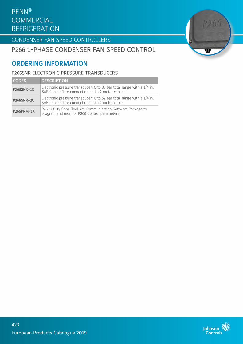
HVAC CONTROL PRODUCTS
423
European Products Catalogue 2019
PENN® COMMERCIAL REFRIGERATIONCONDENSER FAN SPEED CONTROLLERS
P266 1-PHASE CONDENSER FAN SPEED CONTROL
ORDERING INFORMATION P266SNR ELECTRONIC PRESSURE TRANSDUCERS
CODES DESCRIPTION
P266SNR-1C Electronic pressure transducer: 0 to 35 bar total range with a 1/4 in. SAE female flare connection and a 2 meter cable.
P266SNR-2C Electronic pressure transducer: 0 to 52 bar total range with a 1/4 in. SAE female flare connection and a 2 meter cable.
P266PRM-1K P266 Utility Com. Tool Kit. Communication Software Package to program and monitor P266 Control parameters.

424
European Products Catalogue 2019
PENN® COMMERCIAL REFRIGERATION
CONDENSER FAN SPEED CONTROLLERS1-PHASE CONDENSER FAN SPEED CONTROL
P315PRDIRECT-MOUNT PRESSURE ACTUATED FOR EC MOTORS
The direct mount pressure actuated condenser fan speed controllers are designed for speed variation of electronically commutated (EC) motors. Head pressure control of a refrigeration system, through speed variation of the fan on an air-cooled condenser, results in optimum performance throughout the year. The controllers can be used in non-corrosive refrigerant systems.A pressure actuated device provides the most direct and fastest response to pressure variations in the refrigerant system. The controller varies the supply voltage to the motor from 5% to at least 95% over the proportional band.
FEATURES Fan speed variation cndenser pressure control
Pressure input
Direct mount option
Setpoint screw location on top of device
IP65 enclosure
Compact design
Attractive styling
Quick connector plug included
Suitable to control 1 or 3 phase EC motor

HVAC CONTROL PRODUCTS
425
European Products Catalogue 2019
PENN® COMMERCIAL REFRIGERATIONCONDENSER FAN SPEED CONTROLLERS
P315PR 1-PHASE CONDENSER FAN SPEED CONTROL
DIMENSIONS (in mm)Turnaround
Circle 65
HEX 19
26
75106
ORDERING INFORMATION
CODESRANGE (bar) *
ELEMENT STYLE
SETTING (bar)
PROP. BAND (bar)
CONTROLLER MODE **
MINIMUM SHIPPING QUANTITY
ADDITIONAL FEATURES
P315PR-9200C8 to 25
47
16 4
N/A
1 ---
P315PR-9200D 25 Bulk Pack
P315PR-9202C 22 to 42 26 51 ---
P315PR-9203C5 to 15 6 4
P315PR-9203D 25 Bulk Pack
Notes* 1 bar = 100 kPa ≈ 14.5 psi** Minimum speed.

426
European Products Catalogue 2019
PENN® COMMERCIAL REFRIGERATION
CONDENSER FAN SPEED CONTROLLERS
VFD68VARIABLE FREQUENCY DRIVES
The VFD68 Variable Frequency Drive provides three-phase motor speed control in a variety of HVAC/R applications. The VFD68 drive is designed primarily for condenser fan speed control on HVAC and refrigeration condensing units, but can also be set up to control a variety of pumps, blowers and fans.The VFD68 drive accepts an input signal from P499 electronic pressure transducer, or other devices that provide a 0 to 5 VDC, 0 to 10 VDC, or 4 to 20 mA signal.The application-specific design of the VFD68 drive provides a simple interface, which makes the drive easy to understand and operate.You can quickly and easily reconfigure the VFD68 drive to control variable speed pumps in cooling and heating applications, or to control variable speed supply fans in VAV applications.The VFD68 drive is an RS485, RTU-compliant ModBus® slave device and can be integrated into a ModBus network.
APPLICATIONSThe VFD68 drive accepts input signals from a variety of pressure transducers, temperature sensors, and low-voltage controllers to provide continuous response to changing condenser load conditions.The VFD68 drive allows the system to:
Maintain optimum condenser head pressure
Operate in low ambient temperature conditions down to -40 °C
Reduce short-cycling, which occurs when using
Use on/off fan controls
Maintain a more stable evaporator temperature
Operate more efficiently, reducing electricity cost.The VFD68 drive can also:
Help optimize compressor operation, reduce wear, and extend compressor life by stabilizing the condenser head pressures
Reduce motor repair and replacement costs by eliminating the condenser fan short-cycling
Extend refrigerated product life and provide more consistent comfort cooling by stabilizing evaporator temperatures
3-PHASE CONDENSER FAN SPEED CONTROL
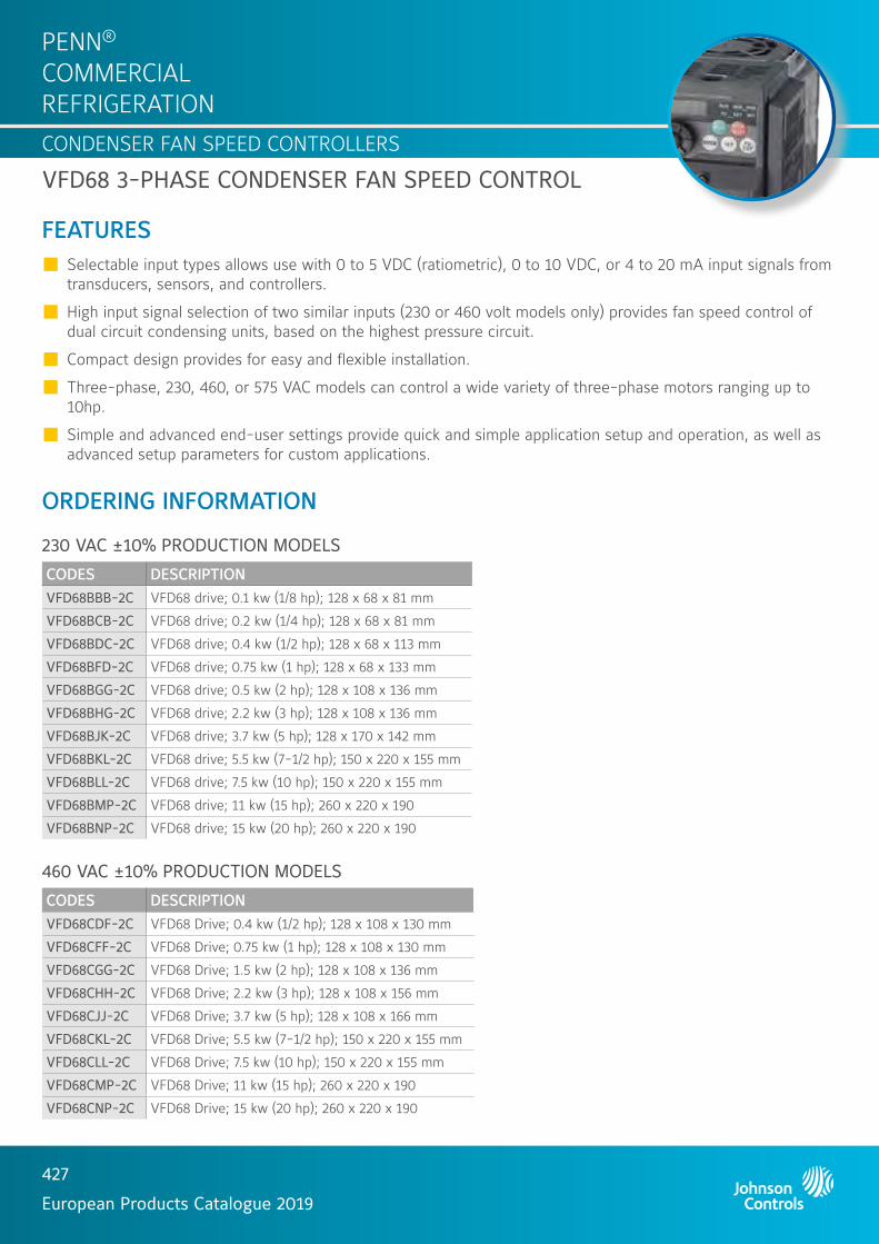
HVAC CONTROL PRODUCTS
427
European Products Catalogue 2019
PENN® COMMERCIAL REFRIGERATIONCONDENSER FAN SPEED CONTROLLERS
VFD68 3-PHASE CONDENSER FAN SPEED CONTROL
FEATURES Selectable input types allows use with 0 to 5 VDC (ratiometric), 0 to 10 VDC, or 4 to 20 mA input signals from transducers, sensors, and controllers.
High input signal selection of two similar inputs (230 or 460 volt models only) provides fan speed control of dual circuit condensing units, based on the highest pressure circuit.
Compact design provides for easy and flexible installation.
Three-phase, 230, 460, or 575 VAC models can control a wide variety of three-phase motors ranging up to 10hp.
Simple and advanced end-user settings provide quick and simple application setup and operation, as well as advanced setup parameters for custom applications.
ORDERING INFORMATION
230 VAC ±10% PRODUCTION MODELS
CODES DESCRIPTIONVFD68BBB-2C VFD68 drive; 0.1 kw (1/8 hp); 128 x 68 x 81 mm
VFD68BCB-2C VFD68 drive; 0.2 kw (1/4 hp); 128 x 68 x 81 mm
VFD68BDC-2C VFD68 drive; 0.4 kw (1/2 hp); 128 x 68 x 113 mm
VFD68BFD-2C VFD68 drive; 0.75 kw (1 hp); 128 x 68 x 133 mm
VFD68BGG-2C VFD68 drive; 0.5 kw (2 hp); 128 x 108 x 136 mm
VFD68BHG-2C VFD68 drive; 2.2 kw (3 hp); 128 x 108 x 136 mm
VFD68BJK-2C VFD68 drive; 3.7 kw (5 hp); 128 x 170 x 142 mm
VFD68BKL-2C VFD68 drive; 5.5 kw (7-1/2 hp); 150 x 220 x 155 mm
VFD68BLL-2C VFD68 drive; 7.5 kw (10 hp); 150 x 220 x 155 mm
VFD68BMP-2C VFD68 drive; 11 kw (15 hp); 260 x 220 x 190
VFD68BNP-2C VFD68 drive; 15 kw (20 hp); 260 x 220 x 190
460 VAC ±10% PRODUCTION MODELS
CODES DESCRIPTIONVFD68CDF-2C VFD68 Drive; 0.4 kw (1/2 hp); 128 x 108 x 130 mm
VFD68CFF-2C VFD68 Drive; 0.75 kw (1 hp); 128 x 108 x 130 mm
VFD68CGG-2C VFD68 Drive; 1.5 kw (2 hp); 128 x 108 x 136 mm
VFD68CHH-2C VFD68 Drive; 2.2 kw (3 hp); 128 x 108 x 156 mm
VFD68CJJ-2C VFD68 Drive; 3.7 kw (5 hp); 128 x 108 x 166 mm
VFD68CKL-2C VFD68 Drive; 5.5 kw (7-1/2 hp); 150 x 220 x 155 mm
VFD68CLL-2C VFD68 Drive; 7.5 kw (10 hp); 150 x 220 x 155 mm
VFD68CMP-2C VFD68 Drive; 11 kw (15 hp); 260 x 220 x 190
VFD68CNP-2C VFD68 Drive; 15 kw (20 hp); 260 x 220 x 190

HVAC CONTROL PRODUCTS
428
European Products Catalogue 2019
PENN® COMMERCIAL REFRIGERATIONCONDENSER FAN SPEED CONTROLLERS
VFD68 3-PHASE CONDENSER FAN SPEED CONTROL
ORDERING INFORMATION
575 VAC +5/-10% PRODUCTION MODELS
CODES DESCRIPTION
VFD68DFM-2C VFD68 Drive; 0.75 kw (1 hp); 150 x 140 x 136 mm
VFD68DGM-2C VFD68 Drive;1.5 kw (2 hp); 150 x 140 x 136 mm
VFD68DHM-2C VFD68 Drive; 2.2 kw (3 hp); 150 x 140 x 136 mm
VFD68DJN-2C VFD68 Drive; 3.7 kw (5 hp); 150 x 220 x 148 mm
VFD68DKN-2C VFD68 Drive; 5.5 kw (7-1/2 hp); 150 x 220 x 148 mm
VFD68DLN-2C VFD68 Drive; 7.5 kw (10 hp); 150 x 220 x 148 mm
ACCESSORIES THE P499R / P499A / P499V MODELS CAN BE CONNECTED TO THE VFD68
VFD68 460 V KIT MODELS (DRIVE - EMC FILTER)
VFD68 KIT VFD68 EMC FILTER
VFD68CDF-2K VFD68CDF-2C FFR-CSH-036-8A-RF1
VFD68CFF-2K VFD68CFF-2C FFR-CSH-036-8A-RF1
VFD68CGG-2K VFD68CGG-2C FFR-CSH-036-8A-RF1
VFD68CHH-2K VFD68CHH-2C FFR-CSH-080-16A-RF1
VFD68CJJ-2K VFD68CJJ-2C FFR-CSH-080-16A-RF1
VFD68CKL-2K VFD68CKL-2C FFR-MSH-170-30A-RF1
VFD68CLL-2K VFD68CLL-2C FFR-MSH-170-30A-RF1

429
European Products Catalogue 2019
PENN® COMMERCIAL REFRIGERATION
FIELD AND COLD ROOM CONTROLLERS
SYSTEM 450TM MODULAR ELECTRONIC CONTROLS
System 450™ is a family of modular, digital electronic controls that is easily assembled and set up to provide reliable temperature, pressure, and humidity control for a wide variety of Heating, Ventilating, Air Conditioning and Refrigeration (HVACR) and commercial/industrial process applications.The System 450 control system is designed to replace System 350™ control system and System 27, and provide many additional features and benefits with less than a dozen model variations.All System 450 control modules are multipurpose and field configurable out-of-the-box; each module is designed for use in temperature, pressure, and humidity systems. A System 450 control system can be easily assembled and configured to monitor and control temperature, pressure, and humidity simultaneously.A single C450 control module can be set up as a stand-alone control or connected to expansion modules to control up to ten outputs based on any of the three available inputs. A control system may consist of relay outputs (Single-Pole, Double-Throw [SPDT]), analog outputs (0–10 VDC or 4–20 mA), or any combination of relay and analog outputs.
FEATURES Durable, compact modular design with plug-together connectors and DIN rail or direct wall mount capability
Multipurpose, field-configurable modules designed for global use
Backlit Liquid Crystal Display (LCD) and four-button touchpad user interface
Up to three inputs and up to ten outputs (relay or analog)
Versatile, all-in-one, stand-alone control modules
An extensive suite of compatible temperature and humidity sensors as well as pressure transducers
High input signal selection
Differential control
Adjustable user-defined reset setpoint (C450R Only)
Adjustable minimum and maximum setpoint temperature (C450R only)
Selectable warm weather shutdown temperature (C450R only)
Adjustable setback temperature (C450R only)
MODULAR ELECTRONIC CONTROL SYSTEM

HVAC CONTROL PRODUCTS
430
European Products Catalogue 2019
PENN® COMMERCIAL REFRIGERATIONFIELD AND COLD ROOM CONTROLLERS
DIMENSIONS (in mm)
ORDERING INFORMATION (PART 1/2)System 450 control modules are capable of monitoring up to three input sensors and controlling up to ten outputs that can be any combinationof relay and analogue outputs (provided by expansion modules).
CODES DESCRIPTION
C450 control module types
C450CBN-4C Control module 1 stage
C450CCN-4C Control module 2 stage
C450CEN-1C Control module with Ethernet communications, LCD, and four-button touchpad UI. (No onboard outputs available on control modules with network communications capabilities.)
C450CRN-1C Control module with RS485 Modbus communications, LCD, and four-button touchpad UI. (No onboard outputs available on control modules with network communications capabilities.)
C450CPN-4C Control module - 1 analog output (PI)
C450CQN-4C Control module - 2 analog 0utput (PI)
C450RBN-1C Reset control module - 1 relay stage
C450RCN-1C Reset control module - 2 relay stage
C450RBN-3CReset control module with LCD, four-button touchpad UI, and SPDT relay output; provides one SPDT output relay. One A99BC-25C temperature sensor with 0.25 m silicon leads and one A99BC-300C temperature sensor with 3 m silicon leads are included in the box with the reset control module.
C450RCN-3CReset control module with LCD, four-button touchpad UI, and SPDT relay output; provides two SPDT output relays. One A99BC-25C temperature sensor with 0.25 m silicon leads and one A99BC-300C temperature sensor with 3 m silicon leads are included in the box with the reset control module.
...Continued...
SYSTEM 450TM MODULAR ELECTRONIC CONTROL SYSTEM
4 Screw slots
(Four)DIN rail
clips
1/2 in. Nominal trade size conduit hole 22

HVAC CONTROL PRODUCTS
431
European Products Catalogue 2019
PENN® COMMERCIAL REFRIGERATIONFIELD AND COLD ROOM CONTROLLERS
ORDERING INFORMATION (PART 2/2)
CODES DESCRIPTION
C450 expansion module types
C450SBN-3C Expansion module 1 relay stage
C450SCN-3C Expansion module 2 relay stage
C450SPN-1C Expansion module - 1 analog output (PI)
C450SQN-1C Expansion module - 2 analog output (PI)
C450 power module
C450YNN-1C Power module 230/24 VAC - 50/60 Hz
C450 sensor types
A99 Temperature sensors, all models, Range -40 / 120 °C
P499RCP-401C Pressure transmitter - Range -1 / 8 bar
P499RCP-402C Pressure transmitter - Range -1 / 15 bar
P499RCP-404C Pressure transmitter - Range 0 / 30 bar
P499RCP-405C Pressure transmitter - Range 0 / 50 bar
HE-67S3-0N00P Humidity transmitter duct mount (include A99)
HE-67S3-0N0BP Humidity transmitter wall mount (include A99)
DPT2650-0R5D-AB Delta P transmitter 0 to 1 mbar
DPT2650-0I0D-AB Delta P transmitter 0 to 25 mbar
SPECIFICATIONS SPDT RELAY OUTPUT CONTACTS AC motor ratings at 208/240 VAC
Full-load Amperes: 4,9 Amp
Locked-rotor Amperes: 29,4 Amp
Non-inductive load at 24/240 VAC: 10 Amp
Pilot duty at 24/240 VAC: 125 VA
A99 All A99 models can be used on the C450
P499
P499RCP-401C Range -1 to 8 bar
P499RCP-402C Range -1 to 15 bar
P499RCP-404C Range 0 to 30 bar
P499RCP-405C Range 0 to 50 bar
HEHE-67S3-0N00P Hum transmitter duct mount (include A99)
HE-67S3-0N0BT Hum transmitter wall mount (include A99)
DTPDPT2650-0R5D-AB Delta P transmitter 0 to 0,5 INWC (or 0 to 1 mbar)
DPT2650-010D-AB Delta P transmitter 0 to 10 INWC (or 0 to 25 mbar)
SYSTEM 450TM MODULAR ELECTRONIC CONTROL SYSTEM

432
European Products Catalogue 2019
PENN® COMMERCIAL REFRIGERATION
FIELD AND COLD ROOM CONTROLLERS
ER LINEELECTRONIC REFRIGERATION LINE
Devices are designed to be incorporated in refrigerated display cases and cold storage rooms.ER Line proposes progressive offer from basic controls to advanced controls including real time clock, energy saving and network communication to be integrated with monitoring system. It also introduces specific products for supermarkets (e.g. compressor rack).
HARDWARE FEATURES Robust front panel for durability and long term usage
Direct 230 V supply, no external transformer required
Up to 5 relays in a single package
NTC or PTC (A99) sensors
Removable plug connectors for quick mounting and wiring
Embedded real time clock, no additional clock card required
Embedded RS485 port, no additional communication card required
APPLICATION FEATURES Positive or negative temperature units with a single product
Minimum and maximum temperature monitoring
Comprehensive controls
Light and standby switching
Energy saving (2nd setpoint)
ELECTRONIC CONTROL DEVICES

HVAC CONTROL PRODUCTS
433
European Products Catalogue 2019
PENN® COMMERCIAL REFRIGERATIONFIELD AND COLD ROOM CONTROLLERS
ER LINE - ELECTRONIC CONTROL DEVICES
ORDERING INFORMATION
PRODUCTS TYPE MOUNTING WIRING COM
PRES
SOR
REL
AYS
FAN
REL
AYS
DEF
ROST
REL
AYS
AU
XIL
IARY
REL
AYS
REA
L TI
ME
CLO
CK
RS4
85
ER54 Evaporator control Panel Removable plug
connectors
ER55-DR Cold room control Din rail Removable plug
connectors (2 relays)
ER55-SM Cold room control Split Fixed screw
connectors (2 relays)
ER65 Rack control Din rail Removable plug connectors
(4 relays)
--- --- ---
NotePlease refer to product bulletins for complete information
ACCESSORIESCODES DESCRIPTION APPLIED PRODUCTSER-NTC-0C NTC sensor, cable 2 m, universal replacement All ER products
ER-COM-1C RS485 cable, 1.5 m, plug connector ER54, ER55-SM
ER-COM-2C RS485 cable, 1.5 m, RJ connector ER55-DR
P499Axx-xxxPressure transducer, 4-20 mA(See also P499 catalogue section)
ER65

HVAC CONTROL PRODUCTS
434
European Products Catalogue 2019
PENN® COMMERCIAL REFRIGERATIONFIELD AND COLD ROOM CONTROLLERS
ER LINE - ELECTRONIC CONTROL DEVICES
ER54 EVAPORATOR CONTROLLERS
FEATURES Panel mount controller
cool thermostat
comprehensive controls
RS485
real time clock
plug connectors
Delivered with one NTC sensor
DIMENSIONS (in mm)
35
77
29
71
14.8
3.5
27.3
71
36
3.7
28.5
ORDERING INFORMATION
CODES RS4
85
POW
ER
SUPP
LY
PRO
TECTI
ON
CLA
SS
TEM
PERA
TURE
RAN
GE
DIS
PLAY
INPU
TS
OU
TPU
TS
ER54-PMW-501C MODBUS230 VAC, +/-10%Consumption 3W
IP55 (front)IP20 (back)
-40 to 70°CAccuracy: +/-0.3 °C
LED 3 digitsDecimal
displaying
• 3 temperatures• 2 voltage free
contacts
• Compressor: SPST 12(5)A
• Fan: SPST 7(2)A• Defrost: SPST 7(2)A• Auxiliary: SPST 7(2)A
ER54-PMW-001C N2 Open

HVAC CONTROL PRODUCTS
435
European Products Catalogue 2019
PENN® COMMERCIAL REFRIGERATIONFIELD AND COLD ROOM CONTROLLERS
ER55 COLD ROOM CONTROLLERS
FEATURES DIN rail mounting controller
cool thermostat
comprehensive controls
RS485
real time clock
plug connectors
Delivered with one NTC sensor
DIMENSIONS (in mm)
97.4
71
1 32 4 11865 7 12
24 2223 21 14171920 18 16 15 13
61
14.8
15.5
CODES RS4
85
POW
ER
SUPP
LY
PRO
TECTI
ON
CLA
SS
TEM
PERA
TURE
RAN
GE
DIS
PLAY
INPU
TS
OU
TPU
TS
ER55-DR230-501C MODBUS230 VAC, +/-10%Consumption 3W
IP20-40 to 70°CAccuracy: +/-0.3°C
LED 3 digitsDecimal
displaying
• 3 temperatures• 2 voltage free
contacts
• Compressor: SPST 7(2)A• Fan: SPST 7(2)A• Defrost: SPST 16(4)A• Auxiliary 1: SPDT 7(2)A• Auxiliary 2: SPST 7(2)A
ER55-DR230-001C N2 Open
ER LINE - ELECTRONIC CONTROL DEVICES

HVAC CONTROL PRODUCTS
436
European Products Catalogue 2019
PENN® COMMERCIAL REFRIGERATIONFIELD AND COLD ROOM CONTROLLERS
ER55 COLD ROOM CONTROLLERS
FEATURES Split mounting controller
cool thermostat
comprehensive controls
RS485
real time clock
plug connectors
Delivered with two NTC sensors
DIMENSIONS (in mm)
97.4
105
13 1514 16 1817 191 32 4 11865 7 9 10 12
46
ORDERING INFORMATION
CODES RS4
85
POW
ER
SUPP
LY
PRO
TECTI
ON
CLA
SS
TEM
PERA
TURE
RAN
GE
DIS
PLAY
INPU
TS
OU
TPU
TS
ER55-SM230-501C MODBUS230 VAC, +/-10%Consumption 3W
IP20-40 to 70°CAccuracy: +/-0.3°C
RemoteLED 3 digits
Decimal displaying
• 3 temperatures• 2 voltage free
contacts
• Compressor: SPST 16(8)A• Fan: SPST 8(3)A• Defrost: SPST 16(4)A• Auxiliary 1: SPST 7(2)A• Auxiliary 2: SPST 7(2)A
ER55-SM230-001C N2 Open
35
77
29
71
14.8
3.5
27.3
71
36
3.7
28.5
ER LINE - ELECTRONIC CONTROL DEVICES

HVAC CONTROL PRODUCTS
437
European Products Catalogue 2019
PENN® COMMERCIAL REFRIGERATIONFIELD AND COLD ROOM CONTROLLERS
ER65 RACK CONTROLLERS
FEATURES DIN rail mounting controller
pressure or temperature control
4 compressors or fans sequencer
RS485
plug connectors
Sensor to be ordered separately (see also P499 pressure transducer section).
DIMENSIONS (in mm)
97.4
71
1 32 4 11865 7 12
24 2223 21 14171920 18 16 15 13
61
14.8
15.5
ORDERING INFORMATION
CODES RS4
85
POW
ER
SUPP
LY
PRO
TECTI
ON
CLA
SS
TEM
PERA
TURE
RAN
GE
DIS
PLAY
INPU
TS
OU
TPU
TS
ER65-RK230-501C MODBUS230 VAC, +/-10%Consumption 3W
IP20-40 to 70°CAccuracy: +/-0.3°C
• LED 3 digits• Decimal
displaying
• 1 temperature• 1 pressure• 2 voltage free
contacts• 3 supplied contacts
(230 V)
• Stages (x4): SPST 5(1)A
• Alarm: SPDT 7(2)AER65-RK230-001C N2 Open
ER LINE - ELECTRONIC CONTROL DEVICES

438
European Products Catalogue 2019
PENN® COMMERCIAL REFRIGERATION
FIELD AND COLD ROOM CONTROLLERS
A525ELECTRONIC REFRIGERATION CONTROLLERS WITH ADAPTIVE DEFROST
The A525 series refrigeration controller with adaptive defrost provides refrigerated space control and defrost control for medium and low temperature refrigeration applications.The A525 controller has five integral line-voltage, dry-contact relays to control the compressor, defrost heater or solenoid, evaporator fans and (user provided) alarm devices. The controller can control resistive heat, hot-gas bypass, or passive defrost. The controller can also control two speed evaporator fans.The adaptive defrost feature allows the controller to adjust the defrost schedule to the minimum number of defrost intervals required to maintain peak efficiency, save energy, and maintain consistent space temperature.The A525 controller has an IP65 enclosure that allows for wall-surface mount or optional DIN Rail mount.
FEATURES 5 Relays / 4 Inputs
CE/UL rated
Easy to clean display front panel
IP65 Robust housing
HACCP logging function
USB port for download logging files / Upload Firmware / Commissioning
Modern Design
Energy saving functionality
RS485 Modbus communication
Communicate with QREV – PSHC Electronic Expansion Valve
VERASYS® compatible
ELECTRONIC CONTROL DEVICES

HVAC CONTROL PRODUCTS
439
European Products Catalogue 2019
PENN® COMMERCIAL REFRIGERATIONFIELD AND COLD ROOM CONTROLLERS
DIMENSIONS (in mm)
196.8
190.5
82.6
ORDERING INFORMATION
CODE DESCRIPTION
A525AEDN-0203C Electronic refrigeration controller with adaptive defrost
A525 - ELECTRONIC CONTROL DEVICES

440
European Products Catalogue 2019
PENN® COMMERCIAL REFRIGERATION
FIELD AND COLD ROOM CONTROLLERS
MS LINEGENERAL PURPOSE AND MULTI-STAGES
This range of versatile controls is intended for single or multistage (2 or 4 stages) applications such as heating, cooling but also humidity or pressure depending on the input type.This range incorporates all control functions as required by modern applications and it exists in both panel mount and DIN rail enclosures. Particular attention has been given to its style in order to better suit your machine design.This complete range of microprocessor based controls offers innovative features and “state of the art” technology.
FEATURES Attractive panel mount and DIN rail mount enclosure
Up to 4 relays in panel mount enclosure
230 Volt power supply models available
Accept temperature (A99) and 0-10 Volts sensor signal depending on models
Power supply to sensors on 0-10 Volts models available from controller
Accurate and interchangeable IP68 sensor
Wide range of enclosures for sensors available
Keyboard lock
SMD technology
MULTI-STAGES CONTROL DEVICES

HVAC CONTROL PRODUCTS
441
European Products Catalogue 2019
PENN® COMMERCIAL REFRIGERATIONFIELD AND COLD ROOM CONTROLLERS
MS LINE MULTI-STAGES CONTROL DEVICES
DIMENSIONS (in mm)
11845
52.570 68
28 35
58
70 75
11845
52.570 68
28 35
58
70 75
Panel model DIN rail model
ORDERING INFORMATION
MS DISPLAY
CODES RANGEPOWER SUPPLY ENCLOSURE INPUT
PROTECTION CLASS ADDITIONAL FEATURES
DIS12T-1C-40 to 70°C
12 VAC/DC
Panel
A99 sensor (incl.)
Overall IP20 Front IP54
• Accuracy: ±1 Unit • Power Consumption:
1.5 VA 50/60 Hz
DIS230T-1C 230 VAC
DIS12V-1C0 to +100% (Rh)
12 VAC 0-10 V from humidity sensor
(not Incl.)DIS230V-1C 230 VAC
MS1 ONE-STAGE CONTROL
CODES RANGEPOWER SUPPLY ENCLOSURE INPUT
OUTPUT RATING 250 VAC
ALARM OUTPUT
PROTECTION CLASS
ADDITIONAL FEATURES
MS1PM12RT-1C
-40 to 70°C
12 VAC/DCPanel A99
sensor (incl.)
SPST 8(3)A
Open Collector
40 VDC/100 mA
Overall IP20 Front IP54 • Accuracy:
±1 Unit • Power
Consumption: 2 VA 50/60 Hz
MS1PM230T-1C 230 VAC SPDT 8(3)A
MS1DR230T-1C 230 VAC DIN rail SPST 8(3)A IP20
MS1PM12RV-1C
-40 to 100
12 VACPanel
0-10 V
SPST 8(3)A Overall IP20 Front IP54MS1PM230V-1C 230 VAC SPDT 8(3)A
MS1DR230V-1C 230 VAC DIN rail SPST 8(3)A IP20

HVAC CONTROL PRODUCTS
442
European Products Catalogue 2019
PENN® COMMERCIAL REFRIGERATIONFIELD AND COLD ROOM CONTROLLERS
MS LINE MULTI-STAGES CONTROL DEVICES
OREDERING INFORMATION
MS2 TWO-STAGE CONTROL
CODES RANGEPOWER SUPPLY ENCLOSURE INPUT
OUTPUT RATING 250 VAC PROTECTION
CLASSADDITIONAL FEATURESEach stage (1-2)
MS2PM12RT-1C
-40 to 70 °C
12 VAC/DC PanelA99
sensor (incl.)
SPST 8(3)A Overall IP20 Front IP54
• Accuracy: ±1 °C
• Power Consumption: 2 VA 50/60 Hz
MS2DR230T-1C 230 VACDIN rail
SPST 8(3)AIP20
MS2DR48DT-1C 12-24 VAC/DC 48 VDC SPDT 8(3)A
MS2PM12RV-1C -40 to 100
12 VAC Panel0-10 V
SPST 8(3)A Overall IP20 Front IP54
MS2DR230V-1C 230 VAC DIN rail SPST 8(3)A IP20
MS4 FOUR-STAGE CONTROL
CODES RANGEPOWER SUPPLY ENCLOSURE INPUT
OUTPUT RATING 250 VAC
PROTECTION CLASS
ADDITIONAL FEATURES
Each stage (1 to 4)
MS4PM12RT-1C
-40 to 70°C
12 VAC/DC PanelA99
sensor (incl.)
SPST 8(3)A Overall IP20 Front IP54
• Accuracy: ±1 Unit
• Power Consumption: 2 VA 50/60 Hz
MS4DR230T-1C 230 VACDIN rail
SPST 8(3)A
MS4DR48T-1C 12-24 VAC/DC 48 VDC SPDT 8(3)A IP20

443
European Products Catalogue 2019
PENN® COMMERCIAL REFRIGERATION
TRANSDUCERS AND SENSORS
P499ELECTRONIC PRESSURE TRANSDUCER
The P499 series is a new global pressure transducer with an excellent price performance ratio. The P499 exceeds the latest industrial CE/UL requirements including surge protection, and is over voltage protected in both positive and reverse polarity. The P499 is designed to produce a linear analogue signal based on the sensed pressure. The pressure port is machined from a solid piece of 17-4PH stainless steel. There are no O-rings or welds that are exposed to the pressure media. This results in a leak proof ,all metal sealed pressure system which withstand more than 10 million pressure cycles without failure.
FEATURES Single-piece machined steel pressure port
Environmentally sealed electronics
Reliable, repeatable performance and long operating life
Slender body design
Available in several pressure ranges up to 50 bar.
DIMENSIONS (in mm)
100
6.4
200 47.5
27 21
12
22.21247.547.5 12
PRESSURE TRANSDUCER
Shielded cable female
Hirchman female Packard female
Shielded cable 105 °C rating
Female pressure connector 7/16 - 20UNF thread
Hirchman DIN 43650
Packard Socket
Female pressure connector 7/16 - 20UNF thread
Female pressure connector 7/16 - 20UNF thread

HVAC CONTROL PRODUCTS
444
European Products Catalogue 2019
PENN® COMMERCIAL REFRIGERATIONTRANSDUCERS AND SENSORS
P499 - PRESSURE TRANSDUCER
ORDERING INFORMATION
2 METER CABLE CONNECTIONS MODELS
CODES PRESS. CONNECTION OUTPUTP499ABS-401C
Male
0.4 to 20 mAP499ABS-404CP499ACS-401C
FemaleP499ACS-404CP499ACS-405CP499VBS-401C
Male
DC 0 V - 10 VP499VBS-404CP499VCS-401C
FemaleP499VCS-404CP499VCS-405C
HIRSCHMANN DIN CONNECTOR
CODES PRESS. CONNECTION OUTPUTP499ABH-401C
Male
0.4 to 20 mA
P499ABH-402CP499ABH-404CP499ACH-401C
FemaleP499ACH-402CP499ACH-404CP499RCH-401C
0.5 - 4.5 VP499RCH-404CP499VBH-401C
Male0 - 10 V
P499VBH-404CP499VCH-401C
FemaleP499VCH-404C
PACKARD CONNECTOR
CODES PRESS. CONNECTION OUTPUTP499ACP-401C
Female
0.4 to 20 mAP499ACP-402CP499ACP-403CP499ACP-404CP499ACP-405CP499RCP-401C
0.5 - 4.5 VP499RCP-402CP499RCP-404CP499RCP-405C
P499VCP-404C 0 - 10 V

445
European Products Catalogue 2019
PENN® COMMERCIAL REFRIGERATION
TRANSDUCERS AND SENSORS
P598ELECTRONIC PRESSURE TRANSDUCER
The P598 series electronic pressure transducers are compact, economical, rugged, direct-mount pressure transducers designed for use in commercial and industrial refrigeration and air conditioning applications. These transducers provide a proportional analog signal based on the sensed pressure.The P598 series transducers feature environmentally protected electronics with stainless steel construction. The digitally compensated P598 transducers with microelectromechanical system (MEMS) pressure sensor technology are highly accurate over a broad temperature range, resisting the effects of wide ambient temperature swings, high humidity, condensation, and icing.The pressure port is milled from SUS303 stainless steel, except for models with a copper tube port. The P598 series transducers operate with any corrosive or non-corrosive refrigerants that are compatible with SUS303 stainless steel. The P598 transducers are also used with water, condensate, glycol, ammonia, and many other compatible fluids and gases.The P598 series offers a variety of pressure ranges, covering most common refrigeration and air conditioning applications.
FEATURES Innovative cavity-side MEMS pressure sensing — Highly accurate over a wide temperature range.
Unique sensor circuitry — Protects transducer from overvoltage and short-circuiting.
Rugged design — Established through life cycle testing of 10 million + cycles for proven reliability.
Approved for Today’s Refrigerants — The P598 is approved for use with ammonia and all hydrochlorofluorocarbons (HCFC), hydro-fluorocarbons (HFC) and HFC refrigerants up to a pressure of 57.71 bar (750 psi).
PRESSURE TRANSDUCER

HVAC CONTROL PRODUCTS
446
European Products Catalogue 2019
PENN® COMMERCIAL REFRIGERATIONTRANSDUCERS AND SENSORS
P598 - PRESSURE TRANSDUCER
ORDERING INFORMATION
STANDARD MODELS
0.5 TO 4.5 VDC RATIOMETRIC FOR BAR APPLICATIONS
CODES
PRESSURE RANGE
PRESSURE PORT ELECTRICAL CONNECTORMinimum pressure
(Pmin)Maximum pressure
(Pmax)
P598RCPSN401C -1 bar 8 bar
1/4 in. SAE 45° internal flare with depressor
PackardP598RCPSN402C -1 bar 15 bar
P598RCPSN404C 0 bar 30 bar
P598RCSSN409C 0 bar 35 barShielded cable
P598RCSSN411C 0 bar 52 bar
Packard connector 1/4 in. SAE 45° internal flare with depressor
Packard connector 1/4 in. SAE 45° external flare
Packard connector 1/4 in. OD copper tube with bulge stop
2 m Shielded cable 1/4 in. SAE 45° internal flare with depressor (applicable with 0.5 to 4.5 VDC ratiometric,
0 to 5 VDC, 0 to 10 VDC)
2 m Shielded cable 1/4 in. SAE 45° external flare (applicable with 0 to 10 VDC)
2 m Shielded cable 1/4 in. SAE 45° external flare (applicable with 4 to 20 mA)
2 m Shielded cable 1/4 in. SAE 45° internal flare with depressor
(applicable with 4 to 20 mA)

HVAC CONTROL PRODUCTS
447
European Products Catalogue 2019
PENN® COMMERCIAL REFRIGERATIONTRANSDUCERS AND SENSORS
P598 - PRESSURE TRANSDUCER
ORDERING INFORMATION
STANDARD MODELS
0 TO 10 VDC FOR BAR APPLICATIONS
CODES
PRESSURE RANGE
PRESSURE PORT ELECTRICAL CONNECTORMinimum pressure
(Pmin)Maximum pressure
(Pmax)
P598VBPSN401C-1 bar
8 bar
1/4 in. SAE 45° flare external thread
PackardP598VBSSN401C
Shielded cableP598VBSSN402C 15 bar
P598VBPSN404C0 bar 30 bar
Packard
P598VBSSN404C Shielded cable
P598VCSSN401C -1 bar 8 bar1/4 in. SAE 45° internal flare
with depressor
Shielded cable
P598VCSSN404C0 bar
30 bar Shielded cable
P598VCSSN405C 50 bar Shielded cable
P598VTPSN401C -1 bar 8 bar 1/4 in. OD copper tube w/ bulge stop
Packard
P598VTPSN404C 0 bar 30 bar Packard
4 TO 20 MA FOR BAR APPLICATIONS
CODES
PRESSURE RANGE
PRESSURE PORT ELECTRICAL CONNECTORMinimum pressure
(Pmin)Maximum pressure
(Pmax)
P598ABSSN401C -1 bar 8 bar1/4 in. SAE 45° flare
external thread
Shielded cable
P598ABPSN404C0 bar 30 bar
Packard
P598ABSSN404C Shielded cable
P598ACPSN401C-1 bar
8 bar
1/4 in. SAE 45° internal flare with depressor
Packard
P598ACSSN401C Shielded cableP598ACPSN402C
15 barPackardP598ACPSN403C
0 barP598ACPSN404C30 bar
P598ACSSN404C Shielded cable
P598ATPSN401C -1 bar 8 bar 1/4 in. OD copper tube with bulge stop Packard
P598ATPSN404C 0 bar 30 bar
WIRE HARNESSES FOR USE WITH THE PACKARD CONNECTORS
CODESLENGTH
(m)WHA-PKD3-200C 2.0
WHA-PKD3-400C 4.0
WHA-PKD3-600C 6.0

448
European Products Catalogue 2019
PENN® COMMERCIAL REFRIGERATION
TRANSDUCERS AND SENSORS
P599ELECTRONIC PRESSURE TRANSDUCER
The P599 series electronic pressure transducers are compact, economical, rugged, direct-mount pressure transducers designed for use in commercial and industrial refrigeration and air conditioning applications. These transducers provide a proportional analog signal based on the sensed pressure.The P599 series transducers feature environmentally protected electronics with stainless steel construction. The digitally compensated P599 transducers are highly accurate over a broad temperature range, resisting the effects of wide ambient temperature swings, high humidity, condensation and icing.The pressure port is machined from 304L stainless steel. No o-rings or organic materials are exposed to the pressure media, allowing for a leak-proof, all-metal, sealed pressure system. The P599 series transducers operate with any corrosive or non-corrosive refrigerants that are compatible with stainless steel (304L SS), including water condensate, carbon dioxide, glycol, most refrigerants (including ammonia) and many other compatible fluids and gases. The P599 transducers also can be used with the following natural refrigerants: NH3 (ammonia) and CO2 (carbon dioxide) in accordance with hazardous location requirements.The P599 series provides transducers in a variety of pressure ranges, covering most common refrigeration and air conditioning applications.
FEATURES Industrial Duty Design — Offers a sealed design that includes a snubber to dampen pressure pulsations and has no o-rings for reliable performance in the most harsh environments.
10 Million Plus Full Scale Pressure Cycle Rated Life Span — Provides life use with no degradation of accuracy or performance over the life of the transducer.
Approved for Today’s Refrigerants — Use with an extensive number of refrigerants, including HCFC, HFC, CO2 and ammonia.
Environmentally Protected Electronics — Provide high vibration tolerance and prevent ingress and egress that can occur through suction line icing and thawing.
PRESSURE TRANSDUCER

HVAC CONTROL PRODUCTS
449
European Products Catalogue 2019
PENN® COMMERCIAL REFRIGERATIONTRANSDUCERS AND SENSORS
P599 - PRESSURE TRANSDUCER
ORDERING INFORMATION
STANDARD MODELS
0.5 TO 4.5 VDC RATIOMETRIC FOR bar APPLICATIONS
CODES
PRESSURE RANGE
PRESSURE PORTELECTRICAL CONNECTOR
Minimum pressure (Pmin)
Maximum pressure (Pmax)
P599RCHS401C
-1 bar8 bar
1/4 in. - SAE 45° internal flare with depressor
Hirschmann® Form C
P599RCPS401CPackard
P599RCPS402C 15 bar
P599RCHS404C0 bar 30 bar
Hirschmann Form C
P599RCPS404C Packard
P599RCSS409C
0 bar
35 bar Shielded cable
P599RCPS405C 50 barPackard
P599RCSS411C 52 bar
P599RJJS412C-1 bar
59 barG3/8 A external Hirschmann Form A
P599RJJS413C 159 bar
Hirshmann Form A G3/8 A external
Packard connector 1/4 in. SAE 45° internal flare with depressor
Hirshmann Form C 1/4 in. SAE 45° external flare
Hirshmann Form C 1/4 in. SAE 45° internal flare with depressor
2 m Shielded cable 1/4 in. SAE 45° external flare
2 m Shielded cable 1/4 in. SAE 45° internal flare with depressor

HVAC CONTROL PRODUCTS
450
European Products Catalogue 2019
PENN® COMMERCIAL REFRIGERATIONTRANSDUCERS AND SENSORS
P599 - PRESSURE TRANSDUCER
ORDERING INFORMATION
0 TO 10 VDC FOR bar APPLICATIONS
CODES
PRESSURE RANGE
PRESSURE PORTELECTRICAL CONNECTOR
Minimum pressure (Pmin)
Maximum pressure (Pmax)
P599VBHS401C
-1 bar
8 bar
1/4 in. - SAE 45° external flareHirschmann Form C
P599VCHS401C1/4 in. - SAE 45° internal flare with depressor
P599VCPS401C Packard
P599VBSS401C 1/4 in. - SAE 45° external flareShielded cable
P599VCSS401C1/4 in. - SAE 45° internal flare with depressor
P599VCPS406C 9 bar Packard
P599VBSS402C15 bar
1/4 in. - SAE 45° external flare Shielded cable
P599VCHS402C 1/4 in. - SAE 45° internal flare with depressor
Hirschmann Form CP599VBHS404C
0 bar 30 bar
1/4 in. - SAE 45° external flare
P599VCHS404C1/4 in. - SAE 45° internal flare with depressor
P599VCPS404C Packard
P599VBSS404C 1/4 in. - SAE 45° external flare Shielded cable
P599VCSS404C -1 bar 39 bar
1/4 in. - SAE 45° internal flare with depressor
Packard
P599VCPS407C0 bar 50 bar
Hirschmann Form C
P599VCSS405C Shielded cable

HVAC CONTROL PRODUCTS
451
European Products Catalogue 2019
PENN® COMMERCIAL REFRIGERATIONTRANSDUCERS AND SENSORS
4 TO 20 MA FOR bar APPLICATIONS
CODES
PRESSURE RANGE
PRESSURE PORTELECTRICAL CONNECTOR
Minimum pressure (Pmin)
Maximum pressure (Pmax)
P599ABHS401C
-1 bar 8 bar
1/4 in. - SAE 45° external flareHirschmann Form C
P599ACHS401C 1/4 in. - SAE 45° internal flare with depressor
P599ACPS401C 1/4 in. - SAE 45° internal flare with depressor Packard
P599ABSS401C 1/4 in. - SAE 45° external flareShielded cable
P599ACSS401C 1/4 in. - SAE 45° internal flare with depressor
P599ABHS402C
-1 bar 15 bar
1/4 in. - SAE 45° external flareHirschmann Form C
P599ACHS402C 1/4 in. - SAE 45° internal flare with depressor
P599ACPS402C 1/4 in. - SAE 45° internal flare with depressor Packard
P599ACPS403C 0 bar 15 bar 1/4 in. - SAE 45° internal flare with depressor Packard
P599ABHS404C
0 bar 30 bar
1/4 in. - SAE 45° external flareHirschmann Form C
P599ACHS404C 1/4 in. - SAE 45° internal flare with depressor
P599ACPS404C 1/4 in. - SAE 45° internal flare with depressor Packard
P599ABSS404C 1/4 in. - SAE 45° external flareShielded cable
P599ACSS404C 1/4 in. - SAE 45° internal flare with depressor
P599ACHS405C
0 bar 50 bar 1/4 in. - SAE 45° internal flare with depressor
Hirschmann Form C
P599ACPS405C Packard
P599ACSS405C Shielded cable
ACCESSORIES
WIRE HARNESSES FOR USE WITH PACKARD CONNECTORS
CODESLENGTH
(m)WHA-PKD3-200C 2.0
WHA-PKD3-400C 4.0
WHA-PKD3-600C 6.0
P599 - PRESSURE TRANSDUCER

452
European Products Catalogue 2019
PENN® COMMERCIAL REFRIGERATION
TRANSDUCERS AND SENSORS
LEAK DETECTORSThe JCI product range offers Leak detectors (in order to comply to the EU F-gas Directive) for the following gases:
Ammonia (NH3)
Synthetic refrigerants HFC (R134a, R410a etc) as shown in this catalogue
Carbon dioxide (CO2)
Hydro Carbons (R290, R600)
The MPU multi point units need to be used in combination with the MP series of detectors. The GD/GS series of detectors are standalone detectors and have 3 alarm relays that are factory calibrated depending on the gas type.
ORDERING INFORMATION
FACTORY-SET ALARM LEVELS (BY EXPERIENCE APPROPRIATE ALARM LEVELS AND RANGES)DETECTOR TYPE RANGE ALARM LEVELS
NH3-1000 0-1000 ppm 150 / 300 / 500 ppm
NH3-4000 0-4000 ppm 150 / 300 / 3000 ppm
NH3-10000 0-10000 ppm 500 / 3000 / 8000 ppm
HFC 0-4000 ppm 100 / 1000 / 2000 ppm
CO2 0-10000 ppm 2000 / 5000 / 8000 ppm
Flammable / explosive gas 0-40% LEL 5 / 10 / 20% LEL
LEAK DETECTION

HVAC CONTROL PRODUCTS
453
European Products Catalogue 2019
PENN® COMMERCIAL REFRIGERATIONTRANSDUCERS AND SENSORS
LEAK DETECTORS - LEAK DETECTION
ORDERING INFORMATION (PART 1/2)
CODES MODEL DETAILS
GD
• Room mounting • Ambient temperature: -40°C to 50°C • Humidity: 0...95% Rh (non condensing)• IP21
GD24-HFC-4000 0-4000 ppm, 12..24 VAC/DC, max 2 W
GD230-HFC-4000 0-4000 ppm, 230 VAC, max 2 W
GS
• Splash proof, room mounting• Ambient temperature: -40°C to 50°C• Humidity: 0...95% Rh (non condensing)• IP54
GS24-HFC-4000 0-4000 ppm, 12..24V AC/DC, max 2 W
GS230-HFC-4000 0-4000 ppm, 230V AC, max 2 W
GSH230CO2-1000
• Splash proof, room mounted detector with build in heater • Ambient temperature: -40°C to 50°C• Humidity: 0...95% Rh• IP67 • 0-10000 ppm , 230 VAC
GSH24CO2-1000
• Splash proof, room mounted detector with build in heater • Ambient temperature: -40°C to 50°C• Humidity: 0...95% Rh• IP67 • 0-10000 ppm , 24 VAC
MP-D
• Room mounting• Ambient temperature: -40°C to 50°C • Humidity: 0..95% Rh (non condensing)• IP21
MP-D-HFC-4000 0-4000 ppm 38-220
MP-DS
• Splash proof, room mounting• Ambient temperature: -40°C to 50°C• Humidity: 0...95% Rh (non condensing)• IP54
MP-DS-HFC-4000 0-4000 ppm 38-420

HVAC CONTROL PRODUCTS
454
European Products Catalogue 2019
PENN® COMMERCIAL REFRIGERATIONTRANSDUCERS AND SENSORS
LEAK DETECTORS - LEAK DETECTION
ORDERING INFORMATION (PART 2/2)
CODES MODEL DETAILS
MPS
• Splash proof, room mounted detector with build in heater • Ambient temperature: -40°C to 50°C• Humidity: 0...95% Rh• IP67 • 0-10000 ppm
MPS-CO2-10000 34-410
MPU
• Ambient temperature: 0°C to 50°C• Humidity: 10...95% Rh (non condensing)• IP66
MPU2C 2 channels, 230V AC / 24V DC, max 10 W 20-310
MPU4C 4 channels, 230V AC / 24V DC, max 10 W 20-300
MPU6C 6 channels, 230V AC / 24V DC, max 10 W 20-305
--- Custom preset alarm levels. Price per channel/detector 60-300
TR-IR
• Splash proof, room mounted detector with build in heater • Ambient temperature: -40°C to 50°C• Humidity: 0...95% Rh• IP67
TR-IR-CO2-10000 39-4312