european fusion development agreement - FIRE
212
EFDA(05)-27/4.10 revision 1 (revision 0: STAC 10/4.1) EFDA EUROPEAN FUSION DEVELOPMENT AGREEMENT A CONCEPTUAL STUDY OF COMMERCIAL FUSION POWER PLANTS Final Report of the European Fusion Power Plant Conceptual Study (PPCS) April 13 th , 2005 EFDA-RP-RE-5.0
-
Upload
khangminh22 -
Category
Documents
-
view
2 -
download
0
Transcript of european fusion development agreement - FIRE

EFDA(05)-27/4.10 revision 1 (revision 0: STAC 10/4.1)
EFDA
EUROPEAN FUSION DEVELOPMENT AGREEMENT
A CONCEPTUAL STUDY OF
COMMERCIAL FUSION POWER PLANTS
Final Report of the European Fusion
Power Plant Conceptual Study (PPCS)
April 13th, 2005
EFDA-RP-RE-5.0


AUTHORS D. Maisonnier (Project Leader, EFDA) I. Cook (UKAEA) P. Sardain (EFDA) R. Andreani (EFDA) L. Di Pace (ENEA) R. Forrest (UKAEA) L. Giancarli (CEA) S. Hermsmeyer (FZK) P. Norajitra (FZK) N. Taylor (UKAEA) D. Ward (UKAEA) CONTRIBUTORS Adomavičius A. (Kaunas un.) Boccaccini L.V. (FZK) Bogusch E. (EFET) Brodén K. (VR) Buenaventura A. (EFET) Bühler L. (FZK) Cambi G. (Bologna un.) Carretero J.A. (EFET) Chen Y. (FZK) Cheyne A. (EFET) Chiesura (EFET) Ciattaglia S. (EFDA) Cipollaro A. (EFET) Collén J. (VR) Diegele E. (EFDA) Dominguez M.T. (EFET) Druyts F. (SCK-CEN) Du Bois d’Enghien G. (EFET) Dumelow J. (EFET) Ebert E. (EFET) Ek M. (EFET) Enderlé R. (CEA) Eurajoki T. (EFET) Everott N. R. (EFET) Fardi F. (EFET) Fenemore P. (EFET) Fischer U. (FZK) Fütterer M. (JRC Petten) Golfier H. (CEA) Gordeev S. (FZK) Gottfried R. (EFET)
Grove D. (EFET) Gulden W. (EFDA) Han W. (UKAEA) Hasemann I. (FZK) Heller M. (EFET) Hutter E. (FZK) Karditsas P. (UKAEA) Karlsson P. (VR) Klein M. (SCK-CEN) Klimm M. (EFET) Kruessmann R. (FZK) Lackner K. (IPP) Lechon Y. (CIEMAT) Li Puma A. (CEA) Lisak M. (CTH) Loughlin M.J. (UKAEA) Malang S. (FZK) Mallants D. (SCK-CEN) Martínez L. (EFET) Massaut V. (SCK-CEN) Matrone A. (EFET) Mattioda F. (ENEA) McCallum A. (EFET) Marbach G. (CEA) Meloni P. (ENEA) Michel B. (CEA) Nardi C. (ENEA) Natalizio A. (ENSAC) Olsson G. (VR) Ooms L. (SCK-CEN) Orden A. (EFET) Orlandi S. (EFET)
Paci S. (Pisa un.) Pampin-Garcia R. (UKAEA) Pascal C. (Technicatome) Pereslavtsev P. (FZK) Pinna T. (ENEA) Pizzuto A. (ENEA) Poitevin Y. (CEA) Poli M. (ENEA) Porfiri M.T. (ENEA) Portone A. (EFDA) Puente D. (EFET) Raskob W. (FZK) Reimann G. (FZK) Reimann J. (FZK) Rieger J. (EFET) Röhlich K. (EFET) Rollet S. (Microrays) Saez R. (CIEMAT) Saibene G. (EFDA) Salomaa R. (TEKES) Scalzullo A. (EFET) Sherwood D. (EFET) Spontón L.L. (VR) Szczepanski J. (Concept 21) Van Hove W. (EFET) Vieider G. (VR) Vivaldi F. (EFET) Wasastjerna F. (VTT) Wilmot D. (EFET) Yitbarek M. (VR) Zemulis G. (TEKES)

This study, supported by the European Communities, was carried out within the framework of the European Fusion Development Agreement. The views and opinions expressed herein
do not necessarily reflect those of the European Commission.
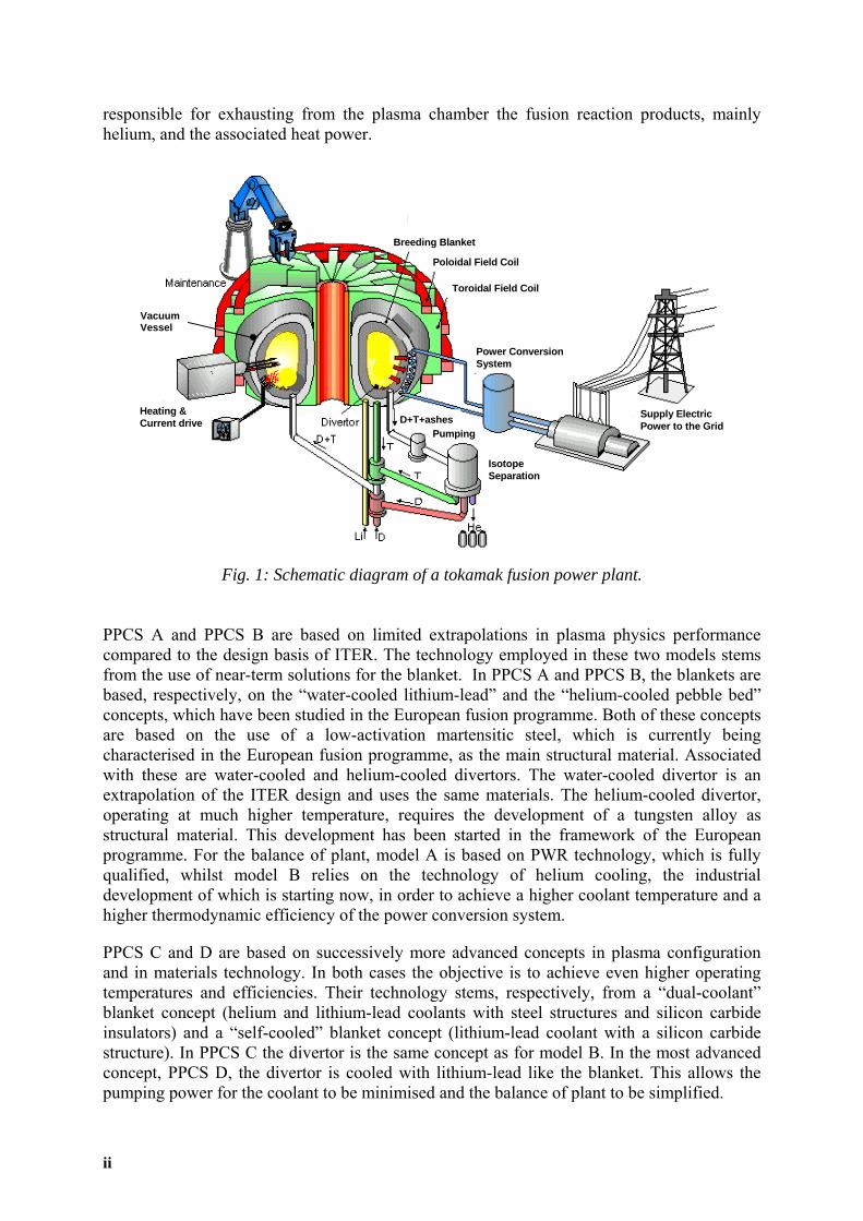
EXECUTIVE SUMMARY 1. Introduction From 1990 to 2000 a series of studies within the European fusion programme, summarised in References 1 and 2, examined the safety, environmental and economic potential of fusion power. These studies showed that: • Fusion power has very promising potential to provide inherent safety and favourable
environmental features, to address global climate change and gain public acceptance. In particular, fusion energy has the potential of becoming a clean, zero-CO2 emission and inexhaustible energy source.
• The cost of fusion electricity is likely to be comparable with that from other environmentally responsible sources of electricity generation.
In the period since these earlier studies, there have been substantial advances in the understanding of fusion plasma physics and in the development of more favourable plasma operating regimes, and progress in the development of materials and technology. Accordingly, it was decided to undertake a comprehensive power plant conceptual design study, updated in the light of our current know-how and understanding, to serve as a better guide for the further evolution of the fusion development programme. The European Power Plant Conceptual Study (PPCS) has been a 3-years study, between mid 2001 and mid 2004, of conceptual designs for commercial fusion power plants. It focussed on four power plant models, named PPCS A to PPCS D, which are illustrative of a wider spectrum of possibilities. These span a range from relatively near-term concepts, based on limited technology and plasma physics extrapolations, to a more advanced conception. All four PPCS plant models differ substantially in their plasma physics, electrical output, blanket and divertor technology from the models that formed the basis of the earlier European studies. They also differ substantially from one another in their size, fusion power and materials compositions, and these differences lead to differences in economic performance and in the details of safety and environmental impacts. This report summarizes the European Power Plant Conceptual Study (PPCS), which continued and expanded earlier European fusion power plant studies [1]. The study was carried out with the help of a large number of experts from both the European fusion research community and its industrial partners. 2. Plant Models All four of the plant models PPCS A to D are based on the tokamak concept as the main line of fusion development (Fig.1), proceeding through JET and ITER. JET, the world’s largest and most advanced operating machine, provides the basis for the plasma physics of ITER, the next step in fusion development. Two main elements characterise each power plant model: the blanket and the divertor. The blanket is the component where the energetic neutrons produced by the fusion process in the burning plasma are slowed down and deliver their energy in the form of heat and are absorbed by lithium atoms to produce the intermediate fuel, tritium. The divertor is the component
i
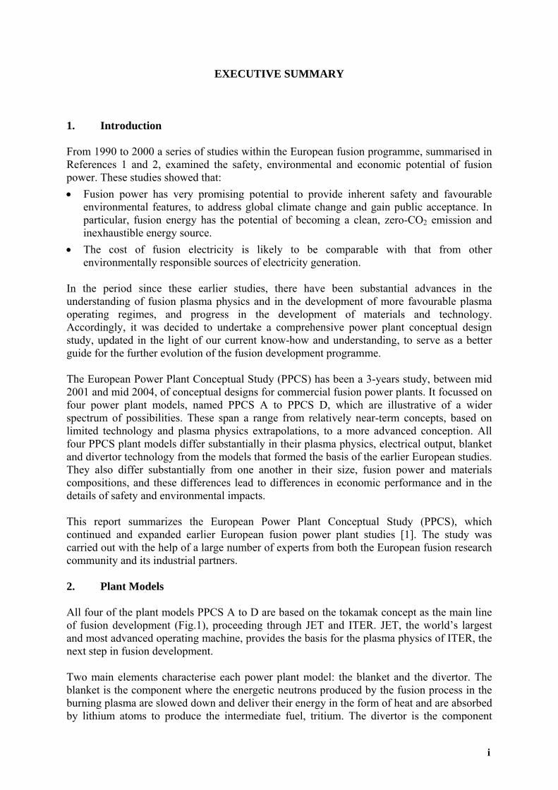
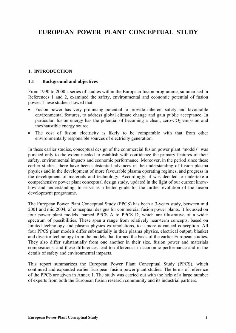
responsible for exhausting from the plasma chamber the fusion reaction products, mainly helium, and the associated heat power.
Breeding Blanket
P
Fig. 1: Schematic diagram of a tokamak fusion power plant.
oloidal Field Coil
Toroidal Field Coil
Power Conversion System
Supply Electric Power to the Grid
Heating &Current drive
IsotopeSeparation
PPCS A and PPCS B are based on limited extrapolations in plasma physics performance compared to the design basis of ITER. The technology employed in these two models stems from the use of near-term solutions for the blanket. In PPCS A and PPCS B, the blankets are based, respectively, on the “water-cooled lithium-lead” and the “helium-cooled pebble bed” concepts, which have been studied in the European fusion programme. Both of these concepts are based on the use of a low-activation martensitic steel, which is currently being characterised in the European fusion programme, as the main structural material. Associated with these are water-cooled and helium-cooled divertors. The water-cooled divertor is an extrapolation of the ITER design and uses the same materials. The helium-cooled divertor, operating at much higher temperature, requires the development of a tungsten alloy as structural material. This development has been started in the framework of the European programme. For the balance of plant, model A is based on PWR technology, which is fully qualified, whilst model B relies on the technology of helium cooling, the industrial development of which is starting now, in order to achieve a higher coolant temperature and a higher thermodynamic efficiency of the power conversion system.
PPCS C and D are based on successively more advanced concepts in plasma configuration and in materials technology. In both cases the objective is to achieve even higher operating temperatures and efficiencies. Their technology stems, respectively, from a “dual-coolant” blanket concept (helium and lithium-lead coolants with steel structures and silicon carbide insulators) and a “self-cooled” blanket concept (lithium-lead coolant with a silicon carbide structure). In PPCS C the divertor is the same concept as for model B. In the most advanced concept, PPCS D, the divertor is cooled with lithium-lead like the blanket. This allows the pumping power for the coolant to be minimised and the balance of plant to be simplified.
PumpingD+T+ashes
Breeding Blanket
Poloidal Field Coil
Toroidal Field Coil
Power Conversion System
Supply Electric Power to the Grid
Heating &Current drive
IsotopeSeparation
PumpingD+T+ashes
Vacuum Vessel
ii

A tungsten alloy layer may be assumed on the first wall of the blanket modules facing the plasma since its erosion rate (0.1 mm per full-power-year in ITER-like conditions) is much lower than low Z materials like beryllium (about 3 mm per full-power-year in ITER-like conditions). The use of this tungsten layer does not impact the wastes issue. For all of the plant models, system analyses were used to integrate the plasma physics and technology constraints, together with other considerations such as unit size and availability, to produce self-consistent plant parameter sets with approximately optimal economic characteristics. The variations in assigned plasma physics and technology constraints drove variations in the fusion power and plant core dimensions, mainly associated with variation in the overall efficiency of the plant, as the electric power output delivered to the network was kept approximately the same for all the models (1500 MWe), with PPCS A having the largest, and PPCS D the smallest, fusion power and plant core dimensions (Fig. 2). The main parameters of the PPCS models are shown in table 1. Following the systems analysis, the conceptual designs of the four Models were developed, and analyses were made of their economic, safety and environmental performance.
-8
-6
-4
-2
0
2
4
6
8
0 5 10 15
R(m)
Z(m
)
ABC
D
ITER
Fig. 2: Illustration of the sizes and shapes of the plasmas in the PPCS Models.
Two key innovative concepts, developed within the study, are worthy of a special note: • One is a scheme for the scheduled replacement of the blanket and divertor, which shows
the potential for good overall plant availability (at least 75%). • The other is a conceptual design for a helium-cooled divertor, which permits heat loads
(10 MW/m2) twice as high as those previously foreseen for helium-cooled concepts.
iii

Model A Model B Model C Model D Parameter (plasma physics) Unit Size (GWe) 1.55 1.33 1.45 1.53 Fusion Power (GW) 5.00 3.60 3.41 2.53 Aspect Ratio 3.0 3.0 3.0 3.0 Elongation (95% flux) 1.7 1.7 1.9 1.9 Triangularity (95% flux) 0.25 0.25 0.47 0.47 Major Radius (m) 9.55 8.6 7.5 6.1 TF on axis (T) 7.0 6.9 6.0 5.6 Plasma Current (MA) 30.5 28.0 20.1 14.1 βN(thermal, total) 2.8, 3.5 2.7, 3.4 3.4, 4.0 3.7, 4.5 Bootstrap Fraction 0.45 0.43 0.63 0.76 Padd (MW) 246 270 112 71 n/nG 1.2 1.2 1.5 1.5 Parameter (engineering) Average neutron wall load 2.2 2.0 2.2 2.4 Divertor Peak load (MWm-2) 15 10 10 5 H&CD Efficiency 0.6 0.6 0.7 0.7 Plant Efficiency* 0.31 0.37 0.42 0.6
Water Helium LiPb/He LiPb Coolant blanket Tin/Tout (°C) 285/325 300/500 480/700
300/480 700/1100
Water Helium Helium LiPb Coolant divertor Tin/Tout (°C) 140/167 540/720 540/720 600/990
Power conversion Rankine Rankine Brayton Brayton * the plant efficiency is the ratio between the unit size and the fusion power
Table 1: Main parameters of the PPCS models.
3. Safety and Environmental Impacts Fusion power stations will have extremely low levels of fuel inventory in the burning chamber, therefore their power production stops a few seconds after fuelling is stopped. They have low levels of residual power density (arising from the decay of activated materials) in their structure after the termination of burn and they will not emit any of the greenhouse gases. In the PPCS models these favourable inherent features have been exploited, by appropriate design and choice of materials, to provide major safety and environmental advantages. • If a total loss of active cooling were to occur during the burn, the plasma would switch off
passively due to impurity influx deriving from temperature rises in the walls of the reaction chamber. Any further temperature increase in the structures, due to residual decay heat, cannot lead to melting. This result is achieved without any reliance on active safety systems or operator actions.
• The maximum radiological doses to the public arising from the most severe conceivable accident driven by in-plant energies (bounding accident) would not exceed 18 mSv, below the level at which evacuation would be considered in many national regulations (50 mSv,
iv

the value which is also recommended by the International Commission on Radiological Protection).
• The power plant will be designed to withstand an earthquake with an intensity equal to that of the most severe historical earthquake increased by a safety margin, in accordance with the safety design rules in force (for example, in France this margin approximately corresponds to an increase of 1 degree on the Richter scale). It would also be possible to provide any features that might be needed to meet the non-evacuation criterion in case of impact of a large aircraft.
• In case of fire, a maximum of a few grams of tritium could be released, by appropriate partitioning of the tritium inventory, which is consistent with the non-evacuation criterion.
• If there is substantial use of beryllium as an in-vessel component (approximately 560 tons are foreseen within the blanket of model B), it may be necessary to recycle it to satisfy the EU legislation on beryllium chemical toxicity.
• The radiotoxicity of the materials (namely, the biological hazard potential associated with their activation) decays by a factor ten thousand over a hundred years. All of this material, after being kept in situ for some decades, will be regarded as non-radioactive (contact dose rate lower than 0.001 mSv/h, decay heat lower than 1 W/m3) or recyclable (contact dose rate lower than 20 mSv/h, decay heat lower than 10 W/m3). The recycling of some material could require remote handling procedures. An alternative could be a shallow land burial, after a time (approximately 100 years) depending on the nuclides contained in the materials and the local regulations.
• None of the materials required are subject to the provisions of non-proliferation treaties. 4. Economics
“Internal cost” is the contribution to the cost of electricity from constructing, fuelling, operating, maintaining and disposing of power stations. The internal cost of electricity from the four PPCS fusion power plants was calculated by applying the codes also used in the Socio-economics Research in Fusion [2] programme. The PROCESS code, adopted in the study, uses well-attested methodologies validated against industry’s cost estimates of ITER. The PPCS plant models differ in physical size, fusion power, the re-circulating power used to drive the electrical current in the burning plasma, the energy multiplication that occurs in the blankets, the efficiency of converting thermal to electrical power, and other respects. Accordingly, the total internal cost of electricity varies between the models, ranging from 5-9 €cents/kWh for model A down to 3-5 €cents/kWh for model D, depending on the assumed level of maturity of the technology considered. The calculated internal cost of electricity from all the models is in the range of estimates for the future costs from other sources (e.g. gas combined cycle, wind), obtained from the literature.
The internal costs of electricity generation do not include costs such as those associated with environmental damage or adverse impacts upon health. The “external costs” of electricity from the four PPCS plant models were estimated by scaling from the results from the Socio-economics Research in Fusion [2] programme using the well-established code ExternE. Because of fusion’s safety and environmental advantages, these external costs are low. In summary, all four PPCS models have low external costs: much lower than fossil fuels, and comparable to, or lower than, wind power.
v

5. Developments needs It is clear from the PPCS results that the main thrusts of the European fusion development programme are on the right lines. These are: • ITER; • optimisation of existing low activation martensitic steels, together with development of
tungsten alloys, and their testing in fission Material Test Reactors and then in the fusion-specific irradiation facility IFMIF, as soon as it becomes available. Parallel development of the more advanced materials envisaged in the PPCS; and
• development of blanket models, to be tested in ITER, based on the use of low activation martensitic steels as the main structural material.
It is also clear from the PPCS results that more work has to be undertaken on the development of divertor systems, ultimately capable of combining high heat flux tolerance and high temperature operation with sufficient lifetime in power plant conditions, and on the development and qualification of maintenance procedures by remote handling to satisfy the availability requirements of power plants. The first of these will require more emphasis on the development of tungsten alloys as structural materials and confirms the need to pursue the development of tungsten alloys as armour material. The effort already made to design and develop an efficient Remote Handling System, successful on JET, and now under way for ITER, will have to be further pursued with a view to power plant operation. A focussed and fast development along the above lines would result in an early demonstration commercial power plant with substantial safety and environmental advantages and, during operation when reliability issues had been ironed out, acceptable economics. Reflection on the PPCS results and the trends in the results, in the light of the understanding that they have brought in their train, also suggests that the following detailed steps should be undertaken: • Performance of a DEMO power plant study. The time is now ripe for such a study to give
guidance to the programme. • Development and testing of helium-cooled divertor concepts capable of tolerating peak
heat fluxes greater than 10 MW/m2. • Establishment of a Remote Handling Test Facility, to be used for the development of
maintenance concepts capable of delivering high availability. 6. Conclusions The PPCS results for the near-term Models A and B suggest that a first commercial fusion power plant - one that would be accessible by a “fast track” route of fusion development, going through ITER and the successful qualification of the materials currently being considered - will be economically acceptable, with major safety and environmental advantages. These models rely on plasma performances marginally better than the design basis of ITER. The results for models C and D illustrate the potential for more advanced power plants.
vi

Acknowledgments The work was performed as a collaborative effort by several European Fusion Associations, and by European Industry (EFET-EWIV). It was jointly funded by Euratom and by the governments of Belgium, France, Germany, Italy, Spain, Sweden and the United Kingdom. The authors of this report wish to express their gratitude to all colleagues from the participating organisations. References 1. I. Cook, G. Marbach, L. Di Pace, C. Girard and N. Taylor, “Safety and environmental
impact of fusion”, EFDA-S-RE-1, April 2001. 2. “Socio-economic aspects of fusion power”, EUR (01) CCE-FU 10/6.2.2, April 2001.
vi


CONTENTS
1. INTRODUCTION 1 1.1 BACKGROUND AND OBJECTIVES 1 1.2 SCOPE OF THIS REPORT 2
2. BASIC FEATURES OF FUSION POWER PLANTS 2 2.1 D-T FUSION REACTION 2 2.2 TOKAMAK CONFIGURATION 3 2.3 SAFETY AND ENVIRONMENTAL CHARACTERISTICS 4
3. FUSION POWER PLANT MODEL SELECTION AND DESIGN 4 3.1 DESIGN METHODOLOGY 4 3.2 PLASMA PHYSICS BASIS 5 3.3 MAINTENANCE SCHEME 6 3.4 SYSTEMS ANALYSES AND OVERALL PLANT PARAMETERS 6
4. KEY FEATURES OF THE FOUR MODELS STUDIED 8 4.1 MODEL A 8 4.2 MODEL B 9 4.2 MODEL B 10 4.3 MODEL C 11 4.4 MODEL D 12 4.5 ENGINEERING PARAMETERS OF THE PLANT MODELS 12 4.6 DIVERTOR ARMOUR AND PLASMA FACING MATERIALS 13
5. ECONOMICS 13 5.1 TYPES OF COST 13 5.2 INTERNAL COSTS 14 5.3 EXTERNAL COSTS 15 5.4 SUMMARY 15
6. SAFETY AND ENVIRONMENTAL IMPACTS 16
6.1 PRIME FEATURES 16 6.2 ACCIDENT ANALYSES 16 6.3 CATEGORISATION OF ACTIVATED MATERIAL 19 6.4 OTHER FACTORS 20 6.5 SUMMARY 21
7. DEVELOPMENT NEEDS 21
8. OVERALL CONCLUSIONS 22
REFERENCES 23
ANNEXES 24

EUROPEAN POWER PLANT CONCEPTUAL STUDY
1. INTRODUCTION
1.1 Background and objectives
From 1990 to 2000 a series of studies within the European fusion programme, summarised in References 1 and 2, examined the safety, environmental and economic potential of fusion power. These studies showed that: • Fusion power has very promising potential to provide inherent safety and favourable
environmental features, to address global climate change and gain public acceptance. In particular, fusion energy has the potential of becoming a clean, zero-CO2 emission and inexhaustible energy source.
• The cost of fusion electricity is likely to be comparable with that from other environmentally responsible sources of electricity generation.
In these earlier studies, conceptual design of the commercial fusion power plant “models” was pursued only to the extent needed to establish with confidence the primary features of their safety, environmental impacts and economic performance. Moreover, in the period since these earlier studies, there have been substantial advances in the understanding of fusion plasma physics and in the development of more favourable plasma operating regimes, and progress in the development of materials and technology. Accordingly, it was decided to undertake a comprehensive power plant conceptual design study, updated in the light of our current know-how and understanding, to serve as a better guide for the further evolution of the fusion development programme. The European Power Plant Conceptual Study (PPCS) has been a 3-years study, between mid 2001 and mid 2004, of conceptual designs for commercial fusion power plants. It focussed on four power plant models, named PPCS A to PPCS D, which are illustrative of a wider spectrum of possibilities. These span a range from relatively near-term concepts, based on limited technology and plasma physics extrapolations, to a more advanced conception. All four PPCS plant models differ substantially in their plasma physics, electrical output, blanket and divertor technology from the models that formed the basis of the earlier European studies. They also differ substantially from one another in their size, fusion power and materials compositions, and these differences lead to differences in economic performance and in the details of safety and environmental impacts. This report summarizes the European Power Plant Conceptual Study (PPCS), which continued and expanded earlier European fusion power plant studies. The terms of reference of the PPCS are given in Annex 1. The study was carried out with the help of a large number of experts from both the European fusion research community and its industrial partners.
European Power Plant Conceptual Study 1

1.2 Scope of this report
The body of this report is written so as to be accessible by scientific readers who are not fusion experts: further details are provided in Annexes. Extensive accounts of the origin of the safety and environmental advantages of fusion power, and of the methods used to demonstrate these, were given in the report on earlier studies [1]. These details are not repeated in this report, but the main points of the calculations and results are described. 2. BASIC FEATURES OF FUSION POWER PLANTS
2.1 D-T fusion reaction
All four of the plant models PPCS A to D are based on the tokamak concept as the main line of fusion development, proceeding through JET and ITER. A schematic diagram showing the basic principles of a fusion power station, based on the “tokamak” magnetic configuration, is given in Fig. 1.
Breeding Blanket
Poloidal Field Coil
Toroidal Field Coil
Power Conversion System
Supply Electric Power to the Grid
Heating &Current drive
IsotopeSeparation
PumpingD+T+ashes
Breeding Blanket
Poloidal Field Coil
Toroidal Field Coil
Power Conversion System
Supply Electric Power to the Grid
Heating &Current drive
IsotopeSeparation
PumpingD+T+ashes
Vacuum Vessel
Fig. 1: Schematic diagram of a tokamak fusion power station. In such a power station, energy is released when nuclei of deuterium and tritium fuse to form helium nuclei. Each such fusion event sets free an energy of 17.6 MeV, of which 14.1MeV appears as the kinetic energy of a neutron and 3.5 MeV appears as the kinetic energy of a helium nucleus. These events occur in a very high temperature (around a hundred million degrees) ionised gas, known as a plasma, of deuterium and tritium. The hot plasma is held thermally insulated from the material surroundings by magnetic fields. It is heated, in part by the kinetic energy of the helium nuclei released from the reactions, in part by an electric current carried by the plasma, and in part by auxiliary heating systems such as radio frequency sources or beams of particles.
2 European Power Plant Conceptual Study

The fuels for fusion are deuterium and lithium. Compounds of lithium (not lithium itself) are in the blanket. They interact with the neutrons from the plasma to generate tritium, which is extracted from the blanket and injected, together with deuterium, into the plasma to sustain the fusion process. The fuels burning in the plasma are continually replenished during operation.
2.2 Tokamak configuration
There are several basic concepts for the practical implementation of fusion power. Of these, the “tokamak” concept has been developed furthest, and has produced 16 MW of fusion power for a short time in a validating experiment using deuterium and tritium in the European JET tokamak. The PPCS power plants are based on the tokamak concept. In such a power plant, the plasma is held by the magnetic fields in a torus-shaped vacuum chamber. Thus the blanket surrounding the plasma is also toroidal. The blanket is the component where the energetic neutrons produced by the fusion process in the burning plasma are slowed down and deliver their energy in the form of heat and are absorbed by lithium atoms to produce the intermediate fuel, tritium. The heat is removed from the blanket by a flow of coolant fluid to steam generators and used to produce electricity in the conventional way. Between the blanket and the vacuum vessel is another toroidal structure, the shield. This serves to reduce the neutron flux to the vacuum vessel and the ex-vessel structures. The magnetic fields are created in part by electric currents in the plasma, and in part by currents in coils surrounding the vacuum vessel. To minimise dissipation of energy, these coils are superconducting. An additional component is the divertor. The divertor is located in the vacuum vessel below the plasma: its function is to evacuate the flow of hot gases (helium, and unburned deuterium and tritium) exhausting from the plasma. These key components are shown in Fig. 2, a cut-away illustration of the fusion power core of the PPCS C power plant. The other plant models are broadly similar, their designs differing from one another in the following respects: the assumptions on achievable physics parameters; the blanket and divertor concepts; material specifications; and consequential changes. Key points are summarised in the appropriate sections below, with further details in the Annexes.
Fig. 2: Cut-away view of the fusion power core of the PPCS model C; the other models are broadly similar.
European Power Plant Conceptual Study 3

2.3 Safety and environmental characteristics
Fusion power stations will have extremely low levels of fuel inventory in the burning chamber, therefore their power production stops a few seconds after fuelling is stopped. They have low levels of residual power density (arising from the decay of activated materials) in their structure after the termination of burn and they will not emit any of the greenhouse gases. In the PPCS models these favourable inherent features have been exploited, by appropriate design and choice of materials, to provide major safety and environmental advantages. Notwithstanding the often substantial changes in fusion power, plant dimensions, and design details compared to earlier studies, the broad features of all the safety and environmental conclusions of the earlier studies have been confirmed and demonstrated with increased confidence and understanding. 3. FUSION POWER PLANT MODEL SELECTION AND DESIGN
3.1 Design methodology
All four of the plant models, PPCS A to D, are based on the tokamak concept. On the basis of the requirements expressed by the European industry and utilities, all models are assumed to work in steady state [3]. PPCS A and PPCS B are based on limited extrapolations in plasma physics performance compared to the design basis of ITER. The technology employed in these two models stems from the use of near-term solutions for the blanket. In PPCS A and PPCS B the blankets are based, respectively, on the “water-cooled lithium-lead” and the “helium-cooled pebble bed” concepts, which have been studied in the European fusion programme. Both of these concepts are based on the use of a low-activation martensitic steel, which is currently being characterised in the European fusion programme, as the main structural material. Associated with these are water-cooled and helium-cooled divertors. The water-cooled divertor is an extrapolation of the ITER design and uses the same materials. The helium-cooled divertor requires, instead, the development of a tungsten alloy as structural material due to the high operating temperature of the coolant, which is incompatible with the maximum operating temperature of Eurofer. This development has been started in the framework of the European fusion programme. For the balance of plant, model A is based on PWR technology, which is fully qualified, whilst model B relies on the technology of helium cooling, the industrial development of which is starting now, in order to achieve a higher coolant temperature and a higher thermodynamic efficiency of the power conversion system. PPCS C and D are based on successively more advanced concepts in plasma configuration and in materials technology. In both cases the objective is to achieve even higher operating temperatures and efficiencies. Their technology stems, respectively, from a “dual-coolant” blanket concept (helium and lithium-lead coolants with steel structures and silicon carbide insulators) and a “self-cooled” blanket concept (lithium-lead coolant with a silicon carbide structure). In PPCS C the divertor is the same concept as for model B. In the most advanced concept, PPCS D, the divertor is cooled with lithium-lead like the blanket. This allows the pumping power for the coolant to be minimised and the balance of plant to be simplified. Two key innovative developments made within the Study are worthy of special note. One is the development of a scheme for the scheduled replacement of the internal components that would have a limited lifetime, the blanket and divertor in particular. The envisaged
4 European Power Plant Conceptual Study

maintenance scheme is based on a segmentation of the blanket in large modules, which is an evolution from the ITER replacement scheme, and shows the potential for good overall plant availability (at least 75%). The blanket segmentation in vertical, “banana-shaped” segments considered during the ITER CDA has not been reconsidered in the PPCS. The other key innovative development is a new conceptual design for a helium-cooled divertor, which permits the toleration of heat loads (10 MW/m2) twice as high as those previously foreseen for helium-cooled concepts. There are no significant constraints on materials availability for the PPCS plant models, even for an extensive use of fusion power over centuries, and none of the materials required are subject to the provisions of the non-proliferation treaties. For all of the plant models, systems analyses were used to integrate the plasma physics and technology constraints, together with other considerations such as unit size and availability, to produce self-consistent plant parameter sets with approximately optimal economic characteristics. The use of economic requirements to select the design parameters was one way in which the PPCS differed from earlier European studies. The variations in assigned plasma physics and technology constraints drove variations in the fusion power and plant core dimensions, with PPCS A having the largest, and PPCS D the smallest fusion power and plant core dimensions. The conceptual designs of the four Models were then developed in detail, and analyses were made of their economic, safety and environmental performance. To begin the process of plant model design, systems code and analytical studies explored the interrelationships of plasma performance, materials performance, engineering, economics and other factors. The systems code studies employed a self-consistent model, PROCESS [4], described and used in earlier studies, but updated and extended, incorporating plasma physics and engineering relationships and limits, improved costing models validated against the ITER cost estimates and by comparison with similar US studies, and availability. PROCESS varies the free parameters of the design, subject to assigned plasma physics modelling and constraints, and engineering relationships and constraints, so as to minimise the cost of electricity. Supplementary analytical studies were used to gain further understanding. The parameters arising from the PROCESS calculations were used as the basis for the conceptual design of four plant models, which are effectively illustrative of a wider spectrum of possibilities. In the course of the design process, feedback of engineering results from the designers and of reviewed plasma physics assessments was input to re-iterated PROCESS calculations, and led to further iterations of the designs.
3.2 Plasma physics basis
At the heart of the PROCESS code is a physics module, which was originally developed for the Conceptual Design Activity phase of ITER and used to explore the early ITER design. This was modified to reflect further developments and has been updated to incorporate modern scaling laws [5]. The use of this simplified level of physics in a systems study of a conceptual power plant mirrors the earlier use in the conceptual studies of ITER. As with ITER, further studies will be needed to explore in more detail the important physics aspects of the power plant concepts, if we are to refine them towards more comprehensive power plant designs. The most important aspects of the physics are the use of IPB98y2 scaling law for the energy confinement, a divertor module based on a simplified divertor model benchmarked to 2D
European Power Plant Conceptual Study 5

code runs, a synchrotron reflection coefficient based on experimental measurements (this can play an important role in divertor protection by core plasma radiation) and a current drive efficiency calculated using NBI efficiency based on a modified Mikkelson-Singer calculation. The numerical limits used in PROCESS were based upon an assessment made for this purpose by an expert panel within the European fusion programme, and subsequent minor updating. These issues are described further in Annexes 2 and 3 to this report. For the two near-term Models, A and B, the plasma physics scenario represents, broadly, parameters about thirty percent better than the design basis of ITER: first stability and high current-drive power, exacerbated by divertor heat load constraints, which drive these devices to larger size and higher plasma current. Models C and D are based on progressive improvements in the level of assumed development in plasma physics, especially in relation to plasma shaping and stability, limiting density, and in minimisation of the divertor loads without penalising the core plasma conditions. A brief discussion of the main issues involving plasma physics is given in sub-section 3.4, and the main parameters are presented in Table 1.
3.3 Maintenance scheme
A key development of the PPCS was a concept for the maintenance scheme, evolved from the ITER scheme, which is capable of supporting high availability. The frequency and the duration of in-vessel maintenance operations are the prime determinants of the availability of a fusion power plant. The divertor is expected to be replaced every two full-power-years because of erosion, the blanket every five full-power-years, corresponding to not more than 150 dpa of neutron damage in steel. ITER uses a segmentation of the internals, especially the blanket, in several hundred modules. In a power plant, such a large number of modules would result in an availability barely above 50%, which is unacceptable. To overcome this difficulty, a completely different segmentation of the reactor internals has been considered in a number of earlier power plant conceptual studies, the ARIES studies in particular. Under this scheme, complete radial sectors of the tokamak are handled as individual units, the number of sectors being driven by the number of toroidal field coils. As this scheme was the only alternative available at the start of the PPCS, it was assessed in great detail. The engineering challenges related to its implementation are considerable. Assuming the resolution of these challenges, it was assessed that the resulting availability would range between 76 and 81%. This range is acceptable for a fusion power plant, though below the availability anticipated by the proponents of this concept. As an alternative, a segmentation of the blanket into the smallest possible number of “large modules” has been assessed. The maximum size of a module is determined by the size of the quasi-equatorial ports through which the modules must pass, which is limited by the magnet arrangements. The total number of modules is between 150 and 200. The feasibility of suitable blanket handling devices was investigated, and it was assessed that a plant availability of at least 75% could be achieved. Maintenance issues are presented in detail in Annex 9.
3.4 Systems analyses and overall plant parameters
The economics of fusion power improves markedly with increase in the net electrical output of the plant. As a compromise between this factor and the disadvantages for grid integration of large unit size, the net electrical output of all the Models was chosen to be around 1,500
6 European Power Plant Conceptual Study

MWe, substantially larger than in earlier European studies. The fusion power is then determined, primarily, by the thermodynamic efficiency and power amplification of the blanket concept, and the amount of gross electrical power recirculated for purposes including current drive: this in turn is determined by the plasma physics basis. The result of these factors is a progressive fall in the fusion power, from PPCS A to PPCS D. Also, from PPCS A to PPCS D, there is a progressive increase in blanket operating temperature, and thus in thermodynamic efficiency, and an increase in the “bootstrap” contribution to the plasma current, which reduces the recirculating electric power. Given the fusion power, the plasma size and power density are primarily determined by the assigned constraints on plasma core physics relating to restricting heat loads to the divertor. Taken together, these considerations lead to a fall in the size of the plasma, from Model A to Model D, shown in Fig. 3. Studies were also performed, using the systems analysis model, to investigate the extent to which load-following (adjusting the electrical output of the plant to match fluctuating demand) will be possible. Both from the plasma physics and technology viewpoints, it would be feasible to reduce the electrical output by about fifty percent. The possible benefits of using high temperature superconducting coils (HTS) were not investigated in details, in particular the consequences of working with a higher magnetic field than that considered in the PPCS models (between 13 and 13.5 T at the conductor). However, even at this field, the use of HTS could have significant benefits both in terms of cost and in design simplifications.
-8
-6
-4
-2
0
2
4
6
8
0 5 10 15
R(m)
Z(m
)
ABC
D
ITER
Fig. 3: Illustration of the sizes and shapes of the plasmas in the PPCS Models.
For comparison, ITER is also shown: this is very similar to Model D. The axis labels denote major radius (R) and height (Z).
The main parameters of the four Models are shown in Table 1.
European Power Plant Conceptual Study 7
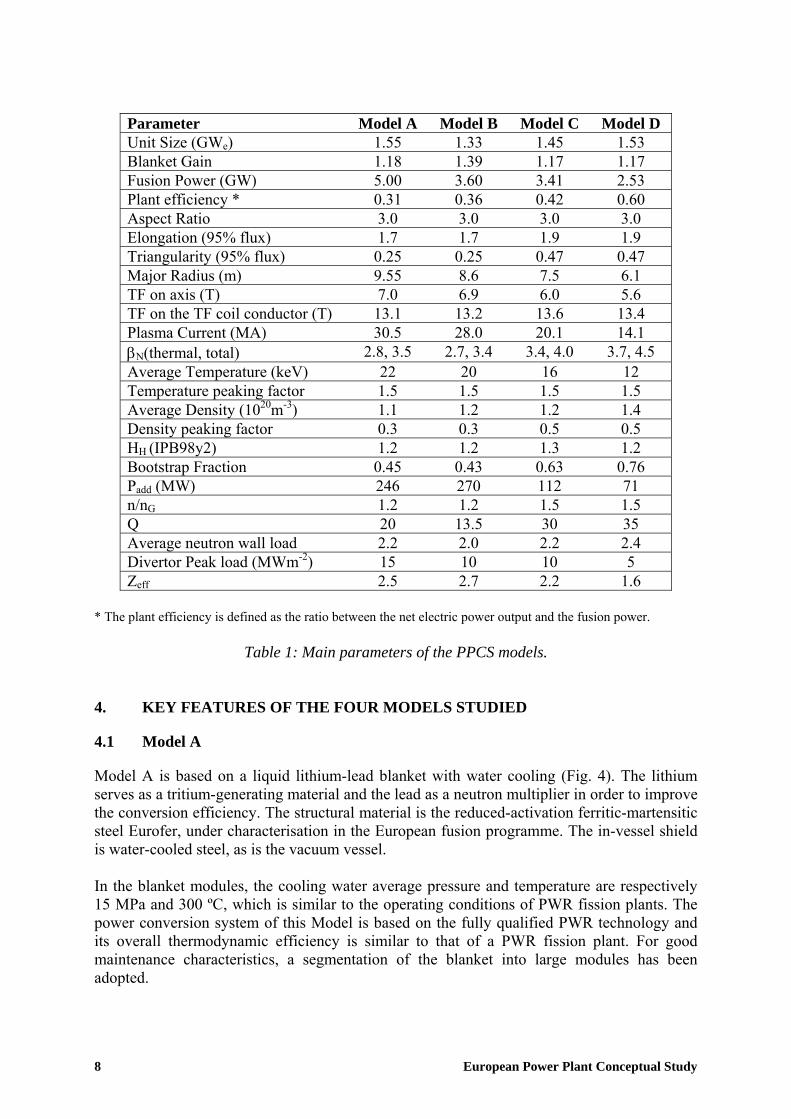
Parameter Model A Model B Model C Model D Unit Size (GWe) 1.55 1.33 1.45 1.53 Blanket Gain 1.18 1.39 1.17 1.17 Fusion Power (GW) 5.00 3.60 3.41 2.53 Plant efficiency * 0.31 0.36 0.42 0.60 Aspect Ratio 3.0 3.0 3.0 3.0 Elongation (95% flux) 1.7 1.7 1.9 1.9 Triangularity (95% flux) 0.25 0.25 0.47 0.47 Major Radius (m) 9.55 8.6 7.5 6.1 TF on axis (T) 7.0 6.9 6.0 5.6 TF on the TF coil conductor (T) 13.1 13.2 13.6 13.4 Plasma Current (MA) 30.5 28.0 20.1 14.1 βN(thermal, total) 2.8, 3.5 2.7, 3.4 3.4, 4.0 3.7, 4.5 Average Temperature (keV) 22 20 16 12 Temperature peaking factor 1.5 1.5 1.5 1.5 Average Density (1020m-3) 1.1 1.2 1.2 1.4 Density peaking factor 0.3 0.3 0.5 0.5 HH (IPB98y2) 1.2 1.2 1.3 1.2 Bootstrap Fraction 0.45 0.43 0.63 0.76 Padd (MW) 246 270 112 71 n/nG 1.2 1.2 1.5 1.5 Q 20 13.5 30 35 Average neutron wall load 2.2 2.0 2.2 2.4 Divertor Peak load (MWm-2) 15 10 10 5 Zeff 2.5 2.7 2.2 1.6
* The plant efficiency is defined as the ratio between the net electric power output and the fusion power.
Table 1: Main parameters of the PPCS models.
4. KEY FEATURES OF THE FOUR MODELS STUDIED
4.1 Model A
Model A is based on a liquid lithium-lead blanket with water cooling (Fig. 4). The lithium serves as a tritium-generating material and the lead as a neutron multiplier in order to improve the conversion efficiency. The structural material is the reduced-activation ferritic-martensitic steel Eurofer, under characterisation in the European fusion programme. The in-vessel shield is water-cooled steel, as is the vacuum vessel. In the blanket modules, the cooling water average pressure and temperature are respectively 15 MPa and 300 ºC, which is similar to the operating conditions of PWR fission plants. The power conversion system of this Model is based on the fully qualified PWR technology and its overall thermodynamic efficiency is similar to that of a PWR fission plant. For good maintenance characteristics, a segmentation of the blanket into large modules has been adopted.
8 European Power Plant Conceptual Study
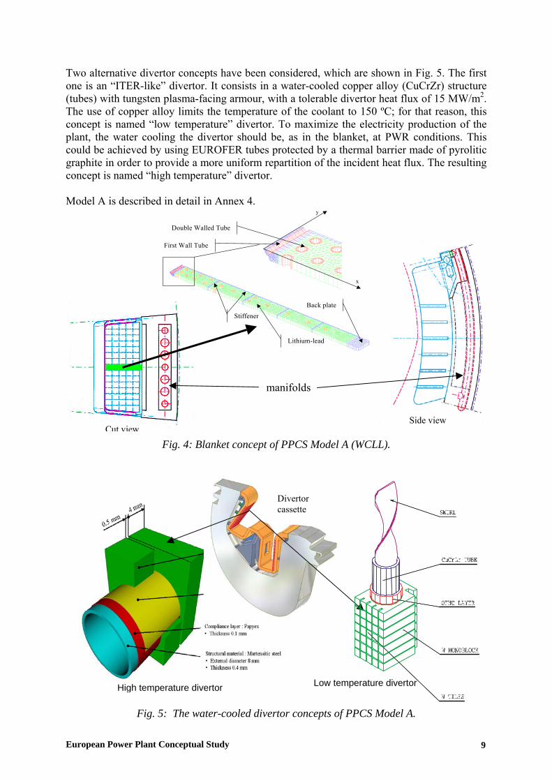
Two alternative divertor concepts have been considered, which are shown in Fig. 5. The first one is an “ITER-like” divertor. It consists in a water-cooled copper alloy (CuCrZr) structure (tubes) with tungsten plasma-facing armour, with a tolerable divertor heat flux of 15 MW/m2. The use of copper alloy limits the temperature of the coolant to 150 ºC; for that reason, this concept is named “low temperature” divertor. To maximize the electricity production of the plant, the water cooling the divertor should be, as in the blanket, at PWR conditions. This could be achieved by using EUROFER tubes protected by a thermal barrier made of pyrolitic graphite in order to provide a more uniform repartition of the incident heat flux. The resulting concept is named “high temperature” divertor. Model A is described in detail in Annex 4.
Fig. 4: Blanket concept of PPCS Model A (WCLL).
Lithium-lead
Double Walled Tube
First Wall Tube
StiffenerBack plate
x
y
Low temperature divertor r
Divertor cassette
manifolds
Side view Cut view
European P
High temperature diverto
Fig. 5: The water-cooled divertor concepts of PPCS Model A.
ower Plant Conceptual Study 9
4.2 Model B
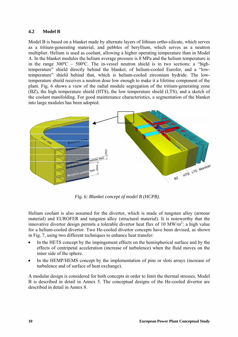
Model B is based on a blanket made by alternate layers of lithium ortho-silicate, which serves as a tritium-generating material, and pebbles of beryllium, which serves as a neutron multiplier. Helium is used as coolant, allowing a higher operating temperature than in Model A. In the blanket modules the helium average pressure is 8 MPa and the helium temperature is in the range 300ºC – 500ºC. The in-vessel neutron shield is in two sections: a “high-temperature” shield directly behind the blanket, of helium-cooled Eurofer, and a “low-temperature” shield behind that, which is helium-cooled zirconium hydride. The low-temperature shield receives a neutron dose low enough to make it a lifetime component of the plant. Fig. 6 shows a view of the radial module segregation of the tritium-generating zone (BZ), the high temperature shield (HTS), the low temperature shield (LTS), and a sketch of the coolant manifolding. For good maintenance characteristics, a segmentation of the blanket into large modules has been adopted.
Fig. 6: Blanket concept of model B (HCPB). Helium coolant is also assumed for the divertor, which is made of tungsten alloy (armour material) and EUROFER and tungsten alloy (structural material). It is noteworthy that the innovative divertor design permits a tolerable divertor heat flux of 10 MW/m2: a high value for a helium-cooled divertor. Two He-cooled divertor concepts have been devised, as shown in Fig. 7, using two different techniques to enhance heat transfer: • In the HETS concept by the impingement effects on the hemispherical surface and by the
effects of centripetal acceleration (increase of turbulence) when the fluid moves on the inner side of the sphere.
• In the HEMP/HEMS concept by the implementation of pins or slots arrays (increase of turbulence and of surface of heat exchange).
A modular design is considered for both concepts in order to limit the thermal stresses. Model B is described in detail in Annex 5. The conceptual designs of the He-cooled divertor are described in detail in Annex 8.
10 European Power Plant Conceptual Study

Fig. 7: He-cooled divertor concepts.
4.3 Model C
Model C has a lithium-lead blanket in which heat is removed by circulation of the lithium-lead itself and helium coolant passing through channels in the structure. This structure is mainly Eurofer, with oxide-dispersion-strengthened RAFM steel in the highest temperature zone (facing the plasma). This design is an evolution of a concept developed for the ARIES-ST power plant. Fig. 8 shows the principle construction of the blanket. The modules are large, stiff boxes with a grid structure inside, which are used as flow channels for the Pb-17Li and helium. High-pressure (8 MPa) helium gas is used to cool the first wall and the entire steel structure. For good maintenance characteristics, a segmentation of the blanket into large modules has been adopted. The liquid-metal Pb-17Li serves as a coolant as well as the tritium-generating material. Its outlet temperature is maximised for efficiency reasons. It enters the modules at 460 °C and exits at 700 °C, which is above the maximum permissible temperature for steel. Therefore, the LiPb flow channels are lined by silicon carbide composite inserts, providing thermal and electrical insulation but no structural function. The thermal insulation allows higher temperature operation of the LiPb for improved thermodynamic efficiency, whilst the electrical insulation avoids MHD effects when pumping the LiPb at high velocity. The PPCS C divertor is a helium-cooled design as in model B (see section 4.2). Model C is described in detail in Annex 6.
European Power Plant Conceptual Study 11

Fig. 8: Dual-coolant blanket (model C), equatorial outboard blanket module
(1.5 x 3.0 x 1.6 m3 rad x tor x pol).
4.4 Model D
The most advanced of the PPCS Plant Models, Model D, uses a lithium-lead blanket in which the LiPb itself is circulated as primary coolant. The structure is made by silicon carbide composite. The divertor structure is also in silicon carbide composite, with tungsten armour, cooled by liquid lithium-lead. The objective for PPCS D is to reach very high blanket operating temperatures, and thus a very high thermodynamic efficiency, as well as very low decay heat densities and low coolant pressures, accepting a higher development risk. The temperature of the coolant in the blanket modules is in the range 700 ºC – 1100 ºC. In order to simplify the lithium-lead flow path and to maximize the blanket coverage, a segmentation of the blanket in vertical, “banana-shaped” segments has been assumed for this model. Model D is described in detail in Annex 7.
4.5 Engineering parameters of the plant models
Table 2 indicates the power repartition and the overall efficiencies of the plants. The net electric power is obtained by subtracting the electric power required for H&CD and for pumping from the gross electric power. The accurate assessment of the power consumptions by other sub systems, mainly cryogenic, is quite difficult in the frame of a conceptual study. The expected values being relatively low (a few tens of MW), it has been decided not to take them into account in the calculation of the net electric power. This can be refined in further studies considering, in addition, possible improvements in either physics or technology for a tenth-of-a-kind reactor. In any case, the methodology being the same for all reactors models, it allows a pertinent comparison between them.
12 European Power Plant Conceptual Study

Model A Model B Model C Model D Fusion Power (MW) 5000 3600 3410 2530 Blanket Power (MW) 4845 4252 3408 2164 Divertor Power (MW) 894 685 583 607 LT Shield Power (MW) - 67 - - Pumping Power (MW) 110 375 87 12 Heating Power (MW) 246 270 112 71 H&CD Efficiency 0.6 0.6 0.7 0.7 Gross Electric Power (MW) 2066 2157 1696 1640 Net Electric Power (MW) 1546 1332 1449 1527 Plant Efficiency * 0.31 0.36 0.42 0.6
* The plant efficiency is defined as the ratio between the fusion power and the net electric power
Table 2: Thermodynamic parameters.
4.6 Divertor armour and plasma facing materials
A tungsten alloy armour has been chosen for the divertor for all models. This choice allows to maximise the divertor lifetime, assumed to be at least 2 FPY for a thickness of the armour of about 5 mm, because of the low sputter yield. The only possible alternative is molybdenum, which is less interesting from the waste management standpoint. As a conservative design choice, a tungsten alloy layer can be assumed on the first wall of the blanket modules to limit its erosion. The erosion rate of tungsten (0.1 mm/FPY in ITER-like conditions) is much lower than low Z materials like beryllium (about 3 mm/FPY in ITER-like conditions). The use of this tungsten layer does not impact the waste categorisation discussed in sub-section 6.3. An issue could be the transmutation of tungsten to osmium via rhenium under prolonged irradiation by 14 MeV neutrons, which could induce embrittlement; however, this is not a killing issue for an armour material. Such layer has not been taken into account in the neutronic analyses of models A and B because of its limited influence on the results. Under more optimistic assumptions, such as those made for model C, a bare stainless steel first wall has been considered as possible. 5. ECONOMICS
5.1 Types of cost
There are two classes of contributions to the cost of electricity from any power source: internal costs and external costs. The term “internal costs” refers to the contributions to the cost of electricity from constructing, fuelling, operating, maintaining and disposing of, power stations. The PPCS internal costs are discussed in sub-section 5.2 below. The internal costs of electricity do not include costs such as those associated with environmental damage or adverse impacts upon health. The PPCS “external costs” are discussed in sub-section 5.3 below. There are also significant economic factors associated with constraints on power production within the energy system as a whole: as discussed in an earlier report [2], these factors favour fusion power as a base load electricity source in the future energy mix.
European Power Plant Conceptual Study 13

The PPCS plant models differ in physical size, fusion power, the re-circulating power used to drive the electrical current in the burning plasma, the energy multiplication that occurs in the blankets, the efficiency of converting thermal to electrical power, and other respects. Accordingly, the total internal cost of electricity varies between the models.
5.2 Internal costs
The internal costs of electricity from the four PPCS Models were calculated using the code PROCESS briefly described in sub-section 3.1 above and used in earlier studies. This uses well-attested methodologies validated against industry’s cost estimates of ITER. The total capital cost, including interest during construction, is combined with replacement costs, other operating costs, payments into a decommissioning fund, and the availability, to obtain the internal cost of electricity. This is done in a standard manner, the “levelised cost” methodology, which is used for example in OECD and IAEA studies [6]. Earlier work with PROCESS [4], confirmed and elucidated by analytical studies, showed that the dependence of cost of electricity on the key parameters of the plasma, of the heat conversion cycle and of the reactor availability is well represented by the following expression:
0.30.4
N0.4
e0.5
th
0.6
NP11
A1coe
βη⎟⎠⎞
⎜⎝⎛∝ (1)
Here coe is cost of electricity, A is the availability, ηth is the thermodynamic efficiency, Pe is the net electric power, βN is the normalised plasma pressure, and N=n/nG is the Greenwald normalised plasma density. It is interesting to note that there is no dependence on the cost of fuel (lithium and deuterium). Fig. 9 shows the cost of electricity for each of the PPCS Models, as calculated in detail by PROCESS, together with the above scaling expression.
0
0.5
1
1.5
0 0.5 1 1.5
coe(scaling)
coe
(PPC
S)
Fig. 9: Relative internal cost of electricity, calculated by PROCESS, for the four PPCS
Models, plotted against the scaling shown in equation (1). The cost falls from Model A to Model B to Model C to Model D, reflecting the assumed
levels of plasma physics and technology development. As with all systems, the absolute value of the internal cost of electricity depends on the level of maturity of the technology. For an early implementation of these power plant models, characteristic of a tenth of a kind plant, the cost range of the PPCS plant models is calculated
14 European Power Plant Conceptual Study

to be 5 to 9 Eurocents/kWh. In a mature technology in which technological learning has progressed, the costs are expected to fall in the range 3 to 5 Eurocents/kWh. For all the Models, the internal cost of electricity is in the range of estimates, in the literature, for future costs from other sources. Both the near-term Models have acceptable competitive internal costs. Fig. 9 also illustrates an important general point: the four PPCS Models are good representatives of a wide class of possible conceptual designs. Internal costs in the region of those of Model C, and the corresponding broad level of development, though not the precise plasma physics and technology of Model C itself, are considered to be the most likely outcome of the fusion development programme. The PPCS economics modelling has been validated against other codes and against the ITER98 cost estimates. The agreement is generally very good, illustrating the robustness of the PPCS analyses. As usual, the most important capital cost issue is the cost of the large magnets. These are assumed to be based around conventional superconducting technology; Nb3Sn for the toroidal field and NbTi for the poloidal field. However, advances in superconductors, to lower cost materials and to higher temperature superconductors, could reduce these costs.
5.3 External costs
A methodology for evaluating the external costs of electricity generation was developed for the European Union: it is known as “ExternE”. In earlier studies [3], this system was used to evaluate the external costs of fusion electricity and compare these with the external costs of other sources. The PPCS external costs were estimated by scaling from these earlier results. The main external-cost-relevant differences between the PPCS Models and the most closely corresponding models forming the basis of the earlier studies are the masses of material and their activation: these form the basis of reliable scaling. The estimated external costs vary between 0.09 Eurocent/kWh for model A and 0.06 Eurocent/kWh for model D. For comparison, according to the same “ExternE” study, the estimated external cost would be 0.05 Eurocent/kWh for wind power, 1 to 2 Eurocent/kWh for methane and 5 to 8 Eurocent/kWh for oil power stations. Because of fusion’s safety and environmental advantages, its external costs are low. All four PPCS Models have external costs much lower than those of fossil fuels and comparable to wind power. Model C and Model D, which make use of silicon carbide, have the lowest external costs. Indeed, the external costs are dominated by the costs of conventional items, particularly conventional accidents during construction.
5.4 Summary
The details of the economic assessment of the four PPCS plant Models are reported in annex 11. The main points in the results are as follows. • The calculated internal cost of electricity from all the models was in the range of estimates
for the future costs from other sources, obtained from the literature. • Within this range, PPCS A has the highest internal cost, followed by PPCS B, then PPCS
C, with the very advanced model PPCS D having the lowest internal cost.
European Power Plant Conceptual Study 15

• Both of the near-term plant models, PPCS A and PPCS B, have acceptable competitive internal costs.
• All four PPCS models have low external costs: much lower than fossil fuels and
comparable to wind power. 6. SAFETY AND ENVIRONMENTAL IMPACTS
6.1 Prime features
Fusion power stations will have extremely low levels of fuel inventory in the burning chamber, therefore their power production stops a few seconds after fuelling is stopped. They have low levels of residual power density (arising from the decay of activated materials) in their structure after the termination of burn and they will not emit any of the greenhouse gases. These favourable generic features lead to substantial safety and environmental advantages, but the full expression of these advantages depends upon the details of design and materials selection. The PPCS Models generally differ substantially in their gross power, major radii, aspect ratio and power density from the Models that formed the basis of earlier studies, so full safety and environmental analyses have been performed. The foundations of all the analyses of safety and environmental impacts were comprehensive calculations of neutronics, activation and derived quantities. These were performed in 3 dimensions, using the codes MCNP and FISPACT, and they are presented in detail in Annex 10.
6.2 Accident analyses
To establish the worst consequences of an accident driven by in-plant energies, bounding accident analyses were performed for Plant Models A and B, in which a hypothetical event sequence is postulated. This was assumed to be a total loss of cooling from all loops in the plant, with no active cooling, no active safety system operating, and no intervention whatever for a prolonged period. The only assumed rejection of decay heat is by passive conduction and radiation through the layers and across the gaps of the model, towards the outer regions where eventually a heat sink is provided by convective circulation of the building atmosphere. The temperature rise is assumed to mobilise tritium and activation products, both erosion dust loose in the vessel and solid activation products in structure mobilised by volatilisation at the surfaces. This inventory, together with the entire contents of one cooling loop, is the source term assumed to be available for leakage from the plant through successive confinement barriers, using conservative assumptions. The fraction of this source that escapes into the environment is then transported, under worst weather assumptions, to an individual at the site boundary. To assess this bounding sequence for Models A and B, temperature transients were computed in a finite-element thermal model, mobilisation and transport through the confinement layers were modelled, and dispersion and dose calculations completed. Fig. 10 shows the calculated poloidal temperature profile in Model A, ten days after the onset of the hypothetical accident.
16 European Power Plant Conceptual Study

Fig. 10: Temperature profile in a poloidal cross-section of PPCS Model A, 10 days after the onset of a hypothetical bounding accident in which a total loss of all coolant is postulated,
together with the failure of all active safety systems. The temperatures are in degree Celsius and Y denotes the vertical direction.
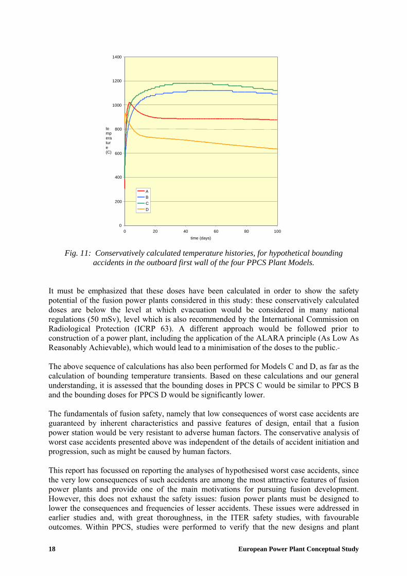
The histories of temperatures throughout the structures were obtained for times up to 100 days. These are illustrated in Fig. 11. Fig. 11, and the detailed calculations, show that at no time does any component reach a temperature close to melting. The decay heat densities in PPCS D are so low that there are essentially no temperature rises in even the worst case accidents, and even when conservatively calculated. Given the temperature histories, the mobilisation of material by volatilisation from surfaces was modelled conservatively by the code APMOB used in earlier studies. Aerosol processes that occur during the movement of mobilised material within the nested containment structures, and the leakages of material from one containment volume to another, were modelled with the code FUSCON. Uncertainties were bridged by conservative assumptions. The dispersion of released material, and resulting doses to a hypothetical most exposed individual at the site boundary were calculated by using the results for worst case weather. This whole procedure gives the conservative estimates of the consequences of worst case accidents to Models A and B shown in Table 3. The differences between the two values come from the fact that a pressure suppression system (condensation pool) is used for model A, in which radioactive material, released in the vacuum vessel, can be trapped. In model B, instead, the radioactive materials mobilised during the accident is confined in an expansion volume with an assumed leak rate of 3% of the volume per day at 1 mbar overpressure.
Model Dose A 1.2 mSV B 18.1 mSV
Table 3: Conservatively calculated doses to the public arising from the most severe
conceivable hypothetical accident driven by in-plant energies.
European Power Plant Conceptual Study 17
0
200
400
600
800
1000
1200
1400
0 20 40 60 80 100time (days)
temperature (C)
A B C D
Fig. 11: Conservatively calculated temperature histories, for hypothetical bounding
accidents in the outboard first wall of the four PPCS Plant Models. It must be emphasized that these doses have been calculated in order to show the safety potential of the fusion power plants considered in this study: these conservatively calculated doses are below the level at which evacuation would be considered in many national regulations (50 mSv), level which is also recommended by the International Commission on Radiological Protection (ICRP 63). A different approach would be followed prior to construction of a power plant, including the application of the ALARA principle (As Low As Reasonably Achievable), which would lead to a minimisation of the doses to the public. The above sequence of calculations has also been performed for Models C and D, as far as the calculation of bounding temperature transients. Based on these calculations and our general understanding, it is assessed that the bounding doses in PPCS C would be similar to PPCS B and the bounding doses for PPCS D would be significantly lower. The fundamentals of fusion safety, namely that low consequences of worst case accidents are guaranteed by inherent characteristics and passive features of design, entail that a fusion power station would be very resistant to adverse human factors. The conservative analysis of worst case accidents presented above was independent of the details of accident initiation and progression, such as might be caused by human factors. This report has focussed on reporting the analyses of hypothesised worst case accidents, since the very low consequences of such accidents are among the most attractive features of fusion power plants and provide one of the main motivations for pursuing fusion development. However, this does not exhaust the safety issues: fusion power plants must be designed to lower the consequences and frequencies of lesser accidents. These issues were addressed in earlier studies and, with great thoroughness, in the ITER safety studies, with favourable outcomes. Within PPCS, studies were performed to verify that the new designs and plant
18 European Power Plant Conceptual Study
parameters did not lead to outcomes that would invalidate the earlier conclusions. Systematic accident identification and ranking studies were performed. Based on these, four accident scenarios were selected for detailed analysis. The results of these calculations confirmed the conclusions of the earlier studies and the doses arising were much lower than the doses from the hypothetical bounding accidents summarised above (e.g. by 2 orders of magnitude for model B).
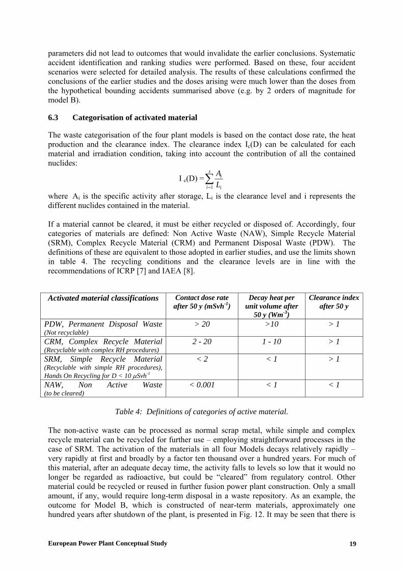
6.3 Categorisation of activated material
The waste categorisation of the four plant models is based on the contact dose rate, the heat production and the clearance index. The clearance index Ic(D) can be calculated for each material and irradiation condition, taking into account the contribution of all the contained nuclides:
I c(D) =∑=
z
i i
i
LA
1
where Ai is the specific activity after storage, Li is the clearance level and i represents the different nuclides contained in the material. If a material cannot be cleared, it must be either recycled or disposed of. Accordingly, four categories of materials are defined: Non Active Waste (NAW), Simple Recycle Material (SRM), Complex Recycle Material (CRM) and Permanent Disposal Waste (PDW). The definitions of these are equivalent to those adopted in earlier studies, and use the limits shown in table 4. The recycling conditions and the clearance levels are in line with the recommendations of ICRP [7] and IAEA [8].
Activated material classifications Contact dose rate after 50 y (mSvh-1)
Decay heat per unit volume after
50 y (Wm-3)
Clearance index after 50 y
PDW, Permanent Disposal Waste (Not recyclable)
> 20 >10 > 1
CRM, Complex Recycle Material (Recyclable with complex RH procedures)
2 - 20 1 - 10 > 1
SRM, Simple Recycle Material (Recyclable with simple RH procedures), Hands On Recycling for D < 10 µSvh-1
< 2 < 1 > 1
NAW, Non Active Waste (to be cleared)
< 0.001 < 1 < 1
Table 4: Definitions of categories of active material.
The non-active waste can be processed as normal scrap metal, while simple and complex recycle material can be recycled for further use – employing straightforward processes in the case of SRM. The activation of the materials in all four Models decays relatively rapidly – very rapidly at first and broadly by a factor ten thousand over a hundred years. For much of this material, after an adequate decay time, the activity falls to levels so low that it would no longer be regarded as radioactive, but could be “cleared” from regulatory control. Other material could be recycled or reused in further fusion power plant construction. Only a small amount, if any, would require long-term disposal in a waste repository. As an example, the outcome for Model B, which is constructed of near-term materials, approximately one hundred years after shutdown of the plant, is presented in Fig. 12. It may be seen that there is
European Power Plant Conceptual Study 19
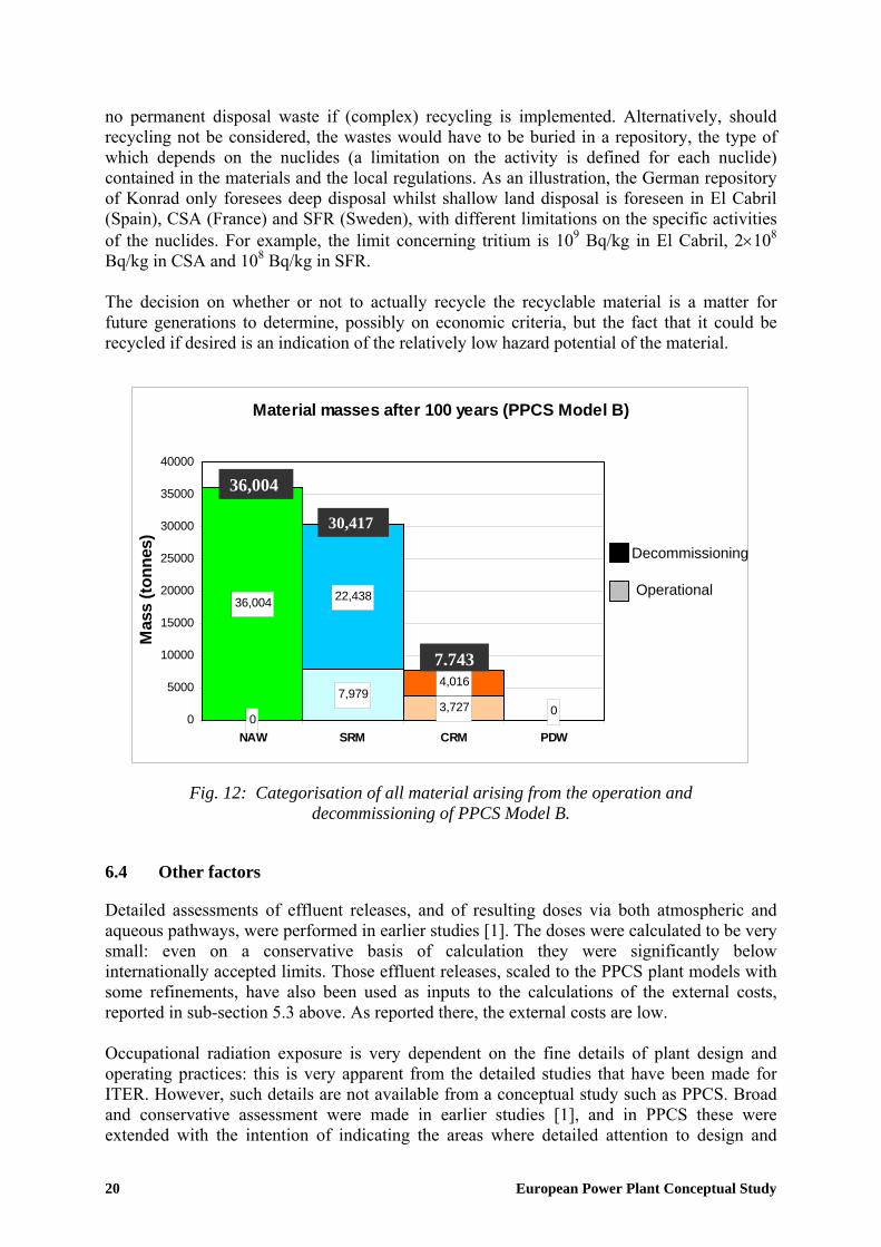
no permanent disposal waste if (complex) recycling is implemented. Alternatively, should recycling not be considered, the wastes would have to be buried in a repository, the type of which depends on the nuclides (a limitation on the activity is defined for each nuclide) contained in the materials and the local regulations. As an illustration, the German repository of Konrad only foresees deep disposal whilst shallow land disposal is foreseen in El Cabril (Spain), CSA (France) and SFR (Sweden), with different limitations on the specific activities of the nuclides. For example, the limit concerning tritium is 109 Bq/kg in El Cabril, 2×10⁸ Bq/kg in CSA and 108 Bq/kg in SFR. The decision on whether or not to actually recycle the recyclable material is a matter for future generations to determine, possibly on economic criteria, but the fact that it could be recycled if desired is an indication of the relatively low hazard potential of the material.
Material masses after 100 years (PPCS Model B)
003,727
7,9794,016
22,43836,004
00
5000
10000
15000
20000
25000
30000
35000
40000
NAW SRM CRM PDW
Mas
s (to
nnes
)
Decommissioning
Operational
7,743
30,417
36,004
Fig. 12: Categorisation of all material arising from the operation and decommissioning of PPCS Model B.
6.4 Other factors
Detailed assessments of effluent releases, and of resulting doses via both atmospheric and aqueous pathways, were performed in earlier studies [1]. The doses were calculated to be very small: even on a conservative basis of calculation they were significantly below internationally accepted limits. Those effluent releases, scaled to the PPCS plant models with some refinements, have also been used as inputs to the calculations of the external costs, reported in sub-section 5.3 above. As reported there, the external costs are low. Occupational radiation exposure is very dependent on the fine details of plant design and operating practices: this is very apparent from the detailed studies that have been made for ITER. However, such details are not available from a conceptual study such as PPCS. Broad and conservative assessment were made in earlier studies [1], and in PPCS these were extended with the intention of indicating the areas where detailed attention to design and
20 European Power Plant Conceptual Study
operating practices might be worthwhile. The results suggest that the blanket tritium removal system and the vacuum pumping system may be the areas most warranting detailed attention in any further detailed studies. Assessments were also performed in earlier studies of hazards (if any) that might arise from exposure to electromagnetic fields. It was concluded that there are no hazards to the public (apart from those that are inherent in all methods of electric power generation, handling and transmission), and that control of occupational exposures should be reasonably straightforward to achieve.
6.5 Summary
If a total loss of active cooling were to occur during the burn, the plasma would switch off passively due to impurity influx deriving from temperature rises in the walls of the reaction chamber. Any further temperature increase in the structures, due to residual decay heat, cannot lead to melting. This result is achieved without any reliance on active safety systems or operator actions. The maximum radiological doses to the public arising from the most severe conceivable accident driven by in-plant energies (bounding accident) would be below the level at which evacuation would be considered in many national regulations (50 mSv, the value which is also recommended by the International Commission on Radiological Protection). The power plant will be designed to withstand an earthquake with an intensity equal to that of the most severe historical earthquake increased by a safety margin, in accordance with the safety design rules in force (for example, in France this margin approximately corresponds to an increase of 1 degree on the Richter scale). It would also be possible to provide any features that might be needed to meet the non-evacuation criterion in case of impact of a large aircraft. In case of fire, a maximum of a few grams of tritium could be released, by appropriate partitioning of the tritium inventory, which is consistent with the non-evacuation criterion. If there is substantial use of beryllium as an in-vessel component (approximately 560 tons are foreseen within the blanket of model B), it may be necessary to recycle it to satisfy the EU legislation on beryllium chemical toxicity. The radiotoxicity of the materials (namely, the biological hazard potential associated with their activation) decays by a factor ten thousand over a hundred years. All of this material, after being kept in situ for some decades, will be regarded as non-radioactive (contact dose rate lower than 0.001 mSv/h, decay heat lower than 1 W/m3) or recyclable (contact dose rate lower than 20 mSv/h, decay heat lower than 10 W/m3). The recycling of some material could require remote handling procedures, which are still to be validated; an alternative could be a shallow land burial, after a time (approximately 100 years) depending on the nuclides contained in the materials and the local regulations. There will be no need for geological repositories. Thus the activated material from fusion power stations would not constitute a waste management burden for future generations. None of the materials required are subject to the provisions of non-proliferation treaties. 7. DEVELOPMENT NEEDS It is clear from the PPCS results that the main thrusts of the European fusion development programme are on the right lines. These are:
European Power Plant Conceptual Study 21
• ITER; • the optimisation of existing low activation martensitic steels, together with the
development of tungsten alloys, and their testing in IFMIF, and the parallel development of the more advanced materials envisaged in the PPCS; and
• the development of blanket modules, to be tested in ITER, based on the use of low activation martensitic steels as the main structural material.
It is also clear from the PPCS results that more work has to be undertaken on the development of divertor systems, ultimately capable of combining high heat flux tolerance and high temperature operation with sufficient lifetime in power plant conditions, and on the development and qualification of maintenance procedures by remote handling to satisfy the availability requirements of power plants. The first of these will require more emphasis on the development of tungsten alloys as structural materials and confirms the need to pursue the development of tungsten alloys as armour material. The effort already made to design and develop an efficient Remote Handling System, successful on JET, and now under way for ITER, will have to be further pursued with a view to power plant operation. A focussed and fast development along the above lines would result in an early demonstration commercial power plant with substantial safety and environmental advantages and, during operation when reliability issues had been ironed out, acceptable economics. Reflection on the PPCS results and the trends in the results, in the light of the understanding that they have brought in their train, also suggests that the following detailed steps should be undertaken. • Development of a fifth reactor model based on the helium-cooled lithium-lead concept
(HCLL), which appears to have considerable safety, environmental and economic potential, considering that this is one of the two blanket lines (HCLL and HCPB) selected in EU since 2002 for testing in ITER. In fact, a power plant study for the HCLL model has already been launched in 2004.
• Performance of a DEMO power plant study. The time is now ripe for such a study to give guidance to the ITER-accompanying programme in plasma physics and technology.
• Development and testing of helium-cooled divertor concepts capable of tolerating peak heat fluxes greater than 10 MW/m2.
• Establishment of a Remote Handling Test Facility, to be used for the development of maintenance concepts capable of delivering high availability.
• Studies aiming at optimising the shielding efficiency of helium-cooled blankets with minimal thickness on the inboard side of the torus.
8. OVERALL CONCLUSIONS The PPCS results for the near-term Models A and B suggest that a first commercial fusion power plant - one that would be accessible by a “fast track” route of fusion development, going through ITER and the successful qualification of the materials currently being considered - will be economically acceptable, with major safety and environmental advantages. These models rely on plasma performances marginally better than the design basis of ITER. The results for models C and D illustrate the potential for more advanced power plants.
22 European Power Plant Conceptual Study

In the PPCS plant models, the favourable inherent safety features of fusion have been exploited, by appropriate design and materials choice, to provide substantial safety and environmental advantages. In particular: • If a total loss of active cooling were to occur during the burn, the plasma would switch off
passively due to impurity influx deriving from temperature rises in the walls of the reaction chamber. Any further temperature increase in the structures, due to residual decay heat, cannot lead to melting. This result is achieved without any reliance on active safety systems or operator actions.
• The maximum radiological doses to the public arising from the most severe conceivable accident driven by in-plant energies would be below the level at which evacuation would be considered in many national regulations (50 mSv, the value which is also recommended by the International Commission on Radiological Protection).
• The radiotoxicity of the materials (namely, the biological hazard potential associated with their activation) decays by a factor ten thousand over a hundred years. All of this material, after being kept in situ for some decades, will be regarded as non-radioactive or recyclable (contact dose rate lower than 20 mSv/h, decay heat lower than 10 W/m3).
The two classes of contributions to the cost of electricity from any power source - internal cost and external cost – were both studied in PPCS: • The calculated internal cost of electricity from all the models was in the range of estimates
for the future costs from other sources, obtained from the literature. • All four PPCS models have low external costs: much lower than fossil fuels and
comparable to wind power. The most notable of the technical advances achieved during the PPCS are: the conclusions that plasma performance broadly thirty percent better than the design basis of ITER is sufficient for economic viability; the evolution from the ITER maintenance scheme of a maintenance concept capable of delivering high availability; and the development of a helium-cooled divertor concept capable of tolerating a peak heat load of ten MW/m2. REFERENCES 1. I Cook, G Marbach, L Di Pace, C Girard and N Taylor, “Safety and environmental
impact of fusion”, EFDA-S-RE-1, April 2001. 2. “Socio-economic aspects of fusion power”, EUR (01) CCE-FU 10/6.2.2, April 2001. 3. R. Toschi et al., “how far is a fusion power reactor from an experimental reactor”, Fusion
Engineering and Design 56-57 (2001) 163-172. 4. TC Hender, PJ Knight, I. Cook, UKAEA FUS 333 (1996). 5. ITER Physics basis, Nuclear Fusion 39 (1999) 2175. 6. Projected Costs of Generating Electricity, Update 1998, OECD/IEA Paris, ISBN 92-64-
16162-7. 7. ICRP Recommendations, ICRP Publication 60, Annals of ICPR, Vol. 21, No. 1-3, 1990. 8. Clearance Levels for Radionuclides in Solid Materials: Application of Exemption
Principles, Interim Report for Comment, IAEA TECDOC-855, Vienna, January 1996.
European Power Plant Conceptual Study 23
ANNEXES A1. PPCS stage III objectives A2. PPCS physics basis A3. Selection of PPCS plant parameters A4. PPCS Model A A5. PPCS Model B A6. PPCS Model C A7. PPCS Model D A8. He-cooled divertor concepts A9. Assessment of remote maintenance schemes for the PPCS A10. Safety and environment assessment of the PPCS models A11. Economic assessment of the PPCS models
24 European Power Plant Conceptual Study

ANNEXE 1


PPCS Final Report Annex 1 – PPCS stage III objectives
EFDA EFDA – TS(01)-9/4.1.3/PPCS Close Support Unit Garching 13 February 2001
Subject: Power Plant Conceptual Study, Detailed Objectives for Stage III
Recommendation: The EFDA Technology Sub-Committee is invited to
approve the attached objectives for the Stage III of the Power Plant Conceptual Study and to authorise the EFDA Close Support Unit – Garching to proceed by written procedure for the definition and allocation of the related §5.1(a) contracts.
1/9
PPCS Final Report Annex 1 – PPCS stage III objectives
POWER PLANT CONCEPTUAL STUDY – STAGE III DETAILED OBJECTIVES
INTRODUCTION The Power Plant Conceptual Study (PPCS) was launched in January 2000. Its objectives, as approved by the CCE-FU on 1.07.1999, are to assist in (i) assessing fusion energy status and in (ii) establishing coherence and priorities in the EU fusion programme. The PPCS was preceded in 1999 by a preparatory study on Power Plant Availability (PPA) and by pertinent studies in the Safety and Environmental Assessment of Fusion Power (SEAFP and SEAL programmes). The PPCS is divided into three stages. Stage I ended in May 2000. It used the results from earlier studies and from reviews of non-European work to develop draft objectives for fusion power plant designs. Stage II extends this work and focuses on three activities: clarification of the physics assumptions and evaluation of their impact on the design; exploration of remote maintenance concepts aiming for high reactor availability; and studying the sensitivity of achieving the safety and economic objectives to assumptions made about other issues in technology. Stage II will come to an end in early 2001. The work in Stage III will comprise the conceptual design of one or more models of a commercial fusion power plant, and the safety, environmental and economic assessment of these designs. This paper highlights the proposed key elements and organisation of the PPCS stage III work-programme. OBJECTIVES OF THE PPCS-STAGE III The PPCS needs to produce a report that will be the reference for assessing the fusion energy status and for establishing coherence and priorities in the EU fusion programme. The PPCS is in particular expected to provide answers to the questions asked outside the fusion community on the relevance of fusion as a future energy source. The study has, therefore, to demonstrate: • the credibility of the power plant design(s); • the claims for the safety and environmental advantages and for the economic viability of
fusion power; • the robustness of the analyses and conclusions. It is probably impossible to do so with a single power plant design and it is proposed to proceed in two steps. Firstly, to demonstrate the safety and environmental advantages of fusion power. Secondly, to assess credibility, and therefore the economic viability, of fusion power. Plant models with limited extrapolations will be considered in the first step whilst more advanced concepts will be considered in the second step. It is however important to stress that these models do not necessarily correspond to a logical development sequence (i.e. they do not constitute the road-map for fusion), but to possible reactor concepts that could be considered
2/9

PPCS Final Report Annex 1 – PPCS stage III objectives
depending on the energy and political situation at a given moment in the future following the successful completion of the ITER programme1. MODELS FOR THE FIRST STEP A robust design of a prototype fusion reactor is one requiring the minimum extrapolation assuming a successful completion of the ITER programme and a successful completion of the on-going long term R&D in the blanket and materials area. The adoption of proven technology for the balance of plant, without being a major design driver, would further strengthen the design. The physics assumptions proposed are given in annex 1 and they are being reviewed by an ad-hoc group chaired by the chairman of the FPC. On the technical side it would be the inappropriate to anticipate the outcome of the R&D related to the breeder blanket concepts, focused on the WCLL (Water Cooled Lithium Lead ) and the HCPB (Helium Cooled Pebble Bed) concepts. A water cooled system requires a smaller extrapolation of technology than a helium cooled one. On the other hand, a helium cooled system should result is a higher plant thermodynamic efficiency. It is therefore proposed to consider 2 models in the first step. Both models will use a low-activation ferritic-martensitic steel (e.g. EUROFER) as main structural material for in-vessel components. The first model will adopt the WCLL blanket concept and a water cooled divertor concept. The second model will adopt the HCPB blanket concept and, subject to confirmation, a helium cooled divertor concept. Considering the work already carried out on the proposed concepts, limited efforts will be required to finalise the conceptual design of both plants and most of them will be devoted to integration issues. Similarly, the safety and environmental assessment of both concepts is expected to benefit extensively from previous SEAFP and SEAL studies. MODELS FOR THE SECOND STEP Preliminary studies (PPA) carried out in 1999 suggest that a fusion power plant based on limited extrapolations with respect to ITER could be economically competitive with coal, provided “externalities” or pollution-abatement costs be taken into account, and with renewables, provided storage costs and the economic benefit for considering a 10th-of-a-kind reactor be taken into account2. However, this only holds provided not all the assumptions made are conservative. Therefore, to assess the economic viability of fusion power, it is proposed to consider reactor models with higher efficiency, higher availability and, possibly, more aggressive physics than
1 An economic assessment of the model(s) developed in the first step will also be carried out to check whether the resulting cost of electricity is in the same range than that of alternative energy sources. Similarly, the assumptions made for the model(s) developed in the second step should not jeopardise the safety and environmental advantages inherent to fusion. 2 The rough order of merit for reducing the COE (Cost Of Electricity)is: availability, thermodynamic efficiency, unit size (net electrical output), normalised beta and limiting density normalised to the Greenwald density.
3/9

PPCS Final Report Annex 1 – PPCS stage III objectives
those considered in the first step. Practically, it is proposed to consider two alternative concepts, the second of which would correspond to fairly aggressive hypothesis. The first model will adopt the so-called “dual coolant” concept, i.e. a self-cooled Li-Pb blanket with a helium cooled first wall. The divertor, subject to confirmation, would be helium cooled and the structural material will be a low activation steel3. The second model could be based on a self-cooled Li-Pb blanket with SiC-SiC as structural material in order to optimise the thermodynamic efficiency. CRITICAL ISSUES To assist in the conceptual design of the models identified here-above, and to address issues of particular concern to the public, a number of specific analyses and review will be carried out. For instance: • to ensure a high availability, alternative maintenance schemes to those extrapolated from
ITER and adopted in the first step will be investigated; • possible strategies for rad-waste production minimisation, recycling and storage will be
assessed. DEFINITION AND ALLOCATION OF ART. 5.1(a) CONTRACTS Following the approval of the detailed objectives for the Stage III of the Power Plant Conceptual Study set out in this paper, the EFDA Close Support Unit – Garching requests the authorisation to proceed by written procedure for the definition and allocation of the related §5.1(a) contracts.
3 SiC-SiC inserts are required for electrical insulation purposes.
4/9
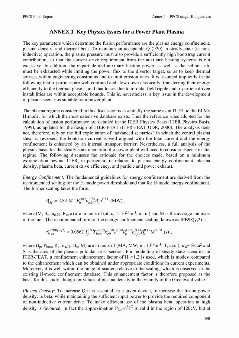
PPCS Final Report Annex 1 – PPCS stage III objectives
ANNEX 1 Key Physics Issues for a Power Plant Plasma The key parameters which determine the fusion performance are the plasma energy confinement, plasma density, and thermal beta. To maintain an acceptable Q (>20) in steady-state (ie non-inductive) operation, the plasma pressure must also provide a sufficiently high bootstrap current contribution, so that the current drive requirement from the auxiliary heating systems is not excessive. In addition, the α-particle and auxiliary heating power, as well as the helium ash, must be exhausted while limiting the power flux to the divertor target, so as to keep thermal stresses within engineering constraints and to limit erosion rates. It is assumed implicitly in the following that α-particles are well confined and slow down classically, transferring their energy efficiently to the thermal plasma, and that losses due to toroidal field ripple and α-particle driven instabilities are within acceptable bounds. This is, nevertheless, a key issue in the development of plasma scenarios suitable for a power plant. The plasma regime considered in this discussion is essentially the same as in ITER, ie the ELMy H-mode, for which the most extensive database exists. Thus the reference rules adopted for the calculation of fusion performance are detailed in the ITER Physics Basis (ITER Physics Basis, 1999), as updated for the design of ITER-FEAT (ITER-FEAT ODR, 2000). The analysis does not, therefore, rely on the full exploitation of “advanced scenarios” in which the central plasma shear is reversed, the bootstrap current is well aligned with the total current and the energy confinement is enhanced by an internal transport barrier. Nevertheless, a full analysis of the physics basis for the steady-state operation of a power plant will need to consider aspects of this regime. The following discusses the rationale for the choices made, based on a minimum extrapolation beyond ITER, in particular, in relation to plasma energy confinement, plasma density, plasma beta, current drive efficiency, and particle and power exhaust. Energy Confinement: The fundamental guidelines for energy confinement are derived from the recommended scaling for the H-mode power threshold and that for H-mode energy confinement. The former scaling takes the form, , PLH = 2.84 M−1Bo
0.82ne,200.58Ro
1a0.81 (MW) where (M, Bo, ne,20, Ro, a) are in units of (at.u., T, 1020m-3, m, m) and M is the average ion mass of the fuel. The recommended form of the energy confinement scaling, known as IPB98(y,2) is, ,
τE ,th
IPB98( y,2) = 0.0562 Ip0.93Ploss
−0.69κeff0.78ε0.58Ro
1.97ne,190.41Bo
0.15M 0.19 (s) where (Ip, Ploss, Ro, ne,19, Bo, M) are in units of (MA, MW, m, 1019m-3, T, at.u.), κeff=S/πa2 and S is the area of the plasma poloidal cross-section. For modelling of steady-state scenarios in ITER-FEAT, a confinement enhancement factor of HH=1.2 is used, which is modest compared to the enhancement which can be obtained under appropriate conditions in current experiments. Moreover, it is well within the range of scatter, relative to the scaling, which is observed in the existing H-mode confinement database. This enhancement factor is therefore proposed as the basis for this study, though for values of plasma density in the vicinity of the Greenwald value. Plasma Density: To increase Q it is essential, in a given device, to increase the fusion power density, ie beta, while maintaining the sufficient input power to provide the required component of non-inductive current drive. To make efficient use of the plasma beta, operation at high density is favoured. In fact the approximation Pfus~n2T2 is valid in the region of 12keV, but at
5/9
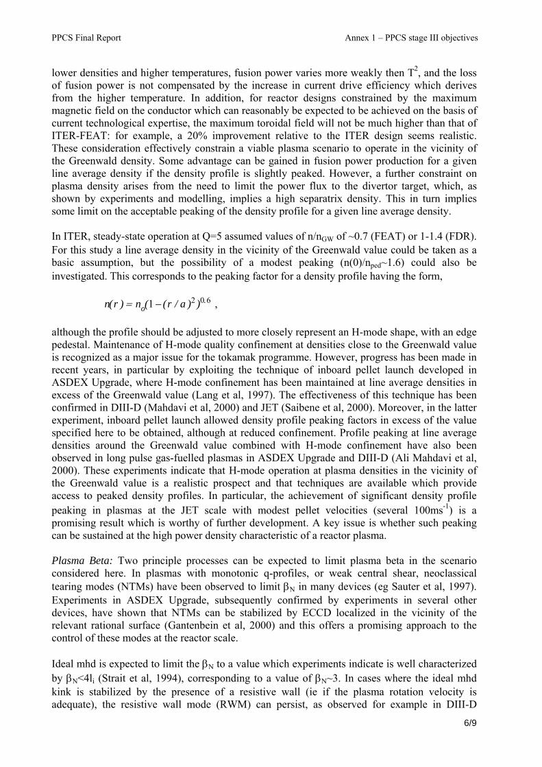
PPCS Final Report Annex 1 – PPCS stage III objectives
lower densities and higher temperatures, fusion power varies more weakly then T2, and the loss of fusion power is not compensated by the increase in current drive efficiency which derives from the higher temperature. In addition, for reactor designs constrained by the maximum magnetic field on the conductor which can reasonably be expected to be achieved on the basis of current technological expertise, the maximum toroidal field will not be much higher than that of ITER-FEAT: for example, a 20% improvement relative to the ITER design seems realistic. These consideration effectively constrain a viable plasma scenario to operate in the vicinity of the Greenwald density. Some advantage can be gained in fusion power production for a given line average density if the density profile is slightly peaked. However, a further constraint on plasma density arises from the need to limit the power flux to the divertor target, which, as shown by experiments and modelling, implies a high separatrix density. This in turn implies some limit on the acceptable peaking of the density profile for a given line average density. In ITER, steady-state operation at Q=5 assumed values of n/nGW of ~0.7 (FEAT) or 1-1.4 (FDR). For this study a line average density in the vicinity of the Greenwald value could be taken as a basic assumption, but the possibility of a modest peaking (n(0)/nped~1.6) could also be investigated. This corresponds to the peaking factor for a density profile having the form, , n(r ) = no(1− (r / a )2 )0.6
although the profile should be adjusted to more closely represent an H-mode shape, with an edge pedestal. Maintenance of H-mode quality confinement at densities close to the Greenwald value is recognized as a major issue for the tokamak programme. However, progress has been made in recent years, in particular by exploiting the technique of inboard pellet launch developed in ASDEX Upgrade, where H-mode confinement has been maintained at line average densities in excess of the Greenwald value (Lang et al, 1997). The effectiveness of this technique has been confirmed in DIII-D (Mahdavi et al, 2000) and JET (Saibene et al, 2000). Moreover, in the latter experiment, inboard pellet launch allowed density profile peaking factors in excess of the value specified here to be obtained, although at reduced confinement. Profile peaking at line average densities around the Greenwald value combined with H-mode confinement have also been observed in long pulse gas-fuelled plasmas in ASDEX Upgrade and DIII-D (Ali Mahdavi et al, 2000). These experiments indicate that H-mode operation at plasma densities in the vicinity of the Greenwald value is a realistic prospect and that techniques are available which provide access to peaked density profiles. In particular, the achievement of significant density profile peaking in plasmas at the JET scale with modest pellet velocities (several 100ms-1) is a promising result which is worthy of further development. A key issue is whether such peaking can be sustained at the high power density characteristic of a reactor plasma. Plasma Beta: Two principle processes can be expected to limit plasma beta in the scenario considered here. In plasmas with monotonic q-profiles, or weak central shear, neoclassical tearing modes (NTMs) have been observed to limit βN in many devices (eg Sauter et al, 1997). Experiments in ASDEX Upgrade, subsequently confirmed by experiments in several other devices, have shown that NTMs can be stabilized by ECCD localized in the vicinity of the relevant rational surface (Gantenbein et al, 2000) and this offers a promising approach to the control of these modes at the reactor scale. Ideal mhd is expected to limit the βN to a value which experiments indicate is well characterized by βN<4li (Strait et al, 1994), corresponding to a value of βN~3. In cases where the ideal mhd kink is stabilized by the presence of a resistive wall (ie if the plasma rotation velocity is adequate), the resistive wall mode (RWM) can persist, as observed for example in DIII-D
6/9
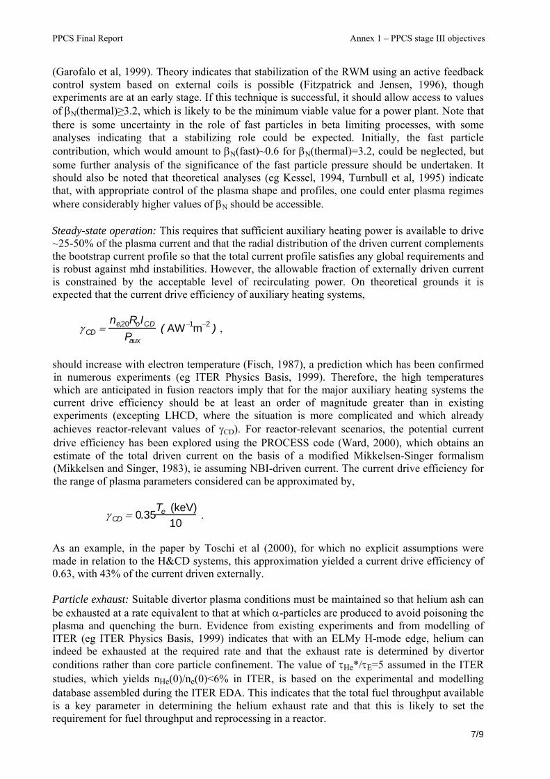
PPCS Final Report Annex 1 – PPCS stage III objectives
(Garofalo et al, 1999). Theory indicates that stabilization of the RWM using an active feedback control system based on external coils is possible (Fitzpatrick and Jensen, 1996), though experiments are at an early stage. If this technique is successful, it should allow access to values of βN(thermal)≥3.2, which is likely to be the minimum viable value for a power plant. Note that there is some uncertainty in the role of fast particles in beta limiting processes, with some analyses indicating that a stabilizing role could be expected. Initially, the fast particle contribution, which would amount to βN(fast)~0.6 for βN(thermal)=3.2, could be neglected, but some further analysis of the significance of the fast particle pressure should be undertaken. It should also be noted that theoretical analyses (eg Kessel, 1994, Turnbull et al, 1995) indicate that, with appropriate control of the plasma shape and profiles, one could enter plasma regimes where considerably higher values of βN should be accessible. Steady-state operation: This requires that sufficient auxiliary heating power is available to drive ~25-50% of the plasma current and that the radial distribution of the driven current complements the bootstrap current profile so that the total current profile satisfies any global requirements and is robust against mhd instabilities. However, the allowable fraction of externally driven current is constrained by the acceptable level of recirculating power. On theoretical grounds it is expected that the current drive efficiency of auxiliary heating systems,
γ CD =
ne,20RoICD
Paux ( AW−1m−2 ) ,
should increase with electron temperature (Fisch, 1987), a prediction which has been confirmed in numerous experiments (eg ITER Physics Basis, 1999). Therefore, the high temperatures which are anticipated in fusion reactors imply that for the major auxiliary heating systems the current drive efficiency should be at least an order of magnitude greater than in existing experiments (excepting LHCD, where the situation is more complicated and which already achieves reactor-relevant values of γCD). For reactor-relevant scenarios, the potential current drive efficiency has been explored using the PROCESS code (Ward, 2000), which obtains an estimate of the total driven current on the basis of a modified Mikkelsen-Singer formalism (Mikkelsen and Singer, 1983), ie assuming NBI-driven current. The current drive efficiency for the range of plasma parameters considered can be approximated by,
γ CD = 0.35
Te (keV)10
.
As an example, in the paper by Toschi et al (2000), for which no explicit assumptions were made in relation to the H&CD systems, this approximation yielded a current drive efficiency of 0.63, with 43% of the current driven externally. Particle exhaust: Suitable divertor plasma conditions must be maintained so that helium ash can be exhausted at a rate equivalent to that at which α-particles are produced to avoid poisoning the plasma and quenching the burn. Evidence from existing experiments and from modelling of ITER (eg ITER Physics Basis, 1999) indicates that with an ELMy H-mode edge, helium can indeed be exhausted at the required rate and that the exhaust rate is determined by divertor conditions rather than core particle confinement. The value of τHe*/τE=5 assumed in the ITER studies, which yields nHe(0)/ne(0)<6% in ITER, is based on the experimental and modelling database assembled during the ITER EDA. This indicates that the total fuel throughput available is a key parameter in determining the helium exhaust rate and that this is likely to set the requirement for fuel throughput and reprocessing in a reactor.
7/9

PPCS Final Report Annex 1 – PPCS stage III objectives
Power exhaust: Dissipation of a substantial fraction of the α-particle and auxiliary power before it reaches the divertor target is the key plasma-wall interaction issue for a power plant. It happens that, for the plasma parameters used in Toschi et al (2000), the sum of core bremsstrahlung, synchrotron emission and impurity line radiation from intrinsic impurities was approximately equal to the proposed current drive power (~80MW). Nevertheless, if the α-particle power (400MW) for this case were deposited within the area defined by the strike zones at the divertor target, the peak power loading would amount to ~50MWm-2. On the basis of arguments relating to surface erosion rates and tritium retention, tungsten appears as the most suitable plasma facing material for the divertor target for steady-state reactor operation. This implies, however, that a maximum peak power flux of 15MWm-2 would be permissible and the divertor plasma temperature would need to be reduced below 20eV to ensure that the erosion rate is acceptable (Wu and Mszanowski, 1995). Moreover, divertor conditions would need to be such that transient power loads due to ELMs were adequately buffered, since modelling of the factors influencing the lifetime of the ITER divertor target (Pacher et al, 1996) has shown that melting due to energy pulse from ELMs and disruptions would be limiting factors for tungsten PFCs. Divertor scenarios developed for the ITER FDR (ITER FDR, 1998) illustrate a promising approach to control of the power flux in a reactor. Based on operating regimes in existing experiments, such as the CDH-mode in ASDEX Upgrade (Gruber et al, 1995), or the RI-mode in TEXTOR (Messiaen et al, 1996), dissipation of exhaust power in ITER FDR utilized the concept of ‘impurity seeding’, in which a noble gas such as neon or argon is injected into the divertor plasma at low concentrations (<1%). This results in a substantial increase in line radiation in the edge region of the bulk plasma and in the divertor. Two dimensional numerical modelling of the ITER divertor (eg Kukushkin et al, 1997) showed that, at high densities and by exploiting radiation from intrinsic and seeded impurities, a ‘partially detached’ divertor regime could be developed which allowed the power conducted and convected to the target to be reduced from 200MW to ~70MW, bringing the peak heat flux to the divertor target to below 10MWm-2. Access to partially detached divertor conditions are an important aspect of the analysis, since this mode of operation preferentially reduces the target heat flux and electron temperature close to the separatrix as a result not only of impurity radiation, but also of loss processes such as volumetric recombination and ion-neutral friction processes. For cases with ~400MW of α-power, the ITER FDR scenario seems the only likely means of limiting the peak heat flux to the divertor target to below 15MWm-2, but the requirement on midplane separatrix density and its compatibility with core density needs to be evaluated. Based on the considerations outlined here, it is possible to propose a set of plasma parameters which would provide the necessary level of plasma performance for a power plant, but which would not involve too large an extrapolation beyond those of ITER, on the assumption that ITER’s steady-state mission goals are achieved: βN(thermal)=3.5 n/nGW=1.1 HH=1.2 While these values are challenging, in terms of our present capability (though values equal, or very close, to these have been achieved separately), they are representative of the plasma conditions which must be attained to establish an attractive reactor design.
8/9
PPCS Final Report Annex 1 – PPCS stage III objectives
References Fisch, N.J., Rev. Mod. Phys. 59 (1987) 175. Fitzpatrick, R. and Jensen, T.H., Phys. Plasmas 3 (1996) 2641. Gantenbein, G. et al: Phys. Rev. Lett. 85 (2000) 1242. Garofalo, A.M. et al: Phys. Rev. Lett. 82 (1999) 3811. Gruber, O. et al, Phys. Rev. Lett. 74 (1995) 4217. Technical Basis for the Final Design Report, Cost Review and Safety Analysis, ITER EDA Documentation Series No. 16, IAEA, Vienna (1998). ITER Physics Basis, Nucl. Fusion 39 (1999) 2137. Technical Basis for the ITER-FEAT Outline Design Report, Cost Review and Safety Analysis, ITER EDA Documentation Series, IAEA, Vienna (2000). Kessel, C., Phys. Rev. Lett. 72 (1994) 1212. Kukushkin, A.S. et al, Nucl. Mater. 241-243 (1997) 268. Lang, P. et al, Phys. Rev. Lett. 79 (1997) 1487. Mahdavi, M.A. et al, Proc 14th Int Conf on Plasma-Surface Interactions in Controlled Fusion Devices, Rosenheim, 2000 (to be published). Messiaen, A.M. et al, Phys. Rev. Lett. 77 (1996) 2487. Mikkelsen, D.R. and Singer, C.E., Nucl. Technol./Fusion 4 (1983) 237. Pacher, H.D. et al, J. Nucl. Mater. 241-243 (1997) 255. Saibene, G. et al. to be published. Sauter, O. et al, Phys. Plasmas 4 (1997) 1654. Strait, E.J., Phys. Plasmas 1 (1994) 1415. Toschi, R. et al, Proc 21st Symposium on Fusion Technology, Madrid, 2000 (to be published). Turnbull, A.D. et al, Phys. Rev. Lett. 74 (1995) 718. Ward, D.J., private communication (2000). Wu, C.H. and Mszanowski, U., J. Nucl. Mater. 281 (1995) 293.
9/9


ANNEXE 2


PPCS Final Report Annex 2 – Physics
REPORT OF THE AD-HOC GROUP TO ASSESS THE PHYSICS ASSUMPTIONS UNDERLYING
THE POWER PLANT CONCEPTUAL STUDY (PPCS) 1. Introduction The Power Plant Conceptual Study co-ordinated by EFDA is presently in a transition phase from stage II to stage III. Recently the EFDA Technology Sub-Committee approved the Technology Workprogramme 2001 in which the Technical Specifications of the PPCS stage III are described: document EFDA TS(01)-10/4.1.PPCS from 28 March 2001. The PPCS stage III shall formally start on 8 July 2001 and finish on 31 December 2002. The main objectives of the study are to demonstrate the credibility of fusion power plant design(s) the claims for the safety and environmental advantages and for the economic viability of
fusion power the robustness of the analyses and conclusions.
According to a request from EFDA and from the FPC chairman an ad-hoc group of physicists has been formed for the monitoring of the plant parameters selection and a review the physics model used in the PROCESS code to check its consistency with the latest physics results before stage III of the study starts. The membership of this ad-hoc group is as follows: U. Samm (chairman), E. Barbato, J.G. Cordey, J. Lister, D. Moreau, J. Ongena, H. Wobig, D. Bartlett (secretary). The group met on 30 May 2001 in Jülich. During this meeting presentations were given by D. Campbell on Key Physics Issues and by D. Ward on the Impact of Physics Assumptions on Conceptual Power Plant Design and Economics. The meeting was also attended by K. Lackner and G. Saibene from EFDA CSU Garching and by V. Philipps and B. Unterberg from Jülich. The report is based on these talks, on the Technical Specifications of the PPCS stage III and on other documents describing the previous work, e.g. PPCS-II, Sensitivity of Economics Requirements to Variation in Assumed Physics and
Technological Constraints by Ward, Cook and Taylor; with annex 2 The Impact of Physics Assumptions on Fusion Economics by Ward, Cook and Knight (paper from IAEA Sorrento 2000)
How far is a Fusion Power Reactor from an Experimental Reactor by Toschi et al. (SOFT Madrid 2000)
1/9

PPCS Final Report Annex 2 – Physics
2. Objectives The report should be seen as an internal paper providing guidance to the PPCS rather than a text for the public. The assessment follows the main approach of the PPCS, i.e. a moderate extrapolation from ITER-FEAT to make use of the huge data base available. However, the study must be open for other developments, e.g. in the field of stellarators or spherical tokamaks. Steady state operation (or at least very long pulses) is the major difference between a power plant and ITER-FEAT. As a consequence for tokamaks only plasma scenarios with significant fractions of non-inductive current drive have to be considered. From a description of the probable progress with the different plasma scenarios like e.g. H-mode, radiative modes or reversed shear and with the different confinement schemes tokamak, spherical tokamak or stellarator a set of probable plasma parameters should follow. In particular, the physics extrapolation described for PPCS stage III has to be assessed. It is important to point out any significant trade-off between different plasma properties and the necessity for optimisation. If possible the functional description of parameters should be given and their range of validity. These interdependencies can then be used during the PPCS, e.g. in the PROCESS code, to find the optimum combination of parameters. The discussion of probable progress in physics is inevitably linked to required physics R&D to be performed in present experiments and later also in ITER-FEAT as well as in other accompanying devices. A list of R&D needs with special emphasis on power plant requirements is given in the appendix. In the following sections the key physics issues are discussed according to the above objectives within the four categories confinement, MHD, current drive and divertor. 3. The Confinement Scaling and Appropriate Limiting Values for the
Dimensionless parameters The energy confinement scaling used in the PPCS is presently the same expression that the ITER team were recommended to use for their design studies, namely the IPB98(y,2) scaling(1). This expression, which was derived in 1998 for steady state ELMy H-mode plasmas, using the multi machine database ITERH.DB3v5. This database, which was assembled during 1997-98, included data with normalised β and density normalised to the Greenwald density limit in the ranges 0.5 < βn < 3 and 0.2 < n/nGR < 0.9. Since 1998 the database has been considerably extended and the latest version of the database which was assembled in Sept. 2000 contains data in the ranges 0.5 < βn < 3.5 and 0.2 < n/nGR < 1.4. The increase in both these ranges clearly illustrates the progress that was made in the period 1997-2000. In Kardaun et al(2) it has been shown that the IPB98(y, 2) scaling is still a very good fit to the extended database having a root mean square error of 15%. Expressing this in terms of H98 factor (τE /τ98) the range is 0.7 < H98 < 1.3 .
2/9
PPCS Final Report Annex 2 – Physics
Recently JET under EFDA has been operating with highly shaped plasmas, which has resulted in a further enhancement of the high density data set, this will be made available to the multimachine database in July 2001. Thus the assumptions made in the PPCS of βn < 3.5, n/nGR < 1.2 and H98 < 1.2 seem quite reasonable, particularly in view of the progress that has been made during the last four years. Turning to the peaking of the density profile, all of the three ELMy H-mode devices, ASDEX Upgrade, DIII-D and JET have reported peaking of the density profile. However the origin of this peaking is not yet fully understood, it is not clear whether the peaking is a consequence of the beam fuelling or an anomalous pinch. In view of this uncertainty it would be wise to use in design studies at this stage values not much higher than the average value of the database n(o)/nped = 1.3 for the peaking. A major unresolved issue both for ITER and PPCS is to obtain a good confinement regime with divertor tolerant ELMs. Other areas in which further research is needed are, refuelling and influence of rotation on confinement and the development of a database in which a large fraction of current is driven non-inductively. A full 1½ -D transport modelling of one of the power plant scenarios should be completed in order to check that the steady state profiles of j, Te, ne etc. are similar to those used in the PROCESS code. 1) ITER Physics Basis Nucl. Fusion 39 p2204 (1999). 2) Kardaun, O., et al. IAEA, Sorrento (2001). 4. MHD, Equilibria, Control and Disruptions Different aspects concerning MHD, Equilibria, Control and Disruptions were raised by the AHG. The shaping and control aspects of PPCS will not present a significant development beyond ITER and were not considered. It was assumed that the required poloidal field control power will be negligible cost compared with the heating and current drive systems, and this should already be demonstrated on ITER. 4.1 Disruptivity The AHG accepted that essentially disruption-free operation of PPCS is both necessary and technically plausible following the commissioning and definition of the operational space (for the first of a kind). The latter condition is necessary due to the lack of an explicit model of the disruption limit at high density. Since the economics impose operation at high density, this empirical limit will have to be validated during commissioning of the first device. This position is based on the consideration that once a plasma has lasted for all the typical characteristic times, up to the thermal time constants of the device, the plasma should never spontaneously disrupt in the absence of other failures. Considerable R&D will be needed to achieve the stringent requirement of one disruption per year. 4.2 Equilibrium The choice of elongation and triangularity for PPCS will be frozen and based on DEMO, to be based on ITER, which is mainly based on a few observations of the improvement of confinement with shape, linked to the triangularity dependence of the pedestal (see confinement section). The choice of the precise equilibrium will not have a serious impact on
3/9

PPCS Final Report Annex 2 – Physics
cost. The AHG raised the question of SND vs DND, as traditional. Since the dominant cost lever might be the first wall replacement, splitting the averaged power and hence averaged erosion over double the surface might be beneficial. Precise balancing of instantaneous power would not be required and precise balancing of erosion should be possible. R&D would be needed in the mean time to convert this reasoning into a serious argument. 4.3 ELMs The ELMy H-mode is chosen for confinement and impurity/density control. Too large ELMs would not be tolerable. There is no reason why another regime with a more benign limitation mechanism on the pedestal pressure should not be found for PPCS during the R&D in the next decades and indications already exist that this might be the case. The AHG did not feel that the assumption that a benign ELMy or ELM-free regime will be found for PPCS was an unreasonable. 4.4 Resistive Wall Modes (RWM) Beyond the free boundary ideal MHD pressure limit, around βN=3 (roughly 4 li), stabilisation is provided by the vessel wall, but only for a finite time due to the vessel resistivity. Beyond this time, active stabilisation of the RWM is required. The stabilisation of the n=1 mode is followed after a small further increase in βN by higher (n,m) modes. Stabilising more modes would yield reducing benefits for increasing complexity. The AHG expressed the concern that the increase in βN by stabilising the n=1 RWM might even be of marginal interest in view of the weak dependence of the Cost of Electricity on βN presented by the proponents. On the other hand, previous design studies have always indicated the cost effectiveness of increased bootstrap current obtained by stabilising the RWM and consequently increasing βN. The AHG therefore proposed that if the proponents choose to assume n=1 RWM stabilisation, a free-boundary βN limited design should also be checked as a test case to validate the cost effectiveness of the RWM stabilisation, taking some increased risk and complexity into consideration. The stabilisation of RWM in ITER is essential as a means of obtaining maximum fusion performance for a given installation cost and will therefore provide the required R&D for PPCS. 4.5 Neoclassical Tearing Modes (NTM) NTMs may or may not be a problem in PPCS. ITER intends to stabilise NTMs with ECH/ECCD, which is an essential experimental approach to maximising fusion performance for a given installation cost. However, the gain compared with the increase in complexity and possible loss of reliability might not be necessarily advantageous for the PPCS. The AHG recognises that stabilising the NTM would not be a major power consumption issue, since PPCS is driven by significant levels of additional heating, but that complexity and guaranteed performance might be the major issues. The AHG considers that obtaining suitable plasma profiles which do not lead to NTM destabilisation is a more fruitful approach which will require R&D. 5. Heating and Current Drive The steady state operation of a tokamak reactor relies upon the fact that the electrical current necessary for plasma confinement can be driven non-inductively. It then consists of two parts, (i) a self-generated current stemming from the density and temperature gradients (the
4/9
PPCS Final Report Annex 2 – Physics
neoclassical bootstrap effect), and (ii) an externally driven current which comes from the application of high power heating through the interaction of neutral beams or radio frequency waves with the various particle species. Since the amount of recirculated power must be minimized in an attractive reactor design, it is essential that the bootstrap current fraction and the current drive efficiency of the external heating systems are both as large as possible. The present assessment is of course highly subject to the level of progress one can reasonably anticipate during the operation of ITER and the required R&D will be outlined.
5.1. Assumptions concerning the bootstrap current fraction The discovery of improved confinement modes in tokamaks, at reduced plasma current (i.e. high safety factor, q), has recently generated a growing interest in the potential steady state operation of these devices because they allow higher performances than standard scenarios in terms of H-factor and normalized beta parameter (ßN). The combination of a large ßN and q results in a larger bootstrap current fraction, and the radial profile of this current can in principle be almost aligned with the current density profile which is required to maintain this so-called advanced tokamak equilibrium, thus requiring a minimum amount of external drive. This should constitute a significant part of the ITER research program as the physics basis for these scenarios is not yet fully developed, and therefore an extrapolation to the reactor scale is still subject to large uncertainties. Nevertheless, it is important to investigate the possibility of integrating the various physical and technological constraints inherent to such a regime into a commercial reactor design. In this sense the assumed parameters constitute a reasonable set anticipating on the progress which will be made during the operation of ITER. ßN = 3.5 leads to a bootstrap current fraction of 46% which is well within the present experimental data since fractions up to 70% have been reached at densities significantly lower than the Greenwald density. The balance between the bootstrap fraction and the externally driven current depends largely on the assumed plasma density, current drive efficiency and aspect ratio. A trade-off therefore has to be made and this leaves room for further optimisation.
5.2. Assumptions concerning the current drive efficiency The design assumes that the external heating and current drive (H&CD) will be provided by negative-ion-based neutral beam injection (N-NBI). Although the optimum balance between various systems is not known, the procurement of several systems could induce some extra capital cost, but this uncertainty should not be important in the evaluation of the cost of electricity. Also real time control of the discharge will demand that the peak deliverable power be sufficiently large compared to the average injected power. The quoted additional powers of about 100 MW is therefore to be understood as a time average.
The current drive efficiency of N-NBI is evaluated from a sound theoretical basis, which predicts a linear increase with temperature. The theory is in fair agreement with present experimental results, but here a large extrapolation is required as the largest measured efficiencies are of the order of 0.1-0.3x10²⁰ AW-1m-2, whereas efficiencies of 1.13 and 1.02x10²⁰ AW-1m-2, respectively, are required from the two proposed provisional power plant models. It would be worthwhile to investigate the effect of lower current drive efficiencies to take into account the need to drive current in colder plasma regions for profile control. The assumed current drive efficiency should be an important factor in estimating the cost of electricity and we suggest that this dependency be better evaluated. 6. Divertor and Exhaust
5/9
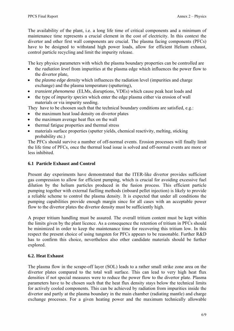
PPCS Final Report Annex 2 – Physics
The availability of the plant, i.e. a long life time of critical components and a minimum of maintenance time represents a crucial element in the cost of electricity. In this context the divertor and other first wall components are crucial. The plasma facing components (PFCs) have to be designed to withstand high power loads, allow for efficient Helium exhaust, control particle recycling and limit the impurity release. The key physics parameters with which the plasma boundary properties can be controlled are • the radiation level from impurities at the plasma edge which influences the power flow to
the divertor plate, • the plasma edge density which influences the radiation level (impurities and charge
exchange) and the plasma temperature (sputtering), • transient phenomena (ELMs, disruptions, VDEs) which cause peak heat loads and • the type of impurity species which enter the edge plasma either via erosion of wall
materials or via impurity seeding. They have to be choosen such that the technical boundary conditions are satisfied, e.g.: • the maximum heat load density on divertor plates • the maximum average heat flux on the wall • thermal fatigue properties and thermal stress • materials surface properties (sputter yields, chemical reactivity, melting, sticking
probability etc.) The PFCs should survive a number of off-normal events. Erosion processes will finally limit the life time of PFCs, once the thermal load issue is solved and off-normal events are more or less inhibited. 6.1 Particle Exhaust and Control Present day experiments have demonstrated that the ITER-like divertor provides sufficient gas compression to allow for efficient pumping, which is crucial for avoiding excessive fuel dilution by the helium particles produced in the fusion process. This efficient particle pumping together with external fuelling methods (inboard pellet injection) is likely to provide a reliable scheme to control the plasma density. It is expected that under all conditions the pumping capabilities provide enough margin since for all cases with an acceptable power flow to the divertor plates the divertor density must be sufficiently high. A proper tritium handling must be assured. The overall tritium content must be kept within the limits given by the plant licence. As a consequence the retention of tritium in PFCs should be minimized in order to keep the maintenance time for recovering this tritium low. In this respect the present choice of using tungsten for PFCs appears to be reasonable. Further R&D has to confirm this choice, nevertheless also other candidate materials should be further explored. 6.2. Heat Exhaust The plasma flow in the scrape-off layer (SOL) leads to a rather small strike zone area on the divertor plates compared to the total wall surface. This can lead to very high heat flux densities if not special measures were to reduce the power flow to the divertor plate. Plasma parameters have to be chosen such that the heat flux density stays below the technical limits for actively cooled components. This can be achieved by radiation from impurities inside the divertor and partly at the plasma boundary in the main chamber (radiating mantle) and charge exchange processes. For a given heating power and the maximum technically allowable
6/9

PPCS Final Report Annex 2 – Physics
power flux density on the target a minimum value for the divertor and mantle radiation follows. This relation should be an important element in the PROCESS code. The radiation level can be provided by intrinsic impurities (e.g. carbon as in present experiments) and for active control by seeded impurities (e.g. noble gases as required for a tungsten divertor). The type of impurity determines among other plasma parameters the ratio of radiation level located inside and outside the divertor. The trade-off between radiation level and fuel dilution due to impurities in the core deserves special attention. An important objective for further R&D is the development of an integral model which provides an adequate description of the relations between eroded/seeded impurities and impurity transport, radiation, confinement and fuel dilution. The implementation of simplified relations derived from such a model in the PROCESS code at a later stage would then be highly recommended. High divertor radiation with an acceptable low impurity content in the main plasma is probably only achievable via high divertor density and hence high upstream separatrix density. This constraint may limit the operational window for certain plasma scenarios which rely on low or moderate separatrix densities. This affects also the ELM behaviour. However, ELMs are more a problem of erosion rather than of heat exhaust. 6.3 Impurity Control and Sufficient Life Time of Wall Components Once the average heat exhaust is solved, there are still other processes limiting the life time of the PFCs: sputtering, chemistry and melting or sublimation during transient heat loads like with ELMs or disruptions and the neutron wall load. Due to re-deposition processes the net-erosion is normally significantly smaller than the direct erosion yield. Where areas with net-erosion or net-deposition will develop depends on local and global particle migration. Today no coherent modelling exists which allows to predict quantitatively the life time of a wall element due to erosion. Therefore, the reactor studies so far work with very global assumptions leading to a replacement of the divertor modules about every two years, which appears to be reasonable. A significantly improved modelling of erosion and re-deposition for reactor conditions will later hopefully be available but it is unlikely to be the case during the PPCS stage III. A possible transient overload due to ELMs is a critical issue which will lead to an important boundary condition for the operational window for different plasma scenarios. The PPCS should only consider confinement scenarios which provide moderate ELMs leading not to melting or sublimation of PFC material. 7. Conclusions A set of key physics parameters for the start of the PPCS III is available which represents a rather moderate extrapolation from present knowledge. There is sufficient confidence that all critical issues mentioned in the assessment can be clarified during the ongoing R&D in the next decade. The corresponding results to be expected during the next years on stellarators and spherical tokamaks will need special attention at a later stage. The AHG proposes to list in detail the formulae used in the PROCESS code. It would be useful if - as a kind of mutual benefit between the PPCS and the physics R&D - a simple
7/9

PPCS Final Report Annex 2 – Physics
analytic expression could be developed for all the key scalings. The AHG also felt that the treatment of the divertor issues in the code should be clarified in view of the importance of this topic. It is interesting to note that the PPCS might also have some impact on the ongoing physics R&D. Since the various aspects of a tokamak can have a quite different lever on the cost of electricity (e.g. availability more important than β), the results of an optimisation with the PROCESS code might have important impact on the relative weight of certain R&D work. It is recommended that the use of the confinement scaling expressions, limiting βN values, current drive efficiencies and divertor model should be reviewed at 1-2 yearly intervals. The AHG feels that after the start of the PPCS stage III a first revisit of this assessment after about one year would be appropriate.
8/9
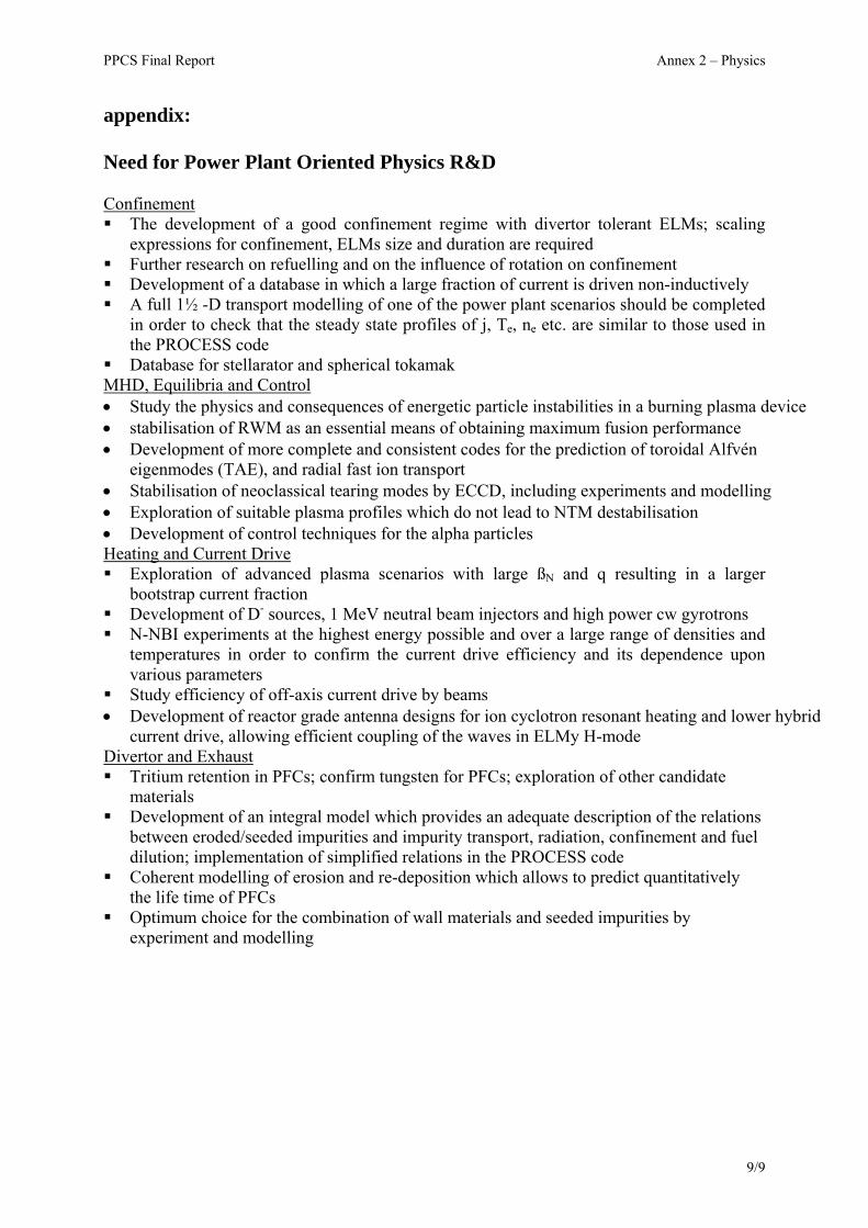
PPCS Final Report Annex 2 – Physics
appendix: Need for Power Plant Oriented Physics R&D Confinement The development of a good confinement regime with divertor tolerant ELMs; scaling
expressions for confinement, ELMs size and duration are required Further research on refuelling and on the influence of rotation on confinement Development of a database in which a large fraction of current is driven non-inductively A full 1½ -D transport modelling of one of the power plant scenarios should be completed
in order to check that the steady state profiles of j, Te, ne etc. are similar to those used in the PROCESS code
Database for stellarator and spherical tokamak MHD, Equilibria and Control • Study the physics and consequences of energetic particle instabilities in a burning plasma device • stabilisation of RWM as an essential means of obtaining maximum fusion performance • Development of more complete and consistent codes for the prediction of toroidal Alfvén
eigenmodes (TAE), and radial fast ion transport • Stabilisation of neoclassical tearing modes by ECCD, including experiments and modelling • Exploration of suitable plasma profiles which do not lead to NTM destabilisation • Development of control techniques for the alpha particles Heating and Current Drive Exploration of advanced plasma scenarios with large ßN and q resulting in a larger
bootstrap current fraction Development of D- sources, 1 MeV neutral beam injectors and high power cw gyrotrons N-NBI experiments at the highest energy possible and over a large range of densities and
temperatures in order to confirm the current drive efficiency and its dependence upon various parameters
Study efficiency of off-axis current drive by beams • Development of reactor grade antenna designs for ion cyclotron resonant heating and lower hybrid
current drive, allowing efficient coupling of the waves in ELMy H-mode Divertor and Exhaust Tritium retention in PFCs; confirm tungsten for PFCs; exploration of other candidate
materials Development of an integral model which provides an adequate description of the relations
between eroded/seeded impurities and impurity transport, radiation, confinement and fuel dilution; implementation of simplified relations in the PROCESS code
Coherent modelling of erosion and re-deposition which allows to predict quantitatively the life time of PFCs
Optimum choice for the combination of wall materials and seeded impurities by experiment and modelling
9/9


ANNEXE 3

PPCS final report - annex 3
SELECTION OF PPCS PLANT PARAMETERS
D J Ward INTRODUCTION Consistent with the philosophy underlying the PPCS, a range of assumptions were made about the plasma physics parameters of the power plant concepts, which were intended to represent the range of possible outcomes of the fusion development programme. It is important to stress that the PPCS is not a plasma physics study but a study of technologies of power plant concepts, nonetheless it is important that a range of consistent assumptions about the plasma physics parameters is made. These were guided by an assessment group [1] and later refined by further consideration of more advanced plant models [2]. It is recognised that the PPCS plant models are not the only possible concepts but are intended to be representative examples that cover the range of possible fusion power plants. In the power plant concepts, consistency between the plasma physics and technology assumptions is achieved using a systems code, PROCESS [3], which incorporates simple models of all of the major plant systems, starting with the plasma and progressing out to the site and buildings. It does not include detailed transport or equilibrium calculations or multi-dimensional modelling of divertor physics. In this sense the results are approximate but this allows the inclusion of a wide range of effects simultaneously through the use of transport scaling laws, density limits, a zero dimensional divertor model, expressions for current drive efficiency, bootstrap current, fusion power production, radiation, and the way in which they interact with the superconducting coil designs, stress limits, blanket efficiency and shielding requirements. In exploring the range of concepts, both in terms of plasma physics and technology, the approach has been to try to match the level of technological development to the level of physics development. This involves a judgement about the expected level of developments in different areas and may not, in fact, accurately reproduce the developments that will occur in the fusion programme. It is perhaps more likely that developments in one area will be faster than developments in another, however that is difficult to predict today. The result of these assumptions is that there are plant models with the least ambitious plasma physics combined with the least ambitious technologies and others are most ambitious in all areas. It is recognised that this does not include all possibilities but is intended to capture the range of likely outcomes. This leads to a range from moderate normalised plasma pressure (βN), high current drive power devices, coupled to technologies with moderate thermodynamic efficiency, through high βN, high bootstrap fraction, reduced current drive power machines coupled to high efficiency technologies. THE SYSTEMS CODE The selection of the plant parameters involves using a systems code, PROCESS, to model the complex interactions among and between the plasma physics and technology parameters. This is the same approach that was used in the scoping studies
1/11 /

PPCS final report - annex 3
for ITER, the Conceptual Design Activity, and the basis of the physics can be found in the ITER Physics Design Guidelines [4] as well as in a specific report on the physics for a power plant [5]. Those earlier studies have been updated to reflect more recent information, particularly modern scaling laws, and applied to a power producing plant, however the essential basis remains the same. The models used are too detailed to describe in full here, (the code is 60,000 lines long in total) but some insight into how the code works can be given. A further view of these issues can be found in [6]. Each aspect of the physics and technology is captured in a mathematical model of the parameters concerned. For instance the plasma power balance equation that must be satisfied can be represented as
auxOHαradcond PPPPP0 +++−−= where the conduction and radiation losses are balanced by the heating by α particles, auxiliary heating and ohmic heating, if any. In practice, these terms have a complex dependence on the plasma parameters, for instance the radiated power includes bremsstrahlung, synchrotron and line radiation with non-linear dependencies on density, temperature and impurity content. The α power includes non-thermal as well as thermal power and the conduction losses are different for electrons and ions and vary with the plasma parameters in the way specified by a scaling law, here the ITER confinement scaling, IPB98y2 is used [7]. Of course there is a similar power balance equation for the plant as a whole that must account for energy multiplication, efficiency of electricity generation and power consumption in current drive, cryogenics and other systems. As with the plasma power balance, the overall plant power balance includes complex dependencies on plant parameters, particularly through the current drive and cryogenic powers. One of the other key physics consistency requirements that must be met relates to the plasma current, assumed to be supplied by a combination of the bootstrap effect and external current drive (in a steady state device).
CDBSp III += Again, both contributions have complex dependencies on the plasma parameters as described in [4,5,8]. In addition there are models of the divertor heat flux [4], limiting density [4], plasma dilution and all other key parameters. There are also equations for the superconducting properties, coil sizes and stresses, radial build and other key technology parameters. The way that the systems code operates is that all consistency equations must be simultaneously satisfied, within the limits that are set on, for instance, the H-factor, βN, density limit multiplier and divertor heat load, with the final solution chosen from the family of possibilities by minimising the cost of electricity (since the code also includes costing algorithms for every major system).
2/11 /

PPCS final report - annex 3
An illustration of how the systems study is used is that it might be asked to find a design of power plant that minimises electricity cost, given a fixed net electrical output, and upper limits to the H-factor, βN, density limit multiplier and divertor heat load, in a device of a given aspect ratio, elongation and triangularity with profile peaking factors given. The code then finds the fusion power needed to produce that electrical output, with corresponding values of machine size, electron density, temperature, ion and impurity densities and auxiliary heating power that minimises the cost of electricity within the other constraints such as superconducting properties and limiting stresses on the coils. In doing this it also gives information, amongst other things, on the plasma current, bootstrap fraction, radiated power, current drive efficiency, gross electric power, recirculating power, radial build, blanket masses and lifetimes and the costs of each major system. KEY DRIVERS In the sections that follow, the specific plant models are detailed. There are, however, areas of general importance that arise in determining the operating point of these plant models. These are described briefly here and, although their further investigation is outside the scope of the PPCS, it is important that they be followed up in further work. A particularly important area is the linkage between divertor heat load, plasma radiation, confinement and current drive power. If the tolerable divertor heat load in one of the plant models were to be reduced, this would necessitate an increase in radiated power. In the systems study this could not all be radiated outside the confinement region, so the core confinement would be increased to maintain the fusion power in spite of increased losses. This in turn would drive an increase in size and plasma current and a corresponding increase in current drive power (in a steady state device) [9]. It also means that whilst the systems study usually pushes to the highest possible βN, it also pushes to the highest H-factor as it needs high confinement to minimise the effect of the divertor heat load constraint on the machine size.
This chain linking divertor heat load to machine size and current drive power is one of the most important areas of the PPCS physics. It suggest a strong motivation for development work on technology of increased tolerable heat load and physics to reduce the heat load and improve confinement (also improving scaling laws at high β). It is also important to develop efficient current drive systems that can run reliably in steady state to reduce the re-circulating power. These results should be investigated further by more sophisticated modelling of coupled divertor and core plasmas. It would then be valuable to incorporate modified relationships in the systems analysis if these could be identified. Another area of general importance is that the cost-optimised plants do not always operate at high Q (fusion gain). This is perhaps inevitable in the high current drive machines, but highlights the fact that it is not always the best solution to operate at maximum Q. These power plants could operate at higher Q, for instance at higher safety factor and bootstrap fraction, but the overall power production would be reduced and the cost of electricity increased. Although the recirculating power is high in some of the plant models (approaching 30%) this is still the economic optimum for
3/11 /
PPCS final report - annex 3
the plant under the given constraints. It is important that it appears to be feasible to operate power plants at this high level of recirculating power and, while it seems unlikely that this can be easily reduced in those cases, it is again imperative that efficient steady state current drive systems be demonstrated. Again these results should be further investigated by more sophisticated modelling. MODELS A AND B Beginning with the least ambitious plant models, these are considered to be near term plants, operating in the first stability regime, with a high-recycling divertor that must be protected from excessive heat flux by radiation through impurity seeding of the divertor and the main plasma, as well as bremsstrahlung and synchrotron radiation from the core. These are conceived as modified versions of the ITER (98) design with modest plasma shaping [7]. Coupled with the moderate thermodynamic efficiency and the energy multiplication inherent in the chosen blanket concepts, these assumptions yield relatively large plants with relatively high current drive power, as shown in Figure 1 and Table 1. The starting point for the plasma physics of these plant models was set by [1]. The large size and high plasma current of these models are in large part due to the assumptions about divertor protection which requires high confinement to offset large radiation. Model B represents a higher degree of extrapolation than model A from the divertor and the BoP points of view. MODELS C AND D In looking to more advanced plant models, more advanced plasma physics [2] is assumed to be coupled to more ambitious technologies [10,11]. Model C technology represents a relatively small advance whilst Model D represents a high degree of development. Higher values of normalised β, in plasmas with stronger shaping but also higher safety factor are assumed, implicitly based around the advanced tokamak scenario which is presently being explored in existing machines around the world. The higher value of βp gives a higher bootstrap fraction and reduced current drive power, which plays an important role in power plant size and economics. The gain in current drive power is traded off somewhat against the loss in fusion power that is achieved at higher safety factor, since the plants operate at higher βN but not much higher βT. Divertor protection is assumed to be partly (Model C) or wholly (Model D) relaxed by advances in heat load reduction such as an ergodic divertor or pebble bed divertor, although this is not included explicitly except in the reduced penalty paid by the core plasma. Higher H factor and higher nG are allowed (partly necessary because of reduced current density operating at higher q). Combined with the higher thermodynamic efficiency inherent in the Model C and D blanket concepts, the result is smaller machines with reduced current drive requirements. There remain concerns about the achievement of such plasma conditions, for instance the high confinement with high bootstrap current, reduced internal inductance. This level of assumed plasma physics development is consistent with the corresponding level in the technology development assumptions. The
4/11 /

PPCS final report - annex 3
parameters are illustrated in Figure 1 and Table 1, following which more discussion of the main plasma physics features of the plant models is given.
-8
-6
-4
-2
0
2
4
6
8
0 2 4 6 8 10 12 14
A
BC
D
ITER
Figure 1: Schematic of the plasma shape and size for each of the PPCS plant models
Parameter Model A Model B Model C Model D Unit Size (GWe) 1.55 1.33 1.45 1.53 Blanket Gain 1.18 1.39 1.17 1.17 plant efficiency * 0.31 0.36 0.42 0.60 Fusion Power (GW) 5.0 3.6 3.4 2.5 Aspect Ratio 3.0 3.0 3.0 3.0 Elongation (95% flux) 1.7 1.7 1.9 1.9 Triangularity (95% flux) 0.25 0.25 0.47 0.47 Major Radius (m) 9.55 8.6 7.5 6.1 TF on axis (T) 7.0 6.9 6.0 5.6 TF on the TF coil conductor (T)
13.1 13.2 13.6 13.4
Plasma Current (MA) 30.5 28.0 20.1 14.1 βN(thermal, total) 2.8, 3.5 2.7, 3.4 3.4, 4.0 3.7, 4.5 Average Temperature (keV) 22 20 16 12 Temperature peaking factor 1.5 1.5 1.5 1.5 Average Density (1020m-3) 1.1 1.2 1.2 1.4 Density peaking factor 0.3 0.3 0.5 0.5 HH (IPB98y2) 1.2 1.2 1.3 1.2 Bootstrap Fraction 0.45 0.43 0.63 0.76 Padd (MW) 246 270 112 71
5/11 /
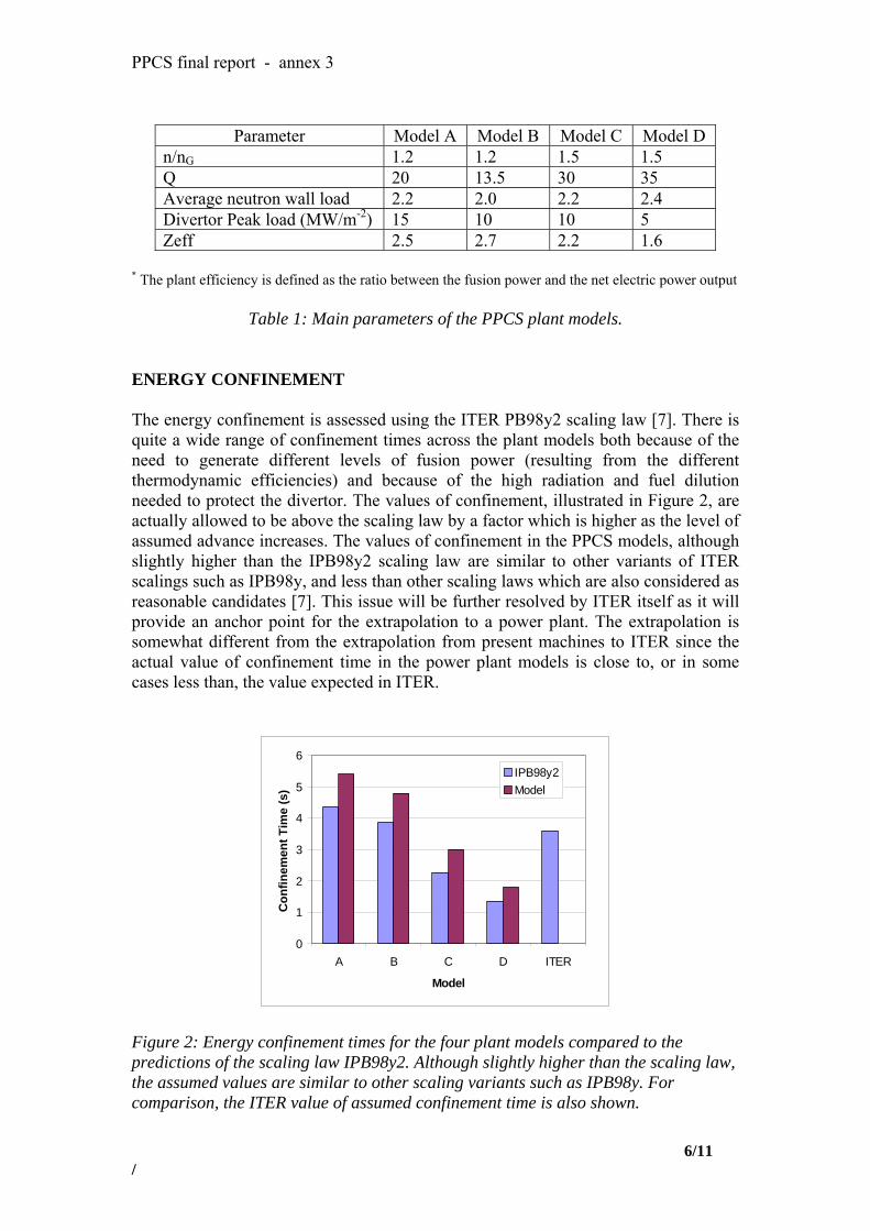
PPCS final report - annex 3
Parameter Model A Model B Model C Model D n/nG 1.2 1.2 1.5 1.5 Q 20 13.5 30 35 Average neutron wall load 2.2 2.0 2.2 2.4 Divertor Peak load (MW/m-2) 15 10 10 5 Zeff 2.5 2.7 2.2 1.6
* The plant efficiency is defined as the ratio between the fusion power and the net electric power output
Table 1: Main parameters of the PPCS plant models.
ENERGY CONFINEMENT The energy confinement is assessed using the ITER PB98y2 scaling law [7]. There is quite a wide range of confinement times across the plant models both because of the need to generate different levels of fusion power (resulting from the different thermodynamic efficiencies) and because of the high radiation and fuel dilution needed to protect the divertor. The values of confinement, illustrated in Figure 2, are actually allowed to be above the scaling law by a factor which is higher as the level of assumed advance increases. The values of confinement in the PPCS models, although slightly higher than the IPB98y2 scaling law are similar to other variants of ITER scalings such as IPB98y, and less than other scaling laws which are also considered as reasonable candidates [7]. This issue will be further resolved by ITER itself as it will provide an anchor point for the extrapolation to a power plant. The extrapolation is somewhat different from the extrapolation from present machines to ITER since the actual value of confinement time in the power plant models is close to, or in some cases less than, the value expected in ITER.
0
1
2
3
4
5
6
A B C D ITER
Model
Con
finem
ent T
ime
(s)
IPB98y2Model
Figure 2: Energy confinement times for the four plant models compared to the predictions of the scaling law IPB98y2. Although slightly higher than the scaling law, the assumed values are similar to other scaling variants such as IPB98y. For comparison, the ITER value of assumed confinement time is also shown.
6/11 /

PPCS final report - annex 3
H-MODE THRESHOLD POWER All the plant models are assumed to operate in H-mode. At the operating point there is no difficulty for any of the plant models in reaching the H-mode threshold power (illustrated in Figure 3). In each case, the additional heating power alone is above the H-mode threshold although in practise, of course, it is likely that the plasma would develop in H-mode from a lower density and build up to the operating point, in which case the additional heating power is much greater than required to achieve an H-mode.
0
50
100
150
200
A B C D
PPCS Model
Pthr
esh
(MW
)
Figure 3: The estimated H-mode threshold power for the four plant models. PLASMA RADIATION In the plant models, a range of constraints are assumed to be imposed by the maximum tolerable divertor heat load. In models A and B, it is assumed that the divertor heat load is ameliorated by impurity seeding of the edge plasma and also the core in order to increase radiated power and reduce the divertor heat flux. This is a clear penalty for a high power device and has a considerable impact on the machine size, plasma current and current drive power. In models C and D this requirement is relaxed under the assumption that developments in the fusion programme, such as an ergodic divertor, will reduce the penalty imposed by the divertor on the main plasma. For model C this corresponds to allowing a factor of two higher nominal heat flux even though the divertor would not tolerate this if no additional amelioration technique were used. For Model D it is assumed that progress in heat flux control is such that there is no penalty imposed on the main plasma by the divertor. Figure 4 shows the radiation from the core (inside the H-mode transport barrier) and edge of each plant model.
7/11 /

PPCS final report - annex 3
0
0.1
0.2
0.3
0.4
0.5
0.6
0.7
A B C D
Model
Frac
tion
radi
atio
n
EdgeCore
Figure 4: The calculated radiated power fraction in the four plant models. Model A and B have the highest radiation fraction as it is assumed that there will be no advance in controlling power flow to the divertor other than by radiation. CURRENT DRIVE Each of the PPCS plant models is assumed to operate in steady state with the plasma current driven by a combination of the bootstrap effect and current drive by external heating. In the calculations of the power needed, the efficiency of negative ion neutral beam current drive is used although it is not implied that this is the only possibility. The current drive efficiency uses the Mikkelson-Singer [8] approximation to current drive efficiency. The bootstrap current is calculated using the expressions derived for ITER calculations [4]. In terms of planned ITER operating scenarios [12], these plant models are closest to the ITER Steady State operation, although at higher β values. Models A and B have similar values of βp to the steady state ITER operating scenario whilst model C and D have higher values, and consequently higher fractions of bootstrap current.
0
0.1
0.2
0.3
0.4
0.5
0.6
0.7
0.8
A B C DModel
Boo
tstr
ap F
ract
ion
Figure 5: Calculated bootstrap fraction in the four plant models. Model C and D operate at higher βp and so have higher bootstrap fraction.
8/11 /

PPCS final report - annex 3
Figure 5 shows the calculated bootstrap fraction of each plant model. Models A and B have less than 50% bootstrap current which, when combined with the high plasma currents needed in these devices, leads to high current drive power requirements. Models C and D operate at higher βp
and consequently higher bootstrap fraction. Together with the lower plasma current in these plant models, this leads to relatively low values of current drive power. The calculated values of the current that must be driven and the corresponding current drive power for the four plant models are illustrated in Figure 6. Models A and B have very high current drive power, but even this level is only sufficient to drive the required current because of the relatively high temperature operation of these plants. The current drive efficiency is substantially higher than expected in ITER, primarily because of the higher temperature. This issue of the high plasma current, driven by the need for high energy confinement to compensate the high radiative losses for protection of the divertor, is a major one in these models and suggests that divertor protection is the most important problem facing plant models of power plants of this general design.
PPCS Current Drive Power
0
50
100
150
200
250
300
0 5 10 15 20
Current Driven (MA)
Cur
rent
Driv
e Po
wer
(MW
)
A
B
C
D
Figure 6: Required value of externally driven current and the associated level of power for the four plant models. Model A and B have high current drive requirements both because the total current is higher and the bootstrap fraction is lower. DENSITY LIMIT Each of the plant models uses the Greenwald scaling [13], to determine the density limit, with an allowed multiplier that increases from Model A through to Model D, as shown in Table 1. High density and high edge density are important to protect the divertor, however it simultaneously serves to reduce the effectiveness of the current drive. SUMMARY Consistent with the philosophy underlying the PPCS, a range of assumptions are made on the plasma physics parameters of the power plant concepts, which are
9/11 /
PPCS final report - annex 3
intended to represent the range of possible outcomes of the fusion development programme. In the power plant concepts, consistency between the plasma physics and technology assumptions is achieved using a systems code, PROCESS, which incorporates simple models of all of the major plant systems, starting with the plasma and progressing out to the site and buildings. In exploring the range of concepts, both in terms of plasma physics and technology, the approach has been to try to match the level of technological development to the level of physics development. In considering the least ambitious plant models, Models A and B, these are considered to be near term plants, operating in the first stability regime. They include a high-recycling divertor that must be protected from excessive heat flux by radiation through impurity seeding of the divertor and the main plasma, as well as bremsstrahlung and synchrotron radiation from the core. Coupled with moderate thermodynamic efficiency these assumptions yield relatively large plants with relatively high current drive power. The current drive efficiency is quite high because of the high electron temperature. The large size and high plasma current of these models are in large part due to the assumptions about divertor protection which requires high confinement to offset large radiation. In looking to more advanced plant models, Models C and D, more advanced plasma physics is coupled to more ambitious technologies. Higher values of normalised β, in plasmas with stronger shaping but also higher safety factor are assumed, implicitly based around the advanced tokamak scenario which is presently being explored in existing machines around the world. The higher value of βp gives a higher bootstrap fraction and reduced current drive power, which plays an important role in power plant size and economics. Combined with higher thermodynamic efficiency, the result is smaller machines with reduced current drive requirements. REFERENCES [1] Annex 2 of the PPCS Report [2] Saibene G, note of 27/09/2001 [3] T.C. Hender, P.J. Knight and I. Cook, Fusion Technology 30 (1996) 1605. [4] N A Uckan, ITER Physics Design Guidelines 1989, IAEA Vienna (1990), ITER Document No 10 [5] Physics assessment for the European Reactor Study, T Hender et al, AEA Fus 172 (1992) [6] The Physics of Magnetic Fusion Reactors, J Sheffield, Revs Modern Physics, 66 (1994) 1015-1103 [7] ITER Physics Basis, Nuclear Fusion 39 (1999) 2175 [8] D R Mikkelsen and C E Singer, Nuclear Technology Fusion 4 (1983) 237 [9] Assessment of economics of PPCS plant models A and B. D J Ward PPCS/UKAEA/PPCS6-2 July 2002 [10] Annex 6 of the PPCS Report [11] Annex 7 of the PPCS Report
10/11 /

PPCS final report - annex 3
[12] M Shimada et al, Fusion Energy Conference 2002 (Lyon) IAEA, Vienna, paper CT-2 [13] M Greenwald, Nuclear Fusion 28 (1988) 2199 ACKNOWLEDGEMENTS This work was supported by the UK Engineering and Physical Sciences Research Council and by EURATOM.
11/11 /


ANNEXE 4


PPCS final report - Annex 4
EU Power Plant Conceptual Study – Model A: WCLL concept
1. Introduction The model A is based on the use of the WCLL DEMO blanket developed within EU in the last ten years [1] and on the water-cooled ITER divertor [2]. This reactor model is the one requiring the smaller extrapolation from present-day knowledge both on physical and technological aspects. The conceptual design is made for a reactor of 1500 MWe net electrical power and includes the power conversion system and the balance of plant. It takes into account the maintenance scheme and the contribution of the divertor power to the power conversion cycle. It also provides a confinement strategy which is based on the results of SEAFP studies [3]. The overall objective is to produce electricity at the lowest possible costs meeting high safety standards. Some requirements have been set out by the industry and the utilities [4] and among them : steady state operation, 40 years lifetime, availability of about 80 %, no need for an evacuation plan, minimisation of the fraction of wastes which are not qualified for clearance.
2. Reactors parameters A small extrapolation from present-day knowledge is assumed [4] [5]; this allows to make use of the available database. The energy confinement scaling is based on the IPB98(y,2) scaling [6], assuming ELMy H-mode with an H factor up to 1.2 allowed. The discrepancy with the extended database induces an uncertainty on the H98 factor (τE/τ98): 0.7 < H98 < 1.3. The assumptions of the normalised β and the density normalised to the Greenwald density are the following: βN < 3.5, n/nGR < 1.2. The considered peaking of the density profile corresponds to the average value of the database. In order to maintain the steady state operation, current drive will be used. At high temperatures, high current drive efficiencies can be achieved using negative ion-based neutral beam injection; 60 % is considered for this study. With a relatively low value of the safety factor (about 3), the bootstrap current fraction is below 0.5, so a significant current drive power is required. The corresponding reactor parameters have been evaluated using the PROCESS code [7] and are given in the table 1.
Unit Size (MWe) 1546 Fusion Power (MW) 5000 Aspect Ratio 3.0 Elongation (95% flux) 1.7 Triangularity (95% flux) 0.25 Major Radius (m) 9.55 TF on axis (T) 7.0 TF on the TF coil conductor (T) 13.1 Number of toroidal coils 18 Plasma Current (MA) 30.5 βN(thermal,total) 2.8, 3.5 Average temperature (keV) 22 Temperature peaking factor 1.5 Average density (1020m-3) 1.1 Density peaking factor 0.3 HH (IPB98y2) 1.2
1/14
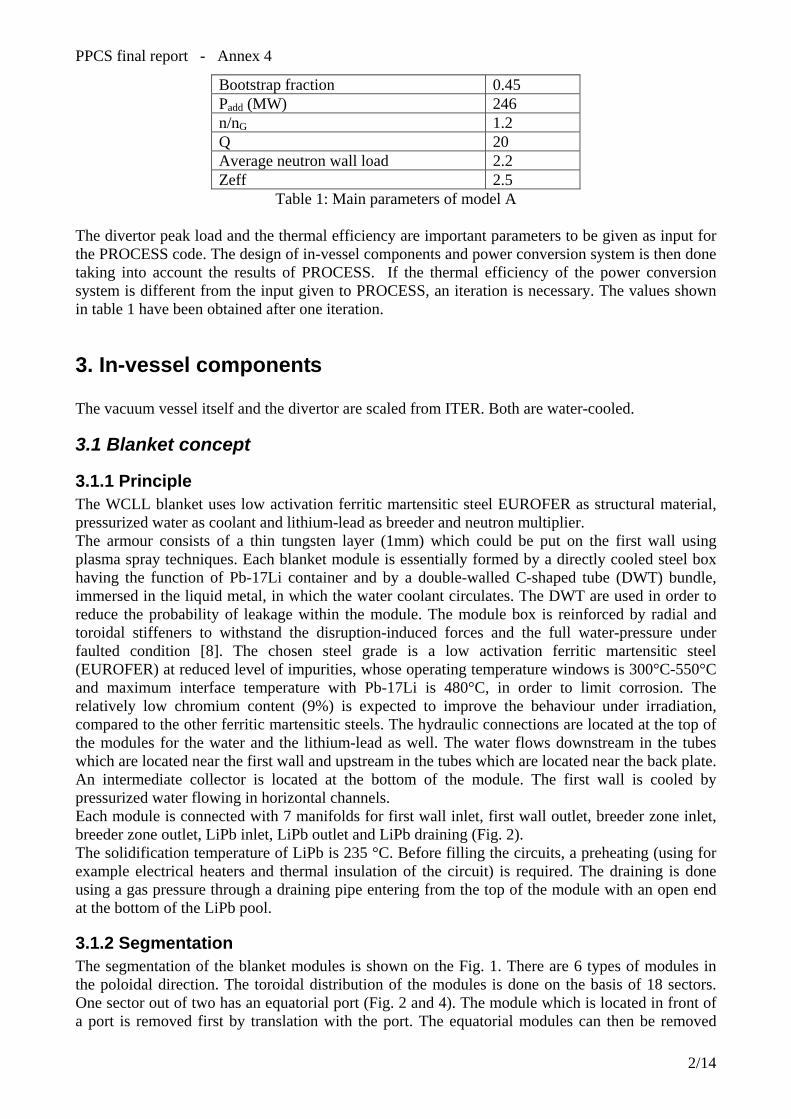
PPCS final report - Annex 4
Bootstrap fraction 0.45 Padd (MW) 246 n/nG 1.2 Q 20 Average neutron wall load 2.2 Zeff 2.5
Table 1: Main parameters of model A
The divertor peak load and the thermal efficiency are important parameters to be given as input for the PROCESS code. The design of in-vessel components and power conversion system is then done taking into account the results of PROCESS. If the thermal efficiency of the power conversion system is different from the input given to PROCESS, an iteration is necessary. The values shown in table 1 have been obtained after one iteration.
3. In-vessel components The vacuum vessel itself and the divertor are scaled from ITER. Both are water-cooled.
3.1 Blanket concept
3.1.1 Principle The WCLL blanket uses low activation ferritic martensitic steel EUROFER as structural material, pressurized water as coolant and lithium-lead as breeder and neutron multiplier. The armour consists of a thin tungsten layer (1mm) which could be put on the first wall using plasma spray techniques. Each blanket module is essentially formed by a directly cooled steel box having the function of Pb-17Li container and by a double-walled C-shaped tube (DWT) bundle, immersed in the liquid metal, in which the water coolant circulates. The DWT are used in order to reduce the probability of leakage within the module. The module box is reinforced by radial and toroidal stiffeners to withstand the disruption-induced forces and the full water-pressure under faulted condition [8]. The chosen steel grade is a low activation ferritic martensitic steel (EUROFER) at reduced level of impurities, whose operating temperature windows is 300°C-550°C and maximum interface temperature with Pb-17Li is 480°C, in order to limit corrosion. The relatively low chromium content (9%) is expected to improve the behaviour under irradiation, compared to the other ferritic martensitic steels. The hydraulic connections are located at the top of the modules for the water and the lithium-lead as well. The water flows downstream in the tubes which are located near the first wall and upstream in the tubes which are located near the back plate. An intermediate collector is located at the bottom of the module. The first wall is cooled by pressurized water flowing in horizontal channels. Each module is connected with 7 manifolds for first wall inlet, first wall outlet, breeder zone inlet, breeder zone outlet, LiPb inlet, LiPb outlet and LiPb draining (Fig. 2). The solidification temperature of LiPb is 235 °C. Before filling the circuits, a preheating (using for example electrical heaters and thermal insulation of the circuit) is required. The draining is done using a gas pressure through a draining pipe entering from the top of the module with an open end at the bottom of the LiPb pool.
3.1.2 Segmentation The segmentation of the blanket modules is shown on the Fig. 1. There are 6 types of modules in the poloidal direction. The toroidal distribution of the modules is done on the basis of 18 sectors. One sector out of two has an equatorial port (Fig. 2 and 4). The module which is located in front of a port is removed first by translation with the port. The equatorial modules can then be removed
2/14
PPCS final report - Annex 4
followed by the top and bottom modules. The hydraulic disconnection of the top and bottom modules is supposed to be done after the removal of the equatorial modules. The maximum number of modules is 189. The modules are about 4 m-high, between 0.6 and 0.9 m-thick and between 1.5 to 2.3 m wide. The dimensions of the ports (1.8 m wide, 4.54 m high) allow the passage of all modules. The attachment of the module to the shielding remains an open issue. The principle of this attachment has been defined: one fixed point and other attachment points allowing thermal expansion. Nevertheless the question of the access to the modules is of concern since for the design of the WCLL modules it is preferable to avoid front access.
3.1.3 Reliability The improvement of the reliability due to the use of the double wall tubes (DWT) has been assessed in the reference [9]. The double tube failure rate (Λ) can be roughly deduced from the single tube failure rate (λ) through the equation 1: ΛT ≈ 2.(λT)2, T being the mission time (λT<<1). According to available data banks on water reactors and fast breeder reactors, the failure rate of single wall tubes (SWT) in steam generators and exchangers is about 10-8/h/SWT for U tubes. The extrapolation of this value to the tubes of the WCLL blanket requires a correction factor in order to take into account the specific WCLL operating conditions (pressure, temperature, neutron irradiation, …); 103 seems to be a conservative value for this correction factor [8]. According to this value, the failure rate of a SWT in WCLL conditions would be 10-5/h/SWT. Applying equation 1 and taking into account the correction factor, the failure rate of a DWT in WCLL conditions would be 4.10-9/h/DWT [9], for U tubes of a banana shaped concept. Because of the segmentation (§ 3.1.2), the numbers of bends, butt welds and also tubes is higher than in the banana shaped concept. Moreover, the number of tubes is higher in C tubes concepts than in U tubes concepts. This globally leads to a decrease of the reliability by a factor, which is about 10. Thus, the failure rate of a DWT would be 4.10-8/h/DWT for the PPCS model A.
3.1.4 Neutronics Based on the reactor parameters [10], neutron source distribution data provided by UKAEA [11] and nuclear cross-section data from the Fusion Evaluated Nuclear Data Library FENDL-2 [12], neutronics 3D calculations have been performed using the MCNP Monte Carlo code [13]. The considered fusion power is 5500 MW; this value is different from the one mentioned in table 1 (5000 MW) because the studies have been done before the iteration mentioned in section 2. The tungsten layer mentioned in section 3.1.1 is not taken into account assuming its low influence on the results. The calculated Tritium Breeding Ratio is 1.06. The Tritium Breeding Ratio can be improved by reducing the gap between top inboard and top outboard modules (see Fig.1). This gap has been initially implemented in order to allow an independent removal of each of the top inboard and outboard modules, which does not appear as an important requirement from the point of view of the availability.
3.1.5 Thermo-mechanical analysis The thermo-mechanical analysis has been done only for the equatorial outboard module which is supposed to be the dimensioning one [14]. Specifications for neutron wall loading and average value of surface heat flux are respectively 2.52 MW/m2 and 0.57 MW/m2. The inlet pressure, temperature and velocity of the water in the DWT's are respectively 15.5 MPa, 285 °C and 5 m/s. The thermal constraints are as follows:
Maximum coolant temperature < 340°C (Tsat=343°C) Subcooled boiling and critical heat flux criteria [15] Outlet average temperature > 320°C
3/14
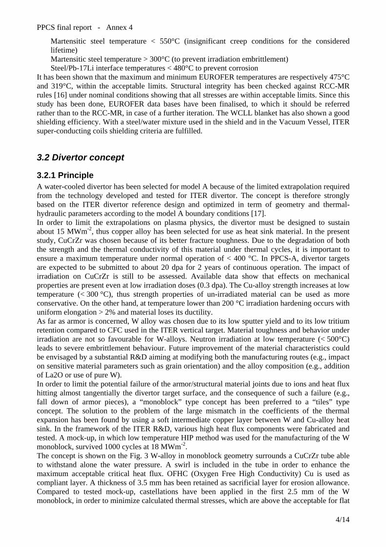
PPCS final report - Annex 4
Martensitic steel temperature < 550°C (insignificant creep conditions for the considered lifetime) Martensitic steel temperature > 300°C (to prevent irradiation embrittlement) Steel/Pb-17Li interface temperatures < 480°C to prevent corrosion
It has been shown that the maximum and minimum EUROFER temperatures are respectively 475°C and 319°C, within the acceptable limits. Structural integrity has been checked against RCC-MR rules [16] under nominal conditions showing that all stresses are within acceptable limits. Since this study has been done, EUROFER data bases have been finalised, to which it should be referred rather than to the RCC-MR, in case of a further iteration. The WCLL blanket has also shown a good shielding efficiency. With a steel/water mixture used in the shield and in the Vacuum Vessel, ITER super-conducting coils shielding criteria are fulfilled.
3.2 Divertor concept
3.2.1 Principle A water-cooled divertor has been selected for model A because of the limited extrapolation required from the technology developed and tested for ITER divertor. The concept is therefore strongly based on the ITER divertor reference design and optimized in term of geometry and thermal-hydraulic parameters according to the model A boundary conditions [17]. In order to limit the extrapolations on plasma physics, the divertor must be designed to sustain about 15 MWm-2, thus copper alloy has been selected for use as heat sink material. In the present study, CuCrZr was chosen because of its better fracture toughness. Due to the degradation of both the strength and the thermal conductivity of this material under thermal cycles, it is important to ensure a maximum temperature under normal operation of < 400 °C. In PPCS-A, divertor targets are expected to be submitted to about 20 dpa for 2 years of continuous operation. The impact of irradiation on CuCrZr is still to be assessed. Available data show that effects on mechanical properties are present even at low irradiation doses (0.3 dpa). The Cu-alloy strength increases at low temperature (< 300 °C), thus strength properties of un-irradiated material can be used as more conservative. On the other hand, at temperature lower than 200 °C irradiation hardening occurs with uniform elongation > 2% and material loses its ductility. As far as armor is concerned, W alloy was chosen due to its low sputter yield and to its low tritium retention compared to CFC used in the ITER vertical target. Material toughness and behavior under irradiation are not so favourable for W-alloys. Neutron irradiation at low temperature (< 500°C) leads to severe embrittlement behaviour. Future improvement of the material characteristics could be envisaged by a substantial R&D aiming at modifying both the manufacturing routes (e.g., impact on sensitive material parameters such as grain orientation) and the alloy composition (e.g., addition of La2O or use of pure W). In order to limit the potential failure of the armor/structural material joints due to ions and heat flux hitting almost tangentially the divertor target surface, and the consequence of such a failure (e.g., fall down of armor pieces), a “monoblock” type concept has been preferred to a “tiles” type concept. The solution to the problem of the large mismatch in the coefficients of the thermal expansion has been found by using a soft intermediate copper layer between W and Cu-alloy heat sink. In the framework of the ITER R&D, various high heat flux components were fabricated and tested. A mock-up, in which low temperature HIP method was used for the manufacturing of the W monoblock, survived 1000 cycles at 18 MWm-2. The concept is shown on the Fig. 3 W-alloy in monoblock geometry surrounds a CuCrZr tube able to withstand alone the water pressure. A swirl is included in the tube in order to enhance the maximum acceptable critical heat flux. OFHC (Oxygen Free High Conductivity) Cu is used as compliant layer. A thickness of 3.5 mm has been retained as sacrificial layer for erosion allowance. Compared to tested mock-up, castellations have been applied in the first 2.5 mm of the W monoblock, in order to minimize calculated thermal stresses, which are above the acceptable for flat
4/14

PPCS final report - Annex 4
surface. However, further experiments are required to check if flat surface may be acceptable despite the high theoretical stresses. Flat surface monoblock would be the preferred solution because castellations could promote crack initiation.
3.2.2 Thermo-mechanical analyses Thermal and thermo-mechanical analyses have been carried out in order to optimize both geometry and thermal-hydraulic conditions (water velocity and inlet temperature). It has been assumed that a uniform surface heat flux of 15 MW.m-2 is deposited on a length of 50 cm of the divertor armour. A fixed volume heat deposition in each material due to neutron irradiation has also been taken into account, that is a power density of 27 MW.m-3 in W, and 5 MW.m-3 in OFHC and in CuCrZr. Thermal analyses have been performed on a bi-dimensional model. In order to take into account the rear structure to which the divertor will be attached, the temperature of the points in the rear face has been fixed to 300 °C. Thermo-mechanical calculations have been carried out on a three-dimensional model to best take into account the real boundary conditions. Elastic-plastic behavior has been assumed for the OFHC compliant layer, with a linear cinematic stress hardening model. Linear-elastic behavior has been assumed for the other materials. In order to simulate the fact that tube can slide without bending around its axis, homogeneous displacements in axial direction have been imposed to the nodes of the tube upper face. Retained optimum water coolant parameters are: inlet temperatures 140°C, velocity 20 ms-1. Minimum, average and maximum temperatures in various materials are summarized in table 10. Maximum temperatures are everywhere lower than allowable limits. The coolant warming up along the 50 cm is 10° C, and the ratio between critical heat flux and maximum heat flux higher than 2. The maximum displacement in axial direction is 0.01 mm, compatible with the gap (0.2 mm) between monoblocks. Maximum values of equivalent Von Mises stresses are summarized in the table 2. As expected, they are localized at the materials interface because of different thermal expansion coefficients. Both in the monoblock and in the tiles, thermal stresses are under limits at corresponding temperatures.
Tmin Tave Tmax VMmax
W-Tiles 477 805 1111 280 W-Monoblock 189 316 752 637 OFHC 183 233 342 64 Tube CuCrZr 172 211 298 346
Table 2: Temperatures (°C) and maximum equivalent Von Mises stresses (MPa) in divertor.
3.2.3 Alternative divertor concept An alternative water-cooled divertor concept (Fig. 4) has been studied which should allow an operating temperature of water of about 300 °C [18], with an allowable peak flux of 15 MWm-2. This concept uses Eurofer as structural material and tungsten as armour material. A thermal barrier in pyrolitic graphite is used to obtain a better repartition of the flux. A thermal analysis shows that the maximal flux in structural material is limited to 13 MW/m2 instead of 20 MW/m2 without thermal barrier. In order to satisfy the critical heat flux criteria a swirl is provided. In these conditions, water local velocity is 20 m/s and critical heat flux is approximately 16.7 MW/m2. The consequences of irradiation on the different materials have been assessed. Experiments have shown that pyrolitic graphite keeps its structural integrity up to, at least, 15 dpa [19]. The loss of thermal conductivity depends on the irradiation temperature; in the particular case of this concept,
5/14
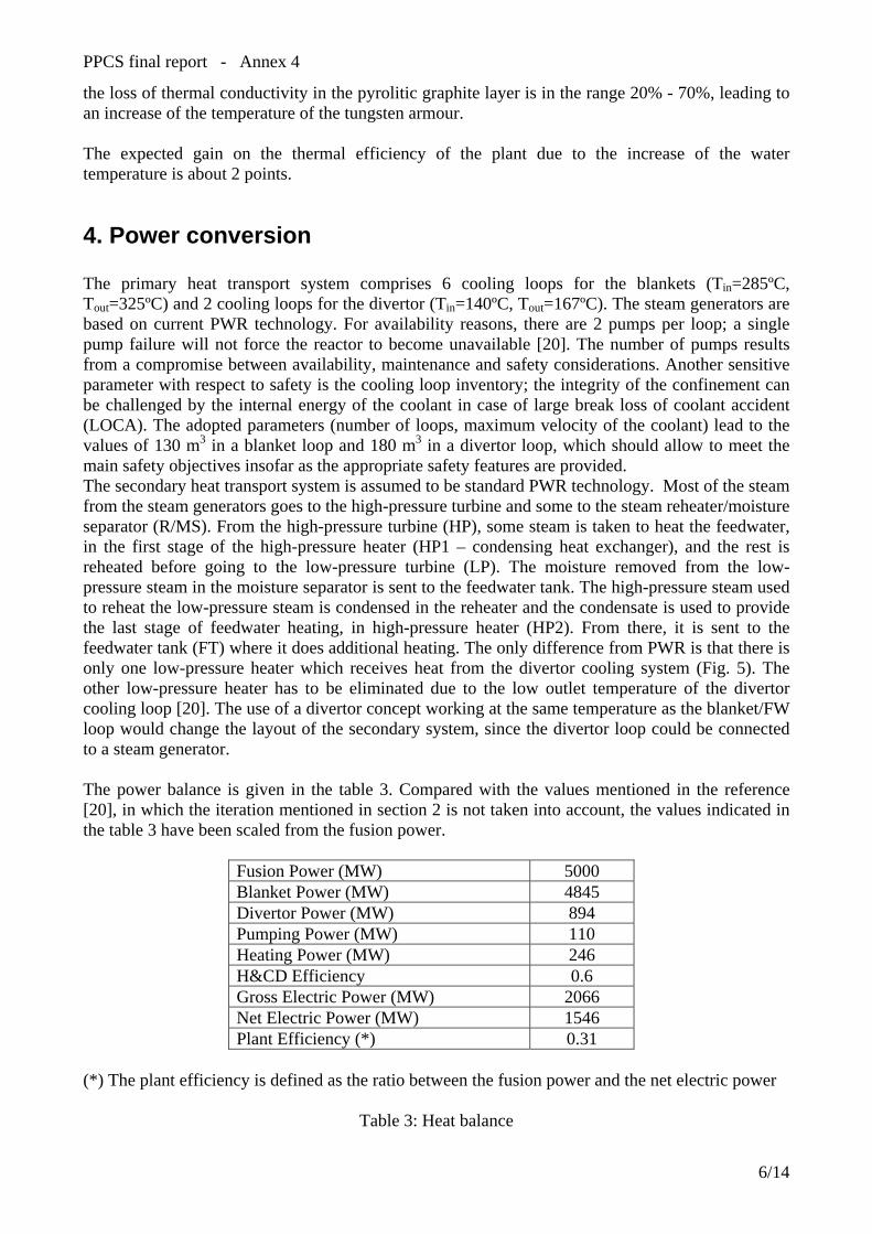
PPCS final report - Annex 4
the loss of thermal conductivity in the pyrolitic graphite layer is in the range 20% - 70%, leading to an increase of the temperature of the tungsten armour. The expected gain on the thermal efficiency of the plant due to the increase of the water temperature is about 2 points.
4. Power conversion The primary heat transport system comprises 6 cooling loops for the blankets (Tin=285ºC, Tout=325ºC) and 2 cooling loops for the divertor (Tin=140ºC, Tout=167ºC). The steam generators are based on current PWR technology. For availability reasons, there are 2 pumps per loop; a single pump failure will not force the reactor to become unavailable [20]. The number of pumps results from a compromise between availability, maintenance and safety considerations. Another sensitive parameter with respect to safety is the cooling loop inventory; the integrity of the confinement can be challenged by the internal energy of the coolant in case of large break loss of coolant accident (LOCA). The adopted parameters (number of loops, maximum velocity of the coolant) lead to the values of 130 m3 in a blanket loop and 180 m3 in a divertor loop, which should allow to meet the main safety objectives insofar as the appropriate safety features are provided. The secondary heat transport system is assumed to be standard PWR technology. Most of the steam from the steam generators goes to the high-pressure turbine and some to the steam reheater/moisture separator (R/MS). From the high-pressure turbine (HP), some steam is taken to heat the feedwater, in the first stage of the high-pressure heater (HP1 – condensing heat exchanger), and the rest is reheated before going to the low-pressure turbine (LP). The moisture removed from the low-pressure steam in the moisture separator is sent to the feedwater tank. The high-pressure steam used to reheat the low-pressure steam is condensed in the reheater and the condensate is used to provide the last stage of feedwater heating, in high-pressure heater (HP2). From there, it is sent to the feedwater tank (FT) where it does additional heating. The only difference from PWR is that there is only one low-pressure heater which receives heat from the divertor cooling system (Fig. 5). The other low-pressure heater has to be eliminated due to the low outlet temperature of the divertor cooling loop [20]. The use of a divertor concept working at the same temperature as the blanket/FW loop would change the layout of the secondary system, since the divertor loop could be connected to a steam generator. The power balance is given in the table 3. Compared with the values mentioned in the reference [20], in which the iteration mentioned in section 2 is not taken into account, the values indicated in the table 3 have been scaled from the fusion power.
Fusion Power (MW) 5000 Blanket Power (MW) 4845 Divertor Power (MW) 894 Pumping Power (MW) 110 Heating Power (MW) 246 H&CD Efficiency 0.6 Gross Electric Power (MW) 2066 Net Electric Power (MW) 1546 Plant Efficiency (*) 0.31
(*) The plant efficiency is defined as the ratio between the fusion power and the net electric power
Table 3: Heat balance
6/14

PPCS final report - Annex 4
5. Balance of plant A first layout of the fusion power plant has been proposed (Fig. 6). The main dimensions have been scaled from ITER [21]. The tokamak building is located at the center of the plant area. It is divided in three main sections: the pit is the section within the bioshield; it notably houses the magnets, the vacuum vessel, the
cryostat. the galleries are located outside the bioshield, from the basement to the crane hall. the crane hall is located above the bioshield.
The confinement strategy includes a vacuum vessel pressure suppression system (VVPSS) allowing to maintain the pressure within the vacuum vessel and the compartments around the TCWS below the design limit in case of LOCA
6. Conclusion The model A is a concept of a near term fusion reactor requiring small extrapolations of present-day knowledge on both physics and technology, which is based on the water-cooled Pb-17Li blanket (WCLL) and water-cooled divertor. Further R&D is required for the divertor concept and the material properties, notably the behaviour of the EUROFER steel grade under irradiation. In particular, an improvement of the divertor concept could allow it to operate at higher temperature leading to higher efficiency.
7/14
PPCS final report - Annex 4
References [1] L. Giancarli, M. Dalle Donne, W. Dietz, "Status of the European breeding blanket technology, Fusion engineering and Design, 36 (1997) 57-74. [2] ITER, Design Description Document, WBS 1.7, July 2001. [3] I. Cook, G. Marbach, L. Di Pace, C. Girard, P. Rocco, NP Taylor, "Results conclusions and implications of the SEAFP- programme", Fusion Engineering and Design 51-52 (2000) 409-417. [4] D. Maisonnier, R. Andreani, S. Hermsmeyer, G. Saibene, P. Sardain, D. Ward, "Power Plant Conceptual Study, Main Technological Issues", IAEA TCM on Steady State Operation of Fusion Magnetic Devices, April 2002. [5] U. Samm, E. Barbato, J.G. Cordey, J. Lister, D. Moreau, J. Ongena, H. Wobig, D. Bartlett, "Report of the Ad Hoc Group to Assess the Physics Assumptions Underlying the Power Plant Conceptual Study (PPCS), 2001. [6] ITER Physics basis, Nuclear Fusion 39 (1999) 2175 [7] TC. Hender, PJ. Knight, I. Cook, UKAEA FUS 333 (1996). [8] Y. Poitevin, L. Giancarli, A. Li Puma, J. Szczepanski, "Status of the design and performances of the WCLL Test Blanket Module for ITER-FEAT”, to appear in Fus. Eng. & Des., Proc. ISFNT-5, April 7-13, 2002, San Diego (CA). [9] A. Li Puma, M. Eid, "Double wall tube concept – impact on the pressure tubes reliability/availability", CEA Report SERMA/LCA/RT/01-2999/A, 2001. [10] D. Ward, Provisional plant parameters for Power Plant Conceptual Study Models A & B, Report PPCS/UKAEA/PPCS1.1, September 2001. [11] M. Loughlin, UKAEA Culham, Neutron source for initial design phase of the Power Plant Conceptual Study, personal communication, September 2001. [12] H. Wienke and M. Herman, FENDL/MG-2.0 and FENDL/MC-2.0, The processed cross-section libraries for neutron-photon transport calculations, version 1, March 1997, IAEA Vienna, Report IAEA-NDS-176, Rev. 1, October 1998. [13] Y. Chen, U. Fischer, P. Pereslavtsev and F. Wasastjerna, The EU Power Plant Conceptual Study - Neutronic Design Analyses for Near Term and Advanced Reactor Models, Forschungzentrum Karlsruhe, Report FZKA-6763, 2002. [14] B. Michel, Thermo mechanical evaluation of the WCLL blanket concept (model A), CEA Report SERI/LFEA 02/5008, 2002. [15] W.H. HENS and al. "Analysis of heat transfer, burnout, pressure drop and density data for high pressure water", Argonne National Laboratory,ANL4627 (1951). [16] RCC-MR "Règles de conception et de constructions des matériels mécaniques des îlots nucléaires RNR" AFCEN, mai 1993.
8/14

PPCS final report - Annex 4
[17] A. Li Puma, L. Giancarli, Y. Poitevin, J.F. Salavy, P. Sardain, J. Szczepanski, "Optimisation of a water cooled divertor for the European power plant conceptual study", to appear in Fus. Eng. & Des., Proc. ISFNT-5, April 7-13, 2002, San Diego (CA). [18] B. Michel, "New design of a high temperature water cooled divertor for the European Power Plant Conceptual Study", CEA Report SERI/LFEA 02/5020, 2002. [19] C.H. Wu, J.P. Bonal, B. Thiele, G. Tsotridis, H. Kwast, H. Werle, J.P. Coad, G. Federici, G. Vieider, "Neutron irradiation effects on the properties of carbon materials", Journal of Nclear Materials 212-215 (1994) 416-420. [20] A. Natalizio, J. Collén, "Conceptual design of main cooling system for a fusion power reactor with water cooled lithium lead blanket", Studsvik report ES-02/35, June 2002. [21] A. Orden Martinez, "Conceptual design of a fusion power plant – 3D drawings for model A", IBERTEF report 095-039-E-M-00002, May 2002.
9/14

PPCS final report - Annex 4
Fig. 1: Poloidal distribution of the blanket modules
10/14

PPCS final report - Annex 4
Fig. 2: Global view of a WCLL blanket module
11/14
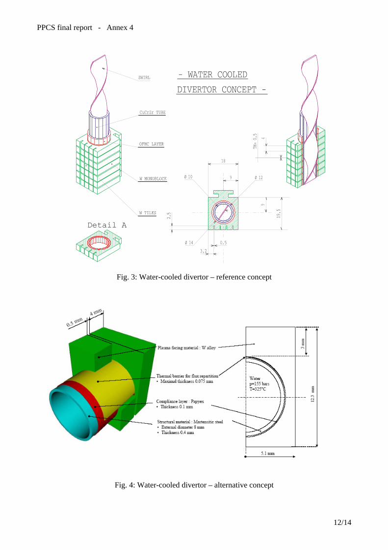
PPCS final report - Annex 4
Fig. 3: Water-cooled divertor – reference concept
Fig. 4: Water-cooled divertor – alternative concept
12/14
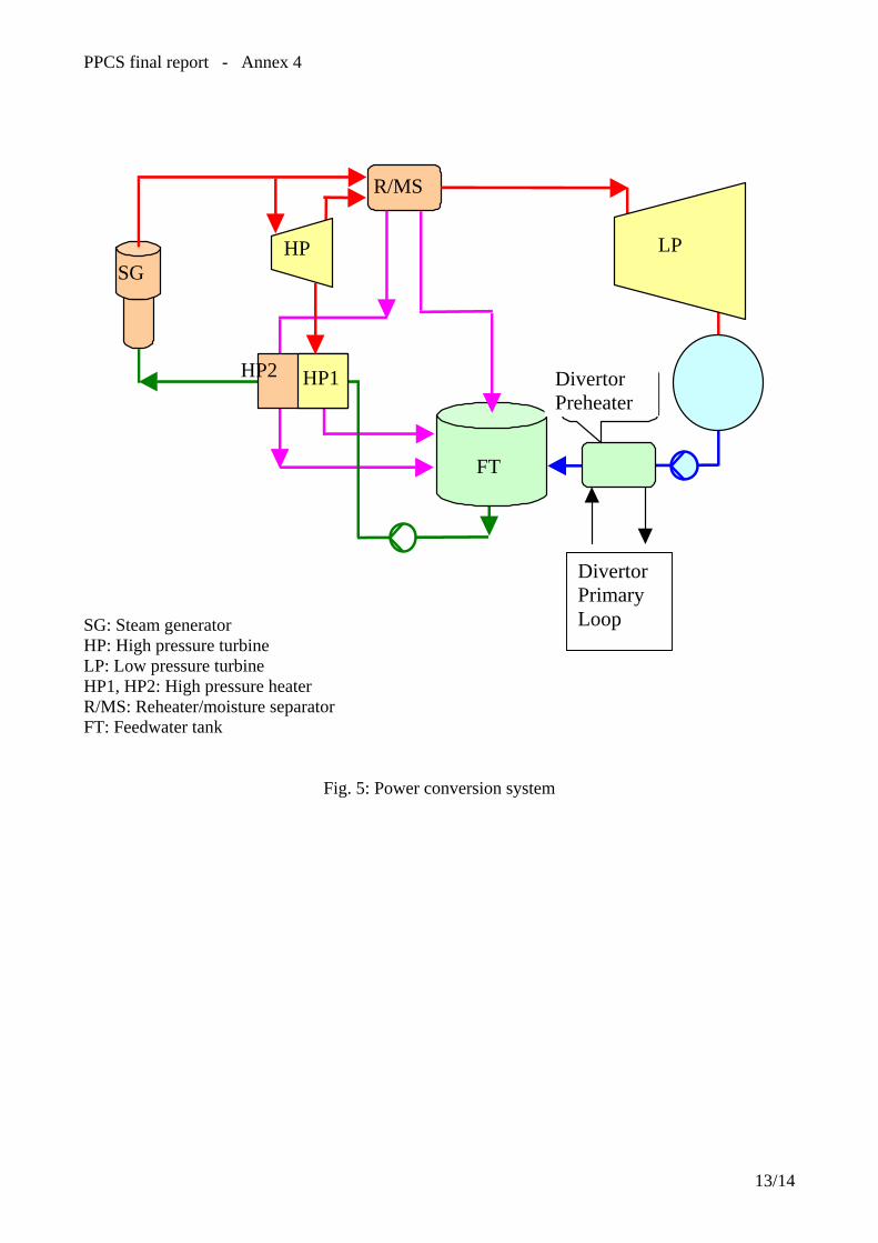
PPCS final report - Annex 4
R/MS
LP HP SG
HP2 DivertorPreheater
Divertor Preheater
HP1
FT
Divertor Primary Loop
SG: Steam generator HP: High pressure turbine LP: Low pressure turbine HP1, HP2: High pressure heater R/MS: Reheater/moisture separator FT: Feedwater tank
Fig. 5: Power conversion system
13/14

PPCS final report - Annex 4
Fig. 6: Plant layout
14/14

ANNEXE 5


PPCS final report - Annex 5: Plant model B
EU Power Plant Conceptual Study – Model B: HCPB concept 1. Introduction The Helium Cooled Pebble Bed (HCPB) reactor concept is based on the HCPB DEMO blanket [6] that has been a EU reference concept for ten years. Within the study it represents a near-term concept that relies for its realisation on moderate extrapolation in both plasma physics and technology. The conceptual design was intended to be for a reactor of 1500 MWe. It aims at including all aspects that are relevant for demonstrating the viability and economical attractiveness of fusion power, like - the lay-out of key in-vessel components and primary cooling circuit - the lay-out and performance of the power conversion system - the balance of plant. Late changes in the electric power needed for heating & current drive have meant that the actual power to the electricity grid falls short of the target 1500 MW by 170 MW and that a re-iteration of the plant model would be needed to re-dress the balance. On the design of in-vessel components it has to be acknowledged that work actually carried out is different from the limited adaptation of the DEMO concept foreseen in the definition of the PPCS. Firstly, the choice of a segmentation different from the DEMO one has shifted the focus on developing new ideas for radial segmentation, in-vessel manifolding, etc. The requirement that the blanket box must withstand accidental pressurisation to 8 MPa is an issue that could not be resolved within the study, but calls for an urgent and substantial design review. Secondly, the importance of a Helium cooled divertor capable of 10 MW/m2 (or more) peak heat flux both for a consistent blanket concept containing Beryllium but no water/steam, and for a significant contribution of high grade heat from the divertor to plant efficiency, was only realised during phase III of the study and led to a first concept presented within this report. Both issues have already initiated new design work with more resources than scheduled in the PPCS, which will lead to a higher level of detail and consistency in the plant model. 2. Reactor parameters A small extrapolation from present-day knowledge is assumed [1]; this allows to make use of the available database The energy confinement scaling is based on the IPB98y2 scaling, assuming ELMy H-mode with a H factor of up to 1.2. The discrepancy with the extended database induces an uncertainty on the H98 factor (τE/τ98): 0.7<H98<1.3. The assumptions of the normalised β and the density normalised to the Greenwald density are the following: βN<3.5, n/nGR<1.2. The considered peaking of the density profile corresponds to an average value of the database. In order to maintain the steady state operation, current drive will be used. At high temperatures, high current drive efficiencies can be achieved using negative ion-based neutral beam injection; 60% is considered for this study. With a relatively low value of the safety factor (about 3), the bootstrap current fraction is below 0.5, so a significant current drive power is required. The corresponding reactor parameters have been evaluated using the PROCESS code [8] and are given in Table 1. The divertor peak load, the thermal efficiency and the blanket gain (power increase by nuclear reactions in the blanket) are key lay-out parameters to be given as input for the PROCESS code. The design of in-vessel components and power conversion system is then done taking into account the results of PROCESS. Differences in input values to PROCESS and results from plant design were aligned by iteration.
1/16
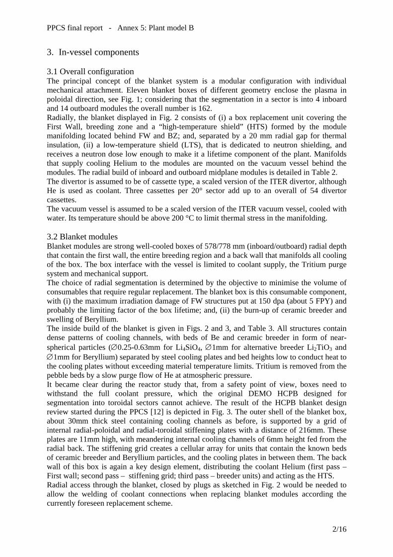
PPCS final report - Annex 5: Plant model B
3. In-vessel components 3.1 Overall configuration The principal concept of the blanket system is a modular configuration with individual mechanical attachment. Eleven blanket boxes of different geometry enclose the plasma in poloidal direction, see Fig. 1; considering that the segmentation in a sector is into 4 inboard and 14 outboard modules the overall number is 162. Radially, the blanket displayed in Fig. 2 consists of (i) a box replacement unit covering the First Wall, breeding zone and a “high-temperature shield” (HTS) formed by the module manifolding located behind FW and BZ; and, separated by a 20 mm radial gap for thermal insulation, (ii) a low-temperature shield (LTS), that is dedicated to neutron shielding, and receives a neutron dose low enough to make it a lifetime component of the plant. Manifolds that supply cooling Helium to the modules are mounted on the vacuum vessel behind the modules. The radial build of inboard and outboard midplane modules is detailed in Table 2. The divertor is assumed to be of cassette type, a scaled version of the ITER divertor, although He is used as coolant. Three cassettes per 20° sector add up to an overall of 54 divertor cassettes. The vacuum vessel is assumed to be a scaled version of the ITER vacuum vessel, cooled with water. Its temperature should be above 200 °C to limit thermal stress in the manifolding. 3.2 Blanket modules Blanket modules are strong well-cooled boxes of 578/778 mm (inboard/outboard) radial depth that contain the first wall, the entire breeding region and a back wall that manifolds all cooling of the box. The box interface with the vessel is limited to coolant supply, the Tritium purge system and mechanical support. The choice of radial segmentation is determined by the objective to minimise the volume of consumables that require regular replacement. The blanket box is this consumable component, with (i) the maximum irradiation damage of FW structures put at 150 dpa (about 5 FPY) and probably the limiting factor of the box lifetime; and, (ii) the burn-up of ceramic breeder and swelling of Beryllium. The inside build of the blanket is given in Figs. 2 and 3, and Table 3. All structures contain dense patterns of cooling channels, with beds of Be and ceramic breeder in form of near-spherical particles (∅0.25-0.63mm for Li4SiO4, ∅1mm for alternative breeder Li2TiO3 and ∅1mm for Beryllium) separated by steel cooling plates and bed heights low to conduct heat to the cooling plates without exceeding material temperature limits. Tritium is removed from the pebble beds by a slow purge flow of He at atmospheric pressure. It became clear during the reactor study that, from a safety point of view, boxes need to withstand the full coolant pressure, which the original DEMO HCPB designed for segmentation into toroidal sectors cannot achieve. The result of the HCPB blanket design review started during the PPCS [12] is depicted in Fig. 3. The outer shell of the blanket box, about 30mm thick steel containing cooling channels as before, is supported by a grid of internal radial-poloidal and radial-toroidal stiffening plates with a distance of 216mm. These plates are 11mm high, with meandering internal cooling channels of 6mm height fed from the radial back. The stiffening grid creates a cellular array for units that contain the known beds of ceramic breeder and Beryllium particles, and the cooling plates in between them. The back wall of this box is again a key design element, distributing the coolant Helium (first pass – First wall; second pass – stiffening grid; third pass – breeder units) and acting as the HTS. Radial access through the blanket, closed by plugs as sketched in Fig. 2 would be needed to allow the welding of coolant connections when replacing blanket modules according the currently foreseen replacement scheme.
2/16

PPCS final report - Annex 5: Plant model B
3.3 Low-temperature shield (LTS) The LTS needs to achieve levels of radiation damage in the reactor vessel and in-vessel manifold low enough for re-welding; 1 appm He is regarded as the limit. The reference solution proposed is a 250 mm-thick shield containing 18 vol% ZrH1.7 in steel cylinders of 30 mm inner diameter and 3 mm wall thickness; the structure of the LTS is made of EUROFER steel, Helium is used as coolant. The gap between HTS and LTS allows the latter to be operated under 300 °C, with Helium temperature Tin=240ºC and Tout=280ºC. ZrH1.7 can be safely operated up to slightly above 800 °C, where hydrogen partial pressure is about 0.5 MPa, but rising steeply with increasing temperature. Plant safety demands measures that keep LTS temperatures below critical values under all accidental circumstances. Good thermal contact with the vacuum vessel, and a natural convection cooling loop using lead inside steel tubes on the inside of the vacuum vessel have been proposed [3], to create a design that has passive safety properties. If the reference LTS concept was not accepted despite its passive safety then tungsten carbide WC could be used that has been shown to have comparable shielding properties [5]. 3.4 In-vessel manifold and vacuum vessel In the vacuum vessel, the He manifolding is positioned behind the LTS. Minimising the radial space requirement for in-vessel manifolding is an important contribution to reducing plant size and cost, and has been a key motivation for design choices, particularly because Helium coolant cross sections are much larger than those of a water cooling system. The poloidal manifold pipes are fixed to the vacuum vessel. They are concentric, the inner “hot leg” having circular cross section while the outer “cold leg” is square. Key geometric data of the manifolding are displayed in Table 5. The system has three branches, the inboard (module #3-#6) and outboard (#7-#11) branch entering the VV between modules #6 and #7, the divertor branch (#1,#2) in the divertor region. The number of manifold pipes assigned to each module depends on the module’s power; pipes are collected in a header inside the manifold region to achieve one in-/outlet per module. The radial space requirements set out above – 200 mm inboard and 290 mm outboard – exceed the values of 150/250 mm assumed in the radial build-up of the neutronic model. However, the neutronics analyses assume 15% steel in the manifold; the values beyond 50% in the present manifold mean that one of the MF solid walls – 30/40 mm – may be added to the LTS, leaving 170/250 mm to be compared to initial values. 3.5 Divertor The segmentation of the divertor is proposed to be a scaled version of the cassettes developed for ITER; a new design proposal has been made for the target plates that are dedicated to removing the high heat flux from particles leaving the magnetic confinement of the plasma. The divertor has been laid out to be cooled by Helium of 10 MPa pressure, with 500°C inlet temperature and 740°C outlet temperature. The divertor concept was first proposed in [9] and has sparked of new and more substantial design efforts [15]. Fig. 4 shows this evolution of the helium-cooled divertor that is used in model C of the PPCS and, as the subject of a dedicated tasks of the reactor study, is discussed in the annex 8. 4. Availability
3/16

PPCS final report - Annex 5: Plant model B
For the blanket modules an optimum replacement interval arrangement is derived whereas for the divertor cassettes a standard replacement interval is assumed [7]. This involves replacement of a third of the blanket modules at a time co-incident with the divertor cassette replacement intervals, the benefit being that the outage time does not have to be extended beyond the cassette replacement time at two year intervals. The total planned downtime for blanket module and divertor cassette maintenance is calculated to be equivalent to 10.7% of machine life. 5. Main analyses 5.1 Neutronic analyses Based on the reactor parameters [18], neutron source distribution data provided by UKAEA 0 and nuclear cross section data from the Fusion Evaluated Nuclear Data Library FENDL-2, 3D neutronics calculations were carried out with the MCNP code. The models include the plasma chamber, poloidally arranged blanket and shield modules, a bottom divertor port with integrated divertor, the vacuum vessel and the toroidal field coil. The details of these analyses, assuming 3300 MW fusion power are given in [5]. With the last iteration of PROCESS suggesting a reactor of 3600 MW fusion power and 8.7 m major radius, the neutronic data were scaled by a factor (36/33) for powers, and (8.7/8.6)2 for surfaces. The global TBR amounts to 1.12 at 30 at% 6Li-enrichment. 5.2 Helium cooling thermal hydraulic lay-out Size and overall power of the eleven types of blanket module are very different. For the chosen segmentation this leads to a situation where module #5 produces only one third of the power, and coolant mass flow, of modules #1 or #9 yet offers the same number of, but shorter, First Wall channels. The width of First Wall channels in the different modules, and thus the FW itself, is varied to balance in-vessel pressure drop. The lay-out is also influenced by the length of in-vessel manifolding that is the second large contribution to pressure drop. The operating point for module #9 is displayed in Table 4. 5.3 Thermo-mechanical analyses of the blanket box At FW Helium outlet temperatures of about 360°C and velocities of over 100 m/s, it is well known from previous analyses that maximum FW temperatures are below 530°C and that material strength is sufficient to withstand the coolant pressure in the First Wall channels. More detailed stress analyses of an entire blanket, using a representative slice, under operation conditions will be carried out for the revised HCPB; first stress analyses for that blanket box have focussed on faulted-condition full-coolant pressure inside the box and support the claim that 8 MPa are rejected. Thermo-mechanical analyses of the originally proposed divertor were carried out [9]. However, with new and more detailed designs proposed, these analyses have become obsolete. 6. Tritium recovery Tritium generated in the ceramic breeder is removed by a Helium purge gas stream at atmospheric pressure; Beryllium pebble beds are purged, too. Previous analyses for the HCPB DEMO blanket built with MANET steel demonstrate the influence of the steel surface sticking factor and of a coolant side oxide layer. They suggest that conditions can be created where the permeation rate of Tritium into the coolant is 1 g/d. Rates are strongly design- and temperature-dependent and will need to be calculated for the revised HCPB blanket design.
4/16
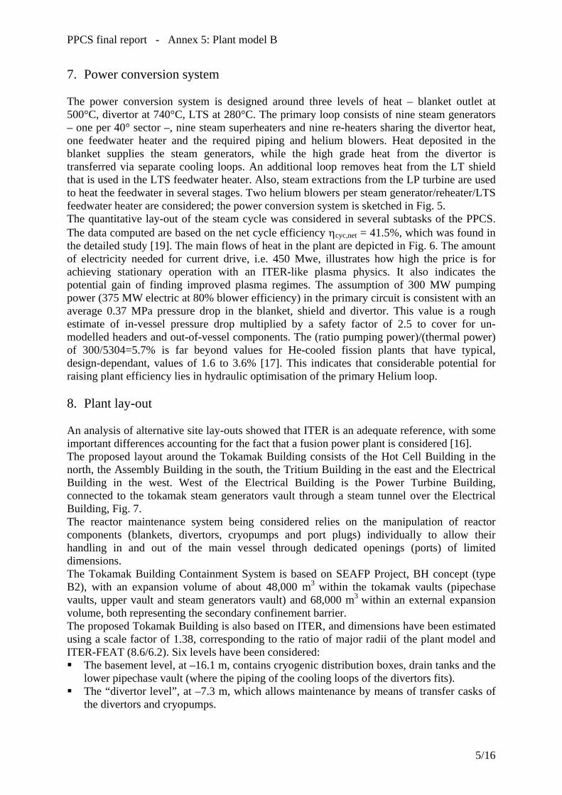
PPCS final report - Annex 5: Plant model B
7. Power conversion system The power conversion system is designed around three levels of heat – blanket outlet at 500°C, divertor at 740°C, LTS at 280°C. The primary loop consists of nine steam generators – one per 40° sector –, nine steam superheaters and nine re-heaters sharing the divertor heat, one feedwater heater and the required piping and helium blowers. Heat deposited in the blanket supplies the steam generators, while the high grade heat from the divertor is transferred via separate cooling loops. An additional loop removes heat from the LT shield that is used in the LTS feedwater heater. Also, steam extractions from the LP turbine are used to heat the feedwater in several stages. Two helium blowers per steam generator/reheater/LTS feedwater heater are considered; the power conversion system is sketched in Fig. 5. The quantitative lay-out of the steam cycle was considered in several subtasks of the PPCS. The data computed are based on the net cycle efficiency ηcyc,net = 41.5%, which was found in the detailed study [19]. The main flows of heat in the plant are depicted in Fig. 6. The amount of electricity needed for current drive, i.e. 450 Mwe, illustrates how high the price is for achieving stationary operation with an ITER-like plasma physics. It also indicates the potential gain of finding improved plasma regimes. The assumption of 300 MW pumping power (375 MW electric at 80% blower efficiency) in the primary circuit is consistent with an average 0.37 MPa pressure drop in the blanket, shield and divertor. This value is a rough estimate of in-vessel pressure drop multiplied by a safety factor of 2.5 to cover for un-modelled headers and out-of-vessel components. The (ratio pumping power)/(thermal power) of 300/5304=5.7% is far beyond values for He-cooled fission plants that have typical, design-dependant, values of 1.6 to 3.6% [17]. This indicates that considerable potential for raising plant efficiency lies in hydraulic optimisation of the primary Helium loop. 8. Plant lay-out An analysis of alternative site lay-outs showed that ITER is an adequate reference, with some important differences accounting for the fact that a fusion power plant is considered [16]. The proposed layout around the Tokamak Building consists of the Hot Cell Building in the north, the Assembly Building in the south, the Tritium Building in the east and the Electrical Building in the west. West of the Electrical Building is the Power Turbine Building, connected to the tokamak steam generators vault through a steam tunnel over the Electrical Building, Fig. 7. The reactor maintenance system being considered relies on the manipulation of reactor components (blankets, divertors, cryopumps and port plugs) individually to allow their handling in and out of the main vessel through dedicated openings (ports) of limited dimensions. The Tokamak Building Containment System is based on SEAFP Project, BH concept (type B2), with an expansion volume of about 48,000 m3 within the tokamak vaults (pipechase vaults, upper vault and steam generators vault) and 68,000 m3 within an external expansion volume, both representing the secondary confinement barrier. The proposed Tokamak Building is also based on ITER, and dimensions have been estimated using a scale factor of 1.38, corresponding to the ratio of major radii of the plant model and ITER-FEAT (8.6/6.2). Six levels have been considered: The basement level, at –16.1 m, contains cryogenic distribution boxes, drain tanks and the
lower pipechase vault (where the piping of the cooling loops of the divertors fits). The “divertor level”, at –7.3 m, which allows maintenance by means of transfer casks of
the divertors and cryopumps.
5/16
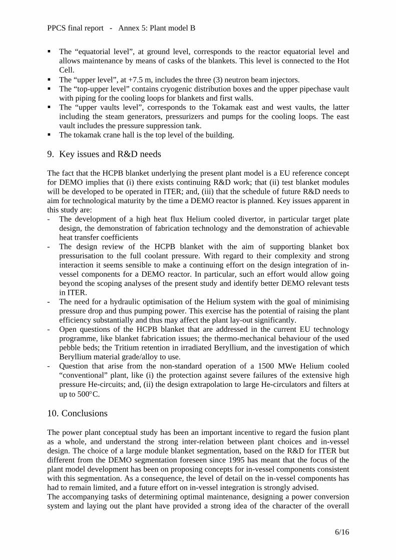
PPCS final report - Annex 5: Plant model B
The “equatorial level”, at ground level, corresponds to the reactor equatorial level and allows maintenance by means of casks of the blankets. This level is connected to the Hot Cell.
The “upper level”, at +7.5 m, includes the three (3) neutron beam injectors. The “top-upper level” contains cryogenic distribution boxes and the upper pipechase vault
with piping for the cooling loops for blankets and first walls. The “upper vaults level”, corresponds to the Tokamak east and west vaults, the latter
including the steam generators, pressurizers and pumps for the cooling loops. The east vault includes the pressure suppression tank.
The tokamak crane hall is the top level of the building. 9. Key issues and R&D needs The fact that the HCPB blanket underlying the present plant model is a EU reference concept for DEMO implies that (i) there exists continuing R&D work; that (ii) test blanket modules will be developed to be operated in ITER; and, (iii) that the schedule of future R&D needs to aim for technological maturity by the time a DEMO reactor is planned. Key issues apparent in this study are: - The development of a high heat flux Helium cooled divertor, in particular target plate
design, the demonstration of fabrication technology and the demonstration of achievable heat transfer coefficients
- The design review of the HCPB blanket with the aim of supporting blanket box pressurisation to the full coolant pressure. With regard to their complexity and strong interaction it seems sensible to make a continuing effort on the design integration of in-vessel components for a DEMO reactor. In particular, such an effort would allow going beyond the scoping analyses of the present study and identify better DEMO relevant tests in ITER.
- The need for a hydraulic optimisation of the Helium system with the goal of minimising pressure drop and thus pumping power. This exercise has the potential of raising the plant efficiency substantially and thus may affect the plant lay-out significantly.
- Open questions of the HCPB blanket that are addressed in the current EU technology programme, like blanket fabrication issues; the thermo-mechanical behaviour of the used pebble beds; the Tritium retention in irradiated Beryllium, and the investigation of which Beryllium material grade/alloy to use.
- Question that arise from the non-standard operation of a 1500 MWe Helium cooled “conventional” plant, like (i) the protection against severe failures of the extensive high pressure He-circuits; and, (ii) the design extrapolation to large He-circulators and filters at up to 500°C.
10. Conclusions The power plant conceptual study has been an important incentive to regard the fusion plant as a whole, and understand the strong inter-relation between plant choices and in-vessel design. The choice of a large module blanket segmentation, based on the R&D for ITER but different from the DEMO segmentation foreseen since 1995 has meant that the focus of the plant model development has been on proposing concepts for in-vessel components consistent with this segmentation. As a consequence, the level of detail on the in-vessel components has had to remain limited, and a future effort on in-vessel integration is strongly advised. The accompanying tasks of determining optimal maintenance, designing a power conversion system and laying out the plant have provided a strong idea of the character of the overall
6/16

PPCS final report - Annex 5: Plant model B
plant. The estimation of plant economics suggests that the Helium cooled solid breeder concept is a serious contender for the technology at least of mid-term nuclear fusion.
7/16

PPCS final report - Annex 5: Plant model B
References [1] ITER, Design Description Document, WBS 1.7, July 2001 [2] L. V. Boccaccini (ed.), European Helium Cooled Pebble Bed (HCPB) Test Blanket,
ITER Design Description Document, FZKA 6127, 1999. [3] L. Boccaccini et al., Passive system for cooling the inboard region in case of a severe
accident, Fus. Eng. Design 63-64, pp. 251-256, 2002. [4] G. du Bois d'Enghien, J. Snoeck, PPCS III - Economic assessment of models A and B
Optimisation of the energy conversion efficiency, Belgatom report TIERSDI/4NT/0004518/000/00, September 2002.
[5] Y. Chen, U. Fischer, P. Pereslavtsev, F. Wasastjerna, The EU Power Plant Conceptual Study – Neutronic design analyses for near term and advanced reactor models, FZKA-6763, 2002.
[6] M. Dalle Donne (ed.), European DEMO BOT solid breeder blanket, KfK 5429, Forschungszentrum Karlsruhe, 1994.
[7] J. N. Dumelow, D. Grove, Model B (Helium cooled pebble bed blanket, Helium cooled divertor), report EFET/TR/N/208 -C9579/DD, March 2002.
[8] T.C. Hender et al., PROCESS code, UKAEA FUS 333, Culham, 1996. [9] S. Hermsmeyer, S. Malang, Gas-cooled high performance divertor for a power plant,
Fus. Eng. Design 61-62, pp. 197-202, 2002. [10] S. Hermsmeyer et al., An improved European helium cooled pebble bed blanket, Fus.
Eng. Design 58-59, pp 689-693, 2001. [11] S. Hermsmeyer (ed.), Conceptual Design of the Helium Cooled Pebble Bed Blanket
Plant Model in the Frame of the EU Power Plant Conceptual Study, to appear as FZKA report, Forschungszentrum Karlsruhe, 2003.
[12] S. Hermsmeyer et al., Revised EU Helium cooled pebble bed blanket for DEMO, SOFE conference, San Diego, USA, October 2003.
[13] M. Loughlin, UKAEA Culham, Neutron source for initial design phase of the PPCS, personal communication, September 2001.
[14] D. Maisonnier et al., Power plant conceptual study, main technological issues, 3rd IAEA Tech. Comm. Meetg. on steady state operation of magnetic fusion devices, Greifswald, Germany, May 2002.
[15] P. Norajitra et al., State of the art: development of a Helium-cooled divertor for DEMO, SOFE conference, San Diego, USA, October 2003.
[16] A. Orden Martinez, Conceptual design of a fusion power plant – 3D drawings for model B, EFET-IBERTEF report 095-039-E-M-00003, May 2002.
[17] G. Vieider, Conceptual design of main cooling systems for a fusion power reactor with He-cooled pebble bed blanket, Studsvik report ES-02/02, January 2002.
[18] D. Ward, Provisional plant parameters for Power Plant Conceptual Study models A and B, Report PPCS/UKAEA/PPCS1.1, September 2001.
[19] G. du Bois d’Enghien, Economic assessment of models A and B, optimisation of the energy conversion efficiency, Report EFDA/93-851 HJ, 30.08.2002
8/16

PPCS final report - Annex 5: Plant model B
Tables Table 1 Reactor parameters (updated version of [18], June 2002)
Parameter Model B Unit Size (MWe) 1332 Blanket Gain 1.39 Fusion Power (MW) 3600 Aspect Ratio 3.0 Elongation (95% flux) 1.7 Triangularity (95% flux) 0.25 Major Radius (m) 8.6 TF on axis (T) 6.9 TF on the TF coil conductor (T) 13.2 Plasma Current (MA) 28.0 βN(thermal, total) 2.7, 3.4 Average Temperature (keV) 20 Temperature peaking factor 1.5 Average Density (1020m-3) 1.2 Density peaking factor 0.3 HH (IPB98y2) 1.2 Bootstrap Fraction 0.43 Padd (MW) 270 n/nG 1.2 Q 13.5 Average neutron wall load 2.0 Divertor Peak load (MW/m-2) 10 Zeff 2.7
9/16

PPCS final report - Annex 5: Plant model B
Table 2 Radial build-up of in-vessel components
Inboard Outboard thickness [cm] thickness [cm] material component cumulativea) cumulativea) (volume fractions) 0.4 0.4 0.4 0.4 1.0 Eurofer first wall 1.4 1.8 1.4 1.8 0.27 Eurofer/0.73 He FW channel 0.5 2.3 0.5 2.3 1.0 Eurofer first wall 36.5 38.8 46.5 48.8 0.154Breeder/0.692
Be/0.098Eurofer/ 0.055He-coolantb)
blanket breeding zone
2 40.8 2 50.8 1.0 Eurofer blanket back wall 17 57.8 27 77.8 0.6
Eurofer/0.4He/void HT shield
2 59.8 2 79.8 void gap 25 84.8 25 104.8 0.9 (0.6 Eurofer+0.4
ZrH)/0.1He LT shield
15 99.8 25 129.8 0.15 Eurofer manifolds a)based 14mm first wall channel (Pos. 2) b)heterogeneous array of cooling plate (0.5 cm; 64 vol% Eurofer) + Be pebble bed (4.5 cm) + cooling plate (0.5 cm; 64 vol% Eurofer) + breeder pebble bed (1.0 cm)
Table 3 Blanket design features
Part Description First wall U-shaped plate 21 – 37mm thick; channel widths 12mm (#5); 19mm (#6);
23mm (#2,3); 26mm (#1,4,7,10,11); 27mm (#8); 28mm (#9) channel height 16mm, channel pitch 22mm
Breeding zone cooling plate 5mm thick, cooling channels 3x2mm2, channel pitch 5mmRadial channels with U-turn near FW, divided into packs of three channels to reduce thermal interaction between hot/cold leg
Ceramic breeder pebble bed 11-12mm high (10mm in neutronic calculations) Beryllium pebble bed 40 mm high
Table 4 Design point of outboard midplane module #9 (scaled to 3600MW fusion power)
Number of modules per sector 4+14 Module height [m] ~ 2 Module width [m] ~ 4 FW thickness (overall incl. channels) [mm] 4 (37) FW channel geometry [mm2] 16 x 28 Surface heat flux on FW [MW/m2] 0.5 Neutron Wall Loading on FW [MW/m2] 2.4 Module power [MW] 30.0 FW channel He velocity [m/s] 116 Helium inlet/outlet temperatures [°C] 300 /500 Helium pressure [MPa] 8 Pressure drop FW [MPa] 0.121
10/16
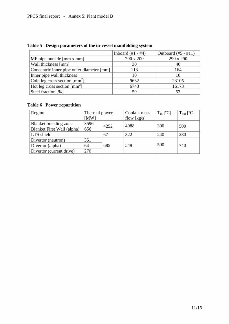
PPCS final report - Annex 5: Plant model B
Table 5 Design parameters of the in-vessel manifolding system
Inboard (#1 - #4) Outboard (#5 - #11) MF pipe outside [mm x mm] 200 x 200 290 x 290 Wall thickness [mm] 30 40 Concentric inner pipe outer diameter [mm] 113 164 Inner pipe wall thickness 10 10 Cold leg cross section [mm2] 9632 23105 Hot leg cross section [mm2] 6743 16173 Steel fraction [%] 59 53
Table 6 Power repartition
Region Thermal power [MW]
Coolant mass flow [kg/s]
Tin [ºC] Tout [ºC]
Blanket breeding zone 3596 Blanket First Wall (alpha) 656 4252 4088 300 500
LTS shield 67 322 240 280 Divertor (neutron) 351 Divertor (alpha) 64 Divertor (current drive) 270
685 549 500 740
11/16

PPCS final report - Annex 5: Plant model B
#3
#9
#1 #11
Figure 1 Radial-poloidal in-vessel cross section (from neutronics model, [5])
12/16

PPCS final report - Annex 5: Plant model B
Figure 2 View of radial module segmentation, and sketch of in-vessel inboard manifolding
Figure 3 Revised HCPB blanket (back view showing stiffened breeding zone BZ, manifolding HTS not displayed)
13/16

PPCS final report - Annex 5: Plant model B
Figure 4: Helium-cooled divertor (HEMS concept)
14/16

PPCS final report - Annex 5: Plant model B
SUPERHEATER(DIVERTOR C. L.)
STEAM GENERATOR(BLANKET C. L.)
PREHEATER(LT SHIELD C. L.)
STEAM REHEATER(DIVERTOR C. L.)
Figure 5 Sketch of the power conversion system
Figure 6 Plant power flow scheme
15/16

PPCS final report - Annex 5: Plant model B
Figure 7 Plant general lay-out
16/16

ANNEXE 6


PPCS final report - Annex 6: Plant model C
EU Power Plant Conceptual Study – Model C: Conceptual Design and Assessment of the Dual-Coolant Blanket Introduction Within the framework of the EU Power Plant Conceptual Study, also the design of the Dual-Coolant (DC) Blanket (the so-called model C) was assessed technologically [1]. Here, the results shall be summarised briefly, starting with a general description of the concept and some very important design requirements to be fulfilled. Reactor specifications Model C is based on a self-cooled lead-lithium breeding zone and a helium-cooled structure made of reduced-activation ferritic steel (EUROFER) as well as a helium-cooled divertor. Flow channel inserts made of SiC composite in the lead-lithium channels serve as thermal and electric insulators to minimise magneto-hydrodynamic (MHD) pressure loss and reach high coolant exit temperatures and, thus, a high efficiency of the power conversion system, for which the BRAYTON cycle (closed-cycle helium gas turbine) is used. The technological and physics assumptions employed for model C represent more advanced extrapolations with respect to those of models A and B and they allow to achieve a higher plant efficiency. The following overall design requirements and criteria should be considered:
• The exchange of blanket and divertor modules should be easy. Time and costs have to be limited.
• Shielding of welds and magnets is necessary to enhance lifetime. • The volumetric fraction of steel in the structure should be as low as possible to
enhance the breeding ratio. • The use of oxide dispersion-strengthened (ODS) steel should be limited to the zone of
the highest temperature, i.e. the plasma-facing zone of the first wall. • The coolant inlet temperature should be high enough to avoid embrittlement of the
materials under irradiation. • Primary coolant loops are provided with concentric tubes with the “hot outlet fluid”
being in the inner tube. The inner and outer tube walls are cooled by the “cold” inlet flow through the annular channels. In addition, the inner tube for the Pb-17Li must be thermally insulated with SiCf/SiC inserts, because the coolant outlet temperature is higher than the permissible design limit for the structure material.
• Tritium permeation losses should be kept as low as possible. Thus, systems for trapping the tritium have to be foreseen, in particular for the purification of the liquid-metal breeder.
Physics of the reactors Models C and D are based on advanced physical assumptions. They are characterised by a high β and high confinement with realistic plasma pressure gradients, MHD stabilisation by strong plasma shaping, a high bootstrap current fraction, low divertor power loads and low Zeff (no ELMs are foreseen in reactor operation).
1/11

PPCS final report - Annex 6: Plant model C
Investigations of the two more advanced models C and D with the PROCESS code show that the advanced physics assumptions indeed lead to a high Q, reduced-size reactor, high bootstrap current fraction, and reduced plasma current when compared to models A and B, with nuclear loads limited to < 2.5 MW/m². Moreover, the heat load of the divertor could be reduced to 5 MW/m² (model D). In all cases, the net power plant output to the grid is 1500 MWe and the D-T fuel mix is 50-50. The main parameters of the model C concept are shown in the table 1
Unit Size (GWe) 1.45 Blanket Gain 1.17 Net Conversion efficiency 0.42 Fusion Power (GW) 3.41 Aspect Ratio 3.0 Elongation (95% flux) 1.9 Triangularity (95% flux) 0.47 Major Radius (m) 7.5 TF on axis (T) 6.0 TF on the TF coil conductor (T) 13.6 Plasma Current (MA) 20.1 βN(thermal, total) 3.4, 4.0 Average Temperature (keV) 16 Temperature peaking factor 1.5 Average Density (1020m-3) 1.2 Density peaking factor 0.5 HH (IPB98y2) 1.3 Bootstrap Fraction 0.63 Padd (MW) 112 n/nG 1.5 Q 30 Average neutron wall load 2.2 Divertor Peak load (MW/m-2) 10 Zeff 2.2
Table 1: main parameters of the model C
2/11

PPCS final report - Annex 6: Plant model C
Design description of the in-vessel components
Fig. 1: Large-module segmentation of the dual-coolant blankets.
Blanket: The advanced dual-coolant (DC) blanket concept is mainly characterised by the use of self-cooled breeding zones with the liquid metal Pb-17Li serving as a breeder for tritium (TBR > 1) and as a coolant for removing the heat gained from fusion energy. For the structure, a helium-cooled reduced-activation ferritic/martensitic (RAFM) steel is used, with SiCf/SiC flow channel inserts (FCIs) serving as electric and thermal insulators in the Pb-17Li channels. Instead of the “banana segments” adopted in earlier studies, the blanket segmentation now consists of “large modules” (Fig. 1). They help to reduce thermal stresses and to cope better with the forces caused by disruptions. In addition, maintenance is facilitated. The blankets are divided into a lifetime part (cold shield, coolant manifold, and vacuum vessel) and a removable part, i.e. the blanket modules containing the breeding zone and the hot shield, which will be exchanged in about 5-6 years’ intervals. Fig. 2 shows the principle construction of the blanket that also acts as a shield for the magnets. The modules are large, stiff boxes with a grid structure inside, which are used as flow channels for the Pb-17Li and helium. As material, EUROFER can be used with a small layer of ODS on the plasma-facing surface. The modules are radially attached to the cold shield plate by screws.
3/11
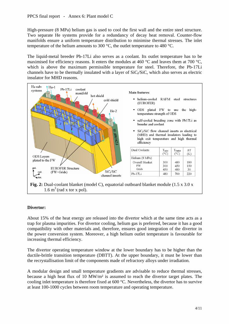
PPCS final report - Annex 6: Plant model C
High-pressure (8 MPa) helium gas is used to cool the first wall and the entire steel structure. Two separate He systems provide for a redundancy of decay heat removal. Counter-flow manifolds ensure a uniform temperature distribution to minimise thermal stresses. The inlet temperature of the helium amounts to 300 °C, the outlet temperature to 480 °C. The liquid-metal breeder Pb-17Li also serves as a coolant. Its outlet temperature has to be maximised for efficiency reasons. It enters the modules at 460 °C and leaves them at 700 °C, which is above the maximum permissible temperature for steel. Therefore, the Pb-17Li channels have to be thermally insulated with a layer of SiCf/SiC, which also serves as electric insulator for MHD reasons.
Fig. 2: Dual-coolant blanket (model C), equatorial outboard blanket module (1.5 x 3.0 x 1.6 m3 (rad x tor x pol).
Divertor: About 15% of the heat energy are released into the divertor which at the same time acts as a trap for plasma impurities. For divertor cooling, helium gas is preferred, because it has a good compatibility with other materials and, therefore, ensures good integration of the divertor in the power conversion system. Moreover, a high helium outlet temperature is favourable for increasing thermal efficiency. The divertor operating temperature window at the lower boundary has to be higher than the ductile-brittle transition temperature (DBTT). At the upper boundary, it must be lower than the recrystallisation limit of the components made of refractory alloys under irradiation. A modular design and small temperature gradients are advisable to reduce thermal stresses, because a high heat flux of 10 MW/m² is assumed to reach the divertor target plates. The cooling inlet temperature is therefore fixed at 600 °C. Nevertheless, the divertor has to survive at least 100-1000 cycles between room temperature and operating temperature.
4/11
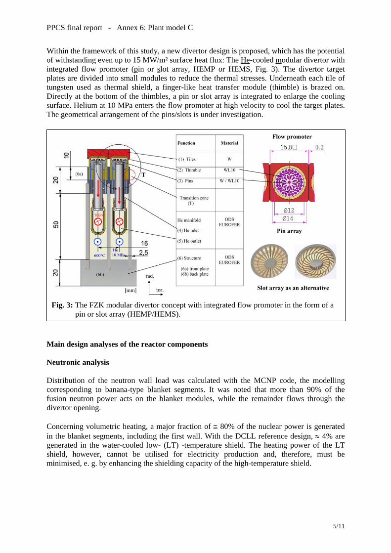
PPCS final report - Annex 6: Plant model C
Within the framework of this study, a new divertor design is proposed, which has the potential of withstanding even up to 15 MW/m² surface heat flux: The He-cooled modular divertor with integrated flow promoter (pin or slot array, HEMP or HEMS, Fig. 3). The divertor target plates are divided into small modules to reduce the thermal stresses. Underneath each tile of tungsten used as thermal shield, a finger-like heat transfer module (thimble) is brazed on. Directly at the bottom of the thimbles, a pin or slot array is integrated to enlarge the cooling surface. Helium at 10 MPa enters the flow promoter at high velocity to cool the target plates. The geometrical arrangement of the pins/slots is under investigation.
Fig. 3: The FZK modular divertor concept with integrated flow promoter in the form of a pin or slot array (HEMP/HEMS).
Main design analyses of the reactor components Neutronic analysis Distribution of the neutron wall load was calculated with the MCNP code, the modelling corresponding to banana-type blanket segments. It was noted that more than 90% of the fusion neutron power acts on the blanket modules, while the remainder flows through the divertor opening. Concerning volumetric heating, a major fraction of ≅ 80% of the nuclear power is generated in the blanket segments, including the first wall. With the DCLL reference design, ≈ 4% are generated in the water-cooled low- (LT) -temperature shield. The heating power of the LT shield, however, cannot be utilised for electricity production and, therefore, must be minimised, e. g. by enhancing the shielding capacity of the high-temperature shield.
5/11
PPCS final report - Annex 6: Plant model C
Shielding efficiency Two essential requirements must be fulfilled: first, the re-weldability of lifetime components made of steel, and, second, sufficient protection of the superconducting toroidal field (TF) coils. Based on existing data, the current assumption is that re-welding of stainless steel should be successful at helium concentrations below 1 appm. Calculations to estimate the helium production in EUROFER steel show that even after a lifetime cycle of 40 years, re-weldability is achieved. Hence, the LT shield can be designed as a lifetime component, if weld joints are placed on its rear. The TF coil, on the other hand, is protected from the penetrating radiation by the blanket, the shield, and the vacuum vessel. An efficient neutron moderator (water or a hydride) is required to this end, combined with a good neutron absorber (steel, tungsten, etc.). Radiation loads of the TF coils were calculated for the inboard mid-plane, where the shielding requirements are highest due to the minimum space available between the plasma and the TF coil. It is noted that the design limits can be met with the DCLL reference design. Thermomechanical and thermohydraulic layout calculations for the blanket and He-cooled divertor The layout of the blanket and the divertor requires iterations between system code analysis and blanket layout concerning neutronic, thermohydraulic, thermomechanical, MHD, and velocity field calculations to determine a set of reactor parameters. Results obtained for the blanket and divertor are presented in Tab. 1. Thermomechanical calculations were performed to show that the temperature requirements as well as the stress requirements can be fulfilled: For the ODS on the first wall, two temperature requirements hold: The surface temperature should stay below 650 °C, while the interface temperature to Pb-17Li should be below 500 °C due to corrosion. Since no reliable data for ODS are available, data from T91 were taken. The results show that the requirements can be fulfilled. Calculations for SiCf/SiC channel inserts revealed that temperature and stresses here are well below the permissible limits. In the same way, temperatures and stresses were assessed for the divertor. Structural design criteria as required by the ITER structural design code are met, i.e. mechanical stresses do not exceed design limits under any operation condition. Based on these values, it is expected that fatigue resulting from some anticipated 100-1000 cycles of reactor shut-down with cooling down from operation conditions to RT would be permissible. Thermohydraulic assessment of the divertor revealed e.g. that a heat transfer coefficient of 24,600 MW/m²K averaged over the slot surface can be obtained for HEMS, which is sufficient for cooling the target plates. This requires a pumping power of 8.6% related to the heat removal.
6/11

PPCS final report - Annex 6: Plant model C
Table 1: Main data of the DC blanket concept.
Overall plant Electric output [MW] 1449 Fusion power [MW] 3410
Blanket Divertor Average neutron wall load [MW/m2] 2.27 1.7 Max. neutron wall load [MW/m2] 3.0 Average surface heat load [MW/m2] 0.45 0.67 Max. surface heat load [MW/m2] 0.59 10 Alpha-particle surface power [MW] 546 136 H&CD power [MW] 112 Neutron power [MW] 2445 283 Energy multiplication 1.17 1.17 Thermal power [MW] 3408 583 Surface area [m2] 1077 69.3 (target)
Helium coolant: - Inlet temperature [°C] 300 700 (target) - Outlet temperature [°C] 480 800 (target) - Pressure [MPa] 8 10 (target) - Mass flow rate [kg/s] 1528 473 (bulk)
477 (target) Pb-17Li coolant:
- Inlet temperature [°C] 480 - Outlet temperature [°C] 700 - Mass flow rate [kg/s] 46053
Secondary helium loop: - Inlet temperature [°C] 285 - Outlet temperature [°C] 700 - Pressure [MPa] 15 Net efficiency (blanket/divertor cycle) 0.42
MHD analyses The pressure drop in the Pb-17Li channels of the blanket due to magnetic/electric resistance is small, if all walls are covered by an SiC electric insulation of 5 mm thickness . But one should be aware of the fact that the electric resistivity of SiC under fusion-relevant irradiation is still unknown to date. Three-dimensional effects at the strong contractions and expansions will cause the major fraction of pressure drop in the dual-coolant blanket. These crucial elements, however, cannot be analysed by standard correlations. The relatively high values that were found can be reduced, if the cross section of the access tubes are enlarged. Finally, it should be mentioned that the fraction of the pumping power for the liquid-metal coolant is relatively low.
7/11

PPCS final report - Annex 6: Plant model C
Power conversion system (PCS) For safety reasons (chemical reaction between water and liquid metal) and a high thermal efficiency to be attained, a Brayton cycle (closed-cycle helium gas turbine) is considered as reference concept. Thus, tritium permeation losses to the environment can be minimised. Four parallel Brayton cycles are used. The overall plant efficiency to about 42%. Tritium recovery and Pb-17Li purification The requirements on the tritium removal and recovery system are to keep the tritium inventory low in the total blanket system and to limit the tritium losses to the environment to an acceptable value. Above all the tritium permeating through the walls of the heat rejection heat exchanger and intercoolers into the water is to be considered. These losses might be limited easily to acceptable values due to the low temperatures (maximum helium temperature ≈ 300 °C, water temperature ≈ 30 °C) in these components. Several methods were proposed and assessed for tritium removal from Pb-17Li. During the breeding process, also helium will be produced. Due to its low solubility in Pb-17Li, bubbles will be formed. It might be straightforward to combine helium bubble removal with the tritium removal system discussed, since some of the methods might also be efficient for helium bubble removal. Finally, liquid-metal purification systems will be required to control the oxygen content of the system and remove corrosion products. For irradiated Pb-17Li, additional removal of heavy metal isotopes (Po, Hg, Ti) will be necessary. Purification and control systems for helium cooling loops Several helium loops cool the different systems of the plant. Helium gas has to be cleaned regularly so as to remove gaseous and radioactive impurities (especially tritium). The coolant purification system (CPS) will also serve as a means of pressure control. Balance of plant (BoP) This section deals with a series of systems in addition to and integrated with the reactor and its fusion-related auxiliaries to make up an entire operational system capable of generating electrical power. The following main systems were considered:
• Primary heat transport system • Power conversion cycle • Service water system: for cooling auxiliary systems • Component cooling water system: provides cooling water to selected auxiliary
components. The component cooling water system acts as an intermediate barrier between the circulating water system and potentially radioactive cooling loads to reduce the possibility of radioactive leakage to the environment.
• Circulating water system: provides for a continuous supply of cooling water to the heat rejection heat exchanger, the intercoolers, the component cooling water heat exchanger, and the service water system.
• Water treatment plant • Compressed-air system
8/11

PPCS final report - Annex 6: Plant model C
• Fire protection • Electric power • HVAC system: provides for the ventilation and air conditioning of different plant
buildings.
Fig. 4: Fusion power plant, general layout.
Fusion power plant layout The whole power plant site comprises several buildings to house the reactor, auxiliary systems, power supply and the turbines, but also workshops and offices (Fig. 4). The design of the tokamak building and the hot cell building is further evaluated, based on the design of the ITER site. A general view of tokamak building with different levels is illustrated in Fig. 5. Main key issues and R&D needs The following issues still remain to be studied: Blanket:
a) MHD modelling and computations of 3D inertial flows in expansions. b) Tritium recovery: present experience with components for tritium recovery is not
sufficient to design reliably such a system. More work on liquid/gas contactors is recommended, which should also include other volatile radioactive isotopes.
c) Pb-17Li purification: corrosion products in liquid-metal loops must be avoided by using efficient purification systems. The aim should be to keep these products in solution and to trap them in cold traps and preventing them from depositing, especially
9/11
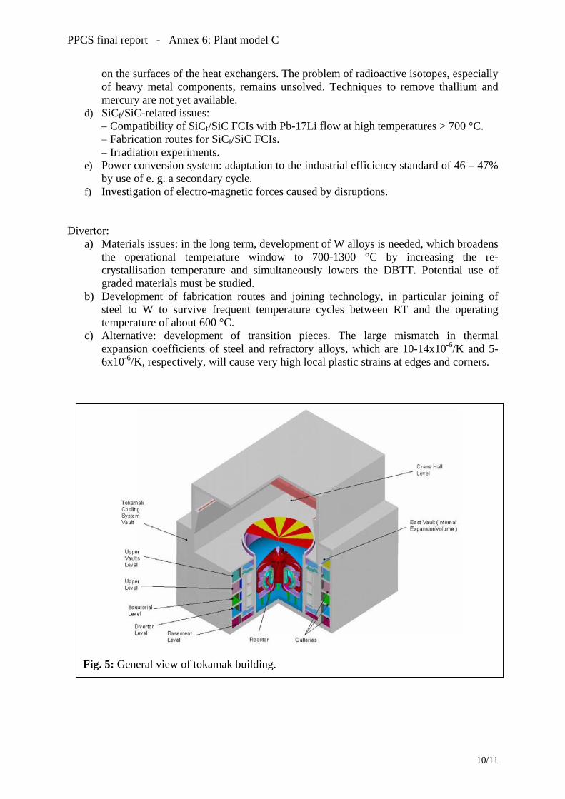
PPCS final report - Annex 6: Plant model C
on the surfaces of the heat exchangers. The problem of radioactive isotopes, especially of heavy metal components, remains unsolved. Techniques to remove thallium and mercury are not yet available.
d) SiCf/SiC-related issues: − Compatibility of SiCf/SiC FCIs with Pb-17Li flow at high temperatures > 700 °C. − Fabrication routes for SiCf/SiC FCIs. − Irradiation experiments.
e) Power conversion system: adaptation to the industrial efficiency standard of 46 – 47% by use of e. g. a secondary cycle.
f) Investigation of electro-magnetic forces caused by disruptions. Divertor:
a) Materials issues: in the long term, development of W alloys is needed, which broadens the operational temperature window to 700-1300 °C by increasing the re-crystallisation temperature and simultaneously lowers the DBTT. Potential use of graded materials must be studied.
b) Development of fabrication routes and joining technology, in particular joining of steel to W to survive frequent temperature cycles between RT and the operating temperature of about 600 °C.
c) Alternative: development of transition pieces. The large mismatch in thermal expansion coefficients of steel and refractory alloys, which are 10-14x10-6/K and 5-6x10⁻⁶/K, respectively, will cause very high local plastic strains at edges and corners.
Fig. 5: General view of tokamak building.
10/11

PPCS final report - Annex 6: Plant model C
Conclusions
odel C in the present PPCS represents a compromise between the “near-term” models A
he improved reference design of the DC with a modular blanket segmentation and the
he overall results of this study allow the conclusion to be drawn that the plant model C has a
eferences
. Norajitra, L. Bühler, A. Buenaventura, E. Diegele, U. Fischer, S. Gordeev, E. Hutter, R.
Mand B with their limited attractiveness and the “very advanced” model D with its very attractive features, but considerable development risks. This study is aimed at assessing the self-cooled liquid-metal breeder blanket for use in a standardised commercial power plant with a typical unit size of 1500 MWe. This requires iterative calculations between the system code analysis and the blanket layout. Interactions between the conceptual design of blanket and divertor, system code, neutronic, thermohydraulic, thermomechanical, and MHD analyses, the power conversion system, and balance of plant are pointed out and discussed. Tconceptual design of the modular He-cooled divertor are addressed. The concept of the DC blanket is based on the use of a helium-cooled ferritic steel structure, the self-cooled Pb-17Li breeding zone, and SiCf/SiC flow channel inserts. The latter serve as electric and thermal insulators that minimise pressure losses and allow for a relatively high Pb-17Li exit temperature, leading to a high thermal efficiency. Additionally, integrating the divertor and other sub-systems in the power conversion system to raise the overall efficiency of the plant is discussed. Thigh potential of meeting the goal of fusion research, i.e. to develop an economically and environmentally attractive energy source. R PKruessmann, S. Malang, A. Orden, G. Reimann, J. Reimann, G. Vieider, D. Ward, F. Wasastjerna: Conceptual Design of the Dual-Coolant Blanket within the Framework of the EU Power Plant Conceptual Study (TW2-TRP-PPCS12), Final Report, FZKA 6780 (May 2003)
11/11


ANNEXE 7


PPCS final report - Annex 7: Plant model D
EU Power Plant Conceptual Study – Model D : Conceptual Design and Assessment of Self-Cooled Lithium-Lead (SCLL) In-Vessel Components
1 – Introduction Within the framework of the European Power Plant Conceptual Studies (PPCS), the most advanced reactor model (Model D) is based on a Self-Cooled Lithium-Lead (SCLL) blanket concept. It is associated with the largest attractiveness and at the same time with the largest development risk. The objective of the study of such an advanced reactor model is to show that the fusion power can reach very high safety standard associated with high thermal efficiency and good economic performance. The assumed guidelines are therefore the maximisation of the coolant outlet temperature and the minimisation of the energy stored in the vacuum vessel, which means a minimisation of afterheat, of the operating pressure and of the chemical reactivity with water and air. The choice of using SiCf/SiC for structures and Pb-17Li as breeder and coolant in most in-vessel components is in line with these guidelines. In fact, SiCf/SiC structures allow high coolant temperature, and show very low short term activation and afterheat levels. Associated with the use of Pb-17Li (Li enriched at 90% in 6Li) as breeder, coolant, neutron multiplier and tritium carrier, this system achieves high plant efficiency and has the potential for reaching good safety standards. In fact, this choice leads to have low afterheat, low operating pressures and low chemical reactivity with water and air in the in-vessel components and, therefore, permits to minimize the energy stored in the vacuum vessel. The SCLL blanket design and associated systems are based on the most attractive features of existing blanket designs such as TAURO [1] and ARIES-AT [2]. All analyses have been performed assuming largely improved properties of SiCf/SiC compared to present-day knowledge. For instance, the SiCf/SiC thermal conductivity after irradiation has been assumed about five time larger than the value known today. Reactor parameters have been determined assuming large, although reasonable, extrapolation of present-day plasma physics knowledge. Other advanced features, such as high-temperature super-conducting coils and potential for industrial hydrogen production, can also been envisaged in future studies. The following sections summarise the main achievements obtained in the studies performed on this advanced reactor model (Model D). The details can be found in the final report of the study edited in February 2003 [3]. 2 – Reactor Parameters Although double null plasmas may be less challenging for the vertical stabilisation system of the reactor, single null plasmas have been selected because a larger database of experimental data from present-day experiments is available, on which to base the extrapolation to a reactor. The reactor parameters have been defined for 1500 MWe of net electrical power to the grid. They have been evaluated with the PROCESS code [4]. In order to minimize the number of components, it has been assumed that 16 coils are sufficient for avoiding excessive toroidal field ripple. The main assumptions are that a highly shaped plasma with an optimisation of the magnetic shear profile can achieve a total normalised β of 4.5 and that, with an increased safety factor, q>4, the high poloidal β allows a large bootstrap current fraction and low levels of re-circulating power for current drive. It has also been assumed that improvements in divertor
1/17
PPCS final report - Annex 7: Plant model D
physics and technology are sufficient and no penalty is imposed on the core plasma to protect the divertor. The maximum heat flux on the divertor is then 5 MW/m2. It is assumed that high normalised density operation is feasible. Combined with the high value of thermal efficiency, it is possible to have a modest sized device that is capable of producing large electrical power output. The obtained set of parameters is given in Table I. Using this parameters, a set of plasma equilibrium calculations has led to the plasma shape shown in Fig. 1. The relatively high plasma shape might require stabilizing coils placed in the rear part of the front outboard blanket to ensure toroidal continuity. 3 – Major Design Choices Several design choices have been made in order to define the complete reactor plant, as follows:
• The blanket consists in several meters-high segments with co-axial Pb-17Li poloidal flow, which allows to maximize the coolant outlet temperature.
• Blanket segments remote maintenance is performed vertically through ports at the top of the vacuum vessel (after Pb-17Li draining). Poloidally, the blanket is divided in 3 parts: outboard, inboard and top-board (see Fig. 1). One of the two top-board segments is extracted together with the port cap. Toroidally, there are 16 TF coils, which form 16 VV sectors, each of them including 3 outboard segments and 2 inboard and top-board segments.
• Divertor remote maintenance is performed horizontally through a bottom port as in ITER.
• In order to reduce the amount of waste, the outboard blanket is divided in two zones, a front zone, about 30 cm-thick, replaceable relatively often (depending on the SiCf/SiC lifetime), and a back zone, submitted to a lower n-flux, which could be a lifetime component. The Pb-17Li is expected to be purified, refurbished in 6Li and recycled. Inboard and top-board blankets, being relatively thin, are not radially split.
• Pb-17Li pressure inside the blanket and divertor is dictated by hydrostatic pressure. To minimize this value it is therefore preferred to have horizontal heat exchangers and to have an independent divertor cooling circuit.
4 – Design Description of In-Vessel Components for SCLL Reactor The Pb-17Li feeding pipes and drain system enter the vessel from the bottom. The remote connection and disconnection of the blanket and divertor pipes before removal represent a major design challenge. A poloidal cross section of the in-vessel components is given in Fig. 1. 4.1 – Blanket The blanket is formed by only two materials: the SiCf/SiC structure and the Pb-17Li which acts as breeder/multiplier and coolant. The design is based on the principle of coaxial flow, proposed in the ARIES-AT [2] study, which allows to have a maximum Pb-17Li outlet temperature of 1100°C without exceeding the limit of 1000°C for SiCf/SiC. The first wall is protected by a 2mm-thick layer of tungsten. Each outboard segment is formed by 5 modules attached on a thick back plate that gives sufficient strength for segment transport during replacement and allows its attachment to the back components (see Fig. 2). A mid-plane module horizontal cross-section is shown in Fig. 3, where the two outboard radial zones are
2/17
PPCS final report - Annex 7: Plant model D
also indicated. The Pb-17Li enter from the bottom and flows first in the thin external layer (at 4.5 m/s), then turns down at the top and flows down at low velocity in the central region. 4.2 – Divertor The SCLL reactor foresees to have an independent divertor system. Depending on the specifications, the divertor could in principle be cooled by water, Helium, or Pb-17Li. Liquid walls could also be considered. However, if one wants to apply the reactor overall safety strategy of low-energy inventory in the vacuum vessel, the best option would be the use of Pb-17Li coolant with SiCf/SiC structures and W-protection tiles. A divertor concept, based on these materials and derived from the ARIES-AT one [2], is described in [5] and shown in Fig. 4. It can allow a maximum surface heat flux of 5 MW/m2. In this concept, the Pb-17Li inlet/outlet temperatures are, respectively, 600°C and 1000°C. The relatively high outlet temperature is obtained by assuming that the Pb-17Li, after cooling the divertor plates, recovers also the neutron energy deposited in the rear shield. 4.3 – Shielding & Vacuum Vessel Because of the relatively low shielding efficiency of the blanket a significant fraction neutron energy (~8%) is deposited in the shield region. It is therefore necessary to recover most of this energy for electrical power production. The shield region is then divided in two zones: a first zone, called “high-temperature shield (HTS)”, cooled by Pb-17Li and connected with the blanket cooling circuits, and a second zone, called “low temperature shield (LTS)”, cooled by the Helium (250°C, 4 MPa). Helium is also used as vacuum vessel coolant. The HTS uses SiCf/SiC as structural material and WC as neutron absorber. The LTS uses borated steel as structural material and WC. In the inboard blanket, typical thickness is 30 cm for the HTS, and 35 cm for the LTS. 5 – Main Performed Analyses 5.1 – Neutronics Analyses Tritium Breeding Ratio (TBR), heat deposition and shielding analyses has been performed with a Monte Carlo code (MCNP) using a 3D geometrical model describing all the main in-vessel components, for the case where Pb-17Li is used as coolant in blanket, divertor and HTS. The radial built of the SCLL blanket and shield is given in Table II. The obtained TBR is 1.12 of which 0.98 in the blanket, 0.13 in the divertor, and 0.01 in the HTS. The neutron deposited energy for the whole reactor is 2290 MW leading to an energy multiplication factor of 1.13. The energy deposited in the HTS is about 190 MW and in the divertor region is about 280 MW. The shielding efficiency has been calculated on the inboard side with respect to the super-conducting coils limits used for ITER. It has been found that the use of WC in both shield and vacuum vessel allows to have a sufficient shielding efficiency and that the use of water and/or hydrides is not necessary. This conclusion is important for safety because it allows to exclude any accidental production of hydrogen within the vacuum vessel. High temperature super-conducting coils (up to 77 K) might be used. This choice could lead to lower shielding requirements and, may be, lower cost 5.2 – Thermo-mechanical Analyses
3/17
PPCS final report - Annex 7: Plant model D
Thermo-mechanical analyses have been performed with the FEM CASTEM code, using a 3D model and TAURO design criteria [2]. Assuming Pb-17Li inlet/outlet temperatures of respectively 700°C and 1100°C, and Pb-17Li pressure of 1.5 MPa, the Pb-17Li velocity in the front thin layer is 4.5 m/s, the average velocity in the annular layer is 2.0 m/s and in the internal volume is 0.16 m/s. Because of the coaxial flow, the maximum SiCf/SiC temperature is indeed kept at 1000°C. Evaluated stresses are acceptable for the whole structure. The blanket design point is given in Table III. 5.3 – MHD Analyses Main pressure drops due to MHD effects are expected in the 4 mm-thick channel behind the FW where the Pb-17Li coolant flows at 4.5 m/s. MHD analyses have been performed with a FZK code that solves by asymptotic and numeric techniques the 3D governing equations for conservation of momentum, mass, and charge and Ohm’s law for strong, externally applied magnetic fields. Assuming a magnetic field of 4 T in the outboard blanket, 6 T in the topboard and 8 T in the inboard ones, the corresponding pressure drops are respectively 0.44 MPa, 0.19 MPa, and 0.85 MPa. These pressure drop values are obtained assuming fully established flow in the blanket which seems to be justified for the very elongated blanket geometry. Three-dimensional effects and pressure drops in the supplying lines will give additional contributions which should be evaluated in future analyses. 6 - Tritium recovery and Pb-17Li purification Because of the required high Pb-17Li velocity, the Pb-17Li in the blanket is renewed more than 1000 times a day. Therefore, the T-partial pressure in a single pass remains very low and it is neither necessary nor efficient to try to extract on-line all the produced tritium. It is therefore proposed to derive a fraction (say 1%) of the Pb-17Li flow after having passed through the heat-exchanger in order to avoid too large heat losses. The extractor could be characterised by He-bubbles in counter-flow to the Pb-17Li at 700°C and achieve T-extraction efficiency as high as 80%. Material issues have not yet been considered. The required T-extraction efficiency and the fraction of derived Pb-17Li will depend on the maximum acceptable T-partial pressure in the heat exchanger which is dictated by the maximum tolerable T-permeation towards the helium secondary circuit. Other T-extraction methods could also be envisaged, for instance using permeators or directly performing the extraction in a specifically designed heat exchanger. Pb-17Li purification may be necessary for extracting radioisotopes characterised by high ingestion and inhalation hazard potential in case of accidental release. The purification may occur in-line or by batches depending on the chosen criteria. 7 – Cooling Circuits and Estimated Efficiency The proposed architecture of the cooling circuits includes one loop for the extraction and conversion of the divertor thermal power (~600 MW) with its own turbo-generator and 4 loops for the blanket and HTS thermal power (~2160 MW), which could use 4 turbo-generators with dimensions close to the present-day technological capability in fission (i.e., HTR). Three-stages compressors are assumed. The corresponding scheme is given in Fig. 5 and the main characteristics of the power conversion system are given in Table IV. The proposed Pb-17Li/He heat exchangers are of the tube-type because of the pressure difference between primary and secondary circuits. In the reference case, the high temperature Pb-17Li is expected to flow in U-tubes made of high-temperature resisting
4/17

PPCS final report - Annex 7: Plant model D
materials (e.g., SiCf/SiC or W). Main R&D should focus on improving heat exchange on the He-side. Heat exchanger dimensions are about 3 m of diameter and more than 20 m of length. The SCLL reactor efficiency, defined as net electrical output (~1500 MWe) divided by the fusion power, is about 61%. 8 – Power Plant Layout The proposed preliminary general layout of the Model D Power Plant is based on the ITER plant layout with the addition of the electricity generating system, that is the Turbine Building and associated Electrical Park (220 kV). In Fig. 5 is shown the scheme of primary cooling system, secondary cooling system (including turbo-generators with connection to electrical grid) and the Pb-17Li detritiation and purification systems. A preliminary evaluation of the required areas and volumes for the plant has been performed [6]. For instance, the primary coolant circuits is developed over a total piping length of about 250 m with pipes diameter of 20 inches (about 0.5 m) and include about 50 bends. All the corresponding components are arranged partially in the Tokamak building (i.e., the heat exchangers) and partially in the other surrounding buildings, each devoted to specific functions. The arrangement of the different buildings is defined with the objective to minimise the occupied area. The main identified building are the Electrical building containing all equipment for powering the magnet system, the Turbine Building containing the secondary cooling circuits components, the Tritium Building, the Assembly Building and the Hot Cells where maintenance and processing of in-vessel components and port plugs are performed. The high outlet coolant temperature (1100°C) would allow to couple electricity production (using the components described above) to Hydrogen production, which would require specific equipment to be added on the plant. The ratio between the power devoted to H-production and the power devoted to electricity production depends on an overall economic assessment, which has not been performed in the present study. However, it can be said that some hundreds of tons of H2 per day can be produced while keeping substantial electrical production. 9 – Main key issues and R&D needs R&D requirements concerns issues directly related to the blanket designs such as the SiCf/SiC properties, the in-vessel components fabrication, the pipes connections and attachment systems, the development of all out of vessel components, the most significant of them is the high-temperature heat exchanger. High-temperature superconductors requires also a large R&D program as stated in the previous section, although they have a lower priorities compared to the other issues. Present-day SiCf/SiC composites are not adequate to be used directly as structure of nuclear components. A comparison between measured properties on present-day SiCf/SiC and requirements are given in Table V. In fact, there are some key issues influencing its attractiveness, which can be identified as “development risks” and which define the required R&D program. The most important requirements are:
• improvement of thermal conductivity, especially through the thickness, at high temperature and under neutron irradiation;
• determination and possible improvement of maximum working temperature under irradiation (swelling, compatibility with Pb-17Li);
5/17

PPCS final report - Annex 7: Plant model D
• confirmation of the out-of-pile mechanical and thermo-mechanical properties after the beginning of irradiation;
• development and validation of appropriate design criteria (e.g., maximum allowed stresses) which could ensure reasonable component reliability;
• determination and improvement of the lifetime; • capability of fabrication of components with homogeneous properties at large
dimensions, with particular attention to the minimum thickness (especially for the divertor design) and maximum thickness (especially for the blanket back-plate);
• development, testing and validation of acceptable joining techniques; • determination of the electrical conductivity under irradiation; • establishment of the maximum interface temperature with Pb-17Li under
representative flowing conditions and irradiation level; in particular verification that no Pb-17Li infiltration through the SiCf/SiC surface will occur, the major risk being an increase of the wall electrical conductivity;
• compatibility of brazing material with Pb-17Li. The above list of requirements gives the main guidelines for future R&D for SiCf/SiC. In terms of priorities, thermal conductivity though the thickness, effects of irradiation, and brazing/joining techniques are clearly the most important items to be addressed. Blanket and divertor pipes connection and blanket segment fixation are expected to be performed remotely, the corresponding proposed systems are derived from existing low temperature metal technology. The general assumption is that similar technology can be developed for high temperature operations, likely using ceramic composites materials (for some items, W could be a possible alternative). Significant R&D will be necessary to show the validity of this assumption although it has a lower level of priority. Because of the high Pb-17Li temperature all primary circuits components (T-extractors, pumps, valves, and especially heat exchangers) need special R&D. Heat exchangers, because of the severe operating conditions coupled with strong safety requirements related to Tritium control, appears among the most challenging components to be developed. 10 – Conclusions The Self-Cooled Lithium-Lead reactor has been defined within the EU Power Plant Studies as the most advanced reactor which can reasonably be conceived by extrapolating both physics and technology knowledge. Of course, these extrapolations need long-term experimental validation. This study has to be considered as a preliminary evaluation of the main characteristics, performance and required design features of an ideal design. Further improvements, allowing to define a more integrated design, are required. In spite of the preliminary nature of this work, this study has shown that a SCLL blanket could lead to very high energy conversion efficiency resulting in good prospects to achieve fusion economic competitiveness associated with good safety standards. References [1] H. Golfier, G. Aiello, M. Fütterer, L. Giancarli, A. Li Puma, Y. Poitevin, J. Szczepanski, “Progress on the TAURO Blanket System”, Fus. Eng. & Des. 61-62 (2002) 461-470.
6/17

PPCS final report - Annex 7: Plant model D
[2] A.R Raffray, R. Jones, G. Aiello, M. Billone, L. Giancarli, H. Golfier, A. Hasegawa, Y. Katoh, A. Kohyama, S. Nishio, B. Riccardi, and M.S. Tillack, “Design and material issues for high performances SiCf/SiC-based fusion power cores”, Fus. Eng. & Des. 55 (2001) 55-95. [3] L. Giancarli, L. Bülher, U. Fischer, R. Enderlé, A. Li Puma, D. Maisonnier, C. Pascal, P. Pereslavtsev, Y. Poitevin, A. Portone, G. Saibene, P. Sardain, J. Szczepanski, D. Ward, “Conceptual Design of Model D Reactor based on Self-Cooled Lithium-Lead (SCLL) Blanket using SiCf/SiC Structures”, CEA Report, DEN/CPT (February 2003). [4] T. C Hender, P. J. Knight and I. Cook, “The PROCESS code”, UKAEA FUS 333 (1996). [5] A. Li Puma, L. Giancarli, H. Golfier, Y. Poitevin, and J. Szczepanski, “Potential performances of a divertor concept based on liquid metal cooled SiCf/SiC structures”, presented at SOFT-22, September 8-13, 2002, Helsinki (Finland). [6] A. Scalzullo, “Layout Arragement Study for Primary and Seconadry Circuits of the PPCS-Model D Option“, Ansaldo Report, EFE-PPCS-SMPX-2000 (Decemebr 2002).
7/17

PPCS final report - Annex 7: Plant model D
Table I
Main parameters obtained for the Model D reactor (“advanced model”)
Basic Parameters Unit Size [MWe] 1527 Major Radius [m] 6.1 Aspect Ratio 3.0 Plasma Current [MA] 14.1 TF on axis [T] 5.6 Number of TF coils 16 TF on TF Coil Conductor [T] 13.4 Elongation (X-point, 95% flux) 2.1, 1.9 Triangularity (X-point, 95% flux) 0.7, 0.47 Q 35 Physics Parameters HH (IPB98y2) 1.2 n/nG 1.5 βN(thermal, total) 3.7, 4.5 Bootstrap fraction 0.76 Safety factor q(95) 4.5 Zeff 1.6 Average Electron Temperature [keV] 12 Temperature peaking factor 1.5 Density peaking factor 0.5 Engineering Parameters Fusion Power [MW] 2530 Source peaking factor 2.5 Heating Power [MW] 71 Average neutron wall load [MW/m2] 2.4 FW Surface Heat Flux [MW/m2] 0.5 Max. Divertor Heat Load [MW/m2] 5
8/17
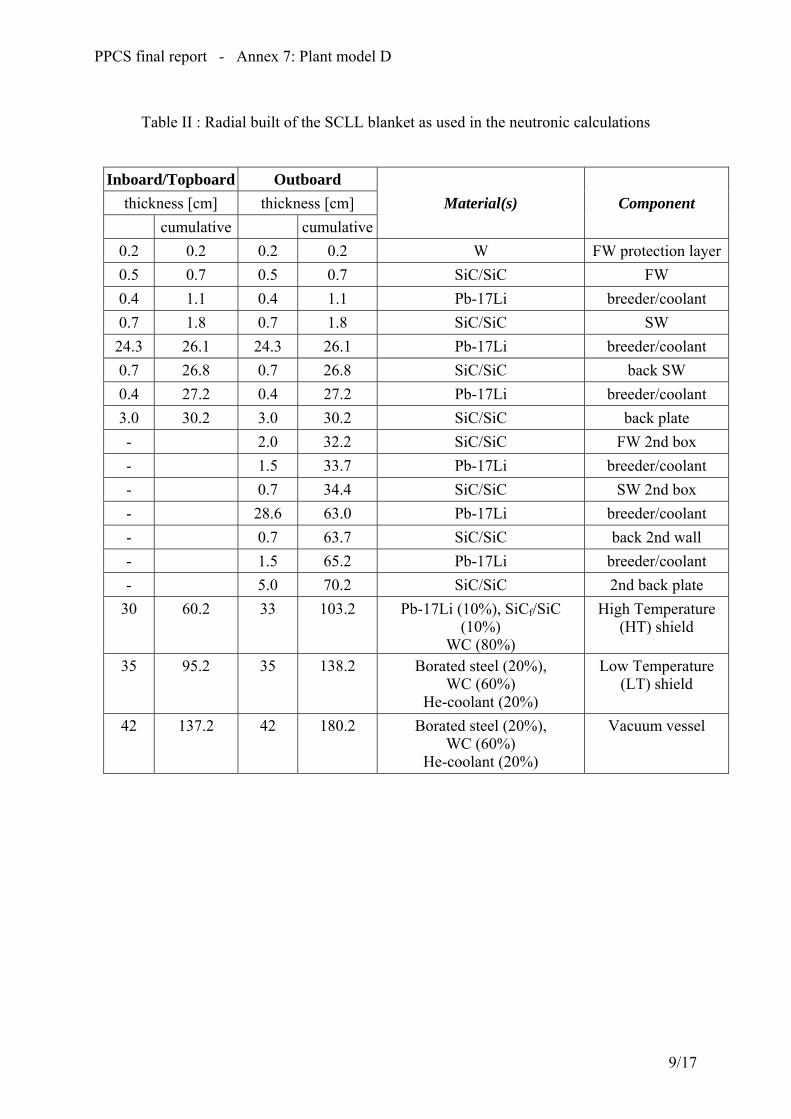
PPCS final report - Annex 7: Plant model D
Table II : Radial built of the SCLL blanket as used in the neutronic calculations
Inboard/Topboard Outboard thickness [cm] thickness [cm] Material(s) Component cumulative cumulative
0.2 0.2 0.2 0.2 W FW protection layer0.5 0.7 0.5 0.7 SiC/SiC FW 0.4 1.1 0.4 1.1 Pb-17Li breeder/coolant 0.7 1.8 0.7 1.8 SiC/SiC SW 24.3 26.1 24.3 26.1 Pb-17Li breeder/coolant 0.7 26.8 0.7 26.8 SiC/SiC back SW 0.4 27.2 0.4 27.2 Pb-17Li breeder/coolant 3.0 30.2 3.0 30.2 SiC/SiC back plate - 2.0 32.2 SiC/SiC FW 2nd box - 1.5 33.7 Pb-17Li breeder/coolant - 0.7 34.4 SiC/SiC SW 2nd box - 28.6 63.0 Pb-17Li breeder/coolant - 0.7 63.7 SiC/SiC back 2nd wall - 1.5 65.2 Pb-17Li breeder/coolant - 5.0 70.2 SiC/SiC 2nd back plate
30 60.2 33 103.2 Pb-17Li (10%), SiCf/SiC (10%)
WC (80%)
High Temperature (HT) shield
35 95.2 35 138.2 Borated steel (20%), WC (60%)
He-coolant (20%)
Low Temperature (LT) shield
42 137.2 42 180.2 Borated steel (20%), WC (60%)
He-coolant (20%)
Vacuum vessel
9/17
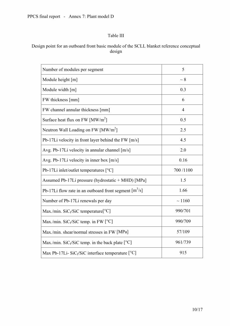
PPCS final report - Annex 7: Plant model D
Table III
Design point for an outboard front basic module of the SCLL blanket reference conceptual
design
Number of modules per segment 5
Module height [m] ~ 8
Module width [m] 0.3
FW thickness [mm] 6
FW channel annular thickness [mm] 4
Surface heat flux on FW [MW/m2] 0.5
Neutron Wall Loading on FW [MW/m2] 2.5
Pb-17Li velocity in front layer behind the FW [m/s] 4.5
Avg. Pb-17Li velocity in annular channel [m/s] 2.0
Avg. Pb-17Li velocity in inner box [m/s] 0.16
Pb-17Li inlet/outlet temperatures [°C] 700 /1100
Assumed Pb-17Li pressure (hydrostatic + MHD) [MPa] 1.5
Pb-17Li flow rate in an outboard front segment [m3/s] 1.66
Number of Pb-17Li renewals per day ~ 1160
Max./min. SiCf/SiC temperature[°C] 990/701
Max./min. SiCf/SiC temp. in FW [°C] 990/709
Max./min. shear/normal stresses in FW [MPa] 57/109
Max./min. SiCf/SiC temp. in the back plate [°C] 961/739
Max Pb-17Li- SiCf/SiC interface temperature [°C] 915
10/17
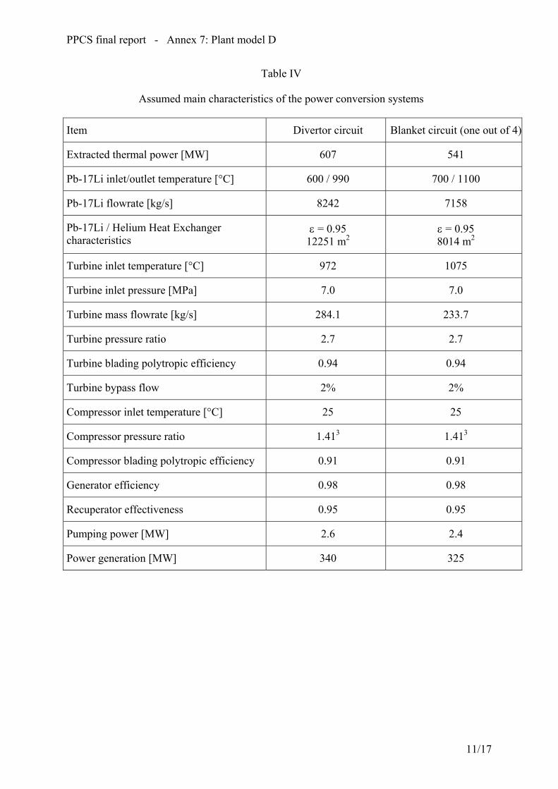
PPCS final report - Annex 7: Plant model D
Table IV
Assumed main characteristics of the power conversion systems
Item Divertor circuit Blanket circuit (one out of 4)
Extracted thermal power [MW] 607 541
Pb-17Li inlet/outlet temperature [°C] 600 / 990 700 / 1100
Pb-17Li flowrate [kg/s] 8242 7158
Pb-17Li / Helium Heat Exchanger characteristics
ε = 0.95 12251 m2
ε = 0.95 8014 m2
Turbine inlet temperature [°C] 972 1075
Turbine inlet pressure [MPa] 7.0 7.0
Turbine mass flowrate [kg/s] 284.1 233.7
Turbine pressure ratio 2.7 2.7
Turbine blading polytropic efficiency 0.94 0.94
Turbine bypass flow 2% 2%
Compressor inlet temperature [°C] 25 25
Compressor pressure ratio 1.413 1.413
Compressor blading polytropic efficiency 0.91 0.91
Generator efficiency 0.98 0.98
Recuperator effectiveness 0.95 0.95
Pumping power [MW] 2.6 2.4
Power generation [MW] 340 325
11/17

PPCS final report - Annex 7: Plant model D
Table V
SiC/SiC properties and data base Comparison between assumed values and typical present-day measured values.
Key SiCf/SiC Properties and Parameters *
Assumed values [1] in the design analyses
Typical measured value
Density ≈ 3000 kg/m3 ≈ 2500 kg/m3
Porosity ≈ 5% ≈ 10% Young's Modulus 200-300 GPa ≈ 200 GPa Poisson's ratio 0.16-0.18 0.18 Thermal Expansion Coefficient ≈ 4 x 10⁻⁶/°C 4 x 10⁻⁶/°C Specific heat 190 J/kg-K 190 J/kg-K Thermal Conductivity in Plane (1000°C)
≈ 20 W/m-K (EOL) ≈ 15 W/m-K (BOL)
Thermal Conductivity through Thickness (1000°C)
≈ 20 W/m-K (EOL) ≈ 7.5 W/m-K (BOL)
Electrical Conductivity ≈ 500 /�m (under irradiation, EOL value)
≈ 500 /�m (before irradiation)
Tensile Strength Trans-laminar Shear Strength Inter-laminar Shear Strength
300 MPa - -
300 MPa 200 MPa 44 MPa
Maximum allowable tensile Stress
Not used* Unknown*
Max. Allowable Temperature (Irradiation Swelling basis)
≈ 1000 °C ≈ 1000 °C
Maximum Allowable Interface Temperature with breeder
≈ 1000°C (flowing) ≈ 800°C (static)
Min. Allowable Temperature (Thermal conductivity basis)
≈ 600 °C ≈ 600 °C
Cost ≤ $400/kg ≈ 10 times larger
12/17

PPCS final report - Annex 7: Plant model D
Fig. 1 : View of the SCLL blanket segmentation
13/17

PPCS final report - Annex 7: Plant model D
Fig. 2 : Mid-plane cross section of a blanket sector
14/17

PPCS final report - Annex 7: Plant model D
Fig. 3 : Outboard blanket mid-plane cross-section
15/17
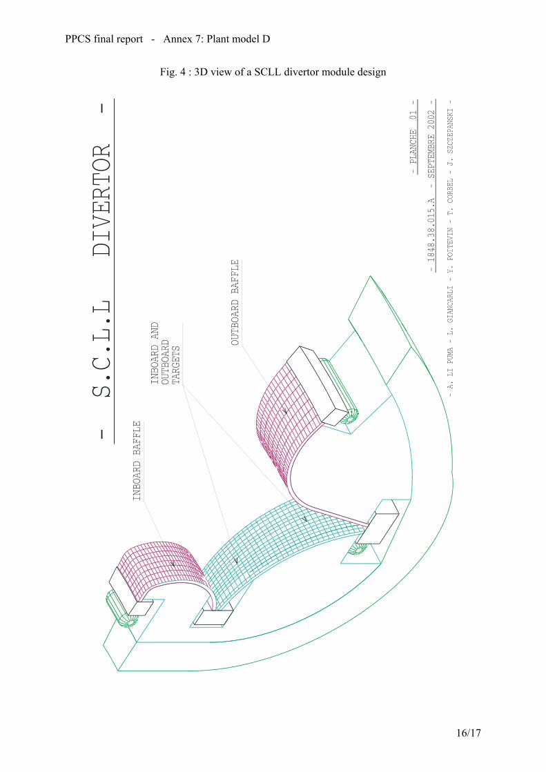
PPCS final report - Annex 7: Plant model D
Fig. 4 : 3D view of a SCLL divertor module design
16/17

PPCS final report - Annex 7: Plant model D
Fig. 5 : Scheme of SCLL primary and secondary cooling circuits and of T-extraction system for a single loop
p p
Coo
ling
Wat
er
12”
Pb-1
7Li
2”10
”20”
20”
2”
pum
p
20”
He
10”
P1=2
Prim
ary
pum
ps 5
0%
4”4”
He+
Triti
um
BLA
NK
ET
He-
detri
tiatio
nsy
stem
T ex
tract
or
Pb-1
7Li t
ank
Pb-1
7Li
purif
icat
ion
p p
Coo
ling
Wat
er
12”
Pb-1
7Li
2”10
”20”
20”
2”
pum
p
20”
He
10”
P1=2
Prim
ary
pum
ps 5
0%
4”4”
He+
Triti
um
BLA
NK
ET
He-
detri
tiatio
nsy
stem
T ex
tract
or
Pb-1
7Li t
ank
Pb-1
7Li
purif
icat
ion
17/17


ANNEXE 8

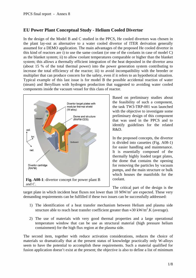
PPCS final report - Annex 8
EU Power Plant Conceptual Study - Helium Cooled Divertor
In the design of the Model B and C studied in the PPCS, He cooled divertors was chosen in the plant lay-out as alternative to a water cooled divertor of ITER derivation generally assumed for a DEMO application. The main advantages of the proposed He cooled divertor in this kind of reactors are i) to use the same coolant (or one of the coolants in case of model C) as the blanket system; ii) to allow coolant temperatures comparable or higher than the blanket system; this allows a thermally efficient integration of the heat deposited in the divertor area (about 15 % of the total thermal power) into the power generation system contributing to increase the total efficiency of the reactor; iii) to avoid incompatibility with the breeder or multiplier that can produce concern for the safety, even if it refers to an hypothetical situation. Typical example of this last issue is for model B the possible accidental reaction of water (steam) and Beryllium with hydrogen production that suggested to avoiding water cooled components inside the vacuum vessel for this class of reactor.
Based on preliminary studies about the feasibility of such a component, the task TW3-TRP-001 was launched with the objective to investigate some preliminary design of this component that was used in the PPCS and to identify guidelines for the related R&D.
In the proposed concepts, the divertor is divided into cassettes (Fig. A08-1) for easier handling and maintenance. It is essentially composed of the thermally highly loaded target plates, the dome that contains the opening for removing the particles by vacuum pumps, and the main structure or bulk which houses the manifolds for the coolant.
The critical part of the design is the target plate in which incident heat fluxes not lower than 10 MW/m2 are expected. These very demanding requirements can be fulfilled if these two issues can be successfully addressed:
Fig. A08-1: divertor concept for power plant B and C.
1) The identification of a heat transfer mechanism between Helium and plasma side structure able to reach heat transfer coefficient greater than ≈30 kW/m2.K (average).
2) The use of materials with very good thermal properties and a large operational temperature window that can be use as structural material (high pressure helium containment) for the high flux region at the plasma side.
The second item, together with reduce activation considerations, reduces the choice of materials so dramatically that at the present status of knowledge practically only W-alloys seem to have the potential to accomplish these requirements. Such a material qualified for fusion application doesn’t exist at the present; the objective is also to define a list of minimum
1/8

PPCS final report - Annex 8
requirements for the development of fusion materials that will be addressed in the EU Material Programme.
The main objective is, however, to explore the item 1) and on the basis of the identified heat transfer mechanism, to propose conceptual designs (including the mechanical and thermo-hydraulic lay-out, fabrication technologies, etc.) for the target plates.
Taking into account a set of basic requirements [A08-1], a lay-out for the target plates has been achieved based on the following principles:
- modular design; the high flux surface is divided in small units (few cm2) to reduce thermal stresses;
- radial cooling: helium is fed in each unit from the vacuum vessel side, reaches the high flux surface and comes back; the units are fed in parallel to reduce the total pressure drops and the outlet helium temperature;.
- use of heat transfer promoters to reach high heat transfer coefficient (> 30 kW/m2.K) at the plasma side of the coolant channels; helium reaches in this region high velocity (100-200 m/s) in small (1 mm or less as minimum dimension) and short channels.
- use of W-alloy with structural functions for the whole containment of the high pressure helium (or part of them, e.g. caps as show later in the design description); the use of these materials envisages in the design high temperature for the coolant (at least greater than 600 °C) to provide margin against the increase of the DBTT under irradiation.
- covering of the target plate with a sacrificial layer (tiles) to assure protection against plasma erosion; practically only W tiles with a thickness of about 5 mm are under discussion with an estimated lifetime of about 2 years.
ENEA and FZK have proposed two designs for the high flux target based on two different heat transfer mechanisms between helium and high flux surface: the HETS (High Efficiency Thermal Shield) and HEMP/HEMS (HE-cooled Modular divertor concept with integrated Pin
array / Slot array), respectively. UKAEA has contributed to this task performing the thermal and structural assessment for the HETS concept [A08-02]. The main differences between the two concepts are, as already mentioned, in the heat transfer mechanism used to reach the point 1), and on the different thermo-hydraulic working point. Differences are also in the design of the target plates and in the proposed material especially for the structural part that should support the cups and provide the manifolds for the helium;
Fig. A08-2: CAD picture of the HETS concept
2/8

PPCS final report - Annex 8
however these later differences are less concept-depending and the results of the R&D can be mostly shared between the two proposed design.
Conceptual Design and Assessment of the HETS Concept
This concept relies on a jet of fluid impinging on a hemispherical surface and flowing out of the curved surface (Fig. A08-2). The increase in heat transfer is obtained by the impingement effects on the hemispherical surface and by the effects of centripetal acceleration (increase in turbulence) when the fluid moves on the inner side of the sphere. Tests have been performed
on a copper mock-up, using water as coolant and gave very interesting results in terms of heat transfer capacity. It is relevant to note that the channels have typical dimensions greater than 1 mm [A08-03].
The HETS elements will be arranged in rows of 6 parallel elements (Fig. A08-3), forming a module (approximate length 200 mm) and 5 modules (in series) will form a divertor strip,
having approximate length 1000 mm and width of about 35 mm. These strips will be arranged (note that the hexagonal shape of the elements allows for a total coverage of a plane surface) to form a divertor plate.
Fig. A08-3: HETS drawings.
Table A08-1 - Stresses in the structure and in the support plate (MPa)
Location Mechanical stress Thermal stress
Max Value All. Value (1) Max. Value All. Value (2)
Dome 108 133 361 (3) 400
Support plate 59 67 171 (3) 200
(1) For primary membrane stresses (2) Evaluated at 1000 °C (3) Nodal value from numerical output
The module will be in W (element dome) and in DENSIMET 18K (supporting elements). Safety relevant issues concerning the Ni content (lower than 4.5%) are being assessed. The
3/8
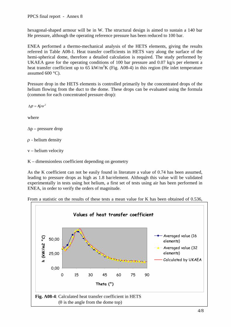
PPCS final report - Annex 8
hexagonal-shaped armour will be in W. The structural design is aimed to sustain a 140 bar He pressure, although the operating reference pressure has been reduced to 100 bar.
ENEA performed a thermo-mechanical analysis of the HETS elements, giving the results referred in Table A08-1. Heat transfer coefficients in HETS vary along the surface of the hemi-spherical dome, therefore a detailed calculation is required. The study performed by UKAEA gave for the operating conditions of 100 bar pressure and 0.07 kg/s per element a heat transfer coefficient up to 65 kW/m2K (Fig. A08-4) in this region (He inlet temperature assumed 600 °C).
Pressure drop in the HETS elements is controlled primarily by the concentrated drops of the helium flowing from the duct to the dome. These drops can be evaluated using the formula (common for each concentrated pressure drop):
2vKp ρ=∆
where
∆p – pressure drop
ρ - helium density
v – helium velocity
K – dimensionless coefficient depending on geometry
As the K coefficient can not be easily found in literature a value of 0.74 has been assumed, leading to pressure drops as high as 1.8 bar/element. Although this value will be validated experimentally in tests using hot helium, a first set of tests using air has been performed in ENEA, in order to verify the orders of magnitude.
From a statistic on the results of these tests a mean value for K has been obtained of 0.536,
Values of heat transfer coefficient
0,00
25,00
50,00
0 15 30 45 60 75 90
Theta (°)
h (k
W/m
2 °C
) Averaged value (16elements)
Averaged value (32elements)Calculated by UKAEA
Fig. A08-4: Calculated heat transfer coefficient in HETS (θ is the angle from the dome top)
4/8
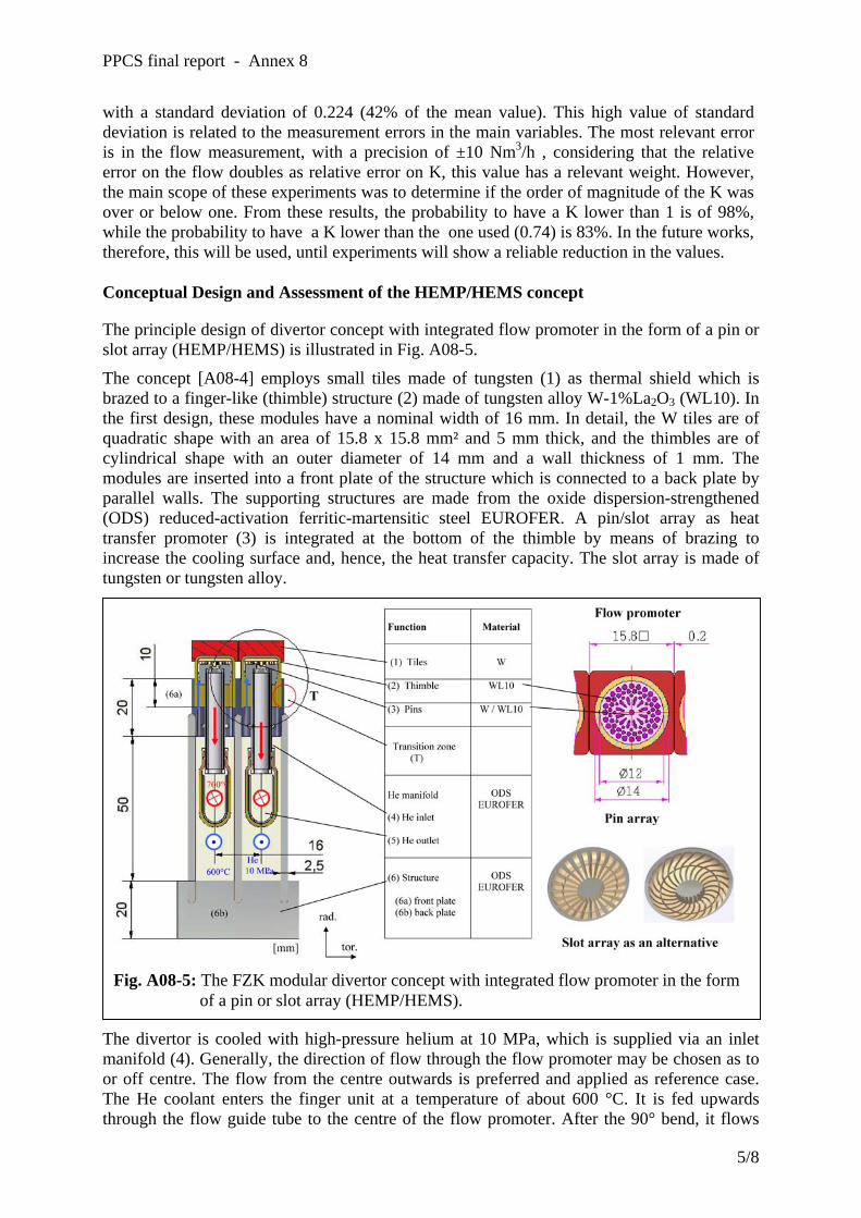
PPCS final report - Annex 8
with a standard deviation of 0.224 (42% of the mean value). This high value of standard deviation is related to the measurement errors in the main variables. The most relevant error is in the flow measurement, with a precision of ±10 Nm3/h , considering that the relative error on the flow doubles as relative error on K, this value has a relevant weight. However, the main scope of these experiments was to determine if the order of magnitude of the K was over or below one. From these results, the probability to have a K lower than 1 is of 98%, while the probability to have a K lower than the one used (0.74) is 83%. In the future works, therefore, this will be used, until experiments will show a reliable reduction in the values.
Conceptual Design and Assessment of the HEMP/HEMS concept
The principle design of divertor concept with integrated flow promoter in the form of a pin or slot array (HEMP/HEMS) is illustrated in Fig. A08-5.
The concept [A08-4] employs small tiles made of tungsten (1) as thermal shield which is brazed to a finger-like (thimble) structure (2) made of tungsten alloy W-1%La2O3 (WL10). In the first design, these modules have a nominal width of 16 mm. In detail, the W tiles are of quadratic shape with an area of 15.8 x 15.8 mm² and 5 mm thick, and the thimbles are of cylindrical shape with an outer diameter of 14 mm and a wall thickness of 1 mm. The modules are inserted into a front plate of the structure which is connected to a back plate by parallel walls. The supporting structures are made from the oxide dispersion-strengthened (ODS) reduced-activation ferritic-martensitic steel EUROFER. A pin/slot array as heat transfer promoter (3) is integrated at the bottom of the thimble by means of brazing to increase the cooling surface and, hence, the heat transfer capacity. The slot array is made of tungsten or tungsten alloy.
Fig. A08-5: The FZK modular divertor concept with integrated flow promoter in the form of a pin or slot array (HEMP/HEMS).
The divertor is cooled with high-pressure helium at 10 MPa, which is supplied via an inlet manifold (4). Generally, the direction of flow through the flow promoter may be chosen as to or off centre. The flow from the centre outwards is preferred and applied as reference case. The He coolant enters the finger unit at a temperature of about 600 °C. It is fed upwards through the flow guide tube to the centre of the flow promoter. After the 90° bend, it flows
5/8
PPCS final report - Annex 8
radially from the centre through the slot or pin array towards the outer edge with high velocity. It is heated up to about 700 °C and routed downwards to the He outlet manifolds (5).
The development and optimization of the divertor concepts require a close link and iterative approach of the main issues of design, analyses, materials, fabrication technology, and experiments. Optimising the pin or slot arrangement with respect to size, shape and distance is an important thermohydraulic issue. The large mismatch in the thermal expansion coefficients of W alloys and the steel structure, which are about 4-6*10-6/K and 10-14*10-6/K, respectively, will cause very high local plastic strains at edges and corners in the transition zone (T) under temperature cyclic loadings. To avoid thermocyclic plastification at the joints, an appropriate design of transition pieces is required, which is now under investigation. A further step in design is the optimization of the module size in order to minimise the number of modules and, thus, the production costs (current number of modules approx. 300,000). Predicting the temperatures and stresses by means of CFD and FEM computer codes is indispensable to ensure that the engineering design limits are not exceeded. Comparison of different CFD programs showed that their calculation results are in reasonable agreement with each other, but differ in some details. Experiments will be indispensable to validate the computer codes.
Boundary conditions for the thermohydraulic divertor layout are considered, e.g. the total heat load, shape of its distribution and the position of the moving peak. In the present layout the divertor target plate (length = 1 m) is divided in 2 zones which are connected in series. All finger units within one zone are connected in parallel. Taking the necessary finger unit mass flow into account, the total mass flow for the divertor would become to high, if all finger units would be connected in parallel. For the HEMS concept with slot array (24 straight slots, gaps 0.3 mm) the CFD calculation predict a sufficient cooling performance for an He inlet pressure of 10 MPa and a He mass flow of about 6 g/s per tile (size 16x16 mm). In each cooling zone (each with length of 0.5 m) of the outboard high heat flux area (1 m) 31 cooling fingers are arranged in poloidal direction. For these 31 parallel fingers a total mass flow of 188 g/s is necessary to obtain the required cooling performance. For one outboard divertor plate 51 parallel rows are arranged in toroidal direction. From this the total mass flow of one divertor outboard plate is about 9.6 kg/s. The stress calculations with ANSYS also show that all stresses are below the engineering 3Sm limit (maximum primary plus secondary von Mises stress in the thimble amounts to 250 MPa < 420 MPa allowable at 1150 °C).
Tungsten is considered the most promising material that can withstand the specified high heat load, because it possesses a high melting point, high thermal conductivity, and relatively low thermal expansion. In addition, it is low-activating, has a high resistance against sputtering and erosion, and suitable for the use as thermal shield. Its disadvantages are poor DBTT and RCT values, high hardness, and a high brittleness, which make the fabrication of tungsten components comparatively difficult. The tiles have no structural function. A sacrificial layer of 2 mm is foreseen for an estimated service life of about 1-2 years. The operating temperature window of the W alloys structures is restricted by the DBTT at the lower and the RCT at the upper boundary. Generally, the DBTT, RCT, and strength properties of W and/or W alloys are determined by the deformation processes and their prehistory as well as by the doping compositions. For irradiated W alloys the presently known temperature window range extends from 800 to 1200 °C. Enhancing this temperature window is a challenging task of material development, whereas up to now, only some data are available for unirradiated refractory metals, the less for irradiated conditions.
Standard tooling methods (e.g. milling) are not applicable for W/W alloys due to their high hardness and toughness. This applies in particular to parts of microstructure shape and relatively high aspect ratios (i.e. the ratio between the height and width of the structure). Several fabrication methods for the flow promoter (pin and slot arrays) and thimble unit made
6/8

PPCS final report - Annex 8
of tungsten alloy are being investigated at FZK and Efremov. The promising methods are electric discharge machining (EDM), electrochemical milling (ECM), powder injection moulding (PIM), and laser machining. Examples of W mockup fabrication by means of EDM and laser methods are shown in Fig. A08-6.
Technological studies and experiments are being performed at Efremov regarding for example joining W tile with thimble of W alloy and W thimble with steel structure by means of high temperature brazing. A helium loop will be built at Efremov this year for high heat flux integral tests of divertor mock-ups and to determine the pressure loss and heat transfer coefficient of the cooling unit for the design variants.
A study on helium-cooled divertor concepts with flow promoter is performed on the major fields of design, analyses, material, fabrication technology, and experiments. The design goal is to reach a peak hat load of 10 MW/m2. Two conceptual designs with different kinds of flow promoter, i.e. pin array (HEMP) and slot array (HEMS) are investigated. The latter shows an advantage in the easier manufacturing and is regarded as reference version. For the manufacturing of divertor components of tungsten and tungsten-alloy, EDM, ECM, Laser, and PIM are regarded promising methods, which require further R&D. Technological experiments concerning W/W and W/steel joints were successfully performed at Efremov, further R&D needed for the improvement.
Mock-up of W-thimble with integrated slot array fabricated by EDM process.
W-slot array prepared by Laser process
Fig. A08-6: Examples of W mock-up fabrication by means of EDM and laser methods.
Taking into account the temperature constraints for the structure of tungsten and a region of moving peak heat flux, thermohydraulic layout was carefully performed leading to a necessary He mass flow rate of 6 g/s for one divertor finger module. With a boundary condition of 10 MPa He pressure and 634 °C He inlet temperature at target, the maximum W structure temperature amounts to 1297 °C (< design limit of 1300 °C). The pressure loss was calculated to 0.35 MPa for the target plate and 0.44 MPa for the whole cassette, corresponding to a pumping power of about 9% related to the heat removal. Stress calculations with ANSYS also show that all stresses are below the engineering 3Sm limit.
The overall results of this study show that the He-cooled modular divertor concept (HEMS) meets a large variety of requirements, e.g. loading conditions and materials and fabrication issues and is viable.
Nevertheless, divertor design is being advanced continuously towards easier design, less fabrication effort, and increasing cooling performance. One of such conceivable concepts is the He-cooled Multi-Jet (HEMJ) design, which is based on multiple jet impingement cooling technology being state-of-the-art for internal cooling in high temperature machines like gas and steam turbines. This concept shows many advantages, e.g. jet-to-wall direct cooling without flow promoter, uniform He temperature over the cooling surface, stable mass flow
7/8

PPCS final report - Annex 8
distribution, stable form of the curved thimble bottom, high heat packing density by hexagonal tile shape, easy exchange and tests of the box units, etc. It is being investigated in detail. First assessment show promising high potential of heat flux limit in the range of 15 MW/m2.
Conclusions and future work
The studies carried out in the frame of the TW3-TRP-001 tasks of the PPCS have shown under which conditions a design of a He-cooled divertor for DEMO can be achieved [A08-1]. In particular two conceptual designs of the target plate have been presented based on the HETS and HEMP/HEMS heat transfer mechanisms; for these designs a mechanical and thermo-hydraulic lay-out has been proposed and assessed. Anticipated manufacturing technologies and materials properties based on a reasonable extrapolation to DEMO of present knowledge have been assumed in the design.
Two important issues have been identified on which the successful completion of this work is depending: 1) the validation of the proposed heat transfer mechanisms with an appropriate experimental programme that should confirm the computational results, and 2) the qualification of fusion materials (especially W-alloy) and fabrication technologies (e.g. joint techniques for high temperature component).
In 2004, the work is devoted to the experimental validation of the HETS and HEMP/HEMS concepts (namely pressure drops and heat transfer coefficient); small mock-ups reproducing the finger units will be tested in helium facility in FZK and EFREMOV.
References [A08-1] L.V. Boccaccini, P. Karditsas, C. Nardi, P. Norajitra, Executive summary of task
TW3-TRP-001, FZK 2004. [A08-2] P. Karditsas, Optimization of the HETS He-cooled divertor concept:Thermal-Fluid
and structural analysis, UKAEA (2003). [A08-3] C. Nardi, C. Annino, G. Brolatti, S. Papastergiou, A. Pizzuto, Evaluation of the
HETS divertor thermal and fluid performances, FUS-TEC DI-MC-R-002, ENEA (2004).
[A08-4] R. Krüssmann, P. Norajitra, L. V. Boccaccini, T. Chehtov, R. Giniyatulin, S.
Gordeev, T. Ihli, G. Janeschitz, A. O. Komarov, W. Krauss, V. Kuznetsov, R. Lindau, I. Ovchinnikov, V. Piotter, M. Rieth, R. Ruprecht, Conceptual Design of a He-cooled divertor with integrated flow and heat transfer promoters (PPCS Subtask TW3-TRP-001-D2), Part I (Summary) and Part II (Detailed Version), FZKA 6974 & 6975, 2004.
8/8
ANNEXE 9


PPCS final report - Annex 9
EU Power Plant Conceptual Study - Maintenance Introduction The mechanical properties of structural materials deteriorate under neutrons bombardment. The high energy neutrons produced during the D-T fusion reaction affects the properties of the materials used for the blanket and the divertor, i.e. the reactor internal components. After reaching a given fluence, the internals must therefore be replaced. Because they are highly activated, their replacement must be carried out fully remotely. For the PPCS models A, B and C, EUROFER is considered as structural material for the blanket and for the divertor. In models B and C, a tungsten alloy is also used for parts of the divertor structure. Tungsten is used as armour material for both blanket and divertor. The mechanical properties of EUROFER are assumed to be acceptable up to a fluence of 15 Mwa/m2, corresponding with 150 dpa neutron damage, which broadly corresponds with a lifetime of 5 FPY (full power year) for the blanket in reactor. For the divertor, the lifetime is expected to be limited by the erosion of the armour material, and it is assumed to be of 2 FPY. According to all estimates made to date, the main driver for the reactor availability is the duration of the in-vessel components replacement. It is assumed that nearly all other scheduled maintenance operations are carried out in parallel whilst an arbitrary value, extrapolated from today’s experience with fission reactors, is taken to account for unscheduled outages. Maintenance Schemes Maintenance schemes for tokamaks can be classified in two main categories. In the first category complete reactor sectors are translated vertically upwards or horizontally outwards (a sector includes always all the internals - blanket and divertor - in between 2 TF coils, and may include part of the main vacuum vessel and a TF coil). In the second category the internals are segmented to allow their handling in and out of the main vessel through dedicated openings of limited dimensions. The translation of large reactor sectors has been considered, for instance, in the conceptual studies of the ARIES-I [1], ARIES-RS [2] and DREAM [3] devices. Various segmentations of the internals have been considered depending on the access ports available. In the ITER CDA [4] the blanket was segmented in large segments handled through upper, vertical ports whilst the divertor was segmented in plates handled through equatorial, horizontal ports. In ITER FDR [5] the blanket was segmented in modules handled through equatorial, horizontal ports whilst the divertor was segmented in cassettes handled through lower, (quasi) horizontal ports. Similar segmentations, although with some variations, have been considered during several reactor studies, e.g.
1/11
PPCS final report - Annex 9
SEAFP [6] and SSTR [7]. A point of interest is that the blanket and the divertor segmentation are somewhat independent, i.e. it is possible to have either blanket segments or modules with either divertor plates or cassettes. In all cases, the number of items to be replaced is a parameter with a major impact on the time required to replace the reactor internals and, therefore, on the overall reactor availability. Two maintenance schemes, corresponding to two different segmentations of the internals, are presented and discussed in this annex. Alternative maintenance schemes have also been investigated within the PPCS, considering access inside the vessel via different ports (e.g. upper VV ports) and / or different segmentations of the internals (e.g. handling of vertical “rings”), but none resulted in any significant advantages with respect to the concepts described below. Large Sectors Basic concept The rationale behind this maintenance scheme is that it minimizes the number of items to be replaced. Practically, there are as many sectors as TF coils, typically between 14 and 18. When the sector is translated upwards, as in ARIES-I, it necessarily includes a portion of the main vessel and a TF coil. Moreover, most upper PF coils must be removed prior to sector handling. In addition to logistics difficulties associated with the handling of very large, heavy and activated components, this scheme raises the following issues:
• contamination control during opening and closing of the vacuum vessel; • the difficulties associated with the dis-assembly and re-assembly of the magnet
structure; • the accuracy with which the sector must be reassembled to guarantee the correct
alignment of the internals after their replacement. To eliminate the first 2 issues, the ARIES-RS and the DREAM concepts consider TF coils of large dimensions which allow, in principle, the horizontal translation of a sector without dismantling the toroidal magnet assembly (fig. 1). Main issues This “large handling sector concept” requires a separate maintenance port for each power core sector. Due to the large size of the sector and to the configuration of the ports around the vacuum vessel (VV), the concept results in a significant increased in the dimensions of the VV, of the TF and some PF coils, and of the reactor building. The equatorial floor is eliminated and the access requirements to the ports require all services and auxiliaries to be routed from the top or the bottom of the reactor. The very large openings through the vessel and through the cryostat to allow the sectors withdrawal requires vacuum doors or considerable dimensions. These doors are arranged vertically, which complicates their handling and the vacuum-sealing procedure. Due to the design of the VV with large
2/11

PPCS final report - Annex 9
maintenance ports the power core sectors will have to be fixed to the bottom area of the VV or / and to neighbouring sectors. Other significant logistics issues are also likely to arise when considering the transport of the large sectors to and from the hot cell. Availability Although none of the above issues is theoretically unfeasible, each represents a significant engineering challenge. Moreover, even assuming that they could be satisfactorily solved, the expected increased plant availability was not found to be as significant as anticipated. To minimise the overall replacement time of the power core, a cask system was proposed to allow the removal of a sector with a single docking sequence (fig. 2). In this cask all equipment needed for sector replacement is integrated:
• cask door with double seal system • port plate opening system • mover for port plug and sector • manipulator arm for locking and tooling • tools for cutting and welding • storage areas for port plug and power core sector.
To reduce, additionally, the replacement time of all sectors, a replacement sequence involving the replacement of more than one sector with only one docking sequence was been investigated. In this case, the system must provide storage for two sectors inside a single cask. The impact of the overall layout is even larger than with a cask designed to handle one sector at a time. The availability was then estimated for the following four options:
• single sector cask, two casks operating in parallel; • single sector cask, three casks operating in parallel; • double sector cask, two casks operating in parallel; • double sector cask, three casks operating in parallel.
The estimated availability ranges between 76.5 and 81.2 %, the time required to replace an individual sector being comprised between 10 and 12 days (table 1 summarises the time required for the removal of a large sector). These numbers are well below the preliminary estimates provided by the original proponents of this concept, which were above 90%. In fact, although the number of components handled is reduced to the minimum, their enormous size results in lengthy individual operations. The estimated availability is, effectively, comparable to that of the “large module handling concept”, which was adopted as reference for the PPCS plant models (see following section).
3/11
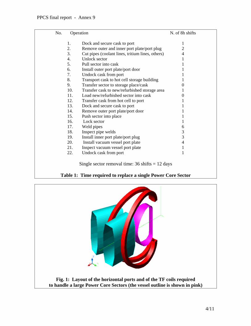
PPCS final report - Annex 9
No. Operation N. of 8h shifts
1. Dock and secure cask to port 1 2. Remove outer and inner port plate/port plug 2 3. Cut pipes (coolant lines, tritium lines, others) 4 4. Unlock sector 1 5. Pull sector into cask 1 6. Install outer port plate/port door 1 7. Undock cask from port 1 8. Transport cask to hot cell storage building 1 9. Transfer sector to storage place/cask 0 10. Transfer cask to new/refurbished storage area 1 11. Load new/refurbished sector into cask 0 12. Transfer cask from hot cell to port 1 13. Dock and secure cask to port 1 14. Remove outer port plate/port door 1 15. Push sector into place 1 16. Lock sector 1 17. Weld pipes 6 18. Inspect pipe welds 3 19. Install inner port plate/port plug 3 20. Install vacuum vessel port plate 4 21. Inspect vacuum vessel port plate 1 22. Undock cask from port 1
Single sector removal time: 36 shifts = 12 days
Table 1: Time required to replace a single Power Core Sector
Fig. 1: Layout of the horizontal ports and of the TF coils required to handle a large Power Core Sectors (the vessel outline is shown in pink)
4/11
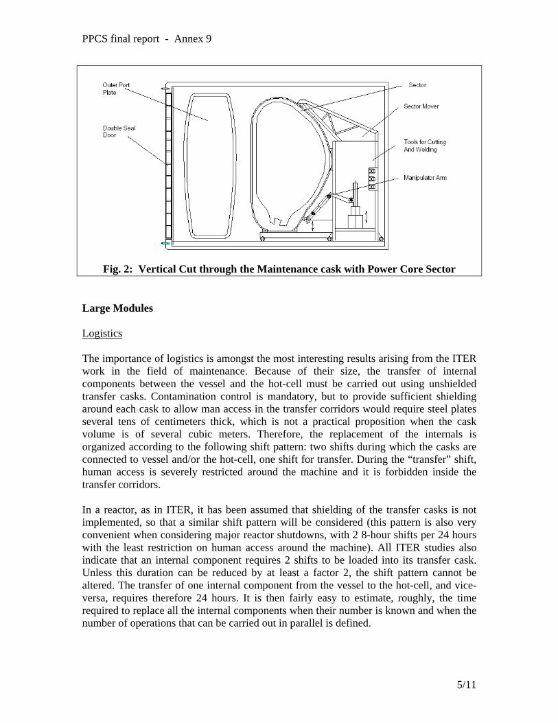
PPCS final report - Annex 9
Fig. 2: Vertical Cut through the Maintenance cask with Power Core Sector
Large Modules Logistics The importance of logistics is amongst the most interesting results arising from the ITER work in the field of maintenance. Because of their size, the transfer of internal components between the vessel and the hot-cell must be carried out using unshielded transfer casks. Contamination control is mandatory, but to provide sufficient shielding around each cask to allow man access in the transfer corridors would require steel plates several tens of centimeters thick, which is not a practical proposition when the cask volume is of several cubic meters. Therefore, the replacement of the internals is organized according to the following shift pattern: two shifts during which the casks are connected to vessel and/or the hot-cell, one shift for transfer. During the “transfer” shift, human access is severely restricted around the machine and it is forbidden inside the transfer corridors. In a reactor, as in ITER, it has been assumed that shielding of the transfer casks is not implemented, so that a similar shift pattern will be considered (this pattern is also very convenient when considering major reactor shutdowns, with 2 8-hour shifts per 24 hours with the least restriction on human access around the machine). All ITER studies also indicate that an internal component requires 2 shifts to be loaded into its transfer cask. Unless this duration can be reduced by at least a factor 2, the shift pattern cannot be altered. The transfer of one internal component from the vessel to the hot-cell, and vice-versa, requires therefore 24 hours. It is then fairly easy to estimate, roughly, the time required to replace all the internal components when their number is known and when the number of operations that can be carried out in parallel is defined.
5/11

PPCS final report - Annex 9
In the ITER FDR-1998 there were 720 blanket modules and 54 divertor cassettes, in the ITER FDR-2001 there are 420 blanket modules and 54 divertor cassettes. On the basis of the previous considerations it is easy to conclude that such a segmentation in “small” elements does not allow to satisfy the power plant availability requirement, which was set at 75% for the PPCS. Extrapolations from the more detailed estimates made for ITER of the time required to replace the blanket modules and the divertor cassettes confirm this conclusion. A different segmentation of the blanket was considered for the PPCS models. The main goal was to minimize the number of modules, hereafter called “large modules”, whilst retaining the ability to handle them through the equatorial ports. The size of the ports was limited by the magnet arrangements, in particular by the requirement to minimize the size of the TF coils. To achieve an overall plant availability of 75%, it was anticipated that the number of large modules should be below 200 (EFDA internal memo). The divertor segmentation in cassettes (3 cassette per sector) was not reconsidered. Blanket handling devices The feasibility and the kinematics of the handling equipment required to handle the large modules was investigated in some details [8]. One key issue to be resolved is the preferred location of the rails required to support the module handling device(s). One option requires 2 quasi-equatorial rails, one inboard and one outboard (fig. 3). This scheme allows for the complete decoupling of blanket handling from divertor handling but requires rails in the region with the highest neutron loading, thereby affecting the reactor TBR and the blanket module design considerably. Alternatively, the blanket handling device can be supported by the divertor rails (fig. 4). This scheme has the minimum impact on the reactor design but there is a strong coupling between blanket and divertor handling. In a reactor there will only be a very small number of unscheduled failures of the internal components, so that the requirement to replace the internals in a specific order has practically no effect on the overall availability. Moreover, it is possible to consider a maintenance scheme where the replacement of a given module or cassette requires the prior removal of a limited number of modules or cassettes. In all cases, it was estimated that the handling devices should be able to handle modules weighting up to 20-25 tons. Availability The availability of the PPCS models A and B was estimated under a variety of hypothesis [9, 10]. The availability ranges between 76.3% for model A (180 large modules) – assuming the non-simultaneous handling of blanket and divertor and assuming 3 ports at the equatorial and at the lower level for maintenance – and 88.3% for model B (162 large modules) – assuming the simultaneous handling of blanket and divertor and assuming 4 ports at the equatorial and at the lower level for maintenance.
6/11
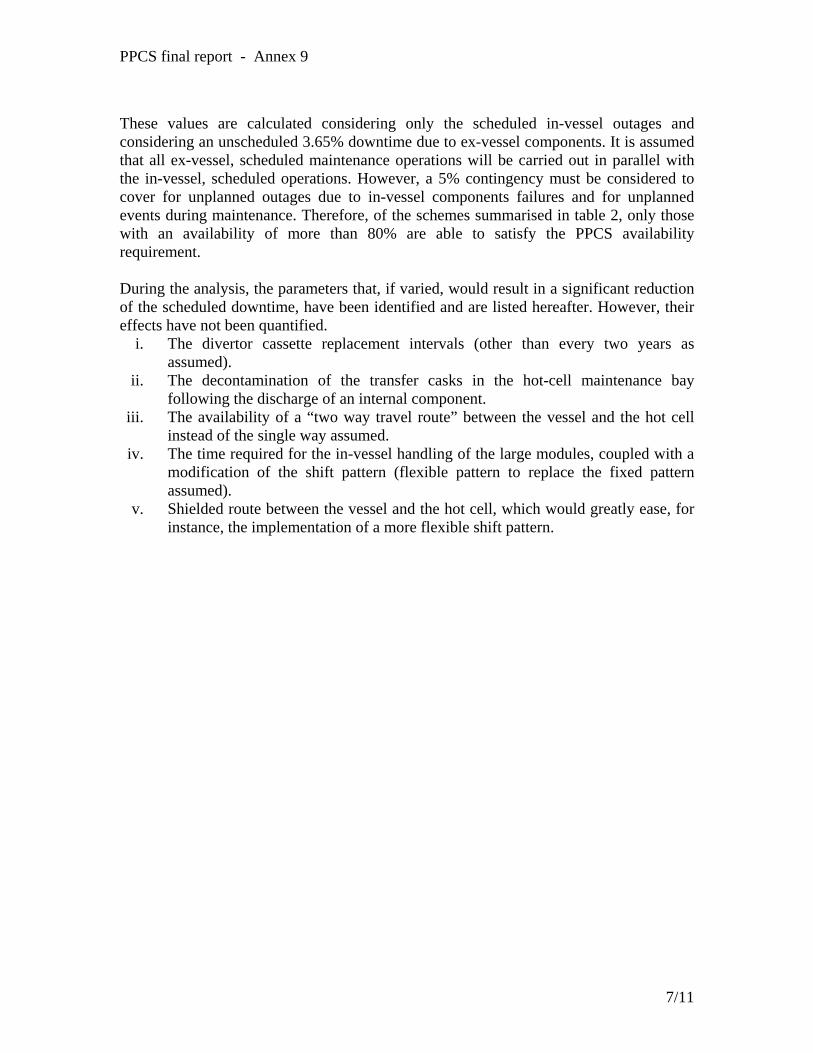
PPCS final report - Annex 9
These values are calculated considering only the scheduled in-vessel outages and considering an unscheduled 3.65% downtime due to ex-vessel components. It is assumed that all ex-vessel, scheduled maintenance operations will be carried out in parallel with the in-vessel, scheduled operations. However, a 5% contingency must be considered to cover for unplanned outages due to in-vessel components failures and for unplanned events during maintenance. Therefore, of the schemes summarised in table 2, only those with an availability of more than 80% are able to satisfy the PPCS availability requirement. During the analysis, the parameters that, if varied, would result in a significant reduction of the scheduled downtime, have been identified and are listed hereafter. However, their effects have not been quantified.
i. The divertor cassette replacement intervals (other than every two years as assumed).
ii. The decontamination of the transfer casks in the hot-cell maintenance bay following the discharge of an internal component.
iii. The availability of a “two way travel route” between the vessel and the hot cell instead of the single way assumed.
iv. The time required for the in-vessel handling of the large modules, coupled with a modification of the shift pattern (flexible pattern to replace the fixed pattern assumed).
v. Shielded route between the vessel and the hot cell, which would greatly ease, for instance, the implementation of a more flexible shift pattern.
7/11

PPCS final report - Annex 9
Table 2: Availability of models A and B for various combinations of variables. A 5% contingency must be added to cover for unplanned outages due to in-vessel
components failures and for unplanned events during maintenance.
Fig. 3: Handling devices for large blanket modules requiring 2 quasi-equatorial rails. One device handles the modules above the rails, the other the modules below.
8/11
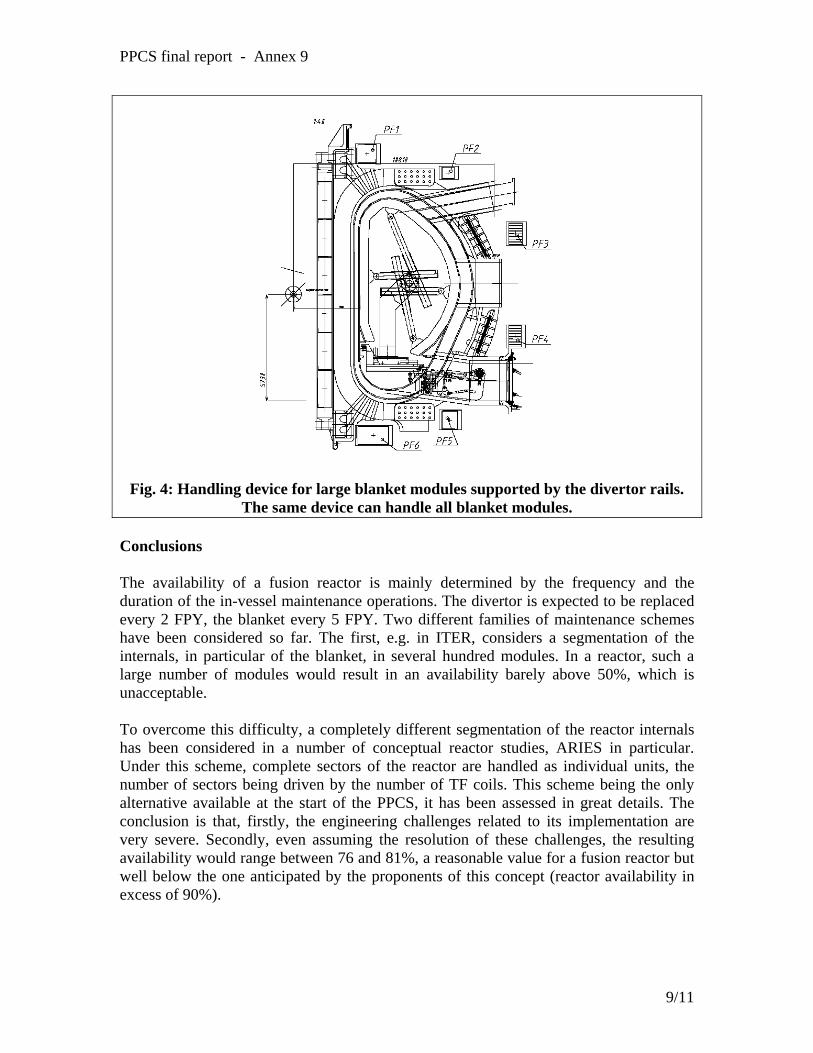
PPCS final report - Annex 9
Fig. 4: Handling device for large blanket modules supported by the divertor rails. The same device can handle all blanket modules.
Conclusions The availability of a fusion reactor is mainly determined by the frequency and the duration of the in-vessel maintenance operations. The divertor is expected to be replaced every 2 FPY, the blanket every 5 FPY. Two different families of maintenance schemes have been considered so far. The first, e.g. in ITER, considers a segmentation of the internals, in particular of the blanket, in several hundred modules. In a reactor, such a large number of modules would result in an availability barely above 50%, which is unacceptable. To overcome this difficulty, a completely different segmentation of the reactor internals has been considered in a number of conceptual reactor studies, ARIES in particular. Under this scheme, complete sectors of the reactor are handled as individual units, the number of sectors being driven by the number of TF coils. This scheme being the only alternative available at the start of the PPCS, it has been assessed in great details. The conclusion is that, firstly, the engineering challenges related to its implementation are very severe. Secondly, even assuming the resolution of these challenges, the resulting availability would range between 76 and 81%, a reasonable value for a fusion reactor but well below the one anticipated by the proponents of this concept (reactor availability in excess of 90%).
9/11

PPCS final report - Annex 9
As an alternative, a segmentation of the blanket in the smallest possible number of “large modules” has been considered. The maximum size of the module was determined by the size of the (quasi) equatorial ports thought which the modules must pass. The size of these ports was limited by the magnet arrangements, in particular by the requirement to minimize the size of the TF coils. The total number of modules is between 150 and 200 and the feasibility of suitable blanket handling devices was assessed. Moreover, a reactor availability of at least 75% can be achieved.
10/11

PPCS final report - Annex 9
References [1] M. Kikuchi et al., Recent Directions in Plasma Physics and its Impact on Tokamak Magnetic Fusion Design, Fusion Engineering and Design 16, 1991. [2] S. Malang et al., ARIES-RS Maintenance Approach for High Availability, Fusion Engineering and Design 41, 1998. [3] S. Nishio et al., The Concept of Drastically Easy Maintenance (DREAM) Tokamak Reactor, Fusion Engineering and Design 25, 1994. [4] ITER Conceptual Design Report, IAEA/ITER/DS/18, IAEA, Vienna, 1991 [5] ITER Final Design Report, G A0 FDR 4 01-06-28 R 0.2, July 2001 [6] Reader et al., SEAFP final report, June 1995 [7] S. Mori et al., Blanket and divertor design for the Steady State Tokamak Reactor (SSTR), Fusion Engineering and Design, volume 18, December 1991, Pages 249-258 [8] Task Order FZ (PPCS stage 1) – EFET report [9] J.N. Dumelow, D. Grove, PPCS Model B – assessment of availability, task order EFDA 93581 HJ, March 2002 [10] J.N. Dumelow, Alternative Maintenance Schemes for the PPCS: Study of Logistics for the Transport of Large Blanket Modules and Divertor Cassettes from the Reactor to the Hot Cell and Estimate of Availability, task order EFDA 93581 HX, January 2003
11/11


ANNEXE 10

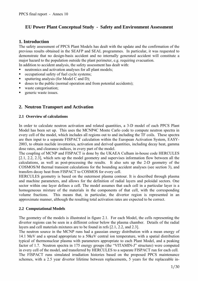
PPCS final report - Annex 10
EU Power Plant Conceptual Study - Safety and Environment Assessment
1. Introduction The safety assessment of PPCS Plant Models has dealt with the update and the confirmation of the previous results obtained in the SEAFP and SEAL programmes. In particular, it was requested to demonstrate that no design-basis accident and no internally generated accident will constitute a major hazard to the population outside the plant perimeter, e.g. requiring evacuation. In addition to accident analysis, the safety assessment has dealt with: neutronics and activation analyses for all plant models; occupational safety of fuel cycle systems; sputtering analysis (for Model C and D); doses to the public (normal operation and from potential accidents); waste categorisation; generic waste issues.
2. Neutron Transport and Activation 2.1 Overview of calculations In order to calculate neutron activation and related quantities, a 3-D model of each PPCS Plant Model has been set up. This uses the MCNP4C Monte Carlo code to compute neutron spectra in every cell of the model, which includes all regions out to and including the TF coils. These spectra are then input to a separate FISPACT calculation within the European Activation System, EASY-2003, to obtain nuclide inventories, activation and derived quantities, including decay heat, gamma dose rates, and clearance indices, in every part of the model. The coupling of MCNP and FISPACT is done by the UKAEA Culham in-house code HERCULES [2.1, 2.2, 2.3], which sets up the model geometry and supervises information flow between all the calculations, as well as post-processing the results. It also sets up the 2-D geometry of the COSMOS/M thermal transient calculations for the bounding accident analyses (see section 3), and transfers decay heat from FISPACT to COSMOS for every cell. HERCULES geometry is based on the outermost plasma contour. It is described through plasma and machine parameters, and allows for the definition of radial layers and poloidal sectors. One sector within one layer defines a cell. The model assumes that each cell in a particular layer is a homogeneous mixture of the materials in the components of that cell, with the corresponding volume fractions. This means that, in particular, the divertor region is represented in an approximate manner, although the resulting total activation rates are expected to be correct. 2.2 Computational Models The geometry of the models is illustrated in figure 2.1. For each Model, the cells representing the divertor regions can be seen in a different colour below the plasma chamber. Details of the radial layers and cell materials mixtures are to be found in refs [2.1, 2.2, and 2.3]. The neutron source in the MCNP runs had a gaussian energy distribution with a mean energy of 14.1 MeV and a spread appropriate to a 50keV central ion temperature, with a spatial distribution typical of thermonuclear plasma with parameters appropriate to each Plant Model, and a peaking factor of 1.7. Neutron spectra in 175 energy groups (the “VITAMIN-J” structure) were computed in every cell of the model, and transferred by HERCULES to a separate FISPACT run for each cell. The FISPACT runs simulated irradiation histories based on the proposed PPCS maintenance schemes, with a 2.5 year divertor lifetime between replacements, 5 years for the replaceable in-
1/30
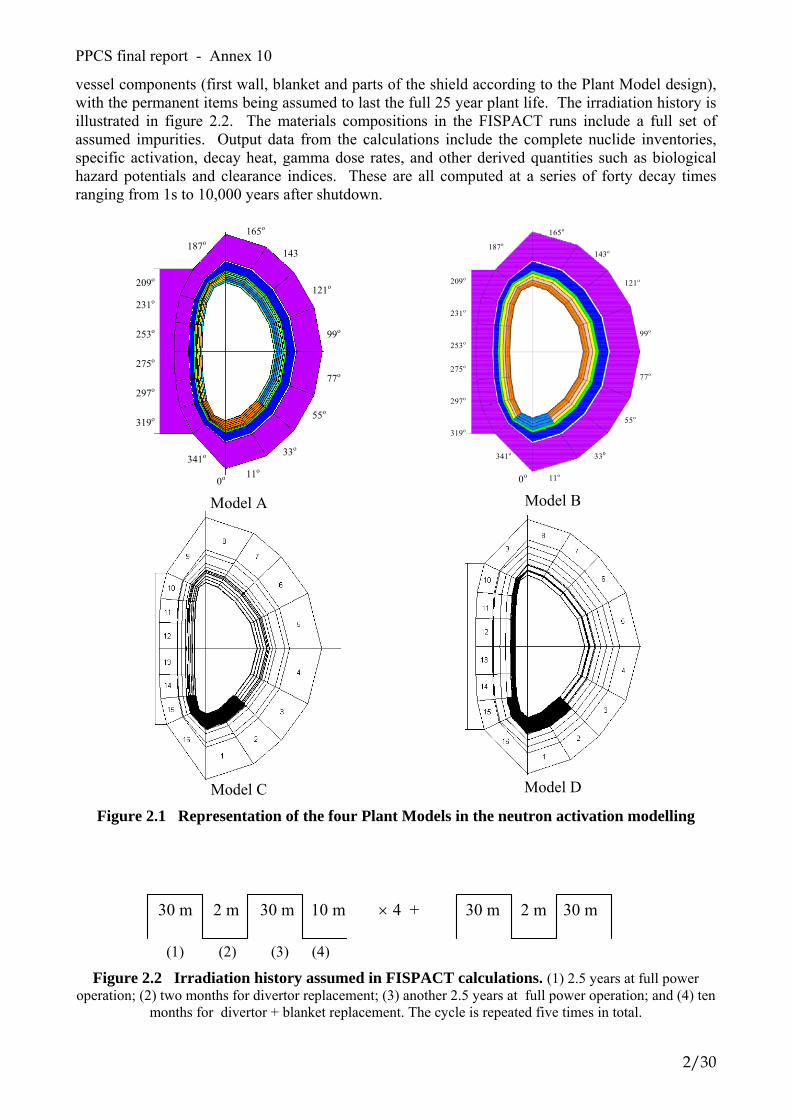
PPCS final report - Annex 10
vessel components (first wall, blanket and parts of the shield according to the Plant Model design), with the permanent items being assumed to last the full 25 year plant life. The irradiation history is illustrated in figure 2.2. The materials compositions in the FISPACT runs include a full set of assumed impurities. Output data from the calculations include the complete nuclide inventories, specific activation, decay heat, gamma dose rates, and other derived quantities such as biological hazard potentials and clearance indices. These are all computed at a series of forty decay times ranging from 1s to 10,000 years after shutdown.
0o 11o
33o
55o
77o
99o
121o
143
165o
187o
209o
231o
253o
275o
297o
319o
341o
Model A
0o 11o
330
55o
77o
99o
121o
143o
165o
187o
209o
231o
253o
275o
297o
319o
341o
Model B
Model C
Model D
Figure 2.1 Representation of the four Plant Models in the neutron activation modelling
30 m 2 m 30 m 10 m × 4 + 30 m 2 m 30 m
(1) (2) (3) (4) Figure 2.2 Irradiation history assumed in FISPACT calculations. (1) 2.5 years at full power
operation; (2) two months for divertor replacement; (3) another 2.5 years at full power operation; and (4) ten months for divertor + blanket replacement. The cycle is repeated five times in total.
2/30

PPCS final report - Annex 10
2.3 Results The full output data from the activation modelling, totalling several GByte, was available as input to other parts of the safety and environmental analyses. As an example of the results, figure 2.3 shows the specific activation (Bq/kg) in a selection of cells from Plant Model B - these are the cells on the inboard side at the axial mid-plane of the plasma.
PPCS model B (HCPB) Specific activity histories (Bq/kg) -- Inboard midplane
1,0E+04
1,0E+05
1,0E+06
1,0E+07
1,0E+08
1,0E+09
1,0E+10
1,0E+11
1,0E+12
1,0E+13
1,0E+14
1,0E+15
1,0E+16
1E-09 1E-08 1E-07 1E-06 1E-05 1E-04 1E-03 1E-02 1E-01 1E+00 1E+01 1E+02 1E+03 1E+04
time (years)
spec
ific
activ
ity (B
q/kg
)
TF coil VV Manifold LT shieldHT shield Blanket backplate Breeder back Breeder middleBreeder front FW front
sec min hour day month year
Figure 2.3 Specific activity (Bq/kg) histories of the inboard midplane
cells of the PPCS model B
3/30
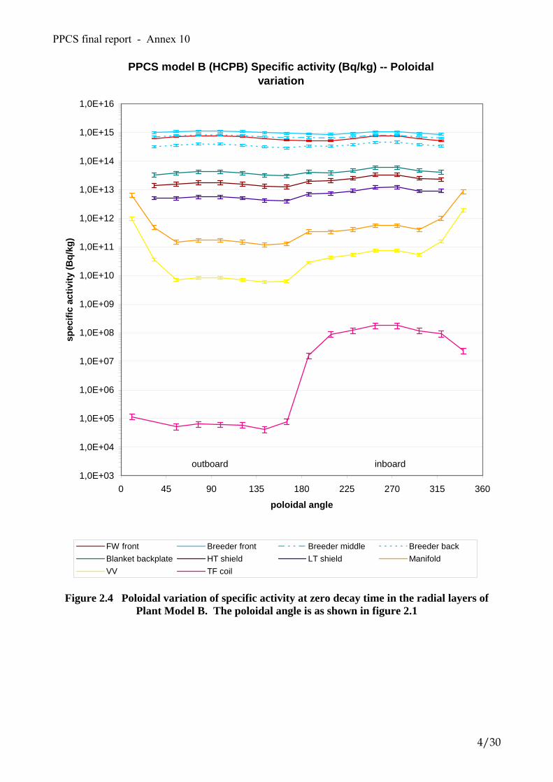
PPCS final report - Annex 10
PPCS model B (HCPB) Specific activity (Bq/kg) -- Poloidal variation
1,0E+03
1,0E+04
1,0E+05
1,0E+06
1,0E+07
1,0E+08
1,0E+09
1,0E+10
1,0E+11
1,0E+12
1,0E+13
1,0E+14
1,0E+15
1,0E+16
0 45 90 135 180 225 270 315 360
poloidal angle
spec
ific
activ
ity (B
q/kg
)
FW front Breeder front Breeder middle Breeder backBlanket backplate HT shield LT shield ManifoldVV TF coil
outboard inboard
Figure 2.4 Poloidal variation of specific activity at zero decay time in the radial layers of
Plant Model B. The poloidal angle is as shown in figure 2.1
4/30
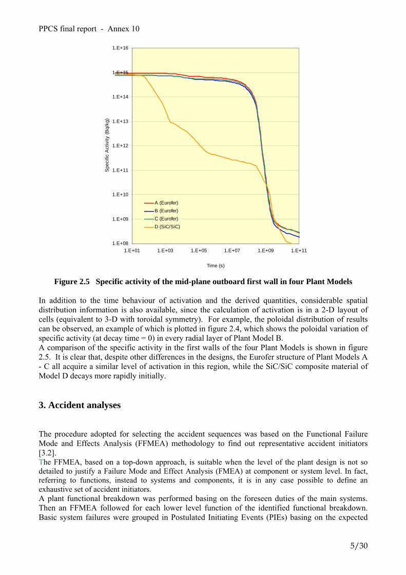
PPCS final report - Annex 10
1.E+08
1.E+09
1.E+10
1.E+11
1.E+12
1.E+13
1.E+14
1.E+15
1.E+16
1.E+01 1.E+03 1.E+05 1.E+07 1.E+09 1.E+11
Time (s)
Spe
cific
Act
ivity
(Bq/
kg)
A (Eurofer)B (Eurofer)C (Eurofer)D (SiC/SiC)
Figure 2.5 Specific activity of the mid-plane outboard first wall in four Plant Models
In addition to the time behaviour of activation and the derived quantities, considerable spatial distribution information is also available, since the calculation of activation is in a 2-D layout of cells (equivalent to 3-D with toroidal symmetry). For example, the poloidal distribution of results can be observed, an example of which is plotted in figure 2.4, which shows the poloidal variation of specific activity (at decay time = 0) in every radial layer of Plant Model B. A comparison of the specific activity in the first walls of the four Plant Models is shown in figure 2.5. It is clear that, despite other differences in the designs, the Eurofer structure of Plant Models A - C all acquire a similar level of activation in this region, while the SiC/SiC composite material of Model D decays more rapidly initially. 3. Accident analyses The procedure adopted for selecting the accident sequences was based on the Functional Failure Mode and Effects Analysis (FFMEA) methodology to find out representative accident initiators [3.2]. The FFMEA, based on a top-down approach, is suitable when the level of the plant design is not so detailed to justify a Failure Mode and Effect Analysis (FMEA) at component or system level. In fact, referring to functions, instead to systems and components, it is in any case possible to define an exhaustive set of accident initiators. A plant functional breakdown was performed basing on the foreseen duties of the main systems. Then an FFMEA followed for each lower level function of the identified functional breakdown. Basic system failures were grouped in Postulated Initiating Events (PIEs) basing on the expected
5/30

PPCS final report - Annex 10
consequences in terms of plant damage, of mobilisation of radioactive inventory, and, finally, of possible harm to workers and population. The PIEs were then grouped for typology and for each typology a general discussion on possible evolution of the accident was carried out. Based on the indications about radioactive inventory mobilization and possible environmental release, four accidental situations were pointed out to be considered for deterministic assessment, as indicated below: Design basis accidents: • Ex-Vacuum Vessel loss of coolant (ex-VV LOCA); • In-Vacuum Vessel loss of coolant (in-VV LOCA) due to an ex- Vacuum Vessel loss of
coolant (ex-VV LOCA); Beyond design basis accidents: • Loss of Flow (LOFA) without plasma shutdown inducing an in-Vacuum Vessel loss of
coolant (in-VV LOCA); • Loss of Heat Sink without plasma shutdown. In addition to these accident sequences for Plant Models A and B (for a total of 8 accident sequences to be analysed), the bounding temperature transient accident analyses, assuming the complete loss of all coolant from all loops and no active cooling or safety systems for a long period, were included to have a complete safety assessment. They were performed for all four plant models. The detailed description of the accidents and required design data is reported in references [3.1] [3.3], [3.4]. All the data related to radioactive inventory or decay heat or contact or ingestion/inhalation dose were taken from neutronics and activation analyses (Section 2). The radioactive inventory, derived from SEAFP [3.5], [3.6], assumed for the accident sequences are listed in table 3.1.
Table 3.1 Radioactive Source Terms Defined for Accident Analyses [3.3] Source terms Model A Model B Model C Tritium in VV 1 kg 1 kg 1 kg
Dust 10 kg (7.6 kg of SS-dust + 2.4
kg W-dust)
10 kg (7.6 kg of SS-dust + 2.4
kg W-dust)
10 kg (8.55 kg of ODS-dust +
1.45 kg of W-dust) Tritium in coolant 15 g (per loop) 1 g (per loop) 3 E-3 g (per loop)
ACPs total inventory 50 kg (per loop) - - ACPs mobilization fraction 1% of 50 kg (per loop) - -
Sputtering products ~ 0 g ~ 0 g Note: mobilisation fraction for dust and tritium assumed = 1 3.1 Bounding Accident Analyses 3.1.1 Overview of modelling To establish the bounding consequences of an internally-initiated accident, bounding accident analyses were performed in which a hypothetical event sequence is postulated. This is assumed to be a total loss of cooling from all loops in the plant, with no active cooling, no active safety system operating, and no intervention whatever for a prolonged period. The only rejection of decay heat is by passive conduction and radiation through the layers and across the gaps of the model, towards the outer regions where eventually a heat sink is provided by convective circulation of the building atmosphere. The temperature rise is assumed to mobilise tritium and activation products, both erosion dust loose in the vessel and solid activation products in structure mobilised by volatilisation at the surfaces. This inventory, together with the entire contents of one cooling loop, is the source term assumed to be available for leakage from the plant through successive confinement barriers,
6/30
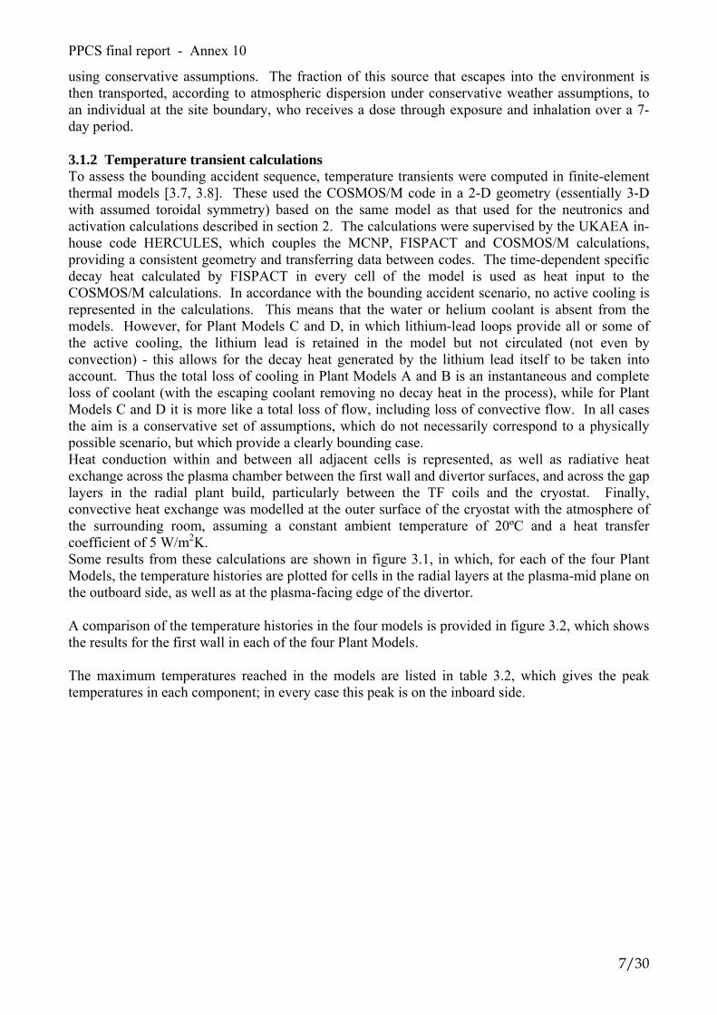
PPCS final report - Annex 10
using conservative assumptions. The fraction of this source that escapes into the environment is then transported, according to atmospheric dispersion under conservative weather assumptions, to an individual at the site boundary, who receives a dose through exposure and inhalation over a 7-day period. 3.1.2 Temperature transient calculations To assess the bounding accident sequence, temperature transients were computed in finite-element thermal models [3.7, 3.8]. These used the COSMOS/M code in a 2-D geometry (essentially 3-D with assumed toroidal symmetry) based on the same model as that used for the neutronics and activation calculations described in section 2. The calculations were supervised by the UKAEA in-house code HERCULES, which couples the MCNP, FISPACT and COSMOS/M calculations, providing a consistent geometry and transferring data between codes. The time-dependent specific decay heat calculated by FISPACT in every cell of the model is used as heat input to the COSMOS/M calculations. In accordance with the bounding accident scenario, no active cooling is represented in the calculations. This means that the water or helium coolant is absent from the models. However, for Plant Models C and D, in which lithium-lead loops provide all or some of the active cooling, the lithium lead is retained in the model but not circulated (not even by convection) - this allows for the decay heat generated by the lithium lead itself to be taken into account. Thus the total loss of cooling in Plant Models A and B is an instantaneous and complete loss of coolant (with the escaping coolant removing no decay heat in the process), while for Plant Models C and D it is more like a total loss of flow, including loss of convective flow. In all cases the aim is a conservative set of assumptions, which do not necessarily correspond to a physically possible scenario, but which provide a clearly bounding case. Heat conduction within and between all adjacent cells is represented, as well as radiative heat exchange across the plasma chamber between the first wall and divertor surfaces, and across the gap layers in the radial plant build, particularly between the TF coils and the cryostat. Finally, convective heat exchange was modelled at the outer surface of the cryostat with the atmosphere of the surrounding room, assuming a constant ambient temperature of 20ºC and a heat transfer coefficient of 5 W/m2K. Some results from these calculations are shown in figure 3.1, in which, for each of the four Plant Models, the temperature histories are plotted for cells in the radial layers at the plasma-mid plane on the outboard side, as well as at the plasma-facing edge of the divertor. A comparison of the temperature histories in the four models is provided in figure 3.2, which shows the results for the first wall in each of the four Plant Models. The maximum temperatures reached in the models are listed in table 3.2, which gives the peak temperatures in each component; in every case this peak is on the inboard side.
7/30
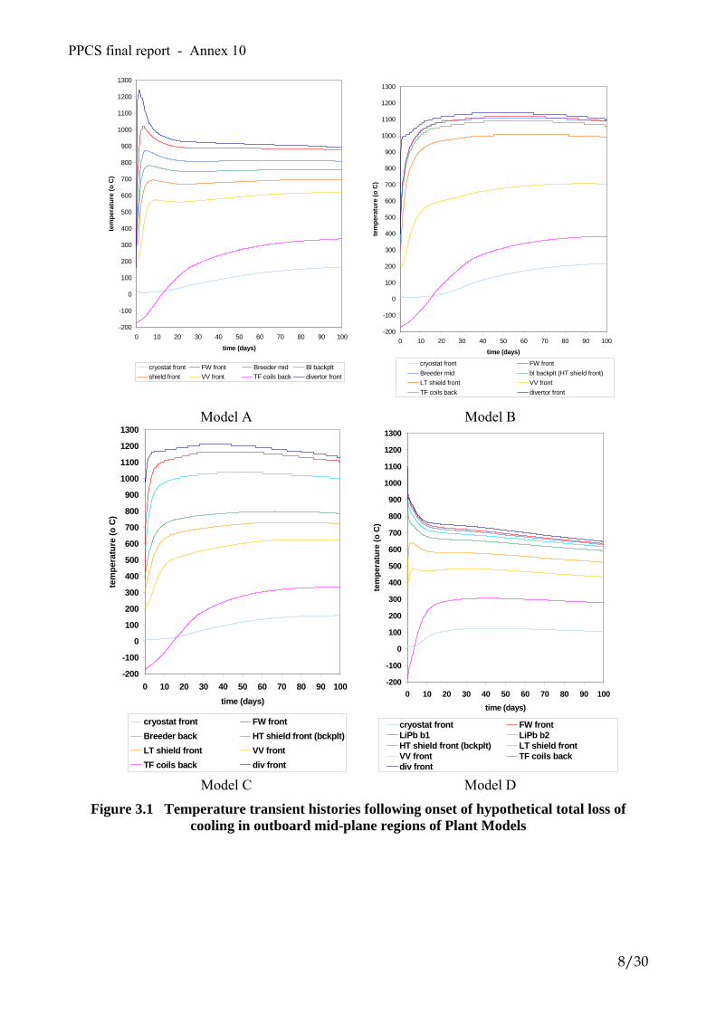
PPCS final report - Annex 10
-200
-100
0
100
200
300
400
500
600
700
800
900
1000
1100
1200
1300
0 10 20 30 40 50 60 70 80 90 100
time (days)
tem
pera
ture
(o C
)
cryostat front FW front Breeder mid Bl backpltshield front VV front TF coils back divertor front
Model A
-200
-100
0
100
200
300
400
500
600
700
800
900
1000
1100
1200
1300
0 10 20 30 40 50 60 70 80 90 100
time (days)
tem
pera
ture
(o C
)cryostat front FW frontBreeder mid bl backplt (HT shield front)LT shield front VV frontTF coils back divertor front
Model B
-200
-100
0
100
200
300
400
500
600
700
800
900
1000
1100
1200
1300
0 10 20 30 40 50 60 70 80 90 100time (days)
tem
pera
ture
(o C
)
cryostat front FW frontBreeder back HT shield front (bckplt)LT shield front VV frontTF coils back div front
Model C
-200
-100
0
100
200
300
400
500
600
700
800
900
1000
1100
1200
1300
0 10 20 30 40 50 60 70 80 90 100time (days)
tem
pera
ture
(o C
)
cryostat front FW frontLiPb b1 LiPb b2HT shield front (bckplt) LT shield frontVV front TF coils backdiv front
Model D
Figure 3.1 Temperature transient histories following onset of hypothetical total loss of cooling in outboard mid-plane regions of Plant Models
8/30

PPCS final report - Annex 10
0
200
400
600
800
1000
1200
1400
0 20 40 60 80 100
time (days)
tem
pera
ture
(C)
ABCD
Figure 3.2 Temperature histories in the outboard first wall of Plant Models A-D in the
bounding accident scenario Table 3.2 Maximum temperatures reached in the four Plant Models in the bounding accident
scenario, assuming prolonged absence of any active cooling
component Plant Model A Plant Model B Plant Model C Plant Model D
FW 1030 ºC 1130 ºC 1180 ºC 935 ºC
blanket 1000 ºC 1130 ºC 1190 ºC 934 ºC
shield 918 ºC 1140 ºC 1190 ºC 881 ºC
VV 836 ºC 1040 ºC 1150 ºC 716 ºC
TF coil 772 ºC 990 ºC 1120 ºC 692 ºC
cryostat 165 ºC 216 ºC 230 ºC 123 ºC
divertor 1240 ºC 1140 ºC 1210 ºC 908 ºC
The 2-D geometry of the finite element modelling allows the temperature distribution to be observed at any time in the scenario. As an example, figure 3.3 shows the temperature distribution in Plant Model B and in Plant Model D, 100 days after the onset of the loss of cooling.
9/30

PPCS final report - Annex 10
(a)
(b)
Figure 3.3 Temperature distribution (ºC) in Plant Model B (a) and in Plant Model D (b) (100 days after onset of bounding accident scenario
The origin of the lower temperatures in Plant Model D, compared with the other three models, is the very much lower decay heat of the SiC/SiC composite structural material, compared with Eurofer. This is clear in figure 3.4, which compares the specific decay heat (kW/kg) in these materials in the first walls of the four Plant Models.
1.E-05
1.E-04
1.E-03
1.E-02
1.E-01
0 20 40 60 80 1
Time (days)
Dec
ay h
eat (
kW/k
g)
00
A (Eurofer)
B (Eurofer)C (Eurofer)
D (SiC/SiC)
Figure 3.4 Specific decay heat in outboard first wall structural materials of four Plant Models
10/30
PPCS final report - Annex 10
3.1.3 Mobilisation and release modelling In order to assess the consequences of the bounding accident scenario, with the temperature transients as calculated above, a sequence is considered with conservative assumptions for the resulting mobilisation of active material, its transport through the confinement and release from the plant. The stages in the sequence are: • Mobilisation of material from divertor, first wall and blanket through temperature-driven
volatilisation. • Transport through coolant channels and ducting to the location of the break and into the vacuum
vessel. • Aerosol transport and removal. Particles evolve according to aerosol physics. Agglomeration
and removal from the containment atmosphere occur. • Leak through containment barriers. A proportion of the mobilised gases will become available
to drive mobilised material, by virtue of a pressure differential, through cracks in the boundaries of the containment system.
• Atmospheric dispersion and dose to the most exposed individual (MEI) at the site boundary. This sequence has been analysed for Plant Models A and B [3.9], with conservative assumptions employed throughout. The source term assumed for the calculations includes the maximum 1 kg in-vessel tritium inventory, 10 kg dust (7.6 kg steel plus 2.4 kg tungsten) together with 500 g of activated corrosion products from the water coolant in the case of Plant Model A. These are all assumed mobilised, plus a full inventory of activation products volatilised from the solid material, as computed by the UKAEA Culham in-house code APMOB, which uses the calculated temperature histories with empirical volatilisation data. The confinement and aerosol modelling is done using the FUSCON code, which results in an environmental source term representing the inventory of material released from the plant. Dispersion of the released material, and consequent 7-day dose to the most exposed individual (MEI) at the site boundary, assumed to be 1 km from the plant, has been calculated by FZK for Plant Models A and B (see section 4). A similar analysis has not been performed for Plant Models C and D. However based on the results of the activation analysis and temperature transient calculations of these two models, and other features of the design, it is judged that the consequences of the bounding accident scenario would be no higher than for Models A and B [3.10]. The outcome for Model C is expected to be similar to that of Model B, whereas for Model D the consequences would be very much lower, due mainly to the extremely low decay heat (see figure 3.4) and negligible temperature rise (figure 3.2) in that model. 3.2 Accident Sequence Analysis The eight plus one accident sequences selected through an FFMEA approach and listed above were analysed using computer codes by the involved Organisation. In the following the accident sequences together with Organisation in charge and computer codes used are listed. Plant Model A Accident Sequence Computer Code Used Organisation in Charge ex-VV LOCA MELCOR fusion version based on
release 1.8.2 VR Studsvik EcoSafe
in-VV LOCA due to an ex-VV LOCA MELCOR fusion version based on release 1.8.2
VR Studsvik EcoSafe
LOFA inducing an in-VV LOCA APROS TEKES Loss of Heat Sink APROS TEKES
11/30

PPCS final report - Annex 10
Plant Model B Accident Sequence Computer Code Used Organisation in Charge ex-VV LOCA MELCOR 1.8.5 QZ + COCOSYS EFET-Belgatom + EFET
Framatome-ANP in-VV LOCA due to an ex-VV LOCA MELCOR 1.8.5 QZ + COCOSYS EFET-Belgatom + EFET
Framatome-ANP LOFA inducing an in-VV LOCA ATHENA/Mod1 + ECART ENEA + University of Pisa Loss of Heat Sink ATHENA/Mod1 ENEA
Plant Model C LOFA inducing an in-VV LOCA MELCOR 1.8.5 VR Studsvik EcoSafe
Before to proceed on the summary of accident analyses results, it would be important to remember that one of the aims of these accident sequence analysis was to check the preliminary design data chosen for the confinement scheme, optimizing if necessary the dimensions of the suppression tank (ST) and drain tank (DT) for the Plant Model A and of the expansion volume (EV) for the Plant Model B, and in general of the rupture discs area in order to avoid peaks of pressure impairing the 2nd containment barriers. The scheme of the confinement for Plant Models A and B is illustrated in figure 3.5. Ventilation features of the containments is shown in table 3.3 [3.3].
Table 3.3 Ventilation features of the containments Containment Design
pressure (MPa)
Leak rate (% of the volume/day)
Scale rules Leakage [m3/s]
Vacuum Vessel (VV)
0.2 1 model A 5 model B
(at design pressure)
Scales with square root of pressure differential (*)
Leakage(A) = )(360024
01.0
0
0
PPPPV
D −−
⋅⋅
⋅
Leakage(B) = )(360024
05.0
0
0
PPPPV
D −−
⋅⋅
⋅
Cooling Room (CR)
0.16 10 model A 75 model B
(at design pressure)
Scales with square root of pressure differential
Leakage(A) = )(360024
10.0
0
0
PPPPV
D −−
⋅⋅
⋅
Leakage(B) = )(360024
75.0
0
0
PPPPV
D −−
⋅⋅
⋅
Drain Tank (Model A)
0.16 10 (at design pressure)
Scales with square root of pressure differential
Leakage = )(360024
10.0
0
0
PPPPV
D −−
⋅⋅
⋅
Supression Tank (Model A)
0.16 10 (at design pressure)
As per Drain Tank
Expansion Volume (EV)
(Model B)
0.16 75 (at design pressure)
Scales with square root of pressure differential
Leakage = )(360024
75.0
0
0
PPPPV
D −−
⋅⋅
⋅
(*) Legenda: P0 = atmospheric pressure (Pa) 24 = hours per day P = current pressure (Pa) 3600 = seconds per hour PD = design pressure (Pa)
12/30

PPCS final report - Annex 10
Figure 3.5 Plant Models A and B confinement options [3.3]
The following suggestions were made for Model A [3.11]:
Design parameters Old New Rupture disc opening set point pressure from TCWS vault to suppression tank (ST) and drain tank (DT)
0.14 MPa 0.12 MPa
Area of the rupture disc from the TCWS vault to ST 40 m2 80 m2
Volume suppression tank (ST) 20,000 m3 40,000 m3
Volume suppression tank (ST) pool 2,000 m3 4,000 m3
13/30

PPCS final report - Annex 10
The following suggestions were made for Model B [3.12]:
Design parameters Old New Area of the rupture disc from Vacuum Vessel to EV 2 m2 0.2 m2
Area of the rupture disc from the Lower Pipechase (LPCV) to the North Vault (EVNO)
2 m2 5 m2
Area of the rupture disc from the Upper Pipechase (UPCV) to the East Vault (EVEA)
2 m2 10 m2
Area of the rupture disc from the East Vault (EVEA) to the Expansion Volume (EV)
2 m2 10 m2
Expansion Volume size 68,000 m3 50,000 m3
Another important suggestion arisen from the accident analyses of Plant Model B was related to the secondary side of the steam generator (SG). Some modifications to the SG and secondary side reference data were necessary to have the correct heat balance and heat transfer. That was due to some incoherencies in the SG design. Anyway, the modifications introduced were not intended as a new design reference but only the mean to reach satisfying heat sink behaviour to perform the accident analysis [3.13], [3.14]. The same conclusion was obtained even in the LOFA + in-VV LOCA analysis carried out on Plant Model C where the tube design length of the blanket helium cooling loop heat exchanger (HX) (6.8 m) was increased to 10 m in the model to achieve the target heat transfer [3.4]. The determination of the environmental source terms was required for seven of the nine accident sequences, as the loss of the heat sink accidents was only selected with the aim to determine the maximum time allowed for the intervention of a safe plasma shut down system, able to preserve the thermal-mechanical feature in the FW/BL structures. At the present, five accident sequences were analysed up to the assessment of the environmental source terms [3.i, 3.10, 3.11, 3.12, 3.13], one was retained to provide very low environmental release considering the low radioactive inventory involved (ex-VV LOCA of Plant Model B) [3.12] and one was assessed only for the part related to the thermal-hydraulic and containment response analysis (LOFA inducing an in-VV LOCA in the Plant Model A) [3.16]. The bounding temperature accident sequences for Plant Models A and B also provided environmental source terms, (see Section 3.1) [3.9]. Among the accident sequences analysed the most challenging scenario in terms of environmental release is the loss of flow (LOFA) followed by the in-Vacuum Vessel LOCA related to the Plant Model B [3.15]. Different parametric analyses were then carried out in order to investigate the effect of reducing the leakage rate from the Expansion Volume (reference value = 75% vol./day at design pressure scaling down with square root of pressure differential, as shown in table 3.3) to reduced values (1% - 10%). These values are obtainable by a steel liner, with a negligible impact on the total capital cost. It was found that the presence of the steel liner would allow reducing the release to the environment up to nearly 2 orders of magnitude. Nevertheless, even adopting these simple technical solutions, the environmental releases is still the largest among the accident sequences analysed. That would call another important issue related to the hypothesis made about the “mobilization fraction” of the dusts after the coolant release into the VV. This parameter should be better investigated, as it is a fundamental one influencing the subsequent transport processes and the external releases. As matter of fact, it was conservatively assumed a mobilisation fraction of 100 % for the dust at the beginning of the accident sequence. Similar results were obtained for LOFA + in-VV LOCA for Plant Model C. Anyhow, the results obtained in terms of environmental source terms confirmed the full validity of the design as far as the confinement design is concerned. Those related to the accident sequences analysed for the Plant Model A (ex-VV LOCA and ex-VV + in-VV LOCA) calculated for a 7-day release are very limited: (case of ex-VV LOCA): ACP <1 mg , tritium 2.3 mg, no dust release as the VV was not involved, (case of ex-VV LOCA + in-VV LOCA): ACP < 0.01 g, tritium < 0.2 g and dust release < 2 g.
14/30

PPCS final report - Annex 10
They are represented in figure 3.6.
ACP
ACP
tritium
tritium
SS dust
a) W dust b)
Figure 3.6 Plant Model A LOCA, a) ex-VV LOCA, b) ex-VV LOCA + in-VV LOCA Those related to the accident sequences analysed for the Plant Model B ex-VV LOCA were almost negligible at only 1 g-T in the affected loop was involved. Anyhow this accident analysis was useful to better define the confinement design data [3.12], namely to optimise the size of the External Expansion Volume. It was demonstrated that a thorough analysis of the junctions interconnecting the containment compartments and the expansion volumes is at least as important as the total containment volume. Even with the rather small EV volume of 40,000 m3 the assumed ex-vessel LOCA accident can be managed without serious release to the environment, if only the discharge paths within the containment are properly designed. The containment analysis is summarised in figure 3.7.
2 - 5 m2
2-10 m2 EV = 68,000 m3
With reduced junction section area
2-10 m2
68,000 m3
40,000 m3
EV = 40,000 m3
With enlarged junction section area
a) b)
Figure 3.7 PMB confinement scheme, b) ex-VV LOCA containment response analysis
15/30

PPCS final report - Annex 10
The other accident sequence relative to the Plant Model B (ex-VV + in-VV LOCA) calculated for a 30-h release provided low values as well. They were: dust ~ 0.17 g, tritium ~ 0.6 g as shown in figure 3.8 [3.12]. For this accident analysis, in order to account for necessary safety margins, the size of the external Expansion Volume was increased to 50,000 m3. In this analysis it was assumed the most conservative leakage rate equal to 75% vol./day for Cooling Room and Expansion Volume as indicated in table 3.3. The radioactive inventory release to the environment is limited because, as shown in figure 3.8, it commences not before than ~ 17 h after the break in the cooling loop. During the preceding period there is no direct connection between the VV and the EV (the differential pressure needed to break the rupture disk is not reached). After about 17 an indirect connection is established through the Cooling Room (CR) between the Vacuum Vessel and the EV, as the pressure inside the VV exceeds that in the CR.
Tritium
24 h
0.6 g Dust
0.2 g
24 h
Figure 3.8 Plant Model B ex-VV + in-VV LOCA environmental source terms The LOFA inducing an in-VV LOCA for Plant Model A has been evaluated as far as the containment response is concerned [3.16]. A pump seizure in one PHTS cooling loop of the first wall/blanket (FW/BL) leads to a loss of flow (LOFA) without coast-down. The FPSS does not intervene, plasma burning continues at full power and all safety and control systems (relief valve and pressurizer) are assumed to be disabled. The pressure inside the pressurizer exceeds the set point of 16.5 MPa, water-steam mixture is discharged through the safety valve. This happens several times before the FW channels breach takes place (220 s after pump seizure). The total amount of steam (water) expelled through the safety valve is about 6 tons. The amount is significant and a solution for a controlled volume for the storage is recommended. An interconnection with the suppression tank could be suitable. After the disruption the FW temperature reaches a value of 1400 °C but after the inlet of water it cools rapidly approaching to 300 °C about 800 s after the LOFA beginning. The pressurization of both the suppression tank in the dry well region and the drain tank follows the vacuum vessel pressure. The drain tank is completely pressurized in about 100 seconds. The suppression tank is the main tool for mitigating the vacuum vessel pressurization. For the current suppression tank it takes about 50,000 seconds (almost 14 hours) to reach the design limit of the vacuum vessel pressure, 0.2 MPa. Figure 3.9 shows the FW temperature history in the first 800 seconds and the VV pressure for a time interval of 20,000 s.
16/30

PPCS final report - Annex 10
0,00
0,04
0,08
0,12
100 1000 10000 100000t,s
p,M
pa
Rupture disk open Figure 3.9 Plant Model A LOFA + in-VV LOCA; a) FW temperature, b) VV pressure The environmental releases calculated for the accident sequence LOFA + in-VV LOCA related to Plant Model B, are the largest. A careful assessment of the second containment performance can limit drastically the environmental source term (EST) release. The accident for Plant Model B is summarized in figure 3.10 [3.15]. The same type of accident for Plant Model C affecting one of the four helium blanket cooling loops has been schematized by MELCOR code adapted for fusion. The summary of the accident sequence is represented in figure 3.11 [3.4].
a) b)
Figure 3.10 LOFA +in-VV LOCA for Plant Model B;
a) ECART containment scheme, b) pressure trends inside VV and EV (reference case)
17/30

PPCS final report - Annex 10
48 h 24 h
a) b)
Figure 3.11 LOFA +in-VV LOCA for Plant Model C (PMC); a) MELCOR model, b) pressure inside plasma chamber (pc) and expansion volume (ev) The capability of the Plant Model B confinement design to withstand the severe “LOFA + in vessel LOCA” transient, was confirmed from the point of view of the design pressure. However, radioactive releases to the external environment are large if the reference design data is assumed. For this reason a parametric analysis was carried out to investigate the influence on EST of the possibility to operate an emergency detritiation system inside (EDS) the EV. More significant results of the parametric analysis are in table 3.4. Complete results of the parametric analysis are given in references [3.15] and [3.17]. Table 3.5 provides the EST assessed for LOFA + in-VV LOCA for Plant Model C [3.4]. It should be reminded here that no intervention of EDS was considered. Table 3.4 Plant Model B LOFA + in-VV LOCA EST for 24-h time interval [3.15]
Reference case Case 1 Case 2 Case 3 Case 4 Case 10 (*) EV lkg. = 75% no EDS
EV lkg. = 1% no EDS
EV lkg. = 75% EDS 3.0 kg/s
EV lkg. = 10%, EDS 3.0 kg/s
EV lkg. = 1%, EDS 3.0 kg/s,
EV lkg. = 1%, EDS 3.0 kg/s, plus scrubber
Tritium [g] 52.8 3.5 30.5 8.1 1.9 2.0 W dust [g] 102.0 4.6 62.0 15.0 3.3 0.2 Steel dust [g] (°) 323.0 14.5 196.4 47.4 10.5 0.6 (*) case 10 was performed afterwards in the frame of Task TW3-TSS-LT1 [3.17] (°) Eurofer [2.1] [2.2] Table 3.5 Plant Model C LOFA + in-VV LOCA EST for 24-h time interval [3.4] EV lkg. = 1% no EDSTritium [g] 4.7 W dust [g] 3.4 Steel dust [g] (°) 21.2 (°) Eurofer ODS [2.3] The Loss of Heat Sink following the loss of condenser vacuum was analysed for Plant Model B [3.14]. The aim of this accident analysis was to assess the maximum time allowed for the intervention of the FPSS, to preserve the thermal-mechanical integrity of the FW/BL structures, well before to get the critical temperature of the materials. It was simulated by the sharp interruption of the SG feed water without taking into account any Emergency Cooling System. The SG removed power decreases very quickly due to the limited water inventory within the SG tubes. The unbalancing with respect to the power removed by the
18/30

PPCS final report - Annex 10
primary cooling leads to the primary temperature increase and consequently the collapse of such power too. Another effect of the helium heating up is the pressurisation of the primary loop which reaches the opening set point of the safety valve (10% above the loop design pressure) after 61 s from the beginning of the transient. The safety valve intervention has not an appreciable effect on the FW/BL module structure heating up, where the mean temperature of the FW layer plasma facing attains the critical value of 1073 °K after 206 s of transient. The time to reach the critical value for the wall temperature is sufficient for the intervention of the safety system. Redundancy to avoid failure of the plasma shut down system intervention should be foreseen. The time to poison the plasma by means of gas injection is the comparison parameter for this intervention. Figure 3.12 shows the temperature evolution of FW average temperature and helium average temperature during the transient up to reaching the critical temperature of 800 °C.
Figure 3.12 Single outboard module helium and FW mean temperature of Plant Model B To conclude this section, all the EST assessed for the 8+1 accident sequences selected and for the bounding temperature accident sequences are summarised in table 3.6. Table 3.6 EST assessed for accident sequences (Plant Models A, B and C)
Plant Model A Release time [h] T (g) [1] ACP (g) Dust (g) FW (g) DIV (g) Ex-VV LOCA 24 0.0024 0.00072 - - - Ex-VV LOCA + in-VV LOCA 24 0.17 0.0095 1.63 - - LOFA + in-VV LOCA N.A. N.A. N.A. N.A. - - Loss of Heat Sink 14 N.A. N.A. N.A. - -
EST
Bounding Temperature Sequence 168 13.6 1.78 35.3 0.24 0.27 Plant Model B Release time [h] T (g) [2] ACP (g) Dust (g) FW (g) DIV (g) Ex-VV LOCA 30 ~ 0 - - - - Ex-VV LOCA + in-VV LOCA 30 0.6 - 0.17 - - LOFA + in-VV LOCA [*] 24 3.5 - 19.1 - - Loss of Heat Sink 0.55 N.A. - N.A. - -
EST
Bounding Temperature Sequence 168 ~ 8.1 - 18.2 1570 177 Plant Model C Release time [h] T (g) [2] ACP (g) Dust (g) FW (g) DIV (g)
EST
LOFA + in-VV LOCA 24 4.7 - 24.6 - - [1] as HTO, [2] as HT, [*] related to case 1 of table 3.4
19/30

PPCS final report - Annex 10
4. Public dose calculations Having estimated potential source terms for the release of radionuclides into the environment, it is important to assess the consequences to the public in terms of doses of other potential consequences. As early emergency actions such as evacuation of the population are most disruptive for the normal live, it must be assured that they will never occur or are at least very limited following potential accidental releases of radionuclides to the environment. Therefore, dose assessments, for the source terms defined in chapter 3 have been performed by FZK [4.1]. In particular releases to the atmosphere for plant models A and B were investigated. Dose target of interest was the 7-day dose to the most exposed individual (MEI) – often taken as criterion for evacuation. The computer program UFOTRI was applied for assessing the consequences of accidental tritium releases. Calculations for accidentally released activation products were performed with the version NL/95 of the program system COSYMA / (subsystem NL), including extended data sets for activation products. Parameters were selected in agreement to calculations performed earlier to allow an easy comparison between the results. As the evacuation dose differ from country to country, the German regulation was applied as reference for the calculations. Here, the dose criterion is defined as committed effective dose equivalent for the first 7 days exposure. This includes the exposure pathways external irradiation from the passing cloud and the first week external irradiation from the ground, the internal exposure from inhalation + skin absorption and the internal exposure from inhalation + skin absorption from the reemitted radionuclides during the first week. Dose conversion factors according to ICRP-60 were applied in the public dose calculations. As the weather conditions play an important role in the transport and dispersion of the radionuclides released into the atmosphere, different conditions have to be investigated. One of the most effective approaches is the use of so called ‘probabilistic’ weather samples. This comprises 144 different weather sequences, which represent the release situations within a reference time interval – often one year - with respect to turbulence, rain and travel time. Results of such calculations are doses with a certain probability of occurrence. In particular the 95% percentile of the distribution is often used as criterion in national regulations for licensing assessments. As these investigations were carried out for a generic site, a standard set of weather data representing the area around Karlsruhe were taken. For each of the source terms such probabilistic calculations were performed. It was assumed that the release takes place over a 24-hour period, which is a conservative assumption, as the characteristic release time ranges typically from 1 - 7 days. In agreement with national licensing arrangements, the upper 95%-percentile of the results was taken as the reference dose criteria, bearing in mind the compounding of conservative assumptions that have been made throughout the analysis. Another important parameter is the release height, which was set to 10 m as this results in the highest dose in the vicinity of the plant. Besides for one kilometre distance, the evacuation criteria for the most exposed individual were calculated at various distance bands. However, this summary concentrates on the results for the MEI at 1000 m distance for which the dose values are given in table 4.1.
20/30

PPCS final report - Annex 10
Table 4.1 Worst case values for the 7-day dose to the most exposed individual at 1000 m distance (24-h release, 95% fractile)
Dose [mSv]
Plant Model Bounding Temperature Sequence
Ex-VV LOCA Ex-VV LOCA + in-VV LOCA
LOFA + in-VV LOCA
A 1.16 1.71E-3 0.16 N.A.
B 18.1 N.A. N.A. 0.42 (*)
(*) case 1 of table 3.4, but tritium conservatively considered as HTO Within the ITER project, the dose criterion for evacuation was set to 50 mSv to be in accordance with many national arrangements. Doses from all the release scenarios considered in this work package are far below this intervention dose. Even the dose value for the bounding release case is far below 50 mSv. The contribution of activation products and tritium to the total dose is often close to each other, thus there is no particular fraction of the source term dominating the results. A similar analysis has not been performed for Plant Models C and D. However, based on the results of the activation analysis and temperature transient calculations of these two models [3.8], together with other features of the design, it is justified to assume that the consequences of the bounding accident scenario would be not higher than for Models A and B. A potential assessment for Model C is expected to be similar to that of Model B, whereas for Model D the consequences would be very much lower, mainly due to the extremely low decay heat (see figure 3.4) and negligible temperature rise (figure 3.2) in that model. As far as the LOFA accident is concerned and bearing in mind that the EST for Plant Model C (see table 3.5) are similar to those of Plant Model B (see table 3.4), the expected dose to the MEI for this accident sequence can be estimated to be quite close to that determined for Plant Model B.
21/30

PPCS final report - Annex 10
5 . Occupational Safety A minimisation of the occupational radiation exposure was also proposed as one of the major safety requirement for a fusion power plant. It was noted, during the requirements development stage of PPCS, that the fuel cycle systems had the potential to contribute significantly to the Power Plant Conceptual Study (PPCS) annual occupational radiation exposure. Three fuel cycle systems were highlighted as needing more attention during the subsequent stages of the study. These were the fuelling, vacuum pumping and blanket tritium recovery systems. They have been analysed in two separate assessments: one for Plant Models A and B [5.1] and the other for Plant Models C and D [5.2]. The design of these systems has not yet been sufficiently developed, at the conceptual level, and, for some systems, not at all. Therefore, it has been necessary, to make design and operation assumption, in order to obtain a rudimentary assessment of the potential worker dose impact from normal maintenance activities. The results of this study indicate that, for the assumed system design, the vacuum pumping system has the potential to be the largest contributor to worker radiation exposure. It accounts for more than half of the total dose estimated for the three systems. The blanket tritium removal system is next, accounting for about one third of the total dose, and the fuelling systems are the smallest contributor, and generally within acceptable levels. Plant Model A, defined for PPCS, has the largest worker radiation exposure with reference to the three systems analyzed. This is partly due to the higher fusion power, which is about 35-40% more than Model B and C, and two times more than Model D (5.0 GW vs. 3.6 GW PMB, 3.45 GW PMC and 2.5 GW PMD), and partly due to the liquid lithium-lead circuits used to extract the bred tritium Even accounting for the considerable uncertainties associated with the estimating methodologies, the discrepancy between the estimated doses and the targets (The total dose target assigned to these systems, in the GDRD was 180 p-mSv/a) suggests the need for significant development in system and component design. The main improvement suggested by the results of this study, which is applicable to both plant models, is for a reduction in the number of the vacuum pumps. This implies the development of cryogenic pumps with a larger pumping capacity than what has been used in the study. The development of larger capacity components is a dose reduction strategy that can be applied also to the blanket tritium removal system. The fuelling systems (pellet injection and gas puffing), already complies with the GDRD target. The approaches used to estimate worker doses are simple, by necessity, due to the early stage of design information and documentation, hence, the uncertainty associated with the dose estimates is large. Nevertheless, this assessment provides a reasonable indication of where such doses might end up, once the design is completed. More importantly, however, it provides valuable feedback to the designers by highlighting those systems and components that have the potential to produce large worker doses, so that additional design effort can be directed where it has the largest impact.
22/30

PPCS final report - Annex 10
6. Waste Management 6.1 Waste Categorisation The waste categorisation of the four plant models was carried out by UKAEA [6.1, 6.2] Based on the contact dose rate, the heat production and the Clearance Index four categories of materials are defined. These are Non Active Waste (NAW), Simple Recycle Material (SRM), Complex Recycle Material (CRM) and Permanent Disposal Waste (PDW). The definitions of these are equivalent to those adopted in earlier studies, and use the limits shown in table 6.1.
Table 6.1 Definitions of categories of active material
Activated material classifications Contact dose rate after 50 y (mSvh-1)
Decay heat per unit volume after
50 y (Wm-3)
Clearance index after 50 y
PDW, Permanent Disposal Waste (Not recyclable)
> 20 >10 >1
CRM, Complex Recycle Material (Recyclable with complex RH procedures)
2 - 20 1 - 10 >1
SRM, Simple Recycle Material (Recyclable with simple RH procedures), Hands On Recycling for D < 10 µSvh-1
< 2 < 1 >1
NAW, Non Active Waste (to be cleared)
<0.001 <1 < 1
The activation of the various components is taken from the full 2-D activation calculations (see section 2). It is assumed that first wall and blankets are replaced every 5 years, while the divertor is replaced every 2.5 years. Data are presented at 50 and 100 years after shutdown, which means that the decay time for the various replacement components is longer. All cooling water is removed as this will not be disposed of during decommissioning. Amounts in the four categories for each component at the two decay times are given in tables and the totals are shown in figures 6.1 - 6.4.
57,243 59,716
42,161
87,857
36,853
15,408
26,723
00
10,000
20,000
30,000
40,000
50,000
60,000
70,000
80,000
90,000
100,000
50 100
Decay time (y)
Mas
s (to
nnes
)
Total NAWTotal SRMTotal CRMTotal PDW
Figure 6.1 Masses (tonnes) of the material from the various regions of Model A after 50 and 100 years cooling. Note that all replacements of the same component are included
23/30

PPCS final report - Annex 10
32,134
36,004
16,974
30,417
11,303
7,743
13,753
00
5,000
10,000
15,000
20,000
25,000
30,000
35,000
40,000
50 100
Decay time (y)
Mas
s (to
nnes
)
Total NAWTotal SRMTotal CRMTotal PDW
Figure 6.2 Masses (tonnes) of the material from the various regions of Model B after 50 and
100 years cooling. Note that all replacements of the same component are included
30,327 30,327
12,780
52,277
29,168
15,023
25,352
00
10,000
20,000
30,000
40,000
50,000
60,000
50 100
Decay time (y)
Mas
s (to
nnes
)
Total NAWTotal SRMTotal CRMTotal PDW
Figure 6.3 Masses (tonnes) of the material from the various regions of Model C with the reference divertor after 50 and 100 years cooling. Note that all replacements of the same
component are included
6,514 6,514
24,909
39,369
17,384
11,9819,057
00
5,000
10,000
15,000
20,000
25,000
30,000
35,000
40,000
50 100
Decay time (y)
Mas
s (to
nnes
)
Total NAWTotal SRMTotal CRMTotal PDW
Figure 6.4 Masses (tonnes) of the material from the various regions of Model D after 50 and
100 years cooling. Note that all replacements of the same component are included The total masses of material generated from the operation of Models A, B, C and D over their lifetimes are 1.630×10⁵, 7.416×10⁴, 9.763×10⁴
and 5.786×10⁴ tonnes respectively. 50 years after
24/30

PPCS final report - Annex 10
shutdown there are still significant amounts of material that need permanent disposal (2.672×10⁴, 1.375×10⁴, 2.535×10⁴
and 9.057×10³ tonnes respectively). The situation is dramatically transformed at 100 years since there is no Permanent Disposal Waste (PDW). At that time over half of Model A (53.91%) is SRM, about half of Model B (43.33%) is NAW and over half of Models C (53.55%) and D (68.04%) is SRM. 6.2 Generic issues Some generic waste issues were studied partly by using selected quantitative information for PPCS-III Plant Models A, B, C, and D and partly by using quantitative information from earlier power plant studies [6.3, 6.4]. Table 6.2 shows an overview of the different assessments performed and the organisations in charge. The assessments were in some cases based on current practices for management of fission reactor waste in different countries and in other cases based on new principles specially defined for fusion waste. Some plant models are more desirable from a waste management perspective. All in-vessel component operational waste from PPCS-III Plant Model A can e. g. be recycled based on the simple recycling limit 2 mSv/h. Very low-level fusion material could be cleared based on present practices and principles. The clearance values differ from country to country as well as the procedures and practices. There is in fact not yet an international consensus even if international organisations such as the IAEA and the EU are proposing recommendations or guidelines. For β/γ-emitters, procedures and measurements techniques exist to check the low clearance values. The main issue is to avoid the presence of local hot spots due to in-homogeneity. For metals, melting in a foundry and representative sampling of the melt can solve this problem. For concrete, crushing, mixing and statistical sampling of the perfectly mixed materials can solve it too. The recycling of radioactive materials (i.e. materials with radioactive levels above the clearance levels) inside the nuclear industry is already a reality and it is an increasing market. For metals, the main technique is to melt the radioactive materials in a foundry and to use the molten metal to fabricate simple re-usable products. Up to now, only simple geometry shielding pieces, metallic containers or drums are fabricated using “radioactive” metals. For the contaminated parts and the low activated parts, which will be produced mainly during the decommissioning of a fusion reactor, there is nearly no doubt that low radioactive materials will be recycled in the nuclear industry. At that time, more complex materials could probably be constructed. Waste material not passing clearance or recycling criteria after intermediate storage has to be packed and conditioned for final disposal. The existing repository types used for operational fission waste could then be suitable for the major part of the waste from different fusion plant models. However, part of the waste from some plant models has to be disposed off in a deep repository. The PPCS-III Plant Model C divertor material exceeds e. g. the acceptance level for Mo-93 in the Finish repository type in crystalline bedrock. The Swedish repository SFR has also tight limits for long-lived nuclides. This means that a deep geological repository is required for the dominating part of in-vessel components from SEAFP Plant Models 2, 3, 5 and 6 if present practices and principles in Sweden are applied. The closed iron ore mine Konrad in Germany will possibly be used for disposal of low- and intermediate level radioactive waste with insignificant heat-generation. This type of extremely dry repository should be very useful for the disposal of fusion waste. 100 % of the waste quantities from the SEAFP plant models studies could be accepted for disposal in this repository type after 100 years. Results from a study performed in Belgium indicate that the acceptability of waste from SEAFP-2 plant models in a geological repository located in a clay layer is questionable. Serious problems can be expected for the compatibility of many fusion waste types with the chemical conditions
25/30
PPCS final report - Annex 10
prevailing in a repository in clay. Also various waste types can lead to the generation of corrosion gas. The final destination of tritium bearing waste is determined by its activity after any conditioning/detritiation techniques have been employed. The largest percentage of the tritiated waste generated is expected to come from low-level soft waste. It is expected that this waste form (plastics, paper etc) will most likely be disposed of via incineration at an appropriate facility. Waste will higher activities could be placed in an intermediate storage facility until the radioactivity falls to acceptable levels for disposal. Hopefully a great portion of the tritium could be recovered and reused. However, there will probably be a need to design new containers to be used for the storage and transportation of tritium containing waste and tritium. A fusion power plant of 1 GW will consume about 150 kg of tritium per year. To start-up the power plant there must be an external supply of tritium. Current shipping containers, in Canada, are designed and licensed to transport 50 g of tritium. But larger containers have also been considered in past studies, such as ITER.
Table 6.2 Generic waste issues Assessment Organisation in Charge
Clearance and recycling from the policy point of view ENEA
Clearance and recycling based on current practices in the fission industry
SCK-CEN
Tritiated waste transport and proliferation based on European experience
EFET (NNC Limited)
Tritiated waste transport and proliferation based on Canadian experience
ENEA
Characteristics of fusion specific repositories based on Finnish experiences
EFET (Fortum)
Characteristics of a fusion specific repository with focus on deep disposal in clay formations and intruder doses
SCK-CEN
Characteristics of a fusion specific repository based on criteria for disposal planned for Swedish and German fission waste
VR (Studsvik RadWaste)
Definition of a radio-toxicity index for fusion waste ENEA
Processes for recycling the breeding blanket material ENEA
Recycling of the solid metallic parts of the blanket modules and divertor
SCK-CEN
Waste packaging and conditioning from the long-term safety point of view
EFET (Fortum)
Special requirements to waste conditioning and packaging due to the tritium borne by the waste
EFET (NNC Limited)
Acceptance criteria for final disposal of fusion waste SCK-CEN
Need and technique for intermediate storage of fusion waste VR (Studsvik RadWaste)
26/30

PPCS final report - Annex 10
7 External Costs External costs are those costs which arise from the effects of pollution, accidents etc but are not covered by the market price. These costs were estimated in reports from Ciemat [7.1] and UKAEA [7.2, 7.3, 7.4], with the latter producing a more preliminary value. The work was based on the SERF results, looking at the differences between the two sets of models and assessing the effect on costs. The methodology for this work is based on the ExternE concept, which was also used in the earlier SERF studies. The summary of external costs for Models A and B is shown in table 7.1. The external costs for Models C and D were not derived in such detail, the final figure for both models was 0.6m€/kWh. The main conclusion is that for all PPCS models the costs are very much less than the direct cost. A new conclusion from the current study is that there is little difference between the external costs for water and He cooled models, in contrast to previous SERF estimates which showed that water cooling was significantly more expensive. Also the extremely low amount of 14C generated in Model D indicates that this contribution to external costs can be made negligible by suitable design choices.
Table 7.1 Summary table of external costs of PPCSA and PPCSB models Stage Burden Model A
(m€/kWh) Model B
(m€/kWh) Materials manufacturing 3.56E-02 3.56E-02
Damages from atmospheric emissions 3.35E-03 3.20E-03 Transport of construction materials
Road accidents 3.26E-03 3.12E-03
Building activities Occupational accidents 1.64e-01 1.64e-01 Inhalation 3.23E-04 2.96E-04
External exposure from the cloud
8.45E-09 6.83E-09
External exposure from the ground
1.66E-06 1.62E-10
Power plant operation
Routine emissions
Local
Ingestion 2.66E-03 1.52E-09 Global 1.63E-01 6.44E-02 Occupational exposure 3.09E-02 1.67E-02 Other occupational accidents 9.85E-03 9.85E-03 Decommissioning Emissions of the transport 4.51E-04 3.11E-04 Road accidents 8.53E-05 5.89E-05 Occupational accidents 1.71E-01 1.71E-01 Recycling Emissions of the transport 8.40E-03 4.56E-03 Road accidents 1.59E-03 8.67E-04 Non radioactive dust emissions
1.07E-02 1.13E-02 Radioactive emissions 1.69E-02 1.15E-02 C-14 5.13E-04 6.61E-04 Site restoration Emissions 3.79E-03 3.79E-03 Traffic accidents 6.24E-04 6.24E-04 Waste disposal 2.35E-01 1.77E-01 Total 0.861
(0.225-3.494) 0.677
(0.184-2.633) 68% confidence intervals are shown in brackets.
27/30
PPCS final report - Annex 10
8. Sputtering analysis for Plant Models C and D The scope of this analysis was to compare the mass production of nuclides due to the sputtering phenomena with the generation of the activated corrosion products inside the cooling pipes of the blanket for the Plant Model D and in the blanket box for the Plant Model C [8.1]. The main goal was to evaluate the relative significance of the two source terms in relation to the doses for the occupational radiation exposure. The calculations of the sputtering production in the internal wall of the cooling pipes for both the blanket concepts have been performed by means of the software code called SPUTTER (UKAEA). From the results obtained, the sputtered material in the PPCS concepts C and D does not represent a big concern for the reactors’ maintenance in both the blanket concepts in terms of total mass and activity compared to the ACPs for ITER. The most important contribution to the total activity released to the coolant during the assumed 40-years full power continuous operation (i.e. the integrated released activity) is due the isotope Al-28, as well known for the use of the SiC/SiC material for the cooling pipes.
Table 8.1 - Mass of source terms and total activity due to ACP and sputtering
Reactor Type of source
term
Mass of source terms (kg)
Life time (years)
Total Activity (Bq)
C model (DCLL) Sputtering 1.7 30 6.63 E+14
D model (TAURO) Sputtering 11.42 40 7.8 E+14
ITER ACPs 47 40 4.0 E+14
It has to be underlined that if the occupational radiation exposure due to maintenance on the cooling pipes has to be evaluated, others parameters have to be taken into account, such as the rate of decay of the various radioactive nuclides and their filters removal from the coolant. The indication coming out from the calculation shall be considered as indicative of sputtering production, which could be solved by purging the coolant during the normal operation of the plant removing the activated products (taking also into account the radioactive decay). A good point reached in this study is that the quantity of the source terms due to the sputtered materials in Plant Models C and D are lower than the activation corrosion products in ITER in terms of quantity and comparable in terms of activity, in spite the plants are different but having with more than one similarity. More detailed evaluation can be performed once the cooling loop designs will develop and more details about the equipments will be available.
28/30
PPCS final report - Annex 10
References [2.1] R. Pampin-Garcia, M. J. Loughlin, “ Neutronic and activation calculations for PPCS Plant
Model A”, PPCS/UKAEA/PPCS4D2-3, May 2002 [2.2] R. Pampin-Garcia, M. J. Loughlin, “ Neutronic and activation calculations for PPCS Plant
Model B”, PPCS/UKAEA/PPCS4D2-2, March 2002 [2.3] R. Pampin-Garcia and M.J. Loughlin Neutronic and activation calculations for PPCS Plant
Models C and D”. PPCS/UKAEA/PPCS14D3-1 January 2003 [3.1] M. T. Porfiri, “Required Data for the Accident Analyses in Power Plant Conceptual Study
Assessment”, FUS-TN-SA-SE-R-027, September 2001 [3.2] T. Pinna, M. T. Porfiri, G. Cambi, “Identification and Selection of Accident Sequences for
the Power Plant Conceptual Study”, EFDA Task TW1 TRP PPCS4, Deliverable 3, FUS-TN-SA-SE-R-30, January 2002
[3.3] L. Di Pace, T. Pinna, M.T. Porfiri, “Accident Description for Power Plant Conceptual Study”, ENEA Report FUS-TN-SA-SE-R-47, Rev. 1, September 2002
[3.4] zeM. Yitbarek and L.-L. Spontón, “LOFA and In-Vessel LOCA for the PPCS Reactor, Model C”, TW2-TRP-PPCS14, Deliverable 6, STUDSVIK NUCLEAR AB doc. N-04/003, January 2004
[3.5] J. Raeder et al., “Safety and Environmental Assessment of Fusion Power (SEAFP)”, Report of the SEAFP Project. European Commission DGXII, Fusion Programme, EURFUBRU XII-217/95, Brussels, June 1995
[3.6] I. Cook, “The potential for mobilisation, transport, release and consequences”, SEAFP2/1.4/UKAEA/2 (Rev. 0)
[3.7] R. Pampin-Garcia, “Calculation of Temperature Transients in Postulated Bounding Accidents in Plant Models A and B”, PPCS/UKAEA/PPCS4D2-4, January 2003
[3.8] R. Pampin-Garcia, “Heat Transfer Analysis of the Bounding Accident for PPCS Plant Models C and D”, PPCS/UKAEA/PPCS14D3-2, May 2003
[3.9] W.E. Han, “Environmental Source Term Evaluation for PPCS Bounding Accidents”, PPCS/UKAEA/PPCS4D7, August 2003
[3.10] N.P. Taylor, “Assessment of Performance of Plant Models C and D in Bounding Accident Scenarios”, PPCS/UKAEA/PPCS14D5, March 2004
[3.11] L.-L. Spontón, “Ex-vessel and In-vessel LOCAs for the PPCS reactor, Model A”, TW1-TRP-PPCS4, Deliverable 8, doc. STUDSVIK ECO & SAFETY AB ES-02/46, November 2002
[3.12] M. Klimm, “Containment Analyses for a conceptual He-cooled Fusion Power Plant Model B”, NGES5/2002/en/0257, October 2002
[3.13] A. Cipollaro, “Safety Analysis of the PPCS FW/BL Helium Cooled HTS”, doc. EFET-Belgatom, TIERSDI/4NT/4582, EFDA/93-851 HJ Final, October 2002
[3.14] F. Mattioda, P. Meloni, M. Poli, “Safety Analysis of the PPCS FW/BL Helium Cooled with the ATHENA Code”, PPCS/ENEA/TW1-TRP-PPCS4/5, April 2003
[3.15] S. Paci, “ECART Analysis of an In-Vessel Break in the First Wall of the Power Plant Conceptual Study”, PPCS/ENEA/TW1-TRP-PPCS4/6, DIMNP 001 (003), April 2003
[3.16] G. Žemulis, A. Adomavičius and R. Salomaa, “Loss of Flow Accident Analysis of a Water-cooled Fusion Reactor”, paper to be presented at 4th Baltic Heat Transfer Conference, Kaunas, Lithuania, August 25-27, 2003
[3.17] S. Paci, “Analysis of the External Radioactive Releases for an In-Vessel Break in the Power Plant Conceptual Study Using the ECART Code”, FUS-TN-SA-SE-R-93/ DIMNP 022 (03), December 2003
29/30

PPCS final report - Annex 10
[4.1] W. Raskob and I. Hasemann, “Dose calculations for the Power Plant Conceptual Study (PPCS)”, Revision 1, doc FZK IKET-Nr. 9/03, February 2004
[5.1] A. Natalizio, L. Di Pace, “Occupational Radiation Exposure for The Fuel Cycle of PPCS Models A and B”, PPCS/ENEA/TW1-TRP-PPCS4/4 (Rev.0), November 2002
[5.2] A. Natalizio, L. Di Pace, “Occupational Radiation Exposure for the Fuel Cycle of PPCS Models C and D”, PPCS/ENEA/PPCS14D8-1 (Rev.0), April 2003
[6.1] R.A. Forrest, “Categorisation of activated material for PPCS Plant Models A and B”, UKAEA/EURATOM Fusion Association, PPCS/UKAEA/PPCS5D2-1, January 2003
[6.2] R.A. Forrest, “Categorisation of activated material for PPCS Plant Models C and D”, UKAEA/EURATOM Fusion Association, PPCS/UKAEA/PPCS15D2-1, January 2003
[6.3] K. Brodén, “PPCS8 final report on fusion waste generic issues”, Studsvik RadWaste AB, 2002. Technical Note RW-02/11.
[6.4] K. Brodén, L. Di Pace, F. Druyts, T. Eurajoki, N. Everott and L. Ooms, “PPCS18 final report on fusion waste generic issues”, Studsvik RadWaste AB, 2003. Technical Note RW-03/17 Rev. 1.
[7.1] Y. Lechon and R. Saez, ‘Preliminary estimates of external costs of models A and B’, Ciemat PPCS5-D4, March 2004.
[7.2] D. J. Ward, ‘Data to allow provisional estimate of external costs - plant model A’, PPCS/UKAEA/PPCS5D8-2, April 2002.
[7.3] D. J. Ward, ‘Data to allow provisional estimate of external costs - plant model B’, PPCS/UKAEA/PPCS5D8-1, April 2002.
[7.4] D. J. Ward, ‘Data and provisional estimate of external costs - plant models C and D’, PPCS/UKAEA/PPCS15D8-1, February 2003.
[7.5] CIEMAT, 2001. Socioeconomic research on Fusion . SERF2 (1999-2000). Task 1: Externalities of Fusion. Exploitation and improvement of work performed under SERF1. Final Report
[8.1] S. Rollet, G. Cambi, P. Karditsas, M. T. Porfiri ,” Sputtering evaluation for the models C and D of the Power Plant Conceptual Study”, doc. ENEA FUS-TN SA-SE-R-77, June 2003
30/30

ANNEXE 11

PPCS final report - Annex 11
ASSESSMENT OF THE DIRECT COSTS OF THE PPCS PLANT MODELS
D J Ward
INTRODUCTION The assessment of the PPCS plant models includes an evaluation of the likely economic performance. Such an assessment relies inevitably on estimates of key technology factors such as the power plant availability, cost and lifetime of components as well as key economic assumptions concerning discount rates and technological learning rates. The economic assessment is intended to serve two purposes: firstly to give estimates of the relative economic merits of the four plant models, and secondly to give insight into the absolute value expected for the cost of electricity from a future fusion power plant. This cannot be an exact science since the plant models have different levels of uncertainty about achieving their assumed performance levels; it is for this reason that a range of possibilities is included in the PPCS study. It is also expected that a crucial aspect of the assessment of the cost of constructing a fusion power plant will relate to the cost reductions achieved in moving from present day, one-off prototypical devices, to commercially produced multiple units. We are not in a position to suggest which plant model would perform best through such a technological learning phase so we must instead apply the same level of learning to each. Before describing the plant models individually, this aspect of technological learning is briefly described. TECHNOLOGICAL LEARNING The process of technological learning leads to cost reductions in technologies as the industry matures. This is a very important part of the economic assessment of a technology yet to mature. Studies of technological learning across a wide range of technologies have shown how costs diminish as production increases. This is routinely captured by a progress ratio which gives the ratio between unit cost before and after a doubling in production. Figure 1 shows some of the early work in this area, taken from [1], which shows a mean level of progress ratio of 0.82, implying a cost reduction of 18% with each doubling of total production. This would suggest that after the production of 100 items, the cost per item would be around 27% of the cost of the first item. A good example from the world of energy is that of wind power, where very high costs have been reduced substantially as production has increased. Wind power serves as a very good illustration of the complexity of the technological learning process, as the cost of electricity has fallen faster than the pure capital cost of wind turbines. This results from additional improvements in operation, maintenance and availability, including better matching of turbine characteristics to the installation site. The impact of learning rate is revisited after the discussion of discount rates and of the individual plant models.
/ 1/10

PPCS final report - Annex 11
0
2
4
6
8
10
12
14
0.56 0.6 0.6
40.6
80.7
20.7
6 0.8 0.84
0.88
0.92
0.96 1
1.04
1.08
Progress Ratio
Freq
uenc
y
Figure 1: Progress Ratio across a range of industries (after [1]). DISCOUNT RATE Another major issue which is not fusion specific but nonetheless crucial in determining the absolute cost of electricity is the discount rate. In common with other capital intensive systems, such as wind power, the cost of money is a vitally important input to the economic assessment. There is no correct value of discount rate; assumed values vary between countries, between sectors within a country and vary with time. Nonetheless we must make a decision on the discount rate to use. In the evaluation that follows we will choose a 6% real discount rate, which is intermediate between a public sector, risk free discount rate (for instance 3.5% in the UK) and a typical private sector discount rate. KEY FEATURES OF THE PLANT MODELS Model A Plant Model A is based around a water cooled power plant design with a Lithium-Lead eutectic as the neutron multiplier and tritium generating material [2]. The main structural material of the blanket is low activation martensitic steel (EUROFER). This is often referred to as a WCLL (water cooled lithium lead) power plant. This power plant does not assume advanced levels of plasma physics or technology performance, achieving a conversion efficiency of 31% coupled to a plasma carrying 30MA of current. The need to restrict the divertor heat load is achieved in part by a high radiated power fraction. The large size of this power plant is in large part due to the need to achieve sufficient confinement to protect the divertor through increased core radiation. If this divertor constraint were relaxed, either by technological advances or by improvement in the way the power is handled in the edge plasma, the major radius of the machine could be reduced substantially with a halving of the current drive power. This emphasises the economic advantages to be gained from improved divertor performance.
/ 2/10
PPCS final report - Annex 11
It is recognised that this is not the only way to achieve the required electrical output in a near-term power plant. However, this is a good example of how the constraints on plasma physics and technology that have been imposed drive the design to a relatively large size, relatively high recirculating power design, and this will serve as a good baseline from which to explore the effect of improvements, through other plant models. Model B Although classed as a near term plant, Model B has significant technological advantages. It is a helium cooled pebble bed design (HCPB) which has the main benefit of higher overall conversion efficiency [3]. As well as the benefit from the helium cooling, the conceptual design includes pebbles of beryllium in the blanket which leads to a significant energy gain in the blanket. The overall advantage of Model B is that lower fusion power is required to produce the same electrical power so the plant is physically smaller. As with model A, though, it is still a plant with high recirculating power in which the main plasma is constrained in order to satisfy the divertor heat load limit. The efficiency is 36%. Model C Plant Model C is based around a dual cooled blanket design with a Lithium-Lead eutectic as the neutron multiplier and tritium generating material [4]. The main structural material of the blanket is low activation martensitic steel (EUROFER) with SiC/SiC inserts as insulators between the steel and the lithium-lead. This is often referred to as a DCLL (dual cooled lithium lead) power plant. Note that this power plant assumes advances in plasma physics and (to some extent) technology performance over what is presently achieved, leading to a net conversion efficiency of 44% coupled to a plasma carrying 20MA of current. In addition, the need to restrict the divertor heat load is achieved in part by impurity seeding and the need for a high radiated power. Model D Model D is assumed to have significant advantages in both plasma physics performance and technology. One of the main plasma physics advantages is that the core plasma is not penalised for the restriction on the divertor power load, that is it has been assumed that one of the possible techniques for ameliorating the divertor heat load has been successful. The limits on stability and confinement are also relaxed somewhat, as is the limiting density that can be achieved. Model D is a self-cooled lithium lead design (SCLL) which has the main benefit of higher overall conversion efficiency as a result of high coolant temperatures [5], resulting from the use of SiC/SiC as the structural material for the blanket. The main advantage of Model D is that lower fusion power is required to produce the same electrical power so the plant is physically smaller. Unlike the earlier plant models, A
/ 3/10

PPCS final report - Annex 11
and B, the plant does not have a high recirculating power nor is the main plasma constrained in order to satisfy the divertor heat load limit. The efficiency is 60%. CAPITAL COST For the economic assessment of the PPCS Plant Models, we use costing algorithms that are well established, having been benchmarked against ITER designs and also against other international studies. In the following, the costs are quoted in January 2004 €. The important economic assumptions underlying the figures are that this is assumed to be a 10th of a kind plant with a corresponding cost reduction factor of 0.65 for fusion specific items. This is a more conservative cost reduction factor than the average of Figure 1, based on experience of industries in the energy sector alone. Figure 2 shows the normalised capital cost for each plant model, normalised to fusion power and to electrical power. This graph shows a very important feature of the PPCS, that is the cost of the devices is closely proportional to the fusion power. This rather surprising result arises in spite of the rather different levels of development assumed across the range of plant models and is a result of the natural tendency of fusion plants to have lower specific cost at larger size. Figure 2 also shows that the capital cost per Watt of electricity reduces across the Plant Models from A to D. This is a result of the ability to produce the electrical power in a smaller plant, due to the increasing thermodynamic efficiency.
0
2
4
6
8
A B C D
Plant Model
Spec
ific
cost
(€/W
)
costperWfcostperWe
Figure 2: The capital cost of the plant models normalised to the fusion power and to the net electrical power. Figure 3 gives more information on the cost breakdown of the plant models. The most important issue for the power plants is the cost of the magnets. For Models A, B and C these are based on conventional superconducting technology, Nb3Sn for the toroidal field and NbTi for the poloidal field. Advances in superconductors, to lower cost materials and to high temperature superconductors are expected to reduce these costs but this is an uncertain issue. For Model D, it would be inconsistent to assume advances in plasma physics and technology without assuming developments in
/ 4/10
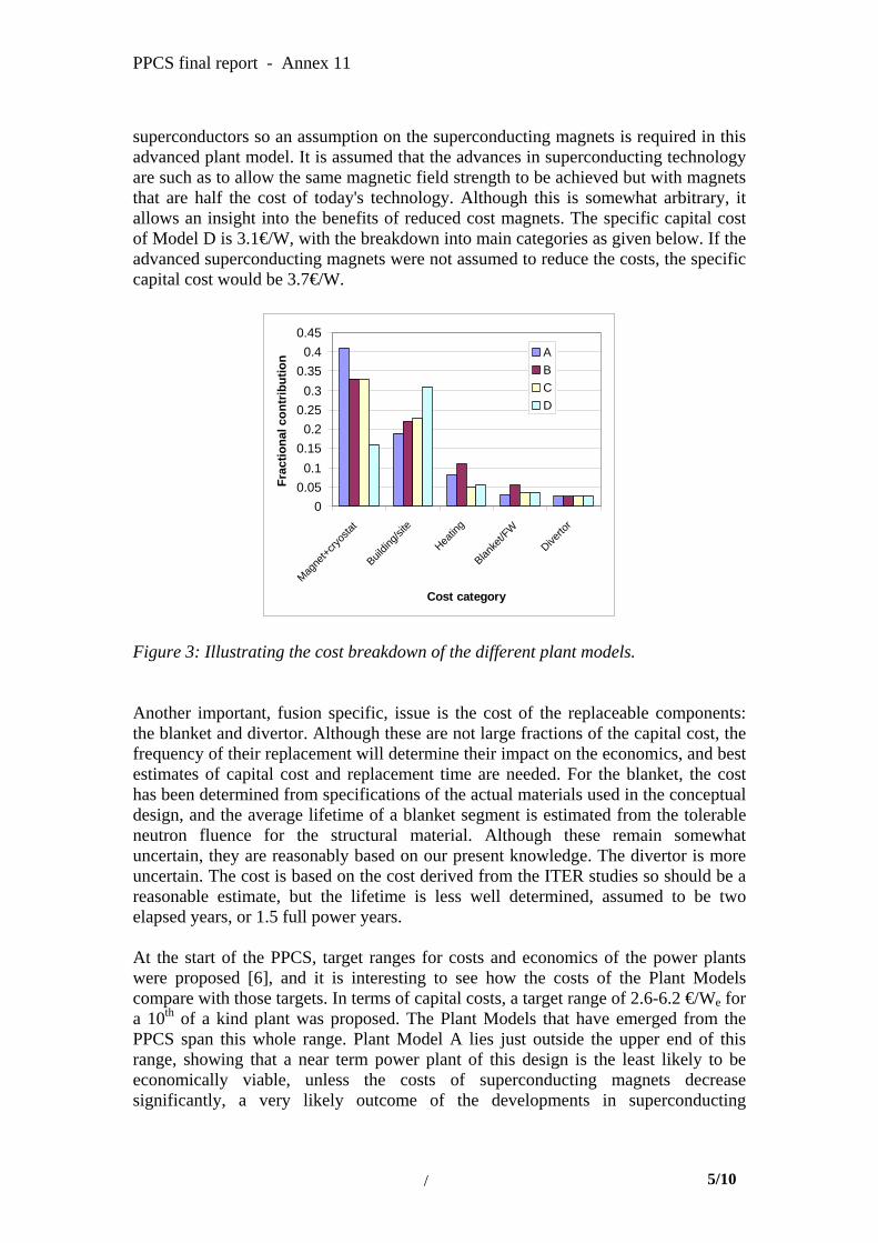
PPCS final report - Annex 11
superconductors so an assumption on the superconducting magnets is required in this advanced plant model. It is assumed that the advances in superconducting technology are such as to allow the same magnetic field strength to be achieved but with magnets that are half the cost of today's technology. Although this is somewhat arbitrary, it allows an insight into the benefits of reduced cost magnets. The specific capital cost of Model D is 3.1€/W, with the breakdown into main categories as given below. If the advanced superconducting magnets were not assumed to reduce the costs, the specific capital cost would be 3.7€/W.
00.050.1
0.150.2
0.250.3
0.350.4
0.45
Magne
t+cryo
stat
Buildin
g/site
Heatin
g
Blanke
t/FW
Diverto
r
Cost category
Frac
tiona
l con
trib
utio
n ABCD
Figure 3: Illustrating the cost breakdown of the different plant models. Another important, fusion specific, issue is the cost of the replaceable components: the blanket and divertor. Although these are not large fractions of the capital cost, the frequency of their replacement will determine their impact on the economics, and best estimates of capital cost and replacement time are needed. For the blanket, the cost has been determined from specifications of the actual materials used in the conceptual design, and the average lifetime of a blanket segment is estimated from the tolerable neutron fluence for the structural material. Although these remain somewhat uncertain, they are reasonably based on our present knowledge. The divertor is more uncertain. The cost is based on the cost derived from the ITER studies so should be a reasonable estimate, but the lifetime is less well determined, assumed to be two elapsed years, or 1.5 full power years. At the start of the PPCS, target ranges for costs and economics of the power plants were proposed [6], and it is interesting to see how the costs of the Plant Models compare with those targets. In terms of capital costs, a target range of 2.6-6.2 €/We for a 10th of a kind plant was proposed. The Plant Models that have emerged from the PPCS span this whole range. Plant Model A lies just outside the upper end of this range, showing that a near term power plant of this design is the least likely to be economically viable, unless the costs of superconducting magnets decrease significantly, a very likely outcome of the developments in superconducting
/ 5/10
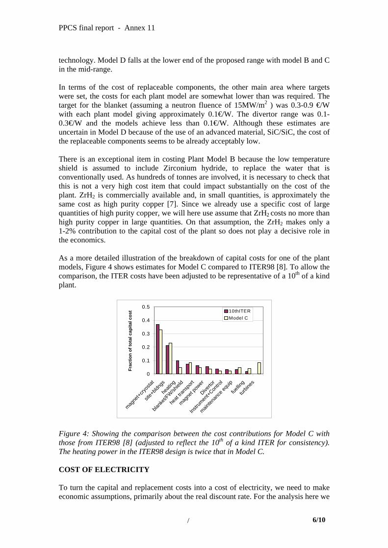
PPCS final report - Annex 11
technology. Model D falls at the lower end of the proposed range with model B and C in the mid-range. In terms of the cost of replaceable components, the other main area where targets were set, the costs for each plant model are somewhat lower than was required. The target for the blanket (assuming a neutron fluence of 15MW/m2 ) was 0.3-0.9 €/W with each plant model giving approximately 0.1€/W. The divertor range was 0.1-0.3€/W and the models achieve less than 0.1€/W. Although these estimates are uncertain in Model D because of the use of an advanced material, SiC/SiC, the cost of the replaceable components seems to be already acceptably low. There is an exceptional item in costing Plant Model B because the low temperature shield is assumed to include Zirconium hydride, to replace the water that is conventionally used. As hundreds of tonnes are involved, it is necessary to check that this is not a very high cost item that could impact substantially on the cost of the plant. ZrH2 is commercially available and, in small quantities, is approximately the same cost as high purity copper [7]. Since we already use a specific cost of large quantities of high purity copper, we will here use assume that ZrH2 costs no more than high purity copper in large quantities. On that assumption, the ZrH2 makes only a 1-2% contribution to the capital cost of the plant so does not play a decisive role in the economics. As a more detailed illustration of the breakdown of capital costs for one of the plant models, Figure 4 shows estimates for Model C compared to ITER98 [8]. To allow the comparison, the ITER costs have been adjusted to be representative of a 10th of a kind plant.
0
0.1
0.2
0.3
0.4
0.5
magne
t+cryo
stat
site+
bldng
s
heati
ng
blank
et/FW
/shiel
d
heat
trans
port
magne
t pow
er
Diverto
r
Instru
ment+C
ontro
l
mainten
ance
equip
fuellin
g
turbin
es
Frac
tion
of to
tal c
apita
l cos
t 10thITERModel C
Figure 4: Showing the comparison between the cost contributions for Model C with those from ITER98 [8] (adjusted to reflect the 10th of a kind ITER for consistency). The heating power in the ITER98 design is twice that in Model C. COST OF ELECTRICITY To turn the capital and replacement costs into a cost of electricity, we need to make economic assumptions, primarily about the real discount rate. For the analysis here we
/ 6/10

PPCS final report - Annex 11
will assume a 6% real discount rate, neglect taxation and use a 40 year plant life. The plant availability is assumed to be 75%. The cost of electricity is determined using the levelised cost approach [9] in which all costs and benefits are brought into present day values (the year of commissioning the plant) using discounting. The results of these studies can be summarised in a figure which serves to illustrate the importance of the technological learning in determining costs. Figure 5 shows the cost of electricity for the plant models as a function of the learning factor, broadly designed to represent the variation from an early implementation of fusion power (the first 10 plants) through to a mature fusion economy (up to 1000 plants).
0
2
4
6
8
10
0 0.2 0.4 0.6 0.8 1
Learning Factor
coe
(c/k
Wh)
AB
CD
Figure 5: Calculated cost of electricity from the PPCS fusion power plant models with different degrees of technological learning. The Learning Factor is the cost reduction from the first of a kind plant, applied only to fusion specific items. The breakdown of the cost of electricity into its main components is illustrated in Figure 6.
0
0.1
0.2
0.3
0.4
0.5
0.6
0.7
0.8
Capita
l
Diverto
r rep
O&M
Blanke
t/FW
rep
Decom
m
ABCD
Figure 6: The main components of the cost of electricity for each plant model (10th of a kind) expressed as a fraction of the total.
/ 7/10
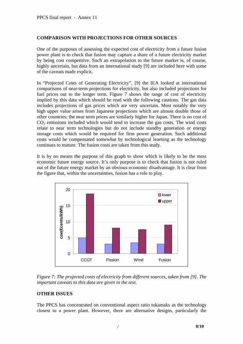
PPCS final report - Annex 11
COMPARISON WITH PROJECTIONS FOR OTHER SOURCES One of the purposes of assessing the expected cost of electricity from a future fusion power plant is to check that fusion may capture a share of a future electricity market by being cost competitive. Such an extrapolation to the future market is, of course, highly uncertain, but data from an international study [9] are included here with some of the caveats made explicit. In “Projected Costs of Generating Electricity”, [9] the IEA looked at international comparisons of near-term projections for electricity, but also included projections for fuel prices out to the longer term. Figure 7 shows the range of cost of electricity implied by this data which should be read with the following cautions. The gas data includes projections of gas prices which are very uncertain. Most notably the very high upper value arises from Japanese projections which are almost double those of other countries; the near term prices are similarly higher for Japan. There is no cost of CO2 emissions included which would tend to increase the gas costs. The wind costs relate to near term technologies but do not include standby generation or energy storage costs which would be required for firm power generation. Such additional costs would be compensated somewhat by technological learning as the technology continues to mature. The fusion costs are taken from this study. It is by no means the purpose of this graph to show which is likely to be the most economic future energy source. It’s only purpose is to check that fusion is not ruled out of the future energy market by an obvious economic disadvantage. It is clear from the figure that, within the uncertainties, fusion has a role to play.
0
5
10
15
20
CCGT Fission Wind Fusion
coe(
€cen
ts/k
Wh)
lowerupper
Figure 7: The projected costs of electricity from different sources, taken from [9]. The important caveats to this data are given in the text. OTHER ISSUES The PPCS has concentrated on conventional aspect ratio tokamaks as the technology closest to a power plant. However, there are alternative designs, particularly the
/ 8/10

PPCS final report - Annex 11
Stellarator and the ST (Spherical Tokamak). Although these are not the subject of this study, preliminary analysis to identify areas where there may be economic benefits have been carried out. For the Stellarator, a provisional costing of the Helias reactor [10] has been carried out. This revealed that to the level of reliability of the study, the Stellarator economics are similar to the tokamak. The main concern is over the magnets. Overall, although the coil set is more complicated, and probably larger, in the Stellarator, the advantage of using NbTi instead of NbSn leads to magnet costs no higher, and possibly lower, than a tokamak. The economic gain of not needing a current drive system in the Stellarator is not very large, although this assumes of course that such a system can be made to work reliably in a tokamak. If this were not the case, or if another area of steady state operation, such as disruption avoidance, became very important, the Stellarator may well have the advantage. For ST power plants, concept studies [11] have been examined for their economic potential. The benefits of the ST lie in its compact design and reduced need for superconducting magnets. Its disadvantages lie in the higher recirculating power and the need to replace the centre column frequently. Again, overall there is not a decisive economic advantage, however there are clear benefits in maintenance due to the compact design. The conventional tokamak studies assume high availability can be achieved by sophisticated maintenance systems. If this were not possible, the ST would appear to have the advantage. CONCLUSIONS The economics of Plant Models A, B, C and D of the PPCS have been estimated with the best information presently available. In terms of the cost targets set at the start of the PPCS based on projections for other energy sources, Plant Model A lies a little above the upper end of the target range for specific capital cost, suggesting that Model A is the least likely to be economically viable in the future energy market. However, Model A serves as a good base model designed around near term assumptions which can be used to explore the effect of developments. For instance, a similar plant in which superconducting improvements are included or one using helium coolant for higher efficiency would move inside the target range. Plant Model B already falls within the target range for specific capital cost, though near the upper end, and so has a greater chance of being economically viable in the future energy market. Plant Model C lies approximately at the middle of the target range for specific capital cost, suggesting that Model C has a reasonable chance to be economically viable in the future energy market. Developments in superconducting magnet technology would improve this situation further.
/ 9/10
PPCS final report - Annex 11
Plant Model D already falls at the lower end of the target range for specific capital cost, so has a high probability of being economically viable in the future energy market. In terms of targets for cost of replaceable components, all models perform well, although for Model D particularly, the blanket costs remain uncertain. Nonetheless, a substantial increase in the blanket costs could be tolerated without substantial impact on the economics, as it is not presently a very important cost item. Further assumptions are needed to turn the capital costs into costs of electricity. With the assumptions made here, relevant for a 10th of a kind power plant, the resulting cost of electricity is 9c/kWh for Model A, 8 c/kWh for Model B, 7 c/kWh for Model C and 5 c/kWh for Model D. These costs are expected to reduce in a mature fusion industry with further technological learning to lie in the range 3 to 5 c/kWh. ACKNOWLEDGEMENTS This work was jointly supported by the UK Engineering and Physical Sciences Research Council and by EURATOM. REFERENCES [1] Dutton and Thomas, Academy of Management Review 1984, Vol 9 No 2 253-247 [2] Model A, Volumes and Masses, note from Pereslavtsev and Fischer, 1-3-02 [3] Model B, Volumes and Masses, note from Chen and Fischer 3-12-01; Pampin and Loughlin PPCS/UKAEA/PPCS4D2-2, March 2002 [4] Conceptual Design of the Dual Coolant Blanket in the frame of the EU Power Plant Conceptual Study, P Norajitra et al, November 2002, Report No. FZKA 6780. [5] Conceptual Design of Model D reactor based on Self-Cooled Lithium-Lead (SCLL) blanket using SiC/SiC structures, L Giancarli et al, December 2002. [6] General Design Requirements Document, PPCS Team, Edited by D J Ward, PPCS/TRP4D3/UKAEA/1 March 2001 [7] Goodfellow Catalogue 2001/02, Goodfellow Cambridge Ltd, UK [8] Technical Basis for the ITER Final Design Report, Cost Review and Safety Analysis, ITER EDA Documentation No 16, IAEA Vienna, 1998. [9] Projected Costs of Generating Electricity, Update 1998, OECD/IEA Paris, ISBN 92-64-16162-7 [10] Beidler et al, Fusion Energy Conference 2000 (Sorrento) IAEA, Vienna, paper FT/4 [11] Wilson et al, Fusion Energy Conference 2002 (Lyon) IAEA, Vienna, paper FT/1-5
/ 10/10