
Ethiopian Electricity Agency Draft interface code (Generation)
32
Ethiopian Electricity Agency Draft interface code (Generation)
-
Upload
khangminh22 -
Category
Documents
-
view
0 -
download
0
Transcript of Ethiopian Electricity Agency Draft interface code (Generation)
Ethiopian Electricity Agency
Draft interface code (Generation)
ii
Contents
1 Introduction 1
2 Preamble 2
3 Structure of the interface arrangements 6
4 Interface general conditions (IGC) 7
4.1 IGC1 - implementation 7
4.2 IGC2 - unforeseen circumstances 7
4.3 IGC3 - Interface Arrangements for Generation review panel 7
5 Generation planning code 9
5.1 GPC1 - objectives 9
5.2 GPC2 – transfer of planning data 9
5.3 GPC3 – Design Standards 10
6 Generation connection conditions (GCC) 11
6.1 GCC1 – objective 11
6.2 GCC2 – Information required for connection 11
6.3 GCC3 – Information provided by EEPCo 12
6.4 GCC4 - ownership boundary 13
6.5 GCC5 - Technical requirements for generator connections 13
7 Generation operation code (GOC) 24
7.1 GOC1- Annual operational planning 24
7.2 GOC2 - Weekly Operational Planning 25
7.3 GOC3 – monitoring, testing and investigation 25
7.4 GOC4 – safety coordination 26
8 System operating code (SOC) 27
8.1 SOC1 - generation scheduling 27
iii
8.2 SOC2 - generation despatch 27
8.3 SOC3 – frequency and time control 28
8.4 SOC4 – voltage and reactive control 28
Tables and Figures
Tables
Table 1 Annual operational planning 24
Table 2 Weekly operational planning 25
Table 3 Generation scheduling 27
Figures
Figure 1 Generation interface Code 5
Abbreviations
ASO Adjacent System Operator means the owner and/or operator of a transmission system in another country interconnected to the EEPCo transmission system
BOO Build-own operate
BOOT Build-own operate transfer
BOT Build-operate transfer
CENELEC European regional standards body for Electro-technical Standards
CC Connection Contract between the IPP and EEPCo
DCC Distribution Connection Conditions code
DOC Distribution Operating Code
DPC Distribution Planning Code
ECBS-10 Electrical Installations of Buildings code, chapter 10, issued by the Ministry of Development & Infrastructure
EEA Ethiopian Electricity Agency
EELPA The Ethiopian Electric Power Authority, now called EEPCO.
iv
EEPCo Ethiopian Electric Power Corporation
EIA Environmental Impact Assessment
EPA Environmental Protection Authority
EPSEMP Ethiopian Power System Expansion Master Plan
EREDPC Ethiopian Rural Energy Development and Promotion Center
GCC Generation Connection Conditions
GPC Generation Planning Code
GOC Generation Operating Code
ICS Interconnected system
ID Independent distributors
IEC International Electro-technical Commission
IFC International Finance Corporation (World Bank Group)
IGC Interface General Conditions
ISO International Standards Organisation
MCI Mandatory Contractual Item is one in which costs are incurred which are to be covered under the Power Purchase Agreement (PPA) or the Negotiated Transportation Contract (NTC).
MWUD Ministry of Works and Urban Development
NRECA National Rural Electrification Cooperative Association
NTC Negotiated Transportation Contract
PPA Power Purchase Agreement
REB Rural Electrification Board
REF Rural Electrification Fund
RES Rural Electrification Secretariat
SCS Self-contained system (isolated networks)
SEEE Society of Ethiopian Electrical Engineers
SO System Operator means the owner and/or operator of EEPCo’s transmission and/or distribution system as appropriate
SOC System Operating Code
QSAE Quality and Standards Authority of Ethiopia
1
1 Introduction
This Paper describes a draft Interface Code (Generation) for the interconnected electricity system in Ethiopia.
The Paper begins in Section 2 with a description of the possible participants in the electricity industry in Ethiopia and the relationships between them. Section 3 outlines the interface code. Sections 4 to 8 describe the contents of the code.
2
2 Preamble
Under present legislation the following is allowed:
independent power producers can establish power generating plant; and
independent distributors (ID) and suppliers of electrical energy can supply customers using a standalone arrangement (i.e., not connected to EEPCo’s ICS). Issues associated with the connection of IDs to the ISC are dealt with in the Interface Code (Distribution).
It is envisaged that all independent power producers generating plant will be connected to EEPCo’s transmission system. Further, it is assumed that any generating plant connected to the distribution system of EEPCo, either directly or via an independent distributor’s distribution network will only operate on a standby basis.
IPP generation will be self-despatched according to their contracts with EEPCo instructing changes where necessary to balance the system.
It is further envisaged that large customers would be allowed to buy directly from IPPs. Full commercial arrangements for many customers to buy from many IPPs would require a Balancing and Settlement Code. However (interim) arrangements whereby a single IPP could sell to a few customers over a relatively long period of time could be achieved by negotiated transportation contracts (NTC). [The NTC would contain clauses dealing with:
1. payment for Use of System:
a. Note that the issue of who pays for reinforcement to the transmission system is much more significant than when EEPCo buys all the output;
2. payment or adjustment for losses;
3. payment or roll-over terms associated with over/under generation;
4. payment or curtailment when the customer power offtake is greater than generation capacity;
5. payment terms associated with IPP maintenance when the customer power offtake is greater than the available generation;
6. payment for SO instructed increase or decrease in output;
7. terms dealing with non-transportation (generation restricted or load not supplied):
a. this will include coordination of customer disconnection for transmission or distribution maintenance; and

3
8. terms dealing with customer issues such as metering, loadshedding and disconnection (see below).
The IPP will put in place (as part of the NTC) an agreement whereby the SO can purchase energy/power on a short-term basis where the full output is not being sold directly to customers. (This might be on an energy swap basis)
The interface with the IPP would be very similar to an IPP selling only to EEPCo and is dealt with under this code. However decisions on scheduling and dispatch in the Operating Code may be altered and scheduling and dispatch decisions will be inputs into the settlement of the commercial agreement. These will be:
A commercial schedule which is the profile of output that the IPP must deliver in order to meet customer demand plus losses plus any additions or subtractions of rollover energy. This will be limited to the generator availability (i.e. reduced during breakdown).
A final instructed dispatch profile – note that the generator is required to comply with this profile.
Differences between the commercial schedule and the final dispatch will be dealt with under the SO payment terms of the NTC.
Where a customer signs up to by power from an IPP this is a change in circumstances for the customer, so is dealt with under the connections code. The connection code will deal with:
1) Metering:
a) the customer must have commercial metering of appropriate standard of accuracy;
b) the metering shall be over short enough (settlement) periods that the customer peak loads can be identified ( this can be from ¼ hr to 8hrs, initially 1hr is suggested);
c) load values for each settlement period must be recorded and electronically downloadable.
2) Load shedding:
a) EEPCo shall inform the customer/IPP whether they can in operational timescales identify the customer and ensure it is not loadshed for general energy or power shortage:
i) if the customer cannot be separately identified then it’s loadshedding shall be as a normally part of EEPCo’s customer base:
(1) the terms in the NTC shall acknowledge this;
(2) in particular the IPP customer offtake power shall be reduced appropriately in calculating any shortfall costs;
ii) if the customer can be separately identified then:

4
(1) the terms in the NTC shall acknowledge this;
(2) the customer shall not be loadshed due to EEPCo energy or power shortage:
(a) it may be switched off for transmission reasons (faults maintenance etc;
(3) shortfall of generation by the IPP shall be dealt with under the NTC:
(a) in general the customer shall not be disconnected and the IPP shall pay EEPCo under terms of NTC;
(b) if the system is short at the same time then the SO will disconnect IPP customers first until the total IPP demand is within its generation output.
3) Low frequency tripping shall be on the same basis as currently.
4) The IPP shall have the right to require EEPCo to disconnect their customers for contractual reasons:
a) The principal reason for disconnection will be non-payment.]
It is also envisaged that IPPs be allowed on the basis of selling their output to a separate sovereign state (Djibouti). It is assumed that the IPP will connect locally to the EEPCo network and an interconnector be put in place between the EEPCo system and the transmission system in the adjacent sovereign state. This approach will maximise the benefits to the two systems (and the two states).
[The interface between the IPP and the SO will be very similar to that for IPPs selling directly to customers and is dealt with under this code. A Negotiated Transportation Contract to the point of interconnection will be required.]
[The interconnection between EEPCo and the electricity transmission system will be under the terms of an agreement between two sovereign states so cannot be limited by an interconnector interface code written purely under Ethiopian law. However the Model Interface Code (Interconnection) contains the items/issues that need to be covered in any interconnection agreement that would apply between the systems.]
[Once an interconnection agreement is put in place then a code shall be finalised so all parties can benefit. Note that the code will in all likelihood have different terms for different interconnectors.]
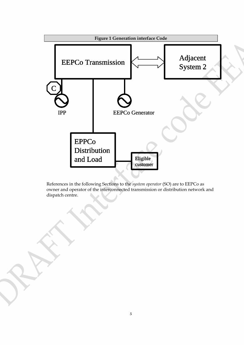
The arrangements discussed above are shown diagrammatically in Figure 1. Clearly for these arrangements to operate safely and efficiently certain conditions have to be fulfilled and certain rules have to be followed. This document sets out
those conditions and rules at the interface (shown as CC
in Figure 1). [An NTC would apply from the generator connection to either the eligible customer terminals or to the border with the adjacent sovereign state.]
5
Figure 1 Generation interface Code
References in the following Sections to the system operator (SO) are to EEPCo as owner and operator of the interconnected transmission or distribution network and dispatch centre.
Adjacent
System 2EEPCo Transmission
C
EPPCo
Distribution
and Load Eligible
customer
IPP EEPCo Generator
Adjacent
System 2
Adjacent
System 2EEPCo TransmissionEEPCo Transmission
CC
EPPCo
Distribution
and Load
EPPCo
Distribution
and Load Eligible
customer
Eligible
customer
IPP EEPCo Generator

6
3 Structure of the interface arrangements
The Interface Arrangement for Generation is split into a number of codes:
1) The Interface General Conditions (IGC) sets out the legal framework guiding the operation of the Interface Arrangements.
2) The Generation Planning Code. The Generation Planning Code (GPC) contains details of the general objectives and design principles and standards and the planning information that must be made available.
3) The Generation Connection Conditions. The Generation Connection Conditions (GCC) describes the information flow between the Generator and EEPCo the technical requirements and the definition of ownership boundary.
4) The Generation Operating Code. The Generation Operating Code (GOC) GOC1 covers operational planning, monitoring, testing and information and the vital issue of safety coordination.
5) The System Operation Code. The System Operation Code (SOC) covers scheduling and dispatch together with frequency and voltage control.
The Interface Arrangements for Generation are a set of engineering requirements on IPPs and the SO which permit the coordinated safe, secure and economic operation of the power system.
[In certain cases the action that the IPP is required to perform (by the SO) will have cost consequences. These costs will be covered in the Power Purchase Agreement (PPA), the Negotiated Transportation Contract (NTC) or the Connection Contract (CC). These arrangements do not dictate the form of any associated payments as many differing contract types exist, from an all-inclusive price to individual incentivised payments for every discrete service.]
[Where an item in these arrangements has an identifiable cost then this will be noted as being a Mandatory Contractual Item (MCI) for ongoing potentially regular items to put in the associated PPA or NTC and for one off items such as a requirement to upgrade circuit breaker capability in the Connection Contract (CC). The comment will suggest whether the MCI goes in the PPA/NTC or the CC. It is also possible that the costs have been incurred by the SO and caused by the generator.]

7
4 Interface general conditions (IGC)
4.1 IGC1 - implementation
[We propose that] EEPCo’s transmission and distribution Licences will impose a duty on the system operator (SO, namely EEPCo) to implement and enforce the Interface Arrangements for generation, distribution and interconnection.
All users (IPP’s and ID’s) will be required, by their licences, to abide by the relevant parts of the Interface arrangements and to provide the SO such rights of access, services and facilities and to comply with such instructions as the SO may reasonably require to implement and enforce the interface arrangements.
4.2 IGC2 - unforeseen circumstances
If circumstances arise which the provisions of the Interface Arrangements have not foreseen the SO shall, to the extent reasonably practicable in the circumstances, consult promptly and in good faith with affected users in an effort to reach agreement as to what should be done.
If agreement cannot be reached in the time available the SO will determine what is to be done.
Each user shall comply with all instructions given to it by the SO following such a determination. The SO shall promptly refer all such unforeseen circumstances and any such determination to the Interface Arrangements Review Panel in accordance with IGC3.
In the event of any conflict between the provisions of the Interface Arrangements and any contract the provisions of the Interface Arrangements shall prevail.
Unforeseen circumstances are a Mandatory Contractual Item, which would need to be in PPA/NTC and CC as he cost incurred might be of an operational nature or may require changes to equipment.
4.3 IGC3 - Interface Arrangements for Generation review panel
The Ethiopian Electricity Agency (the Agency) shall establish and maintain a panel, which shall be a standing body to carry out the following functions:
a) Keep the Interface Arrangements for Generation and its working under review;
b) Review all suggestions for amendments to the Interface Arrangements for Generation which the Agency, the SO, or any user may submit to the panel;

8
c) Agree amendments to the Interface Arrangements for Generation that the panel feels are necessary giving reasons for such amendments;
d) Issue guidance in relation to the Interface Arrangements for Generation and its implementation when asked to do so by any user;
e) Consider what changes are necessary to the Interface Arrangements for Generation arising out of any unforeseen circumstances referred to it by the SO under IGC2.
The Panel shall be a public body consisting of:
a) Chairperson and one person appointed by the Agency (who shall act as technical secretary);
b) One person representing EEPCo transmission and system operations;
c) One person representing EEPCo generation
d) One observer from EEPCo distribution;
e) Two persons representing IPP’s;
f) One observer representing ID’s;
g) One observer representing Interconnector interests.
The concept of observer is useful in keeping parties informed of changes that are occurring.
Scheduling the meetings of the Interface Arrangements (G, D & I) on the same day would allow representatives to attend all three in different roles.
[A review of this Section should be made, prior to finalisation, to ensure consistency with the Regulation and to remove repetition].
9
5 Generation planning code
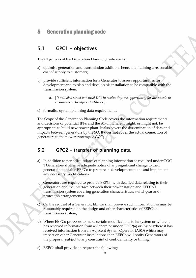
5.1 GPC1 - objectives
The Objectives of the Generation Planning Code are to:
a) optimise generation and transmission additions hence maintaining a reasonable cost of supply to customers;
b) provide sufficient information for a Generator to assess opportunities for development and to plan and develop his installation to be compatible with the transmission system:
a. [It will also assist potential IIPs in evaluating the opportunity for direct sale to customers or to adjacent utilities];
c) formalise system planning data requirements.
The Scope of the Generation Planning Code covers the information requirements and decisions of potential IPPs and the SO on where it might, or might not, be appropriate to build new power plant. It also covers the dissemination of data and impacts between generators by the SO. It does not cover the actual connection of generators to the power system(see GCC).
5.2 GPC2 – transfer of planning data
a) In addition to periodic updates of planning information as required under GOC 1 Generators shall give adequate notice of any significant change to their generation to enable EEPCo to prepare its development plans and implement any necessary modifications;
b) Generators are required to provide EEPCo with detailed data relating to their generation and the interface between their power station and EEPCo’s transmission system covering generation characteristics, switchgear and protection arrangements;
c) On the request of a Generator, EEPCo shall provide such information as may be reasonably required on the design and other characteristics of EEPCo’s transmission system;
d) Where EEPCo proposes to make certain modifications to its system or where it has received information from a Generator under GPC2(a) or (b); or where it has received information from an Adjacent System Operator (ASO) which may impact on other Generator installations then EEPCo will notify Generators of the proposal, subject to any constraint of confidentiality or timing;
e) EEPCo shall provide on request the following:

10
i. present and future circuit capacities relevant to the proposed point of connection;
ii. forecasts of present and future generation /demand balance on [relevant parts of] EEPCo's grid system;
iii. [EEPCo may levy a charge for preparing this information as approved by EEA]. This information will be prepared within 28 days after receipt of the request [or the agreement of the person making the request to pay the cost of preparing the information, whichever is the longer].
5.3 GPC3 – Design Standards
5.3.1 Frequency
The expected standard frequency range is
Normal operating range 49.5 to 50.5 Hz
During system disturbances 48.0 to 52 Hz
[The disturbance range above is that which the generator must be capable of accommodating without needing to disconnect from the system. The frequency at which the Generator may trip in order to protect its equipment is an MCI (in the PPA/NTC).]
5.3.2 Reactive Requirements
All Generators are required to ensure availability of reactive resources to enable the requirements of the transmission system to be met. Generators shall operate their plant at a power factor range from 0.9 leading to 0.85 lagging as measured at the terminals of each Generating Unit. [Designing to this standard and maintaining the standard is an MCI in the CC].
Any additional reactive resource requirements necessary for the operation of the grid system will be determined by the system operator and allocated to the appropriate generator. [Potential requirement:
1. The generator connection is at a position in the network where significant reactive capability is required:
a. this requirement may have been identified by the SO; or
b. this requirement may be a consequence of the generator connecting there;
c. the generator may be required to put in place:
i. static capacitive or inductive equipment;
ii. add synchronous compensation capability to the generator design; or
iii. increase the generators active MVA capability; ]
d. [this will be a MCI in the CC and in the PPA/MTC for ongoing costs.]
11
6 Generation connection conditions (GCC)
6.1 GCC1 – objective
The objectives of the Generation Connection Conditions are to:
a) Define the minimum standards for the method of connection to EEPCo’s transmission system and the technical, design and operational standards to which generators connecting to the transmission system shall comply,
b) Specify the technical arrangements required at the ownership boundary between EEPCo’s transmission system and the Generator’s installation.
The Scope covers all the information that must be passed between the Generator and the SO so that for a planned IPP they can:
1. design in detail an appropriate connection including:
i. compatibility of generator and power system;
ii. required transmission reinforcement;
2. agree the ownership boundary:
i. and all safety interface issues;
3. clarify responsibility on all technical issues over the life of the connection;
4. agree a Connection Contract;
[It does not cover the operation of the IPP or the commercial issues in the PPA or NTC.]
6.2 GCC2 – Information required for connection
The prospective Generator shall supply the following to EEPCo:
a) The following details on generation to be connected:
Plant name. Unit number. Maximum capacity in megawatts. Minimum capacity in megawatts. Commissioning date. Retirement date. Type of generation [run-of-river, peak-sharing reservoir, etc.]. Fuel type

12
Fuel storage capacity Forced outage rate. Load and energy output schedules (weekly, monthly, annual). Maintenance outages: date and period.
b) Single line diagram showing all electrical components of the Generators installation including all impedance data (synchronous, transient and sub-transient).
c) The date when connection is required.
6.3 GCC3 – Information provided by EEPCo
Based on the information provided by the prospective Generator EEPCo shall prepare a statement containing as many of the following elements as are necessary for, or relevant to, the proposed installation:
a) Nominal voltage at which connection will be made.
b) The likely maximum variation in voltage at the point of connection.
c) Method of connection, extension and/or reinforcement details together with information on metering.
d) Method of earthing.
e) Maximum import capacity from EEPCo system for miscellaneous station uses
f) Limits relating to:
Harmonic Distortion Voltage Flicker Unbalance
g) Maximum export capacity to EEPCo’s transmission system.
h) Detailed engineering constraints [such as maximum fault infeed current (see GCC5)].
i) Expected lead-time of providing connection (following formal acceptance of terms for supply).
j) Cost of connection and terms for supply.
[The items listed in this section will form the basis for the Connection Contract. Diagrams, values, limits and other data arrived at under GCC5 will form appendices to the contract].
13
6.4 GCC4 - ownership boundary
All the equipment at the ownership boundary shall meet EEPCo’s design standards. Connections shall incorporate a means of disconnection of the Generator’s system by EEPCo.
The respective ownership of equipment shall be recorded in a written agreement between EEPCo and the Generator or in diagrammatic form, as required.
6.5 GCC5 - Technical requirements for generator connections
6.5.1 Generator's responsibility
Primary responsibilities
The Generator is financially responsible for the design, installation, operation, and maintenance of all necessary equipment for connection to the grid system, unless otherwise stated in a contractual agreement. It is also the Generator's responsibility to submit specifications and detailed plans for the protective devices to the system operator for information. Written approval from the system operator is required prior to parallel operation of power plants and the system operator shall not unreasonably withhold any approval.
In addition to the direct connection facilities, the system operator is responsible for system upgrades necessary to transmit generation into the grid system. System additions could include, but are not limited to, new line construction, line reconductoring, circuit breaker replacement, and special generation tripping schemes.
The system operator will not assume any responsibility for protection of the Generator's plant(s), or of any other portion of the Generator's electrical equipment. The Generator is fully responsible for protecting its equipment in such a manner that faults or other disturbances in the grid system do not cause damage to the Generator's equipment.
Access to premises by authorised persons
SO will have the right to inspect the Generator's facilities at any time and without delay to verify the correct operation of all equipment, [including controls, circuit breakers, relays (and relay settings), metering, and telemetering,] which would affect the grid system's operation and/or safety.
Arrangements will be provided so that the system operator on giving prior notice and reasons for the visit may have access to the Generator's facilities and metering equipment at any time.

14
Operating contacts and phone numbers
The Generator will provide data on contact person(s) and associated telephone number(s) to the system operator. The telephone number(s) will allow for 24 hour per day contact of either a manned control room related to the Generator's generating facilities or to any other responsible party the Generator may employ to operate their facilities. Changes to phone numbers, points of contact, etc., shall be immediately communicated to the system operator preferably in advance of the actual change. When notification is made in advance, the effective date of change will be provided as well,
The system operator will provide the Generator with phone numbers for the appropriate contacts concerning operations. Phones are manned 24 hours per day.
Staffing and training
The Generator will maintain an adequate staff properly trained for the administration, operation, and maintenance of the facilities. The engineering staff for operation and maintenance of the facilities should meet the competence requirements of [the Regulations].
Disconnection of generator by the system operator
The system operator will be given the right to open the connection to the generator via circuit breaker, switches, etc., thereby isolating the Generator's equipment without prior notice for any one of the following reasons:
1) System emergencies that require emergency operations for disconnection include the following:
a) Voltage excursions in excess of ± 10 percent of nominal;
b) Transmission system elements loaded at or beyond their long time emergency (LTE) rating where such disconnection would alleviate such a problem;
c) Situations involving restoration of service; and
d) Overgeneration on the grid system that is the partial or full cause of the system moving out of a normal operating mode.
2) For items "1b" and "1d" above, if a reduction in Generator’s output alleviates the problem; such reduction may be requested by the system operator, rather than disconnection.
Maintenance scheduling and approval
Planned maintenance outages by the Generator - providing greater than [2.5 MW but less than 10 MW] will be submitted to the system operator no less than 14 days in advance of the planned outage date.

15
Generators providing greater than [10 MW] net or more to the grid system will submit its planned maintenance schedule to be received by the fifteenth of each month. It will cover three succeeding years and include any planned equipment outages, which result in a reduction in capacity of [10 MW] or greater.
6.5.2 Connection Information Requirement
The system operator shall be informed of the design, construction, and operation of any Generator's facilities involving Generator/grid system interface.
Initial planning data
The Generator should submit a preliminary one-line electrical diagram and specific information regarding the electrical and physical characteristics of the Generator's facility and equipment. Manufacturer's certified test data should also be supplied when received. The system operator and Generator should initially determine the expected mode of operation of the Generator's generating facility, including the expected forced outage rate, hourly pattern of generation, and use of the Generator generating facility capacity and energy.
Connection plan
The connection facilities, including substation equipment and metering and protective devices, should be planned to meet the SO's reliability criteria and should be in conformance with the SO’s design standards.
The SO should prepare a connection plan based on studies of planned-operation modes for the generator/grid system facilities.
Substation design
The design of the generator substation and related equipment should be such that the equipment can be operated [according to the System Operations Code - Section 8].
Safety and reliability. To guarantee the safety of the grid system's personnel, the Generator will install a disconnecting device between the generator and the grid system. The disconnecting device shall be accessible to the system operator at all times. The disconnecting device must be a manually operable isolating switch with visible break for the purpose of isolating the Generator's equipment from the grid system. It should be installed at location agreed upon by the system operator and capable of being locked.
Connection voltage. The substation facilities will be designed on the connection voltage. If a Generator's facility is to be directly connected with the grid system, voltage at the point of connection will be specified by the system operator and will be one of the grid system's standard voltages.
16
Power plant design
The Generator's power plant should meet appropriate international standards [or equivalent] and all other requirements for operation in parallel with the grid system. The design of the plant should provide the ability to operate in accordance with the System Operations Code [Section 8] in a manner not to reduce or adversely impact the quality of service being provided by EEPCo to its customers.
Load following capability. Generation will be designed so that it can follow system load. [If this is not possible because of restrictions due to the use of the facility by the Generator for other purposes or reasons, the generation facility must be designed to be able to follow a prescheduled load pattern to be agreed upon by the Generator and the system operator].
Voltage and reactive control. The Generator should provide suitable automatic voltage regulating equipment compatible with the grid system for controlling the voltage specified by the system operator. [The limits of voltage variation and required reactive capability of units should be specified by the SO].
Emergency availability. The Generator's facility should be able to perform the following operations during emergencies in a manner similar to that of a utility resource:
a) Coming on line;
b) Adjusting generation output;
c) Remaining in operation and connected to the system; and
d) Coming offline where generator would contribute to overloading facilities or over-generation conditions.
Governor response. The Generator's facility should be designed so that each generating unit is capable of responding automatically to normal variations in the system frequency.
Relay systems. The relay systems for the Generator's power plant should be adequate to prevent equipment damage for contingencies occurring both within the plant and outside the plant on the grid system. The Generator shall inform the system operator the Under Frequency Trip Settings for its generating units. [The settings shall be set as low as possible to assist the system, but should be at a level to prevent damage to the generating units themselves.]
Requirements and limitations. The Generator's power plant equipment should permit the expected mode of operation without undue maintenance or life reduction. Controls within the plant should be provided to permit all reasonably expected modes of operation.
Maintenance requirements. The Generator's power plant should be designed to permit safety, routine, and emergency maintenance to all components: a) so that

17
availability can be maximised; and b) so that outages can be coordinated with the SO.
Forced outage rate. The Generator's power plant should be capable of operating with a forced outage rate comparable to that of utility equipment, [or as may be specified by the SO].
Harmonics. Generator's generation should not exceed the Interface Code's specification for harmonic content.
Transmission System Reinforcement
Any additions or modifications to the grid system found necessary for connection of the Generator's facilities shall be designed [and costed] by the SO.
[The cost of system additions that are required as a result of the addition of generators to the grid system will be borne [by the SO.]]
Transmission planning studies. The system operator is responsible for making system planning and development studies for connection of a generator to the grid system:
1) The Generator is required to request in writing from the system operator a planning study to determine, among other things the availability of transmission capacity on the grid system, the equipment necessary to connect the Generator's facility to the grid system, the breakdown of cost estimates for connection, and the time necessary to build the connection facilities. In order to conduct the studies it is necessary that the Generator provides the following:
a) The information the Generator is required to provide for connection to the grid system as described in GCC2;
b) A one-line electrical arrangement diagram and specific information regarding the electrical characteristics of the Generator's facility in the initial planning stages of the project;
c) Any additional information that the system operator may request for the study [including but not limited to transformer high- and low side voltages and the fixed tap ratios of the transformers];
2) The system operator will determine necessary information from the system study to accomplish the following:
a) Advise Generators of any limit to the transmission system capacity and the completion for any remaining capacity;
b) Allocate capacity on constrained transmission system on a first-come first-served basis; and
18
c) Identify limits of the grid system's ability to accept generator output under the grid system outage contingency.
6.5.3 Relay settings and testing
Protection will be provided by the Generator so that abnormal conditions on the grid system will not cause damage to Generator-owned equipment. Protection also shall be provided by the Generator so that abnormal conditions in the Generator-owned equipment will not cause equipment damage or abnormal conditions on the grid system.
Where the Generator is to provide protective devices for the protection of the grid system, the Generator will submit single-line and elementary wiring diagrams of this equipment to the system operator for approval of the protective functions.
The system operator will specify the settings of those relays that are designated as being required to satisfy the grid system protection practices.
The system operator will seal the designated devices belonging to the system operator located within the Generator's premises and listed on the relay setting documents, verify accuracy of associated circuit wiring, and perform a functional test of the required devices. The functional test will be limited to a trip test.
The system operator will annually check the sealed protective devices belonging to the system operator located with the Generator's premises at no charge to the Generator. A check will consist of a visual/mechanical examination of the designated required devices, seals, and associated wiring. If seals are broken by the Generator or its agency the protective devices will be recalibrated, tested, and resealed. The cost of corrections, if any, will be borne by the Generator.
The Generator will be responsible for specifying the settings and calibrating, testing, and maintaining the remainder of privately owned equipment.
The relay testing of the designated devices will be completed before the station is permitted for commercial operation.
Protection Requirements
The system operator subject to EEA approval may establish different classes for generators, each with distinctive protection and operating requirements:
a) Generation with a capacity of [2.5 MW ] and over, and connected to the transmission system.
b) Generation with a capacity of less than [2.5 MW], and connected to the transmission system.

19
6.5.4 General operating requirements
This Section provides the general operating requirements expected from a Generator when connected to the grid system.
Subject to the conditions of any power purchase agreement (PPA) the system operator should be notified in writing by the Generator at least 30 days before initial energisation and start-up testing of Generator's facility so that the system operator can inspect the facility's equipment and devices associated with the connection that might affect the grid system's operation.
Generators will not be permitted to energise or de-energise the grid system.
The Generator will be required to operate its generating facility in accordance with prudent utility practices.
The generating facility will be operated with all of its protective apparatus in service whenever the generating facility is connected to, or is operated in parallel with, the grid system. Any deviation for brief periods of emergency or maintenance may be made only with the agreement of the system operator.
The Generator will be required to maintain operating communications with the system operator. [Operating communications will include, but not be limited to, system parallel operation or separation, scheduled and unscheduled outages, levels of operating voltage and reactive power, and daily capacity and generation reports].
Generators will be required to keep a daily operations log for the generating facility, which must include information on maintenance outages, maintenance performed, availability, and circuit breaker trip operations requiring a manual reset. [Generators with the necessary metering will be required to log fuel consumption, cogeneration fuel efficiency, kilowatts, kilovars, and kilowatt-hours generated and settings or adjustments of the generator control equipment and protective devices, and any significant events related to the operation of the generating facility, including, but not limited to, real and reactive power production, changes in operating status and protective apparatus operations, and any unusual conditions found during inspections].
If, at any time, the system operator determines after consultations with the Generator that (a) continued parallel operation of the generating facility may endanger the grid system personnel, (b) continued parallel operation of the generating facility may endanger the grid system integrity, (c) continued parallel operation of the generating facility may prevent maintenance of the grid system's facilities, or (d) the Generator's protective apparatus is not fully in service, the system operator will have the right to disconnect the generation facility from the grid system. The generating facility will remain disconnected until such time as the system operator is satisfied that the condition(s) above has been corrected.
6.5.5 System Criteria
[The purpose of this section is to describe how the system is normally operated. This is the background against which Generators can design build and operate their installation.
20
System voltage variation
The voltage on the 230 kV lines of the grid system will normally remain within [±5] percent of the nominal value unless abnormal conditions prevail. The minimum voltage is -10 percent and the maximum voltage is +10 percent under abnormal conditions, but voltages between +5 percent and +10 percent will not last longer than 15 minutes unless abnormal conditions prevail.
System frequency variation
The frequency of the electric power in the grid system will be nominally 50 Hz and shall be controlled within the limits of [49.5 - 50.5] Hz unless exceptional circumstances prevail (normal steady-state operation).
Neutral earthing
At nominal system voltages of 132 kV and above, the higher voltage windings of a transformer of a generating unit must be star connected with the star point suitable for connection to earth.
Phase unbalance
Under planned outage conditions, the maximum negative phase sequence component of the phase voltage on the grid system should remain below 1 percent unless abnormal conditions prevail.
Under planned outage conditions, infrequent short duration peaks with a maximum value of 2 percent are permitted for phase unbalance, subject to the prior agreement of the system operator].
6.5.6 Generator operations criteria
In order to minimize the interference resulting from the parallel operation of generators with the grid system, the following criteria will be met.
Voltage
The Generator's equipment must not cause excessive voltage excursions in excess of ±10 percent of nominal. The Generator will install any necessary voltage regulating equipment. The Generator will provide relaying to disconnect his generating equipment from the grid system if the voltage cannot be maintained within acceptable tolerances.
Flicker
The Generator's facilities shall not cause excessive voltage flicker on the electric power system.

21
Frequency
The operating frequency of the Generator's equipment shall be maintained between 49.5 hertz and 50.5 hertz.
Harmonics
Starting surges or harmonics generated by Generator's equipment must not cause any reduction in the quality of service provided to other generators or interfere with the grid system.
The maximum total level of harmonic distortion on the system from all sources under both planned outages and fault outage conditions must not exceed a total harmonic distortion of [1.5] percent with no individual harmonic greater than [1] percent.
Fault and line clearing
The Generator will be responsible for removing his generation equipment from the electric power system for phase faults, ground faults, or outages occurring on the electric circuit serving him.
Negative phase sequence loadings
Each generating unit will be required to withstand, without tripping, the negative phase sequence loading incurred by clearance of a close-up phase-to-phase fault, by system back-up protection on the transmission system. [Negative phase sequence relays will be- necessary].
Reactive Power Supply Requirements
Synchronous generators. Generators using synchronous generators will be required to generate or supply reactive power so that the generating facility does not impose any additional reactive power demand upon the grid system other than the demand of loads within the facility. Sufficient generator reactive power capability will be provided to withstand normal voltage changes on the grid system. The generator will not be permitted to deliver excess reactive power to the grid system unless otherwise agreed to by the system operator.
Induction generators. If the Generator's generating facility includes induction type generator(s), the Generator will provide power factor correction means so that the generating facility will not normally demand reactive power from, nor supply reactive power to, the grid system. The power factor correction equipment may be installed by the Generator at his facility. The system operator shall have the right to review the Generator's power factor correction plan and to require modifications or additions as needed, in the system operator's opinion, to maintain the grid system's integrity

22
6.5.7 Metering
EEPCo will specify the metering to be employed.
[Transmission System Metering Principles
The term ‘Metering’ refers to the complete measurement system including but not limited to Meters, Voltage Transformers and Current Transformers.
Metering shall conform to standards or ‘Codes of Practice’ that specify accuracy, design and resilience as appropriate for the volume of energy transferred across the metering point.
A single party or ‘Registrant’ shall be responsible for the operation of each metering system, although this function may be delegated to an approved contractor or ‘Meter Operator’ if desired.
Metering shall in all instances include channels for Import, Export, Reactive Lead and Reactive Lag. Check meters shall also be installed for reading and comparison with main meters.
Metering shall wherever possible be installed at the Transmission System boundary. Where this is not possible, loss adjustment factors shall be applied.
Metering shall be sealed by an independent agent after installation and all maintenance works. Notice shall be given should any seals need to be broken or, for emergency works, which have been broken.
Metering shall be connected to an appropriate data collection network (telephone, radio, power-line carrier, etc.) to enable automated data collection.
Metering shall have sufficient memory to store data for [20] times the selected data collection frequency (i.e. 20 days if daily data collection is the norm).
Manual data collection shall be performed if data has not been received after [3] attempts at the normal collection frequency. This manual collection shall be performed within [10] times the normal collection frequency.
Metering shall be inspected by an independent agent. Inspections should be both random and targeted at suspect installations. All metering shall be inspected at least once in any 5 year period.
Manual meter advance readings shall be taken by an independent agent once every [3] months. These advances shall be compared with the sum of the hourly values during this period.
Difference metering may be appropriate where costs of discrete metering are prohibitive.
Where appropriate a dispensation may be granted to allow for non-standard configurations or the use of alternative equipment.]

23
24
7 Generation operation code (GOC)
7.1 GOC1- Annual operational planning
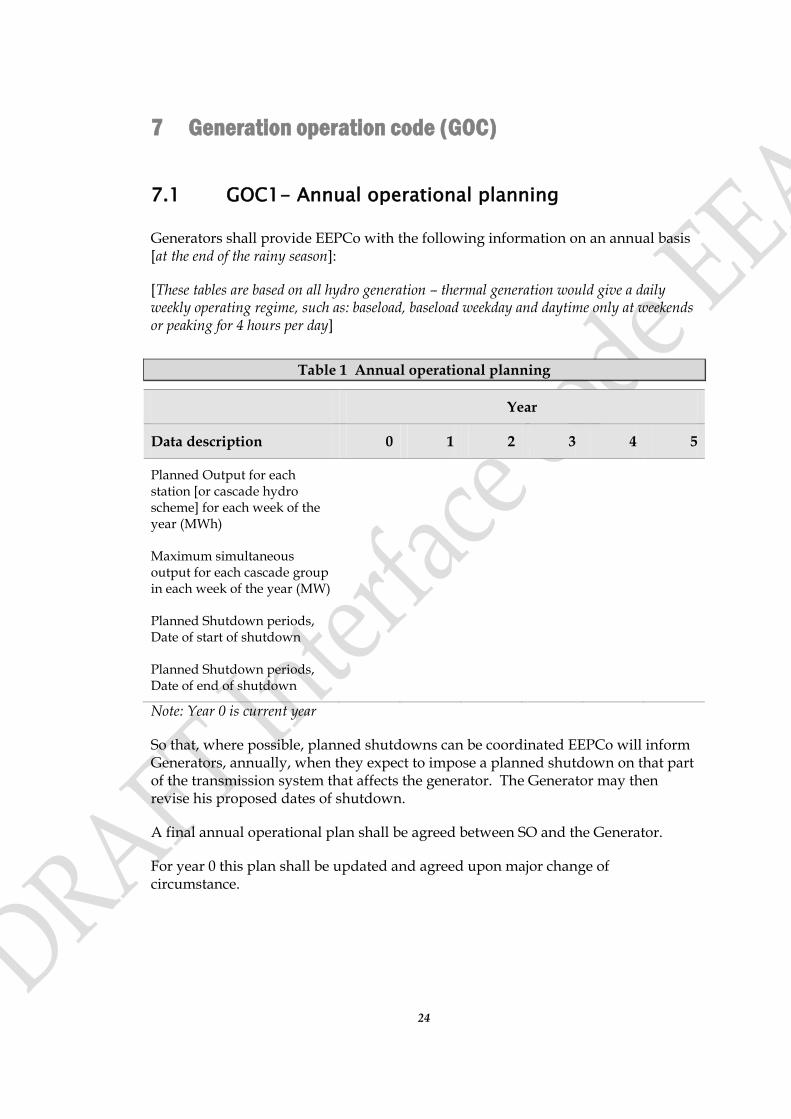
Generators shall provide EEPCo with the following information on an annual basis [at the end of the rainy season]:
[These tables are based on all hydro generation – thermal generation would give a daily weekly operating regime, such as: baseload, baseload weekday and daytime only at weekends or peaking for 4 hours per day]
Table 1 Annual operational planning
Year
Data description 0 1 2 3 4 5
Planned Output for each station [or cascade hydro scheme] for each week of the year (MWh)
Maximum simultaneous output for each cascade group in each week of the year (MW)
Planned Shutdown periods, Date of start of shutdown
Planned Shutdown periods, Date of end of shutdown
Note: Year 0 is current year
So that, where possible, planned shutdowns can be coordinated EEPCo will inform Generators, annually, when they expect to impose a planned shutdown on that part of the transmission system that affects the generator. The Generator may then revise his proposed dates of shutdown.
A final annual operational plan shall be agreed between SO and the Generator.
For year 0 this plan shall be updated and agreed upon major change of circumstance.
25
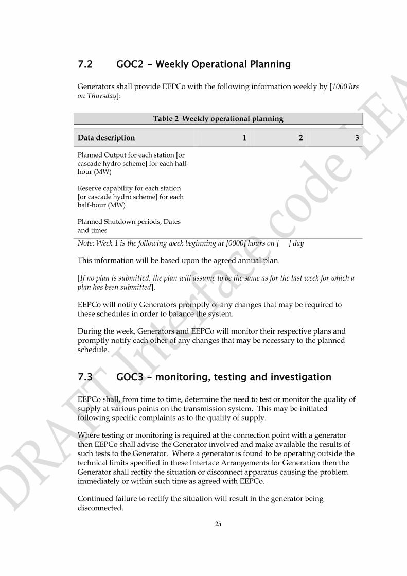
7.2 GOC2 - Weekly Operational Planning
Generators shall provide EEPCo with the following information weekly by [1000 hrs on Thursday]:
Table 2 Weekly operational planning
Data description 1 2 3
Planned Output for each station [or cascade hydro scheme] for each half-hour (MW)
Reserve capability for each station [or cascade hydro scheme] for each half-hour (MW)
Planned Shutdown periods, Dates and times
Note: Week 1 is the following week beginning at [0000] hours on [ ] day
This information will be based upon the agreed annual plan.
[If no plan is submitted, the plan will assume to be the same as for the last week for which a plan has been submitted].
EEPCo will notify Generators promptly of any changes that may be required to these schedules in order to balance the system.
During the week, Generators and EEPCo will monitor their respective plans and promptly notify each other of any changes that may be necessary to the planned schedule.
7.3 GOC3 – monitoring, testing and investigation
EEPCo shall, from time to time, determine the need to test or monitor the quality of supply at various points on the transmission system. This may be initiated following specific complaints as to the quality of supply.
Where testing or monitoring is required at the connection point with a generator then EEPCo shall advise the Generator involved and make available the results of such tests to the Generator. Where a generator is found to be operating outside the technical limits specified in these Interface Arrangements for Generation then the Generator shall rectify the situation or disconnect apparatus causing the problem immediately or within such time as agreed with EEPCo.
Continued failure to rectify the situation will result in the generator being disconnected.
26
EEPCo may check from time to time that the generators are in compliance with agreed protection requirements and settings.
7.4 GOC4 – safety coordination
a) There shall be joint agreement between EEPCo and Generators on the Safety Management System to be used for sites where an operational boundary exists and proper documentation of the safety precautions to be taken shall be maintained. There shall be written authorisation of personnel who do the work of control, operation, work or testing of equipment forming part of or connected to the transmission system.
b) There shall be joint agreement between EEPCo and Generators, which specifies responsibility for system, or control equipment, which shall ensure that only one party is responsible for any item of equipment at any one time.
c) EEPCo and each Generator shall at all times have nominated a person or persons responsible for coordination of safety on the respective systems.
d) EEPCo and each Generator shall maintain a suitable system of documentation which records all relevant operational events that have taken place on the transmission system or the Generator’s power station connected to it and the coordination of relevant safety precautions for work.
e) System diagrams, which show sufficient information for control personnel to carry out their duties, shall be exchanged between EEPCo and the Generator as required. Adequate means of isolation shall be provided at the point of connection to allow work to be carried out safely at either side of the connection.
f) Where necessary, to prevent danger, adequate facilities for earthing shall be provided at either side of the connection to allow work to be carried out safely at the interface or at either side of the interface.
g) All electrical equipment shall be suitably identified where necessary to prevent danger.
h) Instructions for operating and/or earthing generator’s electrical equipment shall be clearly displayed in the Generator’s power station switchroom.
27
8 System operating code (SOC)
8.1 SOC1 - generation scheduling
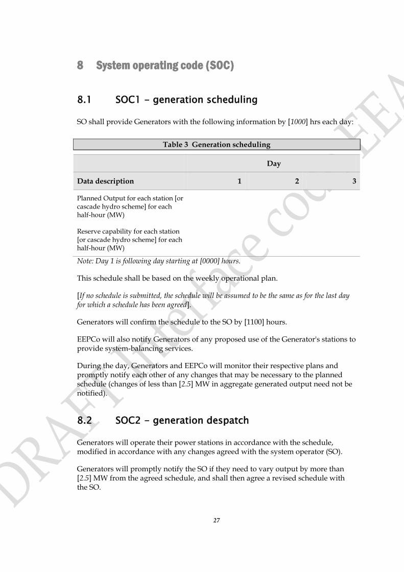
SO shall provide Generators with the following information by [1000] hrs each day:
Table 3 Generation scheduling
Day
Data description 1 2 3
Planned Output for each station [or cascade hydro scheme] for each half-hour (MW)
Reserve capability for each station [or cascade hydro scheme] for each half-hour (MW)
Note: Day 1 is following day starting at [0000] hours.
This schedule shall be based on the weekly operational plan.
[If no schedule is submitted, the schedule will be assumed to be the same as for the last day for which a schedule has been agreed].
Generators will confirm the schedule to the SO by [1100] hours.
EEPCo will also notify Generators of any proposed use of the Generator's stations to provide system-balancing services.
During the day, Generators and EEPCo will monitor their respective plans and promptly notify each other of any changes that may be necessary to the planned schedule (changes of less than [2.5] MW in aggregate generated output need not be notified).
8.2 SOC2 - generation despatch
Generators will operate their power stations in accordance with the schedule, modified in accordance with any changes agreed with the system operator (SO).
Generators will promptly notify the SO if they need to vary output by more than [2.5] MW from the agreed schedule, and shall then agree a revised schedule with the SO.
28
When necessary to balance the system, SO may issue instructions to a Generator to vary from their agreed schedule. The Generator shall comply with such an instruction unless to do so would be unsafe, and shall as soon as practicable notify the SO of any consequential changes that will be required to his agreed schedule.
8.3 SOC3 – frequency and time control
SO is responsible for maintaining system frequency and electric time within the operating limits which are:
Frequency +/- [0.5] Hz Time +/- [10] seconds
Unless agreed otherwise with SO, all generating units that are capable of performing regulating functions such as frequency control are required to contribute towards the maintenance of system frequency.
[The SO will from time to time issue instructions to relevant Generators on the responses required under various levels of frequency deviation].
8.4 SOC4 – voltage and reactive control
SO is responsible for maintaining system voltage and reactive levels within acceptable limits.
Each generator must provide for its own reactive load requirements, as well as its share of reactive requirements associated with interconnecting transmission lines.
Unless agreed otherwise with SO, all automatic voltage regulators and power system stabilizers should be kept in service on generating units to the maximum extent possible.
The SO will from time to time issue instructions to relevant Generators to change the power factor at which they are operating. [This will normally be within the declared parameters, however:
1. The if the generator is asked to operate outside its normal operating parameters in order to assist the system, this may cause:
a. increased maintenance costs; or
b. the generator to deload hence loss of revenue
c. this will be a MCI in the PPA/MTC.]