EtherCAT Tutorial An Introduction for Real-Time Hardware ...
68
Vrije Universiteit Brussel EtherCAT Tutorial An Introduction for Real-Time Hardware Communication on Windows Langlois, Kevin; van der Hoeven, Tom; Rodriguez Cianca, David; Verstraten, Tom; Bacek, Tomislav; Convens, Bryan; Rodriguez Guerrero, Carlos David; Grosu, Victor; Lefeber, Dirk; Vanderborght, Bram Published in: IEEE Robotics and Automation Magazine DOI: 10.1109/MRA.2017.2787224 Publication date: 2018 License: Unspecified Document Version: Submitted manuscript Link to publication Citation for published version (APA): Langlois, K., van der Hoeven, T., Rodriguez Cianca, D., Verstraten, T., Bacek, T., Convens, B., ... Vanderborght, B. (2018). EtherCAT Tutorial An Introduction for Real-Time Hardware Communication on Windows. IEEE Robotics and Automation Magazine, 25(1), 22-25. https://doi.org/10.1109/MRA.2017.2787224 Copyright No part of this publication may be reproduced or transmitted in any form, without the prior written permission of the author(s) or other rights holders to whom publication rights have been transferred, unless permitted by a license attached to the publication (a Creative Commons license or other), or unless exceptions to copyright law apply. Take down policy If you believe that this document infringes your copyright or other rights, please contact [email protected], with details of the nature of the infringement. We will investigate the claim and if justified, we will take the appropriate steps. Download date: 12. Jul. 2022
-
Upload
khangminh22 -
Category
Documents
-
view
3 -
download
0
Transcript of EtherCAT Tutorial An Introduction for Real-Time Hardware ...
Vrije Universiteit Brussel
EtherCAT Tutorial An Introduction for Real-Time Hardware Communication on WindowsLanglois, Kevin; van der Hoeven, Tom; Rodriguez Cianca, David; Verstraten, Tom; Bacek,Tomislav; Convens, Bryan; Rodriguez Guerrero, Carlos David; Grosu, Victor; Lefeber, Dirk;Vanderborght, BramPublished in:IEEE Robotics and Automation Magazine
DOI:10.1109/MRA.2017.2787224
Publication date:2018
License:Unspecified
Document Version:Submitted manuscript
Link to publication
Citation for published version (APA):Langlois, K., van der Hoeven, T., Rodriguez Cianca, D., Verstraten, T., Bacek, T., Convens, B., ... Vanderborght,B. (2018). EtherCAT Tutorial An Introduction for Real-Time Hardware Communication on Windows. IEEERobotics and Automation Magazine, 25(1), 22-25. https://doi.org/10.1109/MRA.2017.2787224
CopyrightNo part of this publication may be reproduced or transmitted in any form, without the prior written permission of the author(s) or other rightsholders to whom publication rights have been transferred, unless permitted by a license attached to the publication (a Creative Commonslicense or other), or unless exceptions to copyright law apply.
Take down policyIf you believe that this document infringes your copyright or other rights, please contact [email protected], with details of the nature of theinfringement. We will investigate the claim and if justified, we will take the appropriate steps.
Download date: 12. Jul. 2022

1
EtherCAT Tutorial, an introduction for real-timehardware communication on Windows
Kevin Langloisa, Tom van der Hoevena, David Rodriguez Ciancaa, Tom Verstratena, Tomislav Baceka, BryanConvensa, Carlos Rodriguez−Guerreroa, Victor Grosua, Dirk Lefebera and Bram Vanderborghta
aRobotics and Multibody Mechanics Research Group (R&MM), Vrije Universiteit Brussel,Pleinlaan 2, 1050 Elsene.
The R&MM Research Group is a partner of Flanders Make.
Abstract—Setting up a real-time hardware communicationfor applications such as precise motion control can be time-consuming and confusing. Therefore, a tutorial on the deploymentof an EtherCAT protocol is introduced. In this article, the authorssituate EtherCAT, briefly discuss the origins and working prin-ciples, and mention advantages over other widely used protocols.Additionally, the main objectives of the tutorial and the requiredsoftware to complete it are presented. Online supplements areincluded with this article, explaining all steps to run a Simulinkmodel in real-time on a Windows machine within a few hours.
Index Terms—EtherCAT, TwinCAT, Robotics, Realtime, Hard-ware communication.
I. INTRODUCTION
Particular application domains in the field of robotics andindustrial automation, require precise motion control capabil-ities. To achieve this, real-time control systems are key todevelop highly dynamic and intelligent robotic systems suchas prosthetic devices [1], [2], exoskeletons [3], legged robots[4], humanoids [5], etc.In these high-end motion control applications, there is a needfor very fast low-level control loops with data rates in theregion of 250 microseconds to 1 millisecond [6].Furthermore, these systems require accurate time synchroniza-tion and high data throughput to which Real-Time Ethernet(RTE) protocols have recently emerged as the leading solutionin industry.EtherCAT (Ethernet for Control Automation Technology) is awidely used RTE protocol, which has shown excellent perfor-mances at a relatively low cost [7], [8], [9]. To conclude, thesimplicity with which it can be deployed and run a Simulinkmodel in real-time, makes EtherCAT a practical solution forrobotic prototyping.This article serves as an introduction to a detailed tutorial onhow to deploy an EtherCAT master running a Simulink modelin real-time on a Windows machine. In the following section,the general working principles and the origins of EtherCATare summarized. This is in order to situate EtherCAT in thevast family of RTE protocols. Following, the advantages of theprotocol relative to other RTE systems and CAN are presented.And to conclude, a summary of the objectives covered in thetutorial are explained, and the required software is listed. In the
Kevin Langlois is corresponding author. E-mail: [email protected]
ideal case, the reader should be able to have a simple test-setuprunning in a matter of hours and with limited hardware costs.The fully detailed step-by-step tutorial can be obtained fromthe online appendix of this paper. Additionally, the tutorialcontains successful implementations on several systems, suchas the Cyberlegs Beta-prosthesis (figure 1).
II. ETHERCAT IN LAYMAN’S TERMS
In this section the functionality of the EtherCAT protocol ispresented. To begin with, the general concepts and origins ofindustrial communication are briefly recalled, after which, thegeneral working principles that apply specifically to EtherCATwill be mentioned. All of this will be discussed with a certainlevel of abstraction, as the goal of this tutorial is only togive the reader a basic understanding of the system in orderto successfully deploy the protocol. Specific resources areconveyed to the reader interested to delve deeper into the field.
A. EtherCAT origins
Technologies such as programmable microcontrollers anddigital signal processors allowed for the replacement of purelyanalog control loops with digital controllers such as PLCs.This led to the core of industrial networking, termed fieldbusprotocols.Many fieldbusses were developed in parallel, and essentially,every company designed their own protocols, which naturallyled to confusion for consumers and developers [11].As a reaction to this, the Fieldbus War; a web of companypolitics and marketing interests which in 2000, led to theestablishment of an international fieldbus standardization, theIEC 61158 [12], [13], [14], [15].In the mean time, Ethernet protocols were already well es-tablished in the office world. The increased data rates ofnewer Ethernet standards (for example 802.3u Fast Ethernet)made it easier to create real-time Ethernet protocols, as thetransmission and retransmission times are significantly shorter.While primarly Fieldbus systems such as Profibus, SERCOS,CAN and many others have allowed for distributed industrialautomation systems, performances of these protocols wereconsidered as too limited when compared to the availableperformances (mainly in terms of data throughput) of non real-time networks such as Ethernet [16].

2
Figure 1. The CYBERLEGs (CYBERnetic LowEr-Limb CoGnitive Ortho-prosthesiS) Beta-prosthesis, which actuates two degrees of freedom (knee andankle) is controlled via an EtherCAT protocol. The prosthesis integrates serieselastic actuators, controlled by custom made electronics boards. [10]
In addition, Ethernet bandwidth enables bus cycle times in themicroseconds range instead of the ms range which, togetherwith the superior performance of modern PC-based controlsystems, allows one to close the control loops over the fieldbusthat previously had to be closed locally in the peripheralsystems [17]. And finally, the large amount of research thathas gone into developing Ethernet as a standard, as well asthe cheap and readily available hardware, and the Internet ofThings (IoT) [18] with which it becomes possible to connectalmost anything with everything, anywhere, illustrates the wishto develop RTE communication protocols.Nonetheless, many challenges presented themselves as therequirements between those two domains - office world andindustry - are very different, as discussed in [11], [19]. The twomain differences in requirements are related to communicationtime determinism and precise clock synchronization.Firstly, time determinism, is the requirement for the transmis-sion times of data packets to be known. This means that thelatency of a signal must be bounded and have a low variance.
The variance of the response time of a signal is often referredto as jitter. And low jitter is required due to the fact thatvariance in time has a negative effect on control loops (thederivative and integral portions of a control loop are affectedby time variation).Secondly, the precise clock synchronization of the network.Real clocks drift and will differ in time over long periods. Aspointed out in [20], unsynchronized networks usually sufferfrom non-negligible jitters.In conclusion, a family of RTE protocols has in recent yearsevolved into a large number of solutions and standards. Two ofthe most prominent representatives of this group are EtherCATand Profinet where the former is believed to offer the bestperformance in terms of communication efficiency and shortcycle times [8].
B. Working principle
Today, there are over 25 different RTE solutions on the mar-ket. They are offered by diverse manufacturers and academiccommunity [19], [9], [16].These solutions integrate different working principles, such asthe method for encapsulation of process data into Ethernetframes, the limitations on network topology, synchronizationof the network, implementation costs, etc.First of all, EtherCAT is Industrial Ethernet and utilizesstandard frames and the physical layer as defined in theEthernet standard IEEE 802.3 [21]. Of the fast Ethernetstandards, 100BASE-TX is the most common and the oneused in EtherCAT networks. By utilizing the full duplex(data transmission in two directions) features of fast Ethernetallows effective data rates of 100 Mbit/s [17]. Furthermore,the EtherCAT protocol employs the master/slave principle tocontrol access to the medium. The master node (typically thecontrol system) sends the Ethernet frames to the slave nodes(such as sensors and actuators), which can extract data fromand insert data into these frames.These process data (of all network devices) are carried to-gether in one or more Ethernet frames. This is the so-calledsummation frame principle as opposed to the individual frameapproach in which every frame carries process data for onlyone device [8].With EtherCAT the standard Ethernet packet is no longerreceived, interpreted and copied at every node, instead, slavedevices process frames on the fly, reading and inserting datawhile the frame is passing through the device. This is handledby hardware-integrated EtherCAT Slave Controllers (ESC) inthe slaves.The process data in industrial networks are relatively smallin quantity (only a few bytes), so that the summation framemethod, combined with the “processing-on-the-fly” feature ofthe EtherCAT slaves, offers good system performance [8],[22]. Moreover, network topology plays an important rolewhen performance of the system is evaluated [22]. Importantaspects are not only cycle time or efficiency, but also cablingeffort, diagnostic features, redundancy options and plug andplay features. EtherCAT networks have no practical limitationsregarding the topology, line, star, tree, ring and all those

3
combined with up to 65535 nodes per segment.Then, for synchronization, EtherCAT relies on a clock syn-chronization mechanism which is known as distributed clock(DC).Basically, clocks of all the DC-enabled slaves in the networkare synchronized with a common timing reference under directcontrol of the master. [7]. Despite being rather simple andstraightforward, the DC mechanism enables accurate synchro-nization (in small-to-medium systems, clock deviations arewell below 1 microsecond).
III. ETHERCAT: ADVANTAGES AND DISADVANTAGES
In this section the advantages of setting up an EtherCATnetwork over other popular industrial communication proto-cols are discussed.
A. Ethernet based solutions
There are more than 25 Ethernet based industrial protocolson the market, but the list of protocols that have a considerableimpact on industry is much shorter [23]. They are:
- EtherCAT- Powerlink- Ethernet/IP- Modbus/TCP- ProfiNet
A multitude of performance evaluations of the remainingsystems are reported in literature. The conclusions of thesestudies are that EtherCAT is an overall highly performing real-time protocol, when compared to the aforementioned protocols[24] [25] [8]. ProfiNet has advantages over EtherCAT inspecific conditions, such as efficiency in asynchronouscommunication [26]. Ethernet/IP neither Modbus/TCP aredeterministic and by consequence, are not suited for hard-real-time control. Major advantages of EtherCAT over theProfiNet and Powerlink are the costs of implementation andthe commercial diffusion of the technology [27]. Studiesalso predict the future pervasiveness of EtherCAT in theindustrial automation and robotics fields [23]. This suggestsEtherCAT to be the leading communication protocol for theseapplications.
A major other communication protocol which is not part ofEthernet based systems are Serial protocols, of which CAN iswidely used in the robotics field.
B. Controller Area Network (CAN)
Controller Area Network (CAN) still is an adequatechoice for low-cost industrial embedded networking. How-ever, Ethernet-based protocols are now able to overcome theshortcomings of CAN, such as limited baud rate and limitednetwork length (1Mb/s at 120 feet). Although the very low-cost implementation as well as the low resource requirementsof CAN protocols still make it an adequate choice in certainapplications (such as automotive industry, small embeddedsolutions, aerospace), the overall advantages of EtherCAT overCAN are:
- Data throughput (currently 100 times higher)- Unlimited network length- Increased system performances- Use of established hardware components
IV. ETHERCAT DEPLOYMENT
An EtherCAT master runs the EtherCAT network andcommunicates with all slaves. This master needs to beimplemented on a real time operating system. Severalsolutions have been developed, the one demonstrated in thistutorial is TwinCAT (The Windows Control and AutomationTechnology).Beckhoff provides the TwinCAT program, whose essentialfunctionality is to reserve a number of physical cores on yourpersonal Windows computer, and run the EtherCAT networkfrom these cores. Windows OS does not run on these coresanymore and only operates on the cores specified by the user.As an example, in this tutorial a quad-core laptop was usedwhere two cores are reserved for the EtherCAT protocol andtwo cores are used for running Windows.The driver running on the EtherCAT reserved cores is acompiled version of a program that can either be written inPLC language or C/C++ code. Beckhoff provides functionalityto run compiled Simulink models (in C++) as drivers in thekernel space.
Below, a list is presented with the required software tosuccessfully turn a windows computer into a real-time targetrunning an EtherCAT network.
- Microsoft Visual Studio 2010 or higher. Required ifprogramming is directly done in C++, otherwise the shellprovided with TwinCAT can be used.
- Matlab 2011 (or newer) including Matlab Coder.- TwinCAT 3.1 (Free for non-commercial use).- Beckhoff TE1400 module (Free for simulink models with
5 inputs, 5 outputs and 100 blocks. Larger models requirea license).
- Microsoft Windows Driver Kit 7 (Free) or higher.The tutorial guides the reader through the implementation of
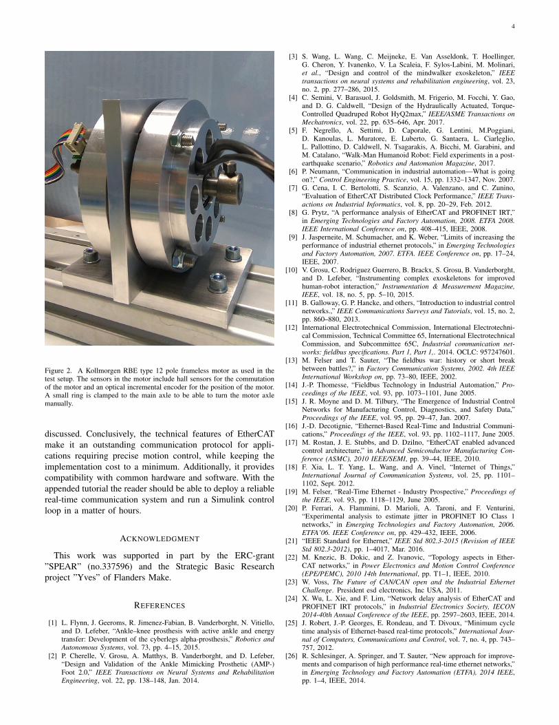
a real-time control loop developed in Simulink and compatiblewith widely used hardware components (Maxon drivers andmotors). The reader is directed through the installation andconfiguration of all the necessary software on a Windowsmachine. Debugging tools for TwinCAT and Simulink, aswell as instructions on the activation of Beckhoff licensesare included. Additionally, experimental implementations areshown, such as the active prosthesis depicted in figure 1, aframeless brushless motor, depicted in figure 2, and more.
V. CONCLUSION
In this article the main outline of a broader hands-on tutorialon the EtherCAT communication protocol for real-time hard-ware communication in robotics and automation applicationsis presented. This includes an introduction to fieldbus systems,and a general description of the EtherCAT features. Literatureconcerning the assessment of the protocol’s performances wereconveyed to the reader and the advantages of the protocol were
4
Figure 2. A Kollmorgen RBE type 12 pole frameless motor as used in thetest setup. The sensors in the motor include hall sensors for the commutationof the motor and an optical incremental encoder for the position of the motor.A small ring is clamped to the main axle to be able to turn the motor axlemanually.
discussed. Conclusively, the technical features of EtherCATmake it an outstanding communication protocol for appli-cations requiring precise motion control, while keeping theimplementation cost to a minimum. Additionally, it providescompatibility with common hardware and software. With theappended tutorial the reader should be able to deploy a reliablereal-time communication system and run a Simulink controlloop in a matter of hours.
ACKNOWLEDGMENT
This work was supported in part by the ERC-grant”SPEAR” (no.337596) and the Strategic Basic Researchproject ”Yves” of Flanders Make.
REFERENCES
[1] L. Flynn, J. Geeroms, R. Jimenez-Fabian, B. Vanderborght, N. Vitiello,and D. Lefeber, “Ankle–knee prosthesis with active ankle and energytransfer: Development of the cyberlegs alpha-prosthesis,” Robotics andAutonomous Systems, vol. 73, pp. 4–15, 2015.
[2] P. Cherelle, V. Grosu, A. Matthys, B. Vanderborght, and D. Lefeber,“Design and Validation of the Ankle Mimicking Prosthetic (AMP-)Foot 2.0,” IEEE Transactions on Neural Systems and RehabilitationEngineering, vol. 22, pp. 138–148, Jan. 2014.
[3] S. Wang, L. Wang, C. Meijneke, E. Van Asseldonk, T. Hoellinger,G. Cheron, Y. Ivanenko, V. La Scaleia, F. Sylos-Labini, M. Molinari,et al., “Design and control of the mindwalker exoskeleton,” IEEEtransactions on neural systems and rehabilitation engineering, vol. 23,no. 2, pp. 277–286, 2015.
[4] C. Semini, V. Barasuol, J. Goldsmith, M. Frigerio, M. Focchi, Y. Gao,and D. G. Caldwell, “Design of the Hydraulically Actuated, Torque-Controlled Quadruped Robot HyQ2max,” IEEE/ASME Transactions onMechatronics, vol. 22, pp. 635–646, Apr. 2017.
[5] F. Negrello, A. Settimi, D. Caporale, G. Lentini, M.Poggiani,D. Kanoulas, L. Muratore, E. Luberto, G. Santaera, L. Ciarleglio,L. Pallottino, D. Caldwell, N. Tsagarakis, A. Bicchi, M. Garabini, andM. Catalano, “Walk-Man Humanoid Robot: Field experiments in a post-earthquake scenario,” Robotics and Automation Magazine, 2017.
[6] P. Neumann, “Communication in industrial automation—What is goingon?,” Control Engineering Practice, vol. 15, pp. 1332–1347, Nov. 2007.
[7] G. Cena, I. C. Bertolotti, S. Scanzio, A. Valenzano, and C. Zunino,“Evaluation of EtherCAT Distributed Clock Performance,” IEEE Trans-actions on Industrial Informatics, vol. 8, pp. 20–29, Feb. 2012.
[8] G. Prytz, “A performance analysis of EtherCAT and PROFINET IRT,”in Emerging Technologies and Factory Automation, 2008. ETFA 2008.IEEE International Conference on, pp. 408–415, IEEE, 2008.
[9] J. Jasperneite, M. Schumacher, and K. Weber, “Limits of increasing theperformance of industrial ethernet protocols,” in Emerging Technologiesand Factory Automation, 2007. ETFA. IEEE Conference on, pp. 17–24,IEEE, 2007.
[10] V. Grosu, C. Rodriguez Guerrero, B. Brackx, S. Grosu, B. Vanderborght,and D. Lefeber, “Instrumenting complex exoskeletons for improvedhuman-robot interaction,” Instrumentation & Measurement Magazine,IEEE, vol. 18, no. 5, pp. 5–10, 2015.
[11] B. Galloway, G. P. Hancke, and others, “Introduction to industrial controlnetworks.,” IEEE Communications Surveys and Tutorials, vol. 15, no. 2,pp. 860–880, 2013.
[12] International Electrotechnical Commission, International Electrotechni-cal Commission, Technical Committee 65, International ElectrotechnicalCommission, and Subcommittee 65C, Industrial communication net-works: fieldbus specifications. Part 1, Part 1,. 2014. OCLC: 957247601.
[13] M. Felser and T. Sauter, “The fieldbus war: history or short breakbetween battles?,” in Factory Communication Systems, 2002. 4th IEEEInternational Workshop on, pp. 73–80, IEEE, 2002.
[14] J.-P. Thomesse, “Fieldbus Technology in Industrial Automation,” Pro-ceedings of the IEEE, vol. 93, pp. 1073–1101, June 2005.
[15] J. R. Moyne and D. M. Tilbury, “The Emergence of Industrial ControlNetworks for Manufacturing Control, Diagnostics, and Safety Data,”Proceedings of the IEEE, vol. 95, pp. 29–47, Jan. 2007.
[16] J.-D. Decotignie, “Ethernet-Based Real-Time and Industrial Communi-cations,” Proceedings of the IEEE, vol. 93, pp. 1102–1117, June 2005.
[17] M. Rostan, J. E. Stubbs, and D. Dzilno, “EtherCAT enabled advancedcontrol architecture,” in Advanced Semiconductor Manufacturing Con-ference (ASMC), 2010 IEEE/SEMI, pp. 39–44, IEEE, 2010.
[18] F. Xia, L. T. Yang, L. Wang, and A. Vinel, “Internet of Things,”International Journal of Communication Systems, vol. 25, pp. 1101–1102, Sept. 2012.
[19] M. Felser, “Real-Time Ethernet - Industry Prospective,” Proceedings ofthe IEEE, vol. 93, pp. 1118–1129, June 2005.
[20] P. Ferrari, A. Flammini, D. Marioli, A. Taroni, and F. Venturini,“Experimental analysis to estimate jitter in PROFINET IO Class 1networks,” in Emerging Technologies and Factory Automation, 2006.ETFA’06. IEEE Conference on, pp. 429–432, IEEE, 2006.
[21] “IEEE Standard for Ethernet,” IEEE Std 802.3-2015 (Revision of IEEEStd 802.3-2012), pp. 1–4017, Mar. 2016.
[22] M. Knezic, B. Dokic, and Z. Ivanovic, “Topology aspects in Ether-CAT networks,” in Power Electronics and Motion Control Conference(EPE/PEMC), 2010 14th International, pp. T1–1, IEEE, 2010.
[23] W. Voss, The Future of CAN/CAN open and the Industrial EthernetChallenge. President esd electronics, Inc USA, 2011.
[24] X. Wu, L. Xie, and F. Lim, “Network delay analysis of EtherCAT andPROFINET IRT protocols,” in Industrial Electronics Society, IECON2014-40th Annual Conference of the IEEE, pp. 2597–2603, IEEE, 2014.
[25] J. Robert, J.-P. Georges, E. Rondeau, and T. Divoux, “Minimum cycletime analysis of Ethernet-based real-time protocols,” International Jour-nal of Computers, Communications and Control, vol. 7, no. 4, pp. 743–757, 2012.
[26] R. Schlesinger, A. Springer, and T. Sauter, “New approach for improve-ments and comparison of high performance real-time ethernet networks,”in Emerging Technology and Factory Automation (ETFA), 2014 IEEE,pp. 1–4, IEEE, 2014.
5
[27] D. Orfanus, R. Indergaard, G. Prytz, and T. Wien, “EtherCAT-basedplatform for distributed control in high-performance industrial applica-tions,” in Emerging Technologies & Factory Automation (ETFA), 2013IEEE 18th Conference on, pp. 1–8, IEEE, 2013.

EtherCAT Tutorial, an introduction for real-time
hardware communication on Windows
Kevin Langlois*a, Tom van der Hoevena, David Rodriguez Ciancaa, TomVerstratena, Tomislav Baceka, Bryan Convensa, Carlos
Rodriguez−Guerreroa, Victor Grosua, Dirk Lefebera and BramVanderborghta
aRobotics and Multibody Mechanics Research Group (R&MM),Vrije Universiteit Brussel,Pleinlaan 2, 1050 Elsene.
The R&MM Research Group is a partner of Flanders Make.
*Kevin Langlois is corresponding author. E-mail: [email protected]
1

1 Introduction
Robots are a growing group of devices that can be used for an ever increasingvariety of tasks. Typically robotics is a profession where many different areasof expertise are to be combined into a device that for example interacts witha human or works in a factory. Unfortunately, for the majority of robotics re-searchers excellence in all areas simultaneously is not easy. Often, excellence inmechanical engineering appears to go hand in hand with the slight neglect ofpractical programming of control architectures.It is typically in a prototype lab, as the example above illustrated, that manymechanically oriented engineers need ’that one control guy in the lab’ to get theirmechanical structures to move, let alone be controlled properly. Figuring outthe best hardware control strategy, learning to code in a new language and manyother practical problems often discourage the mechanically oriented engineer toproperly control their own test-setups. Naturally you will have to annoy yourfellow researchers with questions on ‘how to move your setup or robot’.If we break the problem of ’moving your setup or robot’ down a little there arethree different building blocks that need to be considered.Firstly, on the most mechanical level there are motors that actuate your setupand sensors that measure the state of the motor. These motors naturally needto be regulated with a voltage, and this task is performed by a low-level mo-tor controller. The low-level motor controller generally reads the sensors on themotor axis to determine the current motor state and accepts a position/veloci-ty/torque setpoint from a high level control program to set a desired motor state.The low-level motor controller then moves from the current state to the desiredstate by applying the required voltage to the motor.Secondly, on the most control oriented level there is the high-level control pro-gram. This control strategy could for example be that your motor has to tracka certain reference trajectory with the use of a PID controller.Thirdly, there is the communication between the high level control program andthe motor controller. This ’hardware communication layer’ can be done in manyways. A widely used high performance solution is to use an EtherCAT network.Such a network can easily run at 1kHz on your own computer to ensure real-timecommunication between your measurement/actuation setup and your personalcomputer. Therefore this tutorial will focus on exactly what EtherCAT is, whatmake up the key components of an EtherCAT network and most importantly:how you can setup your very own network for your measurement setup or yourrobot.A tutorial is presented on how to get a Simulink measurement model running ona Windows machine with a real-time EtherCAT network. This tutorial includesreal-time tracking of a reference trajectory with a motor and reading values real-time from sensors.Throughout the tutorial additional information is presented on the componentsthat make up the EtherCAT network. As you will read in this instructive docu-ment, an EtherCAT network consists of a master and several slaves. The tutorialpart focuses on the master side of the EtherCAT network, or in other words the
2

software that runs and maintains the communication in the network.The remainder of this document is structured as follows. Section 2 containsan instructive and comprehensive overview of what an EtherCAT network isand what the key components are in such a network. In section 3 the tutorialfor a prototyping test setup is presented. All required (mostly free) softwareis clearly listed and the main installation sequences are illustrated with the es-sential ’print-screens’. The basic control systems developed in this tutorial arebased on Maxon driver boards and controllers, however any EtherCAT slavemodule or device can also be used to achieve a running setup. Debugging toolsin Simulink and TwinCAT are introduced in section 4. Section 5 is dedicatedto the licensing of TwinCAT products, allowing the user to integrate more com-plex models. Additionally, we added some experimental implementations of theEtherCAT protocol in section 6, illustrating possible application domains. Lastlyin Appendix A an informative section is presented on the different EtherCATslaves. Throughout the tutorial, references are made to any available additionalonline material and examples.
As a final note, it should be stated that there is no part in this work whichcan be considered really ‘novel’. The majority of the work can be constructedby combining various documents and films on the web and the EtherCAT tech-nology exists already for quite some years. The tutorial is merely intended as anintroduction to a high performance hardware communication protocol for hardreal-time applications and which is compatible with Simulink. In this way wehope to give the reader a shortcut to a functional system with low hardwarecosts.
3

2 EtherCAT, TwinCAT, master and slaves
This section contains a start to the background information on EtherCAT net-works. It is not the intention of this tutorial to explain the detailed workingprinciples of the protocol, but merely give the reader a general understandingof the technology in order to complete this tutorial. For a more detailed expla-nation, the reader is referred to the Beckhoff Information System website [1].First, a small section is devoted to what EtherCAT is and what makes up anEtherCAT network. Secondly, a section is devoted to TwinCAT as a masterenvironment to an EtherCAT network.
2.1 What is EtherCAT?
EtherCAT is a way to communicate between a computer and motor drives andall sorts of analog and digital inputs and outputs (IO). The main advantagecompared to any other ways to do the same communication like USB, RS232,CAN, etc. is that this type of communication is Industrial Ethernet (and utilizesstandard frames and the physical layer as defined in the Ethernet Standard IEEE802.3 [2]) and can achieve real-time communication. Realtime communicationgenerally means that information (like setpoints for the motor or readings of thesensors) can be sent over the network at a high frequency (1kHz or higher).Today, there are over 25 different Real Time Ethernet (RTE) solutions on themarket offered by diverse manufacturers and the academic community [3], [4], [5].These solutions use different approaches regarding the method for encapsulationof process data into Ethernet frames, which offer different advantages.EtherCAT protocol is based on so-called summation frame principle in whichthe process data of all network devices are carried together in one or more Eth-ernet frames, as opposed to the individual frame approach in which every framecarries process data for only one device [6]. Also, with EtherCAT the standardEthernet packet (containing data) is no longer received, interpreted and copiedat every slave, instead, slave devices process frames on the fly, reading and in-serting data while the frame is passing through the device. This is handled byhardware-integrated EtherCAT Slave Controllers (ESC) in the slaves.Process data in industrial networks are relatively small in quantity (only a fewbytes), so that the summation frame method, combined with the “processing-on-the-fly” feature of the EtherCAT slaves, allows to achieve good system per-formance when compared to other protocols [6], [7].
2.2 Master/Slave Architecture
EtherCAT employs the master/slave principle to control access to the medium,see figure 1. The EtherCAT master (typically the control system) uses a standardEthernet port and network configuration information stored in the EtherCATNetwork Information file (ENI). The ENI is created based on EtherCAT SlaveInformation files (ESI) which are provided by the vendors for every device. Themaster node sends the EtherCAT frames to the slave nodes, which can extract
4

data from and insert data into these frames, schematically represented in figure2. Slave nodes are devices such as EPOS3 motor drives which have the Ethernetports on it to communicate with an EtherCAT master. An EtherCAT master isa computer device which maintains the data communication between the masterand the different slaves.
Figure 1: The EtherCAT network architecture, consisting of a master/slave pro-tocol.
Figure 2: The EtherCAT frame simply replaces the IP frame of a standard Ether-net message. Thus, the Ethernet frame does not need modification, contributingto flexibility for EtherCAT.
5

The EtherCAT frame starts with a standard header which tells the nodeshow long the EtherCAT portion of the frame will be. After the header, theframe contains Process Data Objects (PDOs).The PDOs correspond to the number of nodes and contain data for a node. ThePDOs are individually addressed, telling the nodes which PDOs to take. Thisis an important term as we will later see, when our control model’s inputs arelinked to the hardware outputs. The final portion of the frame is the workingcounter which ensures the entirety of the frame was received by the node.Network topology plays an important role when performance of the system isevaluated [7]. Important aspects are not only cycle time or efficiency, but alsocabling effort, diagnostic features, redundancy options and plug and play fea-tures. EtherCAT networks have no practical limitations regarding the topology,line, star, tree, ring and all those combined with up to 65535 nodes per segment.For synchronization, EtherCAT relies on a clock synchronization mechanismwhich is known as distributed clock (DC). Basically, clocks of all the DC-enabledslaves in the network are synchronized with a common timing reference underdirect control of the master. [8]. Despite being rather simple and straightfor-ward, the DC mechanism enables accurate synchronization (in small-to-mediumsystems, clock deviations are well below 1 microseconds).
2.3 TwinCAT
On the software side, different master environments exist, such as Etherlab,Labview-realtime and SOEM/ebox, but in this tutorial we will use TwinCAT(The Windows Control and Automation Technology). The reason being that itdoes not require a Linux computer and is generally easy and user-friendly to op-erate. Basically, TwinCAT allows to to reserve some cores in a personal windowscomputer, make a link to the kernel space of the computer and turn it into arealtime target that can run and maintain an EtherCAT network. TwinCAT 3eXtended Automation Engineering Environment (XAE) allows the integration ofadditional programming languages or tools, such as MATLAB and Simulink, seefigure 3. Users can design their control algorithms in MATLAB and Simulink,and use Simulink Coder to generate TwinCAT modules. The integration ofMATLAB and Simulink into TwinCAT 3 facilitates a connection to the scien-tific field by integrating the TwinCAT real-time execution of tasks and modulesinto Microsoft Visual Studio. In conclusion, we know that TwinCAT is a pro-gram to implement a realtime target that runs an EtherCAT network betweena master, such as a Windows machine, and the slaves, such as motor drives andIO. In the next section, we present the implementation of a Simulink model onthis realtime target created in TwinCAT.
6

Figure 3: TwinCAT 3 eXtended Automation Engineering Environment (XAE)allows the integration of MATLAB and Simulink .
7

3 Tutorial
In this section the implementation of a Simulink model on the realtime targetcreated with TwinCAT is detailed.To start, in section 3.1, the required software to complete this tutorial is listed.This is assuming a computer with only blank Windows 7 or 10 running on it.Secondly, in section 3.2, the software installation sequence is explained.Thirdly, section 3.3 introduces a simple Simulink model along with the instruc-tions on how to compile the model into a module that can be run on the Twin-CAT target.Fourthly, in section 3.4, the realtime TwinCAT target is set up, the com-piled Simulink model is imported and the inputs and outputs of the (compiled)Simulink model are connected to the variables of the EtherCAT network slaves.Lastly, in section 3.5, an instruction is presented on how to run the compiledSimulink model on the TwinCAT target.
3.1 List of required and provided software
This is a list of the required software to complete the tutorial. The following pro-grams must already be preloaded on the computer or installed from the varioussoftware companies that provide them:
- Microsoft Visual Studio professional 2010 or newer.
- MATLAB 2015b (including MATLAB Coder, which in some cases is partof the academic license).
- The ’general target model’ as included with this tutorial. This can howevereasily be replaced by any other model.
- Microsoft Windows Driver Kit 7 or higher (Installation “Microsoft Win-dows Driver Kit (WDK)”).
Additionally the following software should be downloaded from the Beckhoff sitewhen specified in the tutorial, so not right now.
- TwinCAT 3.
- Beckhoff TE1400 module.
3.2 Installation and downloading of software
Please follow the instruction sequence for all programs presented in this sectioncarefully, it does matter in which order programs are installed.
8

1. Install Microsoft visual studio 2010 professional
- In order to build C++ programs with TwinCAT a version of Visual studioprofessional 2010 or newer is needed. If the (future) intention is to codedirectly in C/C++ in TwinCAT install the professional version of VisualStudio.
- If you will only use PLC programs or compiled Simulink models, you mayuse the Visual Studio shell that comes with TwinCAT.
2. Install TwinCAT 3 eXtended Automation Engineering
TwinCAT 3 eXtended Automation Engineering Environment (XAE) allows theintegration of additional programming languages or tools, such as MATLAB andSimulink. Users can design their control algorithms in MATLAB and Simulink,and use Simulink Coder to generate TwinCAT modules.
1. Navigate to the Beckhoff website to download the TwinCAT 3.1 - eXtendedAutomation Engineering (XAE) program:https://www.beckhoff.com/english.asp?download/tc3-downloads.htm
2. Select TE1xxxx Engineering.
3. Select TwinCAT 3.1 - eXtended Automation Engineering (XAE).
4. Start the download and follow the instructions. When asked whether youwant to integrate TwinCAT into Visual Studio 2010 professional, do it.Don’t use the Visual Studio 2010 shell.
5. TwinCAT 3.1 should now run inside Visual Studio 2010 professional.
3. Install Microsoft Windows Driver Kit 7 (WDK)
Implementing TwinCAT3 C++ modules requires parts of the Microsoft “Win-dows Driver Kit 7 (WDK)”. The steps to install the driver kit can be found onthe Beckhoff Information System website [1] and are represented here:
1. Download the “Windows Driver Kit 7.1” from the Microsoft DownloadCenter.http://www.microsoft.com/downloads/en/details.aspx?displaylang=
en&FamilyID=36a2630f-5d56-43b5-b996-7633f2ec14ff
2. After download burn a CD from the downloaded ISO image or make useof virtual CD software.
3. Start “KitSetup.exe” from the CD / downloaded ISO image (on Windows7machines please start installation with “Run As Administrator...”).
4. Select option “Build Environment” - all other components are not requiredby TwinCAT 3 - and “OK” to proceed. See figure 4.
9

Figure 4: Installation of the Windows Driver Kit 7.1. Select option “BuildEnvironment” - all other components are not required by TwinCAT 3
5. After agreeing to the Microsoft EULA license please select a target folderfor the installation.
6. Start installation with selecting “OK”, such as depicted on figure 5.
Figure 5: Installation of the Windows Driver Kit 7.1. Select option ”BuildEnvironment” - all other components are not required by TwinCAT 3
7. Navigate to “Start”-> “Control Panel” -> “System” and select “Advancedsystem settings”
8. Select tab “Advanced” and click on “Environment Variables...”
10

9. In the lower area for “System variables” select “New..” and add followinginformation:Variable name WINDDK7Variable value C:\WinDDK\7600.16385.1The path may differ due to a different version of Windows Driver Kit or adifferent installation path during installation. See figure 6.
Figure 6: Environment variable ‘WINDDK7’ added.
10. After installation re-login or reboot the machine for establishing the newenvironment variable settings.
Test signing
- For the implementation of TwinCAT 3 C++ modules on x64 platformsthe driver must be signed with a certificate.
11. Enter the following in the Visual Studio prompt with administrator rights:makecert -r -pe -ss PrivateCertStore -n CN=MyTestSigningCert MyTestSigningCert.cer
- This is followed by creation of a self-signed certificate, which is stored in the file“MyTestSigningCert.cer” and in the Windows Certificate Store.
11
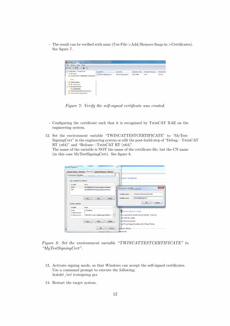
- The result can be verified with mmc (Use File->Add/Remove Snap-in->Certificates).See figure 7.
Figure 7: Verify the self-signed certificate was created.
- Configuring the certificate such that it is recognized by TwinCAT XAE on theengineering system.
12. Set the environment variable “TWINCATTESTCERTIFICATE” to “MyTest-SigningCert” in the engineering system or edit the post-build step of “Debug—TwinCATRT (x64)” and “Release—TwinCAT RT (x64)”.The name of the variable is NOT the name of the certificate file, but the CN name(in this case MyTestSigningCert). See figure 8.
Figure 8: Set the environment variable “TWINCATTESTCERTIFICATE” to“MyTestSigningCert”.
13. Activate signing mode, so that Windows can accept the self-signed certificates.Use a command prompt to execute the following:bcdedit /set testsigning yes
14. Restart the target system.
12

- If test signing mode is enabled, this is displayed at the bottom right of the desktop,such as depicted on figure 9. The PC now accepts all signed drivers for execution.
Figure 9: If test signing mode is enabled, this is displayed at the bottom right ofthe desktop.
15. TwinCAT is now configured to be able to run C++ modules.
4. Install MATLAB
- Install a version newer than MATLAB 2011a. The most important thingis that the version of MATLAB includes the MATLAB/Simulink Coderapp.
5. Install Beckhoff TE1400 Module
The TwinCAT MATLAB/Simulink Target offers System Target Files for theuse of the MATLAB/Simulink coder. It enables the generation of TwinCAT 3runtime modules, which can be instanced and parameterised in the TwinCAT 3engineering environment.
1. Navigate to the Beckhoff website to install the TE1400 module:https://www.beckhoff.com/english.asp?twincat/te1400.htm.
2. Press the download button and follow all instructions.
3. Start the ‘TE1400-TargetForMatlabSimulink’ Setup.
4. Start MATLAB and execute %TwinCAT3Dir%..\Functions\TE1400- Tar-getForMatlabSimulink\SetupTwinCatTarget.p such as on figure 10.Do not forget to run MATLAB with administrator privileges.
13

Figure 10: Installation of the TE1400 module
All required software is installed and should be operational
3.3 Simulink model and compilation
In this section we analyse the setup of the Simulink model file that is providedonline with this tutorial. We will compile the Simulink model and import it inTwinCAT which is running in Visual Studio.
Main model
In figure 11 the main Simulink model is depicted. Some text is provided tofunction as a quick memory-help on how to use the model.In the top section of the model the inputs that have to be read from hardwarecan be distinguished. The ‘TC Module Input’ blocks can be found in the librarybrowser under ‘beckhoff’. The data type of the input blocks must be configuredto match the data type that the real hardware device emits over the EtherCATnetwork. For example, a motor drive sends the current motor position as anINT16, the input block in Simulink has to be configured to read an INT16. The‘To file’ block has to be configured for arrays. Also make sure to change the filelocation to .../general target/temp data. Further reading on this topic can befound in the document http://download.beckhoff.com/download/document/automation/twincat3/TwinCAT_3_Matlab_Simulink_EN.pdf on page 24.In the middle section the motor trajectory is read from the work space andwritten to a model output. This ‘TC Module Output’ block can also be found inthe model library browser under ’beckhoff’. The trajectory has to be generatedwith the ’generate model trajectory’ m-file that is supplied with the Simulinkmodel. Do not forget to assign a valid data type for the trajectory output.The bottom section handles the enabling of the motor drive and the starting and
14
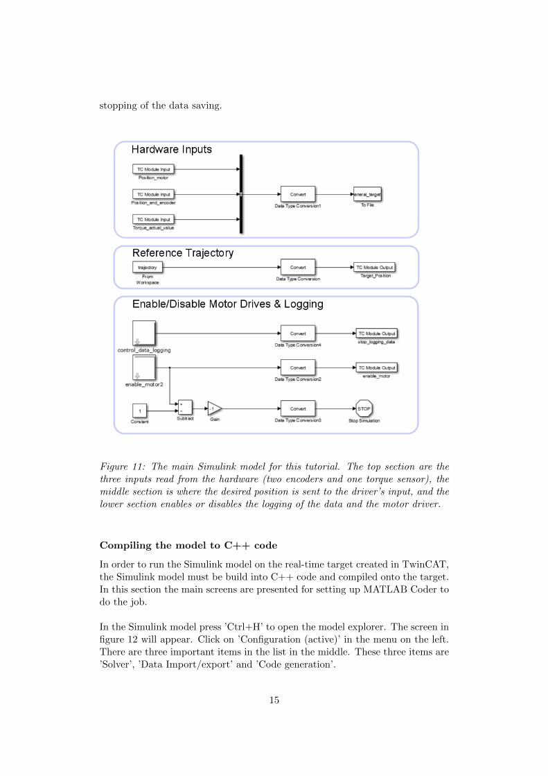
stopping of the data saving.
Figure 11: The main Simulink model for this tutorial. The top section are thethree inputs read from the hardware (two encoders and one torque sensor), themiddle section is where the desired position is sent to the driver’s input, and thelower section enables or disables the logging of the data and the motor driver.
Compiling the model to C++ code
In order to run the Simulink model on the real-time target created in TwinCAT,the Simulink model must be build into C++ code and compiled onto the target.In this section the main screens are presented for setting up MATLAB Coder todo the job.
In the Simulink model press ’Ctrl+H’ to open the model explorer. The screen infigure 12 will appear. Click on ’Configuration (active)’ in the menu on the left.There are three important items in the list in the middle. These three items are’Solver’, ’Data Import/export’ and ’Code generation’.
15

The solver has to be set to a fixed step solver because the model runs at afixed frequency. The stop time does not really matter, the model will continuerunning after the specified ten seconds. Under ´additional options’ the fixedstep time can be set to 0.001 s, which equals a cycle frequency on the EtherCATnetwork of 1kHz, such as in figure 13.In figure 14, the ‘Data Import/Export’ item is configured (midpane). Savingdata to the MATLAB workspace is not possible via this route, but has to bedone in a different way that we will see later.
Figure 12: The main screen of the model explorer, with on the left the ‘Configu-ration (Active)’ pane and in the middle, the ‘Solver’, ‘Data Import/Export’ and‘Code Generation’ items.
Figure 13: The solver has to be set to a fixed step solver. The stop time doesnot really matter, the model will continue running after the specified ten seconds.Under ‘additional options’ the fixed step time can be set to 0.001 s.
16
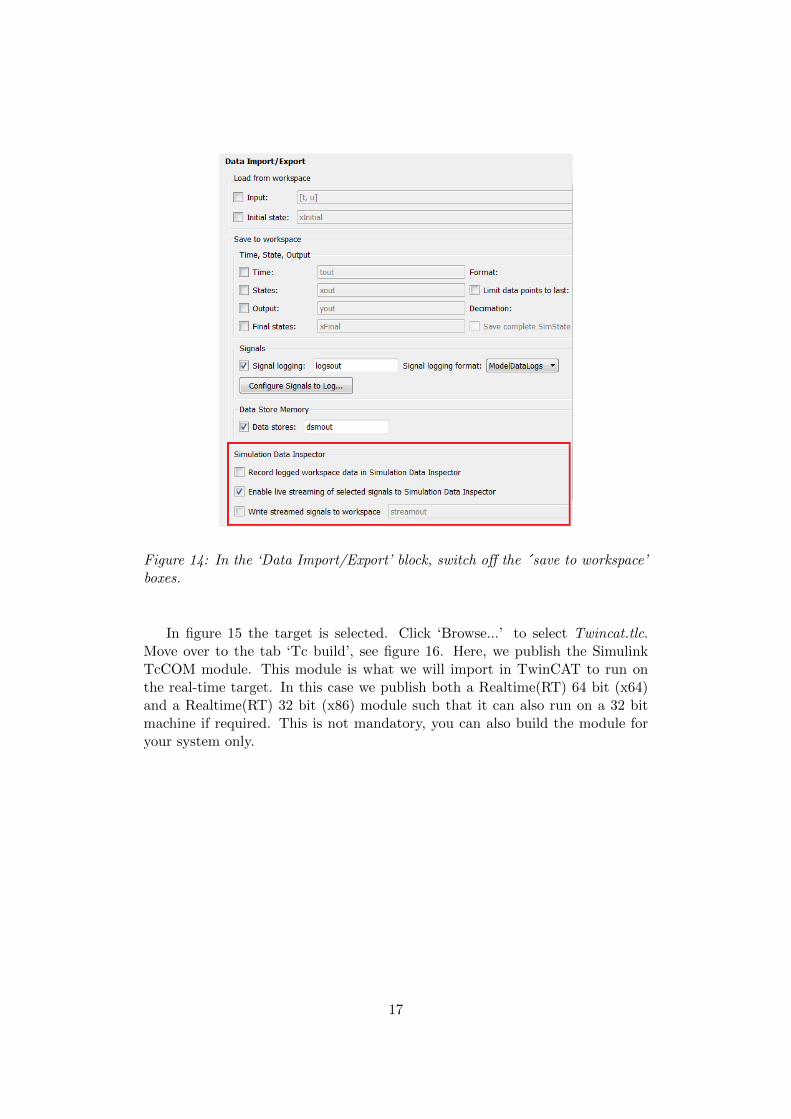
Figure 14: In the ‘Data Import/Export’ block, switch off the ´save to workspace’boxes.
In figure 15 the target is selected. Click ‘Browse...’ to select Twincat.tlc.Move over to the tab ‘Tc build’, see figure 16. Here, we publish the SimulinkTcCOM module. This module is what we will import in TwinCAT to run onthe real-time target. In this case we publish both a Realtime(RT) 64 bit (x64)and a Realtime(RT) 32 bit (x86) module such that it can also run on a 32 bitmachine if required. This is not mandatory, you can also build the module foryour system only.
17

Figure 15: Enlarged screen for code generation where the target can be selected.Browse for the Twincat.tlc file.
18

Figure 16: The screen for publishing the Simulink TcCOM module. If you runa 32 bit computer make sure to publish the generated C++ module for a 32 bittarget (x86).
The last two tabs that need to be considered are the ‘Tc External Mode’ and‘Tc Advanced’ tabs. In the ‘Tc External’ tab, figure 17, we can select whetherwe want to control the Simulink model running on the real-time target withthe Simulink model running in MATLAB. Technically this means that an ADS(Automation Device Specification) protocol is set up between MATLAB andTwinCAT. It is a method for accessing the Bus Coupler information directlyfrom the PC. For the rest of the tutorial we will use this protocol, and thus,check all boxes under the tab ‘Tc External Mode’.
19

Figure 17: The ADS (Automation Device Specification) protocol is set up betweenMATLAB and TwinCAT. Check all boxes to allow the Simulink model running onthe real-time target to be controlled by the Simulink model running on MATLAB.
Lastly, move to the ‘Tc Advanced’ tab, depicted in figure 18. In this tab, wecan decide how the generated module should be called. Make sure the taskassignment is set to ‘ManualConfig’, the callby is set to ‘CyclicTask’ and stepsize is set to ‘RequireMatchingTaskCycleTime’. This is because we require themodel to be called by a ‘task’ that has the same cycle time as we compiled forthe model (1ms).
Figure 18: This is the ‘Tc Advanced’ tab. Here, we can define how to call thereal-time generated module. In this case, we require the model to be called by a’task’ that has the same Cycle time as we compiled for the model (1ms).
The remaining tabs are not considered important at this point. Having com-pleted these steps you can return to the ‘General’ tab and press ‘Generate Code’.MATLAB will now start compiling your model and publish it to a directorywhere TwinCAT can read it.
20

3.4 Setting up the TwinCAT real-time target and importing andconnecting the compiled Simulink model
In order to set up the TwinCAT realtime target, we follow 4 steps:
1. Any EtherCAT slaves, like in our case an EPOS3 motor drive and a Beck-hoff module, are connected to the EtherCAT network master.
2. Importing the compiled Simulink model into the TwinCAT environmentand setup to run on the real-time target.
3. Connection of the inputs and outputs of the Simulink model to the Ether-CAT slaves in the network.
4. The ’ExtendedFileWriter’ module for writing data from the real-time tar-get to the hard drive of the computer is added and connected in TwinCAT.
All these steps are explained in this section.
TwinCAT real-time target
Start up Microsoft Visual Studio. Create a new project (File -> New -> Project).We make a TwinCAT XAE project, and name it ‘simulink realtime target’. Wenow see the main TwinCAT screen as depicted in figure 19. On the left theproject solution tree can be found. Under ’System’ the parameters for the real-time part of the system and the task execution speeds are set. Also, the Simulinkmodel will show up here. Under PLC, we can write programs to be executedby our hardware in PLC language. Under C++ we can write programs to beexecuted by our hardware in C++ code and under I/O all hardware in oursystem is listed.
Figure 19: The main screen of a TwinCAT project with on the left, the projectsolution tree.
21

In the tree, by expanding the ‘SYSTEM’ tab we can create a new task (rightclick ’tasks’ -> add new item). Name it ‘SimulinkTarget’ and reduce the ’CycleTicks’ to 1. This means the task cycle time is set to 1ms.
Simulink model import
Just like any program written in PLC language or C++ language, the Simulinkmodel will function as the ’high level control program’ that works with thehardware listed under IO. To import the Simulink model, add a new TcCOMobject (right click TcCOM Objects -> add new item). Expand TE1400 ModuleVendor, like in figure 20, and select ‘general target model’.
Figure 20: To import the real-time generated Simulink model into TwinCAT, aTcCOM object was added. If needed, multiple models can be imported and runsimultaneously.
By expanding ‘TcCOM Objects’ and double clicking ‘Object1’, the Simulinkblock diagram can be found, see figure 21.
22

Figure 21: By expanding ‘TcCOM Objects’ and double clicking ‘Object1’ in theleft tree, we can find the Simulink block diagram under the ’Block Diagram’ tab.
Now select the ’context’ tab (double clicking ‘Object1’ in the left tree). Inthe ’task’ dropdown menu select the ‘SimulinkTarget’ task, see figure 22. Thisprocedure links the model to the task that we created before. In this way, thetask is updating every 1ms which means the Simulink model will run at 1kHz.
23
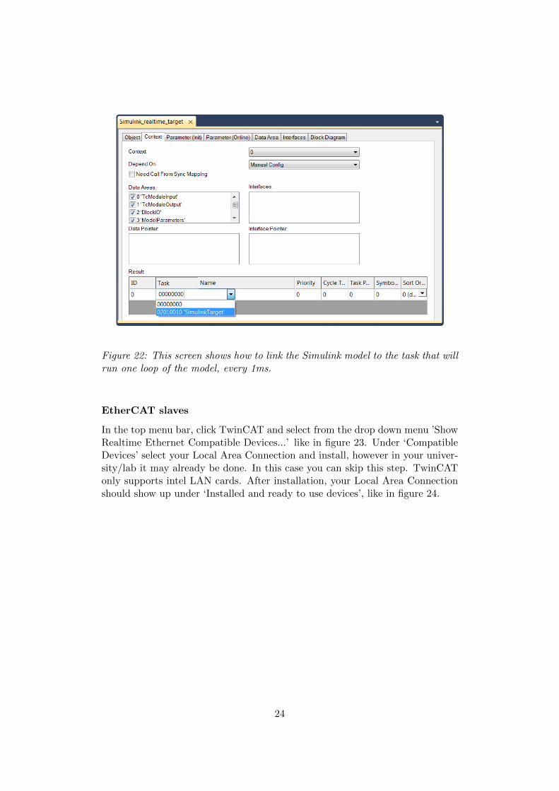
Figure 22: This screen shows how to link the Simulink model to the task that willrun one loop of the model, every 1ms.
EtherCAT slaves
In the top menu bar, click TwinCAT and select from the drop down menu ’ShowRealtime Ethernet Compatible Devices...’ like in figure 23. Under ‘CompatibleDevices’ select your Local Area Connection and install, however in your univer-sity/lab it may already be done. In this case you can skip this step. TwinCATonly supports intel LAN cards. After installation, your Local Area Connectionshould show up under ‘Installed and ready to use devices’, like in figure 24.
24
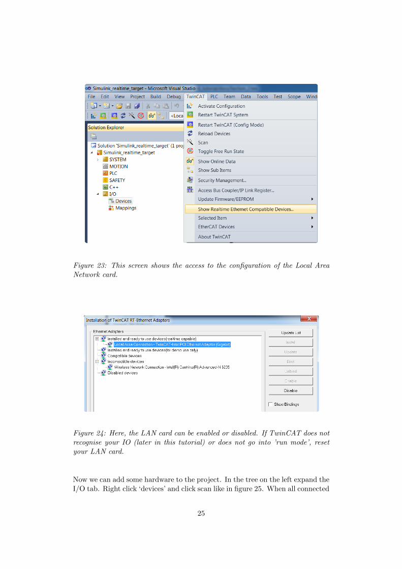
Figure 23: This screen shows the access to the configuration of the Local AreaNetwork card.
Figure 24: Here, the LAN card can be enabled or disabled. If TwinCAT does notrecognise your IO (later in this tutorial) or does not go into ’run mode’, resetyour LAN card.
Now we can add some hardware to the project. In the tree on the left expand theI/O tab. Right click ‘devices’ and click scan like in figure 25. When all connected
25
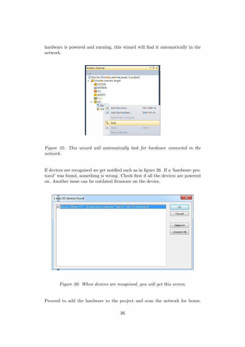
hardware is powered and running, this wizard will find it automatically in thenetwork.
Figure 25: This wizard will automatically look for hardware connected in thenetwork.
If devices are recognised we get notified such as in figure 26. If a ‘hardware pro-tocol’ was found, something is wrong. Check first if all the devices are poweredon. Another issue can be outdated firmware on the device.
Figure 26: When devices are recognised, you will get this screen.
Proceed to add the hardware to the project and scan the network for boxes.
26

Append the axis to NC axis. Activate free run. In the model tree on theleft you will now see the EtherCAT hardware in your network. As depicted infigure 27 in our case, this is an EPOS3 drive, a MIR device to read encodersand a Beckhoff EK1100 module. TwinCAT can only recognise devices if it hastheir .ESI file. This file contains information about the device functionalityand settings. In this case, you need to download the ESI (EtherCAT SlaveInformation) file for the EPOS3 drive from the Maxon website and copy it tothe folder Twincat\3.1\Config\Io\EtherCAT. After doing this, TwinCAT shouldbe able to see your device. Note it is possible that an etherCAT enabled devicerequires more than a .xml (ESI) file for proper operation. Always ask the devicemanufacturer if you have all the right files.
Figure 27: Overview screen with on the left all hardware listed in the modelsolution tree.
Double click the EPOS3. Select the ’slots’ tab like in figure 28. In here, theEPOS3 can be configured in different modes. Each mode has a specific PDOconfiguration so if you change mode it is likely that links you make to thesePDO entries (as explained later in the tutorial) will be lost. A solution can beCST/CSV/CSP mode where you can toggle between any mode you want andthe PDO’s contain all entries for current position/velocity/torque and curren-t/velocity/position setpoints. Further reading on the EPOS3 can be found inthe application notes of the Maxon website.
27
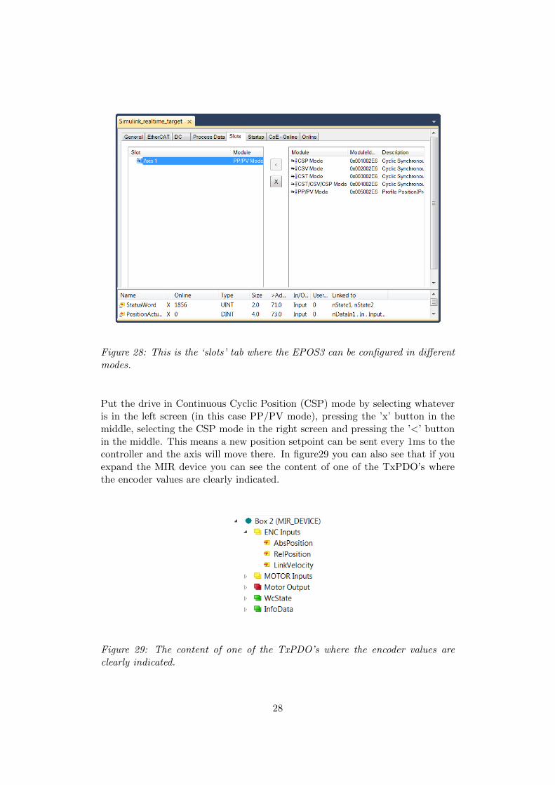
Figure 28: This is the ‘slots’ tab where the EPOS3 can be configured in differentmodes.
Put the drive in Continuous Cyclic Position (CSP) mode by selecting whateveris in the left screen (in this case PP/PV mode), pressing the ’x’ button in themiddle, selecting the CSP mode in the right screen and pressing the ’<’ buttonin the middle. This means a new position setpoint can be sent every 1ms to thecontroller and the axis will move there. In figure29 you can also see that if youexpand the MIR device you can see the content of one of the TxPDO’s wherethe encoder values are clearly indicated.
Figure 29: The content of one of the TxPDO’s where the encoder values areclearly indicated.
28

PLC project
The next thing to do is to make a PLC program to enable and disable the motordrive. This could also be done in the Simulink model but for illustrative purposesit will be achieved with a small PLC project.Right click PLC in the tree menu on the left and click ’Add new item’. Namethe new standard PLC project ’EnableMotor’ and click ok. You have a situationlike in figure 30 now if you expand the menus in the PLC tree.
Figure 30: Right click PLC in the tree menu on the left and click ’Add new item’.Name the new standard PLC project ‘EnableMotor’.
Right click POUs and select ’add’ and then ’POU’ like in figure 31. Namethe POU ´EnableMotor’ and select ´program’ and ´Structured text’ for theimplementation language. Click Open. Double click the new ´EnableMotor(PRG)’ program. Copy the content from figure 32 to your own program. Go tothe MAIN (PRG, in the left tree) and copy the content of figure 33 to your mainprogram. Save all and press ´F7’ to build your solution.
Inputs and outputs connection
We can connect the variables in the hardware PDO’s with the in- and outputs ofthe Simulink model. As depicted in figure 34 right click for example RelPositionand click ’change link’.
29

Figure 31: In this screen we add a Process Organization Unit (POU). As can beseen from the screen, a lot more, such as VISU’s (visualizations/frontscreens)can be added if desired.
Figure 34: Screen for establishing the connection between a hardware entry (inthis case the RelPosition of an encoder and an entry on the control program.
Like in figure 35, select ‘position end encoder’ and click ok. The link is nowestablished between the position of the end encoder in the hardware and theinput of the Simulink block that receives the position of the end encoder.
30

Figure 32: Here, the commands to enable the motor can be written. The neces-sary and specific commands for a Maxon EPOS3 controller can be found in theapplication notes of the controller.
Figure 33: This is the program ‘EnableMotor’ from the main program (MAIN),which is executed by the task ’PlcTask’.
31
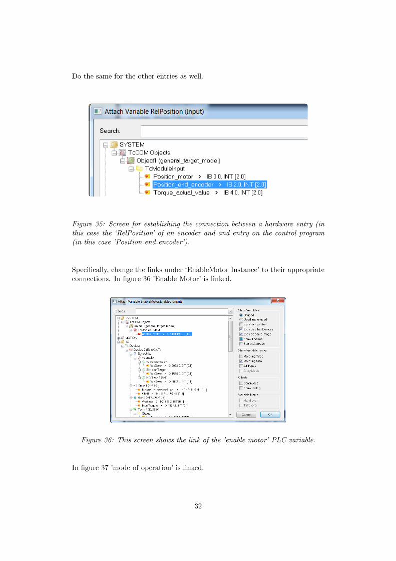
Do the same for the other entries as well.
Figure 35: Screen for establishing the connection between a hardware entry (inthis case the ‘RelPosition’ of an encoder and and entry on the control program(in this case ’Position end encoder’).
Specifically, change the links under ‘EnableMotor Instance’ to their appropriateconnections. In figure 36 ’Enable Motor’ is linked.
Figure 36: This screen shows the link of the ’enable motor’ PLC variable.
In figure 37 ’mode of operation’ is linked.
32
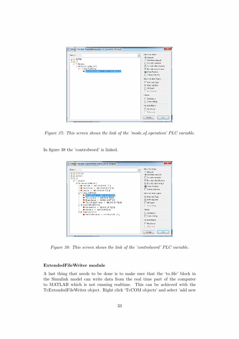
Figure 37: This screen shows the link of the ’mode of operation’ PLC variable.
In figure 38 the ’controlword’ is linked.
Figure 38: This screen shows the link of the ’controlword’ PLC variable.
ExtendedFileWriter module
A last thing that needs to be done is to make sure that the ‘to file’ block inthe Simulink model can write data from the real time part of the computerto MATLAB which is not running realtime. This can be achieved with theTcExtendedFileWriter object. Right click ‘TcCOM objects’ and select ’add new
33

item’. Referring to figure 39, select the ‘ExtendedFileWriter’ module and clickok.
Figure 39: The TcExtendedFileWriter object makes sure that the ‘to file’ blockin the Simulink model can write data from the real time part of the computer toMATLAB which is not running realtime.
Similarly as for the TcCOM Objects, go to the context tab and link the task tothe SimulinkTarget task. Now go to ‘Object1 (general target model)’ and selectthe tab ’parameter (init)’. Like in figure 40 connect the ExtendedFileAccessOIDto the ‘Object2 (TcExtendedFilewriter)’ object. Under ‘Object2 (TcExtended-Filewriter)’, change the link of the ‘pause’ entry to ‘stop logging data’ like infigure 41. That’s it for setting up the hard- and software.
34

Figure 40: Screen for connecting the ExtendedFileWriter module to the Simulinkmodule.
Figure 41: This screen shows the connection between the ’pause’ entry of theExtendedFileWriter module and the provided ’Stop logging data’ entry of theSimulink model. This was done to make sure that the .mat file that is created bythe filewriter module only contains the data from the experiment that we want.
35
3.5 Running the real-time target, the Simulink model and them-files
This section handles the final and most practical part of the tutorial: doing ameasurement with the real-time Simulink model. If all previous sections werecompleted with success, this section should not give any problems and presentsmerely the execution sequence of running a realtime Simulink model on yourcomputer.
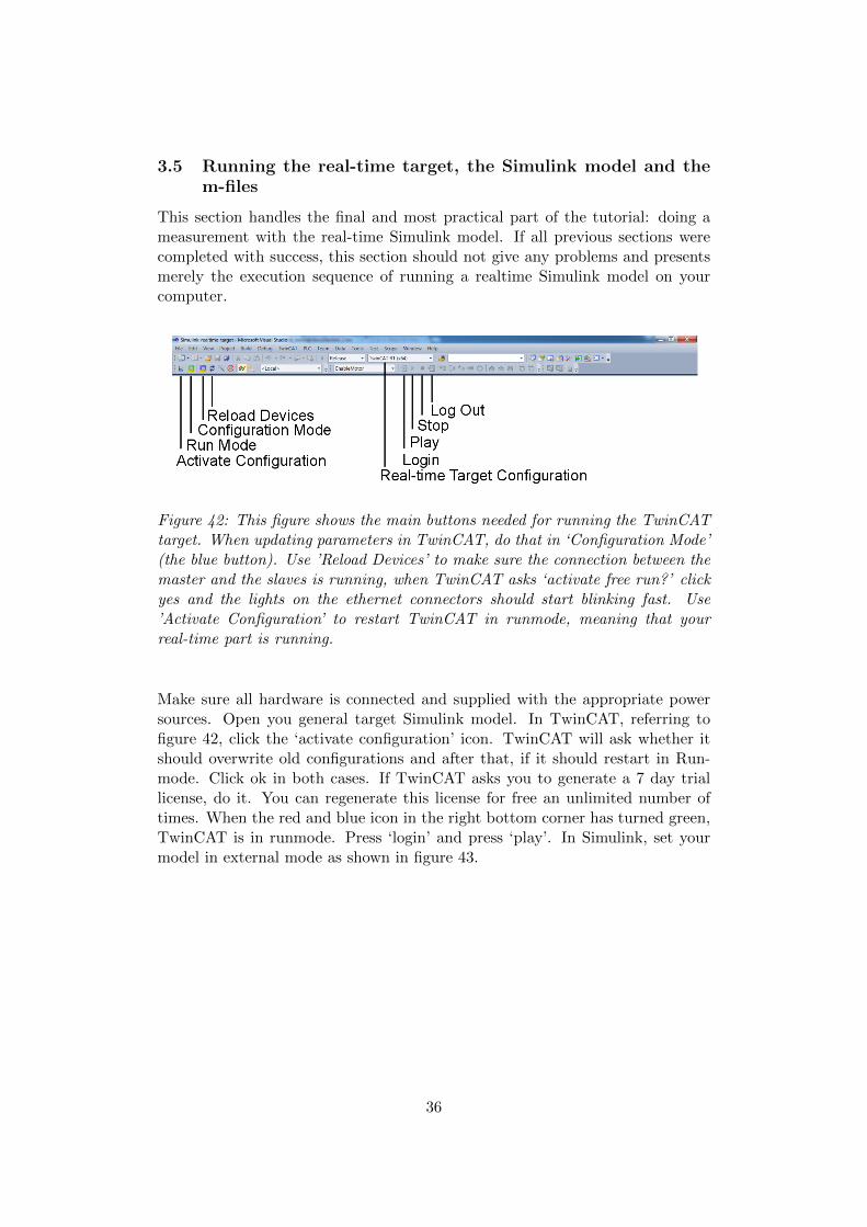
Figure 42: This figure shows the main buttons needed for running the TwinCATtarget. When updating parameters in TwinCAT, do that in ‘Configuration Mode’(the blue button). Use ’Reload Devices’ to make sure the connection between themaster and the slaves is running, when TwinCAT asks ‘activate free run?’ clickyes and the lights on the ethernet connectors should start blinking fast. Use’Activate Configuration’ to restart TwinCAT in runmode, meaning that yourreal-time part is running.
Make sure all hardware is connected and supplied with the appropriate powersources. Open you general target Simulink model. In TwinCAT, referring tofigure 42, click the ‘activate configuration’ icon. TwinCAT will ask whether itshould overwrite old configurations and after that, if it should restart in Run-mode. Click ok in both cases. If TwinCAT asks you to generate a 7 day triallicense, do it. You can regenerate this license for free an unlimited number oftimes. When the red and blue icon in the right bottom corner has turned green,TwinCAT is in runmode. Press ‘login’ and press ‘play’. In Simulink, set yourmodel in external mode as shown in figure 43.
36

Figure 43: This figure shows you to put your Simulink model in ’External’ modein order to be able to make a connection with the real-time Simulink modulerunning on the TwinCAT target. The button highlighted in red is the ‘connect totarget’ button, and establishes a connection between the two. You can start thesimulation by pressing the ‘play’ button (next to ‘connect to target’.
In MATLAB, run ‘generate motor trajectory.m’ and open the general targetmodel in MATLAB. Press the ‘connect to target ’ button to connect to the tar-get1. When you press play, the drive will enable and the motor will start to movethe trajectory that you set for it in the Simulink model. When the motor hasstopped after 15.3 seconds, the simulation stops but you still need to press thestop button. Click the ‘restart TwinCAT in configuration mode’ button. Run‘save and plot data.m’. You will see the data that you just recorded.
Congrats, you’re done! You can now use the knowledge to alter anything youlike in the Simulink model you would like and you can run it as often as youwant. Do however make sure that you complete the sequence for running anexperiment entirely each time you do it. Now start playing and enjoy!
1Connecting to the target in Windows 8 or Windows 10 failed on certain computers in ourexperiments. This was due to the system clock setup. To solve this, open command prompt(Admin) and navigate to C:/TwinCAT/3.1/System, and execute win8settick.bat and restartthe PC.
37

4 TwinCAT debugging
This section gives a brief introduction to debugging tools available in Simulinkand TwinCAT environments. Different options are available in both of theseenvironments for detecting and analyzing errors within a TcCOM module cre-ated in Simulink. Since Simulink may treat certain exceptions and/or errorsdifferently than TwinCAT, it is important to synchronize the two and the waythey handle relevant exceptions. For a complete overview of different TwinCATexceptions and debugging options, the reader is refered to the Beckhoff Infor-mation System website [1]. In the sequel, a general debugging procedure will beshown on the example of a floating point (FPU) exception. The whole procedureis meant to enable debugging in the block diagram exported during generation ofthe TcCOM module and displayed in the TwinCAT development environment.(The most common way to debug C++ programs - setting the breakpoints andstepping through the code - is also available in TwinCAT environment, but is notsubject of this tutorial.)
4.1 Setting up debugger in Simulink environment
The first step in synchronizing the two environments in error-handling is tochange the Simulink publish configuration to Debug, as shown in figure 44. Whenthe block model is in the testing phase, this option enables debugging of theexported block diagram in TwinCAT environment, which is often needed. Ifno debugging is required, e.g. in a release version, the option Release can beselected here.
Figure 44: In the Simulink model, under Model Explorer (press Ctrl+H), goto Configuration Parameters\Code Generation\Tc Build, and change PublishConfiguration to Debug.
Earlier in this document, in the section on setting up Simulink model param-eters, it is already mentioned that options Export block diagram and Export blockdiagram debug information in TcAdvanced tab of the configuration parameters
38

need to be enabled. Given the importance of these two options being enabled, itis worth reminding here to make sure that they are enabled, as shown in figure45.
Figure 45: Make sure that in the Simulink model, under Model Explorer (pressCtrl+H), Configuration Parameters\Code Generation\Tc Advanced, the optionsExport Block Diagram and Export Block Diagram Debug Information are enabled.
Above mentioned options are general ones, and need to be enabled regardlessof the error or exception one might experience. However, any one exception isparticular and might require different settings in order for diagnostics to workproperly. In the case of the floating point (FPU) error, used as an example inthis tutorial, it is necessary to change signal handling in Data Validity tab of theblock model Diagnostics tool as shown in 46. In the case of other exceptions,signal attributes might need to be changed accordingly.
Figure 46: In the Simulink model, under Model Explorer (Ctrl+H), go to Config-uration Parameters\Diagnostics\Data Validity, and change Division by singularmatrix, and Inf or NaN block output to error.
4.2 Setting up debugger in TwinCAT environment
TwinCAT C++ offers different mechanisms for debugging C++ modules run-ning under real-time conditions, including the ones built within the Simulinkenvironment. To do so, the first step is to enable C++ debugger, as this op-tion is switched off by default and must be activated before the configuration isactivated. Figure 47 shows how to activate C++ debugger in TwinCAT environ-
39

ment. As already described earlier, TwinCAT is integrated in Microsoft VisualStudio 2010.
Figure 47: In Visual Studio, in the main solution tree of the project there is aninput called called ’C++’. Click on it and open the tab called ’C++ Debugger’.There, enable the C++ Debugger.
If the above given steps are followed, and the C/C++ source code of thegenerated TcCOM module is present on the engineering systems (so that VisualStudio debugger is able to find it), debugging within the block diagram can beexecuted. The debugging is carried out by assigning the possible breakpoints tothe blocks in the block diagram, which are then represented as points. The colorof the point provides information about the current state of the breakpoint. Toget to this point, one must first activate configuration (see figure 48) and thenattach the process to XAE debugger code (see figure 49). If exceptions occurduring processing of a TcCom module, the point at which the exception occurredis shown in the block diagram - the block that caused the exception is highlightedin the block diagram, provided the line of code responsible for the exception canbe assigned to a block. The name of the block is shown in red, and the blockitself is marked in bold.
Attaching the process to XAE debugger will automatically start the Twin-CAT Live Watch, a tool that can be used to monitor process variables withoutsetting breakpoints. This tool can also be started independently, by going tothe main menu of Visual Studio and navigating the following: Debug - Win-dows - TwinCAT Live Watch. If TwinCAT runs on a real machine with axismovements, the user will probably not wish to set any breakpoints just for mon-itoring variables. On reaching a breakpoint the execution of a task would bestopped and, depending on the configuration, the axis would immediately cometo a halt or would continue to move in an uncontrolled fashion, which mighthave hazardous consequences.
40

Figure 48: In the TwinCAT project in Visual Studio, select tab ’TwinCAT’ andthen ’Activate Configuration’. The status icon should turn green, meaning thatthe system is in active mode.
Figure 49: In the main menu of Visual Studio, select ’Debug - Attach to pro-cess..’. When ’Attach to Process’ window opens, select ’TwinCAT XAE’ as atransport method, ’Localhost’ as a qualifier and confirm with ’Attach’ button.The process in active configuration is now connected to the debugger.
41

5 Licensing TwinCAT products
For certain applications it might be necessary to purchase a commercial licensefor the TE1400 module.More specifically, a license is required for models withmore than 100 Simulink blocks, or when the number of inputs of outputs ishigher than five. Of course, a license is also required in the case of commercialuse. This chapter contains detailed instructions on how to activate a TwinCATlicense.
Situation
Beckhoff TE1400 Module allows the use of MATLAB/Simulink to establish con-trol systems that can be later exported into a C or C++ code that can be runwithin the TwinCAT3 environment.This way, complex control systems can becreated in a fast and intuitive way without prior programming knowledge in Cor C++ language. This makes the TE1400 module a useful tool for rapid con-trol prototyping, real-time simulation and model-based monitoring applications.For testing purposes, the module generator of the TE1400 can be used in demomode without a license. However, this limits its application to models with amaximum of 100 Simulink blocks, 5 inputs and 5 output signals, and only fornon-commercial purposes. Generally, robotic applications require larger modelswith greater number of input and output blocks corresponding to sensors and ac-tuators. In these cases, purchasing a commercial license for the TE1400 modulebecomes a requisite.
Beckhoff offers three kind of licenses:
� Trial license: some TwinCAT 3 Runtime products can be activated freeof charge for testing purposes for 7 days, as many times as required. Thelicense TC1320 (or TC1220 with PLC license) is required to start a Twin-CAT configuration with a module generated from Simulink. Therefore, itis necessary to get this license if the TE1400 module is used. Withoutactivated license, the module and consequently the TwinCAT system can-not be started. In this case you get error messages relating to the licenseviolation. You can generate a 7-day trial license for the TC1320 within theTwinCAT environment as many times as required without any limitation.Unfortunately, this option is not available for the TE1400, and purchasinga commercial license is mandatory.
� Standard license: it consist of a commercial license that is tied to a uniquesystem ID. It is installed in a single IPC and cannot be shared with others.
� Volume license: they offer simple handling of TwinCAT 3 licenses withoutrequiring activation and with a straightforward exchange of IPCs. TheTwinCAT3 license dongle with memory function consists of a new storingdevice for license files and offers an attractive alternative to a volumelicense. TwinCAT3 license dongles combine the benefits of straightforwardvolume licensing with a high degree of flexibility for the required TwinCAT3 license configuration. The disadvantages of a volume license, such as fixed
42

license configuration and the fixation to customer-specific hardware, can becircumvented. A TwinCAT 3 license dongle offers greater flexibility withregard to the control computer (e.g. during service), since the TwinCAT3 license is no longer tied to a specific IPC so it can be exchanged formultiple IPCs, which is very convenient within a lab environment as thesame license file can be used in multiple setups (not simultaneously). Theonly requirement is that the TwinCAT 3 hardware platform level mustmatch the corresponding TwinCAT 3 license.
TwinCAT standard licenses (as the TE1400) are always tied to a specifichardware – generally a TwinCAT dongle (EL6070 (EtherCAT Terminal) orC9900-L100 (USB stick)). In principle it is also possible to tie a TwinCAT3 license to a specific Beckhoff IPC. However, this has the severe disadvantagethat, if an IPC is replaced, the TwinCAT 3 licenses are no longer valid for thenew IPC. If, on the other hand, the TwinCAT 3 licenses are tied to a TwinCAT3license dongle, the IPC can easily be replaced.
Among all the different licensing options Beckhoff offers, we believe the USBdongle with memory function is the most convenient within a lab and fast pro-totyping environment due to its high flexibility and intrinsic advantages. In thefollowing sections we describe the required procedure to save a standard license(TE14000) into a license dongle C9900-L100 (USB stick).
License Key USB Stick C9900-L100
The USB dongle stick provided by Beckhoff does not include any stored license.Therefore it is necessary to include the required licenses on it. The followingsteps summarize the procedure that has to be carried out in order to store alicense file into the USB dongle stick to further use it in a TwinCAT project:
1. Insert the USB drive into the USB slot of your computer. Note that inthe current TwinCAT version the TwinCAT3 USB dongle is not detectedautomatically. It must be initialized (set as license device) once in theproject. The TwinCAT3 USB dongle must therefore always be locatedprecisely at the USB slot which was configured for this project (For a newproject you can, of course, select a different position for the TwinCAT3USB dongle.)
2. In the TwinCAT System Manager, scan for new devices to check whetherthe system finds the C9900-L100 license dongle, such as in figure 50. ForTwinCAT 3 volume license dongles please note that a special, custom ESIfile must be used for the volume license dongle. In case the system doesnot recognise the dongle, the specific ESI file can be downloaded from theBeckhoff Information System website [1]. The downloaded file should thenbe stored in: TwinCAT\3.x\Config\Io\USB
43

Figure 50: Scan for new devices to check whether the system finds the C9900-L100 license dongle.
3. In the project click on the subitem “SYSTEM”, then double-click on “Li-cense”, such as in figure 51.
4. In the window that opens select the tab “License Device”2
5. In the hardware section select “Dongle (EtherCAT terminal EL6070, USB)”.
2In Windows 10, there is a slightly different procedure to get the Dongle working. First,select “Add” which is in the “Order Information (Runtime)” tab. This will open a sublevelunder the “Licence” tab, in which we can add the actual dongle.
44

Figure 51: (1) Scan for new devices to check whether the system finds the C9900-L100 license dongle. (2) Click on the subitem “SYSTEM”. (3) Select the tab“License Device”. (4) Select “Dongle (EtherCAT terminal EL6070, USB)”. (5)Click on “Search”.
6. Click on “Search” to find TwinCAT3 license dongles at the USB ports orin the connected EtherCAT network.
7. In the search results select the TwinCAT3 USB license dongle C9900-L100,see figure 52.
Figure 52: (6) Select the TwinCAT3 USB license dongle C9900-L100. (7) Clickon “OK”.
8. Then click on “OK”. In the “Order Information” tab, the C9900-L100 canthen be selected as hardware basis for the licensing procedure.
9. Click on the “Order Information” tab at the top, figure 53.
10. Under “System Id” open the selection box by clicking on the down arrow.
45

Figure 53: (8) Click on the “Order Information” tab. (9) Under “System Id”open the selection box. (10) Select “Dongle Hardware Id”.
11. Select “Dongle Hardware Id”.
12. The system ID required for licensing is now provided by the selected Twin-CAT3 license dongle, see figure 54.
13. Enter the license ID (the corresponding order number provided by Beck-hoff) in the field “License Id”. The lower section of the “Order Informa-tion” tab shows a list of licenses, which TwinCAT has determined auto-matically based on your project. If licenses were added manually, these arealso listed here. In the “Manage Licenses” tab you can select / add licensesmanually. Here we can manually add the TE1400 license. Double-checkthat all listed licenses are also included in the order with the specified num-ber – otherwise the Beckhoff license server would issue an error message! Iflicenses are listed, which are NOT included in the order with this number,these should be deselected in the “Manage Licenses” tab.
14. The “License Request file” can then be generated via the “Generate File”button (14).
46

Figure 54: (12) The system ID required for licensing is now provided by theselected TwinCAT3 license dongle. (13) Enter the license ID. (14) Generate the“License Request file”.
A window opens, in which you can specify where the License Request file isto be stored. (We recommend accepting the default settings.)
47

Figure 55: Specify where the License Request file is to be stored.
Clicking on “Save” triggers a prompt as to whether the License Request file isto be sent to the Beckhoff license server (prerequisites: an email program mustbe installed on your computer, and your computer must be connected to theInternet).
Figure 56: Send the License Request file
Click on “Yes” to send the License Request file right away. If no email pro-gram is installed on your computer, or if you have no Internet access, answer thequestion with “No” and copy the License Request file to a data storage device(e.g. USB stick). Send the file from a computer with Internet access and emailprogram to the Beckhoff license server ([email protected]). The Beckhofflicense server returns the License Response file to the same email address fromwhich the License Request file was sent. When the server receives the email withyour license request, it compares the request with the order number and returns
48

an email (to the same email address, from which the License Request file wassent) with a “License Response file”.3 The contents of the License Response filesmust not be changed, otherwise the license file becomes invalid. The next stepis to save the activated License Response file into the USB dongle. The memoryfunction requires TwinCAT 3.1 build 4018.26 or higher (Engineering and Run-time). This version initially offers the main basic functions for uploading anddownloading of the License Response files. The TwinCAT 3 license dongles areconfigured in the “License Device” tab of the TwinCAT license manager:
Figure 57: TwinCAT 3 license dongles are configured in the “License Device”tab.
In order to save a license into the USB dongle, click on “Download license todevice”. A window opens in which you can select the previously obtained Licenseresponse file. This way, a copy of the requested license is permanently stored intoyour USB dongle. TwinCAT 3 does not work directly with the files on the dongle;it always loads a “working copy” of the files onto the hard disk of the IPCs. It istherefore important to download the license files once manually or automaticallyon each startup of the TwinCAT 3 Runtime for each project. To do it manually,click on “Cache License data”. It Copies all files of the TwinCAT3 licensedongle to the hard disk of the IPC in directory “TwinCAT\3.x\Target\Licenses”.
3The only difference between the License Response file and the License Request file is asignature, which documents the validity of the license file.
49

However we recommend to click on “Cache or check License Response files duringstartup”. When this checkbox is ticked, TwinCAT 3 checks automatically oneach start of the runtime whether the files on the hard disk match those inthe dongle memory. If the dongle contains newer or additional files, they areautomatically downloaded to the hard disk of the IPC (“cached”). Once theproject is run, you should be able to see which licenses are active (or valid)within your project in the “project licenses” tab. If you followed all the previoussteps, you should be able to see your new TE1400 license as “valid”. If not, youcan press the bottom “Reload Info”. It reads the data of the selected dongle againand update the display of the dongle parameters. If no valid data are displayedunder “Dongle Status”, the data can be re-read via this button. Finally, if youwant to delete the stored licenses in your dongle, click on “Clear License Store”
50

6 Experimental implementations
6.1 Frameless Motor
In this section a small experimental setup equipped with EtherCAT technologyis presented. The setup is run from a Dell Latitude E6440 laptop on which Twin-CAT is installed as well as MATLAB 2015b. The main hardware components ofthis setup are a Kollmorgen RBE series frameless motor, and an EPOS3 motorcontroller. The motor of the setup is depicted in figure 58. The main idea of thissetup is to implement a very simple impedance controller in Simulink and to runthis Simulink model realtime from a Windows PC with the hardware connected.
The simple impedance control law that is implemented has the followingequation:
T = Kp(x− xref ) + Kv(x− xref ) (1)
where Kp is a proportional position gain, Kv is a proportional velocity gain, xis the motor axle position and x is the motor axle velocity. To obtain a springlike behaviour in the motor the reference position xref can be set to 0 and Kp
now functions as the spring constant of the spring that the motor emulates. Inorder to obtain a stable system we of course need a small damper in the form ofa small value for Kv and xref = 0 but also a high cycle time to allow the systemto respond to disturbances.
The equation can easily be converted to a Simulink model. The model canbe compiled with MATLAB/Simulink coder and afterwards be imported as aTcCom object in TwinCAT. The model can now be run in realtime on thededicated cores in the computer and still be controlled from Simulink runningin external mode on the windows cores of the computer.
The results of a simple experiment with the frameless motor are depicted inthe graph of figure 59. The motor emulates a spring and as can be seen fromthe graph, different values for a spring stiffness were easily implemented andemulated in the motor. Graphs are easily obtained and stored in MATLAB forfurther data processing.
51

Figure 58: A Kollmorgen RBE type 12 pole frameless motor as used in thesimple test setup. The aluminum casing was made to fit the motor and allowfor testing to obtain the motor performance characteristics. The sensors in themotor include hall sensors for the commutation of the motor and an opticalincremental encoder for the position of the motor. A small ring is clamped tothe main axle to be able to turn the motor axle manually.
52
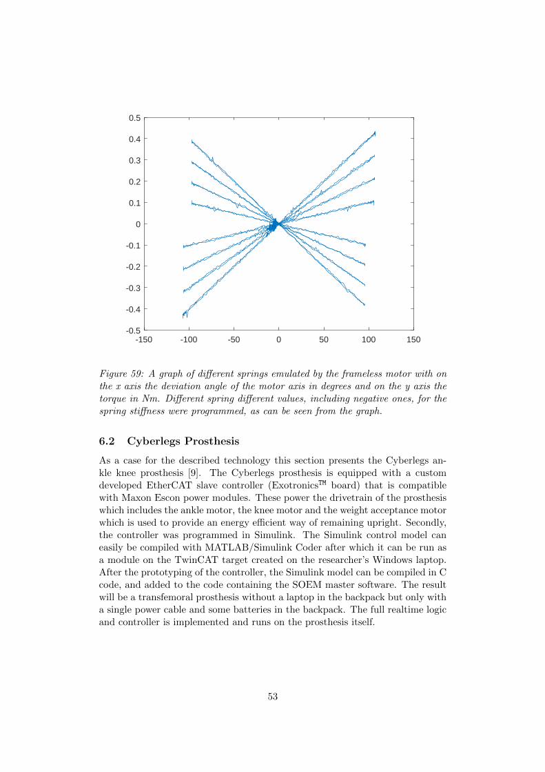
-150 -100 -50 0 50 100 150-0.5
-0.4
-0.3
-0.2
-0.1
0
0.1
0.2
0.3
0.4
0.5
Figure 59: A graph of different springs emulated by the frameless motor with onthe x axis the deviation angle of the motor axis in degrees and on the y axis thetorque in Nm. Different spring different values, including negative ones, for thespring stiffness were programmed, as can be seen from the graph.
6.2 Cyberlegs Prosthesis
As a case for the described technology this section presents the Cyberlegs an-kle knee prosthesis [9]. The Cyberlegs prosthesis is equipped with a customdeveloped EtherCAT slave controller (ExotronicsTM board) that is compatiblewith Maxon Escon power modules. These power the drivetrain of the prosthesiswhich includes the ankle motor, the knee motor and the weight acceptance motorwhich is used to provide an energy efficient way of remaining upright. Secondly,the controller was programmed in Simulink. The Simulink control model caneasily be compiled with MATLAB/Simulink Coder after which it can be run asa module on the TwinCAT target created on the researcher’s Windows laptop.After the prototyping of the controller, the Simulink model can be compiled in Ccode, and added to the code containing the SOEM master software. The resultwill be a transfemoral prosthesis without a laptop in the backpack but only witha single power cable and some batteries in the backpack. The full realtime logicand controller is implemented and runs on the prosthesis itself.
53

Figure 60: The Cyberlegs ankle-knee prosthesis. This prosthesis has four Ex-otronics boards installed to drive the motors. Two of these motor drivers arelabeled 4011 and 4012 and can be seen in the picture. Another observation thatmust be made is the white Ethernet cable with the yellow plug and the blackpower cable running to the prosthesis. These two cables are the only two cablesrequired for prototyping control architectures with Simulink and TwinCAT froma Windows laptop.
54

6.3 Dual Motor Setup
Another setup where TwinCAT was applied is shown in Figure 61. The setupis used to test a dual-motor architecture. Two DC motors, a 90W Maxon RE35motor with a 43:1 reduction and a 150W Maxon RE40 motor with a 15:1 reduc-tion, are coupled to a single output (an inertial load) by means of a planetarydifferential. Furthermore, both motors are equipped with controllable brakes. Ifengaged, the brakes deliver a static torque, and the motor can be shut down.This way, energy losses in the drivetrain are avoided. The dual-motor architec-ture creates a redundant kinematic degree of freedom. It allows for distributingthe power requirements over both motors in the most energy-efficient way. Witha proper control, the system can be made more energy-efficient than a singlemotor [10]. As low-level controllers, two Maxon MAXPOS 50/5 drives are used.They communicate with the TwinCAT target through the MAXPOS’s Ether-CAT connection. The controllable brakes are normally engaged, and can bedisengaged by applying a 24V voltage. A transistor is used to switch betweenthe on and off state; the transistors are controlled by means of the digital out-puts on the MAXPOS drives. These can be accessed on the TwinCAT target,just like the readings from the encoders on the Maxon motors. Finally, a torquesensor and an encoder are used to determine the output speed and torque. Thesignals are acquired by Beckhoff modules (EL5101 and EL3102). The BeckhoffEK1100 coupler transmits the values to the TwinCAT target through Ether-CAT. A crucial aspect is the synchronization of the low-level motor controllersand the controllable brakes. Just like in the previous examples, the controller iswritten in Simulink and converted to C code by MATLAB/Simulink Coder. Justlike in the previous examples, this code is run on the TwinCAT created on theresearcher’s Windows PC. The controller runs at a rate of 1 kHz, and succeeds insimultaneously controlling the speed of both motors in real-time using feedbackfrom the encoder on the output.
55
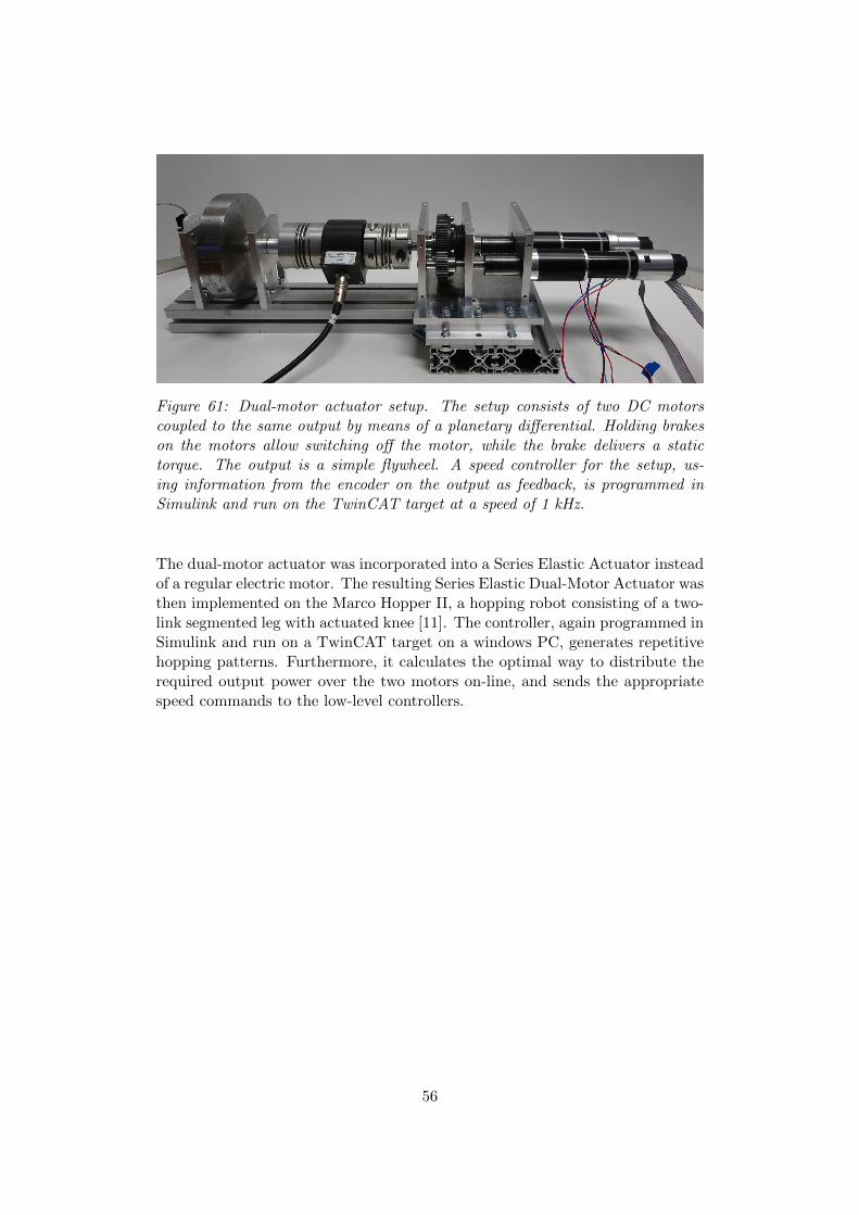
Figure 61: Dual-motor actuator setup. The setup consists of two DC motorscoupled to the same output by means of a planetary differential. Holding brakeson the motors allow switching off the motor, while the brake delivers a statictorque. The output is a simple flywheel. A speed controller for the setup, us-ing information from the encoder on the output as feedback, is programmed inSimulink and run on the TwinCAT target at a speed of 1 kHz.
The dual-motor actuator was incorporated into a Series Elastic Actuator insteadof a regular electric motor. The resulting Series Elastic Dual-Motor Actuator wasthen implemented on the Marco Hopper II, a hopping robot consisting of a two-link segmented leg with actuated knee [11]. The controller, again programmed inSimulink and run on a TwinCAT target on a windows PC, generates repetitivehopping patterns. Furthermore, it calculates the optimal way to distribute therequired output power over the two motors on-line, and sends the appropriatespeed commands to the low-level controllers.
56

Figure 62: Marco Hopper II setup. A Bowden cable is used to transmit themotion from the Series Elastic Dual-Motor actuator (left) to the knee of thehopping robot (right).
6.4 Test bench for robotic devices and actuators
This section is devoted to an EtherCAT based one degree of freedom test benchfor performing static as well as dynamic measurements on actuators or roboticdevices. The setup is run from a Lenovo ThinkPad W541 laptop on which Twin-CAT and MATLAB 2015b are installed on Windows 10. As a specific illustrationof the use of this testbench, the total setup depicted in figure 63, consists of anOmron R88M-1L75030C-S2 AC servo motor (load motor) powered by an OmronR88D-1SN-10F-ECT EtherCAT 400V AC servo drive and equipped with a Wit-tenstein NP 035S-MF2-40-0E1-1S planetary gearbox. From a Simulink modelrunning in realtime in TwinCAT, this load motor is commanded the ankle loadtorque or the ankle angle of the AMP-Foot prosthesis connected at the outputof the test bench, and such mimicking the ankle torque caused by the amputee’sweight. The prosthesis itself is driven by a maxon EC 4 pole motor in spin-dle drive setup and powered by an Elmo DCWHI20/100EEH EtherCAT servodrive. The ankle torque is measured by a DRFL-VI-500-w ETH messtechniktorque transducer and since this device does not have any Ethernet ports, thisdata is transferred to the EtherCAT network by the means of a 16 bit, 2-channel,-10V/+10V analog input terminals, Beckhoff EL3102 module connected to an
57

EK1100 coupler. A 4-channel 5 V DC digital output terminal (EL2124 Beck-hoff module) in combination with a KL9505 Beckhoff module providing 5V DCpower supply is used to control a small hobby servo motor that (un)locks theclutch. Measured variables such as phase voltages, phase currents, ankle out-put torque, encoder position and velocity of all servo drives are saved in theMATLAB workspace for easy further data processing. This example illustratesa simple and save way to perform dynamic measurements (to obtain e.g. elec-trical energy consumption during different gait cycles) or testing novel controlstrategies without the possibility of the amputee getting injured in the first trials.
Figure 63: One degree of freedom test bench for performing static as well asdynamic measurements on actuators or robotic devices running TwinCAT
58
References
[1] “Beckhoff Information System.” https://infosys.beckhoff.com/index en.htm.
[2] “IEEE Standard for Ethernet,” IEEE Std 802.3-2015 (Revision of IEEEStd 802.3-2012), pp. 1–4017, Mar. 2016.
[3] M. Felser, “Real-Time Ethernet - Industry Prospective,” Proceedings of theIEEE, vol. 93, pp. 1118–1129, June 2005.
[4] J. Jasperneite, M. Schumacher, and K. Weber, “Limits of increasing theperformance of industrial ethernet protocols,” in Emerging Technologies andFactory Automation, 2007. ETFA. IEEE Conference on, pp. 17–24, IEEE,2007.
[5] J.-D. Decotignie, “Ethernet-Based Real-Time and Industrial Communica-tions,” Proceedings of the IEEE, vol. 93, pp. 1102–1117, June 2005.
[6] G. Prytz, “A performance analysis of EtherCAT and PROFINET IRT,” inEmerging Technologies and Factory Automation, 2008. ETFA 2008. IEEEInternational Conference on, pp. 408–415, IEEE, 2008.
[7] M. Knezic, B. Dokic, and Z. Ivanovic, “Topology aspects in Ether-CAT networks,” in Power Electronics and Motion Control Conference(EPE/PEMC), 2010 14th International, pp. T1–1, IEEE, 2010.
[8] G. Cena, I. C. Bertolotti, S. Scanzio, A. Valenzano, and C. Zunino, “Eval-uation of EtherCAT Distributed Clock Performance,” IEEE Transactionson Industrial Informatics, vol. 8, pp. 20–29, Feb. 2012.
[9] L. Flynn, J. Geeroms, R. Jimenez-Fabian, B. Vanderborght, N. Vitiello, andD. Lefeber, “Ankle–knee prosthesis with active ankle and energy transfer:Development of the cyberlegs alpha-prosthesis,” Robotics and AutonomousSystems, vol. 73, pp. 4–15, 2015.
[10] T. Verstraten, R. Furnemont, P. Lopez-Garcia, D. Rodriguez-Cianca, H.-L.Cao, B. Vanderborght, and D. Lefeber, “Modeling and design of an energy-efficient dual-motor actuation unit with a planetary differential and holdingbrakes,” Mechatronics (submitted Aug. 2017), no. 9, 2017.
[11] J. Oehlke, M. A. Sharbafi, P. Beckerle, and A. Seyfarth, “Template-basedhopping control of a bio-inspired segmented robotic leg,” in BiomedicalRobotics and Biomechatronics (BioRob), 2016 6th IEEE International Con-ference on, pp. 35–40, IEEE, 2016.
[12] V. Grosu, C. Rodriguez Guerrero, B. Brackx, S. Grosu, B. Vander-borght, and D. Lefeber, “Instrumenting complex exoskeletons for im-proved human-robot interaction,” Instrumentation & Measurement Mag-azine, IEEE, vol. 18, no. 5, pp. 5–10, 2015.
59
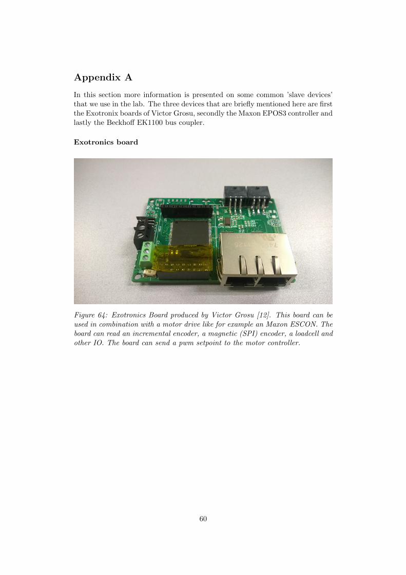
Appendix A
In this section more information is presented on some common ’slave devices’that we use in the lab. The three devices that are briefly mentioned here are firstthe Exotronix boards of Victor Grosu, secondly the Maxon EPOS3 controller andlastly the Beckhoff EK1100 bus coupler.
Exotronics board
Figure 64: Exotronics Board produced by Victor Grosu [12]. This board can beused in combination with a motor drive like for example an Maxon ESCON. Theboard can read an incremental encoder, a magnetic (SPI) encoder, a loadcell andother IO. The board can send a pwm setpoint to the motor controller.
60

EPOS3 motor controller
Figure 65: Maxon EPOS3 controller. The EPOS3 controller is a versatile motordrive that can be configured for position, velocity and torque control. These areno longer sold by Maxon. Alternatives are MAXPOS and EPOS4 drivers. Thesedrives ’speak’ EtherCAT and can easily be imported into TwinCAT. Extensivedocumentation on the devices can be found at the specific page on the websiteunder downloads
61

Beckhoff EK1100 coupler
Figure 66: Beckhoff EK1100 EtherCAT coupler with IO modules. This is anessential device in the vast majority of all test-setups. The EK1100 couplermodule can be coupled to a great number of E-bus modules. These modules can forexample be analog inputs, analog outputs, digital IO but also encoder interfacesor motor terminals. The for example analog read values are directly published onthe EtherCAT network and can be seen under the EK1100 module in TwinCAT.
62