Equivalent-Charge-Based Optimization of Spokes-and-Hub ...
48
Equivalent-Charge-Based Optimization of Spokes-and-Hub Permanent Magnets for Hand-Held MR Imaging by Irene A. Kuang B.S. Biomedical Engineering, The University of Texas at Austin (2017) Submitted to the Department of Electrical Engineering and Computer Science in partial fulfillment of the requirements for the degree of Master of Science in Electrical Engineering and Computer Science at the MASSACHUSETTS INSTITUTE OF TECHNOLOGY May 2020 c Massachusetts Institute of Technology 2020. All rights reserved. Author ................................................................ Department of Electrical Engineering and Computer Science May 15, 2020 Certified by ............................................................ Jacob K. White Professor of Electrical Engineering and Computer Science Thesis Supervisor Accepted by ........................................................... Leslie A. Kolodziejski Professor of Electrical Engineering and Computer Science Chair, Department Committee on Graduate Students
-
Upload
khangminh22 -
Category
Documents
-
view
1 -
download
0
Transcript of Equivalent-Charge-Based Optimization of Spokes-and-Hub ...

Equivalent-Charge-Based Optimization ofSpokes-and-Hub Permanent Magnets for Hand-Held
MR Imaging
by
Irene A. KuangB.S. Biomedical Engineering, The University of Texas at Austin (2017)
Submitted to the Department of Electrical Engineering and ComputerScience
in partial fulfillment of the requirements for the degree of
Master of Science in Electrical Engineering and Computer Science
at the
MASSACHUSETTS INSTITUTE OF TECHNOLOGY
May 2020
c� Massachusetts Institute of Technology 2020. All rights reserved.
Author . . . . . . . . . . . . . . . . . . . . . . . . . . . . . . . . . . . . . . . . . . . . . . . . . . . . . . . . . . . . . . . .Department of Electrical Engineering and Computer Science
May 15, 2020
Certified by. . . . . . . . . . . . . . . . . . . . . . . . . . . . . . . . . . . . . . . . . . . . . . . . . . . . . . . . . . . .Jacob K. White
Professor of Electrical Engineering and Computer ScienceThesis Supervisor
Accepted by . . . . . . . . . . . . . . . . . . . . . . . . . . . . . . . . . . . . . . . . . . . . . . . . . . . . . . . . . . .Leslie A. Kolodziejski
Professor of Electrical Engineering and Computer ScienceChair, Department Committee on Graduate Students

2
Equivalent-Charge-Based Optimization of Spokes-and-Hub
Permanent Magnets for Hand-Held MR Imaging
by
Irene A. Kuang
Submitted to the Department of Electrical Engineering and Computer Scienceon May 15, 2020, in partial fulfillment of the
requirements for the degree ofMaster of Science in Electrical Engineering and Computer Science
AbstractThe complex infrastructure needed for high-field magnetic resonance (MR) scannershas relegated this very safe, and remarkably revealing, clinical tool to high-end hospi-tal care. But for many potential applications of MR—point-of-care diagnostics, rou-tine screening or classroom experimentation—image quality is far less critical thanportability and low cost. Emphasizing cost and portability over image quality has ledresearchers to focus on low-field MR, of the order of tens to hundreds of millitesla,generated using arrays of inexpensive permanent magnets. In this thesis, I describe amethod for differentiating the potential from end-cap equivalent charges to efficientlycompute the fields from bar magnets in a hundred- bar “spokes-and-hub” permanentmagnet topology and demonstrate its potential as a low-cost MR imager.
Thesis Supervisor: Jacob K. WhiteTitle: Professor of Electrical Engineering and Computer Science
3

4

Acknowledgments
I would like to thank my thesis advisor, Professor Jacob White, for his endless pa-
tience, vision, teachings, and willingness to spend many long hours in the lab with me.
It’s truly a pleasure to work with someone so enthusiastic about research and teaching.
Many thanks go out to all of my lab mates and the rest of the MR community of
MIT and the Martino’s Center. Thank you to Nick Arango, Georgy Guryev, Bran-
don Motes, Jason Stockmann, Patrick McDaniel, and Larry Wald for being people
I could always rely on them for helpful discussion and advice. A very special thank
you to Professor Elfar Adalsteinsson for introducing me to Jacob and the field of MR.
Thanks also to Chadwick Collins and Megumi Masuda-Loos for all their administra-
tive help and support.
None of this would be possible without the A4 Café, Mamaleh’s Delicatessen, and
Felipe’s Taqueria for their unfailing support (and caffeine supply) throughout the pro-
cess of researching and writing this thesis. I also owe my sanity to my friends both
here at MIT and those many miles away – Alex Barksdale, Andrea Dillon, Annalisa
Taylor, Ankita Ghoshal, Becki Ho, Chloe Wu, ChoongSze Lee, Elizabeth Shih, Gina
Lee, Jason Zhang, Joseph Maalouf, Kristin Astrachan, Lucy Chai, Luis Limon III,
Monica Agrawal, Nicholas Possis, Baby Sarah Wu, and Shankara Anand, to name a
few.
Finally, I would like to express my deepest appreciation for my parents, JB and
Sumin, and brothers, Matthew and Joe Joe, for supporting me through everything.
5

6

Contents
1 Introduction 13
1.1 Low-Cost, Portable MRI . . . . . . . . . . . . . . . . . . . . . . . . . 13
2 MRI Background 17
2.1 Main Magnetic Field (B0) . . . . . . . . . . . . . . . . . . . . . . . . 18
2.2 Radiofrequency (RF) Excitation (B1) . . . . . . . . . . . . . . . . . . 18
2.3 Gradient Fields . . . . . . . . . . . . . . . . . . . . . . . . . . . . . . 19
2.4 Signal Acquisition . . . . . . . . . . . . . . . . . . . . . . . . . . . . . 20
2.4.1 Projection-Based Reconstruction . . . . . . . . . . . . . . . . 20
2.4.2 2D Fourier Transform Imaging . . . . . . . . . . . . . . . . . . 21
2.5 Conventional MRI Hardware . . . . . . . . . . . . . . . . . . . . . . . 22
2.5.1 Superconducting Magnets for B0 . . . . . . . . . . . . . . . . 22
2.5.2 Permanent Magnets for B0 . . . . . . . . . . . . . . . . . . . . 22
2.5.3 Control Console and Signal Chain . . . . . . . . . . . . . . . . 24
3 Spokes-and-Hub Magnet 27
3.1 Magnet Design Considerations . . . . . . . . . . . . . . . . . . . . . . 27
3.2 Magnetic Field Simulation and Optimization . . . . . . . . . . . . . . 28
3.3 Magnet Construction . . . . . . . . . . . . . . . . . . . . . . . . . . . 30
3.4 Field Measurements . . . . . . . . . . . . . . . . . . . . . . . . . . . . 33
4 Results 35
4.1 Magnet Characterization . . . . . . . . . . . . . . . . . . . . . . . . . 35
7

4.1.1 Imaging Slice Thickness . . . . . . . . . . . . . . . . . . . . . 35
4.1.2 Radially Symmetric Fields . . . . . . . . . . . . . . . . . . . . 37
4.1.3 Field Measurements . . . . . . . . . . . . . . . . . . . . . . . 37
4.2 Spin Echoes . . . . . . . . . . . . . . . . . . . . . . . . . . . . . . . . 39
5 Conclusions 43
8
List of Figures
1-1 Existing low-field, permanent magnet MR systems. (a) tabletop ed-
ucational scanner from [3] (b) single-sided Halbach hydration sensor
from [4] (c) MR cap from [5] (d) rotating Halbach array MRI system
from [6, 7] (e) ultra-low field SQUID-based MRI system from [8, 9] (f)
FDA-approved, portable point-of-care scanner from [10] . . . . . . . . 15
2-1 Proton spin evolution in the presence of B0 and B1 fields. (a) proton
rotating about its own axis in the absence of an external magnetic
field (b) proton precession at the Larmor frequency when exposed to
a z-directed external magnetic field, B0 (c) in the laboratory frame of
reference, RF pulse that is tuned to Larmor frequency is applied to
the transverse plane as the magnetization moves away from the z-axis
(d) simplified rotating frame of reference showing flip angle, ✓, of the
magnetization vector when RF pulse is applied . . . . . . . . . . . . . 19
2-2 Conventional spin echo sequence for 2D discrete Fourier image encoding 21
2-3 Halbach cylinder permanent magnet designs from Wald et al. [1] . . . 23
2-4 Radially magnetized rings of magnets adapted from [25] . . . . . . . . 23
2-5 NMR/MRI consoles: (from left to right) Tecmag Apollo (35,000 USD)
[29], Medusa (2,000 USD) [30], Red Pitaya (400 USD) [31] . . . . . . 25
3-1 Simulated B0 field maps in x-y (top row) and y-z plane (bottom row) 29
3-2 Hub separation distance optimization . . . . . . . . . . . . . . . . . . 29
3-3 STL model of 3D printed magnet enclosure . . . . . . . . . . . . . . . 30
9

3-4 Assembled spokes-and-hub magnets with simulated B0 field and homo-
geneity. In each row, from left to right: picture of assembled magnet;
quadrature points for field simulator; simulated x-y fields through cen-
ter slice of magnet; field homogeneity along one radius within center
slice . . . . . . . . . . . . . . . . . . . . . . . . . . . . . . . . . . . . 31
3-5 Array of ALS31300 Hall effect sensors for B0 field measurements . . . 33
4-1 Simulated imaging slice thickness for 0.25, 1, and 2 mm slabs. Top
row: �B0 field map of entire slice; Bottom row: �B0 along a single
radius of the slice . . . . . . . . . . . . . . . . . . . . . . . . . . . . . 36
4-2 B0 field along rings at different radii in the desired FOV . . . . . . . 37
4-3 B0 field measurements along one radius of spokes-and-hub magnets . 38
4-4 RF signal chain . . . . . . . . . . . . . . . . . . . . . . . . . . . . . . 40
4-5 (a) Received signal chain circuit schematic using THS4222 op-amp (b)
PCB layout for 8-channel STHV800 ultrasound driver chip and receive
signal chain . . . . . . . . . . . . . . . . . . . . . . . . . . . . . . . . 40
4-6 At-home spokes-and-hub MR setup . . . . . . . . . . . . . . . . . . . 41
4-7 Spin echoes on spokes-and-hub magnets . . . . . . . . . . . . . . . . . 42
10

List of Tables
3.1 Constructed spokes-and-hub magnets . . . . . . . . . . . . . . . . . . 32
4.1 �B0 and excitation frequency for various simulated slice thicknesses . 36
11

12
Chapter 1
Introduction
Magnetic resonance imaging (MRI) is considered by many as the gold standard imag-
ing diagnostic tool in clinical settings. It is both very safe and a remarkably revealing
tool in high-end hospital care. However, access to MRI is limited in point-of-care de-
tection and diagnostics as well as in its educational use due to the cost, size, and safety
of superconducting magnets. In this thesis, I am proposing a novel, easy-to-assemble
“spokes-and-hub” magnet design for low-field (ten to hundreds of mT) portable scan-
ners that employs lost-cost and readily-accessible components. To design this mag-
net, fields from bar magnets are computed efficiently by differentiating the potential
from end-cap equivalent charges thus allowing for computationally-optimized field
uniformity. Existing ultrasound-capable ICs will then be leveraged with classical MR
imaging strategies to create a low-cost, portable imager.
1.1 Low-Cost, Portable MRI
Following in the footsteps of other powerful imaging modalities, such as computed
tomography (CT), ultrasound, and x-ray, there has been increased focus on develop-
ment of portable scanners in the MR community [1, 2]. While portable x-ray and
ultrasound systems have been used in point-of-care applications since the early 1900s,
it wasn’t until recent decline in the cost of manufacturing rare-earth permanent mag-
nets and embedded systems/microcontrollers that has led to rapid development of
13

low-field, low-cost, portable MRI systems.
Within the field of MR, many of the advancements in portable imagers have been
led by groups in the Greater Boston area at MIT and the MGH Martino’s Center for
Biomedical Imaging, several of whom I’ve been able to work with and learn from (Fig.
1-1). At MIT/MGH, low-cost portable MR tools for a variety of use cases have been
developed, from tabletop educational scanners (Fig. 1-1a) to single-sided MR hydra-
tion sensors (Fig. 1-1b) to point-of-care brain imagers (Fig. 1-1c,d) [3, 4, 5, 6, 7]. In
addition, other research groups and industry startups have explored the low-field MR
space—the ultra-low-field SQUID-based system from Los Alamos National Labora-
tory (Fig. 1-1e) and the portable, point-of-care scanner from the startup Hyperfine
(Fig. 1-1f), to name a few [8, 9, 10, 11].
14
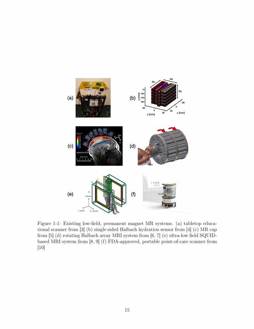
Figure 1-1: Existing low-field, permanent magnet MR systems. (a) tabletop educa-tional scanner from [3] (b) single-sided Halbach hydration sensor from [4] (c) MR capfrom [5] (d) rotating Halbach array MRI system from [6, 7] (e) ultra-low field SQUID-based MRI system from [8, 9] (f) FDA-approved, portable point-of-care scanner from[10]
15

16
Chapter 2
MRI Background
Since its discovery in the early 1970s, magnetic resonance imaging (MRI) has provided
noninvasive diagnostic imaging of the human anatomy. Some advantages of MR
include no ionizing radiation, high spatial resolution, and a large range of physical
parameters that can be captured. However, conventional MR hardware is expensive
and often limited in accessibility outside of hospital settings [1].
MR scanners utilize static and alternating radiofrequency (RF) magnetic fields to
excite hydrogen atoms (protons) which are abundant in the body, most notably in
water and fat. When subjected to a strong external magnetic field, B0, the magnetic
moment vectors of the hydrogen atoms align in the direction of the field and exhibit
a resonance at the Larmor frequency, f0.
f0 =�
2⇡| B0 | (2.1)
� is referred to as the gyromagnetic ratio of a particle’s magnetic moment to its
angular momentum. Hydrogen atoms in an external magnetic field will precess at
a frequency that is proportional to the applied field and �2⇡ = 42.577 MHz/T. MR
convention dictates that the external field is z-directed, or longitudinally-directed [12].
17
2.1 Main Magnetic Field (B0)
In MR, a strong magnet produces a static magnetic field (B0) in the z-direction. For
clinical scanners, the B0 field typically ranges from 1.5 - 7 Tesla. These magnets
are passively shimmed using small pieces of metal or magnets to be homogeneous
to around 1 part per million (ppm). When a proton is exposed to a B0 field, a
z-directed net magnitization, M0, is induced on it, and they will precess in the B0
field at the Larmor frequency [12].
2.2 Radiofrequency (RF) Excitation (B1)
In order to obtain an MR signal, an RF pulse is applied to a coil in the x-y plane
(or transverse-plane) to excite the spins of the hydrogen atoms into resonance. This
RF pulse is referred to as the B1 field and oscillates at the Larmor frequency of the
static B0 field (Fig. 2-1). The B1 field rotates the proton magnetization by an angle
that is a function of its strength (B1) and duration (⌧).
✓ = �B1⌧ (2.2)
In a typical MR system, the B1 field is several orders of magnitude smaller than
B0 and its duration is on the order of milliseconds. The RF transmit coil generally
consists of one or more turns of wire placed within the main B0 magnet.
Similarly, an RF coil is also responsible for receiving the MR signal from the
excited spins. This signal is captured in the induced voltage on the coil due to a
change in magnetic flux as defined in Faraday’s law of induction.
E = �d�B
dt(2.3)
In nuclear magnetic resonance (NMR) and MRI, the nuclear magnetization vector
is governed by the Bloch equations:
dM
dt= M ⇥ �B � Mxi+Myj
T2� (Mz �M0)k
T1(2.4)
18

where T1 represents the time constant for return of Mz and T2 represents the decay
of the transverse magnetizations, Mx and My.
Oftentimes, a single coil performs both RF transmit and receive (T/R). Arrays
of T/R coils are also common in clinical MR, but will not be discussed here (see
[13, 14]). After RF excitation, there is a time-varying signal called the free induction
decay (FID) that results from the decaying transverse magnetization (Mxy). Sets of
FIDs and refocused FIDs can be reconstructed into an MR image [15].
Figure 2-1: Proton spin evolution in the presence of B0 and B1 fields. (a) protonrotating about its own axis in the absence of an external magnetic field (b) protonprecession at the Larmor frequency when exposed to a z-directed external magneticfield, B0 (c) in the laboratory frame of reference, RF pulse that is tuned to Larmorfrequency is applied to the transverse plane as the magnetization moves away fromthe z-axis (d) simplified rotating frame of reference showing flip angle, ✓, of themagnetization vector when RF pulse is applied
2.3 Gradient Fields
Conventional MR imaging relies on linear, DC, spatial encoding magnetic fields in the
x-, y-, and z-directions. These fields, referred to as the gradient fields (Gx, Gy, and
19
Gz), are turned on and off during the image acquisition process. The gradients allow
for spatial localization of received signals by perturbing the B0 homogeneity. Depend-
ing on the desired orientation of the imaging plane, each gradient axis corresponds
to either a slice-select, phase-encoding, or frequency-encoding/readout gradient. A
typical clinical MR gradient strength is less than 1 G/cm or 10 mT/m.
2.4 Signal Acquisition
Two basic image acquisition methods are most commonly used low-field MRI: projection-
based reconstruction and 2D Fourier transform imaging with linear gradients de-
scribed above. However, there are dozens of more sophisticated image acquisition
schemes that have been employed in clinical MR imaging that will not be discussed
here.
For both projection and Fourier imaging, a 90� excitation and 180� refocusing
pulse in the B1 transverse axis are played in succession, separated by some time,
TE/2. At some time after the initial 90� pulse, the echo time (TE), the excited spins
are back in phase and produce what is known as the spin echo (SE) signal that is
picked up by the RF receive coil.
2.4.1 Projection-Based Reconstruction
Similar to the tomographic projection techniques used in x-ray and CT, early MR
and NMR imaging made use of this method by collecting projections of magnetization
vector signals along several different angles in the presence of some gradient field and
integrating over the excited plane [16, 17, 18, 19]. The total received signal sr(t) is
given by
sr(t) =Z
x
Z
ym(x, y)e�j!0te�j�Gxtdxdy (2.5)
20

The baseband signal is then given by
s(t) = sr(t)e+j!0t (2.6)
2.4.2 2D Fourier Transform Imaging
Most commonly used in MRI is the 2D Fourier transform approach where many pro-
jections are taken at one single projection angle to reconstruct an image, m(x,y).
Conventional MR acquisition involves using linear gradient waveforms (see Section
2.3) multiplied by a set spatial frequency weighting factor to sample in the Cartesian
frequency domain, called k-space. When the prescribed set of k-space lines are sam-
pled, an image can be reconstructed using the 2D discrete Fourier transform (DFT).
The acquisition timing diagram for the 2DFT is shown in Fig. 2-2.
Figure 2-2: Conventional spin echo sequence for 2D discrete Fourier image encoding
21

2.5 Conventional MRI Hardware
2.5.1 Superconducting Magnets for B0
Most clinical magnets are superconducting solenoidal electromagnets whose coils are
cooled in liquid helium to maintain a homogeneous B0 field. While these magnets are
very homogeneous and can provide high-resolution imaging, the cost of purchasing
and maintaining the magnet remain very high. Typical 1.5T and 3T clinical magnets
cost an average of 1.5 and 2 million US dollars (USD), respectively [20]. On top of
this base cost, there are also significant costs to maintaining the sitting cost of the
cryogenic cooling system as well as building an RF-shielded room, which can amount
to as much as 100,000 USD [1].
2.5.2 Permanent Magnets for B0
Since the introduction of NdFeB rare-earth magnets in the 1980s, permanent magnet
arrays for low-field B0 magnets has becoming increasingly popular as a means for
reducing hardware costs (in both the magnet and RF subsystem) [21]. A popular
configuration that has been explored comes from the work of Halbach [22, 23, 24].
Various permanent magnet Halbach cylinder designs have been discussed in a recent
review article by Wald et al. and are shown in Fig. 2-3 [1]. Several Halbach array
MR systems that have been built are also found in Fig. 1-1.
Another permanent magnet topology that has been proposed for low-field MR
comes from a 1991 patent by Aubert that involves using radially polarized ring mag-
nets or NdFeB cube magnets arranged in a ring to create a longitudinal magnetic
field (whereas the Halbach array has a transverse field) [25, 26, 27, 28]. This magnet
topology provides opportunities to explore novel image encoding strategies and coil
geometries in a low-cost system; however, it has yet to be built in a physical system
and the current optimization methods for designing these magnets are inefficient and
computationally expensive as they integrate the fields over the entire surface of the
ring. The focus of this thesis will discuss the optimization and construction of a MR
22
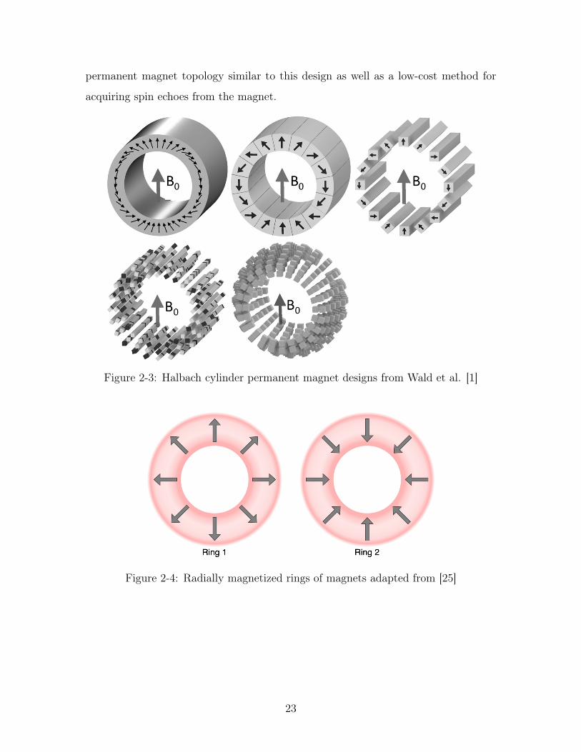
permanent magnet topology similar to this design as well as a low-cost method for
acquiring spin echoes from the magnet.
Figure 2-3: Halbach cylinder permanent magnet designs from Wald et al. [1]
Figure 2-4: Radially magnetized rings of magnets adapted from [25]
23
2.5.3 Control Console and Signal Chain
In MR, the control console is responsible for controlling the timing and execution of
RF and gradient pulse sequences, reads in the received signals, and sometimes even
performs signal processing (e.g. down-conversion, filtering).
Conventional console systems from large MRI vendors like Siemens, GE, and
Philips are available at a high cost due to its infrequent and nonrecurring devel-
opment costs and low production volume. Commercially-available, programmable
systems, such as the Redstone and Apollo NMR/MRI consoles from Tecmag, have
been used in portable MR research but at a high cost (35,000 USD) [29, 5]. A hand-
ful of less-expensive (2,000-10,000 USD) MRI consoles have been developed in recent
years to mitigate these costs, however, these systems are often closed-source and in-
flexible. The Medusa MR console from Stanford University (2011) is a well-known,
scalable, modular USB-controlled solution for tabletop MR systems. However, it has
limited memory for data and pulse sequence storage and is not phase stable between
repetitions [30].
Particularly in the low-field MR regime (1-10MHz), recent improvements in low-
cost, phase-stable RF signal processing modules are beginning to be exploited. For
example, the Red Pitaya (400 USD) is a two-channel field programmable gate array
(FPGA) capable of signal generation and digitization up to 40MHz [31]. The console
systems mentioned here are shown in Fig. 2-5.
Since typical MR systems operate at a Larmor frequency above 50 MHz, they
require high frequency RF amplifiers and preamplifiers for excitation and receive, re-
spectively. This hardware often requires high power dissipation capabilities and strict
bandwidth limits, driving up their cost. For low-field MR, RF amplifiers and pream-
plifiers can be obtained at a significantly lower cost due to the lessened frequency and
power constraints [32].
24

Figure 2-5: NMR/MRI consoles: (from left to right) Tecmag Apollo (35,000 USD)[29], Medusa (2,000 USD) [30], Red Pitaya (400 USD) [31]
25

26

Chapter 3
Spokes-and-Hub Magnet
3.1 Magnet Design Considerations
Other groups have demonstrated through calculation and simulation that sets of ra-
dially polarized ring magnets can create homogeneous fields as shown in Fig. 2-4
[25, 26, 27, 28]. To maintain a radial �!B field such that r · �!B = 0, the magneti-
zation density of the magnets must be manufactured to decrease continuously with
radius. For this reason, these radially polarized magnets are expensive, difficult to
manufacture uniformly, and dangerous to handle.
To mitigate these costs, I have proposed a "spokes-and-hub" magnet topology con-
sisting of rings of cheap, commercially-available, and uniform axially polarized cylin-
drical/rectangular bar magnets, or "spokes". By calculating the fields from equivalent
charges at the end points of the bar magnet spokes, the charges at the outer edge
of the ring are negligible if the spokes are long enough. Because of the variety of
commercial bar magnets geometries, the "hubs" can be densely packed as if it were a
continuous ring to allow for uniform magnetic fields. Optimized spokes-and-hub mag-
nets also have several advantages for hand-held, low-cost, low-field, single-slice MR
imaging (50-200 mT) in that their frame is open, and they are safe to assemble, and
can be scaled to different sizes and field strengths for both clinical and educational
applications.
27

3.2 Magnetic Field Simulation and Optimization
Gauss-Legendre-quadrature based discretization of the equivalent-charge method was
used to compute magnetic fields from axially-magnetized, cylindrical and square rods
arranged in two large rings with opposite polarity (Fig. 3-1). Because the fields are so
efficiently computed, optimization techniques can be used to quickly tune parameters
for magnet design. Levenberg-Marquardt nonlinear least squares optimization in
Matlab was used to minimize the field inhomogeneity about a desired field of view
(FOV) at the center of the magnet, and obtain an optimal z-axis separation distance
between the two sets of magnet rings. Differentiating the potential from end-cap
equivalent charges is so efficient at computing fields from bar magnets, that in less
than minute, a laptop running Matlab can computationally-optimize field uniformity
in hundred-bar wagon-wheel (or spokes-and-hub) magnets [33, 34, 35, 36].
Shown in Fig. 3-1 can see examples of the simulated B0 field through thin slices
in the x-y and y-z planes at the center of an approximately 107 mT magnet. A
noteworthy feature of these spokes-and-hub magnets is their field uniformity within
slices in the x-y plane, with homogeneity on the order of hundreds of parts per million
(ppm). Additionally, in this same simulated magnet, we can easily compute and
analyze the B0 field along other planes. The plot of B0 in the y-z plane shows the
field varies greatly (by around 1 mT, or 1000 ppm) over the same area as the x-y slice
shown above it.
Because the B0 homogeneity can be modified by adjusting the distance between
rings, the hub separation that minimizes field inhomogeneities is optimized for in
Matlab. Figure 3-2 demonstrates the B0 field homogeneity for varying hub separa-
tions.
28

Figure 3-1: Simulated B0 field maps in x-y (top row) and y-z plane (bottom row)
Figure 3-2: Hub separation distance optimization
29
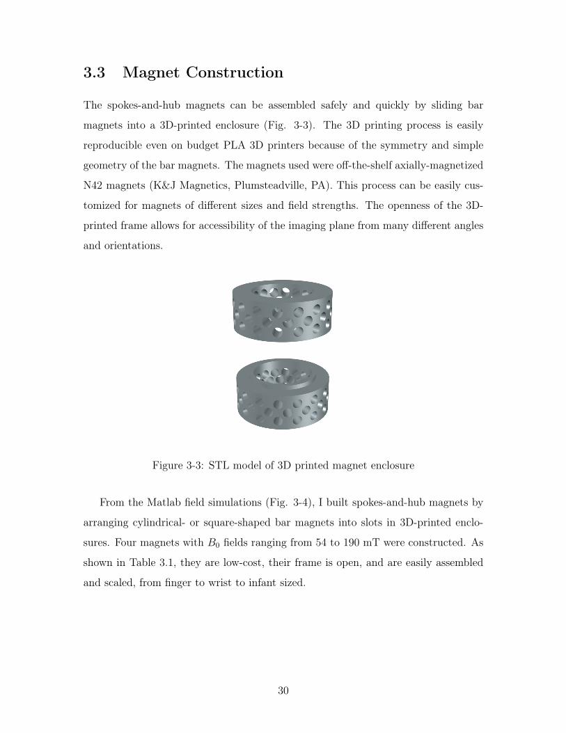
3.3 Magnet Construction
The spokes-and-hub magnets can be assembled safely and quickly by sliding bar
magnets into a 3D-printed enclosure (Fig. 3-3). The 3D printing process is easily
reproducible even on budget PLA 3D printers because of the symmetry and simple
geometry of the bar magnets. The magnets used were off-the-shelf axially-magnetized
N42 magnets (K&J Magnetics, Plumsteadville, PA). This process can be easily cus-
tomized for magnets of different sizes and field strengths. The openness of the 3D-
printed frame allows for accessibility of the imaging plane from many different angles
and orientations.
Figure 3-3: STL model of 3D printed magnet enclosure
From the Matlab field simulations (Fig. 3-4), I built spokes-and-hub magnets by
arranging cylindrical- or square-shaped bar magnets into slots in 3D-printed enclo-
sures. Four magnets with B0 fields ranging from 54 to 190 mT were constructed. As
shown in Table 3.1, they are low-cost, their frame is open, and are easily assembled
and scaled, from finger to wrist to infant sized.
30

Figure 3-4: Assembled spokes-and-hub magnets with simulated B0 field and homo-geneity. In each row, from left to right: picture of assembled magnet; quadraturepoints for field simulator; simulated x-y fields through center slice of magnet; fieldhomogeneity along one radius within center slice
31

Table 3.1: Constructed spokes-and-hub magnets
Magnet Dimensions Field Strength(Larmor frequency) Cost
spokes:32 cylindrical N42 magnets
6.35 mm diameter50.8 mm length
hub:34.29 mm inner diameter
107 mT(4.57 MHz) 75 USD
spokes:192 rectangular N42 magnets
6.35 x 3.175 x 6.35 mm
hub:25.4 mm inner diameter
191.3 mT(8.145 MHz) 100 USD
spokes:96 cylindrical N42 magnets
6.35 mm diameter50.8 mm length
hub:42.672 mm inner diameter
191.1 mT(8.137 MHz) 350 USD
spokes:96 rectangular N42 magnets
6.35 x 6.35 x 50.8 mm
hub:132.64 mm inner diameter
54.8 mT(2.33 MHz) 425 USD
32

3.4 Field Measurements
Since the z-directed field is assumed to be radially symmetric about the z = 0 plane,
field measurements were taken along the inner radius of the magnet within the op-
timized FOV of interest using an ALS31300 3D Linear Hall-Effect Sensor (Allegro
Microsystems, Manchester, NH).
Figure 3-5: Array of ALS31300 Hall effect sensors for B0 field measurements
33

34

Chapter 4
Results
4.1 Magnet Characterization
4.1.1 Imaging Slice Thickness
Looking into the feasible slice thicknesses for MR imaging, I’ve shown �B0 maps in
Fig. 4-1 for slice thickness of 0.25, 1, and 2 mm where the an inter-slice homogeneity
ranges from tens to thousands of ppm. The �B0 maps were calculated by subtracting
the field at the center x-y plane between the hub rings from the an x-y slice 0.25,
1, and 2 mm away. Table 4.1 lists the maximum �B0 found within each of the
simulated slices and the corresponding frequency bandwidth that would be required
from an RF pulse to excite the entire region. Because of the large variation in B0
in the z-direction, we see that the spokes-and-hub magnets should be limited to very
thin slices and cannot be used directly for volumetric imaging without implementing
broadband RF pulses. Volumetric images instead can be obtained by sliding the
magnet, as made possible by its open frame.
35

Figure 4-1: Simulated imaging slice thickness for 0.25, 1, and 2 mm slabs. Top row:�B0 field map of entire slice; Bottom row: �B0 along a single radius of the slice
Table 4.1: �B0 and excitation frequency for various simulated slice thicknesses
Slice Thickness Maximum �B0 Required Excitation Frequency Bandwidth0.25 mm 0.0064 mT 0.27 kHz1 mm 0.0959 mT 4.08 kHz2 mm 0.3026 mT 12.88 kHz
36

Figure 4-2: B0 field along rings at different radii in the desired FOV
4.1.2 Radially Symmetric Fields
Furthermore, when looking into the field patterns along rings within the same thin
slice, the fields are radially symmetric and have little variation within each ring com-
pared to the homogeneity of the entire slice. As shown in Fig. 4-2, the field variation
within the rings is less than 0.02 mT with a homogeneity within a couple ppm. The
variation along each ring can be attributed to error when mapping the Cartesian
discretization of simulation points to the circular mask for selecting rings of fields.
This radial symmetry is noteworthy because it can be exploited for imaging or for
projection-encoding.
4.1.3 Field Measurements
Because of the spokes-and-hub magnet’s radial symmetry discussed above, field mea-
surements were made along a single radius. The measured fields are shown by red
circles and compared to simulated fields in white. The precision of the hall-effect
probe is denote by the red error bars. Measured fields over the optimized FOV
closely match the simulated B0 within the hall-effect probe margin of error for each
magnet.
37

Figure 4-3: B0 field measurements along one radius of spokes-and-hub magnets
38

4.2 Spin Echoes
To demonstrate the feasibility of these spokes-and-hub magnets as tools for MR imag-
ing, I obtained spin echoes on the 191 mT magnets using the signal chain detailed in
Fig. 4-4. The RF subsystem consists of a Teensy 4.0 microcontroller, an 8-channel
STHV800 ultrasound pulser chip, and a transmit/receive coil. I used the STHV800 ul-
trasound pulser (30 USD, STMicroelectronics) to create programmable, high-voltage
pulses as well as receiving low-amplitude signals through its T/R switch. Because
each channel is driven by 2 digital bits, the chip can be enabled by digital square-wave
outputs. Teensy 4.0 (20 USD, PJRC), with its ARM Cortex-M7 processor and dy-
namic clock scaling functionality, can generate reliable pulses with a timing resolution
of 3.3 ns that the ultrasound pulser can drive the RF coil. This allows for careful
control of the RF output from the Teensy through amplitude and frequency modula-
tion. The low-amplitude MR signals received on the ultrasound driver are amplified
through two inverting op-amp stages for a total gain of 100. I designed a printed
circuit board (PCB) to control the STHV800 driver and receive signal chain, and the
4-layer board was prototyped by PCBWay (Shenzhen, China) shown in Fig. 4-5. The
RF coil was taken from the MIT and Martinos Center tabletop educational scanners
that also operate at the same Larmor frequency of ⇠8.13MHz. The Teensy’s ARM
Cortex-M7 processor. The use of lower fields strengths allows for significantly lowered
cost of RF transmit and receive hardware compared to conventional MR because high
voltage H-bridge drivers and operational amplifiers can be used at this frequency. The
widespread accessibility to these parts also allows for the spokes-and-hub MR setup
to be replicated outside of the laboratory environment. Figure 4-6 shows the at-home
working system (despite global pandemic conditions).
39
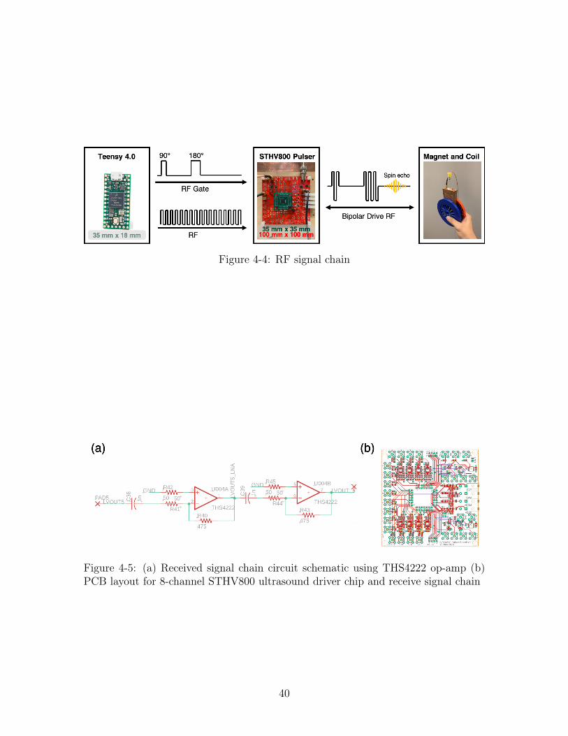
Figure 4-4: RF signal chain
Figure 4-5: (a) Received signal chain circuit schematic using THS4222 op-amp (b)PCB layout for 8-channel STHV800 ultrasound driver chip and receive signal chain
40
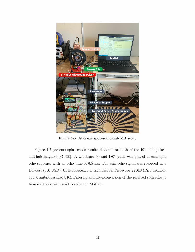
Figure 4-6: At-home spokes-and-hub MR setup
Figure 4-7 presents spin echoes results obtained on both of the 191 mT spokes-
and-hub magnets [37, 38]. A wideband 90 and 180� pulse was played in each spin
echo sequence with an echo time of 0.5 ms. The spin echo signal was recorded on a
low-cost (350 USD), USB-powered, PC oscilloscope, Picoscope 2206B (Pico Technol-
ogy, Cambridgeshire, UK). Filtering and downconversion of the received spin echo to
baseband was performed post-hoc in Matlab.
41
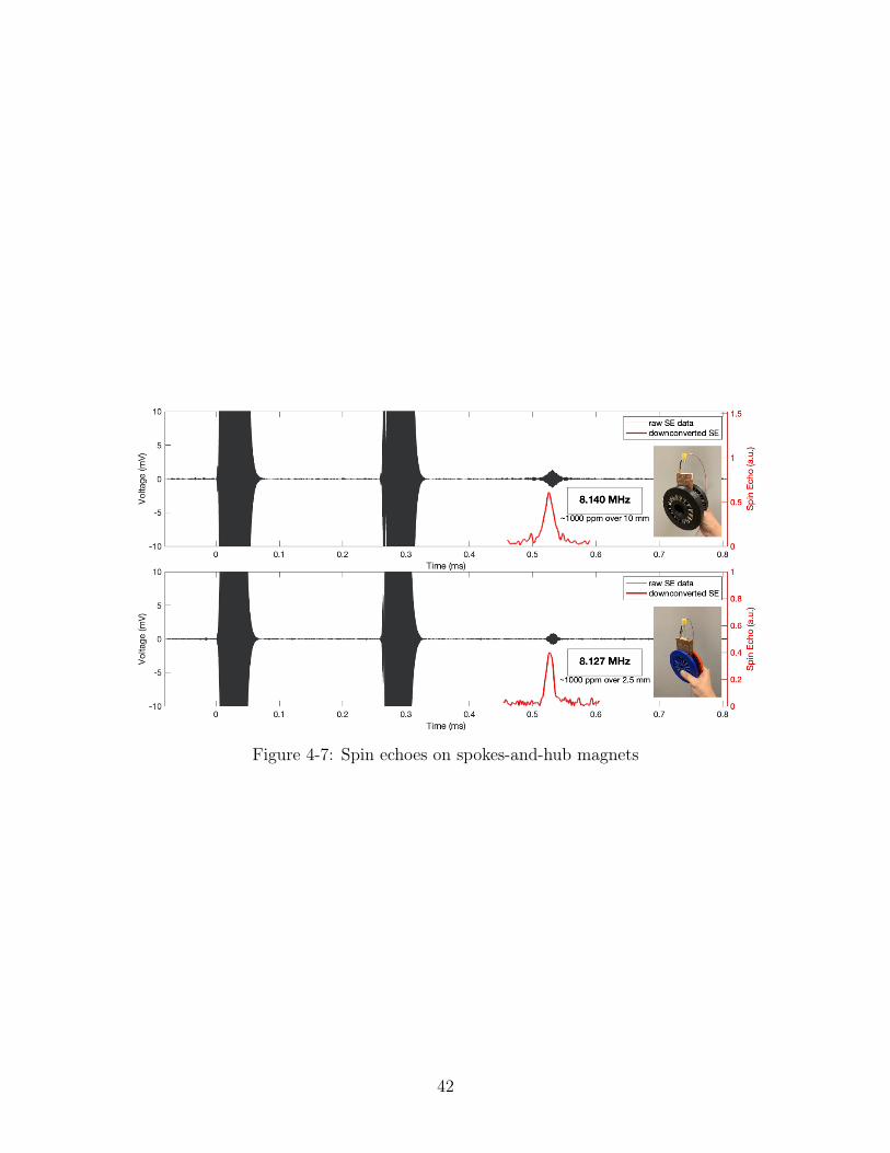
Figure 4-7: Spin echoes on spokes-and-hub magnets
42

Chapter 5
Conclusions
Here I have characterized and demonstrated feasibility of several, easy-to-assemble
spokes-and-hub low-field permanent magnet structures for MRI. In simulation, we
have a computationally-efficient method for accurately modeling the B0 field across
multiple planes within the magnet bore. With the ability to efficiently simulate
the fields, we can further optimize the fields within the magnet to also allow for
built-in linear gradients in the static magnetic field by introducing unequal numbers
of bar magnets within each ring. Regarding the design of the magnet, its open
structure allows for imaging along all three axes, as well as potential for utilization
of mechanical rotation of the magnet for gradient encoding and projection-based
imaging [39, 6]. The spoke rings can also be easily taken apart to allow for novel
coil geometries. Of particular interest, spokes-and-hub magnet demonstrates great
promise as a low-cost, hand-held tool for clinical scanning of adult limbs/extremities
and pediatric brains, most notably with applications towards hydrocephalus detection
in newborns which does not require high-resolution imaging [40]. Moving forward, in
my PhD, I plan to apply this spokes-and-hub topology to an imaging system capable of
these clinical applications with fields optimized to capitalize on the magnet’s inherent
inhomogeneities.
43

44

Bibliography
[1] L. L. Wald, P. C. McDaniel, T. Witzel, J. P. Stockmann, and C. Z. Cooley,“Low-cost and portable MRI,” Journal of Magnetic Resonance Imaging, pp. 1–11, 2019.
[2] J. P. Marques, F. F. Simonis, and A. G. Webb, “Low-field MRI: An MR physicsperspective,” Journal of Magnetic Resonance Imaging, vol. 49, no. 6, pp. 1528–1542, 2019.
[3] C. Z. Cooley, J. P. Stockmann, T. Witzel, C. LaPierre, A. Mareyam, F. Jia,M. Zaitsev, Y. Wenhui, W. Zheng, P. Stang, G. Scott, E. Adalsteinsson, J. K.White, and L. L. Wald, “Design and implementation of a low-cost, tabletop MRIscanner for education and research prototyping,” Journal of Magnetic Resonance,vol. 310, p. 106625, 2020.
[4] A. Bashyam, M. Li, and M. J. Cima, “Design and experimental validation ofUnilateral Linear Halbach magnet arrays for single-sided magnetic resonance,”Journal of Magnetic Resonance, vol. 292, pp. 36–43, jul 2018.
[5] P. C. McDaniel, C. Z. Cooley, J. P. Stockmann, and L. L. Wald, “The MR Cap:A single-sided MRI system designed for potential point-of-care limited field-of-view brain imaging,” Magnetic Resonance in Medicine, vol. 82, pp. 1946–1960,nov 2019.
[6] C. Z. Cooley, J. P. Stockmann, B. D. Armstrong, M. Sarracanie, M. H. Lev, M. S.Rosen, and L. L. Wald, “Two-dimensional imaging in a lightweight portable MRIscanner without gradient coils,” Magnetic Resonance in Medicine, vol. 73, no. 2,pp. 872–883, 2015.
[7] C. Z. Cooley, M. W. Haskell, S. F. Cauley, C. Sappo, C. D. Lapierre, C. G.Ha, J. P. Stockmann, and L. L. Wald, “Design of sparse halbach magnet arraysfor portable MRI using a genetic algorithm,” IEEE Transactions on Magnetics,vol. 54, pp. 1–12, jan 2017.
[8] A. N. Matlashov, E. Burmistrov, P. E. Magnelind, L. Schultz, A. V. Ur-baitis, P. L. Volegov, J. Yoder, and M. A. Espy, “SQUID-based systems forco-registration of ultra-low field nuclear magnetic resonance images and magne-toencephalography,” Physica C: Superconductivity and its Applications, vol. 482,no. September 2014, pp. 19–26, 2012.
45

[9] M. A. Espy, P. E. Magnelind, A. N. Matlashov, S. G. Newman, H. J. Sandin,L. J. Schultz, R. Sedillo, A. V. Urbaitis, and P. L. Volegov, “Progress towarda deployable SQUID-based ultra-low field MRI system for anatomical imaging,”IEEE Transactions on Applied Superconductivity, vol. 25, no. 3, 2015.
[10] M. S. Poole, C. Hugon, H. A. Dyvorne, L. Sacolick, W. J. Mileski, J. C. Jordan,A. B. Katze Jr, J. M. Rothberg, T. Rearick, and C. T. McNulty, “Portablemagnetic resonance imaging methods and apparatus,” 2018.
[11] V. S. Zotev, A. N. Matlachov, P. L. Volegov, H. J. Sandin, M. A. Espy, J. C.Mosher, A. V. Urbaitis, S. G. Newman, and R. H. Kraus, “Multi-Channel SQUIDSystem for MEG and Ultra-Low-Field MRI,” IEEE Transactions on AppliedSuperconductivity, vol. 17, no. 2, pp. 839–842, 2007.
[12] D. G. Nishimura, Physical principles of magnetic resonance imaging. StanfordUniversity, 1996.
[13] B. Gruber, M. Froeling, T. Leiner, and D. W. Klomp, “RF coils: A practicalguide for nonphysicists,” Journal of Magnetic Resonance Imaging, vol. 48, no. 3,pp. 590–604, 2018.
[14] U. Katscher and P. Börnert, “Parallel RF transmission in MRI,” NMR inBiomedicine, vol. 19, no. 3, pp. 393–400, 2006.
[15] R. H. Hashemi, W. G. Bradley, and C. J. Lisanti, MRI: The Basics. LWW, 3 ed.,2010.
[16] P. C. Lauterbur, “Image formation by induced local interactions: examples em-ploying nuclear magnetic resonance,” Nature, vol. 242, no. 5394, pp. 190–191,1973.
[17] B. Liu, G. Wang, E. L. Ritman, G. Cao, J. Lu, O. Zhou, L. Zeng, and H. Yu,“Image reconstruction from limited angle projections collected by multisourceinterior x-ray imaging systems,” Physics in Medicine and Biology, vol. 56, no. 19,pp. 6337–6357, 2011.
[18] J. E. Eben, T. L. Vent, C. J. Choi, S. Yarrabothula, L. Chai, M. Nolan, E. Kobe,R. J. Acciavatti, and A. D. A. Maidment, “Development of a next generationtomosynthesis system,” Proc. SPIE, vol. 10573, no. March 2018, p. 212, 2018.
[19] G. Schultz, H. Weber, D. Gallichan, W. R. Witschey, A. M. Welz, C. A. Cocosco,J. Hennig, and M. Zaitsev, “Radial imaging with multipolar magnetic encodingfields,” IEEE Transactions on Medical Imaging, vol. 30, no. 12, pp. 2134–2145,2011.
[20] C. Obyn and I. Cleemput, “The capital cost and productivity of MRI in a Belgiansetting,” Jbr-Btr, vol. 93, no. 2, pp. 92–96, 2010.
46

[21] D. Brown, B. M. Ma, and Z. Chen, “Developments in the processing and prop-erties of NdFeb-type permanent magnets,” Journal of Magnetism and MagneticMaterials, vol. 248, no. 3, pp. 432–440, 2002.
[22] K. Halbach, “Design of permanent multipole magnets with oriented rare earthcobalt material,” Nuclear Instruments and Methods, vol. 169, no. 1, pp. 1–10,1980.
[23] G. Moresi and R. Magin, “Miniature permanent magnet for table-top NMR,”Concepts in Magnetic Resonance Part B: Magnetic Resonance Engineering,vol. 19, no. 1, pp. 35–43, 2003.
[24] H. Raich and P. Blümler, “Design and construction of a dipolar Halbach arraywith a homogeneous field from identical bar magnets: NMR Mandhalas,” Con-cepts in Magnetic Resonance Part B: Magnetic Resonance Engineering, vol. 23,no. 1, pp. 16–25, 2004.
[25] G. Aubert, “Cylindrical permanent magnet with longitudinal induced field,”1991.
[26] C. Hugon, F. D’Amico, G. Aubert, and D. Sakellariou, “Design of arbitrar-ily homogeneous permanent magnet systems for NMR and MRI: Theory andexperimental developments of a simple portable magnet,” Journal of MagneticResonance, vol. 205, no. 1, pp. 75–85, 2010.
[27] C. Hugon, P. M. Aguiar, G. Aubert, and D. Sakellariou, “Design, fabrication andevaluation of a low-cost homogeneous portable permanent magnet for NMR andMRI,” Comptes Rendus Chimie, vol. 13, no. 4, pp. 388–393, 2010.
[28] Z. H. Ren, W. C. Mu, and S. Y. Huang, “Design and Optimization of a Ring-Pair Permanent Magnet Array for Head Imaging in a Low-Field Portable MRISystem,” IEEE Transactions on Magnetics, vol. 55, no. 1, pp. 1–8, 2019.
[29] Http://www.tecmag.com/history/, “History - Tecmag.”
[30] P. P. Stang, S. M. Conolly, J. M. Santos, J. M. Pauly, and G. C. Scott, “Medusa:A scalable MR console using USB,” IEEE Transactions on Medical Imaging,vol. 31, pp. 370–379, feb 2012.
[31] S. M. Anand, “OCRA : a low-cost, open-source FPGA-based MRI console capa-ble of real-time control,” Master’s thesis, Massachusetts Institute of Technology,2018.
[32] N. K. Almazrouei, M. I. Newton, and R. H. Morris, “Operational Amplifiers Re-visited for Low Field Magnetic Resonance Relaxation Time Measurement Elec-tronics,” Proceedings, vol. 42, no. 1, p. 1, 2019.
47
[33] J. P. Selvaggi, S. Salon, O. M. Kwon, and M. V. Chari, “Calculating the externalmagnetic field from permanent magnets in permanent-magnet motors - An alter-native method,” IEEE Transactions on Magnetics, vol. 40, no. 5, pp. 3278–3285,2004.
[34] H. S. Choi, S. H. Lee, and I. H. Park, “General formulation of equivalent magneticcharge method for force density distribution on interface of different materials,”IEEE Transactions on Magnetics, vol. 41, no. 5, pp. 1420–1423, 2005.
[35] H. Rui and F. Jian, “Magnetic field analysis of permanent magnet array for planarmotor based on Equivalent Magnetic Charge method,” Proceedings of the WorldCongress on Intelligent Control and Automation (WCICA), pp. 3966–3970, 2012.
[36] M. Curti, J. J. Paulides, and E. A. Lomonova, “An overview of analytical meth-ods for magnetic field computation,” 2015 10th International Conference on Eco-logical Vehicles and Renewable Energies, EVER 2015, no. April, 2015.
[37] I. Kuang, N. Arango, J. Stockmann, E. Adalsteinsson, and J. White, “Equivalent-Charge-Based Optimization of Spokes-and-Hub Magnets for Hand-Held andClassroom MR Imaging,” in Proc. Intl. Soc. Mag. Reson. Med. 27, 2019.
[38] I. Kuang, N. Arango, J. Stockmann, E. Adalsteinsson, and J. White, “Bloch-Optimized Dithered-Ultrasound-Pulse RF for Low-Field Inhomogeneous Perma-nent Magnet MR Imagers,” Proc. Intl. Soc. Mag. Reson. Med. 28, 2020.
[39] Z. H. Cho, S. T. Chung, J. Y. Chung, S. H. Park, J. S. Kim, C. H. Moon,and I. K. Hong, “A new silent magnetic resonance imaging using a rotating DCgradient,” Magnetic Resonance in Medicine, vol. 39, no. 2, pp. 317–321, 1998.
[40] M. G. Kartal and O. Algin, “Evaluation of hydrocephalus and other cerebrospinalfluid disorders with MRI: An update,” Insights into Imaging, vol. 5, no. 4,pp. 531–541, 2014.
48