EQUIPMENT QUOTATION Total Net Sell Price excluding ...
16
Carrier Corporation 400 76th Street SW, Suite 14 Byron Center, MI 49315 (P) 616-583-1600 (F) 616-583-1262 www.commercial.carrier.com EQUIPMENT QUOTATION KISD 2013 Unit Vent Repl This quote is subject to attached terms and conditions Page 1 of 3 Job Name: KISD 2013 Unit Vent Repl Quote Date: 03/08/2013 Job Location: Grand Rapids, MI Quote Number: 10757 Attention: Fred Hayward Phone Number: 616-299-2848 Customer: Kent Intermediate School District Fax Number: Address: Grand Rapids, MI E-Mail Address: [email protected] We at Carrier are pleased to quote the following equipment for the above referenced project in accordance with attached terms and conditions. Mark For Qty Model Number Description FC-4 Row 800 cfm 7 42DEA08GLCY6AYYYW2 Carrier Ducted, Ceiling, Cabinet, Furred-In Fan Coil Unit, 800 CFM Cooling, Includes the Following: • 120-1-60 Motor Voltage • 4-Pipe Heating and Cooling • 4 rows Cooling , 1 row Heating • Left Hand (Please Confirm Handing) • Line Voltage Tstat by Others • Opposite end coil connections (Please Confrim) • Rear Return / Front Supply • Std 1 in. Throwaway Filter • Tell-Tale Drain Pan, Drip Lip • Special Feature: HW Coil in Preheat Position (HW Coil First in Airstream – Cooling Down Stream of Heating) Total Net Sell Price excluding sales tax: $1,189.00 EACH FC-800 cfm MXB 7 QS0504-52-MB MicroMetl Mixing Box to Mate w/ Above 42DE08 Fan Coil Units, Includes the Following: • Tuffskin Insulation • Not Painted, All Controls By Others • Dampers are Connected Internally • Bottom Access Total Net Sell Price excluding sales tax: $534.00 EACH FC-4 Row 1000 cfm 1 42DEA10GLCY6AYYYW2 Carrier Ducted, Ceiling, Cabinet, Furred-In Fan Coil Unit, 1000 CFM Cooling, Includes the Following: • 120-1-60 Motor Voltage • 4-Pipe Heating and Cooling • 4 rows Cooling , 1 row Heating • Left Hand (Please Confirm Handing) • Line Voltage Tstat by Others • Opposite end coil connections (Please Confrim) • Rear Return / Front Supply • Std 1 in. Throwaway Filter • Tell-Tale Drain Pan, Drip Lip • Special Feature: HW Coil in Preheat Position (HW Coil First in Airstream – Cooling Down Stream of Heating) Total Net Sell Price excluding sales tax: $1,243.00 EACH
-
Upload
khangminh22 -
Category
Documents
-
view
2 -
download
0
Transcript of EQUIPMENT QUOTATION Total Net Sell Price excluding ...

Carrier Corporation 400 76th Street SW, Suite 14
Byron Center, MI 49315
(P) 616-583-1600 (F) 616-583-1262
www.commercial.carrier.com
EQUIPMENT QUOTATION
KISD 2013 Unit Vent Repl This quote is subject to attached terms and conditions Page 1 of 3
Job Name: KISD 2013 Unit Vent Repl Quote Date: 03/08/2013 Job Location: Grand Rapids, MI Quote Number: 10757 Attention: Fred Hayward Phone Number: 616-299-2848 Customer: Kent Intermediate School District Fax Number: Address: Grand Rapids, MI E-Mail Address: [email protected]
We at Carrier are pleased to quote the following equipment for the above referenced project in accordance with attached terms and conditions.
Mark For Qty Model Number Description
FC-4 Row 800
cfm
7 42DEA08GLCY6AYYYW2 Carrier Ducted, Ceiling, Cabinet, Furred-In Fan Coil Unit, 800 CFM Cooling, Includes the Following:
• 120-1-60 Motor Voltage • 4-Pipe Heating and Cooling • 4 rows Cooling, 1 row Heating • Left Hand (Please Confirm Handing) • Line Voltage Tstat by Others • Opposite end coil connections (Please Confrim) • Rear Return / Front Supply • Std 1 in. Throwaway Filter • Tell-Tale Drain Pan, Drip Lip • Special Feature: HW Coil in Preheat Position (HW Coil First in Airstream –
Cooling Down Stream of Heating)
Total Net Sell Price excluding sales tax: $1,189.00 EACH
FC-800
cfm MXB 7 QS0504-52-MB MicroMetl Mixing Box to Mate w/ Above 42DE08 Fan Coil Units,
Includes the Following: • Tuffskin Insulation • Not Painted, All Controls By Others • Dampers are Connected Internally • Bottom Access
Total Net Sell Price excluding sales tax: $534.00 EACH
FC-4 Row
1000 cfm
1 42DEA10GLCY6AYYYW2 Carrier Ducted, Ceiling, Cabinet, Furred-In Fan Coil Unit, 1000 CFM Cooling, Includes the Following:
• 120-1-60 Motor Voltage • 4-Pipe Heating and Cooling • 4 rows Cooling, 1 row Heating • Left Hand (Please Confirm Handing) • Line Voltage Tstat by Others • Opposite end coil connections (Please Confrim) • Rear Return / Front Supply • Std 1 in. Throwaway Filter • Tell-Tale Drain Pan, Drip Lip • Special Feature: HW Coil in Preheat Position (HW Coil First in Airstream –
Cooling Down Stream of Heating)
Total Net Sell Price excluding sales tax: $1,243.00 EACH
fredhayward
Text Box
fredhayward
Text Box
fredhayward
Text Box
fredhayward
Text Box
YES
fredhayward
Text Box
YES
fredhayward
Text Box
YES
fredhayward
Text Box
YES

KISD 2013 Unit Vent Repl Equipment and/or Service CSS-TCES 041310 Page 2 of 3
FC-1000 cfm MXB
1 MB-1303-123 MicroMetl Mixing Box to Mate w/ Above 42DE10 Fan Coil Unit, Includes the Following:
• Tuffskin Insulation • Not Painted, All Controls By Others • Dampers are Connected Internally • Bottom Access
Total Net Sell Price excluding sales tax: $575.00 EACH
Total Net Sell Price excluding sales tax: $13,879.00
QUOTATION NOTES:
Note: • 1st year parts only warranty (one (1) year from start-up or eighteen (18) months from date of shipment, whichever
comes first) unless specified otherwise in this proposal.
The following items are NOT included with the equipment identified above: • Installation, rigging, carting. • Equipment base/pad and anchor bolts. • Any piping or accessories except as noted elsewhere in this proposal. • Electrical work including power and control wiring except as noted elsewhere in this proposal. • All instrumentation mounted in field piping.
SPECIAL NOTES: 1. Above price is firm and will remain in effect for 30 days. 2. No taxes, permits, start-up, and or service are included in above proposal unless otherwise noted. 3. Compliance to local codes neither guaranteed nor implied. 4. All orders subject to credit acceptance by Carrier Management. 5. Equipment is manufactured under strict Carrier Corporation manufacturing standards and in compliance with the
National Electric Code. 6. Carrier does not accept and will not be held liable for any flow down requirements from the owner or any higher
tier contractor unless specifically agreed to in writing. 7. Holiday or weekend work required on Carrier start-ups is not included in the above proposal unless otherwise
noted. 8. Any work or material furnished at Carrier’s expense, must have written authorization and approval from Carrier
prior to furnishing such service or materials. Immediately upon completion of such work, the approved price shall be invoiced for immediate processing of a credit memo and applied to your account. Deductions from our invoices or back charges for unauthorized work or materials will not be accepted.
We appreciate your consideration of this quotation and would like to thank you for your interest in Carrier products and services. Should you have any questions concerning the above quotation, please feel free to contact me personally. Sincerely, Carrier Direct Sales Dan Matthes Sales Engineer Carrier Corporation 400 76th Street SW, Suite 14 Byron Center, MI 49315 [email protected] 616-583-1600 - (DID) 860-998-9187 - (eFax) 616-583-1262 - (Office Fax)
fredhayward
Text Box
fredhayward
Text Box

KISD 2013 Unit Vent Repl Equipment and/or Service CSS-TCES 041310 Page 3 of 3
CARRIER CORPORATION TERMS AND CONDITIONS OF SALE – EQUIPMENT AND/OR SERVICE
1. PAYMENT AND TAXES- Payment shall be made 1.25% 10/ net 30 days from date of invoice. Carrier reserves the right to require cash payment or other alternative method of payment prior to shipment or completion of work if Carrier determines, in its sole discretion, that Customer or Customer's assignee’s financial condition at any time does not justify continuance of the net 30 days payment term. In addition to the price, the Customer shall also pay Carrier any taxes or government charges arising from this Agreement. 2. EXTRAS- Equipment, parts or labor in addition to those specified in this Agreement will be provided upon receipt of Customer’s written authorization and paid for as an extra and subject to the terms of this Agreement. 3. RETURNS- No items will be accepted for return without prior written authorization. Returned goods may be subject to a restocking charge. Special order and non-stock items cannot be returned. 4. SHIPMENT- All shipments shall be F.O.B. shipping point, freight prepaid and allowed to the job site. Shipment dates quoted are approximate. Carrier does not guarantee a particular date for shipment or delivery. 5. PARTIAL SHIPMENT- Carrier shall have the right to ship any portion of the equipment included in this Agreement and invoice Customer for such partial shipment. 6. DELAYS– Delays caused by conditions beyond the reasonable control of either party shall not be the liability of either party to this Agreement. 7. WARRANTY- Carrier warrants that all equipment manufactured by Carrier Corporation and all Carrier equipment, parts or components supplied hereunder will be free from defects in material and workmanship. Carrier shall at its option repair or replace, F.O.B. point of sale, any equipment, part or component sold by Carrier and determined to be defective within one (1) year from the date of initial operation or eighteen (18) months from date of shipment, whichever is earlier. Carrier does not warrant products not manufactured by Carrier Corporation, but it does pass on to Customer any available manufacturer’s warranty for those products. Carrier warrants that all service provided by Carrier hereunder shall be performed in a workmanlike manner. In the event any such service is determined to be defective within ninety (90) days of completion of that service, Carrier shall at its option re-perform or issue a credit for such service, Carrier’s obligation to repair or replace any defective equipment, parts or components during the warranty period shall be Customer’s exclusive remedy. Carrier shall not be responsible for labor charges for removal or reinstallation of defective equipment, parts or components, for charges for transportation, handling and shipping or refrigerant loss, or for repairs or replacement of such equipment, parts or components, required as a consequence of faulty installation, misapplication, vandalism, abuse, exposure to chemicals, improper servicing, unauthorized alteration or improper operation by persons other than Carrier. THIS WARRANTY IS GIVEN IN LIEU OF ALL OTHER WARRANTIES, EXPRESS, IMPLIED OR STATUTORY INCLUDING THE IMPLIED WARRANTIES OF MERCHANTABILITY AND FITNESS FOR A PARTICULAR PURPOSE. 8. WORKING HOURS– All services performed under this Agreement including major repairs, are to be provided during Carrier’s normal working hours unless otherwise agreed. 9. ADDITIONAL SERVICE- Services or parts requested by Customer in addition to those specified in this Agreement will be provided upon receipt of Customer’s written authorization and invoiced at Carrier’s prevailing labor rates and parts charges. Additional services or parts shall be supplied under the terms of this Agreement. 10. CUSTOMER RESPONSIBILITIES (Service Contracts only) – Customer shall:
• Provide safe and reasonable equipment access and a safe work environment. • Permit access to Customer’s site, and use of building services including but not limited to: water, elevators, receiving dock facilities, electrical service and local telephone service. • Keep areas adjacent to equipment free of extraneous material, move any stock, fixtures, walls or partitions that may be necessary to perform the specified service. • Promptly notify Carrier of any unusual operating conditions. • Upon agreement of a timely mutual schedule, allow Carrier to stop and start equipment necessary to perform service. • Provide adequate water treatment. • Provide the daily routine equipment operation (if not part of this Agreement) including availability of routine equipment log readings. • Where Carrier’s remote monitoring service is provided, provide and maintain a telephone line with long distance direct dial and answer capability. • Operate the equipment properly and in accordance with instructions. • Promptly address any issues that arise related to mold, fungi, mildew or bacteria. • Identify and label any asbestos containing material that may be present. The customer will provide, in writing, prior to the start of a job, a signed statement regarding the absence or
presence of asbestos for any job where the building or the equipment to be serviced is older than 1981. Should this document state that no asbestos is present, the customer will also provide in writing the method used to determine the absence of asbestos.
11. EXCLUSIONS– Carrier is not responsible for items not normally subject to mechanical maintenance including but not limited to: duct work, casings, cabinets, fixtures, structural supports, grillage, water piping, steam piping, drain piping, cooling tower fill, boiler tubes, boiler refractory, disconnect switches and circuit breakers. Carrier is not responsible for repairs, replacements, alterations, additions, adjustments, repairs by others, unscheduled calls or emergency calls, any of which may be necessitated by negligent operation, abuse, misuse, prior improper maintenance, vandalism, obsolescence, building system design, damage due to freezing weather, chemical/electrochemical attack, corrosion, erosion, deterioration due to unusual wear and tear, any damage related to the presence of mold, fungi, mildew, or bacteria, damage caused by power reductions or failures or any other cause beyond Carrier’s control. Carrier shall not be required to perform tests, install any items of equipment or make modifications that may be recommended or directed by insurance companies, government, state, municipal or other authority. However, in the event any such recommendations occur, Carrier, at its option, may submit a proposal for Customer’s consideration in addition to this Agreement. Carrier shall not be required to repair or replace equipment that has not been properly maintained. 12. EQUIPMENT CONDITION & RECOMMENDED SERVICE (Service Contracts only) – Upon the initial scheduled operating and/or initial annual stop inspection, should Carrier determine the need for repairs or replacement, Carrier will provide Customer in writing an ‘equipment condition’ report including recommendations for corrections and the price for repairs in addition to this Agreement. In the event Carrier recommends certain services (that are not included herein or upon initial inspection) and if Customer does not elect to have such services properly performed in a timely fashion, Carrier shall not be responsible for any equipment or control failures, operability or any long-term damage that may result. Carrier at its option will either continue to maintain equipment and/or controls to the best of its ability, without any responsibility, or remove such equipment from this Agreement, adjusting the price accordingly. 13. PROPRIETARY RIGHTS (Service Contracts only)- During the term of this Agreement and in combination with certain services, Carrier may elect to install, attach to Customer equipment, or provide portable devices (hardware and/or software) that shall remain the personal proprietary property of Carrier. No devices installed, attached to real property or portable device(s) shall become a fixture of the Customer locations. Customer shall not acquire any interest, title or equity in any hardware, software, processes, and other intellectual or proprietary rights to devices that are used in connection with providing service on Customer equipment. 14. LIMITATION OF LIABILITY- Under no circumstances shall Carrier be liable for any incidental, special or consequential damages, including loss of revenue, loss of use of equipment or facilities, or economic damages based on strict liability or negligence. Carrier shall be liable for damage to property, other than equipment provided under this Agreement, and to persons, to the extent that Carrier’s negligent acts or omissions directly contributed to such injury or property damage. Carrier’s maximum liability for any reason (except for personal injuries) shall consist of the refunding of all moneys paid by Customer to Carrier under this Agreement. 15. CANCELLATION- Customer may cancel this Agreement only with Carrier’s prior written consent, and upon payment of reasonable cancellation charges. Such charges shall take into account costs and expenses incurred, and purchases or contract commitments made by Carrier and all other losses due to the cancellation including a reasonable profit. 16. CUSTOMER TERMINATION FOR CARRIER NON-PERFORMANCE – Customer shall have the right to terminate this Agreement for Carrier’s non-performance provided Carrier fails to cure such non-performance within 30 days after having been given prior written notice of the non-performance. Upon early termination or expiration of this Agreement, Carrier shall have free access to enter Customer locations to disconnect and remove any Carrier personal proprietary property or devices as well as remove any and all Carrier-owned parts, tools and personal property. Additionally, Customer agrees to pay Carrier for all incurred but unamortized service costs performed by Carrier including overheads and a reasonable profit. 17. CARRIER TERMINATION – Carrier reserves the right to discontinue its service any time payments have not been made as agreed or if alterations, additions or repairs are made to equipment during the term of this Agreement by others without prior agreement between Customer and Carrier. 18. CLAIMS- Any suits arising from the performance or nonperformance of this Agreement, whether based upon contract, negligence, and strict liability or otherwise, shall be brought within one (1) year from the date the claim arose. 19. GOVERNMENT PROCUREMENTS- The components, equipment and services provided by Carrier are “commercial items” as defined in Section 2.101 of the Federal Acquisition Regulations ("FAR"), and the prices of such components, equipment and services are based on Carrier's commercial pricing policies and practices (which do not consider any special requirements of U.S. Government cost principles, FAR Part 31, or any similar procurement regulations). As such, Carrier will not agree to provide or certify cost or pricing data, nor will Carrier agree to comply with the Cost Accounting Standards (CAS). In addition, no federal government procurement regulations, such as FARs or DFARs, shall apply to this Agreement except those regulations expressly accepted in writing by Carrier. 20. HAZARDOUS MATERIALS- Carrier is not responsible for the identification, detection, abatement, encapsulating or removal of asbestos, products or materials containing asbestos, similar hazardous substances, or mold, fungi, mildew, or bacteria. If Carrier encounters any asbestos or other hazardous material while performing this Agreement, Carrier may suspend its work and remove its employees from the project, until such material and any hazards associated with it are abated. The time for Carrier’s performance shall be extended accordingly, and Carrier shall be compensated for the delay. 21. WASTE DISPOSAL - Customer is wholly responsible for the removal and proper disposal of waste oil, refrigerant and any other material generated during the term of this Agreement. 22. SUPERSEDURE, ASSIGNMENT and MODIFICATION- This Agreement contains the complete and exclusive statement of the agreement between the parties and supersedes all previous or contemporaneous, oral or written, statements. Customer may assign this Agreement only with Carrier’s prior written consent. No modification to this Agreement shall be binding unless in writing and signed by both parties. 23. FOR WORK BEING PERFORMEND IN CALIFORNIA: Contractors are required by law to be licensed and regulated by the Contractors’ State License Board which has jurisdiction to investigate complaints against contractors if a complaint regarding a patent act or omission is filed within four years of the date of the alleged violation. A complaint regarding a latent act or omission pertaining to structural defects must be filed within 10 years of the date of the alleged violation. Any questions concerning a contractor may be referred to the Registrar, Contractors’ State License Board, P.O. Box 26000, Sacramento, California 95826.
Accepted By: Quote Date: 03/08/2013 Name: Quote Number: 10757 Title: PO Number: Company: Job Name: KISD 2013 Unit Vent Repl
Date: Total Sell Price: (Excluding Sales Tax) $13,879.00
fredhayward
Text Box
SUBMITTAL
Project
KISD 2013 UV Replacement
Date
Friday, March 08, 2013
Contact
Fred
Dan Matthes

FC-4 Row 800 cfmProject: KISD 2013 UV Replacement 03/08/2013 Prepared By: Dan Matthes 04:18PM
FC-4 Row 800 cfm
Tag Cover SheetUnit Report
Certified DrawingPerformance Report
Fan Coil Builder 4.04 Page 2 of 13
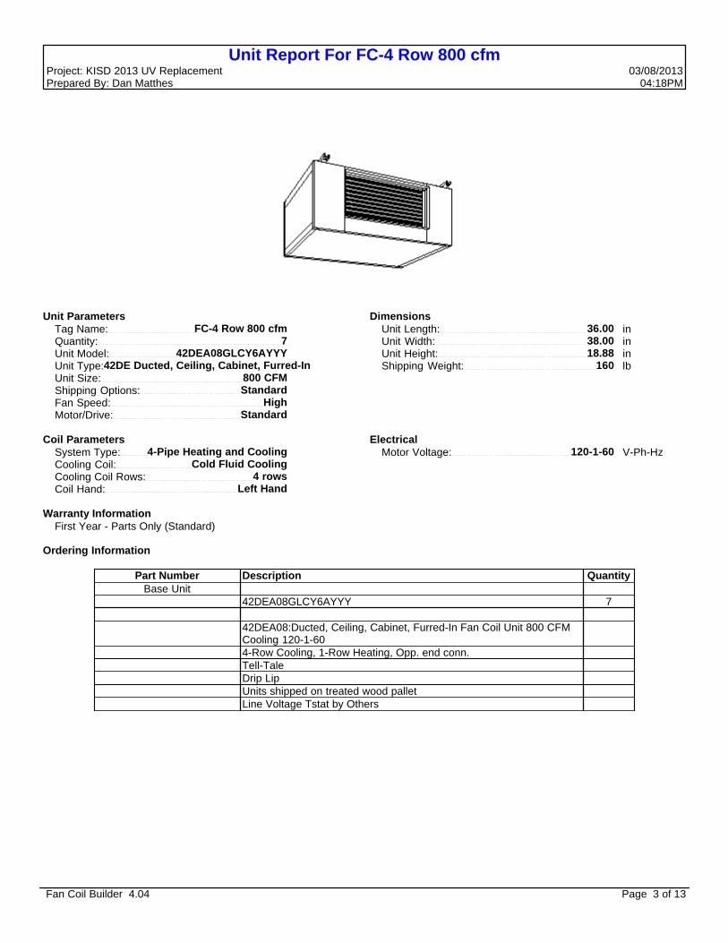
Unit Report For FC-4 Row 800 cfmProject: KISD 2013 UV Replacement 03/08/2013 Prepared By: Dan Matthes 04:18PM
Unit Parameters Tag Name: FC-4 Row 800 cfm Quantity: 7 Unit Model: 42DEA08GLCY6AYYY Unit Type:42DE Ducted, Ceiling, Cabinet, Furred-In Unit Size: 800 CFM Shipping Options: Standard Fan Speed: High Motor/Drive: Standard
Dimensions Unit Length: 36.00 in Unit Width: 38.00 in Unit Height: 18.88 in Shipping Weight: 160 lb
Coil Parameters System Type: 4-Pipe Heating and Cooling Cooling Coil: Cold Fluid Cooling Cooling Coil Rows: 4 rows Coil Hand: Left Hand
Electrical Motor Voltage: 120-1-60 V-Ph-Hz
Warranty Information First Year - Parts Only (Standard)
Ordering Information
Part Number Description Quantity Base Unit
42DEA08GLCY6AYYY 7 42DEA08:Ducted, Ceiling, Cabinet, Furred-In Fan Coil Unit 800 CFM
Cooling 120-1-60
4-Row Cooling, 1-Row Heating, Opp. end conn. Tell-Tale Drip Lip Units shipped on treated wood pallet Line Voltage Tstat by Others
Fan Coil Builder 4.04 Page 3 of 13

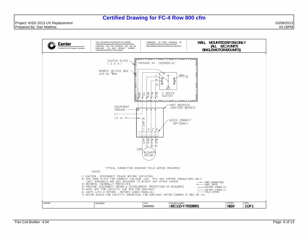
Certified Drawing for FC-4 Row 800 cfmProject: KISD 2013 UV Replacement 03/08/2013 Prepared By: Dan Matthes 04:18PM
THIS DOCUMENT ISTHE PROPERTY OF CARRIER CORPORATION AND IS DELIVERED UPON THE EXPRESS CONDITIONTHATTHE CONTENTS WILLNOT BE DISCLOSED OR USEDWITHOUT CARRIER CORPORATION'S WRITTEN CONSENT
SUBMISSION OF THESE DRAWINGS ORDOCUMENTS DOES NOT CONSTITUTE PARTPERFORMANCE ORACCEPTANCE OF CONTRACT
HORIZONTAL DUCTEDFURRED-IN CABINET
UNIT42DEA
NOTE: 1.R.H. shown, L.H. opposite. 2.All dimensions ±1/4" 3.Galvanized finish
JOB NAME
JOB NUMBER
DATE
DRAWING NUMBER REVISION SHEET
42DE-202-1 E 1 OF 1
02/12/2009
2 2 14 x 47-3/459484864200042DEA20
2 2 14 x 43-3/455444460180042DEA18
2 2 14 x 38-3/450393955160042DEA16
2 2 14 x 33-3/445343450140042DEA14
2 2 14 x 28-3/440292945120042DEA12
1 1 14 x 23-3/435242440100042DEA10
1 1 14 x 19-3/431202036800 42DEA08
1 1 14 x 14-3/426151531600 42DEA06
MOTOR BLWRD C B A
QUANTITY/UNIT FILTERSIZE (in)
DIMENSION -INCHES NOM CFM
UNITMODEL
Fan Coil Builder 4.04 Page 4 of 13

Certified Drawing for FC-4 Row 800 cfmProject: KISD 2013 UV Replacement 03/08/2013 Prepared By: Dan Matthes 04:18PM
SUBMISSION OF THESE DRAWINGS ORDOCUMENTS DOES NOT CONSTITUTE PARTPERFORMANCE OR ACCEPTANCE OF CONTRACT
THIS DOCUMENT IS THE PROPERTY OF CARRIER CORPORATION AND IS DELIVERED UPON THE EXPRESS CONDITION THAT THE CONTENTS WILL NOT BEDISCLOSED OR USED WITHOUT CARRIER CORPORATION'S WRITTTEN CONSENT
JOB NAME
JOB NUMBER
DATE
DRAWING NUMBER REVISION SHEET
42DA,DC,DE AND DF OPTIONALCOIL CONNECTION LOCATION
SIZES 06 THRU 2042DA
09/26/2003
42DA-203-1 C 1 OF 1
A
G
C
F
RIGHT
C A
F G
LEFT
3, 4, 6 ROW COILS
RIGHT LEFT
A
G
C C
A
F G
B D
F E E
B D
ALL SPLIT COILS
INLET OUTLET
ALL DIMENSIONS 5/8"
COIL CONNECTIONS DIMENSIONS 3-Row Coil 4-Row Coil 6-Row Coil
A C F G A C F G A C F G 3 7 / 8 6 7 5 / 16 7 5 / 16
2 13/ 16 6 1 / 16 4 13/ 16 107 / 16 1 3 / 4 7 1 / 8 4 13/ 16 107 / 163 7 / 8 6 4 13/ 16 9 13/ 163 7 / 8 6 7 15/ 16 7 15/ 16
2 13/ 16 6 1 / 16 5 7 / 16 9 13/ 16 1 3 / 4 7 1 / 8 5 7 / 16 9 13/ 163 7 / 8 6 5 7 / 16 107 / 16
Unit Size
Right Hand
600-800 600-20001000-2000 600-800 600-20001000-2000
LeftHand
COIL CONNECTIONS DIMENSIONS 3 & 1 Split Coil 3 & 2 Split Coil
A B C D E F G A B C D E F G 2 13/ 16 3 7 / 8 6 1 / 16 1 1 / 16 7 5 / 16 7 5 / 16 139 / 16 2 1 / 4 3 7 / 8 6 1 / 16 3 / 4 7 5 / 16 7 5 / 16 131 / 4
2 13/ 16 3 7 / 8 6 1 / 16 1 1 / 16 4 13/ 16 9 13/ 16 139 / 16 2 1 / 4 3 7 / 8 6 1 / 16 3 / 4 4 13/ 16 9 13/ 16 131 / 4
2 13/ 16 3 7 / 8 6 1 / 16 7 / 16 7 15/ 16 7 15/ 16 1215/ 16 2 1 / 4 3 7 / 8 6 1 / 16 3 / 4 7 15/ 16 7 15/ 16 131 / 4
2 13/ 16 3 7 / 8 6 1 / 16 7 / 16 5 7 / 16 107 / 16 1215/ 16 2 1 / 4 3 7 / 8 6 1 / 16 3 / 4 5 7 / 16 107 / 16 131 / 4
Unit Size
Right Hand
600-800 1000-2000
600-800 1000-2000
LeftHand
COIL CONNECTIONS DIMENSIONS 4 & 1 Split Coil 4 & 2 Split Coil
A B C D E F G A B C D E F G
1 3 / 4 2 13/ 16 6 1 / 16 7 / 16 4 13/ 16 107 / 16 1215/ 16 2 1 / 4 3 7 / 8 7 1 / 8 3 / 4 4 13/ 16 107 / 16 131 / 4
1 3 / 4 2 13/ 16 6 1 / 16 1 1 / 16 5 7 / 16 9 13/ 16 139 / 16 2 1 / 4 3 7 / 8 7 1 / 8 3 / 4 5 7 / 16 9 13/ 16 131 / 4
Unit Size
Right Hand 600-2000
600-2000LeftHand
COIL CONNECTIONS6 & 1 Split Coil
A B C D E F G
1 3 / 4 2 7 / 8 8 1 / 4 3 / 8 4 3 / 4 103 / 8 131 / 4
1 3 / 4 2 7 / 8 8 1 / 4 3 / 8 4 3 / 4 103 / 8 131 / 4
Unit Size
Right Hand
600-800 1000-2000
600-800 1000-2000
LeftHand
SIZE 1-2 ROW 3 ROW 4 ROW 6 ROW 600 5 / 8 5 / 8 5 / 8 7 / 8
800 5 / 8 5 / 8 5 / 8 7 / 8
1000 5 / 8 7 / 8 7 / 8 7 / 8
1200 5 / 8 7 / 8 7 / 8 7 / 8
1400 5 / 8 7 / 8 1 1 / 8 1 1 / 8
1600 5 / 8 7 / 8 1 1 / 8 1 1 / 8
1800 5 / 8 1 1 / 8 1 1 / 8 1 1 / 8
2000 5 / 8 1 1 / 8 1 1 / 8 1 1 / 8
NOTES:1.See Physical Data for piping knockout locations on DE and DF units. 2.Cooling coil is first in the air stream.
NOTE: Does not apply when optional valve packages are used.
COIL CONNECTIONS SIZES (O.D.COPPER SWEAT)
Fan Coil Builder 4.04 Page 5 of 13
Certified Drawing for FC-4 Row 800 cfmProject: KISD 2013 UV Replacement 03/08/2013 Prepared By: Dan Matthes 04:18PM
SUBMISSION OF THESE DRAWINGS ORDOCUMENTS DOES NOT CONSTITUTE PARTPERFORMANCE OR ACCEPTANCE OF CONTRACT
THIS DOCUMENT IS THE PROPERTY OF CARRIER CORPORATION AND IS DELIVERED UPON THE EXPRESS CONDITION THAT THE CONTENTS WILL NOT BEDISCLOSED OR USED WITHOUT CARRIER CORPORATION'S WRITTTEN CONSENT
JOB NAME JOB NUMBER DATE DRAWING NUMBER REVISION SHEET
WALL MOUNTED 3 SP. SW. ONLY(ALL 42C,V UNITS
SINGLE MOTOR 42D UNITS)
06/26/2002 1 OF 142C,V,D-Y-70338901 NEW
Fan Coil Builder 4.04 Page 6 of 13
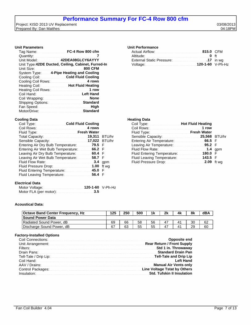
Performance Summary For FC-4 Row 800 cfmProject: KISD 2013 UV Replacement 03/08/2013 Prepared By: Dan Matthes 04:18PM
Unit Parameters Tag Name: FC-4 Row 800 cfm Quantity: 7 Unit Model: 42DEA08GLCY6AYYY Unit Type:42DE Ducted, Ceiling, Cabinet, Furred-In Unit Size: 800 CFM System Type: 4-Pipe Heating and Cooling Cooling Coil: Cold Fluid Cooling Cooling Coil Rows: 4 rows Heating Coil: Hot Fluid Heating Heating Coil Rows: 1 row Coil Hand: Left Hand Coil Wrapping: None Shipping Options: Standard Fan Speed: High Motor/Drive: Standard
Unit Performance Actual Airflow: 815.0 CFM Altitude: 0 ft External Static Pressure: .17 in wg Voltage: 120-1-60 V-Ph-Hz
Cooling Data Coil Type: Cold Fluid Cooling Coil Rows: 4 rows Fluid Type: Fresh Water Total Capacity: 19,311 BTU/hr Sensible Capacity: 17,022 BTU/hr Entering Air Dry Bulb Temperature: 79.5 F Entering Air Wet Bulb Temperature: 66.2 F Leaving Air Dry Bulb Temperature: 60.4 F Leaving Air Wet Bulb Temperature: 58.7 F Fluid Flow Rate: 3.4 gpm Fluid Pressure Drop: 1.00 ft wg Fluid Entering Temperature: 45.0 F Fluid Leaving Temperature: 56.4 F
Heating Data Coil Type: Hot Fluid Heating Coil Rows: 1 row Fluid Type: Fresh Water Sensible Capacity: 25,568 BTU/hr Entering Air Temperature: 66.5 F Leaving Air Temperature: 95.2 F Fluid Flow Rate: 1.4 gpm Fluid Entering Temperature: 180.0 F Fluid Leaving Temperature: 143.5 F Fluid Pressure Drop: 2.09 ft wg
Electrical Data Motor Voltage: 120-1-60 V-Ph-Hz Motor FLA (per motor): 3.5
Acoustical Data:
Octave Band Center Frequency, Hz 125 250 500 1k 2k 4k 8k dBA
Sound Power Data Radiated Sound Power, dB 69 66 58 56 47 41 30 62 Discharge Sound Power, dB 67 63 55 55 47 41 29 60
Factory-Installed Options Coil Connections: Opposite end Unit Arrangement: Rear Return / Front Supply Filters: Std 1 in. Throwaway Drain Pans: Standard Drain Pan Tell-Tale / Drip Lip: Tell-Tale and Drip Lip Coil Hand: Left Hand AAV / Drains: Manual Air Vents only Control Packages: Line Voltage Tstat by Others Insulation: Std. Tufskin II Insulation
Fan Coil Builder 4.04 Page 7 of 13

FC-4 Row 1000 cfmProject: KISD 2013 UV Replacement 03/08/2013 Prepared By: Dan Matthes 04:18PM
FC-4 Row 1000 cfm
Tag Cover SheetUnit Report
Certified DrawingPerformance Report
Fan Coil Builder 4.04 Page 8 of 13

Unit Report For FC-4 Row 1000 cfmProject: KISD 2013 UV Replacement 03/08/2013 Prepared By: Dan Matthes 04:18PM
Unit Parameters Tag Name: FC-4 Row 1000 cfm Quantity: 1 Unit Model: 42DEA10GLCY6AYYY Unit Type:42DE Ducted, Ceiling, Cabinet, Furred-In Unit Size: 1000 CFM Shipping Options: Standard Fan Speed: High Motor/Drive: Standard
Dimensions Unit Length: 40.00 in Unit Width: 38.00 in Unit Height: 18.88 in Shipping Weight: 170 lb
Coil Parameters System Type: 4-Pipe Heating and Cooling Cooling Coil: Cold Fluid Cooling Cooling Coil Rows: 4 rows Coil Hand: Left Hand
Electrical Motor Voltage: 120-1-60 V-Ph-Hz
Warranty Information First Year - Parts Only (Standard)
Ordering Information
Part Number Description Quantity Base Unit
42DEA10GLCY6AYYY 1 42DEA10:Ducted, Ceiling, Cabinet, Furred-In Fan Coil Unit 1000 CFM
Cooling 120-1-60
4-Row Cooling, 1-Row Heating, Opp. end conn. Tell-Tale Drip Lip Units shipped on treated wood pallet Line Voltage Tstat by Others
Fan Coil Builder 4.04 Page 9 of 13

Certified Drawing for FC-4 Row 1000 cfmProject: KISD 2013 UV Replacement 03/08/2013 Prepared By: Dan Matthes 04:18PM
THIS DOCUMENT ISTHE PROPERTY OF CARRIER CORPORATION AND IS DELIVERED UPON THE EXPRESS CONDITIONTHATTHE CONTENTS WILLNOT BE DISCLOSED OR USEDWITHOUT CARRIER CORPORATION'S WRITTEN CONSENT
SUBMISSION OF THESE DRAWINGS ORDOCUMENTS DOES NOT CONSTITUTE PARTPERFORMANCE ORACCEPTANCE OF CONTRACT
HORIZONTAL DUCTEDFURRED-IN CABINET
UNIT42DEA
NOTE: 1.R.H. shown, L.H. opposite. 2.All dimensions ±1/4" 3.Galvanized finish
JOB NAME
JOB NUMBER
DATE
DRAWING NUMBER REVISION SHEET
42DE-202-1 E 1 OF 1
02/12/2009
2 2 14 x 47-3/459484864200042DEA20
2 2 14 x 43-3/455444460180042DEA18
2 2 14 x 38-3/450393955160042DEA16
2 2 14 x 33-3/445343450140042DEA14
2 2 14 x 28-3/440292945120042DEA12
1 1 14 x 23-3/435242440100042DEA10
1 1 14 x 19-3/431202036800 42DEA08
1 1 14 x 14-3/426151531600 42DEA06
MOTOR BLWRD C B A
QUANTITY/UNIT FILTERSIZE (in)
DIMENSION -INCHES NOM CFM
UNITMODEL
Fan Coil Builder 4.04 Page 10 of 13

Certified Drawing for FC-4 Row 1000 cfmProject: KISD 2013 UV Replacement 03/08/2013 Prepared By: Dan Matthes 04:18PM
SUBMISSION OF THESE DRAWINGS ORDOCUMENTS DOES NOT CONSTITUTE PARTPERFORMANCE OR ACCEPTANCE OF CONTRACT
THIS DOCUMENT IS THE PROPERTY OF CARRIER CORPORATION AND IS DELIVERED UPON THE EXPRESS CONDITION THAT THE CONTENTS WILL NOT BEDISCLOSED OR USED WITHOUT CARRIER CORPORATION'S WRITTTEN CONSENT
JOB NAME
JOB NUMBER
DATE
DRAWING NUMBER REVISION SHEET
42DA,DC,DE AND DF OPTIONALCOIL CONNECTION LOCATION
SIZES 06 THRU 2042DA
09/26/2003
42DA-203-1 C 1 OF 1
A
G
C
F
RIGHT
C A
F G
LEFT
3, 4, 6 ROW COILS
RIGHT LEFT
A
G
C C
A
F G
B D
F E E
B D
ALL SPLIT COILS
INLET OUTLET
ALL DIMENSIONS 5/8"
COIL CONNECTIONS DIMENSIONS 3-Row Coil 4-Row Coil 6-Row Coil
A C F G A C F G A C F G 3 7 / 8 6 7 5 / 16 7 5 / 16
2 13/ 16 6 1 / 16 4 13/ 16 107 / 16 1 3 / 4 7 1 / 8 4 13/ 16 107 / 163 7 / 8 6 4 13/ 16 9 13/ 163 7 / 8 6 7 15/ 16 7 15/ 16
2 13/ 16 6 1 / 16 5 7 / 16 9 13/ 16 1 3 / 4 7 1 / 8 5 7 / 16 9 13/ 163 7 / 8 6 5 7 / 16 107 / 16
Unit Size
Right Hand
600-800 600-20001000-2000 600-800 600-20001000-2000
LeftHand
COIL CONNECTIONS DIMENSIONS 3 & 1 Split Coil 3 & 2 Split Coil
A B C D E F G A B C D E F G 2 13/ 16 3 7 / 8 6 1 / 16 1 1 / 16 7 5 / 16 7 5 / 16 139 / 16 2 1 / 4 3 7 / 8 6 1 / 16 3 / 4 7 5 / 16 7 5 / 16 131 / 4
2 13/ 16 3 7 / 8 6 1 / 16 1 1 / 16 4 13/ 16 9 13/ 16 139 / 16 2 1 / 4 3 7 / 8 6 1 / 16 3 / 4 4 13/ 16 9 13/ 16 131 / 4
2 13/ 16 3 7 / 8 6 1 / 16 7 / 16 7 15/ 16 7 15/ 16 1215/ 16 2 1 / 4 3 7 / 8 6 1 / 16 3 / 4 7 15/ 16 7 15/ 16 131 / 4
2 13/ 16 3 7 / 8 6 1 / 16 7 / 16 5 7 / 16 107 / 16 1215/ 16 2 1 / 4 3 7 / 8 6 1 / 16 3 / 4 5 7 / 16 107 / 16 131 / 4
Unit Size
Right Hand
600-800 1000-2000
600-800 1000-2000
LeftHand
COIL CONNECTIONS DIMENSIONS 4 & 1 Split Coil 4 & 2 Split Coil
A B C D E F G A B C D E F G
1 3 / 4 2 13/ 16 6 1 / 16 7 / 16 4 13/ 16 107 / 16 1215/ 16 2 1 / 4 3 7 / 8 7 1 / 8 3 / 4 4 13/ 16 107 / 16 131 / 4
1 3 / 4 2 13/ 16 6 1 / 16 1 1 / 16 5 7 / 16 9 13/ 16 139 / 16 2 1 / 4 3 7 / 8 7 1 / 8 3 / 4 5 7 / 16 9 13/ 16 131 / 4
Unit Size
Right Hand 600-2000
600-2000LeftHand
COIL CONNECTIONS6 & 1 Split Coil
A B C D E F G
1 3 / 4 2 7 / 8 8 1 / 4 3 / 8 4 3 / 4 103 / 8 131 / 4
1 3 / 4 2 7 / 8 8 1 / 4 3 / 8 4 3 / 4 103 / 8 131 / 4
Unit Size
Right Hand
600-800 1000-2000
600-800 1000-2000
LeftHand
SIZE 1-2 ROW 3 ROW 4 ROW 6 ROW 600 5 / 8 5 / 8 5 / 8 7 / 8
800 5 / 8 5 / 8 5 / 8 7 / 8
1000 5 / 8 7 / 8 7 / 8 7 / 8
1200 5 / 8 7 / 8 7 / 8 7 / 8
1400 5 / 8 7 / 8 1 1 / 8 1 1 / 8
1600 5 / 8 7 / 8 1 1 / 8 1 1 / 8
1800 5 / 8 1 1 / 8 1 1 / 8 1 1 / 8
2000 5 / 8 1 1 / 8 1 1 / 8 1 1 / 8
NOTES:1.See Physical Data for piping knockout locations on DE and DF units. 2.Cooling coil is first in the air stream.
NOTE: Does not apply when optional valve packages are used.
COIL CONNECTIONS SIZES (O.D.COPPER SWEAT)
Fan Coil Builder 4.04 Page 11 of 13

Certified Drawing for FC-4 Row 1000 cfmProject: KISD 2013 UV Replacement 03/08/2013 Prepared By: Dan Matthes 04:18PM
SUBMISSION OF THESE DRAWINGS ORDOCUMENTS DOES NOT CONSTITUTE PARTPERFORMANCE OR ACCEPTANCE OF CONTRACT
THIS DOCUMENT IS THE PROPERTY OF CARRIER CORPORATION AND IS DELIVERED UPON THE EXPRESS CONDITION THAT THE CONTENTS WILL NOT BEDISCLOSED OR USED WITHOUT CARRIER CORPORATION'S WRITTTEN CONSENT
JOB NAME JOB NUMBER DATE DRAWING NUMBER REVISION SHEET
WALL MOUNTED 3 SP. SW. ONLY(ALL 42C,V UNITS
SINGLE MOTOR 42D UNITS)
06/26/2002 1 OF 142C,V,D-Y-70338901 NEW
Fan Coil Builder 4.04 Page 12 of 13

Performance Summary For FC-4 Row 1000 cfmProject: KISD 2013 UV Replacement 03/08/2013 Prepared By: Dan Matthes 04:18PM
Unit Parameters Tag Name: FC-4 Row 1000 cfm Quantity: 1 Unit Model: 42DEA10GLCY6AYYY Unit Type:42DE Ducted, Ceiling, Cabinet, Furred-In Unit Size: 1000 CFM System Type: 4-Pipe Heating and Cooling Cooling Coil: Cold Fluid Cooling Cooling Coil Rows: 4 rows Heating Coil: Hot Fluid Heating Heating Coil Rows: 1 row Coil Hand: Left Hand Coil Wrapping: None Shipping Options: Standard Fan Speed: High Motor/Drive: Standard
Unit Performance Actual Airflow: 1,030.0 CFM Altitude: 0 ft External Static Pressure: .17 in wg Voltage: 120-1-60 V-Ph-Hz
Cooling Data Coil Type: Cold Fluid Cooling Coil Rows: 4 rows Fluid Type: Fresh Water Total Capacity: 25,347 BTU/hr Sensible Capacity: 21,764 BTU/hr Entering Air Dry Bulb Temperature: 79.5 F Entering Air Wet Bulb Temperature: 66.2 F Leaving Air Dry Bulb Temperature: 60.2 F Leaving Air Wet Bulb Temperature: 58.4 F Fluid Flow Rate: 4.4 gpm Fluid Pressure Drop: 1.91 ft wg Fluid Entering Temperature: 45.0 F Fluid Leaving Temperature: 56.5 F
Heating Data Coil Type: Hot Fluid Heating Coil Rows: 1 row Fluid Type: Fresh Water Sensible Capacity: 32,510 BTU/hr Entering Air Temperature: 66.5 F Leaving Air Temperature: 95.4 F Fluid Flow Rate: 1.9 gpm Fluid Entering Temperature: 180.0 F Fluid Leaving Temperature: 145.8 F Fluid Pressure Drop: 4.37 ft wg
Electrical Data Motor Voltage: 120-1-60 V-Ph-Hz Motor FLA (per motor): 6
Acoustical Data:
Octave Band Center Frequency, Hz 125 250 500 1k 2k 4k 8k dBA
Sound Power Data Radiated Sound Power, dB 68 63 57 55 47 40 30 60 Discharge Sound Power, dB 66 60 54 54 47 40 29 58
Factory-Installed Options Coil Connections: Opposite end Unit Arrangement: Rear Return / Front Supply Filters: Std 1 in. Throwaway Drain Pans: Standard Drain Pan Tell-Tale / Drip Lip: Tell-Tale and Drip Lip Coil Hand: Left Hand AAV / Drains: Manual Air Vents only Control Packages: Line Voltage Tstat by Others Insulation: Std. Tufskin II Insulation
Fan Coil Builder 4.04 Page 13 of 13