
EntraPass Installer Guide - Fitch Security Integration
580
DN1415-0810 / Version 4.01 Reference Manual
-
Upload
khangminh22 -
Category
Documents
-
view
10 -
download
0
Transcript of EntraPass Installer Guide - Fitch Security Integration

DN1415-0810 / Version 4.01
Reference Manual

Copyright © 2008 Tyco International Ltd. and its Respective Companies. All Rights Reserved. All specifications were current as of publication date and are subject to change without notice. EntraPass, Kantech and the Kantech logo are trademarks of Tyco International Ltd. and its Respective Companies.

Reference Manual
TYCO INTERNATIONAL LTDEND-USER LICENSE AGREEMENT
FOR KANTECH Software Provided With or Without Products or Components
IMPORTANT - READ CAREFULLYKANTECH Software purchased with or without Products and Components is copyrighted and is purchasedunder the following license terms:
• This End-User License Agreement (“EULA”) is a legal agreement between You (the company, individual or entity who acquired the Software and any related Hardware) and KANTECH, the manufacturer of the integrated secu-rity systems and the developer of the software and any related products or components (“HARDWARE”) which You acquired.
• If the KANTECH software product (“SOFTWARE PRODUCT” or “SOFTWARE”) is intended to be accompanied by HARDWARE, and is NOT accompanied by new HARDWARE, You may not use, copy or install the SOFT-WARE PRODUCT. The SOFTWARE PRODUCT includes computer software, and may include associated media, printed materials, and “online” or electronic documentation.
• Any software provided along with the SOFTWARE PRODUCT that is associated with a separate end-user license agreement is licensed to You under the terms of that license agreement.
• By installing, copying, downloading, storing, accessing or otherwise using the SOFTWARE PRODUCT, You agree unconditionally to be bound by the terms of this EULA, even if this EULA is deemed to be a modification of any previous arrangement or contract. If You do not agree to the terms of this EULA, KANTECH is unwilling to license the SOFTWARE PRODUCT to You, and You have no right to use it.
SOFTWARE PRODUCT LICENSEThe SOFTWARE PRODUCT is protected by copyright laws and international copyright treaties, as well asother intellectual property laws and treaties. The SOFTWARE PRODUCT is licensed, not sold.
1 GRANT OF LICENSE - This EULA grants You the following rights:a Software Installation and Use - For each license You acquire, You may have only one copy of the SOFT-
WARE PRODUCT installed. b Storage/Network Use - The SOFTWARE PRODUCT may not be installed, accessed, displayed, run,
shared or used concurrently on or from different computers, including a workstation, terminal or other digital electronic device (“Device”). In other words, if You have several workstations, You will have to acquire a license for each workstation where the SOFTWARE will be used.
c Backup Copy - You may make back-up copies of the SOFTWARE PRODUCT, but You may only have one copy per license installed at any given time. You may use the back-up copy solely for archival purposes. Except as expressly provided in this EULA, You may not otherwise make copies of the SOFTWARE PRODUCT, including the printed materials accompanying the SOFTWARE.
2 DESCRIPTION OF OTHER RIGHTS AND LIMITATIONSa Limitations on Reverse Engineering, Decompilation and Disassembly - You may not reverse engineer,
decompile, or disassemble the SOFTWARE PRODUCT, except and only to the extent that such activity is expressly permitted by applicable law notwithstanding this limitation. You may not make any changes or modifications to the Software, without the written permission of an officer of KANTECH. You may not remove any proprietary notices, marks or labels from the Software Product. You shall institute reasonable measures to ensure compliance with the terms and conditions of this EULA.
iii

Reference Manual
b Separation of Components - The SOFTWARE PRODUCT is licensed as a single product. Its component parts may not be separated for use on more than one HARDWARE unit.
c Single INTEGRATED PRODUCT - If You acquired this SOFTWARE with HARDWARE, then the SOFT-WARE PRODUCT is licensed with the HARDWARE as a single integrated product. In this case, the SOFT-WARE PRODUCT may only be used with the HARDWARE as set forth in this EULA.
d Rental - You may not rent, lease or lend the SOFTWARE PRODUCT. You may not make it available to oth-ers or post it on a server or web site.
e Software Product Transfer - You may transfer all of Your rights under this EULA only as part of a permanent sale or transfer of the HARDWARE, provided You retain no copies, You transfer all of the SOFTWARE PRODUCT (including all component parts, the media and printed materials, any upgrades and this EULA), and provided the recipient agrees to the terms of this EULA. If the SOFTWARE PRODUCT is an upgrade, any transfer must also include all prior versions of the SOFTWARE PRODUCT
f Termination - Without prejudice to any other rights, KANTECH may terminate this EULA if You fail to com-ply with the terms and conditions of this EULA. In such event, You must destroy all copies of the SOFT-WARE PRODUCT and all of its component parts.
g Trademarks - This EULA does not grant You any rights in connection with any trademarks or service marks of KANTECH or its suppliers.
3 COPYRIGHT
All title and intellectual property rights in and to the SOFTWARE PRODUCT (including but not limited to anyimages, photographs, and text incorporated into the SOFTWARE PRODUCT), the accompanying printedmaterials, and any copies of the SOFTWARE PRODUCT, are owned by KANTECH or its suppliers. You maynot copy the printed materials accompanying the SOFTWARE PRODUCT. All title and intellectual propertyrights in and to the content, which may be accessed through use of the SOFTWARE PRODUCT, are the prop-erty of the respective content owner and may be protected by applicable copyright or other intellectual prop-erty laws and treaties. This EULA grants You no rights to use such content. All rights not expressly grantedunder this EULA are reserved by KANTECH and its suppliers.
4 EXPORT RESTRICTIONS
You agree that You will not export or re-export the SOFTWARE PRODUCT to any country, person, or entitysubject to US export restrictions.
5 CHOICE OF LAW
This Software License Agreement is governed by the laws of the State of New York.
6 LIMITED WARRANTYa NO WARRANTY
KANTECH PROVIDES THE SOFTWARE “AS IS” WITHOUT WARRANTY. KANTECH DOES NOT WAR-RANT THAT THE SOFTWARE WILL MEET YOUR REQUIREMENTS OR THAT OPERATION OF THESOFTWARE WILL BE UNINTERRUPTED OR ERROR-FREE.
b CHANGES IN OPERATING ENVIRONMENTKANTECH shall not be responsible for problems caused by changes in the operating characteristics of theHARDWARE, or for problems in the interaction of the SOFTWARE PRODUCT with non-KANTECH SOFT-WARE or HARDWARE PRODUCTS.
c LIMITATION OF LIABILITY; WARRANTY REFLECTS ALLOCATION OF RISK IN ANY EVENT, IF ANY STATUTE IMPLIES WARRANTIES OR CONDITIONS NOT STATED IN THISLICENSE AGREEMENT, KANTECH'S ENTIRE LIABILITY UNDER ANY PROVISION OF THIS LICENSEAGREEMENT SHALL BE LIMITED TO THE GREATER OF THE AMOUNT ACTUALLY PAID BY YOU TOLICENSE THE SOFTWARE PRODUCT AND FIVE US DOLLARS (USD$5.00). BECAUSE SOME JURIS-DICTIONS DO NOT ALLOW THE EXCLUSION OR LIMITATION OF LIABILITY FOR CONSEQUENTIAL
iv

Reference Manual
OR INCIDENTAL DAMAGES, THE ABOVE LIMITATION MAY NOT APPLY TO YOU.d DISCLAIMER OF WARRANTIES
THIS WARRANTY CONTAINS THE ENTIRE WARRANTY AND SHALL BE IN LIEU OF ANY AND ALLOTHER WARRANTIES, WHETHER EXPRESSED OR IMPLIED (INCLUDING ALL IMPLIED WARRAN-TIES OF MERCHANTABILITY OR FITNESS FOR A PARTICULAR PURPOSE) AND OF ALL OTHEROBLIGATIONS OR LIABILITIES ON THE PART OF KANTECH. KANTECH MAKES NO OTHER WAR-RANTIES. KANTECH NEITHER ASSUMES NOR AUTHORIZES ANY OTHER PERSON PURPORTINGTO ACT ON ITS BEHALF TO MODIFY OR TO CHANGE THIS WARRANTY, NOR TO ASSUME FOR ITANY OTHER WARRANTY OR LIABILITY CONCERNING THIS SOFTWARE PRODUCT.
e EXCLUSIVE REMEDY AND LIMITATION OF WARRANTYUNDER NO CIRCUMSTANCES SHALL KANTECH BE LIABLE FOR ANY SPECIAL, INCIDENTAL, CON-SEQUENTIAL OR INDIRECT DAMAGES BASED UPON BREACH OF WARRANTY, BREACH OF CON-TRACT, NEGLIGENCE, STRICT LIABILITY, OR ANY OTHER LEGAL THEORY. SUCH DAMAGESINCLUDE, BUT ARE NOT LIMITED TO, LOSS OF PROFITS, LOSS OF THE SOFTWARE PRODUCT ORANY ASSOCIATED EQUIPMENT, COST OF CAPITAL, COST OF SUBSTITUTE OR REPLACEMENTEQUIPMENT, FACILITIES OR SERVICES, DOWN TIME, PURCHASERS TIME, THE CLAIMS OF THIRDPARTIES, INCLUDING CUSTOMERS, AND INJURY TO PROPERTY.
WARNING: KANTECH recommends that the entire system be completely tested on a regular basis. However,despite frequent testing, and due to, but not limited to, criminal tampering or electrical disruption, it is possi-ble for this SOFTWARE PRODUCT to fail to perform as expected.
v

Reference Manual
vi

Reference Manual
Table of ContentsChapter 1 •Introduction .................................................................... 1EntraPass Main Features ........................................................................ 2EntraPass Manual and Help .................................................................... 5
Using the Reference Manual .............................................................................. 5Getting Help ...................................................................................................... 5Technical Support ............................................................................................. 6
System Architecture ................................................................................ 7
Chapter 2 •Software Installation ...................................................... 9Recommended System Requirements ................................................... 10
EntraPass WebStation Server .......................................................................... 10Additional Requirements .................................................................................. 10
Installation Kit ....................................................................................... 11Installation Steps .................................................................................. 12
Installing EntraPass Software .......................................................................... 12Adding Optional Components/Features ............................................................. 12
System Installation ............................................................................... 13System Registration .............................................................................. 22
Registering the System .................................................................................... 22Additional System Components ............................................................ 25System Components Edition ................................................................. 28
Assigning a Descriptive Name to an Application ................................................ 28Communication with the EntraPass Server ........................................... 29
Establishing Communication with the Server ..................................................... 29System Update ...................................................................................... 30
Before Updating Your Software ........................................................................ 30Updating Your Software ................................................................................... 30
The EntraPass Software Removal ......................................................... 34
Chapter 3 •Getting Started ............................................................. 37Session Start and End ........................................................................... 38
Starting the EntraPass Primary Server ............................................................. 38Starting the Gateway Program ......................................................................... 40Starting the EntraPass Workstation .................................................................. 41Accessing Information on the Workstation Connection Status ............................ 44Modifying your Work Area Properties ............................................................... 44Retrieving Hidden Windows on the Desktop ...................................................... 45
Express Setup ....................................................................................... 46System Stand-Alone Utilities ................................................................ 47EntraPass Dialogs Toolbars .................................................................. 48Basic Functions .................................................................................... 50
Finding Components ........................................................................................ 50Using an Extended Selection Box ..................................................................... 52Selecting Components ..................................................................................... 53Selecting a specific folder ................................................................................ 55Selecting a Specific Site or Gateway ................................................................ 55Printing a List or a Report ................................................................................ 55Displaying Components Links .......................................................................... 56
vii

Reference Manual
Chapter 4 •System Devices ............................................................ 59EntraPass Applications Configuration .................................................. 60
Configuring an EntraPass Application ...............................................................61Defining General Parameters .............................................................................................. 61Defining Security Parameters .............................................................................................. 62Defining Workspaces .......................................................................................................... 64Defining Message Controls ................................................................................................. 65Defining Alarm Controls ...................................................................................................... 66Defining Network Alarms .................................................................................................... 68Defining e-Mail Report Options ........................................................................................... 68
Configuring a Gateway Application ...................................................................69Configuring General Parameters for a Gateway ................................................................... 70Configuring an Oracle/MS-SQL Interface (CardGateway) ...................................................... 70Creating Server Databases Manually ................................................................................... 73
Configuring the Mirror Database and Redundant Server ....................................74Configuring the SmartLink Application ..............................................................77Configuring the EntraPass Video Vault Application ............................................80
EntraPass Gateways Configuration ....................................................... 86Configuring a Corporate Gateway .....................................................................87
Sites Configuration .............................................................................. 91Setting up Communication timing ......................................................................92Configuring a Direct RS-232 Connection Type ..................................................92Configuring a Kantech IP Link or a KT-400 Ethernet Connection Type (Corporate Gateway Only) ...............................................................................................................93Configuring an Ethernet Polling Connection Type ..............................................96Configuring a Dial-Up (RS-232) Modem Connection Type ..................................97
Controllers Configuration ................................................................... 101KT-400 Ethernet Four Door Controller ............................................................. 101
Main Features .................................................................................................................. 101Configuring General Parameters for Kantech Controllers ................................. 102Configuring a KT-100 Controller ..................................................................... 104Configuring a KT- 200 Controller .................................................................... 105
Defining KT-200 Expansion Devices .................................................................................. 105Defining KT-200 Auxiliary Devices .................................................................................... 105
Programming KT-2252 Elevator Controllers ..................................................... 106Programming REB-8 Elevator Controllers ........................................................ 108
Defining REB-8 Relays ..................................................................................................... 109Configuring the KT-300 Controller .................................................................. 110Configuring the KT-300 Combus Modules ....................................................... 111Configuring the KT-400 Ethernet Four Door Controller ..................................... 113
Configuring the KT-400 Expansion Modules ....................................................................... 115Configuring the Status Relay Activations (for a Corporate Gateway Only) ............................ 122
Defining Controller Options ............................................................................ 122Defining the KT-400 Controller Local Areas ..................................................... 124Defining the KT-400 Elevator Floor Associations ............................................. 125
Associating Pattern With Door and Floor Numbers ............................................................. 125Controller Event Buffer Overflow Message ......................................... 126Doors Configuration ............................................................................ 127
Defining General Parameters for a Door ......................................................... 127Defining Door Keypad Options ........................................................................ 130
For KT-100 and KT-300 Controllers ................................................................................... 130For KT-400 Controllers ..................................................................................................... 130
Defining Door Contact Options ....................................................................... 132Defining REX (Request to Exit) Options .......................................................... 133Defining Interlock Options (Mantrap) ............................................................... 134
viii

Reference Manual
Defining Elevator Doors ................................................................................. 135Configuring Door Events ................................................................................ 136Defining Options for a KT-100, KT-300 and KT-400(Corporate Gateway Only) . 137Configuring External Alarm System Interfaces ................................................ 138
Relay Configuration .............................................................................142Defining Relays ............................................................................................. 142
Input Configuration ..............................................................................143Defining Input ................................................................................................ 143Defining Relays and Inputs ............................................................................ 145Defining an Input for an Elevator Door ............................................................ 146Enabling Remote Event Reporting .................................................................. 147
Output Device Configuration ...............................................................148Defining General Options for an Output .......................................................... 148Associating Events with Auxiliary Outputs ...................................................... 149
Chapter 5 •Video Integration ........................................................ 151Video Server Configuration ..................................................................152
Defining the Video Server Communication Settings ......................................... 152Enhancing the Security of Video Servers ........................................................ 154Defining the EntraPass Video Vault ................................................................ 155
Camera Definition ................................................................................157Defining a Camera ......................................................................................... 157Defining Presets and Patterns ........................................................................ 158Defining Events Recorded by a Camera ......................................................... 159
To Select Camera Events and Schedules ........................................................................... 159Associating a Camera with an Icon ................................................................. 160
Video Views Definition .........................................................................162Defining General Parameters for a Video View ............................................... 162
Video Views Creation and Modification ...............................................165Modifying a Video View .................................................................................. 165
Video Triggers ......................................................................................167Defining Video Triggers ................................................................................. 167
Recording Parameters ..........................................................................169Setting Up Recording Parameters .................................................................. 169Setting Up Stop Recording Parameters .......................................................... 170
Video Event List ...................................................................................172Using the Video Event List ............................................................................. 172Finding Video Events ..................................................................................... 172Playing Video Segments ................................................................................ 178Linking Video Clips with Key Frames .............................................................. 180Exporting Video Files ..................................................................................... 181Protecting a Video with a Password ............................................................... 182
Video Playback .....................................................................................184Viewing a Video Playback .............................................................................. 184
Current Recording ................................................................................186Viewing the Current Recordings ..................................................................... 186
Video Desktop ......................................................................................188Displaying a Video View ................................................................................ 188
Exported Video Viewing .......................................................................190EntraPass Video Vault Browsing .........................................................191
Viewing Video Segments Archived in the EntraPass Video Vault ..................... 191
ix

Reference Manual
Chapter 6 •Definitions .................................................................. 193Schedules Definition ........................................................................... 194
Defining a Schedule ....................................................................................... 195To Create a 2-day Continuous Interval .............................................................................. 196
Floors Definition ................................................................................. 197Graphics Definition ............................................................................. 198
Defining Components of a Graphic ................................................................. 198Designing the Background for the Graphic Window ......................................... 201Assigning System Components to Graphic Icons ............................................. 202
Holidays Definition .............................................................................. 203
Chapter 7 •Operations .................................................................. 205The Operations Toolbar ................................................................................. 205The Operation Dialogs Toolbar ....................................................................... 205The Operations Contextual Menu .................................................................... 206The Component Status Dialog ........................................................................ 206
Manual Operations on the Gateway ..................................................... 208Selecting a Gateway ...................................................................................... 208Performing a Hard Reset ................................................................................ 209Reloading Gateway Data ................................................................................ 209
Manual Operations on Sites ................................................................ 210Performing Manual Operations on a Site ......................................................... 211
Communication Status Messages Available in the List ........................................................ 211Manual Operations on Controllers ...................................................... 213
Selecting a Controller ..................................................................................... 214Performing a Controller Soft Reset ................................................................. 214Performing a Controller Hard Reset ................................................................ 214Reloading a Controller Manually ..................................................................... 215
To Manually Reload a Firmware Controller ........................................................................ 215To Manually Unlock a Reader Keypad ............................................................................... 215To Reset the Cards In and Cards Out Counters or all Controller local area .......................... 215
Calculating Number of Cards In and Cards Out ............................................... 215To Reset the Cards In and Cards Out Counters or all Controller local area .......................... 216
Manual Operations on Doors ............................................................... 217Selecting a Door or a Door Group ................................................................... 218Locking a Door Manually ................................................................................ 218Unlocking a Door Manually ............................................................................. 218Unlocking a Door Temporarily ........................................................................ 218Resetting a Door Schedule ............................................................................. 219Enabling a Door Reader ................................................................................. 219Disabling a Door Reader ................................................................................ 219
Manual Operation on Elevator Doors .................................................. 220Selecting an Elevator Door ............................................................................. 221Locking Floors from Elevator Doors ................................................................ 221Unlocking Floors from Elevator Doors ............................................................. 221Unlocking Floors from Elevator Doors Temporarily .......................................... 222Resetting an Elevator Door Schedule .............................................................. 222Enabling an Elevator Floor ............................................................................. 222Disabling an Elevator Floor ............................................................................ 223
Manual Operations on Relays ............................................................. 224Selecting Relays ............................................................................................ 224Deactivating a Relay Manually ........................................................................ 225 Activating a Relay Manually .......................................................................... 225
x

Reference Manual
Activating a Relay Temporarily ....................................................................... 225Resetting a Relay Schedule ........................................................................... 225
Manual Operations on Inputs ...............................................................226Performing Manual Operations on Inputs ........................................................ 226Returning an Input to Its Normal State Manually ............................................. 227Stopping Monitoring an Input ......................................................................... 227Stopping Input Supervision (Shunt) Temporarily ............................................. 227
Chapter 8 •Users .......................................................................... 229Cards Definition ...................................................................................230
Issuing a New Card ....................................................................................... 230Issuing a New Card in Enhanced User Management Environment ................... 231Creating New Cards Using the “Save As” Feature ........................................... 234Issuing Cards Using the “Batch Load” Feature ................................................ 234Viewing and Verifying PINs ............................................................................ 234
To View Cards Assigned the Same PIN ............................................................................. 235Card Handling ......................................................................................236
Editing a Card ............................................................................................... 236Finding a Card .............................................................................................. 236Deleting a Card ............................................................................................. 236Customizing Card Information Fields .............................................................. 236
Cardholder Access Levels Assignation ...............................................238Assigning an Access Level to a Cardholder .................................................... 238
Card Options Definition .......................................................................239Adding Comments to a Card .......................................................................... 240Limiting Card Usage ...................................................................................... 241Assigning Pictures and Signatures ................................................................. 241
To Assign a Picture from a File ......................................................................................... 242To Assign a Picture Using a Video Camera ........................................................................ 242
Importing a signature from a file ..................................................................... 244Adding a Signature from a Signature Capture Device ...................................... 245Working with Photos and Signatures .............................................................. 246
To Extract Part of an Image .............................................................................................. 246To Edit a Picture/Signature ............................................................................................... 249
Printing Badges ............................................................................................. 250To Select a Badge Printer ................................................................................................. 250To Preview and Print Badges ............................................................................................ 251
Badges Designing ................................................................................253Creating a Badge Template ............................................................................ 253
To Specify Properties for a Badge Layout .......................................................................... 254To Edit a Badge Layout .................................................................................................... 255To Modify the Number of Card Sides ................................................................................. 255To Modify the Background Color ....................................................................................... 257To Add Objects to a Badge Layout .................................................................................... 258To Incorporate Card Information Fields .............................................................................. 259To Align Objects in the Template Layout ............................................................................ 261To Modify Card Fields Properties ...................................................................................... 261To Modify Picture Properties ............................................................................................. 263To Add Static Text Objects ............................................................................................... 265To Add Bar Codes ............................................................................................................ 266To Set Up Barcode Properties ........................................................................................... 268To Add the Current Date ................................................................................................... 268To Add an Image .............................................................................................................. 271To Place Other Design Objects ......................................................................................... 273To Place a Rectangle ....................................................................................................... 274
xi

Reference Manual
Validating Card Access .................................................................................. 275Cards Printing ..................................................................................... 277
Printing Cards ................................................................................................ 277Last Transactions Display ................................................................... 281
Viewing the Last Transaction .......................................................................... 281Card Access Groups Definition ........................................................... 283Access Levels Definition ..................................................................... 284Visitor Cards Definition ....................................................................... 285
Creating a Visitor Card When Creating a New Card ......................................... 285Creating a Visitor Card Using the Card Template ............................................ 285
Card Type Definition ........................................................................... 286Creating a New Card Type ............................................................................. 286
Day Passes Definition ......................................................................... 287Creating a Day Pass ...................................................................................... 287Creating a New Day Pass Using the “Save As” Feature ................................... 288
Batch Operations on Cards ................................................................. 289Performing Operations on a Group of Cards .................................................... 289
CSV Files Import and Export ............................................................... 291Using a Predefined Pattern ............................................................................ 291Creating a New Import/Export Pattern ............................................................. 292Exporting Cards ............................................................................................. 293Importing Cards ............................................................................................. 296Correcting Import/Export Errors ...................................................................... 298
Chapter 9 •Groups ........................................................................ 301Controller Group Creation ................................................................... 302Door Group Creation ........................................................................... 303Relay Group Creation .......................................................................... 304Input Group Creation ........................................................................... 305Access Level Groups Grouping .......................................................... 306Floor Group Creation .......................................................................... 307
Chapter 10 •System Status ........................................................... 309Connection List ................................................................................... 310
Viewing the System Connection List ............................................................... 310Text Status .......................................................................................... 312
Displaying a Component Status ...................................................................... 312Numerical Status ................................................................................. 314Graphic Status .................................................................................... 315
Viewing a Controller Status ............................................................................ 315Video Server Status ............................................................................. 317
Viewing Video Server Status .......................................................................... 317Enabling/Disabling Video Archiving ................................................................. 317
Database Status .................................................................................. 318Server State ......................................................................................... 320
Chapter 11 •System ...................................................................... 321Operators Definition ............................................................................ 322
Creating or Editing an Operator ...................................................................... 322
xii

Reference Manual
Security Level Definition ......................................................................326Creating/Modifying an Operator Security Level ............................................... 326Defining Login Options for an Operator .......................................................... 327Hiding Card Information ................................................................................. 329Assigning Video Custom Buttons .................................................................... 330
Workspace Definition ...........................................................................331Workspace Filtering Modes ............................................................................ 331Selecting Accounts ........................................................................................ 331Selecting EntraPass Applications ................................................................... 332Defining Gateways and Sites ......................................................................... 334Defining Controllers ....................................................................................... 335Defining Doors .............................................................................................. 336Defining Relays ............................................................................................. 337Defining Inputs .............................................................................................. 338Defining Access Levels .................................................................................. 338Defining Card Types ...................................................................................... 339Defining Card Access Group .......................................................................... 340Defining Reports ........................................................................................... 341Defining Graphics .......................................................................................... 343Defining Workspaces ..................................................................................... 343Specifying Security Level ............................................................................... 344Defining Video Servers .................................................................................. 345
To Limit Access to a Specific Camera ................................................................................ 346Defining Video Views ..................................................................................... 348Defining Events ............................................................................................. 348
Event Parameters Definition ................................................................350Defining Events Parameters ........................................................................... 350Creating Associations .................................................................................... 353Viewing an Association .................................................................................. 354Deleting and Restoring Associations .............................................................. 354Printing Event Parameters ............................................................................. 355
Instructions Definition .........................................................................357Defining an Instruction ................................................................................... 357Defining a SmartLink Instruction ..................................................................... 358
To Insert an e-Mail Command in a SmartLink Macro ........................................................... 359Inserting a Pager Command in a SmartLink Macro ............................................................. 361
Message Filters Definition ...................................................................363Defining Event for a Message Filter ................................................................ 363
Database Structure Definition ..............................................................367Viewing the Database Components ................................................................ 367
Chapter 12 •EntraPass Desktops ................................................. 369Work Area Customizing ........................................................................370
Creating a Temporary Workspace .................................................................. 370Changing the Display Properties .................................................................... 372
Specific Desktop Customizing .............................................................373Customizing a Desktop for a “Full Access” Operator ....................................... 373Customizing a Desktop for a “Read-Only” Operator ......................................... 374Transferring a Customized Desktop ................................................................ 375
Message List Desktop ..........................................................................377Viewing and Sorting System Events ............................................................... 377Customizing Event Display in the Message Desktops ...................................... 378Performing Tasks on System Messages ......................................................... 380
Picture Desktop ....................................................................................384
xiii

Reference Manual
Modifying Pictures Display Options ................................................................. 384Filtered Messages Desktop ................................................................. 386
Configuring a Filtered Messages Desktop ....................................................... 386Historical Report Desktop ................................................................... 387
Configuring a Historical Reports Desktop ........................................................ 387To Create and Edit Historical Reports from a Desktop ........................................................ 388To Display Historical Report State in Real-time .................................................................. 388
Playing archived video recordings from a Desktop Message list ....................... 390Alarms Desktop ................................................................................... 391
Defining an Alarms Desktop ........................................................................... 392Viewing System Alarm Messages ................................................................... 393Displaying Alarm Desktops Automatically ........................................................ 395Acknowledging Alarms/Events ........................................................................ 397
To Acknowledge an Alarm Message .................................................................................. 398To Acknowledge Alarms from the Alarms Desktop .............................................................. 399
Instruction Desktop ............................................................................. 400Viewing an Instruction About an Alarm Message ............................................. 400
Graphic Desktop .................................................................................. 402Viewing Graphics in the Graphic Desktop ........................................................ 402
Network Alarms Desktop ..................................................................... 404Viewing network alarms .................................................................................. 404
Video Desktop ..................................................................................... 406Defining a Video desktop ............................................................................... 406Using the Video desktop ................................................................................ 406
Video Server Status ............................................................................. 408Viewing the video server full status ................................................................. 408
Chapter 13 •Reports ..................................................................... 411Quick Report Definition ....................................................................... 412
Defining a Quick Report ................................................................................. 412Historical Reports Definition ............................................................... 415
Defining a Default “All Events” Report ............................................................. 415Defining a Custom Historical Report ............................................................... 416
Defining Components for a Custom Historical Report ......................................................... 417Defining Card Options for a Custom Historical Report ........................................................ 418
Defining a Card Use Report ............................................................................ 419Defining Automatic Report Schedules ............................................................. 421
To Specify Additional Options for an Automatic Report ....................................................... 422Defining a Report Output Format .................................................................... 423Requesting Historical Reports ........................................................................ 425Requesting an Event Report ........................................................................... 427
E-Mailed Reports ................................................................................. 428Defining a Report to E-Mail ............................................................................ 428
Send Reports to Workstations Using SmartLink ................................. 430Time and Attendance Reports Definition ............................................ 431
Defining Time and Attendance Reports ........................................................... 431Time and Attendance Reports Request ............................................... 434
Requesting a Time and Attendance Report Manually ....................................... 434Operations on Time and Attendance ................................................... 435
Adding a Transaction in the Time and Attendance Database ............................ 435Report State ........................................................................................ 438Reports Viewing .................................................................................. 439
xiv

Reference Manual
Displaying a Report ....................................................................................... 439Previewing Historical Reports ........................................................................ 440Previewing Time and Attendance Reports ....................................................... 441
Chapter 14 •EntraPass Options .................................................... 443Default Card Format Selection .............................................................444
Defining a Card Display Format ...................................................................... 444Authentication Password Modification ................................................446
Changing the Authentication Password ........................................................... 446System Language Selection .................................................................447
Changing the System Language ..................................................................... 447Printers Selection and Configuration ...................................................448
Selecting and Setting Up a Log Printer ........................................................... 448Selecting and Setting Up a Report Printer ...................................................... 449Selecting and Setting Up a Badge Printer ....................................................... 449
System Date & Time Modification ........................................................451Multimedia Devices Configuration .......................................................452
Selecting an Alarm Sound .............................................................................. 452Defining Video Options .................................................................................. 453Setting Up the Signature Capture Device ........................................................ 454
System Parameters Configuration .......................................................456Server Parameters ........................................................................................ 456
Server Logs ..................................................................................................................... 456Disk Space ...................................................................................................................... 456Redundant Server ............................................................................................................ 457Logout and Idle ................................................................................................................ 457Schedule ......................................................................................................................... 458Diagnostic ........................................................................................................................ 459Network Alarm ................................................................................................................. 459Icon Status ...................................................................................................................... 460Service Login Information ................................................................................................. 460
Firmware Parameters .................................................................................... 460KT-100 ............................................................................................................................ 461KT-300 ............................................................................................................................ 461KT-400 ............................................................................................................................ 462Kantech IP Link ................................................................................................................ 462
Image Parameters ......................................................................................... 463Picture and Badging ......................................................................................................... 463Graphic ............................................................................................................................ 464
Report Parameters ........................................................................................ 465CSV ................................................................................................................................. 465Disk Space ...................................................................................................................... 465User Name Format ........................................................................................................... 466
Video Parameters .......................................................................................... 467Parameters ...................................................................................................................... 467Capture ........................................................................................................................... 468
Time Parameters ........................................................................................... 469Credentials Parameters ................................................................................. 469
Cards .............................................................................................................................. 469Workstation and Server ................................................................................. 471
Toolbar Buttons ................................................................................................................ 471Backup Scheduler ................................................................................472
Configuring the Backup when the EntraPass Server is Running as a Service ... 472Scheduling Automatic Backups of the System Database ................................. 475
Custom Messages ................................................................................477
xv

Reference Manual
Setting up Custom Messages ......................................................................... 477System Registration ............................................................................ 478Checking Server and Workstation Databases ..................................... 479
Server Database ............................................................................................ 479Workstation Database .................................................................................... 479
Chapter 15 •The EntraPass Server .............................................. 481Server Launch ..................................................................................... 482Server Connection list ......................................................................... 484
Viewing Applications Connected to the Server ................................................ 484Viewing the System Log ................................................................................. 484Viewing System Errors ................................................................................... 485
Backups ............................................................................................... 487Creating Backups of Type D, A, and T ............................................................ 487Restoring Data (D, A and T) ........................................................................... 489
Server Utilities Usage .......................................................................... 491System Language Modification ........................................................... 492
Chapter 16 •System Utilities......................................................... 493Database Utility ................................................................................... 494
Running the Database Utility .......................................................................... 495To Verify Database Integrity ............................................................................................. 496To Update Database Fields ............................................................................................... 496To Verify Database Index ................................................................................................. 497To Verify Database Links .................................................................................................. 497To Verify Database Hierarchy ........................................................................................... 497To verify Database Archive Files ....................................................................................... 497To Verify Time & Attendance Files .................................................................................... 497To Verify Video Event Files ............................................................................................... 498To Swap Descriptions ....................................................................................................... 498To Clean the Database ..................................................................................................... 498To Rebuild Card Last Transaction Files ............................................................................. 498
EntraPass Video Vault ......................................................................... 499Installing the EntraPass Video Vault ............................................................... 499Launching the EntraPass Video Vault ............................................................. 500Managing Archived Video Segments ............................................................... 501
Vocabulary Editor ................................................................................ 504Installing the Vocabulary Editor ...................................................................... 504Translating the System Language ................................................................... 504Integrating your Custom Language in EntraPass ............................................. 508Distributing the New System Vocabulary ......................................................... 510Updating the System Vocabulary .................................................................... 510Upgrading the System Vocabulary .................................................................. 513
Express Setup Program ....................................................................... 514Configuring a Corporate Gateway Site Using Express Setup ............................ 514Configuring a Controller Using Express Setup ................................................. 519
To Define Relays .............................................................................................................. 520To Define Inputs .............................................................................................................. 521To Define Auxiliary Outputs .............................................................................................. 521
Quick Report Viewer ............................................................................ 522PING Diagnostic .................................................................................. 524Workstation—Configuration Program ................................................. 525
xvi

Reference Manual
Migration Utility ...................................................................................526Migrating EntraPass Special Edition to Corporate Edition ................................ 526
To Migrate EntraPass Special Edition Database to Corporate Database .............................. 527The Gateway Interface ..........................................................................528
Starting the Gateway ..................................................................................... 528Reloading the Gateway .................................................................................. 528
MS/SQL Interface .................................................................................530Installing the MS/SQL Interface ...................................................................... 530Configuring the CardGateway ........................................................................ 530Starting the CardGateway .............................................................................. 531
The SmartLink Interface .......................................................................534Configuring the SmartLink Application ............................................................ 534
To Start the SmartLink Application .................................................................................... 534Network Consumption ..........................................................................535
Chapter 17 •Animated Icons ......................................................... 537Controllers ...........................................................................................538Doors ....................................................................................................540Relays ..................................................................................................544Inputs ...................................................................................................546Sites and Gateways ..............................................................................548
Controller Site: ................................................................................................................. 548Gateway: ......................................................................................................................... 548Gateway (Gateway Software Interface): ............................................................................. 550
EntraPass Application ..........................................................................551Others ............................................................................................................................. 551
Index ...................................................................................................................................................... 553
xvii

Reference Manual
xviii

Reference Manual
Chapter 1 • IntroductionWelcome to EntraPass, a powerful multi-user access control system that provides all the features required in the most demanding applications.What is EntraPass? EntraPass is a comprehensive, menu-driven access control software package. Among the many features EntraPass offers, you will find:• Remote communication capability• EntraPass WebStation connection for remote • SmartLink interface with paging systems, HVAC systems, e-mail and more• Redundancy server for fail-safe operation (optional)• Connection to the Kantech IP Link• KT-100, KT-200, KT-300 and KT-400 compatibility• Express setup• Local anti-passback, interaction between door controllers, and DayPass for temporary visitors• Elevator control• Integrated badging capability• Interactive floor plans• Configurable desktops by operator• CardGateway (optional)• Multiple reader technology• External alarm system interfacing• Time and Attendance reporting• E-mail reports capability• Visual diagnostics• Video Integration with American Dynamics family of Intellex® Digital Video Management
System (DVMS) and EDVR • Live video display, recorded video playback, local event logging and saving• Video archiving via EntraPass Video Vault• Vocabulary editorWhat is Access Control? Access control consists of a set of components (door readers, exit detectors, motion detectors, etc.) that are professionally installed and electronically controlled. System workstations are used to receive event messages, acknowledge alarms, modify the system database, etc. A supporting advantage of access control is that all system events are carefully archived and can be easily retrieved for inspection purposes.
1

Reference Manual
EntraPass Main Features SmartLink. EntraPass enables organizations to interface to most intelligent devices such as CCTV multiplexers, alphanumeric pager systems, automated e-mails, HVAC systems, LCD panels, video matrix switchers, etc., using an RS-232 or network connection between one of the EntraPass SmartLink workstation and an external device. Advanced system integration can be accomplished by using the bi-directional SmartLink to communicate with software applications such as Time and Attendance systems, Badging systems, Human Resource Management systems, Student Registration systems, etc., through TCP/IP, an RS-232 port or with DLLs. This allows complete and real-time data exchanges between systems, eliminating redundant data entry.Mirror Database and Redundant Server. The Mirror Database and Redundant Server component provides an alternative duplication mechanism in case of failures and errors of the Primary Server. The mirror database creates a real-time copy of the system database on the Redundant Server. In the event of a failure from the primary server, the mirror database launches the Redundancy Server which supports all the features and functionality of the primary server, except the CardGateway program. Once the primary server returns online, all archives are merged and the entire database is copied or merged from the Redundancy Server.Kantech IP Link. EntraPass is compatible with the Kantech IP Link that provides a secure ethernet connection that serves as a polling device that will control the excess bandwidth by communicating to the Corporate gateways only when necessary. The Kantech IP Link’s main function is to relay information between the controllers and the gateway.KT-100, KT-200, KT-300 and KT-400 Controllers. EntraPass is compatible with Kantech’s KT-100, KT-200, KT-300 and KT-400 controllers. This has an added benefit when upgrading existing sites that require more flexibility and improved user interfaces. It also allows installers to select the controller that best suits their customers’ needs and budget.KT-400. The KT-400 controller is a 4-door ethernet encrypted controller that is used as a door controller and as a IP communication device for a remote site loop. Expansion Modules for the KT-400. The KT-400 controller allows connection of expansion modules in order to add outputs, like relays and open drain outputs, and inputs. Mixing up input and output expansion modules gives the ability to connect up to 256 inputs and 256 outputs per KT-400 Controller.• KT-MOD-REL8: This expansion module is an 8-relay expansion module used as general relays
or elevator control outputs. The module supports daisy chaining which can add up to 32 KT-MOD-REL8 modules for a total of 256 external relays per KT-400 controller.
• KT-MOD-INP16: This expansion module is an input module that adds up to 16 zones to the KT-400 controller. The module supports daisy chaining; you can interconnect up to 15 KT-MOD-INP16 modules for a total of 240 external inputs per KT-400. Adding the 16 onboard inputs of the KT-400 gives a total of 256 inputs per KT-400.
• KT-MOD-OUT16: This expansion module is an open drain to 12 VDC 16 output module. It can be used for elevator access control (may require additional hardware). The module supports daisy chaining; you can interconnect up to 16 KT-MOD-OUT16 modules for a total of 256 external outputs per KT-400.
Express Setup. The Express Setup program enables installers to automatically define and configure the most standard system components. This saves installation time and prevents setup
1 • Introduction2

Reference Manual
errors. With Express Setup, the system is fully functional and ready to test the hardware and wiring before the installer makes the customized changes necessary for a particular site.EntraPass WebStation. The EntraPass WebStation is a tool that allows for card management from a remote location to be used with the regular EntraPass product. In addition, it allows manual operations, door, relay, input, historical reports (.PDF, CSV, XLS, TXT formats) and web views.The interface is ideal to provide card management to Security personnel, secretaries and managers without the need to deploy a full EntraPass workstation. A concurrent connection option will provide access to a pre-determined number of users according to the option purchased in EntraPass.Elevator Control Capability. EntraPass allows installers to program up to 64 floors per elevator cab using expansion devices such as KT-PC4216, KT-PC4204 (16 floors maximum) with the KT-300 or such as KT-MOD-OUT16, KT-MOD-INP16 or KT-MOD-REL8 with the KT-400. This indispensable feature in a multi-tenant building allows facility managers to restrict specific floor access to authorized cardholders.Integrated Badging. The Integrated Badging feature was added to EntraPass to allow users to design and print badges. Pictures and signatures can be imported or, with the necessary devices, captured and incorporated into cards for printing badges.Interactive Floor Plans. EntraPass can import and display high-resolution graphics created on CAD-type systems (converted to .jpg or .bmp), allowing you to design a graphic-based system that operators can use with minimal training. Interactive icons can be added to floor plans to display component status and offer full manual operation of the component in real-time.Configurable Desktops by Operator. With EntraPass, each Operator can be assigned up to 8 configurable desktops. These desktops display selected windows featuring message events, user photos, filtered events, high-resolution graphics and videos, and alarm instructions. Desktops can contain any combination of windows.Interfacing with External Alarm Panels. KT-100, KT-300 and KT-400 controllers allow users to arm, disarm, and postpone the arming of an external alarm panel through. This allows EntraPass to easily integrate with an external alarm system.Time and Attendance Feature. The Time and Attendance feature is a low-cost alternative to high-priced dedicated Time and Attendance systems. It enables operators to print or download time sheets in a CSV format to a payroll system.Visual Diagnostics. EntraPass offers on-screen real-time visual representation of the system devices, with conditions updated in real-time, including high resolution floor plans that can be imported and displayed on screen. Interactive system icons can be added to the graphic to display component status in real-time. Manual operations may be performed from the real-time system graphic.Enhanced Video Integration. EntraPass adds real-time monitoring capability to the Corporate and Global series as a response to the growing importance of video in access control systems. Integration with American Dynamics’ Intellex® digital video management system through the powerful Intellex Application Programming Interface (API) provides real-time video monitoring as well as video playback. Video can be linked to real-time video monitoring as well as video playback. Video can be linked to access events and recorded from one to sixteen cameras from different Intellex units simultaneously. Presets, sequences, dome control and 1x1, 2x2, 3x3, and 4x4 views are available through the EntraPass software. All cameras can be called up directly from a floor plan simply by double-clicking on the camera or dome icon. Operators can configure viewing
3EntraPass Main Features

Reference Manual
parameters for digital video applications through an EntraPass Global or Corporate Edition user interface.EntraPass Video Vault. EntraPass Video Vault enables all video clips from an Intellex alarm or an EntraPass video alarm to be automatically stored as Audio Video Interlaced format (.AVI) files or Kantech Video Intellex (.KVI), Kantech Video Archive (.KVA) and American Dynamics’ Network Client’s video format (.IMG) which can be password protected. Each EntraPass Video Vault may be connected to as many Intellex units as defined within the EntraPass software. Video may be saved to up to 24 pre-programmed hard drive locations. A .bmp image may be associated automatically with each video clip, and a thumbnail image may be created on the first frame of the video clip.Vocabulary Editor. Simple and easy program used to translate the software in the language of your choice. By default, Entrapass is available in English, French, Spanish, German and Italian. It can also be translated in up to 99 languages, by using this feature.
1 • Introduction4

Reference Manual
EntraPass Manual and Help
Using the Reference ManualThe Reference Manual is designed for EntraPass system installers, administrators and users. You may refer to the hard copy of the manual or to the on-line version in pdf format.
Getting HelpOur window-level Help will provide you with immediate and context-related Help. Press [F1] on your keyboard to display the Help related to the active window or select Help > Contents from the EntraPass menu bar. For immediate help, use the Help button, found in all the system windows. You may also use the right-click option; it may either display a shortcut menu or the help file of the active window.
5EntraPass Manual and Help

Reference Manual
Technical SupportIf you cannot find the answer to your question in this manual or in the Help files, we recommend you contact your system installer. Your installer is familiar with your system configuration and should be able to answer any of your questions. Should you need additional information, refer to the following table for the Technical Support Help Desk in your area.
Country/Region Phone NumbersSupport Hours
(Mon. to Fri.)Email
North America Toll Free 1 888 222 1560 (GMT -05:00)
US and Canada Direct: 1 450 444 2030Fax: 1 450 444 2029
8:00 to 20:00 [email protected]
Latin America (GMT -03:00)
Argentina
Direct: 011 5411 4717 2929Direct: 011 5411 4717 1320Direct: 011 5411 4717 5525Fax: 011 5411 4717 1060
9:00 to 18:00 [email protected]
Asia (GMT +08:00)
Singapore Direct: 011 65 6319 9820Fax: 011 65 6319 9821
8:30 to 18:00 [email protected]
Europe Toll Free 1 800 CALL TYCO / 1 800 2255 8926 (GMT +01:00)
Bahrain 800 04127
8:00 to 18:00 [email protected]
France 33 04 72 79 14 83
Greece 00 800 31 22 94 53
Russia 8 10 800 2052 1031
Spain 900 10 190 45
Turkey 00 800 31 92 30 37
United Arab Emirates 800 0 31 0 7123
United Kingdom 44 08701 ADT SUP / 44 08701 238 787Direct: 011 31 475 352 722Fax: 011 31 475 352 725
1 • Introduction6

Reference Manual
System Architecture
7System Architecture

Reference Manual
1 • Introduction8

Reference Manual
Chapter 2 • Software InstallationBefore any installation takes place, make sure that the computers on which the software will be installed meet the necessary requirements.For information concerning hardware equipment installed with the software, refer to the documentation supplied with the hardware.This chapter contains information related to the EntraPass software. You will find:• System requirements• Software installation and upgradingDepending on the system configuration, there are different system hardware requirements for the installation of the EntraPass software.
9

Reference Manual
Recommended System RequirementsThe following system requirements apply to the EntraPass Server, Redundant Server, Video Vault, Oracle/MS-SQL Interface (Card Gateway), Windows Gateway, SmartLink, and Workstation.Make sure that the computer on which you are installing the software meets the following requirements:• Operating Systems: Windows 2000/XP Pro SP2/2003 Standard and Enterprise Server Editions/
Vista Business, Enterprise, and Ultimate• Processor: Pentium IV at 1.8 GHz• 1 GB RAM• Minimum free hard disk space: 20 GB• Color depth: 24-bit (16 million colors), required for Video Integration only• Screen resolution: 1024 x 768• Graphic adapter card: 32 MB• 48X CD-ROM drive• Network Interface card: 10/100 Base-T network adaptorFor Vista operating systems and video integration, we highly recommend a dual core or higher processor and, at minimum 2 GB of RAM. Actual requirements may vary based on your operating system and configuration.
EntraPass WebStation Server• Operating systems: Windows 2003 Standard and Enterprise Servers, XP Pro SP2 and
Business, Enterprise, Ultimate• Latest Windows Service Packs and High Priority updates must be installed• Processor: Pentium IV at 1.8GHz• Minimum hard disk space: 10 GB• 1 GB RAM• Microsoft Internet Information Services (IIS) version 5.0 or higher with the latest security updates• Microsoft .NET Framework 2.0 with the latest security updates• Adobe Flash Player 9.0 must be installed on the client’s PC when accessing the web pages.For more information on installing and configuring the EntraPass WebStation, please refer to the EntraPass WebStation Reference Manual, DN1709.
Additional RequirementsFor several applications, you can use the following devices:• A video capture card—to capture user images for card identification• A sound card—to use warning sounds when an alarm is reported• A badge printer— to print badges (Badging)• A signature capture device— to capture signatures (Badging)• A log printer—(dot-matrix or laser) to print events (messages and alarms)• A Report printer—(laser) to print reports
2 • Software Installation10

Reference Manual
Installation KitThe EntraPass installation package contains EntraPass software CD-ROM as well as the Reference Manual DN1415. It also contains the CBLK-10 kit which includes 30 m (100 ft) RS-232 cable with RJ-12 connectors, the DB9F to RJ-12 (740-1023) adaptor and the DB9M to DB25F (740-1041) adaptor. Your installation CD-ROM allows you to install the basic components of your EntraPass: • 1 Server application• 1 Server workstation and 2 additional workstation applications• 1 Corporate Gateway application• SmartLink and SmartLink Network Interface• Report Viewer• Vocabulary Editor• KT-Finder programThe installation CD-ROM also contains system advanced options. They require an additional license:• 6 Additional workstation applications (for a maximum of 20 +1)• 40 Corporate Gateway applications• Mirror Database and Redundant Server application• Video Vault application• Oracle/MS-SQL Interface component for MS/SQL Interface program• EntraPass WebStation connections
NOTE: Additional options can only be installed after the EntraPass Server has been registered. They require an additional license.
11Installation Kit

Reference Manual
Installation StepsThe InstallShield Wizard will guide you through the installation steps. All you need to do is to enter the System Installation Code (located on the software CD-ROM) and follow the instructions displayed on the screen.
Installing EntraPass Software The system will be up and running in three steps! Installers need to:1 Install the software using the System Installation Code located in the CD-ROM pocket.2 Register the system using the Registration Confirmation Code provided by Kantech Customer
Assistance. 3 Install the first components that are part of the installation kit (5 workstation applications and 1
Gateway; the first workstation application is automatically installed during the installation of the EntraPass Server).
NOTE: The software is fully functional even before it is registered. However, an unregistered system is restricted to ten cards. Moreover, there is an automatic logout after 1 hour of idle time, that is, when there is no action on the keyboard. After an automatic logout, operators need to enter a 20-character password; it is displayed in the lower part of the screen, in a yellow box.
Adding Optional Components/FeaturesFour steps are required to install additional components/features to your system. And there are two ways of doing it:1 Use your installation CD-ROM to install additional components all at once, or go through the Server
or Workstation Registration window to add individual components to your system.2 Call Kantech to obtain or register the component/option Option Serial Number (located on the
Option Certificate) and get the Registration Confirmation Code.3 Enter the Registration Confirmation Code in the Registration window and activate the option. 4 Install the component or option using the Installation Code (if applicable). The Installation Code
is generated by the system; it is displayed in the Registration window.
NOTE: You need to establish communication between the EntraPass Server and the computer where the new component/option is installed (if applicable). Perform this step only if you have installed the component/option on a computer other than where the EntraPass Workstation application has been installed.
2 • Software Installation12

Reference Manual
System Installation1 Before you begin the installation, make sure that no EntraPass application is running.2 Insert the software CD-ROM into the CD-ROM drive. The installation program should start
automatically if your computer is configured to autorun. If the installation program does not start automatically, click Start > Run, then enter D:\Setup.exe (where D: is the CD-ROM drive) in the displayed field.
3 Before you go any further, you will be prompted to Choose setup language. English is selected by default.
NOTE: The setup (InstallShield) language cannot be changed later on if you need to perform an EntraPass update or install system components with a different language. If you must change the setup language, you have to remove and re-install the software.
NOTE: The system and database language depends on the language you select when installing the software. For example, if you select “English”, it will be the system default language at start up. The system and database language can be changed from the EntraPass Server and EntraPass Workstation.
4 Click OK. The Welcome screen will be displayed.
• All the installation windows look the same as the Welcome window. • You will notice the software version you are about to install is located at the top left. • The middle section of the window contains the instructions you will follow throughout the
installation process. The instructions will be updated automatically when you click Next.
13System Installation

Reference Manual
• Back and Next buttons are available at the bottom of the screen to allow navigating back and forth within the installation screens if you wish to verify or modify a parameter you previously setup.
• You can Cancel the installation at any time.5 Click Next to continue the installation. The Setup Start window will be displayed.
6 Select the operation(s) you wish to perform. The first set of options are for new installs and the last option is for updates. During the first installation, you will only be able to select one of the install options. We suggest that you install the first option in the list.• Install Server, Database and Workstation: This option will install the EntraPass
Corporate Edition system. It will be grayed out if the application is already installed on the machine.
• Install Additional Workstation: This option is selected when you are installing an additional workstation. It will be grayed out if a server or a workstation is already installed on the machine.
• Install EntraPass System Components: This option allows installing EntraPass optional or additional system components such as Gateways, WebStations, SmartLink, Video Vault, Oracle/MS-SQL Interface and Mirror Database and Redundant Server, etc. The option will be grayed out if the component has already been installed on the computer.
• Install EntraPass System Tools: This option allows installing EntraPass System Utilities (Vocabulary Editor, Report Viewer, Video Viewer, SmartLink Network Interface, etc.). An option is greyed out if the utility has already been installed on the machine.
• Update Installed Applications: This option will be grayed out if the system has not been installed previously. To update your EntraPass system, see "System Update" on page 30.
2 • Software Installation14

Reference Manual
7 Click Next. The Serial Number window will be displayed.
8 Enter the serial number for the EntraPass Corporate Server or Software. The information is located in the CD-ROM pocket. Make sure to enter the correct digits. The Next button is only enabled if the serial number is valid.
15System Installation

Reference Manual
9 Click Next. The system displays the software End-User License Agreement.
10 Select I accept... if you understand and agree with the conditions described in the end-user license agreement or click I do not accept... to cancel the installation.
NOTE: You will not be able to complete the installation if you refuse the terms of the license agreement. The Next button will remain grayed out until you select I accept...
2 • Software Installation16

Reference Manual
11 Click Next. The Customer Information screen will be displayed.
12 Enter the User Name and the Company Name.13 Select the user type: Anyone who will use this computer or Only the person currently logged in and
registered in the system.
17System Installation

Reference Manual
14 Click Next. The Choose Destination window will be displayed.
15 You can keep the selected directory and click Next, or select another one. • If you want to change the directory where to install the
application, click Change. The Choose Folder dialog will pop up where you can select the new installation directory.
• Type in the destination directory where you want to install EntraPass or double-click the directory structure all the way down to the destination directory. Then, click Ok. The path will be indicated in the Choose Destination Location window.
2 • Software Installation18

Reference Manual
16 Click Next. The Ready to Install the Program window will be displayed.
17 If you need to review the parameters you’ve setup, click Back. If everything is ready for the installation, click Next. The installation will begin.
18 During the installation process, you will be prompted to Select the primary and secondary languages. This will define the language used to build the database and the languages used to run EntraPass.
19 Click OK. The installation will continue.20 During the installation process, you will be
prompted to Install:• the Intellex API,
• If the API is not already installed, click Yes and follow the instructions.• If the is API is already installed, click Yes (Note).
NOTE: If you must install the EDVRBridgeService, you mustinstall the Intellex API even though it was installed before on aprevious installation. The Intellex API is working with the EDVR devices while the EDVRBridgeService is used for video integration Intellex VDR. The EDVRBridgeService should be installed from your CD-ROM.
• the EDVRBridgeService,• If the EDVRBridgeService is not already installed, click the program on your CD-ROM and
follow the instructions.• If the is EDVRBridgeService is already installed, select Control Panel, remove the program,
and then install it from your CD-ROM.
19System Installation

Reference Manual
• the EntraPass WebStation,• If the WebStation is not already installed, click Yes and follow the instructions.• If the is WebStation is already installed, click No.
21 Once the options are completed, the system will prompt you to consult the Read Me file. You can also select to install the applications as Windows services. Applications that run as Windows services will automatically restart after a system shut down even if accidental.
22 Click Next. The system will verify if there are any other applications or utilities you can install. If this is the case, the following message will popup on screen:• If you want to install other applications, click Yes
and start over at number 4.
NOTE: If the application you want to install requires a serial number, you must call the Kantech Technical Support Desk to register the system before you can go any further: see "System Registration" on page 22.
2 • Software Installation20

Reference Manual
• If the installation is completed and you do not wish to install other applications, click No. The InstallShield Wizard Completed window will popup:
23 You can select to restart your computer at this time or do it later.24 Remove the CD-ROM from the CD-ROM drive.25 Click Finish to complete the installation.
NOTE: You must restart the computer after the installation.
26 Your next step will be to contact Kantech Technical Support desk to get your registration key number for the systems different components. Follow the instructions in the next section of this manual.
21System Installation

Reference Manual
System Registration It is recommended to register the system as soon as possible so that users can install additional options and use the access system with no restrictions. In fact, though the system is functional even before the system registration, it is limited to only 10 cards. Moreover, when the system is not yet registered, operators are logged out after one hour of idle time; then they have to enter the randomly-generated 20-character password each time they are logged out.
Registering the System1 Click the Server icon on the computer desktop. You may also start the EntraPass Server from the
Windows® Start menu (Start > EntraPass Corporate Edition > Server > Server)
2 Click Login / Logout button. The Operator Login window appears.
2 • Software Installation22

Reference Manual
3 Enter Kantech in the User name field (not case sensitive). Enter the temporary 20-character password displayed at the bottom of the Operator login window (the temporary password appears on new installations only and is highlighted in yellow). The System registration window appears.
4 Click the Temporary password in use (...) yellow button to register the system. This button is visible on new installations only. The System Registration window appears.
NOTE: There are two ways of registered a new system; register online at www.kantech.com or contact your local Kantech technical support to get the registration confirmation code.
23System Registration

Reference Manual
5 Go to www.kantech.com and click on the Member Center.
NOTE: If you are not a member yet, submit your request and your membership confirmation should be received by email within 1-2 business days.
6 Click on Kantech Registration.
7 Enter the System Serial Number and follow the instructions online.8 Return to the EntraPass System Registration screen and enter the Registration Confirmation
Code, then click OK. The OK button is only enabled when the registration code is valid.
NOTE: If you exit the Server main window without registering the system, the Change Authentication Password window is displayed. It is no longer displayed when the system has been registered.
2 • Software Installation24

Reference Manual
Additional System ComponentsOnce the Server has been registered, you may install additional system components. These include EntraPass applications and other utilities such as the EntraPass Video Vault application. Before you install system components, make sure that the designated computer meets the minimum requirements.You do not need to call Kantech Technical Support to install the first two workstation applications and the first gateway application. These are part of the installation package.1 In the Server main window, click on the Connection toolbar (or Workstation application > Options
toolbar), then click on System Registration. The System registration window appears.
NOTE: The EntraPass server is supplied with three workstation applications and one Corporate Gateway application. One workstation application is automatically installed when the server is installed. It is used for configuration purposes. It does not appear in the lower pane because it is automatically installed and registered. Use the installation CD-ROM and the Installation codes to install the four additional workstation applications. Make sure that the computer on which they will be installed meets the minimum requirements.
2 Click the Print button to print the Installation codes, so that you can take the codes where you are installing the workstation or gateway applications. To avoid errors, do not copy the codes on a piece of paper.
NOTE: When you install an advanced option (for example an additional gateway), you can configure its sites using the Express Setup program.
25Additional System Components

Reference Manual
3 From the System registration window, select the component you want to install. Then select the Click here to install component button (left-hand pane). The component Registration (Name of component) window appears.
4 Enter the Option Serial Number (located on the Option Certificate).
NOTE: There are two ways of registered a new component; register online at www.kantech.com or contact your local Kantech technical support to get the registration confirmation code.
5 Go to www.kantech.com and click on the Member Center.
NOTE: If you are not a member yet, submit your request and your membership confirmation should be received by email within 1-2 business days.
6 Click on Kantech Registration.
2 • Software Installation26

Reference Manual
7 Enter the System Serial Number and follow the instructions online.8 Return to the EntraPass Component Registration screen and enter the Registration
Confirmation Code, then click OK. The OK button is only enabled when both codes are valid.
NOTE: After entering the Registration Confirmation Code, the system generates an Installation Code in the System registration screen. Blue flags identify components that have been created, but not yet activated. Green flags indicate components that have been activated. The installation code is required when you are ready to install the component with the EntraPass CD-ROM.
27Additional System Components

Reference Manual
System Components EditionEntraPass enable users to assign custom names to applications for easy identification in system events. You can also modify components names in their definition menu (Devices > EntraPass Applications).
Assigning a Descriptive Name to an Application1 From the Registration window, select an application,
then click the Edit button. The Edit a component window appears.
2 Enter a descriptive name for the selected EntraPass application in the Description fields. It is recommended to enter two names, one in the primary language and the second in the secondary language if EntraPass runs in two languages.
3 Check one or more appropriate option(s):• Workstation locked: check this option if this
application will be installed on a computer and be used only for receiving system events.
• Locked for authentication: check this option if you want the computer where you have installed the EntraPass application not to send its authentication data to the server.
• Use specific password for authentication: check this option if you want to assign a specific password to this workstation. If you select this option, enter the password in the Authentication password field.
NOTE: The Application type field displays the type of the selected EntraPass application. For instance, it will display “Corporate Gateway” if the selected application is a Corporate Gateway application. This identification is also displayed in the EntraPass application definition window (Devices > Defining an EntraPass application).
NOTE: In a Managed Access environment, the Edit component dialog will only display the Descriptions field to allow you to setup a name for your master account.
2 • Software Installation28

Reference Manual
Communication with the EntraPass ServerAfter an EntraPass application has been installed on a computer, communication with the EntraPass Server must be established between the two computers. The following steps will assist you in configuring and establishing the first communication between the workstation application and the EntraPass Server using the proper protocol.
NOTE: Before you proceed, make sure that the Server is online. If it is not, launch it.
Establishing Communication with the Server1 From the Windows® Start menu, select All Programs > EntraPass Corporate Edition >
EntraPass application > Register to Server. You may also start the EntraPass application; the system automatically launches the registration program when an application attempts to connect to the Server before it is registered.
NOTE: The Registration window also appears when you launch an application before the EntraPass Server is online. When this happens, simply start the EntraPass Server.
2 Click to select the communication protocol that is used between the EntraPass Server and the EntraPass application.• NetBEUI: The NetBEUI protocol (NetBIOS
Enhanced User Interface) uses the computer name to communicate with devices. Enter the name of the computer where the EntraPass Server software is installed (case sensitive). The name of the current computer is displayed in the status bar. You may use the Scan button to browse and to display existing computer names.
• TCP/IP: Enter the TCP/IP address of the computer where the EntraPass Server program is installed. The EntraPass Server TCP/IP address appears in the Server status bar.
• Domain Name: Enter the computer name or the workgroup from which the EntraPass Server is a member.
• Local: Enter Local when registering a component on the same computer as the EntraPass Server software is installed. This option will take the address from the Server software.
3 Check the Provide local TCP/IP address button if this EntraPass workstation connects to the EntraPass server using a VPN (Virtual Private Network) connection. Type the IP address used by the VPN application. This address is provided by the VPN application and is usually accessible by clicking on the minimized VPN icon found in the system tray.
4 You may enter an Authentication Password if you want operators to use a specific password when they register EntraPass workstations to the EntraPass Server.
29Communication with the EntraPass Server

Reference Manual
System UpdateWhen you update your software, the system automatically detects the components that are installed and updates them.It is highly recommended to update your system when the system is at its minimum use (Friday night, for example.)
Before Updating Your Software1 Perform a complete backup of your system database. For more information on how to perform
a backup, see "Backups" on page 487.2 If you have a Mirror Database and Redundant Server component installed, you MUST shutdown
the Redundant Server FIRST.3 Shutdown the EntraPass Server and all other EntraPass applications. No applications, services
or service controls should be running when you perform a system update.
NOTE: The update must be performed on all the applications. Once the update is complete, DO NOT START THE Mirror Database and Redundant Server yet.
4 Verify the system database (see "Database Utility" on page 494) to make sure that no errors are detected.
5 Once you have verified the database and no errors are present, start the EntraPass Server. Once the Server is up-and-running, start the Mirror Database and Redundant Server. It is essential to start the Server before starting the Mirror Database and Redundant Server.
6 Once all applications have been updated, we strongly recommend that you reload the gateways to ensure that all data will be refreshed and sent to controllers (Operations > Gateway reload).
7 You may also use the View connected List menu item to verify the status of all the system gateways and EntraPass applications. For details, see "The EntraPass Server" on page 481.
Updating Your Software1 Insert the software installation CD-ROM into the CD-ROM drive. The installation program should
start automatically if your computer is configured to autorun. If the installation program does not
2 • Software Installation30

Reference Manual
start automatically, click Start > Run, then enter d:\Setup.exe (where d: is the CD-ROM drive) in the displayed field. The system displays the installation setup window.
2 Click Next. The Welcome window will be displayed.
3 Click Next. The Setup Start window will be displayed.
31System Update

Reference Manual
4 Select Update Installed Applications and click Next. The Previous Software window will be displayed, listing all the software that are currently installed on your machine.
5 Click Next to continue. The update will start and all programs currently installed on your machine will be updated.
2 • Software Installation32

Reference Manual
6 Click the View button to read the Read-Me File that contains information on the updates that were done to the different applications. When you are done with this file, close it. You will automatically return to the Setup End window.
7 Click Next. The system will verify if there are any other applications or utilities you can install. If this is the case, a message will popup on screen:• If you want to install other applications, click Yes
and start over at number 2.
NOTE: If the application you want to install requires a serial number, you must call the Kantech Technical Support Help Desk to register the system before you can go any further: see "System Registration" on page 22.
• If the installation is completed, click No. The Maintenance Completed window will popup:
8 You can select to restart your computer at this time or do it later.9 Remove the CD-ROM from the CD-ROM drive.10 Click Finish to complete the installation.
NOTE: After the update, you must restart the computer in the order prescribed at the beginning of this chapter, see "Before Updating Your Software" on page 30.
33System Update

Reference Manual
The EntraPass Software RemovalIf you need to remove the EntraPass software from the computer, you will use the Add/Remove Programs option in the Control Panel.1 Click Start > Settings > Control Panel. 2 When the Control Panel is opened, click Add/Remove Programs to open the dialog.3 Select the program you want to delete from the list and click Remove. The EntraPass Uninstall
program dialog will display on the screen.
4 Select the application you want to uninstall. If you want to uninstall EntraPass completely, check the Uninstall all applications box.
5 Click Next. 6 Before you go any further, the system will prompt you
to confirm. • Click Yes if you want to continue the uninstall
process.• Click No if you want to cancel the uninstall
process.
2 • Software Installation34

Reference Manual
7 When the uninstall process is completed, the Maintenance completed dialog will display on the screen.
8 Click Finish to exit the wizard.9 Restart your computer.
35The EntraPass Software Removal

Reference Manual
2 • Software Installation36

Reference Manual
Chapter 3 • Getting StartedThis chapter introduces operators to the EntraPass system graphical user interface and basic functions.To start an EntraPass session, you have to launch the EntraPass Server, the Gateway and the Entrapass Workstation. The server is a dedicated computer on a network that manages the access control system database. It is used to receive and dispatch information from the gateways. Gateways receive information from sites and transmit it to the server. EntraPass Workstations enable operators to access and program the system database and components.
NOTE: The Mirror Database and Redundant Server component may be enabled to monitor the activity of the Primary Server and to serve as an alternative if the Primary Server fails.Take note that even though the CardGateway cant connect to the Redundant Server, all events will be buffered until the connection to the Primary Server is restored.
The software allows operators to start the gateway and the workstation application at the same time by clicking on the Gateway-Workstation icon located on the desktop.
NOTE: All authorized system operators must have a unique and confidential login name and password that should be assigned by the system installer/administrator. It is very important to restrict access to the EntraPass workstations to authorized personnel only.
37

Reference Manual
Session Start and End1 From the Windows® Start menu, click Start > All Programs > EntraPass Corporate Edition >
Server / Workstation, where the EntraPass application may be a Workstation only application, a Gateway application, or any system stand-alone utility. You may also start the program from the EntraPass shortcut icon on your desktop.
2 On startup, the application attempts communication with the Server. The display language depends on the settings of the operator who was previously logged on the EntraPass. English is the software default language.
NOTE: You have to start the EntraPass server first. If you start an EntraPass workstation before starting the server, you are prompted to register your application to the server even when the application has already been registered. If the application has been registered, you just have to start the server.
Starting the EntraPass Primary ServerThe EntraPass Server is used for:
• Displaying all the applications connected to the server, the system event and system error logs
• Registering new connections (workstation applications, gateway applications, client applications such as SmartLink, Video Vault, Report Viewer, etc.)
• Performing backups (Data, Archives, Time and Attendance databases)• Restoring data (data, archive, Time and Attendance databases) • Verifying database integrity• Changing the database language
1 Start the Server (from Windows® Start menu or from the desktop).
2 The server startup window displays a progress bar as well as the information related to the server startup process. When the process is completed, the login screen will display on screen.
3 • Getting Started38

Reference Manual
3 Click the Login/Logout button to open the Operator login screen.
4 From the EntraPass Operator login, enter your User name and Password. The default User name is kantech. It is not case sensitive. The default Password is kantech, in lower case; it is case sensitive.
NOTE: To allow an operator to login to the server, the System Administrator must select the option “Allow login on server”, during the “Operator security level” definition (System > Security Level). For more information, see "Security Level Definition" on page 326.
NOTE: The system keeps the last five usernames, allowing operators to select their username from the drop-down list.To delete a username from the list, simply select it, then press Delete on the keyboard. By default, the Display Login List parameter is disabled. You must enable it in the EntraPass Application dialog.
39Session Start and End

Reference Manual
5 Once you have entered the correct login information, the EntraPass Server main window appears with the toolbar activated. Select the desired tab or the corresponding menu item to perform an operation or to display system information.
NOTE: The status bar indicates the communication status: Green: Communication is OK, Red: Communication problems.
6 Point the cursor to the status flag (colored rectangle) to enable a hint describing the displayed information: the first two colored rectangles indicate the server database open state and the database locked state. • If the first status flag is red, this indicates that the system database is not open. This could
be due to a backup or a database verification in progress. If it is purple, this indicates that the database is locked because a backup is being restored or the Mirror database is copying data.
• If the second status flag is red, this indicates that the database is unavailable. This happens when the server is processing data or updating the database.
• A green rectangle indicates that the database is available.
Starting the Gateway ProgramThe gateway program may be installed on the same computer as the server or the EntraPass workstation application, but it is recommended to install it on a dedicated computer.
3 • Getting Started40

Reference Manual
1 Start the gateway (from Windows® Start menu or from the desktop). You do not need to enter a password or a username. The EntraPass Corporate Edition main window appears.
2 You may right click anywhere in the Gateway window to display a submenu:• Minimize minimizes the Gateway window• Send to tray sends the window to the status (tray) bar
3 Pay attention to the progress bars; they indicate:• Configuration data received from the server: this indicates configuration data such as
card modifications are being sent to the gateway from the server.• Data requested by workstation: this is requested data such as a status request.• Messages sent to server: these messages originating from a controller are sent to the
server.4 You may select the System menu item to login, to logout, or to perform a gateway reload.5 You may select the Gateway menu item if you want to choose a gateway. The number of
gateways that are communicating with the server is displayed on status bar in the Gateway main window.
NOTE: The status flags show the communication status. The first status flag indicates the status of the communication with the server. If red, this indicates that the server is not communicating with the Gateway. This can occur when the server is offline (you may then start the server). The system date and time, the number of gateways and the server IP address appear also on the status bar.
Starting the EntraPass WorkstationAn EntraPass workstation is a computer where the EntraPass monitoring application has been installed. It enables operators to access and program the system database and components. Make sure that the server is online when you start the EntraPass workstation software.On startup, the workstation application attempts communication with the Server. The display language depends on the settings of the operator who was previously logged on the system. English is the software default language.
NOTE: Start the EntraPass server first. If you start an application before starting the server, you are prompted to register your application to the server even when the application has already been registered. If the application has been registered, you just start the server.
41Session Start and End

Reference Manual
1 Start EntraPass workstation (from Windows® Start menu or from the EntraPass desktop icon).
2 The EntraPass Workstation main window will display on screen.
NOTE: When the server is off-line, the first status flag on the left (colored rectangles of the status bar) turns red; the Login/Logout button is disabled. If this happens, launch the server; the EntraPass workstation will resume its operation.
3 • Getting Started42

Reference Manual
3 Click the Login/logout button on the toolbar to access the Operator login dialog.
4 Enter your User name and Password. The password is case sensitive. The default User name is kantech. It is not case sensitive. The default Password is kantech, in lower case; it is case sensitive.
NOTE: If you cannot login properly, check if the Caps Lock key on your keyboard is activated. When proper login data have been entered, the system menu, toolbar and status bar are enabled. Also, the server must be running if you want to be able to log in the system.
NOTE: By default, operators are not allowed to login on more than one EntraPass workstation at a time. If required, an operator can have concurrent logins, see Chapter 11 ‘Creating or Editing an Operator’ on page 322. However, an operator may login on the EntraPass Server and EntraPass workstation at the same time.
43Session Start and End

Reference Manual
Accessing Information on the Workstation Connection Status1 Click any tab to access the system toolbar or select a menu item to access the system menu. In
the lower part of the window, color-coded flags indicate the communication status: Green, communication is OK; Red: communication problems; Blue: a report is pending.
2 Move the cursor over the colored rectangles to show details about the network status, the network database status and the workstation application report status.
3 Move the cursor over the displayed numeric values to show details. It will indicate, in order, the system date and time, the operator’s name, items in the Alarms desktop, alarms to be acknowledged, etc.
4 Double-click (or single click, depending on your system settings) any number in the status bar to display the Status information window.
NOTE: It is recommended to use the Login/logout button when you exit EntraPass programs. This ensures that the system databases are shutdown properly.
Modifying your Work Area Properties1 Right click anywhere in the main window to display the Properties window. It allows you to
customize the window buttons as well as the background color.2 To modify the size of the toolbar buttons,
select one of the following:• Small buttons: small buttons are
displayed below menu items• Large buttons with images:
components icons are displayed on large buttons
• Large buttons without images: no icons are displayed
3 In the Miscellaneous section, make the appropriate choice:• Display menu: only the menu bar appears. No icons are displayed. Right-click the work
area to modify the properties.• Display toolbar: the menu bar and the toolbar are displayed.
4 Select a background color for the work space.
3 • Getting Started44

Reference Manual
Retrieving Hidden Windows on the DesktopEntraPass allows you to work with multiple windows opened in the Desktop area. When a window is minimized or sent to the background, it completely disappears from the screen. A command in the workstation contextual menu can help you retrieve the dialogs.• If the window was minimized, the command in the menu will bring it at the front of the screen
where you will be able to maximize it.• If the window was sent to the background, the command in the menu will bring it to the
foreground.This command applies for desktop screens, configuration screens, operation screens, status screens, database screens and report screens. 1 Right-click the background area of the workstation window. A contextual menu will popup.
2 In the example above, the Status screen was sent to the background. Clicking the Status screen command in the menu will bring it back to the foreground.
45Session Start and End

Reference Manual
Express SetupExpress Setup allows you to configure system components such as sites and controllers, as well as devices associated with these components such as doors and inputs. This utility reduces programming to a minimum, allowing the installer to test the installation and system components. You may use it to configure a site or to define controllers associated with a site.When used to configure a site, it allows installers to associate this site to a gateway. It also allows installers to configure the site rapidly, giving minimum configuration information about the controllers connected to it. You may launch Express Setup from Windows® Start menu: Start > All Programs > EntraPass Corporate Edition > Server > Express Setup or by clicking the Express Setup icon from a number of EntraPass workstations’ windows. When used to configure a controller, it allows operators to assign default values to a controller and to its associated devices (input, relays and output). In this case, it is launched from a system message box or from a controller definition menu.
NOTE: You have to login to the server when you launch Express Setup. In fact, as the program allows you to modify the system devices configuration, it is essential to authenticate yourself before proceeding with any modification.
For details on Express Setup, see "Express Setup Program" on page 514.
3 • Getting Started46

Reference Manual
System Stand-Alone UtilitiesEntraPass includes a number of stand-alone utilities that allow operators to perform a variety of tasks including verifying the system database or changing the system language. The following is a list of EntraPass stand-alone utilities:• Database Utility: This program is intended to re-index archived files, update database fields,
verify archived files, verify the database integrity, verify the database index, verify the database links and verify the database hierarchy. This utility is run while the server is shutdown.
• Express Setup: Program used to configure all the components related to a gateway including the type of readers used, type of connection, number of sites, number of controllers in a site, etc.
• KT-Finder: Program used to configure locally or remotely Kantech IP devices such as the Kantech IP Link, the KT-400 Ethernet Four Door Controller and the KT-NCC Network Communications Controller (Note).
NOTE: The KT-NCC Network Communications Controller is only available with EntraPass Global Edition.
• PING Diagnostic: Program used to diagnose network related problems.• System Report Viewer: Program used by the operator to view reports without having to start a
Workstation. When this utility is installed, operators can view reports sent by other workstations using the EntraPass e-mail feature.
• Vocabulary Editor: Simple and easy program used to translate the software in the language of your choice.
• Workstation (Configuration Program): Program, similar to a standard workstation, used by the system administrator to configure the system logical and physical components.
• Migration Utility: Program used to transfer information relating to software and database for the upgrade from Special Edition to Corporate Edition or Corporate to Global Edition.
These utilities may be launched from the Windows® Start menu of any computer where Entrapass Server or EntraPass workstations are installed. For details on EntraPass stand-alone utilities, see "System Utilities" on page 493.
47System Stand-Alone Utilities

Reference Manual
EntraPass Dialogs ToolbarsEntraPass dialogs display most of the following buttons. They are an easy way to access the system functions. Usually, a “hint” is displayed when you move the cursor over an icon. You may access the toolbar from any EntraPass dialog window. Icons vary according to the window that is open. Most of the icons are similar to icons you are familiar with and that are used in the computer industry.
Icon Description
The New icon is used to insert new information in the system database. This may be adding a site, a schedule, a controller, etc.The Save icon saves all the information you have entered since the last save. Information is saved directly in the system.
The Save As icon allows operators to save all of the information of an existing component under a new name without affecting the original component. When using this option while issuing a card, it allows you to create a new card or save under a new card number without having to modify the information of the original card.The Delete icon is used to delete the currently selected record. As a security against accidental deletion, a warning is displayed prompting you for confirmation. When a component is erased, all links with other items are erased as well. However, the records (archives) are kept in the database after an item is erased.The Print icon: depending on which menu you are working in, the Print button can be used to print reports, card lists, event parameters, etc.
The Parent icon allows operators to display their search in a hierarchy or to divide searches by gateways, site and controller (according to the menu). This button becomes useful when the system database increases in size; you can find a specific item by selecting its parent items. The Link icon enables operators to see all instances of an item in other menus. For more information, see "Displaying Components Links" on page 56.The Find icon allows operators to find a specific item or component in the system database by using a specific character string. For more information, see "Finding Components" on page 50.The Express Setup icon allows installers and system administrators to configure system devices by assigning default settings.
The Close icon is used to close a menu or a sub-menu. If you forget to save your information before closing a menu, the system displays a window prompting you to confirm the “save” operation before closing the menu.The Cancel icon is used to cancel all modifications that were made since the last time a valid save was performed. The system will prompt you to confirm the operation.
3 • Getting Started48

Reference Manual
Use the Help icon to view the help content on a specific subject.
The OK icon is used to save and accept the modifications, additions or deletions made to a record in the database of the system.The Select all icon is used to select all the items or components displayed in a list.
The Unselect all icon is used to unselect all the items or components that were previously selected in a list of choices.
In several system windows, operators have access to graphic and animation buttons. These buttons are particularly useful when you want to display the status of a component before performing an operation on that component.The Enable graphic icon is used for example in the Status menu and in the Operations menu. When enabled, this button displays the image related to the selected component (i.e.: door) and displays also the associated components (i.e.: reader). To display components in real-time, this button must be used with the Enable animation button. The Enable animation icon: when enabled, this icon automatically enables the Enable graphic icon. This activates the current component (i.e.: door) and displays its status in real-time. For example, if you wish to lock a door which was previously unlocked, the reader's image (also visible) will be modified; the green dot will change to red.
Right-click Right-click allows operators to enable a shortcut menu from which they can choose a specific command depending on the active menu.
Icon Description
49EntraPass Dialogs Toolbars

Reference Manual
Basic FunctionsFollowing are the basic system operations:• Find components• Select components• Print lists or reports• View links between components
Finding ComponentsThe Find Components function allows operators to find a specific item or component in the system database by using a specific character string.There are two types of Find Components dialogs: One that can be accessed from any EntraPass window toolbar; One that will be accessed through all the dialogs that pertain to users (Cards, Visitor Cards and Daypasses). 1 In both cases, you must click the binoculars button in the toolbar to open the Find component
dialog.
• The window on the left is used to find components and the window on the right is used to find cards.
Icons Description
Will search the database for components or cards.
Will search the database for the picture that corresponds to the card you selected in the list.
3 • Getting Started50

Reference Manual
2 To start a search, enter a keyword and click the binoculars on the right. To reduce the search results, check one of the boxes:• Start with: Results will list all components that start with the one you have just entered, in
alphabetical order, and will include the rest of the list of components available in the database.
• Begins with: Results will list only components with name that start with the text you specified.
• Contains: Results will list all components that contain the text you specify.
Will open a menu where you can select which card index you want to search on (card number, cardholder name, card information fields, etc.).
Icons Description
51Basic Functions

Reference Manual
3 If you want to view the picture that corresponds to the card selected in the list, click the binocular with a plus sign button.
4 To cancel a search in progress, click the Cancel button. 5 Click OK. The selected component in the list will be displayed in the dialog where you initiated
the search.
Using an Extended Selection BoxAn extended selection box allows you to view all components of a drop-down list by right-clicking on the list. This option is available where a drop-down list exists for components such as applications,
3 • Getting Started52

Reference Manual
controllers, and doors. If the option is available, a hint box is displayed when the cursor is placed over the drop-down list.
• Available Filters types in the extended selection box are:• Contains• Starts with• Ends with• Exact words• Selected
• You can also enter specific words in the Text filter field to locate a specific item. • You can choose to Suppress the address in the search results.• You can also set the number of Columns for search result display.
Selecting ComponentsThe Component selection function allows operators to select one or more system components. The method employed may be context sensitive.1 From the active window, click the Select Components button. It opens a secondary window
from which you may select appropriate options.2 You may need to check options that are displayed or use the Select All button (left) to select all
the displayed options. You may also select Single to view components that are not grouped or select Group to view the existing groups.
3 From the displayed list, select the component/group you want to display. You may check the View option to display the components associated with the selected components.
53Basic Functions

Reference Manual
4 Where available, use the Select all button to select all the components, or use the Clear all button to remove the check marks from the selected components. Click Cancel to return to the previous window without any selections or changes.
5 Another selection method may be used as displayed in the following Controller Status window. Right click inside the window to display an Extended Selection Box with a complete listing of components.
3 • Getting Started54

Reference Manual
6 Set the required number of columns in the Extended Selection box window to display all components as required. A Text Filter may be employed to limit the listing.
7 Click OK to apply selections and return to previous window.
Selecting a specific folderYou may need to browse through the network or hard drive to locate a specific folder for backups, for example. 1 From the active window, click the Select button (it is identified by “...”). It opens a secondary
window from which you may select a specific folder. 2 To change the destination folder, browse the Drives drop-down list (lower part of the window).
You may click the Refresh drive list to make sure that the displayed list is up-to-date. 3 Once you locate the folder you are searching, click OK to go back to the active window.
Selecting a Specific Site or GatewayEntraPass offers you the ability to associate a specific component with a specific gateway/site. For example, you can define a specific holiday for a specific site or gateway.1 From an active window, click the New icon. The system displays the Select Gateway/Site
window. 2 Double-click a Site/Gateway from the displayed list, then click OK. 3 Assign a meaningful name to the component being defined. 4 Follow the steps to complete the task.
Printing a List or a ReportOperators may need the Print function to:• Print a list of cards• Print event parameters• Print event-relay association
55Basic Functions

Reference Manual
• Setup a report for printing1 From any EntraPass window, click the Print icon. 2 Select the components you wish to include in your list. You can use the Select all button (if
available) to include all the displayed components in the list.3 When you select Print empty fields option (if available), the list will include the titles of the
fields even if they are empty.4 When you have finished selecting the fields, you can preview your list before you actually print
it. When you preview the list, you can:• Define the printer setup • Print a hardcopy of your report or list • Save the report or list for later use with the Quick Viewer program or load an existing
report. For more information on this program, see "Quick Report Viewer" on page 522.5 If you want to modify the settings, close, modify and print your list.6 You can use the Font button to select a specific font and font size for your list. 7 To select or modify a font selection:
• Select the font type from the Font menu. A preview of your selection will be displayed in the Sample box.
• Choose the formatting attribute from the Font Style menu (regular, italic, bold or bold italic).
• Enter the font size from the Size menu (10 or 11 is a default). The smaller the font, the more items appear on your list.
8 You can also select a color from the Color menu (black is a default). The changes appear automatically in the sample box. Click on OK when you are done. Use the Preview button from the Print window to preview your output before printing.
NOTE: If there is no printer configured for the computer, an error message appears.
Displaying Components LinksThe View links function allows you to view all instances of an item within other menus. Therefore, it is possible to see all links an item has with other items.
NOTE: You can use the View links button before you delete a component from the database in order to see which menus will be affected by the deletion. You can also print the links of a selected component.
3 • Getting Started56

Reference Manual
1 From any menu window, select a component and click the Link button. All the components that are associated with the selected component are displayed.
2 The icons that are located on the left side of the components indicate the component type. For example, if you select the Always valid schedule (in the Schedule definition menu) and click the Link button, the system will display a list of all the menus in which this schedule is used.
NOTE: In the highlighted example, the Always valid schedule is used as the REX (Request to EXit) schedule in the Door definition menu.You can right-click an item to select a category. For example, if you right-click and select Access levels, only the access levels in which this schedule is defined are displayed.
3 To view the links of the selected door with other components of the system, select the door, then click the Link button again:
4 All system components that are associated with the selected door appear. In this example, the “door” is used in the Administrator access level; users granted this access level are allowed access to the selected door.
5 Click the Print button to print the information displayed on the screen.
57Basic Functions

Reference Manual
3 • Getting Started58

Reference Manual
Chapter 4 • System DevicesAfter the installation of the system hardware and software, you have to configure the access system devices. These include software components (EntraPass applications, Gateways, SmartLink, Redundant Server and Database and EntraPass Video Vault) and physical components (controllers, relays, doors, etc.).
NOTE: It is recommended to use the Express Setup program to save configuration time and to prevent setup errors. In addition, using Express Setup allows you to test the hardware and wiring immediately after the installation.
You run the Express Setup program when you are configuring gateways, sites or controllers for the first time. You may run the Express set up utility by clicking its icon in EntraPass windows. You may also launch the Express Setup program from the Windows® Start menu or from the System Registration window or from a system prompt, when, for instance, you are adding a controller to your system.For detailed information about using the Express Setup program, see "Express Setup Program" on page 514.
NOTE: If you are using the Video Integration feature, EntraPass enables you to assign all system components into a video view; the same way you assign them to system interactive floor plans (graphics). To do this, you simply select the video view where you want the system component (EntraPass application, site, gateway, controller, etc.) to appear. Video views are defined in the Video menu (Video tab > Video views).
59

Reference Manual
EntraPass Applications ConfigurationThe minimum configuration of an EntraPass software package includes a server, a workstation application (EntraPass monitoring application) and a gateway application. The gateway application can be integrated with the EntraPass workstation on the same computer. The software package comprises a number of applications including:• A workstation application• A server application, • One Corporate application,• And a number of utilities such as the Vocabulary editor, the Express Database utility, etc. It is recommended to install the EntraPass server on a dedicated computer for system stability.The EntraPass application dialog allows operators to configure computers where EntraPass is installed. This includes configuring computers where you have installed: the EntraPass Workstation software, the Gateways, the Mirror Database and Redundant Server programs, as well as computers where you have installed the SmartLink Interface, if applicable.To configure the EntraPass applications, you have to define:• General parameters applicable to all computers where EntraPass is installed• Security parameters (applicable to all EntraPass applications) • Filters (to define which gateways and EntraPass applications will send messages to the
Workstation application being configured).• Message/alarm controls.
4 • System Devices60

Reference Manual
Configuring an EntraPass Application1 From the EntraPass main window, select the Devices tab, then click the EntraPass
applications icon. The EntraPass applications main window appears.
NOTE: Items displayed in the EntraPass application window vary depending on the selected EntraPass application. For example, if the selected application in a workstation-type application, tabs such as Workstation, Gateway and Site, etc., are displayed. If the selected application is a Redundant server, the Redundant server tab appears.
2 From the EntraPass application drop-down list, select the application you want to configure. This list displays all EntraPass applications that have been installed and registered. The Application type drop-down list displays the type of the selected item. It may display Workstation, Gateway, Mirror Database and Redundant Server, etc.
3 Assign a name to the selected EntraPass application. If you are running the software in two languages, for example in English and French, you may assign a name in English and in French.
4 Click the Save button to activate the new application.
Defining General ParametersThe General tab allows you to specify the system behavior when the operator is inactive, that is when there is no action on the keyboard (idle time). 1 For added security, specify the system behavior when the operator is inactive. This feature
provides additional security to prevent access to the system by an unauthorized person. The default delay is 20 minutes. You may keep the default delay or change it.• Select the Send to tray on idle if you want the EntraPass applications to be minimized
when there is no action on the keyboard. If you do this, you have to specify the period after which the application will be minimized if there is no action on the keyboard: in the Send to tray on idle, enter the delay after which the EntraPass applications will be minimized and sent to the task bar.
61EntraPass Applications Configuration

Reference Manual
• Select the Automatic Logout on idle option if you want the EntraPass applications to logout when there is no action on the keyboard. If you do this, you have to specify the period after which the application will be minimized: in the Automatic logout on idle enter the delay after which the Operator will be automatically logged out, (the option has to be checked).
2 If the Video feature is enabled, the Video view field appears. If this is the case, select the Video view in which you want the defined component to appear. For details on defining video views, see "Video Views Definition" on page 162.
3 From the Graphic list, you may select the graphic to which the EntraPass applications is assigned, if applicable. For details on defining graphics, see "Graphics Definition" on page 198.
Defining Security ParametersThis section applies to all EntraPass applications: EntraPass Workstations, Gateways, SmartLink (if installed), Mirror Database and Redundant Server, etc.1 From the EntraPass applications window, select a workstation and move to the Parameters
tab.
2 Make the appropriate choices:• Disable application: if selected, the operator will not be able to start the application. This
field must be used with caution. • Disable authentication to server: When this option is checked, it is no longer possible to
register the EntraPass application to the server. • Encryption: select this option if all incoming or outgoing messages for this application
should be encrypted.• Auto disable authentication: if selected, the system will automatically disable
authentication when the application has authenticated itself for the first time.• Allow auto-connection: if selected, the EntraPass workstation will automatically attempt
to connect itself to the server following a communication failure.
4 • System Devices62

Reference Manual
• Display login list: if checked, this option tells the system to save the five last login names to make them available for selection when opening new sessions. This option offers a fast way to open a session since an operator has only to select a user name and enter a password. You may however leave this field to its default setting (unchecked) for increased security; this will oblige operators to enter both a valid user name and password before accessing EntraPass.
• Must be login to close application: checking this option will oblige operators to login before they exit an EntraPass program.
• Suspend messages: if this option is selected, all incoming messages for this EntraPass applications will be suspended. Use this option for an EntraPass workstation that is used only to configure components or when messages are not required.
• Operator must login at least once to display messages: checking this option will oblige the operator to login at least once with a valid username and password before system messages can be viewed.
• Display description in title bar: check this box to display EntraPass applications description in the window titlebar (top).
• Display description in taskbar: check this box to display EntraPass applications description in the window taskbar (bottom).
• Disable video: check this option to hide the video view options from this EntraPass workstation user interface. If this option is checked, the Video Events List, Video Playback and Video desktop options are disabled in the system. Operators with appropriate user permissions will be able to configure the Video option but will not be able to view live or recorded video segments.
• Notify when remote sites must be updated: check this option to tell the system to send a notification before updating remote sites. When this option is enabled, operators will receive a notification before updating site communicating via a modem. If this option is selected, operators will receive a notification each time data related to sites (such as schedules, controllers, etc.) are modified. They will have the choice of updating remote sites (Yes), refusing the change (No) or clicking Details so that they can select specific sites to be updated.
63EntraPass Applications Configuration

Reference Manual
Defining WorkspacesThe Workspace tab allows you to select which workspace configuration and event parameters will be applied on a specific workstation therefore making EntraPass geographically relevant. This feature provides the ability to define workstation behavior.
• Apply workstation workspace and event parameters: When checked this will enable the workstation workspace definition for event messages display.• When logged out: will apply the selected workspace rules when the no one is logged on
the workstation.• When logged in: will apply the selected workspace rules when an operator is logged in,
overriding the operator’s workspace definition. • When shutdown: will apply the selected workspace rules when the workstation is
shutdown. • Apply operator workspace to filter messages: when operator logs on, the workstation will
apply the operator workspace rules.• The Process when both workspaces are selected section lists the options available when
both Apply workstation workspace and event parameters and Apply operator workspace to filter messages boxes are checked.• Workstation workspace AND Operator workspace: events will be filtered according to
the EntraPass workstation workspace configuration, and filtered again according to the workspace configuration of the operator who is currently logged on the EntraPass workstation.
• Workstation workspace OR Operator workspace: will select the workspace that has a higher level in the hierarchy.
• Operator workspace ONLY: Operator workspace will have priority over the workstation workspace.
4 • System Devices64

Reference Manual
Defining Message Controls 1 Click the Messages tab to define how messages should be processed when the EntraPass
workstation is connected (or not) to the server.
NOTE: Messages desktops are configured in the Desktop definition menu. For details, see EntraPass Desktops on page 369.
2 In the Message control section:• Specify the number of messages that will be kept on the server when the EntraPass
workstation is off-line, that is, when it is not connected to the server. The server buffers a maximum of 100,000 messages per EntraPass workstation (default: 5,000).
• Specify the number of messages that will be kept on the workstation. There is a maximum of 100,000 messages per EntraPass workstation. By default, it keeps 5,000 messages.
NOTE: The EntraPass workstation will always keep newer events. To view older events, you have to request a historical report. For details on requesting reports, see Reports on page 411.
3 Specify if the Server should keep newest or oldest messages when its buffer reaches the defined maximum number: • Keep older messages: The Server will keep the oldest messages and archive the newest
messages when the EntraPass workstation is off-line and when the Server buffer is full. • Keep newer messages: The Server will keep the newest messages and archive the oldest
messages when the EntraPass workstation is off-line and when its buffer is full. Messages are processed on a first in - first out basis.
4 In the Clear Message Desktops section, specify when messages should be cleared:• On logout (on a regular logout by an operator)• On workstation shutdown (when the EntraPass workstation is completely shutdown)
65EntraPass Applications Configuration

Reference Manual
5 In the Picture information section, select the field content that will be displayed below the cardholder picture. The Show cardholder information with picture drop-down list contains 10 definable fields (Card information 1, Card information 2, etc.).
NOTE: By default, the field displays “card information #1” to “card information #10”. These labels may be customized. For more information on renaming card information labels, see "Customizing Card Information Fields" on page 236.
6 In the Status icon refresh delay section, specify the time interval at which the EntraPass applications refreshes the condition reported by the status icon visible in the status bar. Refresh delays range from 0.01 to 4.59 sec. in increments of 0.01 sec.
7 You can define the Maximum Records in Report Desktop that can be retrieved from archived files and displayed on screen. The maximum is 200,000.
Defining Alarm Controls1 Click the Alarms tab to define how alarms should be processed when the EntraPass
workstation is connected (or not) to the server.
NOTE: Alarms desktops are configured in the Desktop definition menu. For details, see EntraPass Desktops on page 369.
2 In the Alarm control section:• Specify the number of alarms that will be kept on server when the EntraPass workstation
is off-line, that is, when it is not connected to the EntraPass Server. The EntraPass Server buffers a maximum of 100,000 alarms per EntraPass workstation (default: 5,000).
4 • System Devices66

Reference Manual
• Specify the number of alarms that will be kept on workstation. There is a maximum of 100,000 alarms per EntraPass workstation. By default, it keeps 5,000 alarms.
NOTE: The EntraPass workstation will always keep newer events. To view older events, you have to request a historical report. For details on requesting reports, see Reports on page 411.
3 Specify if the server should keep newest or oldest alarms when its buffer reaches the defined maximum number: • Keep older alarms: The Entrapass Server will keep the oldest alarms and archive the
newest alarms when the EntraPass workstation is off-line and when the Server buffer is full.
• Keep newer alarms: The EntraPass Server keep the newest alarms and archive the oldest alarms when the EntraPass workstation is off-line and when its buffer is full. Alarms are processed on a first in - first out basis.
4 In the Clear Alarms Desktops section, specify when alarms should be cleared:• On logout (on a regular logout by an operator)• On workstation shutdown (when the EntraPass workstation is completely shutdown)
5 You may define the acknowledgement parameters. Checking Display alarm message box will send an acknowledgement message box even if the operator is working in another application. When this option is enabled, you have to enter the delay during which the acknowledgement message box will be suspended. At the end of the delay, an alarm message box will be displayed again requiring an acknowledgement from the operator.
6 You can check the Disable auto display of video views option to prevent video views from being automatically displayed by this workstation. In fact, video views defined as alarms and associated with components are automatically displayed when the component goes in alarm.
7 You may check the option Send message on acknowledge time-out to generate an “acknowledge time-out” event when the operator fails to acknowledge an event during the time-out delay specified in the Acknowledge time-out delay field. The message will be sent to the Message desktop and the Alarms desktop. For more information on EntraPass desktops, see EntraPass Desktops on page 369.
67EntraPass Applications Configuration

Reference Manual
Defining Network AlarmsThe Networks alarms tab will only appear if you checked the Use network alarm option box in the System parameters dialog, under the Network alarms tab in the Server section.
1 Specify whether all the system (network) alarms will be reloaded on startup. System alarms are stored in the server database. If the No reload on startup option is checked, operators will have to manually reload the system alarms.
NOTE: Manual reload of the system alarms can be done though the Network Alarms desktop. To do so, open the desktop, right-click on an item and select Refresh from the contextual menu. You may want to check this option for fast startup; it is useful when the system has a slow connection.
Defining e-Mail Report OptionsEntraPass offers users the ability to send and to view reports using e-mail capabilities. E-mails can be sent in two formats: report pack files (rpf) and comma separated values (CSV).• rpf files: this file is a compressed report file. It can be opened with a double-click. To view rpf
files, users must install a new version of EntraPass Workstation package or the Report Viewer (Set up window) utility found on the installation CD-ROM or on Kantech Web site (www.kantech.com).
• CSV files: these files can be viewed using Excel or any text file editor.
4 • System Devices68

Reference Manual
1 From the EntraPass applications main window, select the E-mail tab.
2 In the E-mail server (SMTP or Exchange server) field, enter the IP address of the E-mail server that will be used for sending e-mails.
3 In the E-mail Port field, enter the number of the port that will be used for sending e-mails (usually 25).
4 Enter a valid E-mail address in the E-mail sender field. This e-mail address will be used for authenticating the e-mail server.
NOTE: To view reports sent from EntraPass, the Report Viewer utility must be installed on computers where EntraPass is not installed. To install this utility: Installation CD-ROM > Setup window.
Configuring a Gateway ApplicationThe EntraPass Gateway converts the information received from a controller or a site and transmits the converted data to the server that in turns transmits it to the appropriate EntraPass application. It also converts the information received from the EntraPass workstation and transmits it to controllers. The gateway interfaces the sites and the EntraPass application. The gateway application allows you to monitor the controller sites connected to the gateway. You may add up to 40 Corporate Gateways.
69EntraPass Applications Configuration

Reference Manual
Configuring General Parameters for a Gateway1 From the EntraPass application drop-down list, select the gateway application you want to
configure. When the selected application is a gateway type, the Application type field in the General tab displays “Gateway”.
2 For details on defining the system behavior on idle, see "EntraPass Applications Configuration" on page 60.
3 To define security parameters for the gateway application, see "Defining Security Parameters" on page 62.
Configuring an Oracle/MS-SQL Interface (CardGateway)The Oracle/MS-SQL Interface creates a real-time mirror copy of the EntraPass card databases (Card table, Card group table, Card type table and Badge table) in MS-SQL or Oracle database. In addition, it allows operators to interact with the system card database from their MS-SQL or Oracle programs. Operators can add, modify and delete cards, or obtain card-related information from the EntraPass card database. The card information is updated in all the databases, whatever the program used to modify or to update the database; MS-SQL Interface ensures that the modifications are conveyed to the server and then sent to the workstations.
NOTE: The Oracle/MS-SQL Interface requires an additional license.
Make sure that the MS-SQL or Oracle client software is installed on the same computer as the Oracle/MS-SQL Interface. It it not recommended to install the Oracle/MS-SQL Interface on a computer where EntraPass is installed. Installing the two applications on the same computer may cause problems during data exchange between EntraPass and the Oracle or MS-SQL Server. To configure the Oracle/MS-SQL database Interface you have to define:
• General parameters (applicable to the Oracle/MS-SQL Database Interface), including the EntraPass application security parameters
4 • System Devices70

Reference Manual
• Database parameters, including the database access rights1 From the EntraPass application drop-down list, select Oracle/MS-SQL Interface.
2 Define the application on which you have installed the Oracle/MS-SQL Interface. For more details, see "EntraPass Applications Configuration" on page 60.
3 Select the Parameters tab to define security parameters for the Oracle/MS-SQL Interface. For details, see "Defining Security Parameters" on page 62.
4 Select the ORACLE/MS-SQL Interface tab to indicate how the EntraPass software will communicate with the client database and to define the database access rights.
71EntraPass Applications Configuration

Reference Manual
5 From the Database type drop-down list, select the database server: Oracle 8.0 server, Oracle 7.3 server or SQL server. Be sure to select the correct server version since the database configuration is different from one version to another.
NOTE: If the wrong version is selected, the Oracle/MS-SQL Interface will not communicate and will not be able to connect to the server.
6 Enter the database Server name. 7 Type the name of the requested Oracle or SQL Database Name.8 If you are using an Oracle server, type the name of the Oracle data file which points to the data
you wish to access
NOTE: Oracle and SQL servers may be configured to contain more than one database. Accessing an SQL database requires pointing to its name while accessing an Oracle database requires pointing to its name and specific data file. Refer to your network administrator for access parameters to the database specific to your application.
9 Check the Use administrator Access for Initialization option, if applicable. Checking this option enables you to enter a valid Administrator username and password.
NOTE: It is important to check this box. If you do not, you must manually create the database, the username and password in the database server.
10 Enter the Administrator user name and Administrator password. The program will automatically create the database, username and password in the server database
11 In the Database access area, enter a username and password which will be used by the CardGateway to connect to the Oracle/SQL database.
NOTE: The database access procedure does not allow the CardGateway to create or modify an existing user profile on an Oracle/SQL server.
12 Check the Keep deleted records option if you want to keep the record of a card, even when the card is deleted from the EntraPass database. The record will be kept in the Oracle/MS-SQL Interface database.
NOTE: If you do not select this option, deleted records will be physically and permanently erased from the Oracle/MS-SQL database.
NOTE: When EntraPass creates the card database automatically in the SQL or Oracle Server, it allows a maximum of 50MB for the card database. If you want to increase the size of the database, you must create the database manually. For more information, see the next section. Creating Server Databases Manually.
4 • System Devices72

Reference Manual
13 Click the Service tab to define login information when the Oracle/MS/SQL interface runs as a service and a report needs to be printed.
• The Login to EntraPass service application box must be checked to activate this option.• Enter the Oracle/MS-SQL Interface Domain name and Login name.• Type in the Password and Password confirmation.
Creating Server Databases ManuallyIn order to integrate the database with EntraPass, you have to create the database that will be used and then create the Kantech operator in the database. If your system is using an MS-SQL server, proceed as follows:
Creating an Operator Manually in the ORACLE/MS-SQL Server
The first step in integrating ORACLE/MS-SQL with EntraPass is to create the database that will be used.1 Right-click the Database folder and select New Database. 2 Enter the database name in the Database name field. 3 Click OK once you have entered the name of the database.
Creating a KANTECH Operator for an MS-SQL Server
You have to create an operator that the Oracle/MS-SQL Interface will use to login the MS-SQL server. 1 Right-click Logins and select New Login.2 Enter kantech (lower case) in the Name field.3 Make sure that the SQL Server Authentication option is checked. 4 Enter kantech (in lower case) as the password in the Password field. 5 Click the Database Access tab.
73EntraPass Applications Configuration

Reference Manual
6 Check the name of the database created in step 2. When you select this option, the bottom part of the window displays “Database Roles - Permit in database role”.
7 In order to be able to modify the database, check the Public and db_owner options and click OK to save and exit. You will be prompted to confirm the password.
8 Enter kantech (lower case) and click OK to exit.
Creating a KANTECH Operator for an Oracle Server
1 Login the ORACLE server as the administrator. Default name “kantech” may be used.2 Create a database. Default database name “KanCard” may be used.3 Create a login profile. Default username and password “kantech” may be used.4 Assign the kantech operator the permission “Owner”.
NOTE: If any defaults are changed, there must be a consistent Database name, User name and Password between the Database and EntraPass software.
Configuring the Mirror Database and Redundant Server The Mirror Database monitors the communication between itself and the Primary Server. The Mirror Database is a real-time copy of the system database and Windows system registry entries, except the Oracle/MS-SQL card database.When communication between the Mirror Database and the Primary Server fails, the Mirror Database automatically initiates the delay after which the Redundant Server is automatically started to replace the Primary Server. The Mirror Database and Redundant Server program cannot run on the same computer as the Entrapass software server. The Mirror Database and Redundant Server should be installed on a dedicated computer.
NOTE: You can operate the system with more than one Mirror Database and Redundant Server. The Mirror Database and Redundant Server feature requires an additional license.
To configure the Mirror database and Redundant server workstation, you have to define:• General parameters applicable to the Mirror Database and Redundant Server, including
security parameters• Redundant Server parameters• Security parameters
4 • System Devices74

Reference Manual
1 From the EntraPass application drop-down list, select the Mirror Database and Redundant Server application.
2 To define parameters in the General tab, see "Defining General Parameters" on page 61.3 Select the Parameters tab to define security parameters for the Mirror Database and
Redundant Server. For details, see "Defining Security Parameters" on page 62.4 Move to the Redundant Server tab to define communication parameters for the Mirror
Database and Redundant Server.
75EntraPass Applications Configuration

Reference Manual
5 Select the protocol that is used to communicate with the computer where the Mirror Database is installed: None, TCP/IP (network server), NetBEUI (computer name) or Automatic.
NOTE: When you select TCP/IP, the Redundant server address field is enabled to allow you to enter the TCP/IP address of the computer hosting the Mirror Database and Redundant Server. The field can also be edited when you select NetBeui.
NOTE: If Automatic is checked, the IP address of the computer hosting the Mirror Database and Redundant Server will be sent to the server for broadcast to all workstations on the network. This option is particularly useful if you don’t know the IP address or if the computer is set to a dynamic IP address or if the computer is connected to a DHCP server.
6 Enter the Redundant server IP address. 7 Select the course of action the redundancy server must take in cases of Startup with no
server communication. 8 Specify the options for starting the Redundant Server when the main server shuts down: this
may be automatically on a normal shutdown (when an operator shuts down the EntraPass server) or on an abnormal shutdown. The Mirror Database will start the Redundant Server when the delay indicated in the Wait before start server field has expired.
NOTE: If you do not check the Start server automatically option, the Redundant Server will not start when the primary server is closed under normal conditions (i.e. operator shutdown). Therefore, it will be necessary to start it manually.
9 Specify the system’s course of action when the server returns to normal (On server restore): enter the delay after which the Redundant Server will be stopped when the primary server returns to its normal functioning. During this time, the Redundant Server will continue to prevail (maximum allowed: 59:59 minutes).
10 Move to the Restore Parameters tab to define the redundant server’s course of action when the main server comes back up after a shut down.
• To automate the restore process from the redundant server, check the Automatic process on restore box. The rest of the options become enabled.
4 • System Devices76

Reference Manual
• Check the appropriate boxes depending on the features you have installed, and the restore process you want to activate.
NOTE: You can select Restore or Merge.
• Restore: Will transfer the whole database that contains all the transactions from the redundancy server to the main server and overwrite any data created on the main server.
• Merge: Will only transfer data from the redundancy server when the transactions cannot be found on the main server.
NOTE: When using the Merge feature, data will not be transferred in cases where, for example, a card has been modified on the redundant server and the main server simultaneously while the main server was disconnected.
11 Click the Service tab to define login information when the Mirror Database and Redundant Server run as a service and a report needs to be printed.
• The Login to EntraPass service application box must be checked to activate this option.• Enter the Mirror database and Redundancy Server Domain name and Login name.• Type in the Password and Password confirmation.
Configuring the SmartLink ApplicationThe SmarkLink application allows operators to interface the EntraPass access control software with any intelligent device such as video matrix switchers, paging systems, e-mail application, etc., using an RS-232 connection between one of the EntraPass workstations and the external device. Integration with other systems can also be accomplished through software DLLs. SmartLink can be used to connect to another computer to exchange information and update it automatically in real-time. It also enables EntraPass to receive and send messages, reports or commands, and to communicate with client applications.
NOTE: The SmartLink feature requires no additional license.
77EntraPass Applications Configuration

Reference Manual
EntraPass allows you to configure the SmartLink communication mode. For more information on SmartLink and how it works, see your SmartLink Reference Manual. 1 From EntraPass application drop-down list, select the system SmartLink application.
2 Define the workstation on which you have installed the SmartLink interface. For more details, see "Defining Security Parameters" on page 62.
3 Configure the SmartLink workstation security parameters. For more details, see "Defining Security Parameters" on page 62.
4 Click the SmartLink tab to view and setup the SmartLink connection parameters.
5 From the Mode enabled drop-down list in the SmartLink serial connection section and the SmartLInk network connection section, select the appropriate mode of transmission:• Messages only: SmartLink will only receive messages.
4 • System Devices78

Reference Manual
• Commands only: SmartLink will only execute commands (instructions).• Messages and commands: SmartLink will receive messages and execute commands.
NOTE: When you start the SmartLink application, the connection options for the serial port and network modes are retrieved from the EntraPass Server. If the network connection mode of the SmartLink is other than “none”, the SmartLink application will be started to allow a client application to connect to the SmartLink application, either to execute commands or to receive messages sent through the network or both process simultaneously.
6 Check the Bypass event parameter preset option if you want to ignore all default settings of the Event Parameter definition menu (System > Event Parameters). By default, all events are programmed to be sent to all workstations (including the SmartLink workstation). Check this option to avoid receiving unnecessary instructions and events that are not intended for the SmartLink application.
NOTE: You will have to “manually” create associations of events and instructions in the Event Parameter definition menu. For example, you could select the event “Door forced open” and send only a specific instruction to the SmartLink application that would send an e-mail.
7 In the SmarLink instructions section, you may define Startup or Default instructions. The instruction you assign will be processed automatically when the SmartLink application is started. For details on defining SmartLink and other system instructions, see "Instructions Definition" on page 357.
8 Click the SmartLink e-Mail tab to view and setup the SmartLink connection parameters.
• To use the SmartLink option with the e-mail service, enter the E-mail server name, port value and sender address.
NOTE: The e-mail port value is set to 25 by default. You may leave it as is or change this value to another available port on the network (between 0 and 65 535). For information about setting of the e-mail server, contact the network administrator.
79EntraPass Applications Configuration

Reference Manual
9 Click the Service tab to define login information when the SmartLink server runs as a service and a report needs to be printed.
• The Login to EntraPass service application box must be checked to activate this option.• Enter the SmartLink Domain name and Login name.• Type in the Password and Password confirmation.
Configuring the EntraPass Video Vault ApplicationThe EntraPass Video Vault application addresses the need for better video data archiving. This application retrieves video segments from the Video Servers connected to EntraPass and saves these video segments for future reference. In fact, video segments can be kept on the video server for a limited period of time. This period depends on the video server disk capacity and settings. In order to take full advantage of the Video Integration capability, EntraPass users who are running a video monitoring software need EntraPass Video Vault to manage their video archive database.After installing and registering the EntraPass Video Vault application, you must define its environment among other EntraPass applications. For details about registering EntraPass Video Vault, see "Adding Optional Components/Features" on page 12. For details about using EntraPass Video Vault, see "EntraPass Video Vault" on page 499.
4 • System Devices80

Reference Manual
1 From the EntraPass Application drop-down list, select EntraPass Video Vault.
2 To define General parameters for the EntraPass Video Vault application, see "Defining General Parameters" on page 61.
3 To define security parameters for the EntraPass Video Vault application, see "Defining Security Parameters" on page 62.
4 Select Folder tab to specify the video file location and name structure. The settings defined in this window will be reflected in the way the video files will be displayed in the Browse Video Vault window (Video tab > Browse Video Vault).
81EntraPass Applications Configuration

Reference Manual
• Destination drive(s): specify the list of drives where video segments will be archived. Video segments will be saved according to the disk space available on the drive and according to order of the selected drives.
NOTE: Destination drives that are displayed for selection correspond to the mapped network drives on your computer. They differ from a computer to another.
NOTE: By default, drives are listed alphabetically. You may decide to change this order according to the space available on each disk. The up/down green arrows allows you to change the sequence of drives to use for archiving. displayed for selection correspond to the mapped network drives on your computer. They differ from a computer to another.
• Minimum free disk space (MB): Enter the minimum free disk space allowed before the system sends a message that there is no more disk space in the EntraPass Video Vault.
• Disk free space threshold (MB): Enter the maximum threshold space allowed before the system sends a message that the EntraPass Video Vault has reached its disk space threshold.
• Date field separator: You can define the date field separator that will appear in the archived video directory.
• Destination folder: select the folder that will be used to archive video data. If you do not specify a target folder, no video segment will be archived. By default, video segments will be archived in C:\KantechVideoArchive folder.
• Sub-folder structure: Each combo box contains the criteria that will be used to create a sub-directory where to archive video data. For example, selecting Video Server Name will create a sub-directory for each video server where all corresponding video segments will be stored. If you go down further and select Day-yyyy-mm-dd, another sub-directory will be created under Video Server Name to store video segments daily. You can go down to 5 levels of sub-directories.
5 Select File tab to define the file naming convention.
• Filename structure: Check the boxes that correspond to the information you wish to include in the file name.
4 • System Devices82

Reference Manual
• Separators: You can define a field separator for the filename as well as data and time. 6 Select the Process tab to tell the system how archived video segments will be processed.
• Default Video file format for your video archives: You can archive video segments using the KVI, KVA, AVI or IMG formats.
• KVI stands for Kantech Video Intellex format. The KVI file contains thumbnail and video context information and places a watermark on embedded.img. It must be viewed with the Intellex Video Player that uses the American Dynamics API. You must make sure that the API has been installed on the client’s computer.
• KVA stands for Kantech Video AVI format. The KVA file contains thumbnail and video context information with no watermark on the embedded .avi. Video files can be viewed using Windows Media Player or any other AVI player on the market.
• AVI stands for Audio Video Interlaced format. EDVR runs AVI format files. AVI video files are viewed using Windows Media Player.
• IMG is the Intellex native format. Video data are stored in Intellex format (.img) and can be viewed using the Intellex Video Player.
NOTE: KVI and KVA formats enable users to protect video files with a password and to specify key frames for any selected video event. Key frames offer a fast way for retrieving video segments based on a a still image (bmp) representing the whole video sequence.
• Simultaneous video segment transfers: Select the number of simultaneous downloads. You cannot retrieve more than one video segment from one video server at a time. However, it is possible to retrieve more than one segment from more than one video server simultaneously. The minimum value is 1; the maximum is 8.
NOTE: A high number of retrievals requires more network bandwidth. As the flow of video data requires a great amount of network bandwidth, contact the Network administrator for these settings.
83EntraPass Applications Configuration

Reference Manual
• Video segment duration limit: Specify the minimum and maximum duration of the video segment to be archived. Moving the cursor over the editable field will activate a hint indicating the minimum and maximum duration. This feature can prove useful if you want to restrict the number of archived video segments. For example, the restriction can be based on the size of the record. For example, you can tell the system to ignore all video recordings with a duration of less than 10 seconds.
• Default password for KVI and KVA file formats: For increased security, check the box if you want to protect the archived video segments by a password. The KVI and KVA formats add the benefit of protecting your archived data with a password. Make sure to enter identical information in the Password and Password Confirmation fields. Operators with appropriate permission for viewing archived video segments will be required to enter a valid password before viewing the video segment.
• Kantech server polling frequency (m:ss) Using the slide bar to specify how often the EntraPass Video Vault will poll the EntraPass server.
NOTE: Keep in mind that network traffic will be affected by the polling frequency between the EntraPass Server, Workstations, Gateways and Video servers. Faster polling means higher network bandwidth use.
7 Click the Significant Frame tab to define the key images that will be used as thumbnails to preview video segments in the directories. • You must select a setup type:
• Significant Frame: The most representative still image of the video segment. This key image serves as a summary for the video segment. It can be used as a thumbnail, for example, when searching for a specific video segment.
• Significant Frame on Sequence: This feature is used only with dome cameras where a pattern has been set for the camera to follow and the most representative still image of the video segment must be defined within that pattern.
• Significant Frame on Preset: This feature is used only with dome cameras where preset positions have been defined. The most representative image of the video
4 • System Devices84

Reference Manual
segment can be set taking in consideration the time needed by a camera to move from the first frame to the next preset position.
• You can select one of the Default Key Frame types for each significant frame setup type:• No image: there will be no thumbnail for this video segment.• First frame: The video segment will be represented by a still image of the pre-alarm
recording. This automatically enables the Delay for Significant Frame (ss:cc) parameter, which is the delay calculated after the first frame to select the thumbnail image that will represent the video segment. Moving the cursor over the editable field will display the min./max. time range admissible.
• Event Frame: the video segment will be represented by the image that was captured when the alarm occurred.
8 Click the Service tab to define login information when the Entrapass Video Vault server runs as a service and a report needs to be printed.
• The Login to EntraPass service application box must be checked to activate this option.• Enter the EntraPass Video Vault Domain name and Login name.• Type in the Password and Password confirmation.
85EntraPass Applications Configuration

Reference Manual
EntraPass Gateways ConfigurationEntrapass Gateways convert the information received from a controller or a site and transmit the converted data to the server. Gateways also convert the information received from the server and transmit it to controllers. The gateways may be installed on a dedicated computer, or integrated with another EntraPass workstation.The following table shows Corporate gateway features:
* System requirements may differ according to the size of the sites and the number of events generated per day.
Capacities Corporate Gateway
Number of Gateways 41
Local sites 32 sites withserial and USB
On-line remote sites 512 sites withKantech IP Link* and KT-400
Dial up modems at host site 32 per gateway
Remote dial up sites 512 per gateway
Controllers per gateway 17,408 total (32 KT per site)
Readers/keypads per gateway
34,816
Events for timer on/off 29
4 • System Devices86

Reference Manual
Configuring a Corporate Gateway1 From the Devices definition tab, click the Gateway icon.
2 From the Gateway drop-down list, select the gateway to be configured.3 Under the General tab:
• Select a Graphic and Video view to which the Gateway is assigned, if applicable.The video view feature will only be activated If the video feature is enabled in EntraPass.
• If your Corporate gateway connects to the first controller of a remote site via modem, click the Host Modem Definition button to configure the modem communication options.
• Click on the New button to add a modem to the modem selection list.
87EntraPass Gateways Configuration

Reference Manual
• Configure the modem as per the example entries shown in the previous window and click OK to return to the Device definition window.
NOTE: For reliability and configuration consistency, Kantech currently supports the US Robotics Sportster external modem only. Moreover, the Modem connection type should be set to Receive and transmit while the Modem settings should not be changed. If you are uncertain about modem setup parameters, consult your network administrator for the settings which apply to your particular hardware configuration.
4 Under the KT-100, KT-200, KT-300 Events tab, set the LED Timer on and Timer off for each event. A Corporate Gateway is configured to manage 30 events.
4 • System Devices88

Reference Manual
5 Under the KT-400 Events tab, set the LED Pulse on and Pulse off for each event. A Corporate Gateway is configured to manage 29 events.
NOTE: A Corporate Gateway-based system may support up to 41 Corporate Gateways.
The following table lists all the events available in a Corporate Gateway:
NOTE 1: The activation period for the event Waiting for keypad is defined under the Keypad delays tab in Step 6, on page 99).
NOTE 2: The activation period for the event Waiting for a second card is defined in “Configuring the KT-400 Ethernet Four Door Controller” on page 113 for KT-400.
Access granted Request to exit denied Door unlocked
Access denied Arming request granted Reader disabled
Time-out on access granted Arming request denied Door armed
Waiting for keypad (Note 1) Postpone granted Waiting for a second card (Note 2)
Time-out on keypad Postpone denied Time-out on waiting for a second card
Bad code on keypad Door opened Access denied - Waiting for a second card
Valid floor selection Door forced open Access denied - Reader locked
Invalid floor selection Pre-alarm door opened too long Exit delay
Time-out on floor selection Door open too long Entry delay
Request to exit granted Door alarm on relock
89EntraPass Gateways Configuration

Reference Manual
6 Under the Keypad delays tab, define keypad options.
• In the Keypad delays section, enter the Inter-digit delay time (m:ss). It represents the maximum delay permitted between each selection of a keypad key by a user.
• Enter the Time-out on keypad delay time (m:ss). It is set in seconds. It represents the maximum time allowed for users to begin entering their personal identification number at a keypad.
NOTE: The maximum time allowed for both the inter-digit and time-out on keypad delays is 2 minutes and 7 seconds, and, for KT-400, this is 4 minutes and 15 seconds.
• In the Delays (KT-100, KT-300 and KT-400 only) section, using the up/down arrows, determine the number of Invalid attempts before keypad disabled. Users have a maximum of 255 invalid attempts before the keypad is disabled.
• Enter the Keypad disabled duration delay (h:mm). The maximum duration allowed is 4 hours and 15 minutes. When the counter reaches the maximum, the keypad will be disabled for all cards. It is disabled for the delay specified in the Keypad disabled duration field.
• Enter the Reset attempt counter delay (m:ss). When the delay specified in the Reset attempt counter field is expired, the system will set the attempt counter to zero. The maximum delay is 4 minutes and 15 seconds. If the value entered is greater than the maximum allowed, then the system will use the previous correct value.
4 • System Devices90

Reference Manual
Sites ConfigurationA site is composed of controllers attached to the same serial port. The system can manage up to 32 local sites per Corporate Gateway. EntraPass also allows users to add up to 512 remote dial up sites per Corporate Gateway.Corporate Gateway sites are composed of KT-100, KT-200,KT-300 and KT-400 controllers.Items displayed in the EntraPass Site window vary depending on the selected connection type. For example, if the selected connection type is an RS-232, an RS-232 tab will be displayed to configure the corresponding serial port and baud rate. If the connection type is dial-up, three extra tabs will be displayed for modem configuration.Five types of connections are available: Direct (RS-232 and USB), Secure IP (KT-400), Secure IP (Kantech IP Link), Ethernet (polling) and Dial-Up (RS-232) modem.1 From the Devices window, click the Site icon.
2 Select the Gateway where the site will be configured. 3 If you are defining a new Site, assign a name to the new site and click the Save icon. The bullet
next to the Site name will turn green.4 Under the General tab:
• In the Hardware definition section, specify the number of controllers for the site. There may be up to 32 controllers per site. If the number specified is greater than the maximum allowed, the system will set the value to 32.
• In the Daylight saving time options section, check the Use Windows daylight saving time setting box to automatically switch to daylight saving time according to Windows standard settings. Leave unchecked if you want to do it manually.
• If you are communicating with a remote site by modem, enter the time difference between gateway location and EntraPass server location in the Time adjustment based on Gateway timezone (h) field. This setting will allow events from the remote site to be displayed at local gateway time on EntraPass workstations located in different timezones.
91Sites Configuration

Reference Manual
• Select a Graphic and Video view to which the gateway is assigned, if applicable.The video view will only be activated If the video feature is enabled in EntraPass.
• Use the scroll list to select the Connection type between the computer and the gateway. This will determine which tabs will be displayed for configuration.
Setting up Communication timingCaution: Do not use the Communication timing option. If you need to set up the communication delay and polling frequency, call Kantech Technical Support Help Desk. Inappropriate use of this option may cause serious problems to the system. The Communication timings window shows the actual default settings. They must be preserved unless advised otherwise by Kantech.
Configuring a Direct RS-232 Connection TypeThis type of connection can be configured in EntraPass Corporate Edition for Corporate gateways to communicate via a RS-232 gateway.
4 • System Devices92

Reference Manual
1 When selecting the Direct RS-232 connection type option in the General tab, a RS-232 tab will become available.
• Select the Communication Port COM.• Select the Controller’s loop baud rate. The default rate is 19200 baud.
Configuring a Kantech IP Link or a KT-400 Ethernet Connection Type (Corporate Gateway Only)
This type of connection can be configured in a Corporate gateway with EntraPass Corporate Edition to communicate via a Kantech IP Link module or a KT-400 Ethernet Four Door Controller.
NOTE: For complete information on configuring the Kantech IP Link module, please refer to the Kantech IP Link Module Installation Manual, DN1670.
NOTE: For complete information on the KT-400 Ethernet Four Door Controller, please refer to the KT-400 Ethernet Four Door Controller Installation Manual, DN1726.
NOTE: If you choose Secure (IP KT-400) as a connection type, the master controller must be KT-400.
93Sites Configuration

Reference Manual
1 When you specify Secure IP (IP Link) or Secure IP (KT-400) from the Connection type drop-down list in the General tab, you will be able to access three extra tabs: IP Link or KT-400 IP configuration, IP Link or KT-400 automated connection and IP Link or KT-400 parameters.
• MAC address: Complete the device MAC address. The first 6 characters in the MAC address (00-50-F9) cannot be modified.
• Check the Online box.• Obtain IP address automatically: Check this option when configuring the device with a
Reserved DHCP IP address.• Use the following IP Address: Check this option when you want to assign a static IP
address to the device. When selected the next three parameters will become available.• IP Address: The static IP address should be provided by the System Administrator.• Subnet Mask: This address should be provided by the System Administrator.• Gateway (Router): This address should be provided by the System Administrator. • DNS server address: This address should be provided by the System Administrator.
• Port 18810 is automatically assigned to the device by default. It should not be modified unless the IP device is at a remote location, like in a WAN.
• The EntraPass Special Edition / Corporate Gateway IP address will be used.• IP address: You will enter the gateway computer IP address.• Domain name: If you don’t have the gateway IP address, you can enter the domain name
provided by the System Administrator.
NOTE: You must select to either enter the IP address or the domain name. You cannot enter both at the same time.
• Test DNS: Once you have entered the domain name, click on the Test DNS button. This should display the corresponding IP address.
4 • System Devices94

Reference Manual
2 Move to the KT-400 or IP Link automated connection tab if you are in a WAN environment.
• The Broadcast configuration box must be checked at all times.• Local IP Address (LAN): Will assign the Kantech IP Link module IP address
automatically.• Public IP Address (WAN): This IP address should have been provided by your
internet provider. This corresponds to the IP of the remote site.• Domain Name (WAN): This information should be provided by the System
Administrator. This corresponds to the IP of the remote site.• Enable KT-Finder Wizard: Check this box if you want to use the KT-Finder as a configuration
and troubleshooting tool.
95Sites Configuration

Reference Manual
3 Move to the KT-400 or IP Link Parameters tab to configure security and communication parameters.
• Encryption key: You will enter a 16-digit hexadecimal code to secure your site.• Controller’s loop baud rate: Enter the controller’s loop baud rate.
NOTE: For KT-200, the maximum baud rate is 19200.
• In the Delay section:• Heartbeat frequency (mm:ss): Enter the frequency to which you want the Kantech IP Link
module to send a signal to the gateway to indicate it is online (1:00 to 59:59).• Fail-soft delay on gateway communication failure (mm:ss): Enter the delay before the
Kantech IP Link will consider communication with a controller has been lost and the controller is in fail-soft mode.
• Retry Count: Enter the number of times the Kantech IP Link will try to communicate with a controller within the delay setup in the previous parameter before acknowledging communication failure (1 to 15).
• Maximum wait on send command: When applicable, enter the maximum delay period that the gateway will allow for the IP Link to acknowledge reception of a command from an EntraPass workstation.
Configuring an Ethernet Polling Connection TypeThis type of connection can be configured in EntraPass Corporate Edition for Corporate gateways to communicate with the gateway via the network (Lantronix).
4 • System Devices96

Reference Manual
1 When selecting the Ethernet (Polling) option in the General tab, an IP device tab will become available.
• Enter the terminal server IP address and Port number. • Select the communication protocol:
• TCP if the site communicates with the gateway through a terminal server using TCP protocol. In this case, you have to configure the terminal server. To do this, follow the manufacturer’s instructions or refer to the Terminal server documentation.
• UDP (User Datagram Protocol), uses the IP protocol to send datagrams from one Internet application to another. It is called “connectionless” because the sender and the receiver are not required to connect before the transmission of data. Check this option if the site you are configuring uses this protocol.
Configuring a Dial-Up (RS-232) Modem Connection TypeIf you specified Dial-up (RS-232) modem from the Connection type drop-down list in the General tab, you will be able to access three extra tabs: Modem options, Modem schedule parameters and Miscellaneous.
NOTE: The Dial-up option is only available when selecting a Corporate gateway.
97Sites Configuration

Reference Manual
1 Select the Modem Options tab to set outgoing call behavior to site modem.
NOTE: The Remote Baud rate should not be changed. If you are uncertain about modem setup parameters, consult your network administrator for the settings which apply to your particular hardware configuration.
• Enter the Code to access an outside line (if applicable). • Enter the Remote phone number.
NOTE: For reliability and configuration consistency, Kantech currently supports the US Robotics Sportster external modem only.
NOTE: The Modem init settings can not be changed.
• Select the Phone line type: Tone or Pulse.• Set the Number of rings before answer that will define the number of rings before the
modem picks up the call. This option is valid whenever ring schedules are not in effect.• Set the Number of retries. This will set the number of calls the modem will attempt to
make before giving up.• Set the Answer on first ring schedule option to configure the time interval during which
site modem will be allowed to answer on one ring.
4 • System Devices98

Reference Manual
2 Move to the Modem Schedule parameters tab to set time intervals during which the gateway or site connects to remote sites or gateways (through modem calls) in order to perform specific tasks.
• Click on the Retrieve site events browse button to bring up the schedule selection window. Select the schedule that best corresponds to the time requirements set out for this task. For more information on defining schedules, see "Schedules Definition" on page 194
• Repeat this step for If data is modified since last, Report events under priority call type and Report events automatically.
• Define the delay before the system will Fail to report after (mm:ss).
NOTE: To schedule the reporting of events under priority call types, first define Priority call types for items such as doors, inputs and controllers.
99Sites Configuration
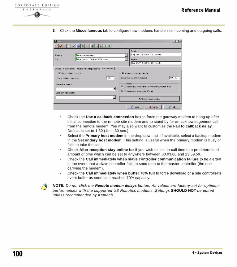
Reference Manual
3 Click the Miscellaneous tab to configure how modems handle site incoming and outgoing calls.
• Check the Use a callback connection box to force the gateway modem to hang up after initial connection to the remote site modem and to stand by for an acknowledgement call from the remote modem. You may also want to customize the Fail to callback delay. Default is set to 1:30 (1min 30 sec.).
• Select the Primary host modem in the drop down list. If available, select a backup modem in the Secondary host modem. This setting is useful when the primary modem is busy or fails to take the call.
• Check After reception stay online for if you wish to limit in-call time to a predetermined amount of time which can be set to anywhere between 00.03.00 and 23.59.59.
• Check the Call immediately when slave controller communication failure to be alerted in the event that a slave controller fails to send data to the master controller (the one carrying the modem).
• Check the Call immediately when buffer 70% full to force download of a site controller’s event buffer as soon as it reaches 70% capacity.
NOTE: Do not click the Remote modem delays button. All values are factory-set for optimum performances with the supported US Robotics modems. Settings SHOULD NOT be edited unless recommended by Kantech.
4 • System Devices100

Reference Manual
Controllers ConfigurationControllers provide audiovisual feedback on the access decision. Typically, a red/green light (LED) indicator on the reader informs the cardholder that the door is unlocked or that access has been denied. A local door alarm can be installed to provide an audible warning if the door is forced open or remains open after an access.The controller definition tells the system how a controller is being used and what devices are associated with it: (doors, input zones, relays and output devices). Controllers may be defined during a gateway or site configuration; or in the controller definition menu, by selecting either the controller icon (Devices > Controller) or by using Express Setup program.EntraPass supports four types of controllers: KT-100, KT-200, KT-300 and KT-400. These provide the ability to activate local functions associated with a controller. The number of devices associated with a controller varies according to the controller type. The following table summarizes the basic components associated with each type of Kantech controller:
KT-400 Ethernet Four Door ControllerThe KT-400 is a 4-door Ethernet-ready encrypted controller providing a secure solution for any company looking for the highest security available. It integrates into existing EntraPass Version 4.01 systems and with other Kantech controllers or can be the basis of new security installations. In North America (UL) and Europe (EU), the KT-400 brings new exciting features at the door
Main Features• Up to 256 inputs (16 onboard with high security double end of line resistor configuration) • Up to 256 outputs • Four Onboard form C relays• 16 reader output on board• Onboard 128-bit AES encryption ensures a high degree of network security • Removable terminal blocks• On Board Ethernet port ensures quick network connectivity, no external Ethernet device
required• Automatic Port Detection• For readers, locks and other devices, built-in battery backed power supply ensures continuous
operation and saves installation time and money by eliminating the need for an external power source
• Can act as an IP Master controller on a RS-485 network
Type Doors Relays Input Zones
Auxiliary Outputs
KT-100 1 4 4 2
KT-200 2 2 16 4
KT-300 2 2 8 4
KT-400 4 4 16 16
101Controllers Configuration

Reference Manual
• Compatible with Kantech controllers KT-100, KT-300 & (KT-200 on a separate loop)• Dedicated Tamper Input• External lock device power option• Four configurable output per reader• Built-in WEB page configuration• Multiple Configuration Options (IP, RS-485 & RS-232)• Low network bandwidth consumption • Visual Status Indicators (LEDs)• More supervision and monitoring• Controller local area with anti-passback• 100,000 Card per controller and 20,000 stored events in stand alone mode• Activation time on temporary action & events
Configuring General Parameters for Kantech Controllers1 From the Devices > Controller menu, select the gateway associated with the controller site.2 From the Site drop-down list, select the site where the controller is located.3 From the Controller drop-down list, select the controller you want to define. Once selected, the
language section is enabled. You may rename the selected controller.4 In the General tab drop-down list, select the KT Controller type.
• Assign a meaningful name to the controller in the language section (English and French in our example), then click the Save icon. Once you save, the Controller type drop-down list becomes disabled.
NOTE: If you selected KT-200, a number appears next to the drop-down list. If you move your cursor above that number, a hint will popup to indicate the jumper setup for that KT-200 controller.
4 • System Devices102

Reference Manual
• The system prompts you to use the Express Setup program. Click Yes to continue. If you select No you will have to manually configure these devices in their respective definition menus (doors, relays, inputs and auxiliary outputs).
NOTE: EntraPass offers you the ability to install two types of readers on the same controller (primary and secondary The two readers must be of the same technology (Wiegand or ABA). This feature is only available with KT-100, KT-300 and KT-400
• After configuring components associated with the controller, select the reader and keypad installed on your controller from the Reader and Keypad type drop-down lists.
NOTE: The New reader driver icon allows you to install a custom driver for a specific controller. Moreover, using this button allows you to add the driver in the Reader+ Driver table, making it available the next time you want to configure a new controller.
• Use the Disable controller polling when you need to put the controller in disable mode. In disable mode, the controller will never be polled and all status requests from this specific controller will send a message that this controller is disabled.
NOTE: This option can be used when a controller is removed temporarily but must not be deleted (when under repair, for example). It also allows Operators to easily setup the software before the physical installation is completed.
• Select a Graphic and Video view to which the gateway is assigned, if applicable.The video view will only be activated If the video feature is enabled in EntraPass.
5 To define the schedules applicable to the new controller, you must move to the Supervision Schedule tab.
• Select the applicable Schedules for the new controller:• When a KT-100 or KT-300 is selected: only the Power supervision schedule list is
displayed.• For KT-200 or KT-400, the Power supervision schedule and the Tamper switch
supervision schedule lists are available.
103Controllers Configuration

Reference Manual
6 Click the Save icon.
Configuring a KT-100 ControllerOnce the general parameters are defined, the Controller type tab is displayed.1 Select the KT-100 tab from the Controller window.
2 Enter the controller serial number in the Serial number field. Usually, the number is found on the controller label. The field is defined to accept only numeric characters, except for the first character which may be an a or A. If a lower case character is entered, the system converts it to a capital letter.
3 Enter the Wait for second access card delay. The maximum time allowed is 2 minutes 07 seconds. This feature is useful for secured areas where two cards are required to access a secured door. If the value entered is greater than the maximum allowed, the system will use the existing value.
4 In the Keypad escape key drop-down list, choose a keypad escape key if applicable. This feature is associated with PIN numbers. When a user enters a wrong number, he/she may press the escape key and re-enter the PIN, without incrementing the number of attempts.
5 In the Input resistor type drop-down list, select the resistor type used with your system. By default, this choice is set to Single resistor. This feature is used as a supervision device for all inputs. In fact, if this feature is enabled and if an input is disconnected, an alarm message is generated and sent to the Alarm message desktop (or other desktop configured to receive such events).
NOTE: For details on defining options for KT-100 controllers, see "Defining Controller Options" on page 122.
4 • System Devices104

Reference Manual
Configuring a KT- 200 ControllerEach KT-200 can monitor, in real-time, the state of 16 input points such as magnetic contacts, motion detectors, temperature sensors, etc. The door contact (supervising door state) and the REX (warning the system that a user is exiting) are connected to such inputs.The KT-200 is equipped with two relays. These relays can be activated according to schedules, reported events or a combination of different logical conditions. The system is expandable to 16 relays using REB-8 relay expansion board modules. REB-8 may be used as relays or as elevator controllers. KT-2252 are only used as elevator controllers.
NOTE: Please note that KT-2252 are no longer available.
Defining KT-200 Expansion DevicesKT-2252 elevators offer a low voltage interface for up to 32 floors. Up to 4 KT-2252 can be connected to one KT-200 controller for a maximum of 64 floors per cab. One KT-2252 can be shared between 2 cabs, serving a maximum of 16 floors each (one common service switch for both cabs). When users present their cards to the elevator cab reader, the KT-200 verifies which floors can be accessed by this cardholder and sends a list of floors to be enabled to the KT-2252 interface. The KT-2252 closes the electronic interrupters corresponding to the related floors.
Defining KT-200 Auxiliary Devices1 From the Controller definition window, select the KT-200 tab.
2 In the Auxiliary devices section, select the type of devices used with KT-200 controller. • Check the REB-8 relay option if REB-8 expansion boards are used as relays. Only 16
relays can be defined. If two REB-8 are added, the last two relays (the 17th and 18th relays) can be used to perform different actions. You have to specify the additional actions for the two relays in the Extra relay drop-down list.
105Controllers Configuration

Reference Manual
• Check the KT-2252 elevator controller and REB-8 relay option if KT-2252 are used as elevator controllers and REB-8 are used as relays on the same door controller. A maximum of four KT-2252 can be connected to the controller.
• Check the REB-8 Elevator Controller option if REB-8 are used for elevator control. Up to four REB-8 can be used for elevator control.
NOTE: When an elevator controller option is checked, an Elevator tab appears beside the KT-200 tab.
The following section explains how to program elevator controls using REB-8 and KT-2252 elevator controllers.
Programming KT-2252 Elevator ControllersThe Elevator tab allows you to specify which auxiliary devices are used with the KT-200 for elevator control and how they are used. Depending on the expansion board installed and on the option checked, the Elevator window displays the REB-8 Installed or KT-2252 Installed section.1 From the Controller definition window, select the KT-200 tab.
2 In the Auxiliary devices section, select KT-2252 elevator controller, or KT-2252 elevator controller and REB-8 relay. The Elevator tab appears beside the KT-200 tab.
4 • System Devices106

Reference Manual
3 To configure elevator controllers, select the Elevator tab. When KT-2252 elevator controllers are used, the Elevator mode section is enabled.
4 In the Elevator mode section, check the appropriate number of floors. This indicates how the floors are controlled with the KT-2252. • Select 16 Floors if there is one KT-2252 for two cabs sharing the same floors.• Select 32 Floors if there is one KT-2252 per cab.
NOTE: The Inputs column refers to the KT-2252 terminals. When floors have been defined (in the Floor menu), the Floors column contains the floors that are associated with the inputs.
5 In the KT-2252 installed section, specify the number of KT-2252 installed. The options are cumulative. If for example the KT-2252 #3 option is checked, KT-2252 #1 & 2 have to be checked as well. The following table summarizes how KT-2252 elevator controllers are used:
Number of Cabs
Number of Floors
Number ofKT-2252
1 8 1
1 16 1
1 32 1
1 64 2
2 8 1
2 16 1
2 32 2
2 64 4
107Controllers Configuration

Reference Manual
6 In the Floors column, select the floors associated with KT-2252 controller terminals.
NOTE: The Inputs column refers to the KT-2252 terminals. When floors have been defined (in the Floor menu), the Floors column contains the floors associated with the inputs.
Programming REB-8 Elevator ControllersREB-8 relay expansion boards may be used as a cost-efficient alternative for elevator control. With a REB-8 expansion board added to a KT-200, the software may control up to two elevator cabs per controller.1 In the KT-200 definition window, select the REB-8 elevator controller option. When the option
is selected, an Elevator tab appears beside the KT-200 tab. The REB-8 definition section is only active when REB-8 are used as relays.
4 • System Devices108

Reference Manual
2 Select the Elevator tab to configure the REB-8 elevator controllers. Up to four REB-8 elevator controllers are supported.
3 Specify the number of REB-8 that are installed on the controller. The selection is cumulative. For example, if four REB-8 are installed, the first three checkboxes have to be checked also. The following table summarizes how REB-8 are assigned to floors and to elevator cabs.
NOTE: The Inputs column refers to the REB-8 terminals. When floors have been defined (in the Floor menu), the Floors column contains the floors that are associated with the inputs.
4 In the Floors column, select the floors associated with REB-8 controller terminals. For details on floor definition and door group definition, see "Doors Configuration" on page 127.
NOTE: There is no floor confirmation when an REB-8 is used as an elevator controller.
Defining REB-8 RelaysWhen REB-8 are used as relays, you need to specify how many relays are installed on the KT-200. The controller can handle a maximum of 16 accessible relays and already provides 2 on-board relays.
Number of REB-8
Number of Floors
Number of Cabs
1 1 to 8 Cab 1
2 9 to 16 Cab 1
3 1 to 8 Cab 2
4 9 to 16 Cab 2
109Controllers Configuration

Reference Manual
1 Under the KT-200 tab, select the REB-8 relay option if REB-8 are used as relays.
2 If they are used with the KT-2252 elevator controller, select the KT-2252 elevator controller and REB8 relay option. In either case, the REB-8 definition section is enabled.
3 In the REB-8 Definition section, select the appropriate option: No REB-8, One REB-8 or Two REB-8.
4 If two REB-8 are added (for a total of 18 relays), the last two relays can be used to perform different actions: select the use for the extra relays from the Extra relay drop-down list.
5 Select the Status relay tab to program a relay or group of relays that will be activated when an event occurs.
Configuring the KT-300 ControllerThe KT-300 constantly supervises battery condition and reports “Low battery / No battery condition” status to the system. It also supervises locking devices for short and open circuits to detect lock failures.KT-300 controllers support Combus modules. The Combus is a 4-conductor cable bus to which several expansion modules are connected in parallel to add inputs, outputs, relays and an LCD time and date display.
4 • System Devices110

Reference Manual
1 From the Site menu, click the Controller icon, then select the KT-300 tab.
2 Enter the controller serial number in the Serial number field. Usually, the number is found on the controller label. The field is defined to accept only numeric characters, except for the first character. It may be an a or A. If a lower case character is entered, the system converts it to upper case.
3 Enter the Wait for second access card delay. The maximum time allowed is two minutes and seven seconds. If the value entered is greater than the maximum allowed, the system will use the existing value. This feature is useful when access to a place is controlled by two cards.
4 In the Keypad escape key drop down list, choose a keypad escape key if applicable. This feature is associated with PINs. When a user enters a wrong number, he/she may press the escape key and re-enter the PIN, without incrementing the number of attempts.
5 In the Resistor type drop-down list, select the resistor type. By default, the Single resistor option is selected. If you hear a long buzz, verify the number of resistors installed on your system.
Configuring the KT-300 Combus Modules Five combus modules can be connected to a KT-300:• KT-PC4108 (8-zone input expansion module). This module has a tamper contact input.• KT-PC4116 (16-zone input expansion module). This module has a tamper contact input.• KT-PC4204 (4-relay/power supply expansion module). It has a tamper contact input and also
includes a built-in 12VDC, 1A power supply for field devices.• KT-PC4216 (16-zone output expansion module). It can be used for elevator control, although
additional hardware may be required.• KT3-LCD (Kantech 32-character liquid crystal display). The LCD is green (normal status), red
(power failure) and yellow (trouble).
111Controllers Configuration

Reference Manual
1 If a Combus module is installed to the KT-300 controller, click the Combus module configuration button. Undefined Combus terminals are identified by red flags/bullets. Once a module has been defined, it is identified by a green flag.
2 To define a module, select one, then click the Define button (lower part of the window). The Enter Combus module serial number message box appears.
3 Enter the module’s serial number, then click OK.
NOTE: To obtain this number, you have to activate the Tamper switch or to press any key on the keyboard. The Combus serial number is displayed in the Desktop Message.
4 Assign names to the modules in the language fields.5 Check the options related to the module you want to configure (if these are displayed in the
window).
NOTE: Usage options of a module vary according to the selected Combus module. For example, installing the KT3-LCD and checking the options Combus low power and Display date and time will allow the KT-300 to report Combus low power conditions and to display the date and time.
The following table summarizes the options associated with each module:
Combus type Options Additional options
KT3-LCD Combus low power, display date and time
No additional options
KT-PC4108 Tamper alarm, Combus low power 8-input module
KT-PC4116 Tamper alarm, Combus low power 16-input module
4 • System Devices112

Reference Manual
6 Check the Combus low power option so that the KT-300 will report any Combus low power condition
7 Check Display date and time option so that LCD can display the date and time.8 When you have finished configuring the Combus module, click the Ok button to go back to the
KT-300 status relay tab.
9 Associate a Local activation relay for Power failure, Combus failure and Combus low power. If you want to assign a specific relay, you may click the three-dot button and select a specific relay or group of relays.
NOTE: To configure local activation relay, you must configure relays (Devices > Relays), and then select specific relays for local activation.
10 Under Priority call type, assign the call type option that best suits failure event reporting. To access the Priority call type feature, the site connection type must be set to Modem.
NOTE: For more information, see "Sites Configuration" on page 91.
Configuring the KT-400 Ethernet Four Door ControllerThe KT-400 constantly supervises ac power and battery condition and reports “AC Power Failure”, “Normal Battery”, “Low Battery”, “Battery Critical”, “No Battery”, or “Battery Brown Out”, status to the
KT-PC4204 Tamper alarm, Combus low power, Low battery, Power failure, lower auxiliary power
Used as relays (1-4)
KT-PC4216 Tamper alarm, Combus low power Used as outputs
Combus type Options Additional options
113Controllers Configuration

Reference Manual
EntraPass system. Power outputs are supervised and electronically protected against short-circuits and surges. Locking devices are also supervised for short and open circuits.
NOTE: For hardware information on the KT-400 Ethernet Four Door Controller, please refer to the KT-400 Ethernet Four Door Controller Installation Manual, DN1726.
1 From the Devices > Controller menu, click on the General tab and select the Reader type(s).
2 Select the Keypad type (if applicable).
3 Click on the KT-400 tab. Enter the controller serial number in the Serial number field. The number is found on the controller label next to the reset button. The field is defined to accept
4 • System Devices114

Reference Manual
only numeric characters, except for the first character. It may be an a or A. If a lower case character is entered, the system converts it to upper case.
4 Enter the Wait for second access card delay. The maximum time allowed is 2 minutes and 7 seconds. If the value entered is greater than the maximum allowed, the system will use the existing value. This feature is useful when access to a place is controlled by two cards.
5 In the Keypad escape key drop down list, choose a keypad escape key if applicable. This feature is associated with PINs. When a user enters a wrong number, he/she may press the escape key and re-enter the PIN, without incrementing the number of attempts.
6 In the EOL Resistor (5.6 K) drop-down list, select the resistor type. By default, the Single resistor option is selected. If you hear a long buzz from the installed reader/keypad, verify the number of resistors installed on your system.
Configuring the KT-400 Expansion ModulesThe KT-400 Ethernet Four Door Controller support expansion modules through its SPI expansion port. The SPI port is a 6-conductor cable bus to which several expansion modules are daisy-chained to add inputs, outputs and relays.
Warning: The KT-400 SPI port maximum current draw is 500 mA, when the 12V AUX terminals are not used. External power supply (12 VDC, 2 Amps) for the expansion module is required when the total current draw exceeds 500mA on the SPI Port. For additional details, please refer to the KT-400 Ethernet Four Door Controller Installation Manual, DN1726.
Three expansion module types are available:• KT-MOD-INP16: The KT-MOD-INP16 is an input module that adds 240 zones to the KT-400
controller. Up to 15 input modules (16 input modules if used for elevator configuration) can be connected to a KT-400 for a total of 240 external inputs. Adding the 16 onboard inputs of the KT-400 gives a total of 256 inputs per KT-400. For further details, check the KT-MOD-INP16 KT-400 Expansion Module 16-Zone Input with SPI Cable, Install Sheet, DN1776.
• KT-MOD-OUT16: The KT-MOD-OUT16 is a 16-output module. It can be used for elevator access control with additional hardware. Up to 16 output modules can be connected to a KT-400 for a total of 256 outputs. For further details, check the KT-MOD-OUT16 KT-400 Expansion Module 16-Output with SPI Cable, Install Sheet, DN1781.
115Controllers Configuration

Reference Manual
• KT-MOD-REL8: The KT-MOD-REL8 is an 8-relay outputs expansion module used as general relays or elevator control outputs. Up to 32 relay modules can be connected to a KT-400 for a total of 256 relays. For further details, check the KT-MOD-REL8 KT-400 Expansion Module 8-Relay Output with SPI Cable, Install Sheet, DN1786.
The following table summarizes the options associated with each module:
NOTE: There are already 4 relays available on the KT-400. Make sure to check the relay number assignments to prevent redundancy unless it has been planned on purpose.
NOTE: The 9-16 relay configuration is set by default.
Expansion Module Options
KT-MOD-INP16 Controller inputs (up to 256) and/or elevator inputs (up to 64 per elevator door)
KT-MOD-OUT16 Outputs relays (up to 256) and/or elevator outputs (up to 64 per elevator door)
KT-MOD-REL8 (Note) Relays (up to 256) and/or elevator outputs (up to 64 per elevator door)
4 • System Devices116

Reference Manual
1 If an expansion module(s) is(are) connected to a KT-400, click the Expansion module configuration button. The Expansion modules setup appears.
2 To add a KT-MOD-INP16, select the Input Module tab and then click on Add. If there is more than one input modules listed, make sure that you select the correct one before changing the input assignments. Assign names to the modules in the language fields and choose the options.
NOTE: Controller inputs 1-16 are reserved to the inputs on the KT-400.
Example with Inputs 1-8 Configured as Controller Inputs
If you want to then go to
configure an input module KT-MOD-INP16 Step 2.
configure an output module KT-MOD-OUT16 Step 4.
configure an output module KT-MOD-REL8 Step 5.
modify an existing expansion module configuration Step 6.
117Controllers Configuration

Reference Manual
3 Selection of the inputs numbers can be done in two ways: using the drop-down menu or the Extended selection box. Right-click on the inputs menu selection to view the Extended selection box, see "Using an Extended Selection Box" on page 52.
Example with Inputs 9-16 Configured as Elevator Inputs
NOTE: This is an exclusive condition. You cannot select the same item in the Inputs drop-down menu and in the Elevator inputs drop-down menu because it will be a duplicate, and the system does not accept any duplicate. For example, Inputs # 17-24 cannot be selected twice. Another way to let you understand this concept, is that in the Elevator inputs menu the same item will not be available for the same door. The same concept applies for the Elevator outputs menu.
4 • System Devices118

Reference Manual
4 To add a KT-MOD-OUT16, select the Output Module tab and then click on Add. When you click on the Add button, a menu appears and lets you select which output module you want to add. Assign names to the modules in the language fields and choose the options.
Example with Outputs 1-8 Configured as Output Relays
Example with Outputs 9-16 Configured as Elevator Outputs
119Controllers Configuration

Reference Manual
5 To add a KT-MOD-REL8, select the Output Module tab and then click on Add. When you click on the Add button, a menu appears and lets you select which output module you want to add. Assign names to the modules in the language fields and choose the options.
Example with Relays 1-8 Configured as Elevator Outputs
Example with Relays 1-8 Configured as Relays
4 • System Devices120

Reference Manual
Warning: There are already 4 relays available on the KT-400. Make sure to check the relay number assignments to prevent redundancy unless it has been planned on purpose.6 From the Summary tab, you can modify all the modules. Make sure to highlight the module you
want to modify in the left column before doing any modifications on the right side.Example of Modifications for an Existing Expansion Module
7 When you have finished configuring the expansion modules, click the OK button to go back to the KT-400 configuration window.
NOTE: For more information, see "Sites Configuration" on page 91.
121Controllers Configuration

Reference Manual
Configuring the Status Relay Activations (for a Corporate Gateway Only)1 Select the Status relay tab to program a relay or group of relays that will be activated when an
event occurs.
Defining Controller OptionsThe Option tab enables operators to configure such features as:• Anti-passback (for synchronizing entry/exit readers)• Duress function (for defining a panic button)• Card count options (for specifying cards in an area), etc.
NOTE: The anti-passback option works with entry/exit readers. It allows security administrators to keep track of the number of monitored cardholders in an area. It is local to each controller defined by corresponding entry/exit readers. A relay can be activated when the counter reaches the number of cards defined to be inside the area; the relay is disabled when the number of cards in the area goes below the specified number.
4 • System Devices122

Reference Manual
1 In the Controller window, click the Option tab to define anti-passback options, duress options and card count options./
2 Determine the Duress options. When a duress option is selected, you have to assign a duress key, that is a silent panic key.• Duress on access granted: this option enables the duress key when access is granted.• Duress on access denied: this option enables the duress key, even when access is
denied.3 Select a duress key from the Keypad duress key drop-down list.
NOTE: For added security, you may select the two options. The anti-passback programming is available on a Corporate Gateway configuration only.
4 From the Anti-passback options (available for the Corporate Gateway only), select the anti-passback option from the Type drop-down list: when an anti-passback option is enabled, a card cannot be used on an exit door unless it has been used on a corresponding entry door.• None: the anti-passback option is disabled.• Soft anti-passback: this option allows a cardholder to use an entry (or exit) reader more
than once without using the corresponding exit (or entry) reader. Only an “Access granted - Passback bad location” event is sent to the Message desktop.
• Hard anti-passback: a card used at an entry reader will not be able to access the same entry reader again until it has used the corresponding exit reader. Only an “Access denied - Passback bad location” event is sent to the Message desktop.
• Controller local area: this selection enables the Controller local area tab. This option is only functional with the KT-400; the Controller Local Area tab will only appear with a KT-400.
5 In the Forgive schedule section, click the three-dot button to set a schedule for resetting the anti-passback option on all other cards.
NOTE: The Forgive Schedule section is enabled only when Soft anti-passback or Hard anti-passback item is selected.
123Controllers Configuration

Reference Manual
6 In the Miscellaneous section, indicate options for Enable fail-soft delay (10-255 s). During a fail-soft mode, the controller operates in stand-alone mode, following a communication failure.
7 Enter the 32-bit card family code (optional). You can locate this hexadecimal code on the access card.
8 In the Card count options, use the up or down controls to set the maximum card number. The maximum card number allowed is 2,147,483,647. The system keeps track of the number of monitored cards that are in the monitored area and activates a relay when the count is reached. When users exit the area, the counter decrements and the relay will eventually reset when the count is smaller than the value defined.
9 You may configure the system to Activate a single relay or a group of relays when the maximum count is reached. Click the three-dot button to select the relay or relay group that will be activated when the number is reached.
NOTE: The Activate relay section is enabled only when Soft anti-passback or Hard anti-passback item is selected.
Defining the KT-400 Controller Local AreasNOTE: The controller local area option is only available with the KT-400 on Corporate Gateways and EntraPass Special Edition.
1 In the Controller window, click the Controller local area tab to define up to 4 local areas.
2 Assign a name for both languages for the 1st controller local area.3 Select the Forgive schedule from the drop-down menu.4 Enter the maximum number of cards allowed in the Cards threshold field.5 Check the Deny access on area full box to prevent more users to enter the area after the
cards threshold has been reached.6 Click on the three-dot to select the relay or the relay group to activate when the cards threshold
has been reached.7 Repeat steps 2 to 6 for each controller local area.
4 • System Devices124

Reference Manual
Defining the KT-400 Elevator Floor AssociationsNOTE: The Elevator tab displays only when expansion modules have been defined as inputs or outputs for elevators under the KT-400 tab, see Configuring the KT-400 Expansion Modules on page 115.
Associating Pattern With Door and Floor NumbersFor KT-400 controller only, it is possible to choose up to four patterns to define door and floor numbers that will be associated with each pattern. By default, pattern 1 specifies all door numbers.
1 In the Controller window, click the elevator tab to define the floor associations.
2 In the Elevator tab, click Pattern #2, and then select the appropriate Door number check box(es).
3 From the Floors drop-down menu, select the appropriate item or floor number to associate with the door number and the pattern number.
4 Repeat Steps 2 and 3 for each pattern.5 Click Save.
125Controllers Configuration

Reference Manual
Controller Event Buffer Overflow MessageWhen a controller is disconnected from the server, the controller buffer starts collecting the controller’s events. When the buffer is full, it transfers the oldest events in a secondary buffer (50 to 100 bytes) that always contain 50 events. When the communication is restored, the system then starts sending messages to the Desktop Message List (shown below) to indicate that the buffer is full and that events are being deleted from the buffer.
• The controller will delete messages in FIFO order (First In, First Out). The oldest message will therefore be deleted first.
• When the controller is reconnected to the server, the controller events will be sent to the Message list all at once, in the following order: events in the controller’s secondary event buffer; a single Event Buffer Overflow will display, followed by the list of events generated while the controller was disconnected from the server.
• In the Message List above, the highlighted error message “Event buffer overflow” is the 50th oldest controller event sent to the Message List.
4 • System Devices126

Reference Manual
Doors ConfigurationThis menu is used to define the door parameters on which readers and/or keypads are installed. A door can be considered as an elevator door, a Time & Attendance door, an entry door for anti-passback, an exit door for anti-passback or an access door. All this depends on how the settings are programmed.The controlled door may be secured at all times or only during defined schedules. The common locking devices used are electric door strikes and electromagnetic locks. A door may be equipped with one or two readers, with one reader at each side. For doors equipped with two readers, the outer reader has to be defined as an entry reader and the inner reader as an exit reader.
Defining General Parameters for a DoorNOTE: When you are using the KT-300 system, you are working with h:mm:ss and the range value can be from 00:00:01 to 9:06:07. Each time you are using a KT-400 system, you are working with hh:mm:ss and the range value can be from 00:00:01 to 04:15 (255 sec.) for a KT-100, KT-200 and KT-300; or to 18:12:15 (65535 seconds) for a KT-400. So, please take this difference into consideration.
1 In the Devices toolbar, select the Door icon.
This screen only applies to a KT-400 with Controller Local Areas.
127Doors Configuration

Reference Manual
This screen applies to controllers without Controller Local Areas.
2 In the Door window, select the appropriate Gateway to view the controller sites for a specific gateway, then select a site (from the Site drop-down list) and the controller associated with the door you want to define.
3 From the Door drop-down list, select the door you want to modify or define. New items are identified with a red button. The button turns green once the item has been defined and saved.
4 From the General tab, specify the Door lock mode: Depending on the lock device used, the locked state will energized or de-energized to lock.• Fail-secure: The strike is locked when power is removed (door locks, door strikes).• Fail-safe: The lock output is energized to lock the door (electro magnetic locks).
5 Check the Elevator cab option if the door is to be used for elevator control. When this option is checked, the Elevator tab is displayed to define the unlocking schedules.
6 Specify the Time and Attendance type:• None: The reader is considered as an access reader. An access reader generates only
“Access granted/Access denied” events.• Entry: An entry door is an entry point. In order for the system to record an entry, the door
must be opened after a valid access (if a door contact is installed).• Exit: An exit door is an exit point. In order for the system to record an exit, the door must be
opened after a valid access (if a door contact is installed).
7 Specify the Door Anti-Passback type:
If the Controller Local Areas then go to
are not enabled Step 7.
are enabled Step 9.
4 • System Devices128

Reference Manual
• Access: The reader is considered as an access reader. Anti-Passback options are not used with access doors. An access reader generates only “Access granted/Access denied” events.
• Entry: An entry door is an entry point. In order for the system to record an entry, the door must be opened after a valid access (if a door contact is installed).
• Exit: An exit door is an exit point. In order for the system to record an exit, the door must be opened after a valid access (if a door contact is installed).
8 Go to Step 11.
NOTE: None, Soft anti-passback and Hard anti-passback are used only with the KT-400 and Controller Local Areas.
9 Specify the Door Anti-Passback type:• None: the anti-passback option is disabled.• Soft anti-passback: If the destination area is under Deny Access on Local Area Full,
access is denied. When a user is passing his access card to a local area, for example, the system will allow him to access another local area even if the user was not in the Local area before. The system will generate the event: “Access granted - Passback bad location“.
• Hard anti-passback: If the destination area is under Deny Access on Local Area Full, access is denied. A card used at an entry reader will not be able to access the same entry reader again until it has used the corresponding exit reader. The system will generate the event: “Access denied - Passback bad location“.
10 Specify the Local area before and local area after. These items are enabled and can be specified only for Controller Local Area.
11 Specify the Extended door access delay:• Unlock time (hh:mm:ss): The time during which the door is unlocked on a valid card read
or a valid request to exit event (when the REX is defined to unlock the door). The time range value can be from 00:00:01 to 04:15 (255 sec.) for a KT-100, KT-200 and KT-300; or to 18:12:15 (65535 seconds) for a KT-400. If this is an elevator door and a push button (input) is used to enable floor selection, this is the time during which a floor selection will be allowed. Usually, a longer period should be defined to allow the user to select floors. For more information, see "Defining an Input for an Elevator Door" on page 146.
• Open time (hh:mm:ss): The time during which a door can remain opened following a permitted access or a valid request to exit request. This applies only to a door defined with a door contact input. The time range value can be from 00:00:01 to 04:15 (255 sec.) for a KT-100, KT-200 and KT-300; or to 18:12:15 (65535 seconds) for a KT-400. After this delay has expired, the system will generate the event “door open too long” and the door piezo will sound to warn the cardholder. You can use the Pre-alarm on door open too long (Door window, Contact tab) to sound the door piezo when half of this delay has expired. It will continue to sound until the door is closed.
12 The Extended door access delay (hh:mm:ss) feature allows to keep the door open for an extended period in order to allow people with disabilities to pass through without triggering an alarm. If you want to use this option, specify the delays in the Unlock time and Open time fields. The time range value, for both delays, can be from 00:00:01 to 04:15 (255 sec.) for a KT-100, KT-200 and KT-300; or to 18:12:15 (65535 seconds) for a KT-400.
129Doors Configuration

Reference Manual
13 Unlock Schedule will allow the system to unlock the door for a predetermine period of time that you will select.
14 Select a Graphic and Video view to which the gateway is assigned, if applicable. The video view will only be activated if the video feature is enabled in EntraPass.
NOTE: EntraPass offers the ability to program an extended door access delay and to specify specific unlock and open time delays reserved for people with disabilities. In addition to setting this special access delay, the user’s access card must be programmed with this feature. Only available with KT-100, KT-300 and KT-400.
Defining Door Keypad Options
For KT-100 and KT-300 ControllersDoors can be defined with relay activation when the * or # keys are pressed on the keypad. This option is available only for KT-100 (with firmware version 1.04 and higher) and KT-300 (with firmware version 1.16 and higher) controllers.
For KT-400 ControllersDoors can be defined with relay or relay group activation by pressing any specified key on the keypad.
NOTE: The Keypad tab is enabled only if you have selected a Keypad type while defining the controller associated with the door being defined, see "Select the Keypad type (if applicable)." on page 114. There are 4 keys. The first 2 keys: # and * are fixed keys and they are similar and play the same role as in the KT-300 system. The 2 other keys: Key 3 and key 4 are variable according to the client’s needs.
4 • System Devices130

Reference Manual
1 From the Door window, select the Keypad tab.
2 Specify how access to the door is controlled:• Reader only: Select this option if access is granted using a reader. A reader only
installation is the most common application.• Reader or keypad: Select this option if access is granted using a reader or a keypad only.
A keypad only installation is generally considered less secure than a reader only installation, because a user may “lend” its PIN to another person but cannot prevent further use (in comparison to getting a card back).
NOTE: This option can be enabled on a reader with an integrated keypad if you want, for instance, to use the keypad only.
• Reader and keypad: Select this option if both a reader and a keypad are used to permit access to this door. The keypad will only be used when the “keypad schedule” is valid. Adding a keypad to a reader significantly increases the level of security. PIN code requirement can be limited by a schedule for use only outside business hours, for example, rather than during high traffic hours.
3 From the Card and PIN schedule menu, select a schedule during which cardholders will have to enter their PIN after a valid card read. The time allowed between a valid card read and entering the PIN at the keypad is set in the Gateway definition menu (Time-out on keypad option).
4 Check the Enable duress function on keypad option, if desired. 5 Select the Keypad relay activation key(s):
• For KT-100 and KT-300 Controllers: For doors defined with keypad or reader and keypad, you can program the star key (*) or pound key (#) to activate a relay. When this feature is enabled, users can activate a relay simply by pressing the appropriate key.
131Doors Configuration

Reference Manual
• For KT-400 Controllers: For doors defined with keypad or reader and keypad, you can program *, # or any key to activate a relay or a relay group. When this feature is enabled, users can activate a relay or a relay group simply by pressing the appropriate key.
Defining Door Contact OptionsIn most applications, the low cost door contact is the only supervisory element that protects the investment made to control access to the door. The door lock and card reader (or keypad) provide security and prevent unauthorized entry only when the door is closed and locked. A simple door contact allows the ability to monitor several door conditions such as: door forced open, door open too long, interlock options (mantrap), etc.
1 In the Door window, select the Contact tab.
2 Select the door contact from the Door contact list.
NOTE: For KT-200 Controllers, Input 1 (door contact) and 2 (request to exit device) are ideally reserved for Door 1 of the controller whereas Input 9 (door contact) and 10 (request to exit device) are ideally reserved for Door 2 of the same controller. The input that is used for the door contact or REX contact SHOULD NOT have a “monitoring” schedule defined in the “Input Definition” menu.
3 Check the door reading options:• Door open reading—If selected, this option allows the system to read cards while the door
is open. However the system will not unlock the door if it was locked. If selected, the event “Access granted” is generated. Otherwise, the event “Access granted - Door open” is generated.
• Door unlocked reading—If selected, this option allows the system to read cards while the door is unlocked manually by the operator or by a valid unlock schedule. If selected, the event “Access granted - Door unlocked” will be generated on access. To ignore all access events while the door is unlocked, leave this option unselected.
• Pre-alarm door opened too long—If selected, this option allows the system to generate the event “pre-alarm door open too long” and sound the door piezo when half of the delay defined in the Open time field is expired. It will continue to sound until the door is closed.
4 • System Devices132

Reference Manual
• Unlock on access door opened— If selected, this option allows the system to unlock access on door opened at any time.
4 Select the appropriate Relock on access option. You may choose to relock an access On door opening or On door closing.
Defining REX (Request to Exit) OptionsA signal from the REX indicates that someone wants to exit through a controlled door. Devices such as motion detectors, push buttons can provide the REX signal. EntraPass enables users to configure doors with unlock time reset each time the primary or secondary REX is triggered. This option is available only for KT-100 (with firmware version 1.04) and KT-300 (with firmware version 1.16) controllers.1 From the door window, select the REX tab, then check the appropriate Relock on Rex options:
• On door opening, if you want the door device to re-lock following a valid access• On door closing, if you want the door device to re-lock when it closes.
2 For the primary and Secondary Rex options, make the appropriate choices:• Assign the REX contact: the input to which a “request to exit” detector can be connected.
This input must be local; it has to be one of the inputs on the controller operating the door.• Select a Rex schedule: when this schedule becomes valid, the controller will detect
request to exit signals originating for the exit contact. This option applies only to a door defined with a REX contact.
• Unlock on REX: the door will be unlocked if a valid request to exit is permitted by the controller. This option may be useful on exit doors such as interior doors, shipping doors or other push doors through which people carrying packages may pass. The system will permit the exit and generates the “request to exit granted” event rather than “door forced open” event.
• Resettable REX function: the unlock time is restarted on a valid request to exit. Open and unlock times are defined in the door definition (Devices > Door > General). Select this option for high traffic area doors such as manufacturing doors where many users may need
133Doors Configuration

Reference Manual
to exit at short intervals (for example after a work shift) to prevent unwanted door open too long or door forced open events.
NOTE: It is recommended to choose either Unlock on REX or Resettable Rex function, not the two options at the same time. If you choose these two options, the door may remain unlocked for long periods of time. Moreover, these features should not be used if a door contact has not been defined.
Defining Interlock Options (Mantrap)You may define interlock options (mantrap) between two doors to synchronize the time when these two doors are open/closed. The interlock options are also called the mantrap. This ensures that once the cardholder has accessed the first door, that door is closed and locked before the cardholder is granted access to the second door. The two doors have to be controlled by the same controller. 1 In the Door window, select the Miscellaneous tab.
2 From the Door drop-down list, select the first door for which you want to define interlock options (mantrap).
3 From the Interlock contact list, select the first input for the interlock options (mantrap). The selected input has to be the door contact of the second door.
4 Return to the Door drop-down list to select the second door for which the interlock options (mantrap) are being defined; then select the interlock contact for this second door. It has to be the door contact of the first door.
5 Select the Interlock schedule: the two doors must have the same interlock schedule. This is the schedule according to which the interlock is checked by the controller before access is granted to users.
NOTE: The interlock options (mantrap) are not available on doors controlled by a KT-100.
6 Check the No lock by input when lock by alarm system armed option when applicable.
4 • System Devices134

Reference Manual
7 Check the Unlock door by schedule after first man in option to unlock the door automatically when a first access card is granted.
8 The Suspend report delay on door relock (hh:mm:ss) indicates the time during which the selected inputs will not be monitored when the door unlocks. It is not possible to shunt a door contact since the system will automatically shunt it.
9 In the Shunt inputs scrolling pane, select inputs that will not be monitored when the door unlocks. Selected inputs or input group will remain unmonitored for the delay defined in the Shunt delay field.
10 granted to users.
NOTE: The Shunt input items vary depending on the KT-300 or KT-400 system used.
Defining Elevator DoorsDuring a door definition, it is possible to specify whether it is a “regular door” or an Elevator cab (Door window, General tab). When a door is defined as an Elevator cab, an Elevator tab is displayed in the Door definition window. This tab is used to define the automatic unlock schedules for specific floor groups. 1 From the Door definition window, select the Elevator tab.
2 From the Unlock schedule #1 list, select the applicable unlock schedule. By default, you may select the Always valid schedule. You may also create a new schedule (Definition menu, Schedules).
3 From the Floor group #1 list, select the appropriate floor group associated with the Unlock schedule #1. Only floors that have a valid schedule in the Floor group definition will be unlocked or available for selection when the Unlock schedule #1 becomes valid.
4 From the Unlock schedule #2 list, select the schedule applicable to the second group of floors. 5 From the Floor group #2 list, select the appropriate floor group. Only floors that have a valid
schedule in the Floor group definition will be “unlocked” or available for selection when the Unlock schedule #2 becomes valid.
135Doors Configuration

Reference Manual
Important Notes: • The Unlock schedule defined during a door definition (Door menu, General tab) will
OVERRIDE these schedules even if they are valid.• Only one Unlock schedule can be valid at a time. For example if the first schedule (Unlock
schedule #1) is valid from 6h00 to 9h00 and the second schedule (Unlock Schedule #2) is valid from 7h00 to 9h00, then Unlock schedule #2 will NEVER be valid since Unlock schedule #1 is already valid.
• Do not overlap schedules. For example, if the first schedule is valid from 8h00 am to 17h00 and the second schedule is valid from 16h00 to 21h00, the gap (between 16h00 and 17h00) can result in erratic operation of the elevator control system.
• Only floors that have a valid schedule in the Floor Group definition will be “unlocked” or available for selection when the unlock schedules become valid.
NOTE: For more information on how to program elevator control using REB-8 relays, see "Defining KT-200 Expansion Devices" on page 105.
Configuring Door Events1 In the Door window, select the Door events tab. This is to define the relays (or relay groups)
that are to be activated on specified events. However, when you are using a controller other than KT-400, this tab is used to define relays only.
2 Select the relay that will be activated locally, on such events as: Door forced open, Door open too long, Door alarm on relock or Lock Trouble.
4 • System Devices136

Reference Manual
3 Once all door event features have been set, select the Access events tab to define relays (or relay groups if you are using KT-400) that are to be activated on miscellaneous events.
NOTE: EntraPass offers you the ability to define a relay that will be activated if the Extended delay feature is used. The card used must be defined with this feature. Only KT-100, KT-300 and KT-400 can be configured with the Extended door access delay feature.
4 Select the relay that will be activated locally or the relay group when you are using KT-400, on such events as: Invalid card status, Bad access level, Other access denied, Duress alarm, Access granted and Card traced.
Defining Options for a KT-100, KT-300 and KT-400(Corporate Gateway Only)The following tab only appears when KT-100, KT-300 and KT-400 controllers have been configured in a Corporate gateway.
137Doors Configuration

Reference Manual
1 Select the Options and alarm system tab.
• Supervised door lock device: This feature is used in specific applications such as bank vaults to compensate for the slow motor locks. Adding this delay avoids false door forced open alarms if a user is opening the door before it has been completely secured at the end of unlocking delay. Check this option if you want to enable it in EntraPass.
• Motor lock delay: Enter the time period (hh:mm:ss) after which the door will be considered locked. The default value is 0:00 for inactive. For example, if this delay is set to 5 seconds and unlocking delay is 20 seconds after access granted; the lock output will d deactivate after 15 seconds and no door forced open alarm will be generated if the door is opened during the last 5 seconds.
• If a second card read is required, select a schedule from the Second card schedule required (two-man rule) list.
• Relay to follow lock output: Only available for KT-400. The relay follows the lock output status.
NOTE: When KT-100, KT-300 and KT-400 are installed in a Corporate Gateway, the system offers the ability to interface an external alarm system.
Configuring External Alarm System InterfacesThe following option is only available when KT-100, KT-300 or KT-400 controllers have been configured in a Corporate gateway.KT-100, KT-300 and KT-400 controllers offer the ability to interface with any external alarm system. When you add these Kantech controllers to an existing alarm system, cardholders can arm/disarm an existing system, simply by presenting a valid card on an entry/exit door. Adding a keypad will increase the system security since cardholders will be required to enter a PIN in addition to presenting a card.There are five options to arm/disarm or postpone an external alarm system:
4 • System Devices138

Reference Manual
• On a valid card read on an arming reader• On a valid arming code entered on a keypad• By pressing a button on a keypad• By pressing a button connected to an input• By an automatic arming/disarming schedule
There may be a combination of the options. For example, an alarm system will be disarmed with a correct access code during a valid predefined schedule and after a valid card read.1 Click the External alarm system options button located under the Options and Alarm
System tab in the Door dialog. The Alarm system options dialog will display on screen.
2 Under the Arming request tab, select the Arming request input. This is the input that is activated on an external alarm arming request.
3 Once you have selected an arming request input, you have to Enable arming request schedule during which the request will be valid.
4 If applicable, select an Arming access level. • The Group option allows you to select all access levels. • The Single option allows you to select a specific level. • If the level you want does not appear in the list, you may right-click in the Arming access
level field to create a specific level to arm the external alarm system.5 To increase the security of your alarm system:
• Wait for access granted to arm will force the user to present a valid card before pressing the selected Keypad button option.
• Relock door on request to arm will be used in conjunction with the Wait for access granted to arm to override the schedule.
• Relock door on arming after exit delay will relock the door and arm the system after the pre-configure exit delay is over.
• Prevent arming request on input status will prevent arming the system if an input is in alarm.
6 Specify the Exit delay and Entry delay (hh:mm:ss). The Entry delay is the time during which the alarm system is bypassed after an access granted event. The Exit delay is the period before which the system is armed. The maximum values are 18:12:15 for both the exit and
139Doors Configuration

Reference Manual
entry delays. When the KT-300 system is used, the maximum values are 9:06:07. Usually the entry delay is shorter than the exit delay.
7 Select the input that will indicate the External alarm system panel status. When the selected input status is “normal”, this indicates that the external alarm panel is armed.
8 Select the Input tab to define input devices that will be supervised or shunted (no supervision) when the alarm system is armed. The input description column contains all the inputs that are defined in the system.
• In the drop-down menu, select the appropriate input where you want an external alarm system to supervise them; in the second drop-down menu, select the appropriate item for which you want to suspend supervision (on entry, on exit, or when the alarm system is disarmed).
9 Select the Postpone arming tab to select the Input to postpone arming.
10 Select the applicable schedule from the Enable postpone arming schedule.
4 • System Devices140

Reference Manual
11 You may check the Wait for access granted to postpone box. If this option is checked, the alarm system will be postponed only after a valid card read and the cardholder will then press the selected Keypad button to postpone the external alarm system.
12 Select the Postpone or disarm access level from the list. 13 Select the Relay tab to define a relay or a group of relays (available only when you are using a
KT-400 system) and input status for the external alarm relays.
NOTE: When you select an Alarm relay, you may specify its Activation type. It may be activated permanently or temporarily.
141Doors Configuration

Reference Manual
Relay ConfigurationThe output control relays provided on each KT-100, KT-200, KT-300 and KT-400 can be used to activate alarms or other devices such as lighting control, ventilation, and air conditioning. These relays can be activated according to schedules, events reported by the system. They can also be activated to indicate the status of an alarm system or a combination of different logic conditions.
Defining Relays1 From the Devices definition tab, select the Relay icon.
2 Select the Gateway, the Site and the Controller from the displayed drop-down lists, then select the relay for which you want to define settings.
3 Specify the Operating mode for the relay:• Normal: the relay is normally de-energized (deactivated) until it is energized (activated) by
an operator, an event or any other system schedule.• Reverse: the relay is normally energized (activated or resting) until it is de-energized
(deactivated) by an operator, an event or any other system function.4 Specify the Automatic activation schedule: when this schedule is valid, the relay will be
triggered (activated or deactivated) according to the specified activation mode.5 Specify the Disable relay action: when this schedule is valid, the relay will be deactivated (or
activated) according to the predefined operating mode. 6 Set the Temporary activation timer to indicate the delay during which the relay will be
temporarily triggered following a temporary activation.
NOTE: When the timer is set to zero, the default activation delay is set to five seconds. Maximum time allowed: 9:06:07 (9 hours, 6 minutes and 7 seconds). When you are using the KT-400, the maximum time allowed is 18:12:15 (18 hours, 12 minutes and 15 seconds).
7 Select a Graphic and Video view associated with the relay, if applicable.
4 • System Devices142

Reference Manual
Input ConfigurationDoor controllers can monitor the state of input points such as: door contacts, interlocks, alarm points, motion detectors, temperature sensors, any REX and other devices with dry contacts. KT-100 monitors the state of 4 input points, KT-200 monitors the state of 16 input points, and KT-300 monitors the state of 8 on-board input points, with a maximum capacity of 16. • For KT-200 only. Inputs are normally closed or normally open dry contacts connected in series
with one resistor. If the dry contact is connected in series with the green resistor, the input number will be odd. If the dry contact is connected in series with the red resistor, the input number will be even.
• Input 1 (door contact) and 2 (request to exit device) are ideally reserved for Door 1 of the controller whereas Input 9 (door contact) and 10 (request to exit device) are ideally reserved for Door 2 of the same controller. The input that is used for the door contact or REX contact SHOULD NOT have a “monitoring” schedule defined in the “Input Definition” menu.
• For KT-100 Controllers. Input 1 is reserved for door contact while input 2 is reserved for a request to exit device.
• For KT-300 Controllers. Input 1 should be reserved for contact on door 1 while input 2 should be used for request to exit device for door 1 of the controller. Input 3 should be reserved for contact on door 2 while input 4 should be used for request to exit device for door 2 of the controller.
• For KT-400 Controllers. Input 1 should be reserved for contact on door 1 while input 2 should be used for request to exit device for door 1 (REX Door #1) of the controller. Input 5 should be reserved for contact on door 2 while input 6 should be used for request to exit device for door 2 of the controller. Input 9 should be reserved for contact on door 3 while input 10 should be used for request to exit device for door 3 of the controller. Input 13 should be reserved for contact on door 4 while input 6 should be used for request to exit device for door 4 of the controller.
Defining InputYou may define Input devices from the Controller definition menu or from the Devices definition window.
143Input Configuration

Reference Manual
1 From the Devices definition tab, select the Input icon.
2 Select a specific gateway (from the Gateway drop-down list), a site (from the Site drop-down list), a controller (from the Controller drop-down list).
3 From the Input drop-down list, select the input you want to define. 4 Assign a Monitoring schedule to the selected input: this is the schedule during which the
system will supervise the condition of the input. When the schedule is valid, a change in input condition generates either an “Input in alarm” or “Input restore” event.
NOTE: The input that is used for the door contact, REX contact or interlock contact SHOULD NOT have a monitoring schedule.
5 Specify the Normal condition for the input: it may be Closed or Opened.6 By default, EntraPass will not select the Controller report input state when not supervised
check box. This is to keep data traffic at a minimum. However, this option can be enabled if necessary.
7 Specify the Input response time. This delay corresponds to a period within which an input must remain in the same state before a transition is recognized. This delay is expressed in minutes (mm:ss:cc). The maximum time is 10:55:35 for both the alarm response and alarm restore times. • Alarm response time (mm:ss:cc): The delay before the system generates the input and
alarm event.• Restore response time (mm:ss:cc): The delay before the system generates the input
restore events (Corporate Gateways only).
NOTE: Specifying the input response time allows bouncing time when the contact changes state, and helps to generate only one event for each transition if this time is longer than the bouncing time. For example, a 01:00:00 delay requires that a condition remains stable for at least one minute before it is reported.
4 • System Devices144

Reference Manual
8 Select a Graphic and Video view associated with the input, if applicable.
Defining Relays and Inputs1 Select the Relay and input tab to define which relay(s) or input(s) will be activated or shunted
when this input is enabled.
2 From the Activate relay list, select a relay or a relay group that will be triggered when this input is enabled.
3 Activate relay temporarily will activate the relay according to the Temporary activation parameters defined in the Relay dialog.
NOTE: Setting the timer to 0:00:00 will instruct the relay to follow the input's state.
4 In the Temporary Shunt Timer (h:mm:ss) field, specify the period during which an input is not monitored. Setting the timer to 0:00:00 will instruct the relay to follow the input state. The maximum value for the Shunt delay (hh:mm:ss) is 18:12:00 when you are using the KT-400.
NOTE: For the system to process properly the reset delay on a temporary shunt, the Temporary Shunt Timer option must be set in the definition of the input that will reset the delay. For example, if Input 1 will temporary shunt Input 2, the Temporary Shunt Timer must be specified also in the definition of Input 2.
5 From the Shunt input list, select the input that will not be monitored when the input being defined is enabled.
NOTE: When the input is restored or returns to normal condition, the shunted input will also return to normal condition. The event “Input shunted by input” will be generated by the system. When the input returns to normal condition, the event “Input unshunted by input” will be generated.
145Input Configuration

Reference Manual
Defining an Input for an Elevator DoorWhen the input being defined or edited is used for elevator control, an Elevator tab is displayed in the Input definition window.You may associate an input to a push button. It can then be used by a guard or by a receptionist to temporarily enable the floors defined in the Floor group activation section.1 In the Input definition window, select the Elevator tab.
NOTE: Only the floors marked with an “X” in the State column in the Floor group menu will be available for selection. The system will temporarily enable floor selection according to the delay defined in the Unlock time of the Door menu. A valid schedule has to be selected (Enable schedule list) for this feature to be activated. It may be necessary to define a door as an elevator cab to access this tab.
2 In the Select cab for floor group activation section, select the cab associated with the input. 3 Select the Floor group associated with the selected cab, that will be enabled when the input is
triggered.4 Select a schedule according to which the defined input will carry out this command.
4 • System Devices146

Reference Manual
Enabling Remote Event Reporting1 Select the Input event tab.
2 From the Local activation relay list, select a relay or a relay group that will be triggered when this input is in alarm (activated).
NOTE: The relay group is only available when you are using KT-400.
3 Under Priority call type, assign the call type option that best suits the reporting of the event which triggered the input.
NOTE: To access the Priority call type feature, the site connection type must be set to Modem. For more information, see "Configuring a Dial-Up (RS-232) Modem Connection Type" on page 97.
147Input Configuration

Reference Manual
Output Device ConfigurationOutputs usually control the reader LED and buzzer. There are four outputs available per KT-200, KT-300 (2 per door), but there are 16 outputs for KT-400 controllers (4 per door). A KT-100 supervises the state of two outputs.Electrical outputs are configured as open-collector. They provide an open circuit when deactivated (not connected to ground) and are switched to ground when activated.You may configure Output devices from a controller definition menu or from a gateway window.
Defining General Options for an Output1 From the Devices configuration window, select the Output icon.
NOTE: The Miscellaneous section is hidden in the case of using the KT-400 system because the items are already defined in the Gateway/KT-400 events.
2 Select the physical components related to the output: gateway, site, controller for the output.
4 • System Devices148

Reference Manual
3 From the Output drop-down list, select the output you are modifying. 4 Specify the Operating mode for the output device:
• Normal—The output is switched to ground when it is activated.• Inverse—The output is an open circuit (not grounded) when it is activated.
5 In the Selected doors section, select which door will affect the output you are configuring:• First door—Only the first door port will follow the state programmed for these events. • Second door—Only the second door port will follow the state programmed for these
events.
NOTE: This option is not available with KT-100.
6 Set the Activation period (m:ss) delay. It defines the activation time in seconds during which the output remains active when it is programmed for a temporary activation. An e will leave the output activated indefinitely, regardless of the activation type.
NOTE: This option is not available when you are using the KT-400.
NOTE: If you are using the Video Integration feature, EntraPass enables you to assign all system components into a video view, the same way you assign them to a system interactive floor plan (graphic). To do this, you simply select the video view where you want the system component (Workstation, site, gateway, controller, etc.) to appear.
Associating Events with Auxiliary OutputsSystem events can trigger auxiliary outputs. You can define how each event will trigger the output.1 Select the Definition tab to associate a door event with an auxiliary output.
2 In the Options column, associate an event with an output state.• Steady timed—The output given this option will not flash, it will remain activated for the
specified activation period and will return to normal state when the activation period is over.
149Output Device Configuration

Reference Manual
• Flash timed—The output will flash and remain activated for the specified activation period and will return to its normal state when the activation period is over.
• Steady—The output given this option will not flash, it will remain activated until it returns to normal condition.
• Flash—The output will flash and remain activated until its condition returns to normal.
NOTE: The on-off delays for the outputs are pre-defined during the gateway definition. For details, see "EntraPass Gateways Configuration" on page 86. Events for timer on/off vary depending on the type of the selected gateway.
4 • System Devices150

Reference Manual
Chapter 5 • Video IntegrationEntraPass Corporate Edition offers real-time monitoring capability as a response to the growing importance of video in access control systems. The Video feature allows operators to define Video parameters and use video features from EntraPass user interfaces. EntraPass Administrators have to define video configuration and viewing parameters including: • Video servers for use in EntraPass (identifying the video source and specifying cameras
connected to it)• Video views for Video monitoring using EntraPass desktops• Video recording triggers• Recording parameters• EntraPass Video Vault, etc.
NOTE: Installing and using the video feature may take a great amount of your company network bandwidth (LAN or WAN). The network administrator may control the use of the network bandwidth for video data transfer.
The following diagram shows how the video feature is integrated in EntraPass. The EntraPass Video Vault utility can be installed on the same computer as any other EntraPass application or on a dedicated computer.
151

Reference Manual
Video Server ConfigurationA video server is connected to EntraPass through a specific IP address. The video server captures, stores and distributes video data to the EntraPass desktops for monitoring and surveillance purposes. Video data can then be accessed by any EntraPass workstation (with appropriate permission) through the network. In order to use the video feature in EntraPass, the video server must be identified to EntraPass. To do this, you have to:• Define the video server communication settings• Specify video parameters including the number of cameras connected to the server• Set communication delays• Define parameters for use with EntraPass Video Vault, etc.
Defining the Video Server Communication Settings1 From the EntraPass main window, click the Video tab, then click the Video server icon in the
Video window toolbar. The Video server window appears with the General tab enabled.
2 From the Video server drop-down list, select the Video server you want to configure (or click the New icon to create a new one), then assign it a descriptive name in the language section. It is recommended to supply a name in the two languages if you are running the application in two languages.
5 • Video Integration152

Reference Manual
3 From the Video Server type drop-down list, select the DVR type for the Video server you are configuring.
NOTE: The current version of the software integrates with American Dynamics Intellex and EDVR (Embedded Digital Video Recorder). EntraPass supports all versions of Intellex: DVMS8000 and DVMS16000, Intellex IP (up to 16 network video streams), Intellex Ultra (16 channels) and Intellex LT. This later version limits the number of cameras to 4, 8 or 16 depending on the selected Intellex LT (LT-4, LT-8 or LT-16). EntraPass also supports EDVR-4, EDVR-9 and EDVR-16.
4 Check the On-line option to tell EntraPass that the video server is on-line.
NOTE: The On-line option must be unchecked when the server is off-line for long periods such as maintenance reasons, for example. Otherwise, EntraPass will continue polling the video server; this may cause the system to hang.
5 In the IP address field, specify the static IP address of the Video server. Make sure that the Video server is set to a static IP address. For specific information about the video server IP address, contact your network administrator.
6 Specify the port information for Video, Communication and Event. Make sure that these are the same used by the DVR (Digital Video Recorder).
NOTE: The TCP port (Transmission Control Protocol) is used by the Video application to communicate with EntraPass. Options displayed in the TCP port section depend on the device you are configuring. For details about ports and their settings, contact your network administrator or the documentation provided with the Digital Video Recorder (DVR) vendor.
7 Check the Bypass Ping for identification option if you want to save on bandwidth utilization. In fact if this option is not checked, the workstation will continually poll for server identification.
8 Check the Specify video server login option if you want users to enter their credentials before accessing the Video server. If this option is checked the Login tab appears in the Video Server window.
9 Check the Bypass DVR Messages option if you want to cancel all the messages coming from Intellex.
10 In the Video server parameters section:• Enter the Number of cameras. The number of cameras connected to the video server (or use
the up/down arrows) or click the Import camera details button to get this information from the video server. Using the Import camera details button offers a fast way to define cameras connected to the video server. In fact, when you click this button, EntraPass will connect to the Video server and get the number and default names for cameras connected to the DVR.
• Specify the Polling frequency (mm:ss). The polling frequency refers to the delay between two polls from the Kantech Server to the Video Server. This operation is processed by the Kantech Video Server Interface.
• Specify Polls before Communication failure. This refers to the number of unsuccessful polls before the EntraPass Server declares the Intellex server offline. For example, if you enter 4 in this field, EntraPass will attempt to connect four times to the video server before it declares that the Intellex server is down.
153Video Server Configuration

Reference Manual
• Indicate the Time zone adjustment. Using the up/down arrows, specify the Time zone adjustment if the EntraPass server and the Intellex server are not in the same time zone. The time zone adjustment refers to the time zone difference between the Intellex server and the EntraPass server. Adjusting the time zone enables workstations to retrieve events generated by the Intellex server at the EntraPass Server’s time.
• Check the Time for clock synchronization box. The Time synchronization refers to the time of the day when the video server will synchronize with the Kantech server for date and time. This operation is processed by the Kantech Video Server Interface.
NOTE: The EntraPass server serves as the reference time source. Intellex server will process the time according to the EntraPass Server’s time. For example, if the EntraPass Server’s time is 3:00 and that of the Intellex server is 2:00, the Timezone adjustment data will be -1 so that the Intellex server can display the correct information about an event that occurred at a specific time.
Enhancing the Security of Video Servers1 If your Intellex video server is secured by Policy Manager, EntraPass operators must use a
domain name, a specific login and password to access the video server. In that case, you will check the Specify Video server login box in the General tab.
NOTE: For details about the video server security parameters, contact the network administrator.
2 If the Specify video server login option is checked, select the Login tab that appears.
3 Enter the login data in the displayed fields: • Domain name: enter the domain name used by the Intellex Video server. • Login name: enter the login name used for accessing the Intellex server. • Password: enter the password specific to the domain controller.
5 • Video Integration154

Reference Manual
• Password confirmation: the password for confirmation must be identical to the password entered in the previous field. If you get an error message, make sure that the Caps Lock key is not activated.
Defining the EntraPass Video VaultThe EntraPass Video Vault parameters tab allows you to specify settings such as archiving schedule or transfer frequency for EntraPass Video Vault if this application has been activated in EntraPass and has been configured for use within the EntraPass applications. • For details about installing EntraPass Video Vault, see "Adding Optional Components/Features"
on page 12. • For details about configuring the EntraPass Video Vault application, see "Configuring the
EntraPass Video Vault Application" on page 80. • For details about using EntraPass Video Vault, see "EntraPass Video Vault" on page 499.1 From the Video server window, select the Video Vault parameters tab.
2 Enter information for the EntraPass Video Vault application:• Video Vault application: the name of the EntraPass Video Vault application associated with
the selected video server. • Archive schedule: the selected schedule indicates the period during which video segments
will be saved. When this schedule is valid, all video segments from user-defined triggers, video server triggers or manual triggers will be saved for archiving purposes.
3 Define the Video segment transfer parameters:• Transfer interval (hh:mm): the interval specified in this field indicates the period during which
videos segments are retrieved from the video server. This feature restricts data retrieval and the availability of the video server during a specified period of time.
NOTE: Intellex allows one video retrieval at a time. If, for instance, the specified period is 02:00 --> 04:00, video segments will be retrieved for two hours per day. If the specified period is 18:00 --> 06:00, this indicates an interval of twelve hours starting from 6:00 PM to 6:00 AM.
155Video Server Configuration

Reference Manual
• Notify on transfer failure (days): this number indicates the number of days allocated for the video retrieval. If a video segment was not retrieved after the number of days specified in this field, the video segment will be considered unrecoverable for archiving and EntraPass Video Vault will notify the operator of the failure.
• File language: This option is applicable to KVI and KVA formats only. Users can choose between English and French as the language that will be used to describe the archived data.
• Video file format: select the format for the video file that will be retrieved:• Video Vault default: this is the format defined for the selected EntraPass Video Vault
(Devices > EntraPass Applications > (Select Video Vault application) > Video Vault Process tab).
• KVI (Kantech Intellex Video) Format: The KVI file contains thumbnail and video context information and places a watermark on embedded .img. It must be viewed with the Intellex Video Player that uses the American Dynamics API. You must make sure that the API has been installed on the client’s computer.
• KVA (Kantech Video AVI) Format: The KVA file contains thumbnail and video context information with no watermark on the embedded .AVI. Video files can be viewed using Windows Media Player or any other AVI player on the market.
• AVI (Audio Video Interlaced) Format: This is the standard AVI format, with no watermark. Video files can be viewed using EDVR, Windows Media Player or any other AVI player on the market. You must make sure that the EDVR Bridge has been installed on the client‘s computer.
• IMG Intellex Format: This format places a watermark on the video. It must be viewed with the Intellex Video Player using the American Dynamics API. You must make sure that the API has been installed on the client‘s computer.
4 For increased security, check the Use a password for KVI and KVA file formats option if you want to protect the KVI and KVA archived video segments by a password. Make sure to enter identical information in the Password and Password confirmation fields. Before viewing video segments archived on the EntraPass Video Vault being defined, operators will have to enter this password. Archived video files can be viewed from the Browse Video Vault window.
5 • Video Integration156

Reference Manual
Camera DefinitionEntraPass offers you the ability to assign names to cameras, presets, and patterns for easy identification in the Video desktop and in all system video events.The definition of a camera includes identifying its:• Types (fixed or dome)• Presets (for dome cameras)• Patterns (for dome cameras)The camera name is displayed when viewing live or recorded video events. The default names are Camera1 through Camera n (where n is the last camera number).
Defining a Camera1 From the Video window toolbar, click the Camera button. The Camera window appears.
2 Select the camera you want to define, then assign it a descriptive name in the enabled language fields. It is recommended to assign a name both in the primary and secondary languages if the system is running in two languages.
3 Select the Camera type from the drop-down list.• Fixed camera: no preset/pattern; operators cannot control a fixed camera. • Dome: preset and pattern available; selecting this option allows operators to control the
camera. If you select this option, assign descriptive names to the camera presets.4 Check the Show camera option for the camera to be accessible for selection and display in the
Video view desktop. It is important to check this option if you want the camera to be enabled in EntraPass. Only operators with appropriate permission will be able to view a camera with the
157Camera Definition

Reference Manual
Show camera option not checked (Hidden/covert cameras). To assign permission to an operator: System > Operator definition > Privileges.
NOTE: If you leave the Show camera box unchecked, the camera will not appear in the Video view component window (Video view > Modify video view components) and will not therefore be assigned in the Video desktop for view. This feature allows to hide a camera from all view. Operators who do not have appropriate permission will not be able to view, search, export or carry any other operation on a camera for which they do not have access permission. However, all links and references to this camera will be kept. This feature is different from deleting a camera since links to a deleted camera are deleted as well.
5 Check the Select specific events option if you want this camera to record specific events. By default all camera events are displayed in the Video Events List. However, you can decide which events will be recorded by a specific camera by checking this option. When you do this, the Event tab appears. You can then select it and select specific events will be recorded by the camera being defined. If this option is checked, you have to select events that will be recorded by this camera.
6 Using the Up/down controls, adjust the number of presets and patterns for the selected camera if the selected camera is a dome. When you do this, the Preset or Pattern tabs appear in the Camera window.
7 Select the view type you want to display when an alarm occurs.• Video View: The video view selected will be displayed when an alarm occurs on this camera. • Graphic View: The graphic view selected will be displayed when an alarm occurs on this
camera.
Defining Presets and Patterns1 From the Video server window select the Preset (or Pattern) tab to assign custom names to your
presets.
5 • Video Integration158

Reference Manual
2 Select a table cell, then overtype the default name. If you are running the system in two languages, enter the name in both the primary and secondary language, then click Close to close the Preset (or Pattern) window.
NOTE: If you select a preset or pattern and click the Default button, the assigned name is replaced by the default name.
Defining Events Recorded by a Camera If the Select specific events option is checked in the General tab, you have to:• Select events that will be recorded by the camera being defined and that will be sent to the
EntraPass Server. This option is disabled when a camera is connected to an Intellex LT DVR.• Select or define a schedule that will be used by the video server to report selected events to the
EntraPass Server. This schedule can be used as a filter to limit the message flow from the Video Server to the Entrapass Server. For instance, choosing an Always valid schedule will send all the selected events to the EntraPass server. Specifying a limited period of time will allow to send events that occurred during a targeted period of time.
To Select Camera Events and Schedules1 From the Camera window, select the Event tab. Typical camera events are displayed in the
window. These are specific to the selected DVR.
2 Select a schedule for camera event reporting. Only events that will be recorded during the specified period of time will be sent to the EntraPass server. Right clicking the Event report schedule field enables operators to create a new schedule or to select an existing one. To define a schedule see "Defining a Schedule" on page 195.
3 Select camera events that you want to send to the EntraPass server. Specifying events to be sent to the Intellex server is a way of saving on controlling the flow of the video data, and hence of decreasing bandwidth usage. The list of events is specific to the video server. The following list is available on Intellex servers:
159Camera Definition

Reference Manual
• Camera advanced motion alarm: the camera will send any event related to a motion alarm.• Camera alarm: the camera will send any event related to a change that occurred in the
target area. • Camera motion alarm: the camera will send to the EntraPass server all video segment
events related to any movement that occurred in the target area. • Camera museum• Camera perimeter: the camera will send to the EntraPass server all video segment
events related to an object that has crossed into or out of the target area. 4 Select the Video Vault Comment tab if you want to add information regarding the camera being
defined. KVI and KVA file formats from this camera that will be saved in EntraPass Video Vault will be displayed with the comment entered in this window.
5 Enter the comment you want to associate with the camera being defined, then save and close the window.
Associating a Camera with an IconEntraPass offers you the ability to associate a specific icon with a camera for easy identification in the Video desktop and system Graphic.
5 • Video Integration160

Reference Manual
1 From the Camera window, select the camera you want to associate with an icon, then click or double-click the button next to the camera type drop-down list. The Select an icon window opens.
2 Choose an appropriate icon to associate with the selected camera, then double-click it to close the window. When you do this, a camera is associated with an icon using the icon index.
NOTE: The Camera icon in the Camera window toolbar allows you to add custom icons to the list of available icons. The Add and Delete buttons allow operators to add other icons for selection or to remove icons from the displayed list. The list of icons is displayed when you click the Camera icon in the toolbar.
161Camera Definition

Reference Manual
Video Views DefinitionOnce the video server is defined and its cameras identified, operators can define video views that will be displayed in the Video desktop for viewing and monitoring purposes. EntraPass operators will then call pre-programmed presets and patterns. There is no limit to the number of presets that can be defined in the system. EntraPass Devices (workstations, gateways, sites, controllers, etc.) can be associated with video views. Later, the video view can be selected in the components definition in order to display the component in the video view.
Defining General Parameters for a Video View1 Select the Video view button from the Video toolbar. The Video View window appears with the
General tab enabled.
2 From the Video view drop-down list, select a video view (or click the New icon to create one), then assign it a name in the language section. If the system is running in two languages, you have to give a name in each language.
3 From the Default size on video drop-down list, select an appropriate size for the image that will be displayed: you may choose to select a smaller size if you have to display the Video window with another window.• Large: 1024x768• Medium: 800x600• Small: 640x480• Tiny: 400x300• Last used: displays the size that was previously displayed in the Video desktop.
4 From the Default size on graphic drop-down list, select a size for the image that will be displayed on the system graphics (Large, Medium, Small, Tiny, Last used).
5 • Video Integration162

Reference Manual
5 Specify the Refresh rate percentage using the Up/down arrows.
NOTE: The Refresh Rate Percentage is related to the image compression/quality. The image quality impacts the system performance: the higher the quality, the lower the compression and the lower the system performance will be. If you set the Refresh Rate to high (> 80), the compression will be low. As result, the application will use a larger network bandwidth. This may result in a slower process. The following table shows the recommended options:
6 Check the Re-initialize video view delay (mm:ss) option if you want the system to refresh the displayed image. If you check this box, the displayed image will be automatically updated when the specified delay is elapsed. This feature is very useful if the defined camera view includes patterns or presets.
7 From the Video control section, make the appropriate choices:• Show metrics: this option enables the system to display the number of frames per second
(Fps) and the number of bits per seconds (Bps) for the selected camera. The information appears in the upper section of the Video window (and in the Video desktop).
• Show camera controls: check this option for use with dome cameras. Selecting this option allows operators to control a dome camera. It is not available with fixed cameras.
• Show overlay: check this option if you want the camera identification (camera name and server) to appear in the Video desktop.
• Auto-hide text: if this option is checked, the system will not display the information related to a camera.
• Enable camera zoom: check this option if you want to display the zoom value for the selected camera.
NOTE: The Enable video pattern section is enabled once components have been assigned to the video view.
8 Check the Enable video pattern box to alternate video images in the Video window. If you have defined a 2X2 view, then the video pattern will be composed of four images alternating in the video display according to the delay specified in the Camera display delay field. If you do not check this option, the video view will display a static image.
Quality Description Result
80 and Over Super quality Images are recorded at the highest image quality, using the lowest level of compression. This setting requires the highest amount of storage space and network bandwidth.
50 Normal, Default
Images are recorder at normal image quality. This setting provides a balance between compression and storage space requirements. The smaller, more subtle changes between images are ignored.
40 Low quality Images are recorded at low image quality, using the highest level of compression. This setting requires the lowest amount of storage space and network bandwidth.
163Video Views Definition

Reference Manual
9 Check Delay before launching sequence (m:ss) box to specify the transition delay before the images start alternating in the Video window.
10 Specify the display delays for Cameras, Presets, Patterns and Graphics.
NOTE: These delays indicate the time interval during which a video or graphic appears in the Video display before it is replaced by another. Refer to the following table for the minimum/default delays. The maximum delay is 9:59 seconds.
11 Select the Details tab to view data about the selected view: video servers, cameras, and when applicable, camera presets and patterns.
Delay Minimum (sec.)
Delay before launching sequence 2 seconds
Camera display delay 3 seconds
Preset display delay 5 seconds
Pattern display delay 10 seconds
Graphic display delay 5 seconds
5 • Video Integration164

Reference Manual
Video Views Creation and Modification Video presets and patterns enable users to perform automatic actions on domes. They are configured for view in the desktop dedicated to Video viewing. They enable to optimize the time dedicated to video viewing when displaying videos using pre-programmed views. EntraPass enables users to define a wide variety of views, depending on their needs:
• Single camera • Multiple cameras • Multiple graphics and cameras• Server-specific view: these are created by dragging a server into the display• Multiple video servers: depending on their needs, EntraPass users can create views from
multiple video servers.
Modifying a Video View1 From the Video view window, click the Modify Video view components button to edit or create
content for the Video view desktop.
2 From the left-hand panes, select a camera, a camera preset, or a camera pattern, then drag it into a right-hand pane cell. A camera is identified by its name and corresponding icon. A preset is identified by the camera name and the preset name.
NOTE: A specific camera can appear in more than one cell; in this case, the Enable video sequence option must be enabled. A graphic can appear only in one cell. You can put cameras from different Video Server but the source must be from the same vendor.
3 Click one of buttons in the upper part of the right pane to specify the number of images you want to display:• Click 1 X 1 to display 1 image• Click 2 X 2 to display 4 images • Click 3 X 3 to display 9 images
165Video Views Creation and Modification

Reference Manual
• Click 4 X 4 to display 16 images.
NOTE: You can create a view by dragging a video server into the display. This view will contain all cameras from this specific server.
NOTE: The number of the images displayed influence the speed of the network bandwidth. For example, if you are displaying 4X4 images, the network bandwidth will be slower than when you are displaying a 1X1 image.
4 Click the Test button to view the result of the selection. The displayed Video view appears in the Video desktop for video monitoring and surveillance (Desktops > Desktop dedicated to video monitoring).
NOTE: To delete a camera from a cell, right-click it, then select Delete from the shortcut menu.
5 Click the Close button (bottom left or the “X” top right) to close the Video test window.
5 • Video Integration166

Reference Manual
Video TriggersVideo triggers are system events that start or stop recording. Any event related to the selected component type can trigger recording including exception events originating from a video server. A source component must be specified for each type of triggering event. For example, the “door” component must be specified for the “Door forced” event message. There is no limit to the number of definable video triggers.
Defining Video TriggersThe following information can be defined:• Name in two languages• Component type: type of component to be programmed for the trigger. Events are related to
system components: gateway, site, controller, etc. Based on an event that occurred on the selected system component, the trigger will start or stop recording.
NOTE: The list of parameters depends on the video server type connected to EntraPass. It can vary depending on server feature availability and decisions on subsequent implementation. All EntraPass events can be associated with the video trigger function.
1 From the Video toolbar, select the Video trigger button. The Video trigger window appears.
2 Click the new icon (or select an existing trigger if you want to modify one). Assign a descriptive name to the trigger.
NOTE: An alert message appears when you attempt to save before selecting the component type as well as the component for the trigger being defined.
3 From the Component drop-down list, select the component that will trigger the recording event. It may be a door controller, for example.
167Video Triggers

Reference Manual
4 From the Trigger schedule select a schedule for the trigger to be valid. If necessary, you can define a specific schedule for this trigger (Definition > Schedule). If there is no schedule selected for a trigger, the trigger will be disabled.
5 From the Related event list, select the event or events related to the video trigger.
5 • Video Integration168

Reference Manual
Recording ParametersThe Recording Parameters menu enables users to define parameters that control video recording and to associate recording parameters (such as video source, cameras, etc.) with a video trigger. For each recording event, you must specify parameters such as the video server source, the camera, etc. A recording can be stopped by a timer (maximum recording time) or by a trigger when a stop recording trigger is used. A source component must be specified for each type of triggering event. For example, the “door” component must be specified for the “Door forced” event message. The resulting action (whether to start or stop recording) must also be specified. EntraPass offers you the ability to associate multiple recording parameters with one trigger. In this case, all recordings will be associated with the single event and it will be possible to save all record segments as a single event recording.
Setting Up Recording ParametersThe Video record window lets you configure how EntraPass Video records videos. You must possess the appropriate privileges to set up this feature.There is no limit to the number of definable recording parameters. The following information can be defined:
• Name in two languages (for systems in two languages)• Video source (server and camera)• Preset and patterns• Start recording trigger • Pre-alarm time • Maximum total recording time, etc.
1 From the Video toolbar, click the Recording parameters icon. The Recording parameters window appears, the General tab enabled.
169Recording Parameters

Reference Manual
2 Click the New icon to create new Recording parameters (or select one from the Recording parameters drop-down list) and assign a descriptive name to the Recording parameters.
3 From the Video server pop-up window, select the video server that will be used for the Recording parameters.
4 From the Camera drop-down list, select the camera for this Recording parameters.
NOTE: If the selected camera is a dome, you can specify the Preset or Pattern name and number. Defining these options allows you to direct the camera to a specific position for recording. However, the pre-alarm time feature may not work well with the preset/pattern option. In fact, the pre-alarm may be triggered when the camera is directed to a location different from the one where the video recording event occurred.
5 From the Start recording trigger pop-up window, select the Video trigger you want to associate with the Recording parameters being defined. The Video trigger pop-up window displays all video triggers defined in the system.
6 In the Timings section, specify:• Pre-alarm time (m:ss): This option enables users to retrieve from the Intellex server, segment
that was recorded before recording was triggered. For example, if a recording was triggered at 2:00 PM and if the Pre-alarm time is 1min. 0 seconds, the record segment will start at 1h 59.
• Maximum total recording time (m:ss): This options allows you to specify a maximum length for the recording. This includes the pre-alarm time but not the post-alarm recording delay. The maximum allowed is 5 minutes.
7 Check the Custom recording rate (fps) option if you want to enable the custom rate option so that EntraPass can override the Intellex image rate settings.
NOTE: This parameter will have an effect on the DVR only if you previously selected the Use Auto Rate Mode parameter when setting up the Intellex Server parameters. Selecting Use Camera Selectable Rate instead will disable the Custom recording rate parameter in EntraPass.
8 Using the up/down arrows, specify the recording rate for recording parameters. The value you set will be used by EntraPass exclusively for the selected recording parameters. By default, this value is set to 2.5 fps. The average value is 7.5 fps. Below this value, there is no motion. When the value is set to a value grater than 7.5 fps, for example 8.5, there is motion. Adversely, the computer’s performance can be affected.
NOTE: The record rate is defined in frames per second (fps). The frames per second relates to how many pictures it will record in a second. Real time recording is about 30 fps on each camera.
Setting Up Stop Recording ParametersIf you want to associate the defined recording parameters with a trigger for stopping recording, check the Stop recording trigger option. If you do this, the Stop recording trigger tab appears in the Recording parameters window.
5 • Video Integration170

Reference Manual
1 From the Recording parameters window, select the Stop recording trigger tab.
• Post-alarm recording delay (m:ss): this delay enables the system to end recording when recording is stopped by an “end recording delay” condition. Moving the mouse pointer over the field shows the value allowed in the field.
• Trigger: select one (or more) trigger(s) that will stop recording.
NOTE: You can create new stop recording triggers by right-clicking the triggers display area.
171Recording Parameters

Reference Manual
Video Event ListThe Video Event List window displays all video segments recorded in the system and stored in the Video server database as well as video segments archived in EntraPass Video Vault. These video segments can originate from three sources:• Video triggers• Manual requests from operators• Automatic recordings from video servers
NOTE: Operators must have access permission to the video server in order to perform operation on events displayed in the Video Event list. For example, if an operator has not been assigned permission to use a specific video server, he/she will not view events originating from this server. User permission are assigned while defining the security level: System > Security level.
Using the Video Event ListThe Video Event List window displays all video events as well as their description. EntraPass operators can:• Search for a specific event associated with a video segment based on the date and time when
the video was recorded• Play a video segment• Export the video segment for future consultation• Stream or copy video segments from EntraPass Video Vault• Retry all aborted transfers: these are transfers of video segments that were tagged for archive
but which were not transferred to EntraPass Video Vault.
Finding Video EventsUnder Video > Video event list, use the Search button to locate and view video segments. If the Search button is not displayed on screen, click the Menu button to make it appear. • The Video server tab allows you to search for a video segment on a specific video server.• The Events tab allows you to filter events. • The Options tab allows you to determine the size of the video you are looking for. Appropriate
user access rights are necessary for performing this task. • The Archive state tab allows you to filter archived events according to their status.
5 • Video Integration172

Reference Manual
1 From the Video Events List, click the Search button. The Find video event window appears.
NOTE: If the Menu and Legend buttons are not activated, the window will not show the legend nor the buttons in the lower part.
2 From the Find a video events window, select the Start date and time and the End date and time for the video segments you are looking for.
NOTE: The Legends button allows you to display a status legend related to video events. The Play and Copy from Video Vault buttons are enabled when the selected video events have already been archived on EntraPass Video Vault.
173Video Event List

Reference Manual
3 Select the video server that you want to include in the search. You can select All video servers if you want to search through all video servers defined in the system.
NOTE: If an event was registered by more than one video server, at least one of the servers must be selected for the event to be included in the list.
5 • Video Integration174

Reference Manual
4 Select the Events tab to filter events to be included in the report. You can select All events all check specific events.
5 Select the Options tab to filter video segments according to their duration.
175Video Event List

Reference Manual
6 Check the Size filter option, then enter the duration in the Greater than (mm:ss) and Smaller than (mm:ss) fields. The value entered is in minutes and seconds. This feature allows you to target video segments meeting specific duration criteria.
7 Select the Archive State tab to filter events according to the archive status.
8 Check the Archive state option if you want to specify which events will be included in the filter. If you want to include all events, leave these options unchecked.
5 • Video Integration176

Reference Manual
9 Click OK to go back to the Video event list window.
NOTE: The Play and Copy from Video Vault buttons are enabled when the selected video event has been archived on EntraPass Video Vault. Archived events are identified by a green flag.
10 Do one of the following using the buttons described bellow:
Button Use description
Use this Search button to search for events associated with a video segment. For details, see "Finding Video Events" on page 172.
Use the Play button to view a video event. When you click this button, the Video desktop displays the video event. If only one camera was used, which is most often the case, the system displays the duration of the video event. If the video event was recorded by more than one camera on a single server, the video server will use the most optimal display layout. If the video event was registered by more than one server, it is possible to select a specific video server. For example, 2x2 for a maxi-mum of 4 camera, 3x3 for a maximum of 9 camera or less and 4x4 for a maximum of 16 cameras. For events with various length, events will be played based on the longer event. Note that this feature shows limitations when used in systems not con-figured for continuous recording as it will not display cameras involved outside the selected time frame.
The Copy from Vault button allows operators to retrieve video segments that have been archived on EntraPass Video Vault.
The Play from Vault button enables operators to view a video event that has been archived on EntraPass Video Vault
177Video Event List

Reference Manual
Playing Video SegmentsThe Video Event List window is divided in two panes: the left-hand pane displays all video events that were retrieved according to the search criteria. The lower pane of the window displays the legend explaining the status of each event. It also contains buttons that enable operators to perform operations on video recordings.The right-hand pane contains three tabs:• The Details tab displays the text description of the video event such as the video server that
recorded the event, the operator who was logged on, etc. • The Camera tab shows cameras that are associated with a selected event. • The Image tab contains the key frame for the video sequence. The key frame serves as preview
of the video sequence. It is from this pane that you can associate a video key frame and link it to the video segment.
NOTE: Video recordings can be streamed from the left-hand pane (Play button) or from the Camera tab. You can also view camera recordings from the Message desktop. To do so, you have to select a video recording event (identified by a camera icon in the Message desktop), right-click it and select View video segment from the shortcut menu.
The Retry aborted button enables operators to trigger any archiving process that was suspended.
Use the Menu button to display the buttons in the lower part of the window and the Legend button to display a legend about the status of the displayed video recording events.
The KVI (Kantech Video Intellex), KVA (Kantech Video AVI), IMG and AVI formats are available for your Export needs. These formats allow users to store all the data rela-tive to a video event such as the event icon or key frame, description, etc.
The Save button is enabled when an operator enters data in the Comment field. It enables operators to save comments associated with a video event.
The Cancel button is enabled when the Comment field is modified. It enables oper-ators to discard the comment and to go back to the previous value.
Button Use description
5 • Video Integration178

Reference Manual
1 From the Video event list, select an event, then click the Play button. The video clip appears in the Video Playback window.
2 You may select the Camera tab to view information about the camera that captured the selected event. To do this, select the Camera tab in the right hand pane to view camera information.
• Start/End dates and time when the recording event occurred.
179Video Event List

Reference Manual
• Recording time (mm:ss): duration of the video segment. This duration is specified when defining recording parameters (Video menu > Recording parameters).
• Video trigger, if any: the video trigger is defined in the Video trigger menu and then selected in the Recording parameters definition.
NOTE: The status indicator next to the video server name indicates the current connection status of the server.
3 You can:• Click the Play button to view this video segment of the selected camera for the duration of
the recording. The video appears also in the Video desktop (Desktop menu)• Click the Export button to export it for future use. For details, see "Exporting Video Files" on
page 181.
Linking Video Clips with Key FramesEntraPass users have the ability to save a still image that best represents a video sequence linking this image to the whole video recording. This may be useful for example if one event was registered by more than one camera and you want to associate the recording with a more explicit image. Viewing the video event will enable users to identify the best image for this video event, to snap it, paste it and save it as the best sequence for the video clip.It is also possible to retrieve a previously saved image and to link it to a video segment, or to paste a previously snapped image.1 From the video event list, select an event, then click the Image tab (right pane).
2 From the image window, you can:• Import image: click the Import button to retrieve a previously saved or exported image from a
file.
5 • Video Integration180

Reference Manual
• Paste image: click this button to paste a previously snapped image. The Paste image button is enabled only when you have snapped (copied) an image while viewing it. You can first play a video clip, snap it and then paste it.
• Clear: click the clear button to delete the displayed image from view.
Exporting Video FilesEntraPass exports video segments in four formats: KVI and KVA. • KVI (Kantech Video Intellex format). Video data are stored in Intellex format (.img). A simple
double-click allows you to view the file using VideoPlayerIntellex.exe. • KVA (Kantech Video AVI format). Video data are stored in AVI format (.avi). A double click
opens the video file using VideoPlayerWindow.exe. • AVI format• IMG formatEntraPass users have two options when exporting videos:• From the Video event list (without previewing the video)• From the video playback window: in this case, the video is previewed before it is exported.1 From the video event list, select the video event you want to export.
2 Click the Export button. The Enter a video filename window opens. 3 Enter a file name in the File name field. By default, the file is assigned the Kantech KVI
format.The file will be saved among EntraPass program files:\Kantech\Server CE\Video. Later you can call this file simply by double-clicking it.
NOTE: Video files can be viewed in the View exported videos window (Video tab > View Exported video). The video file is displayed with its name, date and time. Key frames (if any) associated with a video clip can also be previewed in this window.
181Video Event List

Reference Manual
4 Click Save to close the Enter filename window. When you do this, the Description and password window appear.
Protecting a Video with a PasswordYou can protect exported videos using a password. Users must enter this password to view exported videos.
NOTE: The password protection is applicable to KVI and KVA video formats only.
1 Select the video you want to export, then click the Export button.
5 • Video Integration182

Reference Manual
2 Enter a description for the video segment, in the Enter Video filename window, then click Save. The Description and password window appears.
3 Check the Use password box if you want to add more security to this video segment. Users will have to enter this password in order to view the saved video segment.
4 Enter a password and confirm the password in the displayed field. 5 Click OK to close the Description and password window. Click OK to close the system message
confirming the export.
183Video Event List

Reference Manual
Video PlaybackThe Video Playback feature offers the ability to view recorded video one camera at a time. To do so, you have to specify the period of time for the playback. A maximum of one hour is allowed. To do so: • Select a camera in the left-hand pane• Drag and drop it into the View playback area.
Viewing a Video Playback1 From the Video playback window, specify the Start date and time and End date and time for the
video you want to view. The maximum allowed is 1 hour. Therefore you may stream video events that occurred on the same date and for a maximum of one hour.
2 From the left-hand pane, select a camera then drop it into the right pane. It plays for the time specified in the start and end time. Use the controls in the lower part of the Playback window (right pane) to play, fast forward, rewind or stop the video playback.
NOTE: If the requested video is not available, a message appears in the lower part of the window; the Snap and Export buttons remain disabled. If a video is available, the message Requesting video is displayed.
• Snap: copy the displayed image and save it in the \tmp\image folder and use it as a still image representing the video sequence. Later, the snapped image will automatically appear in the View exported video when browsing the exported videos. It is recommended to add a comment to the snapped image; the comment will appears next to the image.
• Export: export the video clip for future usage• Tag to archive: mark the video sequence so that it is queued for archive.
NOTE: You can drag the slider at the bottom of the right-hand pane to increase or decrease the speed of the video clip your are playing.
5 • Video Integration184

Reference Manual
3 To save a specific video image, click the Snap button.
4 Accept the default name or enter a specific name for the video recording. The video recording is saved in: Program files\Kantech\Server_CE\Tmp\Image. The video image can then be viewed using a Windows® image viewer such as Paint. Simply, double-click the video image to view it.
185Video Playback

Reference Manual
Current RecordingThe Current recording feature allows users to view the list of all on-going recordings. The information displayed depends on the source of the recording request:• Started by a video trigger• Started by an operator• Started by an alarm on the video server
Viewing the Current Recordings1 From the Video toolbar, click the Current recording button. The current recording window
appears, it shows all on-going recordings.
The following table shows the information displayed in the Current recording window depending on the source of the recording.
Initiated by Information
Video server alarm • Initiated by• Event name • Start date and time
Video trigger • Initiated by• Video trigger• Recording parameter• Event• Start date and time• Remaining time for the recording
5 • Video Integration186

Reference Manual
Operator • Initiated by• Workstation• Operator name• Start date and time• Remaining time for the recording
Initiated by Information
187Current Recording

Reference Manual
Video DesktopThe Video Desktop allows operators to display and monitor, in real-time, video cameras configured and connected to the network.
Displaying a Video View1 From the EntraPass main window, select
the Desktop tab, then select the desktop dedicated to Video. The Video View window appears in the desktop.
NOTE: The Video desktop will be empty the first time you open it and “No video view selected” is displayed.
2 Select video view from the drop-down list at the bottom of the window. You can edit the view (Video view > select a specific View > Modify Video view components button).
3 Buttons in the lower part of the window allow you to perform various tasks:
Buttons Description
Use these buttons to select a size for the displayed video.Note: A bigger image requires more process power. Therefore, selecting a bigger image may result in lower process power.
These buttons are configured in the Operator security level. They enable operators to perform pre programmed tasks such as viewing video playback with a fixed or variable delay, generating video events with fixed or custom parameters. For details on programing this buttons, see "Security Level Definition" on page 326.
Use these buttons to Create and Edit video views.
Use this Show view selector button to display a mosaic view of all the camera defined in the sys-tem.
Help and Close buttons. These are EntraPass standard buttons.
5 • Video Integration188

Reference Manual
4 Click the Show view selector button to display the View selector window. This small window allows you to so select a specific view or to monitor a specific camera pattern. For instance, if you select a cell in the View selector, the sequence is interrupted to display the selected cell.
NOTE: When you open the Video view selector while a camera is recording, the camera icon will blink until the end of the recording.
5 From the displayed view, you can click a dome camera icon to display control buttons for this camera (movement, zoom, focus). Available options depend on the Digital Video Management system connected to your system. Please refer to your DVMS documentation for additional information.
NOTE: If your dome camera is set with pre programmed movement patterns, you can define a view displaying a pattern composed of one or many of these pattern. For more details, see "Video Views Definition" on page 162.
189Video Desktop

Reference Manual
Exported Video ViewingEntraPass enables users to view all exported videos. This feature makes it possible to browse the list of all exported videos and to preview a key frame of the exported videos sequence for all KVI and KVA formats. Moreover, users can preview the exported video segment before viewing it. 1 From the Video toolbar, select the View exported video icon. The Video folder opens
automatically, with the list of all exported video sequences that have been exported.
2 Select a video sequence. The video thumbnail appears in the lower left part of the window. The directory contains the Date and Time the video was taken, the video file format (Type) and the File Name. You can then click the Preview button for details about the exported video. When you preview the video sequence, the system displays information about the camera as well as the software version (Image tab, About button).
5 • Video Integration190

Reference Manual
EntraPass Video Vault BrowsingEntraPass Video Vault offers an easy way for preserving important video data for future reference. In fact, video recordings have a limited life span depending on the video server settings and capability. Moreover, since video recordings require a great amount of disk space, using an archive management tool such as EntraPass Video Vault enables organizations to better manage and easily retrieve video contents. The archiving activity is monitored from the EntraPass Video Vault user interface. The Browse EntraPass Video Vault interface offers a Windows-like navigation pane that enables operators (with appropriate permission) to play video segments archived on EntraPass Video Vault.
Viewing Video Segments Archived in the EntraPass Video Vault1 From the Video main window, select the Browse Video Vault button.
2 To view a specific segment, select a video segment, then click the Play from Video Vault button.
191EntraPass Video Vault Browsing

Reference Manual
5 • Video Integration192

Reference Manual
Chapter 6 • DefinitionsUse the Definition toolbar to define the system logical components such as:• Schedules• Floors• Graphics• Holidays
193

Reference Manual
Schedules DefinitionA schedule indicates when the system will execute certain operations such as automatically unlocking doors, permitting access to employees, running automatic reports, monitoring inputs, etc. It also determines when events are to be acknowledged or when to activate relays controlling different functions (lighting, heat, etc.).You can use the same schedule in different menus, but it is recommended to create a different schedule for each application, because it is much easier to modify a particular schedule without affecting other applications.Each schedule is composed of four intervals. Each interval has a starting and ending time. Each of these intervals can be individually selected for the seven days of the week, and for 4 holidays.EntraPass gives you the possibility of programming 99 schedules per gateway and an unlimited number of system schedules. To do so, you must activate the Upgrade to advanced schedule capability option in the System parameters dialog (Option > System parameters).
NOTE: For more information, please see "Schedule" on page 458.
EntraPass supports two groups of schedules:• System schedules: System schedules for global functions such as event parameters,
operators login schedules and video triggers. These are not loaded in controllers.• Corporate site schedules: These are defined per site. You can define 99 schedules per
corporate site for such purposes as: power supervision (controllers), unlock schedule (doors), Rex schedule (doors), activation mode (relay), monitoring schedule (input).
If you are assigning or defining schedules, make sure that you are selecting the proper category for this schedule. For example, if you are assigning or defining a system schedule (for workstation, operators, event parameters, video triggers) this schedule will be available for selecting components of this category. If you are selecting a schedule for physical components such as controllers, doors, inputs, their schedules will be grouped by site if you are using a Corporate Gateway. If you have defined two sites in your system, there will be two separate groups of schedules for each site. You can define up to 99 schedules for each site.
6 • Definitions194

Reference Manual
Defining a Schedule1 From the EntraPass main window, click the Definition tab. Then click the Schedules icon from
the Definition toolbar.
NOTE: If you have checked the Upgrade to advanced schedule capability option (System parameter > Server > Schedule tab), the Gateway/Site drop-down list appears for selection. From the Gateway/site drop-down list, select a Site or a System schedule (applicable to system components such as event parameters, video triggers, operator login).
2 From the Schedule drop down list, select the schedule you want to modify or select the schedule applicable to the category selected in previous step, or click the New icon to create a new one.
3 Assign a name (or modify an existing one) to the schedule. It is recommended to choose a meaningful name.
4 You can click the Holiday icon in the toolbar to view the list of holiday that are defined in the system.
NOTE: EntraPass supports four types of holidays.
5 Specify the Start time: this is the scheduled time when the interval becomes valid. It will become invalid when the end time has been reached.
6 Specify the End time: this is the scheduled time when the interval is no longer valid.
NOTE: Start and end times are in 24-hour time format; this gives a range from 00:00 to 24:00. For any interval, the end time must be greater than the start time.
7 Check the Days of the week during which this schedule interval will be valid. To do this, click in the check box below each day.
8 Check the holiday type (Hol1, Hol2, etc.) column checkbox if you have defined four holidays in the Holiday definition menu and you want this interval to be valid during a holiday.
195Schedules Definition

Reference Manual
To Create a 2-day Continuous IntervalTo create an interval from Monday 20:00 (8:00 PM) to Tuesday 08:00 AM, the schedule must be divided into two intervals:1 First define an interval for Monday from 20:00 to 24:00;
2 Define a second interval for Tuesday from 00:00 to 08:00. The system considers these two intervals as one continuous interval.
6 • Definitions196

Reference Manual
Floors DefinitionThe Floor dialog is used to create or edit elevator floors. Once the floors are created, they are grouped and associated with a schedule that will define when access is permitted.1 In the Definition toolbar, click the Floor icon.
2 In the Site drop-down list, select the gateway/site for which you are defining floors. This allows you to minimize the list of components defined in the system.
3 Select a floor or click the New icon to create a new floor group. 4 Assign a meaningful name to the floor, then click the Close button. The system prompts you to
save.
197Floors Definition

Reference Manual
Graphics DefinitionA graphic corresponds to the secured area of the system where components (EntraPass applications, controllers, inputs, relays, etc.) are located on a site. With graphics, operators can easily view the exact location of a component installed on a site, or the status of components and devices such as doors, contacts, motion detectors, controllers, assigned to the graphic. Operators can perform manual operations directly from the displayed component (for example, locking/unlocking a door).You can create as many graphics as you need. Each graphic can display up to 250 components including using live video as a background. You may also import graphics or maps from other programs in the following formats (BMP, EMF, WMF, JPEG, GIF, PCX, PNG, TIF or PCD).
NOTE: Entrapass offers users four sample floor plans. You can customize them to suit your system needs. The sample floor plans are located at:C:\Program Files\Kantech\Server-CE\Generaldata\Demobmp folder.
Defining Components of a Graphic1 In the Definition toolbar, click the Graphics icon.
2 From the Graphic drop-down list, select the graphic you want to modify, or click the New icon to create a new one.
3 Assign a name to the graphic (or modify the existing name).
NOTE: When you select an existing graphic, or when you create a new one, all the components that are assigned in your graphic are displayed in the left-hand pane. The right-hand part of the window displays the graphic itself.
6 • Definitions198

Reference Manual
4 From the Graphic Definition window, Click here to create, edit or modify a graphic to bring up the Assign Components window.
NOTE: If the video feature is enabled in your system, video components are added to the Graphics menu. These video components can be accessed from the graphic layout. The icon can be positioned on a graphic layout and its status can be retrieved by clicking on the video icon. In addition to standard options, the following status option will be available for the video component: Video Server Online / Offline, Video Server Parameters (Related to a specific vendor) and Camera status.
5 Click on the Options menu to display a pull down menu of drawing options. A check mark appears next to an option that is activated.• Show hints provides the component’s name (component's
address and name) when you point your mouse cursor over that graphic.
• Draw transparently will place a transparent icon on top of a background picture for a blended effect.
• Draw frame draws a frame around the component. Frame color indicates the current frame color and allows you to change the color.
• Auto display video view lets you add a video view.• Select Edit background picture to edit the background of
the selected graphic. From this window you can modify the graphic's frame and background color and add annotations.
199Graphics Definition

Reference Manual
• Select Add live video as background to have live video as background.
• Select Add Web page as background to have a Web page as background. Enter the URL address of the site and press Enter on the keyboard, or click Test. The Login and Password are not required unless the Web page you want to access requires it. Click Test to see that the page is loading properly. Then, click Save.‘
• Select Clear background in order 2to clear the background picture of the graphic only leaving the assigned components. You can use this option when you want to insert a new graphic and leave the same components.
6 • Definitions200

Reference Manual
Designing the Background for the Graphic Window1 Double-click anywhere in the background of the Assign components window to bring up the
Design background picture dialog.
2 Use this window to import a graphic that was created with another application or create your own background using the drawing toolbar buttons.
•To import an existing graphic, click the diskette icon, then drag and drop the diskette in the work area. Once you have positioned the component, and released the mouse button, the Image properties dialog will pop up on the screen. The system
displays the Open window. Locate the graphic you want to import and click Open. The graphic will be placed in the graphic area of the dialog.
•To import a custom icon into the background graphic, click the Custom images button in the toolbar. The Select an image window pops up on the screen. Select an icon, then click OK to close the window and import the image in your design.
• To insert shapes and text in the background image, select a rectangle, a circle, an ellipse, etc. in the toolbar, and drag and drop it in your background.
• To modify a shape you’ve just placed in the burgeoned window, right-click it to open the Properties dialog. and make the appropriate modifications (color, position, etc.).
• You can setup the system to display the Properties dialog as you drop the shape into the design window. To do so, select the Show properties on Drop from the Options menu.
• To retrieve shapes that were previously saved to a disk, select the Load annotations option in the Image menu. When you add
201Graphics Definition

Reference Manual
shapes to a graphic, you have the option of saving them as annotation on a separate file in order to retrieve them later.
• To save annotations on a separate file from your graphic, select the Save annotations option in the Image menu. You will be able to retrieve them for later use.
• To clear the shapes, select Clear annotation in the Image menu. If you save the graphic with the shapes, the shape become permanent.
• Use the View menu to define how the graphic will be displayed.
NOTE: Sizing handles (square handles that are displayed along the sides of the object that surrounds the selected object) indicate the object is selected.
Assigning System Components to Graphic Icons1 From the Assign Components window toolbar, click and drag the selected component to the
desired position. To drag an object across a window, select the object with your mouse and drag, while keeping the button pressed down, to the desired location in the graphic.
2 Once you have positioned the component, and released the mouse button, the Assign Form dialog will pop up on the screen
3 Select the system component you want to assign to the icon on the screen.4 Click OK to go back to the previous window.
NOTE: If you do not assign the icon to a component, the icon will not be saved in the graphic. Only components that were not selected in the graphic will be available for selection.
6 • Definitions202

Reference Manual
Holidays DefinitionA holiday is treated differently than other days. It is recommended to program holidays at the beginning of the year; this helps to modify floating holidays for the current year (Easter, Thanksgiving, etc.). 1 A holiday may be identified by a specific type (Hol 1, 2, 3, 4). The same day may be defined as
a holiday at one site, but as a regular day in another site. From the Definition window, select the Holiday icon. The Holiday window appears.
2 To create a new holiday, select the New icon. 3 To create a global holiday, proceed with the holiday definition. If you want to define a holiday for
a specific gateway/site, select the gateway/site from the drop-down list. 4 Assign a name to the holiday.5 From the Date pull-down menu, select a the holiday date from the calender.6 Check the Recurring option if this is the case for the holiday you are defining.
NOTE: If the holiday is not a recurring holiday, you will have to reprogram it for the following year. You can program holidays years in advance; but it is recommended to review holidays on a yearly basis.
7 In the Holiday type section, select the type of the holiday you are defining. This gives you flexibility when defining a holiday. For example, you may decide that a given day is a holiday for a certain group of users, but it is a regular day for another group.
203Holidays Definition

Reference Manual
6 • Definitions204

Reference Manual
Chapter 7 • OperationsUnder the Operations tab, operators will be able to perform manual operations on various system components (gateway, site, controller, etc.). Manual operations are used to override schedules or process special requests, when necessary. When you launch a manual operation on a component, it is possible to view the status of the selected components in real-time. You can also edit components by accessing the component directly from the operation window.
The Operations ToolbarThe Operations toolbar, located at the top of the Workstation window will allow you to access all operation dialogs (gateway, site, controller, etc.), where you will be able to perform manual operations such as manually resetting or monitoring devices, disabling readers, etc.
The Operation Dialogs ToolbarAll operation windows have a series of icons in the toolbar. Series of icons will only appear in specific operation windows. The five buttons described below appear in all operation windows.
NOTE: A hint is displayed when you move your cursor over a button. It gives details about the operation to be performed.
Icon Description
Select All is used to select all the items or components displayed in the list.
Unselect All is used to unselect all the items or components that were previously selected in the list.
Enable Graphic displays the image related to the selected component (i.e.: door) and will also display the associated components (i.e.: reader). To display in real-time, this button must be used with the Enable animation button.
Enable Animation will automatically enable the Enable graphic button. This will acti-vate the current component (i.e.: door) and will display its status in real-time.
Help will open the On line help corresponding to the window you are currently navigating.
205

Reference Manual
The Operations Contextual MenuYou will be able to access a contextual menu by right clicking within the list in any operation window.The items in the popup menu correspond to the icons in the operation window toolbar. Three additional options can be found in the popup menu, when you access it from the Gateway, the Site, the Guard Tour State or the area operation window.• State: Opens a status window that contains the current
information corresponding to the component you selected in the list. For more details, see "The Component Status Dialog" on page 206.
• Edit: Opens the window corresponding to the selected component to allow editing.
• Extended selection box: Opens the Extended selection box dialog that allows you to search for a specific component.
The Component Status DialogA message window that contains the gateway and site messages can be accessed by right-clicking within the corresponding operations window under the Operation tab, and selecting Status in the contextual menu.
7 • Operations206

Reference Manual
In the example above, the information is listed for a Corporate gateway. We have listed some of the information that can appear in that window.
NOTE: The information displayed in the status window corresponds to your configuration and will be different whether you access it from a gateway or a site operations window.
Parameter Description
Gateway status Indicates if the gateway is connected or not.
Number of sites Indicates the number of sites for this gateway.
Number of cards Indicates the number of cards processed by this controller
Number of processes Indicates the number of processes
Version Indicates the software and hardware version number.
Local Time Indicates the controller’s current local time.
Last startup Date the last system startup was performed.
207

Reference Manual
Manual Operations on the GatewayManual operations on the gateway feature allows operators to communicate with the gateways to refresh and reload gateway data.
NOTE: A hint is displayed when you move your cursor over a button. It gives details about the operation to be performed.
Selecting a Gateway1 From the EntraPass workstation main window, select the Operations tab and click the Gateway
button to open the Gateway dialog where all the gateways connected to your system will be listed.
NOTE: Please see Chapter 17 "Sites and Gateways" on page 548 for a definition of the icons in the Gateway window.
Icon Definition
Hard reset: will delete the existing gateway database and reload it with new informa-tion.Reset commands should be executed with caution. Before you carry out a gateway reset operation, we recommend you contact our Technical Support. For more information, see "Technical Support" on page 6.
Reload: will delete the content of the gateway database, restart the gateway and reload the data from the system database.
Broadcast: will send a signal to the selected component manually.
7 • Operations208

Reference Manual
Performing a Hard ResetNOTE: Reset commands should be executed with caution. Before you carry out a controller reset operation, we recommend you contact our Technical Support. For more information, see "Technical Support" on page 6.
1 Select the gateway for which you want to perform a hard reset. 2 Click the Hard reset button. This command will erase the existing gateway database and reload it
with new information.
Reloading Gateway DataEntraPass allows operators to reload data in order to refresh system parameters with new data from the system database. When should you reload a gateway?
• After major changes in the system database such as new cards, new devices, modification of component definition, definition of new schedules;
• When one or more controller(s) is malfunctioning (when it does not receive data for instance).
After a reload operation, the gateway reorganizes the data received and communicates the new data to all the sites and controllers.
NOTE: Communication with controllers is suspended during a reload operation.
1 Select the gateway for which you want to reload the data.2 Click the Reload data button. Gateway data will be updated.
209Manual Operations on the Gateway

Reference Manual
Manual Operations on SitesThe manual operations on site feature is used to poll unassigned controllers. For example, when a controller has been added in the system without a serial number, you can use this command to get the controller serial number.
NOTE: A hint is displayed when you move your cursor over a button. It gives details about the operation to be performed.
Icon Description
Connect to remote site: Click to connect to a remote site using a pre-configured dial-up connection.
Disconnect remote site: Click to close the connection between this EntraPass worksta-tion and the remote site.
Force disconnect site: Force disconnect remote site immediately, even if the system is reloading.This option is only available in a Corporate Gateway.
Disable remaining time: Click to stay connected until clicked again. This action disables preset connection remaining time. This action bypasses any idle time.
Update remote site: After selecting site, click to connect and update parameters.
Update all remote sites: Click to connect and update parameters on all sites starting with the first site on the list.
Remove site from connect and wait list: Select a site then click to suspend connection after all sites had been set for update.
Reload IP Link firmware: will force a reload of the selected Kantech IP Link firmware.
NOTE: For security reasons, the System Administrator may disable this icon.
Broadcast IP Device: will send a signal to the selected Kantech IP Link and also the KT-400 IP Secure.
7 • Operations210

Reference Manual
Performing Manual Operations on a Site1 From the Operation window, click on the Site icon to open the Site window, then select the
gateway to which the site is connected.
2 To poll a controller that is not assigned, click the Controller icon. A message is sent to an unassigned controller, asking it to identify itself. When the controller receives the call from the site, it sends an acknowledgement message in the Message desktop.
3 You may select the Message desktop to view the controller serial number.
NOTE: The % column shows the communication performance of a selected site. If the percentage is too low (below 75% for instance), it may indicate that the site is not communicating efficiently. Communication problems may stem from various reasons such as interferences, damaged cables, etc.
Communication Status Messages Available in the ListThe messages in the list area of the dialog indicate the site communication status. In the following example, you will see communication status messages for Corporate Gateways.
Corporate Gateways
Message Description
Site Communication OK All site controllers can communicate with the gateway.
Site Communication Trouble At least one of the site controllers can’t communicate with the gateway.
211Manual Operations on Sites

Reference Manual
Site Communication Failure Communication failed between the site controllers and the gateway.
Site Communication Cannot be Opened
The gateway cannot open the communication port.
Message Description
7 • Operations212

Reference Manual
Manual Operations on ControllersThis dialog is used to reset or reload a controller: soft reset, hard reset, reload and reload controller firmware.
NOTE: A hint is displayed when you move your cursor over a button. It gives details about the operation to be performed.
Icon Definition
Soft reset: will not affect the controller database. This command sends new information to a controller to update its physical components (relays, inputs, doors and outputs)
Hard reset: will erase the existing controller database and reload it with new information in the controller databaseReset commands should be executed with caution. Before you carry out a controller reset operation, we recommend you contact our Technical Support. For more information, see "Technical Support" on page 6.
Reload: will reload the controller database; if for example a controller database is not reloaded correctly due to an erratic operation
Reload controller firmware: will reload the firmware of the controller (KT-100, KT-300).
Unlock reader keypad: will unlock the reader keypad for KT-100 controllers.
Reset reader power: will reset the controller reader power. This operation can only be performed on KT-300.
Forgive: will reset to zero the cards-in and cards-out counters or card counters from con-troller local area
Anti-passback cards list: displays the number of cards per local area, obtain a card list in local area controllers, move cards (when you have a KT-400 system) and allows you to get position a a card. This feature is used only for Corporate Gateway.
213Manual Operations on Controllers

Reference Manual
Selecting a Controller1 From the Operations window, select the Controller icon to open the Controller window where you
will be able to reset the controller.
2 From the Gateway/Site pane, select a gateway or site. Controllers attached to this gateway/site appear in the right-hand pane.• From the Controller list, select the controller where the operations will take place. It has to
be highlighted. To perform the operation on a group of controllers, select Controller Group (lower right-hand pane).
NOTE: If only one site or gateway is defined in the system, the Site Controller or Gateway list pane will not appear on the Controller window.
Performing a Controller Soft ResetA soft reset will refresh the data in the controller. 1 In the Controller dialog, select desired controller or controller group.2 Click the Soft reset icon in the toolbar. This command will sends new information to the controller
to update its physical components (relays, inputs, doors and outputs, etc.)
Performing a Controller Hard ResetA hard reset will delete the existing controller database and reload it with new information in the controller database.
NOTE: Reset commands should be executed with caution. Before you carry out a controller reset operation, we recommend you contact our Technical Support. For more information, see "Technical Support" on page 6.
7 • Operations214

Reference Manual
1 In the Controller dialog, select desired controller or controller group.2 Click the Hard reset icon in the toolbar. This command will sends new information to the
controller to update its physical components (relays, inputs, doors and outputs, etc.)
Reloading a Controller ManuallyEntraPass allows you to reload a controller database when, for example, a controller database is not reloaded correctly due to an erratic operation.1 In the Controller dialog, select desired controller or controller group.2 Click the Reload icon in the toolbar. The controller’s database will be reloaded.
To Manually Reload a Firmware ControllerEntraPass allows you to reload a controller firmware database for KT-100 and KT-300. You will perform a firmware reload after a system or firmware upgrade.1 In the Controller dialog, select desired controller or controller group.2 Click the Reload controller firmware icon in the toolbar.
To Manually Unlock a Reader KeypadEntraPass allows you to unlock the reader keypad for KT-100 controllers from a workstation.1 In the Controller dialog, select desired controller or controller group.2 Click the Unlock reader keypad icon in the toolbar.
To Reset the Cards In and Cards Out Counters or all Controller local areaThis option allows to reset to zero for the cards in and cards out counter. 1 In the Controller dialog, select desired controller or controller group.2 Click the Forgive icon in the toolbar. Card holders will not be considered inside or outside until
the next use of their card at an entry or exit reader.
Calculating Number of Cards In and Cards OutIf you have one or more controllers configured with anti-passback, this function allows you to view a list of cards that are considered inside (Cards in) or outside (Cards out) an area. To do so, the passback option (either soft or hard synchronization) has to be enabled on the reader and the door has to be defined as an entry or exit door. 1 In the Controller dialog, in the Gateway/Site section, select KT-400-IP. Then in the Controller
section, the list of appropriate controllers relative to the selection display.2 Select desired controller or controller group.3 Click the Get Card List icon in the toolbar. The system will display the number of cards in or cards
out for the selected controller or controller group.
NOTE: This operation is performed only on one controller at a time as it may be a lengthy operation.The option is only available on a Corporate Gateway.
4 Right-click the appropriate local area number, and then click Find card position.
215Manual Operations on Controllers

Reference Manual
In the Get card position dialog box, click Start with, Begin with or Contains to filter the search criterion.5 In the list, select the wanted card position, and then click Get position.
To Reset the Cards In and Cards Out Counters or all Controller local areaThis option allows to reset to zero for the cards in and cards out counter. 1 In the Controller dialog, select desired controller or controller group.2 Click the Forgive icon in the toolbar. Card holders will not be considered inside or outside until
the next use of their card at an entry or exit reader.
7 • Operations216

Reference Manual
Manual Operations on DoorsThis dialog allows an authorized operator to manually modify the state of a door or group of doors. Operators can manually lock/unlock a door, temporary lock/unlock a door or group of doors, and enable/disable readers on selected doors.
NOTE: A hint is displayed when you move your cursor over a button. It gives details about the operation to be performed.
There are various reasons why you would want to perform one of these operations; for example you may need to “disable a reader” for a short period in order to deny access to the door, etc.This operation allows an operator to lock a door that was previously unlocked by an operator or a schedule. When a door is manually locked through the Operation menu, it remains locked until:• The presentation of a valid card (will re-lock after access), or• The next valid change of the automatic unlocking schedule (for a door defined with an unlocking
schedule), or• An operator manually unlocks the door.
Icon Definition
Lock door or group of doors: will manually lock the selected door or group of doors.
Unlock door or group of doors: The selected door or group of doors will be manually unlocked and will remain unlock until the next valid change of the unlocking schedule or an operator manually locks the door or group of doors
Temporarily lock/unlock door or group of doors: Temporarily unlocks a door or group of doors for a preset delay. Once the delay expires, the door or group of doors re-lock automatically.
Return to schedule: Will re-apply the locking schedule for a door or a group of doors.
Enable card reader: will enable a previously disabled door reader.
Disable card reader: will disable a door reader and user will not be able to access that door, even if they have access rights.
Arm door: Will arm a door, which means the system will lock the door and arm the alarm system so anybody cannot enter in the building or in the room.
Disarm door: Will disarm a door, which means the system will unlock the door and disarm the alarm system so the person who has her access card and who has permission to access to the building or to the room will be able to access to it.
217Manual Operations on Doors

Reference Manual
Selecting a Door or a Door Group1 From the Operations window, select the Door icon. The Door window appears.2 Click the Enable animation icon to view a real-time display of the door status.
• The left-hand pane displays the list of all Sites/Gateways. You may select all or select one site/gateway.
• The individual doors associated with the site/gateway selected on the left are displayed in the top right side of the pane. If you select All on the left, all doors in the system will be listed on the right. You can select one, several or all doors.
NOTE: If only one site or gateway is defined in the system, the site or gateway list window will not appear on the Controller window.
• Door groups associated to the site/gateway selected on the left are displayed at the bottom right side of the pane. If you select All on the left, all door groups in the system will be listed at the bottom right. You can select one or several or all groups.
Locking a Door Manually1 In the Door dialog, select desired door(s) or door group. 2 Click the Lock-door icon in the toolbar.
Unlocking a Door Manually1 In the Door dialog, select desired door(s) or door group.2 Click the Unlock-door icon in the tool bar. The selected door(s) will be manually unlocked. The
system will prompt for operator confirmation. A door defined with an automatic unlocking schedule will remain unlocked until:• The next valid change of the unlocking schedule, or• An operator manually locks the door.
Unlocking a Door TemporarilyEntraPass allows you to temporarily unlock a door for a preset delay. Once the delay expires, the door re-locks automatically. You can use this option in cases where you need to grant access to a user who does not have a card or has forgotten his/her card.
NOTE: The maximum unlock time: 4:15 (255 seconds).
1 Click the Temporarily unlock icon. The Change delay on action dialog will popup.
2 Enter the New time delay (m:ss) and click OK. The selected door will be temporarily unlocked by an operator.
NOTE: If a door contact is installed, the door will re-lock as soon the system sees a “door open-door closed” transition. There is no “Animation” for this type of operation.
7 • Operations218

Reference Manual
Resetting a Door ScheduleEntraPass allows you to reset a door schedule after a manual operation has been performed on a component.1 In the Door dialog, select desired door(s) or door group.2 Click the Return to Schedule button. This option will reset the schedule for the selected
components.
Enabling a Door Reader1 In the Door dialog, select desired door(s) or door group.2 Click the Reader-enable button. This option enables a previously disabled door reader.
Disabling a Door Reader1 In the Door dialog, select desired door(s) or door group.2 Click the Reader-disabled button. This option disables a previously enabled reader. Disabling a
reader prohibits users from accessing the door, even if access rights have been granted.
219Manual Operations on Doors

Reference Manual
Manual Operation on Elevator DoorsThis dialog allows an authorized operator to manually lock, unlock or temporarily unlock elevator floors. The window will also display, in real-time, the status of the selected elevator door(s).
How Elevator Access Is authorized• The cardholder pushes an “up/down” button, the elevator door opens, • The cardholder presents its card at the reader (usually inside the cab), • The system checks if the schedule assigned to this door is valid. If yes, the system checks
which floor group is associated to this door, • Then the system verifies each floor of the floor group (in the floor group menu) and checks if the
schedule associated to each floor of the group is valid or not valid. • Only floors that have a valid schedule will be available for selection by the user (the elevator
panel will enable the buttons corresponding to the floors).
NOTE: A hint is displayed when you move your cursor over a button. It gives details about the operation to be performed.
Icon Definition
Lock elevator floor or group of elevator floors: will manually lock the selected eleva-tor floor or group of elevator floors.
Unlock elevator floor or group of elevator floors: The selected elevator floor or group of elevator floors will be manually unlocked and will remain unlock until the next valid change of the unlocking schedule or an operator manually locks the elevator floor or group of elevator floors.
Temporarily lock/unlock elevator floor or group of elevator floors: Temporarily unlocks an elevator floor or group of elevator floors for a preset delay. Once the delay expires, the elevator floor or group of elevator floors re-lock automatically.
Return to schedule: Will re-apply the locking schedule for a door or a group of doors.
Enable card reader: will enable a previously disabled reader.
Disable card reader: will disable a reader and users will not be able to access any eleva-tor floor, even if they have access rights.
Enable elevator floor: will enable a previously disabled elevator floor or floor group.
Disable elevator floor: will disable an elevator floor or floor group and users will not be able to access that elevator floor or floor group, even if they have access rights.
7 • Operations220

Reference Manual
Selecting an Elevator Door1 From the Operations menu, select the Elevator door icon.
2 Click the Enable animation icon to view a real-time display of the elevator door status.• The left-hand pane displays the list of all Sites/Gateways. You may select all or select one
site/gateway. • The individual elevator doors associated with the site/gateway selected on the left are
displayed in the top right side of the pane. If you select All on the left, all elevator doors in the system will be listed on the right. You can select one, several or all elevator doors.
• Elevator door groups associated to the site/gateway selected on the left are displayed at the bottom right of the pane. If you select All on the left, all elevator door groups in the system will be listed at the bottom right. You can select one or several or all elevator door groups.
Locking Floors from Elevator Doors1 Select an elevator door or a group of elevator doors. 2 Click the Lock icon in the toolbar. This command will manually lock the floor group that was
previously unlocked by an operator or a schedule.
NOTE: A door defined without an unlocking schedule will only be locked by a manual command. To lock all floors that were previously unlocked, use the Unlock option in the Manual operation on doors menu.
Unlocking Floors from Elevator Doors1 Select an elevator door or a group of elevator doors. 2 Click the Unlock elevator floors icon in the toolbar to unlock a previously locked floor. This
command will only enable the elevator floors that are defined with an “X” in the “State” column of the Floor group Definition menu. If you do this, the system will prompt the you to select a
221Manual Operation on Elevator Doors

Reference Manual
floor group that should be unlocked (available). Once the group is selected, the system will prompt the operator to confirm the operation.
NOTE: For a door defined with an “automatic unlocking schedule”, floors will remain available until:
• The next valid change of the unlocking schedule, or • An operator manually locks the door.
NOTE: A door defined without an unlocking schedule will only be locked by a manual command. To lock all floors that were previously unlocked, use the Unlock option in the Manual operation on doors menu.
NOTE: When a manual unlocking operation is completed, only floors that are defined with an “X” in the “state” field of the Floor Group Definition menu will be available for selection. Also, when communication is lost and the controllers are working in stand-alone mode, only the floors marked with an “X” will be available for selection and the access schedule will be ignored.
Unlocking Floors from Elevator Doors TemporarilyEntraPass allows you to temporarily unlock a floor from an elevator door for a preset delay. Once the delay expires, the elevator door re-locks automatically.
NOTE: The maximum unlock time: 4:15 (255 seconds).
1 Click the Temporarily unlock icon. The Change delay on action dialog will popup.
2 Enter the New time delay (m:ss) and click OK. The selected elevator floor will be temporarily unlocked by an operator.
NOTE: This command will only temporarily enable the elevator floors that are defined with an “X” in the “State” column of the “Floor group Definition menu” (available for selection).
NOTE: There is no “Animation” for this type of operation. To temporarily unlock all floors, use the “temporarily unlock door” option in the “manual operation on doors” menu.
Resetting an Elevator Door ScheduleEntraPass allows you to reset an elevator door schedule after a manual operation has been performed on a component.1 In the Elevator door dialog, select desired elevator door(s) or door group.2 Click the Return to Schedule button. This option will reset the schedule for the selected
components.
Enabling an Elevator Floor1 In the Elevator floor dialog, select desired floor(s) or floor group.2 Click the Enable elevator floor button. This option enables previously disabled elevator floors or
floor group.
7 • Operations222

Reference Manual
Disabling an Elevator Floor1 In the Elevator door dialog, select desired floor(s) or floor group.2 Click the Disabled elevator floor button. This option disables a previously enabled elevator floor.
Disabling a floor prohibits users from accessing the floor, even if access rights have been granted.
223Manual Operation on Elevator Doors

Reference Manual
Manual Operations on RelaysUse this menu to manually change the state of a relay or group of relays. You can activate/deactivate and temporarily activate relays or group of relays manually. The window will also display, in real-time, the status of the selected relay(s). This feature allows to manually turn off a relay; for example, when an input programmed to activate a relay goes in alarm in unknown conditions.
NOTE: A hint is displayed when you move your cursor over a button. It gives details about the operation to be performed.
Selecting Relays1 From the Operation window, select the Relay icon.
Add CE screen2 Click the Enable animation icon to view a real-time display of the relay status.
• The left-hand pane displays the list of all Sites/Gateways. You may select All or select one site/gateway.
• The individual relays associated with the site/gateway selected on the left are displayed in the top right side of the pane. If you select All on the left, all relays in the system will be listed on the right. You can select one, several or all relays.
• Relay groups associated to the site/gateway selected on the left are displayed at the bottom right side of the pane. If you select All on the left, all relay groups in the system will be listed at the bottom right. You can select one or several or all groups.
Icon Definition
Deactivate relay: allows an operator to deactivate a relay which was previously activated by an operator, event, schedule or input in alarm.
Activate relay: activate a relay which was previously deactivated by an operator, event, schedule or input in alarm.
Temporarily activated relay: Temporarily activate a relay or group of relays for a pre-set delay.
Return to schedule: Will re-apply a schedule after a manual operation was performed on a component.
7 • Operations224

Reference Manual
Deactivating a Relay Manually1 Select a relay or a group of relays.2 Click the Deactivate Relay icon.
NOTE: If you manually deactivate a relay that is usually activated according to a schedule, it will remain deactivated until its reactivation schedule becomes valid. This means that if a relay needs to be activated according to a schedule and you deactivate it, remember to reactivate it again for the remaining scheduled time, because one relay can be defined for various components of the system; its activation or deactivation will relate to its configuration within these components.
Activating a Relay Manually1 Select a relay or a group of relays. 2 Click the Activate Relay icon. The selected relay(s) will be activated. This operation allows an
operator to activate a relay which was previously deactivated by an operator, event, schedule or input in alarm.
Activating a Relay Temporarily1 In the right-hand pane, you may select a relay in the upper part of the window, All Relays in the
lower part of the window.2 Click the Activate relay temporarily icon. The Change delay on action
window will popup on screen. 3 Enter the New time delay (m:ss) and click OK. The selected relay will be
temporarily activated by an operator.
NOTE: The selected relay(s) will be temporarily activated. This is useful for an operator who would like to activate temporarily a relay which was previously deactivated by an operator, event, schedule or input in alarm. The system displays a message box requesting that a temporary activation delay, is entered. When this delay is over, the relay will be deactivated automatically.
Resetting a Relay ScheduleEntraPass allows you to reset a relay schedule after a manual operation has been performed on a component.1 In the Relay door dialog, select desired relay(s) or relay group.2 Click the Return to Schedule button. This option will reset the schedule for the selected
components.
225Manual Operations on Relays

Reference Manual
Manual Operations on InputsThis dialog allows you to bring an input back to its normal state, or to stop monitoring an input, or monitor a specific input at all times, or to perform a temporary shunt on a selected input, if it had been previously modified from its original state as setup in the Device menu.
NOTE: A hint is displayed when you move your cursor over a button. It gives details about the operation to be performed.
Performing Manual Operations on Inputs1 From the Operation window, select the Input icon.
2 Click the Enable animation icon to view a real-time display of the relay status.• The left-hand pane displays the list of all Sites/Gateways. You may select All or select one
site/gateway.
Icon Definition
Input normal: returns an input to its normal state as setup in the Device menu.
Input continuous supervision: will monitor the selected input at all times.
Input with no supervision will terminate the input monitoring, regardless of its schedule, and will start monitoring with the next pre-defined schedule.
Input no supervision temporarily (Shunt): will stop input monitoring for a pre-set period of time.
7 • Operations226

Reference Manual
• The individual input associated with the site/gateway selected on the left are displayed in the top right side of the pane. If you select All on the left, all inputs in the system will be listed on the right. You can select one, several or all inputs.
• Input groups associated to the site/gateway selected on the left are displayed at the bottom right side of the pane. If you select All on the left, all input groups in the system will be listed at the bottom right. You can select one or several or all input groups.
Returning an Input to Its Normal State ManuallyThis option is used in cases where an input status has been modified by an operator and you want to return the input to its normal state. For example, if an input is assigned a monitoring schedule in its definition and an operator has reversed the state of the input making it “not supervised”, it can be returned to its normal state using this button.1 Select an input or a group of inputs.2 Click the Input normal icon. The selected input returns to its normal state as defined in the Device
menu.
Stopping Monitoring an InputYou will use this option to terminate the input supervision, regardless of its schedule (if defined).1 Select an input or a group of inputs.2 Click the Input no supervision. The selected input will not be monitored.
Stopping Input Supervision (Shunt) TemporarilyYou will use this option when you want the system to bypass a specific input, for a specific period of time. 1 To temporarily shunt an input, select the input, then click the Temporarily shunt icon. The input
will not be monitored temporarily. 2 Click the Input no supervision temporarily. The Change delay on
action dialog will popup.3 Enter the New time delay (m:ss) and click OK. An icon next to the
input will indicate that it is temporarily shunt. If an alarm occurs, or if the input is disconnected, no message will be sent to the desktop Message list.
227Manual Operations on Inputs

Reference Manual
7 • Operations228

Reference Manual
Chapter 8 • UsersThe Users menu allows you to easily manage the EntraPass cardholder database. The Users toolbar icons start the following tasks:• Define and issue cards as well as perform card-related tasks (find, modify or delete existing
cards),• Design and print badges using the integrated badging feature. Pictures and signatures can be
imported or, with the necessary devices, captured and incorporated into cards for printing badges,
• Define and manage card access groups,• Define access levels, • Define visitor card templates,• Define card types,• Define and issue day passes,• Modify groups of cards,• Import or export CSV files.The integrated badging function in EntraPass allows users to create and print badges. It is also possible to import or, with the appropriate utilities, to capture and integrate images and signatures on the card in order to print badges.
229

Reference Manual
Cards DefinitionCards are defined by the following properties: card number, cardholder name, card type, access level and status (valid, invalid, pending, lost/stolen or expired).If you have enabled the Use card multiple format option in the Card format dialog (see "Defining a Card Display Format" on page 444), you will be able to change the card format for each card individually from the Card dialog. This option allows more flexibility in assigning user cards for sites equipped with different reader technologies. In other words, when creating a new card for a user, the operator will be able to select a card format directly in the Card dialog, according to the reader type used in the area where the user will be accessing the building.If you have enabled the Enhanced user management feature in the System parameters dialog (see "Credentials Parameters" on page 469), card definition will be slightly different. In this type of environment, EntraPass allows for the creation of a user card with no number assigned to it. In both cases, cards will be defined by: cardholder name, card type, card access level and status (valid, invalid, pending, lost/stolen). Cards records can be searched, sorted and deleted.
Issuing a New Card1 From the Users tab, select the Card icon. The displayed Card window is used to enter/verify
general information on the cardholder.
NOTE: If you enabled the Enhanced User Management, move to the next section to see "Issuing a New Card in Enhanced User Management Environment" on page 231.
2 Click the New icon (first icon) in the toolbar. The Card number field is enabled. 3 Enter the number printed on the card (Card number field), then press Enter. If it is a new card, the
Card user name field is initialized with “New user”. If the card already exists, the system displays information about the card.
4 Enter the cardholder’s name in the Card user name field. You can enter up to 50 characters.
8 • Users230

Reference Manual
5 Check the Copy to visitor card checkbox. When this option is checked, card information fields are copied to the Visitor template database (the card number is not copied). This feature enables you to archive profiles that are retrieved should you issue a temporary card.
6 Click on the Card type box to access the Card type menu. Select the card type for the new card. The card type is used to group cardholders; it is useful for modifying an existing card group and creating reports, etc. For more information on how to create/modify card types, see "Card Type Definition" on page 286.
NOTE: From the Card type window, you can right-click the Card type field and choose New to create a new card type, choose Select to pick an existing card type or you can choose Edit to edit an existing card type.
NOTE: The system automatically displays the Creation date, the Modification date and the Modification count information on the upper right-hand side of the Card dialog.
7 Fill out the Card Information 1 to 10 fields. These are user definable fields. They are used to store additional information regarding the cardholder. For example, you could use Card Information 1 to store the employee number; Card Information 2, Department where the employee works; Card Information 3, employee address, etc. Later, card information fields will be used to index reports, customize cardholder lists, etc.
NOTE: These information fields are editable labels. To rename an information field label, double-click it, then enter the appropriate name in the displayed fields. You can enter up to 50 characters.
8 Click the Save icon.
Issuing a New Card in Enhanced User Management Environment1 From the Users tab, select the Card icon. The displayed Card window is used to enter/verify
general information on the cardholder.
231Cards Definition

Reference Manual
2 Click the New icon (first icon) in the toolbar. The Card user name field is enabled to enter the cardholder’s name. You can enter up to 50 characters.
3 Click Save.4 Double-click on the Card type field to open the Card type window. Select the card type for the new
card. The card type is used to group cardholders; it is useful for modifying an existing card group and creating reports, etc. For more information on how to create/modify card types, see "Card Type Definition" on page 286.
NOTE: In the Card type field, you can right-click the Card type field and choose New to create a new card type, choose Select to select an existing card type or you can choose Edit to edit an existing card type.
5 Click on the Card number tab, double-click on Card #1 if you want to change the label.
6 Enter the Card number.• If EntraPass was previously configured for multiple card formats, you can modify the card
format by right-clicking the Card number field, see "Defining a Card Display Format" on page 444 to enable the multiple card formats and select a new default card format for Card #1 to Card #5. The default card format is HH:DDDDD (Hexadecimal and decimal 24 bits).
NOTE: The Access Level will apply to the user which means all 5 cards.
• When the Multiple Card Format is enabled: A list of all card formats will display when you right-click in the card number field.
8 • Users232

Reference Manual
• When a card format has been defined by the system administrator: The card format has a check mark next to its description.
7 As an option, you can assign the Card number immediately. If you are using the EntraPass WebStation, you can leave the field empty and assign the card number at a later time.
8 If your access rights allow it, you can decide to Display card number or not, then the user card number in reports and message lists in the EntraPass workstations.
NOTE: The system automatically displays the Creation date, the Modification date and the Modification count information on the upper right-hand side of the Card dialog.
9 Check the Use expiration date option and select the corresponding date.10 Check the Trace option if you want to monitor the use of a particular card. Selecting this option will
cause the “Card traced” event to be generated each time this card is presented to a card reader. For example, you can request and generate a report containing the “card traced” event in order to verify user actions.
11 Check the Stolen/Lost option, if the card has been stolen or lost. The card will not be functional anymore.
12 Repeat Steps 5 to 11 for Card #2 to Card #5, if applicable. The selections can be different for the 5 cards.
NOTE: For the remainder of the Card dialog, Enhanced user management or not. We will use the regular EntraPass screens (no Card Number tab will show) to explain the remaining card parameters.
233Cards Definition

Reference Manual
Creating New Cards Using the “Save As” FeatureThe Save as feature allows you to create a new card based on an existing card, only making changes to specific information. For example: changing only the user name and keeping all other card information. 1 Type required changes into specific fields in the Card
window and click the Save as icon. This feature allows you to create a new card under a new card number.
2 Enter the new card number in the New card number field.
3 Select the Keep/Delete original card options to specify if the original card should be kept or deleted (usually kept), then click OK to save the new information. The Card window is displayed.
Issuing Cards Using the “Batch Load” FeatureThe Batch Load feature allows operators to issue cards by presenting cards to a door reader. The card number is displayed on an “unknown card” or “access denied” event messages. During a Batch Load operation, the operator can create new cards or modify existing ones.1 From the Card window, click the Batch Load button.2 From the Door drop-down list, select the door that will be
used to read the cards.3 Check the following options:
• Refresh an access granted: if this option is checked, each time an access is granted the information displayed will be refreshed with data relative to the card.
• Save on new card: if this option is checked, new cards will be saved in the card database on an “unknown card” event message. If this box is not checked, the operator will have to save the card manually each time a card is read.
NOTE: When this option is selected, the first card presented to the door reader will be saved only when presenting a second card or by pressing the save icon.
• Find: allows operators to search for an existing card in order to create a new card based on the existing card data.
NOTE: If an operator clicks the Close button without saving (when the Save button is still enabled), a system prompt will ask to save the last information.
Viewing and Verifying PINsEntraPass enables you to view and validate each configured cardholders’ PINs in the Card and Visitor windows.
8 • Users234

Reference Manual
To View Cards Assigned the Same PIN1 From the Card or Visitor window, click the
List of PIN owners button.2 Enter the PIN number you wish to validate
and click OK. A list containing all operators that have a PIN number will be displayed on the screen.
NOTE: If the system is set to PIN duplication (Options > System Parameters), and if the PIN is used by more than one cardholders, the system displays a list of cardholders who are using the PIN. This feature is useful when for example you want to display the list of cardholders who are using a given PIN or if you are issuing new cards and you want to verify which PINs are already being used.
235Cards Definition

Reference Manual
Card Handling
Editing a Card• Enter the card number in the Card number field and press Enter. The system displays the
card; you may then modify the card as required.• Browse the Card number field using the Up/down arrows and then select the card to be
modified.• Browse the Card user name field, using the Up/down arrows.
Finding a CardYou can perform two types of card searches from the Card dialog toolbar:
Find the card information
Find archived card information
NOTE: For more information on how to search information in EntraPass, see "Finding Components" on page 50
Deleting a CardThe Delete feature allows an operator who has the proper access rights to remove a card from the cardholder database. A card that has been deleted from the cardholder database must be re-issued again in order to use it again.1 Locate the card you want to delete.2 Click the Delete icon, then click Yes in the Warning message box.
NOTE: Although a deleted card is removed from the card database, it remains in the card history; all events involving that card remain in the event messages database. An event report locating past events that involved any deleted card can be performed.
Customizing Card Information FieldsYou may rename Card information fields under the General tab according to your organization requirements. These fields can contain any information. They can be used as edit boxes or drop-down lists.
8 • Users236

Reference Manual
1 In the Card definition dialog, select any card, then double-click the Card information field under the General tab. The system displays the Change labels window:
2 Select the field you want to modify on the left, and enter the name in the field on the right. If your system operates in two languages, two fields will be available to enter the field name in both languages. For example, if you want to rename Card Information 1 to Employee number, double-click the Card Information 1 label and enter the new name in the field(s) on the right.
3 Select the Edit field option if the information appears as an Edit field (one-line information) or Drop-down list (as applicable); then click OK to save your modifications.
4 You need to repeat these steps for all the fields you want to modify.
NOTE: Check Mandatory field to ensure that this field is not left empty.
NOTE: An operator must have full access privileges to edit card information fields. An operator with read only access may only view information in these fields.
237Card Handling

Reference Manual
Cardholder Access Levels AssignationAn access level must be assigned to each card. Access levels determine where and when the card will be valid. The access level allows the cardholder entry to selected locations during specified schedules. For information on defining access levels, see "Access Levels Definition" on page 284.
NOTE: When you modify the access level assigned to a card, you also modify the user’s access permission to the doors and schedules associated to that access level.
In order to assign an access level to a card, you have to:• Create schedules that will correspond to the time the user has access to the desired doors,• Assign the created schedule to the desired doors (in the Access level definition menu),• Assign the access level to cards.
Assigning an Access Level to a Cardholder1 From the Card definition window, select the Access level tab. The Access level window appears, it
displays the Gateway/Site column and Access level drop down list.
2 Click the Card access group button (displayed on the left of the Site or Gateway list) to copy information from a Card access group to a card. The Gateway/Site column displays the sites and gateways to which an access level will be associated.
3 From the Access level drop-down list, select the access level that will determine the cardholder’s access to the doors of the selected site. If you do not want this cardholder to have access to the door of this site, leave this field to None.
NOTE: You have to create Access levels (Users > Access Level) to have them displayed in the Access Level drop-down list.
8 • Users238

Reference Manual
Card Options DefinitionUse the Miscellaneous tab to specify and view card options.1 Select a card number using the Up/down arrows. The Start date field indicates the card creation
date. You can change this information by selecting another date in the displayed calender. The start date must be the same day or earlier than the current date; else, the Card state field (Miscellaneous section) will be set to “Pending”.
2 Check the Use end date box if applicable. When this box is checked, the system displays a calender allowing you to select the end date. When the end date is reached, the Card state field is set to “Expired”.
NOTE: When creating a card with a limited access time of 24 hours of less, for example a Day Pass, the card will expire at midnight. This expiration may take up to one minute to register in the system.
3 Check the Delete when expired option (if applicable). This option can only be used with the Use end date option. When selected, the card information will automatically be deleted on the expiry date (using the end date specified), otherwise the Card state field will be modified to “Expired”.
NOTE: A deleted card is a card that is not active in the system database. Even if a card was deleted, previous events generated by this card are still stored in the archive file.
4 Check the Wait for keypad option to force users to enter a PIN on keypad to access all doors, then in the Editable PIN field enter the PIN that users will be required to enter.
NOTE: Selecting the Wait for keypad will delay access to a door for this card until the correct PIN has been entered on a keypad. This only affects doors defined with both reader and keypad in the Door Definition menu (Devices > Doors). The keypad schedule must also be valid for this door. For more information on defining a door, see "Doors Configuration" on page 127.
239Card Options Definition

Reference Manual
5 From the Card state drop-down list, assign a state to the selected card. By default, a card is valid. The following states are available:• Valid: the card is functional,• Invalid: the card is NOT functional, • Lost/Stolen: the card is NOT functional,• Expired: the card has reached its expiry date,• Pending: the card is not yet functional.
NOTE: You cannot force a card state to Pending by selecting this state from the Card state drop-down list. To do so, you have to change the Start date.
6 Check the Card trace option if you want to monitor the use of a particular card. Selecting this option will cause the “Card traced” event to be generated each time this card is presented to a card reader. For example, you can request and generate a report containing the “card traced” event in order to verify user actions.
7 Check the Disable passback option if you want the card to override the passback option when defined.
NOTE: If your are issuing a card for a cardholder with disabilities, check the Extended door access delay option. To enable this option in the system, you have to define appropriate delays in the Door definition. This option is also available when defining visitor cards.
Adding Comments to a Card1 From the Card window, select the Comment tab.
2 Enter a comment (if necessary) relative to this cardholder. The displayed field can be used to store additional information in the database. Maximum allowed: up to 241 characters.
3 Click the Save button, then the Close button to exit.
8 • Users240

Reference Manual
Limiting Card UsageEntraPass offers the ability to set card use count options so that you may limit the number of times a card can be used. 1 From the Card window, select the Usage tab.
2 Check the Enable usage restriction option in order to enable the card use count feature.3 From the Card count value scrolling list, set the maximum number you want this card to be used.
You may enter the number in the field or use the Up/down arrows.
NOTE: Once you set the Card count value, the Card count options field is automatically incremented each time the cardholder uses the card. After a certain number of uses, you may check the Reset to zero field if you want the counter to be reset to zero when the maximum value is reached.
Assigning Pictures and Signatures EntraPass offers the ability to associate photos and signatures with cardholders and to associate badge templates with cards as well as to print badges. Photos and signatures can be retrieved from files, pasted from the clipboard, or captured using an appropriate device. To capture video images, use any MCI and TWAIN compliant device. For capturing signatures, signature pads such as Topaz, Penware TTI500 and Penware TT3100 are recommended.
241Card Options Definition

Reference Manual
To Assign a Picture from a File1 From the Card window, select the Picture tab.
2 Right-click the picture area. A shortcut menu appears; choose the appropriate action:• Get picture from file: this option allows you to select a previously saved picture.• Paste picture: this option allows you to paste a picture from the clipboard. To use this
option, you have to copy the picture, then paste it into the picture window.
NOTE: The Video capture option is enabled only when a video capturing device is installed.
3 From the Files of type drop-down list, select the file type you are looking for or leave this field to All to display all image files. Make sure that the Auto displayer option is selected to enable preview.
NOTE: Files with the following extensions are supported: BMP, EMF, WMF, JPG, GIF, PNG, PCD, and TIF.
4 Select the directory where the image is stored. Select the image you are looking for, then click Open to import it into the Card window.
NOTE: To delete the imported picture, right-click the picture, then choose Clear picture from the shortcut menu.
To Assign a Picture Using a Video CameraThe Video capture option is enabled only when the option Enable video capture is checked: Options > Multimedia devices > Video tab.
NOTE: Before you can capture images using a video camera, all equipment needs to be properly configured. For more information, consult your manufacturer’s device manual. If you have more than one video driver, you will need to specify the video driver to be used (Options > Multimedia devices > Video tab).
8 • Users242

Reference Manual
1 Right-click the picture area.
2 From the shortcut menu, select Video capture. This option is enabled only when the Video capture capability has been enabled in the Options menu (Options > Multimedia devices > Video).
NOTE: Options may vary depending on the video capture program. If you have more than one video driver, you will need to specify the video driver you are using. For more information on configuring your video drivers, see "Multimedia Devices Configuration" on page 452.
243Card Options Definition

Reference Manual
3 Click the Freeze button when you are satisfied with the displayed image, then click the Capture button to paste and save the displayed image.
4 To associate a badge layout with the defined card, select one from the Badge layout list. For information on how to define a badge layout, see "Badges Designing" on page 253.
NOTE: The Print badge and Preview badge buttons are enabled only when a badge printer and badge layout has been selected and the option Use badge printer checked: Options > Printer > Badge printer. If these buttons are enabled, you can preview and print the cardholder’s badge.
Importing a signature from a fileYou can import a signature, just as you import other images such as logos or pictures into the card.
8 • Users244

Reference Manual
1 From the Card window, right-click the signature area. A shortcut menu appears.
2 From the shortcut menu, make the appropriate choice:• Get signature from file: allows you to select a previously saved signature,• Paste signature: allows you to paste a signature that was previously copied to the
clipboard. The option is enabled when there is content in the clipboard.
NOTE: The Signature pad option is enabled only when the appropriate device is enabled in the Options menu (Options > Multimedia devices > Signature).
3 Select the signature file, then click Open.
Adding a Signature from a Signature Capture DeviceUse this option if a Signature Capture Device is installed and configured. The Signature pad option is enabled only when the appropriate device is enabled in the Options menu (Options > Multimedia devices > Signature).
245Card Options Definition

Reference Manual
1 From the Card window, right-click the signature area. A shortcut menu appears.
2 From the shortcut menu, select Signature pad. The Signature window appears, allowing you to preview the signature.
3 Click OK to paste the signature in the card window.
Working with Photos and SignaturesThe EntraPass Integrated Badging feature allows users to extract part of an image or enhance images that are incorporated into cards.
To Extract Part of an ImageIf you have incorporated a large image but you need only part of it, you can select and extract the part that you want to assign to the card (picture, signature).
8 • Users246

Reference Manual
1 Right-click the image you have just imported.
NOTE: The Extract option is enabled after you have started the selection mode. Similarly, the Undo option is enabled only when an image has been pasted.
2 Select Start selection mode from the shortcut menu.
NOTE: You can increase the size of the selection rectangle by dragging its sides and corners to adjust to the part of the image you want to extract. You can also move it by dragging it to the desired area of the image.
247Card Options Definition

Reference Manual
3 Once you have selected the part you want to incorporate into the card, right-click the image again. A shortcut menu appears.
NOTE: To disable the current selection, right-click the picture, then select Cancel selection mode. Select Undo to discard the changes. The Undo option is enabled only when you have pasted an image.
4 From the shortcut menu, select Extract.
8 • Users248

Reference Manual
To Edit a Picture/Signature1 Right click the image you want to edit.
NOTE: The Barcode area allows you to assign a barcode to a badge for identification purposes. Select any item from the drop-down list to be used as the value of the barcode. Select Custom to enable the Value field and type a specific barcode value. If you do not enter a custom barcode value, the Card number is used as the default value.
2 From the shortcut menu, select Edit (picture or signature).
3 Adjust the features of the image using the displayed options. The Reset all option enables you to go back to the original image:
p
249Card Options Definition

Reference Manual
• Auto contrast: this feature gives better contrast by intensifying lights and shadows: it makes the darks darker and the lights lighter. In general, this auto contrast feature gives a good result when a simple contrast adjustment is needed to improve an image’s contrast.
• Sharpen: this feature provides more definition to blurry images by applying sharpening only when an edge is found.
• Brightness: this feature allows you to add light to the image by sliding towards the positive values.
• Reset all: this feature allows you to undo all the changes and to restore the original image.4 Click OK to close the Picture editing window.5 From the Badge layout pull-down menu, select a layout to associate with the card you have defined
To define a badge layout, see "Badges Designing" on page 253.
Printing BadgesYou may print badges, visitor cards and daypasses from a Card or from all Badge preview windows. The software is set up to let you print one single or double-sided badges.Before you print, you have to select a badge printer. It may be any network printer, or a specific badge printer.
To Select a Badge Printer1 From the EntraPass Workstation window, select the Options toolbar, then click the Printer Option
button.2 From the Printer option window, select the Badge printer tab.
NOTE: You can print badges to any network printer. However, to print badges on appropriate cards, you have to select a badge printer.
3 Check the Badge printer option to indicate to the system that a badge printer is selected. If the Badge printer option is checked, the Print badge and Preview badge are displayed in windows where you can print badges (Card, Visitor, and Daypass windows).
4 From the Select badge printer drop-down list, select the printer dedicated to badging.5 Adjust the margins:
8 • Users250

Reference Manual
• Origin offset, X axis: indicates the left margin.• Y axis indicates the upper margin.
To Preview and Print BadgesThe Badge - Preview and Print window allows you to preview a badge layout with card information (if the badge layout is associated with a card) or with default values (if the template is not yet associated with a particular card). The program permits you to print single or double sided badges. 1 From the Card, Visitor or Daypass window, click the Preview badge button.
NOTE: From the Badge design window, the preview option allows you to view a badge with default values since there is no card associated with it (Badge design > Layout > Preview).
251Card Options Definition

Reference Manual
2 From the Badge - Preview and Printing window, choose a printing option:
• Print front side: only the front side (preview in the left-hand pane) is printed.• Print back side: only the back side (preview in the right-hand pane) is printed. This button
is enabled only when the badge is defined with two sides.• Print both sides: the front and back side are printed. This button is enabled only when the
badge is defined with two sides.
NOTE: Important! In Order to print badges with barcodes, your printer has to be properly set. You have to select the “black resin” option, otherwise, barcode readers may not detect the barcode. If you have problems with barcode printing or reading, refer to your printer manufacturer’s manual.
8 • Users252

Reference Manual
Badges DesigningEntraPass contains a badge layout editor which enables users to create, save, edit or delete badge templates that are later selected and associated with cards for badge printing. You can create and edit badge templates, add colored or graphic backgrounds, logos, text, barcodes, and place photo or signature holders.
Creating a Badge Template1 From the Users menu, select the Badge icon. The Badge window appears.
NOTE: The Badge window contains all the tools available in other EntraPass windows: new, save, copy, delete, print, links, search (the Hierarchy button is disabled). However, it contains an additional 1-2 button which allows to modify the number of sides assigned to a badge layout.
2 Click the New icon in the toolbar. The Badge properties window appears.
253Badges Designing

Reference Manual
To Specify Properties for a Badge Layout1 In the Badge properties window, indicate the number of sides for the badge, then select the desired
size for the badge layout, then click OK.
2 Indicate the number of sides for the badge, then select the desired size for the badge layout, then click OK.
NOTE: Measures are expressed either in inches or millimeters (a hundredth of an inch or a tenth of a millimeter). To change the unit of measure, check the appropriate radio button in the Units section.
3 Enter the name for the badge template in the language fields. You can enter up to 40 characters.
8 • Users254

Reference Manual
4 You may check Set as default card layout if you want this new design to be automatically used for all new badges.
NOTE: Only one default layout is available. When you select one layout and check the option Select as default card layout, the current default layout is replaced.
5 Click the Save icon to save the badge template.
To Edit a Badge LayoutThe Badge design utility allows users to edit the badge layout, to add background color or graphics, to modify the font, etc.
NOTE: Once a card layout is created, you cannot modify its size; you have to create a new layout. However, you can modify the number of sides by clicking on the Sides icon in the Badge window toolbar.
To Modify the Number of Card Sides1 From the badge window, select the badge you want to edit.
255Badges Designing

Reference Manual
2 From the Badge window toolbar, click the 1-2 button.
3 Click the Save icon to save the new badge information.
8 • Users256

Reference Manual
To Modify the Background Color1 From the Badge window, select the badge you want to modify.2 Click the Click here to modify the card layout button (located in the lower part of the window) to
open the Badge design window.
NOTE: When you move the cursor over the Badge design objects, a hint explaining each object appears.
257Badges Designing

Reference Manual
3 To modify the template background color, right-click anywhere in the work area. The Properties shortcut menu appears.
4 Select Properties. The Background properties window appears.
5 Select the appropriate options for the template:• No background (default setting)• Use color as background: this
option will allow you to apply a background color to all the designs.
• Use image as background. This option allows you to incorporate an image that will be displayed as a watermark in all the badges.
• Orientation: allows you to select a landscape (horizontal) or portrait (vertical) display.
To Add Objects to a Badge LayoutBy a simple click and drop feature, the Badging utility permits you to incorporate objects into the badge template:• Card fields information,• Barcodes,• Text boxes,• Current date,• Previously saved images and logos (BMP, JPG, GIF, etc.),• Border,
Working area
8 • Users258

Reference Manual
• Rectangle (including rounded rectangle, ellipse),• Line, pointer,
NOTE: Objects are incorporated with their default settings. To modify an object’s properties, right-click the object, then select appropriate settings from the shortcut menu.
To Incorporate Card Information Fields1 To add card information fields to the badge template, click the Card fields icon. The Card fields
submenu appears.
259Badges Designing

Reference Manual
2 To modify an object property before you drop it, go to Options in the Badge design window, then choose Show properties on drop. If you do this, the Properties window will open every time you drop an item in the template work area.
NOTE: To enable last and first name selection in the Card fields menu of the Badge design window, go to the Options menu, then choose System parameters, select the User name format tab, check Parse user name checkbox, then select the name (first or last name) that will be used for sorting cardholders’ names. For more information see "User Name Format" on page 466.
3 From the shortcut menu, select the card information field you want to add to the template layout, then click in the template work area to incorporate that field you have selected.
NOTE: When you add a photo to a badge design template, the photo that appears is only a placeholder. It indicates where the cardholder’s photo will be displayed. When a badge is assigned to a card, the appropriate cardholder’s photo is displayed.
8 • Users260

Reference Manual
To Align Objects in the Template LayoutGrids assist you in aligning items in the badge layout template. It can be used as a visual aid to place items on gridlines.
Three options are available to help you align your objects in the badge template: • Show gridlines: displays grid points to aid with object alignment.• Align to grid: must be activated before you start building your template. As you “click and
drop” design objects in the template work area, they will be “snapped” to the nearest grid mark.
• Grid settings: allows you to specify the horizontal (Height) and vertical (Width) grid spacing (in pixels).
NOTE: To disable the grid unselect Show gridline in the Align menu.
To Modify Card Fields Properties Objects are incorporated in the template with their default settings (font, color, etc.). You can modify the settings later. For example, you can modify the appearance of any text object, such as card field, static text, date, etc.
261Badges Designing

Reference Manual
1 From the Badge design template, right-click the object you have inserted (in this example, Card information fields).
8 • Users262

Reference Manual
2 From the shortcut menu, select Card fields properties.
NOTE: The Properties menu item depends on the selected item. For example, it will change to Image properties or Current date properties, depending on the selected object.
3 From the Card fields properties window, you can modify all the text properties:• Font (name, color, style (bold, italic, underline)),• Background (transparent or solid with a color),• Justification (horizontal, vertical),• Orientation,• Parameters (word wrap, for example).
NOTE: The Set as default checkbox allows you to apply all the characteristic to all text objects that will be incorporated in the template.
NOTE: When Text Orientation is set to “Other” it is not possible to resize the field.
To Modify Picture PropertiesThis applies to any picture object such as photos, logos, and signatures.
263Badges Designing

Reference Manual
1 From the Badge design work area, right-click the image (picture, logo) or signature that you want to modify.
2 From the shortcut menu, select Images properties. 3 You may select another image from file or
modify the image properties:• Stretch ratio: select this option if you
want the image to be centered in the image holder space, while keeping the proportion of the original image.
• Transparent mode: if you choose this option, there is no background color,
• Draw frame: select this option if you want a frame around the picture object,
• Frame color (enabled when a Frame option is selected): select this option if you want to apply a specific color to the image frame. The Frame color drop-down list enables you to select a custom color from the frame.
4 You may check the Set as default option if you want these properties to apply to all image objects you add in the badge template.
8 • Users264

Reference Manual
To Add Static Text ObjectsTo add text objects to a badge, first click and drop a text box, then enter the text in the Text properties window. It is also in the Text properties window that you modify the text appearance.1 From the Badge design tool bar, click the text icon. To resize the text box, select it and use the two-
headed arrow to drag the sizing handles to the desired position. This also allows you to change the height and width of the text box.
2 To align the text box, see "To Align Objects in the Template Layout" on page 261.
265Badges Designing

Reference Manual
3 To add text to the text box, right-click the text box, then select Static text properties from the shortcut menu.
4 Enter text in the Enter text field; then modify the text properties as desired. The Preview section shows the result of the changes you apply to the text.
To Add Bar CodesThe Badging feature allows users to add bar codes to badges. By default, the barcode value is the card number, if no other value is specified.
8 • Users266

Reference Manual
1 From the Badge design window, click the Barcode icon, then click in the Badge design work area.
2 To align the barcode, see "To Align Objects in the Template Layout" on page 261.
267Badges Designing

Reference Manual
To Set Up Barcode Properties1 From the Badge design window, right click the barcode to open the Barcode Properties window.
2 From the Properties window, you can define settings for the barcode that you want to incorporate in the Badge design.
NOTE: If it is necessary to set Barcode encoding option to Code 39-Modulo 43, set Field Checksum to true.
To Add the Current DateYou add the current date just as you add any other design item by selecting the item in the tool bar, then by clicking in the Badge design work area.
Supported Encoding Options:Code 39 or Code 39-Modulo 43POSTNETCodabarEAN 8 & EAN 13UPC AUPC ECode 2 of 5Interleaved 2 of 5Code 128
8 • Users268

Reference Manual
1 From the Badge Design template, select the Current date icon, then click in the Badge design work area.
269Badges Designing

Reference Manual
2 Right-click the current date to display the shortcut menu.
3 To align the current date, see "To Align Objects in the Template Layout" on page 261.4 Select Current date properties from the shortcut menu.
8 • Users270

Reference Manual
5 From the Current date properties window, you can:• Select the date format (top of the window)• Change the text properties: font, color, justification, orientation etc.
To Add an ImageBackground images can be imported from any directory. Scanned images, photos taken with a digital camera and artwork created in any illustration design program can be incorporated into the badge design.1 From the Badge design window, select the Picture icon.
NOTE: The Badging feature supports most available image formats: BMP, JPG, EMF, WMF, GIF, PNG, PCD, and TIF.
271Badges Designing

Reference Manual
2 Drop the Picture icon in the template work area. The Image properties window appears.
3 Click the Select image from file button. The Open window appears, allowing you to select an image.
Click the zoom button to increase the size of the image in the preview pane
8 • Users272

Reference Manual
4 Browse to the desired image, then click Open. The picture appears in the template area.
NOTE: When you import an image, you have to resize it to its original size as illustrated on the following image.
5 Using the sizing handles, adjust the image to the desired size, then move it to the right-hand position; you can use the grid to align it properly. For more information, see "To Align Objects in the Template Layout" on page 261.
6 Right click the image to modify its properties. For details, see "To Modify Picture Properties" on page 263.
To Place Other Design ObjectsThe Badging feature lets you add borders, rectangles (regular, rounded, ellipse), lines and pointers, just as you add any other design object, by a click in the toolbar, then a drop in the design work area.
273Badges Designing

Reference Manual
1 From the Badge design window, select the object you want to add (next to the Diskette icon), then click in the Badge design work area” The Border properties window opens.
2 To modify the border properties, select the border color, the border style, and the border width. You may check the Set as default option, then click OK to exit.
To Place a Rectangle1 From the Badge design window, select the rectangle tool (next to the Border tool), then click in the
work area.
NOTE: This applies also to rectangles, rounded rectangles and ellipses.
2 From the Rectangle properties window, you may define the rectangle properties before importing it: • Line color,• Line style,
8 • Users274

Reference Manual
• Line width,• Background (brush style and brush color).
Validating Card AccessThe Validate card access feature lets you view access levels that are assigned to a particular cardholder. 1 From the Card window, select a card.
2 From the Card window toolbar, click the View and Validate Access button (the key icon in the toolbar).
3 From the Select specific value section, select the date, time and the door on which the validation is required. The system displays the access levels for the selected door as well as the schedules assigned to the displayed access levels. The Access Level column displays the access levels associated with the selected door. The Schedule column displays the schedule associated with the access level.• Red—Indicates that access to the selected door on the selected date and time is not
allowed (not authorized).
275Badges Designing

Reference Manual
• Green—Indicates that access to the selected door on the selected date and time is allowed (authorized).
8 • Users276

Reference Manual
Cards PrintingUse the Print feature to print a specific range of all the cards that are stored in the database. You can select various filters to customize the card list.You can preview your list so that you can modify or verify the settings (fields) before printing.You can also use the Font button to set a different font and font size for your report.
NOTE: Whatever your selections, the card user name and card number will always be displayed. By default, only fields containing information will be printed. If no fields are selected, only cards containing information will be printed. If you want to print empty fields, check the Print empty fields option. If you want to simply preview card reports there must be at least one printer installed on the computer.
Printing Cards1 From the Card window, click the Printer icon.
NOTE: By default, empty fields are not printed. To print empty fields, check the Print empty fields option.
2 Select a sorting criteria from the Card Index drop-down list. These are card information fields.3 If you are printing a specific range, check the Specific range option. Select the field that will be
used to sort the card list. For example, if you select Card number, the cards in the list will be sorted according to the card numbers in ascending order. This field can also be used to target a specific range of cards when using the Lower/Upper boundaries fields.
277Cards Printing
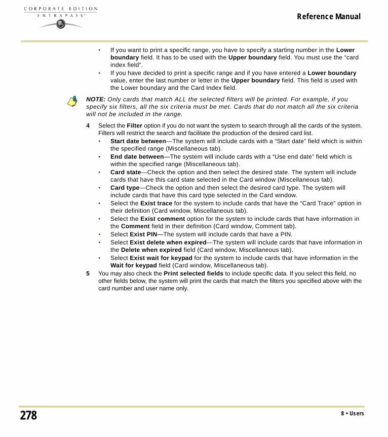
Reference Manual
• If you want to print a specific range, you have to specify a starting number in the Lower boundary field. It has to be used with the Upper boundary field. You must use the “card index field”.
• If you have decided to print a specific range and if you have entered a Lower boundary value, enter the last number or letter in the Upper boundary field. This field is used with the Lower boundary and the Card Index field.
NOTE: Only cards that match ALL the selected filters will be printed. For example, if you specify six filters, all the six criteria must be met. Cards that do not match all the six criteria will not be included in the range.
4 Select the Filter option if you do not want the system to search through all the cards of the system. Filters will restrict the search and facilitate the production of the desired card list.• Start date between—The system will include cards with a “Start date” field which is within
the specified range (Miscellaneous tab).• End date between—The system will include cards with a “Use end date” field which is
within the specified range (Miscellaneous tab).• Card state—Check the option and then select the desired state. The system will include
cards that have this card state selected in the Card window (Miscellaneous tab).• Card type—Check the option and then select the desired card type. The system will
include cards that have this card type selected in the Card window.• Select the Exist trace for the system to include cards that have the “Card Trace” option in
their definition (Card window, Miscellaneous tab).• Select the Exist comment option for the system to include cards that have information in
the Comment field in their definition (Card window, Comment tab).• Select Exist PIN—The system will include cards that have a PIN.• Select Exist delete when expired—The system will include cards that have information in
the Delete when expired field (Card window, Miscellaneous tab).• Select Exist wait for keypad for the system to include cards that have information in the
Wait for keypad field (Card window, Miscellaneous tab).5 You may also check the Print selected fields to include specific data. If you select this field, no
other fields below, the system will print the cards that match the filters you specified above with the card number and user name only.
8 • Users278

Reference Manual
6 Click the Select door access filter button if you want to include cards associated to a door.
7 Select the Based on time option if you want to select cards according to the time or select Based on schedule if you want to select cards according to a defined schedule.
NOTE: To extend the selection, right click within Select door for access filter window.
8 Check the appropriate field you want to print. The system will include the field content as it appears in the card definition.
279Cards Printing

Reference Manual
9 You may save the list as a.QRP file (Quick Report) to view later using the Quick Viewer option. 10 You can also use the “Font” button to use a different font and font size for your list. The changes will
appear automatically in the sample box. Use the Preview button from the print window to preview your report.
8 • Users280

Reference Manual
Last Transactions DisplayThe View last transactions feature lets you view the most recent transactions for the selected cardholder. For example, the window will display “Access denied” as the type of event, and will display the date and time as well as the event message that was displayed in the Message desktop. The system displays the 15 most recent transactions for each category: • Access denied events (bad location, bad access level, bad card status, etc.),• Access granted events,• Database events (that have affected the database, such as: card definition modified, relay
definition modified, etc.),• Other/Miscellaneous events (these include events that were generated by cardholders),• Time and Attendance events (entry, exit).
NOTE: To view more transactions for a specific category, see the “Card use report” option in the Historical Report definition menu.
Viewing the Last Transaction1 From the card definition window, select the View last transaction icon.
• Type—Displays the event category. • Date and time—Displays the date and the time stamp of the event message.• Event message—Displays the event message that was sent to the server (and to the
authorized EntraPass workstation) when this event occurred. This is the same message as in the Message desktop (Desktop menu).
• Details—Displays additional details directly related to the type of transaction. For example, for a “card definition modified” event message, the Details column lists the EntraPass applications from which the card was modified as well as the operator name.
281Last Transactions Display

Reference Manual
• Refresh—This button can be used to refresh the window with new transactions as they happen. As cardholders generate events, new information is available.
• Parent—To view the parent component of a selected component. For more information, see "Basic Functions" on page 50.
• Print—Use this button to print an exact copy of the window. For more information, see "Basic Functions" on page 50.
8 • Users282

Reference Manual
Card Access Groups DefinitionPre-programmed card access groups allow quick selection of access levels for various sites of the system. This card access group can be recalled during card programming instead of re-entering the access levels for each site.It is only the card access group information that is associated with the card. Therefore, you can modify the card access group information without modifying the card access information.
NOTE: When importing cards, the Card access group may be used to assign an access level to the cards.
1 From the card definition window, click the access group icon.
2 To modify an existing card access group, select it from the Card access group drop-down list. To create a new group, click on the New button and enter the group name in the language section. The Site column displays the site associated with a card access group.
3 From the Access level drop-down list, select the access level that will determine the access to the doors of the selected site.
283Card Access Groups Definition

Reference Manual
Access Levels DefinitionAccess levels determine where and when the card will be valid. Pre-programmed card access groups allow quick selection of access levels for various gateways. A total of 248 access levels can be programmed per site. In order to assign an access level to a card, you have to:
• Create schedules that will correspond to the time the user has access to the desired doors• Assign the created schedule to the desired doors (in the Access level definition menu)• Assign the access level to a card.
NOTE: The default access level is Always valid, all doors: cardholders assigned this default access level have access to all doors at any time. To restrict access to certain doors and at a certain time, you have to create a specific access level.
1 From the Users tab, select the Access level icon. The Access level window appears.
2 From the Access level drop-down list, click on New, then assign a meaningful name to the access level you are creating.
NOTE: Components that are displayed in the Doors and Schedule or Floor group columns have to be pre-defined for selection. To define Doors: Devices > Sites > Doors. To define Schedules: Definition > Schedules. To define Floors groups: Groups > Doors.
3 From the Doors list, select the doors to which the cardholder has access.4 From the Schedule column, select the schedule during which the cardholder will have access to
the corresponding door.5 Select the floor group, if applicable.
8 • Users284

Reference Manual
Visitor Cards DefinitionA visitor card is issued on a temporary basis. It serves as a template for entering user information. You can create visitor cards in two ways:• Copying the card information field into the Visitor card database when a new card or a daypass
is created in the system,• Creating a new visitor card.
Creating a Visitor Card When Creating a New Card1 Select the Card icon from the Users window. The Card window appears.
2 Check the Copy to visitor card option. The card information will be used later for creating new cards and issuing day passes.
Creating a Visitor Card Using the Card Template1 Select the Visitor card icon from the Card window toolbar.
2 Enter the required information in the Visitor card fields.
NOTE: For more information on Day Passes and Visitor cards, see "Cards Definition" on page 230. The Picture tab allows you to display the cardholders picture and signature as well as to preview and print badges.
285Visitor Cards Definition

Reference Manual
Card Type DefinitionA card type is used to group cardholders and can later be used to modify an existing card group or to create reports. It can also be used to restrict access to card information for a particular operator. For example, you can restrict an operator’s ability to issue or view a specific card group. For instance, if a card type is defined as “Administrators”, an operator who does not have the appropriate security level will not be able to issue, view, modify, delete, or print this type of card.
NOTE: The system is preset with five card types: administrator, employee, security, maintenance and visitor. A card type can be assigned to a card access group. This way, if a cardholder is issued a card type associated with a card access group, the access information of the card access group will automatically be transferred to the cardholder.
Creating a New Card Type1 From the Users menu, click the Card type icon. The Card type window appears.
2 In the Card type window, click the New button in the toolbar and enter the necessary information in the language section.
3 From the Card access group to assign list, select a card access group or create one. For details about card access groups, see "Card Access Groups Definition" on page 283.
4 To assign a card type to a cardholder, see "Users" on page 229.
8 • Users286

Reference Manual
Day Passes DefinitionA day pass is issued to visitors such as contractors, employees from different divisions, customers, etc. This menu option offers an easy way to allow access to “visitors” for a single day.Even if the day pass cardholder does not return the day pass card, the card will expire the same day at 24:00, and will no longer grant access.You can use profiles that were copied to the “Visitor definition” menu to create day passes (use the “find visitor” button). You can also use an existing day pass to create a new one.
Creating a Day Pass1 From the Users menu, select the Day pass icon. The Day Pass window appears.
2 You can fill out the fields or browse the card databases to the desired card. For more information, see "Users" on page 229.
3 Check the Copy to visitor card option if you want to save this day pass in the visitor database.
NOTE: For more information of visitor cards, see "Cards Definition" on page 230. The Picture tab allows you to display the cardholders picture and signature as well as to preview and print badges.
287Day Passes Definition

Reference Manual
Creating a New Day Pass Using the “Save As” FeatureThe Save as feature allows you to create a new day pass based on an existing one, only making changes to specific information and assigning it new card number. You may, for example, change only the user name and keep all other card information. 1 From the Users menu, select the Day pass icon. The Day Pass window appears.
2 To locate an existing card, click the binoculars and select the card you want to duplicate.3 Type required changes into specific fields and click the Save as icon. 4 You will be prompted for a new card number.
8 • Users288

Reference Manual
Batch Operations on CardsThis menu is used to modify a specific card type group. For example, you could modify the “end date” of all the cards assigned the “administrator” card type. Individual fields will appear only when the appropriate check box is checked.
Performing Operations on a Group of Cards1 From the Users menu, click the Batch operations icon.
2 Select a user group from the Card type drop-down list. All cards having this card type will be modified.
3 Select the appropriate option from the Operation with drop-down list.• No notification—The system will not notify nor request confirmation from the operator.• Notification—The system will display a window displaying the process.• Notification and confirmation—The system will display a window displaying the process
and will prompt operators to confirm the operation for each cardholder having the selected card type.
4 Check the option you want to modify for the selected type. • Card state—If a card state is selected, the system will assign this new card state to all the
cardholders of the selected card type.• Card count value—If a card count value is selected, the system will assign this value to all
the cardholders of the selected card type.• Trace—If trace is selected, the system will trace all cardholders of the selected card type.• Start date—If a start date is selected, the cards will be valid only from this start date. This
new date will be assigned to all cardholders having the selected card type.• End date—If an end date is selected, the cards will be invalid after this end date. This new
date will be assigned to all cardholders having the selected card type.
289Batch Operations on Cards

Reference Manual
• Delete when expired—If selected, the cards will be deleted when the end date specified in the Card Definition menu is reached.
• Wait for keypad—If selected, all the cardholders of the specified card type will have to enter their PIN at the keypad after a valid card read, in order to permit access to the door (if keypads are defined).
• Card access group—If checked, two scroll lists become available to modify card access groups for the selected Card type. The first scrolling list defines the action to perform on the selected card type. The second scrolling list contains the card access groups (already defined in EntraPass) that will be used to perform the action.
• Replace card access group (Replace): replaces the current access level with the one selected in the scrolling list.
• Update card access group (Update): updates the current access level with the one selected in the scrolling list except where sites were set to none in the current access level. No new access levels will be added.
• Add new access level (Add): this option is used in situations when new sites are added and the sites’ access levels must be added to the current access level list. All sites that are set to none in the current access level list will be updated with the sites in the new access level list.
• Update add access level (Merge): merges the sites in both lists. The new sites have precedence over the current ones.
Examples of batch operations on card access levels
• Card layout—If checked, the list of card layout templates will be listed.5 Click the Execute button to start the process. The system will prompt you to accept the operation.6 Click Yes if you want to continue. As soon as the process is initiated, a red indicator is displayed at
the bottom left of the dialog. The indicator will remain red until the end of the process.
Current Access Level
New Access Level Replace Update Add Merge
Site Y1 Site X1 Site X1 Site X1 Site Y1 Site X1
Site Y2 Site X2 Site X2 Site X2 Site Y2 Site X2
Site Y3 None None Site Y3 Site Y3 Site Y3
None Site X4 Site X4 None Site X4 Site X4
8 • Users290

Reference Manual
CSV Files Import and ExportThe CSV Import/Export feature allows the ability to import or export card files that are saved in a CSV (Comma Separated Value) format. Importing/exporting data between two applications allows the ability for the two application to share data.CSV files can be edited in most applications (Excel, NotePad, etc.). You will use the CSV Import/Export feature if:• You are upgrading from EntraPass DOS or WinPass 64 and you want to retrieve the cards
created in these previous versions.• Your company desires to import the card database information into the payroll system. Using
the Import/Export feature will save a considerable amount of time in setting up the card holder database.
• Your company has a new database: instead of having to reprogram all the information already available in the card database, the system administrator could export the data contained in the card database (names, departments, card numbers, etc.) into a CSV file that can be imported into the target database.
NOTE: The CSV Import/Export feature imposes a number of rules: each field contains a specific value format that has to be respected. For example, the card state field will only accept the following values (0=valid, 1=invalid, 2=stolen/lost).
To Import/Export card information, you may use Kantech pre-defined patterns or you may create your custom patterns.
Using a Predefined PatternTwo patterns are available: the EntraPass (1,2,3) and the WinPass 64 model. You may use the template “as is” or you may edit it.1 From the Users menu, select the Import/Export CSV button.
2 From the Select operation drop-down list, select either Import or Export.3 In the Available Patterns pane, select the pattern you wish to use. This depends on the software
you are upgrading from.4 Use the Edit button if you want to edit the pattern.
291CSV Files Import and Export

Reference Manual
Creating a New Import/Export PatternThis menu lets you create your own import/export mask that will be used to import or export CSV files.1 From the Users menu, select Import/Export CSV File icon. The system displays the Import /
Export CSV file window.
2 From the Import/Export CSV file window, click New Pattern. The New pattern window displays a list of all the fields that are available in the EntraPass card databases. They contain specific value formats that have to be respected. For example, the card state field will only accept the following values (0=valid, 1=invalid, 2=stolen/lost).
3 Using the Hand buttons, select the fields you wish to include in your pattern. The Transaction code and the Card number fields are displayed by default. Once the fields are selected, you can
8 • Users292

Reference Manual
use the red Up/down red arrows to organize information (this will indicate how information will be arranged in the CSV file).
4 Specify the Add code and Modification code. These codes are used by the system to identify, when importing a file, which card has to be modified or added to the card database. Default add code is “+” and default modification code is “+”.
5 Select the Delete code. This code is used by the system to identify, when importing a file, which card has to be removed from the card database. Default delete code is “-”.
6 Select the Field separator. This code will be used to separate the selected fields when importing or exporting data. Usually a comma (,) is selected. Keep this in mind when adding users’ last names and first names separated by a commas.
7 Select the Date format. The date will be exported or imported according to the specified format. The most commonly used format is YYYY/MM/DD.
NOTE: The Use DLL feature allows you to enable a program that will convert specific card numbers. You may use the Remove DLL when you do not wish to enable the program that converts card numbers.
8 Click OK to exist the pattern window and to specify the new pattern name.
9 Enter the pattern name, then click OK. The system automatically returns to the Export/Import CSV file window. The pattern you have just created is displayed in the Available patterns list.
10 If you want to add or remove fields from your pattern, double-click the new pattern to edit and make the necessary modifications. Now you can import or export your information using the new pattern you have just created.
Exporting CardsYour organization may need to export the card database data into another application. You may use a predefined template or create a custom template.
293CSV Files Import and Export

Reference Manual
1 From the Users tab, select the Import/Export CSV File button. The system displays the Import / Export CSV file window.
2 From the Select operation drop-down list, select Export. 3 From the Available patterns list (left-hand pane), select the pattern you want to use when
exporting cards. If necessary, you may edit the pattern so that it matches the target application pattern, else, you may create a new one. (For more information on how to create a pattern, see "Creating a New Import/Export Pattern" on page 292).
4 From the Transaction file, select the folder in which EntraPass will save the card database content. You can open the CSV file in Excel, NotePad, etc.
8 • Users294

Reference Manual
5 Once you have selected/created an export folder, click OK to return to the Import / Export CSV file window.
6 Click the Export button; it is enabled once the transaction file is selected. The system displays a window allowing you to filter the cards you want to export.
NOTE: For cards to be included in your file, they must match all the selected filters, if one or more filters are not matched, the card will not be included.
295CSV Files Import and Export

Reference Manual
7 In the Export Card’s filter window, specify the cards you want to export. Once you have made all your selections, click the Export button. The Import / Export CSV file window appears.
NOTE: The Transaction file field shows the target file name and location. By default, the export file is saved in the specified folder (Exportdata, in this example). The status bar (lower part of the window), shows the number of imported cards (1, in this example). The default name is YYYYMMDD.csv. You can open the target file with NotePad for instance.
Importing Cards1 From the Users menu, select the Import/Export CSV File icon. The Import / Export CSV file
dialog will display on screen.
2 In the Select Operation drop-down list, select Import.
8 • Users296

Reference Manual
3 Click the Available patterns button to select the pattern that will be used to import the cards information (for more information on how to create a pattern, see "Creating a New Import/Export Pattern" on page 292).
4 From the Transaction file pull-down menu, browse your hard drive to the CSV file that contains the data to import into the card database.
5 Once the file has been selected, click Open. You will return to the Import / export CSV file window.
297CSV Files Import and Export

Reference Manual
6 If no errors are present (or once you have corrected errors), click Import to complete the operation.
NOTE: The system scans the file to be imported; then it displays the results using a color code. Each entry is identified by a color flag. A yellow or red flag identifies an entry in error. Errors are frequently caused by the patterns. You have to select another pattern or edit the pattern you are using so that the pattern entries have to match the source file entries. There may be errors also even if the transaction code is identified by a green flag.
Correcting Import/Export ErrorsThe CSV Import/Export feature imposes a number of rules: each field contains a specific value format that has to be respected. For example, the card state field will only accept the following values (0=valid, 1=invalid, 2=stolen/lost). The pattern used has to match the pattern used by the source file.The present section will assist you in correcting import/export errors.1 Click the Import or Export button to start the transaction (the following example illustrates a case
of importing CSV data). The lower part of the window displays the number of cards in the list.
NOTE: Although entries in the Transaction code column are identified with a green flag, the Card number column is empty. This indicates problems in the pattern conversion.
2 Click the Import button.
NOTE: The Error button is enabled because the system encountered problems during the import transaction.
8 • Users298

Reference Manual
3 You may click the Error button to display information about the error. The Process error window shows that the pattern used is invalid.
4 Click the Close button to go back to the Import Export window.5 In the Import/Export CSV window, double-click the pattern you have used for the Import transaction
(Custom, in the example above).
299CSV Files Import and Export

Reference Manual
6 From the Field separator drop-down list, select Comma as the field separator, then click OK. Data in the Card number field indicates that the import transaction will be successful.
8 • Users300

Reference Manual
Chapter 9 • GroupsIt is useful to create groups so that operators can perform modifications on a group of components or other system functions.
NOTE: Each system component has to be defined before it can be included in a group.
You can create:• Controller groups• Door groups• Relay groups• Input groups,• Access level groups • Floor groups
301

Reference Manual
Controller Group CreationThe Controller group menu is used to group a number of controllers of the same site. The controller group can later be used to perform manual operations on controllers, for instance (i.e.: reload).1 From the Groups window, select the Controller icon.
2 Select the View hierarchy button to display all the sites defined in the system.3 From the Gateway/Site drop-down list, select the site or gateway from which you want to group
controllers.4 To create a new group of controllers, click the New icon. To modify an existing group, select one
from the Controller group drop-down list, then enter the necessary information in the language section.
5 From the list of controllers connected to the selected site, check the controllers that are to be assigned to the group.
NOTE: For more information on controllers, see "Controllers Configuration" on page 101
9 • Groups302

Reference Manual
Door Group CreationThe Door group menu is used to group doors of a specific site. The door group can later be used to carry out manual operations such as unlocking a group of doors. 1 From the Groups window, select the Door icon.
2 Select the View hierarchy button to display all the sites defined in the system. 3 From the Gateway/Site drop-down list, select the site or gateway from which you want to group
doors.4 From the Door Group drop-down list, select a door group you want to modify or click the New icon
to create a new group, then enter the necessary information.5 From the Door list, select the doors that must be assigned to the group.
NOTE: For more information on doors, see "Doors Configuration" on page 127.
303Door Group Creation

Reference Manual
Relay Group CreationThe Relay group menu is used to group relays of a specific site. This relay group can later be used to carry out manual operations such as temporarily activating relays. 1 From the Groups window, select the Relay icon.
2 Select the View hierarchy button to display all the sites defined in the system.3 From the Gateway/Site drop-down list, select the site or gateway from which you want to group
relays.4 From the Relay group drop-down list, select a relay group or click the New icon to create a new
group; then enter the necessary information in the language section.5 From the Relay list, select the relays that must be assigned to the group.
NOTE: For more information on relays, see "Relay Configuration" on page 142.
9 • Groups304

Reference Manual
Input Group CreationThe Input group menu is used to group inputs of a controller site.This input group can later be used to carry out manual operations such as shunt on inputs. 1 From the Groups window, select the Input icon.
2 Select the View hierarchy button to display all the sites defined in the system.3 From the Gateway/Site drop-down list, select the site for which you want to group inputs.4 From the Inputs group drop-down list, select an existing group to modify it, or click the New icon
to create a new group; then enter the necessary information in the language section.5 From the Inputs list, select the inputs that must be assigned to the group.
NOTE: For more information on inputs, see "Input Configuration" on page 143.
305Input Group Creation

Reference Manual
Access Level Groups GroupingThe Access level group dialog is used to group access levels of the same site. 1 From the Group window, select the Access level group icon.
2 Select the View hierarchy button to display all the sites defined in the system.3 From the Gateway/Site drop-down list, select the site or gateway from which you want to group
access levels.4 Click the New button to create a new group access level, and assign a name in the English field.5 Check the boxes that correspond to the access level group.
9 • Groups306

Reference Manual
Floor Group CreationThis menu is used to group the floors that were created in the floor definition menu. Floor groups are also used for various operations in the system such as: manual operations (unlocking schedules), access levels, etc.1 From the Groups tab, select the Floor/Elevator door icon.
2 Select the View hierarchy button to display all the sites defined in the system; then from the Gateway/Site drop-down list, select the site or gateway from which you want to group the floors.
3 From the Floor group drop-down list, select an existing group if you want to modify it; or click the New icon to create a new group. Then enter the name of the group in the language section.
4 From the list of defined floors that is displayed by the system, check the State column for the Floors you want to include in the group. Only floors that have the State field selected will be enabled when: • A manual unlock operation is done, or • An “input” is programmed, for example, as a push button to enable floors for visitors
(Devices > Input definition menu > Elevator tab), • Cardholders present their card to the card reader to enable floor selection when the
controller is operating in stand-alone mode (due to communication failure). Only the floors marked with an “X” are available for selection.
5 Only floors that have State selected will be enabled when: • A manual unlocking operation is done, or • An “input” is programmed, for example as a push button to enable floors for visitors (input
definition menu - elevator tab),
307Floor Group Creation

Reference Manual
• Cardholders present their card at the card reader to enable floor selection and the controller is operating in “stand-alone” (due to communication failure). Only the floors marked with an “X” will be available for selection
9 • Groups308

Reference Manual
Chapter 10 • System StatusThe Status menu allows system operators to view the status of various devices and components of the access system:• The Connection list button provides information regarding applications registered to the server
(operator name, local identification, etc.).• The Text button allows operators to view, in text, the status of EntraPass applications,
gateways, sites, controllers (KT-100, KT-200, or KT-300), doors, relays, inputs. The status displayed depends on the controller installed.
• The Numerical button allows operators to view the statistical status of all components, by gateway. For example, you can view the number of inputs in an alarm.
• The Graphic button allows operators to display the graphic status of a controller.• The Database button provides information on the database structure. In addition, an operator
can perform configuration operations or manual commands from the database window.• The Video Server button allows operators to display the statuses related to the EntraPass Video
Vault process.
309

Reference Manual
Connection ListThe Connection List displays details about a selected application, such as: operator name, last query date, local identification number, etc. It is also used to verify if EntraPass applications are connected to the server.
Viewing the System Connection List1 In the Status window, select the Connection icon. The Connection list window appears.A scrolling list contains all applications listed together or individually. You can select All connections, or a specific gateway and view the details of the connection for the selected application(s).
2 Click the “+” sign to see detailed information about an application.• A Red circle indicates that the EntraPass application is not connected to the server • A Green circle indicates that the EntraPass application is connected to the server.• Protocol—Identifies the protocol (language) used to communicate with the server. The
protocol is used to inform the system on how the information is shared between computers. Local identification—Identifies the label of the application on the network. This name is used by the server to identify your application.
• Network identification—Provides the IP address of the application on the network or NetBEUI name.
• Operator name—Displays the name of the operator currently logged on this application. The operator name is used for many purposes, such as to identify who performed a modification to a card, who acknowledged an alarm, etc. For information on modifying the operator name, see "Operators Definition" on page 322.
• Last query date—Displays the time the application last polled the server. The server and application exchange information on a regular basis.
10 • System Status310

Reference Manual
• Connected date—Displays the date and time at which this application started its connection with the server. This date will be used to generate an event and kept in archives.
• Transactions—Displays the number of requests performed by the application (number of exchanges with the server), i.e. report queries, for example.
• Errors—Displays the amount of errors encountered by the application. This field will reset when the application is shutdown.
• Messages/Alarms buffered (0/1) • 0: the number of messages/alarms buffered for this application on the server when the
application is off-line (not in communication). This number will reset to “0” when the application connects to the server and messages are sent.
• 1: the number of messages/alarms that were sent to this application since the Server is operational. If the Server is shutdown, this number will reset.
NOTE: The server holds a maximum of 100,000 messages and 100,000 alarms per workstation (default: 5,000) in the buffer. You can modify these settings through the Workstation Definition menu. You can also specify if newer or older events should be buffered. Events will be buffered only when the workstation is off-line (not connected to the server); and when the fields “Apply operator parameters for messages” and “Apply operator parameters for alarms” are not selected (for more information, see "EntraPass Applications Configuration" on page 60).
311Connection List

Reference Manual
Text StatusThe Text status allows an operator to display the status of a selected component (and sub-components) as well as all the characteristics associated with this component in a text form. This menu option applies to all the system devices: applications, gateways, sites, controllers, doors, relays and inputs. The text window contains additional buttons/icons that assist operators in their tasks:• The first seven buttons represent system devices (Workstation, Gateway, Site, Controller,
Door, Input and Output). • Summary / Detailed list—The magnifying glass icon is used to display components that are not in
normal condition. It displays a summary list or a detailed list. • Summary: shows the components that are not in normal condition• Detail: shows all the components in any condition.
• Stop display—This button is used to stop the display when the information is taking too much time. It cancels or interrupts the process.
• Refresh—Refreshes the status of the selected components.• Print—Use this button to print the displayed status. You can preview your report before printing
it.
Displaying a Component Status1 From the Status tab, select the Text Status button. The Text window appears.
10 • System Status312

Reference Manual
2 In the Text window, select the icon of the component for which you want to view the status. If you select the Workstation icon, the system displays the list of the EntraPass Applications defined in the system.
3 You can check the EntraPass application you want to display the status or enter a few characters of the component name (field at the top) for the system to searched in the database. For example, you can enter “Sec” for Security Office. The system will highlight the first name containing the entered characters. You may also click the Select all button to select all the EntraPass applications; or select specific components by clicking in the checkboxes next to each component name. The Clear all button removes the check marks from the selected components. Click Cancel to return to the previous window without any selections or changes.
4 You may check the View sub-components box (lower part of the window) to display detailed information on the sub-components linked to the selected component. For example, if you selected a controller, all its components (doors, relays, inputs) with appropriate status will be displayed on the window if this option was checked. For more focus in one window, filter doors, relays or inputs by site.
5 Click OK to return to the previous window and apply your selections.
NOTE: The Magnifying glass button is used to display components that are not in normal condition. When it is in a “summary” position, only components that are not in normal condition will be displayed; the “detailed” position, displays a full status of all components.
313Text Status

Reference Manual
Numerical StatusThis menu allows an operator to view the number of components in a “not normal” state for a selected gateway. 1 In the Status tab, select the Numerical status button. The Numerical window appears.
2 From the Gateway drop-down list, select the gateway for which you want to display the status. The window displays the number of cards for that gateway, the number of inputs in alarm, the number of relays manually activated, the number of doors forced open, etc. This can be very useful if you need to find out how many cards are defined.
10 • System Status314

Reference Manual
Graphic StatusThis feature is used to display a graphical status of a door controller, including the status of all its components (outputs, inputs, power supply status, communication status, etc.) represented by colored shapes (circle, square, etc.).• An ellipse shape represents the controller• A circle represents a door• A square represents a relay• A rectangle represents an input. Rectangles may be horizontal (KT-200 and KT-300) or vertical
(KT-100).
Viewing a Controller Status 1 From the Gateway drop-down list, select the gateway on which the controller to display is
located. You may select “All gateways” to display all the controllers in the list. 2 From the Controller drop-down list, select the controller for which you want to display the status.Example with a KT-200 Controller
315Graphic Status

Reference Manual
Example with a KT-400 Controller
NOTE: The displayed graphic depends on the type of the controller selected.
3 To find out which items are represented by a colored shape, move the mouse over a colored shape. The item highlighted on the right-hand (in the list) identifies the component.
4 Select a controller from the Controller list drop-down list (right side of the window), double-click the item on which status is required.• Red—The component is “Supervised” and “in a trouble state”.• Green—The component is “Supervised” and “in normal condition”.• Yellow—The component is “Not Supervised” and “in a trouble state”.• Gray—The component is “Not Supervised” and “in normal condition”.• Blue—The relay is activated (by an event or an operator).
NOTE: If there’s more than one controller site per gateway, the numbers between parentheses (xx) indicates the controller number and the following numbers (xx) indicate the component number.
10 • System Status316

Reference Manual
Video Server StatusThis feature is used to monitor video servers’ statuses related to the EntraPass Video Vault archiving process. The Video Server option can be accessed from the Status tab. The Video Server window lists all video servers and their statuses.
Viewing Video Server Status1 Click the Video Server icon under the Status tab. The Video Server window will open and display
all video servers and their statuses.
• State: Enabled/Disabled video archiving• Video Vault: Linked to the EntraPass Video Vault• Schedule: Valid/Invalid archive schedule state• Date and Time: of the last transaction for this video server with the EntraPass Video Vault• State: Description of the las transaction for this video server with the EntraPass Video Vault.
Enabling/Disabling Video ArchivingNOTE: This option is only available when you install the EntraPass Video Vault
1 Right-click the server for which you want to enable/disable the video archiving process. • In the contextual menu, select Enable to activate the archiving process.• In the contextual menu, select Disable to interrupt the archiving process.
317Video Server Status

Reference Manual
Database StatusThis window displays the status of the components within the database while browsing the database structure. The system displays all applications (connected or not), the gateway, controller sites, etc. You can also perform manual operations directly from the window and edit components in order to modify their configuration. 1 From the Status window, select the Database icon. The Database window appears.
NOTE: The icon identifies the type of component.
2 In the Database window, select the application you want to view the database. The lower part of the window displays the actual status of the selected component as well as its full name.
3 Select a component to modify its definition directly from the Database window. For example, if you have selected a door, right-click the door to display a shortcut menu.
4 Select a command in the cascading sub-menu; select a menu option.
NOTE: The command list varies according to the selected component.
5 Make your modifications to return to the Database status window. The Right-click shortcut menu offers the following options:• Full expand—This feature allows you to fully expand the tree status and view all
components. Only applications that are connected to the server will display a “+” sign.• Full collapse—This feature allows you to fully collapse the tree status and hide all
components of the root component. • Edit—When you select an assigned component (i.e.: input) and click edit, the system will
edit the definition window so you can modify its definition and when finished, return to the window you edited the component from.
10 • System Status318

Reference Manual
• Limited display / No limited display—When you click on a physical component, the bottom part of the window displays its status.
• By selecting Limited display, the system will erase the previous status and display the status of the next selected component.
NOTE: The icons on the left side components indicate the component type.
319Database Status

Reference Manual
Server StateThe Server state dialog allows users to view detailed information on the server such as system information, system global memory, system process memory and system disk space.
10 • System Status320

Reference Manual
Chapter 11 • SystemUse the System menu to define parameters for systems operators, security levels, event parameters, instructions, and message filters. This menu allows you also to view the EntraPass database structure.You will define system parameters as follows:• Operator: user name, login name, password settings for EntraPass operators • Security level: use this menu to grant or deny access permission on system logical
components (desktop display, card fields, etc.) for an operator’s day to day operations• Workspace: use this menu to grant or deny operators access to view and configure the system
physical components (gateways, sites, relays, etc.)• Event parameter: use this menu to define priority, color, schedule (display, printing schedule,
acknowledgement) for system events • Instruction: use this menu to create instructions for alarm messages and SmartLink
applications• Message filter: Use this menu to direct event messages from a specific EntraPass application
to another EntraPass application and to define sort criteria for messages that are sent to the Filtered Message desktop.
• Database structure: Use this menu to display EntraPass physical and logical components and to edit or sort system components.
321

Reference Manual
Operators DefinitionUse the Operator menu to define system operators and to determine their security level and privileges. An operator is responsible for issuing cards, carrying out manual operations on system components, requesting reports, arming the system, etc.For security reasons, each operator accessing the system database should have his/her profile defined to ensure that all the actions performed in the system will be traceable. You need to create at least one operator account or modify the pre-created accounts in order for the operator to use and operate EntraPass and to receive event messages.There are three default operators created in the system. These are associated with three levels of access rights:• Installer (login name and password are kantech): Full access to view, modify, delete, print
components.• Administrator (the login Kantech1 and the password kantech): Medium access with limited
access to system menus. • Guard (login Kantech2 and password are kantech): Limited access to system menus.
NOTE: You can define operators using the default operators or you can create new operators. For details about operators’ security levels, see "Security Level Definition" on page 326.
Creating or Editing an Operator1 From the System tab, select the Operator icon to open the Operator window.
NOTE: The upper right-hand corner shows the last EntraPass workstation where the operator logged on and the last login date.
2 Enter the operator Name. The operator name is composed of a maximum of 40 alphanumeric characters (including spaces). This is the name that will be displayed in the desktop message lists and the reports.
11 • System322

Reference Manual
3 Enter the operator’s e-mail (optional).4 Enter the operator Login name. This is a descriptive name composed of 6 to 20 alphanumeric
characters (including spaces).
NOTE: On login, operators must enter their login name followed by their password in order for the system to validate their access. The login name is displayed in the events’ details when operator events are generated (i.e. manual operation, login, logout, etc.).
5 In the Password field, enter the password that will be used to login with the login name. The password is alphanumeric and consists of a maximum of twenty characters (minimum seven characters). The password is not displayed nor printed, the system displays the password as asterisks.
NOTE: The password is case-sensitive - make sure that all operators are aware of this.
6 In the Password Confirmation field, enter the operator password again for confirmation using the proper case. If this password is not identical to the one entered in the password field, an error message will appear.
7 In the Language section, check the appropriate option for the display language for this operator. If you change the display language, it will be effective only when the operator logs out and logs in again. When an operator logs out and exits an application, the next operator who logs on the application will see the startup window in the language of the last operator.
8 In the Privileges section:• Select the Auto acknowledge option. If this option is selected, the Manual button is added
to the Alarms desktop (see "EntraPass Desktops" on page 369). The operator can decide to manually or automatically acknowledge events. This is an operator privilege.
• Select the Override workstation workspace message option, if applicable. When this field is selected, the basic workstation workspace configuration will be ignored and the operator will receive events from all workstations and gateways.
• Check the Privileges option if you want this operator to view hidden cameras. For camera definition: Video > Camera > Show camera option
• Automatic video display: this option tells the system to automatically display video clips on an alarm event for the operator who is logged on. If the Alarm desktop is configured and open, the video is automatically displayed. If the alarm desktop is not open, the system checks the video display settings for this workstation (Devices > Messages 2 of 2, Disable autodisplay of video views, if this option is not checked, the system checks the video view settings for this operator: Operator > Automatic video display checkbox.
NOTE: The Override workstation workspace message option is a privilege granted to operators. It allows them to receive all events regardless of which workstation they are logged into at the time. If this option is selected and the Apply operator parameters for messages and Apply operator parameters for alarms options of the Workstation definition are also selected, then the basic configuration will be ignored and events will be filtered according to the security level of the operator who is currently logged into the workstation.
• If required, check the Allow concurrent logins from the same operator.• If required, check Allow login to WebStation from the operator. The WebStation
component must have been registered with the EntraPass Server in order to display the checkbox.
323Operators Definition

Reference Manual
9 Click on the Security tab to set operator access parameters.
10 From the Login Schedule pull-down menu, select the schedule during which the operator will be allowed to login into the system. You may want to create a specific schedule for an operator (Definition > Schedule), and then assign the schedule to the operator.
NOTE: To allow an operator to login to different EntraPass applications or to the EntraPass Server select the field Allow login on application and/or Allow login on server (System > Security Level > Miscellaneous tab).
11 From the Security Level pull-down menu, select a security level that will determine which components an operator has access to. A security level consists of menus through which an operator can modify the database, create components, view system components and events, etc.
NOTE: It is possible to define up to 250 custom security levels; EntraPass offers 3 built-in security levels (Installer, Administrator and Guard) on configuration. The default configuration for Installer permits access to all system components. The Installer must program other security levels to limit operator access to menu commands and/or options.
12 From the Workspace pull-down menu, select a workspace that will determine which physical components (desktop display, card fields, etc.) the operator will be able to access for day to day operations.
NOTE: EntraPass offers 1 built-in Installer workspace when you install EntraPass for the first time.
13 Access the Security section to edit the security features of the currently displayed operator profile:• Operator disabled: use this feature if you want to temporarily suspend or limit an operator
access to the system without using an expiry date. If you select an operator and then check this box, the selected operator will not be able to run the application.
11 • System324

Reference Manual
• Change password at next login: use this feature if you want an operator to change his/her password at next login.
• Disable operator on bad password: use this feature to limit the number of retries on bad password. For example, if you set this number to three (3), the operator will be disable after three errors when entering his/her password.
• Days before password is reset: this feature allows to manage operators’ passwords. At the end of the number of the days specified in this field, the operator will be prompted to change his/her password.
• Use expiration date: this feature allows you also to manage operators’ password. When this feature is checked, you have to select an expiration date (Operator expiration date).
• Operator expiration date: used with the Use expiration date feature, the Operator expiration date allows you to disable an operator’s access at a specified date.
NOTE: Changes to the currently displayed profile will take effect at the next login attempt.
325Operators Definition

Reference Manual
Security Level DefinitionSecurity level refers to the permissions granted to an operator to access EntraPass logical components (desktops, card information, etc.), as well as to perform some actions on those components.
NOTE: You have to program the appropriate security levels if you want to limit operator access to commands and/or options of the system menu.
There are three operators and security levels already configured in EntraPass. It is possible to customize an operator security level; the system allows you to create up to 250 security levels.Each operator has a separate login name, password and a corresponding security level. The password is case-sensitive. These are: Installer, Administrator and Guard.• Installer:
• Login name and password: kantech• Security level: By default, a user defined as Installer has full access to all the system
menus. He/she can read and edit system components and has unrestricted access to the system.
• Administrator: • Login name: kantech1; password: kantech• Security level: Administrator. By default, a user defined as Administrator has limited
access to a number of the system menus. • Guard:
• Login name: kantech2; password: kantech• Security level: Guard. By default, a user defined as Guard has limited access to the
system menu.
Creating/Modifying an Operator Security LevelAssigning security levels is critical to the system. In fact, if a security level is given full access to a system menu, operators who are assigned this security level will be able to modify system parameters. Make sure that each operator is given the security level corresponding to his/her tasks. Items in the Security Level window are presented in a root tree with all components available forselection. This structure makes it possible to target specific components when grantingsecurity level for manual operations. Each security level is identified by a color: full access (green), read-only (yellow) and no access (red). The security manager or an operator with appropriate permissions can easily change or assign a component to a lower level security level by double clicking an item until it changes to the desired color code.
NOTE: Operators will not be able to see items for which they have not been given access.
11 • System326

Reference Manual
1 Under the System tab, select the Security level icon. The Security level window appears with the Menu tab enabled.
2 From the drop-down list, select the Security level you want to modify. • To create a new security level, click the New button and enter the necessary information in
the language section. 3 Under the Menu tab, double-click an item until it reaches the desired status: No access (red),
Read-only (yellow) or Full access (green).
NOTE: A user with Read-only rights will not be able to print components in EntraPass.
Defining Login Options for an OperatorThe Miscellaneous tab allows you to define operator login and system display options:• Operator login options: you can allow or restrict an operator to login an EntraPass workstation
or server. • Active windows that can be kept on the desktop: EntraPass allows operators to keep five active
windows on the desktop.• Component display options: components can be displayed with our without their physical
address. The physical address can appear on the left or right of the component name.
327Security Level Definition

Reference Manual
1 Select the Miscellaneous tab to define parameters for the security level being defined.
2 In the Login restrictions section, select the appropriate login options:• Select Allow login on server to allow the operator to login to the EntraPass server
(Primary or Redundant).• Select Allow login on workstation to allow the operator to login to any application in the
system. 3 The Keep on application desktop section allows users to increase the number of active
windows on the desktop. In fact, operators can open five windows at the same time: one configuration window and four windows from the other categories. EntraPass windows are classified in five categories: • Configuration screen: this group includes all the menus that allow an operator to program
the system. This group includes such menu items as: User menu (card, Badging, card access group, access level, visitor, card type; Definition menu; Group menu; Devices menu; System menu; Video menu; Historical and Time and attendance reports.
• Operation screen: this group includes all the Operation menu items and the Video playback option.
• Status screen: this group includes windows of the Status menu, Current recording menu and Report state menu.
• Database screen: The following menus are included in this category: Option menu (card format, authentication password, select languages, Printers options, Changes date and time, etc.); Items of the User menu (Daypass, batch operations and Import/Export CSV); View Report, Operation on T&A, and View exported videos
• Report screen: this group includes Quick Report, Historical and Time and attendance report requests and Video list windows.
NOTE: These options allow operators to keep more than one window active on the desktop. They can bring to front or send to back the window they want to display, simply by pressing [ALT-F6].
11 • System328

Reference Manual
4 In the Components physical address section, specify how the component's physical address will be displayed. This will also affect how components will be sorted.• Display on left—If selected, components will be sorted by their address (i.e. 01.01.01
Controller xyz).• Display on right—If selected, components will be sorted by their component name (i.e.
Controller xyz 01.01.01).• No display—If selected, the address will not be displayed (i.e. Controller xyz) and
components will be sorted by name.5 If you are using the Video feature, EntraPass enables you to deny viewing permission to a
specified security level by checking the Hide camera from video views.
NOTE: Checking the Hide camera form video view option tells the system to verify access permission to cameras before loading a video view. For example, if the selected operator’s security level has access to a video server but not to all cameras defined in the video server and has access to the selected video view, the system will hide the camera that has been un-selected when assigning permission to the video server. For details, see "To Limit Access to a Specific Camera" on page 346.
Hiding Card InformationEntraPass offers you the ability to hide card information fields from view. For example, you can decide that a certain security level (Guard for example) can view or modify card information field. To do so, select the security level, then under the Card Fields tab, check the box that corresponds to the fields you want to hide.1 Select the Card fields tab to limit the number of card fields which are visible to the operator
who is assigned this security level.
2 Select the fields (either individually or in groups) that will be hidden to the selected security level. In the example above, operators who will be assigned the Guard security level will not see the selected fields.
329Security Level Definition

Reference Manual
Assigning Video Custom ButtonsEntraPass offers you the ability to customize five buttons for use in the Video interface. System installers and administrators can customize buttons for use by operators in the Video desktop. For example, a button customized for Playback with fixed delay with specific pre-record and record delays and assigned to a specific Security level will enable operators to trigger the actions related to the specific button.If you associate a custom button with a specific task (play back or generating video events, additional buttons are added to the Video desktop (Desktops > Desktop dedicated to video viewing)1 From the Security level drop-down list, select the security level you want to define/edit.
2 Select the Video custom button tab to assign permission to this operator. The following permission can be granted:• Playback with fixed delay• Playback with custom delay• Generate recording event with fixed parameters• Generate recording with custom parameters.
3 Select the option you want to assign to the operator being modified.
NOTE: Pressing the button associated with Playback with fixed delay will start a play back with the specified duration. This includes the pre-alarm recording time and the maximum recording time.
11 • System330

Reference Manual
Workspace DefinitionWorkspaces allow System Administrators to grant or deny operators access to system physical components such as gateways, sites, relays, etc. Workspaces are defined according to the type of tasks the operators will be allowed to perform in EntraPass; creating and editing items, viewing components, printing lists or reports, etc.Operators who are assigned a given workspace will not be able to see nor modify EntraPass components that are not selected in that workspace definition.Workspaces can also be used by operators to discriminate the information they want to view on screen. For example, a System Administrator who has access to all components of the EntraPass system may want to view only specific components. In that case, the System Administrator can define a specific workspace for that environment and work within those parameters.
NOTE: There is only one default Installer workspace created when you install EntraPass for the first time.
Workspace Filtering ModesThere are two ways of filtering workspace components in EntraPass: • Regular filter: will display all system components you can select to create your workspace.
You can navigate through all tabs and select components indiscriminately. You don’t need to select a parent component (a controller for example) in order to view and select the child component (a door).
• Hierarchical filter: items in a list will be displayed according to the item selected in the level above. For example, when selecting a specific site (parent), the system will automatically adjusts itself to display only the corresponding controllers (children). And if you select a specific controller (parent), the system will adjust itself to display only the corresponding doors (children), and so on. This option is only available under the following tabs: Entrapass application, Gateway and Site, Controller, Door, Relay, Input and Access level.
NOTE: If a tab is empty, verify that you have selected components from it’s parent.
1 If you wish to switch from the regular mode of filtering to the hierarchical mode of filtering, or vice versa, a popup menu is available when right-clicking in the title bar of each individual tabs in the Workspace dialog. A check mark indicates which option is selected.
2 Once you have selected the filtering mode, it will remain activated under all tabs.
Selecting AccountsThis feature allows you to select the accounts that will be available to an operator who is assigned this workspace.
331Workspace Definition

Reference Manual
1 From the Workspace drop-down list, select the workspace you want to define or edit.
• To create a new workspace, click the New button and enter the necessary information in the language section.
• Select All accounts if you want all the displayed accounts to be available to the operator who is assigned the workspace
• You can also select individual accounts from the displayed list.2 Save your modifications.
Selecting EntraPass ApplicationsThis feature allows you to select the applications that will be available to an operator who is assigned this workspace.In the following example, the workspace (Administrator) will not view messages sent by the EntraPass SmartLink application because it is not assigned to their workspace.
11 • System332

Reference Manual
1 From the Workspace tab, select the workspace you want to define or edit.
NOTE: When an operator is allowed to use the “Network alarms message desktop (Desktops menu), only alarm events originating from the EntraPass applications and components of the applications that are selected in this window will be displayed. The workspace definition acts as a filter for the “Network alarms message desktop”.
• Select All EntraPass applications if you want all the displayed applications to be available to the operator who is assigned the workspace
• You can also select individual EntraPass applications from the displayed list.2 Save your modifications.
333Workspace Definition

Reference Manual
Defining Gateways and Sites1 Move to the Gateway and Site tab to select the list of gateways and sites that will be available
to an operator who is assigned the workspace.
• Select All gateways and sites if you want all the displayed gateways and sites to be available to the operator assigned this workspace.
• You can also select individual gateways and sites from the displayed list.2 Save your modifications.
11 • System334

Reference Manual
Defining Controllers1 Move to the Controller tab to select the list of controllers that will be available to an operator
who is assigned the workspace.
• Select All controllers if you want all the displayed controllers to be available to the operator who is assigned this workspace.
• You can also select individual controllers from the displayed list.2 Save your modifications.
NOTE: When you select a controller, you also select all the components defined “under” or related to the controller (i.e. doors, relays, inputs, outputs). Make sure that you have also selected the gateway (Gateway and Site tab) for which the selected controller is defined. If the gateway is not selected, the controller will not be available even if it is selected in the list.
335Workspace Definition

Reference Manual
Defining Doors1 Move to the Door tab to select the list of doors that will be available to an operator who is
assigned this workspace.
• Select All doors if you want all the displayed doors to be available to the operator who is assigned this workspace.
• You can also select individual doors from the displayed list.2 Save your modifications.
11 • System336

Reference Manual
Defining Relays1 Move to the Relay tab to select the list of relays that will be available to an operator who is
assigned the workspace.
• Select All relays if you want all the displayed doors to be available to the operator assigned this workspace.
• You can also select individual relays from the displayed list.2 Save your modifications.
337Workspace Definition

Reference Manual
Defining Inputs1 Move to the Input tab to select the list of inputs that will be available to an operator who is
assigned the selected workspace.
• Select All inputs if you want all the displayed inputs to be available to the operator assigned this workspace.
• You can also select individual inputs from the displayed list.2 Save your modifications.
Defining Access LevelsAssociating specific access levels to a workspace allows you to control the access levels that an operator can define or modify. For example, a security guard may have the right to issue cards that are valid for a given door or access level only.
11 • System338

Reference Manual
1 Move to the Access level tab to select the list of access levels that will be available to an operator who is assigned this workspace.
• Select All access levels if you want all the displayed access levels to be available to an operator who is assigned this workspace.
• You can also select individual access levels from the displayed list.2 Save your modifications.
NOTE: Make sure that you have also selected the gateway for which the selected access level is defined. If the gateway is not selected, the access level will not be available even if it is selected in the list.
Defining Card TypesThis feature restricts the operator action. In fact, card types that are not selected in this menu will not be available to an operator when creating or editing cards. For example, you may decide that an operator with the Guard workspace will not be able to issue a specific card type such as Security. To do this, select the Guard workspace, then uncheck Security when filtering card types for the Guard workspace.
339Workspace Definition

Reference Manual
1 Move to the Card type tab to select the card types that will be available to an operator who is assigned the selected workspace.
• Select All card types if you want all the displayed card types to be available to the operator assigned this workspace.
• You can also select individual card types from the displayed list.2 Save your modifications.
Defining Card Access GroupThis feature gives operators access to specific card access groups for batch operations according to their workspace.
11 • System340

Reference Manual
1 Move to the Card access group tab to select the list of card access groups that will be available to an operator who is assigned this workspace.
• Select All Card access group if you want all the displayed card access groups to be available to the operator who is assigned this workspace.
• You can also select individual card access groups from the displayed list.2 Save your modifications.
Defining ReportsThis feature gives operators access to specific reports according to their workspace. For example, a System Administrator may have access to all the reports that can be generated whereas the Guards’ Supervisor may only have access to all Guard Tour related reports. The reports will be generated from the Archived Message list on the workstation desktop. Once the reports have been assigned to workspaces, operators will only have access to reports that correspond to their workspace.
341Workspace Definition

Reference Manual
1 Move to the Report tab to select the list of reports that will be available to an operator who is assigned this workspace.
• Select All reports if you want all the displayed reports to be available to the operator who is assigned this workspace.
• You can also select individual reports from the displayed list.2 Save your modifications.
11 • System342

Reference Manual
Defining Graphics1 Move to the Graphics tab to select the list of graphics that will be available to an operator who
is assigned the workspace.
• Select All graphics if you want all the displayed graphics to be available to the operator assigned this workspace.
• You can also select individual graphics from the displayed list.2 Save your modifications.
Defining WorkspacesThis feature gives operators access to information that pertains to specific workspaces according to other operators workspaces. For example, Guards in the system may have a workspace assigned to them according to the area they are patrolling and the type of information they can view and edit in EntraPass. The Guard’s Supervisor, however, must have access the information available to all the Guards working in his department. In that case the list of workspaces for the Supervisor will contain all the Guards’ workspaces defined in EntraPass.
343Workspace Definition
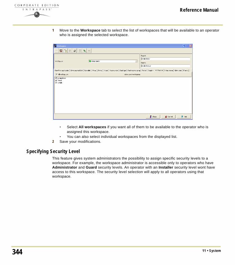
Reference Manual
1 Move to the Workspace tab to select the list of workspaces that will be available to an operator who is assigned the selected workspace.
• Select All workspaces if you want all of them to be available to the operator who is assigned this workspace.
• You can also select individual workspaces from the displayed list.2 Save your modifications.
Specifying Security LevelThis feature gives system administrators the possibility to assign specific security levels to a workspace. For example, the workspace administrator is accessible only to operators who have Administrator and Guard security levels. An operator with an Installer security level wont have access to this workspace. The security level selection will apply to all operators using that workspace.
11 • System344

Reference Manual
1 Move to the Security level tab to select the security level(s) that you want to assign that workspace. If you must create a new security level, see "Security Level Definition" on page 326.
• Select All security levels if you want to assign them all to that workspace.• You can also select individual security level from the displayed list.
2 Save your modifications.
Defining Video ServersThe video server list allows you to assign or limit operator access to specific video servers and cameras. For example, even if a workspace level allows access to a video server, you still have the ability to restrict access to a specific camera for that workspace. This feature makes it easier to define or modify permission for accessing a video server, a video view or other video menu items.
345Workspace Definition

Reference Manual
1 Move to the Video server tab to select the list of video servers that will be available to an operator who is assigned the selected workspace.
• Select All video servers if you want all of them to be available to the operator who is assigned this workspace.
• You can also select individual video servers from the displayed list.2 Save your modifications.
NOTE: To filter video views available to an operator, the operator’s workspace must have access permission to the video server associated with this specific video view. For example, if operators are granted access permission to a video view but their workspace definition does not give them access to the video server where the video view is defined, the video view will not be available to operators with this workspace.
To Limit Access to a Specific CameraEntraPass offers the ability to grant permission to a video server and still restrict access to the cameras registered to that server.
NOTE: If you don’t want the operator to view a camera for which he/she does not have access, you must first check the Hide camera from view option in the Security level dialog. Checking this option will hide the camera from the video view even when the operator has full access to the video server in which the camera has been defined.
11 • System346

Reference Manual
1 From the Workspace window, select the Video server tab. 2 Check the video server box that contains the camera you wish to hide and double-click the
name of the video server. This will open the Select camera window.
3 From the Select camera window, un-select the cameras you want to hide for this workspace.4 Click OK to close the Select camera window. You will notice that the video server is still
selected under the Video view tab. Removing a camera from the list will only deny access to that camera, not the corresponding video server.
5 Save your modifications.
347Workspace Definition

Reference Manual
Defining Video Views1 Move to the Video views tab to select the list of video views that will be available to an operator
who is assigned the selected workspace.
• Select All video views if you want all of them to be available to the operator who is assigned this workspace.
• You can also select individual video views from the displayed list.2 Save your modifications.
Defining EventsThis feature is used to define the event messages that can be displayed to operators who are assigned the selected workspace.
11 • System348

Reference Manual
1 Move to the Events tab to select the list of events that will be displayed on an operator workstation.
• Select the events you want to display for the operator who is assigned this workspace.2 Save your modifications.
349Workspace Definition

Reference Manual
Event Parameters DefinitionDefining event parameters is one of the most powerful features of the system. For each event, you can determine how it will be processed by the system. For example, you can:• Direct events to output devices (such as Messages desktop and log printer), • Send instructions to a SmartLink application,• Define schedules that will allow, for example, to send alarms to an EntraPass application only
at night, • Send a specific event to a specific EntraPass application, etc.There are more than 400 system events. The most common among them are:• Access granted• Input in alarm• Card modified by operator, etc.Events are associated with system components, such as doors, controllers, gateways, Entrapass applications, etc. Every event message is associated with a system component and output devices or group of devices. For example, an Access granted event can be defined for each individual door or by default it can be defined for all doors. This flexibility allows for different actions or responses on a door-by-door basis.
Defining Events ParametersThe Event parameters dialog allows you to customize your system events. In fact, you can specify events that will be printed automatically or acknowledged during a specific schedule. You can also send instructions to inform an operator of an alarm through other media (i.e.: e-mail, pager, etc.) when alarms are generated.By default, all events are defined to be displayed on all the Message desktops of all EntraPass applications defined in the system. You can customize your system events by manually associating events and components.There are two types of associations: manual and default association.
• Default associations: Default associations are preset in the system. By default all events messages occur on all components associated with them and are displayed in Messages desktops. You may keep the default settings.
Default associationsComments
Component Workstation
Default Default All events originating from all components are sent to all workstations
Default (Specific) Workstation 2 All events originating from all components are sent to only Workstation 2
Specific (Door 1) Default Only events originating from Door 1 are sent to all workstations
11 • System350

Reference Manual
• Manual associations: Manual associations are setup by administrator and allow to send messages to Message desktops for specific events. The following table shows the three types of manual associations:
NOTE: Manual associations take priority over default associations. When you define a manual association between an event message and a component, the default association is ignored. It can be restored by deleting the manual association. Manual associations should be used with caution. The most common use for this feature is the SmartLink application.
1 From the System tab, click the Event parameters icon.
Manual associationExample
Component Workstation
Specific Specific Events generated by Door 1 are sent to only Worksation 1.
Specific Unspecified or default Events generated by Door 1 are sent to all Workstations (default).
Unspecified or default Specific Events generated by any of the Doors (default) will be sent to Workstation 1 only.
351Event Parameters Definition

Reference Manual
2 From the Event drop-down list, select an event for which you want to define settings.
NOTE: By default, all events are defined to be sent to the Messages desktop of all EntraPass workstations defined in the system with an always valid schedule. It is recommended to keep default settings especially when these settings apply to all events/components. However, you may decide to create manual associations if you want a specific event to generate a specific message or alarm. The selected event will appear on all doors and will be displayed on all EntraPass workstations.
3 In the Display settings section, specify the display options: by default, all events are programmed to be displayed in the Messages desktop window of all the EntraPass workstations of the system, and are assigned an Always valid schedule.
NOTE: If you are running EntraPass SmartLink application, this schedule must remain to “Always valid” or otherwise messages/commands will not be forwarded to the application.
4 From the Print popup menu, select a schedule to determine when the event will be printed. When this schedule is valid, the selected event will be printed on the printer defined on the workstation to which it is being sent.
5 From the Color drop-down list, select the color that will be used to display the event in the Message desktop. The default colors are set according to the following convention:• Red for alarm events;• Green for elements returning to a normal condition;• Yellow for warnings and errors;• Blue for other events.
6 In the Alarm Settings section, specify:• Alarm (schedule)—When this schedule is valid, the event will be sent to the Alarms
Desktop of the selected workstations and will require an acknowledgement from the operator.
• Instructions—Select the instruction that will be sent to the Instruction desktop with the event to be acknowledged. Instructions will only be sent when the alarm schedule is valid.
NOTE: For the SmartLink application, the instruction does not require that the alarm schedule be valid. You can leave the Alarm schedule field blank, and the instruction will be sent anyway.
7 Assign the Priority level to the event. This determines the sequence in which alarm messages will be displayed to the operator in the alarm queue. The priorities are preset to the most common values (0 = higher, 9 = lower).
11 • System352

Reference Manual
Creating Associations1 In the Event parameters window, select an event from the Event drop-down list. From the
component pane (on the left) select a component and then select an EntraPass workstation to which the event message will be sent.
2 Click the Save icon to create the new association. In this case, All access - Door opened events that will occur on the selected door will be sent to the assigned workstation computer (selected on the right-hand side).
NOTE: The Save icon is enabled only when the selected event/component becomes part of an association.
353Event Parameters Definition

Reference Manual
Viewing an Association1 From the component pane (on the left) select a component and then select an EntraPass
application to which the event message will be sent.
2 Click the View association icon in the toolbar. The View default parameters message box shows if the event parameters were set by default or manually.
3 To close the View default parameters message box, click the View association icon in the toolbar.
Deleting and Restoring AssociationsYou may decide, for example, that an event from a specific component should no longer be sent to the Message desktop of all workstations, or to a specific desktop. To do this, you have to delete the existing association. It is recommended to use this feature with caution.
11 • System354

Reference Manual
1 In the Event parameters window, select the event you want to modify from the Event drop-down list.
2 Click the Delete icon in the toolbar. 3 From the Delete event
parameters window, make your choice:• Restore default: this
option will apply the default alarm and display settings.
• Delete association: if you select this option, the alarm and display settings fields will be left blank and ready for new information. Once you have deleted the settings, you must re-define them.
• Cancel: select this option if you want to cancel the delete operation.
Printing Event ParametersEntraPass allows you to print events parameters (alarm and display settings) for the selected events.
355Event Parameters Definition

Reference Manual
1 From the Event parameters window, select the Printer icon.
2 In the Select events pane, select the events to be included in your printout or click on the Select all button to select all the events from the displayed list.
3 In the Select workstations pane select the EntraPass workstation (or workstations) to be included in your printout or click on the Select all button to select all the EntraPass workstations from the displayed list.• Print empty fields: If selected, the system will print the fields that do not contain any
information. Only the field title will be printed.• Print with default values: If selected, the system will print the default associations as well
as manual associations.
NOTE: If you do not select this field, only manual associations (not involving defaults) will be displayed in the report. If you do not have manual associations (Component x with workstation y), the report will be empty.
• Print components reference: If selected, the system will print the component physical address next to the component identification.
• Use the Font button to choose a different font (and font size) for your report.• Select the Preview button before printing, if desired.
11 • System356

Reference Manual
Instructions DefinitionThis menu is used to define instructions that must be assigned to events. When an alarm is generated, the instruction will display in the Instruction window (Desktop menu) for acknowledgement.Usually, each line will contain a single directive; the response instructions will be composed of several directives (lines). This allows for greater flexibility when modifications are required.
Defining an Instruction1 From the System main window, select the Instruction icon.
2 To create a new instruction, click the New icon. To modify an existing instruction, select one from the Instruction drop-down list.
3 Enter the instruction name/identification in the language section. 4 Select an appropriate language tab to enter the instruction. Instructions are entered in one
selected language.
NOTE: You may enter up to 511 characters (including spaces) per instruction.
5 To assign instructions to events, see "Event Parameters Definition" on page 350.
357Instructions Definition

Reference Manual
Defining a SmartLink Instruction
The Instruction definition menu allows you to create SmartLink instructions. If you have a SmartLink application installed, the Macro-insertion menu button is enabled. It allows operators to send built-in macro-commands to the SmartLink application.1 In the Instruction window, select the Macro insertion menu for
SmartLink button or right-click and a menu will be displayed.
NOTE: When creating SmartLink instructions, only commands that are written in the primary language are considered as valid commands. For more information on macro-commands, refer to your SmartLink Specifications Manual.
The following table describes the options you will find in the menu.
Parameter Description
Date Insert a date in the instruction. Options are: Year, Month, Day, YYYY/MM/DD or MM/DD/YYY
Time Insert a time in the instruction. Options are: Hour, Minute, Second, HH:MM:SS or HH:MM.
Event Insert event description in the instruction. You can select to display event name (Text) or Number.
Location Insert the location where the instruction must take place. Options are: EntraPass Application, Gateway or Site.
Information #1 to 4 Insert event information. Options in the database are: Index Number, Index Text, Component ID and Component Text.
Card Information Insert card information in the instruction. Options are: Card Number, Card User Name, Card Information #1 to #10 or Com-ment.
Numerical Value Insert a number in the instruction.
Character String Insert a string of characters (free text) in the instruction.
Add Delay Insert a delay in 1/10 secs in the instruction.
Carriage Return Insert a carriage return in the instruction.
Trim Right Will delete the last character to the right of the instruction.
E-Mail To insert and e-mail in the instruction that will be sent automatically when the event occurs.
11 • System358

Reference Manual
To Insert an e-Mail Command in a SmartLink MacroWhen building an instruction using SmartLink, EntraPass allows you to insert an e-mail command to that instruction.
Modem To insert a message in the instruction that will be sent automatically through a pager when the event occurs.
Serial Device for Mes-sages
Select the Serial Com Port and Baud rate to send the message.
Serial Device for Commands
Select the Serial Com Port and Baud rate to send the command.
File File opens the Select a filename dialog that allows you to locate a file (or create a new one) where all event information entered in the instruction will be logged when an event occurs.Close will close the file. Commit to disk will save the file to disk. This command will not close the file.
Execute File opens the Select a filename dialog that allows you to locate the exe-cutable that will be used with the macro command.Parameter opens the Enter Character Strings dialog allowing you to type a string of characters that will be added to the macro command.Action allows you to define how you want to launch the macro (Launch Hidden, Launch Normal, Launch Minimized, Launch Maximized or Terminate the process).
Network Insert a Network Tag.
Modify Language You can modify the command language to English or French.
Save SmartLink Mode Insert in the SmartLink command to interrupt and place current SmartLink mode in the background (for example sending and e-mail). This command must always be used with Restore Previous SmartLink Mode.
Restore Previous SmartLink Mode
Insert in the SmartLink command to restore the previous SmartLink mode. This command must always be used with Save SmartLink Mode.
Parameter Description
359Instructions Definition

Reference Manual
1 Once you have selected an existing instruction or created a new one, click the Macro insertion menu for SmartLink and select the e-Mail command. The e-Mail instruction builder dialog will display on screen.
2 Enter the your e-mail address in the From... field.3 Enter the e-mail address or addresses where the message should be sent in the Too... field.
Each address should be separated by a semi-colon (;).4 If you wish to send a copy of this e-mail to other people, enter their name in the Cc... field.5 Enter the e-mail Subject.6 If you want to attach a file to the e-mail, enter the entire path to the file. Each file must be
separated by a semi-colon (;).7 Enter the message in the large window.
11 • System360

Reference Manual
8 Click OK to attach the e-mail to the SmartLink instruction. The message will appear in the Instruction window
Inserting a Pager Command in a SmartLink MacroWhen building an instruction using SmartLink, EntraPass allows you to insert a command that will send a message to a paging system.1 Once you have selected an existing instruction or created a new one, click the Macro insertion
menu for SmartLink and select the Modem command. The Modem instruction parameters dialog will display on screen.
361Instructions Definition

Reference Manual
2 Modem serial port parameter should already be setup.3 Enter Dial information such as the pager Phone number.Check the Pager options box and enter a Message that will display on the pager (if the receiving pager has the option to display) and the Delay before message will be sent to the pager.4 Click OK. The phone number and message will appear in the Instruction window
11 • System362

Reference Manual
Message Filters DefinitionThe Message filter feature allows you to define filters for the Filtered Messages desktop. These filters are used to view a specific selection of events. There are many pre-defined filters such as: access events, controller events, etc. These filters can be accessed by all operators. You can select or create filters directly from the “Filtered Messages” desktop or from the Message Filters menu.
NOTE: For more information, see "Filtered Messages Desktop" on page 386.
Defining Event for a Message Filter1 In the System main window, select the Message Filter icon.The Message filter window
appears.
2 From the Message filter drop-down list, select an event message type (for example: Door events or Relay events) for which you want to define a filter. You may also click the New icon to create your own filter.
3 From the Event list, select the events that must appear in the selected filter. You may check the Select all events option, if you do not want to select specific events. For example, for a Door events type filter, you may decide to include all events or select the Access-denied events.
4 Select the Door filters tab to filter doors that will send messages to the Filtered messages desktop. Additionally, when “Access events” are filtered, the cardholder’s picture can be
363Message Filters Definition

Reference Manual
displayed with the event (if pictures are assigned to cardholders). You can select which doors will display the cardholder picture when the event for this door is generated.
5 Check the All doors option or choose specific doors for which the cardholders’s picture will be displayed an door event.
6 From the Door filter type, select the filter that will be used for filtering Door events:• Door filter: Only events related to the selected doors will be sent to the Filtered Message
desktop• Pictures filter: Cardholders’ pictures related to cards presented to the selected doors will
be sent to the Filtered Message desktop • Filters for doors and pictures: Door events related to the selected doors as well as
cardholders’ pictures that triggered door events on the selected doors will be sent to the Filtered Message desktop.
11 • System364

Reference Manual
7 Select the EntraPass applications tab to filter applications that will send messages to the Filtered Messages desktop.
8 Check the All EntraPass applications option for the Filtered Messages desktop to receive all events originating from all EntraPass applications defined in the system. You may also choose to display events from specific applications. To do this, select the EntraPass application from which you want to receive events.
9 Select the Gateway and site tab to filter gateways and sites events sent to the Filtered Messages desktop.
365Message Filters Definition

Reference Manual
10 Check the All events option to receive events originating from the components of the gateways or sites. You may select the gateway or the site that will send events to be displayed.
NOTE: When you use filters, the system retrieves events that are already displayed in your Message desktop and sorts these events according to the settings of the selected filter. If events originating from a specific gateway are displayed in your messages desktop and this gateway is not selected in the filter definition, then these events will not be displayed when you select this filter.
11 Select the Special filter tab to filter events according to their type.
• Picture: all events associated with a cardholder’s picture will be displayed in the Filtered Message desktop.
• Fail-soft: all events generated by a controller in stand-alone mode following a communication failure will be sent to the Filtered Message desktop. Fail-soft messages are identified with a + sign in the Filtered Message desktop (and Message Desktop) when this option is select when defining the Messages list properties (Desktop > Message Desktop > right-click an event > Properties).
• Video: all video record events will be sent to the Filtered Messages desktop.
NOTE: When you use filters, the system retrieves events that are already displayed in your Message desktop and filters these events according to the settings of the selected filter. If events originating from a specific gateway are displayed in your messages desktop and this gateway is not selected in the filter definition, then these events will not be displayed when you select this filter.
11 • System366

Reference Manual
Database Structure DefinitionUse the Database structure menu to browse the system database. It will display the entire structure of the database including:• The system physical components (EntraPass applications, gateways, sites, controllers, doors,
relays, inputs and auxiliary outputs), and• Logical components (cards, schedules, reports, instructions, groups, etc.). Operators can edit or sort the system components from the Database structure window.
Viewing the Database Components1 Form the System menu, select the Database structure icon.
NOTE: If the Video feature is enabled in EntraPass, its components will appear in the Database explorer.
2 To display only the Physical component, select the physical components icon.When selected, only the physical components of the database will be displayed.
NOTE: By default, physical components are ALWAYS displayed.
3 To display Logical components, select the logical components icon. When selected, logical components of the database will be displayed along with the physical components.
4 You may use the Refresh button to refresh the display in order to obtain the most recent information saved in the server database.
5 You may select the Full Expand button to fully expand the tree structure and view all sub-components of a selected component. For example, if you use this button on a controller, the system will display the controller components (doors, inputs, relays) on the right-hand side of the window.
367Database Structure Definition

Reference Manual
6 You may select the Collapse button to fully collapse the tree structure and hide all sub-components of a selected component.
7 To edit a component, right-click it and select Edit from the contextual menu. The system will display the definition window so you can modify the component’s parameters.
8 To sort the component, right click the component, then select Sort from the contextual menu. Sort the components listed in the right-hand pane of the window for an easier find. You can sort by component address or name.
NOTE: You can define how the component's physical address will be displayed. This will also affect how components will be sorted. For more on this, see "Security Level Definition" on page 326.
11 • System368

Reference Manual
Chapter 12 • EntraPass DesktopsDesktops receive and display system events (current or historical), alarms, cardholders’s picture, system graphics, etc. A desktop can also be used to acknowledge alarms, display instructions, etc. There are eight (8) pre-defined desktops. These can be configured as follows:• Desktop 1: All system events• Desktop 2: System events and pictures• Desktop 3: Filtered system events• Desktop 4: Filtered system event and picture, etc.• Desktop 5: Alarms screen• Desktop 6: Graphic screen• Desktop 7: Network alarms screen• Desktop 8: Video desktop, if the Video option is enabled in EntraPass. The following windows can be combined with other desktops:• Instructions• Pictures• Historical ReportsIt is possible to display more than one window at a time. Depending on their security level, operators can modify the settings of each of these windows (background color, size, toolbar, etc.). However, an operator whose access level is ‘read-only’ on a given desktop cannot modify, move, maximize or minimize a desktop.
NOTE: Only operators with the required security level can customize their desktops (System tab > Security Level). They also have the ability to allow “Read-only operators” to modify their desktop settings. In this case, the changes apply only to the current session.
369

Reference Manual
Work Area CustomizingEntraPass enables operators, with appropriate permissions, to customize their work area, to create a temporary workspace and to modify the desktop properties. To define an operator’s security level: System tab > Security Level.
Creating a Temporary Workspace1 From the Desktop window, right-click in the area below the menu bar.
2 Choose Select a temporary workspace from the shortcut menu.
3 Choose the Component list filter workspace and the Event message filter workspace from the drop-down menus in order to create a temporary workspace.
• The Component list filter workspace lets you select the specific component list of an existing workspace.
12 • EntraPass Desktops370

Reference Manual
• The Event message filter workspace (optional) lets you select only the upcoming messages, not the buffered messages, from an existing workspace.
NOTE: A temporary workspace must include a Component list filter workspace selection to be enabled. If you only select an Event message list filter workspace, the temporary workspace banner will not display.
4 Click OK. A banner displays below the menu bar with the names of each selection of the temporary workspace.
5 Repeat Steps 1 to 4 to return to the original workspace or double-click on the banner to create or modify the temporary workspace.
371Work Area Customizing

Reference Manual
Changing the Display Properties1 From the Desktop window, right-click anywhere in the window.
2 Select Properties from the shortcut menu.3 From the Properties window that appears,
select the display options: you may change the default size of buttons, the default background color, etc. • Small buttons: If this option is
selected, small components’ icons are displayed with no descriptive text. This option can be appropriate for operators who are familiar with EntraPass icons and do not need an additional description.
• Large buttons with images: Icons are displayed with their description. • Large buttons without images: Large buttons are displayed with no description. • Display menu: check this option to view the system menu.• Display toolbar: check this option to view the toolbar for system menus.• Background color: select a background color for the whole work area. • Change system font: click this button to change the font for all the user interface.
12 • EntraPass Desktops372

Reference Manual
Specific Desktop CustomizingEntraPass enables operators with appropriate permission to customize their desktop. Moreover, operators with full access permissions can permit operators with read-only permission to customize their desktop. They can also customize a specific desktop and transfer this customized desktop to other operators using the Assign desktop feature. The following sections explain how to customize a desktop:• Customizing a desktop by a full access operator• Customizing a desktop for a read-only operator• Transferring a customized desktop
Customizing a Desktop for a “Full Access” OperatorOperators with full access permission have the ability to customize their desktops. To grant full access to an operator: (System > Security Level).1 Select the desktop you want to customize, right-click and select Properties in the menu to open
the Desktop properties dialog.
373Specific Desktop Customizing

Reference Manual
2 From the Desktop name field, assign a meaningful name to the desktop you are configuring.3 Select the window type:
• Floating window—a floating window can be resized and positioned anywhere in the work area screen. For example, you can choose to send it to the back or to bring it to the front. If a floating window was sent to the back, you may bring it to the front by right-clicking the desktop button, then selecting the Bring to front menu item.
• Desktop window—a desktop window is trapped within the work area. It is not possible to send the window in the background. It always remains within the main work area.
4 To save your changes:• Click OK—If selected, you just save your the changes, the window is not displayed. • Click OK & GO—If selected, this function saves your changes and displays the window you
have just configured.
NOTE: When opening a desktop window for the first time, you may need to re-size it in order to view the information correctly. To do so, point to the frame border you want to change; when the pointer turns into a double-headed arrow, drag the border to exact size. You may then position the window in the work area to the desired position.
Customizing a Desktop for a “Read-Only” OperatorThe security manager or an operator with the appropriate security level can give permission to operators who do not have the appropriate permission to customize their desktop during a session.
12 • EntraPass Desktops374

Reference Manual
1 Login, using the user name and password of the operator with ‘full access’ security level.2 Select the desktop you want to customize, right-click and select Properties in the menu to open
the Desktop properties dialog.
NOTE: The Permit button appears when the operator who is logged on has ‘read-only’ access permission. The permission acquired during this session will be valid until the operator logs out.
3 Click the Permit button. The operator login window appears. Enter your username and password, and click, OK. The temporary permission will be granted.
Transferring a Customized Desktop Another possibility available to the Security Manager (or to the operator with the appropriate security level) is to customize a desktop, and then to assign the settings to other operators who may not have the appropriate security level to modify their desktop settings.
375Specific Desktop Customizing

Reference Manual
1 Right-click the desktop you want to assign the settings.
2 Select the Assign (desktop) option from the shortcut menu.
3 From the displayed window, select the operators to whom you wish to assign the desktop properties (you must check the appropriate checkbox). You may select operators one by one, or you may use the Select all button.
12 • EntraPass Desktops376

Reference Manual
Message List DesktopBy default, the first desktop is defined as the Messages List Desktop. It displays all system events. Events are displayed with their icon, date and time, description, system components involved in the event such as controllers, cardholder pictures (if defined), etc. When a new event is displayed, the window scrolls up. The newest events are added at the bottom of the window.
Viewing and Sorting System EventsBy default, the first desktop is dedicated to displaying system events.When you select an event from the list, you interrupt the incoming sequence (the green status indicator located at the bottom left part of the desktop turns red when scrolling is interrupted). By default, the scrolling will restart automatically after a pre-set period of time, unless the auto-scroll parameter was disabled, In that case, to restore the normal scrolling, click the Restart Scroll button.
NOTE: If you configure a Desktop as a message screen and a picture screen, two windows are displayed simultaneously when you select the desktop.
1 Select the first desktop. By default, all system events are displayed in ascending order with an area at the bottom of the screen that displays the selected event in the list.
NOTE: You may change the message color: System > Events parameters. You may also change the events display order; see "Customizing Event Display in the Message Desktops" on page 378.
2 From the Message list screen, you may change the sorting criterion (Sorted by scroll-down list). You may choose to sort by:• Sequence—Events are sorted according to the normal sequence (default). New events are
added at the bottom of the window. (This option is not available for Archived Messages Lists.)
377Message List Desktop

Reference Manual
• Date and time—This sort order interrupts the normal scrolling of events. This feature is useful when you want to know when an event was generated. This time may be different from the “normal sequence” for dial-up sites for instance or after a power failure.
• Event—When selected, the system sorts the Event message column in alphabetical order, grouping identical events. For example, all Input in alarm events are grouped together in alphabetical order.
• Message type—When selected, the system sorts the Event message column in alphabetical order, grouping similar events. For example, all Site events are grouped together in alphabetical order.
NOTE: To go back to the default display, Select Sequence from the Sorted by drop-down list.
3 Clicking the Text filter button (top of the window) will open the Text filter dialog that allows to enter a key word to display all the events that contain that keyword in the Message list. To close the Text filter dialog box, click Cancel or the Windows closing button (X).
4 To return to the normal display of events in the Messages list screen, click the Text filter button.
Customizing Event Display in the Message Desktops1 From the displayed shortcut menu (Message desktop > Right-click a message), select
Properties.
2 From the Properties window, select the appropriate display options.• Multi-line—Usually, events are displayed on a single line. You can increase the line
spacing between events by checking the appropriate option (1, 2, 3 or 4 lines). • Show icons —You can choose to display different types of icons beside each event.
• Message type—When you select this option, the system inserts an icon next to events indicating the type of event. For example, if the event is a “door forced open” an icon representing a door is displayed (a hand represents a manual operation, a diskette
12 • EntraPass Desktops378

Reference Manual
represents the operation that modified the database, etc.). Access events are represented by the login/logout icons.
• Picture—When you select this option, the system inserts a card icon next to events containing cardholder pictures.
• Fail-soft messages—When you select this option, the system displays a plus (+) sign next to the events that occurred when controllers were off-line.
• Video: check this option if you want the selected desktop to display video data from the video server connected to your system.
• The Miscellaneous section allows you to enable additional options:• Keep card picture—When selected, the system keeps the latest card picture (if the
Picture window option is selected) until another event containing a card occurs.• Display toolbar—Displays/hides the toolbar on the top of the Message Desktop.• Manual properties save only—When you select this option, you have to click the
Save button (once selected, the button is disabled). The system saves all the settings defined in the Properties window as well as the position of the window within the Messages Desktop.
• Display selected messages (full)—When you select this option, a smaller window is added at the bottom portion of the Message window. It displays the selected event with its full description. This feature is very useful when your Message window is too small to display the entire description of an event.
• Display events in bold: select this option to increase the legibility of text event messages displayed in EntraPass desktops (Message list, Filtered messages and Alarm desktops). Moreover, if the color selected for an event message is the same color as the background color, the event message will be displayed in black bold so that it can always stand out. (This option is not available for Archived Messages Lists.)
• Last Message on Top: By default, event messages are displayed in ascending order of occurrence, with the area at the bottom of the screen reserved for the highlighted
379Message List Desktop

Reference Manual
event. You can select to display the events in descending order, with the highlighted event showing above the list of event messages.
• Auto-scroll delay (mm:ss): Will automatically start scrolling the message list after a pre-set delay when the operator selects an item in the list. By default, this option is turned on with a preset delay. You can select to turn this option off which means that the operator will have to click the Restart Scroll button in the Messages List. (This option is not available for Archived Messages Lists.)
• Message background color—Allows the operator to modify the background color of the message window.
NOTE: To change the font color of system messages: System > Event parameters.
Performing Tasks on System MessagesEntraPass enables you to perform various tasks on system events. These include:• Deleting messages
12 • EntraPass Desktops380

Reference Manual
• Viewing card information• Validating card status and card transaction• Modifying the desktop properties (such as display options), etc.• Play, edit and export video recordings• Play archived videos from the EntraPass Video Vault
NOTE: Some tasks are related to the selected desktop. For example, if you right-click an alarm event, the shortcut menu displays tasks that are related to alarm events. For details, see "Alarms Desktop" on page 391.
1 From the Message desktop, right-click an event to enable a shortcut menu:
2 Do one of the following:• Delete all—This option allows an operator to delete all the events displayed. • Card—This menu items offers two choices: View card transactions and Search card.
Select View card transactions to display all access information related to the cardholder who has triggered the access event. The Search card shortcut allows you to browse the card database and to display information about all the card numbers associated with this specific card user name from the View card information window. From this window, operators can perform a variety of tasks including viewing and validating information contained on a card, such as the card number, cardholder name, card state (valid or invalid), card type, etc. They can also select a card and view its transactions or view and
381Message List Desktop

Reference Manual
validate a card access. For details about validating cardholders’ access and last transactions, see "Cards Definition" on page 230.
• Video recording— This menu items offers three options: Play, Play/Edit/Export and Play from Vault. Selecting Play allows users to play the video event in the Playback window, offering options to snap (copy) it and save it for future use. Selecting Play/Edit/Export offers users features similar to the ones in the Video Event List. Operators can then display details about the event (camera, server, comment field) and camera information, etc. The video event can also be played and exported. Selecting Play from Vault allows operators to view a video that is already stored in the EntraPass Video Vault.
NOTE: If camera icons are not displayed, simply right-click a video event message, select properties from the shortcut menu, and check Video in the Show icons section of the Properties
• View parent—Displays the parent of each component related to the selected event.• Edit—This feature offers you the ability to edit each component associated with the
selected event. If Edit is selected, a shortcut menu displays components associated with the selected event. In this example, the Site definition modified event involves the EntraPass application, the operator who was on duty when the event was generated and the site related to the event. It is now possible to edit any of the three components by selecting it from the shortcut menu.
NOTE: If the selected event is an access event and if the card that triggered the event has already been registered in the system, it will be possible to edit the card. However, if the card is associated with an Access denied - card unknown event, the card will be created and registered in the system.
12 • EntraPass Desktops382

Reference Manual
• Send to back—This option only works when the window type is set to floating. It sends the active window behind the main application window. To bring back to front, right click the desktop button, then select Bring to front.
• Properties—This menu item enables users to modify the display properties for the selected desktop.
383Message List Desktop

Reference Manual
Picture DesktopIf you selected Picture screen when defining the Message desktop, the Message desktop always appears with a Picture window. Access events are displayed with the cardholder’s picture if you have set the appropriate display option in the Message filter definition (System > Message filters). For details, see "Message Filters Definition" on page 363.
Modifying Pictures Display Options1 From the Filtered Message list and Picture, select an access event, then right-click the
cardholder’s picture.
2 From the shortcut menu, select Properties.
3 From the Aspect drop-down list, select the display size for the picture:
Send to back—This option only works when the window type is set to floating. It sends the active window (Picture window) behind the Message desktop main window. To bring it back to front, right click the Message desktop button, then select Bring to front from the shortcut menu.
12 • EntraPass Desktops384

Reference Manual
• Design size: the cardholder’s picture will be displayed with its original size.• Stretch —This option stretches the picture to the window size without maintaining
proportions. The picture may appear distorted.• Stretch ratio—This option stretches the picture to the window size while maintaining
proportions.4 Select the information you want to see displayed with the cardholder’s picture:
• Door: The door where the card was presented will be displayed above of the cardholder’s picture
• Event: The event message will be displayed• Card information: The card information field will be displayed above the picture.• Comment: If this option is selected, a comment field appears below the cardholder’s
picture. The comment entered when defining the card appears in this field.
385Picture Desktop

Reference Manual
Filtered Messages DesktopThe Filtered Messages desktop allows operators to display specific events. For example, you can create filters to display events that are related to a specific controller and from a particular gateway of the system. If this is the case, those events will be displayed in the Filtered Message desktop.Filtered messages are defined in the Message filters menu: System > Message filters.
NOTE: When you use filters, the system retrieves events that are already displayed in the Messages desktop and filters these events according to the selected filters.
Configuring a Filtered Messages Desktop1 From the Desktop main window, select the desktop you want to configure as a Filtered
messages desktop.2 Assign a meaningful name to the Filtered message desktop; then define the desktop type
(Message window, Picture window or both).
3 You can change the Text filter, to display specific events. For details on the Filtered messages desktop, see "Message List Desktop" on page 377.
12 • EntraPass Desktops386

Reference Manual
Historical Report DesktopThe Historical Report desktop allows operators to display events that come from pre-defined, historical reports, view the report generation state and, when available, to play video recordings from the EntraPass Video Vault. Security levels will determine which historical reports are available to each operator. The Historical Report message list operates the same way as all message lists in EntraPass except that it has an extra combo box that allows operators to select a pre-defined historical report.Historical reports are defined under Report > Historical ReportSecurity levels for reports are defined under System > Security Level > under the Report tab.
Configuring a Historical Reports Desktop1 From the Desktop main window, click the desktop button you want to configure as a Historical
Reports Desktop.2 Assign a meaningful name to the Historical Reports Desktop, then define the desktop type
(Message window, Picture window or both).
3 Select the sort criteria you want to use to display historical data (Date and Time, Event, or Message Type).
NOTE: The sequential sort option is not available for archived messages.
4 You can enter a text string that will be used for searching specific archived messages (when applicable).
5 In the combo-box, select the historical Report you want to generate. The list of available reports corresponds to your security level.
387Historical Report Desktop

Reference Manual
6 After selecting the report, a Date and Time window will popup requesting a reporting date and time period.
7 Enter Start and End date and time or click the calendar icon to open the calendar and select the start and end dates, and then type in the start and end times.
8 Check the Empty screen box process request box in order to clear the Historical Report message list of the previous search results.
9 Click OK. The status indicator light located at the bottom left of the screen will change from green to blue to indicate a historical report is being generated. It will turn green again when the data transfer will be completed and the historical data will be displayed according to the criteria you have selected.
To Create and Edit Historical Reports from a Desktop• When your security level allows you to create new reports, you can access the Historical Report
dialog from the New Report command in the Historical Report Desktop pop up menu. For more information on Historical Reports, see see "Historical Reports Definition" on page 415
• When your security level allows you to edit existing reports, you can access the Historical Report dialog from the Edit Report command in the Historical Report Desktop popup menu. For more information on Historical Reports, see "Historical Reports Definition" on page 415
To Display Historical Report State in Real-timeThis feature allows you to view the progress of report generation for a specific report in the Historical Report Desktop List
12 • EntraPass Desktops388

Reference Manual
1 Right-click an entry in the Historical Report Desktop window. A contextual menu will pop up.
2 Select Report State. The Report State dialog will open displaying Report generation information.
3 When the report is finally generated in the Desktop window, the information in the Report State dialog will disappear. Click Close.
389Historical Report Desktop

Reference Manual
Playing archived video recordings from a Desktop Message list1 Select the video you would like to play and right-click to access the contextual menu.
2 If the video has been stored into the Entrapass Video Vault, the Play from Vault option will be enabled. Once you click on it, the Video Playback window will open and start playing the selected recording.
12 • EntraPass Desktops390

Reference Manual
Alarms DesktopThe Alarms desktop is used to view and to acknowledge alarm events. Alarm events are defined in the Event Parameter menu (System > Event Parameters). Any event can be defined as an alarm event. Alarm events require operator acknowledgment and are displayed in the Alarms desktop.A schedule must be defined for all alarms (System > Event parameters, Alarm settings).When an alarm is generated during a valid schedule, operators have to acknowledge the alarm.Alarms are displayed with date and time, alarm description, details, instructions (if defined) and associated graphic or video clip. New events are added at the bottom of the Alarm desktop unless you have setup the list to display in descending order (in the Alarm Desktop Properties dialog).
NOTE: The System Administrator may decide not to display alarm messages in the desktops. In this case, the alarm desktops will not be available to any user. For more information on disabling the network alarm option, see "Network Alarm" on page 459.
391Alarms Desktop

Reference Manual
Defining an Alarms Desktop1 From the Desktop main window, select the desktop in which you want to display alarm
messages, then define the window type: Floating or Desktop type.
2 Specify the secondary windows that will be associated with the Alarms desktop: • Display on new alarm: Will open the Alarms desktop automatically when an alarm occurs. • Message screen: This window allows operators to view and acknowledge alarms that
have an “acknowledgement schedule” selected in the Event Parameters definition menu (System > Event Parameters > Alarm settings) or to display the auto-acknowledge button configured in the Operator dialog (System > Operator > Privileges).
• Instructions screen: This window displays the instruction that is linked to the event to be acknowledged (i.e. call the police, send a message to a client application, etc.). Instructions are defined in the System > Instructions. Then after, they may be associated with events.
12 • EntraPass Desktops392

Reference Manual
• Graphic screen:This window will display the location of the alarm being reported (if graphics are defined in the system). For more information on assigning graphic, see "Graphics Definition" on page 198.
NOTE: An Alarm desktop may be defined as a Message window, a graphic window and an Instruction window. These features may apply to a single desktop. When you select a desktop defined with these three features, three windows are displayed simultaneously. For a better display, you may need to resize and to position the windows.
Viewing System Alarm Messages1 Select the Alarm desktop. Alarm events are displayed according to the criteria selected in the
Sorted by field.
2 You can double-click the log area (middle of the window) to add a comment. The Add a comment window opens and enables you to enter text data. Once you have finished and clicked the OK button to close the window, the alarm event will be preceded by a + sign, indicating that an annotation has been added to the alarm event.
3 You may change/define the sorting order (Sorted by drop-down list):• Sequence—alarms are sorted by their order of arrival. This the default sequence. The
window scrolls to the end each time a new alarm is displayed.• State—alarms are sorted according to their status (acknowledged, to be acknowledged or
flagged). When you use this option, you interrupt the normal scrolling of events. Select “sequence” to go back to the default display.
• Date and time—alarms are sorted according to the date and time of their arrival. • Event—The Event messages column is sorted in alphabetical order, grouping identical
events For example, all Input in alarm events are grouped. • Priority—Events are sorted by priority (as defined in Event parameter).
4 You may right-click anywhere in the window to enable the Properties window from which you can enable alarm status icons:
393Alarms Desktop

Reference Manual
• Red—To be acknowledged or suspended. If suspended, the suspension delay is displayed. When the delay expires, the operator is required to acknowledge again. If the delay is not expired but the operator wishes to acknowledge a suspended alarm, he/she has to click on the delay. The delay will be reset to zero.
• Green—Acknowledged.• Yellow—Flagged.• Black—Deleted. To view alarms that have been manually deleted, select the View deleted
logs from the Properties.• Blue—Manual log.
5 Select the Manual / Automatic buttons to toggle the acknowledgement method (automatic or manual). Only operators who are assigned this feature in the Operator Definition menu can use this option. For more information, see "Operators Definition" on page 322.
NOTE: The Manual / Automatic acknowledgement option is only available through the Alarms Desktop. When the operator logs out, it will return to “manual” by default.
6 Right click an alarm message to perform additional tasks on alarm events:
• Manual log—When selected, the system displays the Manual log window to allow an operator to add log comments, and hence to generate a customized event (with priority, event details, color etc.).When a manual log is added, a hand and a blue circle are added beside an alarm message. These are visible when icons are enabled (right-click an alarm event > Properties > Show icons)
• Acknowledge—When selected, a green point is inserted beside an alarm message to indicate that the event was acknowledged.
• Flag—When selected, the system flags the selected event. A yellow indicator is inserted beside flagged events.
• Add comment—Allows operators to enter comments concerning the selected event. The added comments are displayed in the bottom part of the alarm window. A blue + sign
12 • EntraPass Desktops394

Reference Manual
beside an alarm message indicates that a comment was added to the alarm message (visible when icons are enabled: right-click an alarm event > Properties > Show icons)
• Print log—When selected, the system prints the alarm message.• Delete log—When selected, the selected alarm message is marked for deletion (the
indicator becomes “black” to indicate that the log has been marked for deletion). To view the logs marked for deletion, before you actually purge them, right click anywhere in the window and select Properties then select View deleted logs.
• Purge deleted log—Select this option to permanently remove logs that were marked for deletion.
Displaying Alarm Desktops AutomaticallyEntraPass enables users to display graphics automatically - from any desktop - as soon as an alarm occurs.This feature enables operators on duty to automatically view new alarms without having to open the alarm desktop and secondary windows associated with it. If Display on new alarm is checked the alarm desktop (and its secondary windows) will be displayed as soon as an alarm occurs regardless of the active window.
395Alarms Desktop

Reference Manual
1 Define a desktop and customize it as an alarm desktop: for this, you have to check the items of the Alarms desktop section.
2 Check the Display on new alarm option so that operators can automatically view new alarms without having to open the alarm desktop and secondary windows associated with it.
NOTE: If this option is checked and if an operator calls up the alarm desktop, the desktop icon background color turns blue, indicating that the alarm and its secondary windows are displayed when a new alarm occurs. If however this option is selected when defining a Filtered message desktop for instance and if the desktop icon is selected, the filtered message desktop will be displayed (the background color of its icon turns blue), but the windows below the Display on new alarm section will not be displayed; they are only displayed when a new alarm occurs. If those windows are displayed (on new alarm), clicking the “X” in the top right hand corner of one of them will close all the open windows. If Display on new alarm is not checked, the alarm desktop and all its secondary windows will be displayed on call (that is, when the alarm desktop is selected).
12 • EntraPass Desktops396

Reference Manual
3 Click OK and Go for your configuration to take effect immediately.
NOTE: When you define a desktop as an alarm desktop to be displayed on new alarm, it is recommended to reopen the Automatic Alarm Display desktop, to position its windows the way you want them to appear, then to click OK and GO again. This way, it will appear exactly as you have defined it.
Acknowledging Alarms/EventsUsually, operators have to acknowledge receipt of an alarm condition (event—such as intrusion, input in alarm, etc.) by responding in ways such as depressing an acknowledgment button. In EntraPass, operators acknowledge alarm messages from an alarm warning box or from the Alarms desktop window.
NOTE: A sound can be added to alarm events. For more details about setting options for an alarm sound, see "Multimedia Devices Configuration" on page 452.
Acknowledgement options are setup in the EntraPass application definition (Devices > EntraPass application (selected Workstation) > Alarm tab, Acknowledgement parameters). Events that require operator acknowledgment are defined in the System > Event Parameters.
NOTE: If the component that is in alarm is assigned to a video view, the video view or video recording is automatically displayed when an alarm occurs.
Automatic AcknowledgementAlarms can be automatically acknowledged without operator intervention. This option is enabled in the Operator definition menu (System > Operators > Privileges, Auto acknowledge).
NOTE: In order for the Manual button to display on the Alarm Desktop window, it is important to close the EntraPass session and reopen it after you have selected the Auto acknowledge option.
NOTE: Only operators granted the appropriate access privilege should be using this option. If the Automatic acknowledge feature is used, the alarm message box is not displayed; therefore, it will not be possible to suspend alarms. If this option is enabled in the Operator definition menu, the Manual button is added to the Alarms desktop. This button toggles between Manual and Automatic acknowledgement.
397Alarms Desktop

Reference Manual
To Acknowledge an Alarm Message1 When the Acknowledgement required message box appears, take one of the following
actions:
• Click the Acknowledge button to acknowledge the displayed alarm event. The red status button turns green once an alarm is acknowledged.
• Click the Suspend button to suspend alarms while doing other operations in the system. The alarm will be suspended for the delay time specified in the EntraPass application definition menu. Once the suspended alarm delay time expires, the system prompts the operator to acknowledge the alarm.
• Click the Flag button if you want to acknowledge an alarm message, and if you want to identify it for future reference. A flagged alarm is identified by a yellow button.
• Click the Mute button if you want to stop the alarm sound.
NOTE: The Acknowledgement required message box will be presented in a format without the Instructions window if there are no instructions associated with the alarm message.
NOTE: If the component that is in alarm is assigned to a video view, the video view or video recording is automatically displayed when an alarm occurs.
12 • EntraPass Desktops398

Reference Manual
To Acknowledge Alarms from the Alarms Desktop1 Select the alarm event you want to acknowledge (one that has been flagged, for instance),
Right-click to enable a shortcut menu.2 Select Acknowledge from the sub-menu. The status indicator becomes green.
NOTE: To tag an alarm message for specific purposes, select the alarm event you want to identify; right-click and select Flag from the sub-menu. You can also click an alarm message until the color of its status indicator changes to the desired color.
399Alarms Desktop

Reference Manual
Instruction DesktopThe Instruction window displays the instructions to follow when an alarm is reported. Instructions will only be displayed if this option is enabled during the Event Parameters settings (System > Event parameters, Alarm settings).
Viewing an Instruction About an Alarm Message1 You may view instructions about an alarm by selecting the Alarms desktop defined as a
message and an instruction window, or defined as an instruction window. When a desktop is defined as being both a message window and an instruction window, the two windows are displayed at the same time:
12 • EntraPass Desktops400

Reference Manual
2 You may also view an instruction about an alarm by selecting an alarm message and right-clicking it.
NOTE: This feature is very useful when the Alarms desktop is too small to display the entire description of an event.
401Instruction Desktop

Reference Manual
Graphic DesktopThe Graphic desktop displays the graphical location of the alarm being reported (if graphics are defined in the system). A graphic corresponds to the secured area of the system where components (EntraPass application, controllers, inputs, relays, etc.) are located on a site. With graphics, operators can easily view the exact location of a component installed on a site, or the status of components and devices such as area groups, areas, doors, contacts, motion detectors, controllers, assigned to the graphic. In an emergency situation where muster reporting has been defined, icons will indicate when all employees have vacated the area. Operators can perform manual operations directly from the displayed component (for example lock/unlock a door). To define interactive floor plans, see "Graphics Definition" on page 198.
Viewing Graphics in the Graphic Desktop1 Right click the desktop icon you want to assign to graphic, name the desktop (Graphics, for
example), then define the window type (Floating or Desktop). 2 Click OK and Go to display the Graphics desktop.3 Right click anywhere in the Graphic desktop, then, from the shortcut menu, select the graphic
you want to display.
NOTE: If the window is smaller than the graphic size, you can click-hold-and-drag the graphic to move it around within the Graphic window.
4 You may right click anywhere in the graphic to enable a shortcut menu in order to:• Adjust the display size of the selected graphic (Fit to screen, Design size or Picture size.• Select Auto result for the system to display a message indicating the cause of the
communication loss in case of communication failure. If Auto result is not selected, operators will have to manually request the results for the component by using the Show result.
5 Right-click a component in abnormal condition to enable a sub menu.
12 • EntraPass Desktops402

Reference Manual
NOTE: Components in alarms are represented by their animated icons. Selecting an animated icon and viewing its parent components allows operators to learn more about the “alarm condition”.
6 Select Full status from the shortcut menu to display the error list related to one or all the components in alarm.
7 Select the Double click menu item to allow operators to modify the status of a component in alarm from the Graphic desktop. For example, if the displayed component is a door and if the Double click menu item was set to Unlock, an operator can manually open the door from the Graphic desktop.
NOTE: When you modify the Double-click feature via the Graphic desktop, the system does not save the modifications. Modify the default Double-click feature via the graphic definition (Definition > Graphics, Design window, right click a component > Default dblclick menu item). For more information on how to create graphics and on how to assign components to graphics, see "Graphics Definition" on page 198.
403Graphic Desktop

Reference Manual
Network Alarms DesktopThe Network Alarms desktop is used to view all the alarms in the system. Only events that require operator acknowledgment and that are programmed in the Event Parameters menu are displayed in the Network Alarms Desktop.
NOTE: Network Alarms are available on all workstations of the system. By default the server sends network alarms to all workstations at startup. If you do not want the system to automatically send network alarms, use the No reload on startup option (Devices > EntraPass application > Network Alarm tab). This option is useful when the connection between the workstation and the server is slow.
Operators will only be authorized to view network alarms that were sent to the Applications that are selected in their security level definition menu.
Viewing network alarms1 Select the Network Alarms desktop.
2 Right click anywhere in the window to enable a shortcut menu:• Refresh: this options allows operators to load new alarm messages in the Network alarms
desktop. The Refresh menu item is particularly useful when the server does not load automatically network alarm at startup; that is, when the No reload network alarms on startup option is checked in the Workstation definition menu (Devices> Workstation > Messages 1 of 2 tab).
• Print log—When selected, the system prints the alarm message.
12 • EntraPass Desktops404

Reference Manual
• Delete log—Purges alarm records from the system. When you select this option, the Delete network alarms window appears. You can then specify the Deletion option (selected, all or custom messages).
NOTE: To limit the number of records kept in the alarm database, use the Maximum records in system logs: Options > Server parameters > Server tab). This option is used for the server and workstation alarm message databases.
405Network Alarms Desktop

Reference Manual
Video DesktopIf the Video feature is enabled in EntraPass, you can configure a desktop as a Video desktop.
Defining a Video desktop1 From the Desktop menu, right-click a desktop to bring up the Desktop properties window.2 In the Desktop name field, assign a name to the new desktop.3 Select the window type for this desktop.4 Check the Video window option.
Using the Video desktop1 In the Desktop window, select the desktop defined as the Video desktop.The Video display
window appears.
2 Select an icon (in the lower part of the window) to determine for instance the size of the views or to display the Panel window (a small window associated with the video display).
The following table shows the available options:
View Icon Description
Large. This view sets the window to 1024x768 pixels
12 • EntraPass Desktops406

Reference Manual
Medium. This view sets the window to 800x600 pixels
Small. This view sets the window to 640x480 pixels
Tiny. This view sets the window to 400x300 pixels.
Creates a new video view
Shows panel window
Video playback
These buttons appear in the lower part of the Video desktop when the operator who is logged on was assigned specific permission for viewing and generating video events. This custom buttons offer a fast way for viewing or generating video events.
Edits the current video view
Shows the help related to the Video desktop
Closes the Video window
View Icon Description
407Video Desktop

Reference Manual
Video Server StatusEntraPass offers the ability to display parameters of the video devices connected to the Video server. Operators can for example view information related to network data transfer (images and digital sounds).
NOTE: Installing and using the Video feature may take a great amount of your company network bandwidth (LAN or WAN). The network administrator may control the use of the network bandwidth for Video transfer.
Viewing the video server full status1 From the Graphic desktop window, right-click the Video Server icon to display a shortcut menu.2 From the shortcut menu, select Full status to display information about the video server status.
NOTE: The content of the Full Status window depends on the video server associated with EntraPass.
The following list provides a short description of the displayed fields.
Item Description
Unit name The network name of the remote DVMS system (Intellex in this example). The Unit name is followed by the DVR IP address
Unit type The type of the unit. can be Intellex, Iris (network client), etc.
12 • EntraPass Desktops408

Reference Manual
Schedule mode The current schedule mode of the remote DVMS unit. It indicates how images are recorded by the DVR installation. The values for this field can be: • Regular (regular schedule)• Single (only a single camera)• Custom (a custom schedule has been set by the operator).
Recording in progress
The active record statue of the remote DVMS unit. Values can be: • True: is recording• False: is stopped.
Time span (h:mm) The time interval (in second) between the oldest and newest images in the database.
Unit version The official version of the DVMS unit.
Number of cameras The number of cameras connected to the Video server. The source of the video data is generally a camera, but it may also be a television station or other video source.The value varies from 0 to 16.
Record mode The record mode can be linear or circular• (Linear: if you select this option, the recording will continue
uninterrupted until the available space is finished; • Circular: if you select this option, the DVR will notify the
operators before the recording space is completely filled. The operator will then choose to continue the recording or to stop it. By default, the recording mode is set to Circular.
Recording mode The recording standard of the remote unit. The recording standard depends on the area.Values can be: • NTSC: the NTSC standard is mainly used in America and in
many Asian countries such as Japan and South Korea or • PAL: the PAL standard is mainly used in Germany, Great
Britain, China, Australia and Brazil.
Estimated remaining images
The estimated number of frames that may still be recorded in the video database before the DVMS unit space is completely filled. This option is only useful if the recording mode is linear.
Interface version (API)
Indicates the version of the application interface between EntraPass and the selected Video server.
Number of audio The number of audio streams available of the video server unit. The source of the audio data is generally a microphone, but may be another audio source.
Item Description
409Video Server Status

Reference Manual
Record rate The rate code value. This value indicates the aggregate recording rate for the DVR unit in number of frames per second. The value can be: 1, 2.5, 7.5, 15, 30, 60, 120, other value.
Total number of images
The total number of images in the remote unit’s database.
Version compatibility Compatibility between the versions of the DVR unit and the application interface used.
Number of text The numbers of text data streams available from the DVMS. The text data source may be a cash register or other device.
Item Description
12 • EntraPass Desktops410

Reference Manual
Chapter 13 • ReportsEntraPass software allows users to define and generate reports. These reports may be generated automatically or requested manually. Reports can be sent by e-mail or by using SmartLink. There are three types of reports:• Quick reports: these are based on selected group of events (i.e.: door, controller, etc.) and
event types (normal, abnormal, etc.) • Historical reports: these are historical and card use reports. The historical report type contains
archived and filtered events, whereas card use reports contain events related to card use. • T & A reports (Time and attendance): these are defined according to selected doors and
cards defined as time and attendance.Under the Report toolbar, EntraPass users may also:• View reports— this feature allows an operator to select pre-defined reports to view on screen
or to print.• View Report states—this features allows an operator to view the status of all reports that have
been previously generated. • Perform Manual operations on Time and Attendance reports to add, insert, and delete Time
and Attendance entries.
411

Reference Manual
Quick Report DefinitionThe Quick report feature offers a rapid method of creating reports for certain types of events. For example, it is possible to create a report regarding all abnormal or normal access events in just a few seconds. Quick report files may be viewed using the EntraPass Quick Viewer, a utility that allows users to display Quick report files and all.QRP files. These include report files that are saved from a report preview. The Quick Viewer is launched from Windows® Start menu, without the need to launch the software.
Defining a Quick Report1 Under the Report toolbar, click the Quick report request icon.
2 From the Event drop-down list, select the event type for the current report (access, controller, door, relay, input, operator, manual operation events, etc.). If you have selected “access events”, the Card tab appears in the window.
3 Among the Event type options, select the event type to be included in the report. • Normal—Quick report can create reports based on normal events. In an access report,
normal events would be such events as “access granted” for instance.• Abnormal—Such events as access denied (bad access level, supervisor level required),
workstation server abnormal disconnection, gateway communication failure, or all events related to a process that is not complete (a controller reload failure, for example), are considered abnormal.
• Normal & abnormal—Select this option to include normal and abnormal events in the report.
• Custom events—Select this option to include your own events. The Custom tab appears when the Custom events option is selected. This option allows the operator to selects the
13 • Reports412

Reference Manual
components that have generated the selected events according to the setting in the “event” field.
NOTE: When you use the Event field, you have to specify which component(s) should be used or not used. Once you select an event (i.e. access), the system displays all the doors of the gateway. If you select Controllers, the system displays all the controllers for the gateway. Once you have selected an event (i.e. controller events), select the controllers (i.e. list of controllers) to be included in the report.
4 Select the Card tab to specify filter details about the report. The Card tab appears only if a card-related event is selected.
5 In the Card index drop-down list, specify the information that will be used as the filter. For example, if you select “card number”, only access events in which the defined card numbers appear will be selected.
NOTE: If you select Card number, the Lower and Upper boundary editable fields display the default numerical values to be replaced by card numbers. If you select Card user name, these fields are enabled to receive text data. For example, you can enter A in the Lower boundary field and F in the Upper boundary fields for the system to include events in which the selected door is defined and events in which the defined card numbers appear but only for card users whose names begin with A to F. If you select All, the editable fields are disabled.
6 In the Report name tab, enter a name for the report (this name will be displayed on your report).
7 In the Start/end date tab, enter the date and time on which the system will start to collect the events. For example, if you enter 7:00 and an event occurred at 6:00, this event will not be included. To target events that occurred during a specific time frame, use the Time period tab.
8 In the Time period tab, check the Specific time frame option to include events that match the specified time frame. Enter the target time for the report.
413Quick Report Definition

Reference Manual
9 If you want to overwrite the previous file, select the Miscellaneous tab then check Overwrite existing output file. If you do this, the existing default output file will be replaced by this new one.
10 Define the output parameters: • Database output type: Select the database output format (Paradox, Dbase IV, or.CSV). • Directory—Indicates where the report is saved and stored. The default folder is:
C:\ProgramFiles\Kantech\Workstation_CE\Report\your file.xx. • Output filename—Indicates the output file name. By default, reports are saved on disk in
C:\ProgramFiles\Kantech\Workstation_CE\Report\your file.xx. The report filename is composed of the date and time on which the report was created. You can modify the filename if necessary, but do not modify the extension.
• Database output process—Select the appropriate output processes. A report template is associated with each output.
• Database only: The report will be saved in the system database.• Display historical report: The report will appear on-screen.• Report printed (sequence, date or events): The report will be printed according to the
specified sort order.• E-mail historical report: The report will be sent by e-mail to a specified valid e-mail
address.• Send to workstation—Select the workstation to which the quick report should be sent.The
list contains all workstations where SmartLink applications have been installed. When SmartLink is installed on two or more workstations connected to the network, you can generate reports on one workstation and send the results to another workstation by selecting the SmartLink that corresponds to the workstation where you want to display the report.
11 Click the Execute button to launch the report. To view the report, select the View report tab.
13 • Reports414

Reference Manual
Historical Reports DefinitionThe Historical report definition feature allows users to define customized historical reports and card use reports with their own automatic execution parameters. Reports that are defined with automatic settings are automatically generated at the specified time. However, they may be requested manually when needed. The “Historical Report Request” menu enables operators to trigger reports by overriding automatic settings. When requested manually, automatic settings are ignored.
Defining a Default “All Events” ReportYou may generate a default report that will include all events. The default report is an Historical report type. EntraPass enables you to send an automatic report by e-mail.1 Under the Report toolbar, click the Historical report icon. The Historical report window
appears.
2 Only the language section can be modified for the all events historical report.
415Historical Reports Definition

Reference Manual
Defining a Custom Historical Report1 Under the Report toolbar, click the Historical report icon. The Historical report window
appears.
2 To create a new report, click the New icon (in the toolbar) and enter the necessary information in the language section. To modify an existing report, select it from the Report drop-down list.
3 You may check the Select all events option. All the 426 possible events will be checked and included in the report. You may choose to check specific events that you want to include in the report. Move left or right to view the other events.
4 Check the Overwrite existing output file option if you want the system to replace the existing output file each time the report is automatically generated according to the settings defined in the Automatic report schedule tab.
5 Check the Allow WebStation Request for historical report request through the EntraPass WebStation. The WebStation component must have been registered with the EntraPass Server in order to display the checkbox.
NOTE: When you select the Historical report type with a filter mode (Filter mode drop-down list), the system will display additional tabs: Components and Cards when events are selected.
6 Historical Reports Only. If you selected Historical report, check the Specific time frame option. If selected, the time frame specified will be used by the system. Only events (event time) that are within this specific time frame will be included in your report. For example, if you define 8:00 to 8:30, only events which occurred during this time frame will be included in the report.
7 Select the Automatic report schedule tab to specify details about the report. For details about defining an automatic report, see "Defining Automatic Report Schedules" on page 421.
13 • Reports416

Reference Manual
Defining Components for a Custom Historical ReportIf the selected report is a Historical report type and if you have selected a Filter mode, the Components and Cards tabs will appear only when the corresponding events are checked. You have to specify the components and cards that may affect the report.1 Historical Reports Only. Select one of the 3 Filter modes. These filters are used to target
specific events that were generated from selected components. You can select various filtering methods. When you use this field, you have to specify which component(s) and card(s) to use.
2 Select the event(s) or check Select all events.3 Move to the Components tab. The Components window lists all the component types that
have a direct link with the selected events.
417Historical Reports Definition

Reference Manual
4 Select an event type to display its items in the right-hand pane. If you select Card type, the right-hand pane displays all the card types defined in the system. If you select Doors, all the access system doors are displayed in the right-hand pane.
NOTE: If an item in the left-hand pane (Selected components) is selected, its color changes (turns red). When it is deselected, it resumes to the default color.
Defining Card Options for a Custom Historical Report1 In the Historical report window, move to the Cards tab. It is displayed only when access events
are selected. It is used to add more filters to your report in order to target specific events.
2 Select the All Cards option to include all cards.When you do this, the other fields are disabled. When you select the Use card type as filter option, you can add filters for your report. You can view the fields that are included/excluded as filters and specify a lower and upper boundaries for each selection.
3 Specify the information that will be used as a filter (Filter index drop-down list). For example, if you select “Card number”, as the filter index, only access events in which the defined card numbers appear will be selected.
4 From the Filter mode drop-down list (None, Include, Exclude), specify if the system should exclude or include the value range that you specify in the Upper/Lower boundary fields. When a filter mode is selected (Exclude or Include), the “Boundary” fields are enabled.
5 Enter the value range in the Lower/Upper boundary fields according to the selection in the Filter mode field. These may be, for example, alphabet letters (if the filter index is by names; or numeric, if the filter index is by card number). You could, for instance, use the card user name and specify A to F in the Lower/Upper boundary as the lower and upper boundaries. As a
13 • Reports418

Reference Manual
result the system will include events in which the selected door is defined and events in which the defined card numbers appear but only for card holders whose names begin with A to F.
NOTE: Users may select more than one filter for the same report using the filter index. Events will be filtered n times depending on how many filter indexes are defined for the report.
Defining a Card Use ReportThe card use report feature is used to create reports that will list cardholders who did/did not generate events since a specific number of days or a specific date. For example, operators could request a report including “access granted” events that were generated since a specific date.
NOTE: When you select a card use report option, the Use definition tab appears in the Historical report window. It allows you to define the card use parameters, such as: used since a specific date, not used since 30 days before today, etc.
The system displays five event types:• Access denied (bad location, bad access level, bad card status, etc.)• Access granted• Database (events that have affected the database, such as card definition modified)• Other events• Time and Attendance events (entry, exit)1 In the Historical report window, select a report from the Report drop-down list. If you are
creating a new report, click the New icon in the toolbar, then enter the necessary information in the language section.
2 From the Report type drop-down list, select Card use report. When you select the Card use report type, only events related to card usage are displayed in the left-hand pane.
419Historical Reports Definition

Reference Manual
3 You may check the Select all events option (when it is checked the display pane is disabled), or you may select only the events you want to include in the report.
4 Check the Overwrite existing output file option if you want the system to replace the existing output file each time the report is automatically generated according to the settings defined in the Automatic report schedule tab.
5 Check the Allow WebStation Request for historical report request through the EntraPass WebStation. The WebStation component must have been registered with the EntraPass Server in order to display the checkbox.
6 You may also check the Process separately option if you want the events to be processed individually for each card. For example, if you want a report for “Access denied events” and “Access granted events”, if you do not check the Process separately option, the report will contain all these events. When the Process separately option is checked the report will display Access granted events and Access denied events separately.
NOTE: The Process separately option appears only when the report type is a Card use report.
7 Move to the Use definition tab to specify the card use options (Not used since or Used since) and defined periods.
NOTE: The Use definition tab appears only when the selected report type is a Card use report.
8 To define the target period, check the From checkbox and enter a date in the From field. You may select a date in the calender when you click the Calender button. Alternatively, you may use the up/down controls or enter the Number of days back, starting from today’s date.
9 When you have finished defining the report, save it. You may request it using the Report request button in the Report toolbar.
10 Select the Automatic report schedule tab to specify details about the report. For details about defining an automatic report, see "Defining Automatic Report Schedules" on page 421.
13 • Reports420

Reference Manual
Defining Automatic Report SchedulesFor both Historical and Card use reportsUse the Automatic report schedule tab to define automatic settings for your reports so they can be automatically generated when needed. These settings indicate:• The frequency: when the report should be generated (none, weekly, monthly, once) • The time period covered• The output process (display, print, etc.) • The output type (dBase, Paradox, CSV) • The destination (workstation) • The language and the filename1 In the Historical report window, move to the Automatic report schedule tab.
2 From the Schedule mode drop-down list, select the frequency at which the report should be executed:• Select None if you want the report to be manually requested (see Historical Report
Request).• Select Weekly if you want a report every week. You have to check the day on which the
report should be executed automatically.• Select Monthly if the report is needed once a month. You have to specify the day (ex. the
second Friday of the month or the 15th day of the month) when the report will be executed automatically.
• Select Once if you want the report to be executed automatically on a specified date.3 In the Start at this time field, enter the time at which the system will start executing the report.4 Specify the Scheduling parameters.
NOTE: These settings are ignored when the report is requested manually by an operator.
• Start this many days back—The report will start collecting events according to the number of days specified in this field. It is based on the present date.
421Historical Reports Definition

Reference Manual
• Start at this time—Once you specify the amount of days, specify the starting time (i.e.: 7:00am). For example, if you enter 7:00, events that occurred at 6:00 will not be included in the report.
• Stop this many days back—The report will include the specified number of days entered in this field. It is based on the present date.
• Stop at this time—Once you specify the number of days, specify the ending time (i.e.:5:00 pm), that is, the day on which the system will stop collecting data; you may also specify the time at which it will stop. For example, if you enter 7:00 and an event occurred at 8:00, then this event will not be included. To target events that occurred during a specific time frame, you have to use the Specific time frame option.
NOTE: The start and end time are only used for the first day and last day, for example if you start collecting events on Monday at 8:00 and end on Friday at 17:00 all events between 8:00 Monday and 17:00 Friday will be included. The system does not use the start and end time for each day but for the whole period.
To Specify Additional Options for an Automatic Report1 Select the More button to add more settings to the automatic scheduled report. When you click
the More button, the Automatic report output definition window appears.
2 From the Output type drop-down list, select the output format of the report. You may choose Paradox, Dbase IV, or CSV formats.
NOTE: From the Database output process, you can select E-mail historical report if you want this report to be automatically sent to specified recipients. If you choose this option, select the E-mail tab to enter the recipients’ e-mail address in the Send E-mail to field. EntraPass enables you to protect the report by a password before e-mailing it.
3 You may check the Automatic filename (...) option. The default file name is YYY_MM_DD-HH_MM_SS.X, indicating the year_ month_ day-hours, minutes_second.file extension.
NOTE: For details on the output type and the output process, refer to the table below. It gives a comparison of the different report formats.
13 • Reports422

Reference Manual
The following table shows the difference between these database formats and their output file formats:
4 Refer to the following table for information on the editing tools compatible with the output files. Only.db file formats can be edited.
5 From the Output process drop-down list, select the report template. It will be used with the requested report. For details on the output format, see "Defining a Report Output Format" on page 423.
Defining a Report Output FormatHistorical and Card use reports1 If you select Database only (CSV, Paradox and Dbase): The report will include the following
information: event sequence, date and time, event message, description types (displays a specific number that identifies a component in the system), description names (displays the
Database Description .db .rdf .csv
Paradox In addition to the traditional.db,.rdf output formats, the Para-dox database generates the.px,.xg0,.xg1,.yg0,.yg1 files. These contain the indexes and are useful when using a “Paradox” database. They can also be used by the database administrator.
X X X
Dbase IV A popular database management system format for storing data that is supported by nearly all database management and spreadsheet systems. Even systems that do not use the DBase format internally are able to import and export data in Dbase format.
X X -
CSV Will save the report in a comma separated values format (yourfile.csv). A data format in which each piece of data is separated by a comma. This is a popular format for transfer-ring data from one application to another; because most database systems are able to import and export comma-delimited data.
- X
Output file Paradox Dbase IV CSV
.db, Editing tool dBase IV, dBFast, MultiEdit, DbVista, Paradox, SmartWare and XtreeGold.
dBase III, IV, FoxPro, dBFast, DataBoss and Excel.
-
.csv, Editing tool - - Excel, NotePad, WordPad, etc.
.rdf, Viewing tool EntraPass tool (Borland Database Engine)
EntraPass tool (Borland Database Engine)
NotePad
423Historical Reports Definition

Reference Manual
name of the component as defined in the system—name of description type number) as well as the card number (for card-related events).
NOTE: A database only report is saved in the reports folder in the specified format. It will not be printed nor displayed.
2 If you select Display Historical report - Display card last transaction report (Paradox Only): The report will automatically be displayed on your desktop when completed. You can customize the report before you print it manually. For more information on how to customize the report, see "Previewing Historical Reports" on page 440. The report will include the following information: event sequence, date and time, event message, card number (for card-related events) and descriptions 1 to 4 which contain details on the event.
3 Report printed by sequence (Paradox Only): This report is sorted by event sequence number (order in which they were generated by the system) and printed automatically at the printer of the destination workstation.
4 Report printed by date and time (Paradox Only): This report is sorted by date and time and printed automatically at the printer of the destination workstation.
NOTE: The printed reports (option three and four) will be saved in the reports folder in the specified format. They will also be printed but not displayed.
5 Report printed by event (Paradox Only): This report is sorted by event message (alphabetically) and printed automatically at the printer of the destination workstation. The report is saved in the reports folder in the specified format, but not displayed.
Time and Attendance ReportsTime and attendance reports will be saved in the reports folder, they are not printed nor displayed. User have to manually retrieve the report to view it, they can also use the “View Report” menu.1 Single file with all data (CSV only): The report is generated in one file containing the data and
the descriptions (date & time, transaction ID, card number, card user name and door description).
2 Database with transactions (CSV, Paradox & DBase IV): The report is generated with all the data and transactions in one single file. It includes the date & time, the transaction ID, the card number and the card user name.
3 Display time and attendance report (Paradox only): The report will automatically be displayed on the desktop when completed. You can customize the report before you print it manually. It contains: the card number, card user name, entry time, exit time, contents of the card information field as selected in report definition and total hours per cardholder. For more information on how to customize the report, see "Previewing Time and Attendance Reports" on page 441.
4 Two (2) databases with all data (Paradox & DbaseIV): the report will be generated in two separate files: • One file containing: date, time, event message (transaction type), pkcard, pkdoor,
pkdoorgroup.• One file containing: pk description (explaining pkcard, pkdoor and pkdoorgroup), card
number, object and contents of card information field selected in the report definition menu.
NOTE: Pk refers to a component unique number within the system
13 • Reports424

Reference Manual
5 Single database with all data (Paradox & DbaseIV): The report will be generated in one file containing the data and the descriptions (date and time, transaction ID, card number, card user name, door description and sequence).
6 CSV compilation time and attendance (CSV Only): The report will be generated in two files. One file containing a total, of hours for instance, by department, and the other file containing detailed information. Depending on the number of days covered by the report, a “day” column will be reserved for each day.• Automatic filename—Select this feature if you want the system to automatically use the
date and time as the filename. You cannot use the “overwrite existing output file” when you use this option.
• Filename—If you wish to overwrite the same report (for example—every week), you can enter a filename here and when the report will be executed according to specifications, the new report will replace the oldest report.
• Destination: this is where the report should be sent/printed automatically.You can also use the Overwrite existing output option to specify a different destination file.
• Report language—This field is used to include additional information in your report. Select from the displayed list.
Requesting Historical Reports With this feature operators can request pre-defined Historical reports or Card use reports that were created using the Historical Report menu. Operators can also e-mail the report to one or multiple recipients.
NOTE: If your report contain automatic settings, these will be ignored. You must indicate new settings.
1 Under the Report toolbar, click the Report Request icon. The Report request window appears.
2 In the Report list display pane, select the report that you want to execute.
425Historical Reports Definition

Reference Manual
3 You may define output parameters, including the database output type format (Paradox, DBase IV, CSV, PDF, Excel, RTF or Text), the target folder, the output filename, etc. For more information on how to select an output format, see "Defining a Report Output Format" on page 423.
NOTE: If a Card use report is selected, the “Date and time” section is disabled.
4 Click Execute. A system message informs you that the report is being processed. The Report options window appears and is then minimized to the task bar.
5 Select the Preview button to define the report and filter options. This will increase the readability of the report by adding, for instance, alternating band colors, framing events, icons in the reports, etc., or by sorting events in the report (by event ID number, alphabetical order or date and time).
6 Enter the description in the Search description field. The report is updated in real-time when you enter a filter option.
7 You may use Preview to preview the report or the Properties button to view details about the report. When you click the Preview button, the system will display the result of the report. From that window, you can save the report (in a.QRP format) or print the report.
13 • Reports426

Reference Manual
Requesting an Event Report1 Under the Report toolbar, click the Report request icon. The Historical report request window
appears.
2 Specify the Start and End time. By default, the end date and time are set to the system time. 3 You may specify the output parameters or leave these to default.
NOTE: It is important to know the differences among the output type and processes. For details, see "Defining a Report Output Format" on page 423.
4 You may select the Report state icon from the toolbar to view the report status.5 Select the View report icon from the toolbar to view the report. The default report name is
YYYY_MM_DD_-HH_MM_SS.db.
427Historical Reports Definition

Reference Manual
E-Mailed ReportsEntraPass allows you to e-mail any report to one or more recipients. The e-mail feature is enabled when defining an EntraPass workstation and when specifying the report database output format. Historical, time and attendance and quick reports can be sent by e-mail to any valid e-mail address.
Defining a Report to E-Mail1 Under the Report toolbar, select Quick report request, Report request or T and A request.
2 In the Report List, select the report you want to e-mail.3 Define the report’s parameters.4 In the Database Output Process drop down menu, select the e-Mail (detailed, summary or
statistics) report you want to send.5 Click the Define E-mail parameters button to open the Automatic report output definition
window.
6 In the Send E-mail to enter the recipient’s e-mail address. For multiple recipients, addresses are separated by a semi-colon.
13 • Reports428

Reference Manual
7 Click OK to close this window.
NOTE: Sending reports does not compromise the security of your data. In fact, EntraPass allows you to protect rpf files with a password. Only recipients with the correct password will be able to access the file. You cannot set a password to CSV files.
8 Click the Execute button to send the report to the specified recipient. The report will be sent to the workstation selected in the Send to workstation drop-down list and to the specified recipients.
429E-Mailed Reports

Reference Manual
Send Reports to Workstations Using SmartLinkYou can send reports to a workstation where SmartLink is installed (even though EntraPass is not installed on that machine). When SmartLink is installed on two or more workstations connected to the network, you can generate reports on one workstation and send the results to another workstation, using SmartLink.1 Under the Report tab, click the icon that corresponds to the type of report you want to send.
This option is available in the Quick Report Request dialog, the Report Request dialog and the Time and Attendance Request dialog.
2 In order to send a report to another SmartLink workstation, you must first select an existing report or define a new one.
3 In the Send to workstation drop down menu, select the SmartLink that corresponds to the workstation where you want to send the report.• When the report is ready, it will popup on the recipient screen.• If SmartLink is running as a service, the report will not be displayed on screen. But it will be
saved to the Reports directory.
13 • Reports430

Reference Manual
Time and Attendance Reports DefinitionThis feature is used to define customized time and attendance reports with automatic execution parameters.
NOTE: Reports can be defined with automatic settings so they are generated when you need them or can be requested manually using the “Time and attendance report request” icon. When requested manually, automatic settings are ignored.
Defining Time and Attendance Reports1 Under the Report tab, click the T & A Report icon.
2 If you select the Doors option, only the doors defined as “Time and attendance” doors (in the Door definition menu) are displayed. Check the View deleted doors to add deleted doors to the list. When you select the Door group option, the View deleted doors option is disabled. The system displays the door groups of your system; then you may select one.
3 Check the Overwrite existing output file option if you want the system to replace the existing file. If you leave this option unchecked, the system will create another output file.
431Time and Attendance Reports Definition

Reference Manual
4 Select the Card tab to add other filters for the report.
NOTE: The Card type tab appears when the Use card type as filter box is checked.
5 Select a filter index, then select a filter mode (None, Include, Exclude). If you have selected a filter index, select the filter mode and enter the value range in the Upper/Lower boundary fields. To include all the fields, leave the filter mode to None. For example, if you select Card number as the Filter index, leave the filter mode to None so that all events triggered by cards will appear in the report.
6 To add information in the sort criteria, select an item from the Additional information drop-down list.
NOTE: Repeat these steps for all the card information fields that are listed in the filter index field. You could use the card user name and specify A to F in the Upper/Lower boundary fields for the system to include events in which the defined card numbers appear but only for card users whose names begin with A to F (G and up will not be included even if the card number is included in the range).
7 Select the Card type tab if it is displayed, then specify the Card types that will be included in the report. This tab appears if you have checked the Use card type filter option.
8 Select the Automatic report schedule tab to specify information for automatic reports. For details, see "Defining Automatic Report Schedules" on page 421.
13 • Reports432

Reference Manual
9 Select the Rules tab to define the rules of time and attendance in employee time reports. Rules can be created to define periods of time as specific values. For example, all employee entries between 7:50 AM and 8:15 AM can be defined as the value of 8:00 AM on reports.
433Time and Attendance Reports Definition

Reference Manual
Time and Attendance Reports RequestThe Request Time and attendance reports feature is used to request the pre-defined Time and attendance reports that were created using the Time and Attendance Report Definition menu. This feature is useful when you want to override automatic settings.
NOTE: If the report contains automatic settings, these will be ignored.
Requesting a Time and Attendance Report Manually1 Under the Report tab, click the T and A Request icon. The T and A Request report window
appears.
2 From the Report list display pane, select the Time and Attendance report that you want to execute.
3 Specify Date and time as well as the Output parameters.4 Click Execute to trigger the report.
NOTE: The Time and Attendance report is automatically saved in the output folder of the Application selected in the Send to workstation field.
NOTE: For the Paradox output type, the system displays a report preview window. For other output formats, you will have to retrieve the report manually since it is not printed or displayed. To view all the reports that have been generated, use the View report button in the Report toolbar. For details on reports output formats, see "Defining a Report Output Format" on page 423.
13 • Reports434

Reference Manual
Operations on Time and Attendance Use the Operation on Time and Attendance feature to manually insert, add or delete Time and Attendance transactions in the database. This feature is useful for an organization using the Time and Attendance feature for the payroll system, for instance.
Adding a Transaction in the Time and Attendance Database1 Under the Report tab, click the Operation on T and A icon.
2 Enter the Card number for which you want to modify the Time and Attendance transactions, then click the Load button. If you do not know the number, use the Find button.
NOTE: The card number field is mandatory to start loading.
3 Select the View deleted transactions option if you want to view the transactions that were previously deleted. Deleted transactions are marked with an “X” in the Delete column.
4 Check the Find deleted cards option if you want to find the deleted cards. This does not apply to entries that were added manually.
5 Specify the Start date, the day on which the system will start to collect the events, by clicking the Calender icon and selecting a specific date. Only events that occurred on this date and after are displayed.
NOTE: The Start date is mandatory to start loading.
6 Specify the End date, that is the day and time on which the system will stop collecting events. Only events that occurred on the specified date and before are displayed. If you do not specify an end date, the system will include all the data up to the present day time.
7 In the Site drop-down list, select the appropriate site to view the Time and Attendance doors.
NOTE: The gateway is mandatory to start loading.
435Operations on Time and Attendance

Reference Manual
8 You may check the All Doors option, then all the doors displayed under this field will be selected. You may also select specific doors. All the Time and Attendance events that were generated for the selected doors will be displayed.
9 Check the View deleted doors option so that even doors that are no longer defined as time and attendance doors (but that have been defined as time and attendance) will be displayed.
NOTE: Doors are mandatory to start loading.
10 Enter the necessary information in the transaction table. The transaction table displays the transactions for the selected cardholder:• The Delete column indicates transactions that have been deleted (if the View deleted
transactions option is checked). These are identified by an X.• The Date column indicates the date on which the transaction occurred. Use this field to
specify the date when you manually insert a new transaction. • The Time column indicates the time at which the cardholder entered or exited an area. Use
this field to specify the time (entry or exit) when manually inserting a new transaction.• The Transaction column indicates the transaction type. For every entry transaction, there
should be an exit transaction. • Entry—indicates that this is an entry transaction generated when a cardholder
presented his/her card at a door defined as entry.• Exit—Indicates that this is an exit transaction generated when a cardholder presented
his/her card at a door defined as “Exit”.• Manual entry—Indicates that this is an entry transaction that was manually inserted or
added in the system. When you manually insert a transaction, you have to specify if this transaction is an “Entry” transaction or an exit transaction. For every entry, there should be an exit.
• Manual exit—Indicates that this is an “exit” transaction that was manually inserted or added in the system. When you manually insert a transaction, you have to specify if this transaction is an entry transaction or an exit transaction. For every entry, there should be an exit.
• The Door column indicates which door was accessed by this user. When you manually insert a transaction, you have to specify the door according to the transaction type (Entry or Exit).
NOTE: If you are inserting an entry transaction, only doors defined as “Entry doors” will be displayed in the list. If your are inserting an exit transaction, only doors defined as “Exit doors” will be displayed in the list.
11 Click the Load button to load the transactions from the server for this cardholder. You have to enter the card number, select the gateway/site and door(s), then click the Load button. The button is disabled once you have loaded the transactions.
12 Click the Add button to add a transaction to the existing transaction list. The new transaction will be added at the end of the list.
13 Use the Insert button to insert a transaction between existing transactions or above any transaction.
13 • Reports436

Reference Manual
14 Click Cancel to cancel any insertion or modification that was made BEFORE saving.
NOTE: When you delete a transaction that was added manually, it is permanently deleted from the list; as opposed to transactions that were generated by controllers. When they are deleted, they are identified by an X in the Deleted column.
437Operations on Time and Attendance

Reference Manual
Report StateUse the Report state feature to display a list as well as the status of all requested reports that are still pending.
1 To delete/stop a pending report, select it, then click Abort.
13 • Reports438

Reference Manual
Reports ViewingThe View Report feature enables users to view the reports that were defined and saved in the system. Operators can use it to view reports in any format, or to customize a report before printing it.
NOTE: When you create a report (csv, db or dbf), the system automatically creates an associated rdf file. This rdf file is the one that is listed in the View report window. When you click “Preview”, the system automatically launches the appropriate program to view the report.
Displaying a Report1 Under the Report toolbar, click the View report icon. The system displays the default
destination folder. If the report was saved in a different folder, browse the disk, using the scroll-down arrow (bottom of the window) to the report you want to display.
2 Select the report you want to view. If there is a printer installed, the Preview button is enabled. It is used to preview the report before printing it.
NOTE: You must have a printer installed on your computer in order to preview or print reports. To setup a printer, click on Start > Settings > Printers > Add Printer. For more information, consult your system administrator.
3 Click the Details button to display information about the report. If you click the Details button, the Report details window appears, displaying information related to the selected report file such as the report filename, title, type, date, etc. To close the Report details window, click the Details button again.
4 Click the Preview button to view the report in the system displays the Report preview window.
439Reports Viewing

Reference Manual
Previewing Historical Reports1 From the View report window, select the report you want to view in the right-hand pane. If you
select an historical report generated by Paradox, the Report Options window will display allowing you to customize your report before printing it.
NOTE: If you select a CSV type of report, the report will be generated in a WordPad window, in text format.
2 Define the filter options: enter a text string in the Search description field. The report will be sorted leaving only events containing the specified text string. You may refine your filter:• Contains: All events which contain the specified text will be included in the report.• Starts with: All events which start with the specified text will be included in the report.• Ends with: All events which end with the specified text will be included in the report.• Exact words: All events containing the exact specified text will be included in the report.
3 Click Preview. The system displays the result of the report. From that window, you can save the report (in a.QRP format) or print the report.
4 Click Properties to access the Reports details window where detailed information is displayed:• Report filename: Displays the whole path where the report was saved as well as its name.• Report title: Displays the title of the report.• Start date: Reports are created for a selected time frame. This option specifies the starting
date of this time frame.
13 • Reports440

Reference Manual
• End date: Reports are created for a selected time frame. This option specifies the ending date of this time frame as well as the time.
• Requested: Displays the date and time at which the report was requested.• Delivered: Displays the date and time at which the report was produced and printed. • Requested by: Displays the name of the operator that requested the report.• Count: Displays the number of transactions (lines) in the report. • Output process: Displays a list of the possible templates used for this report.
Previewing Time and Attendance Reports1 In the View report window, select the report you want to view. If the selected report was
defined as a “Display Time and Attendance Report” and “Paradox Database” as the output format, the following window appears.
2 Select the display options: • Group by— Select this option for easier management. The report data may be grouped by
card user names or by card numbers. • Sort by—You may choose a sort order, by user names, or by card numbers. • Report type—Select this option for easier management. You may choose to include
details with or without total. 3 Click Preview to display the result of the report. From that window, you can save the report
(in.QRP format) or print the report.
441Reports Viewing

Reference Manual
13 • Reports442

Reference Manual
Chapter 14 • EntraPass OptionsThe Options toolbar offers users the ability to change a number of system parameters. These include changing the card format, the authentication password, the date and time, or changing server parameters. The following menu options are available from both the Workstation and the Server windows:• Select a default card format• Change the authentication password• Select a language• Setup printer option• Change the system date and time• Setup the multimedia devices• Modify the system parameters• Schedule automatic backups• System registration (this icon disappears from the Workstation menu once the system has been
registered)The following utilities are available from the Option menu only in the EntraPass Workstation application:• Configure printer options (log and badge printers) • Configure multimedia devices (alarm, video and signature capture settings)• Configure custom Messages• Server full database check• Workstation full database check
443

Reference Manual
Default Card Format SelectionThe EntraPass system can accommodate various reader types. Depending on the reader type, the card display format may vary. The Card format dialog allows you to select the default format that will be setup automatically when creating a new card.
Defining a Card Display Format1 Under the Options toolbar, click on the Card format icon.
NOTE: The Card #2, Card #3, Card #4, Card # 5 sections are deactivated when the Advanced User option is chosen.
2 Select a card format for Card #1.• Decimal—Refers to numbers in base 10.• Octal—Each octal digit represents exactly three binary digits. An octal format refers to the
base-8 number system, which uses eight unique symbols (0, 1, 2, 3, 4, 5, 6, and 7). Programs often display data in octal format because this format is relatively easy for
14 • EntraPass Options444

Reference Manual
humans to read and can easily be translated into a binary format, the format used in computer programming.
• Hexadecimal—Each hexadecimal digit represents four binary digits. An hexadecimal format refers to the base-16 number system, which consists of 16 unique symbols: the numbers 0 to 9 and the letters A to F. For example, the decimal number 15 is represented as F in the hexadecimal numbering system. The hexadecimal system is useful because it can represent every byte (8 bits) as two consecutive hexadecimal digits. It is easier for humans to read hexadecimal numbers than binary numbers.
NOTE: The 17, 18, 19 and 20 digits will be compatible with EntraPass in a future version.
3 Check the Use multiple card format box if your environment contains multiple reader types and you would like to have the capability to select a different reader, that is not the default reader, when creating a new card.
4 Select one of the Duplicate PIN process in the scrolling box. This feature can be used for example while loading cards in a batch. An operator may decide to set the PIN option to allow duplication. Later, if desired, the duplicate PINs can be changed to prevent confusion. • No duplication: a warning appears on the workstation, the PIN field will be reset to the
value you are attempting to duplicate and will be enabled, inviting you to enter a valid PIN. Only PIN 00000 will be duplicated regardless of the PIN setting option.
• Notify when duplication: the server verifies if this PIN already exists. If the PIN exists, a message box appears, indicating that the PIN exists. A Details button will allow operators to view a list of cardholders who were issued this PIN.
• Duplication: no test will be processed, the PIN will be accepted even if it is a duplicate.5 When the Advanced User option has been chosen, select an alternate default card format for
Card #2.6 When the Advanced User option has been chosen, repeat Step 5 for Card #3, Card #4 and
Card #5.7 Under the Global card format for KT-100, KT-300 and KT-400, select the appropriate option to
coordinate with the selection in the upper section of the dialog.• 24-bit Wiegand card, 5-digit PIN (KT-200 default): for up to 24-bit for KT-100, KT-200,
KT-300 and KT-400.• 32-bit card, 5-digit PIN: for up to 32-bit for KT-100, KT-300 and KT-400.• 24-bit Wiegand card, 6-digit PIN: for up to 24-bit for KT-100, KT-300 and KT-400.• Up to 16 characters ABA card, 6-digit PIN: for up to 16 for KT-100, KT-300 and KT-400.
NOTE: KT-100, KT-300 and KT-400 controllers will do a hard reset on card format change. Avoid alternating between different card formats because this may result in lost card information.
445Default Card Format Selection

Reference Manual
Authentication Password ModificationThe authentication password is used to authenticate EntraPass Workstations to the EntraPass Server.The authentication password window is automatically displayed when the system has not yet been registered.
NOTE: If you are not using a specific password for authentication, then the user will have to use the master default password for workstation authentication. The default authentication password is kantech, in lower case. Passwords are case sensitive.
Changing the Authentication Password1 From the Options main window, select the Authentication password icon.
2 Enter the current authentication password (case sensitive) in the Old authentication password field. The default authentication password is kantech, in lower case.
3 Enter the new authentication password in New authentication password field (case sensitive). 4 Enter the new authentication password in the Verify authentication password for
confirmation. This field will verify that the new authentication password was typed properly (case sensitive).
5 Click OK to exist. When you receive an error message, make sure that the data you have just entered in the New authentication password and in the Verify authentication password fields are identical (case sensitive).
NOTE: The authentication password is different from the operator password. The authentication password is used to authenticate workstations, whereas the operator password is used to open a session.
14 • EntraPass Options446

Reference Manual
System Language SelectionEntraPass allows you to run the software in the language of your choice. The basic languages are English, French, Spanish, German and Italian. The Vocabulary Editor utility enable users to add other custom languages.
Changing the System Language1 From the EntraPass main window, select the Options toolbar, then click the Select language
icon.
NOTE: When you modify the primary language, the database operation will be suspended during the operation and the changes will be effective only when you shutdown and then restart the system. The database language will be modified according the ascii values of the characters in the primary language. Accents and special characters of different languages may have an impact on your database.
2 From the Select primary language drop-down list, select the language you want to use as a primary language. From the Select Secondary language drop-down list, select the language you want to use as a secondary language.
3 Log out of EntraPass and login again.
447System Language Selection

Reference Manual
Printers Selection and ConfigurationThe Printer options dialog that can be accessed under the Options toolbar allows users to select a log printer that will be used when printing events and to select a report or a badge printer.
Selecting and Setting Up a Log PrinterWhen you define events (in the Events parameters definition menu), it is possible to determine how and when events will be printed. For example, you can decide to dispatch events to an EntraPass application, a printer, or to activate a relay. Your decision may be based on, for instance, schedules that will send alarms to a remote terminal at a specific moment.
NOTE: You need to assign a “print” schedule to certain events to print them at a specified time.
1 From Printer options dialog select the Log printer tab.
2 Select a printing option in the Printer type section:• No log printer—If you select this option, no event will be printed, even if a print schedule is
defined for the events.• Use Network/Local Windows® printer (page printer)—If you select this option, all
events sent to the printer will be buffered and printed when a full page is ready to be printed. Events will be printed on the network/local printer - not on a specific log printer.
• Use local dot matrix printer—If you select this option, all events sent to the printer will be printed one-by-one and one under the other, or it will print one event per page, depending on your printer type. Select the printer port that will be used in the “printer” field. Specify if messages and alarms will be printed on this printer.
3 In the Printer selection section, specify whether you wont to print message or alarms.• Print messages log—If you select this option, all events that are assigned a “display”
schedule in the events parameters menu will be printed.• Print alarms logs—If you select this option, all events that are assigned an “alarm”
schedule (and need to be acknowledged) in the events parameters menu will be printed.4 From the Printer drop-down list, select the specific printer that will be used as a log printer.
14 • EntraPass Options448

Reference Manual
• If you have selected a dot matrix printer, select the Port on which the printer is connected to communicate with the computer. The Port field appears when a dot matrix printer is selected.
• If you are using a network/local printer, select the Font and the Font size. The font and font size influence the number of events that will be printed on one page. Using a smaller font increases the number of events printed on a page.
Selecting and Setting Up a Report PrinterThe Report printer will be defined to print reports1 From the Printer options window, select the Report printer tab.
Selecting and Setting Up a Badge PrinterThe Badge printer will be defined to print badges that are created in EntraPass.1 From the Printer option window, select the Badge printer tab.
2 Check the Badge printer option if a badge printer will be used; as a result, the Print badge and Preview badge button will be displayed in the Card, Visitor, and Day pass windows.
449Printers Selection and Configuration

Reference Manual
3 From the Select badge printer drop-down list, select the appropriate badge printer.4 If you want the picture on the reverse side of the badge to be inverted, click the Invert Reverse
Side box.5 Check the Use barcode 39 as font when appropriate, and select the corresponding Font.
14 • EntraPass Options450

Reference Manual
System Date & Time ModificationThe Change system y option should be used with caution and only when necessary; this functions may affect logical components of the access system (i.e. schedules, etc.). If, for any reason, you want to adjust the system time and date, it is better to do so using the Server parameters settings (Options > Server Parameters > Time adjustment).For details on network time adjustment, see "EntraPass Options" on page 443. 1 From the Option main window, select the Change System date and time icon.
2 Enter the date in the Date field, or select a date from the calender. Connected components of this application will also receive the date change notification.
3 Enter the time in the Time field. Connected components of this application will also receive the time change notification.
4 Click OK to exit.
NOTE: If you want the system to automatically change the time when necessary, use the Time adjustment tab of the Server Parameters definition menu. For details, see "EntraPass Options" on page 443.
IMPORTANT NOTE: You should not change the time using Windows® settings. It is strongly recommended to change the system time through the server parameter settings.
451System Date & Time Modification

Reference Manual
Multimedia Devices ConfigurationThe Multimedia devices utility allows you to set up your system multimedia objects:• Alarm sound• Video capture devices • Signature capture devices• Video feature devices
Selecting an Alarm Sound1 From the Options main window, select the Multimedia devices icon.
2 Check the Assign alarm sound option if you want an alarm sound notification.3 Select a sound from the displayed list. 4 Select a Priority level for the selected sound so that it is played when an alarm defined with
this priority is sounded.
NOTE: The Priority level refers to the order in which alarm messages are displayed in the Alarm desktop. In EntraPass, O is associated with the highest priority, and 9 to the lowest.For more information, see "Event Parameters Definition" on page 350.
5 Click the Play button to listen to the selected sound. The system will play the selected sound.6 Click the Add button to add a new sound from your personal files. Clicking on this button
displays a new window allowing you to add new alarm sounds.
NOTE: The Current selection section displays the sound currently selected (in use). You can adjust the delay of the alarm sound in the Delay field.
14 • EntraPass Options452

Reference Manual
Defining Video Options1 From the Multimedia devices window, select the Video capture tab.
2 Check the Enable video capture box to enable the video capture options in your system. • MCI device: Standard Windows® capture drivers.• Twain device: Twain capture drivers. (Recommended).• Use overlay: Option activated for image capture devices.• Enable controls menu: Activates options (such as zoom, pan and tilt) on image capture
devices, if applicable.• MCI device number: Select identification number of MCI device.• Portrait: Enables portrait orientation of captured images.• Landscape: Enables landscape orientation of captured images. (Default value).
3 Click the Test button to verify if the video camera is functional.
453Multimedia Devices Configuration

Reference Manual
Setting Up the Signature Capture Device1 From the Multimedia devices window, select the Signature tab.
2 Check the Enable Signature pad option to enable the use of a signature pad device. 3 From the displayed list of supported Signature pad devices, select the driver for the signature
pad you want to use.4 Check the Remote application box if the signature device is setup as such.
NOTE: The Test button allows you to check if the driver selected is functional. When you click the Test button, the Signature Pad Test window appears. This window appears whenever you choose the Signature pad option (Card, Visitor and Daypass definition windows).
14 • EntraPass Options454

Reference Manual
5 Select the Video tab to set video options for use with the Video Integration feature. This option allows you to choose between the windows or video format for Video playback.
• Disable DirectX option: DirectX is a Windows® technology that enables higher performance in graphics and multimedia, including video and sound. By default, DirectX is enabled with the Video feature. However, you may want to disable it; if for example Video images are not correctly displayed or are not displayed at all, disabling DirectX can be useful. However, when DirectX is disabled, the system will use more system resources.
• The Video bandwidth control option allows you to reduce or increase the bandwidth required to stream live video without compromising video storage quality and computer performance. The range value is between 1 KB/s and 4096 KB/s.
NOTE: The video bandwidth control value cannot exceed the EntraPass Server value (see page 476).
455Multimedia Devices Configuration

Reference Manual
System Parameters ConfigurationThe System parameters dialog allows the System Administrator to modify parameters that define the EntraPass system.This dialog may be accessed from a workstation or a server. Parameters have been grouped together under different labels such as Server, Gateway, Firmware, Image, etc. If the Video Integration feature is enabled in your system, the corresponding parameters will appear under the Video label.
Server ParametersUnder the Server tab, you will define server logs capacity, diagnostic capabilities, security parameters, disk space threshold, network alarms and icon status.
Server Logs
You can define the maximum number of records to store in the system logs and the system error logs (up to 100,000). Records include transactions such as: login to server, logout from server, disconnection, connection, stop or start server, registration requested, etc. These records are kept with the date/time, the workstation (where the event or error came from), the operator and the description of the transactions.
Disk SpaceThe Disk Space feature has been developed as a protection against system failures that may be caused by the lack of disk space. This feature allows you to monitor the amount of free disk space for optimal system operation or for generating reports. In fact, EntraPass offers the ability to have the system abort the execution of a report if the free disk space has reached a specified threshold.
14 • EntraPass Options456

Reference Manual
• Disk free space threshold (MB) scroll-down list: specify a disk space threshold that indicates when you want the system to send a warning when the amount of free space falls below the value indicated. This value is in mega bytes. The range value is 2000 up to 99999 MB.
• Time between notifications (hh:mm): enter the amount of time between notifications when the disk free space has reached the quota specified in the Disk space threshold field. For example, if you enter 00:30 in the field, a system warning will be displayed every half an hour. The time range value is 00:10 to 24:00.
Redundant ServerNOTE: This option will not be available if you don’t have a redundant server.
You can define the automatic restart delay (m:ss) for the Mirror Database and Redundant Server. The time range value is 1:00 to 9:59.
NOTE: The MS/SQL Interface program is not supported by the Mirror Database and Redundant Server. Even though the MS/SQL Interface cannot connect to the Mirror Database and Redundant Server, the MS/SQL Interface will buffer all the events.
Logout and IdleYou will access this tab to specify the EntraPass applications behavior when idle (when there is no action on the keyboard from the operator).
• Automatic logout on idle: the operator will have to re-inter his/her user name and password to enable the server application again. The maximum allowed delay is (mm:ss): 9 minutes and 59 seconds.
457System Parameters Configuration

Reference Manual
• Send to tray on idle: the server application will be minimized and sent to the task bar when the specified delay expires, if the operator who is currently logged in is inactive. The maximum allowed delay is (mm:ss): 59 minutes and 59 seconds.
• Must login to close a Server application: if checked, this option obliges operators to authenticate themselves by entering user name and password to close the Server application.
• Notify last log out: if checked, EntraPass will notify the last operator who is logging out.• Display description in title bar: the workstation/server name will be displayed on top of the
window.• Display description in taskbar: the workstation name will be displayed in the lower part of the
window.• Display Login List: if checked, the five most recent operators to log into any EntraPass
application will be displayed in the login dialog. This feature allows for easier system access for the operators who will simply select their user name and enter their password. It can also be used for administrative follow up where a System Administrator can view the list of operators who have recently logged on a specific application.
NOTE: Despite the advantages, it is recommended to disable the Display Login List whenever system security is at stake.
ScheduleThe Schedule tab is where you will be able to upgrade to advanced schedule capability. In fact, EntraPass offers users more flexibility and ease of use by grouping schedules per gateway, site or system logical components. This option is not automatically enabled upon installation of version 3.18 and higher of EntraPass.
NOTE: Make sure that you really need to upgrade to advance schedule before checking the box.
Schedules are grouped as follows:• System schedules: System schedules are applicable to system logical components such
as: event parameters, operators login schedules, video triggers, etc. System schedules are not loaded in a particular controller; they are applicable to all the system. You can program an unlimited number of system schedules.
• Corporate site schedules: These are defined per site. You can define 100 schedules per Corporate site for such purposes as power supervision (controllers), door unlocking, REX trigger (doors), activation mode (relay), input monitoring, etc.
• After checking the box and clicking OK, a warning will popup on screen indicating that the action is reversible but with consequences.
14 • EntraPass Options458

Reference Manual
• We strongly suggest that you perform a backup of your data before activating this option.
• Once the process has been completed, you will notice that the Schedule tab will have disappeared from the System Parameter dialog.
DiagnosticThe diagnostic feature allows the system to make network diagnostic.
• Allow diagnostic on network uses the PING (Packet INternet Groper) utility program. This stand-alone program diagnoses network intermittent related problems and/or determines whether a specific IP address is accessible. For details on the PING program, see "System Utilities" on page 493.
• Show system database reference will display system components unique numbers. For example, if you are in the Door dialog, you can view the door number by placing your mouse cursor over the Door scroll list. A hint will pop up to display the component’s (door) unique number.
Network AlarmNetwork alarms and associated comments can be displayed on operator’s desktops. This option is enabled by default but you can disable it if you don’t need to display the alarm information on desktops.If you decide to display the information, you will also need to define the maximum number of records that will be kept in the network alarm table.
• You can decide to Use network alarm feature or leave it unchecked to disable it.
459System Parameters Configuration

Reference Manual
• Use the up/down scroll to enter the Maximum records in network alarm (maximum is 100,000) to define the number of records allowed in the table.
• When you define this setting, the server will automatically apply the same setting to all workstations on the network. This is to ensure that the file size does not take too much disk space on the workstation and the server's hard disk.
NOTE: When the table reaches the maximum records, events are removed from the table on a first in first out basis. For approximately 100,000 (max) events, the file is about 100 MB. For more information on network alarms, see "EntraPass Desktops" on page 369.
Icon StatusThe Status time out delay (m:ss) parameter allows you to define a period of time before the workstation queries the server for the latest icon statuses. The higher the delay, the lower the icon refresh rate will be therefore creating less traffic on the network. The maximum time out delay is 1 min. 30 seconds.
Service Login InformationService Login Information is required for the Backup Scheduler. The information entered here are required when the server runs as a service.
• You need to check the Login Server service application box to enable the feature.• You must enter the server Domain name or Workgroup, the Login name and the Password
twice for confirmation.
Firmware ParametersThis section contains all the information pertaining to controllers, gateways and IP communication module, as well as the section to update you firmware.
14 • EntraPass Options460

Reference Manual
KT-100The KT-100 tab specifies the location of the folder containing the firmware for KT-100 controllers. The system will use this data to update the installed controllers.
KT-300The KT-300 tab specifies the location of the folder containing the firmware for KT-300 controllers. The system will use this data to update the installed controllers.
461System Parameters Configuration

Reference Manual
KT-400The KT-400 tab specifies the location of the folder containing the firmware for KT-400 controllers. The system will use this data to update the installed controllers.
• When checked, the Enable TFTP KT-400 updater option will allow operators to upgrade the KT-400 firmware from the Update firmware button from the Operation > Site dialog in EntraPass.
NOTE: The EntraPass Server computer must be restarted in order to enable the TFTP KT-400 updater.
• For security reasons, you may decide, as a System Administrator to disable this option and not allow operators to update the firmware.
Kantech IP LinkThe IP Link tab specifies the location of the folder containing the firmware for the Kantech IP Link module. The system will use this data to update the installed firmware.
14 • EntraPass Options462

Reference Manual
• When checked, the Enable TFTP IP Link updater option will allow operators to upgrade the IP Link firmware from the Update firmware button from the Operation > Site dialog in EntraPass.
NOTE: The EntraPass Server computer must be restarted in order to enable the TFTP IP Link updater.
• For security reasons, you may decide, as a System Administrator to disable this option and not allow operators to update the firmware.
Image ParametersThe Image directory is where you will define parameters for the badging features. You will define image quality for picture, signature and background images.• If you are using the badging feature, it is recommended to leave the jpeg quality to default.
Reducing the image quality may affect the quality of the pictures imported from badges.• If you are not using the badging feature, you may reduce the jpeg quality of your images so that
they will not occupy a large space in the database. You must take in consideration, however, that reducing the quality of the saved images may affect the quality of the photos imported into badges.
A parameter allows you to save cards and visitor card pictures, signatures and background graphics to a file instead of directly to the database. We are offering this option for sites that have large banks of pictures and graphics. The picture, signature and graphic database can currently contain up to 2 Gb of data each. The parameter will be used in instances where a site may need more space to save pictures, signatures and graphics.
Picture and BadgingThe picture and badging feature allows you to adjust the image and signature quality for use with the Badging feature.
463System Parameters Configuration

Reference Manual
• Unchecking Use JPEG format for pictures, signatures and badges tells the system to save pictures (or signatures) in a tiff format.
NOTE: Remember that this may affect the image quality. If you are not an advanced user, leave these values to default.
• The User picture, Signature, Badge background and Badge picture indicate the quality of the image that will be saved. If you choose 10, the saved image quality will be poor; 100 indicates an excellent quality.
• Select the location of the Picture (Signature) transparent color position for pictures and signature. Four choices are available (top-right, top-left, bottom-right and bottom-left). By default, the system chooses the bottom left-hand corner for the transparent background color. EntraPass allows operators to choose a more suitable color.
• When checking the Save card pictures and signatures in a file box, the system will create Picture and Signature directories under C:\Program Files\Kantech\Server_CE\Data where all pictures and signatures will be saved instead of directly in the database.
• When checking the Save visitor pictures and signatures in a file box, the system will create Picture and Signature directories under C:\Program Files\Kantech\Server_CE\Data where all visitor pictures and signatures will be saved instead of directly in the database.
NOTE: When modifying an existing picture or signature, EntraPass will save it to the appropriate file and delete the corresponding entry in the database.
GraphicThe graphic feature allows you to adjust the graphic quality for use with the EntraPass software.
• Unchecking Use JPEG format for graphics tells the system to save graphics in a tiff format.
NOTE: Remember that this may affect the image quality. If you are not an advanced user, leave these values to default.
• The JPEG quality value for Graphic background (picture) indicates the quality of the image that will be saved. If you choose 10, the saved image quality will be poor; 100 indicates an excellent quality.
14 • EntraPass Options464

Reference Manual
• When checking the Save graphics in a file box, the system will create a Graphic directory under C:\Program Files\Kantech\Server_CE\Data where all graphics will be saved instead of directly in the database.
NOTE: When modifying an existing graphics, EntraPass will save it to the appropriate file and delete the corresponding entry in the database.
Report ParametersThe Report tab enables users to define the field separator for reports, disk space threshold and user name format.
CSVUnder the CSV tab, you can define the field separator for your reports.• By default, the system uses a comma (,) as the Field separator. You can modify the comma for
another character. Other options are: Period, Equal, Semicolon, Colon, Space and tab.• It is recommended to check the Date and time on separate fields option. When selected, CSV
(comma separated values) as the output process for your reports, by default, the system includes the date and the time in a single field. When you select this option, the system will separate the date and the time fields.
Disk SpaceThis feature is a protection when for instance a huge report has been requested. In this case, the system will abort the execution of the report and displays an alert message indicating the reason of the cancellation.• Abort report if free space lower than (MB) scroll-down list allows you to specify the minimum
amount of free disk space required for the execution of reports. The range value is 2000 to 999,999 MB.
465System Parameters Configuration

Reference Manual
• Maximum event for e-mail report scroll-down list allows you to specify the minimum amount of free disk space required for the execution of reports. The range value is 100 to 10,000 events.
User Name FormatSpecifying the user name format will tell the system how cardholder’s names will be displayed in EntraPass.
• Parse user name should be checked if you want to select a method of parsing the user’s name in the system.
• User name format lets you select the parsing method. Options are: Begin with last name, Begin with first name.
• Parse user name with lets you select the character that will be used to parse the user name fields.Options are: Comma, Period, Equal, Semicolon, Colon, Space.
• Strict search on card field should be left empty unless you wish to keep the previous method (EntraPass Version 3.17 and lower) of strict searching a card field for reports.
NOTE: Prior to version 3.18 of EntraPass, the system used a strict search method that required Administrators to enter specific upper and lower boundaries to attain specific results. For example, for generating a report that included all users whose last name started with A, the lower boundary had to be A and the upper boundary had to be AZZZZZ. Now, the system will display all user names that start with an A just by entering A as a lower and upper boundary.
14 • EntraPass Options466

Reference Manual
Video ParametersThe Video section will display only if the Video integration option is enabled in the EntraPass system. You will define the time synchronization, remote video process and JPEG format for video images.
ParametersThe Parameters tab allows you to define parameters for the video process.
• Disable manual time synchronization will keep the EntraPass server from updating the video server date and time following a manual modification of time. This feature is useful when, for example, you want to keep all recording events that occurred at the video server regardless of the actual time at the EntraPass server.
• The Remote video process control parameters section contains parameters that define remote management of video processes between the EntraPass Server and the video servers connected to EntraPass. It manages all the tasks (controls) related to: recordings, polls, events, and presets and patterns.• Preset and pattern control application field allows you to enter the number of
applications that will be simultaneously launched for processing presets and patterns. The system is preset with a range value of 1 to 8 concurrent applications.
NOTE: A Preset and Pattern Control application is launched each time a video recording is started following a trigger on a preset. If you set this number to 1 and if there are for instance more than 1 video servers with presets and patterns defined, the control application will process presets on all video servers. If you decide to increase the number of Preset and Pattern Control Applications, keep in mind that running many concurrent applications takes a great amount of system resources.
• Disable DirectX will disable DirectX, a Windows® technology that enables higher performance when working or viewing graphics and other multimedia contents, including video and sound. By default, DirectX is enabled with the Video feature. You may
467System Parameters Configuration

Reference Manual
sometimes need to disable it if, for example, video images are not correctly displayed or are not displayed at all.
NOTE: The system will use more system resources when DirectX is disabled
• Reset remote video process application will allow the system to terminate and automatically restart the Remote Video Process application a few seconds later. This option may be used in instances when the video events are not being displayed.
• Reset remote video process applications control will allow the system to terminate the Control applications (recordings, polls, events and preset and patterns) and automatically restart the Remote Video Process application.
• Log Video process error will allow the system to keep a log of all video process errors in the EntraPass server files. Video process errors are logged in C:\Program files\Kantech\Server_CE\Bin\Log. Each Remote Video Process Control application generates a log file:
• RVP_LOG_00.txt (errors generated by RVP0.exe)• RVPPoll_LOG_01.txt (errors generated by RVPPOLL1.exe)• RVPEvent_LOG_02.txt (errors generated by RVEVENT3.exe)• RVPRecord_LOG_03.txt (errors generated by RVPRECORD3.exe). • RVPControl_LOG_04.txt (errors generated by RVPCONTROL4.exe).The system will
generate as many log files as there are control applications running concurrently (RVPControl_LOG_05 to 08). The number of error log files will be equal to the number defined in the Preset and pattern control application field.
• Limit video bandwidth allows you to reduce or increase the bandwidth required to stream live video without compromising video storage quality and computer performance. The range value is between 1 KB/s to 4096 KB/s. The value will apply to all workstations including the EntraPass Server. However, for any specific workstation, this value can be reduced locally from the Options toolbar > Multimedia Devices > Video on page 455.
NOTE: The workstation value cannot exceed the EntraPass Server value.
CaptureThe Capture option allows you to define the image quality that will display in the video thumbnails.
14 • EntraPass Options468

Reference Manual
• The Video image capture indicates the quality of the image that will be saved as a thumbnail for each video. If you choose 10, the saved image quality will be poor; 100 indicates an excellent quality.
Time ParametersThe Time section allows you to specify which gateway will be used to automatically adjust the time of all the computers connected to the EntraPass server. This feature is very useful when managing remote sites.
NOTE: The gateway polls the first controller on the first site at 5:47 am or 05:47, 1:47 pm or 13:47 and 7:47 pm or 19:47 to get the controller time.
• No time adjustment will disable the option.• By Gateway will automatically synchronize the time of all computers with the Gateway selected
in the scrolling list.• By Server will automatically synchronize the time of all computers at regular intervals. You
must also select the rate of Hours between refreshes in the adjacent selection box. The range value is 1 to 9999 hours.
Credentials Parameters
CardsUnder the Card tab, System Administrators will be able to migrate their EntraPass system to enhanced user management where users are managed by their user name as well as their card number(s). Each card holder will be handled by user name and have up to 5 different numbers. This will allow for creating cards without assigning card number to the new cards, see "Issuing a New Card in Enhanced User Management Environment" on page 231. This option will be used with the EntraPass WebStation for card management. For more information on the EntraPass WebStation, please refer to the reference manual, DN1709.
469System Parameters Configuration

Reference Manual
WARNING: Enabling the migrate to enhanced user management is NOT REVERSIBLE through the software. However, when the system is migrating data, a backup is performed in EntraPass, so this can be restored to return to its previous action.
• Migrate to enhanced user management: when checked, EntraPass will migrate to the enhanced user management.
• After checking the box and clicking OK, a warning will popup on screen indicating that the action is irreversible before EntraPass performs a backup of your data.
• Once the process has been completed, you will notice that the option is greyed out under the Card tab.
14 • EntraPass Options470

Reference Manual
Workstation and Server
Toolbar Buttons
The toolbar buttons size can be increased up to 2.5 times the original size, in order to improve visibility of the text below the button. This is applicable to the EntraPass Server and EntraPass Workstations. Logout and log back in to apply the change to the toolbar. Here is an example at minimum size (1.0) compared to maximum size (2.5).
471System Parameters Configuration

Reference Manual
Backup SchedulerA backup is a copy of the systems database which serves as a substitute or alternative in case the computer fails. If your system computer fails, you may restore a backup copy onto another computer (on which the EntraPass Server application has been installed). • Back up your files regularly, at least once a week or more if many modifications were made to
the database.• We recommend that you make two backups of all your database files. To be especially safe,
keep them in separate locations. • To backup your files, you can use:
• the menus of the Server/Backup Tab, or • the Backup Scheduler to apply automatic schedules, or • other third party software and hardware (the third party software is not recommended).
NOTE: By default, when you backup or restore files, the Server databases will temporarily be disabled (not available). The Workstations will not be able to modify the databases.
The Backup Scheduler program is used to schedule automatic backups of your data, archives, and Time and attendance databases. Define the default settings and the system will do the rest!
Configuring the Backup when the EntraPass Server is Running as a ServiceThese steps are required when the EntraPass Server is running as a service and you must backup to another computer within the same workgroup or domain.
NOTE: You must have full administrator privileges to perform the following steps at the EntraPass Server. Please refer to the network administrator, if you don’t have the privileges or you are not familiar with Windows Administrative Tools.
1 From the EntraPass Server, go to Options > System Parameters > Server > Service Login Information.
14 • EntraPass Options472

Reference Manual
2 Fill-in all the mandatory fields: Domain name, Login name, Password and Password Confirmation.
NOTE: The Domain Name is the same as the Workgroup or Domain name which includes the EntraPass Server and the backup computer, see examples below.
3 Click OK.4 From the Windows Start menu, go to Control Panel > Administrative Tools > Services.5 Open the EntraPass Corporate Server Service.
473Backup Scheduler

Reference Manual
6 Under the Logon tab, enter the information for This account, which should be same as in Step 2.
7 Click OK.
14 • EntraPass Options474

Reference Manual
Scheduling Automatic Backups of the System Database1 From the Options tab, select the Backup Scheduler icon.
2 Select the tab corresponding to the information you want to backup: Data, Archive, Time & Attendance or Video event.
NOTE: By default, the system will automatically backup your files every Sunday at 4:00 AM for all new installations. Setting this feature at 4:00AM has an added benefit of not interfering with the system processing time or other tasks scheduled around midnight.
3 Select the Automatic backup option to enable the options displayed in the window. The options displayed depend on the tab that is enabled.
4 Select the Backup folder: • Default folder—will backup your files in a system default backup folder. By default, the
name of the backup sub-directory is generated automatically according to the following convention: X_YYYY_MM_DD_HH_MM_SS (Where 'X' = Data or Archives or Time and Attendance (D, A or T), year, month, day, hour, minutes, and seconds.
NOTE: By default, the system backs up all the information originating from the following directories: C:/Program files/Kantech/Server/Data or Archive or Time on video or V. The information is sent to: C:/Program files/Kantech/Server/Backup/X_YYYY_MM_DD_HH_MM_SS.
475Backup Scheduler

Reference Manual
• Specific folder—will backup your files in a sub-folder labeled according to the default convention in the XXX folder.
5 Select the Backup type: The options that are displayed depend on the type of the data to be saved. • Under the Data tab only:
• Separate files: will backup the databases one by one.• Self-extracting compressed file: will create an executable file (*.exe) that will
compress the information so as to reduce the amount of disk space taken by the backup.
• Under the Archive, Time and Attendance and Video Event tabs only:• Separate files (full backup): will backup all databases.• Self-extracting compressed file (full backup): will create an executable file (*.exe)
that will compress the information so as to reduce the amount of disk space taken by the backup.
• Separate files (incremental): will backup all databases. Only the information that was modified since the last backup will be saved.
• Self-extracting compressed file (incremental): will create an executable file (*.exe) that will compress the information so as to reduce the amount of disk space taken by the backup. Only the information that was modified since the last backup will be saved.
NOTE: Restoring a self-extracting backup after an EntraPass upgrade can only be done from the EntraPass Server where the original self-extracting backup was done.
NOTE: When you have selected “full backup”, each time a backup is done a new sub-folder containing the data or the self-extracting file will be created. If you are using the incremental backup type, only the information that was modified since the last backup will be saved. If you want to restore information, you will have to restore all the sub-folders one-by-one (starting from the oldest).
6 Select the frequency of the backup, • Weekly: the backup will be carried out once a week. Specify which day (example, the
backup will be executed every Thursday). • Monthly: the backup will be carried out monthly, specify the day of the month (example,
the backup will be carried out every first day of the month).• Daily: the backup will be carried out every day.• Now: this option allows you to request a backup when you need it.
7 Enter the time at which the backup will start (24:00 format).8 Repeat steps 1 to 8 for all the remaining tabs.9 Click on OK to save.
14 • EntraPass Options476

Reference Manual
Custom MessagesThe Custom Messages option allows operators with proper security rights to define custom messages that can generate an event based on a schedule. Up to 10 custom messages can be programmed to trigger an event at a preset time. And each custom message can be triggered when the schedule becomes valid, invalid, or both. In other words, you can trigger up to 20 custom events if you take into account the start and/or end of a schedule interval.Each custom events will be displayed in the Messages List on the Desktops.
Setting up Custom Messages1 From the Options toolbar, click Custom Messages.
2 In the first tab, enter the first custom message you want to see display in the Messages List. Two fields are available for primary and secondary languages.
3 Select a preset schedule that will determine when the custom event will be triggered.4 Select if you want the custom event to be triggered when the schedule becomes Valid or
Invalid, or both.5 Move to the second tab to enter a second custom message, and so on.
477Custom Messages

Reference Manual
System Registration This menu is used to register new system applications such as Workstation, Gateway, SmartLink, etc. in order to register and use the system's database and to establish communication with the Server.
NOTE: For more information on how to install and register new applications, see "Software Installation" on page 9. Before you install new applications, make sure that you have the proper serial numbers for the installation.
14 • EntraPass Options478

Reference Manual
Checking Server and Workstation Databases
Server Database1 From the Options toolbar, click the Server full
database check icon. The system displays a warning.2 Select Yes to continue.
NOTE: This is a surface operation. If your system is experiencing problems, you must run the Database Utility program from the Windows® Start menu. For more information, see ‘To Verify Database Integrity’ on page 496.
Workstation Database1 From the Options toolbar, click the Workstation full
database check icon. The system displays a warning.2 Select Yes to continue.
NOTE: This is a surface operation. If your system is experiencing problems, you must run the Database Utility program from the Windows® Start menu. For more information, see ‘To Verify Database Integrity’ on page 496.
479Checking Server and Workstation Databases

Reference Manual
14 • EntraPass Options480

Reference Manual
Chapter 15 • The EntraPass Server The EntraPass Server is a dedicated computer on a network that manages the access control system database. It is used to receive and dispatch information received from the different gateways and workstations receiving information from connected controller sites. In some applications, a Redundant Server and a Mirror Database can be used as an alternative if the Primary server failed.The EntraPass server can be used for:• Displaying all the workstations connected to the server, the system event log and system error
log• Registering new connections and system options (workstation, gateway, client applications,
etc.) • Creating and restoring backups (Data, Archives, Time and Attendance and Video Event
databases)• Restoring data (Data, Archive, Time and Attendance and Video Event databases)• Verifying database integrity• Changing the database language• Cleaning the database by clearing records relating to previously erased data
481

Reference Manual
Server LaunchIn order to access the EntraPass Server commands, you have to start the Server and login. Operators are identified when they log in. This allows them to have access to the security system menu associated with their security level, and to establish communication and initiate interaction with the workstations. However, it is not mandatory to login for the Server to operate.1 From the Windows® Start menu, click Start > All Programs > EntraPass Corporate > Server > Server.
You may also click the Server icon on the desktop, if applicable. After loading itself, the server login screen will display on the screen.
2 Enter your User name and Password (case sensitive) and click OK to continue. To modify this password, see "Operators Definition" on page 322.
NOTE: To allow an operator to login to the server, select the “Allow login on server” option, during the Security Level definition of an operator. For more information, see "Security Level Definition" on page 326.
15 • The EntraPass Server482

Reference Manual
• The status bar at the bottom of the screen indicates the communication status and the colored flags represent the status of a system logical or physical component: Green indicates that communication is ok, Red indicates that theirs communication problems, Purple indicates that the database is locked for authentication.• Database availability state • Database locked state: it turns red when the database is locked• System date and time• Login name of the operator who is currently logged in the Server• Number of client connections, that is, the number of workstations connected to the server• Number of system logs (messages and events)• Number of error logs• Computer name (NetbEUI) where the server is installed• Server’s IP address• Secondary IP address, if the Mirror database and Redundant server communicate with the
server through a TCP/IP connection and if they are configured in the system• Other IP address, if applicable.
483Server Launch

Reference Manual
Server Connection listThis menu allows operators to view various lists which show current operational status between the EntraPass server and the workstations connected to it
Viewing Applications Connected to the ServerOperators can view the status of all Entrapass applications from the Workstation or Server user interface. 1 In the EntraPass server application, select the Connection tab and click the Connection List
icon.
2 Click the + sign next to each workstation to view details about a workstation (such as: registration codes, TCP/IP address, connections, messages buffered, etc.).
Viewing the System LogThe System Log window contains all the login and logout events for all workstations defined in the system. The logs are displayed with date and time, the workstation name, the operator name using the workstation as well as the log type.The System Log window contains all the login and logout events for all workstations defined in the system.
15 • The EntraPass Server484

Reference Manual
1 To view system log, select the View System Log icon.
2 From the Sorted by drop-down list, select the sorting criterion: the system events will be displayed according to your specifications.• Date and time— This is the normal incoming sequence, if you select another sorting mode,
you interrupt the normal sequence. Select date and time to restore the normal sequence. To do this, you have also to use the “restart scroll” button.
• Operator—When selected, all columns will be sorted according to the Operator column in alphabetical order.
• Workstation—When selected, all columns will be sorted according to the Workstation column in alphabetical order.
• Text filter—When selected, a new window will be displayed. From that window, enter the text string (i.e.: kantech), and the system will only display logs containing the specified string text. To return to normal display, click on text filter.
3 You may change the background color. To do this, right-click on the window and select a color from the displayed shortcut list.
4 You may also clear the window. To do this, right-click in the window, then select Clear from the shortcut menu.
Viewing System ErrorsThe system errors are displayed with the date and time, the workstation name where the error originated from, the code number and its description.
485Server Connection list

Reference Manual
1 Select the View system errors icon to view all the errors that occurred in the system.
2 You may also use the right-click menu to change the window background or to clear all the data displayed.
NOTE: For information on system registration, see "System Installation" on page 13.
15 • The EntraPass Server486

Reference Manual
BackupsA backup is a copy of your system database which serves as a substitute or alternative in case the computer fails. Backing up your files safeguards them against accidental loss when for example the hard disk fails or when you accidentally overwrite or delete data. If your computer system fails, you may restore a backup copy onto another computer (on which the EntraPass server has been installed).The EntraPass Backup tab allows operators to perform manual backups of the system data (D), archive (A) and time and attendance (T) databases. It is also used to restore backup data.Safeguard tips:• Back up your files regularly, at least once a week or more if many modifications were made to
the database.• We recommend that you make two backups of all your database files. To be safe, keep them in
different locations. • To backup your files, you can use:
• The menu of the EntraPass Backup utility, or • The EntraPass Backup Scheduler to apply automatic schedules parameter, or• Other third party software and hardware.
NOTE: By default when you backup or restore files, the EntraPass database will temporarily be disabled.On the EntraPass application main window, you will notice that the second colored square at the bottom left of the screen turns red when the database is unavailable. Modifications done on the workstations will not be applied to the database until the database is available again.
All the system data can be found under the following path: C:\Program Files\Kantech\ Server_CE\XXXX. If you are using a third party program to perform backups, it is recommended to backup the whole Kantech directory and sub-directories. Each time a backup is done (even if it is done automatically), a new sub-folder containing the data or the self-extracting file is created. If you are using the “incremental” backup type and you want to restore information, you will have to restore all the sub-folders one-by-one (starting with the oldest).
Creating Backups of Type D, A, and TBy default, the name of the sub-directory in which the data/archive/time and attendance databases will be saved is generated automatically according to the following convention:X_YYYY_MM_DD-h_mm_ss, where X is the data type (D for Data, A for archive and T for Time and Attendance).The following steps explain how to backup data. The same steps apply also when you backup archives or time and attendance data.
487Backups

Reference Manual
1 Select the item you want to backup: data, archive, time and attendance databases. The system displays the backup sub-directory in which the information will be saved. You may keep the default folder, or you may browse your disk to specify a new destination folder for the backup.
NOTE: By default, the system/workstation will backup all the information originating from the following directory: C:\Program Files\Kantech\Server_CE\Data or Archive or Time and attendance to C:\ProgramFiles\Kantech\Server_CE\Backup\ X_YYYY_MM_DD-h_mm_ss, where X is the data type. The data type is followed by the year, month and day information as well as the time of the backup.
2 Select the Backup type:• Separate file: the system will back up the databases one by one (standard). This backup
type includes the Regdata.ini file containing the following identification data: software used to create the backup, backup type (data, archive, time and attendance), operator who requested the backup, date and time of the backup as well as the software version.
• Self-extracting compressed file: the system will create an executable file (.exe) that will compress the information so as to reduce the amount of disk space taken by the backup. The system displays information identifying the backup: software used to create the
15 • The EntraPass Server488

Reference Manual
backup, backup type (data, archive, time and attendance), operator who requested the backup, date and time of the backup as well as the software version.
NOTE: If you want to use the .exe file on its own to restore a self-extracting backup, make sure that the EntraPass system code is the same as the one stored in the .exe backup file or else the extraction will not work. In cases where your system has failed and EntraPass data and applications are no longer available, we strongly suggest that you reinstall EntraPass and use the backup functionality to restore your backup instead of using the .exe file on its own.
3 From the Drives drop-down list, select the drive on which the backup will be performed. A list of choices is available according to your computer settings. To save as default, leave as is.
4 You may click the New folder button if you want to specify a new destination folder.5 Click OK to launch the backup procedure. The backup process can be viewed on the bottom
part of the window.
NOTE: You can use the “Backup Scheduler” to schedule or plan automatic backups. To schedule automatic backups see "EntraPass Options" on page 443.When you backup or restore files, the Server databases are temporarily disabled. You cannot modify the databases when a backup is in process.
Restoring Data (D, A and T)If you are restoring data, it is strongly recommended to perform a backup before you do so.If you are using a third party program to restore the data, it is recommend to restore the whole Kantech directory and sub-directories.
489Backups

Reference Manual
1 From the Backup tab, select the desired Restore button (Data, Archive, Time and attendance). The system displays the Restore data window. It displays the path of the backup folder.
NOTE: By default, the system restores all the information originating from the following directory: C:\ProgramFiles\Kantech\Server_CE\Backup\ X_YYYY_MM_DD-h_mm_ss to C:\Program Files\Kantech\Server_CE\Data or Archive or Time and Attendance.
2 To change the destination folder, browse the Drives drop-down list. Click OK to launch the restore process.
NOTE: It is recommended to reload the Gateway after restoring the data (Operation > Reload data).
15 • The EntraPass Server490

Reference Manual
Server Utilities UsageThis menu allows users to verity the system database integrity and to restore the system data bases. This menu is also accessible from workstations. For more information on the system utilities, see "System Utilities" on page 493.1 Select the Utility tab to use the server utilities.
2 Select an icon in the toolbar (according to the task you want to perform, such as, for example, Verify database integrity. The appropriate dialog will display on screen.
3 Click the Rebuild button. The system automatically starts the operation and displays a progress bar indicating that the process is on-going.
NOTE: Certain windows may provide only a Yes or No button rather than a Rebuild button to start the operation.
NOTE: The Clean database utility also provides a Yes or No button to clear records from the database relating to previously erased data.
491Server Utilities Usage

Reference Manual
System Language ModificationIn order to have the system display the languages of your choice, you must first select the primary language, then the secondary language.1 From the Options toolbar, click Select language.
2 From the Select primary language drop-down list, select the language you want to use as the primary language. From the Select Secondary language drop-down list, select the language you want to use as the secondary language.
3 Logout.4 Log back in.
15 • The EntraPass Server492

Reference Manual
Chapter 16 • System UtilitiesThis section groups the utility programs of the EntraPass Software. These programs are accessible from the Windows® Start menu. The following programs are launched from the server or the workstation.• Database Utility — Program intended to re-index archived files, update database fields, verify
archived files, verify the database integrity, verify the database index, verify the database links and to verify the database hierarchy while the server is shutdown.
• EntraPass Video Vault Application —Program used to manage video segments archive. This program will process requests from EntraPass users to view archived video segments and to monitor video archiving processes.
• Express Setup — Program used to configure all the components related to a gateway including the type of readers used, type of connection, number of controller sites, number of controllers in a site, etc.
• KT-Finder — Program used to configure locally or remotely Kantech IP devices such as the Kantech IP Link, the KT-400 Ethernet Four Door Controller and the KT-NCC.
• PING Diagnostic — Program used to diagnose network intermittent related problems.• Quick Report Viewer — Program used by the operator to view reports without having to start
EntraPass.• System Report Viewer — Program used by the operator to view reports without having to start
EntraPass. This utility is installed from the Setup window.• Vocabulary Editor — Program used to translate, in the language of your choice, the display text of
the software.• Workstation — Configuration Program—Program, similar to a standard workstation, used by the
system administrator to configure the system logical and physical components.• Migration Utility — Program used to transfer database information for the upgrade from Special
to Corporate Edition or Corporate Edition to Global Edition.• The Oracle/MS-SQL Interface — The MS-SQL Interface is a program that creates a real-time copy of
the EntraPass card database in the MS-SQL or ORACLE Server. This program allows user to modify, add or obtain card-related information, all this in real-time, from the MS-SQL or ORACLE Client version. The MS-SQL Interface card database, which contains cardholder information, will be updated automatically as soon as new information is available in the EntraPass card database.
NOTE: The MS-SQL Interface program is not supported by the Mirror Database and Redundant Server.
• The SmartLink Interface — The SmartLink interface allow users to define a message and format data that may be sent on the second COM port or to a disk file. Using the SmartLink feature, you can interface to just about any intelligent device such as video matrix switchers, paging systems, etc.
493

Reference Manual
Database UtilityThe Database utility program verifies the integrity of the database tables that are used to store events, alarms, network alarms, and graphics. Basically, the system scans all the system database tables and corrects errors (when they are found). Usually, the system verifies the database integrity automatically at start-up (a system message is displayed). If an operator decides not to perform a database check at startup, he/she may trigger the operation later, using the Database Utility program.It may also be necessary to launch the database utility program when for instance the system experiences problems frequently. This operation should be executed when the system is not much used since the system databases are not available during operations on the databases.Some verifications such as re-indexing the archive files, updating database fields, verifying archive files, or swapping database languages require that the EntraPass applications be shutdown. Then, you can start the Database utility. When an operation that requires the application to be shutdown is launched, the operator is warned that the database access will be suspended during the operation.
NOTE: The EntraPass Server must be shutdown before you run the database utility.
16 • System Utilities494

Reference Manual
Running the Database Utility1 You can use the icons under the Utility tab in the EntraPass server application, or launch the
Database Utility from the Windows® Start > All Programs > EntraPass Corporate Edition > Workstation > Database Utility.
NOTE: When you select the File > Workstation menu, the system displays only two icons, the Verify database integrity and the Update database fields icons. The File > Server menu offers more choices
495Database Utility

Reference Manual
To Verify Database Integrity1 Click the Verify database integrity icon in the toolbar. You have the choice to perform a quick
or a complete check.• Quick check: The system scans through the database tables, but does not display a
detailed report afterwards.• Complete check: The system scans through the database tables and a detailed report is
displayed.
To Update Database FieldsThis function is automatically executed when you perform a software is updated.If an operator performs a database restore (Server, Options toolbar, Restore), the database fields are automatically updated when the information is restored. Even when an operator performs a database restore outside the Server (copies the databases from a third party backup program), this function is automatically carried out when the Server is started up again. 1 From the EntraPass Database utility window, select the Update database field icon.
NOTE: Use this function when, for instance, you experience problems when starting the server or workstation. When the system does not start, this may imply that there are problems in the database; that the source and the structure do not match.
16 • System Utilities496

Reference Manual
To Verify Database IndexThe Verify database Index program allows to entirely rebuild the database index by using the information that was copied in the primary databases and grouping it to rebuild the Registry.DB database. The latter is used to increase the system performance.
NOTE: This program can be used when a database is corrupted because it has not been backed up.
To Verify Database LinksThe Verify Database Links utility is used to rebuild all the links of the database. Moreover, this program cleans the databases by deleting links that are no longer valid. For example, if a schedule was assigned to a functionality and this schedule was deleted, the system will initialize the field where it was assigned in the primary database. It will also remove the records that point to deleted components. For example, if an access level is assigned to a gateway and this access level was deleted, it will delete the record in the database.The Verify Database Links utility enables complete management of the links between each component and ensures that the correct information is displayed when:• Viewing the structure of a component's links to all other components of the system,• Removing all the traces of a component within the database when this component has been
deleted. For example, if a schedule is deleted, the system will use the link list to initialize all the database fields that contains this schedule.
NOTE: It may be necessary to use this function when it is obvious that the database links are incorrect. This features is useful when for example the system experiences abnormal terminations.
To Verify Database Hierarchy In EntraPass, the database is set up in a hierarchical way, which means that all components have a parent and can have children components. The Verify database hierarchy utility is used to rebuild the parent-child links within the database. The results of this program are limited if the damages of the database are severe.
NOTE: When a user tries to access a controller by selecting a gateway and a site and when the result does not correspond to the reality, this means that the database hierarchy is probably corrupted. In this case, the Verify database hierarchy feature can be used to correct the problem. If the problem cannot be fixed, this could mean that the database is too damaged to be fixed. It will be necessary to restore the database.
To verify Database Archive FilesThis function is used to verify archive files. It assigns a new unique sequential value to all primary indexes of archive files.
To Verify Time & Attendance FilesThis function is used to verify time and attendance database files. It assigns a new unique sequential value to all primary indexes of time and attendances database files.
497Database Utility

Reference Manual
To Verify Video Event FilesThis function is used to verify video event files. It assigns a new unique sequential value to all primary indexes of video event files. Depending on the number of video event files you have, start with the quick check of the database, if you get errors then do the complete check of the database.
To Swap DescriptionsThis function is used to interchange or to swap the database descriptions.
To Clean the Database This option is used to physically remove database records which have been identified by the system as erased. Most of these records relate to cards and are kept in the Deleted Components section of the database. Using this option will considerably reduce the space required by your database. It will also improve system performance relating to searches for card information. It will not affect the table Registry, nor will it have an impact on historical reports.
NOTE: It is strongly suggested to back-up the database before performing this operation. Clean database will suspend operation of the database while cleaning is in effect.
To Rebuild Card Last Transaction FilesThis function is used to rebuild the card last transaction files.
16 • System Utilities498

Reference Manual
EntraPass Video VaultThe EntraPass Video Vault application addresses the need for optimal video data storage and archive management. This application offers an easy way for collecting important video data for future reference. In fact, video recordings have a limited life span depending on the video server setting and capability. Moreover, since video recordings require a great amount of disk space, using an archive management tool such as EntraPass Video Vault enables organizations to better manage and easily retrieve video contents.EntraPass Video Vault enables EntraPass users to:• View the status of video archiving requests• Monitor the status of video servers associated with the active EntraPass Video Vault application• Monitor video download logs• Archive video segmentsThe EntraPass Video Vault application will process the following video segment types:• Video segments that were triggered by an automated trigger• Video segments triggered by a manual operation• Video segments recorded following video server triggers• Exported video segments tagged for archiving
NOTE: The EntraPass Video Vault application requires an additional license. It is possible to install more than one EntraPass Video Vault application with EntraPass. Each EntraPass Video Vault must be configured for use with EntraPass (Devices > EntraPass Applications).
Installing the EntraPass Video VaultAn Option Certificate is required to install EntraPass Video Vault. For details about installing EntraPass advanced options, see "Adding Optional Components/Features" on page 12.
499EntraPass Video Vault

Reference Manual
1 From the EntraPass System Registration window, select the EntraPass Video Vault, then select the Click here to install component button
2 Enter the Option Serial Number found on the EntraPass Video Vault Management Option Certificate.
3 Enter the Registration Confirmation Code provided by the Kantech Technical Support personnel.
4 Click OK to close the Component registration window. Once you have completed the registration process, the EntraPass Video Vault application is added to the Components list in the System Registration window.
5 Use the Installation code and the installation CD-ROM to install EntraPass Video Vault on any computer meeting the minimum requirements for the EntraPass workstation application. For details about system requirements, see "Recommended System Requirements" on page 10.
Launching the EntraPass Video VaultAt startup, the EntraPass Video Vault application tries to connect to the EntraPass server. If you are launching the application for the first time, you may need the EntraPass Server’s IP address. Also, make sure to launch the EntraPass Server before attempting to run EntraPass Video Vault.
16 • System Utilities500

Reference Manual
1 From the shortcut menu on the desktop, or from the Windows® Start menu, launch the EntraPass Video Vault application.• Video Vault root directory: indicates the default folder where video segments are stored.
The EntraPass Video Vault root directory is determined when configuring EntraPass Video Vault from the EntraPass environment (EntraPass workstation application > Devices > EntraPass Applications > EntraPass Video Vault). The default EntraPass Video Vault root directory is C:\Kantech Video Vault.
• Current process: indicates the number of video segments that are being retrieved for archival purposes.
• (KVI, KVA, AVI, IMG) files archived: shows the number of video segment files retrieved by EntraPass Video Vault.
• Default video file format: the default format for archiving files. This format is defined while configuring video archiving parameters for the EntraPass Video Vault: EntraPass workstation application > Video > Video server > Video Vault Parameters tab.
• Registered Video Server(s): indicates the number of video servers associated with he active EntraPass Video Vault application. An EntraPass Video Vault application is associated with a video server when defining the Video Server (EntraPass workstations application > Video > Video server > Video Vault Parameters tab).
• Processing error count: indicates the number of unsuccessful video archiving processes. To learn why the archiving process was not completed, login to Video Vault > Action menu item > Video Server List. The Action menu item appears only when you have entered a valid operator user name and password. EntraPass enables you to retry retrieving unsuccessful archiving processes from the Video Events List window: EntraPass workstation application > Video > Video Events List.
Managing Archived Video Segments1 From the EntraPass Video Vault main window, select System > Login to launch EntraPass
Video Vault and login.
2 Enter the User name and Password for EntraPass Video Vault, then click OK to close the Operator login window. You cannot log in two EntraPass applications simultaneously using the same user name and password. Since you must run EntraPass Video Vault and the EntraPass server at the same time, make sure to use a different user name for EntraPass Video Vault.
501EntraPass Video Vault

Reference Manual
NOTE: To view detailed information about the numerical values displayed on the main window, login to EntraPass Video Vault.
3 To view the list of Video servers associated with the EntraPass Video Vault application and the status of the archiving process, select the View Video server menu item.
• Video server on line, archive period valid: During this period, the EntraPass Server retrieves video segments from the Video server and queues them for archiving by EntraPass Vault. All video segments originating from video triggers (automatic or manual) and segments tagged to be archived in the Video Events List are archived in the EntraPass Video Vault.
• Video server offline, archive period valid: This status is tagged with a red flag. It indicates that the EntraPass server cannot retrieve video segments from the Video server for various reasons. Video segments recorded during that period will not be available for EntraPass Video Vault.
16 • System Utilities502

Reference Manual
• Video server online, archive period not valid• Video server offline, archive period not valid
4 To view the list of drive on which video data have been archived, select the View drive list menu item. The Drive list window shows the status of all the files retrieved by EntraPass Video Vault from the Video server.
• Disk ready• Disk space lower than 100 MB• Network drive not available• Cannot access this drive
5 Select Transaction log to view the list of transaction errors.
NOTE: The transaction log window shows all the transactions that have occurred in the software since the last time it was run. The Filters fields enable users to select the type of transactions to be displayed.
503EntraPass Video Vault

Reference Manual
Vocabulary EditorThe Vocabulary Editor allows users to translate the display text of the software in the language of their choice.EntraPass offers you the possibility of adding up to 99 languages for the purpose of changing the text language in the graphic user interface. However, you can only run the software in two languages at a time, a primary and a secondary language. If you want to use the software in a language other than English, French, German, Italian or Spanish, you can have the database dictionary translated in the language of your choice. You will then have to integrate the translated dictionary in the software. The creation of a new display language is carried out in three stages: • Translating the source text,• Integrating the newly created language to the EntraPass dictionary in the Server,• Distributing the new custom language to all EntraPass application.
NOTE: In order to be able to run a new language, your operating system (Windows®) must support the desired language. For example, your keyboard (characters) and window (display) must support the specific characters of the desired language. The computers where EntraPass applications are running must also support the language. For more information on language support, refer to your system administrator.
Installing the Vocabulary EditorEntraPass Vocabulary Editor is a stand-alone program. You can install it and run it independently.If you want to translate the system language, you just have to install the Vocabulary editor and then to translate the vocabulary database.
NOTE: You do not need an additional license to install the Vocabulary Editor. You just have to select it in the Setup window. For more information, see "System Installation" on page 13.
Translating the System LanguageEntraPass Vocabulary Editor is a stand-alone program. You can run it independently, you do not need to launch EntraPass software to run the Vocabulary editor. The Vocabulary Editor program will assist you if you want to translate the software in a language, other than English, French, Spanish Italian or German.
16 • System Utilities504

Reference Manual
1 Start the Vocabulary editor from the Windows® Start menu: click Start > All Programs > EntraPass Corporate Edition > Vocabulary Editor > Vocabulary Editor.
2 From the available Language list, select the new language, then click New. The system displays again the Select language window.
505Vocabulary Editor

Reference Manual
3 Select the source language for the translation, then click OK. The newly selected language is transferred to the right in the Custom Languages display list. The Edit and Delete buttons are enabled.
16 • System Utilities506

Reference Manual
4 Click the Edit button to start translating the software vocabulary. The system displays the dictionary database.
NOTE: You must make sure that the Customdictionnary directories are regularly backed up (C:\ProgramFiles\Kantech\Vocabulary Editor\CustomDictionary\files.xxx.ath) or C:\ProgramFiles\Kantech\”Application type”\CustomDictionary\files.xxx.0
The table below shows the value of the Vocabulary Editor color codes.
• The “Source language” column contains text based on the basic language that was selected during the creation of the vocabulary. This column will serve as a “source” for the translation. Software language columns cannot be modified by the user.
• Use the right-click to enable a contextual sub-menu or use the Language editor toolbar. A hint appears when you position the mouse over a button.
VOCABULARY EDITOR COLOR CODES VALUE
Green Valid text string.
Blue/Green New text string.
Red Obsolete text string.
507Vocabulary Editor

Reference Manual
Integrating your Custom Language in EntraPassOnce the translation is finished, you have to integrate the new dictionary into the system dictionary so that system operators can use it.1 Start the Vocabulary Editor. The Vocabulary Editor window toolbar displays five buttons.
NOTE: The Graphic User Interface will only appear in one of five languages: English, French, German, Italian or Spanish.
16 • System Utilities508

Reference Manual
2 Select a newly translated vocabulary.
• You may choose to Apply changes to the Operational dictionary: this option is useful when you want to test your changes before you update other workstations.
• Restore the operational vocabulary: this option allows the user to easily restore the default languages. It creates a self-extracting file which restores the original dictionary.
• Scan dictionary for new entries: this option is useful when the software was updated for example.
509Vocabulary Editor

Reference Manual
3 If you decide to implement the new vocabulary, select the Actions menu, then choose Create self-extracting file for update option. The system creates the Updatedictionary.exe file, and prompts you to select a destination folder for the file:
4 Select the destination folder for Updatedictionary.exe. By default, the Self-extracting file is stored in C:\Program Files\Kantech (application).
NOTE: It is recommended to copy the Updatedictionary.exe file on a network folder if you want operators to access the file to update their software application.
Distributing the New System VocabularyBefore you run the file, make sure to exit the EntraPass software; otherwise the operation will not work. To update the system vocabulary, you have to update the EntraPass server first. If you have a Mirror database application, close it before you shutdown the server (so it does not start the Redundant Server when you close the EntraPass server). Once the Mirror database application is shutdown, shutdown the Primary server, update it and re-start the server. Update the Mirror database and the Redundant server, then start the Mirror database.
Updating the System Vocabulary1 Exit all Entrapass programs.2 Start Windows Explorer® > Kantech > (EntraPass application), then copy the
Updatedictionary.exe on the server.
16 • System Utilities510

Reference Manual
3 Double-click Updatedictionary.exe. The system displays the Entrapass applications that are installed on the computer.
4 Select each application, then click the Update dictionary button.5 You have to copy Updatedictionary.exe on every computer where EntraPass is installed, and
then double-click it in order to launch the language update. To do so, you have first to exit all EntraPass applications before you run the self-extracting file.
6 Select the application you want to update (one at a time) and click Update dictionary button. The system will automatically copy the vocabulary to the Custom Dictionary directory then merge the custom directory with the application dictionary.
NOTE: You MUST update all the applications in the system.
NOTE: To restore the dictionary back to original default values, follow the same procedures as for updating the dictionary.
511Vocabulary Editor

Reference Manual
7 Once you have finished updating the dictionary database for the Primary Server, the Mirror Database and the Redundant Server, start the Primary server.
8 Select the Options toolbar, then select the Select language icon.
9 In the Select the language window, select the primary language and the secondary language. The newly integrated language is displayed in the list. It is important to select the language at this stage, otherwise the operators of the system will not be able to use it.
NOTE: For example, if your primary language is “English” and your secondary language is “French”: if you select your new language (i.e. Russian) as primary, all operators who have “English” as their display language in the Operator menu will be modified to “Russian”. On the other hand, if you change the secondary language to “Russian” and operators are using “English”, you will have to manually select “Russian” in the Operator definition menu”. To assign the desired language to an operator, use the System definition menu, then select the Operator definition menu.
16 • System Utilities512

Reference Manual
10 Before you update all the applications, login on the server and verify the display language. If everything seems to be normal, then you can proceed with the system update. Remember, the computers must support the language (display and keyboard).
NOTE: For every language you are installing, be sure to select the correct keyboard (Start > Settings > Control panel > Keyboard). The selected keyboard is displayed in the system tray.
Upgrading the System VocabularyWhen you upgrade your system, the new or modified strings are automatically inserted in the system vocabulary and also in the custom dictionary.If you have added a custom language to your system, you have to translate the new/modified strings following a system upgrade. Therefore, you have to re-edit the vocabulary and create a new self-extracting file.When you re-open the vocabulary table, new strings are indicated by a green point. Obsolete strings (no longer used) are tagged red.
NOTE: For easier management, we recommend that you always edit your vocabulary from the same computer and integrate it to the system using a self-extracting file.
513Vocabulary Editor

Reference Manual
Express Setup ProgramThe Express Setup program offers a quick and simple way to configure all the components of a system gateway: type of readers used, number of sites, site name, number of controllers on a site, etc. For example, it enables users to modify a door’s name by automatically applying default settings to all relays and inputs of controllers connected to the selected door.
Configuring a Corporate Gateway Site Using Express Setup1 From Windows® Start menu: Start > All Programs > EntraPass Corporate Edition >
Workstation/Server > Express Setup. You may also launch Express Setup by clicking the Express Setup icon from the registration window or gateway definition window.
NOTE: The Operator login window appears only when starting Express setup in stand alone mode.
2 Enter your Operator user name and password, then click OK. The OK button is enabled when the Password field contains data.
16 • System Utilities514

Reference Manual
3 Select the gateway for which you want to configure a site, then click the New site icon.
4 Enter the Site name in the Site description field, then select the reader type.5 Select the Reader type.6 Set the Number of controllers.7 Select the Controller type for this site.8 Specify the Connection type. This indicates how the site communicates with the gateway
computer. The connection types available will follow the controller type selection.• Select Direct (RS-232 or USB), if the site is integrated to the gateway computer and
connected to it by an RS-232 serial port. If the connection type is direct, then you have to specify the serial port (com:) as well as the controller site baud rate (usually set at either 9600 or 19200). The default value is 19200.
515Express Setup Program

Reference Manual
• Select Ethernet (polling) if the site communicates with the gateway through a terminal server device (Lantronix) using a port number. Then you have to specify the terminal server’s IP Address and Port number. If the connection type is TCP/IP, the port settings section is disabled. To configure the terminal server, follow the manufacturer’s instructions or refer to the terminal server documentation.
• Select Dial-up (RS-232) modem if applicable.• Select Secure IP (KT-400) if applicable. Complete the associated tabs.• Select Secure IP (IP Link) if applicable. Complete the associated tabs.
9 Click OK.
NOTE: You have to specify minimum configuration for the controllers defined in the site. This includes assigning a name to the controller, specifying the passback option, and entering the serial number (the serial number column appears only when it is a KT-100, KT-300 or KT-400 controllers).
NOTE: The passback feature will not allow any card to re-enter unless it has been used to exit. This requires that readers be used for both entry and exit.
10 Check the Same door 1 and 2 and Same door 3 and 4 box if a reader is installed on each side of the door. The Same door 3 and 4 boxes are available only when you are using KT-400.
11 Select the appropriate Passback type (none, soft or hard). If a door is defined as an access door, there is no anti-passback defined for this door. An entry or an exit door can be assigned a passback option.
12 Enter the serial number, if this column is displayed. Usually the information is found on the controller label (does not apply to KT-200).
13 Click OK. The components associated with the controller and to the site are created in the server database. By default, the KT-200 and KT-300 are assigned two doors except for the KT-
16 • System Utilities516

Reference Manual
400 which is assigned four doors, if the Same door option is not checked. The following table summarizes default values that are assigned to controllers.
NOTE: When the system is updating the database, the second status flag turns red, indicating that the system database is locked. When you try to access another system menu while the database is locked, an error message appears. Simply wait until the system database becomes available.
The following are default values assigned to controllers by the Express Setup program.
The following table summarizes how input zones are used by the system.
Controller Door Relays Input zones Aux. output
KT-100 1 4 4 2
KT-200 2 2 16 4
KT-300 2 2 8 4
KT-400 4 4 16 16
Input zones System use Controllers
1 Door 1 contact All
2 Door 1 Rex All
3 Door 2 contact KT-100 & KT-300
4 Door 2 Rex KT-100 & KT-300
5 Door 2 contact KT-400
6 Door 2 Rex KT-400
9 Door 2 contact KT-200
10 Door 2 Rex KT-200
9 Door 3 contact KT-400
10 Door 3 Rex KT-400
13 Door 4 contact KT-400
14 Door 4 Rex KT-400
517Express Setup Program

Reference Manual
The following table summarizes how output zones are used by the system.
NOTE: The remaining components (relays and input zones) are undefined, that is, they have been created but not yet defined. Components that are defined are grayed out. You cannot select them or change their description. You can change their description in their respective definition menu (Devices > Relays/Input zones).
By default, the system assumes that:• The reader is IoProx Kantech XSF Format,• The power supervision schedule is always valid,• The failsoft delay is enabled for 45 seconds,• The resistor type is single (KT-100 and KT-300),• The wait for second card delay is 30 seconds.
Aux. output Use Controllers
1 LED (Door 1) KT-100, KT-200 & KT-300
2 Buzzer (Door 1) KT-100, KT-200 & KT-300
3 LED (Door 2) KT-200 & KT-300
4 Buzzer (Door 2) KT-200 & KT-300
1 OUT1 (Door 1) KT-400
2 OUT2 (Door 1) KT-400
3 LED (Door 1) KT-400
4 Buzzer (Door 1) KT-400
5 OUT1 (Door 2) KT-400
6 OUT2 (Door 2) KT-400
7 LED (Door 2) KT-400
8 Buzzer (Door 2) KT-400
9 OUT1 (Door 3) KT-400
10 OUT2 (Door 3) KT-400
11 LED (Door 3) KT-400
12 Buzzer (Door 3) KT-400
13 OUT1 (Door 4) KT-400
14 OUT2 (Door 4) KT-400
15 LED (Door 4) KT-400
16 Buzzer (Door 4) KT-400
16 • System Utilities518

Reference Manual
Configuring a Controller Using Express SetupWhen you add a controller to a site and immediately save, the system prompts you to use the Express Setup tool to define the controller. You may also launch this tool by selecting a controller and clicking the Express Setup icon in the controller toolbar.1 From the Controller window, under the General tab, select the Controller type.2 Click on Save, a message box should display: Do you want to use the Express Setup program
to configure the associated devices. Click Yes to continue with the Express Setup.• If you click on No, you can always return to the Express Setup by clicking on the rabbit
icon.
NOTE: Please note that the KT-300 is a 2-door system while a KT-400 is a 4-door system.
3 Specify if Both readers are installed on the same door, if applicable. When two readers are installed on the same door, the REX contact option is disabled.
519Express Setup Program

Reference Manual
4 Click the Advanced button to define the other devices, such as doors, inputs, relays and outputs.
NOTE: Components are listed in the left-hand pane. The related tabs are displayed in the middle of the window. When you select a component, its default name, number and default settings are displayed in the language section. Select a component to enable its tab. Components that are assigned are gray and cannot be modified at this stage. However, you may later modify any component description in its definition menu (Devices > Controller/Door/Relay/Input/Output).
To Define RelaysYou may configure relays to define their operation mode, activation and deactivation schedules. If you want to assign a name to the relay, you have to select it. When you use the Select All button, the default names are kept.1 Select the first relay if you want to modify its description. The relay tab is enabled. You have to
check the box beside the relay name in order to enable the language section.
2 Check the appropriate options for the Operating mode and for the Activation mode.
16 • System Utilities520

Reference Manual
3 In the Automatic activation schedule drop-down list, choose the appropriate activation Schedule.
To Define InputsBy default, the response time for a REX is 250 ms; it is 500 ms for other input zones. The alarm restore time is 150ms by default. The Express Setup program allows you to define the Input Normal State and Monitoring Schedule.1 Select the first undefined input (its checkbox is not gray). Check its box to enable the language
fields, then assign names to it.
2 Select the Monitoring schedule from the drop-down list. If you want to assign a custom schedule to the selected input, you have to define it. (Definition > Schedule).
To Define Auxiliary OutputsBy default, all outputs are defined, as follows:• Auxiliary output 1 is used as a LED for door 1 (KT-100, KT-200 and KT-400)• Auxiliary output 2 is used as a buzzer for door 1 (KT-100, KT-200 and KT-400)• Auxiliary output 3 is used as a LED for door 2 (KT-200 and KT-300)• Auxiliary output 4 is used as a buzzer for door 2 (KT-200 and KT-300).• Auxiliary output 3 is used as a LED for door 1 (KT-400)• Auxiliary output 4 is used as a buzzer for door 1 (KT-400).• Auxiliary output 7 is used as a LED for door 2 (KT-400)• Auxiliary output 8 is used as a buzzer for door 2 (KT-400).• Auxiliary output 11 is used as a LED for door 3 (KT-400)• Auxiliary output 12 is used as a buzzer for door 3 (KT-400).• Auxiliary output 15 is used as a LED for door 4 (KT-400)• Auxiliary output 16 is used as a buzzer for door 4 (KT-400).If you want to change their definition, you may do so while defining a controller or in their definition menu (Devices > Auxiliary Outputs)
521Express Setup Program

Reference Manual
Quick Report ViewerThe Quick Report Viewer program allows operators to view previously saved reports without having to start EntraPass. It is used to view / display / load reports that were previously saved (in a.QRP format) during a print preview or Quick reports. For details on requesting and generating reports, see "Reports" on page 411. This program is useful when EntraPass is off-line and when a report must be displayed for specific purposes.1 From the Windows® task bar, click Start > All Programs > EntraPass > Server > Quick
Report Viewer.
2 Click the Open button to open a report. The system displays the Open window:
3 By default, when a report is saved in a QRP format, the system automatically saves it in “My Documents” folder. If you have saved the report in another folder you have to browse to the folder to select the report.
16 • System Utilities522

Reference Manual
4 Click Open to preview the report. Once you have selected the requested report, the system will display your report:
5 Use the toolbar buttons to preview the report:
Icon Description
Use the Zoom out button to zoom out the report view.
Use the Zoom In button to display details (view closer).
Use Previous Page and Next Page buttons to change pages.
Use the Open button to open a report located in any folder on your computer.
Use the Print button to print the report. There will be no printer setup dialog box, the report will automatically print, to cancel the printing, click Cancel.
Use the Quit button to quit the application.
523Quick Report Viewer

Reference Manual
PING DiagnosticThis stand-alone program is used to diagnose network intermittent related problems and/or to determine whether a specific IP address is accessible. It works by sending a packet (block) to the specified address and waiting for a reply. The PING diagnostic program is used primarily to troubleshoot Internet connections.
NOTE: If you want this option to be available, you have to select the “Allow diagnostic on network” field when defining the server parameters. For more information, see "The EntraPass Server" on page 481.
1 From the Windows® Start menu, click Start > All Programs > EntraPass Corporate Edition > Workstation/Server > PING Diagnostic.
2 From the scrolling list, select the application you want to monitor (Server, Workstation, Gateway, etc.).
3 Select the Block size from the drop-down list. This field is used to select the amount of data that will be sent. Selections vary from 1KB to 1024KB (1MB).
4 In the TCP/IP address field, enter IP address of the computer you want to test the communication link.
NOTE: See your Network Administrator for the required TCP-IP address.
5 When you have entered the TCP/IP address, click the Test button to execute the command. The information will be sent 16 times.The system displays the number of bytes sent and the number of bytes received and the delay (in milliseconds).
NOTE: The delay between attempts should be similar, except for the first attempt which could be longer than the others. If you do not have a response, the message will be displayed in the following format: Sent(block) Bytes, No Answer (1717)
16 • System Utilities524

Reference Manual
Workstation—Configuration ProgramThis utility program is useful when a workstation or gateway needs to be configured. It contains all the menus and features necessary to configure a system with event display, desktops, manual operations or reports.The system installer can configure all workstations directly from this program without having to go from workstation to workstation.Start the Workstation config system utility from Windows® start menu Start > All Programs > EntraPass Corporate Edition > Server > Workstation for Configuration. This program can also be launched from a shortcut on the desktop.When using this option, you must first create the operators and security levels (System menu), then define the gateway, sites, controllers (Devices menu).
NOTE: For more information see "Software Installation" on page 9.
525Workstation—Configuration Program

Reference Manual
Migration Utility
Migrating EntraPass Special Edition to Corporate EditionEntraPass offers you the ability to migrate your database from Special Edition to Corporate Edition.Before start the migration process, you must take a backup of your EntraPass Special Edition database. For more information on backing up your database, see "Backups" on page 487.You will then install EntraPass Corporate Edition. For details on installing EntraPass Corporate Edition, see "System Installation" on page 13.
NOTE: Do not run EntraPass Corporate Edition and do not register at this time.
The next step will be to run the migration utility. Once your database has been migrated, you will run EntraPass Corporate Edition and register it with Kantech Technical Support.For more details on upgrading EntraPass Special Edition to EntraPass Corporate Edition, see Application Note DN1619.
16 • System Utilities526

Reference Manual
To Migrate EntraPass Special Edition Database to Corporate Database1 Install EntraPass Corporate Edition (do not run it, do not register it). For details about the
software installation, see "Software Installation" on page 9.2 Run the Migration Utility: from the Windows Start menu > All Programs > EntraPass Corporate
Edition > Server > Migration from EntraPass Special Edition. The Migration Utility main window appears.
3 From the Migration window, navigate to the EntraPass SE database directory.4 Launch EntraPass Corporate Edition. Register EntraPass Corporate Edition. To register
EntraPass Corporate Edition, call Kantech technical support. For details, see "Software Installation" on page 9.
527Migration Utility

Reference Manual
The Gateway InterfaceA gateway is a software interface that is used to convert the information received from the sites/gateway (which receives information from the controller loops) to the server. The server and the gateway communicate in the same protocol while the controllers and the site/gateway communicate in the same protocol. Usually, the Gateway software are installed on the same computer. Sometimes, the Gateway can be installed on an external computer which is linked to another computer equipped with the Gateway software interface (that communicates the information to the server). The access control system is in fact composed of two different systems: • Computers are used to enter information and access the database.• Door controllers (grouped in loops) are managed through the Gateway.The System menu lets you login/logout and reload the Gateway.
Starting the GatewayYou can start the Workstation and the Gateway, the workstation only or just the Gateway only interface.1 Click on Start > All Programs > EntraPass (software) > Gateway > Gateway. This is when
you only have the “Gateway Only” software installed. You may also click Start > All Programs > EntraPass (software) > Workstation & Gateway > Gateway (when you have the Workstation & Gateway software installed).
Reloading the GatewayThis option is used to reload information to a specific gateway. It is used to refresh all or some parameters relative to the network. Information included in the Server is downloaded to each gateway, then the gateways reload the controllers. When you perform this operation, the controllers will be working on their own (fail-soft mode).The status bar indicates the system's date and time, the name of the operator who is currently logged, the status (could be any message such as running, etc.) and the IP address of the EntraPass server (the green square indicates the server state, if yellow then it is the Redundancy Server).
16 • System Utilities528

Reference Manual
• Configuration data received from the server: The progress bar indicates that configuration data is being received from the EntraPass Server. Configuration data can be information such as “Card modifications, etc.”.
• Data requested by workstation: The progress bar indicates that data is being requested from the EntraPass Workstations of the system (could be any). Data can be information such as “Status Requests, etc.”.
• Messages generated by the gateway: The progress bar indicates that messages are generated from the gateway. These messages can be: Access granted, input in alarm, Access denied—bad access level, etc.
• Configuration data sent to the controllers: The progress bar indicates that configuration data (which was received by the EntraPass Server) is being forwarded to the controllers.
NOTE: The progress bars indicate data transfers being executed and that information is being sent back and forth.
529The Gateway Interface

Reference Manual
MS/SQL InterfaceThe MS/SQL Interface is a program that creates a real-time copy of the EntraPass card database in the MS-SQL or ORACLE Server. This interface allows user to modify, add or obtain card-related information, all this in real-time, from the MS-SQL or ORACLE Client version. The MS/SQL Interface card database, which contains cardholder information, will be updated automatically as soon as new information is available in the EntraPass card database.
NOTE: The MS/SQL Interface program is not supported by the Mirror Database and Redundant Server.
Depending on the client interface that is used (EntraPass or ORACLE/MS-SQL Client) to add or modify a card, the MS/SQL Interface program ensures that the modifications is conveyed to the EntraPass Server and vice versa and that the information, whatever its origin, is updated in both databases. (For more information, see the “exchange data process” diagram).
Installing the MS/SQL InterfaceIt is recommended to install the MS/SQL Interface program on a computer where use is at its minimum, since the data exchange process is processed through the computer running the software. Depending on the size of the database and the number of transactions, the updating process may require more memory. Furthermore, the computer on which the software will be installed must meet the same requirements as an ordinary EntraPass Workstation (see "Recommended System Requirements" on page 10).1 Install the Oracle/MS-SQL Interface component (CardGateway) by following the installation
procedure, see "System Installation" on page 13 (use the appropriate installation code). 2 You MUST install ORACLE/MS-SQL client on the same computer as the MS/SQL Interface
program. You can also install the MS/SQL Interface program on a computer where an existing /ORACLE/MS-SQL client software is already installed,
3 To complete the installation, you must create the database in the ORACLE/MS-SQL Server. To do so, you can manually create the database or you can use the automatic integrated function to automatically create the database in the Server (see MS/SQL Interface Configuration below).
Configuring the CardGatewayFor more information on how to configure the MS/SQL Interface program in order to create the database automatically or to manually create the database, user name and password in MS-SQL / ORACLE Server, see "Creating Server Databases Manually" on page 73.
16 • System Utilities530

Reference Manual
Starting the CardGateway1 From the Windows® tool bar, click on Start > All Programs > EntraPass Corporate Edition >
MS-SQL and Oracle Interface > MS-SQL and Oracle Interface. The display language depends on the settings of the operator that was previously logged in this workstation.
Once you have performed the above steps, the software will try to establish a link with the server. During the process, the following screen will be displayed:
2 When the application connects to the ORACLE/MS-SQL server for the first time, it creates 5 tables in the KANCARD database named: tbCard, tbCardType, tbCardAccessGroup, tbTransactionIn and tbTransactionOut.
NOTE: Information or data that is being transferred from the EntraPass primary server to the MS/SQL Interface database will be compressed for faster transfer.
The first three tables (tbCard, tbCardType, tbCardAccessGroup) are filled at the first connection with all the Cards, Card Access Groups and Card Types. Writing in these tables is not necessary because the MS/SQL Interface periodically updates them. They should only be read.The tbTransactionIn table is used to create, modify or delete cards from the ORACLE/MS-SQL server. The MS/SQL Interface scans this table periodically. When it finds a card, it creates, modifies or delete this card in the EntraPass server depending on the value of the State column of the tbTransactionIn record (a state value of 0 will create or modify the card and a state value of 1 will delete the card). Once this is done, the MS/SQL Interface will delete the card from the tbTransactionIn table.The tbTransactionOut table contains the history of all creations, modifications and deletions of cards (since the start of the CardGateway). All successful creations, modifications or deletions of a card done by the MS/SQL Interface after reading this card in the tbTransactionIn table will also be found in the tbTransactionOut table.
531MS/SQL Interface

Reference Manual
3 Then, the main application screen will be displayed:
System configuration• Server name—This field indicates the name of the SQL or Oracle Server as defined in the
workstation definition menu.• EntraPass State—This field indicates the real-time status of the EntraPass server. In case of
failure, messages would appear here.
Database• Database State—This field indicates the real-time status of the card database.
Transaction Report• Data received from the EntraPass Server—When card-related information are modified within
the EntraPass server (database), the information is also forwarded to the MS/SQL Interface database where the SQL or Oracle Server will collect the information. This field indicates the number of transactions that were executed and sent to the card database.
• Data updated on SQL Server—• Nb of cards sent to EntraPass Server—This field indicates the number of cards that were added
or modified in the SQL or Oracle client application and that were sent to the EntraPass Server’s database.
TransactionsThe registry contains the details of the transactions that are processed by the CardGateway program. You must login to access this screen.
16 • System Utilities532

Reference Manual
DiagramThe diagram below shows the “DATA EXCHANGE PROCESS” between the CardGateway program and the MS-SQL / ORACLE database.
533MS/SQL Interface

Reference Manual
The SmartLink InterfaceThe SmartLink interface allow a user to define a message and format type that may be sent on the second COM port or to a disk file. The following pages explain how to build a character string that can be sent through the SmartLink.Using the SmartLink feature, you can interface to just about any intelligent device such as video matrix switchers, paging systems, etc. To do this, a RS-232 link is cabled between one of the EntraPass Workstation and the external device. The necessary command strings and protocols can be easily edited on site to fit just about any job. The SmartLink simplifies the interfacing to “alien” intelligent devices because it provides the system installer all the tools necessary to build and maintain the actual interface without having to purchase “special” drivers from Kantech.In communications, a link is a line or channel over which data is transmitted. The transmission of data from one computer to another, or from one device to another. A communications device, therefore, is any machine that assists data transmission. For example, modems, cables, and ports are all communications devices.
Required Material• A computer that meets the same requirements as an EntraPass Workstation (see
"Recommended System Requirements" on page 10),• Installation CD-ROM for the SmartLink application including the serial number.
Installation1 Create the new application in the Workstation Registration menu, see "Recommended System
Requirements" on page 10 for more information on how to create new applications,2 Install the SmartLink application on the computer (see "System Installation" on page 13).3 Once the SmartLink application is installed, you need to configure the SmartLink application,4 If you are using the Message Mode, you will need to create instructions using special macro-
commands. For more information on how to create instructions, see "Instructions Definition" on page 357.
Configuring the SmartLink ApplicationThe configuration is done on an ordinary EntraPass workstation or any EntraPass Workstation for configuration (found on the same computer as the Server software). Depending on the modes that will be used for the SmartLink (Messages or Commands), you must program the workstation accordingly.
To Start the SmartLink Application1 From the computer where the SmartLink application is installed, click on the Windows® task bar
and select Start > All Programs > EntraPass > SmartLink > SmartLink. The SmartLink application will be started. Refer to the SmartLink Specifications Manual for more information on the SmartLink Application.
16 • System Utilities534

Reference Manual
Network ConsumptionThe consumption of network time can be divided in many categories:
Messages:A message originating from a Server can generate:
• Minimum: 128 bytes + (# workstations, SmartLinks * 32 bytes)• Maximum: 128 bytes + (# workstations * 416 bytes)
• A message originating from a Workstation, Gateway, etc. generates 56 bytes.• Using pictures (cardholders) on a system will increase the network traffic. The increase will
mainly depend on the number of workstations that are using this option, the number of cards in the system as well as the number of transactions per card.
Reloads:Since reloads are sporadic actions that have few impacts on the network, it is possible to break down the reload consumption of the Gateway into commonly used features.
Manual Operations:There are 2 types of manual operations:
Features Bytes Details
System 256 -
Controllers # * 32 Where # = 0 to 128
Doors # * 32 Where # = 0 to 256
Relays # * 16 Where # = 0 to 2048
Inputs # * 16 Where # = 0 to 2048
Auxiliary outputs # * 16 Where # = 0 to 512
Areas # * 32 Where # = 0 to 100
Alarm partitions # * 64 Where # = 0 to 100
Controller groups # * 32 Where # = 0 to 100
Door groups # * 80 Where # = 0 to 100
Relay groups # * 320 Where # = 0 to 100
Input groups # * 320 Where # = 0 to 100
Access level groups # * 80 Where # = 0 to 100
Access levels # * 640 Where # = 0 to 248
Schedules # * 64 Where # = 0 to 99
Cards # * 16 Where # = 0 to 32,000
Holidays # * 64 -
Event parameters # * 16 Where # = 0 to 50,000
535Network Consumption

Reference Manual
• Operations that are used to execute functions such as unlocking a door. These operations, which are occasionally requested, usually involve an insignificant amount of information.
• Operations which are used to recuperate a component or request a card list. Even though these operations can be frequently requested, they usually involve an insignificant amount of information. For example, requesting a door status only requires 16 bytes OUT and 64 bytes IN.
16 • System Utilities536

Reference Manual
Chapter 17 • Animated IconsAnimated icons indicate the status of physical or logical components in the windows of EntraPass software. They represent the component status in real time and simulate a movement by displaying a series of pictures associated with the component.If a particular component status is difficult to identify, use this section to identify it.
537

Reference Manual
Controllers Controller animated icons indicate the status of a door controller in the graphic window (Desktop > Graphic desktop) or in the “Operation” window.
Status unknown
Appears when the EntraPass application has not received the component' status after four (4) attempts. It is displayed in: • the Operation window (alarms, door, elevator door, relay, input, reload data) • or the Desktop > Graphic desktop.
Controller AC failure
Appears when the controller is in AC failure. It is displayed in: • the Graphic desktop (Desktop > Graphic desktop window)• the Operation > Controller Reset Controller AC failure and Tamper Switch in “alarm”
Appears when the controller is in AC failure and the tamper switch is in alarm. It is displayed in: • the Graphic desktop (Desktop > Graphic desktop window)• the Operation > Controller Reset
Controller is not communicating
Appears when the controller is not communicating. It is displayed in: • the “Operation” — “Controller Reset” windows. • the Desktop > Graphic desktop.
Controller communication is regular (no problem)
Appears when the controller is communicating and the communication is regular. It is displayed in: • the Graphic desktop (Desktop > Graphic desktop window)• the Operation > Controller Reset.
Controller status is not yet known
Appears when the status of the controller is not yet known. It is displayed in:
17 • Animated Icons538

Reference Manual
• the Graphic desktop (Desktop > Graphic desktop window)
Controller is in “Reset” and AC failure
Appears when the controller is in “reset mode” and in “AC failure”. It is displayed in: • the Graphic desktop (Desktop > Graphic desktop window)• the Operation > Controller Reset.
Controller is in “Reset”, “AC failure” and “Tamper in alarm”
Appears when the controller is in “reset mode”, in “AC failure” and the tamper is in alarm. It is displayed in:• the Graphic desktop (Desktop > Graphic desktop window)• the Operation > Controller Reset
Controller is in reset and tamper in alarm
Appears when the controller is in “reset mode” and the tamper is in alarm. It is displayed in: • the Graphic desktop (Desktop > Graphic desktop window)• the Operation > Controller Reset.
Controller tamper in alarm
Appears when the controller tamper is in alarm. It is displayed in: • the Graphic desktop (Desktop > Graphic desktop window)• the Operation > Controller Reset when the controller tamper is in alarm.
Controller reloading firmware
Appears when the controller is reloading firmware. It is displayed in: • the Graphic desktop (Desktop > Graphic desktop window)• the Operation > Controller Reset.
539Controllers

Reference Manual
DoorsIcons representing a door state indicate the status of door within the graphic window (from the desktop) or within the “Operation” window.
Door forced open
This animated icon appears when the door is opened and that no access granted nor request to exit was permitted. It is displayed in: • the Graphic desktop (Desktop > Graphic desktop window)• the Operation > Door, Elevator Door
Door forced open (reader disabled)
This animated icon appears when the door is opened and that no access granted nor request to exit was permitted and the reader is disabled. it is displayed in: • the “Graphic” window (desktop—graphic) • the Operation > Door, Elevator Door
Door closed and locked
This animated icon appears when the door is closed and locked. It is displayed in: • the Graphic desktop (Desktop > Graphic desktop window)• the Operation > Door
Door closed and locked (reader disabled)
This animated icon appears when the door closed and locked and that the reader is disabled. It is displayed in: • the Graphic desktop (Desktop > Graphic desktop window)• the Operation > Door.
Door status unknown
This animated icon appears in: • the “Graphic” window (desktop—graphic) when the status of the door is not yet known.
17 • Animated Icons540

Reference Manual
Door open too long
This animated icon appears when the door is opened more than the permitted delay set in “open time”. It is displayed in: • the Graphic desktop (Desktop > Graphic desktop window)• the Operation > Door, Elevator door.
Door open too long (reader disabled)
This animated icon appears when the door is opened more than the permitted delay set in “open time” and that the reader is disabled. It is displayed in: • the Graphic desktop (Desktop > Graphic desktop window)• the Operation > Door, Elevator door.
Door open and unlocked manually
This animated icon appears when the door is opened and it was unlocked by an operator. it is displayed in: • the Graphic desktop (Desktop > Graphic desktop window)• the Operation > Door > Elevator door.
Door open and unlocked manually (reader disabled)
This animated icon appears when the door is opened and it was unlocked by an operator and the reader is disabled. It is displayed in: • the Graphic desktop (Desktop > Graphic desktop window)• the Operation > Door > Elevator door.
Door is opened and unlocked by schedule
This animated icon appears when the door is opened and it was unlocked by a schedule. It is displayed in: • the Graphic desktop (Desktop > Graphic desktop window)• the Operation > Door > Elevator door.
Door is opened and unlocked by schedule (reader disabled)
541Doors

Reference Manual
This animated icon appears when the door is opened, and it was unlocked by a schedule and the reader is disable. It is displayed in: • the Graphic desktop (Desktop > Graphic desktop window)• the Operation > Door > Elevator door.
Door pre-alarm on open too long
This animated icon appears when the door is opened more than half the time permitted delay set in “open time”. It is displayed in: • the Graphic desktop (Desktop > Graphic desktop window)• the Operation > Door > Elevator door.
Door pre-alarm on open too long (reader disabled)
This animated icon appears when the door is opened more than half the time permitted delay set in “open time” and the reader is disabled. It is displayed in: • the Graphic desktop (Desktop > Graphic desktop window)• the Operation > Door > Elevator door.
Door still opened schedule invalid
This animated icon appears when the door is opened and the unlock schedule is invalid. It is displayed in: • the Graphic desktop (Desktop > Graphic desktop window)• the Operation > Door/Elevator door.
Door still opened schedule invalid (reader disabled)
This animated icon appears when the door is opened and the unlock schedule is invalid and the reader is disabled. It is displayed in: • the Graphic desktop (Desktop > Graphic desktop window)• the Operation > Door/ Elevator door.
Door unlocked by an operator
This animated icon appears when the door is unlocked by an operator (manually). It is displayed in: • the Graphic desktop (Desktop > Graphic desktop window)• the Operation > Door > Elevator door.
17 • Animated Icons542

Reference Manual
Door unlocked by an operator (reader disabled)
This animated icon appears when the door is unlocked by an operator (manually) and the reader is disabled. It is displayed in: • the Graphic desktop (Desktop > Graphic desktop window)• the Operation > Door/Elevator door.
Door unlocked by a schedule
This animated icon appears when the door is unlocked by a schedule. It is displayed in: • the Graphic desktop (Desktop > Graphic desktop window)• the Operation > Door/Elevator door.
Door unlocked by a schedule (reader disabled)
This animated icon appears when the door is unlocked by a schedule and the reader is disabled. It is displayed in: • the Graphic desktop (Desktop > Graphic desktop window)• the Operation > Door/Elevator door.
Elevator door unlocked and closed
This animated icon appears when the elevator door is closed and unlocked. It is displayed in: • the Graphic desktop (Desktop > Graphic desktop window)• the Operation > Door/Elevator door.
543Doors

Reference Manual
RelaysRelays icons indicate the status of a relay within the graphic window (from the desktop) or within the “Operation” window.
Relay activated by an event
This animated icon appears in: • the “Graphic” window (desktop—graphic) when the relay is triggered by an event.• the Operation > Relay when the relay is triggered by an event.
Relay temporarily activated by an event
This animated icon appears in: • the “Graphic” window (desktop—graphic) when the relay is temporarily activated by an event.• the Operation > Relay when the relay is temporarily activated by an event.
Relay activated by an input
This animated icon appears in: • the “Graphic” window (desktop—graphic) when the relay is triggered by an input.• the Operation > Relay when the relay is triggered by an input.
Relay temporarily activated by an input
This animated icon appears in: • the “Graphic” window (desktop—graphic) when the relay is temporarily activated by an input.• the Operation > Relay when the relay is temporarily activated by an input.
Relay activated by an operator
This animated icon appears in: • the “Graphic” window (desktop—graphic) when the relay is activated by an operator.• the Operation > Relay when the relay is activated by an operator.
Relay temporarily activated by an operator
17 • Animated Icons544

Reference Manual
This animated icon appears in: • the “Graphic” window (desktop—graphic) when the relay is temporarily activated by an
operator.• the Operation > Relay when the relay is temporarily activated by an operator.
Relay activated by a schedule
This animated icon appears in: • the “Graphic” window (desktop—graphic) when the relay is activated by a schedule.• the Operation > Relay when the relay is activated by a schedule.
Relay deactivated
This animated icon appears in: • the “Graphic” window (desktop—graphic) when the relay is not activated.• the Operation > Relay when the relay is not activated.
Relay status unknown
This animated icon appears in: • the “Graphic” window (desktop—graphic) when the status of the relay is not yet known.
545Relays

Reference Manual
InputsThis section is used to indicate the status of an input within the graphic window (from the desktop) or within the “Operation” window.
Input in alarm—Not supervised
This animated icon appears in: • the “Graphic” window (desktop—graphic) when the input is in alarm and the monitoring
schedule is invalid.• the Operation > Input when the input is in alarm and the monitoring schedule is invalid.
Input in alarm—Shunted by operator
This animated icon appears in: • the “Graphic” window (desktop—graphic) when the input is in alarm and it is shunted by an
operator.• the Operation > Input when the input is in alarm and it is shunted by an operator.
Input in alarm—Supervised
This animated icon appears in: • the “Graphic” window (desktop—graphic) when the input is in alarm and the monitoring
schedule is valid.• the Operation > Input when the input is in alarm and the monitoring schedule is valid.
Input in alarm—Supervised by operator
This animated icon appears in: • the “Graphic” window (desktop—graphic) when the input is in alarm and it is supervised by an
operator (continuous supervision).• the Operation > Input when the input is in alarm and it is supervised by an operator (continuous
supervision).
Input OK—Not supervised
This animated icon appears in: • the “Graphic” window (desktop—graphic) when the input is in normal condition and the
monitoring schedule is invalid.
17 • Animated Icons546

Reference Manual
• the Operation > Input when the input is in normal condition and the monitoring schedule is invalid.
Input OK—Shunted by operator
This animated icon appears in: • the “Graphic” window (desktop—graphic) when the input is in normal condition and it is shunted
by an operator.• the Operation > Input when the input is in normal condition and it is shunted by an operator.
Input OK—Supervised
This animated icon appears in: • the “Graphic” window (desktop—graphic) when the input is in normal condition and the
monitoring schedule is valid.• the Operation > Input when the input is in normal condition and the monitoring schedule is valid.
Input OK—Supervised by operator
This animated icon appears in: • the “Graphic” window (desktop—graphic) when the input is in normal condition and it is
supervised by an operator (continuous supervision).• the Operation > Input when the input is in normal condition and it is supervised by an operator
(continuous supervision).
Input status unknown
This animated icon appears in the “Graphic” desktop when the status of the input is not yet known.
547Inputs

Reference Manual
Sites and GatewaysThese icons indicate the status of a site, or gateway within the graphic window (from the desktop) or within the “Operation” window.
Controller Site:Site status is not yet known
This animated icon appears in: • the “Graphic” window (desktop—graphic) when the status of the controller site is not yet known.
Controller site connected
This animated icon appears in: • the “Graphic” window (desktop—graphic) when the site is connected and communication is OK.• the Operation > Reload data when the site is connected and communication is OK.
Controller site connected and in “Reload Data”
This animated icon appears in: • the “Graphic” window (desktop—graphic) when the site is connected and is in “reload data”
state.• the Operation > Reload data when the site is connected and is in “reload data” state.
Controller site—Communication Failure
This animated icon appears in: • the “Graphic” window (Desktop—graphic) when the site is disconnected and there is a
communication failure.• the Operation > Reload data when the site is disconnected and there is a communication
failure.
Gateway:Gateway—Communication Failure
This animated icon appears in:
17 • Animated Icons548

Reference Manual
• the “Operation” (door, elevator door, relay, input, reload gateway) window when the gateway is in communication failure.
• the “Graphic” window (desktop—graphic) when the gateway is in communication failure.
Gateway in “Reload Data”
This animated icon appears in: • the “Graphic” window (Desktop—graphic) when the gateway is being reloaded.• the Operation > (door, elevator door, relay, input, reload gateway) when the gateway is being
reloaded.
Gateway—Communication Failure during Reload Data
This animated icon appears in: • the “Operation” (reload data gateway) window when the gateway loses communication during a
reload data operation.• the “Graphic” window (desktop—graphic) when the gateway loses communication during a
reload data operation.
Gateway communication is regular (no problem)
This animated icon appears in: • the “Graphic” window (desktop—graphic) when the gateway is communicating and the
communication is regular.• the Operation > Reload data gateway, communication is regular.
Gateway Trouble
This animated icon appears in: • the “Graphic” window (desktop—graphic) when the gateway is not communicating.• the Operation > Reload data gateway, the gateway is not communicating.
Gateway Trouble when Reloading
This animated icon appears in: • the “Graphic” window (desktop—graphic) when the gateway is not communicating. • the Operation > Reload data gateway is not communicating with the gateway during a reload
data operation.
549Sites and Gateways

Reference Manual
Gateway (Gateway Software Interface):Gateway OK—communicating
This animated icon appears in: • the “Graphic” window (desktop—graphic) when the gateway is communicating.• the Operation > Reload data when the gateway is communicating.
Gateway in “Reload Data”
This animated icon appears in: • the “Graphic” window (desktop—graphic) when the gateway is being reloaded.• the Operation > Reload data when the gateway is being reloaded.
Gateway—Communication Failure
This animated icon appears in: • the “Graphic” window (desktop—graphic) when gateway is not communicating.• the Operation > Reload data when the gateway is not communicating.
17 • Animated Icons550

Reference Manual
EntraPass ApplicationApplication status is not yet known
This animated icon appears in: • the “Graphic” window (desktop—graphic) when the status of the application is not yet known.
Application attempts communication
This animated icon appears in: • the startup window when the workstation attempts to communicate with the server.
Application—Communication Failure
This animated icon appears in: • the “Graphic” window (desktop—graphic) when the workstation is in communication failure.• the “Operation” window (alarm, door, elevator door, relay, input, reload gateway) when the
workstation is in communication failure.
OthersDatabase Initialization
This animated icon appears in: • the startup window when the workstation initializes the database.
Data not available
This animated icon is used to indicate a transient stage. This could indicate that the requested information is not currently available.
No state available
This animated icon is used to indicate a transient stage. This could indicate that the requested component status is not currently available.
551EntraPass Application

Reference Manual
Output status is not yet known
This animated icon appears in: • the “Graphic” window (desktop—graphic) when the status of the output is not yet known.
Status unknown
This animated icon appears in: • the “Operation” (alarms, door, elevator door, relay, input, reload) window when the workstation
has not received the component' status after four (4) attempts.• the “Graphic” window (desktop—graphic) when the workstation has not received the
component' status after four (4) attempts.
Error in process
This animated icon appears in: • the “Operation” (alarms, door, elevator door, relay, input, reload data) window when a specific
error is detected.• the “Graphic” window (desktop—graphic) when a specific error is detected.
Undefined Component
This animated icon appears in: • the “Operation” window (alarm, door, elevator door, relay, input, reload data gateway) when the
component does not exist.• the “Graphic” window (desktop—graphic) when the component does not exist.
17 • Animated Icons552

Reference Manual
Index
AAccess Levels
Administrator 57Create groups 306
Access levelsArming 139Bad 137
Acknowledging AlarmsAcknowledge schedule 352Alarm sound 452Automatic 323Set priority 352
Acknowledging alarmsDefinition and purpose 397Using the alarm message box 67
Additional system components 25Advanced schedule capability 458Alarm message box 67Alarm Sound 452Animated Icons
Controllers 538Doors 540Inputs 546Others 551Site and gateway 548
Animated iconsRelays 544
Assign picture from file 242Authentication 62Auto Acknowledge 323Auto-connection 62Automatic backup
Backup scheduler 475
BBackground
Live video 200
Web page 200Backup 487Backup scheduler 472
Service login information 460Badging 3
Get picture from file 242MCI 241Paste picture 242Video images 241
BandwidthVideo 455, 468
ButtonsCancel 48Enable Animation 49, 205Enable Graphic 49, 205OK 49Select All 205Unselect All 49, 205
CCard
Card number 232, 233Creation date 233Lost 233Modification date 233Modifications count 233Stolen 233trace 233
Card access group definition 283Card format
Hard reset 445Multiple card format 445
Card Information fields 231Card last transaction files
Rebuild 498Card management
WebStation 469Card number
Trace 233Card type definition 286Card use reports
Schedule mode 421
553

Reference Manual
WebStation 420CardGateway
Mirror Database and Redundant Server 2, 74Oracle/MS-SQL Interface 70
CardsAssign a card access group 238Assign a picture 241Assign access levels to cardholders 238Card format 444Change card format 444Copy to visitor card 231Create a day pass 287Create access level groups 283Create card types 286Default card format 444Delete when expired 239Enhanced user management 469Information fields 231Keep picture on desktop 379Last transactions 281Modification date 231Modifications count 231Number 230Print a list of cards 277Show cardholder information with picture 66Start date 239State 240Trace 240Use count options 241User name 230, 232Validate Card Access 275Wait for keypad 239
Change card formatDecimal 444Hexadecimal 445Octal 444
Clean Database 498Clear alarm messages 65, 67Communication timing 92Components physical address 329Concurrent logins
Operator 323Configure system devices 59
ConfiguringMirror Database and Redundant Server 74Oracle/MS-SQL Interface 70
ControllerDefinition 101Express Setup 519
Controller local areaKT-400 123
Controller’s Loop baud rate 515Controller’s loop baud rate 93Controllers 59
Animated icons 538Create groups 302Reset 213Status (graphic view) 315
Corporate 1000Driver 444
Corporate GatewayConfigure 87
Corporate gatewayExpress Setup 514
Creation dateCard 233
CredentialsEnhanced user management 469
CSV files 68CSV Import/Export 291
Create patterns 292Exporting procedure 293Importing procedure 296
DDatabase
Checking 479Logical components (view) 367Structure 367Utility program
Rebuild card last transaction files 498Swap descriptions 498Verify Database hierarchy 497Verify Database links 497Verify Time and Attendance files 497
554

Reference Manual
Verify video event files 498Database integrity
Verify 494Database Output Type 414Database Status 318Day Pass Definition 287Define E-mail Parameters 428Desktop
Alarms 391Filtered messages 386
DesktopsAlarms desktop
Acknowledge 394Delete log 395, 405Display graphic screen 402Display instruction screen 400Flag 394Print log 395, 404Purge deleted log 395
Historical reports 387Messages desktop
Auto-rescroll delay 380Background color 380Delete all 381Display events in bold 379Display last message on top 379Display message (in full) 379Display toolbar 379Keep card picture 379Manual properties 379Message type 378Multi-line 378Play archived video recordings 390Send to back 383Show icons 378View parent 382
Network alarmsDesktop 404
Diagnostic on Network (Server) 459Dial-up modem 97Directory 414Disable Door Reader 219, 223Disable video 63
DoorReturn to schedule 217, 220, 224
Door contact 132Door Group 303Doors 59
Animated icons 540Create groups 303Door contact 132Door unlock reading 132Elevator cab 128Lock mode 128Open time 129Pre-alarm on door opened too long 132Re-lock on door closing 133Re-lock on door opening 133REX contact 133Unlock on REX 133Unlock time 129
DriverCorporate 1000 444
Duress options 123
EEditing system components 28Elevator Control
Create floor groups 307Create floors 197Elevator cab (door) 128
Elevator controlREB-8s 106Select cab for floor group activation 146Unlock schedules (elevator floors) 135
Elevator controllers 105e-mail
options 68Enable Door Reader 219, 222Enable/Disable Card Readers 217Enable/Disable card readers 217, 220Encryption 62Enhanced user management
Credentials 469Ethernet (polling) 516
555

Reference Manual
Ethernet polling 96Event buffer
Controller 100Events
Acknowledge schedule 352Color 352Deleting and restoring associations 354Display (schedule) 352Instructions (assign to events) 352Parameter definition 350Print parameters 355Print schedule 352Set priority 352Viewing associations 353
Expansion ModulesConfiguring 115
Expired 240Exported Video 190Express Setup 514
Configuring a corporate gateway 514Controller 519
FFail-Soft 366, 379Floor
Confirmation 109Definition 197Group 307
GGateway
Animated icons 548Hard reset 208
Gateway data reload 208Graphic
Definition 198Graphic Status (controller view) 315Graphics
See also Animated Icons 537Groups
Access levels 306Controllers 302Doors 303Floors 307Inputs 305Relays 304
HHard anti-passback 123, 129Hard reset
Card format 445Hardware
Definition 91Historical Reports
Automatic filename 425Automatic report schedule screen 421Destination 425Filter mode 417Output process 423Output type 422Preview 440Report language 425Schedule mode 421Selected components 417
Historical reports 415Desktop 387State 388WebStation 416
Holiday definition 203Host modem definition 87
IIcons, see Animated Icons 537Import/Export 291Inputs
Animated icons 546Continuous supervision 226Create groups 305Group 305Monitoring schedule 144
556

Reference Manual
Normal 226Normal condition 144
Installation 9Installing the system 13Instructions
Assign to events 352Definition 357
Interlock optionsMantrap 134
KKantech IP Link 93Keypad escape key 104KT Controllers 102KT-100 103KT-100 controller 104KT-200
Configuring 105Expansion devices 105
KT-2252 elevator controllers 105Program 106
KT-300 103KT-400
Configuring 113Controller local area 123Defining controller local areas 124Expansion modules 115
KT-400 Ethernet Four Door Controller 93KT-MOD-INP16 115KT-MOD-OUT16 115KT-MOD-REL8 115
LLanguage
Modification 447Language (operator) 323Lock/Unlock
Door 217Door temporarily 217Elevator door 220
Elevator door temporarily 220Login
Name 323Schedule 324
Logout on idle 62Lost
Card 233
MMantrap 134
Interlock options 134Manual Operations
Disable reader 217, 220Enable readers 217, 220Lock door 217Lock elevator door 220Temporarily lock door 217, 220Temporarily unlock door 217, 220Unlock doors 217, 220
Master Password 446New 446Verify 446
MessagesDesktop 377
Messages Definition (Filters) 363Mirror Database and Redundant Server
CardGateway 2, 74Configuring 74
Modem dial-up 97MS-SQL Interface
See Oracle/MS-SQL Interface 70Multimedia Devices 443, 452
Alarm sound 452Signature capture 454Video options 453
Muster reportService login information 460
NNetwork alarms
557

Reference Manual
Desktop 404Normal condition 144
OOnline help 5Operator
Concurrent logins 323WebStation login 323
Operator definition 322Operators
Allow login on server 328Bypass workstation message filter 323Language selection 323Login name 323Login Restrictions 328Operator login schedule 324Password 323
Oracle/MS-SQL InterfaceCardGateway 70Configuring 70
Output definition 148Output filename 414Outputs
Activation period 149Associating door events to auxiliary outputs 149Flash 150Flash timed 150Operating mode 149Steady 150Steady timed 149
PPassback
Option 240Password
Change master password 446Operator 323
Pending 240Picture 242PIN
Duplicate PIN process 445PIN number 104, 239PING Diagnostic Program 524Port number 516Power supervision schedule 103Print a log 395, 404Print cards 277Print Event Parameters 355Printer, see Log printer 448
QQuick report viewer 522
RREB-8 Elevator controllers
Program 108REB-8 relay expansion board modules 105Redundancy server address 76Redundant Server
CardGateway Limitations 74See Mirror Database and Redundant Server 74
Redundant serverCardGateway 457System parameters 457
Register the system 22Registration
see Workstation registration 478Server 478
RelayActivate 224Deactivate 224Temporarily activate 224
Relay Group 304Relays 59
Activation schedule 142Animated icons 544Create groups 304Operation mode 142Temporary activation timer 142
Remote modem delay 100
558

Reference Manual
ReportsWebStation 416, 420
Reset, see Controllers 213REX 105REX (Request to EXit) 133REX contact 133REX options 133rpf files 68RS-232 serial port 92, 515
SSchedule definition 194Schedules
Acknowledge schedule 352Days 195End time 195Login schedule (operators) 324Monitoring schedule (inputs) 144Printing events 352REX schedule 133Start time 195Unlock schedule # 1 (elevator doors) 135
Security levelAdministrator 322Assign to operator 324Definition 326Installer 322Read only - (View components) 328Restricted 322Workspace 324
Security levelsWorkspace 344
Security parameters 62selecting accounts 331selecting applications 332Server
Database Utility Program, see Database 494Getting Started 482Login 482Registration 478
Server’s IP Address 516Shunt delay 145
Signature capture 454Site
Retrieving site events 99SmartLink
Create instructions 358WebStation 77
SmartLink application 77Soft anti-passback 123, 129Sound Notification 452SPI Port
KT-400 115SQL Interface
See Oracle/MS-SQL Interface 70Start a session 38State (cards), see Cards 240Status icon
Refresh delay 66Stolen
Card 233Suspend messages 63Swap descriptions 498System components 28System data 487System Date & Time 451System Log
View 485System Parameters 456
TTCP/IP 97Technical Support 6Terminal server 97Time & Attendance Reports
Add transactions 436Automatic Report output definition 434Preview 441Select doors 431Use specific card range 432
Time and AttendanceDoors 128
TraceCard 233
559

Reference Manual
Card number 233Option 240
UUDP 97Unlock schedules (elevator floors) 135Upgrading the system 30Usage restriction 241User Datagram Protocol (UDP) 97Users 229
VValidate Card Access 275Video
Background 200Bandwidth 455, 468
Video Integration 151Video server options 467Video Vault
Configuring EntraPass Video Vault 80File format 83
View Last Transactions 281Visitor definition 285Visual feedback
see Reader 101
WWeb page
Background 200WebStation
Card number 233Card use reports 420Enhanced user management 469Historical Reports 416Operator login 323SmartLink 77
WebViewsAdd Web page as background 200
Graphic definition 198What is access control? 1Window
Description 63Workspace 331, 332
Defining access levels 338Defining applications 335Defining card access group 340Defining card types 339Defining doors 336Defining events 348Defining gateways and sites 334Defining graphics 343Defining inputs 338Defining relays 337Defining reports 341Defining video servers 345Defining video views 348Defining workspace 343Filters 64Security Levels 344Security levels 324
WorkstationAutomatic logout on idle 62Suspend messages 63
560

© 2008 Tyco International Ltd. and its Respective Companies. All Rights Reserved.Tel.: +1 (450) 444-2030 • Toll Free: +1 888 222-1560 • Fax: +1 (450) 444-2029
Internet: www.kantech.com • E-mail: [email protected]