Enhancing the Thermal Performance of a Double Pipe Heat ...
13
*Corresponding Author Vol. 25 (No. 2) / 099 International Journal of Thermodynamics (IJoT) Vol. 25 (No. 2), pp. 099-111, 2022 ISSN 1301-9724 / e-ISSN 2146-1511 doi: 10.5541/ijot.1059520 https://dergipark.org.tr/en/pub/ijot Published online: June 1, 2022 Enhancing the Thermal Performance of a Double Pipe Heat Exchanger in Turbulent Flow Conditions Manish Sanserwal 1,2 , Devendra Yadav 1* , and Mayank Bhardwaj 3 , Gurjeet Singh 4 1 Department of Mechanical Engineering, Galgotias College of Engineering and Technology, Greater Noida 201308, Uttar Pradesh, India 2 Department of Mechanical Engineering, Delhi Technological University, Delhi, India 3 University Institute of Engineering and Technology, Kurukshetra University, Kurukshetra, Haryana, India 4 Department of Mechanical Engineering, PEC University of Technology, Chandigarh, India E-mail: 1* [email protected] Received 4 February 2022, Revised 13 April 2022, Accepted 27 April 2022 Abstract Heat exchangers with high thermal performance are required for industrial applications. Using heat transfer methodology in conjunction with simple design changes and assembly functions of heat exchangers could be an effective way to accomplish this. An experimental analysis was performed in this study to improve the heat transfer performance of a double pipe heat exchanger by implanting a flat strip spring turbulator (FST) within the heat exchanger's inner tube. The experimental investigation of the Double pipe heat exchanger in conjunction with three sets of FST turbulators (pitch: 15 cm, 10 cm, and 5 cm) for turbulent flow (Re 9000-38000) was carried out. The Nusselt number, friction factor ratio, and thermal performance factor of heat exchangers with FST at various pitches are found to be between 60 and 170, 1.44 and 1.76, and 0.94 and 1.06, respectively. The highest heat transfer achieved by using a flat spring turbulator is 20% for a pitch value of 5cm. In comparison to other sets of FST, a double pipe heat exchanger with FST pitch value of 10 cm has greater thermohydraulic performance. When compared to previous research, the experimental results obtained from this work at higher Reynolds numbers the friction factor are within a well-accepted range. Keywords: Heat exchanger; spring turbulator; thermal performance factor; heat transfer coefficient; Wilson plot. 1. Introduction The heat exchanger allows heat to be transferred from the hotter fluid to the cooler fluid. There are essentially two types of categories: direct and indirect. In comparison to direct heat exchangers, indirect heat exchangers are more commonly used in industries since they eliminate fluid mixing during operation. In the current context, designing a heat exchanger is not an easy task because it still has scale and fluid flow rate constraints depending on the application. To obtain high heat transferability in heat exchangers, more attention on size reduction is required. The numerous techniques used in the heat exchanger to improve the rate of heat transfer [1]–[4], can be categorized as active, passive, and combined techniques (Fig. 1). Mechanical aids, injection, suction, electrostatic fields, and surface and fluid vibration all demand more power (external power) than the power used to run the heat exchanger. In contrast, in passive approaches, specially engineered geometries or turbulent circulation generators or turbulators are employed to impede the fluid flow with the purpose of enhancing heat transfer without the use of an external (additional) power source [5]. Multiple heat transfer improvement approaches, such as the use of twisted strips and tapes, coil or helical wire, polished surfaces, rough surfaces, stretched surfaces, perforated conical rings, conical springs, and so on, are included in the passive approach. However, the compound strategy combines passive and active methods to improve the thermo- hydraulic performance of a heat exchanger. Hence, heat transfer enhancement in a heat exchanger can also be procured by creating turbulence in the fluid flow and at last, considering this concept as a motivation for literature. Therefore, the literature study was carried out to investigate how much higher the heat transfer rate in the heat exchanger with turbulators can be achieved. For the improvement in heat transfer rate with a full width twisted tape under laminar flow and steady wall temperature condition, Dasmahapatra & Rao [6] utilizes a viscous non-Newtonian fluid. Al-Fahed & Chakroun [7] experimentally investigated the heat transfer enhancement in a fully developed turbulent flow with a tube- tape clearance under constant heat flux condition. Whereas, an experimental study on twisted tape turbulator in a horizontal tube under viscous flow conditions were carried out by Manglik & Bergles [8]. Zamankhan [9] studied an improvement in the heat transfer rate in a heat exchanger with a helical metal wire turbulator using a glycol-water solution as a working fluid with varying concentrations. The 3D mathematical model, also developed for the confirmation of experimental data and the comparison of numerical findings with experimental results, concluded that actual system behaviors could be predicted by the LES model. [10] investigate conical spring turbulators in different configurations (convergent, divergent, and convergent- divergent conical rings CR, DR, and CDR) at different cone angles of 30°, 45°, 60° in a concentric double pipe heat
-
Upload
khangminh22 -
Category
Documents
-
view
1 -
download
0
Transcript of Enhancing the Thermal Performance of a Double Pipe Heat ...
*Corresponding Author Vol. 25 (No. 2) / 099
International Journal of Thermodynamics (IJoT) Vol. 25 (No. 2), pp. 099-111, 2022 ISSN 1301-9724 / e-ISSN 2146-1511 doi: 10.5541/ijot.1059520 https://dergipark.org.tr/en/pub/ijot Published online: June 1, 2022
Enhancing the Thermal Performance of a Double Pipe Heat Exchanger in
Turbulent Flow Conditions
Manish Sanserwal1,2, Devendra Yadav1*, and Mayank Bhardwaj3, Gurjeet Singh4
1Department of Mechanical Engineering, Galgotias College of Engineering and Technology, Greater Noida 201308,
Uttar Pradesh, India 2Department of Mechanical Engineering, Delhi Technological University, Delhi, India
3University Institute of Engineering and Technology, Kurukshetra University, Kurukshetra, Haryana, India 4Department of Mechanical Engineering, PEC University of Technology, Chandigarh, India
E-mail: 1*[email protected]
Received 4 February 2022, Revised 13 April 2022, Accepted 27 April 2022
Abstract
Heat exchangers with high thermal performance are required for industrial applications. Using heat transfer
methodology in conjunction with simple design changes and assembly functions of heat exchangers could be an
effective way to accomplish this. An experimental analysis was performed in this study to improve the heat transfer
performance of a double pipe heat exchanger by implanting a flat strip spring turbulator (FST) within the heat
exchanger's inner tube. The experimental investigation of the Double pipe heat exchanger in conjunction with three
sets of FST turbulators (pitch: 15 cm, 10 cm, and 5 cm) for turbulent flow (Re 9000-38000) was carried out. The
Nusselt number, friction factor ratio, and thermal performance factor of heat exchangers with FST at various pitches
are found to be between 60 and 170, 1.44 and 1.76, and 0.94 and 1.06, respectively. The highest heat transfer achieved
by using a flat spring turbulator is 20% for a pitch value of 5cm. In comparison to other sets of FST, a double pipe
heat exchanger with FST pitch value of 10 cm has greater thermohydraulic performance. When compared to previous
research, the experimental results obtained from this work at higher Reynolds numbers the friction factor are within a
well-accepted range.
Keywords: Heat exchanger; spring turbulator; thermal performance factor; heat transfer coefficient; Wilson plot.
1. Introduction
The heat exchanger allows heat to be transferred from the
hotter fluid to the cooler fluid. There are essentially two
types of categories: direct and indirect. In comparison to
direct heat exchangers, indirect heat exchangers are more
commonly used in industries since they eliminate fluid
mixing during operation. In the current context, designing a
heat exchanger is not an easy task because it still has scale
and fluid flow rate constraints depending on the application.
To obtain high heat transferability in heat exchangers, more
attention on size reduction is required. The numerous
techniques used in the heat exchanger to improve the rate of
heat transfer [1]–[4], can be categorized as active, passive,
and combined techniques (Fig. 1). Mechanical aids,
injection, suction, electrostatic fields, and surface and fluid
vibration all demand more power (external power) than the
power used to run the heat exchanger. In contrast, in passive
approaches, specially engineered geometries or turbulent
circulation generators or turbulators are employed to impede
the fluid flow with the purpose of enhancing heat transfer
without the use of an external (additional) power source [5].
Multiple heat transfer improvement approaches, such as the
use of twisted strips and tapes, coil or helical wire, polished
surfaces, rough surfaces, stretched surfaces, perforated
conical rings, conical springs, and so on, are included in the
passive approach. However, the compound strategy
combines passive and active methods to improve the thermo-
hydraulic performance of a heat exchanger. Hence, heat
transfer enhancement in a heat exchanger can also be
procured by creating turbulence in the fluid flow and at last,
considering this concept as a motivation for literature.
Therefore, the literature study was carried out to investigate
how much higher the heat transfer rate in the heat exchanger
with turbulators can be achieved. For the improvement in
heat transfer rate with a full width twisted tape under laminar
flow and steady wall temperature condition, Dasmahapatra
& Rao [6] utilizes a viscous non-Newtonian fluid. Al-Fahed
& Chakroun [7] experimentally investigated the heat transfer
enhancement in a fully developed turbulent flow with a tube-
tape clearance under constant heat flux condition. Whereas,
an experimental study on twisted tape turbulator in a
horizontal tube under viscous flow conditions were carried
out by Manglik & Bergles [8]. Zamankhan [9] studied an
improvement in the heat transfer rate in a heat exchanger
with a helical metal wire turbulator using a glycol-water
solution as a working fluid with varying concentrations. The
3D mathematical model, also developed for the confirmation
of experimental data and the comparison of numerical
findings with experimental results, concluded that actual
system behaviors could be predicted by the LES model. [10]
investigate conical spring turbulators in different
configurations (convergent, divergent, and convergent-
divergent conical rings CR, DR, and CDR) at different cone
angles of 30°, 45°, 60° in a concentric double pipe heat

100 / Vol. 25 (No. 2) Int. Centre for Applied Thermodynamics (ICAT)
Figure 1. Techniques for heat transfer enhancement (HTET).
exchanger at different Reynolds number (10000-34000).
Yadav et al. [11], [12] designed and fabricated a trio tube
heat exchanger setup which has the better heat transfer
capability and also compact in size. This heat exchanger
requires ≈ 58% smaller in pipe length for the same amount
of heat transfer as of double pipe heat exchanger.
Sheikholeslami et al. [13]–[15] conducted an experimental
investigation on a double pipe air to water heat exchanger
with discontinuous helical turbulators (typical plane and
perforated) at different Reynolds numbers, pitch and open
area ratio for estimating the behaviour of heat transfer and
pressure drop. For finding the optimal design of heat
exchanger, Non-dominated Sorting Genetic Algorithm II
(NSGA II) is used for having high efficiency and ANSYS
FLUENT14 for better numerical simulation.
Later on, in the same scenario, the investigation was
conducted typical and perforated circular-ring (TCR and
PCR) turbulators. Nanan et.al. [16] carried out a comparative
investigation in a heat exchanger between different
turbulators designs: twisted and straight cross-baffles,
twisted-baffles, alternate twisted and straight alternate-
baffles and last one is straight baffles and with different pitch
ratios (P/D = 1 to 2) and Reynolds number (6000 to 20000).
For better comparison, a numerical simulation also is done
with all types of turbulator for a better understanding of heat
transfer enhancement and friction factor. Mashoofi et. al.
[17] investigated tube in tube helically coil (TTHC) heat
exchange with and without helical wire turbulator in four
ways: TTHC heat exchanger a) with turbulator inside the
inner tube b) with turbulator inside the annulus c) with
turbulator inside both tube d) without turbulator, for
evaluating the effect on heat transfer and frictional factor.
The use of turbulator only in the annulus (containing hot
water) and turbulator only in an inner tube (containing air)
enhance the airside Nusselt number by 8-32% and 52-82%,
respectively. Later, a helical wire turbulator (only inside the
tube) in the shell and tube helically coiled heat exchanger
was investigated by Panahi et al. [18]. Sandeep et al. [19]
experimentally and numerically investigated a novel
turbulator (aluminum small plate placed in the cross-type
arrangement) act as airflow divider at a different pitch to tube
diameter ratios varying from 0.54 to 1.09 at a 90° angle of
twist. For evaluating the Nusselt number enhancement at a
different angle of twist (45° and 30°), a CFD simulation was
conducted and find out 1.33 to 1.46 times and 1.43 to 1.60
times of enhancement at 45° and 30°, respectively.
Khorasani et al. [20] investigated the effect of a spiral wire
turbulator with four different-different spring pitches and
wire diameter in a helical tube with constant heat flux.
Further, each arrangement was conducted for five types of
flow rates of water. It is found that, with the increase in
spring pitch and wire diameter of the spiral wire turbulator,
Nusselt number also increases up to 70% and 73%
respectively. Zohiret. al. [21] utilize a coiled wire turbulator
upon the outer surface of the inner tube of double pipe heat
exchanger and achieve convective heat transfer coefficient
enhancement of 400% and 450% in parallel (same direction)
and counterflow (opposite direction) respectively. Budaket.
al. [22] numerically analyzes the four geometries of
turbulators in concentric pipe heat exchanger located inside
the inner pipe and considering both parallel flow and counter
flow condition at different flow rates. Also, formed an
ANSYS 12.0 fluent program code to analyses pressure and
thermal characteristics. Kumar et. al. [23] included the effect
of perforation index (PI = 8% to 24%) and found, 4 and 1.47
times of heat transfer enhancement at PI=8% & d/D=0.6 and
PI=24% & d/D=0.8 condition, respectively when compared
with the plain tube. Singh et. al. [24] experimentally
investigated circular solid ring turbulator with multiple
twisted tape arrangements inside the core. Later, Kumar et
al.[25] utilized both solid and perforated circular-ring
turbulator with twisted tape for investigation. Results
revealed improvement in both, heat transfer and thermal
performance factor over the smooth pipe in a range of around
2.2-3.54 and 1.18- 1.64 times, respectively. Whereas, Dattet.
al. [26] investigated a solid circular ring turbulator with a
number (ranges 1 to 4) of square wing twisted tape. Akpinar
[27] experimentally studied the effect of helical spring
turbulator inside the inner pipe of a double pipe heat
exchanger on heat transfer and friction factor. Nusselt
Int. J. of Thermodynamics (IJoT) Vol. 25 (No. 2) / 101
number and dimensionless exergy loss increment found to be
2.64 and 1.16 times, respectively as compared to the heat
exchanger not using turbulator. Maradiya et. al. [28] revealed
that twisted tape as turbulator not performed well with air as
compare to water as a working fluid due to large density of
liquid. Also, in case of air heating application, ribs or
deflector and vortex generators, whereas, in case of liquids,
swirl producing devices are more useful in thermal
performance factor improvement.
According to the literature and recent review papers
[29]–[31], passive turbulators perform better in the water
medium than in the air medium in the double concentric pipe
heat exchanger. In most cases, turbulators clearly increase
the heat transfer rate to a significant level at a high Reynolds
number. The majority of the researches concentrated on
disturbing the fluid not only in the centre but also along the
wall of the heat exchanger tube (where turbulators are
inserted) in order to disturb the laminar sub-layer. The
current study used a flat strip spring turbulator (FST) to
alleviate the disadvantages associated with earlier
investigations, namely the higher value of the friction factor.
This FST design advantage of less material use and to expect
the maximum possible increase in heat transfer at the lowest
pressure drop. So far, no experimental work on flat metal
strip springs has been published; this is a novel design
consisting of circular rings, springs, and twisted tape to
provide better distribution of fluid streams with lower
frictional loss. This research also focuses on the employment
of several sets of FST turbulator to obtain the best FST value
for maximum thermohydraulic performance.
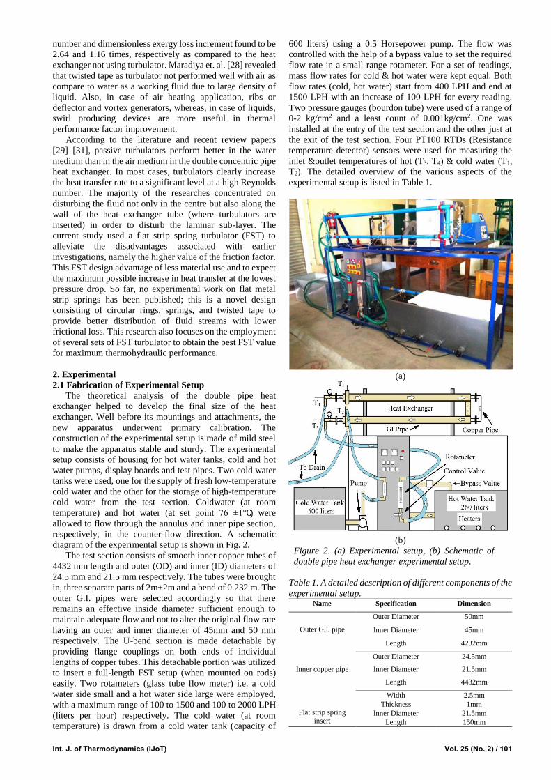
2. Experimental
2.1 Fabrication of Experimental Setup
The theoretical analysis of the double pipe heat
exchanger helped to develop the final size of the heat
exchanger. Well before its mountings and attachments, the
new apparatus underwent primary calibration. The
construction of the experimental setup is made of mild steel
to make the apparatus stable and sturdy. The experimental
setup consists of housing for hot water tanks, cold and hot
water pumps, display boards and test pipes. Two cold water
tanks were used, one for the supply of fresh low-temperature
cold water and the other for the storage of high-temperature
cold water from the test section. Coldwater (at room
temperature) and hot water (at set point 76 ±1℃) were
allowed to flow through the annulus and inner pipe section,
respectively, in the counter-flow direction. A schematic
diagram of the experimental setup is shown in Fig. 2.
The test section consists of smooth inner copper tubes of
4432 mm length and outer (OD) and inner (ID) diameters of
24.5 mm and 21.5 mm respectively. The tubes were brought
in, three separate parts of 2m+2m and a bend of 0.232 m. The
outer G.I. pipes were selected accordingly so that there
remains an effective inside diameter sufficient enough to
maintain adequate flow and not to alter the original flow rate
having an outer and inner diameter of 45mm and 50 mm
respectively. The U-bend section is made detachable by
providing flange couplings on both ends of individual
lengths of copper tubes. This detachable portion was utilized
to insert a full-length FST setup (when mounted on rods)
easily. Two rotameters (glass tube flow meter) i.e. a cold
water side small and a hot water side large were employed,
with a maximum range of 100 to 1500 and 100 to 2000 LPH
(liters per hour) respectively. The cold water (at room
temperature) is drawn from a cold water tank (capacity of
600 liters) using a 0.5 Horsepower pump. The flow was
controlled with the help of a bypass value to set the required
flow rate in a small range rotameter. For a set of readings,
mass flow rates for cold & hot water were kept equal. Both
flow rates (cold, hot water) start from 400 LPH and end at
1500 LPH with an increase of 100 LPH for every reading.
Two pressure gauges (bourdon tube) were used of a range of
0-2 kg/cm2 and a least count of 0.001kg/cm2. One was
installed at the entry of the test section and the other just at
the exit of the test section. Four PT100 RTDs (Resistance
temperature detector) sensors were used for measuring the
inlet &outlet temperatures of hot (T3, T4) & cold water (T1,
T2). The detailed overview of the various aspects of the
experimental setup is listed in Table 1.
(a)
(b)
Figure 2. (a) Experimental setup, (b) Schematic of
double pipe heat exchanger experimental setup.
Table 1. A detailed description of different components of the
experimental setup. Name Specification Dimension
Outer G.I. pipe
Outer Diameter 50mm
Inner Diameter 45mm
Length 4232mm
Inner copper pipe
Outer Diameter 24.5mm
Inner Diameter 21.5mm
Length 4432mm
Flat strip spring
insert
Width 2.5mm
Thickness 1mm
Inner Diameter 21.5mm
Length 150mm

102 / Vol. 25 (No. 2) Int. Centre for Applied Thermodynamics (ICAT)
2.2 Accretion Techniques Utilized in Current Work
An overview investigation of different types of
turbulence generation devices has been conducted in a wide
range of Reynolds numbers. A spring turbulator perform
better for turbulent flow with conical shape and different
arrangements of converging, diverging and converging and
diverging. In turbulent flow, conical converging spring
shows lower friction factor and disturbance to boundary
layer as compared to diverging spring in circular cross-
section pipe within range of 10,000 to 34,000 [10]. In
contrast, the performance of helical spring tubulators inside
the inner pipe of a double pipe heat exchanger. Nusselt
number increases as the pitch of helical spring increases at
higher Reynold number [27]. The perforated solid metal ring
was tested with different open area ratio (0 to 0.0833) in the
range of Reynolds numbers 6000 to 12,000 Additionally, it
was noted that the friction factor decreased as the
perforations increased in the metal ring inserts when liquids
used as working fluid [15]. The combined performance of
metal rings and twisted tape turbulaors with different pitch
ratios (1 and 2) and twist ratios (2,3 and 4) was investigated
and found higher heat transfer enhancement but at a cost of
higher friction factors in the ranges of Reynold number from
6000 to 24000 [24]. A triple twisted tape utilised as swirl
flow generator inserts with four type of twist ratio (1.92 to
6.97) under the condition of constant heat flux. As the twist
ratio decreases, values of different parameter (Nu, friction
factor and efficiency) increases within the range Reynold
number of 7200 to 50,200 [32]. The performance of helical
spring tubulators was not as good as that of conical spring
tabulators. The perforated metal ring turbulators have close
to half the Nusselt number values of conical spring
turbulators. Single twisted tape turbulators are found to
perform better in flow with a low Reynolds number as
opposed to one with a higher Reynolds number because they
block the flow, which results in an increased friction factor.
Compared to the other swirl inserts, Nusselt number
performance of metal rings and twisted tape turbulaors was
found to be the best but with higher friction factor value.
Hence thermohydraulic performance of twisted tape not
better at higher values of Reynold number of turbulent flow.
Therefore, it may be estimated that, for double pipe heat
exchanger, flat plate turbulator perform well in the turbulent
flow because its having all essential benefits of conical
spring, metal rings and twisted tape.
In current work, a double pipe heat exchanger is used as
a standard configuration. The passive heat transfer
enhancement technique was predictable in order to increase
the efficiency of the current heat exchanger without affecting
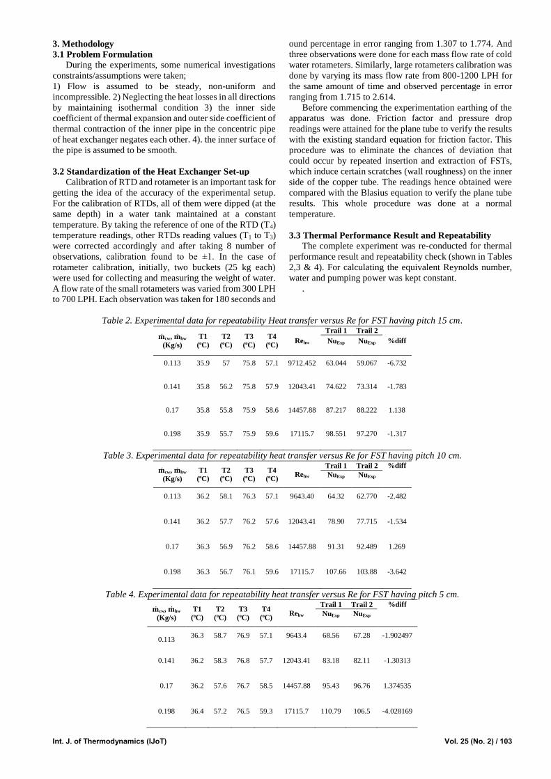
the surface area necessary for heat transfer. Flat strip spring
turbulators as shown Fig. 3 were used as swirl generators.
Diameter of FST was 21.4mm which was only adequately
large enough to get fit inside the inner copper tube so that,
once inside and after initiation of hot water flow any undue
movement or shivering could be prohibited. FST was
fabricated in Mohits springs Pvt. Ltd. located in Meerut Utter
Pradesh who are specialized in the manufacturing of springs.
The FSTs were visualized mounted simultaneously on thin
high carbon steel at certain specific gaps known as Pitch.
Rods of varying pitches were prepared to insert them in inner
copper tubes. The idea behind this concept was to create an
obstruction to hot water flow which consequently enhances
the turbulence and swirl flow thereby augmenting the rate of
heat transfer.
FSTs were mounted by brazing on high carbon steel rod
to prevent any flickering when inserted in inner copper tubes
and with hot water flow commenced. Several pitches were
decided in advance depending upon which the brazing was
done. The U bend section was detached by opening the
flange couplings, and hence, the FST of P = 15cm was
inserted followed by 10cm and 5cm pitches.
Figure 3. Flat spring tabulator (FST) mounted on rod having (a) 15 cm pitch, (b) 10cm Pitch, (c) 5cm Pitch.
a
b
c
P=15 cm
P=10 cm
P=5 cm
FST
Int. J. of Thermodynamics (IJoT) Vol. 25 (No. 2) / 103
3. Methodology
3.1 Problem Formulation
During the experiments, some numerical investigations
constraints/assumptions were taken;
1) Flow is assumed to be steady, non-uniform and
incompressible. 2) Neglecting the heat losses in all directions
by maintaining isothermal condition 3) the inner side
coefficient of thermal expansion and outer side coefficient of
thermal contraction of the inner pipe in the concentric pipe
of heat exchanger negates each other. 4). the inner surface of
the pipe is assumed to be smooth.
3.2 Standardization of the Heat Exchanger Set-up
Calibration of RTD and rotameter is an important task for
getting the idea of the accuracy of the experimental setup.
For the calibration of RTDs, all of them were dipped (at the
same depth) in a water tank maintained at a constant
temperature. By taking the reference of one of the RTD (T4)
temperature readings, other RTDs reading values (T1 to T3)
were corrected accordingly and after taking 8 number of
observations, calibration found to be ±1. In the case of
rotameter calibration, initially, two buckets (25 kg each)
were used for collecting and measuring the weight of water.
A flow rate of the small rotameters was varied from 300 LPH
to 700 LPH. Each observation was taken for 180 seconds and
ound percentage in error ranging from 1.307 to 1.774. And
three observations were done for each mass flow rate of cold
water rotameters. Similarly, large rotameters calibration was
done by varying its mass flow rate from 800-1200 LPH for
the same amount of time and observed percentage in error
ranging from 1.715 to 2.614.
Before commencing the experimentation earthing of the
apparatus was done. Friction factor and pressure drop
readings were attained for the plane tube to verify the results
with the existing standard equation for friction factor. This
procedure was to eliminate the chances of deviation that
could occur by repeated insertion and extraction of FSTs,
which induce certain scratches (wall roughness) on the inner
side of the copper tube. The readings hence obtained were
compared with the Blasius equation to verify the plane tube
results. This whole procedure was done at a normal
temperature.
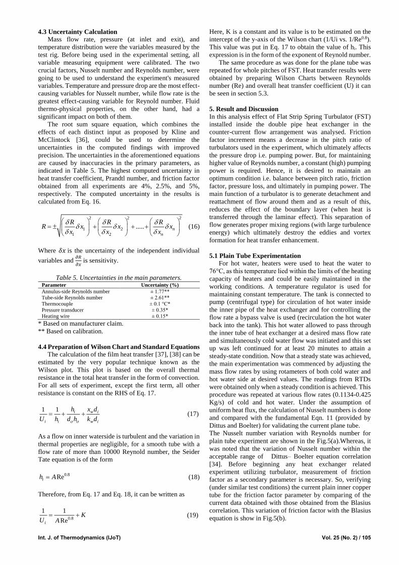
3.3 Thermal Performance Result and Repeatability
The complete experiment was re-conducted for thermal
performance result and repeatability check (shown in Tables
2,3 & 4). For calculating the equivalent Reynolds number,
water and pumping power was kept constant.
.
Table 2. Experimental data for repeatability Heat transfer versus Re for FST having pitch 15 cm.
��cw, ��hw
(Kg/s)
T1
(oC)
T2
(oC)
T3
(oC)
T4
(oC) Rehw
Trail 1 Trail 2
%diff NuExp NuExp
0.113 35.9 57 75.8 57.1 9712.452 63.044 59.067 -6.732
0.141 35.8 56.2 75.8 57.9 12043.41 74.622 73.314 -1.783
0.17 35.8 55.8 75.9 58.6 14457.88 87.217 88.222 1.138
0.198 35.9 55.7 75.9 59.6 17115.7 98.551 97.270 -1.317
Table 3. Experimental data for repeatability heat transfer versus Re for FST having pitch 10 cm.
��cw, ��hw
(Kg/s)
T1
(oC)
T2
(oC)
T3
(oC)
T4
(oC) Rehw
Trail 1 Trail 2 %diff
NuExp NuExp
0.113 36.2 58.1 76.3 57.1 9643.40 64.32 62.770 -2.482
0.141 36.2 57.7 76.2 57.6 12043.41 78.90 77.715 -1.534
0.17 36.3 56.9 76.2 58.6 14457.88 91.31 92.489 1.269
0.198 36.3 56.7 76.1 59.6 17115.7 107.66 103.88 -3.642
Table 4. Experimental data for repeatability heat transfer versus Re for FST having pitch 5 cm.
��cw, ��hw
(Kg/s)
T1
(oC)
T2
(oC)
T3
(oC)
T4
(oC) Rehw
Trail 1 Trail 2 %diff
NuExp NuExp
0.113 36.3 58.7 76.9 57.1 9643.4 68.56 67.28 -1.902497
0.141 36.2 58.3 76.8 57.7 12043.41 83.18 82.11 -1.30313
0.17 36.2 57.6 76.7 58.5 14457.88 95.43 96.76 1.374535
0.198 36.4 57.2 76.5 59.3 17115.7 110.79 106.5 -4.028169

104 / Vol. 25 (No. 2) Int. Centre for Applied Thermodynamics (ICAT)
3.4 Factors Affected by Varying Pitch Between
Consecutive FST
Pitch over here refers to the distance between two
consecutive FST mounted on a brass rod. Apart from the
enhancement in heat transfer and thermal performance
installation of FST leads in the increase in pumping power
requirement. The minimum pitch of the turbulators allows
more turbulators on the given length which leads to more
friction to the flow, more back pressure generates and all
these leads to more pumping power requirement. This
arrangement also separates the boundary layer commencing
earlier as the pitch between two consecutive turbulators
going to be decrease. Fig. 4 represents the effect of FST over
variation in pitch ratio
Figure 4. Repercussion by varying pitch value of FST.
4. Data Reduction
Water is taken as a working fluid for all the experiments
conducted with a parametric study of the effects of variation
in mass flow rate for turbulent case. Installation of FST with
varying pitch ratio influences the flow conditions including
an adverse effect i.e. increment of friction factor. Different
equations required for the basis of such experiments are
summed as follows:
Quantity of heat flow [33] for hot and cold water loops can
be calculated from Eqn. (1) and (2)
( )c c pc ce ciQ m C T T (1)
(T )h h ph hi heQ m c T (2)
The arithmetic average of heat exchange from the hotter
and colder fluid streams is
.2
h cave
Q QQ
(3)
The overall heat transfer coefficient can be calculated as
.aveQU
A lmtd
(4)
ln ( ) / ( )
hi ce he ci
hi ce he ci
T T T Tlmtd
T T T T
(5)
Where A is the circumferential area of the inner pipe.
4.1 Standard Equation
The non-dimensional numbers; Nu, Re and Pr calculated
from Eqn:
hDNu
k (6)
ReVD
(7)
Prpc
k
(8)
2
2
P
l V
d
(9)
c
mV
A (10)
4.2 Heat Transfer and Friction Factor Calculation
For the heat transfer calculations, some standard
equations from the literatures were used for the experimental
flow conditions.
DittusBoelter Equation [34]
0.8 0.30.023Re PrNu (11)
Friction factor for the different flow arrangements were
calculated from Blasius Equation and Darcy-weisbach
equations [33]
0.25
0.3164
Re (12)
2
2
P
L V
D
(13)
Thermal performance factor calculation at constant pumping
power
3 3Re RePT T
(14)
The thermal performance factor and performance
evaluation criteria is the key parameter in designing effective
heat exchanging devices [35]. The thermal performance
factor (η) is the ratio of the Nusselt number ratio (𝑁𝑢T/𝑁𝑢PT)
to the friction factor ratio (λT/λPT) considering constant
pumping powerand can be represented as
1/3
T PT
T PT
Nu Nu
(15)
Int. J. of Thermodynamics (IJoT) Vol. 25 (No. 2) / 105
4.3 Uncertainty Calculation
Mass flow rate, pressure (at inlet and exit), and
temperature distribution were the variables measured by the
test rig. Before being used in the experimental setting, all
variable measuring equipment were calibrated. The two
crucial factors, Nusselt number and Reynolds number, were
going to be used to understand the experiment's measured
variables. Temperature and pressure drop are the most effect-
causing variables for Nusselt number, while flow rate is the
greatest effect-causing variable for Reynold number. Fluid
thermo-physical properties, on the other hand, had a
significant impact on both of them.
The root sum square equation, which combines the
effects of each distinct input as proposed by Kline and
McClintock [36], could be used to determine the
uncertainties in the computed findings with improved
precision. The uncertainties in the aforementioned equations
are caused by inaccuracies in the primary parameters, as
indicated in Table 5. The highest computed uncertainty in
heat transfer coefficient, Prandtl number, and friction factor
obtained from all experiments are 4%, 2.5%, and 5%,
respectively. The computed uncertainty in the results is
calculated from Eq. 16.
22 2
1 2
1 2
..... n
n
R R RR x x x
x x x
(16)
Where 𝛿𝑥 is the uncertainty of the independent individual
variables and 𝜕𝑅
𝜕𝑥 is sensitivity.
Table 5. Uncertainties in the main parameters. Parameter Uncertainty (%)
Annulus-side Reynolds number ± 1.77** Tube-side Reynolds number ± 2.61**
Thermocouple ± 0.1 °C*
Pressure transducer ± 0.35*
Heating wire ± 0.15*
* Based on manufacturer claim.
** Based on calibration.
4.4 Preparation of Wilson Chart and Standard Equations
The calculation of the film heat transfer [37], [38] can be
estimated by the very popular technique known as the
Wilson plot. This plot is based on the overall thermal
resistance in the total heat transfer in the form of convection.
For all sets of experiment, except the first term, all other
resistance is constant on the RHS of Eq. 17.
1 1 i w i
i i w i
h x d
U h d h k d
(17)
As a flow on inner waterside is turbulent and the variation in
thermal properties are negligible, for a smooth tube with a
flow rate of more than 10000 Reynold number, the Seider
Tate equation is of the form
0.8Reih A (18)
Therefore, from Eq. 17 and Eq. 18, it can be written as
0.8
1 1
Rei
KU A
(19)
Here, K is a constant and its value is to be estimated on the
intercept of the y-axis of the Wilson chart (1/Ui vs. 1/Re0.8).
This value was put in Eq. 17 to obtain the value of hi. This
expression is in the form of the exponent of Reynold number.
The same procedure as was done for the plane tube was
repeated for whole pitches of FST. Heat transfer results were
obtained by preparing Wilson Charts between Reynolds
number (Re) and overall heat transfer coefficient (U) it can
be seen in section 5.3.
5. Result and Discussion
In this analysis effect of Flat Strip Spring Turbulator (FST)
installed inside the double pipe heat exchanger in the
counter-current flow arrangement was analysed. Friction
factor increment means a decrease in the pitch ratio of
turbulators used in the experiment, which ultimately affects
the pressure drop i.e. pumping power. But, for maintaining
higher value of Reynolds number, a constant (high) pumping
power is required. Hence, it is desired to maintain an
optimum condition i.e. balance between pitch ratio, friction
factor, pressure loss, and ultimately in pumping power. The
main function of a turbulator is to generate detachment and
reattachment of flow around them and as a result of this,
reduces the effect of the boundary layer (when heat is
transferred through the laminar effect). This separation of
flow generates proper mixing regions (with large turbulence
energy) which ultimately destroy the eddies and vortex
formation for heat transfer enhancement.
5.1 Plain Tube Experimentation
For hot water, heaters were used to heat the water to
76°C, as this temperature lied within the limits of the heating
capacity of heaters and could be easily maintained in the
working conditions. A temperature regulator is used for
maintaining constant temperature. The tank is connected to
pump (centrifugal type) for circulation of hot water inside
the inner pipe of the heat exchanger and for controlling the
flow rate a bypass valve is used (recirculation the hot water
back into the tank). This hot water allowed to pass through
the inner tube of heat exchanger at a desired mass flow rate
and simultaneously cold water flow was initiated and this set
up was left continued for at least 20 minutes to attain a
steady-state condition. Now that a steady state was achieved,
the main experimentation was commenced by adjusting the
mass flow rates by using rotameters of both cold water and
hot water side at desired values. The readings from RTDs
were obtained only when a steady condition is achieved. This
procedure was repeated at various flow rates (0.1134-0.425
Kg/s) of cold and hot water. Under the assumption of
uniform heat flux, the calculation of Nusselt numbers is done
and compared with the fundamental Eqn. 11 (provided by
Dittus and Boelter) for validating the current plane tube.
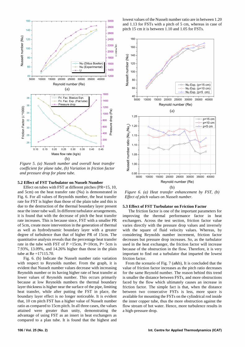
The Nusselt number variation with Reynolds number for
plain tube experiment are shown in the Fig.5(a).Whereas, it
was noted that the variation of Nusselt number within the
acceptable range of Dittus– Boelter equation correlation
[34]. Before beginning any heat exchanger related
experiment utilizing turbulator, measurement of friction
factor as a secondary parameter is necessary. So, verifying
(under similar test conditions) the current plain inner copper
tube for the friction factor parameter by comparing of the
current data obtained with those obtained from the Blasius
correlation. This variation of friction factor with the Blasius
equation is show in Fig.5(b).
106 / Vol. 25 (No. 2) Int. Centre for Applied Thermodynamics (ICAT)
(a)
(b)
Figure 5. (a) Nusselt number and overall heat transfer
coefficient for plane tube, (b) Variation in friction factor
and pressure drop for plane tube.
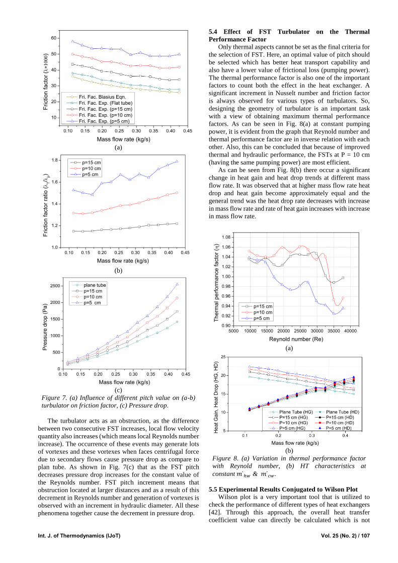
5.2 Effect of FST Turbulator on Nusselt Number
Effect on tubes with FST at different pitches (PR=15, 10,
and 5cm) on the heat transfer rate (Nu) is demonstrated in
Fig. 6. For all values of Reynolds number, the heat transfer
rate for FST is higher than those of the plain tube and this is
due to the destruction of the thermal boundary layer present
near the inner tube wall. In different turbulator arrangements,
it is found that with the decrease of pitch the heat transfer
rate increases. This is because since, FST with a smaller PR
of 5cm, create more intervention in the generation of thermal
as well as hydrodynamic boundary layer with a greater
degree of turbulence than that of higher PR of 15cm. The
quantitative analysis reveals that the percentage heat transfer
rate in the tube with FST of P =15cm, P=10cm, P= 5cm is
7.93%, 13.09%, and 14.26% higher than those in the plain
tube at Re =17115.70.
Fig. 6. (b) Indicate the Nusselt number ratio variation
with respect to Reynolds number. From the graph, it is
evident that Nusselt number values decrease with increasing
Reynolds number or its having higher rate of heat transfer at
lower values of Reynolds number. This occurs primarily
because at low Reynolds numbers the thermal boundary
layer thickness is higher near the surface of the pipe, limiting
heat transfer, while after putting the FST in place, the
boundary layer effect is no longer noticeable. It is evident
that, 10 cm pitch FST has a higher value of Nusselt number
ratio as compared to 15cm pitch. In all three cases, the values
attained were greater than unity, demonstrating the
advantage of using FST as an insert in heat exchangers as
compared to a plan tube. It is found that the highest and
lowest values of the Nusselt number ratio are in between 1.20
and 1.13 for FSTs with a pitch of 5 cm, whereas in case of
pitch 15 cm it is between 1.10 and 1.05 for FSTs.
(a)
(b)
Figure 6. (a) Heat transfer enhancement by FST, (b)
Effect of pitch values on Nusselt number.
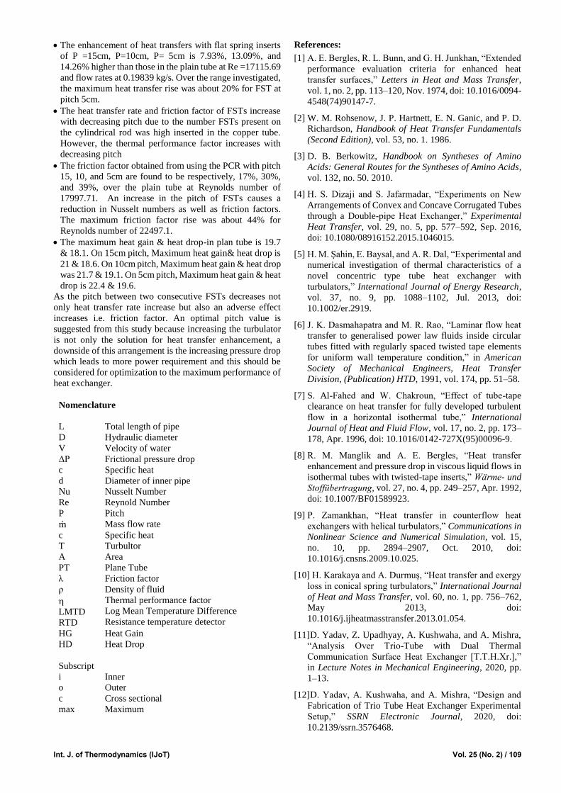
5.3 Effect of FST Turbulator on Friction Factor
The friction factor is one of the important parameters for
improving the thermal performance factor in heat
exchangers. Across the test section, friction factor value
varies directly with the pressure drop values and inversely
with the square of fluid velocity values. Whereas, by
considering Reynolds number increment, friction factor
decreases but pressure drop increases. So, as the turbulator
used in the heat exchanger, the friction factor will increase
because of the obstruction in the flow. Therefore, it is very
important to find out a turbulator that imparted the lowest
friction factor.
From the scenario of Fig. 7 (a&b), It is concluded that the
value of friction factor increases as the pitch ratio decreases
for the same Reynold number. The reason behind this trend
is smaller the distance between FSTs, and more obstructions
faced by the flow which ultimately causes an increase in
friction factor. The simple fact is that, when the distance
between two consecutive FSTs is less, more space is
available for mounting the FSTs on the cylindrical rod inside
the inner copper tube, thus the more obstruction against the
flow stream of hot water. Hence, more turbulence results in
a high-pressure drop.
Int. J. of Thermodynamics (IJoT) Vol. 25 (No. 2) / 107
(a)
(b)
(c)
Figure 7. (a) Influence of different pitch value on (a-b)
turbulator on friction factor, (c) Pressure drop.
The turbulator acts as an obstruction, as the difference
between two consecutive FST increases, local flow velocity
quantity also increases (which means local Reynolds number
increase). The occurrence of these events may generate lots
of vortexes and these vortexes when faces centrifugal force
due to secondary flows cause pressure drop as compare to
plan tube. As shown in Fig. 7(c) that as the FST pitch
decreases pressure drop increases for the constant value of
the Reynolds number. FST pitch increment means that
obstruction located at larger distances and as a result of this
decrement in Reynolds number and generation of vortexes is
observed with an increment in hydraulic diameter. All these
phenomena together cause the decrement in pressure drop.
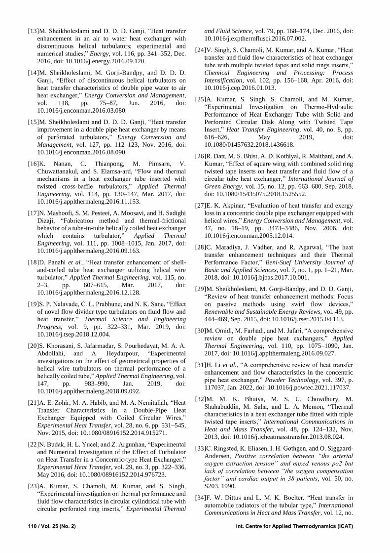
5.4 Effect of FST Turbulator on the Thermal
Performance Factor
Only thermal aspects cannot be set as the final criteria for
the selection of FST. Here, an optimal value of pitch should
be selected which has better heat transport capability and
also have a lower value of frictional loss (pumping power).
The thermal performance factor is also one of the important
factors to count both the effect in the heat exchanger. A
significant increment in Nusselt number and friction factor
is always observed for various types of turbulators. So,
designing the geometry of turbulator is an important task
with a view of obtaining maximum thermal performance
factors. As can be seen in Fig. 8(a) at constant pumping
power, it is evident from the graph that Reynold number and
thermal performance factor are in inverse relation with each
other. Also, this can be concluded that because of improved
thermal and hydraulic performance, the FSTs at P = 10 cm
(having the same pumping power) are most efficient.
As can be seen from Fig. 8(b) there occur a significant
change in heat gain and heat drop trends at different mass
flow rate. It was observed that at higher mass flow rate heat
drop and heat gain become approximately equal and the
general trend was the heat drop rate decreases with increase
in mass flow rate and rate of heat gain increases with increase
in mass flow rate.
(a)
(b)
Figure 8. (a) Variation in thermal performance factor
with Reynold number, (b) HT characteristics at
constant 𝑚 ℎ𝑤 & 𝑚 𝑐𝑤.
5.5 Experimental Results Conjugated to Wilson Plot
Wilson plot is a very important tool that is utilized to
check the performance of different types of heat exchangers
[42]. Through this approach, the overall heat transfer
coefficient value can directly be calculated which is not

108 / Vol. 25 (No. 2) Int. Centre for Applied Thermodynamics (ICAT)
easier indirect calculation from the experimental results due
to inaccessible surface temperature values. The
experimental results obtained from the experiment on double
pipe heat exchanger experimental setup with flat strip spring
Turbulator insert were analyzed with Wilson chart (having
variation between overall heat transfer coefficient (U) and
Reynold number). The results were plotted between
10000/Ui and 10000/Re0.8, which is presented in Fig. 9. The
variation of 10000/U follows the linear trend as of the
Wilson plot. However, the experimental values are slightly
lesser than that of the straight-line of the Wilson plot.
Figure 9. Visualization of overall heat transfer coefficient
with Wilson plot.
5.6 Comparison of Performance Parameters of Different
Turbulators
In the Table 6, the term “Nusselt number ratio”
(Numax/Nup) is the ratio of maximum Nusselt number after
augmentation to Nuseelt number of the plane tube, and
“friction factor ratio” (λmax/λp) is the ratio of maximum
friction factor after augmentation to friction factor of the plan
tube. In current work, the Nusselt number ratio comes only
1.2 at the expense of friction factor ratio of 1.44 in a range of
Reynolds no. (9000–38,000). Whereas, maximum increment
in Nusselt number ratio is claimed by Singh et. al. [24] i.e.
4.6 but at a higher value of friction factor ratio of 36.07 in a
range of Reynolds no. (6300– 22500) and as it is well known
that, with the increment in Reynolds number friction factor
also increases which further increases required pumping
power and makes the heat exchange process uneconomical.
So, in the present study even at a higher value of Reynolds
number friction factor obtaining well-accepted range as
compared to the previous studies.
6. Conclusion
The present experimental study presents the potential
application of FST to enhance the heat transport performance
of a concentric double tube heat exchanger. The
experimental objectives investigation was successfully
carried out with the insertion of FST at various pitch values
at varying cold and hot water flow rate of 500 to 1500 LPH
and 500 to 2000 LPH, respectively. All the time, the
experiment was in turbulent flow with Reynold number
ranging from 9000 to 38000, which significantly influences
the different parameter of heat exchanger (Nusselt number,
friction, and thermal performance factor). The most
remarkable conclusions drawn after conducting this
experiment are:
Table 6. Comparison of performance parameters of different turbulators.
Author Turbulator
used
Parameters Reynolds
Number
Nusselt
Number ratio
Friction
factor ratio
Image
Karakaya et. al. [10]
Conical spring turbulators
different cone angle (30°,
45°, 60°)
10,000 to
34,000
Numax≈ 3.33 Nup
λmax≈ 1.72 λp
Sheikholeslami et. al. [15]
typical and perforated
circular
turbulators
open area ratio (0 to 0.0625),
pitch ratio
(1.83 to 5.83)
6000
to12,000
Numax≈ 2.12 Nup
λmax≈ 11.40 λp
Singh et. al. [24]
solid ring
tubular (SRT) with Number of
twisted tapes
(TT): 1, 2, 3, 4
Pitch ratios (1
and 2_, twist
ratios ( 2, 3, and 4)
6300 to
22500
Numax ≈ 4.6 Nup
λmax≈36.07 λp
Akpinar[27] helical (spring
shaped)
6500 to
13,000
Numax ≈ 2.64 Nup
λmax≈ 2.74 λp
Bhuiya et al. [39] Triple twisted
tape
Twist ratio-
1.92–6.79
7200 to
50,200
Numax ≈ 3.85 Nup
λmax≈ 4.2 λp
Present study Flat strip spring
turbulator
At different pitch ratio of 5,
10 &15
9000 to 38000
Numax ≈ 1.2 Nup
λmax≈ 1.44 λp
Int. J. of Thermodynamics (IJoT) Vol. 25 (No. 2) / 109
The enhancement of heat transfers with flat spring inserts
of P =15cm, P=10cm, P= 5cm is 7.93%, 13.09%, and
14.26% higher than those in the plain tube at Re =17115.69
and flow rates at 0.19839 kg/s. Over the range investigated,
the maximum heat transfer rise was about 20% for FST at
pitch 5cm.
The heat transfer rate and friction factor of FSTs increase
with decreasing pitch due to the number FSTs present on
the cylindrical rod was high inserted in the copper tube.
However, the thermal performance factor increases with
decreasing pitch
The friction factor obtained from using the PCR with pitch
15, 10, and 5cm are found to be respectively, 17%, 30%,
and 39%, over the plain tube at Reynolds number of
17997.71. An increase in the pitch of FSTs causes a
reduction in Nusselt numbers as well as friction factors.
The maximum friction factor rise was about 44% for
Reynolds number of 22497.1.
The maximum heat gain & heat drop-in plan tube is 19.7
& 18.1. On 15cm pitch, Maximum heat gain& heat drop is
21 & 18.6. On 10cm pitch, Maximum heat gain & heat drop
was 21.7 & 19.1. On 5cm pitch, Maximum heat gain & heat
drop is 22.4 & 19.6.
As the pitch between two consecutive FSTs decreases not
only heat transfer rate increase but also an adverse effect
increases i.e. friction factor. An optimal pitch value is
suggested from this study because increasing the turbulator
is not only the solution for heat transfer enhancement, a
downside of this arrangement is the increasing pressure drop
which leads to more power requirement and this should be
considered for optimization to the maximum performance of
heat exchanger.
Nomenclature
L Total length of pipe
D Hydraulic diameter
V Velocity of water
ΔP Frictional pressure drop
c Specific heat
d Diameter of inner pipe
Nu Nusselt Number
Re Reynold Number
P Pitch
m Mass flow rate
c Specific heat
T Turbultor
A Area
PT Plane Tube
λ Friction factor
ρ Density of fluid
LMTD
RTD
Thermal performance factor
Log Mean Temperature Difference
Resistance temperature detector
HG Heat Gain
HD Heat Drop
Subscript
i Inner
o Outer
c Cross sectional
max Maximum
References:
[1] A. E. Bergles, R. L. Bunn, and G. H. Junkhan, “Extended
performance evaluation criteria for enhanced heat
transfer surfaces,” Letters in Heat and Mass Transfer,
vol. 1, no. 2, pp. 113–120, Nov. 1974, doi: 10.1016/0094-
4548(74)90147-7.
[2] W. M. Rohsenow, J. P. Hartnett, E. N. Ganic, and P. D.
Richardson, Handbook of Heat Transfer Fundamentals
(Second Edition), vol. 53, no. 1. 1986.
[3] D. B. Berkowitz, Handbook on Syntheses of Amino
Acids: General Routes for the Syntheses of Amino Acids,
vol. 132, no. 50. 2010.
[4] H. S. Dizaji and S. Jafarmadar, “Experiments on New
Arrangements of Convex and Concave Corrugated Tubes
through a Double-pipe Heat Exchanger,” Experimental
Heat Transfer, vol. 29, no. 5, pp. 577–592, Sep. 2016,
doi: 10.1080/08916152.2015.1046015.
[5] H. M. Şahin, E. Baysal, and A. R. Dal, “Experimental and
numerical investigation of thermal characteristics of a
novel concentric type tube heat exchanger with
turbulators,” International Journal of Energy Research,
vol. 37, no. 9, pp. 1088–1102, Jul. 2013, doi:
10.1002/er.2919.
[6] J. K. Dasmahapatra and M. R. Rao, “Laminar flow heat
transfer to generalised power law fluids inside circular
tubes fitted with regularly spaced twisted tape elements
for uniform wall temperature condition,” in American
Society of Mechanical Engineers, Heat Transfer
Division, (Publication) HTD, 1991, vol. 174, pp. 51–58.
[7] S. Al-Fahed and W. Chakroun, “Effect of tube-tape
clearance on heat transfer for fully developed turbulent
flow in a horizontal isothermal tube,” International
Journal of Heat and Fluid Flow, vol. 17, no. 2, pp. 173–
178, Apr. 1996, doi: 10.1016/0142-727X(95)00096-9.
[8] R. M. Manglik and A. E. Bergles, “Heat transfer
enhancement and pressure drop in viscous liquid flows in
isothermal tubes with twisted-tape inserts,” Wärme- und
Stoffübertragung, vol. 27, no. 4, pp. 249–257, Apr. 1992,
doi: 10.1007/BF01589923.
[9] P. Zamankhan, “Heat transfer in counterflow heat
exchangers with helical turbulators,” Communications in
Nonlinear Science and Numerical Simulation, vol. 15,
no. 10, pp. 2894–2907, Oct. 2010, doi:
10.1016/j.cnsns.2009.10.025.
[10] H. Karakaya and A. Durmuş, “Heat transfer and exergy
loss in conical spring turbulators,” International Journal
of Heat and Mass Transfer, vol. 60, no. 1, pp. 756–762,
May 2013, doi:
10.1016/j.ijheatmasstransfer.2013.01.054.
[11] D. Yadav, Z. Upadhyay, A. Kushwaha, and A. Mishra,
“Analysis Over Trio-Tube with Dual Thermal
Communication Surface Heat Exchanger [T.T.H.Xr.],”
in Lecture Notes in Mechanical Engineering, 2020, pp.
1–13.
[12] D. Yadav, A. Kushwaha, and A. Mishra, “Design and
Fabrication of Trio Tube Heat Exchanger Experimental
Setup,” SSRN Electronic Journal, 2020, doi:
10.2139/ssrn.3576468.
110 / Vol. 25 (No. 2) Int. Centre for Applied Thermodynamics (ICAT)
[13] M. Sheikholeslami and D. D. D. Ganji, “Heat transfer
enhancement in an air to water heat exchanger with
discontinuous helical turbulators; experimental and
numerical studies,” Energy, vol. 116, pp. 341–352, Dec.
2016, doi: 10.1016/j.energy.2016.09.120.
[14] M. Sheikholeslami, M. Gorji-Bandpy, and D. D. D.
Ganji, “Effect of discontinuous helical turbulators on
heat transfer characteristics of double pipe water to air
heat exchanger,” Energy Conversion and Management,
vol. 118, pp. 75–87, Jun. 2016, doi:
10.1016/j.enconman.2016.03.080.
[15] M. Sheikholeslami and D. D. D. Ganji, “Heat transfer
improvement in a double pipe heat exchanger by means
of perforated turbulators,” Energy Conversion and
Management, vol. 127, pp. 112–123, Nov. 2016, doi:
10.1016/j.enconman.2016.08.090.
[16] K. Nanan, C. Thianpong, M. Pimsarn, V.
Chuwattanakul, and S. Eiamsa-ard, “Flow and thermal
mechanisms in a heat exchanger tube inserted with
twisted cross-baffle turbulators,” Applied Thermal
Engineering, vol. 114, pp. 130–147, Mar. 2017, doi:
10.1016/j.applthermaleng.2016.11.153.
[17] N. Mashoofi, S. M. Pesteei, A. Moosavi, and H. Sadighi
Dizaji, “Fabrication method and thermal-frictional
behavior of a tube-in-tube helically coiled heat exchanger
which contains turbulator,” Applied Thermal
Engineering, vol. 111, pp. 1008–1015, Jan. 2017, doi:
10.1016/j.applthermaleng.2016.09.163.
[18] D. Panahi et al., “Heat transfer enhancement of shell-
and-coiled tube heat exchanger utilizing helical wire
turbulator,” Applied Thermal Engineering, vol. 115, no.
2–3, pp. 607–615, Mar. 2017, doi:
10.1016/j.applthermaleng.2016.12.128.
[19] S. P. Nalavade, C. L. Prabhune, and N. K. Sane, “Effect
of novel flow divider type turbulators on fluid flow and
heat transfer,” Thermal Science and Engineering
Progress, vol. 9, pp. 322–331, Mar. 2019, doi:
10.1016/j.tsep.2018.12.004.
[20] S. Khorasani, S. Jafarmadar, S. Pourhedayat, M. A. A.
Abdollahi, and A. Heydarpour, “Experimental
investigations on the effect of geometrical properties of
helical wire turbulators on thermal performance of a
helically coiled tube,” Applied Thermal Engineering, vol.
147, pp. 983–990, Jan. 2019, doi:
10.1016/j.applthermaleng.2018.09.092.
[21] A. E. Zohir, M. A. Habib, and M. A. Nemitallah, “Heat
Transfer Characteristics in a Double-Pipe Heat
Exchanger Equipped with Coiled Circular Wires,”
Experimental Heat Transfer, vol. 28, no. 6, pp. 531–545,
Nov. 2015, doi: 10.1080/08916152.2014.915271.
[22] N. Budak, H. L. Yucel, and Z. Argunhan, “Experimental
and Numerical Investigation of the Effect of Turbulator
on Heat Transfer in a Concentric-type Heat Exchanger,”
Experimental Heat Transfer, vol. 29, no. 3, pp. 322–336,
May 2016, doi: 10.1080/08916152.2014.976723.
[23] A. Kumar, S. Chamoli, M. Kumar, and S. Singh,
“Experimental investigation on thermal performance and
fluid flow characteristics in circular cylindrical tube with
circular perforated ring inserts,” Experimental Thermal
and Fluid Science, vol. 79, pp. 168–174, Dec. 2016, doi:
10.1016/j.expthermflusci.2016.07.002.
[24] V. Singh, S. Chamoli, M. Kumar, and A. Kumar, “Heat
transfer and fluid flow characteristics of heat exchanger
tube with multiple twisted tapes and solid rings inserts,”
Chemical Engineering and Processing: Process
Intensification, vol. 102, pp. 156–168, Apr. 2016, doi:
10.1016/j.cep.2016.01.013.
[25] A. Kumar, S. Singh, S. Chamoli, and M. Kumar,
“Experimental Investigation on Thermo-Hydraulic
Performance of Heat Exchanger Tube with Solid and
Perforated Circular Disk Along with Twisted Tape
Insert,” Heat Transfer Engineering, vol. 40, no. 8, pp.
616–626, May 2019, doi:
10.1080/01457632.2018.1436618.
[26] R. Datt, M. S. Bhist, A. D. Kothiyal, R. Maithani, and A.
Kumar, “Effect of square wing with combined solid ring
twisted tape inserts on heat transfer and fluid flow of a
circular tube heat exchanger,” International Journal of
Green Energy, vol. 15, no. 12, pp. 663–680, Sep. 2018,
doi: 10.1080/15435075.2018.1525552.
[27] E. K. Akpinar, “Evaluation of heat transfer and exergy
loss in a concentric double pipe exchanger equipped with
helical wires,” Energy Conversion and Management, vol.
47, no. 18–19, pp. 3473–3486, Nov. 2006, doi:
10.1016/j.enconman.2005.12.014.
[28] C. Maradiya, J. Vadher, and R. Agarwal, “The heat
transfer enhancement techniques and their Thermal
Performance Factor,” Beni-Suef University Journal of
Basic and Applied Sciences, vol. 7, no. 1, pp. 1–21, Mar.
2018, doi: 10.1016/j.bjbas.2017.10.001.
[29] M. Sheikholeslami, M. Gorji-Bandpy, and D. D. Ganji,
“Review of heat transfer enhancement methods: Focus
on passive methods using swirl flow devices,”
Renewable and Sustainable Energy Reviews, vol. 49, pp.
444–469, Sep. 2015, doi: 10.1016/j.rser.2015.04.113.
[30] M. Omidi, M. Farhadi, and M. Jafari, “A comprehensive
review on double pipe heat exchangers,” Applied
Thermal Engineering, vol. 110, pp. 1075–1090, Jan.
2017, doi: 10.1016/j.applthermaleng.2016.09.027.
[31] H. Li et al., “A comprehensive review of heat transfer
enhancement and flow characteristics in the concentric
pipe heat exchanger,” Powder Technology, vol. 397, p.
117037, Jan. 2022, doi: 10.1016/j.powtec.2021.117037.
[32] M. M. K. Bhuiya, M. S. U. Chowdhury, M.
Shahabuddin, M. Saha, and L. A. Memon, “Thermal
characteristics in a heat exchanger tube fitted with triple
twisted tape inserts,” International Communications in
Heat and Mass Transfer, vol. 48, pp. 124–132, Nov.
2013, doi: 10.1016/j.icheatmasstransfer.2013.08.024.
[33] C. Ringsted, K. Eliasen, I. H. Gøthgen, and O. Siggaard-
Andersen, Positive correlation between “the arterial
oxygen extraction tension” and mixed venous po2 but
lack of correlation between “the oxygen compensation
factor” and cardiac output in 38 patients, vol. 50, no.
S203. 1990.
[34] F. W. Dittus and L. M. K. Boelter, “Heat transfer in
automobile radiators of the tubular type,” International
Communications in Heat and Mass Transfer, vol. 12, no.

Int. J. of Thermodynamics (IJoT) Vol. 25 (No. 2) / 111
1, pp. 3–22, 1985, doi: 10.1016/0735-1933(85)90003-X.
[35] R. L. Webb, “Performance evaluation criteria for use of
enhanced heat transfer surfaces in heat exchanger
design,” International Journal of Heat and Mass
Transfer, vol. 24, no. 4, pp. 715–726, Apr. 1981, doi:
10.1016/0017-9310(81)90015-6.
[36] S. Kline and F. McClintock, “Describing uncertainties in
single-sample experiments,” Mechanical Engineering,
vol. 75, pp. 3–8, 1953.
[37] D. Wilkie, “Wilson Plot,” in A-to-Z Guide to
Thermodynamics, Heat and Mass Transfer, and Fluids
Engineering, Begellhouse, 2011.
[38] J. Fernández-Seara, F. J. Uhía, J. Sieres, and A. Campo,
“Experimental apparatus for measuring heat transfer
coefficients by the Wilson plot method,” European
Journal of Physics, vol. 26, no. 3, pp. N1–N11, May
2005, doi: 10.1088/0143-0807/26/3/N01.
[39] M. M. Bhunia, K. Panigrahi, S. Das, K. K.
Chattopadhyay, and P. Chattopadhyay, “Amorphous
graphene – Transformer oil nanofluids with superior
thermal and insulating properties,” Carbon, vol. 139, pp.
1010–1019, Nov. 2018, doi:
10.1016/j.carbon.2018.08.012.