Engineering Metrology Prof. J. Ramkumar Dr. Amandeep Singh ...
16
Engineering Metrology Prof. J. Ramkumar Dr. Amandeep Singh Oberoi Department of Mechanical Engineering & Design Programme Department of Industrial & Production Engineering Indian Institute of Technology, Kanpur National Institute of Technology, Jalandhar Lecture - 11 Laboratory demonstration: Vernier Caliper Welcome back to the course on Engineering Metrology. This is the special session wherein we will study the instruments will do the practical measurements using the instruments that we have learned or that we have studied in those theoretical part. The first instrument I will select here is Vernier Calliper. (Refer Slide Time: 00:32) So, these are the two vernier calipers that we will discuss. These are both manufactured by Mitutoyo Japan and they has certain specifications, you can see the instrument here, it has various components.
-
Upload
khangminh22 -
Category
Documents
-
view
1 -
download
0
Transcript of Engineering Metrology Prof. J. Ramkumar Dr. Amandeep Singh ...

Engineering MetrologyProf. J. Ramkumar
Dr. Amandeep Singh OberoiDepartment of Mechanical Engineering & Design Programme
Department of Industrial & Production EngineeringIndian Institute of Technology, Kanpur
National Institute of Technology, Jalandhar
Lecture - 11Laboratory demonstration: Vernier Caliper
Welcome back to the course on Engineering Metrology. This is the special session
wherein we will study the instruments will do the practical measurements using the
instruments that we have learned or that we have studied in those theoretical part. The
first instrument I will select here is Vernier Calliper.
(Refer Slide Time: 00:32)
So, these are the two vernier calipers that we will discuss. These are both manufactured
by Mitutoyo Japan and they has certain specifications, you can see the instrument here, it
has various components.

(Refer Slide Time: 00:49).
This instrument is having main scale. The length of the main scale of the instrument is
about 12 inches. You can see that it is calibrated up to200 mm on the main scale on the
lower side.
(Refer Slide Time: 01:05).
It is actually 200 mm; however, the length of the scale is even larger. Actually this length
is to accommodate the other scale or the other part that is, the moveable part of the
caliper, moveable part of the instrument that we will just discuss and on the upper side of
the scale of the main scale we have in scale which is calibrated up to 8 inches.
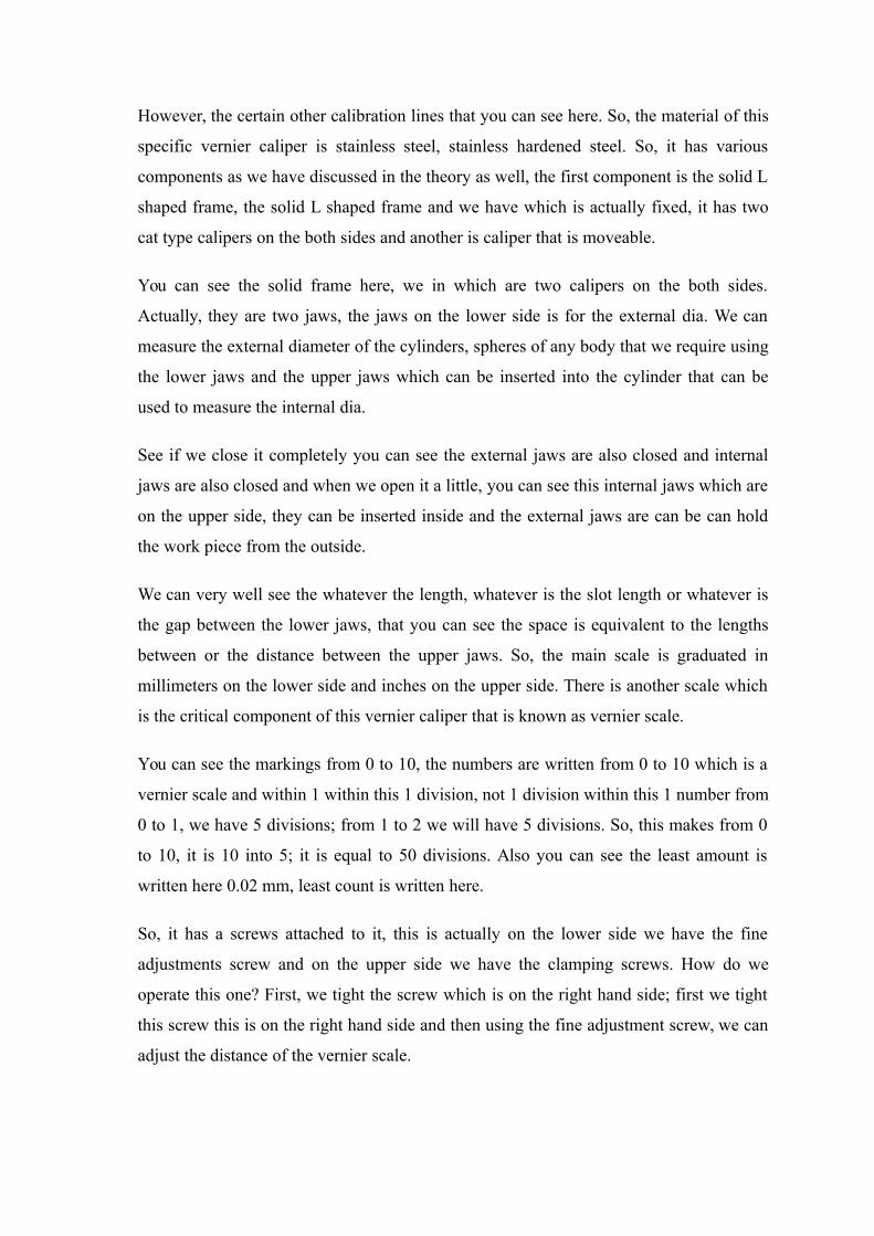
However, the certain other calibration lines that you can see here. So, the material of this
specific vernier caliper is stainless steel, stainless hardened steel. So, it has various
components as we have discussed in the theory as well, the first component is the solid L
shaped frame, the solid L shaped frame and we have which is actually fixed, it has two
cat type calipers on the both sides and another is caliper that is moveable.
You can see the solid frame here, we in which are two calipers on the both sides.
Actually, they are two jaws, the jaws on the lower side is for the external dia. We can
measure the external diameter of the cylinders, spheres of any body that we require using
the lower jaws and the upper jaws which can be inserted into the cylinder that can be
used to measure the internal dia.
See if we close it completely you can see the external jaws are also closed and internal
jaws are also closed and when we open it a little, you can see this internal jaws which are
on the upper side, they can be inserted inside and the external jaws are can be can hold
the work piece from the outside.
We can very well see the whatever the length, whatever is the slot length or whatever is
the gap between the lower jaws, that you can see the space is equivalent to the lengths
between or the distance between the upper jaws. So, the main scale is graduated in
millimeters on the lower side and inches on the upper side. There is another scale which
is the critical component of this vernier caliper that is known as vernier scale.
You can see the markings from 0 to 10, the numbers are written from 0 to 10 which is a
vernier scale and within 1 within this 1 division, not 1 division within this 1 number from
0 to 1, we have 5 divisions; from 1 to 2 we will have 5 divisions. So, this makes from 0
to 10, it is 10 into 5; it is equal to 50 divisions. Also you can see the least amount is
written here 0.02 mm, least count is written here.
So, it has a screws attached to it, this is actually on the lower side we have the fine
adjustments screw and on the upper side we have the clamping screws. How do we
operate this one? First, we tight the screw which is on the right hand side; first we tight
this screw this is on the right hand side and then using the fine adjustment screw, we can
adjust the distance of the vernier scale.
Then the vernier caliper is as I have said is made up of either stainless steel or tools steel
depending up on the nature and severity of the applications. So, it has grade, graduations
which can be either in forward vernier or backward vernier. This specific vernier caliper
that we have in hand is the forward vernier. You can see that reading first starts from 0 to
10, had it been from 10 to 0 it might be called as on the vernier scale on the very had it
been from 10 to 0 it might be called as a backward vernier.
So, as the clamping screw enables the caliper of the movable jaw in a particular position
after the jaws have been set accurately over the jaw being measured. Now, this adjusts
the further motion of the moveable jaw. The moveable jaw when it is locked using the
clamping screw, the operator now note on the reading in a convenient position because
the jaws will not move further. Now, the finer adjustment screws enables the operator to
accurately enclose the portion of the jaw where measurement is required by applying
optimum clamping pressure. However, there are certain guidelines before using the
vernier caliper I would like to tell them.
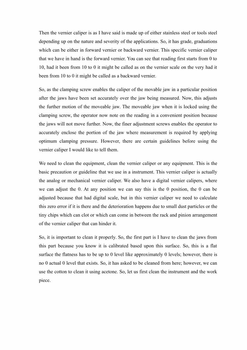
We need to clean the equipment, clean the vernier caliper or any equipment. This is the
basic precaution or guideline that we use in a instrument. This vernier caliper is actually
the analog or mechanical vernier caliper. We also have a digital vernier calipers, where
we can adjust the 0. At any position we can say this is the 0 position, the 0 can be
adjusted because that had digital scale, but in this vernier caliper we need to calculate
this zero error if it is there and the deterioration happens due to small dust particles or the
tiny chips which can clot or which can come in between the rack and pinion arrangement
of the vernier caliper that can hinder it.
So, it is important to clean it properly. So, the first part is I have to clean the jaws from
this part because you know it is calibrated based upon this surface. So, this is a flat
surface the flatness has to be up to 0 level like approximately 0 levels; however, there is
no 0 actual 0 level that exists. So, it has asked to be cleaned from here; however, we can
use the cotton to clean it using acetone. So, let us first clean the instrument and the work
piece.
(Refer Slide Time: 07:46).
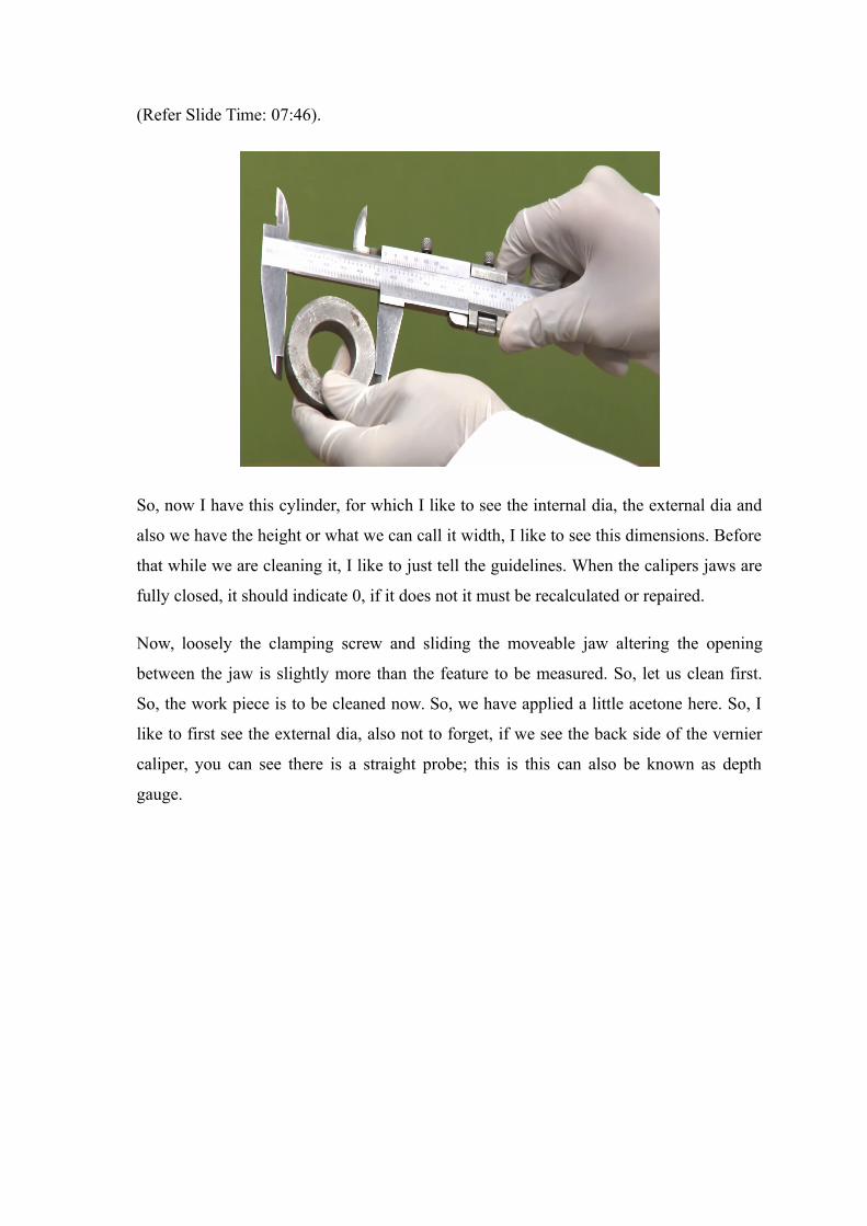
So, now I have this cylinder, for which I like to see the internal dia, the external dia and
also we have the height or what we can call it width, I like to see this dimensions. Before
that while we are cleaning it, I like to just tell the guidelines. When the calipers jaws are
fully closed, it should indicate 0, if it does not it must be recalculated or repaired.
Now, loosely the clamping screw and sliding the moveable jaw altering the opening
between the jaw is slightly more than the feature to be measured. So, let us clean first.
So, the work piece is to be cleaned now. So, we have applied a little acetone here. So, I
like to first see the external dia, also not to forget, if we see the back side of the vernier
caliper, you can see there is a straight probe; this is this can also be known as depth
gauge.
(Refer Slide Time: 09:30).
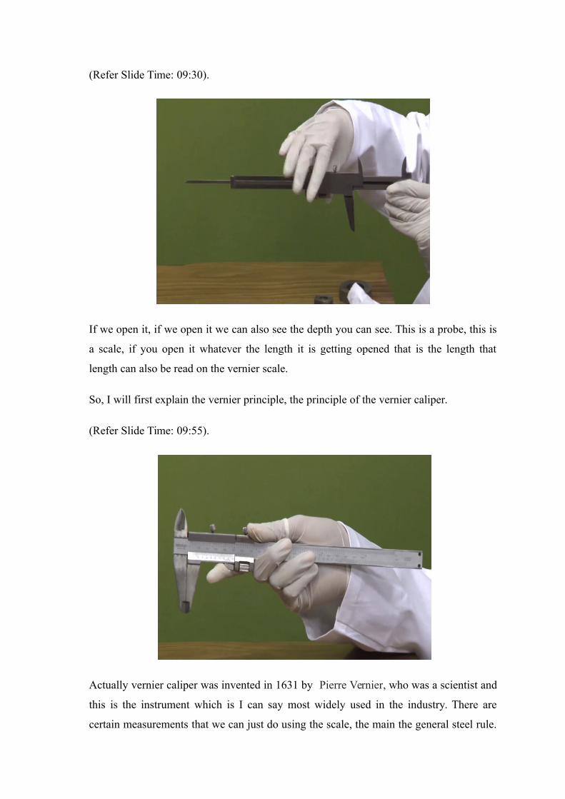
If we open it, if we open it we can also see the depth you can see. This is a probe, this is
a scale, if you open it whatever the length it is getting opened that is the length that
length can also be read on the vernier scale.
So, I will first explain the vernier principle, the principle of the vernier caliper.
(Refer Slide Time: 09:55).
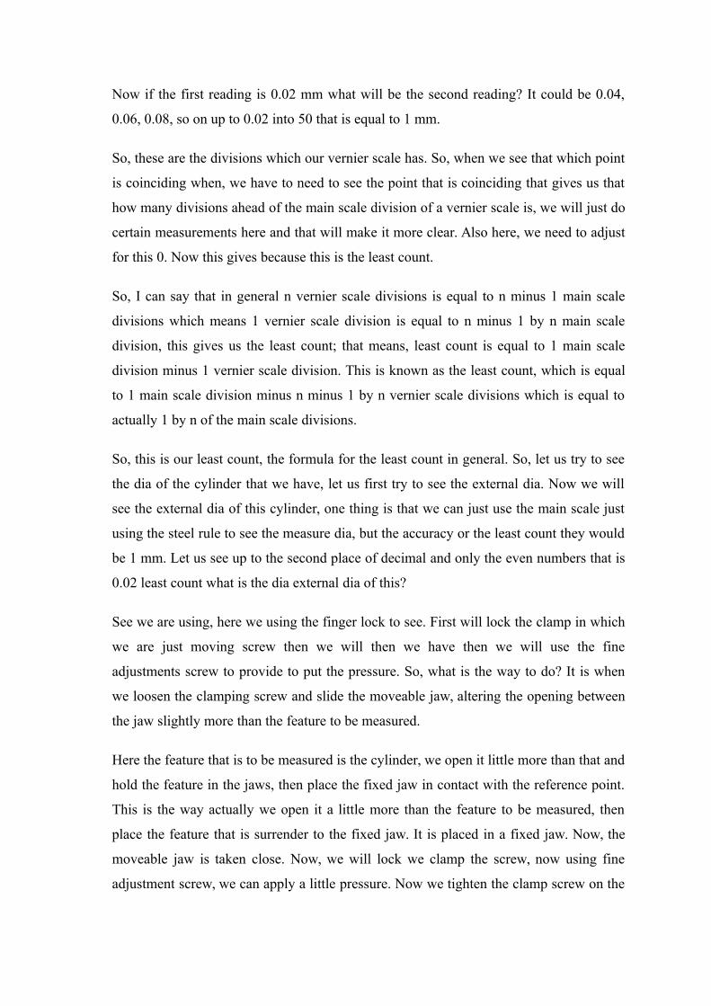
Actually vernier caliper was invented in 1631 by Pierre Vernier, who was a scientist and
this is the instrument which is I can say most widely used in the industry. There are
certain measurements that we can just do using the scale, the main the general steel rule.

But the steel rule will do a least steel rule generally 1 mm or might be it sometimes it is
0.5 mm; 1 mm is divided into two parts. But the vernier caliper points up to 00.1 mm of
a least count is available, least count is nothing least count is a minimum reading that can
be read that can be taken using the specific instrument.
So, before checking the reading I like to discuss the principle of vernier caliper. So, you
can see that there are 50 divisions on the vernier scale. See, if you see the numbers, the
numbers are from 0 to 10; between 0 to 1 there are 5 divisions, between 1 to 2 there are 5
divisions, between 2 to 3 there are 5 divisions. If I continue this thing, it is 5 divisions
into 10 times; it becomes 50. So, the 50th division of the vernier scale, the lower scale
that is a vernier scale is matching with some reading on the main scale if you can see.
So, you can see that the last reading of the vernier scale is coinciding with the reading
which reading? Which reading of the main scale? 49th, if you see the numbers between
40 and 50 the divisions between 40 and 50 on the main scale. It is from the one reading
ahead of the 50, it is the 49th reading. The last reading on the vernier scale is coinciding
with the 49th reading of the main scale. If this coincidence is there this means that the 0
is perfect, there is no zero error. So, this is actually 49 to 50, I will like to explain this
principle by using a most simple calculation.
(Refer Slide Time: 12:18)
.
So, let me say there is a scale in which we have 9 divisions 0, 1, 2, 3, 4, 5, 6, 7, 8 and 9;
these 9 divisions I will call it main scale, 1, 2 and 9 and there is another scale which has

10 divisions; 1, 2, 3, 4, 5, 6, 7, 8, 9 and 10, I think let us call it this is principle of vernier
caliper.
So, what is happening? This 10 divisions of vernier scale, 10 divisions of the vernier
scale I will call it VS is equal to 9 divisions of main scale, which implies 10 into vernier
scale is equal to 9 into main scale, which implies vernier scale is equal to 9 by 10 of
main scale is equal to 0.9. That means, vernier scale is equal to 0.9 times of main scale;
that means, 1 Vernier Scale Division is equal to 0.9 Main Scale Division or this is equal
to 0.9 mm.
What if this number is 49 here and this number is 50 here in the present scale? That
implies vernier scale is equal to 49 by 50 of main scale; that means, 1 vernier scale
division is equal to it is about it is 0.98 main scale divisions is equal to 0.98 mm. So,
what does this gets us to?
(Refer Slide Time: 15:42)
This implies that if I see the first division, if this is the main scale, if this is the main
scale and this is our vernier scale below, if this is 1 mm, this first division and this value
we can say one vernier scale division is equal to 0.98 mm, which means this value is
0.98 and this value is equal to 0 point or I can better call it better calculate it in a way 1.0
total 1 minus 0.98 is equal to 0.02 mm. That is the first reading is 0.02 mm.
Now if the first reading is 0.02 mm what will be the second reading? It could be 0.04,
0.06, 0.08, so on up to 0.02 into 50 that is equal to 1 mm.
So, these are the divisions which our vernier scale has. So, when we see that which point
is coinciding when, we have to need to see the point that is coinciding that gives us that
how many divisions ahead of the main scale division of a vernier scale is, we will just do
certain measurements here and that will make it more clear. Also here, we need to adjust
for this 0. Now this gives because this is the least count.
So, I can say that in general n vernier scale divisions is equal to n minus 1 main scale
divisions which means 1 vernier scale division is equal to n minus 1 by n main scale
division, this gives us the least count; that means, least count is equal to 1 main scale
division minus 1 vernier scale division. This is known as the least count, which is equal
to 1 main scale division minus n minus 1 by n vernier scale divisions which is equal to
actually 1 by n of the main scale divisions.
So, this is our least count, the formula for the least count in general. So, let us try to see
the dia of the cylinder that we have, let us first try to see the external dia. Now we will
see the external dia of this cylinder, one thing is that we can just use the main scale just
using the steel rule to see the measure dia, but the accuracy or the least count they would
be 1 mm. Let us see up to the second place of decimal and only the even numbers that is
0.02 least count what is the dia external dia of this?
See we are using, here we using the finger lock to see. First will lock the clamp in which
we are just moving screw then we will then we have then we will use the fine
adjustments screw to provide to put the pressure. So, what is the way to do? It is when
we loosen the clamping screw and slide the moveable jaw, altering the opening between
the jaw slightly more than the feature to be measured.
Here the feature that is to be measured is the cylinder, we open it little more than that and
hold the feature in the jaws, then place the fixed jaw in contact with the reference point.
This is the way actually we open it a little more than the feature to be measured, then
place the feature that is surrender to the fixed jaw. It is placed in a fixed jaw. Now, the
moveable jaw is taken close. Now, we will lock we clamp the screw, now using fine
adjustment screw, we can apply a little pressure. Now we tighten the clamp screw on the

moveable jaw without disturbing the light contact between caliber in the jaw, then we
will tighten the screw.
Then we will remove the feature. Then will remove the feature, now because both the
screws both the clamping screws are locked we can very conveniently see the readings.
Now to see the readings, let us see what is the 0? 0 of the vernier scale is matching with
51, 50 is actually not matching is a little forward then the 51st division. That is it is about
51 and we will see which reading is coinciding. So, let us see which reading is
coinciding, actually this is a close look we have to be careful. The best coincidence here
is the reading number 4 between 0 to 1, the 4th reading is coinciding, which means the
dia of this work piece is equal to main scale reading, main scale reading plus least count
into the coinciding vernier scale reading.
(Refer Slide Time: 22:16)
So, which is equal to main scale reading is 51 plus least count is 0.02 into 4th reading
which is equal to 51.08 mm, this is the external dia. So, actually when we do the
calculations when we do the measurements, it is not done only one, as we will discuss
statistical aspects of metrology no reading is taken only once. Generally, we do not trust
the single measurements we do multiple measurements.
So, we will check the dia at some other location as well. Again the same procedure;
opening, moving it to the fixed jaw, then closing, locking, the clamp, locking, then fine
adjustment screw, a little pressure so that we can do the properly. Now, let us see the
readings again. So it is about 51, main scale readings are again 51; this is observation 1,
then observation 2. The main scale reading here is 51 plus least count into vernier scale
reading. Let us see which vernier scale reading is coinciding. If you see it closely the
reading that is coinciding here the 9th reading is coinciding.
So, it is 9th reading which is equal to 51 plus 0.18 is equal to 51.18. So, you can see that
two observations, the two observations there is a difference of 0.1 mm. So, when we see
it by using generally a scale, the reading would be the reading at we when we that we can
see is just I think it would be 51 only. The dia actually it has to touch a reference plane
here, [FL] the dia is about, the dia is about 51. So, the thing is that this difference 0.08,
0.18, so, we can do multiple observations using this and take an average.
So, that average will send the next reading if it comes 51 point; if I take only these two
readings as my final observations, the final dia of this work piece would be 51.8 plus 18
is 51.13. So, it is because like this 51.08 plus 51.18 by 2 average is equal to 51.13 mm.
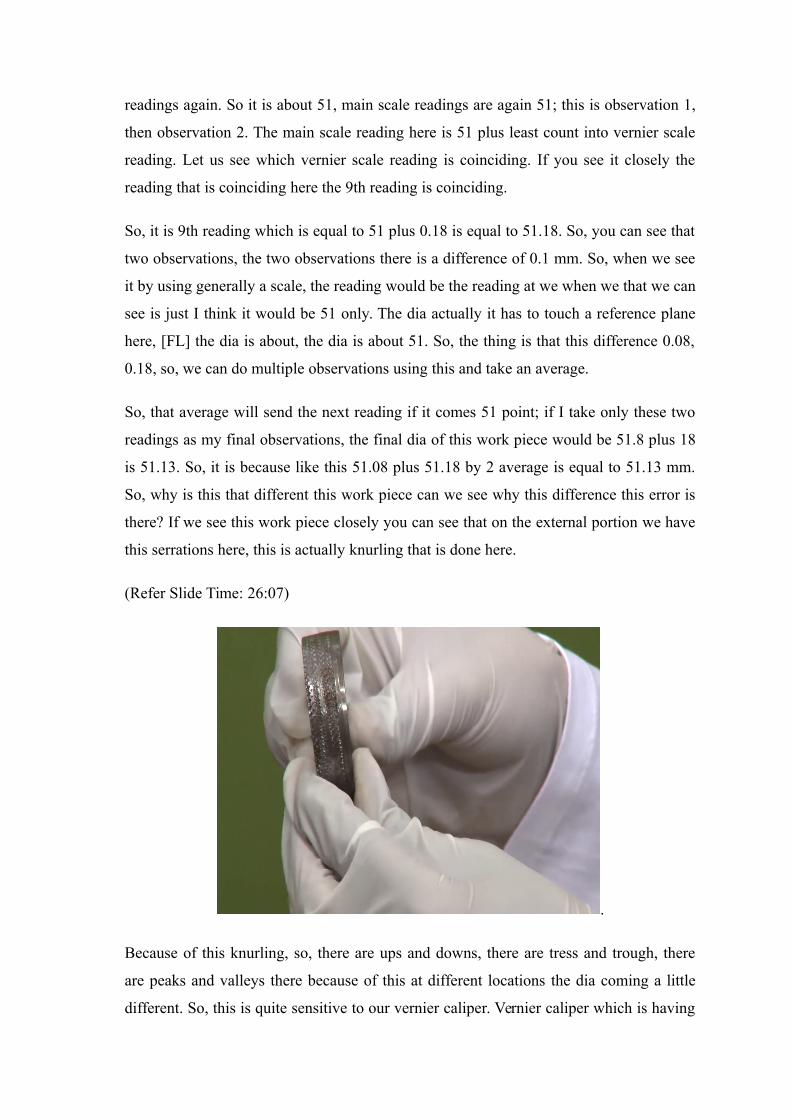
So, why is this that different this work piece can we see why this difference this error is
there? If we see this work piece closely you can see that on the external portion we have
this serrations here, this is actually knurling that is done here.
(Refer Slide Time: 26:07)
.
Because of this knurling, so, there are ups and downs, there are tress and trough, there
are peaks and valleys there because of this at different locations the dia coming a little
different. So, this is quite sensitive to our vernier caliper. Vernier caliper which is having
least count or sensitivity equal to 0.02 mm that is able to identify this difference. So, this
difference is high, this is event is out of the order of based on these divisions this
difference is of the order of 0.1 mm that I have just written here. So, also we can see the
internal dia. So, I will pick another work piece here for which I will use all the jaws the
depth gauge, the internal external to draw the full drawing of to draw to identify or to see
the full measurements or full dimensions of this work piece.
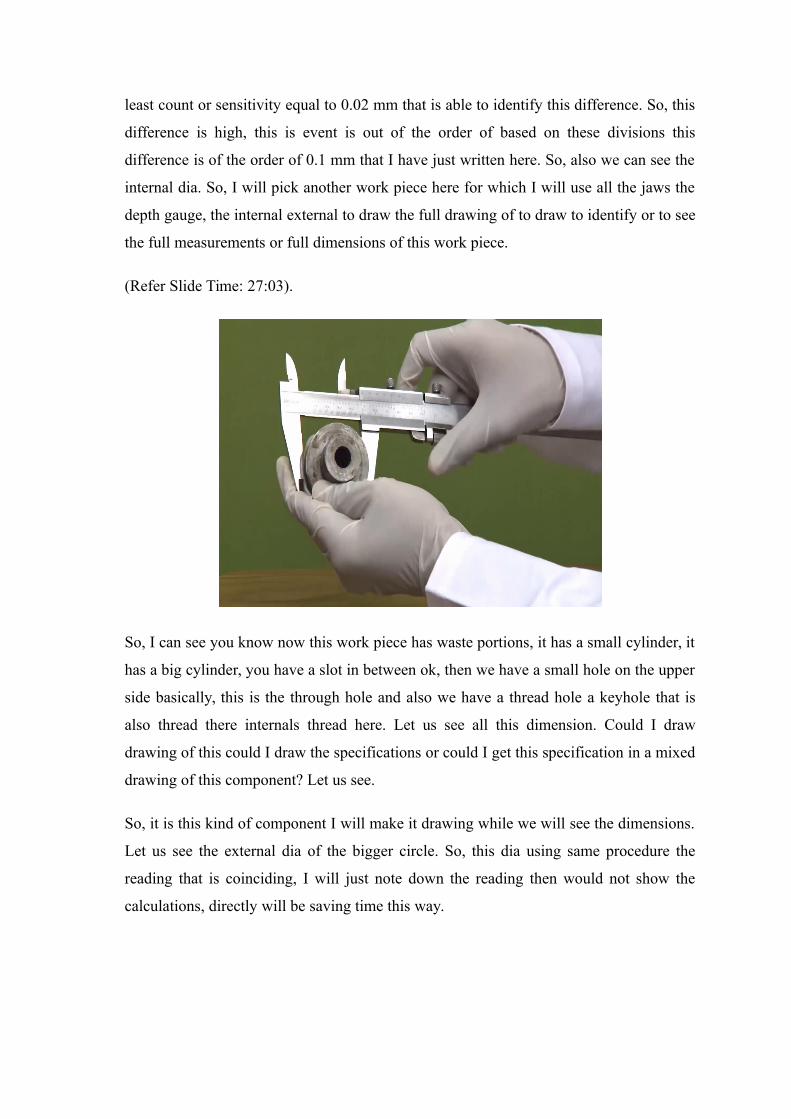
(Refer Slide Time: 27:03).
So, I can see you know now this work piece has waste portions, it has a small cylinder, it
has a big cylinder, you have a slot in between ok, then we have a small hole on the upper
side basically, this is the through hole and also we have a thread hole a keyhole that is
also thread there internals thread here. Let us see all this dimension. Could I draw
drawing of this could I draw the specifications or could I get this specification in a mixed
drawing of this component? Let us see.
So, it is this kind of component I will make it drawing while we will see the dimensions.
Let us see the external dia of the bigger circle. So, this dia using same procedure the
reading that is coinciding, I will just note down the reading then would not show the
calculations, directly will be saving time this way.

(Refer Slide Time: 28:15).
So, the single dia here is in the vernier caliper, the approximate reading here is.
Student: 49 units per.
It is this dia, let me call it capital D let me choose some different colour before
dimensioning, it is 49; I will just use main scale division plus 0.02 into vernier scale
division; it is 49 plus 0.02.
Student: 11.
Into 11; you can see the 11th reading is coinciding here. So, this is 49 into sorry 49 plus
0.22 is equal to 49.22, I will just put this value here. Next is the internal dia, this is small
d, this is capital d, this is let me call it capital T, let me call it small t, let me call this
depth, we can see the internal dia as well by inserting the internal jaws inside the
cylinder, you are locking the screws using the same principle, after locking the screws
we can see the reading. So, the internal dia is the main scale reading is 11 and the
coinciding point is 44th, it is 11 plus 0.2 into 44. This is small a, this is equal to 11.44
mm. So, up to two places of decimals and even numbers we can see all these dimensions.
So, this dimensions small d is there then this small t, capital T, and t dash, also we can
see this small dia, let me call it s. So, we will put all this calculations and word you with
the notes. So, this was actually the purpose of this demonstration was to show the show
this principle and use of the vernier caliper. This vernier caliper, the vernier scale is not

only used in the calipers, it can also used in height gauge. Height gauge is the also of the
instruments that we will use for the demonstrations for the.
Now, there are certain precautions when we use the caliper; some general precautions
and some specific to this vernier caliper.
(Refer Slide Time: 32:04).
The first precaution I would put is the measuring force, do not apply excessive force to
the work piece, excessive measuring force we develop measurement errors because of
the positions deviations of jaws. So, no excessive force, it can lead to positional
deviation errors. Number 2 is the observer error that is parallax error; however, the
instrument is quite clear, the we can see which reading is coinciding which of the vernier
scale readings coinciding with the main scale, but in general parallax error could also
come; not in vernier caliper in general parallax error is avoided, this is it is instrumented
is not that sensitive that parallax error would be significant here, but it is an important,
error if it comes it can give us difference over 1 reading at least.
So, number 3 is the outside measurement; the outside measurement we can put the work
piece as close to the reference surface as possible and have the measuring phases fitted
with the work piece because the outside measurement sometimes if it is not put in a
proper way it can give us some error then inside measurement also has similar kind of
drawbacks may have similar kind of drawbacks inside measurements.
So, inside measurements or in outside measurements it is important to note the maximum
reading and the smallest reading; maximum and you call it minimum. Take both readings
at least if possible then also I did not use that depth measurement, I can also use the
depth gauge. In depth measurement, you can see the depth of this work piece using the
depth gauge.
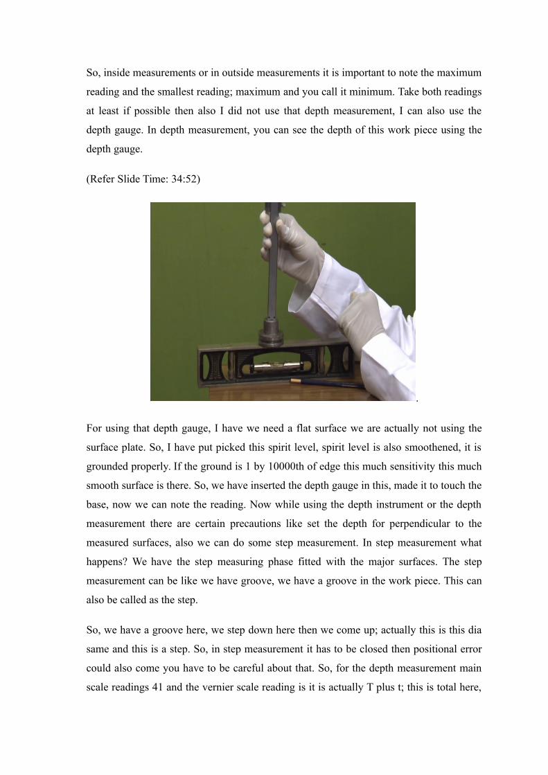
(Refer Slide Time: 34:52)
.
For using that depth gauge, I have we need a flat surface we are actually not using the
surface plate. So, I have put picked this spirit level, spirit level is also smoothened, it is
grounded properly. If the ground is 1 by 10000th of edge this much sensitivity this much
smooth surface is there. So, we have inserted the depth gauge in this, made it to touch the
base, now we can note the reading. Now while using the depth instrument or the depth
measurement there are certain precautions like set the depth for perpendicular to the
measured surfaces, also we can do some step measurement. In step measurement what
happens? We have the step measuring phase fitted with the major surfaces. The step
measurement can be like we have groove, we have a groove in the work piece. This can
also be called as the step.
So, we have a groove here, we step down here then we come up; actually this is this dia
same and this is a step. So, in step measurement it has to be closed then positional error
could also come you have to be careful about that. So, for the depth measurement main
scale readings 41 and the vernier scale reading is it is actually T plus t; this is total here,
this is 41 plus 0 point it is 0.02, 0.02 into 7; 7th reading is coinciding; it is equal to 41.44
mm. So, this is our vernier calipers, we also have another vernier caliper. Actually in this
vernier caliper also we did not have any zero error. Had it been a zero error we have to
add or subtract that sometimes the 0 is not coinciding, sometimes a reading is forward or
backward.
So, some it is not coinciding. So, we have to adjust it accordingly. So, whenever it is
forward, it would mean that the reading is a little larger whether it of the detective jaws
which are closed when the jaws are open in little this is known as positive error. So,
whatever reading that we gather is sense if I get reading 50.20, if this error is 0.10, so,
this 50.20 is 0.10 is something that is added to it when you need to subtract that; this
positive error has to be subtracted and if it is an overlap, if it is an overlap that will be a
negative error that has to be added. So, we have to adjust it for the errors. To give with
the errors, so, as the zero error does not occur, the instrument error we have the dial
gauge, we have the dial vernier. The dial vernier is the one first I will discussed the dial
gauge then I will discuss dial vernier, after that and also there as I said they are digital
vernier calipers in which we can set 0 at any point, so that can also be the deal with the
zero error.
So, this was the vernier caliper. In the next part of lab demonstration, I will discuss about
the dial gauge and the dial vernier. Then we will move to the micrometer. Let us meet in
the next part of the lab demonstration.
Thank you.