Engineering Equipment Specification 25/7 - Western Power ...
49
EE SPEC 25/7 October 2021 - 1 of 49 - Company Directive ENGINEERING EQUIPMENT SPECIFICATION 25/7 110V Batteries, Chargers, Distribution Boards & Associated Auxiliary Cabling For Metering Circuit Breaker Type Primary Network Substations Author: Graham Brewster Implementation Date: October 2021 Approved by Carl Ketley-Lowe Engineering Policy Manager Date: 6 th October 2021 Target Staff Group Network Services Teams, Engineering Design Teams, Primary System Design Teams & ICPs Impact of Change Green – The change has no immediate impact on working practices or has been aligned to current working practices – Communication via a monthly update of changed policy. Team Manager discretion on how the changes are communicated to the team. Planned Assurance checks None NOTE: The current version of this document is stored in the WPD Corporate Information Database. Any other copy in electronic or printed format may be out of date. Copyright 2021 Western Power Distribution
-
Upload
khangminh22 -
Category
Documents
-
view
0 -
download
0
Transcript of Engineering Equipment Specification 25/7 - Western Power ...
EE SPEC 25/7 October 2021 - 1 of 49 -
Company Directive
ENGINEERING EQUIPMENT SPECIFICATION 25/7
110V Batteries, Chargers, Distribution Boards & Associated Auxiliary Cabling For
Metering Circuit Breaker Type Primary Network Substations
Author: Graham Brewster
Implementation Date: October 2021
Approved by
Carl Ketley-Lowe
Engineering Policy Manager
Date: 6th October 2021
Target Staff Group Network Services Teams, Engineering Design Teams, Primary System Design Teams & ICPs
Impact of Change Green – The change has no immediate impact on working practices or has been aligned to current working practices – Communication via a monthly update of changed policy. Team Manager discretion on how the changes are communicated to the team.
Planned Assurance checks None
NOTE: The current version of this document is stored in the WPD Corporate Information Database. Any other copy in electronic or printed format may be out of date. Copyright 2021 Western Power Distribution
EE SPEC 25/7 October 2021 - 2 of 49 -
IMPLEMENTATION PLAN Introduction This Engineering Equipment Specification (EE SPEC) defines the requirements for substation 110V batteries, battery chargers, dc distribution boards & associated auxiliary cabling which are to be deployed at “metering circuit breaker” type primary network substations. Main Changes This is an existing document which has been reviewed prior to re-tendering. Some sections have been re-written to make non-brand specific, to remove ambiguities, or to simplify the requirements. A full list of the changes can be found in the ‘Document Revision & Review Table’. Substantive technical changes are as follows:
Inclusion of transducer for remote (i.e. telecontrol) monitoring of battery voltage Ensuring there is sufficient space in the battery compartment to accommodate
alternative brands of monobloc in the event that economics favour a different product when they are replaced at end of life
Revised requirements for double-pole isolation switch on DC distribution board Replacement batteries moved to EE SPEC 204
Other changes include a new ‘General Requirements’ section for where equipment is supplied under a contract with WPD. This includes (amongst other things):
An optional ‘Erection & Commissioning’ Service
Impact of Changes
Target Staff Group Network Services Teams, Engineering Design Teams, Primary System Design Teams & ICPs
Impact of Change Green – The change has no immediate impact on working practices or has been aligned to current working practices – Communication via a monthly update of changed policy. Team Manager discretion on how the changes are communicated to the team.
Implementation Actions
Managers to notify relevant staff that this document has been published The document shall be uploaded onto the WPD Technical Information website
(www.westernpowertechinfo.co.uk) There are no retrospective actions.
Implementation Timetable This Engineering Equipment Specification shall be implemented with immediate effect. 110Vdc systems at “metering circuit breaker” type primary network substations may be installed in accordance with the previous version of this document (EE SPEC 25/6) until March 2022.
EE SPEC 25/7 October 2021 - 3 of 49 -
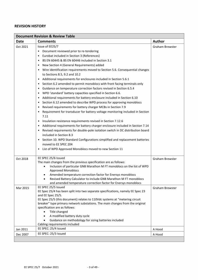
REVISION HISTORY
Document Revision & Review Table
Date Comments Author
Oct 2021 Issue of EE25/7
• Document reviewed prior to re-tendering
• Eurobat included in Section 3 (References)
• BS EN 60445 & BS EN 60446 included in Section 3.1
• New Section 4 (General Requirements) added
• Wire identification requirements moved to Section 5.6. Consequential changes
to Sections 8.5, 9.2 and 10.2
• Additional requirements for enclosures included in Section 5.6.1
• Section 6.2 amended to permit monoblocs with front facing terminals only
• Guidance on temperature correction factors revised in Section 6.5.4
• WPD ‘standard’ battery capacities specified in Section 6.6.
• Additional requirements for battery enclosure included in Section 6.10
• Section 6.12 amended to describe WPD process for approving monoblocs
• Revised requirements for battery charger MCBs in Section 7.9
• Requirement for transducer for battery voltage monitoring included in Section
7.11
• Insulation resistance requirements revised in Section 7.12.6
• Additional requirements for battery charger enclosure included in Section 7.14
• Revised requirements for double-pole isolation switch in DC distribution board
included in Section 8.3
• Section 10. WPD Standard Configurations simplified and replacement batteries
moved to EE SPEC 204
• List of WPD Approved Monoblocs moved to new Section 11
Graham Brewster
Oct 2018 EE SPEC 25/6 Issued The main changes from the previous specification are as follows:
Inclusion of particular GNB Marathon M FT monoblocs on the list of WPD Approved Monoblocs
Amended temperature correction factor for Enersys monoblocs
Revised Battery Calculator to include GNB Marathon M FT monoblocs and amended temperature correction factor for Enersys monoblocs
Graham Brewster
Mar 2015 EE SPEC 25/5 Issued EE Spec 25/4 has been split into two separate specifications, namely EE Spec 23 and EE Spec 25/5. EE Spec 25/5 (this document) relates to 110Vdc systems at “metering circuit breaker” type primary network substations. The main changes from the original specification are as follows:
Title changed
A modified battery duty cycle
Guidance on methodology for sizing batteries included Cabling requirements included
Graham Brewster
Jan 2011 EE SPEC: 25/4 Issued A Hood
Dec 2007 EE SPEC: 25/3 Issued A Hood
EE SPEC 25/7 October 2021 - 4 of 49 -
CONTENTS
1.0 INTRODUCTION ......................................................................................................... 6
2.0 DEFINITIONS .............................................................................................................. 6
3.0 REFERENCES .............................................................................................................. 6
3.1 British Standards ....................................................................................................... 6
3.2 Energy Networks Association Technical Specifications ............................................ 7
3.3 Institute Of Electrical & Electronic Engineers (IEEE) ................................................. 7
3.4 Association of European Automotive & Industrial Battery Manufacturers (EUROBAT) ................................................................................................................. 7
4.0 GENERAL REQUIREMENTS .......................................................................................... 8
4.1 WPD Product Approval .............................................................................................. 8
4.2 Packaging and Labelling ............................................................................................ 9
4.3 Delivery and Offloading ........................................................................................... 10
4.4 Erection and Commissioning Service ...................................................................... 11
4.5 Quality assurance .................................................................................................... 13
4.6 Defects ..................................................................................................................... 14
5.0 OVERALL TECHNICAL REQUIREMENTS ...................................................................... 14
5.1 Substation DC Supply Arrangements ...................................................................... 14
5.2 Schematic Diagram of Battery, Charger & DC Distribution Board .......................... 17
5.3 Environmental Conditions ....................................................................................... 17
5.4 Electromagnetic Compatibility ................................................................................ 17
5.5 DC System Earthing ................................................................................................. 18
5.6 Wiring and Terminations ......................................................................................... 18
5.7 Construction Requirements for Enclosures ............................................................ 19
5.8 Drawings and Instructions ....................................................................................... 19
6.0 ADDITIONAL REQUIREMENTS FOR BATTERIES .......................................................... 20
6.1 Schematic Diagram of Battery ................................................................................. 20
6.2 Monobloc Type ........................................................................................................ 21
6.3 Monobloc Performance, Durability & Design Life................................................... 21
6.4 Battery Arrangement............................................................................................... 21
6.5 Battery Sizing ........................................................................................................... 21
6.6 WPD Standard Battery Capacities ........................................................................... 22
6.7 Battery Accessories ................................................................................................. 23
6.8 Battery Connections ................................................................................................ 23
6.9 Protection and Testing Facilities ............................................................................. 23
6.10 Enclosure ................................................................................................................. 23
6.11 Labelling ................................................................................................................... 25
6.12 Monobloc Approval ................................................................................................. 25
7.0 ADDITIONAL REQUIREMENTS FOR BATTERY CHARGERS ........................................... 27
7.1 Schematic Diagram of Battery Charger ................................................................... 27
7.2 General .................................................................................................................... 27
7.3 Design Life ............................................................................................................... 27
7.4 AC Circuits and Maintenance Facilities ................................................................... 27
7.5 DC Output Current Rating ....................................................................................... 29
EE SPEC 25/7 October 2021 - 5 of 49 -
7.6 DC Output Voltage Control...................................................................................... 29
7.7 DC Output Current Control ..................................................................................... 29
7.8 Performance ............................................................................................................ 29
7.9 Charger Input / Output Protection .......................................................................... 29
7.10 Charger Control Module and other Electronic Components .................................. 30
7.11 Instrumentation Requirements ............................................................................... 30
7.12 Battery & Charger Monitoring Requirements ......................................................... 30
7.13 Charger Burden ....................................................................................................... 34
7.14 Enclosure ................................................................................................................. 34
7.15 Labelling ................................................................................................................... 35
8.0 ADDITIONAL REQUIREMENTS FOR DC DISTRIBUTION BOARDS ................................. 36
8.1 Schematic Diagram of the DC Distribution Board ................................................... 36
8.2 Design Life ............................................................................................................... 36
8.3 Circuits and Maintenance Facilities ......................................................................... 36
8.4 Enclosure ................................................................................................................. 37
8.5 Wire Marking And Insulation Colour ....................................................................... 37
8.6 Labelling ................................................................................................................... 37
9.0 ADDITIONAL REQUIREMENTS FOR AUXILIARY CABLING ............................................ 38
9.1 Schematic Diagram of Auxiliary Cabling .................................................................. 38
9.2 Auxiliary Cables - Power .......................................................................................... 39
9.3 Auxiliary Cables - Multipair ..................................................................................... 39
9.4 Auxiliary Cables - Glands ......................................................................................... 39
10.0 WPD STANDARD CONFIGURATIONS ....................................................................... 40
10.1 Systems .................................................................................................................... 40
10.2 Distribution Boards For Unearthed 110V DC Systems ............................................ 40
11.0 WPD APPROVED MONOBLOCS ............................................................................... 41
12.0 PERFORMANCE DATA FOR WPD APPROVED MONOBLOCS ..................................... 41
13.0 SIZING OF LEAD ACID BATTERIES & CHARGERS ....................................................... 42
13.1 WPD Battery Sizing Calculator ................................................................................. 42
13.2 Battery Duty Cycle ................................................................................................... 42
13.3 Preliminary Selection of Cell / Monobloc Type ....................................................... 43
13.4 Battery Sizing Methodology .................................................................................... 43
13.5 Example Calculation ................................................................................................ 45
EE SPEC 25/7 October 2021 - 6 of 49 -
1.0 INTRODUCTION The operational security of the distribution network is dependent upon reliable and secure dc auxiliary supplies. 110V dc systems are used to power protection and switchgear control equipment, and a “no-break” supply is required. This Engineering Equipment Specification defines the requirements for substation 110V batteries, chargers and dc distribution boards which are to be deployed at “metering circuit breaker” type primary network substations.
2.0 DEFINITIONS For the purpose of this Engineering Equipment Specification the following definitions apply:
WPD Western Power Distribution
Primary Network Substation A 132kV, 66kV or 33kV substation including directly associated 66kV, 33kV, 25kV, 11kV and 6.6kV switchboards at transformer stations
“Metering Circuit Breaker” Substation
A substation constructed for the sole purpose of supplying a single customer via a single metering circuit breaker
Cell The basic electro-chemical unit used to generate or store electrical energy
Monobloc A multi-compartment container housing a number of separate, but electrically interconnected cells. 12V monoblocs are typically employed
Battery Multiple cells or monoblocs electrically interconnected in an appropriate series / parallel arrangement to provide the requisite level of operating voltage and current
Battery Duty Cycle The load a battery is expected to supply for a specified period following loss of output from the battery charger (for whatever reason)
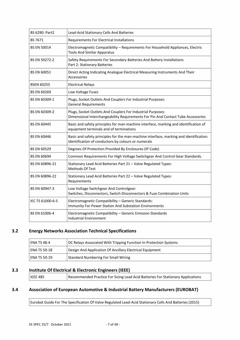
3.0 REFERENCES This document makes reference to, or should be read in conjunction with, the documents listed below. The issue and date of the documents listed below shall be those applicable at the date of issue of this document, unless stated otherwise.
3.1 British Standards
BS 88-2 Low Voltage Fuses
BS 381C Specification For Colours For Identification, Coding And Special Purposes
BS 5467 Electric cables – Thermosetting insulated, armoured cables for voltages of 600/1000V and 1900/3300V
BS 6121-1 Armour glands – Requirements and test methods
BS 6121-5 Code of practice for selection, installation and inspection of cable glands and armour glands
EE SPEC 25/7 October 2021 - 7 of 49 -
BS 6290: Part2 Lead-Acid Stationary Cells And Batteries
BS 7671 Requirements For Electrical Installations
BS EN 50014 Electromagnetic Compatibility – Requirements For Household Appliances, Electric Tools And Similar Apparatus
BS EN 50272-2 Safety Requirements For Secondary Batteries And Battery Installations Part 2: Stationary Batteries
BS EN 60051 Direct Acting Indicating Analogue Electrical Measuring Instruments And Their Accessories
BSEN 60255 Electrical Relays
BS EN 60269 Low Voltage Fuses
BS EN 60309-1 Plugs, Socket Outlets And Couplers For Industrial Purposes: General Requirements
BS EN 60309-2 Plugs, Socket Outlets And Couplers For Industrial Purposes: Dimensional Interchangeability Requirements For Pin And Contact Tube Accessories
BS EN 60445 Basic and safety principles for man-machine interface, marking and identification of equipment terminals and of terminations
BS EN 60446 Basic and safety principles for the man-machine interface, marking and identification. Identification of conductors by colours or numerals
BS EN 60529 Degrees Of Protection Provided By Enclosures (IP Code)
BS EN 60694 Common Requirements For High Voltage Switchgear And Control Gear Standards.
BS EN 60896-21 Stationary Lead Acid Batteries Part 21 – Valve Regulated Types: Methods Of Test
BS EN 60896-22 Stationary Lead Acid Batteries Part 22 – Valve Regulated Types: Requirements
BS EN 60947-3 Low Voltage Switchgear And Controlgear: Switches, Disconnectors, Switch-Disconnectors & Fuse Combination Units
IEC TS 61000-6-5 Electromagnetic Compatibility – Generic Standards: Immunity For Power Station And Substation Environments
BS EN 61006-4 Electromagnetic Compatibility – Generic Emission Standards Industrial Environment
3.2 Energy Networks Association Technical Specifications
ENA TS 48-4 DC Relays Associated With Tripping Function In Protection Systems
ENA TS 50-18 Design And Application Of Ancillary Electrical Equipment
ENA TS 50-19 Standard Numbering For Small Wiring
3.3 Institute Of Electrical & Electronic Engineers (IEEE)
IEEE 485 Recommended Practice For Sizing Lead Acid Batteries For Stationary Applications
3.4 Association of European Automotive & Industrial Battery Manufacturers (EUROBAT)
Eurobat Guide For The Specification Of Valve Regulated Lead-Acid Stationary Cells And Batteries (2015)
EE SPEC 25/7 October 2021 - 8 of 49 -
4.0 GENERAL REQUIREMENTS The following general requirements apply where 110V batteries, battery chargers, dc distribution boards and associated auxiliary cabling are supplied under a contract with WPD.
4.1 WPD Product Approval
4.1.1 WPD Approved Products
Some sections of this specification make reference to “WPD Approved Products”. These are items which have either completed a formal product approval process or are tried and tested by virtue of have been satisfactorily deployed on the distribution network for an extended period of time. Where any product offered by the supplier is not a WPD approved product then the supplier shall complete the ‘WPD Product Approval Process’ described in section 4.1.3 below prior to that product being deployed on the distribution network. This prerequisite, and other requirements contained in this specification, are not intended to restrict or inhibit the introduction of new product but simply to ensure that there is a suitable investigation or exercise of care that a reasonable business would normally be expected to take before entering into a contract, and that work equipment is so constructed as to be suitable for the purpose for which it is to be used.
4.1.2 WPD Approved Product Is Not To Be Changed No change in the product, packaging or labelling shall be made after approval has been granted without prior notice and without receipt of agreement from WPD, in writing, to the proposed change.
4.1.3 WPD Product Approval Process The cost of WPD Product Approval shall be borne by the supplier and included in the tender costs. The supplier shall, at the time of tender, provide the following information:
a) Drawings (where appropriate)
b) Technical Datasheets
c) Control of Substances Hazardous to Health (COSHH) Datasheets (where applicable) such as to guide WPD in the safe use, storage and disposal of the product
d) A written declaration of conformance or otherwise with relevant parts of this Engineering Equipment Specification
EE SPEC 25/7 October 2021 - 9 of 49 -
e) Details of where product is manufactured
f) Details of packaging and labelling
g) Details of how gross weight is to be marked packages with a gross weight over 1 kg, as will enable WPD to comply with the Health and Safety Manual handling Operation Regulations 1992
h) Details of product packaging disposal, as will enable WPD to comply with the requirements of BS EN 14001: 1996 – Environmental Management Systems
i) Details of any warranty, and what this covers
4.2 Packaging and Labelling Packaging shall be non-returnable, easily disposable and where practicable bio-degradable and/or recyclable. The packaging method must be robust, resistant to impact damage during transit and from handling equipment, and be suitable for the applied weight and load. All timber (including wooden boxes, and pallets) if used in the packing shall be new, dry, and properly seasoned. The timber shall be natural wood. The timber and any timber treatment shall not damage the product. If the pallets are to be stacked on one another during transit and / or storage then the load-bearing points shall be positioned above one another ensuring that the stack is both sturdy and stable and will not crush under self-weight. Pallets must conform to the following specification:
a) Pallets must be either Euro pallets (measuring 1200mm by 800mm) or four way pallets (measuring 1200mm by 1000mm) that are in good condition and strong enough to bear the weight of the Items being delivered.
b) Components must not overhang the pallet in any direction.
c) Individual pallets must not be more than 1.5m high.
d) Maximum pallet weight must not exceed 450kg. All labels shall be legible, indelible and must be suitable and durable for the lifetime of the package. Each package / pallet / box must be labelled with the following details:
a) WPD E5 Code
EE SPEC 25/7 October 2021 - 10 of 49 -
b) Material Description
c) Manufacturer’s name
d) Quantity of product contained within the package / pallet / box
e) Gross weight of package / pallet / box in kg
4.3 Delivery and Offloading The Supplier is responsible for delivery and offloading. There are three modes of delivery for 110V & 220V batteries, battery chargers, battery controllers, dc distribution boards and associated auxiliary cabling to WPD:
Delivery to its central stores
Delivery to its local depots
Delivery direct to site
WPD will confirm the requirements for delivery at the time of ordering. Delivery is expected to be predominantly to WPD substation sites. Delivery shall be made using a vehicle equipped with a mechanical offloading system such as a tail-lift or vehicle mounted crane. The operator shall be fully trained, competent, and carry the relevant certification. Any lifting equipment used for offloading shall have a valid and current test certificate. The delivery driver must:
Report to the WPD Recipient1 immediately on arrival at the site and agree a plan for the safe offloading of the goods
Use any site traffic route designated by the WPD Recipient
Offload the goods onto the area of ground designated by the WPD Recipient Where at all possible the area of ground designated by the WPD Recipient will be a hard and level surface, however this cannot be guaranteed for deliveries direct to site. Consequently the delivery driver must come prepared for offloading onto sloping, uneven, loose, or soft surfaces. It is the delivery driver’s responsibility to raise any concerns they may have about the designated traffic route and offloading area to the WPD Recipient.
1 The WPD employee who is to receive the goods at the premises on behalf of the Company
EE SPEC 25/7 October 2021 - 11 of 49 -
4.4 Erection and Commissioning Service
The Supplier shall provide an optional erection and commissioning service for the 110V battery, charger, and DC distribution boards. This shall include the following activities:
Movement of the goods from the offloading point to the switch room / relay room where they are to be installed
Placement of the cubicles & boards in their final position and fixing in place
Connection of the cubicles & boards to the substation main earthing system
Installation of the interconnecting cables between cubicles & boards. In order to avoid any doubt, cabling to the ac distribution board, scada/telecontrol outstation and to switchgear & protection cubicles is outside the scope of works
Installation of the monoblocs and the associated battery connections
Identification labelling of the monoblocs
Application of all settings, including (but not limited to) charger dc output current & voltage settings, tranducer scaling, high & low volts alarm settings, battery impedance monitoring settings, earth fault alarm settings, etc
Testing & commissioning of the installed equipment
The production and handover of a formal, written commissioning report documenting the results of the commissioning inspections and tests
WPD reserves the right to witness some or all of the testing and commissioning activities.
4.4.1 Distribution Safety Rules All work in the substation will be undertaken in accordance with Western Power Distribution Safety Rules. The Supplier’s workers are not expected to hold any authorisation under WPD Distribution Safety Rules. WPD will provide personal supervision of the Supplier’s workers at all times during the course of their work. In order to avoid any doubt, this supervision relates solely to compliance with Distribution Safety Rules – the Supplier shall be fully responsible for the supervision and activities of all their workers, including their subcontractors, employed under this contract. The Supplier shall provide their workers with, and their workers shall wear, flame retardant coveralls, light eye protection, safety helmets and safety footwear whilst working on site.
EE SPEC 25/7 October 2021 - 12 of 49 -
4.4.2 CDM Regulations Erection and commissioning activities in the substation will be subject to the Construction Design & Management Regulations (CDM Regulations). The Supplier shall carry out the duties of Contractor as defined in the CDM Regulations. All costs associated with compliance with the CDM Regulations shall be deemed to have been included in the Supplier’s tender price. The Supplier’s price should take account of the costs of:
Complying with directions given by the Principal Contractor
Complying with parts of the construction phase plan relevant to their work
Attending site inductions
Coordinating work activities with those of other parties
Preparing risk assessments and method statements
4.4.3 Manual Handling Equipment, Tools, Test Equipment and PPE The Supplier is responsible for providing all necessary manual handling equipment, tools, test equipment and personal protective equipment necessary for their work. All costs associated with this shall be deemed to have been included in the Supplier’s tender price. Access to the switch room / relay room where the goods are to be installed may not be straightforward at some substations. There may be steps to negotiate or the need to traverse sloping, uneven, loose, or soft surfaces. The Supplier shall employ appropriate manual handling equipment, for example, rough terrain sack trolleys, rough terrain platform trolleys, stair trolleys, dolleys and the like. All power tools shall either be battery or 110Vac operated. In the case of the latter, the supplier shall also provide the necessary 230/110V power tool transformers. All ac operated power tools shall have an in-date PAT test certificate. All test equipment and test instruments shall be commercially manufactured and have in-date calibration certificates. All ac operated test equipment shall also have an in-date PAT test certificate.
4.4.4 Site Workers The Supplier shall indicate which site workers are directly employed by themselves and which are subcontractors.
EE SPEC 25/7 October 2021 - 13 of 49 -
WPD reserves the right to insist alternative site workers are employed to satisfy the requirements of the contract works. This right will only be exercised where WPD deems the site worker has insufficient ability, displays poor workmanship, or fails to cooperate with any reasonable instruction given by the Principal Contractor or the WPD person providing supervision under the auspices of the Distribution Safety Rules.
4.4.5 Site Mobilisation The Supplier is responsible for the transportation of personnel, tools, equipment and materials to and from the substation site. All costs associated with this shall be deemed to have been included in the Supplier’s tender price.
4.4.6 Accommodation & Welfare Where the location of the substation or the duration of the work requires site workers to be away from home overnight, the Supplier is responsible for the overnight accommodation and welfare of those individuals. All costs associated with this shall be deemed to have been included in the Supplier’s tender price.
4.5 Quality assurance The Supplier shall confirm, at the time of tendering, whether or not approval is held in accordance with a Quality Assurance Scheme accredited under ISO 9000. If not, he shall submit a statement of quality assurance procedures employed to control the quality of the product, including the performance of sub-suppliers and sub-contractors. WPD reserves the right to make, from time to time, such inspections of the Supplier’s facilities as it may deem to be reasonably necessary to ensure compliance with this Specification and any Contract of which it forms a part. The Supplier shall provide free of charge to WPD such samples as, in WPD’s opinion, may be reasonably required for inspection and/or retention as quality control samples. WPD will confirm the requirements for samples at the time of tendering. WPD reserves the right to require the Supplier to undertake such testing, at the Supplier’s premises or other agreed location, as WPD may deem to be reasonably necessary to verify compliance with this Specification. These tests may involve subjecting the product to extreme operating conditions, and may include destructive tests. WPD reserves the right to require the Supplier to repeat, from time to time, such tests as it may deem to be reasonably necessary to demonstrate continued compliance with the Specification. The Supplier shall submit with his tender, details of how product traceability is assured.
EE SPEC 25/7 October 2021 - 14 of 49 -
The Supplier shall submit with his tender, a list of the tests and inspections which are to be carried out on the product prior to despatch which shall demonstrate, to the satisfaction of WPD, the absence of damage or decay and fitness for installation and service.
4.6 Defects In the event that WPD notifies the supplier of a defect or other non-conformance with the 110V batteries, battery chargers, dc distribution boards or associated auxiliary cabling, the supplier shall carry out a diligent investigation and provide WPD with a written report explaining the root cause of the defect or non-conformance and the measures the supplier is going to take to prevent a recurrence. The supplier shall work with WPD to decide the appropriate course of action in relation to:
The defective or non-conforming item
Any similar item stocked in WPD’s central or local stores
Any similar item installed on site
5.0 OVERALL TECHNICAL REQUIREMENTS
5.1 Substation DC Supply Arrangements The 110V batteries, chargers & distribution boards will be employed at “metering circuit breaker” type primary network substations. Each of these substations will provide electricity to a single customer via a single metering circuit breaker. However, if the connection to the network is “looped” rather than “teed”, the WPD switchboard may consist of up to three circuit breakers (two feeder and one metering circuit breakers). The 110Vdc systems are used to drive protection and switchgear control equipment associated with these power circuits. 110Vdc systems shall be designed to provide “no-break” supplies at all times, in particular whilst routine maintenance, repair or replacement activities are undertaken on batteries & chargers, or the charger ac incoming supply. This is because it is, or may, be unacceptable for:
a) DC supplies to protection and switchgear control equipment to be depleted whilst the associated power circuit is energised
b) All power circuits to be made dead concurrently whilst activities of this type are undertaken
A sustained shutdown of an entire primary network substation (including the site ac auxiliary power supply) as a consequence of either a localised or widespread event will result in the 110V battery slowly discharging due to the standing load. The shutdown could last for 72 hours (worst case scenario).
EE SPEC 25/7 October 2021 - 15 of 49 -
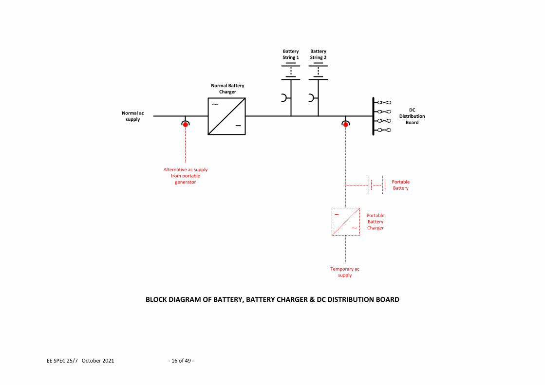
Accordingly, the DC supply arrangements shall include the following facilities:
A means of supplying the battery charger from a portable generator whilst the normal fixed ac supply is being maintained, repaired or replaced
Two parallel-connected strings of batteries arranged in a manner such that dc supplies can be maintained whilst one battery string is being maintained, repaired or replaced
A means of connecting a portable battery & portable battery charger whilst the battery charger or battery cubicle is being repaired or replaced
A block diagram of the battery, charger and dc distribution board is shown below.
EE SPEC 25/7 October 2021 - 16 of 49 -
_
Alternative ac supply from portable
generator
Normal ac supply
BatteryString 1
BatteryString 2
_
Temporary ac supply
Portable Battery Charger
Portable Battery
Normal Battery Charger
DC Distribution
Board
BLOCK DIAGRAM OF BATTERY, BATTERY CHARGER & DC DISTRIBUTION BOARD
EE SPEC 25/7 October 2021 - 17 of 49 -
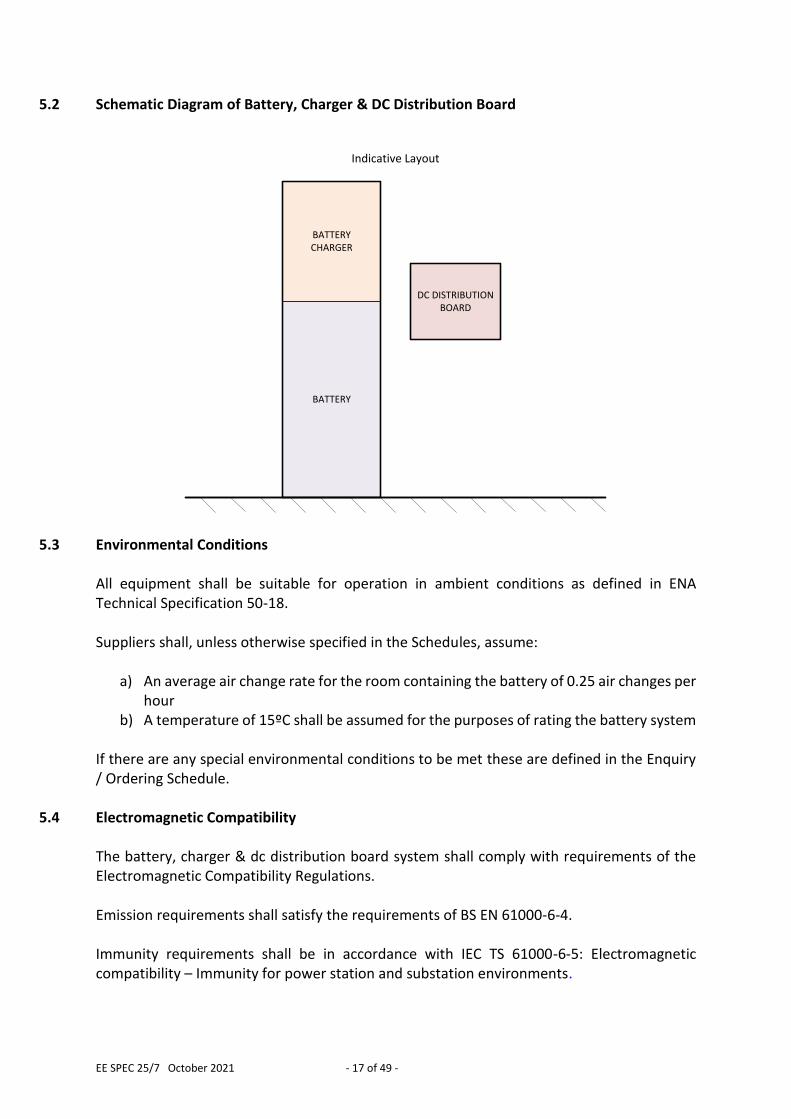
5.2 Schematic Diagram of Battery, Charger & DC Distribution Board
BATTERYCHARGER
BATTERY
DC DISTRIBUTION BOARD
Indicative Layout
5.3 Environmental Conditions All equipment shall be suitable for operation in ambient conditions as defined in ENA Technical Specification 50-18. Suppliers shall, unless otherwise specified in the Schedules, assume:
a) An average air change rate for the room containing the battery of 0.25 air changes per hour
b) A temperature of 15ºC shall be assumed for the purposes of rating the battery system If there are any special environmental conditions to be met these are defined in the Enquiry / Ordering Schedule.
5.4 Electromagnetic Compatibility The battery, charger & dc distribution board system shall comply with requirements of the Electromagnetic Compatibility Regulations. Emission requirements shall satisfy the requirements of BS EN 61000-6-4. Immunity requirements shall be in accordance with IEC TS 61000-6-5: Electromagnetic compatibility – Immunity for power station and substation environments.
EE SPEC 25/7 October 2021 - 18 of 49 -
5.5 DC System Earthing 110Vdc systems shall not be directly connected to earth, but earthed via the high impedance of an insulation monitoring (i.e. earth leakage) device. In other words, 110Vdc systems shall be IT systems (I=Isolated, T=Earth) as described in BS 7671.
5.6 Wiring and Terminations All interconnecting control wiring, terminations and terminal blocks shall be in accordance with ENA Technical Specification 50-18. Terminal blocks for alarm facilities shall be screw clamp type, to ENA Technical Specification 50-18, with a hinged link for isolation purposes.
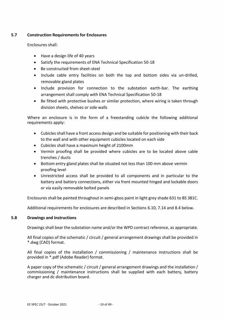
5.6.1 Conductor Identification By Colour Manufacturers shall identify all conductors within DC distribution boards and all other conductors at the point of interface to auxiliary cabling by the use of coloured insulation in accordance with BS 7671, BS EN 60446 and Table 1 below.
5.6.2 Wire Identification Marks Manufacturers shall apply alphanumeric identification marks to small wiring located at the point of interface to auxiliary cabling complying with BS 7671 and BS EN 60446 and as per Table 1 below. Manufacturers may apply identification marks to small wiring complying with other standards, or to their own convention, at terminals which are not located at the point of interface to auxiliary cabling. Identification marks (ferrules) shall also be fitted to each wire in every auxiliary cable. The ferruling shall comply with the requirements contained in ENA Technical Specification 50-19. Its purpose is to facilitate tracing through equipment for function checking and fault-finding and consequently this numbering shall be shown on schematic and wiring diagrams. Table 1: Conductor Identification By Colour and Alphanumeric Characters
Conductor Insulation Colour
Alphanumeric Characters
Single Phase AC
Phase Conductors
Neutral Conductors
Brown Blue
L1 N
Unearthed DC
Positive Conductors
Negative Conductors
Brown Grey
L+ L-
EE SPEC 25/7 October 2021 - 19 of 49 -
5.7 Construction Requirements for Enclosures
Enclosures shall:
Have a design life of 40 years
Satisfy the requirements of ENA Technical Specification 50-18
Be constructed from sheet-steel
Include cable entry facilities on both the top and bottom sides via un-drilled,
removable gland plates
Include provision for connection to the substation earth-bar. The earthing
arrangement shall comply with ENA Technical Specification 50-18
Be fitted with protective bushes or similar protection, where wiring is taken through
division sheets, shelves or side walls Where an enclosure is in the form of a freestanding cubicle the following additional requirements apply:
Cubicles shall have a front access design and be suitable for positioning with their back
to the wall and with other equipment cubicles located on each side
Cubicles shall have a maximum height of 2100mm
Vermin proofing shall be provided where cubicles are to be located above cable
trenches / ducts
Bottom entry gland plates shall be situated not less than 100 mm above vermin
proofing level
Unrestricted access shall be provided to all components and in particular to the
battery and battery connections, either via front mounted hinged and lockable doors
or via easily removable bolted panels Enclosures shall be painted throughout in semi-gloss paint in light grey shade 631 to BS 381C. Additional requirements for enclosures are described in Sections 6.10, 7.14 and 8.4 below.
5.8 Drawings and Instructions Drawings shall bear the substation name and/or the WPD contract reference, as appropriate. All final copies of the schematic / circuit / general arrangement drawings shall be provided in *.dwg (CAD) format. All final copies of the installation / commissioning / maintenance instructions shall be provided in *.pdf (Adobe Reader) format. A paper copy of the schematic / circuit / general arrangement drawings and the installation / commissioning / maintenance instructions shall be supplied with each battery, battery charger and dc distribution board.
EE SPEC 25/7 October 2021 - 20 of 49 -
6.0 ADDITIONAL REQUIREMENTS FOR BATTERIES Batteries will be employed in a float charge application (i.e. permanently connected to a load and to a dc power supply) and in a static location (i.e. not generally intended to be moved from place to place). The load will comprise of protection relays and switchgear control equipment i.e. a utility switching application. The battery is required to supply the dc power requirements when the following conditions occur:
The load on the dc system exceeds the maximum output of the battery charger
The output of the battery charger is interrupted
The ac power supply to the charger is lost
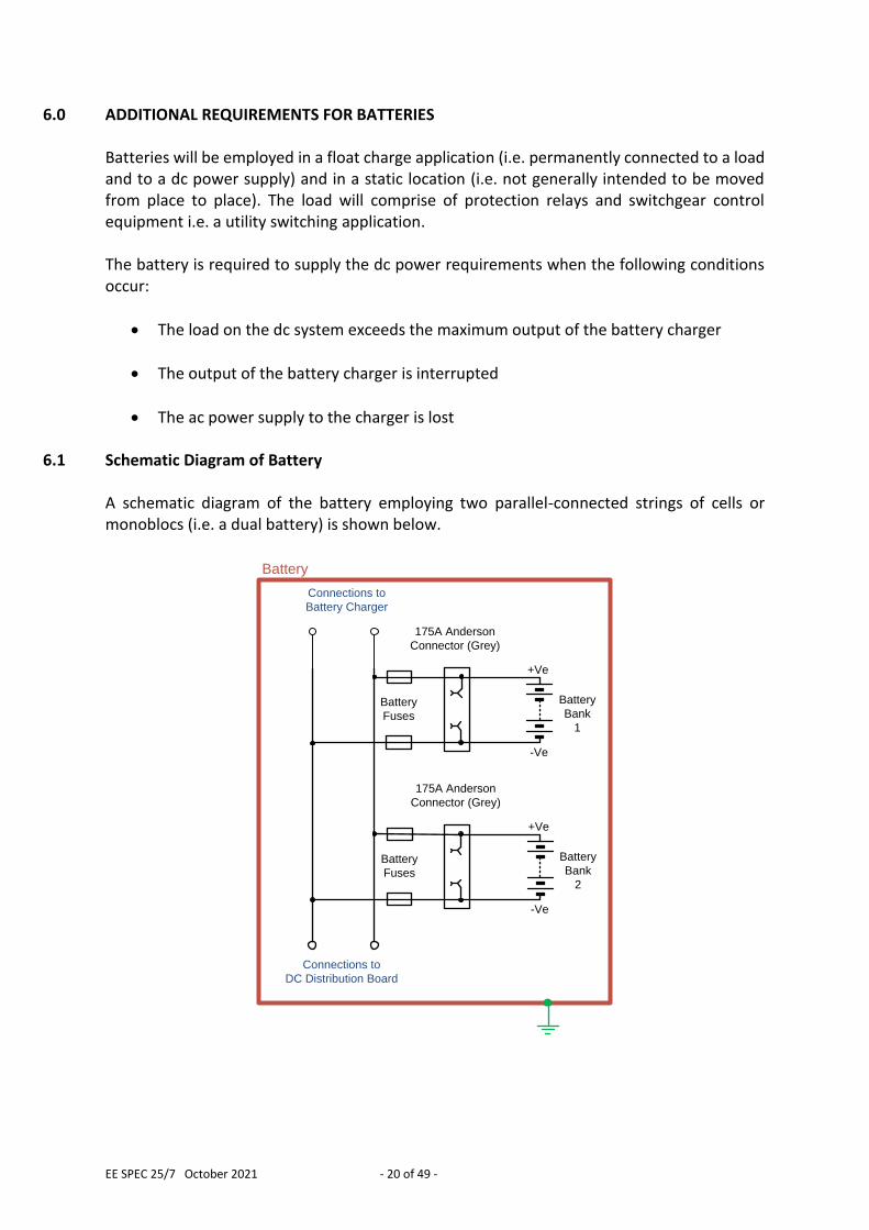
6.1 Schematic Diagram of Battery A schematic diagram of the battery employing two parallel-connected strings of cells or monoblocs (i.e. a dual battery) is shown below.
Battery
+Ve
-Ve
Battery
Fuses
175A Anderson
Connector (Grey)
Battery
Bank
1
+Ve
-Ve
Battery
Fuses
175A Anderson
Connector (Grey)
Battery
Bank
2
Connections to
Battery Charger
Connections to
DC Distribution Board
EE SPEC 25/7 October 2021 - 21 of 49 -
6.2 Monobloc Type Batteries associated with 110V systems shall employ valve regulated lead-acid monoblocs complying with BS EN 60896-21 and BS EN 60896-22. The monoblocs shall be equipped with front-facing terminals in order to facilitate maintenance and testing activities.
6.3 Monobloc Performance, Durability & Design Life The design life of the battery shall be at least 10 years, which shall be calculated using an average ambient temperature of 20°C. Monoblocs shall have a service life in excess of 1100 days at an operating temperature of 40°C and shall maintain their capacity for in excess of 350 days at a stress temperature of 55°C when tested in accordance with BS EN 60896-21. Monoblocs shall be classified as “12 years & longer – Very Long Life” according to Eurobat.
6.4 Battery Arrangement The battery shall consist of two parallel-connected strings of monoblocs. Each string shall consist of a number of series-connected monoblocs (as appropriate for the battery voltage). Each string shall be identical i.e. employ the same number and type of monobloc and contain 50% of the overall battery capacity.
6.5 Battery Sizing The battery system shall be sized in accordance with the requirements of this section and using the methodology described in IEEE Standard 485: Recommended Practice for Sizing Lead Acid Batteries for Stationary Applications. A worked example is included in Section 13.0.
6.5.1 Battery Duty Cycle The battery system shall, in the event of a failure of either the charger or its ac supply, be capable of supporting:
The standing dc load for a period of 72 hours, followed by The simultaneous opening (tripping) of 3 circuit breakers, followed by The sequential closing of 3 circuit breakers
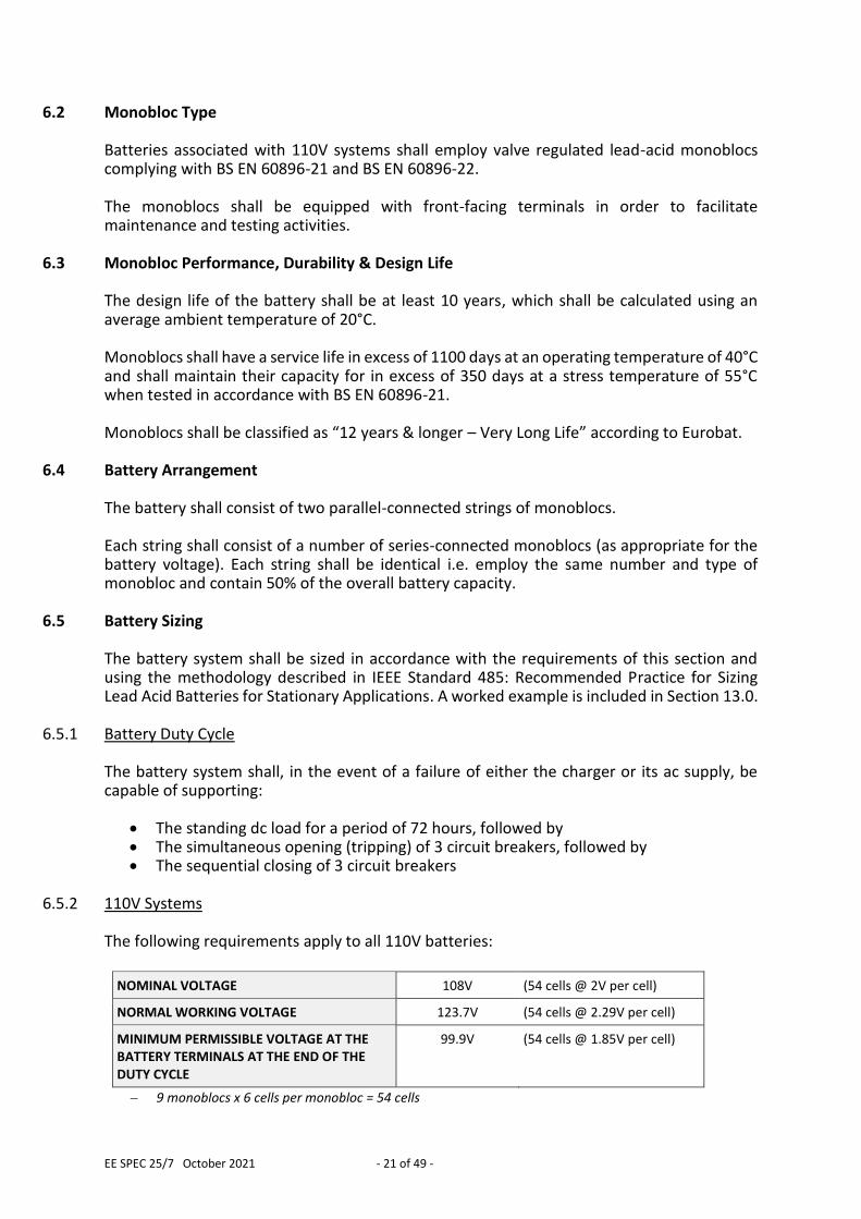
6.5.2 110V Systems
The following requirements apply to all 110V batteries:
NOMINAL VOLTAGE 108V (54 cells @ 2V per cell)
NORMAL WORKING VOLTAGE 123.7V (54 cells @ 2.29V per cell)
MINIMUM PERMISSIBLE VOLTAGE AT THE BATTERY TERMINALS AT THE END OF THE DUTY CYCLE
99.9V (54 cells @ 1.85V per cell)
9 monoblocs x 6 cells per monobloc = 54 cells
EE SPEC 25/7 October 2021 - 22 of 49 -
6.5.3 Battery Design Margin It is prudent to provide a margin to allow for unforeseen additional load on the dc system or for ambient temperatures being lower than expected. A battery design margin of 1.1 shall be applied to the battery sizing calculation.
6.5.4 Temperature Correction Factor A temperature of 15ºC shall be assumed for the purposes of rating the battery system. The available capacity in a monobloc is affected by its operating temperature and rated capacity is typically based upon an ambient temperature of 20ºC or 25ºC. Manufacturer’s data on the effect of battery temperature on the electrical discharge performance shall be used to determine a temperature correction factor to be applied to the battery sizing calculation.
Guidance Battery capacity shall be assessed using a temperature of 15°C whereas design life shall be assessed using 20°C. Manufacturer ratings are usually based on an ambient temperature of 20°C. Typically, a temperature correction factor of 1.04 is applied to the battery sizing calculation to correct for a temperature of 15ºC. This temperature correction is based upon a 1 hour discharge rate.
6.5.5 Ageing Factor End of service life shall be deemed to be the point at which the battery’s actual capacity has reached 80% of the nominal capacity. The battery shall perform the full specified discharge duty cycle throughout its service life, and consequently a 1.25 factor for age shall be applied to the battery sizing calculation.
6.6 WPD Standard Battery Capacities WPD requires battery systems to be provided in two different capacities. The following duty cycles set the benchmark against which the performance of proposed monoblocs can be assessed using the methodology described in Section 6.5 above.
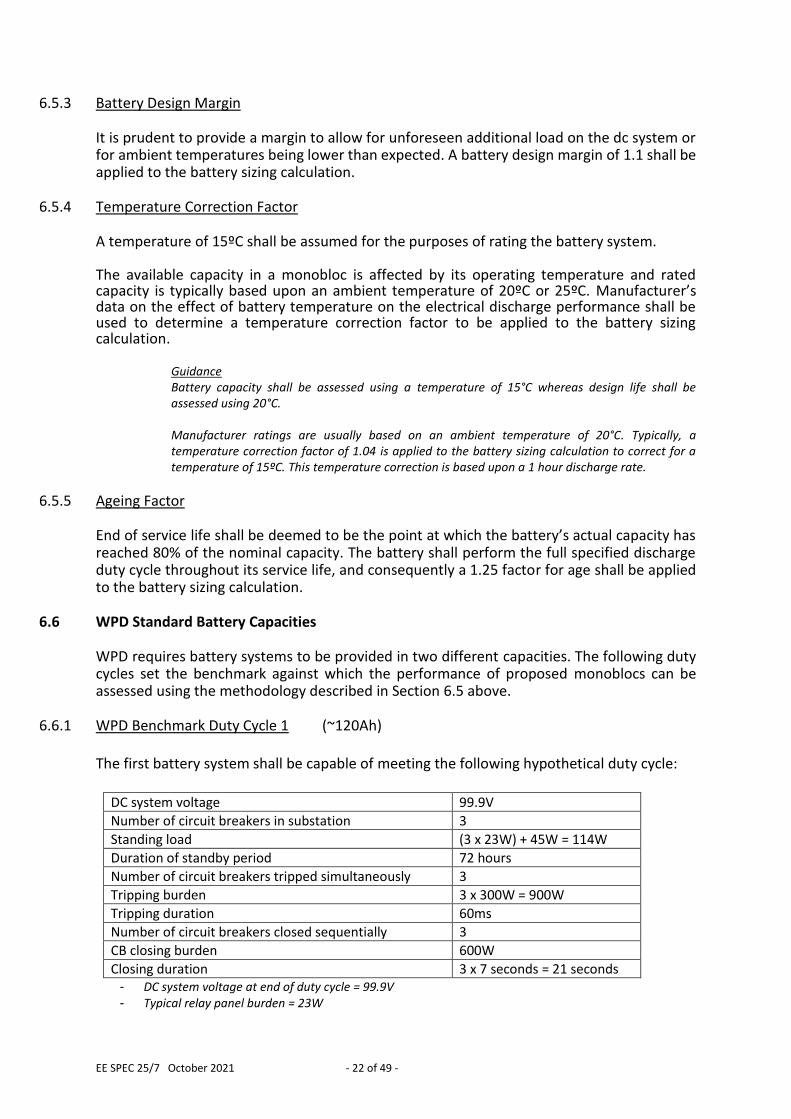
6.6.1 WPD Benchmark Duty Cycle 1 (~120Ah) The first battery system shall be capable of meeting the following hypothetical duty cycle:
DC system voltage 99.9V
Number of circuit breakers in substation 3
Standing load (3 x 23W) + 45W = 114W
Duration of standby period 72 hours
Number of circuit breakers tripped simultaneously 3
Tripping burden 3 x 300W = 900W
Tripping duration 60ms
Number of circuit breakers closed sequentially 3
CB closing burden 600W
Closing duration 3 x 7 seconds = 21 seconds - DC system voltage at end of duty cycle = 99.9V - Typical relay panel burden = 23W
EE SPEC 25/7 October 2021 - 23 of 49 -
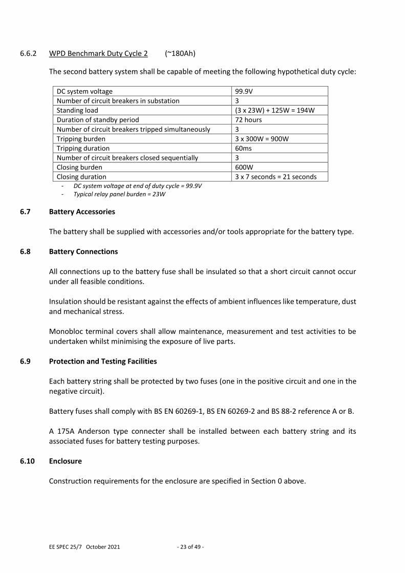
6.6.2 WPD Benchmark Duty Cycle 2 (~180Ah)
The second battery system shall be capable of meeting the following hypothetical duty cycle:
DC system voltage 99.9V
Number of circuit breakers in substation 3
Standing load (3 x 23W) + 125W = 194W
Duration of standby period 72 hours
Number of circuit breakers tripped simultaneously 3
Tripping burden 3 x 300W = 900W
Tripping duration 60ms
Number of circuit breakers closed sequentially 3
Closing burden 600W
Closing duration 3 x 7 seconds = 21 seconds - DC system voltage at end of duty cycle = 99.9V - Typical relay panel burden = 23W
6.7 Battery Accessories The battery shall be supplied with accessories and/or tools appropriate for the battery type.
6.8 Battery Connections All connections up to the battery fuse shall be insulated so that a short circuit cannot occur under all feasible conditions. Insulation should be resistant against the effects of ambient influences like temperature, dust and mechanical stress. Monobloc terminal covers shall allow maintenance, measurement and test activities to be undertaken whilst minimising the exposure of live parts.
6.9 Protection and Testing Facilities Each battery string shall be protected by two fuses (one in the positive circuit and one in the negative circuit). Battery fuses shall comply with BS EN 60269-1, BS EN 60269-2 and BS 88-2 reference A or B. A 175A Anderson type connecter shall be installed between each battery string and its associated fuses for battery testing purposes.
6.10 Enclosure Construction requirements for the enclosure are specified in Section 0 above.
EE SPEC 25/7 October 2021 - 24 of 49 -
The battery shall be provided in its own self-contained and lockable compartment. It is permissible for this to form part of a cubicle housing the battery charger. Both battery strings may be housed in the same compartment. Monoblocs shall be arranged in a single row per shelf, orientated such that their terminals face towards the enclosure door. The battery enclosure shall be sized such that:
Monoblocs on each shelf are associated with a single battery string only
Shelves associated with the same battery string are grouped together i.e. are not intermingled with shelves associated with the other battery string
There is sufficient space to accommodate alternative brands of monobloc in the event that economics favour a different product when they are replaced at end of life. To this extent, cubicles shall be sized assuming the following:
Monobloc dimensions are 127mm (w) x 565mm (l) x 321mm (h)
10mm gap is provided around the sides of each monobloc
20mm gap is provided above the top of each monobloc
A single battery string or an individual monobloc can be replaced without dismantling or removing other equipment
There is adequate access to monobloc terminals to allow maintenance, measurement and test activities to be undertaken (e.g. for voltage & impedance measurements, discharge tests and the like)
There is a physical gap between neighbouring monoblocs, between monoblocs and the sides of the enclosure and between monoblocs and the shelf above, which shall be in accordance with the manufacturer’s recommendations
The enclosure floor and shelves (where fitted) shall be designed to take the load of the monoblocs. A weight of not less than 70kg per monobloc should be assumed for this assessment. The battery enclosure shall provide a degree of protection to at least IP2X or IPXXB classification in accordance with BS EN 60529. Whilst the volume of gas emitted by valve regulated lead-acid cells or monoblocs is very small under normal charging conditions, it increases significantly in the event of overcharging. Sufficient natural ventilation shall be provided to prevent the formation of an explosive hydrogen concentration within the enclosure under fault conditions, specifically, in the event of an overvoltage condition of 2.40V per cell. Ventilation requirements shall be calculated in accordance with BS EN 50272-2 and the average air change rate for the room containing the battery declared in section 4.3.
EE SPEC 25/7 October 2021 - 25 of 49 -
6.11 Labelling
6.11.1 Monobloc Labelling Each monobloc shall be provided with a durable and easily visible alphanumeric identification to enable specific maintenance records to be kept and faulty monoblocs to be identified unambiguously. The identification shall commence with a letter which identifies the string, followed by a number which identifies the monobloc. Numbering shall start at the positive pole, with each monobloc being consecutively numbered all the way to the negative pole.
For example: A5 A label shall be placed on the front of each monobloc specifying the replacement date. The date shall be 8 years from the date of supply (to the nearest month).
6.11.2 Battery Identification Label The battery cubicle shall be provided with a durable and easily visible alphanumeric identification label mounted on the exterior of the enclosure. The alphanumeric identification shall be 110V BATTERY (WPD)
6.11.3 Manufacturer’s Information Label The exterior of the cubicle shall be provided with a durable and easily visible information label showing the following details:
Name of manufacturer or supplier
Manufacturer’s or supplier’s type reference
Nominal battery voltage
Nominal or rated capacity of the battery
6.12 Monobloc Approval Only monoblocs which are approved by WPD are permitted to be used on the WPD distribution network. A list of monoblocs which have already been approved by WPD can be found in Section 11.0. Where a monobloc is proposed which is not on the approved list then, in addition to demonstrating conformance with this specification, the supplier shall also arrange at its own expense, for the battery capacity to be verified by discharge testing at an independent test facility, and for the worst performing monobloc to be subject to a tear-down inspection. A formal written report shall be provided for both the discharge test and the tear-down inspection.
EE SPEC 25/7 October 2021 - 26 of 49 -
Unless otherwise agreed by WPD in writing, the independent test facility shall be:
Northern Industrial Battery Services Ltd (NIBS) Four Crosses Business Park Four Crosses Llanymynech, Powys SY22 6ST
The discharge test shall be carried out in accordance with the following requirements:
The test shall be performed on a single battery string consisting of six series-connected monoblocs
The monoblocs shall be selected at random from a batch of new monoblocs which have not previously been subject to any discharge
The blocs shall be positioned side-by-side at the manufacturer’s recommended spacing and with the terminals linked using the manufacturer’s recommended interconnects
The ambient temperature shall be 20°C
The voltage per monobloc and the overall string voltage shall be automatically recorded at one minute intervals during the test
The temperature of each bloc shall be periodically measured during the test.
The battery shall be discharged at the three-hour rate
The test shall be terminated when a string voltage of 61.2V is reached (i.e. 36 cells x 1.70V per cell) or when one of the six monoblocs has reached a voltage 10.2V (6 cells x 1.70V per cell), whichever occurs first
The monoblocs will have failed the discharge test if the test has to be terminated after less than 180 minutes have elapsed.
EE SPEC 25/7 October 2021 - 27 of 49 -
7.0 ADDITIONAL REQUIREMENTS FOR BATTERY CHARGERS
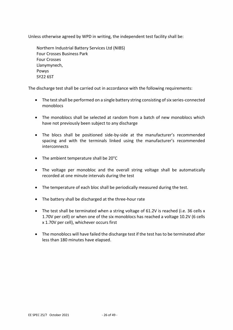
7.1 Schematic Diagram of Battery Charger
Charger
A
B
L
N
MCB MCB
Battery Charger
E
Generator Connection Socket
Change-over
Switch
230Va.c. Connections
to Battery
Connections to
AC Distribution Board
“Urgent” Relay Output ContactConnections to Telecontrol Outstation
[“Battery Urgent” Alarm]
“Non Urgent” Relay Output ContactConnections to Telecontrol Outstation
[“Battery Non Urgent” Alarm]
NOTES:“Urgent” and “Non-Urgent” relays shown in the de-energised state
7.2 General The charger shall be an automatic constant voltage charger utilising thyristor controlled rectifier technology. The charger shall be constructed so that the thyristor controlled rectifier unit can be easily removed and replaced.
7.3 Design Life The design life of the battery charger shall be at least 20 years.
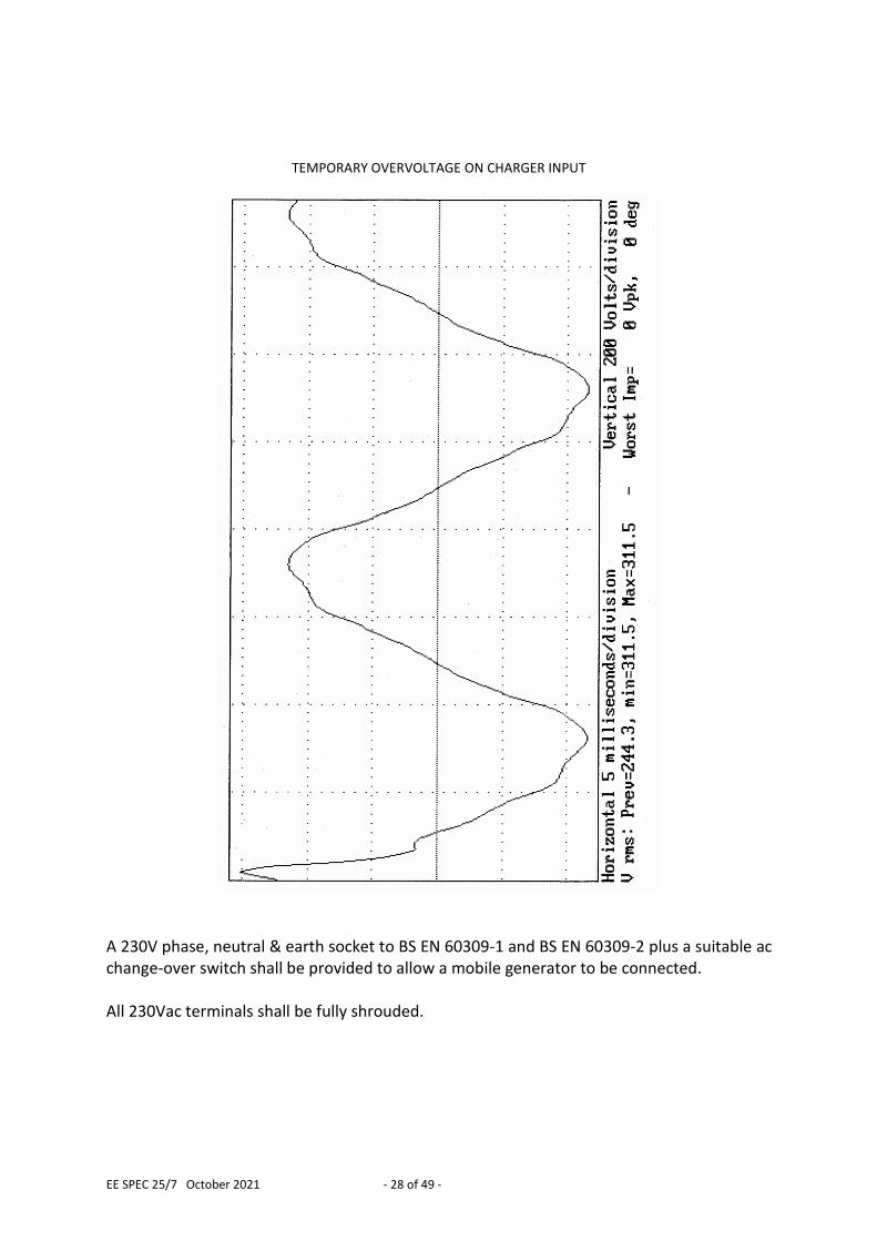
7.4 AC Circuits and Maintenance Facilities The battery charger shall operate from a 230Vac single phase 50Hz supply. The battery charger shall include current and voltage limiting circuitry, along with frequency interference suppression to comply with BS EN 55014-1 under all operating conditions. The battery charger shall not be damaged by temporary over-voltages of the type shown below lasting for 3 seconds.
EE SPEC 25/7 October 2021 - 28 of 49 -
TEMPORARY OVERVOLTAGE ON CHARGER INPUT
A 230V phase, neutral & earth socket to BS EN 60309-1 and BS EN 60309-2 plus a suitable ac change-over switch shall be provided to allow a mobile generator to be connected. All 230Vac terminals shall be fully shrouded.

EE SPEC 25/7 October 2021 - 29 of 49 -
7.5 DC Output Current Rating
The charger dc output current rating shall be not less than:
C10 current for the battery + (Charger Design Margin x Standing Load Current) It is prudent to provide a margin to allow for unforeseen additional load on the dc system. A charger design margin of 1.1 shall be employed in the charger sizing calculation.
7.6 DC Output Voltage Control The float voltage setting shall be adjustable about the set value, accommodating the range of float voltages recommended by the battery manufacturer. Boost charging facilities shall not be provided.
7.7 DC Output Current Control The charger output current shall be adjustable between 20% and 100% of the current rated output current.
7.8 Performance On float charge, the output voltage shall not vary by more than +1% to -1% under the following conditions:
a) Frequency varying between +1% and -1% of 50 Hz.
b) AC input voltage varying between +10% and -6% of 230V or 400V (as appropriate).
c) Charger DC current output varying between 0% and 100% of the nominal rating. The AC ripple permitted on the battery system output shall not exceed 2% of rated voltage and shall not exceed levels that have an adverse effect on battery life. The charger shall be designed to prevent, as far as possible, transient voltages or spikes above 137.5V occurring on the DC output.
7.9 Charger Input / Output Protection The input and output of the charger shall be protected by suitable miniature circuit breakers (MCBs). Residual current devices (RCD) shall not be used. The fault level on the LV electrical installation is likely to be very high. MCBs suitable for an industrial application (i.e. to BS EN 60947-2) with a current breaking capacity of not less than 15kA shall be employed.
EE SPEC 25/7 October 2021 - 30 of 49 -
7.10 Charger Control Module and other Electronic Components All electronic components shall be chosen such that they should not require replacement during the design life of the system.
7.11 Instrumentation Requirements
7.11.1 Instrumentation for Local Monitoring The battery charger shall include instrumentation which displays the charger dc output voltage and current.
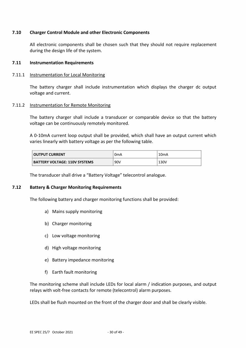
7.11.2 Instrumentation for Remote Monitoring The battery charger shall include a transducer or comparable device so that the battery voltage can be continuously remotely monitored. A 0-10mA current loop output shall be provided, which shall have an output current which varies linearly with battery voltage as per the following table.
OUTPUT CURRENT 0mA 10mA
BATTERY VOLTAGE: 110V SYSTEMS 90V 130V
The transducer shall drive a “Battery Voltage” telecontrol analogue.
7.12 Battery & Charger Monitoring Requirements The following battery and charger monitoring functions shall be provided:
a) Mains supply monitoring
b) Charger monitoring
c) Low voltage monitoring
d) High voltage monitoring
e) Battery impedance monitoring
f) Earth fault monitoring The monitoring scheme shall include LEDs for local alarm / indication purposes, and output relays with volt-free contacts for remote (telecontrol) alarm purposes. LEDs shall be flush mounted on the front of the charger door and shall be clearly visible.
EE SPEC 25/7 October 2021 - 31 of 49 -
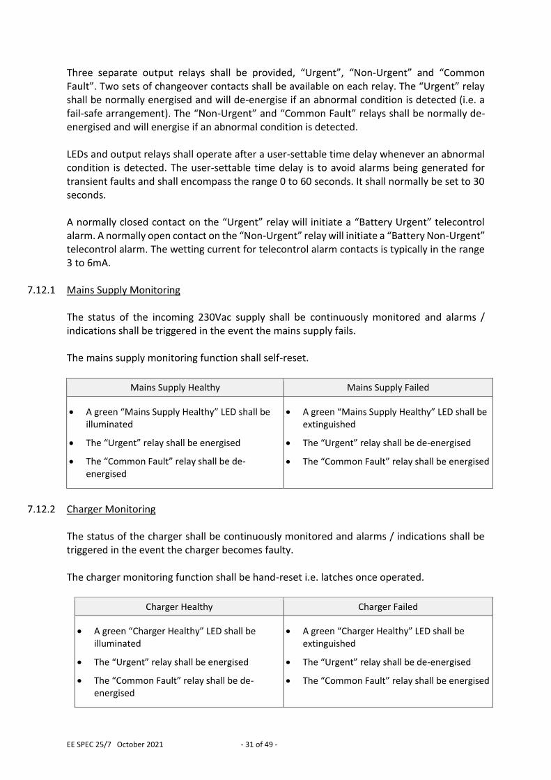
Three separate output relays shall be provided, “Urgent”, “Non-Urgent” and “Common Fault”. Two sets of changeover contacts shall be available on each relay. The “Urgent” relay shall be normally energised and will de-energise if an abnormal condition is detected (i.e. a fail-safe arrangement). The “Non-Urgent” and “Common Fault” relays shall be normally de-energised and will energise if an abnormal condition is detected. LEDs and output relays shall operate after a user-settable time delay whenever an abnormal condition is detected. The user-settable time delay is to avoid alarms being generated for transient faults and shall encompass the range 0 to 60 seconds. It shall normally be set to 30 seconds. A normally closed contact on the “Urgent” relay will initiate a “Battery Urgent” telecontrol alarm. A normally open contact on the “Non-Urgent” relay will initiate a “Battery Non-Urgent” telecontrol alarm. The wetting current for telecontrol alarm contacts is typically in the range 3 to 6mA.
7.12.1 Mains Supply Monitoring The status of the incoming 230Vac supply shall be continuously monitored and alarms / indications shall be triggered in the event the mains supply fails. The mains supply monitoring function shall self-reset.
Mains Supply Healthy Mains Supply Failed
A green “Mains Supply Healthy” LED shall be illuminated
The “Urgent” relay shall be energised
The “Common Fault” relay shall be de-energised
A green “Mains Supply Healthy” LED shall be extinguished
The “Urgent” relay shall be de-energised
The “Common Fault” relay shall be energised
7.12.2 Charger Monitoring
The status of the charger shall be continuously monitored and alarms / indications shall be triggered in the event the charger becomes faulty. The charger monitoring function shall be hand-reset i.e. latches once operated.
Charger Healthy Charger Failed
A green “Charger Healthy” LED shall be illuminated
The “Urgent” relay shall be energised
The “Common Fault” relay shall be de-energised
A green “Charger Healthy” LED shall be extinguished
The “Urgent” relay shall be de-energised
The “Common Fault” relay shall be energised
EE SPEC 25/7 October 2021 - 32 of 49 -
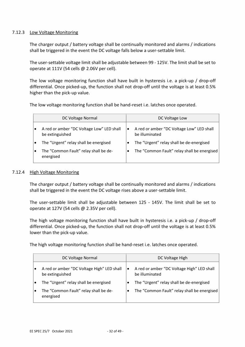
7.12.3 Low Voltage Monitoring The charger output / battery voltage shall be continually monitored and alarms / indications shall be triggered in the event the DC voltage falls below a user-settable limit. The user-settable voltage limit shall be adjustable between 99 - 125V. The limit shall be set to operate at 111V (54 cells @ 2.06V per cell). The low voltage monitoring function shall have built in hysteresis i.e. a pick-up / drop-off differential. Once picked-up, the function shall not drop-off until the voltage is at least 0.5% higher than the pick-up value. The low voltage monitoring function shall be hand-reset i.e. latches once operated.
DC Voltage Normal DC Voltage Low
A red or amber “DC Voltage Low” LED shall be extinguished
The “Urgent” relay shall be energised
The “Common Fault” relay shall be de-energised
A red or amber “DC Voltage Low” LED shall be illuminated
The “Urgent” relay shall be de-energised
The “Common Fault” relay shall be energised
7.12.4 High Voltage Monitoring
The charger output / battery voltage shall be continually monitored and alarms / indications shall be triggered in the event the DC voltage rises above a user-settable limit. The user-settable limit shall be adjustable between 125 - 145V. The limit shall be set to operate at 127V (54 cells @ 2.35V per cell). The high voltage monitoring function shall have built in hysteresis i.e. a pick-up / drop-off differential. Once picked-up, the function shall not drop-off until the voltage is at least 0.5% lower than the pick-up value. The high voltage monitoring function shall be hand-reset i.e. latches once operated.
DC Voltage Normal DC Voltage High
A red or amber “DC Voltage High” LED shall be extinguished
The “Urgent” relay shall be energised
The “Common Fault” relay shall be de-energised
A red or amber “DC Voltage High” LED shall be illuminated
The “Urgent” relay shall be de-energised
The “Common Fault” relay shall be energised
EE SPEC 25/7 October 2021 - 33 of 49 -
7.12.5 Battery Impedance Monitoring
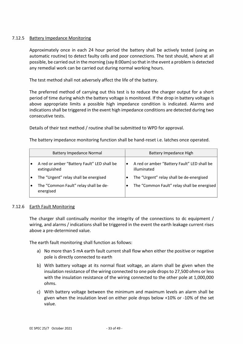
Approximately once in each 24 hour period the battery shall be actively tested (using an automatic routine) to detect faulty cells and poor connections. The test should, where at all possible, be carried out in the morning (say 8:00am) so that in the event a problem is detected any remedial work can be carried out during normal working hours. The test method shall not adversely affect the life of the battery. The preferred method of carrying out this test is to reduce the charger output for a short period of time during which the battery voltage is monitored. If the drop in battery voltage is above appropriate limits a possible high impedance condition is indicated. Alarms and indications shall be triggered in the event high impedance conditions are detected during two consecutive tests. Details of their test method / routine shall be submitted to WPD for approval. The battery impedance monitoring function shall be hand-reset i.e. latches once operated.
Battery Impedance Normal Battery Impedance High
A red or amber “Battery Fault” LED shall be extinguished
The “Urgent” relay shall be energised
The “Common Fault” relay shall be de-energised
A red or amber “Battery Fault” LED shall be illuminated
The “Urgent” relay shall be de-energised
The “Common Fault” relay shall be energised
7.12.6 Earth Fault Monitoring
The charger shall continually monitor the integrity of the connections to dc equipment / wiring, and alarms / indications shall be triggered in the event the earth leakage current rises above a pre-determined value. The earth fault monitoring shall function as follows:
a) No more than 5 mA earth fault current shall flow when either the positive or negative pole is directly connected to earth
b) With battery voltage at its normal float voltage, an alarm shall be given when the insulation resistance of the wiring connected to one pole drops to 27,500 ohms or less with the insulation resistance of the wiring connected to the other pole at 1,000,000 ohms.
c) With battery voltage between the minimum and maximum levels an alarm shall be given when the insulation level on either pole drops below +10% or -10% of the set value.
EE SPEC 25/7 October 2021 - 34 of 49 -
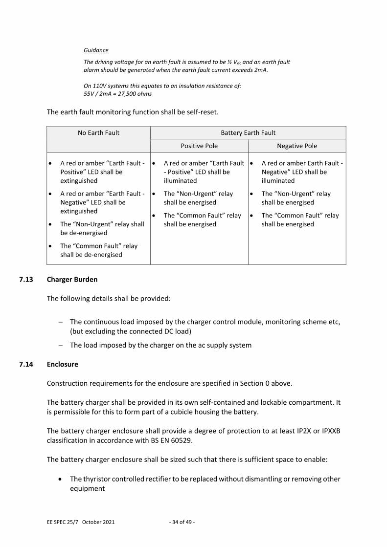
Guidance
The driving voltage for an earth fault is assumed to be ½ Vdc and an earth fault alarm should be generated when the earth fault current exceeds 2mA. On 110V systems this equates to an insulation resistance of: 55V / 2mA = 27,500 ohms
The earth fault monitoring function shall be self-reset.
No Earth Fault Battery Earth Fault
Positive Pole Negative Pole
A red or amber “Earth Fault - Positive” LED shall be extinguished
A red or amber “Earth Fault - Negative” LED shall be extinguished
The “Non-Urgent” relay shall be de-energised
The “Common Fault” relay shall be de-energised
A red or amber “Earth Fault - Positive” LED shall be illuminated
The “Non-Urgent” relay shall be energised
The “Common Fault” relay shall be energised
A red or amber Earth Fault - Negative” LED shall be illuminated
The “Non-Urgent” relay shall be energised
The “Common Fault” relay shall be energised
7.13 Charger Burden
The following details shall be provided:
The continuous load imposed by the charger control module, monitoring scheme etc, (but excluding the connected DC load)
The load imposed by the charger on the ac supply system
7.14 Enclosure Construction requirements for the enclosure are specified in Section 0 above. The battery charger shall be provided in its own self-contained and lockable compartment. It is permissible for this to form part of a cubicle housing the battery. The battery charger enclosure shall provide a degree of protection to at least IP2X or IPXXB classification in accordance with BS EN 60529. The battery charger enclosure shall be sized such that there is sufficient space to enable:
The thyristor controlled rectifier to be replaced without dismantling or removing other equipment
EE SPEC 25/7 October 2021 - 35 of 49 -
Maintenance activities to be carried out, such as adjusting float voltage and output current settings, cleaning heat sinks and fans, testing battery alarms etc.
There is adequate access to all components to allow inspections to be undertaken (e.g. for signs of overheating, damage, or decay)
7.15 Labelling
7.15.1 Battery Charger Identification Label
The battery charger shall be provided with a durable and easily visible alphanumeric identification label mounted on the exterior of the enclosure. The alphanumeric identification shall be 110V BATTERY CHARGER (WPD)
7.15.2 Manufacturer’s Information Label The battery charger shall be provided with a durable and easily visible information label showing the following details:
Name of manufacturer or supplier
Manufacturer’s or supplier’s type reference
Rated ac input voltage
Rated ac input current
Rated dc output voltage
Rated dc output current
Date of manufacture
EE SPEC 25/7 October 2021 - 36 of 49 -
8.0 ADDITIONAL REQUIREMENTS FOR DC DISTRIBUTION BOARDS
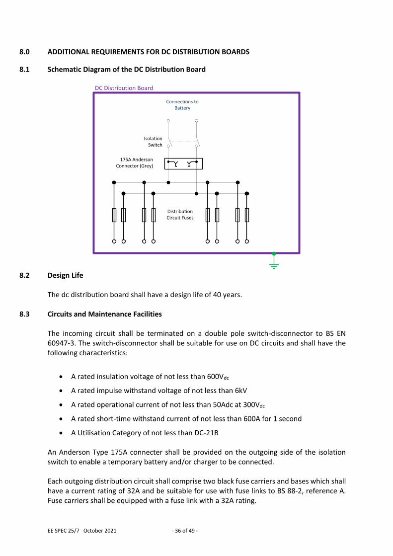
8.1 Schematic Diagram of the DC Distribution Board
Isolation Switch
175A Anderson Connector (Grey)
DC Distribution Board
Distribution Circuit Fuses
Connections toBattery
8.2 Design Life
The dc distribution board shall have a design life of 40 years.
8.3 Circuits and Maintenance Facilities The incoming circuit shall be terminated on a double pole switch-disconnector to BS EN 60947-3. The switch-disconnector shall be suitable for use on DC circuits and shall have the following characteristics:
A rated insulation voltage of not less than 600Vdc
A rated impulse withstand voltage of not less than 6kV
A rated operational current of not less than 50Adc at 300Vdc
A rated short-time withstand current of not less than 600A for 1 second
A Utilisation Category of not less than DC-21B An Anderson Type 175A connecter shall be provided on the outgoing side of the isolation switch to enable a temporary battery and/or charger to be connected. Each outgoing distribution circuit shall comprise two black fuse carriers and bases which shall have a current rating of 32A and be suitable for use with fuse links to BS 88-2, reference A. Fuse carriers shall be equipped with a fuse link with a 32A rating.
EE SPEC 25/7 October 2021 - 37 of 49 -
8.4 Enclosure
The distribution board shall be contained within a wall mounted enclosure which is physically separate from the cubicles associated with the battery & charger. The enclosure will be mounted immediately adjacent to the battery & charger and will be interconnected with it by short lengths of cable. The rationale behind this approach is that it facilitates the preservation of substation dc auxiliary supplies during the replacement of the battery, charger or associated cubicle, which have a much shorter design life than that of the distribution board. The enclosure shall be equipped with a front mounted hinged and lockable door. Construction requirements for the enclosure are specified in Section 0 above.
8.5 Wire Marking And Insulation Colour All wiring in the DC distribution board shall be marked and coloured as per Section 5.6 above.
8.6 Labelling All labelling shall be in accordance with ENA Technical Specification 50-18.
8.6.1 Distribution Board Identification Label The DC distribution board shall be provided with a durable and easily visible alphanumeric identification label mounted on the exterior of the enclosure. The alphanumeric identification shall be 110V DC DISTRIBUTION BOARD (WPD)
8.6.2 Manufacturer’s Information Label The exterior of the enclosure shall be provided with a durable and easily visible information label showing the following details:
Name of manufacturer or supplier
Date of manufacture
8.6.3 Fuse-holder Identification Labels
Each fuse-holder shall be provided with a durable and easily visible alphanumeric identification label mounted immediately adjacent denoting its function. The alphanumeric identification shall be in the form X Y Z, where:
X = DC+ or DC- (as appropriate)
EE SPEC 25/7 October 2021 - 38 of 49 -
Y = CIRCUIT NAME
Z = (*A) (where * is the fuse link current rating) For example: DC+ SWITCHGEAR (32A)
8.6.4 Component Identification Labels The Anderson connector shall be provided with a durable and easily visible alphanumeric identification label mounted immediately adjacent denoting its function.
9.0 ADDITIONAL REQUIREMENTS FOR AUXILIARY CABLING
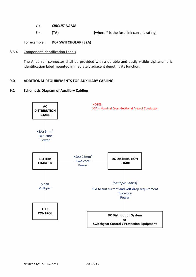
9.1 Schematic Diagram of Auxiliary Cabling
BATTERYCHARGER
DC DISTRIBUTIONBOARD
TELECONTROL
AC DISTRIBUTION
BOARD
XSA≥ 6mm2 Two-core
Power
XSA≥ 25mm2 Two-core
Power
5 pair Multipair
[Multiple Cables]
XSA to suit current and volt-drop requirementTwo-core
Power
NOTES:XSA = Nominal Cross-Sectional Area of Conductor
DC Distribution Systemor
Switchgear Control / Protection Equipment
EE SPEC 25/7 October 2021 - 39 of 49 -
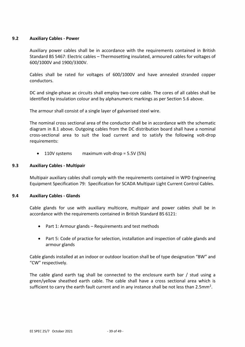
9.2 Auxiliary Cables - Power
Auxiliary power cables shall be in accordance with the requirements contained in British Standard BS 5467: Electric cables – Thermosetting insulated, armoured cables for voltages of 600/1000V and 1900/3300V. Cables shall be rated for voltages of 600/1000V and have annealed stranded copper conductors. DC and single-phase ac circuits shall employ two-core cable. The cores of all cables shall be identified by insulation colour and by alphanumeric markings as per Section 5.6 above. The armour shall consist of a single layer of galvanised steel wire. The nominal cross sectional area of the conductor shall be in accordance with the schematic diagram in 8.1 above. Outgoing cables from the DC distribution board shall have a nominal cross-sectional area to suit the load current and to satisfy the following volt-drop requirements:
110V systems maximum volt-drop = 5.5V (5%)
9.3 Auxiliary Cables - Multipair Multipair auxiliary cables shall comply with the requirements contained in WPD Engineering Equipment Specification 79: Specification for SCADA Multipair Light Current Control Cables.
9.4 Auxiliary Cables - Glands Cable glands for use with auxiliary multicore, multipair and power cables shall be in accordance with the requirements contained in British Standard BS 6121:
Part 1: Armour glands – Requirements and test methods
Part 5: Code of practice for selection, installation and inspection of cable glands and armour glands
Cable glands installed at an indoor or outdoor location shall be of type designation “BW” and “CW” respectively. The cable gland earth tag shall be connected to the enclosure earth bar / stud using a green/yellow sheathed earth cable. The cable shall have a cross sectional area which is sufficient to carry the earth fault current and in any instance shall be not less than 2.5mm2.
EE SPEC 25/7 October 2021 - 40 of 49 -
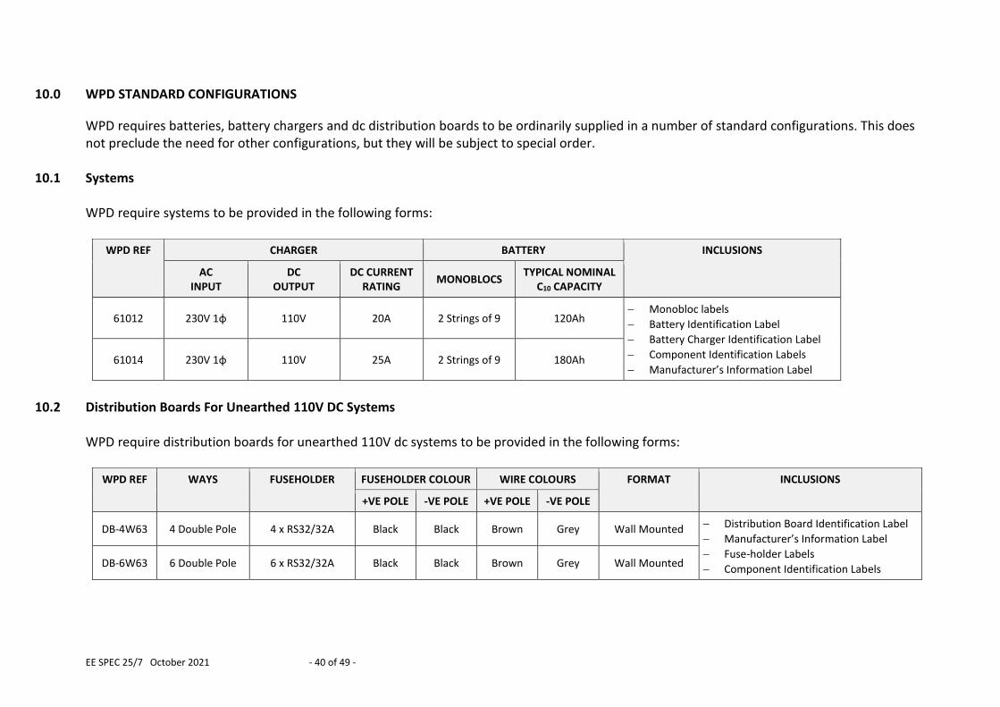
10.0 WPD STANDARD CONFIGURATIONS
WPD requires batteries, battery chargers and dc distribution boards to be ordinarily supplied in a number of standard configurations. This does not preclude the need for other configurations, but they will be subject to special order.
10.1 Systems WPD require systems to be provided in the following forms:
WPD REF CHARGER BATTERY INCLUSIONS
AC
INPUT DC
OUTPUT DC CURRENT
RATING MONOBLOCS
TYPICAL NOMINAL C10 CAPACITY
61012 230V 1φ 110V 20A 2 Strings of 9 120Ah Monobloc labels
Battery Identification Label
Battery Charger Identification Label
Component Identification Labels
Manufacturer’s Information Label 61014 230V 1φ 110V 25A 2 Strings of 9 180Ah
10.2 Distribution Boards For Unearthed 110V DC Systems
WPD require distribution boards for unearthed 110V dc systems to be provided in the following forms:
WPD REF WAYS FUSEHOLDER FUSEHOLDER COLOUR WIRE COLOURS FORMAT INCLUSIONS
+VE POLE -VE POLE +VE POLE -VE POLE
DB-4W63 4 Double Pole 4 x RS32/32A Black Black Brown Grey Wall Mounted Distribution Board Identification Label
Manufacturer’s Information Label
Fuse-holder Labels
Component Identification Labels DB-6W63 6 Double Pole 6 x RS32/32A Black Black Brown Grey Wall Mounted
EE SPEC 25/7 October 2021 - 41 of 49 -
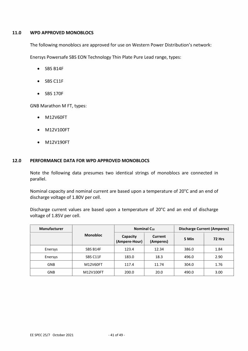
11.0 WPD APPROVED MONOBLOCS The following monoblocs are approved for use on Western Power Distribution’s network: Enersys Powersafe SBS EON Technology Thin Plate Pure Lead range, types:
SBS B14F
SBS C11F
SBS 170F GNB Marathon M FT, types:
M12V60FT
M12V100FT
M12V190FT
12.0 PERFORMANCE DATA FOR WPD APPROVED MONOBLOCS Note the following data presumes two identical strings of monoblocs are connected in parallel. Nominal capacity and nominal current are based upon a temperature of 20°C and an end of discharge voltage of 1.80V per cell. Discharge current values are based upon a temperature of 20°C and an end of discharge voltage of 1.85V per cell.
Manufacturer
Monobloc
Nominal C10 Discharge Current (Amperes)
Capacity (Ampere-Hour)
Current (Amperes)
5 Min 72 Hrs
Enersys SBS B14F 123.4 12.34 386.0 1.84
Enersys SBS C11F 183.0 18.3 496.0 2.90
GNB M12V60FT 117.4 11.74 304.0 1.76
GNB M12V100FT 200.0 20.0 490.0 3.00
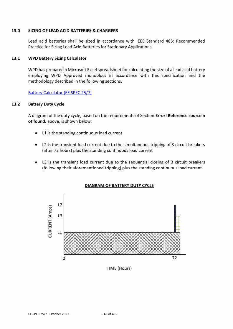
EE SPEC 25/7 October 2021 - 42 of 49 -
13.0 SIZING OF LEAD ACID BATTERIES & CHARGERS
Lead acid batteries shall be sized in accordance with IEEE Standard 485: Recommended Practice for Sizing Lead Acid Batteries for Stationary Applications.
13.1 WPD Battery Sizing Calculator WPD has prepared a Microsoft Excel spreadsheet for calculating the size of a lead acid battery employing WPD Approved monoblocs in accordance with this specification and the methodology described in the following sections. Battery Calculator (EE SPEC 25/7)
13.2 Battery Duty Cycle A diagram of the duty cycle, based on the requirements of Section Error! Reference source not found. above, is shown below.
L1 is the standing continuous load current
L2 is the transient load current due to the simultaneous tripping of 3 circuit breakers (after 72 hours) plus the standing continuous load current
L3 is the transient load current due to the sequential closing of 3 circuit breakers (following their aforementioned tripping) plus the standing continuous load current
0 72
TIME (Hours)
CU
RR
ENT
(Am
ps) L2
L1
DIAGRAM OF BATTERY DUTY CYCLE
L3
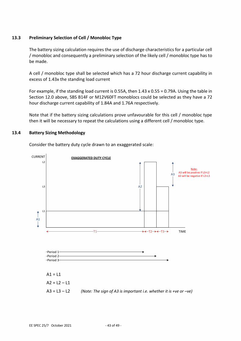
EE SPEC 25/7 October 2021 - 43 of 49 -
13.3 Preliminary Selection of Cell / Monobloc Type
The battery sizing calculation requires the use of discharge characteristics for a particular cell / monobloc and consequently a preliminary selection of the likely cell / monobloc type has to be made. A cell / monobloc type shall be selected which has a 72 hour discharge current capability in excess of 1.43x the standing load current For example, if the standing load current is 0.55A, then 1.43 x 0.55 = 0.79A. Using the table in Section 12.0 above, SBS B14F or M12V60FT monoblocs could be selected as they have a 72 hour discharge current capability of 1.84A and 1.76A respectively. Note that if the battery sizing calculations prove unfavourable for this cell / monobloc type then it will be necessary to repeat the calculations using a different cell / monobloc type.
13.4 Battery Sizing Methodology Consider the battery duty cycle drawn to an exaggerated scale:
TIME
CURRENT
T1 T2 T3
A1
A2
A3
Period 1Period 2Period 3
EXAGGERATED DUTY CYCLE
Note: A3 will be positive if L3>L2 A3 will be negative if L2>L3
L1
L2
L3
A1 = L1
A2 = L2 – L1
A3 = L3 – L2 (Note: The sign of A3 is important i.e. whether it is +ve or –ve)
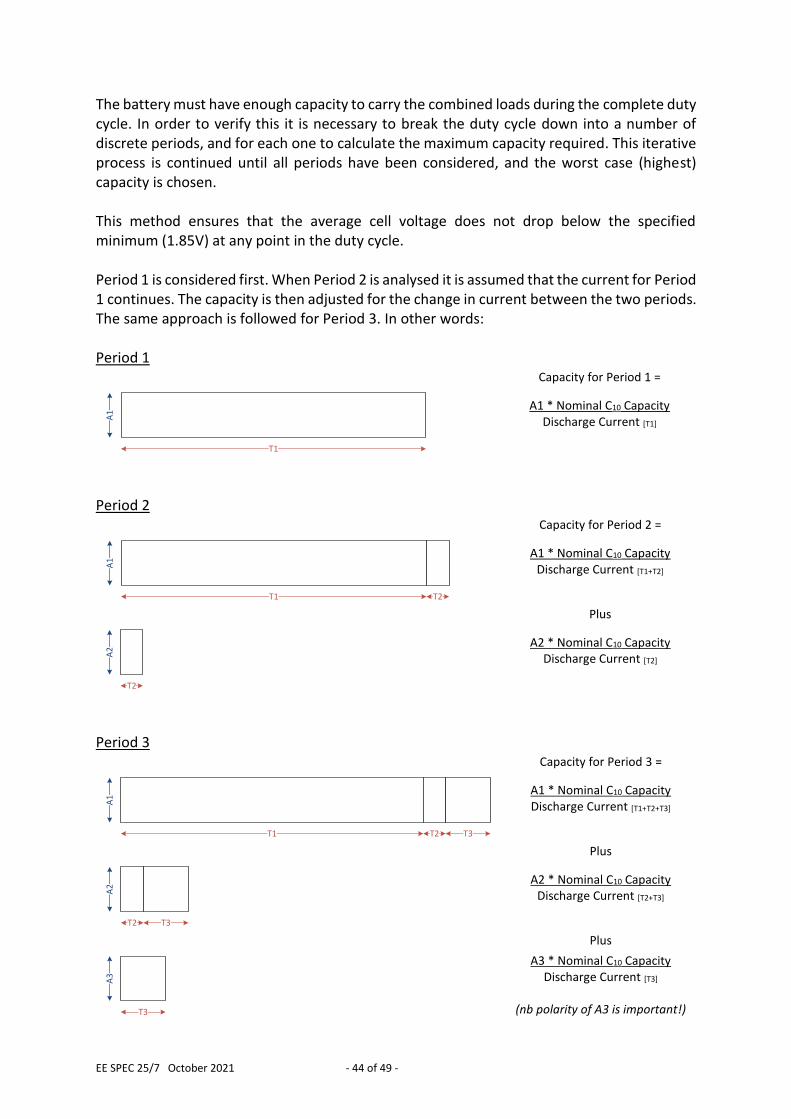
EE SPEC 25/7 October 2021 - 44 of 49 -
The battery must have enough capacity to carry the combined loads during the complete duty cycle. In order to verify this it is necessary to break the duty cycle down into a number of discrete periods, and for each one to calculate the maximum capacity required. This iterative process is continued until all periods have been considered, and the worst case (highest) capacity is chosen. This method ensures that the average cell voltage does not drop below the specified minimum (1.85V) at any point in the duty cycle. Period 1 is considered first. When Period 2 is analysed it is assumed that the current for Period 1 continues. The capacity is then adjusted for the change in current between the two periods. The same approach is followed for Period 3. In other words: Period 1 Capacity for Period 1 =
T1
A1
A1 * Nominal C10 Capacity Discharge Current [T1]
Period 2 Capacity for Period 2 =
T1 T2
A1
A1 * Nominal C10 Capacity Discharge Current [T1+T2]
Plus
T2
A2
A2 * Nominal C10 Capacity Discharge Current [T2]
Period 3 Capacity for Period 3 =
T1 T2
A1
T3
A1 * Nominal C10 Capacity Discharge Current [T1+T2+T3]
Plus
T2
A2
T3
A2 * Nominal C10 Capacity Discharge Current [T2+T3]
Plus
T3
A3
A3 * Nominal C10 Capacity Discharge Current [T3]
(nb polarity of A3 is important!)
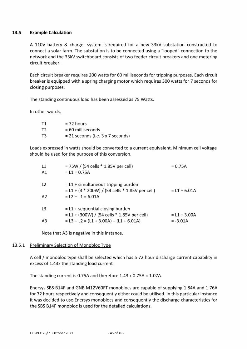
EE SPEC 25/7 October 2021 - 45 of 49 -
13.5 Example Calculation A 110V battery & charger system is required for a new 33kV substation constructed to connect a solar farm. The substation is to be connected using a “looped” connection to the network and the 33kV switchboard consists of two feeder circuit breakers and one metering circuit breaker. Each circuit breaker requires 200 watts for 60 milliseconds for tripping purposes. Each circuit breaker is equipped with a spring charging motor which requires 300 watts for 7 seconds for closing purposes. The standing continuous load has been assessed as 75 Watts. In other words,
T1 = 72 hours T2 = 60 milliseconds T3 = 21 seconds (i.e. 3 x 7 seconds)
Loads expressed in watts should be converted to a current equivalent. Minimum cell voltage should be used for the purpose of this conversion.
L1 = 75W / (54 cells * 1.85V per cell) = 0.75A A1 = L1 = 0.75A L2 = L1 + simultaneous tripping burden
= L1 + (3 * 200W) / (54 cells * 1.85V per cell) = L1 + 6.01A A2 = L2 – L1 = 6.01A L3 = L1 + sequential closing burden
= L1 + (300W) / (54 cells * 1.85V per cell) = L1 + 3.00A A3 = L3 – L2 = (L1 + 3.00A) – (L1 + 6.01A) = -3.01A
Note that A3 is negative in this instance.
13.5.1 Preliminary Selection of Monobloc Type A cell / monobloc type shall be selected which has a 72 hour discharge current capability in excess of 1.43x the standing load current The standing current is 0.75A and therefore 1.43 x 0.75A = 1.07A. Enersys SBS B14F and GNB M12V60FT monoblocs are capable of supplying 1.84A and 1.76A for 72 hours respectively and consequently either could be utilised. In this particular instance it was decided to use Enersys monoblocs and consequently the discharge characteristics for the SBS B14F monobloc is used for the detailed calculations.
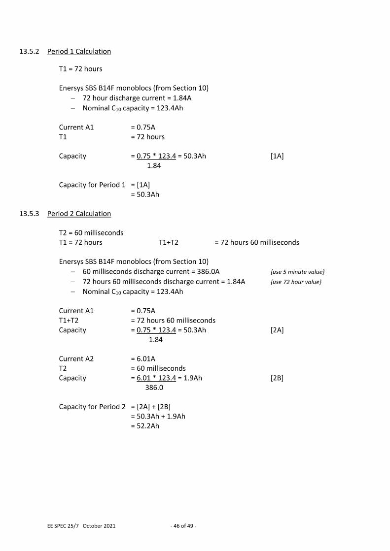
EE SPEC 25/7 October 2021 - 46 of 49 -
13.5.2 Period 1 Calculation
T1 = 72 hours Enersys SBS B14F monoblocs (from Section 10)
72 hour discharge current = 1.84A
Nominal C10 capacity = 123.4Ah Current A1 = 0.75A T1 = 72 hours Capacity = 0.75 * 123.4 = 50.3Ah [1A]
1.84 Capacity for Period 1 = [1A]
= 50.3Ah
13.5.3 Period 2 Calculation T2 = 60 milliseconds T1 = 72 hours T1+T2 = 72 hours 60 milliseconds Enersys SBS B14F monoblocs (from Section 10)
60 milliseconds discharge current = 386.0A {use 5 minute value}
72 hours 60 milliseconds discharge current = 1.84A {use 72 hour value}
Nominal C10 capacity = 123.4Ah Current A1 = 0.75A T1+T2 = 72 hours 60 milliseconds Capacity = 0.75 * 123.4 = 50.3Ah [2A]
1.84 Current A2 = 6.01A T2 = 60 milliseconds Capacity = 6.01 * 123.4 = 1.9Ah [2B]
386.0 Capacity for Period 2 = [2A] + [2B]
= 50.3Ah + 1.9Ah = 52.2Ah
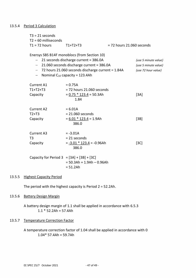
EE SPEC 25/7 October 2021 - 47 of 49 -
13.5.4 Period 3 Calculation
T3 = 21 seconds T2 = 60 milliseconds T1 = 72 hours T1+T2+T3 = 72 hours 21.060 seconds Enersys SBS B14F monoblocs (from Section 10)
21 seconds discharge current = 386.0A {use 5 minute value}
21.060 seconds discharge current = 386.0A {use 5 minute value}
72 hours 21.060 seconds discharge current = 1.84A {use 72 hour value}
Nominal C10 capacity = 123.4Ah Current A1 = 0.75A T1+T2+T3 = 72 hours 21.060 seconds Capacity = 0.75 * 123.4 = 50.3Ah [3A]
1.84 Current A2 = 6.01A T2+T3 = 21.060 seconds Capacity = 6.01 * 123.4 = 1.9Ah [3B]
386.0 Current A3 = -3.01A T3 = 21 seconds Capacity = -3.01 * 123.4 = -0.96Ah [3C]
386.0 Capacity for Period 3 = [3A] + [3B] + [3C]
= 50.3Ah + 1.9Ah – 0.96Ah = 51.2Ah
13.5.5 Highest Capacity Period
The period with the highest capacity is Period 2 = 52.2Ah.
13.5.6 Battery Design Margin A battery design margin of 1.1 shall be applied in accordance with 6.5.3
1.1 * 52.2Ah = 57.4Ah
13.5.7 Temperature Correction Factor A temperature correction factor of 1.04 shall be applied in accordance with 0
1.04* 57.4Ah = 59.7Ah
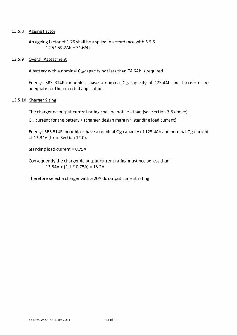
EE SPEC 25/7 October 2021 - 48 of 49 -
13.5.8 Ageing Factor
An ageing factor of 1.25 shall be applied in accordance with 6.5.5 1.25* 59.7Ah = 74.6Ah
13.5.9 Overall Assessment A battery with a nominal C10 capacity not less than 74.6Ah is required. Enersys SBS B14F monoblocs have a nominal C10 capacity of 123.4Ah and therefore are adequate for the intended application.
13.5.10 Charger Sizing The charger dc output current rating shall be not less than (see section 7.5 above):
C10 current for the battery + (charger design margin * standing load current) Enersys SBS B14F monoblocs have a nominal C10 capacity of 123.4Ah and nominal C10 current of 12.34A (from Section 12.0). Standing load current = 0.75A Consequently the charger dc output current rating must not be less than:
12.34A + (1.1 * 0.75A) = 13.2A Therefore select a charger with a 20A dc output current rating.
EE SPEC 25/7 October 2021 - 49 of 49 -
APPENDIX A SUPERSEDED DOCUMENTATION This document supersedes EE SPEC: 25/6 dated October 2018 which has now been withdrawn.
APPENDIX B RECORD OF COMMENT DURING CONSULTATION Comments received
APPENDIX C ANCILLARY DOCUMENTATION EE SPEC 23 110V and 220V Batteries, Chargers, Controllers, Distribution Boards &
Associated Cabling For Primary Network Substations Other Than Metering Circuit Breaker Type
APPENDIX D
KEY WORDS Batteries; Chargers; Distribution; Boards; 110V; DC; Primary; Metering;