ENGINEER PROGRAMMING MANUAL - Vigi Securite
28
Attention: This manual contains information on limitations regarding product use and function and information on the limitations as to liability of the manufacturer. The entire manual should be carefully read. The information in this manual is a subject to change without notice! INSTALLATION AND OPERATION MANUAL Extinguishing Control Panel IVY
-
Upload
khangminh22 -
Category
Documents
-
view
7 -
download
0
Transcript of ENGINEER PROGRAMMING MANUAL - Vigi Securite

Attention: This manual contains information on limitations regarding product use and function and information on the limitations as to liability of the manufacturer. The entire manual should be carefully read.
The information in this manual is a subject to change without notice!
INSTALLATION AND OPERATION MANUAL
Extinguishing Control Panel
IVY

IVY - Installation and Programming Manual
2
Table of Contents 1. INTRODUCTION .................................................................................................................................................................... 4
1.1. General Description ............................................................................................................................................... 4 1.2. General Specifications ........................................................................................................................................... 4
1.2.1 General Technical Specifications ...................................................................................................... 4 1.2.2 Environment ..................................................................................................................................... 5 1.2.3 Electrical Characteristics ................................................................................................................... 5
2. INSTALLATION ...................................................................................................................................................................... 7 2.1. Wall Mounting ........................................................................................................................................................ 7 2.2. System Components ............................................................................................................................................. 8
2.2.1Configuration of the basic modules .................................................................................................... 8 2.2.2 Description of the main PCB (control panel) ...................................................................................... 9 2.2.3 Main Power Supply Unit .................................................................................................................. 12 2.2.4 Connection of Back-up Batteries ..................................................................................................... 13
2.3. Circuits Wiring ...................................................................................................................................................... 13
2.3.1 Zone Circuits Wiring ....................................................................................................................... 13 2.3.2 Sounders Circuits Wiring ................................................................................................................. 13 2.3.3 Connecting to the Supervised Inputs ............................................................................................... 14 2.3.4 Solenoid Wiring – Connecting the Extinguishing Circuit ................................................................... 14 2.3.5 Connecting the OC Outputs ............................................................................................................ 14
3. INDICATION AND CONTROLS ........................................................................................................................................... 15 4. OPERATION MODES .......................................................................................................................................................... 18
4.1. Normal Operation Mode ...................................................................................................................................... 18 4.2. Stage 1 (Fire Alarm) ............................................................................................................................................ 18 4.3. Stage 2 (Extinguishing activated) ........................................................................................................................ 18 4.4. Extinguishing Released ....................................................................................................................................... 19 4.5. Fault ..................................................................................................................................................................... 19 4.6. Double Action Mode ............................................................................................................................................ 19
5. PROGRAMMING OF SYSTEM TIMES ................................................................................................................................ 20 5.1. Setting EXTINGUISHING DURATION TIME ....................................................................................................... 20 5.2. Setting EXTINGUISHING DELAY TIME .............................................................................................................. 21 5.3. Setting RESET HOLD TIME ................................................................................................................................ 21
6. USER OPERATION ............................................................................................................................................................. 21 6.1. Disabling/Enabling of Zones ................................................................................................................................ 21 6.2. Disabling/Enabling SND1 (Sounder Output 1) ..................................................................................................... 22 6.3. Zone Test ............................................................................................................................................................. 23
7. LOG MODULE (Optional) ..................................................................................................................................................... 24 7.1. Installation ............................................................................................................................................................ 24 7.2. Elements .............................................................................................................................................................. 25 7.3. LCD screen and Functional Buttons .................................................................................................................... 25 7.4. Menus .................................................................................................................................................................. 25
7.4.1 Reviewing the EVENT HISTORY .................................................................................................... 25 7.4.2 Setting the Date and Time .............................................................................................................. 26 7.4.3 Setting the Language ...................................................................................................................... 26
Appendix A – Messages for Events ......................................................................................................................................... 27
EN 54-2:1997/A1:2006/AC:1999; EN 54-4:1997/A2:2006/AC:1999; EN12094
IVY Intended for use in fire detection and fire alarm systems in and around buildings. Essential Characteristics Performance
Performance under fire conditions Pass
Response delay (response time to fire) Pass
Operational reliability Pass
Durability of operational reliability and response delay: temperature resistance Pass
Durability of operational reliability: humidity resistance Pass
Durability of operational reliability: vibration resistance Pass
Durability of operational reliability: electrical resistance Pass
Teletek Electronics JSC Bulgaria, Sofia 1407, 14А Srebarna Str., Tel.: +359 2 9694 800, Fax: +359 2 962 52 13
e-mail: [email protected]
181293
DoP No: 097 1293-CPR-0590

IVY – Installation and Programming Manual
3
GUARANTEE The guarantee terms are determined by the serial number (barcode) of the electronic device! During the guarantee period the manufacturer shall, at its sole discretion, replace or repair any defective product when it is returned to the factory. All parts replaced and/or repaired shall be covered for the remainder of the original guarantee, or 6 months, whichever period is longer. The original purchaser shall immediately send manufacturer a written notice of the defective parts or workmanship.
INTERNATIONAL GUARANTEE Foreign customers shall possess the same guarantee rights as those any customer in Bulgaria, except that manufacturer shall not be liable for any
related customs duties, taxes or VAT, which may be payable.
GUARANTEE PROCEDURE The guarantee will be granted when the appliance in question is returned. The guarantee period and the period for repair are determined in advance. The manufacturer shall not accept any product, of which no prior notice has been received via the RAN form at: http://teletek-electronics.com/en/ran-form The setup and programming included in the technical documentation shall not be regarded as defects. Teletek Electronics bears no responsibility for the loss of programming information in the device being serviced.
CONDITIONS FOR WAIVING THE GUARANTEE This guarantee shall apply to defects in products resulting only from improper materials or workmanship, related to its normal use. It shall not cover:
• Devices with destroyed serial number (barcode);
• Damages resulting from improper transportation and handling;
• Damages caused by natural calamities, such as fire, floods, storms, earthquakes or lightning;
• Damages caused by incorrect voltage, accidental breakage or water; beyond the control of the manufacturer;
• Damages caused by unauthorized system incorporation, changes, modifications or surrounding objects;
• Damages caused by peripheral appliances unless such peripheral appliances have been supplied by the manufacturer;
• Defects caused by inappropriate surrounding of installed products;
• Damages caused by failure to use the product for its normal purpose;
• Damages caused by improper maintenance;
• Damages resulting from any other cause, bad maintenance or product misuse. In the case of a reasonable number of unsuccessful attempts to repair the product, covered by this guarantee, the manufacturer’s liability shall be limited to the replacement of the product as sole compensation for breach of the guarantee. Under no circumstances shall the manufacturer be liable for any special, accidental or consequential damages, on the grounds of breach of guarantee, breach of agreement, negligence, or any other legal notion.
WAIVER This Guarantee shall contain the entire guarantee and shall be prevailing over any and all other guarantees, explicit or implicit (including any implicit guarantees on behalf of the dealer, or adaptability to specific purposes), and over any other responsibilities or liabilities on behalf of the manufacturer. The manufacturer does neither agree, nor empower, any person, acting on his own behalf, to modify, service or alter this Guarantee, nor to replace it with another guarantee, or another liability with regard to this product.
UNWARRANTED SERVICES The manufacturer shall repair or replace unwarranted products, which have been returned to its factory, at its sole discretion under the conditions below. The manufacturer shall accept no products for which no prior notice has been received via the RAN form at: http://teletek-electronics.com/en/ran-form. The products, which the manufacturer deems repairable, will be repaired and returned. The manufacturer has prepared a price list and those products, which can be repaired, shall be paid for by the Customer. The devices with unwarranted services carry 6 months guarantee for the replaced parts. The closest equivalent product, available at the time, shall replace the products, the manufacturer deems un-repairable. The current market price shall be charged for every replaced product.
STANDARDS AND CONFORMITY The extinguishing fire alarm control panel IVY is designed according and with conformity to EN 54 – 2/4 standard. Conforms and approved in accordance with CPR (Construction Products Regulation).
DOCUMENTATION FEEDBACK If you have any comments or suggestions on our products’ manuals or installation instructions you can email us on: [email protected] Your feedback on product documentation will help us to improve the contents of our manuals and stickers and keep them up-to-date. Please, include in your feedback email the product name, the revision of the manual or instruction (8-digit number with Revision and date of issue) and the page number.

IVY - Installation and Programming Manual
4
1. INTRODUCTION
1.1. General Description
IVY is a conventional fire extinguishing control panel. The panel is designed for using together with systems for gas, powder, aerosol, water and other types of active extinguishing.
IVY has 3 hardwire zones - 2 extinguishing with activation of automatic fire detectors and 1 conventional fire zone. Automatic and manual operation modes (selectable via 3 positional key lock) allow the operators to choose the extinguishing process control. The extinguishing process can be activated also manually with a special button MANUAL RELEASE on the front panel.
The IVY conventional panel is designed for extinguishing in one zone and can operate with solenoids, pressostats and other kind of actuators.
Optional LOG module for reviewing of recorded memory events (up to 1000 events) can be included in the system configuration.
Figure 1. IVY Extinguishing panel – General view
1.2. General Specifications
The front panel is divided into two operation sections: fire and extinguishing. The fire section includes information LEDs for zone and system status, and operation buttons for resetting, testing, disabling zones, etc. The access for operation with the fire part is realized via key switch with two access levels. The extinguishing section includes information LEDs for activated inputs and a mode selector – three-position key switch. The extinguishing process can also be started manually with a special button protected with a yellow plastic cover.
1.2.1 General Technical Specifications
• Zones: o Extinguishing – 2 fixed zones (Zone 1 and Zone 2) o Conventional Fire Alarm – 1 fixed zone (Zone 3)
• Detectors per zone – up to 32 conventional detectors
• Potential outputs: o SND 1 (Sounder 1) – Monitored, 24VDC, 300mA o SND 2 (Sounder 2) – Monitored, 24VDC, 300mA o EXTING (Extinguishing, EN 12094-1) – Monitored, 24VDC/1A 5min, 24VDC/3A 20ms
• Supervised balanced inputs (see item 2.2.2 for detailed description): o Manual Release o Hold o Mode Select o On/Off Exting (Enable/Disable Extinguishing) o Low Press. (Low Pressure) o Flow Control

IVY – Installation and Programming Manual
5
• Relay outputs: o 1 Stage Relay (1 STAGE) – Non-monitored, 5-30VDC/1A o 2 Stage Relay (2 STAGE) – Non-monitored, 5-30VDC/1A o Fault Relay – Non-monitored, 5-30VDC/1A
• Non-monitored outputs, OC (Open Collector) type, 30mA o OC1 (Hold Activation event) o OC2 (Disabled mode selected) o OC3 (Low Pressure event) o OC4 (Manual mode selected)
• 2-digits LED indication (7 segment display)
• Memory events LOG module (optional), 1000 events, real-time clock, built-in mounting
1.2.2 Environment
• Degree of protection: IP30
• Operation temperature: -5ºС up to +40ºC
• Relative humidity: up to 95% (without condense)
• Storage temperature: -10ºС up to +60ºC
• Weight (without the batteries): ~ 3.2 kg.
1.2.3 Electrical Characteristics Earth Connection The earth connection has to be realized in accordance with the rules for the electrical safety with the total resistance in the circuit lower than 10Ω. It is mandatory to connect the main power supply cable to the middle input of the fire panel terminal – see also item 2.2.3 Main power connection.
ATTENTION: Do not install the extinguishing panel near power electromagnetic fields (radio equipment, electric motors, etc.)!
Main power supply In normal operating conditions, the extinguishing panel is powered on from the mains voltage line. In case of mains voltage line loss, the fire panel is equipped with two rechargeable batteries. The characteristics of the main power supply are as follows:
• Main power supply: 110 230 VAC ±10%
• Frequency: 47 60 Hz
• Electrical output: 26VDC; 1.5A Backup (accumulator) power supply
• Voltage output (U): 27.2V
• Accumulator batteries: 2 x 12V / 7Ah, sealed lead-acid type rechargeable battery
• Internal resistance of the accumulator battery Ri: < 0.3Ω
• Max. dimensions of one accumulator battery: 152x62x100mm
• Type of the battery connection: with a cable shoe
Loading capacity
• Max. loading capacity of the zone lines Z1, Z2 and Z3: 70mA DC
• Max. loading capacity of AUX output: 1500mA DC @ 24VDC
• Max. loading capacity of sounder outputs SND1 and SND2: 300mA DC @ 24VDC
• Max. loading capacity of relay type outputs REL 1 ST, REL 2 ST and FAULT: 300mA DC @ 24VDC
• Max. loading capacity of open collector type outputs OC1, OC2, OC3 and OC4: 30mA DC @ 24VDC
• Max. total loading capacity (sum of the five capacities mentioned above): 1.5A DC
• Max. loading capacity of extinguishing output EXTING: 2A DC @ 24VDC for not more than 10 seconds

IVY - Installation and Programming Manual
6
Consumption
• From the main power supply in standby mode: o For a minimum configuration*: 15 mA AC
• From the backup power supply with FAULT for AC lost: o For a minimum configuration*: 65 mA DC
* The minimum configuration of IVY panel includes: main PCB, indication PCB, power supply unit – for their position in the panel’s box see item 2.2.1. List of the used fuses
• Main power supply ................................. 4А, F type, glass fuse, size 5х20mm
• AUX output ............................................. 2А, PTC type, resettable fuse
• Sounder outputs ..................................... 1А, PTC type, resettable fuse
• Extinguishing outputs ............................. 2A, PTC type, resettable fuse
• For power supply of the zone lines ........ 0.75A, PTC type, resettable fuse
• Accumulator batteries ............................ 6.3A, safety fuse, size 5х20mm
Items supplied with IVY Panel:
• Installation and Operation Manual – Document No. 18020843 (this manual)
• Accessory pack containing the following items: o 6 x 2.2k ± 5%, 0.25W Resistors o 3 x 10k ± 5%, 0.25W Resistor o 2 x 100V/1.0A Diode o 1 Mini Jumper o 1 x 4A, 20mm glass fuse (spare main power supply fuse) o 1 x Pair of keys 35mm (for 2-position access control key-lock Ø12mm) o 1 x Pair of keys 41mm (for 3-position menu selector key-lock Ø19mm) o 4 x 4.2х38 Screw, crossed slot DIN7981 o 1 x 2.5/100mm Cable tie (for fixing the main power supply cable) o 4 x 6х30mm Anchors (for wall mounting) o 4 x EOL modules o 1 x 100mm Cable for battery serial connection (red and black cable shoes for easy recognition at
installation)
ATTENTION! Qualified specialists only should install the panel. The electronic components of the panel are vulnerable to electrostatic discharge. Never install or deinstall components in the panel’s configuration which are being power supplied!

IVY – Installation and Programming Manual
7
2. INSTALLATION
2.1. Wall Mounting
• The panel must be installed in a clean dry place and must not be subject to impacts or vibrations (Figure 2). It must be situated far away from heating appliances. The temperature must be -5ºС to + 40ºC. The panel is not waterproof! • Unpack the panel and observe for visible damages due to bad transport or incorrect storing. • Open the front cover and disconnect the flat indication cable and the earthling point (Figure 3).
Figure 2 Figure 3 • Remove the front cover as dismount the side hinges first (Figure 4). Do not remove the cables from the terminals on the indication PCB, situated on the back side of the front cover!
Figure 4 • Disconnect the cable to the main power unit on the right side. • Undo the five screws fixing the main control PCB to the panel’s bottom and lift it gently towards you. Keep it in a safe place. With the main PCB removed there is more free space inside the bottom for running cables and there is no chance to damage the main PCB during mounting the panel’s bottom. • Choose inlets for the main power supply cable, zones and sounders circuits, control devices, etc. Remove the knockouts just from those holes used for cable running (Figure 5).
Figure 5 – Elements of the metal bottom: а) View from above; b) Front view. 1 – Main mounting holes. 2 – Holes for cable running. 3 – Hole for main power supply cable running, protected with a knockout. 4 – 10 holes Ø20mm for cable running, protected with knockouts, suitable for mounting of cable glands also.

IVY - Installation and Programming Manual
8
• Mark the places of the main mounting holes on the surface. • Drill holes (suitable for anchors Ø6mm) on the wall and fix the panel’s bottom. • Route the external cables into the back box, make off connection glands etc., BUT DO NOT make any connections at this stage. RUN THE MAINS CABLE THROUGH ITS OWN CABLE ENTRY POINT AND KEEP MAINS WIRING AWAY FROM SYSTEM AND OTHER LOW VOLTAGE WIRING. • When the cable running is complete re-fit the main PCB on the panel’s bottom using the five screws. • Connect the cable to the main power unit on the right side. • Connect the mains supply and earth to the power supply terminal (see Figure 9), BUT DO NOT switch on the main electrical supply at this stage. • Place the two batteries in an upright position. Use the 100mm cable from the spare parts kit to connect the batteries in series. • Place the temperature sensor behind the batteries. • Mount the front cover back to the bottom as mount the hinges in the reverse order of that described on Figure 4. • Connect back the flat cable for the indication and the earthling point (Figure 3). Observe the connection of the indication cable to be set stable on place. The unstable connection may cause malfunctioning of the panel. • Proceed with initial power up of the system and testing. • When you finish with power up and testing steps and the panel is in normal operation mode you must fix the front cover to the bottom with the two screws from the spare parts kit.
2.2. System Components
2.2.1Configuration of the basic modules
Figure 6 – Configuration of the modules in the box
• 1 – Main PCB (control panel)
• 2 – Power supply unit
• 3 – Terminal 230V for connection of the main power supply cable (see Figure 9)
• 4 – Place for accumulator batteries, 2 х 12V/ 7Ah, series connection (the batteries are sold separately; they are shown on the figure for illustration of the positive and negative poles position)
• 5 – Temperature sensor

IVY – Installation and Programming Manual
9
2.2.2 Description of the main PCB (control panel) The main PCB of IVY panel is fitted to the metal bottom with four screws. The connections to the main power unit, indication board and earth points are factory mounted. The connection wires for zones and control devices must be run out through the opening above the terminal rows. The terminals are designed to accept wires with cross section up to 2.5mm2. Do not run wires in front of or behind the control panel PCB. The wires must be fed over the upper side the terminals.
Figure 7 – Main PCB of IVY control panel
Description of the terminal row (left to right)
• Z1, Z2 – Terminals for connecting the extinguishing zones, 2-wire cross-zoning connection of the detectors in the flooding area.
• Z3 – Terminal for connecting the fire alarm conventional zone, 2-wire connection of detectors and call points. This zone is only for fire alarm detection and signalization.
• Manual Release – Supervised balanced input. This input is used for sending a signal to the control panel (via call point) for starting the extinguishing in the protected area. More than one call point can be connected to this line.
• Hold - Supervised balanced input. This input is used for sending a signal to the control panel (via call point or a pressure switch) for holding (delaying) the extinguishing in the protected area. The active state of the input, NC (Normal closed) or NO (Normal open), can be set via jumper J4.
• Mode Select - Supervised balanced input. This input is used for sending a signal to the control panel (via switch on/off contact) for the selected operation mode for the extinguishing. The input is enabled for operation only when the 3-position key-lock in the extinguishing section on the front panel (see item 3, figure 17, position 6) is set to AUTOMATIC mode. When the input is activated the panel will switch to MANUAL mode.
• On/Off Exting - Supervised balanced input. This input is used for enabling/disabling of the extinguishing from an external device and can be set via jumper J5.
• Low Press. - Supervised balanced input. This input is used for sending a signal to the control panel (from a pressostat contact, balance or other device) for monitoring the pressure level of the extinguishing agent (e.g.
bottles, meaning that the gas from the bottle is released and the pressure drops). The active state of the input, NC (Normal closed) or NO (Normal open), can be set via jumper J3.
• Flow Control - Supervised balanced input. This input is used for monitoring of the gas releasing process in normal operation mode. When the “Flow Control” input is activated the LEDs “Released” and “Flow Control” are lighting on, the outputs SND2 and OC2, and the relay contact “Stage 2” are triggered on, and the internal buzzer is on. Attention: The activation of the “Flow Control” input will not initiate an extinguishing process in the protected site! If the “Flow Control” input is activated and an alarm signal for extinguishing is received during that time, the extinguishing will start immediately because of its highest priority.
• OC1 – Open collector output. The output changes its state in case of “Hold” activation event.

IVY - Installation and Programming Manual
10
• OC2 – Open collector output. The output changes its state when the panel enters in Extinguishing Released operation mode – see item 4.4 on page 19. The panel enters in Extinguishing Released operation mode in case of:
o The extinguishing output “Exting” has been activated, or o The “Flow Control” input has been activated, which is used for monitoring of the gas releasing process.
• OC3 – Open collector output. The output changes its state in case of “Low pressure” activation event.
• OC4 – Open collector output. The output changes its state when the panel is switched to MANUAL mode via the 3-position key-lock selector (see item 3, figure 17, position 6) or via the “Mode Select” input.
• ± AUX – 28V, 300mA. Auxiliary output for power supply of external devices.
• 1 Stage (NC/NO/COM) – Dry contact relay output. The relay is activated in case of Stage 1 (Fire Alarm) operation mode.
• 2 Stage (NC/NO/COM) – Dry contact relay output. The relay is activated in case of Stage 2 (Extinguishing activated) operation mode.
• Fault (NC/NO/COM) – Dry contact relay output. The relay is activated in case of fault in the control panel.
• SND 1 – Monitored sounder output. The output is activated in case of Stage 1 (Fire Alarm) detected in Zone 1 or Zone 2 or Zone 3.
• SND 2 – Monitored sounder output. The output is activated in case of Stage 2 (Extinguishing activated) operation mode or in case of activation of the “Flow Control” input.
• Exting (Extinguishing output, EN 12094-1) – Supervised output for activation of solenoid which starts the extinguishing automatics.
LEDs FAULT Indication
In case of fault condition in the system the FAULT LED on the front panel lights on permanently together with one or more LEDs for system faults indication situated in the middle of the control PCB. All LEDs for faults indication are lighting on in yellow in case of a trouble event. The indication is active until the fault is corrected and the normal operation of the panel is restored. With the FAULT LED, according the specific fault, is possible to light on other system fault indicators on the front panel - see also item 2.4. The faults indication is active until the fault is corrected and the normal operation of the panel is restored.
The description of the system faults is as follows:
• SND 1 - Fault in the Sounder circuit for Stage 1 (Fire Alarm). There is open or short circuit, reverse connected sounder or bad sounder parameters. Lights on together with SND FLT/DSBL LED on the front panel.
• SND 2 - Fault in the Sounder circuit for Stage 2 (Extinguishing activated). There is open or short circuit, reverse connected sounder or bad sounder parameters. Lights on together with SND FLT/DSBL LED on the front panel.
• EXT OUT - Fault in the extinguishing circuit. There is open or short circuit, reverse connection or bad device parameters.
• AUX 24V - Fault of the auxiliary output.
• 12V LOSS - Overload of the internal PCB voltage circuits. The internal busser is not working.
• BATT LOW - Low battery charge or battery is broken (battery high resistance event). Lights on together with POWER FAULT LED on the front panel. You must replace the batteries immediately and check them for proper charging!
• BATT LOSS - The batteries are missing or not connected. Lights on together with POWER FAULT LED on the front panel.
• AC LOSS - The main power supply is missing or disconnected. Lights on together with POWER FAULT LED on the front panel.
• EARTH - Short-circuit to earth fault.

IVY – Installation and Programming Manual
11
• MAN IN - Fault in MANUAL RELEASE input - open or short circuit.
• HOLD IN - Fault in HOLD input - open or short circuit.
• MODE IN - Fault in MODE SELECT input - open or short circuit.
• ENBL/DSBL IN - Fault in ON/OFF EXITING input - open or short circuit.
• PRESS IN - Fault in LOW PRESSURE input - open or short circuit.
• FLOW IN - Fault in FLOW CONTROL input - open or short circuit.
Jumper terminals settings
The jumpers on main control PCB are for setting a range of functionalities of IVY panel. The OFF position is when the terminals are left free (no jumper is set on), and the position ON is when a jumper is set on.
IVY Jumpers – default configuration
*Note: J1 and J2 are not used.
OFF Position – no jumper is set on.
ON Position – the jumper is set on.
a) b) c)
Figure 8 – Jumper Settings
Every changing of the jumper configuration is set immediately with no need of resetting the panel. The meaning of the jumper configuration settings is described in the table below. The defaults are marked into grey.
Jumper Status Function
J3 ON The “Low Press.” input is normally closed.
OFF* The “Low Press.” input is normally open.
J4 ON* The “Hold” input is normally open.
OFF The “Hold” input is normally closed.
J5 ON* The Extinguishing can be enabled manually.
OFF The Extinguishing cannot be enabled manually.
J6 ON “Double action” mode is enabled.
OFF* “Double action” mode is disabled.
J7 ON* The earth fault indication is enabled.
OFF The earth fault indication is disabled.
J8 ON* Removed detector from the base not checking up.
OFF Removed detector from the base checking up.
* Factory default settings.
Programming DIP switch
The PRG DIP switch is used for realizing of the following operations: 1. Setting the duration of the system times: Extinguishing duration, Extinguishing delay and Hold reset. The programming is performed when the slide is moved to ON position. For details on programming of system times see item 5. 2. For nullifying the flooding time (Extinguishing duration time) when it is running - set the PRG switch to ON position to deactivate the extinguishing output. ATTENTION: After nullifying the flooding time it is a mandatory to set the PRG DIP switch back to OFF position, otherwise the panel will enter into programming mode in resetting!
IVY - Installation and Programming Manual
12
Other PCB elements
• Fuses: o AUX – 2А, PTC type, resettable o FAULT Relay – 0.75A, PTC type, resettable o SND 1, SND 2 – 1A, PTC type, resettable o Exting - 2A, PTC type, resettable o Battery - 6.3A, safety fuse, size 5х20mm
• BATT Connector – Battery connection wires - see item 2.2.4.
• Buzzer – Built-in internal buzzer for sound indication of system troubles and events.
Note: Network interface and Micro USB are not used – for future development.
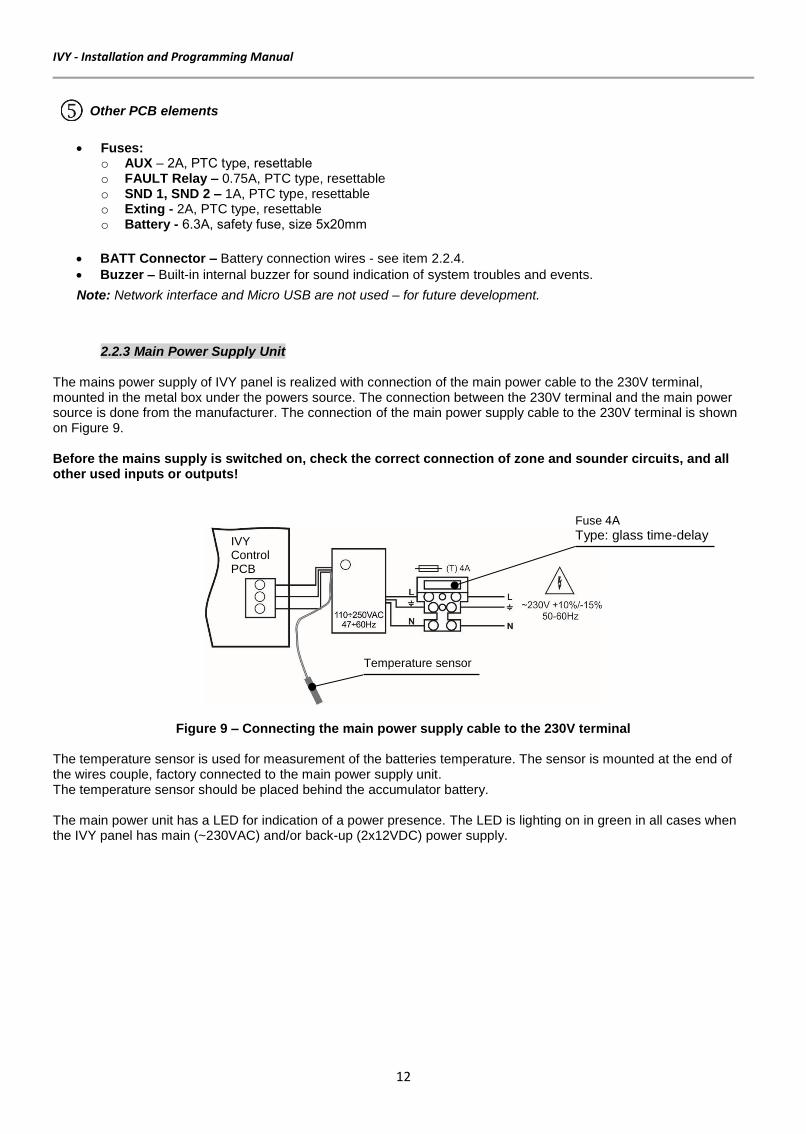
2.2.3 Main Power Supply Unit The mains power supply of IVY panel is realized with connection of the main power cable to the 230V terminal, mounted in the metal box under the powers source. The connection between the 230V terminal and the main power source is done from the manufacturer. The connection of the main power supply cable to the 230V terminal is shown on Figure 9. Before the mains supply is switched on, check the correct connection of zone and sounder circuits, and all other used inputs or outputs!
Figure 9 – Connecting the main power supply cable to the 230V terminal
The temperature sensor is used for measurement of the batteries temperature. The sensor is mounted at the end of the wires couple, factory connected to the main power supply unit. The temperature sensor should be placed behind the accumulator battery. The main power unit has a LED for indication of a power presence. The LED is lighting on in green in all cases when the IVY panel has main (~230VAC) and/or back-up (2x12VDC) power supply.
Fuse 4А
Type: glass time-delay
Temperature sensor
IVY Control PCB

IVY – Installation and Programming Manual
13
2.2.4 Connection of Back-up Batteries The accumulator battery leads are mounted on a terminal at the bottom of main control panel. The back-up power supply of IVY panel is realized with two batteries 12VDC/7Ah connected into series. Use the 100mm cable from the spare parts kit (with red and black cable shoes) to connect the batteries in series and after than observing the polarity connect the battery leads from the main PCB - see Figure 10.
Figure 10 – Serial connection of the batteries
2.3. Circuits Wiring
2.3.1 Zone Circuits Wiring Zone 1 and Zone 2 are extinguishing zones. Use 2-wire cross-zoning connection of the detectors in the flooding area. The extinguishing in the protected area will start only when Zone 1 AND Zone 2 are activated and the panel is in Stage 2 (Extinguishing activated) operation mode. The extinguishing process will not start if only Zone 1 or Zone 2 is activated.
Figure 11 – Cross-zoning connection diagram for Zone 1 and Zone 2
Zone 3 is a conventional fire alarm zone. Use 2-wire connection of automatic fire alarm detectors and call point in the protected area. Activation of Zone 3 starts Stage 1 (Fire Alarm) operation mode and activates the “1 Stage” Relay output on the PCB control panel.
Figure 12 – Connection diagram for Zone 3
2.3.2 Sounders Circuits Wiring To every monitored output SND could be connected several sounders - Figure 13. The maximum number of sounders that could be connected in the circuit depends on their total current consumption, which must not exceed 0.3A. Before connecting the last sounder in the circuit, parallel to it must be added resistor 10k.
Figure 13 – Connecting sounders to SND output
PCB negative (black) battery wire PCB positive (red) battery wire
Sounder 1 Sounder 2 Sounder N

IVY - Installation and Programming Manual
14
Important Note There is difference at activation of SND1 and SND2 sounder circuit outputs.
• SND1 circuit output is activated at Stage 1 (Fire Alarm) operation mode – any of the Zone 1, 2 or 3 is activated.
• SND2 circuit output is activated at Stage 2 (Extinguishing activated) operation mode, when: o Zone 1 and Zone 2 are activated; o The button Manual Release is manually pressed; o The “Flow Control” input is activated.
2.3.3 Connecting to the Supervised Inputs The supervised inputs Manual Release, Hold, Mode Select, ON/OFF Extinguishing and Low Press are used for controlling the operation of the IVY panel.
Figure 14 – Connections to the supervised inputs
2.3.4 Solenoid Wiring – Connecting the Extinguishing Circuit For normal (stand-by) operation mode, the Solenoid must have a resistance in the range 20-80Ohms. It is recommended the value of the resistance to be minimum 30Ohm or greater to ensure that maximum current rating of the extinguishing output is not exceeded. A suppression diode must be connected at the end of the solenoid circuit for preventing the electromagnetic field generated by the solenoid when it de-energizes from causing interference to the operation of the control panel. The diode also is fitted as an end-of-line module.
Figure 15 – Example of wiring a solenoid
2.3.5 Connecting the OC Outputs The open collector outputs are used for connecting external devices. The OC1, OC2, OC3 and OC4 has same functionality and characteristics. The internal structure and examples are shown on Figure 16.
a) OC Internal circuit diagram
b) Examples for connecting Relay or LED
Figure 16 – Connecting OC output circuits

IVY – Installation and Programming Manual
15
3. INDICATION AND CONTROLS The front panel is divided into two main control sections:
Figure 17 – IVY Front panel
FIRE Alarm Section Extinguishing Section
1 - LED indication for the used zones*. 5 - LED indication for the extinguishing status*.
2 - LED indication for the system status*. 6 - LED indication for selected operation mode for extinguishing*. The mode is switched on via the 3-position key-lock or via “Mode Select” input, as the LED for the currently selected mode is lighting on.
3 - Operation buttons. 7 - 7 segment display for counting the remaining time (Stage 2 - Extinguishing activated) before starting the extinguishing.
4 - 2-positon key-lock for access control. 8 – Protected button for manual releasing of the extinguishing.
* The descriptions are printed on a slide-in paper label, suitable for changing in various languages. The paper label is placed in a special opening on the inner side of the indication PCB, over the flat cable for the indication.
Description of the zone LED indication:
LED Color Status Description
Z1 (Zone 1)
red Lights ON FIRE Alarm in ZONE 1.
yellow
Lights ON ZONE 1 is disabled.
Blinking 1. Slow blinking with frequency 0.25Hz/sec – FAULT: Open circuit in ZONE 1. 2. Normal blinking with frequency 0.5Hz/sec – FAULT: Short circuit in ZONE 1. 3. Fast blinking with frequency 1Hz/sec – TEST in ZONE 1.
Z2 (Zone 2)
red Lights ON FIRE Alarm in ZONE 2.
yellow
Lights ON ZONE 2 is disabled.
Blinking 1. Slow blinking with frequency 0.25Hz/sec – FAULT: Open circuit in ZONE 2. 2. Normal blinking with frequency 0.5Hz/sec – FAULT: Short circuit in ZONE 2. 3. Fast blinking with frequency 1Hz/sec – TEST in ZONE 2.
Z3 (Zone 3)
red Lights ON FIRE Alarm in ZONE 3.
yellow
Lights ON ZONE 3 is disabled.
Blinking 1. Slow blinking with frequency 0.25Hz/sec – FAULT: Open circuit in ZONE 3. 2. Normal blinking with frequency 0.5Hz/sec – FAULT: Short circuit in ZONE 3. 3. Fast blinking with frequency 1Hz/sec – TEST in ZONE 3.
Fire Alarm Section Extinguishing Section (red)

IVY - Installation and Programming Manual
16
Description of system status LED indication:
LED Color Description
FIRE red Lights on permanently in case of fire alarm event – fire alarm signal from an automatic or manual call point. The FIRE LED (red color) of the respective zone in fire alarm is lighting on too.
FAULT yellow Lights on permanently in case of fault event in the system. The FAULT LED (yellow color) of the respective zone in fault is lighting on too.
SYSTEM FAULT yellow CPU FAULT. Lights on permanently in case of main microprocessor fault.
DISABLE yellow Lights permanently at disabled zone(s)/sounder(s). Blinking during the enabling/disabling of zone(s)/sounder(s).
SND FLT/ DSBL yellow Lights permanently in case of fault or disablement of the sounders circuits. Blinking during the enabling/disabling of SND1 sounder circuit.
TEST yellow Blinking during testing of zones. The yellow LED of the currently tested zone is blinking too.
POWER FAULT yellow Lights permanently in case of AC loss (230VAC) or Battery lost events.
POWER ON green Lights permanently in normal operation mode, indicating presence of main power supply 230VAC and/or back-up power supply.
Operation buttons:
Button Action Access Level Functionality
Silence Buzzer
1 and 2 • Deactivation of the internal buzzer.
• Increasing values in Programming of system times.
Silence Sounders
2
• Deactivation of SND1 output when the panel is in Stage 1 (Fire Alarm) or Stage 2 (Extinguishing activated) operation mode. After pressing the button, the LED next to it lights or blinks in yellow:
- At Stage 1 (Fire Alarm) lights on permanently – full silencing of the sounders. - At Stage 2 (Extinguishing activated) is blinking – partial silencing of the sounders.
• Decreasing values in Programming of system times.
Test/ Scroll
2
• Entering in zone Test mode.
• Scrolling down for selecting zone(s)/sounder(s) for enabling/disabling.
• Scrolling through the settings in Programming of system times.
Enable/ Disable
2 • Confirmation for enabling/disabling of zone(s)/sounder(s) (SND1). Attention: The SND2 sounder output cannot be disabled.
Reset 2 Resetting the panel without switching off the main power supply.
Selecting the Access level
The access level for operation with the fire alarm section of IVY panel is managed via two-position key lock:
Position Access Level Description
1 Only the Silence Buzzer button is active.
2 All buttons are active. The zone tests, enabling/disabling of zones/sounders can be performed.

IVY – Installation and Programming Manual
17
Description of Extinguishing Section LED indication:
LED Color Status Description
ACTIVATED red
Blinking FIRE Alarm in Zone 1 or Zone 2.
Lights ON
The extinguishing process is started. Note: The extinguishing process is started in case of: - The Operation MODE of the Extinguishing process of the panel is AUTOMATIC or MANUAL (see the Table “Selecting the mode for the extinguishing process”) and one of the following:
- Both Zone 1 and Zone 2 are in FIRE Alarm mode – the Operation MODE of the Extinguishing process of the panel is AUTOMATIC, or - The “Manual Release” button on the front panel is pressed on, or - The “Manual Release” input on the main board is activated.
RELEASED red Lights ON 1. The extinguishing output has been operated. 2. The “Flow Control” input on the main board is activated.
HOLD ACTIVATED
yellow Lights ON The “HOLD” input has been operated.
LOW PRESSURE
yellow Lights ON The “LOW PRESSURE” input has been operated.
FLOW CONTROL
yellow Lights ON The FLOW CONTROL input has been operated.
Selecting the mode for the extinguishing process
The selection of the operation mode of the extinguishing process of IVY panel is managed via 3-position key lock, “Mode Select” and “On/Off Exting” inputs on the main board. The mode is selected when the yellow LED in front of it is lighting on.
MODE - Extinguishing
3-position key-lock selection
“Mode Select” Input state
“On/Off Exting” Input state
Description
AUTOMATIC AUTOMATIC Inactive Inactive
The extinguishing process is automatic. The panel will enter Stage 2 (Extinguishing activated) operation mode and the extinguishing runs as: - AUTOMATIC, in case FIRE Alarm in both Zone 1 and Zone 2. - MANUAL, in case “Manual Release” button on the front panel is pressed on, or “Manual Release” input on the main board is activated.
MANUAL
AUTOMATIC Activated Inactive The extinguishing process is manually operated only. MANUAL
Inactive or Activated
Inactive
DISABLED
DISABLED Inactive or Activated
Inactive or Activated
The extinguishing process is disabled. Any of the positions
Inactive or Activated
Activated
Attention: Once started the extinguishing process, its operation mode could not be changed!

IVY - Installation and Programming Manual
18
7-segment display
This is a 7-segment display for counting the remaining time to extinguishing in the premises. The counter is activated in Stage 2 (Extinguishing activated) mode. It is used to visualize the set times for Extinguishing Duration, Extinguishing Delay and Reset Hold during programming.
Manual Release Button
This is a button for manual release of the extinguishing. It is active when Automatic or Manual mode for the extinguishing process is selected. The button is protected with cover for avoiding of accidental pressing.
4. OPERATION MODES
4.1. Normal Operation Mode
The extinguishing panel IVY is in normal operation mode (stand-by) when only the LED “POWER ON” on the front power is lighting on in green. The internal buzzer and all other status LEDs are off. The key for selection of the extinguishing mode is set to Automatic, Manual or Disabled position.
4.2. Stage 1 (Fire Alarm)
The extinguishing panel IVY goes to Stage 1 (Fire Alarm) operation mode when a fire alarm is generated from a detector or call point in some of the fire zones – Zone 3 and/or only one of the fire zones Zone 1 or Zone 2. During Stage 1 (Fire Alarm) operation mode are activated:
- The sounder output SND1 and the internal buzzer (interrupted sound signal). - The “Stage 1” Relay output. - The FIRE LED (red) of the Zone detected fire and the general FIRE indicator on the front panel. - In case of FIRE Alarm in Zone 1 or Zone 2 is generated, the LED “ACTIVATED” (on the extinguishing section of the front panel) is blinking in red.
The User can stop the signalization of the internal buzzer by pressing the SILENCE BUZZER button. The SND1 output can be suppressed by pressing the SILENCE SOUNDERS button – the yellow LED lights on. The extinguishing process can be manually started by pressing the MANUAL RELEASE button on the front panel or activation of “Manual Release” input on the main board if the operation mode of the extinguishing process is set to MANUAL or AUTOMATIC – see the table on page 17, item 6. Selecting the mode for the extinguishing process.
4.3. Stage 2 (Extinguishing activated)
The extinguishing panel IVY goes to Stage 2 (Extinguishing activated) if one of the following events are following in sequence:
- Stage 1 (Fire Alarm) operation mode activated by Zone 1 and a second fire alarm from Zone 2 is generated (the operation mode of the extinguishing process is AUTOMATIC). - Stage 1 (Fire Alarm) operation mode activated by Zone 2 and a second fire alarm from Zone 1 is generated (the operation mode of the extinguishing process is AUTOMATIC). - Stage 1 (Fire Alarm) operation mode activated by Zone 3 and fire alarms from Zone 1 AND Zone 2 are generated (the operation mode of the extinguishing process is AUTOMATIC). - The panel is in normal operation mode and the MANUAL RELEASE button on the front panel is pressed or the “Manual Release” input on the main board is activated (the operation mode of the extinguishing process is set to MANUAL or AUTOMATIC).
During Stage 2 (Extinguishing activated) operation mode are activated: - The sounder output SND2 and the internal buzzer (continuous sound signal). - The Stage 2 Relay output. - The sounder output SND1 and the “Stage 1” Relay output, if the panel is entered Stage 1 (Fire Alarm) operation Mode before that. - The FIRE LED (red) of the Zones detected fire and the general FIRE indicator on the front panel. - The “ACTIVATED” LED (on the extinguishing section of the front panel) lights ON in red. - The Evacuation time starts running counting down the time left to starting the extinguishing on the site. - When the Evacuation time is over the extinguishing devices are activated for the Extinguishing duration time - the panel enters in Extinguishing operation mode.
Attention: The SND2 output cannot be silenced, only the SND1 output can be silenced if is activated. The user can only stop the signalization of the internal buzzer by pressing the SILENCE BUZZER button. Pressing of HOLD button (connected to supervised input HOLD on the main PCB) will reset the evacuation time.

IVY – Installation and Programming Manual
19
4.4. Extinguishing Released The extinguishing is a process for releasing of extinguishing agents via special automatic devices in case of fire alarm in the protected premises. The extinguishing process can be started manually at any time with pressing the MANUAL RELEASE button on the front panel when operation mode of the extinguishing process is set to MANUAL or AUTOMATIC. The extinguishing in the site starts after the set EXTINGUISHING DELAY TIME is out. During Extinguishing Released operation mode are activated:
- The “ACTIVATED” LED is lighting on in red. - The extinguishing devices are activated via the “Exting” output for the Extinguishing duration time – the “RELEASED” LED lights on in red.
The operation of the panel in Extinguishing Release mode is necessary to program the respective system times – see for details item 5.
4.5. Fault The extinguishing panel IVY goes to Fault mode in case of fault condition in the system – short or open circuit, main or back-up power supply lost, CPU error, etc. In case of fault event one or more LEDs on the PCB are lighting on (see item 2.2.2, section 2) together with the general FAULT LED indicator on the front panel. In case of fault in the sounders circuits the SOUNDER FAULT/DISABLE LED is blinking. During FAULT mode are activated:
- The internal buzzer with a beeping signal. - The Fault Relay output.
4.6. Double Action Mode The purpose of setting a Double Action mode is to prevent false alarms. Double Action mode is set when the jumper J6 on the main PCB is set on. In Double Action mode any detector activation within the system generates an ALARM event to the respective zone, but will awaits a second fire signal from the same zone to generate a FIRE signal. The RESET command shall disable the FIRE events. If during 3 minutes there is no other fire alarm signal from the same zone, the FIRE alarm will be ignored.
Examples for DOUBLE action mode operation:
1 – An incoming alarm signal from Detector 1 and zone reset; 2 – Waiting for a second alarm signal from the same detector in the zone; 3 – Second alarm signal from Detector 1 in the zone.
EXAMPLE 1: In this case the fire panel will not activate the sounders and the signalization on the front panel, because during time interval 2 no second alarm signal is generated. EXAMPLE 2: In this case the fire panel will activate the sounders and the signalization on the front panel, because during time interval 2, two alarm signals are generated.
Time Time
3 min 3 min
EXAMPLE 1 EXAMPLE 2
D 1 D 1 D 1

IVY - Installation and Programming Manual
20
5. PROGRAMMING OF SYSTEM TIMES The programming of system times is done with a DIP switch located on the left bottom of the main control panel PCB:
Figure 18 – Programming button
The button has two positions as the programming is done with switching in ON position. The User sets the following special system times: 1. EXTINGUISHING DURATION TIME – time during the extinguishing output is activated.
2. EXTINGUISHING DELAY TIME – delay before the extinguishing output is going to be activated (delay starts after ACTIVATED LED has operated).
3. RESET HOLD TIME - time after extinguishing output has operated during which the panel is not able to be reset in order to prevent half discharging and etc. The programming of the times follows the described above order. No confirmation of the set time is needed. Use the TEST/SCROLL button to stroll down between different set times.
During programming of system times the following buttons has a special functionality:
Button Functionality
Increasing values
Decreasing values
Scrolling through the settings.
5.1. Setting EXTINGUISHING DURATION TIME Switch the PRG button into ON position. The 7-segment display on the front panel is lighting on. The User can set a time from 0 to 495 seconds, as the visualization is in steps multiple on 5 sec (.0 – 9.9). For example:
Set Indication Corresponding to sec.
.1 5
.2 10 - Default
.3 15
.4 20
… …
9.7 485
9.8 490
9.9 495

IVY – Installation and Programming Manual
21
Use the SILENCE BUZZER to increase values – every pressing of the button increases the time with 5 seconds. Use the SILENCE SOUNDERS to decrease values – every pressing of the button decreases the time with 5 seconds. Example for setting 30 seconds EXTINGUISHING DURATION TIME:
10 seconds preset value
Press 4 times 30 seconds new set value
Press the TEST/SCROLL button to move to the next system time.
5.2. Setting EXTINGUISHING DELAY TIME The User can set a time from 0 to 60 seconds. The default pre-set EXTINGUISHING DELAY TIME is 60 seconds. Use the SILENCE BUZZER to increase values – every pressing of the button increases the time with 1 second. Use the SILENCE SOUNDERS to decrease values – every pressing of the button decreases the time with 1 second. Press the TEST/SCROLL button to move to the next system time.
5.3. Setting RESET HOLD TIME The User can set a time from 0 to 30 minutes. The default pre-set RESET HOLD TIME is 30 minutes. Use the SILENCE BUZZER to increase values – every pressing of the button increases the time with 1 minute. Use the SILENCE SOUNDERS to decrease values – every pressing of the button decreases the time with 1 minute. Press the TEST/SCROLL button to move back to the first system time. To exit programming mode and to save the new set values, turn the dip switch PRG to OFF position.
6. USER OPERATION
6.1. Disabling/Enabling of Zones The disabling/enabling of zones is allowed at access level 2. The disabling/enable of Zone 1, Zone 2 and Zone 3 follows a common operation algorithm. After entering the disabling/enabling mode the selected zone number blinks if it is currently enabled and it is lighting on if it is currently disabled. The DISABLE LED on the front panel is blinking. The disabled zone numbers are lighting on together with the DISABLE LED in normal operation mode. The panel will not follow the status of the disabled zones. The set disablements are ignored when the main and back-up power supply are lost – power reset of the panel. To disable Zone 1, do in sequence:
• Press ENABLE/DISABLE button
- DISABLE LED blinks. - The ZONE 1 yellow LED blinks.
• Press ENABLE/DISABLE button again
- The ZONE 1 yellow LED light on permanently. - DISABLE LED blinks. - ZONE 1 is DISABLED.
• Press RESET button to exit the menu and to confirm settings
- DISABLE LED lights on. - The ZONE 1 yellow LED lights on.

IVY - Installation and Programming Manual
22
To enable Zone 1, do in sequence:
• Press ENABLE/DISABLE button
- DISABLE LED blinks. - The ZONE 1 yellow LED lights on.
• Press ENABLE/DISABLE button again
- The ZONE 1 yellow LED blinks. - DISABLE LED blinks. - ZONE 1 is ENABLED.
• Press RESET button to exit the menu and to confirm settings
- DISABLE LED and ZONE 1 yellow LED are off.
To disable Zone 2, do in sequence:
• Press ENABLE/DISABLE button
- DISABLE LED blinks. - The ZONE 1 yellow LED blinks if enabled and lights on if it is disabled.
• Press TEST/SCROLL button
- DISABLE LED blinks. - The ZONE 2 yellow LED blinks.
• Press ENABLE/DISABLE button
- The ZONE 2 yellow LED lights on permanently. - DISABLE LED blinks. - ZONE 2 is DISABLED.
• Press RESET button to exit the menu and to confirm settings
- DISABLE LED lights on. - The ZONE 2 yellow LED lights on.
To enable Zone 2, do in sequence:
• Press ENABLE/DISABLE button
- DISABLE LED blinks. - The ZONE 1 yellow LED blinks if enabled and lights on if it is disabled.
• Press TEST/SCROLL button
- DISABLE LED blinks. - The ZONE 2 yellow LED lights on permanently.
• Press ENABLE/DISABLE button
- The ZONE 2 yellow LED blinks. - DISABLE LED blinks. - ZONE 2 is ENABLED.
• Press RESET button to exit the menu and to confirm settings
- DISABLE LED and ZONE 2 yellow LED are off.
Notes: 1. The disabling/ enabling of Zone 3 is done in the same way as after pressing the ENABLE/DISABLE button press TEST/SCROLL button until you reach Zone 3. 2. The disabling/ enabling of any Zone is impossible when any of them (no matter which) is in FIRE Alarm condition. 3. The procedure for disabling/ enabling of Zones is terminated when any of the Zones enters in FIRE Alarm condition.
6.2. Disabling/Enabling SND1 (Sounder Output 1) The disabling/enabling of SND1 is allowed at access level 2. Attention: The SND2 sounder output cannot be disabled! After entering the disabling/enabling mode the User scrolls down to SOUNDER FAULT/DISABLE LED. The DISABLE LED on the front panel is blinking together with SOUNDER FAULT/DISABLE LED. The set disablements are ignored when the main and back-up power supply are lost – power reset of the panel.

IVY – Installation and Programming Manual
23
To disable SND1, do in sequence:
• Press ENABLE/DISABLE button
- DISABLE LED blinks. - The ZONE 1 yellow LED blinks.
• Press TEST/SCROLL button three times
- DISABLE LED blinks. - SOUNDER FAULT/DISABLE LED blinks.
• Press ENABLE/DISABLE button
- DISABLE LED blinks. - SOUNDER FAULT/DISABLE LED lights on.
• Press RESET button to exit the menu and to confirm settings
- DISABLE LED lights on. - SOUNDER FAULT/DISABLE LED lights on. - SND1 is DISABLED.
To enable SND1, do in sequence:
• Press ENABLE/DISABLE button
- DISABLE LED blinks. - The ZONE 1 yellow LED blinks. - SOUNDER FAULT/DISABLE LED lights on.
• Press TEST/SCROLL button three times
- DISABLE LED blinks. - SOUNDER FAULT/DISABLE LED lights on.
• Press ENABLE/DISABLE button
- DISABLE LED blinks. - SOUNDER FAULT/DISABLE LED blinks.
• Press RESET button to exit the menu and to confirm settings
- DISABLE LED and SOUNDER FAULT/DISABLE LED are off. - SND1 is ENABLED.
Notes: 1. The enabling/disabling of SND1 (Sounder Output 1) is impossible, when any of the Zones is in Fire Alarm condition. 2. The procedure for disabling/ enabling of SND1 (Sounder Output 1), is terminated when any of the Zones enters in FIRE Alarm condition.
6.3. Zone Test
The Zone Test mode gives the installer the possibility to test the efficiency of the system - whether the detectors react to smoke, heat, etc. Attention: Only one zone can be tested at one and the same time! To perform Zone Testing, do in sequence:
• Press TEST/SCROLL button
- TEST LED will start blinking. - The ZONE 1 yellow LED starts blinking. - ZONE 1 is in test mode. Test a detector from this zone whether it reacts to smoke, heat, etc.
• Press TEST/SCROLL button again to continue with the system testing
- TEST LED will continue blinking. - The ZONE 1 yellow LED lights out (the zone is no longer in test mode). - The ZONE 2 yellow LED blinks in yellow. ZONE 2 is in test mode. Test a detector from this zone whether it react to smoke, heat, etc.
Continue the system testing by pressing the TEST/SCROLL button. The exit from the Zone Test mode is automatic after the end of the test procedure in the last Zone 3.

IVY - Installation and Programming Manual
24
7. LOG MODULE (Optional) The IVY LOG Module, or IVY ML, is an optional module for recording and viewing of events in IVY extinguishing panel. All of the events are stored in a non-volatile memory. The module has a real time clock powered on from own battery. The events can be viewed on an LCD screen (2x16 symbols) with a date and time of occurring. The LOG module comes in a kit with a front folio (sticker) with opening for the screen and tactile operation buttons.
7.1. Installation Attention: Before installation of IVY ML module to the panel’s configuration, it is obligatory to switch off the main and the back-up power supply of IVY panel!
Figure 19 – Back side of the front cover
The module is mounted on the back side of the metal cover. The connection is via an interface connector to the indication board of the panel – J1 terminal on the module to the P2 terminal on the panel’s indication board. The IVY ML is fixed to the cover with 5 screws on the location shown on Figure 19. 1 – Indication PCB 2 – P2 terminal for connection of IVY LOG module 3 – Location for mounting the IVY LOG module
Figure 20 – Interface connection between IVY LOG module and indication PCB
To install the IVY ML module to the panel’s configuration, do in sequence: 1. Undo the two screws on the front cover of the panel and open it. 2. Disconnect the main and the back-up power supply of IVY panel. 3. Remove the packings of IVY ML module. 4. Replace the solid front folio on the cover with the one from the LOG module’s kit. The positions for screen opening and tactile buttons must align with the same openings on the metal cover. 5. Connect the interface connectors - J1 terminal on the module to the P2 terminal on the panel’s indication board. The pins on the interface connector of the module must be connected exactly as shown on Figure 20! If the connection is correct, the buttons of the module are aligned with the respective opening on the metal cover. The openings for fixing the module must align with the ones on the back side of the metal cover. 6. Fix the module’s PCB to the metal bottom with the screws from the spare parts kit. 7. Place a jumper on J8 terminal to provide an independent power supply of the real-time clock in case of losing the main and back-up power supply of the panel. 8. Switch on the main and back-up power supply of IVY panel. The LEDs on the PCB start lighting according the current state. In normal operation mode the green LED is lighting on and the yellow is blinking showing the communication between the panel and the module. 9. Perform settings for the date, time and language. 10. Close the cover of the panel and fix it with the screws.
IVY Indication board
IVY ML

IVY – Installation and Programming Manual
25
7.2. Elements The IVY LOG module is easy for operation with a few basic elements - Figure 21.
Figure 21 – IVY LOG module elements
1 - Openings for fixing to the metal cover. 2 - Built-in 3V battery. To enable it, place a jumper on J8 terminal – position 4. 3 - Programming button. 4 - Terminal to provide an independent power supply of the real-time clock in case of losing the main and back-up power supply of the panel. 5 - LED indication of the module’s status. In normal operation mode the green LED is lighting on and the yellow LED is blinking showing the communication between the panel and the module.
7.3. LCD screen and Functional Buttons The recorded messages are viewed on the LCD screen on two rows. The backup light of the screen is disabled after 30 seconds if no other button is pressed. The IVY ML module has 4 functional buttons for user operation and programming.
Button Action Functionality
Enter
• Entering in menus.
• Confirmation of the entered data.
Cancel
• Cancelation of the entered data.
• Exit from the menus.
Up
• Scrolling up through menus.
• Increasing values in programming mode.
Down
• Scrolling down through menus.
• Decreasing values in programming mode.
7.4. Menus The following menus are available in IVY LOG module:
• EVENT HISTORY – Menu for viewing the recorded system events.
• SET DATE/TIME – Menu for setting the actual date and time.
• LANGUAGE – Menu for selecting different language of the menus.
7.4.1 Reviewing the EVENT HISTORY In normal operation mode press ENTER button. The first menu in the list is EVENT HISTORY. To access the recorded messages, press ENTER button again.

IVY - Installation and Programming Manual
26
The first message in the list is the last event in the system (the newest recorded in the log). On the second row are viewed the date and time of occurring. To review the second and following messages, press the DOWN arrow button. To turn back, start pressing the UP arrow button. See APPENDIX А for the detailed list of all messages with its description. To exit the EVENT HISTORY menu, press CANCEL button.
7.4.2 Setting the Date and Time The setting is started with pressing the programming button for 2 seconds (on the IVY LOG module PCB) – see Figure 21, position 3. Press ENTER button and select the SET DATE/TIME menu with DOWN arrow button.
Set in sequence the current date, month and year, and time [Hour:Minutes]. After the last confirmation the module exits to normal operation mode. You can reject the entered values with pressing CANCEL button – the module exits to normal operation mode. The exit of the programming menu is automatic after 5 minutes if no button is pressed.
7.4.3 Setting the Language The setting is started with pressing the programming button for 2 seconds (on the IVY LOG module PCB) – see Figure 21, position 3. Press ENTER button and select the LANGUAGE menu with DOWN arrow button.
You can reject the currently selected language with pressing CANCEL button – the module exits to normal operation mode. The exit of the programming menu is automatic after 5 minutes if no button is pressed.
The “VV” symbol points the current value for setting. Use the UP button to increase the value and DOWN button to decrease it. Press ENTER button to move to the next value for setting.
English is the default set language Use the DOWN button to review other available languages. Press ENTER button to confirm the selection.

IVY – Installation and Programming Manual
27
Appendix A – Messages for Events Event Message Description
Power On Initial power up after main power supply on.
AC Loss Main power supply 220V lost.
AC Restore Main power supply 220V lost - restored.
Reset RESET of the panel. The RESET button has been pressed.
Snd X Fault Sounder circuit Fault (X is the number of the sounder circuit).
Snd X Fault Rst Sounder circuit Fault - restored (X is the number of the sounder circuit).
Snd Disabled The sounder circuit SND1 is disabled.
Snd Enabled The sounder circuit SND1 is enabled.
Fire Zone X Fire alarm in a zone (X is the number of the zone).
Test Zone X Test in a zone (X is the number of the zone).
Fault Zone X Fault in a zone (X is the number of the zone).
Restored Zone X Normal operation mode restored in a zone (X is the number of the zone).
Disabled Zone X A zone is disabled (X is the number of the zone).
Enabled Zone X A zone is enabled (X is the number of the zone).
Sys Fault Panel system fault.
Silenced Buzzer The internal buzzer is silenced.
Silenced Sounder The sounders are silenced after activation.
Batt Low Low charge of the accumulator battery of the panel.
Batt Loss The accumulator battery of the panel is missing.
Batt Rst The accumulator battery of the panel is restored.
Charger FLT Fault in accumulator battery charging.
Charger Rst Fault in accumulator battery charging - restored.
Earth Fault Earth fault in the panel circuits. (The jumper J7 is set on the panel’s PCB.)
Earth Fault RST Earth fault in the panel circuits - restored.
Earth Flt Dsbl Earth fault indication is disabled. (The jumper J7 is removed.)
Earth Flt Enbl Earth fault indication is enabled. (The jumper J7 is set.)
Low Press The input “Low Press” is activated.
Low Press Rst The input “Low Press” is restored (deactivated).
LPress FLT Fault in input “Low Press” - short or broken circuit.
LPress FLT Rst Fault in input “Low Press” - restored.
Manual Fault Fault in input “Manual Release” - short or broken circuit.
Manual Rst Fault in input “Manual Release” - restored.
Manual Enabled Manual operation mode enabled - activated input “Mode Select” or “Manual mode” selected via key on the front panel.
Manual Active The input “Manual Release” is activated.
Auto Active Automatic extinguishing is started in Zone 1 and Zone 2.
Auto Enabled Automatic operation mode enabled - activated input “Mode Select” or “Automatic mode” selected via key on the front panel.
Ext Disabled The extinguishing is disabled - activated input “Enable/Disable” or “Disabled mode” selected via key on the front panel.
Ext Enabled The extinguishing is enabled via input “Enable/Disable”.
Hold Active The input “Hold” is activated.
Hold Fault Fault in input “Hold” - short or broken circuit.
Hold Rst Fault in input “Hold” - restored.
Released The LED “Released” on the front panel is activated.
Enabled FLT Fault in input “Enable/Disable” - short or broken circuit.
Enabled Rst Fault in input “Enable/Disable” - restored.
Mode Fault Fault in input “Mode select” - short or broken circuit.
Mode Rst Fault in input “Mode select” - restored.
Ext Out FLT Fault in input “Extinguishing” - short or broken circuit.
Ext Out RST Fault in input “Extinguishing” - restored.
Aux Fault Fault in input “AUX” - short circuit.
Aux Rst Fault in input “AUX” - restored.
DBL Knock Enbl Double action mode is enabled.
DBL Knock Dsbl Double action mode is disabled.

18020843, RevB, 06/ 2018
www.teletek-electronics.com
Address: Bulgaria, 1407 Sofia, 14А Srebarna Str. Tel.: +359 2 9694 800, Fax: +359 2 962 52 13
e-mail: [email protected]