ENGINE CONTROL SYSTEM SECTION EC - DanteSpec – Stay ...
548
ENGINE CONTROL SYSTEM SECTION EC CONTENTS TB45E ENGINE AND EMISSION CONTROL OVERALL SYSTEM...........................................................................9 Circuit Diagram ............................................................9 TROUBLE DIAGNOSIS FOR POWER SUPPLY ..........10 Main Power Supply and Ground Circuit ....................10 TROUBLE DIAGNOSIS FOR ″CAMSHAFT POSI SEN″ (DTC 11)...............................................................12 Camshaft Position Sensor (CMPS) ...........................12 TROUBLE DIAGNOSIS FOR ″MASS AIR FLOW SEN″ (DTC 12) ..............................................................13 Mass Air Flow Sensor (MAFS) ..................................13 TROUBLE DIAGNOSIS FOR ″COOLANT TEMP SEN″ (DTC 13) ..............................................................14 Engine Coolant Temperature Sensor (ECTS) ...........14 TROUBLE DIAGNOSIS FOR ″IGN SIGNAL-PRIMARY″ (DTC 21).......................................15 Ignition Signal ............................................................15 TROUBLE DIAGNOSIS FOR ″OVER HEAT″ (DTC 28) ..................................................................................16 Cooling Fan Control (Overheat) ................................16 TROUBLE DIAGNOSIS FOR ″THROTTLE POSI SEN″ (DTC 43) ..............................................................17 Throttle Position Sensor ............................................17 TROUBLE DIAGNOSIS FOR NON-DETECTABLE ITEMS.............................................................................18 Vehicle Speed Sensor (VSS) ....................................18 Idle Air Control Valve (IACV) - Auxiliary Air Control (AAC) Valve ..................................................19 Park/Neutral Position Switch .....................................20 Injector .......................................................................21 Start Signal ................................................................22 Fuel Pump .................................................................23 IACV-FICD Solenoid Valve ........................................24 MIL & Data Link Connectors .....................................25 TB45S ENGINE AND EMISSION CONTROL OVERALL SYSTEM.........................................................................26 Circuit Diagram ..........................................................26 CARBURETOR ..............................................................29 Automatic Choke .......................................................29 Fuel Cut Control System ...........................................31 ISC-FI Pot ..................................................................32 IGNITION CONTROL SYSTEM.....................................33 Wiring Diagram - IGN -..............................................33 COOLING FAN MOTOR ELECTRICAL CIRCUIT ........35 Wiring Diagram - COOL/F -.......................................35 ELECTRIC FUEL PUMP ...............................................36 Wiring Diagram - FPCM - ..........................................36 ELECTRIC FUEL PUMP ...............................................40 Wiring Diagram -FPCM- ............................................40 EXHAUST EMISSION CONTROL SYSTEM.................41 Boost Controlled Deceleration Device (BCDD) .........41 TB48DE M/T TROUBLE DIAGNOSIS - INDEX ..................................43 Alphabetical & P No. Index for DTC .........................43 PRECAUTIONS .............................................................44 Supplemental Restraint System (SRS) ″AIR BAG″ and ″SEAT BELT PRE-TENSIONER″ .............44 Precautions for On Board Diagnostic (OBD) System of Engine ......................................................44 Engine Fuel & Emission Control System ..................45 Wiring Diagrams and Trouble Diagnosis ...................48 PREPARATION ..............................................................49 Special Service Tool ..................................................49 Commercial Service Tools .........................................49 ENGINE AND EMISSION CONTROL OVERALL SYSTEM.........................................................................50 Circuit Diagram ..........................................................50 System Diagram ........................................................52 Engine Control Component Parts Location ...............53 Vacuum Hose Drawing ..............................................56 System Chart .............................................................58 ENGINE AND EMISSION BASIC CONTROL SYSTEM DESCRIPTION ...............................................59 Multiport Fuel Injection (MFI) System .......................59 Electronic Ignition (EI) System ..................................62 GI MA EM LC FE CL MT AT TF PD FA RA BR ST RS BT HA EL SE IDX EC-1
-
Upload
khangminh22 -
Category
Documents
-
view
1 -
download
0
Transcript of ENGINE CONTROL SYSTEM SECTION EC - DanteSpec – Stay ...

ENGINE CONTROL SYSTEM
SECTIONECCONTENTS
TB45E
ENGINE AND EMISSION CONTROL OVERALLSYSTEM...........................................................................9
Circuit Diagram............................................................9TROUBLE DIAGNOSIS FOR POWER SUPPLY ..........10
Main Power Supply and Ground Circuit....................10TROUBLE DIAGNOSIS FOR ″CAMSHAFT POSISEN″ (DTC 11)...............................................................12
Camshaft Position Sensor (CMPS) ...........................12TROUBLE DIAGNOSIS FOR ″MASS AIR FLOWSEN″ (DTC 12) ..............................................................13
Mass Air Flow Sensor (MAFS) ..................................13TROUBLE DIAGNOSIS FOR ″COOLANT TEMPSEN″ (DTC 13) ..............................................................14
Engine Coolant Temperature Sensor (ECTS) ...........14TROUBLE DIAGNOSIS FOR ″IGNSIGNAL-PRIMARY ″ (DTC 21).......................................15
Ignition Signal ............................................................15TROUBLE DIAGNOSIS FOR ″OVER HEAT″ (DTC28) ..................................................................................16
Cooling Fan Control (Overheat) ................................16TROUBLE DIAGNOSIS FOR ″THROTTLE POSISEN″ (DTC 43) ..............................................................17
Throttle Position Sensor ............................................17TROUBLE DIAGNOSIS FOR NON-DETECTABLEITEMS.............................................................................18
Vehicle Speed Sensor (VSS) ....................................18Idle Air Control Valve (IACV) - Auxiliary AirControl (AAC) Valve ..................................................19Park/Neutral Position Switch .....................................20Injector .......................................................................21Start Signal ................................................................22Fuel Pump .................................................................23IACV-FICD Solenoid Valve ........................................24MIL & Data Link Connectors .....................................25
TB45S
ENGINE AND EMISSION CONTROL OVERALLSYSTEM.........................................................................26
Circuit Diagram..........................................................26CARBURETOR ..............................................................29
Automatic Choke .......................................................29Fuel Cut Control System ...........................................31ISC-FI Pot ..................................................................32
IGNITION CONTROL SYSTEM.....................................33Wiring Diagram - IGN -..............................................33
COOLING FAN MOTOR ELECTRICAL CIRCUIT ........35Wiring Diagram - COOL/F -.......................................35
ELECTRIC FUEL PUMP ...............................................36Wiring Diagram - FPCM -..........................................36
ELECTRIC FUEL PUMP ...............................................40Wiring Diagram -FPCM- ............................................40
EXHAUST EMISSION CONTROL SYSTEM .................41Boost Controlled Deceleration Device (BCDD).........41
TB48DE M/T
TROUBLE DIAGNOSIS - INDEX ..................................43Alphabetical & P No. Index for DTC .........................43
PRECAUTIONS .............................................................44Supplemental Restraint System (SRS) ″AIRBAG″ and ″SEAT BELT PRE-TENSIONER″.............44Precautions for On Board Diagnostic (OBD)System of Engine ......................................................44Engine Fuel & Emission Control System ..................45Wiring Diagrams and Trouble Diagnosis...................48
PREPARATION ..............................................................49Special Service Tool ..................................................49Commercial Service Tools .........................................49
ENGINE AND EMISSION CONTROL OVERALLSYSTEM.........................................................................50
Circuit Diagram..........................................................50System Diagram ........................................................52Engine Control Component Parts Location...............53Vacuum Hose Drawing ..............................................56System Chart .............................................................58
ENGINE AND EMISSION BASIC CONTROLSYSTEM DESCRIPTION ...............................................59
Multiport Fuel Injection (MFI) System .......................59Electronic Ignition (EI) System ..................................62
GI
MA
EM
LC
FE
CL
MT
AT
TF
PD
FA
RA
BR
ST
RS
BT
HA
EL
SE
IDX
EC-1

Air Conditioning Cut Control......................................63Fuel Cut Control (at no load & high enginespeed) ........................................................................63
EVAPORATIVE EMISSION SYSTEM ...........................64Description .................................................................64Inspection...................................................................64
POSITIVE CRANKCASE VENTILATION ......................67Description .................................................................67Inspection...................................................................67
BASIC SERVICE PROCEDURE ...................................68Fuel Pressure Release ..............................................68Fuel Pressure Check .................................................68Injector Removal and Installation ..............................69How to Check Idle Speed and Ignition Timing..........70Idle Air Volume Learning ...........................................71
ON BOARD DIAGNOSTIC SYSTEMDESCRIPTION ...............................................................73
Introduction ................................................................73Diagnostic Trouble Code (DTC) ................................73NATS (Nissan Anti-theft System) ..............................75Malfunction Indicator Lamp (MIL)..............................75CONSULT-II ...............................................................79
TROUBLE DIAGNOSIS - Introduction ........................89Introduction ................................................................89Diagnostic Worksheet................................................89
TROUBLE DIAGNOSIS - Work Flow ...........................91Work Flow..................................................................91Description for Work Flow .........................................92
TROUBLE DIAGNOSIS - Basic Inspection ................93Basic Inspection.........................................................93
TROUBLE DIAGNOSIS - General Description .........104Fail-Safe Chart.........................................................104Symptom Matrix Chart.............................................105CONSULT-II Reference Value in Data MonitorMode........................................................................108Major Sensor Reference Graph in Data MonitorMode........................................................................110ECM Harness Connector Terminal Layout..............112ECM Terminals and Reference Value .....................112
TROUBLE DIAGNOSIS - SPECIFICATION VALUE ..121Description ...............................................................121Testing Condition .....................................................121Inspection Procedure...............................................121Diagnostic Procedure ..............................................122
TROUBLE DIAGNOSIS FOR INTERMITTENTINCIDENT.....................................................................125
Description ...............................................................125Diagnostic Procedure ..............................................125
TROUBLE DIAGNOSIS FOR POWER SUPPLY ........126Main Power Supply and Ground Circuit..................126
DTC P0100 MASS AIR FLOW (MAF) SENSOR ........131Component Description ...........................................131
CONSULT-II Reference Value in Data MonitorMode........................................................................131ECM Terminals and Reference Value .....................131On Board Diagnosis Logic.......................................131Fail-Safe Mode ........................................................131DTC Confirmation Procedure ..................................132Wiring Diagram........................................................133Diagnostic Procedure ..............................................134Component Inspection.............................................135
DC P0115 ENGINE COOLANT TEMPERATURE(ECT) SENSOR (CIRCUIT) .........................................136
Component Description ...........................................136CONSULT-II Reference Value in Data MonitorMode........................................................................136On Board Diagnosis Logic.......................................136Fail-Safe Mode ........................................................137DTC Confirmation Procedure ..................................137Wiring Diagram........................................................138Diagnostic Procedure ..............................................139Component Inspection.............................................140
DTC P0120 THROTTLE POSITION (TP) SENSOR ...141Component Description ...........................................141CONSULT-II Reference Value in Data MonitorMode........................................................................141ECM Terminals and Reference Value .....................142On Board Diagnosis Logic.......................................142Fail-Safe Mode ........................................................142DTC Confirmation Procedure ..................................142Wiring Diagram........................................................144Diagnostic Procedure ..............................................145Component Inspection.............................................146
DTC P0130 (BANK 1), P0150 (BANK 2) HO2S1(CIRCUIT).....................................................................148
Component Description ...........................................148CONSULT-II Reference Value in Data MonitorMode........................................................................148ECM Terminals and Reference Value .....................148On Board Diagnosis Logic.......................................149Overall Function Check ...........................................149Wiring Diagram........................................................150Diagnostic Procedure ..............................................152Component Inspection.............................................153
DTC P0325 (BANK 1), P0330 (BANK 2) KNOCKSENSOR (KS) ..............................................................155
Component Description ...........................................155On Board Diagnosis Logic.......................................155DTC Confirmation Procedure ..................................155Wiring Diagram........................................................156Diagnostic Procedure ..............................................157Component Inspection.............................................158
DTC P0340 CAMSHAFT POSITION (CMP)SENSOR ......................................................................159
CONTENTS (Cont’d)
EC-2

Component Description ...........................................159ECM Terminals and Reference Value .....................159On Board Diagnosis Logic.......................................160DTC Confirmation Procedure ..................................160Wiring Diagram........................................................162Diagnostic Procedure ..............................................163Component Inspection.............................................164
DTC P1217 ENGINE OVER TEMPERATURE(OVERHEAT) ...............................................................166
System Description..................................................166Operation .................................................................166CONSULT-II Reference Value In Data MonitorMode........................................................................166ECM Terminals and Reference Value .....................167On Board Diagnosis Logic.......................................167Overall Function Check ...........................................168Wiring Diagram........................................................169Diagnostic Procedure ..............................................170Main 12 Causes of Overheating..............................175Component Inspection.............................................176
DTC P1320 IGNITION SIGNAL ...................................177Component Description ...........................................177CONSULT-II Reference Value in Data MonitorMode........................................................................177ECM Terminals and Reference Value .....................177On Board Diagnosis Logic.......................................178DTC Confirmation Procedure ..................................178Wiring diagram.........................................................179Diagnostic Procedure ..............................................182Component Inspection.............................................184
HO2S1 HEATER ..........................................................186System Description..................................................186CONSULT-II Reference Value in Data MonitorMode........................................................................186ECM Terminals and Reference Value .....................186Wiring Diagram........................................................187Diagnostic Procedure ..............................................189Component Inspection.............................................190
EVAP CANISTER PURGE VOLUME CONTROLSOLENOID VALVE ......................................................191
Description ...............................................................191CONSULT-II Reference Value in Data MonitorMode........................................................................191ECM Terminals and Reference Value .....................192Wiring diagram.........................................................193Diagnostic Procedure ..............................................194Component Inspection.............................................196
VEHICLE SPEED SENSOR (VSS) .............................197Component Description ...........................................197ECM Terminals and Reference Value .....................197Wiring Diagram........................................................198Diagnostic Procedure ..............................................199
IDLE AIR CONTROL VALVE (IACV) - AUXILIARYAIR CONTROL (AAC) VALVE ....................................200
Description ...............................................................200CONSULT-II Reference Value in Data MonitorMode........................................................................201ECM Terminals and Reference Value .....................201Wiring Diagram........................................................202Diagnostic Procedure ..............................................203Component Inspection.............................................204
CLOSED THROTTLE POSITION SWITCH ................205Component Description ...........................................205ECM Terminals and Reference Value .....................205Wiring Diagram........................................................206Diagnostic Procedure ..............................................207Component Inspection.............................................209
INTAKE VALVE TIMING CONTROL ...........................211System Description..................................................211Operation .................................................................212CONSULT-II Reference Value in Data MonitorMode........................................................................212ECM Terminals and Reference Value .....................212Wiring Diagram........................................................213Diagnostic Procedure ..............................................214Component Inspection.............................................215
PARK/NEUTRAL POSITION SWITCH ........................216Component Description ...........................................216CONSULT-II Reference Value In Data MonitorMode........................................................................216ECM Terminals and Reference Value .....................216Wiring Diagram........................................................217Diagnostic Procedure ..............................................218
TRANSFER SWITCH...................................................220Component Description ...........................................220ECM Terminals and Reference Value .....................220Wiring Diagram........................................................221Diagnostic Procedure ..............................................222
VARIABLE INDUCTION AIR CONTROL SYSTEM(VIAS) ...........................................................................224
Description ...............................................................224ECM Terminals and Reference Value .....................225Wiring Diagram........................................................226Diagnostic Procedure ..............................................227
INJECTOR ...................................................................228Component Description ...........................................228CONSULT-II Reference Value in Data MonitorMode........................................................................228ECM Terminals and Reference Value .....................228Wiring Diagram........................................................229Diagnostic Procedure ..............................................230Component Inspection.............................................231
START SIGNAL ...........................................................232
GI
MA
EM
LC
FE
CL
MT
AT
TF
PD
FA
RA
BR
ST
RS
BT
HA
EL
SE
IDX
CONTENTS (Cont’d)
EC-3

CONSULT-II Reference Value in Data MonitorMode........................................................................232ECM Terminals and Reference Value .....................232Wiring Diagram........................................................233Diagnostic Procedure ..............................................234
FUEL PUMP.................................................................235System Description..................................................235Component Description ...........................................235CONSULT-II Reference Value in Data MonitorMode........................................................................235ECM Terminals and Reference Value .....................236Wiring Diagram........................................................237Diagnostic Procedure ..............................................238Component Inspection.............................................240
POWER STEERING OIL PRESSURE SWITCH .........241Component Description ...........................................241CONSULT-II Reference Value in Data MonitorMode........................................................................241ECM Terminals and Reference Value .....................241Wiring Diagram........................................................242Diagnostic Procedure ..............................................243Component Inspection.............................................244
ELECTRICAL LOAD SIGNAL .....................................245Wiring Diagram........................................................245Diagnostic Procedure ..............................................246
MIL & DATA LINK CONNECTORS .............................247Wiring Diagram........................................................247
SERVICE DATA AND SPECIFICATIONS (SDS) ........248Fuel Pressure Regulator..........................................248Idle Speed and Ignition Timing................................248Mass Air Flow Sensor..............................................248Engine Coolant Temperature Sensor ......................248Fuel Pump ...............................................................248EVAP Canister Purge Volume Control SolenoidValve ........................................................................248IACV-AAC Valve ......................................................249Injector .....................................................................249Ignition Coil with Power Transistor ..........................249Condenser ...............................................................249Throttle Position Sensor ..........................................249
TB48DE A/T
TROUBLE DIAGNOSIS - INDEX ................................250Alphabetical & P No. Index for DTC .......................250
PRECAUTIONS ...........................................................252Supplemental Restraint System (SRS) ″AIRBAG″ and ″SEAT BELT PRE-TENSIONER″...........252Precautions for On Board Diagnostic (OBD)System of Engine ....................................................252Engine Fuel & Emission Control System ................253Wiring Diagrams and Trouble Diagnosis.................256
PREPARATION ............................................................257
Special Service Tool ................................................257Commercial Service Tools .......................................257
ENGINE AND EMISSION CONTROL OVERALLSYSTEM.......................................................................258
Circuit Diagram........................................................258System Diagram ......................................................260Engine Control Component Parts Location.............261Vacuum Hose Drawing ............................................264System Chart ...........................................................266
ENGINE AND EMISSION BASIC CONTROLSYSTEM DESCRIPTION .............................................267
Multiport Fuel Injection (MFI) System .....................267Electronic Ignition (EI) System ................................270Air Conditioning Cut Control....................................271Fuel Cut Control (at no load & high enginespeed) ......................................................................272CAN Communication ...............................................273
EVAPORATIVE EMISSION SYSTEM .........................274Description ...............................................................274Inspection.................................................................274
POSITIVE CRANKCASE VENTILATION ....................277Description ...............................................................277Inspection.................................................................277
BASIC SERVICE PROCEDURE .................................278Fuel Pressure Release ............................................278Fuel Pressure Check ...............................................278Injector Removal and Installation ............................279How to Check Idle Speed and Ignition Timing........280Accelerator Pedal Released Position Learning.......280Throttle Valve Closed Position Learning .................281Idle Air Volume Learning .........................................281
ON BOARD DIAGNOSTIC SYSTEMDESCRIPTION .............................................................283
Introduction ..............................................................283Diagnostic Trouble Code (DTC) ..............................283NATS (Nissan Anti-theft System) ............................285Malfunction Indicator Lamp (MIL)............................285CONSULT-II .............................................................289
TROUBLE DIAGNOSIS - Introduction ......................300Introduction ..............................................................300Diagnostic Worksheet..............................................300
TROUBLE DIAGNOSIS - Work Flow .........................302Work Flow................................................................302Description for Work Flow .......................................303
TROUBLE DIAGNOSIS - Basic Inspection ..............304Basic Inspection.......................................................304
TROUBLE DIAGNOSIS - General Description .........310DTC Inspection Priority Chart..................................310Fail-Safe Chart.........................................................310Symptom Matrix Chart.............................................311CONSULT-II Reference Value in Data MonitorMode........................................................................314
CONTENTS (Cont’d)
EC-4

Major Sensor Reference Graph in Data MonitorMode........................................................................316ECM Harness Connector Terminal Layout..............318ECM Terminals and Reference Value .....................318
TROUBLE DIAGNOSIS - SPECIFICATION VALUE ..327Description ...............................................................327Testing Condition .....................................................327Inspection Procedure...............................................327Diagnostic Procedure ..............................................328
TROUBLE DIAGNOSIS FOR INTERMITTENTINCIDENT.....................................................................331
Description ...............................................................331Diagnostic Procedure ..............................................331
TROUBLE DIAGNOSIS FOR POWER SUPPLY ........332Main Power Supply and Ground Circuit..................332
DTC U1000 CAN COMMUNICATION LINE ................337Description ...............................................................337On Board Diagnosis Logic.......................................337DTC Confirmation Procedure ..................................337Wiring Diagram........................................................338Diagnostic Procedure ..............................................339
DTC P0100 MASS AIR FLOW (MAF) SENSOR ........340Component Description ...........................................340CONSULT-II Reference Value in Data MonitorMode........................................................................340ECM Terminals and Reference Value .....................340On Board Diagnosis Logic.......................................340Fail-Safe Mode ........................................................340DTC Confirmation Procedure ..................................341Wiring Diagram........................................................342Diagnostic Procedure ..............................................343Component Inspection.............................................344
DC P0115 ENGINE COOLANT TEMPERATURE(ECT) SENSOR (CIRCUIT) .........................................345
Component Description ...........................................345CONSULT-II Reference Value in Data MonitorMode........................................................................345On Board Diagnosis Logic.......................................345Fail-Safe Mode ........................................................346DTC Confirmation Procedure ..................................346Wiring Diagram........................................................347Diagnostic Procedure ..............................................348Component Inspection.............................................349
DTC P0120 THROTTLE POSITION (TP) SENSOR ...350Component Description ...........................................350CONSULT-II Reference Value in Data MonitorMode........................................................................350ECM Terminals and Reference Value .....................350On Board Diagnosis Logic.......................................351DTC Confirmation Procedure ..................................351Wiring Diagram........................................................354Diagnostic Procedure ..............................................355
Component Inspection.............................................358DTC P0121 ACCELERATOR PEDAL POSITION(APP) SENSOR ...........................................................359
Component Description ...........................................359CONSULT-II Reference Value in Data MonitorMode........................................................................359ECM Terminals and Reference Value .....................359On Board Diagnosis Logic.......................................360DTC Confirmation Procedure ..................................361Wiring Diagram........................................................362Diagnostic Procedure ..............................................363Component Inspection.............................................365
DTC P0130 (BANK 1), P0150 (BANK 2) HO2S1(CIRCUIT).....................................................................366
Component Description ...........................................366CONSULT-II Reference Value in Data MonitorMode........................................................................366ECM Terminals and Reference Value .....................366On Board Diagnosis Logic.......................................367Overall Function Check ...........................................367Wiring Diagram........................................................368Diagnostic Procedure ..............................................370Component Inspection.............................................371
DTC P0325 (BANK 1), P0330 (BANK 2) KNOCKSENSOR (KS) ..............................................................373
Component Description ...........................................373On Board Diagnosis Logic.......................................373DTC Confirmation Procedure ..................................373Wiring Diagram........................................................374Diagnostic Procedure ..............................................375Component Inspection.............................................376
DTC P0340 CAMSHAFT POSITION (CMP)SENSOR ......................................................................377
Component Description ...........................................377ECM Terminals and Reference Value .....................377On Board Diagnosis Logic.......................................378DTC Confirmation Procedure ..................................378Wiring Diagram........................................................380Diagnostic Procedure ..............................................381Component Inspection.............................................382
DTC P0605 ECM .........................................................384Component Description ...........................................384On Board Diagnosis Logic.......................................384DTC Confirmation Procedure ..................................384Diagnostic Procedure ..............................................386
DTC P1065 ECM POWER SUPPLY (BACK UP) .......387Component Description ...........................................387ECM Terminals and Reference Value .....................387On Board Diagnosis Logic.......................................387DTC Confirmation Procedure ..................................387Wiring Diagram........................................................388Diagnostic Procedure ..............................................389
GI
MA
EM
LC
FE
CL
MT
AT
TF
PD
FA
RA
BR
ST
RS
BT
HA
EL
SE
IDX
CONTENTS (Cont’d)
EC-5

DTC P1121 ELECTRIC THROTTLE CONTROLACTUATOR ..................................................................390
Description ...............................................................390On Board Diagnosis Logic.......................................390DTC Confirmation Procedure ..................................390Diagnostic Procedure ..............................................392
DTC P1122 ELECTRIC THROTTLE CONTROLFUNCTION (CIRCUIT).................................................393
Description ...............................................................393ECM Terminals and Reference Value .....................393On Board Diagnosis Logic.......................................393DTC Confirmation Procedure ..................................394Wiring Diagram........................................................395Diagnostic Procedure ..............................................396Component Inspection.............................................398
DTC P1123 THROTTLE CONTROL MOTORRELAY (CIRCUIT) ........................................................399
Component Description ...........................................399CONSULT-II Reference Value in Data MonitorMode........................................................................399ECM Terminals and Reference Value .....................399On Board Diagnosis Logic.......................................399DTC Confirmation Procedure ..................................399Wiring Diagram........................................................401Diagnostic Procedure ..............................................402Component Inspection.............................................403
DTC P1217 ENGINE OVER TEMPERATURE(OVERHEAT) ...............................................................404
System Description..................................................404Operation .................................................................404CONSULT-II Reference Value In Data MonitorMode........................................................................404ECM Terminals and Reference Value .....................405On Board Diagnosis Logic.......................................405Overall Function Check ...........................................406Wiring Diagram........................................................407Diagnostic Procedure ..............................................408Main 12 Causes of Overheating..............................413Component Inspection.............................................414
DTC P1320 IGNITION SIGNAL ...................................415Component Description ...........................................415CONSULT-II Reference Value in Data MonitorMode........................................................................415ECM Terminals and Reference Value .....................415On Board Diagnosis Logic.......................................416DTC Confirmation Procedure ..................................416Wiring Diagram........................................................417Diagnostic Procedure ..............................................420Component Inspection.............................................422
DTC P1805 BRAKE SWITCH .....................................424Description ...............................................................424
CONSULT-II Reference Value in Data MonitorMode........................................................................424ECM Terminals and Reference Value .....................424On Board Diagnostic Logic......................................424DTC Confirmation Procedure ..................................424Wiring Diagram........................................................426Diagnostic Procedure ..............................................427Component Inspection.............................................429
HO2S1 HEATER ..........................................................430System Description..................................................430CONSULT-II Reference Value in Data MonitorMode........................................................................430ECM Terminals and Reference Value .....................430Wiring Diagram........................................................431Diagnostic Procedure ..............................................433Component Inspection.............................................434
EVAP CANISTER PURGE VOLUME CONTROLSOLENOID VALVE ......................................................435
Description ...............................................................435CONSULT-II Reference Value in Data MonitorMode........................................................................435ECM Terminals and Reference Value .....................436Wiring Diagram........................................................437Diagnostic Procedure ..............................................438Component Inspection.............................................440
VEHICLE SPEED SENSOR (VSS) .............................441Description ...............................................................441Diagnostic Procedure ..............................................441
INTAKE VALVE TIMING CONTROL ...........................442System Description..................................................442Operation .................................................................443CONSULT-II Reference Value in Data MonitorMode........................................................................443ECM Terminals and Reference Value .....................443Wiring Diagram........................................................444Diagnostic Procedure ..............................................445Component Inspection.............................................446
PARK/NEUTRAL POSITION SWITCH ........................447Component Description ...........................................447CONSULT-II Reference Value In Data MonitorMode........................................................................447ECM Terminals and Reference Value .....................447Wiring Diagram........................................................448Diagnostic Procedure ..............................................450
SNOW MODE SWITCH ...............................................452Component Description ...........................................452ECM Terminals and Reference Value .....................452Wiring Diagram........................................................453Diagnostic Procedure ..............................................454
VARIABLE INDUCTION AIR CONTROL SYSTEM(VIAS) ...........................................................................456
Description ...............................................................456
CONTENTS (Cont’d)
EC-6

ECM Terminals and Reference Value .....................457Wiring Diagram........................................................458Diagnostic Procedure ..............................................459
INJECTOR ...................................................................460Component Description ...........................................460CONSULT-II Reference Value in Data MonitorMode........................................................................460ECM Terminals and Reference Value .....................460Wiring Diagram........................................................461Diagnostic Procedure ..............................................462Component Inspection.............................................463
START SIGNAL ...........................................................464CONSULT-II Reference Value in Data MonitorMode........................................................................464ECM Terminals and Reference Value .....................464Wiring Diagram........................................................465Diagnostic Procedure ..............................................466
FUEL PUMP.................................................................467System Description..................................................467Component Description ...........................................467CONSULT-II Reference Value in Data MonitorMode........................................................................467ECM Terminals and Reference Value .....................468Wiring Diagram........................................................469Diagnostic Procedure ..............................................470Component Inspection.............................................472
POWER STEERING OIL PRESSURE SWITCH .........473Component Description ...........................................473CONSULT-II Reference Value in Data MonitorMode........................................................................473ECM Terminals and Reference Value .....................473Wiring Diagram........................................................474Diagnostic Procedure ..............................................475Component Inspection.............................................476
ELECTRICAL LOAD SIGNAL .....................................477Description ...............................................................477Diagnostic Procedure ..............................................478
MIL & DATA LINK CONNECTORS .............................480Wiring Diagram........................................................480
SERVICE DATA AND SPECIFICATIONS (SDS) ........481Fuel Pressure Regulator..........................................481Idle Speed and Ignition Timing................................481Mass Air Flow Sensor..............................................481Engine Coolant Temperature Sensor ......................481Heated Oxygen Sensor 1 ........................................481Fuel Pump ...............................................................481EVAP Canister Purge Volume Control SolenoidValve ........................................................................481Injector .....................................................................482Ignition Coil with Power Transistor ..........................482Condenser ...............................................................482Throttle Control Motor..............................................482
TD
QUICK-GLOW SYSTEM ..............................................483Circuit Diagram........................................................483Wiring Diagram........................................................487
FAST IDLE CONTROL CIRCUIT ................................495Wiring Diagram........................................................495
ENGINE ROOM FAN MOTOR ELECTRICALCIRCUIT .......................................................................496
Wiring Diagram........................................................496Electrical Components Inspection ...........................497
FUEL CUT SYSTEM....................................................498Wiring Diagram........................................................498
ZD30DDTi
ENGINE AND EMISSION CONTROL OVERALLSYSTEM.......................................................................500
Circuit Diagram........................................................500TROUBLE DIAGNOSIS FOR POWER SUPPLY ........502
Main Power Supply and Ground Circuit..................502DTC 0102 MASS AIR FLOW SEN ..............................504
Wiring Diagram........................................................504DTC 0103 COOLANT TEMP SEN ..............................505
Wiring Diagram........................................................505DTC 0104 VEHICLE SPEED SEN ..............................506
Wiring Diagram........................................................506Diagnostic Procedure ..............................................508
DTC 0203 ACCEL POS SW (F/C) ..............................509Wiring Diagram........................................................509
DTC 0208 OVER HEAT ...............................................510Wiring Diagram........................................................510Diagnostic Procedure ..............................................511Component Inspection.............................................517Main 12 Causes of Overheating..............................518
DTC 0402 P9⋅FUEL TEMP SEN .................................519Wiring Diagram........................................................519
DTC 0403 ACCEL POS SENSOR ..............................520Wiring Diagram........................................................520
DTC 0504 A/T COMM LINE ........................................522Wiring Diagram........................................................522
DTC 0701 P1⋅CAM POS SEN .....................................523Wiring Diagram........................................................523
DTC 0702 P2⋅TDC PULSE SIG ..................................524Wiring Diagram........................................................524
DTC 0703 P3⋅PUMP COMM LINE ..............................525Wiring Diagram........................................................525
DTC 0704 P4⋅SPILL/V CIRC, DTC 0706 P6 ⋅SPILLVALVE ..........................................................................526
Wiring Diagram........................................................526DTC 0707 P7⋅F/INJ TIMG FB .....................................527
Wiring Diagram........................................................527DTC 0807 ECM 14.......................................................528
GI
MA
EM
LC
FE
CL
MT
AT
TF
PD
FA
RA
BR
ST
RS
BT
HA
EL
SE
IDX
CONTENTS (Cont’d)
EC-7

Wiring Diagram........................................................528DTC 0902 ECM RLY ....................................................529
Wiring Diagram........................................................529DTC 0905 TURBO PRESSURE ..................................530
Wiring Diagram........................................................530DTC 1003 EGR VOLUME CONT/V.............................531
Wiring Diagram........................................................531DTC 1004 FUEL CUT SYSTEM1 ................................532
Wiring Diagram........................................................532GLOW CONTROL SYSTEM .......................................533
Wiring Diagram........................................................533Diagnostic Procedure ..............................................535
START SIGNAL ...........................................................541Wiring Diagram........................................................541
PARK/NEUTRAL POSITION (PNP) SWITCH .............542Wiring Diagram........................................................542
HEAT UP SWITCH ......................................................543Wiring Diagram........................................................543
SWIRL CONTROL VALVE CONTROL SOLENOIDVALVE ..........................................................................544
Wiring Diagram........................................................544INTAKE AIR CONTROL VALVE CONTROLSOLENOID VALVE ......................................................545
Wiring Diagram........................................................545AIR CONDITIONER CONTROL ..................................546
Wiring Diagram........................................................546MI (MIL) & DATA LINK CONNECTORS .....................547
Wiring Diagram........................................................547
When you read wiring diagrams:I Read GI section, “HOW TO READ WIRING DIAGRAMS”.I See EL section, “POWER SUPPLY ROUTING” for power distribution circuit.When you perform trouble diagnoses, read GI section, “HOW TO FOLLOW FLOW CHART INTROUBLE DIAGNOSES” and “HOW TO PERFORM EFFICIENT DIAGNOSIS FOR AN ELECTRICALINCIDENT”.
CONTENTS (Cont’d)
EC-8

Circuit Diagram
TEC299M
ENGINE AND EMISSION CONTROL OVERALL SYSTEM TB45E
EC-9
GI
MA
EM
LC
FE
CL
MT
AT
TF
PD
FA
RA
BR
ST
RS
BT
HA
EL
SE
IDX

Main Power Supply and Ground Circuit
TEC300M
TROUBLE DIAGNOSIS FOR POWER SUPPLY TB45E
EC-10

TEC359
TROUBLE DIAGNOSIS FOR POWER SUPPLY TB45E
Main Power Supply and Ground Circuit(Cont’d)
EC-11
GI
MA
EM
LC
FE
CL
MT
AT
TF
PD
FA
RA
BR
ST
RS
BT
HA
EL
SE
IDX

Camshaft Position Sensor (CMPS)
TEC301M
TROUBLE DIAGNOSIS FOR “CAMSHAFT POSI SEN” (DTC 11) TB45E
EC-12

Mass Air Flow Sensor (MAFS)
TEC214M
TROUBLE DIAGNOSIS FOR “MASS AIR FLOW SEN” (DTC 12) TB45E
EC-13
GI
MA
EM
LC
FE
CL
MT
AT
TF
PD
FA
RA
BR
ST
RS
BT
HA
EL
SE
IDX

Engine Coolant Temperature Sensor (ECTS)
TEC302M
TROUBLE DIAGNOSIS FOR “COOLANT TEMP SEN” (DTC 13) TB45E
EC-14

Ignition Signal
TEC215M
TROUBLE DIAGNOSIS FOR “IGN SIGNAL-PRIMARY” (DTC 21) TB45E
EC-15
GI
MA
EM
LC
FE
CL
MT
AT
TF
PD
FA
RA
BR
ST
RS
BT
HA
EL
SE
IDX

Cooling Fan Control (Overheat)
TEC303M
TROUBLE DIAGNOSIS FOR “OVER HEAT” (DTC 28) TB45E
EC-16

Throttle Position Sensor
TEC304M
TROUBLE DIAGNOSIS FOR “THROTTLE POSI SEN” (DTC 43) TB45E
EC-17
GI
MA
EM
LC
FE
CL
MT
AT
TF
PD
FA
RA
BR
ST
RS
BT
HA
EL
SE
IDX

Vehicle Speed Sensor (VSS)
TEC305M
TROUBLE DIAGNOSIS FOR NON-DETECTABLE ITEMS TB45E
EC-18

Idle Air Control Valve (IACV) — Auxiliary AirControl (AAC) Valve
TEC218M
TROUBLE DIAGNOSIS FOR NON-DETECTABLE ITEMS TB45E
EC-19
GI
MA
EM
LC
FE
CL
MT
AT
TF
PD
FA
RA
BR
ST
RS
BT
HA
EL
SE
IDX

Park/Neutral Position Switch
TEC306M
TROUBLE DIAGNOSIS FOR NON-DETECTABLE ITEMS TB45E
EC-20

Injector
TEC220M
TROUBLE DIAGNOSIS FOR NON-DETECTABLE ITEMS TB45E
EC-21
GI
MA
EM
LC
FE
CL
MT
AT
TF
PD
FA
RA
BR
ST
RS
BT
HA
EL
SE
IDX

Start Signal
TEC221M
TROUBLE DIAGNOSIS FOR NON-DETECTABLE ITEMS TB45E
EC-22

Fuel Pump
TEC307M
TROUBLE DIAGNOSIS FOR NON-DETECTABLE ITEMS TB45E
EC-23
GI
MA
EM
LC
FE
CL
MT
AT
TF
PD
FA
RA
BR
ST
RS
BT
HA
EL
SE
IDX

IACV-FICD Solenoid Valve
TEC308M
TROUBLE DIAGNOSIS FOR NON-DETECTABLE ITEMS TB45E
EC-24

MIL & Data Link Connectors
TEC309M
TROUBLE DIAGNOSIS FOR NON-DETECTABLE ITEMS TB45E
EC-25
GI
MA
EM
LC
FE
CL
MT
AT
TF
PD
FA
RA
BR
ST
RS
BT
HA
EL
SE
IDX

Circuit DiagramWAGON AND HARDTOP MODELS WITH NATS
TEC169M
ENGINE AND EMISSION CONTROL OVERALL SYSTEM TB45S
EC-26

WAGON AND HARDTOP MODELS WITHOUT NATS
TEC170M
ENGINE AND EMISSION CONTROL OVERALL SYSTEM TB45S
Circuit Diagram (Cont’d)
EC-27
GI
MA
EM
LC
FE
CL
MT
AT
TF
PD
FA
RA
BR
ST
RS
BT
HA
EL
SE
IDX

PICKUP MODELS
TEC001M
ENGINE AND EMISSION CONTROL OVERALL SYSTEM TB45S
Circuit Diagram (Cont’d)
EC-28

Automatic ChokeWAGON AND HARDTOP MODELS
TEC171M
CARBURETOR TB45S
EC-29
GI
MA
EM
LC
FE
CL
MT
AT
TF
PD
FA
RA
BR
ST
RS
BT
HA
EL
SE
IDX

PICKUP MODELS
TEC267M
CARBURETOR TB45S
Automatic Choke (Cont’d)
EC-30

Fuel Cut Control SystemPICKUP MODELS
TEC173M
CARBURETOR TB45S
EC-31
GI
MA
EM
LC
FE
CL
MT
AT
TF
PD
FA
RA
BR
ST
RS
BT
HA
EL
SE
IDX

ISC-FI PotWAGON AND HARDTOP MODELS
TEC227M
CARBURETOR TB45S
EC-32

Wiring Diagram — IGN —WAGON AND HARDTOP MODELS WITH NATS
TEC226M
IGNITION CONTROL SYSTEM TB45S
EC-33
GI
MA
EM
LC
FE
CL
MT
AT
TF
PD
FA
RA
BR
ST
RS
BT
HA
EL
SE
IDX

TEC174M
IGNITION CONTROL SYSTEM TB45S
Wiring Diagram — IGN — (Cont’d)
EC-34

Wiring Diagram — COOL/F —WAGON AND HARDTOP MODELS
TEC228M
COOLING FAN MOTOR ELECTRICAL CIRCUIT TB45S
EC-35
GI
MA
EM
LC
FE
CL
MT
AT
TF
PD
FA
RA
BR
ST
RS
BT
HA
EL
SE
IDX

Wiring Diagram — FPCM —LHD MODELS WITH NATS
TEC175M
ELECTRIC FUEL PUMP TB45S
EC-36
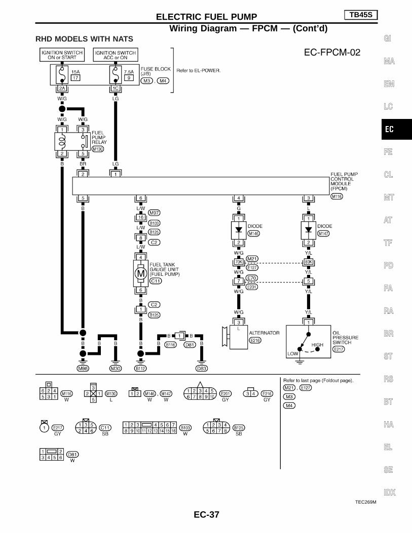
RHD MODELS WITH NATS
TEC269M
ELECTRIC FUEL PUMP TB45S
Wiring Diagram — FPCM — (Cont’d)
EC-37
GI
MA
EM
LC
FE
CL
MT
AT
TF
PD
FA
RA
BR
ST
RS
BT
HA
EL
SE
IDX

LHD MODELS WITHOUT NATS
TEC176M
ELECTRIC FUEL PUMP TB45S
Wiring Diagram — FPCM — (Cont’d)
EC-38

RHD MODELS WITHOUT NATS
TEC268M
ELECTRIC FUEL PUMP TB45S
Wiring Diagram — FPCM — (Cont’d)
EC-39
GI
MA
EM
LC
FE
CL
MT
AT
TF
PD
FA
RA
BR
ST
RS
BT
HA
EL
SE
IDX

Wiring Diagram —FPCM—PICKUP MODELS
TEC270M
ELECTRIC FUEL PUMP TB45S
EC-40
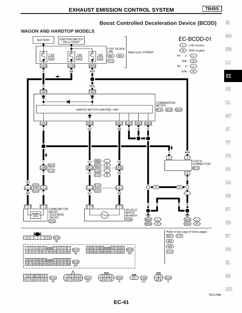
Boost Controlled Deceleration Device (BCDD)WAGON AND HARDTOP MODELS
TEC178M
EXHAUST EMISSION CONTROL SYSTEM TB45S
EC-41
GI
MA
EM
LC
FE
CL
MT
AT
TF
PD
FA
RA
BR
ST
RS
BT
HA
EL
SE
IDX

PICKUP MODELS
TEC271M
EXHAUST EMISSION CONTROL SYSTEM TB45S
Boost Controlled Deceleration Device (BCDD)(Cont’d)
EC-42

Alphabetical & P No. Index for DTCALPHABETICAL INDEX FOR DTC
X: Applicable —: Not applicable
Items(CONSULT-II screen terms)
DTCMIL Illumination Reference page
CONSULT-II ECM*1
CMPS/CIRC P0340 0340 X EC-159
COOLANT T SEN/CIRC P0115 0115 X EC-136
ENG OVER TEMP P1217 1217 X EC-166
HO2S1 (B1)*4 P0130 0130 X EC-148
HO2S1 (B2)*4 P0150 0150 X EC-148
IGN SIGNAL-PRIMARY P1320 1320 X EC-177
KNOCK SEN/CIRC-B1 P0325 0325 — EC-155
KNOCK SEN/CIRC-B2 P0330 0330 — EC-155
MAF SEN/CIRCUIT P0100 0100 X EC-131
NATS MALFUNCTION*3 P1610 - P1615 1610 - 1615 X EL section
NO DTC IS DETECTED. FURTHERTESTING MAY BE REQUIRED
— 0000 — —
NO DTC IS DETECTED. FURTHERTESTING MAY BE REQUIRED
— Flashing*2 — EC-76
THRTL POS SEN/CIRC P0120 0120 X EC-141
*1: In Diagnostic Test Mode II (Self-diagnostic results).*2: While engine is running, front heated oxygen sensor monitoring status is shown by blinks.*3: Models with NATS (Nissan Anti-Theft System)*4: Models with three way catalyst
P NO. INDEX FOR DTCX: Applicable —: Not applicable
DTCMIL Illumination
Items(CONSULT-II screen terms)
Reference pageCONSULT-II ECM*1
— Flashing*2 —NOT DTC IS DETECTED. FURTHERTESTING MAY BE REQUIRED
EC-76
— 0000 —NOT DTC IS DETECTED. FURTHERTESTING MAY BE REQUIRED
—
P0100 0100 X MAF SEN/CIRCUIT EC-131
P0115 0115 X COOLANT T SEN/CIRC EC-136
P0120 0120 X THRTL POS SEN/CIRC EC-141
P0130 0130 X HO2S1 (B1)*4 EC-148
P0150 0150 X HO2S1 (B2)*4 EC-148
P0325 0325 — KNOCK SEN/CIRC-B1 EC-155
P0330 0330 X KNOCK SEN/CIRC-B2 EC-155
P0340 0340 X CMPS/CIRC EC-159
P1217 1217 X ENG OVER TEMP EC-166
P1320 1320 X IGN SIGNAL-PRIMARY EC-177
P1610 - P1615*3 1610 - 1615 X NATS MALFUNCTION EL section
*1: In Diagnostic Test Mode II (Self-diagnostic results).*2: While engine is running, front heated oxygen sensor monitoring status is shown by blinks.*3: Models with NATS (Nissan Anti-Theft System)*4: Models with three way catalyst
TROUBLE DIAGNOSIS — INDEX TB48DE M/T
EC-43
GI
MA
EM
LC
FE
CL
MT
AT
TF
PD
FA
RA
BR
ST
RS
BT
HA
EL
SE
IDX

Supplemental Restraint System (SRS) “AIRBAG” and “SEAT BELT PRE-TENSIONER”
The Supplemental Restraint System such as “AIR BAG” and “SEAT BELT PRE-TENSIONER” used along witha seat belt, helps to reduce the risk or severity of injury to the driver and front passenger for certain types ofcollision. The SRS system composition which is available to NISSAN MODEL Y61 is as follows (The compo-sition varies according to the destination and optional equipment.):I For a frontal collision
The Supplemental Restraint System consists of driver air bag module (located in the center of the steer-ing wheel), front passenger air bag module (located on the instrument panel on passenger side), seat beltpre-tensioners, a diagnosis sensor unit, warning lamp, wiring harness and spiral cable.
I For a side collisionThe Supplemental Restraint System consists of front side air bag module (located in the outer side of frontseat), satellite sensor, diagnosis sensor unit (one of components of air bags for a frontal collision), wiringharness, warning lamp (one of components of air bags for a frontal collision).
Information necessary to service the system safely is included in the RS section of this Service Manual.WARNING:I To avoid rendering the SRS inoperative, which could increase the risk of personal injury or death
in the event of a collision which would result in air bag inflation, all maintenance should be per-formed by an authorized NISSAN dealer.
I Improper maintenance, including incorrect removal and installation of the SRS, can lead to per-sonal injury caused by unintentional activation of the system. For removal of Spiral Cable and AirBag Module, see the RS section.
I Do not use electrical test equipment on any circuit related to the SRS unless instructed to in thisService Manual. SRS wiring harnesses can be identified by yellow harness connector.
Precautions for On Board Diagnostic (OBD)System of Engine
The ECM has an on board diagnostic system. It will light up the malfunction indicator lamp (MIL) to warn thedriver of a malfunction causing emission deterioration.CAUTION:I Be sure to turn the ignition switch “OFF” and disconnect the negative battery terminal before any
repair or inspection work. The open/short circuit of related switches, sensors, solenoid valves, etc.will cause the MIL to light up.
I Be sure to connect and lock the connectors securely after work. A loose (unlocked) connector willcause the MIL to light up due to the open circuit. (Be sure the connector is free from water, grease,dirt, bent terminals, etc.)
I Certain systems and components, especially those related to OBD, may use a new style slide-locking type harness connector.For description and how to disconnect, refer to EL section, “Description”, “HARNESS CONNEC-TOR”.
I Be sure to route and secure the harnesses properly after work. The interference of the harness witha bracket, etc. may cause the MIL to light up due to the short circuit.
I Be sure to erase the unnecessary malfunction information (repairs completed) from the ECM beforereturning the vehicle to the customer.
PRECAUTIONS TB48DE M/T
EC-44

Engine Fuel & Emission Control SystemI Always use a 12 volt battery as power source.I Do not attempt to disconnect battery cables while engine
is running.I Before connecting or disconnecting the ECM harness
connector, turn ignition switch OFF and disconnect nega-tive battery terminal. Failure to do so may damage the ECMbecause battery voltage is applied to ECM even if ignitionswitch is turned off.
I Before removing parts, turn ignition switch OFF and thendisconnect battery ground cable.
I Do not disassemble ECM.I If a battery terminal is disconnected, the memory will
return to the ECM value.The ECM will now start to self-control at its initial value.Engine operation can vary slightly when the terminal isdisconnected. However, this is not an indication of a prob-lem. Do not replace parts because of a slight variation.
I When connecting ECM harness connector, fasten itsecurely with a lever as far as it will go as shown at right.
SEF289H
SEF707Y
PBIB0088E
PBIB0089E
PRECAUTIONS TB48DE M/T
EC-45
GI
MA
EM
LC
FE
CL
MT
AT
TF
PD
FA
RA
BR
ST
RS
BT
HA
EL
SE
IDX

I When connecting or disconnecting pin connectors into orfrom ECM, take care not to damage pin terminals (bend orbreak).Make sure that there are not any bends or breaks on ECMpin terminal, when connecting pin connectors.
I Securely connect ECM harness connectors.A poor connection can cause an extremely high (surge)voltage to develop in coil and condenser, thus resulting indamage to ICs.
I Keep engine control system harness at least 10 cm (4 in)away from adjacent harness, to prevent engine controlsystem malfunctions due to receiving external noise,degraded operation of ICs, etc.
I Keep engine control system parts and harness dry.
I Before replacing ECM, perform “ECM Terminals and Refer-ence Value” inspection and make sure ECM functionsproperly. Refer to EC-112.
I Handle mass air flow sensor carefully to avoid damage.I Do not disassemble mass air flow sensor.I Do not clean mass air flow sensor with any type of deter-
gent.I Even a slight leak in the air intake system can cause seri-
ous problems.I Do not shock or jar the camshaft position sensor.
I After performing each TROUBLE DIAGNOSIS, perform“DTC Confirmation Procedure” or “Overall FunctionCheck”.The DTC should not be displayed in the “DTC ConfirmationProcedure” if the repair is completed. The “Overall Func-tion Check” should be a good result if the repair is com-pleted.
PBIB0090E
MEF040D
SAT652J
PRECAUTIONS TB48DE M/T
Engine Fuel & Emission Control System(Cont’d)
EC-46

I When measuring ECM signals with a circuit tester, neverallow the two tester probes to contact.Accidental contact of probes will cause a short circuit anddamage the ECM power transistor.
I Do not use ECM ground terminals when measuring input/output voltage. Doing so may result in damage to theECM’s transistor. Use a ground other than ECM terminals,such as the ground.
I Do not operate fuel pump when there is no fuel in lines.I Tighten fuel hose clamps to the specified torque.
I Do not depress accelerator pedal when starting.I Immediately after starting, do not rev up engine unneces-
sarily.I Do not rev up engine just prior to shutdown.
I When installing C.B. ham radio or a mobile phone, be sureto observe the following as it may adversely affect elec-tronic control systems depending on installation location.
— Keep the antenna as far as possible from the electroniccontrol units.
— Keep the antenna feeder line more than 20 cm (8 in) awayfrom the harness of electronic controls. Do not let themrun parallel for a long distance.
— Adjust the antenna and feeder line so that the standing-wave radio can be kept smaller.
— Be sure to ground the radio to vehicle body.
SEF348N
SEC686C
SEF709Y
SEF708Y
PRECAUTIONS TB48DE M/T
Engine Fuel & Emission Control System(Cont’d)
EC-47
GI
MA
EM
LC
FE
CL
MT
AT
TF
PD
FA
RA
BR
ST
RS
BT
HA
EL
SE
IDX

I Regarding TB48DE engine, “B1” and “B2” are located asin the following illustration.
Wiring Diagrams and Trouble DiagnosisWhen you read Wiring diagrams, refer to the following:I “How to Read Wiring Diagrams” in GI sectionI “POWER SUPPLY ROUTING” for power distribution circuit in
EL sectionWhen you perform trouble diagnosis, refer to the following:I “HOW TO FOLLOW TEST GROUPS IN TROUBLE DIAG-
NOSES” in GI sectionI “How to Perform Efficient Diagnosis for an Electrical Incident”
in GI section
SEC888C
SEC889C
PRECAUTIONS TB48DE M/T
Engine Fuel & Emission Control System(Cont’d)
EC-48

Special Service Tool
Tool numberTool name
Description
KV10117100Heated oxygen sensorwrench
NT379
Loosening or tightening front heated oxygensensor with 22 mm hexagon nut
Commercial Service Tools
Tool name Description
Fuel filler cap adapter
NT653
Checking fuel tank vacuum relief valve openingpressure
Oxygen sensor threadcleaner
AEM488
Reconditioning the exhaust system threadsbefore installing a new oxygen sensor. Use withanti-seize lubricant shown below.a: 18 mm dia. with pitch 1.5 mm, for Zirconia
Oxygen Sensorb: 12 mm dia. with pitch 1.25 mm, for Titania
Oxygen Sensor
Anti-seize lubricant(PermatexTM 133AR orequivalent meeting MILspecification MIL-A-907)
NT779
Lubricating oxygen sensor thread cleaning toolwhen reconditioning exhaust system threads.
PREPARATION TB48DE M/T
EC-49
GI
MA
EM
LC
FE
CL
MT
AT
TF
PD
FA
RA
BR
ST
RS
BT
HA
EL
SE
IDX

Circuit Diagram
TEC141M
ENGINE AND EMISSION CONTROL OVERALLSYSTEM TB48DE M/T
EC-50

TEC142M
ENGINE AND EMISSION CONTROL OVERALLSYSTEM TB48DE M/T
Circuit Diagram (Cont’d)
EC-51
GI
MA
EM
LC
FE
CL
MT
AT
TF
PD
FA
RA
BR
ST
RS
BT
HA
EL
SE
IDX

System Diagram
SEC319D
ENGINE AND EMISSION CONTROL OVERALLSYSTEM TB48DE M/T
EC-52

Engine Control Component Parts Location
SEC549C
ENGINE AND EMISSION CONTROL OVERALLSYSTEM TB48DE M/T
EC-53
GI
MA
EM
LC
FE
CL
MT
AT
TF
PD
FA
RA
BR
ST
RS
BT
HA
EL
SE
IDX

SEC536C
SEC538CA
SEC540C
SEC542C
SEC537C
SEC539C
ENGINE AND EMISSION CONTROL OVERALLSYSTEM TB48DE M/T
Engine Control Component Parts Location(Cont’d)
EC-54

SEC541C
SEC543C
SEC544C
SEC546CA
SEC545C
SEC547CA
ENGINE AND EMISSION CONTROL OVERALLSYSTEM TB48DE M/T
Engine Control Component Parts Location(Cont’d)
EC-55
GI
MA
EM
LC
FE
CL
MT
AT
TF
PD
FA
RA
BR
ST
RS
BT
HA
EL
SE
IDX

Vacuum Hose Drawing
Refer to “System Diagram”, EC-52, for vacuum control system.Note: Do not use soapy water or any type of solvent while installing vacuum hoses or purge hoses.
SEC548C
ENGINE AND EMISSION CONTROL OVERALLSYSTEM TB48DE M/T
EC-56

VACUUM HOSE DRAWING FOR VIAS
SEC887C
ENGINE AND EMISSION CONTROL OVERALLSYSTEM TB48DE M/T
Vacuum Hose Drawing (Cont’d)
EC-57
GI
MA
EM
LC
FE
CL
MT
AT
TF
PD
FA
RA
BR
ST
RS
BT
HA
EL
SE
IDX

System Chart
Camshaft position sensor E
ECM
Mass air flow sensor E
Engine coolant temperature sensor E
Heater oxygen sensor 1* E
Ignition switch E
Throttle position sensor E
Closed throttle position switch E
Park/neutral position (PNP) switch E
Vehicle speed sensor E
Air conditioner switch E
Ambient air temperature switch E
Battery voltage E
Transfer switch E
Knock sensor E
Electrical load E
Power steering oil pressure switch E
NATS** E
*: Model with three way catalyst**: Model with NATS (Nissan Anti-Theft System)
Fuel injection &mixture ratio control E Injectors
Electronic ignition system E Power transistor
Idle air control system E IACV-AAC valve
Fuel pump control E Fuel pump relay
On board diagnostic system EMIL (On the instrumentpanel)
Power valve control E VIAS control solenoid valve
Intake valve timing control EIntake valve timing controlsolenoid valve
Heated oxygen sensor 1monitor* & on board diag-nostic system
EMalfunction indicator lamp(On the instrument panel)
EVAP canister purge flowcontrol E
EVAP canister purge volumecontrol solenoid valve
Heated oxygen sensorheater control* E Heated oxygen sensor*1
Air conditioner cut control E Air conditioner relay
Cooling fan control E Cooling fan relays
ENGINE AND EMISSION CONTROL OVERALLSYSTEM TB48DE M/T
EC-58

Multiport Fuel Injection (MFI) SystemINPUT/OUTPUT SIGNAL LINE
Camshaft position sensorE
Engine speed and piston position
ECM E Injector
Mass air flow sensorE
Amount of intake air
Engine coolant temperature sensorE
Engine coolant temperature
Heated oxygen sensor 1*E
Density of oxygen in exhaust gas
Throttle position sensorE
Throttle position
Closed throttle position switchE
Throttle valve idle position
Neutral position switch (M/T models)E
Gear position
Vehicle speed sensorE
Vehicle speed
Ignition switchE
Start signal
Battery voltageE
Battery voltage
*: Model with three way catalyst
BASIC MULTIPORT FUEL INJECTIONSYSTEMThe amount of fuel injected from the fuel injector isdetermined by the ECM. The ECM controls thelength of time the valve remains open (injectionpulse duration). The amount of fuel injected is aprogram value in the ECM memory. The programvalue is preset by engine operating conditions.These conditions are determined by input signals(for engine speed and intake air) from both the cam-shaft position sensor and the mass air flow sensor.
VARIOUS FUEL INJECTIONINCREASE/DECREASE COMPENSATIONThe amount of fuel injected is compensated for toimprove engine performance. This will be madeunder various operating conditions as listed below.<Fuel increase>I During warm-upI When starting the engineI During accelerationI Hot-engine operation<Fuel decrease>I During decelerationI When the vehicle speed is extremely highI Extremely high-engine coolant temperatureI When select lever is changed from “N” to “D” at
high engine speed (A/T models only)
ENGINE AND EMISSION BASIC CONTROL SYSTEMDESCRIPTION TB48DE M/T
EC-59
GI
MA
EM
LC
FE
CL
MT
AT
TF
PD
FA
RA
BR
ST
RS
BT
HA
EL
SE
IDX

MIXTURE RATIO FEEDBACK CONTROL (CLOSED LOOP CONTROL) [MODEL WITH THREEWAY CATALYST]
The mixture ratio feedback system provides the best air-fuel mixture ratio for driveability and emission con-trol. The three way catalyst (manifold) can then better reduce CO, HC and NOx emissions. This system usesheated oxygen sensor 1 in the exhaust manifold to monitor if the engine operation is rich or lean. The ECMadjusts the injection pulse width according to the sensor voltage signal. For more information about heatedoxygen sensor 1. This maintains the mixture ratio within the range of stoichiometric (ideal air-fuel mixture).This stage is referred to as the closed loop control condition.
Open loop controlThe open loop system condition refers to when the ECM detects any of the following conditions. Feedbackcontrol stops in order to maintain stabilized fuel combustion.I Deceleration and accelerationI High-load, high-speed operationI Malfunction of heated oxygen sensor 1 or its circuitI Insufficient activation of heated oxygen sensor 1 at low engine coolant temperatureI High engine coolant temperatureI During warm-upI After shifting from “N” to “D” (For A/T models)I When starting the engine
MIXTURE RATIO SELF-LEARNING CONTROL [MODEL WITH THREE WAY CATALYST]The mixture ratio feedback control system monitors the mixture ratio signal transmitted from heated oxygensensor 1. This feedback signal is then sent to the ECM. The ECM controls the basic mixture ratio as close tothe theoretical mixture ratio as possible. However, the basic mixture ratio is not necessarily controlled asoriginally designed. Both manufacturing differences (i.e., mass air flow sensor hot film) and characteristicchanges during operation (i.e., injector clogging) directly affect mixture ratio.Accordingly, the difference between the basic and theoretical mixture ratios is monitored in this system. Thisis then computed in terms of “injection pulse duration” to automatically compensate for the difference betweenthe two ratios.“Fuel trim” refers to the feedback compensation value compared against the basic injection duration. Fuel trimincludes short term fuel trim and long term fuel trim.“Short term fuel trim” is the short-term fuel compensation used to maintain the mixture ratio at its theoreticalvalue. The signal from heated oxygen sensor 1 indicates whether the mixture ratio is RICH or LEAN comparedto the theoretical value. The signal then triggers a reduction in fuel volume if the mixture ratio is rich, and anincrease in fuel volume if it is lean.“Long term fuel trim” is overall fuel compensation carried out long-term to compensate for continual deviationof the short term fuel trim from the central value. Such deviation will occur due to individual engine differences,wear over time and changes in the usage environment.
PBIB0121E
ENGINE AND EMISSION BASIC CONTROL SYSTEMDESCRIPTION TB48DE M/T
Multiport Fuel Injection (MFI) System (Cont’d)
EC-60

FUEL INJECTION SYSTEMTwo types of systems are used.
Simultaneous multiport fuel injection systemFuel is injected simultaneously into all six cylinders twice eachengine cycle. In other words, pulse signals of the same width aresimultaneously transmitted from the ECM.The six injectors will then receive the signals two times for eachengine cycle.This system is used when the engine is being started and/or if thefail-safe mode (CPU) is operating.
Sequential multiport fuel injection systemFuel is injected into each cylinder during each engine cycle accord-ing to the firing order. This system is used when the engine is run-ning.
FUEL SHUT-OFFFuel to each cylinder is cut off during deceleration or operation ofthe engine at excessively high speeds.
SEF630V
ENGINE AND EMISSION BASIC CONTROL SYSTEMDESCRIPTION TB48DE M/T
Multiport Fuel Injection (MFI) System (Cont’d)
EC-61
GI
MA
EM
LC
FE
CL
MT
AT
TF
PD
FA
RA
BR
ST
RS
BT
HA
EL
SE
IDX

Electronic Ignition (EI) SystemINPUT/OUTPUT SIGNAL LINE
Camshaft position sensorE
Engine speed and piston position
ECM E Powertransistor
Mass air flow sensorE
Amount of intake air
Engine coolant temperature sensorE
Engine coolant temperature
Throttle position sensorE
Throttle position
Closed throttle position switchE
Throttle valve idle position
Vehicle speed sensorE
Vehicle speed
Ignition switchE
Start signal
Park/neutral position switchE
Neutral position
BatteryE
Battery voltage
Knock sensorE
Knock signal
SYSTEM DESCRIPTIONThe ignition timing is controlled by the ECM to maintain the bestair-fuel ratio for every running condition of the engine.The ignition timing data is stored in the ECM. This data forms themap shown left.The ECM detects information such as the injection pulse width andcamshaft position sensor signal. Responding to this information,ignition signals are transmitted to the power transistor.
e.g. N: 1,800 rpm, Tp: 1.50 msecA °BTDC
During the following conditions, the ignition timing is revised by theECM according to the other data stored in the ECM.I At startingI During warm-upI At idleI Hot-engine operationI At accelerationThe knock sensor retard system is designed only for emergencies.The basic ignition timing is programmed within the anti-knockingzone, if recommended fuel is used under dry conditions. The retardsystem does not operate under normal driving conditions.If engine knocking occurs, the knock sensor monitors the condition.The signal is transmitted to the ECM. The ECM retards the ignitiontiming to eliminate the knocking condition.
SEF742M
ENGINE AND EMISSION BASIC CONTROL SYSTEMDESCRIPTION TB48DE M/T
EC-62

Air Conditioning Cut ControlINPUT/OUTPUT SIGNAL LINE
Camshaft position sensorE
Engine speed
ECM EAir condi-tionerrelay
Air conditioner switchE
Air conditioner “ON” signal
Throttle position sensorE
Throttle valve opening angle
Ignition switchE
Start signal
Engine coolant temperature sensorE
Engine coolant temperature
Ambient air temperature switchE
Ambient air temperature
SYSTEM DESCRIPTIONThis system improves engine operation when the airconditioner is used.Under the following conditions, the air conditioner isturned off.
I When the accelerator pedal is fully depressedI When cranking the engineI During the engine coolant temperature is exces-
sively highI During high-engine speed operation
Fuel Cut Control (at no load & high enginespeed)
INPUT/OUTPUT SIGNAL LINE
Vehicle speed sensor EVehicle speed
ECM E Injectors
Neutral position switch (M/T models) ENeutral position
Engine coolant temperature sensor EEngine coolant temperature
Camshaft position sensor EEngine speed
Closed throttle position switch EThrottle valve closed position
If the engine speed is above 2,800 rpm with no load (for example,in neutral and engine speed over 2,800 rpm) fuel will be cut off aftersome time. The exact time when the fuel is cut off varies based onengine speed.Fuel cut will operate until the engine speed reaches 1,000 rpm,then fuel cut is cancelled.NOTE:This function is different than deceleration control listed undermultiport fuel injection on EC-59.
ENGINE AND EMISSION BASIC CONTROL SYSTEMDESCRIPTION TB48DE M/T
EC-63
GI
MA
EM
LC
FE
CL
MT
AT
TF
PD
FA
RA
BR
ST
RS
BT
HA
EL
SE
IDX

Description
The evaporative emission system is used to reduce hydrocarbonsemitted into the atmosphere from the fuel system. This reduction ofhydrocarbons is accomplished by activated charcoals in the EVAPcanister.The fuel vapor in the sealed fuel tank is led into the EVAP canisterwhich contains activated carbon and the vapor is stored there whenthe engine is not operating or when refueling to the fuel tank.The EVAP canister retains the fuel vapor until the EVAP canister ispurged by air.The vapor in the EVAP canister is purged by the air through thepurge line to the intake manifold when the engine is operating.EVAP canister purge volume control solenoid valve is controlled byECM. When the engine operates, the flow rate of vapor controlledby EVAP canister purge volume control solenoid valve is propor-tionally regulated as the air flow increases.EVAP canister purge volume control solenoid valve also shuts offthe vapor purge line when decelerating or idling.
InspectionEVAP CANISTERBlow air into each of three ports to check that air flows freely.
SEF749T
SEF083Y
EVAPORATIVE EMISSION SYSTEM TB48DE M/T
EC-64

FUEL CHECK VALVE1. Blow air through connector on fuel tank side.
A considerable resistance should be felt and a portion of air flowshould be directed toward the EVAP canister side.
2. Blow air through connector on EVAP canister side.Air flow should be smoothly directed toward fuel tank side.
3. If fuel check valve is suspected of not properly functioning insteps 1 and 2 above, replace it.
FUEL CUT VALVE
Cut valve operationEnsure that continuity of air passage does not exist when theinstalled cut valve is tilted to 90° or 180°.
FUEL TANK VACUUM RELIEF VALVE1. Wipe clean valve housing.2. Check valve opening pressure and vacuum.
Pressure:16.0 - 20.0 kPa (0.16 - 0.20 bar, 0.163 - 0.204kg/cm 2, 2.32 - 2.90 psi)
Vacuum:−6.0 to −3.5 kPa (−0.060 to −0.035 bar, −0.061 to−0.036 kg/cm 2, −0.87 to −0.51 psi)
3. If out of specification, replace fuel filler cap as an assembly.CAUTION:Use only a genuine fuel filler cap as a replacement.
SEF631V
SEC886CA
SEF632VA
SEF084Y
SEF943S
EVAPORATIVE EMISSION SYSTEM TB48DE M/T
Inspection (Cont’d)
EC-65
GI
MA
EM
LC
FE
CL
MT
AT
TF
PD
FA
RA
BR
ST
RS
BT
HA
EL
SE
IDX

EVAPORATIVE EMISSION (EVAP) CANISTER PURGEVOLUME CONTROL SOLENOID VALVERefer to EC-191.
EVAP VAPOR LINEVisually inspect EVAP vapor lines for improper attachment and forcracks, damage, loose connections, chafing and deterioration.Refer to Vacuum Hose Drawing, EC-56.
EVAPORATIVE EMISSION SYSTEM TB48DE M/T
Inspection (Cont’d)
EC-66

DescriptionThis system returns blow-by gas to the intake manifold collector.The positive crankcase ventilation (PCV) valve is provided to conduct crankcase blow-by gas to the intakemanifold.During partial throttle operation of the engine, the intake manifold sucks the blow-by gas through the PCVvalve.Normally, the capacity of the valve is sufficient to handle any blow-by and a small amount of ventilating air.The ventilating air is then drawn from the air duct into the crankcase. In this process the air passes throughthe hose connecting air inlet tubes to the rocker cover.Under full-throttle condition, the manifold vacuum is insufficient to draw the blow-by flow through the valve.The flow goes through the hose connection in the reverse direction.On vehicles with an excessively high blow-by, the valve does not meet the requirement. This is because someof the flow will go through the hose connection to the intake collector under all conditions.
InspectionPCV (Positive Crankcase Ventilation) VALVEWith engine running at idle, remove PCV valve from breather sepa-rator. A properly working valve makes a hissing noise as air passesthrough it. A strong vacuum should be felt immediately when a fin-ger is placed over the valve inlet.
PCV HOSE1. Check hoses and hose connections for leaks.2. Disconnect all hoses and clean with compressed air. If any
hose cannot be freed of obstructions, replace.
SEF921W
SEC137A
ET277
POSITIVE CRANKCASE VENTILATION TB48DE M/T
EC-67
GI
MA
EM
LC
FE
CL
MT
AT
TF
PD
FA
RA
BR
ST
RS
BT
HA
EL
SE
IDX

Fuel Pressure ReleaseBefore disconnecting fuel line, release fuel pressure from fuelline to eliminate danger.
With CONSULT-II1. Start engine.2. Perform “FUEL PRESSURE RELEASE” in “WORK SUPPORT”
mode with CONSULT-II.(Touch “START” and after engine stalls, crank it two or threetimes to release all fuel pressure.)
3. Turn ignition switch off.
Without CONSULT-II1. Remove fuse for fuel pump.2. Start engine.3. After engine stalls, crank it two or three times to release all fuel
pressure.4. Turn ignition switch off and reconnect fuel pump fuse.
Fuel Pressure CheckI When reconnecting fuel line, always use new clamps.I Make sure that clamp screw does not contact adjacent
parts.I Use a torque driver to tighten clamps.I Use Pressure Gauge to check fuel pressure.1. Release fuel pressure to zero, refer to above.2. Disconnect fuel hose between fuel filter and fuel tube (engine
side).3. Install pressure gauge between fuel filter and fuel tube.4. Start engine and check for fuel leakage.
5. Read the indication of fuel pressure gauge.At idling:
Approximately 245 kPa (2.45 bar, 2.5 kg/cm 2, 36psi)
A few seconds after ignition switch is turned OFF toON:
Approximately 294 kPa (2.94 bar, 3.0 kg/cm 2, 43psi)
6. Stop engine and disconnect fuel pressure regulator vacuumhose from intake manifold.
7. Plug intake manifold with a rubber cap.8. Connect variable vacuum source to fuel pressure regulator.9. Start engine and read indication of fuel pressure gauge as
vacuum is changed.Fuel pressure should decrease as vacuum increases. If resultsare unsatisfactory, replace fuel pressure regulator.
SEF214Y
SEC550C
SEC551C
SEF718BA
BASIC SERVICE PROCEDURE TB48DE M/T
EC-68

Injector Removal and Installation1. Release fuel pressure to zero.2. Disconnect harness connector clip.3. Disconnect injector harness connectors.4. Disconnect fuel hoses from fuel tube assembly.5. Remove fuel tube assemblies in reverse numerical sequence of
that shown in the figure at left.
6. Expand and remove clips securing fuel injectors.7. Extract fuel injectors straight from fuel tubes.I Do not extract injector by pinching connector.I Be careful not to damage injector nozzles during removal.I Do not bump or drop fuel injectors.
8. Install injector to fuel tube assembly.I Lubricate O-rings with a smear of silicone oil.I Be careful not to damage O-rings with service tools, finger
nails or clips. Do not expand or twist O-rings.I Discard old clips, replace with new ones.9. Position clips in grooves on fuel injectors.I Make sure that protrusions of fuel injectors are aligned
with cutouts of clips after installation.10. Align protrusions of fuel tubes with those of fuel injectors. Insert
fuel injectors straight into fuel tubes.11. After properly inserting fuel injectors, check to make sure that
fuel tube protrusions are engaged with those of fuel injectors,and that flanges of fuel tube are engaged with clips.
12. Tighten fuel tube assembly mounting nuts in numericalsequence (indicated in the figure at left) and in two stages.
: Tightening torque N ⋅m (kg-m, ft-lb)1st stage:
9 - 20 (0.9 - 2.1, 7 - 15)2nd stage:
21 - 26 (2.1 - 2.7, 16 - 19)13. Insert fuel hoses into fuel tubes so that ends of fuel hoses butt
up against fuel tubes; fasten with clamps, avoiding bulges.CAUTION:After properly connecting fuel tube assembly to injector andfuel hose, check connection for fuel leakage.
SEC552C
SEC553C
SEC559C
SEC554C
SEC552C
BASIC SERVICE PROCEDURE TB48DE M/T
EC-69
GI
MA
EM
LC
FE
CL
MT
AT
TF
PD
FA
RA
BR
ST
RS
BT
HA
EL
SE
IDX

How to Check Idle Speed and Ignition TimingIDLE SPEEDI Using CONSULT-IICheck idle speed in “DATA MONITOR” mode with CONSULT-II.
IGNITION TIMINGAny of following two methods may be used.I Method A1) Attach timing light to loop wire as shown.2) Check ignition timing.
I Method Ba) Remove No. 1 ignition coil.b) Connect No. 1 ignition coil and No. 1 spark plug with suitable
high-tension wire as shown, and attach timing light clamp to thiswire.
c) Check ignition timing.
SEF058Y
SEC560C
SEC561C
SEC562C
SEF166Y
BASIC SERVICE PROCEDURE TB48DE M/T
EC-70

Idle Air Volume LearningDESCRIPTION“Idle Air Volume Learning” is an operation to learn the idle air vol-ume that keeps each engine within the specific range. It must beperformed under any of the following conditions:I Each time IACV-AAC valve, throttle body or ECM is replaced.I Idle speed or ignition timing is out of specification.
PRE-CONDITIONINGBefore performing “Idle Air Volume Learning”, make sure that all ofthe following conditions are satisfied.Learning will be cancelled if any of the following conditions aremissed for even a moment.I Battery voltage: More than 12.9V (At idle)I Engine coolant temperature: 70 - 99°C (158 - 210°F)I PNP switch: ONI Electric load switch: OFF
(Air conditioner, heater fan, headlamp, rear window defogger)I Cooling fan motor: Not operatingI Steering wheel: Neutral (Straight-ahead position)I Vehicle speed: StoppedI Transmission: Warmed-up
Drive vehicle for 10 minutes.
OPERATION PROCEDURE
With CONSULT-II1. Turn ignition switch “ON”. Wait at least 1 second.2. Turn ignition switch “OFF”. Wait at least 10 seconds.3. Start engine and warm it up to normal operating temperature.4. Check that all items listed under the topic “PRE-CONDITION-
ING” (previously mentioned) are in good order.5. Turn ignition switch “ON” and wait at least 10 seconds.6. Start the engine and let it idle for at least 30 seconds.7. Select “IDLE AIR VOL LEARN” in “WORK SUPPORT” mode.8. Touch “START” and wait 20 seconds.9. Make sure that “CMPLT” is displayed on CONSULT-II screen.
If “INCMP” is displayed, “Idle Air Volume Learning” will not becarried out successfully. In this case, find the cause of theproblem by referring to the NOTE below.
10. Rev up the engine two or three times. Make sure that idle speedand ignition timing are within specifications.
Engine and transmis-sion type
Idle speed(in “P” or “N” position)
Ignition timing(in “P” or “N” position)
TB48DE M/T 675±50 rpm 5±5° BTDC
Without CONSULT-II1. Turn ignition switch “ON”. Wait at least 1 second.2. Turn ignition switch “OFF”. Wait at least 10 seconds.3. Start engine and warm it up to normal operating temperature.4. Check that all items listed under the topic “PRE-CONDITION-
ING” (previously mentioned) are in good order.5. Turn ignition switch “OFF” and wait at least 10 seconds.6. Start the engine and let it idle for at least 30 seconds.7. Disconnect throttle position sensor harness connector (brown),
then reconnect it within 5 seconds.8. Wait 20 seconds.
SEF217Z
SEF454Y
SEF455Y
SEC562C
BASIC SERVICE PROCEDURE TB48DE M/T
EC-71
GI
MA
EM
LC
FE
CL
MT
AT
TF
PD
FA
RA
BR
ST
RS
BT
HA
EL
SE
IDX

9. Make sure that idle speed is within specifications. If not, theresult will be incomplete. In this case, find the cause of theproblem by referring to the NOTE below.
10. Rev up the engine two or three times. Make sure that idle speedand ignition timing are within specifications.
Engine and transmis-sion type
Idle speed(in “P” or “N” position)
Ignition timing(in “P” or “N” position)
TB48DE M/T 675±50 rpm 5±5° BTDC
NOTE:If idle air volume learning cannot be performed successfully,proceed as follows:1) Check that throttle valve is fully closed.2) Check PCV valve operation.3) Check that downstream of throttle valve is free from air
leakage.4) Adjust closed throttle position switch and reset memory.
(Refer to Basic Inspection, EC-93.)5) When the above four items check out OK, engine compo-
nent parts and their installation condition are question-able. Check and eliminate the cause of the problem.It is useful to perform EC-121, “TROUBLE DIAGNOSIS —SPECIFICATION VALUE”.
6) If any of the following conditions occur after the enginehas started, eliminate the cause of the problem and per-form “Idle air volume learning” all over again:
I Engine stalls.I Erroneous idle.I Blown fuses related to the IACV-AAC valve system.
BASIC SERVICE PROCEDURE TB48DE M/T
Idle Air Volume Learning (Cont’d)
EC-72

IntroductionThe ECM has an on board diagnostic system, which detects malfunctions related to engine sensors or actua-tors. Self-diagnosis items are listed in “DIAGNOSTIC TROUBLE CODE INDEX”, EC-43.The malfunction indicator lamp (MIL) on the instrument panel lights up when a specific malfunction is detected,or when the ECM enters fail-safe mode (Refer to EC-104.). For diagnostic items causing the MIL to light up,refer to “DIAGNOSTIC TROUBLE CODE INDEX”, EC-43.
Diagnostic Trouble Code (DTC)HOW TO READ DTCMalfunction items can be confirmed by the following methods.
With CONSULT-IICONSULT-II displays the DTC in “SELF-DIAGNOSTIC RESULTS” mode.Examples: P0100, P0120, P0340, etc. (CONSULT-II also displays the malfunctioning component or system.)
Without CONSULT-IIThe number of blinks of the malfunction indicator lamp in the Diagnostic Test Mode II (Self-Diagnostic Results)indicates the DTC. Examples: 0100, 1320, etc.I Output of a DTC indicates a malfunction. However, Mode II does not indicate whether the malfunc-
tion is still occurring or has occurred in the past and has returned to normal.CONSULT-II can identify malfunction status as shown below. Therefore, using CONSULT-II (if avail-able) is recommended.
A sample of CONSULT-II display is shown at left. The malfunctionis displayed in “SELF-DIAGNOSTIC RESULTS” mode of CON-SULT-II. Time data indicates how many times the vehicle wasdriven after the last detection of a malfunction.If the malfunction is being detected currently, the time data will be“0”.
FREEZE FRAME DATAThe ECM records the driving conditions such as fuel system status, calculated load value, engine coolanttemperature, short term fuel trim*, long term fuel trim*, engine speed, vehicle speed, absolute throttle positionand base fuel schedule at the moment a malfunction is detected.Data which are stored in the ECM memory, along with the DTC, are called freeze frame data. The data, storedtogether with the DTC data, are called freeze frame data and displayed on CONSULT-II. The freeze framedata can only be displayed on the CONSULT-II screen. For details, see EC-82.Only one set of freeze frame data can be stored in the ECM.When more than one DTC is detected, the freeze frame data detected first is stored in the memory.The freeze frame data (along with the DTCs) are cleared when the ECM memory is erased. Procedures forclearing the ECM memory are described in “HOW TO ERASE EMISSION-RELATED DIAGNOSTIC INFOR-MATION”. Refer to EC-73.*: Model with three way catalyst
HOW TO ERASE EMISSION-RELATED DIAGNOSTIC INFORMATION
How to erase DTC (With CONSULT-II)1. If the ignition switch stays “ON” after repair work, be sure to turn ignition switch “OFF” once. Wait at least
9 seconds and then turn it “ON” (engine stopped) again.2. Turn CONSULT-II “ON” and touch “ENGINE”.3. Touch “SELF-DIAG RESULTS”.4. Touch “ERASE”. (The DTC in the ECM will be erased.)
SEC890C
ON BOARD DIAGNOSTIC SYSTEM DESCRIPTION TB48DE M/T
EC-73
GI
MA
EM
LC
FE
CL
MT
AT
TF
PD
FA
RA
BR
ST
RS
BT
HA
EL
SE
IDX

The emission-related diagnostic information in the ECM can be erased by selecting “ERASE” in the “SELF-DIAG RESULTS” mode with CONSULT-II.
How to erase DTC (No tools)1. If the ignition switch stays “ON” after repair work, be sure to turn ignition switch “OFF” once.2. Wait at least 10 seconds and then turn it “ON” (engine stopped) again.3. Change the diagnostic test mode from Mode II to Mode I by depressing the accelerator pedal. Refer to
EC-76, “How to Switch Diagnostic Test Mode”.NOTE:I If the battery is disconnected, the emission-related diagnostic information will be lost after approx.
24 hours.I The following data are cleared when the ECM memory is erased.1) Diagnostic trouble codes2) Freeze frame data3) OthersActual work procedures are explained using a DTC as an example. Be careful so that not only the DTC, butall of the data listed above, are cleared from the ECM memory during work procedures.
SEC555C
ON BOARD DIAGNOSTIC SYSTEM DESCRIPTION TB48DE M/T
Diagnostic Trouble Code (DTC) (Cont’d)
EC-74

NATS (Nissan Anti-theft System)I If the security indicator lights up with the ignition switch in
the “ON” position or “NATS MALFUNCTION” is displayedon “SELF-DIAG RESULTS” screen, perform self-diagnosticresults mode with CONSULT-II using NATS program card.Refer to NATS (Nissan Anti-Theft System) in EL section.
I Confirm no self-diagnostic results of NATS is displayedbefore touching “ERASE” in “SELF-DIAG RESULTS” modewith CONSULT-II.
I When replacing ECM, initialization of NATS system andregistration of all NATS ignition key IDs must be carried outwith CONSULT-II using NATS program card.Therefore, be sure to receive all keys from vehicle owner.Regarding the procedure of NATS initialization and NATSignition key ID registration, refer to CONSULT-II operationmanual, NATS.
Malfunction Indicator Lamp (MIL)The MIL is located on the instrument panel.1. The MIL will light up when the ignition switch is turned ON
without the engine running. This is a bulb check.I If the MIL does not light up, refer to EL section, “WARNING
LAMPS” or see EC-247.2. When the engine is started, the MIL should go off.
If the MIL remains on, the on board diagnostic system hasdetected an engine system malfunction.
ON BOARD DIAGNOSTIC SYSTEM FUNCTIONThe on board diagnostic system has the following four functions.
Diagnostic test mode I1. BULB CHECK:
This function checks the MIL bulb for damage (blown, open circuit, etc.).If the MIL does not come on, check MIL circuit and ECM test mode selector. (See EC-76.)
2. MALFUNCTION WARNING:This is a usual driving condition. When a malfunction is detected, the MIL will light up to inform the driverthat a malfunction has been detected.
Diagnostic test mode II3. SELF-DIAGNOSTIC RESULTS:
This function allows DTCs to be read.4. HEATED OXYGEN SENSOR 1 MONITOR*:
*: Model with three way catalyst
SEF543X
SAT652J
ON BOARD DIAGNOSTIC SYSTEM DESCRIPTION TB48DE M/T
EC-75
GI
MA
EM
LC
FE
CL
MT
AT
TF
PD
FA
RA
BR
ST
RS
BT
HA
EL
SE
IDX

MIL flashing without DTCIf the ECM is in Diagnostic Test Mode II, MIL may flash when engine is running. In this case, check ECM testmode following “HOW TO SWITCH DIAGNOSTIC TEST MODES”.How to switch the diagnostic test (function) modes, and details of the above functions are described later. (SeeEC-76.)
Condition Diagnostic Test Mode I Diagnostic Test Mode II
Ignition switch in “ON” position
Engine stopped
BULB CHECK SELF-DIAGNOSTIC RESULTS
Engine running
MALFUNCTION WARNINGHEATED OXYGEN SENSOR 1
MONITOR*
*: Model with three way catalyst
The following emission-related diagnostic information is cleared when the ECM memory is erased.1) Diagnostic trouble codes2) Free frame data3) Others
HOW TO SWITCH DIAGNOSTIC TEST MODENOTE:I It is better to count the time accurately with a clock.I It is impossible to switch the diagnostic mode when an accelerator pedal position sensor circuit
has a malfunction.I Always ECM returns to Diagnostic Test Mode I after ignition switch is turned “OFF”.
How to set Diagnostic Test Mode II (Self-diagnostic results)1. Confirm that accelerator pedal is fully released, turn ignition switch “ON” and wait 3 seconds.2. Repeat the following procedure quickly five times within 5 seconds.a. Fully depress the accelerator pedal.b. Fully release the accelerator pedal.3. Wait 7 seconds, fully depress the accelerator pedal and keep it for approx. 10 seconds until the MIL starts
blinking.4. Fully release the accelerator pedal.
ECM has entered to Diagnostic Test Mode II (Self-diagnostic results).
How to set Diagnostic Test Mode II (Heated Oxygen Sensor 1 Monitor) [Model with threeway catalyst]1. Set the ECM in Diagnostic Test Mode II (Self-diagnostic results). Refer to EC-76, “How to Set Diagnostic
Test Mode II (Self-diagnostic Results)”.2. Start Engine.
ECM has entered to Diagnostic Test Mode II (Heated oxygen sensor 1 monitor).ECM will start heated oxygen sensor 1 monitoring from the bank 1 sensor.
PBIB0092E
ON BOARD DIAGNOSTIC SYSTEM DESCRIPTION TB48DE M/T
Malfunction Indicator Lamp (MIL) (Cont’d)
EC-76

How to switch monitored sensor from Bank 1 to Bank 2 or vice versa (Model with threeway catalyst)1. Fully depress the accelerator pedal quickly and then release it immediately.2. Make sure that monitoring sensor has changed by MIL blinking as follows.
How to Erase Diagnostic Test Mode II (Self-diagnostic Results)1. Set ECM in Diagnostic Test Mode II (Self-diagnostic results). Refer to EC-76 “How to Set Diagnostic Test
Mode II (Self-diagnostic Results)”.2. Fully depress the accelerator pedal and keep it for more than 10 seconds.
The emission-related diagnostic information has been erased from the backup memory in the ECM.3. Fully release the accelerator pedal, and confirm the DTC 0000 is displayed.
DIAGNOSTIC TEST MODE I — BULB CHECKIn this mode, the MIL on the instrument panel should stay ON. If it remains OFF, check the bulb. Refer to“WARNING LAMPS” in EL section or see EC-247.
DIAGNOSTIC TEST MODE I — MALFUNCTION WARNING
MIL Condition
ON When the malfunction is detected or the ECM’s CPU is malfunctioning.
OFF No malfunction.
I These DTC numbers are clarified in Diagnostic Test Mode II (SELF-DIAGNOSTIC RESULTS).
DIAGNOSTIC TEST MODE II — SELF-DIAGNOSTIC RESULTS
PBIB0093E
SEC687C
ON BOARD DIAGNOSTIC SYSTEM DESCRIPTION TB48DE M/T
Malfunction Indicator Lamp (MIL) (Cont’d)
EC-77
GI
MA
EM
LC
FE
CL
MT
AT
TF
PD
FA
RA
BR
ST
RS
BT
HA
EL
SE
IDX

A particular trouble code can be identified by the number of four-digit numeral flashes. The “zero” is indicatedby the number of ten flashes. The length of time the 1,000th-digit numeral flashes on and off is 1.2 secondsconsisting of an ON (0.6-second) - OFF (0.6-second) cycle.The 100th-digit numeral and lower digit numerals consist of a 0.3-second ON and 0.3-second OFF cycle.A change from one digit numeral to another occurs at an interval of 1.0-second OFF. In other words, the laternumeral appears on the display 1.3 seconds after the former numeral has disappeared.A change from one trouble code to another occurs at an interval of 1.8-second OFF.In this way, all the detected malfunctions are classified by their DTC numbers. The DTC “0000” refers to nomalfunction. (See EC-43, “INDEX FOR DTC”.)
How to erase Diagnostic Test Mode II (Self-diagnostic results)The DTC can be erased from the back up memory in the ECM by depressing accelerator pedal. Refer to EC-76“How to Switch Diagnostic Test Mode”.I If the battery is disconnected, the DTC will be lost from the backup memory after approx. 24 hours.I Be careful not to erase the stored memory before starting trouble diagnoses.
DIAGNOSTIC TEST MODE II — HEATED OXYGEN SENSOR 1 MONITOR (MODEL WITHTHREE WAY CATALYST)In this mode, the MIL displays the condition of the fuel mixture (lean or rich) which is monitored by the heatedoxygen sensor 1.
MIL Fuel mixture condition in the exhaust gas Air fuel ratio feedback control condition
ON LeanClosed loop system
OFF Rich
*Remains ON or OFF Any condition Open loop system
*: Maintains conditions just before switching to open loop.
To check the heated oxygen sensor 1 function, start engine in the Diagnostic Test Mode II and warm it up untilengine coolant temperature indicator points to the middle of the gauge.Next run engine at about 2,000 rpm for about 2 minutes under no-load conditions. Then make sure that theMIL comes ON more than 5 times within 10 seconds with engine running at 2,000 rpm under no-load.
ON BOARD DIAGNOSTIC SYSTEM DESCRIPTION TB48DE M/T
Malfunction Indicator Lamp (MIL) (Cont’d)
EC-78

CONSULT-IICONSULT-II INSPECTION PROCEDURE1. Turn ignition switch OFF.2. Connect “CONSULT-II” to data link connector.
(Data link connector is located under the instrument lowercover on the driver’s side.)
3. Turn ignition switch ON.4. Touch “ENGINE”.
5. Perform each diagnostic test mode according to each serviceprocedure.
For further information, see the CONSULT-II Operation Manual.
SEC556C
SEC557C
SEC558C
ON BOARD DIAGNOSTIC SYSTEM DESCRIPTION TB48DE M/T
EC-79
GI
MA
EM
LC
FE
CL
MT
AT
TF
PD
FA
RA
BR
ST
RS
BT
HA
EL
SE
IDX

FUNCTION
Diagnostic test mode Function
Work supportThis mode enables a technician to adjust some devices faster and more accurately by follow-ing the indications on the CONSULT-II unit.
Self-diagnostic results Self-diagnostic results such as DTCs and freeze frame data can be read and erased quickly.*1
Data monitor Input/Output data in the ECM can be read.
Data monitor (SPEC)Input/Output of the specification for Basic fuel schedule, AFM, A/F feedback control value andthe other data monitor items can be read.
Active testDiagnostic Test Mode in which CONSULT-II drives some actuators apart from the ECMs andalso shifts some parameters in a specified range.
Function testConducted by CONSULT-II instead of a technician to determine whether each system is “OK”or “NG”.
ECM part number ECM part number can be read.
*1 The following emission-related diagnostic information is cleared when the ECM memory is erased.1. Diagnostic trouble codes2. Freeze frame data3. Others
WORK SUPPORT MODE
WORK ITEM CONDITION USAGE
TP SW/TP SEN IDLE POSI ADJ I FOLLOW THE BASIC INSPECTION INSTRUCTION INTHE SERVICE MANUAL.
When adjusting the idle throttleposition
FUEL PRESSURE RELEASE I FUEL PUMP WILL STOP BY TOUCHING “START”DURING IDLING.CRANK A FEW TIMES AFTER ENGINE STALLS.
When releasing fuel pressurefrom fuel line
IDLE AIR VOL LEARN I THE IDLE AIR VOLUME THAT KEEPS THE ENGINEWITHIN THE SPECIFIED RANGE IS MEMORIZED INECM.
When learning the idle air volume
TARGET IGNITION TIMING ADJ* I IDLE CONDITION When adjusting target ignition tim-ingAfter adjustment, confirm targetignition timing with a timing light.I If once the “TARGET IDLE
RPM ADJ” has been done, theIdle Air Volume Learning proce-dure will not be completed.
TARGET IDLE RPM ADJ* I IDLE CONDITION When setting target idle speed
CD ADJUSTMENT I IDLE CONDITION When setting “CO” adjustmentvalue
*: This function is not necessary in the usual service procedure.
ON BOARD DIAGNOSTIC SYSTEM DESCRIPTION TB48DE M/T
CONSULT-II (Cont’d)
EC-80

ENGINE CONTROL COMPONENT PARTS/CONTROL SYSTEMS APPLICATION
Item
DIAGNOSTIC TEST MODE
WORKSUPPORT
SELF-DIAGNOSTICRESULTS
DATAMONITOR
DATAMONITOR
(SPEC)
ACTIVETEST
DTCFREEZEFRAMEDATA
EN
GIN
EC
ON
TR
OL
CO
MP
ON
EN
TPA
RT
S
INP
UT
Camshaft position sensor x x x x
Mass air flow sensor x x x
Engine coolant temperature sen-sor
x x x x x
Heated oxygen sensor 1*1 x x x
Vehicle speed sensor x x x
Throttle position sensor x x x
Knock sensor x
Ignition switch (start signal) x x
Closed throttle position switch(accelerator pedal position sen-sor signal)
x x
Air conditioner switch x x
Park/neutral position (PNP)switch
x x
Power steering pressure switch x x
Ambient air temperature switch x x
Battery voltage x x
Load signal x x
OU
TP
UT
Injectors x x x
Power transistor (Ignition timing)x
(Ignition sig-nal)
x x x
IACV-AAC valve x x x
EVAP canister purge volumecontrol solenoid valve
x x x
Air conditioner relay x x
Fuel pump relay x x x x
Cooling fan x x x x
Heated oxygen sensor 1heater*1
x x
Intake valve timing control sole-noid valve
x x x
VIAS control solenoid valve x x x
Calculated load value x x
CO adjustment value*2 x
X: Applicable*1: Model with three way catalyst*2: Model without three way catalyst
ON BOARD DIAGNOSTIC SYSTEM DESCRIPTION TB48DE M/T
CONSULT-II (Cont’d)
EC-81
GI
MA
EM
LC
FE
CL
MT
AT
TF
PD
FA
RA
BR
ST
RS
BT
HA
EL
SE
IDX

SELF-DIAGNOSTIC MODERegarding items detected in “SELF-DIAG RESULTS” mode, refer to “DIAGNOSTIC TROUBLE CODEINDEX”, EC-43.
Freeze frame data
Freeze frame data item Description
DIAG TROUBLE CODE[PXXXX]
I Engine Control component part/control system has a trouble code, it is displayed as “PXXXX”. (Referto “TROUBLE DIAGNOSIS — INDEX”, EC-43.)
FUEL SYS-B1* I “Fuel injection system status” at the moment a malfunction is detected is displayed.I One mode in the following is displayed.
“MODE 2”: Open loop due to detected system malfunction“MODE 3”: Open loop due to driving conditions (power enrichment, deceleration enrichment)“MODE 4”: Closed loop - using oxygen sensor(s) as feedback for fuel control“MODE 5”: Open loop - has not yet satisfied condition to go to closed loop
COOLANT TEMP [°C] or[°F]
I The engine coolant temperature at the moment a malfunction is detected is displayed.
S-FUEL TRM-B1 [%]* I “Short-term fuel trim” at the moment a malfunction is detected is displayed.I The short-term fuel trim indicates dynamic or instantaneous feedback compensation to the base fuel
schedule.
L-FUEL TRM-B1 [%]* I “Long-term fuel trim” at the moment a malfunction is detected is displayed.I The long-term fuel trim indicates much more gradual feedback compensation to the base fuel sched-
ule than short-term fuel trim.
ENGINE SPEED [rpm] I The engine speed at the moment a malfunction is detected is displayed.
VEHICL SPEED [km/h]or [mph]
I The vehicle speed at the moment a malfunction is detected is displayed.
ABSOL TH⋅P/S [degree]or [%]
I The throttle valve opening angle at the moment a malfunction is detected is displayed.
B/FUEL SCHDL [msec] I The base fuel schedule at the moment a malfunction is detected is displayed.
*: Model with three way catalyst
ON BOARD DIAGNOSTIC SYSTEM DESCRIPTION TB48DE M/T
CONSULT-II (Cont’d)
EC-82

DATA MONITOR MODE
Monitored item[Unit]
ECMinput
signals
Mainsignals Description Remarks
ENG SPEED [rpm]
q qI Indicates the engine speed computed
from the signal of the camshaft positionsensor.
I Accuracy becomes poor if engine speeddrops below the idle rpm.
I If the signal is interrupted while theengine is running, an abnormal valuemay be indicated.
MAS A/F SE-B1 [V] q q I The signal voltage of the mass air flowsensor is displayed.
I When the engine is stopped, a certainvalue is indicated.
B/FUEL SCHDL[msec] q
I “Base fuel schedule” indicates the fuelinjection pulse width programmed intoECM, prior to any learned on board cor-rection.
COOLAN TEMP/S[°C] or [°F]
q qI The engine coolant temperature (deter-
mined by the signal voltage of the enginecoolant temperature sensor) is displayed.
I When the engine coolant temperaturesensor is open or short-circuited, ECMenters fail-safe mode. The engine coolanttemperature determined by the ECM isdisplayed.
HO2S1*1 (B1)*2 [V] q q I The signal voltage of the heated oxygensensor 1 is displayed.
HO2S1*1 (B2)*2 [V] q qHO2S1 MNTR*1(B1)*2 [RICH/LEAN] q
I Display of heated oxygen sensor 1 signalduring air-fuel ratio feedback control:RICH ... means the mixture became“rich”, and control is being affectedtoward a leaner mixture.LEAN ... means the mixture became“lean”, and control is being affectedtoward a rich mixture.
I After turning ON the ignition switch,“RICH” is displayed until air-fuel mixtureratio feedback control begins.
I When the air-fuel ratio feedback isclamped, the value just before the clamp-ing is displayed continuously.
HO2S1 MNTR*1(B2)*2 [RICH/LEAN] qVHCL SPEED SE[km/h] or [mph] q q I The vehicle speed computed from the
vehicle speed sensor signal is displayed.
BATTERY VOLT [V] q q I The power supply voltage of ECM is dis-played.
THRTL POS SEN [V] q q I The throttle position sensor signal volt-age is displayed.
START SIGNAL[ON/OFF] q q I Indicates [ON/OFF] condition from the
starter signal.I After starting the engine, [OFF] is dis-
played regardless of the starter signal.
CLSD TH POS[ON/OFF] q q I Indicates [ON/OFF] condition from the
throttle position sensor signal.
AIR COND SIG[ON/OFF] q q
I Indicates [ON/OFF] condition of the airconditioner switch as determined by theair conditioner signal.
P/N POSI SW[ON/OFF] q q I Indicates [ON/OFF] condition from the
park/neutral position switch signal.
PW/ST SIGNAL[ON/OFF] q q
I [ON/OFF] condition of the power steeringoil pressure switch determined by thepower steering oil pressure signal is indi-cated.
ON BOARD DIAGNOSTIC SYSTEM DESCRIPTION TB48DE M/T
CONSULT-II (Cont’d)
EC-83
GI
MA
EM
LC
FE
CL
MT
AT
TF
PD
FA
RA
BR
ST
RS
BT
HA
EL
SE
IDX

Monitored item[Unit]
ECMinput
signals
Mainsignals
Description Remarks
LOAD SIGNAL[ON/OFF]
q q
I Indicates [ON/OFF] condition from theelectrical load signal.ON ... Rear window defogger switch isON and/or lighting switch is in 2nd posi-tion.OFF ... Both rear window defoggerswitch and lighting switch are OFF.
AMB TEMP SW[ON/OFF] q I Indicates [ON/OFF] condition from the
ambient air temperature switch signal.IGNITION SW[ON/OFF] q I Indicates [ON/OFF] condition from igni-
tion switch.INJ PULSE-B1 [msec]
qI Indicates the actual fuel injection pulse
width compensated by ECM according tothe input signals.
I When the engine is stopped, a certaincomputed value is indicated.
IGN TIMING [BTDC] q I Indicates the ignition timing computed byECM according to the input signals.
I When the engine is stopped, a certainvalue is indicated.
A/F ALPHA-B1*1 [%] q I The mean value of the air-fuel ratio feed-back correction factor per cycle is indi-cated.
I When the engine is stopped, a certainvalue is indicated.
I This data also includes the data for theair-fuel ratio learning control.
A/F ALPHA-B2*1 [%] qCAL/LD VALUE [%] I “Calculated load value” indicates the
value of the current airflow divided bypeak airflow.
ABSOL TH-P/S [%] I The throttle valve opening angle at themoment a malfunction is detected is dis-played.
IACV-AAC/V [step]
qI Indicates IACV-AAC/V control value com-
puted by ECM according to the input sig-nals.
PURG VOL C/V [%] I Indicates the EVAP canister purge vol-ume control solenoid valve control valuecomputed by the ECM according to theinput signals.
I The opening becomes larger as thevalue increases.
VIAS S/V [ON/OFF] I The control condition of the VIAS controlsolenoid valve (determined by ECMaccording to the input signals) is indi-cated.
I OFF ... VIAS control solenoid valve is notoperating.ON ... VIAS control solenoid valve isoperating.
INT/V SOL-B1[ON/OFF]
I The control condition of the intake valvetiming control solenoid valve (determinedby ECM according to the input signals) isindicated.ON ... intake valve timing control is oper-ating.OFF ... Intake valve timing control is notoperating.
AIR COND RLY[ON/OFF] q
I The air conditioner relay control condition(determined by ECM according to theinput signal) is indicated.
ON BOARD DIAGNOSTIC SYSTEM DESCRIPTION TB48DE M/T
CONSULT-II (Cont’d)
EC-84

Monitored item[Unit]
ECMinput
signals
Mainsignals
Description Remarks
FUEL PUMP RLY[ON/OFF] q
I Indicates the fuel pump relay control con-dition determined by ECM according tothe input signals.
HO2S1 HTR*1 (B1)*2[ON/OFF]
I Indicates [ON/OFF] condition of heatedoxygen sensor 1 heater determined byECM according to the input signals.HO2S1 HTR*1 (B2)*2
[ON/OFF]COOLING FAN[HI/LOW/OFF]
q
I The control condition of the cooling fan(determined by ECM according to theinput signal) is indicated.HI ... High speed operationLOW ... Low speed operationOFF ... Stop
IDL A/V LEARN [YET/CMPLT/INCMP]
I Display the condition of idle air volumelearningYET ... Idle air volume learning has notbeen performed yet.CMPLT ... Idle air volume learning hasalready been performed successfully.INCMP ... Idle air volume learning hasnot been performed successfully.
Voltage [V] I Voltage, frequency, duty cycle or pulsewidth measured by the probe.
I Only “#” is displayed if item is unable tobe measured.
I Figures with “#”s are temporary ones.They are the same figures as an actualpiece of data which was just previouslymeasured.
Frequency [msec],[Hz] or [%]DUTY-HIDUTY-LOWPLS WIDTH-HIPLS WIDTH-LOW
NOTE:Any monitored item that does not match the vehicle being diagnosed is deleted from the display automatically.*1: Models with three way catalyst*2: The display of (B1) and (B2) of the monitor item is explained on EC-48.
DATA MONITOR (SPEC) MODE
Monitored Item
Monitored item [Unit] ECMinput
signals
Mainsignals
Description Remarks
ENG SPEED [rpm]
q qI Indicates the engine speed computed
from the signal of the camshaft positionsensor.
MAS A/F SE-B1 [V] q q I The signal voltage of the mass air flowsensor specification is displayed.
I When engine is running specificationrange is indicated.
B/FUEL SCHDL[msec] q
I “Base fuel schedule” indicates the fuelinjection pulse width programmed intoECM, prior to any learned on board cor-rection.
I When engine is running specificationrange is indicated.
A/F ALPHA-B1** [%]*A/F ALPHA-B2** [%]* q
I The mean value of the air-fuel ratio feed-back correction factor per cycle is indi-cated.
I When engine is running specificationrange is indicated.
I This data also includes the data for theair-fuel ratio learning control.
NOTE:Any monitored item that does not match the vehicle being diagnosed is deleted from the display automatically.*: Models with three way catalyst**: The display of (B1) and (B2) of the monitor item is explained on EC-48.
ON BOARD DIAGNOSTIC SYSTEM DESCRIPTION TB48DE M/T
CONSULT-II (Cont’d)
EC-85
GI
MA
EM
LC
FE
CL
MT
AT
TF
PD
FA
RA
BR
ST
RS
BT
HA
EL
SE
IDX

ACTIVE TEST MODE
TEST ITEM CONDITION JUDGEMENT CHECK ITEM (REMEDY)
IGNITION TIMING
I Engine: Return to the originaltrouble condition
I Timing light: SetI Retard the ignition timing using
CONSULT-II.
If trouble symptom disappears, seeCHECK ITEM.
I Adjust ignition timing (by movingcamshaft position sensor)
IACV-AAC/VOPENING
I Engine: After warming up, idlethe engine.
I Change the IACV-AAC valveopening step using CONSULT-II.
Engine speed changes according tothe opening step.
I Harness and connectorI IACV-AAC valve
POWER BAL-ANCE
I Engine: After warming up, idlethe engine.
I A/C switch “OFF”I Shift lever “N”I Cut off each injector signal one
at a time using CONSULT-II.
Engine runs rough or dies.
I Harness and connectorI CompressionI InjectorsI Power transistorI Spark plugsI Ignition coil
COOLING FANI Ignition switch: ONI Turn the cooling fan “HI”, “LOW”
and “OFF” using CONSULT-II.Cooling fan moves and stops.
I Harness and connectorI Cooling fan motorI Cooling fan relay
ENG COOLANTTEMP
I Engine: Return to the originaltrouble condition
I Change the engine coolant tem-perature using CONSULT-II.
If trouble symptom disappears, seeCHECK ITEM.
I Harness and connectorI Engine coolant temperature sen-
sorI Fuel injectors
FUEL PUMPRELAY
I Ignition switch: ON (Enginestopped)
I Turn the fuel pump relay “ON”and “OFF” using CONSULT-IIand listen to operating sound.
Fuel pump relay makes the operat-ing sound.
I Harness and connectorI Fuel pump relay
VIAS SOL VALVE
I Ignition switch: ONI Turn solenoid valve “ON” and
“OFF” with CONSULT-II and lis-ten for operating sound.
Solenoid valve makes an operatingsound.
I Harness and connectorsI Solenoid valve
VALVE TIMINGSOL
I Ignition switch: ONI Turn solenoid valve “ON” and
“OFF” with CONSULT-II and lis-ten to operating sound.
Solenoid valve makes an operatingsound.
I Harness and connectorI Intake valve timing control sole-
noid valve
PURG VOLCONT/V
I Engine: After warming up, runengine at 1,500 rpm.
I Change the EVAP canister purgevolume control solenoid valveopening percent using CON-SULT-II.
Engine speed changes according tothe opening percent.
I Harness and connectorsI Solenoid valve
ON BOARD DIAGNOSTIC SYSTEM DESCRIPTION TB48DE M/T
CONSULT-II (Cont’d)
EC-86

REAL TIME DIAGNOSIS IN DATA MONITOR MODE(RECORDING VEHICLE DATA)CONSULT-II has two kinds of triggers and they can be selected bytouching “SETTING” in “DATA MONITOR” mode.1) “AUTO TRIG” (Automatic trigger):I The malfunction will be identified on the CONSULT-II screen in
real time.In other words, DTC and malfunction item will be displayed ifthe malfunction is detected by ECM.At the moment a malfunction is detected by ECM, “MONITOR”in “DATA MONITOR” screen is changed to “Recording Data ...xx%” as shown at left, and the data after the malfunction detec-tion is recorded. Then when the percentage reached 100%,“REAL-TIME DIAG” screen is displayed. If “STOP” is touchedon the screen during “ Recording Data ... xx%”, “REAL-TIMEDIAG” screen is also displayed.The recording time after the malfunction detection and therecording speed can be changed by “TRIGGER POINT” and“Recording Speed”. Refer to CONSULT-II OPERATIONMANUAL.
2) “MANU TRIG” (Manual trigger):I DTC and malfunction item will not be displayed automatically
on CONSULT-II screen even though a malfunction is detectedby ECM.DATA MONITOR can be performed continuously even thougha malfunction is detected.
Use these triggers as follows:1) “AUTO TRIG”I While trying to detect the DTC by performing the “DTC Confir-
mation Procedure”, be sure to select to “DATA MONITOR(AUTO TRIG)” mode. You can confirm the malfunction at themoment it is detected.
I While narrowing down the possible causes, CONSULT-IIshould be set in “DATA MONITOR (AUTO TRIG)” mode, espe-cially in case the incident is intermittent.When you are inspecting the circuit by gently shaking (or twist-ing) the suspicious connectors, components and harness in the“DTC Confirmation Procedure”, the moment a malfunction isfound the DTC will be displayed. (Refer to GI section, “IncidentSimulation Tests”.)
2) “MANU TRIG”I If the malfunction is displayed as soon as “DATA MONITOR” is
selected, reset CONSULT-II to “MANU TRIG”. By selecting“MANU TRIG” you can monitor and store the data. The datacan be utilized for further diagnosis, such as a comparison withthe value for the normal operating condition.
SEC564C
SEF707X
ON BOARD DIAGNOSTIC SYSTEM DESCRIPTION TB48DE M/T
CONSULT-II (Cont’d)
EC-87
GI
MA
EM
LC
FE
CL
MT
AT
TF
PD
FA
RA
BR
ST
RS
BT
HA
EL
SE
IDX

SEF720X
ON BOARD DIAGNOSTIC SYSTEM DESCRIPTION TB48DE M/T
CONSULT-II (Cont’d)
EC-88

IntroductionThe engine has an ECM to control major systems such as fuelcontrol, ignition control, idle air control system, etc. The ECMaccepts input signals from sensors and instantly drives actuators.It is essential that both input and output signals are proper andstable. At the same time, it is important that there are no problemssuch as vacuum leaks, fouled spark plugs, or other problems withthe engine.It is much more difficult to diagnose a problem that occurs intermit-tently rather than continuously. Most intermittent problems arecaused by poor electric connections or improper wiring. In thiscase, careful checking of suspected circuits may help prevent thereplacement of good parts.A visual check only may not find the cause of the problems. A roadtest with CONSULT-II or a circuit tester connected should be per-formed. Follow the “Work Flow” on EC-91.Before undertaking actual checks, take just a few minutes to talkwith a customer who approaches with a driveability complaint. Thecustomer can supply good information about such problems, espe-cially intermittent ones. Find out what symptoms are present andunder what conditions they occur. A “Diagnostic Worksheet” like theexample on next page should be used.Start your diagnosis by looking for “conventional” problems first.This will help troubleshoot driveability problems on an electronicallycontrolled engine vehicle.
Diagnostic WorksheetThere are many operating conditions that lead to the malfunctionsof engine components. A good knowledge of such conditions canmake troubleshooting faster and more accurate.In general, each customer may feel differently about a given prob-lem. It is important to fully understand the symptoms or conditionsfor a customer complaint.Utilize a diagnostic worksheet like the one on next page in order toorganize all the information for troubleshooting.
MEF036D
SEF233G
SEF234G
SEF907L
TROUBLE DIAGNOSIS — Introduction TB48DE M/T
EC-89
GI
MA
EM
LC
FE
CL
MT
AT
TF
PD
FA
RA
BR
ST
RS
BT
HA
EL
SE
IDX

WORKSHEET SAMPLE
Customer name MR/MS Model & Year VIN
Engine # Trans. Mileage
Incident Date Manuf. Date In Service Date
Fuel and fuel filler capl Vehicle ran out of fuel causing misfire.l Fuel filler cap was left off or incorrectly screwed on.
Symptoms
l Storability
l Impossible to start l No combustion l Partial combustionl Partial combustion affected by throttle positionl Partial combustion NOT affected by throttle position
l Possible but hard to start l Others [ ]
l Idlingl No fast idle l Unstable l High idle l Low idlel Others [ ]
l Driveabilityl Stumble l Surge l Knock l Lack of powerl Intake backfire l Exhaust backfirel Others [ ]
l Engine stalll At the time of start l While idlingl While accelerating l While deceleratingl Just after stopping l While loading
Incident occurrencel Just after delivery l Recentlyl In the morning l At night l In the daytime
Frequency l All the time l Under certain conditions l Sometimes
Weather conditions l Not affected
Weather l Fine l Raining l Snowing l Others [ ]
Temperature l Hot l Warm l Cool l Cold l Humid °F
Engine conditions
l Cold l During warm-up l After warm-up
Engine speed
Road conditions l In town l In suburbs l Highway l Off road (up/down)
Driving conditions
l Not affectedl At starting l While idling l At racingl While accelerating l While cruisingl While decelerating l While turning (RH/LH)
Vehicle speed
Malfunction indicator lamp l Turned on l Not turned on
TROUBLE DIAGNOSIS — Introduction TB48DE M/T
Diagnostic Worksheet (Cont’d)
EC-90

Work Flow
*1: If time data of “SELF-DIAGRESULTS” is other than “0” referto “TROUBLE DIAGNOSIS FORINTERMITTENT INCIDENT”,EC-125.
*2: If the incident cannot beduplicated, refer to “TROUBLEDIAGNOSIS FOR INTERMIT-
TENT INCIDENT”, EC-125.*3: If the on board diagnostic system
cannot be performed, check mainpower supply and ground circuit.Refer to “TROUBLE DIAGNOSISFOR POWER SUPPLY”, EC-126.
*4: If the malfunctioning part cannotbe found, refer to “TROUBLEDIAGNOSIS FOR INTERMIT-TENT INCIDENT”, EC-125.
*5: EC-121
SEF510ZC
TROUBLE DIAGNOSIS — Work Flow TB48DE M/T
EC-91
GI
MA
EM
LC
FE
CL
MT
AT
TF
PD
FA
RA
BR
ST
RS
BT
HA
EL
SE
IDX

Description for Work Flow
STEP DESCRIPTION
STEP IGet detailed information about the conditions and the environment when the incident/symptom occurred using the“DIAGNOSTIC WORK SHEET”. (Refer to EC-90.)
STEP II
Before confirming the concern, check and write down (print out using CONSULT-II) the Diagnostic Trouble Code(DTC) and the freeze frame data, then erase the code and the data. (Refer to EC-73.) The DTC and the freezeframe data can be used when duplicating the incident at STEP III & IV.Study the relationship between the cause, specified by DTC, and the symptom described by the customer. (The“Symptom Matrix Chart” will be useful. See EC-105.)Also check related service bulletins for information.
STEP III
Try to confirm the symptom and under what conditions the incident occurs.The “DIAGNOSTIC WORK SHEET” and the freeze frame data are useful to verify the incident. Connect CON-SULT-II to the vehicle in DATA MONITOR (AUTO TRIG) mode and check real time diagnosis results.If the incident cannot be verified, perform “TROUBLE DIAGNOSIS FOR INTERMITTENT INCIDENT”. (Refer toEC-125.)If the malfunction code is detected, skip STEP IV and perform STEP V.
STEP IV
Try to detect the Diagnostic Trouble Code by driving in (or performing) the “DTC Confirmation Procedure”. Checkand read the DTC and freeze frame data by using CONSULT-II.During the DTC verification, be sure to connect CONSULT-II to the vehicle in DATA MONITOR (AUTO TRIG) modeand check real time diagnosis results.If the incident cannot be verified, perform “TROUBLE DIAGNOSIS FOR INTERMITTENT INCIDENT”. (Refer toEC-125.)In case the “DTC Confirmation Procedure” is not available, perform the “Overall Function Check” instead. The DTCcannot be displayed by this check, however, this simplified “check” is an effective alternative.The “NG” result of the “Overall Function Check” is the same as the DTC detection.
STEP V
Take the appropriate action based on the results of STEP I through IV.If the malfunction code is indicated, proceed to TROUBLE DIAGNOSIS FOR DTC PXXXX.If the normal code is indicated, proceed to the BASIC INSPECTION. (Refer to EC-93.) If CONSULT-II is available,perform “DATA MONITOR (SPEC)” mode with CONSULT-II and proceed to the “TROUBLE DIAGNOSIS-SPECIFI-CATION VALUE”, EC-121. (If a malfunction is detected, proceed to “REPAIR/REPLACE”.) Then perform inspec-tions according to the Symptom Matrix Chart. (Refer to EC-105.)
STEP VI
Identify where to begin diagnosis based on the relationship study between symptom and possible causes. Inspectthe system for mechanical binding, loose connectors or wiring damage using (tracing) “Harness Layouts”.Gently shake the related connectors, components or wiring harness with CONSULT-II set in “DATA MONITOR(AUTO TRIG)” mode.Check the voltage of the related ECM terminals or monitor the output data from the related sensors with CON-SULT-II. Refer to EC-112, 108.The “DIAGNOSTIC PROCEDURE” in EC section contains a description based on open circuit inspection. A shortcircuit inspection is also required for the circuit check in the DIAGNOSTIC PROCEDURE. For details, refer to GIsection, “HOW TO PERFORM EFFICIENT DIAGNOSIS FOR AN ELECTRICAL INCIDENT”, “Circuit Inspection”.Repair or replace the malfunction parts.
STEP VII
Once you have repaired the circuit or replaced a component, you need to run the engine in the same conditionsand circumstances which resulted in the customer’s initial complaint.Perform the “DTC Confirmation Procedure” and confirm the normal code [Diagnostic trouble code No. P0000 or0000] is detected. If the incident is still detected in the final check, perform STEP VI by using a different methodfrom the previous one.Before returning the vehicle to the customer, be sure to erase the unnecessary (already fixed) DTC in ECM. (Referto EC-73.)
TROUBLE DIAGNOSIS — Work Flow TB48DE M/T
EC-92

Basic InspectionPreparationI Make sure that the following parts are in
good order.(1) Battery(2) Ignition system(3) Engine oil and coolant levels(4) Fuses(5) ECM harness connector(6) Vacuum hoses(7) Air intake system
(Oil filler cap, oil level gauge, etc.)(8) Fuel pressure
(9) Engine compression(10) Throttle valveI On air conditioner equipped models, checks
should be carried out while the air condi-tioner is “OFF”.
I When measuring “CO” percentage, insertprobe more than 40 cm (15.7 in) into tail pipe.
I Turn off headlamps, heater blower, rear win-dow defogger.
I Keep front wheels pointed straight ahead.
Precaution:Perform Basic Inspection without electrical or mechanicalloads applied;I Headlamp switch is OFF,I Air conditioner switch is OFF,I Rear window defogger switch is OFF,I Steering wheel is in the straight-ahead position, etc.
BEFORE STARTING1. Check service records for any recent
repairs that may indicate a relatedproblem, or the current need for sched-uled maintenance.
2. Open engine hood and check the fol-lowing:
I Harness connectors for improper con-nections
I Vacuum hoses for splits, kinks, orimproper connections
I Wiring for improper connections,pinches, or cuts
I Air cleaner cloggingI Hoses and ducts for leaksI Gasket
CHECK THROTTLEVALVE OPERATION.1. Remove intake air
ducts.2. Check throttle valve
operation when movingthrottle drum by hand.
3. Retighten the throttledrum fixing nuts.
If NG, clean the throttlebody and throttle valve.Then, go to “CHECKTHROTTLE DRUMOPERATION”.
G
OKF
CHECK THROTTLE DRUM OPERATION.1. Start engine and warm it up to normal
operating temperature.2. Confirm that throttle drum is in contact
with the stopper.
OKWithCONSULT-II
OKWithoutCONSULT-II
ENG
CHECK ACCELERATORWIRE INSTALLATION.Check accelerator wire forslack.If NG, adjust acceleratorwire. Refer to FE section,“Adjusting Acceleratorwire”. Then “CHECKTHROTTLE DRUMOPERATION” again.
qA qC
H
SEF142I
SEF146U
SEC565C
H
H
TROUBLE DIAGNOSIS — Basic Inspection TB48DE M/T
EC-93
GI
MA
EM
LC
FE
CL
MT
AT
TF
PD
FA
RA
BR
ST
RS
BT
HA
EL
SE
IDX

qA
CHECK THROTTLE POSITION SWITCHCLOSED POSITION.
With CONSULT-II
1. Turn ignition switch “ON”.2. Select “CLSD THL POS” in “DATA
MONITOR” mode with CONSULT-II.3. Read “CLSD THL POS” signal under
the following conditions.I Insert a 0.05 mm (0.0020 in) and 0.15
mm (0.0059 in) feeler gauge alter-nately between stopper and throttledrum as shown in the figure andcheck the signal.
“CLSD THL POS” signal should remain“ON” while inserting 0.05 mm (0.0020in) feeler gauge.“CLSD THL POS” signal should remain“OFF” while inserting 0.15 mm (0.0059in) feeler gauge.
OK
ENG
ADJUSTMENTTHROTTLE POSITIONSWITCH CLOSED POSI-TION-I
With CONSULT-II
1. Loosen throttle positionsensor fixing bolts.
2. Insert 0.05 mm (0.0020in) feeler gaugebetween stopper andthrottle drum as shownin the figure.
3. Turn throttle positionsensor body counter-clockwise until “CLSDTHL POS” signalswitches to “OFF”.
FOK
E
NG
ADJUSTMENTTHROTTLE POSITIONSWITCH CLOSED POSI-TION-II
With CONSULT-II
1. Temporarily tighten sen-sor body fixing bolts asfollows.
I Gradually move thesensor body clockwiseand stop it when“CLSD THL POS” sig-nal switches from“OFF” to “ON”, thentemporarily tightensensor body fixingbolts.
2. Make sure two or threetimes that the signal is“ON” when the throttlevalve is closed and“OFF” when it isopened.
3. Remove 0.05 mm(0.0020 in) feeler gaugethen insert 0.15 mm(0.0059 in) feelergauge.
4. Make sure two or threetimes that the signalremains “OFF” whenthe throttle valve isclosed.
5. Tighten throttle positionsensor.
6. Check the “CLSD THLPOS” signal again.
I The signal remains“OFF” while closingthrottle valve.
qB
SEC566C
SEF061Y
SEC566C
SEC567C
SEC568C
H
H
H
TROUBLE DIAGNOSIS — Basic Inspection TB48DE M/T
Basic Inspection (Cont’d)
EC-94

qB
RESET THROTTLE POSITION SENSORIDLE POSITION MEMORY.
With CONSULT-II
NOTE: Always warm up engine to nor-mal operating temperature. If engine iscool, the throttle position sensor idleposition memory will not be reset cor-rectly.1. Remove feeler gauge.2. Start engine.3. Warm up engine to normal operating
temperature.4. Select “CLSD THL POS” in “DATA
MONITOR” mode.5. Stop engine. (Turn ignition switch
“OFF”.)6. Turn ignition switch “ON” and wait at
least 5 seconds.7. Turn ignition switch “OFF” and wait at
least 10 seconds.8. Replace steps 6 and 7 until “CLSD
THL POS” signal changes to “ON”.
qE
SEC567C
SEF864V
SEF061Y
H
H
TROUBLE DIAGNOSIS — Basic Inspection TB48DE M/T
Basic Inspection (Cont’d)
EC-95
GI
MA
EM
LC
FE
CL
MT
AT
TF
PD
FA
RA
BR
ST
RS
BT
HA
EL
SE
IDX

qC
CHECK THROTTLE POSITION SWITCHCLOSED POSITION.
Without CONSULT-II
1. Disconnect closed throttle positionswitch harness connector.
2. Check continuity between closedthrottle position switch terminals 4 and5 under the following conditions.
I Insert the 0.05 mm (0.0020 in) and 0.15mm (0.0059 in) feeler gauge alter-nately between the stopper andthrottle drum as shown in the figure.
“Continuity should exist” while insert-ing 0.05 mm (0.0020 in) feeler gauge.“Continuity should not exist” whileinserting 0.15 mm (0.0059 in) feelergauge.
OK
ENG ADJUSTMENT
THROTTLE POSITIONSWITCH CLOSED POSI-TION-I
Without CON-SULT-II
1. Loosen throttle positionsensor fixing bolts.
2. Insert 0.05 mm (0.0020in) feeler gaugebetween stopper andthrottle drum as shownin the figure.
3. Turn the throttle positionsensor body counter-clockwise until continu-ity does not exist.
FOK
E
NG
ADJUST THROTTLEPOSITION SWITCHCLOSED POSITION-II
Without CON-SULT-II
1. Temporarily tighten sen-sor body fixing bolts asfollows.
I Gradually move thesensor body clockwiseand stop it when thecontinuity comes toexist, then temporarilytighten sensor bodyfixing bolts.
2. Make sure two or threetimes that the continuityexists when the throttlevalve is closed and con-tinuity does not existwhen it is opened.
3. Remove 0.05 mm(0.0020 in) feeler gaugethen insert 0.15 mm(0.0059 in) feelergauge.
4. Make sure two or threetimes that the continuitydoes not exist when thethrottle valve is closed.
5. Tighten throttle positionsensor.
6. Check the continuityagain.Continuity does notexist while closing thethrottle valve.
qD
SEF711X
SEC566C
SEC566C
SEF711X
SEC567C
H
H
H
TROUBLE DIAGNOSIS — Basic Inspection TB48DE M/T
Basic Inspection (Cont’d)
EC-96

qD
RESET THROTTLE POSITION SENSORIDLE POSITION MEMORY.
Without CONSULT-II
NOTE: Always warm up engine to nor-mal operating temperature. If engine iscool, the throttle position sensor idleposition memory will not be reset cor-rectly.1. Remove feeler gauge.2. Reconnect throttle position switch har-
ness connector.3. Start engine.4. Warm up engine to normal operating
temperature.5. Stop engine. (Turn ignition switch
“OFF”.)6. Turn ignition switch “ON” and wait at
least 5 seconds.7. Turn ignition switch “OFF” and wait at
least 10 seconds.8. Repeat steps 6 and 7, 3 to 10 times.
qE
H
CHECK DTC.1. Start engine and warm it up to normal
operating temperature.2. Rev (2,000 to 3,000 rpm) two or three
times.3. Make sure to DTC is displayed with
CONSULT-II or ECM diagnostic testmode-II.
OK
ENG
REPAIR MALFUNCTION.Repair or replace compo-nents as necessaryaccording to corresponding“Diagnostic procedure”.
F
CHECK TARGET IDLE SPEED.
With CONSULT-II
1. Start engine and warm it up to normaloperating temperature.
2. Select “ENG SPEED” in “DATA MONI-TOR” mode with CONSULT-II.
3. Check idle speed.M/T: 675±50 rpm
Without CONSULT-II
1. Start engine and warm it up to normaloperating temperature.
2. Check idle speed.M/T: 675±50 rpm
NG
EOK
qL
qF
SEF864V
H
H
H
H
TROUBLE DIAGNOSIS — Basic Inspection TB48DE M/T
Basic Inspection (Cont’d)
EC-97
GI
MA
EM
LC
FE
CL
MT
AT
TF
PD
FA
RA
BR
ST
RS
BT
HA
EL
SE
IDX

qF
H G qH
CMPLT
PERFORM IDLE AIR VOLUME LEARNING.Refer to “Idle Air Volume Learning”, EC-71.
CMPLT
EIMCMP Follow the construction of “Idle
Air Volume Learning”.
CHECK TARGET IDLE SPEED AGAIN.
With CONSULT-II
1. Start engine and warm it up to normal oper-ating temperature.
2. Select “ENG SPEED” in “DATA MONITOR”mode with CONSULT-II.
3. Check idle speed.M/T: 675±50 rpm
OK
ENG REPLACE IACV-AAC VALVE
Replace IACV-AAC valve.
qJ
HPERFORM IDLE AIR VOL-UME LEARNING.Refer to “Idle Air VolumeLearning”, EC-71Which is the result CMPLTor INCMP?If “INCMP ”, follow the con-struction of “Idle Air VolumeLearning”.
INCMP
qGFollow the construction of “IdleAir Volume Learning”.
qH
H
G
CHECK TARGET IDLE SPEED AGAIN
With CONSULT-II
1. Start engine and warm it up to normal oper-ating temperature.
2. Select “ENG SPEED” in “DATA MONITOR”mode with CONSULT-II.
3. Check idle speed.M/T: 675±50 rpm
Without CONSULT-II
1. Start engine and warm it up to normal oper-ating temperature.
2. Check idle speed.M/T: 675±50 rpm
OK
ENG CHECKING ECM FUNCTION
1. Substitute another known-good ECM to check ECMfunction. (ECM may be thecause of a problem, butthis is rarely the case.)
2. Perform initialization ofNATS system and registra-tion of NATS ignition keyIDS. Refer to “NATS(Nissan Anti-theft System)”,EC-75.
qI
H
H
H
H H
H
H
TROUBLE DIAGNOSIS — Basic Inspection TB48DE M/T
Basic Inspection (Cont’d)
EC-98

qG
H
qI
CHECK IGNITION TIMING1. Start engine and warm it up to normal oper-
ating temperature.2. Check ignition timing at idle using a timing
light.M/T: 5°±5° BTDC
OK
ENG ADJUST CAMSHAFT POSI-
TION SENSOR1. Start engine and warm it up
to normal operating tem-perature.
With CONSULT-II
2. Select “TARGET IGN TIMADJ” in “WORK SUP-PORT”.
3. Touch start.4. Adjust camshaft position
sensor using timing light.M/T: 5°±5° BTDC
Without CONSULT-II
2. Disconnect throttle positionsensor harness connector.
3. Adjust camshaft positionsensor using timing light.M/T: 5°±5° BTDC
4. If OK, reconnect throttleposition sensor harnessconnector.
OK NG
HqJ
Model with three way catalyst: qM
Model without three way catalyst: qN
CHECK TIMING CHAININSTALLATIONCheck timing chain installation.Refer to “TIMING CHAIN” inEM section.
NG
Repair the timing chain instal-lation.
qH
SEC563C
SEC190D
H
H
H
H
H
TROUBLE DIAGNOSIS — Basic Inspection TB48DE M/T
Basic Inspection (Cont’d)
EC-99
GI
MA
EM
LC
FE
CL
MT
AT
TF
PD
FA
RA
BR
ST
RS
BT
HA
EL
SE
IDX

qL
CHECK IGNITION TIMING.1. Start engine and let it idle.2. Check ignition timing at idle
using a timing light.M/T: 5°±5° BTDC
NG
EOK Model with three way catalyst:
qM
Model without three way cata-lyst: qN
FqM
H
PERFORM IDLE AIR VOLUMELEARNING.Refer to “Idle Air VolumeLearning”, EC-71.Which is the result CMPLT orINCMP?
CMPLT
EINCMP 1. Follow the construction of
“Idle Air Volume Learning”.
qN
H
E
CHECK TARGET IDLE SPEEDAGAIN
With CONSULT-II
1. Start engine and warm it up tonormal operating temperature.
2. Select “ENG SPEED” in “DATAMONITOR” mode with CON-SULT-II.
3. Check idle speed.M/T: 675±50 rpm
Without CONSULT-II
1. Start engine and warm it up tonormal operating temperature.
2. Check idle speed.M/T: 675±50 rpm
OK
ENG CHECK ECM FUNCTION.
1. Substitute another known-good ECM to check ECMfunction. (ECM may be thecause of a problem, but thisis rarely the case.)
2. Perform initialization ofNATS system and registra-tion of NATS ignition keyIDs. Refer to “NATS (NissanAnti-theft System)”, EC-75.
qO
SEC563C
H
H
H
H
TROUBLE DIAGNOSIS — Basic Inspection TB48DE M/T
Basic Inspection (Cont’d)
EC-100

qO
CHECK IGNITION TIMING.1. Start engine and let it idle.2. Check ignition timing at idle using
a timing light.M/T: 5°±5° BTDC
OK
ENG ADJUST CAMSHAFT POSI-
TION SENSOR1. Start engine and warm it up
to normal operating tempera-ture.
With CONSULT-II
2. Select “TARGET IGN TIMADJ” in “WORK SUPPORT”.
3. Touch start.4. Adjust camshaft position sen-
sor using timing light.M/T: 5°±5° BTDC
Without CONSULT-II
2. Disconnect throttle positionsensor harness connector.
3. Adjust camshaft position sen-sor using timing light.M/T: 5°±5° BTDC
4. If OK, reconnect throttle posi-tion sensor harness connec-tor.
OK NG
Model with three way catalyst: qP
Model without three way catalyst: qQ
qM
HCHECK CHAIN INSTALLATIONCheck timing chain installation.Refer to “TIMING CHAIN” in EMsection.If NG, replace the timing chaininstallation.
OK
qN
NG
HqM
SEC563C
SEC190D
H
H
H
H
TROUBLE DIAGNOSIS — Basic Inspection TB48DE M/T
Basic Inspection (Cont’d)
EC-101
GI
MA
EM
LC
FE
CL
MT
AT
TF
PD
FA
RA
BR
ST
RS
BT
HA
EL
SE
IDX

qP
With three waycatalyst
Set the diagnostic test mode II (Heated oxygensensor 1 monitor). Refer to EC-76.
Run engine at about 2,000 rpm for about 2 min-utes under no-load.
CHECK HEATED OXYGEN SENSOR 1 SIG-NAL.
With CONSULT-II
1. See “HO2S1 MNTR” in “DATA MONITOR”mode.
2. Maintaining engine at 2,000 rpm under no-load (engine is warmed up to normal operat-ing temperature), check that the monitor fluc-tuates between “LEAN” and “RICH” morethan 5 times during 10 seconds.1 cycle: RICH → LEAN → RICH2 cycles: RICH → LEAN → RICH → LEAN
→ RICH---------------------------------------------------------------------------------------------------------------------------------------- OR ----------------------------------------------------------------------------------------------------------------------------------------
Without CONSULT-II
Make sure that malfunction indicator lamp goeson and off more than 5 times during 10 secondsat 2,000 rpm.
OK
ENG Check oxygen sensor and the
circuit.
OK
F
qR
HERASE UNNECESSARY DTC.After this inspection, unnecessary DTC No.might be displayed.Erase the stored memory in ECM and TCM(Transmission control module).Refer to “HOW TO ERASE EMISSION-RE-LATED DIAGNOSTIC INFORMATION, EC-73.
OK
INSPECTION END
SAT652J
H
H
H
H
H
TROUBLE DIAGNOSIS — Basic Inspection TB48DE M/T
Basic Inspection (Cont’d)
EC-102

CHECK IDLE CO%Check the CO% by inserting a CO metersampling probe into the tail pipe.CO%: 2±1%
OK
ENG
ADJUST IDLE CO%
With CONSULT-II
1. Start engine and warm itup to normal operatingtemperature.
2. Select “CO ADJUST-MENT” in “WORK SUP-PORT” mode with CON-SULT-II.
3. Select “START”.4. When “CO ADJUST-
MENT” is displayed,confirm idle speed iswithin the standard andadjust until the CO valuemeets the standard.
I When CO value is toohigh: Press “Qd” or“DOWN” button
I When CO value is toolow: Press “Qu” or “UP”button
NOTE:Once CO adjustment but-ton is pressed, wait untilthe CO meter measure-ment result comes up. Itmay take some timebecause of the time lagexisting between pressingCO adjustment button andactual CO alteration. Ifnecessary, press adjust-ment button again andrepeat the procedure untilit reaches the standard.5. After confirming CO
adjustment value iswithin the standard,press “UP DATE” button.
NOTE:By pressing “UP DATE”button, CO adjustmentvalue is written into hardmemory inside the ECM.Please note that if theCONSULT-II display isreturned to initial menuwithout pressing the “UPDATE” button, the adjustedCO value is ignored.
F
Go to qR .
SEC884C
SEC885C
H
H
TROUBLE DIAGNOSIS — Basic Inspection TB48DE M/T
Basic Inspection (Cont’d)
EC-103
GI
MA
EM
LC
FE
CL
MT
AT
TF
PD
FA
RA
BR
ST
RS
BT
HA
EL
SE
IDX

Fail-Safe ChartThe ECM enters fail-safe mode, if any of the following malfunctions are detected due to the open or short cir-cuit.When the ECM enters the ECM fail-safe mode listed in the last column below, the MIL illuminates.
DTC No. ECM* Engine operating condition in fail-safe mode
P0100 0100 Engine speed will not rise more than 2,400 rpm due to the fuel cut.
P0115 0115 Engine coolant temperature will be determined by ECM based on the time after turning ignition switch“ON” or “START”.CONSULT-II displays the engine coolant temperature decided by ECM.
P0120 0120 Throttle position will be determined based on the amount of mass air flow and the engine speed.Therefore, acceleration will be poor.
*: In Diagnostic Test Model II (Self-diagnostic results)
ConditionEngine coolant temperature decided
(CONSULT-II display)
Just as ignition switch is turned ON or START 40°C (104°F)
More than 6 minutes after ignition START 80°C (176°F)
Except as shown above20 - 80°C (68 - 176°F)(Depends on the time)
Driving condition
When engine is idling Normal
When accelerating Poor acceleration
TROUBLE DIAGNOSIS — General Description TB48DE M/T
EC-104

Symptom Matrix Chart
SYSTEM— Basic engine control system
SYMPTOM
Reference page
HA
RD
/NO
STA
RT
/RE
STA
RT
(EX
CP.
HA
)
EN
GIN
ES
TALL
HE
SIT
AT
ION
/SU
RG
ING
/FLA
TS
PO
T
SP
AR
KK
NO
CK
/DE
TO
NA
TIO
N
LAC
KO
FP
OW
ER
/PO
OR
AC
CE
LER
AT
ION
HIG
HID
LE/L
OW
IDLE
RO
UG
HID
LE/H
UN
TIN
G
IDLI
NG
VIB
RA
TIO
N
SLO
W/N
OR
ET
UR
NT
OID
LE
OV
ER
HE
AT
S/W
AT
ER
TE
MP
ER
AT
UR
EH
IGH
EX
CE
SS
IVE
FU
EL
CO
NS
UM
PT
ION
EX
CE
SS
IVE
OIL
CO
NS
UM
PT
ION
OV
ER
CO
OLS
OV
ER
CH
AR
GIN
G
BA
TT
ER
YD
EA
D(U
ND
ER
CH
AR
GE
)
Warranty symptom code AA AB AC AD AE AF AG AH AJ AK AL AM 1P 1X HA
Fuel Fuel pump circuit 1 1 2 3 2 3 3 3 2 EC-235
Fuel pressure regulator system 2 3 4 4 4 4 4 4 4 4 EC-68
Injector circuit 1 1 2 3 2 2 2 2 2 EC-228
Evaporative emission system 3 3 4 4 4 4 4 4 4 4 EC-64
Air Positive crankcase ventilation system 3 3 4 4 4 4 4 4 4 4 1 EC-67
Incorrect idle speed adjustment 3 3 1 1 1 1 1 EC-70
IACV-AAC valve circuit 1 1 2 3 3 2 2 2 2 2 2 EC-200
Ignition Incorrect ignition timing adjustment 3 3 1 1 1 1 1 1 EC-70
Ignition circuit 1 1 2 2 2 2 2 2 EC-177
Main power supply and ground circuit 2 2 3 3 3 3 3 3 3 2 EC-126
Cooling Cooling fan circuit 3 3 3 2 3 3 3 3 3 1 2 1 3 EC-159
Air conditioner circuit 3 2 3 3 3 3 3 3 3 3 2 HA section
1 - 6: The numbers refer to the order of inspection.
TROUBLE DIAGNOSIS — General Description TB48DE M/T
EC-105
GI
MA
EM
LC
FE
CL
MT
AT
TF
PD
FA
RA
BR
ST
RS
BT
HA
EL
SE
IDX

SYSTEM— Engine control system
SYMPTOM
Reference page
HA
RD
/NO
STA
RT
/RE
STA
RT
(EX
CP.
HA
)
EN
GIN
ES
TALL
HE
SIT
AT
ION
/SU
RG
ING
/FLA
TS
PO
T
SP
AR
KK
NO
CK
/DE
TO
NA
TIO
N
LAC
KO
FP
OW
ER
/PO
OR
AC
CE
LER
AT
ION
HIG
HID
LE/L
OW
IDLE
RO
UG
HID
LE/H
UN
TIN
G
IDLI
NG
VIB
RA
TIO
N
SLO
W/N
OR
ET
UR
NT
OID
LE
OV
ER
HE
AT
S/W
AT
ER
TE
MP
ER
AT
UR
EH
IGH
EX
CE
SS
IVE
FU
EL
CO
NS
UM
PT
ION
EX
CE
SS
IVE
OIL
CO
NS
UM
PT
ION
OV
ER
CO
OLS
OV
ER
CH
AR
GIN
G
BA
TT
ER
YD
EA
D(U
ND
ER
CH
AR
GE
)
Warranty symptom code AA AB AC AD AE AF AG AH AJ AK AL AM 1P 1X HA
Engine con-trol
Camshaft position sensor circuit 2 2 2 2 2 3 3 3 3 EC-159
Mass air flow sensor circuit 1 1 2 2 2 2 2 2 2 2 EC-131
Engine coolant temperature sensor circuit 1 1 2 3 2 3 2 2 3 2 2 EC-136
Throttle position sensor circuit 1 2 2 2 2 2 2 2 EC-141
Incorrect throttle position sensor adjust-ment
2 3 3 1 3 1 1 3 EC-93
Intake valve timing control system 3 3 2 3 3 3 EC-211
Vehicle speed sensor circuit 2 3 3 3 EC-197
Knock sensor circuit 2 2 2 3 EC-155
ECM 2 2 3 3 3 3 3 3 3 3 3 EC-104
Start signal circuit 2 EC-232
Park/Neutral position switch circuit 3 3 3 3 3 EC-216
Variable Induction Air Control (VIAS) sys-tem
2 EC-224
Electrical load signal circuit 2 3 3 EC-245
Power steering oil pressure switch circuit 2 3 3 EC-241
1 - 6: The numbers refer to the order of inspection.
TROUBLE DIAGNOSIS — General Description TB48DE M/T
Symptom Matrix Chart (Cont’d)
EC-106

SYSTEM— Engine mechanical & other
SYMPTOM
Reference page
HA
RD
/NO
STA
RT
/RE
STA
RT
(EX
CP.
HA
)
EN
GIN
ES
TALL
HE
SIT
AT
ION
/SU
RG
ING
/FLA
TS
PO
T
SP
AR
KK
NO
CK
/DE
TO
NA
TIO
N
LAC
KO
FP
OW
ER
/PO
OR
AC
CE
LER
AT
ION
HIG
HID
LE/L
OW
IDLE
RO
UG
HID
LE/H
UN
TIN
G
IDLI
NG
VIB
RA
TIO
N
SLO
W/N
OR
ET
UR
NT
OID
LE
OV
ER
HE
AT
S/W
AT
ER
TE
MP
ER
AT
UR
EH
IGH
EX
CE
SS
IVE
FU
EL
CO
NS
UM
PT
ION
EX
CE
SS
IVE
OIL
CO
NS
UM
PT
ION
OV
ER
CO
OLS
OV
ER
CH
AR
GIN
G
BA
TT
ER
YD
EA
D(U
ND
ER
CH
AR
GE
)
Warranty symptom code AA AB AC AD AE AF AG AH AJ AK AL AM 1P 1X HA
Fuel Fuel tank 5
5
FE section
Fuel piping 5 5 5 5 5 5 5
—
Vapor lock
Valve deposit5 5 5 5 5 5 5Poor fuel (Heavy weight gasoline, Low
octane)
Air Air duct 5
5 5 5 5 5 5
Air cleaner
Air leakage from air duct(Mass air flow sensor — throttle body)
5 5 5 5 5Throttle body, Throttle wire FE section
Air leakage from intake manifold/Collector/Gasket
—
Cranking Battery1 1 1 1 1 1 1 1 1
EL sectionAlternator circuit
Starter circuit 3
PNP switch 4 AT section
Flywheel 6 EM section
Engine Cylinder head
6 6 6 6 6 6 6 6
EM section
Cylinder head gasket 4
6Cylinder block
Piston
Piston ring
Connecting rod
Bearing
Crankshaft 6
Valvemechanism
Timing chain 6 6 6 6 6 6 6 6 6
Camshaft 5 5 5 5 5 5 5 5
Intake valve6 6 6 6 6 6 6 6 6
Exhaust valve
ExhaustExhaust manifold/Tube/Muffler/Gasket 5 5 5 5 5
EM section &FE section
Three way catalyst* 5 5 5 5 5 5 5 5 FE section
Lubrication Oil pan/Oil strainer/Oil pump/Oil filter/Oilgallery 5 5 5 5 5 5 5 5 5
LC section
Oil level (Low)/Filthy oil
Cooling Radiator/Hose/Radiator filler cap
5 5 5 5 4 5
Thermostat 2
Water pump
Water gallery
Cooling fan 2 EC section
Coolant level (low)/Contaminated coolant MA section
NATS (Nissan Anti-Theft System)1 1
EC-75 or ELsection
1 - 6: The numbers refer to the order of inspection.
TROUBLE DIAGNOSIS — General Description TB48DE M/T
Symptom Matrix Chart (Cont’d)
EC-107
GI
MA
EM
LC
FE
CL
MT
AT
TF
PD
FA
RA
BR
ST
RS
BT
HA
EL
SE
IDX

CONSULT-II Reference Value in Data MonitorMode
Remarks:I Specification data are reference values.I Specification data are output/input values which are detected or supplied by the ECM at the connector.
* Specification data may not be directly related to their components signals/values/operations.i.e. Adjust ignition timing with a timing light before monitoring IGN TIMING, because the monitor may show the specification data
in spite of the ignition timing not being adjusted to the specification data. This IGN TIMING monitors the data calculated by theECM according to the signals input from the camshaft position sensor and other ignition timing related sensors.
I If the real-time diagnosis results are NG and the on board diagnostic system results are OK when diagnosing the mass air flowsensor, first check to see if the fuel pump control circuit is normal.
MONITOR ITEM CONDITION SPECIFICATION
ENG SPEEDI Tachometer: ConnectI Run engine and compare tachometer indication with the CONSULT-II value.
Almost the same speed as the CON-SULT-II value.
MAS A/F SE-B1
I Engine: After warming upI Air conditioner switch: OFFI Shift lever: NI No-load
Idle Approx. 1.1 - 1.5V
2,500 rpm Approx. 1.7 - 2.4V
COOLAN TEMP/S I Engine: After warming up More than 70°C (158°F)
HO2S1 (B1)*HO2S1 (B2)*
I Engine: After warming up Maintaining engine speed at 2,000 rpm 0 - 0.3V +, Approx. 0.6 - 1.0V
HO2S1 MNTR (B1)*HO2S1 MNTR (B2)*
I Engine: After warming up Maintaining engine speed at 2,000 rpmLEAN +, RICHChanges more than 5 times during 10seconds.
VHCL SPEED SEI Turn drive wheels and compare speedometer indication with the CONSULT-II
value.Almost the same speed as the CON-SULT-II value
BATTERY VOLT I Ignition switch: ON (Engine stopped) 11 - 14V
THRTL POS SENI Ignition switch: ON(Engine stopped)I Shift lever: N
Accelerator pedal: Fully released 0.15 - 0.85V (a)
Throttle valve: partially open Between (a) and (b)
Accelerator pedal: Fully depressed 3.5 - 4.7V (b)
START SIGNAL I Ignition switch: ON , START , ON OFF , ON , OFF
CLSD THL POSI Ignition switch: ONI Shift lever: N
Accelerator pedal: Fully released ON
Accelerator pedal: Slightly depressed OFF
AIR COND SIGI Engine: After warming up, idle the
engine
Air conditioner switch: OFF OFF
Air conditioner switch: ON(Compressor operates.)
ON
P/N POSI SW I Ignition switch: ONShift lever: Neutral ON
Shift lever: Except above OFF
PW/ST SIGNALI Engine: After warming up, idle the
engine
Steering wheel is in neutral position.(Forward direction)
OFF
Steering wheel is turned. ON
LOAD SIGNAL I Ignition switch: ON
Rear window defogger switch is ONand/or lighting switch is in 2nd.
ON
Rear window defogger switch is OFFand lighting switch is OFF.
OFF
AMB TEMP SWI Ignition switch: ONI Compare ambient air temperature with
the following:
Below 19°C (66°F) OFF
Above 25°C (77°F) ON
IGNITION SW I Ignition switch: ON , OFF , ON ON , OFF , ON
A/C PRESS SW I Engine: Running
A/C pressure is more than 1,422 - 1,618kPa (14.5 - 16.5 kg/cm2, 206 - 235 psi).
ON
A/C pressure is less than 1,128 - 1,422kPa (11.5 - 14.5 kg/cm2, 164 - 206 psi).
OFF
INJ PULSE-B1
I Engine: After warming upI Shift lever: NI Air conditioner switch: OFFI No-load
Idle 2.0 - 3.0 msec
2,000 rpm 1.9 - 2.9 msec
TROUBLE DIAGNOSIS — General Description TB48DE M/T
EC-108

MONITOR ITEM CONDITION SPECIFICATION
IGN TIMING
I Engine: After warming upI Shift lever: NI Air conditioner switch: OFFI No-load
Idle 3° - 7° BTDC
2,000 rpm 25° - 45° BTDC
A/F ALPHA-B1*A/F ALPHA-B2*
I Engine: After warming up Maintaining engine speed at 2,000 rpm 54% - 155%
CAL/LD VALUE
I Engine: After warming upI Shift lever: NI Air conditioner switch: OFFI No-load
Idle 10% - 35%
2,500 rpm 10% - 35%
ABSOL TH⋅P/S
I Engine: After warming up, idle theengine
Throttle valve: fully closed 0.0%
I Engine: After warming upI Ignition switch: ON
(Engine stopped)Throttle valve: fully opened 80.0%
IACV-AAC/V
I Engine: After warming upI Air conditioner switch: OFFI Shift lever: “N”I No-load
Idle 5 - 20 steps
2,000 rpm —
PURG VOL C/V
I Engine: After warming upI Shift lever: NI Air conditioner switch: OFFI No-load
Idle 0.0%
2,000 rpm —
VIAS S/V I Engine: After warming upIdle OFF
More than 5,000 rpm ON
AIR COND RLYI Engine: After warming up, idle the
engine
Air conditioner switch: OFF OFF
Air conditioner switch: ON(Compressor operates)
ON
FUEL PUMP RLY
I For 5 seconds after turning ignition switch ONI Engine running or cranking
ON
I Except above conditions OFF
COOLING FANI After warming up engine, idle the
engine.I Air conditioner switch: OFF
Engine coolant temperature is 94°C(201°F) or less.
OFF
Engine coolant temperature is between95°C (203°F) and 104°C (219°F).
LOW
Engine coolant temperature is 105°C(221°F) or more.
HIGH
HO2S1 HTR (B1)*HO2S1 HTR (B2)*
I Engine speed: Below 3,600 rpm ON
I Engine speed: Above 3,600 rpm OFF
*: Models with three way catalyst
TROUBLE DIAGNOSIS — General Description TB48DE M/T
CONSULT-II Reference Value in Data MonitorMode (Cont’d)
EC-109
GI
MA
EM
LC
FE
CL
MT
AT
TF
PD
FA
RA
BR
ST
RS
BT
HA
EL
SE
IDX

Major Sensor Reference Graph in Data MonitorMode
The following are the major sensor reference graphs in “DATA MONITOR” mode.
THRTL POS SEN, ABSOL TH-P/S, CLSD THL POSBelow is the data for “THRTL POS SEN”, “ABSOL TH-P/S” and “CLSD THL POS” when depressing theaccelerator pedal with the ignition switch “ON”.The signal of “THRTL POS SEN” and “ABSOL TH-P/S” should rise gradually without any intermittent drop orrise after “CLSD THL POS” is changed from “ON” to “OFF”.
ENG SPEED, MAS A/F SE-B1, THRTL POS SEN, INJ PULSE-B1Below is the data for “ENG SPEED”, “MAS A/F SE-B1”, “THRTL POS SEN” and “INJ PULSE” when revvingengine quickly up to 4,800 rpm under no load after warming up engine to normal operating temperature.Each value is for reference, the exact value may vary.
SEF171ZA
SEF241Y
TROUBLE DIAGNOSIS — General Description TB48DE M/T
EC-110

SEF259QB
TROUBLE DIAGNOSIS — General Description TB48DE M/T
Major Sensor Reference Graph in Data MonitorMode (Cont’d)
EC-111
GI
MA
EM
LC
FE
CL
MT
AT
TF
PD
FA
RA
BR
ST
RS
BT
HA
EL
SE
IDX

ECM Harness Connector Terminal Layout
ECM Terminals and Reference ValuePREPARATION1. ECM is located behind the center console. For this inspection,
remove fuse box cover.2. Remove ECM harness protector.
3. Perform all voltage measurements with the connector con-nected. Extend tester probe as shown to perform tests easily.
I Open harness securing clip to make testing easier.I Use extreme care not to touch 2 pins at one time.I Data is for comparison and may not be exact.
PBIB0075E
SEC669CA
MEC486B
TROUBLE DIAGNOSIS — General Description TB48DE M/T
EC-112

ECM INSPECTION TABLESpecification data are reference values and are measured between each terminal and body ground.CAUTION:Do not use ECM ground terminals when measuring input/output voltage. Doing so may result in dam-age to the ECM’s transistor. Use a ground other than ECM terminals, such as the ground.
TERMINALNO.
WIRECOLOR
ITEM CONDITION DATA (DC voltage)
567131415
BR/WGY/LBR/YGY/RBRGY
Injector No. 1Injector No. 2Injector No. 3Injector No. 4Injector No. 5Injector No. 6
Engine is running.
Warm-up conditionIdle speed
BATTERY VOLTAGE(11 - 14V)*1
SEC670C
Engine is running.
Warm-up conditionEngine speed is 2,000 rpm.
BATTERY VOLTAGE(11 - 14V)*1
SEC671C
8 G/YHeated oxygensensor 1 heater(bank 1)*2
Engine is running.
Engine speed is below 3,600 rpm.0 - 1.0V
Engine is running.
Engine speed is above 3,600 rpm.
BATTERY VOLTAGE(11 - 14V)
9 L/RHeated oxygensensor 1 heater(bank 2)*2
Engine is running.
Engine speed is below 3,600 rpm.0 - 1.0V
Engine is running.
Engine speed is above 3,600 rpm.
BATTERY VOLTAGE(11 - 14V)
TROUBLE DIAGNOSIS — General Description TB48DE M/T
ECM Terminals and Reference Value (Cont’d)
EC-113
GI
MA
EM
LC
FE
CL
MT
AT
TF
PD
FA
RA
BR
ST
RS
BT
HA
EL
SE
IDX

TERMINALNO.
WIRECOLOR
ITEM CONDITION DATA (DC voltage)
181920212930
Y/RGYR/BR/GR
Ignition signal No. 1Ignition signal No. 2Ignition signal No. 3Ignition signal No. 4Ignition signal No. 5Ignition signal No. 6
Engine is running.
Warm-up conditionIdle speed
0 - 0.1V*1
SEC672C
Engine is running.
Warm-up conditionEngine speed is 2,000 rpm.
0 - 0.2V*1
SEC673C
22 LRear air conditionerrelay (Rear coolercut relay)
Engine is running.
Both A/C switch and blower switch are“ON” (Compressor operates).
0 - 1.0V
Engine is running.
A/C switch is “OFF”.
BATTERY VOLTAGE(11 - 14V)
24 Y/L Air conditioner relay
Engine is running
Both A/C switch and blower switch are“ON” (Compressor operates).
0 - 1.0V
Engine is running.
A/C switch is “OFF”.
BATTERY VOLTAGE(11 - 14V)
27 LG/RVIAS control sole-noid valve
Engine is running.
Idle speed
BATTERY VOLTAGE(11 - 14V)
Engine is running.
Engine speed is above 5,000 rpm.0 - 1.0V
35 Y/G MIL
Ignition switch “ON” 0 - 1.0V
Engine is running.
Idle speed
BATTERY VOLTAGE(11 - 14V)
TROUBLE DIAGNOSIS — General Description TB48DE M/T
ECM Terminals and Reference Value (Cont’d)
EC-114

TERMINALNO.
WIRECOLOR
ITEM CONDITION DATA (DC voltage)
38 Y/B Tachometer signal
Engine is running.
Warm-up conditionIdle speed
3 - 6V*1
SEC674C
Engine is running.
Engine speed is 2,000 rpm.
3 - 6V*1
SEC675C
40*441*3
R/Y Fuel pump relay
Ignition switch “ON”
For 5 seconds after turning ignition switch“ON”
Engine is running.
0 - 1.0V
Ignition switch “ON”
More than 5 seconds after turning ignitionswitch “ON”
BATTERY VOLTAGE(11 - 14V)
42 B/YECM relay(Self shut-off)
Engine is running.
Ignition switch “OFF”
For 5 seconds after turning ignition switch“OFF”
0 - 1.0V
Ignition switch “OFF”
5 seconds passed after turning ignitionswitch “OFF”
BATTERY VOLTAGE(11 - 14V)
48495051
L/WL/RL/YG/Y
IACV-AAC valveEngine is running.
Idle speed0.1 - 14V
TROUBLE DIAGNOSIS — General Description TB48DE M/T
ECM Terminals and Reference Value (Cont’d)
EC-115
GI
MA
EM
LC
FE
CL
MT
AT
TF
PD
FA
RA
BR
ST
RS
BT
HA
EL
SE
IDX

TERMINALNO.
WIRECOLOR
ITEM CONDITION DATA (DC voltage)
52 P/LVehicle speed sen-sor
Engine is running.
Jack up all wheelsIn 1st gear position4 km/h (2 MPH)
Approx. 2.5V
SEC680C
Engine is running.
Jack up all wheelsIn 2nd gear position
Approx. 2.0V
SEC681C
53 W/G Ignition switch
Ignition switch “OFF” 0V
Ignition switch “ON”BATTERY VOLTAGE(11 - 14V)
54 W/BEVAP canisterpurge volume con-trol solenoid valve
Engine is running.
Idle speed
BATTERY VOLTAGE(11 - 14V)*1
SEC676C
Engine is running.
Engine speed is about 2,000 rpm (Morethan 100 seconds after starting engine).
BATTERY VOLTAGE(11 - 14V)*1
SEC677C
55 L/BCooling fan relay(High)
Engine is running.
Cooling fan is operating at high speed.0 - 1.0V
Engine is running.
Cooling fan is not operating.
BATTERY VOLTAGE(11 - 14V)
56 LCooling fan relay(Low)
Engine is running.
Cooling fan is operating.0 - 1.0V
Engine is running.
Cooling fan is not operating.
BATTERY VOLTAGE(11 - 14V)
TROUBLE DIAGNOSIS — General Description TB48DE M/T
ECM Terminals and Reference Value (Cont’d)
EC-116

TERMINALNO.
WIRECOLOR
ITEM CONDITION DATA (DC voltage)
59 R/W Start signalIgnition switch “ON” Approximately 0V
Ignition switch “START” 9 - 14V
60 W/PUTransfer switch(2WD/4WD)
Ignition switch “ON”
Transfer gear position is “2H”Approx. 0.05V
Ignition switch “ON”
Transfer gear position is “4H”
BATTERY VOLTAGE(11 - 14V)
Ignition switch “ON”
Transfer gear position is “4L”Approx. 0.05V
62*463*4
LCamshaft positionsensor (REF signal)
Engine is running.
Warm-up conditionIdle speed
Approx. 0.3 - 0.6V*1
SEC682C
Engine is running.
Engine speed is 2,000 rpm
Approx. 0.4 - 0.5V*1
SEC683C
63*3 B/WCamshaft positionsensor (POS sig-nal)
Engine is running.
Warm-up conditionIdle speed
2.6 - 2.7V*1
SEC678C
Engine is running.
Engine speed is 2,000 rpm.
2.5 - 2.6V*1
SEC679C
71 LGThrottle positionswitch (Closedposition)
Ignition switch “ON”
Accelerator pedal fully released
BATTERY VOLTAGE(11 - 14V)
Ignition switch “ON”
Accelerator pedal fully depressed.Approx. 0V
TROUBLE DIAGNOSIS — General Description TB48DE M/T
ECM Terminals and Reference Value (Cont’d)
EC-117
GI
MA
EM
LC
FE
CL
MT
AT
TF
PD
FA
RA
BR
ST
RS
BT
HA
EL
SE
IDX

TERMINALNO.
WIRECOLOR
ITEM CONDITION DATA (DC voltage)
79 OR/LPower steering oilpressure switch
Engine is running.
Steering wheel is being turned.Approx. 0V
Engine is running.
Steering wheel is not being turned.Approx. 5V
80 R/PU PNP switch
Ignition switch “ON”
Gear position is Neutral.Approximately 0V
Ignition switch “ON”
Except the above gear positionApproximately 5V
83*384*3
LCamshaft positionsensor (REF signal)
Engine is running. (Warm-up condition)
Idle speed
Approx. 0.3 - 0.6V*1
SEC682C
Engine is running.
Engine speed is 2,000 rpm
Approx. 0.3 - 0.6V*1
SEC683C
84*4 B/WCamshaft positionsensor (POS sig-nal)
Engine is running.
Warm-up conditionIdle speed
Approx. 2.6 - 2.7V*1
SEC678C
Engine is running.
Engine speed is 2,000 rpm.
Approx. 2.5 - 2.6V*1
SEC679C
86 LG/BAir conditionerswitch
Engine is running.
Both air conditioner switch and blowerswitch are “ON”. (Compressor operates.)
Approx. 0V
Engine is running.
Air conditioner switch is “OFF”.
BATTERY VOLTAGE(11 - 14V)
TROUBLE DIAGNOSIS — General Description TB48DE M/T
ECM Terminals and Reference Value (Cont’d)
EC-118

TERMINALNO.
WIRECOLOR
ITEM CONDITION DATA (DC voltage)
89 B Sensors’ ground
Engine is running.
Warm-up conditionIdle speed
Approximately 0V
91 W/GMass air flow sen-sor
Engine is running.
Warm-up conditionIdle speed
0.75 - 1.2V
Engine is running.
Warm-up conditionEngine speed is 2,500 rpm.
1.7 - 2.4V
95 WPower supply forECM (Buck-up)
Ignition switch “OFF”BATTERY VOLTAGE(11 - 14V)
96 W/RRear window defog-ger switch
Engine is running.
Rear defogger switch is “OFF”0V
Engine is running.
Rear defogger switch is “ON”
BATTERY VOLTAGE(11 - 14V)
97 L/B Headlamp switch
Engine is running.
Headlamp switch is “ON”
BATTERY VOLTAGE(11 - 14V)
Engine is running.
Headlamp switch is “OFF”0V
103 YSensors’ powersupply
Ignition switch “ON” Approximately 5V
108 GThrottle positionsensor
Completely closed (a) 0.15 - 0.85V
Partially open Between (a) and (b)
Completely open (b) 3.5 - 4.7V
109 B/WMass air flow sen-sor ground
Engine is running.
Warm-up conditionIdle speed
Approximately 0V
114 R/LHeated oxygensensor 1 (bank 1)*2
Engine is running.
Warm-up conditionEngine speed is 2,000 rpm.
0 - Approximately 1.0V (Peri-odically change)
115 L/WHeated oxygensensor 1 (bank 2)*2
Engine is running.
Warm-up conditionEngine speed is 2,000 rpm.
0 - Approximately 1.0V (Peri-odically change)
121 LG/BEngine coolant tem-perature sensor
Engine is running.Approximately 0 - 4.8VOutput voltage varies withengine coolant temperature.
125126
WW
Knock sensor(Bank 1)Knock sensor(Bank 2)
Engine is running.
Idle speedApproximately 2.5V
TROUBLE DIAGNOSIS — General Description TB48DE M/T
ECM Terminals and Reference Value (Cont’d)
EC-119
GI
MA
EM
LC
FE
CL
MT
AT
TF
PD
FA
RA
BR
ST
RS
BT
HA
EL
SE
IDX

TERMINALNO.
WIRECOLOR
ITEM CONDITION DATA (DC voltage)
152 RIntake valve timingcontrol solenoidvalve
Engine is running.
Warm-up conditionIdle speed
BATTERY VOLTAGE (11 -14V)
Engine is running.
Warm-up conditionTransmission in any gear position except“N”Accelerator pedal depressed.
Approx. 0.3V
156159165168
BBBB
ECM groundEngine is running.
Idle speedEngine ground
163166
RR
Power supply forECM
Ignition switch “ON”BATTERY VOLTAGE(11 - 14V)
164 PU Data link connectorIgnition switch “ON”
CONSULT-II or GST is disconnected.
BATTERY VOLTAGE(11 - 14V)
*1: Average voltage for pulse signal (Actual pulse signal can be confirmed by oscilloscope.)*2: Model with three way catalyst*3: Model with NATS (Nissan Anti-Theft System)*4: Model without NATS (Nissan Anti-Theft System)
TROUBLE DIAGNOSIS — General Description TB48DE M/T
ECM Terminals and Reference Value (Cont’d)
EC-120
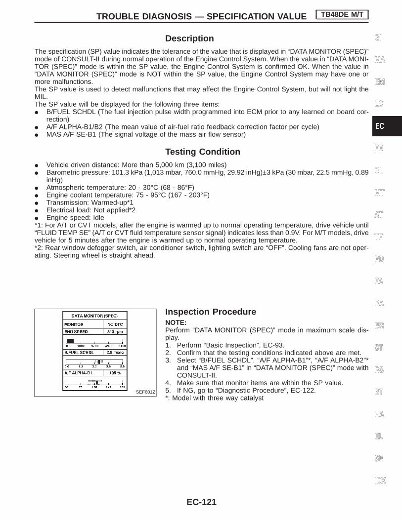
DescriptionThe specification (SP) value indicates the tolerance of the value that is displayed in “DATA MONITOR (SPEC)”mode of CONSULT-II during normal operation of the Engine Control System. When the value in “DATA MONI-TOR (SPEC)” mode is within the SP value, the Engine Control System is confirmed OK. When the value in“DATA MONITOR (SPEC)” mode is NOT within the SP value, the Engine Control System may have one ormore malfunctions.The SP value is used to detect malfunctions that may affect the Engine Control System, but will not light theMIL.The SP value will be displayed for the following three items:I B/FUEL SCHDL (The fuel injection pulse width programmed into ECM prior to any learned on board cor-
rection)I A/F ALPHA-B1/B2 (The mean value of air-fuel ratio feedback correction factor per cycle)I MAS A/F SE-B1 (The signal voltage of the mass air flow sensor)
Testing ConditionI Vehicle driven distance: More than 5,000 km (3,100 miles)I Barometric pressure: 101.3 kPa (1,013 mbar, 760.0 mmHg, 29.92 inHg)±3 kPa (30 mbar, 22.5 mmHg, 0.89
inHg)I Atmospheric temperature: 20 - 30°C (68 - 86°F)I Engine coolant temperature: 75 - 95°C (167 - 203°F)I Transmission: Warmed-up*1I Electrical load: Not applied*2I Engine speed: Idle*1: For A/T or CVT models, after the engine is warmed up to normal operating temperature, drive vehicle until“FLUID TEMP SE” (A/T or CVT fluid temperature sensor signal) indicates less than 0.9V. For M/T models, drivevehicle for 5 minutes after the engine is warmed up to normal operating temperature.*2: Rear window defogger switch, air conditioner switch, lighting switch are “OFF”. Cooling fans are not oper-ating. Steering wheel is straight ahead.
Inspection ProcedureNOTE:Perform “DATA MONITOR (SPEC)” mode in maximum scale dis-play.1. Perform “Basic Inspection”, EC-93.2. Confirm that the testing conditions indicated above are met.3. Select “B/FUEL SCHDL”, “A/F ALPHA-B1”*, “A/F ALPHA-B2”*
and “MAS A/F SE-B1” in “DATA MONITOR (SPEC)” mode withCONSULT-II.
4. Make sure that monitor items are within the SP value.5. If NG, go to “Diagnostic Procedure”, EC-122.*: Model with three way catalyst
SEF601Z
TROUBLE DIAGNOSIS — SPECIFICATION VALUE TB48DE M/T
EC-121
GI
MA
EM
LC
FE
CL
MT
AT
TF
PD
FA
RA
BR
ST
RS
BT
HA
EL
SE
IDX

Diagnostic Procedure
SEF613ZA
TROUBLE DIAGNOSIS — SPECIFICATION VALUE TB48DE M/T
EC-122

SEF768Z
TROUBLE DIAGNOSIS — SPECIFICATION VALUE TB48DE M/T
Diagnostic Procedure (Cont’d)
EC-123
GI
MA
EM
LC
FE
CL
MT
AT
TF
PD
FA
RA
BR
ST
RS
BT
HA
EL
SE
IDX

SEF615Z
TROUBLE DIAGNOSIS — SPECIFICATION VALUE TB48DE M/T
Diagnostic Procedure (Cont’d)
EC-124

DescriptionIntermittent incidents (I/I) may occur. In many cases, the problem resolves itself (the part or circuit functionreturns to normal without intervention). It is important to realize that the symptoms described in the custom-er’s complaint often do not recur on DTC visits. Realize also that the most frequent cause of I/I occurrencesis poor electrical connections. Because of this, the conditions under which the incident occurred may not beclear. Therefore, circuit checks made as part of the standard diagnostic procedure may not indicate the spe-cific problem area.
COMMON I/I REPORT SITUATIONS
STEP in Work Flow Situation
II The CONSULT-II is used. The SELF-DIAG RESULTS screen shows time data other than “0” or “1t”.
III The symptom described by the customer does not recur.
IV DTC data does not appear during the DTC Confirmation Procedure.
VI The Diagnostic Procedure for PXXXX does not indicate the problem area.
Diagnostic Procedure
1 INSPECTION START
Erase DTCs. Refer to “HOW TO ERASE EMISSION-RELATED DIAGNOSTIC INFORMATION” (EC-73).
E GO TO 2.
2 CHECK GROUND TERMINALS
Check ground terminals for corroding or loose connection. Refer to GI section, “GROUND INSPECTION”.
OK or NG
OK E GO TO 3.
NG E Repair or replace.
3 SEARCH FOR ELECTRICAL INCIDENT
Perform GI section, “Incident Simulation Tests”.
OK or NG
OK E INSPECTION END
NG E Repair or replace.
TROUBLE DIAGNOSIS FOR INTERMITTENTINCIDENT TB48DE M/T
EC-125
GI
MA
EM
LC
FE
CL
MT
AT
TF
PD
FA
RA
BR
ST
RS
BT
HA
EL
SE
IDX

Main Power Supply and Ground CircuitECM TERMINALS AND REFERENCE VALUESpecification data are reference values and are measured between each terminal and ground.CAUTION:Do not use ECM ground terminals when measuring input/output voltage. Doing so may result in dam-age to the ECM’s transistor. Use a ground other than ECM terminals, such as the ground.
TER-MINAL
NO.
WIRECOLOR
ITEM CONDITIONDATA
(DC voltage)
42 B/Y ECM relay (Self-shutoff)
Engine is running.
Ignition switch “OFF”
For 5 seconds after turning ignition switch“OFF”
0 - 1.0V
Ignition switch “OFF”
A few seconds passed after turning ignitionswitch “OFF”
BATTERY VOLTAGE(11 - 14V)
53 W/G Ignition switch
Ignition switch “OFF” 0V
Ignition switch “ON”BATTERY VOLTAGE(11 - 14V)
95 W Power supply (Back-up) Ignition switch “OFF”BATTERY VOLTAGE(11 - 14V)
156159165168
B ECM groundEngine is running.
Idle speedEngine ground
163166
B/R Power supply for ECM Ignition switch “ON”BATTERY VOLTAGE(11 - 14V)
TROUBLE DIAGNOSIS FOR POWER SUPPLY TB48DE M/T
EC-126

TEC143M
TROUBLE DIAGNOSIS FOR POWER SUPPLY TB48DE M/T
Main Power Supply and Ground Circuit(Cont’d)
EC-127
GI
MA
EM
LC
FE
CL
MT
AT
TF
PD
FA
RA
BR
ST
RS
BT
HA
EL
SE
IDX

TEC144M
TROUBLE DIAGNOSIS FOR POWER SUPPLY TB48DE M/T
Main Power Supply and Ground Circuit(Cont’d)
EC-128

INSPECTION START
Start engine.Is engine running?
Yes
ENo
CHECK POWER SUP-PLY-I.1. Turn ignition switch
“ON”.2. Check voltage between
ECM terminal q53 andground with CONSULT-IIor tester.Voltage: Battery volt-age
If NG, check the following.I 10A fuseI Harness connectors
M52 , F7I Harness for open or
short between ECM andfuse
If NG, repair harness orconnectors.
OK
Go to “CHECK GROUNDCIRCUIT” on next page.
CHECK POWER SUPPLY-II.1. Stop engine.2. Check voltage between ECM terminal
q95 and ground with CONSULT-II ortester.Voltage: Battery voltage
OK
ENG
Check the following.I Harness connectors
E127 , M21I Harness connectors
M52 , F7I 10A fuseI Harness for open or
short between ECM andbattery
If NG, repair harness orconnectors.
CHECK POWER SUPPLY-III.1. Turn ignition switch “ON” and then turn
“OFF”.2. Check voltage between ECM terminals
163 , 166 , and ground with CON-SULT-II or tester.Voltage:After turning ignition switch “OFF”,battery voltage will exist for a fewseconds, then drop to approximately0V.
NG
EOK
Go to “CHECK GROUNDCIRCUIT” on next page.
Case-1: Battery voltage doesnot exist.
Case-2: Battery voltage existsfor more than a fewseconds.
Case-1 ECase-2
Go to “CHECK ECMRELAY” on next page.
qA
SEC817C
SEC818C
SEC819C
SEC684CA
H
H
H
H
H
TROUBLE DIAGNOSIS FOR POWER SUPPLY TB48DE M/T
Main Power Supply and Ground Circuit(Cont’d)
EC-129
GI
MA
EM
LC
FE
CL
MT
AT
TF
PD
FA
RA
BR
ST
RS
BT
HA
EL
SE
IDX

qA
CHECK HARNESS CONTINUITYBETWEEN ECM RELAY AND ECM.1. Disconnect ECM harness connector.2. Disconnect ECM relay.3. Check harness continuity between ECM
terminals 163 , 166 and terminal q6 .Refer to Wiring Diagram.Continuity should exist.If OK, check harness for short toground and short to power.
OK
ENG
Check the following.I Harness connectors
M52 , F7I Harness for open or
short between ECM andECM relay
If NG, repair open circuit,short to ground or short topower in harness or con-nectors.
CHECK VOLTAGE BETWEEN ECMRELAY AND GROUND.Check voltage between terminals q2 , q7and ground with CONSULT-II or tester.Voltage: Battery voltage
OK
ENG
Check the following.I Harness connectors
E127 , M21I 10A and 15A fuseI Harness for open or
short between ECM relayand battery
If NG, repair harness orconnectors.
CHECK OUTPUT SIGNAL CIRCUIT.Check harness continuity between ECMterminal q42 and relay terminal q1 .Refer to wiring diagram.Continuity should exist.If OK, check harness for short to groundand short to power.
OK
ENG
Check the following.I Harness connectors
M52 , F7I Harness for open or
short between ECM andECM relay
If NG, repair open circuit,short to ground or short topower in harness or con-nectors.
CHECK ECM RELAY.1. Apply 12V direct current between relay
terminals q1 and q2 .2. Check continuity between relay termi-
nals q6 and q7 , q3 and q5 .12V (q1 - q2 ) applied:
Continuity exists.No voltage applied:
No continuity
OK
ENG
Replace ECM relay.
CHECK GROUND CIRCUIT.1. Turn ignition switch “OFF”.2. Loosen and retighten engine ground
screws.3. Disconnect ECM harness connector.4. Check harness continuity between ECM
terminals 156 , 159 , 165 , 168 andengine ground.Continuity should exist.If OK, check harness for short to power.
OK
ENG
Check the following.I Joint connector-7I Harness for open or
short between ECM andground
Repair open circuit, shortto power in harness orconnectors.
CHECK INTERMITTENT INCIDENT.Refer to “TROUBLE DIAGNOSIS FORINTERMITTENT INCIDENT”, EC-125.
INSPECTION END
SEC685C
PBIB0077E
SEC821C
H
H
H
H
H
H
H
TROUBLE DIAGNOSIS FOR POWER SUPPLY TB48DE M/T
Main Power Supply and Ground Circuit(Cont’d)
EC-130

Component DescriptionThe mass air flow sensor is placed in the stream of intake air. Itmeasures the intake flow rate by measuring a part of the entireintake flow. It consists of a hot film that is supplied with electriccurrent from the ECM. The temperature of the hot wire is controlledby the ECM a certain amount. The heat generated by the hot wireis reduced as the intake air flows around it. The more air, thegreater the heat loss.Therefore, the ECM must supply more electric current to the hotwire as air flow increases. This maintains the temperature of the hotwire. The ECM detects the air flow by means of this current change.
CONSULT-II Reference Value in Data MonitorMode
Remarks: Specification data are reference values.
MONITOR ITEM CONDITION SPECIFICATION
MAS A/F SE-B1
I Engine: After warming upI Air conditioner switch: “OFF”I Shift lever: Neutral positionI No-load
Idle 1.1 - 1.5V
2,500 rpm 1.7 - 2.4V
ECM Terminals and Reference ValueSpecification data are reference values and are measured between each terminal and ground.CAUTION:Do not use ECM ground terminals when measuring input/output voltage. Doing so may result in dam-age to the ECM’s transistor. Use a ground other than ECM terminals, such as the ground.
TER-MINAL
NO.
WIRECOLOR
ITEM CONDITIONDATA
(DC voltage)
91 W/G Mass air flow sensor
Engine is running. (Warm-up condition)
Idle speed1.1 - 1.5V
Engine is running. (Warm-up condition)
Engine speed is 2,500 rpm.1.7 - 2.4V
109 B/WMass air flow sensorground
Engine is running. (Warm-up condition)
Idle speedApproximately 0V
On Board Diagnosis Logic
DTC No. Malfunction is detected when ... Check Items (Possible Cause)P01000100
A) An excessively high voltage from the sensor is sentto ECM when engine is not running.
I Harness or connectors(The sensor circuit is open or shorted.)
I Mass air flow sensorC) A voltage from the sensor is constantly approx. 1.0Vwhen engine is running.
B) An excessively low voltage from the sensor is sentto ECM* when engine is running.
I Harness or connectors(The sensor circuit is open or shorted.)
I Intake air leaksI Mass air flow sensor
*: When the malfunction is detected, the ECM enters fail-safe mode and the MIL lights up.
Fail-Safe Mode
Detected items Engine operating condition in fail-safe mode
Mass air flow sensor circuit Engine speed will not rise more than 2,400 rpm due to the fuelcut.
SEC688C
DTC P0100 MASS AIR FLOW (MAF) SENSOR TB48DE M/T
EC-131
GI
MA
EM
LC
FE
CL
MT
AT
TF
PD
FA
RA
BR
ST
RS
BT
HA
EL
SE
IDX

DTC Confirmation ProcedureNOTE:If “DTC Confirmation Procedure” has been previouslyconducted, always turn ignition switch “OFF” and wait at least10 seconds before conducting the next test.
PROCEDURE FOR MALFUNCTION AWith CONSULT-II
1) Turn ignition switch “ON”.2) Select “DATA MONITOR” mode with CONSULT-II.3) Wait at least 2 seconds.4) If DTC is detected, go to “Diagnostic Procedure”, EC-134.
Without CONSULT-II1) Turn ignition switch “ON”, and wait at least 2 seconds.2) Turn ignition switch “OFF”, wait at least 10 seconds and then
turn “ON”.3) Perform “Diagnostic Test Mode II (Self-diagnostic results)” with
ECM.4) If DTC is detected, go to “Diagnostic Procedure”, EC-134.
PROCEDURE FOR MALFUNCTION B AND CWith CONSULT-II
1) Turn ignition switch “ON”.2) Select “DATA MONITOR” mode with CONSULT-II.3) Start engine and wait 2 seconds at most.4 If DTC is detected, go to “Diagnostic Procedure”, EC-134.
Without CONSULT-II1) Turn ignition switch “ON”.2) Start engine and wait 2 seconds at most.3) Turn ignition switch “OFF”, wait at least 10 seconds and then
turn “ON”.4) Perform “Diagnostic Test Mode II (Self-diagnostic results)” with
ECM.5) If DTC is detected, go to “Diagnostic Procedure”, EC-134.
SEF058Y
SEF058Y
DTC P0100 MASS AIR FLOW (MAF) SENSOR TB48DE M/T
EC-132

Wiring Diagram
TEC146M
DTC P0100 MASS AIR FLOW (MAF) SENSOR TB48DE M/T
EC-133
GI
MA
EM
LC
FE
CL
MT
AT
TF
PD
FA
RA
BR
ST
RS
BT
HA
EL
SE
IDX

Diagnostic Procedure
INSPECTION START
1. Turn ignition switch “OFF”.2. Loosen and retighten engine ground
screws.
OK
CHECK POWER SUPPLY.1. Disconnect mass air flow sensor har-
ness connector.2. Turn ignition switch “ON”.3. Check voltage between terminals q2 ,
q4 and ground with CONSULT-II ortester.
OK
ENG Check the following.
I Harness connectorsM52 , F7
I Harness for open orshort between mass airflow sensor and ECMrelay
I Harness for open orshort between mass airflow sensor and ECM
If NG, repair harness orconnectors.
CHECK GROUND CIRCUIT.1. Turn ignition switch “OFF”.2. Disconnect ECM harness connector.3. Check harness continuity between ter-
minal q3 and ECM terminal 109 .Refer to Wiring Diagram.Continuity should exist.If OK, check harness for short toground and short to power.
OK
ENG Repair open circuit, short
to ground or short to powerin harness or connectors.
CHECK INPUT SIGNAL CIRCUIT.Check harness continuity between MAFsensor terminal q1 and ECM terminal q91 .Refer to Wiring Diagram.Continuity should exist.If OK, check harness for short to groundand short to power.
OK
ENG Repair open circuit, short
to ground or short to powerin harness or connectors.
CHECK COMPONENT(Mass air flow sensor).Refer to “COMPONENT INSPECTION”,EC-135.
OK
ENG Replace mass air flow sen-
sor.
qA
Terminal Voltage
2 Approximately 5V
4 BATTERY VOLTAGE
SEC690C
SEC688C
PBIB0076E
H
H
H
H
H
H
DTC P0100 MASS AIR FLOW (MAF) SENSOR TB48DE M/T
EC-134

qA
CHECK SHIELD CIRCUIT.1. Remove joint connector-7 F40 .2. Check the following.
I Continuity between joint connectorterminal q3 and ground
I Joint connector(Refer to “HARNESS LAYOUT” in ELsection.)
Continuity should exist.If OK, check harness for short to power.Then reconnect joint connector.
OK
ENG Check the following.
I Joint connector-7 F40
I Harness for open orshort between joint con-nector-7 and engineground
If NG, repair harness orconnectors.
CHECK INTERMITTENT INCIDENT.Refer to “TROUBLE DIAGNOSIS FORINTERMITTENT INCIDENT”, EC-125.
INSPECTION END
Component InspectionMASS AIR FLOW SENSOR1. Turn ignition switch “ON”.2. Start engine and warm it up to normal operating temperature.3. Check voltage between ECM terminal q91 and ground.
Conditions Voltage V
Ignition switch “ON” (Engine stopped.) Approx. 1.0
Idle (Engine is warmed-up sufficiently.) 1.1 - 1.5
2,500 rpm 1.7 - 2.4
Idle to about 4,000 rpm* 1.1 - 1.5 to Approx. 4.0
*: Check for linear voltage rise in response to increase to about 4,000 rpm in enginespeed.
4. If the voltage is out of specification, proceed the following.I Turn ignition switch “OFF”.I Disconnect mass air flow sensor harness connector and recon-
nect it again.I Perform steps 2 and 3 again.5. If NG, remove mass air flow sensor from air duct. Check hot film
for damage or dust.6. If NG, clean or replace mass air flow sensor.
PBIB0078E
SEC691C
H
H
H
DTC P0100 MASS AIR FLOW (MAF) SENSOR TB48DE M/T
Diagnostic Procedure (Cont’d)
EC-135
GI
MA
EM
LC
FE
CL
MT
AT
TF
PD
FA
RA
BR
ST
RS
BT
HA
EL
SE
IDX

Component DescriptionThe engine coolant temperature sensor is used to detect the enginecoolant temperature. The sensor modifies a voltage signal from theECM. The modified signal returns to the ECM as the engine cool-ant temperature input. The sensor uses a thermistor which is sen-sitive to the change in temperature. The electrical resistance of thethermistor decreases as temperature increases.
<Reference data>
Engine coolant tempera-ture
°C (°F)
Voltage*(V)
Resistance(kΩ)
−10 (14) 4.4 7.0 - 11.420 (68) 3.5 2.1 - 2.9
50 (122) 2.2 0.68 - 1.0090 (194) 1.0 0.236 - 0.260
*: These data are reference values and are measured between ECM terminal121 (Engine coolant temperature sensor) and ground.
CAUTION:Do not use ECM ground terminals when measuring input/output voltage. Doing so may result in damage to the ECM’stransistor. Use a ground other than ECM terminals, such as theground.
CONSULT-II Reference Value in Data MonitorMode
MONITOR ITEM CONDITION SPECIFICATION
COOLAN TEMP/S I Engine: After warming up More than 70°C (158°F)
On Board Diagnosis Logic
DiagnosticTrouble Code
No.Malfunction is detected when ...
Check Items(Possible Cause)
P01150115
I An excessively high or low voltage from the sensor issent to ECM.*
I Harness or connectors(The sensor circuit is open or shorted.)
I Engine coolant temperature sensor
*: When this malfunction is detected, the ECM enters fail-safe mode and MIL lights up.
SEF594K
SEF012P
DC P0115 ENGINE COOLANT TEMPERATURE (ECT)SENSOR (CIRCUIT) TB48DE M/T
EC-136

Fail-Safe Mode
Detected items Engine operating condition in fail-safe mode
Engine coolant tempera-ture sensor circuit
Engine coolant temperature will be determined by ECM based on the time after turning ignition switch“ON” or “START”.CONSULT-II displays the engine coolant temperature decided by ECM.
ConditionEngine coolant temperature decided (CONSULT-II
display)
Just as ignition switch is turned ON or START 40°C (104°F)
More than approx. 4 minutes after turning ignitionswitch ON or START
80°C (176°F)
Except as shown above20 - 80°C (68 - 176°F)(Depends on the time)
When the fail-safe system for engine coolant temperature sensor is activated, the cooling fan operateswhile the engine is running.
DTC Confirmation ProcedureNOTE:If “DTC Confirmation Procedure” has been previouslyconducted, always turn ignition switch “OFF” and wait at least10 seconds before conducting the next test.
With CONSULT-II1) Turn ignition switch “ON”.2) Select “DATA MONITOR” mode with CONSULT-II.3) Wait at least 5 seconds.4) If DTC is detected, go to “Diagnostic Procedure”, EC-139.
Without CONSULT-II1) Turn ignition switch “ON” and wait at least 5 seconds.2) Turn ignition switch “OFF”, wait at least 10 seconds and then
turn “ON”.3) Perform “Diagnostic Test Mode II (Self-diagnostic results)” with
ECM.4) If DTC is detected, go to “Diagnostic Procedure”, EC-139.
SEF013Y
DC P0115 ENGINE COOLANT TEMPERATURE (ECT)SENSOR (CIRCUIT) TB48DE M/T
EC-137
GI
MA
EM
LC
FE
CL
MT
AT
TF
PD
FA
RA
BR
ST
RS
BT
HA
EL
SE
IDX

Wiring Diagram
TEC147M
DC P0115 ENGINE COOLANT TEMPERATURE (ECT)SENSOR (CIRCUIT) TB48DE M/T
EC-138

Diagnostic Procedure
INSPECTION START
CHECK POWER SUPPLY.1. Turn ignition switch “OFF”.2. Disconnect engine coolant temperature
sensor harness connector.3. Turn ignition switch “ON”.4. Check voltage between terminal q2 and
ground with CONSULT-II or tester.Voltage:
Approximately 5V
OK
ENG Repair harness or connec-
tors.
CHECK GROUND CIRCUIT.1. Turn ignition switch “OFF”.2. Check harness continuity between ter-
minal q1 and engine ground.Refer to Wiring Diagram.Continuity should exist.If OK, check harness for short toground and short to power.
OK
ENG Check the following.
I Harness for open orshort between ECM andengine coolant tempera-ture sensor
If NG, repair open circuit,short to ground or short topower in harness or con-nectors.
CHECK COMPONENT(Engine coolant temperature sensor).Refer to “COMPONENT INSPECTION”,EC-140.
OK
ENG Replace engine coolant
temperature sensor.
CHECK INTERMITTENT INCIDENT.Refer to “TROUBLE DIAGNOSIS FORINTERMITTENT INCIDENT”, EC-125.
INSPECTION END
SEC689C
SEF645R
H
H
H
H
H
DC P0115 ENGINE COOLANT TEMPERATURE (ECT)SENSOR (CIRCUIT) TB48DE M/T
EC-139
GI
MA
EM
LC
FE
CL
MT
AT
TF
PD
FA
RA
BR
ST
RS
BT
HA
EL
SE
IDX

Component InspectionENGINE COOLANT TEMPERATURE SENSORCheck resistance as shown in the figure.
<Reference data>
Temperature °C (°F) Resistance kΩ
20 (68) 2.1 - 2.9
50 (122) 0.68 - 1.00
90 (194) 0.236 - 0.260
If NG, replace engine coolant temperature sensor.
SEF152P
SEF012P
DC P0115 ENGINE COOLANT TEMPERATURE (ECT)SENSOR (CIRCUIT) TB48DE M/T
EC-140

Component DescriptionThe throttle position sensor responds to the accelerator pedal movement. This sensor is a kind of potentiom-eter which transforms the throttle position into output voltage, and emits the voltage signal to the ECM. Inaddition, the sensor detects the opening and closing speed of the throttle valve and feeds the voltage signalto the ECM.Idle position of the throttle valve is determined by the ECM receiving the signal from the throttle position sen-sor. This sensor controls engine operation such as fuel cut. On the other hand, the “Wide open and closedthrottle position switch”, which is built into the throttle position sensor unit, is not used for engine control.
CONSULT-II Reference Value in Data MonitorMode
Specification data are reference values.
MONITOR ITEM CONDITION SPECIFICATION
THRTL POS SENI Ignition switch: ON
(Engine stopped)
Throttle valve: fully closed 0.15 - 0.85V (a)
Throttle valve: partially opened Between (a) and (b)
Throttle valve: fully opened 3.5 - 4.7V (b)
ABSOL TH⋅P/S
I Engine: After warming up, idlethe engine
Throttle valve: fully closed 0.0%
I Engine: After warming upI Ignition switch: ON
(Engine stopped)Throttle valve: fully opened Approx. 80%
SEC692C
DTC P0120 THROTTLE POSITION (TP) SENSOR TB48DE M/T
EC-141
GI
MA
EM
LC
FE
CL
MT
AT
TF
PD
FA
RA
BR
ST
RS
BT
HA
EL
SE
IDX

ECM Terminals and Reference ValueSpecification data are reference values and are measured between each terminal and ground.CAUTION:Do not use ECM ground terminals when measuring input/output voltage. Doing so may result in dam-age to the ECM’s transistor. Use a ground other than ECM terminals, such as the ground.
TERMI-NALNO.
WIRECOLOR
ITEM CONDITION DATA (DC Voltage)
89 B Sensors’ ground
Engine is running.
Warm up conditionIdle speed
Approximately 0V
103 Y Sensors’ power supply Ignition switch “ON” Approximately 5V
108 G Throttle position sensor
Engine is running.
Warm-up conditionAccelerator pedal fully released
0.15 - 0.85V
Ignition switch “ON”
Accelerator pedal fully depressed3.5 - 4.7V
On Board Diagnosis Logic
DTC No. Malfunction is detected when ... Check Items (Possible Cause)
P01200120
An excessively low or high voltage from the sensor issent to ECM* while driving.
I Harness or connectors(The throttle position sensor circuit is open orshorted.)
I Throttle position sensor
*: When this malfunction is detected, the ECM enters fail-safe mode and the MIL lights up.
Fail-Safe Mode
Detected items Engine operating condition in fail-safe mode
Throttle position sensorcircuit
Throttle position will be determined based on the injected fuel amount and the engine speed.Therefore, acceleration will be poor.
Condition Driving condition
When engine is idling Normal
When accelerating Poor acceleration
DTC Confirmation ProcedureNOTE:If “DTC Confirmation Procedure” has been previously conducted,always turn ignition switch “OFF” and wait at least 10 secondsbefore conducting the next test.CAUTION:Always drive vehicle at a safe speed.TESTING CONDITION:I This test may be conducted with the drive wheels lifted in
the shop or by driving the vehicle. If a road test is expectedto be easier, it is unnecessary to lift the vehicle.
DTC P0120 THROTTLE POSITION (TP) SENSOR TB48DE M/T
EC-142

With CONSULT-II1) Turn ignition switch “ON” and select “DATA MONITOR” mode
with CONSULT-II.2) Start engine and maintain the following conditions for at least
2 consecutive seconds.
VHCL SPEED SE More than 4 km/h (2 MPH)
Selector lever Suitable position except “N” or “P”position
3) If DTC is detected, go to “Diagnostic Procedure”, EC-145.
Without CONSULT-II1) Start engine and maintain the following conditions for at least
2 consecutive seconds.
Vehicle speed More than 4 km/h (2 MPH)
Selector lever Suitable position except “N” or “P”position
2) Turn ignition switch “OFF”, wait at least 10 seconds and thenturn “ON”.
3) Perform “Diagnostic Test Mode II (Self-diagnostic results)” withECM.
4) If DTC is detected, go to “Diagnostic Procedure”, EC-145.
SEF175Y
DTC P0120 THROTTLE POSITION (TP) SENSOR TB48DE M/T
DTC Confirmation Procedure (Cont’d)
EC-143
GI
MA
EM
LC
FE
CL
MT
AT
TF
PD
FA
RA
BR
ST
RS
BT
HA
EL
SE
IDX

Wiring Diagram
TEC154M
DTC P0120 THROTTLE POSITION (TP) SENSOR TB48DE M/T
EC-144

Diagnostic Procedure
INSPECTION START
1. Turn ignition switch “OFF”.2. Loosen and retighten engine ground
screws.
OK
CHECK POWER SUPPLY.1. Turn ignition switch “OFF”.2. Disconnect throttle position sensor har-
ness connector.3. Turn ignition switch “ON”.4. Check voltage between terminal q3 and
ground with CONSULT-II or tester.Voltage: Approximately 5V
OK
ENG Check the following.
I Harness for open orshort between throttleposition sensor and ECM
If NG, repair harness orconnectors.
CHECK GROUND CIRCUIT.1. Turn ignition switch “OFF”.2. Check harness continuity between
throttle position sensor harness connec-tor terminal q1 and ECM terminal q89 .Refer to Wiring Diagram.Continuity should exist.If OK, check harness for short toground and short to power.
OK
ENG If NG, repair open circuit,
short to ground or short topower in harness or con-nectors.
CHECK INPUT SIGNAL CIRCUIT.1. Disconnect ECM harness connector.2. Check harness continuity between ECM
terminal 108 and terminal q2 .Refer to Wiring Diagram.Continuity should exist.If OK, check harness for short toground and short to power.
OK
ENG Check the following.
I Harness for open orshort between throttleposition sensor and ECM
If NG, repair open circuit,short to ground or short topower in harness or con-nectors.
qA
SEC690C
SEC562C
SEF582V
H
H
H
H
H
DTC P0120 THROTTLE POSITION (TP) SENSOR TB48DE M/T
EC-145
GI
MA
EM
LC
FE
CL
MT
AT
TF
PD
FA
RA
BR
ST
RS
BT
HA
EL
SE
IDX

qA
CHECK COMPONENT(Throttle position sensor).Refer to “COMPONENT INSPECTION”,EC-146.
OK
ENG
Replace throttle positionsensor. To adjust it, per-form BASIC INSPECTION,EC-93.
CHECK SHIELD CIRCUIT.1. Remove joint connector-7 F40 .2. Check the following.
I Continuity between joint connectorterminal q3 and ground
I Joint connector(Refer to “HARNESS LAYOUT” in ELsection.)
Refer to Wiring Diagram.Continuity should exist.If OK, check harness for short to power.Then reconnect joint connector.
OK
ENG
Check the following.I Joint connector-7 F40I Harness for open or
short between joint con-nector-7 and engineground
If NG, repair harness orconnectors.
CHECK INTERMITTENT INCIDENT.Refer to “TROUBLE DIAGNOSIS FORINTERMITTENT INCIDENT”, EC-125.
INSPECTION END
Component InspectionTHROTTLE POSITION SENSOR
With CONSULT-II1) Start engine and warm it up to normal operating temperature.2) Turn ignition switch “OFF” and wait at least 10 seconds.3) Turn ignition switch ON.4) Select “DATA MONITOR” mode with CONSULT-II.5) Check voltage of “THRTL POS SEN” under the following con-
ditions.NOTE:Voltage measurement must be made with throttle position sen-sor installed in vehicle.
Throttle valve conditions Voltage (V)
Completely closed 0.15 - 0.85 (a)
Partially open Between (a) and (b)
Completely open 3.5 - 4.7 (b)
If NG, adjust closed throttle position switch. Refer to “BasicInspection”, EC-93.
6) If it is impossible to adjust closed throttle position switch in“Basic Inspection”, replace throttle position sensor.
SEF179Y
H
H
H
H
DTC P0120 THROTTLE POSITION (TP) SENSOR TB48DE M/T
Diagnostic Procedure (Cont’d)
EC-146

Without CONSULT-II1) Start engine and warm it up to normal operating temperature.2) Turn ignition switch “OFF” and wait at least 10 seconds.3) Turn ignition switch ON.4) Check voltage between ECM terminal 108 (Throttle position
sensor signal) and ground under the following conditions.NOTE:Voltage measurement must be made with throttle position sen-sor installed in vehicle.
Throttle valve conditions Voltage (V)
Completely closed 0.15 - 0.85 (a)
Partially open Between (a) and (b)
Completely open 3.5 - 4.7 (b)
If NG, adjust closed throttle position switch. Refer to “BasicInspection”, EC-93.
5) If it is impossible to adjust closed throttle position switch in“Basic Inspection”, replace throttle position sensor.
SEC826C
DTC P0120 THROTTLE POSITION (TP) SENSOR TB48DE M/T
Component Inspection (Cont’d)
EC-147
GI
MA
EM
LC
FE
CL
MT
AT
TF
PD
FA
RA
BR
ST
RS
BT
HA
EL
SE
IDX

Component DescriptionThe heated oxygen sensor 1 is placed into the exhaust manifold. Itdetects the amount of oxygen in the exhaust gas compared to theoutside air. The heated oxygen sensor 1 has a closed-end tubemade of ceramic zirconia. The zirconia generates voltage fromapproximately 1V in richer conditions to 0V in leaner conditions.The heated oxygen sensor 1 signal is sent to the ECM. The ECMadjusts the injection pulse duration to achieve the ideal air-fuelratio. The ideal air-fuel ratio occurs near the radical change from 1Vto 0V.
CONSULT-II Reference Value in Data MonitorMode
Specification data are reference values.
MONITOR ITEM CONDITION SPECIFICATION
HO2S1 (B1)HO2S1 (B2)
I Engine: After warming up Maintaining engine speed at 2,000 rpm
0 - 0.3V ) 0.6 - 1.0V
HO2S1 MNTR (B1)HO2S1 MNTR (B2)
LEAN ) RICHChanges more than 5 timesduring 10 seconds.
ECM Terminals and Reference ValueSpecification data are reference values, and are measured between each terminal and ground.CAUTION:Do not use ECM ground terminals when measuring voltage. Doing so may result in damage to theECM’s transistor. Use a ground other than ECM terminals such as the body ground.
TER-MINAL
NO.
WIRECOLOR
ITEM CONDITIONDATA
(DC voltage)
114(B1)
W
Heated oxygen sensors 1
Engine is running.
After warming up to normal operating tempera-ture and engine speed is 2,000 rpm.
0 - Approximately 1.0V(periodically change)115
(B2)W
SEF463R
SEF288D
DTC P0130 (BANK 1), P0150 (BANK 2) HO2S1(CIRCUIT) TB48DE M/T
EC-148

On Board Diagnosis LogicUnder the condition in which the heated oxygen sensor 1 (front)signal is not input, the ECM circuits will read a continuous approxi-mately 0.3V. Therefore, for this diagnosis, the time that output volt-age is within 200 to 400 mV range is monitored, and the diagnosischecks that this time is not inordinately long.
Diagnostic TroubleCode No.
Malfunction is detected when ...Check Items
(Possible Cause)P0130, 0130(Bank 1)
I The voltage from the sensor is constantly approx. 0.3V. I Harness or connectors(The sensor circuit is open or shorted.)
I Heated oxygen sensor 1P0150, 0150(Bank 2)
Overall Function CheckUse this procedure to check the overall function of the heated oxy-gen sensor 1 circuit.
1) Start engine and warm it up to normal operating tem-perature.
2) Select “MANU TRIG” in “DATA MONITOR” mode withCONSULT-II, and select “HO2S1 (B1)” and “HO2S1(B2)”.
3) Hold engine speed at 2,000 rpm under no load.4) Make sure that the indications do not remain in the
range between 0.2 to 0.4V.5) If NG, go to “Diagnostic Procedure”, EC-152.
1) Start engine and warm it up to normal operating tem-perature.
2) Set voltmeter probes between ECM terminal 114 (B1),115 (B2) (sensor signal) and ground.
3) Check the following with engine speed held at 2,000rpm constant under no load.
I The voltage does not remain in the range of 0.2 - 0.4V.4) If NG, go to “DIAGNOSTIC PROCEDURE”, EC-152.
SEF237U
SEF646Y
SEC184D
DTC P0130 (BANK 1), P0150 (BANK 2) HO2S1(CIRCUIT) TB48DE M/T
EC-149
GI
MA
EM
LC
FE
CL
MT
AT
TF
PD
FA
RA
BR
ST
RS
BT
HA
EL
SE
IDX

Wiring DiagramBANK 1
TEC245M
DTC P0130 (BANK 1), P0150 (BANK 2) HO2S1(CIRCUIT) TB48DE M/T
EC-150

BANK 2
TEC247M
DTC P0130 (BANK 1), P0150 (BANK 2) HO2S1(CIRCUIT) TB48DE M/T
Wiring Diagram (Cont’d)
EC-151
GI
MA
EM
LC
FE
CL
MT
AT
TF
PD
FA
RA
BR
ST
RS
BT
HA
EL
SE
IDX

Diagnostic Procedure
INSPECTION START
1. Turn ignition switch “OFF”.2. Loosen and retighten engine ground
screws.
CHECK INPUT SIGNAL CIRCUIT.1. Turn ignition switch “OFF”.2. Disconnect corresponding heated oxy-
gen sensor 1 harness connector andECM harness connector.
3. Check harness continuity between ECMand sensor terminals.
Refer to wiring diagram.Continuity should exist.
4. Check harness continuity between ECMand sensor or ground.
Refer to wiring diagram.Continuity should not exist.If OK, check harness for short toground and short to power.
OK
ENG Repair harness or connec-
tors.
CHECK SHIELD CIRCUIT.1. Disconnect joint connector-7.2. Check harness continuity between ter-
minal q3 and ground.Refer to wiring diagram.Continuity should exist.If OK, check harness for short to power.
OK
ENG Check the following.
I Joint connector-7I Harness for open or
short between joint con-nector and ground
Repair open circuit, shortto power in harness orconnectors.
CHECK COMPONENT(Heated oxygen sensor 1).Refer to “COMPONENT INSPECTION” onnext page.
OK
ENG REPLACE HO2S1.
Perform “TROUBLE DIAGNOSIS FORINTERMITTENT INCIDENT”, EC-125.
INSPECTION END
DTCTerminals
ECM Sensor
P0130 114 2
P0150 115 2
DTCTerminals
ECM or sensor Ground
P0130 114 or 2 Ground
P0150 115 or 2 Ground
SEC888C
SEC690C
H
H
H
H
H
H
DTC P0130 (BANK 1), P0150 (BANK 2) HO2S1(CIRCUIT) TB48DE M/T
EC-152

Component InspectionHEATED OXYGEN SENSOR 1
1) Start engine and warm it up to normal operating tem-perature.
2) Select “MANU TRIG” and “HI SPEED” in “DATA MONI-TOR” mode with CONSULT-II, and select “HO2S1 (B1)/(B2)” and “HO2S1 MNTR (B1)/(B2)”.
3) Hold engine speed at 2,000 rpm under no load duringthe following steps.
4) Touch “RECORD” on CONSULT-II screen.5) Check the following.I “HO2S1 MNTR (B1)/(B2)” in “DATA MONITOR” mode
changes from “RICH” to “LEAN” to “RICH” 5 times in 10seconds.5 times (cycles) are counted as shown below:
cycle | 1 | 2 | 3 | 4 | 5 |HO2S1 MNTR (B1) R-L-R-L-R-L-R-L-R-L-R
R = “HO2S1 MNTR (B1)/(B2)”, “RICH”L = “HO2S1 MNTR (B1)/(B2)”, “LEAN”
I “HO2S1 (B1)/(B2)” voltage goes above 0.6V at leastonce.
I “HO2S1 (B1)/(B2)” voltage goes below 0.30V at leastonce.
I “HO2S1 (B1)/(B2)” voltage never exceeds 1.0V.CAUTION:I Discard any heated oxygen sensor which has been
dropped from a height of more than 0.5 m (19.7 in) onto ahard surface such as a concrete floor; use a new one.
I Before installing new oxygen sensor, clean exhaust sys-tem threads using Oxygen Sensor Thread Cleaner toolJ-43897-18 or J-43897-12 and approved anti-seize lubri-cant.
------------------------------------------------------------------------------------------------------------------------------------------------------------------------------------------------------------------------------------------------------- OR -------------------------------------------------------------------------------------------------------------------------------------------------------------------------------------------------------------------------------------------------------1) Start engine and warm it up to normal operating tem-
perature.2) Set voltmeter probes between ECM terminal 114 (B1),
115 (B2) (sensor signal) and ground.3) Check the following with engine speed held at 2,000
rpm constant under no load.I Malfunction indicator lamp goes on more than 5 times
within 10 seconds in Diagnostic Test Mode II (HEATEDOXYGEN SENSOR 1 MONITOR, EC-76).
I The maximum voltage is over 0.6V at least one time.I The minimum voltage is below 0.30V at least one time.I The voltage never exceeds 1.0V.
SEF977Z
SEF978Z
SEC184D
DTC P0130 (BANK 1), P0150 (BANK 2) HO2S1(CIRCUIT) TB48DE M/T
EC-153
GI
MA
EM
LC
FE
CL
MT
AT
TF
PD
FA
RA
BR
ST
RS
BT
HA
EL
SE
IDX

CAUTION:I Discard any heated oxygen sensor which has been
dropped from a height of more than 0.5 m (19.7 in) onto ahard surface such as a concrete floor; use a new one.
I Before installing new oxygen sensor, clean exhaust sys-tem threads using Oxygen Sensor Thread Cleaner toolJ-43897-18 or J-43897-12 and approved anti-seize lubri-cant.
DTC P0130 (BANK 1), P0150 (BANK 2) HO2S1(CIRCUIT) TB48DE M/T
Component Inspection (Cont’d)
EC-154

Component DescriptionThe knock sensor is attached to the cylinder block under the intakemanifold. It senses engine knocking using a piezoelectric element.A knocking vibration from the cylinder block is sensed as vibrationalpressure. This pressure is converted into a voltage signal and sentto the ECM.Freeze frame data will not be stored in the ECM for the knocksensor. The MIL will not light for knock sensor malfunction.
On Board Diagnosis Logic
Diagnostic TroubleCode No.
Malfunction is detected when ....Check Items
(Possible Cause)
P0325 (Bank 1)0325P0330 (Bank 2)0330
I An excessively low or high voltage from the knocksensor is sent to ECM.
I Harness or connectors(The knock sensor circuit is open or shorted.)
I Knock sensor
DTC Confirmation ProcedureNOTE:If “DTC Confirmation Procedure” has been previouslyconducted, always turn ignition switch “OFF” and wait at least10 seconds before conducting the next test.TESTING CONDITION:Before performing the following procedure, confirm that bat-tery voltage is more than 10V at idle.
With CONSULT-II1) Turn ignition switch “ON” and select “DATA MONITOR” mode
with CONSULT-II.2) Start engine and run it for at least 5 seconds at idle speed.3) If DTC is detected, go to EC-157, “Diagnostic Procedure”.
Without CONSULT-II
1) Start engine and run it for at least 5 seconds at idle speed.2) Turn ignition switch “OFF”, wait at least 10 seconds and then
turn “ON”.3) Perform “Diagnostic Test Mode II” (Self-diagnostic results) with
ECM.4) If DTC is detected, go to EC-157, “Diagnostic Procedure”.
SEF598K
SEF058Y
DTC P0325 (BANK 1), P0330 (BANK 2) KNOCKSENSOR (KS) TB48DE M/T
EC-155
GI
MA
EM
LC
FE
CL
MT
AT
TF
PD
FA
RA
BR
ST
RS
BT
HA
EL
SE
IDX

Wiring Diagram
TEC153M
DTC P0325 (BANK 1), P0330 (BANK 2) KNOCKSENSOR (KS) TB48DE M/T
EC-156

Diagnostic Procedure
INSPECTION START
CHECK KNOCK SENSOR INPUT SIGNALCIRCUIT FOR OPEN AND SHORT-I.1. Turn ignition switch “OFF”.2. Disconnect ECM harness connector.3. Check resistance between ECM termi-
nals 125 , 126 and engine ground.Refer to Wiring Diagram.
NOTE:It is necessary to use an ohmmeterwhich can measure more than 10 M Ω.
Resistance:Approximately 530-590 k Ω [at 20°C(68°F)]
4. Also check harness for short to groundand short to power.
NG
EOK
Go to qA .
CHECK KNOCK SENSOR INPUT SIGNALCIRCUIT FOR OPEN AND SHORT-II.1. Disconnect knock sensor harness con-
nector.2. Check harness continuity between ECM
terminal 125 and knock sensor (bank1) terminal q1 , ECM terminal 126 andknock sensor (bank) terminal q1 . Referto Wiring Diagram.
3. Also check harness for short to groundand short to power.Continuity should exist.
OK
ENG Check the following.
I Harness connect F13 ,F108
I Harness for open orshort between ECM andknock sensor
Repair open circuit or shortto ground or short to powerin harness or connectors.
CHECK COMPONENT (Knock sensor).Refer to EC-158, “Component Inspection”.
OK
ENG Replace knock sensor.
CHECK INTERMITTENT INCIDENT.Refer to “TROUBLE DIAGNOSIS FORINTERMITTENT INCIDENT”, EC-125.
qA
RETIGHTEN GROUND SCREWS.Loose and retighten engine ground screws.
CHECK KNOCK SENSOR SHIELD CIR-CUIT FOR OPEN AND SHORT.1. Disconnect knock sensor harness con-
nector F109 , F110 .2. Check harness continuity between
knock sensor harness connector F109 ,F110 terminals q2 and engine ground.
Refer to Wiring Diagram.3. Also check harness for short to power
Continuity should exist.
ENG Repair open circuit or short
to power in harness or con-nectors.
CHECK INTERMITTENT INCIDENT.Refer to “TROUBLE DIAGNOSIS FORINTERMITTENT INCIDENT”, EC-125.
SEC693C
SEC690C
H
H
H
H
H
H
H
DTC P0325 (BANK 1), P0330 (BANK 2) KNOCKSENSOR (KS) TB48DE M/T
EC-157
GI
MA
EM
LC
FE
CL
MT
AT
TF
PD
FA
RA
BR
ST
RS
BT
HA
EL
SE
IDX

Component InspectionKNOCK SENSORNOTE:Use an ohmmeter which can measure more than 10 M Ω.1. Disconnect knock sensor harness connector.2. Check resistance between terminal q1 and ground.
Resistance: Approximately 530 - 590 k Ω [at 20°C(68°F)]
CAUTION:Do not use any knock sensors that have been dropped orphysically damaged. Use only new ones.SEF478Y
DTC P0325 (BANK 1), P0330 (BANK 2) KNOCKSENSOR (KS) TB48DE M/T
EC-158

Component DescriptionThe camshaft position sensor (CMPS) is a basic component of theECM. It monitors engine speed and piston position. It sends signalsto the ECM to control fuel injection, ignition timing and other func-tions.The camshaft position sensor has a rotor plate and a wave-form-ing circuit. The rotor plate has 360 slits for 1° signal and 6 slits for120° signal. Light Emitting Diodes (LED) and photo diodes are builtinto the wave-forming circuit.When the rotor plate passes between the LED and the photo diode,the following happens:Slits in the rotor plate continually cut the transmitted light to thephoto diode from the LED. This generates rough-shaped pulsesconverted into on-off pulses by the wave forming circuit sent to theECM.
ECM Terminals and Reference ValueSpecification data are reference values, and are measured between each terminal and ground.CAUTION:Do not use ECM ground terminals when measuring voltage. Doing so may result in damage to theECM’s transistor. Use a ground other than ECM terminals such as the body ground.
TER-MINAL
NO.
WIRECOLOR
ITEM CONDITIONDATA
(DC voltage)
62*383*263*384*2
LCamshaft position sensor(REF signal)
Engine is running. (Warmed-up condition)
Idle speed
Approximately 0.3 -0.6V*1
SEC682C
Engine is running. (Warmed-up condition)
Engine speed is 2,000 rpm.
Approximately 0.3 -0.6V*1
SEC683C
SEC695C
SEF614B
DTC P0340 CAMSHAFT POSITION (CMP) SENSOR TB48DE M/T
EC-159
GI
MA
EM
LC
FE
CL
MT
AT
TF
PD
FA
RA
BR
ST
RS
BT
HA
EL
SE
IDX

TER-MINAL
NO.
WIRECOLOR
ITEM CONDITIONDATA
(DC voltage)
84*363*2
B/WCamshaft position sensor(POS signal)
Engine is running. (Warmed-up condition)
Idle speed
1.0 - 4.0V*1
SEC678C
Engine is running. (Warmed-up condition)
Engine speed is 2,000 rpm.
1.0 - 4.0V*1
SEC679C
*1: Average voltage for pulse signal (Actual pulse signal can be confirmed by oscilloscope.)*2: Model with NATS (Nissan Anti-Theft System)*3: Model without NATS (Nissan Anti-Theft System)
On Board Diagnosis Logic
DiagnosticTrouble Code
No.Malfunction is detected when .... Check Items
(Possible Cause)
P03400340
A) Either 1° or 120° signal is not sent to ECM for thefirst few seconds during engine cranking.
...........................................................................................
I Harness or connectors(The camshaft position sensor circuit is open orshorted.)
I Camshaft position sensorI Starter motor (Refer to EL section.)I Starting system circuit (Refer to EL section.)I Dead (Weak) battery
B) Either 1° or 120° signal is not sent to ECM duringengine running.
...........................................................................................
C) Either 1° or 120° signal is not in the normal patternduring engine running.
DTC Confirmation ProcedurePerform “Procedure for malfunction A” first. If DTC cannot beconfirmed, perform “Procedure for malfunction B and C”.NOTE:If “DTC CONFIRMATION PROCEDURE” has been previouslyconducted, always turn ignition switch “OFF” and wait at least5 seconds before conducting the next test.TESTING CONDITION:Before performing the following procedure, confirm that bat-tery voltage is more than 10.5V at idle.
DTC P0340 CAMSHAFT POSITION (CMP) SENSOR TB48DE M/T
ECM Terminals and Reference Value (Cont’d)
EC-160

PROCEDURE FOR MALFUNCTION A
With CONSULT-II1) Turn ignition switch “ON” and select “DATA MONITOR” mode
with CONSULT-II.2) Crank engine at least 2 seconds.
(If engine does not run, turn ignition switch to “START” for atleast 2 seconds.)
3) If DTC is detected, go to “Diagnostic Procedure”, EC-163.
Without CONSULT-II1) Crank engine for at least 2 seconds.
(If engine does not run, turn ignition switch to “START” for atleast 2 seconds.)
2) Turn ignition switch “OFF”, wait at least 10 seconds and thenturn “ON”.
3) Perform “Diagnostic Test Mode II (Self-diagnostic results)” withECM.
4) If DTC is detected, go to “Diagnostic Procedure”, EC-163.
PROCEDURE FOR MALFUNCTION B AND C
With CONSULT-II1) Turn ignition switch “ON”.2) Select “DATA MONITOR” mode with CONSULT-II.3) Start engine and run it for at least 2 seconds at idle speed.4) If DTC is detected, go to “DIAGNOSTIC PROCEDURE”,
EC-163.
Without CONSULT-II1) Start engine and run it for at least 2 seconds at idle speed.2) Turn ignition switch “OFF”, wait at least 10 seconds and then
turn “ON”.3) Perform “Diagnostic Test Mode II (Self-diagnostic results)” with
ECM.4) If DTC is detected, go to “Diagnostic Procedure”, EC-163.
SEF013Y
DTC P0340 CAMSHAFT POSITION (CMP) SENSOR TB48DE M/T
DTC Confirmation Procedure (Cont’d)
EC-161
GI
MA
EM
LC
FE
CL
MT
AT
TF
PD
FA
RA
BR
ST
RS
BT
HA
EL
SE
IDX

Wiring Diagram
TEC145M
DTC P0340 CAMSHAFT POSITION (CMP) SENSOR TB48DE M/T
EC-162

Diagnostic Procedure
INSPECTION START
CHECK STARTING SYSTEM.Does the engine turn over?(Does the starter motor operate?)
Yes
ENo Check starting system.
(Refer to EL section.)
1. Turn ignition switch “OFF”.2. Loosen and retighten engine ground
screws.
OK
CHECK POWER SUPPLY.1. Disconnect camshaft position sensor
harness connector.2. Turn ignition switch “ON”.3. Check voltage between terminal q3 and
ground with CONSULT-II or tester.Voltage: Battery voltage
OK
ENG Check the following.
I Harness connectorsM52 , F7
I Harness for open or shortbetween camshaft posi-tion sensor and ECM
I Harness for open or shortbetween camshaft posi-tion sensor and ECMrelay
If NG, repair harness orconnectors.
CHECK GROUND CIRCUIT.1. Turn ignition switch “OFF”.2. Check harness continuity between termi-
nal q4 and engine ground.Refer to Wiring Diagram.Continuity should exist.If OK, check harness for short to power.
OK
ENG Repair open circuit, short to
power in harness or con-nectors.
CHECK INPUT SIGNAL CIRCUIT.1. Turn ignition switch “OFF”.2. Disconnect ECM harness connector.3. Check harness continuity between
CMPS terminals q1 , q2 and ECM termi-nals.
*1: Model with NATS (Nissan Anti-TheftSystem)
*2: Model without NATS (Nissan Anti-Theft System)
Refer to Wiring Diagram.If OK, check harness for short to groundand short to power.
OK
ENG Repair open circuit, short to
ground or short to power inharness or connectors.
qA
CMPSterminal
ECM ter-minal
Continuity
120° sig-nal
(REF sig-nal)
q1q83 , q84 *1
(q62 , q63 )*2Yes
1° signal(POS sig-
nal)q2
q63 *1q84 *2
Yes
SEC690C
SEC696C
SEC697C
H
H
H
H
H
H
DTC P0340 CAMSHAFT POSITION (CMP) SENSOR TB48DE M/T
EC-163
GI
MA
EM
LC
FE
CL
MT
AT
TF
PD
FA
RA
BR
ST
RS
BT
HA
EL
SE
IDX

qA
CHECK COMPONENT.(Camshaft position sensor).Refer to “COMPONENT INSPECTION”,EC-164.
OK
ENG Replace camshaft position
sensor.
CHECK SHIELD CIRCUIT.1. Remove joint connector-7 F40 .2. Check the following.
I Continuity between joint connector ter-minal q3 and ground
I Joint connector(Refer to “HARNESS LAYOUT” in ELsection.)
Continuity should exist.If OK, check harness for short to power.Then reconnect joint connector.
OK
ENG Check the following.
I Joint connector-7 F40
I Harness for open or shortbetween joint connector-7and engine ground
If NG, repair harness orconnectors.
CHECK INTERMITTENT INCIDENT.Refer to “TROUBLE DIAGNOSIS FORINTERMITTENT INCIDENT”, EC-125.
INSPECTION END
Component InspectionCAMSHAFT POSITION SENSOR1. Start engine and warm it up to the normal operating tempera-
ture.2. Check voltage between the following ECM terminals and
ground with DC range.
ECM terminal Reference illustration
1° signal(POS signal)
q63 *1q84 *2
qA
120° signal(REF signal)
(q83 , q84 )*1(q62 , q63 )*2
qB
*1: Model with NATS (Nissan Anti-Theft System)*2: Model without NATS (Nissan Anti-Theft System)CAUTION:Do not use ECM ground terminals when measuring voltage.Doing so may result in damage to the ECM’s transistor. Use aground other than ECM terminals such as the body ground.
SEC827C
H
H
H
H
DTC P0340 CAMSHAFT POSITION (CMP) SENSOR TB48DE M/T
Diagnostic Procedure (Cont’d)
EC-164

TER-MINAL
NO.
WIRECOLOR
ITEM CONDITIONDATA
(DC voltage)
62*383*263*384*2
LCamshaft position sensor(REF signal)
Engine is running. (Warmed-up condition)
Idle speed
Approximately 0.3 -0.6V*1
SEC682C
Engine is running. (Warmed-up condition)
Engine speed is 2,000 rpm.
Approximately 0.3 -0.6V*1
SEC683C
84*363*2
B/WCamshaft position sensor(POS signal)
Engine is running. (Warmed-up condition)
Idle speed
1.0 - 4.0V*1
SEC678C
Engine is running. (Warmed-up condition)
Engine speed is 2,000 rpm.
1.0 - 4.0V*1
SEC679C
*1: Average voltage for pulse signal (Actual pulse signal can be confirmed by oscilloscope.)*2: Model with NATS (Nissan Anti-Theft System)*3: Model without NATS (Nissan Anti-Theft System)
If NG, replace camshaft position sensor.
DTC P0340 CAMSHAFT POSITION (CMP) SENSOR TB48DE M/T
Component Inspection (Cont’d)
EC-165
GI
MA
EM
LC
FE
CL
MT
AT
TF
PD
FA
RA
BR
ST
RS
BT
HA
EL
SE
IDX

System Description
Vehicle speed sensor EVehicle speed
ECM E Cooling fan relaysEngine coolant temperature sensor EEngine coolant temperature
Air conditioner switch EAir conditioner “ON” signal
The ECM controls the cooling fan corresponding to the vehicle speed, engine coolant temperature, and airconditioner ON signal. The control system has 3-step control [HIGH/LOW/OFF].
Operation
CONSULT-II Reference Value In Data MonitorMode
Remarks: Specification data are reference values.
MONITOR ITEM CONDITION SPECIFICATION
COOLING FAN
I After warming up engine, idle theengine.
I Air conditioner switch “OFF”I Vehicle stopped
Engine coolant temperature is 94°C(201°F) or less. OFF
Engine coolant temperature is 95°C(203°F) to 104°C (219°F). LOW
Engine coolant temperature is 105°C(221°F) or more. HIGH
I After warming up engine, idle theengine.
I Air conditioner switch “ON”I Vehicle stopped
Engine coolant temperature is 94°C(201°F) or less. LOW
Engine coolant temperature is 95°C(203°F) or more. HIGH
AIR COND SIG I Engine: After warming up, idle theengine
Air conditioner switch: “OFF” OFF
Air conditioner switch: “ON”(Compressor operates.) ON
SEC694C
DTC P1217 ENGINE OVER TEMPERATURE(OVERHEAT) TB48DE M/T
EC-166

ECM Terminals and Reference ValueSpecification data are reference values and are measured between each terminal and ground.CAUTION:Do not use ECM ground terminals when measuring input/output voltage. Doing so may result in dam-age to the ECM’s transistor. Use a ground other than ECM terminals, such as the ground.
TER-MINAL
NO.
WIRECOLOR
ITEM CONDITIONDATA
(DC voltage)
56 LCooling fan relay (Lowspeed)
Engine is running.
Cooling fan is not operating.
BATTERY VOLTAGE(11 - 14V)
Engine is running.
Cooling fan is operating.Approximately 0V
55 L/BCooling fan relay(High speed)
Engine is running.
Cooling fan is not operating.Cooling fan is operating at low speed.
BATTERY VOLTAGE(11 - 14V)
Engine is running.
Cooling fan is operating at high speed.Approximately 0V
On Board Diagnosis LogicThis diagnosis continuously monitors the engine coolant temperature.If the cooling fan or another component in the cooling system malfunctions, the engine coolant temperaturewill rise.When the engine coolant temperature reaches an abnormally high temperature condition, a malfunction isdetected by the ECM and the MIL lights on.
Diagnostic troublecode No.
Malfunction is detected when ...Check Items
(Possible Cause)
P12171217
I Cooling fan does not operate properly (Overheat).I Cooling fan system does not operate properly (Over-
heat).I Engine coolant was not added to the system using
the proper filling method.
I Harness or connectors(The cooling fan circuit is open or shorted)
I Cooling fanI ThermostatI Improper ignition timingI Engine coolant temperature sensorI Blocked radiatorI Blocked front end (Improper fitting of nose
mask)I Crushed vehicle frontal area (Vehicle frontal
is collided but not repaired)I Blocked air passage by improper installation
of front fog lamp or fog lamps.I Improper mixture ratio of coolantI Damaged bumperFor more information, refer to “MAIN 12CAUSES OF OVERHEATING”, EC-175.
CAUTION:When a malfunction is indicated, be sure to replace the coolant following the procedure in the MAsection (“Changing Engine Coolant”, “ENGINE MAINTENANCE”). Also, replace the engine oil.a. Fill radiator with coolant up to specified level with a filling speed of 2 liters per minute like pour-
ing coolant by kettle. Be sure to use coolant with the proper mixture ratio. Refer to MA section(“Anti-freeze Coolant Mixture Ratio”, “RECOMMENDED LUBRICANTS AND FLUIDS”).
b. After refilling coolant, run engine to ensure that no water-flow noise is emitted.
DTC P1217 ENGINE OVER TEMPERATURE(OVERHEAT) TB48DE M/T
EC-167
GI
MA
EM
LC
FE
CL
MT
AT
TF
PD
FA
RA
BR
ST
RS
BT
HA
EL
SE
IDX

Overall Function CheckUse this procedure to check the overall function of the cooling fan.During this check, a DTC might not be confirmed.WARNING:Never remove the radiator cap when the engine is hot. Seriousburns could be caused by high pressure fluid escaping fromthe radiator.Wrap a thick cloth around cap. Carefully remove the cap byturning it a quarter turn to allow built-up pressure to escape.Then turn the cap all the way off.
With CONSULT-II1) Check the coolant level and mixture ratio (using coolant tester)
in the reservoir tank and radiator.Allow engine to cool before checking coolant level andmixture ratio.
I If the coolant level in the reservoir tank and/or radiator is belowthe proper range, skip the following steps and go to “Diagnos-tic Procedure”, EC-170.
I If the coolant mixture ratio is out of the range of 45 to 55%(varies depending on destinations), replace the coolant in thefollowing procedure LC section, “Changing Engine Coolant”.
2) Confirm whether customer filled the coolant or not. If customerfilled the coolant, skip the following steps and go to “Diagnos-tic Procedure”, EC-170.
3) Turn ignition switch “ON”.4) Perform “COOLING FAN” in “ACTIVE TEST” mode with CON-
SULT-II.5) If the results are NG, go to “Diagnostic Procedure”, EC-170.
Without CONSULT-II1) Check the coolant level and mixture ratio (using coolant tester)
in the reservoir tank and radiator.Allow engine to cool before checking coolant level andmixture ratio.If the coolant level in the reservoir tank and/or radiator is belowthe proper range, skip the following steps and go to “Diagnos-tic Procedure”, EC-170.
I If the coolant mixture ratio is out of the range of 45 to 55%(varies depending on destinations), replace the coolant in thefollowing procedure LC section, “Changing Engine Coolant”.
2) Confirm whether customer filled the coolant or not. If customerfilled the coolant, skip the following steps and go to “Diagnos-tic Procedure”, EC-170.
3) Start engine.Be careful not to overheat engine.
4) Set temperature control lever to full cold position.5) Turn air conditioner switch “ON”.6) Turn blower fan switch “ON”.7) Run engine at idle for a few minutes with air conditioner oper-
ating.Be careful not to overheat engine.
8) Make sure that cooling fan operates. Refer to “OPERATION”table of Cooling fan, EC-166.If NG, go to “Diagnostic Procedure”, EC-170.
AEC640
SEF646X
SEC163BA
DTC P1217 ENGINE OVER TEMPERATURE(OVERHEAT) TB48DE M/T
EC-168

Wiring Diagram
TEC151M
DTC P1217 ENGINE OVER TEMPERATURE(OVERHEAT) TB48DE M/T
EC-169
GI
MA
EM
LC
FE
CL
MT
AT
TF
PD
FA
RA
BR
ST
RS
BT
HA
EL
SE
IDX

Diagnostic ProcedureINSPECTION START
Do you have CONSULT-II?
YesE
No GO TO qA Without CON-SULT-II.
CHECK COOLING FAN LOW SPEEDOPERATION.
With CONSULT-II1. Disconnect cooling fan relay-2 and -3.2. Turn ignition switch “ON”.3. Perform “COOLING FAN” in “ACTIVE
TEST” mode with CONSULT-II.4. Make sure that cooling fans-1 and -2
operate at low speed.
OK
ENG GO TO qC . Check cooling
fan low speed control cir-cuit.
CHECK COOLING FAN HIGH SPEEDOPERATION.
With CONSULT-II1. Turn ignition switch “OFF”.2. Reconnect cooling fan relay-2 and -3.3. Turn ignition switch “ON”.4. Perform “COOLING FAN” in “ACTIVE
TEST” mode with CONSULT-II.5. Make sure that cooling fans-1 and -2
operate at high speed.
OK
ENG GO TO qD . Check cooling
fan high speed control cir-cuit.
GO TO qB .
SEC698C
SEF646X
SEF111X
H
H
H
H
DTC P1217 ENGINE OVER TEMPERATURE(OVERHEAT) TB48DE M/T
EC-170

qA
CHECK COOLING FAN LOW SPEEDOPERATION.
Without CONSULT-II1. Disconnect cooling fan relays-2 and -3.2. Start engine and let it idle.3. Set temperature lever at full cold posi-
tion.4. Turn air conditioner switch “ON”.5. Turn blower fan switch “ON”.6. Make sure that cooling fans-1 and -2
operate at low speed.
OK
ENG GO TO qC . Check cooling
fan low speed control cir-cuit.
CHECK COOLING FAN HIGH SPEEDOPERATION.
Without CONSULT-II1. Turn ignitions witch “OFF”.2. Reconnect cooling fan relays-2 and -3.3. Turn air conditioner switch and blower
fan switch “OFF”.4. Disconnect engine coolant temperature
sensor harness connector.5. Connect 150Ω resistor to engine coolant
temperature sensor harness connector.6. Restart engine and make sure that cool-
ing fans-1 and -2 operate at high speed.
OK
ENG GO TO qD . Check cooling
fan high speed control cir-cuit.
GO TO qB .
SEC698C
SEC163BA
SEC322D
H
H
H
DTC P1217 ENGINE OVER TEMPERATURE(OVERHEAT) TB48DE M/T
Diagnostic Procedure (Cont’d)
EC-171
GI
MA
EM
LC
FE
CL
MT
AT
TF
PD
FA
RA
BR
ST
RS
BT
HA
EL
SE
IDX

qB
CHECK COOLING SYSTEM FOR LEAK.Apply pressure to the cooling system witha tester, and check if the pressure drops.
Testing pressure:157 kPa (1.6 kg/cm 2, 23 psi)
CAUTION:Higher than the specified pressure maycause radiator damage.Pressure should not drop.
OK
ENG Check the following for
leak.I HoseI RadiatorI Water pump (Refer to LC
section, “Water Pump”.)If NG, repair or replace.
CHECK RADIATOR CAP.Apply pressure to cap with a tester andcheck radiator cap relief pressure.
Radiator cap relief pressure:For the Middle East:
78 - 98 kPa (0.78 - 0.98 bar,0.8 - 1.0 kg/cm 2, 11 - 14 psi)
Except above:108 - 127 kPa (1.08 - 1.27 bar,1.1 - 1.3 kg/cm 2, 16 - 18 psi)
OK
ENG Replace radiator cap.
CHECK THERMOSTAT.1. Remove thermostat.2. Check valve seating condition at normal
room temperatures.It should seat tightly.
3. Check valve opening temperature andvalve lift.Valve opening temperature:76.5°C (170°F) [standard]Valve lift:More than 10 mm/90°C (0.39 in/194°F)
4. Check if valve is closed at 5°C (9°F)below valve opening temperature. Fordetails, refer to LC section, “Thermo-stat”.
OK
ENG Replace thermostat.
CHECK ENGINE COOLANT TEMPERA-TURE SENSOR.Refer to “COMPONENT INSPECTION”,EC-140.
OK
ENG Replace engine coolant
temperature sensor.
CHECK MAIN 12 CAUSES.If the cause cannot be isolated, go to“MAIN 12 CAUSES OF OVERHEATING”,EC-175.
CHECK INSPECTION END
SLC754A
SLC755A
SLC343
H
HH
HH
HH
H
H
DTC P1217 ENGINE OVER TEMPERATURE(OVERHEAT) TB48DE M/T
Diagnostic Procedure (Cont’d)
EC-172
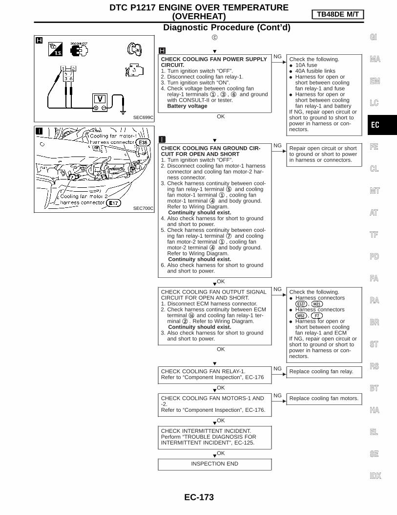
qC
CHECK COOLING FAN POWER SUPPLYCIRCUIT.1. Turn ignition switch “OFF”.2. Disconnect cooling fan relay-1.3. Turn ignition switch “ON”.4. Check voltage between cooling fan
relay-1 terminals q1 , q3 , q6 and groundwith CONSULT-II or tester.Battery voltage
OK
ENG Check the following.
I 10A fuseI 40A fusible linksI Harness for open or
short between coolingfan relay-1 and fuse
I Harness for open orshort between coolingfan relay-1 and battery
If NG, repair open circuit orshort to ground to short topower in harness or con-nectors.
CHECK COOLING FAN GROUND CIR-CUIT FOR OPEN AND SHORT1. Turn ignition switch “OFF”.2. Disconnect cooling fan motor-1 harness
connector and cooling fan motor-2 har-ness connector.
3. Check harness continuity between cool-ing fan relay-1 terminal q5 and coolingfan motor-1 terminal q1 , cooling fanmotor-1 terminal q4 and body ground.Refer to Wiring Diagram.Continuity should exist.
4. Also check harness for short to groundand short to power.
5. Check harness continuity between cool-ing fan relay-1 terminal q7 and coolingfan motor-2 terminal q1 , cooling fanmotor-2 terminal q4 and body ground.Refer to Wiring Diagram.Continuity should exist.
6. Also check harness for short to groundand short to power.
OK
ENG Repair open circuit or short
to ground or short to powerin harness or connectors.
CHECK COOLING FAN OUTPUT SIGNALCIRCUIT FOR OPEN AND SHORT.1. Disconnect ECM harness connector.2. Check harness continuity between ECM
terminal q56 and cooling fan relay-1 ter-minal q2 . Refer to Wiring Diagram.Continuity should exist.
3. Also check harness for short to groundand short to power.
OK
ENG Check the following.
I Harness connectorsE127 , M21
I Harness connectorsM52 , F7
I Harness for open orshort between coolingfan relay-1 and ECM
If NG, repair open circuit orshort to ground or short topower in harness or con-nectors.
CHECK COOLING FAN RELAY-1.Refer to “Component Inspection”, EC-176
OK
ENG Replace cooling fan relay.
CHECK COOLING FAN MOTORS-1 AND-2.Refer to “Component Inspection”, EC-176.
OK
ENG Replace cooling fan motors.
CHECK INTERMITTENT INCIDENT.Perform “TROUBLE DIAGNOSIS FORINTERMITTENT INCIDENT”, EC-125.
OK
INSPECTION END
SEC699C
SEC700C
H
H
H
H
H
H
H
DTC P1217 ENGINE OVER TEMPERATURE(OVERHEAT) TB48DE M/T
Diagnostic Procedure (Cont’d)
EC-173
GI
MA
EM
LC
FE
CL
MT
AT
TF
PD
FA
RA
BR
ST
RS
BT
HA
EL
SE
IDX

qD
CHECK COOLING FAN POWER SUPPLY CIR-CUIT.1. Turn ignition switch “OFF”.2. Disconnect cooling fan relays-2 and -3.3. Turn ignition switch “ON”.4. Check voltage between cooling fan relays-2
and -3 terminals q1 , q6 and ground withCONSULT-II or tester.Battery voltage
OK
ENG Check the following.
I Harness for open or shortbetween cooling fan relays-2and -3 and 10A fuse
I Harness for open or shortbetween cooling fan relays-2and fusible link
If NG, repair harness or con-nectors.
CHECK COOLING FAN GROUND CIRCUITFOR OPEN AND SHORT1. Turn ignition switch “OFF”.2. Disconnect cooling fan motor-1 harness con-
nector and cooling fan motor-2 harness con-nector.
3. Check harness continuity between cooling fanrelay-2 terminal q7 and cooling fan motor-1terminal q2 , cooling fan relay-2 terminal q3and cooling fan motor-1 terminal q3 , coolingfan relay-2 terminal q5 and body ground.Refer to Wiring Diagram.Continuity should exist.
4. Also check harness for short to ground andshort to power.
5. Check harness continuity between cooling fanrelay-3 terminal q7 and cooling fan motor-2terminal q2 , cooling fan relay-3 terminal q3 ,cooling fan relay-2 terminal q5 .Refer to Wiring Diagram.Continuity should exist.
6. Also check harness for short to ground andshort to power.
OK
ENG Repair open circuit or short to
ground or short to power inharness or connectors.
CHECK COOLING FAN OUTPUT SIGNAL CIR-CUIT FOR OPEN AND SHORT.1. Disconnect ECM harness connector.2. Check harness continuity between ECM termi-
nal q55 and cooling fan relay-2 terminal q2 ,cooling fan relay-3 terminal q2 .Refer to Wiring Diagram.Continuity should exist.
3. Also check harness for short to ground andshort power.
OK
ENG Check the following.
I Harness connectors E127 ,M21
I Harness connectors M52 ,F7
I Harness for open or shortbetween cooling fan relay-2and -3 and ECM
If NG, repair open circuit orshort to ground or short topower in harness or connec-tors.
CHECK COOLING FAN RELAYS-2 AND -3.Refer to “Component Inspection”, EC-176.
OK
ENG Replace cooling fan relays.
CHECK COOLING FAN MOTORS.Refer to “Component Inspection”, EC-176.
OK
ENG Replace cooling fan motors.
CHECK INTERMITTENT INCIDENT.Perform “TROUBLE DIAGNOSIS FOR INTER-MITTENT INCIDENT”, EC-125.
OK
INSPECTION END
SEC780C
SEC698C
SEC700C
H
H
H
H
H
H
H
DTC P1217 ENGINE OVER TEMPERATURE(OVERHEAT) TB48DE M/T
Diagnostic Procedure (Cont’d)
EC-174

Main 12 Causes of Overheating
Engine Step Inspection item Equipment Standard Reference page
OFF 1 I Blocked radiatorI Blocked condenserI Blocked radiator grilleI Blocked bumper
I Visual No blocking —
2 I Coolant mixture I Coolant tester 30 - 50% coolant mixture See “RECOMMENDEDFLUIDS AND LUBRI-CANTS” in MA section.
3 I Coolant level I Visual Coolant up to MAX levelin reservoir tank andradiator filler neck
See “Changing EngineCoolant”, “ENGINE MAIN-TENANCE” in MA section.
4 I Radiator cap I Pressure tester 108 - 127 kPa(1.08 - 1.27 bar, 1.1 - 1.3kg/cm2, 16 - 18 psi)59 - 98 kPa (0.59 - 0.98bar, 0.6 - 1.0 kg/cm2,9 - 14 psi) (Limit)
See “System Check”,“ENGINE COOLING SYS-TEM” in LC section.
ON*2 5 I Coolant leaks I Visual No leaks See “System Check”,“ENGINE COOLING SYS-TEM” in LC section.
ON*2 6 I Thermostat I Touch the upper andlower radiator hoses
Both hoses should be hot. See “Thermostat” and“Radiator”, “ENGINECOOLING SYSTEM” inLC section.
ON*1 7 I Cooling fan I Visual (Coupling)I CONSULT-II
Operating See “TROUBLE DIAGNO-SIS FOR DTC P1217”,EC-166.
OFF 8 I Combustion gas leak I Color checker chemicaltester 4 gas analyzer
Negative —
ON*3 9 I Coolant temperaturegauge
I Visual Gauge less than 3/4when driving
—
I Coolant overflow to res-ervoir tank
I Visual No overflow during drivingand idling
See “Changing EngineCoolant”, “ENGINE MAIN-TENANCE” in MA section.
OFF*4 10 I Coolant return from res-ervoir tank to radiator
I Visual Should be initial level inreservoir tank
See “ENGINE MAINTE-NANCE” in MA section.
OFF 11 I Cylinder head I Straight gauge feelergauge
0.1 mm (0.004 in) Maxi-mum distortion (warping)
See “Inspection”, “CYLIN-DER HEAD” in EM sec-tion.
12 I Cylinder block and pis-tons
I Visual No scuffing on cylinderwalls or piston
See “Inspection”, “CYLIN-DER BLOCK” in EM sec-tion.
*1: Engine running at idle for coupling type. Turn ignition switch ON for electrical cooling fan.*2: Engine running at 3,000 rpm for 10 minutes.*3: Drive at 90 km/h (55 MPH) for 30 minutes and then let idle for 10 minutes.*4: After 60 minutes of cool down time.For more information, refer to “OVERHEATING CAUSE ANALYSIS” in LC section.
DTC P1217 ENGINE OVER TEMPERATURE(OVERHEAT) TB48DE M/T
EC-175
GI
MA
EM
LC
FE
CL
MT
AT
TF
PD
FA
RA
BR
ST
RS
BT
HA
EL
SE
IDX

Component InspectionCOOLING FAN RELAYS-1, -2 AND -3Check continuity between terminals q3 and q5 , q6 and q7 .
Conditions Continuity
12V direct current supply between terminals 1 and2
Yes
No current supply No
If NG, replace relay.
COOLING FAN MOTORS-1 AND -21. Disconnect cooling fan motor harness connectors.2. Supply cooling fan motor terminals with battery voltage and
check operation.
Speed
Terminals
(+) (−)
Cooling fan motor Low 1 4
High 1, 2 3, 4
Cooling fan motor should operate.If NG, replace cooling fan motor.
SEF745U
SEF734W
DTC P1217 ENGINE OVER TEMPERATURE(OVERHEAT) TB48DE M/T
EC-176

Component DescriptionIGNITION COIL & POWER TRANSISTORThe ignition signal from the ECM is sent to and amplified by thepower transistor. The power transistor turns on and off the ignitioncoil primary circuit. This on-off operation induces the proper highvoltage in the coil secondary circuit.
CONSULT-II Reference Value in Data MonitorMode
Specification data are reference values.
MONITOR ITEM CONDITION SPECIFICATION
IGN TIMING
I Engine: After warming upI Air conditioner switch: “OFF”I Shift lever: “N”I No-load
Idle 3° - 7° BTDC
2,000 rpm 25° - 45° BTDC
ECM Terminals and Reference ValueSpecification data are reference values, and are measured between each terminal and ground.CAUTION:Do not use ECM ground terminals when measuring voltage. Doing so may result in damage to theECM’s transistor. Use a ground other than ECM terminals such as the body ground.
TER-MINAL
NO.
WIRECOLOR
ITEM CONDITIONDATA
(DC voltage)
181920212930
Y/RGYR/BR/GR
Ignition signal (No. 1)Ignition signal (No. 2)Ignition signal (No. 3)Ignition signal (No. 4)Ignition signal (No. 5)Ignition signal (No. 6)
Engine is running. (Warmed-up condition)
Idle speed
0 - 0.1V*
SEC672C
Engine is running. (Warmed-up condition)
Engine speed is 2,000 rpm.
0 - 0.2V*
SEC673C
*: Average voltage for pulse signal (Actual pulse signal can be confirmed by oscilloscope.)
SEC781C
DTC P1320 IGNITION SIGNAL TB48DE M/T
EC-177
GI
MA
EM
LC
FE
CL
MT
AT
TF
PD
FA
RA
BR
ST
RS
BT
HA
EL
SE
IDX

On Board Diagnosis Logic
Diagnostic TroubleCode No.
Malfunction is detected when ...Check Items
(Possible Cause)
P13201320
I The ignition signal in the primary circuit is not sentduring engine cranking or running.
I Harness or connectors(The ignition primary circuit is open or shorted.)
I Power transistor unit built into ignition coilI Camshaft position sensorI Camshaft position sensor circuit
DTC Confirmation ProcedureNOTE:I If “DTC” has been previously conducted, always turn igni-
tion switch “OFF” and wait at least 10 seconds before con-ducting the next test.
I If DTC P1320 is displayed with DTC P0340, perform troublediagnosis for DTC P0340 first. Refer to EC-159.
With CONSULT-II1) Turn ignition switch “ON”.2) Select “DATA MONITOR” mode with CONSULT-II.3) Start engine and wait at least 5 seconds. (If engine does not
run, turn ignition switch to “START” for at least 5 seconds.)4) If DTC is detected, go to “Diagnostic Procedure”, EC-182.
Without CONSULT-II1) Turn ignition switch “ON”.2) Start engine. (If engine does not run, turn ignition switch to
“START” for at least 5 seconds.)3) Turn ignition switch “OFF”, wait at least 10 seconds and then
turn “ON”.4) Perform “Diagnostic Test Mode II (Self-diagnostic results)” with
ECM.5) If DTC is detected, go to “Diagnostic Procedure”, EC-182.
SEF058Y
DTC P1320 IGNITION SIGNAL TB48DE M/T
EC-178

Wiring diagram
TEC325M
DTC P1320 IGNITION SIGNAL TB48DE M/T
EC-179
GI
MA
EM
LC
FE
CL
MT
AT
TF
PD
FA
RA
BR
ST
RS
BT
HA
EL
SE
IDX

TEC149M
DTC P1320 IGNITION SIGNAL TB48DE M/T
Wiring diagram (Cont’d)
EC-180

TEC150M
DTC P1320 IGNITION SIGNAL TB48DE M/T
Wiring diagram (Cont’d)
EC-181
GI
MA
EM
LC
FE
CL
MT
AT
TF
PD
FA
RA
BR
ST
RS
BT
HA
EL
SE
IDX

Diagnostic Procedure
INSPECTION START
Start engine.Is engine running?
No
EYes Go to “SEARCH FOR
MALFUNCTIONING CIR-CUIT” on next page.
CHECK POWER SUPPLY-1.1. Turn ignition switch “OFF”.2. Disconnect ECM relay.3. Check voltage between terminals q2 ,
q5 and ground with CONSULT-II ortester.Voltage: Battery voltage
OK
ENG Check the following.
I Harness connectorsE127 , M21
I 10A fuseI 15A fuseI Harness for open or
short between batteryand ECM relay
If NG, repair harness orconnectors.
CHECK OUTPUT SIGNAL CIRCUIT-1.1. Disconnect ECM harness connector.2. Check harness continuity between ECM
terminal q42 and ECM relay terminal q1 .Refer to Wiring Diagram.Continuity should exist.If OK, check harness for short toground and short to power.
OK
ENG Check the following.
I Harness connectorsM52 , F7
I Harness for open orshort between ECM relayand ECM
If NG, repair open circuit orshort to ground or short topower in harness or con-nectors.
CHECK ECM RELAY.1. Apply 12V direct current between relay
terminals q1 and q2 .2. Check continuity between relay termi-
nals q3 and q5 , q7 and q6 .12V (q1 - q2 ) applied:
Continuity exists.No voltage applied:
No continuity
OK
ENG Replace ECM relay.
1. Reconnect ECM relay and ECM har-ness connector.
2. Go to “CHECK POWER SUP-PLY-2” on next page.
SEC684CA
SEC782C
SEC202B
H
H
H
H
H
DTC P1320 IGNITION SIGNAL TB48DE M/T
EC-182

SEARCH FOR MALFUNCTIONING CIR-CUIT.1. Start engine and let it idle.
With CONSULT-II2. Perform “POWER BALANCE” in
“ACTIVE TEST” mode with CONSULT-II.3. Search for circuit which does not pro-
duce a momentary engine speed drop.-------------------------------------------------------------------------------------------------------------------------------------- OR --------------------------------------------------------------------------------------------------------------------------------------
Without CONSULT-II2. Check output signal voltage between
ECM terminals q18 , q19 , q20 , q21 , q29 , q30
and ground with oscilloscope.3. Search for circuit that signal voltage
does not match to “DATA” in “ECM Ter-minal and Reference Value”.
CHECK POWER SUPPLY-2.1. Turn ignition switch “OFF”.2. Disconnect ignition coil harness con-
nector(s).3. Turn ignition switch “ON”.4. Check voltage between each ignition
coil harness connector terminal q1 andground with CONSULT-II or tester.Voltage: Battery voltage
OK
ENG Check the following.
I Harness connectorsM50 , F5
I Harness connectorsF25 , F121
I Harness for open orshort between ignitioncoil and ECM relay
If NG, repair harness orconnectors.
CHECK CONDENSER CIRCUIT FOROPEN AND SHORT.1. Turn ignition switch OFF.2. Disconnect condenser harness connec-
tor.3. Check harness continuity between ECM
relay terminal q3 and condenser termi-nal q1 , condenser terminal q2 andengine ground.Refer to Wiring Diagram.Continuity should exist.
4. Also check harness for short to groundand short to power.
OK
ENG Check the following.
I Harness connectorsM50 , F5
I Check for open or shortbetween ECM relay andcondenser.
If NG, repair open circuit orshort to ground or short topower in harness or con-nectors.
CHECK GROUND CIRCUIT.1. Turn ignition switch “OFF”.2. Loosen and retighten engine ground
screws.3. Check harness continuity between igni-
tion coil harness connector terminal q2and engine ground.Refer to Wiring Diagram.Continuity should exist.If OK, check harness for short to power.
OK
ENG Check the following.
I Harness connectorsF121 , F25
I Check for open or shortbetween ignition coil andengine ground
If NG, repair open circuit orshort to power in harnessor connectors.
qA
(Go to next page.)
SEF793X
SEC828C
SEC783C
SEC784C
SEF305T
H
H
H
H
DTC P1320 IGNITION SIGNAL TB48DE M/T
Diagnostic Procedure (Cont’d)
EC-183
GI
MA
EM
LC
FE
CL
MT
AT
TF
PD
FA
RA
BR
ST
RS
BT
HA
EL
SE
IDX

qA
CHECK OUTPUT SIGNAL CIRCUIT-2.1. Disconnect ECM harness connector.2. Check harness continuity between each
ignition coil harness connector terminalq3 and each ECM harness connectorterminal.Refer to Wiring Diagram.Continuity should exist.If OK, check harness for short toground and short to power.
OK
ENG Repair open circuit or short
to ground or short to powerin harness or connectors.
CHECK COMPONENT(Ignition coil with power transistor).Refer to “COMPONENT INSPECTION”,EC-184.
OK
ENG Replace ignition coil
assembly.
CHECK COMPONENT(Condenser).Refer to “COMPONENT INSPECTION”,EC-185.
OK
ENG Replace condenser.
CHECK INTERMITTENT INCIDENT.Refer to “TROUBLE DIAGNOSIS FORINTERMITTENT INCIDENT”, EC-125.
INSPECTION END
Component InspectionIGNITION COIL WITH POWER TRANSISTOR1. Turn ignition switch “OFF”.2. Disconnect ignition coil harness connector.3. Check resistance between ignition coil terminals as follows.
Terminal No. (Polarity) Resistance Ω [at 25°C (77°F)]
3 (+) - 2 (-) Except 0 or
1 (+) - 3 (-)Except 0
1 (+) - 2 (-)
SEC690C
SEF371Q
H
H
H
H
H
DTC P1320 IGNITION SIGNAL TB48DE M/T
Diagnostic Procedure (Cont’d)
EC-184

CONDENSER1. Turn ignition switch “OFF”.2. Disconnect condenser harness connector.3. Check resistance between condenser terminals as q1 and q2 .
Resistance Above 1 MΩ at 25°C (77°F)
SEF124Y
DTC P1320 IGNITION SIGNAL TB48DE M/T
Component Inspection (Cont’d)
EC-185
GI
MA
EM
LC
FE
CL
MT
AT
TF
PD
FA
RA
BR
ST
RS
BT
HA
EL
SE
IDX

System Description
Camshaft position sensor EEngine speed ECM E
Heatedoxygensensor 1heater
The ECM performs ON/OFF control of the heatedoxygen sensor 1 heater corresponding to the enginespeed.
OPERATION
Engine speed rpmHeated oxygen sensor 1
heater
Above 3,600 OFF
Below 3,600 ON
CONSULT-II Reference Value in Data MonitorMode
Specification data are reference values.
MONITOR ITEM CONDITION SPECIFICATION
HO2S1 HTR (B1)HO2S1 HTR (B2)
I Engine speed: Idle ON
I Engine speed: Above 3,600 OFF
ECM Terminals and Reference ValueSpecification data are reference values, and are measured between each terminal and ground.CAUTION:Do not use ECM ground terminals when measuring voltage. Doing so may result in damage to theECM’s transistor. Use a ground other than ECM terminals such as the body ground.
TER-MINAL
NO.
WIRECOLOR
ITEM CONDITIONDATA
(DC voltage)
8(B1)
G/YHeated oxygen sensor 1heater
Engine is running.
Engine speed is below 2,800 rpm.0 - 0.5V
9(B2)
L/REngine is running.
Engine speed is above 2,800 rpm.
BATTERY VOLTAGE(11 - 14V)
HO2S1 HEATER TB48DE M/T
EC-186

Wiring DiagramBANK 1
TEC246M
HO2S1 HEATER TB48DE M/T
EC-187
GI
MA
EM
LC
FE
CL
MT
AT
TF
PD
FA
RA
BR
ST
RS
BT
HA
EL
SE
IDX

BANK 2
TEC248M
HO2S1 HEATER TB48DE M/T
Wiring Diagram (Cont’d)
EC-188

Diagnostic Procedure
INSPECTION START
OVERALL FUNCTION CHECK1. Start engine.
With CONSULT-II
2. Select “HO2S1 HTR (B1)/(B2)” in “DATAMONITOR” mode.
3. Check the following.
Without CONSULT-II
2. Check voltage between ECM terminalsq9 (B1)/q8 (B2) and ground with CONSULT-IIor tester under the following conditions.
NG
EOK INSPECTION END
CHECK POWER SUPPLY.1. Turn ignition switch “OFF”.2. Disconnect corresponding heated oxygen sen-
sor 1 harness connector.3. Turn ignition switch “ON”.4. Check voltage between terminal q3 and
ground.Voltage: Battery voltage
OK
ENG Check the following.
I Harness connectorsF7 , M52
I 10A fuseI Harness for open or short
between heated oxygen sen-sor 1 and fuse
If NG, repair harness or con-nectors.
CHECK GROUND CIRCUIT.1. Turn ignition switch “OFF”.2. Disconnect ECM harness connector.3. Check harness continuity between terminal
and sensor.
Refer to wiring diagram.Continuity should exist.If OK, check harness for short to ground andshort to power.
OK
ENG Repair harness or connectors.
CHECK COMPONENT(Heated oxygen sensor 1 heater).Refer to “COMPONENT INSPECTION” on nextpage.
OK
ENG REPLACE HO2S1.
Perform “TROUBLE DIAGNOSIS FOR INTER-MITTENT INCIDENT”, EC-125.
INSPECTION END
Engine speed rpm Heated oxygen sensor1 heater
Above 3,600 OFF
Below 3,600 ON
Engine speed rpm Heated oxygen sensor1 heater
Engine speed is below3,600 rpm. Approximately 0V
Engine speed isabove 3,600 rpm. Battery voltage
Heated oxy-gen sensor
1 heater
Terminals
ECM Sensor
P0135 B1 9 1
P0155 B2 8 1
SEC888C
SEC320D
SEC321D
SEC180D
H
H
H
H
H
H
HO2S1 HEATER TB48DE M/T
EC-189
GI
MA
EM
LC
FE
CL
MT
AT
TF
PD
FA
RA
BR
ST
RS
BT
HA
EL
SE
IDX

Component InspectionHEATED OXYGEN SENSOR 1 HEATERCheck resistance between terminals q3 and q1 .
Resistance: 2.3 - 4.3 Ω at 25°C (77°F)Check continuity between terminals q2 and q1 , q3 and q2 .
Continuity should not exist.If NG, replace the heated oxygen sensor 1.CAUTION:I Discard any heated oxygen sensor which has been dropped
from a height of more than 0.5 m (19.7 in) onto a hard sur-face such as a concrete floor; use a new one.
I Before installing new oxygen sensor, clean exhaust systemthreads using Oxygen Sensor Thread Cleaner toolJ-43897-18 or J-43897-12 and approved anti-seize lubricant.
SEC181D
HO2S1 HEATER TB48DE M/T
EC-190

DescriptionSYSTEM DESCRIPTION
Sensor Input Signal to ECMECM func-
tionActuator
Camshaft position sensor Engine speed
EVAP canis-ter purgecontrol
EVAP canister purge volumecontrol solenoid valve
Mass air flow sensor Amount of intake air
Engine coolant temperature sensor Engine coolant temperature
Ignition switch Start signal
Power steering oil pressure switch Power steering signal
Throttle position sensor Throttle position
Heated oxygen sensor 1Density of oxygen in exhaust gas(Mixture ratio feedback signal)
Air conditioner switch Air conditioner signal
Vehicle speed sensor Vehicle speed
This system controls flow rate of fuel vapor from the EVAP canis-ter. The opening of the vapor by-pass passage in the EVAP canis-ter purge volume control solenoid valve changes to control the flowrate. The EVAP canister purge volume control solenoid valverepeats ON/OFF operation according to the signal sent from theECM. The opening of the valve varies for optimum engine control.The optimum value stored in the ECM is determined by consider-ing various engine conditions. When the engine is operating, theflow rate of fuel vapor from the EVAP canister is regulated as theair flow changes.
COMPONENT DESCRIPTIONThe EVAP canister purge volume control solenoid valve uses aON/OFF duty to control the flow rate of fuel vapor from the EVAPcanister. The EVAP canister purge volume control solenoid valve ismoved by ON/OFF pulses from the ECM. The longer the ON pulse,the greater the amount of fuel vapor that will flow through the valve.
CONSULT-II Reference Value in Data MonitorMode
MONITOR ITEM CONDITION SPECIFICATION
PURG VOL C/V
I Engine: After warming upI No-loadI Lift up drive wheels and suitable
gear position
Idle 0%
More than 30 seconds after startingengineRev engine up from 2,000 to 4,000rpm.
30 - 100%
SEF337U
EVAP CANISTER PURGE VOLUME CONTROLSOLENOID VALVE TB48DE M/T
EC-191
GI
MA
EM
LC
FE
CL
MT
AT
TF
PD
FA
RA
BR
ST
RS
BT
HA
EL
SE
IDX

ECM Terminals and Reference ValueSpecification data are reference values and are measured between each terminal and ground.CAUTION:Do not use ECM ground terminals when measuring input/output voltage. Doing so may result in dam-age to the ECM’s transistor. Use a ground other than ECM terminals, such as the ground.
TERMI-NALNO.
WIRECOLOR
ITEM CONDITION DATA (DC Voltage)
54 W/BEVAP canister purge vol-ume control solenoid valve
Engine is running.
Idle speed
BATTERY VOLTAGE(11 - 14V)*1
SEC676C
Engine is running.
Engine speed is about 2,000 rpm (More than100 seconds after starting engine).
BATTERY VOLTAGE(11 - 14V)*1
SEC677C
EVAP CANISTER PURGE VOLUME CONTROLSOLENOID VALVE TB48DE M/T
EC-192

Wiring diagram
TEC155M
EVAP CANISTER PURGE VOLUME CONTROLSOLENOID VALVE TB48DE M/T
EC-193
GI
MA
EM
LC
FE
CL
MT
AT
TF
PD
FA
RA
BR
ST
RS
BT
HA
EL
SE
IDX

Diagnostic Procedure
INSPECTION START
CHECK OVERALL FUNCTION.
With CONSULT-II
1. Start engine and let it idle.2. Select “PURG VOL CONT/V” in
“ACTIVE TEST” mode with CONSULT-II.
3. Remove the purge vacuum hosebetween the EVAP canister and EVAPcanister purge volume control solenoidvalve at the EVAP canister.
4. Touch “UP/DOWN” on CONSULT-IIscreen. Check to see if vacuum existsunder the following conditions.
Without CONSULT-II
1. Lift up vehicle, start engine and warm itup to normal operating temperature.
2. Remove the purge vacuum hosebetween the EVAP canister and EVAPcanister purge volume control solenoidvalve at the EVAP canister.
3. Check to see if vacuum exists whenrevving engine from 2,000 to 4,000 rpmin a suitable gear position other than“P” or “N”.
NG
EOK
CHECK EVAP CANISTER.1. Turn ignition switch
“OFF”.2. Remove EVAP canister.3. Blow air into each of
three ports to check thatair flows freely.
If NG, replace EVAP canis-ter.
OK
INSPECTION END
CHECK POWER SUPPLY.1. Turn ignition switch “OFF”.2. Disconnect EVAP canister purge vol-
ume control solenoid valve harnessconnector.
3. Turn ignition switch “ON”.4. Check voltage between terminal q1 and
engine ground with CONSULT-II ortester.Voltage: Battery voltage
OK
ENG
Check the following.I Harness connectors
M52 , F7I 10A fuseI Harness for open or
short between EVAPcanister purge volumecontrol solenoid valveand 10A fuse
If NG, repair harness orconnectors.
GO TO qA .
ConditionPURGE VOL CONT/V
Vacuum
0% No
100% Yes
Condition Vacuum
When depressingaccelerator pedal
Yes
When releasing accel-erator pedal com-
pletelyNo
SEC891C
SEC892C
SEC785C
SEF083Y
SEC815C
H
H
H
H
EVAP CANISTER PURGE VOLUME CONTROLSOLENOID VALVE TB48DE M/T
Wiring diagram (Cont’d)
EC-194

qA
CHECK OUTPUT SIGNAL CIRCUIT.1. Turn ignition switch “OFF”.2. Disconnect ECM harness connector.3. Check harness continuity between
ECM terminal q54 and terminal q2 .Refer to Wiring Diagram.Continuity should exist.If OK, check harness for short toground and short to power.
OK
ENG
Repair open circuit or shortto ground or short to powerin harness or connectors.
CHECK COMPONENT(EVAP canister purge volume control sole-noid valve).Refer to “COMPONENT INSPECTION”,EC-196.
OK
ENG
Replace EVAP canisterpurge volume control sole-noid valve.
CHECK INTERMITTENT INCIDENT.Refer to “TROUBLE DIAGNOSIS FORINTERMITTENT INCIDENT”, EC-125.
INSPECTION END
H
H
H
H
EVAP CANISTER PURGE VOLUME CONTROLSOLENOID VALVE TB48DE M/T
Diagnostic Procedure (Cont’d)
EC-195
GI
MA
EM
LC
FE
CL
MT
AT
TF
PD
FA
RA
BR
ST
RS
BT
HA
EL
SE
IDX

Component InspectionEVAP canister purge volume control solenoid valve
With CONSULT-II1. Start engine.2. Perform “PURG VOL CONT/V” in “ACTIVE TEST” mode with
CONSULT-II. Check that engine speed varies according to thevalve opening.If OK, inspection end. If NG, go to following step.
3. Check air passage continuity.
ConditionPURG VOL CONT/V value
Air passage continuitybetween qA and qB
100.0% Yes
0.0% No
If NG, replace the EVAP canister purge volume control solenoidvalve.------------------------------------------------------------------------------------------------------------------------------------------------------------------------------------------------------------------------------------------------------- OR -------------------------------------------------------------------------------------------------------------------------------------------------------------------------------------------------------------------------------------------------------
Without CONSULT-IICheck air passage continuity.
ConditionAir passage continuity
between qA and qB
12V direct current supply between ter-minals
Yes
No supply No
If NG or operation takes more than 1 second, replace solenoidvalve.
SEC816C
SEF660U
SEF661U
EVAP CANISTER PURGE VOLUME CONTROLSOLENOID VALVE TB48DE M/T
EC-196

Component DescriptionThe vehicle speed sensor is installed in the transmission. It con-tains a pulse generator which provides a vehicle speed signal to thespeedometer. The speedometer then sends a signal to the ECM.
ECM Terminals and Reference ValueSpecification data are reference values and are measured between each terminal and ground.CAUTION:Do not use ECM ground terminals when measuring input/output voltage. Doing so may result in dam-age to the ECM’s transistor. Use a ground other than ECM terminals, such as the ground.
TER-MINAL
NO.
WIRECOLOR
ITEM CONDITIONDATA
(DC voltage)
52 P/L Vehicle speed sensor
Engine is running.
Jack up all wheels.In 1st gear position4 km/h (2 MPH)
Approx. 2.5V
SEC680C
Engine is running.
Jack up all wheels.In 2nd gear position20 km/h (12 MPH)
Approx. 2.0V
SEC681C
SEC814C
VEHICLE SPEED SENSOR (VSS) TB48DE M/T
EC-197
GI
MA
EM
LC
FE
CL
MT
AT
TF
PD
FA
RA
BR
ST
RS
BT
HA
EL
SE
IDX

Wiring Diagram
TEC156M
VEHICLE SPEED SENSOR (VSS) TB48DE M/T
EC-198

Diagnostic Procedure
INSPECTION START
CHECK OVERALL FUNCTION.1. Lift up the vehicle.
With CONSULT-II
2. Start engine.3. Read “VHCL SPEED SE” signal in
“DATA MONITOR” mode with CON-SULT-II.The vehicle speed on CONSULT-IIshould be able to exceed 10 km/h (6MPH) when rotating wheels with suit-able gear position.
-------------------------------------------------------------------------------------------------------------------------------------- OR --------------------------------------------------------------------------------------------------------------------------------------
Without CONSULT-II
2. Turn ignition switch “ON”.3. Rotate drive wheel by hand.4. Check voltage between ECM terminal
q52 and ground.Voltage should vary between approx.0 - 5V.
NG
EOK INSPECTION END
CHECK INPUT SIGNAL CIRCUIT.1. Turn ignition switch “OFF”.2. Disconnect ECM harness connector
and combination meter harness con-nector.
3. Check harness continuity between ECMterminal q52 and terminal q64 .Refer to Wiring Diagram.Continuity should exist.If OK, check harness for short toground and short to power.
OK
ENG Check the following.
I Harness for open orshort between ECM andcombination meter
If NG, repair open circuit,short to ground or short topower in harness or con-nectors.
CHECK SPEEDOMETER FUNCTION.Make sure that speedometer functionsproperly.
OK
ENG Check the following.
I Harness for open orshort between combina-tion meter and vehiclespeed sensor
If NG, repair harness orconnectors.I Vehicle speed sensor
and its circuit(Refer to EL section.)
CHECK INTERMITTENT INCIDENT.Refer to “TROUBLE DIAGNOSIS FORINTERMITTENT INCIDENT”, EC-125.
INSPECTION END
SEF196Y
SEC822C
H
H
H
H
H
VEHICLE SPEED SENSOR (VSS) TB48DE M/T
EC-199
GI
MA
EM
LC
FE
CL
MT
AT
TF
PD
FA
RA
BR
ST
RS
BT
HA
EL
SE
IDX

DescriptionSYSTEM DESCRIPTION
Sensor Input Signal to ECMECM func-
tionActuator
Camshaft position sensor (POS) Engine speed
Idle air con-trol
IACV-AAC valve
Engine coolant temperature sensor Engine coolant temperature
Ignition switch Start signal
Throttle position sensor Throttle position
PNP switch Park/Neutral position
Air conditioner switch Air conditioner operation
Power steering oil pressure switch Power steering load signal
Battery Battery voltage
Vehicle speed sensor Vehicle speed
Cooling fan Cooling fan operation
Electrical load Electrical load signal
This system automatically controls engine idle speed to a specifiedlevel. Idle speed is controlled through fine adjustment of the amountof air which by-passes the throttle valve via IACV-AAC valve. TheIACV-AAC valve changes the opening of the air by-pass passageto control the amount of auxiliary air. This valve is actuated by astep motor built into the valve, which moves the valve in the axialdirection in steps corresponding to the ECM output signals. Onestep of IACV-AAC valve movement causes the respective openingof the air by-pass passage. (i.e. when the step advances, the open-ing is enlarged.) The opening of the valve is varied to allow foroptimum control of the engine idling speed. The camshaft positionsensor (POS) detects the actual engine speed and sends a signalto the ECM. The ECM then controls the step position of the IACV-AAC valve so that engine speed coincides with the target valuememorized in ECM. The target engine speed is the lowest speedat which the engine can operate steadily. The optimum value storedin the ECM is determined by taking into consideration variousengine conditions, such as during warm up, deceleration, andengine load (air conditioner, power steering, cooling fan operationand electrical load).
COMPONENT DESCRIPTIONThe IACV-AAC valve is operated by a step motor for centralizedcontrol of auxiliary air supply. This motor has four winding phasesand is actuated by the output signals of ECM which turns ON andOFF two windings each in sequence. Each time the IACV-AACvalve opens or closes to change the auxiliary air quantity, the ECMsends a pulse signal to the step motor. When no change in theauxiliary air quantity is needed, the ECM does not issue the pulsesignal. A certain voltage signal is issued so that the valve remainsat that particular opening.
SEF937W
IDLE AIR CONTROL VALVE (IACV) — AUXILIARY AIRCONTROL (AAC) VALVE TB48DE M/T
EC-200

CONSULT-II Reference Value in Data MonitorMode
MONITOR ITEM CONDITION SPECIFICATION
IACV-AAC/V
I Engine: After warming upI Air conditioner switch: OFFI Shift lever: “N”I No-load
Idle 5 - 30 steps
2,000 rpm —
ECM Terminals and Reference ValueSpecification data are reference values and are measured between each terminal and ground.CAUTION:Do not use ECM ground terminals when measuring input/output voltage. Doing so may result in dam-age to the ECM’s transistor. Use a ground other than ECM terminals, such as the ground.
TER-MINAL
NO.
WIRECOLOR
ITEM CONDITION DATA (DC Voltage)
48495051
L/WL/RL/YG/Y
IACV-AAC valve
Engine is running.
Warm-up conditionIdle speed
0.1 - 14V
IDLE AIR CONTROL VALVE (IACV) — AUXILIARY AIRCONTROL (AAC) VALVE TB48DE M/T
EC-201
GI
MA
EM
LC
FE
CL
MT
AT
TF
PD
FA
RA
BR
ST
RS
BT
HA
EL
SE
IDX

Wiring Diagram
TEC157M
IDLE AIR CONTROL VALVE (IACV) — AUXILIARY AIRCONTROL (AAC) VALVE TB48DE M/T
EC-202

Diagnostic ProcedureINSPECTION START
CHECK OVERALL FUNCTION.1. Turn ignition switch “OFF”.2. Read the voltage signal between ECM
terminals q48 , q49 , q50 , q51 (IACV-AACvalve signal) and ground with an oscillo-scope.
3. Turn ignition switch “ON”, wait at least 5seconds and then “OFF”.
4. Verify that the oscilloscope screenshows the signal wave as shown in thefigure at least once every 10 secondsafter turning ignition switch “OFF”.
NG
EOK INSPECTION END
CHECK POWER SUPPLY.1. Turn ignition switch “OFF”.2. Disconnect IACV-AAC valve harness
connector.3. Turn ignition switch “ON”.4. Check voltage between terminal q2 , q5
and ground with CONSULT-II or tester.Battery voltage
OK
ENG Check the harness for open
or short between IACV-AACand ECM relay.If NG, repair harness orconnectors.
CHECK OUTPUT SIGNAL CIRCUIT.1. Turn ignition switch “OFF”.2. Disconnect ECM harness connector.3. Check harness continuity between ECM
terminal q48 and IACV-AAC valve har-ness connector terminal q1 , ECM termi-nal q49 and IACV-AAC valve harnessconnector terminal q4 , ECM terminal q50
and IACV-AAC valve harness connectorterminal q3 , ECM terminal q51 and IACV-AAC valve harness connector terminalq6 .Refer to Wiring Diagram.Continuity should exist.
4. Also check harness for short to groundand short to power.
OK
ENG Repair open circuit or short
to ground or short to powerin harness or connectors.
CHECK IACV-AAC VALVE.Refer to “Component Inspection”, EC-204.
OK
ENG REPLACE IACV-AAC
VALVE.1. Replace IACV-AAC valve
assembly.2. Perform “Idle Air Volume
Learning”, EC-71.Which is the resultCMPLT or INCMP?If INCMP, follow the con-struction of “Idle Air VolumeLearning”.
CMPLT
GO TO qA . INSPECTION END
SEC786C
SEC787C
SEC789C
SEC788C
H
H
H
H
H H
IDLE AIR CONTROL VALVE (IACV) — AUXILIARY AIRCONTROL (AAC) VALVE TB48DE M/T
EC-203
GI
MA
EM
LC
FE
CL
MT
AT
TF
PD
FA
RA
BR
ST
RS
BT
HA
EL
SE
IDX

qA
CHECK TARGET IDLE SPEED.1. Turn ignition switch “OFF”.2. Reconnect all harness connectors.3. Start engine and warm it up to normal
operating temperature.4. Also warm up transmission to normal
operating temperature.Drive vehicle for 10 minutes.
5. Stop vehicle with engine running.6. Check target idle speed.
M/T models: 675±50 rpm
OK
ENG Perform “Idle Air Learning”,
EC-71.
CHECK INTERMITTENT INCIDENT.Perform “TROUBLE DIAGNOSIS FORINTERMITTENT INCIDENT”, EC-125.
INSPECTION END
Component InspectionIACV-AAC Valve1) Disconnect IACV-AAC valve harness connector.2) Check IACV-AAC valve resistance.
Condition Resistance
Terminal 2 and terminals 1, 320 - 24Ω [at 20°C (68°F)]
Terminal 5 and terminals 4, 6
3) Reconnect IACV-AAC valve harness connector.4) Turn ignition switch “ON” and “OFF”, and ensure the IACV-AAC
valve, makes operating sound and according to the ignitionswitch position.If NG, replace the IACV-AAC valve.
SEF125Y
H
H
H
IDLE AIR CONTROL VALVE (IACV) — AUXILIARY AIRCONTROL (AAC) VALVE TB48DE M/T
Diagnostic Procedure (Cont’d)
EC-204

Component DescriptionA closed throttle position switch and wide open throttle positionswitch are built into the throttle position sensor unit. The wide openthrottle position switch is not used.When the throttle valve is in the closed position, the closed throttleposition switch sends a voltage signal to the ECM. The ECM onlyuses this signal to open or close the EVAP canister purge controlvalve when the throttle position sensor is malfunctioning.
ECM Terminals and Reference ValueSpecification data are reference values and are measured between each terminal and ground.CAUTION:Do not use ECM ground terminals when measuring input/output voltage. Doing so may result in dam-age to the ECM’s transistor. Use a ground other than ECM terminals, such as the ground.
TER-MINAL
NO.
WIRECOLOR
ITEM CONDITION DATA (DC Voltage)
71 LGThrottle position switch(Closed position)
Ignition switch “ON”
Accelerator pedal fully released
BATTERY VOLTAGE(11 - 14V)
Ignition switch “ON”
Accelerator pedal depressedApproximately 0V
SEC562C
CLOSED THROTTLE POSITION SWITCH TB48DE M/T
EC-205
GI
MA
EM
LC
FE
CL
MT
AT
TF
PD
FA
RA
BR
ST
RS
BT
HA
EL
SE
IDX

Wiring Diagram
TEC159M
CLOSED THROTTLE POSITION SWITCH TB48DE M/T
EC-206

Diagnostic Procedure
INSPECTION START
CHECK OVERALL FUNCTION.
With CONSULT-II
1. Turn ignition switch “ON”.2. Select “ENGINE” and then select “DATA
MONITOR” mode with CONSULT-II.3. Check indication of “CLSD THL/P SW”
under the following conditions. Mea-surement must be made with throttleposition switch installed in vehicle.
Without CONSULT-II
1. Turn ignition switch “ON”.2. Check voltage between ECM terminal
q71 (closed throttle position switch sig-nal) and ground under the followingconditions.
NG
EOK CHECK THROTTLE POSI-
TION SENSOR.Go to qB .
CHECK POWER SUPPLY.1. Turn ignition switch “OFF”.2. Disconnect throttle position switch har-
ness connector.3. Turn ignition switch “ON”.4. Check voltage between closed throttle
position switch terminal q5 and engineground with CONSULT-II or tester.Voltage: Battery voltage
OK
ENG Check the following.
I Harness connectorsM52 , F7
I 10A fuseI Harness for open or
short between throttleposition switch and fuse
If NG, repair harness orconnectors.
CHECK INPUT SIGNAL CIRCUIT.1. Turn ignition switch “OFF”.2. Disconnect ECM harness connector.3. Check harness continuity between ECM
terminal q71 and closed throttle positionswitch terminal q4 .Refer to Wiring Diagram.Continuity should exist.If OK, check harness for short toground and short to power.
OK
ENG Repair harness or connec-
tors.
GO TO qA .
Throttle valve conditions CLSD THL/P SW
Completely closed ON
Partially open or com-pletely open
OFF
Throttle valve conditions Continuity
Completely closed Yes
Partially or completelyopen
No
SEC791C
SEC922C
SEC562C
SEC790C
H
H
H
H
CLOSED THROTTLE POSITION SWITCH TB48DE M/T
EC-207
GI
MA
EM
LC
FE
CL
MT
AT
TF
PD
FA
RA
BR
ST
RS
BT
HA
EL
SE
IDX

qA
ADJUST THROTTLE POSITION SWITCH.Perform BASIC INSPECTION, EC-93.
OK
CHECK COMPONENT(Closed throttle position switch).Refer to “COMPONENT INSPECTION” onEC-209.
OK
ENG Replace throttle position
switch.
qB
H
CHECK COMPONENT(Throttle position sensor).Refer to “COMPONENT INSPECTION” onEC-209.
OK
ENG Replace throttle position
sensor.
CHECK INTERMITTENT INCIDENT.Refer to “TROUBLE DIAGNOSIS FORINTERMITTENT INCIDENT”, EC-125.
INSPECTION END
H
H
H
H
H
CLOSED THROTTLE POSITION SWITCH TB48DE M/T
Diagnostic Procedure (Cont’d)
EC-208

Component InspectionCLOSED THROTTLE POSITION SWITCH
With CONSULT-II1) Turn ignition switch “ON”.2) Select “DATA MONITOR” mode with CONSULT-II.3) Check indication of “CLSD THL POS” under the following con-
ditions.NOTE:Measurement must be made with closed throttle positionswitch installed in vehicle.
Throttle valve conditions CLSD THL POS
Completely closed ON
Partially open or completely open OFF
If NG, adjust closed throttle position switch. Refer to “BasicInspection”, EC-93.
4) If it is impossible to adjust closed throttle position switch in“Basic Inspection”, replace closed throttle position switch.
Without CONSULT-II1) Disconnect throttle position switch harness connector.2) Check continuity between terminals q4 and q5 under the fol-
lowing conditions. Refer to Wiring Diagram.NOTE:Continuity measurement must be made with closed throttleposition switch installed in vehicle.
Throttle valve conditions Continuity
Completely closed Yes
Partially open or completely open No
If NG, adjust closed throttle position switch. Refer to “BasicInspection”, EC-93.
3) If it is impossible to adjust closed throttle position switch in“Basic Inspection”, replace closed throttle position switch.
THROTTLE POSITION SENSORWith CONSULT-II
1. Select “ENGINE” and then select “DATA MONITOR” mode withCONSULT-II.
2. Check voltage of “THRTL POS SEN” under the following con-ditions.Voltage measurement must be made with throttle positionsensor installed in vehicle.
Throttle valve conditions THRTL POS SEN
Completely closed (a) 0.15 - 0.85V
Partially open Between (a) and (b)
Completely open (b) 3.5 - 4.7V
If NG, replace throttle position sensor.
SEC791C
SEC791C
CLOSED THROTTLE POSITION SWITCH TB48DE M/T
EC-209
GI
MA
EM
LC
FE
CL
MT
AT
TF
PD
FA
RA
BR
ST
RS
BT
HA
EL
SE
IDX

Without CONSULT-II
Check voltage between ECM terminal 108 (Throttle position sen-sor signal) and ground.Voltage measurement must be made with throttle position sen-sor installed in vehicle.
Throttle valve conditions Voltage
Completely closed (a) 0.15 - 0.85V
Partially open Between (a) and (b)
Completely open (b) 3.5 - 4.7V
If NG, replace throttle position sensor.
SEC792C
CLOSED THROTTLE POSITION SWITCH TB48DE M/T
Component Inspection (Cont’d)
EC-210

System Description
Camshaft position sensor EEngine speed
ECM E
Intake valvetiming con-trolsolenoidvalve
Mass air flow sensor EAmount of intake air
Engine coolant temperature sensor EEngine coolant temperature
Throttle position sensor EThrottle position
Vehicle speed sensor EVehicle speed
The intake valve timing control system is utilized tocontrol intake valve opening and closing timing.Engine coolant temperature signals, engine speed,amount of intake air, vehicle speed and throttle posi-tion are used to determine intake valve timing.The intake camshaft sprocket position is regulatedby oil pressure controlled by the intake valve timingcontrol.
When ECM sends ON signal to intake valve timingcontrol solenoid valve, oil pressure is transmitted tocamshaft sprocket. Then, intake side camshaft isadvanced.
SEF587TA
INTAKE VALVE TIMING CONTROL TB48DE M/T
EC-211
GI
MA
EM
LC
FE
CL
MT
AT
TF
PD
FA
RA
BR
ST
RS
BT
HA
EL
SE
IDX

Operation
Engine operating conditionIntake valve timing con-
trolsolenoid valve
Intake valve openingand closing time Valve overlap Engine valve timing
I Engine coolant temperature isbetween 70°C (158°F) to 118°C(244°F) and engine speed isbetween 800 rpm and 4,200 rpm.
I During high load conditionI Vehicle speed is more than 8 km/h
(5 MPH).
ON Advance Increased qII
Those other than above OFF Normal Normal qI
CONSULT-II Reference Value in Data MonitorMode
Specification data are reference values.
MONITOR ITEM CONDITION SPECIFICATION
INT/V SOL-B1
I Engine is in warm up condition.I Engine speed is more than 800 rpm.I Suitable gear positionI Vehicle speed is more than 8 km/h (5 MPH).
OFF , ON (Using “NIT/V TIM-B1” in “DATA MONITOR”, thedifference of degree between “OFF” and “ON” is approxi-mately 20 deg.
ECM Terminals and Reference ValueSpecification data are reference values, and are measured between each terminal and ground.CAUTION:Do not use ECM ground terminals when measuring voltage. Doing so may result in damage to theECM’s transistor. Use a ground other than ECM terminals such as the body ground.
TER-MINAL
NO.
WIRECOLOR
ITEM CONDITIONDATA
(DC voltage)
152 RIntake valve timing controlsolenoid valves
Engine is running.
Intake valve timing control solenoid is operating.Approximately 0V
Engine is running.
Intake valve timing control solenoid is not operating.Battery voltage (11 - 14V)
INTAKE VALVE TIMING CONTROL TB48DE M/T
EC-212

Wiring Diagram
TEC158M
INTAKE VALVE TIMING CONTROL TB48DE M/T
EC-213
GI
MA
EM
LC
FE
CL
MT
AT
TF
PD
FA
RA
BR
ST
RS
BT
HA
EL
SE
IDX

Diagnostic Procedure
INSPECTION START
CHECK OVERALL FUNCTION.
With CONSULT-II
1. Turn ignition switch “ON” and select“VALVE TIMING SOL” in “ACTIVETEST” mode with CONSULT-II.
2. Select “ON/OFF” then check valve tim-ing solenoid valve click sound.Do you hear the operation sound?
1) Lift up vehicle, start engine and warm itup to normal operating temperature.
2) Shift to a suitable gear position otherthan “P” or “N” and rev up engine from2,000 to 3,000 rpm.
3) Check voltage between ECM terminal152 (Intake valve timing control sole-
noid valve signal) and ground under thefollowing conditions.
No
EYes INSPECTION END
CHECK POWER SUPPLY.1. Stop engine.2. Disconnect intake valve timing control
solenoid valve harness connector.3. Turn ignition switch “ON”.4. Check voltage between terminal q2 and
ground.Voltage: Battery voltage
OK
ENG Check the following.
I Harness connectorsM52 , F7
I 10A fuseI Harness for open or short
between the intake valvetiming control solenoidvalve and fuse
If NG, repair harness orconnectors.
CHECK OUTPUT SIGNAL CIRCUIT.1. Turn ignition switch “OFF”.2. Disconnect ECM harness connector.3. Check harness continuity between ECM
terminal 152 and solenoid valve termi-nal q1 .Refer to Wiring Diagram.Continuity should exist.
If OK, check harness for short to groundand short to power.
OK
ENG Repair harness or connec-
tors.
CHECK ENGINE OIL PRESSURE.Refer to LC section (“Oil Pressure Check”,“ENGINE LUBRICATION SYSTEM”).
OK
ENG Repair lubrication system.
CHECK INTAKE AIR SYSTEM.Check intake air system for leaks.
OK
ENG Repair intake air system.
GO TO qA .
Conditions Voltage
Not revving engine. Approximately 0V
Revving engine.Battery voltage(Momentary)
SEC923C
SEC323D
SEC793C
SEC794C
H
H
H
H
H
H
INTAKE VALVE TIMING CONTROL TB48DE M/T
EC-214

qA
CHECK COMPONENT(Intake valve timing control solenoid valve).Refer to “COMPONENT INSPECTION”,EC-215.
OK
ENG Replace intake valve timing
control solenoid valve.
Replace intake valve timing controlsprocket with camshaft.
CHECK INTERMITTENT INCIDENT.Refer to “TROUBLE DIAGNOSIS FORINTERMITTENT INCIDENT”, EC-125.
INSPECTION END
Component InspectionINTAKE VALVE TIMING CONTROL SOLENOID VALVE1. Check oil passage visually for any metal debris.2. Supply intake valve timing control solenoid valve terminals with
battery voltage.3. Make sure that inside plunger protrudes.
If NG, replace intake valve timing control solenoid valve.
SEC795C
H
H
H
H
INTAKE VALVE TIMING CONTROL TB48DE M/T
Diagnostic Procedure (Cont’d)
EC-215
GI
MA
EM
LC
FE
CL
MT
AT
TF
PD
FA
RA
BR
ST
RS
BT
HA
EL
SE
IDX

Component DescriptionWhen the gear position is in “Neutral”, neutral position is “ON”.ECM detects the position because the continuity of the line (the“ON” signal) exists.
CONSULT-II Reference Value In Data MonitorMode
Remarks: Specification data are reference values.
MONITOR ITEM CONDITION SPECIFICATION
P/N POSI SW I Ignition switch: ONShift lever: Neutral position ON
Except above OFF
ECM Terminals and Reference ValueSpecification data are reference values and are measured between each terminal and ground.CAUTION:Do not use ECM ground terminals when measuring input/output voltage. Doing so may result in dam-age to the ECM’s transistor. Use a ground other than ECM terminals, such as the ground.
TER-MINAL
NO.
WIRECOLOR
ITEM CONDITIONDATA
(DC voltage)
80 R/PUPark/neutral position sig-nal
Ignition switch “ON”
Gear position is neutral.Approximately 0V
Ignition switch “ON”
Except the above gear positionApproximately 5V
SEC796C
PARK/NEUTRAL POSITION SWITCH TB48DE M/T
EC-216

Wiring Diagram
TEC160M
PARK/NEUTRAL POSITION SWITCH TB48DE M/T
EC-217
GI
MA
EM
LC
FE
CL
MT
AT
TF
PD
FA
RA
BR
ST
RS
BT
HA
EL
SE
IDX

Diagnostic Procedure
INSPECTION START
CHECK OVERALL FUNCTION.1. Turn ignition switch “ON”.
With CONSULT-II
2. Select “P/N POSI SW” in “DATA MONI-TOR” mode with CONSULT-II.
3. Check the “P/N POSI SW” signal underthe following conditions.Neutral position: ONExcept above position: OFF
-------------------------------------------------------------------------------------------------------------------------------------- OR --------------------------------------------------------------------------------------------------------------------------------------
Without CONSULT-II
2. Check voltage between ECM terminalq80 and ground with CONSULT-II ortester under the following conditions.Voltage:
Neutral positionApproximately 0V
Except above positionApproximately 5V
NG
EOK INSPECTION END
CHECK GROUND CIRCUIT.1. Turn ignition switch “OFF”.2. Disconnect neutral position switch har-
ness connector.3. Check harness continuity between termi-
nal q2 and body ground.Refer to Wiring Diagram.Continuity should exist.If OK, check harness for short topower.
OK
ENG Check the following.
I Harness connectorsE202 , E69
I Harness for open or shortbetween Park/Neutralposition switch and bodyground
If NG, repair open circuit,short to power in harnessor connectors.
CHECK INPUT SIGNAL CIRCUIT.1. Disconnect ECM harness connector.2. Check harness continuity between ECM
terminal q80 and terminal q1 .Refer to Wiring Diagram.Continuity should exist.If OK, check harness for short toground and short to power.
OK
ENG Check the following.
I Harness connectorsF7 , M52
I Harness connectorsM21 , E127
I Harness connectorsE70 , E201
I Harness for open or shortbetween ECM and neutralposition switch
If NG, repair open circuit,short to ground or short topower in harness or con-nectors.
qA
SEF595V
SEF212Y
SEC823C
H
H
H
H
PARK/NEUTRAL POSITION SWITCH TB48DE M/T
EC-218

qA
CHECK COMPONENT(Park/Neutral position switch).Refer to MT section.
OK
ENG Replace Park/Neutral posi-
tion switch.
CHECK INTERMITTENT INCIDENT.Refer to “TROUBLE DIAGNOSIS FORINTERMITTENT INCIDENT”, EC-125.
INSPECTION END
H
H
H
PARK/NEUTRAL POSITION SWITCH TB48DE M/T
Diagnostic Procedure (Cont’d)
EC-219
GI
MA
EM
LC
FE
CL
MT
AT
TF
PD
FA
RA
BR
ST
RS
BT
HA
EL
SE
IDX

Component DescriptionWhen the 4WD switch is “ON” (Except Transfer neutral switch is in“N” position), 4WD indicator lamp is “ON”. ECM detects the posi-tion because the ECM input signal is approximately 0V.
ECM Terminals and Reference ValueSpecification data are reference values and are measured between each terminal and ground.CAUTION:Do not use ECM ground terminals when measuring input/output voltage. Doing so may result in dam-age to the ECM’s transistor. Use a ground other than ECM terminals, such as the ground.
TER-MINAL
NO.
WIRECOLOR
ITEM CONDITIONDATA
(DC voltage)
60 W/PU 4WD switch signal
Ignition switch “ON”
Transfer neutral switch is except neutral posi-tion.4WD switch is “ON”.
Approximately 0V
Ignition switch “ON”
Except above switch positionBattery voltage (11 - 14V)
SEC797C
TRANSFER SWITCH TB48DE M/T
EC-220

Wiring Diagram
TEC225M
TRANSFER SWITCH TB48DE M/T
EC-221
GI
MA
EM
LC
FE
CL
MT
AT
TF
PD
FA
RA
BR
ST
RS
BT
HA
EL
SE
IDX

Diagnostic Procedure
INSPECTION START
CHECK POWER SUPPLY FOR COMBI-NATION METER.1. Disconnect combination meter harness
connector.2. Turn ignition switch “ON”.3. Check voltage between combination
meter terminal q13 and ground.Battery voltage
OK
ENG Check the following.
I 10A fuseI Harness for open or short
between combinationmeter and fuse.
I Combination meter. Referto EL section.
If NG, repair open circuit,short to ground or short topower in harness or con-nectors.
CHECK INPUT SIGNAL CIRCUIT-I.1. Turn ignition switch “OFF”.2. Disconnect ECM harness connector and
transfer neutral relay harness connector.3. Check harness continuity between Com-
bination meter terminal q13 and transferneutral relay terminal q4 .Refer to Wiring Diagram.Continuity should exist.
4. Check harness continuity between ECMterminal q60 and transfer neutral relayterminal q4 . Refer to wiring diagram.Continuity should exist.
If OK, reconnect harness connectors.
OK
ENG Check the following.
I Harness connector M21 ,E127
I Harness connector M52 ,F7
If NG, repair open circuit,short to ground or short topower in harness or con-nectors.
CHECK INPUT SIGNAL CIRCUIT-II.1. Disconnect transfer neutral relay har-
ness connector and transfer neutralswitch harness connector.
2. Check continuity between transfer neu-tral relay terminal q1 and transfer neu-tral switch terminal q1 .Refer to wiring diagram.Continuity should exist.If OK, reconnect harness connectors.
ENG Check the following.
I Harness connector E70 ,E201
I Transfer neutral relayRefer to “Checking Posi-tion Switch” in TF section.
I Diode E170I Transfer neutral switch
Refer to “Checking Posi-tion Switch” in TF section.
If NG, repair open circuit,short to ground or short topower in harness connec-tors.
GO TO qA .
SEC799C
H
H
H
H
TRANSFER SWITCH TB48DE M/T
EC-222

qA
CHECK INPUT SIGNAL CIRCUIT-III.1. Disconnect transfer neutral relay har-
ness connector and 4WD switch har-ness connectors.
2. Check continuity between transfer neu-tral relay terminal q3 and 4WD switchterminal q1 .Refer to wiring diagram.Continuity should exist.If OK, reconnect harness connectors.
OK
ENG Check the following.
I Harness connector E70 ,E201
I Transfer neutral relayRefer to “Checking Posi-tion Switch” in TF section.
I 4WD switchRefer to “Checking Posi-tion Switch” in TF section.
I Harness open or shortbetween 4WD switch andtransfer neutral relay.
If NG, repair open circuit,short to ground or short topower in harness connec-tors.
CHECK GROUND CIRCUIT.1. Turn ignition switch “OFF”.2. Disconnect 4WD switch harness con-
nector.3. Check harness continuity between 4WD
switch harness connector terminal q2and ground.Refer to Wiring Diagram.Continuity should exist.
4. Disconnect transfer neutral switch har-ness connector.
5. Check harness continuity between trans-fer neutral switch terminal q2 andground.Refer to Wiring Diagram.Continuity should exist.
If OK, check harness for short to power.
OK
ENG Check the following.
I Harness connector E201 ,E70
I Harness for open or shortbetween 4WD switch andbody ground.
I Harness for open or shortbetween transfer neutralswitch and body ground.
If NG, repair open circuit,short to power in harnessor connectors.
CHECK INTERMITTENT INCIDENT.Refer to “TROUBLE DIAGNOSIS FORINTERMITTENT INCIDENT”, EC-125.
INSPECTION END
H
H
H
H
TRANSFER SWITCH TB48DE M/T
Diagnostic Procedure (Cont’d)
EC-223
GI
MA
EM
LC
FE
CL
MT
AT
TF
PD
FA
RA
BR
ST
RS
BT
HA
EL
SE
IDX

DescriptionSYSTEM DESCRIPTION
Sensor Input Signal to ECMECM func-
tionActuator
Mass air flow sensor Amount of intake air
VIAS con-trol
VIAS control solenoid valve
Throttle position sensor Throttle position
Closed throttle position Throttle valve idle position
Ignition switch Start signal
Camshaft position sensor Engine speed
Engine coolant temperature sensor Engine coolant temperature
When the engine is running at low or medium speed, the ECMsends the signal to the VIAS control solenoid valve then powervalve is fully closed. Under this condition, the effective suction portlength is equivalent to the total length of the intake manifold collec-tor’s suction port including the intake valve. This long suction portprovides increased air intake which results in improved suctionefficiency and higher torque generation.The surge tank and one-way valve are provided. When engine isrunning at high speed, the ECM does not send the signal to theVIAS control solenoid valve, thus enabling power valve to be fullyopened. This signal introduces the intake manifold vacuum into thepower valve actuator and therefore opens the power valve to twosuction passages together in the collector.Under this condition, the effective port length is equivalent to the
SEC802C
VARIABLE INDUCTION AIR CONTROL SYSTEM(VIAS) TB48DE M/T
EC-224

length of the suction port provided independently for each cylinder.This shortened port length results in enhanced engine output withreduced suction resistance under high speeds.
COMPONENT DESCRIPTION
Power valveThe power valve is installed in intake manifold collector and usedto control the suction passage of the variable induction air controlsystem. It is set in the fully closed or fully opened position by thepower valve actuator operated by the vacuum stored in the surgetank. The vacuum in the surge tank is controlled by the VIAS con-trol solenoid valve.
VIAS control solenoid valveThe VIAS control solenoid valve cuts the intake manifold vacuumsignal for power valve control. It responds to ON/OFF signals fromthe ECM. When the solenoid is off, the vacuum signal from theintake manifold is for high speed. When the ECM sends an ONsignal the coil pulls the plunger downward and feeds the vacuumsignal to the power valve actuator.
ECM Terminals and Reference ValueSpecification data are reference values and are measured between each terminal and ground.CAUTION:Do not use ECM ground terminals when measuring input/output voltage. Doing so may result in dam-age to the ECM’s transistor. Use a ground other than ECM terminals, such as the ground.
TER-MINAL
NO.
WIRECOLOR
ITEM CONDITION DATA (DC Voltage)
27 LG/RVIAS control solenoidvalve
Engine is running.
Idle speed
BATTERY VOLTAGE(11 - 14V)
Engine is running.
Engine speed is above 5,000 rpm.0 - 1.0V
SEC803C
SEC804C
VARIABLE INDUCTION AIR CONTROL SYSTEM(VIAS) TB48DE M/T
Description (Cont’d)
EC-225
GI
MA
EM
LC
FE
CL
MT
AT
TF
PD
FA
RA
BR
ST
RS
BT
HA
EL
SE
IDX

Wiring Diagram
TEC161M
VARIABLE INDUCTION AIR CONTROL SYSTEM(VIAS) TB48DE M/T
EC-226

Diagnostic Procedure
INSPECTION START
CHECK OVERALL FUNCTION.
With CONSULT-II1. Start engine and warm it up to normal
operating temperature.2. Perform “VIAS SOL VALVE” in “ACTIVE
TEST” mode with CONSULT-II.3. Turn VIAS control solenoid valve “ON”
and “OFF”, and make sure that powervalve actuator rod moves.
Without CONSULT-II1. Start engine and warm it up to normal
operating temperature.2. Rev engine quickly up to above 5,000
rpm and make sure that power valveactuator rod moves.
NG
EOK INSPECTION END
CHECK VIAS CONTROL SOLENOIDVALVE POWER SUPPLY CIRCUIT.1. Stop engine.2. Disconnect VIAS control solenoid valve
harness connector.3. Turn ignition switch “ON”.4. Check voltage between terminal q1 and
ground with CONSULT-II or tester.Voltage: Battery voltage
OK
ENG Check the following.
I Harness connectorsM52 , F7
I 10A fuseI Harness continuity
between fuse and VIAScontrol solenoid valve
If NG, repair harness orconnectors.
CHECK VIAS CONTROL SOLENOIDVALVE OUTPUT SIGNAL CIRCUIT FOROPEN AND SHORT.1. Turn ignition switch “OFF”.2. Disconnect ECM harness connector.3. Check harness continuity between ECM
terminal q27 and terminal q2 . Refer toWiring Diagram.Continuity should exist.
4. Also check harness for short to groundand short to power.
OK
ENG Repair open circuit or short
to ground or short to powerin harness or connectors.
RETEST OVERALL FUNCTION.1. Reconnect harness connectors discon-
nected.2. Perform CHECK OVERALL FUNCTION
again.
NG
EOK INSPECTION END
CHECK INTERMITTENT INCIDENT.Refer to “TROUBLE DIAGNOSIS FORINTERMITTENT INCIDENT”, EC-125.
OK
ENG Repair or replace harness
or connectors.
Replace VIAS control solenoid valve asintake manifold collector assembly.
SEC805C
SEC806C
SEC804C
SEC807C
H
H
H
H
H
H
VARIABLE INDUCTION AIR CONTROL SYSTEM(VIAS) TB48DE M/T
EC-227
GI
MA
EM
LC
FE
CL
MT
AT
TF
PD
FA
RA
BR
ST
RS
BT
HA
EL
SE
IDX

Component DescriptionThe fuel injector is a small, precise solenoid valve. When the ECMsupplies a ground to the injector circuit, the coil in the injector isenergized. The energized coil pulls the ball valve back and allowsfuel to flow through the injector into the intake manifold. Theamount of fuel injected depends upon the injection pulse duration.Pulse duration is the length of time the injector remains open. TheECM controls the injection pulse duration based on engine fuelneeds.
CONSULT-II Reference Value in Data MonitorMode
Specification data are reference values.
MONITOR ITEM CONDITION SPECIFICATION
INJ PULSE-B1/B2
I Engine: After warming upI Air conditioner switch: “OFF”I Shift lever: “N”I No-load
Idle 2.4 - 3.2 msec
2,000 rpm 1.9 - 2.8 msec
B/FUEL SCHDL dittoIdle 2.0 - 3.2 msec
2,000 rpm 1.4 - 2.6 msec
ECM Terminals and Reference ValueSpecification data are reference values and are measured between each terminal and ground.CAUTION:Do not use ECM ground terminals when measuring input/output voltage. Doing so may result in dam-age to the ECM’s transistor. Use a ground other than ECM terminals, such as the ground.
TER-MINAL
NO.
WIRECOLOR
ITEM CONDITIONDATA
(DC voltage)
567131415
BR/WGY/LBR/YGY/RBRGY
Injector No. 1Injector No. 2Injector No. 3Injector No. 4Injector No. 5Injector No. 6
Engine is running. (Warm-up condition)
Idle speed
BATTERY VOLTAGE(11 - 14V)
SEC670C
Engine is running.
Engine speed is 2,000 rpm.
BATTERY VOLTAGE(11 - 14V)
SEC671C
: Average voltage for pulse signal (Actual pulse signal can be confirmed by oscilloscope.)
SEF375Z
INJECTOR TB48DE M/T
EC-228

Wiring Diagram
TEC162M
INJECTOR TB48DE M/T
EC-229
GI
MA
EM
LC
FE
CL
MT
AT
TF
PD
FA
RA
BR
ST
RS
BT
HA
EL
SE
IDX

Diagnostic Procedure
INSPECTION START
CHECK OVERALL FUNCTION.1. Start engine.
With CONSULT-II
2. Perform “POWER BALANCE” in“ACTIVE TEST” mode with CONSULT-II.
3. Make sure that each circuit produces amomentary engine speed drop.
-------------------------------------------------------------------------------------------------------------------------------------- OR --------------------------------------------------------------------------------------------------------------------------------------
Without CONSULT-II
2. Listen to each injector operating sound.Clicking noise should be heard.
NG
EOK INSPECTION END
CHECK POWER SUPPLY.1. Stop engine.2. Disconnect each injector harness con-
nector.3. Turn ignition switch “ON”.4. Check voltage between each terminal
q2 and ground with CONSULT-II ortester.Voltage: Battery voltage
OK
ENG Check the following.
I Harness connectorsM52 , F7
I Harness connectorsF12 , F101
I 10A fuseI Harness for open or short
between injector and fuseblock
If NG, repair harness orconnectors.
CHECK OUTPUT SIGNAL CIRCUIT.1. Turn ignition switch “OFF”.2. Disconnect ECM harness connector.3. Check harness continuity between each
terminal q1 and ECM terminals q5 , q6 ,q7 , q13 , q14 , q15 .Refer to Wiring Diagram.Continuity should exist.If OK, check harness for short to groundand short to power.
OK
ENG Check the following.
I Harness connectorsF101 , F12
I Harness for open or shortbetween ECM and injec-tor
If NG, repair open circuit orshort to ground or short topower in harness or con-nectors.
CHECK COMPONENT(Injector).Refer to “COMPONENT INSPECTION” onEC-231.
OK
ENG Replace injector.
CHECK INTERMITTENT INCIDENT.Refer to “TROUBLE DIAGNOSIS FORINTERMITTENT INCIDENT”, EC-125.
INSPECTION END
SEF190Y
SEF730L
SEC793C
SEC808C
H
H
H
H
H
H
INJECTOR TB48DE M/T
EC-230

Component InspectionINJECTOR1. Disconnect injector harness connector.2. Check resistance between terminals as shown in the figure.
Resistance: 13.5 - 17.5 Ω [at 20°C (68°F)]If NG, replace injector.
SEC809C
INJECTOR TB48DE M/T
EC-231
GI
MA
EM
LC
FE
CL
MT
AT
TF
PD
FA
RA
BR
ST
RS
BT
HA
EL
SE
IDX

CONSULT-II Reference Value in Data MonitorMode
Specification data are reference values.
MONITOR ITEM CONDITION SPECIFICATION
START SIGNAL I Ignition switch: ON , START , ON OFF , ON , OFF
ECM Terminals and Reference ValueSpecification data are reference values and are measured between each terminal and ground.CAUTION:Do not use ECM ground terminals when measuring input/output voltage. Doing so may result in dam-age to the ECM’s transistor. Use a ground other than ECM terminals, such as the ground.
TER-MINAL
NO.
WIRECOLOR
ITEM CONDITION DATA (DC Voltage)
59 R/W Start signalIgnition switch “ON” Approximately 0V
Ignition switch “START” 9 - 12V
START SIGNAL TB48DE M/T
EC-232

Wiring Diagram
TEC163M
START SIGNAL TB48DE M/T
EC-233
GI
MA
EM
LC
FE
CL
MT
AT
TF
PD
FA
RA
BR
ST
RS
BT
HA
EL
SE
IDX

Diagnostic Procedure
INSPECTION START
CHECK OVERALL FUNCTION.
With CONSULT-II
1. Turn ignition switch “ON”.2. Check “START SIGNAL” in “DATA
MONITOR” mode with CONSULT-II.
-------------------------------------------------------------------------------------------------------------------------------------- OR --------------------------------------------------------------------------------------------------------------------------------------
Without CONSULT-II
1. Turn ignition switch to “START”.2. Check voltage between ECM terminal
q59 and ground.Voltage:
Ignition switch “START”Battery voltage (9 - 12V)
Except aboveApproximately 0V
NG
EOK INSPECTION END
Check if 7.5A fuse is OK.
OKE
NG Replace 7.5A fuse.
CHECK INPUT SIGNAL CIRCUIT.1. Turn ignition switch “OFF”.2. Disconnect ECM harness connector and
7.5A fuse.3. Check harness continuity between ECM
terminal q59 and fuse block.Refer to Wiring Diagram.Continuity should exist.If OK, check harness for short to groundand short to power.
OK
ENG Check the following.
I Harness connectorsM52 , F7
I Harness for open or shortbetween ECM and fuseblock
If NG, repair open circuit,short to ground or short topower in harness or con-nectors.
CHECK INTERMITTENT INCIDENT.Refer to “TROUBLE DIAGNOSIS FORINTERMITTENT INCIDENT”, EC-125.
INSPECTION END
IGN “ON” OFF
IGN “START” ON
PBIB0182E
SEC824C
H
H
H
H
H
START SIGNAL TB48DE M/T
EC-234

System Description
Camshaft position sensorE
Engine speed
ECM EFuelpumprelayIgnition switch
EStart signal
The ECM activates the fuel pump for several sec-onds after the ignition switch is turned on to improveengine storability. If the ECM receives a 120° signalfrom the camshaft position sensor, it knows that theengine is rotating, and causes the pump to operate.If the 120° signal is not received when the ignitionswitch is on, the engine stalls. The ECM stops pumpoperation and prevents battery discharging, therebyimproving safety. The ECM does not directly drivethe fuel pump. It controls the ON/OFF fuel pumprelay, which in turn controls the fuel pump.
Condition Fuel pump operation
Ignition switch is turned to ON.Operates for5 seconds.
Engine running and cranking Operates.
When engine is stopped Stops in 1 second.
Except as shown above Stops.
Component DescriptionThe fuel pump with a fuel damper is an in-tank type (the pump anddamper are located in the fuel tank).
CONSULT-II Reference Value in Data MonitorMode
Remarks: Specification data are reference values.
MONITOR ITEM CONDITION SPECIFICATION
FUEL PUMP RLY
I Ignition switch is turned to ON (Operates for 5 seconds).I Engine running and crankingI When engine is stopped (Stops in 1 second)
ON
Except as shown above OFF
SEF609V
FUEL PUMP TB48DE M/T
EC-235
GI
MA
EM
LC
FE
CL
MT
AT
TF
PD
FA
RA
BR
ST
RS
BT
HA
EL
SE
IDX

ECM Terminals and Reference ValueSpecification data are reference values and are measured between each terminal and ground.CAUTION:Do not use ECM ground terminals when measuring input/output voltage. Doing so may result in dam-age to the ECM’s transistor. Use a ground other than ECM terminals, such as the ground.
TER-MINAL
NO.
WIRECOLOR
ITEM CONDITIONDATA
(DC voltage)
40*2(41)*1
R/Y Fuel pump relay
Ignition switch “ON”
For 5 seconds after turning ignition switch“ON”
Engine is running.
0 - 1.0V
Ignition switch “ON”
5 seconds after turning ignition switch “ON”
BATTERY VOLTAGE(11 - 14V)
*1: With NATS (Nissan Anti-Theft System)*2: Without NATS (Nissan Anti-Theft System)
FUEL PUMP TB48DE M/T
EC-236

Wiring Diagram
TEC164M
FUEL PUMP TB48DE M/T
EC-237
GI
MA
EM
LC
FE
CL
MT
AT
TF
PD
FA
RA
BR
ST
RS
BT
HA
EL
SE
IDX

Diagnostic Procedure
INSPECTION START
CHECK OVERALL FUNCTION.1. Turn ignition switch “ON”.2. Pinch fuel feed hose with fingers.
Fuel pressure pulsation should be felton the fuel feed hose for 5 secondsafter ignition switch is turned “ON”.
NG
EOK INSPECTION END
CHECK POWER SUPPLY.1. Turn ignition switch “OFF”.2. Disconnect fuel pump relay.3. Turn ignition switch “ON”.4. Check voltage between terminals q1 ,
q3 and ground with CONSULT-II ortester.Voltage: Battery voltage
OK
ENG Check the following.
I 15A fuseI Harness for open or short
between fuse and fuelpump relay
If NG, repair harness orconnectors.
CHECK GROUND CIRCUIT-I.1. Turn ignition switch “OFF”.2. Disconnect fuel tank gauge unit (fuel
pump) harness connector.3. Check harness continuity between termi-
nal q6 and body ground.Refer to Wiring Diagram.Continuity should exist.If OK, check harness for short topower.
OK
ENG Check the following.
I Harness connectorsC2 , B37 (LHD models)
I Harness connectorsC2 , B125 (RHD mod-
els)I Harness for open or short
between fuel pump andbody ground
If NG, repair open circuit,short to power in harnessor connectors.
CHECK GROUND CIRCUIT-II.1. Turn ignition switch “OFF”.2. Check harness continuity between relay
terminal q5 and fuel pump terminal q4 .Refer to Wiring Diagram.Continuity should exist.If OK, check harness for short toground and short to power.
OK
ENG Check the following.
I Harness connectorsM20 , B19 (LHD models)
I Harness connectorsM97 , B103 (RHD mod-
els)I Harness connectors
B137 , C2 (LHD models)I Harness connectors
B125 , C2 (RHD mod-els)
I Harness for open or shortbetween fuel pump andfuel pump relay
If NG, repair open circuit,short to ground or short topower in harness or con-nectors.
qA
(Go to next page.)
SEC810C
SEC684CA
SEF479P
SEF608V
H
H
H
H
H
FUEL PUMP TB48DE M/T
EC-238

qA
CHECK OUTPUT SIGNAL CIRCUIT.1. Disconnect ECM harness connector.2. Check harness continuity between ECM
terminal q40 (Without NATS) or q41 (WithNATS) and fuel pump relay terminal q2 .Refer to Wiring Diagram.Continuity should exist.If OK, check harness for short toground and short to power.
OK
ENG Check the following.
I Harness connectorsM52 , F7
I Harness for open or shortbetween ECM and fuelpump relay
If NG, repair open circuit,short to ground or short topower in harness or con-nectors.
CHECK COMPONENT(Fuel pump relay).
With CONSULT-II
1. Reconnect fuel pump relay, fuel pumpharness connector and ECM harnessconnector.
2. Turn ignition switch “ON”.3. Turn fuel pump relay “ON” and “OFF” in
“ACTIVE TEST” mode with CONSULT-IIand check operating sound.
-------------------------------------------------------------------------------------------------------------------------------------- OR --------------------------------------------------------------------------------------------------------------------------------------
Without CONSULT-II
Refer to “COMPONENT INSPECTION”,EC-240.
OK
ENG Replace fuel pump relay.
CHECK COMPONENT(Fuel pump).Refer to “COMPONENT INSPECTION”,EC-240.
OK
ENG Replace fuel pump.
CHECK INTERMITTENT INCIDENT.Refer to “TROUBLE DIAGNOSIS FORINTERMITTENT INCIDENT”, EC-125.
INSPECTION END
SEF073Y
H
H
H
H
H
FUEL PUMP TB48DE M/T
Diagnostic Procedure (Cont’d)
EC-239
GI
MA
EM
LC
FE
CL
MT
AT
TF
PD
FA
RA
BR
ST
RS
BT
HA
EL
SE
IDX

Component InspectionFUEL PUMP RELAYCheck continuity between terminals q3 and q5 .
Conditions Continuity
12V direct current supplybetween terminals q1 and q2
Yes
No current supply No
If NG, replace relay.
FUEL PUMP1. Disconnect fuel pump harness connector.2. Check resistance between terminals q4 and q6 .
Resistance: 0.2 - 5.0 Ω at 25°C (77°F)If NG, replace fuel pump.
SEF511P
SEF607V
FUEL PUMP TB48DE M/T
EC-240

Component DescriptionThe power steering oil pressure switch is attached to the powersteering high-pressure tube and detects a power steering load.When a power steering load is detected, it signals the ECM. TheECM adjusts the IACV-AAC valve to increase the idle speed andadjust for the increased load.
CONSULT-II Reference Value in Data MonitorMode
Remarks: Specification data are reference values.
MONITOR ITEM CONDITION SPECIFICATION
PW/ST SIGNALI Engine: After warming up, idle the
engine
Steering wheel in neutral position(forward direction)
OFF
The steering wheel is turned. ON
ECM Terminals and Reference ValueSpecification data are reference values and are measured between each terminal and ground.CAUTION:Do not use ECM ground terminals when measuring input/output voltage. Doing so may result in dam-age to the ECM’s transistor. Use a ground other than ECM terminals, such as the ground.
TER-MINAL
NO.
WIRECOLOR
ITEM CONDITIONDATA
(DC voltage)
79 OR/LPower steering oil pres-sure switch
Engine is running.
Steering wheel is being turned.0V
Engine is running.
Steering wheel is not being turned.Approximately 5V
SEC811C
POWER STEERING OIL PRESSURE SWITCH TB48DE M/T
EC-241
GI
MA
EM
LC
FE
CL
MT
AT
TF
PD
FA
RA
BR
ST
RS
BT
HA
EL
SE
IDX

Wiring Diagram
TEC165M
POWER STEERING OIL PRESSURE SWITCH TB48DE M/T
EC-242

Diagnostic ProcedureINSPECTION START
CHECK OVERALL FUNCTION.
With CONSULT-II
1. Start engine.2. Check “PW/ST SIGNAL” in “DATA
MONITOR” mode with CONSULT-II.Steering is neutral position: OFFSteering is turned: ON
-------------------------------------------------------------------------------------------------------------------------------------- OR --------------------------------------------------------------------------------------------------------------------------------------
Without CONSULT-II1. Start engine.2. Check voltage between ECM terminal
q79 and ground.Voltage:
When steering wheel is turnedquickly, or fully turned
Approximately 0VExcept above
Approximately 5V
NG
EOK INSPECTION END
CHECK GROUND CIRCUIT.1. Turn ignition switch “OFF”.2. Disconnect power steering oil pressure
switch harness connector.3. Check harness continuity between termi-
nal q2 and engine ground.Refer to Wiring Diagram.Continuity should exist.If OK, check harness for short to power.
OK
ENG Repair open circuit, short to
power in harness or con-nectors.
CHECK INPUT SIGNAL CIRCUIT.1. Disconnect ECM harness connector.2. Check harness continuity between ECM
terminal q79 and terminal q1 .Refer to Wiring Diagram.Continuity should exist.If OK, check harness for short to groundand short to power.
OK
ENG Repair open circuit, short to
ground or short to power inharness or connectors.
qA
(Go to next page.)
SEF757X
SEC825C
SEC811C
H
H
H
H
POWER STEERING OIL PRESSURE SWITCH TB48DE M/T
EC-243
GI
MA
EM
LC
FE
CL
MT
AT
TF
PD
FA
RA
BR
ST
RS
BT
HA
EL
SE
IDX

qA
CHECK COMPONENT(Power steering oil pressure switch).Refer to “COMPONENT INSPECTION”,EC-244.
OK
ENG Replace power steering oil
pressure switch.
CHECK INTERMITTENT INCIDENT.Refer to “TROUBLE DIAGNOSIS FORINTERMITTENT INCIDENT”, EC-125.
INSPECTION END
Component InspectionPOWER STEERING OIL PRESSURE SWITCH1. Disconnect power steering oil pressure switch harness connec-
tor then start engine.2. Check continuity between terminals q1 and q2 .
Conditions Continuity
Steering wheel is being turned or fully turned Yes
Steering wheel is not being turned No
If NG, replace power steering oil pressure switch.SEC812C
H
H
H
POWER STEERING OIL PRESSURE SWITCH TB48DE M/T
Diagnostic Procedure (Cont’d)
EC-244

Wiring Diagram
TEC167M
ELECTRICAL LOAD SIGNAL TB48DE M/T
EC-245
GI
MA
EM
LC
FE
CL
MT
AT
TF
PD
FA
RA
BR
ST
RS
BT
HA
EL
SE
IDX

Diagnostic Procedure
INSPECTION START
CHECK OVERALL FUNCTION.1. Turn ignition switch “OFF”.2. Disconnect ECM harness connector.3. Turn ignition switch “ON”.4. Check voltage between ECM terminal
q96 , q97 and ground with CONSULT-II ortester.Voltage between q96 and ground:
Rear window defogger “ON”Voltage: Battery voltage
Rear window defogger “OFF”Voltage: 0V
Voltage between q97 and ground:Lighting switch “ON”
Voltage: Battery voltageLighting switch “OFF”
Voltage: 0V
NG
EOK INSPECTION END
CHECK POWER SUPPLY.1. Turn ignition switch “OFF”.2. Disconnect combination switch harness
connector and rear window defoggerrelay harness connector.
3. Turn ignition switch “ON”.4. Check voltage between combination
switch terminal q11 and ground.Voltage: Battery voltage
5. Check voltage between rear windowdefogger relay terminal q6 and ground.Voltage: Battery voltage
If OK, check harness for short to groundor short to power.
OK
ENG Check the following.
I Harness connectorsM21 , E127
I 7.5A fuseI 10A fuseI Harness for open or
short between rear win-dow defogger relay andfuse
I Harness for open orshort between combina-tion switch and fuse
If NG, repair open circuitshort to ground or short topower in harness or con-nectors.
CHECK INPUT SIGNAL CIRCUIT.1. Disconnect ECM harness connector.2. Check harness continuity between com-
bination switch terminal q12 and ECMterminal q97 . Refer to wiring diagram.Continuity should exist.
3. Check harness continuity between rearwindow defogger relay terminal q5 andECM terminal q96 .Refer to wiring diagram.Continuity should exist.
If OK, reconnect harness connectors.
OK
ENG Check the following.
I Harness connectorsE127 , M21
I Harness connectorsM50 , F5
I Harness open or shortbetween combinationswitch and ECM
I Harness open or shortbetween rear windowdefogger relay
If NG, repair open circuitshort to ground or short topower in harness connec-tors.
CHECK INTERMITTENT INCIDENT.Refer to “TROUBLE DIAGNOSIS FORINTERMITTENT INCIDENT”, EC-125.
INSPECTION END
SEC813C
SEC924C
H
H
H
H
H
ELECTRICAL LOAD SIGNAL TB48DE M/T
EC-246
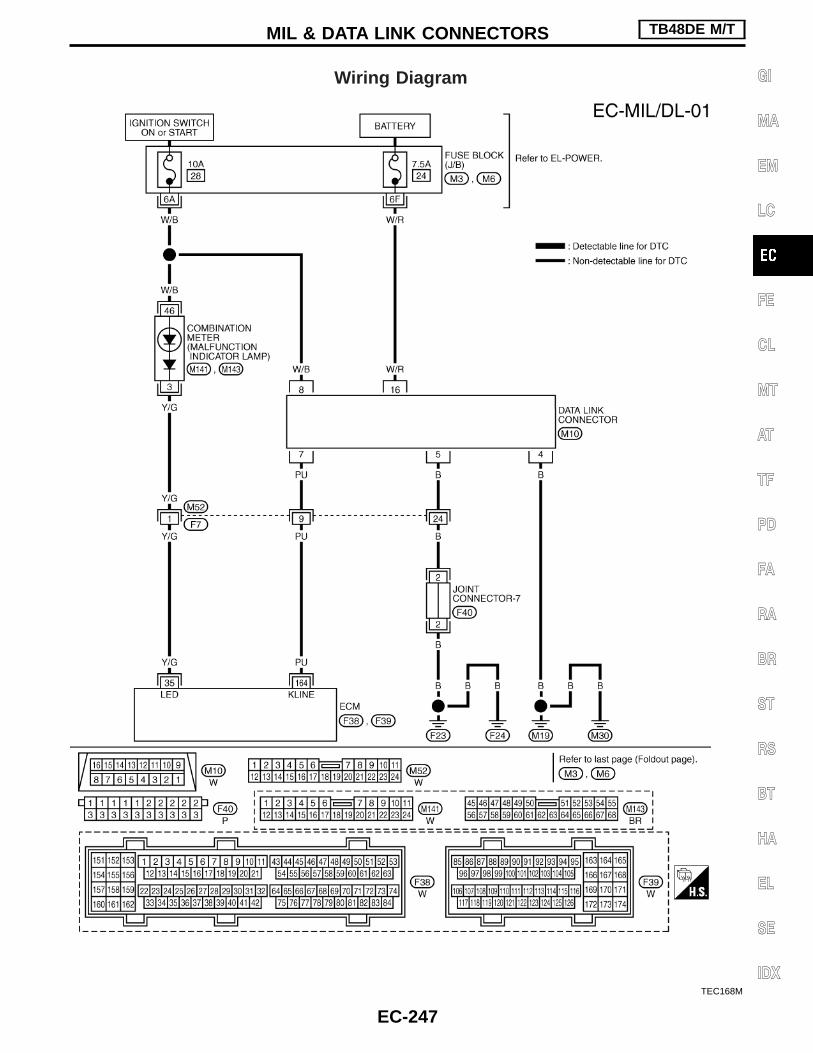
Wiring Diagram
TEC168M
MIL & DATA LINK CONNECTORS TB48DE M/T
EC-247
GI
MA
EM
LC
FE
CL
MT
AT
TF
PD
FA
RA
BR
ST
RS
BT
HA
EL
SE
IDX

Fuel Pressure Regulator
Fuel pressurekPa (bar, kg/cm2, psi)
At idleApproximately
245 (2.45, 2.5, 36)
A few seconds after ignitionswitch is turned OFF to ON
Approximately294 (2.94, 3.0, 43)
Idle Speed and Ignition Timing
Idle speed rpm
Target idle speed 675±50No-load*1(in “N” position)
Air conditioner: ON(in “N” position)
950 or more
Ignition timing 5°±5° BTDC
Throttle position sensoridle position V
0.15 - 0.85
*1: Under the following conditions:I Air conditioner switch: OFFI Steering wheel: Kept in straight-ahead positionI Electrical load: OFF (Lights, heater fan & rear window defog-
ger)
Mass Air Flow Sensor
Supply voltage V Battery voltage (11 - 14)
Output voltage at idle V0.75 - 1.5 at idle*
1.7 - 2.4 at 2,500 rpm*
*: Engine is warmed up to normal operating temperature and runningunder no-load.
Engine Coolant Temperature Sensor
Temperature °C (°F) Resistance
20 (68) 2.1 - 2.9 kΩ
50 (122) 0.68 - 1.00 kΩ
90 (194) 0.236 - 0.260 kΩ
Fuel Pump
Resistance [at 25°C (77°F)] Ω 0.2 - 5.0
EVAP Canister Purge Volume Control SolenoidValve
Resistance [at 20°C (68°F)] Ω 31 - 35
SERVICE DATA AND SPECIFICATIONS (SDS) TB48DE M/T
EC-248
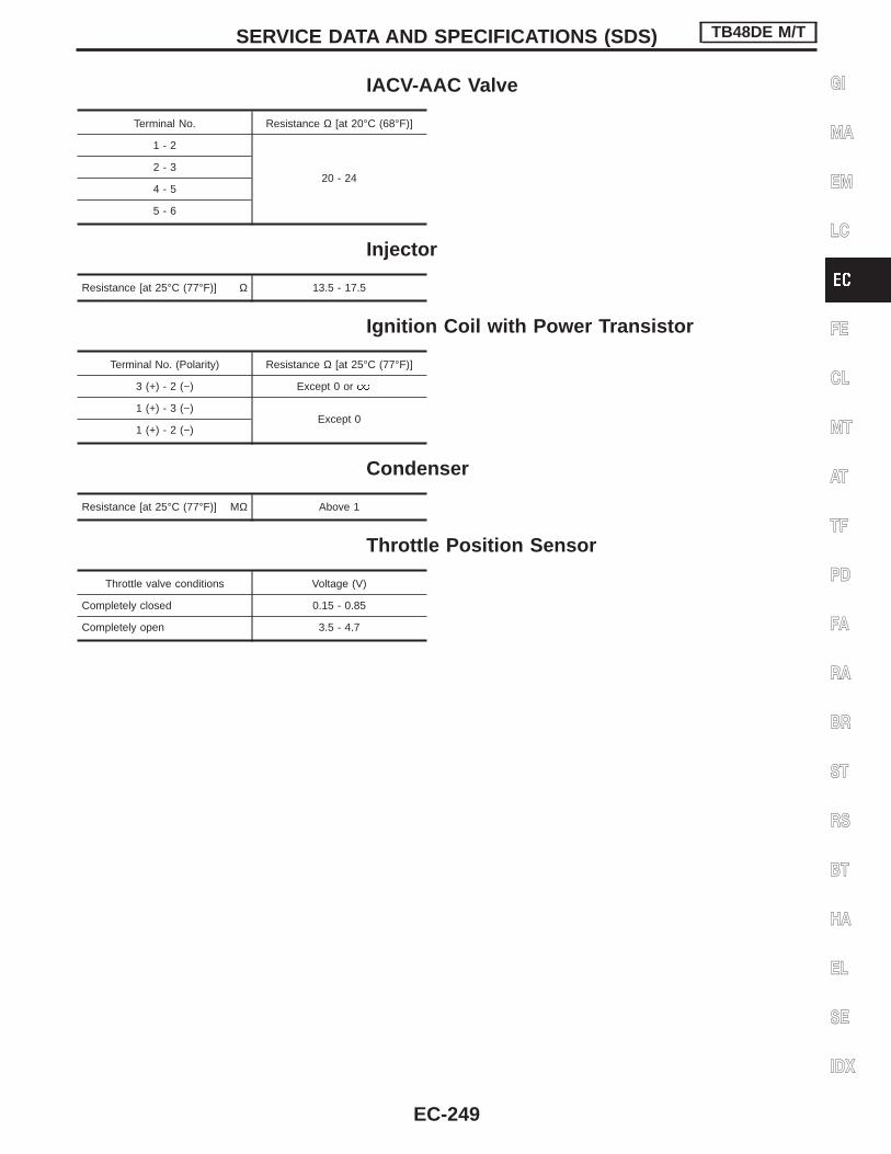
IACV-AAC Valve
Terminal No. Resistance Ω [at 20°C (68°F)]
1 - 2
20 - 242 - 3
4 - 5
5 - 6
Injector
Resistance [at 25°C (77°F)] Ω 13.5 - 17.5
Ignition Coil with Power Transistor
Terminal No. (Polarity) Resistance Ω [at 25°C (77°F)]
3 (+) - 2 (−) Except 0 or
1 (+) - 3 (−)Except 0
1 (+) - 2 (−)
Condenser
Resistance [at 25°C (77°F)] MΩ Above 1
Throttle Position Sensor
Throttle valve conditions Voltage (V)
Completely closed 0.15 - 0.85
Completely open 3.5 - 4.7
SERVICE DATA AND SPECIFICATIONS (SDS) TB48DE M/T
EC-249
GI
MA
EM
LC
FE
CL
MT
AT
TF
PD
FA
RA
BR
ST
RS
BT
HA
EL
SE
IDX

Alphabetical & P No. Index for DTCALPHABETICAL INDEX FOR DTC
Items(CONSULT-II screen)
DTC*1Reference page
CONSULT-II ECM*2
Unable to access ECM — — EC-310
ACCL POS SEN/CIRC P0121 0121 EC-359
BRAKE SW/CIRCUIT P1805 1805 EC-424
CAN COMM CIRCUIT U1000 1000*7 EC-337
CMP SEN/CIRCUIT P0340 0340 EC-377
COOLANT T SEN/CIRC*4 P0115 0115 EC-345
ECM P0605 0605 EC-384
ECM BACK UP/CIRC P1065 1065 EC-387
ENG OVER TEMP P1217 1217 EC-404
ETC ACTR P1121 1121 EC-390
ETC FUNCTION/CIRC P1122 1122 EC-393
ETC MOT RLY/CIRC P1123 1123 EC-399
HO2S1 (B1)*5 P0130 0130 EC-366
HO2S1 (B2)*5 P0150 0150 EC-366
IGN SIGNAL-PRIMARY P1320 1320 EC-415
KNOCK SEN/CIRC-B1 P0325 0325 EC-373
KNOCK SEN/CIRC-B2 P0330 0330 EC-373
MAF SEN/CIRCUIT*4 P0100 0100 EC-340
NATS MALFUNCTION P1610 1610-1615*6 EC-285
NO DTC IS DETECTED. FURTHER TESTING MAY BE REQUIRED. No DTC Flashing*3 EC-286
NO DTC IS DETECTED. FURTHER TESTING MAY BE REQUIRED. P0000 0000 —
THRTL POS SEN/CIRC*4 P0120 0120 EC-350
*1: 1st trip DTC No. is the same as DTC No.*2: In Diagnostic Test Mode II (Self-diagnostic results).*3: While engine is running.*4: When the fail-safe operation occurs, the MIL illuminates.*5: Models with three way catalyst.*6: Models with NATS (Nissan Anti-Theft System)*7: The troubleshooting for this DTC needs CONSULT-II.
TROUBLE DIAGNOSIS — INDEX TB48DE A/T
EC-250

P NO. INDEX FOR DTC
DTC*1 Items(CONSULT-II screen)
Reference pageCONSULT-II ECM*2
— — Unable to access ECM EC-310
No DTC Flashing*3 NO DTC IS DETECTED. FURTHER TESTING MAY BE REQUIRED. EC-286
U1000 1000*7 CAN COMM CIRCUIT EC-337
P0000 0000 NO DTC IS DETECTED. FURTHER TESTING MAY BE REQUIRED. —
P0100 0100 MAF SEN/CIRCUIT*4 EC-340
P0115 0115 COOLANT T SEN/CIRC*4 EC-345
P0120 0120 THRTL POS SEN/CIRC*4 EC-350
P0121 0121 ACCL POS SEN/CIRC EC-359
P0130 0130 HO2S1 (B1)*5 EC-366
P0150 0150 HO2S1 (B2)*5 EC-366
P0325 0325 KNOCK SEN/CIRC-B1 EC-373
P0330 0330 KNOCK SEN/CIRC-B2 EC-373
P0340 0340 CMP SEN/CIRCUIT EC-377
P0605 0605 ECM EC-384
P1065 1065 ECM BACK UP/CIRC EC-387
P1121 1121 ETC ACTR EC-390
P1122 1122 ETC FUNCTION/CIRC EC-393
P1123 1123 ETC MOT RLY/CIRC EC-399
P1217 1217 ENG OVER TEMP EC-404
P1320 1320 IGN SIGNAL-PRIMARY EC-415
P1610 1610-1615*6 NATS MALFUNCTION EC-285
P1805 1805 BRAKE SW/CIRCUIT EC-424
*1: 1st trip DTC No. is the same as DTC No.*2: In Diagnostic Test Mode II (Self-diagnostic results).*3: While engine is running.*4: When the fail-safe operation occurs, the MIL illuminates.*5: Models with three way catalyst.*6: Models with NATS (Nissan Anti-Theft System)*7: The troubleshooting for this DTC needs CONSULT-II.
TROUBLE DIAGNOSIS — INDEX TB48DE A/T
Alphabetical & P No. Index for DTC (Cont’d)
EC-251
GI
MA
EM
LC
FE
CL
MT
AT
TF
PD
FA
RA
BR
ST
RS
BT
HA
EL
SE
IDX

Supplemental Restraint System (SRS) “AIRBAG” and “SEAT BELT PRE-TENSIONER”
The Supplemental Restraint System such as “AIR BAG” and “SEAT BELT PRE-TENSIONER” used along witha seat belt, helps to reduce the risk or severity of injury to the driver and front passenger for certain types ofcollision. The SRS system composition which is available to NISSAN MODEL Y61 is as follows (The compo-sition varies according to the destination and optional equipment.):I For a frontal collision
The Supplemental Restraint System consists of driver air bag module (located in the center of the steer-ing wheel), front passenger air bag module (located on the instrument panel on passenger side), seat beltpre-tensioners, a diagnosis sensor unit, warning lamp, wiring harness and spiral cable.
I For a side collisionThe Supplemental Restraint System consists of front side air bag module (located in the outer side of frontseat), satellite sensor, diagnosis sensor unit (one of components of air bags for a frontal collision), wiringharness, warning lamp (one of components of air bags for a frontal collision).
Information necessary to service the system safely is included in the RS section of this Service Manual.WARNING:I To avoid rendering the SRS inoperative, which could increase the risk of personal injury or death
in the event of a collision which would result in air bag inflation, all maintenance should be per-formed by an authorized NISSAN dealer.
I Improper maintenance, including incorrect removal and installation of the SRS, can lead to per-sonal injury caused by unintentional activation of the system. For removal of Spiral Cable and AirBag Module, see the RS section.
I Do not use electrical test equipment on any circuit related to the SRS unless instructed to in thisService Manual. SRS wiring harnesses can be identified by yellow harness connector.
Precautions for On Board Diagnostic (OBD)System of Engine
The ECM has an on board diagnostic system. It will light up the malfunction indicator lamp (MIL) to warn thedriver of a malfunction causing emission deterioration.CAUTION:I Be sure to turn the ignition switch “OFF” and disconnect the negative battery terminal before any
repair or inspection work. The open/short circuit of related switches, sensors, solenoid valves, etc.will cause the MIL to light up.
I Be sure to connect and lock the connectors securely after work. A loose (unlocked) connector willcause the MIL to light up due to the open circuit. (Be sure the connector is free from water, grease,dirt, bent terminals, etc.)
I Certain systems and components, especially those related to OBD, may use a new style slide-locking type harness connector.For description and how to disconnect, refer to EL section, “Description”, “HARNESS CONNEC-TOR”.
I Be sure to route and secure the harnesses properly after work. The interference of the harness witha bracket, etc. may cause the MIL to light up due to the short circuit.
I Be sure to erase the unnecessary malfunction information (repairs completed) from the ECM beforereturning the vehicle to the customer.
PRECAUTIONS TB48DE A/T
EC-252

Engine Fuel & Emission Control SystemI Always use a 12 volt battery as power source.I Do not attempt to disconnect battery cables while engine
is running.I Before connecting or disconnecting the ECM harness
connector, turn ignition switch OFF and disconnect nega-tive battery terminal. Failure to do so may damage the ECMbecause battery voltage is applied to ECM even if ignitionswitch is turned off.
I Before removing parts, turn ignition switch OFF and thendisconnect battery ground cable.
I Do not disassemble ECM.I If a battery terminal is disconnected, the memory will
return to the ECM value.The ECM will now start to self-control at its initial value.Engine operation can vary slightly when the terminal isdisconnected. However, this is not an indication of a prob-lem. Do not replace parts because of a slight variation.
I When connecting ECM harness connector, fasten itsecurely with a lever as far as it will go as shown at right.
SEF289H
SEF707Y
PBIB0088E
PBIB0089E
PRECAUTIONS TB48DE A/T
EC-253
GI
MA
EM
LC
FE
CL
MT
AT
TF
PD
FA
RA
BR
ST
RS
BT
HA
EL
SE
IDX

I When connecting or disconnecting pin connectors into orfrom ECM, take care not to damage pin terminals (bend orbreak).Make sure that there are not any bends or breaks on ECMpin terminal, when connecting pin connectors.
I Securely connect ECM harness connectors.A poor connection can cause an extremely high (surge)voltage to develop in coil and condenser, thus resulting indamage to ICs.
I Keep engine control system harness at least 10 cm (4 in)away from adjacent harness, to prevent engine controlsystem malfunctions due to receiving external noise,degraded operation of ICs, etc.
I Keep engine control system parts and harness dry.
I Before replacing ECM, perform “ECM Terminals and Refer-ence Value” inspection and make sure ECM functionsproperly. Refer to EC-318.
I Handle mass air flow sensor carefully to avoid damage.I Do not disassemble mass air flow sensor.I Do not clean mass air flow sensor with any type of deter-
gent.I Do not disassemble electric throttle control actuator.I Even a slight leak in the air intake system can cause seri-
ous problems.I Do not shock or jar the camshaft position sensor.
I After performing each TROUBLE DIAGNOSIS, perform“DTC Confirmation Procedure” or “Overall FunctionCheck”.The DTC should not be displayed in the “DTC ConfirmationProcedure” if the repair is completed. The “Overall Func-tion Check” should be a good result if the repair is com-pleted.
PBIB0090E
MEF040D
SAT652J
PRECAUTIONS TB48DE A/T
Engine Fuel & Emission Control System(Cont’d)
EC-254

I When measuring ECM signals with a circuit tester, neverallow the two tester probes to contact.Accidental contact of probes will cause a short circuit anddamage the ECM power transistor.
I Do not use ECM ground terminals when measuring input/output voltage. Doing so may result in damage to theECM’s transistor. Use a ground other than ECM terminals,such as the ground.
I Do not operate fuel pump when there is no fuel in lines.I Tighten fuel hose clamps to the specified torque.
I Do not depress accelerator pedal when starting.I Immediately after starting, do not rev up engine unneces-
sarily.I Do not rev up engine just prior to shutdown.
I When installing C.B. ham radio or a mobile phone, be sureto observe the following as it may adversely affect elec-tronic control systems depending on installation location.
— Keep the antenna as far as possible from the electroniccontrol units.
— Keep the antenna feeder line more than 20 cm (8 in) awayfrom the harness of electronic controls. Do not let themrun parallel for a long distance.
— Adjust the antenna and feeder line so that the standing-wave radio can be kept smaller.
— Be sure to ground the radio to vehicle body.
SEF348N
SEC686C
SEF709Y
SEF708Y
PRECAUTIONS TB48DE A/T
Engine Fuel & Emission Control System(Cont’d)
EC-255
GI
MA
EM
LC
FE
CL
MT
AT
TF
PD
FA
RA
BR
ST
RS
BT
HA
EL
SE
IDX

I Regarding TB48DE engine, “B1” and “B2” are located asin the following illustration.
Wiring Diagrams and Trouble DiagnosisWhen you read Wiring diagrams, refer to the following:I “How to Read Wiring Diagrams” in GI sectionI “POWER SUPPLY ROUTING” for power distribution circuit in
EL sectionWhen you perform trouble diagnosis, refer to the following:I “HOW TO FOLLOW TEST GROUPS IN TROUBLE DIAG-
NOSES” in GI sectionI “How to Perform Efficient Diagnosis for an Electrical Incident”
in GI section
SEC888C
SEC889C
PRECAUTIONS TB48DE A/T
Engine Fuel & Emission Control System(Cont’d)
EC-256
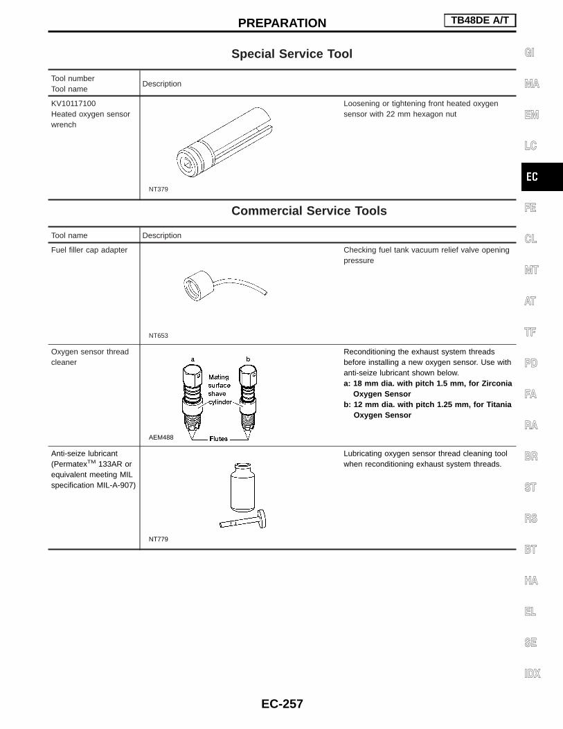
Special Service Tool
Tool numberTool name
Description
KV10117100Heated oxygen sensorwrench
NT379
Loosening or tightening front heated oxygensensor with 22 mm hexagon nut
Commercial Service Tools
Tool name Description
Fuel filler cap adapter
NT653
Checking fuel tank vacuum relief valve openingpressure
Oxygen sensor threadcleaner
AEM488
Reconditioning the exhaust system threadsbefore installing a new oxygen sensor. Use withanti-seize lubricant shown below.a: 18 mm dia. with pitch 1.5 mm, for Zirconia
Oxygen Sensorb: 12 mm dia. with pitch 1.25 mm, for Titania
Oxygen Sensor
Anti-seize lubricant(PermatexTM 133AR orequivalent meeting MILspecification MIL-A-907)
NT779
Lubricating oxygen sensor thread cleaning toolwhen reconditioning exhaust system threads.
PREPARATION TB48DE A/T
EC-257
GI
MA
EM
LC
FE
CL
MT
AT
TF
PD
FA
RA
BR
ST
RS
BT
HA
EL
SE
IDX

Circuit Diagram
TEC241M
ENGINE AND EMISSION CONTROL OVERALLSYSTEM TB48DE A/T
EC-258

TEC242M
ENGINE AND EMISSION CONTROL OVERALLSYSTEM TB48DE A/T
Circuit Diagram (Cont’d)
EC-259
GI
MA
EM
LC
FE
CL
MT
AT
TF
PD
FA
RA
BR
ST
RS
BT
HA
EL
SE
IDX

System Diagram
SEC197D
ENGINE AND EMISSION CONTROL OVERALLSYSTEM TB48DE A/T
EC-260

Engine Control Component Parts Location
SEC191D
ENGINE AND EMISSION CONTROL OVERALLSYSTEM TB48DE A/T
EC-261
GI
MA
EM
LC
FE
CL
MT
AT
TF
PD
FA
RA
BR
ST
RS
BT
HA
EL
SE
IDX

SEC538CA
SEC540C
SEC542C
SEC192D
SEC539C
SEC541C
ENGINE AND EMISSION CONTROL OVERALLSYSTEM TB48DE A/T
Engine Control Component Parts Location(Cont’d)
EC-262

SEC543C
SEC544C
SEC546CA
SEC545C
SEC547CA
ENGINE AND EMISSION CONTROL OVERALLSYSTEM TB48DE A/T
Engine Control Component Parts Location(Cont’d)
EC-263
GI
MA
EM
LC
FE
CL
MT
AT
TF
PD
FA
RA
BR
ST
RS
BT
HA
EL
SE
IDX

Vacuum Hose Drawing
Refer to “System Diagram”, EC-260, for vacuum control system.Note: Do not use soapy water or any type of solvent while installing vacuum hoses or purge hoses.
SEC548C
ENGINE AND EMISSION CONTROL OVERALLSYSTEM TB48DE A/T
EC-264

VACUUM HOSE DRAWING FOR VIAS
SEC887C
ENGINE AND EMISSION CONTROL OVERALLSYSTEM TB48DE A/T
Vacuum Hose Drawing (Cont’d)
EC-265
GI
MA
EM
LC
FE
CL
MT
AT
TF
PD
FA
RA
BR
ST
RS
BT
HA
EL
SE
IDX

System Chart
Camshaft position sensor E
ECM
Mass air flow sensor E
Engine coolant temperature sensor E
Heater oxygen sensor 1*1 E
Ignition switch E
Throttle position sensor E
Accelerator pedal position sensor E
Park/neutral position (PNP) switch E
Vehicle speed sensor*3 E
Air conditioner switch*3 E
Ambient air temperature switch E
Battery voltage E
A/T mode switch E
Knock sensor E
Electrical load*3 E
Power steering oil pressure switch E
TCM (Transmission control module) E
NATS*2 E
*1: Model with three way catalyst*2: Model with NATS (Nissan Anti-Theft System)*3: The signals are sent to the ECM through CAN communication line.
Fuel injection &mixture ratio control E Fuel injectors
Electronic ignition system E Power transistor
Idle air control system EElectric throttle controlactuatorFuel injectors
Fuel pump control E Fuel pump relay
On board diagnostic system EMIL (On the instrumentpanel)
Power valve control E VIAS control solenoid valve
Intake valve timing control EIntake valve timing controlsolenoid valve
Heated oxygen sensor 1monitor*1 & on board diag-nostic system
EMalfunction indicator lamp(On the instrument panel)
EVAP canister purge flowcontrol E
EVAP canister purge volumecontrol solenoid valve
Heated oxygen sensorheater control*1 E Heated oxygen sensor 1*1
Air conditioner cut control E Air conditioner relay
Cooling fan control E Cooling fan relays
ENGINE AND EMISSION CONTROL OVERALLSYSTEM TB48DE A/T
EC-266

Multiport Fuel Injection (MFI) SystemINPUT/OUTPUT SIGNAL LINE
Camshaft position sensorE
Engine speed and piston position
ECM E Injector
Mass air flow sensorE
Amount of intake air
Engine coolant temperature sensorE
Engine coolant temperature
Heated oxygen sensor 1*1E
Density of oxygen in exhaust gas
Throttle position sensorE
Throttle position
Accelerator pedal position sensorE
Accelerator pedal position
Park/neutral position (PNP) switchE
Gear position
Vehicle speed*2E
Vehicle speed
Air conditioner switch*2E
Air conditioner operation
Ignition switchE
Start signal
Battery voltageE
Battery voltage
*1: Model with three way catalyst*2: Signals are sent to the ECM through CAN communication line.
BASIC MULTIPORT FUEL INJECTIONSYSTEMThe amount of fuel injected from the fuel injector isdetermined by the ECM. The ECM controls thelength of time the valve remains open (injectionpulse duration). The amount of fuel injected is aprogram value in the ECM memory. The programvalue is preset by engine operating conditions.These conditions are determined by input signals(for engine speed and intake air) from both the cam-shaft position sensor and the mass air flow sensor.
VARIOUS FUEL INJECTIONINCREASE/DECREASE COMPENSATIONThe amount of fuel injected is compensated for toimprove engine performance. This will be madeunder various operating conditions as listed below.<Fuel increase>I During warm-upI When starting the engineI During accelerationI Hot-engine operation<Fuel decrease>I During decelerationI When the vehicle speed is extremely highI Extremely high-engine coolant temperatureI When select lever is changed from “N” to “D” at
high engine speed (A/T models only)
ENGINE AND EMISSION BASIC CONTROL SYSTEMDESCRIPTION TB48DE A/T
EC-267
GI
MA
EM
LC
FE
CL
MT
AT
TF
PD
FA
RA
BR
ST
RS
BT
HA
EL
SE
IDX

MIXTURE RATIO FEEDBACK CONTROL (CLOSED LOOP CONTROL) [MODEL WITH THREEWAY CATALYST]
The mixture ratio feedback system provides the best air-fuel mixture ratio for driveability and emission con-trol. The three way catalyst (manifold) can then better reduce CO, HC and NOx emissions. This system usesheated oxygen sensor 1 in the exhaust manifold to monitor if the engine operation is rich or lean. The ECMadjusts the injection pulse width according to the sensor voltage signal. For more information about heatedoxygen sensor 1. This maintains the mixture ratio within the range of stoichiometric (ideal air-fuel mixture).This stage is referred to as the closed loop control condition.
Open loop controlThe open loop system condition refers to when the ECM detects any of the following conditions. Feedbackcontrol stops in order to maintain stabilized fuel combustion.I Deceleration and accelerationI High-load, high-speed operationI Malfunction of heated oxygen sensor 1 or its circuitI Insufficient activation of heated oxygen sensor 1 at low engine coolant temperatureI High engine coolant temperatureI During warm-upI After shifting from “N” to “D” (For A/T models)I When starting the engine
MIXTURE RATIO SELF-LEARNING CONTROL [MODEL WITH THREE WAY CATALYST]The mixture ratio feedback control system monitors the mixture ratio signal transmitted from heated oxygensensor 1. This feedback signal is then sent to the ECM. The ECM controls the basic mixture ratio as close tothe theoretical mixture ratio as possible. However, the basic mixture ratio is not necessarily controlled asoriginally designed. Both manufacturing differences (i.e., mass air flow sensor hot film) and characteristicchanges during operation (i.e., injector clogging) directly affect mixture ratio.Accordingly, the difference between the basic and theoretical mixture ratios is monitored in this system. Thisis then computed in terms of “injection pulse duration” to automatically compensate for the difference betweenthe two ratios.“Fuel trim” refers to the feedback compensation value compared against the basic injection duration. Fuel trimincludes short term fuel trim and long term fuel trim.“Short term fuel trim” is the short-term fuel compensation used to maintain the mixture ratio at its theoreticalvalue. The signal from heated oxygen sensor 1 indicates whether the mixture ratio is RICH or LEAN comparedto the theoretical value. The signal then triggers a reduction in fuel volume if the mixture ratio is rich, and anincrease in fuel volume if it is lean.“Long term fuel trim” is overall fuel compensation carried out long-term to compensate for continual deviationof the short term fuel trim from the central value. Such deviation will occur due to individual engine differences,wear over time and changes in the usage environment.
PBIB0121E
ENGINE AND EMISSION BASIC CONTROL SYSTEMDESCRIPTION TB48DE A/T
Multiport Fuel Injection (MFI) System (Cont’d)
EC-268

FUEL INJECTION SYSTEMTwo types of systems are used.
Simultaneous multiport fuel injection systemFuel is injected simultaneously into all six cylinders twice eachengine cycle. In other words, pulse signals of the same width aresimultaneously transmitted from the ECM.The six injectors will then receive the signals two times for eachengine cycle.This system is used when the engine is being started and/or if thefail-safe mode (CPU) is operating.
Sequential multiport fuel injection systemFuel is injected into each cylinder during each engine cycle accord-ing to the firing order. This system is used when the engine is run-ning.
FUEL SHUT-OFFFuel to each cylinder is cut off during deceleration or operation ofthe engine at excessively high speeds.
SEF630V
ENGINE AND EMISSION BASIC CONTROL SYSTEMDESCRIPTION TB48DE A/T
Multiport Fuel Injection (MFI) System (Cont’d)
EC-269
GI
MA
EM
LC
FE
CL
MT
AT
TF
PD
FA
RA
BR
ST
RS
BT
HA
EL
SE
IDX

Electronic Ignition (EI) SystemINPUT/OUTPUT SIGNAL LINE
Camshaft position sensorE
Engine speed and piston position
ECM E Powertransistor
Mass air flow sensorE
Amount of intake air
Engine coolant temperature sensorE
Engine coolant temperature
Throttle position sensorE
Throttle position
Accelerator pedal position sensorE
Accelerator pedal position
Vehicle speed*1E
Vehicle speed
Ignition switchE
Start signal
Park/neutral position switchE
Gear position
BatteryE
Battery voltage
Knock sensorE
Knock signal
*1: Signal is sent to the ECM through CAN communication line.
SYSTEM DESCRIPTIONThe ignition timing is controlled by the ECM to maintain the bestair-fuel ratio for every running condition of the engine.The ignition timing data is stored in the ECM. This data forms themap shown left.The ECM detects information such as the injection pulse width andcamshaft position sensor signal. Responding to this information,ignition signals are transmitted to the power transistor.
e.g. N: 1,800 rpm, Tp: 1.50 msecA °BTDC
During the following conditions, the ignition timing is revised by theECM according to the other data stored in the ECM.I At startingI During warm-upI At idleI Hot-engine operationI At accelerationThe knock sensor retard system is designed only for emergencies.The basic ignition timing is programmed within the anti-knockingzone, if recommended fuel is used under dry conditions. The retardsystem does not operate under normal driving conditions.If engine knocking occurs, the knock sensor monitors the condition.The signal is transmitted to the ECM. The ECM retards the ignitiontiming to eliminate the knocking condition.
SEF742M
ENGINE AND EMISSION BASIC CONTROL SYSTEMDESCRIPTION TB48DE A/T
EC-270

Air Conditioning Cut ControlINPUT/OUTPUT SIGNAL LINE
Camshaft position sensorE
Engine speed
ECM EAir condi-tionerrelay
Air conditioner switch*1E
Air conditioner “ON” signal
Throttle position sensorE
Throttle valve opening angle
Ignition switchE
Start signal
Engine coolant temperature sensorE
Engine coolant temperature
Vehicle speed*1E
Vehicle speed
Ambient air temperature switchE
Ambient air temperature
*1: Signals are sent to the ECM through CAN communication line.
SYSTEM DESCRIPTIONThis system improves engine operation when the airconditioner is used.Under the following conditions, the air conditioner isturned off.
I When the accelerator pedal is fully depressedI When cranking the engineI During the engine coolant temperature is exces-
sively highI During high-engine speed operation
ENGINE AND EMISSION BASIC CONTROL SYSTEMDESCRIPTION TB48DE A/T
EC-271
GI
MA
EM
LC
FE
CL
MT
AT
TF
PD
FA
RA
BR
ST
RS
BT
HA
EL
SE
IDX
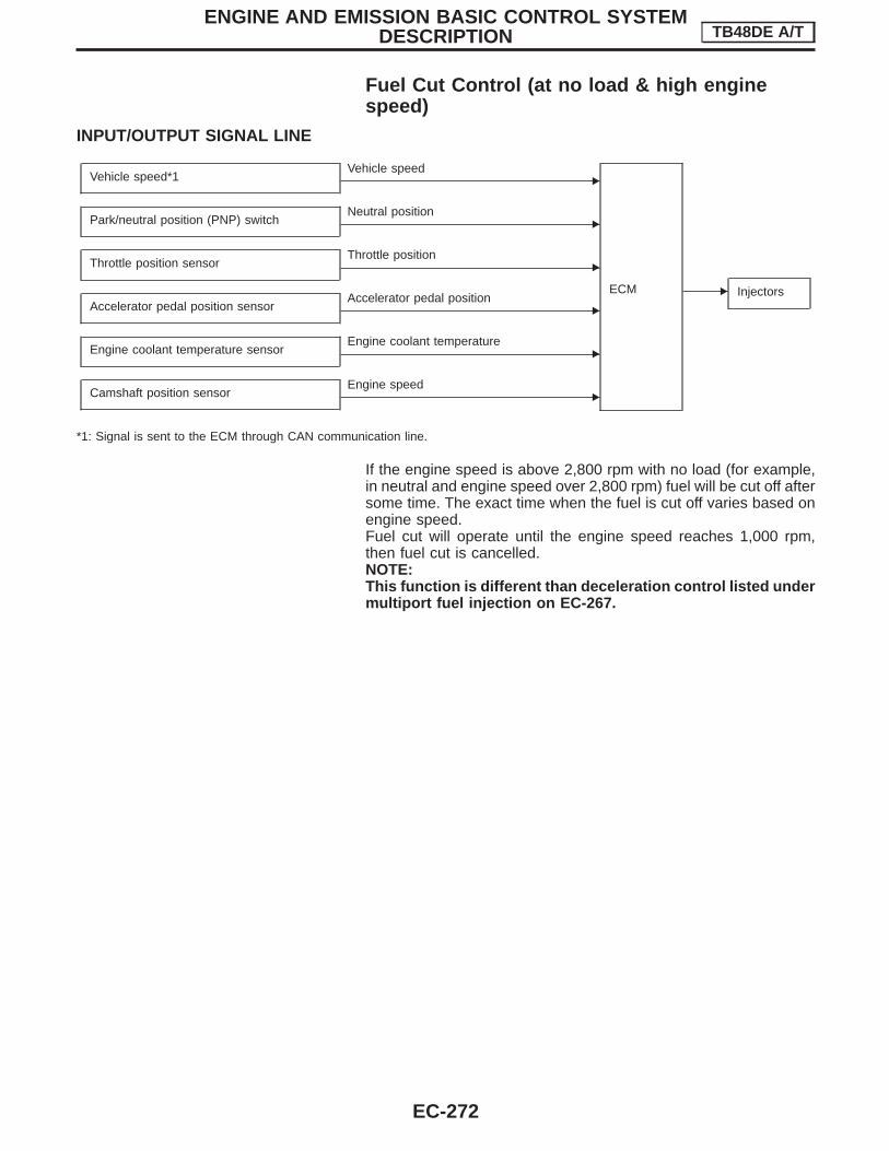
Fuel Cut Control (at no load & high enginespeed)
INPUT/OUTPUT SIGNAL LINE
Vehicle speed*1 EVehicle speed
ECM E Injectors
Park/neutral position (PNP) switch ENeutral position
Throttle position sensor EThrottle position
Accelerator pedal position sensor EAccelerator pedal position
Engine coolant temperature sensor EEngine coolant temperature
Camshaft position sensor EEngine speed
*1: Signal is sent to the ECM through CAN communication line.
If the engine speed is above 2,800 rpm with no load (for example,in neutral and engine speed over 2,800 rpm) fuel will be cut off aftersome time. The exact time when the fuel is cut off varies based onengine speed.Fuel cut will operate until the engine speed reaches 1,000 rpm,then fuel cut is cancelled.NOTE:This function is different than deceleration control listed undermultiport fuel injection on EC-267.
ENGINE AND EMISSION BASIC CONTROL SYSTEMDESCRIPTION TB48DE A/T
EC-272

CAN CommunicationSYSTEM DESCRIPTIONCAN (Controller Area Network) is a serial communication line for real time application. It is an on-vehicle mul-tiplex communication line with high data communication speed and excellent error detection ability. Manyelectronic control units are equipped onto a vehicle, and each control unit shares information and links withother control units during operation (not independent). In CAN communication, control units are connected with2 communication lines (CAN H line, CAN L line) allowing a high rate of information transmission with less wir-ing. Each control unit transmits/receives data but selectively reads required data only.
SYSTEM DIAGRAM
Input/output signal chartT: Transmit R: Receive
Signals Combination meter TCM ECM
Engine speed signal R R T
Engine coolant temperature signal R R T
Accelerator pedal position signal R T
Closed throttle position signal R T
Wide open throttle position signal R T
A/T fluid temperature warning lamp signal R T R
Current gear position signal R T R
Shift change signal T R
Air conditioner switch signal T R
Headlamp switch signal T R
Rear window defogger switch signal T R
Brake switch signal T R
Vehicle speed signal T R R
A/T self diagnosis signal T R
Manual mode signal T R
SEL599Y
ENGINE AND EMISSION BASIC CONTROL SYSTEMDESCRIPTION TB48DE A/T
EC-273
GI
MA
EM
LC
FE
CL
MT
AT
TF
PD
FA
RA
BR
ST
RS
BT
HA
EL
SE
IDX

Description
The evaporative emission system is used to reduce hydrocarbonsemitted into the atmosphere from the fuel system. This reduction ofhydrocarbons is accomplished by activated charcoals in the EVAPcanister.The fuel vapor in the sealed fuel tank is led into the EVAP canisterwhich contains activated carbon and the vapor is stored there whenthe engine is not operating or when refueling to the fuel tank.The EVAP canister retains the fuel vapor until the EVAP canister ispurged by air.The vapor in the EVAP canister is purged by the air through thepurge line to the intake manifold when the engine is operating.EVAP canister purge volume control solenoid valve is controlled byECM. When the engine operates, the flow rate of vapor controlledby EVAP canister purge volume control solenoid valve is propor-tionally regulated as the air flow increases.EVAP canister purge volume control solenoid valve also shuts offthe vapor purge line when decelerating or idling.
InspectionEVAP CANISTERBlow air into each of three ports to check that air flows freely.
SEF749T
SEF083Y
EVAPORATIVE EMISSION SYSTEM TB48DE A/T
EC-274

FUEL CHECK VALVE1. Blow air through connector on fuel tank side.
A considerable resistance should be felt and a portion of air flowshould be directed toward the EVAP canister side.
2. Blow air through connector on EVAP canister side.Air flow should be smoothly directed toward fuel tank side.
3. If fuel check valve is suspected of not properly functioning insteps 1 and 2 above, replace it.
FUEL CUT VALVE
Cut valve operationEnsure that continuity of air passage does not exist when theinstalled cut valve is tilted to 90° or 180°.
FUEL TANK VACUUM RELIEF VALVE1. Wipe clean valve housing.2. Check valve opening pressure and vacuum.
Pressure:16.0 - 20.0 kPa (0.16 - 0.20 bar, 0.163 - 0.204kg/cm 2, 2.32 - 2.90 psi)
Vacuum:−6.0 to −3.5 kPa (−0.060 to −0.035 bar, −0.061 to−0.036 kg/cm 2, −0.87 to −0.51 psi)
3. If out of specification, replace fuel filler cap as an assembly.CAUTION:Use only a genuine fuel filler cap as a replacement.
SEF631V
SEC886CA
SEF632VA
SEF084Y
SEF943S
EVAPORATIVE EMISSION SYSTEM TB48DE A/T
Inspection (Cont’d)
EC-275
GI
MA
EM
LC
FE
CL
MT
AT
TF
PD
FA
RA
BR
ST
RS
BT
HA
EL
SE
IDX

EVAPORATIVE EMISSION (EVAP) CANISTER PURGEVOLUME CONTROL SOLENOID VALVERefer to EC-435.
EVAP VAPOR LINEVisually inspect EVAP vapor lines for improper attachment and forcracks, damage, loose connections, chafing and deterioration.Refer to Vacuum Hose Drawing, EC-264.
EVAPORATIVE EMISSION SYSTEM TB48DE A/T
Inspection (Cont’d)
EC-276

DescriptionThis system returns blow-by gas to the intake manifold collector.The positive crankcase ventilation (PCV) valve is provided to conduct crankcase blow-by gas to the intakemanifold.During partial throttle operation of the engine, the intake manifold sucks the blow-by gas through the PCVvalve.Normally, the capacity of the valve is sufficient to handle any blow-by and a small amount of ventilating air.The ventilating air is then drawn from the air duct into the crankcase. In this process the air passes throughthe hose connecting air inlet tubes to the rocker cover.Under full-throttle condition, the manifold vacuum is insufficient to draw the blow-by flow through the valve.The flow goes through the hose connection in the reverse direction.On vehicles with an excessively high blow-by, the valve does not meet the requirement. This is because someof the flow will go through the hose connection to the intake collector under all conditions.
InspectionPCV (Positive Crankcase Ventilation) VALVEWith engine running at idle, remove PCV valve from breather sepa-rator. A properly working valve makes a hissing noise as air passesthrough it. A strong vacuum should be felt immediately when a fin-ger is placed over the valve inlet.
PCV HOSE1. Check hoses and hose connections for leaks.2. Disconnect all hoses and clean with compressed air. If any
hose cannot be freed of obstructions, replace.
SEF921W
SEC137A
ET277
POSITIVE CRANKCASE VENTILATION TB48DE A/T
EC-277
GI
MA
EM
LC
FE
CL
MT
AT
TF
PD
FA
RA
BR
ST
RS
BT
HA
EL
SE
IDX

Fuel Pressure ReleaseBefore disconnecting fuel line, release fuel pressure from fuelline to eliminate danger.
With CONSULT-II1. Start engine.2. Perform “FUEL PRESSURE RELEASE” in “WORK SUPPORT”
mode with CONSULT-II.(Touch “START” and after engine stalls, crank it two or threetimes to release all fuel pressure.)
3. Turn ignition switch off.
Without CONSULT-II1. Remove fuse for fuel pump.2. Start engine.3. After engine stalls, crank it two or three times to release all fuel
pressure.4. Turn ignition switch off and reconnect fuel pump fuse.
Fuel Pressure CheckI When reconnecting fuel line, always use new clamps.I Make sure that clamp screw does not contact adjacent
parts.I Use a torque driver to tighten clamps.I Use Pressure Gauge to check fuel pressure.1. Release fuel pressure to zero, refer to above.2. Disconnect fuel hose between fuel filter and fuel tube (engine
side).3. Install pressure gauge between fuel filter and fuel tube.4. Start engine and check for fuel leakage.
5. Read the indication of fuel pressure gauge.At idling:
Approximately 245 kPa (2.45 bar, 2.5 kg/cm 2, 36psi)
A few seconds after ignition switch is turned OFF toON:
Approximately 294 kPa (2.94 bar, 3.0 kg/cm 2, 43psi)
6. Stop engine and disconnect fuel pressure regulator vacuumhose from intake manifold.
7. Plug intake manifold with a rubber cap.8. Connect variable vacuum source to fuel pressure regulator.9. Start engine and read indication of fuel pressure gauge as
vacuum is changed.Fuel pressure should decrease as vacuum increases. If resultsare unsatisfactory, replace fuel pressure regulator.
SEF214Y
SEC550C
SEC551C
SEF718BA
BASIC SERVICE PROCEDURE TB48DE A/T
EC-278

Injector Removal and Installation1. Release fuel pressure to zero.2. Disconnect harness connector clip.3. Disconnect injector harness connectors.4. Disconnect fuel hoses from fuel tube assembly.5. Remove fuel tube assemblies in reverse numerical sequence of
that shown in the figure at left.
6. Expand and remove clips securing fuel injectors.7. Extract fuel injectors straight from fuel tubes.I Do not extract injector by pinching connector.I Be careful not to damage injector nozzles during removal.I Do not bump or drop fuel injectors.
8. Install injector to fuel tube assembly.I Lubricate O-rings with a smear of silicone oil.I Be careful not to damage O-rings with service tools, finger
nails or clips. Do not expand or twist O-rings.I Discard old clips, replace with new ones.9. Position clips in grooves on fuel injectors.I Make sure that protrusions of fuel injectors are aligned
with cutouts of clips after installation.10. Align protrusions of fuel tubes with those of fuel injectors. Insert
fuel injectors straight into fuel tubes.11. After properly inserting fuel injectors, check to make sure that
fuel tube protrusions are engaged with those of fuel injectors,and that flanges of fuel tube are engaged with clips.
12. Tighten fuel tube assembly mounting nuts in numericalsequence (indicated in the figure at left) and in two stages.
: Tightening torque N ⋅m (kg-m, ft-lb)1st stage:
9 - 20 (0.9 - 2.1, 7 - 15)2nd stage:
21 - 26 (2.1 - 2.7, 16 - 19)13. Insert fuel hoses into fuel tubes so that ends of fuel hoses butt
up against fuel tubes; fasten with clamps, avoiding bulges.CAUTION:After properly connecting fuel tube assembly to injector andfuel hose, check connection for fuel leakage.
SEC552C
SEC553C
SEC559C
SEC554C
SEC552C
BASIC SERVICE PROCEDURE TB48DE A/T
EC-279
GI
MA
EM
LC
FE
CL
MT
AT
TF
PD
FA
RA
BR
ST
RS
BT
HA
EL
SE
IDX

How to Check Idle Speed and Ignition TimingIDLE SPEEDI Using CONSULT-IICheck idle speed in “DATA MONITOR” mode with CONSULT-II.
IGNITION TIMINGAny of following two methods may be used.I Method A1) Attach timing light to loop wire as shown.2) Check ignition timing.
I Method Ba) Remove No. 1 ignition coil.b) Connect No. 1 ignition coil and No. 1 spark plug with suitable
high-tension wire as shown, and attach timing light clamp to thiswire.
c) Check ignition timing.
Accelerator Pedal Released Position LearningDESCRIPTION“Accelerator Pedal Released Position Learning” is an operation to learn the fully released position of theaccelerator pedal by monitoring the accelerator pedal position sensor output signal. It must be performed eachtime harness connector of accelerator pedal position sensor or ECM is disconnected.
OPERATION PROCEDURE1. Make sure that accelerator pedal is fully released.2. Turn ignition switch “ON” and wait at least 2 seconds.3. Turn ignition switch “OFF” wait at least 10 seconds.4. Turn ignition switch “ON” and wait at least 2 seconds.5. Turn ignition switch “OFF” wait at least 10 seconds.
SEF058Y
SEC560C
SEC561C
SEF166Y
BASIC SERVICE PROCEDURE TB48DE A/T
EC-280

Throttle Valve Closed Position LearningDESCRIPTION“Throttle Valve Closed Position Learning” is an operation to learn the fully closed position of the throttle valveby monitorizing the throttle position sensor output signal. It must be performed each time harness connectorof electric throttle control actuator or ECM is disconnected.
OPERATION PROCEDURE1. Turn ignition switch “ON”.2. Turn ignition switch “OFF” and wait at least 10 seconds.
Make sure that throttle valve moves during above 10 seconds by confirming the operating sound.
Idle Air Volume LearningDESCRIPTION“Idle Air Volume Learning” is an operation to learn the idle air vol-ume that keeps each engine within the specific range. It must beperformed under any of the following conditions:I Each time electric throttle control actuator or ECM is replaced.I Idle speed or ignition timing is out of specification.
PRE-CONDITIONINGBefore performing “Idle Air Volume Learning”, make sure that all ofthe following conditions are satisfied.Learning will be cancelled if any of the following conditions aremissed for even a moment.I Battery voltage: More than 12.9V (At idle)I Engine coolant temperature: 70 - 99°C (158 - 210°F)I PNP switch: ONI Electric load switch: OFF
(Air conditioner, heater fan, headlamp, rear window defogger)I Cooling fan motor: Not operatingI Steering wheel: Neutral (Straight-ahead position)I Vehicle speed: StoppedI Transmission: Warmed-up
For models with CONSULT-II, drive vehicle until “FLUID TEMPSE” in “DATA MONITOR” mode of “A/T” system indicates lessthan 0.9V.For models without CONSULT-II, drive vehicle for 10 minutes.
OPERATION PROCEDURE
With CONSULT-II1. Perform EC-282, “Throttle Valve Closed Position Learning”.2. Start engine and warm it up to normal operating temperature.3. Check that all items listed under the topic “PRE-CONDITION-
ING” (previously mentioned) are in good order.4. Select “IDLE AIR VOL LEARN” in “WORK SUPPORT” mode.5. Touch “START” and wait 20 seconds.6. Make sure that “CMPLT” is displayed on CONSULT-II screen.
If “INCMP” is displayed, “Idle Air Volume Learning” will not becarried out successfully. In this case, find the cause of theproblem by referring to the “Diagnostic Procedure”, EC-282.
7. Rev up the engine two or three times and make sure that idlespeed and ignition timing are within the specifications.
ITEM SPECIFICATION
Idle speed 675±50 rpm (in “P” or “N” position)
Ignition timing 5±5° BTDC (in “P” or “N” position)
SEF217Z
SEF454Y
SEF455Y
BASIC SERVICE PROCEDURE TB48DE A/T
EC-281
GI
MA
EM
LC
FE
CL
MT
AT
TF
PD
FA
RA
BR
ST
RS
BT
HA
EL
SE
IDX

Without CONSULT-IINOTE:I It is better to count the time accurately with a clock.I It is impossible to switch the diagnostic mode when an accelerator pedal position sensor circuit
has a malfunction.1. Perform EC-282, “Throttle Valve Closed Position Learning”.2. Start engine and warm it up to normal operating temperature.3. Check that all items listed under the topic “PRE-CONDITIONING” (previously mentioned) are in good
order.4. Turn ignition switch “OFF” and wait at least 10 seconds.5. Confirm that accelerator pedal is fully released, turn ignition switch “ON” and wait 3 seconds.6. Repeat the following procedure quickly five times within 5 seconds.a. Fully depress the accelerator pedal.b. Fully release the accelerator pedal.7. Wait 7 seconds, fully depress the accelerator pedal and keep it for approx. 20 seconds until the MIL goes
off.8. Fully release the accelerator pedal within 3 seconds after the MIL goes off.9. Start engine and let it idle.10. Wait 20 seconds.
11. Rev up the engine two or three times and make sure that idle speed and ignition timing are within thespecifications.
ITEM SPECIFICATION
Idle speed 675±50 rpm (in “P” or “N” position)
Ignition timing 5±5° BTDC (in “P” or “N” position)
12. If idle speed and ignition timing are not within the specification, the result will be incomplete. In this case,find the cause of the problem by referring to the “Diagnostic Procedure” EC-282.
DIAGNOSTIC PROCEDUREIf idle air volume learning cannot be performed successfully, proceed as follows:1. Check that throttle valve is fully closed.2. Check PCV valve operation.3. Check that downstream of throttle valve is free from air leakage.4. When the above three items check out OK, engine component parts and their installation condi-
tion are questionable. Check and eliminate the cause of the problem.It is useful to perform EC-327, “TROUBLE DIAGNOSIS — SPECIFICATION VALUE”.
5. If any of the following conditions occur after the engine has started, eliminate the cause of theproblem and perform “Idle air volume learning” all over again:
I Engine stalls.I Erroneous idle.
PBIB0091E
BASIC SERVICE PROCEDURE TB48DE A/T
Idle Air Volume Learning (Cont’d)
EC-282

IntroductionThe ECM has an on board diagnostic system, which detects malfunctions related to engine sensors or actua-tors. Self-diagnosis items are listed in “DIAGNOSTIC TROUBLE CODE INDEX”, EC-250.The malfunction indicator lamp (MIL) on the instrument panel lights up when a specific malfunction is detected,or when the ECM enters fail-safe mode (Refer to EC-310.). For diagnostic items causing the MIL to light up,refer to “DIAGNOSTIC TROUBLE CODE INDEX”, EC-250.
Diagnostic Trouble Code (DTC)HOW TO READ DTCMalfunction items can be confirmed by the following methods.
With CONSULT-IICONSULT-II displays the DTC in “SELF-DIAGNOSTIC RESULTS” mode.Examples: P0100, P0120, P0340, etc. (CONSULT-II also displays the malfunctioning component or system.)
Without CONSULT-IIThe number of blinks of the malfunction indicator lamp in the Diagnostic Test Mode II (Self-Diagnostic Results)indicates the DTC. Examples: 0100, 1320, etc.I Output of a DTC indicates a malfunction. However, Mode II does not indicate whether the malfunc-
tion is still occurring or has occurred in the past and has returned to normal.CONSULT-II can identify malfunction status as shown below. Therefore, using CONSULT-II (if avail-able) is recommended.
A sample of CONSULT-II display is shown at left. The malfunctionis displayed in “SELF-DIAGNOSTIC RESULTS” mode of CON-SULT-II. Time data indicates how many times the vehicle wasdriven after the last detection of a malfunction.If the malfunction is being detected currently, the time data will be“0”.
FREEZE FRAME DATAThe ECM records the driving conditions such as fuel system status, calculated load value, engine coolanttemperature, short term fuel trim*, long term fuel trim*, engine speed, vehicle speed, absolute throttle positionand base fuel schedule at the moment a malfunction is detected.Data which are stored in the ECM memory, along with the DTC, are called freeze frame data. The data, storedtogether with the DTC data, are called freeze frame data and displayed on CONSULT-II. The freeze framedata can only be displayed on the CONSULT-II screen. For details, see EC-292.Only one set of freeze frame data can be stored in the ECM.When more than one DTC is detected, the freeze frame data detected first is stored in the memory.The freeze frame data (along with the DTCs) are cleared when the ECM memory is erased. Procedures forclearing the ECM memory are described in “HOW TO ERASE EMISSION-RELATED DIAGNOSTIC INFOR-MATION”. Refer to EC-283.*: Model with three way catalyst
HOW TO ERASE EMISSION-RELATED DIAGNOSTIC INFORMATION
How to erase DTC (With CONSULT-II)1. If the ignition switch stays “ON” after repair work, be sure to turn ignition switch “OFF” once. Wait at least
9 seconds and then turn it “ON” (engine stopped) again.2. Turn CONSULT-II “ON” and touch “ENGINE”.3. Touch “SELF-DIAG RESULTS”.4. Touch “ERASE”. (The DTC in the ECM will be erased.)
SEC890C
ON BOARD DIAGNOSTIC SYSTEM DESCRIPTION TB48DE A/T
EC-283
GI
MA
EM
LC
FE
CL
MT
AT
TF
PD
FA
RA
BR
ST
RS
BT
HA
EL
SE
IDX

The emission-related diagnostic information in the ECM can be erased by selecting “ERASE” in the “SELF-DIAG RESULTS” mode with CONSULT-II.
How to erase DTC (No tools)1. If the ignition switch stays “ON” after repair work, be sure to turn ignition switch “OFF” once.2. Wait at least 10 seconds and then turn it “ON” (engine stopped) again.3. Change the diagnostic test mode from Mode II to Mode I by depressing the accelerator pedal. Refer to
EC-286, “How to Switch Diagnostic Test Mode”.NOTE:I If the battery is disconnected, the emission-related diagnostic information will be lost after approx.
24 hours.I The following data are cleared when the ECM memory is erased.1) Diagnostic trouble codes2) Freeze frame data3) OthersActual work procedures are explained using a DTC as an example. Be careful so that not only the DTC, butall of the data listed above, are cleared from the ECM memory during work procedures.
SEC555C
ON BOARD DIAGNOSTIC SYSTEM DESCRIPTION TB48DE A/T
Diagnostic Trouble Code (DTC) (Cont’d)
EC-284

NATS (Nissan Anti-theft System)I If the security indicator lights up with the ignition switch in
the “ON” position or “NATS MALFUNCTION” is displayedon “SELF-DIAG RESULTS” screen, perform self-diagnosticresults mode with CONSULT-II using NATS program card.Refer to NATS (Nissan Anti-Theft System) in EL section.
I Confirm no self-diagnostic results of NATS is displayedbefore touching “ERASE” in “SELF-DIAG RESULTS” modewith CONSULT-II.
I When replacing ECM, initialization of NATS system andregistration of all NATS ignition key IDs must be carried outwith CONSULT-II using NATS program card.Therefore, be sure to receive all keys from vehicle owner.Regarding the procedure of NATS initialization and NATSignition key ID registration, refer to CONSULT-II operationmanual, NATS.
Malfunction Indicator Lamp (MIL)The MIL is located on the instrument panel.1. The MIL will light up when the ignition switch is turned ON
without the engine running. This is a bulb check.I If the MIL does not light up, refer to EL section, “WARNING
LAMPS” or see EC-480.2. When the engine is started, the MIL should go off.
If the MIL remains on, the on board diagnostic system hasdetected an engine system malfunction.
ON BOARD DIAGNOSTIC SYSTEM FUNCTIONThe on board diagnostic system has the following four functions.
Diagnostic test mode I1. BULB CHECK:
This function checks the MIL bulb for damage (blown, open circuit, etc.).If the MIL does not come on, check MIL circuit and ECM test mode selector. (See EC-286.)
2. MALFUNCTION WARNING:This is a usual driving condition. When a malfunction is detected, the MIL will light up to inform the driverthat a malfunction has been detected.
Diagnostic test mode II3. SELF-DIAGNOSTIC RESULTS:
This function allows DTCs to be read.4. HEATED OXYGEN SENSOR 1 MONITOR*:
*: Model with three way catalyst
SEF543X
SAT652J
ON BOARD DIAGNOSTIC SYSTEM DESCRIPTION TB48DE A/T
EC-285
GI
MA
EM
LC
FE
CL
MT
AT
TF
PD
FA
RA
BR
ST
RS
BT
HA
EL
SE
IDX

MIL flashing without DTCIf the ECM is in Diagnostic Test Mode II, MIL may flash when engine is running. In this case, check ECM testmode following “HOW TO SWITCH DIAGNOSTIC TEST MODES”.How to switch the diagnostic test (function) modes, and details of the above functions are described later. (SeeEC-286.)
Condition Diagnostic Test Mode I Diagnostic Test Mode II
Ignition switch in “ON” position
Engine stopped
BULB CHECK SELF-DIAGNOSTIC RESULTS
Engine running
MALFUNCTION WARNINGHEATED OXYGEN SENSOR 1
MONITOR*
*: Model with three way catalyst
The following emission-related diagnostic information is cleared when the ECM memory is erased.1) Diagnostic trouble codes2) Free frame data3) Others
HOW TO SWITCH DIAGNOSTIC TEST MODENOTE:I It is better to count the time accurately with a clock.I It is impossible to switch the diagnostic mode when an accelerator pedal position sensor circuit
has a malfunction.I Always ECM returns to Diagnostic Test Mode I after ignition switch is turned “OFF”.
How to set Diagnostic Test Mode II (Self-diagnostic results)1. Confirm that accelerator pedal is fully released, turn ignition switch “ON” and wait 3 seconds.2. Repeat the following procedure quickly five times within 5 seconds.a. Fully depress the accelerator pedal.b. Fully release the accelerator pedal.3. Wait 7 seconds, fully depress the accelerator pedal and keep it for approx. 10 seconds until the MIL starts
blinking.4. Fully release the accelerator pedal.
ECM has entered to Diagnostic Test Mode II (Self-diagnostic results).
How to set Diagnostic Test Mode II (Heated Oxygen Sensor 1 Monitor) [Model with threeway catalyst]1. Set the ECM in Diagnostic Test Mode II (Self-diagnostic results). Refer to EC-286, “How to Set Diagnos-
tic Test Mode II (Self-diagnostic Results)”.2. Start Engine.
ECM has entered to Diagnostic Test Mode II (Heated oxygen sensor 1 monitor).ECM will start heated oxygen sensor 1 monitoring from the bank 1 sensor.
PBIB0092E
ON BOARD DIAGNOSTIC SYSTEM DESCRIPTION TB48DE A/T
Malfunction Indicator Lamp (MIL) (Cont’d)
EC-286

How to switch monitored sensor from Bank 1 to Bank 2 or vice versa (Model with threeway catalyst)1. Fully depress the accelerator pedal quickly and then release it immediately.2. Make sure that monitoring sensor has changed by MIL blinking as follows.
How to Erase Diagnostic Test Mode II (Self-diagnostic Results)1. Set ECM in Diagnostic Test Mode II (Self-diagnostic results). Refer to EC-286 “How to Set Diagnostic Test
Mode II (Self-diagnostic Results)”.2. Fully depress the accelerator pedal and keep it for more than 10 seconds.
The emission-related diagnostic information has been erased from the backup memory in the ECM.3. Fully release the accelerator pedal, and confirm the DTC 0000 is displayed.
DIAGNOSTIC TEST MODE I — BULB CHECKIn this mode, the MIL on the instrument panel should stay ON. If it remains OFF, check the bulb. Refer to“WARNING LAMPS” in EL section or see EC-480.
DIAGNOSTIC TEST MODE I — MALFUNCTION WARNING
MIL Condition
ON When the malfunction is detected or the ECM’s CPU is malfunctioning.
OFF No malfunction.
I These DTC numbers are clarified in Diagnostic Test Mode II (SELF-DIAGNOSTIC RESULTS).
DIAGNOSTIC TEST MODE II — SELF-DIAGNOSTIC RESULTS
PBIB0093E
SEC687C
ON BOARD DIAGNOSTIC SYSTEM DESCRIPTION TB48DE A/T
Malfunction Indicator Lamp (MIL) (Cont’d)
EC-287
GI
MA
EM
LC
FE
CL
MT
AT
TF
PD
FA
RA
BR
ST
RS
BT
HA
EL
SE
IDX

A particular trouble code can be identified by the number of four-digit numeral flashes. The “zero” is indicatedby the number of ten flashes. The length of time the 1,000th-digit numeral flashes on and off is 1.2 secondsconsisting of an ON (0.6-second) - OFF (0.6-second) cycle.The 100th-digit numeral and lower digit numerals consist of a 0.3-second ON and 0.3-second OFF cycle.A change from one digit numeral to another occurs at an interval of 1.0-second OFF. In other words, the laternumeral appears on the display 1.3 seconds after the former numeral has disappeared.A change from one trouble code to another occurs at an interval of 1.8-second OFF.In this way, all the detected malfunctions are classified by their DTC numbers. The DTC “0000” refers to nomalfunction. (See EC-250, “INDEX FOR DTC”.)
How to erase Diagnostic Test Mode II (Self-diagnostic results)The DTC can be erased from the back up memory in the ECM by depressing accelerator pedal. Refer toEC-286 “How to Switch Diagnostic Test Mode”.I If the battery is disconnected, the DTC will be lost from the backup memory after approx. 24 hours.I Be careful not to erase the stored memory before starting trouble diagnoses.
DIAGNOSTIC TEST MODE II — HEATED OXYGEN SENSOR 1 MONITOR (MODEL WITHTHREE WAY CATALYST)In this mode, the MIL displays the condition of the fuel mixture (lean or rich) which is monitored by the heatedoxygen sensor 1.
MIL Fuel mixture condition in the exhaust gas Air fuel ratio feedback control condition
ON LeanClosed loop system
OFF Rich
*Remains ON or OFF Any condition Open loop system
*: Maintains conditions just before switching to open loop.
To check the heated oxygen sensor 1 function, start engine in the Diagnostic Test Mode II and warm it up untilengine coolant temperature indicator points to the middle of the gauge.Next run engine at about 2,000 rpm for about 2 minutes under no-load conditions. Then make sure that theMIL comes ON more than 5 times within 10 seconds with engine running at 2,000 rpm under no-load.
ON BOARD DIAGNOSTIC SYSTEM DESCRIPTION TB48DE A/T
Malfunction Indicator Lamp (MIL) (Cont’d)
EC-288

CONSULT-IICONSULT-II INSPECTION PROCEDURE1. Turn ignition switch OFF.2. Connect “CONSULT-II” to data link connector.
(Data link connector is located under the instrument lowercover on the driver’s side.)
3. Turn ignition switch ON.4. Touch “ENGINE”.
5. Perform each diagnostic test mode according to each serviceprocedure.
For further information, see the CONSULT-II Operation Manual.
SAT619K
SEC557C
SEC558C
ON BOARD DIAGNOSTIC SYSTEM DESCRIPTION TB48DE A/T
EC-289
GI
MA
EM
LC
FE
CL
MT
AT
TF
PD
FA
RA
BR
ST
RS
BT
HA
EL
SE
IDX

FUNCTION
Diagnostic test mode Function
Work supportThis mode enables a technician to adjust some devices faster and more accurately by follow-ing the indications on the CONSULT-II unit.
Self-diagnostic results Self-diagnostic results such as DTCs and freeze frame data can be read and erased quickly.*1
Data monitor Input/Output data in the ECM can be read.
Data monitor (SPEC)Input/Output of the specification for Basic fuel schedule, AFM, A/F feedback control value andthe other data monitor items can be read.
Active testDiagnostic Test Mode in which CONSULT-II drives some actuators apart from the ECMs andalso shifts some parameters in a specified range.
Function testConducted by CONSULT-II instead of a technician to determine whether each system is “OK”or “NG”.
ECM part number ECM part number can be read.
*1 The following emission-related diagnostic information is cleared when the ECM memory is erased.1. Diagnostic trouble codes2. Freeze frame data3. Others
WORK SUPPORT MODE
WORK ITEM CONDITION USAGE
TP SW/TP SEN IDLE POSI ADJ I FOLLOW THE BASIC INSPECTION INSTRUCTION INTHE SERVICE MANUAL.
When adjusting the idle throttleposition
FUEL PRESSURE RELEASE I FUEL PUMP WILL STOP BY TOUCHING “START”DURING IDLING.CRANK A FEW TIMES AFTER ENGINE STALLS.
When releasing fuel pressurefrom fuel line
IDLE AIR VOL LEARN I THE IDLE AIR VOLUME THAT KEEPS THE ENGINEWITHIN THE SPECIFIED RANGE IS MEMORIZED INECM.
When learning the idle air volume
TARGET IGNITION TIMING ADJ* I IDLE CONDITION When adjusting target ignition tim-ingAfter adjustment, confirm targetignition timing with a timing light.I If once the “TARGET IDLE
RPM ADJ” has been done, theIdle Air Volume Learning proce-dure will not be completed.
TARGET IDLE RPM ADJ* I IDLE CONDITION When setting target idle speed
CO ADJUSTMENT I IDLE CONDITION When setting “CO” adjustmentvalue
*: This function is not necessary in the usual service procedure.
ON BOARD DIAGNOSTIC SYSTEM DESCRIPTION TB48DE A/T
CONSULT-II (Cont’d)
EC-290

ENGINE CONTROL COMPONENT PARTS/CONTROL SYSTEMS APPLICATION
Item
DIAGNOSTIC TEST MODE
WORKSUPPORT
SELF-DIAGNOSTICRESULTS
DATAMONITOR
DATAMONITOR
(SPEC)
ACTIVETEST
DTCFREEZEFRAMEDATA
EN
GIN
EC
ON
TR
OL
CO
MP
ON
EN
TPA
RT
S
INP
UT
Camshaft position sensor x x x x
Mass air flow sensor x x x
Engine coolant temperature sen-sor x x x x x
Heated oxygen sensor 1*1 x x x
Vehicle speed sensor x x x
Accelerator pedal position sensor x x x
Throttle position sensor x x x
Knock sensor x
Ignition switch (start signal) x x
Closed throttle position switch(accelerator pedal position sen-sor signal)
x x
Air conditioner switch x x
Park/neutral position (PNP)switch x x
Power steering oil pressureswitch x x
Ambient air temperature switch x x
Battery voltage x x
Load signal x x
OU
TP
UT
Injectors x x x
Power transistor (Ignition timing)x
(Ignition sig-nal)
x x x
Throttle control motor relay x x x
EVAP canister purge volumecontrol solenoid valve x x x
Air conditioner relay x x
Fuel pump relay x x x x
Cooling fan x x x x
Heated oxygen sensor 1heater*1 x x
Intake valve timing control sole-noid valve x x x
VIAS control solenoid valve x x x
Calculated load value x x
CO adjustment value*2 x
X: Applicable*1: Model with three way catalyst*2: Model without three way catalyst
ON BOARD DIAGNOSTIC SYSTEM DESCRIPTION TB48DE A/T
CONSULT-II (Cont’d)
EC-291
GI
MA
EM
LC
FE
CL
MT
AT
TF
PD
FA
RA
BR
ST
RS
BT
HA
EL
SE
IDX

SELF-DIAGNOSTIC MODERegarding items detected in “SELF-DIAG RESULTS” mode, refer to “DIAGNOSTIC TROUBLE CODEINDEX”, EC-250.
Freeze frame data
Freeze frame data item Description
DIAG TROUBLE CODE[PXXXX]
I Engine Control component part/control system has a trouble code, it is displayed as “PXXXX”. (Referto “TROUBLE DIAGNOSIS — INDEX”, EC-250.)
FUEL SYS-B1* I “Fuel injection system status” at the moment a malfunction is detected is displayed.I One mode in the following is displayed.
“MODE 2”: Open loop due to detected system malfunction“MODE 3”: Open loop due to driving conditions (power enrichment, deceleration enrichment)“MODE 4”: Closed loop - using oxygen sensor(s) as feedback for fuel control“MODE 5”: Open loop - has not yet satisfied condition to go to closed loop
COOLANT TEMP [°C] or[°F]
I The engine coolant temperature at the moment a malfunction is detected is displayed.
S-FUEL TRM-B1 [%]* I “Short-term fuel trim” at the moment a malfunction is detected is displayed.I The short-term fuel trim indicates dynamic or instantaneous feedback compensation to the base fuel
schedule.
L-FUEL TRM-B1 [%]* I “Long-term fuel trim” at the moment a malfunction is detected is displayed.I The long-term fuel trim indicates much more gradual feedback compensation to the base fuel sched-
ule than short-term fuel trim.
ENGINE SPEED [rpm] I The engine speed at the moment a malfunction is detected is displayed.
VEHICL SPEED [km/h]or [mph]
I The vehicle speed at the moment a malfunction is detected is displayed.
ABSOL TH⋅P/S [degree]or [%]
I The throttle valve opening angle at the moment a malfunction is detected is displayed.
B/FUEL SCHDL [msec] I The base fuel schedule at the moment a malfunction is detected is displayed.
*: Model with three way catalyst
ON BOARD DIAGNOSTIC SYSTEM DESCRIPTION TB48DE A/T
CONSULT-II (Cont’d)
EC-292

DATA MONITOR MODE
Monitored item[Unit]
ECMinput
signals
Mainsignals Description Remarks
ENG SPEED [rpm]
q qI Indicates the engine speed computed
from the signal of the camshaft positionsensor.
I Accuracy becomes poor if engine speeddrops below the idle rpm.
I If the signal is interrupted while theengine is running, an abnormal valuemay be indicated.
MAS A/F SE-B1 [V] q q I The signal voltage of the mass air flowsensor is displayed.
I When the engine is stopped, a certainvalue is indicated.
B/FUEL SCHDL[msec] q
I “Base fuel schedule” indicates the fuelinjection pulse width programmed intoECM, prior to any learned on board cor-rection.
COOLAN TEMP/S[°C] or [°F]
q qI The engine coolant temperature (deter-
mined by the signal voltage of the enginecoolant temperature sensor) is displayed.
I When the engine coolant temperaturesensor is open or short-circuited, ECMenters fail-safe mode. The engine coolanttemperature determined by the ECM isdisplayed.
HO2S1* (B1)** [V] q q I The signal voltage of the heated oxygensensor 1 is displayed.
HO2S1* (B2)** [V] q qHO2S1 MNTR* (B1)**[RICH/LEAN] q
I Display of heated oxygen sensor 1 signalduring air-fuel ratio feedback control:RICH ... means the mixture became“rich”, and control is being affectedtoward a leaner mixture.LEAN ... means the mixture became“lean”, and control is being affectedtoward a rich mixture.
I After turning ON the ignition switch,“RICH” is displayed until air-fuel mixtureratio feedback control begins.
I When the air-fuel ratio feedback isclamped, the value just before the clamp-ing is displayed continuously.
HO2S1 MNTR* (B2)**[RICH/LEAN] qVHCL SPEED SE[km/h] or [mph] q q I The vehicle speed computed from the
vehicle speed sensor signal is displayed.
BATTERY VOLT [V] q q I The power supply voltage of ECM is dis-played.
ACCEL SEN 1 [V] q q I The accelerator pedal position sensorsignal voltage is displayed.
ACCEL SEN 2 [V] qTHRTL SEN 1 [V] q q I The throttle position sensor signal volt-
age is displayed.
THRTL SEN 2 [V] qSTART SIGNAL[ON/OFF] q q I Indicates [ON/OFF] condition from the
starter signal.I After starting the engine, [OFF] is dis-
played regardless of the starter signal.
CLSD TH POS[ON/OFF] q q I Indicates [ON/OFF] condition from the
throttle position sensor signal.
AIR COND SIG[ON/OFF] q q
I Indicates [ON/OFF] condition of the airconditioner switch as determined by theair conditioner signal.
P/N POSI SW[ON/OFF] q q I Indicates [ON/OFF] condition from the
park/neutral position switch signal.
PW/ST SIGNAL[ON/OFF] q q
I [ON/OFF] condition of the power steeringoil pressure switch determined by thepower steering oil pressure signal is indi-cated.
ON BOARD DIAGNOSTIC SYSTEM DESCRIPTION TB48DE A/T
CONSULT-II (Cont’d)
EC-293
GI
MA
EM
LC
FE
CL
MT
AT
TF
PD
FA
RA
BR
ST
RS
BT
HA
EL
SE
IDX

Monitored item[Unit]
ECMinput
signals
Mainsignals
Description Remarks
LOAD SIGNAL[ON/OFF]
q q
I Indicates [ON/OFF] condition from theelectrical load signal.ON ... Rear window defogger switch isON and/or lighting switch is in 2nd posi-tion.OFF ... Both rear window defoggerswitch and lighting switch are OFF.
AMB TEMP SW[ON/OFF] q I Indicates [ON/OFF] condition from the
ambient air temperature switch signal.
IGNITION SW[ON/OFF] q I Indicates [ON/OFF] condition from igni-
tion switch.
BRAKE SW [ON/OFF] q I Indicates [ON/OFF] condition from thestop lamp switch signal.
THRTL RELAY[ON/OFF] q
I Indicates the throttle control motor relaycontrol condition determined by the ECMaccording to the input.
INJ PULSE-B1 [msec]
qI Indicates the actual fuel injection pulse
width compensated by ECM according tothe input signals.
I When the engine is stopped, a certaincomputed value is indicated.
IGN TIMING [BTDC] q I Indicates the ignition timing computed byECM according to the input signals.
I When the engine is stopped, a certainvalue is indicated.
A/F ALPHA-B1* [%] q I The mean value of the air-fuel ratio feed-back correction factor per cycle is indi-cated.
I When the engine is stopped, a certainvalue is indicated.
I This data also includes the data for theair-fuel ratio learning control.
A/F ALPHA-B2* [%] qCAL/LD VALUE [%] I “Calculated load value” indicates the
value of the current airflow divided bypeak airflow.
PURG VOL C/V [%] I Indicates the EVAP canister purge vol-ume control solenoid valve control valuecomputed by the ECM according to theinput signals.
I The opening becomes larger as thevalue increases.
VIAS S/V [ON/OFF] I The control condition of the VIAS controlsolenoid valve (determined by ECMaccording to the input signals) is indi-cated.
I OFF ... VIAS control solenoid valve is notoperating.ON ... VIAS control solenoid valve isoperating.
INT/V SOL-B1[ON/OFF]
I The control condition of the intake valvetiming control solenoid valve (determinedby ECM according to the input signals) isindicated.ON ... intake valve timing control is oper-ating.OFF ... Intake valve timing control is notoperating.
AIR COND RLY[ON/OFF] q
I The air conditioner relay control condition(determined by ECM according to theinput signal) is indicated.
ON BOARD DIAGNOSTIC SYSTEM DESCRIPTION TB48DE A/T
CONSULT-II (Cont’d)
EC-294

Monitored item[Unit]
ECMinput
signals
Mainsignals
Description Remarks
FUEL PUMP RLY[ON/OFF] q
I Indicates the fuel pump relay control con-dition determined by ECM according tothe input signals.
HO2S1 HTR* (B1)**[ON/OFF]
I Indicates [ON/OFF] condition of heatedoxygen sensor 1 heater determined byECM according to the input signals.HO2S1 HTR* (B2)**
[ON/OFF]
COOLING FAN[HI/LOW/OFF]
q
I The control condition of the cooling fan(determined by ECM according to theinput signal) is indicated.HI ... High speed operationLOW ... Low speed operationOFF ... Stop
IDL A/V LEARN [YET/CMPLT/INCMP]
I Display the condition of idle air volumelearningYET ... Idle air volume learning has notbeen performed yet.CMPLT ... Idle air volume learning hasalready been performed successfully.INCMP ... Idle air volume learning hasnot been performed successfully.
Voltage [V] I Voltage, frequency, duty cycle or pulsewidth measured by the probe.
I Only “#” is displayed if item is unable tobe measured.
I Figures with “#”s are temporary ones.They are the same figures as an actualpiece of data which was just previouslymeasured.
Frequency [msec],[Hz] or [%]
DUTY-HI
DUTY-LOW
PLS WIDTH-HI
PLS WIDTH-LOW
NOTE:Any monitored item that does not match the vehicle being diagnosed is deleted from the display automatically.*: Models with three way catalyst**: The display of (B1) and (B2) of the monitor item is explained on EC-256.
ON BOARD DIAGNOSTIC SYSTEM DESCRIPTION TB48DE A/T
CONSULT-II (Cont’d)
EC-295
GI
MA
EM
LC
FE
CL
MT
AT
TF
PD
FA
RA
BR
ST
RS
BT
HA
EL
SE
IDX

DATA MONITOR (SPEC) MODE
Monitored Item
Monitored item [Unit] ECMinput
signals
Mainsignals
Description Remarks
ENG SPEED [rpm]
q qI Indicates the engine speed computed
from the signal of the camshaft positionsensor.
MAS A/F SE-B1 [V] q q I The signal voltage of the mass air flowsensor specification is displayed.
I When engine is running specificationrange is indicated.
B/FUEL SCHDL[msec] q
I “Base fuel schedule” indicates the fuelinjection pulse width programmed intoECM, prior to any learned on board cor-rection.
I When engine is running specificationrange is indicated.
A/F ALPHA-B1** [%]*A/F ALPHA-B2** [%]* q
I The mean value of the air-fuel ratio feed-back correction factor per cycle is indi-cated.
I When engine is running specificationrange is indicated.
I This data also includes the data for theair-fuel ratio learning control.
NOTE:Any monitored item that does not match the vehicle being diagnosed is deleted from the display automatically.*: Models with three way catalyst**: The display of (B1) and (B2) of the monitor item is explained on EC-256.
ON BOARD DIAGNOSTIC SYSTEM DESCRIPTION TB48DE A/T
CONSULT-II (Cont’d)
EC-296

ACTIVE TEST MODE
TEST ITEM CONDITION JUDGEMENT CHECK ITEM (REMEDY)
IGNITION TIMING
I Engine: Return to the originaltrouble condition
I Timing light: SetI Retard the ignition timing using
CONSULT-II.
If trouble symptom disappears, seeCHECK ITEM.
I Adjust ignition timing (by movingcamshaft position sensor)
POWER BAL-ANCE
I Engine: After warming up, idlethe engine.
I A/C switch “OFF”I Shift lever “N”I Cut off each injector signal one
at a time using CONSULT-II.
Engine runs rough or dies.
I Harness and connectorI CompressionI InjectorsI Power transistorI Spark plugsI Ignition coil
COOLING FANI Ignition switch: ONI Turn the cooling fan “HI”, “LOW”
and “OFF” using CONSULT-II.Cooling fan moves and stops.
I Harness and connectorI Cooling fan motorI Cooling fan relay
ENG COOLANTTEMP
I Engine: Return to the originaltrouble condition
I Change the engine coolant tem-perature using CONSULT-II.
If trouble symptom disappears, seeCHECK ITEM.
I Harness and connectorI Engine coolant temperature sen-
sorI Fuel injectors
FUEL PUMPRELAY
I Ignition switch: ON (Enginestopped)
I Turn the fuel pump relay “ON”and “OFF” using CONSULT-IIand listen to operating sound.
Fuel pump relay makes the operat-ing sound.
I Harness and connectorI Fuel pump relay
VIAS SOL VALVE
I Ignition switch: ONI Turn solenoid valve “ON” and
“OFF” with CONSULT-II and lis-ten for operating sound.
Solenoid valve makes an operatingsound.
I Harness and connectorsI Solenoid valve
VALVE TIMINGSOL
I Ignition switch: ONI Turn solenoid valve “ON” and
“OFF” with CONSULT-II and lis-ten to operating sound.
Solenoid valve makes an operatingsound.
I Harness and connectorI Intake valve timing control sole-
noid valve
PURG VOLCONT/V
I Engine: After warming up, runengine at 1,500 rpm.
I Change the EVAP canister purgevolume control solenoid valveopening percent using CON-SULT-II.
Engine speed changes according tothe opening percent.
I Harness and connectorsI Solenoid valve
ON BOARD DIAGNOSTIC SYSTEM DESCRIPTION TB48DE A/T
CONSULT-II (Cont’d)
EC-297
GI
MA
EM
LC
FE
CL
MT
AT
TF
PD
FA
RA
BR
ST
RS
BT
HA
EL
SE
IDX

REAL TIME DIAGNOSIS IN DATA MONITOR MODE(RECORDING VEHICLE DATA)CONSULT-II has two kinds of triggers and they can be selected bytouching “SETTING” in “DATA MONITOR” mode.1) “AUTO TRIG” (Automatic trigger):I The malfunction will be identified on the CONSULT-II screen in
real time.In other words, DTC and malfunction item will be displayed ifthe malfunction is detected by ECM.At the moment a malfunction is detected by ECM, “MONITOR”in “DATA MONITOR” screen is changed to “Recording Data ...xx%” as shown at left, and the data after the malfunction detec-tion is recorded. Then when the percentage reached 100%,“REAL-TIME DIAG” screen is displayed. If “STOP” is touchedon the screen during “ Recording Data ... xx%”, “REAL-TIMEDIAG” screen is also displayed.The recording time after the malfunction detection and therecording speed can be changed by “TRIGGER POINT” and“Recording Speed”. Refer to CONSULT-II OPERATIONMANUAL.
2) “MANU TRIG” (Manual trigger):I DTC and malfunction item will not be displayed automatically
on CONSULT-II screen even though a malfunction is detectedby ECM.DATA MONITOR can be performed continuously even thougha malfunction is detected.
Use these triggers as follows:1) “AUTO TRIG”I While trying to detect the DTC by performing the “DTC Confir-
mation Procedure”, be sure to select to “DATA MONITOR(AUTO TRIG)” mode. You can confirm the malfunction at themoment it is detected.
I While narrowing down the possible causes, CONSULT-IIshould be set in “DATA MONITOR (AUTO TRIG)” mode, espe-cially in case the incident is intermittent.When you are inspecting the circuit by gently shaking (or twist-ing) the suspicious connectors, components and harness in the“DTC Confirmation Procedure”, the moment a malfunction isfound the DTC will be displayed. (Refer to GI section, “IncidentSimulation Tests”.)
2) “MANU TRIG”I If the malfunction is displayed as soon as “DATA MONITOR” is
selected, reset CONSULT-II to “MANU TRIG”. By selecting“MANU TRIG” you can monitor and store the data. The datacan be utilized for further diagnosis, such as a comparison withthe value for the normal operating condition.
SEC564C
SEF707X
ON BOARD DIAGNOSTIC SYSTEM DESCRIPTION TB48DE A/T
CONSULT-II (Cont’d)
EC-298

SEF720X
ON BOARD DIAGNOSTIC SYSTEM DESCRIPTION TB48DE A/T
CONSULT-II (Cont’d)
EC-299
GI
MA
EM
LC
FE
CL
MT
AT
TF
PD
FA
RA
BR
ST
RS
BT
HA
EL
SE
IDX

IntroductionThe engine has an ECM to control major systems such as fuelcontrol, ignition control, idle air control system, etc. The ECMaccepts input signals from sensors and instantly drives actuators.It is essential that both input and output signals are proper andstable. At the same time, it is important that there are no problemssuch as vacuum leaks, fouled spark plugs, or other problems withthe engine.It is much more difficult to diagnose a problem that occurs intermit-tently rather than continuously. Most intermittent problems arecaused by poor electric connections or improper wiring. In thiscase, careful checking of suspected circuits may help prevent thereplacement of good parts.A visual check only may not find the cause of the problems. A roadtest with CONSULT-II or a circuit tester connected should be per-formed. Follow the “Work Flow” on EC-302.Before undertaking actual checks, take just a few minutes to talkwith a customer who approaches with a driveability complaint. Thecustomer can supply good information about such problems, espe-cially intermittent ones. Find out what symptoms are present andunder what conditions they occur. A “Diagnostic Worksheet” like theexample on next page should be used.Start your diagnosis by looking for “conventional” problems first.This will help troubleshoot driveability problems on an electronicallycontrolled engine vehicle.
Diagnostic WorksheetThere are many operating conditions that lead to the malfunctionsof engine components. A good knowledge of such conditions canmake troubleshooting faster and more accurate.In general, each customer may feel differently about a given prob-lem. It is important to fully understand the symptoms or conditionsfor a customer complaint.Utilize a diagnostic worksheet like the one on next page in order toorganize all the information for troubleshooting.
MEF036D
SEF233G
SEF234G
SEF907L
TROUBLE DIAGNOSIS — Introduction TB48DE A/T
EC-300

WORKSHEET SAMPLE
Customer name MR/MS Model & Year VIN
Engine # Trans. Mileage
Incident Date Manuf. Date In Service Date
Fuel and fuel filler capl Vehicle ran out of fuel causing misfire.l Fuel filler cap was left off or incorrectly screwed on.
Symptoms
l Storability
l Impossible to start l No combustion l Partial combustionl Partial combustion affected by throttle positionl Partial combustion NOT affected by throttle position
l Possible but hard to start l Others [ ]
l Idlingl No fast idle l Unstable l High idle l Low idlel Others [ ]
l Driveabilityl Stumble l Surge l Knock l Lack of powerl Intake backfire l Exhaust backfirel Others [ ]
l Engine stalll At the time of start l While idlingl While accelerating l While deceleratingl Just after stopping l While loading
Incident occurrencel Just after delivery l Recentlyl In the morning l At night l In the daytime
Frequency l All the time l Under certain conditions l Sometimes
Weather conditions l Not affected
Weather l Fine l Raining l Snowing l Others [ ]
Temperature l Hot l Warm l Cool l Cold l Humid °F
Engine conditions
l Cold l During warm-up l After warm-up
Engine speed
Road conditions l In town l In suburbs l Highway l Off road (up/down)
Driving conditions
l Not affectedl At starting l While idling l At racingl While accelerating l While cruisingl While decelerating l While turning (RH/LH)
Vehicle speed
Malfunction indicator lamp l Turned on l Not turned on
TROUBLE DIAGNOSIS — Introduction TB48DE A/T
Diagnostic Worksheet (Cont’d)
EC-301
GI
MA
EM
LC
FE
CL
MT
AT
TF
PD
FA
RA
BR
ST
RS
BT
HA
EL
SE
IDX

Work Flow
*1: If time data of “SELF-DIAGRESULTS” is other than “0” referto “TROUBLE DIAGNOSIS FORINTERMITTENT INCIDENT”,EC-331.
*2: If the incident cannot beduplicated, refer to “TROUBLEDIAGNOSIS FOR INTERMIT-TENT INCIDENT”, EC-331.
*3: If the on board diagnostic systemcannot be performed, check mainpower supply and ground circuit.Refer to “TROUBLE DIAGNOSISFOR POWER SUPPLY”, EC-332.
*4: If the malfunctioning part cannotbe found, refer to “TROUBLEDIAGNOSIS FOR INTERMIT-TENT INCIDENT”, EC-331.
*5: EC-327
SEF510ZC
TROUBLE DIAGNOSIS — Work Flow TB48DE A/T
EC-302

Description for Work Flow
STEP DESCRIPTION
STEP IGet detailed information about the conditions and the environment when the incident/symptom occurred using the“DIAGNOSTIC WORK SHEET”. (Refer to EC-301.)
STEP II
Before confirming the concern, check and write down (print out using CONSULT-II) the Diagnostic Trouble Code(DTC) and the freeze frame data, then erase the code and the data. (Refer to EC-283.) The DTC and the freezeframe data can be used when duplicating the incident at STEP III & IV.Study the relationship between the cause, specified by DTC, and the symptom described by the customer. (The“Symptom Matrix Chart” will be useful. See EC-311.)Also check related service bulletins for information.
STEP III
Try to confirm the symptom and under what conditions the incident occurs.The “DIAGNOSTIC WORK SHEET” and the freeze frame data are useful to verify the incident. Connect CON-SULT-II to the vehicle in DATA MONITOR (AUTO TRIG) mode and check real time diagnosis results.If the incident cannot be verified, perform “TROUBLE DIAGNOSIS FOR INTERMITTENT INCIDENT”. (Refer toEC-331.)If the malfunction code is detected, skip STEP IV and perform STEP V.
STEP IV
Try to detect the Diagnostic Trouble Code by driving in (or performing) the “DTC Confirmation Procedure”. Checkand read the DTC and freeze frame data by using CONSULT-II.During the DTC verification, be sure to connect CONSULT-II to the vehicle in DATA MONITOR (AUTO TRIG) modeand check real time diagnosis results.If the incident cannot be verified, perform “TROUBLE DIAGNOSIS FOR INTERMITTENT INCIDENT”. (Refer toEC-331.)In case the “DTC Confirmation Procedure” is not available, perform the “Overall Function Check” instead. The DTCcannot be displayed by this check, however, this simplified “check” is an effective alternative.The “NG” result of the “Overall Function Check” is the same as the DTC detection.
STEP V
Take the appropriate action based on the results of STEP I through IV.If the malfunction code is indicated, proceed to TROUBLE DIAGNOSIS FOR DTC PXXXX.If the normal code is indicated, proceed to the BASIC INSPECTION. (Refer to EC-304.) If CONSULT-II is available,perform “DATA MONITOR (SPEC)” mode with CONSULT-II and proceed to the “TROUBLE DIAGNOSIS-SPECIFI-CATION VALUE”, EC-327. (If a malfunction is detected, proceed to “REPAIR/REPLACE”.) Then perform inspec-tions according to the Symptom Matrix Chart. (Refer to EC-311.)
STEP VI
Identify where to begin diagnosis based on the relationship study between symptom and possible causes. Inspectthe system for mechanical binding, loose connectors or wiring damage using (tracing) “Harness Layouts”.Gently shake the related connectors, components or wiring harness with CONSULT-II set in “DATA MONITOR(AUTO TRIG)” mode.Check the voltage of the related ECM terminals or monitor the output data from the related sensors with CON-SULT-II. Refer to EC-318, 314.The “DIAGNOSTIC PROCEDURE” in EC section contains a description based on open circuit inspection. A shortcircuit inspection is also required for the circuit check in the DIAGNOSTIC PROCEDURE. For details, refer to GIsection, “HOW TO PERFORM EFFICIENT DIAGNOSIS FOR AN ELECTRICAL INCIDENT”, “Circuit Inspection”.Repair or replace the malfunction parts.
STEP VII
Once you have repaired the circuit or replaced a component, you need to run the engine in the same conditionsand circumstances which resulted in the customer’s initial complaint.Perform the “DTC Confirmation Procedure” and confirm the normal code [Diagnostic trouble code No. P0000 or0000] is detected. If the incident is still detected in the final check, perform STEP VI by using a different methodfrom the previous one.Before returning the vehicle to the customer, be sure to erase the unnecessary (already fixed) DTC in ECM. (Referto EC-283.)
TROUBLE DIAGNOSIS — Work Flow TB48DE A/T
EC-303
GI
MA
EM
LC
FE
CL
MT
AT
TF
PD
FA
RA
BR
ST
RS
BT
HA
EL
SE
IDX
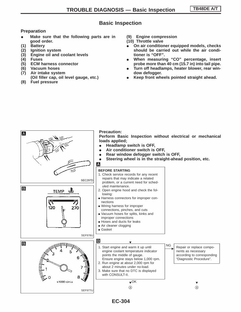
Basic InspectionPreparationI Make sure that the following parts are in
good order.(1) Battery(2) Ignition system(3) Engine oil and coolant levels(4) Fuses(5) ECM harness connector(6) Vacuum hoses(7) Air intake system
(Oil filler cap, oil level gauge, etc.)(8) Fuel pressure
(9) Engine compression(10) Throttle valveI On air conditioner equipped models, checks
should be carried out while the air condi-tioner is “OFF”.
I When measuring “CO” percentage, insertprobe more than 40 cm (15.7 in) into tail pipe.
I Turn off headlamps, heater blower, rear win-dow defogger.
I Keep front wheels pointed straight ahead.
Precaution:Perform Basic Inspection without electrical or mechanicalloads applied;I Headlamp switch is OFF,I Air conditioner switch is OFF,I Rear window defogger switch is OFF,I Steering wheel is in the straight-ahead position, etc.
BEFORE STARTING1. Check service records for any recent
repairs that may indicate a relatedproblem, or a current need for sched-uled maintenance.
2. Open engine hood and check the fol-lowing:
I Harness connectors for improper con-nections
I Wiring harness for improperconnections, pinches, and cuts
I Vacuum hoses for splits, kinks andimproper connections
I Hoses and ducts for leaksI Air cleaner cloggingI Gasket
1. Start engine and warm it up untilengine coolant temperature indicatorpoints the middle of gauge.Ensure engine stays below 1,000 rpm.
2. Run engine at about 2,000 rpm forabout 2 minutes under no-load.
3. Make sure that no DTC is displayedwith CONSULT-II.
OK
ENG Repair or replace compo-
nents as necessaryaccording to corresponding“Diagnostic Procedure”.
qA qA
SEC297D
SEF976U
SEF977U
H
H H
TROUBLE DIAGNOSIS — Basic Inspection TB48DE A/T
EC-304

qA qD
CHECK TARGET IDLE SPEED.
With CONSULT-II
1. Run engine at about 2,000 rpm forabout 2 minutes under no-load.
2. Rev engine (2,000 to 3,000 rpm) two orthree times under no-load, then runengine at idle speed for about 1 minute.
3. Read idle speed in “DATA MONITOR”mode with CONSULT-II.A/T: 675±50 rpm (in “P” or “N” posi-
tion)
Without CONSULT-II
1. Run engine at about 2,000 rpm forabout 2 minutes under no-load.
2. Rev engine (2,000 to 3,000 rpm) two orthree times under no-load, then runengine at idle speed for about 1minute.
3. Check idle speed.A/T: 675±50 rpm (in “P” or “N” posi-
tion)
OK
ENG
PERFORM THROTTLEVALVE CLOSED POSI-TION LEARNING.1. Stop engine.2. Perform EC-281,
“Throttle Valve ClosedPosition Learning”.
OK
PERFORM IDLE AIRVOLUME LEARNING.Refer to EC-281, “Idle AirVolume Learning”.Which is the resultCMPLT or INCMP?
CMPLT
qB
HqC
INCMP
qC
1. Follow the constructionof “Idle Air VolumeLearning”.
2. Go to qD .
CHECK IGNITION TIMING.1. Run engine at idle.2. Check ignition timing with a timing light.
A/T: 5±5° BTDC (in “P” or “N” posi-tion)
OK
ENG
ADJUST CAMSHAFTPOSITION SENSOR.1. Start engine and warm it
up to normal operatingtemperature.
With CONSULT-II
2. Select “TARGET IGNTIM ADJ” in “WORKSUPPORT”.
3. Touch start.4. Adjust camshaft position
sensor using timinglight.A/T: 5°±5° BTDC
Without CON-SULT-II
2. Adjust camshaft positionsensor using timinglight.A/T: 5°±5° BTDC
NG
Model with three way catalyst: qKModel without three way catalyst: qL
qD FOK
CHECK TIMING CHAININSTALLATION.Check timing chain instal-lation.Refer to “TIMING CHAIN”in EM section.
NG
qD F Repair the timing chaininstallation.
SEF978U
SEF058Y
SEC563C
SEC190D
H H
H
H
H
H
H
H
H
TROUBLE DIAGNOSIS — Basic Inspection TB48DE A/T
Basic Inspection (Cont’d)
EC-305
GI
MA
EM
LC
FE
CL
MT
AT
TF
PD
FA
RA
BR
ST
RS
BT
HA
EL
SE
IDX
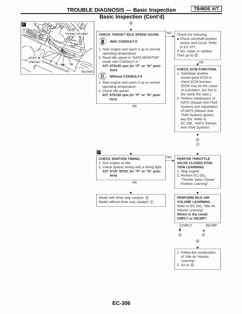
qB
CHECK TARGET IDLE SPEED AGAIN.
With CONSULT-II
1. Start engine and warm it up to normaloperating temperature.
2. Read idle speed in “DATA MONITOR”mode with CONSULT-II.A/T: 675±50 rpm (in “P” or “N” posi-
tion)
Without CONSULT-II
1. Start engine and warm it up to normaloperating temperature.
2. Check idle speed.A/T: 675±50 rpm (in “P” or “N” posi-
tion)
OK
ENG Check the following.
I Check camshaft positionsensor and circuit. Referto EC-377.
If NG, repair or replace.Then go to qD .
OK
CHECK ECM FUNCTION.1. Substitute another
known-good ECM tocheck ECM function.(ECM may be the causeof a problem, but this isthe rarely the case.)
2. Perform initialization ofNATS (Nissan Anti-TheftSystem) and registrationof NATS (Nissan Anti-Theft System) ignitionkey IDs. Refer toEC-285, “NATS (NissanAnti-Theft System)”.
qD
qJ
CHECK IGNITION TIMING.1. Run engine at idle.2. Check ignition timing with a timing light.
A/T: 5°±5° BTDC (in “P” or “N” posi-tion)
OK
ENG PERFOR THROTTLE
VALVE CLOSED POSI-TION LEARNING.1. Stop engine.2. Perform EC-281,
“Throttle Valve ClosedPosition Learning”.
Model with three way catalyst: qK
Model without three way catalyst: qL
PERFORM IDLE AIRVOLUME LEARNING.Refer to EC-281, “Idle AirVolume Learning”.Which is the resultCMPLT or INCMP?
CMPLT
qG
HqH
INCMP
qH
1. Follow the constructionof “Idle Air VolumeLearning”.
2. Go to qD .
SEC563C
H
H
H
H H
H H
H
H
TROUBLE DIAGNOSIS — Basic Inspection TB48DE A/T
Basic Inspection (Cont’d)
EC-306

qG qI
CHECK TARGET IDLE SPEED AGAIN.
With CONSULT-II
1. Start engine and warm it up to normaloperating temperature.
2. Read idle speed in “DATA MONITOR”mode with CONSULT-II.A/T: 675±50 rpm (in “P” or “N” posi-
tion)
Without CONSULT-II
1. Start engine and warm it up to normaloperating temperature.
2. Check idle speed.A/T: 675±50 rpm (in “P” or “N” posi-
tion)
OK
ENG Check the following.
I Check camshaft positionsensor and circuit. Referto EC-377.
If NG, repair or replace.Then go to qD .
CHECK ECM FUNCTION.1. Substitute another
known-good ECM tocheck ECM function.(ECM may be the causeof a problem, but this isthe rarely the case.)
2. Perform initialization ofNATS (Nissan Anti-TheftSystem) and registrationof NATS (Nissan Anti-Theft System) ignitionkey IDs. Refer toEC-285, “NATS (NissanAnti-Theft System)”.
qD
CHECK IGNITION TIMING AGAIN.1. Run engine at idle.2. Check ignition timing with a timing light.
A/T: 5±5° BTDC (in “P” or “N” posi-tion)
OK
ENG ADJUST CAMSHAFT
POSITION SENSOR.1. Start engine and warm it
up to normal operatingtemperature.
With CONSULT-II
2. Select “TARGET IGNTIM ADJ” in “WORKSUPPORT”.
3. Touch start.4. Adjust camshaft position
sensor using timinglight.A/T: 5°±5° BTDC
Without CON-SULT-II
2. Adjust camshaft positionsensor using timinglight.A/T: 5°±5° BTDC
NG
Model with three way catalyst: qK
Model without three way catalyst: qL
qJ FOK
CHECK TIMING CHAININSTALLATION.Check timing chain instal-lation. Refer to EM section,“TIMING CHAIN”.If NG, repair the timingchain installation. Then goto qD .
OK
qI
SEC563C
SEC190D
H H
H
H
H
H
H
H
TROUBLE DIAGNOSIS — Basic Inspection TB48DE A/T
Basic Inspection (Cont’d)
EC-307
GI
MA
EM
LC
FE
CL
MT
AT
TF
PD
FA
RA
BR
ST
RS
BT
HA
EL
SE
IDX

qK
With three waycatalyst
Set the diagnostic test mode II (Heated oxygensensor 1 monitor). Refer to EC-286.
Run engine at about 2,000 rpm for about 2 min-utes under no-load.
CHECK HEATED OXYGEN SENSOR 1 SIG-NAL.
With CONSULT-II
1. See “HO2S1 MNTR” in “DATA MONITOR”mode.
2. Maintaining engine at 2,000 rpm under no-load (engine is warmed up to normal operat-ing temperature), check that the monitor fluc-tuates between “LEAN” and “RICH” morethan 5 times during 10 seconds.1 cycle: RICH → LEAN → RICH2 cycles: RICH → LEAN → RICH → LEAN
→ RICH---------------------------------------------------------------------------------------------------------------------------------------- OR ----------------------------------------------------------------------------------------------------------------------------------------
Without CONSULT-II
Make sure that malfunction indicator lamp goeson and off more than 5 times during 10 secondsat 2,000 rpm.
OK
ENG Check oxygen sensor and the
circuit.
OK
F
qM
HERASE UNNECESSARY DTC.After this inspection, unnecessary DTC No.might be displayed.Erase the stored memory in ECM and TCM(Transmission control module).Refer to “HOW TO ERASE EMISSION-RE-LATED DIAGNOSTIC INFORMATION, EC-283.
OK
INSPECTION END
SAT652J
H
H
H
H
H
TROUBLE DIAGNOSIS — Basic Inspection TB48DE A/T
Basic Inspection (Cont’d)
EC-308

qL
CHECK IDLE CO%Check the CO% by inserting a CO metersampling probe into the tail pipe.CO%: 2±1%
OK
ENG
ADJUST IDLE CO%
With CONSULT-II
1. Start engine and warm itup to normal operatingtemperature.
2. Select “CO ADJUST-MENT” in “WORK SUP-PORT” mode with CON-SULT-II.
3. Select “START”.4. When “CO ADJUST-
MENT” is displayed,confirm idle speed iswithin the standard andadjust until the CO valuemeets the standard.
I When CO value is toohigh: Press “Qd” or“DOWN” button
I When CO value is toolow: Press “Qu” or “UP”button
NOTE:Once CO adjustment but-ton is pressed, wait untilthe CO meter measure-ment result comes up. Itmay take some timebecause of the time lagexisting between pressingCO adjustment button andactual CO alteration. Ifnecessary, press adjust-ment button again andrepeat the procedure untilit reaches the standard.5. After confirming CO
adjustment value iswithin the standard,press “UP DATE” button.
NOTE:By pressing “UP DATE”button, CO adjustmentvalue is written into hardmemory inside the ECM.Please note that if theCONSULT-II display isreturned to initial menuwithout pressing the “UPDATE” button, the adjustedCO value is ignored.
F
Go to qM .
SEC884C
SEC885C
H
H
TROUBLE DIAGNOSIS — Basic Inspection TB48DE A/T
Basic Inspection (Cont’d)
EC-309
GI
MA
EM
LC
FE
CL
MT
AT
TF
PD
FA
RA
BR
ST
RS
BT
HA
EL
SE
IDX

DTC Inspection Priority ChartIf some DTCs are displayed at the same time, perform inspections one by one based on the following prior-ity chart.NOTE:If DTC U1000 is displayed with other DTC, first perform the trouble diagnosis for DTC U1000. Refer toEC-337.
Priority Detected items (DTC)
1
I U1000 CAN communication lineI P0100 Mass air flow sensorI P0115 Engine coolant temperature sensorI P0120 Throttle position sensorI P0121 Accelerator pedal position sensorI P0325 P0330 Knock sensorI P0340 Camshaft position sensorI P0605 ECMI P1320 Ignition signal
2 I P0130 P0150 Heated oxygen sensor 1I P1065 ECM power supplyI P1122 Electric throttle control functionI P1123 Throttle control motor relayI P1805 Brake switch
3 I P1121 Electric throttle control actuatorI P1217 Engine over temperature (OVERHEAT)
Fail-Safe ChartThe ECM enters fail-safe mode, if any of the following malfunctions are detected due to the open or short cir-cuit.When the ECM enters the ECM fail-safe mode listed in the last column below, the MIL illuminates.
DTC No. ECM* Engine operating condition in fail-safe mode
P0100 0100 Engine speed will not rise more than 2,400 rpm due to the fuel cut.
P0115 0115 Engine coolant temperature will be determined by ECM based on the time after turning ignition switch“ON” or “START”.CONSULT-II displays the engine coolant temperature decided by ECM.
P0120 0120 ECM controls the electric throttle control actuator by regulating the throttle opening to a small range.Therefore, acceleration will be poor.
*: In Diagnostic Test Model II (Self-diagnostic results)
ConditionEngine coolant temperature decided
(CONSULT-II display)
Just as ignition switch is turned ON or START 40°C (104°F)
More than 6 minutes after ignition START 80°C (176°F)
Except as shown above20 - 80°C (68 - 176°F)(Depends on the time)
Driving condition
When engine is idling Normal
When accelerating Poor acceleration
TROUBLE DIAGNOSIS — General Description TB48DE A/T
EC-310

Symptom Matrix Chart
SYSTEM— Basic engine control system
SYMPTOM
Reference page
HA
RD
/NO
STA
RT
/RE
STA
RT
(EX
CP.
HA
)
EN
GIN
ES
TALL
HE
SIT
AT
ION
/SU
RG
ING
/FLA
TS
PO
T
SP
AR
KK
NO
CK
/DE
TO
NA
TIO
N
LAC
KO
FP
OW
ER
/PO
OR
AC
CE
LER
AT
ION
HIG
HID
LE/L
OW
IDLE
RO
UG
HID
LE/H
UN
TIN
G
IDLI
NG
VIB
RA
TIO
N
SLO
W/N
OR
ET
UR
NT
OID
LE
OV
ER
HE
AT
S/W
AT
ER
TE
MP
ER
AT
UR
EH
IGH
EX
CE
SS
IVE
FU
EL
CO
NS
UM
PT
ION
EX
CE
SS
IVE
OIL
CO
NS
UM
PT
ION
OV
ER
CO
OLS
OV
ER
CH
AR
GIN
G
BA
TT
ER
YD
EA
D(U
ND
ER
CH
AR
GE
)
Warranty symptom code AA AB AC AD AE AF AG AH AJ AK AL AM 1P 1X HA
Fuel Fuel pump circuit 1 1 2 3 2 3 3 3 2 EC-467
Fuel pressure regulator system 2 3 4 4 4 4 4 4 4 4 EC-278
Injector circuit 1 1 2 3 2 2 2 2 2 EC-460
Evaporative emission system 3 3 4 4 4 4 4 4 4 4 EC-274
Air Positive crankcase ventilation system 3 3 4 4 4 4 4 4 4 4 1 EC-277
Incorrect idle speed adjustment 3 3 1 1 1 1 1 EC-280
Electric throttle control actuator 1 1 2 3 3 2 2 2 2 2 2EC-350EC-393EC-399
Ignition Incorrect ignition timing adjustment 3 3 1 1 1 1 1 1 EC-280
Ignition circuit 1 1 2 2 2 2 2 2 EC-415
Main power supply and ground circuit 2 2 3 3 3 3 3 3 3 2 EC-332
Cooling Cooling fan circuit 3 3 3 2 3 3 3 3 3 1 2 1 3 EC-377
Air conditioner circuit 3 2 3 3 3 3 3 3 3 3 2 HA section
1 - 6: The numbers refer to the order of inspection.
TROUBLE DIAGNOSIS — General Description TB48DE A/T
EC-311
GI
MA
EM
LC
FE
CL
MT
AT
TF
PD
FA
RA
BR
ST
RS
BT
HA
EL
SE
IDX

SYSTEM— Engine control system
SYMPTOM
Reference page
HA
RD
/NO
STA
RT
/RE
STA
RT
(EX
CP.
HA
)
EN
GIN
ES
TALL
HE
SIT
AT
ION
/SU
RG
ING
/FLA
TS
PO
T
SP
AR
KK
NO
CK
/DE
TO
NA
TIO
N
LAC
KO
FP
OW
ER
/PO
OR
AC
CE
LER
AT
ION
HIG
HID
LE/L
OW
IDLE
RO
UG
HID
LE/H
UN
TIN
G
IDLI
NG
VIB
RA
TIO
N
SLO
W/N
OR
ET
UR
NT
OID
LE
OV
ER
HE
AT
S/W
AT
ER
TE
MP
ER
AT
UR
EH
IGH
EX
CE
SS
IVE
FU
EL
CO
NS
UM
PT
ION
EX
CE
SS
IVE
OIL
CO
NS
UM
PT
ION
OV
ER
CO
OLS
OV
ER
CH
AR
GIN
G
BA
TT
ER
YD
EA
D(U
ND
ER
CH
AR
GE
)
Warranty symptom code AA AB AC AD AE AF AG AH AJ AK AL AM 1P 1X HA
Engine con-trol
Camshaft position sensor circuit 2 2 2 2 2 3 3 3 3 EC-377
Mass air flow sensor circuit 1 1 2 2 2 2 2 2 2 2 EC-340
Engine coolant temperature sensor circuit 1 1 2 3 2 3 2 2 3 2 2 EC-345
Throttle position sensor circuit 1 2 2 2 2 2 2 2 EC-141
Accelerator pedal position sensor circuit 3 2 1 2 2 EC-359
Heated oxygen sensor 1 circuit*1 1 2 3 2 2 2 2 EC-366
Intake valve timing control system 3 3 2 3 3 3 EC-442
Vehicle speed sensor circuit 2 3 3 3 EC-197
Knock sensor circuit 2 2 2 3 EC-373
ECM 2 2 3 3 3 3 3 3 3 3 3 EC-310
Start signal circuit 2 EC-464
Park/Neutral position switch circuit 3 3 3 3 3 EC-216
Variable Induction Air Control (VIAS) sys-tem
2 EC-456
Electrical load signal circuit 2 3 3 EC-245
Power steering oil pressure switch circuit 2 3 3 EC-473
1 - 6: The numbers refer to the order of inspection.*1: Model with three way catalyst
TROUBLE DIAGNOSIS — General Description TB48DE A/T
Symptom Matrix Chart (Cont’d)
EC-312

SYSTEM— Engine mechanical & other
SYMPTOM
Reference page
HA
RD
/NO
STA
RT
/RE
STA
RT
(EX
CP.
HA
)
EN
GIN
ES
TALL
HE
SIT
AT
ION
/SU
RG
ING
/FLA
TS
PO
T
SP
AR
KK
NO
CK
/DE
TO
NA
TIO
N
LAC
KO
FP
OW
ER
/PO
OR
AC
CE
LER
AT
ION
HIG
HID
LE/L
OW
IDLE
RO
UG
HID
LE/H
UN
TIN
G
IDLI
NG
VIB
RA
TIO
N
SLO
W/N
OR
ET
UR
NT
OID
LE
OV
ER
HE
AT
S/W
AT
ER
TE
MP
ER
AT
UR
EH
IGH
EX
CE
SS
IVE
FU
EL
CO
NS
UM
PT
ION
EX
CE
SS
IVE
OIL
CO
NS
UM
PT
ION
OV
ER
CO
OLS
OV
ER
CH
AR
GIN
G
BA
TT
ER
YD
EA
D(U
ND
ER
CH
AR
GE
)
Warranty symptom code AA AB AC AD AE AF AG AH AJ AK AL AM 1P 1X HA
Fuel Fuel tank 5
5
FE section
Fuel piping 5 5 5 5 5 5 5
—
Vapor lock
Valve deposit5 5 5 5 5 5 5Poor fuel (Heavy weight gasoline, Low
octane)
Air Air duct 5
5 5 5 5 5 5
Air cleaner
Air leakage from air duct(Mass air flow sensor — Electric throttlecontrol actuator)
5 5 5 5 5Electric throttle control actuator, Throttlewire
FE section
Air leakage from intake manifold/Collector/Gasket
—
Cranking Battery1 1 1 1 1 1 1 1 1
EL sectionAlternator circuit
Starter circuit 3
PNP switch 4 AT section
Drive plate 6 EM section
Engine Cylinder head
6 6 6 6 6 6 6 6
EM section
Cylinder head gasket 4
6Cylinder block
Piston
Piston ring
Connecting rod
Bearing
Crankshaft 6
Valvemechanism
Timing chain 6 6 6 6 6 6 6 6 6
Camshaft 5 5 5 5 5 5 5 5
Intake valve6 6 6 6 6 6 6 6 6
Exhaust valve
ExhaustExhaust manifold/Tube/Muffler/Gasket 5 5 5 5 5
EM section &FE section
Three way catalyst* 5 5 5 5 5 5 5 5 FE section
Lubrication Oil pan/Oil strainer/Oil pump/Oil filter/Oilgallery 5 5 5 5 5 5 5 5 5
LC section
Oil level (Low)/Filthy oil
Cooling Radiator/Hose/Radiator filler cap
5 5 5 5 4 5
Thermostat 2
Water pump
Water gallery
Cooling fan 2 EC section
Coolant level (low)/Contaminated coolant MA section
NATS (Nissan Anti-Theft System)1 1
EC-285 or ELsection
1 - 6: The numbers refer to the order of inspection.
TROUBLE DIAGNOSIS — General Description TB48DE A/T
Symptom Matrix Chart (Cont’d)
EC-313
GI
MA
EM
LC
FE
CL
MT
AT
TF
PD
FA
RA
BR
ST
RS
BT
HA
EL
SE
IDX

CONSULT-II Reference Value in Data MonitorMode
Remarks:I Specification data are reference values.I Specification data are output/input values which are detected or supplied by the ECM at the connector.
* Specification data may not be directly related to their components signals/values/operations.i.e. Adjust ignition timing with a timing light before monitoring IGN TIMING, because the monitor may show the specification data
in spite of the ignition timing not being adjusted to the specification data. This IGN TIMING monitors the data calculated by theECM according to the signals input from the camshaft position sensor and other ignition timing related sensors.
MONITOR ITEM CONDITION SPECIFICATION
ENG SPEEDI Tachometer: ConnectI Run engine and compare tachometer indication with the CONSULT-II value.
Almost the same speed as the CON-SULT-II value.
MAS A/F SE-B1
I Engine: After warming upI Air conditioner switch: OFFI Shift lever: NI No-load
Idle Approx. 1.3 - 1.7V
2,500 rpm Approx. 1.7 - 2.4V
COOLAN TEMP/S I Engine: After warming up More than 70°C (158°F)
HO2S1 (B1)*HO2S1 (B2)*
I Engine: After warming up Maintaining engine speed at 2,000 rpm 0 - 0.3V +, Approx. 0.6 - 1.0V
HO2S1 MNTR (B1)*HO2S1 MNTR (B2)*
I Engine: After warming up Maintaining engine speed at 2,000 rpmLEAN +, RICHChanges more than 5 times during 10seconds.
VHCL SPEED SEI Turn drive wheels and compare speedometer indication with the CONSULT-II
value.Almost the same speed as the CON-SULT-II value
BATTERY VOLT I Ignition switch: ON (Engine stopped) 11 - 14V
ACCEL SEN 1ACCEL SEN 2
I Ignition switch: ON(engine stopped)
I Shift lever: D
Accelerator pedal: Fully released More than 0.36V
Accelerator pedal: Fully depressed Less than 4.75V
THRTL SEN 1THRTL SEN 2
I Ignition switch: ON(engine stopped)
Accelerator pedal: Fully released More than 0.36V
Accelerator pedal: Fully depressed Less than 2.0V
START SIGNAL I Ignition switch: ON , START , ON OFF , ON , OFF
CLSD THL POSI Ignition switch: ONI Shift lever: N
Accelerator pedal: Fully released ON
Accelerator pedal: Slightly depressed OFF
AIR COND SIGI Engine: After warming up, idle the
engine
Air conditioner switch: OFF OFF
Air conditioner switch: ON(Compressor operates.)
ON
P/N POSI SW I Ignition switch: ONShift lever: Neutral ON
Shift lever: Except above OFF
PW/ST SIGNALI Engine: After warming up, idle the
engine
Steering wheel is in neutral position.(Forward direction)
OFF
Steering wheel is turned. ON
LOAD SIGNAL I Ignition switch: ON
Rear window defogger switch is ONand/or lighting switch is in 2nd.
ON
Rear window defogger switch is OFFand lighting switch is OFF.
OFF
AMB TEMP SWI Ignition switch: ONI Compare ambient air temperature with
the following:
Below 19°C (66°F) OFF
Above 25°C (77°F) ON
IGNITION SW I Ignition switch: ON , OFF , ON ON , OFF , ON
A/C PRESS SW I Engine: Running
A/C pressure is more than 1,422 - 1,618kPa (14.5 - 16.5 kg/cm2, 206 - 235 psi).
ON
A/C pressure is less than 1,128 - 1,422kPa (11.5 - 14.5 kg/cm2, 164 - 206 psi).
OFF
BRAKE SW I Ignition switch: ONBrake pedal: Fully released OFF
Brake pedal: Slightly depressed ON
INJ PULSE-B1
I Engine: After warming upI Shift lever: NI Air conditioner switch: OFFI No-load
Idle 3.0 - 4.0 msec
2,000 rpm 3.0 - 4.0 msec
TROUBLE DIAGNOSIS — General Description TB48DE A/T
EC-314

MONITOR ITEM CONDITION SPECIFICATION
IGN TIMING
I Engine: After warming upI Shift lever: NI Air conditioner switch: OFFI No-load
Idle 3° - 7° BTDC
2,000 rpm 25° - 45° BTDC
A/F ALPHA-B1*A/F ALPHA-B2*
I Engine: After warming up Maintaining engine speed at 2,000 rpm 75 - 125%
CAL/LD VALUE
I Engine: After warming upI Shift lever: NI Air conditioner switch: OFFI No-load
Idle 10% - 35%
2,500 rpm 10% - 35%
PURG VOL C/V
I Engine: After warming upI Shift lever: NI Air conditioner switch: OFFI No-load
Idle 0.0%
2,000 rpm —
VIAS S/V I Engine: After warming upIdle OFF
More than 5,000 rpm ON
AIR COND RLYI Engine: After warming up, idle the
engine
Air conditioner switch: OFF OFF
Air conditioner switch: ON(Compressor operates)
ON
FUEL PUMP RLY
I For 5 seconds after turning ignition switch ONI Engine running or cranking
ON
I Except above conditions OFF
COOLING FANI After warming up engine, idle the
engine.I Air conditioner switch: OFF
Engine coolant temperature is 94°C(201°F) or less.
OFF
Engine coolant temperature is between95°C (203°F) and 104°C (219°F).
LOW
Engine coolant temperature is 105°C(221°F) or more.
HIGH
THRTL RELAY I Ignition switch: ON ON
HO2S1 HTR (B1)*HO2S1 HTR (B2)*
I Engine speed: Below 3,600 rpm ON
I Engine speed: Above 3,600 rpm OFF
CAN COMMCAN CIRC 1CAN CIRC 2CAN CIRC 3CAN CIRC 4
I Ignition switch: ON OK
*: Models with three way catalyst
TROUBLE DIAGNOSIS — General Description TB48DE A/T
CONSULT-II Reference Value in Data MonitorMode (Cont’d)
EC-315
GI
MA
EM
LC
FE
CL
MT
AT
TF
PD
FA
RA
BR
ST
RS
BT
HA
EL
SE
IDX

Major Sensor Reference Graph in Data MonitorMode
The following are the major sensor reference graphs in “DATA MONITOR” mode.
CLSD THL POS, ACCEL SEN 1, THRTL SEN 1Below is the data for “CLSD THL POS”, “ACCEL SEN 1” and “THRTL SEN 1” when depressing the accelera-tor pedal with the ignition switch “ON” and with selector lever in “D” position.The signal of “ACCEL SEN 1” and “THRTL SEN 1” should rise gradually without any intermittent drop or riseafter “CLSD THL POS” is changed from “ON” to “OFF”.
ENG SPEED, MAS A/F SE-B1, HO2S1 (B1), INJ PULSE-B1Below is the data for “ENG SPEED”, “MAS A/F SE-B1”, “HO2S1 (B1)” and “INJ PULSE-B1” when revvingengine quickly up to 4,800 rpm under no load after warming up engine sufficiently.Each value is for reference, the exact value may vary.
PBIB0198E
SEF241Y
TROUBLE DIAGNOSIS — General Description TB48DE A/T
EC-316

SEC189D
TROUBLE DIAGNOSIS — General Description TB48DE A/T
Major Sensor Reference Graph in Data MonitorMode (Cont’d)
EC-317
GI
MA
EM
LC
FE
CL
MT
AT
TF
PD
FA
RA
BR
ST
RS
BT
HA
EL
SE
IDX

ECM Harness Connector Terminal Layout
ECM Terminals and Reference ValuePREPARATION1. ECM is located behind the center console. For this inspection,
remove fuse box cover.2. Remove ECM harness protector.
3. Perform all voltage measurements with the connector con-nected. Extend tester probe as shown to perform tests easily.
I Open harness securing clip to make testing easier.I Use extreme care not to touch 2 pins at one time.I Data is for comparison and may not be exact.
PBIB0075E
SEC669CA
MEC486B
TROUBLE DIAGNOSIS — General Description TB48DE A/T
EC-318

ECM INSPECTION TABLESpecification data are reference values and are measured between each terminal and ground.CAUTION:Do not use ECM ground terminals when measuring input/output voltage. Doing so may result in dam-age to the ECM’s transistor. Use a ground other than ECM terminals, such as the ground.
TERMINALNO.
WIRECOLOR
ITEM CONDITION DATA (DC voltage)
567131415
BR/WGY/LBR/YGY/RBRGY
Injector No. 1Injector No. 2Injector No. 3Injector No. 4Injector No. 5Injector No. 6
Engine is running.
Warm-up conditionIdle speed
BATTERY VOLTAGE(11 - 14V)*1
SEC670C
Engine is running.
Warm-up conditionEngine speed is 2,000 rpm.
BATTERY VOLTAGE(11 - 14V)*1
SEC671C
8 G/YHeated oxygensensor 1 heater(bank 1)*2
Engine is running.
Engine speed is below 3,600 rpm.0 - 1.0V
Engine is running.
Engine speed is above 3,600 rpm.
BATTERY VOLTAGE(11 - 14V)
9 L/RHeated oxygensensor 1 heater(bank 2)*2
Engine is running.
Engine speed is below 3,600 rpm.0 - 1.0V
Engine is running.
Engine speed is above 3,600 rpm.
BATTERY VOLTAGE(11 - 14V)
TROUBLE DIAGNOSIS — General Description TB48DE A/T
ECM Terminals and Reference Value (Cont’d)
EC-319
GI
MA
EM
LC
FE
CL
MT
AT
TF
PD
FA
RA
BR
ST
RS
BT
HA
EL
SE
IDX

TERMINALNO.
WIRECOLOR
ITEM CONDITION DATA (DC voltage)
181920212930
Y/RGYR/BR/GR
Ignition signal No. 1Ignition signal No. 2Ignition signal No. 3Ignition signal No. 4Ignition signal No. 5Ignition signal No. 6
Engine is running.
Warm-up conditionIdle speed
0 - 0.1V*1
SEC672C
Engine is running.
Warm-up conditionEngine speed is 2,000 rpm.
0 - 0.2V*1
SEC673C
22 LRear air conditionerrelay (Rear coolercut relay)
Engine is running.
Both A/C switch and blower switch are“ON” (Compressor operates).
0 - 1.0V
Engine is running.
A/C switch is “OFF”.
BATTERY VOLTAGE(11 - 14V)
24 Y/L Air conditioner relay
Engine is running
Both A/C switch and blower switch are“ON” (Compressor operates).
0 - 1.0V
Engine is running.
A/C switch is “OFF”.
BATTERY VOLTAGE(11 - 14V)
26 P/LThrottle controlmotor relay
Ignition switch “OFF” BATTERY VOLTAGE(11 - 14V)
Ignition switch “ON” 0 - 1.0V
27 LG/RVIAS control sole-noid valve
Engine is running.
Idle speed
BATTERY VOLTAGE(11 - 14V)
Engine is running.
Engine speed is above 5,000 rpm.0 - 1.0V
35 Y/G MIL
Ignition switch “ON” 0 - 1.0V
Engine is running.
Idle speed
BATTERY VOLTAGE(11 - 14V)
TROUBLE DIAGNOSIS — General Description TB48DE A/T
ECM Terminals and Reference Value (Cont’d)
EC-320

TERMINALNO.
WIRECOLOR
ITEM CONDITION DATA (DC voltage)
38 Y/B Tachometer signal
Engine is running.
Warm-up conditionIdle speed
3 - 6V*1
SEC674C
Engine is running.
Engine speed is 2,000 rpm.
3 - 6V*1
SEC675C
40*441*3
R/Y Fuel pump relay
Ignition switch “ON”
For 5 seconds after turning ignition switch“ON”
Engine is running.
0 - 1.0V
Ignition switch “ON”
More than 5 seconds after turning ignitionswitch “ON”
BATTERY VOLTAGE(11 - 14V)
42 B/YECM relay(Self shut-off)
Engine is running.
Ignition switch “OFF”
For 5 seconds after turning ignition switch“OFF”
0 - 1.0V
Ignition switch “OFF”
5 seconds passed after turning ignitionswitch “OFF”
BATTERY VOLTAGE(11 - 14V)
53 W/G Ignition switch
Ignition switch “OFF” 0V
Ignition switch “ON”BATTERY VOLTAGE(11 - 14V)
TROUBLE DIAGNOSIS — General Description TB48DE A/T
ECM Terminals and Reference Value (Cont’d)
EC-321
GI
MA
EM
LC
FE
CL
MT
AT
TF
PD
FA
RA
BR
ST
RS
BT
HA
EL
SE
IDX

TERMINALNO.
WIRECOLOR
ITEM CONDITION DATA (DC voltage)
54 W/BEVAP canisterpurge volume con-trol solenoid valve
Engine is running.
Idle speed
BATTERY VOLTAGE(11 - 14V)*1
SEC676C
Engine is running.
Engine speed is about 2,000 rpm (Morethan 100 seconds after starting engine).
BATTERY VOLTAGE(11 - 14V)*1
SEC677C
55 L/BCooling fan relay(High)
Engine is running.
Cooling fan is operating at high speed.0 - 1.0V
Engine is running.
Cooling fan is not operating.
BATTERY VOLTAGE(11 - 14V)
56 LCooling fan relay(Low)
Engine is running.
Cooling fan is operating.0 - 1.0V
Engine is running.
Cooling fan is not operating.
BATTERY VOLTAGE(11 - 14V)
59 R/W Start signalIgnition switch “ON” Approximately 0V
Ignition switch “START” 9 - 14V
60 W/G Snow mode switch
Ignition switch “ON”
Snow mode switch is “OFF”Approx. 0V
Ignition switch “ON”
Snow mode switch is “ON”
BATTERY VOLTAGE(11 - 14V)
TROUBLE DIAGNOSIS — General Description TB48DE A/T
ECM Terminals and Reference Value (Cont’d)
EC-322

TERMINALNO.
WIRECOLOR
ITEM CONDITION DATA (DC voltage)
62*463*4
LCamshaft positionsensor (REF signal)
Engine is running.
Warm-up conditionIdle speed
Approx. 0.3 - 0.6V*1
SEC682C
Engine is running.
Engine speed is 2,000 rpm
Approx. 0.4 - 0.5V*1
SEC683C
63*384*4
B/WCamshaft positionsensor (POS sig-nal)
Engine is running.
Warm-up conditionIdle speed
2.6 - 2.7V*1
SEC678C
Engine is running.
Engine speed is 2,000 rpm.
2.5 - 2.6V*1
SEC679C
79 OR/LPower steering oilpressure switch
Engine is running.
Steering wheel is being turned.Approx. 0V
Engine is running.
Steering wheel is not being turned.Approx. 5V
80 R/PU PNP switch
Ignition switch “ON”
Gear position is Neutral.Approximately 0V
Ignition switch “ON”
Except the above gear positionApproximately 5V
TROUBLE DIAGNOSIS — General Description TB48DE A/T
ECM Terminals and Reference Value (Cont’d)
EC-323
GI
MA
EM
LC
FE
CL
MT
AT
TF
PD
FA
RA
BR
ST
RS
BT
HA
EL
SE
IDX

TERMINALNO.
WIRECOLOR
ITEM CONDITION DATA (DC voltage)
84*3 LCamshaft positionsensor (REF signal)
Engine is running. (Warm-up condition)
Idle speed
Approx. 0.3 - 0.6V*1
SEC682C
Engine is running.
Engine speed is 2,000 rpm
Approx. 0.3 - 0.6V*1
SEC683C
84*4 B/WCamshaft positionsensor (POS sig-nal)
Engine is running.
Warm-up conditionIdle speed
Approx. 2.6 - 2.7V*1
SEC678C
Engine is running.
Engine speed is 2,000 rpm.
Approx. 2.5 - 2.6V*1
SEC679C
87 WAccelerator pedalposition sensor 1
Ignition switch “ON”
Gear position is “D”Accelerator pedal fully released
More than 0.36V
Ignition switch “ON”
Gear position is “D”Accelerator pedal fully depressed
Less than 4.75V
89 B Sensors’ ground
Engine is running.
Warm-up conditionIdle speed
Approximately 0V
91 W/GMass air flow sen-sor
Engine is running.
Warm-up conditionIdle speed
0.75 - 1.2V
Engine is running.
Warm-up conditionEngine speed is 2,500 rpm.
1.7 - 2.4V
TROUBLE DIAGNOSIS — General Description TB48DE A/T
ECM Terminals and Reference Value (Cont’d)
EC-324

TERMINALNO.
WIRECOLOR
ITEM CONDITION DATA (DC voltage)
94 L/GAccelerator pedalposition sensor 2power supply
Ignition switch “ON” Approximately 2.5V
95 WPower supply forECM (Buck-up)
Ignition switch “OFF”BATTERY VOLTAGE(11 - 14V)
98 R/LThrottle positionsensor 2
Ignition switch “ON”
Gear position is “D”Accelerator pedal fully released
Less than 4.75V
Ignition switch “ON”
Gear position is “D”Accelerator pedal fully depressed
More than 0.36V
100 RAccelerator pedalposition sensor 2ground
Ignition switch “ON” Approximately 0V
103 YSensors’ powersupply
Ignition switch “ON” Approximately 5V
106 G/Y Stop lamp switch
Engine is running.
Brake pedal fully releasedApproximately 0V
Engine is running.
Brake pedal fully depressed
BATTERY VOLTAGE(11 - 14V)
108 LThrottle positionsensor 1
Ignition switch “ON”
Gear position is “D”Accelerator pedal fully released
More than 0.36V
Ignition switch “ON”
Gear position is “D”Accelerator pedal fully depressed
Less than 4.75V
109 B/WMass air flow sen-sor ground
Engine is running.
Warm-up conditionIdle speed
Approximately 0V
114 R/LHeated oxygensensor 1 (bank 1)*2
Engine is running.
Warm-up conditionEngine speed is 2,000 rpm.
0 - Approximately 1.0V (Peri-odically change)
115 L/WHeated oxygensensor 1 (bank 2)*2
Engine is running.
Warm-up conditionEngine speed is 2,000 rpm.
0 - Approximately 1.0V (Peri-odically change)
117 GAccelerator pedalposition sensor 2
Ignition switch “ON”
Gear position is “D”Accelerator pedal fully released
More than 0.18V
Ignition switch “ON”
Gear position is “D”Accelerator pedal fully depressed
Less than 2.37V
121 LG/BEngine coolant tem-perature sensor
Engine is running.Approximately 0 - 4.8VOutput voltage varies withengine coolant temperature.
TROUBLE DIAGNOSIS — General Description TB48DE A/T
ECM Terminals and Reference Value (Cont’d)
EC-325
GI
MA
EM
LC
FE
CL
MT
AT
TF
PD
FA
RA
BR
ST
RS
BT
HA
EL
SE
IDX

TERMINALNO.
WIRECOLOR
ITEM CONDITION DATA (DC voltage)
125126
WW
Knock sensor(Bank 1)Knock sensor(Bank 2)
Engine is running.
Idle speedApproximately 2.5V
151 L/WThrottle controlmotor (Open)
Ignition switch “ON”
Accelerator pedal is depressing
0 - 14V*1
PBIB0058E
152 RIntake valve timingcontrol solenoidvalve
Engine is running.
Warm-up conditionIdle speed
BATTERY VOLTAGE(11 - 14V)
Engine is running.
Warm-up conditionTransmission in any gear position except“N”Accelerator pedal depressed.
Approx. 0.45V
153156159165168
BBBBB
ECM groundEngine is running.
Idle speedEngine ground
154 L/BThrottle controlmotor (Close)
Ignition switch “ON”
Accelerator pedal is releasing
0 - 14V*1
PBIB0061E
157 GThrottle controlmotor relay powersupply
Ignition switch “ON”BATTERY VOLTAGE(11 - 14V)
163166
RR
Power supply forECM
Ignition switch “ON”BATTERY VOLTAGE(11 - 14V)
164 PU Data link connectorIgnition switch “ON”
CONSULT-II or GST is disconnected.
BATTERY VOLTAGE(11 - 14V)
171 W/RCAN communica-tion line
Ignition switch “ON”Approximately 1.7 - 2.3VOutput voltage varies with thecommunication status.
174 G/BCAN communica-tion line
Ignition switch “ON”Approximately 2.6 - 3.2VOutput voltage varies with thecommunication status.
*1: Average voltage for pulse signal (Actual pulse signal can be confirmed by oscilloscope.)*2: Model with three way catalyst*3: Model with NATS (Nissan Anti-Theft System)*4: Model without NATS (Nissan Anti-Theft System)
TROUBLE DIAGNOSIS — General Description TB48DE A/T
ECM Terminals and Reference Value (Cont’d)
EC-326

DescriptionThe specification (SP) value indicates the tolerance of the value that is displayed in “DATA MONITOR (SPEC)”mode of CONSULT-II during normal operation of the Engine Control System. When the value in “DATA MONI-TOR (SPEC)” mode is within the SP value, the Engine Control System is confirmed OK. When the value in“DATA MONITOR (SPEC)” mode is NOT within the SP value, the Engine Control System may have one ormore malfunctions.The SP value is used to detect malfunctions that may affect the Engine Control System, but will not light theMIL.The SP value will be displayed for the following three items:I B/FUEL SCHDL (The fuel injection pulse width programmed into ECM prior to any learned on board cor-
rection)I A/F ALPHA-B1/B2 (The mean value of air-fuel ratio feedback correction factor per cycle)I MAS A/F SE-B1 (The signal voltage of the mass air flow sensor)
Testing ConditionI Vehicle driven distance: More than 5,000 km (3,100 miles)I Barometric pressure: 101.3 kPa (1,013 mbar, 760.0 mmHg, 29.92 inHg)±3 kPa (30 mbar, 22.5 mmHg, 0.89
inHg)I Atmospheric temperature: 20 - 30°C (68 - 86°F)I Engine coolant temperature: 75 - 95°C (167 - 203°F)I Transmission: Warmed-up*1I Electrical load: Not applied*2I Engine speed: Idle*1: For A/T or CVT models, after the engine is warmed up to normal operating temperature, drive vehicle until“FLUID TEMP SE” (A/T or CVT fluid temperature sensor signal) indicates less than 0.9V. For M/T models, drivevehicle for 5 minutes after the engine is warmed up to normal operating temperature.*2: Rear window defogger switch, air conditioner switch, lighting switch are “OFF”. Cooling fans are not oper-ating. Steering wheel is straight ahead.
Inspection ProcedureNOTE:Perform “DATA MONITOR (SPEC)” mode in maximum scale dis-play.1. Perform “Basic Inspection”, EC-304.2. Confirm that the testing conditions indicated above are met.3. Select “B/FUEL SCHDL”, “A/F ALPHA-B1”*, “A/F ALPHA-B2”*
and “MAS A/F SE-B1” in “DATA MONITOR (SPEC)” mode withCONSULT-II.
4. Make sure that monitor items are within the SP value.5. If NG, go to “Diagnostic Procedure”, EC-328.*: Model with three way catalyst
SEF601Z
TROUBLE DIAGNOSIS — SPECIFICATION VALUE TB48DE A/T
EC-327
GI
MA
EM
LC
FE
CL
MT
AT
TF
PD
FA
RA
BR
ST
RS
BT
HA
EL
SE
IDX

Diagnostic Procedure
SEF613ZA
TROUBLE DIAGNOSIS — SPECIFICATION VALUE TB48DE A/T
EC-328

SEF768Z
TROUBLE DIAGNOSIS — SPECIFICATION VALUE TB48DE A/T
Diagnostic Procedure (Cont’d)
EC-329
GI
MA
EM
LC
FE
CL
MT
AT
TF
PD
FA
RA
BR
ST
RS
BT
HA
EL
SE
IDX

SEF615Z
TROUBLE DIAGNOSIS — SPECIFICATION VALUE TB48DE A/T
Diagnostic Procedure (Cont’d)
EC-330

DescriptionIntermittent incidents (I/I) may occur. In many cases, the problem resolves itself (the part or circuit functionreturns to normal without intervention). It is important to realize that the symptoms described in the custom-er’s complaint often do not recur on DTC visits. Realize also that the most frequent cause of I/I occurrencesis poor electrical connections. Because of this, the conditions under which the incident occurred may not beclear. Therefore, circuit checks made as part of the standard diagnostic procedure may not indicate the spe-cific problem area.
COMMON I/I REPORT SITUATIONS
STEP in Work Flow Situation
II The CONSULT-II is used. The SELF-DIAG RESULTS screen shows time data other than “0” or “1t”.
III The symptom described by the customer does not recur.
IV DTC data does not appear during the DTC Confirmation Procedure.
VI The Diagnostic Procedure for PXXXX does not indicate the problem area.
Diagnostic Procedure
1 INSPECTION START
Erase DTCs. Refer to “HOW TO ERASE EMISSION-RELATED DIAGNOSTIC INFORMATION” (EC-283).
E GO TO 2.
2 CHECK GROUND TERMINALS
Check ground terminals for corroding or loose connection. Refer to GI section, “GROUND INSPECTION”.
OK or NG
OK E GO TO 3.
NG E Repair or replace.
3 SEARCH FOR ELECTRICAL INCIDENT
Perform GI section, “Incident Simulation Tests”.
OK or NG
OK E INSPECTION END
NG E Repair or replace.
TROUBLE DIAGNOSIS FOR INTERMITTENT INCIDENT TB48DE A/T
EC-331
GI
MA
EM
LC
FE
CL
MT
AT
TF
PD
FA
RA
BR
ST
RS
BT
HA
EL
SE
IDX

Main Power Supply and Ground CircuitECM TERMINALS AND REFERENCE VALUESpecification data are reference values and are measured between each terminal and ground.CAUTION:Do not use ECM ground terminals when measuring input/output voltage. Doing so may result in dam-age to the ECM’s transistor. Use a ground other than ECM terminals, such as the ground.
TER-MINAL
NO.
WIRECOLOR
ITEM CONDITIONDATA
(DC voltage)
42 B/Y ECM relay (Self-shutoff)
Engine is running.
Ignition switch “OFF”
For 5 seconds after turning ignition switch“OFF”
0 - 1.0V
Ignition switch “OFF”
A few seconds passed after turning ignitionswitch “OFF”
BATTERY VOLTAGE(11 - 14V)
53 W/G Ignition switch
Ignition switch “OFF” 0V
Ignition switch “ON”BATTERY VOLTAGE(11 - 14V)
156159165168
B ECM groundEngine is running.
Idle speedEngine ground
163166
B/R Power supply for ECM Ignition switch “ON”BATTERY VOLTAGE(11 - 14V)
TROUBLE DIAGNOSIS FOR POWER SUPPLY TB48DE A/T
EC-332

TEC243M
TROUBLE DIAGNOSIS FOR POWER SUPPLY TB48DE A/T
Main Power Supply and Ground Circuit(Cont’d)
EC-333
GI
MA
EM
LC
FE
CL
MT
AT
TF
PD
FA
RA
BR
ST
RS
BT
HA
EL
SE
IDX

TEC144M
TROUBLE DIAGNOSIS FOR POWER SUPPLY TB48DE A/T
Main Power Supply and Ground Circuit(Cont’d)
EC-334

INSPECTION START
Start engine.Is engine running?
Yes
ENo
CHECK POWER SUP-PLY-I.1. Turn ignition switch
“ON”.2. Check voltage between
ECM terminal q53 andground with CONSULT-IIor tester.Voltage: Battery volt-age
If NG, check the following.I 10A fuseI Harness connectors
M52 , F7I Harness for open or
short between ECM andfuse
If NG, repair harness orconnectors.
OK
Go to “CHECK GROUNDCIRCUIT” on next page.
CHECK POWER SUPPLY-III.1. Turn ignition switch “OFF”.2. Turn ignition switch “ON” and then turn
“OFF”.3. Check voltage between ECM terminals
163 , 166 , and ground with CON-SULT-II or tester.Voltage:After turning ignition switch “OFF”,battery voltage will exist for a fewseconds, then drop to approximately0V.
NG
EOK
Go to “CHECK GROUNDCIRCUIT” on next page.
Case-1: Battery voltage doesnot exist.
Case-2: Battery voltage existsfor more than a fewseconds.
Case-1 ECase-2
Go to “CHECK ECMRELAY” on next page.
qA
SEC817C
SEC819C
H
H
H
H
TROUBLE DIAGNOSIS FOR POWER SUPPLY TB48DE A/T
Main Power Supply and Ground Circuit(Cont’d)
EC-335
GI
MA
EM
LC
FE
CL
MT
AT
TF
PD
FA
RA
BR
ST
RS
BT
HA
EL
SE
IDX

qA
CHECK HARNESS CONTINUITYBETWEEN ECM RELAY AND ECM.1. Disconnect ECM harness connector.2. Disconnect ECM relay.3. Check harness continuity between ECM
terminals 163 , 166 and terminal q6 .Refer to Wiring Diagram.Continuity should exist.If OK, check harness for short toground and short to power.
OK
ENG
Check the following.I Harness connectors
M52 , F7I Harness for open or
short between ECM andECM relay
If NG, repair open circuit,short to ground or short topower in harness or con-nectors.
CHECK VOLTAGE BETWEEN ECMRELAY AND GROUND.Check voltage between terminals q2 , q7and ground with CONSULT-II or tester.Voltage: Battery voltage
OK
ENG
Check the following.I Harness connectors
E127 , M21I 10A and 15A fuseI Harness for open or
short between ECM relayand battery
If NG, repair harness orconnectors.
CHECK OUTPUT SIGNAL CIRCUIT.Check harness continuity between ECMterminal q42 and relay terminal q1 .Refer to wiring diagram.Continuity should exist.If OK, check harness for short to groundand short to power.
OK
ENG
Check the following.I Harness connectors
M52 , F7I Harness for open or
short between ECM andECM relay
If NG, repair open circuit,short to ground or short topower in harness or con-nectors.
CHECK ECM RELAY.1. Apply 12V direct current between relay
terminals q1 and q2 .2. Check continuity between relay termi-
nals q6 and q7 , q3 and q5 .12V (q1 - q2 ) applied:
Continuity exists.No voltage applied:
No continuity
OK
ENG
Replace ECM relay.
CHECK GROUND CIRCUIT.1. Turn ignition switch “OFF”.2. Loosen and retighten engine ground
screws.3. Disconnect ECM harness connector.4. Check harness continuity between ECM
terminals 156 , 159 , 165 , 168 andengine ground.Continuity should exist.If OK, check harness for short to power.
OK
ENG
Check the following.I Joint connector-7I Harness for open or
short between ECM andground
Repair open circuit, shortto power in harness orconnectors.
CHECK INTERMITTENT INCIDENT.Refer to “TROUBLE DIAGNOSIS FORINTERMITTENT INCIDENT”, EC-331.
INSPECTION END
SEC684CA
SEC685C
PBIB0077E
SEC821C
H
H
H
H
H
H
H
TROUBLE DIAGNOSIS FOR POWER SUPPLY TB48DE A/T
Main Power Supply and Ground Circuit(Cont’d)
EC-336

DescriptionCAN (Controller Area Network) is a serial communication line for real time application. It is an on-vehicle mul-tiplex communication line with high data communication speed and excellent error detection ability. Manyelectronic control units are equipped onto a vehicle, and each control unit shares information and links withother control units during operation (not independent). In CAN communication, control units are connected with2 communication lines (CAN H line, CAN L line) allowing a high rate of information transmission with less wir-ing. Each control unit transmits/receives data but selectively reads required data only.
On Board Diagnosis Logic
DTC No. Malfunction is detected when ... Check Items (Possible Cause)
U10001000*
A) ECM cannot communicate to other control unit. I Harness or connectors(CAN communication line is open or shorted.)B) ECM cannot communicate for more than the speci-
fied time.
*: The troubleshooting for this DTC needs CONSULT-II.
DTC Confirmation Procedure1. Turn ignition switch “ON” and wait at least 3 seconds.2. Select “DATA MONITOR” mode with CONSULT-II.3. If DTC is detected, go to EC-339, “Diagnostic Procedure”.
DTC U1000 CAN COMMUNICATION LINE TB48DE A/T
EC-337
GI
MA
EM
LC
FE
CL
MT
AT
TF
PD
FA
RA
BR
ST
RS
BT
HA
EL
SE
IDX

Wiring Diagram
TEC258M
DTC U1000 CAN COMMUNICATION LINE TB48DE A/T
EC-338

Diagnostic Procedure
INSPECTION START
1. Turn ignition switch “ON”.2. Select “CAN COMM SIGNALS” in
“DATA MONITOR” mode with CON-SULT-II.
3. Print out the CONSULT-II screen.
Go to EL section, “CAN SYSTEM”.
SEC186D
SEC187D
H
H
DTC U1000 CAN COMMUNICATION LINE TB48DE A/T
EC-339
GI
MA
EM
LC
FE
CL
MT
AT
TF
PD
FA
RA
BR
ST
RS
BT
HA
EL
SE
IDX

Component DescriptionThe mass air flow sensor is placed in the stream of intake air. Itmeasures the intake flow rate by measuring a part of the entireintake flow. It consists of a hot film that is supplied with electriccurrent from the ECM. The temperature of the hot wire is controlledby the ECM a certain amount. The heat generated by the hot wireis reduced as the intake air flows around it. The more air, thegreater the heat loss.Therefore, the ECM must supply more electric current to the hotwire as air flow increases. This maintains the temperature of the hotwire. The ECM detects the air flow by means of this current change.
CONSULT-II Reference Value in Data MonitorMode
Remarks: Specification data are reference values.
MONITOR ITEM CONDITION SPECIFICATION
MAS A/F SE-B1
I Engine: After warming upI Air conditioner switch: “OFF”I Shift lever: Neutral positionI No-load
Idle 0.75 - 1.5V
2,500 rpm 1.7 - 2.4V
ECM Terminals and Reference ValueSpecification data are reference values and are measured between each terminal and ground.CAUTION:Do not use ECM ground terminals when measuring input/output voltage. Doing so may result in dam-age to the ECM’s transistor. Use a ground other than ECM terminals, such as the ground.
TER-MINAL
NO.
WIRECOLOR
ITEM CONDITIONDATA
(DC voltage)
91 W/G Mass air flow sensor
Engine is running. (Warm-up condition)
Idle speed0.75 - 1.5V
Engine is running. (Warm-up condition)
Engine speed is 2,500 rpm.1.7 - 2.4V
109 B/WMass air flow sensorground
Engine is running. (Warm-up condition)
Idle speedApproximately 0V
On Board Diagnosis Logic
DTC No. Malfunction is detected when ... Check Items (Possible Cause)P01000100
A) An excessively high voltage from the sensor is sentto ECM when engine is not running.
I Harness or connectors(The sensor circuit is open or shorted.)
I Mass air flow sensorC) A voltage from the sensor is constantly approx. 1.0Vwhen engine is running.
B) An excessively low voltage from the sensor is sentto ECM* when engine is running.
I Harness or connectors(The sensor circuit is open or shorted.)
I Intake air leaksI Mass air flow sensor
*: When the malfunction is detected, the ECM enters fail-safe mode and the MIL lights up.
Fail-Safe Mode
Detected items Engine operating condition in fail-safe mode
Mass air flow sensor circuit Engine speed will not rise more than 2,400 rpm due to the fuelcut.
SEC688C
DTC P0100 MASS AIR FLOW (MAF) SENSOR TB48DE A/T
EC-340

DTC Confirmation ProcedureNOTE:If “DTC Confirmation Procedure” has been previouslyconducted, always turn ignition switch “OFF” and wait at least10 seconds before conducting the next test.
PROCEDURE FOR MALFUNCTION AWith CONSULT-II
1) Turn ignition switch “ON”.2) Select “DATA MONITOR” mode with CONSULT-II.3) Wait at least 2 seconds.4) If DTC is detected, go to “Diagnostic Procedure”, EC-343.
Without CONSULT-II1) Turn ignition switch “ON”, and wait at least 2 seconds.2) Turn ignition switch “OFF”, wait at least 10 seconds and then
turn “ON”.3) Perform “Diagnostic Test Mode II (Self-diagnostic results)” with
ECM.4) If DTC is detected, go to “Diagnostic Procedure”, EC-343.
PROCEDURE FOR MALFUNCTION B AND CWith CONSULT-II
1) Turn ignition switch “ON”.2) Select “DATA MONITOR” mode with CONSULT-II.3) Start engine and wait 2 seconds at most.4 If DTC is detected, go to “Diagnostic Procedure”, EC-343.
Without CONSULT-II1) Turn ignition switch “ON”.2) Start engine and wait 2 seconds at most.3) Turn ignition switch “OFF”, wait at least 10 seconds and then
turn “ON”.4) Perform “Diagnostic Test Mode II (Self-diagnostic results)” with
ECM.5) If DTC is detected, go to “Diagnostic Procedure”, EC-343.
SEF058Y
SEF058Y
DTC P0100 MASS AIR FLOW (MAF) SENSOR TB48DE A/T
EC-341
GI
MA
EM
LC
FE
CL
MT
AT
TF
PD
FA
RA
BR
ST
RS
BT
HA
EL
SE
IDX

Wiring Diagram
TEC146M
DTC P0100 MASS AIR FLOW (MAF) SENSOR TB48DE A/T
EC-342

Diagnostic Procedure
INSPECTION START
1. Turn ignition switch “OFF”.2. Loosen and retighten engine ground
screws.
OK
CHECK POWER SUPPLY.1. Disconnect mass air flow sensor har-
ness connector.2. Turn ignition switch “ON”.3. Check voltage between terminals q2 ,
q4 and ground with CONSULT-II ortester.
OK
ENG Check the following.
I Harness connectorsM52 , F7
I Harness for open orshort between mass airflow sensor and ECMrelay
I Harness for open orshort between mass airflow sensor and ECM
If NG, repair harness orconnectors.
CHECK GROUND CIRCUIT.1. Turn ignition switch “OFF”.2. Disconnect ECM harness connector.3. Check harness continuity between ter-
minal q3 and ECM terminal 109 .Refer to Wiring Diagram.Continuity should exist.If OK, check harness for short toground and short to power.
OK
ENG Repair open circuit, short
to ground or short to powerin harness or connectors.
CHECK INPUT SIGNAL CIRCUIT.Check harness continuity between MAFsensor terminal q1 and ECM terminal q91 .Refer to Wiring Diagram.Continuity should exist.If OK, check harness for short to groundand short to power.
OK
ENG Repair open circuit, short
to ground or short to powerin harness or connectors.
CHECK COMPONENT(Mass air flow sensor).Refer to “COMPONENT INSPECTION”,EC-344.
OK
ENG Replace mass air flow sen-
sor.
qA
Terminal Voltage
2 Approximately 5V
4 BATTERY VOLTAGE
SEC690C
SEC688C
PBIB0076E
H
H
H
H
H
H
DTC P0100 MASS AIR FLOW (MAF) SENSOR TB48DE A/T
EC-343
GI
MA
EM
LC
FE
CL
MT
AT
TF
PD
FA
RA
BR
ST
RS
BT
HA
EL
SE
IDX

qA
CHECK SHIELD CIRCUIT.1. Remove joint connector-7 F40 .2. Check the following.
I Continuity between joint connectorterminal q3 and ground
I Joint connector(Refer to “HARNESS LAYOUT” in ELsection.)
Continuity should exist.If OK, check harness for short to power.Then reconnect joint connector.
OK
ENG Check the following.
I Joint connector-7 F40
I Harness for open orshort between joint con-nector-7 and engineground
If NG, repair harness orconnectors.
CHECK INTERMITTENT INCIDENT.Refer to “TROUBLE DIAGNOSIS FORINTERMITTENT INCIDENT”, EC-331.
INSPECTION END
Component InspectionMASS AIR FLOW SENSOR1. Turn ignition switch “ON”.2. Start engine and warm it up to normal operating temperature.3. Check voltage between ECM terminal q91 and ground.
Conditions Voltage V
Ignition switch “ON” (Engine stopped.) Approx. 1.0
Idle (Engine is warmed-up sufficiently.) 1.1 - 1.5
2,500 rpm 1.7 - 2.4
Idle to about 4,000 rpm* 1.1 - 1.5 to Approx. 4.0
*: Check for linear voltage rise in response to increase to about 4,000 rpm in enginespeed.
4. If the voltage is out of specification, proceed the following.I Turn ignition switch “OFF”.I Disconnect mass air flow sensor harness connector and recon-
nect it again.I Perform steps 2 and 3 again.5. If NG, remove mass air flow sensor from air duct. Check hot film
for damage or dust.6. If NG, clean or replace mass air flow sensor.
PBIB0078E
SEC691C
H
H
H
DTC P0100 MASS AIR FLOW (MAF) SENSOR TB48DE A/T
Diagnostic Procedure (Cont’d)
EC-344

Component DescriptionThe engine coolant temperature sensor is used to detect the enginecoolant temperature. The sensor modifies a voltage signal from theECM. The modified signal returns to the ECM as the engine cool-ant temperature input. The sensor uses a thermistor which is sen-sitive to the change in temperature. The electrical resistance of thethermistor decreases as temperature increases.
<Reference data>
Engine coolant tempera-ture
°C (°F)
Voltage*(V)
Resistance(kΩ)
−10 (14) 4.4 7.0 - 11.420 (68) 3.5 2.1 - 2.9
50 (122) 2.2 0.68 - 1.0090 (194) 1.0 0.236 - 0.260
*: These data are reference values and are measured between ECM terminal121 (Engine coolant temperature sensor) and ground.
CAUTION:Do not use ECM ground terminals when measuring input/output voltage. Doing so may result in damage to the ECM’stransistor. Use a ground other than ECM terminals, such as theground.
CONSULT-II Reference Value in Data MonitorMode
MONITOR ITEM CONDITION SPECIFICATION
COOLAN TEMP/S I Engine: After warming up More than 70°C (158°F)
On Board Diagnosis Logic
DiagnosticTrouble Code
No.Malfunction is detected when ...
Check Items(Possible Cause)
P01150115
I An excessively high or low voltage from the sensor issent to ECM.*
I Harness or connectors(The sensor circuit is open or shorted.)
I Engine coolant temperature sensor
*: When this malfunction is detected, the ECM enters fail-safe mode and MIL lights up.
SEF594K
SEF012P
DC P0115 ENGINE COOLANT TEMPERATURE (ECT)SENSOR (CIRCUIT) TB48DE A/T
EC-345
GI
MA
EM
LC
FE
CL
MT
AT
TF
PD
FA
RA
BR
ST
RS
BT
HA
EL
SE
IDX

Fail-Safe Mode
Detected items Engine operating condition in fail-safe mode
Engine coolant tempera-ture sensor circuit
Engine coolant temperature will be determined by ECM based on the time after turning ignition switch“ON” or “START”.CONSULT-II displays the engine coolant temperature decided by ECM.
ConditionEngine coolant temperature decided (CONSULT-II
display)
Just as ignition switch is turned ON or START 40°C (104°F)
More than approx. 4 minutes after turning ignitionswitch ON or START
80°C (176°F)
Except as shown above20 - 80°C (68 - 176°F)(Depends on the time)
When the fail-safe system for engine coolant temperature sensor is activated, the cooling fan operateswhile the engine is running.
DTC Confirmation ProcedureNOTE:If “DTC Confirmation Procedure” has been previouslyconducted, always turn ignition switch “OFF” and wait at least10 seconds before conducting the next test.
With CONSULT-II1) Turn ignition switch “ON”.2) Select “DATA MONITOR” mode with CONSULT-II.3) Wait at least 5 seconds.4) If DTC is detected, go to “Diagnostic Procedure”, EC-348.
Without CONSULT-II1) Turn ignition switch “ON” and wait at least 5 seconds.2) Turn ignition switch “OFF”, wait at least 10 seconds and then
turn “ON”.3) Perform “Diagnostic Test Mode II (Self-diagnostic results)” with
ECM.4) If DTC is detected, go to “Diagnostic Procedure”, EC-348.
SEF013Y
DC P0115 ENGINE COOLANT TEMPERATURE (ECT)SENSOR (CIRCUIT) TB48DE A/T
EC-346

Wiring Diagram
TEC147M
DC P0115 ENGINE COOLANT TEMPERATURE (ECT)SENSOR (CIRCUIT) TB48DE A/T
EC-347
GI
MA
EM
LC
FE
CL
MT
AT
TF
PD
FA
RA
BR
ST
RS
BT
HA
EL
SE
IDX

Diagnostic Procedure
INSPECTION START
CHECK POWER SUPPLY.1. Turn ignition switch “OFF”.2. Disconnect engine coolant temperature
sensor harness connector.3. Turn ignition switch “ON”.4. Check voltage between terminal q2 and
ground with CONSULT-II or tester.Voltage:
Approximately 5V
OK
ENG Repair harness or connec-
tors.
CHECK GROUND CIRCUIT.1. Turn ignition switch “OFF”.2. Check harness continuity between ter-
minal q1 and engine ground.Refer to Wiring Diagram.Continuity should exist.If OK, check harness for short toground and short to power.
OK
ENG Check the following.
I Harness for open orshort between ECM andengine coolant tempera-ture sensor
If NG, repair open circuit,short to ground or short topower in harness or con-nectors.
CHECK COMPONENT(Engine coolant temperature sensor).Refer to “COMPONENT INSPECTION”,EC-349.
OK
ENG Replace engine coolant
temperature sensor.
CHECK INTERMITTENT INCIDENT.Refer to “TROUBLE DIAGNOSIS FORINTERMITTENT INCIDENT”, EC-331.
INSPECTION END
SEC689C
SEF645R
H
H
H
H
H
DC P0115 ENGINE COOLANT TEMPERATURE (ECT)SENSOR (CIRCUIT) TB48DE A/T
EC-348

Component InspectionENGINE COOLANT TEMPERATURE SENSORCheck resistance as shown in the figure.
<Reference data>
Temperature °C (°F) Resistance kΩ
20 (68) 2.1 - 2.9
50 (122) 0.68 - 1.00
90 (194) 0.236 - 0.260
If NG, replace engine coolant temperature sensor.
SEF152P
SEF012P
DC P0115 ENGINE COOLANT TEMPERATURE (ECT)SENSOR (CIRCUIT) TB48DE A/T
EC-349
GI
MA
EM
LC
FE
CL
MT
AT
TF
PD
FA
RA
BR
ST
RS
BT
HA
EL
SE
IDX

Component DescriptionElectric Throttle Control Actuator consists of throttle control motor,acceleration pedal position sensor, throttle position sensor, etc. Thethrottle position sensor responds to the throttle valve movement.The throttle position sensor has the two sensors. These sensorsare a kind of potentiometers which transform the throttle valveposition into output voltage, and emit the voltage signal to the ECM.In addition, these sensors detect the opening and closing speed ofthe throttle valve and feed the voltage signals to the ECM. TheECM judges the current opening angle of the throttle valve fromthese signals and the ECM controls the throttle control motor tomake the throttle valve opening angle properly in response to driv-ing condition.
CONSULT-II Reference Value in Data MonitorMode
Specification data are reference values.
MONITOR ITEM CONDITION SPECIFICATION
THRTL SEN1THRTL SEN2
I Ignition switch: ON(Engine stopped)
I Shift lever: D
Accelerator pedal: Fully released More than 0.36V
Accelerator pedal: Fully depressed Less than 4.75V
ECM Terminals and Reference ValueSpecification data are reference values and are measured between each terminal and body ground.CAUTION:Do not use ECM ground terminals when measuring input/output voltage. Doing so may result in dam-age to the ECM’s transistor. Use a ground other than ECM terminals, such as the ground.
TER-MINAL
NO.
WIRECOLOR
ITEM CONDITIONDATA
(DC voltage)
89 B Sensors’ ground
Engine is running.
Warm-up conditionIdle speed
Approximately 0V
98 R/L Throttle position sensor 2
Ignition switch “ON”
Gear position is “D”Accelerator pedal fully released
Less than 4.75V
Ignition switch “ON”
Gear position is “D”Accelerator pedal fully depressed
More than 0.36V
103 Y Sensors’ power supply Ignition switch “ON” Approximately 5V
108 L Throttle position sensor 1
Ignition switch “ON”
Gear position is “D”Accelerator pedal fully released
More than 0.36V
Ignition switch “ON”
Gear position is “D”Accelerator pedal fully depressed
Less than 4.75V
PBIB0145E
DTC P0120 THROTTLE POSITION (TP) SENSOR TB48DE A/T
EC-350

On Board Diagnosis Logic
DTC No. Malfunction is detected when ... Check Items (Possible Cause)
P01200120
A) An excessively low or high voltage from the throttleposition sensor 1 is sent to ECM.
I Harness or connectors(The throttle position sensor 1 or 2 circuit is openor shorted.)
I Electric throttle control actuatorB) An excessively low or high voltage from the throttle
position sensor 2 is sent to ECM.
C) A difference between signals from sensor 1 andsensor 2 is out of the specified range.
D) ECM detects a voltage of power source for sensoris excessively low or high.
E) Closed throttle position learning value is excessivelylow.
I Electric throttle control actuator
F) Closed throttle position learning is not performedsuccessfully, repeatedly.
G) Throttle valve opening angle, computed by the ECMfrom the input signals of sensor 1 and sensor 2, isout of the normal range.
I Harness or connectors(The throttle position sensor 1 or 2 circuit is openor shorted.)
I Electric throttle control actuator
FAIL-SAFE MODEECM enters in fail-safe mode when the malfunction A, B, C,D or G is detected.
Detected items Engine operation condition in fail-safe mode
Malfunction A The ECM controls the electric throttle control actuator in regulating the throttle opening in order for the idleposition to be within +10 degrees.The ECM regulates an opening speed of approx. 5 seconds to an opening of 10 degrees.So, the acceleration will be poor.
Malfunction B
Malfunction C*
Malfunction D
ECM stops the electric throttle control actuator control, throttle valve is maintained at a fixed opening(approx. 5 degrees) by the return spring.When the accelerator pedal depressed value reaches a throttle opening of 30 degrees or more, the throttlevalve opens to a maximum of 20 degrees by the accelerator wire.
Malfunction G
Throttle position will be determined based on the injected fuel amount and the engine speed.Therefore, acceleration will be poor. The MIL lights up.
Condition Driving condition
When engine is idling Normal
When accelerating Poor acceleration
*: The ECM enters in the fail-safe mode when the normal signal is entered to the ECM after the malfunction C was detected.
DTC Confirmation ProcedureNOTE:I Perform “PROCEDURE FOR MALFUNCTION A, B, C, D
AND G” first. If the DTC cannot be confirmed, perform“PROCEDURE FOR MALFUNCTION E”. If the DTC cannotbe confirmed, perform “PROCEDURE FOR MALFUNCTIONF”.
I If “DTC Confirmation Procedure” has been previouslyconducted, always turn ignition switch “OFF” and wait atleast 10 seconds before conducting the next test.
TESTING CONDITION:I Before performing the following procedure, confirm that
battery voltage is more than 10V at idle.
DTC P0120 THROTTLE POSITION (TP) SENSOR TB48DE A/T
EC-351
GI
MA
EM
LC
FE
CL
MT
AT
TF
PD
FA
RA
BR
ST
RS
BT
HA
EL
SE
IDX

PROCEDURE FOR MALFUNCTION A, B, C, D AND G
With CONSULT-II1. Turn ignition switch “ON”.2. Select “DATA MONITOR” mode with CONSULT-II.3. Start engine and let it idle for 1 second.4. If DTC is detected, go to EC-355, “MALFUNCTION A, B, C, D
and G” in “Diagnostic Procedure”.
Without CONSULT-II1. Start engine and let it idle for 1 second.2. Turn ignition switch “OFF”, wait at least 10 seconds and then
turn “ON”.3. Perform “Diagnostic Test Mode II (Self-diagnostic results)” with
ECM.4. If DTC is detected, go to EC-355, “MALFUNCTION A, B, C, D
and G” in “Diagnostic Procedure”.
PROCEDURE FOR MALFUNCTION E
With CONSULT-II1. Turn ignition switch “ON”.2. Select “DATA MONITOR” mode with CONSULT-II.3. Turn ignition switch “OFF”, wait at least 10 seconds.4. Turn ignition switch “ON”.5. If DTC is detected, go to EC-357, “MALFUNCTION E and F” in
“Diagnostic Procedure”.
Without CONSULT-II1. Turn ignition switch “ON”.2. Turn ignition switch “OFF”, wait at least 10 seconds and then
turn “ON”.3. Perform “Diagnostic Test Mode II (Self-diagnostic results)” with
ECM.4. If DTC is detected, go to EC-357, “MALFUNCTION E and F” in
“Diagnostic Procedure”.
PROCEDURE FOR MALFUNCTION F
With CONSULT-II1. Turn ignition switch “ON”.2. Select “DATA MONITOR” mode with CONSULT-II.3. Turn ignition switch “OFF”, wait at least 10 seconds.4. Turn ignition switch “ON”.5. Repeat steps 3 and 4, 32 times.6. If DTC is detected, go to EC-357, “MALFUNCTION E and F in
“Diagnostic Procedure”.
SEF058Y
SEF058Y
SEF058Y
DTC P0120 THROTTLE POSITION (TP) SENSOR TB48DE A/T
DTC Confirmation Procedure (Cont’d)
EC-352

Without CONSULT-II1. Turn ignition switch “ON”.2. Turn ignition switch “OFF”, wait at least 10 seconds and then
turn “ON”.3. Repeat step 2, 32 times.4. If DTC is detected, go to EC-357, “MALFUNCTION E and F” in
“Diagnostic Procedure”.
DTC P0120 THROTTLE POSITION (TP) SENSOR TB48DE A/T
DTC Confirmation Procedure (Cont’d)
EC-353
GI
MA
EM
LC
FE
CL
MT
AT
TF
PD
FA
RA
BR
ST
RS
BT
HA
EL
SE
IDX

Wiring Diagram
TEC250M
DTC P0120 THROTTLE POSITION (TP) SENSOR TB48DE A/T
EC-354

Diagnostic ProcedureMALFUNCTION A, B, C, D, AND G
RETIGHTEN GROUND SCREWS.1. Turn ignition switch “OFF”.2. Loosen and retighten engine ground
screws.
CHECK THROTTLE POSITION SENSORPOWER SUPPLY CIRCUIT.1. Disconnect electric throttle control
actuator harness connector F10 .2. Turn ignition switch “ON”.3. Check voltage between electric throttle
control actuator terminal q1 and groundwith CONSULT-II or tester.Voltage: Approximately 5V
OK
ENG Check the following.
I Harness for open orshort between ECM andthrottle position sensor
I Harness for open orshort between ECM andaccelerator pedal posi-tion sensor
I Harness for open orshort between ECM andmass air flow sensor
If NG, repair short toground or short to power inharness or connectors.
CHECK THROTTLE POSITION SENSORGROUND CIRCUIT FOR OPEN ANDSHORT.1. Turn ignition switch “OFF”.2. Check harness continuity between elec-
tric throttle control actuator terminal q5and engine ground.Refer to Wiring Diagram.
3. Also check harness for short to groundand short to power.Continuity should exist.
OK
ENG Check the following.
I Harness for open orshort between ECM andelectric throttle controlactuator.
If NG, repair open circuit orshort to ground or short topower in harness or con-nectors.
CHECK THROTTLE POSITION SENSORINPUT SIGNAL CIRCUIT FOR OPENAND SHORT.1. Disconnect ECM harness connector.2. Check harness continuity between ECM
terminal q98 and electric throttle controlactuator terminal q2 , ECM terminal
108 and electric throttle control actua-tor terminal q4 .Refer to Wiring Diagram.
3. Also check harness for short to groundand short to power.Continuity should exist.
OK
ENG Repair open circuit or short
to ground or short to powerin harness or connectors.
qA
SEC690C
SEC182D
PBIB0082E
H
H
H
H
DTC P0120 THROTTLE POSITION (TP) SENSOR TB48DE A/T
EC-355
GI
MA
EM
LC
FE
CL
MT
AT
TF
PD
FA
RA
BR
ST
RS
BT
HA
EL
SE
IDX

qA
CHECK THROTTLE POSITION SENSORSHIELD CIRCUIT FOR OPEN ANDSHORT.1. Turn ignition switch “OFF”.2. Disconnect joint connector-7.3. Check the following.I Continuity between joint connector-7
terminals q1 and q3I Continuity between joint connector-7
terminal q3 and engine groundRefer to Wiring Diagram.Continuity should exist.(Refer to “Harness Layout” in EL sec-tion.)
4. Also check harness for short to power.5. Then reconnect joint connector-7.
OK
ENG
Repair open circuit or shortto power in harness orconnectors.
CHECK THROTTLE POSITION SENSOR.Refer to EC-358, “Component Inspection”.
OK
ENG
REPLACE ELECTRICTHROTTLE CONTROLACTUATOR.1. Replace the electric
throttle control actuator.2. Perform EC-282,
“Throttle Valve ClosedPosition Learning”.
3. Perform EC-281, “IdleAir Volume Learning”.
CHECK INTERMITTENT INCIDENT.Refer to EC-331, “TROUBLE DIAGNOSISFOR INTERMITTENT INCIDENT”.
INSPECTION END INSPECTION END
H
H
H
H H
DTC P0120 THROTTLE POSITION (TP) SENSOR TB48DE A/T
Diagnostic Procedure (Cont’d)
EC-356

MALFUNCTION E AND F
CHECK ELECTRIC THROTTLE CON-TROL ACTUATOR VISUALLY.1. Turn ignition switch “OFF”.2. Remove the intake air duct.3. Check if foreign matter is caught
between the throttle valve and thehousing.
OK
ENG Remove the foreign matter
and clean the electricthrottle control actuatorinside.
REPLACE ELECTRIC THROTTLE CON-TROL ACTUATOR.1. Replace the electric throttle control
actuator.2. Perform EC-280, “Accelerator Pedal
Released Position Learning”.3. Perform EC-282, “Throttle Valve Closed
Position Learning”.4. Perform EC-281, “Idle Air Volume
Learning”.
INSPECTION END
SEC183D H
H
DTC P0120 THROTTLE POSITION (TP) SENSOR TB48DE A/T
Diagnostic Procedure (Cont’d)
EC-357
GI
MA
EM
LC
FE
CL
MT
AT
TF
PD
FA
RA
BR
ST
RS
BT
HA
EL
SE
IDX

Component InspectionTHROTTLE POSITION SENSOR1. Reconnect all harness connectors disconnected.2. Perform EC-282, “Throttle Valve Closed Position Learning”.3. Turn ignition switch “ON”.4. Set selector lever to “D” position.5. Check voltage between ECM terminals q98 (TP sensor 2), 108
(TP sensor 1) and engine ground under the following condi-tions.
Terminal Accelerator pedal Voltage
98(Throttle position sensor 2)
Fully released Less than 4.75V
Fully depressed More than 0.36V
108(Throttle position sensor 1)
Fully released More than 0.36V
Fully depressed Less than 4.75V
6. If NG, replace electric throttle control actuator and go to thenext step.
7. Perform EC-282, “Throttle Valve Closed Position Learning”.8. Perform EC-281, “Idle Air Volume Learning”.
PBIB0179E
DTC P0120 THROTTLE POSITION (TP) SENSOR TB48DE A/T
EC-358

Component DescriptionElectric Throttle Control Actuator consists of throttle control motor,acceleration pedal position sensor, throttle position sensor, etc.Accelerator pedal position sensor is connected to the acceleratorpedal through the throttle drum and accelerator wire, and detectsthe accelerator pedal position by the throttle drum rotation angle.
Accelerator pedal position sensor has the two sensors. These sen-sors are a kind of potentiometers which transform the acceleratorpedal position into output voltage, and emit the voltage signal to theECM. In addition, these sensors detect the opening and closingspeed of the accelerator pedal and feed the voltage signals to theECM. The ECM judges the current opening angle of the accelera-tor pedal from these signals and controls the throttle control motorbased on these signals.Idle position of the accelerator pedal is determined by the ECMreceiving the signal from the accelerator pedal position sensor. TheECM uses this signal for the engine operation such as fuel cut.
CONSULT-II Reference Value in Data MonitorMode
Specification data are reference values.
MONITOR ITEM CONDITION SPECIFICATION
ACCEL SEN1ACCEL SEN2
I Ignition switch: ON(engine stopped)
I Shift lever: D
Accelerator pedal: Fully released More than 0.36V
Accelerator pedal: Fully depressed Less than 4.75V
CLSD THL POSI Ignition switch: ONI Shift lever: D
Accelerator pedal: Fully released ON
Accelerator pedal: Slightlydepressed
OFF
ECM Terminals and Reference ValueSpecification data are reference values and are measured between each terminal and body ground.CAUTION:Do not use ECM ground terminals when measuring input/output voltage. Doing so may result in dam-age to the ECM’s transistor. Use a ground other than ECM terminals, such as the ground.
TER-MINAL
NO.
WIRECOLOR
ITEM CONDITIONDATA
(DC voltage)
87 WAccelerator pedal positionsensor 1
Ignition switch “ON”
Gear position is “D”Accelerator pedal fully released
More than 0.36V
Ignition switch “ON”
Gear position is “D”Accelerator pedal fully depressed
Less than 4.75V
89 B Sensors’ ground
Engine is running.
Warm-up conditionIdle speed
Approximately 0V
SEC182D
PBIB0146E
DTC P0121 ACCELERATOR PEDAL POSITION (APP)SENSOR TB48DE A/T
EC-359
GI
MA
EM
LC
FE
CL
MT
AT
TF
PD
FA
RA
BR
ST
RS
BT
HA
EL
SE
IDX

TER-MINAL
NO.
WIRECOLOR
ITEM CONDITIONDATA
(DC voltage)
94 LGAccelerator pedal positionsensor 2 power supply
Ignition switch “ON” 2.0 - 3.0V
100 RAccelerator pedal positionsensor 2 ground
Ignition switch “ON” Approximately 0V
103 Y Sensors’ power supply Ignition switch “ON” Approximately 5V
117 GAccelerator pedal positionsensor 2
Ignition switch “ON”
Gear position is “D”Accelerator pedal fully released
More than 0.18V
Ignition switch “ON”
Gear position is “D”Accelerator pedal fully depressed
Less than 2.37V
On Board Diagnosis Logic
DTC No. Malfunction is detected when ... Check Items (Possible Cause)
P01210121
A) An excessively low or high voltage from the accel-erator pedal position sensor 1 is sent to ECM.
I Harness or connectors(The accelerator pedal position sensor 1 or 2 cir-cuit is open or shorted.)
I Electric throttle control actuatorB) An excessively low or high voltage from the accel-
erator pedal position sensor 2 is sent to ECM.
C) A difference between signals from sensor 1 andsensor 2 is out of the specified range.
FAIL-SAFE MODEECM enters in fail-safe mode when the malfunction A, B or C is detected.
Detected items Engine operating condition in fail-safe mode
Malfunction A The ECM controls the electric throttle control actuator in regulating the throttle opening in order for the idleposition to be within +10 degrees.The ECM regulates an opening speed of approx. 5 seconds to an opening of 10 degrees.So, the acceleration will be poor.
Malfunction B
Malfunction C
DTC P0121 ACCELERATOR PEDAL POSITION (APP)SENSOR TB48DE A/T
ECM Terminals and Reference Value (Cont’d)
EC-360

DTC Confirmation ProcedureNOTE:If “DTC Confirmation Procedure” has been previouslyconducted, always turn ignition switch “OFF” and wait at least10 seconds before conducting the next test.TESTING CONDITION:Before performing the following procedure, confirm that bat-tery voltage is more than 10V at idle.
WITH CONSULT-II1. Turn ignition switch “ON”.2. Select “DATA MONITOR” mode with CONSULT-II.3. Start engine and let it idle for 1 second.4. If DTC is detected, go to EC-363, “Diagnostic Procedure”.
WITHOUT CONSULT-II1. Start engine and let it idle for 1 second.2. Turn ignition switch “OFF”, wait at least 10 seconds and then
turn “ON”.3. Perform “Diagnostic Test mode II (Self-diagnostic results)” with
ECM.4. If DTC is detected, go to EC-363, “Diagnostic Procedure”.
SEF058Y
DTC P0121 ACCELERATOR PEDAL POSITION (APP)SENSOR TB48DE A/T
EC-361
GI
MA
EM
LC
FE
CL
MT
AT
TF
PD
FA
RA
BR
ST
RS
BT
HA
EL
SE
IDX

Wiring Diagram
TEC252M
DTC P0121 ACCELERATOR PEDAL POSITION (APP)SENSOR TB48DE A/T
EC-362

Diagnostic Procedure
RETIGHTEN GROUND SCREWS.1. Turn ignition switch “OFF”.2. Loosen and retighten engine ground
screws.
CHECK APP SENSOR POWER SUPPLYCIRCUIT.1. Disconnect electric throttle control
actuator harness connector F4 .2. Turn ignition switch “ON”.3. Check voltage between electric throttle
control actuator terminals q7 , q10 andground with CONSULT-II or tester.
OK
ENG Check the following.
I Harness for open orshort between ECM andelectric throttle controlactuator
If NG, repair open circuit orshort to ground or short topower in harness or con-nectors.
CHECK APP SENSOR GROUND CIR-CUIT FOR OPEN AND SHORT.1. Turn ignition switch “OFF”.2. Check harness continuity between elec-
tric throttle control actuator terminalsq9 , q12 and engine ground.Refer to Wiring Diagram.
3. Also check harness for short to groundand short to power.Continuity should exist.
OK
ENG Check the following.
I Harness for open orshort between ECM andelectric throttle controlactuator
If NG, repair open circuit orshort to ground or short topower in harness or con-nectors.
CHECK APP SENSOR INPUT SIGNALCIRCUIT FOR OPEN AND SHORT.1. Disconnect ECM harness connector.2. Check harness continuity between ECM
terminal q87 and electric throttle controlactuator terminal q8 , ECM terminal
117 and electric throttle control actua-tor terminal q11 .Refer to Wiring Diagram.Continuity should exist.
3. Also check harness for short to groundand short to power.
OK
ENG Check the following.
I Harness for open orshort between ECM andelectric throttle controlactuator
If NG, repair open circuit orshort to ground or short topower in harness or con-nectors.
qA
Electric throttle controlactuator terminal
Voltage (V)
7 Approximately 5
10 Approximately 2.5
SEC690C
SEC182D
PBIB0084E
H
H
H
H
DTC P0121 ACCELERATOR PEDAL POSITION (APP)SENSOR TB48DE A/T
EC-363
GI
MA
EM
LC
FE
CL
MT
AT
TF
PD
FA
RA
BR
ST
RS
BT
HA
EL
SE
IDX

qA
CHECK APP SENSOR SHIELD CIRCUITFOR OPEN AND SHORT.1. Turn ignition switch “OFF”.2. Disconnect joint connector-7.3. Check the following. Refer to Wiring
Diagram.I Continuity between joint connector-7
terminals q1 and q3I Continuity between joint connector-7
terminal q3 and engine groundContinuity should exist.(Refer to “Harness Layout” in EL sec-tion.)
4. Also check harness for short to power.5. Then reconnect joint connector-7.
OK
ENG
Repair open circuit or shortto power in harness orconnectors.
CHECK APP SENSOR.Refer to EC-365, “Component Inspection”.
OK
ENG
REPLACE ELECTRICTHROTTLE CONTROLACTUATOR.1. Replace the electric
throttle control actuator.2. Perform EC-280, “Accel-
erator Pedal ReleasedPosition Learning”.
3. Perform EC-282,“Throttle Valve ClosedPosition Learning”.
4. Perform EC-281, “IdleAir Volume Learning”.
CHECK INTERMITTENT INCIDENT.Refer to EC-331, “TROUBLE DIAGNOSISFOR INTERMITTENT INCIDENT”.
INSPECTION END INSPECTION END
H
H
H
H H
DTC P0121 ACCELERATOR PEDAL POSITION (APP)SENSOR TB48DE A/T
Diagnostic Procedure (Cont’d)
EC-364

Component InspectionACCELERATOR PEDAL POSITION SENSOR1. Reconnect all harness connectors disconnected.2. Perform EC-282, “Throttle Valve Closed Position Learning”.3. Turn ignition switch “ON”.4. Set selector lever to “D” position.5. Check voltage between ECM terminals q87 (APP sensor 1
signal), 117 (APP sensor 2 signal) and engine ground underthe following conditions.
Terminal Accelerator pedal Voltage
87(Accelerator pedal position sensor 1)
Fully released More than 0.36V
Fully depressed Less than 4.75V
117(Accelerator pedal position sensor 2)
Fully released More than 0.18V
Fully depressed Less than 2.37V
6. If NG, replace electric throttle control actuator and go to thenext step.
7. Perform EC-282, “Throttle Valve Closed Position Learning”.8. Perform EC-281, “Idle Air Volume Learning”.
PBIB0184E
DTC P0121 ACCELERATOR PEDAL POSITION (APP)SENSOR TB48DE A/T
EC-365
GI
MA
EM
LC
FE
CL
MT
AT
TF
PD
FA
RA
BR
ST
RS
BT
HA
EL
SE
IDX

Component DescriptionThe heated oxygen sensor 1 is placed into the exhaust manifold. Itdetects the amount of oxygen in the exhaust gas compared to theoutside air. The heated oxygen sensor 1 has a closed-end tubemade of ceramic zirconia. The zirconia generates voltage fromapproximately 1V in richer conditions to 0V in leaner conditions.The heated oxygen sensor 1 signal is sent to the ECM. The ECMadjusts the injection pulse duration to achieve the ideal air-fuelratio. The ideal air-fuel ratio occurs near the radical change from 1Vto 0V.
CONSULT-II Reference Value in Data MonitorMode
Specification data are reference values.
MONITOR ITEM CONDITION SPECIFICATION
HO2S1 (B1)HO2S1 (B2)
I Engine: After warming up Maintaining engine speed at 2,000 rpm
0 - 0.3V ) 0.6 - 1.0V
HO2S1 MNTR (B1)HO2S1 MNTR (B2)
LEAN ) RICHChanges more than 5 timesduring 10 seconds.
ECM Terminals and Reference ValueSpecification data are reference values, and are measured between each terminal and ground.CAUTION:Do not use ECM ground terminals when measuring voltage. Doing so may result in damage to theECM’s transistor. Use a ground other than ECM terminals such as the body ground.
TER-MINAL
NO.
WIRECOLOR
ITEM CONDITIONDATA
(DC voltage)
114(B1)
W
Heated oxygen sensors 1
Engine is running.
After warming up to normal operating tempera-ture and engine speed is 2,000 rpm.
0 - Approximately 1.0V(periodically change)115
(B2)W
SEF463R
SEF288D
DTC P0130 (BANK 1), P0150 (BANK 2) HO2S1(CIRCUIT) TB48DE A/T
EC-366

On Board Diagnosis LogicUnder the condition in which the heated oxygen sensor 1 signal isnot input, the ECM circuits will read a continuous approximately0.3V. Therefore, for this diagnosis, the time that output voltage iswithin 200 to 400 mV range is monitored, and the diagnosis checksthat this time is not inordinately long.
Diagnostic TroubleCode No.
Malfunction is detected when ...Check Items
(Possible Cause)P0130, 0130(Bank 1)
I The voltage from the sensor is constantly approx. 0.3V. I Harness or connectors(The sensor circuit is open or shorted.)
I Heated oxygen sensor 1P0150, 0150(Bank 2)
Overall Function CheckUse this procedure to check the overall function of the heated oxy-gen sensor 1 circuit.
1) Start engine and warm it up to normal operating tem-perature.
2) Select “MANU TRIG” in “DATA MONITOR” mode withCONSULT-II, and select “HO2S1 (B1)” and “HO2S1(B2)”.
3) Hold engine speed at 2,000 rpm under no load.4) Make sure that the indications do not remain in the
range between 0.2 to 0.4V.5) If NG, go to “Diagnostic Procedure”, EC-370.
1) Start engine and warm it up to normal operating tem-perature.
2) Set voltmeter probes between ECM terminal 114 (B1),115 (B2) (sensor signal) and ground.
3) Check the following with engine speed held at 2,000rpm constant under no load.
I The voltage does not remain in the range of 0.2 - 0.4V.4) If NG, go to “DIAGNOSTIC PROCEDURE”, EC-370.
SEF237U
SEF646Y
SEC184D
DTC P0130 (BANK 1), P0150 (BANK 2) HO2S1(CIRCUIT) TB48DE A/T
EC-367
GI
MA
EM
LC
FE
CL
MT
AT
TF
PD
FA
RA
BR
ST
RS
BT
HA
EL
SE
IDX

Wiring DiagramBANK 1
TEC245M
DTC P0130 (BANK 1), P0150 (BANK 2) HO2S1(CIRCUIT) TB48DE A/T
EC-368

BANK 2
TEC247M
DTC P0130 (BANK 1), P0150 (BANK 2) HO2S1(CIRCUIT) TB48DE A/T
Wiring Diagram (Cont’d)
EC-369
GI
MA
EM
LC
FE
CL
MT
AT
TF
PD
FA
RA
BR
ST
RS
BT
HA
EL
SE
IDX

Diagnostic Procedure
INSPECTION START
1. Turn ignition switch “OFF”.2. Loosen and retighten engine ground
screws.
CHECK INPUT SIGNAL CIRCUIT.1. Turn ignition switch “OFF”.2. Disconnect corresponding heated oxy-
gen sensor 1 harness connector andECM harness connector.
3. Check harness continuity between ECMand sensor terminals.
Refer to wiring diagram.Continuity should exist.
4. Check harness continuity between ECMand sensor or ground.
Refer to wiring diagram.Continuity should not exist.If OK, check harness for short toground and short to power.
OK
ENG Repair harness or connec-
tors.
CHECK SHIELD CIRCUIT.1. Disconnect joint connector-7.2. Check harness continuity between ter-
minal q3 and ground.Refer to wiring diagram.Continuity should exist.If OK, check harness for short to power.
OK
ENG Check the following.
I Joint connector-7I Harness for open or
short between joint con-nector and ground
Repair open circuit, shortto power in harness orconnectors.
CHECK COMPONENT(Heated oxygen sensor 1).Refer to “COMPONENT INSPECTION” onnext page.
OK
ENG Replace HO2S1.
Perform “TROUBLE DIAGNOSIS FORINTERMITTENT INCIDENT”, EC-331.
INSPECTION END
DTCTerminals
ECM Sensor
P0130 114 2
P0150 115 2
DTCTerminals
ECM or sensor Ground
P0130 114 or 2 Ground
P0150 115 or 2 Ground
SEC888C
SEC690C
H
H
H
H
H
H
DTC P0130 (BANK 1), P0150 (BANK 2) HO2S1(CIRCUIT) TB48DE A/T
EC-370

Component InspectionHEATED OXYGEN SENSOR 1
1) Start engine and warm it up to normal operating tem-perature.
2) Select “MANU TRIG” and “HI SPEED” in “DATA MONI-TOR” mode with CONSULT-II, and select “HO2S1 (B1)/(B2)” and “HO2S1 MNTR (B1)/(B2)”.
3) Hold engine speed at 2,000 rpm under no load duringthe following steps.
4) Touch “RECORD” on CONSULT-II screen.5) Check the following.I “HO2S1 MNTR (B1)/(B2)” in “DATA MONITOR” mode
changes from “RICH” to “LEAN” to “RICH” 5 times in 10seconds.5 times (cycles) are counted as shown below:
cycle | 1 | 2 | 3 | 4 | 5 |HO2S1 MNTR (B1) R-L-R-L-R-L-R-L-R-L-R
R = “HO2S1 MNTR (B1)/(B2)”, “RICH”L = “HO2S1 MNTR (B1)/(B2)”, “LEAN”
I “HO2S1 (B1)/(B2)” voltage goes above 0.6V at leastonce.
I “HO2S1 (B1)/(B2)” voltage goes below 0.30V at leastonce.
I “HO2S1 (B1)/(B2)” voltage never exceeds 1.0V.CAUTION:I Discard any heated oxygen sensor which has been
dropped from a height of more than 0.5 m (19.7 in) onto ahard surface such as a concrete floor; use a new one.
I Before installing new oxygen sensor, clean exhaust sys-tem threads using Oxygen Sensor Thread Cleaner toolJ-43897-18 or J-43897-12 and approved anti-seize lubri-cant.
------------------------------------------------------------------------------------------------------------------------------------------------------------------------------------------------------------------------------------------------------- OR -------------------------------------------------------------------------------------------------------------------------------------------------------------------------------------------------------------------------------------------------------1) Start engine and warm it up to normal operating tem-
perature.2) Set voltmeter probes between ECM terminal 114 (B1),
115 (B2) (sensor signal) and ground.3) Check the following with engine speed held at 2,000
rpm constant under no load.I Malfunction indicator lamp goes on more than 5 times
within 10 seconds in Diagnostic Test Mode II (HEATEDOXYGEN SENSOR 1 MONITOR, EC-286).
I The maximum voltage is over 0.6V at least one time.I The minimum voltage is below 0.30V at least one time.I The voltage never exceeds 1.0V.
SEF977Z
SEF978Z
SEC184D
DTC P0130 (BANK 1), P0150 (BANK 2) HO2S1(CIRCUIT) TB48DE A/T
EC-371
GI
MA
EM
LC
FE
CL
MT
AT
TF
PD
FA
RA
BR
ST
RS
BT
HA
EL
SE
IDX

CAUTION:I Discard any heated oxygen sensor which has been
dropped from a height of more than 0.5 m (19.7 in) onto ahard surface such as a concrete floor; use a new one.
I Before installing new oxygen sensor, clean exhaust sys-tem threads using Oxygen Sensor Thread Cleaner toolJ-43897-18 or J-43897-12 and approved anti-seize lubri-cant.
DTC P0130 (BANK 1), P0150 (BANK 2) HO2S1(CIRCUIT) TB48DE A/T
Component Inspection (Cont’d)
EC-372

Component DescriptionThe knock sensor is attached to the cylinder block under the intakemanifold. It senses engine knocking using a piezoelectric element.A knocking vibration from the cylinder block is sensed as vibrationalpressure. This pressure is converted into a voltage signal and sentto the ECM.Freeze frame data will not be stored in the ECM for the knocksensor. The MIL will not light for knock sensor malfunction.
On Board Diagnosis Logic
Diagnostic TroubleCode No.
Malfunction is detected when ....Check Items
(Possible Cause)
P0325 (Bank 1)0325P0330 (Bank 2)0330
I An excessively low or high voltage from the knocksensor is sent to ECM.
I Harness or connectors(The knock sensor circuit is open or shorted.)
I Knock sensor
DTC Confirmation ProcedureNOTE:If “DTC Confirmation Procedure” has been previouslyconducted, always turn ignition switch “OFF” and wait at least10 seconds before conducting the next test.TESTING CONDITION:Before performing the following procedure, confirm that bat-tery voltage is more than 10V at idle.
With CONSULT-II1) Turn ignition switch “ON” and select “DATA MONITOR” mode
with CONSULT-II.2) Start engine and run it for at least 5 seconds at idle speed.3) If DTC is detected, go to EC-375, “Diagnostic Procedure”.
Without CONSULT-II
1) Start engine and run it for at least 5 seconds at idle speed.2) Turn ignition switch “OFF”, wait at least 10 seconds and then
turn “ON”.3) Perform “Diagnostic Test Mode II” (Self-diagnostic results) with
ECM.4) If DTC is detected, go to EC-375, “Diagnostic Procedure”.
SEF598K
SEF058Y
DTC P0325 (BANK 1), P0330 (BANK 2) KNOCKSENSOR (KS) TB48DE A/T
EC-373
GI
MA
EM
LC
FE
CL
MT
AT
TF
PD
FA
RA
BR
ST
RS
BT
HA
EL
SE
IDX

Wiring Diagram
TEC153M
DTC P0325 (BANK 1), P0330 (BANK 2) KNOCKSENSOR (KS) TB48DE A/T
EC-374

Diagnostic Procedure
INSPECTION START
CHECK KNOCK SENSOR INPUT SIGNALCIRCUIT FOR OPEN AND SHORT-I.1. Turn ignition switch “OFF”.2. Disconnect ECM harness connector.3. Check resistance between ECM termi-
nals 125 , 126 and engine ground.Refer to Wiring Diagram.
NOTE:It is necessary to use an ohmmeterwhich can measure more than 10 M Ω.
Resistance:Approximately 530-590 k Ω [at 20°C(68°F)]
4. Also check harness for short to groundand short to power.
NG
EOK
Go to qA .
CHECK KNOCK SENSOR INPUT SIGNALCIRCUIT FOR OPEN AND SHORT-II.1. Disconnect knock sensor harness con-
nector.2. Check harness continuity between ECM
terminal 125 and knock sensor (bank1) terminal q1 , ECM terminal 126 andknock sensor (bank) terminal q1 . Referto Wiring Diagram.
3. Also check harness for short to groundand short to power.Continuity should exist.
OK
ENG Check the following.
I Harness connect F13 ,F108
I Harness for open orshort between ECM andknock sensor
Repair open circuit or shortto ground or short to powerin harness or connectors.
CHECK COMPONENT (Knock sensor).Refer to EC-376, “Component Inspection”.
OK
ENG Replace knock sensor.
CHECK INTERMITTENT INCIDENT.Refer to “TROUBLE DIAGNOSIS FORINTERMITTENT INCIDENT”, EC-331.
qA
RETIGHTEN GROUND SCREWS.Loose and retighten engine ground screws.
CHECK KNOCK SENSOR SHIELD CIR-CUIT FOR OPEN AND SHORT.1. Disconnect knock sensor harness con-
nector F109 , F110 .2. Check harness continuity between
knock sensor harness connector F109 ,F110 terminals q2 and engine ground.
Refer to Wiring Diagram.3. Also check harness for short to power
Continuity should exist.
ENG Repair open circuit or short
to power in harness or con-nectors.
CHECK INTERMITTENT INCIDENT.Refer to “TROUBLE DIAGNOSIS FORINTERMITTENT INCIDENT”, EC-331.
SEC693C
SEC690C
H
H
H
H
H
H
H
DTC P0325 (BANK 1), P0330 (BANK 2) KNOCKSENSOR (KS) TB48DE A/T
EC-375
GI
MA
EM
LC
FE
CL
MT
AT
TF
PD
FA
RA
BR
ST
RS
BT
HA
EL
SE
IDX

Component InspectionKNOCK SENSORNOTE:Use an ohmmeter which can measure more than 10 M Ω.1. Disconnect knock sensor harness connector.2. Check resistance between terminal q1 and ground.
Resistance: Approximately 530 - 590 k Ω [at 20°C(68°F)]
CAUTION:Do not use any knock sensors that have been dropped orphysically damaged. Use only new ones.SEF478Y
DTC P0325 (BANK 1), P0330 (BANK 2) KNOCKSENSOR (KS) TB48DE A/T
EC-376

Component DescriptionThe camshaft position sensor (CMPS) is a basic component of theECM. It monitors engine speed and piston position. It sends signalsto the ECM to control fuel injection, ignition timing and other func-tions.The camshaft position sensor has a rotor plate and a wave-form-ing circuit. The rotor plate has 360 slits for 1° signal and 6 slits for120° signal. Light Emitting Diodes (LED) and photo diodes are builtinto the wave-forming circuit.When the rotor plate passes between the LED and the photo diode,the following happens:Slits in the rotor plate continually cut the transmitted light to thephoto diode from the LED. This generates rough-shaped pulsesconverted into on-off pulses by the wave forming circuit sent to theECM.
ECM Terminals and Reference ValueSpecification data are reference values, and are measured between each terminal and ground.CAUTION:Do not use ECM ground terminals when measuring voltage. Doing so may result in damage to theECM’s transistor. Use a ground other than ECM terminals such as the body ground.
TER-MINAL
NO.
WIRECOLOR
ITEM CONDITIONDATA
(DC voltage)
62*383*263*384*2
LCamshaft position sensor(REF signal)
Engine is running. (Warmed-up condition)
Idle speed
Approximately 0.3 -0.6V*1
SEC682C
Engine is running. (Warmed-up condition)
Engine speed is 2,000 rpm.
Approximately 0.3 -0.6V*1
SEC683C
SEC695C
SEF614B
DTC P0340 CAMSHAFT POSITION (CMP) SENSOR TB48DE A/T
EC-377
GI
MA
EM
LC
FE
CL
MT
AT
TF
PD
FA
RA
BR
ST
RS
BT
HA
EL
SE
IDX

TER-MINAL
NO.
WIRECOLOR
ITEM CONDITIONDATA
(DC voltage)
84*363*2
B/WCamshaft position sensor(POS signal)
Engine is running. (Warmed-up condition)
Idle speed
1.0 - 4.0V*1
SEC678C
Engine is running. (Warmed-up condition)
Engine speed is 2,000 rpm.
1.0 - 4.0V*1
SEC679C
*1: Average voltage for pulse signal (Actual pulse signal can be confirmed by oscilloscope.)*2: Model with NATS (Nissan Anti-Theft System)*3: Model without NATS (Nissan Anti-Theft System)
On Board Diagnosis Logic
DiagnosticTrouble Code
No.Malfunction is detected when .... Check Items
(Possible Cause)
P03400340
A) Either 1° or 120° signal is not sent to ECM for thefirst few seconds during engine cranking.
...........................................................................................
I Harness or connectors(The camshaft position sensor circuit is open orshorted.)
I Camshaft position sensorI Starter motor (Refer to EL section.)I Starting system circuit (Refer to EL section.)I Dead (Weak) battery
B) Either 1° or 120° signal is not sent to ECM duringengine running.
...........................................................................................
C) Either 1° or 120° signal is not in the normal patternduring engine running.
DTC Confirmation ProcedurePerform “Procedure for malfunction A” first. If DTC cannot beconfirmed, perform “Procedure for malfunction B and C”.NOTE:If “DTC CONFIRMATION PROCEDURE” has been previouslyconducted, always turn ignition switch “OFF” and wait at least5 seconds before conducting the next test.TESTING CONDITION:Before performing the following procedure, confirm that bat-tery voltage is more than 10.5V at idle.
DTC P0340 CAMSHAFT POSITION (CMP) SENSOR TB48DE A/T
ECM Terminals and Reference Value (Cont’d)
EC-378

PROCEDURE FOR MALFUNCTION A
With CONSULT-II1) Turn ignition switch “ON” and select “DATA MONITOR” mode
with CONSULT-II.2) Crank engine at least 2 seconds.
(If engine does not run, turn ignition switch to “START” for atleast 2 seconds.)
3) If DTC is detected, go to “Diagnostic Procedure”, EC-381.
Without CONSULT-II1) Crank engine for at least 2 seconds.
(If engine does not run, turn ignition switch to “START” for atleast 2 seconds.)
2) Turn ignition switch “OFF”, wait at least 10 seconds and thenturn “ON”.
3) Perform “Diagnostic Test Mode II (Self-diagnostic results)” withECM.
4) If DTC is detected, go to “Diagnostic Procedure”, EC-381.
PROCEDURE FOR MALFUNCTION B AND C
With CONSULT-II1) Turn ignition switch “ON”.2) Select “DATA MONITOR” mode with CONSULT-II.3) Start engine and run it for at least 2 seconds at idle speed.4) If DTC is detected, go to “DIAGNOSTIC PROCEDURE”,
EC-381.
Without CONSULT-II1) Start engine and run it for at least 2 seconds at idle speed.2) Turn ignition switch “OFF”, wait at least 10 seconds and then
turn “ON”.3) Perform “Diagnostic Test Mode II (Self-diagnostic results)” with
ECM.4) If DTC is detected, go to “Diagnostic Procedure”, EC-381.
SEF013Y
DTC P0340 CAMSHAFT POSITION (CMP) SENSOR TB48DE A/T
DTC Confirmation Procedure (Cont’d)
EC-379
GI
MA
EM
LC
FE
CL
MT
AT
TF
PD
FA
RA
BR
ST
RS
BT
HA
EL
SE
IDX

Wiring Diagram
TEC145M
DTC P0340 CAMSHAFT POSITION (CMP) SENSOR TB48DE A/T
EC-380

Diagnostic Procedure
INSPECTION START
CHECK STARTING SYSTEM.Does the engine turn over?(Does the starter motor operate?)
Yes
ENo Check starting system.
(Refer to EL section.)
1. Turn ignition switch “OFF”.2. Loosen and retighten engine ground
screws.
OK
CHECK POWER SUPPLY.1. Disconnect camshaft position sensor
harness connector.2. Turn ignition switch “ON”.3. Check voltage between terminal q3 and
ground with CONSULT-II or tester.Voltage: Battery voltage
OK
ENG Check the following.
I Harness connectorsM52 , F7
I Harness for open or shortbetween camshaft posi-tion sensor and ECM
I Harness for open or shortbetween camshaft posi-tion sensor and ECMrelay
If NG, repair harness orconnectors.
CHECK GROUND CIRCUIT.1. Turn ignition switch “OFF”.2. Check harness continuity between termi-
nal q4 and engine ground.Refer to Wiring Diagram.Continuity should exist.If OK, check harness for short to power.
OK
ENG Repair open circuit, short to
power in harness or con-nectors.
CHECK INPUT SIGNAL CIRCUIT.1. Turn ignition switch “OFF”.2. Disconnect ECM harness connector.3. Check harness continuity between
CMPS terminals q1 , q2 and ECM termi-nals.
*1: Model with NATS (Nissan Anti-TheftSystem)
*2: Model without NATS (Nissan Anti-Theft System)
Refer to Wiring Diagram.If OK, check harness for short to groundand short to power.
OK
ENG Repair open circuit, short to
ground or short to power inharness or connectors.
qA
CMPSterminal
ECM ter-minal
Continuity
120° sig-nal
(REF sig-nal)
q1q83 , q84 *1
(q62 , q63 )*2Yes
1° signal(POS sig-
nal)q2
q63 *1q84 *2
Yes
SEC690C
SEC696C
SEC697C
H
H
H
H
H
H
DTC P0340 CAMSHAFT POSITION (CMP) SENSOR TB48DE A/T
EC-381
GI
MA
EM
LC
FE
CL
MT
AT
TF
PD
FA
RA
BR
ST
RS
BT
HA
EL
SE
IDX

qA
CHECK COMPONENT.(Camshaft position sensor).Refer to “COMPONENT INSPECTION”,EC-382.
OK
ENG Replace camshaft position
sensor.
CHECK SHIELD CIRCUIT.1. Remove joint connector-7 F40 .2. Check the following.
I Continuity between joint connector ter-minal q3 and ground
I Joint connector(Refer to “HARNESS LAYOUT” in ELsection.)
Continuity should exist.If OK, check harness for short to power.Then reconnect joint connector.
OK
ENG Check the following.
I Joint connector-7 F40
I Harness for open or shortbetween joint connector-7and engine ground
If NG, repair harness orconnectors.
CHECK INTERMITTENT INCIDENT.Refer to “TROUBLE DIAGNOSIS FORINTERMITTENT INCIDENT”, EC-331.
INSPECTION END
Component InspectionCAMSHAFT POSITION SENSOR1. Start engine and warm it up to the normal operating tempera-
ture.2. Check voltage between the following ECM terminals and
ground with DC range.
ECM terminal Reference illustration
1° signal(POS signal)
q63 *1q84 *2
qA
120° signal(REF signal)
(q83 , q84 )*1(q62 , q63 )*2
qB
*1: Model with NATS (Nissan Anti-Theft System)*2: Model without NATS (Nissan Anti-Theft System)CAUTION:Do not use ECM ground terminals when measuring voltage.Doing so may result in damage to the ECM’s transistor. Use aground other than ECM terminals such as the body ground.
SEC827C
H
H
H
H
DTC P0340 CAMSHAFT POSITION (CMP) SENSOR TB48DE A/T
Diagnostic Procedure (Cont’d)
EC-382

TER-MINAL
NO.
WIRECOLOR
ITEM CONDITIONDATA
(DC voltage)
62*383*263*384*2
LCamshaft position sensor(REF signal)
Engine is running. (Warmed-up condition)
Idle speed
Approximately 0.3 -0.6V*1
SEC682C
Engine is running. (Warmed-up condition)
Engine speed is 2,000 rpm.
Approximately 0.3 -0.6V*1
SEC683C
84*363*2
B/WCamshaft position sensor(POS signal)
Engine is running. (Warmed-up condition)
Idle speed
1.0 - 4.0V*1
SEC678C
Engine is running. (Warmed-up condition)
Engine speed is 2,000 rpm.
1.0 - 4.0V*1
SEC679C
*1: Average voltage for pulse signal (Actual pulse signal can be confirmed by oscilloscope.)*2: Model with NATS (Nissan Anti-Theft System)*3: Model without NATS (Nissan Anti-Theft System)
If NG, replace camshaft position sensor.
DTC P0340 CAMSHAFT POSITION (CMP) SENSOR TB48DE A/T
Component Inspection (Cont’d)
EC-383
GI
MA
EM
LC
FE
CL
MT
AT
TF
PD
FA
RA
BR
ST
RS
BT
HA
EL
SE
IDX

Component DescriptionThe ECM consists of a microcomputer and connectors for signalinput and output and for power supply. The ECM controls theengine.
On Board Diagnosis Logic
DTC No. Malfunction is detected when ... Check Items (Possible Cause)
P06050605
A) ECM calculation function is malfunctioning. I ECM
B) ECM EEP-ROM system is malfunctioning.
C) ECM self shut-off function is malfunctioning.
FAIL-SAFE MODEECM enters in fail-safe mode when the malfunction A is detected.
Detected items Engine operation condition in fail-safe mode
Malfunction A
ECM stops the electric throttle control actuator control, throttle valve is maintained at a fixed opening(approx. 5 degrees) by the return spring.When the accelerator pedal depressed value reaches a throttle opening of 30 degrees or more, the throttlevalve opens to a maximum of 20 degrees by the accelerator wire.
DTC Confirmation ProcedurePerform “PROCEDURE FOR MALFUNCTION A” first.If the DTC cannot be confirmed, perform “PROCEDURE FORMALFUNCTION B”.If there is no problem on “PROCEDURE FOR MALFUNCTIONB”, perform “PROCEDURE FOR MALFUNCTION C”.NOTE:If “DTC Confirmation Procedure” has been previouslyconducted, always turn ignition switch “OFF” and wait at least10 seconds before conducting the next test.
PROCEDURE FOR MALFUNCTION A
With CONSULT-II1. Turn ignition switch “ON”.2. Select “DATA MONITOR” mode with CONSULT-II.3. If DTC is detected, go to EC-386, “Diagnostic Procedure”.
SEF093X
SEF058Y
DTC P0605 ECM TB48DE A/T
EC-384

Without CONSULT-II1. Turn ignition switch “ON”.2. Turn ignition switch “OFF”, wait at least 10 seconds and then
turn “ON”.3. Perform “Diagnostic Test Mode II (self-diagnostic results)” with
ECM.4. If DTC is detected, go to EC-386, “Diagnostic Procedure”.
PROCEDURE FOR MALFUNCTION B
With CONSULT-II1. Turn ignition switch “ON” and wait at least 1 second.2. Select “DATA MONITOR” mode with CONSULT-II.3. Turn ignition switch “OFF”, wait at least 10 seconds, and then
turn “ON”.4. If DTC is detected, go to EC-386, “Diagnostic Procedure”.
Without CONSULT-II1. Turn ignition switch “ON” and wait at least 1 second.2. Turn ignition switch “OFF”, wait at least 10 seconds, and then
turn “ON”.3. Perform “Diagnostic Test Mode II (self-diagnostic results)” with
ECM.4. If DTC is detected, go to EC-386, “Diagnostic Procedure”.
PROCEDURE FOR MALFUNCTION C
With CONSULT-II1. Turn ignition switch “ON” and wait at least 1 second.2. Select “DATA MONITOR” mode with CONSULT-II.3. Turn ignition switch “OFF”, wait at least 10 seconds, and then
turn “ON”.4. Repeat step 3 procedure, 32 times.5. If DTC is detected, go to EC-386, “Diagnostic Procedure”.
Without CONSULT-II1. Turn ignition switch “ON” and wait at least 1 second.2. Turn ignition switch “OFF”, wait at least 10 seconds, and then
turn “ON”.3. Repeat step 2 procedure, 32 times.4. Perform “Diagnostic Test Mode II (self-diagnostic results)” with
ECM.5. If DTC is detected, go to EC-386, “Diagnostic Procedure”.
SEF058Y
SEF058Y
DTC P0605 ECM TB48DE A/T
DTC Confirmation Procedure (Cont’d)
EC-385
GI
MA
EM
LC
FE
CL
MT
AT
TF
PD
FA
RA
BR
ST
RS
BT
HA
EL
SE
IDX

Diagnostic Procedure
INSPECTION START
With CONSULT-II
1. Turn ignition switch “ON”.2. Select “SELF-DIAG RESULTS” mode
with CONSULT-II.3. Touch “ERASE”.4. Perform “DTC Confirmation Proce-
dure”.See EC-384.5. Is the DTC P0605 displayed again?
Without CONSULT-II
1. Turn ignition switch “ON”.2. Erase the Diagnostic Test Mode II (Self-
diagnostic results) memory. Refer toEC-284, “How to Erase DTC (WithoutCONSULT-II)”.
3. Perform “DTC Confirmation Proce-dure”.
See EC-384.4. Is the DTC 0605 displayed again?
Yes
ENo INSPECTION END
REPLACE ECM.1. Replace ECM.2. Perform initialization of NATS (NISSAN
ANTI-THEFT SYSTEM) system andregistration of all NATS ignition key IDs.Refer to EC-285, “NATS (Nissan Anti-theft System)”.
3. Perform EC-280, “Accelerator PedalReleased Position Learning”.
4. Perform EC-282, “Throttle Valve ClosedPosition Learning”.
5. Perform EC-281, “Idle Air VolumeLearning”.
INSPECTION END
H
H
H
DTC P0605 ECM TB48DE A/T
EC-386
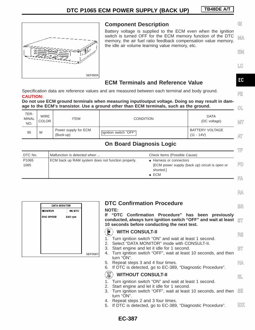
Component DescriptionBattery voltage is supplied to the ECM even when the ignitionswitch is turned OFF for the ECM memory function of the DTCmemory, the air fuel ratio feedback compensation value memory,the idle air volume learning value memory, etc.
ECM Terminals and Reference ValueSpecification data are reference values and are measured between each terminal and body ground.CAUTION:Do not use ECM ground terminals when measuring input/output voltage. Doing so may result in dam-age to the ECM’s transistor. Use a ground other than ECM terminals, such as the ground.
TER-MINAL
NO.
WIRECOLOR
ITEM CONDITIONDATA
(DC voltage)
95 WPower supply for ECM(Buck-up)
Ignition switch “OFF”BATTERY VOLTAGE(11 - 14V)
On Board Diagnosis Logic
DTC No. Malfunction is detected when ... Check Items (Possible Cause)
P10651065
ECM back up RAM system does not function properly. I Harness or connectors[ECM power supply (back up) circuit is open orshorted.]
I ECM
DTC Confirmation ProcedureNOTE:If “DTC Confirmation Procedure” has been previouslyconducted, always turn ignition switch “OFF” and wait at least10 seconds before conducting the next test.
WITH CONSULT-II1. Turn ignition switch “ON” and wait at least 1 second.2. Select “DATA MONITOR” mode with CONSULT-II.3. Start engine and let it idle for 1 second.4. Turn ignition switch “OFF”, wait at least 10 seconds, and then
turn “ON”.5. Repeat steps 3 and 4 four times.6. If DTC is detected, go to EC-389, “Diagnostic Procedure”.
WITHOUT CONSULT-II1. Turn ignition switch “ON” and wait at least 1 second.2. Start engine and let it idle for 1 second.3. Turn ignition switch “OFF”, wait at least 10 seconds, and then
turn “ON”.4. Repeat steps 2 and 3 four times.5. If DTC is detected, go to EC-389, “Diagnostic Procedure”.
SEF093X
SEF058Y
DTC P1065 ECM POWER SUPPLY (BACK UP) TB48DE A/T
EC-387
GI
MA
EM
LC
FE
CL
MT
AT
TF
PD
FA
RA
BR
ST
RS
BT
HA
EL
SE
IDX

Wiring Diagram
TEC244M
DTC P1065 ECM POWER SUPPLY (BACK UP) TB48DE A/T
EC-388

Diagnostic Procedure
CHECK ECM POWER SUPPLY.1. Turn ignition switch “OFF”.2. Disconnect ECM harness connector.3. Check voltage between ECM terminal
q95 and ground with CONSULT-II ortester.Voltage: Battery voltage
OK
ENG DETECT MALFUNCTION-
ING PART.Check the following.I Harness connectors
E127 , M21
I Harness connectorsM52 , F7
I 10A fuseI Harness for open or
short between ECM andbattery
If NG, repair or replaceharness or connectors.
CHECK INTERMITTENT INCIDENT.Refer to EC-331, “TROUBLE DIAGNOSISFOR INTERMITTENT INCIDENT”.
OK
ENG If NG, repair or replace
harness or connectors.
PERFORM DTC CONFIRMATION PRO-CEDURE.
With CONSULT-II
1. Turn ignition switch “ON”.2. Select “SELF DIAG RESULTS” mode
with CONSULT-II.3. Touch “ERASE”.4. Perform “DTC Confirmation Proce-
dure”.See EC-387.
5. Is the DTC P1065 displayed again?
Without CONSULT-II
1. Turn ignition switch “ON”.2. Erase the Diagnostic Test mode II (Self-
diagnostic results) memory.Refer to EC-284, “How to Erase DTC(Without CONSULT-II)”.
3. Perform “DTC Confirmation Proce-dure”.See EC-387.
4. Is the DTC 1065 displayed again?
No
EYes REPLACE ECM.
1. Replace ECM.2. Perform initialization of
NATS (NISSAN ANTI-THEFT SYSTEM) sys-tem and registration ofall NATS ignition keyIDs.Refer to EC-285, “NATS(Nissan Anti-theft Sys-tem)”.
3. Perform EC-280, “Accel-erator Pedal ReleasedPosition Learning”.
4. Perform EC-282,“Throttle Valve ClosedPosition Learning”.
5. Perform EC-281, “IdleAir Volume Learning”.
INSPECTION END
INSPECTION END
PBIB0087E
H
H
H
H
DTC P1065 ECM POWER SUPPLY (BACK UP) TB48DE A/T
EC-389
GI
MA
EM
LC
FE
CL
MT
AT
TF
PD
FA
RA
BR
ST
RS
BT
HA
EL
SE
IDX

DescriptionElectric Throttle Control Actuator consists of throttle control motor, acceleration pedal position sensor, throttleposition sensor, etc.The throttle control motor is operated by the ECM and it opens and closes the throttle valve.Accelerator pedal position sensor detects the accelerator pedal position, the opening and closing speed of theaccelerator pedal and feeds the voltage signals to the ECM. The ECM judges the current opening angle ofthe accelerator pedal from these signals and controls the throttle control motor based on these signals.The throttle position sensor detects the throttle valve position, and the opening and closing speed of the throttlevalve and feeds the voltage signals to the ECM. The ECM judges the current opening angle of the throttlevalve from these signals and the ECM controls the throttle control motor to make the throttle valve openingangle properly in response to driving condition.
On Board Diagnosis Logic
DTC No. Malfunction is detected when ... Check Items (Possible Cause)
P11211121
A) Electric throttle control actuator does not functionproperly due to the return spring malfunction.
I Electric throttle control actuator
B) Throttle valve opening angle in fail-safe mode is notin specified range.
C) ECM detect the throttle valve is stuck open.
FAIL-SAFE MODEECM enters in fail-safe mode when the malfunction A, B or C is detected
Detected items Engine operating condition in fail-safe mode
Malfunction AThe ECM controls the electric throttle throttle actuator by regulating the throttle opening around the idleposition. The engine speed will not rise more than 2,000 rpm.
Malfunction B ECM controls the electric throttle control actuator by regulating the throttle opening to 20 degrees or less.
Malfunction C
While the vehicle is driving, it slows down gradually by fuel cut. After the vehicle stops, the engine stalls.The engine can restart in “N” or “P” position, and engine speed will not exceed 1,000 rpm or more.When throttle is not movable, negative pressure does not occur because throttle valve is kept open, there-fore if depressing brake pedal two or three times, braking performance lowers.
DTC Confirmation ProcedureNOTE:I Perform “PROCEDURE FOR MALFUNCTION A AND B”
first. If the DTC cannot be confirmed, perform “PROCE-DURE FOR MALFUNCTION C”.If there is no problem on “PROCEDURE FOR MALFUNC-TION A AND B”, perform “PROCEDURE FOR MALFUNC-TION C”.
I If “DTC Confirmation Procedure” has been previouslyconducted, always turn ignition switch “OFF” and wait atleast 10 seconds before conducting the next test.
PROCEDURE FOR MALFUNCTION A AND B
With CONSULT-II1. Turn ignition witch “ON” and wait at least 1 second.2. Select “DATA MONITOR” mode with CONSULT-II.3. Shift selector lever to “D” position and wait at least 2 seconds.4. Turn ignition switch “OFF”, wait at least 10 seconds, and then
turn “ON”.5. If DTC is detected, go to EC-392, “Diagnostic Procedure”.
SEF058Y
DTC P1121 ELECTRIC THROTTLE CONTROLACTUATOR TB48DE A/T
EC-390

Without CONSULT-II1. Turn ignition witch “ON” and wait at least 1 second.2. Shift selector lever to “D” position and wait at least 2 seconds.3. Turn ignition switch “OFF”, wait at least 10 seconds, and then
turn “ON”.4. Perform “Diagnostic Test Mode II (Self-diagnostic results)” with
ECM.5. If DTC is detected, go to EC-392, “Diagnostic Procedure”.
PROCEDURE FOR MALFUNCTION C
With CONSULT-II1. Turn ignition switch “ON” and wait at least 1 second.2. Select “DATA MONITOR” mode with CONSULT-II.3. Shift selector lever to “D” position and wait at least 2 seconds.4. Shift selector lever to “N” or “P” position.5. Start engine and let it idle for 3 seconds.6. If DTC is detected, go to EC-392, “Diagnostic Procedure”.
Without CONSULT-II1. Turn ignition switch “ON” and wait at least 1 second.2. Shift selector lever to “D” position and wait at least 2 seconds.3. Shift selector lever to “N” or “P” position.4. Start engine and let it idle for 3 seconds.5. Turn ignition switch “OFF”, wait at least 10 seconds, and then
turn “ON”.6. Perform “Diagnostic Test Mode II (Self-diagnostic results)” with
ECM.7. If DTC is detected, go to EC-392, “Diagnostic Procedure”.
SEF058Y
DTC P1121 ELECTRIC THROTTLE CONTROLACTUATOR TB48DE A/T
DTC Confirmation Procedure (Cont’d)
EC-391
GI
MA
EM
LC
FE
CL
MT
AT
TF
PD
FA
RA
BR
ST
RS
BT
HA
EL
SE
IDX

Diagnostic Procedure
CHECK ELECTRIC THROTTLE CON-TROL ACTUATOR VISUALLY.1. Remove the intake air duct.2. Check if a foreign matter is caught
between the throttle valve and thehousing.
OK
ENG Remove the foreign matter
and clean the electricthrottle control actuatorinside.
REPLACE ELECTRIC THROTTLE CON-TROL ACTUATOR.1. Replace the electric throttle control
actuator.2. Perform EC-280, “Accelerator Pedal
Released Position Learning”.3. Perform EC-282, “Throttle Valve Closed
Position Learning”.4. Perform EC-281, “Idle Air Volume
Learning”.
INSPECTION END
SEC183DH
H
DTC P1121 ELECTRIC THROTTLE CONTROLACTUATOR TB48DE A/T
EC-392

DescriptionNOTE:If DTC P1122 is displayed with DTC P1121, first perform the trouble diagnosis for DTC P1121. Refer toEC-286, “DTC P1121 ELECTRIC THROTTLE CONTROL ACTUATOR”.Electric Throttle Control Actuator consists of throttle control motor, acceleration pedal position sensor, throttleposition sensor, etc.The throttle control motor is operated by the ECM and it opens and closes the throttle valve.The current opening angle of the throttle valve is detected by the throttle position sensor and it provides thefeedback to the ECM to control the throttle control motor to make the throttle valve opening angle properly inresponse to driving condition.
ECM Terminals and Reference ValueSpecification data are reference values and are measured between each terminal and ground.CAUTION:Do not use ECM ground terminals when measuring input/output voltage. Doing so may result in dam-age to the ECM’s transistor. Use a ground other than ECM terminals, such as the ground.
TER-MINAL
NO.
WIRECOLOR
ITEM CONDITIONDATA
(DC voltage)
151 L/WThrottle control motor(Close)
Ignition switch “ON”
Accelerator pedal is depressing
0 - 14V
PBIB0058E
154 L/BThrottle control motor(Open)
Ignition switch “ON”
Accelerator pedal is releasing
0 - 14V
PBIB0061E
153 B ECM groundEngine is running
Idle speedEngine ground
: Average voltage for pulse signal (Actual pulse signal can be confirmed by oscilloscope.)
On Board Diagnosis Logic
DTC No. Malfunction is detected when ... Check Items (Possible Cause)
P11221122
A) Electric throttle control feedback function does notoperate properly.
I Harness or connectors(Throttle control motor circuit is open or shorted.)
I Electric throttle control actuatorB) An excessively high ampere of current flows throughthrottle control motor to ECM.
FAIL-SAFE MODEWhen the malfunction A is detected, the ECM enters fail-safe mode and the MIL lights up.
DTC P1122 ELECTRIC THROTTLE CONTROLFUNCTION (CIRCUIT) TB48DE A/T
EC-393
GI
MA
EM
LC
FE
CL
MT
AT
TF
PD
FA
RA
BR
ST
RS
BT
HA
EL
SE
IDX

Detected items Engine operating condition in fail-safe mode
Malfunction A
ECM stops the electric throttle control actuator control, throttle valve is maintained at a fixed opening(approx. 5 degrees) by the return spring.When the accelerator pedal depressed value reaches a throttle opening of 30 degrees or more, the throttlevalve opens to a maximum of 20 degrees by the accelerator wire.
DTC Confirmation ProcedureNOTE:If “DTC Confirmation Procedure” has been previouslyconducted, always turn ignition switch “OFF” and wait at least10 seconds before conducting the next test.
WITH CONSULT-II1. Turn ignition switch “ON” and wait at least 2 seconds.2. Select “DATA MONITOR” mode with CONSULT-II.3. Start engine and let it idle for 5 seconds.4. If DTC is detected, go to EC-396, “Diagnostic Procedure”.
WITHOUT CONSULT-II1. Turn ignition switch “ON” and wait at least 2 seconds.2. Start engine and let it idle for 5 seconds.3. Turn ignition switch “OFF”, wait at least 10 seconds and then
turn “ON”.4. Perform “Diagnostic Test Mode II (Self-diagnostic results)” with
ECM.5. If DTC is detected, go to EC-396, “Diagnostic Procedure”.
SEF058Y
DTC P1122 ELECTRIC THROTTLE CONTROLFUNCTION (CIRCUIT) TB48DE A/T
On Board Diagnosis Logic (Cont’d)
EC-394

Wiring Diagram
TEC253M
DTC P1122 ELECTRIC THROTTLE CONTROLFUNCTION (CIRCUIT) TB48DE A/T
EC-395
GI
MA
EM
LC
FE
CL
MT
AT
TF
PD
FA
RA
BR
ST
RS
BT
HA
EL
SE
IDX

Diagnostic Procedure
CHECK THROTTLE CONTROL MOTOROUTPUT SIGNAL CIRCUIT FOR OPENAND SHORT.1. Turn ignition switch “OFF”.2. Disconnect electric throttle control
actuator harness connector F10 .3. Disconnect ECM harness connector.4. Check harness continuity between the
following terminals.Refer to wiring diagram.
5. Also check harness for short to groundand short to power.
OK
ENG
Repair open circuit or shortto ground or short to powerin harness or connectors.
CHECK THROTTLE CONTROL MOTORGROUND CIRCUIT FOR OPEN ANDSHORT.1. Check harness continuity between ECM
terminal 153 and engine ground.Refer to Wiring Diagram.Continuity should exist.
2. Also check harness for short to power.
OK
ENG
Repair open circuit or shortto power in harness orconnectors.
CHECK ELECTRIC THROTTLE CON-TROL ACTUATOR VISUALLY.1. Remove the intake air duct.2. Check if foreign matter is caught
between the throttle valve and thehousing.
OK
ENG
Remove the foreign matterand clean the electricthrottle control actuatorinside.
CHECK THROTTLE CONTROL MOTORRefer to EC-398, “Component Inspection”.
OK
ENG
REPLACE ELECTRICTHROTTLE CONTROLACTUATOR.1. Replace the electric
throttle control actuator.2. Perform EC-280, “Accel-
erator Pedal ReleasedPosition Learning”.
3. Perform EC-282,“Throttle Valve ClosedPosition Learning”.
4. Perform EC-281, “IdleAir Volume Learning”.
qAINSPECTION END
Electric throttlecontrol actuator
terminal
ECMterminal
Continuity
6151 Should exist
154 Should not exist
3151 Should not exist
154 Should exist
SEC182D
SEC183D
H
H
H
HH
DTC P1122 ELECTRIC THROTTLE CONTROLFUNCTION (CIRCUIT) TB48DE A/T
EC-396

qA
CHECK THROTTLE POSITION SENSORSHIELD CIRCUIT FOR OPEN ANDSHORT.1. Turn ignition switch “OFF”.2. Disconnect joint connector-7.3. Check continuity between joint connec-
tor-7 terminal q3 and engine ground.Refer to Wiring Diagram.Continuity should exist.(Refer to “Harness Layout” in EL sec-tion.)
4. Also check harness for short to power.5. Then reconnect joint connector-7.
OK
ENG
Repair open circuit or shortto power in harness orconnectors.
CHECK INTERMITTENT INCIDENT.Refer to EC-331, “TROUBLE DIAGNOSISFOR INTERMITTENT INCIDENT”.
OK
ENG
Repair or replace harnessor connectors.
REPLACE ELECTRIC THROTTLE CON-TROL ACTUATOR.1. Replace the electric throttle control
actuator.2. Perform EC-280, “Accelerator Pedal
Released Position Learning”.3. Perform EC-282, “Throttle Valve Closed
Position Learning”.4. Perform EC-281, “Idle Air Volume
Learning”.
INSPECTION END
H
H
H
H
DTC P1122 ELECTRIC THROTTLE CONTROLFUNCTION (CIRCUIT) TB48DE A/T
Diagnostic Procedure (Cont’d)
EC-397
GI
MA
EM
LC
FE
CL
MT
AT
TF
PD
FA
RA
BR
ST
RS
BT
HA
EL
SE
IDX

Component InspectionTHROTTLE CONTROL MOTOR1. Disconnect electric throttle control actuator harness connector
F10 .2. Check resistance between terminals q3 and q6 .
Resistance: Approximatel y 1 - 15Ω [at 25°C (77°F)]3. If NG, replace electric throttle control actuator and go to next
step.4. Perform EC-280, “Accelerator Pedal Released Position Learn-
ing”.5. Perform EC-282, “Throttle Valve Closed Position Learning”.6. Perform EC-281, “Idle Air Volume Learning”.
PBIB0095E
DTC P1122 ELECTRIC THROTTLE CONTROLFUNCTION (CIRCUIT) TB48DE A/T
EC-398

Component DescriptionPower supply for the Throttle Control motor is provided to the ECM via throttle control motor relay. The throttlecontrol motor relay is ON/OFF controlled by the ECM. When the ignition switch is turned ON, the ECM sendsan ON signal to throttle control motor relay and battery voltage is provided to the ECM. When the ignition switchis turned OFF, the ECM sends an OFF signal to throttle control motor relay and battery voltage is not pro-vided to the ECM.
CONSULT-II Reference Value in Data MonitorMode
Specification data are reference values.
MONITOR ITEM CONDITION SPECIFICATION
THRTL RELAY I Ignition switch: ON ON
ECM Terminals and Reference ValueSpecification data are reference values and are measured between each terminal and body ground.CAUTION:Do not use ECM ground terminals when measuring input/output voltage. Doing so may result in dam-age to the ECM’s transistor. Use a ground other than ECM terminals, such as the ground.
TER-MINAL
NO.
WIRECOLOR
ITEM CONDITIONDATA
(DC voltage)
26 P/LThrottle control motorrelay
Ignition switch “OFF”BATTERY VOLTAGE(11 - 14V)
Ignition switch “ON” 0 - 1.0V
157 GThrottle control motorrelay power supply
Ignition switch “ON”BATTERY VOLTAGE(11 - 14V)
On Board Diagnosis Logic
DTC No. Malfunction is detected when ... Check Items (Possible Cause)
P11231123
A) ECM detects the throttle control motor relay is stuckON.
I Harness or connectors(Throttle control motor relay circuit is open orshorted.)
I Throttle control motor relayB) ECM detects the throttle control motor relay is stuck
OFF.
FAIL-SAFE MODEECM enters fail-safe mode when the malfunction A is detected.
Detected items Engine operating condition in fail-safe mode
Malfunction A
ECM stops the electric throttle control actuator control, throttle valve is maintained at a fixed opening(approx. 5 degrees) by the return spring.When the accelerator pedal depressed value reaches a throttle opening of 30 degrees or more, the throttlevalve opens to a maximum of 20 degrees by the accelerator wire.
DTC Confirmation ProcedureNOTE:If “DTC Confirmation Procedure” has been previouslyconducted, always turn ignition switch “OFF” and wait at least10 seconds before conducting the next test.TESTING CONDITION:Before performing the following procedure, confirm that bat-tery voltage is more than 10V at idle.
DTC P1123 THROTTLE CONTROL MOTOR RELAY(CIRCUIT) TB48DE A/T
EC-399
GI
MA
EM
LC
FE
CL
MT
AT
TF
PD
FA
RA
BR
ST
RS
BT
HA
EL
SE
IDX

WITH CONSULT-II1. Turn ignition switch “ON” and wait at least 1 second.2. Select “DATA MONITOR” mode with CONSULT-II.3. If DTC is detected, go to EC-402, “Diagnostic Procedure”.
WITHOUT CONSULT-II1. Turn ignition switch “ON” and wait at least 1 second.2. Turn ignition switch “OFF”, wait at least 10 seconds and then
turn “ON”.3. Perform “Diagnostic Test Mode II (Self-diagnostic results)” with
ECM.4. If DTC is detected, go to EC-402, “Diagnostic Procedure”.
SEF058Y
DTC P1123 THROTTLE CONTROL MOTOR RELAY(CIRCUIT) TB48DE A/T
DTC Confirmation Procedure (Cont’d)
EC-400

Wiring Diagram
TEC254M
DTC P1123 THROTTLE CONTROL MOTOR RELAY(CIRCUIT) TB48DE A/T
EC-401
GI
MA
EM
LC
FE
CL
MT
AT
TF
PD
FA
RA
BR
ST
RS
BT
HA
EL
SE
IDX

Diagnostic Procedure
CHECK THROTTLE CONTROL MOTORRELAY POWER SUPPLY.1. Turn ignition switch “OFF”.2. Disconnect throttle control motor relay
harness connector.3. Check voltage between throttle control
motor relay terminals q2 , q3 andground with CONSULT-II or tester.Voltage: Battery voltage
OK
ENG
Check the following.I 15A fuseI Harness for open or
short between throttlecontrol motor relay andbattery
If NG, repair or replaceharness or connectors.
CHECK THROTTLE CONTROL MOTORRELAY INPUT SIGNAL CIRCUIT FOROPEN AND SHORT.1. Disconnect ECM harness connector.2. Check continuity between ECM terminal
157 and throttle control motor relayterminal q5 .Refer to Wiring Diagram.
3. Also check harness for short to groundand short to power.Continuity should exist.
OK
ENG
Check the following.I Harness connectors
E127 , M21I Harness connectors
M50 , F5I Harness for open or
short between ECM andthrottle control motorrelay
If NG, repair open circuit orshort to ground or short topower in harness or con-nectors.
CHECK THROTTLE CONTROL MOTORRELAY OUTPUT SIGNAL CIRCUIT FOROPEN AND SHORT.1. Check continuity between ECM terminal
q26 and throttle control motor relay ter-minal q1 .Refer to Wiring Diagram.Continuity should exist.
2. Also check harness for short to groundand short to power.
OK
ENG
DETECT MALFUNCTION-ING PART.Check the following.I Harness connectors
E127 , M21I Harness connectors
M50 , F5I Harness for open or
short between ECM andthrottle control motorrelay
If NG, repair open circuit orshort to ground or short topower in harness or con-nectors.
CHECK THROTTLE CONTROL MOTORRELAY.Refer to EC-403, “Component Inspection”.
OK
ENG
If NG, replace throttle con-trol motor relay.
CHECK INTERMITTENT INCIDENT.Refer to EC-331, “TROUBLE DIAGNOSISFOR INTERMITTENT INCIDENT”.
INSPECTION END
SEC185D
PBIB0097E
H
H
H
H
H
DTC P1123 THROTTLE CONTROL MOTOR RELAY(CIRCUIT) TB48DE A/T
EC-402

Component InspectionTHROTTLE CONTROL MOTOR RELAY1. Apply 12V direct current between relay terminals q1 and q2 .2. Check continuity between relay terminals q3 and q5 .
Conditions Continuity
12V direct current supply between ter-minals q1 and q2
Yes
No current supply No
3. If NG, replace throttle control motor relay.PBIB0098E
DTC P1123 THROTTLE CONTROL MOTOR RELAY(CIRCUIT) TB48DE A/T
EC-403
GI
MA
EM
LC
FE
CL
MT
AT
TF
PD
FA
RA
BR
ST
RS
BT
HA
EL
SE
IDX

System Description
Vehicle speed sensor EVehicle speed
ECM E Cooling fan relaysEngine coolant temperature sensor EEngine coolant temperature
Air conditioner switch EAir conditioner “ON” signal
The ECM controls the cooling fan corresponding to the vehicle speed, engine coolant temperature, and airconditioner ON signal. The control system has 3-step control [HIGH/LOW/OFF].
Operation
CONSULT-II Reference Value In Data MonitorMode
Remarks: Specification data are reference values.
MONITOR ITEM CONDITION SPECIFICATION
COOLING FAN
I After warming up engine, idle theengine.
I Air conditioner switch “OFF”I Vehicle stopped
Engine coolant temperature is 94°C(201°F) or less. OFF
Engine coolant temperature is 95°C(203°F) or more. HIGH
I After warming up engine, idle theengine.
I Air conditioner switch “ON”I Vehicle stopped
Engine coolant temperature is 94°C(201°F) or less. LOW
Engine coolant temperature is 95°C(203°F) or more. HIGH
AIR COND SIG I Engine: After warming up, idle theengine
Air conditioner switch: “OFF” OFF
Air conditioner switch: “ON”(Compressor operates.) ON
SEC694C
DTC P1217 ENGINE OVER TEMPERATURE(OVERHEAT) TB48DE A/T
EC-404

ECM Terminals and Reference ValueSpecification data are reference values and are measured between each terminal and ground.CAUTION:Do not use ECM ground terminals when measuring input/output voltage. Doing so may result in dam-age to the ECM’s transistor. Use a ground other than ECM terminals, such as the ground.
TER-MINAL
NO.
WIRECOLOR
ITEM CONDITIONDATA
(DC voltage)
56 LCooling fan relay (Lowspeed)
Engine is running.
Cooling fan is not operating.
BATTERY VOLTAGE(11 - 14V)
Engine is running.
Cooling fan is operating.Approximately 0V
55 L/BCooling fan relay(High speed)
Engine is running.
Cooling fan is not operating.Cooling fan is operating at low speed.
BATTERY VOLTAGE(11 - 14V)
Engine is running.
Cooling fan is operating at high speed.Approximately 0V
On Board Diagnosis LogicThis diagnosis continuously monitors the engine coolant temperature.If the cooling fan or another component in the cooling system malfunctions, the engine coolant temperaturewill rise.When the engine coolant temperature reaches an abnormally high temperature condition, a malfunction isdetected by the ECM and the MIL lights on.
Diagnostic troublecode No.
Malfunction is detected when ...Check Items
(Possible Cause)
P12171217
I Cooling fan does not operate properly (Overheat).I Cooling fan system does not operate properly (Over-
heat).I Engine coolant was not added to the system using
the proper filling method.
I Harness or connectors(The cooling fan circuit is open or shorted)
I Cooling fanI ThermostatI Improper ignition timingI Engine coolant temperature sensorI Blocked radiatorI Blocked front end (Improper fitting of nose
mask)I Crushed vehicle frontal area (Vehicle frontal
is collided but not repaired)I Blocked air passage by improper installation
of front fog lamp or fog lamps.I Improper mixture ratio of coolantI Damaged bumperFor more information, refer to “MAIN 12CAUSES OF OVERHEATING”, EC-413.
CAUTION:When a malfunction is indicated, be sure to replace the coolant following the procedure in the MAsection (“Changing Engine Coolant”, “ENGINE MAINTENANCE”). Also, replace the engine oil.a. Fill radiator with coolant up to specified level with a filling speed of 2 liters per minute like pour-
ing coolant by kettle. Be sure to use coolant with the proper mixture ratio. Refer to MA section(“Anti-freeze Coolant Mixture Ratio”, “RECOMMENDED LUBRICANTS AND FLUIDS”).
b. After refilling coolant, run engine to ensure that no water-flow noise is emitted.
DTC P1217 ENGINE OVER TEMPERATURE(OVERHEAT) TB48DE A/T
EC-405
GI
MA
EM
LC
FE
CL
MT
AT
TF
PD
FA
RA
BR
ST
RS
BT
HA
EL
SE
IDX
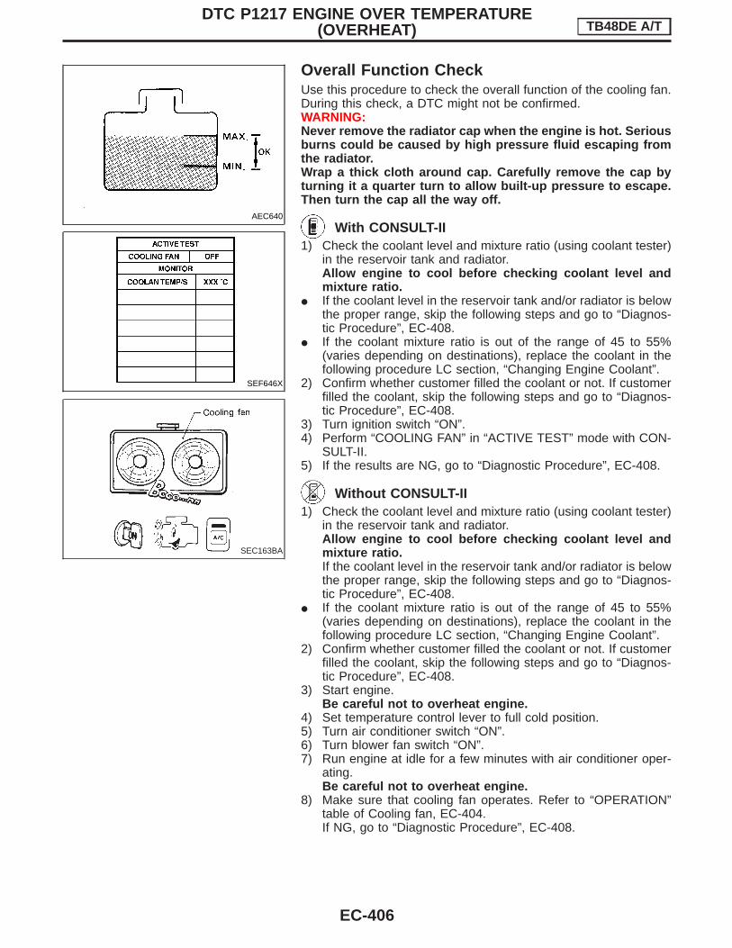
Overall Function CheckUse this procedure to check the overall function of the cooling fan.During this check, a DTC might not be confirmed.WARNING:Never remove the radiator cap when the engine is hot. Seriousburns could be caused by high pressure fluid escaping fromthe radiator.Wrap a thick cloth around cap. Carefully remove the cap byturning it a quarter turn to allow built-up pressure to escape.Then turn the cap all the way off.
With CONSULT-II1) Check the coolant level and mixture ratio (using coolant tester)
in the reservoir tank and radiator.Allow engine to cool before checking coolant level andmixture ratio.
I If the coolant level in the reservoir tank and/or radiator is belowthe proper range, skip the following steps and go to “Diagnos-tic Procedure”, EC-408.
I If the coolant mixture ratio is out of the range of 45 to 55%(varies depending on destinations), replace the coolant in thefollowing procedure LC section, “Changing Engine Coolant”.
2) Confirm whether customer filled the coolant or not. If customerfilled the coolant, skip the following steps and go to “Diagnos-tic Procedure”, EC-408.
3) Turn ignition switch “ON”.4) Perform “COOLING FAN” in “ACTIVE TEST” mode with CON-
SULT-II.5) If the results are NG, go to “Diagnostic Procedure”, EC-408.
Without CONSULT-II1) Check the coolant level and mixture ratio (using coolant tester)
in the reservoir tank and radiator.Allow engine to cool before checking coolant level andmixture ratio.If the coolant level in the reservoir tank and/or radiator is belowthe proper range, skip the following steps and go to “Diagnos-tic Procedure”, EC-408.
I If the coolant mixture ratio is out of the range of 45 to 55%(varies depending on destinations), replace the coolant in thefollowing procedure LC section, “Changing Engine Coolant”.
2) Confirm whether customer filled the coolant or not. If customerfilled the coolant, skip the following steps and go to “Diagnos-tic Procedure”, EC-408.
3) Start engine.Be careful not to overheat engine.
4) Set temperature control lever to full cold position.5) Turn air conditioner switch “ON”.6) Turn blower fan switch “ON”.7) Run engine at idle for a few minutes with air conditioner oper-
ating.Be careful not to overheat engine.
8) Make sure that cooling fan operates. Refer to “OPERATION”table of Cooling fan, EC-404.If NG, go to “Diagnostic Procedure”, EC-408.
AEC640
SEF646X
SEC163BA
DTC P1217 ENGINE OVER TEMPERATURE(OVERHEAT) TB48DE A/T
EC-406

Wiring Diagram
TEC151M
DTC P1217 ENGINE OVER TEMPERATURE(OVERHEAT) TB48DE A/T
EC-407
GI
MA
EM
LC
FE
CL
MT
AT
TF
PD
FA
RA
BR
ST
RS
BT
HA
EL
SE
IDX

Diagnostic ProcedureINSPECTION START
Do you have CONSULT-II?
YesE
No GO TO qA Without CON-SULT-II.
CHECK COOLING FAN LOW SPEEDOPERATION.
With CONSULT-II1. Disconnect cooling fan relay-2 and -3.2. Turn ignition switch “ON”.3. Perform “COOLING FAN” in “ACTIVE
TEST” mode with CONSULT-II.4. Make sure that cooling fans-1 and -2
operate at low speed.
OK
ENG GO TO qC . Check cooling
fan low speed control cir-cuit.
CHECK COOLING FAN HIGH SPEEDOPERATION.
With CONSULT-II1. Turn ignition switch “OFF”.2. Reconnect cooling fan relay-2 and -3.3. Turn ignition switch “ON”.4. Perform “COOLING FAN” in “ACTIVE
TEST” mode with CONSULT-II.5. Make sure that cooling fans-1 and -2
operate at high speed.
OK
ENG GO TO qD . Check cooling
fan high speed control cir-cuit.
GO TO qB .
SEC698C
SEF646X
SEF111X
H
H
H
H
DTC P1217 ENGINE OVER TEMPERATURE(OVERHEAT) TB48DE A/T
EC-408

qA
CHECK COOLING FAN LOW SPEEDOPERATION.
Without CONSULT-II1. Disconnect cooling fan relays-2 and -3.2. Start engine and let it idle.3. Set temperature lever at full cold posi-
tion.4. Turn air conditioner switch “ON”.5. Turn blower fan switch “ON”.6. Make sure that cooling fans-1 and -2
operate at low speed.
OK
ENG GO TO qC . Check cooling
fan low speed control cir-cuit.
CHECK COOLING FAN HIGH SPEEDOPERATION.
Without CONSULT-II1. Turn ignitions witch “OFF”.2. Reconnect cooling fan relays-2 and -3.3. Turn air conditioner switch and blower
fan switch “OFF”.4. Disconnect engine coolant temperature
sensor harness connector.5. Connect 150Ω resistor to engine coolant
temperature sensor harness connector.6. Restart engine and make sure that cool-
ing fans-1 and -2 operate at high speed.
OK
ENG GO TO qD . Check cooling
fan high speed control cir-cuit.
GO TO qB .
SEC698C
SEC163BA
SEC322D
H
H
H
DTC P1217 ENGINE OVER TEMPERATURE(OVERHEAT) TB48DE A/T
Diagnostic Procedure (Cont’d)
EC-409
GI
MA
EM
LC
FE
CL
MT
AT
TF
PD
FA
RA
BR
ST
RS
BT
HA
EL
SE
IDX

qB
CHECK COOLING SYSTEM FOR LEAK.Apply pressure to the cooling system witha tester, and check if the pressure drops.
Testing pressure:157 kPa (1.6 kg/cm 2, 23 psi)
CAUTION:Higher than the specified pressure maycause radiator damage.Pressure should not drop.
OK
ENG Check the following for
leak.I HoseI RadiatorI Water pump (Refer to LC
section, “Water Pump”.)If NG, repair or replace.
CHECK RADIATOR CAP.Apply pressure to cap with a tester andcheck radiator cap relief pressure.
Radiator cap relief pressure:For the Middle East:
78 - 98 kPa (0.78 - 0.98 bar, 0.8 -1.0 kg/cm 2, 11 - 14 psi)
Except above:108 - 127 kPa (1.08 - 1.27 bar, 1.1- 1.3 kg/cm 2, 16 - 18 psi)
OK
ENG Replace radiator cap.
CHECK THERMOSTAT.1. Remove thermostat.2. Check valve seating condition at normal
room temperatures.It should seat tightly.
3. Check valve opening temperature andvalve lift.Valve opening temperature:76.5°C (170°F) [standard]Valve lift:More than 10 mm/90°C (0.39 in/194°F)
4. Check if valve is closed at 5°C (9°F)below valve opening temperature. Fordetails, refer to LC section, “Thermo-stat”.
OK
ENG Replace thermostat.
CHECK ENGINE COOLANT TEMPERA-TURE SENSOR.Refer to “COMPONENT INSPECTION”,EC-349.
OK
ENG Replace engine coolant
temperature sensor.
CHECK MAIN 12 CAUSES.If the cause cannot be isolated, go to“MAIN 12 CAUSES OF OVERHEATING”,EC-413.
CHECK INSPECTION END
SLC754A
SLC755A
SLC343
H
HH
HH
HH
H
H
DTC P1217 ENGINE OVER TEMPERATURE(OVERHEAT) TB48DE A/T
Diagnostic Procedure (Cont’d)
EC-410

qC
CHECK COOLING FAN POWER SUPPLYCIRCUIT.1. Turn ignition switch “OFF”.2. Disconnect cooling fan relay-1.3. Turn ignition switch “ON”.4. Check voltage between cooling fan
relay-1 terminals q1 , q3 , q6 and groundwith CONSULT-II or tester.Battery voltage
OK
ENG Check the following.
I 10A fuseI 40A fusible linksI Harness for open or
short between coolingfan relay-1 and fuse
I Harness for open orshort between coolingfan relay-1 and battery
If NG, repair open circuit orshort to ground to short topower in harness or con-nectors.
CHECK COOLING FAN GROUND CIR-CUIT FOR OPEN AND SHORT1. Turn ignition switch “OFF”.2. Disconnect cooling fan motor-1 harness
connector and cooling fan motor-2 har-ness connector.
3. Check harness continuity between cool-ing fan relay-1 terminal q5 and coolingfan motor-1 terminal q1 , cooling fanmotor-1 terminal q4 and body ground.Refer to Wiring Diagram.Continuity should exist.
4. Also check harness for short to groundand short to power.
5. Check harness continuity between cool-ing fan relay-1 terminal q7 and coolingfan motor-2 terminal q1 , cooling fanmotor-2 terminal q4 and body ground.Refer to Wiring Diagram.Continuity should exist.
6. Also check harness for short to groundand short to power.
OK
ENG Repair open circuit or short
to ground or short to powerin harness or connectors.
CHECK COOLING FAN OUTPUT SIGNALCIRCUIT FOR OPEN AND SHORT.1. Disconnect ECM harness connector.2. Check harness continuity between ECM
terminal q56 and cooling fan relay-1 ter-minal q2 . Refer to Wiring Diagram.Continuity should exist.
3. Also check harness for short to groundand short to power.
OK
ENG Check the following.
I Harness connectorsE127 , M21
I Harness connectorsM52 , F7
I Harness for open orshort between coolingfan relay-1 and ECM
If NG, repair open circuit orshort to ground or short topower in harness or con-nectors.
CHECK COOLING FAN RELAY-1.Refer to “Component Inspection”, EC-414
OK
ENG Replace cooling fan relay.
CHECK COOLING FAN MOTORS-1 AND-2.Refer to “Component Inspection”, EC-414.
OK
ENG Replace cooling fan motors.
CHECK INTERMITTENT INCIDENT.Perform “TROUBLE DIAGNOSIS FORINTERMITTENT INCIDENT”, EC-331.
OK
INSPECTION END
SEC699C
SEC700C
H
H
H
H
H
H
H
DTC P1217 ENGINE OVER TEMPERATURE(OVERHEAT) TB48DE A/T
Diagnostic Procedure (Cont’d)
EC-411
GI
MA
EM
LC
FE
CL
MT
AT
TF
PD
FA
RA
BR
ST
RS
BT
HA
EL
SE
IDX

qD
CHECK COOLING FAN POWER SUPPLY CIR-CUIT.1. Turn ignition switch “OFF”.2. Disconnect cooling fan relays-2 and -3.3. Turn ignition switch “ON”.4. Check voltage between cooling fan relays-2
and -3 terminals q1 , q6 and ground withCONSULT-II or tester.Battery voltage
OK
ENG Check the following.
I Harness for open or shortbetween cooling fan relays-2and -3 and 10A fuse
I Harness for open or shortbetween cooling fan relays-2and fusible link
If NG, repair harness or con-nectors.
CHECK COOLING FAN GROUND CIRCUITFOR OPEN AND SHORT1. Turn ignition switch “OFF”.2. Disconnect cooling fan motor-1 harness con-
nector and cooling fan motor-2 harness con-nector.
3. Check harness continuity between cooling fanrelay-2 terminal q7 and cooling fan motor-1terminal q2 , cooling fan relay-2 terminal q3and cooling fan motor-1 terminal q3 , coolingfan relay-2 terminal q5 and body ground.Refer to Wiring Diagram.Continuity should exist.
4. Also check harness for short to ground andshort to power.
5. Check harness continuity between cooling fanrelay-3 terminal q7 and cooling fan motor-2terminal q2 , cooling fan relay-3 terminal q3 ,cooling fan relay-2 terminal q5 .Refer to Wiring Diagram.Continuity should exist.
6. Also check harness for short to ground andshort to power.
OK
ENG Repair open circuit or short to
ground or short to power inharness or connectors.
CHECK COOLING FAN OUTPUT SIGNAL CIR-CUIT FOR OPEN AND SHORT.1. Disconnect ECM harness connector.2. Check harness continuity between ECM termi-
nal q55 and cooling fan relay-2 terminal q2 ,cooling fan relay-3 terminal q2 .Refer to Wiring Diagram.Continuity should exist.
3. Also check harness for short to ground andshort power.
OK
ENG Check the following.
I Harness connectors E127 ,M21
I Harness connectors M52 ,F7
I Harness for open or shortbetween cooling fan relay-2and -3 and ECM
If NG, repair open circuit orshort to ground or short topower in harness or connec-tors.
CHECK COOLING FAN RELAYS-2 AND -3.Refer to “Component Inspection”, EC-414.
OK
ENG Replace cooling fan relays.
CHECK COOLING FAN MOTORS.Refer to “Component Inspection”, EC-414.
OK
ENG Replace cooling fan motors.
CHECK INTERMITTENT INCIDENT.Perform “TROUBLE DIAGNOSIS FOR INTER-MITTENT INCIDENT”, EC-331.
OK
INSPECTION END
SEC780C
SEC698C
SEC700C
H
H
H
H
H
H
H
DTC P1217 ENGINE OVER TEMPERATURE(OVERHEAT) TB48DE A/T
Diagnostic Procedure (Cont’d)
EC-412

Main 12 Causes of Overheating
Engine Step Inspection item Equipment Standard Reference page
OFF 1 I Blocked radiatorI Blocked condenserI Blocked radiator grilleI Blocked bumper
I Visual No blocking —
2 I Coolant mixture I Coolant tester 30 - 50% coolant mixture See “RECOMMENDEDFLUIDS AND LUBRI-CANTS” in MA section.
3 I Coolant level I Visual Coolant up to MAX levelin reservoir tank andradiator filler neck
See “Changing EngineCoolant”, “ENGINE MAIN-TENANCE” in MA section.
4 I Radiator cap I Pressure tester 108 - 127 kPa(1.08 - 1.27 bar, 1.1 - 1.3kg/cm2, 16 - 18 psi)59 - 98 kPa (0.59 - 0.98bar, 0.6 - 1.0 kg/cm2,9 - 14 psi) (Limit)
See “System Check”,“ENGINE COOLING SYS-TEM” in LC section.
ON*2 5 I Coolant leaks I Visual No leaks See “System Check”,“ENGINE COOLING SYS-TEM” in LC section.
ON*2 6 I Thermostat I Touch the upper andlower radiator hoses
Both hoses should be hot. See “Thermostat” and“Radiator”, “ENGINECOOLING SYSTEM” inLC section.
ON*1 7 I Cooling fan I Visual (Coupling)I CONSULT-II
Operating See “TROUBLE DIAGNO-SIS FOR DTC P1217”,EC-404.
OFF 8 I Combustion gas leak I Color checker chemicaltester 4 gas analyzer
Negative —
ON*3 9 I Coolant temperaturegauge
I Visual Gauge less than 3/4when driving
—
I Coolant overflow to res-ervoir tank
I Visual No overflow during drivingand idling
See “Changing EngineCoolant”, “ENGINE MAIN-TENANCE” in MA section.
OFF*4 10 I Coolant return from res-ervoir tank to radiator
I Visual Should be initial level inreservoir tank
See “ENGINE MAINTE-NANCE” in MA section.
OFF 11 I Cylinder head I Straight gauge feelergauge
0.1 mm (0.004 in) Maxi-mum distortion (warping)
See “Inspection”, “CYLIN-DER HEAD” in EM sec-tion.
12 I Cylinder block and pis-tons
I Visual No scuffing on cylinderwalls or piston
See “Inspection”, “CYLIN-DER BLOCK” in EM sec-tion.
*1: Engine running at idle for coupling type. Turn ignition switch ON for electrical cooling fan.*2: Engine running at 3,000 rpm for 10 minutes.*3: Drive at 90 km/h (55 MPH) for 30 minutes and then let idle for 10 minutes.*4: After 60 minutes of cool down time.For more information, refer to “OVERHEATING CAUSE ANALYSIS” in LC section.
DTC P1217 ENGINE OVER TEMPERATURE(OVERHEAT) TB48DE A/T
EC-413
GI
MA
EM
LC
FE
CL
MT
AT
TF
PD
FA
RA
BR
ST
RS
BT
HA
EL
SE
IDX

Component InspectionCOOLING FAN RELAYS-1, -2 AND -3Check continuity between terminals q3 and q5 , q6 and q7 .
Conditions Continuity
12V direct current supply between terminals 1 and2
Yes
No current supply No
If NG, replace relay.
COOLING FAN MOTORS-1 AND -21. Disconnect cooling fan motor harness connectors.2. Supply cooling fan motor terminals with battery voltage and
check operation.
Speed
Terminals
(+) (−)
Cooling fan motor Low 1 4
High 1, 2 3, 4
Cooling fan motor should operate.If NG, replace cooling fan motor.
SEF745U
SEF734W
DTC P1217 ENGINE OVER TEMPERATURE(OVERHEAT) TB48DE A/T
EC-414

Component DescriptionIGNITION COIL & POWER TRANSISTORThe ignition signal from the ECM is sent to and amplified by thepower transistor. The power transistor turns on and off the ignitioncoil primary circuit. This on-off operation induces the proper highvoltage in the coil secondary circuit.
CONSULT-II Reference Value in Data MonitorMode
Specification data are reference values.
MONITOR ITEM CONDITION SPECIFICATION
IGN TIMING
I Engine: After warming upI Air conditioner switch: “OFF”I Shift lever: “N”I No-load
Idle 3° - 7° BTDC
2,000 rpm 25° - 45° BTDC
ECM Terminals and Reference ValueSpecification data are reference values, and are measured between each terminal and ground.CAUTION:Do not use ECM ground terminals when measuring voltage. Doing so may result in damage to theECM’s transistor. Use a ground other than ECM terminals such as the body ground.
TER-MINAL
NO.
WIRECOLOR
ITEM CONDITIONDATA
(DC voltage)
181920212930
Y/RGYR/BR/GR
Ignition signal (No. 1)Ignition signal (No. 2)Ignition signal (No. 3)Ignition signal (No. 4)Ignition signal (No. 5)Ignition signal (No. 6)
Engine is running. (Warmed-up condition)
Idle speed
0 - 0.1V*
SEC672C
Engine is running. (Warmed-up condition)
Engine speed is 2,000 rpm.
0 - 0.2V*
SEC673C
*: Average voltage for pulse signal (Actual pulse signal can be confirmed by oscilloscope.)
SEC781C
DTC P1320 IGNITION SIGNAL TB48DE A/T
EC-415
GI
MA
EM
LC
FE
CL
MT
AT
TF
PD
FA
RA
BR
ST
RS
BT
HA
EL
SE
IDX

On Board Diagnosis Logic
Diagnostic TroubleCode No.
Malfunction is detected when ...Check Items
(Possible Cause)
P13201320
I The ignition signal in the primary circuit is not sentduring engine cranking or running.
I Harness or connectors(The ignition primary circuit is open or shorted.)
I Power transistor unit built into ignition coilI Camshaft position sensorI Camshaft position sensor circuit
DTC Confirmation ProcedureNOTE:I If “DTC” has been previously conducted, always turn igni-
tion switch “OFF” and wait at least 10 seconds before con-ducting the next test.
I If DTC P1320 is displayed with DTC P0340, perform troublediagnosis for DTC P0340 first. Refer to EC-377.
With CONSULT-II1) Turn ignition switch “ON”.2) Select “DATA MONITOR” mode with CONSULT-II.3) Start engine and wait at least 5 seconds. (If engine does not
run, turn ignition switch to “START” for at least 5 seconds.)4) If DTC is detected, go to “Diagnostic Procedure”, EC-420.
Without CONSULT-II1) Turn ignition switch “ON”.2) Start engine. (If engine does not run, turn ignition switch to
“START” for at least 5 seconds.)3) Turn ignition switch “OFF”, wait at least 10 seconds and then
turn “ON”.4) Perform “Diagnostic Test Mode II (Self-diagnostic results)” with
ECM.5) If DTC is detected, go to “Diagnostic Procedure”, EC-420.
SEF058Y
DTC P1320 IGNITION SIGNAL TB48DE A/T
EC-416

Wiring Diagram
TEC325M
DTC P1320 IGNITION SIGNAL TB48DE A/T
EC-417
GI
MA
EM
LC
FE
CL
MT
AT
TF
PD
FA
RA
BR
ST
RS
BT
HA
EL
SE
IDX

TEC149M
DTC P1320 IGNITION SIGNAL TB48DE A/T
Wiring Diagram (Cont’d)
EC-418

TEC150M
DTC P1320 IGNITION SIGNAL TB48DE A/T
Wiring Diagram (Cont’d)
EC-419
GI
MA
EM
LC
FE
CL
MT
AT
TF
PD
FA
RA
BR
ST
RS
BT
HA
EL
SE
IDX

Diagnostic Procedure
INSPECTION START
Start engine.Is engine running?
No
EYes Go to “SEARCH FOR
MALFUNCTIONING CIR-CUIT” on next page.
CHECK POWER SUPPLY-1.1. Turn ignition switch “OFF”.2. Disconnect ECM relay.3. Check voltage between terminals q2 ,
q5 and ground with CONSULT-II ortester.Voltage: Battery voltage
OK
ENG Check the following.
I Harness connectorsE127 , M21
I 10A fuseI 15A fuseI Harness for open or
short between batteryand ECM relay
If NG, repair harness orconnectors.
CHECK OUTPUT SIGNAL CIRCUIT-1.1. Disconnect ECM harness connector.2. Check harness continuity between ECM
terminal q42 and ECM relay terminal q1 .Refer to Wiring Diagram.Continuity should exist.If OK, check harness for short toground and short to power.
OK
ENG Check the following.
I Harness connectorsM52 , F7
I Harness for open orshort between ECM relayand ECM
If NG, repair open circuit orshort to ground or short topower in harness or con-nectors.
CHECK ECM RELAY.1. Apply 12V direct current between relay
terminals q1 and q2 .2. Check continuity between relay termi-
nals q3 and q5 , q7 and q6 .12V (q1 - q2 ) applied:
Continuity exists.No voltage applied:
No continuity
OK
ENG Replace ECM relay.
1. Reconnect ECM relay and ECM har-ness connector.
2. Go to “CHECK POWER SUP-PLY-2” on next page.
SEC684CA
SEC782C
SEC202B
H
H
H
H
H
DTC P1320 IGNITION SIGNAL TB48DE A/T
EC-420

SEARCH FOR MALFUNCTIONING CIR-CUIT.1. Start engine and let it idle.
With CONSULT-II2. Perform “POWER BALANCE” in
“ACTIVE TEST” mode with CONSULT-II.
3. Search for circuit which does not pro-duce a momentary engine speed drop.
-------------------------------------------------------------------------------------------------------------------------------------- OR --------------------------------------------------------------------------------------------------------------------------------------
Without CONSULT-II2. Check output signal voltage between
ECM terminals q18 , q19 , q20 , q21 , q29 , q30
and ground with oscilloscope.3. Search for circuit that signal voltage
does not match to “DATA” in “ECM Ter-minal and Reference Value”.
CHECK POWER SUPPLY-2.1. Turn ignition switch “OFF”.2. Disconnect ignition coil harness con-
nector(s).3. Turn ignition switch “ON”.4. Check voltage between each ignition
coil harness connector terminal q1 andground with CONSULT-II or tester.Voltage: Battery voltage
OK
ENG Check the following.
I Harness connectorsM50 , F5
I Harness connectorsF25 , F121
I Harness for open orshort between ignitioncoil and ECM relay
If NG, repair harness orconnectors.
CHECK CONDENSER CIRCUIT FOROPEN AND SHORT.1. Turn ignition switch OFF.2. Disconnect condenser harness connec-
tor.3. Check harness continuity between ECM
relay terminal q3 and condenser termi-nal q1 , condenser terminal q2 andengine ground.Refer to Wiring Diagram.Continuity should exist.
4. Also check harness for short to groundand short to power.
OK
ENG Check the following.
I Harness connectorsM50 , F5
I Check for open or shortbetween ECM relay andcondenser
If NG, repair open circuit orshort to ground or short topower in harness or con-nectors.
CHECK GROUND CIRCUIT.1. Turn ignition switch “OFF”.2. Loosen and retighten engine ground
screws.3. Check harness continuity between igni-
tion coil harness connector terminal q2and engine ground.Refer to Wiring Diagram.Continuity should exist.If OK, check harness for short to power.
OK
ENG Check the following.
I Harness connectorsF121 , F25
I Check for open or shortbetween ignition coil andengine ground
If NG, repair open circuit orshort to power in harnessor connectors.
qA
(Go to next page.)
SEF793X
SEC828C
SEC783C
SEC784C
SEF305T
H
H
H
H
DTC P1320 IGNITION SIGNAL TB48DE A/T
Diagnostic Procedure (Cont’d)
EC-421
GI
MA
EM
LC
FE
CL
MT
AT
TF
PD
FA
RA
BR
ST
RS
BT
HA
EL
SE
IDX

qA
CHECK OUTPUT SIGNAL CIRCUIT-2.1. Disconnect ECM harness connector.2. Check harness continuity between each
ignition coil harness connector terminalq3 and each ECM harness connectorterminal.Refer to Wiring Diagram.Continuity should exist.If OK, check harness for short toground and short to power.
OK
ENG Repair open circuit or short
to ground or short to powerin harness or connectors.
CHECK COMPONENT(Ignition coil with power transistor).Refer to “COMPONENT INSPECTION”,EC-422.
OK
ENG Replace ignition coil
assembly.
CHECK COMPONENT(Condenser).Refer to “COMPONENT INSPECTION”,EC-423.
OK
ENG Replace condenser.
CHECK INTERMITTENT INCIDENT.Refer to “TROUBLE DIAGNOSIS FORINTERMITTENT INCIDENT”, EC-331.
INSPECTION END
Component InspectionIGNITION COIL WITH POWER TRANSISTOR1. Turn ignition switch “OFF”.2. Disconnect ignition coil harness connector.3. Check resistance between ignition coil terminals as follows.
Terminal No. (Polarity) Resistance Ω [at 25°C (77°F)]
3 (+) - 2 (-) Except 0 or
1 (+) - 3 (-)Except 0
1 (+) - 2 (-)
SEC690C
SEF371Q
H
H
H
H
H
DTC P1320 IGNITION SIGNAL TB48DE A/T
Diagnostic Procedure (Cont’d)
EC-422

CONDENSER1. Turn ignition switch “OFF”.2. Disconnect condenser harness connector.3. Check resistance between condenser terminals as q1 and q2 .
Resistance Above 1 MΩ at 25°C (77°F)
SEF124Y
DTC P1320 IGNITION SIGNAL TB48DE A/T
Component Inspection (Cont’d)
EC-423
GI
MA
EM
LC
FE
CL
MT
AT
TF
PD
FA
RA
BR
ST
RS
BT
HA
EL
SE
IDX

DescriptionBrake switch signal is applied to the ECM through the stop lamp switch when the brake pedal is depressed.This signal is used mainly to decrease the engine speed when the vehicle is driving.
CONSULT-II Reference Value in Data MonitorMode
Specification data are reference values.
MONITOR ITEM CONDITION SPECIFICATION
BRAKE SW I Ignition switch: ONBrake pedal: Fully released OFF
Brake pedal: Slightly depressed ON
ECM Terminals and Reference ValueSpecification data are reference values and are measured between each terminal and body ground.CAUTION:Do not use ECM ground terminals when measuring input/output voltage. Doing so may result in dam-age to the ECM’s transistor. Use a ground other than ECM terminals, such as the ground.
TER-MINAL
NO.
WIRECOLOR
ITEM CONDITIONDATA
(DC voltage)
106 G/Y Stop lamp switch
Engine is running
Brake pedal fully releasedApproximately 0V
Engine is running
Brake pedal fully depressed
BATTERY VOLTAGE(11 - 14V)
On Board Diagnostic Logic
DTC No. Malfunction detected when ...Check Items
(Possible Cause)
P18051805
A brake switch signal is not sent to ECM for anextremely long time while the vehicle is driving.
I Harness or connectors(Stop lamp switch circuit is open or shorted.)
I Stop lamp switch
DTC Confirmation Procedure
WITH CONSULT-II1. Turn ignition switch “ON”.2. Fully depress the brake pedal for at least 5 seconds.3. Erase the DTC with CONSULT-II.4. Select “DATA MONITOR” mode with CONSULT-II.5. If DTC is detected, go to “Diagnostic Procedure”, EC-427.
WITHOUT CONSULT-II1. Turn ignition switch “ON”.2. Fully depress the brake pedal for at least 5 seconds.3. Erase the “Diagnostic Test Mode II (Self-diagnostic results)
memory. Refer to EC-287, “How to Erase DTC (Without CON-SULT-II)”.
4. Turn ignition switch “OFF”, wait at least 10 seconds and thenturn “ON”.
SEF058Y
DTC P1805 BRAKE SWITCH TB48DE A/T
EC-424

5. Perform “Diagnostic Test Mode II (Self-diagnostic results)” withECM.
6. If DTC is detected, go to “Diagnostic Procedure”, EC-427.
DTC P1805 BRAKE SWITCH TB48DE A/T
DTC Confirmation Procedure (Cont’d)
EC-425
GI
MA
EM
LC
FE
CL
MT
AT
TF
PD
FA
RA
BR
ST
RS
BT
HA
EL
SE
IDX

Wiring Diagram
TEC249M
DTC P1805 BRAKE SWITCH TB48DE A/T
EC-426

Diagnostic Procedure
INSPECTION START
OVERALL FUNCTION CHECK
With CONSULT-II.
1. Turn ignition switch “ON”.2. Select “BRAKE SW” in “DATA MONI-
TOR” mode with CONSULT-II.3. Check the following.
Without CONSULT-II.
1. Turn ignition switch “ON”.2. Check voltage ECM terminal 106 and
ground following condition.
NG
EOK
INSPECTION END
CHECK STOP LAMP SWITCH CIRCUIT.1. Turn ignition switch “OFF”.2. Check the stop lamp when depressing
and releasing the brake pedal.
OK
ENG
qC
qA
H
CHECK STOP LAMP SWITCH INPUTSIGNAL CIRCUIT FOR OPEN ANDSHORT.1. Turn ignition switch “OFF”.2. Disconnect ECM harness connector.3. Disconnect stop lamp switch harness
connector.4. Check harness continuity between ECM
terminal 106 and stop lamp switch ter-minal q2 . Refer to Wiring Diagram.Continuity should exist.
5. Also check harness for short to groundand short to power.
OK
ENG
Check the following.I Harness connectors
M52 , F7I Harness for open or
short between ECM andstop lamp switch
If NG, repair open circuit orshort to ground or short topower in harness or con-nectors.
qB
CONDITION SPECIFICATION
Brake pedal: Fullyreleased
OFF
Brake pedal: Slightlydepressed
ON
CONDITION SPECIFICATION
Brake pedal: Fullyreleased
0V
Brake pedal: Slightlydepressed
Battery voltage(11 - 14V)
Brake pedal Stop lamp
Fully released Not illuminated
Depressed Illuminated
SEC193D
SEC194D
H
H
H
H
DTC P1805 BRAKE SWITCH TB48DE A/T
EC-427
GI
MA
EM
LC
FE
CL
MT
AT
TF
PD
FA
RA
BR
ST
RS
BT
HA
EL
SE
IDX

qB
CHECK STOP LAMP SWITCH.Refer to “Component Inspection”, EC-429.
OK
ENG Replace stop lamp switch.
CHECK INTERMITTENT INCIDENT.Refer to “TROUBLE DIAGNOSIS FORINTERMITTENT INCIDENT”, EC-331.
INSPECTION END
qC
CHECK STOP LAMP SWITCH VOLT-AGE.1. Disconnect stop lamp switch harness
connector.2. Check voltage between stop lamp
switch terminal q1 and ground withCONSULT-II or tester.Voltage: Battery voltage
OK
ENG Check the following.
I 10A fuseI Fuse block (J/B) M3I Harness for open and
short between stop lampswitch and battery
If NG, repair open circuit orshort to ground or short topower in harness or con-nectors.
qA
SEC194D
PBIB0117E
H
H
H
H
H
DTC P1805 BRAKE SWITCH TB48DE A/T
Diagnostic Procedure (Cont’d)
EC-428

Component InspectionSTOP LAMP SWITCH1. Disconnect stop lamp switch harness connector.
2. Check continuity between stop lamp switch terminals q1 andq2 under the following conditions.
Conditions Continuity
Brake pedal fully released Should not exist.
Brake pedal depressed Should exist.
3. If NG, replace stop lamp switch.
SEC194D
PBIB0118E
DTC P1805 BRAKE SWITCH TB48DE A/T
EC-429
GI
MA
EM
LC
FE
CL
MT
AT
TF
PD
FA
RA
BR
ST
RS
BT
HA
EL
SE
IDX

System Description
Camshaft position sensor EEngine speed ECM E
Heatedoxygensensor 1heater
The ECM performs ON/OFF control of the heatedoxygen sensor 1 heater corresponding to the enginespeed.
OPERATION
Engine speed rpmHeated oxygen sensor 1
heater
Above 3,600 OFF
Below 3,600 ON
CONSULT-II Reference Value in Data MonitorMode
Specification data are reference values.
MONITOR ITEM CONDITION SPECIFICATION
HO2S1 HTR (B1)HO2S1 HTR (B2)
I Engine speed: Idle ON
I Engine speed: Above 3,600 OFF
ECM Terminals and Reference ValueSpecification data are reference values, and are measured between each terminal and ground.CAUTION:Do not use ECM ground terminals when measuring voltage. Doing so may result in damage to theECM’s transistor. Use a ground other than ECM terminals such as the body ground.
TER-MINAL
NO.
WIRECOLOR
ITEM CONDITIONDATA
(DC voltage)
8(B1)
G/YHeated oxygen sensor 1heater
Engine is running.
Engine speed is below 2,800 rpm.0 - 0.5V
9(B2)
L/REngine is running.
Engine speed is above 2,800 rpm.
BATTERY VOLTAGE(11 - 14V)
HO2S1 HEATER TB48DE A/T
EC-430

Wiring DiagramBANK 1
TEC246M
HO2S1 HEATER TB48DE A/T
EC-431
GI
MA
EM
LC
FE
CL
MT
AT
TF
PD
FA
RA
BR
ST
RS
BT
HA
EL
SE
IDX

BANK 2
TEC248M
HO2S1 HEATER TB48DE A/T
Wiring Diagram (Cont’d)
EC-432

Diagnostic Procedure
INSPECTION START
OVERALL FUNCTION CHECK1. Start engine.
With CONSULT-II
2. Select “HO2S1 HTR (B1)/(B2)” in “DATAMONITOR” mode.
3. Check the following.
Without CONSULT-II
2. Check voltage between ECM terminalsq9 (B1)/q8 (B2) and ground with CONSULT-IIor tester under the following conditions.
NG
EOK INSPECTION END
CHECK POWER SUPPLY.1. Turn ignition switch “OFF”.2. Disconnect corresponding heated oxygen sen-
sor 1 harness connector.3. Turn ignition switch “ON”.4. Check voltage between terminal q3 and
ground.Voltage: Battery voltage
OK
ENG Check the following.
I Harness connectorsF7 , M52
I 10A fuseI Harness for open or short
between heated oxygen sen-sor 1 and fuse
If NG, repair harness or con-nectors.
CHECK GROUND CIRCUIT.1. Turn ignition switch “OFF”.2. Disconnect ECM harness connector.3. Check harness continuity between terminal
and sensor.
Refer to wiring diagram.Continuity should exist.If OK, check harness for short to ground andshort to power.
OK
ENG Repair harness or connectors.
CHECK COMPONENT(Heated oxygen sensor 1 heater).Refer to “COMPONENT INSPECTION” on nextpage.
OK
ENG REPLACE HO2S1.
Perform “TROUBLE DIAGNOSIS FOR INTER-MITTENT INCIDENT”, EC-331.
INSPECTION END
Engine speed rpm Heated oxygen sensor1 heater
Above 3,600 OFF
Below 3,600 ON
Engine speed rpm Heated oxygen sensor1 heater
Engine speed is below3,600 rpm. Approximately 0V
Engine speed isabove 3,600 rpm. Battery voltage
Heated oxy-gen sensor
1 heater
Terminals
ECM Sensor
P0135 B1 9 1
P0155 B2 8 1
SEC888C
SEC320D
SEC321D
SEC180D
H
H
H
H
H
H
HO2S1 HEATER TB48DE A/T
EC-433
GI
MA
EM
LC
FE
CL
MT
AT
TF
PD
FA
RA
BR
ST
RS
BT
HA
EL
SE
IDX

Component InspectionHEATED OXYGEN SENSOR 1 HEATERCheck resistance between terminals q3 and q1 .
Resistance: 2.3 - 4.3 Ω at 25°C (77°F)Check continuity between terminals q2 and q1 , q3 and q2 .
Continuity should not exist.If NG, replace the heated oxygen sensor 1.CAUTION:I Discard any heated oxygen sensor which has been dropped
from a height of more than 0.5 m (19.7 in) onto a hard sur-face such as a concrete floor; use a new one.
I Before installing new oxygen sensor, clean exhaust systemthreads using Oxygen Sensor Thread Cleaner toolJ-43897-18 or J-43897-12 and approved anti-seize lubricant.
SEC181D
HO2S1 HEATER TB48DE A/T
EC-434

DescriptionSYSTEM DESCRIPTION
Sensor Input Signal to ECMECM func-
tionActuator
Camshaft position sensor Engine speed
EVAP canis-ter purgecontrol
EVAP canister purge volumecontrol solenoid valve
Mass air flow sensor Amount of intake air
Engine coolant temperature sensor Engine coolant temperature
Ignition switch Start signal
Power steering oil pressure switch Power steering signal
Throttle position sensor Throttle position
Heated oxygen sensor 1Density of oxygen in exhaust gas(Mixture ratio feedback signal)
Air conditioner switch Air conditioner signal
Vehicle speed sensor Vehicle speed
This system controls flow rate of fuel vapor from the EVAP canis-ter. The opening of the vapor by-pass passage in the EVAP canis-ter purge volume control solenoid valve changes to control the flowrate. The EVAP canister purge volume control solenoid valverepeats ON/OFF operation according to the signal sent from theECM. The opening of the valve varies for optimum engine control.The optimum value stored in the ECM is determined by consider-ing various engine conditions. When the engine is operating, theflow rate of fuel vapor from the EVAP canister is regulated as theair flow changes.
COMPONENT DESCRIPTIONThe EVAP canister purge volume control solenoid valve uses aON/OFF duty to control the flow rate of fuel vapor from the EVAPcanister. The EVAP canister purge volume control solenoid valve ismoved by ON/OFF pulses from the ECM. The longer the ON pulse,the greater the amount of fuel vapor that will flow through the valve.
CONSULT-II Reference Value in Data MonitorMode
MONITOR ITEM CONDITION SPECIFICATION
PURG VOL C/V
I Engine: After warming upI No-loadI Lift up drive wheels and suitable
gear position
Idle 0%
More than 30 seconds after startingengineRev engine up from 2,000 to 4,000rpm.
30 - 100%
SEF337U
EVAP CANISTER PURGE VOLUME CONTROLSOLENOID VALVE TB48DE A/T
EC-435
GI
MA
EM
LC
FE
CL
MT
AT
TF
PD
FA
RA
BR
ST
RS
BT
HA
EL
SE
IDX

ECM Terminals and Reference ValueSpecification data are reference values and are measured between each terminal and ground.CAUTION:Do not use ECM ground terminals when measuring input/output voltage. Doing so may result in dam-age to the ECM’s transistor. Use a ground other than ECM terminals, such as the ground.
TERMI-NALNO.
WIRECOLOR
ITEM CONDITION DATA (DC Voltage)
54 W/BEVAP canister purge vol-ume control solenoid valve
Engine is running.
Idle speed
BATTERY VOLTAGE(11 - 14V)*1
SEC676C
Engine is running.
Engine speed is about 2,000 rpm (More than100 seconds after starting engine).
BATTERY VOLTAGE(11 - 14V)*1
SEC677C
EVAP CANISTER PURGE VOLUME CONTROLSOLENOID VALVE TB48DE A/T
EC-436

Wiring Diagram
TEC155M
EVAP CANISTER PURGE VOLUME CONTROLSOLENOID VALVE TB48DE A/T
EC-437
GI
MA
EM
LC
FE
CL
MT
AT
TF
PD
FA
RA
BR
ST
RS
BT
HA
EL
SE
IDX

Diagnostic Procedure
INSPECTION START
CHECK OVERALL FUNCTION.
With CONSULT-II
1. Start engine and let it idle.2. Select “PURG VOL CONT/V” in
“ACTIVE TEST” mode with CONSULT-II.
3. Remove the purge vacuum hosebetween the EVAP canister and EVAPcanister purge volume control solenoidvalve at the EVAP canister.
4. Touch “UP/DOWN” on CONSULT-IIscreen. Check to see if vacuum existsunder the following conditions.
Without CONSULT-II
1. Lift up vehicle, start engine and warm itup to normal operating temperature.
2. Remove the purge vacuum hosebetween the EVAP canister and EVAPcanister purge volume control solenoidvalve at the EVAP canister.
3. Check to see if vacuum exists whenrevving engine from 2,000 to 4,000 rpmin a suitable gear position other than“P” or “N”.
NG
EOK
CHECK EVAP CANISTER.1. Turn ignition switch
“OFF”.2. Remove EVAP canister.3. Blow air into each of
three ports to check thatair flows freely.
If NG, replace EVAP canis-ter.
OK
INSPECTION END
CHECK POWER SUPPLY.1. Turn ignition switch “OFF”.2. Disconnect EVAP canister purge vol-
ume control solenoid valve harnessconnector.
3. Turn ignition switch “ON”.4. Check voltage between terminal q1 and
engine ground with CONSULT-II ortester.Voltage: Battery voltage
OK
ENG
Check the following.I Harness connectors
M52 , F7I 10A fuseI Harness for open or
short between EVAPcanister purge volumecontrol solenoid valveand 10A fuse
If NG, repair harness orconnectors.
GO TO qA .
ConditionPURGE VOL CONT/V
Vacuum
0% No
100% Yes
Condition Vacuum
When depressingaccelerator pedal
Yes
When releasing accel-erator pedal com-
pletelyNo
SEC891C
SEC892C
SEC785C
SEF083Y
SEC815C
H
H
H
H
EVAP CANISTER PURGE VOLUME CONTROLSOLENOID VALVE TB48DE A/T
EC-438

qA
CHECK OUTPUT SIGNAL CIRCUIT.1. Turn ignition switch “OFF”.2. Disconnect ECM harness connector.3. Check harness continuity between
ECM terminal q54 and terminal q2 .Refer to Wiring Diagram.Continuity should exist.If OK, check harness for short toground and short to power.
OK
ENG
Repair open circuit or shortto ground or short to powerin harness or connectors.
CHECK COMPONENT(EVAP canister purge volume control sole-noid valve).Refer to “COMPONENT INSPECTION”,EC-440.
OK
ENG
Replace EVAP canisterpurge volume control sole-noid valve.
CHECK INTERMITTENT INCIDENT.Refer to “TROUBLE DIAGNOSIS FORINTERMITTENT INCIDENT”, EC-331.
INSPECTION END
H
H
H
H
EVAP CANISTER PURGE VOLUME CONTROLSOLENOID VALVE TB48DE A/T
Diagnostic Procedure (Cont’d)
EC-439
GI
MA
EM
LC
FE
CL
MT
AT
TF
PD
FA
RA
BR
ST
RS
BT
HA
EL
SE
IDX

Component InspectionEVAP canister purge volume control solenoid valve
With CONSULT-II1. Start engine.2. Perform “PURG VOL CONT/V” in “ACTIVE TEST” mode with
CONSULT-II. Check that engine speed varies according to thevalve opening.If OK, inspection end. If NG, go to following step.
3. Check air passage continuity.
ConditionPURG VOL CONT/V value
Air passage continuitybetween qA and qB
100.0% Yes
0.0% No
If NG, replace the EVAP canister purge volume control solenoidvalve.------------------------------------------------------------------------------------------------------------------------------------------------------------------------------------------------------------------------------------------------------- OR -------------------------------------------------------------------------------------------------------------------------------------------------------------------------------------------------------------------------------------------------------
Without CONSULT-IICheck air passage continuity.
ConditionAir passage continuity
between qA and qB
12V direct current supply between ter-minals
Yes
No supply No
If NG or operation takes more than 1 second, replace solenoidvalve.
SEC816C
SEF660U
SEF661U
EVAP CANISTER PURGE VOLUME CONTROLSOLENOID VALVE TB48DE A/T
EC-440

DescriptionThe vehicle speed sensor is installed in the transmission. It con-tains a pulse generator which provides a vehicle speed signal to thecombination meter. The combination meter then sends a signal tothe ECM through CAN communication line.
Diagnostic Procedure
OVERALL FUNCTION CHECK
With CONSULT-II
1. Lift up drive wheels.2. Read “VHCL SPEED SE” in “DATA
MONITOR” mode with CONSULT-II.The vehicle speed on CONSULT-IIshould exceed 10 km/h (6 MPH) whenrotating wheels with suitable gear posi-tion.
Without CONSULT-II
1. Lift up drive wheels.2. Start engine.3. Read vehicle speed with combination
meter. The vehicle speed indicationshould be able to exceed 10 km/h (6MPH) when rotating wheels with suit-able gear position.
NG
EOK INSPECTION END
CHECK VEHICLE SPEED SENSOR CIR-CUIT.Refer to EL section.
OK
ENG Repair or replace.
CHECK COMBINATION METER.Check combination meter function.Refer to EL section.
INSPECTION END
H
H
H
VEHICLE SPEED SENSOR (VSS) TB48DE A/T
EC-441
GI
MA
EM
LC
FE
CL
MT
AT
TF
PD
FA
RA
BR
ST
RS
BT
HA
EL
SE
IDX

System Description
Camshaft position sensor EEngine speed
ECM E
Intake valvetiming con-trolsolenoidvalve
Mass air flow sensor EAmount of intake air
Engine coolant temperature sensor EEngine coolant temperature
Throttle position sensor EThrottle position
Vehicle speed sensor EVehicle speed
The intake valve timing control system is utilized tocontrol intake valve opening and closing timing.Engine coolant temperature signals, engine speed,amount of intake air, vehicle speed and throttle posi-tion are used to determine intake valve timing.The intake camshaft sprocket position is regulatedby oil pressure controlled by the intake valve timingcontrol.
When ECM sends ON signal to intake valve timingcontrol solenoid valve, oil pressure is transmitted tocamshaft sprocket. Then, intake side camshaft isadvanced.
SEF587TA
INTAKE VALVE TIMING CONTROL TB48DE A/T
EC-442

Operation
Engine operating conditionIntake valve timing con-
trolsolenoid valve
Intake valve openingand closing time Valve overlap Engine valve timing
I Engine coolant temperature isbetween 70°C (158°F) to 118°C(244°F) and engine speed isbetween 800 rpm and 4,200 rpm.
I During high load conditionI Vehicle speed is more than 8 km/h
(5 MPH).
ON Advance Increased qII
Those other than above OFF Normal Normal qI
CONSULT-II Reference Value in Data MonitorMode
Specification data are reference values.
MONITOR ITEM CONDITION SPECIFICATION
INT/V SOL-B1
I Engine is in warm up condition.I Engine speed is more than 800 rpm.I Suitable gear positionI Vehicle speed is more than 8 km/h (5 MPH).
OFF , ON (Using “NIT/V TIM-B1” in “DATA MONITOR”, thedifference of degree between “OFF” and “ON” is approxi-mately 20 deg.
ECM Terminals and Reference ValueSpecification data are reference values, and are measured between each terminal and ground.CAUTION:Do not use ECM ground terminals when measuring voltage. Doing so may result in damage to theECM’s transistor. Use a ground other than ECM terminals such as the body ground.
TER-MINAL
NO.
WIRECOLOR
ITEM CONDITIONDATA
(DC voltage)
152 RIntake valve timing controlsolenoid valves
Engine is running.
Intake valve timing control solenoid is operating.Approximately 0V
Engine is running.
Intake valve timing control solenoid is not operating.Battery voltage (11 - 14V)
INTAKE VALVE TIMING CONTROL TB48DE A/T
EC-443
GI
MA
EM
LC
FE
CL
MT
AT
TF
PD
FA
RA
BR
ST
RS
BT
HA
EL
SE
IDX

Wiring Diagram
TEC158M
INTAKE VALVE TIMING CONTROL TB48DE A/T
EC-444

Diagnostic Procedure
INSPECTION START
CHECK OVERALL FUNCTION.
With CONSULT-II
1. Turn ignition switch “ON” and select“VALVE TIMING SOL” in “ACTIVETEST” mode with CONSULT-II.
2. Select “ON/OFF” then check valve tim-ing solenoid valve click sound.Do you hear the operation sound?
1) Lift up vehicle, start engine and warm itup to normal operation temperature.
2) Shift to a suitable gear position otherthan “P” or “N” and rev engine up from2,000 to 3,000 rpm.
3) Check voltage between ECM terminal152 (Intake valve timing control sole-
noid valve signal) and ground under thefollowing conditions.
No
EYes INSPECTION END
CHECK POWER SUPPLY.1. Stop engine.2. Disconnect intake valve timing control
solenoid valve harness connector.3. Turn ignition switch “ON”.4. Check voltage between terminal q2 and
ground.Voltage: Battery voltage
OK
ENG Check the following.
I Harness connectorsM52 , F7
I 10A fuseI Harness for open or short
between the intake valvetiming control solenoidvalve and fuse
If NG, repair harness orconnectors.
CHECK OUTPUT SIGNAL CIRCUIT.1. Turn ignition switch “OFF”.2. Disconnect ECM harness connector.3. Check harness continuity between ECM
terminal 152 and solenoid valve termi-nal q1 .Refer to Wiring Diagram.Continuity should exist.
If OK, check harness for short to groundand short to power.
OK
ENG Repair harness or connec-
tors.
CHECK ENGINE OIL PRESSURE.Refer to LC section (“Oil Pressure Check”,“ENGINE LUBRICATION SYSTEM”).
OK
ENG Repair lubrication system.
CHECK INTAKE AIR SYSTEM.Check intake air system for leaks.
OK
ENG Repair intake air system.
GO TO qA .
Conditions Voltage
Not revving engine. Approximately 0V
Revving engine.Battery voltage(Momentary)
SEC923C
SEC323D
SEC793C
SEC794C
H
H
H
H
H
H
INTAKE VALVE TIMING CONTROL TB48DE A/T
EC-445
GI
MA
EM
LC
FE
CL
MT
AT
TF
PD
FA
RA
BR
ST
RS
BT
HA
EL
SE
IDX

qA
CHECK COMPONENT(Intake valve timing control solenoid valve).Refer to “COMPONENT INSPECTION”,EC-446.
OK
ENG Replace intake valve timing
control solenoid valve.
Replace intake valve timing controlsprocket with camshaft.
CHECK INTERMITTENT INCIDENT.Refer to “TROUBLE DIAGNOSIS FORINTERMITTENT INCIDENT”, EC-331.
INSPECTION END
Component InspectionINTAKE VALVE TIMING CONTROL SOLENOID VALVE1. Check oil passage visually for any metal debris.2. Supply intake valve timing control solenoid valve terminals with
battery voltage.3. Make sure that inside plunger protrudes.
If NG, replace intake valve timing control solenoid valve.
SEC795C
H
H
H
H
INTAKE VALVE TIMING CONTROL TB48DE A/T
Diagnostic Procedure (Cont’d)
EC-446

Component DescriptionWhen the gear position is “P” or “N”, park/neutral position (PNP)switch is “ON”.ECM detects the position because the continuity of the line (the“ON” signal) exists.The park/neutral position (PNP) switch assembly also includes atransmission range switch to detect selector lever position.
CONSULT-II Reference Value In Data MonitorMode
Remarks: Specification data are reference values.
MONITOR ITEM CONDITION SPECIFICATION
P/N POSI SW I Ignition switch: ONShift lever: Neutral position ON
Except above OFF
ECM Terminals and Reference ValueSpecification data are reference values and are measured between each terminal and ground.CAUTION:Do not use ECM ground terminals when measuring input/output voltage. Doing so may result in dam-age to the ECM’s transistor. Use a ground other than ECM terminals, such as the ground.
TER-MINAL
NO.
WIRECOLOR
ITEM CONDITIONDATA
(DC voltage)
80 R/PUPark/neutral position sig-nal
Ignition switch “ON”
Gear position is “P” or “N” position.Approximately 0V
Ignition switch “ON”
Except the above gear positionApproximately 5V
SEC199D
PARK/NEUTRAL POSITION SWITCH TB48DE A/T
EC-447
GI
MA
EM
LC
FE
CL
MT
AT
TF
PD
FA
RA
BR
ST
RS
BT
HA
EL
SE
IDX

Wiring Diagram
TEC256M
PARK/NEUTRAL POSITION SWITCH TB48DE A/T
EC-448
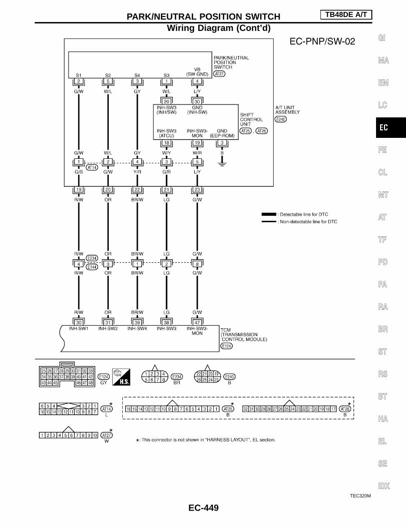
TEC320M
PARK/NEUTRAL POSITION SWITCH TB48DE A/T
Wiring Diagram (Cont’d)
EC-449
GI
MA
EM
LC
FE
CL
MT
AT
TF
PD
FA
RA
BR
ST
RS
BT
HA
EL
SE
IDX

Diagnostic Procedure
INSPECTION START
CHECK OVERALL FUNCTION.
With CONSULT-II
1. Turn ignition switch “ON”.2. Select “P/N POSI SW” in “DATA MONI-
TOR” mode with CONSULT-II.3. Check the “P/N POSI SW” signal under
the following conditions.
Without CONSULT-II
1. Turn ignition switch “ON”.2. Check voltage between ECM terminal
q80 (PNP signal) and ground under thefollowing conditions.
NG
EOK
INSPECTION END
CHECK PNP SWITCH SIGNAL.
With CONSULT-II
1. Turn ignition switch “ON”.2. Select “A/T”, then “DATA MONITOR”
mode with CONSULT-II.3. Select “P/N POSI SW” signal and check
its indication under the following condi-tions.
Without CONSULT-II
Confirm that the PNP switch signal is sentto TCM correctly.Refer to AT section, “PARK/NEUTRALPOSITION SWITCH”.
OK
ENG
CHECK PNP SWITCHCIRCUIT.Check the PNP switch cir-cuit.Refer to AT section,“PARK/NEUTRAL POSI-TION SWITCH”.
INSPECTION END
GO TO qA .
Position (Selector lever) Known-good signal
“N” and “P” position ON
Except the above position OFF
Condition Voltage
Gear position is “N” or “P”. 0V
Except the above gearposition Battery voltage
Condition(Gear position) P/N POSI SW
“P” or “N” position ON
Other positions OFF
SEF212Y
PBIB0169E
PBIB0102E
H
H
H
H
PARK/NEUTRAL POSITION SWITCH TB48DE A/T
EC-450

qA
CHECK PNP SWITCH INPUT SIGNALCIRCUIT-I FOR OPEN AND SHORT.1. Turn ignition switch “OFF”.2. Disconnect TCM harness connector.3. Disconnect park/neutral position relay-3
harness connector.4. Check harness continuity between TCM
terminal q48 and park/neutral positionrelay-3 terminal q2 .Refer to Wiring Diagram.Continuity should exist.
5. Also check harness for short to groundand short to power.
OK
ENG If NG, repair open circuit or
short to ground or short topower in harness or con-nectors.
CHECK PNP SWITCH INPUT SIGNALCIRCUIT-II FOR OPEN AND SHORT.1. Check harness continuity between park/
neutral position relay-3 terminals q1 ,q6 and ground.Refer to Wiring Diagram.Continuity should exist.
2. Also check harness for short to power.
OK
ENG Repair open circuit or short
to power in harness orconnectors.
CHECK PNP SWITCH INPUT SIGNALCIRCUIT-III FOR OPEN AND SHORT.1. Disconnect ECM harness connector.2. Check harness continuity between ECM
terminal q80 and park/neutral positionrelay-3 terminal q7 .Refer to Wiring Diagram.Continuity should exist.
OK
ENG Check the following.
I Harness connectorsF7 , M52
I Harness connectorsM21 , E127
I Harness for open orshort between ECM andPark/Neutral positionrelay-3
If NG, repair open circuit orshort to ground or short topower in harness or con-nectors.
CHECK PARK/NEUTRAL POSITIONRELAY-3.Refer to AT section.
OK
ENG If NG, replace park/neutral
position relay-3.
CHECK INTERMITTENT INCIDENT.Refer to EC-331, “TROUBLE DIAGNOSISFOR INTERMITTENT INCIDENT”.
INSPECTION END
SEC185D
SEC298D
H
H
H
H
H
H
PARK/NEUTRAL POSITION SWITCH TB48DE A/T
Diagnostic Procedure (Cont’d)
EC-451
GI
MA
EM
LC
FE
CL
MT
AT
TF
PD
FA
RA
BR
ST
RS
BT
HA
EL
SE
IDX

Component DescriptionTo turn on the switch, push the lower side of it. The indicator lightof the switch will illuminate and the transmission shifts into thesnow driving mode.I This mode is used for standing starts on slippery (snowy,
sandy) roads.I When the selector lever is in the D position, the transmission
shifts from 1st to 5th gear automatically from standing starts orwhen accelerating from low speed.
ECM Terminals and Reference ValueSpecification data are reference values and are measured between each terminal and ground.CAUTION:Do not use ECM ground terminals when measuring input/output voltage. Doing so may result in dam-age to the ECM’s transistor. Use a ground other than ECM terminals, such as the ground.
TER-MINAL
NO.
WIRECOLOR
ITEM CONDITIONDATA
(DC voltage)
60 Y/G Snow mode switch
Ignition switch “ON”
Snow mode switch is snow position.Snow switch is “ON”.
Battery voltage (11 - 14V)
Ignition switch “ON”
Except above switch positionApproximately 0V
SEC222D
SNOW MODE SWITCH TB48DE A/T
EC-452

Wiring DiagramWITH SNOW MODE SWITCH
TEC263M
SNOW MODE SWITCH TB48DE A/T
EC-453
GI
MA
EM
LC
FE
CL
MT
AT
TF
PD
FA
RA
BR
ST
RS
BT
HA
EL
SE
IDX

Diagnostic Procedure
INSPECTION START
CHECK OVERALL FUNCTION.1. Turn ignition switch “ON”.2. Check voltage as follows.
NG
EOK
NG
CHECK SNOW INDICA-TOR LAMP.1. Turn ignition switch “ON”.2. Check snow indicator
lamp as follows.
OK
INSPECTION END
qA F
CHECK POWER SUPPLY FOR SNOWMODE SWITCH.1. Disconnect snow mode switch harness
connector.2. Turn ignition switch “ON”.3. Check voltage between snow mode
switch terminal q2 and ground.Battery voltage
OK
ENG Check the following.
I 7.5A fuseI Harness connectors
M20 , B19I Harness for open or short
between snow modeswitch and fuse.
If NG, repair open circuit,short to ground or short topower in harness or con-nectors.
CHECK INPUT SIGNAL CIRCUIT-I.1. Turn ignition switch “OFF”.2. Disconnect ECM harness connector.3. Check harness continuity between snow
mode switch terminal q1 and ECM ter-minal q60 .Refer to Wiring Diagram.Continuity should exist.
4. Check harness continuity between ECMterminal q60 and snow mode switch ter-minal q6 . Refer to wiring diagram.Continuity should exist.
5. Also check harness for short to groundand short to power.
If OK, reconnect ECM harness connector.
OK
ENG Check the following.
I Harness connector B19 ,M20
I Harness connector M51 ,F6
I Harness for open or shortbetween snow modeswitch and ECM
If NG, repair open circuit,short to ground or short topower in harness or con-nectors.
CHECK GROUND CIRCUIT.1. Check harness continuity between snow
mode switch harness connector terminalq7 and ground.Refer to Wiring Diagram.Continuity should exist.
If OK, check harness for short to power.
OK
ENG Check the following.
I Harness connector B19 ,M20
I Harness for open or shortbetween snow modeswitch and ground.
If NG, repair open circuit,short to power in harnessor connectors.
CHECK INTERMITTENT INCIDENT.Refer to “TROUBLE DIAGNOSIS FORINTERMITTENT INCIDENT”, EC-331.
INSPECTION END
Snow mode switch ECM terminal q60 voltage
AUTO 0 V
SNOW 11 - 14 V (Battery voltage)Snow mode
switchSnow indica-
tor lamp
AUTO OFF
SNOW ON
SEC188D
H
H
H
H
H
H
H
SNOW MODE SWITCH TB48DE A/T
EC-454

qA
CHECK SNOW INDICATOR LAMP INPUTSIGNAL CIRCUIT.1. Check continuity between snow mode
switch terminal q1 and q6 . Refer towiring diagram.Continuity should exist.
2. Also check harness for short to groundand short to power.
OK
ENG Repair open circuit, short
to ground or short to powerin harness or connectors.
CHECK SNOW INDICATOR LAMPGROUND.1. Check harness continuity between
snow mode switch terminal q7 andground. Refer to wiring diagram.Continuity should exist.
OK
ENG Check the following.
I Harness connectorsB19 , M20
I Harness for open orshort between snowmode switch and ground
If NG, repair open circuit,short to power in harnessor connectors.
CHECK SNOW INDICATOR LAMP.Refer to EL or AT section.
OK
ENG Replace snow indicator
lamp or snow mode switchassembly.
INSPECTION END
H
H
H
H
SNOW MODE SWITCH TB48DE A/T
Diagnostic Procedure (Cont’d)
EC-455
GI
MA
EM
LC
FE
CL
MT
AT
TF
PD
FA
RA
BR
ST
RS
BT
HA
EL
SE
IDX

DescriptionSYSTEM DESCRIPTION
Sensor Input Signal to ECMECM func-
tionActuator
Mass air flow sensor Amount of intake air
VIAS con-trol
VIAS control solenoid valve
Throttle position sensor Throttle position
Accelerator pedal position sensor Accelerator pedal position
Ignition switch Start signal
Camshaft position sensor Engine speed
Engine coolant temperature sensor Engine coolant temperature
When the engine is running at low or medium speed, the ECMsends the signal to the VIAS control solenoid valve then powervalve is fully closed. Under this condition, the effective suction portlength is equivalent to the total length of the intake manifold collec-tor’s suction port including the intake valve. This long suction portprovides increased air intake which results in improved suctionefficiency and higher torque generation.The surge tank and one-way valve are provided. When engine isrunning at high speed, the ECM does not send the signal to theVIAS control solenoid valve, thus enabling power valve to be fullyopened. This signal introduces the intake manifold vacuum into thepower valve actuator and therefore opens the power valve to twosuction passages together in the collector.Under this condition, the effective port length is equivalent to the
SEC802C
VARIABLE INDUCTION AIR CONTROL SYSTEM (VIAS) TB48DE A/T
EC-456

length of the suction port provided independently for each cylinder.This shortened port length results in enhanced engine output withreduced suction resistance under high speeds.
COMPONENT DESCRIPTION
Power valveThe power valve is installed in intake manifold collector and usedto control the suction passage of the variable induction air controlsystem. It is set in the fully closed or fully opened position by thepower valve actuator operated by the vacuum stored in the surgetank. The vacuum in the surge tank is controlled by the VIAS con-trol solenoid valve.
VIAS control solenoid valveThe VIAS control solenoid valve cuts the intake manifold vacuumsignal for power valve control. It responds to ON/OFF signals fromthe ECM. When the solenoid is off, the vacuum signal from theintake manifold is for high speed. When the ECM sends an ONsignal the coil pulls the plunger downward and feeds the vacuumsignal to the power valve actuator.
ECM Terminals and Reference ValueSpecification data are reference values and are measured between each terminal and ground.CAUTION:Do not use ECM ground terminals when measuring input/output voltage. Doing so may result in dam-age to the ECM’s transistor. Use a ground other than ECM terminals, such as the ground.
TER-MINAL
NO.
WIRECOLOR
ITEM CONDITION DATA (DC Voltage)
27 LG/RVIAS control solenoidvalve
Engine is running.
Idle speed
BATTERY VOLTAGE(11 - 14V)
Engine is running.
Engine speed is above 5,000 rpm.0 - 1.0V
SEC803C
SEC804C
VARIABLE INDUCTION AIR CONTROL SYSTEM (VIAS) TB48DE A/T
Description (Cont’d)
EC-457
GI
MA
EM
LC
FE
CL
MT
AT
TF
PD
FA
RA
BR
ST
RS
BT
HA
EL
SE
IDX

Wiring Diagram
TEC161M
VARIABLE INDUCTION AIR CONTROL SYSTEM (VIAS) TB48DE A/T
EC-458

Diagnostic Procedure
INSPECTION START
CHECK OVERALL FUNCTION.
With CONSULT-II1. Start engine and warm it up to normal
operating temperature.2. Perform “VIAS SOL VALVE” in “ACTIVE
TEST” mode with CONSULT-II.3. Turn VIAS control solenoid valve “ON”
and “OFF”, and make sure that powervalve actuator rod moves.
Without CONSULT-II1. Start engine and warm it up to normal
operating temperature.2. Rev engine quickly up to above 5,000
rpm and make sure that power valveactuator rod moves.
NG
EOK INSPECTION END
CHECK VIAS CONTROL SOLENOIDVALVE POWER SUPPLY CIRCUIT.1. Stop engine.2. Disconnect VIAS control solenoid valve
harness connector.3. Turn ignition switch “ON”.4. Check voltage between terminal q1 and
ground with CONSULT-II or tester.Voltage: Battery voltage
OK
ENG Check the following.
I Harness connectorsM52 , F7
I 10A fuseI Harness continuity
between fuse and VIAScontrol solenoid valve
If NG, repair harness orconnectors.
CHECK VIAS CONTROL SOLENOIDVALVE OUTPUT SIGNAL CIRCUIT FOROPEN AND SHORT.1. Turn ignition switch “OFF”.2. Disconnect ECM harness connector.3. Check harness continuity between ECM
terminal q27 and terminal q2 . Refer toWiring Diagram.Continuity should exist.
4. Also check harness for short to groundand short to power.
OK
ENG Repair open circuit or short
to ground or short to powerin harness or connectors.
RETEST OVERALL FUNCTION.1. Reconnect harness connectors discon-
nected.2. Perform CHECK OVERALL FUNCTION
again.
NG
EOK INSPECTION END
CHECK INTERMITTENT INCIDENT.Refer to “TROUBLE DIAGNOSIS FORINTERMITTENT INCIDENT”, EC-331.
OK
ENG Repair or replace harness
or connectors.
Replace VIAS control solenoid valve asintake manifold collector assembly.
SEC805C
SEC806C
SEC804C
SEC807C
H
H
H
H
H
H
VARIABLE INDUCTION AIR CONTROL SYSTEM (VIAS) TB48DE A/T
EC-459
GI
MA
EM
LC
FE
CL
MT
AT
TF
PD
FA
RA
BR
ST
RS
BT
HA
EL
SE
IDX

Component DescriptionThe fuel injector is a small, precise solenoid valve. When the ECMsupplies a ground to the injector circuit, the coil in the injector isenergized. The energized coil pulls the ball valve back and allowsfuel to flow through the injector into the intake manifold. Theamount of fuel injected depends upon the injection pulse duration.Pulse duration is the length of time the injector remains open. TheECM controls the injection pulse duration based on engine fuelneeds.
CONSULT-II Reference Value in Data MonitorMode
Specification data are reference values.
MONITOR ITEM CONDITION SPECIFICATION
INJ PULSE-B1/B2
I Engine: After warming upI Air conditioner switch: “OFF”I Shift lever: “N”I No-load
Idle 2.4 - 3.2 msec
2,000 rpm 1.9 - 2.8 msec
B/FUEL SCHDL dittoIdle 2.0 - 3.2 msec
2,000 rpm 1.4 - 2.6 msec
ECM Terminals and Reference ValueSpecification data are reference values and are measured between each terminal and ground.CAUTION:Do not use ECM ground terminals when measuring input/output voltage. Doing so may result in dam-age to the ECM’s transistor. Use a ground other than ECM terminals, such as the ground.
TER-MINAL
NO.
WIRECOLOR
ITEM CONDITIONDATA
(DC voltage)
567131415
BR/WGY/LBR/YGY/RBRGY
Injector No. 1Injector No. 2Injector No. 3Injector No. 4Injector No. 5Injector No. 6
Engine is running. (Warm-up condition)
Idle speed
BATTERY VOLTAGE(11 - 14V)
SEC670C
Engine is running.
Engine speed is 2,000 rpm.
BATTERY VOLTAGE(11 - 14V)
SEC671C
: Average voltage for pulse signal (Actual pulse signal can be confirmed by oscilloscope.)
SEF375Z
INJECTOR TB48DE A/T
EC-460

Wiring Diagram
TEC162M
INJECTOR TB48DE A/T
EC-461
GI
MA
EM
LC
FE
CL
MT
AT
TF
PD
FA
RA
BR
ST
RS
BT
HA
EL
SE
IDX

Diagnostic Procedure
INSPECTION START
CHECK OVERALL FUNCTION.1. Start engine.
With CONSULT-II
2. Perform “POWER BALANCE” in“ACTIVE TEST” mode with CONSULT-II.
3. Make sure that each circuit produces amomentary engine speed drop.
-------------------------------------------------------------------------------------------------------------------------------------- OR --------------------------------------------------------------------------------------------------------------------------------------
Without CONSULT-II
2. Listen to each injector operating sound.Clicking noise should be heard.
NG
EOK INSPECTION END
CHECK POWER SUPPLY.1. Stop engine.2. Disconnect each injector harness con-
nector.3. Turn ignition switch “ON”.4. Check voltage between each terminal
q2 and ground with CONSULT-II ortester.Voltage: Battery voltage
OK
ENG Check the following.
I Harness connectorsM52 , F7
I Harness connectorsF12 , F101
I 10A fuseI Harness for open or short
between injector and fuseblock
If NG, repair harness orconnectors.
CHECK OUTPUT SIGNAL CIRCUIT.1. Turn ignition switch “OFF”.2. Disconnect ECM harness connector.3. Check harness continuity between each
terminal q1 and ECM terminals q5 , q6 ,q7 , q13 , q14 , q15 .Refer to Wiring Diagram.Continuity should exist.If OK, check harness for short to groundand short to power.
OK
ENG Check the following.
I Harness connectorsF101 , F12
I Harness for open or shortbetween ECM and injec-tor
If NG, repair open circuit orshort to ground or short topower in harness or con-nectors.
CHECK COMPONENT(Injector).Refer to “COMPONENT INSPECTION” onEC-463.
OK
ENG Replace injector.
CHECK INTERMITTENT INCIDENT.Refer to “TROUBLE DIAGNOSIS FORINTERMITTENT INCIDENT”, EC-331.
INSPECTION END
SEF190Y
SEF730L
SEC793C
SEC808C
H
H
H
H
H
H
INJECTOR TB48DE A/T
EC-462

Component InspectionINJECTOR1. Disconnect injector harness connector.2. Check resistance between terminals as shown in the figure.
Resistance: 13.5 - 17.5 Ω [at 20°C (68°F)]If NG, replace injector.
SEC809C
INJECTOR TB48DE A/T
EC-463
GI
MA
EM
LC
FE
CL
MT
AT
TF
PD
FA
RA
BR
ST
RS
BT
HA
EL
SE
IDX

CONSULT-II Reference Value in Data MonitorMode
Specification data are reference values.
MONITOR ITEM CONDITION SPECIFICATION
START SIGNAL I Ignition switch: ON , START , ON OFF , ON , OFF
ECM Terminals and Reference ValueSpecification data are reference values and are measured between each terminal and ground.CAUTION:Do not use ECM ground terminals when measuring input/output voltage. Doing so may result in dam-age to the ECM’s transistor. Use a ground other than ECM terminals, such as the ground.
TER-MINAL
NO.
WIRECOLOR
ITEM CONDITION DATA (DC Voltage)
59 R/W Start signalIgnition switch “ON” Approximately 0V
Ignition switch “START” 9 - 12V
START SIGNAL TB48DE A/T
EC-464

Wiring Diagram
TEC163M
START SIGNAL TB48DE A/T
EC-465
GI
MA
EM
LC
FE
CL
MT
AT
TF
PD
FA
RA
BR
ST
RS
BT
HA
EL
SE
IDX

Diagnostic Procedure
INSPECTION START
CHECK OVERALL FUNCTION.
With CONSULT-II
1. Turn ignition switch “ON”.2. Check “START SIGNAL” in “DATA
MONITOR” mode with CONSULT-II.
-------------------------------------------------------------------------------------------------------------------------------------- OR --------------------------------------------------------------------------------------------------------------------------------------
Without CONSULT-II
1. Turn ignition switch to “START”.2. Check voltage between ECM terminal
q59 and ground.Voltage:
Ignition switch “START”Battery voltage (9 - 12V)
Except aboveApproximately 0V
NG
EOK INSPECTION END
Check if 7.5A fuse is OK.
OKE
NG Replace 7.5A fuse.
CHECK INPUT SIGNAL CIRCUIT.1. Turn ignition switch “OFF”.2. Disconnect ECM harness connector and
7.5A fuse.3. Check harness continuity between ECM
terminal q59 and fuse block.Refer to Wiring Diagram.Continuity should exist.If OK, check harness for short to groundand short to power.
OK
ENG Check the following.
I Harness connectorsM52 , F7
I Harness for open or shortbetween ECM and fuseblock
If NG, repair open circuit,short to ground or short topower in harness or con-nectors.
CHECK INTERMITTENT INCIDENT.Refer to “TROUBLE DIAGNOSIS FORINTERMITTENT INCIDENT”, EC-331.
INSPECTION END
IGN “ON” OFF
IGN “START” ON
PBIB0182E
SEC824C
H
H
H
H
H
START SIGNAL TB48DE A/T
EC-466

System Description
Camshaft position sensorE
Engine speed
ECM EFuelpumprelayIgnition switch
EStart signal
The ECM activates the fuel pump for several sec-onds after the ignition switch is turned on to improveengine storability. If the ECM receives a 120° signalfrom the camshaft position sensor, it knows that theengine is rotating, and causes the pump to operate.If the 120° signal is not received when the ignitionswitch is on, the engine stalls. The ECM stops pumpoperation and prevents battery discharging, therebyimproving safety. The ECM does not directly drivethe fuel pump. It controls the ON/OFF fuel pumprelay, which in turn controls the fuel pump.
Condition Fuel pump operation
Ignition switch is turned to ON.Operates for5 seconds.
Engine running and cranking Operates.
When engine is stopped Stops in 1 second.
Except as shown above Stops.
Component DescriptionThe fuel pump with a fuel damper is an in-tank type (the pump anddamper are located in the fuel tank).
CONSULT-II Reference Value in Data MonitorMode
Remarks: Specification data are reference values.
MONITOR ITEM CONDITION SPECIFICATION
FUEL PUMP RLY
I Ignition switch is turned to ON (Operates for 5 seconds).I Engine running and crankingI When engine is stopped (Stops in 1 second)
ON
Except as shown above OFF
SEF609V
FUEL PUMP TB48DE A/T
EC-467
GI
MA
EM
LC
FE
CL
MT
AT
TF
PD
FA
RA
BR
ST
RS
BT
HA
EL
SE
IDX

ECM Terminals and Reference ValueSpecification data are reference values and are measured between each terminal and ground.CAUTION:Do not use ECM ground terminals when measuring input/output voltage. Doing so may result in dam-age to the ECM’s transistor. Use a ground other than ECM terminals, such as the ground.
TER-MINAL
NO.
WIRECOLOR
ITEM CONDITIONDATA
(DC voltage)
40*2(41)*1
R/Y Fuel pump relay
Ignition switch “ON”
For 5 seconds after turning ignition switch“ON”
Engine is running.
0 - 1.0V
Ignition switch “ON”
5 seconds after turning ignition switch “ON”
BATTERY VOLTAGE(11 - 14V)
*1: With NATS (Nissan Anti-Theft System)*2: Without NATS (Nissan Anti-Theft System)
FUEL PUMP TB48DE A/T
EC-468

Wiring Diagram
TEC164M
FUEL PUMP TB48DE A/T
EC-469
GI
MA
EM
LC
FE
CL
MT
AT
TF
PD
FA
RA
BR
ST
RS
BT
HA
EL
SE
IDX

Diagnostic Procedure
INSPECTION START
CHECK OVERALL FUNCTION.1. Turn ignition switch “ON”.2. Pinch fuel feed hose with fingers.
Fuel pressure pulsation should be felton the fuel feed hose for 5 secondsafter ignition switch is turned “ON”.
NG
EOK INSPECTION END
CHECK POWER SUPPLY.1. Turn ignition switch “OFF”.2. Disconnect fuel pump relay.3. Turn ignition switch “ON”.4. Check voltage between terminals q1 ,
q3 and ground with CONSULT-II ortester.Voltage: Battery voltage
OK
ENG Check the following.
I 15A fuseI Harness for open or short
between fuse and fuelpump relay
If NG, repair harness orconnectors.
CHECK GROUND CIRCUIT-I.1. Turn ignition switch “OFF”.2. Disconnect fuel tank gauge unit (fuel
pump) harness connector.3. Check harness continuity between termi-
nal q6 and body ground.Refer to Wiring Diagram.Continuity should exist.If OK, check harness for short topower.
OK
ENG Check the following.
I Harness connectorsC2 , B37 (LHD models)
I Harness connectorsC2 , B125 (RHD mod-
els)I Harness for open or short
between fuel pump andbody ground
If NG, repair open circuit,short to power in harnessor connectors.
CHECK GROUND CIRCUIT-II.1. Turn ignition switch “OFF”.2. Check harness continuity between relay
terminal q5 and fuel pump terminal q4 .Refer to Wiring Diagram.Continuity should exist.If OK, check harness for short toground and short to power.
OK
ENG Check the following.
I Harness connectorsM20 , B19 (LHD models)
I Harness connectorsM97 , B103 (RHD mod-
els)I Harness connectors
B137 , C2 (LHD models)I Harness connectors
B125 , C2 (RHD mod-els)
I Harness for open or shortbetween fuel pump andfuel pump relay
If NG, repair open circuit,short to ground or short topower in harness or con-nectors.
qA
(Go to next page.)
SEC810C
SEC684C
SEF479P
SEF608V
H
H
H
H
H
FUEL PUMP TB48DE A/T
EC-470

qA
CHECK OUTPUT SIGNAL CIRCUIT.1. Disconnect ECM harness connector.2. Check harness continuity between ECM
terminal q40 (Without NATS) or q41 (WithNATS) and fuel pump relay terminal q2 .Refer to Wiring Diagram.Continuity should exist.If OK, check harness for short toground and short to power.
OK
ENG Check the following.
I Harness connectorsM52 , F7
I Harness for open or shortbetween ECM and fuelpump relay
If NG, repair open circuit,short to ground or short topower in harness or con-nectors.
CHECK COMPONENT(Fuel pump relay).
With CONSULT-II
1. Reconnect fuel pump relay, fuel pumpharness connector and ECM harnessconnector.
2. Turn ignition switch “ON”.3. Turn fuel pump relay “ON” and “OFF” in
“ACTIVE TEST” mode with CONSULT-IIand check operating sound.
-------------------------------------------------------------------------------------------------------------------------------------- OR --------------------------------------------------------------------------------------------------------------------------------------
Without CONSULT-II
Refer to “COMPONENT INSPECTION”,EC-472.
OK
ENG Replace fuel pump relay.
CHECK COMPONENT(Fuel pump).Refer to “COMPONENT INSPECTION”,EC-472.
OK
ENG Replace fuel pump.
CHECK INTERMITTENT INCIDENT.Refer to “TROUBLE DIAGNOSIS FORINTERMITTENT INCIDENT”, EC-331.
INSPECTION END
SEF073Y
H
H
H
H
H
FUEL PUMP TB48DE A/T
Diagnostic Procedure (Cont’d)
EC-471
GI
MA
EM
LC
FE
CL
MT
AT
TF
PD
FA
RA
BR
ST
RS
BT
HA
EL
SE
IDX

Component InspectionFUEL PUMP RELAYCheck continuity between terminals q3 and q5 .
Conditions Continuity
12V direct current supplybetween terminals q1 and q2
Yes
No current supply No
If NG, replace relay.
FUEL PUMP1. Disconnect fuel pump harness connector.2. Check resistance between terminals q4 and q6 .
Resistance: 0.2 - 5.0 Ω at 25°C (77°F)If NG, replace fuel pump.
SEF511P
SEF607V
FUEL PUMP TB48DE A/T
EC-472

Component DescriptionThe power steering oil pressure switch is attached to the powersteering high-pressure tube and detects a power steering load.When a power steering load is detected, it signals the ECM. TheECM adjusts the IACV-AAC valve to increase the idle speed andadjust for the increased load.
CONSULT-II Reference Value in Data MonitorMode
Remarks: Specification data are reference values.
MONITOR ITEM CONDITION SPECIFICATION
PW/ST SIGNALI Engine: After warming up, idle the
engine
Steering wheel in neutral position(forward direction)
OFF
The steering wheel is turned. ON
ECM Terminals and Reference ValueSpecification data are reference values and are measured between each terminal and ground.CAUTION:Do not use ECM ground terminals when measuring input/output voltage. Doing so may result in dam-age to the ECM’s transistor. Use a ground other than ECM terminals, such as the ground.
TER-MINAL
NO.
WIRECOLOR
ITEM CONDITIONDATA
(DC voltage)
79 OR/LPower steering oil pres-sure switch
Engine is running.
Steering wheel is being turned.0V
Engine is running.
Steering wheel is not being turned.Approximately 5V
SEC811C
POWER STEERING OIL PRESSURE SWITCH TB48DE A/T
EC-473
GI
MA
EM
LC
FE
CL
MT
AT
TF
PD
FA
RA
BR
ST
RS
BT
HA
EL
SE
IDX

Wiring Diagram
TEC165M
POWER STEERING OIL PRESSURE SWITCH TB48DE A/T
EC-474
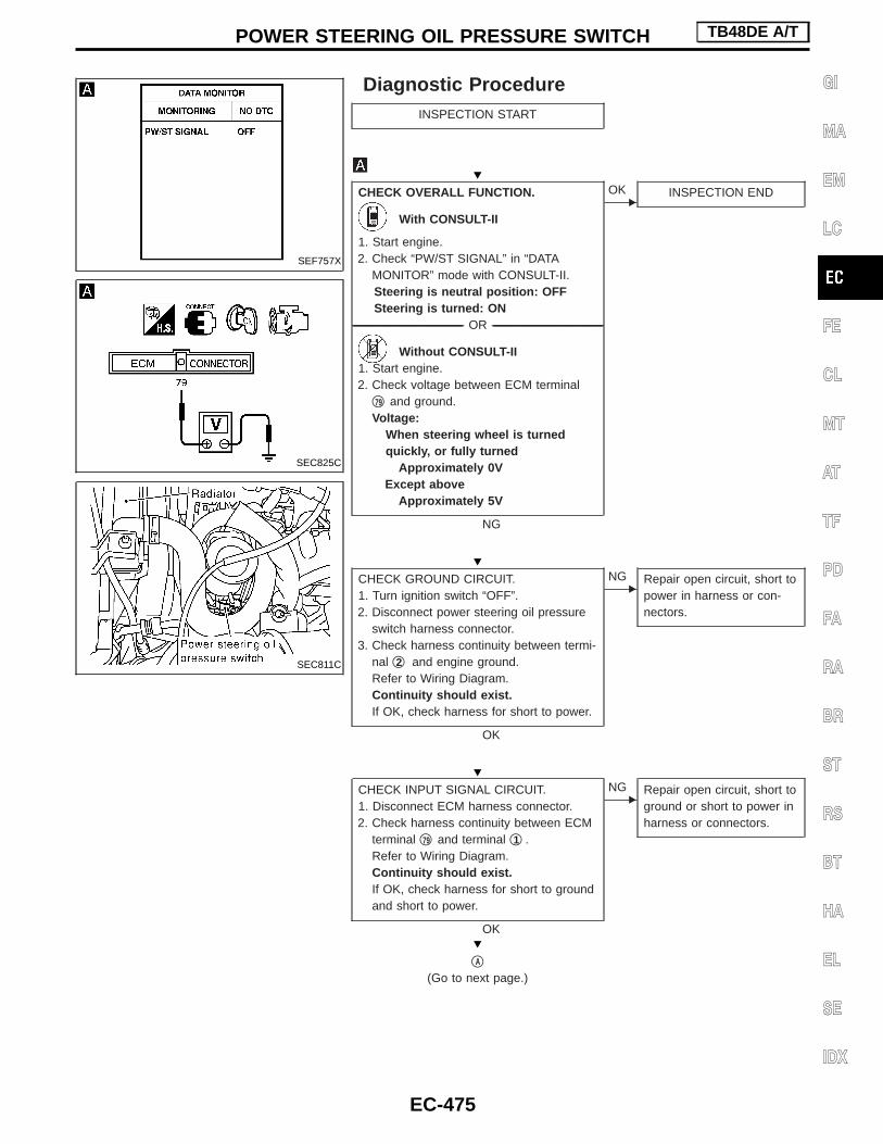
Diagnostic ProcedureINSPECTION START
CHECK OVERALL FUNCTION.
With CONSULT-II
1. Start engine.2. Check “PW/ST SIGNAL” in “DATA
MONITOR” mode with CONSULT-II.Steering is neutral position: OFFSteering is turned: ON
-------------------------------------------------------------------------------------------------------------------------------------- OR --------------------------------------------------------------------------------------------------------------------------------------
Without CONSULT-II1. Start engine.2. Check voltage between ECM terminal
q79 and ground.Voltage:
When steering wheel is turnedquickly, or fully turned
Approximately 0VExcept above
Approximately 5V
NG
EOK INSPECTION END
CHECK GROUND CIRCUIT.1. Turn ignition switch “OFF”.2. Disconnect power steering oil pressure
switch harness connector.3. Check harness continuity between termi-
nal q2 and engine ground.Refer to Wiring Diagram.Continuity should exist.If OK, check harness for short to power.
OK
ENG Repair open circuit, short to
power in harness or con-nectors.
CHECK INPUT SIGNAL CIRCUIT.1. Disconnect ECM harness connector.2. Check harness continuity between ECM
terminal q79 and terminal q1 .Refer to Wiring Diagram.Continuity should exist.If OK, check harness for short to groundand short to power.
OK
ENG Repair open circuit, short to
ground or short to power inharness or connectors.
qA
(Go to next page.)
SEF757X
SEC825C
SEC811C
H
H
H
H
POWER STEERING OIL PRESSURE SWITCH TB48DE A/T
EC-475
GI
MA
EM
LC
FE
CL
MT
AT
TF
PD
FA
RA
BR
ST
RS
BT
HA
EL
SE
IDX
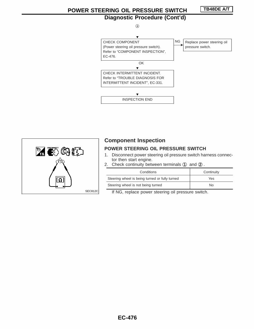
qA
CHECK COMPONENT(Power steering oil pressure switch).Refer to “COMPONENT INSPECTION”,EC-476.
OK
ENG Replace power steering oil
pressure switch.
CHECK INTERMITTENT INCIDENT.Refer to “TROUBLE DIAGNOSIS FORINTERMITTENT INCIDENT”, EC-331.
INSPECTION END
Component InspectionPOWER STEERING OIL PRESSURE SWITCH1. Disconnect power steering oil pressure switch harness connec-
tor then start engine.2. Check continuity between terminals q1 and q2 .
Conditions Continuity
Steering wheel is being turned or fully turned Yes
Steering wheel is not being turned No
If NG, replace power steering oil pressure switch.SEC812C
H
H
H
POWER STEERING OIL PRESSURE SWITCH TB48DE A/T
Diagnostic Procedure (Cont’d)
EC-476

DescriptionThe electrical load signal (Headlamp switch signal, rear window defogger switch signal, etc) is transferredthrough the CAN communication line from combination meter to ECM.
ELECTRICAL LOAD SIGNAL TB48DE A/T
EC-477
GI
MA
EM
LC
FE
CL
MT
AT
TF
PD
FA
RA
BR
ST
RS
BT
HA
EL
SE
IDX

Diagnostic Procedure
CHECK LOAD SIGNAL CIRCUIT OVER-ALL FUNCTION-I1. Turn ignition switch “ON”.2. Connect CONSULT-II and select “DATA
MONITOR” mode.3. Select “LOAD SIGNAL” and check indi-
cation under the following conditions.
OK
ENG
qA
CHECK LOAD SIGNAL CIRCUIT OVER-ALL FUNCTION-IICheck “LOAD SIGNAL” indication underthe following conditions.
OK
ENG
qB
INSPECTION END
qA
CHECK REAR WINDOW DEFOGGERFUNCTION.1. Start engine.2. Turn “ON” the rear window defogger
switch.3. Check the rear windshield. Is the rear
windshield heated up?
Yes
ENo
Check rear window defog-ger circuit. Refer to ELsection, “REAR WINDOWDEFOGGER”.
CHECK REAR WINDOW DEFOGGERINPUT SIGNAL CIRCUIT FOR OPEN ORSHORT.1. Stop engine.2. Check the circuit for open and short
between combination meter and rearwindow defogger.Refer to EL section, “Wiring Diagram —LOAD/S”.
OK
ENG
Repair open circuit or shortto ground or short to powerin harness connectors.
CHECK COMBINATION METERRefer to EL section, “COMBINATIONMETERS”.
OK
ENG
Replace combinationmeter.
CHECK INTERMITTENT INCIDENTRefer to EC-331, “TROUBLE DIAGNOSISFOR INTERMITTENT INCIDENT”.
INSPECTION END
Condition Indication
Rear window defoggerswitch “ON”.
ON
Rear window defoggerswitch “OFF”.
OFF
Condition Indication
Lighting switch “ON”at 2nd position
ON
Lighting switch “OFF” OFF
PBIB0103E
H
H
H
H
H
H
H
ELECTRICAL LOAD SIGNAL TB48DE A/T
EC-478

qB
CHECK HEADLAMP FUNCTION1. Start engine.2. Turn “ON” the lighting switch at 2nd
position.3. Check that headlamp high beams are
illuminated.
OK
ENG Check headlamp circuit.
Refer to EL section,“HEADLAMP”.
CHECK HEADLAMP INPUT SIGNAL CIR-CUIT1. Stop engine.2. Check the circuit for open and short
between combination meter and head-lamp.Refer to EL section, “Wiring Diagram —LOAD/S —”.
3. Also check harness for short to groundand short to power.
OK
ENG Repair open circuit or short
to ground or short to powerin harness connectors.
CHECK COMBINATION METERRefer to EL section, “COMBINATIONMETERS”.
OK
ENG Replace combination
meter.
CHECK INTERMITTENT INCIDENTRefer to EC-331, “TROUBLE DIAGNOSISFOR INTERMITTENT INCIDENT”.
INSPECTION END
H
H
H
H
H
ELECTRICAL LOAD SIGNAL TB48DE A/T
Diagnostic Procedure (Cont’d)
EC-479
GI
MA
EM
LC
FE
CL
MT
AT
TF
PD
FA
RA
BR
ST
RS
BT
HA
EL
SE
IDX

Wiring Diagram
TEC318M
MIL & DATA LINK CONNECTORS TB48DE A/T
EC-480

Fuel Pressure Regulator
Fuel pressurekPa (bar, kg/cm2, psi)
At idleApproximately
245 (2.45, 2.5, 36)
A few seconds after ignitionswitch is turned OFF to ON
Approximately294 (2.94, 3.0, 43)
Idle Speed and Ignition Timing
Idle speed rpm
Target idle speed 675±50No-load*1(in “N” position)
Air conditioner: ON(in “N” position)
With three waycatalyst
850 rpm or more
Without three waycatalyst
950 rpm or more
Ignition timing 5°±5° BTDC
*1: Under the following conditions:I Air conditioner switch: OFFI Steering wheel: Kept in straight-ahead positionI Electrical load: OFF (Lights, heater fan & rear window defog-
ger)
Mass Air Flow Sensor
Supply voltage V Battery voltage (11 - 14)
Output voltage at idle V0.75 - 1.5 at idle*
1.7 - 2.4 at 2,500 rpm*
*: Engine is warmed up to normal operating temperature and runningunder no-load.
Engine Coolant Temperature Sensor
Temperature °C (°F) Resistance
20 (68) 2.1 - 2.9 kΩ
50 (122) 0.68 - 1.00 kΩ
90 (194) 0.236 - 0.260 kΩ
Heated Oxygen Sensor 1
Resistance [at 25°C (77°F)] 2.3 - 4.3Ω
Fuel Pump
Resistance [at 25°C (77°F)] Ω 0.2 - 5.0
EVAP Canister Purge Volume Control SolenoidValve
Resistance [at 20°C (68°F)] Ω 31 - 35
SERVICE DATA AND SPECIFICATIONS (SDS) TB48DE A/T
EC-481
GI
MA
EM
LC
FE
CL
MT
AT
TF
PD
FA
RA
BR
ST
RS
BT
HA
EL
SE
IDX
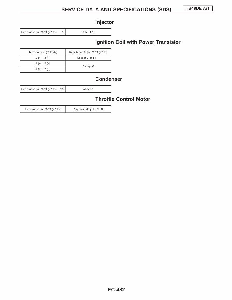
Injector
Resistance [at 25°C (77°F)] Ω 13.5 - 17.5
Ignition Coil with Power Transistor
Terminal No. (Polarity) Resistance Ω [at 25°C (77°F)]
3 (+) - 2 (−) Except 0 or
1 (+) - 3 (−)Except 0
1 (+) - 2 (−)
Condenser
Resistance [at 25°C (77°F)] MΩ Above 1
Throttle Control Motor
Resistance [at 25°C (77°F)] Approximately 1 - 15 Ω
SERVICE DATA AND SPECIFICATIONS (SDS) TB48DE A/T
EC-482
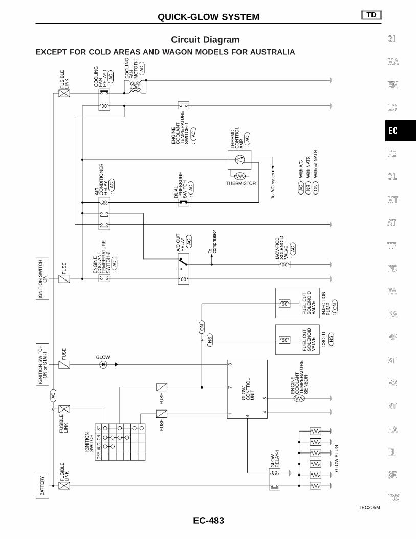
Circuit DiagramEXCEPT FOR COLD AREAS AND WAGON MODELS FOR AUSTRALIA
TEC205M
QUICK-GLOW SYSTEM TD
EC-483
GI
MA
EM
LC
FE
CL
MT
AT
TF
PD
FA
RA
BR
ST
RS
BT
HA
EL
SE
IDX

FOR COLD AREAS AND WAGON MODELS FOR AUSTRALIA
TEC286M
QUICK-GLOW SYSTEM TD
Circuit Diagram (Cont’d)
EC-484

PICKUP MODELS FOR AUSTRALIA
TEC081M
QUICK-GLOW SYSTEM TD
Circuit Diagram (Cont’d)
EC-485
GI
MA
EM
LC
FE
CL
MT
AT
TF
PD
FA
RA
BR
ST
RS
BT
HA
EL
SE
IDX

PICKUP MODELS EXCEPT FOR AUSTRALIA
TEC009M
QUICK-GLOW SYSTEM TD
Circuit Diagram (Cont’d)
EC-486

Wiring DiagramEXCEPT FOR COLD AREAS AND WAGON MODELS FOR AUSTRALIA
TEC451
QUICK-GLOW SYSTEM TD
EC-487
GI
MA
EM
LC
FE
CL
MT
AT
TF
PD
FA
RA
BR
ST
RS
BT
HA
EL
SE
IDX

TEC206M
QUICK-GLOW SYSTEM TD
Wiring Diagram (Cont’d)
EC-488

FOR COLD AREAS AND WAGON MODELS FOR AUSTRALIA
TEC287M
QUICK-GLOW SYSTEM TD
Wiring Diagram (Cont’d)
EC-489
GI
MA
EM
LC
FE
CL
MT
AT
TF
PD
FA
RA
BR
ST
RS
BT
HA
EL
SE
IDX

TEC288M
QUICK-GLOW SYSTEM TD
Wiring Diagram (Cont’d)
EC-490

TEC289M
QUICK-GLOW SYSTEM TD
Wiring Diagram (Cont’d)
EC-491
GI
MA
EM
LC
FE
CL
MT
AT
TF
PD
FA
RA
BR
ST
RS
BT
HA
EL
SE
IDX

TEC290M
QUICK-GLOW SYSTEM TD
Wiring Diagram (Cont’d)
EC-492

PICKUP MODELS
TEC291M
QUICK-GLOW SYSTEM TD
Wiring Diagram (Cont’d)
EC-493
GI
MA
EM
LC
FE
CL
MT
AT
TF
PD
FA
RA
BR
ST
RS
BT
HA
EL
SE
IDX

TEC292M
QUICK-GLOW SYSTEM TD
Wiring Diagram (Cont’d)
EC-494

Wiring Diagram
TEC229M
FAST IDLE CONTROL CIRCUIT TD
EC-495
GI
MA
EM
LC
FE
CL
MT
AT
TF
PD
FA
RA
BR
ST
RS
BT
HA
EL
SE
IDX

Wiring Diagram
TEC230M
ENGINE ROOM FAN MOTOR ELECTRICAL CIRCUIT TD
EC-496

Electrical Components InspectionCheck continuity between terminals q3 and q5 .
Conditions Continuity
12V direct current supply betweenterminals q1 and q2
Yes
No current supply No
If NG, replace relay.
SEF145X
ENGINE ROOM FAN MOTOR ELECTRICAL CIRCUIT TD
EC-497
GI
MA
EM
LC
FE
CL
MT
AT
TF
PD
FA
RA
BR
ST
RS
BT
HA
EL
SE
IDX

Wiring DiagramWAGON MODELS
TEC133M
FUEL CUT SYSTEM TD
EC-498

PICKUP MODELS
TEC293M
FUEL CUT SYSTEM TD
Wiring Diagram (Cont’d)
EC-499
GI
MA
EM
LC
FE
CL
MT
AT
TF
PD
FA
RA
BR
ST
RS
BT
HA
EL
SE
IDX

Circuit DiagramFOR EUROPE
TEC095M
ENGINE AND EMISSION CONTROL OVERALL SYSTEM ZD30DDTi
EC-500

EXCEPT FOR EUROPE
TEC277M
ENGINE AND EMISSION CONTROL OVERALL SYSTEM ZD30DDTi
Circuit Diagram (Cont’d)
EC-501
GI
MA
EM
LC
FE
CL
MT
AT
TF
PD
FA
RA
BR
ST
RS
BT
HA
EL
SE
IDX

Main Power Supply and Ground Circuit
TEC181M
TROUBLE DIAGNOSIS FOR POWER SUPPLY ZD30DDTi
EC-502

TEC097M
TROUBLE DIAGNOSIS FOR POWER SUPPLY ZD30DDTi
Main Power Supply and Ground Circuit(Cont’d)
EC-503
GI
MA
EM
LC
FE
CL
MT
AT
TF
PD
FA
RA
BR
ST
RS
BT
HA
EL
SE
IDX

Wiring Diagram
TEC182M
DTC 0102 MASS AIR FLOW SEN ZD30DDTi
EC-504

Wiring Diagram
TEC183M
DTC 0103 COOLANT TEMP SEN ZD30DDTi
EC-505
GI
MA
EM
LC
FE
CL
MT
AT
TF
PD
FA
RA
BR
ST
RS
BT
HA
EL
SE
IDX

Wiring DiagramFOR EUROPE
TEC184M
DTC 0104 VEHICLE SPEED SEN ZD30DDTi
EC-506

EXCEPT FOR EUROPE
TEC278M
DTC 0104 VEHICLE SPEED SEN ZD30DDTi
Wiring Diagram (Cont’d)
EC-507
GI
MA
EM
LC
FE
CL
MT
AT
TF
PD
FA
RA
BR
ST
RS
BT
HA
EL
SE
IDX

Diagnostic Procedure
1 CHECK VEHICLE SPEED SENSOR INPUT SIGNAL CIRCUIT FOR OPEN AND SHORT
1. Turn ignition switch “OFF”.2. Disconnect ECM harness connector and combination meter harness connector.3. Check harness continuity between ECM terminal 26 and combination meter terminal 26 (For Europe), 65 (Except for Europe).
Refer to Wiring Diagram.Continuity should exist.
4. Also check harness for short to ground and short to power.
OK or NG
OK E GO TO 3.
NG E GO TO 2.
2 DETECT MALFUNCTIONING PART
Check the following.I Harness connectors M52, F7I Joint connector-1I Harness for open or short between ECM and combination meter
E Repair open circuit or short to ground or short to power in harness or connectors.
3 CHECK SPEEDOMETER FUNCTION
Make sure that speedometer functions properly.
OK or NG
OK E GO TO 5.
NG E GO TO 4.
4 CHECK SPEEDOMETER CIRCUIT FOR OPEN AND SHORT
Check the following.I Harness connectors E70, E201I Harness connectors M86, E104 or M21, E127I Harness for open or short between combination meter and vehicle speed sensor
OK or NG
OK E Check vehicle speed sensor and combination meter. Refer to EL section.
NG E Repair open circuit or short to ground or short to power in harness or connectors.
5 CHECK INTERMITTENT INCIDENT
Refer to “TROUBLE DIAGNOSIS FOR INTERMITTENT INCIDENT”.
E INSPECTION END
DTC 0104 VEHICLE SPEED SEN ZD30DDTi
EC-508

Wiring Diagram
TEC185M
DTC 0203 ACCEL POS SW (F/C) ZD30DDTi
EC-509
GI
MA
EM
LC
FE
CL
MT
AT
TF
PD
FA
RA
BR
ST
RS
BT
HA
EL
SE
IDX

Wiring Diagram
TEC186M
DTC 0208 OVER HEAT ZD30DDTi
EC-510

Diagnostic Procedure
1 INSPECTION START
Do you have CONSULT-II?
Yes or No
Yes E GO TO 2.
No E GO TO 3.
2 CHECK COOLING FAN OPERATION
With CONSULT-II1. Turn ignition switch “ON”.2. Perform “COOLING FAN” in “ACTIVE TEST” mode with CONSULT-II.
SEF646X
3. Make sure that cooling fan-1 operates.
OK or NG
OK E GO TO 12.
NG E GO TO 4.
3 CHECK COOLING FAN OPERATION
Without CONSULT-II1. Turn ignition switch “OFF”.2. Disconnect engine coolant temperature sensor harness connector.3. Connect 150Ω resistor to engine coolant temperature sensor harness connector.4. Restart engine and make sure that cooling fan operates.
MEC475B
OK or NG
OK E GO TO 12.
NG E GO TO 4.
DTC 0208 OVER HEAT ZD30DDTi
EC-511
GI
MA
EM
LC
FE
CL
MT
AT
TF
PD
FA
RA
BR
ST
RS
BT
HA
EL
SE
IDX

4 CHECK COOLING FAN POWER SUPPLY CIRCUIT
1. Turn ignition switch “OFF”.2. Disconnect cooling fan relay-1.
SEF690V
3. Turn ignition switch “ON”.4. Check voltage between cooling fan relay-1 terminals 1, 5 and ground with CONSULT-II or tester.
SEF607X
OK or NG
OK E GO TO 6.
NG E GO TO 5.
5 DETECT MALFUNCTIONING PART
Check the following.I Fuse block (J/B) connector E112I 10A fuse or 20A fuseI 30A fusible linksI Harness for open or short between cooling fan relay-1 and fuseI Harness for open or short between cooling fan relay-1 and battery
E Repair open circuit or short to ground or short to power in harness or connectors.
DTC 0208 OVER HEAT ZD30DDTi
Diagnostic Procedure (Cont’d)
EC-512

6 CHECK COOLING FAN GROUND CIRCUIT FOR OPEN AND SHORT
1. Turn ignition switch “OFF”.2. Disconnect cooling fan motor-1 harness connector.
SEF691V
3. Check harness continuity between cooling fan relay-1 terminal 3 and cooling fan motor-1 terminals 1, 3, cooling fan motor-1 ter-minals 2, 4 and body ground. Refer to Wiring Diagram.Continuity should exist.
4. Also check harness for short to ground and short to power.
OK or NG
OK E GO TO 7.
NG E Repair open circuit or short to ground or short to power in harness or connectors.
7 CHECK COOLING FAN OUTPUT SIGNAL CIRCUIT FOR OPEN AND SHORT
1. Disconnect ECM harness connector.2. Check harness continuity between ECM terminal 14 and cooling fan relay-1 terminal 2. Refer to Wiring Diagram.
Continuity should exist.3. Also check harness for short to ground and short to power.
OK or NG
OK E GO TO 9.
NG E GO TO 8.
8 DETECT MALFUNCTIONING PART
Check the following.I Harness connectors E127, M21I Harness connectors M52, F7I Harness for open or short between cooling fan relay-1 and ECM
E Repair open circuit or short to ground or short to power in harness or connectors.
9 CHECK COOLING FAN RELAY-1
Refer to “Component Inspection”, EC-517.
OK or NG
OK E GO TO 10.
NG E Replace cooling fan relay.
DTC 0208 OVER HEAT ZD30DDTi
Diagnostic Procedure (Cont’d)
EC-513
GI
MA
EM
LC
FE
CL
MT
AT
TF
PD
FA
RA
BR
ST
RS
BT
HA
EL
SE
IDX

10 CHECK COOLING FAN MOTOR-1
Supply battery voltage between the following terminals and check operation.
SEF645V
MTBL1304
OK or NG
OK E GO TO 11.
NG E Replace cooling fan motor.
11 CHECK INTERMITTENT INCIDENT
Perform “TROUBLE DIAGNOSIS FOR INTERMITTENT INCIDENT”.
E INSPECTION END
12 CHECK COOLING SYSTEM FOR LEAK
Apply pressure to the cooling system with a tester, and check if the pressure drops.Testing pressure: 157 kPa (1.57 bar, 1.6 kg/cm 2, 23 psi)
CAUTION:Higher than the specified pressure may cause radiator damage.
SLC754A
Pressure should not drop.
OK or NG
OK E GO TO 14.
NG E GO TO 13.
DTC 0208 OVER HEAT ZD30DDTi
Diagnostic Procedure (Cont’d)
EC-514

13 DETECT MALFUNCTIONING PART
Check the following for leak.I HoseI RadiatorI Water pump (Refer to LC section, “Water Pump”.)
E Repair or replace.
14 CHECK RADIATOR CAP
Apply pressure to cap with a tester and check radiator cap relief pressure.
SLC755A
Radiator cap relief pressure:79 - 98 kPa (0.78 - 0.98 bar, 0.8 - 1.0 kg/cm 2, 11 - 14 psi)
OK or NG
OK E GO TO 15.
NG E Replace radiator cap.
DTC 0208 OVER HEAT ZD30DDTi
Diagnostic Procedure (Cont’d)
EC-515
GI
MA
EM
LC
FE
CL
MT
AT
TF
PD
FA
RA
BR
ST
RS
BT
HA
EL
SE
IDX

15 CHECK THERMOSTAT
1. Remove thermostat.2. Check valve seating condition at normal room temperatures.
It should seat tightly.3. Check valve opening temperature and valve lift.
SLC343
Valve opening temperature:82°C (180°F) [standard] (Models for cold areas)76.5°C (170°F) [standard] (Models for except cold areas)
Valve lift:More than 10 mm/95°C (0.394 in/203°F)
4. Check if valve is closed at 5°C (9°F) below valve opening temperature. For details, refer to LC section, “Thermostat”.
OK or NG
OK E GO TO 16.
NG E Replace thermostat.
16 CHECK ENGINE COOLANT TEMPERATURE SENSOR
1. Remove engine coolant temperature sensor.2. Check resistance between engine coolant temperature sensor terminals 1 and 2 as shown in the figure.
SEF304X
OK or NG
OK E GO TO 17.
NG E Replace engine coolant temperature sensor.
DTC 0208 OVER HEAT ZD30DDTi
Diagnostic Procedure (Cont’d)
EC-516
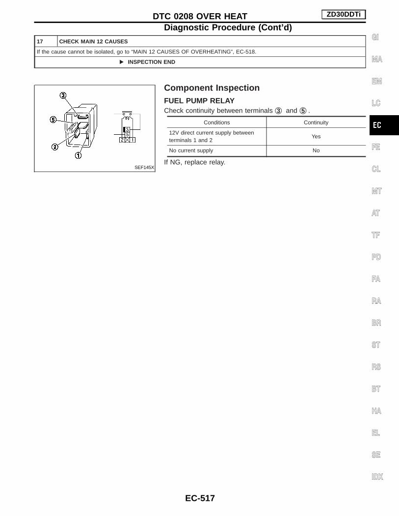
17 CHECK MAIN 12 CAUSES
If the cause cannot be isolated, go to “MAIN 12 CAUSES OF OVERHEATING”, EC-518.
E INSPECTION END
Component InspectionFUEL PUMP RELAYCheck continuity between terminals q3 and q5 .
Conditions Continuity
12V direct current supply betweenterminals 1 and 2
Yes
No current supply No
If NG, replace relay.SEF145X
DTC 0208 OVER HEAT ZD30DDTi
Diagnostic Procedure (Cont’d)
EC-517
GI
MA
EM
LC
FE
CL
MT
AT
TF
PD
FA
RA
BR
ST
RS
BT
HA
EL
SE
IDX

Main 12 Causes of Overheating
Engine Step Inspection item Equipment Standard Reference page
OFF 1 I Blocked radiatorI Blocked condenserI Blocked radiator grilleI Blocked bumper
I Visual No blocking —
2 I Coolant mixture I Coolant tester 30 - 50% coolant mixture See “RECOMMENDEDFLUIDS AND LUBRI-CANTS” in MA section.
3 I Coolant level I Visual Coolant up to MAX levelin reservoir tank andradiator filler neck
See “Changing EngineCoolant”, “ENGINE MAIN-TENANCE” in MA section.
4 I Radiator cap I Pressure tester 78 - 98 kPa(0.78 - 0.98 bar, 0.8 - 1.0kg/cm2, 11 - 14 psi)59 - 98 kPa (0.59 - 0.98bar, 0.6 - 1.0 kg/cm2,9 - 14 psi) (Limit)
See “System Check”,“ENGINE COOLING SYS-TEM” in LC section.
ON*2 5 I Coolant leaks I Visual No leaks See “System Check”,“ENGINE COOLING SYS-TEM” in LC section.
ON*2 6 I Thermostat I Touch the upper andlower radiator hoses
Both hoses should be hot. See “Thermostat” and“Radiator”, “ENGINECOOLING SYSTEM” inLC section.
ON*1 7 I Cooling fan I Visual Operating See “DTC 0208 OVERHEAT”.
OFF 8 I Combustion gas leak I Color checker chemicaltester 4 gas analyzer
Negative —
ON*3 9 I Coolant temperaturegauge
I Visual Gauge less than 3/4when driving
—
I Coolant overflow to res-ervoir tank
I Visual No overflow during drivingand idling
See “Changing EngineCoolant”, “ENGINE MAIN-TENANCE” in MA section.
OFF*4 10 I Coolant return from res-ervoir tank to radiator
I Visual Should be initial level inreservoir tank
See “ENGINE MAINTE-NANCE” in MA section.
OFF 11 I Cylinder head I Straight gauge feelergauge
0.1 mm (0.004 in) Maxi-mum distortion (warping)
See “Inspection”, “CYLIN-DER HEAD” in EM sec-tion.
12 I Cylinder block and pis-tons
I Visual No scuffing on cylinderwalls or piston
See “Inspection”, “CYLIN-DER BLOCK” in EM sec-tion.
*1: Engine running at idle.*2: Engine running at 3,000 rpm for 10 minutes.*3: Drive at 90 km/h (55 MPH) for 30 minutes and then let idle for 10 minutes.*4: After 60 minutes of cool down time.For more information, refer to “OVERHEATING CAUSE ANALYSIS” in LC section.
DTC 0208 OVER HEAT ZD30DDTi
EC-518

Wiring Diagram
TEC187M
DTC 0402 P9⋅FUEL TEMP SEN ZD30DDTi
EC-519
GI
MA
EM
LC
FE
CL
MT
AT
TF
PD
FA
RA
BR
ST
RS
BT
HA
EL
SE
IDX

Wiring Diagram
TEC188M
DTC 0403 ACCEL POS SENSOR ZD30DDTi
EC-520

TEC189M
DTC 0403 ACCEL POS SENSOR ZD30DDTi
Wiring Diagram (Cont’d)
EC-521
GI
MA
EM
LC
FE
CL
MT
AT
TF
PD
FA
RA
BR
ST
RS
BT
HA
EL
SE
IDX

Wiring Diagram
TEC190M
DTC 0504 A/T COMM LINE ZD30DDTi
EC-522

Wiring Diagram
TEC187M
DTC 0701 P1⋅CAM POS SEN ZD30DDTi
EC-523
GI
MA
EM
LC
FE
CL
MT
AT
TF
PD
FA
RA
BR
ST
RS
BT
HA
EL
SE
IDX

Wiring Diagram
TEC187M
DTC 0702 P2⋅TDC PULSE SIG ZD30DDTi
EC-524

Wiring Diagram
TEC187M
DTC 0703 P3⋅PUMP COMM LINE ZD30DDTi
EC-525
GI
MA
EM
LC
FE
CL
MT
AT
TF
PD
FA
RA
BR
ST
RS
BT
HA
EL
SE
IDX

Wiring Diagram
TEC187M
DTC 0704 P4⋅SPILL/V CIRC, DTC 0706 P6 ⋅SPILL VALVE ZD30DDTi
EC-526

Wiring Diagram
TEC187M
DTC 0707 P7⋅F/INJ TIMG FB ZD30DDTi
EC-527
GI
MA
EM
LC
FE
CL
MT
AT
TF
PD
FA
RA
BR
ST
RS
BT
HA
EL
SE
IDX

Wiring Diagram
TEC191M
DTC 0807 ECM 14 ZD30DDTi
EC-528

Wiring Diagram
TEC192M
DTC 0902 ECM RLY ZD30DDTi
EC-529
GI
MA
EM
LC
FE
CL
MT
AT
TF
PD
FA
RA
BR
ST
RS
BT
HA
EL
SE
IDX

Wiring Diagram
TEC193M
DTC 0905 TURBO PRESSURE ZD30DDTi
EC-530
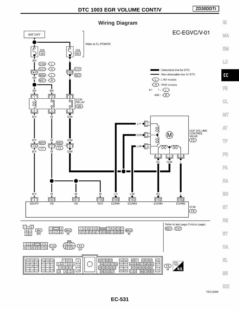
Wiring Diagram
TEC194M
DTC 1003 EGR VOLUME CONT/V ZD30DDTi
EC-531
GI
MA
EM
LC
FE
CL
MT
AT
TF
PD
FA
RA
BR
ST
RS
BT
HA
EL
SE
IDX
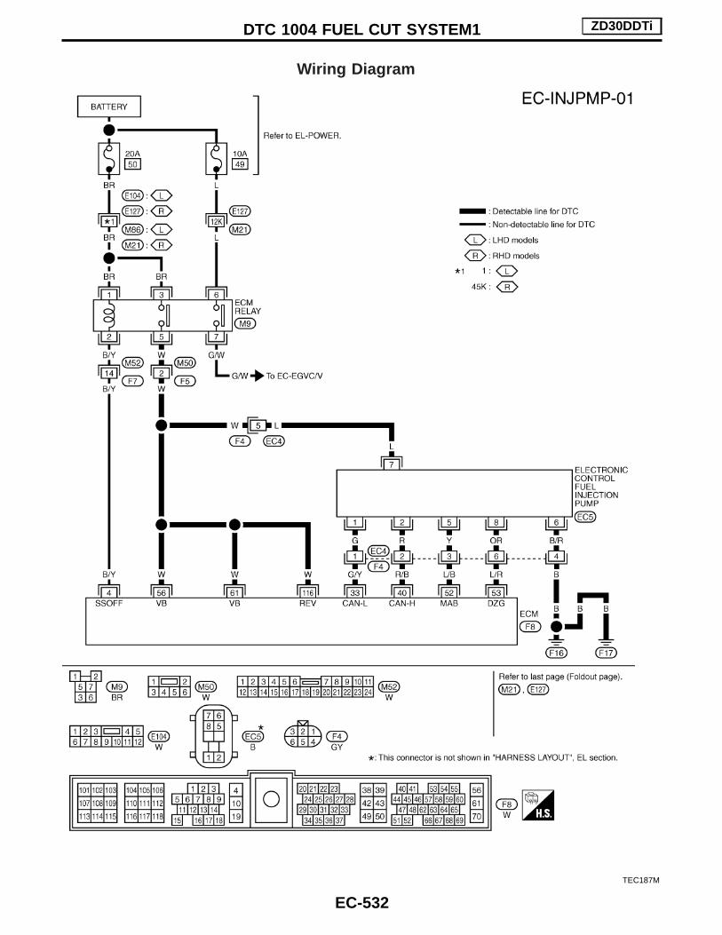
Wiring Diagram
TEC187M
DTC 1004 FUEL CUT SYSTEM1 ZD30DDTi
EC-532

Wiring DiagramFOR EUROPE
TEC195M
GLOW CONTROL SYSTEM ZD30DDTi
EC-533
GI
MA
EM
LC
FE
CL
MT
AT
TF
PD
FA
RA
BR
ST
RS
BT
HA
EL
SE
IDX

EXCEPT FOR EUROPE
TEC279M
GLOW CONTROL SYSTEM ZD30DDTi
Wiring Diagram (Cont’d)
EC-534

Diagnostic ProcedureEXCEPT FOR EUROPE
1 INSPECTION START
Check fuel level, fuel supplying system, starter motor, etc.
OK or NG
OK E GO TO 2.
NG E Correct.
2 CHECK INSTALLATION
Check that all glow plug connecting plate nuts are installed properly.
SEF233Z
OK or NG
OK (With CONSULT-II) E GO TO 3.
OK (Without CONSULT-II) E GO TO 4.
NG E Install properly.
3 CHECK GLOW INDICATOR LAMP OPERATION
With CONSULT-II1. Turn ignition switch “ON”.2. Select “COOLAN TEMP/S” in “DATA MONITOR” mode with CONSULT-II.3. Confirm that “COOLAN TEMP/S” indicates below 75°C (167°F). If it indicates above 75°C (167°F), cool down engine.
SEF013Y
4. Turn ignition switch “OFF”, wait at least 5 seconds and then turn “ON”.5. Make sure that glow indicator lamp is turned “ON” for 1.5 seconds or more after turning ignition switch “ON”, and then turned
“OFF”.
OK or NG
OK E GO TO 5.
NG E GO TO 6.
GLOW CONTROL SYSTEM ZD30DDTi
EC-535
GI
MA
EM
LC
FE
CL
MT
AT
TF
PD
FA
RA
BR
ST
RS
BT
HA
EL
SE
IDX

4 CHECK GLOW INDICATOR LAMP OPERATION
Without CONSULT-II1. Turn ignition switch “ON”.2. Confirm that the voltage between ECM terminal 19 and ground is above 1.36V. If it is below 1.36V, cool down engine.
SEF430Y
3. Turn ignition switch “OFF”, wait at least 5 seconds and then turn “ON”.4. Make sure that glow indicator lamp is turned “ON” for 1.5 seconds or more after turning ignition switch “ON”, and then turned
“OFF”.
OK or NG
OK E GO TO 5.
NG E GO TO 6.
5 CHECK GLOW CONTROL SYSTEM OVERALL FUNCTION
1. Turn ignition switch “OFF”.2. Set voltmeter probe between glow plug and engine body.3. Turn ignition switch “ON”.4. Check the voltage between glow plug and engine body under the following conditions.
SEF234Z
OK or NG
OK E INSPECTION END
NG E GO TO 11.
GLOW CONTROL SYSTEM ZD30DDTi
Diagnostic Procedure (Cont’d)
EC-536

6 CHECK GLOW INDICATOR LAMP POWER SUPPLY CIRCUIT
1. Turn ignition switch “OFF”.2. Disconnect combination meter harness connector M143.3. Turn ignition switch “ON”.4. Check voltage between combination meter terminal 46 and ground with CONSULT-II or tester.
SEC265DVoltage: Battery voltageOK or NG
OK E GO TO 8.
NG E GO TO 7.
7 DETECT MALFUNCTIONING PART
Check the following.1. Fuse block (J/B) connector M32. 10A fuse3. Harness for open or short between combination meter and fuse
E Repair open circuit or short to ground or short to power in harness or connectors.
8 CHECK GLOW INDICATOR LAMP OUTPUT SIGNAL CIRCUIT FOR OPEN AND SHORT
1. Turn ignition switch “OFF”.2. Disconnect ECM harness connector.3. Disconnect combination meter harness connector M141.4. Check harness continuity between ECM terminal 16 and combination meter terminal 2. Refer to Wiring Diagram.
Continuity should exist.5. Also check harness for short to ground and short to power.
OK or NG
OK E GO TO 10.
NG E GO TO 9.
9 DETECT MALFUNCTIONING PART
Check the following.1. Harness connectors M51, F62. Harness for open or short between combination meter and ECM
E Repair open circuit or short to ground or short to power in harness or connectors.
10 CHECK COMBINATION METER
Check combination meter and glow indicator lamp. Refer to EL section (“METER AND GAUGES”).
OK or NG
OK E GO TO 18.
NG E Repair or replace combination meter.
GLOW CONTROL SYSTEM ZD30DDTi
Diagnostic Procedure (Cont’d)
EC-537
GI
MA
EM
LC
FE
CL
MT
AT
TF
PD
FA
RA
BR
ST
RS
BT
HA
EL
SE
IDX

11 CHECK GLOW RELAY POWER SUPPLY CIRCUIT
1. Turn ignition switch “OFF”.2. Disconnect glow relay.
SEF235Z
3. Check voltage between glow relay terminals 1, 3 and ground with CONSULT-II or tester.
SEF451Z
OK or NG
OK E GO TO 13.
NG E GO TO 12.
12 DETECT MALFUNCTIONING PART
Check the following.I 100A fusible linkI Harness for open or short between glow relay and battery
E Repair harness or connectors.
13 CHECK GLOW RELAY OUTPUT SIGNAL CIRCUIT FOR OPEN AND SHORT
1. Disconnect ECM harness connector.2. Check harness continuity between ECM terminal 111 and glow relay terminal 2. Refer to Wiring Diagram.
Continuity should exist.3. Also check harness for short to ground and short to power.
OK or NG
OK E GO TO 15.
NG E GO TO 14.
GLOW CONTROL SYSTEM ZD30DDTi
Diagnostic Procedure (Cont’d)
EC-538

14 DETECT MALFUNCTIONING PART
Check the following.I Harness connectors E127, M21I Harness connectors M51, F6I Harness for open or short between glow relay and ECM
E Repair open circuit or short to ground or short to power in harness or connectors.
15 CHECK HARNESS CONTINUITY BETWEEN GLOW RELAY AND GLOW PLUG FOR OPEN AND SHORT
1. Disconnect glow plug harness connector.2. Check harness continuity between glow relay terminal 5 and glow plug harness connector. Refer to Wiring Diagram.
Continuity should exist.3. Also check harness for short to ground and short to power.
OK or NG
OK E GO TO 16.
NG E Repair open circuit or short to ground or short to power in harness or connectors.
16 DETECT MALFUNCTIONING PART
Check the following.I Harness connectors E67, E223I Harness connectors E225, E241I Harness for open or short between glow relay and glow plug
E Repair open circuit or short to ground or short to power in harness or connectors.
17 CHECK GLOW RELAY
Check continuity between glow relay terminals 3 and 5 under the following conditions.
SEF433Y
OK or NG
OK E GO TO 18.
NG E Replace glow relay.
GLOW CONTROL SYSTEM ZD30DDTi
Diagnostic Procedure (Cont’d)
EC-539
GI
MA
EM
LC
FE
CL
MT
AT
TF
PD
FA
RA
BR
ST
RS
BT
HA
EL
SE
IDX

18 CHECK GLOW PLUG
1. Remove glow plug connecting plate.2. Check glow plug resistance.
SEF236Z
NOTE:I Do not bump glow plug heating element. If it is bumped, replace glow plug with a new one.I If glow plug is dropped from a height of 10 cm (3.94 in) or higher, replace with a new one.I If glow plug installation hole is contaminated with carbon, remove it with a reamer or suitable tool.I Hand-tighten glow plug by turning it two or three times, then tighten using a tool to specified torque.
: 15 - 20 N⋅m (1.5 - 2.1 kg-m, 11 - 15 ft-lb)
OK or NG
OK E GO TO 19.
NG E Replace glow plug.
19 CHECK INTERMITTENT INCIDENT
Refer to “TROUBLE DIAGNOSIS FOR INTERMITTENT INCIDENT”.
E INSPECTION END
GLOW CONTROL SYSTEM ZD30DDTi
Diagnostic Procedure (Cont’d)
EC-540

Wiring Diagram
TEC196M
START SIGNAL ZD30DDTi
EC-541
GI
MA
EM
LC
FE
CL
MT
AT
TF
PD
FA
RA
BR
ST
RS
BT
HA
EL
SE
IDX

Wiring Diagram
TEC197M
PARK/NEUTRAL POSITION (PNP) SWITCH ZD30DDTi
EC-542

Wiring Diagram
TEC198M
HEAT UP SWITCH ZD30DDTi
EC-543
GI
MA
EM
LC
FE
CL
MT
AT
TF
PD
FA
RA
BR
ST
RS
BT
HA
EL
SE
IDX

Wiring Diagram
TEC199M
SWIRL CONTROL VALVE CONTROL SOLENOID VALVE ZD30DDTi
EC-544

Wiring Diagram
TEC200M
INTAKE AIR CONTROL VALVE CONTROL SOLENOIDVALVE ZD30DDTi
EC-545
GI
MA
EM
LC
FE
CL
MT
AT
TF
PD
FA
RA
BR
ST
RS
BT
HA
EL
SE
IDX

Wiring Diagram
TEC201M
AIR CONDITIONER CONTROL ZD30DDTi
EC-546

Wiring DiagramFOR EUROPE
TEC202M
MI (MIL) & DATA LINK CONNECTORS ZD30DDTi
EC-547
GI
MA
EM
LC
FE
CL
MT
AT
TF
PD
FA
RA
BR
ST
RS
BT
HA
EL
SE
IDX

EXCEPT FOR EUROPE
TEC280M
MI (MIL) & DATA LINK CONNECTORS ZD30DDTi
Wiring Diagram (Cont’d)
EC-548