
ENERGY TECHNOLOGY AND GOVERNANCE PROGRAM ...
606
ENERGY TECHNOLOGY AND GOVERNANCE PROGRAM Quarterly Report July – September, 2015 Prepared for: Prepared by: 1300 Pennsylvania Avenue, NW Suite 550 Washington, DC 20004-3022 www.usea.org Under USAID Cooperative Agreement Number: AID-OAA-A-12-00036 October, 2015
-
Upload
khangminh22 -
Category
Documents
-
view
0 -
download
0
Transcript of ENERGY TECHNOLOGY AND GOVERNANCE PROGRAM ...

ENERGY TECHNOLOGY AND GOVERNANCE PROGRAM
Quarterly Report
July – September, 2015
Prepared for:
Prepared by: 1300 Pennsylvania Avenue, NW Suite 550 Washington, DC 20004-3022 www.usea.org Under USAID Cooperative Agreement Number: AID-OAA-A-12-00036 October, 2015

ETAG Quarterly Report July - September 2015 Page 1
Energy Technology and Governance Program July – September 2015 Quarterly Report
Table of Contents
Executive Summary……………………………………………………………………………………………………………………4
Introduction .................................................................................................................................... 6 1. Southeast Europe Cooperation Initiative Transmission Planning Project (SECI) ........................ 8
2. Black Sea Regional Transmission Planning Project (BSTP) ........................................................ 12
3. Joint BSTP/Black Sea Regional Regulatory Initiative Workshop & Joint SECI and Black Sea Meeting on Model Integration .................................................................................................... 16
4. Security of Supply and Mutual Assistance Program for Southeast Europe ............................. 17
6. Ukraine ...................................................................................................................................... 21
7. Armenia ..................................................................................................................................... 23
8. Georgia ...................................................................................................................................... 25 9. Monitoring and Evaluation Plan ............................................................................................... 27

ETAG Quarterly Report July - September 2015 Page 2
AC Alternating Current AGT Azerbaijan-Georgia-Turkey Power Bridge Project B2B Back-to back Station BPA Bonneville Power Administration BSRI Black Sea Regulatory Initiative BSTP Black Sea Regional Transmission System Planning Project CGM Common Grid Model DSO Distribution System Operator BPM Business Process Manual E&E Bureau for Europe and Eurasia EAP Energy Assistance Program for Armenia EIHP Energy Institute Hrvoje Požar EKC Electricity Coordinating Center ENTSO-E European Network of Transmission System Operators – Electricity EPSO Electric Power System Operator of Armenia EPRA Engineering, Procurement, Research and Analysis, Inc. ESCR Effective Short Circuit Ratio ETAG Energy Technology and Governance Program GOGC Georgian Oil and Gas Corporation GSE Georgian State Electrosystem HVDC High Voltage Direct Current IOA Interconnection Operating Agreement ISO Independent System Operator KEDS Kosovo Electricity Distribution System kV Kilovolt M&S Maintenance and Support MW Megawatt NTC Net transfer Capacity MOENR Ministry of Energy and Natural Resources of Armenia MOU Memorandum of Understanding NARUC National Association of Regulatory Commissioners NTC(s) Net Transfer Capacity(ies) OAA Office of Acquisition Assistance OPF Optimal Power Flow PJM Pennsylvania, Jersey, Maryland Interconnect, LLC PSRC Public Service Regulatory Commission of Armenia PSS/E Power System Simulator for Engineers RUM Romania-Ukraine-Moldova Sub-regional Transmission Planning Project RDSM Regional Dynamic Stability Model SRIE Scientific Research Institute for Energy SECI Southeast Europe Cooperation Initiative Transmission Planning Project SEE Southeast Europe

ETAG Quarterly Report July - September 2015 Page 3
SOS Security of Supply SPS Special Protection System TEIAS Turkish Electricity Transmission Corporation TOR Terms of Reference TSO(s) Transmission System Operator(s) USAID United States Agency for International Development USEA United States Energy Association

ETAG Quarterly Report July - September 2015 Page 4
Energy Technology and Governance Program July - September 2015 Quarterly Report
Executive Summary …The SECI Working Group is currently planning to conduct the next Working Group meeting on October 14, 2015 in Sofia, Bulgaria during which members will review the status of the 2020, 2025 and 2030 regional transmission planning models, provide an update on the ‘Network and Market Perspectives of 2030: Assessing the Impact of Regional Connections to Italy’ Study and review progress on establishing SECI as a self-sustainable organization following USAID support…Page 8
…The SECI Working Group utilized the market database and proposed methodology finalized during the previous quarter to perform sample network simulations to verify the accuracy of the market model to be used to calculate the effect on network stability and wholesale electricity prices of the HVDC interconnection between Montenegro and Italy …Page 11
…The BSTP Working Group is currently planning to conduct the next Working Group meeting on October 12-13, 2015 in Sofia, Bulgaria during which members will discuss the final results of Phase I and II of the Techno-Economic Evaluation of Candidate Transmission Projects, review the OPF modeling exercises of each TSO and potential terms of reference for the next phase of the BSTP workplan…Page 13
…The BSTP Working Group has completed the technical and social welfare benefit analysis of the seven interconnection projects of regional significance using the ENTSO-E cost benefit methodology for eight planning regimes (maximum and minimum demand regimes for winter, spring, summer and autumn). The results provide positive indications for each of the analyzed projects in terms of improved network flexibility to support regional electricity trade and increased social welfare benefits in the form of reduced electricity prices …Page 14
…The BSTP Working Group is making steady progress in developing its long term planning model for the 2025 forecast horizon…Page 15
…The DSO Working Group is currently planning to conduct the next Working Group meeting on October 16, 2015 in Tirana, Albania to review the final results and recommendations of the ‘Lessons Learned Report from the 2014 Flooding and Ice Storm Disasters in Southeast Europe,’ present findings of the ‘Connection of Distributed Generation to Distributed Networks’ study and determine key performance indicators for the second phase of the benchmarking process…Page 18
…The DSO Working Group distributed a second questionnaire to clarify responses, collect more detailed metrics on each DSO’s distributed generation connection policies and procedures…Page 19
…Schweitzer Engineering Laboratories (SEL) completed installation, programming and testing of ADMS equipment for the pilot project in the Brcko Distribution Utility in Bosnia & Herzegovina. SEL conducted a two day intensive training and provided thorough documentation on how to utilize the equipment to the utility…Page 20

ETAG Quarterly Report July - September 2015 Page 5
…Under a Mission funded buy-in, the Electricity Coordinating Center (EKC) has commenced performance of steady state analysis and DMCC Engineering has commenced performance of transient stability analysis of the Ukrainian network’s forecasted performance for the winter 2015/2016 peak demand…Page 23 … USEA developed a Terms of Reference for Mr. Gurgen Hakobyan of Yerevan, Armenia to serve as the lead technical advisor for the revision of the draft grid code. After extended discussions with Mr. Hakobyan, Mr. Hakobyan informed USEA he had accepted a position with Tetra Tech and would no longer be available to serve as the technical lead for the project…Page 24
…USEA entered into discussions with Argonne National Laboratory on the Terms of Reference for conducting the EMCAS software training to provide GSE with a tool to simulate day-ahead wholesale electricity market operations …Page 26

ETAG Quarterly Report July - September 2015 Page 6
Energy Technology and Governance Program Fiscal Year 2015 Work Plan Quarterly Update
USAID assisted countries in the Southeast Europe Energy Community and the Black Sea region are developing policies, incentives and regulations to support European clean energy mandates and to accelerate integration of their domestic electricity markets with European regional electricity markets. In response, there is heightened interest among private investors and international financial institutions in developing new, clean energy wind, photovoltaic and small hydroelectric generation plants in the Europe and Eurasia (E&E) region. Investment in these technologies has the potential to transform the regional energy economy through, 1) a shift in the electricity generation mix toward clean energy production; 2) the development of regional clean energy electricity markets; and 3) enhanced energy security.
Owing to the intermittent nature imposed by variable wind currents, cloud cover and precipitation, clean energy technologies pose unique technical challenges to their integration in the E&E regional high voltage electricity networks. Best practices in North America and Europe indicate that solutions to clean energy integration lie in a robust and reliable regional electricity transmission network capable of hosting clean energy generators and the transmission of their electrical output. The networks must be sufficiently flexible and reliable to support cross-border markets for clean energy production and the back-up capacity needed to compensate for intermittent generation, while optimizing for the varied weather, geography and the seasonal and temporal production and consumption of electricity in the E&E region.
Toward this end, the Energy Technology and Governance Program will support the following objectives:
1. Plan for robust, reliable cross border transmission interconnections as the backbone infrastructure for cross border trade and exchange of electricity generated by clean and innovative energy technologies
2. Develop technical rules, guidelines, and network infrastructure assessments to accelerate
integration of clean and innovative energy technologies 3. Support utility commercialization, privatization and market transformation to improve overall
network efficiency and support clean energy market development 4. Build capacity within regional transmission and distribution system operators to develop
climate change adaptation and mitigation emergency response and disaster preparedness programs
The delivery mechanisms to support these objectives are:
I. Southeast Europe Cooperation Initiative (SECI) Transmission Planning Project The USEA has supported the SECI Transmission Planning Project since 2002 with the objective to promote regional cooperation in transmission planning through the development of common transmission planning tools and methodologies. Members of the project working group represent the transmission system operators (TSO) of Albania, Bosnia & Herzegovina, Bulgaria, Croatia, Kosovo, Macedonia, Montenegro, Romania and Serbia. Neighboring TSOs from Turkey,

ETAG Quarterly Report July - September 2015 Page 7
Hungary, Slovenia, Greece and Italy participate in the project in a support role.
II. Black Sea Regional Transmission System Planning Project The BSTP was established by the United States Agency for International Development, the United States Energy Association and the TSO of the Black Sea region in 2004 to build institutional capacity to develop and analyze the region’s first common transmission planning model. Members of the project working group represent the TSOs of Armenia, Bulgaria, Georgia, Moldova, Romania, Russia, Turkey and Ukraine.
III. Southeast Europe Security of Supply and Mutual Assistance Working Group
Similar to the USAID/USEA Southeast Europe Coordination Initiative Transmission Planning Working Group (SECI), USEA will establish a Security of Supply and Mutual Assistance Working Group populated by Southeast Europe distribution company representatives and regulatory authorities. The Working Group will assist utilities in the region to develop common Disaster Preparedness & Emergency Response programs.
IV. Utility Commercialization, Privatization and Market Transformation Bilateral Partnerships with U.S. utilities for Georgia and Kosovo USEA will provide bilateral assistance through utility partnerships in Georgia and Kosovo that will support utilities in these countries to participate in national and regional clean energy markets. The partnerships will employ volunteers from U.S. electric and gas utilities, which will share the cost of the program by contributing the labor associated with their participation in hosting exchange visits and conducting advisory missions overseas.

ETAG Quarterly Report July - September 2015 Page 8
1. Southeast Europe Cooperation Initiative Transmission Planning Project (SECI) The USEA has supported the Southeast Europe Cooperation Initiative (SECI) Transmission Planning Project since 2002 with the objective to promote regional cooperation in transmission planning through the development of common transmission planning tools and methodologies. Members of the project working group represent the TSOs of Albania, Bosnia & Herzegovina, Bulgaria, Croatia, Kosovo, Macedonia, Montenegro, Romania and Serbia. Neighboring TSOs from Turkey, Hungary, Slovenia, Greece and Italy participate in the project in a support role. The SECI Working Group developed the first detailed national and regional steady state, dynamic and short circuit models of the high voltage network for the planning horizons of 2002 and 2005 winter peak and summer minimum conditions. Subsequently, similar national and regional models were developed for 2010, 2015 and 2020. These models are used to identify bottlenecks to regional trade of electricity, model the impact of the transmission network on energy security initiatives, determine the potential to integrate renewable energy resources, and identify network investment requirements.
The SECI Working Group is the steward of the regional models, updating them on a quarterly basis to ensure accuracy as national networks and energy plans change. In FY ’14 the Working Group will develop a 2025 intermediate term and a 2030 long term forecasting model, while continuing to update the 2020 near term model. As steward of the models, it is developing mechanisms and processes to share the models with interested parties, including International Financial Institutions, bilateral donors, and neighboring TSOs with an interest in funding generation and transmission projects consistent with the objectives of SECI participants. Objective 1: Plan for robust, reliable cross border transmission interconnections as the
backbone infrastructure for cross border trade and exchange of electricity generated by clean and innovative technologies.
1. Task One: Organize and Conduct Meetings of the SECI Working Group/Update 2020 and Develop 2025 SECI Transmission Planning Models The Working Group will continue to update the following national and regional models of the SECI high voltage transmission system: 2020 Load Flow Model 2020 Dynamic Model
In addition to updating the 2020 models, the Working Group will finalize development of the 2025 regional Load Flow model. The Working Group will develop a set of 2030 load flow and dynamic models to be consistent with the planning requirement time horizons of ENTSO-E. Updates will be coordinated at regularly scheduled quarterly Working Group meetings, at which revisions to the models will be discussed and agreed to.
QUARTERLY UPDATE The next SECI Working Group meeting is scheduled to take place during the next fiscal quarter - October 14 in Sofia, Bulgaria. The preparations for this meeting were initiated during this quarter. The objectives of the meeting will be to:

ETAG Quarterly Report July - September 2015 Page 9
• Review the status of the 2020, 2025 and 2030 regional transmission planning models • Provide an update on the study “Network and Market Perspectives to 2030: Assessing the
Impact of Regional Connections to Italy” and discuss next steps • Review progress on the establishment of SECI as a self-sustainable organization following USAID
support ATTACHMENT 1: Draft SECI Working Group Meeting Agenda Sustainability of SECI TSP Project USAID plans to gradually reduce financial support to SECI in FY 2016 with the goal of establishing SECI as a self-sustainable organization by FY 2017. USEA/USAID and the SECI technical coordinator have convened a SECI Sustainability Committee to assist in brainstorming the path to sustainability. All SECI Working Group members are invited to join the Sustainability Committee which meets regularly by Skype. The Committee is in the process of developing a SECI Sustainability Business Plan which will provide details on how to transition SECI into a self-sustainable organization. The business plan:
1) Defines the future role of the SECI TSP through a Value Proposition and Mission Statement summarizing the benefits the Project brings to its member TSOs.
2) Proposes an initial two-year workplan outlining planning studies, capacity building training programs and workshops consistent with the SECI TSP Value Proposition and Mission Statement.
3) Details an initial two-year launch budget establishing member contributions toward finanical and programmatic sustainability;
4) Defines a post-USAID Governance Plan ensuring democratic and transparent decision making among SECI TSP members.
5) Provides an initial staffing and management plan for the SECI TSP designed to efficiently and effectively administer the project at the lowest possible cost to its members.
6) Recommends an organizational host that will provide legal, accounting human resource, and other administrative support necessary to implement the SECI TSP as an ongoing and sustainable project.
7) Provides a SECI TSP Memorandum of Understanding to be signed by each prospective member detailing the rights and responsbilities conveyed through membership in the Project.
8) Assesses legal and taxation issues assoicated with establishing the SEC TSP as an independent project by its members.
USAID/USEA are in the process of meeting with the senior management of each of the SECI TSOs to gain their support in continuing SECI post USAID support. To date, USAID/USEA have gained initial support of the TSOs in Albania, Bosnia and Herzegovina, Kosovo, Macedonia, Romania and Serbia. Visits to the remaining TSOs will be conducted during the next quarter.

ETAG Quarterly Report July - September 2015 Page 10
QUARTERLY UPDATE
During the previous quarter USEA hired a lawyer in Macedonia to research the available options and provide a recommendation on how to establish SECI as a legal entity in Macedonia. The lawyer was recommended by USAID Macedonia having provided assistance on prior USAID activities. The lawyer drafted a memo detailing the pros and cons for each of the following options:
1. Association (non-profit), 2. Joint Stock Company (for-profit) & 3. Limited Liability Company (for profit).
During this quarter the SECI Sustainability Committee reviewed the memorandum and determined that the best option would be to establish SECI as a non-profit association in Skopje, Macedonia. A draft Memorandum of Understanding was drafted by the lawyer delineating a proposed structure for SECI as a non-profit association and detailing the various roles and responsibilities of the founding members. This draft MOU will be presented and discussed at the next SECI WG meeting in October
The sustainability Committee also decided that SECI should conduct a forum for the senior management of the SECI TSOs in early 2016 to highlight the accomplishments of SECI over the past 15 years and to gain their support to transition SECI into a legal entity following withdrawal of USAID support. This will be discussed in more detail during the next SECI WG meeting in October.
ATTACHMENT 2: Draft MOU on the Establishment of SECI as a Non-Profit Association in Macedonia 2. SECI Training and Capacity Building
The SECI TSP will conduct the following training and capacity building relevant to the daily operations of the member TSOs and in support of SECI studies and assessments in this workplan.
Developing and Applying Generation Cost Curves for Market and Network Analyses Date: May 2015 (coincidental to SECI TSP Working Group Meeting) Duration: Two Days Participants: Two Representatives from each TSO Course Description: With the gradual introduction of wholesale electricity market trade, development of the network is no longer centrally planned, but is increasingly driven by market forces determining the location of generation facilities, load flows and the extent to which distributed generation penetrates the network. To better understand market behavior, TSO must improve their capacity to forecast new and unanticipated load flows resulting from the optimization of arbritage between wholesale markets with varying prices of electricity. This training course will introduce TSO to sources of data used to develop generation cost curves, including both fixed and variable costs; the process of constructing such curves, including development of ramping costs; Excel and software applications used to develop cost curves; and the use and application of optimization software used to conduct network analyses. Responsible Parties: USEA Milestones:
Date Action Jan – Mar 2015 Draft Terms of Reference for Trainer& Identify Trainer April 2015 Develop Training Materials May 2015 Conduct Training

ETAG Quarterly Report July - September 2015 Page 11
QUARTERLY UPDATE It was decided to postpone this workshop until the winter 2016 SECI WG meeting.
3. Network and Market Perspectives to 2030: Assessing the Impact of Regional Connections to Italy As a region, Southeast Europe is characterized by an overall deficit of generation capacity and electricity supply. With its predominance of hydroelectric and lignite generation capacity, it is largely dependent on weather and hydrology for stable supplies and prices of electricity. Nascent electricity markets support limited electricity trade resulting from variations in available generation capacity and hydrology within the region, but lack the depth and liquidity necessary to attract investment in new generation capacity. Furthermore, congestion and bottlenecks in the internal high voltage transmission networks of Southeast Europe are technical limitations to electricity trade. These challenges will be compounded when the high voltage undersea direct current (DC) cable connecting the networks of Montenegro and Italy is constructed and energized, as soon as 2016, resulting in unforeseen changes in electricity flows and economics of regional electricity trade. The SECI TSP will address these challenges by planning for transmission infrastructure investments necessary to ensure system stability and incentivize the investment in clean energy resources required to address the region’s capacity deficit in a low carbon manner. Working with system operators, policy makers, regulators and donors in Southeast Europe, the SECI TSP will ensure network stakeholders fully understand the scope of impending changes associated with the Montenegro-Italy interconnection and further ensure they are prepared with a set of system stability plans and recommendations to reinforce the network in light of the potentially radically different patterns of electricity trade and power flows it will bring.
Using SECI network planning models developed and updated by the SECI Working Group in 2014, the SECI TSP will conduct an analysis to assess the network stability and electricity market impact of the new undersea cable under construction to connect Montenegro with Italy. The assessment will measure the technical and economic impact of projected electricity exports from the region to Italy, with an emphasis on the incentives it will provide for new clean energy investments in, and exports from, Southeast Europe.
Preparation of the assessment will be conducted in two phases: 1) development of the common regional market model; 2) preparation of the network and market analyses.
Phase one will be completed in FY 2015 and Phase two will be completed in FY 2016.
Responsible Parties: USEA, Energy Institute Hrvoje Požar (EIHP), EKC Milestones:
Date Action Nov 2014 Adopt Terms of Reference and Distribute Data Survey March 2015 Phase1 – Task 1: Creation of database for market analyses June 2015 Phase1 – Task 2: Methodology for market studies June 2015 Phase1 – Task 3: Development of network models for target
years (2025/2030) QUARTERLY UPDATE

ETAG Quarterly Report July - September 2015 Page 12
During this quarter, EKC and EIHP utilized the market database and proposed methodology finalized during the previous quarter to perform sample network simulations and analyses in order to verify the accuracy of the market model. The results of these simulations will be reported during the next SECI WG meeting in October.
2. Black Sea Regional Transmission System Planning Project (BSTP)
The Black Sea Transmission Planning Project (BSTP) was established in 2004 by the United States Agency for International Development, the United States Energy Association and the TSOs of the Black Sea region into build institutional capacity to develop and analyze the region’s first common transmission planning model. Members of the project working group represent the TSOs of Armenia, Bulgaria, Georgia, Moldova, Romania, Russia, Turkey and Ukraine. The BSTP Working Group developed the first detailed national and regional load flow and dynamic models of the high voltage network for the 2010, 2015 and 2020 planning horizons. These models are used to identify bottlenecks to regional trade of electricity, model the impact of the transmission network on energy security initiatives, determine the potential to integrate renewable energy resources, and identify network investment requirements. The models were updated to reflect more accurate estimates of new renewable capacity projected to be added to the network in 2015 and 2020. Using the Optimal Power Flow feature of PSS/E, the Working Group produced transmission constrained optimized dispatch models of the national and regional power systems. The optimized models tested the security and reliability of the regional network using economically based scenarios for cross border trade. The results suggest where network reinforcement and new interconnections are required to optimize regional trade of new, clean and renewable resources.
The BSTP Working Group is the steward of the regional models, updating them on a quarterly basis to ensure accuracy as national networks and energy plans change. In FY ’15 the Working Group will complete development of a 2025 intermediate term forecasting model, while continuing to update the 2020 near term model. In addition, it will continue to develop mechanisms and processes to ensure model sharing with interested parties, including: International Financial Institutions, bilateral donors, and neighboring TSOs with an interest in funding generation and transmission projects consistent with the objectives of the BSTP.
Objective 1: Plan for robust, reliable cross border transmission interconnections as the backbone infrastructure for cross border trade and exchange of electricity generated by clean and innovative technologies.
1. Organize and Conduct Meetings of the BSTP Working Group/Update 2020 and Develop 2025 BSTP Transmission Planning Models
The Working Group will continue to update the following national and regional models of the Black Sea high voltage transmission system:
• 2020 Load Flow Model • 2020 Dynamic Model • 2020 Optimal Power Flow Model

ETAG Quarterly Report July - September 2015 Page 13
A set of new 2025 models will be developed during this phase of the BSTP. Model developments, updates, and subsequent revisions will be discussed and coordinated at regularly scheduled Working Group meetings.
a) BSTP Working Group Meeting #3 Dates: September 2015 Location: Sofia, Bulgaria Objectives: • Update BSTP Regional Transmission System Models for 2020 • Continue Development of 2025 Load Flow Network Planning Model Development • Review Data Surveys and Preliminary Results of the Market and Social Welfare
Components of the ENTSO-E Cost Benefit Analyses of New Network Reinforcement Projects of Regional Significance
• Exchange Information on Electricity Sector Developments in Each Country
QUARTERLY UPDATE The Black Sea Regional Transmission Planning Project Working Group is preparing to conduct a one and a half day meeting in Sofia, Bulgaria from October 12-13, 2015.
This planned meeting is to discuss the final results of Phase I and II of the Techno-Economic Evaluation of Candidate Transmission Projects and building upon the accomplishments of the previous Working Group meeting conducted in June 2015 in Budapest, Hungary which focused on adapting the ENTSO-E Cost Benefit Analysis (CBA) methodology to the BSTP region. The meeting will review the OPF modeling and analysis exercises of each TSO practiced to further improve and update the OPF model for each country. The Working Group will discuss the current status of the 2020 and 2025 load flow, dynamic and optimal power flow models. The Working Group is making steady progress in developing its long term planning model for the 2025 forecast horizon, with the next update scheduled for February 2016. The Working Group will review projects of regional significance, including project updates for the Ukraine/Moldova/ENTSO-E Power System Interconnection Project and discuss the Georgian State Electrosystem’s application of the Cost Benefit Analysis (CBA) to the Ten Year Network Development Plan (TYNDP) for Georgia for 2015-2025 through the following CBA indicators: the network transfer capacity increment between two cross border points of the transmission system; the estimated cost of the project; the impact of the project on security of supply; the socio-economic welfare benefits; potential to integrate renewable energy sources; potential to reduce transmission losses, the potential to reduce CO2 emissions, the impact on technical resiliency and system safety, reliability and flexibility,; and the impact on urban and protected areas. The Working Group will discuss potential terms of reference for the next phase of the BSTP Working Group Work Plan. Possibly analyses include: utilization of the BSTP OPF model for calculation of the potential to reduce technical losses on a regional basis, potential to share balancing reserves on a regional basis (stability impact study of RES), and development of 2020 and 2025 steady state models for calculating short circuit currents. ATTACHMENT 3: Draft BSTP Working Group Meeting Agenda

ETAG Quarterly Report July - September 2015 Page 14
2. Conduct ENTSO-E Market and Social Welfare Cost Benefit Analyses of New Network Reinforcement Projects of Regional Significance – Phase II of the ENTSO-E Cost Benefit Analysis Having completed the network analysis portion of the ENTSO-E cost benefit analysis of network reinforcement project of regional significance, The Working Group will adapt and analyze the Social Welfare components. When completed, the TSOs will have been trained in, and will have conducted, technical, social welfare, and environmental analyses of proposed network reinforcement projects of regional significance. These projects will form the basis of new interconnections and internal reinforcements needed to accelerate trade and exchange of clean energy in the region. Completion of the adaptation of the ENTSO-E Cost Benefit Analysis methodology to the Black Sea region provides the TSOs with another tool in their planning toolboxes that is consistent with best practices in Europe and provides them with new dimensions for analyzing projects, including a project’s capacity to integrate renewable energy, reduce carbon emissions and lower the price of electricity to end-use consumers. A critical component of completing the market and social welfare components of the Cost Benefit Analysis is the completion of the 2025 load flow, OPF and Dynamic network models upon which the analysis will be conducted.
QUARTERLY UPDATE This workplan element activity is complete with the expectation that the final results will be presented at the next BSTP Working Group Meeting to be held in October 2015 in Sofia, Bulgaria.
3. Report on Market and Social Welfare Components of Cost-benefit Analyses (Phase 2)
On the basis of Black Sea CBA Methodology the consultant will perform a multi-criteria assessment for each candidate transmission line identified by the TSOs. The consultant will score the above mentioned indicators on the following scale: Negative, Neutral, Minor Positive, Medium positive or High Positive impact. The overall technical assessment of all of the analyzed projects will be given in appropriate form as a multi-criteria matrix.
Action Date
First Draft of Cost-Benefit Analyses (Phase 2) July 2015
Final Draft of Cost-Benefit Analyses (Phase 2) September 2015
QUARTERLY UPDATE This workplan element activity is progressing as anticipated. Final results of the Phase I and II: Techno-Economic Evaluation of Candidate Transmission Projects are to be presented at the October 2015 BSTP Working Group Meeting to be held in Sofia, Bulgaria.
The Working Group has completed the social welfare benefit analysis for the remaining spring and autumn maximum and minimum regimes and conducted the social welfare sensitivity analyses for the interconnection projects for all eight planning regimes (maximum and minimum demand regimes for winter, spring, summer and autumn).
The analysis results of all seven projects indicate a positive influence on the technical performance of the power systems of the member TSOs and on the regional transmission network. The projects provide both social welfare benefits and increase the flexibility of regional networks to support various market and electricity trading scenarios that may emerge. At the next Working Group meeting, members will

ETAG Quarterly Report July - September 2015 Page 15
review these analyses and combine them with the technical analyses conducted in the initial workplan phase to provide a comprehensive technical and economic cost benefit evaluation for each of the seven candidate projects.
4. Regular updates of regional models for load flow, OPF and dynamic analyses – Phase
The following data exchange protocol has been agreed to by the BSTP Working Group:
• TSOs send updates to EKC by February 28, 2015 as well as new OPF and dynamic models for 2025
• EKC distributes updated regional model by March 31, 2015 • TSOs send updates to EKC by July 15, 2015 • EKC distributes updated regional model by September 20, 2015
The consultant will collect all model updates from the TSOs and integrate them into the regional model. Thereafter, the consultant will check the accuracy of the models and update and correct them, as needed. The models will be updated based on the model guidelines adopted by the BSTP Working Group.
Action Date
TSO Regional Model Updates with new OPF and Dynamic models sent to EKC
February 2015
EKC Distribution of Updated Regional Model March 2015
TSO Regional Model Updates sent to EKC July 2015
EKC Distribution of Updated Regional Model September 2015
QUARTERLY UPDATE This workplan element activity is progressing as anticipated. The Working Group is making steady progress in developing its long term planning model for the 2025 forecast horizon, with the next update scheduled for February 2016.

ETAG Quarterly Report July - September 2015 Page 16
3. Joint BSTP/Black Sea Regional Regulatory Initiative Workshop & Joint SECI and Black Sea Meeting on Model Integration
Objective 1: Plan for robust, reliable cross border transmission interconnections as the backbone infrastructure for cross border trade and exchange of electricity generated by clean and innovative technologies.
1. Conduct a Joint Meeting of the BSTP and SECI Working Groups A meeting of the SECI and BSTP working groups will be conducted to exchange information on how the excess generation capacity of the Black Sea Region can be efficiently transmitted to Southeast Europe which does not have enough capacity to meet demand.
Dates: March 2015 Location: Bucharest, Romania Objectives:
• To review the Black Sea and the Southeast Europe transmission system networks • To discuss possibilities for transmitting power between the two regions via Turkey
QUARTERLY UPDATE Following the March 2015 joint meeting of the BSTP and BSRI, a concept of conducting a joint technical and economic network study was jointly discussed between USAID, USEA and the NARUC. The study would focus on the potential for the Black Sea region to share balancing reserves in an effort to reduce overall system costs and integrate greater quantities of intermittent clean energy production sources.
This study concept was reviewed at the June 2015 BSTP Working Group meeting and taken into consideration with other candidate projects for the 2016 ETAG Workplan cycle. A final determination of conducting this study will be undertaken at the next meeting of the Working Group to be conducted in October 2015, and in consultation with USAID and NARUC.
QUARTERLY UPDATE This activity has been temporarily been put on hold due to the reorganization of NARUC’s work in Europe & Eurasia.

ETAG Quarterly Report July - September 2015 Page 17
4. Security of Supply and Mutual Assistance Program for Southeast Europe
Objective 4: Build capacity within regional transmission and distribution system operators to develop climate change adaptation and mitigation emergency response and disaster preparedness programs
Climate change induced and manmade outages occurring in the distribution system networks in Southeast Europe threaten the security of electricity supply for end-user consumers and disrupt economic activity. To assist distribution system operators in Southeast Europe and reduce the breadth and scope of outages in their networks, USAID, together with the United States Energy Association, has established a Southeast Europe Distribution System Operator (DSO) Security of Supply Working Group.
Working Group members currently include representatives from the DSOs of: Albania Bosnia and Herzegovina Croatia Kosovo Macedonia Serbia
Representatives from the regulatory agencies (RAs) in these countries serve as observers to the Working Group.
Modelled after the Southeast Europe Cooperation Initiative (SECI) Transmission System Planning Project, the activities of the DSO Security of Supply Working Group will be demand driven to respond to the needs of the distribution companies in the region, with an emphasis on the following deliverables: • Business continuity plans to help electric companies plan for all scenarios, such as severe
weather events that may impact their ability to provide reliable electric power to consumers; • Mutual assistance plans to encourage distribution companies to share staff and materials
considered necessary for fast restoration of service after a significant outage; • Maintaining and sharing critical inventory to ensure adequate supply of spare parts necessary
to respond to outage events; • Emergency procurement systems to allow for rapid procurement of essential equipment in
emergency situations; • Asset management programs to optimize the life of distribution network infrastructure; and • Benchmarking of best practices.
These deliverables will assist the SEE DSOs to harden their distribution systems, thereby mitigating potential system outages induced by weather and climate related events. It will also assist them to adapt to climate induced outages by improving their ability to restore service in an efficient and timely manner as a result of weather related system disturbances. Though it is widely accepted that distribution system outages continue to plague Southeastern European electric power systems, the exact number, frequency, duration and the scope of outages in terms of the number of customers effected is not quantified.

ETAG Quarterly Report July - September 2015 Page 18
QUARTERLY UPDATE 1. Conduct Meetings of the Southeast Europe Distribution System Operator Security of Supply Working Group
QUARTERLY UPDATE The next DSO Working Group meeting is scheduled to take place during the next fiscal quarter on October 16 in Tirana, Albania. Preparations for this meeting were initiated during this quarter. The objectives of the next meeting will be to:
• Review the final results and recommendations from the report “Lessons Learned Report from 2014 Flooding and Ice Storm Disasters in Southeast Europe”
• Present findings from the study “Connection of Distributed Generation to Distribution Networks: Recommendations for Technical Requirements, Procedures and Agreements”
• Determine the key performance indicators to be collected for the second phase of the benchmarking process and confirm next steps.
• Discuss and develop a workplan of activities for the next fiscal year
ATTACHMENT 4: Draft DSO Working Group Meeting Agenda 1. Connection of Distributed Generation to Distribution Networks: Recommendations for Technical
Requirements, Procedures and Agreements The Working Group will initiate a region-wide study to identify obstacles to accelerated deployment of distributed generation resources and recommend solutions to overcoming them on a country-by-country basis. The study will:
a. Identify international best practices for safely connecting distributed generation facilities to medium and low voltage networks while maintaining system security and reliability;
b. Recommend solutions to overcoming legal and regulatory changes to customer owned distributed generation and net metering;
c. Discuss decoupling of utility revenue from volumetric based tariff methodologies to incentivize distribution system operators to connect customer owned and utility owned distributed generation to the network;
d. Recommend terms for provision of emergency back-up power from distribution system operators to facilities at which customer owned generation is deployed;
e. Examine distribution grid codes and recommend revisions to support net metering in Southeast Europe DSOs;
f. Identify solutions to other technical, legal and regulatory impediments. Responsible Parties: USEA, Energy Institute Hrvoje Požar (EIHP) Milestones:
Action Date Adopt Terms of Reference February 2015
Develop questionnaire and distribute to DSOs March 2015
Collect responses, analyze data and prepare draft report March 7 May 2015
Draft report presented at working group May 2015
Final Report July 2015

ETAG Quarterly Report July - September 2015 Page 19
QUARTERLY UPDATEERLDATE During the previous quarter, EIHP presented the findings from an initial database questionnaire which was distributed to each of the DSOs. During this quarter, EIHP distributed a second questionnaire to clarify responses, collect more detailed metrics on each DSO’s distributed generation connection policies and procedures and request additional information. The updated results and next steps for the study will be reviewed at the next working group meeting in Tirana in October 2015.
ATTACHMENT 5: DSO Distributed Generation Integration - Second Questionnaire
3. Lessons Learned Report from 2014 Flooding and Ice Storm Disasters in Southeast Europe Croatia experienced significant icing in February 2014 and Bosnia, Croatia and Serbia experienced severe flooding in spring 2014. Both of these disasters resulted in substantial electric system outages and extensive equipment damage. Preliminary estimates are that reconstruction costs could reach more that $100 million. The value of lost electricity sales resulting from the inability to deliver electricity to customers could be substantially higher.
This report will survey how the affected DSOs responded to these extreme situations and provide a lessons learned of what worked and recommendations on what could have been done better. The goal is to provide guidelines on how to better respond to these types of emergencies in the future. The report will cover the following: extensive flooding in Serbia, Bosnia and Herzegovina and Croatia ice storm in Croatia emergency procedures in all regional DSOs Observations/Recommendations Drawbacks observed Short description of special technical solutions used Recommendations derived from the experience gained (lessons learned) Plans for improving performance under emergency events
Responsible Parties: USEA, Energy Institute Hrvoje Požar (EIHP) Milestones:
Action Date Develop questionnaire and distribute to DSOs
December 2014
Collect responses, analyze data January-February 2015 Meeting and interview with relevant DSOs March - May 2015 Draft Report presented at Working Group meeting
May 2015
Final Report September 2015 E QUARTERLY UPDATE During the previous quarter, EIHP presented the findings from an initial database questionnaire which was distributed to each of the DSOs. During this quarter, EIHP distributed a second questionnaire to clarify responses and request additional information. The results and a set of recommendations will be reviewed at the next working group meeting in Tirana in October 2015.

ETAG Quarterly Report July - September 2015 Page 20
4. Smart Grid Automation Pilot Project The application of smart grid automated distribution management systems (ADMS) is often prescribed as the solution to intermittency associated with distributed renewable energy generation resources. ADMS provides wide area awareness of the network through remote sensing capability and rapid, automated dispatch of the network. Conversion from “blind” operation of distribution networks in today’s operating environment to smart grid enabled networks will smooth and balance intermittent resources by more effectively directing electricity from surplus to deficit areas of the network.
USAID and USEA will partner with Schweitzer Engineering , a U.S. manufacturer of Automated Distribution Management Systems, for a pilot project in the Brcko Distribution utility in Bosnia & Herzegovina. The project will provide ADMS on a single feeder line in the selected distribution system operator’s network. In doing so, ETAG will:
a. Develop criteria to identify a distribution system operator service districts in which customers have identified a desire to deploy distributed generation and which suffer from frequent network outages of significant duration;
b. Collect baseline data on unplanned system outages; c. Build capacity of distribution system operator counterparts in designing, deploying and
operating an ADMS; d. Deploy ADMS in tandem with existing System Control and Data Acquisition systems
(SCADA); e. Measure improvements in power quality, reduction in the frequency and duration of
outages and increase the amount of distributed generation resources connected to the pilot network;
f. Disseminate a case study to Southeast Europe policy and regulatory authorities and stakeholders, of best practices and lessons learned to replicate and scale up throughout the SOS Working Group.
Responsible Parties: USEA, Schweitzer Engineering Milestones:
Action Date Identify appropriate feeder to install ADMS equipment October - December 2014 Collect baseline data prior to installation of equipment October – December 2014 Install equipment January- February 2015 Collect periodic data from ADMS and measure performance against baseline data
February - August 2015
Prepare final report and present at next working group meeting September 2015 QUARTERLY UPDATE During this quarter Schweitzer Engineering Laboratories, Inc. (SEL) completed the installation, programming and testing of the equipment. The project was fully commissioned on September 1, 2015. SEL also conducted a two-day training workshop at Komunalno Brcko headquarters for engineers on how to effectively program and utilize the equipment. A delegation of USAID, USEA and SEL representatives is tentatively scheduled in October 2015 to visit Komunalno Brcko and tour the pilot project. ATTACHMENT 6: Agenda for SEL Training Workshop

ETAG Quarterly Report July - September 2015 Page 21
ATTACHMENT 7: Materials for SEL Training Workshop ATTACHMENT 8: Trip Report for SEL Training Workshop
5. Ukraine
Objective 2: Develop technical rules, guidelines, and network infrastructure assessments to accelerate integration of clean and innovative energy technologies
1. Ukraine Power System Support Project Winter Summer 2015/2016 Network Stability Analysis
The Ukraine Power System Support Project (UPSSP) was established in September 2014 to investigate the impact on the security of supply of electricity resulting from fuel shortages and damage to the network topology in Eastern Ukraine. The first and second phases of the project included an emergency network study that assessed the high voltage transmission network’s stability in response to curtailed gas and coal fueled electric power generation and an anticipated increase in demand for electricity resulting from consumers switching to electric resistance heating from municipally supplied heat produced by combined heat and power plants. A steady state load flow analysis of nine scenarios involving varying assumptions on fuel supply, electricity demand, and regional interconnections was conducted. The analysis yielded recommendations for a hierarchy of remedial actions to be taken by network dispatchers in response to voltage and frequency instability caused by lack of generation capacity and damage to the network in the conflict zone. The load flow analysis conducted in Phase I for the winter of 2014-2015 identified critical network control points and generation units, instability of which could threaten the overall security of the Ukrainian high voltage network. A stability analysis performed in Phase II for the same period examined these critical network points and recommended remedial mitigation actions. The third phase of the project examined the static and dynamic stability of the network for the summer peak and off peak regimes during the Ukrenergo network maintenance schedule.
This fourth phase of the UPSSP supports steady state and dynamic stability analysis for the winter 2015-2016 maximum load regime to identify potential areas of network instability resulting from the changes in network topology in the conflict zone of eastern Ukraine and potential curtailments of coal and natural gas supplies.
Scenarios to be analysed in Phase IV analysis were suggested by Ukrenergo. Steady state and transient stability analysis will be conducted on scenarios to examine the effects on system security and stability with and without the following lines in service. The effects of these lines will be examined in combination with assumptions regarding connection to the IPS/UPS synchronous zone and the availability of anthracite coal: 1) OHLs Zaporizhzhya NPP – Kahovs’ka-750 kV with a connection to the SS Kahovs’ka-750 to 330 kV network and RivneNPP – Kyivs’ka-750 and;
2) Khmel’nitska NPP - Kyivs’ka-750 with connection SS Kyivs’ka-750 to 330 kV network.
- Update the current Ukrainian network model topology from previous phases of the project including lines, substations and transformers, power plants and generation units, with specific

ETAG Quarterly Report July - September 2015 Page 22
attention to the network elements in the Eastern Ukraine; and develop load flow simulation models for the upcoming winter maximum regime;
- Accounting for the unclear status of the availability of anthracite coal during the winter of 2015/2016, incorporate two scenarios into the analysis that feature a “business as usual” anthracite coal supply and zero availability of anthracite coal supply;
- Perform a steady state analysis of the scenarios and identify critical parts of transmission network and propose recommendations for remedial actions based on standard static analysis taking into account network limitations imposed on the system resulting from generation curtailment and increased load; and
- Propose appropriate recommendations for power system equipment and devices to preserve power system stability during the winter maximum regime – voltage and reactive power perspectives.
Responsible Parties: USEA; EKC; DMCC
Action Date Action 1. Distribute 2015 Winter regime Load Flow
Model Questionnaires to Ukrenergo August 7, 2015 Milestone
2. In coordination with DMCC Engineering develop and submit to USEA for approval a template for the report format of the study( including Numbering Protocol for Chapter and sub-Chapter Subheadings; Font Size and Color for Chapter and sub-Chapter Subheadings; Numbering Protocol for Tables, Figures, Drawings; Table of Contents Format; Format for Footers, Headers and Page Numbering)
August 20, 2015 Deliverable
3. Receive completed Excel Questionnaires and final national models in “sav” format from Ukrenergo.
August 21, 2015 Milestone
4. Develop 4 simulation scenarios to be analysed (with/without “new 750 kV lines” and with/without “anthracite fired power plants’ production
September 2, 2015 Deliverable
5. Travel to Kiev, Ukraine, to participate in a 2-days technical meeting
September 17-18, 2015
Milestone
6. Submit Draft Report Analysis of 2015/2016 Winter Peak Regimes and Reactive Power Compensation Devices
October 15, 2015 Deliverable
7. Submit Final Report Analysis of 2015/2016 Winter Peak Regimes and Reactive Power Compensation Devices
November 13, 2015 Deliverable
QUARTERLY UPDATE

ETAG Quarterly Report July - September 2015 Page 23
EKC has commenced performance of steady state analysis of the network. DMCC has commenced performance of transient stability analysis of the network. This is an activity supported by a USAID/Ukraine Mission funded buy-in to the ETAG Cooperative Agreement. This activity was not included in Revision 3.2 of the FY’15 Workplan, but was conducted with the full support and understanding of the Office of Energy and Infrastructure, Bureau for Europe and Eurasia. ARMENIA Objective 2: Develop technical rules, guidelines, and network infrastructure assessments to accelerate integration of clean and innovative energy technologies
1. Develop A Draft Transmission Network Technical Code (Grid Code) Based On ENTSO-E Requirements And Adapted To The Unique Network Topology And Market Model Of Armenia
In FY 2014, USEA produced a second draft Grid Code in coordination with the Stakeholder Working Group established by the Ministry of Energy. The Grid code provides a draft set of rules, procedures and standards consistent with the approved requirements of the ENTSO-E network codes.
At the conclusion of FY14 USEA submitted the draft Grid Code to the Ministry of Energy together with an explanatory note of remaining outstanding issues to be addressed by the Stakeholder Working Group and USEA’s consultant, Mr. Doug Bowman. To date, USEA has not received comment from the Ministry on the draft and explanatory note.
Recognizing the need for further revision to the draft Grid code to bring it into compliance with current Armenian energy law and regulation, USEA has proposed a hybrid approach to its completion. USEA will continue to employ the resources of Mr. Bowman as the subject matter expert on ENTSO-E grid code requirements. USEA will also continue to employ the services of the Scientific Research Institute for Energy (SRIE) of Armenia as the subject matter expert for Armenian technical standards, planning procedures and market operations. And, USEA will engage a lawyer with energy legal/regulatory expertise to: 1) ensure the draft grid code complies with current Armenian legislation and regulation; and 2) bring the drafted language into compliance with the format, structure and syntax of Armenian legal documents.
USEA will work through an iterative process of revising the draft Grid Code together with the consultants and the Stakeholder Working Group to arrive at a final draft that complies with current Armenian law and is consistent with the ENTSO-E Grid Code requirements. Toward this end, USEA will conduct two to three meetings of the Stakeholder Working Group to finalize the draft Grid Code. Between meetings, the local consultants will advance the draft such that it can be reviewed by Mr. Bowman and discussed and revised at subsequent Working Group meetings.
Responsible Parties: USEA; Scientific Research Institute for Energy; Doug Bowman; Araksya Isakhanyan
Action Party Date TSubmit Consulting Agreements for OAA Approval USEA December 22, 2014
Conduct Legal Review of Chapter One Grid Code Isakhanyan January 15, 2015

ETAG Quarterly Report July - September 2015 Page 24
Stakeholder Working Group Meeting USEA March 2015
Stakeholder Working Group Meeting USEA May 2015
Final Draft Grid Code SRIE; Bowman June 2015
Legal/Regulatory Compliance Review Isakhanyan June 2015
Presentation to Ministry & Stakeholders USEA July 2015
Presentation to Stakeholder Ministry & Stakeholder Working Group
USEA September 2015
QUARTERLY UPDATE During this quarter, USEA developed a Terms of Reference for Mr. Gurgen Hakobyan of Yerevan, Armenia to serve as the lead technical advisor for the revision of the draft grid code. After extended discussions with Mr. Hakobyan, Mr. Hakobyan informed USEA he had accepted a position with Tetra Tech and would no longer be available to serve as the technical lead for the project. At the time of this report, USEA is in consultation with the E&E Bureau and USAID/Armenia to determine options for completing the draft Grid Code.

ETAG Quarterly Report July - September 2015 Page 25
6. GEORGIA (Co-funded by Black Sea Regional Transmission System Planning Project) Objective 2: Develop technical rules, guidelines, and network infrastructure assessments to accelerate integration of clean and innovative energy technologies 1. Purchase Electricity Market Complex Adaptive System (EMCAS) software and provide technical
training on its use and application to the Georgian State Electrosystem
In coordination with USAID’s support for the Georgian Electricity Market Model (GEMM), USEA will arrange for the GSE to execute a license for the ownership of the EMCAS software and contract with Argonne National Laboratory to provide technical training on its application for developing forecasts of the day ahead electricity markets in accord with GEMM.
EMCAS probes the possible operational and economic impacts of various external events on the electricity sector. The analysis is completed on an hourly basis over a user-specified period of time. Market participants are represented as “agents” with their own set of objectives, decision-making rules, and behavioral patterns. Agents are modelled as independent entities that make decisions and take actions using limited and/or uncertain information available to them, similar to how organizations and individuals operate in the real world. EMCAS includes all the entities participating in power markets, including consumers, generation companies (GenCos), Transmission Companies (TransCos), Distribution Companies (DisCos), Demand Companies (DemCos), Independent System Operators (ISO) or Regional Transmission Organizations (RTO), and regulators.
In coordination with USEA provided training, GSE will develop a model of the Georgian electricity market to be used to simulate day ahead electricity market transactions.
Responsible Parties: USEA, Argonne National Laboratory Milestones:
Action
Date
Install software and Conduct One Week Training April 2015
Submit Trip Report with Recommendations and Agenda for Second Training Week
May 2015
Review Initial Draft of Georgian EMCAS Market Model and Conduct Second Week Training
July 2015
Submit Trip Report with Review of Draft EMCAS Model, Recommendations for Revisions and Draft Agenda for Third Week Training
July 2015
Review Final Draft of Georgian EMCAS Model and Provide Third Week of Training
September 2015
Submit Final Report Reviewing Georgian EMCAS Model with Recommendations for Follow-up, as Necessary
September 2015

ETAG Quarterly Report July - September 2015 Page 26
QUARTERLY UPDATE During this quarter, USEA entered into discussions with Argonne National Laboratory on the Terms of Reference for conducting the EMCAS training. Due to delays associated with the receipt of the Mission funded buy-in and in finalizing a sub-agreement with Argonne, this workplan activity is significantly behind schedule.
ATTACHMENT 9: Draft Terms of Reference for EMCAS Training
8. MONITORING AND EVALUATION PLAN

ETAG Quarterly Report July - September 2015 Page 27
The United States Energy Association will monitor the following indicators through quarterly, annual, and final reports. Meetings and trainings will also be evaluated based on surveys.
Program Objective
Program Area Program Element Indicator FY 2015 Targets FY 2015 Results
Economic Growth Infrastructure
Program Design and Learning Element Number of Special Studies 13 8
Economic Growth Infrastructure
Program Design and Learning Element
Number of Information Gathering or Research Activities 26 13
Economic Growth Infrastructure
EG 4.1 Modern Energy Services
Number of energy agencies, regulatory bodies, utilities and civil society organizations undertaking capacity strengthening as a result of USG assistance 23 19
Economic Growth Infrastructure
EG 4.1 Modern Energy Services
Number of energy enterprises with improved business operations as a result of USG assistance 18 15
Economic Growth Infrastructure
EG 4.1 Modern Energy Services
Number of people receiving USG supported training in energy related policy and regulatory practices 50 86
Economic Growth Infrastructure
EG 4.1 Modern Energy Services
Number of people receiving USG supported training in technical energy fields 57 86
Economic Growth Environment
EG 8.2 Clean Productive Environment
Number of utilities with increased adaptive capacity to cope with impacts of climate variability and change as a result of USG assistance 17 19

1 This program is made possible by the support of the American people through the United States Agency for International Development (USAID). The contents are the responsibility of the United States Energy Association and do not necessarily reflect the views of USAID or the United States Government.
Energy Technology and Governance Program
SECI TRANSMISSION SYSTEM PLANNING MEETING
DRAFT AGENDA
October 14, 2015 Sofia, Bulgaria
Hilton Sofia
1 Bulgaria Blvd., 1421 Sofia, Bulgaria
9:00 Opening and Welcoming Remarks
Andrew Popelka, Senior Energy Advisor, United States Agency for International Development William Polen, Senior Director, United States Energy Association Kliment Naumoski, MEPSO, SECI Technical Coordinator Introductions Approval of the meeting agenda
09:15 Status of Regional Transmission System Models, RTSM
& Regional Dynamic System Model, RDSM Djordje Dobrijevic, EKC Status and updates of RTSM & RDSM Updates of the list of projects (planed and realized projects) All Year 2015: discrepancies between planned and realized projects in the grid Year 2020: preparation/update of short-term model
10:00 Study on SEE Electricity Market Perspectives until 2030
Phase 1: Creation of Market Database and Network Models Goran Majstrovic, EIHP, Djordje Dobrijevic & Nebojsa Jovic & Dusan Vlaisavljevic, EKC Overview of market database and model Any open questions and clarifications
10:30 MORNING BREAK 11:00 Study on SEE Electricity Market Perspectives until 2030
Phase 2: SEE Electricity Market Perspectives Study Goran Majstrovic, EIHP, Djordje Dobrijevic & Nebojsa Jovic & Dusan Vlaisavljevic, EKC Draft results of first simulations on market model Schedules and deadlines

2 This program is made possible by the support of the American people through the United States Agency for International Development (USAID). The contents are the responsibility of the United States Energy Association and do not necessarily reflect the views of USAID or the United States Government.
12:00 LUNCH BREAK 13:00 Sustainability of SECI TSP Project
Albert Doub, Program Director, United States Energy Association Lidija Ognenova, SECI Technical Coordinator Presentation of MEMO and MoU Kliment Naumoski, MEPSO, Goran Majstrovic, EIHP, Nebojsa Jovic, EKC Ideas for Work Plan 2016/2017
Sharing the power system reserves in the region (regional balancing integration) Handling the power imbalances evoked by RES Managing the extreme voltages on 400 kV grid during off-peak regimes Report on the market development on the retail level Revitalization of the transmission grid Training course/s
William Polen, Senior Director, United States Energy Association Concept for the plenary conference (forum) in early 2016
Draft agenda List of participants Workshop/lecture/forum
14:30 Briefing on ENTSO-E planning activities
Kliment Naumoski, MEPSO 14:45 Briefing on Feasibility Study on Synchronous Interconnection of Ukrainian and
Moldovan Power Systems to ENTSO-E Continental European Power System Nebojsa Vucinic, EMS
15:00 AFTERNOON BREAK
15:30 ] Status of 400 kV HVDC link ME – IT Dejan Dedovic, CGES, Nebojsa Jovic, EKC
16:00 Discussion of Transmission System Updates and Issues in TSOs All “Hot” topics in TSO operation and planning activities
16:30 Any Open Issues
All Migration of SECI shared folder from Dropbox to Google Drive
17:00 End of the Meeting

MEMORANDUM OF UNDERSTANDING AND COOPERATION
Concluded in _________________ on __.__. 2015
Signatories of this Memorandum are the following parties:
Operatori I Sistemit te Transmetimit with registered seat in _______________, Albania,
represented by _________________, Director
Nezavisni operator sustava u Bosni i Hercegovini with registered seat in _______________,
Bosnia and Herzegovina, represented by _________________, Director
Electricity System Opeator e.a.d with registered seat in _______________, Bulgaria,
represented by _________________, Director
HEP-Operator prijenosnog sustava d.o.o. with registered seat in _______________, Croatia,
represented by _________________, Director
Transmission System and Market Operators with registered seat in _______________,
Kosovo, represented by _________________, Director
Macedonian Electricity Power System Operator with registered seat in _______________,
Macedonia, represented by _________________, Director
Crnogorski Elektroprenosni Sistem AD with registered seat in _______________,
Montenegro, represented by _________________, Director
JP Elektromreža Srbije with registered seat in _______________, Serbia, represented by
_________________, Director.
Transelectrica with registered seat in _______________, Romania, represented by
_________________, Director.
Turkiye Elektrik Iletim A.S. with registered seat in _______________, Turkey, represented by
_________________, Director.
Electricity Coordinating Center Ltd. - EKC with registered seat in _______________, Serbia,
represented by _________________, Director.
Energetski institut Hrvoje Požar - EIHP with registered seat in _______________, Croatia,
represented by _________________, Director.
Comment [KN1]: Are there any other members who will sign MoU?

WHEREAS the signatory parties are members of the Southeast Europe Cooperation Initiative
Transmission System Planning Project (SECI TSP) as a unique collaboration of the
transmission system operators (TSO) of Southeast Europe that was launched in 2000.
WHEREAS the initial goal of the SECI TSP Project is to assist the regional TSOs to:
Plan for robust, reliable cross border transmission interconnections as the backbone
infrastructure for cross border trade of electricity generated by clean and innovative
energy technologies; and
Develop technical rules, guidelines and network infrastructure assessments to
accelerate integration of clean and innovative energy technologies.
WHEREAS the signatory parties have committed since the start of the SECI TSP Project to
voluntarily share system data, load forecasts and national planning models in an effort to
develop the first common, region wide planning model.
WHEREAS the United States Agency for International Development (USAID) and the United
States Energy Association (USEA) since 2001 have supported the SECI TSP with funds to
conduct quarterly meetings of the SECI TSP Working Group, training and for limited consulting
support required to integrate national models and analyze the results of selected regional
modeling scenarios.
WHEREAS the recently prepared SECI TSP Sustainability Business Plan provides for a two-
year transition period during which USAID will gradually reduce its financing and the project
should be made financially sustainable through contributions provided by its members.
WHEREAS the participating TSOs seek to establish the SECI TSP as a financially and
programmatically sustainable independent, non-profit entity in order to continue and broaden
the benefits the project conveyed upon them.
WHEREAS this Memorandum of Understanding and Cooperation details the rights and
responsibilities of each signatory party in the process of establishing and operating new long-
term legal entity that will work towards accomplishing the SECI TSP Mission Statement: „The
SECI TSP supports regional cooperation in transmission planning in Southeast Europe to
identify priority investment within national networks and on the interconnections between
neighboring systems that improve the security and reliability and enhance market based trade
and exchange of electricity”.
The signatory parties, hereby, agree as follows:

Article 1
(1) The signatory parties agree to jointly found and become members of a legal entity.
(2) The legal entity will be registered and based in Skopje, Republic of Macedonia and will
operate under Macedonian laws.
(3) The legal entity will be established in a form of non-governmental and non-profit association
(hereinafter: Association) in accordance with the Macedonian Law on Associations and
Foundations.
Article 2
(1) In order to establish the Association each signatory party as founding member will:
- bring a formal decision, which should be done by the signatory party highest management
body, i.e. body that has an authority to decide on issues of this nature, and in which it will be
clearly indicated that the signatory party will become founding member of the Association,
- appoint a representative, who will attend the Founding Assembly, vote at the Assembly and
sign the documents adopted at the Assembly, if this Memorandum provides such rights,
- provide other necessary documents, such as but not limited to: the prove of registration of the
signatory party and identification document of the appointed representative, which will be used
for the purpose of drafting the founding acts and / or completing the registration process, and
(2) Each signatory party will provide the necessary documents to the person assigned by SECI
TSP Project / MEPSO to prepare the Founding Assembly and the subsequent registration
process by DAY, MONTH, 2016.
(3) The signatory party’s appointed representative should attend the Founding Assembly that
will be held in Skopje, Republic of Macedonia, in the period around MONTH, 2016. Each
signatory party’s appointed representative will be invited to attend the Founding Assembly at
least two weeks prior to the day on which the Assembly will be held. Each signatory party will
bear the travel and accommodation costs for its representative attending the Founding
Assembly.
Article 3
The following is an indicative list of the Association’s goals, which will be defined and formalized
in the Association’s Articles of Incorporation and Statute:
- to support the regional cooperation in transmission planning in Southeast Europe
- to improve the security and reliability and enhance market based trade and exchange of
electricity
- to accelerate integration of clean and innovative energy technologies. Comment [D2]: To add or modify if necessary.

Article 4
The Association will implement the following type of activities:
- Develop and update regional grid models of SEE
- Provide ongoing training in the use and application of transmission planning software
- Perform regional grid studies
- Follow and accomplish ENSTO-E planning activities
- Promote the results to a wide audience of senior TSO, policy and regulatory authorities
- Organize regular and ad hoc consultative and coordination meetings for its members,
- Organize conferences, workshops, lectures and other type of events for its members
and other interested parties,
- Implement projects that are in line with and contribute to the accomplishment of the
Association goals,
- Implement other activities which are in line with the Association’s goals.
Article 5
(1) The Association will have the following type of membership:
i. Regular member – this type of membership will be granted to each regional
transmission system operator, who will have the following basic rights and
responsibilities:
- obligation to pay annual membership fee in amount of ???? (or determined in the
Association’s Statute),
- right to vote at the founding assembly and each subsequent general assembly,
and
- right to propose persons for position at (to be represented in) the Association
management and supervisory bodies.
ii. Associate member - this type of membership will be granted to EIHP and EKC who will
have the following basic rights and responsibilities:
- no obligation to pay annual membership fee,
- right to attend the Assembly without voting right,
- possibility to be represented in the Association management and supervisory
bodies, and
- participate in the activities of the Association (e.g. conduct analyses) and be
compensated for the services provided.
iii. Observer member - this type of membership will be granted to USAID, ENTSO-E, EnC,
other Macedonian legal entities and/or physical persons who will have the following
basic rights and responsibilities:
- no obligation to pay annual membership fee,
- right to attend the founding assembly and each subsequent general assembly
without a voting right, and
- participate in and / or be informed of the Association activities.
.
Comment [KN3]: To add or modify if necessary.
Comment [D4]: Here the types of membership are given. For review.
Comment [KN5]: Maybe to define small (symbolic) fee, for example 50 EUR. Just to protect
from “intruders”. Of course, statute will define procedure for adding
members with some conditions.

(2) The rights and responsibilities of each type of member will be further detailed and elaborated
in the Statute of the Association.
(3) The Statute of the Association will lay down the conditions and the procedure for becoming a
member of the Association, as well as for termination of the membership of the exis.
Article 6
(1) The Association will have the following organizational and management structure:
- Assembly – as the highest body required by the Law, which gathers all members and has
meetings at least once a year,
- Management (Executive) Board - composed of at least 3 members with a mandate of 2
years. It will have regular sessions, at least every quarter and will be responsible for
implementing the decisions and other legal acts adopted by the Assembly, establishing internal
working groups and monitoring their work, approving procurements exceeding the determined
threshold, preparing Assembly’s meetings, etc.
- The President (Chairman) of the Management Board will be at the same time President of
the Association, who will be taksed for the day-to-day operations of the Association, such as
enforcing the decisions of the Management Board, implementing the annual program activities,
signing contracts, preparing the Management Board meetings, etc.
- Supervisory Board - composed of at least 3 members with a mandate of 2 years. It will have
sessions at least once a year and will be responsible for monitoring and controling the spending
of the funds and concluded contracts that have financial implications.
(2) The mandate and specific authorities and responsibilities of each body will be further
detailed and elaborated in the Statute of the Association.
Article 7
The work of the Association will be financed through various funding sources. The following is an indicative list of possible funding sources:
- Membership fee; - Donations and sponsorships; - Grants; - Business activities; and - Other funding sources.
Article 8
(1) Any amendment to this Memorandum of Understanding and Cooperation must be mutually
agreed on by both parties and reflected in an Annex.
Comment [D6]: The only mandatory bodies required by the Law are the Assembly and the
authorized representative (President, Director…
whatever the Association decides to name it). Establishing other internal bodies is optional.
Comment [KN7]: I think this body is not necessary.
Proposal: 1. Assembly: gen. directors, authorized
representatives
2. Board: Planning experts from TSO, EIHP, EKC 3. Operational staff
To review

(2) This Memorandum of Understanding and Cooperation is composed in English in __ (__)
originals, 1 (one) for each Signatory Party.
(3) This Memorandum of Understanding and Cooperation shall enter into force on the day of
signing.
For the ???: For the ???:
____________________________
???
Director
__________________________
???
Director
For the ???: For the ???:
____________________________
???
Director
__________________________
???
Director
For the ???: For the ???:
____________________________
???
Director
__________________________
???
Director

1 This program is made possible by the support of the American people through the United States Agency for
International Development (USAID). The contents are the responsibility of the United States Energy
Association and do not necessarily reflect the views of USAID or the United States Government.
f
Energy Technology and Governance Program
BLACK SEA REGIONAL TRANSMISSION PLANNING PROJECT WORKING GROUP MEETING
October 12-13, 2015
Hilton Sofia
1, Bulgaria Blvd., Sofia, 1421, Bulgaria
Tel. +359-2-933-5000
DRAFT AGENDA OBJECTIVES The objectives of the meeting are to:
Review the Final Draft of Cost-Benefit Analyses Report (Phase I and II) Review the Results of the OPF Model Update Continue Development of the BSTP 2025 Optimal Power Flow and Dynamic
Models Based on the 2025 Load Flow Model Exchange Information on System Developments of Selected Projects of Regional
Significance Discuss and Approve TORs for the Next Phase of BSTP Analysis
MONDAY, OCTOBER 12 9:00 OPENING AND WELCOMING REMARKS
Review of Agenda, Goals, and Objectives of Meeting Andrew Popelka, Senior Energy Advisor, Bureau for Europe and Eurasia,
USAID Mityu Hristozov, Bulgarian Electricity System Operator William L. Polen, Senior Director, United States Energy Association
9:15 FINAL RESULTS OF PHASE I and II: TECHNO-ECONOMIC EVALUATION OF
CANDIDATE TRANSMISSION PROJECTS Milos Stojkovic, Electricity Coordinating Center (EKC)
ARMENIA BULGARIA GEORGIA

2 This program is made possible by the support of the American people through the United States Agency for
International Development (USAID). The contents are the responsibility of the United States Energy
Association and do not necessarily reflect the views of USAID or the United States Government.
MOLDOVA 10:30 MORNING BREAK 11:00 FINAL RESULTS OF PHASE I and II: TECHNO-ECONOMIC EVALUATION OF
CANDIDATE TRANSMISSION PROJECTS Dushan Vlaisljevic, Electricity Coordinating Center (EKC)
ROMANIA TURKEY UKRAINE
12:00 TEN-YEAR NETWORK DEVELOPMENT PLAN OF GEORGIA FOR 2015 2025: UTILIZATION OF ENTSO-E COST BENEFIT ANALYSIS (CBA)
METHODOLOGY Giorgi Arziani, Georgian State Electrosystem (GSE)
12:30 LUNCH 13:30 OPF MODELING AND ANALYSIS EXERCISES: TSO PRESENTATIONS Member TSOs will present a summary of the OPF Modeling Exercises to further
improve and update the BSTP Project OPF Model for each country
ARMENIA Karine Khachbulaghyan, System Operator JSC
BULGARIA Rosen Ulinski, Bulgarian Electricity System Operator
GEORGIA Georgi Arziani, Georgian State Electrosystem (GSE)
MOLDOVA Octavian Ciobirca, Moldelectrica
ROMANIA Anca Antemir, C.N. TRANSELECTRICA S.A
TURKEY Abdussamet Kandemir, TEIAS
UKRAINE Liudmyla Chaiun, Ukrenergo
15:00 AFTERNOON BREAK 15:30 UPDATING THE 2020 and 2025 LOAD FLOW MODEL AND DEVELOPING THE
2025 OPTIMAL POWER FLOW AND DYNAMIC MODELS Milos Stojkovic, Electricity Coordinating Center (EKC)
15:45 REGIONAL PROJECT UPDATES

3 This program is made possible by the support of the American people through the United States Agency for
International Development (USAID). The contents are the responsibility of the United States Energy
Association and do not necessarily reflect the views of USAID or the United States Government.
Members will discuss projects of regional significance with a focus on how the BSTP tools were employed to analyze them and how the projects impact the region
MOLDOVA/ROMANIA/UKRAINE ENTSO-E POWER SYSTEM INTERCONNECTION PROJECT Oana Zachia, Project Manager, Head of Forecast Consumption Office, C.N.
TRANSELECTRICA S.A 16:00 UKRAINE POWER SYSTEM SUPPORT PROJECT ANALYSIS OF 2015 SUMMER
REGIMES STUDY Milos Stojkovic, Electricity Coordinating Center (EKC)
16:15 ADJOURN TUESDAY, OCTOBER 13 9:00 TECHNOLOGY UPDATE: PSS/E 34.0 HIGHLIGHTS
Dr. Hasan Basri Cetinkaya, Siemens 9:30 POTENTIAL TERMS OF REFERENCES FOR THE NEXT PHASE OF THE BSTP
WORKPLAN William L. Polen, Senior Director, United States Energy Association Milos Stojkovic, Electricity Coordinating Center (EKC)
1. UTILIZATION OF THE BSTP OPF MODEL FOR CALCULATION OF THE
POTENTIAL TO REDUCE TECHNICAL LOSSES ON A REGIONAL BASES
2. POTENTIAL TO SHARE BALANCING RESERVES ON A REGIONAL BASIS (STABILITY IMPACT STUDY OF RES)
3. DEVELOPMENT OF 2020 AND 2025 STEADY STATE MODELS FOR
CALCULATING SHORT CIRCUIT CURRENTS 10:30 MORNING BREAK 11:00 NEXT STEPS AND MEETING REPORT
William L. Polen, Senior Director, United States Energy Association 11:30 ADJOURN 12:00 LUNCH 19:30 DINNER HOSTED BY USEA

1 This program is made possible by the support of the American people through the United States Agency
for International Development (USAID). The contents are the responsibility of the United States Energy
Association and do not necessarily reflect the views of USAID or the United States Government.
Energy Technology and Governance Program
SOUTHEAST EUROPE DISTRIBUTION SYSTEM OPERATOR SECURITY OF SUPPLY WORKING GROUP
WORKING GROUP MEETING
October 16, 2015
Sheraton Tirana Hotel, Sheshi Italia, Tiranë 1000, Albania
DRAFT AGENDA
The objectives of this meeting are to:
Develop the Workplan of activities for the next year
Review findings and recommendations of report "DSO Disaster Response and Mutual Assistance Best Practices: Lessons Learned from Recent Climate Related Emergencies in Southeast Europe."
Review latest findings and next steps of report “Connection of Distributed Generation to Distribution Networks: Recommendations for Technical Requirements, Procedures and Agreements."
Friday, October 16, 2015
8:30 a.m. Welcoming Remarks, Introductions, and Overview of Meeting - Andrew Popelka, Senior Energy Advisor, United States Agency for International Development (USAID) - Adrian Cela, General Director, OSHEE - William Polen, Senior Director, United States Energy Association (USEA) - Albert Doub, Program Director, United States Energy Association (USEA) - Goran Strmecki, Hrvatska Elektroprivreda (HEP)
8:45 a.m. Update of Report - “Connection of Distributed Generation to Distribution Networks: Recommendations for Technical Requirements, Procedures and Agreements." - Minea Skok, Energy Institute Hrvoje Pozar
Review data collected from survey 10:00 a.m. Break

2 This program is made possible by the support of the American people through the United States Agency
for International Development (USAID). The contents are the responsibility of the United States Energy
Association and do not necessarily reflect the views of USAID or the United States Government.
10:30 a.m. Austrian DSO experience with DG integration - Reinhard Nenning, Vorarlberg Netz - Dr. Andreas Abart Netz OÖ - DI Benoit Bletterie AIT Vienna
11:00 a.m. SEE DSO Benchmarking Study - Second Phase
- Tomislav Baricevic, Energy Institute Hrvoje Pozar 11:30 a.m. Experiences with Loss Reduction - OSHEE, Albania 12:00 p.m. Lunch 1:00 p.m. Findings / Recommendations – “DSO Disaster Response and
Mutual Assistance Best Practices: Lessons Learned from Recent Climate Related Emergencies in Southeast Europe." - Goran Majstrovic, Energy Institute Hrvoje Pozar
2:00 p.m. DSO Updates (5-7 minutes each)
Moderator: Albert Doub, Program Director, United States Energy Association Each DSO is requested to provide a 5-7 minute presentation highlighting recent changes and key issues.
ERS, BiH EPBIH BIH EPHZ HB, BiH JP Komunalno Brcko, BiH
3:00 p.m. Break 3:30 p.m. DSO Updates - Continued
HEP ODS, Croatia KEDS and KESCO, Kosovo EVN, Macedonia EPS, Serbia
4:00 p.m. Workplan Development - Future Working Group Activities
- Albert Doub, Program Director, United States Energy Association Distributed Generation Workshop Restructuring / Preparations for Retail Competition Other topics / activities
4:45 p.m. Meeting Minutes, Next Steps and To Do List 5:00 p.m. Adjourn

Additional questions / Required clarifications
1 (EDB) Please explain in more detail DG connection cost sharing model in your DSO, and
comment whether is satisfactory for DSO and investors.
2 (EDB) If possible, please provide more detailed answer to question no. 15: “Are there any DG
unit connection cost?”
3 (ERS) Could you please prepare short description on net-metering contract and experience
gained while working on this model.
4 (ERS) With regard of analyses performed in the DG connection process, are there any
differences between LV and MV DGs applications? Are these analyses equally extensive, or
there are some differences (if “yes”, please explain)?
5 (ERS) To Q21 “Are DGs financially responsible for imbalances (deviation between planned and
realized generation output?”, your answer was positive. Could you please explain in more
detail how in Republika Srpska DGs bear financial responsibility for imbalances?
6 (EPHZHB) Please explain, how making of grid connection study (EOTRP) depends on DGs size?
7 (EPHZHB) To Q9 “formal connection requirements that the DSO places on DGs related to
voltage variations/drops in DG connection point”, your answer was 2 %. Is this 2 % limit
prescribed by some bylaw or DSO internal act? If “yes”, please specify the act.
8 (EPHZHB) Related to answer to Q15, could you please specify DGs for which indicated unit
prices apply.
9 (EPHZHB) Related to answer to Q19 “Are there any limitations in total quota of DG installed
capacity” could you please elaborate in more detail about the limits.
10 (EPHZHB) To Q21 “Are DGs financially responsible for imbalances (deviation between planned
and realized generation output?”, your answer was positive. Could you please explain in
more detail how DGs bear financial responsibility for imbalances?
11 (EPBiH) Are those internal DSO acts indicated in your answer to Q2 publically available? For
example:
a. Procedura kojom se propisuje postupak izdavanje prethodne elektroenergetske
saglasnosti za krajnje kupce i proizvođače TP 72/05, zajedno sa prilozima”.
b. Procedura kojom se propisuje postupak provjere kolizije i zaštita/izmještanje
elektrodistributivnih objekata PD 72/06, zajedno sa prilozima,
c. Procedura kojom se propisuje postupak izdavanje elektroenergetske saglasnosti za
krajnje kupce i proizvođače TP 72/07, zajedno sa prilozima,
d. Procedura kojom se propisuje postupak priključenja krajnjih kupaca i proizvođače na
distributivnu mrežu TP 75/01, zajedno sa prilozima,
e. Proceduru kojom se propisuje postupak ustanovljenja prekoračenja odobrene
priključne snage i regulisanje isporuke električne energije u novim uslovima TP 72/02,
zajedno sa prilozima.
12 (EPBiH) Related to your answer to Q9 “formal connection requirements that the DSO places
on DGs related to voltage variations/drops in DG connection point”, please elaborate in more
detail how limit on reactive energy production/consumption and other technical limits
(mentioned in your answer) are used with regard to voltage variations/drops?
13 (EPBiH) Related to your answer to Q21, does it mean that owners of DGs will participate in
balance mechanism (borne some part of imbalance costs) or total imbalance costs will be
covered by fees for the promotion of electricity generation from renewable sources?

14 (EPBiH) Related to your answer to Q23, “DSO/TSO is not allowed to limit DG output in the
case of jeopardized security of supply or network congestions”, please specify in which act is
this stipulated?
15 (EPS) Please elaborate the relevance of “JP Elektroprivreda Srbije, Tehnička preporuka br.16,
Osnovni tehnički zahtevi za priključenje malih elektrana na mrežu Elektrodistribucije Srbije, I
izdanje, Beograd, 2003.“ for the connection of DGs to distribution systems in Serbia.
16 (EPS) Related to answer to Q19, please specify quotas for wind power plants and solar power
plants, and how they were determined?
17 (EPS) Related to answer to Q20 please clarify how DG meter readings form are used in
balance mechanism?
18 (EPS) Related to answer to Q22 if possible please explain in more detail why constant power
factor resulted with disconnection of DGs from distribution system ?
19 (HEP) Related to answer to Q5b if possible please indicate which software is officially used in
DSO for DG connection analyses.
20 (HEP) Related to your answer to Q23, “DSO/TSO is not allowed to limit DG output in the case
of jeopardized security of supply or network congestions”, please specify in which act is this
stipulated?
21 (EVNM) Are those internal DSO acts indicated in your answer to Q2 publically available?
22 (EVNM) Related to answer to Q5b if possible please indicate which software is officially used
in DSO for DG connection analyses.
23 (EVNM) Related to answer to Q6 if possible please clarify what is the purpose of investor
made analyses (based on data received from DSO). How are these treated by DSO?
24 (EVNM) Related to your answer to Q21, if “preferential” producers are exempt from
participating in costs of balancing the power system, how these costs are covered? What is
the purpose of hourly plans (see Q20) that DGs are submitting on the electricity market
(besides for system operation planning made by TSO)?
25 (OSHEE) Please explain why there no existing and planned power plants on LV level?
26 (OSHEE) Are there any publically available documents that describe connection procedure
and criteria and in this sense help DG investors willing to connect to distribution system?
27 (OSHEE) Related to your answer to Q17, “Who is the owner of the relevant metering
device?”, you indicated “KESH and the buyers”. Please explain when are the buyers and when
KESH the owner of metering device.
28 (KEDS) Please specify connection voltage of two newly planned wind power plants with
installed capacity 56,1 MW and 32,5 MW.
29 (KEDS) Please could you specify whether all newly planned 12 planned hydro power plants
(with total installed capacity 77,47 MW) will be connected to voltages below 35 kV?
30 (KEDS) Please explain why there no existing and planned power plants on LV level?
31 (KEDS) Related to answer to Q19 “Are there any limitations in total quota of DG installed
capacity” could you please clarify are there any technical limits (not limits on subsidizing) in
the system with regards connection of DGs? For example, some countries in the region use
technical limits for wind power plants due to their intermittent production and impact on
operational reserves they require in the system.
32 (KEDS) To Q21 “Are DGs financially responsible for imbalances (deviation between planned
and realized generation output?”, your answer was positive for DGs over 5 MW. Could you
please explain in more detail how DGs bear financial responsibility for imbalances?
33 (KEDS) Related to your answer to Q23, “DSO/TSO is not allowed to limit DG output in the case
of jeopardized security of supply or network congestions”, please specify in which act is this
stipulated?

34 (KEDS) Please specify who must buy electricity produced by DGs (Q27).
35 (all DSOs) If possible provide flowchart depicting all steps in the connection procedure for
DGs.
36 (all DSOs) If applied in your system, please comment pros and cons of unlimited validity of
consent for connection once the investor started the construction works.
37 (all DSOs) Are there any publically available practical guidelines on DSO website that explain
connection procedure to applicants/DG investors, deadlines, conditions, and so on. Do you
deem information publically available transparent and informative enough?
38 (all DSOs) Are there, already used in practice or envisaged in the future, so called simplified
procedures for connection of smaller DGs up (i.e. until certain size)? If “yes”, please indicate
size limit and also report simplifications adopted/envisaged.

Dodatna pitanja / Tražena pojašnjenja
1 (EDB) Molimo objasnite detaljnije model dijeljenja troškova za izgradnju priključka (pitanje
14) koji se koristi u EDB-u i komentirajte da li je prema mišljenju ODS-a kao i budućih
korisnika mreže (investitora) zadovoljavajući?
2 (EDB) Molimo da u nekoliko rečenica opišete koji se jedinične cijene i na koji način (u kojim
slučajevima koriste u Vašem ODS-u (pitanje 15).
3 (ERS) Molimo opis ugovora vezano uz primjenu „neto mjerenja“ u ERS, kao i praktična
iskustva pozitivna i negativna (npr. ne koje ste probleme naišli i kako ste ih riješili) koja su
stečena tijekom rada na ovom modelu.
4 (ERS) Vezano uz analize koje se provode u postupku priključenja DI, ima li razlika u pogledu
vrsta i složenosti analiza koje se koriste za korisnike koji se priključuju na NN mrežu spram
korisnika koji se priključuju na SN mrežu. Ako je odgovor pozitivan (ima razlika) molimo
opišite ih.
5 (ERS) Vezano uz pitanje 21, „Jesu li proizvođači iz distribuirane proizvodnje odgovorni za
neuravnoteženje (razlike između planirane i ostvarene proizvodnje)?“ Vaš je odgovor bio
pozitivan. Molimo opišite detaljnije kako u Republici Srpskoj DI sudjeluju (snose) troškove
radi odstupanja (od plana) koja uzrokuju?
6 (EPHZHB) Molimo objasnite detaljnije kako izrada EOTRP-a (hoće li se napraviti ili neće) ovisi
o instaliranoj snazi DI?
7 (EPHZHB) Vezano uz pitanje 9., Postoje li formalni zahtjevi koje ODS zahtijeva od strane
distribuirane proizvodnje vezani uz promjene/padove napona u točki priključenja elektrane?“,
Vaš je odgovor bio 2 %. Da li je predmetno ograničenja od 2 % propisano nekim dokumentom
(aktom)?. Ako je odgovor pozitivan, molimo navedite kojim.
8 (EPHZHB) Vezao uz vaš odgovor na pitanje 15., molimo navedite DI za na koje se navedene
jedinične cijene primjenjuju.
9 (EPHZHB) Vezano uz Vaš odgovor na pitanje 19., „Postoje li ograničenja vezana uz ukupnu
kvotu instalirane snage distribuirane proizvodnje?“ molimo objasnite detaljnije o kojim je
ograničenjima riječ i što je razlog njihova uvođenja (npr. tehnički ili nešto drugo).
10 (EPHZHB) Vezano uz Vaš odgovor na pitanje 21., „Jesu li proizvođači iz distribuirane
proizvodnje odgovorni za neuravnoteženje (razlike između planirane i ostvarene
proizvodnje)?“, Vaš je odgovor bio pozitivan. Molimo opišite detaljnije kako u Federaciji BiH
DI sudjeluju (snose) troškove radi odstupanja (od plana) koja uzrokuju?
11 (EPBiH) Da li su interni akti koje ste naveli u odgovoru na pitanje 2., javno dostupni
(objavljeni) na Internetskoj stranici ODS-a (EPBiH):
a. Procedura kojom se propisuje postupak izdavanje prethodne elektroenergetske
saglasnosti za krajnje kupce i proizvođače TP 72/05, zajedno sa prilozima”.
b. Procedura kojom se propisuje postupak provjere kolizije i zaštita/izmještanje
elektrodistributivnih objekata PD 72/06, zajedno sa prilozima,
c. Procedura kojom se propisuje postupak izdavanje elektroenergetske saglasnosti za
krajnje kupce i proizvođače TP 72/07, zajedno sa prilozima,
d. Procedura kojom se propisuje postupak priključenja krajnjih kupaca i proizvođače na
distributivnu mrežu TP 75/01, zajedno sa prilozima,
e. Proceduru kojom se propisuje postupak ustanovljenja prekoračenja odobrene
priključne snage i regulisanje isporuke električne energije u novim uslovima TP 72/02,
zajedno sa prilozima.

12 (EPBiH) Vezano uz Vaš odgovor na pitanje 9., „formalni zahtjevi koje ODS zahtijeva od strane
distribuirane proizvodnje vezani uz promjene/padove napona u točki priključenja elektrane“,
molimo objasnite detaljnije kako se ograničenja na proizvodnju/potrošnju jalove snage i
ostala tehnička ograničenja (koja spominjete u Vašem odgovoru) koriste u cilju održavanja
napona na mjestu priključenja u distribucijskoj mreži?
13 (EPBiH) Vezano uz Vaš odgovor na pitanje 21., „Jesu li proizvođači iz distribuirane proizvodnje
odgovorni za neuravnoteženje (razlike između planirane i ostvarene proizvodnje)?“, da li to
znači kako će vlasnici DI djelomično sudjelovati u balansnom mehanizmu (snositi dio troškova
radi odstupanja od svojih planova proizvodnje) ili će se cjelokupni troškovi uravnoteženja
koje uzrokuju OIEK pokrivati iz naknade za poticanje OIEK (dakle OIEK neće biti odgovorni
uzravno za odstupanje od svojih planova)?
14 (EPBiH) Vezano uz Vaš odgovor na pitanje 23., „ODS-u/OPS-u nije dopušteno ograničenje
proizvodnje distribuiranih elektrana u slučaju ugrožene sigurnosti opskrbe ili zagušenja u
mreži?“, molimo navedite u kojem aktu (dokumentu) je navedena zabrana propisana.
15 (EPS) Molimo navedite relevantnost dokumenta iz 2003. “JP Elektroprivreda Srbije, Tehnička
preporuka br.16, Osnovni tehnički zahtevi za priključenje malih elektrana na mrežu
Elektrodistribucije Srbije, I izdanje, Beograd, 2003.“ za priključenje DI na distribucijski sustav u
Srbiji.
16 (EPS) Vezano uz Vaš odgovor na pitanje 19., molimo navedite kvote koje se koriste za
vjetroelektrane i solarne elektrane, i temeljem čega su određene.
17 (EPS) Vezano uz Vaš odgovor na pitanje 20., molimo objasnite kako se očitanja proizvodnje
na brojilima DI koriste u balansnom mehanizmu?
18 (EPS) Vezano uz Vaš odgovor na pitanje 22., molimo objasnite detaljnije zašto je rad DI s
fiksnim faktorom snage uzrokovao ispade elektrana s distribucijske mreže.
19 (HEP) Vezano uz Vaš odgovor na pitanje 5., molimo navedite koji software službeno koristi u
Vašem ODS-u za analize priključenja na distribucijsku mrežu.
20 (HEP ) Vezano uz Vaš odgovor na pitanje 23., „ODS-u/OPS-u nije dopušteno ograničenje
proizvodnje distribuiranih elektrana u slučaju ugrožene sigurnosti opskrbe ili zagušenja u
mreži?“, molimo navedite u kojem aktu (dokumentu) je navedena zabrana propisana.
21 (svi ODS-ovi) Molimo dostavite (slikovni) dijagram toka sa svim koracima u postupku
priključenja DI na distribucijsku mrežu.
22 (svi ODS-ovi) Ukoliko se primjenjuje u Vašoj zemlji/sustavu, molimo navedite koje su prema
Vašem mišljenju prednosti i nedostatci neograničenog važenja „prava na priključenje“
investitora nakon što su počeli s izgradnjom svojeg objekta.
23 (svi ODS-ovi) Da li postoje na ODS-ovima Internetskim stranicama službene upute (javno
objavljene) koje objašnjavaju detaljno sve korake u postupku priključenja na distribucijsku
mrežu, uključivo i rokove, uvjete i sl. Da li držite informacije koje u trenutno javno dostupne
investitorima transparentima i dovoljno informativnima za investitore?
24 (svi ODS-ovi) Da li u Vašem ODS-u (zemlji) postoje ili je predviđeno u budućnosti uvojiti ih,
takozvane „pojednostavljene postupke“ za priključenja „malih“ DI (npr. do uključivo neke
snage)? Ako je Vaš odgovor pozitivan, molimo navedite granicu snage do koje se primjenjuje
pojednostavljeni postupak, kao i pojednostavljenja koja se primjenjuju odnosno planiranu
primijeniti. Ako je Vaš odgovor negativan, molimo navedite smatrate li da bi se potonje
trebalo uvesti i navedite na koji način (prema Vašem mišljenju/iskustvima iz prakse).

EPBiH
EPHZHB
ERS
EDB
HEP ODS
KEDS
EVNM
EPS
OSHEE


APP 351 SEL-351 Directional Overcurrent and Reclosing Relay
Agenda
Day 1 Time Topic Section
8 a.m.–12 p.m. Welcome and Introductions
SEL-351 Relay Family Overview
Model Options
1
SEL-4000 Relay Test System: SEL-AMS and SEL-5401 Software 2
Using ACSELERATOR® QuickSet SEL-5030 Software With the SEL-351S 3
Front-Panel Targets and Display 4
SELOGIC® Control Equations
Hands-On Exercise: SELOGIC® Control Equations
5
12 p.m.–1 p.m. Lunch
1 p.m.–5 p.m. Relay Settings Overview 6
Overcurrent Elements 7
Best Choice Ground Directional Elements™ 8
Voltage and Frequency Elements 9
Relay Logic and Settings 10
Day 2 Time Topic Section
8 a.m.–12 p.m. SEL-351S Front-Panel Large Operator Controls
Hands-On Exercise: Front Panel
11
SEL-351S Hands-On Exercises
Meter Test
Overcurrent Element Pickup Test
Inverse-Time Overcurrent Element Timing Tests
Under-/Overvoltage Element Test
Synchronism-Check Element Test
Fault Locator Test
12
Breaker Monitor 13
12 p.m.–1 p.m. Lunch

APP 351 SEL-351 Directional Overcurrent and Reclosing Relay
Agenda (continued)
Day 2 (continued) Time Topic Section
1 p.m.–5 p.m. Retrieving, Understanding, and Analyzing Event Report Information 14
Optional: MIRRORED BITS® Communications
Hands-On Exercise: MIRRORED BITS
15
Optional: Data Acquisition and Control via Distributed Network Protocol (DNP)
DNP Tables
Application Guide AG2000-10: SEL-351S Data Acquisition and Control via Distributed Network Protocol (DNP) (A JOB DONE®
Example)
16
Optional: SEL-351R Recloser Control 17
Optional Hands-On Exercise:
SEL-351S Directional Element Test
SEL-351S Reclosing Tests
Fuse-Saving Scheme
Ground Enable/Disable Switch
Breaker Failure
Raise Ground Taps During High Load
Trip Coil Monitor
Loss-of-Potential Alarm
18
Reference:
HyperTerminal Communications
SEL-351S Relay Word Bits
SEL-351S Command Summary
Application Guide AG96-08: Making Trip Circuit Monitor Logic With SELOGIC™ Control Equations
19

SEL-351 Directional Overcurrent and Reclosing Relay
APP 351
Instructor Manual
20090915
Schweitzer Engineering Laboratories, Inc. SEL University
2350 NE Hopkins Court Pullman, WA 99163
(509) 338-4026 Internet: www.selinc.com
*SELUAPP351-2*

These training materials are provided for SEL University course participants. Only authorized SEL employees or third-party instructors with express permission from SEL may present these training materials. SEL is not responsible for training materials provided by unauthorized users outside of the SEL University training environment.
Copyright 2009 Schweitzer Engineering Laboratories, Inc. All rights reserved.

SEL-351 Directional Overcurrent and Reclosing Relay
APP 351
Student Manual
20090915
Schweitzer Engineering Laboratories, Inc. SEL University
2350 NE Hopkins Court Pullman, WA 99163
(509) 338-4026 Internet: www.selinc.com
*SELUAPP351-1*

These training materials are provided for SEL University course participants. Only authorized SEL employees or third-party instructors with express permission from SEL may present these training materials. SEL is not responsible for training materials provided by unauthorized users outside of the SEL University training environment.
Copyright 2009 Schweitzer Engineering Laboratories, Inc. All rights reserved.

APP 351 SEL-351 Directional Overcurrent and Reclosing Relay
Agenda
Day 1 Time Topic Section
8 a.m.–12 p.m. Welcome and Introductions
SEL-351 Relay Family Overview
Model Options
1
SEL-4000 Relay Test System: SEL-AMS and SEL-5401 Software 2
Using ACSELERATOR® QuickSet SEL-5030 Software With the SEL-351S 3
Front-Panel Targets and Display 4
SELOGIC® Control Equations
Hands-On Exercise: SELOGIC® Control Equations
5
12 p.m.–1 p.m. Lunch
1 p.m.–5 p.m. Relay Settings Overview 6
Overcurrent Elements 7
Best Choice Ground Directional Elements™ 8
Voltage and Frequency Elements 9
Relay Logic and Settings 10
Day 2 Time Topic Section
8 a.m.–12 p.m. SEL-351S Front-Panel Large Operator Controls
Hands-On Exercise: Front Panel
11
SEL-351S Hands-On Exercises
Meter Test
Overcurrent Element Pickup Test
Inverse-Time Overcurrent Element Timing Tests
Under-/Overvoltage Element Test
Synchronism-Check Element Test
Fault Locator Test
12
Breaker Monitor 13
12 p.m.–1 p.m. Lunch

APP 351 SEL-351 Directional Overcurrent and Reclosing Relay
Agenda (continued)
Day 2 (continued) Time Topic Section
1 p.m.–5 p.m. Retrieving, Understanding, and Analyzing Event Report Information 14
Optional: MIRRORED BITS® Communications
Hands-On Exercise: MIRRORED BITS
15
Optional: Data Acquisition and Control via Distributed Network Protocol (DNP)
DNP Tables
Application Guide AG2000-10: SEL-351S Data Acquisition and Control via Distributed Network Protocol (DNP) (A JOB DONE
®
Example)
16
Optional: SEL-351R Recloser Control 17
Optional Hands-On Exercise:
SEL-351S Directional Element Test
SEL-351S Reclosing Tests
Fuse-Saving Scheme
Ground Enable/Disable Switch
Breaker Failure
Raise Ground Taps During High Load
Trip Coil Monitor
Loss-of-Potential Alarm
18
Reference:
HyperTerminal Communications
SEL-351S Relay Word Bits
SEL-351S Command Summary
Application Guide AG96-08: Making Trip Circuit Monitor Logic With SELOGIC™ Control Equations
19

SEL-351 Directional Overcurrent and Reclosing Relay – APP 351Section 1 – SEL-351 Relay Family Overview
1APP351_FamilyOverview_r12
This overview of the SEL-351 relay family will introduce the primary relay features and protection functions for the SEL-351 series.
This section will cover:
• Primary differences between the SEL-351 family of relays
• Application recommendations for SEL-351 relays
• Protection elements and logic overview
• Specialized features and options

SEL-351 Directional Overcurrent and Reclosing Relay – APP 351Section 1 – SEL-351 Relay Family Overview
2APP351_FamilyOverview_r12
Feature Option Table:
SEL-351A SEL-351-5, -6, -7 SEL-351S-5, -6, -7 SEL-351R-0, -1, -2
MIRRORED BITS N/A Yes
Option -6, -7
Yes
Option -6, -7
Yes
Option -1, -2
Communications-assisted scheme logic
N/A DTT, DUTT, POTT, PUTT, DCB, DCUB
DTT, DUTT, POTT, PUTT, DCB, DCUB
DTT, DUTT,
POTT, PUTT, DCB, DCUB
Load Profile Report N/A Yes
Options -6, -7
Yes
Options -6, -7
Yes
Options -1, -2
Power Elements N/A Yes Option -7 Yes Option -7 N/A
LCD and Pushbuttons
Yes – Option
Yes Yes Yes
Programmable Operator Controls, Indicators
N/A N/A Yes Yes
DNP Yes – Option
Yes – Option Yes – Option Yes – Option
Voltage Sag, Swell, Interruption Report
N/A Yes Option -7 Yes Option -7 N/A

SEL-351 Directional Overcurrent and Reclosing Relay – APP 351Section 1 – SEL-351 Relay Family Overview
3APP351_FamilyOverview_r12
The SEL-351A is economically priced to meet most distribution needs. For protection requiring overcurrent, over- and undervoltage, frequency, reclosing, and synchronism-check elements, the SEL-351A can meet all your needs. The relay is available with or without LCD and buttons. The SEL-351A is the perfect upgrade choice for existing users of SEL-251/267 products.

SEL-351 Directional Overcurrent and Reclosing Relay – APP 351Section 1 – SEL-351 Relay Family Overview
4APP351_FamilyOverview_r12
The SEL-351-5, -6, -7 offers transmission or distribution overcurrent protection with optional load profile recording, MIRRORED BITS® communications, and power quality monitoring capabilities. Apply the SEL-351 to protect and control radial or looped transmission, subtransmission, or distribution circuits; use pilot protection on transmission or subtransmission circuits, including three-terminal lines; apply directional and nondirectional overcurrent protection for transformer/bus main/bus-tie breaker.

SEL-351 Directional Overcurrent and Reclosing Relay – APP 351Section 1 – SEL-351 Relay Family Overview
5APP351_FamilyOverview_r12
• Plug-compatible replacement for Kyle®/Cooper Form 3, 3A, 4, 4A, 4C, FXA, and FXB recloser controls, including "EZ" recloser control settings for rapid installation. Programmable four-shot auto-reclosing function with optional synchronism and voltage check logic to match a variety of reclosing practices. Sequence coordination logic to coordinate with downstream reclosers.
• U.S. (IEEE) and IEC relay curves, user-programmable curves, and all traditional recloser curves included for maximum recloser control flexibility and coordination; constant time adder, vertical multiplier, and minimum response time functions.
• Large front-panel display and programmable operator control interface pushbuttons for easy recloser control. Control interface pushbuttons include lock function to prevent inadvertent operation. Pushbuttons are preprogrammed and labeled with popular recloser control switch functions, but can be reprogrammed and relabeled to meet unique application requirements.
• 120 Vac powered battery charging system monitors and tests the 24 Vdc battery. Automatic sleep and local/remote wakeup function. Twelve Vdc available for powering modems and radio communications equipment (6 W continuous, 13 W for 1 second).
• Optional stainless steel enclosure.

SEL-351 Directional Overcurrent and Reclosing Relay – APP 351Section 1 – SEL-351 Relay Family Overview
6APP351_FamilyOverview_r12
The SEL-351S has the greatest flexibility, with programmable pushbuttons and direct control. The relay now has configurable labels that allow custom buttons and LED text to be displayed on the relay. The configurable labels offer the flexibility to accommodate a variety of protection applications while using the same product.

SEL-351 Directional Overcurrent and Reclosing Relay – APP 351Section 1 – SEL-351 Relay Family Overview
7APP351_FamilyOverview_r12
Recognized safety standards include UL, CSA, and CE.

SEL-351 Directional Overcurrent and Reclosing Relay – APP 351Section 1 – SEL-351 Relay Family Overview
8APP351_FamilyOverview_r12
The SEL-351 family can protect a wide variety of applications for many types of distribution protection. Several applications are covered in the following slides.
This section includes the SEL-351A, SEL-351S, and SEL-351-5, -6, -7 relays.

SEL-351 Directional Overcurrent and Reclosing Relay – APP 351Section 1 – SEL-351 Relay Family Overview
9APP351_FamilyOverview_r12
Use the SEL-351 for feeder protection and reclosing control on radial or looped distribution lines. The relay provides a sensitive, secure mix of phase and ground overcurrent elements, with directional control. A four-shot recloser with synchronism check is included. The synchronism-check voltage, Vs, is compatible with phase-to-phase or phase-to-ground connected PTs.
Apply as many as six over- and underfrequency elements for load shedding purposes. Each frequency element has a separate timer, and all elements are supervised by a settable phase undervoltage element. The three-phase voltage inputs are settable for either phase-to-phase (open-delta) or phase-to-neutral (wye) connections.
Built-in metering functions eliminate the need for metering transducers in the substation.

SEL-351 Directional Overcurrent and Reclosing Relay – APP 351Section 1 – SEL-351 Relay Family Overview
10APP351_FamilyOverview_r12
Use SEL-351 relays to provide overcurrent protection and frequency control for heavily loaded industrial plants. Implement a zone-interlocking scheme using I/O or MIRROREDBITS communications to quickly isolate and clear a feeder fault, while still allowing bus fault protection.

SEL-351 Directional Overcurrent and Reclosing Relay – APP 351Section 1 – SEL-351 Relay Family Overview
11APP351_FamilyOverview_r12
SEL-351 relays have two very useful monitoring features: the station dc battery voltage monitor and the breaker contact wear monitor. Use both functions to assess the condition of these critical power system apparatuses. Schedule maintenance or replacement of key equipment to keep system operation economical and reliable.
Breaker failure protection can be created using SELOGIC® control equations.

SEL-351 Directional Overcurrent and Reclosing Relay – APP 351Section 1 – SEL-351 Relay Family Overview
12APP351_FamilyOverview_r12
Use SEL-351 relays as backup overcurrent protection plus 4-shot recloser for transmission lines.
Directional elements, loss-of-potential logic, and communications-assisted tripping schemes are also desirable functions at a transmission terminal.

SEL-351 Directional Overcurrent and Reclosing Relay – APP 351Section 1 – SEL-351 Relay Family Overview
13APP351_FamilyOverview_r12
Use SEL-351 relays to control multiple-stage capacitor banks. Use advanced SELOGICcontrol equations to implement a staged rotation control scheme to ensure all switches are operated equally. This will help increase the life and lower the intervals of maintenance needed on capacitor bank switches. For more information, see the following application guides:
• AG99-05: “SEL-351 Relay Staged Capacitor Bank Control”
• AG2002-24: “Voltage Supervision of the Synchronism-Checking Element in the SEL-352-1, -2 Relay, Add Line Overvoltage and Three-Phase Live Line/Bus Voltage Supervision”
The directional power elements (SEL-351S-7 and SEL-351-7) can be set to respond to reactive power, which is ideally suited for VAR-controlled capacitor switching schemes.

SEL-351 Directional Overcurrent and Reclosing Relay – APP 351Section 1 – SEL-351 Relay Family Overview
14APP351_FamilyOverview_r12
The SEL-351 can be used as a source transfer scheme when a customer has two sources feeding an important load. To minimize downtime, the SEL-351 family with MIRROREDBITS communications and advanced SELOGIC control equation schemes can be used to create a fast and secure automatic throw-over scheme. For more information, see the Application Guide “AG2000-06 Making SEL-351R Recloser Controls Talk.”

SEL-351 Directional Overcurrent and Reclosing Relay – APP 351Section 1 – SEL-351 Relay Family Overview
15APP351_FamilyOverview_r12
Use the voltage and frequency elements to implement a load-shedding scheme. Use the SEL-351 family as a cogeneration intertie with synchronism check, voltage elements, frequency elements, and power elements.

SEL-351 Directional Overcurrent and Reclosing Relay – APP 351Section 1 – SEL-351 Relay Family Overview
16APP351_FamilyOverview_r12
Directional or Nondirectional Overcurrent Elements
• Phase, negative-sequence, neutral ground, and residual ground element types
• Instantaneous, definite-time, and time-overcurrent elements for each element type

SEL-351 Directional Overcurrent and Reclosing Relay – APP 351Section 1 – SEL-351 Relay Family Overview
17APP351_FamilyOverview_r12

SEL-351 Directional Overcurrent and Reclosing Relay – APP 351Section 1 – SEL-351 Relay Family Overview
18APP351_FamilyOverview_r12

SEL-351 Directional Overcurrent and Reclosing Relay – APP 351Section 1 – SEL-351 Relay Family Overview
19APP351_FamilyOverview_r12
Phase Instantaneous/Definite-Time Overcurrent Elements
Four levels of phase instantaneous/definite-time overcurrent elements are available. Two additional levels of phase instantaneous overcurrent elements (Levels 5 and 6) are also available.
Level 2 element 67P2S in Figure 3.3 is used in directional comparison blocking schemes. All the other phase instantaneous/definite-time overcurrent elements are available for use in any tripping or control scheme.
Relay Feature Listing:
Maximum-Phase Time-Overcurrent• 1 (351-0, -1, -2, -3, -4, -5, -6, -7, 351A)• 2 (351S-5, -6, -7)
Single-Phase Time-Overcurrent• 3 (351-0, -1, -2, -3, -4, -5, -6, -7, 351A)
Residual Ground Time-Overcurrent• 1 (351-0, -1, -2, -3, -4, -5, -6, -7, 351A)• 2 (351S-5, -6, -7)
Neutral Ground Time-Overcurrent• 1 (351-0, -1, -2, -3, -4, -5, -6, -7, 351A)• 2 (351S-5, -6, -7)
Negative-Sequence Time-Overcurrent• 1 (351-0, -1, -2, -3, -4, -5, -6, -7, 351A, 351S-5, -6, -7)

SEL-351 Directional Overcurrent and Reclosing Relay – APP 351Section 1 – SEL-351 Relay Family Overview
20APP351_FamilyOverview_r12

SEL-351 Directional Overcurrent and Reclosing Relay – APP 351Section 1 – SEL-351 Relay Family Overview
21APP351_FamilyOverview_r12
Voltage Values Used by Voltage Elements Voltage Description
VA A-phase voltage, from SEL-351S rear-panel voltage input VA (see Note 1) VB B-phase voltage, from SEL-351S rear-panel voltage input VB (see Note 1) VC C-phase voltage, from SEL-351S rear-panel voltage input VC (see Note 1) VAB Phase-to-phase voltage (see Note 2) VBC Phase-to-phase voltage (see Note 2) VCA Phase-to-phase voltage 3V0 Zero-sequence voltage (see Note 1) V2 Negative-sequence voltage V1 Positive-sequence voltage VS Synchronism-check voltage, from SEL-351S rear-panel voltage input VS (see
Note 3)
Note 1: Not available when delta-connected (PTCONN = DELTA).
Note 2: Measured directly when delta-connected.
Note 3: Voltage VS can be used in the synchronism check elements when global setting VSCONN = VS. Voltage VS can be connected to a zero-sequence voltage source (typically a broken-delta connection) when global setting VSCONN = 3V0. Voltage VS is also used in the three voltage elements, independent of the VSCONN setting. Note: Voltage VS cannot be used for 3V0 measurement and as a synchronism check input at the same time.

SEL-351 Directional Overcurrent and Reclosing Relay – APP 351Section 1 – SEL-351 Relay Family Overview
22APP351_FamilyOverview_r12
Frequency is determined from the voltage connected to voltage terminals VA-N.
Over- (81O) or underfrequency (81U) elements detect true frequency disturbances. Use the independently time-delayed output of these elements to shed load or trip local generation. Phase undervoltage supervision prevents undesired frequency element operation during faults.
Implement an internal multistage frequency trip/restore scheme at each breaker location using the multiple over- and underfrequency levels. This avoids the cost of wiring a complicated trip and control scheme from a separate frequency relay.
Over- and Underfrequency Elements:
• All independent with separate timers
• All supervised by settable phase undervoltage element
• Set separately as over- and underfrequency elements

SEL-351 Directional Overcurrent and Reclosing Relay – APP 351Section 1 – SEL-351 Relay Family Overview
23APP351_FamilyOverview_r12
Protection features listed above are common to all SEL-351 relays.

SEL-351 Directional Overcurrent and Reclosing Relay – APP 351Section 1 – SEL-351 Relay Family Overview
24APP351_FamilyOverview_r12
Shorten the time required to program the SEL-351 relays by using ACSELERATOR®
QuickSet SEL-5030 software. Use the graphical logic development tool to visualize the programmable logic functions. Use the event viewer features to speed up post-fault analysis.

SEL-351 Directional Overcurrent and Reclosing Relay – APP 351Section 1 – SEL-351 Relay Family Overview
25APP351_FamilyOverview_r12
Use the patented MIRRORED BITS technology to easily implement relay-to-relay communications.
The integration elements include 16 each of local, remote, and latch bits.
The SEL-2020/2030 Communication Processors can be connected to SEL relays and other IEDs in a star configuration to poll and to communicate with any of the relays through one point of contact.

SEL-351 Directional Overcurrent and Reclosing Relay – APP 351Section 1 – SEL-351 Relay Family Overview
26APP351_FamilyOverview_r12
Control functions listed above are common to all SEL-351 relays.

SEL-351 Directional Overcurrent and Reclosing Relay – APP 351Section 1 – SEL-351 Relay Family Overview
27APP351_FamilyOverview_r12

SEL-351 Directional Overcurrent and Reclosing Relay – APP 351Section 1 – SEL-351 Relay Family Overview
28APP351_FamilyOverview_r12
Control Switches (Latch, Remote, Local)
8 (351-0, -1, -2, -3, -4)16 (351-5, -6, -7; 351A; 351S-5, -6, -7)
Front-Panel Operator Pushbuttons
10 (351S-5, -6, -7)

SEL-351 Directional Overcurrent and Reclosing Relay – APP 351Section 1 – SEL-351 Relay Family Overview
29APP351_FamilyOverview_r12
Sixteen Latch Control Switches (Eight in SEL-351-0, -1, -2, -3, -4)
• Replace traditional latching relays and associated wiring
• Operate via SELOGIC control equation settings
• Use latch control switch outputs (latch bits LT1–LT16) in other SELOGIC control equations
• Latch bit status retained for power loss

SEL-351 Directional Overcurrent and Reclosing Relay – APP 351Section 1 – SEL-351 Relay Family Overview
30APP351_FamilyOverview_r12
I/O Board Options
• Main Board (all models)
12 standard outputs, 8 inputs
2 EIA-232 ports
• Optional I/O Boards (3 unit models)
12 standard outputs, 8 inputs
12 high-current interrupting outputs, 8 inputs

SEL-351 Directional Overcurrent and Reclosing Relay – APP 351Section 1 – SEL-351 Relay Family Overview
31APP351_FamilyOverview_r12
Analog Input Continuous Ratings SEL-351A SEL-351-5, -6, -7 SEL-351S-5, -6, -7 SEL-351R-0, -1, -2
Continuous Current – Phase
15A (5A nominal)
3A (1A nominal)
15A (5A nominal)
3A (1A nominal)
15A (5A nominal)
3A (1A nominal)
3A (1A nominal)
Continuous Current – Neutral
15A (0.2A nominal)
1.5A (0.05A nominal)
15A (0.2A nominal)
1.5A (0.05A nominal)
15A (0.2A nominal)
1.5A (0.05A nominal)
1.5A (0.05A nominal)
Continuous Voltage 300V L-N or L-L 300V L-N or L-L 300V L-N or L-L 300V L-N

SEL-351 Directional Overcurrent and Reclosing Relay – APP 351Section 1 – SEL-351 Relay Family Overview
32APP351_FamilyOverview_r12
Set display points to include numerical values for demand and peak real and reactive power (in and out) and phase currents, real and reactive energy in and out, breaker operation counter value, the last time the breaker monitor was reset, plus enhanced time-overcurrent setting values with text string descriptors in a single display point.

SEL-351 Directional Overcurrent and Reclosing Relay – APP 351Section 1 – SEL-351 Relay Family Overview
33APP351_FamilyOverview_r12
This is the rear-panel view of the Connectorized® SEL-351A. Current input connections are made using the lower left connector. The companion slide-in connector includes shorting bars that prevent arcing when the connector is removed from the relay.
Connectorized SEL-351A relays offer the advantage of robust connections while minimizing installation and replacement time. Three styles of industry-proven, high-reliability connectors are applied. A current shorting connector for current inputs, a plug-in terminal block for I/O, and a quick disconnect connector applied for voltage inputs are all included.
Connectorized available models:
• 2-unit horizontal rack/panel (351-0, -1, -2, -3, -4)• 3-unit horizontal rack/panel (351-0, -1, -2, -3, -4, -5, -6, -7; 351S-5, -6, -7)• 3-unit vertical rack (351-0, -1, -2, -3, -4, -5, -6, -7)• 3-unit vertical panel (351-0, -1, -2, -3, -4, -5, -6, -7; 351S-5, -6, -7)
Terminal Block available in:
• 2-unit horizontal rack/panel (351-0, -1, -2, -3, -4, -5, -6, -7; 351A)• 2-unit vertical panel (351A)• 3-unit horizontal rack/panel (351-0, -1, -2, -3, -4, -5, -6, -7; 351S-5, -6, -7)• 3-unit vertical rack (351-0, -1, -2, -3, -4, -5, -6, -7)• 3-unit vertical panel (351-0, -1, -2, -3, -4, -5, -6, -7; 351S-5, -6, -7)

SEL-351 Directional Overcurrent and Reclosing Relay – APP 351Section 1 – SEL-351 Relay Family Overview
34APP351_FamilyOverview_r12
Awareness of SEL-351 Output Contact Ratings is important for safe application.

SEL-351 Directional Overcurrent and Reclosing Relay – APP 351Section 1 – SEL-351 Relay Family Overview
35APP351_FamilyOverview_r12
The SEL-351-5, SEL-351A, and SEL-351S-5 share most of the same standard features except for the following:
• The SEL-351-5 adds pilot schemes over the SEL-351A.
• The SEL-351S-5 adds recloser curves, programmable buttons, configurable labels, and direct control over the SEL-351-5 and SEL-351A.
The SEL-351A is economically priced to meet most distribution needs. For protection requiring overcurrent, over- and undervoltage, frequency, reclosing, and synchronism-check elements, the SEL-351A can meet all your needs.
The relay is available with or without LCD buttons. The SEL-351A is a good upgrade choice for existing users of SEL-251/267 products.
For applications that do not require directional overcurrent (67), the SEL-351A-1 provides the most cost-effective protection solution.

SEL-351 Directional Overcurrent and Reclosing Relay – APP 351Section 1 – SEL-351 Relay Family Overview
36APP351_FamilyOverview_r12
Select either 5 A or 1 A standard secondary phase input current ordering options.
Nondirectional sensitive earth fault protection options are available for either 5 A or 1 A nominal CTs. In both cases, the neutral channel has a nominal rating of 0.05 A.
Directional sensitive earth fault protection options are available for either 5 A or 1 A nominal phase CTs. In both cases, the neutral channel has a nominal rating of 0.2 A. Select this option for Petersen Coil grounded, ungrounded, or impedance-grounded feeder protection.

SEL-351 Directional Overcurrent and Reclosing Relay – APP 351Section 1 – SEL-351 Relay Family Overview
37APP351_FamilyOverview_r12
Many enhanced features and options in SEL-351 relays are specialized to provide more flexible and effective protection.

SEL-351 Directional Overcurrent and Reclosing Relay – APP 351Section 1 – SEL-351 Relay Family Overview
38APP351_FamilyOverview_r12
Select between delta and wye PT configurations through a software switch setting. This eliminates the need to stock separate relays for both PT requirements.
Configure the VSCONN setting to set the VS channel as a synchronizing source or for a direct broken-delta 3V0 input.

SEL-351 Directional Overcurrent and Reclosing Relay – APP 351Section 1 – SEL-351 Relay Family Overview
39APP351_FamilyOverview_r12

SEL-351 Directional Overcurrent and Reclosing Relay – APP 351Section 1 – SEL-351 Relay Family Overview
40APP351_FamilyOverview_r12
When PTCONN is set to DELTA, the VB phase PT secondary must be wired to the neutral. The relay measures the phase-to-phase voltages of VAB and VCB. The relay internally calculates VCA to give three phase-to-phase voltages.

SEL-351 Directional Overcurrent and Reclosing Relay – APP 351Section 1 – SEL-351 Relay Family Overview
41APP351_FamilyOverview_r12
The direct 3V0 measurement is commonly used in ungrounded systems where protection requires zero-sequence voltage and current for directional protection.

SEL-351 Directional Overcurrent and Reclosing Relay – APP 351Section 1 – SEL-351 Relay Family Overview
42APP351_FamilyOverview_r12
Using V1 (positive-sequence voltage) for frequency tracking is useful for Petersen Coil and ungrounded/high-impedance systems. If a line-to-ground fault occurs on A-phase, the voltage can easily drop below 20 or even equal zero while the system continues to serve the load. Switching from VA to V1 allows the relay to track the frequency and adjust the sampling for any frequency excursions during the fault condition.

SEL-351 Directional Overcurrent and Reclosing Relay – APP 351Section 1 – SEL-351 Relay Family Overview
43APP351_FamilyOverview_r12
Specify SEL-351 relays with sensitive directional ground fault protection elements for Petersen Coil grounded, impedance grounded, and ungrounded distribution systems (0.2 A nominal neutral required).
A traditional wattmetric element and a new, more sensitive incremental conductance element provide ground fault protection for Petersen Coil grounded systems. Variations of existing SEL ground fault protection technology provide a zero-sequence reactance element for ungrounded/high-impedance grounded systems and protection for low-impedance grounded systems.

SEL-351 Directional Overcurrent and Reclosing Relay – APP 351Section 1 – SEL-351 Relay Family Overview
44APP351_FamilyOverview_r12
On heavily loaded feeders, the load-encroachment logic adds security. This logic allows you to set the phase overcurrent elements below peak load current to see end-of-line phase faults in heavily loaded feeder applications.
This load-encroachment logic uses positive-sequence load-in and load-out elements to discriminate between load and fault conditions.
When the load impedance (Z1) resides in a load region, load-encroachment logic blocks the phase overcurrent elements. When a phase fault occurs, Z1 moves from a load region to the line angle and allows the phase overcurrent elements to operate.

SEL-351 Directional Overcurrent and Reclosing Relay – APP 351Section 1 – SEL-351 Relay Family Overview
45APP351_FamilyOverview_r12
Communications-Assisted Tripping Logic Availability SEL-351A SEL-351-5, -6, -7 SEL-351S-5, -6, -7 SEL-351R-0, -1, -2
Communications-assisted scheme logic
N/A DTT, DUTT, POTT, PUTT, DCB, DCUB
DTT, DUTT, POTT, PUTT, DCB, DCUB
DTT, DUTT, POTT, PUTT, DCB, DCUB

SEL-351 Directional Overcurrent and Reclosing Relay – APP 351Section 1 – SEL-351 Relay Family Overview
46APP351_FamilyOverview_r12
MIRRORED BITS Communications Availability
SEL-351A SEL-351-6, -7 SEL-351S-6, -7 SEL-351R-1, -2
MIRRORED BITS N/A Yes – 2 ports Yes – 2 ports Yes – 2 ports

SEL-351 Directional Overcurrent and Reclosing Relay – APP 351Section 1 – SEL-351 Relay Family Overview
47APP351_FamilyOverview_r12
SEL Application Guides Describe MIRRORED BITS Implementation
AG2001-12 Implementing MIRRORED BITS Technology Over Various Communications Media AG2000-02 MIRRORED BITS Communications With Free-Wave Technologies Spread Spectrum
Radios

SEL-351 Directional Overcurrent and Reclosing Relay – APP 351Section 1 – SEL-351 Relay Family Overview
48APP351_FamilyOverview_r12
Select Specific Model for Power Directional Elements
SEL-351A SEL-351-7 SEL-351S-7 SEL-351R-0, -1, -2
Power Elements PWR1, PWR2, PWR3, PWR4
N/A Yes Yes N/A

SEL-351 Directional Overcurrent and Reclosing Relay – APP 351Section 1 – SEL-351 Relay Family Overview
49APP351_FamilyOverview_r12

SEL-351 Directional Overcurrent and Reclosing Relay – APP 351Section 1 – SEL-351 Relay Family Overview
50APP351_FamilyOverview_r12

SEL-351 Directional Overcurrent and Reclosing Relay – APP 351Section 1 – SEL-351 Relay Family Overview
51APP351_FamilyOverview_r12
Programmable Timing Diagram
SV1
SV1T
SV1PU SV1DO
01
01
Time

SEL-351 Directional Overcurrent and Reclosing Relay – APP 351Section 1 – SEL-351 Relay Family Overview
52APP351_FamilyOverview_r12
Additional SEL-351 relay monitoring features:
• Fault locating
• Event reporting with oscillography
• Sequential events recorder (SER)
• Sixteen target LEDs
• Rotating display messages
– 8 (SEL-351-0, -1, -2, -3, -4)
– 16 (SEL-351-5, -6, -7; 351S-5, -6, -7)
– 16 (SEL-351A with optional LCD)
• Programmable target LEDs
– SEL-351S-5, -6, -7

SEL-351 Directional Overcurrent and Reclosing Relay – APP 351Section 1 – SEL-351 Relay Family Overview
53APP351_FamilyOverview_r12

SEL-351 Directional Overcurrent and Reclosing Relay – APP 351Section 1 – SEL-351 Relay Family Overview
54APP351_FamilyOverview_r12
Example values:

SEL-351 Directional Overcurrent and Reclosing Relay – APP 351Section 1 – SEL-351 Relay Family Overview
55APP351_FamilyOverview_r12

SEL-351 Directional Overcurrent and Reclosing Relay – APP 351Section 1 – SEL-351 Relay Family Overview
56APP351_FamilyOverview_r12
Example instantaneous metering values:

SEL-351 Directional Overcurrent and Reclosing Relay – APP 351Section 1 – SEL-351 Relay Family Overview
57APP351_FamilyOverview_r12

SEL-351 Directional Overcurrent and Reclosing Relay – APP 351Section 1 – SEL-351 Relay Family Overview
58APP351_FamilyOverview_r12

SEL-351 Directional Overcurrent and Reclosing Relay – APP 351Section 1 – SEL-351 Relay Family Overview
59APP351_FamilyOverview_r12
Example demand metering values:

SEL-351 Directional Overcurrent and Reclosing Relay – APP 351Section 1 – SEL-351 Relay Family Overview
60APP351_FamilyOverview_r12
The screen capture shows an example of the max/min metering values.

SEL-351 Directional Overcurrent and Reclosing Relay – APP 351Section 1 – SEL-351 Relay Family Overview
61APP351_FamilyOverview_r12
Example SER Report:
FEEDER 1 Date: 04/12/99 Time: 10:20:16.896 STATION A FID=SEL-351S-5-R100-VO-Z001001-D199908xx CID=2xxxx # DATE TIME ELEMENT STATE 19 04/12/99 08:30:33.222 Relay newly powered up 18 04/12/99 09:20:22.830 IN102 Asserted 17 04/12/99 09:27:58.364 LB4 Asserted 16 04/12/99 09:27:58.364 OUT102 Asserted 15 04/12/99 09:27:58.368 LB4 Deasserted 14 04/12/99 09:27:58.385 IN101 Asserted 13 04/12/99 09:27:58.385 OUT102 Deasserted 12 04/12/99 09:28:03.385 79LO Deasserted 11 04/12/99 09:28:31.717 51G Asserted 10 04/12/99 09:28:31.721 51P Asserted 9 04/12/99 09:28:31.729 50P1 Asserted 8 04/12/99 09:28:31.729 79CY Asserted 7 04/12/99 09:28:31.729 OUT101 Asserted 6 04/12/99 09:28:31.808 50P1 Deasserted 5 04/12/99 09:28:31.816 51G Deasserted 4 04/12/99 09:28:31.816 51P Deasserted 3 04/12/99 09:28:31.816 IN101 Deasserted 2 04/12/99 09:28:31.879 OUT101 Deasserted 1 04/12/99 09:28:36.874 OUT102 Asserted

SEL-351 Directional Overcurrent and Reclosing Relay – APP 351Section 1 – SEL-351 Relay Family Overview
62APP351_FamilyOverview_r12
Example screen from ACSELERATOR QuickSet Software shows selected load profile analog values.
The user selects analog values—any value in the relay is available.
Load profile output format example:
=>LDP 7/23/96<ENTER> <STX> FEEDER 1 Date: mm/dd/yy Time: hh:mm:ss.sss STATION A FID=SEL-351S-6-R100-VO-Z001001-D199908xx CID=xxxx # DATE TIME label1 label2 label3 label4 label5 ... labeln 512 07/23/96 07:00:35 xxxxx.xxx xxxxx.xxx xxxxx.xxx xxxxx.xxx xxxxx.xxx ... xxxxx.xxx 511 07/23/96 08:00:15 xxxxx.xxx xxxxx.xxx xxxxx.xxx xxxxx.xxx xxxxx.xxx ... xxxxx.xxx 510 07/23/96 09:00:01 xxxxx.xxx xxxxx.xxx xxxxx.xxx xxxxx.xxx xxxxx.xxx ... xxxxx.xxx <ETX> =>

SEL-351 Directional Overcurrent and Reclosing Relay – APP 351Section 1 – SEL-351 Relay Family Overview
63APP351_FamilyOverview_r12
There are three types of voltage elements:
• Voltage sag
• Voltage swell
• Voltage interruption
Example screen from ACSELERATOR QuickSet Software, showing selected voltage sag, swell, interruption threshold values.

SEL-351 Directional Overcurrent and Reclosing Relay – APP 351Section 1 – SEL-351 Relay Family Overview
64APP351_FamilyOverview_r12
ExampleSag/Swell/Interruption(SSI) Report(PTCONN = WYE):
=>SSI <ENTER> FEEDER A27 Date: 12/06/00 Time: 09:12:07.369 CROWN SUB FID=SEL-351-7-R3xx-V0-Zxxxxxx-D2000xxxx CID=xxxx I nom. A B C G = 5 Amp N = 5 Amp Current(% I nom.) Voltage(% Vbase) Vbase Ph ST # Date Time Ia Ib Ic Ig In Va Vb Vc Vs (kV) ABC 36 11/22/00 08:47:24.272 11 13 15 3 0 100 99 100 0 14.94 ... R 35 12/05/00 16:21:12.635 20 23 28 7 0 98 98 98 0 15.29 ... P 34 12/05/00 16:21:12.639 20 22 29 8 0 98 98 98 0 15.29 ... P 33 12/05/00 16:21:12.644 20 22 28 7 0 98 98 98 0 15.29 ... P 32 12/05/00 16:21:12.648 20 23 28 7 0 98 98 98 0 15.29 ... P 31 12/05/00 16:21:12.652 20 23 28 8 0 98 98 98 0 15.29 ... P 30 12/05/00 16:21:12.656 20 22 29 8 0 98 98 98 0 15.29 ... P 29 12/05/00 16:21:12.660 20 31 29 26 0 98 98 99 0 15.29 ... P 28 12/05/00 16:21:12.664 20 62 30 40 0 98 90 101 0 15.29 ... P 27 12/05/00 16:21:12.669 20 67 32 50 0 98 89 105 0 15.29 ... P 26 12/05/00 16:21:12.673 20 112 33 88 0 98 78 108 0 15.29 ... P 25 12/05/00 16:21:12.677 20 111 34 86 0 98 78 111 0 15.29 ... P 24 12/05/00 16:21:12.681 20 125 34 99 0 98 75 111 0 15.29 ... P 23 12/05/00 16:21:12.685 20 125 34 99 0 98 75 111 0 15.29 .U. F 22 12/05/00 16:21:12.689 20 125 35 99 0 98 75 111 0 15.29 .U. F 21 12/05/00 16:21:12.694 20 122 34 94 0 98 76 110 0 15.29 .UO F 20 12/05/00 16:21:12.698 20 88 33 62 0 98 82 108 0 15.29 .UO F 19 12/05/00 16:21:12.702 20 88 31 60 0 98 83 104 0 15.29 .UO F 18 12/05/00 16:21:12.706 20 34 30 8 0 98 94 101 0 15.29 .UO F 17 12/05/00 16:21:12.710 20 34 29 9 0 98 94 98 0 15.29 .UO F 16 12/05/00 16:21:12.714 20 15 28 12 0 98 98 98 0 15.29 .U. F 15 12/05/00 16:21:12.718 19 15 28 12 0 98 98 98 0 15.29 .U. F 14 12/05/00 16:21:12.723 20 14 29 12 0 98 98 98 0 15.29 ... E 13 12/05/00 16:21:12.727 20 14 28 12 0 98 98 98 0 15.29 ... E 12 12/05/00 16:21:12.731 20 15 28 12 0 98 98 98 0 15.29 ... E 11 12/05/00 16:21:12.735 20 15 29 12 0 98 98 98 0 15.29 ... E 10 12/05/00 16:21:12.739 20 14 29 12 0 98 98 98 0 15.29 ... E 9 12/05/00 16:21:12.743 20 14 28 12 0 98 98 98 0 15.29 ... E 8 12/05/00 16:21:12.748 20 15 28 12 0 98 98 98 0 15.29 ... E 7 12/05/00 16:21:12.752 19 15 28 12 0 98 98 98 0 15.29 ... E 6 12/05/00 16:21:12.756 19 14 28 12 0 98 98 98 0 15.29 ... E 5 12/05/00 16:21:12.760 20 14 28 12 0 98 98 98 0 15.29 ... E 4 12/05/00 16:21:12.764 20 15 28 12 0 98 98 98 0 15.29 ... E 3 12/05/00 16:21:12.768 19 15 28 12 0 98 98 98 0 15.29 ... E 2 12/05/00 16:21:12.773 19 14 29 12 0 98 98 98 0 15.29 ... E 1 12/05/00 16:21:12.777 20 14 28 12 0 98 98 98 0 15.29 ... E

SEL-351 Directional Overcurrent and Reclosing Relay – APP 351Section 1 – SEL-351 Relay Family Overview
65APP351_FamilyOverview_r12
Options:
• Sensitive earth fault: Additional cost for SEL-351A
• Power elements: 351-2, -4, -7; 351S-7
• Pilot tripping schemes: Not available in 351A
• MIRRORED BITS communications: 351-1, -2, -3, -4, -6, -7; 351S-6, -7
• DNP3 L2: Additional cost for SEL-351A
• Unsolicited binary SER: 351-5, -6, -7

SEL-351 Directional Overcurrent and Reclosing Relay – APP 351Section 1 – SEL-351 Relay Family Overview
66APP351_FamilyOverview_r12

SEL-351 Directional Overcurrent and Reclosing Relay – APP 351Section 1 – SEL-351 Relay Family Overview
67APP351_FamilyOverview_r12

01b_A
PP
351_351F
am
ilyC
om
parisonT
able
_r3
.docx
Page 1
of
4
Featu
re C
om
pari
so
n:
SE
L-3
51 F
am
ily o
f R
ela
ys,
Inclu
din
g t
he S
EL
-351R
Reclo
ser
Co
ntr
ol
Fe
atu
res
co
mm
on
to
all
mo
dels
Pr
otec
tion
Func
tions
Ph
ase
Dire
ctio
nal O
/C –
4 le
vels
† R
esid
ual G
roun
d D
irect
iona
l O/C
– 4
leve
ls†
Neu
tral G
roun
d D
irect
iona
l O/C
– 4
leve
ls†
Neg
ativ
e-Se
quen
ce D
irect
iona
l O/C
– 4
leve
ls†
Phas
e O
/C –
6 le
vels
R
esid
ual G
roun
d O
/C –
6 le
vels
N
eutra
l Gro
und
O/C
– 6
leve
ls
Neg
ativ
e-Se
quen
ce O
/C –
6 le
vels
O
ver-
/und
erfr
eque
ncy
– 6
leve
ls
Six
Setti
ng G
roup
s Lo
ad-E
ncro
achm
ent S
uper
visi
on†
Switc
h-O
nto-
Faul
t trip
logi
c
F
ea
ture
s c
om
mo
n t
o a
ll m
od
els
C
ontr
ol F
unct
ions
Fo
ur-S
hot R
eclo
sing
Rel
ay
Sync
hron
ism
Che
ck o
n cl
osin
g –
com
pens
atio
n av
aila
ble
for c
onst
ant
phas
e an
gle
diff
eren
ce†
Vol
tage
Che
ck o
n cl
osin
g†
SELO
GIC
® C
ontro
l Equ
atio
ns
Mon
itori
ng F
unct
ions
Fa
ult L
ocat
ing†
Ev
ent R
epor
ting
with
osc
illog
raph
y Se
quen
tial E
vent
s Rec
orde
r H
igh
Acc
urac
y M
eter
ing,
and
SEL
Fas
t Met
er b
inar
y pr
otoc
ol
Bre
aker
Mon
itor w
ith a
larm
s Si
xtee
n Ta
rget
LED
s F
ea
ture
co
mp
ari
so
n
351-5
351-6
351-7
351
A351
S-5
351
S-6
351
S-7
351R
-0351R
-1351R
-2
Prot
ectio
n Fu
nctio
ns
Max
imum
-Pha
se T
ime
O/C
1
1 1
1 2
2
2
2
Not
e 8
2 N
ote
8 2
Not
e 8
Sing
le-P
hase
Tim
e O
/C
3 3
3 3
0 0
0 0
0 0
Res
idua
l Gro
und
Tim
e O
/C
1 1
1 1
2
2
2
2 N
ote
8 2
Not
e 8
2 N
ote
8 N
eutra
l Gro
und
Tim
e O
/C
1 1
1 1
2
2
2
2 N
ote
8 2
Not
e 8
2 N
ote
8 N
egat
ive-
Sequ
ence
Tim
e O
/C
1 1
1 1
1
1
1
1 N
ote
8 1
Not
e 8
1 N
ote
8 U
nder
volta
ge –
thre
e-ph
ase,
sing
le-p
hase
, ph
ase-
to-p
hase
* *
*
Ove
rvol
tage
– sa
me
as u
nder
volta
ge, p
lus
sequ
ence
* *
*
Sens
itive
Ear
th F
ault
Prot
ectio
n (S
EF)
Opt
. O
pt.
Opt
. $
Opt
. O
pt.
Opt
. D
ir.
Dir.
D
ir.
Dire
ctio
nal S
EF P
rote
ctio
n –
Pete
rsen
coi
l /
impe
danc
e-gr
ound
ed /
ungr
ound
ed sy
stem
s $
$ $
$ $
$ $
Pow
er E
lem
ents
Pi
lot T
rippi
ng S
chem
es
MIR
RO
RED
BIT
S® C
omm
unic
atio
ns

01b_A
PP
351_351F
am
ilyC
om
parisonT
able
_r3
.docx
Page 2
of
4
Featu
re c
om
pari
so
n (
co
nti
nu
ed
)
35
1-5
35
1-6
35
1-7
35
1A
35
1S
-5
35
1S
-63
51
S-7
35
1R
-03
51
R-1
35
1R
-2
Con
trol
Fun
ctio
ns
Latc
h C
ontro
l Sw
itche
s 16
16
16
16
16
16
16
8
8 16
R
emot
e C
ontro
l Sw
itche
s, in
clud
ing
SEL
Fast
O
pera
te b
inar
y pr
otoc
ol
16
16
16
16
16
16
16
8 8
16
Loca
l Con
trol S
witc
hes
16
16
16
16 *
* 16
16
16
8
8 16
Fr
ont-P
anel
Ope
rato
r Con
trols
and
Indi
cato
rs
10
10
10
9 9
9 El
ectri
cally
sepa
rate
Trip
and
Clo
se p
ushb
utto
ns
and
indi
catin
g LE
Ds
$ $
$
Con
figur
able
labe
ls fo
r ope
rato
r con
trols
and
ta
rget
LED
s
$
$ $
$ $
$
Mon
itori
ng F
unct
ions
Fr
ont-P
anel
LC
D a
nd p
ushb
utto
ns
$
Prog
ram
mab
le T
arge
t LED
s
Rot
atin
g D
ispl
ay M
essa
ges
16
16
16
16 *
* 16
16
16
8
8 16
Lo
ad P
rofil
e R
epor
t
V
olta
ge S
ag, S
wel
l, In
terr
upt R
ecor
der
Subs
tatio
n B
atte
ry M
onito
r with
ala
rms
N
ote
4 N
ote
4 N
ote
4
Inte
grat
ion
Func
tions
D
NP
3.0
L2 P
roto
col
Opt
. O
pt.
Opt
. $
Opt
. O
pt.
Opt
. O
pt.
Opt
. O
pt.D
Is
olat
ed E
IA-4
85 se
rial p
ort
$
$ $
EIA
-232
seria
l por
ts 3
3 3
3 3
3 3
3 3
3 SE
L Fa
st S
ER b
inar
y pr
otoc
ol
Ethe
rnet
Vol
tage
Con
nect
ions
(300
V in
put r
atin
gs)
Sing
le v
olta
ge in
put
†
† †
Four
inpu
ts (3
wye
-con
nect
ed, 1
sync
h. c
heck
)
$ $
$ O
pen-
delta
con
nect
ion
Sele
ctab
le
Sele
ctab
le
Sele
ctab
le
Sele
ctab
le
Sele
ctab
le
Sele
ctab
le
Sele
ctab
le
B
roke
n-de
lta z
ero-
sequ
ence
vol
tage
inpu
t (r
epla
ces s
ynch
roni
sm-c
heck
func
tion)
Se
lect
able
Se
lect
able
Se
lect
able
Se
lect
able
Se
lect
able
Se
lect
able
Se
lect
able
Not
e: S
EL-3
51, 3
51-1
, 351
-2, 3
51-3
, 351
-4 in
form
atio
n ha
s bee
n re
mov
ed fr
om th
is ta
ble.

01b_A
PP
351_351F
am
ilyC
om
parisonT
able
_r3
.docx
Page 3
of
4
Leg
end:
Opt
. O
ptio
nal
Incl
udes
recl
oser
tim
e-ov
ercu
rren
t cur
ves
D
ir.
Dire
ctio
nal (
not f
or P
eter
sen
Coi
l or u
ngro
unde
d sy
stem
s)
$ A
dded
cos
t opt
ion
Tw
elve
of t
he si
xtee
n ta
rget
LED
s are
pro
gram
mab
le
* Si
ngle
vol
tage
inpu
t mod
els o
f the
SEL
-351
R h
ave
few
er o
verv
olta
ge a
nd u
nder
volta
ge e
lem
ents
ava
ilabl
e D
D
NP
dial
-out
func
tion
with
com
patib
le m
odem
s (SE
L-35
1R-2
onl
y)
† Th
ree-
phas
e vo
ltage
s mus
t be
conn
ecte
d in
ord
er to
per
form
dire
ctio
nal o
verc
urre
nt p
rote
ctio
n, lo
ad-e
ncro
achm
ent s
uper
visi
on, a
nd fa
ult
loca
ting.
In a
dditi
on, s
ingl
e vo
ltage
inpu
t mod
els o
f the
SEL
-351
R c
anno
t per
form
sync
hron
ism
che
ck o
r vol
tage
che
ck o
n cl
osin
g **
Lo
cal C
ontro
l Sw
itche
s and
Rot
atin
g D
ispl
ay M
essa
ges o
nly
avai
labl
e w
ith L
CD
opt
ion
R
efer
to w
ww
.selin
c.co
m /
SEL
Lite
ratu
re /
Ord
erin
g In
form
atio
n (M
odel
Opt
ion
Tabl
es) f
or p
reci
se d
efin
ition
of p
rodu
ct o
ptio
ns.
Not
e: S
EL
-351
R R
eclo
ser
Con
trol
diff
eren
ces f
rom
oth
er S
EL-
351
Rel
ays
1.
14
-pin
con
trol c
able
rece
ptac
le (c
ompa
tible
with
man
y C
oope
r rec
lose
rs)
2.
Pain
ted
stee
l enc
losu
re
3.
Stai
nles
s ste
el e
nclo
sure
(add
ed c
ost o
ptio
n)
4.
Inte
gral
bat
tery
cha
rger
with
mon
itorin
g 5.
24
V le
ad a
cid
batte
ries
6.
Aux
iliar
y 12
V p
ower
supp
ly fo
r rad
ios,
mod
ems,
etc.
7.
"E
Z Se
tting
s" m
ode
for b
asic
recl
oser
setti
ngs,
in a
dditi
on to
stan
dard
SEL
-351
setti
ngs
8.
Four
use
r pro
gram
mab
le ti
me-
over
curr
ent c
urve
s (SE
L-58
04 re
clos
er c
urve
des
ign
softw
are
incl
uded
) 9.
“P
hant
om V
olta
ge”
setti
ng a
llow
s thr
ee-p
hase
pow
er m
eter
ing
(est
imat
ed) w
ith o
nly
one
phas
e vo
ltage
con
nect
ion
10.
Eigh
t SEL
OG
IC u
p/do
wn
coun
ters

01b_A
PP
351_351F
am
ilyC
om
parisonT
able
_r3
.docx
Page 4
of
4
Ch
assis
Siz
e a
nd
Co
nfi
gu
rati
on
; In
pu
t an
d O
utp
ut
Op
tio
ns A
vail
ab
ilit
y:
SE
L-3
51_ R
ela
ys
Co
nn
ecto
r sty
le
Mo
un
tin
g s
tyle
an
d
ori
en
tati
on
Re
lay m
od
els
ava
ila
ble
fo
r e
ac
h c
on
nec
tor
sty
le,
ch
as
sis
siz
e, m
ou
nti
ng
sty
le,
an
d o
rien
tati
on
(b
lan
k c
ell
s i
nd
ica
te "
no
t a
va
ila
ble
").
C
hassis
siz
e
H =
ho
rizo
nta
lV
= v
ert
ical
351-0
, 35
1-1
, 3
51-2
, 351-3
, 351-4
351-5
, 35
1-6
, 3
51-7
351
A
351
S-5
, 3
51
S-6
, 3
51
S-7
Con
nect
oriz
ed
2U
H
rack
or p
anel
?
2U
V
pan
el
3
3U
H
rack
or p
anel
?
1
1
1
3U
V ra
ck
1
1
3U
V p
anel
1
1
1
Ter
min
al B
lock
2U
H ra
ck o
r pan
el?
2U
V p
anel
3
3U
H ra
ck o
r pan
el?
2
2
2 3U
V
rack
2
2
3U
V
pan
el
2
2
2 ?
Proj
ectio
n pa
nel-m
ount
als
o av
aila
ble.
Mai
n bo
ard:
12
outp
uts,
8 in
puts
(des
igna
ted
OU
T1–O
UT1
1 an
d A
LAR
M, I
N1–
IN8)
. Opt
iona
l hig
h-cu
rren
t int
erru
ptin
g ou
tput
s. Tw
o EI
A-2
32 se
rial p
orts
. O
UT1
–OU
T8 a
re fi
xed
as F
orm
-A c
onta
cts,
OU
T9–O
UT1
1 an
d A
LAR
M a
re c
onfig
urab
le fr
om F
orm
-A to
For
m-B
. N
o op
tiona
l I/O
boa
rd a
vaila
ble.
M
ain
Boa
rd: 8
out
puts
, 6 in
puts
(des
igna
ted
OU
T101
–OU
T107
and
ALA
RM
, IN
101–
IN10
6). T
hree
EIA
-232
seria
l por
ts.
All
outp
uts a
re c
onfig
urab
le fr
om F
orm
-A to
For
m-B
. N
o op
tiona
l I/O
boa
rd a
vaila
ble.
M
ain
Boa
rd: 8
out
puts
, 6 in
puts
(des
igna
ted
OU
T101
–OU
T107
and
ALA
RM
, IN
101–
IN10
6). T
hree
EIA
-232
seria
l por
ts.
All
outp
uts a
re c
onfig
urab
le fr
om F
orm
-A to
For
m-B
.
Opt
iona
l I/O
Boa
rd: 1
2 ou
tput
s, 8
inpu
ts (d
esig
nate
d O
UT2
01–O
UT2
12, I
N20
1–IN
208)
. Opt
iona
l hig
h-cu
rren
t int
erru
ptin
g ou
tput
s. 1
Opt
iona
l I/O
boa
rd c
onta
cts O
UT2
01–O
UT2
08 a
re fi
xed
as F
orm
-A c
onta
cts,
OU
T209
–OU
T212
are
con
figur
able
from
For
m-A
to F
orm
-B.
2 A
ll op
tiona
l I/O
boa
rd c
onta
cts (
OU
T201
–OU
T212
) are
con
figur
able
from
For
m-A
to F
orm
-B.
3 Fr
ont-P
anel
LC
D o
ptio
n no
t ava
ilabl
e.
Inp
ut
an
d O
utp
ut
Deta
ils:
SE
L-3
51R
Reclo
ser
Co
ntr
ols
:
8 ou
tput
s, 6
inpu
ts, p
lug-
in c
onne
ctor
s (de
sign
ated
OU
T101
–OU
T107
and
ALA
RM
, IN
101–
IN10
6). T
hree
EIA
-232
seria
l por
ts. O
ptio
nal:
One
EIA
-485
isol
ated
se
rial p
ort.
All
outp
uts a
re c
onfig
urab
le fr
om F
orm
-A to
For
m-B
.

SEL-351A Protection System Standard with Ethernet, IEEE C37.118 Synchrophasor Measurement, DNP3 Outstation, Modbus® TCP/RTU, Operator Controls and LCD, 8 Outputs, 6 Inputs, Conventional Terminal Blocks, ACSELERATOR QuickSet® SEL-5030 Software(1)
Part Number: 0 3 5 1 A 0 X 1
Firmware Standard (same as SEL-351-5, without pilot protection schemes) 0
Chassis and Mounting 2U Horizontal Rack Mount H
2U Horizontal Panel Mount 3
2U Vertical Panel Mount(2) 4
2U Horizontal Projection Panel Mount* 5
User Interface Standard Interface 0
Standard plus SafeLock™ Trip/Close Pushbuttons* 1
Standard Interface plus USB* 2
Standard plus SafeLock Trip/Close Pushbuttons and USB* 6
Power Supply 24/48 Vdc 2
48/125 Vdc or 120 Vac 3
125/250 Vdc or Vac 4
Communications Interface (1)10/100Base-T A
(1)10/100Base-T, EIA-485* B
(1)100Base-FX* C
(1)100Base-FX, EIA-485* D
(2)10/100Base-T, EIA-485* E
(2)100Base-FX, EIA-485* F
Secondary Input Current 1 Amp Phase, 1 Amp Neutral 1
5 Amp Phase, 5 Amp Neutral 5
5 Amp Phase, 1 Amp Neutral 6 1 Amp Phase, 0.05 Amp Neutral (nondirectional Sensitive Earth Fault [SEF] protection)* 8
5 Amp Phase, 0.05 Amp Neutral (nondirectional Sensitive Earth Fault [SEF] protection)* 9
1 Amp Phase, 0.2 Amp Neutral (directional protection for various systems, described below)(3)*
A
5 Amp Phase, 0.2 Amp Neutral (directional protection for various systems, described below)(3)*
B
Control Input Voltage 24 Vdc 1
48 Vdc 2
Copyright © SEL 2009
All rights reserved.
Page 1 of 2 WI-8347
20090720

2350 NE Hopkins Court - Pullman, WA 99163 USA Phone: +1.509.332.1890 - Fax: +1.509.332.7990
110 Vdc 3
125 Vdc 4
220 Vdc 5
250 Vdc 6
Conformal Coat None X
Conformal Coated Circuit Boards* 2 * Additional Cost (1) Download ACSELERATOR Quickset SEL-5030 software for free at www.selinc.com/software.htm. ACSELERATOR Quickset on CD (503001WX4) is available upon request. (2) Vertical panel mount has no LCD. (3) Directional protection for ungrounded, high-impedance grounded, Peterson Coil grounded, and low-impedance (directional SEF) grounded systems; nondirectional SEF protection also provided. Note: Accepts single-phase voltage up to 300V line-neutral or three-phase voltages up to 300V line-neutral, Wye or delta connection configurable via global setting. Note: The SEL-351A comes standard with a CD manual. A printed instruction manual is available upon request.
Copyright © SEL 2009
All rights reserved.
Page 2 of 2 WI-8347
20090720

SEL-351 Protection System Standard with Ethernet, IEEE C37.118 Synchrophasor Measurement, DNP3 Outstation, Modbus® TCP/RTU, Operator Controls and LCD, 8 Outputs, 6 Inputs, Conventional Terminal Blocks, ACSELERATOR QuickSet® SEL-5030 Software(1)
Part Number: 0 3 5 1 1
Firmware Basic(2) 5
Standard (includes MIRRORED BITS® and Load Profile) 6
Standard plus Power Elements, Voltage Sag/Swell/Interruption* 7
Chassis and Mounting 2U Horizontal Rack Mount 2 X
3U Horizontal Rack Mount* 3
2U Horizontal Panel Mount 4 X
3U Horizontal Panel Mount* 5
2U Horizontal Projection Panel Mount* 6 X
3U Horizontal Projection Panel Mount* 7
3U Vertical Rack Mount* 8
3U Vertical Panel Mount* 9
User Interface Standard Interface A
Standard plus SafeLock™ Trip/Close Pushbuttons* B
Standard Interface plus USB* C
Standard plus SafeLock Trip/Close Pushbuttons and USB* D
Power Supply 24/48 Vdc 2
48/125 Vdc or 125 Vac 3
125/250 Vdc or Vac 4
Communications Interface (1)10/100Base-T A
(1)10/100Base-T, EIA-485* B
(1)100Base-FX* C
(1)100Base-FX, EIA-485* D
(2)10/100Base-T, EIA-485* E
(2)100Base-FX, EIA-485* F
Copyright © SEL 2008–2009
All rights reserved.
Page 1 of 2 WI-8349
20090612

2350 NE Hopkins Court - Pullman, WA 99163 USA Phone: +1.509.332.1890 - Fax: +1.509.332.7990
Secondary Input Current 1 Amp Phase, 1 Amp Neutral 1
5 Amp Phase, 5 Amp Neutral 5
5 Amp Phase, 1 Amp Neutral 6 1 Amp Phase, 0.05 Amp Neutral (nondirectional Sensitive Earth Fault [SEF] protection) 8
5 Amp Phase, 0.05 Amp Neutral (nondirectional Sensitive Earth Fault [SEF] protection) 9
1 Amp Phase, 0.2 Amp Neutral (directional protection for various systems, described below)(3)*
A
5 Amp Phase, 0.2 Amp Neutral (directional protection for various systems, described below)(3)*
B
Control Input Voltage 24 Vdc 1
48 Vdc 2
110 Vdc 3
125 Vdc 4
220 Vdc 5
250 Vdc 6
I/O Board No Additional I/O X
Additional 12 Std Outputs, 8 Inputs(4)* 2
Additional 12 High I/C Outputs, 8 Inputs(4)* 6
Conformal Coat None X
Conformal Coated Circuit Boards* 2 * Additional Costs (1) Download ACSELERATOR QuickSet SEL-5030 software for free at www.selinc.com/software.htm. ACSELERATOR QuickSet on CD (503001WX4) is available upon request. (2) The basic SEL-351-5 does not include MIRRORED BITS or Load Profile. SEL provides enhanced functions in the standard SEL-351-6 at no additional charge. (3) Directional protection for ungrounded, high-impedance grounded, Peterson Coil grounded, and low-impedance (directional SEF) grounded systems; nondirectional SEF protection also provided. (4) Available in 3U Chassis only.
Note: Accepts single-phase voltage up to 300V line-neutral or three-phase voltages up to 300V line-neutral, Wye or delta connection configurable via global setting. Note: The SEL-351 comes standard with a CD manual. A printed instruction manual is available upon request.
Copyright © SEL 2008–2009
All rights reserved.
Page 2 of 2 WI-8349
20090612

SEL-351S Protection System Standard with Ethernet, IEEE C37.118 Synchrophasor Measurement, DNP3 Outstation, Modbus® TCP/RTU, Operator Controls and LCD, 8 Outputs, 6 Inputs, Conventional Terminal Blocks, ACSELERATOR QuickSet® SEL-5030 Software(1)
Part Number: 0 3 5 1 S X 1
Firmware Basic(2) 5
Standard (includes MIRRORED BITS® and Load Profile) 6 Standard plus Power Elements, Voltage Sag/Swell/Interruption* 7
Chassis and Mounting Horizontal Rack Mount H
Horizontal Panel Mount 3
Vertical Panel Mount 4
Horizontal Projection Panel Mount* 5 Horizontal Rack Mount and Conformally Coated Circuit Boards* C
Horizontal Panel Mount and Conformally Coated Circuit Boards* 7
Vertical Panel Mount and Conformally Coated Circuit Boards* 8 Horizontal Projection Panel Mount and Conformally Coated Circuit Boards* 9
User Interface Standard Interface 3
Standard plus Configurable Labels(3)* 4
Standard plus SafeLock™ Trip/Close Pushbuttons* 5 Standard plus SafeLock Trip/Close Pushbuttons and Configurable Labels(3)*
6
Standard Interface plus USB* A
Standard plus Configurable Labels(3) and USB* B
Standard plus SafeLock Trip/Close Pushbuttons and USB* C Standard plus SafeLock Trip/Close Pushbuttons and Configurable Labels(3) and USB*
D
Power Supply 24/48 Vdc 2
48/125 Vdc or 125 Vac 3
125/250 Vdc or Vac 4
Communications Interface (1)10/100Base-T A
(1)10/100Base-T, EIA-485* B
(1)100Base-FX* C
(1)100Base-FX, EIA-485* D
(2)10/100Base-T, EIA-485* E
Copyright © SEL 2008–2009
All rights reserved.
Page 1 of 2 WI-8323
20090612

2350 NE Hopkins Court - Pullman, WA 99163 USA Phone: +1.509.332.1890 - Fax: +1.509.332.7990
(2)100Base-FX, EIA-485* F
Secondary Input Current 1 Amp Phase, 1 Amp Neutral 1
5 Amp Phase, 5 Amp Neutral 5
5 Amp Phase, 1 Amp Neutral 6 1 Amp Phase, 0.05 Amp Neutral (nondirectional Sensitive Earth Fault [SEF] protection) 8
5 Amp Phase, 0.05 Amp Neutral (nondirectional Sensitive Earth Fault [SEF] protection) 9
1 Amp Phase, 0.2 Amp Neutral (directional protection for various systems, described below)(4)*
A
5 Amp Phase, 0.2 Amp Neutral (directional protection for various systems, described below)(4)*
B
Control Input Voltage 24 Vdc 1
48 Vdc 2
110 Vdc 3
125 Vdc 4
220 Vdc 5
250 Vdc 6
I/O Board No Additional I/O X
Additional 12 Standard Outputs, 8 Inputs* 2
Additional 12 High I/C Outputs, 8 Inputs* 6 *Additional Cost (1) Download ACSELERATOR QuickSet SEL-5030 software for free at www.selinc.com/software.htm. ACSELERATOR QuickSet on CD (503001WX4) is available upon request. (2) The Basic SEL-351S does not include MIRRORED BITS or Load Profile. SEL provides enhanced functions in the Standard SEL-351S at no additional charge. (3) This ordering option provides a means to customize SEL-351S front-panel Target LED and Operate Control labels. For model numbers specifying "Configurable Labels", a configuration kit is provided (packaged in the relay box). (4) Directional protection for ungrounded, high-impedance grounded, Peterson Coil grounded, and low-impedance (directional SEF) grounded systems; nondirectional SEF protection also provided. Note: Accepts single-phase voltage up to 300V line-neutral or three-phase voltages up to 300V line-neutral, Wye or delta connection configurable via global setting. Note: The SEL-351S comes standard with a CD manual. A printed instruction manual is available upon request.
Copyright © SEL 2008–2009
All rights reserved.
Page 2 of 2 WI-8323
20090612

SEL-351 Directional Overcurrent and Reclosing Relay – APP 351Section 2 – SEL-4000 Relay Test System: SEL-AMS and SEL-5401 Software
1APP351_5401SoftwareAMS_r10
SEL-AMS low-power simulation removes danger of thermal damage to the relay or electric shock during test and commissioning. It also removes much of the weight and associated cost of amplifiers found in common test equipment.
SEL-5401 Relay test software provides an interface for SEL-AMS (Adaptive Multichannel Source) on PCs with 32-bit operating systems. The interface allows for easy, understandable control of analog and logical outputs, for relay control and metering tests or general power system simulation on SEL relays.

SEL-351 Directional Overcurrent and Reclosing Relay – APP 351Section 2 – SEL-4000 Relay Test System: SEL-AMS and SEL-5401 Software
2APP351_5401SoftwareAMS_r10
There are enough analog and contact outputs and sense inputs to simulate complex double-ended distance protection schemes or four input-differential schemes.
The 16-bit resolution analog outputs are precise. Twelve channels can be individually assigned as either voltage or current outputs.
SEL low-level test interfaces are common on most SEL-2xx relays, and all SEL-3xx, SEL-5xx, and SEL-4xx series relays. Simply remove the front face plate of the relay, disconnect the low-level ribbon cable that supplies low-level voltage signals from the output of the relay instrument transformers to the main processing board, and connect the main processing board to the SEL-AMS via the appropriate cable supplied with the cable pack. Replace the front panel temporary to conceal the relay components and allow use of the relay front panel during testing.

SEL-351 Directional Overcurrent and Reclosing Relay – APP 351Section 2 – SEL-4000 Relay Test System: SEL-AMS and SEL-5401 Software
3APP351_5401SoftwareAMS_r10
A manual Front Panel mode in SEL-5401 allows for relay test quantities to be manually input and ramped by magnitude or angle.
State simulation test files that simulate changing power system and protection control system conditions can be built manually.
Data can also be input from MathCAD® files, or read from standard IEEE COMTRADE files.
A starting model or template is included for all SEL relays that defines the correct voltage and current channel configuration and scaling factors. The user can also create new templates for custom tests.

SEL-351 Directional Overcurrent and Reclosing Relay – APP 351Section 2 – SEL-4000 Relay Test System: SEL-AMS and SEL-5401 Software
4APP351_5401SoftwareAMS_r10
The patented Low-Level Test Interface brings cost and convenience benefits to testing SEL relays. It makes an ideal development tool for the design engineer’s desktop.
Protection and control design departments use SEL-5401 to develop and prove complex protection and control schemes.
Commissioning and maintenance staff use SEL-5401 for simple meter test to COMTRADE replay for complex events and troubleshooting.

SEL-351 Directional Overcurrent and Reclosing Relay – APP 351Section 2 – SEL-4000 Relay Test System: SEL-AMS and SEL-5401 Software
5APP351_5401SoftwareAMS_r10
• SEL-5401 is an improved version of the older DOS-based SELTEST that is faster and more user-friendly, with the capacity for growth.
• Relay test software for use with SEL-AMS on PCs with 32-bit operating systems.
• Easy, understandable, control of analog and logical outputs for relay, control, and metering tests or general power system simulation on SEL relays.

SEL-351 Directional Overcurrent and Reclosing Relay – APP 351Section 2 – SEL-4000 Relay Test System: SEL-AMS and SEL-5401 Software
6APP351_5401SoftwareAMS_r10
• Test the relay, measure its response, and react for realistic simulation of power system sequential conditions.
• 12 analog, 10 contact out, 6 sense channels simulate two-line end scheme.
• SEL-AMS low-power simulation removes danger of thermal damage or electric shock during test and commissioning.

SEL-351 Directional Overcurrent and Reclosing Relay – APP 351Section 2 – SEL-4000 Relay Test System: SEL-AMS and SEL-5401 Software
7APP351_5401SoftwareAMS_r10
• Low-power testing means less danger, damage, wear, and tear.
• Easy to understand means less mistakes, more learning.
• From the absurdly simple to the realistically complex.
• Intuitive front-panel interface.
• Steady-state phasors, ramp values, or timing for traditional style tests.
• Control amplitude, phase, frequency, and logical outputs.
• Sense input change of state and time the response.

SEL-351 Directional Overcurrent and Reclosing Relay – APP 351Section 2 – SEL-4000 Relay Test System: SEL-AMS and SEL-5401 Software
8APP351_5401SoftwareAMS_r10
• All levels of simulation for all kinds of tests and circumstances.
• Powerful multistate dynamic phasor simulation for operate/restraint boundary tests and timing/reclose/coordination tests.
• Relay response initiates state change for realistic power frequency sequential simulation.

SEL-351 Directional Overcurrent and Reclosing Relay – APP 351Section 2 – SEL-4000 Relay Test System: SEL-AMS and SEL-5401 Software
9APP351_5401SoftwareAMS_r10
This is the main screen from which configuration and other test modes are accessed.
1. Starting with the computer running Windows® and at the desktop, double-click the SEL-5401 icon to start.
2. If the SEL-5401 icon is not visible, look for the SEL applications icon, or look for either application under Start > Programs.
The SEL-5401 main screen will appear.

SEL-351 Directional Overcurrent and Reclosing Relay – APP 351Section 2 – SEL-4000 Relay Test System: SEL-AMS and SEL-5401 Software
10APP351_5401SoftwareAMS_r10
The baud rate and download protocol settings must match those on the SEL-AMS. (Defaults are shown above.)
1. Locate the menu bar with captions File, Edit, Run, etc.
2. Click the configuration caption or press <Alt+O>.
3. Click Communications on the drop-down menu.
The Communications screen will appear.

SEL-351 Directional Overcurrent and Reclosing Relay – APP 351Section 2 – SEL-4000 Relay Test System: SEL-AMS and SEL-5401 Software
11APP351_5401SoftwareAMS_r10
From the main screen, select File > New to open the Unit Under Test database.

SEL-351 Directional Overcurrent and Reclosing Relay – APP 351Section 2 – SEL-4000 Relay Test System: SEL-AMS and SEL-5401 Software
12APP351_5401SoftwareAMS_r10
The Relay Type field shows all standard SEL relays and any special types that have been configured in this computer. The connection, channel, and scaling details can be viewed on the TAB pages at the right.
1. Select the Relay Type drop-down menu arrow to show relay types.
2. Scroll down the list using keyboard cursor arrows or the scroll bar until SEL-351Sis highlighted, then click it.
3. If SEL-351S is not included in the list, perform the configuration procedure (see the following slides).
4. Click OK to return to the main screen.

SEL-351 Directional Overcurrent and Reclosing Relay – APP 351Section 2 – SEL-4000 Relay Test System: SEL-AMS and SEL-5401 Software
13APP351_5401SoftwareAMS_r10

SEL-351 Directional Overcurrent and Reclosing Relay – APP 351Section 2 – SEL-4000 Relay Test System: SEL-AMS and SEL-5401 Software
14APP351_5401SoftwareAMS_r10

SEL-351 Directional Overcurrent and Reclosing Relay – APP 351Section 2 – SEL-4000 Relay Test System: SEL-AMS and SEL-5401 Software
15APP351_5401SoftwareAMS_r10
1. Click the box next to Use existing relay’s configuration as a starting point.
2. Select the Relay Name drop-down menu just above the check box, and scroll down until SEL-351 is shown. Select SEL-351.

SEL-351 Directional Overcurrent and Reclosing Relay – APP 351Section 2 – SEL-4000 Relay Test System: SEL-AMS and SEL-5401 Software
16APP351_5401SoftwareAMS_r10
The proper configuration for the SEL-351S is as follows:
Channel # Label Scale Factor Unit
1 IA 50 A
2 IB 50 A
3 IC 50 A
4 IN 50 A
5 VA 102 V
6 VB 102 V
7 VC 102 V
8 VS 102 V
Once you have input the proper settings, select Save. You are now ready to run the SEL-AMS test files on the SEL-351S.

SEL-351 Directional Overcurrent and Reclosing Relay – APP 351Section 2 – SEL-4000 Relay Test System: SEL-AMS and SEL-5401 Software
17APP351_5401SoftwareAMS_r10
Go to the front-panel screen, and set up some typical test values.

SEL-351 Directional Overcurrent and Reclosing Relay – APP 351Section 2 – SEL-4000 Relay Test System: SEL-AMS and SEL-5401 Software
18APP351_5401SoftwareAMS_r10
Set up the relay to show meter display.
1. On the SEL-351 front panel, press EXIT repeatedly until the relay enable prompt EN shows.
2. Press METER. “Observe Meter” display shows IA and IB 0.
3. Press up/down arrows to cycle though other values.
4. On the computer, click the Start button to start the test.
5. Observe the status display, then the “Test Run” prompt.
6. Once the test starts, the relay displays the test values in primary quantities—that is, the values it sees scaled by the CT and PT ratio settings of the relay. In this case, we are using the default settings from the factory.
7. The “Observe Meter” display shows IA 120. Cycle though the other values.

SEL-351 Directional Overcurrent and Reclosing Relay – APP 351Section 2 – SEL-4000 Relay Test System: SEL-AMS and SEL-5401 Software
19APP351_5401SoftwareAMS_r10
The front panel is a very useful tool for watching the response of the relay and performing pickup/dropout tests.
1. Click the boxes marked Sync next to IA, IB, IC magnitude. Click the red arrow in Mag Inc/Dec Sync. Watch the display.
2. Click Stop when done. Click Close to return to the main screen.

SEL-351 Directional Overcurrent and Reclosing Relay – APP 351Section 2 – SEL-4000 Relay Test System: SEL-AMS and SEL-5401 Software
20APP351_5401SoftwareAMS_r10
Now we are going to get ready for a more realistic test.
1. Press TARGET RESET on the relay to ensure targets are cleared.
2. On the computer, click Edit. Select and click Append State to End. Edit State 1 and 2 description and values fields as shown. Click the Download and Runbutton.
3. The values of Pre-Fault are typical to allow the relay to assume normal service conditions. The fault values shown are just made up, a case of “What If?” For a real test, use real numbers from a load flow, faults study, or fault record or a program such as SEL One Bus.
4. Observe status display as test sets up and then runs.
5. Observe the relay trips showing Inst., Zone 1, A, G, Q targets. Reset targets.
6. Observe the Results window on test completion. Click Close to return to the main screen.
The relay responds to the fault values by tripping.
But not all “What If?” values will make the relay trip. The relay is smart enough to know that some amplitudes and angles are not real, and the relay will block and/or alarm. So do not be disappointed if your experiment does not come out as you thought.
Try experimenting with different test values.

SEL-351 Directional Overcurrent and Reclosing Relay – APP 351Section 2 – SEL-4000 Relay Test System: SEL-AMS and SEL-5401 Software
21APP351_5401SoftwareAMS_r10

SEL-351 Directional Overcurrent and Reclosing Relay – APP 351Section 2 – SEL-4000 Relay Test System: SEL-AMS and SEL-5401 Software
22APP351_5401SoftwareAMS_r10
• Start with any SEL event report.
• Ask your customer for a report of an interesting relay operation.
• Note what kind of relay the report is from.

SEL-351 Directional Overcurrent and Reclosing Relay – APP 351Section 2 – SEL-4000 Relay Test System: SEL-AMS and SEL-5401 Software
23APP351_5401SoftwareAMS_r10

SEL-351 Directional Overcurrent and Reclosing Relay – APP 351Section 2 – SEL-4000 Relay Test System: SEL-AMS and SEL-5401 Software
24APP351_5401SoftwareAMS_r10
SEL-5601 Analytic Assistant automatically makes a COMTRADE file set when an SEL event report is viewed.

SEL-351 Directional Overcurrent and Reclosing Relay – APP 351Section 2 – SEL-4000 Relay Test System: SEL-AMS and SEL-5401 Software
25APP351_5401SoftwareAMS_r10
There are a couple of steps to go through to view the waveforms. In this case, we do not care about the preferences setup; we just want to view the file so that the SEL-5601 will make COMTRADE and make sure there are actually waveforms to view.
1. At the SEL-5601 main screen, select View, then Graph from the drop-down menu.
2. In Graph Preferences, click OK to view. Verify that the waveforms are present.
3. SEL-5601 will make a COMTRADE file set automatically.
4. Close the window and program.

SEL-351 Directional Overcurrent and Reclosing Relay – APP 351Section 2 – SEL-4000 Relay Test System: SEL-AMS and SEL-5401 Software
26APP351_5401SoftwareAMS_r10
COMTRADE C37.111.1991 file sets have three files:
• A Header (.HDR) which contains free-form ASCII text with details of the circumstances surrounding the events written for and to be read by humans.
• A Configuration (.CFG) file containing ASCII text for scaling, sampling, and timing data. The file is formatted so that it can be read by a computer. It also specifies whether the accompanying data file is in ASCII or binary form.
• A Data (.DAT) file which contains sample numbers, time, and values. The file is formatted so that it can be read by a computer. ASCII data files can also be read by humans using a word processor. To read the binary form, you need a hex file reader.

SEL-351 Directional Overcurrent and Reclosing Relay – APP 351Section 2 – SEL-4000 Relay Test System: SEL-AMS and SEL-5401 Software
27APP351_5401SoftwareAMS_r10

SEL-351 Directional Overcurrent and Reclosing Relay – APP 351Section 2 – SEL-4000 Relay Test System: SEL-AMS and SEL-5401 Software
28APP351_5401SoftwareAMS_r10
This introduction shows how to run tests from the simple to the complex. The SEL-5401 has more features, such as Frequency Control, Logic Output, and State Change.
These tools can save you time and money in development and help you to develop a sound design. Tests via the Low-Level Test Interface can verify relay operation and settings. Along with a meter and load flow phasing check, this ensures a complete and correct installation.

SEL-351 Directional Overcurrent and Reclosing Relay – APP 351Section 3 – Using ACSELERATOR QuickSet SEL-5030 Software With the SEL-351S
1APP351_AcSELerator5030_351S_r10

SEL-351 Directional Overcurrent and Reclosing Relay – APP 351Section 3 – Using ACSELERATOR QuickSet SEL-5030 Software With the SEL-351S
2APP351_AcSELerator5030_351S_r10

SEL-351 Directional Overcurrent and Reclosing Relay – APP 351Section 3 – Using ACSELERATOR QuickSet SEL-5030 Software With the SEL-351S
3APP351_AcSELerator5030_351S_r10
If you select Auto detect, ACSELERATOR® QuickSet will determine the correct data speed for the relay. If you know the data speed for the relay, you can select that speed for a quicker connection.

SEL-351 Directional Overcurrent and Reclosing Relay – APP 351Section 3 – Using ACSELERATOR QuickSet SEL-5030 Software With the SEL-351S
4APP351_AcSELerator5030_351S_r10

SEL-351 Directional Overcurrent and Reclosing Relay – APP 351Section 3 – Using ACSELERATOR QuickSet SEL-5030 Software With the SEL-351S
5APP351_AcSELerator5030_351S_r10

SEL-351 Directional Overcurrent and Reclosing Relay – APP 351Section 3 – Using ACSELERATOR QuickSet SEL-5030 Software With the SEL-351S
6APP351_AcSELerator5030_351S_r10

SEL-351 Directional Overcurrent and Reclosing Relay – APP 351Section 3 – Using ACSELERATOR QuickSet SEL-5030 Software With the SEL-351S
7APP351_AcSELerator5030_351S_r10

SEL-351 Directional Overcurrent and Reclosing Relay – APP 351Section 3 – Using ACSELERATOR QuickSet SEL-5030 Software With the SEL-351S
8APP351_AcSELerator5030_351S_r10

SEL-351 Directional Overcurrent and Reclosing Relay – APP 351Section 3 – Using ACSELERATOR QuickSet SEL-5030 Software With the SEL-351S
9APP351_AcSELerator5030_351S_r10

SEL-351 Directional Overcurrent and Reclosing Relay – APP 351Section 3 – Using ACSELERATOR QuickSet SEL-5030 Software With the SEL-351S
10APP351_AcSELerator5030_351S_r10

SEL-351 Directional Overcurrent and Reclosing Relay – APP 351Section 3 – Using ACSELERATOR QuickSet SEL-5030 Software With the SEL-351S
11APP351_AcSELerator5030_351S_r10

SEL-351 Directional Overcurrent and Reclosing Relay – APP 351Section 3 – Using ACSELERATOR QuickSet SEL-5030 Software With the SEL-351S
12APP351_AcSELerator5030_351S_r10

SEL-351 Directional Overcurrent and Reclosing Relay – APP 351Section 3 – Using ACSELERATOR QuickSet SEL-5030 Software With the SEL-351S
13APP351_AcSELerator5030_351S_r10

SEL-351 Directional Overcurrent and Reclosing Relay – APP 351Section 3 – Using ACSELERATOR QuickSet SEL-5030 Software With the SEL-351S
14APP351_AcSELerator5030_351S_r10

SEL-351 Directional Overcurrent and Reclosing Relay – APP 351Section 3 – Using ACSELERATOR QuickSet SEL-5030 Software With the SEL-351S
15APP351_AcSELerator5030_351S_r10

SEL-351 Directional Overcurrent and Reclosing Relay – APP 351Section 3 – Using ACSELERATOR QuickSet SEL-5030 Software With the SEL-351S
16APP351_AcSELerator5030_351S_r10

SEL-351 Directional Overcurrent and Reclosing Relay – APP 351Section 3 – Using ACSELERATOR QuickSet SEL-5030 Software With the SEL-351S
17APP351_AcSELerator5030_351S_r10

SEL-351 Directional Overcurrent and Reclosing Relay – APP 351Section 3 – Using ACSELERATOR QuickSet SEL-5030 Software With the SEL-351S
18APP351_AcSELerator5030_351S_r10

SEL-351 Directional Overcurrent and Reclosing Relay – APP 351Section 3 – Using ACSELERATOR QuickSet SEL-5030 Software With the SEL-351S
19APP351_AcSELerator5030_351S_r10

SEL-351 Directional Overcurrent and Reclosing Relay – APP 351Section 3 – Using ACSELERATOR QuickSet SEL-5030 Software With the SEL-351S
20APP351_AcSELerator5030_351S_r10

SEL-351 Directional Overcurrent and Reclosing Relay – APP 351Section 3 – Using ACSELERATOR QuickSet SEL-5030 Software With the SEL-351S
21APP351_AcSELerator5030_351S_r10

SEL-351 Directional Overcurrent and Reclosing Relay – APP 351Section 3 – Using ACSELERATOR QuickSet SEL-5030 Software With the SEL-351S
22APP351_AcSELerator5030_351S_r10

SEL-351 Directional Overcurrent and Reclosing Relay – APP 351Section 3 – Using ACSELERATOR QuickSet SEL-5030 Software With the SEL-351S
23APP351_AcSELerator5030_351S_r10

SEL-351 Directional Overcurrent and Reclosing Relay – APP 351Section 3 – Using ACSELERATOR QuickSet SEL-5030 Software With the SEL-351S
24APP351_AcSELerator5030_351S_r10

SEL-351 Directional Overcurrent and Reclosing Relay – APP 351Section 3 – Using ACSELERATOR QuickSet SEL-5030 Software With the SEL-351S
25APP351_AcSELerator5030_351S_r10

SEL-351 Directional Overcurrent and Reclosing Relay – APP 351Section 3 – Using ACSELERATOR QuickSet SEL-5030 Software With the SEL-351S
26APP351_AcSELerator5030_351S_r10

SEL-351 Directional Overcurrent and Reclosing Relay – APP 351Section 3 – Using ACSELERATOR QuickSet SEL-5030 Software With the SEL-351S
27APP351_AcSELerator5030_351S_r10

SEL-351 Directional Overcurrent and Reclosing Relay – APP 351Section 3 – Using ACSELERATOR QuickSet SEL-5030 Software With the SEL-351S
28APP351_AcSELerator5030_351S_r10

SEL-351 Directional Overcurrent and Reclosing Relay – APP 351Section 3 – Using ACSELERATOR QuickSet SEL-5030 Software With the SEL-351S
29APP351_AcSELerator5030_351S_r8
Click any setting and press the <F1> key for specific help on that setting. The ACSELERATOR QuickSet help system includes a large portion of the instruction manual information on settings.

SEL-351 Directional Overcurrent and Reclosing Relay – APP 351Section 3 – Using ACSELERATOR QuickSet SEL-5030 Software With the SEL-351S
30APP351_AcSELerator5030_351S_r10

SEL-351 Directional Overcurrent and Reclosing Relay – APP 351Section 3 – Using ACSELERATOR QuickSet SEL-5030 Software With the SEL-351S
31APP351_AcSELerator5030_351S_r10

SEL-351 Directional Overcurrent and Reclosing Relay – APP 351Section 3 – Using ACSELERATOR QuickSet SEL-5030 Software With the SEL-351S
32APP351_AcSELerator5030_351S_r10

SEL-351 Directional Overcurrent and Reclosing Relay – APP 351Section 3 – Using ACSELERATOR QuickSet SEL-5030 Software With the SEL-351S
33APP351_AcSELerator5030_351S_r10

SEL-351 Directional Overcurrent and Reclosing Relay – APP 351Section 3 – Using ACSELERATOR QuickSet SEL-5030 Software With the SEL-351S
34APP351_AcSELerator5030_351S_r10

SEL-351 Directional Overcurrent and Reclosing Relay – APP 351Section 3 – Using ACSELERATOR QuickSet SEL-5030 Software With the SEL-351S
35APP351_AcSELerator5030_351S_r10

SEL-351 Directional Overcurrent and Reclosing Relay – APP 351Section 3 – Using ACSELERATOR QuickSet SEL-5030 Software With the SEL-351S
36APP351_AcSELerator5030_351S_r10

SEL-351 Directional Overcurrent and Reclosing Relay – APP 351Section 3 – Using ACSELERATOR QuickSet SEL-5030 Software With the SEL-351S
37APP351_AcSELerator5030_351S_r10

SEL-351 Directional Overcurrent and Reclosing Relay – APP 351Section 3 – Using ACSELERATOR QuickSet SEL-5030 Software With the SEL-351S
38APP351_AcSELerator5030_351S_r10

SEL-351 Directional Overcurrent and Reclosing Relay – APP 351Section 3 – Using ACSELERATOR QuickSet SEL-5030 Software With the SEL-351S
39APP351_AcSELerator5030_351S_r10

SEL-351 Directional Overcurrent and Reclosing Relay – APP 351Section 3 – Using ACSELERATOR QuickSet SEL-5030 Software With the SEL-351S
40APP351_AcSELerator5030_351S_r10

SEL-351 Directional Overcurrent and Reclosing Relay – APP 351Section 3 – Using ACSELERATOR QuickSet SEL-5030 Software With the SEL-351S
41APP351_AcSELerator5030_351S_r10

SEL-351 Directional Overcurrent and Reclosing Relay – APP 351Section 3 – Using ACSELERATOR QuickSet SEL-5030 Software With the SEL-351S
42APP351_AcSELerator5030_351S_r10

SEL-351 Directional Overcurrent and Reclosing Relay – APP 351Section 3 – Using ACSELERATOR QuickSet SEL-5030 Software With the SEL-351S
43APP351_AcSELerator5030_351S_r10

SEL-351 Directional Overcurrent and Reclosing Relay – APP 351Section 3 – Using ACSELERATOR QuickSet SEL-5030 Software With the SEL-351S
44APP351_AcSELerator5030_351S_r10

SEL-351 Directional Overcurrent and Reclosing Relay – APP 351Section 3 – Using ACSELERATOR QuickSet SEL-5030 Software With the SEL-351S
45APP351_AcSELerator5030_351S_r10

SEL-351 Directional Overcurrent and Reclosing Relay – APP 351Section 3 – Using ACSELERATOR QuickSet SEL-5030 Software With the SEL-351S
46APP351_AcSELerator5030_351S_r10

SEL-351 Directional Overcurrent and Reclosing Relay – APP 351Section 3 – Using ACSELERATOR QuickSet SEL-5030 Software With the SEL-351S
47APP351_AcSELerator5030_351S_r10

SEL-351 Directional Overcurrent and Reclosing Relay – APP 351Section 3 – Using ACSELERATOR QuickSet SEL-5030 Software With the SEL-351S
48APP351_AcSELerator5030_351S_r10

SEL-351 Directional Overcurrent and Reclosing Relay – APP 351Section 3 – Using ACSELERATOR QuickSet SEL-5030 Software With the SEL-351S
49APP351_AcSELerator5030_351S_r8
Newer Microsoft operating systems (e.g., Windows Vista, Windows 7) no longer include the HyperTerminal terminal emulation software. ACSELERATOR QuickSet has a built-in terminal emulator that can be used instead. Access the terminal in one of three ways: select it from the Communications menu, click the terminal shortcut on the shortcut bar, or use the <Ctrl+T> keyboard shortcut.

SEL-351 Directional Overcurrent and Reclosing Relay – APP 351Section 3 – Using ACSELERATOR QuickSet SEL-5030 Software With the SEL-351S
50APP351_AcSELerator5030_351S_r8
The QuickSet terminal has two views. The Monitor view displays communications data between the PC and the relay in its binary format. These data can be useful for troubleshooting communications issues. The Terminal view is used to communicate with the relay via an ASCII (text) interface. All serial port commands can be used through this interface. A summary of serial commands is included at the end of this course manual and in SEL instruction manuals.

SEL-351 Directional Overcurrent and Reclosing Relay – APP 351Section 3 – Using ACSELERATOR QuickSet SEL-5030 Software With the SEL-351S
51APP351_AcSELerator5030_351S_r8
If needed, terminal sessions can be logged to a text file for later reference. Select Logging> Terminal Logging from the Communications menu, and then select your desired log file name and location.

SEL-351 Directional Overcurrent and Reclosing Relay – APP 351Section 3 – Using ACSELERATOR QuickSet SEL-5030 Software With the SEL-351S
52APP351_AcSELerator5030_351S_r8
ACSELERATOR QuickSet now includes a software tool for loading new firmware into SEL devices. Select Firmware Loader from the Tools menu. The Firmware Loader will execute a series of checks to ensure that the device and communications path are suitable for a firmware upgrade. If all checks are successful, the window above is displayed. Locate the firmware file to be loaded on the device, and select which optional tasks you wish to perform. We recommend that you always save calibration and device settings. Click Next to move to the next step.
The Firmware Loader will prompt for a location in which to store the calibration settings, a name for the device settings, and which events to store if you opted to save them. Device settings will be saved in the active settings database.

SEL-351 Directional Overcurrent and Reclosing Relay – APP 351Section 3 – Using ACSELERATOR QuickSet SEL-5030 Software With the SEL-351S
53APP351_AcSELerator5030_351S_r8
If all data are stored as desired, click Next to continue loading the new firmware.

SEL-351 Directional Overcurrent and Reclosing Relay – APP 351Section 3 – Using ACSELERATOR QuickSet SEL-5030 Software With the SEL-351S
54APP351_AcSELerator5030_351S_r8
Step 3 requires no user intervention. The Firmware Loader will prepare the device and send the new firmware file. After the firmware load is complete, the Firmware Loader will reestablish the connection with the device.
During Step 4, calibration and device settings are verified and restored if needed.

SEL-351 Directional Overcurrent and Reclosing Relay – APP 351Section 4 – Front-Panel Targets and Display
1APP351_FrontPanelTargetsDisplay_r12
This presentation provides an overview of SEL-351 front panels, targets, and display.

SEL-351 Directional Overcurrent and Reclosing Relay – APP 351Section 4 – Front-Panel Targets and Display
2APP351_FrontPanelTargetsDisplay_r12

SEL-351 Directional Overcurrent and Reclosing Relay – APP 351Section 4 – Front-Panel Targets and Display
3APP351_FrontPanelTargetsDisplay_r12
See Table 5.1 in the SEL-351S Instruction Manual for front-panel target LED definitions and settings.

SEL-351 Directional Overcurrent and Reclosing Relay – APP 351Section 4 – Front-Panel Targets and Display
4APP351_FrontPanelTargetsDisplay_r12
The pushbuttons have a primary and a secondary function on all SEL relays.
The primary function of each pushbutton is listed in the first row of text under each pushbutton. The primary function is active after the front-panel timeout occurs and until a pushbutton is pushed one time. Timeout occurs when no pushbuttons are pressed on the front panel within a programmable amount of time. The primary function can also be obtained by pressing the exit pushbutton.
The secondary function of each pushbutton is listed in the second row of text under each pushbutton. After selection of a primary function has occurred, such as target, fault, set, meter, status, other, or group, the secondary status of the pushbuttons are active such as no/cancel, yes/select, scroll right, scroll left, scroll up, scroll down, or exit. The secondary function of the pushbuttons is necessary to scroll through primary function data such as targeting, metering, or event history.

SEL-351 Directional Overcurrent and Reclosing Relay – APP 351Section 4 – Front-Panel Targets and Display
5APP351_FrontPanelTargetsDisplay_r12
1. Press OTHER. This provides a display as shown.
2. Use the RIGHT ARROW pushbutton to underline TAR.
3. Press SELECT.

SEL-351 Directional Overcurrent and Reclosing Relay – APP 351Section 4 – Front-Panel Targets and Display
6APP351_FrontPanelTargetsDisplay_r12
Next:
4. Use the DOWN ARROW pushbutton to select a TARGET row.
5. Press SELECT.

SEL-351 Directional Overcurrent and Reclosing Relay – APP 351Section 4 – Front-Panel Targets and Display
7APP351_FrontPanelTargetsDisplay_r12
This changes the bottom row of LEDs from their primary function to indicate the status of the relay elements in the TARGET row selected.
The Status and Trip Target LEDs, when illuminated, are indicators of the following:
ENABLED: the SEL-351S is enabled
TRIP: a trip occurred by an overcurrent element, underfrequency element, or otherwise
INST: instantaneous trip
COMM: communications-assisted trip
SOTF: switch-onto-fault trip
50: instantaneous or definite-time overcurrent element generated trip
51: time-overcurrent element generated trip
81: frequency-generated trip
RESET: the 79 element is in the reset state, ready for a reclose cycle
CYCLE: the 79 element is actively in the trip/reclose cycle mode
LOCKOUT: all reclose attempts were unsuccessful, so the 79 element goes to the lockout state
A, B, C: phases A, B, or C involved in fault
G: ground involved in fault
N: neutral element generated trip

SEL-351 Directional Overcurrent and Reclosing Relay – APP 351Section 4 – Front-Panel Targets and Display
8APP351_FrontPanelTargetsDisplay_r12
For example, TAR 40 looks like this. This can be very useful as a testing aid.

SEL-351 Directional Overcurrent and Reclosing Relay – APP 351Section 4 – Front-Panel Targets and Display
9APP351_FrontPanelTargetsDisplay_r12
LED12 through LED21 (TRIP through LOCKOUT), LED25 (G), and LED26 (N) are programmable via SELOGIC control equation settings and global settings. They either latch in on the rising edge of trip or follow the state of the corresponding SELOGIC control equation setting (illuminated = logical 1; extinguished = logical 0).
Programmable Front-Panel Target LED Logic:
S Q
new TRIPbreaker closes (globalsetting RSTLED = Y
Target Reset Pushbutton or command (TAR R)
R Reset (unlatch) if anyof the following occur:
LEDx
LEDxL
(Latch in on trip?Y = logical 1, N = logical 0)
Set (latch in) on risingedge of TRIP Latched
TLEDx
Follow state of SELOGIC setting
Set/Reset Latch
x = 12 through 21, 25, and 26
SELOGICSetting
GlobalSetting
LEDOutput
••
•

SEL-351 Directional Overcurrent and Reclosing Relay – APP 351Section 4 – Front-Panel Targets and Display
10APP351_FrontPanelTargetsDisplay_r12
The shown LEDs are fixed.
SEL-351S Target LED Numbering
LED 11
LED 12
LED 13
LED 14
LED 15
LED 16
LED 17
LED 18
LED 19
LED 20
LED 21
LED 22
LED 23
LED 24
LED 25
LED 26

SEL-351 Directional Overcurrent and Reclosing Relay – APP 351Section 4 – Front-Panel Targets and Display
11APP351_FrontPanelTargetsDisplay_r12
The above LEDs are all programmable, and each LED has an option to latch on a trip. This makes it easy to see if a relay has tripped and identify what caused it to trip at a glance.
If an LED is programmed as a status LED, it follows the state of user-selected elements, illuminating or extinguishing according to the assertion or deassertion of the elements. For example, if one of the programmable LEDs (e.g., LED “COMM”) is changed to indicate a “dead line” condition, logic (SET L) and global (SET G) settings like the following are made:
LED14 = 27S (voltage element 27S causes LED14 [“COMM”] to illuminate when an undervoltage condition is detected on voltage channel VS, subject to global setting LED14L)
LED14L = N (do not latch in LED14 [“COMM”] on rising edge of trip. Thus, LED14 illuminates or extinguishes, depending if element 27S is asserted or deasserted, respectively.)
Some relabeling of the front panel may be needed to completely reprogram an LED. For this example, LED14 (“COMM”) can be relabeled “DEAD LINE.”

SEL-351 Directional Overcurrent and Reclosing Relay – APP 351Section 4 – Front-Panel Targets and Display
12APP351_FrontPanelTargetsDisplay_r12

SEL-351 Directional Overcurrent and Reclosing Relay – APP 351Section 4 – Front-Panel Targets and Display
13APP351_FrontPanelTargetsDisplay_r12
If an LED is programmed as a trip target LED and its programmable condition is true, it illuminates and stays illuminated (latches in) on the rising edge of a trip. For example, if one of the programmable LEDs (e.g., LED “SOTF”) is changed to indicate an “undervoltage trip” condition, logic (SET L) and global (SET G) settings like the following are made:
TR = … + SV2T (effective time-qualified undervoltage element is set to trip)
SV2 = 3P27 (three-phase undervoltage condition time-qualified with timer SV2T)
LED15 = SV2T (effective time-qualified voltage element SV2T causes LED15 [“SOTF”] to illuminate, subject to global setting LED15L)
LED15L = Y (latch in LED15 [“SOTF”] on rising edge of trip. Thus, if effective time-qualified voltage element SV2T is asserted at rising edge of trip, then LED15 [“SOTF”] illuminates and stays illuminated [latches in])
Trip target LEDs can be optionally reset if the breaker closes (global settingRSTLED = Y).
Some relabeling of the front panel may be needed to completely reprogram an LED. For the above example, LED15 (“SOTF”) can be relabeled “U/V TRIP.”

SEL-351 Directional Overcurrent and Reclosing Relay – APP 351Section 4 – Front-Panel Targets and Display
14APP351_FrontPanelTargetsDisplay_r12
In the application above, the customer wanted transformer overcurrent protection. At the time, he was also going to purchase a transformer monitoring device that provided alarm and trip functions for various transformer anomalies. The SEL-351 was proposed with the extra I/O board. In this configuration, the SEL-351 has 14 input contacts and 19 output contacts, plus the alarm contact.
The SEL-351 can also display 16 messages on the LCD screen. The customer decided to purchase the SEL-351 for transformer overcurrent protection, and also annunciation and tripping for various transformer faults.

SEL-351 Directional Overcurrent and Reclosing Relay – APP 351Section 4 – Front-Panel Targets and Display
15APP351_FrontPanelTargetsDisplay_r12
Display messages in the SEL-351 have two setting requirements. First, the logic settings (e.g., DP1, DP2) must be programmed to control when a message is displayed. Second, the text settings have to be programmed with the actual messages that will be displayed on the LCD.

SEL-351 Directional Overcurrent and Reclosing Relay – APP 351Section 4 – Front-Panel Targets and Display
16APP351_FrontPanelTargetsDisplay_r12
There are eight rotating displays in the SEL-351. The SEL-351A has an optional display.
If display point labels (e.g., “79 DISABLED” and “BREAKER OPEN”) are enabled for display, they also enter into the display rotation.
Global setting SCROLD determines how long each message is displayed, settable from 1 to 60 seconds.
IA=50 IB=50 IC=50 IN=0
1
9
SERIAL PORT F
DWG. M351S018
Press CNTRL forExtra Control
79 DISABLEDBREAKER OPEN

SEL-351 Directional Overcurrent and Reclosing Relay – APP 351Section 4 – Front-Panel Targets and Display
17APP351_FrontPanelTargetsDisplay_r12

SEL-351 Directional Overcurrent and Reclosing Relay – APP 351Section 4 – Front-Panel Targets and Display
18APP351_FrontPanelTargetsDisplay_r12

SEL-351 Directional Overcurrent and Reclosing Relay – APP 351Section 4 – Front-Panel Targets and Display
19APP351_FrontPanelTargetsDisplay_r12
SEL-351 Local Control Switches: “Local Bits”
• Replace up to 16 traditional control switches and associated wiring
• Operate via front panel
• Emulate switch functions
ON/OFFOFF/MOMENTARYON/OFF/MOMENTARY
• Use local control switch outputs (local bits LB1–LB16) in SELOGIC control equations
• Local bit status retained for power loss

SEL-351 Directional Overcurrent and Reclosing Relay – APP 351Section 4 – Front-Panel Targets and Display
20APP351_FrontPanelTargetsDisplay_r12
The manual trip of a circuit breaker in this application is performed through the local control access from the relay front panel. Local control functions have only text setting requirements. The SEL-351 has 16 local control bits that can be programmed for 16 individual functions. Local control bits have three possible states: cleared (deasserted), set (asserted), or pulsed (momentarily asserted). The messages that are displayed while in local control mode correspond to the position of the local control bit. CLB1 is the message that is displayed to clear the local control bit. SLB1 is the message that is displayed to set the local control bit. PLB1 is the message that is displayed to momentarily pulse the local control bit.
NLB1 is the name of the control function.
If you need to null the text from a field, enter “NA.”
Note: Because the SEL-351S has the large operator controls, the local control bit settings are not part of the factory default settings. However, they can be added by entering the appropriate settings as shown above.

SEL-351 Directional Overcurrent and Reclosing Relay – APP 351Section 4 – Front-Panel Targets and Display
21APP351_FrontPanelTargetsDisplay_r12
In the default display, the message above indicates that some control functions have been programmed in the relay and can be accessed by pressing the CNTRL pushbutton.
This message appears only when control functions are programmed.

SEL-351 Directional Overcurrent and Reclosing Relay – APP 351Section 4 – Front-Panel Targets and Display
22APP351_FrontPanelTargetsDisplay_r12

SEL-351 Directional Overcurrent and Reclosing Relay – APP 351Section 4 – Front-Panel Targets and Display
23APP351_FrontPanelTargetsDisplay_r12
After the primary function has been selected, the pushbuttons respond to the secondary functions. Press the RIGHT ARROW or LEFT ARROW pushbutton until the display message MANUAL TRIP appears. Then press the SELECT pushbutton.

SEL-351 Directional Overcurrent and Reclosing Relay – APP 351Section 4 – Front-Panel Targets and Display
24APP351_FrontPanelTargetsDisplay_r12
After selecting the local control function, MANUAL TRIP, press the LEFT ARROW pushbutton to move the underscore character from the No to the Yes position.

SEL-351 Directional Overcurrent and Reclosing Relay – APP 351Section 4 – Front-Panel Targets and Display
25APP351_FrontPanelTargetsDisplay_r12
With the underscore in the Yes position, press the SELECT pushbutton to trip the breaker. The display will indicate that the local bit has asserted to the trip position.

SEL-351 Directional Overcurrent and Reclosing Relay – APP 351Section 4 – Front-Panel Targets and Display
26APP351_FrontPanelTargetsDisplay_r12
Press the EXIT pushbutton to discontinue local control access and return to the default displays.

SEL-351 Directional Overcurrent and Reclosing Relay – APP 351Section 4 – Front-Panel Targets and Display
27APP351_FrontPanelTargetsDisplay_r12
In the default display, the message “Press CNTRL for Local Control” is an indication that control functions have been programmed into the relay and can be accessed by pressing the CNTRL pushbutton.
This message displays only when local control functions are programmed.

SEL-351 Directional Overcurrent and Reclosing Relay – APP 351Section 5a – SELOGIC Control Equations
1APP351_SELogicControlEquations_r12
SELOGIC® provides a simple programming language for users to develop customized applications and control schemes.
SELOGIC is based on combining Boolean operators and SEL Relay Word bits to create equations that will perform specialized protection functions.
This section introduces operators and expressions commonly used in creating SELOGICcontrol equations, and provides several equation examples.

SEL-351 Directional Overcurrent and Reclosing Relay – APP 351Section 5a – SELOGIC Control Equations
2APP351_SELogicControlEquations_r12
The primary operators used in creating SELOGIC equations are shown above.
SELOGIC allows the relay engineer the freedom to combine elements and build entire control schemes inside the relay. Control schemes are logically constructed using +,*, and ! symbols to combine relay elements in parallel, series, or invert. The SEL-351 offers many nondedicated relay elements, timers, and latches that make control scheme implementation easy.
In the past, relay engineers have been limited to combining elements outside the relay using external contacts and interconnected wiring. Today, it is possible to build a virtual control scheme inside the relay.
Using SELOGIC operators is easy. If you want to effectively place two relay elements in parallel, combine the elements with the + symbol. If you want to effectively place two relay elements in series, combine the elements with the * symbol. If you want to invert an element, place an ! symbol in front of the element.
Rising- and falling-edge detectors, when combined with relay elements, allow you to detect just when a Relay Word element changes state. The rising-edge operator detects the moment in time that a relay element picks up. When a Relay Word element is combined with a rising-edge operator, the combination element will logically assert for one processing interval (pulse one time) when the relay element changes from a not picked up state to a picked up state. The opposite is true for the falling-edge detect operator.
Parentheses make SELOGIC equations more concise and easier to visualize. Use parentheses to enclose portions of the SELOGIC equations or to detect the rising- or falling-edge of an operation.
Embedded parentheses (parentheses enclosed within parentheses) are not allowed.

SEL-351 Directional Overcurrent and Reclosing Relay – APP 351Section 5a – SELOGIC Control Equations
3APP351_SELogicControlEquations_r12
Above are three basic Boolean expressions that allow flexibility within SEL relays.
In SEL relays, all SELOGIC variable timers have a programmable pickup and dropout time. If you want to time delay a pickup of an element such as in a breaker failure scheme, combine that element with a timer and set the desired pickup delay. Then use the timer in SELOGIC as you would have used the relay element. The timer is logically equivalent to the delayed relay element pickup. If you want to time delay a dropout of an element, combine that element with a timer, set the pickup delay to zero, and set the dropout delay to the desired value. The timer is logically equivalent to the delayed relay element dropout. It is also possible to time delay both the pickup and the dropout of a relay element within the same timer.

SEL-351 Directional Overcurrent and Reclosing Relay – APP 351Section 5a – SELOGIC Control Equations
4APP351_SELogicControlEquations_r12
As explained earlier, the rising- and falling-edge detectors allow you to detect just when a Relay Word element changes state. The rising-edge operator detects the moment in time that a relay element picks up. When a Relay Word element asserts, or changes from a not picked up state to a picked up state, the rising-edge function of that element will logically assert for one processing interval (pulse one time). The opposite is true for the falling-edge detect operator.
Latch bits provide a way to seal-in a relay element operation. When the latch is set, the output of the latch is asserted and stays asserted until the latch is reset. Latch functions such as lockout conditions are easy to implement with latch bits and can be used to electrically latch internal elements or output contacts either open or closed.

SEL-351 Directional Overcurrent and Reclosing Relay – APP 351Section 5a – SELOGIC Control Equations
5APP351_SELogicControlEquations_r12

SEL-351 Directional Overcurrent and Reclosing Relay – APP 351Section 5a – SELOGIC Control Equations
6APP351_SELogicControlEquations_r12
Latch control switches can be used for such applications as:
• Reclosing relay enable/disable
• Ground relay enable/disable
• Sequence coordination enable/disable
Latch control switches can be applied to almost any control scheme.

SEL-351 Directional Overcurrent and Reclosing Relay – APP 351Section 5a – SELOGIC Control Equations
7APP351_SELogicControlEquations_r12
The operator control logic makes extensive use of the programmable latch control switches LT1 through LT7, using SELOGIC control equation settings SETx and RSTx; x = 1–7.

SEL-351 Directional Overcurrent and Reclosing Relay – APP 351Section 5a – SELOGIC Control Equations
8APP351_SELogicControlEquations_r12

SEL-351 Directional Overcurrent and Reclosing Relay – APP 351Section 5a – SELOGIC Control Equations
9APP351_SELogicControlEquations_r12
Sixteen (16) SELOGIC control equation variables/timers are available. Each SELOGICcontrol equation variable/timer has a SELOGIC control equation setting input and variable/timer outputs.
Timers SV1T through SV6T have a setting range of a little over 4.5 hours:
• 0.00–999999.00 cycles in 0.25-cycle increments
Timers SV7T through SV16T have a setting range of almost 4.5 minutes:
• 0.00–16000.00 cycles in 0.25-cycle increments
These timer setting ranges apply to both pickup and dropout times(SVnPU and SVnDO, n = 1 through 16).

SEL-351 Directional Overcurrent and Reclosing Relay – APP 351Section 5a – SELOGIC Control Equations
10APP351_SELogicControlEquations_r12
Effective documentation is very important to understanding and troubleshooting SELOGIC. Documenting internal relay logic presents some challenges to the relay engineer. One way to perceive and document SELOGIC equations is shown above—by representing Relay Word elements as discrete relay components inside the relay. These relay elements can be expressed as contacts within a contact diagram.
Externally, all tripping functions are performed by the relay contacts OUT101 and OUT102 in the above diagram. Relay wiring diagrams tend to oversimplify relay functionality and not give a detailed explanation of relay contact functionality. Referencing a control circuit diagram will also show what physical relay contacts are being used and their purpose. However, typical control circuit diagrams do not indicate internal element functionality. Additional documentation is helpful to indicate complete relay contact functionality. Drawing an internal relay element contact diagram is one method of providing this additional source.
Above, SELOGIC has been used to develop a blocking scheme internally in the relay. The scheme works as follows: when the 50P1 relay element is not asserted, relay elements 67P2T, 67G2T, 51PT, and 51GT, when asserted, will cause OUT101 and OUT102 to close. However, if the relay element 50P1 is asserted, the OUT101 and OUT102 contacts are blocked from closing. Internally, the operation of contacts OUT101 and OUT102 is defined by SELOGIC.

SEL-351 Directional Overcurrent and Reclosing Relay – APP 351Section 5a – SELOGIC Control Equations
11APP351_SELogicControlEquations_r12
As shown in the previous diagram, the relay trip equation (TR) is set equal to a SELOGICexpression that combines several Relay Word elements together. Every SEL relay has some form of a trip equation. Combining the relay elements in the trip equation takes advantage of the predefined trip equation logic that controls the dropout of the Relay Word TRIP. The Relay Word TRIP asserts anytime the trip equation is logically asserted, but deasserts only after trip unlatch conditions have been satisfied. You can think of the trip equation as providing contact seal-in for contacts that are programmed to the Relay Word TRIP.
Above is another example of SELOGIC expressed as a contact diagram. OUT101 is visualized as indicated.
This internal logic is an example of using the shot counter in the relay to enable or disable relay elements 67P1T and 67N1T during certain reclose attempts. Above, relay elements 67P1T and 67N1T are allowed to assert OUT101 only when SH0 or SH1 is asserted.

SEL-351 Directional Overcurrent and Reclosing Relay – APP 351Section 5a – SELOGIC Control Equations
12APP351_SELogicControlEquations_r12
Above is another example of SELOGIC expressed as a contact diagram.
Again, OUT101 is visualized as indicated. SV1 is an internal relay timer and can be programmed with a pickup delay, dropout delay, or both. The time delay output of SV1 is SV1T. OUT101 will assert if SV1 is picked up or asserted longer than the pickup time of SV1. SV1 is asserted when either 67P1 or 51P1T asserts.

SEL-351 Directional Overcurrent and Reclosing Relay – APP 351Section 5a – SELOGIC Control Equations
13APP351_SELogicControlEquations_r12
Above is another example of SELOGIC expressed as a contact diagram. This example illustrates that you can use an element set logically to itself to provide a seal-in function. Above, OUT101 asserts when 51P1T asserts as long as TRGTR is deasserted. TRGTR is a relay word that asserts when the TARGET RESET pushbutton is depressed on the front of the relay.
Therefore, if 51P1T asserts and the TARGET RESET button is not depressed on the front of the relay, OUT101 asserts or picks up. OUT101 then seals itself in, allowing 51P1T to drop out and still have OUT101 asserted. OUT101 only deasserts if the TARGET RESET pushbutton is depressed. The number of times an element can be used in logic is limited only by the total number of SELOGIC variables allowed in any one setting group.

SEL-351 Directional Overcurrent and Reclosing Relay – APP 351Section 5b – SELOGIC Examples Hands-On Exercise
1
This hands-on exercise will follow a step-by-step process for building and testing SELOGIC® control equations using operators, timer variables, and latches to close or open contact outputs.
APP351_SELogicHandsOnExercise_r10

SEL-351 Directional Overcurrent and Reclosing Relay – APP 351Section 5b – SELOGIC Examples Hands-On Exercise
2APP351_SELogicHandsOnExercise_r10

SEL-351 Directional Overcurrent and Reclosing Relay – APP 351Section 5b – SELOGIC Examples Hands-On Exercise
3APP351_SELogicHandsOnExercise_r10

SEL-351 Directional Overcurrent and Reclosing Relay – APP 351Section 5b – SELOGIC Examples Hands-On Exercise
4APP351_SELogicHandsOnExercise_r10

SEL-351 Directional Overcurrent and Reclosing Relay – APP 351Section 5b – SELOGIC Examples Hands-On Exercise
5
Logic Diagram
TRGTR
IN101
OUT102
Contact Output Diagram
IN101 OUT102
TRGTR
OUT102
APP351_SELogicHandsOnExercise_r10

SEL-351 Directional Overcurrent and Reclosing Relay – APP 351Section 5b – SELOGIC Examples Hands-On Exercise
6
IN1010
50
1SV1T
OUT103
SV1
APP351_SELogicHandsOnExercise_r10

SEL-351 Directional Overcurrent and Reclosing Relay – APP 351Section 5b – SELOGIC Examples Hands-On Exercise
7
IN1010
50
1SV1T
OUT103
SV1
1
0
SV2
SV2T
APP351_SELogicHandsOnExercise_r10

SEL-351 Directional Overcurrent and Reclosing Relay – APP 351Section 5b – SELOGIC Examples Hands-On Exercise
8
IN1010
50
1SV1T
OUT103
SV1
15
0
SV2
SV2T
APP351_SELogicHandsOnExercise_r10

SEL-351 Directional Overcurrent and Reclosing Relay – APP 351Section 5b – SELOGIC Examples Hands-On Exercise
9
IN1010
50
1SV1T
OUT103
SV1
0
15
SV2
SV2T
0
1
APP351_SELogicHandsOnExercise_r10

SEL-351 Directional Overcurrent and Reclosing Relay – APP 351Section 6 – Relay Settings Overview
1APP351_351SettingsOverview_r8

SEL-351 Directional Overcurrent and Reclosing Relay – APP 351Section 6 – Relay Settings Overview
2APP351_351SettingsOverview_r8
Change or view settings with the SET and SHOWSET serial port commands and the front-panel SET pushbutton. Table 9.1 lists the serial port SET commands.
Make global settings (see Settings Sheets 21–23) before making other relay settings for applications that require delta-connected PTs, or applications requiring an external zero-sequence voltage source to be connected to the relay. Changing global settings PTCONN or VSCONN automatically resets many of the remaining relay settings to default values.
Applications that use wye-connected PTs and have no external zero-sequence voltage source connection do not require changes in the PTCONN and VSCONN settings, so are not affected by the order of setting entry.
Using the ACSELERATOR® QuickSet SEL-5030 Software to make settings changes handles these details automatically.

SEL-351 Directional Overcurrent and Reclosing Relay – APP 351Section 6 – Relay Settings Overview
3APP351_351SettingsOverview_r8
When you issue the SET command, the relay presents a list of settings, one at a time. Enter a new setting, or press <Enter> to accept the existing setting.
The relay checks each entry to ensure that it is within the setting range. If it is not, an “Out of Range” message is generated, and the relay prompts for the setting again.
When all the settings are entered, the relay displays the new settings and prompts for approval to enable them. Answer “Y” to enable the new settings. If changes are made to Global, SER, or Text settings, the relay is disabled while it saves the new settings. If changes are made to the relay or logic settings for the active setting group, the relay is disabled while it saves the new settings. The ALARM contact closes momentarily and the ENABLED LED extinguishes while the relay is disabled. The relay is disabled for about 1 second. If logic settings are changed for the active group, the relay can be disabled for up to 15 seconds.
If changes are made to the relay or logic settings for a setting group other than the active setting group, the relay is not disabled while it saves the new settings. The ALARM contact closes momentarily (for “b” contact, opens for an “a”), but the ENABLED LED remains on while the new settings are saved.

SEL-351 Directional Overcurrent and Reclosing Relay – APP 351Section 6 – Relay Settings Overview
4APP351_351SettingsOverview_r8

SEL-351 Directional Overcurrent and Reclosing Relay – APP 351Section 6 – Relay Settings Overview
5APP351_351SettingsOverview_r8
For example, if Setting Group 4 is the active setting group, Relay Word bit SG6 asserts to logical 1, and the other Relay Word bits SG1–SG5 are all deasserted to logical 0.

SEL-351 Directional Overcurrent and Reclosing Relay – APP 351Section 6 – Relay Settings Overview
6APP351_351SettingsOverview_r8
An example below shows the settings necessary to route the phase time-overcurrent element 51P1T to the output contacts and the SER. The 51P1T element, like many in the SEL-351, is controlled by enable settings and/or torque control SELOGIC control equations. To enable the 51P1T element, set the E51P enable setting and 51PTC torque control settings to the following:
E51P = 1 (via the SET command)
51PTC = 1 (set directly to logical 1, via the SET L command)

SEL-351 Directional Overcurrent and Reclosing Relay – APP 351Section 7 – Overcurrent Elements
1APP351_OvercurrentElements_r11
SEL-351 relays include a robust set of phase, negative-sequence, residual, and neutral overcurrent elements. In the SEL-351S, each element type has six levels of instantaneous protection (four of these levels have definite-time functions).
Each element type has two time-overcurrent elements (except negative-sequence, which has one time-overcurrent element). The SEL-351S provides directional control for each of these overcurrent elements.

SEL-351 Directional Overcurrent and Reclosing Relay – APP 351Section 7 – Overcurrent Elements
2APP351_OvercurrentElements_r11
Multiple overcurrent elements are available to suit a wide range of applications. Select the elements right for the installation. Choose from phase, negative-sequence, residual (3I0 = IA + IB + IC), and neutral current inputs.

SEL-351 Directional Overcurrent and Reclosing Relay – APP 351Section 7 – Overcurrent Elements
3APP351_OvercurrentElements_r11
Use instantaneous/definite-time elements for tripping, supervision, and blocking functions.
50P, Q, G, N Levels
1 2 3 4 5 6
Nondirectional
Directional
Time Delay

SEL-351 Directional Overcurrent and Reclosing Relay – APP 351Section 7 – Overcurrent Elements
4APP351_OvercurrentElements_r11

SEL-351 Directional Overcurrent and Reclosing Relay – APP 351Section 7 – Overcurrent Elements
5APP351_OvercurrentElements_r11

SEL-351 Directional Overcurrent and Reclosing Relay – APP 351Section 7 – Overcurrent Elements
6APP351_OvercurrentElements_r11

SEL-351 Directional Overcurrent and Reclosing Relay – APP 351Section 7 – Overcurrent Elements
e T
ime
in S
econds
7APP351_OvercurrentElements_r11
Opera
te

SEL-351 Directional Overcurrent and Reclosing Relay – APP 351Section 7 – Overcurrent Elements
e T
ime
in
Se
co
nd
s
10
1
100
tpC1(M)
tpC2(M)
tpC3(M)
tpC4(M)
8APP351_OvercurrentElements_r11
Opera
te
0.1
1 10 100
MMultiple of Pickup
Time Dial = 0.5
0.01
p ( )
tpC5(M)

SEL-351 Directional Overcurrent and Reclosing Relay – APP 351Section 7 – Overcurrent Elements
9APP351_OvercurrentElements_r11

SEL-351 Directional Overcurrent and Reclosing Relay – APP 351Section 7 – Overcurrent Elements
10APP351_OvercurrentElements_r11
The relay compares each phase current to the setting 50P1P. When any individual phase exceeds the setting, a corresponding Relay Word bit asserts.
If: IA > 50P1P Relay Word bit 50A1 asserts
IB > 50P1P Relay Word bit 50B1 asserts
IC > 50P1P Relay Word bit 50C1 asserts
If any of the three Relay Word bits (50A1, 50B1, 50C1) assert, Relay Word bit 50P1 will assert.

SEL-351 Directional Overcurrent and Reclosing Relay – APP 351Section 7 – Overcurrent Elements
SEL-351 Level 1, 2, 3, and 4 Phase Instantaneous Overcurrent Elements
Level 1(Setting
E5OP 1)
Level 2(Setting
E5OP 2)
50P1P
50P2P
Settings 50P1
50A1
50B1
50C1
50P2
50A2
50B2
50C2
EnabledLevels
RelayWordBits
11APP351_OvercurrentElements_r11
From theSEL-351 Instruction Manual
Level 3(Setting
E5OP 3)
Level 4(Setting
E5OP 4)
50P3P
50P3
50A3
50B3
50C3
50P4
50P4P
IA50A4
IB50B4
IC50C4

SEL-351 Directional Overcurrent and Reclosing Relay – APP 351Section 7 – Overcurrent Elements
12APP351_OvercurrentElements_r11
FAQ
How are Level 5 and 6 different than Level 1, 2, 3, and 4?
1. Settings 50PnP are unique to each level.
2. Individual phase instantaneous overcurrents are not available; i.e., there are no 50A5, 50B5, 50C5, 50A6, 50B6, or 50C6 Relay Word bits.

SEL-351 Directional Overcurrent and Reclosing Relay – APP 351Section 7 – Overcurrent Elements
13APP351_OvercurrentElements_r11

SEL-351 Directional Overcurrent and Reclosing Relay – APP 351Section 7 – Overcurrent Elements
14APP351_OvercurrentElements_r11
In addition, the instantaneous overcurrent elements can be made directional, “torque controlled,” or time delayed.
• Directional control element via directional elements: function of setting E32, etc.
• SELOGIC torque control equations: 67P1TC used exclusively for Level 1 phase instantaneous. Factory default setting 67P1TC = 1.
• Pickup time delay determined by setting 67P1D.

SEL-351 Directional Overcurrent and Reclosing Relay – APP 351Section 7 – Overcurrent Elements
15APP351_OvercurrentElements_r11
• The torque control switch must be closed before the time-overcurrent element operates. The switch is controlled by the assertion of both the directional control element and the torque control equation.
• If any phase current exceeds the setting 51P1P Relay Word element, 51P1 asserts. The element will use the current and provide the assertion 51P1T depending on the settings and relay characteristics chosen.
• Relay Word element 51P1R asserts when the phase currents are less than the setting 51P1P and the element has had time to reset.
Settings:
51P1P = Pickup overcurrent threshold51P1TC = SELOGIC torque control equation51P1C = Time-overcurrent current selection:
• IEEE• IEC• Cooper Control
51P1CT = Constant time added to relay curve51P1MR = Minimum response time, to modify the curve51PRS = Reset behavior of element
Y = emulate induction diskN = 1 cycle reset

SEL-351 Directional Overcurrent and Reclosing Relay – APP 351Section 7 – Overcurrent Elements
16APP351_OvercurrentElements_r11
From the SEL-351S Instruction Manual, Section 4.

SEL-351 Directional Overcurrent and Reclosing Relay – APP 351 Section 8 – Best Choice Ground Directional Element
1APP351_BestChoiceGndIntro_r9

SEL-351 Directional Overcurrent and Reclosing Relay – APP 351 Section 8 – Best Choice Ground Directional Element
2APP351_BestChoiceGndIntro_r9
The family of SEL-351 relays includes three directional elements for use during unbalanced faults.
The negative-sequence voltage element is as the name of the element implies. It uses negative-sequence voltage for polarizing.
Likewise, the zero-sequence voltage element uses zero-sequence voltage for polarizing.
The channel IN provides polarizing from a current source, such as the neutral of a transformer.

SEL-351 Directional Overcurrent and Reclosing Relay – APP 351 Section 8 – Best Choice Ground Directional Element
3APP351_BestChoiceGndIntro_r9
ORDER is a relay setting. It determines the order in which the logic scans the elements to determine which one to use for directionality. Q represents the negative-sequence element, V represents the zero-sequence element, and I represents the channel IN element. Q, V, and I can be placed in any sequence. If the relay is in service at a station with a transformer neutral current available, you may want to place I first in ORDER. If you determine that negative-sequence is your preferred element, then place it first in ORDER.
At the time of a fault, the logic will check the quantities available for the first element listed, and the relay will use that element if the logic determines that it is reliable for that fault. The logic will sequence through the list and use the first element it deems reliable.
If you do not want to use an element, such as the channel IN, leave it out of the list.
Please note that if the relay is purchased with the SEF option, then channel IN polarizing is not available.

SEL-351 Directional Overcurrent and Reclosing Relay – APP 351 Section 8 – Best Choice Ground Directional Element
4APP351_BestChoiceGndIntro_r9
During a loss-of-potential condition, the channel IN polarizing is obviously not impacted; the Q and V elements, however, are impacted.
If the LOP logic is enabled with the setting Y1, the Q and V elements are disabled. The overcurrent elements conditioned by Q or V will be blocked from operation. The only directional control available will have to come from channel IN polarizing.
If the LOP logic is enabled with the setting Y, the Q and V elements are disabled and the 32GF Relay Word bit is asserted. With 32GF asserted, the overcurrent elements are allowed to operate as nondirectional units.

SEL-351 Directional Overcurrent and Reclosing Relay – APP 351 Section 8 – Best Choice Ground Directional Element
5APP351_BestChoiceGndIntro_r9
The channel IN polarizing is a traditional, current-only based directional scheme. Again, the element is not available if the relay is purchased with the SEF (Sensitive Earth Fault) option.
The current must be above 5 percent of the nominal current for the element to operate. If, during a fault, the current is below the threshold, the logic will deem the element unreliable and not use it.

SEL-351 Directional Overcurrent and Reclosing Relay – APP 351 Section 8 – Best Choice Ground Directional Element
6APP351_BestChoiceGndIntro_r9

SEL-351 Directional Overcurrent and Reclosing Relay – APP 351 Section 8 – Best Choice Ground Directional Element
7APP351_BestChoiceGndIntro_r9
Consider a set of three-phase voltages, Va = 30V at 0°. Vb = 67V at –120°.Vc = 67V at +120°. 3V2 = 37V at 180°.
For a forward single-line to ground fault, A-phase, we would expect maximum torque to be applied when Ia lags Va by the Max Torque Angle, or characteristic line impedance angle.
A typical test for a traditional negative-sequence polarized directional element would be to rotate the Ia test angle plus and minus 90° to verify the boundary between forward and reverse operation.

SEL-351 Directional Overcurrent and Reclosing Relay – APP 351 Section 8 – Best Choice Ground Directional Element
8APP351_BestChoiceGndIntro_r9
Traditional directional elements would calculate a product of magnitudes to develop torque, adjusted by a cosine comparison of the angles of the two inputs. MTA is a constant, as is V2 for an applied set of voltages to the relay. You can verify that by rotating a test angle for Ia plus and minus 90°; you would establish zero torque thresholds. A positive result of the cosine term indicates FORWARD, while a negative result of the cosine term indicates REVERSE.
One limitation of this type of directional element is that the torque is proportional to V2and I2 magnitudes. For small input quantities, the equation may not have enough torque produced to operate (lack of sensitivity for resistive faults) or it may produce an incorrect result.

SEL-351 Directional Overcurrent and Reclosing Relay – APP 351 Section 8 – Best Choice Ground Directional Element
9APP351_BestChoiceGndIntro_r9
Settings for the 32Q element are easy to understand once we see some basic information from a sequence diagram for a line-to-ground fault.
For the local relay at Bus S, the relay measures a negative voltage (there are no sources in the negative-sequence network); in other words, current flows from a zero source across the source impedance, creating a voltage drop from the zero source to the relay location. The local relay measures a positive current, or current leaving the bus. The impedance seen by the local relay is negative, and the magnitude is –ZS2.
For the remote relay at Bus R, the relay measures a negative voltage (there are no sources in the negative-sequence network); in other words, current flows from a zero source across the source impedance, creating a voltage drop from the zero source to the relay location. The remote relay measures a negative current, or current entering the bus from the local terminal going to the bus fault. The impedance seen by the remote relay is positive, and the magnitude is (+ZS2 +ZL2).
At each relay, the measured impedance is compared to the thresholds Z2F and Z2R. A recommended setting is Z2F = 0.5Z1L and Z2R = Z2F+0.1. (Ignore the source impedances and determine the impedances measured by the relay for forward and reverse faults.) At the local relay, –ZS2 is more negative than Z2F, so the fault is declared forward. At the remote relay, (ZS2+ZL2) is more positive than Z2R, so the fault is declared remote (as long as fault detectors are exceeded).

SEL-351 Directional Overcurrent and Reclosing Relay – APP 351 Section 8 – Best Choice Ground Directional Element
10APP351_BestChoiceGndIntro_r9
The above plot shows how the negative-sequence impedance would plot for our 1LG test considered earlier. With I2 applied at zero Amps and a reverse angle (–MTA+180 deg.), the negative-sequence impedance plots at MTA (3V2/3I2) angle and infinite impedance. As current is increased with the angle held constant, the 50QR fault detector and a2 positive-sequence restraint supervision will allow the 32Q element to assert, and it will assert REVERSE. As the current is increased, eventually the thresholds Z2R and Z2F would be found, proving the boundaries of the directional element.
As this shows, testing this directional element is very different from testing traditional elements, where the phase angle of the test current was rotated. To test the 32Q in the SEL-351, test angles are held constant while current magnitude is changed to influence the measured impedance.

SEL-351 Directional Overcurrent and Reclosing Relay – APP 351 Section 8 – Best Choice Ground Directional Element
11APP351_BestChoiceGndIntro_r9
When the angle between the –V2 and a compensated current I2 (measured negative-sequence current whose angle is adjusted by the angle of the line impedance) are in phase, a directional comparator has maximum torque. The cosine comparator gives a maximum output when the angle between two inputs is zero degrees.
The equation is for a directional element that does not compensate V2. The noncompensated method works well for most applications. However, when there is a strong source behind the relay, the negative sequence voltage at the relay can be low. The reduction of V2 is most pronounced for remote faults. To overcome the reduction of V2, a compensating quantity ( • Z • I2) is introduced. The resulting new equation is:P = Re[(V2 – • Z • I2) • (Z • I2)*]
The compensating quantity will boost V2 for forward faults and reduce V2 for reverse faults.

SEL-351 Directional Overcurrent and Reclosing Relay – APP 351 Section 8 – Best Choice Ground Directional Element
12APP351_BestChoiceGndIntro_r9
Using the compensated element equation with = 1 and solving for the balance point, you get the equation for z2, which is equivalent to the measured Z2.
As with the other comparators, we calculate the balance point where T32Q is zero and solve for a quantity that we can test against thresholds. In this case, we check against settings Z2F and Z2R.
If z2 is more negative than Z2F, then the fault is in the forward direction.
If z2 is more positive than Z2R, then the fault is in the reverse direction.
Fault impedances that fall between the settings are a no-operate condition.

SEL-351 Directional Overcurrent and Reclosing Relay – APP 351 Section 8 – Best Choice Ground Directional Element
13APP351_BestChoiceGndIntro_r9
Five settings determine the operation of the 32Q element.
We have seen that setting Z2F and Z2R can be made very easy. Typically, 50QF and 50QR can be set at or near their minimum pickups, and a2 (the ratio of negative- to positive-sequence current) allows the relay’s 32Q element to remain secure during three-phase faults with normal system unbalance.
50QF, 50QR, and a2 also allow points that can be increased to desensitize the relay in extreme cases where line relays at opposing ends of the line are not of the same manufacturer and differ greatly in sensitivities. Especially in pilot tripping schemes, relay sensitivities need to match.

SEL-351 Directional Overcurrent and Reclosing Relay – APP 351 Section 8 – Best Choice Ground Directional Element
14APP351_BestChoiceGndIntro_r9
The settings and functions of the zero-sequence impedance directional element are similar to those for the negative-sequence element.

SEL-351 Directional Overcurrent and Reclosing Relay – APP 351Section 9 – Voltage and Frequency Elements
1APP351_VoltageFreqElements_r11
The SEL-351S features phase (wye-connected only) or phase-to-phase undervoltage (27) and overvoltage (59) elements to create the following protection and control schemes:
• Torque control for the overcurrent protection
• Hot-bus (line), dead-bus (line) recloser control
• Blown transformer high-side fuse detection logic
• Trip/alarm or event report triggers for voltage sags and swells
• Undervoltage (27) load-shedding scheme. (Having both 27 and 81U load-shedding schemes allows detection of system MVAR- and MW-deficient conditions)
• Control schemes for capacitor banks
Use the following undervoltage and overvoltage elements, associated with the VS voltage channel, for additional control and monitoring:
• Hot-line/dead-line recloser control
• Ungrounded capacitor neutrals
• Ground fault detection on delta systems
• Generator neutral overvoltage
• Broken-delta zero-sequence voltage
Independently set positive-, negative-, and zero-sequence voltage elements provide protection and control. Applications include transformer bank single-phase trip schemes and delta-load back-feed detection scheme for dead-line recloser control. Note that zero-sequence elements are not available when the relay is delta connected.

SEL-351 Directional Overcurrent and Reclosing Relay – APP 351Section 9 – Voltage and Frequency Elements
2APP351_VoltageFreqElements_r11
PTCONN = WYE is the default global setting, allowing the user to connect three-phase grounded-wye PTs to the voltage input. PTCONN = DELTA is an option permitting the user to connect open-delta PTs to the voltage input. Previously, PT connections were determined by hardware design.
VSCONN = VS is the default global setting, allowing the user to connect a one-phase PT to be used by the synchronism-check elements in the relay. VSCONN = 3V0 is an option permitting the user to connect three-phase grounded-wye/broken-delta PTs to this input in order to measure zero-sequence voltage directly.
Make global settings (on Settings Sheets 21–23) before making other relay settings for applications that require delta-connected PTs, or applications requiring an external zero-sequence voltage source to be connected to the relay. Changing global settings PTCONN or VSCONN automatically resets many of the remaining relay settings to default values. For example, any settings previously entered for the group settings (SET; SET 1–SET 6), logic settings (SET L; SET L 1–SET L 6), and report settings (SET R) will be lost and will need to be re-entered. The relay will provide two confirmation prompts prior to accepting a change to either PTCONN or VSCONN.
Applications that use wye-connected PTs and have no external zero-sequence voltage source connection do not require changes in the PTCONN and VSCONN settings, so are not affected by the order of setting entry.

SEL-351 Directional Overcurrent and Reclosing Relay – APP 351Section 9 – Voltage and Frequency Elements
3APP351_VoltageFreqElements_r11
Wye-connected PTs offer the greatest quantity of voltage elements.
Single-phase voltage is measured directly.
Phase-to-phase, zero-, negative-, and positive-sequence voltages are calculated from single-phase quantities.
Synchronism-check voltage is measured directly.

SEL-351 Directional Overcurrent and Reclosing Relay – APP 351Section 9 – Voltage and Frequency Elements
4APP351_VoltageFreqElements_r11
Delta-connected PTs offer a few limitations compared to wye-connected PTs.
Single-phase voltage (line-to-neutral) cannot be determined.
Phase-to-phase voltages VAB and VBC are measured directly, while VCA is a calculated quantity.
Zero-sequence voltage cannot be determined with the delta-connected PT option. If zero-sequence voltage is required for a particular protection scheme, set VSCONN = DELTA and connect grounded-wye/broken-delta PTs to the VS input.
Negative- and positive-sequence voltages are calculated from phase-to-phase quantities.
Synchronism-check voltage is measured directly, unless VSCONN = 3V0 for zero-sequence voltage measurement.

SEL-351 Directional Overcurrent and Reclosing Relay – APP 351Section 9 – Voltage and Frequency Elements
5APP351_VoltageFreqElements_r11

SEL-351 Directional Overcurrent and Reclosing Relay – APP 351Section 9 – Voltage and Frequency Elements
6APP351_VoltageFreqElements_r11

SEL-351 Directional Overcurrent and Reclosing Relay – APP 351Section 9 – Voltage and Frequency Elements
7APP351_VoltageFreqElements_r11

SEL-351 Directional Overcurrent and Reclosing Relay – APP 351Section 9 – Voltage and Frequency Elements
8APP351_VoltageFreqElements_r11
A fourth voltage input channel is available for synchronizing and source-checking functions.

SEL-351 Directional Overcurrent and Reclosing Relay – APP 351Section 9 – Voltage and Frequency Elements
9APP351_VoltageFreqElements_r11
Six frequency elements are available. The desired number of frequency elements are enabled with the E81 enable setting.

SEL-351 Directional Overcurrent and Reclosing Relay – APP 351Section 9 – Voltage and Frequency Elements
10APP351_VoltageFreqElements_r11
Frequency is determined from the voltage connected to voltage terminals V A-N.
All elements are disabled if any phase voltage is less than user setting, 27B81P, when group setting VNOM OFF.
All elements are disabled if VA or VAB are less than user setting, 27B81P, when group setting VNOM = OFF.
Pickup accuracy is +/–0.01 Hz.
Timer accuracy is +/–0.25 cycles and +/–0.1 percent of setting.

SEL-351 Directional Overcurrent and Reclosing Relay – APP 351Section 9 – Voltage and Frequency Elements
11APP351_VoltageFreqElements_r11
Enable the two single-phase synchronism-check elements by making the enable setting E25 = Y.

SEL-351 Directional Overcurrent and Reclosing Relay – APP 351Section 9 – Voltage and Frequency Elements
12APP351_VoltageFreqElements_r11

SEL-351 Directional Overcurrent and Reclosing Relay – APP 351Section 9 – Voltage and Frequency Elements
13APP351_VoltageFreqElements_r11
There are separate threshold settings for voltage sag, swell, and interrupt events. These threshold settings are made in terms of percentage of memorized positive-sequence voltage. The threshold settings ranges are:
Sag: 10–90 percent of memorized positive-sequence voltage
Swell: 110–180 percent of memorized positive-sequence voltage
Interrupt: 0–90 percent of memorized positive-sequence voltage
Phase voltages are compared to these threshold settings. If the threshold is passed during a voltage sag, swell, or interrupt disturbance, a report is generated.

SEL-351 Directional Overcurrent and Reclosing Relay – APP 351Section 9 – Voltage and Frequency Elements
14APP351_VoltageFreqElements_r11
Archived data for a voltage sag, swell, or interrupt disturbance:
• Eight pre-disturbance records (1/4-cycle intervals)
• Twenty post-disturbance records (1/4-cycle intervals)
• Fifty-five following records (if disturbance still present; 1-cycle intervals)
• Beyond sixty cycles from outset of disturbance—archive one record anytime voltage or current changes by 10 percent, voltage changes by 6 V sec., or current changes by 3 Amps sec. (5 Amps nom.) from previous cycle
• Archive one record when voltage returns to normal

SEL-351 Directional Overcurrent and Reclosing Relay – APP 351Section 10 – Relay Logic and Settings
1APP351_LogicSettings_r11
This section provides an overview of the SEL-351 series relay logic settings and operation, including Relay Word bits and SELOGIC® control equation setting examples.
Logic settings are combined with the overcurrent, voltage, frequency, and reclosing elements in SELOGIC control equation settings to realize numerous protection and control schemes.

SEL-351 Directional Overcurrent and Reclosing Relay – APP 351Section 10 – Relay Logic and Settings
2APP351_LogicSettings_r11
Setting TR is the SELOGIC control equation trip setting most often used if tripping does not involve communications-assisted or switch-onto-fault trip logic. Any element that asserts in setting TR will cause Relay Word bit TRIP to assert to logical 1.
Setting TRCOMM is supervised by communications-assisted trip logic. As noted in the slide, the SEL-351A does not include communications-assisted trip logic.
Any element that asserts in setting DTT will cause Relay Word bit TRIP to assert to logical 1. An example application of DTT is: DTT = IN106, where input IN106 is connected to the output of direct transfer trip communications equipment.
Setting TRSOTF is supervised by the switch-onto-fault condition SOTFE.
Factory setting for unlatch trip is ULTR = !(51P + 51G).

SEL-351 Directional Overcurrent and Reclosing Relay – APP 351Section 10 – Relay Logic and Settings
Switch-Onto-Fault
Communications-Assisted
Trip Logic
TRSOTF
ECOMM = DCUB1
Direct Transfer Trip
Echo Conversion to Trip
DTT
TRCOMM
ECTT
BTXDSTRT
UBBZ3RBPTRX
ECOMM = DCB
ECOMM = DCUB2
ECOMM = POTT
COMMT
SELOGICTrip
Settings
SELOGICTrip
Settings
ECOMMSettings
RelayWordBits
RelayWordBits
RelayWord
3APP351_LogicSettings_r11
Figure 5.1 Trip Logic Diagram (from the SEL-351S Instruction Manual)
TripSeal-in
andUnlatch
Logic
"Other Trips"Trip Logic
Switch-Onto-FaultTrip Logic
Unlatch TripULTR
Other TripsTR
Switch-Onto-Fault Trip
SOTFE
TRIP
Serial PortCommand
TARGET RESETPushbutton
TAR R
DNP Target Reset
Modbus Target Reset
Rising EdgeDetect
Minimum TripDuration Timer
SOTFT
TRGTR
0
TDURD
SELOGICTrip
Setting
SELOGICSetting
OR-2
OR-1
WordBit

SEL-351 Directional Overcurrent and Reclosing Relay – APP 351Section 10 – Relay Logic and Settings
4APP351_LogicSettings_r11
The close logic provides flexible circuit breaker closing/automatic reclosing with SELOGICcontrol equation settings: 52A (breaker status), CL (close conditions, other than automatic reclosing), ULCL (unlatch close conditions, other than circuit breaker status, close failure, or reclose initiation), and timer setting CFD (Closer Failure Time).
If all the following are true:
• The unlatch close condition is not asserted
• The circuit breaker is open
• The reclose initiation condition (79RI) is not making a rising edge transition, and
• A close failure condition does not exist
Then the CLOSE Relay Word bit can be asserted to logical 1 if either of the following occurs:
• A reclosing relay open interval times out (qualified by SELOGIC control equation setting 79CLS), or
• SELOGIC control equation setting CL goes from logical 0 to logical 1 (rising edge transition).

SEL-351 Directional Overcurrent and Reclosing Relay – APP 351Section 10 – Relay Logic and Settings
Breaker StatusClose Failure
Timer
CF
Rising Edge Detect
ULCL
CFD = OFF
ReclosingRelayOpen
IntervalTime-Out(qualified
by79CLS)
79RI
52A
Reclose Initiate
CloseConditions
(otherthan
automaticreclosing)
q
Unlatch Close
(If setting CFD = OFF, the CloseFailure Timer is inoperativeand does not time limit theCLOSE 0utput condition)
CL
SELOGICSettings
CLOSE
RelayWordBits
Pulses (logical 1)for one processinginterval if CloseFailure Timertimes out (drivesreclosing relay tolockout)
Close FailureCFD
0
5APP351_LogicSettings_r11
Figure 6.1 Close Logic From the SEL-351S Instruction Manual
52A

SEL-351 Directional Overcurrent and Reclosing Relay – APP 351Section 10 – Relay Logic and Settings
6APP351_LogicSettings_r11
Figure 6.8 Reclosing Relay and States and General Operation (from the SEL-351S Instruction Manual)
Reset State
Reclose Cycle StateLockout State
All AutomaticReclosing Attempts
Unsuccessful
UnsuccessfulReclose Initiation
Other Lockout Conditions
Power Up
ResetTimer
TimesOut
Reset Timer Times Out
OtherLockout
Conditions
UnsuccessfulReclose
Initiation
Successful Reclose Initiation
SuccessfulReclose
Initiation
MaintainedLockout
Condition
The circuit breaker has been closed fora qualifying reset time. The SEL-351S isready to go through an automaticreclosing sequence in the reclose cyclestate if the circuit breaker trips openand reclose initiation is successful.
Relay Word bit 79RS = logical 1Front-panel RESET LED illuminated
The SEL-351S automatically recloses thecircuit breaker after each successfulreclose initiation and corresponding setopen interval time.
Relay Word bit 79CY = logical 1Front-panel CYCLE LED illuminated
All automatic reclosing attempts areunsuccessful, reclose initiation is unsuccessful,other lockout conditions occur, or the SEL-351Spowers up. The relay returns to the reset stateafter the circuit breaker is closed, the resettimer times out, and there are no maintainedlockout conditions.
Relay Word bit 79LO = logical 1Front-panel LOCKOUT LED illuminated

SEL-351 Directional Overcurrent and Reclosing Relay – APP 351Section 10 – Relay Logic and Settings
7APP351_LogicSettings_r11
The factory settings for 79RI and 79RIS are:
• 79RI = TRIP
• 79RIS = 52A + 79CY
The transition of the TRIP Relay Word bit from logical 0 to logical 1 initiates open interval timing only if the 52A + 79CY Relay Word bit is at logical 1. Input IN101 is assigned as the breaker status input in the factory settings (52A = IN101).
The circuit breaker has to be closed (circuit breaker status 52A = logical 1) at the instant of the first trip of the auto-reclose cycle in order for the SEL-351 to successfully initiate reclosing and start timing on the first open interval. The SEL-351 is not yet in the reclose cycle state (79CY = logical 0) at the instant of the first trip.
Then for any subsequent trip operations in the auto-reclose cycle, the SEL-351 is in the reclose cycle state (79CY = 1) and the SEL-351 successfully initiates reclosing for each trip. Because of factory setting 79RIS = 52A + 79CY, successful reclose initiation in the reclose cycle state (79CY = logical 1) is not dependent on the circuit breaker status (52A). This allows successful reclose initiation for the case of an instantaneous trip, but the circuit breaker status indication is slow—the instantaneous trip (reclose initiation) occurs before the SEL-351 sees the circuit breaker close.
If a flashover occurs in a circuit breaker tank during an open interval (circuit breaker open and the SEL-351 calls for a trip), the SEL-351 goes immediately to lockout.

SEL-351 Directional Overcurrent and Reclosing Relay – APP 351Section 10 – Relay Logic and Settings
8APP351_LogicSettings_r11
The Stall Open Interval Timer setting stalls the recloser.
SEL-351S Reclosing Relay Elements
Element Name
Description
79BRS Block reset logic timing 79CLS Reclose supervision 79CLSD Reclose supervision limit time setting 79CY Asserted for reclosing relay in the reclose cycle state 79DTL Drive-to-lockout logic setting 79DLS Drive-to-last shot setting, causes the reclosing relay to go to the last shot, if the shot counter
is not at a value greater than or equal to the calculated last shot 79LO Asserted for reclosing relay in the reclose locked-out state 79OI1, 2, 3, 4 Open-interval timers 1, 2, 3, 4 79RI Reclose initiate logical setting. Initiates open interval timing upon detection of logical 0 to
logical 1 transition 79RIS Reclose initiate supervision 79RS Asserted for reclosing relay in the reset state 79RSD Reset time setting from reclose cycle state 79RSLD Reset time setting from lockout state 79SEQ Sequence coordination 79SKP Skip shot setting, causes a reclose shot to be skipped 79STL Stall open-interval timing setting, causes open-interval timer to stall until 79STL is
deasserted

SEL-351 Directional Overcurrent and Reclosing Relay – APP 351Section 10 – Relay Logic and Settings
9APP351_LogicSettings_r11
The reclosing relay is in one (and only one) of these states listed in the table above at any time. When in a given state, the corresponding Relay Word bit asserts to logical 1, and the LED illuminates. Automatic reclosing only takes place when the relay is in the Reclose Cycle State.
For more information, select Help > Settings Help under 351 Database in ACSELERATOR.

SEL-351 Directional Overcurrent and Reclosing Relay – APP 351Section 10 – Relay Logic and Settings
10APP351_LogicSettings_r11
The drive-to-last shot factory setting is 79DLS = 79LO. Any time the relay is in the lockout state, the relay is driven to last shot.

SEL-351 Directional Overcurrent and Reclosing Relay – APP 351Section 10 – Relay Logic and Settings
11APP351_LogicSettings_r11
The skip shot function, 79SKP, is not enabled in the factory settings.
The stall open interval timing, 79STL, is set in the factory as TRIP. After successful reclose initiation, open interval timing does not start as long as the trip condition is present. If an open interval time has not yet started timing, the 79SKP setting is still processed. Once the trip condition goes away, open interval timing can proceed.
The block reset timing setting 79BRS keeps the reset timer from timing.
The sequence coordination setting 79SEQ keeps the relay in step with a downstream line recloser in a sequence coordination scheme, which prevents overreaching SEL-351 overcurrent elements from tripping for faults beyond the line recloser. This is accomplished by incrementing the shot counter and supervising overcurrent elements with resultant shot counter elements.
The reclose supervision condition setting, 79CLS, is checked after reclosing relay open interval timeout. When an open interval times out, 79CLS is checked just once.

SEL-351 Directional Overcurrent and Reclosing Relay – APP 351Section 10 – Relay Logic and Settings
12APP351_LogicSettings_r11
The reclose enable setting, E79, determines the number of open interval time settings that can be set. If an open interval time is set to zero, then that open interval time is not operable, and neither are the open interval times that follow it.
If open interval 1 time setting, 79OI1, is set to zero (79OI1 = 0.00 cycles), no open interval timing takes place, and the reclosing relay is defeated.
The open interval timers time consecutively; they do not have the same beginning time reference point. For example, the open interval 1 time setting, 79OI1 = 30, times first. If the subsequent first reclosure is not successful, then open interval 2 time setting, 79OI2 = 600, starts timing. If the subsequent second reclosure is not successful, the relay goes to the Lockout State.

SEL-351 Directional Overcurrent and Reclosing Relay – APP 351Section 10 – Relay Logic and Settings
13APP351_LogicSettings_r11
The shot counter increments for each reclose operation.
For example, when the relay is timing on open interval 1, 79OI1, it is at shot = 0.
When the open interval times out, the shot counter increments to shot = 1 and so forth for the set open intervals that follow.

SEL-351 Directional Overcurrent and Reclosing Relay – APP 351Section 10 – Relay Logic and Settings
14APP351_LogicSettings_r11
The shot counter cannot increment beyond the last shot for automatic reclosing. The shot counter resets back to shot = 0 when the reclosing relay returns to the Reset State.

SEL-351 Directional Overcurrent and Reclosing Relay – APP 351Section 10 – Relay Logic and Settings
15APP351_LogicSettings_r11
When the shot counter is at a particular shot value (e.g., shot = 2), the corresponding Relay Word bit asserts to logical 1 (e.g., SH2 = logical 1).

SEL-351 Directional Overcurrent and Reclosing Relay – APP 351Section 10 – Relay Logic and Settings
16APP351_LogicSettings_r11
The shot counter also increments for sequence coordination operation.
The shot counter can increment beyond the last shot for sequence coordination.

SEL-351 Directional Overcurrent and Reclosing Relay – APP 351Section 10 – Relay Logic and Settings
17APP351_LogicSettings_r11
Table showing shot counter correspondence to Relay Word bits and open interval times:

SEL-351 Directional Overcurrent and Reclosing Relay – APP 351Section 11a – SEL-351S Front-Panel Large Operator Controls
1APP351_351SLargeOperatorControls_r10
This section provides an overview of the front-panel operator controls for the SEL-351S.

SEL-351 Directional Overcurrent and Reclosing Relay – APP 351Section 11a – SEL-351S Front-Panel Large Operator Controls
2APP351_351SLargeOperatorControls_r10
Except for the LOCK pushbutton, all the pushbuttons should be pressed momentarily to execute their function.
The functions described are based on the factory default settings and pushbutton labels. In addition, optional user-configurable labels can be customized using a PC printer.
GROUND ENABLED: Enables/disables ground overcurrent elements
RECLOSE ENABLED: Enables/disables auto reclosing
REMOTE ENABLED: Enables/disables remote control
ALTERNATE SETTINGS: Switches active setting group between main and alternate setting groups
LOCK (press for 3 sec): Blocks the function of other pushbuttons; has 3-second delay to engage/disengage
HOT LINE TAG: Blocks closing and auto reclosing of the circuit breaker; overrides RECLOSE ENABLED and CLOSE controls
AUX 1: Used to enable/disable user-programmed auxiliary control functions
AUX 2: Used to enable/disable user-programmed auxiliary control functions
BREAKER CLOSED/CLOSE: Use the CLOSE pushbutton to close the connected circuit breaker; has a programmable time delay from 0 to 60 seconds
BREAKER OPEN/TRIP: Use the TRIP pushbutton to open the connected circuit breaker; has a programmable time delay from 0 to 60 seconds

SEL-351 Directional Overcurrent and Reclosing Relay – APP 351Section 11a – SEL-351S Front-Panel Large Operator Controls
3APP351_351SLargeOperatorControls_r10
For most operator control pushbuttons, operation is similar to the diagram below. Corresponding Relay Word bits PB2, PB3, PB4, PB6, PB7, and PB8 assert to logical 1 immediately for one processing interval when the operator control pushbutton is pressed momentarily.
PB5
LOCKoperator controlpushbutton
Pulses to logical 1for one processinginterval (1/4 cycle)
Pressed for longerthan 3 seconds
CorrespondingRelay Word Bit
Output
3 seconds

SEL-351 Directional Overcurrent and Reclosing Relay – APP 351Section 11a – SEL-351S Front-Panel Large Operator Controls
4APP351_351SLargeOperatorControls_r10
The pushbuttons are programmable. Relay Word bits PB1 through PB10 are the outputs of pushbuttons GROUND ENABLED through TRIP, respectively.
The corresponding LEDs (LED1 through LED10, respectively) are programmed independently. This allows great flexibility, especially in indicating status for a function that is controlled both locally and remotely.
These operator controls, regardless of the model, operate identically at the operator control level. The only differences are the apparent front-panel labeling and where the resultant operator control Relay Word bit outputs (PB9 and PB10, respectively) are programmed in SELOGIC® control equations settings by the user.

SEL-351 Directional Overcurrent and Reclosing Relay – APP 351Section 11a – SEL-351S Front-Panel Large Operator Controls
5APP351_351SLargeOperatorControls_r10
Press the GROUND ENABLED pushbutton to enable/disable ground overcurrent element tripping. The corresponding LED illuminates to indicate the enabled state.
Every time the GROUND ENABLED pushbutton is pressed momentarily, Relay Word bit PB1 asserts to logical 1 immediately for one processing interval.
The corresponding GROUND ENABLED LED (controlled by SELOGIC setting LED1) is independent of the GROUND ENABLED pushbutton.
The LOCK operator control logic supervises the GROUND ENABLED pushbutton. LOCK has to be OFF (LT4 = logical 1) in order for the GROUND ENABLED pushbutton to effectively function so that Relay Word bit PB1 can propagate on to latch LT1.
Latch LT1 is set up as a flip-flop with one effective logic input:
• Momentarily press the GROUND ENABLED pushbutton and LT1 sets to logical 1
• Momentarily press the GROUND ENABLED pushbutton again and LT1 resets to logical 0
All latches (LT1 through LT16) are nonvolatile (retain their state if the SEL-351S is powered down and then powered up again). The latch output (Relay Word bit LT1) propagates to the following logic:
• Drives the corresponding GROUND ENABLED pushbutton LED (SELOGIC setting LED1 = LT1) to indicate that ground overcurrent tripping is enabled (LED is illuminated) or disabled (LED is extinguished).
• Drives the 51G1T residual-ground overcurrent element torque control equation (51G1TC = LT1) to enable or disable this factory-set element (TR = … + 51G1T …).

SEL-351 Directional Overcurrent and Reclosing Relay – APP 351Section 11a – SEL-351S Front-Panel Large Operator Controls
6APP351_351SLargeOperatorControls_r10
The RECLOSE ENABLED and HOT LINE TAG pushbuttons have interlocking logic. Additionally, if the reclosing relay is turned off (enable setting E79 = N or open interval setting 79OI1 = 0), then reclosing is defeated.
Press the RECLOSE ENABLED pushbutton to enable/disable auto reclosing. The corresponding LED illuminates to indicate the enabled state. The RECLOSE ENABLED pushbutton is overridden by the operation of the HOT LINE TAG pushbutton in the following scenario:
• Initial state: RECLOSE ENABLED “on” or “off” and HOT LINE TAG “off.”
• Action: Press the HOT LINE TAG pushbutton.
• Result: RECLOSE ENABLED “off” and HOT LINE TAG “on.” The RECLOSE ENABLED pushbutton is now nonfunctional (remains “off”).
RECLOSE ENABLED cannot be turned “on” again, until HOT LINE TAG is turned “off.” Once HOT LINE TAG is “off,” the RECLOSE ENABLED pushbutton is then functional, but remains “off” until the RECLOSE ENABLED pushbutton is pressed again.

SEL-351 Directional Overcurrent and Reclosing Relay – APP 351Section 11a – SEL-351S Front-Panel Large Operator Controls
7APP351_351SLargeOperatorControls_r10
Press the REMOTE ENABLED pushbutton to enable/disable remote control. The corresponding LED illuminates to indicate the enabled state.
The REMOTE ENABLED pushbutton is not operable with the factory settings. Each press of the REMOTE ENABLED pushbutton toggles latch LT3 from LT3 = logical 0 to LT3 = logical 1 and vice versa.
To use the REMOTE ENABLED pushbutton, change the corresponding LED setting to LED3 = LT3 (to monitor the output of latch LT3) and assign LT3 to a supervising role in logic.
For example, the GROUND ENABLED pushbutton (Latch LT1) can be set/reset locally (with the GROUND ENABLED pushbutton) or remotely (with input IN101), if the remote control (IN101) is supervised by Relay Word bit LT3 (REMOTE ENABLED pushbutton). Likewise, the local control (GROUND ENABLED pushbutton) can be supervised by Relay Word bit LT4 (LOCK pushbutton).

SEL-351 Directional Overcurrent and Reclosing Relay – APP 351Section 11a – SEL-351S Front-Panel Large Operator Controls
8APP351_351SLargeOperatorControls_r10
Press the ALTERNATE SETTINGS pushbutton to switch the active setting group between the main setting group (Setting Group 1) and the alternate setting group (Setting Group 2). The corresponding LED illuminates to indicate that the alternate setting group is active.

SEL-351 Directional Overcurrent and Reclosing Relay – APP 351Section 11a – SEL-351S Front-Panel Large Operator Controls
9APP351_351SLargeOperatorControls_r10
While the LOCK pushbutton is pressed, the corresponding LED flashes on and off, indicating a pending engagement or disengagement of the lock function. The LED illuminates constantly to indicate the engaged state. While the lock function is engaged, the following pushbuttons are “locked in position” (assuming factory default settings):
GROUND ENABLED HOT LINE TAG
RECLOSE ENABLED AUX 1
REMOTE ENABLED AUX 2
ALTERNATE SETTINGS
While “locked in position,” these pushbuttons cannot change state if pressed—their corresponding LEDs remain in the same state. When the lock function is engaged, the CLOSE pushbutton cannot close the breaker, but the TRIP pushbutton can still trip the breaker.

SEL-351 Directional Overcurrent and Reclosing Relay – APP 351Section 11a – SEL-351S Front-Panel Large Operator Controls
10APP351_351SLargeOperatorControls_r10
For AUX 3 and AUX 4 in model 0351Sxxx5/6/A/B, corresponding time-delay settings should be left at factory defaults PB9D = 0 cycles and PB10D = 0 cycles, respectively (no time delay). Then, the auxiliary operator control Relay Word bit outputs (PB9 and PB10) operate like the operator control output.

SEL-351 Directional Overcurrent and Reclosing Relay – APP 351Section 11a – SEL-351S Front-Panel Large Operator Controls
11APP351_351SLargeOperatorControls_r10
Press the HOT LINE TAG pushbutton to enable/disable the hot line tag function. The corresponding LED illuminates to indicate the enabled state.
While the hot line tag function is enabled, no closing or auto reclosing can take place via the pushbutton (e.g., the CLOSE pushbutton is inoperative). The HOT LINE TAG pushbutton overrides the RECLOSE ENABLED pushbutton.

SEL-351 Directional Overcurrent and Reclosing Relay – APP 351Section 11a – SEL-351S Front-Panel Large Operator Controls
12APP351_351SLargeOperatorControls_r10
Press the CLOSE pushbutton to close the breaker. The corresponding BREAKER CLOSED LED illuminates to indicate the breaker is closed.
Option: Set a delay, so the operator can press the CLOSE pushbutton and then move a safe distance away from the breaker before the SEL-351S issues a close (the CLOSE pushbutton comes with no set delay in the factory settings).
With a set delay, press the CLOSE pushbutton momentarily, and notice that the corresponding BREAKER CLOSED LED flashes on and off during the delay time, indicating a pending close. Abort the pending close by pressing the CLOSE pushbutton again or by pressing the TRIP pushbutton. This delay setting for the CLOSE pushbutton is PB9D (range: 0 to 3600 cycles; factory-set at 0 cycles—no delay). The delay is set via the SET G command.

SEL-351 Directional Overcurrent and Reclosing Relay – APP 351Section 11a – SEL-351S Front-Panel Large Operator Controls
13APP351_351SLargeOperatorControls_r10
Press the TRIP pushbutton to trip the breaker (and take the control to the lockout state). The corresponding BREAKER OPEN LED illuminates to indicate the breaker is open.
BREAKER OPEN may also be programmed with a delay, so the operator can press the TRIP pushbutton and then move a safe distance away from the breaker before the SEL-351S issues a trip (the TRIP pushbutton comes with no set delay in the factory settings).
With a set delay, press the TRIP pushbutton momentarily and notice the corresponding BREAKER OPEN LED flashes on and off during the delay time, indicating a pending trip. Abort the pending trip by pressing the TRIP pushbutton again or by pressing the CLOSE pushbutton. This delay setting for the TRIP pushbutton is PB10D (range: 0 to 3600 cycles; factory-set at 0 cycles—no delay).
The delay is set via the SET G command.

SEL-351 Directional Overcurrent and Reclosing Relay – APP 351Section 11b – Hands-On Exercises: Front Panel
1APP351_351SFrontPanelExercise_r9

SEL-351 Directional Overcurrent and Reclosing Relay – APP 351Section 11b – Hands-On Exercises: Front Panel
2APP351_351SFrontPanelExercise_r8

SEL-351 Directional Overcurrent and Reclosing Relay – APP 351Section 11b – Hands-On Exercises: Front Panel
3APP351_351SFrontPanelExercise_r8
Frequency Elements Settings and Settings Ranges
Setting Definition Range
27B81P undervoltage frequency element block (responds to VLN when Global setting PTCONN = WYE, responds to VLL when Global setting PTCONN = DELTA) responds to VA-N when PTCONN = SINGLE
25.00–300.00 V secondary (300 V voltage inputs)
81D1P frequency element 1 pickup 40.10–65.00 Hz
81D1D* frequency element 1 time delay 2.00–16000.00 cycles, in 0.25-cycle steps
81D2P frequency element 2 pickup 40.10–65.00 Hz
81D2D* frequency element 2 time delay 2.00–16000.00 cycles, in 0.25-cycle steps
81D3P frequency element 3 pickup 40.10–65.00 Hz
81D3D* frequency element 3 time delay 2.00–16000.00 cycles, in 0.25-cycle steps
81D4P frequency element 4 pickup 40.10–65.00 Hz
81D4D* frequency element 4 time delay 2.00–16000.00 cycles, in 0.25-cycle steps
81D5P frequency element 5 pickup 40.10–65.00 Hz
81D5D* frequency element 5 time delay 2.00–16000.00 cycles, in 0.25-cycle steps
81D6P frequency element 6 pickup 40.10–65.00 Hz
81D6D* frequency element 6 time delay 2.00–16000.00 cycles, in 0.25-cycle steps * Frequency element time delays are best set no less than 5 cycles. Frequency is determined by a zero-
crossing technique on voltage VA. If voltage waveform offset occurs (e.g., due to a fault), then frequency can be off for a few cycles. A 5-cycle or greater time delay (e.g., 81D1D = 6.00 cycles) overrides this occurrence.

SEL-351 Directional Overcurrent and Reclosing Relay – APP 351Section 11b – Hands-On Exercises: Front Panel
4APP351_351SFrontPanelExercise_r8

SEL-351 Directional Overcurrent and Reclosing Relay – APP 351Section 11b – Hands-On Exercises: Front Panel
5APP351_351SFrontPanelExercise_r8
See Section 7 in the SEL-351 Instruction Manual. Table 7.8, Table 7.9, Table 7.10, and Table 7.11 contain lists of available display point mnemonics.

SEL-351 Directional Overcurrent and Reclosing Relay – APP 351Section 11b – Hands-On Exercises: Front Panel
6APP351_351SFrontPanelExercise_r8
Ground elements are one of the most sensitive types of protection. Speed and sensitivity are of utmost importance when using a Hot Line Tag (HLT) function. Therefore, ground elements should always be enabled if HLT is to be used.

SEL-351 Directional Overcurrent and Reclosing Relay – APP 351Section 11b – Hands-On Exercises: Front Panel
7APP351_351SFrontPanelExercise_r8

SEL-351 Directional Overcurrent and Reclosing Relay – APP 351Section 11b – Hands-On Exercises: Front Panel
8APP351_351SFrontPanelExercise_r9

SEL-351 Directional Overcurrent and Reclosing Relay – APP 351Section 11b – Hands-On Exercises: Front Panel
9APP351_351SFrontPanelExercise_r9
From the SEL-351-5, -6, -7 Instruction Manual:Frequency Elements Settings and Settings Ranges
Setting Definition Range
27B81P undervoltage frequency element block (responds to VLN when Global setting PTCONN = WYE, responds to VLL when Global setting PTCONN = DELTA) responds to VA-N when PTCONN = SINGLE
25.00–300.00 V secondary (300 V voltage inputs)
81D1P frequency element 1 pickup 40.10–65.00 Hz
81D1D* frequency element 1 time delay 2.00–16000.00 cycles, in 0.25-cycle steps
81D2P frequency element 2 pickup 40.10–65.00 Hz
81D2D* frequency element 2 time delay 2.00–16000.00 cycles, in 0.25-cycle steps
81D3P frequency element 3 pickup 40.10–65.00 Hz
81D3D* frequency element 3 time delay 2.00–16000.00 cycles, in 0.25-cycle steps
81D4P frequency element 4 pickup 40.10–65.00 Hz
81D4D* frequency element 4 time delay 2.00–16000.00 cycles, in 0.25-cycle steps
81D5P frequency element 5 pickup 40.10–65.00 Hz
81D5D* frequency element 5 time delay 2.00–16000.00 cycles, in 0.25-cycle steps
81D6P frequency element 6 pickup 40.10–65.00 Hz
81D6D* frequency element 6 time delay 2.00–16000.00 cycles, in 0.25-cycle steps * Frequency element time delays are best set no less than 5 cycles. Frequency is determined by a zero-
crossing technique on voltage VA. If voltage waveform offset occurs (e.g., due to a fault), then frequency can be off for a few cycles. A 5-cycle or greater time delay (e.g., 81D1D = 6.00 cycles) overrides this occurrence.

SEL-351 Directional Overcurrent and Reclosing Relay – APP 351Section 11b – Hands-On Exercises: Front Panel
10APP351_351SFrontPanelExercise_r9

SEL-351 Directional Overcurrent and Reclosing Relay – APP 351Section 11b – Hands-On Exercises: Front Panel
11APP351_351SFrontPanelExercise_r9
Note:• PB8 will be used to start a 5-second timing window, during which PB10 will trip the
breaker and allow reclosing.• Normal operation of PB10 is to trip the breaker and drive the relay to lockout.

SEL-351 Directional Overcurrent and Reclosing Relay – APP 351Section 11b – Hands-On Exercises: Front Panel
12APP351_351SFrontPanelExercise_r9
SEL-351 Directional Overcurrent and Reclosing Relay – APP 351Section 12 – SEL-351S Hands-On Exercises
1APP351_351SHandsOnIntro_r6

SEL-351 Directional Overcurrent and Reclosing Relay – APP 351Section 12 – SEL-351S Hands-On Exercises
2APP351_351SHandsOnIntro_r6

APP 351 12b_APP351_351HandsOnTrainingPart1_r10.docx Page 1 of 17
APP 351 SEL-351 Directional Overcurrent and Reclosing Relay
Hands-On Exercise: Part 1
1. Establish Communication With the Relay
2. SEL-351S Factory Default Settings
3. Verify Settings on the Relay to Prepare for Testing
4. Meter Test
5. Overcurrent Element Pickup Tests
6. Inverse-Time Overcurrent Element Timing Tests
7. Under-/Overvoltage Element Test
8. Synchronism-Check Element Test
9. Fault Locator Test

Page 2 of 17 12b_APP351_351HandsOnTrainingPart1_r10.docx APP 351
Establish Communication With the Relay
Step 1. Connect cable C234A between the computer serial port and relay communications Port F, the front port on the relay. This allows communication between the computer and the relay.
Step 2. Start terminal emulation software on computer; this can be any communications program with which you are familiar. Check configuration settings in the software for the following:
Correct COM port selected (usually COM1 or COM2) VT100 emulation 2400 baud 8 data bits 1 stop bit No parity
Step 3. Press <Enter> a few times until the = prompt appears.
This indicates access at Level 0.
Step 4. Type ACC and enter OTTER for the requested password to gain access to Level 1.
Step 5. Type 2AC and enter TAIL for the requested password to gain access to Level 2.
=ACC Password: ? OTTER FEEDER 1 Date: 07/13/99 Time: 02:44:18.666 STATION A Level 1 =>2AC Password: ? TAIL FEEDER 1 Date: 07/13/99 Time: 02:44:24.042 STATION A Level 2 =>>
Note: Some helpful keystrokes are:
<Ctrl+S> for XOFF to pause relay output <Ctrl+Q> for XON to resume relay output <Ctrl+X> for CAN to cancel a command to the relay and abort without saving changes ^ <Enter> to move to the previous entry when making setting changes <Enter> to move to the next entry when making setting changes End <Enter> to exit editing session and display all settings, and be prompted to save (Y/N)
Communications port configuration in the SEL-351 is accomplished with the SET P n command, where n is the port number.

APP 351 12b_APP351_351HandsOnTrainingPart1_r10.docx Page 3 of 17
SEL-351S Factory Default Settings
Setting Changes
The next few pages list the default settings that should be currently loaded in your relay. These are included for informational purposes only and do not require modification at this point. Move on to “Verify Settings on the Relay to Prepare for Testing.”
(SHO) Group 1 NUMERICAL SETTINGS
Group Settings
RID =FEEDER 1 TID =STATION A CTR = 120 CTRN = 120 PTR = 180.00 PTRS = 180.00 VNOM = 67.00 Z1MAG = 2.14 Z1ANG = 68.86 Z0MAG = 6.38 Z0ANG = 72.47 LL = 4.84 E50P = 1 E50N = N E50G = N E50Q = N E51P = 1 E51N = N E51G = 1 E51Q = N E32 = N ELOAD = N ESOTF = N EVOLT = N E25 = N EFLOC = Y ELOP = N ECOMM = N E81 = N E79 = 1 ESV = 1 EDEM = THM EPWR = N ESSI = N 50P1P = 15.00 67P1D = 0.00 50PP1P= OFF 51P1P = 6.00 51P1C = U3 51P1TD= 3.00 51P1RS= N 51P1CT= 0.00 51P1MR= 0.00 51G1P = 1.50 51G1C = U3 51G1TD= 1.50 51G1RS= N 51G1CT= 0.00 51G1MR= 0.00 79OI1 = 300.00 79RSD = 1800.00 79RSLD= 300.00 79CLSD= 0.00 DMTC = 5 PDEMP = 5.00 NDEMP = 1.500 GDEMP = 1.50 QDEMP = 1.50 TDURD = 9.00 CFD = 60.00 3POD = 1.50 50LP = 0.25 SV1PU = 3.00 SV1DO = 0.00
(SHO L) Group 1 SELOGIC Control Equations
TR =51P1T + 51G1T + 67P1 + OC TRCOMM=0 TRSOTF=0 DTT =0 ULTR =!(51P1 + 51G1) PT1 =0 LOG1 =0 PT2 =0 LOG2 =0 BT =0 52A =IN101 CL =CC * LT5 ULCL =TRIP + !(LT5 + CLOSE) + !(LT4 + CLOSE + CC + 79CY) 79RI =TRIP 79RIS =52A + 79CY 79DTL =(!LT2 + !LT5) * (TRIP + !52A) + OC 79DLS =79LO 79SKP =0 79STL =TRIP 79BRS =0 79SEQ =0 79CLS =1 SET1 =!LT1 * PB1 * LT4 RST1 =LT1 * PB1 * LT4 SET2 =!LT2 * LT5 * PB2 * LT4

Page 4 of 17 12b_APP351_351HandsOnTrainingPart1_r10.docx APP 351
RST2 =LT2 * PB2 * LT4 + !LT5 + !(79RS + 79CY + 79LO) SET3 =!LT3 * PB3 * LT4 RST3 =LT3 * PB3 * LT4 SET4 =!LT4 * PB5 RST4 =LT4 * PB5 SET5 =!LT5 * PB6 * LT4 RST5 =LT5 * PB6 * LT4 SET6 =!LT6 * PB7 * LT4 RST6 =LT6 * PB7 * LT4 SET7 =!LT7 * PB8 * LT4 RST7 =LT7 * PB8 * LT4 SET8 =0 RST8 =0 SET9 =0 RST9 =0 SET10 =0 RST10 =0 SET11 =0 RST11 =0 SET12 =0 RST12 =0 SET13 =0 RST13 =0 SET14 =0 RST14 =0 SET15 =0 RST15 =0 SET16 =0 RST16 =0 67P1TC=SH0 67P2TC=1 67P3TC=1 67P4TC=1 67N1TC=1 67N2TC=1 67N3TC=1 67N4TC=1 67G1TC=1 67G2TC=1 67G3TC=1 67G4TC=1 67Q1TC=1 67Q2TC=1 67Q3TC=1 67Q4TC=1 51P1TC=1 51N1TC=1 51G1TC=LT1 51P2TC=1 51N2TC=1 51G2TC=1 51QTC =1 SV1 =FAULT SV2 =0 SV3 =0 SV4 =0 SV5 =0 SV6 =0 SV7 =0 SV8 =0 SV9 =0 SV10 =0 SV11 =0 SV12 =0 SV13 =0 SV14 =0 SV15 =0 SV16 =0 OUT101=TRIP OUT102=CLOSE OUT103=0 OUT104=0 OUT105=0

APP 351 12b_APP351_351HandsOnTrainingPart1_r10.docx Page 5 of 17
OUT106=0 OUT107=0 LED1 =LT1 LED2 =LT2 LED3 =0 LED4 =!SG1 LED5 =!LT4 LED6 =!LT5 LED7 =0 LED8 =0 LED9 =0 LED10 =0 LED12 =TRIP LED13 =FAULT * !SV1T LED14 =COMMT LED15 =SOTFT LED16 =67P1 LED17 =51P1T + 51G1T LED18 =81D1T LED19 =79RS LED20 =79CY LED21 =79LO LED25 =51G1 LED26 =0 DP1 =0 DP2 =0 DP3 =0 DP4 =0 DP5 =0 DP6 =0 DP7 =0 DP8 =0 DP9 =0 DP10 =0 DP11 =0 DP12 =0 DP13 =0 DP14 =0 DP15 =0 DP16 =0 SS1 =!SG1 * PB4 * LT4 SS2 =SG1 * PB4 * LT4 SS3 =0 SS4 =0 SS5 =0 SS6 =0 ER =/51P1 + /51G1 FAULT =51P1 + 51G1 BSYNCH=52A CLMON =0 BKMON =TRIP E32IV =1 TMB1A =0 TMB2A =0 TMB3A =0 TMB4A =0 TMB5A =0 TMB6A =0 TMB7A =0 TMB8A =0 TMB1B =0 TMB2B =0 TMB3B =0 TMB4B =0 TMB5B =0 TMB6B =0 TMB7B =0 TMB8B =0

Page 6 of 17 12b_APP351_351HandsOnTrainingPart1_r10.docx APP 351
(SHO G) Global Settings
PTCONN= WYE VSCONN= VS TGR = 0.00 NFREQ = 60 PHROT = ABC DATE_F= MDY FP_TO = 15 SCROLD= 2 FPNGD = IG LER = 15 PRE = 4 DCLOP = OFF DCHIP = OFF IN101D= 0.50 IN102D= 0.50 IN103D= 0.50 IN104D= 0.50 IN105D= 0.50 IN106D= 0.50 EBMON = Y COSP1 = 10000 COSP2 = 150 COSP3 = 12 KASP1 = 1.20 KASP2 = 8.00 KASP3 = 20.00 LED12L= Y LED13L= Y LED14L= Y LED15L= Y LED16L= Y LED17L= Y LED18L= Y LED19L= N LED20L= N LED21L= N LED25L= Y LED26L= Y RSTLED= Y PB9D = 0.00 PB10D = 0.00
(SHO T) Text Settings
Text Labels: NLB1 = CLB1 = SLB1 = PLB1 = NLB2 = CLB2 = SLB2 = PLB2 = NLB3 = CLB3 = SLB3 = PLB3 = NLB4 = CLB4 = SLB4 = PLB4 = NLB5 = CLB5 = SLB5 = PLB5 = NLB6 = CLB6 = SLB6 = PLB6 = NLB7 = CLB7 = SLB7 = PLB7 = NLB8 = CLB8 = SLB8 = PLB8 = NLB9 = CLB9 = SLB9 = PLB9 = NLB10 = CLB10 = SLB10 = PLB10 = NLB11 = CLB11 = SLB11 = PLB11 = NLB12 = CLB12 = SLB12 = PLB12 = NLB13 = CLB13 = SLB13 = PLB13 = NLB14 = CLB14 = SLB14 = PLB14 = NLB15 = CLB15 = SLB15 = PLB15 = NLB16 = CLB16 = SLB16 = PLB16 = DP1_1 = DP1_0 = Press RETURN to continue DP2_1 = DP2_0 = DP3_1 = DP3_0 = DP4_1 = DP4_0 = DP5_1 = DP5_0 = DP6_1 = DP6_0 = DP7_1 = DP7_0 = DP8_1 = DP8_0 = DP9_1 = DP9_0 = DP10_1= DP10_0= DP11_1= DP11_0= DP12_1= DP12_0= DP13_1= DP13_0= DP14_1= DP14_0= DP15_1= DP15_0= DP16_1= DP16_0= 79LL =SET RECLOSURES 79SL =RECLOSE COUNT
(SHO R) Sequential Events Recorder Trigger Lists
Sequential Events Recorder trigger lists: SER1 =TRIP,51P1T,51G1T,67P1,PB10,OC SER2 =CLOSE,52A,CF,79RS,79CY,79LO,SH0,SH1,SH2,SH3,SH4,PB9,CC SER3 =0 Load Profile settings: LDLIST=0 LDAR = 15

APP 351 12b_APP351_351HandsOnTrainingPart1_r10.docx Page 7 of 17
(SHO P F) Port F
PROTO = SEL SPEED = 2400 BITS = 8 PARITY= N STOP = 1 T_OUT = 15 AUTO = N RTSCTS= N FASTOP= N
(SHO P 1) Port 1
PROTO = SEL SPEED = 2400 BITS = 8 PARITY= N STOP = 1 T_OUT = 15 AUTO = N FASTOP= N
(SHO P 2) Port 2
PROTO = SEL SPEED = 2400 BITS = 8 PARITY= N STOP = 1 T_OUT = 15 AUTO = N RTSCTS= N FASTOP= N
(SHO P 3) Port 3
PROTO = SEL SPEED = 2400 BITS = 8 PARITY= N STOP = 1 T_OUT = 15 AUTO = N RTSCTS= N FASTOP= N

Page 8 of 17 12b_APP351_351HandsOnTrainingPart1_r10.docx APP 351
Verify Settings on the Relay to Prepare for Testing
Step 1. Use the SHO 1, SHO R, and SHO P F commands to verify that the relay’s settings match the factory defaults.
=>>SHO 1 Group 1 Group Settings: RID =FEEDER 1 TID =STATION A CTR = 120 CTRN = 120 PTR = 180.00 PTRS = 180.00 VNOM = 67.00 Z1MAG = 2.14 Z1ANG = 68.86 Z0MAG = 6.38 Z0ANG = 72.47 LL = 4.84 E50P = 1 E50N = N E50G = N E50Q = N E51P = 1 E51N = N E51G = 1 E51Q = N E32 = N ELOAD = N ESOTF = N EVOLT = N E25 = N EFLOC = Y ELOP = N ECOMM = N E81 = N E79 = 1 ESV = 1 EDEM = THM EPWR = N ESSI = N 50P1P = 15.00 67P1D = 0.00 50PP1P= OFF 51P1P = 6.00 51P1C = U3 51P1TD= 3.00 51P1RS= N 51P1CT= 0.00 51P1MR= 0.00 51G1P = 1.50 51G1C = U3 51G1TD= 1.50 51G1RS= N 51G1CT= 0.00 51G1MR= 0.00 79OI1 = 300.00 79RSD = 1800.00 79RSLD= 300.00 79CLSD= 0.00 DMTC = 5 PDEMP = 5.00 NDEMP = 1.500 GDEMP = 1.50 QDEMP = 1.50 TDURD = 9.00 CFD = 60.00 3POD = 1.50 50LP = 0.25 SV1PU = 3.00 SV1DO = 0.00 =>>SHO R Sequential Events Recorder trigger lists: SER1 =TRIP,51P1T,51G1T,67P1,PB10,OC SER2 =CLOSE,52A,CF,79RS,79CY,79LO,SH0,SH1,SH2,SH3,SH4,PB9,CC SER3 =0 Load Profile settings: LDLIST=0 LDAR = 15 =>>SHO P F Port F PROTO = SEL SPEED = 2400 BITS = 8 PARITY= N STOP = 1 T_OUT = 0 AUTO = N RTSCTS= N FASTOP= N
Step 2. If your relay settings do not match the factory defaults, use the SET 1, SET R, and SET P F commands to change the relay settings.

APP 351 12b_APP351_351HandsOnTrainingPart1_r10.docx Page 9 of 17
Meter Test
Connections
Connect single-phase-neutral test voltages to VA, VB, and VC.
Connect single-phase test currents to IA, IB, and IC.
Test Quantities
Step 1. Apply 67 Vac, balanced three-phase, to the voltage inputs.
Step 2. Apply 5 Aac, at an angle in phase with each respective voltage, to the current inputs.
Step 3. Use the MET serial port command, front-panel METER pushbutton, or ACSELERATOR® QuickSet human-machine interface (HMI) to verify:
Voltages: VA = VB = VC = Vsec * PTR = 67 V * 180 = 12.060 kVolts (balanced three-phase)
Currents: IA = IB = IC = Isec * CTR = 5 A * 120 = 600 Amps (balanced three-phase)
Three-Phase Real and Reactive Power: P = VA * IA + VB * IB + VC * IC = (12060 * 600) * 3 = 21.708 MW Q = < 0.1 MVAR (because VA and IA, VB and IB, and VC and IC are all in phase)
Notes:
P = V * I * cos(angle of V – angle of I) Q = V * I * sin(angle of V – angle of I)
When the angle of I equals the angle of V, the difference is zero. Cos(0) = 1 Sin(0) = 0

Page 10 of 17 12b_APP351_351HandsOnTrainingPart1_r10.docx APP 351
Overcurrent Element Pickup Tests
Setting Changes
Enable a ground overcurrent element and set the pickup:
E50G = 1 50G1P = 8.0 67G1D = 0.0
Notes:
Relays are rated at 15 Amps continuous. Apply greater current only for a short period of time. Thermal rating is 500 Amps for 1 second or 250,000 Amps squared seconds.
Phase elements respond to IA or IB or IC, which equals IA when IB and IC are zero. Negative-sequence elements (3I2) respond to IA + a2 * IB + a * IC, which equals IA
when IB and IC are zero. Residual elements (3I0) respond to IA + IB + IC, which equals IA when IB and IC are
zero.
Connections
Connect single-phase test current to IA.
Test Quantities
Raise test current from 0 A to the expected pickup value gradually, watching for either target or output contact indication.
Step 1. Use the TAR n y serial port command to view the status of relay elements in target row n, y times, or
Use the TAR xxxx y serial port command to view the status of relay elements in the same target row as Relay Word bit xxxx, y times, or
Use the front-panel LEDs and LCD display to monitor the status of relay elements by pressing the OTHER pushbutton, selecting TAR, and using the arrow keys to assign the front-panel target LEDs to the appropriate target row, or
Use the ACSELERATOR QuickSet HMI screen and select the TARGET tab
Refer to the SEL-351S Instruction Manual for a table of the Relay Word bits under test.

APP 351 12b_APP351_351HandsOnTrainingPart1_r10.docx Page 11 of 17
Step 2. By monitoring one of the above, verify the following pickup quantities:
Table 1
Setting Set Point Relay Word Bit Test Result
50P1P 15 50P1
50G1P 8 50G1
51P1P 6 51P1
51G1P 1.5 51G1
Be sure to use the GROUND ENABLED pushbutton when testing the ground element.

Page 12 of 17 12b_APP351_351HandsOnTrainingPart1_r10.docx APP 351
Inverse-Time Overcurrent Element Timing Tests
Setting Change
OUT107 = 51P1T or 51G1T (depending on which element is under test)
Connections
Connect single-phase test current to IA. Connect sense input of test equipment to OUT107 of the relay.
Test Quantities
Apply test current value as indicated instantaneously and start the timer on the test equipment. Stop the current and timer on sense input. Compare the time with the calculated time for the element.
Step 1. Calculate the expected trip time of the 51P1T and the 51G1T elements, using the following equation. Use the GROUND ENABLED pushbutton when testing ground elements. TD is the element’s time dial setting, either 51P1TD = 3 or 51G1TD = 1.5, and M is an arbitrary multiple of pickup. Choosing 5 times pickup as our test points (5 · 51P1P = 30 Amps, and 5 · 51G1P = 7.5 Amps), our operating times should be as follows:
2
2
3.8851P1T: 0.0963 0.774 seconds
13.88
51G1T: 0.0963 0.387 seconds1
tp TD tpM
tp TD tpM
Step 2. Apply a test current corresponding to 5 times pickup, as described in Step 1, and start the timer. Stop the current and timer when the relay trips.

APP 351 12b_APP351_351HandsOnTrainingPart1_r10.docx Page 13 of 17
Step 3. Verify that the element’s actual operating time matches our expected operating time. Test the following phase and ground points:
Table 2
51P1T Phase Test TEST RESULTS
IA (AMPS)
MULTIPLESOF TAP
TIME EXPECTED
MIN –4%
MAX4%
SETTINGS 18.00 3.0 1.744 1.674 1.814
51P1P 51P1TD 51P1C 24.00 4.0 1.065 1.022 1.107
6 3 U3 30.00 5.0 0.774 0.743 0.805
36.00 6.0 0.621 0.597 0.646
51G1T Ground Test TEST RESULTS
IA (AMPS)
MULTIPLESOF TAP
TIME EXPECTED
MIN –4%
MAX4%
SETTINGS 4.50 3.0 0.872 0.837 0.907
51G1P 51G1TD 51G1C 6.00 4.0 0.532 0.511 0.554
1.5 1.5 U3 7.50 5.0 0.387 0.371 0.402
9.00 6.0 0.311 0.298 0.323

Page 14 of 17 12b_APP351_351HandsOnTrainingPart1_r10.docx APP 351
Under-/Overvoltage Element Test
Setting Changes
EVOLT = Y 27P1P = 60 59P1P = 127
Connections
Connect three-phase voltage to potential inputs VA, VB, VC, and N.
Test Quantities
Apply balanced three-phase nominal voltages. To test the pickup of the undervoltage element, gradually reduce the voltage of the element under test, until the element asserts. To test the pickup of the overvoltage element, gradually increase the voltage of the element under test. Monitor pickup with appropriate target row.
Step 1. Use the TAR n y serial port command to view the status of relay elements in target row n, y times, or
Use the TAR xxxx y serial port command to view the status of relay elements in the same target row as Relay Word bit xxxx, y times, or
Use the front-panel LEDs and LCD display to monitor the status of relay elements by pressing the OTHER pushbutton, selecting TAR, and using the arrow keys to assign the front-panel target LEDs to the appropriate target row, or
Use the ACSELERATOR QuickSet HMI screen and select the TARGET tab
Refer to the SEL-351S Instruction Manual for a table of the Relay Word bits under test.
Step 2. By monitoring one of the above, verify the following pickup quantities:
Table 3
Setting Set Point Relay Word Bit Test Result
27P1P 60
27A1
27B1
27C1
3P27
59P1P 127
59A1
59B1
59C1
3P59
Note: The 27n1 and 59n1 are single-phase elements, and the 3P27 and 3P59 are three-phase elements.

APP 351 12b_APP351_351HandsOnTrainingPart1_r10.docx Page 15 of 17
Synchronism-Check Element Test
Setting Changes
E25 = Y 25VLO = 60 25VHI = 75 25SF = 0.042 25ANG1 = 25 25ANG2 = 40 SYNCP = VA TCLOSD = 3.00
Connections
Connect three-phase voltage to potential inputs VA, VB, VC, and N. Apply single-phase voltage to potential input VS-NS.
Test Quantities
Apply balanced three-phase nominal voltages and single-phase nominal sync potential. To test the synchronism-check element, rotate the angle of VS in respect to VP until the element deasserts.
Step 1. Use the TAR n y serial port command to view the status of relay elements in target row n, y times, or
Use the TAR xxxx y serial port command to view the status of relay elements in the same target row as Relay Word bit xxxx, y times, or
Use the front-panel LEDs and LCD display to monitor the status of relay elements by pressing the OTHER pushbutton, selecting TAR, and using the arrow keys to assign the front-panel target LEDs to the appropriate target row, or
Use the ACSELERATOR QuickSet HMI screen and select the TARGET tab
Refer to the SEL-351S Instruction Manual for a table of the Relay Word bits under test.

Page 16 of 17 12b_APP351_351HandsOnTrainingPart1_r10.docx APP 351
Step 2. By monitoring one of the above, verify the following pickup quantities:
Table 4
Setting Set Point Relay Word Bit Test Result
25VLO 60 59VP
59VS
25VHI 75 59VP
59VS
25ANG2 40 25A2 +
–
25ANG1 25 25A1 +
–
The 59Vn settings will be asserted when their value is between the set points (25VLO/VHI).
The 25ANGn settings will have both a positive and negative pickup/dropout quantity.

APP 351 12b_APP351_351HandsOnTrainingPart1_r10.docx Page 17 of 17
Fault Locator Test
Setting Changes
OUT107 = 51G1T LER = 30 (30-cycle event report will be generated—this is a global setting; use SET G)
Connections
Connect three-phase voltages and currents to the relay. Connect the sense input of the test equipment to OUT107, and stop the test when OUT107 closes.
Test Quantities
Start with normal balanced voltages applied, as in the meter test above. Instantaneously switch to the faulted test values shown in the table below. Stop the test when the relay trips.
Table 5. Fault Locator Test Values, Calculated Using the Onebus Program (Values Shown Are Phase-to-Neutral, Referenced to Zero Degrees)
Positive Angles Are Counterclockwise From Zero, Negative Angles Are Clockwise From Zero
Location Type VA VB VC IA IB IC Units
2.0 miles 0.88 Ω sec.
AG 30.31
0.00
76.01 –129.26
74.73 130.07
20.66 –71.02
0.00 0.00
0.00 0.00
V or A degrees
Step 1. Verify that the relay trips, and target LEDs on the front panel indicate correct relay action.
Table 6. Output Contact and Target LED Results
Location Type Output Relays Target LEDs
2.0 mi. AG OUT107 EN, TRIP, 51, A, G
Step 2. Issue a serial port HISTORY command to verify correct fault location, or use the front-panel EVENTS pushbutton to view the event summary.

SEL-351 Directional Overcurrent and Reclosing Relay – APP 351Section 13 – Breaker Monitor
1APP351_BreakerMonitor_r9

SEL-351 Directional Overcurrent and Reclosing Relay – APP 351Section 13 – Breaker Monitor
2APP351_BreakerMonitor_r9
The breaker monitor in the SEL-351 helps in scheduling circuit breaker maintenance.
The breaker monitor is set with breaker maintenance information provided by circuit breaker manufacturers. This breaker maintenance information lists the number of close/open operations that are permitted for a given current interruption level.

SEL-351 Directional Overcurrent and Reclosing Relay – APP 351Section 13 – Breaker Monitor
3APP351_BreakerMonitor_r9
To estimate the breaker maintenance curve in the SEL-351 breaker monitor, three set points are entered.
* The action of a circuit breaker closing and then later opening is counted as one close/open operation.

SEL-351 Directional Overcurrent and Reclosing Relay – APP 351Section 13 – Breaker Monitor
4APP351_BreakerMonitor_r9

SEL-351 Directional Overcurrent and Reclosing Relay – APP 351Section 13 – Breaker Monitor
3
4
56789
1000
2
3
4
56789
10,000se/O
pen O
pe
ration
s
5APP351_BreakerMonitor_r9
60403020109876543210.510
2
3
4
56789
100
2
kA Interrupted per Operation
Nu
mber
of
Clo
s

SEL-351 Directional Overcurrent and Reclosing Relay – APP 351Section 13 – Breaker Monitor
3
4
56789
1000
2
3
4
56789
10,000KASP1 = 1.2
COSP1 = 10000
100%
6APP351_BreakerMonitor_r9
60403020109876543210.510
2
3
4
56789
100
2
kA Interrupted per Operation
KASP3 = 20.0
COSP3 = 12
KASP2 = 8.0
COSP2 = 160

SEL-351 Directional Overcurrent and Reclosing Relay – APP 351Section 13 – Breaker Monitor
3
4
56789
1000
2
3
4
56789
10,000100%
10%
7APP351_BreakerMonitor_r9
60403020109876543210.510
2
3
4
56789
100
2
kA Interrupted per Operation

SEL-351 Directional Overcurrent and Reclosing Relay – APP 351Section 13 – Breaker Monitor
8APP351_BreakerMonitor_r9
Setting notes:
• COSP1 must be set greater than COSP2.
• COSP2 must be set greater than or equal to COSP3.
• KASP1 must be set less than KASP2.
• If COSP2 is set the same as COSP3, then KASP2 must be set the same as KASP3.
• KASP3 must be set at least 5 times (but no more than 100 times) the KASP1 setting value.
Example Settings: The following settings are made from the breaker maintenance information in previous slides.
• COSP1 = 10000
• COSP2 = 150
• COSP3 = 12
• KASP1 = 1.20
• KASP2 = 8.00
• KASP3 = 20.00

SEL-351 Directional Overcurrent and Reclosing Relay – APP 351Section 13 – Breaker Monitor
9APP351_BreakerMonitor_r9
The SELOGIC® control equation breaker monitor initiation setting BKMON determines when the breaker monitor reads in current values (Phases A, B, and C) for the breaker maintenance curve and the breaker monitor accumulated currents/trips.
The BKMON setting looks for a rising edge (logical 0 to logical 1 transition) as the indication to read in current values. The acquired current values are then applied to the breaker maintenance curve and the breaker monitor accumulated currents/trips. In the factory default settings, the SELOGIC control equation breaker monitor initiation setting is set:
BKMON = TRIP
When BKMON asserts (Relay Word bit TRIP goes from logical 0 to logical 1), the breaker monitor reads in the current values and applies them to the breaker monitor maintenance curve and the breaker monitor accumulated currents/trips.
The breaker monitor actually reads in the current values 1.5 cycles after the assertion of BKMON. This helps especially if an instantaneous trip occurs. The instantaneous element trips when the fault current reaches its pickup setting level. The fault current may still be “climbing” to its full value, at which it levels off. The 1.5-cycle delay on reading in the current values allows time for the fault current to level off.

SEL-351 Directional Overcurrent and Reclosing Relay – APP 351Section 13 – Breaker Monitor
10APP351_BreakerMonitor_r9
Categorization of data is determined by the status of the TRIP Relay Word bit when the SELOGIC control equation breaker monitor initiation setting BKMON operates.
To make this determination, the status of the TRIP Relay Word bit is checked at the instant BKMON newly asserts. If TRIP is asserted (TRIP = logical 1), the current and trip count information is accumulated under relay initiated trips (Rly Trips). If TRIP is deasserted (TRIP = logical 0), the current and trip count information is accumulated under externally initiated trips (Ext Trips).
Regardless of whether the current and trip count information is accumulated under relay initiated trips or externally initiated trips, this same information is routed to the breaker maintenance curve for continued breaker wear integration.

SEL-351 Directional Overcurrent and Reclosing Relay – APP 351Section 13 – Breaker Monitor
11APP351_BreakerMonitor_r9

SEL-351 Directional Overcurrent and Reclosing Relay – APP 351Section 13 – Breaker Monitor
12APP351_BreakerMonitor_r9
The BRE R command resets the accumulated values and the percent wear for all three phases.
For example, if breaker contact wear has reached the 100 percent wear level for A-phase, the corresponding Relay Word bit BCWA asserts (BCWA = logical 1).
Execution of the BRE R command resets the wear levels for all three phases back to 0 percent and consequently causes Relay Word bit BCWA to deassert (BCWA = logical 0).

SEL-351 Directional Overcurrent and Reclosing Relay – APP 351Section 13 – Breaker Monitor
13APP351_BreakerMonitor_r9

SEL-351 Directional Overcurrent and Reclosing Relay – APP 351Section 13 – Breaker Monitor
14APP351_BreakerMonitor_r9

SEL-351 Directional Overcurrent and Reclosing Relay – APP 351Section 13 – Breaker Monitor
15APP351_BreakerMonitor_r9

SEL-351 Directional Overcurrent and Reclosing Relay – APP 351Section 14 – Retrieving, Understanding, and Analyzing Event Report Information
1APP351_RetrievingAnalyzingEventReports_r11
Technical papers supporting this section:
“Understanding and Analyzing Event Report Information,” by David Costello, available at www.selinc.com.

SEL-351 Directional Overcurrent and Reclosing Relay – APP 351Section 14 – Retrieving, Understanding, and Analyzing Event Report Information
2APP351_RetrievingAnalyzingEventReports_r11
When faults or other system events occur, protective relays record sampled analog currents and voltages, the status of optoisolated inputs and output contacts, the state of all relay elements and programmable logic, and the relay settings. The result is an event report, a stored record of what the relay saw and how it responded. With readily available information from product instruction manuals, the user is provided with all the necessary tools to determine if the response of the relay and the protection system was correct for the given system conditions.

SEL-351 Directional Overcurrent and Reclosing Relay – APP 351Section 14 – Retrieving, Understanding, and Analyzing Event Report Information
3APP351_RetrievingAnalyzingEventReports_r11
Event reports are useful while performing commissioning tests and for troubleshooting relay operations.
IEEE COMTRADE files can be used to represent real-world waveforms, including dc offsets and harmonics. They can be generated by EMTP or other power system simulation programs, or from actual field event reports recorded by relays or other disturbance monitoring equipment. Once a COMTRADE file set is generated, it can be replayed into a relay through test equipment to re-create the event and observe the relay response. This is very useful for documenting disturbances and testing, troubleshooting, or analyzing the response of different designs or programming for the same event.

SEL-351 Directional Overcurrent and Reclosing Relay – APP 351Section 14 – Retrieving, Understanding, and Analyzing Event Report Information
4APP351_RetrievingAnalyzingEventReports_r11
National and regional regulatory councils require utilities and transmission providers to install disturbance monitoring equipment and share information from that equipment. Disturbance monitoring is necessary to determine the performance of the electric system and protective relaying, to verify system models, and to determine the causes of system disturbances. Data from this equipment are compiled by independent system operators and made available to council or power pool members and the North American Electric Reliability Council (NERC).
One regional council, the Electric Reliability Council of Texas (ERCOT), specifies that all power system disturbances, which include undesired trips, faults, and protective relay system operations, be promptly analyzed by the equipment owner. Any deficiencies should be investigated and corrected.
Relays with event reporting meet these regulatory requirements for disturbance monitoring equipment. Traditionally, relays were installed for protection and control purposes, and the ancillary features like metering and event recording were added bonuses. In many cases now, relays are installed because of their data-capturing ability. In comparison to traditional digital fault recorders installed at only generation or the largest transmission substations, where data from one or many terminals away from the fault location had to be analyzed, relays now allow data at the point of the fault to be examined and time coordinated with relay elements, monitored optoisolated inputs, and other apparatus.

SEL-351 Directional Overcurrent and Reclosing Relay – APP 351Section 14 – Retrieving, Understanding, and Analyzing Event Report Information
5APP351_RetrievingAnalyzingEventReports_r11
Before analyzing the details of any event report, start with a basic understanding of what happened, or what should have happened. This generally involves reviewing the relay settings and logic, obtaining the relay history report, and gathering any other information that may be helpful (known fault location, targets from other relays, breaker operations, SCADA, and personnel records). Use the event report to investigate whether the actual operation matches the expected operation.

SEL-351 Directional Overcurrent and Reclosing Relay – APP 351Section 14 – Retrieving, Understanding, and Analyzing Event Report Information
6APP351_RetrievingAnalyzingEventReports_r11
The analog data shown above are reported every quarter-cycle or 90 electrical degrees. This makes it simple to take one sample, the oldest or previous, as the y-component and the next sample, the newest or present, as the x-component of a phasor current or voltage. Modern relays, including the one that generated the event report shown, are capable of sampling much faster, as much as 16 to 64 samples per cycle, for better resolution and oscillography. However, relays continue to offer the analyst a choice of display rates: 16 samples per cycle for generating detailed oscillography or 4 samples per cycle for quick visual analysis.
The number and type of analog channels monitored and captured in an event report will vary by relay model. Simple nondirectional overcurrent relays will record three phase currents and calculated quantities, such as residual current. More advanced distance and directional overcurrent relays will record as many as four phase voltages and four currents, as well as system frequency, dc battery voltage, and calculated quantities such as residual current and positive-sequence memory voltage. Relays intended for closing and reclosing applications may monitor up to six phase voltages, while relays intended for multi-terminal current differential applications can monitor up to 12 phase currents. One line current differential relay records both local and remote phase currents in one event report. Similarly, the number and type of relay elements monitored and captured in an event report will vary by relay model. Product instruction manuals define the acronyms and relay element names used as column labels in the event report, as well as the symbols used to display relay element operating states.
For the event report shown, the sampled analog quantities are reported as root-mean-square (rms) values.

SEL-351 Directional Overcurrent and Reclosing Relay – APP 351Section 14 – Retrieving, Understanding, and Analyzing Event Report Information
7APP351_RetrievingAnalyzingEventReports_r11
Samples are taken at 90° intervals and can be easily converted to a phasor quantity. The magnitude of the phasor is the square root of the sum of the squares of the two samples. The angle of the phasor is the arctangent of Y divided by X. That is, the angle whose tangent is equal to the oldest sample divided by the newest sample. Make sure to adjust the angle as needed to place it in the proper quadrant.
Alternatively, use the rectangular to polar conversion feature of your calculator.
Because the samples are reported in rms, the phasor quantity must be adjusted by the 2 if you are interested in the peak value of the waveform.

SEL-351 Directional Overcurrent and Reclosing Relay – APP 351Section 14 – Retrieving, Understanding, and Analyzing Event Report Information
8APP351_RetrievingAnalyzingEventReports_r11
Historical reports provide an overall picture of what has happened at a location. The relay adds a new entry to the history every time an event report is generated. The history is displayed from newest event, Event 1, to oldest event, Event 6. Each entry provides basic information, referred to as a short event summary, which generally includes the date and time of the event, type of fault, and fault location. The most common use for the history report is to quickly determine which events require further analysis using the detailed event reports.
History reports are also useful for quickly determining element timing. In this case, a technician was using an automated test program to perform routine maintenance testing. When the program reached the ground time-overcurrent tests, it reported that the relay was out of tolerance. The program calculates three arbitrary test points at varying multiples of pickup. It then applies current and measures the response of an output contact programmed to follow the overcurrent element. The program repeats the process rapidly for test points two and three. This history report quickly identifies the actual operate times of each test as the difference between successive phase A-to-G events (pickup) and AG T events (trip).

SEL-351 Directional Overcurrent and Reclosing Relay – APP 351Section 14 – Retrieving, Understanding, and Analyzing Event Report Information
9APP351_RetrievingAnalyzingEventReports_r11
Referring to the product instruction manual, and the relay settings (curve = very inverse, time dial = 4.70, pick up = 0.5 A secondary), the expected operate times can be calculated for each test point.
From the history report, the first test at 2 times tap operates as expected (6.53 sec calc vs. 6.419 sec meas) and within published tolerance (4 percent and 1.5 cycles). The second (1.21 sec calc vs. 0.362 sec meas) and third (0.74 sec calc vs. 0.213 sec meas) tests, however, operate much faster than expected.
The relay has a setting that enables emulation of an induction disk ratchet and time-delayed reset characteristic. Slightly delaying the rest time between successive tests in the automated test program, as would be done when testing an electromechanical relay, easily solves the problem and allows the relay to be tested with as-set settings.

SEL-351 Directional Overcurrent and Reclosing Relay – APP 351Section 14 – Retrieving, Understanding, and Analyzing Event Report Information
10APP351_RetrievingAnalyzingEventReports_r11
Many modern digital relays include a sequential events recorder (SER) report.
SER reports are extremely useful for quickly reviewing a timing sequence, such as time-delayed tripping elements, programmable timers, and reclosing logic during testing or after an operation. Use SER reports for testing overcurrent or other time-delayed tripping elements and logic without having to program and wire output contacts to external test equipment timers.
SER reports can also be very valuable during troubleshooting. The SER report above is from a distribution recloser installation. The recloser control had operated a number of times for downstream faults on the radial line, but the recloser had never automatically reclosed as expected. Instead, it went to lockout each time. Manual and SCADA close operations worked without any problem. Analyzing the SER report made solving this problem an easy task.
In the SER report, the first event at 21:57:17.588 shows that the control tripped by time-overcurrent ground delay curve (51G2T). The reclosing cycle state asserts (79CY), while the reclosing reset state deasserts (79RS) as expected. After the TRIP output closes, an A-phase overvoltage element (59A1) deasserts. This element remains dropped out until the recloser is manually closed by control pushbutton (PB8) (not shown).

SEL-351 Directional Overcurrent and Reclosing Relay – APP 351Section 14 – Retrieving, Understanding, and Analyzing Event Report Information
11APP351_RetrievingAnalyzingEventReports_r11
Because the recloser requires either low voltage ac or line-to-line voltage to close, the relay typically uses an overvoltage element to monitor for a hot source condition. Reclosing is supervised by including the A-phase overvoltage element (59A1) in the reclosing supervision equation. However, with the A-phase metering PT mounted on the load side of the interrupting contacts on this radial line, the 59A1 voltage element drops out after every trip and prevents automatic reclosing. This is further verified by noting that the time difference between the drop out of the TRIP and the control going to lockout (79LO asserting) is equal to the first reclosing open interval time delay (1 second or 60 cycles) plus a 15-second close power wait delay, a settable amount of time allowed for the “source-side” ac voltage to return.
The manual close by pushbutton (PB8) is successful because it is not internally supervised, and the source-side voltage is present.
A jumper is installed to monitor the source-side voltage with a voltage input (VS) and a corresponding overvoltage element (59S1) is set to monitor the single-phase, source-side control power. A simple setting change (79CLS = 59S1 * . . .) makes the close supervision monitor the correct voltage.
The SER made this wiring and setting problem easy to diagnose.

SEL-351 Directional Overcurrent and Reclosing Relay – APP 351Section 14 – Retrieving, Understanding, and Analyzing Event Report Information
12APP351_RetrievingAnalyzingEventReports_r11
The most recent historical information was downloaded from a distribution relay that had to be manually closed after tripping to lockout. The relay controls a recloser that is mounted on a steel stand within the substation and powered from the substation dc battery.
In order to understand how the relay was expected to operate, we should immediately look to the output contact logic and determine what elements were actually used in this application. In this relay, we notice that only two elements are programmed to cause a trip: the nondirectional phase instantaneous element (50H) and the phase time-overcurrent element (51T).

SEL-351 Directional Overcurrent and Reclosing Relay – APP 351Section 14 – Retrieving, Understanding, and Analyzing Event Report Information
13APP351_RetrievingAnalyzingEventReports_r11
The pickup of the 50H element is (30 A secondary) • (CTR=120:1), or 3600 A primary; therefore, we would expect the initial INST A B trip target for a 3766 A phase fault.
The next expected sequence for this relay would be to open the recloser, time on the first reclosing open interval, and then automatically reclose. The first reclose attempt should be after an open delay of 900 cycles, or 15 seconds. However, the second event is an instantaneous C-to-G trip only 0.604 seconds after the initial trip. What would cause a fault to occur during a recloser open period while we are timing to our first reclose attempt?

SEL-351 Directional Overcurrent and Reclosing Relay – APP 351Section 14 – Retrieving, Understanding, and Analyzing Event Report Information
14APP351_RetrievingAnalyzingEventReports_r11
The initial event is an A-B fault. What is not obvious is what happens when the recloser opened. It would appear that the currents go to zero when the recloser opened. However, because of the low load level and the large scaling factor, a key fact is masked. Looking at the event report text, on the next page, quickly reveals the hidden information.

SEL-351 Directional Overcurrent and Reclosing Relay – APP 351Section 14 – Retrieving, Understanding, and Analyzing Event Report Information
Currents Voltages P Q N I Out InA pri V pri
555T 55 555 D 7B T13A 135IR IA IB IC VA VB VC 100C 10 100 E 9K &&&L &&&
LHI LH M R C24R 246
5 -85 100 -10 -7549 5444 2146 .... .. ... . R. .... .B6-0 -17 -71 88 -1952 -5463 7381 .... .. ... . R. .... .B6-5 85 -102 7 7552 -5446 -2142 .... .. ... . R. .... .B6-0 17 75 -85 1961 5456 -7383 .... .. ... . R. .... .B6
7 -85 100 -7 -7552 5451 2132 .... .. ... . R. .... .B6-2 -17 -73 85 -1966 -5446 7383 .... .. ... . R. .... .B6-7 85 -102 10 7545 -5461 -2117 .... .. ... . R. .... .B62 17 71 -88 1976 5439 -7386 .... .. ... . R. .... .B6
5 -85 105 -10 -7540 5468 2105 .... .. ... . R. .... .B6-0 -17 -73 88 -1988 -5434 7393 .... .. ... . R. .... .B6-5 85 -102 10 7537 -5475 -2098 .... .. ... . R. .... .B6-0 17 73 -88 2000 5429 -7398 .... .. ... . R. .... .B6
5 -85 102 -10 -7540 5482 2091 .... .. ... . R. .... .B6-0 -17 -73 88 -2007 -5422 7400 .... .. ... . R. .... .B6-5 182 -187 -2 7033 -5026 -2038 .... .. ... . R. .... .B65 774 -681 -88 1966 5526 -7463 p... .. ... . R. .... .B6
2 -890 885 10 -4795 2793 2019 p... p. ... . R. .... .B6-15 -2282 2141 129 -2822 -4646 7451 p... p. ... . R. .... .B65 1627 -1630 2 2581 -608 -1980 p... p. ... . R. .... .B617 3225 -3004 -204 3848 3511 -7359 p.p. p. ... . R. T... .B6
15APP351_RetrievingAnalyzingEventReports_r11
p p p
-7 -1691 1710 -22 -2021 159 1877 p.p. p. ... . R. T... .B6-17 -3391 3130 241 -3983 -3360 7340 p.p. p. ... . R. T... .465 1659 -1695 39 1947 -108 -1846 p.p. p. ... . C. T... .4619 3381 -3121 -236 4002 3324 -7323 p.p. p. ... . C. T... .46
-5 -1676 1722 -54 -1961 120 1846 p.p. p. ... . C. T... .46-17 -3357 3104 234 -4038 -3266 7302 p.p. p. ... . C. T... .465 1695 -1756 68 1976 -137 -1846 p.p. p. ... . C. T... .4615 3371 -3116 -241 4021 3259 -7278 p.p. p. ... . C. T... .4.
-15 -1535 1593 -71 -2565 764 1803 p.p. p. ... . C. T... .4.22 -2532 2328 226 -3973 -3403 7350 p... p. ... . C. T... .4.15 727 -756 39 4918 -3045 -1843 p... p. ... . C. T... .4.-75 927 -842 -161 3098 4396 -7458 p... p. ... . C. T... .4.
-12 -66 71 -15 -7052 5023 1966 p... p. ... . C. T... .4.90 -119 109 102 -2117 -5377 7480 .... .. ... . C. T... .4.22 7 -10 19 7470 -5398 -2002 .... .. ... . C. T... .4.-75 15 -10 -75 1995 5499 -7484 .... .. ... . C. T... .4.
-19 0 0 -17 -7528 5453 2021 .... .. ... . C. T... .4.56 -5 -2 54 -1988 -5509 7484 .... .. ... . C. T... .4.15 2 2 12 7537 -5468 -2041 .... .. ... . C. T... .4.-51 2 0 -49 1995 5504 -7487 .... .. ... . C. .... .4.
-12 -5 0 -10 -7537 5475 2048 .... .. ... . C. .... .4.51 0 0 49 -2005 -5497 7482 .... .. ... . C. .... .4.10 5 0 10 7535 -5482 -2043 .... .. ... . C. .... .4.-49 0 0 -49 2017 5490 -7482 .... .. ... . C. .... .4.
Event : AB T Location: 0.12 Shot: 0 Targets: INSTABQCurrents (A pri), ABCQN: 3766 3551 239 6124 20

SEL-351 Directional Overcurrent and Reclosing Relay – APP 351Section 14 – Retrieving, Understanding, and Analyzing Event Report Information
16APP351_RetrievingAnalyzingEventReports_r11
Analysis
The initial A-to-B-phase fault is evident. The first digital element to assert is the time-overcurrent pickup (51P), the most sensitively set element. This triggers the event report as expected (ER = 51P setting). To determine what element caused the trip, find the point in time where the trip asserts (OUT T), and look for any other element transitions at the same point. The pickup of the instantaneous phase overcurrent element (50HP) asserts at the same instant that the trip output asserts, while the time-overcurrent element (51P) is picked up but still timing to trip. The reclosing element (79) prepares to time to a reclose by changing from the reset state (R) to the cycle state (C) when the relay trips. IN4 monitors a reclosing enable-disable switch.
IN6, programmed to monitor a 52a auxiliary contact, comes open 2 cycles after the trip, indicating the recloser has opened. However, we can easily see that the C-phase interrupter did not open fully.

SEL-351 Directional Overcurrent and Reclosing Relay – APP 351Section 14 – Retrieving, Understanding, and Analyzing Event Report Information
17APP351_RetrievingAnalyzingEventReports_r11
The trip coil monitor (IN3) is an optoisolated input wired as a voltage divider to monitor the health of the trip coil. When the recloser is closed and the trip output contact is not asserted, the input allows a few milliamperes of current to flow through the trip coil. The voltage drop is across the relay input because it has a much higher impedance than the trip coil (roughly 1000 times greater). In the first five cycles of the previous slide, the input is asserted, meaning that the trip circuit was intact. At the time of trip, the IN3 deasserts, first because of the closed TRIP contact, and then because of the open 52a auxiliary in the trip circuit.

SEL-351 Directional Overcurrent and Reclosing Relay – APP 351Section 14 – Retrieving, Understanding, and Analyzing Event Report Information
18APP351_RetrievingAnalyzingEventReports_r11
In the second event, the failed interrupter flashes over to the recloser tank 0.604 seconds after the first trip occurred. As shown above, the reclosing element (79) immediately goes to lockout. The relay is designed to drive its reclosing element to lockout if a trip occurs during open interval timing. This prevents reclosing after a flash over across an open pole or internal recloser failure. Therefore, the operation of the relay was correct, and the reason for the failure to reclose was the failure of the C-phase interrupter in the recloser.
From the information in the first two events, we know that C-phase carried current for at least 0.721 seconds (the difference between the trigger times of each report, 0.604 seconds, plus 7 more cycles of fault data in Event 2). The fault current seen for the majority of this time was only around 50 A primary. Could we have used a recloser failure element to clear this fault before it developed into a more severe 4000 Amp fault?

SEL-351 Directional Overcurrent and Reclosing Relay – APP 351Section 14 – Retrieving, Understanding, and Analyzing Event Report Information
19APP351_RetrievingAnalyzingEventReports_r11
The recloser failure element, as set in this relay, is intended to cancel reclosing. The element asserts if none of the overcurrent elements in the relay have dropped out 30 cycles after a relay trip is initiated. If the overcurrent elements drop out, the trip failure element stops timing. Using the analytic assistant software, phase current and symmetrical component magnitudes are automatically calculated. At the end of the first event, the C-phase current is only 0.42 A secondary (3IO = Ia + Ib + Ic = 0.412 A). The overcurrent elements that are used for tripping, and those that are not used for tripping, are set much too high to see the 0.412 A phase and residual current flowing through the failed interrupter, so the trip failure logic, as set, is ineffective.
Setting a residual overcurrent element (50NL) to 0.25 A secondary provides sensitive recloser failure supervision for unbalanced faults. Check the event reports in the history of the relay to make sure normal load unbalance is not greater than (0.25 A secondary) • (CTR=120:1), or 30 A primary, so that the reclosing element may be reset. With this setting, our trip failure logic would have seen the unbalance condition caused by the stuck C-phase interrupter. Programming an output contact equal to close when a trip failure is detected could trip a backup protective device (the transformer differential lock-out relay), assert an alarm to the SCADA system to initiate maintenance, and avoid a more intense fault.
It is also recommended to use a shorter, and more appropriate, trip fail time delay.

SEL-351 Directional Overcurrent and Reclosing Relay – APP 351Section 14 – Retrieving, Understanding, and Analyzing Event Report Information
20APP351_RetrievingAnalyzingEventReports_r11
It is assumed that the C-phase interrupter eventually opened because no backup protective device operated, and the beginning of the third event (shown above) shows that the C-phase current is zero. The dispatcher instructed a local technician to report to the substation because the SCADA system indicated the recloser was open and in lockout. Approximately 15 minutes after the initial trip, the third event captures the manual close operation performed by the local technician. Standing at the outdoor control cabinet, directly under the failed recloser, the technician turned reclosing off and then manually closed the recloser. Luckily, the recloser closed without incident.
The third event emphasizes the importance of using a manual close delay. In newer recloser controls and substation relays, front-panel operator controls are built in so that traditional control switches can be eliminated. For safety, the user may add a settable time delay to the operation of the front-panel operator controls. This delay allows an operator to initiate a manual close by pushing the CLOSE pushbutton and then walking away to a safe distance before the close signal is actually sent by the relay to the recloser or breaker.

SEL-351 Directional Overcurrent and Reclosing Relay – APP 351Section 14 – Retrieving, Understanding, and Analyzing Event Report Information
21APP351_RetrievingAnalyzingEventReports_r11
Safety improvements that could be suggested after reviewing the events are:
• Use breaker failure protection to lock out a failed recloser or breaker
• Use local displays, if available, to indicate a failure has occurred
• Provide indication to SCADA that a failure has occurred
• Implement a time-delayed close when the close control is in close proximity to the recloser or breaker

SEL-351 Directional Overcurrent and Reclosing Relay – APP 351Section 14 – Retrieving, Understanding, and Analyzing Event Report Information
22APP351_RetrievingAnalyzingEventReports_r11
The relay in this example generated 10 event reports in just over 20 minutes according to the relay history. In addition to the three events reviewed, there were six event reports triggered by brief downstream B-to-G faults.
The oldest event in the history buffer had a time stamp 11:47:33.395 (shown above). This was a B-to-G trip. The reclose operation was successful for that fault. Had there not been a reclose failure later, we might not have investigated this first event report since it appeared, at first glance, to be a normal trip and reclose event. Further investigation shows that the C-phase interrupter experienced a problem during this initial trip as well. However, the reclose occurred before the fault evolved into a larger problem. Using the analytic software to calculate phase current and symmetrical component magnitudes, it was determined that there was more than enough current (1.3 A C-phase and 3IO) to assert the revised recloser failure logic.

SEL-351 Directional Overcurrent and Reclosing Relay – APP 351Section 14 – Retrieving, Understanding, and Analyzing Event Report Information
23APP351_RetrievingAnalyzingEventReports_r11
Analyzing a series of events for the recloser has provided numerous benefits.

SEL-351 Directional Overcurrent and Reclosing Relay – APP 351Section 14 – Retrieving, Understanding, and Analyzing Event Report Information
24APP351_RetrievingAnalyzingEventReports_r11

SEL-351 Directional Overcurrent and Reclosing Relay – APP 351Section 14 – Retrieving, Understanding, and Analyzing Event Report Information
25APP351_RetrievingAnalyzingEventReports_r11

SEL-351 Directional Overcurrent and Reclosing Relay – APP 351Section 15 – MIRRORED BITS Communications
1APP351_MirroredBits_r11
This presentation gives an overview of relay-to-relay logic communications, referred to as MIRRORED BITS communications. Included in this overview is the MIRRORED BITScommunications protocol, features, and applications.

SEL-351 Directional Overcurrent and Reclosing Relay – APP 351Section 15 – MIRRORED BITS Communications
2APP351_MirroredBits_r11
MIRRORED BITS communications is an innovative, low-cost, relay-to-relay communications technique that sends internal logic status, encoded in a digital message, from one relay to the other. This relay-to-relay logic communications capability opens the door to numerous protection, control, and monitoring applications that would otherwise require more expensive external communications equipment wired through contacts and control inputs. Applications for MIRRORED BITS communications include line protection pilot schemes, remote device control and monitoring, relay cross tripping, and more. It is faster, simpler, less expensive, and more powerful than conventional communications schemes.
To implement relay-to-relay logic communications, you simply select the MIRRORED BITS communications protocol option on either or both of the two rear-panel EIA-232 serial communications ports, and connect the selected port(s) to a communications medium that supports digital data transfer. Some common communications media include:
• Direct EIA-232 metallic connection1
• Direct optical fibers through EIA-232 to fiber-optic transceiver
• Optical fiber network through EIA-232 to fiber-optic network interface3
• Analog microwave or radio through EIA-232 to analog transceiver2,3
• Digital microwave or radio through EIA-232 to digital transceiver3
• Leased digital communications circuit through CSU/DSU3
• Leased analog communications circuit through EIA-232 to analog transceiver2,3
For example, you can use the SEL-2800 self-powered fiber-optic transceiver to communicate with the relay digital logic message via optical fiber up to 500 meters, or with the SEL-2815 up to 15 kilometers, creating an inexpensive, fully isolated, and interference-free communications path.
1 Recommended only for short distances within the same substation control house.2 Some baud rate limitations may apply based on bandwidth of the analog channel.3 Performance may be affected by switched communications networks.

SEL-351 Directional Overcurrent and Reclosing Relay – APP 351Section 15 – MIRRORED BITS Communications
3APP351_MirroredBits_r11
• Improved message security, with associated ROK Relay Word bit to monitor communications status.
• Built-in communications circuit loopback detection using up to four TX_ID and RX_ID address settings.
• Built-in communications circuit loopback test mode, using the new LOOP command, with associated LBOK Relay Word bit to monitor communications status during communications circuit loopback.
• Consecutive “bad message” counter setting, with associated Relay Word bit, RBAD, for alarm or control.
• Statistical “bad channel” setting with associated Relay Word bit, CBAD, for alarm and control.
• Communications channel monitor event log, using the new COMM command, that tallies the number of channel problems by type, the duration of the longest channel problem, and the calculated channel “unavailability” in the summary report; plus detailed information about each of up to 255 channel communications problems in the long report (COMM L).
• MB protocol has 9 total bits per character. In March 1999, SEL introduced the new MB8 protocol. MB8 protocol has 10 total bits per character. The MB8 message framing structure is compatible with the message structure required in radios and other communication devices.
(continued on next slide)

SEL-351 Directional Overcurrent and Reclosing Relay – APP 351Section 15 – MIRRORED BITS Communications
4APP351_MirroredBits_r11
• At 38,400 baud, the MIRRORED BITS back-to-back delay time is 1/4 cycle to 1/2 cycle in all relays.
• A default status setting, RXDFLT, defines the state of each RMB when a “bad message” is received (ROK deasserted). Each RMB is set to default to logical 0 (deasserted), or logical 1 (asserted), or X (value at last good message).
• Pickup and dropout security counter settings, RMBxPU and RMBxDO, define the consecutive number of received messages that must contain the new bit status before the internal relay bit status is permitted to change.
• MIRRORED BITS communications includes a hardware handshaking setting, RTS_CTS= MBT, for the Pulsar® MBT9600 analog modem. This setting slightly changes the message format to provide the additional idle time needed by the modem between message bytes. With this setting, the relay transmits a message every 1/2 power system cycle. Also, the relay monitors the CTS signal on the EIA-232 connector, which the modem deasserts if the channel has too many errors. The modem uses the relay’s RTS signal to determine if the new (1998) or old MIRRORED BITS protocol is in use. The relay RTS signal is deasserted with the new MIRRORED BITS protocol and asserted with the old MIRRORED BITS protocol.

SEL-351 Directional Overcurrent and Reclosing Relay – APP 351Section 15 – MIRRORED BITS Communications
5APP351_MirroredBits_r11
SEL MIRRORED BITS communications saves wiring, reduces equipment costs, and simplifies installation. Simply plug the communications cable or transceiver into the SEL relay rear port DB9 connector to establish the communications channel. The digital logic message is transmitted through the transmit pin output (pin 3) and received through the receive pin input (pin 2) on the relay’s EIA-232 serial communications port.
Once established, each of the relays in the scheme repeatedly sends and receives the digital logic message. Each relay continuously monitors received messages and channel condition, and checks for loopback. Several internal relay elements are available to alarm, supervise, or control based on any adverse conditions.
There is virtually no maintenance, and the built-in monitoring and loopback test mode makes the scheme easy to troubleshoot.

SEL-351 Directional Overcurrent and Reclosing Relay – APP 351Section 15 – MIRRORED BITS Communications
6APP351_MirroredBits_r11
The MIRRORED BITS communications scheme repeatedly sends the status of eight internal relay elements, TMB1n to TMB8n, from one relay to the other, encoded in a digital message. Bidirectional communications, transmit and receive, in each SEL relay, creates eight additional “virtual” outputs on each relay “wired” through the communications channel to eight “virtual” control inputs on the other relay.
The eight “virtual” inputs, RMB1n to RMB8n, are internal relay elements in the receiving relay that follow, or “mirror,” the respective status of the TMB1n to TMB8n elements in the sending relay.
All of the physical output contacts and optically isolated control inputs on each SEL relay remain available for local hard-wired protection, control, and monitoring.

SEL-351 Directional Overcurrent and Reclosing Relay – APP 351Section 15 – MIRRORED BITS Communications
7APP351_MirroredBits_r11
The logical status of each Receive bit, RMB1n through RMB8n, in one SEL relay “mirrors” the logical status of each respective Transmit bit, TMB1n through TMB8n, in the other SEL relay. A change in Relay 2’s TMB1n status from a logical 0 to a logical 1 causes Relay 1’s RMB1n status to change from logical 0 to 1. This creates a virtual connection between the two SEL relays as the Receive MIRRORED BITS, RMBs, of one SEL relay follow the status of the respective Transmit MIRRORED BITS, TMBs, sent from the other SEL relay.
You program each Transmit bit with a SELOGIC® control equation or internal relay element assignment, in the same way you program each relay output contact. You set the TMBs, along with the output contacts, with the SET L command for SEL relay logic settings.
For example, use the setting TMB2A = TRIP and DTT = RMB2A * 52A (“ANDing” the DTT bit with 52A prevents sealing in the trip between both relays) in each relay to establish direct tripping logic from one relay to the other. When the trip logic asserts the TRIP element in Relay 1, for instance, the logic status change asserts the RMB2A element in Relay 2, which makes the DTT SELOGIC expression true (if the breaker is closed and 52A is asserted) and asserts TRIP in Relay 2. The DTT element asserts TRIP directly and illuminates the COMM Target LED on the relay front panel.

SEL-351 Directional Overcurrent and Reclosing Relay – APP 351Section 15 – MIRRORED BITS Communications
8APP351_MirroredBits_r11
1. Message FormatEach message consists of 36 bits divided into four 9-bit characters plus a number of idle bits appropriate for the selected transmission speed. The bits are transmitted in the following order (left to right):
G|d1|d2|d3|d4|d5|d6|P|S|G|d5|d6|d7|d8|d1|d2|P|S|G|d7|d8|d1|d2|d3|d4|P|S|G|d3|d4|d5|d6|d7|d8|P|S|I..I
where: G is a single start bit, P is a single odd parity bit, S is a single stop bit.I....I is one to several idle bits depending on transmission speed.d1 through d8 are the eight MIRRORED BITS of interest. Each bit is inverted before it is sent to the UART and is inverted again after being extracted from theUART. Underlined bits are not inverted.| separates bits.
Note: The UART transmits Least Significant Bit first.
2. Address Generation for Loop-Back DetectionThe relay will not invert one byte of each message, depending on a user-settable transmit address.
Transmit Address Transmit Byte Not Inverted1 12 23 34 4
This technique provides a unique byte pattern in each relay message that is used to detect a loopback circuit configuration.

SEL-351 Directional Overcurrent and Reclosing Relay – APP 351Section 15 – MIRRORED BITS Communications
9APP351_MirroredBits_r11
Multiple security measures are used to ensure that the eight TMB logic status elements are correctly communicated from one relay to another:
• Each Receive bit is repeated three times in the same message (see message structure on previous slide), so it is “triple checked” for consistency. All three bits representing the state of one RMB must agree. If not, the message is rejected. All eight RMBs are checked in each message. If one or more RMBs fail this consistency check, the message is rejected and ROK deasserts.
• Each byte is checked for parity, framing, or overrun errors. Each byte must have the proper odd parity bit status (odd parity is fixed in the transmitted message), each byte must be framed with the proper number of start and stop bits (1 and 1), and each byte must have the proper number of data bits.
• One set of data bits in one of the four bytes is inverted based on the TX_ID setting in the transmitting relay. The receiving relay checks for an inversion pattern based on its RX_ID setting. The message is accepted if the pattern matches. If not, the message is rejected and ROK deasserts. In a two-terminal communications scheme, for example, one relay should have TX_ID = 1 and RX_ID = 2, and the other relay should have TX_ID = 2 and RX_ID = 1. The most important consideration is that the TX_ID and RX_ID settings in the same relay must be different. This permits the relay to detect a loopback communications circuit configuration that causes the relay to send messages to itself.
• From a timing perspective, at least one message must be received for every three messages sent.

SEL-351 Directional Overcurrent and Reclosing Relay – APP 351Section 15 – MIRRORED BITS Communications
10APP351_MirroredBits_r11
While ROK is deasserted, the relay prevents new data from being transferred to the pickup/dropout security counters. Instead, the relay sends one of the following user-selectable default values to the security counter inputs:
Logical 1 = assertedLogical 0 = deassertedX = the last valid value
The user is prompted to select one of the default values for each RMB during the port setting process (SET P).
MIRRORED BITS receives default state (string of 1s, 0s, or Xs)
87654321
RXDFLT=00000000
? 00011XXX<Enter>

SEL-351 Directional Overcurrent and Reclosing Relay – APP 351Section 15 – MIRRORED BITS Communications
11APP351_MirroredBits_r11
When ROKx is asserted, received data is delayed based on the security counter pickup and dropout settings described below:
Transfer of received data to RMB1x–RMB8x is supervised by eight user-programmable pickup/dropout security counters settable from 1 (allow every occurrence to pass) to 8 (require eight consecutive occurrences to pass). The pickup and dropout security count settings are separate.
A pickup/dropout security counter operates identically to a pickup/dropout timer, except that it is set in counts of received messages instead of time. An SEL-351 talking to another SEL-351 sends and receives MIRRORED BITS messages four times per power system cycle. Therefore, a security counter set to two counts will delay a bit by about 1/2 power system cycle. Things get a little more complicated when two relays of different processing rates are connected via MIRRORED BITS.
Consider for instance, an SEL-351 talking to an SEL-321. The SEL-321 processes power system information each 1/8 power system cycle, but processes the pickup/dropout security counters as messages are received. Because the SEL-321 is receiving messages from the SEL-351, it receives one message per 1/4 cycle processing interval. So, a pickup counter set to 2 delays a bit assertion by about 1/2 cycle. However, in that same example, a security pickup counter set to 2 on the SEL-351 will delay a bit by 1/4 cycle, because the SEL-351 is receiving new MIRRORED BITS messages each 1/8 cycle from the SEL-321.

SEL-351 Directional Overcurrent and Reclosing Relay – APP 351Section 15 – MIRRORED BITS Communications
12APP351_MirroredBits_r11
The Relay Word bit ROKx (where x is a null in an SEL-321-1, and an A or a B in an SEL-351 or SEL-311, associated with one of two ports) asserts after successful synchronization and two consecutive messages pass all of the data checks described previously. ROK deasserts immediately upon detection of a bad message.
The Relay Word bit RBADx (where x is a null in an SEL-321-1, and an A or a B in an SEL-351 or SEL-311, associated with one of two ports) asserts when the relay receives a consecutive string of “bad messages” for a time equal to or greater than the RBADPU setting. The RBAD element can be used to provide a time-delayed output to alarm or control other functions. For instance, a setting of RBADPU = 60 causes RBAD to assert after 60 seconds of consecutive bad messages. RBAD deasserts when ROK asserts after successful synchronization and two consecutive good messages.
The Relay Word bit CBAD asserts when the ratio of channel downtime to the total channel time exceeds the CBADPU setting. The setting range is 1 to 10000 times 10E-6. A setting of 1, for instance, means that CBAD will assert when the channel is down for more than one millionth of the total channel time. The times used in the calculation are those accumulated in the COMM records. Use the COMM R command to reset the time accumulators. The CBAD element can be used to provide a time-delayed output to alarm or control other functions.

SEL-351 Directional Overcurrent and Reclosing Relay – APP 351Section 15 – MIRRORED BITS Communications
13APP351_MirroredBits_r11
MIRRORED BITS implementation includes a COMM command. This command has the following variations:
• COMM provides a summary of communications channel problems accumulated from the last time the COMM C command cleared the accumulated problems.
• COMM L provides a summary and detailed event log of communications channel problems.
• COMM C clears the accumulated problems and sets all counters to zero.
The summary provides the date and time range included in the summary, total failures, cause of the last error, the duration of the longest failure, statistical channel unavailability, and an accumulated count of failures caused by: Relay disabled, Data error, Re-sync, Underrun, Overrun, Parity error, and Framing error.
The summary and detailed event log includes the above summary plus details on up to 255 of the most recent communications failures. The details include the communications failure start date and time; end date and time; duration in hours, minutes, seconds, and milliseconds; and event type of either Relay disabled, Data error, Re-sync, Underrun, Overrun, Parity error, or Framing error.

SEL-351 Directional Overcurrent and Reclosing Relay – APP 351Section 15 – MIRRORED BITS Communications
14APP351_MirroredBits_r11
LOOP is another new MIRRORED BITS command. This command has the following variations:
• “LOOP n” sets the MIRRORED BITS port in loopback test mode for five minutes if n is not specified or for the number of minutes specified by n. While in the loopback mode, ROK deasserts, and LBOK asserts if the relay is successfully receiving its own messages. All RMBs go to their default state and cannot change.
• “LOOP DATA n” sets the MIRRORED BITS port in loopback test mode, similar to the LOOP command. In this case, however, all RMBs are active and can change. ROK still deasserts, and LBOK asserts if the relay is successfully receiving its own messages.
• “LOOP R” cancels the loopback test mode.

SEL-351 Directional Overcurrent and Reclosing Relay – APP 351Section 15 – MIRRORED BITS Communications
15APP351_MirroredBits_r11
MIRRORED BITS communications, back-to-back, one-way communication time is shown in the above graph for 60 Hz SEL-321-1 and SEL-351-1 Relays. The bar graph shows the time from digital element assertion in the transmitting relay to digital element assertion in the receiving relay, for each of the most popular data communication baud rates. These times do not include channel propagation time or communications interface device delay time.
The SEL-321-1 processes inputs and outputs eight times per power system cycle, so each processing interval (PI) takes about 2.08 milliseconds (ms) at 60 Hz. The SEL-351 processes inputs and outputs four times per cycle, so each PI is 4.16 ms at 60 Hz. The SEL-321-1 and SEL-351 Relays initiate MIRRORED BITS message transmission at the beginning of a processing interval. Each new message transmission contains the status of Transmit MIRRORED BITS as of the end of the previous processing interval.
In general, if it takes less than half a PI to transmit the MIRRORED BITS message, the message arrives in time to be processed within the same processing interval; the message results are available in the next processing interval. This occurs at 38,400 baud in the SEL-321-1 and SEL-351 Relays. At 19,200 baud, one message is transmitted each consecutive processing interval by both relays, but the message arrives too late to be processed in the same PI; it must wait one additional PI, for a total of three PIs, or 6.3 ms in the SEL-321-1 Relay and 12.5 ms in the SEL-351.
At 9,600 baud, it takes more than 1/8th cycle, but less than 1/4th cycle, to transmit one MIRRORED BITS message. So the SEL-351 communications time remains the same as at 19,200 baud, but the SEL-321-1 must skip a processing interval before sending the next message, increasing the one-way communications time, and introducing a possible recognition time delay. At 4,800 baud and below, both the SEL-321-1 and SEL-351 Relays must skip PIs to transmit each message.
Communications interface devices, such as modems and transceivers, and communications channels will add time delay. In some cases, particularly with direct digital fiber-optic communications, the added delay is insignificant. For instance, the transmission delay through a pair of fiber-optic transceivers and optical cable is typically less than 100 microseconds. Other interface devices and communications channels may introduce more significant delays, possibly tens of milliseconds.

SEL-351 Directional Overcurrent and Reclosing Relay – APP 351Section 15 – MIRRORED BITS Communications
16APP351_MirroredBits_r11
Communications-assisted line protection schemes, such as Permissive Overreaching Transfer Trip (POTT), Permissive Underreaching Transfer Trip (PUTT), Directional Comparison Unblocking (DCUB), Direct Underreaching Transfer Trip (DUTT), Direct Transfer Trip (DTT), and Directional Comparison Blocking (DCB), require communication between relays at line terminals to speed tripping of all line breakers for faults anywhere on the line. You can use MIRRORED BITScommunications to accomplish pilot scheme logic in the same way you would with hard-wired communications scheme equipment, except without the expensive hardware. These schemes can be implemented on two, three, or four terminal lines. With more than two terminals, the communications circuit is delta connected. For example, on a three-terminal line, the Relay 1 transmit signal is connected to the Relay 2 receive input, the Relay 2 transmit signal is connected to the Relay 3 receive input, and Relay 3 transmit signal is connected to the Relay 1 receive input, as shown below. Refer to the appropriate SEL application guide for complete details.
Cogeneration interties need communication between line terminals for several reasons. You can use MIRRORED BITS communications to:
• Direct trip a generator breaker if the remote line protection detects a line fault.
• Block auto-reclosing until the generation is offline.
• Change remote relay settings based on device contact position or current detector.
• Monitor the remote line terminal breaker status, away from generation, before attempting to synchronize.
--> (RX) Relay 1(TX) ------> (RX) Relay 2 (TX) ------> (RX) Relay 3 (TX) --

SEL-351 Directional Overcurrent and Reclosing Relay – APP 351Section 15 – MIRRORED BITS Communications
17APP351_MirroredBits_r11
Some additional MIRRORED BITS communications applications include:
• Cross tripping between two or more relay schemes tripping the same breaker, such as Main 1 and Main 2, or primary and backup protection schemes. You can use MIRROREDBITS communications and SEL-2800 Fiber-Optic Transceivers with a short fiber-optic cable to affect cross tripping between SEL relays, with full electrical isolation.
• You can remotely change SEL relay setting groups. To do this, you set one, two, or three of the RMB elements to “selector switch” logic input assignments SS1, SS2, and SS3, respectively. Program the TMBs in the other SEL relay to follow the logic assignments made for hard-wired control inputs. For instance, with SEL-351 Relays:
set TMB3n = IN101 in Relay 1, set SS1 = RMB3n in Relay 2set TMB4n = IN102 in Relay 1, set SS2 = RMB4n in Relay 2set TMB5n = IN103 in Relay 1, set SS3 = RMB5n in Relay 2
To change settings manually, connect a selector switch to assert combinations of IN101, IN102, and IN103 on Relay 1. To change settings automatically, connect the appropriate breaker 52a contacts or auxiliary relay contacts to these inputs. Refer to the appropriate SEL relay instruction manual for details about Group Setting changes.
• You can perform a line test with automatic reclosing from one line terminal, then use fault detection logic, such as switch-onto-fault, SOTFE, in the SEL relay to block reclosing at the other line terminal before that end recloses into the same permanent fault.
• Connect MIRRORED BITS communications between SEL-351 Relays on transformer low-side main and bus tie breakers to provide auto-changeover functions. Use the SEL-2800 Fiber-Optic Transceivers to provide electrical isolation between relays.

SEL-351 Directional Overcurrent and Reclosing Relay – APP 351Section 15 – MIRRORED BITS Communications
18APP351_MirroredBits_r11
SEL MIRRORED BITS communications offers several significant benefits:
• It performs the function of up to eight traditional communications channels, providing protection, control, and monitoring over a single communications channel.
• Simply connect the EIA-232 serial communications ports on two SEL relays and perform simple relay settings to establish the MIRRORED BITS communications.
• It frees output contacts and control inputs that would otherwise have been hard wired to pilot communications equipment. It adds eight virtual contact outputs and control inputs at no additional cost.
• At 19,200 baud and 9,600 baud, the new MIRRORED BITS communications performs faster than most traditional communications schemes that require external contact driven inputs and outputs. Even at lower baud rates, MIRRORED BITS communications performance is as good as, or better than, many traditional communications schemes. Built-in message checks ensure secure performance at all speeds.
• The SEL relay monitors the MIRRORED BITS communications to ensure message integrity. You can use the ROK, RBAD, and CBAD elements to monitor, alarm, and control other functions upon degradation or loss of communications, and supervise communications-dependent functions to ensure reliable and secure performance. The COMM communications summary and LOOP command for loopback testing provide significant monitoring and testing capability.
• The SEL relay event reports provide the status of the TMB and RMB elements during each sample period. This provides a convenient method checking for MIRRORED BITScommunications channel, relay element performance, and relay scheme logic during critical system disturbances.

SEL-351 Directional Overcurrent and Reclosing Relay – APP 351Section 15 – MIRRORED BITS Communications
19APP351_MirroredBits_r11

SEL-351 Directional Overcurrent and Reclosing Relay – APP 351Section 15 – MIRRORED BITS Communications
20APP351_MirroredBits_r11

SEL-351 Directional Overcurrent and Reclosing Relay – APP 351Section 15 – MIRRORED BITS Communications
21APP351_MirroredBits_r11

SEL-351 Directional Overcurrent and Reclosing Relay – APP 351Section 15 – MIRRORED BITS Communications
22APP351_MirroredBits_r11

SEL-351 Directional Overcurrent and Reclosing Relay – APP 351Section 15 – MIRRORED BITS Communications
23APP351_MirroredBits_r11

SEL-351 Directional Overcurrent and Reclosing Relay – APP 351Section 15 – MIRRORED BITS Communications
24APP351_MirroredBits_r11
Each MIRRORED BIT channel has 8 Transmit MIRRORED BITS (TMBs) and 8 Received MIRRORED BITS (RMBs).
Channel A would consist of TMB1A–TMB8A and RMB1A–RMB8A and Channel B would consist of TMB1B–TMB8B and RMB1B–RMB8B.

SEL-351 Directional Overcurrent and Reclosing Relay – APP 351Section 15 – MIRRORED BITS Communications
25APP351_MirroredBits_r11

SEL-351 Directional Overcurrent and Reclosing Relay – APP 351Section 15 – MIRRORED BITS Communications
26APP351_MirroredBits_r11

SEL-351 Directional Overcurrent and Reclosing Relay – APP 351Section 15 – MIRRORED BITS Communications
27APP351_MirroredBits_r11

SEL-351 Directional Overcurrent and Reclosing Relay – APP 351Section 15 – MIRRORED BITS Communications
28APP351_MirroredBits_r11

SEL-351 Directional Overcurrent and Reclosing Relay – APP 351Section 15 – MIRRORED BITS Communications
29APP351_MirroredBits_r11

SEL-351 Directional Overcurrent and Reclosing Relay – APP 351Section 15 – MIRRORED BITS Communications
30APP351_MirroredBits_r11

APP 351 15b_APP351_MirroredBitsCommExample_r4.docx Page 1 of 1
APP 351 SEL-351 Directional Overcurrent and Reclosing Relay
SEL MIRRORED BITS® Communication Example
Left “Person”
SET P 3 PROTO = MBA SPEED = 19200 CBADPU = 1000 RBADPU = 60 RX_ID = 2 TX_ID = 1 RXDFLT = XXXXXXXX RMB1PU = 1 RMB1DO = 1 : RMB8DO = 1
Connect C272A cable to “Right Person’s” MB port.
Verify communication by issuing the TAR ROKA command. ROKA should be 1 if communication is successful.
If ROKA = 1, issue the COM A C command to
clear the MB communication log.
SET T TERSE NLB1 = MB TEST CLB1 = OFF SLB1 = ON PLB1 = NA
SET T DP1_1 TERSE DP1_1 = MB RECEIVED DP1_0 = NA END
SET L DP1 TERSE DP1 = RMB1A
SET L TMB1A TERSE TMB1A = LB1
Right “Person”
SET P 3 PROTO = MBA SPEED = 19200 CBADPU = 1000 RBADPU = 60 RX_ID = 1 TX_ID = 2 RXDFLT = XXXXXXXX RMB1PU = 1 RMB1DO = 1 : RMB8DO = 1
Connect C272A cable to “Left Person’s” MB port.
Verify communication by issuing TAR ROKA
command. ROKA should be 1 if communication is successful.
If ROKA = 1, issue the COM A C command to
clear the MB communication log.
SET T TERSE NLB1 = MB TEST CLB1 = OFF SLB1 = ON PLB1 = NA
SET T DP1_1 TERSE DP1_1 = MB RECEIVED DP1_0 = NA END
SET L DP1 TERSE DP1 = RMB1A
SET L TMB1A TERSE TMB1A = LB1

SEL-351 Directional Overcurrent and Reclosing Relay – APP 351 Section 16 – Data Acquisition and Control via Distributed Network Protocol (DNP)
1APP351_Optional_351SDNPTraining_r11
A SCADA (Supervisory Control and Data Acquisition) manufacturer developed DNP3 from the lower layers of IEC 60870-5. DNP3 was designed for use in telecontrol applications. The protocol has become popular for both local substation data collection and telecontrol. DNP is one of the protocols included in the IEEE Recommended Practice for Data Communication between Remote Terminal Units and Intelligent Electronic Devices in a Substation.
Rather than individual input and output points wired from the station RTU (remote terminal unit) to the station IEDs (intelligent electronic devices), many stations use DNP to convey measurement and control data to and from the RTU. The RTU then forwards data to the offsite master station. By using data communications rather than hard wiring, designers have reduced installation, commissioning, and maintenance costs while increasing remote control and monitoring flexibility.

SEL-351 Directional Overcurrent and Reclosing Relay – APP 351 Section 16 – Data Acquisition and Control via Distributed Network Protocol (DNP)
2APP351_Optional_351SDNPTraining_r11
DNP3 is a protocol with many features and many ways to accomplish tasks. DNP3 is defined in a series of specifications known as the Basic 4. A companion specification called the Subset Definitions simplifies DNP3 implementation by providing three standard interoperable implementation levels.
Each level is a proper superset of the next lower-numbered level. A higher subset level device can act as a master to a lower subset level device. For example, a typical SCADA master is a Level 3 device and can poll a Level 2 or Level 1 device by using only the data types and functions that the lower-level device uses. A lower-level device can also poll a higher-level device. For example, a Level 1 device can poll a Level 3 device, but the Level 1 device can only access the features and data available in the Level 1.
Level Equipment Types Description 1 Meters, simple IEDs Simple: limited communications
requirements
2 Protective relays, RTUs Moderately complex: monitoring and metering devices and multifunction devices that contain more data
3 Large RTUs, SCADA masters Sophisticated: devices with great amounts of data; complex communication requirements

SEL-351 Directional Overcurrent and Reclosing Relay – APP 351 Section 16 – Data Acquisition and Control via Distributed Network Protocol (DNP)
3APP351_Optional_351SDNPTraining_r11
ObjectsDNP3 uses a system of data references called objects. Each subset level specification requires a minimum implementation of object types and also recommends several optional object types. Object types are commonly referred to as objects. DNP objects are specifications for the type of data the object carries. An object can include a single value or more complex data.
If there can be more than one instance of a type of object, then each instance of the object includes an index that makes it unique. For example, each binary status point (Object 1) has an index. If there are 16 binary status points, these points are Object 1, Index 0 through Object 1, Index 15.
Function CodesEach DNP message includes a function code. Each object has a limited set of function codes that a master may use to manipulate the object. The object listing for the device shows the permitted function codes for each type of object.
Qualifier Codes and RangesDNP3 masters use qualifier codes and ranges to make requests for specific objects by index. Qualifier codes specify the style of range, and the range specified the indices of the objects of interest. DNP masters use qualifier codes to compose the shortest, most concise message possible when requesting points from a DNP remote.
Function Code Function Description 1 Read Request data from the remote 2 Write Send data to the remote 3 Select First part of a select-before-operate operation 4 Execute Second part of a select-before-operate operation 5 Direct operate One-step operation with reply 6 Direct operate, no reply One-step operation with no reply

SEL-351 Directional Overcurrent and Reclosing Relay – APP 351 Section 16 – Data Acquisition and Control via Distributed Network Protocol (DNP)
4APP351_Optional_351SDNPTraining_r11
The SEL-351 Family is available with DNP3 protocol. This includes access to metering data, protection elements (Relay Word), contact I/O, targets, sequential events recorder, breaker monitor, relay summary event reports, settings groups, and time synchronization. The SEL-351 Family supports DNP point remapping. Two modes of operation are available: standard, for backwards and cross-platform compatibility, and Extended with additional features.
Some of the additional features of Extended DNP are a few more data points and another method to upload fault data. Additional information related to the DNP settings can be found in the SEL-351 Instruction Manual.

SEL-351 Directional Overcurrent and Reclosing Relay – APP 351 Section 16 – Data Acquisition and Control via Distributed Network Protocol (DNP)
5APP351_Optional_351SDNPTraining_r11
Both standard and extended DNP may be selected on any of the SEL-351 communications ports; however, it can only be enabled on one port at a time.
Three commands are used in the SEL-351 to configure DNP:
• First, use the SET P command to configure one of the communications ports for DNP.
• Second, use the SET R command to add points to the SER trigger list.
• Last, use the DNP A and DNP B commands to define custom analog and binary input DNP data maps.

SEL-351 Directional Overcurrent and Reclosing Relay – APP 351 Section 16 – Data Acquisition and Control via Distributed Network Protocol (DNP)
6APP351_Optional_351SDNPTraining_r11
Protocol: DNP (standard mode) or DNPE (extended mode)
Baud Rate: 300–38400 Data transmission rate
DNP Address: DNP address of relay
Time Request Interval: Time interval between relay requests for time update from DNP master (in minutes). Set to 0 to disable and use IRIG signal.

SEL-351 Directional Overcurrent and Reclosing Relay – APP 351 Section 16 – Data Acquisition and Control via Distributed Network Protocol (DNP)
7APP351_Optional_351SDNPTraining_r11
With the event class settings CLASSA, CLASSB, CLASSC, you can set the event class for analog, binary, and counter information. You can use the classes as a simple priority system for collecting event data. The relay does not treat data of different classes differently with respect to unsolicited messages, but the relay does allow the master to perform independent class polls.
Class for Analog Event Data: CLASSA – Class for Analog data (DNPE only)
Class for Binary Event Data: CLASSB – Class for Binary data (DNPE only)
Class for Counter Event Data: CLASSC – Class for Counter data (DNPE only)
Analog Input (Object 30 and 32) are reported in primary units
Currents Scaling Decimal Places: DECPLA – Analog current magnitudes scaling (number of decimal places)
Voltages Scaling Decimal Places: DECPLV – Analog voltage magnitudes scaling (number of decimal places)
Miscellaneous Data Scaling Decimal Places: DECPLM – Analog inputs 28 – 35, 42 – 57, 64 – 79, 86 – 104, and 106 scaling (number of decimal places)

SEL-351 Directional Overcurrent and Reclosing Relay – APP 351 Section 16 – Data Acquisition and Control via Distributed Network Protocol (DNP)
8APP351_Optional_351SDNPTraining_r11
STIMEO – Select-Before-Operate Time-out in seconds
DLRETRY – Number of data link retries. The DNP users group recommends using application link confirmations instead of data link confirmations
DTIMEO – Seconds to data link timeout before the messages are re-sent
When DCD drops, the next pending outgoing message may be sent once an idle time is satisfied. This idle time is randomly selected between the minimum and maximum allowed idle times (i.e., MAXDLY and MINDLY).
MINDLY – Minimum seconds from DCD to Transmit data
MAXDLY – Maximum seconds from DCD to Transmit data

SEL-351 Directional Overcurrent and Reclosing Relay – APP 351 Section 16 – Data Acquisition and Control via Distributed Network Protocol (DNP)
9APP351_Optional_351SDNPTraining_r11
When the SEL-351 transmits a DNP message, it delays transmitting after asserting RTS by at least the time in the PREDLY setting. After transmitting the last byte of the message, the SEL-351 delays deasserting RTS by at least the time in the PSTDLY setting.
PREDLY – Settle time from RTS assertion to Transmit data in milliseconds
PSTDLY – Settle time from Transmit data to deassertion of RTS in milliseconds
Event class messages are generated whenever an input changes beyond the value given by the analog dead band settings ANADBA, ANADBV, and ANADBM.
ANADBA – Dead band setting for current analogs
ANADBV – Dead band setting for voltage analogs
ANADBM – Dead band for all other analogs

SEL-351 Directional Overcurrent and Reclosing Relay – APP 351 Section 16 – Data Acquisition and Control via Distributed Network Protocol (DNP)
10APP351_Optional_351SDNPTraining_r11
UNSOL – Enable unsolicited reporting of DNP data to master
PUNSOL – Enable unsolicited reporting of DNP data to master on power up
REPADR – DNP master address for unsolicited reporting
NUMEVE – Number of events on which the relay transmits unsolicited data
AGEEVE – Age of oldest event on which the relay transmits unsolicited data (in seconds)
UTIMEO – Seconds to event message confirm time-out

SEL-351 Directional Overcurrent and Reclosing Relay – APP 351 Section 16 – Data Acquisition and Control via Distributed Network Protocol (DNP)
11APP351_Optional_351SDNPTraining_r11
Create custom analog and binary input data maps so that the DNP master will get only the data that you are interested in from the relay.
This feature gives you the ability to minimize the data traffic on the communications channel so that data can be polled more quickly. It also allows you control over how much data the DNP master receives; therefore, you can prevent possible buffer overflows in the master, especially if several relays are multi-dropped on the same communications channel.
The data that the relay returns will be the points that you put in the custom maps, and the points will be returned in the order that they are placed in the custom map.

SEL-351 Directional Overcurrent and Reclosing Relay – APP 351 Section 16 – Data Acquisition and Control via Distributed Network Protocol (DNP)
12APP351_Optional_351SDNPTraining_r11
The DNP A command allows the user to create a custom analog DNP map. By creating a custom analog DNP map, the data communications traffic can be drastically reduced.
With the default analog DNP map, 114 analog values are retrieved from the relay when the protocol is set to DNP or 123 analog values are retrieved from the relay when the protocol is set to DNPE. For this example, only 7 values will be retrieved.

SEL-351 Directional Overcurrent and Reclosing Relay – APP 351 Section 16 – Data Acquisition and Control via Distributed Network Protocol (DNP)
13APP351_Optional_351SDNPTraining_r11
The DNP B command allows the user to create a custom binary input DNP map. The custom map allows the user to retrieve only the data that he is interested in; therefore, he can minimize the amount of data communications traffic between the relay and the DNP master.

SEL-351 Directional Overcurrent and Reclosing Relay – APP 351 Section 16 – Data Acquisition and Control via Distributed Network Protocol (DNP)
14APP351_Optional_351SDNPTraining_r11

SEL-351 Directional Overcurrent and Reclosing Relay – APP 351 Section 16 – Data Acquisition and Control via Distributed Network Protocol (DNP)
15APP351_Optional_351SDNPTraining_r11
The DNP command displays the current analog and binary input DNP maps that the relay is using.
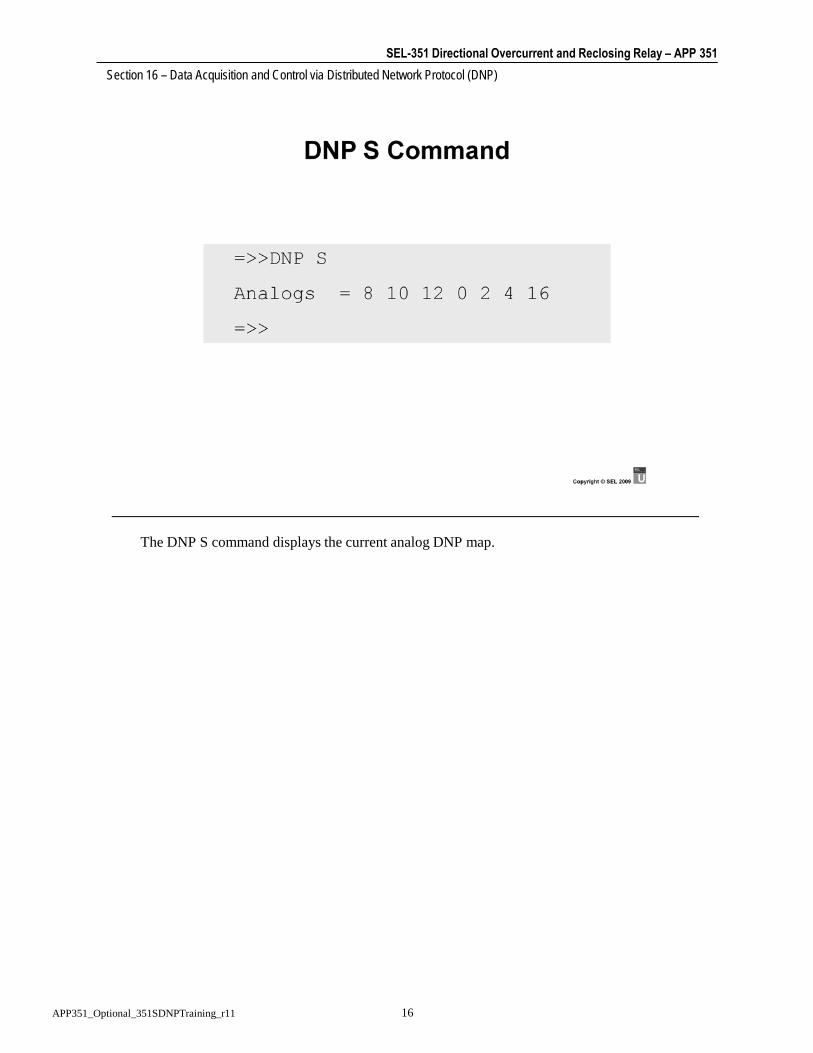
SEL-351 Directional Overcurrent and Reclosing Relay – APP 351 Section 16 – Data Acquisition and Control via Distributed Network Protocol (DNP)
16APP351_Optional_351SDNPTraining_r11
The DNP S command displays the current analog DNP map.

SEL-351 Directional Overcurrent and Reclosing Relay – APP 351 Section 16 – Data Acquisition and Control via Distributed Network Protocol (DNP)
17APP351_Optional_351SDNPTraining_r11
The DNP T command displays the current binary input DNP map.

SEL-351 Directional Overcurrent and Reclosing Relay – APP 351 Section 16 – Data Acquisition and Control via Distributed Network Protocol (DNP)
18APP351_Optional_351SDNPTraining_r11

SEL-351 Directional Overcurrent and Reclosing Relay – APP 351 Section 16 – Data Acquisition and Control via Distributed Network Protocol (DNP)
19APP351_Optional_351SDNPTraining_r11
Control of the trip and close functions through DNP is provided with OC and CC bits. When the DNP master issues a Close command to control Index 32, the CC bit will be pulsed. Likewise, when the DNP master issues a Trip command to control Index 32, the OC bit will be pulsed. The DNP master could also issue a Pulse command to Index 16 to pulse OC and Index 17 to pulse CC.

SEL-351 Directional Overcurrent and Reclosing Relay – APP 351 Section 16 – Data Acquisition and Control via Distributed Network Protocol (DNP)
20APP351_Optional_351SDNPTraining_r11
For this example, LT1 can be controlled by either PB1 or RB1 and RB2. For the remote bits to work, LT3 must also be set. LT3 is being used as a Remote Enable Switch. Remote control of RB1 and RB2 are allowed only when LT3 is set. For this example to work correctly, the remote bits must be pulsed. To pulse RB1, the DNP master can issue a Pulse On command to Index 0 or a Trip, Latch Off, or Pulse Off command to Index 24.

SEL-351 Directional Overcurrent and Reclosing Relay – APP 351 Section 16 – Data Acquisition and Control via Distributed Network Protocol (DNP)
21APP351_Optional_351SDNPTraining_r11

SEL-351 Directional Overcurrent and Reclosing Relay – APP 351 Section 16 – Data Acquisition and Control via Distributed Network Protocol (DNP)
22APP351_Optional_351SDNPTraining_r11
Use the DNP data map to determine the index of the analog values of interest.

SEL-351 Directional Overcurrent and Reclosing Relay – APP 351 Section 16 – Data Acquisition and Control via Distributed Network Protocol (DNP)
23APP351_Optional_351SDNPTraining_r11

SEL-351 Directional Overcurrent and Reclosing Relay – APP 351 Section 16 – Data Acquisition and Control via Distributed Network Protocol (DNP)
24APP351_Optional_351SDNPTraining_r11
Use the DNP data map along with the Relay Word Bit Table to configure the DNP binary input map. Remember to add 500 to the index of a SER point and remember to add that point to the SER Trigger List with SET R.

SEL-351 Directional Overcurrent and Reclosing Relay – APP 351 Section 16 – Data Acquisition and Control via Distributed Network Protocol (DNP)
25APP351_Optional_351SDNPTraining_r11

SEL-351 Directional Overcurrent and Reclosing Relay – APP 351 Section 16 – Data Acquisition and Control via Distributed Network Protocol (DNP)
26APP351_Optional_351SDNPTraining_r11
SEL Application Guide AG2000-10 is a Job Done® example showing how to configure the SEL-351 for operation with a DNP master.

DN
P M
essag
e S
tru
ctu
re –
Data
Lin
k H
ead
er
All
DN
P M
essag
es s
tart
with b
yte
s 0
5,
64
Me
ssag
e le
ngth
: 0
5 -
FF
, d
oe
s n
ot in
clu
de 0
5,
64
, LE
N,
or
CR
C b
yte
s
Fu
ncti
on
Co
de
Fu
ncti
on
Fra
me
Typ
eFC
V
Fram
e fro
m P
rimar
y (P
RM
=1)
0S
end -
Confirm
expecte
dR
eset of
rem
ote
link
0
1S
end -
Confirm
expecte
dR
eset of
user
pro
cess
0
2S
end -
Confirm
expecte
dTest fu
nctio
n f
or
link
1
3S
end -
Confirm
expecte
dU
ser
data
1
4S
end -
Confirm
expecte
dU
ncom
firm
ed u
ser
data
0
9R
equest -
Respond e
xpecte
dR
equest lin
k sta
tus
0
Fram
e fro
m S
econ
dary
(PR
M=0
)0
Confirm
AC
K -
pos. ackn
ow
ledgem
ent
0
1C
onfirm
NA
CK
- n
eg. ackn
ow
ledgem
ent
0
11
Respond
Sta
tus o
f Lin
k1
LE
ND
LC
05
64
DE
ST
INA
TIO
N
LS
BM
SB
SO
UR
CE
LS
BM
SB
CR
C
DIR
Phys
ical tr
ansm
issio
n d
irection
1 =
sta
tion A
to s
tation B
0 =
sta
tion B
to s
tation A
PR
MP
rim
ary
Message
1 =
fra
me f
rom
prim
ary
(in
itia
ting s
tation)
0 =
fra
me f
rom
secondary
(re
spondin
g s
tation)
FC
BF
ram
e c
ount bit
FC
VF
ram
e c
ount bit v
alid
1 =
Fra
me c
ount bit is v
alid
0 =
ignore
fra
me c
ount bit
DF
CD
ata
flo
w c
ontr
ol bit
RE
SR
eserv
ed =
0
FU
NC
TIO
N C
OD
ED
efines the f
ram
e typ
e, how
the d
ata
lin
k w
ill
handle
the f
ram
e
From
R
emot
eFr
om
Mas
ter
Func
tion
Com
men
t
0080
AC
K01
81N
AC
KFa
iled
0B8B
Link
Sta
tus
Repl
y10
90A
CK
Buff
ers
full
1191
NA
CK
Fail/
Buff
ers
full
1B9B
Link
Sta
tus
Repl
y40
C0
RESE
T LI
NK
41C
1Re
set U
ser P
roce
ss44
C4
Unc
onfir
med
Use
r Dat
a49
C9
Link
Sta
tus
Requ
est
52D
2Te
st L
ink
53D
3C
onfir
med
Use
r Dat
a60
E0RE
SET
LIN
KFC
B=1
igno
red
61E1
Rese
t Use
r Pro
cess
FCB=
1 ig
nore
d64
E4U
ncon
firm
ed U
ser D
ata
FCB=
1 ig
nore
d69
E9Li
nk S
tatu
s Re
ques
tFC
B=1
igno
red
72F2
Test
Lin
kFC
B=1
73F3
Con
firm
ed U
ser D
ata
FCB=
1
DIR
1
PR
M
0
FC
B/
RE
S
FC
V/
DF
C
76
54
32
10
Fun
ction
Co
de
DL
C T
ab
le
APP
351_
DN
PMes
sage
Stru
ctur
e1

DN
P M
essag
e S
tru
ctu
re –
Data
Blo
ck
Fin
al
First
76
54
32
10
Sequ
en
ce
CR
C
First
Fin
al
App
Conf
Un-
sol.
76
54
32
10
Se
que
nce
Ap
p
Ctl
Fun
c
Co
de
AP
P H
eader
TH
CO
DE
FUN
CTI
ON
Req
uest
0C
onfirm
1R
ead
2W
rite
3S
ele
ct
4O
pe
rate
5D
ire
ct O
pera
te
6D
irect O
pera
te -
No
Acknow
ledgm
ent
7Im
media
te F
ree
ze
8Im
media
te F
reeze
-N
o A
cknow
ledgm
ent
9F
reeze a
nd C
lea
r
AF
reeze a
nd C
lea
r -
No A
cknow
ledgm
ent
BF
reeze w
ith T
ime
CF
reeze w
ith T
ime -
No A
cknow
ledg
me
nt
DC
old
Re
sta
rt
EW
arm
Resta
rt
FIn
itia
lize D
ata
to
Defa
ults
10
Initia
lize
Ap
plic
atio
n
11
Sta
rt A
pplic
ation
12
Sto
p A
pp
lica
tion
13
Save
Configura
tion
14
Ena
ble
Unsolic
ited M
essages
15
Dis
able
Unsolic
ited M
essages
16
Assig
n C
lass
17
Dela
y M
easu
rem
ent
Res
pons
e 0C
onfirm
81
Response
82
Unsolic
ited
Messag
e
Res.
Res.
Bad
Cn
fg
Alrdy
Exec
Buffr
Ovrf
l
Out
of
rnge
Obj
Unk.
Bad
Fun
c
76
54
32
10
Da
taO
bje
ct H
eade
r. .
.R
eq
uest
Resp
on
se
App
Ctl
Func
Cod
eIn
tern
al In
d.
First
Secon
d
Re
-
sta
rt
Dev
Trb
lLocal
Ne
ed
Tim
e
cla
ss
3
cla
ss
2
cla
ss
1
All
Sta
.
76
54
32
10
APP
351_
DN
PMes
sage
Stru
ctur
e2

DN
P M
essag
e S
tru
ctu
re –
Ob
ject/
Data
Data
Ob
ject H
ead
er
76
54
32
10
Qu
alif
ier
Co
de
Ind
ex
Gro
up
Va
ria-
tio
nR
ange
(0-8
byte
s)
Qua
l.
IND
EX
0N
o I
ndex,
Packed
11 B
yte
Index
22 B
yte
Index
34 B
yte
Index
41 B
yte
Obje
ct
52 B
yte
Obje
ct
64 B
yte
Obje
ct
QU
AL
IFIE
R
08 B
it S
tart
and S
top Indic
es
116 B
it S
tart
and S
top Indic
ies
232 B
it S
tart
and S
top Indic
ies
38 B
it A
bsolu
te A
ddr
Identifie
rs
416 B
it A
bsolu
te A
ddr
Identifie
rs
532 B
it A
bsolu
te A
ddr
Identifie
rs
6N
o R
ange F
ield
78 B
it Q
uantity
816 B
it Q
uantity
932 B
it Q
uantity
B0xB
Variable
Arr
ay
APP
351_
DN
PMes
sage
Stru
ctur
e3

APP351_DNPPortSettingsTables_r1 Page 1 of 1
DNP Port Settings Tables

APP 351 16d_APP351_351SDNPDataObjectTables_r3.docx Page 1 of 6
SEL-351S DNP OBJECT TABLE
The supported object, function, and qualifier code combinations are given by the following object table.
SEL-351S DNP Object Table
Object Request
(supported) Response
(may generate)
Obj *default
Var Description
Func Codes (dec)
Qual Codes (hex)
Func Codes (dec)
Qual Codes (hex)
1 0 Binary Input—All Variations 1 0,1,6,7,8
1 1 Binary Input 1 0,1,6,7,8 129 0,1,7,8
1 2* Binary Input with Status 1 0,1,6,7,8 129 0,1,7,8
2 0 Binary Input Change—All Variations 1 6,7,8
2 1 Binary Input Change without Time 1 6,7,8 129 17,28
2 2* Binary Input Change with Time 1 6,7,8 129,130 17,28
2 3 Binary Input Change with Relative Time 1 6,7,8 129 17,28
10 0 Binary Output—All Variations 1 0,1,6,7,8
10 1 Binary Output
10 2* Binary Output Status 1 0,1,6,7,8 129 0,1
12 0 Control Block—All Variations
12 1 Control Relay Output Block 3,4,5,6 17,28 129 echo of request
12 2 Pattern Control Block
12 3 Pattern Mask
20 0 Binary Counter—All Variations 1 0,1,6,7,8
20 1 32-Bit Binary Counter
20 2 16-Bit Binary Counter
20 3 32-Bit Delta Counter
20 4 16-Bit Delta Counter
20 5 32-Bit Binary Counter without Flag 1 0,1,6,7,8 129 0,1,7,8
20 6* 16-Bit Binary Counter without Flag 1 0,1,6,7,8 129 0,1,7,8
20 7 32-Bit Delta Counter without Flag
20 8 16-Bit Delta Counter without Flag
21 0 Frozen Counter—All Variations
21 1 32-Bit Frozen Counter
21 2 16-Bit Frozen Counter
21 3 32-Bit Frozen Delta Counter
21 4 16-Bit Frozen Delta Counter
21 5 32-Bit Frozen Counter with Time of Freeze
21 6 16-Bit Frozen Counter with Time of Freeze
21 7 32-Bit Frozen Delta Counter with Time of Freeze
21 8 16-Bit Frozen Delta Counter with Time of Freeze
21 9 32-Bit Frozen Counter without Flag
21 10 16-Bit Frozen Counter without Flag

Page 2 of 6 16d_APP351_351SDNPDataObjectTables_r3.docx APP 351
Object Request
(supported) Response
(may generate)
Obj *default
Var Description
Func Codes (dec)
Qual Codes (hex)
Func Codes (dec)
Qual Codes (hex)
21 11 32-Bit Frozen Delta Counter without Flag
21 12 16-Bit Frozen Delta Counter without Flag
22 0 Counter Change Event—All Variations 1 6,7,8
22 1 32-Bit Counter Change Event without Time 1 6,7,8 129 17,28
22 2* 16-Bit Counter Change Event without Time 1 6,7,8 129,130 17,28
22 3 32-Bit Delta Counter Change Event without Time
22 4 16-Bit Delta Counter Change Event without Time
22 5 32-Bit Counter Change Event with Time 1 6,7,8 129 17,28
22 6 16-Bit Counter Change Event with Time 1 6,7,8 129 17,28
22 7 32-Bit Delta Counter Change Event with Time
22 8 16-Bit Delta Counter Change Event with Time
23 0 Frozen Counter Event—All Variations
23 1 32-Bit Frozen Counter Event without Time
23 2 16-Bit Frozen Counter Event without Time
23 3 32-Bit Frozen Delta Counter Event without Time
23 4 16-Bit Frozen Delta Counter Event without Time
23 5 32-Bit Frozen Counter Event with Time
23 6 16-Bit Frozen Counter Event with Time
23 7 32-Bit Frozen Delta Counter Event with Time
23 8 16-Bit Frozen Delta Counter Event with Time
30 0 Analog Input—All Variations 1 0,1,6,7,8
30 1 32-Bit Analog Input 1 0,1,6,7,8 129 0,1,7,8
30 2 16-Bit Analog Input 1 0,1,6,7,8 129 0,1,7,8
30 3 32-Bit Analog Input without Flag 1 0,1,6,7,8 129 0,1,7,8
30 4* 16-Bit Analog Input without Flag 1 0,1,6,7,8 129 0,1,7,8
31 0 Frozen Analog Input—All Variations
31 1 32-Bit Frozen Analog Input
31 2 16-Bit Frozen Analog Input
31 3 32-Bit Frozen Analog Input with Time of Freeze
31 4 16-Bit Frozen Analog Input with Time of Freeze
31 5 32-Bit Frozen Analog Input without Flag
31 6 16-Bit Frozen Analog Input without Flag
32 0 Analog Change Event—All Variations 1 6,7,8
32 1 32-Bit Analog Change Event without Time 1 6,7,8 129 17,28
32 2* 16-Bit Analog Change Event without Time 1 6,7,8 129,130 17,28
32 3 32-Bit Analog Change Event with Time 1 6,7,8 129 17,28
32 4 16-Bit Analog Change Event with Time 1 6,7,8 129 17,28
33 0 Frozen Analog Event—All Variations
33 1 32-Bit Frozen Analog Event without Time
33 2 16-Bit Frozen Analog Event without Time
33 3 32-Bit Frozen Analog Event with Time
33 4 16-Bit Frozen Analog Event with Time

APP 351 16d_APP351_351SDNPDataObjectTables_r3.docx Page 3 of 6
Object Request
(supported) Response
(may generate)
Obj *default
Var Description
Func Codes (dec)
Qual Codes (hex)
Func Codes (dec)
Qual Codes (hex)
40 0 Analog Output Status—All Variations 1 0,1,6,7,8
40 1 32-Bit Analog Output Status 1 0,1,6,7,8 129 0,1,7,8
40 2* 16-Bit Analog Output Status 1 0,1,6,7,8 129 0,1,7,8
41 0 Analog Output Block—All Variations
41 1 32-Bit Analog Output Block 3,4,5,6 17,28 129 echo of request
41 2 16-Bit Analog Output Block 3,4,5,6 17,28 129 echo of request
50 0 Time and Date—All Variations
50 1 Time and Date 1,2 7,8 index = 0
129 07, quantity=
1
50 2 Time and Date with Interval
51 0 Time and Date CTO—All Variations
51 1 Time and Date CTO
51 2 Unsynchronized Time and Date CTO 07, quantity=
1
52 0 Time Delay—All Variations
52 1 Time Delay Coarse
52 2 Time Delay Fine 129 07, quantity=
1
60 0 All Classes of Data 1,20,21 6
60 1 Class 0 Data 1 6
60 2 Class 1 Data 1,20,21 6,7,8
60 3 Class 2 Data 1,20,21 6,7,8
60 4 Class 3 Data 1,20,21 6,7,8
70 1 File Identifier
80 1 Internal Indications 2 0,1 index = 7
81 1 Storage Object
82 1 Device Profile
83 1 Private Registration Object
83 2 Private Registration Object Descriptor
90 1 Application Identifier
100 1 Short Floating Point
100 2 Long Floating Point
100 3 Extended Floating Point
101 1 Small Packed Binary-Coded Decimal
101 2 Medium Packed Binary-Coded Decimal
101 3 Large Packed Binary-Coded Decimal
No object 13,14,23

Page 4 of 6 16d_APP351_351SDNPDataObjectTables_r3.docx APP 351
SEL-351S DATA MAP
The data map may change when newer versions of relay firmware with added capabilities are introduced. The following is the default object map supported by the SEL-351S firmware version R108.
SEL-351S DNP Data Map
DNP Object Type Index Description
01,02 000–499 Relay Word, where 50B3 is 0 and V1GOOD is 495.
01,02 500–999 Relay Word from the SER, encoded same as inputs 000–499 with 500 added.
01,02 1000–1015 Relay front-panel targets, where 1015 is RESET (LED19), 1008 is N (LED26), 1007 is ENABLED (LED11) and 1000 is 81 (LED18).
01,024 1016–1019 Power factor leading for A-, B-, C-, and 3-phase.
01,02 1020 Relay Disabled.
01,02 1021 Relay diagnostic failure.
01,02 1022 Relay diagnostic warning.
01,02 1023 New relay event available.
01,02 1024 Settings change or relay restart.
01,021 1025 A more recent unread relay event is available.
01,021,2 1026-1041 Relay Word rows 64 & 65.
01,021,2 1042-1057 Relay Word rows 64 & 65 from the SER, encoded same as inputs 1026-1041 with 16 added.
10,12 00–15 Remote bits RB1–RB16
10,12 16 Pulse Open command OC.
10,12 17 Pulse Close command CC.
10,12 18 Reset demands.
10,12 19 Reset demand peaks.
10,12 20 Reset energies.
10,12 21 Reset breaker monitor.
10,12 22 Reset front-panel targets.
10,12 23 Read next relay event.
10,12 24–31 Remote bit pairs RB1–RB16.
10,12 32 Open/Close pair OC & CC.
20,22 00 Active settings group.
20,22 01 Internal breaker trips.
20,22 02 External breaker trips.
30,32 00,01 IA magnitude and angle.
30,32 02,03 IB magnitude and angle.
30,32 04,05 IC magnitude and angle.
30,32 06,07 IN magnitude and angle.
30,325 08,09 VA magnitude (kV) and angle.
30,325 10,11 VB magnitude (kV) and angle.

APP 351 16d_APP351_351SDNPDataObjectTables_r3.docx Page 5 of 6
DNP Object Type Index Description
30,325 12,13 VC magnitude (kV) and angle.
30,32 14,15 VS magnitude (kV) and angle.
30,32 16,17 IG magnitude and angle.
30,32 18,19 I1 magnitude and angle.
30,32 20,21 3I2 magnitude and angle.
30,324 22,23 3V0 magnitude (kV) and angle.
30,32 24,25 V1 magnitude (kV) and angle.
30,32 26,27 V2 magnitude (kV) and angle.
30,324 28–31 MW A-, B-, C-, and 3-phase.
30,324 32–35 MVAR A-, B-, C-, and 3-phase.
30,324 36–39 Power factor A-, B-, C-, and 3-phase.
30,32 40 Frequency.
30,32 41 VDC.
30,324 42,43 A-phase MWhr in and out.
30,324 44,45 B-phase MWhr in and out.
30,324 46,47 C-phase MWhr in and out.
30,32 48,49 3-phase MWhr in and out.
30,324 50,51 A-phase MVARhr in and out.
30,324 52,53 B-phase MVARhr in and out.
30,324 54,55 C-phase MVARhr in and out.
30,32 56,57 3-phase MVARhr in and out.
30,32 58–63 Demand IA, IB, IC, IN, IG, and 3I2 magnitudes.
30,324 64–67 A-, B-, C-, and 3-phase demand MW in.
30,324 68–71 A-, B-, C-, and 3-phase demand MVAR in.
30,324 72–75 A-, B- C-, and 3-phase demand MW out.
30,324 76–79 A-, B-, C-, and 3-phase demand MVAR out.
30,32 80–85 Peak demand IA, IB, IC, IN, IG, and 3I2 magnitudes.
30,324 86–89 A-, B-, C-, and 3-phase peak demand MW in.
30,324 90–93 A-, B-, C-, and 3-phase peak demand MVAR in.
30,324 94–97 A-, B-, C-, and 3-phase peak demand MW out.
30,324 98–101 A-, B-, C-, and 3-phase peak demand MVAR out.
30,32 102–104 Breaker contact wear percentage (A, B, C).
30,323 105 Fault type (see table for definition).
30,323 106 Fault location.
30,323 107 Fault current.
30,323 108 Fault frequency.
30,323 109 Fault settings group.
30,323 110 Fault recloser shot counter.
30,323 111–113 Fault time in DNP format (high, middle, and low 16 bits).
30,321 114 Relay internal temperature
30,321 115 Number of unread faults
30,321 116 51P1P setting in primary units
30,321 117 51P2P setting in primary units
30,321 118 51G1P setting in primary units
30,321 119 51G2P setting in primary units

Page 6 of 6 16d_APP351_351SDNPDataObjectTables_r3.docx APP 351
DNP Object Type Index Description
30,321 120 51QP setting in primary units
30,321 121 51N1P setting in primary units
30,321 122 51N2P setting in primary units
40,41 00 Active settings group.
1 Extended mode (DNPE) only. 2 Only on relays with 0.2 A nominal neutral rating. 3 Object type 32 event messages are generated for these points in DNP extended mode (DNPE)
only. 4 For Delta configuration setting PTCONN = DELTA, the per-phase values and 3V0 are
undefined and set to 0. Three-phase values are defined and valid. 5 For Delta configuration setting PTCONN = DELTA, WYE values of VA, VB, and VC are
replaced with Delta values of VAB, VBC, and VCA respectively.

SCHWEITZER ENGINEERING LABORATORIES 2350 NE Hopkins Court A Pullman, WA A 99163-5603 A USA Phone: (509) 332-1890 A Fax: (509) 332-7990 E-mail: [email protected] A Internet: www.selinc.com
Application Guide Volume VII AG2000-10
SEL-351S Data Acquisition and Control via Distributed Network Protocol (DNP)
(A JOB DONE® Example) Mike McKoy
INTRODUCTION
The SEL-351S Relay supports DNP V3.0 Level 2 Slave Protocol that provides access to metering data, Relay Word Bits, targets, sequential events recorder (SER), breaker monitor, relay summary event reports, and settings groups. DNP also provides the capability to operate the relay Trip and Close functions, Remote Bits, as well as reset various metering and monitoring functions in the SEL-351S Relay.
The DNP point remapping function allows the user to create custom analog and binary input DNP maps that allow the user to retrieve only the data of interest from the relay. This feature can drastically reduce the amount of data communications overhead associated with interrogating the relay.
IDENTIFYING THE PROBLEM
For this example, we want to accomplish the following:
1. Configure Port 3 of the SEL-351S Relay as a DNP port.
2. Create a custom analog DNP map that contains VA, VB, VC, IA, IB, IC, IG, MW A, MW B, MW C, MVAR A, MVAR B, MVAR C, Frequency, and all of the relay summary event data.
3. Create a custom binary input DNP map that contains the relay front panel targets, breaker position (as a SER point), ground enable status, reclose enable status, and new relay event status.
4. Set the relay so that controls through DNP are available to trip and close the breaker, enable and block grounds, enable and block reclosing, and select the read next relay event.

2 SEL Application Guide 2000-10 Date Code 20001206
DEFINING THE SOLUTION
Hardware Connections
1. Connect Port 3 of the SEL-351S Relay to the DNP master with an SEL-C280 cable.
2. Connect Port F of the SEL-351S Relay to a serial port on your computer with an SEL-234A cable.
Set the SEL-351S Relay
1. Issue the ACCESS and 2ACCESS commands and associated passwords to get to Access Level 2.
2. Use the SET P 3 command to set Port 3 for the DNP port.
3. Use the DNP A command to create the custom analog DNP map.
4. Use the DNP B command to create the custom binary input DNP map.
5. Use the SET R command to add breaker status (52A) to the SER.
6. Use the SET L 1 command to program the relay to use Remote Bits to enable/block grounds and enable/block reclosing.
Verify Operation with the DNP Master
1. Check the communications statistics from the DNP master (if available) to ensure that reliable communications exist between the DNP master and the relay.
2. Issue class polls with the DNP master to verify that the correct data is being retrieved from the relay.
3. Send controls to the relay and verify that the relay responds as desired.
SET THE SEL-351S, STEP-BY-STEP
1. Connect to the relay and issue the ACCESS and 2ACCESS commands and associated passwords to get to Access Level 2.
2. Use the SET P 3 command to configure Port 3 as the DNP port as shown below:
=>>SET P 3 <ENTER> Port 3 Protocol(SEL,LMD,DNP,DNPE,MBA,MBB,MB8A,MB8B) PROTO = SEL ? DNP<ENTER> Baud Rate(300-38400) SPEED = 9600 ? <ENTER> DNP Address(0-65534) DNPADR= 1 ? <ENTER> Class for Event Data(0-3) ECLASS= 2 ? <ENTER> Minutes for Request Interval(0-32767) TIMERQ= 0 ? <ENTER> Currents Scaling Decimal Places(0-3) DECPLA= 2 ? <ENTER> Voltages Scaling Decimal Places(0-3) DECPLV= 2 ? <ENTER> Misc Data Scaling Decimal Places(0-3) DECPLM= 1 ? <ENTER> Seconds to Select/Operate Time-out(0.00-30.00) STIMEO= 3.0 ? <ENTER> Data Link Retries(0-15) DRETRY= 0 ? <ENTER> Seconds to Data Link Time-out(0-5) DTIMEO= 1 ? <ENTER> Minimum Seconds from DCD to Tx(0.00-1.00) MINDLY= 0.00 ? <ENTER>

Date Code 20001206 SEL Application Guide 2000-10 3
Maximum Seconds from DCD to Tx(0.00-1.00) MAXDLY= 0.00 ? <ENTER> Settle Time from RTS ON to Tx(OFF,0.00-30.00sec) PREDLY= 0.00 ? <ENTER> Settle Time from Tx to RTS OFF(0.00-30.00sec) PSTDLY= 0.00 ? <ENTER> Analog Reporting Deadband Counts(0-32767) ANADB = 10 ? <ENTER> Enable Unsolicited Reporting(Y,N) UNSOL = N ? <ENTER> Enable Unsolicited Reporting at Power-up(Y,N) PUNSOL= N ? <ENTER> DNP Address to Report to(0-65534) REPADR= 0 ? 12<ENTER> Number of Events to Transmit on(1-200) NUMEVE= 10 ? <ENTER> Seconds until Oldest Event to Tx on(0.00-60.00) AGEEVE= 2.0 ? <ENTER> Seconds to Event Message Confirmation Time-out(1-50) UTIMEO= 2 ? <ENTER> PROTO = DNP SPEED = 9600 DNPADR= 1 ECLASS= 2 TIMERQ= 0 DECPLA= 2 DECPLV= 2 DECPLM= 1 STIMEO= 3.0 DRETRY= 0 DTIMEO= 1 MINDLY= 0.00 MAXDLY= 0.00 PREDLY= 0.00 PSTDLY= 0.00 ANADB = 10 UNSOL = N PUNSOL= N REPADR= 12 NUMEVE= 10 AGEEVE= 2.0 UTIMEO= 2 Save Changes(Y/N)? Y<ENTER> Settings saved =>>
Notes:
a. Any port on the SEL-351S Relay can be configured as a DNP port, but only one port can be configured for DNP at a time. For this example, if Port 2 was already configured as a DNP port, when we answered “Y” to Save Settings, a message would have printed that stated “DNP is already active on another port.”
b. The DNP port of the relay must be configured to match the settings of the DNP master. For this example, the relay is setup for polled, report-by-exception data access, without data link retries. This is a common data access method where the master polls occasionally for static data and frequently for event data.
3. Use the DNP A command to create the custom analog DNP map based on the analog data requirements as shown below:
=>>DNP A <ENTER> Enter the new DNP Analog map 8 10 12 0 2 4 16 28 29 30 32 33 34 40 105 106 107 108 109 110 111 112 113<ENTER> Save Changes(Y/N)? Y<ENTER> =>> =>>DNP S<ENTER> Analogs = 8 10 12 0 2 4 16 28 29 30 32 33 34 40 105 106 107 108 109 110 \ 111 112 113 =>>
Notes:
a. The index for each analog point that can be retrieved with DNP can be found in Appendix H of the SEL-351S Instruction Manual. From the analog data requirements of this example and Appendix H, we can determine the order of the points that define the analog DNP map. For instance, the requirements had VA, VB, and VC as the first three

4 SEL Application Guide 2000-10 Date Code 20001206
data points. From the SEL-351S DNP Data Map table in Appendix H of the relay instruction manual, we find that VA is Index 8, VB is Index 10, and VC is Index 12.
b. Although the relay has 114 analog points when using the default DNP map, this example only uses 23 of the points. By creating this custom analog DNP map, the data traffic associated with analogs is cut from 114 points to 23 points.
c. The DNP S command is used to show the current analog DNP map. After making a change to the analog DNP map with the DNP A command, the DNP S command can be used to verify that the correct numbers were entered.
4. Use the DNP B command to create the custom binary input DNP map based on the binary input data requirements as shown below:
=>>DNP B<ENTER> Enter the new DNP Binary map 1000 1001 1002 1003 1004 1005 1006 1007 1008 1009 1010 1011 1012 1013 1014 \ 1015 782 223 222 1023<ENTER> Save Changes(Y/N)? Y<ENTER> =>> =>>DNP T<ENTER> Binaries = 1000 1001 1002 1003 1004 1005 1006 1007 1008 1009 1010 1011 1012 \ 1013 1014 1015 782 223 222 1023 =>>
Notes:
a. The first 16 items in the binary input map are the front-panel targets. The SEL-351S DNP Data Map table in Appendix H of the relay instruction manual is used to find the index numbers (1000 – 1015) for the front-panel targets.
b. The breaker status, or Relay Word Bit 52A, is the binary input after the front-panel targets. The index for the 52A (282) is found from the SEL-351S Relay Word Bits table in Section 9 of the relay instruction manual. For example, to find the index of the 52A bit, go to the Relay Word Bits table and find the 52A bit in the table. The 52A is in row 37 of the table. Since the table starts with row 2, subtract 2 from the 52A row number (37-2). Next, multiply the result times 8 since there are 8 bits in each row ((37-2) x 8). The result, 280, is the index of the right most bit in row 37, the PB9 bit. To get the index of the 52A bit, add 2 since the 52A is 2 bits to the left of PB9. Therefore, the index of the 52A bit equals ((37-2) x 8) + 2, which equals 282. The table reads from right to left, so if LED10 was required on row 37, it would be PB9 (280) plus 5, or 285 since it is located 5 to the left of PB9. Since the data requirements for this example called for the 52A as a SER point, we must add 500 to the index that is found in the SEL-351S Relay Word Bits table as described by the SEL-351S DNP Data Map table in Appendix H of the relay instruction manual. The 52A SER point will then be scanned every quarter-cycle and available to DNP as an event.
c. The ground enable feature for this example is provided by the first Latch Control Switch, LT1, and the reclose enable feature is provided by the second Latch Control Switch, LT2. Therefore, the status of ground enable and reclose enable can be determined from the states of Relay Word Bits LT1 (Index 223) and LT2 (Index 222). The SEL-351S Relay

Date Code 20001206 SEL Application Guide 2000-10 5
Word Bits table in the relay instruction manual is used to determine the index for each Relay Word Bit.
d. The last binary input added to the custom map is the new relay event available status. The index (1023) for this item is found in the SEL-351S DNP Data Map in the relay instruction manual.
e. Again, note the reduction in data communications traffic after creating a custom binary input DNP map. For this example, we are retrieving 20 binary input points. With the default binary input DNP map in the SEL-351S Relay, we would be retrieving 1025 binary input points with a DNP Class 0 poll.
f. The DNP T command is used to show the current binary input DNP map. After making a change to the binary input DNP map with the DNP B command, the DNP T command can be used to verify that the correct numbers were entered.
5. Use the SET R command to add the 52A Relay Word Bit to the SER as shown below:
=>>SET R<ENTER> Sequential Events Recorder trigger lists: 24 elements max.(enter NA to null) SER1 =TRIP,51P1T,51G1T,67P1,PB10,OC ? <ENTER> 24 elements max.(enter NA to null) SER2 =CLOSE,CF,79RS,79CY,79LO,SH0,SH1,SH2,SH3,SH4,PB9,CC ? <ENTER> 24 elements max.(enter NA to null) SER3 =0 ? 52A<ENTER> Load Profile settings: Load profile list (15 elements max., enter NA to null) LDLIST=IA,VA,MW3,PF3 ? <ENTER> Load profile acquisition rate(5,10,15,30,60min) LDAR = 5 ? <ENTER> Sequential Events Recorder trigger lists: SER1 =TRIP,51P1T,51G1T,67P1,PB10,OC SER2 =CLOSE,CF,79RS,79CY,79LO,SH0,SH1,SH2,SH3,SH4,PB9,CC SER3 =52A Load Profile settings: LDLIST=IA,VA,MW3,PF3 LDAR = 5 Save Changes(Y/N)? Y<ENTER> Settings saved =>>
Notes:
For this example, the 52A was added to the third SER trigger list (SER3). It does not matter which SER trigger list the item is included in, but it must be in one of the lists.
6. To successfully issue controls with the Remote Bits and the Trip and Close functions, the relay must be programmed to use these points. The Remote Bits are user programmable, so Remote Bit 1 (RB1) in one relay may enable grounds, but in another relay it could be used to block reclosing. The following listings of logic settings show one way to configure the relay

6 SEL Application Guide 2000-10 Date Code 20001206
to operate as described in this example. Only the settings that pertain to doing controls for this example are shown. Reference Appendix H in the SEL-351S manual to determine the control index that the DNP master must use to issue controls.
a. Trip Equation
TR = 51P1T + 51G1T + 67P1 + PB10 + OC * LT3
The trip equation must include the OC term if the user is going to trip via DNP with the OC bit. In this example, LT3 must also be set to allow OC to cause a trip. LT3 is being used as a remote enable switch. If LT3 is set, remote operations are allowed; otherwise, remote operations are not permitted. The DNP master can set OC by issuing a Trip, Latch Off, or Pulse Off command to control Index 32.
b. Close Equation
CL = (PB9 * LT4 + CC * LT3) * LT5
The close equation must include the CC term if the user is going to close via DNP with the CC bit. Again, LT3 is the remote enable switch and must be set before a DNP command can close the breaker. LT5 is being used as a Hot Line Tag switch and it must be set to allow the CL equation to become true. The DNP master can set CC by issuing a Close, Latch On, or Pulse On command to control Index 32.
c. Ground Torque Control Equation
51G1TC = LT1
The ground torque control equation determines whether or not the ground current is compared to the pickup. For this example, the state of Latch Control Switch 1 is used to enable and block ground protection.
d. Latch Control Switch 1 Equations
SET1 = !LT1 * PB1 * LT4 + !LT1 * /RB1 * LT3 RST1 = LT1 * PB1 * LT4 + LT1 * /RB2 * LT3
LT1 is set by a rising edge of RB1 if LT3, the remote enable, is set. Likewise, LT1 is reset by a rising edge of RB2 if LT3 is set. Since the ground torque control equation is equal to LT1, a rising edge of RB1 when LT3 is set will enable grounds and a rising edge of RB2 when LT3 is set will block grounds. The DNP master can pulse RB1 by issuing a Trip, Latch Off, or Pulse Off command to control Index 24. RB2 can be pulsed via DNP by issuing a Close, Latch On, or Pulse On command to control Index 24.
e. Drive to Lockout Equation
79DTL = (!LT2 + !LT5) * (TRIP + !52A) + PB10 + OC
The drive to lockout equation determines when reclosing is enabled and blocked. Here, Latch Control Switch 2 is a variable in the equation. If the equation is true, the relay is driven to lockout and reclosing is blocked.
f. Latch Control Switch 2 Equations
SET2 =!LT2 * LT5 * PB2 * LT4 + !LT2 * /RB3 * LT3 * LT5 RST2 =LT2 * PB2 * LT4 + !LT5 + !(79RS + 79CY + 79LO) + LT2 * /RB4 * LT3

Date Code 20001206 SEL Application Guide 2000-10 7
LT2 is set by a rising edge of RB3 if LT3, the remote enable, and LT5, the Hot Line Tag switches are set. Likewise, LT2 is reset by a rising edge of RB4 if LT3 is set. Since the Drive to Lockout equation becomes true when LT2 is reset and the breaker trips or is opened, a rising edge of RB4 when LT3 is set will block reclosing, and a rising edge of RB3 when LT3 and LT5 are set will enable reclosing. The DNP master can pulse RB3 by issuing a Trip, Latch Off, or Pulse Off command to control Index 25. RB4 can be pulsed via DNP by issuing a Close, Latch On, or Pulse On command to control Index 25.
g. Read Next Relay Event
The last item to control in this example is the read next relay event point. From the SEL-351S DNP Data Map table in Appendix H of the SEL-351S Instruction Manual we can determine that this point is at Index 23. When there is an unread relay event summary in the queue, the new relay event status binary input, Index 1023, will be set. Then, the read next relay event control point can be operated to move the next unread event summary from the queue to the current data that is being read from analog points 105-113. To operate the read next relay event control point, the DNP master can issue a Close, Latch On, or Pulse On command to Index 23.
SUMMARY
The DNP interface to the SEL-351S provides an effective way to retrieve data from and issue controls to the relay. This example demonstrates how to configure the relay for efficient analog and binary input data acquisition, as well as how to use fixed control points (Read Next Relay Event), along with the controls that are performed with the user programmable bits.
Although this example was written for the SEL-351S Relay, the concepts demonstrated here would apply to other SEL relays that support DNP.
FACTORY ASSISTANCE
The employee-owners of Schweitzer Engineering Laboratories, Inc. are dedicated to making electric power safer, more reliable, and more economical.
We appreciate your interest in SEL products, and we are committed to making sure you are satisfied. If you have any questions, please contact us at:
Schweitzer Engineering Laboratories 2350 NE Hopkins Court Pullman, WA USA 99163-5603 Tel: (509) 332-1890 Fax: (509) 332-7990
We guarantee prompt, courteous, and professional service.
We appreciate receiving any comments and suggestions about new products or product improvements that would help us make your job easier.

8 SEL Application Guide 2000-10 Date Code 20001206
All brand or product names appearing in this document are the trademark or registered trademark of their respective holders.
Schweitzer Engineering Laboratories, SELOGIC, Connectorized, JOB DONE, and are registered trademarks of Schweitzer Engineering
Laboratories.
Copyright © SEL 2000 (All rights reserved) Printed in USA.

SEL-351 Directional Overcurrent and Reclosing Relay – APP 351Section 17 – SEL-351R Recloser Control
1APP351_Optional_351RRecloserControl_r8
SEL designed the SEL-351R based on the SEL-351 Distribution Relay. The SEL-351R has full SEL-351 functionality together with a modified user interface designed for recloser control. When you are using the SEL-351R as a traditional line recloser control, it is only necessary to set the EZ settings (Access Level E). Full SEL-351 functionality is available at a higher access level. (Access levels will be covered in more detail later in this presentation.)
The user interface provides operator controls large enough to be operated with protective gloves.
The SEL-351R is designed for easy installation. Simply remove the connections from the existing Kyle control, mount the SEL-351R using the same drill plan provided on the mounting bracket, and reconnect the existing connections.

SEL-351 Directional Overcurrent and Reclosing Relay – APP 351Section 17 – SEL-351R Recloser Control
2APP351_Optional_351RRecloserControl_r8
The design of the SEL-351R allows for an easy installation, whether it is for a new or retrofit installation.
Control cable and drill plan compatibility are key features of the SEL-351R in that they allow for a simple retrofit installation without requiring any modifications.

SEL-351 Directional Overcurrent and Reclosing Relay – APP 351Section 17 – SEL-351R Recloser Control
3APP351_Optional_351RRecloserControl_r8
The above figure shows an SEL-351R retrofitted into a traditional installation, where single-phase 120 Vac power is the only voltage brought to the control.
When single-phase 120 Vac power is connected to the SEL-351R, all of the traditional recloser control functions and operations are available as well as some of the more advanced features that are described in the following slides.

SEL-351 Directional Overcurrent and Reclosing Relay – APP 351Section 17 – SEL-351R Recloser Control
4APP351_Optional_351RRecloserControl_r8
The SEL-351R is designed to control Cooper three-phase reclosers (equipped with 24 Vdc trip/close circuits). Install the SEL-351R in new or retrofit recloser installations in place of Kyle Form 3, Form 3A, Form 4, Form 4A, Form 4C, and Type FXA and FXB controls.
Because the SEL-351R is plug-compatible with Kyle Form 3, Form 3A, Form 4, Form 4A, Form 4C, or Type FXA or FXB controls, you can use the existing control cable that connects the Kyle control to a Cooper three-phase recloser. For your convenience, SEL also manufactures and offers the control and low voltage close cables.
Standard lengths as well as custom lengths are available. Contact the factory for more information on SEL-351R cables and other cables provided by SEL.

SEL-351 Directional Overcurrent and Reclosing Relay – APP 351Section 17 – SEL-351R Recloser Control
5APP351_Optional_351RRecloserControl_r8
The standard SEL-351R can be applied on new installations using the G&W Viper™ and Joslyn TriMod™ 300R reclosers. These reclosers work with standard “off the shelf”SEL-351Rs.

SEL-351 Directional Overcurrent and Reclosing Relay – APP 351Section 17 – SEL-351R Recloser Control
6APP351_Optional_351RRecloserControl_r8

SEL-351 Directional Overcurrent and Reclosing Relay – APP 351Section 17 – SEL-351R Recloser Control
7APP351_Optional_351RRecloserControl_r8
Underfrequency load shedding element has a pickup range of 40.10–65.00 Hz with a time-delay settable up to 16000 cycles. Five additional frequency elements are available. Use these extra elements for additional underfrequency load-shedding levels (with varying time delays) or to provide a frequency window for load restoration. This logic requires, at a minimum, single-phase 120-Vac power to be connected.
Cold load pickup logic allows closure into a line with cycling loads (i.e., refrigeration or air conditioning, etc.) after an outage. The control logic can be applied so as not to change the pickup or time delay. Rather, the logic “cuts off” the time-overcurrent curve. Thus, sensitivity and coordination are not compromised.
Sequential events recorder (SER) lines are added to the SER for a change-of-state of programmed conditions. The SEL-351R stores the latest 512 lines of the SER report in nonvolatile memory. Use SER reports to gain a broad perspective of system performance at a glance, especially an auto-reclosing sequence.
Event reports are automatically triggered at fault inception and when the SEL-351R issues a trip. Event report length is selectable for 15 or 30 cycles. The current, voltage, frequency, and element status information contained in each report confirms performance of the control scheme and system for each fault.

SEL-351 Directional Overcurrent and Reclosing Relay – APP 351Section 17 – SEL-351R Recloser Control
8APP351_Optional_351RRecloserControl_r8
Six setting groups for designing custom schemes. You can switch the active setting group with the front-panel GROUP pushbutton, a serial port command, or other programmable conditions (e.g., via optoisolated inputs). Use these setting groups to cover a wide range of protection and control contingencies. Selectable setting groups make the SEL-351R ideal for applications requiring frequent setting changes and for adapting the protection to changing system conditions.
The front-panel operator control, ALTERNATE SETTINGS, switches the active setting group between the main and alternate setting groups (Setting Groups 1 and 2, respectively).
The SEL-351R also has flexible time-overcurrent curve options. The user can apply standard recloser curves, as well as relay curves, based on the IEEE C37.111 standard. In addition, the user can add a constant time adder, minimum response time, or adjust time dials to modify the curve. If needed, the user can program a unique curve using the SEL-5804 User-Defined Curve Support for the SEL-351R software program.

SEL-351 Directional Overcurrent and Reclosing Relay – APP 351Section 17 – SEL-351R Recloser Control
9APP351_Optional_351RRecloserControl_r8
Demand ammetering, as well as peak demand ammetering, are provided for the following values:
Input currents: IA,B,C,N (A primary)
Residual ground current: IG [A primary; IG=3I0=(IA+IB+IC)]
Negative-sequence current: 3I2 (A primary)
Sequence coordination keeps the SEL-351R in step with downstream recloser controls. It prevents SEL-351R overreaching fast curves from tripping for faults beyond the downstream recloser control.
Recloser wear monitor monitors mechanical and electrical wear every time the recloser operates. When a result exceeds the threshold set by the recloser wear curve, the SEL-351R asserts a logic point for the affected phase. The logic point can be routed for alarming or to modify reclosing (e.g., shorten the number of reclosers). This method of monitoring recloser wear is solidly based on methods of breaker rating from breaker manufactures, and follows ANSI C37.61-1973 recommendations.
Distributed Network Protocol (DNP) 3.00 Level 2 Slave with point mapping provides an easy interface to third-party devices without requiring the expense of a protocol translator.
SEL MIRRORED BITS® communications sends internal logic status, encoded in a digital message, from one relay or MIRRORED BITS device to the other. MIRRORED BITS communications opens the door to numerous protection, control, and monitoring applications that would otherwise require more expensive external communications equipment wired through contacts and control inputs. Applications for MIRRORED BITS include line protection pilot schemes, remote device control and monitoring, relay cross-tripping, and more. It is faster, simplier, less expensive, and more powerful than conventional communications schemes.

SEL-351 Directional Overcurrent and Reclosing Relay – APP 351Section 17 – SEL-351R Recloser Control
10APP351_Optional_351RRecloserControl_r8
Recent enhancements provide MIRRORED BITS communications over spread spectrum radios. The MIRRORED BITS communications protocol requires a full-duplex channel or a very fast emulation of a full-duplex channel. SEL has recently worked with one radio manufacturer (Freewave) to optimize their radios to meet the rigid requirements of the communications protocol. Spread spectrum radios provide a low-cost, nonlicensed communications path up to 10 miles line-of-sight view and are powered from the SEL-351R.

SEL-351 Directional Overcurrent and Reclosing Relay – APP 351Section 17 – SEL-351R Recloser Control
11APP351_Optional_351RRecloserControl_r8
Full protection and control capabilities are achieved with the SEL-351R when all voltages are connected.
Connect three-phase voltage to voltage channels VA, VB, and VC.
Connect load-side, single-phase voltage to Voltage Channel VS for synchronism check and line voltage check. (Channel VS is connected to Phase A in this example.)
The control cable contains trip and close signals (24 Vdc), recloser status, and currents (IA, IB, IC, IN).

SEL-351 Directional Overcurrent and Reclosing Relay – APP 351Section 17 – SEL-351R Recloser Control
12APP351_Optional_351RRecloserControl_r8
When true three-phase voltage and synchronism-check voltage are connected to the SEL-351R, you gain additional key features through more sophisticated control schemes. Some of these features are:
• Complete metering, including MWh and MVARh, provides extensive and accurate metering capabilities. Metered quantities include phase voltages and currents (including demand), sequence voltages and currents, power, frequency, and energy (including demand), along with maximum/minimum logging of selected quantities.
• Directional overcurrent elements and fault location accurately locates all faults, even during periods of substantial load flow. The fault locator uses fault type, replica line impedance settings, and fault conditions to provide an accurate estimate of fault location without communications channels, special instrument transformers, or prefault information.
• Load-encroachment logic allows phase overcurrent elements to be set securely below maximum expected load to detect end-of-line, three-phase faults in heavily loaded feeder applications.

SEL-351 Directional Overcurrent and Reclosing Relay – APP 351Section 17 – SEL-351R Recloser Control
13APP351_Optional_351RRecloserControl_r8
With the SEL-351R-2 Recloser Control, a setting is available that allows the user to connect any single-phase voltage (phase-to-ground or phase-to-phase) and get “simulated” voltages on the nonconnected phases. From this, the control produces calculated, three-phase quantities for metering purposes.

SEL-351 Directional Overcurrent and Reclosing Relay – APP 351Section 17 – SEL-351R Recloser Control
14APP351_Optional_351RRecloserControl_r8
The SEL-351R-2 Recloser Control includes 16 local, remote, and latch bits, and 16 SELOGIC® control equation variable timers. Also, 8 counters have been added with separate settings to increment, decrement, or reset each counter.
These enhancements make the SEL-351R-2 more flexible and capable for custom schemes, particularly automation schemes like loop sectionalizing and load transfer schemes.

SEL-351 Directional Overcurrent and Reclosing Relay – APP 351Section 17 – SEL-351R Recloser Control
15APP351_Optional_351RRecloserControl_r8
Hardware Overview (Swing-Panel Closed):
• NEMA Type 3R (IP32) Enclosure
• Document Holder
• SEL-351R Front Panel
• 120 Vac (GFCI) Convenience Outlet
• Fuse Holder for GFCI
• Control Cable Receptacle, see Quick Start

SEL-351 Directional Overcurrent and Reclosing Relay – APP 351Section 17 – SEL-351R Recloser Control
16APP351_Optional_351RRecloserControl_r8
Hardware Overview (Swing-Panel Open):
Bring 120 Vac power, close power, three-phase voltage, external control, etc., in and out of the SEL-351R enclosure via the knockout holes.
• 7/8” knockouts for 1/2” conduit fittings
• 1-3/8” knockouts for 1” conduit fittings
Accessories can be mounted on the back panel, above the terminal block. Three EIA-232 serial communications ports are available:
• Serial Port 2 (side panel)
• Serial Port 3 (side panel)
• Serial Port F (front panel)
One EIA-485 serial communications port is available as an ordering option:
• Serial Port 1 (side panel)
The extra I/O (output contacts OUT101 through ALARM and optoisolated inputs IN101 through IN106) is not needed for the basic recloser control functions. The extra I/O is available for SCADA connection or other control and is not polarity sensitive. The optoisolated inputs must be ordered with the appropriate dc voltage rating.

SEL-351 Directional Overcurrent and Reclosing Relay – APP 351Section 17 – SEL-351R Recloser Control
17APP351_Optional_351RRecloserControl_r8
The front-panel display can be used to interrogate the relay for specific information or can be programmed to display preprogrammed custom messages. These preprogrammed messages are then displayed two lines at a time, then switched to the next rotating message. Up to 16 custom display messages can be programmed.
The control CNTRL pushbutton also can be used to execute up to 16 preprogrammed, local control functions. This is in addition to large, operator control buttons.
The large, operator control pushbuttons and LEDs, and the target LEDs, are all programmable. Moreover, each label is changeable. Use these flexible features to program custom control functions as needed. Pushbuttons 9 and 10 (PB9 and PB10) also have built-in, programmable time delays for TRIP and CLOSE pushbuttons. However, any of the pushbuttons can be programmed with a time delay.

SEL-351 Directional Overcurrent and Reclosing Relay – APP 351Section 17 – SEL-351R Recloser Control
18APP351_Optional_351RRecloserControl_r8
Use the front-panel labels to configure a custom scheme for operators.
The front-panel pushbuttons (except TARGET RESET/LAMP TEST) have dual functions (primary and secondary functions). The primary function is the text printed on the pushbutton. After a primary function is selected (e.g., the STATUS pushbutton is pressed), the secondary function pushbuttons (e.g., CANCEL, SELECT, left/right arrows, up/down arrows, EXIT) are then enabled. These secondary functions allow the user to scroll through information, activate settings/control, etc., on the LCD. The following table lists the primary and secondary functions for the pushbuttons shown in this figure.
Primary Function
Secondary Function
TARGET RESET
HELP – Provides help only with front-panel SET commands.
METER CANCEL – Cancel command edit or escape to upper command level.
EVENTS SELECT – Select displayed option or setting.
STATUS – Scroll left on display.
OTHER – Scroll right on display.
SET – Scroll up on display or increment value.
CNTRL – Scroll down on display or decrement value.
GROUP EXIT – Exit entirely from command and return to default display.

SEL-351 Directional Overcurrent and Reclosing Relay – APP 351Section 17 – SEL-351R Recloser Control
19APP351_Optional_351RRecloserControl_r8

SEL-351 Directional Overcurrent and Reclosing Relay – APP 351Section 17 – SEL-351R Recloser Control
20APP351_Optional_351RRecloserControl_r8

SEL-351 Directional Overcurrent and Reclosing Relay – APP 351Section 17 – SEL-351R Recloser Control
21APP351_Optional_351RRecloserControl_r8
Some of the available display values are:
• Metering – current, voltage, MW, MVAR, etc.
• Time-overcurrent element pickup values (in primary).
• Breaker operations counters; percent breaker wear.

SEL-351 Directional Overcurrent and Reclosing Relay – APP 351Section 17 – SEL-351R Recloser Control
22APP351_Optional_351RRecloserControl_r8
The recloser curves in the table below show both the older electronic control designation (e.g., Form 3A) and the newer microprocessor-based control designation (e.g., Form 4C). The recloser curves can be specified in a curve setting using either designation (described on the next slide).
Recloser Curve Cross Reference – Old to NewOld New Old New Old NewA 101 P 115 7 152B 117 R 105 8 113C 133 T 161 8PLUS 111D 116 V 137 9 131E 132 W 138 KG 165F 163 Y 120 11 141G 121 Z 134 13 142H 122 1 102 14 119J 164 2 135 15 112KP 162 3 140 16 139L 107 4 106 17 103M 118 5 114 18 151N 104 6 136

SEL-351 Directional Overcurrent and Reclosing Relay – APP 351Section 17 – SEL-351R Recloser Control
23APP351_Optional_351RRecloserControl_r8
The recloser curves can be specified in a curve setting using either designation. For example, a given traditional recloser curve has the following two designations:
Older electronic control designation (Form 3A): A
Newer microprocessor-based control designation (Form 4C): 101
Traditional recloser curve A and Curve 101 are the same curve—use either designation in making curve settings in the SEL-351R.

SEL-351 Directional Overcurrent and Reclosing Relay – APP 351Section 17 – SEL-351R Recloser Control
24APP351_Optional_351RRecloserControl_r8
The curve modifiers are independently set for each fast and delay curve (phase and ground).
Constant time adder adds time to the selected curve.
Vertical multiplier is the time dial setting for traditional recloser curves. The US and IEC curves have time dial settings conforming to IEEE Standard C37.112-1996.
Minimum response time holds off curve tripping for a minimum time.
High-current trip and high-current lockout are independently set for pickup and active trip.

SEL-351 Directional Overcurrent and Reclosing Relay – APP 351Section 17 – SEL-351R Recloser Control
25APP351_Optional_351RRecloserControl_r8
If the cold load pickup scheme is enabled and the circuit recloser has been open for longer than a user-set time (loss of diversity), the following element operations take place:
• The phase and ground fast curves are turned off.
• The phase and ground slow curves (and SEF element) operate on higher pickups.
The slow curves are not shifted—the low end of the curves are cut off at a higher pickup level. The elements return to their regular pickups after inrush current goes below the regular pickup levels. Optionally, the elements can be forced to their regular pickups with a user-set time (restore).

SEL-351 Directional Overcurrent and Reclosing Relay – APP 351Section 17 – SEL-351R Recloser Control
26APP351_Optional_351RRecloserControl_r8
The feeder in the above figure would traditionally be the last to trip for underfrequency load shedding because it serves critical fire department and hospital loads. Retrofitting recloser control installations on various taps with SEL-351R Recloser Controls means the feeder can now contribute first to underfrequency load shedding at the tap level.
The SEL-351R Recloser Controls on the residential load taps are set to trip first for underfrequency load shedding, without interrupting service to the critical fire department and hospital loads.

SEL-351 Directional Overcurrent and Reclosing Relay – APP 351Section 17 – SEL-351R Recloser Control
27APP351_Optional_351RRecloserControl_r8
The control cable and 120 Vac power are landed on a terminal block and then brought into the actual control. The single-phase 120 Vac power is also factory-connected to paralleled voltage terminals VA, VB, and VC for frequency and voltage elements. VA is used for 81 elements. VA, VB, and VC are used for undervoltage (27) block.
Voltage terminal VS is available for synchronism check and line voltage check or for connection to any other potential transformer for voltage monitoring.
Six (6) optoisolated inputs and eight (8) output contacts (including ALARM) are available for SCADA or other control.
One (1) EIA-485 (optional, add $100) and two (2) EIA-232 serial ports are available. The figure proposes the idea of a radio providing communications with the recloser control via one of the EIA-232 serial ports. Additionally, one front port is for local interface and separate wake-up port.
Ports protocols: SEL (ASCII Terminal), DNP, LMD, MB and MB8.(NOTE: DNP, MB, MB8 are available if specified at time of order.)

SEL-351 Directional Overcurrent and Reclosing Relay – APP 351Section 17 – SEL-351R Recloser Control
28APP351_Optional_351RRecloserControl_r8
The 120 Vac power is landed on a terminal block and then brought into the actual control. The battery monitor/charger takes in the 120 Vac power and provides 24 Vdc power to the control cable trip and close functions, the battery, and the control power supply. If 120 Vac power is lost, the 24 Vdc battery powers the control cable trip and close functions and the control power supply.
An extra EIA-232 serial port is the wake-up port for the control. The figure proposes the idea of a radio providing the wake-up call to the control, if the control has been put in sleep mode by the battery monitor/charger to conserve battery energy.

SEL-351 Directional Overcurrent and Reclosing Relay – APP 351Section 17 – SEL-351R Recloser Control
29APP351_Optional_351RRecloserControl_r8
The voltage elements can indicate a hot or dead source.
System frequency is determined from voltage VA.

SEL-351 Directional Overcurrent and Reclosing Relay – APP 351Section 17 – SEL-351R Recloser Control
30APP351_Optional_351RRecloserControl_r8

SEL-351 Directional Overcurrent and Reclosing Relay – APP 351Section 17 – SEL-351R Recloser Control
31APP351_Optional_351RRecloserControl_r8

SEL-351 Directional Overcurrent and Reclosing Relay – APP 351Section 17 – SEL-351R Recloser Control
32APP351_Optional_351RRecloserControl_r8
One example case where we want to ensure battery capability is maintained is reclosing into a bolted three-phase fault that depressed the line-voltages to nearly zero volts.
A capacitive trip device has also been added to ensure tripping capacity is available under zero dc battery power.

SEL-351 Directional Overcurrent and Reclosing Relay – APP 351Section 17 – SEL-351R Recloser Control
33APP351_Optional_351RRecloserControl_r8
When it is not possible to continuously poll SEL-351Rs, it still may be desirable to get information from units when events do occur. This is particularly important for controls located in remote or rural locations. Thus, we can apply a “call home” feature within the DNP to initiate an automatic dial-out when an event occurs.

SEL-351 Directional Overcurrent and Reclosing Relay – APP 351Section 17 – SEL-351R Recloser Control
34APP351_Optional_351RRecloserControl_r8
This application requires a self-dialing modem that operates off a contact closure. One modem that has been used in dial-out testing of the SEL-351R is the Sixnet-VT-2US, 33.6 KB Self-Dialing Industrial Modem.

SEL-351 Directional Overcurrent and Reclosing Relay – APP 351Section 17 – SEL-351R Recloser Control
35APP351_Optional_351RRecloserControl_r8
A stainless steel cabinet is an ordering option (which can be found on the SEL-351R model option table).
A heater (Part Number 9250004) is available.
Several control cables can be ordered with customized cable lengths. This includes the standard recloser-to-control cable (C510), low-voltage close cable with circular Amphenol connectors (C511), and low-voltage, close cable with ring terminals (C512).
AC power supply converters of varying voltage ratings (100, 110, 200, 220, 240 Vac) can also be ordered.
The Accessory Mounting Kit can be added (Part Number 9250001) or included at no charge at time of order.

SEL-351 Directional Overcurrent and Reclosing Relay – APP 351Section 17 – SEL-351R Recloser Control
36APP351_Optional_351RRecloserControl_r8
304L stainless

SEL-351 Directional Overcurrent and Reclosing Relay – APP 351Section 17 – SEL-351R Recloser Control
37351R_RecloserControlOverview_r8
The SEL-351R Falcon Recloser Control is the latest addition to the SEL recloser control family. Based on the popular and proven SEL-351R platform, the Falcon has been designed for compact, low-cost installations.

SEL-351 Directional Overcurrent and Reclosing Relay – APP 351Section 17 – SEL-351R Recloser Control
38351R_RecloserControlOverview_r8
The SEL-351R Falcon is identical to the SEL-351R-2 in protection and other firmware features. Its differences lie in the physical packaging of the product and the battery system. The terminal block included in previous SEL-351R models has been removed to conserve space. All electrical connections are now made directly to device terminals.
Enclosure: The Falcon enclosure is compact and lightweight. It has a lift-up door and is both shallower and narrower than the traditional SEL-351R enclosure.
HMI: The HMI pushbuttons on the Falcon have been updated to match the new SEL-351 relay family design. It also uses a more compact LCD display.
I/O: To minimize size, the Falcon provides minimal auxiliary I/O capabilities. One input and 2 outputs (1 alarm) are available for use.
Battery: While the Falcon uses the same batteries as all SEL-351R recloser controls, its charging system has been updated. It now uses a float voltage charging system similar to the SEL-651R for optimal battery life.
DNP3, which was an ordering option on previous SEL-351R models, is a standard feature of the SEL-351R Falcon Recloser Control.

SEL-351 Directional Overcurrent and Reclosing Relay – APP 351Section 17 – SEL-351R Recloser Control
39APP351_Optional_351RRecloserControl_r8
Use either of the two drill plans detailed in the figure above. The traditional drill plan (20-1/8 inches on center) is for retrofits of single-size Kyle enclosures—no extra drilling of the pole or mounting structure is needed. SEL provides an additional drill plan (24-5/8 inches on center) for your convenience.
Two 1-1/4-inch diameter lifting holes are provided on the top mounting bracket. The unit weighs 80 pounds (36.3 kg), including battery.
20-1/8"(511.2 mm)
24-5/8"(625.5 mm)
18"(457.2 mm)
Mounting holes/slots for 5/8" (16 mm) bolts
1-1/4" (31.8 mm) diameter holes for lifting
SELdrill plan
Traditional drill plan
27"(685.8 mm)
22"(558.8 mm)

SEL-351 Directional Overcurrent and Reclosing Relay – APP 351Section 17 – SEL-351R Recloser Control
40APP351_Optional_351RRecloserControl_r8
Several of these custom applications have been documented in existing application guides.
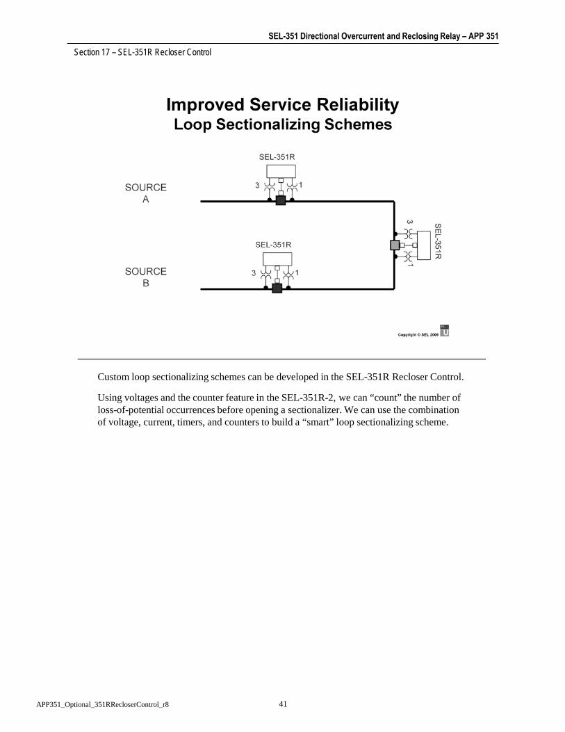
SEL-351 Directional Overcurrent and Reclosing Relay – APP 351Section 17 – SEL-351R Recloser Control
41APP351_Optional_351RRecloserControl_r8
Custom loop sectionalizing schemes can be developed in the SEL-351R Recloser Control.
Using voltages and the counter feature in the SEL-351R-2, we can “count” the number of loss-of-potential occurrences before opening a sectionalizer. We can use the combination of voltage, current, timers, and counters to build a “smart” loop sectionalizing scheme.

SEL-351 Directional Overcurrent and Reclosing Relay – APP 351Section 17 – SEL-351R Recloser Control
42APP351_Optional_351RRecloserControl_r8

SEL-351 Directional Overcurrent and Reclosing Relay – APP 351Section 17 – SEL-351R Recloser Control
43APP351_Optional_351RRecloserControl_r8

SEL-351 Directional Overcurrent and Reclosing Relay – APP 351Section 17 – SEL-351R Recloser Control
44APP351_Optional_351RRecloserControl_r8

SEL-351 Directional Overcurrent and Reclosing Relay – APP 351Section 17 – SEL-351R Recloser Control
45APP351_Optional_351RRecloserControl_r8
The manual trip of a circuit breaker in this application is performed through the local control access from the relay front panel. Local control functions have only text setting requirements. The SEL-351R has eight local control bits that can be programmed for eight individual functions.
Local control bits have three possible states: cleared (deasserted), set (asserted), or pulsed (momentarily asserted). The messages that are displayed while in local control mode correspond to the position of the local control bit. CLB1 is the message that is displayed to clear the local control bit. SLB1 is the message that is displayed to set the local control bit. PLB1 is the message that is displayed to momentarily pulse the local control bit.
NLB1 is the name of the control function.

SEL-351 Directional Overcurrent and Reclosing Relay – APP 351Section 17 – SEL-351R Recloser Control
46APP351_Optional_351RRecloserControl_r8
The SEL-351R EZ settings mode performs traditional recloser control functions and operations. The SEL-351R has full SEL-351 relay functionality together with a modified user interface designed for recloser control. When using the SEL-351R as a traditional line recloser control, it is only necessary to access the EZ Level (Access Level E) Settings.
The SEL-351R ships with the factory EZ settings. Settings Groups 1 and 2 refer to the two choices for the active setting group:
• Settings Group 1 = main settings
• Settings Group 2 = alternate settings
The Global EZ settings apply to both settings Groups 1 and 2. Some factory settings are indicated with an asterisk (*) and are hidden with these particular factory settings. As a general rule, if a main setting is set to N, then the subsettings that follow are hidden.
Setting “Phantom voltages from (VA,VB,VC,VAB,VBC,VCA,OFF)” is available only on SEL-351R-2 relays.

APP 351 18_APP351_Optional_351HandsOnTrainingPart2_r6.docx Page 1 of 6
APP 351 SEL-351 Directional Overcurrent and Reclosing Relay
Hands-On Exercise: Part 2
1. SEL-351S Directional Element Test
2. SEL-351S Reclosing Tests
3. Optional Tests
a. Fuse-Saving Scheme
b. Ground Enable/Disable Switch
c. Breaker Failure
d. Raise Ground Taps During High Load
e. Trip Coil Monitor
f. Loss-of-Potential Alarm

Page 2 of 6 18_APP351_Optional_351HandsOnTrainingPart2_r6.docx APP 351
SEL-351S Directional Element Test
Connections
Connect three-phase voltages and single-phase current to the relay. Connect sense input of test equipment to OUT101 and OUT102 of the relay.
Test Quantities
Start with test voltages as shown in Table 1. Gradually raise current from 0 to 20 Amps with the angle constant at 111.14 degrees.
Note: The SEL-351 uses a unique negative-sequence directional element (Figure 1), which calculates the negative-sequence impedance and determines fault direction from the magnitude and sign of the calculated negative-sequence impedance. The threshold for a forward fault is Z2F = 1.07 Ω sec., and the threshold for a reverse fault is Z2R = 1.27 Ω sec.; these thresholds are supervised by negative-sequence overcurrent elements (50QF, 50QR) and the ratio of negative-sequence to positive-sequence current (a2 factor).
In this testing example, the setting E32 = AUTO. The settings Z2F and Z2R are calculated automatically:
Z2F = Z1MAG / 2 Z2R = (Z1MAG / 2) + 0.2
Table 1. Directional Element Testing
VA VB VC IA IB IC Units
REV Z2 = +1.27 Ω sec.
48.73 0.00
67.0 –120.0
67.0 +120.0
14.50 111.14
0.00 0.00
0.00 0.00
V or A degrees
FOR Z2 = +1.07 Ω sec.
48.73 0.00
67.0 –120.0
67.0 +120.0
17.23 111.14
0.00 0.00
0.00 0.00
V or A degrees
Step 1. Issue the E32 command and verify setting E32 = AUTO.
Step 2. Use the SET L OUT101 command to set OUT101 to the F32Q element, and then set OUT102 to the R32Q element of the relay.
Step 3. Issue the TAR 15 command via the serial port or the front-panel interface.
Step 4. Apply the voltages as shown and begin to gradually raise the current. Verify the pickup of:
50QR_________ 50QF_________
Notes:
Relays are rated at 15 Amps continuous. Apply greater current only for a short period of time.
Thermal rating is 500 Amps for 1 second or 250,000 Amps squared seconds (250,000 I2t).

APP 351 18_APP351_Optional_351HandsOnTrainingPart2_r6.docx Page 3 of 6
Step 5. Issue the TAR 16 command via the serial port or the front-panel interface. Continue to increase the current. Imagine an impedance plane (Figure 1). By holding the voltage constant and increasing the current, we are decreasing the impedance. Verify that the R32Q element asserts when the current exceeds the 50QR supervision setting of 0.25 A. R32Q should deassert at 14.5 A. F32Q element should assert at 17.23 A. Test quantities are calculated as shown in the following equations.
21 22 ( ) 3
3 2VV Va a Vb a Vc ItestZ
Figure 1. Negative-Sequence Directional Element
MTA
3I2 = 3V2 / Z2F
3I2 = 3V2 / Z2R
3I2 = 50QR
3V2
R32Q
F32Q

Page 4 of 6 18_APP351_Optional_351HandsOnTrainingPart2_r6.docx APP 351
SEL-351S Reclosing Tests
Step 1. Make the following setting changes:
E79 = 3, 79OI1 = 120, 79OI2 = 300, 79OI3 = 600
Step 2. Load the RECLOSE.RTA file into the SEL-AMS.
Step 3. Make sure that the GROUND ENABLED and RECLOSE ENABLED LEDs are on.
Step 4. Run the test.
Step 5. Use the SEL-AMS test results button as a quick check of the trip and reclose times.
Step 6. Use the sequential events recorder (SER) report to more accurately verify tripping and reclose times.
Why did we see two different trip times during the reclose cycle? What setting and logic is responsible for the different times? (Hint: 67P1TC = SH0)
Step 7. Add a Hot Bus/Dead Line or a Sync condition to the reclose logic by changing the following settings:
EVOLT = Y, E25 = Y, 59P1P = 60, 27SP =10, 25VLO = 60, 25VHI = 70, 79CLSD = 120, 79CLS = (3P59 * 27S) + 25A1
Step 8. Rerun the RECLOSE.RTA test.
Step 9. Verify reclose times.
Were they accurate? What reclose supervision condition allowed the closes?
Step 10. Load the RECLOSE1.RTA test into the SEL-AMS.
Step 11. Run the test.
Did the relay reclose? What reclose logic prevented the CLOSE?
Step 12. Load the RECLOSE2.RTA test into the SEL-AMS.
Step 13. Run the test.
Did the relay reclose successfully? What reclose logic allowed the CLOSE? (Hint: AMS STATE #3 VS PHASE ANGLE)

APP 351 18_APP351_Optional_351HandsOnTrainingPart2_r6.docx Page 5 of 6
Optional Tests
Test the following relay settings as if you were performing a commissioning test at a substation.
Fuse-Saving Scheme
The instantaneous phase and ground elements are set to only trip the relay for shot zero, or the first trip, in order to save down-line fuses for temporary faults. If the relay recloses and trips again, it should trip only by time-overcurrent elements. Devise a scheme to test this application.
Hints:
Apply a fault above an instantaneous element’s pickup, observe the relay trip instantaneously, and open the breaker. Stop the applied test quantities, and observe the relay reclose. While the reclosing relay is still in the cycle state, apply the same fault. This time the relay should not trip instantaneously, but after a time delay (record the operating time and compare it with an expected operating time).
Ground Enable/Disable Switch
A panel switch, simulated with our front-panel interface (CTRL pushbuttons and LCD display), is used to enable or disable ground elements to prevent misoperations during down-line, single-phase switching. Devise a scheme to test this application.
Breaker Failure
SELOGIC® variable SV1T is used as a breaker failure relay. SV1 is initiated by the relay TRIP, it waits for SV1PU = 12 cycles, and then closes OUT103 to trip an upstream breaker or lockout relay. Devise a scheme to test this application.
Hint:
Extend the operating time of the breaker simulator past the breaker failure time delay of 12 cycles. The breaker simulator consists of a SET LATCH 1 = CLOSE, a RESET LATCH 1 = TRIP, a SELOGIC timer set to SV2 = LT1, SV2PU (close operating time) and SV2DO (trip operating time), and 52A = SV2T. In other words, extending SV2DO from 3 to 15 would simulate a breaker that is slow to open, or stuck.
Raise Ground Taps During High Load
Devise a scheme that will automatically “bump” the tap of our ground time-overcurrent relay during periods of high load. Devise a scheme that will accomplish this, make the necessary settings changes, and test the scheme to verify correct operation.
Hint:
Refer to the Demand Current Logic Output Application in Section 8 of the SEL-351S Instruction Manual.

Page 6 of 6 18_APP351_Optional_351HandsOnTrainingPart2_r6.docx APP 351
Trip Coil Monitor
Devise a scheme that will alarm when our trip coil circuit loses continuity; in other words, develop a trip circuit monitor. Devise a scheme that will accomplish this, make the necessary settings changes, and test the scheme to verify correct operation.
Hint:
Refer to SEL Application Guide AG96-08, “Making Trip Circuit Monitor Logic with SELOGIC® Control Equations.”
Loss-of-Potential Alarm
Devise a scheme that will monitor the PT fuses in the substation yard. Devise a scheme that will accomplish this, make the necessary settings changes, and test the scheme to verify correct operation.

SEL-351 Directional Overcurrent and Reclosing Relay – APP 351Section 19 – HyperTerminal Relay Communications
1APP351_RefHyperTerminalCommunications_r9
HyperTerminal® provides a basic computer interface for SEL relays. This presentation will show how to set up a communications session with HyperTerminal on your computer.
Newer Microsoft® operating systems (e.g., Windows Vista®, Windows® 7) no longer include the HyperTerminal terminal emulation software. In these cases, ACSELERATOR®
QuickSet has a built-in terminal emulator that can be used instead. In QuickSet, access the terminal in one of three ways: select it from the Communications menu, click the terminal shortcut on the shortcut bar, or use the <Ctrl+T> keyboard shortcut.

SEL-351 Directional Overcurrent and Reclosing Relay – APP 351Section 19 – HyperTerminal Relay Communications
2APP351_RefHyperTerminalCommunications_r9
Launch HyperTerminal from the Start menu. The standard configuration for recent releases of Windows places HyperTerminal under Programs/Accessories/Communications.
When creating a new session, make sure that you select the HyperTerminal icon and not the HyperTerminal folder. The HyperTerminal folder is where Windows will store the saved sessions.

SEL-351 Directional Overcurrent and Reclosing Relay – APP 351Section 19 – HyperTerminal Relay Communications
3APP351_RefHyperTerminalCommunications_r9
You must select a name and an icon when launching a new session. After the session is set up, it can be launched by selecting the session name from the HyperTerminal folder from the Start menu under Programs/Accessories/Communications.

SEL-351 Directional Overcurrent and Reclosing Relay – APP 351Section 19 – HyperTerminal Relay Communications
4APP351_RefHyperTerminalCommunications_r9
A phone number is not needed for direct connections. However, the proper COM port must be selected.

SEL-351 Directional Overcurrent and Reclosing Relay – APP 351Section 19 – HyperTerminal Relay Communications
5APP351_RefHyperTerminalCommunications_r9
1. In the COM1 Properties window, using the drop-down arrows, set the following:
Bits per second = 2400Data bits = 8Parity = NStop bits = 1Flow control = Xon/Xoff
2. Click OK
The default baud rate on SEL relays is 2400. In 100 and 200 series relays, the baud rate is changed via a hardware jumper inside the relay. In 300 and 500 series relays, the baud rate is software selectable.

SEL-351 Directional Overcurrent and Reclosing Relay – APP 351Section 19 – HyperTerminal Relay Communications
6APP351_RefHyperTerminalCommunications_r9
The default baud rate for SEL relays is 2400, which is also the default for HyperTerminal. Likewise, the default data bits (8), parity (N), and stop bits (1) for SEL relays is the same as the HyperTerminal defaults. The required change is the flow control. Select Xon/Xoff for SEL relays.

SEL-351 Directional Overcurrent and Reclosing Relay – APP 351Section 19 – HyperTerminal Relay Communications
7APP351_RefHyperTerminalCommunications_r9
Last, but not least, select Properties from the File menu item so that you can select the proper terminal emulation.

SEL-351 Directional Overcurrent and Reclosing Relay – APP 351Section 19 – HyperTerminal Relay Communications
8APP351_RefHyperTerminalCommunications_r9
To avoid extra characters when communicating with SEL relays, select VT100 terminal emulation.
You are now ready to communicate with the relay.

SEL-351 Directional Overcurrent and Reclosing Relay – APP 351Section 19 – HyperTerminal Relay Communications
9APP351_RefHyperTerminalCommunications_r9

SEL-351 Directional Overcurrent and Reclosing Relay – APP 351Section 19 – HyperTerminal Relay Communications
10APP351_RefHyperTerminalCommunications_r9
For long communication connections or where isolation and noise are a concern, use SEL fiber-optic transceivers to provide the communication interface between the devices.

SEL-351 Directional Overcurrent and Reclosing Relay – APP 351Section 19 – HyperTerminal Relay Communications
11APP351_RefHyperTerminalCommunications_r9

SEL-351 Directional Overcurrent and Reclosing Relay – APP 351Section 19 – HyperTerminal Relay Communications
12APP351_RefHyperTerminalCommunications_r9
You only need to type the first three letters of a command. For example:
acc for access
sho for show
eve for event
The commands are not case sensitive; type either “acc” or “ACC.”

SEL-351 Directional Overcurrent and Reclosing Relay – APP 351Section 19 – HyperTerminal Relay Communications
13APP351_RefHyperTerminalCommunications_r9
The passwords are case sensitive. The default password, OTTER, must be uppercase.

SEL-351 Directional Overcurrent and Reclosing Relay – APP 351Section 19 – HyperTerminal Relay Communications
14APP351_RefHyperTerminalCommunications_r9

SEL-351 Directional Overcurrent and Reclosing Relay – APP 351Section 19 – HyperTerminal Relay Communications
15APP351_RefHyperTerminalCommunications_r9

SEL-351 Directional Overcurrent and Reclosing Relay – APP 351Section 19 – HyperTerminal Relay Communications
16APP351_RefHyperTerminalCommunications_r9

SEL-351 Directional Overcurrent and Reclosing Relay – APP 351Section 19 – HyperTerminal Relay Communications
17APP351_RefHyperTerminalCommunications_r9

SEL-351 Directional Overcurrent and Reclosing Relay – APP 351Section 19 – HyperTerminal Relay Communications
18APP351_RefHyperTerminalCommunications_r9

SEL-351 Directional Overcurrent and Reclosing Relay – APP 351Section 19 – HyperTerminal Relay Communications
19APP351_RefHyperTerminalCommunications_r9

SEL-351 Directional Overcurrent and Reclosing Relay – APP 351Section 19 – HyperTerminal Relay Communications
20APP351_RefHyperTerminalCommunications_r9

SEL-351 Directional Overcurrent and Reclosing Relay – APP 351Section 19 – HyperTerminal Relay Communications
21APP351_RefHyperTerminalCommunications_r9
To capture an event record from a relay, select Capture Text from the Transfer menu item.
When Capture Text is active, all text is captured.

SEL-351 Directional Overcurrent and Reclosing Relay – APP 351Section 19 – HyperTerminal Relay Communications
22APP351_RefHyperTerminalCommunications_r9
To capture text, the program needs to know where to store the data. When you enter a file name, the file does not have to exist, but the path must be valid. The program will create a new file, but it will not create a new folder.
If the browse feature is selected, you are restricted to using a preexisting file. The program will not create a new file in the browse mode.
Once the file name has been specified, any and all text displayed on the screen will be captured to the file. Issue the EVE command to retrieve an event report from the relay.

SEL-351 Directional Overcurrent and Reclosing Relay – APP 351Section 19 – HyperTerminal Relay Communications
23APP351_RefHyperTerminalCommunications_r9
You can pause or stop the capture of text at any time by selecting the desired option from the Capture Text option of the Transfer menu item.
View the captured text using any text editor, such as Notepad, or a word processor. If the captured text is an event report, you can view it with the ACSELERATOR Analytic Assistant™ SEL-5601 Software.

SEL-351 Directional Overcurrent and Reclosing Relay – APP 351Section 19 – HyperTerminal Relay Communications
24APP351_RefHyperTerminalCommunications_r9

Date Code 20090602 Instruction Manual SEL-351S Protection System
Appendix DR.Instruction Manual
Relay Word Bits
Overview
Relay Word bits show the status of functions within the relay. The bits are available via communications protocols and the front panel.
Relay Word bits are used in SELOGIC control equation settings. Numerous SELOGIC control equation settings examples are given in Section 3: Overcurrent, Voltage, Synchronism Check, Frequency, and Power Elements through Section 8: Breaker Monitor, Metering, and Load Profile Functions. SELOGIC control equation settings can also be set directly to 1 (logical 1) or 0 (logical 0). Appendix F: Setting SELOGIC Control Equations gives SELOGIC control equation details, examples, and limitations.
The Relay Word bit row numbers correspond to the row numbers used in the TAR command (see TAR Command (Display Relay Element Status) on page 10.54). Rows 0 and 1 are reserved for the display of the two front-panel target LED rows (see Table 10.12).
Table D.2 provides an alphanumeric listing of the Relay Word bits that includes a description of each bit.
Table D.1 and Table D.2 include cross-reference information for most Relay Word bits. Table D.3 describes Relay Word bits that are not described elsewhere in the manual.
Relay Word
Table D.1 Relay Word Bit Mapping (Sheet 1 of 4)
Row Relay Word Bitsa
Instantaneous, Definite-Time, and Inverse-Time Overcurrent Elements (see Section 3)
2 50A1 50B1 50C1 50A2 50B2 50C2 50A3 50B3
3 50C3 50A4 50B4 50C4 50AB1 50BC1 50CA1 50AB2
4 50BC2 50CA2 50AB3 50BC3 50CA3 50AB4 50BC4 50CA4
5 50A 50B 50C 51P1 51P1T 51P1R 51N1 51N1T
6 51N1R 51G1 51G1T 51G1R 51P2 51P2T 51P2R 51N2
7 51N2T 51N2R 51G2 51G2T 51G2R 51Q 51QT 51QR
8 50P1 50P2 50P3 50P4 50N1 50N2 50N3 50N4
9 67P1 67P2 67P3 67P4 67N1 67N2 67N3 67N4

D.2
SEL-351S Protection System Instruction Manual Date Code 20090602
Relay Word BitsRelay Word
10 67P1T 67P2T 67P3T 67P4T 67N1T 67N2T 67N3T 67N4T
11 50G1 50G2 50G3 50G4 50Q1 50Q2 50Q3 50Q4
12 67G1 67G2 67G3 67G4 67Q1 67Q2 67Q3 67Q4
13 67G1T 67G2T 67G3T 67G4T 67Q1T 67Q2T 67Q3T 67Q4T
14 50P5 50P6 50N5 50N6 50G5 50G6 50Q5 50Q6
Directional Control (see Section 4)
15 50QF 50QR 50GF 50GR 32VE 32QGE 32IE 32QE
16 F32P R32P F32Q R32Q F32QG R32QG F32V R32V
17 F32I R32I 32PF 32PR 32QF 32QR 32GF 32GR
Voltage Elements and Synchronism Check Elements (see Section 3)
18 27A1 27B1 27C1 27A2 27B2 27C2 59A1 59B1
19 59C1 59A2 59B2 59C2 27AB 27BC 27CA 59AB
20 59BC 59CA 59N1 59N2 59Q 59V1 27S 59S1
21 59S2 59VP 59VS SF 25A1 25A2 3P27 3P59
Frequency Elements (see Section 3), Three-Pole Open Logic (see Section 5), Directional Control and Loss-of-Potential Logic (see Section 4)
22 81D1 81D2 81D3 81D4 81D5 81D6 27B81 50L
23 81D1T 81D2T 81D3T 81D4T 81D5T 81D6T VPOLV LOP
Synchronism Check Elements (see Section 4) and Optoisolated Inputs (see Section 7)
24 SFAST SSLOW IN106 IN105 IN104 IN103 IN102 IN101
Local Bits, Remote Bits, and Latch Bits (see Section 7)
25 LB1 LB2 LB3 LB4 LB5 LB6 LB7 LB8
26 LB9 LB10 LB11 LB12 LB13 LB14 LB15 LB16
27 RB1 RB2 RB3 RB4 RB5 RB6 RB7 RB8
28 RB9 RB10 RB11 RB12 RB13 RB14 RB15 RB16
29 LT1 LT2 LT3 LT4 LT5 LT6 LT7 LT8
30 LT9 LT10 LT11 LT12 LT13 LT14 LT15 LT16
SELOGIC Control Equation Variables/Timers (see Section 7)
31 SV1 SV2 SV3 SV4 SV1T SV2T SV3T SV4T
32 SV5 SV6 SV7 SV8 SV5T SV6T SV7T SV8T
33 SV9 SV10 SV11 SV12 SV9T SV10T SV11T SV12T
34 SV13 SV14 SV15 SV16 SV13T SV14T SV15T SV16T
Close Logic and Reclosing Relay (see Section 6) and Fault Identification (see Section 5)
35 79RS 79CY 79LO SH0 SH1 SH2 SH3 SH4
36 CLOSE CF RCSF OPTMN RSTMN FSA FSB FSC
Operator Control Pushbuttons and LEDs (see Section 11), Directional Control (see Section 4), Synchronism Check Elements (see Section 3), Breaker Status (see Section 6)
37 LED9 50P32 LED10 59VA TRGTR 52A PB10 PB9
Setting Group Bits (see Section 7), Load Encroachment (see Section 4)
38 SG1 SG2 SG3 SG4 SG5 SG6 ZLOUT ZLIN
Load Encroachment (see Section 4), Breaker Monitor (see Section 8), Trip and Target Logic (see Section 5)
39 ZLOAD BCWA BCWB BCWC COMMT FAULT SOTFT BCW
Table D.1 Relay Word Bit Mapping (Sheet 2 of 4)
Row Relay Word Bitsa

D.3
Date Code 20090602 Instruction Manual SEL-351S Protection System
Relay Word BitsRelay Word
Output Contacts (see Section 7)
40b ALARM OUT107 OUT106 OUT105 OUT104 OUT103 OUT102 OUT101
Switch-Onto-Fault Trip Logic and Communications-Assisted Trip Logic (see Section 5)
41 3PO SOTFE Z3RB KEY EKEY ECTT WFC PT
42 PTRX2 PTRX PTRX1 UBB1 UBB2 UBB Z3XT DSTRT
Communications-Assisted Trip Logic (see Section 5), OPEN and CLOSE Command (see Section 10), Station DC Battery Monitor (see Section 8)
43 NSTRT STOP BTX TRIP OC CC DCHI DCLO
Communications-Assisted Trip Logic (see Section 5), Demand Current Logic Outputs (see Section 8)
44 67P2S 67N2S 67G2S 67Q2S PDEM NDEM GDEM QDEM
Extra I/O Board Output Contacts (see Section 7)
45b,c OUT201 OUT202 OUT203 OUT204 OUT205 OUT206 OUT207 OUT208
46b,c OUT209 OUT210 OUT211 OUT212 * * * *
Extra I/O Board Optoisolated Inputs (see Section 7)
47c IN208 IN207 IN206 IN205 IN204 IN203 IN202 IN201
48 * * * * * * * *
Operator Control Pushbuttons and LEDs (see Section 11)
49 PB1 PB2 PB3 PB4 PB5 PB6 PB7 PB8
50 LED1 LED2 LED3 LED4 LED5 LED6 LED7 LED8
Front-Panel Target LEDs (see Section 5)
51 LED19 LED20 LED21 LED22 LED23 LED24 LED25 LED26
MIRRORED BITS® (see Appendix H)
52d RMB8A RMB7A RMB6A RMB5A RMB4A RMB3A RMB2A RMB1A
53d TMB8A TMB7A TMB6A TMB5A TMB4A TMB3A TMB2A TMB1A
54d RMB8B RMB7B RMB6B RMB5B RMB4B RMB3B RMB2B RMB1B
55d TMB8B TMB7B TMB6B TMB5B TMB4B TMB3B TMB2B TMB1B
56d LBOKB CBADB RBADB ROKB LBOKA CBADA RBADA ROKA
Power Elements and Voltage Sag/Swell/Interruption Elements (see Section 3), IRIG-B Status (see Appendix N)
57e PWRA1 PWRB1 PWRC1 PWRA2 PWRB2 PWRC2 INTC INT3P
58e PWRA3 PWRB3 PWRC3 PWRA4 PWRB4 PWRC4 INTA INTB
59e SAGA SAGB SAGC SAG3P SWA SWB SWC SW3P
60 SAGABe SAGBCe SAGCAe SWABe SWBCe SWCAe TSOK TIRIG
61e 3PWR1 3PWR2 3PWR3 3PWR4 INTAB INTBC INTCA *
Extra Voltage Elements for Open-Delta Connections (see Section 3), VSCONN Indication (see Section 9)
62 27AB2 27BC2 27CA2 59AB2 59BC2 59CA2 59Q2 3V0
Loss-of-Potential (see Section 4), Analog Scaling (see Analog Scaling and Frequency Indicators on page D.15)
63 V1GOOD * * V0GAIN INMET ICMET IBMET IAMET
Directional Control (see Section 4), Phasor Measurement Status (see Appendix N), Fault Identification (see Section 5)
64 GNDSWf 50NFf 50NRf 32NEf F32Nf R32Nf 32NF 32NR
65 PMDOK F32Wf R32Wf F32Cf R32Cf NSAf NSBf NSCf
PTCONN Indication (see Section 9), TEST DB Indication (see Section 10), Frequency Source (see Analog Scaling and Fre-quency Indicators on page D.15)
Table D.1 Relay Word Bit Mapping (Sheet 3 of 4)
Row Relay Word Bitsa

D.4
SEL-351S Protection System Instruction Manual Date Code 20090602
Relay Word BitsRelay Word
66 DELTA WYE SINGLE TESTDB * * * FREQOK
IRIG Time Quality Information (see Appendix N)
67 DST DSTP LPSEC LPSECP TQUAL4 TQUAL3 TQUAL2 TQUAL1
Target Reset Control (see Section 5), Metering Reset Control (see Section 8)
68 RSTTRGT RST_MML RST_ENE RST_HIS RST_BK RST_PDM RST_DEM *
Phasor Measurement Unit Trigger Status (see Appendix N)
69 * * * PMTRIG TREA4 TREA3 TREA2 TREA1
Ethernet Status (see Section 10)
70 LINK5g LINK5Ah LINK5Bh LINKFAIL P5ASELh P5BSELh * *
a “*” indicates not used.b All output contacts can be “a” or “b” type contacts. See Output Contacts on page 7.31 for details.c OUT201–OUT212 and IN201–IN208 only available when the optional I/O board is present.d MIRRORED BITS elements only valid in Firmware Versions 6 or 7 (rows 52–56).e Indicated Power Elements and Sag/Swell/Interruption elements only valid in Firmware Version 7 (rows 57–61).f Indicated Relay Word bits are only valid in Relays with 0.2 A nominal neutral channel (rows 64–65).g LINK5 is replaced by “*” when dual Ethernet connectors are present.h Relay Word bits (for Ethernet ports) are replaced by “*” when a single Ethernet connector is present.
Table D.2 Alphabetic List of Relay Word Bits (Sheet 1 of 12)
Name Description UsageRow (Table D.1)
25A1, 25A2 Synchronism check elements 1 and 2 (see Figure 3.28) Control 21
27A1 A-phase instantaneous undervoltage element (A-phase voltage below pickup setting 27P1P; see Figure 3.21)
Control 18
27A2 A-phase instantaneous undervoltage element (A-phase voltage below pickup setting 27P2P; see Figure 3.21)
Control 18
27AB AB-phase-to-phase instantaneous undervoltage element (AB-phase-to-phase voltage below pickup setting 27PP; see Figure 3.22 and Figure 3.23)
Control 19
27AB2 AB-phase-to-phase instantaneous undervoltage element (AB-phase-to-phase voltage below pickup setting 27PP2P; see Figure 3.23)
Control 62
27B1 B-phase instantaneous undervoltage element (B-phase voltage below pickup setting 27P1P; see Figure 3.21)
Control 18
27B2 B-phase instantaneous undervoltage element (B-phase voltage below pickup setting 27P2P; see Figure 3.21)
Control 18
27B81 Undervoltage element for frequency element blocking (voltage below pickup setting 27B81P; see Figure 3.30, and Figure 3.31)
Testing 22
27BC BC-phase-to-phase instantaneous undervoltage element (BC-phase-to-phase voltage below pickup setting 27PP; see Figure 3.22 and Figure 3.23)
Control 19
27BC2 BC-phase-to-phase instantaneous undervoltage element (BC-phase-to-phase voltage below pickup setting 27PP2P; see Figure 3.23)
Control 62
27C1 C-phase instantaneous undervoltage element (C-phase voltage below pickup setting 27P1P; see Figure 3.21)
Control 18
27C2 C-phase instantaneous undervoltage element (C-phase voltage below pickup setting 27P2P; see Figure 3.21)
Control 18
27CA CA-phase-to-phase instantaneous undervoltage element (CA-phase-to-phase voltage below pickup setting 27PP; see Figure 3.22 and Figure 3.23)
Control 19
27CA2 CA-phase-to-phase instantaneous undervoltage element (CA-phase-to-phase voltage below pickup setting 27PP2P; see Figure 3.23)
Control 62
27S Channel VS instantaneous undervoltage element (channel VS voltage below pickup setting 27SP; see Figure 3.25)
Control 20
Table D.1 Relay Word Bit Mapping (Sheet 4 of 4)
Row Relay Word Bitsa

D.5
Date Code 20090602 Instruction Manual SEL-351S Protection System
Relay Word BitsRelay Word
32GF, 32GR Forward or Reverse directional control routed to residual ground overcurrent elements (see Figure 4.4 and Figure 4.16)
Testing, Special directional control schemes
17
32IE Internal enable for channel IN current-polarized directional element (see Figure 4.4 and Figure 4.8)
Testing 15
32NE Internal enable for directional elements for low-impedance grounded, Petersen Coil grounded, or ungrounded/high-impedance grounded systems (see Figure 4.9)
Testing 64
32NF, 32NR Forward or Reverse directional control routed to neutral ground overcurrent elements (see Figure 4.17 and Figure 4.19)
Testing, Special directional control schemes
64
32PF, 32PR Forward or Reverse directional control routed to phase overcurrent elements (see Figure 4.20 and Figure 4.23)
Testing, Special directional control schemes
17
32QE Internal enable for negative-sequence voltage-polarized directional element (see Figure 4.5, and Figure 4.19)
Testing 15
32QF Forward directional control routed to negative-sequence overcurrent ele-ments (see Figure 4.20 and Figure 4.23)
Testing, Special directional control schemes
17
32QGE Internal enable for negative-sequence voltage-polarized directional element (for ground; see Figure 4.4 and Figure 4.7)
Testing 15
32QR Reverse directional control routed to negative-sequence overcurrent elements (see Figure 4.20 and Figure 4.23)
Testing, Special directional control schemes
17
32VE Internal enable for zero-sequence voltage-polarized directional element (see Figure 4.4 and Figure 4.8)
Testing 15
3P27 = 27A1 * 27B1 * 27C1 (see Figure 3.21 and Figure 3.23) Control 21
3P59 = 59A1 * 59B1 * 59C1 (see Figure 3.21 and Figure 3.23) Control 21
3PO Three pole open condition (see Figure 5.3) Testing 41
3PWR1–3PWR4
Three-phase power elements, 1 through 4 (see Figure 3.38) Tripping, Control (only operable in Firmware Version 7)
61
3V0 3V0 configuration element (asserts when Global setting VSCONN = 3V0; see Figure 9.21)
Indication 62
50A = 50A1 + 50A2 + 50A3 + 50A4 (see Figure 3.4) Tripping, Control 5
50A1–50A4 Level 1 through Level 4 A-phase instantaneous overcurrent elements (see Figure 3.1)
Tripping, Control 2, 3
50AB1–50AB4
Level 1 through Level 4 AB-phase-to-phase instantaneous overcurrent ele-ments (see Figure 3.7)
Tripping, Control 3, 4
50B = 50B1 + 50B2 + 50B3 + 50B4 (see Figure 3.4) Tripping, Control 5
50B1–50B4 Level 1 through Level 4 B-phase instantaneous overcurrent elements (see Figure 3.1)
Tripping, Control 2, 3
50BC1–50BC4 Level 1 through Level 4 BC-phase-to-phase instantaneous overcurrent ele-ments (see Figure 3.7)
Tripping, Control 3, 4
50C = 50C1 + 50C2 + 50C3 + 50C4 (see Figure 3.4) Tripping, Control 5
50C1–50C4 Level 1 through Level 4 C-phase instantaneous overcurrent elements (see Figure 3.1)
Tripping, Control 2, 3
50CA1–50CA4
Level 1 through Level 4 CA-phase-to-phase instantaneous overcurrent ele-ments (see Figure 3.7)
Tripping, Control 3, 4
Table D.2 Alphabetic List of Relay Word Bits (Sheet 2 of 12)
Name Description UsageRow (Table D.1)

D.6
SEL-351S Protection System Instruction Manual Date Code 20090602
Relay Word BitsRelay Word
50G1–50G4 Level 1 through Level 4 residual ground instantaneous overcurrent elements (see Figure 3.10)
Tripping, Testing, Control
11
50G5, 50G6 Level 5 and Level 6 residual ground instantaneous overcurrent elements (see Figure 3.11)
Tripping, Control 14
50GF, 50GR Forward or Reverse direction residual ground overcurrent threshold exceeded (see Figure 4.4 and Figure 4.8)
Testing 15
50L Phase instantaneous overcurrent element for load detection (maximum phase current above pickup setting 50LP; see Figure 5.3)
Testing 22
50N1–50N4 Level 1 through Level 4 neutral ground instantaneous overcurrent elements (see Figure 3.8)
Tripping, Testing, Control
8
50N5, 50N6 Level 5 and Level 6 neutral ground instantaneous overcurrent elements (see Figure 3.9)
Tripping, Control 14
50NF, 50NR Forward or Reverse direction neutral ground overcurrent threshold exceeded (see Figure 4.9)
Testing 64
50P1–50P4 Level 1 through Level 4 phase instantaneous overcurrent elements (see Figure 3.1)
Tripping, Testing, Control
8
50P32 Three-phase directional element overcurrent threshold exceeded (see Figure 4.22)
Testing 37
50P5, 50P6 Level 5 and Level 6 phase instantaneous overcurrent elements (see Figure 3.2)
Tripping, Control 14
50Q1–50Q4 Level 1 through Level 4 negative-sequence instantaneous overcurrent ele-ments (see Figure 3.12)
Testing, Control 11
50Q5, 50Q6 Level 5 and Level 6 negative-sequence instantaneous overcurrent elements (see Figure 3.13)
Control 14
50QF, 50QR Forward or Reverse direction negative-sequence overcurrent threshold exceeded (see Figure 4.4, Figure 4.7, and Figure 4.20)
Testing 15
51G1 Residual ground current above pickup setting 51G1P for residual ground time-overcurrent element 51G1T (see Figure 3.18)
Testing, Control 6
51G1R Residual ground time-overcurrent element 51G1T reset (see Figure 3.18) Testing 6
51G1T Residual ground time-overcurrent element 51G1T timed out (see Figure 3.18)
Tripping 6
51G2 Residual ground current above pickup setting 51G2P for residual ground time-overcurrent element 51G2T (see Figure 3.19)
Testing, Control 7
51G2R Residual ground time-overcurrent element 51G2T reset (see Figure 3.19) Testing 7
51G2T Residual ground time-overcurrent element 51G2T timed out (see Figure 3.19)
Tripping 7
51N1 Neutral ground current (channel IN) above pickup setting 51N1P for neutral ground time-overcurrent element 51N1T (see Figure 3.16)
Testing, Control 5
51N1R Neutral ground time-overcurrent element 51N1T reset (see Figure 3.16) Testing 6
51N1T Neutral ground time-overcurrent element 51N1T timed out (see Figure 3.16) Tripping 5
51N2 Neutral ground current (channel IN) above pickup setting 51N2P for neutral ground time-overcurrent element 51N2T (see Figure 3.17)
Testing, Control 6
51N2R Neutral ground time-overcurrent element 51N2T reset (see Figure 3.17) Testing 7
51N2T Neutral ground time-overcurrent element 51N2T timed out (see Figure 3.17) Tripping 7
51P1 Maximum phase current above pickup setting 51P1P for phase time-overcur-rent element 51P1T (see Figure 3.14)
Testing, Control 5
51P1R Phase time-overcurrent element 51P1T reset (see Figure 3.14) Testing 5
Table D.2 Alphabetic List of Relay Word Bits (Sheet 3 of 12)
Name Description UsageRow (Table D.1)

D.7
Date Code 20090602 Instruction Manual SEL-351S Protection System
Relay Word BitsRelay Word
51P1T Phase time-overcurrent element 51P1T timed out (see Figure 3.14) Tripping 5
51P2 Maximum phase current above pickup setting 51P2P for phase time-overcur-rent element 51P2T (see Figure 3.15)
Testing, Control 6
51P2R Phase time-overcurrent element 51P2T reset (see Figure 3.15) Testing 6
51P2T Phase time-overcurrent element 51P2T timed out (see Figure 3.15) Tripping 6
51Q Negative-sequence current above pickup setting 51QP for negative-sequence time-overcurrent element 51QT (see Figure 3.20)
Testing, Control 7
51QR Negative-sequence time-overcurrent element 51QT reset (see Figure 3.20) Testing 7
51QT Negative-sequence time-overcurrent element 51QT timed out (see Figure 3.20)
Tripping 7
52A Circuit breaker status (asserts to logical 1 when circuit breaker is closed; see Circuit Breaker Status on page 6.5)
Indication 37
59A1 A-phase instantaneous overvoltage element (A-phase voltage above pickup setting 59P1P; see Figure 3.21)
Control 18
59A2 A-phase instantaneous overvoltage element (A-phase voltage above pickup setting 59P2P; see Figure 3.21)
Control 19
59AB AB-phase-to-phase instantaneous overvoltage element (AB-phase-to-phase voltage above pickup setting 59PP; see Figure 3.22 and Figure 3.23)
Control 19
59AB2 AB-phase-to-phase instantaneous overvoltage element (AB-phase-to-phase voltage above pickup setting 59PP2P; see Figure 3.23)
Control 62
59B1 B-phase instantaneous overvoltage element (B-phase voltage above pickup setting 59P1P; see Figure 3.21)
Control 18
59B2 B-phase instantaneous overvoltage element (B-phase voltage above pickup setting 59P2P; see Figure 3.21)
Control 19
59BC BC-phase-to-phase instantaneous overvoltage element (BC-phase-to-phase voltage above pickup setting 59PP; see Figure 3.22 and Figure 3.23)
Control 20
59BC2 BC-phase-to-phase instantaneous overvoltage element (BC-phase-to-phase voltage above pickup setting 59PP2P; see Figure 3.23)
Control 62
59C1 C-phase instantaneous overvoltage element (C-phase voltage above pickup setting 59P1P; see Figure 3.21)
Control 19
59C2 C-phase instantaneous overvoltage element (C-phase voltage above pickup setting 59P2P; see Figure 3.21)
Control 19
59CA CA-phase-to-phase instantaneous overvoltage element (CA-phase-to-phase voltage above pickup setting 59PP; see Figure 3.22 and Figure 3.23)
Control 20
59CA2 CA-phase-to-phase instantaneous overvoltage element (CA-phase-to-phase voltage above pickup setting 59PP2P; see Figure 3.23)
Control 62
59N1 Zero-sequence instantaneous overvoltage element (zero-sequence voltage above pickup setting 59N1P; see Figure 3.22)
Control 20
59N2 Zero-sequence instantaneous overvoltage element (zero-sequence voltage above pickup setting 59N2P; see Figure 3.22)
Control 20
59Q Negative-sequence instantaneous overvoltage element (negative-sequence voltage above pickup setting 59QP; see Figure 3.22 and Figure 3.24)
Control 20
59Q2 Negative-sequence instantaneous overvoltage element (negative-sequence voltage above pickup setting 59Q2P; see Figure 3.24)
Control 62
59S1 Channel VS instantaneous overvoltage element (channel VS voltage above pickup setting 59S1P; see Figure 3.25)
Control 20
59S2 Channel VS instantaneous overvoltage element (channel VS voltage above pickup setting 59S2P; see Figure 3.25)
Control 21
Table D.2 Alphabetic List of Relay Word Bits (Sheet 4 of 12)
Name Description UsageRow (Table D.1)

D.8
SEL-351S Protection System Instruction Manual Date Code 20090602
Relay Word BitsRelay Word
59V1 Positive-sequence instantaneous overvoltage element (positive-sequence voltage above pickup setting 59V1P; see Figure 3.22 and Figure 3.24)
Control 20
59VA Channel VA voltage window element (channel VA voltage between thresh-old settings 25VLO and 25VHI; see Figure 3.27)
Testing 37
59VP Phase voltage window element (selected phase voltage [VP] between thresh-old settings 25VLO and 25VHI; see Figure 3.27)
Testing 21
59VS Channel VS voltage window element (channel VS voltage between threshold settings 25VLO and 25VHI; see Figure 3.27)
Testing 21
67G1–67G4 Level 1 through Level 4 residual ground instantaneous overcurrent elements with directional control option (derived from 50G1–50G4; see Figure 3.10)
Tripping, Testing, Control
12
67G1T–67G4T Level 1 through Level 4 residual ground definite-time overcurrent elements (derived from 67G1–67G4; see Figure 3.10)
Tripping 13
67G2S Level 2 directional residual ground definite-time (short delay) overcurrent element 67G2S timed out (derived from 67G2; see Figure 3.10 and Figure 5.14)
Tripping in DCB schemes
44
67N1–67N4 Level 1 through Level 4 neutral ground instantaneous overcurrent elements with directional control option (derived from 50N1–50N4; see Figure 3.8)
Tripping, Testing, Control
9
67N1T–67N4T Level 1 through Level 4 neutral ground definite-time overcurrent elements (derived from 67N1–67N4; see Figure 3.8)
Tripping 10
67N2S Level 2 directional neutral ground definite-time (short delay) overcurrent element 67N2S timed out (derived from 67N2; see Figure 3.8 and Figure 5.14)
Tripping in DCB schemes
44
67P1–67P4 Level 1 through Level 4 phase instantaneous overcurrent elements with directional control option (derived from 50P1–50P4; see Figure 3.3)
Tripping, Testing, Control
9
67P1T–67P4T Level 1 through Level 4 phase definite-time overcurrent elements (derived from 67P1–67P4; see Figure 3.3)
Tripping 10
67P2S Level 2 directional phase definite-time (short delay) overcurrent element 67P2S timed out (derived from 67P2; see Figure 3.3 and Figure 5.14)
Tripping in DCB schemes
44
67Q1–67Q4 Level 1 through Level 4 negative-sequence instantaneous overcurrent ele-ments with directional control option (derived from 50Q1–50Q4; see Figure 3.12)
Testing, Control 12
67Q1T–67Q4T Level 1 through Level 4 negative-sequence definite-time overcurrent ele-ments (derived from 67Q1–67Q4; see Figure 3.12)
Tripping 13
67Q2S Level 2 directional negative-sequence definite-time (short delay) overcurrent element 67Q2S timed out (derived from 67Q2; see Figure 3.12 and Figure 5.14)
Tripping in DCB schemes
44
79CY Reclosing relay in the Reclose Cycle State (see Figure 6.8 and Table 6.1) Control 35
79LO Reclosing relay in the Lockout State (see Figure 6.8 and Table 6.1) Control 35
79RS Reclosing relay in the Reset State (see Figure 6.8 and Table 6.1) Control 35
81D1–81D6 Level 1 through Level 6 instantaneous frequency elements (see Figure 3.32) Testing 22
81D1T–81D6T Level 1 through Level 6 definite-time frequency elements (derived from 81D1–81D6; see Figure 3.32)
Tripping, Control 23
ALARM ALARM output contact indicating that relay failed or PULSE ALARM command executed (see Figure 7.27)
Indication 40
BCW = BCWA + BCWB + BCWC Indication 39
BCWA A-phase breaker contact wear has reached 100% wear level (see Breaker Monitor on page 8.1)
Indication 39
BCWB B-phase breaker contact wear has reached 100% wear level (see Breaker Monitor on page 8.1)
Indication 39
Table D.2 Alphabetic List of Relay Word Bits (Sheet 5 of 12)
Name Description UsageRow (Table D.1)

D.9
Date Code 20090602 Instruction Manual SEL-351S Protection System
Relay Word BitsRelay Word
BCWC C-phase breaker contact wear has reached 100% wear level (see Breaker Monitor on page 8.1)
Indication 39
BTX Block trip input extension (see Figure 5.14) Testing 43
CBADA, CBADB
MIRRORED BITS® channel unavailability over threshold, Channels A and B (only operable in Firmware Versions 6, 7)
56
CC Asserts 1/4 cycle for CLOSE command execution (see Factory Settings Example on page 6.3)
Testing, Control 43
CF Close Failure condition (asserts for 1/4 cycle; see Figure 6.1) Indication 36
CLOSE Close logic output asserted (see Figure 6.1) Output contact assignment
36
COMMT Communications-assisted trip (see Figure 5.1; used in Table 5.1) Indication 39
DCHI Station dc battery instantaneous overvoltage element (see Figure 8.9) Indication 43
DCLO Station dc battery instantaneous undervoltage element (see Figure 8.9) Indication 43
DELTA Delta-connected configuration element (asserts when Global setting PTCONN = DELTA; see Figure 9.21)
Indication 66
DST Daylight Savings Time active. Only available when Global setting IRIGC = C37.118 and a proper IRIG signal is decoded.
Indication 67
DSTP Daylight Savings Time change Pending. Asserts up to a minute before day-light savings time change
Indication 67
DSTRT Directional carrier start (see Figure 5.14) Testing 42
ECTT Echo conversion to trip condition (see Figure 5.6) Testing 41
EKEY Echo key (see Figure 5.6) Testing 41
F32C Forward directional element for Petersen Coil Incremental Conductance Ele-ment (see Figure 4.14)
Control, Indication 65
F32I Forward channel IN current-polarized directional element (see Figure 4.4 and Figure 4.12)
Testing, Special directional control schemes
17
F32N Forward directional element for low-impedance grounded (Figure 4.13), Petersen Coil grounded (Wattmetric element only—see F32W in Figure 4.14), or ungrounded/high-impedance grounded systems (Figure 4.15)
Testing, Special directional control schemes
64
F32P Forward positive-sequence voltage-polarized directional element (see Figure 4.20 and Figure 4.22)
Testing, Special directional control schemes
16
F32Q Forward negative-sequence voltage-polarized directional element (see Figure 4.20 and Figure 4.21)
Testing, Special directional control schemes
16
F32QG Forward negative-sequence voltage-polarized directional element (for ground; see Figure 4.4 and Figure 4.10)
Testing, Special directional control schemes
16
F32V Forward zero-sequence voltage-polarized directional element (see Figure 4.4 and Figure 4.11)
Testing, Special directional control schemes
16
F32W Forward directional output for Petersen Coil Wattmetric element (an input to F32N logic). See Figure 4.14.
Control, Indication 65
FAULT Output of SELOGIC control equation FAULT (see explanation accompanying FAULT setting in SELOGIC Control Equation Settings (Serial Port Command SET L) on page SET.23)
Indication 39
Table D.2 Alphabetic List of Relay Word Bits (Sheet 6 of 12)
Name Description UsageRow (Table D.1)

D.10
SEL-351S Protection System Instruction Manual Date Code 20090602
Relay Word BitsRelay Word
FREQOK Frequency measurement source valid. See Analog Scaling and Frequency Indicators on page D.15.
Indication, Testing 66
FSA, FSB, FSC
Fault identification logic output used in targeting (see Front-Panel Target LED Logic Details on page 5.31)
Control 36
GDEM Residual ground demand current above pickup setting GDEMP (see Figure 8.14)
Indication 44
GNDSW Directional element for low-impedance grounded or ungrounded/high-impedance grounded systems is operating on neutral channel (IN) current IN; if GNDSW = logical 0, then directional element is operating on residual ground current IG instead (see Internal Enables on page 4.15)
Testing 64
IAMET Channel IA high-gain mode active (see Analog Scaling and Frequency Indi-cators on page D.15)
Event Report 63
IBMET Channel IB high-gain mode active (see Analog Scaling and Frequency Indi-cators on page D.15)
Event Report 63
ICMET Channel IC high-gain mode active (see Analog Scaling and Frequency Indi-cators on page D.15)
Event Report 63
IN101–IN106 Optoisolated inputs IN101 through IN106, asserted (see Figure 7.1) Status sensing or control via optoiso-lated inputs
24
IN201–IN208 Optoisolated inputs IN201 through IN208, asserted (see Figure 7.2) Status sensing or control via optoiso-lated inputs (only operable if optional I/O board installed)
47
INMET Channel IN high-gain mode active (see Analog Scaling and Frequency Indi-cators on page D.15)
Event Report 63
INT3P 3-phase voltage interruption element Sag/Swell/Int reporting (only operable in Firm-ware Version 7)
57
INTA, INTB, INTC
A, B, or C-phase voltage interruption elements (see Figure 3.35) Sag/Swell/Int reporting (only operable in Firm-ware Version 7)
57, 58
INTAB, INTBC, INTCA
Phase-to-phase AB, BC, or CA voltage interruption elements (see Figure 3.35)
Sag/Swell/Int reporting (only operable in Firm-ware Version 7)
61
KEY Key permissive trip signal start (see Figure 5.6) Testing 41
LB1–LB16 Local Bits 1 through 16 asserted (see Figure 7.4) Control via front panel—replacing traditional panel-mounted control switches
25, 26
LBOKA, LBOKB
MIRRORED BITS channel looped back OK, Channels A and B (see Appendix H: MIRRORED BITS Communications (In Firmware Versions 6 and 7))
(only operable in Firmware Versions 6, 7)
56
LED1–LED8 Operator control pushbutton LEDs 1 through 8. Driven by associated SELOGIC settings LED1 through LED 8 (see Figure 11.8 and Figure 11.9)
Indication 50
LED9, LED10 Operator control pushbutton LEDs 9 and 10. Driven by associated SELOGIC settings LED9 and LED10 (see Figure 11.9, Figure 11.13, and Figure 11.14)
Indication 37
Table D.2 Alphabetic List of Relay Word Bits (Sheet 7 of 12)
Name Description UsageRow (Table D.1)

D.11
Date Code 20090602 Instruction Manual SEL-351S Protection System
Relay Word BitsRelay Word
LED19–LED20
Target/Status LEDs 19 through 21. Driven by associated SELOGIC settings LED19 through LED21, and latching logic. See Figure 5.17.
Indication 51
LED22, LED23, LED24
A, B, and C-phase fault-type LEDs (see Front-Panel Target LEDs on page 5.29)
Indication 51
LED25, LED26
Target/Status LEDs 25 and 26. Driven by associated SELOGIC settings LED25 and LED26, and latching logic. See Figure 5.17.
Indication 51
LINK5 Asserted when a valid Ethernet link is detected on port 5 (see Section 10: Communications) (only on relays with a single Ethernet connector)
Indication, Testing 70
LINK5A, LINK5B
Asserted when a valid Ethernet link is detected on port 5A or 5B (see Section 10: Communications) (only on relays with dual Ethernet connectors)
Indication, Testing 70
LINKFAIL Asserted when a valid Ethernet link is not detected on the active port(s) (see Section 10: Communications)
Indication, Testing 70
LOP Loss-of-potential (see Figure 4.1) Testing, Special directional control schemes
23
LPSEC Leap Second direction. Add second if deasserted, delete if asserted. Only available when Global setting IRIGC = C37.118 and a proper IRIG signal is decoded.
Indication 67
LPSECP Leap Second Pending. Asserts up to a minute prior to leap second insertion Indication 67
LT1–LT16 Latch Bits 1 through 16, asserted (see Figure 7.12) Control—replacing traditional latching relays
29, 30
NDEM Neutral ground demand current above pickup setting NDEMP (see Figure 8.14)
Indication 44
NSA, NSB, NSC
A, B, or C-phase fault identification logic output. Used in fault-type target logic for Petersen Coil grounded and ungrounded/high-impedance grounded systems (see Front-Panel Target LEDs on page 5.29)
Control, Indication 65
NSTRT Nondirectional carrier start (see Figure 5.14) Testing 43
OC Asserts 1/4 cycle for OPEN command execution (see Factory Settings Example (Using Setting TR) on page 5.5)
Testing, Control 43
OPTMN Open interval timer is timing (see Reclosing Relay on page 6.13) Testing 36
OUT101–OUT107
Output contacts OUT101 through OUT107, asserted (see Figure 7.27) Indication 40
OUT201–OUT212
Output contacts OUT201 through OUT212, asserted (see Figure 7.28) Indication (only operable if optional I/O board installed)
45, 46
P5ASEL Asserted when port 5A is active (see Section 10: Communications) (only on relays with dual Ethernet connectors,)
Indication, Testing 70
P5BSEL Asserted when port 5B is active (see Section 10: Communications) (only on relays with dual Ethernet connectors)
Indication, Testing 70
PB1–PB8 Operator control pushbutton 1 through 8, momentarily pulsed (one process-ing interval assertion when button is first pressed) (see Figure 11.8 and Figure 11.9)
Control 49
PB10 Operator control pushbutton 10 momentarily pulsed (one processing interval assertion when button is first pressed, unless TRIP pushbutton delay setting PB10D is being used). See Figure 11.9 and Figure 11.14.
Control 37
PB9 Operator control pushbutton 9 momentarily pulsed (one processing interval assertion when button is first pressed, unless CLOSE pushbutton delay setting PB9D is being used). See Figure 11.9 and Figure 11.13.
Control 37
Table D.2 Alphabetic List of Relay Word Bits (Sheet 8 of 12)
Name Description UsageRow (Table D.1)

D.12
SEL-351S Protection System Instruction Manual Date Code 20090602
Relay Word BitsRelay Word
PDEM Phase demand current above pickup setting PDEMP (see Figure 8.14) Indication 44
PMDOK Phasor measurement data OK (see Synchrophasor Relay Word Bits on page N.15)
Synchrophasors 65
PMTRIG Phasor Measurement Unit SELOGIC control equation trigger (see Appendix N: Synchrophasors). Sent with C37.118 synchrophasor message.
Indication, Synchro-phasors
69
PT Permissive trip signal to POTT logic (see Figure 5.5) Testing 41
PTRX Permissive trip signal to Trip logic (see Figure 5.7) Testing 42
PTRX1, PTRX2
Permissive trip signals 1 or 2 from DCUB logic (see Figure 5.10) Testing 42
PWRA1–PWRA4
A-phase power elements 1 through 4 (see Figure 3.37) Tripping, Control (only operable in Firmware Version 7)
57, 58
PWRB1–PWRB4
B-phase power elements 1 through 4 (see Figure 3.37) Tripping, Control (only operable in Firmware Version 7)
57, 58
PWRC1–PWRC4
C-phase power elements 1 through 4 (see Figure 3.37) Tripping, Control (only operable in Firmware Version 7)
57, 58
QDEM Negative-sequence demand current above pickup setting QDEMP (see Figure 8.14)
Indication 44
R32C Reverse directional element for Petersen Coil Incremental Conductance Ele-ment (see Figure 4.14).
Control, Indication 65
R32I Reverse channel IN current-polarized directional element (see Figure 4.4 and Figure 4.12)
Testing, Special directional control schemes
17
R32N Reverse directional element for low-impedance grounded (Figure 4.13), Petersen Coil grounded (Wattmetric element only—see R32W in Figure 4.14), or ungrounded/high-impedance grounded systems (Figure 4.15)
Testing, Special directional control schemes
64
R32P Reverse positive-sequence voltage-polarized directional element (see Figure 4.20 and Figure 4.22)
Testing, Special directional control schemes
16
R32Q Reverse negative-sequence voltage-polarized directional element (see Figure 4.20 and Figure 4.21)
Testing, Special directional control schemes
16
R32QG Reverse negative-sequence voltage-polarized directional element (for ground; see Figure 4.4 and Figure 4.10)
Testing, Special directional control schemes
16
R32V Reverse zero-sequence voltage-polarized directional element (see Figure 4.4 and Figure 4.11)
Testing, Special directional control schemes
16
R32W Reverse directional output for Petersen Coil Wattmetric element (an input to R32N logic). See Figure 4.14.
Control, Indication 65
RB1–RB16 Remote Bits 1 through 16, asserted (see Figure 7.10) Control via serial port
27, 28
RBADA, RBADB
MIRRORED BITS outage duration over threshold, Channels A and B (only operable in Firmware Versions 6, 7)
56
RCSF Reclose supervision failure (asserts for 1/4 cycle; see Figure 6.5) Indication 36
Table D.2 Alphabetic List of Relay Word Bits (Sheet 9 of 12)
Name Description UsageRow (Table D.1)

D.13
Date Code 20090602 Instruction Manual SEL-351S Protection System
Relay Word BitsRelay Word
RMB1A–RMB8A
Received MIRRORED BITS 1 through 8, channel A (see Appendix H: MIRRORED BITS Communications (In Firmware Versions 6 and 7))
(only operable in Firmware Versions 6, 7)
52
RMB1B–RMB8B
Received MIRRORED BITS 1 through 8, channel B (see Appendix H: MIRRORED BITS Communications (In Firmware Versions 6 and 7))
(only operable in Firmware Versions 6, 7)
54
ROKA, ROKB MIRRORED BITS received data OK, Channels A and B (see Appendix H: MIRRORED BITS Communications (In Firmware Versions 6 and 7))
(only operable in Firmware Versions 6, 7)
56
RST_BK Reset Breaker Monitor SELOGIC control equation (see Section 8: Breaker Monitor, Metering, and Load Profile Functions). The relay resets the breaker monitor accumulators when a rising edge is detected on RST_BK.
Indication, Control 68
RST_DEM Reset Demand Metering SELOGIC control equation (see Section 8: Breaker Monitor, Metering, and Load Profile Functions). The relay resets the demand metering registers when a rising edge is detected on RST_DEM.
Indication, Control 68
RST_ENE Reset Energy Metering SELOGIC control equation (see Section 8: Breaker Monitor, Metering, and Load Profile Functions). The relay resets the energy metering registers when a rising edge is detected on RST_ENE.
Indication, Control 68
RST_HIS Reset Event History SELOGIC control equation (see Section 8: Breaker Mon-itor, Metering, and Load Profile Functions). The relay clears the event his-tory archive when a rising edge is detected on RST_HIS.
Indication, Control 68
RST_MML Reset Max/Min Metering SELOGIC control equation (see Section 8: Breaker Monitor, Metering, and Load Profile Functions). The relay resets the max/min metering registers when a rising edge is detected on RST_MML.
Indication, Control 68
RST_PDM Reset Peak Demand Metering SELOGIC control equation (see Section 8: Breaker Monitor, Metering, and Load Profile Functions). The relay resets the peak demand metering registers when a rising edge is detected on RST_PDM.
Indication, Control 68
RSTMN Recloser reset timer is timing (see Reclosing Relay on page 6.13) Testing 36
RSTTRGT Reset Target SELOGIC control equation (see SELOGIC Control Equation Setting RSTTRGT on page 5.35). The relay resets the latching-type front panel target LEDs when a rising edge is detected on RSTTRGT.
Indication, Control 68
SAG3P 3-phase voltage sag element Sag/Swell/Int reporting (only operable in Firm-ware Version 7)
59
SAGA, SAGB, SAGC
A, B, or C-phase voltage sag elements (see Figure 3.33) Sag/Swell/Int reporting (only operable in Firm-ware Version 7)
59
SAGAB, SAGBC, SAGCA
Phase-to-phase AB, BC, or CA voltage sag elements (see Figure 3.33) Sag/Swell/Int reporting (only operable in Firm-ware Version 7)
60
SF Synchronism check element, slip frequency less than setting 25SF (see Figure 3.27)
Testing 21
SFAST Synchronism check element, frequency VP > frequency VS; see Figure 3.27 Special control schemes
24
SG1–SG6 Setting group indication, group 1 through 6, asserted for active group (see Table 7.3)
Indication 38
SH0–SH4 Reclosing relay shot counter = 0, 1, 2, 3, or 4 (see Table 6.3) Control 35
Table D.2 Alphabetic List of Relay Word Bits (Sheet 10 of 12)
Name Description UsageRow (Table D.1)

D.14
SEL-351S Protection System Instruction Manual Date Code 20090602
Relay Word BitsRelay Word
SINGLE Single-phase configuration element (asserts when Global setting PTCONN = SINGLE; see Figure 9.21)
Indication 66
SOTFE Switch-onto-fault logic enable (see Figure 5.3) Testing 41
SOTFT Switch-onto-fault trip (see Figure 5.3; used in Table 5.1) Indication 39
SSLOW Synchronism check element, frequency VP ≤ frequency VS; see Figure 3.27 Special control schemes
24
STOP Carrier stop (see Figure 5.14) Testing 43
SV1–SV16 SELOGIC variables 1 through 16. Associated timers (below) are picked-up when variable is asserted (see Figure 7.24 and Figure 7.25)
Testing, Seal-in functions, etc.
31–34
SV1T–SV16T SELOGIC timers 1 through 16, timed-out when asserted (see Figure 7.24 and Figure 7.25)
Testing, Seal-in functions, etc.
31–34
SW3P 3-phase voltage swell element Sag/Swell/Int reporting (only operable in Firm-ware Version 7)
59
SWA, SWB, SWC
A-, B-, or C-phase voltage swell elements (see Figure 3.34) Sag/Swell/Int reporting (only operable in Firm-ware Version 7)
59
SWAB, SWBC, SWCA
Phase-to-phase AB, BC, or CA voltage swell elements (see Figure 3.34) Sag/Swell/Int reporting (only operable in Firm-ware Version 7)
60
TESTDB Test DataBase command active. Asserts when analog and digital values reported via DNP, Modbus, or Fast Meter protocol may be overridden (see Section 10: Communications).
Testing 66
TIRIG Relay Time is based on IRIG-B time source (see Synchrophasor Relay Word Bits on page N.15)
Synchrophasors 60
TMB1A–TMB8A
Transmit MIRRORED BITS 1 through 8, channel A (see Appendix H: MIR-RORED BITS Communications (In Firmware Versions 6 and 7))
(only operable in Firmware Versions 6, 7)
53
TMB1B–TMB8B
Transmit MIRRORED BITS 1 through 8, channel B (see Appendix H: MIR-RORED BITS Communications (In Firmware Versions 6 and 7))
(only operable in Firmware Versions 6, 7)
55
TQUAL1–TQUAL4
Encoded IRIG time quality bits 1 through 4. Only available when Global set-ting IRIGC = C37.118 and a proper IRIG signal is decoded.
Indication 67
TREA1–TREA4
Trigger Reason bits 1 through 4 (follow SELOGIC control equations of same name—see Appendix N: Synchrophasors). Sent with C37.118 synchrophasor message.
Indication, Synchro-phasors
69
TRGTR Target Reset. TRGTR pulses to logical 1 for one processing interval when either the TARGET RESET pushbutton is pushed or the TAR R (Target Reset) serial port command is executed (see Figure 5.1 and Target Reset/Lamp Test Front-Panel Pushbutton on page 5.34)
Control 37
TRIP Trip logic output asserted (see Figure 5.1) Output contact assignment
43
TSOK Time synchronization OK (see Synchrophasor Relay Word Bits on page N.15)
Synchrophasors 60
UBB Unblocking block to Trip logic (see Figure 5.11) Testing 42
UBB1, UBB2 Unblocking block 1 and 2 from DCUB logic (see Figure 5.10) Testing 42
V0GAIN 3V0 high-gain mode active. See Analog Scaling and Frequency Indicators on page D.15.
Testing 63
Table D.2 Alphabetic List of Relay Word Bits (Sheet 11 of 12)
Name Description UsageRow (Table D.1)

D.15
Date Code 20090602 Instruction Manual SEL-351S Protection System
Relay Word BitsAnalog Scaling and Frequency Indicators
Analog Scaling and Frequency Indicators
The SEL-351S uses the Relay Word bits listed in Table D.3 for internal operations, such as event report preparation and phasor measurement. The operating criteria for these elements is not exact, so they should not be included in commissioning tests.
V1GOOD Positive-sequence overvoltage element (positive-sequence voltage greater than setting VNOM • 0.75 (wye-connected) or VNOM • 0.43 (delta-con-nected); see Figure 4.1)
Testing 63
VPOLV Positive-sequence polarization voltage valid (see Figure 4.22) Testing 23
WFC Weak-infeed condition (see Figure 5.6) Testing 41
WYE Wye-connected configuration element (asserts when Global setting PTCONN = WYE; see Figure 9.21)
Indication 66
Z3RB Zone (level) 3 reverse block (see Figure 5.6) Testing 41
Z3XT Logic output from zone (level) 3 extension timer (see Figure 5.14) Testing 42
ZLIN Load-encroachment “load in” element (see Figure 4.2) Special phase over-current element con-trol
38
ZLOAD = ZLOUT + ZLIN (see Figure 4.2) Special phase over-current element con-trol
39
ZLOUT Load-encroachment “load out” element (see Figure 4.2) Special phase over-current element con-trol
38
Table D.2 Alphabetic List of Relay Word Bits (Sheet 12 of 12)
Name Description UsageRow (Table D.1)
Table D.3 Analog Scaling and Frequency Indicators
Relay Word Bit Description Asserts When:
V0GAIN 3V0 high-gain mode active Zero-sequence voltage 3V0 is less than approximately 80 V sec.
INMET Channel IN high-gain mode active Channel IN current signal is less than the nominal current rating (5 A, 1 A, 0.2 A, or 0.05 A sec)
ICMET Channel IC high-gain mode active Channel IC current signal is less than the nominal current rating (5 A or 1 A sec)
IBMET Channel IB high-gain mode active Channel IB current signal is less than the nominal current rating (5 A or 1 A sec)
IAMET Channel IA high-gain mode active Channel IA current signal is less than the nominal current rating (5 A or 1 A sec)
FREQOK Frequency measurement source valid
VA > 20 V sec or positive-sequence voltage V1 > 6.7 V sec, and the rate of change of frequency is small. Also used as an input to PMDOK (see Appendix N: Synchrophasors).

This page intentionally left blank

Date Code 20090602 Instruction Manual SEL-351S Protection System
SEL-351S Command Summary
Command Description
2AC Enter Access Level 2. If the main board password jumper is not in place, the relay prompts for the entry of the Access Level 2 password.
ACC Enter Access Level 1. If the main board password jumper is not in place, the relay prompts for the entry of the Access Level 1 password.
BAC Enter Breaker Access Level (Access Level B). If the main board password jumper is not in place, the relay prompts the user for the Access Level B password.
BNA Display names of status bits in the A5D1 Fast Meter Message.
BRE Display breaker monitor data (trips, interrupted current, wear).
BRE n Enter BRE W to preload breaker wear. Enter BRE R to reset breaker monitor data.
CAL Enter Access Level C. If the main board password jumper is not in place, the relay prompts for the entry of the Access Level C password. Access Level C is reserved for SEL use only.
CAS Display compressed ASCII configuration message.
CEV n Display event report n in compressed ASCII format.
CHI Display history data in compressed ASCII format.
CLO Close circuit breaker (assert Relay Word bit CC).
COMa n Show communications summary report (COM report) on MIRRORED BITS® channel n (where n = A or B) using all failure records in the channel calculations.
COMa n row1 Show a COM report for MIRRORED BITS channel n using the latest row1 failure records (row1 = 1–255, where 1 is the most recent entry).
COMa n row1 row2 Show COM report for MIRRORED BITS channel n using failure records row1–row2 (row1 = 1–255).
COMa n date1 Show COM report for MIRRORED BITS channel n using failures recorded on date date1 (see DAT command for date format).
COMa n date1 date2 Show COM report for MIRRORED BITS BITS channel n using failures recorded between dates date1 and date2 inclusive.
COMa... L For all COM commands, L causes the specified COM report records to be listed after the summary.
COMa n C Clears communications records for MIRRORED BITS channel n (or both channels if n is not specified, COM C command).
CON n Control Relay Word bit RBn (Remote Bit n; n = 1–16). Execute CON n and the relay responds:CONTROL RBn. Then reply with one of the following:
SRB n set Remote Bit n (assert RBn).
CRB n clear Remote Bit n (deassert RBn).
PRB n pulse Remote Bit n (assert RBn for 1/4 cycle).
COP m n Copy relay and logic settings from group m to group n (m and n are numbers 1–6).
CST Display relay status in compressed ASCII format.
DAT Show date.
DAT mm/dd/yy Enter date in this manner if Global Date Format setting, DATE_F, is set to MDY.
DAT yy/mm/dd Enter date in this manner if Global Date Format setting, DATE_F, is set to YMD.
DNA Display names of Relay Word bits included in the A5D1 Fast Meter message.
ETH Displays the Ethernet port configuration and status.
EVE n Show event report n with 4 samples per cycle (n = 1 to highest numbered event report, where 1 is the most recent report: see HIS command). If n is omitted (EVE command), most recent report is displayed.

2
SEL-351S Protection System Instruction Manual Date Code 20090602
SEL-351S Command Summary
EVE n A Show event report n with analog section only.
EVE n C Show event report n in compressed ASCII format with 16 samples-per-cycle analog resolution and 4 samples-per-cycle digital resolution.
EVE n D Show event report n with digital section only.
EVE n L Show event report n with 32 samples per cycle (similar to EVE n S32).
EVE n Ly Show first y cycles of event report n (y = 1 to Global setting LER).
EVE n Ma Show event report n with communications section only.
EVE n P Show event report n with synchrophasor-level accuracy time adjustment.
EVE n R Show event report n in raw (unfiltered) format with 32 samples-per-cycle resolution.
EVE n Sx Show event report n with x samples per cycle (x = 4, 16, 32, or 128). Must append R parameter for S128 (EVE S128 R)
EVE n V Show event report n with variable scaling for analog values.
EXI Terminate Telnet session.
FIL DIR Display a list of available files.
FILE READ filename Transfer settings file filename from the relay to the PC.
FILE SHOW filename Display contents of file filename.
FILE WRITE filename Transfer settings file filename from the PC to the relay.
GRO Display active group number.
GRO n Change active group to group n (n = 1–6).
HIS n Show brief summary of n latest event reports, where 1 is the most recent entry. If n is not specified, (HIS command) all event summaries are displayed.
HIS C Clear all event reports from nonvolatile memory.
ID Display relay configuration.
L_D Prepares the relay to receive new firmware.
LDPa Show entire Load Profile (LDP) report.
LDPa n Show latest n rows in the LDP report (n = 1 to several thousand, where 1 is the most recent entry).
LDPa m n Show rows m–n in the LDP report (m = 1 to several thousand).
LDPa date1 Show all rows in the LDP report recorded on the specified date (see DAT command for date format).
LDPa date1 date2 Show all rows in the LDP report recorded between dates date1 and date2, inclusive.
LDPa C Clears the LDP report from nonvolatile memory.
LDPa D Display the number of days of LDP storage capacity before data overwrite will occur.
LOOa n t Set MIRRORED BITS channel n to loopback (n = A or B). The received MIRRORED BITS elementsare forced to default values during the loopback test; t specifies the loopback duration in minutes(t = 1–5000, default is 5).
LOOa n DATA Set MIRRORED BITS channel n to loopback. DATA allows the received MIRRORED BITS elements to change during the loopback test.
LOOa n R Cease loopback on MIRRORED BITS channel n and return the channel to normal operation.
MAC Display Ethernet MAC address.
MET k Display instantaneous metering data. Enter k for repeat count (k = 1–32767, if not specified, default is 1).
MET X k Display same as MET command with phase-to-phase voltages and Vbase. Enter k for repeat count(k = 1–32767, if not specified, default is 1).
MET D Display demand and peak demand data. Select MET RD or MET RP to reset.
MET E Display energy metering data. Select MET RE to reset.
MET M Display maximum/minimum metering data. Select MET RM to reset.
Command Description

3
Date Code 20090602 Instruction Manual SEL-351S Protection System
SEL-351S Command Summary
MET PM time k Display synchrophasor measurements (available when TSOK = logical 1). Enter time to display the synchrophasor for an exact specified time, in 24-hour format. Enter k for repeat count.
MET PM HIS Display the most recent MET PM synchrophasor report.
OPE Open circuit breaker (assert Relay Word bit OC).
PAR Change the device part number. Use only under the direction of SEL.
PAS 1 Change Access Level 1 password.
PAS B Change Access Level B password.
PAS 2 Change Access Level 2 password.
PAS C Change the Access Level C password.
PUL n k Pulse output contact n (where n is one of ALARM, OUT101–OUT107, OUT201–OUT212) fork seconds. k = 1–30 seconds; if not specified, default is 1.
QUI Quit. Returns to Access Level 0.
R_S Restore factory default settings. Use only under the direction of SEL. Only available under certain conditions.
SER Show entire Sequential Events Recorder (SER) report.
SER row1 Show latest row1 rows in the SER report (row1 = 1–1024, where 1 is the most recent entry).
SER row1 row2 Show rows row1–row2 in the SER report.
SER date1 Show all rows in the SER report recorded on the specified date (see DAT command for date format).
SER date1 date2 Show all rows in the SER report recorded between dates date1 and date2, inclusive.
SER C Clears SER report from nonvolatile memory.
SET n Change relay settings (overcurrent, reclosing, timers, etc.) for Group n (n = 1–6, if not specified, default is active setting group).
SET n L Change SELOGIC® control equation settings for Group n (n = 1–6, if not specified, default is the SELOGIC control equations for the active setting group).
SET D Change DNP settings.
SET G Change Global settings.
SET M Change Modbus settings.
SET P p Change serial port p settings (p = 1, 2, 3, F, or 5; if not specified, default is active port).
SET R Change SER and LDP Recordera settings.
SET T Change text label settings.
SET... name For all SET commands, jump ahead to specific setting by entering setting name.
SET... TERSE For all SET commands, TERSE disables the automatic SHO command after settings entry.
SHO n Show relay settings (overcurrent, reclosing, timers, etc.) for Group n (n = 1–6, if not specified, default is active setting group).
SHO n L Show SELOGIC control equation settings for Group n (n = 1–6, if not specified, default is the SELOGIC control equations for the active setting group).
SHO D Show DNP settings.
SHO G Show Global settings.
SHO M Show Modbus settings.
SHO P p Show serial port p settings (p = 1, 2, 3, or F; if not specified, default is active port).
SHO R Show SER and LDP Recordera settings.
SHO T Show text label settings.
SHO... name For all SHO commands, jump ahead to specific setting by entering setting name.
SNS Display the Fast Message name string of the SER settings.
Command Description

4
SEL-351S Protection System Instruction Manual Date Code 20090602
SEL-351S Command Summary
SSIb Show entire Voltage Sag/Swell/Interruption (SSI) report.
SSIb row1 Show latest row1 rows in SSI report (row1 = 1 to several thousand, where 1 is the most recent entry).
SSIb row1 row2 Show rows row1–row2 in SSI report.
SSIb date1 Show all rows in SSI report recorded on the specified date (see DAT command for date format).
SSIb date1 date2 Show all rows in SSI report recorded between dates date1 and date2, inclusive.
SSIb C Clears SSI report from nonvolatile memory.
SSIb R Resets Vbase element. See Vbase initialization.
SSIb T Trigger the SSI recorder.
STA Show relay self-test status.
STA C Resets self-test warnings/failures and reboots the relay.
TAR n k Display Relay Word row. If n = 0–70, display row n. If n is an element name (e.g., 50A1), display row containing element n. Enter k for repeat count (k = 1–32767, if not specified, default is 1).
TAR LIST Shows all the Relay Word bits in all of the rows.
TAR R Reset front-panel tripping targets.
TAR ROW... Shows the Relay Word row number at the start of each line, with other selected TARGET commands as described above, such as n, name, k, and LIST.
TEST DB A name value
Override analog label name with value in communications interface.
TEST DB D name value
Override Relay Word bit name with value in communications interface, where value = 0 or 1.
TIM Show or set time (24-hour time). Show current relay time by entering TIM. Set the current time by entering TIM followed by the time of day (e.g., set time 22:47:36 by entering TIM 22:47:36).
TRI [time] Trigger an event report. Enter time to trigger an event at an exact specified time, in 24-hour format.
VEC Display standard vector troubleshooting report (useful to the factory in troubleshooting).
VER Show relay configuration and firmware version.
a Available in firmware versions 6 and 7.b Available in firmware version 7.
Key Stroke Commands
Key Stroke
DescriptionKey Stroke WhenUsing SET Command
Description
Ctrl + Q Send XON command to restart communications port output previously halted by XOFF.
<Enter> Retains setting and moves on to next setting.
Ctrl + S Send XOFF command to pause communications port output.
^<Enter> Returns to previous setting.
Ctrl + X Send CANCEL command to abort current command and return to current access level prompt.
<<Enter> Returns to previous setting section.
><Enter> Skips to next setting section.
END <Enter> Exits setting editing session,then prompts user to save settings.
Ctrl + X Aborts setting editingsession without saving changes.
Command Description

2350 NE Hopkins Court Pullman, WA 99163-5603 USA Phone: (509) 332-1890 Fax: (509) 332-7990 E-mail: [email protected] Internet: www.selinc.com
SEL is an ISO 9001 Certified Company
Making Trip Circuit Monitor Logic With SELOGICTM Control Equations
Jeff Roberts, Armando Guzmán, and Larry Gross
INTRODUCTION
The SEL-321 Relay and the SEL–251 Relay include a trip coil monitor feature to monitor the trip coil path continuity when the breaker is closed. Alternately, you can make a trip coil monitor using SELOGIC™ Control Equations. Any SEL product that uses SELOGIC Control Equations can take advantage of this application. This SELOGIC Control Equation solution has many benefits over external trip coil monitoring devices:
1. It is a free feature with SEL products. 2. It monitors the trip coil continuity with the breaker open or closed. 3. You can use open trip coil path conditions to trigger an event report. 4. You can program the trip coil path open condition to an output contact for alarm and/or
to cancel reclosing. 5. The open trip coil detection logic also signals loss of dc in the tripping circuit.
SELOGIC CONTROL EQUATIONS LOGIC IMPLEMENTATION OF TRIP COIL
MONITORING
Traditional trip coil monitoring relays oversee trip coil path continuity with the breaker in either state -- open or closed. To accomplish this monitoring, connect two digital inputs of the SEL Relay as shown in Figure 1.
Figure 1: DC Connections for SEL Relay Trip Coil Path Monitoring Logic
Application Guide Volume I

2
DIGITAL INPUTS
Inputs IN1 and IN2 in Figure 1 are optoisolated inputs located on the relay rear panel. These inputs are high impedance and do not draw appreciable current -- approximately 4 mA at nominal voltage. This high impedance prevents a relay input from drawing enough current to either pick up the trip coil or keep it energized.
INPUT 1
Connect IN1, according to Figure 1, to monitor the voltage across the breaker closed auxiliary contact (52A) and trip coil. IN1 asserts under normal conditions where the relay is not calling for a trip, the breaker is closed, and the trip coil is not open circuited. This input is deenergized when:
The trip coil becomes open circuited, or The relay calls for a trip (momentary condition unless the breaker fails), or The breaker is open as judged by the 52A contact
INPUT 2
Connect IN2, according to Figure 1, to monitor the voltage across the breaker open auxiliary contact (52B) and the trip coil. IN2 asserts under normal conditions where the breaker is open and the trip coil is not open circuited. This input is deenergized when:
The trip coil becomes open circuited, or The breaker is closed as judged by the 52B contact
TRIP COIL PATH OPEN DETECT CONDITIONS
Table 1 shows both normal and abnormal conditions for the trip coil path. The first two rows show normal trip path conditions, and the third and fourth rows show open trip path conditions. An open trip coil path is indicated when both IN1 and IN2 are deasserted. This same condition also indicates a possible loss of tripping dc.
Table 1: Trip Coil Path Conditions and SEL Relay Input Status
Condition IN1 IN2
Trip Coil Path Good - Breaker Closed - No Trip 1 0
Trip Coil Path Good - Breaker Open 0 1
Trip Coil Path Bad - Breaker Closed 0 0
Trip Coil Path Bad - Breaker Open 0 0
Loss of DC 0 0
Legend: 0 Input Deasserted 1 Input Asserted

3
A SHORT TIME DELAY IS REQUIRED
Introduce a short time delay to allow the breaker auxiliaries to transfer state and the trip contact to open following a trip to prevent erroneous pickup of the trip coil path logic. This means adding a time-delay pickup in the SELOGIC Control Equation. Use one of the general purpose timers in the relay for this function. Each timer has separately settable time-delay pickup and dropout timers. You program the inputs to these timers using the SELOGIC Control Equation variables (i.e., X, Y, Z, SV5, T1A). The time-delayed output of the SELOGIC Control Equation variables are appended with a T (i.e., XT, YT, ZT, SV5T, T1AD).
Program the time-delayed output variable to an output contact for alarming and/or canceling reclosure. Set the pickup timer in the relay settings to the required delay. A typical setting is 20 to 30 cycles. The time you select must be longer than either the minimum time the trip contact is closed (TDUR setting) or the maximum expected breaker auxiliary contact transfer time. You can program the time-delayed output into other relay monitoring and protective functions (i.e., MER, ER, ER1, M86T, SER1).
SEL-321-1
SET G
IN1 = LP1 IN2 = LP2
SET
TXPU = 20 TXDO = 0
SET L
X = !LP1 * !LP2 OUT1 = XT (for alarming)
MER = ... + XT + ... (for event report trigger)
SEL-587
SET
IN1 = NA IN2 = NA TXPU = 20 TXDO = 0
SET L
X = !IN1 * !IN2 OUT1 = XT (for alarming)
MER = ... + XT + ... (for event report trigger)

4
SEL-251
SET
TSPU = 0 TSDO = 0 TZPU = 20 TZDO = 0 S = IN5 + IN6 (Note: IN5 and IN6 must specifically be used) L = ST Z = !L A4 = ZT (for alarming) ER = ... + ZT + ... (for event report trigger)
SET G
IN5 = NA IN6 = NA
SEL-551/SEL-351
SET
SV5PU = 20 SV5DO = 0
SET L
ER1/ER = ... + SV5T + ... (for event report trigger)
SV5 = !IN1 * !IN2
OUT1 = SV5T (for alarming)
(Note: ER setting of SEL-351 follows the output settings)
SET R
SER1 = ... SV5T ... (for sequential event trigger)
SEL-352
SET
SALOG = CUSTOM T1pu = 20 T1do = 0 T1A = !IN101 * !IN102 M86T = ... + T1AD + ... (for breaker failure tripping) MER = ... + T1AD + ... (for event report trigger) OUT101 = T1AD (for alarming)
SET R
SER1 = ... T1AD ... (for sequential event trigger)

5
FACTORY ASSISTANCE
The employee-owners of Schweitzer Engineering Laboratories, Inc. are dedicated to making electric power safer, more reliable, and more economical.
We appreciate your interest in SEL products, and we are committed to making sure you are satisfied. If you have any questions, please contact us at:
Schweitzer Engineering Laboratories, Inc. 2350 NE Hopkins Court Pullman, WA USA 99163-5603 Tel: (509) 332-1890 Fax: (509) 332-7990
We guarantee prompt, courteous, and professional service.
We appreciate receiving any comments and suggestions about new products or product improve-ments that would help us make your job easier.
All brand or product names appearing in this document are the trademark or registered trademark of their respective holders.
Schweitzer Engineering Laboratories, Inc. and are registered trademarks of Schweitzer Engineering Laboratories, Inc. SELOGIC is a trademark of Schweitzer Engineering Laboratories, Inc.
Copyright © SEL 1996 (All rights reserved) Printed in USA.
Making Trip Circuit Monitor Logic With SELOGIC Control Equations SEL Application Guide 96-08 961031

APP 351 SEL-351 Directional Overcurrent and Reclosing Relay
Agenda
Day 1 Time Topic Section
8 a.m.–12 p.m. Welcome and Introductions
SEL-351 Relay Family Overview
Model Options
1
SEL-4000 Relay Test System: SEL-AMS and SEL-5401 Software 2
Using ACSELERATOR® QuickSet SEL-5030 Software With the SEL-351S 3
Front-Panel Targets and Display 4
SELOGIC® Control Equations
Hands-On Exercise: SELOGIC® Control Equations
5
12 p.m.–1 p.m. Lunch
1 p.m.–5 p.m. Relay Settings Overview 6
Overcurrent Elements 7
Best Choice Ground Directional Elements™ 8
Voltage and Frequency Elements 9
Relay Logic and Settings 10
Day 2 Time Topic Section
8 a.m.–12 p.m. SEL-351S Front-Panel Large Operator Controls
Hands-On Exercise: Front Panel
11
SEL-351S Hands-On Exercises
Meter Test
Overcurrent Element Pickup Test
Inverse-Time Overcurrent Element Timing Tests
Under-/Overvoltage Element Test
Synchronism-Check Element Test
Fault Locator Test
12
Breaker Monitor 13
12 p.m.–1 p.m. Lunch

APP 351 SEL-351 Directional Overcurrent and Reclosing Relay
Agenda (continued)
Day 2 (continued) Time Topic Section
1 p.m.–5 p.m. Retrieving, Understanding, and Analyzing Event Report Information 14
Optional: MIRRORED BITS® Communications
Hands-On Exercise: MIRRORED BITS
15
Optional: Data Acquisition and Control via Distributed Network Protocol (DNP)
DNP Tables
Application Guide AG2000-10: SEL-351S Data Acquisition and Control via Distributed Network Protocol (DNP) (A JOB DONE
®
Example)
16
Optional: SEL-351R Recloser Control 17
Optional Hands-On Exercise:
SEL-351S Directional Element Test
SEL-351S Reclosing Tests
Fuse-Saving Scheme
Ground Enable/Disable Switch
Breaker Failure
Raise Ground Taps During High Load
Trip Coil Monitor
Loss-of-Potential Alarm
18
Reference:
HyperTerminal Communications
SEL-351S Relay Word Bits
SEL-351S Command Summary
Application Guide AG96-08: Making Trip Circuit Monitor Logic With SELOGIC™ Control Equations
19

1/9
USEA/USAID Komunalno Brcko Distribution Automation Pilot Project
Training and Commissioning Report
A. Recloser Control Training
The training of Komunalno Brcko engineers was conducted by Mr. John Needs, SEL’s Regional Technical
Manager, based in Stafford, UK. The training ran for two consecutive days, August 26-27, and was
attended by 6 engineers.
The training first focused on a general introduction of SEL recloser control technologies where after Mr.
Needs went into more detail and provided training on equipment settings and applications.
The SEL equipment is supported by accompanying software (free with no licensing requirements), which
was also explained as well as demonstrated during training.
During the Q&A sessions Mr. Needs provided further detailed explanations. Time was provided for
hands-on training and exercises.
The following engineers attended the training:
Mr. Mujo Duric
Mr. Kemal Mahmutovic
Mr. Pero Mitrovic
Mrs. Maida Helic
Mrs. Eldina Mustafic
Mr. Samir Snagic
Please refer to the attached Training Agenda (Annexure A) for further details.
Photos of the training sessions below.

2/9
FLTR: Mr. Mahmutovic, Mr. Snagic, Mr. Needs, Mr. Duric, Mrs. Helic, Mrs. Mustafic, Mr. Mitrovic

3/9
B. Recloser Control Commissioning
Commissioning of the recloser controls went according to plan. All the pre-installation work, such as
installing of the actual recloser switch gear (primary equipment) and the recloser control cabinets, were
already successfully accomplished by Komunalno Brcko by the time the SEL/Saturnelectric team arrived
for the installation and commissioning of the SEL recloser control equipment.
Commissioning of the recloser controls was executed from August 31 – September 2. The project was
led by SEL application engineer, Mr. Giorgio Vielmini, based in Milan, Italy. Mr. Vielmini was supported
by Saturnelectric Engineering from Belgrade, Serbia.
The two recloser locations are respectively located at POTOČARI (a 10 kV Power line) and ZOVIK
(another 10 kV Power line) in the Brcko municipality.
The recloser switch gear were procured (financed, purchased and installed) by Komunalno Brcko. The
switch gear were installed prior to recloser control installation and commissioning.
The donated SEL recloser control equipment were shipped to Saturnelectric in Belgrade where it were
integrated into two separate panels, one each per recloser location. The cabinets were then shipped to
Brcko where Komunalno Brcko installed it at the designated locations.
How will it operate?
Refer to the drawing below which indicates Recloser 1 and Recloser 2 as well as breaker "B" located at
the substation. When there is a problem beyond Recloser 2, then Recloser 2 will open and customers
R2 will not have service. When customer R1 opens, then R1 and customers R2 will not have service.
Previously when the breaker at “B” would open, all the customers R1, R2 and B were disconnected and
no one would have service. Now Komunalno can coordinate that B does not open all the time, instead
only R1 or R2 depending on where the fault is.
We intend to calculate the System Average Interruption Direction Index (SAIDI). This index is the most
used and calculates the total interruption for the average customer during a given time period. It can be
calculated monthly, yearly, or over any period of time. In order to calculate this index, we need to know
the restoration time in minutes, the total number of customers interrupted, and the total number of
customers with service. Since we now have SEL recloser controls in R1 and R2, we will know the
restoration time immediately. The total number of customers interrupted and the total number of

4/9
customers saved will be entered into the system by Komunalno. The Customer Average Interruption
Direction Index (CAIDI) will also be calculated.
Follow-up Actions The following non-operational items were identified during commissioning and will be taken up by SEL
for action and completion:
1. SEL will provide Operator and Administrator guide for the HMI software. SEL will provide it in
English language, Saturn will translate and deliver it to Komunalno.
2. SEL will provide details about warranty, services, and technical support for both equipment and
systems
3. SEL will provide English language pack for Windows installation of the HMI computer
4. SEL will provide details about license for the software to be installed on the HMI computer. SEL
will confirm that all SEL software for Relays settings (AcSELerator Quickset), RTAC settings
(AcSELerator RTAC) and RTAC - HMI development (Diagram Builder) are free of charge.
5. SEL will create a web site account for Mr. Sinisa Andjelic to allow the download of the software
and technical documentation.
6. SEL will provide details about network topology, network addresses and TCP/UDP ports used by
SEL software in order to set up Komunalno firewall.
Komunalno confirmed that site activities have been completed and no more activities are required on
site by SEL or Saturn Electric.
SEL wishes to express its sincere appreciation for Komunalno’s cooperation, notably that of Mr. Mujo
Duric, and for the USEA/USAID partnership which made this pilot a reality.
Photos during- and post commissioning are below for further reference.

5/9
Recloser control screen in control room
Pole mounted recloser control cabinet (one per location)

6/9
Post commissioning: POTOČARI location

7/9
Work during recloser installation at ZOVIK location

8/9
Annexure A
Training Agenda
Day 1
8 a.m.–12 p.m.
Welcome and Introductions
1. SEL-351 Relay Family Overview:
a. Model Options
2. SEL-4000 Relay Test System: SEL-AMS and SEL-5401 Software
3. Using ACSELERATOR® QuickSet SEL-5030 Software With the SEL-351S 3
4. Front-Panel Targets and Display
5. SELOGIC® Control Equations:
a. Hands-On Exercise: SELOGIC® Control Equations
12 p.m.–1 p.m.
Lunch
1 p.m.–5 p.m.
Relay Settings Overview
1. Overcurrent Elements
2. Best Choice Ground Directional Elements™
3. Voltage and Frequency Elements
4. Relay Logic and Settings
Day 2
8 a.m.–12 p.m.
1. SEL-351S Front-Panel Large Operator Controls
a. Hands-On Exercise: Front Panel
2. SEL-351S Hands-On Exercises
a. Meter Test
b. Overcurrent Element Pickup Test
c. Inverse-Time Overcurrent Element Timing Tests
d. Under-/Overvoltage Element Test
e. Synchronism-Check Element Test
f. Fault Locator Test
3. Breaker Monitor
12 p.m.–1 p.m.
Lunch
1 p.m.–5 p.m.

9/9
1. Retrieving, Understanding, and Analyzing Event Report Information
2. Optional: MIRRORED BITS® Communications
a. Hands-On Exercise: MIRRORED BITS
3. Optional: Data Acquisition and Control via Distributed Network Protocol (DNP)
a. DNP Tables
b. Application Guide AG2000-10: SEL-351S Data Acquisition and Control via Distributed
Network Protocol (DNP) (A JOB DONE®Example)
4. Optional: SEL-351R Recloser Control
5. Optional Hands-On Exercise:
a. SEL-351S Directional Element Test
b. SEL-351S Reclosing Tests
c. Fuse-Saving Scheme
d. Ground Enable/Disable Switch
e. Breaker Failure
f. Raise Ground Taps During High Load
g. Trip Coil Monitor
h. Loss-of-Potential Alarm

Energy Technology and Governance Program
Terms of Reference
Transfer of, and Capacity Building on the Electricity Market
Complex Adaptive System Planning Software for GSE
and
Assistance in Refining the GSE GT Max Model
Background
This terms of reference is developed in the framework of the USAID/Georgia Mission funded
buy-in to the USAID/USEA Energy Technology and Governance (ETAG) Program, It builds on
assistance provided by the Argonne National Laboratory (ANL) to the Georgian State
Electrosystem (GSE) through the ETAG Program to enhance the capacity of GSE to perform
transmission system planning and cross-border energy transfer calculations using the Generation
and Transmission Maximization (GTMax) model. GSE is focusing on day-ahead and monthly
planning and the potential for hourly energy transfers among GSE and neighboring transmission
system operators (TSOs). ANL’s training has been critical in developing the information
required for these studies.
GTMax is also useful for analyzing the detailed operational implications associated with both
long term strategic plans and the expansion of GSE generation and transmission resources.
However, GTMax will only analyze the implications of specific plans; it is not designed to find
long term tactics that may be successful in the future. Instead it relies on results from other
models that are specifically designed for developing long-term outlooks.
One model that is well suited for such a purpose is the Electricity Market Complex Adaptive
System (EMCAS). This tool is used to discover long-term capacity expansion schedules, short-
term bidding strategies, and operating regimes that increase the objectives of an electric utility
system such as GSE that operates in a competitive market. Although several types of objectives
can be defined, most entities in a competitive marketplace strive to increase the organization's
financial health and/or to expand sales volume, revenues and market share.
Embedded in EMCAS is the VALORAGUA model. It is designed to optimize the expected
value of a hydropower system via river routing and reservoir operations over a 1 year time period
under uncertainty; recognizing projections of future basin hydrological conditions are imperfect.
VALORAGUA simulated operations are not as detailed as GTMax, but it optimizes operations
on either a weekly or monthly time step over a much longer time horizon. In past studies, ANL
staff has input VALORAGUA monthly results into GTMax to optimize hourly power system
operations. The combination of the two models working together produces a very detailed long-
term view.
Currently GSE inputs historical weekly reservoir release volumes into the GTMax model to help
drive system dispatch. GSE also assumes that all marketplace entities including GSE are price

takers; that is, all market bids to sell energy are equal to production cost. By using EMCAS, GSE
will be able to explore long-term capacity expansion pathways and hydropower operations that
could potentially offer greater financial benefits than status-quo business practices. GSE could
also gain insights into the types of strategic behaviors that its competitors could employ that may
be detrimental GSE.
STATEMENT OF WORK
ANL will provide GSE with the most current version of the EMCAS software and provide
training on its operation and application. EMCAS is used to explore the operational behavior of
electric markets and quantify potential economic impacts. The model is run on an hourly basis
over a user-specified period of time. Market participants are represented as “agents” with their
own set of objectives, decision-making rules, and individual behavioral patterns. Agents are
modelled as independent entities that make decisions and take actions using limited and/or
uncertain information available to them, similar to how organizations and individuals operate in
the real world. EMCAS includes all the entities participating in power markets, including
consumers, generation companies (GenCos), Transmission Companies (TransCos), Distribution
Companies (DisCos), Demand Companies (DemCos), ISO or Regional Transmission
Organizations (RTO), and regulators. All the entities, or agents, interact on several different
layers. In the physical layer, the transmission grid is represented on a detailed bus and branch
level to allow a full-scale load flow analysis. Here, the system operator dispatches the available
generators to meet the load while maintaining the constraints and limitations of the transmission
system. The model can simulate all thermal and renewable generation technologies, as well as all
energy-storage and electric-vehicle technologies. Several business layers are used to model the
various forward markets (e.g., pool energy markets, bilateral contract market) where generation
companies can buy and sell power. On the regulatory layer the user can set various operational
and markets rules. EMCAS simulates the operation of a power system and computes electricity
market clearing prices for each hour and each location in the transmission network. Model
results include the economic impacts on the power sector as well as financial implications for
individual companies and consumer groups under various scenarios. In early 2007, the capability
to analyze power system investments and expansion issues was added using a multi-agent-based
profit maximization approach.
TASK ONE: INTRODCUTION OF ELECTRICTY MARKET COMPLEX ADAPTIVE
SYSTEM MODEL (EMCAS)
This task will lay the foundations for the GSE to develop an EMCAS modeling framework for
conducting EMCAS market simulation and to formulate strategic long-term capacity expansion
plans. In support of these efforts ANL staff will conduct two separate 5-day EMCAS training
sessions at the GSE office in Tbilisi, Georgia and provide remote support via the internet. The
following activities will be conducted during these sessions:
SESSION 1:

Provide GSE with an overview of the theoretical background of agent-based and
complex adaptive systems modeling;
Give presentations on the EMCAS model and its individual components;
Provide GSE with the EMCAS software and, if needed, help install the software on
GSE computers;
With GSE staff, conduct several hands-on generic test cases to demonstrate EMCAS
capabilities;
Discuss with GSE staff options for using EMCAS to represent the GSE system and its
interconnections. To the extent possible GSE and ANL will leverage the topology and
data used for GTMax modeling for this effort;
As time permits during ANL’s first visit to GSE headquarters, begin to implement an
EMCAS representation of the GSE system; and
Prepare a trip report containing an initial set of recommendations, identifying any
obstacles if any, and providing recommendations for overcoming these obstacles.
BETWEEN SESSIONS:
Provide remote support to GSE via the internet, email exchanges, WebEx meetings, and the “Box”
secure file sharing system to complete an initial representation of the GSE system with EMCAS.
SESSION 2:
Using the initial representation of GSE, refine the EMCAS representation of the
system;
If VALORAGUA results are available, create linkages between EMCAS and
VALORAGUA
Discuss with GSE staff various future applications of EMCAS and how it can be used
to discover long-term capacity expansion schedules, short-term bidding strategies,
and operating regimes that meet the objectives of GSE;
With GSE staff conduct several model runs of a) system dispatch and b) capacity
expansion pathways;
Prepare a report containing a final set of recommendations, identifying any obstacles
if any, and recommendations for overcoming these obstacles.
POST SESSIONS:
As funding permits, continue to provide remote support to GSE via the internet, email exchanges,
WebEx meetings, and the “Box” secure file sharing system to complete EMCAS modeling runs.
TASK TWO: CONTINUED SUPPORT ON THE GEORGIAN GTMAX MODEL:
In addition, Mr. Tom Veselka (ANL) will continue to provide support for the ongoing
development and enhancement of the GTMax model as it applies to the GSE system and its
application to various stand-alone and Armenia interconnection model runs. Mr. Veselka will continue working with GTMax specialists in Georgia to evaluate the status of the models and to prepare
updated and improved versions that can be utilized in a sub-regional Armenia/Georgia GTMax study.

The level of effort anticipated from ANL during the period of October 15, 2015 through May 30,
2016 is as follows:
Two five-day EMCAS training sessions in Tbilisi, Georgia, with two Argonne staff for
each session.
Mr. Tom Veselka will remain in Georgia for four additional days following the first trip
to continue GTMax tasks after the scheduled EMCAS sessions.
USEA will provide airline tickets, hotel and transportation expenses and M&IE per diem
up to U.S. government allowances for Tbilis, Georgia for each Argonne staff to complete
the activities listed above.
Action Date Task Type
Initial EMCAS training Session November 2015 Deliverable of a trip report
GTMax training November 2015 Deliverable of a trip report
Final EMCAS training Session March 2016 Deliverable of a trip report