energies - Semantic Scholar
24
Energies 2015, 8, 7441-7464; doi:10.3390/en8077441 energies ISSN 1996-1073 www.mdpi.com/journal/energies Article Characteristic Analysis and Control of a Hybrid Excitation Linear Eddy Current Brake Baoquan Kou *, Yinxi Jin, Lu Zhang and He Zhang Department of Electrical Engineering, Harbin Institute of Technology, Harbin 150080, China; E-Mails: [email protected] (Y.J.); [email protected] (L.Z.); [email protected] (H.Z.) * Author to whom correspondence should be addressed; E-Mail: [email protected]; Tel./Fax: +86-451-8640-3771. Academic Editor: Paul Stewart Received: 31 March 2015 / Accepted: 17 July 2015 / Published: 22 July 2015 Abstract: In this paper, a novel hybrid excitation linear eddy current brake is presented as a braking system for high-speed road and rail vehicles. The presence of the permanent magnets (PMs), whose flux lines in the primary core are oppositely directed with respect to the flux lines by the excitation windings, has the effect of mitigating the saturation of the iron in the teeth of the primary core. This allows the brake to be fed with more intense currents, improving the braking force. First, using the magnetic equivalent circuit method and the layer theory approach, the analytical model of the hybrid excitation linear eddy current brake was developed, which can account for the saturation effects occurring in the iron parts. The saturation effects make the design and control of eddy current brakes more difficult. Second, the relationship between the braking force characteristics and the design parameters were analyzed to provide useful information to the designers of eddy current brakes. Then, the controller of the hybrid excitation linear eddy current brake was designed to control the amplitude of the braking force. Finally, experimental measurements were conducted to verify the validity of the theoretical analysis. Keywords: eddy current brake; hybrid excitation; finite element method; three-level pulse-width modulation (PWM) scheme OPEN ACCESS
-
Upload
khangminh22 -
Category
Documents
-
view
6 -
download
0
Transcript of energies - Semantic Scholar

Energies 2015, 8, 7441-7464; doi:10.3390/en8077441
energies ISSN 1996-1073
www.mdpi.com/journal/energies
Article
Characteristic Analysis and Control of a Hybrid Excitation Linear Eddy Current Brake
Baoquan Kou *, Yinxi Jin, Lu Zhang and He Zhang
Department of Electrical Engineering, Harbin Institute of Technology, Harbin 150080, China;
E-Mails: [email protected] (Y.J.); [email protected] (L.Z.); [email protected] (H.Z.)
* Author to whom correspondence should be addressed; E-Mail: [email protected];
Tel./Fax: +86-451-8640-3771.
Academic Editor: Paul Stewart
Received: 31 March 2015 / Accepted: 17 July 2015 / Published: 22 July 2015
Abstract: In this paper, a novel hybrid excitation linear eddy current brake is presented as
a braking system for high-speed road and rail vehicles. The presence of the permanent
magnets (PMs), whose flux lines in the primary core are oppositely directed with respect to
the flux lines by the excitation windings, has the effect of mitigating the saturation of
the iron in the teeth of the primary core. This allows the brake to be fed with more intense
currents, improving the braking force. First, using the magnetic equivalent circuit method
and the layer theory approach, the analytical model of the hybrid excitation linear eddy
current brake was developed, which can account for the saturation effects occurring in
the iron parts. The saturation effects make the design and control of eddy current brakes
more difficult. Second, the relationship between the braking force characteristics and
the design parameters were analyzed to provide useful information to the designers of eddy
current brakes. Then, the controller of the hybrid excitation linear eddy current brake was
designed to control the amplitude of the braking force. Finally, experimental measurements
were conducted to verify the validity of the theoretical analysis.
Keywords: eddy current brake; hybrid excitation; finite element method; three-level
pulse-width modulation (PWM) scheme
OPEN ACCESS

Energies 2015, 8 7442
1. Introduction
The use of and research on eddy current brakes in high-speed road and rail vehicles have gradually
increased [1–9]. Relative to the traditional mechanical friction brake, the eddy current brake has
the advantages of no mechanical contact, high reliability, long working life, and lower sensitivity to
environmental parameters, such as temperature and aging. Eddy current brakes have excellent braking
performance, especially at high speed.
In eddy current brakes, the magnetic field can be produced by excitation winding systems or by
permanent magnets. According to differences of the flux sources, eddy current brakes can be divided
into three types: electric excitation eddy current brakes, permanent magnet eddy current brakes and
hybrid excitation eddy current brakes. For the electric excitation eddy current brakes, the braking force
can be adjustable, but an additional power supply system is required, and the braking force density is
low. The permanent magnet eddy current brakes allow for elimination of the electrical supply system to
simplify the device structure, but conversely, braking force modulation is not allowed, and magnet
corrosion and relatively low temperature tolerance are potential hazards. The hybrid excitation eddy
current brakes are a combination of the permanent magnet eddy current brakes and the electric excitation
eddy current brakes and exhibit the advantages of both. Therefore, the amplitude of the braking force
density is large and adjustable, and the excitation loss is low. Moreover, according to differences in
the structure, eddy current brakes can be classified as radial [10–12], axial [13,14], or linear [15–17].
Analysis of and research on eddy current brakes can be found in many papers. Gay et al. [18] analyzed
the relationship between the braking force and the design parameters using the analytical method and
the finite element method, respectively, and experimental validation was carried out. However,
the experiment results did not agree with the calculated results well. Canova et al. [19] presented
an analytical model of the eddy current brake considering a 3D analytical correction. Then, the validity
of the 3D analytical model was verified using 3D finite element simulations. Yazdanpanah et al. [20]
developed a subdomain-based analytical model and evaluated the performance characteristics and design
considerations of the device by using the analytical model. The validity of the analytical model was
verified through the 3D finite element method and experimental measurement. The experimental results
of the prototype brake verified the investigations and the design. In addition to the above studies, many
researchers have focused on the analytical model of eddy current brakes [21–25], and the saturation
effects occurring in the iron parts were omitted in most of these calculation models. Moreover, thus far,
the analytical model of hybrid excitation eddy current brakes has been little studied.
In this paper, a novel hybrid excitation linear eddy current brake is presented. The remainder of this
paper is organized as follows: in Section 2, the structure and working principle of the hybrid excitation
linear eddy current brake are explained. The analytical model of the hybrid excitation linear eddy current
brake, which can account for the saturation effects occurring in the iron parts, is deduced in Section 3.
In Section 4, the parameter analysis is provided, and the controller is designed in Section 5. A three-level
PWM scheme is used to reduce the switching frequency and excitation current harmonics. In Section 6,
the experimental verification is carried out, and the paper is concluded in Section 7.

Energies 2015, 8 7443
2. Structure and Working Principle of the Hybrid Excitation Linear Eddy Current Brake
2.1. Structure of the Hybrid Excitation Linear Eddy Current Brake
The hybrid excitation linear eddy current brake includes the primary part and the secondary part, as
shown in Figure 1. The primary part consists of the excitation windings, the primary core and
the permanent magnets. The permanent magnets are polarized parallel to the direction of the movement
of the mover, and they are placed in notches with alternate polarity. The secondary part comprises a low
resistivity conductor plate (in this paper, copper is used) on an iron backing.
Figure 1. Structure of the hybrid excitation linear eddy current brake.
2.2. Working Principle of the Hybrid Excitation Linear Eddy Current Brake
When the excitation windings are without excitation current, the flux generated by the permanent
magnets will form a magnetic short-circuit ring in the primary iron core, and it almost does not pass
through the air gap, as shown in Figure 2a. When excitation current flows through the excitation
windings, there are two flux loops, as shown in Figure 2b.
(a) (b)
Figure 2. Flux flow: (a) excitation windings without excitation current and (b) excitation
windings with excitation current.

Energies 2015, 8 7444
One is produced by the excitation windings, and the other is produced by the permanent magnets.
The solid line is the flux produced by the permanent magnets, the dot and dash line is the flux produced
by the excitation windings, and the dotted line is the total flux produced by the permanent magnets and
the excitation windings. According to the law of electromagnetic induction, the relative movement of
the primary part and the secondary conductor plate causes eddy currents in the conductor plate. Due to
the interactions of the eddy currents and the magnetic flux generated by the permanent magnets and
the excitation windings, the braking force between the primary part and the secondary part is produced.
3. Analytical Model
In this section, the analytical model of the hybrid excitation linear eddy current brake is derived.
The purpose is to rapidly provide insight into the fundamental physics of the eddy current brake
and preliminary design data that verify whether the performance and size are compatible with
the envisioned application.
3.1. Static Field Analysis
In order to build the analytical model of the hybrid excitation linear eddy current brake, the static
field is analyzed. The definition of iron part reluctances and the magnetic equivalent circuit are
shown in Figure 3. All elements of the magnetic equivalent circuit are calculated in detail below.
The ampere-turns of an excitation winding are as follows:
fF NI (1)
where N and I are the turns of the excitation windings and the excitation current, respectively. The MMF
(magnetic motive force) of a permanent magnet is as follows:
c c mF H h (2)
where Hc and hm are the coercivity and width of the permanent magnets, respectively. According to
Figure 3a, the iron part reluctances are calculated as follows:
m1
0 1 δ m
τ
2μ μ
hR
l b
(3)
where τ is the pole pitch, μ0 is the air permeability, μ1 is the relative permeability of R1, lδ is the width
of the primary core, and bm is the height of the permanent magnets.
jms
20 2 δ t
2 2μ μ
hbh
Rl b
(4)
where hs is the height of slot, hj is the height of the primary yoke, μ2 is the relative permeability of R2,
and bt is the tooth width.
30 3 δ j
τ
μ μR
l h (5)
where μ3 is the relative permeability of R3.

Energies 2015, 8 7445
m
40 4 δ m2μ μ τ
bR
l h
(6)
where μ4 is the relative permeability of R4.
b
50 5 δ m2μ μ τ
hR
l h
(7)
where hb is the thickness of the back iron, and μ5 is the relative permeability of R5.
60 6 δ b
τ
μ μR
l h (8)
where μ6 is the relative permeability of R6. The reluctances of the air gap and conductor plate are
calculated as follows:
c0 c δ mμ μ τ
cR
l h
(9)
where c is the conductor plate thickness, and μc is the relative permeability of the conductor plate.
δ0 δ m
δ
μ τR
l h
(10)
where δ is the air gap length. According to the magnetic equivalent circuit, the following equations
are provided:
rf AB r 2 32 2
2F F R R
(11)
c AB m m 1 m2F F R R (12)
AB 6 δ δ 4 5 δ c2 (2 2 2 2 )F R R R R R (13)
δ m r2 (14)
where FAB is the MMF between points A and B, and ϕr, ϕm and ϕδ are the flux of the loops shown in
Figure 3.
δ4R
δ
2
r
2
m
(a) (b)
Figure 3. (a) Definition of iron part reluctances and (b) the magnetic equivalent circuit.

Energies 2015, 8 7446
Thus, it is possible to calculate the amplitude of the air gap flux density:
0δ m
δ
τB
l h
(15)
In many researches, the air gap flux density is assumed as a rectangular wave. But the actual air gap
flux density waveform is not a rectangular wave, as shown in Figure 4. Therefore in this paper, the air
gap flux density waveform for different design parameters is calculated based on the finite element
method (FEM), and an empirical piecewise function is proposed to fitting the actual air gap flux
density waveform.
Figure 4. Waveform of the air gap flux density at the speed of 0 m/s.
The expression of the piecewise function is shown below:
202m
0
202m
m
m m
20
m
m
2m
02
τ2
4
4τ τ
4τ
2
τ2
τ τ2
hx
h hx
hx
Bx
h
B
Bx
hf x
Bx
h
hx
0
20
m
m m
m2
τ τ
42τ τ τ
22 2
2 22
B
Bx
h
h hx
hx
(16)
Therefore, based on the Fourier decomposition, the air gap flux density is expressed as:
τ
2δ 0
4 πsin d = 1,3,5
τ τn
n xB f x x n
(17)

Energies 2015, 8 7447
δ δ e jkxn
n
B B
(18)
π
τ
nk (19)
The specific procedure is explained in below: Firstly, the amplitude of the air gap flux density B0 is
calculated using the magnetic equivalent circuit. Then, the waveform of the air gap flux density
is obtained based on the empirical piecewise function. Finally, the expression of the air gap flux density
is deduced using the Fourier decomposition.
3.2. Braking Force Analysis
A complete 3-dimensional analytical solution for the hybrid excitation linear eddy current brake
proposed in this paper is difficult and will not be attempted. Instead, the configuration of a 2-dimensional
layer model, shown in Figure 5, will be used for the analysis.
Figure 5. Two-dimensional multi-layer model.
The multi-layer model is divided into four different regions:
Region 0: primary core.
Region 1: air gap.
Region 2: secondary conductor plate.
Region 3: back iron.
In order to simplify the analysis, the following assumptions are made. The primary core, conductor
plate and back iron are considered to be infinitely long in the x-direction. All currents are in
the z-direction. The excitation winding, permanent magnets and salient poles are replaced by infinitely
thin linear current sheets backed by smooth iron boundaries. These linear current sheets are chosen in
such a way that they provide the same field in the air gap of the model having smooth structures that
the original excitation windings and permanent magnets produced in the actual machine. In such a case,
the actual air gap δ of the machine is replaced, using Carter’s coefficient, by an effective air gap δe that
accounts for the interpolar space and variable reluctance.
ec
c

Energies 2015, 8 7448
On the plane y = c + δe, there are infinitely thin current sheets flowing in the z-direction. This current
can be expressed as:
sin πs nn
J x J kx
(20)
e δδ δK (21)
where Jn is the amplitude of the harmonics, and Kδ is Carter’s coefficient.
The MMF that is produced by the infinitely thin linear current sheet is:
0
sin π d cosx
nn
n n
Jat J kx x kx
k
(22)
Based on the above assumptions, the air gap flux density produced by the infinitely thin linear current
sheet is the same as that of Equation (18), therefore the following expression can be obtained:
0δ
e
μRe
atB
c
(23)
δe
0μn
n
BJ k c (24)
The electromagnetic equation expressed in terms of the magnetic vector potential A is: 2
0μj A J (25)
This equation has to be written for each region.
Region 1: in the air gap, the conductivity is zero and the field equation is: 2
1 0 A (26)
In order to solve the second-order differential equation system, the variable separation method has
been adopted, and, to simplify the problem, we can assume that all the electromagnetic quantities are
periodic with pole pitch, which means:
, e jkxx y yA A (27)
Therefore, the general solution is shown as:
1 1 1e eky kyn n nA y C D (28)
where C1n and D1n depend on the boundary conditions.
Region 2: this is the only one made of conductive material, and the field equation is: 2
2 0 2μc A J (29)
From Faraday laws:
22 cv x
A
J (30)
where σc is the conductivity of conductor plate and v is the speed.
Finally, the field equation becomes:

Energies 2015, 8 7449
22 0 c 2μcy jk v k y A A (31)
2 2 2e ey yn n nA y C D (32)
where C2n and D2n depend on the boundary conditions and the exponential coefficient is:
2440 cμ e j
ck k v (33)
0 cμ1arctan
2c v
k
(34)
Region 3: assuming that the conductivity in the back iron is zero, the field equation is: 2
3 0 A (35)
3 3 3e eky kyn n nA y C D (36)
In the multi-layer model, we have considered that region 3 is extended from y = 0 to y = −∞, thus:
3 0 A (37)
Therefore, the general solution is shown as:
3 3 ekyn nA y C (38)
where C3n depends on the boundary conditions.
The boundary conditions are shown as follows:
Between region 0 and region 1:
1 e0
δμn
n
A cJ
y
(39)
Between region 1 and region 2:
1 2
1 2
n n
n n y c
B B
H H
(40)
Between region 2 and region 3:
2 3
2 3 0
n n
n n y
B B
H H
(41)
where μb is the relative permeability of the back iron and, in this paper, we assume that:
b 6 (42)
It is possible to calculate the eddy current loss in the conductor plate:
1 12 22 2 22 2
e δ c1 1 2
2sin cose eτ
2 2
k c k c
n
k c k cP pl v k S
k k k
(43)
1 Rek (44)

Energies 2015, 8 7450
2 Imk (45)
2 2n nS C D (46)
where p is the number of pole-pairs.
Finally, the braking force is calculated as:
1 12 22 2 22
δ c1 1 2
2sin cose eσ τ
2 2
k c k ce
n
k c k cPF pl vk S
v k k k
(47)
3.3. Consideration of the Nonlinear Magnetization Characteristics of the Iron Core
The nonlinearity magnetization characteristics of the iron core material are a problem in the analysis
of the eddy current brake because the typical operational condition of the eddy current brake requires
a high supplied excitation current.
In order to address the nonlinearity of the iron core material, the iterative procedure is used. It starts
by assigning an initial value to μ1, μ2, μ3, μ4, μ5 and μ6 to determine the reluctances of the iron core part
and calculate the circuit fluxes. Next, the magnetic flux densities within R1, R2, R3, R4, R5 and R6 are
calculated. Then, based on the B-H curve of the utilized steel, new relative permeabilities μ'1, μ'2, μ'3, μ'4,
μ'5 and μ'6 can be obtained. The process continues until the criterion is individually satisfied for all
relative permeabilities, as shown in Figure 6.
Figure 6. Iterative process of relative permeability.
0.02 =1-6i i
i
i

Energies 2015, 8 7451
Figure 7 compares the braking force obtained using the FEM with two different predicted curves for
the braking force: the analytical method considering core saturation and the analytical method neglecting
core saturation.
Figure 7. Braking force characteristic.
It can be seen that the difference between the analytical methods considering core saturation and
neglecting core saturation is very obvious, especially in the low-speed region (in the high-speed region
because of the eddy current reaction field, the saturation degree of the iron part is reduced). Therefore,
in order to improve the accuracy of the analytical model, the saturation effects must be considered.
4. Parameter Analysis and Its Determination
In this section, the influence of several geometrical and physical parameters on the braking force is
investigated to provide useful information to the designers of hybrid excitation eddy current brakes.
The initial parameters of the hybrid excitation linear eddy current brake are shown in Table 1.
Table 1. Initial parameters of the hybrid excitation linear eddy current brake.
Symbol Quantity Value
hm width of the permanent magnet 18 mm bm height of the permanent magnet 10 mm I excitation current 14 A N turns of the excitation winding 200 L length of the primary iron core 200 mm lδ width of the primary iron core 100 mm hj height of the primary core yoke 11 mm H height of the primary iron core 49 mm δ air gap length 2 mm τ pole pitch 40 mm c conductor plate thickness 2 mm hb back iron thickness 9 mm bt tooth width 16 mm

Energies 2015, 8 7452
4.1. Influence of the Air Gap Length
Figure 8 shows the braking force-speed characteristic with different air gap lengths. It can be seen
that the braking force decreases gradually as the air gap increases, and this is because a large air gap
length will result in a lower magnetic density. In addition, for a large air gap, the high-speed region is
flatter than for a small air gap because the eddy currents are located farther from the primary part and
thus have a lesser weakening influence on them. In order to obtain a larger braking force, the air gap
length is chosen as 1 mm.
Figure 8. Braking force-speed characteristic for different air gap lengths.
4.2. Influence of the Conductor Plate Thickness
The secondary conductor plate is not only an important part of the magnetic circuit but also
the medium of the eddy currents. As the conductor plate thickness increases, the machine air gap
effectively increases (copper has a permeability of, essentially, the air); however, the increase of
the conductor plate thickness results in the increase of the conductivity of the conductor plate. Figure 9
shows the braking force-speed characteristic with different conductor plate thicknesses. It can be seen
that the increasing conductor plate thickness results in a lower peak braking force and smaller critical
speed. In order to obtain a larger braking force, the conductor thickness is chosen as 1 mm.
Energies 2015, 8 7453
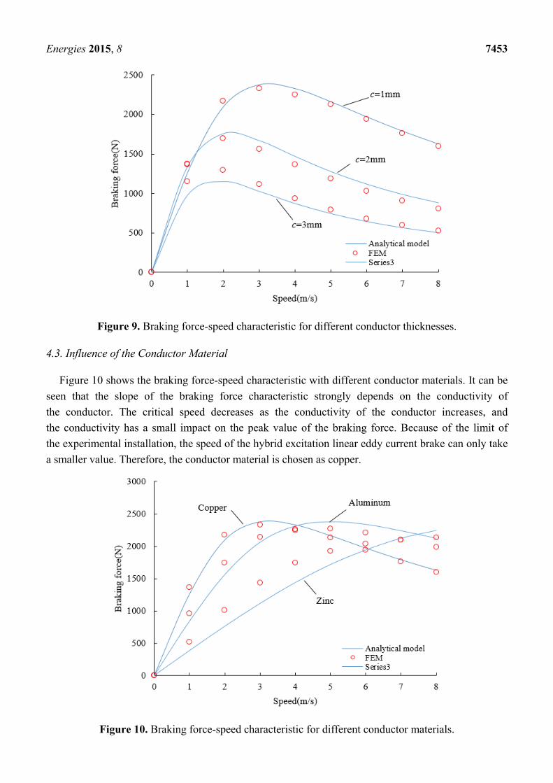
Figure 9. Braking force-speed characteristic for different conductor thicknesses.
4.3. Influence of the Conductor Material
Figure 10 shows the braking force-speed characteristic with different conductor materials. It can be
seen that the slope of the braking force characteristic strongly depends on the conductivity of
the conductor. The critical speed decreases as the conductivity of the conductor increases, and
the conductivity has a small impact on the peak value of the braking force. Because of the limit of
the experimental installation, the speed of the hybrid excitation linear eddy current brake can only take
a smaller value. Therefore, the conductor material is chosen as copper.
Figure 10. Braking force-speed characteristic for different conductor materials.

Energies 2015, 8 7454
4.4. Influence of the Excitation Current
Figure 11 shows the braking force-speed characteristic with different excitation currents. It can be
seen that the braking force increases gradually as the excitation current increases.
Figure 11. Braking force-speed characteristic for different excitation currents.
Moreover, the critical speed slightly increases as the excitation current increases. In order to obtain
a larger braking force and guarantee the thermal stability of the hybrid excitation eddy current brake,
the excitation current is chosen as 14 A.
4.5. Influence of the Magnet Dimension
The effect of the magnet dimensions (the width of the permanent magnets hm and the height of
the permanent magnets bm) is analyzed as shown in Figure 12. The study has been performed considering
a constant magnet volume. It can be seen that there are optimal magnet dimensions that will maximize
the braking force density. The braking force density is the ratio of the braking force to the volume of
the eddy current brake. In order to obtain a larger braking force density, the width of the permanent
magnet is chosen as 13 mm and the height of the permanent magnet is chosen as 14 mm.
Figure 12. Braking force density-speed characteristic for different magnet dimensions.

Energies 2015, 8 7455
5. Eddy Current Brake Controller
This paper presents a reliable and rugged controller of the hybrid excitation linear eddy current brake
to control the amplitude of the braking force. Figure 13 shows the control scheme of the eddy current
brake. There is an outer braking force controller and an inner current controller. The braking force
controller outputs the reference excitation current Iref according to the error between the reference
braking force Fref and the actual braking force Fa. The current controller outputs a reference voltage uref
according to the error between the reference excitation current Iref and the actual excitation current Ia.
One can adjust the excitation current and move forward to adjust the braking force by controlling
the reference voltage uref.
Figure 13. Control scheme of the eddy current brake.
5.1. Current Controller Design
In order to limit the amplitude of the current ripple to an acceptable extent, the three-level PWM
scheme is used in this paper. For the three-level PWM scheme, the amplitude of the current ripple
is independent of the direct current (DC)-link voltage, and the dynamic response characteristics of
the eddy current brake system can be raised by increasing the DC-link voltage without increasing
the current harmonics. Moreover, the switching frequency of an insulated gate bipolar transistor (IGBT)
element is half of the output pulse frequency. This means that the switching frequency of the power
elements is halved for a required dynamic performance of the eddy current brake compared with
the two-level schemes.
5.2. Braking Force Controller Design
Dud to the saturation of the iron core, the relationship between the braking force and the excitation
current is nonlinear. For the ease of control, the nonlinear curve is divided into several piecewise linear
intervals. When the objective braking force Fref is given, the corresponding interval is estimated firstly,
then the corresponding excitation current I* is calculated using the endpoints of the interval (I1, F1) and
(I2, F2), as shown in Figure 14.

Energies 2015, 8 7456
Figure 14. Schematic diagram of piecewise linearization.
The expression of I* is shown below:
* 2 1ref 1 1
2 1
( )I I
I F F IF F
(48)
Finally, the reference excitation current Iref is shown as:
refI I I (49)
where ΔI is the output of the proportion integration (PI) controller.
A block diagram of the braking force controller is shown in Figure 15. The input of the PI controller
is the error signal between the objective braking force Fref and the actual braking force Fa.
Figure 15. Block diagram of the braking force controller.
6. Numerical and Experimental Analysis
The 2-D finite element study is carried out in the same domain as the analytical problem. The field
line distribution and the magnetic flux density map at a speed of 2 m/s are plotted in Figure 16a,b,
respectively. It is observed that the reaction field of eddy currents tilts the field line entering
the secondary conductor and shifts the epicenters of the flux density formation behind the centerlines of
the magnets. Both the tilt and epicenter shift are a function of speed.

Energies 2015, 8 7457
The braking force characteristics of the electric excitation eddy current brake and the hybrid excitation
eddy current brake are compared at the same excitation current. The electric excitation eddy current
brake has the same structure as the hybrid excitation eddy current brake, except that there are not
permanent magnets, as shown in Figure 17.
(a)
2.0
1.6
1.2
0.8
0.4
0.0
B(T)
(b)
Figure 16. (a) Field line distribution and (b) the magnetic flux density map.
Conductor plate
Primary core Excitation winding
Back iron
Figure 17. Structure of the electric excitation linear eddy current brake.
Figure 18a is the magnetic flux density map of the electric excitation eddy current brake at a speed of
2 m/s. The flux density of the gray area is larger than 2 T. Figure 18b is a comparison of the braking
force characteristics of the electric excitation eddy current brake and the hybrid excitation eddy
current brake.
As can be observed in Figure 18, the primary core of the electric excitation eddy current brake is
saturated, but the primary core of the hybrid excitation eddy current brake is not saturated at the same
excitation current, as shown in Figure 16b. Moreover, the braking force produced by the hybrid excitation
eddy current brake is larger than that produced by the electric excitation eddy current brake. In other
words, the excitation loss of the hybrid excitation eddy current brake is lower than that of the electric
excitation eddy current brake under the same braking force level.

Energies 2015, 8 7458
2.0
1.6
1.2
0.8
0.4
0.0
B(T)
(a)
(b)
Figure 18. (a) Magnetic flux density map of the electric excitation eddy current brake and
(b) a comparison between the electric excitation eddy current brake and hybrid excitation
eddy current brake.
Therefore, we can conclude that the presence of the permanent magnets, whose flux lines in
the primary core are oppositely directed with respect to the flux lines by the excitation windings, has
the effect of mitigating the saturation of the iron in the teeth of the primary core. This allows the brake
to be fed with more intense currents, improving the braking force. Through the above analysis, we can
see that the hybrid excitation eddy current brake has many advantages, such as controllability, high force
density and low excitation loss. The prototype of the hybrid excitation linear eddy current brake is shown
in Figure 19a. The prototype includes the primary part and the secondary part. The primary part consisted
of the iron core, excitation windings, permanent magnets, slides, cushion blocks, connecting plate and
so on. The secondary part consisted of the conductor plate, back iron, slide rail and limited block. In this
experiment, the rotation movement of a servo rotating motor is transformed into linear motion through
a ball screw to drive the primary part of the eddy current brake. The test bed is shown in Figure 19b.
It includes the servo rotating motor, a tension-compression sensor, the ball screw, the hybrid excitation
linear eddy current brake and the controller. The measured value of the braking force can be obtained
easily by measuring the output voltage of the tension-compression sensor. In this paper, the relationship
between the output voltage of the tension-compression sensor and the braking force is as shown below.

Energies 2015, 8 7459
out
5mV
VF (50)
In other words, when the output voltage of the tension-compression sensor is 5 mV, the braking force
is 1 N.
(a)
(b)
Figure 19. (a) Prototype of the hybrid excitation linear eddy current brake and (b) the test bed.
The final parameters of the hybrid excitation linear eddy current brake are shown in Table 2.
Table 2. Final parameter of the hybrid excitation linear eddy current brake.
Symbol Quantity Value
hm width of the permanent magnet 13 mm bm height of the permanent magnet 14 mm I excitation current 14 A N turns of the excitation winding 200 L length of the primary iron core 200 mm lδ width of the primary iron core 100 mm hj height of the primary core yoke 11 mm H height of the primary iron core 53 mm δ air gap length 1 mm τ pole pitch 40 mm c conductor plate thickness 1 mm hb back iron thickness 9 mm bt tooth width 16 mm

Energies 2015, 8 7460
Figure 20 shows the experimental measurements of the braking force compared to the calculated
values by finite element method. It can be seen that the agreement between the experimental
measurements and the calculated values by the finite element method is very good. Moreover, due to
the saturation of the iron core, the relationship between the braking force and the excitation current is
nonlinear. As shown in Figure 19b, the length of the stator of the prototype is small, i.e., the stroke of
the prototype is limited. Therefore, the speed cannot reach a higher value. This problem will be solved
in the future.
(a)
(b)
Figure 20. Comparison between the experimental measurements and calculated values via
the finite element method: (a) v = 0.1 m/s and (b) v = 0.15 m/s.
The output current of the full bridge power converter with the two-level PWM schemes and
the three-level PWM schemes are given in Figure 21a,b, respectively. The results show that
the amplitude of the current ripple with the two-level PWM schemes is approximately 50 mA and

Energies 2015, 8 7461
the amplitude of the current ripple with the three-level PWM schemes is approximately 12.5 mA. That
is, the amplitude of the current ripple is significantly reduced by using the three-level PWM schemes.
The experimental waveforms of the braking force are shown in Figure 21c–f. It can be seen that there is
no overshoot in the braking force responses.
(a)
(b)
Figure 21. Cont.

Energies 2015, 8 7462
(c) (d)
(e) (f)
Figure 21. (a) Output current with the two-level PWM schemes; (b) output current with
the three-level PWM scheme; (c) Fref = 70 N; (d) Fref = 80 N; (e) Fref = 90 N and
(f) Fref = 100 N.
The objective braking force, the measured value of the output voltage of the tension-compression
sensor, the measured value of the braking force and the error between the objective braking force and
the measured value of the braking force are shown in Table 3.
Table 3. Analysis of the experimental results.
Objective Braking Force Measured Value of Output Voltage Measured Value of Braking Force Error
70 N 337 mV 67.4 N 3.7%
80 N 381 mV 76.2 N 4.8%
90 N 418 mV 83.6 N 7.1%
100 N 461 mV 92.2 N 7.8%
As can be observed in Table 3, the measured value of the braking force has good correlation with
the objective braking force, and the availability of the eddy current brake controller is verified.
7. Conclusions
In this paper, a novel hybrid excitation linear eddy current brake was presented. The hybrid excitation
linear eddy current brake has the advantages of high force density and low excitation loss compared to
the electric excitation linear eddy current brakes. The validity of the analytical model was verified by
the FEM and experimental tests, therefore the analytical model can be used in the preliminary design of

Energies 2015, 8 7463
eddy current brakes. Parametric analysis was performed to explore the influence of the design parameters
on the eddy current brake performance. Moreover, the experimental results show that the eddy current
brake can generate objective braking force using the controller proposed in this paper. It has been found
that the proposed eddy current brake system can be used in road and rail vehicles.
Acknowledgments
This work was supported by National Science and Technology Major Projects (2012ZX04001-051).
Author Contributions
Baoquan Kou conceived the structural and experiments of the hybrid excitation eddy current brake.
Lu Zhang, He Zhang and Yinxi Jin performed the experiments. Yinxi Jin analyzed the data and wrote
the paper.
Conflicts of Interest
The authors declare no conflict of interest.
References
1. Jang, S.; Lee, S.; Jeong, S. Characteristic analysis of eddy-current brake system using the linear
Halbach array. IEEE Trans. Magn. 2002, 38, 2994–2996.
2. Sainjargal, S.; Byun, J. Analysis and case study of permanent magnet arrays for eddy current brake
systems with a new performance index. J. Magn. 2013, 18, 276–282.
3. Hecquet, M.; Brochet, P.; Lee, S.; Delsalle, P. A linear eddy current braking system defined by
finite element method. IEEE Trans. Magn. 1999, 35, 1841–1844.
4. Gay, S.E. Contactless Magnetic Brake for Automotive Applications. Ph.D. Thesis, Texas A&M
University, College Station, TX, USA, 2005.
5. Wang, P.J.; Chiueh, S.J. Analysis of eddy-current brakes for high speed railway. IEEE Trans. Magn.
1998, 34, 1237–1239.
6. Jang, S.; Lee, S. Comparison of three types of permanent magnet linear eddy-current brakes
according to magnetization pattern. IEEE Trans. Magn. 2003, 39, 3004–3006.
7. Ha, K.; Hong, J.; Kim, G.; Lee, J.; Kang, D. A study of the design for touch free linear eddy current
brake. IEEE Trans. Magn. 1999, 35, 4031–4033.
8. Ihm, H.; Lee, S.; Ham, S.; Lee, J. The influence of slit construction on the eddy current braking
torque considered by 3D FEM analysis. In Proceedings of the International Conference on Electrical
Machines and Systems, Wuhan, China, 17–20 October 2008; pp. 444–446.
9. Choi, J.; Shin, H.; Park, Y.; Jang, S. Torque analysis of axial flux PM type eddy current brake based
on analytical field computations. In Proceedings of the International Conference on Electrical
Machines and Systems, Beijing, China, 20–23 August 2011; pp. 1–5.
10. Amati, N.; Tonoli, A.; Canova, A.; Cavalli, F.; Padovani, M. Dynamic behavior of torsional
eddy-current dampers: Sensitivity of the design parameters. IEEE Trans. Magn. 2007, 43, 3266–3277.

Energies 2015, 8 7464
11. Lequesne, B.; Liu, B.; Nehl, T.W. Eddy-current machines with permanent magnets and solid rotors.
IEEE Trans. Ind. Appl. 1997, 33, 1289–1294.
12. Shin, H.; Choi, J.; Cho, H.; Jang, S. Analytical torque calculations and experimental testing of
permanent magnet axial eddy current brake. IEEE Trans. Magn. 2013, 49, 4152–4155.
13. Canova, A.; Vusini, B. Analytical modeling of rotating eddy-current couplers. IEEE Trans. Magn.
2005, 41, 24–35.
14. Mohammadi, S.; Mirsalim, M.; Vaez-Zadeh, S. Nonlinear modeling of eddy-current couplers.
IEEE Trans. Energy Convers. 2014, 29, 224–231.
15. Li, P.; Ma, J.; Fang, Y. Design and analysis of hybrid excitation rail eddy current brake system of
high-speed train. In Proceedings of the IEEE International Conference on Service Operations,
Logistics, and Informatics, Beijing, China, 10–12 July 2011; pp. 565–569.
16. Edwards, J.D.; Jayawant, B.V.; Dawson, W.R.C.; Wright, D.T. Permanent-magnet linear eddy-current
brake with a non-magnetic reaction plate. IEE Proc. Electr. Power Appl. 1999, 146, 627–631.
17. Jang, S.; Jeong, S.; Cha, S. The application of linear Halbach array to eddy current rail brake system.
IEEE Trans. Magn. 2001, 37, 2627–2629.
18. Gay, S.E.; Ehsani, M. Analysis and experimental testing of a permanent magnet eddy-current brake.
In Proceedings of IEEE Conference Vehicle Power and Propulsion, Chicago, IL, USA, 7–9 September
2005; pp. 756–765.
19. Canova, A.; Vusini, B. Design of axial eddy current couplers. IEEE Trans. Ind. Appl. 2003, 39,
725–733.
20. Yazdanpanah, R.; Mirsalim, M. Axial-flux wound-excitation eddy-current brakes: Analytical study
and parametric modeling. IEEE Trans. Magn. 2014, 50, 1–10.
21. Choi, J.; Jang, S. Analytical magnetic torque calculations and experimental testing of radial flux
permanent magnet-type eddy current brakes. J. Appl. Phys. 2012, 111, doi:10.1063/1.3672408.
22. Singh, A. Theory of eddy-current brakes with thick rotating discs. Proc. IEE 1977, 124, 373–376.
23. Park, M.; Choi, J.; Shin, H.; Jang, S. Torque analysis and measurements of a permanent magnet
type Eddy current brake with a Halbach magnet array based on analytical magnetic field
calculations. J. Appl. Phys. 2014, 115, doi:10.1063/1.4862523.
24. Srivastava, R.K.; Kumar, S. An alternative approach for calculation of braking force of an eddy-current
brake. IEEE Trans. Magn. 2009, 45, 150–154.
25. Liu, Z.J.; Vourdas, A.; Binns, K.J. Magnetic field and eddy current losses in linear and rotating
permanent magnet machines with a large number of poles. IEE Proc. 1991, 138, 289–294.
© 2015 by the authors; licensee MDPI, Basel, Switzerland. This article is an open access article
distributed under the terms and conditions of the Creative Commons Attribution license
(http://creativecommons.org/licenses/by/4.0/).