Enduring primary frequency response requirements for the NEM
73
Enduring primary frequency response requirements for the NEM August 2021 Technical White Paper An Engineering Framework report on requirements for the future National Electricity Market
-
Upload
khangminh22 -
Category
Documents
-
view
1 -
download
0
Transcript of Enduring primary frequency response requirements for the NEM
Enduring primary frequency
response requirements for the NEM
August 2021
Technical White Paper An Engineering Framework report on requirements for the future National Electricity Market

© 2021 Australian Energy Market Operator Limited.
The material in this publication may be used in accordance with the copyright permissions on AEMO’s website.
Important notice
PURPOSE
This report provides general and technical information and analysis on the requirements for primary
frequency response (PFR) in the National Electricity Market, to help inform the Australian Energy Market
Commission in its consideration of proposed changes to the National Electricity Rules.
This report has been prepared using information available to AEMO as at 1 July 2021.
DISCLAIMER
This document or the information in it may be subsequently updated or amended. This document does not
constitute legal or business advice, and should not be relied on as a substitute for obtaining detailed advice
about the National Electricity Law, the National Electricity Rules, or any other applicable laws, procedures or
policies. AEMO has made every effort to ensure the quality of the information in this document but cannot
guarantee its accuracy or completeness.
Accordingly, to the maximum extent permitted by law, AEMO and its officers, employees and consultants
involved in the preparation of this document:
• make no representation or warranty, express or implied, as to the currency, accuracy, reliability or
completeness of the information in this document; and
• are not liable (whether by reason of negligence or otherwise) for any statements or representations in this
document, or any omissions from it, or for any use or reliance on the information in it.]
VERSION CONTROL
Version Release date Changes
1 20/8/2021 Submitted to the Australian Energy Market Commission (AEMC)
© AEMO 2021 | Enduring primary frequency response requirements for the NEM 3
Executive summary
This paper sets out the power system requirements for primary frequency response (PFR) in the National
Electricity Market (NEM), by:
• Examining the role of PFR within the broader frequency control chain.
• Establishing the technical characteristics of effective PFR.
• Outlining how this can be maintained as the power system continues to transition into the future.
The Australian Energy Market Commission (AEMC) is currently considering different policy pathways for
PFR following completion of a three-year mandatory period in June 2023. This technical paper is part of a
package of work undertaken by AEMO to inform the AEMC’s “Primary frequency response incentive
arrangements” rule change consultation1. It outlines AEMO’s position that:
• Tightly managed, widespread PFR establishes a strong control base, supporting the action of slower
acting controls and enabling optimised and robust outcomes across the frequency control chain.
• Effective PFR is essential today. The need is large, distributed, and expected to grow over time as the
power system becomes increasingly dependent on variable and inverter-based generation.
• It will be increasingly important to track and monitor frequency performance under normal operating
conditions against defined benchmarks as the power system transitions and new operational
conditions emerge.
• Enduring PFR arrangements must be effective; they must be able to handle present operational
requirements and a potentially wide range of future operating conditions and system configurations.
This paper addresses a series of questions asked by the AEMC regarding the ongoing needs for PFR in the
NEM. It forms part of a broader body of work – AEMO’s Engineering Framework2 – that is exploring the
changing needs of the NEM power system.
The AEMC’s 2020 mandatory PFR (MPFR) rule3 has re-established effective frequency control within the
normal operating frequency band (NOFB) in the NEM through the introduction of:
• Tightly managed control – narrow deadband frequency responsiveness from generators including
inverter-based resources (IBR) as part of the MPFR roll out, starting from no more than 15 millihertz (mHz)
away from the nominal 50 hertz (Hz) frequency.
• Widespread response – near-universal, mandatory requirement across all scheduled and semi-scheduled
generation, including IBR, and agnostic to technology.
These requirements bring the NEM into line with accepted engineering practice, and are typically specified as
a necessity in comparable power system grid codes internationally. Since the phased roll-out of the MPFR
rule began in September 2020, it has gradually increased the aggregate level of proportional frequency
responsiveness in the NEM, resulting in drastic improvements to frequency performance over this period.
This paper is intended to be read in conjunction with AEMO’s separate regulatory advice, which considers
market and incentivisation frameworks for PFR provision into the future4.
1 AEMC. Primary frequency response incentive arrangements consultation webpage, at https://www.aemc.gov.au/rule-changes/primary-frequency-response-
incentive-arrangements.
2 AEMO. Engineering Framework program webpage, at https://aemo.com.au/en/initiatives/major-programs/engineering-framework.
3 AEMC. Mandatory primary frequency response rule change webpage, at https://www.aemc.gov.au/rule-changes/mandatory-primary-frequency-response.
4 AEMC. Primary frequency response incentive arrangements consultation webpage, at https://www.aemc.gov.au/rule-changes/primary-frequency-response-
incentive-arrangements.

© AEMO 2021 | Enduring primary frequency response requirements for the NEM 4
Effective PFR is essential for robust power system frequency control
Frequency control is a system, managed through an integrated chain of control actions. The first of these is
primary control, based on the strictly local detection and response of plant control systems to changes in
power system frequency. This provides a dynamic active power response, typically in proportion to the
frequency deviation. Effective PFR establishes a strong control base, supporting the action of slower-designed
controls and enabling optimised, robust outcomes across the frequency control chain. Primary and secondary
controls do not act independently or in sequence; rather they are continuously active, complementing each
other to provide effective control of frequency.
Effective PFR:
• Enables contingency frequency control ancillary services (FCAS) reserves to be utilised effectively, by
counteracting the frequency change following a contingency event as soon as the PFR deadband is
crossed, and minimising unnecessary activation of triggered frequency response due to slightly wider than
‘normal’ frequency variations.
• Enables secondary control and primary control to be better utilised together, by freeing the slower-acting
secondary control to operate as it has been designed to, for correcting energy balance and forecast error,
preventing frequency drift and accumulation of time error within the dispatch interval. This, in turn,
reduces the duty on PFR itself.
• Increases power system resilience to frequency disturbances, by providing robust damping and
geographic dispersion in the response, assisting in managing frequency recovery and potential overshoot
during emergency frequency control actions, and reducing the likelihood of local instability.
• Increases predictability in generating system performance during frequency deviations, supporting
analysis of power system performance, and design of control and protection systems.
The need for PFR is large, distributed, and expected to grow over time
A high aggregate level of frequency responsiveness is a critical prerequisite for optimal frequency control
outcomes as the supply mix continues to become increasingly decentralised, inverter-based, and variable.
AEMO considers this is best delivered through a narrow deadband response from all generators.
It is challenging to define an exact level of future PFR requirements that will be sufficient across all plausible
operational conditions. However, the need for PFR can be reasonably expected to grow over time due to
factors including increasing price-driven movement in both generation and load, the introduction of
five-minute settlement in 2021, increasing generation variability due to growth in variable renewable energy
(VRE), and increasing uptake of distributed photovoltaics (DPV, currently without narrowband PFR enabled).
Sufficiency over the range of plausible power system operational conditions will require:
• Contribution from a large fraction of the fleet – this is distinctly different to existing FCAS markets, which
can allocate reserve requirements to a smaller number of providers.
• Geographic diversity in provision – this is fundamental to power system performance under normal
conditions, and system resilience during abnormal system events and network outages/contingencies.
VRE can provide PFR through the implementation of a frequency droop response to active power output
within the control hierarchy of the inverter. Several grid codes internationally require PFR from VRE
generators, and AEMO is engaging with equipment manufacturers through the MPFR rollout to ensure PFR is
provided appropriately from VRE. Uncurtailed VRE is only able to provide an active power response in one
direction; that is, a reduction from its weather-limited output at a given time. By comparison, curtailed VRE
and battery energy storage systems (BESS) are able provide a response in both directions. AEMO supports
the current MPFR approach, which does not require generators to be curtailed (meaning no need to maintain
stored energy to provide PFR).
In some future energy dispatch scenarios, there could be much lower levels of frequency responsive
generation online as part of normal energy market dispatch and, therefore, reduced capacity to meet any
aggregate PFR requirement.

© AEMO 2021 | Enduring primary frequency response requirements for the NEM 5
An aggregate level of PFR delivery requires plant to be capable of frequency response and to be online, and
also to be carrying enough headroom or footroom to provide the response. This headroom/footroom could
be provided from BESS, curtailed VRE generation, or synchronous generation, and sourced through FCAS
arrangements. Importantly, this relies on IBR (VRE or BESS) having PFR capability enabled in the first place.
The MPFR rule applies only to scheduled and semi-scheduled generators. Future periods where almost all
demand is met by distributed energy resources (DER) will be particularly challenging, as DER currently are not
required to provide narrowband PFR, and some form of aggregate headroom/footroom maintenance may be
required at these times.
One potential solution is to mandate narrow deadband PFR from DER devices, particularly DPV and BESS.
Other comparable international standards now allow for specification of narrow frequency deadbands as the
default, within a wide permissible range, with some independent system operators (ISOs) now specifying
narrow frequency deadband settings for DER. AEMO is undertaking further investigation into the feasibility of
similar requirements in Australia. It is worth noting that a high renewable future will likely involve periods of
significant VRE curtailment, which could provide substantial headroom as a by-product.
Importance of tracking frequency performance under normal operating conditions
It will be increasingly important to track and monitor frequency performance under normal operating
conditions against defined benchmarks as the power system transitions and new operational conditions
emerge over time. The Frequency Operating Standard (FOS) does not currently define or specify acceptable
frequency performance under normal conditions. AEMO has examined different options to amend the FOS to
explicitly specify acceptable performance within the NOFB, and has compared frequency outcomes in the
NEM before and after the MPFR rollout against different metrics associated with these options. AEMO
recommends explicit definition of a normal operating primary frequency band (NOPFB) within the FOS, with
adequacy benchmarked through actual frequency performance over any 30-day period; this is consistent with
current practice for the NOFB.
Enduring PFR arrangements must be effective
Effective levels of aggregate frequency responsiveness will be an essential requirement in the future power
system. AEMO reiterates the criticality of enduring PFR arrangements that are effective – that is, able to
handle present operational requirements and also a potentially wide range of future operating conditions and
system configurations in an assured, robust manner.
The AEMC is considering several policy pathways for enduring policy PFR arrangements. These options differ
significantly in their effectiveness; the chosen pathway must enable robust, effective aggregate frequency
responsiveness in the long term that is:
• Decentralised – based on local detection and response, not impacted by communications unavailability,
providing a dependable, robust and proportionate response.
• Distributed – with a large number of geographically disperse contributors, enabling responsiveness
physically close to any disturbance, reducing dependence on individual providers and duty on individual
plant.
• Simple – reduceable to a sequence of lower order control actions that can be implemented within the
control hierarchy of plant, and that, at the system level, provide a stable base level of narrowband
frequency responsiveness for other frequency control actions to be progressively overlaid.
• Predictable – establishes a level of consistent responsiveness to frequency deviations, reducing uncertainty
in power system behaviour, system adequacy, and frequency control need assessment.
• Flexible – can scale over time as the technology mix changes, potentially extending to include new PFR
sources, and can be overlaid with a headroom management mechanism in the future (if needed).
AEMO has provided a separate regulatory advice to the AEMC outlining its assessment of the different policy
pathways under consideration and AEMO’s preferred option for widespread, narrowband PFR arrangements.

© AEMO 2021 | Enduring primary frequency response requirements for the NEM 6
Contents Executive summary 3
1. Introduction 9
1.1 Purpose of this paper 9
1.2 Related work on primary frequency control 9
1.3 Update on the MPFR rollout 10
2. Characterising frequency control 11
2.1 Frequency control chain 11
2.2 Frequency control loops 13
2.3 Technical characteristics of primary frequency response 15
2.4 Importance of effective primary frequency control 17
3. Technical requirements for effective PFR 18
3.1 Tightly-managed control of frequency 18
3.2 Widespread, distributed provision 22
3.3 Frequency Operating Standard amendment 25
4. PFR considerations into the future 30
4.1 Future frequency control needs 30
4.2 Provision of PFR into the future 31
A1. Analysis and case studies 35
A1.1 Normal operating conditions 35
A1.2 Credible contingencies 38
A1.3 Non-credible contingencies 38
A1.4 NEM frequency oscillations after MPFR implementation 44
A1.5 Price-responsive movements in generation and load 45
A2. Interaction between primary and secondary control 47
A2.1 Illustrative example 47
A2.2 Undrill simulations 48
A2.3 System performance before and after Mandatory Primary Frequency Control 50
A2.4 SCADA loss event 55
A2.5 Forward-looking analysis 56
A3. International comparisons 58
A4. Options to amend the Frequency Operating Standard 59
A4.1 Option 1: Qualitative criteria 59
A4.2 Option 2: Update existing FOS criteria 59

© AEMO 2021 | Enduring primary frequency response requirements for the NEM 7
A4.3 Option 3: Standard deviation benchmark 61
A4.4 Option 4: Mileage measure 66
A4.5 Summary and recommendations 68
A5. Effect of fewer PFR providers 70
Tables Table 1 Summary of MPFR implementation as at early July 2021 10
Table 2 Stages within the frequency control chain 12
Table 3 Summary of different FOS amendment options and recommendations 28
Table 4 Event comparison 2008 and 2018 39
Table 5 Average FCAS procured during SCADA outage 43
Table 6 Comparison of international requirements for primary frequency response 58
Table 7 Mainland NEM benchmark options 63
Table 8 Tasmania benchmark options 63
Table 9 Benchmark exceedance | Mainland NEM benchmark | 90th percentile σ = 0.03241 64
Table 10 Benchmark exceedance | Mainland NEM benchmark | 95th percentile σ = 0.03318 64
Table 11 Benchmark exceedance | Mainland NEM benchmark | 99th percentile σ = 0.03472 65
Table 12 Benchmark exceedance | Tasmania benchmark | 90th percentile σ = 0.03792 65
Table 13 Benchmark exceedance | Tasmania benchmark | 95th percentile σ = 0.03905 66
Table 14 Benchmark exceedance | Tasmania benchmark | 99th percentile σ = 0.04112 66
Table 15 Summary table of current FOS criteria for NOFB and additional options 68
Table 16 Summary of different FOS amendment options and recommendations 69
Table 17 Gross rated capacity of online PFR providers (MW) to manage 250 MW deviation 72
Table 18 Maximum provision from each unit to manage 250 MW deviation (as % of rated capacity) 72
Figures Figure 1 Power system frequency control loops 13
Figure 2 Generalised droop-based frequency response profile 16
Figure 3 Frequency performance compared across randomly selected days in jurisdictions 26
Figure 4 Annual distribution of frequency within the NOFB since 2009 – NEM mainland 35
Figure 5 Frequency distribution between 2019-2021 – NEM mainland 36

© AEMO 2021 | Enduring primary frequency response requirements for the NEM 8
Figure 6 Daily mean frequency from 2020-2021 – NEM mainland 36
Figure 7 Monthly frequency crossings since 2007 – NEM mainland 37
Figure 8 Effect of introducing deadbands into primary frequency controllers – NEM frequency
histogram, 24 hours 37
Figure 9 Selected generation events in Q1 2021 and 2020 38
Figure 10 Queensland frequency following separation in 2018 compared to 2008 40
Figure 11 Queensland and New South Wales frequency profile during 25 May 2021 event 41
Figure 12 Queensland and New South Wales frequency profile during 25 May 2021 event, focusing
on multiple contingency events at 1406 hrs 42
Figure 13 Mainland frequency during SCADA outage of 24 January 2021 and estimated aggregate
primary frequency response 43
Figure 14 Frequency oscillations in the NEM after implementation of MPFR – 1 hour period 44
Figure 15 Frequency oscillations in the NEM after implementation of MPFR, five-minute snapshot 45
Figure 16 Price-driven frequency excursion 46
Figure 17 Illustrative example of the relative impact of additional primary control (left) vs additional
secondary control (right) 47
Figure 18 Undrill simulations for a load ramping event under different combinations of primary and
secondary control 49
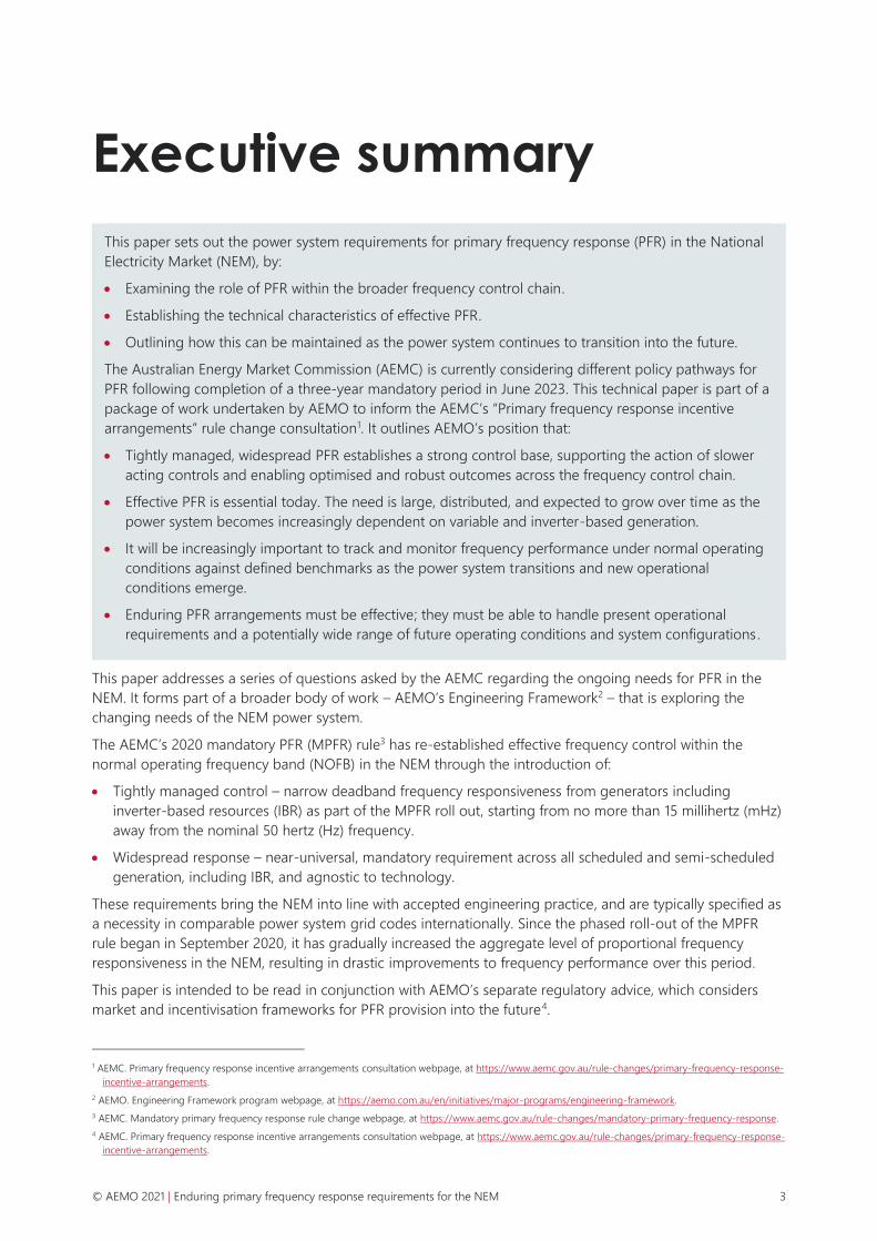
Figure 19 Frequency traces, random periods September to November 2020, showing effect of MPFR 50
Figure 20 Regulation quantities, causer pays four-second data, prior to MPFR 51
Figure 21 Regulation quantities, causer pays four-second data, after MPFR 52
Figure 22 Distribution of time error after implementing MPFR 53
Figure 23 Regulation quantities, causer pays four-second data, after MPFR and changes to AGC 54
Figure 24 Regulation quantities, causer pays four-second data, after MPFR and further changes to
AGC 54
Figure 25 System response with MPFR and without secondary control – SCADA outage, 24 January
2021 55
Figure 26 Unit response with MPFR and without secondary control – SCADA outage, 24 January 2021 56
Figure 27 Projected regulation FCAS requirements for increasing penetrations of wind and solar VRE
generation 57
Figure 28 Frequency in NOPFB (±0.05Hz) since 2007, minimum daily time percentage in prior 30-day
window 61
Figure 29 Historic frequency standard deviation 62
Figure 30 Monthly frequency mileage in the NEM since 2007 67
Figure 31 Monthly frequency mileage in the NEM for the 12 months to March 2021 67
Figure 32 Comparison of options against historic days and current standard, Mainland NEM 68
Figure 33 Impact of droop response aggregate frequency response 70
Figure 34 Comparison of droop response for smaller number of units 71

© AEMO 2021 | Enduring primary frequency response requirements for the NEM 9
1. Introduction
1.1 Purpose of this paper
This paper sets out the power system requirements for primary frequency response (PFR) in the NEM. It
examines the role of PFR within the broader frequency control chain, establishes the technical characteristics
of effective PFR, and outlines how this can be maintained as the power system continues to transition into the
future. The work draws on:
• Power system frequency control theory, international experience, and accepted engineering practice.
• Historical frequency performance in the NEM and learnings during over the MPFR rollout period.
• Consideration of the changing nature of the power system and operational conditions expected to arise
into the future.
This paper is part of a package of work undertaken by AEMO to inform the AEMCs “Primary frequency
response incentive arrangements” rule change consultation5.
It is intended to be read in conjunction with AEMO’s separate regulatory advice, which considers market and
incentivisation frameworks for PFR provision into the future5.
This paper also represents a key deliverable in AEMO’s Frequency Control Work Plan6, which is part of
AEMO’s Engineering Framework7 that is exploring the changing needs of the NEM power system.
1.2 Related work on primary frequency control
AEMO’s rule change request in August 20198 identified an immediate need for mandatory primary frequency
response (MPFR) from scheduled and semi-scheduled generators within a narrow deadband. This was in
response to a degradation in NEM frequency performance from 2014 to 2019 due to declining frequency
responsiveness of generation, coupled with increasing generation and load variability in the power system,
resulting in frequency being increasingly uncontrolled during normal operating conditions.
The rule change request was supported by expert advice from international power system dynamics and
control expert Dr John Undrill9, following his discussions with AEMO operational staff and industry
participants over June and July 2019. Dr Undrill’s advice assisted AEMO to finalise the exact nature of changes
required to existing NEM frequency control arrangements. This paper continues to reference and draw on Dr
Undrill’s advice where relevant.
In March 2020, the AEMC introduced MPFR requirements for scheduled and semi-scheduled generators 10.
This was specified as an interim arrangement, which would begin in June 2020 and sunset in June 2023 to
allow for further work to be done to understand power system requirements and consider enduring PFR
arrangements.
5 AEMC. Primary frequency response incentive arrangements consultation webpage, at https://www.aemc.gov.au/rule-changes/primary-frequency-response-
incentive-arrangements.
6 AEMO, Frequency Control Work Plan update. March 2021, at https://aemo.com.au/-/media/files/electricity/nem/system-operations/ancillary-
services/frequency-control-work-plan/frequency-control-work-plan-update-march-2021.pdf.
7 AEMO. Engineering Framework webpage, at https://aemo.com.au/en/initiatives/major-programs/engineering-framework.
8 AEMO, Electricity Rule Change Proposal – Mandatory Primary Frequency Response. August 2019, at https://www.aemc.gov.au/sites/default/files/2019-
08/Rule%20Change%20Proposal%20-%20Mandatory%20Frequency%20Response.pdf.
9 J. Undrill, Notes on Frequency Control for the Australian Energy Market Operator, at https://www.aemc.gov.au/sites/default/files/2019-
08/International%20Expert%20Advice%20-%20Notes%20on%20frequency%20control.pdf.
10 AEMC. Mandatory primary frequency response rule change webpage, at https://www.aemc.gov.au/rule-changes/mandatory-primary-frequency-response.

© AEMO 2021 | Enduring primary frequency response requirements for the NEM 10
AEMO is currently coordinating changes to generator control systems in accordance with the MPFR rule.
Experience from this roll out is helping inform consideration of enduring PFR arrangements, and is
highlighted throughout this paper.
1.3 Update on the MPFR rollout
Rollout of the MPFR rule began in late September 2020. It has been rolled out in ‘tranches’, starting with the
largest generation (dispatchable unit identifiers [DUIDs] greater than 200 megawatts [MW] maximum
capacity). Table 1 summarises the progress of rolling out the MPFR rule as at early July 2021. Regular updates
on the rollout of the MPFR rule are available via AEMO’s website11.
Generators may request to be exempted from the obligation to provide PFR, although the grounds for
exemptions are narrow, aligned with the prescribed considerations in the rules. To date, exemptions have
been given to only six out of 314 generators affected by the MPFR; these were two small hydro sites and four
of the earliest NEM wind sites, all of which were built without inherent capability to respond to system
frequency. A larger number (39) have been granted variations from one or more PFR parameters (deadband,
droop and response time).
Appendix A1 presents a selection of case studies and analytical results relating to NEM frequency
performance pre and post MPFR roll-out.
Table 1 Summary of MPFR implementation as at early July 2021
Tranche 1
(> 200 MW)
Tranche 2
(80-200 MW)
Tranche 3
(< 80 MW)
Total
Installed capacity (gigawatts [GW]) 36.3 15.9 4.8 57
DUIDs 81 116 117 314
Altered settings / already complied (GW) 30.9 6.1 1.8 38.8
Altered settings / already complied (%) 85% 38% 38% 68%
Outstanding synchronous (GW) 1.9 1.7 0.9 4.6
Outstanding inverter-based resources (IBR) (GW) 3.5 8.1 2 13.7
• 39 DUIDs with variations agreed to PFR requirements
• 6 DUIDs exempted (524 MW) from 314 total
• 75% of outstanding capacity is now IBR, majority have agreed PFR settings
11 AEMO. Primary Frequency Response webpage, at https://aemo.com.au/en/initiatives/major-programs/primary-frequency-response.

© AEMO 2021 | Enduring primary frequency response requirements for the NEM 11
2. Characterising frequency control
2.1 Frequency control chain
Maintaining frequency as close to the nominal 50 hertz (Hz) as possible requires the continuous balancing of
supply and demand.
Frequency control in modern power systems is comprised of an integrated, complementary chain of actions
aiming to retain, recover, then restore frequency to its nominal value following small and large disturbances.
This is achieved through the management of active power over different timescales in response to
supply-demand imbalances.
Table 2 summarises each part of the frequency control chain in terms of the underlying function, the source
of frequency variation it is intended to address, and how it is implemented in the NEM.

© AEMO 2021 | Enduring primary frequency response requirements for the NEM 12
Table 2 Stages within the frequency control chain
Stage Role Control action NEM service Typical response Variability addressed
Inertia Inherently acts to slow
frequency change
No control action.
Physical power system
response.
Minimum inertia requirements. Instantaneous response to
changes in frequency, acting all
the time.
Reduces rate of change
of frequency following a
disturbance.
Primary
control
Dynamic active power
response to frequency
change
(see Section 2.2.1)
Automatic proportional
or triggered response.
Strictly locally detected.
Currently MPFR for scheduled and semi-scheduled generators for
frequency deviations commencing at 50 ± 0.015 Hz
Fast, automatic active power
response through proportional
frequency-droop response.
Small deviations caused
by small imbalances in
generation and load.
Contingency frequency control ancillary services (FCAS) reserves for
frequency deviations outside the NOFB (50 ± 0.15 Hz)
• Enabled through dispatch instructions, allocating headroom and
footroom to cover credible contingencies.
• Raise and lower services acting over fast (6 seconds), slow (60
seconds) and delayed (5 minutes) timeframes. Fast Frequency
Response rule change* introducing very fast services.
Fast, triggered response of
reserves via either proportional
frequency-droop or switched
response controls.
Large sudden frequency
deviations due to
contingency events.
Secondary
control
Supervises and acts to restore
units to set point within the
dispatch interval
(see Section 2.2.2)
Automatic; proportional
and integral response to
frequency, time error and
variation from basepoint.
Remotely co-ordinated.
Regulation FCAS reserves for frequency deviations within the NOFB.
AGC signals sent through supervisory control and data acquisition
(SCADA) to all enabled plant every four seconds, acting over tens of
seconds to minutes.
Slower response with detection
and feedback loop between
unit and dispatch to adjust unit
set point controllers.
Forecast error, frequency
and time error due to
system supply-demand
variations within the
dispatch interval.
Tertiary
control
Supervises and restores
reserves from one dispatch
interval to the next
(see Section 2.2.3)
Allocated by system
operator. Regional
dispatch and inter-area
flows
Central energy dispatch and FCAS reserve enablement through
NEMDE.
Rebalancing at each dispatch
interval.
Generation and load
variability from one
dispatch interval to the
next.
Emergency
control
Arrest severe, rapid frequency
changes, reducing risk of
further cascading faults
(see Section 2.2.4)
Automatic, triggered
shedding of load or
generation. Local
detection and response.
Emergency frequency control schemes to manage large,
uncontrolled frequency changes resulting from non-credible loss of
generation or load.
Controlled shedding of load,
generation or storage response
through frequency-sensitive
relays to rebalance load and
generation.
Sudden, rapid frequency
changes due to major
non-credible MW
changes.
* AEMC, Fast frequency response market ancillary service, rule change consultation, at https://www.aemc.gov.au/rule-changes/fast-frequency-response-market-ancillary-service.

© AEMO 2021 | Enduring primary frequency response requirements for the NEM 13
2.2 Frequency control loops
Frequency control in modern power systems takes place hierarchically, typically comprising four different
control loops. These are illustrated in Figure 1, first conceptually at the generating unit level (a), then in terms
of the functional entities undertaking control actions (b) 12. This section describes different frequency control
loops, how they interrelate and how they are applied in the NEM. An explanation of how each of these
control loops are applied in the NEM is provided in Table 2 above.
Figure 1 Power system frequency control loops
(a) Conceptual view
(b) Functional view
12 Bevrani, H. (2014) Robust power system frequency control, 2nd Edition, Springer International Publishing, at https://www.springer.com/gp/book/
9783319072777, where:
• 𝑓 is frequency, Δ𝑓 is the frequency deviation from the nominal value, 𝑑𝑓/𝑑𝑡 is the rate of change of frequency.
• ∆𝑃𝑚 is the generator mechanical power change, ∆𝑃𝑡𝑖𝑒 is tie-line power change, ACE is area control error (ACE), and ∆𝑃𝑑 is the load/generation
disturbance.
• ∆𝑃𝑃, ∆𝑃𝑆, ∆𝑃𝑇 and ∆𝑃𝐸 are the control action signals for primary, secondary, tertiary, and emergency controls, respectively – represented as 𝑢𝑃 , 𝑢𝑆, 𝑢𝑇
and 𝑈𝑈𝐹𝐿𝑆 respectively in panel (b).
• The 𝛽 is the area bias factor, the 𝛼 is participation factor of generating unit in frequency control, and the 𝐾𝑃 and 𝐾𝑆 are the transfer function/gain of the
primary and secondary controls respectively.

© AEMO 2021 | Enduring primary frequency response requirements for the NEM 14
2.2.1 Primary control loop
The primary control loop control acts quickly (within seconds) in response to frequency deviations. This takes
place through the locally detection of frequency deviations13 from the nominal 50 Hz (∆𝑓) initiating an
automatic control signal to the generating unit (Δ𝑃𝑝 or 𝑢𝑝) for an active power response.
In the NEM, primary control comprises the current MPFR proportional droop response when frequency leaves
a ±0.015Hz deadband around 50 Hz and contingency frequency control ancillary services (FCAS) via
proportional controls, or increasingly via switched controllers, when frequency deviation is beyond the NOFB.
Contingency FCAS is not designed to control, or capable of controlling, frequency to a 50 Hz setpoint.
2.2.2 Secondary control loop
The secondary control loop complements the primary control, acting over slower timeframes (tens of seconds
to minutes) to correct more sustained sources of variability or error accumulating over time, which primary
controllers have initially responded to. This is achieved through addition of a centralised control signal (Δ𝑃𝑠 or
𝑢𝑠) fed back to plant-level primary controllers as a change in dispatch setpoints. Secondary control is
specifically designed to act over slower timeframes than ongoing frequency changes, to complement the
primary control – not act as a replacement for it.
This centralised control uses an error signal known as the area control error (ACE) representing the imbalance
between generation and load, which is proportional to frequency deviations from the nominal 50 Hz (∆𝑓). As
primary control responds to frequency deviations on a proportional basis, it may not be able to achieve the
reference values alone. Some offset may still exist due to energy dispatch forecast error, frequency and time
error. This means secondary control must also include a level of integral control, reflecting how long and how
far frequency has been from its nominal value over a period of time. Secondary control can also take into
account how units have moved from their nominal basepoints as a result of primary control action.
In the NEM, secondary control is implemented through central control of regulation FCAS reserves via
automatic generation control (AGC) commands sent through the NEM supervisory control and data
acquisition (SCADA) system. This acts to fine-tune controller set points to slowly correct deviations in
frequency and help return units to their basepoints.
2.2.3 Tertiary control loop
The tertiary control loop acts to restore the primary and secondary control reserves and assist the return of
frequency to nominal values if secondary reserves are not sufficient. In the NEM, tertiary control is effectively
achieved through the central energy re-dispatch process, rebalancing the system and allocating and restoring
FCAS reserves at each five-minute dispatch interval.
2.2.4 Emergency control loop
The emergency control loop serves as the ‘last line of defence’ in the event of high impact, low probability
contingency events that might otherwise result in widespread and prolonged outage situations if not
managed appropriately. It is comprised of emergency frequency control schemes (such as under frequency
load shedding [UFLS] and over frequency generation shedding [OFGS]) designed to rapidly rebalance the
system upon detection of a severe, rapid frequency deviations14. Emergency level active power controls
implemented by facility owners (such as specialised wideband frequency response controls) could also fall
into this category.
13 In a large power system there can be small differences in locally measured frequency across the system. This has been observed in the NEM. However, if
the power system is in MW balance, these differences average out to zero over longer timeframes.
14 Noting also that more sophisticated protection schemes monitor and detect other quantities, e.g. unstable power swings.

© AEMO 2021 | Enduring primary frequency response requirements for the NEM 15
2.3 Technical characteristics of primary frequency response
This section briefly explains the technical characteristics of PFR at the generator level and how this translates
to aggregate frequency responsiveness at a system level.
2.3.1 Performance parameters
The active power response associated with PFR can be described in terms of three key parameters –
deadband, droop, and response time. These are discussed below, with relevant requirements under the MPFR
rule. Further detail is provided in Section 3 of AEMO’s Interim PFR Requirements (IPFRR)15, and additional
performance requirements are specified in Section 4 of the IPFRR.
Deadband
The deadband specifies an operating zone around the nominal 50 Hz frequency where the generator will not
adjust its power in response to frequency deviations. The MPFR rule establishes a deadband of ± 0.015 Hz16
for generators, introducing a new primary frequency control band (PFCB) of 49.985 Hz to 50.015 Hz. Note
that the rule allows for some variation in deadband for those plants not able to meet this specification for
technical or economic reasons.
Droop
The droop coefficient defines how the generator’s active power changes in response to frequency changes
outside the deadband. This is defined by the equation below:
𝐷𝑟𝑜𝑜𝑝 (%) = 100 ×Δ𝐹/50
Δ𝑃/𝑃𝑀𝐴𝑋
where:
• Δ𝐹 is the frequency deviation beyond the upper or lower limit of generator’s deadband (in Hz).
• Δ𝑃 is active power change (in MW).
• 𝑃𝑀𝐴𝑋 is the Maximum Operating Level (in MW)17.
Droop corresponds to the deviation in frequency from the deadband (as a percentage of the nominal 50 Hz)
that would result in a 100% change in generator MW output from the maximum level.
The IPFRR specify that the droop coefficient must be less than or equal to 5%. The generalised relationship
for the frequency droop active power response is illustrated in Figure 2 (noting droop may be asymmetrical
for over- and under-frequency responses, and may also differ for different levels of frequency change).
15 AEMO. Interim primary frequency response requirements. June 2020, at https://aemo.com.au/en/initiatives/major-programs/primary-frequency-response.
16 In some jurisdictions this is referred to as a 30 Hz deadband.
17 Or the capacity of in-service generating units where multiple generating units are aggregated.

© AEMO 2021 | Enduring primary frequency response requirements for the NEM 16
Figure 2 Generalised droop-based frequency response profile
Response time
This parameter refers to how quickly the generator changes its active power in response to a frequency
deviation outside its deadband. The IPFRR require that generators should be capable of achieving a 5%
change in active power output within no more than 10 seconds, in response to a positive or negative step
change in frequency of up to 0.5 Hz. The speed at which various generation technologies can alter MW
output varies, with inverter-based resources (IBR) capable of much faster response than some synchronous
generation technologies.
2.3.2 Delivery of the response
Unit response
A generator’s ability to deliver PFR following a frequency deviation beyond its deadband depends on it being
online, having suitable control system settings, carrying enough stored energy (where relevant), and having
sufficient MW headroom or footroom to provide the response.
For a given frequency deviation, the delivered active power change is a function of the frequency change, the
generator’s droop coefficient, and its size (maximum operating level).
To a first approximation, the active power response of the generator to small or incremental frequency
movements can be considered independent of its MW generation at any given time. So long as it is online
with sufficient headroom, it will respond to a given incremental frequency deviation with the same MW
change, regardless of its MW output at the time18. As such, this incremental frequency response cannot be
co-optimised with MW dispatch. So long as it is online, the plant will respond. The plant’s response to small
deviations will be small (especially if there are many providers), compared with response to larger disturbance
(via FCAS provision) where reserve allocation is more critical.
Aggregated frequency responsiveness
The combined PFR contributions from online plant together provide an aggregate droop response across the
entire system, expressed as an incremental MW change per Hz frequency change (MW/Hz) and defined in
this paper as aggregate frequency responsiveness.
Effective narrowband PFR involves maintaining an aggregate level of MH/Hz responsiveness in the power
system to respond to relatively small and ongoing, incremental changes in system frequency.
18 As can be seen by rearranging the droop coefficient equation: Δ𝑃 = 100 × [Δ𝐹/50] [𝐷𝑟𝑜𝑜𝑝 (%)/𝑃𝑀𝐴𝑋]⁄ .

© AEMO 2021 | Enduring primary frequency response requirements for the NEM 17
This is distinct from frequency responsive reserves such as contingency FCAS, where MW headroom of firm
reserves for response to large frequency changes is procured, and the allocation of reserves can be
co-optimised with energy dispatch (as MW headroom maintenance can be readily separated from
available MW).
Aggregate responsiveness to small, incremental changes in frequency cannot be treated as a simple fungible
commodity that can be optimised in this way, with volumes and locations rapidly adjusted, due to:
• The impracticality of adjusting generator response parameters (such as deadbands) on operational
timeframes for small frequency deviations. Control system responses to disturbances need to be
consistent for accurate simulation and modelling of power system performance.
• The desirability of a large number of individual providers acting on a smaller, continuous basis (as
explained in Section 3.2.2 and Appendix A5), rather than reserving MW on a few units to respond to larger
frequency deviations if they were to occur, such as contingency events.
• The inability to co-optimise individual PFR-enabled plant response with its MW dispatch (as discussed
above) meaning the aggregate response depends on the number of controllers online. This means
MW/Hz delivery cannot be easily allocated or reserved ahead of MW generation across plant online.
2.4 Importance of effective primary frequency control
It is critical that enduring PFR arrangements are effective – that is, able to handle not only present operational
requirements, but also a potentially wide range of future operating conditions and system configurations in
an assured, robust manner. The University of New South Wales (UNSW) submission19 to the AEMC outlines
the different dimensions of effectiveness in the context of different system services.
The AEMC is considering several policy pathways for enduring policy PFR arrangements. The options being
considered differ significantly in their effectiveness. The chosen policy pathway must enable robust, effective
aggregate frequency responsiveness in the long term that is:
• Decentralised – based on local detection and response, not impacted by communications unavailability,
providing a dependable, robust and proportionate response.
• Distributed – with a large number of contributors over a geographically disperse area, enabling
responsiveness physically close to the disturbance, reducing dependence on individual providers and
prevailing network conditions, and reducing duty on individual plant.
• Simple – reduceable to a sequence of actions that can be handled within the control hierarchy of plant,
and, at the system level, provide a stable base level of narrowband frequency responsiveness for other
frequency control reforms be progressively overlaid.
• Predictable – establishes a level of consistent responsiveness to frequency deviations, reducing
uncertainty in power system behaviour, system adequacy and frequency control need assessment.
• Flexible – can scale over time as the technology mix changes, and can be potentially extended to include
new PFR sources and overlaid with a headroom management mechanism in the future (if needed).
AEMO has provided a separate regulatory advice to the AEMC outlining its assessment of the different policy
pathways under consideration and AEMO’s preferred option for widespread, narrowband PFR arrangements.
19 UNSW – Collaboration on Energy and Environmental Markets. Response to Frequency control rule changes directions paper, February 2021, p. 3, at
https://www.aemc.gov.au/sites/default/files/documents/rule_change_submission_-_erc0263_erc0296_-_unsw_collaboration_energy_and_environmental_
markets_20210204.pdf.

© AEMO 2021 | Enduring primary frequency response requirements for the NEM 18
3. Technical requirements for effective PFR
The AEMC is considering a range of policy pathways for enduring primary frequency response following
completion of the three-year mandatory period in June 2023, including:
• Pathway 1 – existing mandatory PFR requirement maintained.
• Pathway 2 – mandatory requirement maintained and revised, and primary frequency response band
(PFCB) widened to a moderate or wide setting.
• Pathway 3 – no mandatory PFR requirement.
The AEMC is exploring different incentivisation options within these different policy pathways. The policy
pathways differ significantly in their effectiveness. Effective, tight control of frequency is a necessity today and
will be even more necessary in the transition towards a power system that is increasingly dependent on
variable and inverter-based generation. This section explores the following key elements of effective primary
frequency control under normal operating conditions, including:
• Tightly managed control implemented through narrow frequency response deadbands.
• Widespread response enabled on a near-universal basis across all capable generation.
• Tracking frequency performance under normal operating conditions against defined benchmarks.
3.1 Tightly-managed control of frequency
Deadbands in a control system determine the point at which control action begins. The larger the deadband
in frequency response controls, the larger the permitted level of uncontrolled frequency variation. The
AEMC’s alternative policy pathways for enduring PFR arrangements involve different deadband options for
frequency responsiveness. The options differ materially from a system design point of view and in terms of
their ability to provide effective frequency control outcomes under normal operating conditions:
• Narrow deadband (between 0 and ± 0.015 Hz) provides the most stable control of frequency, and the
most robust response to and damping of disturbances. This improves the overall resilience of the power
system during major system events and abnormal operating conditions, and enhances the effectiveness of
secondary control.
• Moderate deadband (± 0.15 Hz) by itself provides no control of frequency within the NOFB and is not
consistent with best practice internationally. PFR would act only after frequency has significantly departed
from 50 Hz, reducing the weight of the system to arrest rate of change of frequency (RoCoF), resulting in a
less resilient power system following contingency events. Adjusting reserve and secondary control
parameters alone would be unable to establish control within the NOFB under normal operating
conditions.
• Wide deadband (± 0.5 Hz) by itself would provide no control of frequency over a 1 Hz range. PFR would
operate only after a very large deviation of frequency, with a material risk of not arresting high RoCoF
events, and a significant reduction in resilience. The Frequency Operating Standard (FOS) would be
consistently breached. Such a lack of control is an unacceptable way to operate a national power system.

© AEMO 2021 | Enduring primary frequency response requirements for the NEM 19
As outlined in the Undrill report20, tight primary control commencing as close as possible to the nominal
50 Hz is a fundamental requirement for effective frequency control, treated as an established necessity across
major industrialised power systems around the world. Reasons for maintaining tight control of frequency
within the NOFB are outlined below.
3.1.1 Interactions between primary and secondary controls
As outlined in Section 2.2, primary and secondary controls are designed to appropriately respond to different
sources of frequency deviation over different timeframes. They are not substitutes for each other, but need to
work together. Effective, narrow-deadband primary control improves the performance of the secondary
control, minimising the work performed by each.
Tight, aggregate primary frequency responsiveness (MW/Hz) counteracts rapid incremental changes in
frequency which, in turn, reduces the primary control duty on individual generating units. This frees
secondary control to operate according to its intended design over slower timescales, correcting energy
balance and forecast error, and minimising frequency drift and accumulation of time error within the dispatch
interval.
Interactions between primary and secondary frequency control are considered in more detail in Appendix A2
(theoretically, through simulations undertaken by Dr Undrill and experience before and after the MPFR
rollout), and demonstrate that:
• High availability of primary control can effectively prevent rapid changes in frequency, minimising the
manoeuvring requirements (PFR duty) of individual units.
• Lack of secondary control adversely increases PFR duty on responsive generating units.
• While primary control responds to ongoing, fast incremental changes in frequency, it does not restore
energy balance and, therefore, frequency to 50 Hz.
• PFR duty on responsive generating units is minimised if secondary and tertiary controls restore energy
balance and frequency returns to 50 Hz.
3.1.2 Maintaining pre-contingent frequency
Generally, power system modelling and adequacy assessment assume nominal frequency prior to any event,
an assumption built into major power system modelling software packages. This is a valid assumption if
frequency is controlled tightly to 50 Hz. However, without tight control of frequency, the level of uncertainty
in where frequency is within the NOFB means this assumption is no longer appropriate.
This is particularly relevant for the setting of contingency FCAS volumes, as well as analysis of non-credible
events such as those studied in the Power System Frequency Risk Review21 (PSFRR). As contingency FCAS
volumes are set assuming a 50 Hz starting frequency, under conditions when frequency is not well controlled,
there is a higher likelihood of the FOS criteria for frequency containment being exceeded. For non-credible
events the uncertainty in pre-contingent frequency means there is additional uncertainty in the frequency
nadir, and so additional uncertainty around the margin available before the activation of UFLS.
Narrow deadband PFR helps to counteract frequency deviations as a result of contingency events well within
the NOFB, as soon as PFR deadbands have been crossed. AEMO analysis of frequency recovery following
contingency events from the loss of major generator units before and after the MPFR rollout is presented in
Section 0. This analysis demonstrates the impact of narrowband PFR reducing the frequency nadir as well as
the time taken for frequency to recover to the nominal 50 Hz value following credible contingency events.
20 J. Undrill, Notes on Frequency Control for the Australian Energy Market Operator, at https://www.aemc.gov.au/sites/default/files/2019-08/International%20
Expert%20Advice%20-%20Notes%20on%20frequency%20control.pdf.
21 At https://aemo.com.au/en/energy-systems/electricity/national-electricity-market-nem/system-operations/power-system-frequency-risk-review.

© AEMO 2021 | Enduring primary frequency response requirements for the NEM 20
3.1.3 Plant synchronisation
Prior to the introduction of the MPFR rule, some generators reported increasing difficulties and delays in
synchronising their generating units to the power system due to the increasing movement of frequency
under normal operating conditions.
International standards require synchronous generation to be designed to synchronise without damage to a
frequency difference of ±0.067 Hz22. Where frequency is drifting more than this (as it did in the NEM prior to
MPFR, as discussed in Appendix A1), longer times to synchronise can reasonably be expected. This introduces
security risks if plants are needed online at short notice to support the power system, and impacts overall
operational flexibility.
The operational flexibility offered to the NEM by these fast start generating systems is expected to become
increasingly important as the proportion of total energy supplied by weather-driven generation increases23.
The ability to start and synchronise rapidly and reliably will become increasingly important for efficient market
operation, which would be supported by more stable control of power system frequency.
The ability to synchronise and load fast start plant rapidly and reliably will likely become increasingly valuable
to operators of this generation once five-minute settlement comes into effect on 1 October 202124.
3.1.4 Avoid unnecessary activation of triggered frequency response
Some contingency FCAS is provided by frequency-triggered interruption of load, or frequency-triggered
automatic start, synchronisation and loading of fast start generation. Contingency FCAS is designed to
provide an active power response to recover frequency following contingency events, particularly the sudden
loss of one or more major generating units. These coarser, triggered MW responses can form an important
component of the overall response to these contingency events.
Prior to the MPFR rule, more frequent crossings of the NOFB were leading to increased triggering of some of
these providers due to the ‘normal’ drifting of frequency, rather than contingency events. Frequent triggering
is disruptive for contingency FCAS providers and could be expected to result in:
• Widening frequency response bands to reduce the occurrence of their activation, and/or adjusting other
settings to reduce the amount of response from the facility, which reduces both their technical
effectiveness and their value in contingency FCAS markets,
• Increasing the cost of their contingency FCAS offers to reflect the increased potential usage, or
• Limiting participation in the contingency FCAS markets, which reduces competition.
Improved control of frequency under normal operating conditions minimises unnecessary triggering of these
services caused by slightly wider than ‘normal’ variation of frequency. Since the introduction of the MPFR rule,
crossings of the NOFB due to normal frequency movement have decreased (see Appendix A1.1.3), allowing
AEMO to revise trigger settings for some providers. As noted in AEMO’s recent MASS consultation25, this has
allowed AEMO to shift default trigger settings closer to the NOFB.
22 IEEE Std C50.12-2005: Salient-Pole 50 Hz and 60 Hz Synchronous Generators and Generator/Motors for Hydraulic Turbine Applications Rated 5 MVA and
above, and IEEE C50.13-2014: Cylindrical-Rotor 50 Hz and 60 Hz Synchronous Generators Rated 10 MVA and above, at https://ieeexplore.ieee.org/
document/1597614.
23 AEMO. Renewable Integration Study – Appendix C – Variability and Uncertainty, 2020, at https://aemo.com.au/-/media/files/major-publications/ris/2020/
ris-stage-1-appendix-c.pdf.
24 See National Electricity Amendment (Five Minute Settlement) Rule 2017 No. 15. at https://www.aemc.gov.au/sites/default/files/2018-07/ERC0201%20note
%20and%20amending%20rule.pdf.
25 AEMO. Amendment of the Market Ancillary Service Specification (MASS) – DER and General consultation, at https://aemo.com.au/en/consultations/
current-and-closed-consultations/mass-consultation.

© AEMO 2021 | Enduring primary frequency response requirements for the NEM 21
3.1.5 Damping oscillations and disturbances
Oscillatory behaviour of any major power system variable is undesirable, and both the NER and AEMO’s
Power System Stability Guidelines have specific requirements to limit oscillations26,27.
Modern, large-scale power systems such as the NEM are characterised by many different complex
components and control interactions, including generator control systems, Emergency Frequency Control
Schemes (EFCS) and Special Protection Schemes (SPS). These schemes use a large array of relays,
measurement equipment, and control designs.
Due to this complexity, it is not possible to identify all possible adverse outcomes resulting from oscillations
that might arise. As a result, a key principle of power system control is that oscillations should be minimised
and movement of system quantities controlled.
Damping and control under normal conditions
Frequency in the NEM exhibits a range of oscillatory frequency movements on an ongoing basis. One mode
of oscillation has a very long period of around 20-25 seconds. On-line monitoring tools available to AEMO
indicate that the halving time of these particular oscillations can exceed the five-second halving time standard
outlined in the National Electricity Rules (NER).
These frequency changes are not the small, low amplitude ongoing oscillations in frequency that are
observed due to inter-area rotor angle oscillations between groups of machines across the interconnection.
Such inter-area oscillations are faster, and can be (and are) well damped through appropriate design of
generator excitation systems, in particular the use of power system stabilisers.
The observed long period oscillations in NEM frequency are instead common mode changes in frequency,
involving all machines across the power system speeding up or slowing down in unison with each other. The
theory underpinning these very slow common-mode frequency oscillations is not well understood, in the
NEM, or internationally, where they have been identified in other power systems.
In addition to these underlying frequency oscillations in the NEM, immediately prior to MPFR rollout,
frequency in the NEM was not controlled under normal operating conditions. Instead, it was moving in an
uncontrolled manner between the boundaries of the NOFB, in response to the accumulation of random
changes in demand and generation that occur on an ongoing basis.
While MPFR roll out is not complete, the adoption of narrowband PFR has significantly improved frequency
control, which includes limiting the magnitude of frequency oscillations. While periodic 20-25 second
oscillations in system frequency can still be observed, their magnitude remains well bounded. This is
discussed further in Appendix Section A1.4.
Frequency control under islanded conditions
Tight frequency control is needed for islanded regions following separation events, as well as under system
intact conditions. Following a separation event, there may be a need to bring more generating resources
online quickly or redispatch existing resources. This movement in generation requires damping to minimise
frequency impacts, in addition to managing the normal changes in supply and demand in the separated
region.
Close control of frequency to near 50 Hz also supports reconnection of islanded areas. The tolerances
required for re-connecting islanded areas with respect to allowable frequency differences are necessarily
small, to avoid major MW transients and associated plant risks that would occur if separated areas with
materially different frequencies were joined.
26 AEMO. Power System Stability Guidelines. 2012, at https://www.aemo.com.au/-/media/files/electricity/nem/security_and_reliability/congestion-
information/2016/power-system-stability-guidelines.pdf.
27 S5.1.8 – Chapter 5 – National Electricity Rules, at https://energy-rules.aemc.gov.au/ner/3.

© AEMO 2021 | Enduring primary frequency response requirements for the NEM 22
Ongoing and large movements in NEM frequency in islanded regions have been observed during previous
islanding events, such as the islanding of Queensland that occurred on 25 August 2018. In that event, the
large movements in frequency delayed the reconnection of Queensland to the NEM.
A similar non-credible separation event occurred on 25 May 2021. This was the first major islanding event in
the NEM since the reintroduction of MPFR. During this event, tighter control of frequency provided by
widespread PFR in both Queensland and the remainder of the NEM (as a result of the MPFR implementation)
supported entirely automatic reconnection of these separated areas in around 15 seconds, as opposed to the
minutes to hours it took for manual reconnection during previous islanding events (for example, 68 minutes
for the 25 August 2018 event). The incident highlighted the benefit of universal PFR requirements enabling
widespread geographic distribution of PFR, greatly supporting the management of this major power system
event. Further detail on the 2021 event is provided in Appendix Section A1.3.2.
3.2 Widespread, distributed provision
Establishing the effective, robust, and enduring PFR arrangements necessary to manage a wide range of
plausible operating conditions and system configurations will require PFR contribution to be widespread and
distributed.
Dr Undrill recommended that narrowband PFR obligations apply to the “… widest practical part of the
generating fleet…” and “… to the extent that it is practical, to all generating resources…” both synchronous and
inverter-based28. Reasons why this is important are outlined below.
3.2.1 Locational resilience
Widespread, distributed provision of PFR is important under normal conditions and for frequency recovery
following contingency events. This is especially relevant in the context of a long, stringy power system like the
NEM with propensity for regional separation.
Contingency events can occur at any time and any location, meaning there is a spatial aspect to robustness.
Response close to the initiating disturbance (rather than far away) reduces the likelihood of other unexpected
locational stability issues, such as angular or voltage stability challenges, arising during the recovery period.
Given the geographic size of the NEM, this requires a significant level of dispersal of frequency response.
The importance of effective aggregate frequency responsiveness across a large proportion of the generation
fleet was highlighted during a significant 70-minute SCADA failure in the NEM on 24 January 2021 (described
further in Appendix Section A1.3.3). During this period, AEMO lost operational visibility of power system
conditions, and could not use SCADA for dispatch of generation or for centralised secondary frequency
control. The AGC system was unable to ramp generation between market dispatch points, or to control units
enabled for regulation FCAS.
Despite this, frequency remained within the NOFB primarily as a result of a large aggregate frequency
response. AEMO has estimated this to be up to 1,157 MW provided across the power system, spread over
some 54 PFR-enabled units that were operating at the time. This PFR response was significantly greater than
the contingency FCAS volumes procured immediately prior to and during the period of the SCADA outage.
PFR was able to act in a coordinated, distributed manner to balance the system, relying on local detection
and response to frequency, rather than centralised communication and control systems that were unavailable.
3.2.2 Large number of providers
Having a widespread, distributed response across a large number of providers minimises the criticality of any
individual provider, including the risks associated with adverse or unexpected behaviours from individual
providers. It also reduces the impact on providers to the lowest possible level, by distributing the aggregate
response to small, incremental changes in frequency amongst the largest number of parties.
28 J. Undrill, Notes on Frequency Control for the Australian Energy Market Operator, Section 2.5, at https://www.aemc.gov.au/sites/default/files/2019-08/
International%20Expert%20Advice%20-%20Notes%20on%20frequency%20control.pdf.

© AEMO 2021 | Enduring primary frequency response requirements for the NEM 23
Compared to widespread, near-universal provision, a reduction in the number of providers would require
more aggressive frequency droop settings from responsive plant to achieve the equivalent level of aggregate
frequency responsiveness. A battery could, in theory, operate at 1% droop and provide the response of five
other units operating at 5% droop (provided the same amount of energy was available).
Appendix A5 examines trade-offs between the capacity of responsive plant online and the droop settings
necessary to achieve a given level of aggregate frequency responsiveness. This analysis concludes it is not
prudent, and may not be feasible, to concentrate PFR provision onto few units, due to one or more of the
following factors:
• It would require exceedingly aggressive droop settings and PFR duty from individual units. There is little or
no experience in the NEM or elsewhere with widespread use of such aggressive droop settings,
particularly where units with such droop settings would in aggregate be large enough to determine
overall system performance. The stability of a large, dispersed and relatively weakly interconnected power
system like the NEM under conditions of low inertia and widespread use of aggressively low droop
settings remains to be determined.
• Synchronous generation has been operated in the NEM with droop settings in the range of 3-5% for
many decades, and similar settings are used almost universally worldwide. While there is some experience
in the NEM with operating a small number of individual IBR at more aggressive (lower %) droop settings
of around 2%, there is little experience in the NEM with operating synchronous generation at droop
settings outside the 3-5% range.
• There are likely to be minimum local requirements in each region that would apply under different system
conditions (see Section 3.2.1).
• Generic constraints (such as thermal limits) limit the dispatch of generators, typically in response to
credible contingencies. For example, there are some constraints that limit regulation enablement in
Queensland under high loading conditions of the Queensland – New South Wales Interconnector (QNI),
or if high utilisation of regulation FCAS in Queensland will reduce interconnector target flows in dispatch.
Similar constraints on generation dispatch to ensure interconnection limits are not exceeded may be
required if there are very high local quantities of frequency response being provided, particularly with
aggressive droop settings.
Prior to the MPFR rule, some generators chose to provide narrowband PFR response or (due to the nature of
their plant) could not easily disable narrowband PFR response. Even plants that countered their narrowband
PFR response through secondary unit or load controllers experienced movement due to frequency.
Generators responding to frequency will experience movement in mechanical components of their control
systems or fluctuation in internal process variables due to frequency response. Control of frequency will
require some generators to be responsive to frequency, regardless of the rule or market arrangements that
drive PFR enablement.
This means the tightness of frequency control affects the impact on generators providing PFR. The higher PFR
participation is, the tighter frequency control will be, and the smaller the impact will be on any individual
provider. Conversely, if frequency is not tightly controlled, the generators responding to frequency with a
narrow deadband will be impacted at a much higher level by ongoing significant frequency movement.
International expert advice on PFR impact to plant
Dr Undrill’s advice29 commented on some of the perceived impacts of PFR to generators when frequency is
tightly controlled though near-universal PFR enablement. These included:
• Wear and tear on control valves – it is often claimed that allowing turbine governors to respond to small
random variations of system frequency results in wear and tear with associated expense. It is also often
claimed this wear and test reduces the reliability of the generating plant. Instances of excessive wear of
29 J. Undrill, Notes on Frequency Control for the Australian Energy Market Operator, Section 5.3, at https://www.aemc.gov.au/sites/default/files/2019-
08/International%20Expert%20Advice%20-%20Notes%20on%20frequency%20control.pdf.

© AEMO 2021 | Enduring primary frequency response requirements for the NEM 24
control valves stems have certainly been recorded, but there is not a good accumulation of quantitative
operating experience to indicate whether it is rare, common, or an ongoing acute problem.
• Effect of governor action on efficiency – another claimed basis for concern about primary control action is
that it reduces power plant efficiency. As with wear and tear, there is not a useful accumulation of
operational experience.
• Wear and tear on boiler, turbine, and hot gas path structures - it is undeniable that continual large-scale
manoeuvring has a cumulative effect on the life of power plant capital equipment. There is good evidence,
however, that such cumulative effects are in general proportion to the scale of temperature changes, and
that continual small manoeuvring can be well tolerated.
Based on this, Dr Undrill concluded that the extent of manoeuvring for primary control of each individual
turbine-generator unit should be as small as possible. This leads directly to the indication that the
responsibility for primary control of power system frequency should be distributed, in proportion to size, as
widely as is practical across the generating fleet.
In the absence of a technical obligation that delivers near-universal tight PFR, duty will fall to those that are
either unable to disable tight frequency control or those that have been selected to provide it through a
market arrangement. Under these conditions, the impact on individual generators could be acute if
participation is low and frequency is poorly controlled.
While not covered in Dr Undrill’s advice, many of the arguments for near-universal tight PFR are expected to
hold when considering future operating conditions where generation is dominated by IBR rather than
synchronous generators. For example, while IBR providing PFR will not face the same physical challenges that
Dr Undrill explored for synchronous generators, they will be just as exposed to the concentration of PFR duty
if there are few PFR providers operating. Similarly, the need for locational resilience remains unchanged.
Considerations for future frequency control needs are explored further in Section 4.
Experience through the MPFR roll out
The rollout of the MPFR rule occurred in stages, or tranches, with the largest generators implementing
changes first. Provisions were made for generators to alter frequency response deadbands in at least two
stages, to avoid moving ahead of any stabilisation in NEM frequency and therefore individually responding
more to frequency than they would be comfortable with.
The co-ordination of frequency deadband changes across many different plants was a key part of the rollout
of the MPFR rule. During the early rollout of the MPFR rule, a handful of the very earliest generators who
reduced their frequency response deadbands found the impact on their plant was larger than they were
initially comfortable with, and they temporarily partially relaxed the deadband changes at their plant until a
larger number of other plants had also altered deadband settings, and frequency stability therefore improved.
Frequency deadbands were then tightened again to agreed settings.
A mechanism exists for generators to be exempted from an obligation to provide PFR. The grounds for such
exemptions are narrow, limited to the prescribed considerations in the rules. As noted in Section 1.3, of 314
generating units affected by the MPFR rule, six (which were built without inherent capability to respond to
system frequency) have been exempted. Another 39 have been allowed to vary their PFR deadband for
technical or economic reasons.
3.2.3 New providers
PFR has been historically provided by synchronous generation. Recognising the transition to a high variable
renewable energy (VRE) future, the MPFR rule applies to all scheduled and semi-scheduled generation.
Modern VRE systems can provide PFR through the implementation of a frequency droop response to active
power output within the control hierarchy of plant control systems. Frequency response capabilities are
standard in all new VRE and battery energy storage systems (BESS), and required for connection under
Schedule S5.2.5 of the NER.

© AEMO 2021 | Enduring primary frequency response requirements for the NEM 25
The inherent controllability of active power from both VRE and BESS is typically significantly higher than
conventional synchronous generation. Frequency response from VRE and BESS can typically be provided
faster, and over a larger part of the MW operating range, than from synchronous generation.
Uncurtailed VRE is only able to provide an active power response in one direction, downwards from whatever
its MW output is based on weather at the time. Curtailed VRE and BESS are able provide a response in both
directions.
Several grid codes internationally require provision of PFR from VRE generators. AEMO is engaging with
original equipment manufacturers (OEMs) as part of the MPFR rollout to ensure PFR is provided appropriately
from the NEM VRE fleet. While inherent control capabilities exist at almost all sites, work to date indicates that
a number of VRE generators, particularly older sites, will require some updates to control software,
particularly to Power Plant Controllers (PPCs) or similar, to meet all NEM active power control requirements.
This is materially different to implementation of the MPFR rule for synchronous generators, almost all of
which met the MPFR requirements by implementing setting changes with existing control systems.
Changes to VRE control system software are currently being trialled and validated at a small number of
generating systems using equipment from each OEM, before moving to wider-scale implementation. PFR has
now been fully implemented at a small number of wind sites, and testing is ongoing at a number of solar
sites. Implementation of PFR from grid-scale BESS has generally proven to be more straightforward.
3.3 Frequency Operating Standard amendment
This paper emphasises the importance of frequency control within the NOFB. While the FOS currently
includes a number of criteria relating to frequency performance, including defining the boundaries for
performance under normal operating conditions (the NOFB30), it does not currently define acceptable
frequency performance within these boundaries.
There is an opportunity to amend the FOS to better specify frequency performance requirements under
normal conditions. This will help the effectiveness of PFR frameworks over time to be understood and
evaluated, benchmarked against actual frequency performance. This will be increasingly important as the
power system transitions and new operational conditions emerge over time (discussed further in Section 4.2).
The FOS Section A.131 specifies the frequency bands for the purpose of the standard:
• The normal operating frequency band (NOFB) is 49.85 Hz to 50.15 Hz, for the mainland and Tasmania,
under normal conditions; that is, a frequency band of ± 0.15 Hz around the 50 Hz nominal frequency.
• The normal operating frequency excursion band (NOFEB) is 49.75 Hz to 50.25 Hz, for the mainland and
Tasmania, under normal conditions.
Further, Section A.2 specifies that:
Except as a result of a contingency event or a load event, system frequency:
a) Shall be maintained within the applicable normal operating frequency excursion band, and
b) Shall not be outside of the applicable normal operating frequency band for more than 5 minutes on any
occasion and not for more than 1% of the time over any 30-day period32.
AEMO monitors and reports on these requirements in its frequency and time deviation monitoring reports33,
on a weekly and quarterly basis. Beyond these requirements, acceptable frequency performance under
normal conditions is not specified in the FOS.
30 The NOFB is specified in the current FOS (January 2020), at https://www.aemc.gov.au/sites/default/files/2020-01/Frequency%20operating%20
standard%20-%20effective%201%20January%202020%20-%20TYPO%20corrected%2019DEC2019.PDF.
31 Reliability Panel AEMC, Frequency Operating Standard, January 2020, p.2, at https://www.aemc.gov.au/sites/default/files/2020-01/Frequency%20
operating%20standard%20-%20effective%201%20January%202020%20-%20TYPO%20corrected%2019DEC2019.PDF.
32 Ibid, p.3.
33 AEMO. Frequency and time deviation monitoring, at https://aemo.com.au/en/energy-systems/electricity/national-electricity-market-nem/system-
operations/ancillary-services/frequency-and-time-deviation-monitoring.

© AEMO 2021 | Enduring primary frequency response requirements for the NEM 26
This section presents AEMO’s investigation of potential options to amend the FOS to specify operational
objectives for frequency management during normal operation. The investigation was identified as a priority
action in AEMO’s Frequency Control Work Plan34 and is intended to inform the AEMC’s consideration of
enduring PFR arrangements in the NEM and a future review of the FOS by the Reliability Panel.
3.3.1 Setting performance criteria
The criteria for frequency control within the NOFB should be set to maintain NEM frequency within the
envelope of domestic and international experience.
Equipment is typically designed to international standards, based on assumptions about what system
conditions are likely to be experienced, so setting frequency performance criteria in the NEM with reference
to performance seen internationally should allow equipment to operate as designed.
Figure 3 compares frequency performance in the NEM with that of other comparable power systems
internationally for randomly selected days in 201935. For the NEM, the figure also includes days before and
after the deterioration in frequency performance (August 2013 and January 2019 respectively) and into the
MPRF rollout (in May 2021).
Figure 3 Frequency performance compared across randomly selected days in jurisdictions
Historical performance in the NEM, including the mainland and Tasmania, should also be considered in
setting FOS criteria as associated benchmark performance levels. The existing FOS criteria, including for
control under normal conditions and following events, have been set based on the historical levels of
performance which have been shown to be adequate.
The FOS criteria and other frequency settings in the NEM are nested, with the level at which one is set
affecting the appropriate setting of the others. Changing the assumed frequency distribution under normal
conditions will affect the requirements around the response to events, which in turn will affect the
requirements around UFLS and OFGS. Better parameterising the criteria for frequency control under normal
conditions to reflect historically acceptable performance where minimal issues were experienced would act in
34 AEMO, Frequency Control Work Plan – update. FOS Criteria Options Analysis March 2021, at https://aemo.com.au/-/media/files/electricity/nem/system-
operations/ancillary-services/frequency-control-work-plan/frequency-control,-work-plan-update-march-2021.pdf, Deliverable 2c).
35 AEMO analysis of data provided by grid operators internationally.

© AEMO 2021 | Enduring primary frequency response requirements for the NEM 27
concert with the existing FOS requirements and avoid the need to redefine frequency requirements for
abnormal conditions.
Analysing historical frequency performance has been used to set benchmarks for future performance in New
Zealand36. AEMO has also started to provide a reference frequency distribution calculated with 2010
frequency data in the quarterly Frequency and Time Error Monitoring reports, to give historical context to
frequency performance37.
Before the steady deterioration seen particularly after 2014, frequency performance in the NEM was deemed
satisfactory by AEMO. The frequency performance in this range is also in line with international experience.
Setting additional FOS NOFB criteria based on the pre-2014 frequency performance within the NOFB would
be appropriate.
Attempting to identify a level of minimum frequency performance at which adverse effects are expected to
occur, such as damage to plant or minimally acceptable system outcomes, would be difficult, because this is
not typically the way frequency performance under normal conditions has been codified in the NEM or
internationally. It would involve a complex investigative effort and would risk unforeseen issues arising in
practice on the system. If the criteria were set below what has been widely experience internationally, then
this would risk novel issues arising in the NEM. Given the rapid pace of change in the NEM, AEMO does not
recommend intentionally introducing a further unknown into the complex mix of planning efforts already
needing investigation.
3.3.2 Options to amend the Frequency Operating Standard
AEMO undertook an analysis of different options to amend the FOS to better specify frequency performance
requirements during normal operating conditions and enable frequency outcomes to be tracked against
these requirements over time. Four possible options were considered:
• Option 1 – a qualitative statement that AEMO must maintain system security and frequency as close as
possible to 50 Hz.
• Option 2 – an additional “normal operating primary frequency band” (NOPFB) within the FOS, specified
alongside the existing NOFB and NOFEB.
• Option 3 – a standard deviation benchmark based on historical frequency performance.
• Option 4 – a mileage measure.
The options analysis, findings and recommendations are presented in Appendix A4, and summarised in
Table 3 below.
AEMO recommends Option 2 be adopted, with the following specification added to the FOS:
• The NOPFB is set at 49.95 Hz to 50.05 Hz, for the mainland and Tasmania, under normal conditions.
• Except as a result of a contingency event or load event, system frequency shall not be outside of the
applicable NOPFB for more than 10% of the time for the mainland and 15% of the time for Tasmania over
any 30-day period.
36 See https://www.ea.govt.nz/assets/dms-assets/21/21989Appendix-A-TASC49-Performance-Benchmarks.pdf.
37 See https://aemo.com.au/-/media/files/electricity/nem/security_and_reliability/ancillary_services/frequency-and-time-error-reports/quarterly-
reports/2020/frequency-and-time-error-monitoring-4th-quarter-2020.pdf?la=en.

© AEMO 2021 | Enduring primary frequency response requirements for the NEM 28
Table 3 Summary of different FOS amendment options and recommendations
Option Recommendation Reasons
Option 1: qualitative statement Not recommended Does not provide any defined metric or benchmark that could be
used to track frequency performance.
Option 2: additional NOPFB Recommended option Transparent and aligned with current FOS descriptions and
implementation.
Option 3: standard deviation
benchmark Not recommended Calculated benchmark gives similar outcomes to Option 2 however is
not aligned with current FOS descriptions, is computationally difficult,
and requires benchmark to be retuned over time.
Option 4: mileage measure
and benchmark Not recommended Benefits unclear. Further work needed to understand whether
benchmarks are necessary and how these benchmarks should be
determined.
3.3.3 Applying the FOS
How the FOS should be applied in operational practice
Updating the FOS will not on its own change frequency performance outcomes in the NEM. Any changes will
require mechanisms to be put in place to realise the required performance. In the case of NOFB frequency
performance, this is achieved through a combination of narrowband PFR and regulation FCAS.
Signal or target
The existing FOS criteria for normal control of frequency are not treated as targets to be maintained at all
times. Rather, AEMO regards performance exceeding the minimum criteria as acceptable, desirable and
expected. AEMO does not act to limit performance to the FOS criteria; the FOS criteria act as a signal of
deteriorating frequency performance. If they are breached consistently over a period, this indicates that
additional measures need to be taken to meet the required performance. Treating FOS criteria as targets
would in practice involve frequently and deliberately trying to lower the frequency stability of the NEM during
periods where it was observed to otherwise exceed the required levels.
AEMO does not envisage the NOPFB would be relevant for managing the secure technical operating
envelope of the power system in real time.
Appropriate timeframe for tracking frequency targets
There are several reasons why treating FOS criteria as targets would be practically difficult and may not result
in significant efficiencies:
• Frequency performance metrics are statistical, applied over significantly longer timeframes than the
five-minute dispatch cycle. The existing FOS criteria for normal frequency control are measured over
30 days. This time window is expected to be applicable to the proposed additional FOS NOFB criteria.
Tracking a minimum performance measure over shorter timeframes has practical complications, due to
phenomena that can affect frequency stability over shorter periods, such as weather, price, and demand
volatility.
• As noted in Section 3.1.1, tight primary frequency control enables secondary frequency control to operate
more effectively. In the NEM, consistency in PFR provision is required for efficient tuning of AGC
Regulation. Changes in PFR volumes over short intervals or rapid movement of PFR duty between units
would interfere with AEMO’s ability to tune AGC effectively. Base regulation FCAS volumes are adjusted
over the period of years based on operational experience. Neither PFR nor regulation FCAS is suited to
modulating volumes over short periods to track or target minimum frequency performance.

© AEMO 2021 | Enduring primary frequency response requirements for the NEM 29
3.3.4 Economic efficiency
It is not clear that tracking a minimum performance is significantly more efficient. As highlighted by
Dr Undrill38, the movement for primary control of each individual generator should be as small as possible.
If frequency is controlled more tightly than the FOS criteria, those generators contributing to PFR will
experience lower duty, and so are expected to contribute to PFR at lower cost and at reduced plant impact.
Regulation FCAS volumes can be adjusted to economically efficient volumes over longer timeframes, noting
that while regulation FCAS contributes to maintaining an acceptable frequency distribution, it has other roles
in keeping PFR providers close to their dispatch targets (minimising PFR duty) and controlling time error.
38 J. Undrill, Notes on Frequency Control for the Australian Energy Market Operator, at https://www.aemc.gov.au/sites/default/files/2019-
08/International%20Expert%20Advice%20-%20Notes%20on%20frequency%20control.pdf.

© AEMO 2021 | Enduring primary frequency response requirements for the NEM 30
4. PFR considerations into the future
Future frequency control requirements will need to be considered in the context of the power system
transition underway.
New operational conditions are expected to emerge as the supply mix progressively becomes increasingly
decentralised, inverter-based, and variable. These include:
• Initially, reducing synchronous generation being displaced by inverter-based VRE.
• Followed by very high levels of inverter-based VRE and distributed photovoltaics (DPV) generation with
very low levels of synchronous generation.
• Eventually, very high levels of behind-the-meter DPV with minimal PFR-enabled generation online.
This chapter describes how the need for aggregate frequency responsiveness is expected to grow as these
operational conditions emerge and considers how this responsiveness could be provided. Widespread,
distributed narrowband PFR from the scheduled and semi-scheduled generation fleet will be a critical
baseline requirement as the transition continues. AEMO acknowledges that additional measures building on
this are likely to be necessary to ensure aggregate frequency responsiveness needs are met.
AEMO’s Engineering Framework is exploring operational conditions expected to emerge in the next five to 10
years that will necessitate changes to current operational practices39. Frequency control requirements will be
explored and reported as part of this process.
4.1 Future frequency control needs
The need for aggregate frequency responsiveness can reasonably be expected to grow over time due to
factors including:
• Increasing generation variability due to ongoing VRE entry and DPV uptake.
• Increasing price-driven movement in both generation and load (especially following the introduction of
five-minute settlement in October 2021).
These factors are discussed further below.
4.1.1 Increasing generation variability due to VRE entry and DPV uptake
AEMO predicts between 13 gigawatts (GW) and 22 GW of utility-scale wind and solar generation (and a
further 10-16 GW of DPV) will be developed in the NEM in the next 10 years. As part of the Renewable
Integration Study, AEMO commissioned DIgSILENT to study VRE ramping impacts on frequency control in the
NEM40. These findings are summarised in Appendix A2.5.1 below for easy reference. The analysis investigated
projected VRE ramps in 2025, under the 2018 Integrated System Plan (ISP) projected generation mix,
considering the impact of varying levels of primary and secondary frequency control.
VRE output changes were found to be typically either not coincident (averaging out to low net variability
across geographically diverse fleet) or coincident but forecastable, such as ramping of solar energy after
dawn and before dusk. However, there will always be a small proportion of coincident ramps in the same
39 AEMO. NEM Engineering Framework – Operational Conditions Summary. July 2021, at https://aemo.com.au/-/media/files/initiatives/engineering-
framework/2021/nem-engineering-framework-july-2021-report.pdf.
40 DIgSILENT for AEMO. Frequency Control Modelling – Investigation of ramp impacts on frequency control in the NEM under high VRE penetration. March
2020, at https://aemo.com.au/-/media/files/major-publications/ris/2020/3563-etr-01-version-20.pdf.

© AEMO 2021 | Enduring primary frequency response requirements for the NEM 31
direction that can lead to mismatches between generation and demand, especially within the five-minute
dispatch interval.
These mismatches are addressed by a combination of primary and secondary frequency control. As the
amount of VRE on the power system increases, the average ramps (and hence mismatches in generation and
demand) will remain similar, and close to zero, but the size of the largest ramps will increase.
This suggests an increasing need for effective PFR and secondary control to accommodate these occasional,
but unforecast, large magnitude ramps. These findings are consistent with previous AEMO projections of
regulation FCAS requirements (discussed in Appendix Section A2.5.2).
Increasing DPV uptake also represents an increasingly large source of variable generation. However,
compared to utility-scale VRE, most DPV cannot be centrally managed or controlled, even under extreme
abnormal system conditions. While DPV is geographically distributed, it is often concentrated within urban
load centres, meaning there is potential for fast-moving cloud fronts to cause increasing MW changes as
uptake continues.
4.1.2 Increasing price-driven movements
Frequency variation due to rapid changes in generation, incentivised by market conditions, are already being
seen in the NEM. A typical occurrence is rapid generation reduction driven by negative energy prices, which
subsequently influences frequency. This is illustrated by the case study in Appendix Section A1.5 showing the
frequency impact of mainland VRE generation responding to negative energy prices.
Rapid reductions in VRE generation output are also being seen in response to price spikes in FCAS markets,
particularly in Tasmania where they can lead to material movements in frequency, due to the small system
size.
The recent semi-scheduled generator dispatch obligation rule change41 clarifies the requirements for how
semi-scheduled plant should change output other than when following available resource, and may slow the
response of these generators to price changes. However, price-driven movement of all types of fast ramping
generation has the potential to influence frequency. Having greater numbers of plant with fast ramping
capability, potentially coupled with higher price volatility, is still expected to affect normal control of
frequency.
The introduction of five-minute settlement42 in October 2021 will further incentivise rapid movement of
generation due to energy market signals. The impact of this change on normal frequency control is difficult to
predict quantitatively, however it is expected to compound the energy market effects on normal control of
frequency, potentially increasing the need for secondary control due to the increased physical volatility that
may be incentivised.
4.2 Provision of PFR into the future
Widespread, narrow deadband response from all generators should be considered an essential basis for
enduring arrangements for effective PFR. As outlined in Section 3, this provides:
• A strong base within the frequency control chain.
• Geographic diversity in response.
• Resilience during non-credible events (such as regional separation and islanding) and other potentially
high-impact low probability abnormal system events.
Other actions building on top of this requirement may be necessary to ensure sufficient PFR is online across
the range of plausible operational conditions into the future.
41 AEMC. Semi-scheduled generator dispatch obligations – rule change webpage, at https://www.aemc.gov.au/rule-changes/semi-scheduled-generator-
dispatch-obligations.
42 AEMO. Five Minute Settlement and Global Settlement program webpage, at https://aemo.com.au/en/initiatives/major-programs/nem-five-minute-
settlement-program-and-global-settlement.

© AEMO 2021 | Enduring primary frequency response requirements for the NEM 32
4.2.1 Future operating conditions
As discussed in Section 2.3.2, delivery of aggregate frequency responsiveness requires both:
• Plant capable of responding to frequency deviations with the capability enabled, and
• Responsive plant to be online with enough headroom or footroom to provide the response.
This section considers these requirements in the context of operating conditions expected to emerge in the
future.
Reducing synchronous generation being displaced by inverter-based VRE
Currently in the NEM, narrowband PFR is largely provided by synchronous plant. There is a need for similar
control response from inverter-based VRE and storage as it replaces decommitted and reducing synchronous
generation. This has been recognised in the MPFR rule, requiring IBR to be PFR-enabled. To date, the current
MPFR arrangements, combined with synchronous generation dispatched in the energy market and reserves
enabled through existing FCAS markets, have been able to provide effective aggregate frequency
responsiveness.
Very high levels of inverter-based VRE and DPV generation with very low levels of synchronous
generation
This corresponds to the case where demand is almost entirely inverter-based VRE, with only the minimum
synchronous unit combinations required to achieve system strength, inertia or other identified essential
system service requirements.
Depending on demand and minimum synchronous generation loading levels, a large share of aggregate
frequency responsiveness would need to be provided by inverter-based VRE and storage. Operation of
synchronous generation at very low load levels can limit or prevent provision of PFR from these units,
although this is very technology-dependent.
Headroom may need to be allocated to ensure sufficient aggregate frequency responsiveness (in both
directions) is online. This could be provided from BESS, curtailed VRE generation, or synchronous generation,
and sourced through existing FCAS arrangements. Importantly, this relies on the IBR having PFR capability
enabled in the first place.
Very high levels of behind-the-meter DPV with minimal PFR enabled generation online
This is the case with minimum system demand as a result of increasing uptake of DPV generation in the
daytime and low underlying demand.
In the NEM today, DPV43 is not required to respond to small, incremental frequency deviations under normal
operating conditions (this is discussed further in Section 4.2.3). This represents an increasingly large
aggregate source of non-responsive generation online displacing PFR-enabled generation online.
AEMO has identified a need for DPV curtailment capability (and additional load enablement) to manage
system security as operational demand in the daytime continues to reduce. This is currently necessary to
ensure sufficient system load for minimum synchronous generation to be online for essential system security
services. The need has arisen under extreme abnormal system conditions in South Australia today (for
example, islanding or elevated risk of separation) but is also emerging in other regions.
Further consideration is required on the sufficiency of aggregate frequency responsiveness at these times.
PFR available from synchronous generation online or utility-scale BESS may not be sufficient to deliver
aggregate requirements, particularly if regional requirements are in place. Such a situation may further
exacerbate the need to curtail DPV if narrowband PFR cannot be provided by DER inverters.
43 And also other DER such as battery storge which have the same default frequency setpoints as DPV (specified in AS4777.2), To date, only DER inverters
participating in DER aggregation trials have different settings.

© AEMO 2021 | Enduring primary frequency response requirements for the NEM 33
Requiring narrowband PFR from DER inverters (and other demand side resources as the NEM becomes
increasingly two-sided) may be a scalable means of increasing aggregate responsiveness as DER uptake
continues. An abundance of headroom might naturally exist during these operational conditions through
curtailed energy as a result of DER export/generation limits.
It is also likely that significant levels of utility-scale BESS and decentralised storage, as well as demand
response, will be acting as a solar soak, capitalising on negative/low energy prices during these periods.
These resources could also contribute narrowband PFR capability, noting there may be limitations on storage
capacity over extended periods and responsive plant bidding may be unavailable during extended negative
price periods.
4.2.2 Headroom maintenance
The discussion of plausible operating conditions above identified the potential need for some form of
headroom/footroom maintenance to guarantee sufficient aggregate frequency responsiveness.
While this need may initially arise only at the extremes of the possible dispatch scenarios, it may become
increasingly common as the generation mix continues to change. Such a need could be identified by
assessing longer-term frequency performance against a range of possible frequency benchmarks, and
looking for degradation of those outcomes over time (as discussed in Section 3.3.3).
There is no agreed, established, or proposed metric for measuring and assessing in advance the adequacy of
PFR levels under normal operating conditions. Existing metrics such as MW of frequency response reserve,
used for assessing contingency FCAS requirements, are not appropriate for assessing system frequency
performance under normal, relatively undisturbed conditions. AEMO is exploring possible metrics for tracking
frequency responsiveness online, reporting on this in the frequency performance monitoring process, and
identifying when additional actions may be necessary on a planning timeframe.
As discussed in Section 2.3.2, under normal operating conditions the power system needs frequency
responsiveness acting on a small, continuous basis rather than reserve set aside in case a large contingency
were to occur. This indicates that managing PFR under normal conditions is more about enough responsive
generation being online and the aggregate responsiveness of this generation, rather than an optimisation of
MW dispatch levels.
It should be noted that the conditions described above, such as high DPV generation at low operational
demand, place the system at risk from multiple or non-credible contingencies, such as the trip of a double-
circuit interconnector. The current NER do not allow for market services, security-constrained dispatch, and
FCAS to manage such contingencies unless they have been declared as “protected events” by the Reliability
Panel, and then subject to the wider FOS. Under foreseeable, normal conditions, AEMO would expect
aggregate frequency responsiveness of the system to be sufficient under MPFR and subject to
recommendations from the report on incentivisation options that accompanies this paper.
If required, energy headroom and footroom from PFR-capable plant could be obtained through an
appropriate market development pathway, starting with targeted structured procurement, with the flexibility
to adapt to changing conditions. As noted in Section 4.2.1, a high renewable future will likely involve periods
of significant VRE curtailment, which could provide substantial headroom/footroom as a by-product, reducing
the need for new procurement mechanisms.
PFR headroom could possibly be integrated with existing FCAS procurement processes, but there would be
key differences to existing FCAS markets, which can concentrate MW reserve requirements onto relatively few
providers. For control of frequency under normal conditions, a large number of individual MW providers are
required, due to the small frequency changes involved and the continuous nature of delivery. The
requirement also needs to be geographically dispersed, which would necessitate regional or sub-regional
procurement. Finally, effective aggregate narrowband frequency responsiveness is not a simple fungible
commodity that can be optimised over short timeframes, with volumes and locations rapidly adjusted.

© AEMO 2021 | Enduring primary frequency response requirements for the NEM 34
4.2.3 Technologies able to provide PFR
Different technologies vary in their ability to provide PFR, in the impact on the plant of providing PFR, and on
a plant’s sensitivity to stable power system frequency conditions. This includes both generation side and
demand side frequency response providers.
There is growing international experience with the provision of frequency control services from inverter-based
technologies. In addition to the provision of PFR from grid-scale IBR (as discussed in Section 3.2.3),
consideration needs to be given to other potential sources of PFR in the future, particularly DER generation
and load in an increasingly two-sided energy system.
Frequency response requirements in the national standard for DER inverters (AS/NZS4777.2:2020) are
specified through a frequency response characteristic that commences at relatively wide deadbands, intended
to support power system frequency recovery only for significant frequency disturbance events. The response
is not a true droop response, but instead a droop-style response where a fixed level of response is
determined according to a droop slope but based on the largest frequency deviation measured.
Other comparable international standards, such as IEEE1547 in the United States (updated in 2018), specify
narrow frequency deadbands as the default, allowing for a wide permissible range. AEMO understands some
bulk power system operators in the United States are implementing IEEE1547 narrow frequency deadband
settings for DER44. Recent work on provision of frequency response from DER in the Hawaiian Islands has also
examined this issue45.
Several issues need further consideration in the context of DER inverters providing narrowband PFR in the
NEM, including:
• Measurement accuracy – requirements have improved with the recent AS4777.2 update, but take time
(100 milliseconds [ms]) to detect and respond to a frequency change.
• Control system responsiveness – this is specified in AS4777.,2 but response is on the slower side for
stability as the potential interaction of many highly responsive and uncoordinated devices is unknown.
• Distribution network security – this includes managing interplay with active anti-islanding requirements
and possible impacts on distribution network flows.
• Consumer impacts and social licence – settings would need to balance impact on consumer exports, and
benefits will need to be demonstrated and communicated carefully due to the potential impact on
consumer exports.
• Headroom requirements – these are not required today and may be practically difficult to implement.
AEMO is exploring the emerging need for narrowband PFR from DER inverters as part of the Engineering
Framework46.
44 For example, MISO. Guideline for IEEE Std 1547-2018 Implementation Recommendations on Requirements Impacting Transmission Systems, November
2019, at https://cdn.misoenergy.org/MISO%20Guideline%20for%20IEEE%20Std%201547388042.pdf.
45 For example, NREL - Fast Grid Frequency Support from Distributed Energy Resources, March 2021, at https://www.nrel.gov/docs/fy21osti/71156.pdf.
46 AEMO. Engineering Framework program webpage, at https://aemo.com.au/en/initiatives/major-programs/engineering-framework.

© AEMO 2021 | Enduring primary frequency response requirements for the NEM 35
A1. Analysis and case studies
A1.1 Normal operating conditions
A1.1.1 Frequency distribution
Figure 4 shows the annual distribution of NEM mainland frequency within the NOFB since 2009, highlighting
significant degradation of frequency control from 2013 onwards, and the improvement post-MPFR in 2021.
Figure 4 Annual distribution of frequency within the NOFB since 2009 – NEM mainland
Figure 5 illustrates the gradual improvement in frequency performance within the NOFB since 2019, over the
course of the MPFR rollout.
0
2
4
6
8
10
12
14
16
18
49.85 -
49.87
49.87 -
49.89
49.89 -
49.91
49.91 -
49.93
49.93 -
49.95
49.95 -
49.97
49.97 -
49.99
49.99 -
50.01
50.01 -
50.03
50.03 -
50.05
50.05 -
50.07
50.07 -
50.09
50.09 -
50.11
50.11 -
50.13
50.13 -
50.15
Den
sity
All 2009 All 2011 All 2013
All 2014 All 2015 All 2016
All 2019 All 2020 All 2021

© AEMO 2021 | Enduring primary frequency response requirements for the NEM 36
Figure 5 Frequency distribution between 2019-2021 – NEM mainland
A1.1.2 Daily mean frequency
The improvement in daily mean frequency during the MPFR implementation is shown in Figure 6.
Figure 6 Daily mean frequency from 2020-2021 – NEM mainland
A1.1.3 Frequency crossings
The number of frequency crossings is another metric for frequency performance under normal operating
conditions. Figure 7 shows crossings for NEM mainland frequency since 2007, at 50 Hz and at each side of the
NOFB boundary.
0
2
4
6
8
10
12
14
16
49.85 -
49.87
49.87 -
49.89
49.89 -
49.91
49.91 -
49.93
49.93 -
49.95
49.95 -
49.97
49.97 -
49.99
49.99 -
50.01
50.01 -
50.03
50.03 -
50.05
50.05 -
50.07
50.07 -
50.09
50.09 -
50.11
50.11 -
50.13
50.13 -
50.15
Den
sity
Range (Hz)
All 2019 2020-Jan 2020-Sep 2020-Oct 2020-Nov 2021-Jan
49.994
49.996
49.998
50
50.002
50.004
50.006
Dec-19 Jan-20 Mar-20 Apr-20 Jun-20 Aug-20 Sep-20 Nov-20 Jan-21 Feb-21 Apr-21 Jun-21
Fre
qu
en
cy (
Hz)

© AEMO 2021 | Enduring primary frequency response requirements for the NEM 37
Figure 7 Monthly frequency crossings since 2007 – NEM mainland
A1.1.4 Impact of introducing deadbands
It should be noted that wherever frequency deadbands are set, the distribution of power system frequency
will sit outside that band for a material portion of the time. This can be seen in the current distribution of
NEM frequency shown in Figure 8, illustrating two ‘peaks’ at around the current +/- 15 mHz frequency
deadbands, with less time in between these points, and significant time spent outside this band.
Figure 8 Effect of introducing deadbands into primary frequency controllers – NEM frequency histogram,
24 hours
0
500
1000
1500
2000
2500
0
10000
20000
30000
40000
50000
60000
70000
80000
90000
100000
Jan-0
7
Jan-0
8
Jan-0
9
Jan-1
0
Jan-1
1
Jan-1
2
Jan-1
3
Jan-1
4
Jan-1
5
Jan-1
6
Jan-1
7
Jan-1
8
Jan-1
9
Jan-2
0
Nu
mb
er
of
NO
FB
Dep
art
ure
s P
er
Mo
nth
Nu
mb
er
of
50H
z C
ross
ing
s p
er
Mo
nth
Number of 50Hz Crossings Number of Departures <49.85Hz Number of Departures >50.15Hz

© AEMO 2021 | Enduring primary frequency response requirements for the NEM 38
A similar distribution of frequency is seen in other power systems where frequency deadbands have
deliberately been introduced or allowed in primary frequency controllers.
A1.2 Credible contingencies
A1.2.1 Comparison of generation events – Q1 2021 vs 2020
AEMO’s Frequency and Time Error Monitoring report for Quarter 1 202147 contains a comparison of frequency
recovery following generation contingency events before and after the MPFR rollout. Figure 9 compares eight
events where a major NEM generator tripped in Q1 2021, against comparable events in 2020. Contingency
sizes range from 506 MW to 666 MW. MPFR contributed to a reduction in the frequency nadir as well as a
reduction in the time taken for frequency to recover to the nominal 50 Hz value.
Figure 9 Selected generation events in Q1 2021 and 2020
A1.3 Non-credible contingencies
A1.3.1 Reduction in resilience shown in Queensland separation events in 2008 and 2018
AEMO's MPFR rule change proposal included a comparison between the Queensland region separation event
on 25 August 2018 and the previous separation event on 28 February 2008, highlighting the reduction in
frequency resilience in the power system over this period48.
47 AEMO. Frequency and Time Error Monitoring – 1st Quarter 2021. May 2021, Section 7.3, at https://aemo.com.au/-/media/files/electricity/nem/security_
and_reliability/ancillary_services/frequency-and-time-error-reports/quarterly-reports/2021/frequency-and-time-error-monitoring-1st-quarter-2021.pdf,
48 AEMO. Electricity Rule Change Proposal – Mandatory Primary Frequency Response. August 2019, Section 2.5, at https://www.aemc.gov.au/sites/default/
files/2019-08/Rule%20Change%20Proposal%20-%20Mandatory%20Frequency%20Response.pdf.

© AEMO 2021 | Enduring primary frequency response requirements for the NEM 39
25 August 2018 separation event
On 25 August 2018, a lightning strike on a transmission tower structure supporting the two 330 kilovolt (kV)
QNI lines caused simultaneous faults on single phases of both circuits of QNI. The Queensland and New
South Wales power systems ultimately lost synchronism as a result of these faults, islanding the Queensland
region. The full sequence of events and analysis is set out in AEMO’s final incident report published on
10 January 201949.
Because 870 MW of electricity was flowing from Queensland to New South Wales at the time, Queensland
experienced an immediate supply surplus, resulting in a rise in frequency. The remainder of the NEM
experienced a supply deficit, resulting in a reduction in frequency. In response to this reduction:
• The frequency controller on the Basslink interconnector immediately increased flow from Tasmania to
Victoria, creating a supply deficit in Tasmania, which caused the disconnection of 81 MW of contracted
interruptible load under the automatic under-frequency load shedding scheme AUFLS2 to rebalance the
Tasmania power system.
• The South Australia – Victoria interconnector at Heywood experienced changes in power system
conditions that triggered the Emergency APD Portland Tripping scheme, which separated the SA region
from Victoria at Heywood. At the time of separation, South Australia was exporting electricity to Victoria,
which resulted in a supply surplus in South Australia, causing frequency to rise. In the remaining Victoria
/New South Wales island, the supply deficit was increased, and frequency continued to fall until UFLS was
triggered.
While most generators met their obligations for frequency response under their performance standards and
FCAS dispatch, the lack of frequency response from some generating systems contributed to significant
technical challenges in arresting and controlling power system frequency, particularly in the earlier stages of
the event.
Comparison with 28 February 2008 event
Prior to 2018, the last time Queensland separated from the rest of the NEM was on 28 February 2008, where
an event in New South Wales led to the loss of the Queensland – New South Wales DC interconnector,
Directlink, followed by the loss of QNI. Table 4 compares key, relevant outcomes following the two events.
Table 4 Event comparison 2008 and 2018
2008 2018
Net loss of supply Queensland to New South Wales 1,091 MW 870 MW
Other regions separated None South Australia
Maximum frequency in Queensland 50.62 Hz 50.9 Hz
Minimum frequency in New South Wales 49.55 Hz 48.85 Hz
Load interrupted None 997.3 MW (UFLS)
81 MW (contracted)
No two power system disturbances are ever the same, and AEMO notes that there are material differences in
power system conditions between the two events, notably outside of Queensland. The differences in system
outcomes between the two events, however, are notable, particularly in Queensland.
49 AEMO. Final Report: Queensland and South Australia system separation on 25 August 2018, at https://aemo.com.au/-/media/Files/Electricity/NEM/
Market_Notices_and_Events/Power_System_Incident_Reports/2018/Qld---SA-Separation-25-August-2018-Incident-Report.pdf.

© AEMO 2021 | Enduring primary frequency response requirements for the NEM 40
The decline in the power system’s resilience to large contingencies over the 10 years between the events was
illustrated by the spread of maximum frequency experienced in Queensland in 2018 compared with 2008 (see
Figure 10), and the significant shedding of load required in 2018 to arrest an event with a similar, but larger,
initiating trigger than in 2008.
Figure 10 Queensland frequency following separation in 2018 compared to 2008
Some other observations from the 2018 event are noteworthy:
• A range of disparate frequency control actions occurred in 2018, including some that combined to
exacerbate frequency deviations. Additional PFR would have counteracted or stabilised some of these
outcomes.
• PFR from some new generating systems installed after the 2008 event was delayed to the point where it
made little or no contribution to arresting the initial frequency deviation after the initial disturbance.
• Some IBR generating systems installed after 2008 tripped because of the operation of near-identical
frequency protection settings and poor ongoing control of frequency. Additional PFR would have reduced
the likelihood of this outcome.
A1.3.2 Impact of PFR shown in Queensland separation event in 2021
On 25 May 2021, the trip of multiple generators and high voltage transmission lines in Queensland led to a
significant reduction of load and temporary synchronous separation between Queensland and New South
Wales. AEMO’s preliminary incident report50 provides a summary of the known facts relating to the incident
(as available at the date of publication). Detailed analysis of the event, and resulting recommendations, will be
released in AEMO’s final incident report.
Based on initial investigations, the sequence of events on 25 May 2021 was as follows:
50 AEMO. Preliminary Report: Trip of multiple generators and lines in Queensland and associated under-frequency load shedding on 25 May 2021, June 2021,
Available at: https://aemo.com.au/-/media/files/electricity/nem/market_notices_and_events/power_system_incident_reports/2021/preliminary-report--trip-
of-multiple-generators-and-lines-in-queensland-and-associated-underfrequenc.pdf

© AEMO 2021 | Enduring primary frequency response requirements for the NEM 41
• Loss of Callide generating units – Callide unit C4 ceased generating at 1334 hrs, and at 1340 hrs CS Energy
informed AEMO of a turbine hall fire at Callide C. At 1344 hrs, Callide C3 tripped from around 417 MW,
then at 1406 hrs, multiple events occurred in quick succession (including the trip of several other
generating units in and trip of all 275 kV lines out of the Calvale 275 kV substation), resulting in the loss of
approximately 3,000 MW of generation in Queensland.
• Separation of Queensland region – at 1406 hrs, due to the generation loss in Queensland, flow on the QNI
rapidly increased, peaking at around 1,064 MW import to Queensland until the interconnector tripped.
Queensland frequency dropped to approximately 48.50 Hz. In response, AEMO observed a net reduction
in load of approximately 2,300 MW in Queensland and 40 MW in Northern New South Wales; the cause is
likely to be associated with the expected operation of automatic UFLS following the observed drop in
frequency.
Figure 11 shows frequency in Queensland and New South Wales during the event, and Figure 12 focuses on
the multiple contingency events at 1406 hrs.
AEMO’s initial investigation shows that Queensland system frequency dropped slightly and recovered when
Callide C4 ceased generating at 1333 hrs. The frequency also dropped and recovered from the Callide C3 trip
at 1344 hrs. However, as Figure 11 and Figure 12 illustrate, the multiple contingency events that occurred at
1406 hrs led to a large frequency drop to around 48.50 Hz in Queensland. In response to this frequency drop,
a net load reduction of around 2,340 MW of load was observed and Queensland returned to approximately
50 Hz. New South Wales (and the rest of the mainland NEM) frequency dropped to around 49.68 Hz before
recovering.
Figure 11 Queensland and New South Wales frequency profile during 25 May 2021 event
Queensland frequency measured at Stanwell 275 kV substation Phase Monitoring Unit.
New South Wales frequency measured at Sydney West 330 kV substation Phase Monitoring Unit.

© AEMO 2021 | Enduring primary frequency response requirements for the NEM 42
Figure 12 Queensland and New South Wales frequency profile during 25 May 2021 event, focusing on
multiple contingency events at 1406 hrs
Queensland frequency measured at Stanwell 275 kV substation Phasor Monitoring Unit.
New South Wales frequency measured at Sydney West 330 kV substation Phasor Monitoring Unit.
Impact of primary frequency response
This was the first major non-credible separation event in the NEM since the roll-out of MPFR.
Tighter control of frequency as a result of widespread PFR in both Queensland and the rest of the NEM (as a
result of the MPFR implementation) supported entirely automatic reconnection of these separated areas in
around 15 seconds, as opposed to the minutes to hours it has taken for manual reconnection during previous
Queensland separation events.
This greatly supported the management of this major power system event.
A1.3.3 Impact of PFR shown in loss of NEM SCADA event on 24 January 2021
A significant failure of AEMO’s SCADA system occurred between approximately 1546 hrs and 1656 hrs on
24 January 2021. During this period:
• AEMO lost operational visibility of power system conditions and could not use SCADA for dispatch of
generation or for centralised secondary frequency control.
• AEMO’s AGC was unable to ramp generation between market dispatch points, or control units enabled for
Regulation FCAS.
• Frequency remained within the requirements of the FOS throughout the incident, and did not depart
the NOFB.
AEMO has published a preliminary incident report on the events of 24 January 202151and a final incident
report will be available after the completion of AEMO’s full investigation. AEMO’s Q1 2021 Frequency and
51 AEMO. Preliminary Report – Total loss of SCADA systems on 24 January 2021, at https://aemo.com.au/-/media/files/electricity/nem/market_notices_and_
events/power_system_incident_reports/2021/preliminary-report-total-loss-of-nem-scada-data.pdf.

© AEMO 2021 | Enduring primary frequency response requirements for the NEM 43
Time Error Monitoring report52 also presents an analysis of the event using data obtained from non-SCADA
sources, including transmission network service providers (TNSPs), and from AEMO’s high-speed monitoring
network.
The action of PFR, which had been increased by implementation of the MPFR rule from late 2020, was of
great benefit to the ongoing control of NEM frequency throughout the event.
The estimated aggregate PFR response is shown in Figure 13. AEMO estimates that up to 1,157 MW of PFR (in
the form of reduced generation) was provided across the power system, which was able to hold frequency
within the NOFB. In the absence of this widespread PFR, the frequency deviation would almost certainly have
been much larger.
Figure 13 Mainland frequency during SCADA outage of 24 January 2021 and estimated aggregate
primary frequency response
It is also notable that the aggregate frequency response was much greater than the contingency FCAS
volumes procured immediately prior to and during the period of the SCADA outage, in particular the lower
services as shown in Table 5; regulation FCAS reserves were of no value as they could not be controlled.
In the absence of the MPFR rule the system may have exceeded the ±0.5 Hz contingency event range, as
indicated by the magnitude of the PFR action which is a proxy for the supply-demand imbalance; however,
interventions such as manual re-dispatch may have countered this.
Table 5 Average FCAS procured during SCADA outage
Fast Slow Delayed Regulation
Raise 602 604 475 250
Lower 238 322 289 154
The availability of PFR across a large proportion of the NEM generation fleet at the time was a demonstration
of operational resilience in action, during an unusual and strenuous system event. Widespread PFR was able
to automatically act in a co-ordinated manner to provide supply-demand balancing and frequency control, as
52 AEMO. Frequency and Time Error Monitoring – Q1 2021, May 2021, Section 7.3, at https://aemo.com.au/-/media/files/electricity/nem/security_and_
reliability/ancillary_services/frequency-and-time-error-reports/quarterly-reports/2021/frequency-and-time-error-monitoring-1st-quarter-2021.pdf,

© AEMO 2021 | Enduring primary frequency response requirements for the NEM 44
it responds to the universal property of system frequency, rather than relying on centralised communication
and control processes via SCADA.
AEMO emphasises that the ability of highly distributed and consistently applied frequency response settings
to minimise the impact of unusual and unplanned for power system events should be a key consideration in
all future reforms of the NEM’s frequency control framework.
Appendix Section A2.4 revisits this case study to explore the trade-offs between primary and secondary
frequency control.
A1.4 NEM frequency oscillations after MPFR implementation
Figure 14 shows frequency oscillations in the NEM over a one-hour snapshot from a period following
implementation of the MPFR rule, with a five-minute zoomed snapshot provided in Figure 15.
These figures show a very slow oscillation in NEM frequency, with a period of 18-22 seconds (0.045-0.055 Hz).
The amplitude of these oscillations is currently well bounded, and online damping measurements suggesting
a typical halving time of 0.5-1 cycle.
In these oscillations, all NEM regions speed up and slow down simultaneously, indicating this is a common
mode oscillation, rather than inter-area. While such very slow common mode frequency oscillations have
been observed in the NEM for many years, including before the recent rollout of the MPFR rule, they are
poorly understood or analysed in the NEM or worldwide. While periodic 20-25 second oscillations in system
frequency can still be observed, their magnitude remains well bounded. Widespread, narrow deadband PFR
should help ensure the amplitude of such oscillations remains well bounded.
Figure 14 Frequency oscillations in the NEM after implementation of MPFR – 1 hour period

© AEMO 2021 | Enduring primary frequency response requirements for the NEM 45
Figure 15 Frequency oscillations in the NEM after implementation of MPFR, five-minute snapshot
A1.5 Price-responsive movements in generation and load
A1.5.1 VRE response to negative prices in South Australia & Victoria – 18 December 2020
This event, shown in Figure 16, illustrates the impact that strongly negative wholesale electricity prices can
have on renewable energy generation and, as a result, frequency.
At 0915 hrs on 18 December 2020, the South Australian and Victorian wholesale electricity price dipped from
~$9/megawatt hour (MWh) to -$1,000/MWh, and stayed at that level for the next 20 minutes. Wind and solar
plants reduced their outputs, primarily due to these low electricity prices. From 0915 hrs to 0930 hrs, mainland
wind output reduced by 46% (820 MW) and mainland solar output reduced by 26% (690 MW).
The rapid pace of these reductions caused a fall in NEM frequency, down to a minimum of 49.78 Hz at
0917 hrs. After the prices of -$1,000/MWh ceased at 0935 hrs, mainland wind and solar output trended
upwards, despite prices being mostly negative until 1015 hrs.

© AEMO 2021 | Enduring primary frequency response requirements for the NEM 46
Figure 16 Price-driven frequency excursion

© AEMO 2021 | Enduring primary frequency response requirements for the NEM 47
A2. Interaction between primary and secondary control
A2.1 Illustrative example
AEMO’s advice53 to the AEMC’s Frequency Control Frameworks Review in 2017 included an illustrative
example of the relative impact of primary and secondary control on frequency control under normal
operating conditions, reproduced here as Figure 17. The figure shows:
• On the left – adding a significant amount of additional proportional primary control (with no significant
deadband), without any corresponding increase in secondary control, would mean frequency deviations
(especially within the NOFB) are arrested faster and the frequency deviation itself would be smaller. The
total restoration time (that is, back to 50 Hz) will likely be similar, as this is dictated by the timing of
secondary control.
• On the right – adding a significant amount of additional secondary control, without additional primary
control, would increase the total resource the secondary controller (AGC) has to work with. Effectively, for
higher ACE values, the secondary controller would have more control action to draw on, so restoration of
frequency would occur (somewhat) earlier. It would also improve restoration time for smaller events
somewhat, because there would likely be more providers, meaning the ramping achieved by them in
aggregate is likely to be higher.
Figure 17 Illustrative example of the relative impact of additional primary control (left) vs additional
secondary control (right)
While these examples are only illustrative and not to scale, it can be seen that adding additional primary
control (rather than secondary) achieves a much greater difference in area from the base level. This is chiefly
because primary control is continuously responding to frequency deviations. Additional primary control
makes this response more effective. Secondary control is only used when necessary, and only by the amount
53 AEMO Frequency Control Frameworks Review advice – Assessment of primary frequency control under normal operation Footnote, 2017, at
https://www.aemc.gov.au/sites/default/files/2018-03/Advice%20from%20AEMO%20-%20Primary%20frequency%20control.PDF. Example is illustrative only
and not to scale. Refer to document for assumptions.

© AEMO 2021 | Enduring primary frequency response requirements for the NEM 48
dictated by the secondary control mechanism (such as AGC). In these examples it is assumed that there is an
adequate amount of both forms of control to begin with; that is, an adequate amount of secondary control is
required to take over from primary control to provide the final correction of frequency to 50 Hz and also to
enable the providers of primary control to return to their normal set-points.
This discussion indicates that additional primary control will be significantly more effective than additional
secondary control, both to contain the maximum frequency deviation and to reduce the integral frequency
error (the area under the curve).
This suggests that additional primary control acting within the NOFB (with tight deadbands) would be a
highly efficient means of meeting the FOS, compared with additional secondary control. This assumes, of
course, that there is adequate secondary control to correct any underlying supply-demand mismatch; if not,
additional secondary control will be required and attempting to cover this shortfall with primary control
would be ineffective.
A2.2 Undrill simulations
AEMO’s rule change request in August 201954 identified an immediate need for mandatory PFR from
scheduled and semi-scheduled generators within a narrow deadband. The rule change request was
supported by expert advice from international power system dynamics and control expert Dr John Undrill55,
following his discussions with AEMO operational staff and industry participants over June and July 2019.
Dr Undrill undertook simulations using a generic, small-scale dynamic model of NEM frequency to
demonstrate the interaction between primary and secondary frequency control. The simulations modelled a
steady, moderate ramp in system demand, with a small random “sizzle” superimposed to create variability in
system frequency.
The results of these simulations are Figure 18:
• Panel (a) – frequency is managed by tight primary control (0.015 Hz deadband) but the load ramp is not
compensated by the secondary control, leading to a drift in frequency over time. While there is a tight
distribution of frequency, it is shifted below 50 Hz, gradually widening over the duration of the load ramp.
• Panel (b) – this represents the ideal performance, with tight primary control (0.015 Hz deadband)
managing changes in frequency and secondary control correcting the energy balance. The frequency
distribution is tight around 50 Hz.
• Panel (c) – frequency changes very fast within the wide primary control deadband (0.15 Hz). This cannot be
controlled by the secondary control action, which instead manages load ramp, resulting in a very wide
frequency distribution.
54 AEMO, Electricity Rule Change Proposal – Mandatory Primary Frequency Response. August 2019, at: https://www.aemc.gov.au/sites/default/files/2019-
08/Rule%20Change%20Proposal%20-%20Mandatory%20Frequency%20Response.pdf.
55 J. Undrill, Notes on Frequency Control for the Australian Energy Market Operator, at https://www.aemc.gov.au/sites/default/files/2019-08/International%20
Expert%20Advice%20-%20Notes%20on%20frequency%20control.pdf. Section 7/

© AEMO 2021 | Enduring primary frequency response requirements for the NEM 49
Figure 18 Undrill simulations for a load ramping event under different combinations of primary and
secondary control
(a) Tight primary control deadband (0.015 Hz), no secondary control
(b) Tight primary control deadband (0.015 Hz), secondary control enabled
(c) Wide primary control deadband (0.15 Hz), secondary control enabled
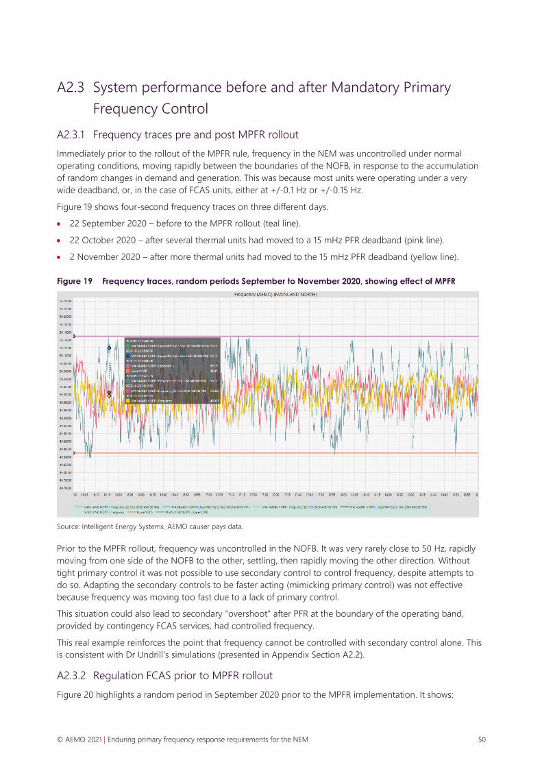
© AEMO 2021 | Enduring primary frequency response requirements for the NEM 50
A2.3 System performance before and after Mandatory Primary
Frequency Control
A2.3.1 Frequency traces pre and post MPFR rollout
Immediately prior to the rollout of the MPFR rule, frequency in the NEM was uncontrolled under normal
operating conditions, moving rapidly between the boundaries of the NOFB, in response to the accumulation
of random changes in demand and generation. This was because most units were operating under a very
wide deadband, or, in the case of FCAS units, either at +/-0.1 Hz or +/-0.15 Hz.
Figure 19 shows four-second frequency traces on three different days.
• 22 September 2020 – before to the MPFR rollout (teal line).
• 22 October 2020 – after several thermal units had moved to a 15 mHz PFR deadband (pink line).
• 2 November 2020 – after more thermal units had moved to the 15 mHz PFR deadband (yellow line).
Figure 19 Frequency traces, random periods September to November 2020, showing effect of MPFR
Source: Intelligent Energy Systems, AEMO causer pays data.
Prior to the MPFR rollout, frequency was uncontrolled in the NOFB. It was very rarely close to 50 Hz, rapidly
moving from one side of the NOFB to the other, settling, then rapidly moving the other direction. Without
tight primary control it was not possible to use secondary control to control frequency, despite attempts to
do so. Adapting the secondary controls to be faster acting (mimicking primary control) was not effective
because frequency was moving too fast due to a lack of primary control.
This situation could also lead to secondary “overshoot” after PFR at the boundary of the operating band,
provided by contingency FCAS services, had controlled frequency.
This real example reinforces the point that frequency cannot be controlled with secondary control alone. This
is consistent with Dr Undrill’s simulations (presented in Appendix Section A2.2).
A2.3.2 Regulation FCAS prior to MPFR rollout
Figure 20 highlights a random period in September 2020 prior to the MPFR implementation. It shows:

© AEMO 2021 | Enduring primary frequency response requirements for the NEM 51
• Enabled regulation FCAS – (shaded areas, light blue for raise regulation, grey for lower regulation
(expressed as negative number).
• ACE – frequency deviation converted to MW (green line).
• Integral component of the ACE (ACEint) (blue line).
• Frequency Indicator (FI) – frequency error converted (smoothed, lagged, trimmed/capped) to a signal for
units to respond to (yellow line).
• Time error – in seconds (on the right-hand side axis) (red line).
Figure 20 Regulation quantities, causer pays four-second data, prior to MPFR
Source: Intelligent Energy Systems, AEMO causer pays data.
During this period, frequency was uncontrolled in the NOFB, shown by the rapid movement of ACE from
positive to negative in cycles. This may have been accentuated by the secondary control responding and
possibly pushing ACE (and frequency) in slow oscillation, possibly because there was “overshoot” by the
secondary controller and no primary control to moderate the secondary action.
AEMO made several changes to AGC in 2019 to try to improve the performance of regulation FCAS,
decreasing the slower integral response (including resetting at 50 Hz), tuning it so the response more closely
followed frequency. AEMO found the “AGC cycle” was too slow, and once a signal was aggregated and sent
to the units, and once the units had responded, frequency would overshoot, and signals would need to be
reversed.
It was evident the secondary control, in terms of both greater quantities enabled and in retuning AGC to
utilise those reserves, could not substitute for a lack of primary control. This is consistent with the Dr Undrill’s
simulations highlighting the different roles they provide (as discussed in Appendix Section A2.2).
A2.3.3 Regulation FCAS after MPFR rollout
This section explores the relationship between primary and secondary control by looking at the period
immediately after the first tranche of generators started operating with a tight MPFR deadband.
It reinforces how secondary control is needed to respond to slowly correct errors in dispatch, rather than
chase frequency, because with increasing availability of tight primary control there is nothing to chase.

© AEMO 2021 | Enduring primary frequency response requirements for the NEM 52
Frequency changing slowly, requiring secondary control to be re-tuned from Hz error
Regulation FCAS had been retuned in 2019 for a system with little to no MPFR in the NOFB (specifically, it had
been retuned to be more sensitive to changes in frequency control and less sensitive to changes in energy,
including time error). When many units implemented tight deadbands and frequency was controlled closer to
50 Hz, this affected the performance of regulation FCAS.
Following investigation, AEMO believes the implementation of the MPFR rule interacted with existing AGC
settings in a manner that had a small but persistent effect, where AGC was unable to actively assist with slight
under-frequency. As system frequency was generally close to 50 Hz, AGC’s measure of ACE hovered inside
the internal dead-zones of the AGC system more often than previously. Without AGC action, negative time
error accumulated slowly but persistently - consistent with Dr Undrill’s simulations discussed in Appendix
Section A2.2, specifically panel (a) of Figure 18.
This effect is shown in Figure 21, where ACE is persistently negative and time error accumulates. This led to
the imposition of a time error constraint in security-constrained dispatch and the enabling of more raise
regulation FCAS (the blue shaded area), yet low utilisation of this service (shown by the FI, represented by the
yellow line). Lower regulation was hardly used (shown by the yellow line not passing into the grey shaded
area).
Figure 21 Regulation quantities, causer pays four-second data, after MPFR
Source: Intelligent Energy Systems, AEMO causer pays data.
Throughout Q4 2020, AEMO operational staff frequently implemented an offset (+0.03 Hz) to the base
frequency (50 Hz) to reverse the accumulations of negative time error. Tuning of the AGC system from
9 December 2020 appears to have re-oriented time error to be more evenly distributed around zero in the
month of December. No further manual time error offsets were required for the remainder of the quarter.
Figure 22 shows the distribution of mainland time error in the months of Q4 2020 compared with Q3 2020.
The deterioration of time error in the negative direction over October and November 2020 is apparent, as is
the re-balancing following AGC tuning in December.

© AEMO 2021 | Enduring primary frequency response requirements for the NEM 53
Figure 22 Distribution of time error after implementing MPFR
Source: AEMO, Frequency and Time Error Monitoring – Quarter 4 2020, at https://aemo.com.au/energy-systems/electricity/national-
electricity-market-nem/system-operations/ancillary-services/frequency-and-time-deviation-monitoring/archive-frequency-and-time-
error-monitoring.
AEMO made a series of changes to AGC, including:
• Changes to AGC parameters covered AGC deadbands.
• Minor adjustments to gains.
• Changes to make integral ACE more persistent.
• Enablement of basepoint adjustment.
Following these changes, the daily distribution of NEM frequency became narrower, suggesting the changes
improved the stability of frequency under normal operating conditions. In early January 2021, however, AEMO
identified that the introduction of AGC basepoint adjustment interfered with data transfer processes used by
the causer pays process, which allocates regulation FCAS costs. As a result, AEMO reversed the change to
AGC basepoint adjustment on 18 January 2021, to assess options to address the issue in the causer pays
process.
Figure 23 shows the AGC system metrics with AGC basepoint adjustment and a dominant integral effect on
the frequency indicator (yellow line).
The concept of basepoint adjustment is that, rather than using frequency to allocate work to enabled units
through the frequency indicator, the net error of units is allocated to those on regulating duty. It means the
secondary control acts independently of frequency (noting that errors in dispatch can cause changes in
frequency). Reallocating errors in dispatch would also have allocated primary response provided to regulating
units. Given the low FI values in Figure 23, basepoint adjustment was the dominant feature of secondary
control in that three-hour snapshot. During the period where basepoint adjustment was active, AEMO
observed an improvement in frequency performance.
Figure 24 shows more recent performance, without basepoint adjustment, which may be indicating that a
more stable performance of the AGC regulation FCAS can be achieved with tight primary control and without
basepoint adjustment.

© AEMO 2021 | Enduring primary frequency response requirements for the NEM 54
Figure 23 Regulation quantities, causer pays four-second data, after MPFR and changes to AGC
Source: Intelligent Energy Systems, AEMO causer pays data.
Figure 24 Regulation quantities, causer pays four-second data, after MPFR and further changes to AGC
Source: Intelligent Energy Systems, AEMO causer pays data.
A2.3.4 Conclusions
This illustrative discussion of frequency performance and regulation FCAS outcomes before and after the
MPFR rollout has highlighted:
• The importance of both primary and secondary control.
• These controls do different things and are not substitutes of the other.

© AEMO 2021 | Enduring primary frequency response requirements for the NEM 55
• The two controls need to work together.
• High availability of primary control can improve the performance of secondary control, likewise effective
secondary control can minimise primary control.
High availability of primary control is important because it is the aggregate weight of the controller, the
aggregate frequency responsiveness in MW/Hz, that prevents rapid changes in frequency and therefore
mitigates the primary control duty these units need to provide. This only occurs, however, if secondary
control is there to correct the imbalance, otherwise frequency will drift – which cannot be managed by the
primary control alone.
A2.4 SCADA loss event
As noted in Appendix Section A1.3.3, on 24 January 2021 the NEM suffered a failure of SCADA, which is
needed for economic dispatch and regulation FCAS. The NEM therefore operated with no secondary
frequency control for about an hour. The following figures present the effect of this, at a system level and at a
unit level (the unit being Loy Yang A1).
Figure 25 shows the frequency gradually drifting upwards to the edge of the NOFB, and remaining at that
level until SCADA was restored. The sum of the generation deviation of the units with MPFR implemented is
shown in the dark purple line, and compared to a modelled response at 5% droop in light purple.
The primary response was proportional to the change in frequency and increased in proportion to the
change in frequency, with the aggregate response being close to a decrease in active power of 1 GW. The
response did not restore the energy balance and frequency remained high.
Figure 25 System response with MPFR and without secondary control – SCADA outage, 24 January 2021
At a unit level, the frequency increased and the unit reduced active power in response. This is consistent
with Dr Undrill’s simulation for a tight MPFR system without secondary control discussed in Appendix
Section A.2.2.

© AEMO 2021 | Enduring primary frequency response requirements for the NEM 56
Figure 26 Unit response with MPFR and without secondary control – SCADA outage, 24 January 2021
This highlights that the primary control seeks to resist changes in frequency but does not restore the energy
balance to 50 Hz. The primary controllers provide energy to slow change in frequency. In the absence of a
large contingency, and with tight MPFR, this change in active power or “PFC Duty” is minimised if the
secondary frequency controllers (regulation FCAS) and economic dispatch manage the energy balance to
ensure the system can return to 50 Hz. The presence of primary frequency control should also prevent
“overshoot” from secondary frequency control by acting against it.
A2.5 Forward-looking analysis
A2.5.1 Higher levels of utility-scale wind and solar
As part of the Renewable Integration Study in 2020, AEMO engaged DIgSILENT to better understand the
impact of the projected growth of variable nature of wind and solar generation on maintaining frequency
under normal operating conditions in the sub five-minute timeframe56. The study investigated the relationship
between primary and secondary frequency control for future NEM conditions with high levels of VRE causing
very fast ramps in generation output.
DIgSILENT developed a detailed model of the NEM AGC control and the energy dispatch system to simulate
the frequency response at system level. This model was tuned through calibration with historical events. The
generation mix was then adjusted to reflect 2025 generation with a higher representation of VRE and a lower
amount of synchronous generation (based on projections from the Draft 2018 ISP).
The analysis investigated projected ramps from changing VRE generation output, and the remedial effect of
various levels of primary frequency control and regulation FCAS on frequency response.
The analysis found that, for the most part, the changes in VRE output are either not coincident (and average
out to a low net variability across a geographically diverse fleet) or coincident, but forecastable, such as
ramping of solar energy after dawn and before dusk. However, there will always be a small proportion of
coincident ramps in the same direction that can lead to mismatches between generation and demand,
especially within the five-minute dispatch intervals.
As the amount of VRE on the power system increases, the average ramps (and hence mismatches in
generation and demand) will remain similar, and close to zero, but the size of the largest ramps will increase.
56 See https://aemo.com.au/-/media/files/major-publications/ris/2020/3563-etr-01-version-20.pdf?la=en.

© AEMO 2021 | Enduring primary frequency response requirements for the NEM 57
This suggests that there may need to be changes to PFC and/or AGC regulation levels to accommodate these
occasional, but unforecast, large magnitude ramps.
A2.5.2 VRE impact on regulation FCAS requirements
AEMO’s 2018 ISP57 included an analysis of regulation FCAS with increasing levels of VRE generation, shown in
Figure 27. This suggests that increasing supply variability as a result of the projected major growth in
utility-scale solar generation, particularly when clustered in renewable energy zones (REZs), will drive
significant increases in the required amount of frequency control services.
Figure 27 Projected regulation FCAS requirements for increasing penetrations of wind and solar VRE
generation
Source: Figure 32, 2018 ISP.
57 AEMO. 2018 Integrated System Plan, Available at: https://aemo.com.au/-/media/files/electricity/nem/planning_and_forecasting/isp/2018/integrated-
system-plan-2018_final.pdf, p.62

© AEMO 2021 | Enduring primary frequency response requirements for the NEM 58
A3. International comparisons
Table 6 Comparison of international requirements for primary frequency response
Jurisdiction Deadband
(± mHz)
Droop (%) Response time
(seconds)
Minimum duration
(seconds)
Enablement
US (FERC Order 842) [1] ≤ 36 ≤ 5 No undue delay Sustained Mandatory
Texas, US [2] ≤ 17 4-5 14-16 30 Mandatory
PJM, US [3] ≤ 36 ≤ 5 No undue delay Sustained Mandatory
Great Britain [4] ≤ 15 3-5 10 30 Market/Mandatory
Ireland [5] ≤ 15 3-5 2-10 30 Mandatory
New Zealand [6] ≤ 20 0-7 6 60 Market
[1] Federal Energy Regulatory Commission, Order No. 842 Essential Reliability Services and the Evolving Bulk-Power System—Primary
Frequency Response, February 2018, at https://cms.ferc.gov/sites/default/files/whats-new/comm-meet/2018/021518/E-2.pdf.
[2] ERCOT, Nodal Operating Guide, March 2021, at http://www.ercot.com/content/wcm/libraries/226349/March_1_2021_
Nodal_Operating_Guide.pdf.
[3] PJM Manual 14D: Generator Operational Requirements, April 2021, at https://pjm.com/-/media/committees-groups/committees/
mrc/2021/20210421/20210421-cab-4-m14d-revisions-clean.ashx .
[4] National Grid, The Grid Code, May 2021, at https://www.nationalgrideso.com/document/162271/download.
[5] EirGrid, Grid Code, December 2020, Available at: https://www.eirgridgroup.com/site-files/library/EirGrid/GridCodeVersion9.pdf.
[6] Electricity Authority, Normal Frequency Management – Decision Paper, September 2018, at https://www.ea.govt.nz/assets/dms-
assets/24/24082Normal-Frequency-Management-Decision-Paper.pdf and https://www.ea.govt.nz/assets/TheCodeParts/Full-
Merged-Code-30-June-2021.pdf.

© AEMO 2021 | Enduring primary frequency response requirements for the NEM 59
A4. Options to amend the Frequency Operating Standard
This appendix summarises a series of options considered by AEMO to update the FOS to explicitly specify
acceptable frequency performance under normal conditions. It also presents analysis of frequency
performance in the NEM before and after the MPFR rollout against different metrics associated with these
options.
A4.1 Option 1: Qualitative criteria
Option 1 considers the introduction of qualitative objectives or criteria within the FOS pertaining to
frequency performance under normal conditions.
This could include a statement in the FOS such as “AEMO must keep the power system stable and securely
operating at a frequency close to 50 Hz”.
Qualitative criteria were ruled out as a feasible option, because implementation and evaluation of frequency
performance would be subjective without a defined trackable metric and any established benchmark or
criteria for acceptable frequency performance.
A4.2 Option 2: Update existing FOS criteria
Option 2 considers the introduction of an additional normal operating primary frequency band (for the
purposes of this report, the NOPFB) within the FOS, to be specified alongside the existing NOFB and
NOFEB.
A4.2.1 Existing FOS criteria
The FOS Section A.158 specifies the frequency bands for the purpose of the standard.
• The normal operating frequency band (NOFB) is 49.85 Hz – 50.15 Hz, for the mainland and Tasmania,
under normal conditions.
• The normal operating frequency excursion band (NOFEB) is 49.75 Hz – 50.25 Hz, for the mainland and
Tasmania, under normal conditions.
Further, Section A.2 specifies that:
Except as a result of a contingency event or a load event, system frequency:
a) shall be maintained within the applicable normal operating frequency excursion band, and
b) shall not be outside of the applicable normal operating frequency band for more than five minutes on
any occasion and not for more than 1% of the time over any 30-day period59.
58 Reliability Panel AEMC, Frequency Operating Standard, January 2020, p.2, at https://www.aemc.gov.au/sites/default/files/2020-01/Frequency%20operating
%20standard%20-%20effective%201%20January%202020%20-%20TYPO%20corrected%2019DEC2019.PDF.
59 Ibid, p.3.

© AEMO 2021 | Enduring primary frequency response requirements for the NEM 60
AEMO monitors and reports on these requirements on a weekly and quarterly basis in its frequency and time
deviation monitoring reports60.
Option 2 would introduce and define the NOPFB within the FOS, and associated frequency performance
metrics using the NOPFB that can be tracked over time.
A4.2.2 Calculation of NOPFB values
AEMO used four-second frequency data through a SCADA system, extracting data separately for the
mainland NEM and Tasmania.
In proposing a NOPFB and associated frequency performance criteria, AEMO has attempted to mirror current
application of the NOFB within the FOS, specifying acceptable performance over any 30-day period. This
involves a balance between the width of the NOPFB and how often frequency is permitted to be outside the
NOPFB.
AEMO’s recommendation for how Option 2 should be specified is based on analysis of historical NEM
frequency performance between 2009 and 2013 as a benchmark for ‘good’ control of frequency under
conditions. On this basis, if Option 2 were to be adopted, it is recommended that:
• The NOPFB is set at 49.95 Hz – 50.05 Hz, for the mainland and Tasmania, under normal conditions.
• Except as a result of a contingency event or load event, system frequency shall not be outside of the
applicable NOPFB for more than 10% of the time for the mainland and 15% of the time for Tasmania over
any 30-day period.
AEMO does not envisage the NOPFB would be relevant for managing the secure technical operating
envelope of the power system in real time.
Establishing the NOPFB boundary
To assess a possible new NOPFB band within the FOS, the calculations that are currently used to assess
frequency performance in the NOFB61 were applied to the NOPFB. As such, this analysis shows the
percentage of time that system frequency is outside a NOPFB range of ±0.05 Hz over any 30-day period.
This analysis included contingency events and load events, which would typically be excluded when
calculating whether the FOS was met (see Appendix Section A4.2.1 above). As such, this analysis gives a
conservative estimate of whether the FOS is met for a given assessment period. If contingency events and
load events were excluded, the percentage of time that system frequency would remain within the NOPFB
would be the same or greater than the values provided in this section.
The calculation method used was as follows:
1. For each day, AEMO extracted four-second SCADA data and calculated the percentage of sour-second
intervals that were outside the NOPFB for that day.
2. On a rolling 30-day basis, the average time outside the NOPFB was calculated for the preceding 30 days.
3. The minimum daily time percentage in a 30-day window was then recorded as the lowest rolling 30-day
average (calculated in step 2) over the last 30 days.
The results from this calculation, for the mainland and Tasmania, between 1 January 2007 and 24 March 2021,
are presented in Figure 28.
60 At https://aemo.com.au/en/energy-systems/electricity/national-electricity-market-nem/system-operations/ancillary-services/frequency-and-time-
deviation-monitoring.
61 See AEMO’s frequency and time error monitoring reports. For example, Quarter 4 2020 report, Figure 1, at https://aemo.com.au/-/media/files/electricity/
nem/security_and_reliability/ancillary_services/frequency-and-time-error-reports/quarterly-reports/2020/frequency-and-time-error-monitoring-4th-
quarter-2020.pdf?la=en.

© AEMO 2021 | Enduring primary frequency response requirements for the NEM 61
Figure 28 Frequency in NOPFB (±0.05Hz) since 2007, minimum daily time percentage in prior 30-day
window
Time inside NOPFB
Data between 1 January 2009 and 31 December 2013 was used to provide an assessment of the percentage
time that system frequency should remain in the NOPFB.
This date range was chosen because it occurred prior to observed deterioration in NEM mainland frequency
performance, as discussed in Appendix Section A1.1 and recent AEMO frequency monitoring reports62.
Across this date range, the average minimum daily time percentage in a 30-day window was 90% for the
mainland NEM and 85% for Tasmania. These benchmark standards are illustrated in Figure 28 and have been
met from December 2020 in the mainland NEM and January 2021 in Tasmania.
A4.3 Option 3: Standard deviation benchmark
Option 3 considers the introduction of a standard deviation benchmark to describe acceptable
frequency performance under normal conditions.
A4.3.1 Calculation of benchmark values
Data and cleaning
AEMO used four-second frequency data through a SCADA system and a Plant Information (PI) system to
archive the data. Data was extracted separately for the mainland NEM and Tasmania.
The calculation used data between 1 January 2009 and 24 March 2021:
62 AEMO. Frequency and time deviation monitoring, at https://aemo.com.au/en/energy-systems/electricity/national-electricity-market-nem/system-
operations/ancillary-services/frequency-and-time-deviation-monitoring.
40%
50%
60%
70%
80%
90%
100%
1/01/2007 1/01/2009 1/01/2011 1/01/2013 1/01/2015 1/01/2017 1/01/2019 1/01/2021
Mainland - including contingencies and load events
Tasmania - including contingencies and load events
Mainland - 90% standard
Tasmania - 85% standard

© AEMO 2021 | Enduring primary frequency response requirements for the NEM 62
• Data between 1 January 2009 and 31 December 2013 was used as the ‘Benchmark Dataset’ to determine
benchmark value options. This period of data was chosen because it occurred prior to observed
deterioration in NEM mainland frequency performance63.
• Data between 1 January 2019 and 24 March 2021 was used as the ‘Test Dataset’ to compare performance
to the benchmark value options.
The four-second SCADA data was cleaned based on the following rules, to remove:
• Intervals with frequency outside 49.85-50.15 Hz.
• Frozen data, which had remained the same for five consecutive intervals.
• Whole days where more than half of the intervals had been removed due to the above cleaning rules.
These cleaning rules were applied to measure the quality of steady state, single frequency keeping behaviour,
and minimise the effect of frequencies caused by SCADA errors and system events.
Benchmark calculations
Four different time periods were used to determine benchmark value options: daily, weekly, monthly and
quarterly.
Step 1: Standard deviation (σ) calculated for each time period
A standard deviation is a measure of variance, or how spread out, the data is from the average.
To calculate the standard deviation frequency for each time grouping (day, week, month, quarter), AEMO:
1. Collected and cleaned Benchmark Data.
2. Grouped data by time period (day, week, month, or quarter).
3. Calculated the standard deviation for each individual interval within a time period group.
Figure 29 shows the calculated historical standard deviation for each time period group since 2009.
Figure 29 Historic frequency standard deviation
63 See AEMO’s frequency and time error monitoring quarter 2 2020 report for details on this deterioration, at https://aemo.com.au/-/media/files/electricity/
nem/security_and_reliability/ancillary_services/frequency-and-time-error-reports/quarterly-reports/2020/frequency-and-time-error-monitoring-2nd-
quarter-2020.pdf?la=en.
0
0.01
0.02
0.03
0.04
0.05
0.06
0.07
0.08
0.09
2009
2010
2011
2012
2013
2014
2015
2016
2017
2018
2019
2020
2021
Sta
nd
ard
Devi
atio
n
Year
Day Week Month Quarter
© AEMO 2021 | Enduring primary frequency response requirements for the NEM 63
Step 2: Percentiles calculated for each time period group
A percentile is a value below which a given percentage of values in its distribution fall.
AEMO calculated the percentile standard deviation (90th, 95th, 99th) by ranking the standard deviations for
each individual time period (step 1) from smallest to largest. The ranked values were used to determine the
particular value that would be greater than 90%, 95% and 99% of the data set; for example, the 90th
percentile standard deviation is the value below which 90% of standard deviation observations (from step 1)
occur for a particular time period.
A4.3.2 Benchmark options
Table 7 and Table 8 below show the standard deviation benchmark options calculated using the Benchmark
Dataset (between 1 January 2009 and 31 December 2013). Several different time horizons were considered as
possible standard deviation benchmark options, including daily, weekly, monthly and quarterly. AEMO’s
current frequency monitoring is monthly, reporting on a quarterly basis; this may be most appropriate here
also.
Table 7 Mainland NEM benchmark options
Time Period Daily Weekly Monthly Quarterly Average
90th percentile
standard deviation 0.03367 0.03244 0.03255 0.03097 0.03241
95th percentile
standard deviation 0.03512 0.03352 0.03286 0.03120 0.03318
99th percentile
standard deviation 0.03872 0.03465 0.03340 0.03212 0.03472
Table 8 Tasmania benchmark options
Time Period Daily Weekly Monthly Quarterly Average
90th percentile
standard deviation 0.03939 0.03818 0.03722 0.03689 0.03792
95th percentile
standard deviation 0.04113 0.03932 0.03874 0.03702 0.03905
99th percentile
standard deviation 0.04435 0.04123 0.04008 0.03883 0.04112
A4.3.3 Applying standard deviation benchmarks
Table 9 to Table 14 show the percentage of time periods within a grouping where the 90th, 95th and 99th
percentile standard deviation benchmark values are exceeded for the mainland NEM and Tasmania. For
example, in Table 9 there are 31 days in the October 2020 period and the standard deviation exceeded the
0.03241 benchmark on 27 days, so the daily exceedance value is 87%.
When applied to the test dataset between 1 January 2019 and 24 March 2021 there was 100% exceedance
across all time periods between 1 January 2019 and 30 June 2019. For brevity, these periods have been
omitted from the table below.

© AEMO 2021 | Enduring primary frequency response requirements for the NEM 64
Table 9 Benchmark exceedance | Mainland NEM benchmark | 90th percentile σ = 0.03241
Time period Daily Weekly Monthly Quarterly
July 2020 100% 100% 100% 100%
August 2020 100% 100% 100%
September 2020 100% 100% 100%
October 2020 87% 100% 100% 100%
November 2020 3% 0% 0%
December 2020 0% 0% 0%
January 2021 0% 0% 0% 0%
February 2021 0% 0% 0%
March 2021* 0% 0% 0%
* Includes data up to the 24 March 2021 inclusive.
Table 10 Benchmark exceedance | Mainland NEM benchmark | 95th percentile σ = 0.03318
Time period Daily Weekly Monthly Quarterly
July 2020 100% 100% 100% 100%
August 2020 100% 100% 100% 0%
September 2020 100% 100% 100% 0%
October 2020 87% 75% 100% 100%
November 2020 3% 0% 0% 0%
December 2020 0% 0% 0% 0%
January 2021 0% 0% 0% 0%
February 2021 0% 0% 0% 0%
March 2021* 0% 0% 0% 0%
* Includes data up to the 24 March 2021 inclusive.

© AEMO 2021 | Enduring primary frequency response requirements for the NEM 65
Table 11 Benchmark exceedance | Mainland NEM benchmark | 99th percentile σ = 0.03472
Time period Daily Weekly Monthly Quarterly
July 2020 100% 100% 100% 100%
August 2020 100% 100% 100% 0%
September 2020 100% 100% 100% 0%
October 2020 77% 75% 100% 0%
November 2020 3% 0% 0% 0%
December 2020 0% 0% 0% 0%
January 2021 0% 0% 0% 0%
February 2021 0% 0% 0% 0%
March 2021* 0% 0% 0% 0%
* Includes data up to the 24 March 2021 inclusive.
Table 12 Benchmark exceedance | Tasmania benchmark | 90th percentile σ = 0.03792
Time period Daily Weekly Monthly Quarterly
July 2020 100% 100% 100% 100%
August 2020 100% 100% 0% 100%
September 2020 100% 100% 0% 100%
October 2020 84% 100% 100% 100%
November 2020 47% 100% 0% 60%
December 2020 23% 0% 0% 0%
January 2021 16% 0% 0% 0%
February 2021 14% 0% 0% 0%
March 2021* 4% 0% 0% 0%
* Includes data up to the 24 March 2021 inclusive.

© AEMO 2021 | Enduring primary frequency response requirements for the NEM 66
Table 13 Benchmark exceedance | Tasmania benchmark | 95th percentile σ = 0.03905
Time period Daily Weekly Monthly Quarterly
July 2020 100% 100% 100% 100%
August 2020 100% 100% 0% 100%
September 2020 100% 100% 0% 100%
October 2020 84% 100% 100% 100%
November 2020 40% 0% 0% 40%
December 2020 10% 0% 0% 0%
January 2021 7% 0% 0% 0%
February 2021 6% 0% 0% 0%
March 2021* 4% 0% 0% 0%
* Includes data up to the 24 March 2021 inclusive.
Table 14 Benchmark exceedance | Tasmania benchmark | 99th percentile σ = 0.04112
Time period Daily Weekly Monthly Quarterly
July 2020 100% 100% 100% 100%
August 2020 100% 100% 0% 100%
September 2020 100% 100% 0% 100%
October 2020 84% 100% 100% 100%
November 2020 40% 0% 0% 40%
December 2020 10% 0% 0% 0%
January 2021 7% 0% 0% 0%
February 2021 6% 0% 0% 0%
March 2021* 4% 0% 0% 0%
* Includes data up to the 24 March 2021 inclusive.
A4.4 Option 4: Mileage measure
Option 4 considers the introduction of a frequency mileage measure and associated benchmark for
frequency performance under normal conditions.
Frequency mileage is a measure of the stability of frequency. It is calculated by summing the absolute
changes in frequency from one interval to the next over a given period. AEMO tracks this metric on a monthly
basis as part of its quarterly frequency performance reporting.
Further consideration is needed to better understand the relevance of mileage in the context of acceptable
frequency performance within the normal operating band, whether benchmarks are necessary, and how these
benchmarks should be specified.

© AEMO 2021 | Enduring primary frequency response requirements for the NEM 67
Figure 30 and Figure 31, from AEMO’s Quarter 1 2021 Frequency and Time Error Monitoring report64, illustrate
frequency mileage in the NEM since 2007 and for the last 12 months respectively. They show that frequency
mileage remained reasonably consistent since the MPFR rollout, with a small decline in the last two quarters
ending in March 2021, but that the change is not nearly as dramatic as the change in frequency performance
over this period. This suggests that frequency mileage may be a better indicator of underlying load behaviour
than frequency performance itself.
Given the uncertain benefits, inclusion of a mileage measure within the FOS is not recommended.
Figure 30 Monthly frequency mileage in the NEM since 2007
Figure 31 Monthly frequency mileage in the NEM for the 12 months to March 2021
64 AEMO. Frequency and Time Error Monitoring – 1st Quarter 2021. May 2021, Section 7.3, at https://aemo.com.au/-/media/files/electricity/nem/security_
and_reliability/ancillary_services/frequency-and-time-error-reports/quarterly-reports/2021/frequency-and-time-error-monitoring-1st-quarter-2021.pdf,

© AEMO 2021 | Enduring primary frequency response requirements for the NEM 68
A4.5 Summary and recommendations
A4.5.1 Comparison of options
Table 15 provides a summary of the implied frequency distributions under Options 2 and 3, as well as current
FOS arrangements. Option 2 and Option 3 are very close together, statistically.
Table 15 Summary table of current FOS criteria for NOFB and additional options
Mean Standard deviation Description
Current NOFB 50 Hz (50.15-50.00)/2.58 = 0.05814 HzA Frequency within the NOFB (49.85-50.15 Hz) 99% of the time.
Option 2 50 Hz (50.05-50.00)/1.65 = 0.03030 HzA Frequency within the NOPFB (49.95-50.05 Hz) 90% of the time.
Option 3 50 Hz 90th percentile standard deviation
benchmark (average across all
time frames) = 0.03241 Hz
Assuming a normal distribution, this represents frequency
within the NOPFB (49.95-50.05 Hz) 88% of the time.
A. Assuming a normal distribution
Figure 32 overlays these implied frequency distributions against several historic months for the mainland
NEM65, including:
• September 2010 – during the period recognised as being characteristic of good frequency performance
within the NOFB.
• September 2019 – during a period recognised as being characteristic of a degraded frequency
performance within the NOFB.
• Select months between September 2020 and March 2021 – showing frequency performance under
progressive rollout of mandatory PFR.
Figure 32 Comparison of options against historic days and current standard, Mainland NEM
65 These historic traces are compiled from 4 second data and include contingency events and load events.
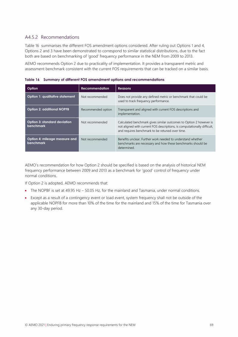
© AEMO 2021 | Enduring primary frequency response requirements for the NEM 69
A4.5.2 Recommendations
Table 16 summarises the different FOS amendment options considered. After ruling out Options 1 and 4,
Options 2 and 3 have been demonstrated to correspond to similar statistical distributions, due to the fact
both are based on benchmarking of ‘good’ frequency performance in the NEM from 2009 to 2013.
AEMO recommends Option 2 due to practicality of implementation. It provides a transparent metric and
assessment benchmark consistent with the current FOS requirements that can be tracked on a similar basis.
Table 16 Summary of different FOS amendment options and recommendations
Option Recommendation Reasons
Option 1: qualitative statement Not recommended Does not provide any defined metric or benchmark that could be
used to track frequency performance.
Option 2: additional NOPFB Recommended option Transparent and aligned with current FOS descriptions and
implementation.
Option 3: standard deviation
benchmark Not recommended Calculated benchmark gives similar outcomes to Option 2 however is
not aligned with current FOS descriptions, is computationally difficult,
and requires benchmark to be retuned over time.
Option 4: mileage measure and
benchmark Not recommended Benefits unclear. Further work needed to understand whether
benchmarks are necessary and how these benchmarks should be
determined.
AEMO’s recommendation for how Option 2 should be specified is based on the analysis of historical NEM
frequency performance between 2009 and 2013 as a benchmark for ‘good’ control of frequency under
normal conditions.
If Option 2 is adopted, AEMO recommends that:
• The NOPBF is set at 49.95 Hz – 50.05 Hz, for the mainland and Tasmania, under normal conditions.
• Except as a result of a contingency event or load event, system frequency shall not be outside of the
applicable NOPFB for more than 10% of the time for the mainland and 15% of the time for Tasmania over
any 30-day period.

© AEMO 2021 | Enduring primary frequency response requirements for the NEM 70
A5. Effect of fewer PFR providers
Primary control is a balance between allowable frequency error, unit droop, and rated capacity of the units
online. Compared to widespread, distributed provision of PFR, having fewer PFR providers would have the
effect of requiring more response from some units, which could only be achieved by requiring a more
aggressive droop response. This is the only way of concentrating the service on a few units (rather than the
whole fleet) without degrading control (allowing larger or more rapid changes in frequency).
Figure 33 provides a simple example of this effect.
Figure 33 Impact of droop response aggregate frequency response
(a) Two 250MW units, different droop
(b) Two 250 MW units same 5% droop

© AEMO 2021 | Enduring primary frequency response requirements for the NEM 71
Figure 34 below shows two further examples, where 1,500 MW of capacity can provide 450 MW of primary
response when operating at 1% droop and +/-0.15 Hz deadband. Alternatively, 7,500 MW of capacity, also
operating with a +/-0.15 Hz deadband, can provide 450 MW of primary response with only a 4% droop.
When shared across more units, the proportional response from each individual unit is significantly reduced.
Figure 34 Comparison of droop response for smaller number of units
(a) At 1 % droop, 6 x 250 MW units
(b) At 4 %, 30 x 250 MW units
Table 17 and Table 18 expand on this concept further. Table 17 shows the gross rated capacity of online plant
that is required to be able to provide primary control for a 250 MW deviation, depending on allowable
frequency error and unit droop settings. The droop setting is assumed to be consistent across all plant (it
need not be in reality) and the allowable frequency error is how tight the system should remain to 50 Hz for
the 250 MW error. Table 18 shows the maximum percentage of rated capacity each unit would have capacity
to provide.

© AEMO 2021 | Enduring primary frequency response requirements for the NEM 72
Table 17 Gross rated capacity of online PFR providers (MW) to manage 250 MW deviation
Allowable frequency error +/-Hz
0.025 0.050 0.075 0.100 0.125 0.150
Dro
op
se
ttin
g o
f su
pp
lie
rs
0.5% 2,500 1,250 833 625 500 417
1.0% 5,000 2,500 1,667 1,250 1,000 833
1.5% 7,500 3,750 2,500 1,875 1,500 1,250
2.0% 10,000 5,000 3,333 2,500 2,000 1,667
2.5% 12,500 6,250 4,167 3,125 2,500 2,083
3.0% 15,000 7,500 5,000 3,750 3,000 2,500
3.5% 17,500 8,750 5,833 4,375 3,500 2,917
4.0% 20,000 10,000 6,667 5,000 4,000 3,333
4.5% 22,500 11,250 7,500 5,625 4,500 3,750
5.0% 25,000 12,500 8,333 6,250 5,000 4,167
Table 18 Maximum provision from each unit to manage 250 MW deviation (as % of rated capacity)
Allowable frequency error +/-Hz
0.025 0.050 0.075 0.100 0.125 0.150
Dro
op
se
ttin
g o
f su
pp
lie
rs
0.5% 10.0% 20.0% 30.0% 40.0% 50.0% 60.0%
1.0% 5.0% 10.0% 15.0% 20.0% 25.0% 30.0%
1.5% 3.3% 6.7% 10.0% 13.3% 16.7% 20.0%
2.0% 2.5% 5.0% 7.5% 10.0% 12.5% 15.0%
2.5% 2.0% 4.0% 6.0% 8.0% 10.0% 12.0%
3.0% 1.7% 3.3% 5.0% 6.7% 8.3% 10.0%
3.5% 1.4% 2.9% 4.3% 5.7% 7.1% 8.6%
4.0% 1.3% 2.5% 3.8% 5.0% 6.3% 7.5%
4.5% 1.1% 2.2% 3.3% 4.4% 5.6% 6.7%
5.0% 1.0% 2.0% 3.0% 4.0% 5.0% 6.0%
Table 17 shows that to keep frequency within +/-0.025 Hz, 25 GW of plant need to be at 5% droop. Table 18
shows that for the same requirement, no more than 1% of the rated capacity can be enabled, or will actually
be utilised, therefore across the 25 GW only 1 MW per 100 MW of capacity can be enabled.
Alternatively, Table 17 shows that to keep frequency within +/-0.15 Hz, 417 MW of plant would need to be at
0.5% droop. Table 18 shows that for the same requirement, no more than 60% of the rated capacity can be
enabled, therefore across the 417 MW, 60 MW per 100 MW of capacity can be enabled to give the 250 MW.

© AEMO 2021 | Enduring primary frequency response requirements for the NEM 73
AEMO concludes from these analyses that for frequency to be tight (well controlled) without very aggressive
droop settings, PFR cannot be concentrated onto a few units.
Again, it is noted synchronous generation has been operated in the NEM with droop settings in the range of
3-5% for many decades, and similar settings are used almost universally worldwide. While there is some early
experience in the NEM with operating a small number of IBR at more aggressive (lower %) droop settings of
around 2%, there is little experience in the NEM with operating synchronous generation, or any large part of
the overall supply, at droop settings outside the 3-5% range.