Emulator of a Boost Converter for Educational Purposes - MDPI
14
electronics Article Emulator of a Boost Converter for Educational Purposes Paula Lamo 1, * , Ángel de Castro 2 , Christian Brañas 3 and Francisco J. Azcondo 3 1 Escuela Superior de Ingeniería y Tecnología, Universidad Internacional de La Rioja, 26006 Logroño, Spain 2 Departamento de Tecnología Electrónica y de las Comunicaciones, Universidad Autónoma de Madrid, 28049 Madrid, Spain; [email protected] 3 Departamento de Tecnología Electrónica, Ingeniería de Sistemas y Automática, Universidad de Cantabria, 39005 Santander, Spain; [email protected] (C.B.); [email protected] (F.J.A.) * Correspondence: [email protected]; Tel.: +34-9-4121-0211 Received: 13 October 2020; Accepted: 6 November 2020; Published: 9 November 2020 Abstract: Project-based learning (PBL) is proposed for the development of a Hardware-in-the-Loop (HIL) platform and the design of its digital controller for an undergraduate course on Digital Electronic Systems. The objective for students is the design of a digitally controlled HIL Boost converter, a digital pulse-width modulator (DPWM) and a current mode controller, implemented in field-programmable gate array (FPGA) devices. To this end, the different parts of the project are developed and evaluated, maximizing the use of FPGA resources in the design of the HIL and DPWM blocks, and applying design techniques that minimize the use of the digital resources used in the design of the controller. Students are equipped with a new individualized educational experience, allowing them to test their technical competence and knowledge in an environment close to the reality of the industry. Keywords: Hardware-in-the-Loop, HIL; power converter; Boost; digital control; current control; FPGA; education; undergraduate; project-based learning, PBL 1. Introduction Engineering curricula must incorporate contents that have jumped from scientific knowledge to emerging technologies in industry in order for the graduates to adapted to present competitive design methods [1]. To train this ability, it is necessary to equip the students with skills in tools which allow them to transfer their theoretical knowledge to the reality of the industry. In this sense, project-based learning (PBL) has been shown to be a very interesting method in the field of electronic engineering [2–6]. PBL is an educational technique through which students face close to real-world problems and challenges under the supervision of the instructor [7]. This methodology prepares students more effectively for professional work, achieving deeper learning [8]. On the other hand, the increase in the complexity of electronic systems, and the need to combine multidisciplinary concepts in a short time and a cost-effective way, have encouraged the search for new techniques for their development and testing, such as mixed signal simulators [9], simulators with analog and mixed signal extensions [10], or using two simulators at the same time—one that simulates the plant and the other the controller of that plant [11]. However, these techniques are slow and complex to develop [12]. That is why a new emulation technique has emerged as a viable and solvent alternative. This strategy is Hardware-in-the-loop (HIL) [13], which is a real-time simulation technique based on the implementation of a model in digital hardware to emulate the plant. Its use is adopted in industry and research laboratories as a low-cost and effective tool for verifying power converter controllers [14,15]. Beyond that, different electrical and non-electrical systems are emulated on which a control action is validated through the HIL concept [16]. Therefore, it can be configured to emulate Electronics 2020, 9, 1883; doi:10.3390/electronics9111883 www.mdpi.com/journal/electronics
-
Upload
khangminh22 -
Category
Documents
-
view
0 -
download
0
Transcript of Emulator of a Boost Converter for Educational Purposes - MDPI

electronics
Article
Emulator of a Boost Converter forEducational Purposes
Paula Lamo 1,* , Ángel de Castro 2 , Christian Brañas 3 and Francisco J. Azcondo 3
1 Escuela Superior de Ingeniería y Tecnología, Universidad Internacional de La Rioja, 26006 Logroño, Spain2 Departamento de Tecnología Electrónica y de las Comunicaciones, Universidad Autónoma de Madrid,
28049 Madrid, Spain; [email protected] Departamento de Tecnología Electrónica, Ingeniería de Sistemas y Automática, Universidad de Cantabria,
39005 Santander, Spain; [email protected] (C.B.); [email protected] (F.J.A.)* Correspondence: [email protected]; Tel.: +34-9-4121-0211
Received: 13 October 2020; Accepted: 6 November 2020; Published: 9 November 2020
Abstract: Project-based learning (PBL) is proposed for the development of a Hardware-in-the-Loop(HIL) platform and the design of its digital controller for an undergraduate course on Digital ElectronicSystems. The objective for students is the design of a digitally controlled HIL Boost converter, a digitalpulse-width modulator (DPWM) and a current mode controller, implemented in field-programmablegate array (FPGA) devices. To this end, the different parts of the project are developed and evaluated,maximizing the use of FPGA resources in the design of the HIL and DPWM blocks, and applyingdesign techniques that minimize the use of the digital resources used in the design of the controller.Students are equipped with a new individualized educational experience, allowing them to test theirtechnical competence and knowledge in an environment close to the reality of the industry.
Keywords: Hardware-in-the-Loop, HIL; power converter; Boost; digital control; current control;FPGA; education; undergraduate; project-based learning, PBL
1. Introduction
Engineering curricula must incorporate contents that have jumped from scientific knowledgeto emerging technologies in industry in order for the graduates to adapted to present competitivedesign methods [1]. To train this ability, it is necessary to equip the students with skills in toolswhich allow them to transfer their theoretical knowledge to the reality of the industry. In this sense,project-based learning (PBL) has been shown to be a very interesting method in the field of electronicengineering [2–6]. PBL is an educational technique through which students face close to real-worldproblems and challenges under the supervision of the instructor [7]. This methodology preparesstudents more effectively for professional work, achieving deeper learning [8].
On the other hand, the increase in the complexity of electronic systems, and the need to combinemultidisciplinary concepts in a short time and a cost-effective way, have encouraged the search for newtechniques for their development and testing, such as mixed signal simulators [9], simulators withanalog and mixed signal extensions [10], or using two simulators at the same time—one that simulatesthe plant and the other the controller of that plant [11]. However, these techniques are slow andcomplex to develop [12]. That is why a new emulation technique has emerged as a viable and solventalternative. This strategy is Hardware-in-the-loop (HIL) [13], which is a real-time simulation techniquebased on the implementation of a model in digital hardware to emulate the plant. Its use is adoptedin industry and research laboratories as a low-cost and effective tool for verifying power convertercontrollers [14,15]. Beyond that, different electrical and non-electrical systems are emulated on which acontrol action is validated through the HIL concept [16]. Therefore, it can be configured to emulate
Electronics 2020, 9, 1883; doi:10.3390/electronics9111883 www.mdpi.com/journal/electronics
Electronics 2020, 9, 1883 2 of 14
electronic systems designed for medical applications [17], mechatronics [18], smart grids [19,20],or, more specifically, power converters [11,21,22].
The implementation of these systems is carried out with different technologies, i.e., field-programmablegate arrays (FPGA), digital signal processors (DSP), complex programmable logic devices (CPLD) ormicroprocessors [23]. FPGA technology is preferred because it enables the selection of time-steps overa wide range [24–26] and the optimization of the processing speed and/or the occupied area [27,28].Those characteristics are combined in a proper trade-off with the selection of the resolution of the signalsinvolved in the emulator [12,29,30] to achieve precision [12] in consistency with the criteria for avoidinglimit cycle conditions, and the specifications of steady-state error and stability margin tolerance.
From a professional point of view, this technique enables the following: (i) simulations to becarried out prior to and in parallel with the development of the plant, so that the simulated parts canbe replaced by those already physically implemented as they become available; (ii) the test of the plant,based on HIL, in extreme situations, avoiding damaging the real plant; and, also, (iii) the reductionof the development cost, avoiding partial prototypes of the elements of the system and the cost ofverification, as well as the breakdowns of a real system [31–34]. Meanwhile, from the academicpoint of view, the use of this tool allows the student to develop projects where they can put theirtechnical knowledge into practice [35]. They can safely test their models and developments in countlesssituations. In this sense, many educational experiences around HIL projects can be found in theliterature applied in different areas. In power systems, visualized experiences based on the use ofintegrated power distribution system laboratory setups are proposed in [36,37]. In [18], students haveremote access to an HIL system that allows them to simulate the already configured behavior of robotmanipulators in the transport area. In [38], medicine students have access to a complex closed-loopplatform that emulates the interaction between the patient and the therapeutic devices. In [39,40],authors propose the use of a platform that allows the simulating of industrial equipment which is notavailable at universities for students to study its control. In general, in all these proposals, the userinteraction with an HIL platform is carried out with a high-level programing language, with a schematictype design or graphic user interface. This makes the internal configuration of the HIL not accessibleto the student.
For all of the above, the design and use of HIL in a PBL in a course on Digital Electronic Systemsprovides the students with an experience close to the industrial reality, which allows them to (i) buildan HIL model, (ii) practice the digital electronics concepts using the hardware description language,(iii) acquire device selection criteria according to the application needs, identifying the pros and consof implementing a design in a concurrent vs. a sequential device and adapt the circuit description inconsistency with the hardware resources, and (iv) define, plan, and carry out a functional verificationof synchronous digital circuits. Regarding the acquisition of skills, students acquire the ability to adaptto the environment and manage projects. So, this broadens the scope of other educational proposalsbased on HIL because making a low-level design of the HIL that is going to be used allows one toacquire competences not only in the field of power electronics, but also in digital electronics.
In this work, a PBL in the subject of Digital Electronic Systems is proposed. The small numberof students and their diverse origin make it possible to carry out a specific pedagogy with thepersonalization and individualization of the teaching-learning objectives. This approach trains thestudents to acquire competences in digital circuit design, defining an HIL model and the correspondingdigital controller without a specific HIL platform but a generic configurable concurrent digital hardware,as is the case of the FPGAs. The selected case study involves the design of a Boost HIL converterand the digital control of its input current. The HIL model and the controller are described with anon-proprietary hardware description language, i.e., a standard such as very high-speed integratedcircuit hardware description language (VHDL). Then, acquired competences are applicable to a broaderfield of digital circuit applications. Furthermore, a collaboration among the professors of the courseand the Hardware & Control Technology Laboratory (HCTLab) of the Universidad Autónoma de
Electronics 2020, 9, 1883 3 of 14
Madrid (UAM) was established to verify the methodology and validate the results using the SPHILtool developed by Sp Control Technologies™ in collaboration with HCTLab.
2. Context
The multidisciplinary Industrial Engineering program at the School of Industrial andTelecommunications Engineers at the University of Cantabria (UC) includes itineraries in electronicsand automation which offer four courses in English. One of them is Digital Electronic Systems, focusedon introducing students to digital hardware description and putting into practice the concepts ofdigital modeling and the control of power converters [41]. The updated content described here wasintroduced in 2018–2019. The incorporation of the HIL technique for system emulation equips thestudents with a more complete experience of the capabilities of the digital circuits in modeling systemsand control verification in a safe and low-cost environment.
Its workload is the 6 European Credit Transfer System (ECTS), and has a weekly sequence offace-to-face activities, which includes two lecture hours, two lab hours a plus one-hour session fortutoring and follow-up activities. During the course, students work on six intermediate home-works,estimated as a two-hour workload each, and eight class-works, which take 15 min to 20 min each.With this organization, three generic competences are developed: to adapt to the digital designframework, to manage projects and to communicate and work in a foreign language. Emphasis isplaced on gaining knowledge of the fundamentals and applications of digital electronics, and developingthe capacity to develop analog, digital and power electronic systems. Finally, as a learning result,students can apply concepts of digital electronics to solve practical problems autonomously, managethe instrumentation of the laboratory, and critically examine the results obtained.
The number of enrolled students is usually low because students can validate the non-compulsorycredits with other soft skills-oriented activities, such as volunteering or language courses. The numberof students enrolled in 2017–2018 (Figure 1) was 10, the following year 8, and the last academicyear (2019–2020) 8. Otherwise, the academic background of the students is diverse, since studentsparticipating in Erasmus and other interchange programs (incoming) and students from the UC coexist.Others (outgoing) use the subject to study in other universities. It is rather common that students withno previous background in power electronics follow the course. All of them attend the face-to-facesessions and participate in the continuous assessment activities. They are in the senior year with littleor no internship experience in the field of the program. Therefore, the subject must be adapted to quitediverse profiles. The practical methodology oriented towards PBL permits the students to advance atdifferent rates when necessary.
Figure 1. Number and origin of the students.

Electronics 2020, 9, 1883 4 of 14
3. Teaching Organization of the Case Study
The proposed case has six practices, as described in Figure 2. The utilized software is highlightedin deep red. Students are introduced to a multi-language hardware description language (HDL)simulation environment, and they can use ModelSim, Vivado and ISE interchangeably based on theirpreferences. Finally, instruments allow them to verify the operation of the system in the FPGA.
Figure 2. Summary of the proposed case.
3.1. Boost Converter Modeling
The Boost converter, shown in Figure 3, is a basic DC–DC power conversion topology. It uses aninductor, L, and a capacitor, C, as elements that store energy. In each switching period, in the first state,the on-time of switch S, energy is transferred from the source to the inductor and from the capacitorto the load. In the subsequent off-time, energy flows from both the source and the inductor throughthe diode, D, to the capacitor and the load, thus producing a higher voltage level across the load, vo,than the source, vg [42]. The Boost is modeled to simulate it together with its controller, as well as torun its real-time model with the controller already in hardware. Boost HIL replaces the real converterduring the controller design stage, introducing a controller test that is easier, cheaper and safer, beforethe test interacting with the real circuit. The reason for using a Boost HIL is to avoid using the realconverter, which uses real power, since it can pose a danger to the equipment and people, who are alsoinexperienced students.
Figure 3. Boost converter.

Electronics 2020, 9, 1883 5 of 14
Its model is the simplest. It uses a fixed time step to facilitate the realization of a synthesizabledescription [12]. Discrete equations define the state variables, inductor current, iL, and capacitorvoltage, vo, and use the low ripple approximation of vg and vo and piecewise linear approximation foriL, updating these variables in each period of numerical integration, n, [43].
In the on-time, the inductor voltage is vg, which is
vg = LdiLdt
(1)
which becomes a difference equation:
iL[n] = iL[n− 1] +∆tL· vg (2)
Similarly, the current–voltage ratio of the capacitor, iC,
iC = Cdv0
dt(3)
is rewritten integrally as a discrete equation,
v0[n] = v0[n− 1] +∆tC· iC (4)
With (2) and (4), the behavior of the converter is described according to the state of the switchand the diode. When S is open, the cases of operation in the continuous-conduction mode (CCM) anddiscontinuous-conduction mode (DCM), as applicable, are emulated. Therefore, there are three states,which are described below.
S closed and D open:
iL[n] = iL[n− 1] +∆tL· vg (5)
v0[n] = v0[n− 1] −∆tC· i0 (6)
S open and D closed:
iL[n] = iL[n− 1] +∆tL·
(vg − v0
)(7)
v0[n] = v0[n− 1] +∆tC· (iL − i0) (8)
S and D open:iL[n] = 0 (9)
v0[n] = v0[n− 1] −∆tC· i0 (10)
∆t is the period of numerical integration, which is equal to the FPGA clock period for obtaining themaximum resolution, without using the better approximation methods that go beyond the objectivesof the course, so ∆t/L and ∆t/C are constant. The variable iC is the current through the capacitor, whichis determined by the output load. The variable iC is −iR if the diode is a closed switch. iR = v0/R is usedif a resistive load is preset.
Students are first asked to describe the Boost converter model using real-type signals in VHDL,not for synthesis, and to elaborate a test bench. This work is divided into two previous sub-works:the digital description of the L and C components and the description of the switch and diode cell.The parameters of the Boost are included in Table 1.

Electronics 2020, 9, 1883 6 of 14
Table 1. Parameters used in the Boost converter.
Parameter Value Parameter Value
∆t 100 ns V0 500 VL 150 µH D 0.6C 500 µF I0 30 A
RL 16.7 Ω IL 75 AVg 200 V - -
3.2. PWM
The pulse-width modulator (PWM) (Figure 4) is presented as the sampler of the controller outputsignal. The frequency response of sampled signals compared with continuous signals, and the possiblegeneration of aliases, are reviewed. The generation of PWM results from the comparison of themodulating signals, resulting from the control action, v*c, that is acquired at the beginning of eachswitching period to obtain the PWM signal, avoiding the vertical crossing effect [44].
Figure 4. PWM modulator with uniform sampling.
The resolution of the PWM depends on the number of clock cycles in the switching period andthe type of carrier. Students are introduced to techniques for increasing the resolution of the PWMblock and how to avoid limit cycle oscillations [45].
Students are asked to describe a synthesizable pulse-width modulator block in VHDL. They havetwo options to generate the carrier signal [46]: triangular signal or sawtooth. A specific task of thePWM block, independent of the general case described in this work, is defined as a lab practice,allowing students to further study this key issue by working with different switching frequenciesand resolutions.
The effect of PWM modulation at a low frequency is visualized on the oscilloscope. The readingfrequency of the sinusoidal signal stored in the memory can be adjusted in the address counter, whichallows for introducing disturbances into the duty cycle value at different frequencies, and this featureis also useful to obtain the frequency response of the Boost HIL.
3.3. Control Design
The technical objective of the project is to control the input current to the converter. The controlof the input current to the converter is chosen so that the controller can be solved with a simpleproportional–integral (PI) action. The design of the control is carried out using linear control techniques.The plant is derived in the digital domain with the aforementioned low-ripple voltage approach [47,48].

Electronics 2020, 9, 1883 7 of 14
Consequently, the current iL is piecewise linearly approximated. The small-signal natural andforced responses, as observed in Figure 5, are superimposed and, later, the disturbance is extractedby subtracting the perturbed current from the unperturbed one, iL, describing the result, iL, in the zdomain using uniform sampling.
Figure 5. Simplified digital modeling of the Boost converter. (a) Natural response and (b) forced response.
Using this method, it results in a second order system,[v[n]i[n]
]=
1− TRC
(1−D)TC
−(1−D)T
L 1
[ v[n− 1]i[n− 1]
]+
[−
ITC
VTL
][d[n− 1]
](11)
from which the transfer function of the plant is obtained
Gic(z) =id=
VTL
z−1 + z−2(
2TRC − 1
)1− z−1
(2− T
RC
)+ z−2
(1 + (1−D)2T2
LC −T
RC
) (12)
where z−1 represents the delay of a switching period. If in the case of sufficiently high frequencydisturbances, vo constant is assumed, the system order is reduced and the analysis is simplified.
i[n] = i[n− 1] + (M1 + M2)d[n− 1]T (13)
The plant being approximated toid=
VL
Tz−1
1− z−1(14)
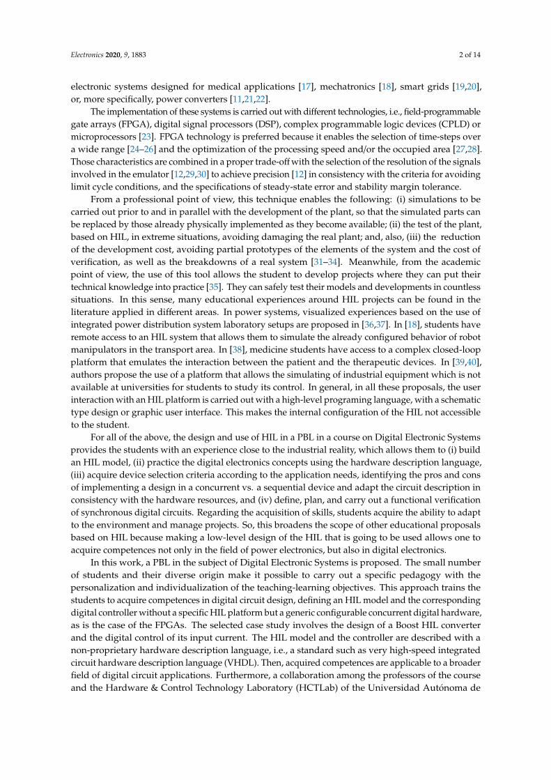
The structure of the current control applied to the Boost HIL is shown in Figure 6. The inductorcurrent, iL, is compared with a reference signal, iref. The generated error signal, ε[n], is the input to thecontrol block, Gc(z), which in this case is a PI controller, whose output is the input to the digital PWM(DPWM) block to generate the on and off signal for the switch S.
In the third practice, the design a PI controller for the input current of the converter is proposed,specifying a sampling frequency fs = 20 kHz, a crossover frequency fc = 2 kHz and a phase marginPM > 50.
Electronics 2020, 9, 1883 8 of 14
Figure 6. Schematic of the closed loop system.
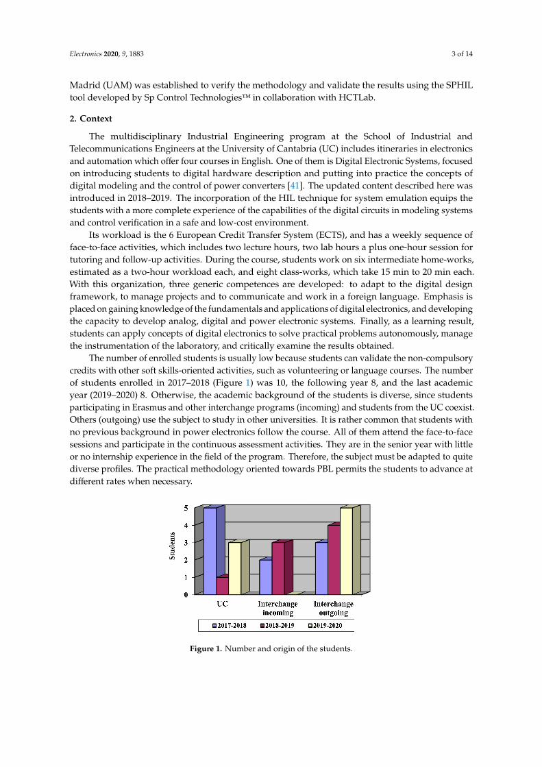
3.4. VHDL Description of Non-Synthesizable Controller
Students rely on simulations with a numerical computing software to verify the design of thedigital controller. The transfer function in the discrete domain has the following format:
Gc(z−1
)=
B0 + B1z−1
1 + A1z−1(15)
where A1, B0 y B1 are system gains.This function is described based on the structure of a finite impulse response (FIR) filter according
to Figure 7.
Figure 7. Materialization of the controller based on FIR filter structure.
The signals (sX, sY, etc.) involved in the digital controller have been highlighted in red. The controlleroutput signal in VHDL code is obtained from
sY <= sXB0 + sX1B1 − sY1A1 (16)
In the fourth practice, the preparation of the VHDL description of the digital controller and thePWM of the Boost converter with real-type signals is proposed. The objective is to verify the controllerinteracting with the Boost HIL by preparing a first version of the test bench for the whole system.
3.5. VHDL Description in Synthesizable Format
Here, students are guided in the transformation of their VHDL description, in real format, of theregulator and Boost, to a synthesizable format, with the aim of becoming familiar with the scalingand quantization concepts and effects. To accomplish this task, they can use different formats andintegers, std_logic_vector and sfixed, after receiving a lesson on fixed point number format. In this
Electronics 2020, 9, 1883 9 of 14
task, students check the operation of the regulator they have designed before verifying its behavior inan FPGA and with a commercial HIL in the next task.
3.6. Complete Assembly (Hardware-in-the-Loop + PWM + Controller)
The design of the system is completed with closed-loop control of the plant. The proposed schemeto carry out this practice is to first use a single FPGA for the whole system, and then later two separateFPGAs for the whole system, as shown in Figure 6, for a more complete verification. The objective is tosynthesize the control code and verify its operation by interacting with HIL. In parallel, the designis evaluated using the SPHIL module [49], in collaboration with the HCTLab of the UAM, in anFPGA. This tool includes a switched Boost model, adjusted using a very intuitive graphical interface tomeasure four different parameters (vg, iL, vC and v0). The other FPGA contains the synthesized code ofthe PI control and PWM designed by the student. In this practice, it is only necessary to read an inputsignal, iL, and, for its configuration, a previous template is provided.
In this part, students use a commercial HIL model to evaluate their proposal, and not the onethey had developed. This task makes the students test their regulator in hardware, to reinforce theirlearning with results in the laboratory where they measure the resulting hardware.
3.7. Evaluation
Finally, marks are given at the end of the course according to the following general criteria:
• no satisfactory solution—fail;• simulation of the basic performance—C;• implementation in FPGA and functional verification—B;• verification of the circuit performance using HIL technique—A.
This score represents 50% of the final mark. The follow-up done in the classroom represents 20%and the other 30% corresponds to the exercises done in the classroom.
4. Results Obtained
This section shows the results of the practical case study. Two FPGA have been used to carry out thefinal verification stage: a Nexys 4DDR (XC7A100T-1CSG324C) and an Arty-Z7 (XC7Z010-1CLG400C).The oscilloscope used is the MSO-X 3104A model from Agilent Technologies.
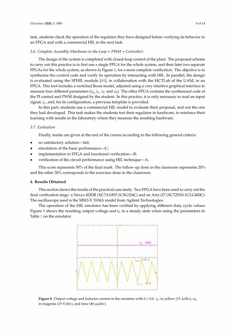
The operation of the HIL emulator has been verified by applying different duty cycle values.Figure 8 shows the resulting output voltage and iL in a steady state when using the parameters inTable 1 on the emulator.
Figure 8. Output voltage and inductor current in the emulator with d = 0.6. iL, in yellow (15 A/div), v0,in magenta (15 V/div), and time (40 µs/div).

Electronics 2020, 9, 1883 10 of 14
Figure 9 shows the results obtained when analyzing the behavior of the controller designed inMATLAB®. The control is then described in VHDL in real format, together with the PWM and theBoost converter, simulating its behavior with ModelSim®. In Figure 10, the results obtained in thesimulation are shown, and their values coincide with those obtained in Figure 8.
Figure 9. Behavior characterization of the control loop with the PI controller designed in Matlab.
Figure 10. Simulation results obtained in ModelSim with the implemented circuit and the test bench.
When converting the code from the real format to another synthesizable one, the float32 formatmay initially be more attractive to students due to its simplicity when it comes to being used on thecircuit. However, this requires a higher number of hardware resources in the FPGA, and its use maycompromise the temporary restrictions of the design. To illustrate this effect, a multiplication of twonumbers in the float32 format and two numbers in 32-bit integer is implemented in class using the ISE®
program. The operations are implemented and shown in Table 2, where the multiplication operationworks 2.7 times faster in int32 than in float32, and it adds 19 times faster, despite having less hardwareresources in general.

Electronics 2020, 9, 1883 11 of 14
Table 2. Parameters used in the Boost converter.
Operation DSP48E LUT Timing
float32 * float32 3 135 52.435 nsfloat32 + float32 2 195 88.970 ns
int32 * int32 4 231 19.315 nsint32 + int32 0 186 4.658 ns
* is multiplication, + is addition and DSP48E and LUT are digital signal processing logic and look up tableelements, respectively.
Finally, the response of the digitally controlled HIL Boost converter is evaluated via the SPHILtool in an Arty Z7-20 FPGA, as shown in Figure 11a, to emulate the Boost HIL, and a Nexys 4 FPGAto emulate a controller and the DPWM. A graphical interface allows the SPHIL user to configurethe parameters of the Boost converter as shown in Figure 11b. With those hardware tests, studentscan evaluate the performance of their regulators, which they had already simulated in a closed loop,and are now working on hardware with a commercial HIL model that makes Boost. This offersextra motivation for students who feels that their work is recognized, because it has real utility andencourages competitiveness among them by checking which design is more robust out of them all.
Figure 11. Boost converter emulator to verify designs proposed by students. (a) Laboratory mountconfiguration and (b) SPHIL graphical user interface.
The power converter model and control has been chosen to combine a practical exercise ofdigital circuit design, considering different sources of specifications for the HIL and the controller.This approach presents a deep insight into the operation of switching power converters, and theirdigital controllers with specific characteristics, different from the analog counterpart. So, the case studyputs in practice concepts of power electronics and digital electronics that are hard to assimilate withoutencountering a practical design, such as the digitalization effects of sampling, quantization, resolutionand additional delays. Moreover, the learning benefits are clear since the contents of digital circuitdesign and power electronics are combined in one course, going from theory to the experimentalverification of the result.
5. Conclusions
A Digital Electronic Systems course focused on PBL is proposed to level students with differentbackgrounds. The project is based on the development of an HIL platform and the design of its digitalcontroller, and concepts of digital modeling, the control of power converters and techniques of digitalhardware description are applied. In general, this proposal allows students to acquire competences

Electronics 2020, 9, 1883 12 of 14
in the field of power electronics and digital electronics at the same time. Specifically, it confrontsstudents with the design trade-off between the limitation of hardware resources and static and dynamicperformance, and allows them to experience the effects of inconsistent designs, such as the appearanceof a response with a limited cycle, and the effects of aliases or delays that reduce or eliminate thephase margin. At the same time, the dual utility of a hardware description standard, initially as aspecification validation tool and later as a circuit definition language, reinforces the acquisition ofabilities to solve effective digital design specifications. Finally, the results of applying this teachingproject have been validated with a proven commercial tool designed in a different environment fromthat in which teaching is carried out, which allows students to obtain an enhanced learning experience.
Author Contributions: P.L. carried out a postdoctorate at the HTCLab of the UAM where she studiedHardware-in-the-Loop techniques under the tutelage of Á.d.C., P.L. developed the practices of this work.F.J.A. and C.B. teach Digital Electronic Systems course in the UC and they put into practice the planned work withstudents. All authors have read and agreed to the published version of the manuscript.
Funding: This research received no external funding.
Acknowledgments: The authors thank the company Sp Control Technologies for the assignment of their SPHILproduct developed together with the HCTLab research group of UAM.
Conflicts of Interest: The authors declare no conflict of interest.
References
1. Zhang, Z.; Hansen, C.T.; Andersen, M.A.E. Teaching Power Electronics With a Design-Oriented, Project-BasedLearning Method at the Technical University of Denmark. IEEE Trans. Educ. 2016, 59, 32–38. [CrossRef]
2. Chu, R.H.; Minasian, R.A.; Yi, X. Inspiring Student Learning in ICT Communications Electronics through aNew Integrated Project-Based Learning Approach. J. Electr. Eng. Educ. 2012, 49, 127–135. [CrossRef]
3. Fernandes, M.A. Project-based learning applied to an embedded systems course. J. Electr. Eng. Educ. 2017,54, 223–235. [CrossRef]
4. Chu, R.H.; Lu, D.D.-C.; Sathiakumar, S. Project-Based Lab Teaching for Power Electronics and Drives.IEEE Trans. Educ. 2008, 51, 108–113. [CrossRef]
5. Martinez, F.; Herrero, L.C.; de Pablo, S. Project-Based Learning and Rubrics in the Teaching of Power Suppliesand Photovoltaic Electricity. IEEE Trans. Educ. 2011, 54, 87–96. [CrossRef]
6. Lamar, D.G.; Miaja, P.F.; Arias, M.; Rodriguez, A.; Rodriguez, M.; Vazquez, A.; Hernando, M.M.; Sebastian, J.Experiences in the Application of Project-Based Learning in a Switching-Mode Power Supplies Course.IEEE Trans. Educ. 2012, 55, 69–77. [CrossRef]
7. Martinez-Rodrigo, F.; Herrero-De Lucas, L.C.; de Pablo, S.; Rey-Boue, A.B. Using PBL to Improve EducationalOutcomes and Student Satisfaction in the Teaching of DC/DC and DC/AC Converters. IEEE Trans. Educ.2017, 60, 229–237. [CrossRef]
8. Zhu, J.; Liu, R.; Liu, Q.; Zheng, T.; Zhang, Z. Engineering Students’ Epistemological Thinking in the Contextof Project-Based Learning. IEEE Trans. Educ. 2019, 62, 188–198. [CrossRef]
9. Ghosh, S.; Giambiasi, N. Modeling and simulation of mixed-signal electronic designs-Enabling analog anddiscrete subsystems to be represented uniformly within a single framework. IEEE Circuits Devices Mag. 2006,22, 47–52. [CrossRef]
10. Pecheux, F.; Lallement, C.; Vachoux, A. VHDL-AMS and Verilog-AMS as alternative hardware descriptionlanguages for efficient modeling of multidiscipline systems. IEEE Trans. Comput. Aided Des. Integr.Circuits Syst. 2005, 24, 204–225. [CrossRef]
11. Lucía, Ó.; Urriza, I.; Barragán, L.A.; Navarro, D.; Jiménez, Ó.; Burdío, J.M. Real-Time FPGA-BasedHardware-in-the-Loop Simulation Test Bench Applied to Multiple-Output Power Converters. IEEE Trans.Ind. Appl. 2011, 47, 853–860. [CrossRef]
12. Sanchez, A.; de Castro, A.; Garrido, J. A Comparison of Simulation and Hardware-in-the-Loop Alternativesfor Digital Control of Power Converters. IEEE Trans. Ind. Inform. 2012, 8, 491–500. [CrossRef]
13. De Farias, A.B.C.; Rodrigues, R.S.; Murilo, A.; Lopes, R.V.; Avila, S. Low-Cost Hardware-in-the-Loop Platformfor Embedded Control Strategies Simulation. IEEE Access 2019, 7, 111499–111512. [CrossRef]
Electronics 2020, 9, 1883 13 of 14
14. Larruscain, G.; Tapia, G.; Susperregui, A.; Martinez, M.I. Student-tailored final year project onmicrocontroller-based hardware-in-the-loop speed control of a wind generator. J. Electr. Eng. Educ.2018, 55, 213–233. [CrossRef]
15. Ahmad, Z.; Torres, J.R.; Veera Kumar, N.; Rakhshani, E.; Palensky, P.; van der Meijden, M. A PowerHardware-in-the-Loop Based Method for FAPR Compliance Testing of the Wind Turbine Converters Control.Energies 2020, 13, 5203. [CrossRef]
16. Kotsampopoulos, P.C.; Kleftakis, V.A.; Hatziargyriou, N.D. Laboratory Education of Modern Power SystemsUsing PHIL Simulation. IEEE Trans. Power Syst. 2017, 32, 3992–4001. [CrossRef]
17. Mascio, C.D.; Gruosso, G. Hardware in the Loop Implementation of the Oscillator-based Heart Model:A Framework for Testing Medical Devices. Electronics 2020, 9, 571. [CrossRef]
18. Temeltas, H.; Gokasan, M.; Bogosyan, S.; Kilic, A. Hardware in the loop simulation of robot manipulatorsthrough Internet in mechatronics education. In Proceedings of the IEEE 2002 28th Annual Conference of theIndustrial Electronics Society, Sevilla, Spain, 5–8 November 2002; Volume 4, pp. 2617–2622.
19. García-Martínez, E.; Sanz, J.F.; Muñoz-Cruzado, J.; Perié, J.M. A Review of PHIL Testing for SmartGrids—Selection Guide, Classification and Online Database Analysis. Electronics 2020, 9, 382. [CrossRef]
20. El Mariachet, J.; Guan, Y.; Matas, J.; Martín, H.; Li, M.; Guerrero, J.M. HIL-Assessed Fast and AccurateSingle-Phase Power Calculation Algorithm for Voltage Source Inverters Supplying to High Total DemandDistortion Nonlinear Loads. Electronics 2020, 9, 1643. [CrossRef]
21. Sankaranarayanan, V.; Shirazi, M.; Gao, Y.; Ghosh, A.; Erickson, R.W.; Maksimovic, D. ControllerHardware-in-the-Loop Validation of a Modular Control Architecture for a Composite DC-DC Converter.In Proceedings of the 2019 20th Workshop on Control and Modeling for Power Electronics (COMPEL),Toronto, ON, Canada, 17–20 June 2019; pp. 1–7.
22. Saralegui, R.; Sanchez, A.; Martínez-García, M.S.; Novo, J.; Castro, A. de Comparison of Numerical Methodsfor Hardware-In-the-Loop Simulation of Switched-Mode Power Supplies. In Proceedings of the 2018 IEEE19th Workshop on Control and Modeling for Power Electronics (COMPEL), Padova, Italy, 25–28 June 2018;pp. 1–6.
23. Woods, R.; McAllister, J.; Lightbody, G.; Yi, Y. FPGA-Based Implementation of Signal. Processing Systems, 2nd ed.;John Wiley & Sons Inc: Hoboken, NJ, USA, 2017; ISBN 978-1-119-07795-4.
24. Jandaghi, B.; Dinavahi, V. Hardware-in-the-Loop Emulation of Linear Induction Motor Drive for MagLevApplication. IEEE Trans. Plasma Sci. 2016, 44, 679–686. [CrossRef]
25. Parma, G.G.; Dinavahi, V. Real-Time Digital Hardware Simulation of Power Electronics and Drives. IEEE Trans.Power Deliv. 2007, 22, 1235–1246. [CrossRef]
26. Matar, M.; Iravani, R. FPGA Implementation of the Power Electronic Converter Model for Real-TimeSimulation of Electromagnetic Transients. IEEE Trans. Power Deliv. 2010, 25, 852–860. [CrossRef]
27. Montano, F.; Ould-Bachir, T.; David, J.P. An Evaluation of a High-Level Synthesis Approach to the FPGA-BasedSubmicrosecond Real-Time Simulation of Power Converters. IEEE Trans. Ind. Electron. 2018, 65, 636–644.[CrossRef]
28. Martínez-García, M.S.; de Castro, Á.; Sanchez, A.; Garrido, J. Word Length Selection Method for HIL powerconverter models. Int. J. Electr. Power Energy Syst. 2021. submitted.
29. Sanchez, A.; de Castro, A.; Garrido, J. Parametrizable Fixed-Point Arithmetic for HIL With Small SimulationSteps. IEEE J. Emerg. Sel. Top. Power Electron. 2019, 7, 2467–2475. [CrossRef]
30. Goñi, O.; Sanchez, A.; Todorovich, E.; Castro, A. de Resolution Analysis of Switching Converter Models forHardware-in-the-Loop. IEEE Trans. Ind. Inform. 2014, 10, 1162–1170. [CrossRef]
31. Jia, J.; Yang, G.; Nielsen, A.H.; Roenne-Hansen, P. Hardware-in-the-loop tests on distance protectionconsidering VSC fault-ride-through control strategies. J. Eng. 2018, 2018, 824–829. [CrossRef]
32. Vu, P.; Nguyen, Q.; Tran, M.; Todeschini, G.; Santoso, S. Adaptive backstepping approach for dc-sidecontrollers of Z-source inverters in grid-tied PV system applications. IET Power Electron. 2018, 11, 2346–2354.[CrossRef]
33. Amin, M.; Aziz, G.A.A.; Durkin, J.; Mohammed, O.A. A Hardware-in-the-Loop Realization of SpeedSensorless Control of PMa-SynRM With Steady-State and Transient Performances Enhancement. IEEE Trans.Ind. Appl. 2019, 55, 5331–5342. [CrossRef]
34. Tian, J.; Liu, J.; Shu, J.; Tang, J.; Yang, J. Engineering modelling of wind turbine applied in real-time simulationwith hardware-in-loop and optimising control. IET Power Electron. 2018, 11, 2490–2498. [CrossRef]

Electronics 2020, 9, 1883 14 of 14
35. Shiakolas, P.S.; Van Schenck, S.R.; Piyabongkarn, D.; Frangeskou, I. Magnetic levitation hardware-in-the-loopand MATLAB-based experiments for reinforcement of neural network control concepts. IEEE Trans. Educ.2004, 47, 33–41. [CrossRef]
36. Rasheduzzaman, M.; Chowdhury, B.H.; Bhaskara, S. Converting an Old Machines Lab Into a FunctioningPower Network With a Microgrid for Education. IEEE Trans. Power Syst. 2014, 29, 1952–1962. [CrossRef]
37. Tang, J.; Xiong, B.; Yang, C.; Tang, C.; Li, Y.; Su, G.; Bian, X. Development of an Integrated Power DistributionSystem Laboratory Platform Using Modular Miniature Physical Elements: A Case Study of Fault Location.Energies 2019, 12, 3780. [CrossRef]
38. Mirinejad, H.; Parvinian, B.; Ricks, M.; Zhang, Y.; Weininger, S.; Hahn, J.; Scully, C.G. Evaluation of FluidResuscitation Control Algorithms via a Hardware-in-the-Loop Test Bed. IEEE Trans. Biomed. Eng. 2020, 67,471–481. [CrossRef] [PubMed]
39. Osen, O.L. On the Use of Hardware-in-the-Loop for Teaching Automation Engineering. In Proceedingsof the 2019 IEEE Global Engineering Education Conference (EDUCON), Dubai, UAE, 8–11 April 2019;pp. 1308–1315.
40. Grega, W. Hardware-in-the-loop simulation and its application in control education. In Proceedings of theFIE’99 Frontiers in Education, 29th Annual Frontiers in Education Conference, Designing the Future ofScience and Engineering Education, San Juan, PR, USA, 10–13 November 1999; Volume 2, p. 12.
41. Azcondo, F.J.; de Castro, A.; Brañas, C. Course on Digital Electronics Oriented to Describing Systems inVHDL. IEEE Trans. Ind. Electron. 2010, 57, 3308–3316. [CrossRef]
42. Maksimovic, D. Computer-aided small-signal analysis based on impulse response of DC/DC switchingpower converters. IEEE Trans. Power Electron. 2000, 15, 1183–1191. [CrossRef]
43. Maksimovic, D.; Zane, R. Small-Signal Discrete-Time Modeling of Digitally Controlled PWM Converters.IEEE Trans. Power Electron. 2007, 22, 2552–2556. [CrossRef]
44. Corradini, L. Analysis and Implementation of Digital Control Architectures for DC-DC Switching Converters.Ph.D. Thesis, University of Padova, Padua, Italy, 2008.
45. Peterchev, A.V.; Sanders, S.R. Quantization resolution and limit cycling in digitally controlled PWM converters.IEEE Trans. Power Electron. 2003, 18, 301–308. [CrossRef]
46. Van de Sype, D.M.; De Gusseme, K.; Van den Bossche, A.P.; Melkebeek, J.A. Small-signal Laplace-domainanalysis of uniformly-sampled pulse-width modulators. In Proceedings of the 2004 IEEE 35th Annual PowerElectronics Specialists Conference (IEEE Cat. No.04CH37551), Aachen, Germany, 20–25 June 2004; Volume 6,pp. 4292–4298.
47. Erickson, R.W.; Maksimovic, D. Fundamentals of Power Electronics, 2nd ed.; Springer: Norwell, MA, USA,2001; ISBN 978-0-7923-7270-7.
48. Azcondo, F.J.; Bracas, C.; Casanueva, R.; Maksimovic, D. Approaches to modeling converters with currentprogrammed control. In Proceedings of the IEEE Workshop Power Electronics Education, Recife, Brazil,16–17 June 2005; pp. 98–104.
49. SpHIL. Sp Control Technologies. Available online: http://spcontroltechnologies.com/sphil/ (accessed on10 October 2020).
Publisher’s Note: MDPI stays neutral with regard to jurisdictional claims in published maps and institutionalaffiliations.
© 2020 by the authors. Licensee MDPI, Basel, Switzerland. This article is an open accessarticle distributed under the terms and conditions of the Creative Commons Attribution(CC BY) license (http://creativecommons.org/licenses/by/4.0/).