elizabeth square, phase 1 silver spring, maryland
802
PROJECT SPECIFICATIONS ELIZABETH SQUARE, PHASE 1 SILVER SPRING, MARYLAND ELIZABETH HOUSE III (EH3) AND SOUTH COUNTY REGIONAL RECREATION AND AQUATICS CENTER (SCRRAC) JUNE 20, 2019 ISSUE FOR CONSTRUCTION VOLUME 5 Prepared By KGD Architecture 1101 15 th Street NW Suite 200 Washington, DC 20005 Prepared For Housing Opportunities Commission of Montgomery County 10400 Detrick Avenue Kensington, MD 20895
-
Upload
khangminh22 -
Category
Documents
-
view
2 -
download
0
Transcript of elizabeth square, phase 1 silver spring, maryland

PROJECT SPECIFICATIONS
ELIZABETH SQUARE, PHASE 1 SILVER SPRING, MARYLAND
ELIZABETH HOUSE III (EH3) AND SOUTH COUNTY REGIONAL RECREATION AND
AQUATICS CENTER (SCRRAC)
JUNE 20, 2019 ISSUE FOR CONSTRUCTION
VOLUME 5
Prepared By KGD Architecture 1101 15th Street NW Suite 200 Washington, DC 20005 Prepared For Housing Opportunities Commission of Montgomery County 10400 Detrick Avenue Kensington, MD 20895


Elizabeth Square, Phase 1 KGD Architecture
Silver Spring, Maryland Issue for Construction
June 20, 2019
TABLE OF CONTENTS 00 0111 - 1 of 10
SECTION 00 0111
VOLUME 1
DIVISION 00
00 0111
00 3132
DIVISION 01
01 1000
01 1100
01 2200
01 2300
01 2600
01 2900
01 3100
01 3200
01 3202
01 3300
01 3523
01 4000
01 4200
01 4500
01 5000
01 5204
01 6000
01 6116
01 7300
01 7329
01 7700
01 7801
01 7802
01 8113.12
01 8113.13
01 8113.14
01 8316
01 9113
01 9113.14
TABLE OF CONTENTS
PROCUREMENT AND CONTRACTING REQUIREMENTS
TABLE OF CONTENTS
SUBSURFACE SOILS INVESTIGATION REPORT
GENERAL REQUIREMENTS
SUMMARY OF WORK
GROUNDBREAKING AND GRAND OPENING REQUIREMENTS
UNIT PRICES
ALTERNATES
CONTRACT MODIFICATION PROCEDURES
PAYMENT PROCEDURES
PROJECT MANAGEMENT AND COORDINATION
CSI 13.2A Request for Interpretation
CONSTRUCTION PROGRESS DOCUMENTATION
PHOTOGRAPHIC DOCUMENTATION
SUBMITTAL PROCEDURES
CSI 12.1A Submittal Transmittal
CSI 1.5A Subcontractors and Major Material Suppliers List
CONTRACTOR’S SAFETY REQUIREMENTS
QUALITY REQUIREMENTS
REFERENCES
CONTRACTOR QUALITY CONTROL
TEMPORARY FACILITIES AND CONTROLS
CONSTRUCTION WASTE MANAGEMENT
PRODUCT REQUIREMENTS
PRODUCT EMISSIONS REQUIREMENTS
EXECUTION REQUIREMENTS
CUTTING AND PATCHING
CLOSEOUT PROCEDURES
CSI 14.1A Punch List
PROJECT RECORD DOCUMENTS
OPERATION AND MAINTENANCE DATA
SUSTAINABLE DESIGN REQUIREMENTS – EH3 ENERGY STAR
SUSTAINABLE DESIGN REQUIREMENTS – EH3 & HC LEED
EH3 LEED Scorecard, June 20, 2019
SUSTAINABLE DESIGN REQUIREMENTS – SCRRAC LEED
SCRRAC LEED Scorecard, June 20, 2019
EXTERIOR ENCLOSURE PERFORMANCE REQUIREMENTS
GENERAL COMMISSIONING REQUIREMENTS – EH3
GENERAL COMMISSIONING REQUIREMENTS - SCRRAC

Elizabeth Square, Phase 1 KGD Architecture
Silver Spring, Maryland Issue for Construction
June 20, 2019
TABLE OF CONTENTS 00 0111 - 2 of 10
DIVISION 02 EXISTING CONDITIONS
02 4119 SELECTIVE DEMOLITION
DIVISION 03 CONCRETE
03 1500 WATERSTOPS
03 3000 CAST-IN-PLACE CONCRETE
Concrete Placement Card
03 3053 HYDROPHOBIC CAST-IN-PLACE CONCRETE
03 3816 UNBONDED POST-TENSIONED CONCRETE
DIVISION 04 MASONRY
04 2000 UNIT MASONRY
04 7200 CAST STONE MASONRY
DIVISION 05 METALS
05 1200 STRUCTURAL STEEL FRAMING
05 3100 STEEL DECK
05 4000 COLD-FORMED METAL FRAMING
05 5000 METAL FABRICATIONS
05 5116 METAL FLOOR PLATE STAIRS
05 5213 PIPE AND TUBE RAILINGS
05 5300 METAL GRATINGS
05 7000 DECORATIVE METAL
05 7300 DECORATIVE METAL RAILINGS
05 7301 DECORATIVE METAL RAILINGS FOR SITEWORK
05 7313 GLAZED DECORATIVE METAL RAILINGS
DIVISION 06 WOOD, PLASTIC, AND COMPOSITES
06 1000 ROUGH CARPENTRY
06 1600 SHEATHING
06 2023 INTERIOR FINISH CARPENTRY
06 4023 INTERIOR ARCHITECTURAL WOODWORK
06 4400 WOOD GRILLES
06 8113 FIBERGLASS REINFORCED RAILINGS

Elizabeth Square, Phase 1 KGD Architecture
Silver Spring, Maryland Issue for Construction
June 20, 2019
TABLE OF CONTENTS 00 0111 - 3 of 10
DIVISION 07 THERMAL AND MOISTURE PROTECTION
07 1300 BELOW-GRADE SHEET WATERPROOFING
07 1413 HOT FLUID-APPLIED RUBBERIZED ASPHALT WATERPROOFING
07 1616 CRYSTALLINE WATERPROOFING
07 1800 TRAFFIC COATINGS
07 1900 WATER REPELLENTS
07 2100 THERMAL INSULATION
07 2400 EXTERIOR INSULATION AND FINISH SYSTEM (EIFS)
072600 VAPOR RETARDERS
07 2613 BELOW-SLAB VAPOR BARRIERS
07 2726 FLUID-APPLIED MEMBRANE AIR BARRIERS
07 4213 METAL PLANK WALL AND SOFFIT PANELS
07 4223 METAL-COMPOSITE MATERIAL WALL PANELS
07 4229 TERRA COTTA WALL PANELS
07 4646 FIBER-CEMENT PANELS
07 5623 THERMOPLASTIC POLYOLEFIN (TPO) ROOFING
07 5563 VEGETATED PROTECTED MEMBRANE ROOFING
07 6200 SHEET METAL FLASHING AND TRIM
07 7200 ROOF ACCESSORIES
07 8100 APPLIED FIREPROOFING
07 8413 PENETRATION FIRESTOPPING
07 8446 FIRE-RESISTIVE JOINT SYSTEMS
07 9200 JOINT SEALANTS
07 9500 EXPANSION JOINT COVER SYSTEMS
DIVISION 08 OPENINGS
08 1113 HOLLOW METAL DOORS AND FRAMES
08 1416 FLUSH WOOD DOORS
08 1433 STILE AND RAIL WOOD DOORS
08 1613 FLUSH FIBERGLASS DOORS AND FRAMES
08 3113 ACCESS DOORS AND FRAMES
08 3313 COILING COUNTER DOORS
08 3323 OVERHEAD ROLLING DOORS
08 3513 FOLDING DOORS
08 4113 ALUMINUM-FRAMED ENTRANCES AND STOREFRONTS
08 4126 ALL-GLASS ENTRANCE SYSTEMS
08 4229 SLIDING AUTOMATIC ENTRANCES
08 4413 GLAZED ALUMINUM CURTAIN WALLS
08 5113 ALUMINUM WINDOWS AND WINDOW WALLS
08 5313 VINYL WINDOWS AND TERRACE DOORS
08 7100 DOOR HARDWARE
08 7913 FIRE DEPARTMENT KEY BOX
08 8000 GLAZING
08 8300 MIRRORS
08 9119 FIXED LOUVERS
08 9516 WALL VENTS

Elizabeth Square, Phase 1 KGD Architecture
Silver Spring, Maryland Issue for Construction
June 20, 2019
TABLE OF CONTENTS 00 0111 - 4 of 10
VOLUME 2
DIVISION 09 FINISHES
09 0561 MOISTURE VAPOR EMISSION CONTROL
09 2100 GYPSUM BOARD ASSEMBLIES
09 2116 GYPSUM BOARD SHAFT WALL ASSEMBLIES
09 2300 GYPSUM PLASTERING
09 3000 TILING
09 5113 ACOUSTICAL PANEL CEILINGS
09 5133 ACOUSTICAL METAL PAN CEILINGS
09 6466 WOOD ATHLETIC FLOORING
09 6513 RESILIENT BASE AND ACCESSORIES
09 6516 RESILIENT SHEET FLOORING
09 6519 RESILIENT TILE FLOORING
09 6566 RESILIENT ATHLETIC FLOORING
09 6623 RESINOUS MATRIX TERRAZZO FLOORING
09 6723 INDUSTRIAL RESINOUS FLOOR COATINGS
09 6800 CARPETING
09 7200 WALL COVERINGS
09 8433 SOUND-ABSORBING WALL UNITS
09 8436 SOUND-ABSORBING CEILING UNITS
09 9100 PAINTING
09 9611 HIGH-PERFORMANCE COATINGS FOR NATATORIUM
09 9653 ELASTOMERIC COATINGS
09 9656 EPOXY FLOOR COATINGS
09 9672 FLUID-APPLIED INSULATION COATING
DIVISION 10 SPECIALTIES
10 1100 VISUAL DISPLAY UNITS
10 1400 SIGNS AND GRAPHICS
Interior and Exterior Sign Systems Message Schedules
10 1419 DIMENSIONAL LETTER SIGNAGE
10 1423 INTERIOR PANEL SIGNAGE
10 1473 PAINTED SIGNAGE
10 2113 TOILET COMPARTMENTS AND SCREENS
10 2123 CUBICLE CURTAINS AND TRACK
10 2213 WIRE MESH PARTITIONS
10 2239 FOLDING PANEL PARTITIONS
10 2243 SLIDING PANEL PARTITIONS
10 2600 WALL PROTECTION
10 2800 TOILET AND BATH ACCESSORIES
10 4413 FIRE PROTECTION CABINETS
10 4416 FIRE EXTINGUISHERS
10 4513 PHOTOLUMINESCENT EGRESS PATH MARKINGS
10 5126 PLASTIC LOCKERS
10 5143 WIRE MESH STORAGE LOCKERS
10 5500 POSTAL SPECIALTIES
10 5700 CLOSET SPECIALTIES
10 7316 METAL CANOPIES

Elizabeth Square, Phase 1 KGD Architecture
Silver Spring, Maryland Issue for Construction
June 20, 2019
TABLE OF CONTENTS 00 0111 - 5 of 10
DIVISION 11 EQUIPMENT
11 1136 VEHICLE CHARGING STATIONS
11 1323 LOADING DOCK EQUIPMENT
11 2423 BUILDING FAÇADE MAINTENANCE EQUIPMENT
11 3100 APPLIANCES
11 3133 GAS FIREPLACES
11 4000 FOODSERVICE
11 6623 GYMNASIUM EQUIPMENT
11 8226 FACILITY WASTE COMPACTORS
11 9400 PET WASH EQUIPMENT
DIVISION 12 FURNISHINGS
12 2113 HORIZONTAL LOUVER BLINDS
12 2413 ROLLER WINDOW SHADES
12 3530 RESIDENTIAL KITCHEN AND BATH CASEWORK
12 3553 PHENOLIC-CORE CASEWORK AND COUNTERTOPS
12 3616 METAL COUNTERTOPS
12 3661 SIMULATED-STONE COUNTERTOPS
12 4813 ENTRANCE FLOOR MATS
12 6313 FIXED BLEACHER SEATING
12 6600 TELESCOPING STANDS
12 9300 ROOFTOP SITE FURNISHINGS
12 9313 BICYCLE STORAGE RACKS
DIVISION 13 SPECIAL CONSTRUCTION
13 1100 SWIMMING POOLS
13 2000 SWIMMING POOL TIMING SYSTEM
13 3000 SWIMMING POOL FAUX ROCKWORK
DIVISION 14 CONVEYING EQUIPMENT
14 2100 ELECTRIC TRACTION ELEVATORS
14 9182 TRASH CHUTES

Elizabeth Square, Phase 1 KGD Architecture
Silver Spring, Maryland Issue for Construction
June 20, 2019
TABLE OF CONTENTS 00 0111 - 6 of 10
VOLUME 3
DIVISION 21 FIRE SUPPRESSION
21 0513 COMMON MOTOR REQUIREMENTS FOR FIRE SUPPRESSION EQUIPMENT
21 0517 SLEEVES AND SLEEVE SEALS FOR FIRE-SUPPRESSION PIPING
21 0518 ESCUTCHEONS FOR FIRE-SUPPRESSION PIPING
21 0523 GENERAL-DUTY VALVES FOR WATER-BASED FIRE-SUPPRESSION PIPING
21 0529 HANGERS AND SUPPORTS FOR FIRE SUPPRESSION PIPING AND
EQUIPMENT
21 0553 IDENTIFICATION FOR FIRE-SUPPRESSION PIPING AND EQUIPMENT
21 1119 FIRE-DEPARTMENT CONNECTIONS
21 1200 FIRE-SUPPRESSION STANDPIPES
21 1313 WET-PIPE SPRINKLER SYSTEMS
21 1316 DRY-PIPE SPRINKLER SYSTEMS
21 3113 ELECTRIC-DRIVE, CENTRIFUGAL FIRE PUMPS
21 3400 PRESSURE-MAINTENANCE PUMPS
21 3900 CONTROLLERS FOR FIRE-PUMP DRIVERS
DIVISION 22 PLUMBING
22 0513 COMMON MOTOR REQUIREMENTS FOR PLUMBING EQUIPMENT
22 0516 EXPANSION FITTINGS AND LOOPS FOR PLUMBING PIPING
22 0517 SLEEVES AND SLEEVE SEALS FOR PLUMBING PIPING
22 0518 ESCUTCHEONS FOR PLUMBING PIPING
22 0519 METERS AND GAGES FOR PLUMBING PIPING
22 0523.12 BALL VALVES FOR PLUMBING PIPING
22 0523.13 BUTTERFLY VALVES FOR PLUMBING PIPING
22 0523.14 CHECK VALVES FOR PLUMBING PIPING
22 0529 HANGERS AND SUPPORTS FOR PLUMBING PIPING AND EQUIPMENT
22 0533 HEAT TRACING FOR PLUMBING PIPING
22 0548.13 VIBRATION CONTROLS FOR PLUMBING PIPING AND EQUIPMENT
22 0553 IDENTIFICATION FOR PLUMBING PIPING AND EQUIPMENT
22 0719 PLUMBING PIPING INSULATION
22 1116 DOMESTIC WATER PIPING
22 1119 DOMESTIC WATER PIPING SPECIALTIES
22 1123 DOMESTIC WATER PUMPS
22 1123.13 DOMESTIC-WATER PACKAGED BOOSTER PUMPS
22 1316 SANITARY WASTE AND VENT PIPING
22 1319 SANITARY WASTE PIPING SPECIALTIES
22 1329 SANITARY SEWERAGE PUMPS
22 1413 FACILITY STORM DRAINAGE PIPING
22 1423 STORM DRAINAGE PIPING SPECIALTIES
22 1429 SUMP PUMPS
22 3300 ELECTRIC, DOMESTIC-WATER HEATERS
22 3400 FUEL-FIRED, DOMESTIC-WATER HEATERS
22 4100 RESIDENTIAL PLUMBING FIXTURES
22 4213.13 COMMERCIAL WATER CLOSETS
22 4213.16 COMMERCIAL URINALS
22 4216.13 COMMERCIAL LAVATORIES
22 4216.16 COMMERCIAL SINKS
22 4223 COMMERCIAL SHOWERS
22 4716 PRESSURE WATER COOLERS

Elizabeth Square, Phase 1 KGD Architecture
Silver Spring, Maryland Issue for Construction
June 20, 2019
TABLE OF CONTENTS 00 0111 - 7 of 10
DIVISION 23 HEATING, VENTILATING, AND AIR-CONDITIONING (HVAC)
23 0513 COMMON MOTOR REQUIREMENTS FOR HVAC EQUIPMENT
23 0516 EXPANSION FITTINGS AND LOOPS FOR HVAC PIPING
23 0517 SLEEVES AND SLEEVE SEALS FOR HVAC PIPING
23 0518 ESCUTCHEONS FOR HVAC PIPING
23 0519 METERS AND GAGES FOR HVAC PIPING
23 0523 GENERAL-DUTY VALVES FOR HVAC PIPING
23 0529 HANGERS AND SUPPORTS FOR HVAC PIPING AND EQUIPMENT
23 0533 HEAT TRACING FOR HVAC PIPING
23 0548 VIBRATION ISOLATION AND SEISMIC RESTRAINTS FOR MECHANICAL
COMPONENTS
23 0553 IDENTIFICATION FOR HVAC PIPING AND EQUIPMENT
23 0593 TESTING, ADJUSTING, AND BALANCING FOR HVAC
23 0713 DUCT INSULATION
23 0716 HVAC EQUIPMENT INSULATION
23 0719 HVAC PIPING INSULATION
23 0800 COMMISSIONING OF MECHANICAL
23 0900 INSTRUMENTATION AND CONTROL FOR HVAC
23 0993 SEQUENCE OF OPERATIONS FOR HVAC CONTROLS
23 1113 FACILITY FUEL-OIL PIPING
23 1123 FACILITY NATURAL-GAS PIPING
23 2113 HYDRONIC PIPING
23 2116 HYDRONIC PIPING SPECIALTIES
23 2123 HYDRONIC PUMPS
23 2300 REFRIGERANT PIPING
23 2513 WATER TREATMENT FOR CLOSED-LOOP HYDRONIC SYSTEMS
23 2516 WATER TREATMENT FOR OPEN-LOOP HYDRONIC SYSTEMS
23 2533 HVAC WATER FILTRATION EQUIPMENT
23 3113 METAL DUCTS
23 3116 NONMETAL DUCTS
23 3300 AIR DUCT ACCESSORIES
23 3346 FLEXIBLE DUCTS
23 3423 HVAC POWER VENTILATORS
23 3600 AIR TERMINAL UNITS
23 3723 HVAC GRAVITY VENTILATORS
23 5100 GENERATOR/ TURBINE EXHAUST SYSTEM
23 5113 DRAFT CONTROL SYSTEM
23 5113.16 VENT DAMPERS
23 5123 GAS VENTS
23 5216 CONDENSING BOILERS
23 5700 HEAT EXCHANGERS FOR HVAC
23 6423.16 HEAT RECOVERY CHILLERS
23 6426.16 WATER-COOLED, ROTARY-SCREW WATER CHILLERS
23 6500 COOLING TOWERS
23 7223 PACKAGED ROOFTOP ENERGY RECOVERY UNITS
23 7313.16 INDOOR, SEMI-CUSTOM AIR-HANDLING UNITS
23 7313.17 CUSTOM AIR HANDLING UNITS – POOL
23 7416.13 PACKAGED ROOFTOP WATER SOURCE HEAT PUMP
23 8126 SPLIT-SYSTEM AIR CONDITIONERS
23 8146 WATER-SOURCE UNITARY HEAT PUMPS
23 8219 FAN COIL UNITS

Elizabeth Square, Phase 1 KGD Architecture
Silver Spring, Maryland Issue for Construction
June 20, 2019
TABLE OF CONTENTS 00 0111 - 8 of 10
DIVISION 23 HEATING, VENTILATING, AND AIR-CONDITIONING (HVAC), CONTINUED
23 8236 FINNED-TUBE RADIATION HEATERS
23 8239.13 CABINET UNIT HEATERS
23 8239.19 WALL AND CEILING UNIT HEATERS
23 8413.29 SELF-CONTAINED STEAM HUMIDIFIERS
VOLUME 4
DIVISION 26 ELECTRICAL
26 0519 LOW-VOLTAGE ELECTRICAL POWER CONDUCTORS AND CABLES
26 0526 GROUNDING AND BONDING FOR ELECTRICAL SYSTEMS
26 0529 HANGERS AND SUPPORTS FOR ELECTRICAL SYSTEMS
26 0533 RACEWAYS AND BOXES FOR ELECTRICAL SYSTEMS
26 0543 UNDERGROUND DUCTS AND RACEWAYS FOR ELECTRICAL SYSTEMS
26 0544 SLEEVES AND SLEEVE SEALS FOR ELECTRICAL RACEWAYS AND CABLING
26 0548.16 SEISMIC CONTROLS FOR ELECTRICAL SYSTEMS
26 0553 IDENTIFICATION FOR ELECTRICAL SYSTEMS
26 0572 OVERCURRENT PROTECTIVE DEVICE SHORT-CIRCUIT STUDY
26 0573 OVERCURRENT PROTECTIVE DEVICE COORDINATION STUDY
26 0574 OVERCURRENT PROTECTIVE DEVICE ARC-FLASH STUDY
26 0800 COMMISSIONING OF ELECTRICAL
26 0913 ELECTRICAL POWER MONITORING AND CONTROL
26 0923 LIGHTING CONTROLS - LUTRON
26 2200 LOW-VOLTAGE TRANSFORMERS
26 2413 SWITCHBOARDS
26 2416 PANELBOARDS
26 2500 ENCLOSED BUS ASSEMBLIES
26 2713 ELECTRICITY METERING
26 2726 WIRING DEVICES
26 2813 FUSES
26 2816 ENCLOSED SWITCHES AND CIRCUIT BREAKERS
26 2923 VARIABLE-FREQUENCY MOTOR CONTROLLERS
26 3213 ENGINE GENERATORS
26 3600 TRANSFER SWITCHES
26 4113 LIGHTNING PROTECTION FOR STRUCTURES
26 4313 SURGE PROTECTION FOR LOW-VOLTAGE ELECTRICAL POWER CIRCUITS
26 5100 ARCHITECTURAL LIGHTING LUMINAIRES
26 5119 LED INTERIOR LIGHTING
26 5619 LED EXTERIOR LIGHTING
DIVISION 27 COMMUNICATIONS
27 0526 GROUNDING & BONDING FOR COMMUNICATION SYSTEMS
27 0537 FIRESTOPPING
27 0553 IDENTIFICATION FOR COMMUNICATIONS
27 1100 COMMUNICATION EQUIPMENT ROOMS FITTING
27 1300 COMMUNICATION BACKBONE CABLING
27 1500 COMMUNICATIONS HORIZONTAL CABLING
27 4100 AUDIO VISUAL SYSTEMS
27 5100 PAGING SYSTEMS

Elizabeth Square, Phase 1 KGD Architecture
Silver Spring, Maryland Issue for Construction
June 20, 2019
TABLE OF CONTENTS 00 0111 - 9 of 10
DIVISION 28 ELECTRONIC SAFETY AND SECURITY
28 3111 DIGITAL, ADDRESSABLE FIRE-ALARM SYSTEM
DIVISION 31 EARTHWORK
31 1000 SITE CLEARING
31 2000 EARTH MOVING
31 2319 DEWATERING
31 5000 EXCAVATION SUPPORT, UNDERPINNING, AND PROTECTION
DIVISION 32 EXTERIOR IMPROVEMENTS
32 1313 CONCRETE PAVING
32 1400 UNIT PAVING
32 1713 PARKING BUMPERS
32 3300 SITE FURNISHINGS
32 3913 MANUFACTURED METAL BOLLARDS
32 5001 MISCELLANEOUS METAL SITE WORK
32 9100 SOILS
32 9200 TURFS AND GRASSES
32 9300 PLANTS
DIVISION 33 UTILITIES
33 4600 SUBDRAINAGE
APPENDICES
Appendix 1A Report of Subsurface Exploration and Geotechnical Engineering Analysis,
Elizabeth House, Silver Spring, Maryland, for For LEE Development Group
Prepared by ECS Mid-Atlantic, LLC, dated August 5, 2014.
Revised Report of Subsurface Exploration and Geotechnical Engineering Analysis,
Elizabeth House, Silver Spring, Maryland, for HOC of Montgomery County,
Prepared by ECS Mid-Atlantic, LLC, dated August 5, 2014, revised July 18, 2017.
Letter Report of Supplemental Geotechnical Subsurface Exploration,
Elizabeth Square III, Silver Spring, Montgomery County, Maryland.
Prepared by ECS Mid-Atlantic, LLC, dated February 27, 2018.
Appendix 2B Multifamily Rental Financing Program Guide, MDHCD, August 9, 2016
Exhibit E.1: Development Quality Threshold Narrative, Elizabeth House III
Exhibit E.2: Development Quality Self-Scoring and Narrative, Elizabeth House III
Appendix 3C EnergyStar Multifamily High Rise National Performance Path Requirements, v1.0

Elizabeth Square, Phase 1 KGD Architecture
Silver Spring, Maryland Issue for Construction
June 20, 2019
TABLE OF CONTENTS 00 0111 - 10 of 10
VOLUME 5
Appendix 4D
Appendix 5E
Commissioning Appendices
Cx Appendix 1 – Glossary of Terms
Cx Appendix 3 – Commissioning Team Responsibilities Matrix
Cx Appendix 4 – SCRRAC Master Equipment List
Cx Appendix 5 - Sample Draft Equipment Prefunctional Checklist
Cx Appendix 6 - Sample Draft Functional Test Procedure
Cx Appensix 8 – Commissioning Submittal Requirements - SCRRAC
Cx Appendix 9 – Building Operator Training Plan
Cx Appendix 11 – Commissioning Coordination Matrix
Cx Appendix 12 – Commissioning Plan
Cx Appendix 13 -- Program of Requirements
LEED Boundary Diagram, dated August 31, 2018
END OF TABLE OF CONTENTS

Elizabeth Square, Phase 1 KGD Architecture Silver Spring, Maryland Issue for Construction June 20, 2019
APPENDIX D 1 of 1
APPENDIX D
COMMISSIONING APPENDICES


Elizabeth Square, Phase 1 KGD Architecture
Silver Spring, Maryland Issue for Construction
June 20, 2019
GLOSSARY OF TERMS APPENDIX 1 - 1 of 4
APPENDIX 1
GLOSSARY OF TERMS


Elizabeth Square, Phase 1 KGD Architecture
Silver Spring, Maryland Issue for Construction
June 20, 2019
GLOSSARY OF TERMS APPENDIX 1 - 2 of 4
APPENDIX 1
GLOSSARY OF TERMS
Action Item: This is any issue that requires an action, response, work, etc. It can be an RFI, a work
directive, a clarification, a “to do” item, an identified deficiency, etc.
Action List: This is a list that is maintained by the Commissioning that includes all action items that
relate to Commissioning activities. These must be categorized as appropriate.
Commissioning (Cx): The process of ensuring that all building systems perform interactively according
to the design intent, the systems are efficient and cost effective and meet MCG's operational needs.
Commissioning Coordinator: This is an individual in various parties that is designated the contact for
that party relative to Commissioning activities.
Commissioning Team (CT): The group of parties involved with the commissioning process of any
given system. The team will generally include a core group involved with all systems. This core group
will generally include the CA, the CM's Commissioning Coordinator, MCG's Commissioning
Coordinator, GC's Commissioning Coordinator. On any given system the team will also include the
Commissioning Coordinator of the contractor(s) responsible for the systems or equipment.
Construction Documents: Generally, the part of the Contract documents that dictate the installation.
Contract Documents: The documents governing the relationships between parties involved in the
design and construction of this project including: Agreements/Contracts, Construction Plans,
Specifications, Addenda, Change Orders, Commissioning Plan.
Contractor: As used herein is a general reference to the applicable installing party and can therefore
refer to the GC, subcontractors, or vendors.
Decommissioning: The systematic process of verifying through testing, documentation, and training that
specified components and systems have been properly shut down and taken safely out of active service
for demolition, abatement, and removal.
Deficiency: An installation or condition that is not in conformance with the construction documents
and/or the design intent.
EA: Energy and Atmosphere – a category of the LEED rating system.
Energy Management and Control System (EMCS): the computer-based control or automation system.
Also known as Building Automation System (BAS), Energy Management System (EMS), Facility
Management System (FMS), Direct Digital Controls (DDC).
Functional Completion: A milestone that marks the completion of the Acceptance Phase and successful
completion of the FPT.

Elizabeth Square, Phase 1 KGD Architecture
Silver Spring, Maryland Issue for Construction
June 20, 2019
GLOSSARY OF TERMS APPENDIX 1 - 3 of 4
Functional Performance Testing: The detailed and thorough testing of the building systems and their
interactions with the building components and other building systems.
Functional Test Procedure (FTP): The document used to record the results of functional performance
testing.
IAQ: Indoor Air Quality.
IAQ Management Plan: A plan developed by the general contractor to protect the HVAC system during
construction, control pollutant sources and interrupt contamination pathways. Sequence the installation of
material to avoid contamination of absorptive material such as insulation, carpeting, ceiling tile and
gypsum wallboard.
LEED: Leadership in Energy and Environmental Design - LEED is an internationally recognized green
building certification system, providing third-party verification that a building or community was
designed and built using strategies aimed at improving performance across all the metrics that matter
most: energy savings, water efficiency, CO2 emissions reduction, improved indoor environmental quality,
and stewardship of resources and sensitivity to their impacts.
Method of Procedure (MOP): A document detailing precisely how and why a procedure will be
accomplished. MOPs are often required for building renovation that require precise details on how a
contractor will perform construction activities without disrupting the operation or comfort of the facility
and its occupants.
Measurement and Verification (M&V): A method for determining the actual energy usage and
potential savings of the energy using systems for a building(s).
Measurement and Verification Plan: A plan that describes the objectives, approach, method and
implementation of the M&V process.
Party: Person, company or entity.
Pre-Functional Checklist (PCs): PCs are equipment/component focused quality control commissioning
documents that are completed by an installing contractor prior to energizing a system or beginning a
functional performance test.
Project Manager (PM): Person in employ of MCG who is in charge of the design and construction
coordination.
RFI: Request for Information.
Start Up: Typically used to refer to the static testing or check out of systems or equipment to ensure that
they are complete, properly installed, and ready for dynamic testing. This will typically be documented
via checklists or forms.
Start Up Checklist Item: This is an item of check out inspections that simply require a Yes/No or
OK/Not response. These are used as one component to the equipment start up verification (start up tests
being the other).

Elizabeth Square, Phase 1 KGD Architecture
Silver Spring, Maryland Issue for Construction
June 20, 2019
GLOSSARY OF TERMS APPENDIX 1 - 4 of 4
Start up Test: This is a test involved with equipment start up. It differs from a checklist item in that a
measurement is required to be documented or a sequence of events must be documented such that it
requires more than a binary response.
Trending: Monitoring and recording a history of parameters typically using the facility management
system.
USGBC: United States Green Building Council.
Web Portal: Web based Commissioning Information Tool. The full version that facilitates developing
the tests is licensed and copyrighted. Web Portal Viewer is shareware that can be used to view existing
tests and record the results. This tool will be used by the Commissioning Authority to store
commissioning documents for this project.


Elizabeth Square, Phase 1 KGD Architecture
Silver Spring, Maryland Issue for Construction
June 20, 2019
COMMISSIONING TEAM RESPONSIBILITY MATRIX APPENDIX 3
APPENDIX 3
COMMISSIONING TEAM
RESPONSIBILITY MATRIX


Commissioning Team Responsibility Matrix APPENDIX 3 Commissioning Plan
Phase MCG Responsibilities Architect & CxA Responsibilities Engineer Responsibilities Contractor Responsibility CA Responsibility
· Develop the Program for the facility. · Assist MCG in documenting the
requirements of the facility
· Assist MCG in documenting the
requirements of the facility
N/A
· Identify the requirements, goals,
preferences, MCG standards or
guidelines that will impact the design
of the facility
· Notify MCG of codes and regulations
that affect the facility
· Notify MCG of codes and regulations
that affect the facility
· Clearly communicate requirements,
preferences, and budget targets to A/E
in a timely manner.
· Endeavor to fully understand MCG's
requirements and preferences and
propose design alternatives to meet
those requirements. Advise MCG of
advantages, disadvantages, and
limitations of various alternatives.
· Endeavor to fully understand MCGs
requirements and preferences and
propose design alternatives to meet
those requirements. Advise MCG of
advantages, disadvantages, and
limitations of various alternatives.
· N/A
· Select CA · Attend design meetings and present
alternatives.
· Attend design meetings and present
alternatives.
· Review and comment on the
conceptual design
· Document the primary thought
processes that result in the concepts
that will form the basis of design.
· Document the primary thought
processes that result in the concepts
that will form the basis of design.
· Identify operations or facilities
personnel for the facility who will be
involved in key decisions throughout
the design/construct process and
eventually operate the facility.
AE and CxA
CxA
AE (review by CxA as needed)
Pro
gra
mm
ing
Co
nce
ptu
al D
esig
n
N/A
N/A
Appendix 3 - Page 1 Elizabeth Square Phase 1 - SCRRAC

Commissioning Team Responsibility Matrix APPENDIX 3 Commissioning Plan
Phase MCG Responsibilities Architect & CxA Responsibilities Engineer Responsibilities Contractor Responsibility CA Responsibility
N/A· Review design intent and design
criteria documentation
· Attend design meetings and present
alternatives.
· Attend design meetings and present
alternatives.
· N/A · Conduct Cx kick off meeting
· Review suggestions and alternatives
proposed by A/E and CA and decide
upon direction for design.
· Draft a appropriate portions of a
"Design Intent" narrative in accordance
with the MCG "Model Design Criteria"
to communicate expectations and
limitations of facility/systems and
equipment. Submit to MCG and CA for
review.
· Draft a appropriate portions of a
"Design Intent" narrative to
communicate expectations and
limitations of facility/systems and
equipment. Submit to MCG and CA for
review.
· Observe, review, and assist
communications between MCG and
A/E.
· Attend design meetings. · Consult with CA and consider
incorporating CA's input.
· Consult with CA and consider
incorporating CA's input.
· Conceive/propose alternatives/issues
for design consideration.
· Appropriately involve anticipated
Operators in key decisions made during
this phase.
· Copy CA on all pertinent
correspondence.
· Copy CA on all pertinent
correspondence.
· Review the conceptual design
documents
· Copy CA on all pertinent
correspondence.
· Prepare the initial Cx Plan and submit
to MCG and CA for review
· Review correspondence and advise on
design direction.
· Review preliminary Cx plan · Review and comment on preliminary
Cx Plan
· Endeavor to ensure MCG's best
interests are incorporated in design.
· Attend design meetings selected by
CA to facilitate performance of work.
· Review, edit and supplement the
Design Intent and Design Criteria
documentation
AE and CxA
CxA
AE (review by CxA as needed)
Sch
em
atic D
esig
n
Appendix 3 - Page 2 Elizabeth Square Phase 1 - SCRRAC

Commissioning Team Responsibility Matrix APPENDIX 3 Commissioning Plan
Phase MCG Responsibilities Architect & CxA Responsibilities Engineer Responsibilities Contractor Responsibility CA Responsibility
N/A· Schematic Design Phase
responsibilities apply also to this phase.
· All responsibilities of the Schematic
Design Phase apply.
· All responsibilities of the Schematic
Design Phase apply.
· N/A · Applicable Schematic Design
responsibilities apply.
· In a timely manner, perform detailed
review of all documents prepared by
A/E and CA and issue comments to
clarify or specify requirements and/or
preferences, including specifically those
of Operators.
· Prepare thorough, accurate, and clear
contract documents.
· Prepare thorough, accurate, and clear
contract documents.
· Review construction documents for
systems included in the Cx scope.
· Endeavor to fully understand the
design intent and the Contract
Documents and request clarifications
as appropriate.
· Send CA one copy of all review
submissions.
· Specify systems that are operable and
maintainable and that meet MCGs
requirements
· Develop PM Codes to be used. These
codes should be those to be
incorporated in the CMMS
(computerized maintenance
management system). These codes will
be used to index the equipment and
associated documentation.
· Specify materials and finishes that do
not outgas excessive air contaminants
and/or cause poor IAQ.
· Read and respond to MCG's and CA's
comments and questions in a timely
fashion. Incorporate MCG's and CA's
comments/suggestions in Contract
Documents when A/E does not feel
they will adversely affect the project.
· Prepare, edit and/or supplement
specifications to identify Cx
requirements
· Incorporate Cx specifications or
related edits in the construction
specifications
· Incorporate Cx specifications or
related edits in the appropriate
sections of the construction
specifications
· Issue comments resulting from
reviews to MCG and A/E in a timely
fashion.
AE and CxA
CxA
AE (review by CxA as needed)
De
sign
De
ve
lop
me
nt a
nd
Co
nstru
ction
Do
cum
en
t De
sign
Appendix 3 - Page 3 Elizabeth Square Phase 1 - SCRRAC

Commissioning Team Responsibility Matrix APPENDIX 3 Commissioning Plan
Phase MCG Responsibilities Architect & CxA Responsibilities Engineer Responsibilities Contractor Responsibility CA Responsibility
N/A· Read and respond to MCG's and CA's
comments and questions in a timely
fashion. Incorporate MCG's and CA's
comments/suggestions in Contract
Documents when A/E does not feel
they will adversely affect the project.
· Update Design Intent narrative and
author a "Design Criteria" narrative in
accordance with the MCG "Model
Design Criteria".
· Attend key design/review meetings as
selected by CA and as required to
facilitate work.
· Update Design Intent narrative and
author a "Design Criteria" narrative.
· Prepare and submit clear and orderly
calculations to MCG and CA for review
and comment. Respond in writing to
comments.
· Review design calculations selected by
CA.
· Incorporate the PM code indexes
developed by MCG on equipment
nomenclature into the design
documents.
· Include in the documents the
requirements for the MCG Operation
and Maintenance Support Information
(OMSI) format for the hard copy [and
the electronic copy] of the operation
and maintenance information.
· Finalize the Cx Plan including all
pertinant Cx specifications, Checklist
and FPT.
· Review the Cx Plan
AE and CxA
CxA
AE (review by CxA as needed)
De
sign
De
ve
lop
me
nt a
nd
Co
nstru
ction
Do
cum
en
t De
sign
(con
t'd)
Appendix 3 - Page 4 Elizabeth Square Phase 1 - SCRRAC

Commissioning Team Responsibility Matrix APPENDIX 3 Commissioning Plan
Phase MCG Responsibilities Architect & CxA Responsibilities Engineer Responsibilities Contractor Responsibility CA Responsibility
N/A· Attend progress meetings to observe
progress and decide upon direction for
open issues.
· Attend coordination meetings called
by CA
· Issue necessary changes in
construction and copy CA.
· Attend coordination meetings called
by CA
· Conduct Cx meeting
· Provide [resident] inspector to
thoroughly inspect construction
through all phases of installation.
Inspector shall identify deficiencies in a
timely manner.
· Issue necessary changes in
construction and copy CA.
· Review shop drawings and product
data. Contact CA prior to approval of
pertinent systems/equipment and
incorporate CA's comments in A/E's
markup or approval.
· As outlined in Construction
Specifications. Generally to completely
install and thoroughly inspect, startup,
test, adjust, balance, and document all
systems and equipment prior to
Acceptance Phase.
· Review applicable project
documentation (shop drawings,
product date, TAB reports, record
drawings, O&M information, etc.) for
adequacy and to ensure system
functionality.
· Involve operators in the inspection
process and communicate their
observations and requirements.
· Review shop drawings and product
data. Contact CA prior to approval of
pertinent systems/equipment and
incorporate CA's comments in A/E's
markup or approval.
· Inspect construction in accordance
with MCG - A/E agreement.
· Include Cx requirements in price and
plan for work. Itemize individual Cx
tasks by system/area in the project
schedule.
· Review and approve start up checklist
forms.
· Witness equipment startup related
tests
· Inspect construction in accordance
with MCG - A/E agreement.
· Author appropriate portions of a
"Systems Overview" that will be
included in the O&M information and
be used for operator training
· Provide a Commissioning Manager
(GCCM). All
subs/vendors/manufacturers with
commissioning responsibilities will
provide a Commissioning Coordinator
(CxC). GCCM and all contractor CxC are
to attend all commissioning meetings.
· Inspect installation periodically, as
follows:
· After completion of major equipment
floor plan layout but prior to the
installation.
· After installation of major equipment,
but prior to hook up with piping and
duct.
· Avail operators for required training
and demonstrations.
· Issue clarifications or interpretations
of Design Intent as required.
· Issue clarifications or interpretations
of Design Intent as required.
· Prepare and submit required draft
forms and systems information.
· Witness equipment startup related
tests
· Facilitate the coordination of the
commissioning work by the CA, and,
with the GC and CA, ensure that
commissioning activities are being
scheduled into the master schedule.
· Maintain a record set of shop
drawings, product data, warrantees,
test reports, balance reports, start up
certifications, etc.
· MDE shall review and approve
balancing reports
· Complete approved start up checklists
and submit along with other
installation certification information
such as balancing reports, warrantees,
testing results, etc.
AE and CxA
CxA
AE (review by CxA as needed)
Co
nstru
ction
Appendix 3 - Page 5 Elizabeth Square Phase 1 - SCRRAC

Commissioning Team Responsibility Matrix APPENDIX 3 Commissioning Plan
Phase MCG Responsibilities Architect & CxA Responsibilities Engineer Responsibilities Contractor Responsibility CA Responsibility
N/A· Provide a Resident Commissioning
Coordinator (CM CxC)
· Review O&M manuals and
incorporate CA's comments in mark up
or approval.
· Maintain a record set of shop
drawings, product data, warrantees,
test reports, balance reports, start up
certifications, etc.
· Schedule and coordinate Cx efforts
required by appropriate subs and
vendors. Participate in respective
portions of start ups and training
· After completion installation of all
major equipment, duct, piping,
electrical equipment and wiring,
sprinkler, fire alarm etc. but prior to
installation of ceiling and drywalls.
· Provide resident inspector to
thoroughly inspect construction
through all phases of installation.
Inspector shall identify deficiencies in a
timely manner. May be the same
person as the CM CxC
· Review O&M manuals and
incorporate CA's comments in mark up
or approval.
· Demonstrate the systems as specified · Attend selected progress meetings to
observe progress and help expedite
completion.
· Furnish a copy of all construction
documents, addenda, change orders
and approved submittals and shop
drawings related to commissioned
equipment to the CA.
· Certify that systems have been
installed and are operating per
Contract Documents.
· Witness selected tests start-ups, and
equipment training.
· Review and approve the functional
performance test procedures
submitted by the CA, prior to testing.
· Submit all O&M information,
instruction postings and diagrams, etc.
· Review O&M information for
information required for the systems
manual
· Maintain an updated set of record
documentation
· Review commissioning progress and
deficiency reports
· Verify (spot check: minimum 10%)
TAB reports.
· Verify (spot check, minimum 10%)
control component calibration.
AE and CxA
CxA
AE (review by CxA as needed)
Co
nstru
ction
(con
t'd)
Appendix 3 - Page 6 Elizabeth Square Phase 1 - SCRRAC

Commissioning Team Responsibility Matrix APPENDIX 3 Commissioning Plan
Phase MCG Responsibilities Architect & CxA Responsibilities Engineer Responsibilities Contractor Responsibility CA Responsibility
N/A· Witness/participate in functional
performance tests.
· Witness key tests and verifications as
selected by A/E.
· Witness key tests and verifications as
selected by A/E.
· As outlined in Construction
Specifications.
· Verify (spot check) equipment
performance certifications.
· Inspect installations and identify
deficiencies.
· Consult on and resolve any design
related issues/problems that arise
during this phase.
· Consult on and resolve any design
related issues/problems that arise
during this phase.
· Generally assist CA in verification and
functional performance testing.
· Witness/participate in 100%
functional performance tests.
· Schedule and provide qualified
operators and maintenance personnel
to attend all training sessions.
· Participate in the systems level
training program for the operators.
· Provide technicians to work at
direction of CA as specified.
· Review commissioning progress and
deficiency reports
· Provide facilities for training sessions
and personnel and equipment to
videotape the training sessions.
·Functionally test systems and
equipment.
· Correct any work not in accordance
with Contract Documents.
· Coordinate the resolution of non-
compliance and design deficiencies
identified in all phases of
commissioning.
· Endeavor to fully understand design
intent; system and equipment
inspections, operation, maintenance,
repair and troubleshooting of systems
and equipment.
· Submit training plan. · Review training plan.
· Assist the GC in coordinating the
training of owner personnel.
· Sign-off (final approval) on individual
commissioning tests as completed and
passing. Recommend completion of the
commissioning process to the PO.
· Record Cx procedures.
Provide Cx Final Report
Provide Systems Manual
AE and CxA
CxA
AE (review by CxA as needed)
Acce
pta
nce
Appendix 3 - Page 7 Elizabeth Square Phase 1 - SCRRAC

Commissioning Team Responsibility Matrix APPENDIX 3 Commissioning Plan
Phase MCG Responsibilities Architect & CxA Responsibilities Engineer Responsibilities Contractor Responsibility CA Responsibility
N/A· Operate and maintain the facility per
the design intent
· Periodically monitor the facility as
applicable
· Log system parameter and document
any deficiencies
· Perform opposite season FTP as
necessary
· Notify design/construct team of any
significant changes required or of any
unanticipated occupancy requirements
that become evident.
· Issue recommendation for
“Substantial Completion”, based on full
satisfaction of spot check and system
performance test result.
· Inform the design construct team of
any salient alterations or changes to
the systems and their setup and
indicate why it was necessitated.
Attend 10 month warranty review · Perform 10 month warranty review,
provide plan for resolution of
outstanding issues, update final
commissioning documentation.
· Endeavor to learn the characteristics
of the facility to better quantify the
requirements. Notify the design
construct team of any significant
deviations from the anticipated
requirements.
· Assist the CA as necessary in the
seasonal or deferred testing and
deficiency corrections required by the
specifications.
AE and CxA
CxA
AE (review by CxA as needed)
Wa
rran
ty / P
ost A
ccep
tan
ce P
erio
d
· Consult with MCG as necessary to
convey and maintain design intent and
respond to any identified deficiencies.
· · Consult with MCG as necessary to
convey and maintain design intent and
respond to any identified deficiencies.
Appendix 3 - Page 8 Elizabeth Square Phase 1 - SCRRAC

Elizabeth Square, Phase 1 KGD Architecture
Silver Spring, Maryland Issue for Construction
June 20, 2019
DESIGN MASTER EQUIPMENT LIST APPENDIX 4
APPENDIX 4
DESIGN MASTER EQUIPMENT LIST


APPENDIX 4SCRRAC Master Equipment List
Design Master Equipment List
Discipline Building Location Equipment ID Equipment Type System PFC Provided
FPT Ptovided MFG
MFG SUBJECT TO CHANGE
Div. 13 - SWIMMING POOLS
SCRRAC POOL FILTER ROOM
P-1A & P-1B FILTER PUMPS COMPETITION POOL
YES YES PACO #50957
Div. 13 - SWIMMING POOLS
SCRRAC POOL FILTER ROOM
NO TAG PUMP CONTROLLER VFD
COMPETITION POOL
N/A N/A NOT LISTED
Div. 13 - SWIMMING POOLS
SCRRAC POOL FILTER ROOM
NO TAG CHEMICAL CONTROLLER
COMPETITION POOL
N/A N/A BECSYS-5
Div. 13 - SWIMMING POOLS
SCRRAC POOL FILTER ROOM
NO TAG CHEMICAL FEEDERS COMPETITION POOL
N/A N/A STENNER 85M5
Div. 13 - SWIMMING POOLS
SCRRAC POOL FILTER ROOM
NO TAG ACID PUMP COMPETITION POOL
N/A N/A STENNER 45M4
Div. 13 - SWIMMING POOLS
SCRRAC POOL FILTER ROOM
NO TAG CO2 FEEDER COMPETITION POOL
N/A N/A CAT AC005
Div. 13 - SWIMMING POOLS
SCRRAC POOL FILTER ROOM
NO TAG U.V. UNIT COMPETITION POOL
N/A N/A AQUIONICS UV SWIM
#PMD150C1/4AWDiv. 13 -
SWIMMING POOLSSCRRAC POOL FILTER
ROOMNO TAG WATER LEVEL
CONTROLLERCOMPETITION
POOL N/A N/A AQUATICONTR
OL #ELC-810
Div. 13 - SWIMMING POOLS
SCRRAC POOL FILTER ROOM
P-2 FILTER PUMP RECREATION POOL
N/A YES PACO#25957
Div. 13 - SWIMMING POOLS
SCRRAC POOL FILTER ROOM
NO TAG PUMP CONTROLLER VFD
RECREATION POOL
N/A N/A NOT LISTED
Page 1 of 18

APPENDIX 4SCRRAC Master Equipment List
Design Master Equipment List
Discipline Building Location Equipment ID Equipment Type System PFC Provided
FPT Ptovided MFG
Div. 13 - SWIMMING POOLS
SCRRAC POOL FILTER ROOM
NO TAG CHEMICAL CONTROLLER
RECREATION POOL
N/A N/A BECSYS-5
Div. 13 - SWIMMING POOLS
SCRRAC POOL FILTER ROOM
NO TAG CHEMICAL FEEDERS RECREATION POOL
N/A N/A STENNER 85M5
Div. 13 - SWIMMING POOLS
SCRRAC POOL FILTER ROOM
NO TAG ACID PUMP RECREATION POOL
N/A N/A STENNER 45M4
Div. 13 - SWIMMING POOLS
SCRRAC POOL FILTER ROOM
NO TAG CO2 FEEDER RECREATION POOL
N/A N/A CAT AC004 FEEDER
Div. 13 - SWIMMING POOLS
SCRRAC POOL FILTER ROOM
NO TAG U.V. UNIT RECREATION POOL
N/A N/A AQUIONICS UV SWIM
#PMD150C1/4AWDiv. 13 -
SWIMMING POOLSSCRRAC POOL FILTER
ROOMNO TAG WATER LEVEL
CONTROLLERRECREATION
POOLN/A N/A AQUATICONTR
OL #ELC-810
Div. 13 - SWIMMING POOLS
SCRRAC POOL FILTER ROOM
P-5 FILTER PUMP RECREATION SPA YES INCLUDED WITH P-4
PACO#25957
Div. 13 - SWIMMING POOLS
SCRRAC POOL FILTER ROOM
WF-P-4 JET PUMP RECREATION SPA YES INCLUDED WITH P-4
PACO#25957
Div. 13 - SWIMMING POOLS
SCRRAC POOL FILTER ROOM
NO TAG FILTER PUMP CONTROLLER VFD
RECREATION SPA N/A N/A NOT LISTED
Div. 13 - SWIMMING POOLS
SCRRAC POOL FILTER ROOM
NO TAG CHEMICAL CONTROLLER
RECREATION SPA N/A N/A BECSYS-5
Div. 13 - SWIMMING POOLS
SCRRAC POOL FILTER ROOM
NO TAG CHEMICAL FEEDERS RECREATION SPA N/A N/A STENNER 85M5
Page 2 of 18

APPENDIX 4SCRRAC Master Equipment List
Design Master Equipment List
Discipline Building Location Equipment ID Equipment Type System PFC Provided
FPT Ptovided MFG
Div. 13 - SWIMMING POOLS
SCRRAC POOL FILTER ROOM
NO TAG ACID PUMP RECREATION SPA N/A N/A STENNER 45M4
Div. 13 - SWIMMING POOLS
SCRRAC POOL FILTER ROOM
NO TAG C02 FEEDER RECREATION SPA N/A N/A CAT AC004 FEEDER
Div. 13 - SWIMMING POOLS
SCRRAC POOL FILTER ROOM
NO TAG U.V. UNIT RECREATION SPA N/A N/A AQUIONICS UV SWIM
#PMD150C1/4AWDiv. 13 -
SWIMMING POOLSSCRRAC POOL FILTER
ROOMNO TAG WATER LEVEL
CONTROLLERRECERATION SPA N/A N/A AQUATICONTR
OL #ELC-810
Div. 13 - SWIMMING
POOLS
SCRRAC POOL FILTER ROOM
WF-P-1 WATER FEATURE POOL PUMP W/ VFD
LEISURE POOL YES INCLUDED WITH P-3
PACO #40957
Div. 13 - SWIMMING
POOLS
SCRRAC POOL FILTER ROOM
WF-P-2 TIDAL BUCKET PUMP LEISURE POOL YES INCLUDED WITH P-3
PENTAIR CHALLENGER
#345202Div. 13 -
SWIMMING POOLS
SCRRAC POOL FILTER ROOM
P-3 FILTER PUMP LEISURE POOL YES YES PACO #40957
Div. 13 - SWIMMING
POOLS
SCRRAC POOL FILTER ROOM
NO TAG FILTER PUMP CONTROLLER VFD
LEISURE POOL N/A N/A NOT LISTED
Div. 13 - SWIMMING
POOLS
SCRRAC POOL FILTER ROOM
NO TAG CHEMICAL CONTROLLER
LEISURE POOL N/A N/A BECSYS-5
Div. 13 - SWIMMING
POOLS
SCRRAC POOL FILTER ROOM
NO TAG CHEMICAL FEEDERS LEISURE POOL N/A N/A STENNER 45M5
Div. 13 - SWIMMING
POOLS
SCRRAC POOL FILTER ROOM
NO TAG ACID PUMP LEISURE POOL N/A N/A STENNER 85M4
Page 3 of 18

APPENDIX 4SCRRAC Master Equipment List
Design Master Equipment List
Discipline Building Location Equipment ID Equipment Type System PFC Provided
FPT Ptovided MFG
Div. 13 - SWIMMING
POOLS
SCRRAC POOL FILTER ROOM
NO TAG C02 FEEDER LEISURE POOL N/A N/A CAT AC004 FEEDER
Div. 13 - SWIMMING
POOLS
SCRRAC POOL FILTER ROOM
NO TAG WATER LEVEL CONTROLLER
LEISURE POOL N/A N/A AQUATICONTROL #ELC-810
Div. 13 SWIMMING POOLS
SCRRAC POOL FILTER ROOM
NO TAG U.V. UNIT LEISURE POOL N/A N/A AQUIONICS UV SWIM
#PMD150C1/4AW
Div. 13 - SWIMMING
POOLS
SCRRAC POOL FILTER ROOM
P-4 FILTER PUMP LEISURE SPA YES INCLUDED WITH P-3
PACO #25957
Div. 13 - SWIMMING
POOLS
SCRRAC POOL FILTER ROOM
NO TAG FILTER PUMP CONTROLLER VFD
LEISURE SPA N/A N/A NOT LISTED
Div. 13 - SWIMMING
POOLS
SCRRAC POOL FILTER ROOM
WF-P-3 JET PUMP W/ VFD LEISURE SPA YES INCLUDED WITH P-3
PACO #25957
Div. 13 - SWIMMING
POOLS
SCRRAC POOL FILTER ROOM
NO TAG CHEMICAL CONTROLLER
LEISURE SPA N/A N/A BECSYS-5
Div. 13 - SWIMMING
POOLS
SCRRAC POOL FILTER ROOM
NO TAG CHEMICAL FEEDERS LEISURE SPA N/A N/A STENNER 85M5
Div. 13 - SWIMMING
POOLS
SCRRAC POOL FILTER ROOM
NO TAG ACID PUMP LEISURE SPA N/A N/A STENNER 45M4
Div. 13 - SWIMMING
POOLS
SCRRAC POOL FILTER ROOM
NO TAG WATER LEVEL CONTROLLER
LEISURE SPA N/A N/A AQUATICONTROL #ELC-810
Page 4 of 18

APPENDIX 4SCRRAC Master Equipment List
Design Master Equipment List
Discipline Building Location Equipment ID Equipment Type System PFC Provided
FPT Ptovided MFG
Div. 13 - SWIMMING
POOLS
SCRRAC POOL FILTER ROOM
NO TAG U.V. UNIT LEISURE SPA N/A N/A AQUIONICS UV SWIM
#PMD150C1/4AWDiv. 13 -
SWIMMING POOLS
SCRRAC POOL FILTER ROOM
NO TAG CO2 FEEDER LEISURE SPA N/A N/A CAT AC004 FEEDER
Div. 22 - Plumbing SCRRAC WATER PUMP ROOM (G109)
CP-1 CIRCULATING PUMP DOM. HOT WATER
YES N/A NOT LISTED
Div. 22 - Plumbing SCRRAC WATER PUMP ROOM (G109)
CP-2 CIRCULATING PUMP DOM. HOT WATER
YES YES NOT LISTED
Div. 22 - Plumbing SCRRAC WATER PUMP ROOM (G109)
CP-3 CIRCULATING PUMP DOM. HOT WATER
YES YES BELL&GOSSETT
ECOCIRC XL B65-130Div. 22 - Plumbing SCRRAC MECH ROOM
(S003)CP-4 CIRCULATING PUMP DOM. HOT
WATERYES YES XL B55-45
Div. 22 - Plumbing SCRRAC MECH ROOM(S003)
CP-5 CIRCULATING PUMP DOM. HOT WATER
YES YES XL B36-45
Div. 22 - Plumbing SCRRAC ELEVATOR SUMP
SP-1 SUMP PUMP W/ CONTROLLER
PARKING DRAINAGE
YES YES PUMP ZOELLER 295
CONT. ZOELLER 10-
1084Div. 22 - Plumbing SCRRAC ELEVATOR SUMP
SP-2 SUMP PUMP W/ CONTROLLER
PARKING DRAINAGE
YES YES PUMP ZOELLER 294
CONT. ZOELLER 10-
1084Div. 22 - Plumbing SCRRAC ELEVATOR
SUMPSP-3 SUMP PUMP W/
CONTROLLERPARKING
DRAINAGE YES YES PUMP:
ZOELLER MODEL H165Div. 22 - Plumbing SCRRAC B2 GARAGE
AREA A G200SP-4 SUMP PUMP W/
CONTROLLERPARKING
DRAINAGE YES YES PUMP ZOELLER
293CONT.
ZOELLER 10-1044
Page 5 of 18

APPENDIX 4SCRRAC Master Equipment List
Design Master Equipment List
Discipline Building Location Equipment ID Equipment Type System PFC Provided
FPT Ptovided MFG
Div. 22 - Plumbing SCRRAC B2 GARAGE AREA A G200
SP-5 SUMP PUMP W/ CONTROLLER
PARKING DRAINAGE
YES YES PUMP ZOELLER 293
CONT. ZOELLER 10-
1044Div. 22 - Plumbing SCRRAC BICYCLE
STORAGE (G206)
SP-6 SUMP PUMP W/ CONTROLLER
PARKING DRAINAGE
YES YES PUMP ZOELLER 292
CONT. ZOELLER 10-
1045Div. 22 - Plumbing SCRRAC BICYCLE STORAGE
(G206)
SP-7 SUMP PUMP W/ CONTROLLER
PARKING DRAINAGE
YES YES PUMP ZOELLER 292
CONT. ZOELLER 10-
1045Div. 22 - Plumbing SCRRAC BICYCLE
STORAGE (G206)
SP-8 SUMP PUMP W/ CONTROLLER
POOL WASTE YES YES PUMP ZOELLER 641
CONT. ZOELLER 10-1110
Div. 22 - Plumbing SCRRAC BICYCLE STORAGE
(G206)
SP-9 SUMP PUMP W/ CONTROLLER
POOL WASTE YES YES PUMP ZOELLER 641
CONT. ZOELLER 10-1110
Div. 22 - Plumbing SCRRAC BICYCLE STORAGE
(G206)
SP-10 SUMP PUMP W/ CONTROLLER
SEWAGE PUMP YES YES PUMP ZOELLER 292
CONT. ZOELLER 10-
1045Div. 22 - Plumbing SCRRAC BICYCLE STORAGE
(G206)
SP-11 SUMP PUMP W/ CONTROLLER
SEWAGE PUMP YES YES PUMP ZOELLER 292
CONT. ZOELLER 10-
1045
Page 6 of 18

APPENDIX 4SCRRAC Master Equipment List
Design Master Equipment List
Discipline Building Location Equipment ID Equipment Type System PFC Provided
FPT Ptovided MFG
Div. 22 - Plumbing SCRRAC B2 GARAGE AREA A G200
SP-12 SUMP PUMP W/ CONTROLLER
SEWAGE PUMP YES YES PUMP ZOELLER 641
CONT. ZOELLER 10-1110
Div. 22 - Plumbing SCRRAC B2 GARAGE AREA A G200
SP-13 SUMP PUMP W/ CONTROLLER
SEWAGE PUMP YES YES PUMP ZOELLER 641
CONT. ZOELLER 10-1110
Div. 22 - Plumbing SCRRAC WATER PUMPROOM (G109)
WH-1 GAS WATER HEATER HOT WATER YES YES CAMUS AV(W)0500
Div. 22 - Plumbing SCRRAC WATER PUMP ROOM (G109)
WH-2 GAS WATER HEATER HOT WATER YES YES CAMUS AV(W)0500
Div. 22 - Plumbing SCRRAC MECH ROOM(S003)
WH-3 GAS WATER HEATER HOT WATER YES YES CAMUS VT-339
Div. 22 - Plumbing SCRRAC MECH ROOM(S003)
WH-4 GAS WATER HEATER HOT WATER YES YES CAMUS VT-339
Div. 22 - Plumbing SCRRAC BICYCLE STORAGE
(G206)
WH-5 ELECTIRC WATER HEATER HOT WATER YES YES AO SMITH MODEL: DEL-80
Div. 23 - HVAC SCRRAC ROOF CT-R-3 COOLING TOWER BUILDING CHILLERS
YES YES BAC
Div. 23 - HVAC SCRRAC ROOF CT-R-4 COOLING TOWER BUILDING CHILLERS
YES YES BAC
Div. 23 - HVAC SCRRAC CHILLER ROOM CH-1-1 CHILLER BUILDING COOLING
YES YES DAIKIN WWVRNNS
Div. 23 - HVAC SCRRAC CHILLER ROOM CH-1-2 CHILLER BUILDING COOLING
YES YES DAIKIN WWVRNNS
Div. 23 - HVAC SCRRAC CHILLER ROOM CWP-1-1 PUMP W/ VFD BUILDING CHILLERS
YES YES BELL&GOSSETT
OR EQUAL
Div. 23 - HVAC SCRRAC CHILLER ROOM CWP-1-2 PUMP W/ VFD BUILDING CHILLERS
YES YES BELL&GOSSETT OR EQUAL
Page 7 of 18

APPENDIX 4SCRRAC Master Equipment List
Design Master Equipment List
Discipline Building Location Equipment ID Equipment Type System PFC Provided
FPT Ptovided MFG
Div. 23 - HVAC SCRRACCHILLER ROOM
CWP-1-3 PUMP W/ VFD BUILDING CHILLERS
YES YES BELL&GOSSETT OR EQUAL
Div. 23 - HVAC SCRRACBOILER ROOM
HRC-1-1 HEAT RECOVERY CHILLER
HEAT RECOVERY CHILLERS
YES YES MULTISTACK MS050XN-410A
Div. 23 - HVAC SCRRAC
BOILER ROOM
HRC-1-2 HEAT RECOVERY CHILLER
HEAT RECOVERY CHILLERS
YES YES MULTISTACK MS050XN-410A
Div. 23 - HVAC SCRRAC
BOILER ROOM
HRC-1-3 HEAT RECOVERY CHILLER
HEAT RECOVERY CHILLERS
YES YES MULTISTACK MS050XN-410A
Div. 23 - HVAC SCRRAC
CHILLER ROOM
RCHP-1-1 PUMP W/ VFD HEAT RECOVERY CHILLERS
YES YES BELL&GOSSETT OR EQUAL
Div. 23 - HVAC SCRRAC BOILER ROOM RHP-1-1 PUMP W/ VFD HEAT RECOVERY CHILLERS
YES YES BELL&GOSSETT OR EQUAL
Div. 23 - HVAC SCRRAC CHILLER ROOM SCHP-1-1 PUMP W/ VFD BUILDING CHILLERS
YES YES BELL&GOSSETT OR EQUAL
Div. 23 - HVAC SCRRAC CHILLER ROOM SCHP-1-2 PUMP W/ VFD BUILDING CHILLERS
YES YES BELL&GOSSETT OR EQUAL
Div. 23 - HVAC SCRRAC CHILLER ROOM PCHP-1-1 PUMP W/ VFD BUILDING CHILLERS
YES YES BELL&GOSSETT OR EQUAL
Div. 23 - HVAC SCRRAC CHILLER ROOM PCHP-1-2 PUMP W/ VFD BUILDING CHILLERS
YES YES BELL&GOSSETT OR EQUAL
Div. 23 - HVAC SCRRAC CHILLER ROOM PCHP-1-3 PUMP W/ VFD BUILDING CHILLERS
YES YES BELL&GOSSETT OR EQUAL
Div. 23 - HVAC SCRRAC BOILER ROOM PHP-1-1 PUMP W/ VFD POOL YES YES BELL&GOSSETT OR EQUAL
Div. 23 - HVAC SCRRAC BOILER ROOM PHP-1-2 PUMP W/ VFD POOL YES YES BELL&GOSSETT OR EQUAL
Div. 23 - HVAC SCRRAC BOILER ROOM SHP-1-1 PUMP W/ VFD POOL YES YES BELL&GOSSETT OR EQUAL
Div. 23 - HVAC SCRRAC BOILER ROOM SHP-1-2 PUMP W/ VFD POOL YES YES BELL&GOSSETT OR EQUAL
Div. 23 - HVAC SCRRAC BOILER ROOM SHP-1-3 PUMP W/ VFD POOL YES YES BELL&GOSSETT OR EQUAL
Page 8 of 18

APPENDIX 4SCRRAC Master Equipment List
Design Master Equipment List
Discipline Building Location Equipment ID Equipment Type System PFC Provided
FPT Ptovided MFG
Div. 23 - HVAC SCRRAC BOILER ROOM SHP-1-4 PUMP W/ VFD POOL YES YES BELL&GOSSETT OR EQUAL
Div. 23 - HVAC SCRRAC LEVEL 1 PDU-1-1 DEHUMIDIFICATION POOL DEHUMIDIFICATI
ON
YES YES INNOVENT CAHU
Div. 23 - HVAC SCRRAC B1 MECH ROOM PDU-B1-1 DEHUMIDIFICATION POOL DEHUMIDIFICATI
ON
YES YES INNOVENT CAHU
Div. 23 - HVAC SCRRAC LEVEL 1 PDU-1-2 DEHUMIDIFICATION POOL DEHUMIDIFICATI
ON
YES YES INNOVENT CAHU
Div. 23 - HVAC SCRRAC LEVEL 1 OAU-1-1 OUTSIDE AIR POOL YES YES INNOVENT ERU
Div. 23 - HVAC SCRRAC LEVEL B1 ERU-B1-1 ENERGY RECOVERY CONDITIONED AIR
YES YES INNOVENT ERU
Div. 23 - HVAC SCRRAC BOILER ROOM B-1-1 BOILER BUILDING HEATING
YES YES VIESSMANN CITOCROSSAL
300 Div. 23 - HVAC SCRRAC BOILER ROOM B-1-2 BOILER BUILDING HEATING
YES YES VIESSMANN CITOCROSSAL
300 Div. 23 - HVAC SCRRAC B1 LEVEL (G105) FCU-B1-1 FAN COIL POOL PUMP ROOM
HEATING/COOLING
YES YES INNOVENT CAHU/
TRANE BCH &FCHG
Div. 23 - HVAC SCRRAC B1 LEVEL (S009) FCU-B1-2 FAN COIL LIFE GUARD. HEATING/COOLI
NG
YES YES INNOVENT CAHU/
TRANE BCH &FCHG
Div. 23 - HVAC SCRRAC B1 LEVEL (S005A)
FCU-B1-3 FAN COIL WET CLASS HEATING/COOLI
NG
YES YES INNOVENT CAHU/
TRANE BCH &FCHG
Page 9 of 18

APPENDIX 4SCRRAC Master Equipment List
Design Master Equipment List
Discipline Building Location Equipment ID Equipment Type System PFC Provided
FPT Ptovided MFG
Div. 23 - HVAC SCRRAC LEVEL 1 FCU-1-1 FAN COIL MAIN MECH HEATING/COOLI
NG
YES YES INNOVENT CAHU/
TRANE BCH &FCHG
Div. 23 - HVAC SCRRAC LEVEL 1 FCU-1-2 FAN COIL MEZZANINEHEATING/COOLING
YES YES INNOVENT CAHU/
TRANE BCH &FCHG
Div. 23 - HVAC SCRRAC LEVEL 2 (S218) FCU-2-1 FAN COIL GYM STORAGE HEATING/COOLI
NG
YES YES INNOVENT CAHU/
TRANE BCH &FCHG
Div. 23 - HVAC SCRRAC LEVEL 1 AHU-1-1 AIR HANDLING UNIT SOCIAL HALL HEATING/COOLI
NG
YES YES DAIKIN CAH
Div. 23 - HVAC SCRRAC LEVEL 1 AHU-1-2 AIR HANDLING UNIT LOBBY HEATING/COOLI
NG
YES YES DAIKIN CAH
Div. 23 - HVAC SCRRAC LEVEL 2 AHU-2-1 AIR HANDLING UNIT EXERCISE HEATING/COOLI
NG
YES YES DAIKIN CAH
Div. 23 - HVAC SCRRAC LEVEL 2 AHU-2-2 AIR HANDLING UNIT LOBBY HEATING/COOLI
NG
YES YES DAIKIN CAH
Div. 23 - HVAC SCRRAC LEVEL 3 AHU-3-1 AIR HANDLING UNIT COMMUNITY HEATING/COOLI
NG
YES YES DAIKIN CAH
Div. 23 - HVAC SCRRAC LEVEL 3 AHU-3-2 AIR HANDLING UNIT GYM HEATING/COOLING W/RE-HEAT
YES YES DAIKIN CAH
Div. 23 - HVAC SCRRAC LEVEL 2 AHU-3-3 AIR HANDLING UNIT GYM HEATING/COOLING W/RE-HEAT
YES YES DAIKIN CAH
Page 10 of 18

APPENDIX 4SCRRAC Master Equipment List
Design Master Equipment List
Discipline Building Location Equipment ID Equipment Type System PFC Provided
FPT Ptovided MFG
Div. 23 - HVAC SCRRAC LEVEL 1 MAU-1-1 AIR HANDLING UNIT KITCHEN MAKE UP AIR
YES YES DAIKIN CAH
Div. 23 - HVAC SCRRAC BOILER ROOM ET-1-1/AS-1-1 EXPANSION TANK &AIRSEPARATOR
CHILLED WATER N/A N/A BELL & GOSSETT
Div. 23 - HVAC SCRRAC BOILER ROOM ET-1-2/AS-1-2 EXPANSION TANK &AIRSEPARATOR
HOT WATER N/A N/A BELL & GOSSETT
Div. 23 - HVAC SCRRAC KITCHEN VAV 1-1-1 VARIABLE VOLUME TERMINAL
BUILDING HEATING
MATRIX PROVIDE
D
YES PRICE
Div. 23 - HVAC SCRRAC SOCIAL HALL VAV 1-1-2 VARIABLE VOLUME TERMINAL
BUILDING HEATING
MATRIX PROVIDE
D
YES PRICE
Div. 23 - HVAC SCRRAC SOCIAL HALL VAV 1-1-3 VARIABLE VOLUME TERMINAL
BUILDING HEATING
MATRIX PROVIDE
D
YES PRICE
Div. 23 - HVAC SCRRAC SOCIAL HALL VAV 1-1-4 VARIABLE VOLUME TERMINAL
BUILDING HEATING
MATRIX PROVIDE
D
YES PRICE
Div. 23 - HVAC SCRRAC SOCIAL HALL VAV 1-1-5 VARIABLE VOLUME TERMINAL
BUILDING HEATING
MATRIX PROVIDE
D
YES PRICE
Div. 23 - HVAC SCRRAC SOCIAL STORAGE
VAV 1-1-6 VARIABLE VOLUME TERMINAL
BUILDING HEATING
MATRIX PROVIDE
D
YES PRICE
Div. 23 - HVAC SCRRAC HOF/VEST VAV 1-2-1 VARIABLE VOLUME TERMINAL
BUILDING HEATING
MATRIX PROVIDE
D
YES PRICE
Div. 23 - HVAC SCRRAC LOBBY/PRE-FUNC
VAV 1-2-2 VARIABLE VOLUME TERMINAL
BUILDING HEATING
MATRIX PROVIDE
D
YES PRICE
Div. 23 - HVAC SCRRAC CAFÉ/CORRIDOR
VAV 1-2-3 VARIABLE VOLUME TERMINAL
BUILDING HEATING
MATRIX PROVIDE
D
YES PRICE
Page 11 of 18

APPENDIX 4SCRRAC Master Equipment List
Design Master Equipment List
Discipline Building Location Equipment ID Equipment Type System PFC Provided
FPT Ptovided MFG
Div. 23 - HVAC SCRRAC ADMIN OFFICE VAV 1-2-4 VARIABLE VOLUME TERMINAL
BUILDING HEATING
MATRIX PROVIDE
D
YES PRICE
Div. 23 - HVAC SCRRAC ADMIN OFFICE VAV 1-2-5 VARIABLE VOLUME TERMINAL
BUILDING HEATING
MATRIX PROVIDE
D
YES PRICE
Div. 23 - HVAC SCRRAC FITNESS VAV 2-1-1 VARIABLE VOLUME TERMINAL
BUILDING HEATING
MATRIX PROVIDE
D
YES PRICE
Div. 23 - HVAC SCRRAC FITNESS VAV 2-1-2 VARIABLE VOLUME TERMINAL
BUILDING HEATING
MATRIX PROVIDE
D
YES PRICE
Div. 23 - HVAC SCRRAC FITNESS VAV 2-1-3 VARIABLE VOLUME TERMINAL
BUILDING HEATING
MATRIX PROVIDE
D
YES PRICE
Div. 23 - HVAC SCRRAC EXERCISE STUDIO
VAV 2-1-4 VARIABLE VOLUME TERMINAL
BUILDING HEATING
MATRIX PROVIDE
D
YES PRICE
Div. 23 - HVAC SCRRAC EXERCISE STUDIO
VAV 2-1-5 VARIABLE VOLUME TERMINAL
BUILDING HEATING
MATRIX PROVIDE
D
YES PRICE
Div. 23 - HVAC SCRRAC EXERCISE STUDIO
VAV 2-1-6 VARIABLE VOLUME TERMINAL
BUILDING HEATING
MATRIX PROVIDE
D
YES PRICE
Div. 23 - HVAC SCRRAC EXERCISE STUDIO
VAV 2-1-7 VARIABLE VOLUME TERMINAL
BUILDING HEATING
MATRIX PROVIDE
D
YES PRICE
Div. 23 - HVAC SCRRAC RESTROOMS VAV 2-1-8 VARIABLE VOLUME TERMINAL
BUILDING HEATING
MATRIX PROVIDE
D
YES PRICE
Div. 23 - HVAC SCRRAC TELECOM/DATA
VAV 2-1-9 VARIABLE VOLUME TERMINAL
BUILDING HEATING
MATRIX PROVIDE
D
YES PRICE
Page 12 of 18

APPENDIX 4SCRRAC Master Equipment List
Design Master Equipment List
Discipline Building Location Equipment ID Equipment Type System PFC Provided
FPT Ptovided MFG
Div. 23 - HVAC SCRRAC LOBBY VAV 2-2-1 VARIABLE VOLUME TERMINAL
BUILDING HEATING
MATRIX PROVIDE
D
YES PRICE
Div. 23 - HVAC SCRRAC LOBBY VAV 2-2-2 VARIABLE VOLUME TERMINAL
BUILDING HEATING
MATRIX PROVIDE
D
YES PRICE
Div. 23 - HVAC SCRRAC LOBBY VAV 2-2-3 VARIABLE VOLUME TERMINAL
BUILDING HEATING
MATRIX PROVIDE
D
YES PRICE
Div. 23 - HVAC SCRRAC LOBBY/REC VAV 2-2-4 VARIABLE VOLUME TERMINAL
BUILDING HEATING
MATRIX PROVIDE
D
YES PRICE
Div. 23 - HVAC SCRRAC FAMILY PLAY VAV 2-2-5 VARIABLE VOLUME TERMINAL
BUILDING HEATING
MATRIX PROVIDE
D
YES PRICE
Div. 23 - HVAC SCRRAC LOBBY VAV 2-2-6 VARIABLE VOLUME TERMINAL
BUILDING HEATING
MATRIX PROVIDE
D
YES PRICE
Div. 23 - HVAC SCRRAC HOLY CROSS CORR.
VAV 2-2-7 VARIABLE VOLUME TERMINAL
BUILDING HEATING
MATRIX PROVIDE
D
YES PRICE
Div. 23 - HVAC SCRRAC COMM. LOUNGE
VAV 3-1-1 VARIABLE VOLUME TERMINAL
BUILDING HEATING
MATRIX PROVIDE
D
YES PRICE
Div. 23 - HVAC SCRRAC COMM. LOUNGE
VAV 3-1-2 VARIABLE VOLUME TERMINAL
BUILDING HEATING
MATRIX PROVIDE
D
YES PRICE
Div. 23 - HVAC SCRRAC ACTIVITY VAV 3-1-3 VARIABLE VOLUME TERMINAL
BUILDING HEATING
MATRIX PROVIDE
D
YES PRICE
Div. 23 - HVAC SCRRAC RESTROOMS VAV 3-1-4 VARIABLE VOLUME TERMINAL
BUILDING HEATING
MATRIX PROVIDE
D
YES PRICE
Page 13 of 18

APPENDIX 4SCRRAC Master Equipment List
Design Master Equipment List
Discipline Building Location Equipment ID Equipment Type System PFC Provided
FPT Ptovided MFG
Div. 23 - HVAC SCRRAC ACTIVITY VAV 3-1-5 VARIABLE VOLUME TERMINAL
BUILDING HEATING
MATRIX PROVIDE
D
YES PRICE
Div. 23 - HVAC SCRRAC ART VAV 3-1-6 VARIABLE VOLUME TERMINAL
BUILDING HEATING
MATRIX PROVIDE
D
YES PRICE
Div. 23 - HVAC SCRRAC ART VAV 3-1-7 VARIABLE VOLUME TERMINAL
BUILDING HEATING
MATRIX PROVIDE
D
YES PRICE
Div. 23 - HVAC SCRRAC GAME VAV 3-1-8 VARIABLE VOLUME TERMINAL
BUILDING HEATING
MATRIX PROVIDE
D
YES PRICE
Div. 23 - HVAC SCRRAC GAME VAV 3-1-9 VARIABLE VOLUME TERMINAL
BUILDING HEATING
MATRIX PROVIDE
D
YES PRICE
Div. 23 - HVAC SCRRAC ACTIVITY VAV 3-1-10 VARIABLE VOLUME TERMINAL
BUILDING HEATING
MATRIX PROVIDE
D
YES PRICE
Div. 23 - HVAC SCRRAC ACTIVITY VAV 3-1-11 VARIABLE VOLUME TERMINAL
BUILDING HEATING
MATRIX PROVIDE
D
YES PRICE
Div. 23 - HVAC SCRRAC CORRIDOR VAV 3-1-12 VARIABLE VOLUME TERMINAL
BUILDING HEATING
MATRIX PROVIDE
D
YES PRICE
Div. 23 - HVAC SCRRAC CONFERENCE VAV 3-1-13 VARIABLE VOLUME TERMINAL
BUILDING HEATING
MATRIX PROVIDE
D
YES PRICE
Div. 23 - HVAC SCRRAC ACTIVITY VAV 3-1-14 VARIABLE VOLUME TERMINAL
BUILDING HEATING
MATRIX PROVIDE
D
YES PRICE
Div. 23 - HVAC SCRRAC ELEV. CONTROLT
VAV 3-1-15 VARIABLE VOLUME TERMINAL
BUILDING HEATING
MATRIX PROVIDE
D
YES PRICE
Page 14 of 18

APPENDIX 4SCRRAC Master Equipment List
Design Master Equipment List
Discipline Building Location Equipment ID Equipment Type System PFC Provided
FPT Ptovided MFG
Div. 23 - HVAC SCRRAC TELECOM/DATA
VAV 3-1-16 VARIABLE VOLUME TERMINAL
BUILDING HEATING
MATRIX PROVIDE
D
YES PRICE
Div. 23 - HVAC SCRRAC CONFERENCE VAV 3-1-17 VARIABLE VOLUME TERMINAL
BUILDING HEATING
MATRIX PROVIDE
D
YES PRICE
Div. 23 - HVAC SCRRAC TELECOM B2 MSSI-B2-1/MSSOB2-1
MINI SPLIT SYSTEM TELECOM COOLING/HEATI
NG
YES YES DAIKIN FAQ/FBQ
RZR
Div. 23 - HVAC SCRRAC SWITCHGEAR MSSI-B2-3/MSSO-B2-3
MINI SPLIT SYSTEM SWITCHGEAR COOLING/HEATI
NG
YES YES DAIKIN FAQ/FBQ
RZQ
Div. 23 - HVAC SCRRAC TELECOM B1 MSSI-B1-3/MSSO-B1-3
MINI SPLIT SYSTEM TELECOM COOLING ?
YES YES DAIKIN FAQ/FBQ RZQ
Div. 23 - HVAC SCRRAC FIREPUMP B1 MSSI-B1-4/MSSO-B1-4
MINI SPLIT SYSTEM FIREPUMP COOLING/HEATI
NG
YES YES DAIKIN FAQ/FBQ
RZQ
Div. 23 - HVAC SCRRAC MAIN LOBBY 11 UNITS
BEH-A BASEBOARD ELECTRIC HEAT
MAIN LOBBY HEATING
YES YES REDD-I
Div. 23 - HVAC SCRRAC MAIN LOBBY 4 UNITS
BEH-B BASEBOARD ELECTRIC HEAT
MAIN LOBBY HEATING
YES YES REDD-I
Div. 23 - HVAC SCRRAC MAIN LOBBY 18 UNITS
BEH-C BASEBOARD ELECTRIC HEAT
MAIN LOBBY HEATING
YES YES REDD-I
Div. 23 - HVAC SCRRAC GENERATOR G215
UH-B2-11 ELECTIRC HEAT GENERATOR HEATER
YES YES RAYWALL 5100
Div. 23 - HVAC SCRRAC GENERATOR G215
UH-B2-10 ELECTRIC HEAT GENERATOR HEATER
YES YES RAYWALL 5100
Div. 23 - HVAC SCRRAC GENERATOR G215
UH-B2-12 ELECTIRC HEAT GENERATOR HEATER
YES YES RAYWALL 5100
Div. 23 - HVAC SCRRAC PUMPROOM B1 UH-B1-7 ELECTIRC HEAT PUMPROOM HEATING
YES YES RAYWALL 5100
Div. 23 - HVAC SCRRAC PUMPROOM B1 UH-B1-8 ELECTIRC HEAT PUMPROOM HEATING
YES YES RAYWALL 5100
Page 15 of 18

APPENDIX 4SCRRAC Master Equipment List
Design Master Equipment List
Discipline Building Location Equipment ID Equipment Type System PFC Provided
FPT Ptovided MFG
Div. 23 - HVAC SCRRAC STORAGE B1 UH-B1-11 ELECTIRC HEAT STORAGE HEATING
YES YES RAYWALL 5100
Div. 23 - HVAC SCRRAC STAIR F WH-B1-1 WALL HEATER STAIR HEATING YES YES RAYWALL 5100Div. 23 - HVAC SCRRAC STAIR E WH-1-1 WALL HEATER STAIR HEATING YES YES RAYWALL 5100Div. 23 - HVAC SCRRAC STAIR D WH-1-2 WALL HEATER STAIR HEATING YES YES RAYWALL 5100Div. 23 - HVAC SCRRAC CHEM
STORAGEEF-B1-1 EXHAUST FAN CHEM EXHAUST YES YES GREENHECK,
BIG ASS FANS
Div. 23 - HVAC SCRRAC POOL EQUIP EF-B1-4 EXHAUST FAN POOL EQUIPMENT
YES YES GREENHECK, BIG ASS FANS
Div. 23 - HVAC SCRRAC WATER PUMP ROOM
EF-B1-6 EXHAUST FAN PUMP EXHAUST YES YES GREENHECK, BIG ASS FANS
Div. 23 - HVAC SCRRAC GEN. ROOM EXHAUST
EF-B1-7 EXHAUST FAN GENERATOR EXHAUST
YES YES GREENHECK, BIG ASS FANS
Div. 23 - HVAC SCRRAC ELECTRICAL EF-2-1 EXHAUST FAN ELECTRICAL EXHAUST
YES YES GREENHECK, BIG ASS
Div. 23 - HVAC SCRRAC POOL PUMP ROOM B1-1
HX-B1-1 HEAT EXCHANGER - PLATE AND FRAME
POOL WATER HEATING
YES YES SONDEX
Div. 23 - HVAC SCRRAC POOL PUMP ROOM B1-1
HX-B1-2 HEAT EXCHANGER - PLATE AND FRAME
POOL WATER HEATING
YES YES SONDEX
Div. 23 - HVAC SCRRAC POOL PUMP ROOM B1-1
HX-B1-3 HEAT EXCHANGER - PLATE AND FRAME
POOL WATER HEATING
YES YES SONDEX
Div. 23 - HVAC SCRRAC POOL PUMP ROOM B1-1
HX-B1-4 HEAT EXCHANGER - PLATE AND FRAME
POOL WATER HEATING
YES YES SONDEX
Div. 23 - HVAC SCRRAC POOL PUMP ROOM B1-1
HX-B1-5 HEAT EXCHANGER - PLATE AND FRAME
POOL WATER HEATING
YES YES SONDEX
Div. 23 - HVAC SCRRAC AHU-3-2 H-3-2 GAS HUMIDIFIERS HUMIDIFCATION YES INCLUDED WITH AHU-3-
2 TEST
CAREL UG045
Div. 23 - HVAC SCRRAC AHU-3-3 H-3-3 GAS HUMIDIFIERS HUMIDIFCATION YES INCLUDED WITH AHU-3-
3 TEST
CAREL UG045
Page 16 of 18

APPENDIX 4SCRRAC Master Equipment List
Design Master Equipment List
Discipline Building Location Equipment ID Equipment Type System PFC Provided
FPT Ptovided MFG
Div. 26 - Electrical SCRRAC EMERGENCY GENERATOR
RM (G215)
GENERATOR NATURAL GAS - EXISTING
SCRRAC SHELTER IN
PLACE
YES/MAY NOT BE IN
SCOPE
YES
Div. 26 - Electrical SCRRAC EMERGENCY GENERATOR
RM (G215)
GENERATOR 350KW DIESEL GENERATOR W/ 200
GAL TANK
SCRRAC LIFE SAFETY
GENERATOR
YES YES BOD CATERPILLAR
Div. 26 - Electrical SCRRAC EMERGENCY GENERATOR
RM (G215)
ATS-S AUTOMATIC TRANSFER SWITCHES
LIFE SAFETY YES YES ASCO SERIES 300
Div. 26 - Electrical SCRRAC EMERGENCY GENERATOR
RM (G215)
ATS-RE AUTOMATIC TRANSFER SWITCHES
LIFE SAFETY YES YES ASCO SERIES 300
Div 26 - Electrical SCRRAC EMERGENCY GENERATOR
RM (G215)
ATS SLR AUTOMATIC TRANSFER SWITCHES
LIFE SAFETY YES YES ASCO SERIES 300
Div 26 - Electrical SCRRAC SWITCHGEAR G201
LUTRON - LIGHTING
CONTROL ( G201A)
LIGTING MANAGEMENT HUB
QP3
LIGHTING CONTROL
YES YES SEE SPECIFICATION
S& SHEET E705
Div 26 - Electrical SCRRAC EMERGENCY GENERATOR ROOM
LUTRON - LIGHTING CONTROL
(G201A)
LIGTING MANAGEMENT HUB
QP3
LIGHTING CONTROL
YES YES SEE SPECIFICATION
S& SHEET E705
Div 26 - Electrical SCRRAC EMERGENCY GENERATOR ROOM
LUTRON - LIGHTING CONTROL
(S008)
LIGTING MANAGEMENT HUB
QP3
LIGHTING CONTROL
YES YES SEE SPECIFICATION
S& SHEET E705
Div 26 - Electrical SCRRAC VARIES VARIES PANELBOARD POWER DISTRIBUITION
YES YES N/A
Page 17 of 18

APPENDIX 4SCRRAC Master Equipment List
Design Master Equipment List
Discipline Building Location Equipment ID Equipment Type System PFC Provided
FPT Ptovided MFG
Div 26 - Electrical SCRRAC VARIES VARIES DISTRRIBUITTION PANEL
POWER DISTRIBUITION
YES YES N/A
Div 26 - Electrical SCRRAC VARIES VARIES SWITCHGEAR POWER DISTRIBUITION
YES YES N/A
Div 26 - Electrical SCRRAC VARIES VARIES TRANSFORMER POWER DISTRIBUITION
YES N/A N/A
Div 26 - Electrical SCRRAC STORAGE S015 LUTRON - LIGHTING CONTROL
(S008)
LIGTING MANAGEMENT HUB
QP3
LIGHTING CONTROL
YES YES SEE SPECIFICATION
S& SHEET E705
Page 18 of 18

Elizabeth Square, Phase 1 KGD Architecture
Silver Spring, Maryland Issue for Construction
June 20, 2019
EQUIPMENT PREFUNCTIONAL CHECKLISTS APPENDIX 5
APPENDIX 5
EQUIPMENT PRE-FUNCTIONAL
CHECKLISTS


Elizabeth House - SCRRACInstallation Verification Checklist
1
Equipment Name: Gas Water Heater Equipment Tag: WH-2Location: Water Pump Room (G109) Service: Domestic Hot Water Manufacturer: Model:Serial Number:
Installation Verification: (Mark with either “X” or “N/A”)General
Unit installed level and properly supported Verify service/maintenance clearanceEquipment labels installed Verify vibration isolation installed
Checked by Subcontractor Foreman: Initials Date: / /
Electrical
Power supply identified & labeled Two emergency shutdown buttons installed Service disconnect switch installed, labeled, & in sight Unit & component grounding installed properly
Checked by Subcontractor Foreman: Initials Date: / /
Ductwork & Piping
Pipes are installed and supported properly Wall/roof penetrations sealed properlyStrainers pulled, cleaned, & re-installed Combustion intake sized & located properlyGas piping connections and components are installed Exhaust flue is sized & located properlyAll gas train accessories provided per Specification Flue stack drain is piped to PH neutralizerPipes are insulated & labeled properly PH neutralizer is piped to floor drainAll valves & gauges installed properly
Checked by Subcontractor Foreman: Initials Date: / /
Controls
Sensors & control devices installed & calibrated Point to point checkout completeMixing valve is set to proper output oF Graphics & sequence of operation programing complete
Checked by Subcontractor Foreman: Initials Date: / /
General Contractor Approval: Date:
Commissioning Provider Approval Date:

Elizabeth House - SCRRACInstallation Verification Checklist
1
Equipment Name: Electric Water Heater Equipment Tag: WH-5Location: Bicycle Storage (G206) Service: Domestic Hot Water Manufacturer: Model:Serial Number:
Installation Verification: (Mark with either “X” or “N/A”)General
Unit installed level and properly supported Verify service/maintenance clearanceEquipment labels installed Verify vibration isolation installed
Checked by Subcontractor Foreman: Initials Date: / /
Electrical
Power supply identified & labeled Two emergency shutdown buttons installed Service disconnect switch installed, labeled, & in sight Unit & component grounding installed properly
Checked by Subcontractor Foreman: Initials Date: / /
Ductwork & Piping
Piping installed and supported properly Wall/floor penetrations sealed properlyStrainers pulled, cleaned, & re-installed All accessories provided per SpecificationValves, connections and components are installed Piping is insulated properlyPiping is labeled properly PH neutralizer is piped to floor drain
Checked by Subcontractor Foreman: Initials Date: / /
Controls
Sensors & control devices installed & calibrated Point to point checkout completeMixing valve is set to proper output oF Graphics & sequence of operation programing complete
Checked by Subcontractor Foreman: Initials Date: / /
General Contractor Approval: Date:
Commissioning Provider Approval Date:

Elizabeth House - SCRRACInstallation Verification Checklist
1
Equipment Name: Gas Water Heater Equipment Tag: WH-1Location: Water Pump Room (G109) Service: Domestic Hot Water Manufacturer: Model:Serial Number:
Installation Verification: (Mark with either “X” or “N/A”)General
Unit installed level and properly supported Verify service/maintenance clearanceEquipment labels installed Verify vibration isolation installed
Checked by Subcontractor Foreman: Initials Date: / /
Electrical
Power supply identified & labeled Two emergency shutdown buttons installed Service disconnect switch installed, labeled, & in sight Unit & component grounding installed properly
Checked by Subcontractor Foreman: Initials Date: / /
Ductwork & Piping
Pipes are installed and supported properly Wall/roof penetrations sealed properlyStrainers pulled, cleaned, & re-installed Combustion intake sized & located properlyGas piping connections and components are installed Exhaust flue is sized & located properlyAll gas train accessories provided per Specification Flue stack drain is piped to PH neutralizerPipes are insulated & labeled properly PH neutralizer is piped to floor drainAll valves & gauges installed properly
Checked by Subcontractor Foreman: Initials Date: / /
Controls
Sensors & control devices installed & calibrated Point to point checkout completeMixing valve is set to proper output oF Graphics & sequence of operation programing complete
Checked by Subcontractor Foreman: Initials Date: / /
General Contractor Approval: Date:
Commissioning Provider Approval Date:

Elizabeth House - SCRRACInstallation Verification Checklist
1
Equipment Name: Gas Water Heater Equipment Tag: WH-3Location: Mech. Room (S003) Service: Domestic Hot Water Manufacturer: Model:Serial Number:
Installation Verification: (Mark with either “X” or “N/A”)General
Unit installed level and properly supported Verify service/maintenance clearanceEquipment labels installed Verify vibration isolation installed
Checked by Subcontractor Foreman: Initials Date: / /
Electrical
Power supply identified & labeled Two emergency shutdown buttons installed Service disconnect switch installed, labeled, & in sight Unit & component grounding installed properly
Checked by Subcontractor Foreman: Initials Date: / /
Ductwork & Piping
Pipes are installed and supported properly Wall/roof penetrations sealed properlyStrainers pulled, cleaned, & re-installed Combustion intake sized & located properlyGas piping connections and components are installed Exhaust flue is sized & located properlyAll gas train accessories provided per Specification Flue stack drain is piped to PH neutralizerPipes are insulated & labeled properly PH neutralizer is piped to floor drainAll valves & gauges installed properly
Checked by Subcontractor Foreman: Initials Date: / /
Controls
Sensors & control devices installed & calibrated Point to point checkout completeMixing valve is set to proper output oF Graphics & sequence of operation programing complete
Checked by Subcontractor Foreman: Initials Date: / /
General Contractor Approval: Date:
Commissioning Provider Approval Date:

Elizabeth House - SCRRACInstallation Verification Checklist
1
Equipment Name: Gas Water Heater Equipment Tag: WH-4Location: Mech. Room (S003) Service: Domestic Hot Water Manufacturer: Model:Serial Number:
Installation Verification: (Mark with either “X” or “N/A”)General
Unit installed level and properly supported Verify service/maintenance clearanceEquipment labels installed Verify vibration isolation installed
Checked by Subcontractor Foreman: Initials Date: / /
Electrical
Power supply identified & labeled Two emergency shutdown buttons installed Service disconnect switch installed, labeled, & in sight Unit & component grounding installed properly
Checked by Subcontractor Foreman: Initials Date: / /
Ductwork & Piping
Pipes are installed and supported properly Wall/roof penetrations sealed properlyStrainers pulled, cleaned, & re-installed Combustion intake sized & located properlyGas piping connections and components are installed Exhaust flue is sized & located properlyAll gas train accessories provided per Specification Flue stack drain is piped to PH neutralizerPipes are insulated & labeled properly PH neutralizer is piped to floor drainAll valves & gauges installed properly
Checked by Subcontractor Foreman: Initials Date: / /
Controls
Sensors & control devices installed & calibrated Point to point checkout completeMixing valve is set to proper output oF Graphics & sequence of operation programing complete
Checked by Subcontractor Foreman: Initials Date: / /
General Contractor Approval: Date:
Commissioning Provider Approval Date:

Elizabeth House - SCRRACInstallation Verification Checklist
1
Equipment Name: Domestic Hot Water Circulating Pump Equipment Tag: CP-1Location: Water Pump Room (G109) Service: Domestic Hot WaterManufacturer: Model:Serial Number:
Installation Verification: (Mark with either “X” or “N/A”)General
Unit installed level and properly supported Verify service/maintenance clearanceEquipment labels installed Verify vibration isolation installed
Checked by Subcontractor Foreman: Initials Date: / /
Electrical
Power supply identified & labeled Service disconnect switch installed, labeled, & in sight
Checked by Subcontractor Foreman: Initials Date: / /
Piping
Flex connections where specified All valves & gauges installed properlyPipes are installed and supported properly Strainers pulled, cleaned, & re-installedPipes are insulated & labeled properly No excessive noise or vibrationsIsolation valves have been provided as needed
Checked by Subcontractor Foreman: Initials Date: / /
Controls
Aquastat set to proper output oF Point to point checkout completeTime clock set with occupied hours of
Checked by Subcontractor Foreman: Initials Date: / /
General Contractor Approval: Date:
Commissioning Provider Approval Date:

Elizabeth House - SCRRACInstallation Verification Checklist
1
Equipment Name: Domestic Hot Water Circulating Pump Equipment Tag: CP-2Location: Water Pump Room (G109) Service: Domestic Hot WaterManufacturer: Model:Serial Number:
Installation Verification: (Mark with either “X” or “N/A”)General
Unit installed level and properly supported Verify service/maintenance clearanceEquipment labels installed Verify vibration isolation installed
Checked by Subcontractor Foreman: Initials Date: / /
Electrical
Power supply identified & labeled Service disconnect switch installed, labeled, & in sight
Checked by Subcontractor Foreman: Initials Date: / /
Piping
Flex connections where specified All valves & gauges installed properlyPipes are installed and supported properly Strainers pulled, cleaned, & re-installedPipes are insulated & labeled properly No excessive noise or vibrationsIsolation valves have been provided as needed
Checked by Subcontractor Foreman: Initials Date: / /
Controls
Aquastat set to proper output oF Point to point checkout completeTime clock set with occupied hours of
Checked by Subcontractor Foreman: Initials Date: / /
General Contractor Approval: Date:
Commissioning Provider Approval Date:

Elizabeth House - SCRRACInstallation Verification Checklist
1
Equipment Name: Domestic Hot Water Circulating Pump Equipment Tag: CP-3Location: Water Pump Room (G109) Service: Domestic Hot WaterManufacturer: Model:Serial Number:
Installation Verification: (Mark with either “X” or “N/A”)General
Unit installed level and properly supported Verify service/maintenance clearanceEquipment labels installed Verify vibration isolation installed
Checked by Subcontractor Foreman: Initials Date: / /
Electrical
Power supply identified & labeled Service disconnect switch installed, labeled, & in sight
Checked by Subcontractor Foreman: Initials Date: / /
Piping
Flex connections where specified All valves & gauges installed properlyPipes are installed and supported properly Strainers pulled, cleaned, & re-installedPipes are insulated & labeled properly No excessive noise or vibrationsIsolation valves have been provided as needed
Checked by Subcontractor Foreman: Initials Date: / /
Controls
Aquastat set to proper output oF Point to point checkout completeTime clock set with occupied hours of
Checked by Subcontractor Foreman: Initials Date: / /
General Contractor Approval: Date:
Commissioning Provider Approval Date:

Elizabeth House - SCRRACInstallation Verification Checklist
1
Equipment Name: Domestic Hot Water Circulating Pump Equipment Tag: CP-4Location: Mech. Room (S003) Service: Domestic Hot WaterManufacturer: Model:Serial Number:
Installation Verification: (Mark with either “X” or “N/A”)General
Unit installed level and properly supported Verify service/maintenance clearanceEquipment labels installed Verify vibration isolation installed
Checked by Subcontractor Foreman: Initials Date: / /
Electrical
Power supply identified & labeled Service disconnect switch installed, labeled, & in sight
Checked by Subcontractor Foreman: Initials Date: / /
Piping
Flex connections where specified All valves & gauges installed properlyPipes are installed and supported properly Strainers pulled, cleaned, & re-installedPipes are insulated & labeled properly No excessive noise or vibrationsIsolation valves have been provided as needed
Checked by Subcontractor Foreman: Initials Date: / /
Controls
Aquastat set to proper output oF Point to point checkout completeTime clock set with occupied hours of
Checked by Subcontractor Foreman: Initials Date: / /
General Contractor Approval: Date:
Commissioning Provider Approval Date:

Elizabeth House - SCRRACInstallation Verification Checklist
1
Equipment Name: Domestic Hot Water Circulating Pump Equipment Tag: CP-5Location: Mech. Room (S003) Service: Domestic Hot WaterManufacturer: Model:Serial Number:
Installation Verification: (Mark with either “X” or “N/A”)General
Unit installed level and properly supported Verify service/maintenance clearanceEquipment labels installed Verify vibration isolation installed
Checked by Subcontractor Foreman: Initials Date: / /
Electrical
Power supply identified & labeled Service disconnect switch installed, labeled, & in sight
Checked by Subcontractor Foreman: Initials Date: / /
Piping
Flex connections where specified All valves & gauges installed properlyPipes are installed and supported properly Strainers pulled, cleaned, & re-installedPipes are insulated & labeled properly No excessive noise or vibrationsIsolation valves have been provided as needed
Checked by Subcontractor Foreman: Initials Date: / /
Controls
Aquastat set to proper output oF Point to point checkout completeTime clock set with occupied hours of
Checked by Subcontractor Foreman: Initials Date: / /
General Contractor Approval: Date:
Commissioning Provider Approval Date:

Elizabeth House - SCRRACInstallation Verification Checklist
1
Equipment Name: Sump Pumps (TYP of All) Equipment Tag: SP-Location: Service:Manufacturer: Model:Serial Number:
Installation Verification: (Mark with either “X” or “N/A”)General
Pumps installed level and properly supported Verify service/maintenance clearanceEquipment labels installed Verify vibration isolation installed
Checked by Subcontractor Foreman: Initials Date: / /
Electrical
Power supply identified & labeled Service disconnect switch installed, labeled, & in sight
Checked by Subcontractor Foreman: Initials Date: / /
Piping
Flex connections where specified All valves & gauges installed properlyPipes are installed and supported properly Strainers pulled, cleaned, & re-installedPipes are labeled properly No excessive noise or vibrationsIsolation valves have been provided as needed
Checked by Subcontractor Foreman: Initials Date: / /
Controls
Floats set to proper operating levels oF Point to point checkout completeLead/Lag operation set-up Alarms (levels & failure) operationalSump filled with water and pump out verified
Checked by Subcontractor Foreman: Initials Date: / /
General Contractor Approval: Date:
Commissioning Provider Approval Date:

beyond engineering
Elizabeth House - SCRRAC Installation Verification Checklist
Equipment Name: Air Handling Unit Equipment Tag: AHU-1-1
Location: Level 1 Service: Social Hall
Manufacturer: Model:
Serial Number:
Installation Verification: (Mark with either “X” or “N/A”)
General
Unit installed level and properly supported Verify service/maintenance clearance
Equipment labels installed Verify vibration isolation installed
Checked by Subcontractor Foreman: Initials Date: / /
Electrical
Power supply identified & labeled Unit & component grounding installed
Service disconnect switch installed, labeled, & in properly
sight
Checked by Subcontractor Foreman: Initials Date: / /
Ductwork & Piping
Wall/roof penetrations sealed properly Pipes are installed and supported properly
Duct is installed and supported properly Strainers pulled, cleaned, & re-installed
Duct is insulated & labeled properly Pipes are insulated & labeled properly
All valves & gauges installed properly
Checked by Subcontractor Foreman: Initials Date: / /
Controls
Sensors & control devices installed & calibrated Point to point checkout complete
Safety items installed & verified Graphics & control programing complete
Calibrations have been verified
Checked by Subcontractor Foreman: Initials Date: / /
General Contractor Approval: Date:
Commissioning Provider Approval: Date:

beyond engineering
Elizabeth House - SCRRAC Installation Verification Checklist
Equipment Name: Air Handling Unit Equipment Tag: AHU-1-2
Location: Level 1 Service: Lobby
Manufacturer: Model:
Serial Number:
Installation Verification: (Mark with either “X” or “N/A”)
General
Unit installed level and properly supported Verify service/maintenance clearance
Equipment labels installed Verify vibration isolation installed
Checked by Subcontractor Foreman: Initials Date: / /
Electrical
Power supply identified & labeled Unit & component grounding installed
Service disconnect switch installed, labeled, & in properly
sight
Checked by Subcontractor Foreman: Initials Date: / /
Ductwork & Piping
Wall/roof penetrations sealed properly Pipes are installed and supported properly
Duct is installed and supported properly Strainers pulled, cleaned, & re-installed
Duct is insulated & labeled properly Pipes are insulated & labeled properly
All valves & gauges installed properly
Checked by Subcontractor Foreman: Initials Date: / /
Controls
Sensors & control devices installed & calibrated Point to point checkout complete
Safety items installed & verified Graphics & control programing complete
Calibrations have been verified
Checked by Subcontractor Foreman: Initials Date: / /
General Contractor Approval: Date:
Commissioning Provider Approval: Date:

beyond engineering
Elizabeth House - SCRRAC Installation Verification Checklist
Equipment Name: Air Handling Unit Equipment Tag: AHU-2-1
Location: Level 2 Service: Exercise
Manufacturer: Model:
Serial Number:
Installation Verification: (Mark with either “X” or “N/A”)
General
Unit installed level and properly supported Verify service/maintenance clearance
Equipment labels installed Verify vibration isolation installed
Checked by Subcontractor Foreman: Initials Date: / /
Electrical
Power supply identified & labeled Unit & component grounding installed
Service disconnect switch installed, labeled, & in properly
sight
Checked by Subcontractor Foreman: Initials Date: / /
Ductwork & Piping
Wall/roof penetrations sealed properly Pipes are installed and supported properly
Duct is installed and supported properly Strainers pulled, cleaned, & re-installed
Duct is insulated & labeled properly Pipes are insulated & labeled properly
All valves & gauges installed properly
Checked by Subcontractor Foreman: Initials Date: / /
Controls
Sensors & control devices installed & calibrated Point to point checkout complete
Safety items installed & verified Graphics & control programing complete
Calibrations have been verified
Checked by Subcontractor Foreman: Initials Date: / /
General Contractor Approval: Date:
Commissioning Provider Approval: Date:

beyond engineering
Elizabeth House - SCRRAC Installation Verification Checklist
Equipment Name: Air Handling Unit Equipment Tag: AHU-2-2
Location: Level 2 Service: Lobby
Manufacturer: Model:
Serial Number:
Installation Verification: (Mark with either “X” or “N/A”)
General
Unit installed level and properly supported Verify service/maintenance clearance
Equipment labels installed Verify vibration isolation installed
Checked by Subcontractor Foreman: Initials Date: / /
Electrical
Power supply identified & labeled Unit & component grounding installed
Service disconnect switch installed, labeled, & in properly
sight
Checked by Subcontractor Foreman: Initials Date: / /
Ductwork & Piping
Wall/roof penetrations sealed properly Pipes are installed and supported properly
Duct is installed and supported properly Strainers pulled, cleaned, & re-installed
Duct is insulated & labeled properly Pipes are insulated & labeled properly
All valves & gauges installed properly
Checked by Subcontractor Foreman: Initials Date: / /
Controls
Sensors & control devices installed & calibrated Point to point checkout complete
Safety items installed & verified Graphics & control programing complete
Calibrations have been verified
Checked by Subcontractor Foreman: Initials Date: / /
General Contractor Approval: Date:
Commissioning Provider Approval: Date:

beyond engineering
Elizabeth House - SCRRAC Installation Verification Checklist
Equipment Name: Air Handling Unit Equipment Tag: AHU-3-1
Location: Level 3 Service: Community
Manufacturer: Model:
Serial Number:
Installation Verification: (Mark with either “X” or “N/A”)
General
Unit installed level and properly supported Verify service/maintenance clearance
Equipment labels installed Verify vibration isolation installed
Checked by Subcontractor Foreman: Initials Date: / /
Electrical
Power supply identified & labeled Unit & component grounding installed
Service disconnect switch installed, labeled, & in properly
sight
Checked by Subcontractor Foreman: Initials Date: / /
Ductwork & Piping
Wall/roof penetrations sealed properly Pipes are installed and supported properly
Duct is installed and supported properly Strainers pulled, cleaned, & re-installed
Duct is insulated & labeled properly Pipes are insulated & labeled properly
All valves & gauges installed properly
Checked by Subcontractor Foreman: Initials Date: / /
Controls
Sensors & control devices installed & calibrated Point to point checkout complete
Safety items installed & verified Graphics & control programing complete
Calibrations have been verified
Checked by Subcontractor Foreman: Initials Date: / /
General Contractor Approval: Date:
Commissioning Provider Approval: Date:

beyond engineering
Elizabeth House - SCRRAC Installation Verification Checklist
Equipment Name: Air Handling Unit Equipment Tag: AHU-3-2
Location: Level 3 Service: Gym
Manufacturer: Model:
Serial Number:
Installation Verification: (Mark with either “X” or “N/A”)
General
Unit installed level and properly supported Verify service/maintenance clearance
Equipment labels installed Verify vibration isolation installed
Checked by Subcontractor Foreman: Initials Date: / /
Electrical
Power supply identified & labeled Unit & component grounding installed
Service disconnect switch installed, labeled, & in properly
sight
Checked by Subcontractor Foreman: Initials Date: / /
Ductwork & Piping
Wall/roof penetrations sealed properly Pipes are installed and supported properly
Duct is installed and supported properly Strainers pulled, cleaned, & re-installed
Duct is insulated & labeled properly Pipes are insulated & labeled properly
All valves & gauges installed properly
Checked by Subcontractor Foreman: Initials Date: / /
Controls
Sensors & control devices installed & calibrated Point to point checkout complete
Safety items installed & verified Graphics & control programing complete
Calibrations have been verified
Checked by Subcontractor Foreman: Initials Date: / /
General Contractor Approval: Date:
Commissioning Provider Approval: Date:

beyond engineering
Elizabeth House - SCRRAC Installation Verification Checklist
Equipment Name: Air Handling Unit Equipment Tag: AHU-3-3
Location: Level 3 Service: Gym
Manufacturer: Model:
Serial Number:
Installation Verification: (Mark with either “X” or “N/A”)
General
Unit installed level and properly supported Verify service/maintenance clearance
Equipment labels installed Verify vibration isolation installed
Checked by Subcontractor Foreman: Initials Date: / /
Electrical
Power supply identified & labeled Unit & component grounding installed
Service disconnect switch installed, labeled, & in properly
sight
Checked by Subcontractor Foreman: Initials Date: / /
Ductwork & Piping
Wall/roof penetrations sealed properly Pipes are installed and supported properly
Duct is installed and supported properly Strainers pulled, cleaned, & re-installed
Duct is insulated & labeled properly Pipes are insulated & labeled properly
All valves & gauges installed properly
Checked by Subcontractor Foreman: Initials Date: / /
Controls
Sensors & control devices installed & calibrated Point to point checkout complete
Safety items installed & verified Graphics & control programing complete
Calibrations have been verified
Checked by Subcontractor Foreman: Initials Date: / /
General Contractor Approval: Date:
Commissioning Provider Approval: Date:

beyond engineering
Elizabeth House - SCRRAC Installation Verification Checklist
Equipment Name: Boiler Equipment Tag: B-1-1
Location: Boiler Room Service: Heating Hot Water System
Manufacturer: Model Number:
Serial Number: V/ ᶲ /Hz: kW
General
Unit installed level and properly supported Verify service/maintenance clearance
Equipment labels installed Verify vibration isolation installed
Checked by Subcontractor Foreman: Initials Date: / /
Electrical
Power supply identified & labeled Two emergency shutdown buttons installed
Service disconnect switch installed, labeled, & in sight Unit & component grounding installed properly
Checked by Subcontractor Foreman: Initials Date: / /
Venting & Piping
Pipes are installed and supported properly Wall/roof penetrations sealed properly
Strainers pulled, cleaned, & re-installed Combustion intake sized & located properly
Gas piping connections and components are installed Exhaust flue is sized & located properly
All gas train accessories provided per Specification Flue stack drain is piped to PH neutralizer
Pipes are insulated & labeled properly PH neutralizer is piped to floor drain
All valves & gauges installed properly
Checked by Subcontractor Foreman: Initials Date: / /
Controls
Sensors & control devices installed & calibrated Point to point checkout complete
Safety items installed & verified Graphics & control programing complete
Calibrations have been verified
Checked by Subcontractor Foreman: Initials Date: / /
General Contractor Approval: Date:
Commissioning Provider Approval Date:

beyond engineering
Elizabeth House - SCRRAC Installation Verification Checklist
Equipment Name: Boiler Equipment Tag: B-1-2
Location: Boiler Room Service: Heating Hot Water System
Manufacturer: Model Number:
Serial Number: V/ ᶲ /Hz: kW
General
Unit installed level and properly supported Verify service/maintenance clearance
Equipment labels installed Verify vibration isolation installed
Checked by Subcontractor Foreman: Initials Date: / /
Electrical
Power supply identified & labeled Two emergency shutdown buttons installed
Service disconnect switch installed, labeled, & in sight Unit & component grounding installed properly
Checked by Subcontractor Foreman: Initials Date: / /
Venting & Piping
Pipes are installed and supported properly Wall/roof penetrations sealed properly
Strainers pulled, cleaned, & re-installed Combustion intake sized & located properly
Gas piping connections and components are installed Exhaust flue is sized & located properly
All gas train accessories provided per Specification Flue stack drain is piped to PH neutralizer
Pipes are insulated & labeled properly PH neutralizer is piped to floor drain
All valves & gauges installed properly
Checked by Subcontractor Foreman: Initials Date: / /
Controls
Sensors & control devices installed & calibrated Point to point checkout complete
Safety items installed & verified Graphics & control programing complete
Calibrations have been verified
Checked by Subcontractor Foreman: Initials Date: / /
General Contractor Approval:
Commissioning Provider Approval Date:

beyond engineering
Elizabeth House - SCRRAC Installation Verification Checklist
Equipment Name: Baseboard Electric Heat Equipment Tag: BEH-A
Location: Main Lobby Service: Main Lobby
Manufacturer: Model Number:
Serial Number: V/ ᶲ /Hz: kW
Installation Verification: (Mark with either “X” or “N/A”)
General
Installed level and properly supported Vibration isolation installed
Equipment labels installed Service/maintenance & minimum clearances
Checked by Subcontractor Foreman: Initials Date: / /
Electrical
Power supply energized and identified Fused disconnect installed and labeled
Checked by Subcontractor Foreman: Initials Date: / /
Controls
Control devices installed & calibrated Fan rotates in correct direction
Heating element energizes Heaters Interlocked to operate with the associated VAV identified.
Checked by Subcontractor Foreman: Initials Date: / /
General Contractor Approval: Date:
Commissioning Provider Approval Date:

beyond engineering
Elizabeth House - SCRRAC Installation Verification Checklist
Equipment Name: Baseboard Electric Heat Equipment Tag: BEH-B
Location: Main Lobby Service: Main Lobby
Manufacturer: Model Number:
Serial Number: V/ ᶲ /Hz: kW
Installation Verification: (Mark with either “X” or “N/A”)
General
Installed level and properly supported Vibration isolation installed
Equipment labels installed Service/maintenance & minimum clearances
Checked by Subcontractor Foreman: Initials Date: / /
Electrical
Power supply energized and identified Fused disconnect installed and labeled
Checked by Subcontractor Foreman: Initials Date: / /
Controls
Control devices installed & calibrated Fan rotates in correct direction
Heating element energizes Heaters Interlocked to operate with the associated VAV identified.
Checked by Subcontractor Foreman: Initials Date: / /
General Contractor Approval: Date:
Commissioning Provider Approval Date:

beyond engineering
Elizabeth House - SCRRAC Installation Verification Checklist
Equipment Name: Baseboard Electric Heat Equipment Tag: BEH-C
Location: Main Lobby Service: Main Lobby
Manufacturer: Model Number:
Serial Number: V/ ᶲ /Hz: kW
Installation Verification: (Mark with either “X” or “N/A”)
General
Installed level and properly supported Vibration isolation installed
Equipment labels installed Service/maintenance & minimum clearances
Checked by Subcontractor Foreman: Initials Date: / /
Electrical
Power supply energized and identified Fused disconnect installed and labeled
Checked by Subcontractor Foreman: Initials Date: / /
Controls
Control devices installed & calibrated Fan rotates in correct direction
Heating element energizes Heaters Interlocked to operate with the associated VAV identified.
Checked by Subcontractor Foreman: Initials Date: / /
General Contractor Approval: Date:
Commissioning Provider Approval Date:

beyond engineering
Elizabeth House - SCRRAC Installation Verification Checklist
Equipment Name: Chiller Equipment Tag: CH-1-1
Location: Chiller Room Service: SCRRAC
Manufacturer: DAIKIN MODEL: WWVRNNS
SERIAL NUMBER:
Installation Verification: (Mark with either “X” or “N/A”)
General
Verify Unit Secured to Structure Verify Service/Maintenance Clearance
Verify Shipping Material Removed Verify All Piping Installed & Insulated Properly
Verify all Valves and Flexible connections installed
Verify Isolation Installed
Verify Location Matches Shop Drawing Verify Exterior Casing is Free of Damage
Verify Equipment Labels Installed Verify Chilled Water pipe leak tested.
Checked by Subcontractor Foreman: Initials Date: / /
Electrical
Verify Local Disconnect(s) Installed Verify Unit Voltage Checked
Verify VFDs /Breaker Size(s) Adequate Verify Disconnect/VFDs Labels Installed
Verify Conduit Properly Connected
Checked by Subcontractor Foreman: Initials Date: / /
Controls
Sensors & control devices installed & calibrated
Checked by Subcontractor Foreman: Initials Date: / /
General Contractor Approval: Date:
Commissioning Provider Approval: Date:

beyond engineering
Elizabeth House - SCRRAC Installation Verification Checklist
Equipment Name: Chiller Equipment Tag: CH-1-2
Location: Chiller Room Service: SCRRAC
Manufacturer: DAIKIN MODEL: WWVRNNS
SERIAL NUMBER:
Installation Verification: (Mark with either “X” or “N/A”)
General
Verify Unit Secured to Structure Verify Service/Maintenance Clearance
Verify Shipping Material Removed Verify All Piping Installed & Insulated Properly
Verify all Valves and Flexible connections installed
Verify Isolation Installed
Verify Location Matches Shop Drawing Verify Exterior Casing is Free of Damage
Verify Equipment Labels Installed Verify Chilled Water pipe leak tested.
Checked by Subcontractor Foreman: Initials Date: / /
Electrical
Verify Local Disconnect(s) Installed Verify Unit Voltage Checked
Verify VFDs /Breaker Size(s) Adequate Verify Disconnect/VFDs Labels Installed
Verify Conduit Properly Connected
Checked by Subcontractor Foreman: Initials Date: / /
Controls
Sensors & control devices installed & calibrated
Checked by Subcontractor Foreman: Initials Date: / /
General Contractor Approval: Date:
Commissioning Provider Approval: Date:

beyond engineering
Elizabeth House - SCRRAC Installation Verification Checklist
Equipment Name: Cooling tower Equipment Tag: CT-R-3
Location: Roof Service: Building Chillers
Manufacturer: BAC MODEL:
SERIAL NUMBER:
Installation Verification: (Mark with either “X” or “N/A”)
General
Verify Unit Secured to Structure Verify Service/Maintenance Clearance
Verify Shipping Material Removed Verify All Piping Installed & Insulated Properly
Verify Fan Rotating Freely Verify Isolation Installed
Verify Fan Bolts Torqued Verify Exterior Casing is Free of Damage
Verify Bearings Lubricated
Verify Water Level Controlled, Installed Properly
Verify Equipment Labels Installed Verify Ladder and Railing Installed Properly
Verify Location Matches Shop Drawing Verify Sheaves Alignment Checked
Verify Condenser Water Piping/Valves Installed Properly
Checked by Subcontractor Foreman: Initials Date: / /
Electrical
Verify Fan Motors Amps Checked Verify Fan Motors Voltage Checked
Verify Local Disconnect(s) Installed Verify VFD/Breaker Size(s) Adequate
Verify Fan Motors Rotation Verify Disconnect/VFD Labels Installed
Verify Conduit Properly Connected
Checked by Subcontractor Foreman: Initials Date: / /
Controls
Sensors & control devices installed & calibrated
Checked by Subcontractor Foreman: Initials Date: / /
General Contractor Approval: Date:
Commissioning Provider Approval: Date:

beyond engineering
Elizabeth House - SCRRAC Installation Verification Checklist
Equipment Name: Cooling tower Equipment Tag: CT-R-4
Location: Roof Service: Building Chillers
Manufacturer: BAC MODEL:
SERIAL NUMBER:
Installation Verification: (Mark with either “X” or “N/A”)
General
Verify Unit Secured to Structure Verify Service/Maintenance Clearance
Verify Shipping Material Removed Verify All Piping Installed & Insulated Properly
Verify Fan Rotating Freely Verify Isolation Installed
Verify Fan Bolts Torqued Verify Exterior Casing is Free of Damage
Verify Bearings Lubricated
Verify Water Level Controlled, Installed Properly
Verify Equipment Labels Installed Verify Ladder and Railing Installed Properly
Verify Location Matches Shop Drawing Verify Sheaves Alignment Checked
Verify Condenser Water Piping/Valves Installed Properly
Checked by Subcontractor Foreman: Initials Date: / /
Electrical
Verify Fan Motors Amps Checked Verify Fan Motors Voltage Checked
Verify Local Disconnect(s) Installed Verify VFD/Breaker Size(s) Adequate
Verify Fan Motors Rotation Verify Disconnect/VFD Labels Installed
Verify Conduit Properly Connected
Checked by Subcontractor Foreman: Initials Date: / /
Controls
Sensors & control devices installed & calibrated
Checked by Subcontractor Foreman: Initials Date: / /
General Contractor Approval: Date:
Commissioning Provider Approval: Date:

beyond engineering
Elizabeth House - SCRRAC Installation Verification Checklist
Equipment Name: Exhaust Fan Equipment Tag: EF-2-1
Location: Electrical Service: Electrical Exhaust
Manufacturer: Model Number:
Serial Number:
Installation Verification: (Mark with either “X” or “N/A”)
General
Unit level and properly supported Service/maintenance/minimum clearances
Equipment labels installed Vibration isolation installed
Checked by Subcontractor Foreman: Initials Date: / /
Electrical
Disconnect(s) installed & labeled Connections to fire alarm panel complete
Checked by Subcontractor Foreman: Initials Date: / /
Venting & Piping
Ducts are installed and supported properly Verify bird screen installed
Ducts are sealed, insulated, & labeled properly Verify motorized dampers installed
Ducts are clean and clear of obstruction
Checked by Subcontractor Foreman: Initials Date: / /
Controls
Verify control devices installed & calibrated Verify point to point checkout complete
Verify direction of fan rotation Verify damper interlock with fan
Checked by Subcontractor Foreman: Initials Date: / /
General Contractor Approval: Date:
Commissioning Provider Approval Date:

beyond engineering
Elizabeth House - SCRRAC Installation Verification Checklist
Equipment Name: Exhaust Fan Equipment Tag: EF-B1-1
Location: Chem Storage Service: Chem Exhaust
Manufacturer: Model Number:
Serial Number:
Installation Verification: (Mark with either “X” or “N/A”)
General
Unit level and properly supported Service/maintenance/minimum clearances
Equipment labels installed Vibration isolation installed
Checked by Subcontractor Foreman: Initials Date: / /
Electrical
Disconnect(s) installed & labeled Connections to fire alarm panel complete
Checked by Subcontractor Foreman: Initials Date: / /
Venting & Piping
Ducts are installed and supported properly Verify bird screen installed
Ducts are sealed, insulated, & labeled properly Verify motorized dampers installed
Ducts are clean and clear of obstruction
Checked by Subcontractor Foreman: Initials Date: / /
Controls
Verify control devices installed & calibrated Verify point to point checkout complete
Verify direction of fan rotation Verify damper interlock with fan
Checked by Subcontractor Foreman: Initials Date: / /
General Contractor Approval: Date:
Commissioning Provider Approval Date:

beyond engineering
Elizabeth House - SCRRAC Installation Verification Checklist
Equipment Name: Exhaust Fan Equipment Tag: EF-B1-4
Location: Pool Equipment Service: Pool Equipment Exhaust
Manufacturer: Model Number:
Serial Number:
Installation Verification: (Mark with either “X” or “N/A”)
General
Unit level and properly supported Service/maintenance/minimum clearances
Equipment labels installed Vibration isolation installed
Checked by Subcontractor Foreman: Initials Date: / /
Electrical
Disconnect(s) installed & labeled Connections to fire alarm panel complete
Checked by Subcontractor Foreman: Initials Date: / /
Venting & Piping
Ducts are installed and supported properly Verify birdscreen installed
Ducts are sealed, insulated, & labeled properly Verify motorized dampers installed
Ducts are clean and clear of obstruction
Checked by Subcontractor Foreman: Initials Date: / /
Controls
Verify control devices installed & calibrated Verify point to point checkout complete
Verify direction of fan rotation Verify damper interlock with fan
Checked by Subcontractor Foreman: Initials Date: / /
General Contractor Approval: Date:
Commissioning Provider Approval Date:

beyond engineering
Elizabeth House - SCRRAC Installation Verification Checklist
Equipment Name: Exhaust Fan Equipment Tag: EF-B1-6
Location: Water Pump Room Service: Pump Room Exhaust
Manufacturer: Model Number:
Serial Number:
Installation Verification: (Mark with either “X” or “N/A”)
General
Unit level and properly supported Service/maintenance/minimum clearances
Equipment labels installed Vibration isolation installed
Checked by Subcontractor Foreman: Initials Date: / /
Electrical
Disconnect(s) installed & labeled Connections to fire alarm panel complete
Checked by Subcontractor Foreman: Initials Date: / /
Venting & Piping
Ducts are installed and supported properly Verify bird screen installed
Ducts are sealed, insulated, & labeled properly Verify motorized dampers installed
Ducts are clean and clear of obstruction
Checked by Subcontractor Foreman: Initials Date: / /
Controls
Verify control devices installed & calibrated Verify point to point checkout complete
Verify direction of fan rotation Verify damper interlock with fan
Checked by Subcontractor Foreman: Initials Date: / /
General Contractor Approval: Date:
Commissioning Provider Approval Date:

beyond engineering
Elizabeth House - SCRRAC Installation Verification Checklist
Equipment Name: Exhaust Fan Equipment Tag: EF-B1-7
Location: Generator Room Service: Generator Room Exhaust
Manufacturer: Model Number:
Serial Number:
Installation Verification: (Mark with either “X” or “N/A”)
General
Unit level and properly supported Service/maintenance/minimum clearances
Equipment labels installed Vibration isolation installed
Checked by Subcontractor Foreman: Initials Date: / /
Electrical
Disconnect(s) installed & labeled Connections to fire alarm panel complete
Checked by Subcontractor Foreman: Initials Date: / /
Venting & Piping
Ducts are installed and supported properly Verify birds creen installed
Ducts are sealed, insulated, & labeled properly Verify motorized dampers installed
Ducts are clean and clear of obstruction
Checked by Subcontractor Foreman: Initials Date: / /
Controls
Verify control devices installed & calibrated Verify point to point checkout complete
Verify direction of fan rotation Verify damper interlock with fan
Checked by Subcontractor Foreman: Initials Date: / /
General Contractor Approval: Date:
Commissioning Provider Approval Date:

beyond engineering
Elizabeth House - SCRRAC Installation Verification Checklist
Equipment Name: Energy Recovery Unit Equipment Tag: ERU-B1-1
Location: Level B1 Service: Lockers.
Manufacturer: Model:
Serial Number:
Installation Verification: (Mark with either “X” or “N/A”)
General
Unit installed level and properly supported Verify service/maintenance clearance
Equipment labels installed Verify vibration isolation installed
Checked by Subcontractor Foreman: Initials Date: / /
Electrical
Power supply identified & labeled Unit & component grounding installed
Service disconnect switch installed, labeled, & in properly
sight
Checked by Subcontractor Foreman: Initials Date: / /
Ductwork & Piping
Wall/roof penetrations sealed properly Pipes are installed and supported properly
Duct is installed and supported properly Strainers pulled, cleaned, & re-installed
Duct is insulated & labeled properly Pipes are insulated & labeled properly
All valves & gauges installed properly
Checked by Subcontractor Foreman: Initials Date: / /
Controls
Sensors & control devices installed & calibrated Point to point checkout complete
Safety items installed & verified Graphics & control programing complete
Calibrations have been verified
Checked by Subcontractor Foreman: Initials Date: / /
General Contractor Approval: Date:
Commissioning Provider Approval: Date:

beyond engineering
Elizabeth House - SCRRAC Installation Verification Checklist
Equipment Name: Fan Coil Unit – 4 Pipe Equipment Tag: FCU-1-1
Location: Level 1 Service: Main Mech.
Manufacturer: Model:
Serial Number:
Installation Verification: (Mark with either “X” or “N/A”)
General
Unit installed level and properly supported Verify service/maintenance clearance
Equipment labels installed Verify vibration isolation installed
Checked by Subcontractor Foreman: Initials Date: / /
Electrical
Power supply identified & labeled Unit & component grounding installed
Service disconnect switch installed, labeled, & in properly
sight
Checked by Subcontractor Foreman: Initials Date: / /
Ductwork & Piping
Wall/roof penetrations sealed properly Pipes are installed and supported properly
Duct is installed and supported properly Strainers pulled, cleaned, & re-installed
Duct is insulated & labeled properly Pipes are insulated & labeled properly
All valves & gauges installed properly
Checked by Subcontractor Foreman: Initials Date: / /
Controls
Sensors & control devices installed & calibrated Point to point checkout complete
Safety items installed & verified Graphics & control programing complete
Calibrations have been verified
Checked by Subcontractor Foreman: Initials Date: / /
General Contractor Approval: Date:
Commissioning Provider Approval: Date:

beyond engineering
Elizabeth House - SCRRAC Installation Verification Checklist
Equipment Name: Fan Coil Unit – 4 Pipe Equipment Tag: FCU-1-2
Location: Level 1 Service: Mezzanine
Manufacturer: Model:
Serial Number:
Installation Verification: (Mark with either “X” or “N/A”)
General
Unit installed level and properly supported Verify service/maintenance clearance
Equipment labels installed Verify vibration isolation installed
Checked by Subcontractor Foreman: Initials Date: / /
Electrical
Power supply identified & labeled Unit & component grounding installed
Service disconnect switch installed, labeled, & in properly
sight
Checked by Subcontractor Foreman: Initials Date: / /
Ductwork & Piping
Wall/roof penetrations sealed properly Pipes are installed and supported properly
Duct is installed and supported properly Strainers pulled, cleaned, & re-installed
Duct is insulated & labeled properly Pipes are insulated & labeled properly
All valves & gauges installed properly
Checked by Subcontractor Foreman: Initials Date: / /
Controls
Sensors & control devices installed & calibrated Point to point checkout complete
Safety items installed & verified Graphics & control programing complete
Calibrations have been verified
Checked by Subcontractor Foreman: Initials Date: / /
General Contractor Approval: Date:
Commissioning Provider Approval: Date:

beyond engineering
Elizabeth House - SCRRAC Installation Verification Checklist
Equipment Name: Fan Coil Unit – 4 Pipe Equipment Tag: FCU-2-1
Location: Level 2 (S218) Service: Gym Storage
Manufacturer: Model:
Serial Number:
Installation Verification: (Mark with either “X” or “N/A”)
General
Unit installed level and properly supported Verify service/maintenance clearance
Equipment labels installed Verify vibration isolation installed
Checked by Subcontractor Foreman: Initials Date: / /
Electrical
Power supply identified & labeled Unit & component grounding installed
Service disconnect switch installed, labeled, & in properly
sight
Checked by Subcontractor Foreman: Initials Date: / /
Ductwork & Piping
Wall/roof penetrations sealed properly Pipes are installed and supported properly
Duct is installed and supported properly Strainers pulled, cleaned, & re-installed
Duct is insulated & labeled properly Pipes are insulated & labeled properly
All valves & gauges installed properly
Checked by Subcontractor Foreman: Initials Date: / /
Controls
Sensors & control devices installed & calibrated Point to point checkout complete
Safety items installed & verified Graphics & control programing complete
Calibrations have been verified
Checked by Subcontractor Foreman: Initials Date: / /
General Contractor Approval: Date:
Commissioning Provider Approval: Date:

beyond engineering
Elizabeth House - SCRRAC Installation Verification Checklist
Equipment Name: Fan Coil Unit – 4 Pipe Equipment Tag: FCU-B1-1
Location: B1 Level (G105) Service: Pool Filter Room
Manufacturer: Model:
Serial Number:
Installation Verification: (Mark with either “X” or “N/A”)
General
Unit installed level and properly supported Verify service/maintenance clearance
Equipment labels installed Verify vibration isolation installed
Checked by Subcontractor Foreman: Initials Date: / /
Electrical
Power supply identified & labeled Unit & component grounding installed
Service disconnect switch installed, labeled, & in properly
sight
Checked by Subcontractor Foreman: Initials Date: / /
Ductwork & Piping
Wall/roof penetrations sealed properly Pipes are installed and supported properly
Duct is installed and supported properly Strainers pulled, cleaned, & re-installed
Duct is insulated & labeled properly Pipes are insulated & labeled properly
All valves & gauges installed properly
Checked by Subcontractor Foreman: Initials Date: / /
Controls
Sensors & control devices installed & calibrated Point to point checkout complete
Safety items installed & verified Graphics & control programing complete
Calibrations have been verified
Checked by Subcontractor Foreman: Initials Date: / /
General Contractor Approval: Date:
Commissioning Provider Approval: Date:

beyond engineering
Elizabeth House - SCRRAC Installation Verification Checklist
Equipment Name: Fan Coil Unit – 4 Pipe Equipment Tag: FCU-B1-2
Location: B1 Level (S009) Service: Life Guard
Manufacturer: Model:
Serial Number:
Installation Verification: (Mark with either “X” or “N/A”)
General
Unit installed level and properly supported Verify service/maintenance clearance
Equipment labels installed Verify vibration isolation installed
Checked by Subcontractor Foreman: Initials Date: / /
Electrical
Power supply identified & labeled Unit & component grounding installed
Service disconnect switch installed, labeled, & in properly
sight
Checked by Subcontractor Foreman: Initials Date: / /
Ductwork & Piping
Wall/roof penetrations sealed properly Pipes are installed and supported properly
Duct is installed and supported properly Strainers pulled, cleaned, & re-installed
Duct is insulated & labeled properly Pipes are insulated & labeled properly
All valves & gauges installed properly
Checked by Subcontractor Foreman: Initials Date: / /
Controls
Sensors & control devices installed & calibrated Point to point checkout complete
Safety items installed & verified Graphics & control programing complete
Calibrations have been verified
Checked by Subcontractor Foreman: Initials Date: / /
General Contractor Approval: Date:
Commissioning Provider Approval: Date:

beyond engineering
Elizabeth House - SCRRAC Installation Verification Checklist
Equipment Name: Fan Coil Unit – 4 Pipe Equipment Tag: FCU-B1-3
Location: B1 Level (S005A) Service: Wet Class
Manufacturer: Model:
Serial Number:
Installation Verification: (Mark with either “X” or “N/A”)
General
Unit installed level and properly supported Verify service/maintenance clearance
Equipment labels installed Verify vibration isolation installed
Checked by Subcontractor Foreman: Initials Date: / /
Electrical
Power supply identified & labeled Unit & component grounding installed
Service disconnect switch installed, labeled, & in properly
sight
Checked by Subcontractor Foreman: Initials Date: / /
Ductwork & Piping
Wall/roof penetrations sealed properly Pipes are installed and supported properly
Duct is installed and supported properly Strainers pulled, cleaned, & re-installed
Duct is insulated & labeled properly Pipes are insulated & labeled properly
All valves & gauges installed properly
Checked by Subcontractor Foreman: Initials Date: / /
Controls
Sensors & control devices installed & calibrated Point to point checkout complete
Safety items installed & verified Graphics & control programing complete
Calibrations have been verified
Checked by Subcontractor Foreman: Initials Date: / /
General Contractor Approval: Date:
Commissioning Provider Approval: Date:

beyond engineering
Elizabeth House - SCRRAC Installation Verification Checklist
Equipment Name: GAS HUMIDIFERS Equipment Tag: H-3-2
Location: Level 3 Service: AHU-3-2
Manufacturer: CAREL Model: UG045
Serial Number:
Installation Verification: (Mark with either “X” or “N/A”)
General
Unit installed level and properly supported Verify service/maintenance clearance
Equipment labels installed Verify vibration isolation installed
Checked by Subcontractor Foreman: Initials Date: / /
Electrical
Power supply identified & labeled Unit & component grounding installed
Service disconnect switch installed, labeled, & in properly
sight
Checked by Subcontractor Foreman: Initials Date: / /
Ductwork/Venting & Piping
Wall/roof penetrations sealed properly Pipes are installed and supported properly
Flue/Duct is installed and supported properly Strainers pulled, cleaned, & re-installed
Flue/Duct is insulated & labeled properly Pipes are insulated & labeled properly
All valves & gauges installed properly
Checked by Subcontractor Foreman: Initials Date: / /
Controls
Sensors & control devices installed & calibrated Point to point checkout complete
Safety items installed & verified Graphics & control programing complete
Calibrations have been verified
Checked by Subcontractor Foreman: Initials Date: / /
General Contractor Approval: Date:
Commissioning Provider Approval: Date:

beyond engineering
Elizabeth House - SCRRAC Installation Verification Checklist
Equipment Name: GAS HUMIDIFERS Equipment Tag: H-3-3
Location: Level 2 Service: AHU-3-2.
Manufacturer: CAREL Model: UG045
Serial Number:
Installation Verification: (Mark with either “X” or “N/A”)
General
Unit installed level and properly supported Verify service/maintenance clearance
Equipment labels installed Verify vibration isolation installed
Checked by Subcontractor Foreman: Initials Date: / /
Electrical
Power supply identified & labeled Unit & component grounding installed
Service disconnect switch installed, labeled, & in properly
sight
Checked by Subcontractor Foreman: Initials Date: / /
Ductwork/Venting & Piping
Wall/roof penetrations sealed properly Pipes are installed and supported properly
Flue/Duct is installed and supported properly Strainers pulled, cleaned, & re-installed
Flue/Duct is insulated & labeled properly Pipes are insulated & labeled properly
All valves & gauges installed properly
Checked by Subcontractor Foreman: Initials Date: / /
Controls
Sensors & control devices installed & calibrated Point to point checkout complete
Safety items installed & verified Graphics & control programing complete
Calibrations have been verified
Checked by Subcontractor Foreman: Initials Date: / /
General Contractor Approval: Date:
Commissioning Provider Approval: Date:

beyond engineering
Elizabeth House - SCRRAC Installation Verification Checklist
Equipment Name: Heat Recovery Chiller Equipment Tag: HRC-1-1
Location: Chiller Room Service: SCRRAC
Manufacturer: MULTISTACK MODEL: MS050XN-410A
SERIAL NUMBER:
Installation Verification: (Mark with either “X” or “N/A”)
General
Verify Unit Secured to Structure Verify Service/Maintenance Clearance
Verify Shipping Material Removed Verify All Piping Installed & Insulated Properly
Verify all Valves and Flexible connections installed
Verify Isolation Installed
Verify Location Matches Shop Drawing Verify Exterior Casing is Free of Damage
Verify Equipment Labels Installed Verify Chilled Water pipe leak tested.
Checked by Subcontractor Foreman: Initials Date: / /
Electrical
Verify Local Disconnect(s) Installed Verify Unit Voltage Checked
Verify VFDs /Breaker Size(s) Adequate Verify Disconnect/VFDs Labels Installed
Verify Conduit Properly Connected
Checked by Subcontractor Foreman: Initials Date: / /
Controls
Sensors & control devices installed & calibrated
Checked by Subcontractor Foreman: Initials Date: / /
General Contractor Approval: Date:
Commissioning Provider Approval: Date:

beyond engineering
Elizabeth House - SCRRAC Installation Verification Checklist
Equipment Name: Heat Recovery Chiller Equipment Tag: HRC-1-2
Location: Chiller Room Service: SCRRAC
Manufacturer: MULTISTACK MODEL: MS050XN-410A
SERIAL NUMBER:
Installation Verification: (Mark with either “X” or “N/A”)
General
Verify Unit Secured to Structure Verify Service/Maintenance Clearance
Verify Shipping Material Removed Verify All Piping Installed & Insulated Properly
Verify all Valves and Flexible connections installed
Verify Isolation Installed
Verify Location Matches Shop Drawing Verify Exterior Casing is Free of Damage
Verify Equipment Labels Installed Verify Chilled Water pipe leak tested.
Checked by Subcontractor Foreman: Initials Date: / /
Electrical
Verify Local Disconnect(s) Installed Verify Unit Voltage Checked
Verify VFDs /Breaker Size(s) Adequate Verify Disconnect/VFDs Labels Installed
Verify Conduit Properly Connected
Checked by Subcontractor Foreman: Initials Date: / /
Controls
Sensors & control devices installed & calibrated
Checked by Subcontractor Foreman: Initials Date: / /
General Contractor Approval: Date:
Commissioning Provider Approval: Date:

beyond engineering
Elizabeth House - SCRRAC Installation Verification Checklist
Equipment Name: Heat Recovery Chiller Equipment Tag: HRC-1-3
Location: Chiller Room Service: SCRRAC
Manufacturer: MULTISTACK MODEL: MS050XN-410A
SERIAL NUMBER:
Installation Verification: (Mark with either “X” or “N/A”)
General
Verify Unit Secured to Structure Verify Service/Maintenance Clearance
Verify Shipping Material Removed Verify All Piping Installed & Insulated Properly
Verify all Valves and Flexible connections installed
Verify Isolation Installed
Verify Location Matches Shop Drawing Verify Exterior Casing is Free of Damage
Verify Equipment Labels Installed Verify Chilled Water pipe leak tested.
Checked by Subcontractor Foreman: Initials Date: / /
Electrical
Verify Local Disconnect(s) Installed Verify Unit Voltage Checked
Verify VFDs /Breaker Size(s) Adequate Verify Disconnect/VFDs Labels Installed
Verify Conduit Properly Connected
Checked by Subcontractor Foreman: Initials Date: / /
Controls
Sensors & control devices installed & calibrated
Checked by Subcontractor Foreman: Initials Date: / /
General Contractor Approval: Date:
Commissioning Provider Approval: Date:

beyond engineering
Elizabeth House - SCRRAC Installation Verification Checklist
Equipment Name: Heat Exchanger – Plate and Frame
Equipment Tag: HX-B1-1
Location: Pool Pump Room Service: SCRRAC
Manufacturer: SONDEX MODEL:
SERIAL NUMBER:
Installation Verification: (Mark with either “X” or “N/A”)
General
Verify Unit Secured to Structure Verify Service/Maintenance Clearance
Verify Shipping Material Removed Verify All Piping Installed & Insulated Properly
Verify all Valves and Flexible connections installed
Verify Isolation Installed
Verify Location Matches Shop Drawing Verify Exterior Casing is Free of Damage
Verify Equipment Labels Installed Verify Water piping leak tested.
Checked by Subcontractor Foreman: Initials Date: / /
General Contractor Approval: Date:
Commissioning Provider Approval: Date:

beyond engineering
Elizabeth House - SCRRAC Installation Verification Checklist
Equipment Name: Heat Exchanger – Plate and Frame
Equipment Tag: HX-B1-2
Location: Pool Pump Room Service: SCRRAC
Manufacturer: SONDEX MODEL:
SERIAL NUMBER:
Installation Verification: (Mark with either “X” or “N/A”)
General
Verify Unit Secured to Structure Verify Service/Maintenance Clearance
Verify Shipping Material Removed Verify All Piping Installed & Insulated Properly
Verify all Valves and Flexible connections installed
Verify Isolation Installed
Verify Location Matches Shop Drawing Verify Exterior Casing is Free of Damage
Verify Equipment Labels Installed Verify Water piping leak tested.
Checked by Subcontractor Foreman: Initials Date: / /
General Contractor Approval: Date:
Commissioning Provider Approval: Date:

beyond engineering
Elizabeth House - SCRRAC Installation Verification Checklist
Equipment Name: Heat Exchanger – Plate and Frame
Equipment Tag: HX-B1-3
Location: Pool Pump Room Service: SCRRAC
Manufacturer: SONDEX MODEL:
SERIAL NUMBER:
Installation Verification: (Mark with either “X” or “N/A”)
General
Verify Unit Secured to Structure Verify Service/Maintenance Clearance
Verify Shipping Material Removed Verify All Piping Installed & Insulated Properly
Verify all Valves and Flexible connections installed
Verify Isolation Installed
Verify Location Matches Shop Drawing Verify Exterior Casing is Free of Damage
Verify Equipment Labels Installed Verify Water piping leak tested.
Checked by Subcontractor Foreman: Initials Date: / /
General Contractor Approval: Date:
Commissioning Provider Approval: Date:

beyond engineering
Elizabeth House - SCRRAC Installation Verification Checklist
Equipment Name: Heat Exchanger – Plate and Frame
Equipment Tag: HX-B1-4
Location: Pool Pump Room Service: SCRRAC
Manufacturer: SONDEX MODEL:
SERIAL NUMBER:
Installation Verification: (Mark with either “X” or “N/A”)
General
Verify Unit Secured to Structure Verify Service/Maintenance Clearance
Verify Shipping Material Removed Verify All Piping Installed & Insulated Properly
Verify all Valves and Flexible connections installed
Verify Isolation Installed
Verify Location Matches Shop Drawing Verify Exterior Casing is Free of Damage
Verify Equipment Labels Installed Verify Water piping leak tested.
Checked by Subcontractor Foreman: Initials Date: / /
General Contractor Approval: Date:
Commissioning Provider Approval: Date:

beyond engineering
Elizabeth House - SCRRAC Installation Verification Checklist
Equipment Name: Heat Exchanger – Plate and Frame
Equipment Tag: HX-B1-5
Location: Pool Pump Room Service: SCRRAC
Manufacturer: SONDEX MODEL:
SERIAL NUMBER:
Installation Verification: (Mark with either “X” or “N/A”)
General
Verify Unit Secured to Structure Verify Service/Maintenance Clearance
Verify Shipping Material Removed Verify All Piping Installed & Insulated Properly
Verify all Valves and Flexible connections installed
Verify Isolation Installed
Verify Location Matches Shop Drawing Verify Exterior Casing is Free of Damage
Verify Equipment Labels Installed Verify Water piping leak tested.
Checked by Subcontractor Foreman: Initials Date: / /
General Contractor Approval: Date:
Commissioning Provider Approval: Date:

beyond engineering
Elizabeth House - SCRRAC Installation Verification Checklist
Equipment Name: Make-Up Air Equipment Tag: MAU-1-1
Location: Level 1 Service: Kitchen
Manufacturer: Model:
Serial Number:
Installation Verification: (Mark with either “X” or “N/A”)
General
Unit installed level and properly supported Verify service/maintenance clearance
Equipment labels installed Verify vibration isolation installed
Checked by Subcontractor Foreman: Initials Date: / /
Electrical
Power supply identified & labeled Unit & component grounding installed
Service disconnect switch installed, labeled, & in properly
sight
Checked by Subcontractor Foreman: Initials Date: / /
Ductwork & Piping
Wall/roof penetrations sealed properly Pipes are installed and supported properly
Duct is installed and supported properly Strainers pulled, cleaned, & re-installed
Duct is insulated & labeled properly Pipes are insulated & labeled properly
All valves & gauges installed properly
Checked by Subcontractor Foreman: Initials Date: / /
Controls
Sensors & control devices installed & calibrated Point to point checkout complete
Safety items installed & verified Graphics & control programing complete
Calibrations have been verified
Checked by Subcontractor Foreman: Initials Date: / /
General Contractor Approval: Date:
Commissioning Provider Approval: Date:

beyond engineering
Elizabeth House - SCRRAC Installation Verification Checklist
Equipment Name: Outdoor Air Unit Equipment Tag: OAU-1-1
Location: Level 1 Service: Lockers
Manufacturer: Model:
Serial Number:
Installation Verification: (Mark with either “X” or “N/A”)
General
Unit installed level and properly supported Verify service/maintenance clearance
Equipment labels installed Verify vibration isolation installed
Checked by Subcontractor Foreman: Initials Date: / /
Electrical
Power supply identified & labeled Unit & component grounding installed
Service disconnect switch installed, labeled, & in properly
sight
Checked by Subcontractor Foreman: Initials Date: / /
Ductwork & Piping
Wall/roof penetrations sealed properly Pipes are installed and supported properly
Duct is installed and supported properly Strainers pulled, cleaned, & re-installed
Duct is insulated & labeled properly Pipes are insulated & labeled properly
All valves & gauges installed properly
Checked by Subcontractor Foreman: Initials Date: / /
Controls
Sensors & control devices installed & calibrated Point to point checkout complete
Safety items installed & verified Graphics & control programing complete
Calibrations have been verified
Checked by Subcontractor Foreman: Initials Date: / /
General Contractor Approval: Date:
Commissioning Provider Approval: Date:

beyond engineering
Elizabeth House - SCRRAC Installation Verification Checklist
Equipment Name: Pool Dehumidification Equipment Tag: PDU-1-1
Location: Level 1 Service: SCRRAC
Manufacturer: INNOVENT Model:
Serial Numbers:
Installation Verification: (Mark with either “X” or “N/A”)
General
Unit installed level and properly supported Verify service/maintenance clearance
Equipment labels installed Verify vibration isolation installed
Checked by Subcontractor Foreman: Initials Date: / /
Electrical
Power supply identified & labeled Unit & component grounding installed
Service disconnect switch installed, labeled, & in properly
sight
Checked by Subcontractor Foreman: Initials Date: / /
Ductwork & Piping
Wall/roof penetrations sealed properly Pipes are installed and supported properly
Duct is installed and supported properly Strainers pulled, cleaned, & re-installed
Duct is insulated & labeled properly Pipes are insulated & labeled properly
All valves & gauges installed properly
Checked by Subcontractor Foreman: Initials Date: / /
Controls
Sensors & control devices installed & calibrated Point to point checkout complete
Safety items installed & verified Graphics & control programing complete
Calibrations have been verified
Checked by Subcontractor Foreman: Initials Date: / /
General Contractor Approval: Date:
Commissioning Provider Approval: Date:

beyond engineering
Elizabeth House - SCRRAC Installation Verification Checklist
Equipment Name: Pool Dehumidification Equipment Tag: PDU-1-2
Location: Level 1 Service: SCRRAC
Manufacturer: INNOVENT Model:
Serial Numbers:
Installation Verification: (Mark with either “X” or “N/A”)
General
Unit installed level and properly supported Verify service/maintenance clearance
Equipment labels installed Verify vibration isolation installed
Checked by Subcontractor Foreman: Initials Date: / /
Electrical
Power supply identified & labeled Unit & component grounding installed
Service disconnect switch installed, labeled, & in properly
sight
Checked by Subcontractor Foreman: Initials Date: / /
Ductwork & Piping
Wall/roof penetrations sealed properly Pipes are installed and supported properly
Duct is installed and supported properly Strainers pulled, cleaned, & re-installed
Duct is insulated & labeled properly Pipes are insulated & labeled properly
All valves & gauges installed properly
Checked by Subcontractor Foreman: Initials Date: / /
Controls
Sensors & control devices installed & calibrated Point to point checkout complete
Safety items installed & verified Graphics & control programing complete
Calibrations have been verified
Checked by Subcontractor Foreman: Initials Date: / /
General Contractor Approval: Date:
Commissioning Provider Approval: Date:

beyond engineering
Elizabeth House - SCRRAC Installation Verification Checklist
Equipment Name: Pool Dehumidification Equipment Tag: PDU-B1-1
Location: B1 Mechanical Room Service: SCRRAC
Manufacturer: INNOVENT Model:
Serial Numbers:
Installation Verification: (Mark with either “X” or “N/A”)
General
Unit installed level and properly supported Verify service/maintenance clearance
Equipment labels installed Verify vibration isolation installed
Checked by Subcontractor Foreman: Initials Date: / /
Electrical
Power supply identified & labeled Unit & component grounding installed
Service disconnect switch installed, labeled, & in properly
sight
Checked by Subcontractor Foreman: Initials Date: / /
Ductwork & Piping
Wall/roof penetrations sealed properly Pipes are installed and supported properly
Duct is installed and supported properly Strainers pulled, cleaned, & re-installed
Duct is insulated & labeled properly Pipes are insulated & labeled properly
All valves & gauges installed properly
Checked by Subcontractor Foreman: Initials Date: / /
Controls
Sensors & control devices installed & calibrated Point to point checkout complete
Safety items installed & verified Graphics & control programing complete
Calibrations have been verified
Checked by Subcontractor Foreman: Initials Date: / /
General Contractor Approval: Date:
Commissioning Provider Approval: Date:

beyond engineering
Elizabeth House - SCRRAC Installation Verification Checklist
Equipment Name: Condenser Water Pump Equipment Tag: CWP-1-1
Location: Chiller Room Service: CW Loop
Manufacturer: Model Number:
Serial Number:
Installation Verification: (Mark with either “X” or “N/A”)
General
Installed level and properly supported Vibration isolation installed
Equipment labels installed Service/maintenance & minimum clearances
Checked by Subcontractor Foreman: Initials Date: / /
Electrical
Power supply energized and identified Pump connected to emergency power and UPS
Fused disconnect installed and labeled Pump connected to VFD
Checked by Subcontractor Foreman: Initials Date: / /
Piping
Flex connections where specified All valves & gauges installed properly
Pipes are installed and supported properly Strainers pulled, cleaned, and re-installed
Pipes are insulated and labeled properly No excessive noise or vibrations
Checked by Subcontractor Foreman: Initials Date: / /
Controls
Control devices installed & calibrated Pump rotates in correct direction
Point to point checkout complete
Checked by Subcontractor Foreman: Initials Date: / /
General Contractor Approval: Date:
Commissioning Provider Approval Date:

beyond engineering
Elizabeth House - SCRRAC Installation Verification Checklist
Equipment Name: Condenser Water Pump Equipment Tag: CWP-1-2
Location: Chiller Room Service: CW Loop
Manufacturer: Model Number:
Serial Number:
Installation Verification: (Mark with either “X” or “N/A”)
General
Installed level and properly supported Vibration isolation installed
Equipment labels installed Service/maintenance & minimum clearances
Checked by Subcontractor Foreman: Initials Date: / /
Electrical
Power supply energized and identified Pump connected to emergency power and UPS
Fused disconnect installed and labeled Pump connected to VFD
Checked by Subcontractor Foreman: Initials Date: / /
Piping
Flex connections where specified All valves & gauges installed properly
Pipes are installed and supported properly Strainers pulled, cleaned, and re-installed
Pipes are insulated and labeled properly No excessive noise or vibrations
Checked by Subcontractor Foreman: Initials Date: / /
Controls
Control devices installed & calibrated Pump rotates in correct direction
Point to point checkout complete
Checked by Subcontractor Foreman: Initials Date: / /
General Contractor Approval: Date:
Commissioning Provider Approval Date:

beyond engineering
Elizabeth House - SCRRAC Installation Verification Checklist
Equipment Name: Condenser Water Pump Equipment Tag: CWP-1-3
Location: Chiller Room Service: CW Loop
Manufacturer: Model Number:
Serial Number:
Installation Verification: (Mark with either “X” or “N/A”)
General
Installed level and properly supported Vibration isolation installed
Equipment labels installed Service/maintenance & minimum clearances
Checked by Subcontractor Foreman: Initials Date: / /
Electrical
Power supply energized and identified Pump connected to emergency power and UPS
Fused disconnect installed and labeled Pump connected to VFD
Checked by Subcontractor Foreman: Initials Date: / /
Piping
Flex connections where specified All valves & gauges installed properly
Pipes are installed and supported properly Strainers pulled, cleaned, and re-installed
Pipes are insulated and labeled properly No excessive noise or vibrations
Checked by Subcontractor Foreman: Initials Date: / /
Controls
Control devices installed & calibrated Pump rotates in correct direction
Point to point checkout complete
Checked by Subcontractor Foreman: Initials Date: / /
General Contractor Approval: Date:
Commissioning Provider Approval Date:

beyond engineering
Elizabeth House - SCRRAC Installation Verification Checklist
Equipment Name: Chilled Water Pump Equipment Tag: PCHP-1-1
Location: Chiller Room Service: PCHP Loop
Manufacturer: Model Number:
Serial Number: V/ ᶲ /Hz:
Installation Verification: (Mark with either “X” or “N/A”)
General
Installed level and properly supported Vibration isolation installed
Equipment labels installed Service/maintenance & minimum clearances
Checked by Subcontractor Foreman: Initials Date: / /
Electrical
Power supply energized and identified Pump connected to emergency power and UPS
Fused disconnect installed and labeled Pump connected to VFD
Checked by Subcontractor Foreman: Initials Date: / /
Piping
Flex connections where specified All valves & gauges installed properly
Pipes are installed and supported properly Strainers pulled, cleaned, and re-installed
Pipes are insulated and labeled properly No excessive noise or vibrations
Checked by Subcontractor Foreman: Initials Date: / /
Controls
Control devices installed & calibrated Pump rotates in correct direction
Point to point checkout complete
Checked by Subcontractor Foreman: Initials Date: / /
General Contractor Approval: Date:
Commissioning Provider Approval Date:

beyond engineering
Elizabeth House - SCRRAC Installation Verification Checklist
Equipment Name: Chilled Water Pump Equipment Tag: PCHP-1-2
Location: Chiller Room Service: PCHP Loop
Manufacturer: Model Number:
Serial Number: V/ ᶲ /Hz:
Installation Verification: (Mark with either “X” or “N/A”)
General
Installed level and properly supported Vibration isolation installed
Equipment labels installed Service/maintenance & minimum clearances
Checked by Subcontractor Foreman: Initials Date: / /
Electrical
Power supply energized and identified Pump connected to emergency power and UPS
Fused disconnect installed and labeled Pump connected to VFD
Checked by Subcontractor Foreman: Initials Date: / /
Piping
Flex connections where specified All valves & gauges installed properly
Pipes are installed and supported properly Strainers pulled, cleaned, and re-installed
Pipes are insulated and labeled properly No excessive noise or vibrations
Checked by Subcontractor Foreman: Initials Date: / /
Controls
Control devices installed & calibrated Pump rotates in correct direction
Point to point checkout complete
Checked by Subcontractor Foreman: Initials Date: / /
General Contractor Approval: Date:
Commissioning Provider Approval Date:

beyond engineering
Elizabeth House - SCRRAC Installation Verification Checklist
Equipment Name: Chilled Water Pump Equipment Tag: PCHP-1-3
Location: Chiller Room Service: PCHP Loop
Manufacturer: Model Number:
Serial Number: V/ ᶲ /Hz:
Installation Verification: (Mark with either “X” or “N/A”)
General
Installed level and properly supported Vibration isolation installed
Equipment labels installed Service/maintenance & minimum clearances
Checked by Subcontractor Foreman: Initials Date: / /
Electrical
Power supply energized and identified Pump connected to emergency power and UPS
Fused disconnect installed and labeled Pump connected to VFD
Checked by Subcontractor Foreman: Initials Date: / /
Piping
Flex connections where specified All valves & gauges installed properly
Pipes are installed and supported properly Strainers pulled, cleaned, and re-installed
Pipes are insulated and labeled properly No excessive noise or vibrations
Checked by Subcontractor Foreman: Initials Date: / /
Controls
Control devices installed & calibrated Pump rotates in correct direction
Point to point checkout complete
Checked by Subcontractor Foreman: Initials Date: / /
General Contractor Approval: Date:
Commissioning Provider Approval Date:

beyond engineering
Elizabeth House - SCRRAC Installation Verification Checklist
Equipment Name: Boiler Water Pump Equipment Tag: PHP-1-1
Location: Boiler Room Service: PHW Loop
Manufacturer: Model Number:
Serial Number: V/ ᶲ /Hz:
Installation Verification: (Mark with either “X” or “N/A”)
General
Installed level and properly supported Vibration isolation installed
Equipment labels installed Service/maintenance & minimum clearances
Checked by Subcontractor Foreman: Initials Date: / /
Electrical
Power supply energized and identified Pump connected to emergency power and UPS
Fused disconnect installed and labeled Pump connected to VFD
Checked by Subcontractor Foreman: Initials Date: / /
Piping
Flex connections where specified All valves & gauges installed properly
Pipes are installed and supported properly Strainers pulled, cleaned, and re-installed
Pipes are insulated and labeled properly No excessive noise or vibrations
Checked by Subcontractor Foreman: Initials Date: / /
Controls
Control devices installed & calibrated Pump rotates in correct direction
Point to point checkout complete
Checked by Subcontractor Foreman: Initials Date: / /
General Contractor Approval: Date:
Commissioning Provider Approval Date:

beyond engineering
Elizabeth House - SCRRAC Installation Verification Checklist
Equipment Name: Boiler Water Pump Equipment Tag: PHP-1-2
Location: Boiler Room Service: PHW Loop
Manufacturer: Model Number:
Serial Number: V/ ᶲ /Hz:
Installation Verification: (Mark with either “X” or “N/A”)
General
Installed level and properly supported Vibration isolation installed
Equipment labels installed Service/maintenance & minimum clearances
Checked by Subcontractor Foreman: Initials Date: / /
Electrical
Power supply energized and identified Pump connected to emergency power and UPS
Fused disconnect installed and labeled Pump connected to VFD
Checked by Subcontractor Foreman: Initials Date: / /
Piping
Flex connections where specified All valves & gauges installed properly
Pipes are installed and supported properly Strainers pulled, cleaned, and re-installed
Pipes are insulated and labeled properly No excessive noise or vibrations
Checked by Subcontractor Foreman: Initials Date: / /
Controls
Control devices installed & calibrated Pump rotates in correct direction
Point to point checkout complete
Checked by Subcontractor Foreman: Initials Date: / /
General Contractor Approval: Date:
Commissioning Provider Approval Date:

beyond engineering
Elizabeth House - SCRRAC Installation Verification Checklist
Equipment Name: Condenser Water Pump Equipment Tag: RCHP-1-1
Location: Chiller Room Service: HRC Loop
Manufacturer: Model Number:
Serial Number:
Installation Verification: (Mark with either “X” or “N/A”)
General
Installed level and properly supported Vibration isolation installed
Equipment labels installed Service/maintenance & minimum clearances
Checked by Subcontractor Foreman: Initials Date: / /
Electrical
Power supply energized and identified Pump connected to emergency power and UPS
Fused disconnect installed and labeled Pump connected to VFD
Checked by Subcontractor Foreman: Initials Date: / /
Piping
Flex connections where specified All valves & gauges installed properly
Pipes are installed and supported properly Strainers pulled, cleaned, and re-installed
Pipes are insulated and labeled properly No excessive noise or vibrations
Checked by Subcontractor Foreman: Initials Date: / /
Controls
Control devices installed & calibrated Pump rotates in correct direction
Point to point checkout complete
Checked by Subcontractor Foreman: Initials Date: / /
General Contractor Approval: Date:
Commissioning Provider Approval Date:

beyond engineering
Elizabeth House - SCRRAC Installation Verification Checklist
Equipment Name: Condenser Water Pump Equipment Tag: RHP-1-1
Location: Boiler Room Service: HRC Loop
Manufacturer: Model Number:
Serial Number:
Installation Verification: (Mark with either “X” or “N/A”)
General
Installed level and properly supported Vibration isolation installed
Equipment labels installed Service/maintenance & minimum clearances
Checked by Subcontractor Foreman: Initials Date: / /
Electrical
Power supply energized and identified Pump connected to emergency power and UPS
Fused disconnect installed and labeled Pump connected to VFD
Checked by Subcontractor Foreman: Initials Date: / /
Piping
Flex connections where specified All valves & gauges installed properly
Pipes are installed and supported properly Strainers pulled, cleaned, and re-installed
Pipes are insulated and labeled properly No excessive noise or vibrations
Checked by Subcontractor Foreman: Initials Date: / /
Controls
Control devices installed & calibrated Pump rotates in correct direction
Point to point checkout complete
Checked by Subcontractor Foreman: Initials Date: / /
General Contractor Approval: Date:
Commissioning Provider Approval Date:

beyond engineering
Elizabeth House - SCRRAC Installation Verification Checklist
Equipment Name: Chilled Water Pump Equipment Tag: SCHP-1-1
Location: Chiller Room Service: SCHW Loop
Manufacturer: Model Number:
Serial Number:
Installation Verification: (Mark with either “X” or “N/A”)
General
Installed level and properly supported Vibration isolation installed
Equipment labels installed Service/maintenance & minimum clearances
Checked by Subcontractor Foreman: Initials Date: / /
Electrical
Power supply energized and identified Pump connected to emergency power and UPS
Fused disconnect installed and labeled Pump connected to VFD
Checked by Subcontractor Foreman: Initials Date: / /
Piping
Flex connections where specified All valves & gauges installed properly
Pipes are installed and supported properly Strainers pulled, cleaned, and re-installed
Pipes are insulated and labeled properly No excessive noise or vibrations
Checked by Subcontractor Foreman: Initials Date: / /
Controls
Control devices installed & calibrated Pump rotates in correct direction
Point to point checkout complete
Checked by Subcontractor Foreman: Initials Date: / /
General Contractor Approval: Date:
Commissioning Provider Approval Date:

beyond engineering
Elizabeth House - SCRRAC Installation Verification Checklist
Equipment Name: Chilled Water Pump Equipment Tag: SCHP-1-2
Location: Chiller Room Service: SCHW Loop
Manufacturer: Model Number:
Serial Number:
Installation Verification: (Mark with either “X” or “N/A”)
General
Installed level and properly supported Vibration isolation installed
Equipment labels installed Service/maintenance & minimum clearances
Checked by Subcontractor Foreman: Initials Date: / /
Electrical
Power supply energized and identified Pump connected to emergency power and UPS
Fused disconnect installed and labeled Pump connected to VFD
Checked by Subcontractor Foreman: Initials Date: / /
Piping
Flex connections where specified All valves & gauges installed properly
Pipes are installed and supported properly Strainers pulled, cleaned, and re-installed
Pipes are insulated and labeled properly No excessive noise or vibrations
Checked by Subcontractor Foreman: Initials Date: / /
Controls
Control devices installed & calibrated Pump rotates in correct direction
Point to point checkout complete
Checked by Subcontractor Foreman: Initials Date: / /
General Contractor Approval: Date:
Commissioning Provider Approval Date:

beyond engineering
Elizabeth House - SCRRAC Installation Verification Checklist
Equipment Name: Boiler Water Pump Equipment Tag: SHP-1-1
Location: Boiler Room Service: SHW Loop
Manufacturer: Model Number:
Serial Number:
Installation Verification: (Mark with either “X” or “N/A”)
General
Installed level and properly supported Vibration isolation installed
Equipment labels installed Service/maintenance & minimum clearances
Checked by Subcontractor Foreman: Initials Date: / /
Electrical
Power supply energized and identified Pump connected to emergency power and UPS
Fused disconnect installed and labeled Pump connected to VFD
Checked by Subcontractor Foreman: Initials Date: / /
Piping
Flex connections where specified All valves & gauges installed properly
Pipes are installed and supported properly Strainers pulled, cleaned, and re-installed
Pipes are insulated and labeled properly No excessive noise or vibrations
Checked by Subcontractor Foreman: Initials Date: / /
Controls
Control devices installed & calibrated Pump rotates in correct direction
Point to point checkout complete
Checked by Subcontractor Foreman: Initials Date: / /
General Contractor Approval: Date:
Commissioning Provider Approval Date:

beyond engineering
Elizabeth House - SCRRAC Installation Verification Checklist
Equipment Name: Boiler Water Pump Equipment Tag: SHP-1-2
Location: Boiler Room Service: SHW Loop
Manufacturer: Model Number:
Serial Number:
Installation Verification: (Mark with either “X” or “N/A”)
General
Installed level and properly supported Vibration isolation installed
Equipment labels installed Service/maintenance & minimum clearances
Checked by Subcontractor Foreman: Initials Date: / /
Electrical
Power supply energized and identified Pump connected to emergency power and UPS
Fused disconnect installed and labeled Pump connected to VFD
Checked by Subcontractor Foreman: Initials Date: / /
Piping
Flex connections where specified All valves & gauges installed properly
Pipes are installed and supported properly Strainers pulled, cleaned, and re-installed
Pipes are insulated and labeled properly No excessive noise or vibrations
Checked by Subcontractor Foreman: Initials Date: / /
Controls
Control devices installed & calibrated Pump rotates in correct direction
Point to point checkout complete
Checked by Subcontractor Foreman: Initials Date: / /
General Contractor Approval: Date:
Commissioning Provider Approval Date:

beyond engineering
Elizabeth House - SCRRAC Installation Verification Checklist
Equipment Name: Boiler Water Pump Equipment Tag: SHP-1-3
Location: Boiler Room Service: Pool -SHW Loop
Manufacturer: Model Number:
Serial Number:
Installation Verification: (Mark with either “X” or “N/A”)
General
Installed level and properly supported Vibration isolation installed
Equipment labels installed Service/maintenance & minimum clearances
Checked by Subcontractor Foreman: Initials Date: / /
Electrical
Power supply energized and identified Pump connected to emergency power and UPS
Fused disconnect installed and labeled Pump connected to VFD
Checked by Subcontractor Foreman: Initials Date: / /
Piping
Flex connections where specified All valves & gauges installed properly
Pipes are installed and supported properly Strainers pulled, cleaned, and re-installed
Pipes are insulated and labeled properly No excessive noise or vibrations
Checked by Subcontractor Foreman: Initials Date: / /
Controls
Control devices installed & calibrated Pump rotates in correct direction
Point to point checkout complete
Checked by Subcontractor Foreman: Initials Date: / /
General Contractor Approval: Date:
Commissioning Provider Approval Date:

beyond engineering
Elizabeth House - SCRRAC Installation Verification Checklist
Equipment Name: Boiler Water Pump Equipment Tag: SHP-1-4
Location: Boiler Room Service: Pool -SHW Loop
Manufacturer: Model Number:
Serial Number:
Installation Verification: (Mark with either “X” or “N/A”)
General
Installed level and properly supported Vibration isolation installed
Equipment labels installed Service/maintenance & minimum clearances
Checked by Subcontractor Foreman: Initials Date: / /
Electrical
Power supply energized and identified Pump connected to emergency power and UPS
Fused disconnect installed and labeled Pump connected to VFD
Checked by Subcontractor Foreman: Initials Date: / /
Piping
Flex connections where specified All valves & gauges installed properly
Pipes are installed and supported properly Strainers pulled, cleaned, and re-installed
Pipes are insulated and labeled properly No excessive noise or vibrations
Checked by Subcontractor Foreman: Initials Date: / /
Controls
Control devices installed & calibrated Pump rotates in correct direction
Point to point checkout complete
Checked by Subcontractor Foreman: Initials Date: / /
General Contractor Approval: Date:
Commissioning Provider Approval Date:

beyond engineering
Elizabeth House - SCRRAC Installation Verification Checklist
Equipment Name: Electric Unit Heater Equipment Tag: UH-B1-7
Location: PUMPROOM B1 Service: PUMPROOM
Manufacturer: Model Number:
Serial Number: V/ ᶲ /Hz: kW
Installation Verification: (Mark with either “X” or “N/A”)
General
Installed level and properly supported Vibration isolation installed
Equipment labels installed Service/maintenance & minimum clearances
Checked by Subcontractor Foreman: Initials Date: / /
Electrical
Power supply energized and identified Fused disconnect installed and labeled
Checked by Subcontractor Foreman: Initials Date: / /
Controls
Control devices installed & calibrated Fan rotates in correct direction
Heating element energizes
Checked by Subcontractor Foreman: Initials Date: / /
General Contractor Approval: Date:
Commissioning Provider Approval Date:

beyond engineering
Elizabeth House - SCRRAC Installation Verification Checklist
Equipment Name: Electric Unit Heater Equipment Tag: UH-B1-8
Location: PUMPROOM B1 Service: PUMPROOM
Manufacturer: Model Number:
Serial Number: V/ ᶲ /Hz: kW
Installation Verification: (Mark with either “X” or “N/A”)
General
Installed level and properly supported Vibration isolation installed
Equipment labels installed Service/maintenance & minimum clearances
Checked by Subcontractor Foreman: Initials Date: / /
Electrical
Power supply energized and identified Fused disconnect installed and labeled
Checked by Subcontractor Foreman: Initials Date: / /
Controls
Control devices installed & calibrated Fan rotates in correct direction
Heating element energizes
Checked by Subcontractor Foreman: Initials Date: / /
General Contractor Approval: Date:
Commissioning Provider Approval Date:

beyond engineering
Elizabeth House - SCRRAC Installation Verification Checklist
Equipment Name: Electric Unit Heater Equipment Tag: UH-B1-11
Location: Storage B1 Service: Storage
Manufacturer: Model Number:
Serial Number: V/ ᶲ /Hz: kW
Installation Verification: (Mark with either “X” or “N/A”)
General
Installed level and properly supported Vibration isolation installed
Equipment labels installed Service/maintenance & minimum clearances
Checked by Subcontractor Foreman: Initials Date: / /
Electrical
Power supply energized and identified Fused disconnect installed and labeled
Checked by Subcontractor Foreman: Initials Date: / /
Controls
Control devices installed & calibrated Fan rotates in correct direction
Heating element energizes
Checked by Subcontractor Foreman: Initials Date: / /
General Contractor Approval: Date:
Commissioning Provider Approval Date:

beyond engineering
Elizabeth House - SCRRAC Installation Verification Checklist
Equipment Name: Electric Unit Heater Equipment Tag: UH-B2-10
Location: Generator G215 Service: Generator
Manufacturer: Model Number:
Serial Number: V/ ᶲ /Hz: kW
Installation Verification: (Mark with either “X” or “N/A”)
General
Installed level and properly supported Vibration isolation installed
Equipment labels installed Service/maintenance & minimum clearances
Checked by Subcontractor Foreman: Initials Date: / /
Electrical
Power supply energized and identified Fused disconnect installed and labeled
Checked by Subcontractor Foreman: Initials Date: / /
Controls
Control devices installed & calibrated Fan rotates in correct direction
Heating element energizes
Checked by Subcontractor Foreman: Initials Date: / /
General Contractor Approval: Date:
Commissioning Provider Approval Date:

beyond engineering
Elizabeth House - SCRRAC Installation Verification Checklist
Equipment Name: Electric Unit Heater Equipment Tag: UH-B2-11
Location: Generator G215 Service: Generator
Manufacturer: Model Number:
Serial Number: V/ ᶲ /Hz: kW
Installation Verification: (Mark with either “X” or “N/A”)
General
Installed level and properly supported Vibration isolation installed
Equipment labels installed Service/maintenance & minimum clearances
Checked by Subcontractor Foreman: Initials Date: / /
Electrical
Power supply energized and identified Fused disconnect installed and labeled
Checked by Subcontractor Foreman: Initials Date: / /
Controls
Control devices installed & calibrated Fan rotates in correct direction
Heating element energizes
Checked by Subcontractor Foreman: Initials Date: / /
General Contractor Approval: Date:
Commissioning Provider Approval Date:

beyond engineering
Elizabeth House - SCRRAC Installation Verification Checklist
Equipment Name: Electric Unit Heater Equipment Tag: UH-B2-12
Location: Generator G215 Service: Generator
Manufacturer: Model Number:
Serial Number: V/ ᶲ /Hz: kW
Installation Verification: (Mark with either “X” or “N/A”)
General
Installed level and properly supported Vibration isolation installed
Equipment labels installed Service/maintenance & minimum clearances
Checked by Subcontractor Foreman: Initials Date: / /
Electrical
Power supply energized and identified Fused disconnect installed and labeled
Checked by Subcontractor Foreman: Initials Date: / /
Controls
Control devices installed & calibrated Fan rotates in correct direction
Heating element energizes
Checked by Subcontractor Foreman: Initials Date: / /
General Contractor Approval: Date:
Commissioning Provider Approval Date:

beyond engineering
Elizabeth House - SCRRAC Installation Verification Checklist
Equipment Name: Electric Wall Heater Equipment Tag: WH-1-1
Location: Stair E Service: Stair E
Manufacturer: Model Number:
Serial Number: V/ ᶲ /Hz: kW
Installation Verification: (Mark with either “X” or “N/A”)
General
Installed level and properly supported Vibration isolation installed
Equipment labels installed Service/maintenance & minimum clearances
Checked by Subcontractor Foreman: Initials Date: / /
Electrical
Power supply energized and identified Fused disconnect installed and labeled
Checked by Subcontractor Foreman: Initials Date: / /
Controls
Control devices installed & calibrated Fan rotates in correct direction
Heating element energizes
Checked by Subcontractor Foreman: Initials Date: / /
General Contractor Approval: Date:
Commissioning Provider Approval Date:

beyond engineering
Elizabeth House - SCRRAC Installation Verification Checklist
Equipment Name: Electric Wall Heater Equipment Tag: WH-1-2
Location: Stair D Service: Stair D
Manufacturer: Model Number:
Serial Number: V/ ᶲ /Hz: kW
Installation Verification: (Mark with either “X” or “N/A”)
General
Installed level and properly supported Vibration isolation installed
Equipment labels installed Service/maintenance & minimum clearances
Checked by Subcontractor Foreman: Initials Date: / /
Electrical
Power supply energized and identified Fused disconnect installed and labeled
Checked by Subcontractor Foreman: Initials Date: / /
Controls
Control devices installed & calibrated Fan rotates in correct direction
Heating element energizes
Checked by Subcontractor Foreman: Initials Date: / /
General Contractor Approval: Date:
Commissioning Provider Approval Date:

beyond engineering
Elizabeth House - SCRRAC Installation Verification Checklist
Equipment Name: Electric Wall Heater Equipment Tag: WH-B1-1
Location: Stair F Service: Stair F
Manufacturer: Model Number:
Serial Number: V/ ᶲ /Hz: kW
Installation Verification: (Mark with either “X” or “N/A”)
General
Installed level and properly supported Vibration isolation installed
Equipment labels installed Service/maintenance & minimum clearances
Checked by Subcontractor Foreman: Initials Date: / /
Electrical
Power supply energized and identified Fused disconnect installed and labeled
Checked by Subcontractor Foreman: Initials Date: / /
Controls
Control devices installed & calibrated Fan rotates in correct direction
Heating element energizes
Checked by Subcontractor Foreman: Initials Date: / /
Final Sign-Off
Manufacturer’s startup complete and attached No open issues
Approved O&M Manual is available Installed system is shown on record drawings
Checked by Subcontractor Foreman: Initials Date: / /
General Contractor Approval: Date:
Commissioning Provider Approval Date:

beyond engineering
Elizabeth House - SCRRAC Installation Verification Checklist
Equipment Name: Mini-Split System (Cooling only) Equipment Tags: MSSI-B1-3 MSSO-B1-3
Location: Telecom B1 Serves: Telecom RVITELECOMCE:
Indoor Unit Outdoor Unit
Manufacturer: Daikin Manufacturer: Daikin
Serial Number: Serial Number:
Model Number: FAQ Model Number: RZR
Installation Verification: (Mark with either “X” or “N/A”)
General
Verify installed level and properly supported Verify outdoor unit mounted on stand
Verify equipment labels installed Verify vibration isolation installed
Verify condensate pump installed Verify service/maintenance clearance
Checked by Subcontractor Foreman: Initials Date: / /
Electrical
Service disconnect switch installed & labeled Verify disconnect labels installed
Verify indoor unit powered from outdoor unit Verify power provided for condensate pump
Smoke detectors and smoke dampers wired
Checked by Subcontractor Foreman: Initials Date: / /
Piping
Verify piping connections at outdoor unit Verify pipes are installed & supported properly
Verify piping connections at indoor unit Verify pipes are properly insulated & labeled
Verify condensate pump piped to drain
Checked by Subcontractor Foreman: Initials Date: / /
Controls
Verify control devices installed & calibrated Verify point to point checkout complete
Verify direction of outdoor unit fan rotation Verify direction of indoor unit fan rotation
Checked by Subcontractor Foreman: Initials Date: / /
General Contractor Approval: Date:
Commissioning Provider Approval Date:

beyond engineering
Elizabeth House - SCRRAC Installation Verification Checklist
Equipment Name: Mini-Split System (Heat Pump) Equipment Tags: MSSI-B1-4 MSSO-B1-4
Location: Fire pump B1 Serves: Fire pump RVITELECOMCE:
Indoor Unit Outdoor Unit
Manufacturer: Daikin Manufacturer: Daikin
Serial Number: Serial Number:
Model Number: FBQ Model Number: RZQ
Installation Verification: (Mark with either “X” or “N/A”)
General
Verify installed level and properly supported Verify outdoor unit mounted on stand
Verify equipment labels installed Verify vibration isolation installed
Verify condensate pump installed Verify service/maintenance clearance
Checked by Subcontractor Foreman: Initials Date: / /
Electrical
Service disconnect switch installed & labeled Verify disconnect labels installed
Verify indoor unit powered from outdoor unit Verify power provided for condensate pump
Smoke detectors and smoke dampers wired
Checked by Subcontractor Foreman: Initials Date: / /
Piping
Verify piping connections at outdoor unit Verify pipes are installed & supported properly
Verify piping connections at indoor unit Verify pipes are properly insulated & labeled
Verify condensate pump piped to drain
Checked by Subcontractor Foreman: Initials Date: / /
Controls
Verify control devices installed & calibrated Verify point to point checkout complete
Verify direction of outdoor unit fan rotation Verify direction of indoor unit fan rotation
Checked by Subcontractor Foreman: Initials Date: / /
General Contractor Approval: Date:
Commissioning Provider Approval Date:

beyond engineering
Elizabeth House - SCRRAC Installation Verification Checklist
Equipment Name: Mini-Split System (Cooling only) Equipment Tags: MSSI-B2-1 MSSO-B2-1
Location: Telecom B2 Serves: Telecom RVITELECOMCE:
Indoor Unit Outdoor Unit
Manufacturer: Daikin Manufacturer: Daikin
Serial Number: Serial Number:
Model Number: FAQ Model Number: RZR
Installation Verification: (Mark with either “X” or “N/A”)
General
Verify installed level and properly supported Verify outdoor unit mounted on stand
Verify equipment labels installed Verify vibration isolation installed
Verify condensate pump installed Verify service/maintenance clearance
Checked by Subcontractor Foreman: Initials Date: / /
Electrical
Service disconnect switch installed & labeled Verify disconnect labels installed
Verify indoor unit powered from outdoor unit Verify power provided for condensate pump
Smoke detectors and smoke dampers wired
Checked by Subcontractor Foreman: Initials Date: / /
Piping
Verify piping connections at outdoor unit Verify pipes are installed & supported properly
Verify piping connections at indoor unit Verify pipes are properly insulated & labeled
Verify condensate pump piped to drain
Checked by Subcontractor Foreman: Initials Date: / /
Controls
Verify control devices installed & calibrated Verify point to point checkout complete
Verify direction of outdoor unit fan rotation Verify direction of indoor unit fan rotation
Checked by Subcontractor Foreman: Initials Date: / /
General Contractor Approval: Date:
Commissioning Provider Approval Date:

beyond engineering
Elizabeth House - SCRRAC Installation Verification Checklist
Equipment Name: Mini-Split System (Heat Pump) Equipment Tags: MSSI-B2-3 MSSO-B2-3
Location: Switchgear Serves: Switchgear RVITELECOMCE:
Indoor Unit Outdoor Unit
Manufacturer: Daikin Manufacturer: Daikin
Serial Number: Serial Number:
Model Number: FBQ Model Number: RZQ
Installation Verification: (Mark with either “X” or “N/A”)
General
Verify installed level and properly supported Verify outdoor unit mounted on stand
Verify equipment labels installed Verify vibration isolation installed
Verify condensate pump installed Verify service/maintenance clearance
Checked by Subcontractor Foreman: Initials Date: / /
Electrical
Service disconnect switch installed & labeled Verify disconnect labels installed
Verify indoor unit powered from outdoor unit Verify power provided for condensate pump
Smoke detectors and smoke dampers wired
Checked by Subcontractor Foreman: Initials Date: / /
Piping
Verify piping connections at outdoor unit Verify pipes are installed & supported properly
Verify piping connections at indoor unit Verify pipes are properly insulated & labeled
Verify condensate pump piped to drain
Checked by Subcontractor Foreman: Initials Date: / /
Controls
Verify control devices installed & calibrated Verify point to point checkout complete
Verify direction of outdoor unit fan rotation Verify direction of indoor unit fan rotation
Checked by Subcontractor Foreman: Initials Date: / /
General Contractor Approval: Date:
Commissioning Provider Approval Date:

beyond engineering
Elizabeth House - SCRRACInstallation Verification Checklist
Equipment Name: VAV- W/ Electric Heat Equipment Tag: VAV-____-____Location: Varies Service: Varies
Use this in reference with VAV provided matrix
Installation Verification: (Mark with either “X” or “N/A”)General
Unit installed level and properly supported Verify service/maintenance clearanceEquipment labels installed Verify vibration isolation installed
Checked by Subcontractor Foreman: Initials Date: / /
Electrical
Power supply identified & labeled Unit & component grounding installed Service disconnect switch installed, labeled, & in properlysight
Checked by Subcontractor Foreman: Initials Date: / /
Ductwork & Piping
Wall/roof penetrations sealed properly Pipes are installed and supported properlyDuct is installed and supported properly Strainers pulled, cleaned, & re-installedDuct is insulated & labeled properly Pipes are insulated & labeled properly
All valves & gauges installed properly
Checked by Subcontractor Foreman: Initials Date: / /
Controls
Sensors & control devices installed & calibrated Point to point checkout completeSafety items installed & verified Graphics & control programing completeCalibrations have been verified
Checked by Subcontractor Foreman: Initials Date: / /
Final Sign-Off
Manufacturer’s startup complete and attached Verify approved O&M Manual is availableVerify installed system is shown on record Verify no open issuesdrawings
Checked by Subcontractor Foreman: Initials Date: / /
General Contractor Approval: Date:
Commissioning Provider Approval: Date:

Elizabeth square, Phase 1Elizabeth House III - SCRRAC
Installation Verification Checklist Matrix
2 of 3
VAV TERMINALBOX UNIT TAG
INSTALLATION VERIFICATION: (Mark with value or "X")
BOX LOCATION AREA SERVED GENERAL ELECTRICAL DUCT PIPING CONTROLFINAL SIGN-
OFFCOMMENTS
VAV- 1-1-1 KITCHEN KITCHEN
VAV- 1-1-2 SOCIAL HALL SOCIAL HALL
VAV- 1-1-3 SOCIAL HALL SOCIAL HALL
VAV- 1-1-4 SOCIAL HALL SOCIAL HALL
VAV- 1-1-5 SOCIAL HALL SOCIAL HALL
VAV- 1-1-6 SOCIAL STORAGE SOCIAL STORAGE
VAV- 1-2-1 HOF/VEST HOF/VEST
VAV- 1-2-2 LOBBY/PRE-FUNC LOBBY/PRE-FUNC
VAV- 1-2-3 CAFÉ/CORRIDOR CAFÉ/CORRIDOR
VAV- 1-2-4 ADMIN OFFICE ADMIN OFFICE
VAV- 1-2-5 ADMIN OFFICE ADMIN OFFICE
VAV- 2-1-1 FITNESS FITNESS
VAV- 2-1-2 FITNESS FITNESS
VAV- 2-1-3 FITNESS FITNESS
VAV- 2-1-4 EXERCISE STUDIO EXERCISE STUDIO
VAV- 2-1-5 EXERCISE STUDIO EXERCISE STUDIO
VAV- 2-1-6 EXERCISE STUDIO EXERCISE STUDIO
VAV- 2-1-7 EXERCISE STUDIO EXERCISE STUDIO
VAV- 2-1-8 RESTROOMS RESTROOMS
VAV- 2-1-9 TELECOM/DATA TELECOM/DATA
VAV- 2-2-1 LOBBY LOBBY
VAV- 2-2-2 LOBBY LOBBY
VAV- 2-2-3 LOBBY LOBBY
VAV- 2-2-4 LOBBY/REC LOBBY/REC
VAV- 2-2-5 FAMILY PLAY FAMILY PLAY

Elizabeth square, Phase 1Elizabeth House III - SCRRAC
Installation Verification Checklist Matrix
3 of 3
VAV- 2-2-6 LOBBY LOBBY
VAV- 2-2-7 HOLY CROSS CORR. HOLY CROSS CORR.
VAV- 3-1-1 COMM. LOUNGE COMM. LOUNGE
VAV- 3-1-2 COMM. LOUNGE COMM. LOUNGE
VAV- 3-1-3 ACTIVITY ACTIVITY
VAV- 3-1-4 RESTROOMS RESTROOMS
VAV- 3-1-5 ACTIVITY ACTIVITY
VAV- 3-1-6 ART ART
VAV- 3-1-7 ART ART
VAV- 3-1-8 GAME GAME
VAV- 3-1-9 GAME GAME
VAV- 3-1-10 ACTIVITY ACTIVITY
VAV- 3-1-11 ACTIVITY ACTIVITY
VAV- 3-1-12 CORRIDOR CORRIDOR
VAV- 3-1-13 CONFERENCE CONFERENCE
VAV- 3-1-14 ACTIVITY ACTIVITY
VAV- 3-1-15 ELEV. CONTROL ELEV. CONTROL
VAV- 3-1-16 TELECOM/DATA TELECOM/DATA
VAV- 3-1-17 CONFERENCE CONFERENCE
VAV TERMINALBOX UNIT TAG
INSTALLATION VERIFICATION: (Mark with value or "X")
BOX LOCATION AREA SERVED GENERAL ELECTRICAL DUCT PIPING CONTROLFINAL SIGN-
OFFCOMMENTS

Elizabeth House - SCRRACInstallation Verification Checklist
1
EQUIPMENT NAME: Emergency Diesel Generator UNIT ID: GENERATORLOCATION: Emergency Generator Room (G215) SERVICE: SCRRAC Life Safety MANUFACTURER: CATERPILLAR MODEL NUMBER:SERIAL NUMBER: V/ ᶲ /Hz: kW 350
Installation Verification: (Mark with either “X” or “N/A”)General
Unit installed level & secured to slab properly Service/maintenance & min manufacturer clearancesEquipment labels installed and visible Warning signs installed as requiredVerify vibration isolation installed Safety items installed & verified
Checked by Subcontractor Foreman: Initials Date: / /
Electrical
Power supply identified & labeled Annunciation panel remotely installed & operationalService disconnect switch installed & labeled Remote E-stop installed & operationalFlex electrical & control connections provided Batteries fully charged & ready for serviceWiring - correct bend radius, no insulation damage Cables terminated in lugs, torqued per ManufacturerPower conductors braced/tied per manufacturer Anchor, alignment, bonding & grounding per CodeConduit is Properly Installed and Free of Damage
Checked by Subcontractor Foreman: Initials Date: / /
Venting & Piping
Enclosure roof penetrations sealed properly Intake and discharge air dampers functionalLouvers and screen installed properly Exhaust flue is sized & located properly – rain capFluids full, operation, & free of leaks (fuel, coolant, lube) Exhaust silencer & pipe insulation complete Pipes are installed and supported properly – flex Exhaust has condensate drain installed at silencerAll valves & gauges installed properly Sensors & control devices installed & calibrated
Checked by Subcontractor Foreman: Initials Date: / /
General Contractor Approval: Date:
Commissioning Provider Approval Date:

Elizabeth House - SCRRACInstallation Verification Checklist
1
EQUIPMENT NAME: Emergency Generator (Existing Natural Gas)
UNIT ID: GENERATOR
LOCATION: Emergency Generator Room (G215) SERVICE: SCRRAC Shelter-In-PlaceMANUFACTURER: MODEL NUMBER:SERIAL NUMBER: V/ ᶲ /Hz: kW
Installation Verification: (Mark with either “X” or “N/A”)General
Unit installed level & secured to slab properly Service/maintenance & min manufacturer clearancesEquipment labels installed and visible Warning signs installed as requiredVerify vibration isolation installed Safety items installed & verified
Checked by Subcontractor Foreman: Initials Date: / /
Electrical
Power supply identified & labeled Annunciation panel remotely installed & operationalService disconnect switch installed & labeled Remote E-stop installed & operationalFlex electrical & control connections provided Batteries fully charged & ready for serviceWiring - correct bend radius, no insulation damage Cables terminated in lugs, torqued per ManufacturerPower conductors braced/tied per manufacturer Anchor, alignment, bonding & grounding per CodeConduit is Properly Installed and Free of Damage
Checked by Subcontractor Foreman: Initials Date: / /
Venting & Piping
Enclosure roof penetrations sealed properly Intake and discharge air dampers functionalLouvers and screen installed properly Exhaust flue is sized & located properly – rain capFluids full, operation, & free of leaks (fuel, coolant, lube) Exhaust silencer & pipe insulation complete Pipes are installed and supported properly – flex Exhaust has condensate drain installed at silencerAll valves & gauges installed properly Sensors & control devices installed & calibrated
Checked by Subcontractor Foreman: Initials Date: / /
General Contractor Approval: Date:
Commissioning Provider Approval Date:

Elizabeth House - SCRRACInstallation Verification
1
EQUIPMENT NAME: Automatic Transfer Switch UNIT ID: ATS-ELOCATION: Emergency Generator RM (G215) SERVICE: Life SafetyMANUFACTURER: MODEL:SERIAL NUMBER:
Installation Verification: (Mark with either “X” or “N/A”)General
Equipment installed level & supported properly Equipment labels installedApplication of manufacturers recommend lubricants Manual transfer operation warning attached & visibleService/maintenance & min manufacturer clearances Room & enclosure - clean, dry & door lockableGang switch mechanism working properly
Checked by Subcontractor Foreman: Initials Date: / /
Electrical
Fed from appropriate sources as indicated on CDs Cables terminated in lugs torques per ManufacturerServing appropriate sources as indicated on CDs Anchor, alignment, bonding & grounding per codeNormal & Emergency sources available Verify Normal & Emergency line side phase rotation
Checked by Subcontractor Foreman: Initials Date: / /
Controls
Manual transfer operation performed successfully Control wiring included in generator startAutomatic transfer operation performed successfully Settings adjusted per Engineer/Specifications
Checked by Subcontractor Foreman: Initials Date: / /
General Contractor Approval: Date:
Commissioning Provider Approval Date:

Elizabeth House - SCRRACInstallation Verification
1
EQUIPMENT NAME: Automatic Transfer Switch UNIT ID: ATS-LRLOCATION: Emergency Generator RM (G215) SERVICE: Life SafetyMANUFACTURER: MODEL:SERIAL NUMBER:
Installation Verification: (Mark with either “X” or “N/A”)General
Equipment installed level & supported properly Equipment labels installedApplication of manufacturers recommend lubricants Manual transfer operation warning attached & visibleService/maintenance & min manufacturer clearances Room & enclosure - clean, dry & door lockableGang switch mechanism working properly
Checked by Subcontractor Foreman: Initials Date: / /
Electrical
Fed from appropriate sources as indicated on CDs Cables terminated in lugs torques per ManufacturerServing appropriate sources as indicated on CDs Anchor, alignment, bonding & grounding per codeNormal & Emergency sources available Verify Normal & Emergency line side phase rotation
Checked by Subcontractor Foreman: Initials Date: / /
Controls
Manual transfer operation performed successfully Control wiring included in generator startAutomatic transfer operation performed successfully Settings adjusted per Engineer/Specifications
Checked by Subcontractor Foreman: Initials Date: / /
General Contractor Approval: Date:
Commissioning Provider Approval Date:

Elizabeth House - SCRRACInstallation Verification
1
EQUIPMENT NAME: Automatic Transfer Switch UNIT ID: ATS-SLOCATION: Emergency Generator RM (G215) SERVICE: Life SafetyMANUFACTURER: MODEL:SERIAL NUMBER:
Installation Verification: (Mark with either “X” or “N/A”)General
Equipment installed level & supported properly Equipment labels installedApplication of manufacturers recommend lubricants Manual transfer operation warning attached & visibleService/maintenance & min manufacturer clearances Room & enclosure - clean, dry & door lockableGang switch mechanism working properly
Checked by Subcontractor Foreman: Initials Date: / /
Electrical
Fed from appropriate sources as indicated on CDs Cables terminated in lugs torques per ManufacturerServing appropriate sources as indicated on CDs Anchor, alignment, bonding & grounding per codeNormal & Emergency sources available Verify Normal & Emergency line side phase rotation
Checked by Subcontractor Foreman: Initials Date: / /
Controls
Manual transfer operation performed successfully Control wiring included in generator startAutomatic transfer operation performed successfully Settings adjusted per Engineer/Specifications
Checked by Subcontractor Foreman: Initials Date: / /
General Contractor Approval: Date:
Commissioning Provider Approval Date:

Elizabeth House - SCRRACInstallation Verification Checklist
24 Hartwell Avenue, Third Floor, Lexington, Massachusetts 02421 1
1
EQUIPMENT NAME: Distribution Panel (typ of all) UNIT ID:LOCATION: SERVICE: SCRRACMANUFACTURER: MODEL:SERIAL NUMBER:
Pre-Installation Verification: (Mark with either “X” or “N/A”)General
Actual manufacturer matches submittal Shipping materials removedActual model number matches submittal Components provided per submittalUnit inspected for physical damage Remove enclosure door and set aside
Checked by Subcontractor Foreman: Initials Date: / /
Installation Verification: (Mark with either “X” or “N/A”)General
Determine location and mount panel Equipment labels installedEquipment installed level & supported properly Arc Flash warning attached & visibleService/maintenance & min manufacturer clearances Room & enclosure - clean, dry & door lockableConduits (Feeder and Branch Circuit) complete
Checked by Subcontractor Foreman: Initials Date: / /
Electrical
Pull dedicated line & neutral - terminate to transformer Cables terminated in lugs, torqued per ManufacturerPull line wires from circuit breaker to relays Test all cables with appropriate cable testerConnect load wiring to relays Ground/ground bus installed & terminated properlySafely Test for shorts prior to powering circuits Phasing marked correctlyClear faults – line, load & relay wiring Breakers operational & working properly
Checked by Subcontractor Foreman: Initials Date: / /
Final Sign-Off
Manufacturer’s startup complete and attached Typed circuit directory completed and accurateNo open issues Filler plates installed in unused panel spacesInstalled system is shown on record drawings Amp - Rated ActualInsulation resistance test complete & attached Volt - Rated ActualDevices installed at proper amp rating & all setting Components/are clearly & correctly identified with have been adjusted to match system Short Circuit & permanent labels (bus, section, breaker, & devices)Coordination Study Clean cabinet of any construction debris or dust
Install enclosure door
Checked by Subcontractor Foreman: Initials Date: / /
General Contractor Approval: Date:
Commissioning Provider Approval: Date:

Elizabeth House - SCRRACInstallation Verification
24 Hartwell Avenue, Third Floor, Lexington, Massachusetts 02421 1
1
EQUIPMENT NAME: Lighting Control Panel UNIT ID:LOCATION: SERVICE:MANUFACTURER: MODEL:SERIAL NUMBER:
Installation Verification: (Mark with either “X” or “N/A”)General
Determine location and mount panel on wall Equipment labels installedEquipment installed level & supported properly Arc Flash warning attached & visibleService/maintenance & min manufacturer clearances Room & enclosure - clean, dry & door lockablePunch knockout holes for high & low voltage conduit Panel directory is typed and accurate
Checked by Subcontractor Foreman: Initials Date: / /
Electrical
Pull dedicated line & neutral - terminate to transformer Pull CAT5 data lines to panel and device and terminatePull line wires from circuit breaker box to relays Cables terminated in lugs torques per ManufacturerConnect line wires to load wires Test all cables with appropriate cable testerSafely Test for shorts prior to powering circuits Pull any switch, dimmer, or sensor wires and terminateClear faults – connect line and load wires to relay Ground/ground bus installed & terminated properlyPull load wires to lighting loads from relay Breaker operational & working properly
Checked by Subcontractor Foreman: Initials Date: / /
General Contractor Approval: Date:
Commissioning Provider Approval: Date:

Elizabeth House - SCRRACInstallation Verification Checklist
24 Hartwell Avenue, Third Floor, Lexington, Massachusetts 02421 1
1
EQUIPMENT NAME: Panelboard (typ of all) UNIT ID:LOCATION: SERVICE: SCRRACMANUFACTURER: MODEL:SERIAL NUMBER:
Pre-Installation Verification: (Mark with either “X” or “N/A”)General
Actual manufacturer matches submittal Shipping materials removedActual model number matches submittal Components provided per submittalUnit inspected for physical damage Remove enclosure door and set aside
Checked by Subcontractor Foreman: Initials Date: / /
Installation Verification: (Mark with either “X” or “N/A”)General
Determine location and mount panel Equipment labels installedEquipment installed level & supported properly Arc Flash warning attached & visibleService/maintenance & min manufacturer clearances Room & enclosure - clean, dry & door lockableConduits (Feeder and Branch Circuit) complete
Checked by Subcontractor Foreman: Initials Date: / /
Electrical
Pull dedicated line & neutral - terminate to transformer Cables terminated in lugs, torqued per ManufacturerPull line wires from circuit breaker to relays Test all cables with appropriate cable testerConnect load wiring to relays Ground/ground bus installed & terminated properlySafely Test for shorts prior to powering circuits Phasing marked correctlyClear faults – line, load & relay wiring Breakers operational & working properly
Checked by Subcontractor Foreman: Initials Date: / /
Final Sign-Off
No open issues Typed circuit directory completed and accurateManufacturer’s startup complete and attached Filler plates installed in unused panel spacesInsulation resistance test complete & attached Amp - Rated ActualInstalled system is shown on record drawings Volt - Rated Actual
Devices installed at proper amp rating & all setting have been adjusted to match system Short Circuit &Coordination Study
Clean cabinet of any construction debris or dustInstall enclosure door
Components/are clearly & correctly identified with permanent labels (bus, section, breaker, & devices)
Checked by Subcontractor Foreman: Initials Date: / /
General Contractor Approval: Date:
Commissioning Provider Approval: Date:

Elizabeth House - SCRRACInstallation Verification Checklist
24 Hartwell Avenue, Third Floor, Lexington, Massachusetts 02421 1
1
EQUIPMENT NAME: Switchgear (typ of all) UNIT ID:LOCATION: SERVICE: SCRRACMANUFACTURER: MODEL:SERIAL NUMBER:
Pre-Installation Verification: (Mark with either “X” or “N/A”)General
Actual manufacturer matches submittal Shipping materials removedActual model number matches submittal Components provided per submittalUnit inspected for physical damage Remove enclosure door and set aside
Checked by Subcontractor Foreman: Initials Date: / /
Installation Verification: (Mark with either “X” or “N/A”)General
Determine location and mount panel Equipment labels installedEquipment installed level & supported properly Arc Flash warning attached & visibleService/maintenance & min manufacturer clearances Room & enclosure - clean, dry & door lockableConduits (Feeder and Branch Circuit) complete
Checked by Subcontractor Foreman: Initials Date: / /
Electrical
Pull dedicated line & neutral - terminate to transformer Cables terminated in lugs, torqued per ManufacturerPull line wires from circuit breaker to relays Test all cables with appropriate cable testerConnect load wiring to relays Ground/ground bus installed & terminated properlySafely Test for shorts prior to powering circuits Phasing marked correctlyClear faults – line, load & relay wiring Breakers operational & working properly
Checked by Subcontractor Foreman: Initials Date: / /
Final Sign-Off
No open issues Typed circuit directory completed and accurateManufacturer’s startup complete and attached Filler plates installed in unused panel spacesInsulation resistance test complete & attached Amp - Rated ActualInstalled system is shown on record drawings Volt - Rated Actual
Devices installed at proper amp rating & all setting have been adjusted to match system Short Circuit &Coordination Study
Clean cabinet of any construction debris or dustInstall enclosure door
Components/are clearly & correctly identified with permanent labels (bus, section, breaker, & devices)
Checked by Subcontractor Foreman: Initials Date: / /
General Contractor Approval: Date:
Commissioning Provider Approval: Date:

Elizabeth House - SCRRACInstallation Verification Checklist
24 Hartwell Avenue, Third Floor, Lexington, Massachusetts 02421 1
1
EQUIPMENT NAME: Transformer (typ of all) UNIT ID:LOCATION: SERVICE: SCRRACMANUFACTURER: MODEL:SERIAL NUMBER:
Pre-Installation Verification: (Mark with either “X” or “N/A”)General
Actual manufacturer matches submittal Shipping materials removedActual model number matches submittal Components provided per submittalUnit inspected for physical damage Remove enclosure door and set aside
Checked by Subcontractor Foreman: Initials Date: / /
Installation Verification: (Mark with either “X” or “N/A”)General
Determine location and mount panel
Label that includes tag designation shown on Drawings for the transformer, feeder, and panelboards or equipment supplied by the secondary
Equipment installed level & supported properly Arc Flash warning attached & visibleService/maintenance & min manufacturer clearances Room & enclosure - clean, dry & lockableConduits (Feeder and Branch Circuit) complete
Checked by Subcontractor Foreman: Initials Date: / /
Electrical
Pull dedicated line & neutral - terminate to transformer Cables terminated in lugs, torqued per ManufacturerPull line wires from switchgear Test all cables with appropriate cable testerConnect load wiring to relays Ground/ground bus installed & terminated properlySafely Test for shorts prior to powering circuits Phasing marked correctlyClear faults – line, load & relay wiring Breakers operational & working properly
Checked by Subcontractor Foreman: Initials Date: / /
Final Sign-Off
Manufacturer’s startup complete and attached Components/are clearly & correctly identified with permanent labels (bus, section, breaker, & devices)
No open issues Install enclosure doorInstalled system is shown on record drawings Amp - Rated ActualInsulation resistance test complete & attached Volt - Rated ActualDevices installed at proper amp rating & all setting Clean cabinet of any construction debris or dusthave been adjusted to match system Short Circuit &Coordination Study
Checked by Subcontractor Foreman: Initials Date: / /
General Contractor Approval: Date:
Commissioning Provider Approval: Date:

Elizabeth House - SCRRACInstallation Verification Checklist
24 Hartwell Avenue, Third Floor, Lexington, Massachusetts 02421 2
2

beyond engineering
Elizabeth House - SCRRACInstallation Verification Checklist
Equipment Name: Filter Pump Equipment Tag: P-1ALocation: Pool Filter Room Service: Competition PoolManufacturer: Model Number:Serial Number: V/ ᶲ /Hz: kW
Installation Verification: (Mark with either “X” or “N/A”)General
Installed level and properly supported Vibration isolation installedEquipment labels installed Service/maintenance & minimum clearances
Checked by Subcontractor Foreman: Initials Date: / /
Electrical
Power supply energized and identified Pump connected to emergency power and UPSFused disconnect installed and labeled Pump connected to VFD
Checked by Subcontractor Foreman: Initials Date: / /
Piping
Flex connections where specified All valves & gauges installed properlyPipes are installed and supported properly Strainers pulled, cleaned, and re-installedPipes are insulated and labeled properly No excessive noise or vibrations
Checked by Subcontractor Foreman: Initials Date: / /
Controls
Control devices installed & calibrated Pump rotates in correct directionPoint to point checkout complete
Checked by Subcontractor Foreman: Initials Date: / /
Final Sign-Off
Verify approved TAB report available Verify no open issuesVerify installed system is shown on record drawings Manufacturer’s startup complete and attachedVerify approved O&M Manual is available
Checked by Subcontractor Foreman: Initials Date: / /
General Contractor Approval: Date:
Commissioning Provider Approval Date:

beyond engineering
Elizabeth House - SCRRACInstallation Verification Checklist
Equipment Name: Filter Pump Equipment Tag: P-1BLocation: Pool Filter Room Service: Competition PoolManufacturer: Model Number:Serial Number: V/ ᶲ /Hz: kW
Installation Verification: (Mark with either “X” or “N/A”)General
Installed level and properly supported Vibration isolation installedEquipment labels installed Service/maintenance & minimum clearances
Checked by Subcontractor Foreman: Initials Date: / /
Electrical
Power supply energized and identified Pump connected to emergency power and UPSFused disconnect installed and labeled Pump connected to VFD
Checked by Subcontractor Foreman: Initials Date: / /
Piping
Flex connections where specified All valves & gauges installed properlyPipes are installed and supported properly Strainers pulled, cleaned, and re-installedPipes are insulated and labeled properly No excessive noise or vibrations
Checked by Subcontractor Foreman: Initials Date: / /
Controls
Control devices installed & calibrated Pump rotates in correct directionPoint to point checkout complete
Checked by Subcontractor Foreman: Initials Date: / /
Final Sign-Off
Verify approved TAB report available Verify no open issuesVerify installed system is shown on record drawings Manufacturer’s startup complete and attachedVerify approved O&M Manual is available
Checked by Subcontractor Foreman: Initials Date: / /
General Contractor Approval: Date:
Commissioning Provider Approval Date:

beyond engineering
Elizabeth House - SCRRACInstallation Verification Checklist
Equipment Name: Filter Pump Equipment Tag: P-2Location: Pool Filter Room Service: Recreation PoolManufacturer: Model Number:Serial Number: V/ ᶲ /Hz: kW
Installation Verification: (Mark with either “X” or “N/A”)General
Installed level and properly supported Vibration isolation installedEquipment labels installed Service/maintenance & minimum clearances
Checked by Subcontractor Foreman: Initials Date: / /
Electrical
Power supply energized and identified Pump connected to emergency power and UPSFused disconnect installed and labeled Pump connected to VFD
Checked by Subcontractor Foreman: Initials Date: / /
Piping
Flex connections where specified All valves & gauges installed properlyPipes are installed and supported properly Strainers pulled, cleaned, and re-installedPipes are insulated and labeled properly No excessive noise or vibrations
Checked by Subcontractor Foreman: Initials Date: / /
Controls
Control devices installed & calibrated Pump rotates in correct directionPoint to point checkout complete
Checked by Subcontractor Foreman: Initials Date: / /
Final Sign-Off
Verify approved TAB report available Verify no open issuesVerify installed system is shown on record drawings Manufacturer’s startup complete and attachedVerify approved O&M Manual is available
Checked by Subcontractor Foreman: Initials Date: / /
General Contractor Approval: Date:
Commissioning Provider Approval Date:

beyond engineering
Elizabeth House - SCRRACInstallation Verification Checklist
Equipment Name: Filter Pump Equipment Tag: P-3Location: Pool Filter Room Service: Leisure PoolManufacturer: Model Number:Serial Number: V/ ᶲ /Hz: kW
Installation Verification: (Mark with either “X” or “N/A”)General
Installed level and properly supported Vibration isolation installedEquipment labels installed Service/maintenance & minimum clearances
Checked by Subcontractor Foreman: Initials Date: / /
Electrical
Power supply energized and identified Pump connected to emergency power and UPSFused disconnect installed and labeled Pump connected to VFD
Checked by Subcontractor Foreman: Initials Date: / /
Piping
Flex connections where specified All valves & gauges installed properlyPipes are installed and supported properly Strainers pulled, cleaned, and re-installedPipes are insulated and labeled properly No excessive noise or vibrations
Checked by Subcontractor Foreman: Initials Date: / /
Controls
Control devices installed & calibrated Pump rotates in correct directionPoint to point checkout complete
Checked by Subcontractor Foreman: Initials Date: / /
Final Sign-Off
Verify approved TAB report available Verify no open issuesVerify installed system is shown on record drawings Manufacturer’s startup complete and attachedVerify approved O&M Manual is available
Checked by Subcontractor Foreman: Initials Date: / /
General Contractor Approval: Date:
Commissioning Provider Approval Date:

beyond engineering
Elizabeth House - SCRRACInstallation Verification Checklist
Equipment Name: Filter Pump Equipment Tag: P-4Location: Pool Filter Room Service: Leisure SPAManufacturer: Model Number:Serial Number: V/ ᶲ /Hz: kW
Installation Verification: (Mark with either “X” or “N/A”)General
Installed level and properly supported Vibration isolation installedEquipment labels installed Service/maintenance & minimum clearances
Checked by Subcontractor Foreman: Initials Date: / /
Electrical
Power supply energized and identified Pump connected to emergency power and UPSFused disconnect installed and labeled Pump connected to VFD
Checked by Subcontractor Foreman: Initials Date: / /
Piping
Flex connections where specified All valves & gauges installed properlyPipes are installed and supported properly Strainers pulled, cleaned, and re-installedPipes are insulated and labeled properly No excessive noise or vibrations
Checked by Subcontractor Foreman: Initials Date: / /
Controls
Control devices installed & calibrated Pump rotates in correct directionPoint to point checkout complete
Checked by Subcontractor Foreman: Initials Date: / /
Final Sign-Off
Verify approved TAB report available Verify no open issuesVerify installed system is shown on record drawings Manufacturer’s startup complete and attachedVerify approved O&M Manual is available
Checked by Subcontractor Foreman: Initials Date: / /
General Contractor Approval: Date:
Commissioning Provider Approval Date:

beyond engineering
Elizabeth House - SCRRACInstallation Verification Checklist
Equipment Name: Filter Pump Equipment Tag: P-5Location: Pool Filter Room Service: Recreation SPAManufacturer: Model Number:Serial Number: V/ ᶲ /Hz: kW
Installation Verification: (Mark with either “X” or “N/A”)General
Installed level and properly supported Vibration isolation installedEquipment labels installed Service/maintenance & minimum clearances
Checked by Subcontractor Foreman: Initials Date: / /
Electrical
Power supply energized and identified Pump connected to emergency power and UPSFused disconnect installed and labeled Pump connected to VFD
Checked by Subcontractor Foreman: Initials Date: / /
Piping
Flex connections where specified All valves & gauges installed properlyPipes are installed and supported properly Strainers pulled, cleaned, and re-installedPipes are insulated and labeled properly No excessive noise or vibrations
Checked by Subcontractor Foreman: Initials Date: / /
Controls
Control devices installed & calibrated Pump rotates in correct directionPoint to point checkout complete
Checked by Subcontractor Foreman: Initials Date: / /
Final Sign-Off
Verify approved TAB report available Verify no open issuesVerify installed system is shown on record drawings Manufacturer’s startup complete and attachedVerify approved O&M Manual is available
Checked by Subcontractor Foreman: Initials Date: / /
General Contractor Approval: Date:
Commissioning Provider Approval Date:

beyond engineering
Elizabeth House - SCRRACInstallation Verification Checklist
Equipment Name: Water Feature Pool Pump W/ VFD Equipment Tag: WF-P-1Location: Pool Filter Room Service: Leisure PoolManufacturer: Model Number:Serial Number: V/ ᶲ /Hz: kW
Installation Verification: (Mark with either “X” or “N/A”)General
Installed level and properly supported Vibration isolation installedEquipment labels installed Service/maintenance & minimum clearances
Checked by Subcontractor Foreman: Initials Date: / /
Electrical
Power supply energized and identified Pump connected to emergency power and UPSFused disconnect installed and labeled Pump connected to VFD
Checked by Subcontractor Foreman: Initials Date: / /
Piping
Flex connections where specified All valves & gauges installed properlyPipes are installed and supported properly Strainers pulled, cleaned, and re-installedPipes are insulated and labeled properly No excessive noise or vibrations
Checked by Subcontractor Foreman: Initials Date: / /
Controls
Control devices installed & calibrated Pump rotates in correct directionPoint to point checkout complete
Checked by Subcontractor Foreman: Initials Date: / /
Final Sign-Off
Verify approved TAB report available Verify no open issuesVerify installed system is shown on record drawings Manufacturer’s startup complete and attachedVerify approved O&M Manual is available
Checked by Subcontractor Foreman: Initials Date: / /
General Contractor Approval: Date:
Commissioning Provider Approval Date:

beyond engineering
Elizabeth House - SCRRACInstallation Verification Checklist
Equipment Name: Tidal Bucket Pump Equipment Tag: WF-P-2Location: Pool Filter Room Service: Leisure PoolManufacturer: Model Number:Serial Number: V/ ᶲ /Hz: kW
Installation Verification: (Mark with either “X” or “N/A”)General
Installed level and properly supported Vibration isolation installedEquipment labels installed Service/maintenance & minimum clearances
Checked by Subcontractor Foreman: Initials Date: / /
Electrical
Power supply energized and identified Pump connected to emergency power and UPSFused disconnect installed and labeled Pump connected to VFD
Checked by Subcontractor Foreman: Initials Date: / /
Piping
Flex connections where specified All valves & gauges installed properlyPipes are installed and supported properly Strainers pulled, cleaned, and re-installedPipes are insulated and labeled properly No excessive noise or vibrations
Checked by Subcontractor Foreman: Initials Date: / /
Controls
Control devices installed & calibrated Pump rotates in correct directionPoint to point checkout complete
Checked by Subcontractor Foreman: Initials Date: / /
Final Sign-Off
Verify approved TAB report available Verify no open issuesVerify installed system is shown on record drawings Manufacturer’s startup complete and attachedVerify approved O&M Manual is available
Checked by Subcontractor Foreman: Initials Date: / /
General Contractor Approval: Date:
Commissioning Provider Approval Date:

beyond engineering
Elizabeth House - SCRRACInstallation Verification Checklist
Equipment Name: Jet Pump W/ VFD Equipment Tag: WF-P-3Location: Pool Filter Room Service: Leisure SPAManufacturer: Model Number:Serial Number: V/ ᶲ /Hz: kW
Installation Verification: (Mark with either “X” or “N/A”)General
Installed level and properly supported Vibration isolation installedEquipment labels installed Service/maintenance & minimum clearances
Checked by Subcontractor Foreman: Initials Date: / /
Electrical
Power supply energized and identified Pump connected to emergency power and UPSFused disconnect installed and labeled Pump connected to VFD
Checked by Subcontractor Foreman: Initials Date: / /
Piping
Flex connections where specified All valves & gauges installed properlyPipes are installed and supported properly Strainers pulled, cleaned, and re-installedPipes are insulated and labeled properly No excessive noise or vibrations
Checked by Subcontractor Foreman: Initials Date: / /
Controls
Control devices installed & calibrated Pump rotates in correct directionPoint to point checkout complete
Checked by Subcontractor Foreman: Initials Date: / /
Final Sign-Off
Verify approved TAB report available Verify no open issuesVerify installed system is shown on record drawings Manufacturer’s startup complete and attachedVerify approved O&M Manual is available
Checked by Subcontractor Foreman: Initials Date: / /
General Contractor Approval: Date:
Commissioning Provider Approval Date:

beyond engineering
Elizabeth House - SCRRACInstallation Verification Checklist
Equipment Name: Jet Pump Equipment Tag: WF-P-4Location: Pool Filter Room Service: Recreation SPAManufacturer: Model Number:Serial Number: V/ ᶲ /Hz: kW
Installation Verification: (Mark with either “X” or “N/A”)General
Installed level and properly supported Vibration isolation installedEquipment labels installed Service/maintenance & minimum clearances
Checked by Subcontractor Foreman: Initials Date: / /
Electrical
Power supply energized and identified Pump connected to emergency power and UPSFused disconnect installed and labeled Pump connected to VFD
Checked by Subcontractor Foreman: Initials Date: / /
Piping
Flex connections where specified All valves & gauges installed properlyPipes are installed and supported properly Strainers pulled, cleaned, and re-installedPipes are insulated and labeled properly No excessive noise or vibrations
Checked by Subcontractor Foreman: Initials Date: / /
Controls
Control devices installed & calibrated Pump rotates in correct directionPoint to point checkout complete
Checked by Subcontractor Foreman: Initials Date: / /
Final Sign-Off
Verify approved TAB report available Verify no open issuesVerify installed system is shown on record drawings Manufacturer’s startup complete and attachedVerify approved O&M Manual is available
Checked by Subcontractor Foreman: Initials Date: / /
General Contractor Approval: Date:
Commissioning Provider Approval Date:


Elizabeth Square, Phase 1 KGD Architecture
Silver Spring, Maryland Issue for Construction
June 20, 2019
FUNCTIONAL TEST PROCEDURES APPENDIX 6
APPENDIX 6
FUNCTIONAL TEST PROCEDURES


beyond engineering
beyond engineering
Elizabeth Square, Phase IElizabeth House III - SCRRAC
Functional Performance Test
1 of 5
OverviewEquipment/Systems Domestic Hot Water System (typ of WH-1, 2, 3, 4, 5 and associated
circulation pump) Complete one form for eachEquipment ID/Tag No. WH-____ & CP-______Equipment Location: VariesArea(s) Served: SCRRAC VariesSystem Description: Gas Fired Hot Water Heater and Circulating pump Spec Section(s): 01 9113.14, 22 1116, 22 3400
Test ExecutionInitial Date: Initial Time:Retest Date: Retest Time:
☐ Dry ☐ Rain ☐ Snow ☐ Sunny ☐ CloudyOutside Air Temperature oF Outside Air Humidity %RHHot Water Temperature oF Chilled Water Temperature oF
Ambient Conditions:
Equipment Data Equipment
NameplateCP-1 WH-1
Matches Approved Submittal
Manufacturer ☐
Model Number ☐Serial Number
Prerequisite DocumentationItem Yes NoVerify that the Pre-Functional Checklist for this piece of equipment has been successfully completed, signed by appropriate parties, and returned to the Commissioning Authority.
☐ ☐
Contractor has issued certification of passed pressure test. ☐ ☐
Contractor has issued certification of approved system flushing ☐ ☐Verify that the manufacturer’s start-up procedure for this piece of equipment has been successfully completed and a copy of the completed start-up procedure has been submitted to the Commissioning Authority.
☐ ☐
Contractor has certified passing of water heater and associated pump leak test ☐ ☐Verify that Test & Balance for this piece of equipment has been successfully completed, reviewed and approved by the Engineer of record, and submitted to the Commissioning Authority.
☐ ☐

beyond engineering
beyond engineering
Elizabeth Square, Phase IElizabeth House III - SCRRAC
Functional Performance Test
-3000 www.ah
www.aha-engineers.com 2 of 5
Prerequisite DocumentationItem Yes No
Verify unit is tied into the BMS system and graphics are complete. (if applicable) ☐ ☐
Verify all required I/O points are listed on the BMS system. (if applicable) ☐ ☐Verify ATC point-to-point and sensor/actuator calibration checks have been completed, documented and has been submitted to the Commissioning Authority. (if applicable) ☐ ☐
All trends specified at the end of this test have been setup and are trending. (if applicable) ☐ ☐
Required Personnel and Tools Available ☐ ☐
System Ready for Functional Testing ☐ ☐
Participants:Required Name Company Project Role
Yes No
CM/GC ☐ ☐
Owner/Owners Rep ☐ ☐
Sub-Contractor ☐ ☐
Controls Contractor ☐ ☐Commissioning Authority ☐ ☐
Commissioning Agent ☐ ☐
Supplies Required for Testing Tools/Supplies Provided by
Schedule
System runs based on non-scheduled variable (e.g.: temperature, pressure) ☒
System runs 24 hours a day, 7 days a week (no schedule) ☒
System runs on then programmable schedule indicated below ☐

beyond engineering
beyond engineering
Elizabeth Square, Phase IElizabeth House III - SCRRAC
Functional Performance Test
-3000 www.ah
www.aha-engineers.com 3 of 5
Mon - Fri Sat - Sun Holiday
*Adj – indicates the point is adjustableSetpoints
Parameter Expected Actual Unit BMS Adj
Temperature (oF) ☐ ☐ ☐Domestic Hot Water Setpoint 120 oF oF ☒ ☐ ☒Kitchen Hot Water Setpoint 140 oF
Alarm Temperature (oF / psi) ☒ ☐ ☐ ☐ ☐
☐ ☐ ☐
Initial ConditionsConditions Unit/ Measured Thermostat/ BMSTemperature oF oF
System hot water temperature oF oF
Alarm (normal) (alarm) (normal) (alarm)
Status (on) (off) (on) (off)
Water Heater
Circulation pump
Comments: The above set points and initial conditions are key items for commissioning purposes. Review all data available at local controllers and the Building Management System (BMS) front-end computer and note any additional values the affect system operations (e.g. lockouts or time delays). Some values will require the use of measurement equipment.
Device Calibration ChecksThe actuators or devices listed below are to be checked for calibration. This is a spot check on a sample of the calibrations completed during the pre-functional checklist and contractor start-up processes. “In calibration” means observing a readout at the BMS and going to the actuator or controlled device and verifying that the BMS reading is correct, this was done during the recording of initial conditions. For the calibration portion - command speed or position to open, intermediate, and closed. Record read out and field observations at each.Below add actual sampled devices

beyond engineering
beyond engineering
Elizabeth Square, Phase IElizabeth House III - SCRRAC
Functional Performance Test
-3000 www.ah
www.aha-engineers.com 4 of 5
Device Calibration Checks
Pass Device or Actuator & Location Procedure/ State 1st BAS
ValueSite
Observation Final BAS Reading Yes No
1. Min: % % % % ☐ ☐
2. Mid: % % % % ☐ ☐Pump
3. Max: % % % % ☐ ☐
1. Closed ☐ ☐
2. 50 % ☐ ☐Valve
3. Full Open ☐ ☐
Sensor Calibration ChecksCheck the sensors listed below for calibration and adequate location. This is a sampling check of calibrations done during the pre-functional checklist and contractor start-up processes. “In calibration” means making a reading with a calibrated test instrument within 6 inches of the site sensor. Verify that the sensor reading (via permanent thermostat, gauge, packaged control panel or Building Management System [BMS]) compared to the test instrument-measured value is within the tolerances specified. If not, install offset at BMS, calibrate or replace sensor. Use the same test instrument as used for the original calibration, if possible. This should instrument should be provided by the controls or mechanical contractor.Below add actual sampled devices
Sensor Calibration ChecksLocation
OK* Pass **Sensor & Location
Yes No
Gauge or Pkg & BAS
Values
Instrument Measured
Value
Point Type
Yes No
Supply Temperature ☐ ☐ oF oF AI ☐ ☐
Return Temperature ☐ ☐ oF oF AI ☐ ☐
Flow Switch ☐ ☐ AI ☐ ☐Pump Start/Stop ☐ ☐ DO ☐ ☐Pump Status ☐ ☐ DI ☐ ☐
* Sensor location is appropriate and away from cause of erratic operation.** See acceptable ranges per specifications in table below
Sensor Calibration PointsPoint Acceptable RangeStatic Pressure ± 0.3 in.wcTemperature ± 1 FDifferential Pressure ± 10 %

beyond engineering
beyond engineering
Elizabeth Square, Phase IElizabeth House III - SCRRAC
Functional Performance Test
-3000 www.ah
www.aha-engineers.com 5 of 6
Airflow ± 10 %Waterflow ± 10 %
Comments:
Functional Performance VerificationThe following procedures are a summary of the steps required to test the system function as described in the attached sequence of operations. The intent is for the system operation to be reviewed at both the piece of equipment (local/measured) and the controller - thermostat, BMS, DDC, etc. (Control). It should be noted that additional steps (not listed) may be required in order to achieve the noted simulation. Items will be noted as Pass Yes/No, N/A – Not Applicable, or N/T – Not Tested. Detailed information on failures will be noted in the commissioning issues log...
Control# Testing Procedure Pass CommentDescription: Gas fired domestic water heater and circulator pump. Water Heater (WH-x) supplied with internal controls and cycles pump as required.
1.
System Operation
Water Heater will cycle i=on and off based on sensed hot water temperature in the system.
As the water heater cycles on and off the associate circulating pump (interlocked) will cycle in unison.
Y / N
Alarm# Testing Procedure Pass Comment1. Y / N2. Y / N3. Y / N
Wrap Up# Testing Procedure Pass Comment1. Y / N2. Y / N3. Y / N

beyond engineering
beyond engineering
Elizabeth Square, Phase IElizabeth House III - SCRRAC
Functional Performance Test
-3000 www.ah
www.aha-engineers.com 6 of 6
Comments:
Trend Report
The following points will be trended every 15 minutes for period of not less than 2 weeks. These trends will be conducted at least twice a year: one in the cooling season and once in the heating season.
Completed Trend Reports will be submitted in a format compatible with MS Excel.
Trend ReportTrend Trend Group Points
Acceptance of Test:
☐ This test cannot be accepted at this time due to the Corrective Issues noted above.
☐This test is accepted by the Commissioning Authority identified below. Any Corrective Issues noted above do not adversely impact the overall performance of the system.
Tested by Date
Witnessed by DateCommissioning Provider
Attachment(s): Sequence of Operations

beyond engineering
beyond engineering
Elizabeth Square, Phase IElizabeth House III - SCRRAC
Functional Performance Test
1 of 7
OverviewEquipment/Systems Sump Pump (typ) Complete form for eachEquipment ID/Tag No. SP-Equipment Location:Area(s) Served: SCRRACSystem Description: Sump PumpSpec Section(s): 01 9113.14, 22 1429
Test ExecutionInitial Date: Initial Time:Retest Date: Retest Time:
☐ Dry ☐ Rain ☐ Snow ☐ Sunny ☐ CloudyOutside Air Temperature oF Outside Air Humidity %RHHot Water Temperature oF Chilled Water Temperature oF
Ambient Conditions:
Equipment Data Equipment
NameplateSP-___
Matches Approved Submittal
Manufacturer n/a ☐
Model Number n/a ☐Serial Number n/a
Prerequisite DocumentationItem Yes NoVerify that the Pre-Functional Checklist for this piece of equipment has been successfully completed, signed by appropriate parties, and returned to the Commissioning Authority.
☐ ☐
Verify that the manufacturer’s start-up procedure for this piece of equipment has been successfully completed and a copy of the completed start-up procedure has been submitted to the Commissioning Authority.
☐ ☐
Verify that Test & Balance for this piece of equipment has been successfully completed, reviewed and approved by the Engineer of record, and submitted to the Commissioning Authority.
☐ ☐
Verify unit is tied into the BMS system and graphics are complete. ☐ ☐
Verify all required I/O points are listed on the BMS system. ☐ ☐Verify ATC point-to-point and sensor/actuator calibration checks have been completed, documented and has been submitted to the Commissioning Authority. ☐ ☐

beyond engineering
beyond engineering
Elizabeth Square, Phase IElizabeth House III - SCRRAC
Functional Performance Test
-3000 www.ah
www.aha-engineers.com 2 of 7
Prerequisite DocumentationItem Yes No
All trends specified at the end of this test have been setup and are trending. ☐ ☐
Required Personnel and Tools Available ☐ ☐
System Ready for Functional Testing ☐ ☐
Participants:Required Name Company Project Role
Yes No
CM/GC ☐ ☐
Owner/Owners Rep ☐ ☐
Sub-Contractor ☐ ☐
Controls Contractor ☐ ☐Commissioning Authority ☐ ☐
Commissioning Agent ☐ ☐
Supplies Required for Testing Tools/Supplies Provided by
Schedule
System runs based on non-scheduled variable (e.g.: temperature, pressure) ☐
System runs 24 hours a day, 7 days a week (no schedule) ☒
System runs on then programmable schedule indicated below (TBD) ☐
Mon - Fri Sat - Sun Holiday
*Adj – indicates the point is adjustableSetpoints
Parameter Expected Actual Unit BMS Adj
☐ ☐ ☐

beyond engineering
beyond engineering
Elizabeth Square, Phase IElizabeth House III - SCRRAC
Functional Performance Test
-3000 www.ah
www.aha-engineers.com 3 of 7
SetpointsParameter Expected Actual Unit BMS AdjLead Off 6” ☒ ☐ ☐Lead On 3’ 6” ☒ ☐ ☐Lag On 4’ 6” ☒ ☐ ☐High Level 5’ ☒ ☐ ☐Emergency High Level 5’ 6” ☒ ☐ ☐
Alarm ☒ ☐ ☐ ☐ ☐Emergency Level 5’ 6” ☒ ☐ ☐High Level 5’ ☒ ☐ ☐
Initial ConditionsConditions Unit/ Measured Thermostat/ BMSSump Level oF oF
Level “ n/a
Alarm (normal) (alarm) (normal) (alarm)
High Water Level
Emergency High Level
Pump Start
Status (on) (off) (on) (off)
Pump Status (6)
Pump Status (7)
Comments: The above set points and initial conditions are key items for commissioning purposes. Review all data available at local controllers and the Building Management System (BMS) front-end computer and note any additional values the affect system operations (e.g. lockouts or time delays). Some values will require the use of measurement equipment.
Device Calibration ChecksThe actuators or devices listed below are to be checked for calibration. This is a spot check on a sample of the calibrations completed during the pre-functional checklist and contractor start-up processes. “In calibration” means observing a readout at the BMS and going to the actuator or controlled device and verifying that the BMS reading is correct, this was done during the recording of initial conditions. For the calibration portion - command speed or position to open, intermediate, and closed. Record read out and field observations at each.Below add actual sampled devices

beyond engineering
beyond engineering
Elizabeth Square, Phase IElizabeth House III - SCRRAC
Functional Performance Test
-3000 www.ah
www.aha-engineers.com 4 of 7
Pass Device or Actuator & Location Procedure/ State Site
Observation ActualYes No
1.Lead On
☐ ☐
2.Lag On
☐ ☐Level Floats
3. Off ☐ ☐
1. High ☐ ☐Alarm Level(s)
2. Emer ☐ ☐
Sensor Calibration ChecksCheck the sensors listed below for calibration and adequate location. This is a sampling check of calibrations done during the pre-functional checklist and contractor start-up processes. “In calibration” means making a reading with a calibrated test instrument within 6 inches of the site sensor. Verify that the sensor reading (via permanent thermostat, gauge, packaged control panel or Building Management System [BMS]) compared to the test instrument-measured value is within the tolerances specified. If not, install offset at BMS, calibrate or replace sensor. Use the same test instrument as used for the original calibration, if possible. This should instrument should be provided by the controls or mechanical contractor.Below add actual sampled devices
Sensor Calibration ChecksLocation
OK* Pass **Sensor & Location
Yes No
Gauge or Pkg & BAS
Values
Instrument Measured
Value
Point Type
Yes No
Float Switch ☐ ☐ AI ☐ ☐Pump Start/Stop ☐ ☐ DO ☐ ☐Pump Status ☐ ☐ DI ☐ ☐
* Sensor location is appropriate and away from cause of erratic operation.** See acceptable ranges per specifications in table below
Sensor Calibration PointsPoint Acceptable RangeStatic Pressure ± 0.3 in.wcTemperature ± 1 FDifferential Pressure ± 10 %Airflow ± 10 %Waterflow ± 10 %
Comments:

beyond engineering
beyond engineering
Elizabeth Square, Phase IElizabeth House III - SCRRAC
Functional Performance Test
-3000 www.ah
www.aha-engineers.com 5 of 7
Functional Performance VerificationThe following procedures are a summary of the steps required to test the system function as described in the attached sequence of operations. The intent is for the system operation to be reviewed at both the piece of equipment (local/measured) and the controller - thermostat, BMS, DDC, etc. (Control). It should be noted that additional steps (not listed) may be required in order to achieve the noted simulation. Items will be noted as Pass Yes/No, N/A – Not Applicable, or N/T – Not Tested. Detailed information on failures will be noted in the commissioning issues log...
Control# Testing Procedure Pass CommentDescription: The sump pumps shall be provided with and controlled by a factory provided, factory mounted and wired, control system including a controller. Below is a sequence of operation.
The sequence of operation is provided to define the basic intent of unit function but is not to conflict with, override or take precedence over the factory controls, sequences, safeties and alarms. The sump pumps shall be monitored by the BAS system
1.
Upon water level of lead start level the internal control package will enable the lead pump.
Once the water level is drawn down below the normal Lead Off level the pump will cycle off.
Y / N
2.
If at any time the water level reaches the “Lag Level” the second pump will be enabled along with the Lead pump.
Both pumps will run in unison till the water level reaches the normal Off level then both pumps will cycle off.
Y / N
Alarm# Testing Procedure Pass Comment1. High Level Alarm Y / N2. Emergency Level Alarm Y / N3. Y / N4. Y / N5. Y / N6. Y / N7. Y / N

beyond engineering
beyond engineering
Elizabeth Square, Phase IElizabeth House III - SCRRAC
Functional Performance Test
-3000 www.ah
www.aha-engineers.com 6 of 7
8. Y / N9. Y / N10. Y / N11. Y / N12. Y / N13. Y / N
Wrap Up# Testing Procedure Pass Comment1. Y / N2. Y / N3. Y / N4. Y / N5. Y / N6. Y / N7. Y / N8. Y / N
Comments:
Trend Report
The following points will be trended every 15 minutes for period of not less than 2 weeks. These trends will be conducted at least twice a year: one in the cooling season and once in the heating season.
Completed Trend Reports will be submitted in a format compatible with MS Excel.
Trend ReportTrend Trend Group Points
Acceptance of Test:

beyond engineering
beyond engineering
Elizabeth Square, Phase IElizabeth House III - SCRRAC
Functional Performance Test
-3000 www.ah
www.aha-engineers.com 7 of 7
☐ This test cannot be accepted at this time due to the Corrective Issues noted above.
☐This test is accepted by the Commissioning Authority identified below. Any Corrective Issues noted above do not adversely impact the overall performance of the system.
Tested by Date
Witnessed by DateCommissioning Provider
Attachment(s): Sequence of Operations

beyond engineering
Elizabeth Square, Phase I Elizabeth House III - SCRRAC
Functional Performance Test
1 of 12
Overview
Equipment/Systems AHU-1-1 (typ. of 1-2, 2-1, 2-2, 3-1) Complete one for each
Equipment ID/Tag No. AHU 1-1
Equipment Location: LEVEL 1
Area(s) Served: SCRRAC SOCIAL HALL
System Description: AIR HANDLING UNITS – VARIABLE AIR VOLUME
Spec Section(s): 23 0993 2.7, 23 7313.16
Test Execution
Initial Date: Initial Time:
Retest Date: Retest Time:
Ambient Conditions: ☐ Dry ☐ Rain ☐ Snow ☐ Sunny ☐ Cloudy
Outside Air Temperature oF Outside Air Humidity %RH
Hot Water Temperature oF Chilled Water Temperature oF
Equipment Data
Equipment
Nameplate
AHU-1-1
Matches Approved Submittal
Manufacturer n/a ☐
Model Number n/a ☐
Serial Number n/a
Prerequisite Documentation
Item Yes No
Verify that the Pre-Functional Checklist for this piece of equipment has been successfully completed, signed by appropriate parties, and returned to the Commissioning Authority.
☐ ☐
Verify that the manufacturer’s start-up procedure for this piece of equipment has been successfully completed and a copy of the completed start-up procedure has been submitted to the Commissioning Authority.
☐ ☐
Verify that Test & Balance for this piece of equipment has been successfully completed, reviewed and approved by the Engineer of record, and submitted to the Commissioning Authority.
☐ ☐
Verify unit is tied into the BMS system and graphics are complete. ☐ ☐
Verify all required I/O points are listed on the BMS system. ☐ ☐ Verify ATC point-to-point and sensor/actuator calibration checks have been completed, documented and has been submitted to the Commissioning Authority. ☐ ☐

beyond engineering
Elizabeth Square, Phase I
Elizabeth House III - SCRRAC Functional Performance Test
-3000 www.ah
www.aha-engineers.com 2 of 12
Prerequisite Documentation
Item Yes No
All trends specified at the end of this test have been setup and are trending. ☐ ☐
Required Personnel and Tools Available ☐ ☐
System Ready for Functional Testing ☐ ☐
Participants:
Name Company Project Role Required
Yes No
CM/GC ☐ ☐
Owner/Owners Rep ☐ ☐
Sub-Contractor ☐ ☐
Controls Contractor ☐ ☐
Commissioning Authority ☐ ☐
Commissioning Agent ☐ ☐
Supplies Required for Testing
Tools/Supplies Provided by
Schedule
System runs based on non-scheduled variable (e.g.: temperature, pressure) ☐
System runs 24 hours a day, 7 days a week (no schedule) ☐
System runs on then programmable schedule indicated below (TBD) ☒
Mon - Fri Sat - Sun Holiday
*Adj – indicates the point is adjustable
Setpoints
Parameter Expected Actual Unit BMS Adj
Temperature (oF) ☐ ☐ ☐

beyond engineering
Elizabeth Square, Phase I
Elizabeth House III - SCRRAC Functional Performance Test
-3000 www.ah
www.aha-engineers.com 3 of 12
Setpoints
Parameter Expected Actual Unit BMS Adj
Supply air temperature set point (leaving unit) Outside Air Reset
Reset from 60°F (adj.)
to 55°F (adj)
oF ☐ ☒ ☒
Supply Air Static Pressure (AHU-1-1, 1-2, 2-1, 2-2, 2-1 only)
T&B to set
“wc ☐ ☒ ☒
Preheating Mixed Air Temperature Setpoint 55 deg F oF ☐ ☒ ☒
Alarm Temperature (oF / psi) ☒ ☐ ☐ ☐ ☐ High Static Shutdown TBD ☐ ☐ ☐ Freeze stat 35 deg F ☒ ☒ ☒ High Supply Air Static Pressure 25% (adj.)
greater than setpoint.
☐ ☒ ☒
Low Supply Air Static Pressure 25% (adj.) less than setpoint
☐ ☒ ☒
High Supply Air Temperature 5°F (adj.) greater than
setpoint. ☐ ☒ ☒
Low Supply Air Temperature 45ºF (adj) ☐ ☒ ☒ High Mixed Air Temp greater than
90°F (adj.). ☐ ☒ ☒
Low Mixed Air Temp: is less than 45°F (adj.).
☐ ☒ ☒
High Return Air Humidity greater than 70% (a
dj) ☐ ☒ ☒
Low Return Air Humidity less than 35% (a
dj.) ☐ ☒ ☒
High Return Air Temp greater than 90°F (adj.)
Low Return Air Temp less than 45°F (adj.)
Initial Conditions
Conditions Unit/ Measured Thermostat/ BMS
Temperature oF oF
Supply air temperature set point (leaving unit) oF oF
Supply Air Static Pressure “wc “wc

beyond engineering
Elizabeth Square, Phase I
Elizabeth House III - SCRRAC Functional Performance Test
-3000 www.ah
www.aha-engineers.com 4 of 12
Initial Conditions
Conditions Unit/ Measured Thermostat/ BMS
(AHU-1-1, 1-2, 2-1, 2-2, 2-1)
Building Static Pressure (AHU-2-1, 3-1 only) oF oF
Mixed Air Temperature oF oF
Heat Exchanger Discharge Air Temperature (AHU-2-1, 3-1 only)
oF oF
Heat Exchanger Discharge Air Humidity (AHU-2-1, 3-1 only)
oF oF
Return Air Humidity % %
Return Air Temperature oF oF
Supply Air Temperature
Preheating Mixed Air Temperature oF oF
Return Air Dampers % %
Exhaust Air Dampers % %
Outside Air Dampers % %
Humidity % %
Return Air Humidity % %
Alarm (normal) (alarm) (normal) (alarm)
High Static Shutdown
Freeze stat
Supply Fan Failure
Supply Fav VFD Failure
Supply and Return Air Smoke Detection
Filter Differential Pressure
Chilled Water Control Valve Failure
Pre-Heating Hot Water Control Valve Failure
Return Air Dampers Failure
Exhaust Air Dampers Failure
Outside Air Dampers Failure
Low Supply Air Static Pressure
High Supply Air Temperature
Low Supply Air Temperature
High Mixed Air Temp
Low Mixed Air Temp

beyond engineering
Elizabeth Square, Phase I
Elizabeth House III - SCRRAC Functional Performance Test
-3000 www.ah
www.aha-engineers.com 5 of 12
Initial Conditions
Conditions Unit/ Measured Thermostat/ BMS
Damper Position % %
Return Air Dampers % %
Exhaust Air Dampers % %
Outside Air Dampers % %
Status (on) (off) (on) (off)
Supply Fan Status
Supply Fan Start/Stop
Exhaust Fan Status (AHU-2-1, 3-1)
Exhaust Fan Start/Stop (AHU-2-1, 3-1)
Operating Hours hrs hrs
Supply Fan VFD
Exhaust Fan VFD (AHU-2-1, 3-1)
Valve 2-way & 3 Way (open) (closed) (open) (closed)
Chilled Water Control Valve
Pre-Heating Hot Water Control Valve
VFD Speed hz/% hz/%
Supply fan VFD speed
Exhaust Fan VFD Speed (AHU-2-1, 3-1 only)
Comments:
The above set points and initial conditions are key items for commissioning purposes. Review all data available at local controllers and the Building Management System (BMS) front-end computer and note any additional values the affect system operations (e.g. lockouts or time delays). Some values will require the use of measurement equipment.
Device Calibration Checks
The actuators or devices listed below are to be checked for calibration. This is a spot check on a sample of the calibrations completed during the pre-functional checklist and contractor start-up processes. “In calibration” means observing a readout at the BMS and going to the actuator or controlled device and verifying that the BMS reading is correct, this was done during the recording of initial conditions. For the calibration portion - command speed or position to open, intermediate, and closed. Record read out and field observations at each. Below add actual sampled devices

beyond engineering
Elizabeth Square, Phase I
Elizabeth House III - SCRRAC Functional Performance Test
-3000 www.ah
www.aha-engineers.com 6 of 12
Device Calibration Checks
Device or Actuator & Location
Procedure/ State 1st BAS Value
Site Observation
Final BAS Reading
Pass
Yes No
Supply Fan VFD
1. Min: % % % % ☐ ☐
2. Mid: % % % % ☐ ☐
3. Max: % % % % ☐ ☐
Supply Fan VFD
1. Min: % % % % ☐ ☐
2. Mid: % % % % ☐ ☐
3. Max: % % % % ☐ ☐
Valve
1. Closed ☐ ☐
2. 50 % ☐ ☐
3. Full Open ☐ ☐
Sensor Calibration Checks
Check the sensors listed below for calibration and adequate location. This is a sampling check of calibrations done during the pre-functional checklist and contractor start-up processes. “In calibration” means making a reading with a calibrated test instrument within 6 inches of the site sensor. Verify that the sensor reading (via permanent thermostat, gauge, packaged control panel or Building Management System [BMS]) compared to the test instrument-measured value is within the tolerances specified. If not, install offset at BMS, calibrate or replace sensor. Use the same test instrument as used for the original calibration, if possible. This should instrument should be provided by the controls or mechanical contractor. Below add actual sampled devices
Sensor Calibration Checks
Sensor & Location
Location OK*
Gauge or Pkg & BAS
Values
Instrument Measured
Value
Point Type
Pass **
Yes No Yes No
Supply Temperature ☐ ☐ oF oF AI ☐ ☐
Return Temperature ☐ ☐ oF oF AI ☐ ☐
Flow Switch ☐ ☐ AI ☐ ☐
Pump Start/Stop ☐ ☐ DO ☐ ☐
Pump Status ☐ ☐ DI ☐ ☐
Pump VFD Fault ☐ ☐ DI ☐ ☐ * Sensor location is appropriate and away from cause of erratic operation. ** See acceptable ranges per specifications in table below

beyond engineering
Elizabeth Square, Phase I
Elizabeth House III - SCRRAC Functional Performance Test
-3000 www.ah
www.aha-engineers.com 7 of 12
Sensor Calibration Points
Point Acceptable Range
Static Pressure ± 0.3 in.wc
Temperature ± 1 F
Differential Pressure ± 10 %
Airflow ± 10 %
Waterflow ± 10 %
Comments:
Functional Performance Verification
The following procedures are a summary of the steps required to test the system function as described in the attached sequence of operations. The intent is for the system operation to be reviewed at both the piece of equipment (local/measured) and the controller - thermostat, BMS, DDC, etc. (Control). It should be noted that additional steps (not listed) may be required in order to achieve the noted simulation. Items will be noted as Pass Yes/No, N/A – Not Applicable, or N/T – Not Tested. Detailed information on failures will be noted in the commissioning issues log...
Control
# Testing Procedure Pass Comment
Note: AHU-2-1 & 3-1 will be equipped with a fixed plate heat exchanger and exhaust fan. All other units will be re-circulation and mixing of outside air only. Run Conditions – Requested: The unit shall run whenever: Any zone is occupied, or a definable number of unoccupied zones need heating or cooling.
1. Freeze Protection: 23 0993 2.7 D
Verify freeze stat is set at 35 deg F, and manually trip device. The unit shall shut down and generate an alarm upon receiving a freeze stat status. Freeze stats shall be set at 35 deg. F Chilled water control valve shall open to 100% (adj.) whenever the freeze stat is on. Return all to normal
Y / N
2. High Static Shutdown: 23 0993 2.7 F
Using a squeeze bulb, trip the high static pressure device, verify alarming at the BMS
Y / N

beyond engineering
Elizabeth Square, Phase I
Elizabeth House III - SCRRAC Functional Performance Test
-3000 www.ah
www.aha-engineers.com 8 of 12
Control
# Testing Procedure Pass Comment
The unit shall shut down and generate an alarm upon receiving a high static shutdown signal. Return all to normal
3. Supply and Return Air Smoke Detection: 23 0993 2.7 G
With AHU enabled preform the following: Manually trip each device to verify shutdown and alarming at the BMS The unit shall shut down and generate an alarm upon receiving a return or supply air smoke detector status. Return all to normal
Y / N
4. Normal Off
With the unit off, verify the following – visually and at the BMS. The Return Air Dampers will be open, the Exhaust Air Dampers and Outside Air Dampers will be closed. Supply fan will be off, and the VFD will be command off. Exhaust fan will be off and the VFD will be commanded off (AHU-2-1, 3-1 only). 23 0993 2.7 O. The outside and exhaust air dampers shall close and the return air damper shall open when the unit is off. If Optimal Start Up is available the mixed air damper shall operate as described in the occupied mode except that the outside air damper shall modulate to fully closed Chilled water and Pre-Heating Hot Water Control Valve will be closed.
Y / N
5. AHU Optimal Start: 23 0993 2.7 H
With the AHU off, from the BMS adjust normal start time (2 hours later than current time of day and adjust the space (zone) temperature setpoint (higher or lower) as needed to force the optimum start of the unit. Outside air temperature may need overriding also. The unit shall start prior to scheduled occupancy based on the time necessary for the zones to reach their occupied setpoints. The start time shall automatically adjust based on changes in outside air temperature and zone temperatures. The outside air damper shall remain fully closed.
Y / N

beyond engineering
Elizabeth Square, Phase I
Elizabeth House III - SCRRAC Functional Performance Test
-3000 www.ah
www.aha-engineers.com 9 of 12
Control
# Testing Procedure Pass Comment
Preform this test multiple times to verify optimum start time function. Return all to normal
6. Supply Fan (Short Cycling): 23 0993 2.7
From the BMS command the FCU(s) on and off several times to verify proper mapping of command and short cycling prevention. The supply fan shall run anytime the unit is commanded to run, unless shutdown on safeties. To prevent short cycling, the supply fan shall have a user definable (adj.) minimum runtime. Return all to normal.
Y / N
7. Supply Air Duct Static Pressure Control: 23 0993 2.7 J
From the BMS increase and then decrease the duct static setpoint from normal. Allow time for the system to stabilize. The controller shall measure duct static pressure and modulate the supply fan VFD speed to maintain a duct static pressure setpoint of 1.5” W.C. (adj.). The speed shall not drop below 30% (adj.). The static pressure setpoint shall be reset based on zone cooling requirements. Return all to normal
Y / N
8. Exhaust Fan (AHU-2-1, 3-1 ONLY): 23 0993 2.7 K
Verify for the approved TAB report that the VFD and the BMS is set for the proper speed. The exhaust fan shall run at constant speed (balanced by VFD) to maintain design airflow
Y / N
9. Supply Air Temperature Setpoint – Outside Air Reset: 23 0993 2.7 L
From the BMS, override the Outside air temperature up and then down to verify Supply Air Temperature reset. The controller shall monitor the supply air temperature and shall maintain a supply air temperature setpoint reset based on outside air temperature. 1. The supply air temperature setpoint shall reset for cooling as follows: a. As outside air temperature rises from 50°F (adj.) to 85°F (adj.), the supply air temperature setpoint shall reset downwards from 60°F (adj.) to 55°F (adj.).
Y / N

beyond engineering
Elizabeth Square, Phase I
Elizabeth House III - SCRRAC Functional Performance Test
-3000 www.ah
www.aha-engineers.com 10 of 12
Control
# Testing Procedure Pass Comment
2. If the return air temperature drops below 68°F (adj.), then the supply air temperature setpoint shall be reset for heating as follows: a. As outside air temperature drops from 50°F (adj.) to 20°F (adj.), the supply air temperature setpoint shall reset upwards from 55°F (adj.) to 60°F (adj.). Continue to below Tests # 9 & 10.
10. Chilled Water Control Valve: 23 0993 2.7 M
In conjunction with the supply air temperature reset above (Test #9) observe the valve operation. The controller shall measure the supply air temperature and modulate the chilled water control valve to maintain its cooling setpoint. 1. The cooling shall be enabled whenever: a. The supply fan status is on. b. The heating is not active. 2. The chilled water control valve shall open to 100% (adj.) whenever the freeze stat is on.
Y / N
11. Pre-Heat Hot Water Control Valve (All Units): 23 0993 2.7 N
In conjunction with the supply air temperature reset above (Test #9) observe the valve operation. The controller shall measure the supply air temperature and modulate the hot water control valve to maintain its heating setpoint. 1. The heating shall be enabled whenever: a. Outside air temperature is less than 65° (adj.). b. AND the supply fan status is on. c. AND the cooling is not active. 2. The hot water control valve shall modulate open for freeze
protection whenever: a. Mixed air temperature drops from 40° to 35°F (adj.). b. The supply fan status is on
Y / N
12. Ensure all setpoints and overrides are returned to normal.
End of Testing

beyond engineering
Elizabeth Square, Phase I
Elizabeth House III - SCRRAC Functional Performance Test
-3000 www.ah
www.aha-engineers.com 11 of 12
Alarm
# Testing Procedure Pass Comment
1. Freezestat Y / N
2. High Static Shutdown Y / N
3. Return Air Smoke Detection Y / N
4. Supply Air Smoke Detection Y / N
5. Return Air Dampers Y / N
6. Exhaust Air Dampers Y / N
7. Outside Air Dampers Y / N
8. Supply Fan Status Commanded on, but the status is off. Supply Fan in Hand: Commanded off, but the status is on.
Y / N
9. Exhaust Fan Status (AHU-2-1, 3-1) Commanded on, but the status is off. Fan in Hand: Commanded off, but the status is on.
Y / N
10. Supply Fan VFD Y / N
11. Exhaust Fan VFD (AHU-2-1, 3-1) Y / N
12. Supply Fan Runtime Exceeded Y / N
13. Exhaust Fan Runtime Exceeded Y / N
14. Low Supply Air Static Pressure Y / N
15. High Supply Air Temperature Y / N
16. Low Supply Air Temperature Y / N
17. High Mixed Air Temp Y / N
18. Low Mixed Air Temp: Y / N
19. High Return Air Humidity Y / N
20. Low Return Air Humidity Y / N
21. High Return Air Temp Y / N
22. Low Return Air Temp Y / N
Wrap Up
# Testing Procedure Pass Comment
1. Y / N
2. Y / N
3. Y / N
4. Y / N
5. Y / N
6. Y / N
7. Y / N
8. Y / N

beyond engineering
Elizabeth Square, Phase I
Elizabeth House III - SCRRAC Functional Performance Test
-3000 www.ah
www.aha-engineers.com 12 of 12
Comments:
Trend Report
The following points will be trended every 15 minutes for period of not less than 2 weeks. These trends will be conducted at least twice a year: one in the cooling season and once in the heating season. Completed Trend Reports will be submitted in a format compatible with MS Excel.
Trend Report
Trend Trend Group Points
Acceptance of Test:
☐ This test cannot be accepted at this time due to the Corrective Issues noted above.
☐ This test is accepted by the Commissioning Authority identified below. Any Corrective Issues noted above do not adversely impact the overall performance of the system.
Tested by Date
Witnessed by Date
Commissioning Provider Attachment(s): Sequence of Operations

beyond engineering
Elizabeth Square, Phase I Elizabeth House III - SCRRAC
Functional Performance Test
1 of 12
Overview
Equipment/Systems AHU (typ. 3-2 & 3-3) Complete one for each
Equipment ID/Tag No. AHU 3-2
Equipment Location: LEVEL 3
Area(s) Served: SCRRAC Gym
System Description: AIR HANDLING UNITS – CONSTANT VOLUME
Spec Section(s): 23 0993 2.7, 23 7313.16
Test Execution
Initial Date: Initial Time:
Retest Date: Retest Time:
Ambient Conditions: ☐ Dry ☐ Rain ☐ Snow ☐ Sunny ☐ Cloudy
Outside Air Temperature oF Outside Air Humidity %RH
Hot Water Temperature oF Chilled Water Temperature oF
Equipment Data
Equipment
Nameplate
AHU 3-2
Matches Approved Submittal
Manufacturer n/a ☐
Model Number n/a ☐
Serial Number n/a
Prerequisite Documentation
Item Yes No
Verify that the Pre-Functional Checklist for this piece of equipment has been successfully completed, signed by appropriate parties, and returned to the Commissioning Authority.
☐ ☐
Verify that the manufacturer’s start-up procedure for this piece of equipment has been successfully completed and a copy of the completed start-up procedure has been submitted to the Commissioning Authority.
☐ ☐
Verify that Test & Balance for this piece of equipment has been successfully completed, reviewed and approved by the Engineer of record, and submitted to the Commissioning Authority.
☐ ☐
Verify unit is tied into the BMS system and graphics are complete. ☐ ☐
Verify all required I/O points are listed on the BMS system. ☐ ☐ Verify ATC point-to-point and sensor/actuator calibration checks have been completed, documented and has been submitted to the Commissioning Authority. ☐ ☐

beyond engineering
Elizabeth Square, Phase I
Elizabeth House III - SCRRAC Functional Performance Test
-3000 www.ah
www.aha-engineers.com 2 of 12
Prerequisite Documentation
Item Yes No
All trends specified at the end of this test have been setup and are trending. ☐ ☐
Required Personnel and Tools Available ☐ ☐
System Ready for Functional Testing ☐ ☐
Participants:
Name Company Project Role Required
Yes No
CM/GC ☐ ☐
Owner/Owners Rep ☐ ☐
Sub-Contractor ☐ ☐
Controls Contractor ☐ ☐
Commissioning Authority ☐ ☐
Commissioning Agent ☐ ☐
Supplies Required for Testing
Tools/Supplies Provided by
Schedule
System runs based on non-scheduled variable (e.g.: temperature, pressure) ☐
System runs 24 hours a day, 7 days a week (no schedule) ☐
System runs on then programmable schedule indicated below (TBD) ☒
Mon - Fri Sat - Sun Holiday
*Adj – indicates the point is adjustable
Setpoints
Parameter Expected Actual Unit BMS Adj
Temperature (oF) ☐ ☐ ☐

beyond engineering
Elizabeth Square, Phase I
Elizabeth House III - SCRRAC Functional Performance Test
-3000 www.ah
www.aha-engineers.com 3 of 12
Setpoints
Parameter Expected Actual Unit BMS Adj
Preheating Mixed Air Temperature Setpoint 55 deg F oF ☐ ☒ ☒ Occupied mode Heating Setpoint 70°F (adj.) oF ☐ ☒ ☒ Occupied mode Cooling Setpoint 75°F (adj.) oF ☐ ☒ ☒ Unoccupied mode Heating Setpoint 55°F (adj.) oF ☐ ☒ ☒ Unoccupied mode Cooling Setpoint 80°F (adj.) oF ☐ ☒ ☒ Zone Override / occupied mode adjustable period of time
TBD mins ☐ ☒ ☒
Zone Setpoint Adjust dead band
set point (IE +/- 3 deg. F)
oF ☐ ☒ ☒
Space Humidity 50% % ☐ ☒ ☒ Supply fan VFD speed TBD % ☐ ☒ ☒ Freeze-stat 35 deg F oF ☒ ☐ ☐ Minimum Outside Air minimum position TBD % ☐ ☒ ☒ High Humidity Discharge TBD % ☒ ☐ ☐
Alarm Temperature (oF / psi) ☒ ☐ ☐ ☐ ☐ Freeze stat 35 deg F ☒ ☐ ☒ High Mixed Air Temp greater than
60°F (adj.). ☐ ☒ ☒
Low Mixed Air Temp: is less than 40°F (adj.).
☐ ☒ ☒
High Zone Temp greater than 90°F (adj.)
☐ ☒ ☒
Low Zone Temp less than 45°F (adj.)
☐ ☒ ☒
Initial Conditions
Conditions Unit/ Measured Thermostat/ BMS
Temperature oF oF
Space Temperature oF oF
Mixed Air Temperature oF oF
Return Air Temperature oF oF
Heating Setpoint oF oF
Cooling Setpoint oF oF
Space Temperature Setpoint oF oF

beyond engineering
Elizabeth Square, Phase I
Elizabeth House III - SCRRAC Functional Performance Test
-3000 www.ah
www.aha-engineers.com 4 of 12
Initial Conditions
Conditions Unit/ Measured Thermostat/ BMS
Return Air Humidity % %
Space Humidity (AHU-3-2, 3-3) % %
Alarm (normal) (alarm) (normal) (alarm)
Freeze stat
Supply and Return Air Smoke Detection
Filter Differential Pressure
Re-Heating Hot Water Control Valve Position (AHU-3-2, 3-3) Failure
Chilled Water Control Valve Failure
Hot Water Control Valve Failure
Return Air Dampers Failure
Outside Air Dampers Failure
High Humidity Discharge
High Mixed Air Temp
Low Mixed Air Temp
Damper Position % %
Return Air Dampers % %
Mixed Air Dampers % %
Outside Air Dampers % %
Status (on) (off) (on) (off)
Supply Fan Status
Supply Fan Start/Stop
Humidifier Status (H-3-2 & H-3-3)
Zone Override
Operating Hours hrs hrs
Supply Fan VFD
Exhaust Fan VFD (AHU-2-1, 3-1)
Valve 2-way & 3 Way (open) (closed) (open) (closed)
Chilled Water Control Valve % %
Hot Water Control Valve % %
Re-Heating Hot Water Control Valve Position (AHU-3-2, 3-3)
% %
Capacity % %

beyond engineering
Elizabeth Square, Phase I
Elizabeth House III - SCRRAC Functional Performance Test
-3000 www.ah
www.aha-engineers.com 5 of 12
Initial Conditions
Conditions Unit/ Measured Thermostat/ BMS
Humidifier Capacity (AHU-3-2, 3-3)
VFD Speed hz/% hz/%
Supply fan VFD speed
Comments:
The above set points and initial conditions are key items for commissioning purposes. Review all data available at local controllers and the Building Management System (BMS) front-end computer and note any additional values the affect system operations (e.g. lockouts or time delays). Some values will require the use of measurement equipment.
Device Calibration Checks
The actuators or devices listed below are to be checked for calibration. This is a spot check on a sample of the calibrations completed during the pre-functional checklist and contractor start-up processes. “In calibration” means observing a readout at the BMS and going to the actuator or controlled device and verifying that the BMS reading is correct, this was done during the recording of initial conditions. For the calibration portion - command speed or position to open, intermediate, and closed. Record read out and field observations at each. Below add actual sampled devices
Device Calibration Checks
Device or Actuator & Location
Procedure/ State 1st BAS Value
Site Observation
Final BAS Reading
Pass
Yes No
Supply Fan VFD
1. Min: % % % % ☐ ☐
2. Mid: % % % % ☐ ☐
3. Max: % % % % ☐ ☐
Supply Fan VFD
1. Min: % % % % ☐ ☐
2. Mid: % % % % ☐ ☐
3. Max: % % % % ☐ ☐
Valve
1. Closed ☐ ☐
2. 50 % ☐ ☐
3. Full Open ☐ ☐
Sensor Calibration Checks
Check the sensors listed below for calibration and adequate location. This is a sampling check of calibrations done during the pre-functional checklist and contractor start-up processes. “In calibration” means making a reading with a calibrated test instrument within 6 inches of the site sensor. Verify that

beyond engineering
Elizabeth Square, Phase I
Elizabeth House III - SCRRAC Functional Performance Test
-3000 www.ah
www.aha-engineers.com 6 of 12
the sensor reading (via permanent thermostat, gauge, packaged control panel or Building Management System [BMS]) compared to the test instrument-measured value is within the tolerances specified. If not, install offset at BMS, calibrate or replace sensor. Use the same test instrument as used for the original calibration, if possible. This should instrument should be provided by the controls or mechanical contractor. Below add actual sampled devices
Sensor Calibration Checks
Sensor & Location
Location OK*
Gauge or Pkg & BAS
Values
Instrument Measured
Value
Point Type
Pass **
Yes No Yes No
Supply Temperature ☐ ☐ oF oF AI ☐ ☐
Return Temperature ☐ ☐ oF oF AI ☐ ☐
Flow Switch ☐ ☐ AI ☐ ☐
Pump Start/Stop ☐ ☐ DO ☐ ☐
Pump Status ☐ ☐ DI ☐ ☐
Pump VFD Fault ☐ ☐ DI ☐ ☐ * Sensor location is appropriate and away from cause of erratic operation. ** See acceptable ranges per specifications in table below
Sensor Calibration Points
Point Acceptable Range
Static Pressure ± 0.3 in.wc
Temperature ± 1 F
Differential Pressure ± 10 %
Airflow ± 10 %
Waterflow ± 10 %
Comments:
Functional Performance Verification
The following procedures are a summary of the steps required to test the system function as described in the attached sequence of operations. The intent is for the system operation to be reviewed at both the piece of equipment (local/measured) and the controller - thermostat, BMS, DDC, etc. (Control). It should be noted that additional steps (not listed) may be required in order to achieve the noted simulation. Items will be noted as Pass Yes/No, N/A – Not Applicable, or N/T – Not Tested. Detailed information on failures will be noted in the commissioning issues log...

beyond engineering
Elizabeth Square, Phase I
Elizabeth House III - SCRRAC Functional Performance Test
-3000 www.ah
www.aha-engineers.com 7 of 12
Control
# Testing Procedure Pass Comment
Description: 23 0993 2.8 A AHU’s controls and sensors shall be provided by the BAS contractor. AHU-3-2, 3-3 will be equipped with a humidifier and re-heat coil for space humidity control. Humidifier shall come with factory controls with network interface card for integration into BAS Run Condition - Scheduled: The unit shall run according to a user definable time schedule.
1. Freeze Protection: 23 0993 2.8 H
Verify freeze stat is set at 35 deg F, and manually trip device. The unit shall shut down and generate an alarm upon receiving a freeze stat status. Freeze stats shall be set at 35 deg. F Chilled water control valve shall open to 100% (adj.) whenever the freeze stat is on. Return all to normal
Y / N
2. Minimum Outside Air Ventilation: 23 0993 2.8 Q
The outside air dampers shall maintain a minimum position (adj.) during building occupied hours and be closed during unoccupied hours.
Y / N
3. Supply and Return Air Smoke Detection: 23 0993 2.8 I
With AHU enabled preform the following: Manually trip each device to verify shutdown and alarming at the BMS The unit shall shut down and generate an alarm upon receiving a return or supply air smoke detector status. Return all to normal
Y / N
4. Normal Off
With the unit off, verify the following – visually and at the BMS. The Return Air Dampers will be open, the Exhaust Air Dampers and Outside Air Dampers will be closed. Supply fan will be off, and the VFD will be command off. Exhaust fan will be off and the VFD will be commanded off (AHU-2-1, 3-1 only).
Y / N

beyond engineering
Elizabeth Square, Phase I
Elizabeth House III - SCRRAC Functional Performance Test
-3000 www.ah
www.aha-engineers.com 8 of 12
Control
# Testing Procedure Pass Comment
23 0993 2.7 O. The outside and exhaust air dampers shall close, and the return air damper shall open when the unit is off. If Optimal Start Up is available, the mixed air damper shall operate as described in the occupied mode except that the outside air damper shall modulate to fully closed Chilled water and Pre-Heating Hot Water Control Valve will be closed.
5. AHU Optimal Start: 23 0993 2.8 F
With the AHU off, from the BMS adjust normal start time (2 hours later than current time of day and adjust the space (zone) temperature setpoint (higher or lower) as needed to force the optimum start of the unit. Outside air temperature may need overriding also. The unit shall start prior to scheduled occupancy based on the time necessary for the zones to reach their occupied setpoints. The start time shall automatically adjust based on changes in outside air temperature and zone temperatures. The outside air damper shall remain fully closed. Preform this test multiple times to verify optimum start time function. Return all to normal
Y / N
6. Zone Unoccupied Override: 23 0993 2.8 G
With the unit in normal unoccupied mode activate the zone sensor override. A timed local override control shall allow an occupant to override the schedule and place the unit into an occupied mode for an adjustable period of time. At the expiration of this time, control of the unit shall automatically return to the schedule
Y / N
7. Supply Fan (Short Cycling): 23 0993 2.8 J
From the BMS command the FCU(s) on and off several times to verify proper mapping of command and short cycling prevention. The supply fan shall run anytime the unit is commanded to run, unless shutdown on safeties. To prevent short cycling, the supply fan shall have a user definable (adj.) minimum runtime. Return all to normal.
Y / N
8. Humidifier: 23 0993 2.8 O (H-3-2 & H-3-3)

beyond engineering
Elizabeth Square, Phase I
Elizabeth House III - SCRRAC Functional Performance Test
-3000 www.ah
www.aha-engineers.com 9 of 12
Control
# Testing Procedure Pass Comment
Humidifier shall be provided by manufacturer of equipment and mounted in the ductwork. Humidifier manufacturer shall provide duct mounted high humidity sensor in supply and humidity sensor in return for control and operation. Humidity controller shall be integrated to the BAS. With the unit in normal mode, adjust the space humidity setpoint 5% higher than current reading. The BMS will call to enable the humidifier. Allow the humidifier to operate and then trip the high discharge humidity sensor. The humidifier will be disabled and alarm at the BMS. Reset the high discharge humidity alarm and the Humidifier will be enabled once again. Allow the humidifier and observe the setpoint being met. Once the setpoint is met the humidifier will be command off by the BMS. Return all to normal.
Y / N
9. Chilled Water Control Valve: 23 0993 2.8 K
With the unit in normal, adjust the space setpoint (for the zone sensor) 5 deg F lower than current space temperature The controller shall measure the space temperature and modulate the chilled water control valve to maintain its cooling setpoint. 1. The cooling shall be enabled whenever: a. The supply fan status is on. b. The heating is not active. 2. The chilled water control valve shall open to 100% (adj.)
whenever the freeze stat is on. Return the space setpoint to normal
Y / N
10. Heat Hot Water Control Valve (All Units): 23 0993 2.8 L
In conjunction with the above test, now adjust the zone setpoint 5 deg F higher.
Y / N

beyond engineering
Elizabeth Square, Phase I
Elizabeth House III - SCRRAC Functional Performance Test
-3000 www.ah
www.aha-engineers.com 10 of 12
Control
# Testing Procedure Pass Comment
The controller shall measure the supply air temperature and modulate the hot water control valve to maintain its heating setpoint. 1. The heating shall be enabled whenever: a. Outside air temperature is less than 65° (adj.). b. The supply fan status is on. c. The cooling is not active. 2. The hot water control valve shall modulate open for freeze
protection whenever: a. Mixed air temperature drops from 40° to 35°F (adj.). b. The supply fan status is on.
11 De-Humidification Mode: 23 0993 2.8 M
From the BMS adjust the space humidity setpoint 5% lower the current space value. The Humidifier, if enabled, with be command off by the BMS. Once off the BMS will command the chilled water valve open and then modulate the re-heat valve open to maintain discharger setpoint and space setpoint as required. Allow time for the system to stabilize. Return all to normal.
Y / N
12. Mixing Damper (Economizer) Control: 23 0993 2.8 R / THIS TEST MAY REQUIRED TO BE CONDUCTED IN THE OFF SEASON.
With the unit enabled, and the outside temperature below 55 deg F, adjust the mixed air setpoint 5 deg F below the current value and then 10 deg F higher – allow time for the system to adjust the higher, lower setpoint. The BMS will modulate the mixing damper as required to maintain new setpoint. The BMS will not allow the mixed air temperature to drop below 40 Deg F. Return all to normal.
Y / N
13. Ensure all setpoints and overrides are returned to normal. End testing.
Y / N
End of Testing

beyond engineering
Elizabeth Square, Phase I
Elizabeth House III - SCRRAC Functional Performance Test
-3000 www.ah
www.aha-engineers.com 11 of 12
Alarm
# Testing Procedure Pass Comment
1. Freezestat Y / N
2. Return Air Smoke Detection Y / N
3. Supply Air Smoke Detection Y / N
4. Return Air Dampers Y / N
5. Mixing Air Dampers Y / N
6. Outside Air Dampers Y / N
7. Supply Fan Status Commanded on, but the status is off. Supply Fan in Hand: Commanded off, but the status is on.
Y / N
8. Supply Fan VFD Y / N
9. Humidifier Failure Y / N
10. Supply Fan Runtime Exceeded Y / N
11. Chilled Water Control Valve Y / N
12. Hot Water (Pre-heat) Control Valve Y / N
13. Re-Heating Hot Water Control Valve Position (AHU-3-2, 3-3) Y / N
Wrap Up
# Testing Procedure Pass Comment
1. Y / N
2. Y / N
3. Y / N
4. Y / N
5. Y / N
6. Y / N
7. Y / N
8. Y / N
Comments:
Trend Report
The following points will be trended every 15 minutes for period of not less than 2 weeks. These trends will be conducted at least twice a year: one in the cooling season and once in the heating season. Completed Trend Reports will be submitted in a format compatible with MS Excel.

beyond engineering
Elizabeth Square, Phase I
Elizabeth House III - SCRRAC Functional Performance Test
-3000 www.ah
www.aha-engineers.com 12 of 12
Trend Report
Trend Trend Group Points
Acceptance of Test:
☐ This test cannot be accepted at this time due to the Corrective Issues noted above.
☐ This test is accepted by the Commissioning Authority identified below. Any Corrective Issues noted above do not adversely impact the overall performance of the system.
Tested by Date
Witnessed by Date
Commissioning Provider Attachment(s): Sequence of Operations

beyond engineering
Elizabeth Square, Phase I Elizabeth House III - SCRRAC
Functional Performance Test
1 of 23
Overview
Equipment/Systems WATER-COOLED, ROTARY-SCREW WATER CHILLERS & HEAT RECOVERY CHILLERS
Equipment ID/Tag No. CH-1-1, 1-2, PCHP-1-1, 1-2, 1-3, SCHP-1-1, 1-2 / HRC-1-1, 1-2, 1-3, RCHP-1-1, RHP-1-1
Equipment Location: Mechanical Room S110
Area(s) Served: Varies
System Description: CHILLED WATER SYSTEM
Spec Section(s): 23 0993, 23 2123, 23 6423.16 & 23 6426.16
Test Execution
Initial Date: Initial Time:
Retest Date: Retest Time:
Ambient Conditions: ☐ Dry ☐ Rain ☐ Snow ☐ Sunny ☐ Cloudy
Outside Air Temperature oF Outside Air Humidity %RH
Hot Water Temperature oF Chilled Water Temperature oF
Equipment Data (random verification of installation check documentation)
Chillers
Nameplate
CH1-1 CH1-2
Matches Approved Submittal
Manufacturer ☐
Model Number ☐
Serial Number
Nameplate HRC-1-1 HRC-1-2
Manufacturer ☐
Model Number ☐
Serial Number
Nameplate HRC-1-3
Manufacturer n/a ☐
Model Number n/a ☐
Serial Number n/a

beyond engineering
Elizabeth Square, Phase I
Elizabeth House III - SCRRAC Functional Performance Test
-3000 www.ah
www.aha-engineers.com 2 of 23
Equipment Data
Primary Pumps
Nameplate
PCHP-1-1 PCHP 1-2
Matches Approved Submittal
Manufacturer ☐
Model Number ☐
Serial Number
Nameplate PCHP-1-3
Manufacturer n/a ☐
Model Number n/a ☐
Serial Number n/a Equipment Data
Secondary Pumps
Nameplate
SCHP-1-1 SCHP 1-2
Matches Approved Submittal
Manufacturer ☐
Model Number ☐
Serial Number Equipment Data
Heat Recovery Chiller Pumps
Nameplate
RCHP-1-1 RHP-1-1
Matches Approved Submittal
Manufacturer ☐
Model Number ☐
Serial Number
Prerequisite Documentation
Item Yes No
Verify that the Pre-Functional Checklist for this piece of equipment has been successfully completed, signed by appropriate parties, and returned to the Commissioning Authority and Cx.
☐ ☐
Prior to testing, the Condenser Water System must be tested and pass proper operation ☐ ☐ Verify that the manufacturer’s start-up procedure for this piece of equipment has been successfully completed and a copy of the completed start-up procedure has been submitted to the Commissioning Authority and Cx.
☐ ☐

beyond engineering
Elizabeth Square, Phase I
Elizabeth House III - SCRRAC Functional Performance Test
-3000 www.ah
www.aha-engineers.com 3 of 23
Prerequisite Documentation
Item Yes No
Verify that Test & Balance for this piece of equipment has been successfully completed, reviewed and approved by the Engineer of record, and submitted to the Commissioning Authority and Cx.
☐ ☐
Verify unit is tied into the BMS system and graphics are complete. ☐ ☐ Verify all required I/O points are listed on the BMS system. (refer to the I/O point list on the following page) ☐ ☐
Verify ATC point-to-point and sensor/actuator calibration checks have been completed, documented and has been submitted to the Commissioning Authority and Cx. ☐ ☐
All trends specified at the end of this test have been setup and are trending. ☐ ☐
Required Personnel and Tools Available ☐ ☐
System Ready for Functional Testing ☐ ☐
Participants:
Name Company Project Role Required
Yes No
CM/GC ☐ ☐
Owner/Owners Rep ☐ ☐
Sub-Contractor ☐ ☐
Controls Contractor ☐ ☐
Commissioning Authority ☐ ☐
Commissioning Agent ☐ ☐
Supplies Required for Testing
Tools/Supplies Provided by
Schedule
System runs based on non-scheduled variable (e.g.: temperature, pressure) ☐
System runs 24 hours a day, 7 days a week (no schedule) ☒

beyond engineering
Elizabeth Square, Phase I
Elizabeth House III - SCRRAC Functional Performance Test
-3000 www.ah
www.aha-engineers.com 4 of 23
System runs on then programmable schedule indicated below ☐
Mon - Fri Sat - Sun Holiday
I/O Point List (expected but not limited to)
CV-C-1 = 2-Position Isolation Valve (CH-1-1 Evaporator) / (fail open) ☐ CV-C-2 = 2-Position Isolation Valve (CH-1-1 Condenser) / (fail open) ☐ CV-C-3 = 2-Position Isolation Valve (CH-1-2 Evaporator) / (fail open) ☐ CV-C-4 = 2-Position Isolation Valve (CH-1-2 Condenser) / (fail open) ☐ CV-C-9 = 2-Position Isolation Valve (HRC) / (fail open) ☐
CV-C-10 = 2-Position Isolation Valve (HRC) / (fail open) ☐ CV-C-11 = 2-Way Modulating Control Valve (Chilled Water Pump Bypass) ☐ FM-C-1 (BTU) = Chilled Water Secondary Capacity and Flow ☐ FM-C-2 = Decoupler Flow (Bi-Directional) ☐ FM-C-3 (BTU) = HRC Chilled Water Capacity and Flow ☐ Chiller Leaving Water Temperature Set Point ☐ Chilled water supply temperature. (CH-1-1, 1-2) ☐ Chilled water return temperature. (CH-1-1, 1-2) ☐ HR Chilled water supply temperature ☐ HR Hot water supply temperature ☐ Heat recovery Chiller flow status - each heat recovery chiller ☐ Percent of full load current - each heat recovery chiller ☐ Each Heat recovery Chiller Status ☐ Heat Recovery Chiller kW - each chiller ☐ Heat recovery Chiller operating hours - each heat recovery chiller ☐ Differential pressure set point. ☐ On/Off control of each chiller (CH-1-1, 1-2) ☐ On/Off control of each chiller (HRC-1-1, 2, 3) ☐ Lead chiller designation. ☐ Lead pump designation. ☐ Lead HRC designation ☐ Primary chilled water pump VFD speed. (PCHP-1-1, 1-2, 1-3) ☐ Secondary chilled water pump VFD speed. (SCHP-1-1, 1-2) ☐ On/off control of each pump and VFD (PCHP-1-1, 1-2, 1-3, SCHP-1-1, 1-2, RCHP-1-1) ☐ Chilled water supply temperature. ☐ Condenser water supply temperature. ☐

beyond engineering
Elizabeth Square, Phase I
Elizabeth House III - SCRRAC Functional Performance Test
-3000 www.ah
www.aha-engineers.com 5 of 23
*Adj – indicates the point is adjustable
Setpoints (all adjustable through BAS)
Parameter Expected Actual Unit BMS Adj
Temperature Setpoint (oF) ☐ ☐ ☒
Chilled water supply temperature 44 ☐ ☒ ☒
Chilled water reset “up” 4 ☐ ☒ ☒
Chilled water reset “down” 1 ☐ ☒ ☒
Chilled water reset high limit 46 ☐ ☒ ☒
Chilled water reset high limit 42 ☐ ☒ ☒
HR Chilled water supply temperature 46 ☐ ☒ ☒
HR Low chilled water supply temperature 42 ☐ ☒ ☒
Off-peak heating (summer) BTU Setpoint 125 tons ☐ ☒ ☐
HRC System enable delay 15 mins ☐ ☒ ☐
Primary Chiller Plant disable (HRC operating) 15 mins ☐ ☒ ☐
Pressure (“w.c.) / (psi) ☐ ☐ ☐
System Differential Pressure 12 psi
(to be established at test and balance)
☐ ☒ ☒
Alarm Setpoints ☐ ☐ ☐
Low chilled water supply temperature 40 ☐ ☒ ☒
High chilled water supply temperature 50 ☐ ☒ ☒
High Differential Pressure 25% greater
than set point
☐ ☒ ☒
Low Differential Pressure 25% lower
than set point
☐ ☒ ☒
High chilled water return temperature 60 ☐ ☒ ☒ Low chilled water return temperature 48 ☐ ☒ ☒ HR High chilled water supply temperature 50 deg. F ☐ ☒ ☒ HR High chilled water return temperature 60 deg. F ☐ ☒ ☒ HR Low chilled water return temperature 48 deg. F ☐ ☒ ☒ Primary chillers demand limit (Primary operating)
100% ☐ ☒ ☒

beyond engineering
Elizabeth Square, Phase I
Elizabeth House III - SCRRAC Functional Performance Test
-3000 www.ah
www.aha-engineers.com 6 of 23
Setpoints (all adjustable through BAS)
Parameter Expected Actual Unit BMS Adj
Primary chillers demand limit (HRC operating) 50% ☐ ☒ ☒ Lead/Lag rotation schedule ☐ ☐ ☐
Manually through the BAS (User
selectable) TBD ☐ ☒ ☒
Daily (User
selectable) TBD ☐ ☒ ☒
Weekly (User
selectable) TBD ☐ ☒ ☒
Monthly (User
selectable) TBD ☐ ☒ ☒
Initial Conditions (add as needed)
Conditions Unit/ Measured Thermostat/ BMS
Chilled water Supply Temperature (CH-1-1) oF oF
Chilled water Return Temperature (CH-1-1) oF oF
Chilled water Supply Temperature (CH-1-2) oF oF
Chilled water Return Temperature (CH-1-2) oF oF
Condenser water supply temperature oF oF
Condenser water return temperature oF oF
Heat Recovery CHW Supply Temp (HRC-1) oF oF
Heat Recovery CHW Return Temp (HRC-1) oF oF
Heat Recovery CHW Supply Temp (HRC-2) oF oF
Heat Recovery CHW Return Temp (HRC-2) oF oF
Heat Recovery CHW Supply Temp (HRC-3) oF oF
Heat Recovery CHW Return Temp (HRC-3) oF oF
Alarm (normal) (alarm) (normal) (alarm)
Chilled water Supply Temperature ☐ ☐ ☐ ☐
Chilled water Return Temperature ☐ ☐ ☐ ☐
CH-1-1 Fail ☐ ☐ ☐ ☐
CH-1-2 Fail ☐ ☐ ☐ ☐
HRC-1 Fail ☐ ☐ ☐ ☐
HRC-2 Fail ☐ ☐ ☐ ☐

beyond engineering
Elizabeth Square, Phase I
Elizabeth House III - SCRRAC Functional Performance Test
-3000 www.ah
www.aha-engineers.com 7 of 23
Initial Conditions (add as needed)
Conditions Unit/ Measured Thermostat/ BMS
HRC-3 Fail ☐ ☐ ☐ ☐
PCHP-1-1 Fail ☐ ☐ ☐ ☐
PCHP-1-2 Fail ☐ ☐ ☐ ☐
PCHP-1-3 Fail ☐ ☐ ☐ ☐
SCHP-1-1 Fail ☐ ☐ ☐ ☐
SCHP-1-2 Fail ☐ ☐ ☐ ☐
RCHP-1-1 Fail ☐ ☐ ☐ ☐
CV-C-1 Isolation valve failure (fail open) ☐ ☐ ☐ ☐
CV-C-2 Isolation valve failure (fail open) ☐ ☐ ☐ ☐
CV-C-3 Isolation valve failure (fail open) ☐ ☐ ☐ ☐
CV-C-4 Isolation valve failure (fail open) ☐ ☐ ☐ ☐
CV-C-9 Isolation valve failure (fail open) ☐ ☐ ☐ ☐
CV-C-10 Isolation valve failure (fail open) ☐ ☐ ☐ ☐
CV-C-11 Isolation valve failure (fail open) ☐ ☐ ☐ ☐
Enable / Lead (Lead) (Lag) (Lead) (Lag)
Chiller-1-1 ☐ ☐ ☐ ☐
Chiller-1-2 ☐ ☐ ☐ ☐
HRC-1 ☐ ☐ ☐ ☐
HRC-2 ☐ ☐ ☐ ☐
HRC-3 ☐ ☐ ☐ ☐
PCHP-1-1 ☐ ☐ ☐ ☐
PCHP-1-2 ☐ ☐ ☐ ☐
PCHP-1-3 ☐ ☐ ☐ ☐
SCHP-1-1 ☐ ☐ ☐ ☐

beyond engineering
Elizabeth Square, Phase I
Elizabeth House III - SCRRAC Functional Performance Test
-3000 www.ah
www.aha-engineers.com 8 of 23
Initial Conditions (add as needed)
Conditions Unit/ Measured Thermostat/ BMS
SCHP-1-2 ☐ ☐ ☐ ☐
RCHP-1-1 ☐ ☐ ☐ ☐
Status (on) (off) (on) (off)
Chiller-1-1 ☐ ☐ ☐ ☐
Chiller-1-2 ☐ ☐ ☐ ☐
HRC-1 ☐ ☐ ☐ ☐
HRC-2 ☐ ☐ ☐ ☐
HRC-3 ☐ ☐ ☐ ☐
PCHP-1-1 ☐ ☐ ☐ ☐
PCHP-1-2 ☐ ☐ ☐ ☐
PCHP-1-3 ☐ ☐ ☐ ☐
SCHP-1-1 ☐ ☐ ☐ ☐
SCHP-1-2 ☐ ☐ ☐ ☐
RCHP-1-1 ☐ ☐ ☐ ☐
Operating Hours hrs hrs
Chilled Water System
Isolation Valve(s) (record any delays) (open) (closed) (open) (closed)
CV-C-1 Isolation valve ☐ ☐ ☐ ☐
CV-C-2 Isolation valve ☐ ☐ ☐ ☐
CV-C-3 Isolation valve ☐ ☐ ☐ ☐
CV-C-4 Isolation valve ☐ ☐ ☐ ☐
CV-C-9 Isolation valve (HRC) ☐ ☐ ☐ ☐
CV-C-10 Isolation valve (HRC) ☐ ☐ ☐ ☐
CV-C-11 Isolation valve ☐ ☐ ☐ ☐
Flow gpm

beyond engineering
Elizabeth Square, Phase I
Elizabeth House III - SCRRAC Functional Performance Test
-3000 www.ah
www.aha-engineers.com 9 of 23
Initial Conditions (add as needed)
Conditions Unit/ Measured Thermostat/ BMS
FM-C-1 (BTU) = Chilled Water Secondary Capacity and Flow
FM-C-2 = Decoupler Flow (Bi-Directional)
FM-C-3 (BTU) = HRC Chilled Water Capacity and Flow
VFD Speed hz/% hz/%
PCHP-1-1
PCHP-1-2
PCHP-1-3
SCHP-1-1
SCHP-1-2
RCHP-1-1
Comments:
The above set points and initial conditions are key items for commissioning purposes. Review all data available at local controllers and the Building Management System (BMS) front-end computer and note any additional values the affect system operations (e.g. lockouts or time delays). Some values will require the use of measurement equipment.
Device Calibration Checks
The actuators or devices listed below are to be checked for calibration. This is a spot check on a sample of the calibrations completed during the pre-functional checklist and contractor start-up processes. “In calibration” means observing a readout at the BMS and going to the actuator or controlled device and verifying that the BMS reading is correct, this was done during the recording of initial conditions. For the calibration portion - command speed or position to open, intermediate, and closed. Record read out and field observations at each. Below add actual sampled devices
Device Calibration Checks
Device or Actuator & Location
Procedure/ State 1st BAS Value
Site Observation
Final BAS Reading
Pass
Yes No
Supply Pump VFD
1. Min: % % % % ☐ ☐
2. Mid: % % % % ☐ ☐
3. Max: % % % % ☐ ☐
Secondary VFD
1. Min: % % % % ☐ ☐
2. Mid: % % % % ☐ ☐
3. Max: % % % % ☐ ☐

beyond engineering
Elizabeth Square, Phase I
Elizabeth House III - SCRRAC Functional Performance Test
-3000 www.ah
www.aha-engineers.com 10 of 23
Device Calibration Checks
Device or Actuator & Location
Procedure/ State 1st BAS Value
Site Observation
Final BAS Reading
Pass
Yes No
Valve
1. Closed % % % ☐ ☐
2. 50 % % % % ☐ ☐
3. Full Open % % % ☐ ☐
Sensor Calibration Checks
Check the sensors listed below for calibration and adequate location. This is a sampling check of calibrations done during the pre-functional checklist and contractor start-up processes. “In calibration” means making a reading with a calibrated test instrument within 6 inches of the site sensor. Verify that the sensor reading (via permanent thermostat, gauge, packaged control panel or Building Management System [BMS]) compared to the test instrument-measured value is within the tolerances specified. If not, install offset at BMS, calibrate or replace sensor. Use the same test instrument as used for the original calibration, if possible. This instrument should be provided by the controls or mechanical contractor. Below add actual sampled devices
Sensor Calibration Checks
Sensor & Location
Location OK*
Gauge or Pkg & BAS
Values
Instrument Measured
Value
Point Type
Pass **
Yes No Yes No
Supply Temperature ☐ ☐ oF oF AI ☐ ☐
Return Temperature ☐ ☐ oF oF AI ☐ ☐
Flow Switch ☐ ☐ DI ☐ ☐
Pump Start/Stop ☐ ☐ DO ☐ ☐
Pump Status ☐ ☐ DI ☐ ☐
Pump VFD Fault ☐ ☐ DI ☐ ☐ * Sensor location is appropriate and away from cause of erratic operation. ** See acceptable ranges per specifications in table below
Sensor Calibration Points
Point Acceptable Range
Static Pressure ± 0.3 in.wc
Temperature ± 1 F
Differential Pressure ± 10 %
Airflow ± 10 %
Waterflow ± 10 %

beyond engineering
Elizabeth Square, Phase I
Elizabeth House III - SCRRAC Functional Performance Test
-3000 www.ah
www.aha-engineers.com 11 of 23
Comments:
Functional Performance Verification
The following procedures are a summary of the steps required to test the system function as described in the attached sequence of operations. The intent is for the system operation to be reviewed at both the piece of equipment (local/measured) and the controller - thermostat, BMS, DDC, etc. (Control). It should be noted that additional steps (not listed) may be required in order to achieve the noted simulation. Items will be noted as Pass Yes/No, N/A – Not Applicable, or N/T – Not Tested. Detailed information on failures will be noted in the commissioning issues log...
Control
# Testing Procedure Pass Comment
1.
Operational Schedule Chiller plant will be scheduled in occupied mode at all times. 23 0993 2.1 E. 1.
Y / N
2.
Chiller Run Conditions 23 0993 2.1 F. (adjust system delays / enables as required) Chiller-1-1 selected as Lead Chiller, associated PCHP-1-1 will be Lead pump.
Y / N
3. 23 0993 2.1 K Chiller Operation
When there is a call for cooling from a chilled water control valve (as monitored by the BAS), the chiller plant will be enabled to run. When a system chilled water valve is open for 5 minutes (adj.), the
lead chiller will be enabled.
Adjust any system chilled water valve to call for chilled water.
a. Associated isolation vales will open (CV-C-1 = CH-1-1
Evaporator / CV-C-2 = CH-1-1 Condenser).
b. Associated primary chilled water pumps will start and run
constant volume once isolation valves prove open (PCHP-1-1 &
CWP-1-1)
c. The chiller will only start after proof of valve open status for 10
seconds (adj.) and pump flow.
Y / N

beyond engineering
Elizabeth Square, Phase I
Elizabeth House III - SCRRAC Functional Performance Test
-3000 www.ah
www.aha-engineers.com 12 of 23
Control
# Testing Procedure Pass Comment
d. The chiller will start and operate under its own internal controls and safeties to maintain the leaving water temperature set-point (reset adjustable)
4. Lag Chiller Control 23 0993 2.1 K. 2.
From the BMS override the current chilled water supply temperature by 3 Deg higher than current calculated setpoint
1. If the supply chilled water temperature, as monitored by the BAS, exceeds set point by 2 deg F. (adj.) , then following will occur:
a. The lag chiller and associated lag primary pump will stage
on and operate in tandem with the lead chiller to maintain the chilled water temperature set point.
b. Prior to transitioning, the demand limit for both chillers will be set to 50% (adj.).
c. Once both chillers are online, the demand limit will reset back to 100% (adj.)
Remove any system modification – allow system to return to normal.
Y / N
2. On decreasing return chilled water temperature, the BAS will stage off the chillers as follows; (From the BMS override the current chilled water return temperature to 48) a. If the return chilled water temperature from the building
drops below 50 degrees F (50% capacity), the lag chiller
and associated pump and isolation valve will stage off.
b. Prior to transitioning, the demand limit for both chillers
will be set to 50% (adj.).
c. Once the lag chiller is offline, the demand limit will reset
back to 100% (adj.) for the operating (Lead) chiller.
Remove any system modification – allow system to return to normal.
Y / N
5. Chilled Water Supply Temperature Reset 23 0993 2.1 L.
(This is typical for Chiller -1-2 operation and will not be test with Chiller-1-2. Verify that Chiller-1-2 is receiving the same setpoint)
Y / N

beyond engineering
Elizabeth Square, Phase I
Elizabeth House III - SCRRAC Functional Performance Test
-3000 www.ah
www.aha-engineers.com 13 of 23
Control
# Testing Procedure Pass Comment
The chilled water supply temperature setpoint will be reset using a trim and respond algorithm based on cooling requirements
Modify system temperatures and/or delays to verify the following:
a. The chilled water supply temperature setpoint will reset up to 4 deg. F above setpoint based on chilled water valve feedback.
b. If all system valves are 90% open (adj.) or greater for a period of 10 minutes, the chilled water supply temperature will reset down 1 deg. F until it reaches design of 42 deg. F.
c. Once the chilled water coils are satisfied (valves closing) then the chilled water supply temperature setpoint will gradually rise 1 deg. F in 10-minute increments to a maximum of 46 deg. F.
Remove any system modification – allow system to return to normal.
6. Refrigerant Detection 23 0993 2.1 M.
The chiller will shut down and an alarm generated upon receiving a refrigerant leak detection status. With the appropriate gas equipment activate the refrigerant alarm. Verify the following:
a. The chiller will shutdown based on internal controls and safeties.
b. Allow time for the refrigerant alarm to clear.
c. Once refrigerant levels reach a safe setpoint in the mechanical plant, the chiller will be restarted manually through the BAS and resume in the last mode of operation and setpoints and will change operation mode as defined by the BAS
Y / N
7. Short cycling Prevention 23 0993 2.1 F. 4.
The chiller will have a minimum downtime between stop and start as
defined by the unit manufacturer. Note chiller cycle delay in
Comment section at right.
a. Remove any BMS overrides or delay adjustments.
b. Chiller will cycle off after delay
c. Associated pumps will de-energize
d. Associated isolation valves will close.
Through the BMS once again enable the chiller, verify the start delay.
Y / N

beyond engineering
Elizabeth Square, Phase I
Elizabeth House III - SCRRAC Functional Performance Test
-3000 www.ah
www.aha-engineers.com 14 of 23
Control
# Testing Procedure Pass Comment
8. Emergency Shutdown 23 0993 2.1 G.
Chiller-1-1 selected as Lead Chiller
Fail Chiller as needed to verify the following:
a. Associated pumps and valves will function as detailed above.
b. The chiller will shutdown (as detailed above) and an alarm
generated upon receiving an emergency shutdown signal status
c. The chiller will shutdown based on internal controls and safeties.
d. Upon receiving a failure alarm, the BAS will start the stand-by
chiller and associated pump and shut down the pump and chiller
associated with the isolation valve in failure.
e. The failed chiller will be restarted manually through the BAS only. f. Once the chiller restarts after a shutdown, the chiller will resume
in the last mode of operation and setpoints and will change operation mode as defined by the BAS.
Y / N
9. Lead / Lag chiller rotation 23 0993 2.1 K. 4 & 5
The designated lead and lag chillers will be determined in the BAS by
one of the following conditions: (Note at right the current method of
rotation)
a. Manually through the BAS. b. Daily c. Weekly d. Monthly Verify the BMS is programed to preform all method of rotation.
** During normal rotation, the BAS will keep the lead chiller enabled
until the new lead chiller has proven to run before shutting down to
ensure smooth rotation.
Y / N
Chiller Run Conditions (adjust system delays / enables as required) Chiller-1-2 selected as Lead Chiller, associated PCHP-1-2 will be Lead pump.
Y / N
10 23 0993 2.1 K Chiller Operation (Chiller-1-2)
When there is a call for cooling from a system chilled water control valve (as monitored by the BAS), the chiller plant will be enabled to run. When a chilled water valve is open for 5 minutes (adj.), the lead chiller will be enabled.
Y / N

beyond engineering
Elizabeth Square, Phase I
Elizabeth House III - SCRRAC Functional Performance Test
-3000 www.ah
www.aha-engineers.com 15 of 23
Control
# Testing Procedure Pass Comment
Adjust any system chilled water valve to call for chilled water. a. Associated isolation vales will open (CV-C-3 = CH-1-2
Evaporator / CV-C-4 = CH-1-4 Condenser).
b. Associated primary chilled water pumps will start and run
constant volume once isolation valves prove open (PCHP-1-2 &
CWP-1-2)
c. The chiller will only start after proof of valve open status for 10
seconds (adj.) and pump flow.
d. The chiller will start and operate under its own internal controls and safeties to maintain the leaving water temperature set-point (reset adjustable).
11 Lag Chiller Control 23 0993 2.1 K. 2.
Chilled Water Supply Control: From the BMS override the current chilled water supply temperature by 3 Deg higher than current calculated setpoint.
1. If the supply chilled water temperature, as monitored by the BAS, exceeds set point by 2 deg F. (adj.) , then following will occur:
a. The lag chiller and associated lag primary pump will stage
on and operate in tandem with the lead chiller to maintain the chilled water temperature set point.
b. Prior to transitioning, the demand limit for both chillers will be set to 50% (adj.).
c. Once both chillers are online, the demand limit will reset back to 100% (adj.)
Remove any system modification – allow system to return to normal.
2. On decreasing return chilled water temperature, the BAS will stage off the chillers as follows; (From the BMS override the current chilled water return temperature to 48) a. If the return chilled water temperature from the building
drops below 50 degrees F (50% capacity), the lag chiller
and associated pump and isolation valve will stage off.
b. Prior to transitioning, the demand limit for both chillers
will be set to 50% (adj.).
c. Once the lag chiller is offline, the demand limit will reset
back to 100% (adj.) for the operating (Lead) chiller.

beyond engineering
Elizabeth Square, Phase I
Elizabeth House III - SCRRAC Functional Performance Test
-3000 www.ah
www.aha-engineers.com 16 of 23
Control
# Testing Procedure Pass Comment
Remove any system modification – allow system to return to normal.
12 Refrigerant Detection 23 0993 2.1 M.
The chiller will shut down and an alarm generated upon receiving a refrigerant leak detection status. With the appropriate gas equipment activate the refrigerant alarm. Verify the following:
a. The chiller will shutdown based on internal controls and safeties.
b. Allow time for the refrigerant alarm to clear.
c. Once refrigerant levels reach a safe setpoint in the
mechanical plant, the chiller will be restarted manually through the BAS and resume in the last mode of operation and setpoints and will change operation mode as defined by the BAS
13 Short cycling Prevention 23 0993 2.1 F. 4.
To prevent short cycling, the chiller will have a minimum downtime
between stop and start as defined by the unit manufacturer. Note
chiller cycle delay in Comment section at right.
a. Remove any BMS overrides or delay adjustments.
b. Chiller will cycle off after delay
c. Associated pumps will de-energize
d. Associated isolation valves will close.
Through the BMS once again enable the chiller, verify the start delay.
Y / N
14 Emergency Shutdown 23 0993 2.1 G.
Chiller-1-2 selected as Lead Chiller Fail Chiller as needed to verify the following:
a. Associated pumps and valves will function as detailed
above.
b. The chiller will shutdown (as detailed above) and an alarm
generated upon receiving an emergency shutdown signal
status
c. The chiller will shutdown based on internal controls and
safeties.
Y / N

beyond engineering
Elizabeth Square, Phase I
Elizabeth House III - SCRRAC Functional Performance Test
-3000 www.ah
www.aha-engineers.com 17 of 23
Control
# Testing Procedure Pass Comment
d. Upon receiving a failure alarm, the BAS will start the stand-
by chiller and associated pump and shut down the pump
and chiller associated with the isolation valve in failure.
e. The failed chiller will be restarted manually through the BAS only.
f. Once the chiller restarts after a shutdown, the chiller will resume in the last mode of operation and setpoints and will change operation mode as defined by the BAS.
15. Primary Chilled Water Pump Lead/Lag/Standby Pump Operation: 23 0993 2.1 I. (The designated lead pump will be determined in the BAS based run-time)
1. When the associated chiller is enabled verify the associated pump operates as follows:
a. A differential pressure sensor is provided at each pump to
monitor and prove flow. b. The lead primary chilled water pump will run anytime the
associated lead chiller is called to run. c. The associated pump will start prior to the chiller being
enabled and will stop only after the chiller shutdown for 2 minutes (adj.)
d. The lead primary chilled water pumps will operate in lead/lag fashion as follows:
1. Pumps will stage on and off as chillers are commanded on and off as described in the Chiller Operation below and the following sequence.
2. The chiller isolation valve will open and be proven open.
3. After the chiller isolation valve is proven open by the BAS, the lead pump will run.
Y / N
2. Upon failure of the lead pump, the lag pump will be commanded on and the lead pump will be turned off. a. Fail the current lead pump and verify that the lag pump
starts. b. After the lag pump is in operation, fail the lag pump.
• The stand-by pump will operate anytime the lag pump fails.
Y / N
3. Verify short cycling prevention on all 3 pumps as defined by the unit manufacturer.
Y / N
16. Secondary Chilled Water Pump Differential Pressure Control – Pump Speed Control 23 0993 2.1 J.

beyond engineering
Elizabeth Square, Phase I
Elizabeth House III - SCRRAC Functional Performance Test
-3000 www.ah
www.aha-engineers.com 18 of 23
Control
# Testing Procedure Pass Comment
1. Secondary Chilled Water Pumps will be determined in the BAS by one of the following conditions: (Note at right the current method of rotation). Secondary Chilled Water Pumps will operate continuously as they serve both the Primary and Heat Recovery Chiller systems. a. Manually through the BAS. b. Daily c. Weekly d. Monthly
Y / N
2. The BAS will monitor the chilled water differential pressure
and modulate the VFD on the secondary pump to maintain the
chilled water differential pressure setpoint.
a. The initial differential pressure recommendation will be 12
LBF/square inch and will be field adjusted by TAB to meet
the requirements of the actual field conditions. The pump
speed will not drop below 20%.
b. Verify BMS and VFD low limit is limited to 20% (Note value
in Comment column).
c. A dead band of +/- 2 psi will be included in the
programming to reduce hunting of pumps for set point
(Note value in Comment column)
Y / N
3. Lag pump enable:
If the lead secondary pump VFD is at 95% for 5 minutes (adj.),
and the differential pressure is below set-point, the lag
secondary pump will be enabled. The lead and lag pump VFD
speeds will ramp in unison to maintain set point.
a. Through the BMS adjust the differential setpoint higher to
simulate a greater need to secondary water pressure.
b. The lag secondary pump will be enabled.
c. The lead and lag pump will ramp in unison.
d. Allow time for the system to stabilize.
Return all values to normal.
4. Will the differential setpoint returned to normal verify the
following: Y / N

beyond engineering
Elizabeth Square, Phase I
Elizabeth House III - SCRRAC Functional Performance Test
-3000 www.ah
www.aha-engineers.com 19 of 23
Control
# Testing Procedure Pass Comment
a. If the lag secondary pump VFD is at 40% for 5 minutes
(adj.), the lag pump will be turned off and the lead pump
VFD speed will modulate to maintain differential pressure
set point.
b. Allow time for the system to stabilize.
5. In event of failure, differential pressure sensor will restart to
last known operating setpoint.
a. Manually fail each sensor.
b. Verify the BMS maintains the last VFD speed signal.
c. Return all to normal.
d. Verify the BMS adjusts to the revised signal.
e. Allow time for the system to stabilize.
Y / N
Now that the Primary chilled water system has be verified the following section of the test will address the Heat Recovery Chiller operation. This system directly affects the enabling and disabling of the Primary chilled water system.
17. Heat Recovery Chiller Operation
1. The heat recovery chiller (HRC-1, 2, 3) and associated pumps (RCHP-1-1, SCHP-1-1, SCHP-1-2 and RHP-1-1) will be enabled to operate continuously under its own internal controls (HRC-1, 2, 3) and safeties. The heat recovery chiller will continuously monitor both the chilled water and hot water conditions and prioritize setpoint based on entering water conditions
2. Off-peak cooling (winter operation) The BAS shall monitor the BTU meter in the secondary chilled water main. If the BTU meter indicates a capacity of 125 tons or less for a period of 15 minutes, the BAS shall enable the heat recovery chiller to operate. The primary chilled water plant will remain operating per its sequence for a period of 15 minutes to allow for compressor loading to increase on the heat recovery chiller. If the BTU meter still indicates a total load of 125 tons or less, the BAS will shut-down the primary chilled water plant.
Via the BMS adjust the BTU Meter (HR Chiller Water) setpoint above the current BTU setpoint by 50 tons and decrease time delays to active the heat recovery chiller system.
Y / N

beyond engineering
Elizabeth Square, Phase I
Elizabeth House III - SCRRAC Functional Performance Test
-3000 www.ah
www.aha-engineers.com 20 of 23
Control
# Testing Procedure Pass Comment
a. HRC isolation valves will open b. RHP-1-1 will start c. HRC (selected Lead) will start has flow is proven. d. Primary chiller will turn off. e. Primary and condenser water pumps will be turned
off. f. Primary Chiller (1-1 or 1-2) evaporator and
condenser isolation valves will close. g. Cooling tower filtration pump and cooling tower
fans will turn-off. h. Secondary pumps will remain operating as
described in the Secondary Chilled Water Pump(s) sequence above.
i. Primary chillers will have demand limit enabled when the heat recovery chillers are enabled and handling a majority of the load (50%)
3. The BAS will continue to monitor the BTU meter in the secondary chilled water main. If the BTU meter indicates a capacity of 130 tons or more for a period of 15 minutes, the reverse will occur, and the primary chiller system will operate.
Via the BMS return the BTU Meter (HR Chiller Water) setpoint to normal or above (if needed) the current BTU setpoint by 50 tons and decrease time delays to deactivate the heat recovery chiller system.
a. Primary chillers demand limit reset to 100% b. Secondary pumps will remain operating as
described in the Secondary Chilled Water Pump(s) sequence above
c. Cooling tower filtration pump and cooling tower fans will turn-on.
d. Primary Chiller (1-1 or 1-2) evaporator and condenser isolation valves will open.
e. Primary and condenser water pumps will be turned on.
f. The selected lead primary chiller will be enabled to run.
g. RHP-1-1 will be disabled (if Off-peak heating (summer mode) is not enabled.
h. The HRC isolation valves will close (if Off-peak
heating (summer mode) is not enabled.
Y / N

beyond engineering
Elizabeth Square, Phase I
Elizabeth House III - SCRRAC Functional Performance Test
-3000 www.ah
www.aha-engineers.com 21 of 23
Control
# Testing Procedure Pass Comment
4. Heat Recovery Chiller Isolation Valve’s
1. The heat recovery chilled water and hot water isolation valves will open anytime the heat recovery chiller is called to run.
2. The isolation valves shall open prior to the heat recovery chiller turning on and close after the heat recovery chiller is proven off. The delay times shall be set appropriately to allow for orderly chilled water system start-up and shutdown. The isolation valve shall therefore have:
a. A user adjustable delay on start b. A user adjustable delay on stop
The heat recovery chiller will only start after proof of valve open status for 10 seconds (adj.) and associated pump has proven status.
3. Isolation valves shall fail to the open position to reduce risk of dead heading the chilled water and hot water pumps. Upon receiving a failure alarm, the BAS shall start the stand-by chiller and associated pump, and shut down the pump and chiller associated with the isolation valve in failure.
Y / N
18.
Refrigerant Detection 23 0993 2.1 M With the necessary gases, provide by the contractor, active the refrigerant alarm.
a. The chiller will shut down and an alarm generated upon receiving a refrigerant leak detection status.
b. The chiller will shutdown based on internal controls and safeties.
c. Once refrigerant levels reach a safe setpoint in the mechanical plant, the chiller will be restarted manually through the BAS and resume in the last mode of operation and setpoints and will change operation mode as defined by the BAS.
Y / N
Alarm
# Testing Procedure Pass Comment
1. Chiller failure (typ of all) Y / N

beyond engineering
Elizabeth Square, Phase I
Elizabeth House III - SCRRAC Functional Performance Test
-3000 www.ah
www.aha-engineers.com 22 of 23
2. Isolation valve failure (typ of all) Y / N
3. Differential pressure sensor failure Y / N
4. Temperature sensor failure (typ of all) Y / N
5. VFD failure (all pumps) Y / N
6. Low chilled water supply temperature Y / N
7. High chilled water supply temperature Y / N
8. Low chilled water return temperature Y / N
9. High chilled water return temperature Y / N
10. High differential pressure Y / N
11. Low differential pressure Y / N
12. Low condenser water supply temperature Y / N
13. High condenser water supply temperature Y / N
14. Pump No Water Flow (CT) (typ of all) Y / N
15. High level water switch turns on Y / N
16. Low water make-up switch turns on Y / N
17. Low level water switch turns on Y / N
18. Vibration Cut-Out switch turns on Y / N
19. Communication Failure: BAS is unable to communicate to chiller controller.
Y / N
20. Refrigerant Detection System alarm Y / N
21. Y / N
Wrap Up
# Testing Procedure Pass Comment
1. Y / N
2. Y / N
3. Y / N
4. Y / N
5. Y / N
6. Y / N
7. Y / N
8. Y / N
Comments:

beyond engineering
Elizabeth Square, Phase I
Elizabeth House III - SCRRAC Functional Performance Test
-3000 www.ah
www.aha-engineers.com 23 of 23
Trend Report
The following points will be trended every 15 minutes for period of not less than 2 weeks. These trends will be conducted at least twice a year: one in the cooling season and once in the heating season. Completed Trend Reports will be submitted in a format compatible with MS Excel.
Trend Report
Trend Trend Group Points
Differential Pressure Control
1. Differential Pressure Setpoint
2. Differential Pressure
3. Fan/Pump Speed
Supply Temperature Control
1. Supply Temperature Setpoint
2. Supply Temperature
3. Return Temperature
4. Boiler, Valve, Cooling/Heating
Acceptance of Test:
☐ This test cannot be accepted at this time due to the Corrective Issues noted above.
☐ This test is accepted by the Commissioning Authority identified below. Any Corrective Issues noted above do not adversely impact the overall performance of the system.
Tested by Date
Witnessed by Date
Commissioning Provider Attachment(s): Sequence of Operations

beyond engineering
Elizabeth Square, Phase I Elizabeth House III - SCRRAC
Functional Performance Test
1 of 14
Overview
Equipment/Systems Cooling Tower(s) 3 & 4, Condenser Water Pumps 1-1, 1-2, (SCRRAC only)
Equipment ID/Tag No. CT-R-3, CT-R-4, CTF-R-2, CWP-1-1, 1-2 & 1-3
Equipment Location: SCRRAC Roof \ Mechanical Room S110
Area(s) Served: SCRRAC
System Description: Condenser Water System (SCRRAC only)
Spec Section(s): 23 0993, 23 2123 & 23 6500
Test Execution
Initial Date: Initial Time:
Retest Date: Retest Time:
Ambient Conditions: ☐ Dry ☐ Rain ☐ Snow ☐ Sunny ☐ Cloudy
Outside Air Temperature oF Outside Air Humidity %RH
Hot Water Temperature oF Chilled Water Temperature oF
Equipment Data
Cooling Tower
Nameplate
Cooling Tower-R-3 Cooling Tower-R-4
Matches Approved Submittal
Manufacturer ☐
Model Number ☐
Serial Number
Equipment Data
CW Pump
Nameplate
CWP-1-1 CWP-1-2
Matches Approved Submittal
Manufacturer ☐
Model Number ☐
Serial Number
Equipment Data
CW Pump
Nameplate
CWP-1-3
Matches Approved Submittal
Manufacturer n/a ☐
Model Number n/a ☐
Serial Number n/a

beyond engineering
Elizabeth Square, Phase I
Elizabeth House III - SCRRAC Functional Performance Test
-3000 www.ah
www.aha-engineers.com 2 of 14
Equipment Data
CW Pump
Nameplate
CTF-R-2
Matches Approved Submittal
Manufacturer n/a ☐
Model Number n/a ☐
Serial Number n/a
Prerequisite Documentation
Item Yes No
Verify that the Pre-Functional Checklist for this piece of equipment has been successfully completed, signed by appropriate parties, and returned to the Commissioning Authority.
☐ ☐
Verify that the manufacturer’s start-up procedure for this piece of equipment has been successfully completed and a copy of the completed start-up procedure has been submitted to the Commissioning Authority.
☐ ☐
Verify that Test & Balance for this piece of equipment has been successfully completed, reviewed and approved by the Engineer of record, and submitted to the Commissioning Authority.
☐ ☐
Verify unit is tied into the BMS system and graphics are complete. ☐ ☐
Verify all required I/O points are listed on the BMS system. ☐ ☐ Verify ATC point-to-point and sensor/actuator calibration checks have been completed, documented and has been submitted to the Commissioning Authority. ☐ ☐
All trends specified at the end of this test have been setup and are trending. ☐ ☐
Required Personnel and Tools Available ☐ ☐
System Ready for Functional Testing ☐ ☐
Participants:
Name Company Project Role Required
Yes No
CM/GC ☐ ☐
Owner/Owners Rep ☐ ☐
Sub-Contractor ☐ ☐
Controls Contractor ☐ ☐
Commissioning Agent ☐ ☐

beyond engineering
Elizabeth Square, Phase I
Elizabeth House III - SCRRAC Functional Performance Test
-3000 www.ah
www.aha-engineers.com 3 of 14
Commissioning Authority ☐ ☐
Supplies Required for Testing
Tools/Supplies Provided by
Schedule
System runs based on non-scheduled variable (e.g.: temperature, pressure) ☐
System runs 24 hours a day, 7 days a week (no schedule) ☒
System runs on then programmable schedule indicated below ☐
Mon - Fri Sat - Sun Holiday
*Adj – indicates the point is adjustable
Setpoints
Parameter Expected Actual Unit BMS Adj
Condenser water supply temperature (oF) 75 deg. F ☐ ☐ ☐ High condenser water supply temperature (oF) 90 deg. F
☐ ☐ ☐
Low condenser water supply temperature (oF) 50 deg. F
☐ ☐ ☐
CWP-1-1 (set by TAB contractor) TBD ☒ ☐ ☐
CWP-1-2 (set by TAB contractor) TBD ☒ ☐ ☐ CWP-1-3 (set by TAB contractor) TBD ☒ ☐ ☐ CT-R-3 Basin Electronic level control setpoint TBD ☐ ☒ ☒ CT-R-4 Basin Electronic level control setpoint TBD ☐ ☒ ☒ CT-R-3 Basin mechanical float switch setpoint TBD ☒ ☐ ☐ CT-R-4 Basin mechanical float switch setpoint TBD ☒ ☐ ☐ CT-R-3 Basin Heater Enable setpoint TBD ☒ ☐ ☐ CT-R-4 Basin Heater Enable setpoint TBD ☒ ☐ ☐

beyond engineering
Elizabeth Square, Phase I
Elizabeth House III - SCRRAC Functional Performance Test
-3000 www.ah
www.aha-engineers.com 4 of 14
Initial Conditions
Conditions Unit/ Measured Thermostat/ BMS
Temperature oF oF
Condenser water supply temperature oF oF
Condenser Water Supply (Common Basin) Temp oF oF
Condenser Water Return Temp oF oF
Alarm (normal) (alarm) (normal) (alarm)
CV-C-5 Fail
CV-C-6 Fail
CV-C-7 (Cooling Tower Bypass)
CV-C-8 Fail
CT-R-3
CT-R-4
CWP-1-1
CWP-1-2
CWP-1-3
CTF-R-2
CT-R-3 Vibration Switch
CT-R-4 Vibration Switch
Electronic Low Water Level Switch
Electronic High Water Level Switch
CT-R-3 VFD
CT-R-4 VFD
CWP-1-1 VFD
CWP-1-2 VFD
CWP-1-3 VFD
Low condenser water supply temperature
High condenser water supply temperature
Enable (on) (off)
CT-R-3
CT-R-4
CWP-1-1
CWP-1-2
CWP-1-3

beyond engineering
Elizabeth Square, Phase I
Elizabeth House III - SCRRAC Functional Performance Test
-3000 www.ah
www.aha-engineers.com 5 of 14
Initial Conditions
Conditions Unit/ Measured Thermostat/ BMS
CTF-R-2
Status (on) (off) (on) (off)
CT-R-3
Basin Heater Status (CT-R-3)
CT-R-4
Basin Heater Status (CT-R-4)
CWP-1-1
CWP-1-2
CWP-1-3
CTF-R-2
Electronic Low Water Level Makeup Switch
Mechanical Low Water Level Makeup Switch
Operating Hours hrs hrs
CT-R-3 hrs hrs
CT-R-4 hrs hrs
CWP-1-1 hrs hrs
CWP-1-2 hrs hrs
CWP-1-3 hrs hrs
CTF-R-2 hrs hrs
Valve(s) (open) (closed) (open) (closed)
CV-C-5 = 2-Way Modulating Control Valve (Makeup Water)
CV-C-6 = 2-Way Modulating Control Valve (Cooling Tower Blowdown)
CV-C-7 = 3-Way Modulating Control Valve (Cooling Tower Bypass)
CV-C-8 = 2-Way Modulating Control Valve (Filtration Blowdown)
Flow gpm
FM-C-4 = Makeup Water Flow gpm
FM-C-5 = Blowdown Water Flow gpm
VFD Speed hz/% hz/%
CT-R-3 hz/% hz/%

beyond engineering
Elizabeth Square, Phase I
Elizabeth House III - SCRRAC Functional Performance Test
-3000 www.ah
www.aha-engineers.com 6 of 14
Initial Conditions
Conditions Unit/ Measured Thermostat/ BMS
CT-R-4 hz/% hz/%
CWP-1-1 hz/% hz/%
CWP-1-2 hz/% hz/%
CWP-1-3 hz/% hz/%
Comments:
The above set points and initial conditions are key items for commissioning purposes. Review all data available at local controllers and the Building Management System (BMS) front-end computer and note any additional values the affect system operations (e.g. lockouts or time delays). Some values will require the use of measurement equipment.
Device Calibration Checks
The actuators or devices listed below are to be checked for calibration. This is a spot check on a sample of the calibrations completed during the pre-functional checklist and contractor start-up processes. “In calibration” means observing a readout at the BMS and going to the actuator or controlled device and verifying that the BMS reading is correct, this was done during the recording of initial conditions. For the calibration portion - command speed or position to open, intermediate, and closed. Record read out and field observations at each. Below add actual sampled devices
Device Calibration Checks
Device or Actuator & Location
Procedure/ State 1st BAS Value
Site Observation
Final BAS Reading
Pass
Yes No
Supply Pump VFD
1. Min: % % % % ☐ ☐
2. Mid: % % % % ☐ ☐
3. Max: % % % % ☐ ☐
Supply Fan VFD
1. Min: % % % % ☐ ☐
2. Mid: % % % % ☐ ☐
3. Max: % % % % ☐ ☐
Valve
1. Closed ☐ ☐
2. 50 % ☐ ☐
3. Full Open ☐ ☐
Sensor Calibration Checks
Check the sensors listed below for calibration and adequate location. This is a sampling check of calibrations done during the pre-functional checklist and contractor start-up processes. “In calibration”

beyond engineering
Elizabeth Square, Phase I
Elizabeth House III - SCRRAC Functional Performance Test
-3000 www.ah
www.aha-engineers.com 7 of 14
means making a reading with a calibrated test instrument within 6 inches of the site sensor. Verify that the sensor reading (via permanent thermostat, gauge, packaged control panel or Building Management System [BMS]) compared to the test instrument-measured value is within the tolerances specified. If not, install offset at BMS, calibrate or replace sensor. Use the same test instrument as used for the original calibration, if possible. This should instrument should be provided by the controls or mechanical contractor. Below add actual sampled devices
Sensor Calibration Checks
Sensor & Location
Location OK*
Gauge or Pkg & BAS
Values
Instrument Measured
Value
Point Type
Pass **
Yes No Yes No
Supply Temperature ☐ ☐ oF oF AI ☐ ☐
Return Temperature ☐ ☐ oF oF AI ☐ ☐
Flow Switch ☐ ☐ AI ☐ ☐
Pump Start/Stop ☐ ☐ DO ☐ ☐
Pump Status ☐ ☐ DI ☐ ☐
Pump VFD Fault ☐ ☐ DI ☐ ☐ * Sensor location is appropriate and away from cause of erratic operation. ** See acceptable ranges per specifications in table below
Sensor Calibration Points
Point Acceptable Range
Static Pressure ± 0.3 in.wc
Temperature ± 1 F
Differential Pressure ± 10 %
Airflow ± 10 %
Waterflow ± 10 %
Comments:
Functional Performance Verification
The following procedures are a summary of the steps required to test the system function as described in the attached sequence of operations. The intent is for the system operation to be reviewed at both the piece of equipment (local/measured) and the controller - thermostat, BMS, DDC, etc. (Control). It should be noted that additional steps (not listed) may be required in order to achieve the noted

beyond engineering
Elizabeth Square, Phase I
Elizabeth House III - SCRRAC Functional Performance Test
-3000 www.ah
www.aha-engineers.com 8 of 14
simulation. Items will be noted as Pass Yes/No, N/A – Not Applicable, or N/T – Not Tested. Detailed information on failures will be noted in the commissioning issues log...
Control
# Testing Procedure Pass Comment
1.
Cooling Tower Operation - 23 0993 2.1 O. 1, 2 & 3 The BAS will measure the cooling tower condenser water supply (basin) temperature and modulate the condenser water bypass valve and fan VFD in sequence to maintain setpoints
Modify condenser water supply temperature 5 Deg F above current value. 1. On a rise in condenser water supply above setpoint, the
tower will operate as follows: a. The bypass valve will modulate open to the tower
to maintain the condenser water supply temperature set point. Allow time for the system to stabilize.
Once new setpoint is met adjust setpoint 5 more Deg F. b. Bypass valve will be fully open to the cooling
towers and the condenser water supply temperature is still above setpoint, the cooling tower fans will be energized and ramp up to maintain setpoint in unison.
Allow time for the system to stabilize.
Y / N
Modify condenser water supply temperature 5 Deg F below current value.
1. On a drop in temperature below setpoint, the tower will
operate as follows:
a. The fans will ramp down in unison to maintain
setpoint. Allow time for the system to stabilize.
Once new higher setpoint is met adjust the setpoint 10 more Deg lower.
b. Once the fan reaches its minimum speed and the condenser water supply temperature is still below setpoint, the fan will be de-energized.
Y / N

beyond engineering
Elizabeth Square, Phase I
Elizabeth House III - SCRRAC Functional Performance Test
-3000 www.ah
www.aha-engineers.com 9 of 14
Control
# Testing Procedure Pass Comment
c. The cooling tower bypass valve will modulate closed to the cooling tower to maintain temperature setpoint.
Leave the system as is to ensure the bypass valve will modulate in “low ambient” mode to maintain the minimum allowable condenser water supply temperature to the chiller as specified by the manufacturer – verify value. May need to be verified in the Opposite Season. Return all setpoints, temperature values to normal.
2. CT-R-3 Vibration cut-out 23 0993 2.1 O. 4 (repeat test for CT-R-4)
Manually trip the vibration sensor on tower CT-R-3, verify the following:
a. The switch activation will shut-off the cooling towers and generate an alarm at the BMS.
b. Manually reset the vibration switch. c. Tower falls will be enabled to run.
Y / N
3. Basin heaters 23 0993 2.1 O. 5 – (Opposite season verification)
Adjust each basin heater setpoints 5 deg F below current basin temperature – verify the following:
a. The basin heaters will energize. b. The BMS will indicate basin heaters are activated.
Y / N
4. Condenser Lead/Lag/Stand-by Pump Operation 23 0993 2.1 N
The condenser water pump will run anytime the primary chiller is called to run. Override needed variables to call for the primary chilled water system to be enabled.
1. The lead pump will start prior to the chiller being
enabled and will stop only after the chiller is disabled. (Note, condenser water isolation valves associated to each chiller will open prior to the lead condenser water pump is enabled)
2. The constant speed condenser water pumps will
operate in a lead/lag/stand-by. (VFD speed to be set by the TAB contractor) a. Pump(s) will stage on and off as chillers are commanded on and off as described in the Chiller Operation above and the following sequence. b. The chiller isolation valve will open and be proven open.
Y / N
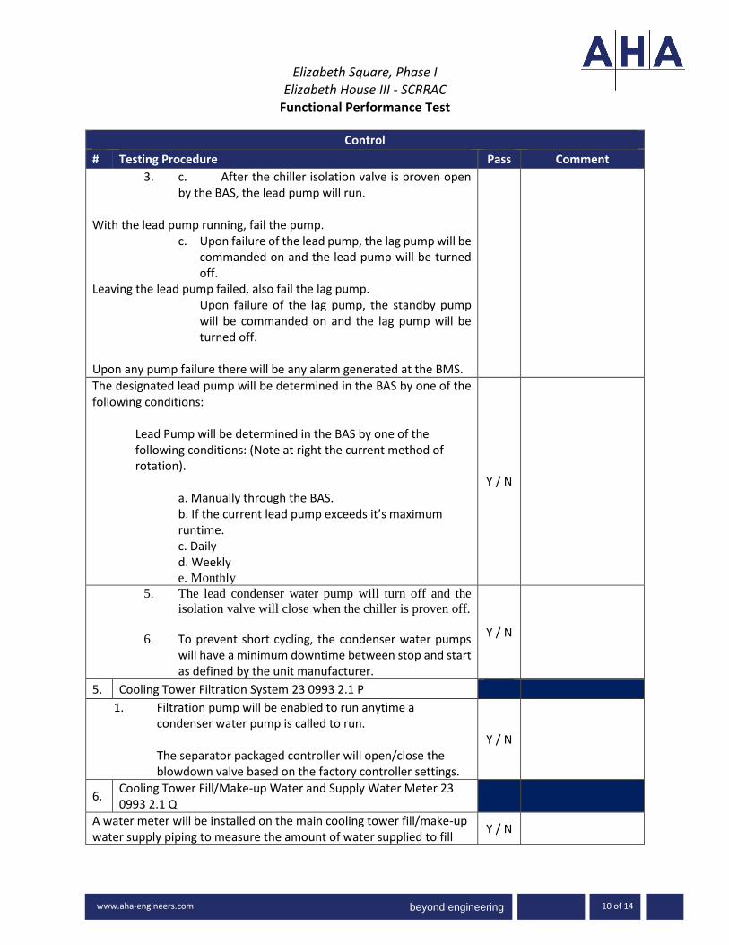
beyond engineering
Elizabeth Square, Phase I
Elizabeth House III - SCRRAC Functional Performance Test
-3000 www.ah
www.aha-engineers.com 10 of 14
Control
# Testing Procedure Pass Comment
3. c. After the chiller isolation valve is proven open by the BAS, the lead pump will run.
With the lead pump running, fail the pump. c. Upon failure of the lead pump, the lag pump will be
commanded on and the lead pump will be turned off.
Leaving the lead pump failed, also fail the lag pump. Upon failure of the lag pump, the standby pump will be commanded on and the lag pump will be turned off.
Upon any pump failure there will be any alarm generated at the BMS.
The designated lead pump will be determined in the BAS by one of the following conditions:
Lead Pump will be determined in the BAS by one of the following conditions: (Note at right the current method of rotation).
a. Manually through the BAS. b. If the current lead pump exceeds it’s maximum runtime. c. Daily d. Weekly e. Monthly
Y / N
5. The lead condenser water pump will turn off and the
isolation valve will close when the chiller is proven off.
6. To prevent short cycling, the condenser water pumps will have a minimum downtime between stop and start as defined by the unit manufacturer.
Y / N
5. Cooling Tower Filtration System 23 0993 2.1 P
1. Filtration pump will be enabled to run anytime a condenser water pump is called to run. The separator packaged controller will open/close the blowdown valve based on the factory controller settings.
Y / N
6. Cooling Tower Fill/Make-up Water and Supply Water Meter 23 0993 2.1 Q
A water meter will be installed on the main cooling tower fill/make-up water supply piping to measure the amount of water supplied to fill
Y / N

beyond engineering
Elizabeth Square, Phase I
Elizabeth House III - SCRRAC Functional Performance Test
-3000 www.ah
www.aha-engineers.com 11 of 14
Control
# Testing Procedure Pass Comment
the cooling tower/condenser piping and/or the cooling tower water treatment blow down make-up water. This data will be sent from the meter to the BAS system for flow rate totalization. The BAS will provide an alarm if the water meter is measuring flow when all float valves and make-up water valves are closed
The cooling tower basin will have an electronic level to maintain the basin water level in the tower. In addition to the electronic level control system, a mechanical float switch will be provided at a level slightly lower than the electronic fill sensor location. (Test to be conducted for both towers). The BAS will monitor both switches and operate fill if either signal indicates low water fill required.
a. From the BMS adjust the electronic level control setpoint slightly higher than the current sensed basin water level.
b. Low sump alarm will be sent to the BAS. c. Verify the make-up valve opens and is indicated
on the BMS. d. Return the electronic fill level setpoint to normal. e. The make-up water valve will close, BMS low
sump alarm will clear. Once all clear(s) have been cleared, manually active the mechanical float switch.
a. Low sump alarm will be sent to the BAS. b. Verify the make-up valve opens and is indicated on
the BMS. c. Release the mechanical float switch. The make-up
water valve will close, d. BMS low sump alarm will clear.
Verify all alarms are cleared and the system is operating normally.
Y / N
Manually active the blow down valve at the cooling tower water treatment location.
1. When the blow down valve at the cooling tower water treatment location opens to drain, the similarly sized make-up water valve, also at the cooling tower water treatment area, will also open.
Y / N

beyond engineering
Elizabeth Square, Phase I
Elizabeth House III - SCRRAC Functional Performance Test
-3000 www.ah
www.aha-engineers.com 12 of 14
Control
# Testing Procedure Pass Comment
a. The BMS will indicate valve activation and valve position.
b. Make-up water valve will activate also – indicated at the BMS.
When the blow down valve closes, the make-up supply valve will also close.
a. Verify the BMS indicates the change in status.
7. Cooling Tower Drain Valves and Drain Water Meter 23 0993 2.1 R
1. From the BMS verify the follow:
a. The user will be provided with a separate onscreen button for the cooling tower’s drain valve.
b. When the button is pushed, the valve will automatically fully open the 2-way drain control valve.
c. A ‘deduct’ water meter will be installed on the main cooling tower drain piping to measure the amount of water sent to sanitary sewer. This data will be sent from the meter to the BAS system for flow rate totalization.
d. The ‘deduct’ water meter will also be sent any water that the cooling tower water treatment chooses to blow down to the drain by opening a 2-way valve.
2. The BAS will provide an alarm if the water meter is measuring flow if either drain or blow down valves indicate closed.
3. The user will be provided with an onscreen button for the condenser water system’s drain valve that when it is pushed will automatically fully open the corresponding 2-way drain control valve.
Y / N
Alarm
# Testing Procedure Pass Comment
1. Cooling Tower(s) failure (typ of both) Y / N
2. Isolation valve failure (typ of all) Y / N
3. Differential pressure sensor failure Y / N
4. Temperature sensor failure (typ of all) Y / N
5. VFD failure (all pumps) Y / N
6. High differential pressure Y / N
7. Low differential pressure Y / N
8. Low condenser water supply temperature Y / N
9. High condenser water supply temperature Y / N

beyond engineering
Elizabeth Square, Phase I
Elizabeth House III - SCRRAC Functional Performance Test
-3000 www.ah
www.aha-engineers.com 13 of 14
10. Pump No Water Flow (CT) (typ of all) Y / N
11. High level water switch turns on Y / N
12. Low water make-up switch turns on Y / N
13. Low level water switch turns on Y / N
14. Vibration Cut-Out switch turns on Y / N
Wrap Up
# Testing Procedure Pass Comment
1. Y / N
2. Y / N
3. Y / N
4. Y / N
5. Y / N
6. Y / N
7. Y / N
8. Y / N
Comments:
Trend Report
The following points will be trended every 15 minutes for period of not less than 2 weeks. These trends will be conducted at least twice a year: one in the cooling season and once in the heating season. Completed Trend Reports will be submitted in a format compatible with MS Excel.
Trend Report
Trend Trend Group Points
Differential Pressure Control
1. Differential Pressure Setpoint
2. Differential Pressure
3. Fan/Pump Speed
Supply Temperature Control
1. Supply Temperature Setpoint
2. Supply Temperature
3. Return Temperature
4. Boiler, Valve, Cooling/Heating
Acceptance of Test:

beyond engineering
Elizabeth Square, Phase I
Elizabeth House III - SCRRAC Functional Performance Test
-3000 www.ah
www.aha-engineers.com 14 of 14
☐ This test cannot be accepted at this time due to the Corrective Issues noted above.
☐ This test is accepted by the Commissioning Authority identified below. Any Corrective Issues noted above do not adversely impact the overall performance of the system.
Tested by Date
Witnessed by Date
Commissioning Provider Attachment(s): Sequence of Operations

beyond engineering
Elizabeth Square, Phase I Elizabeth House III - SCRRAC
Functional Performance Test
1 of 6
Overview
Equipment/Systems Exhaust Fan
Equipment ID/Tag No. EF-2-1 (typ of EF-B1-7)
Equipment Location:
Area(s) Served: SCRRAC Electrical Closet
System Description: Electrical Closet Exhaust
Spec Section(s): 23 0993, 23 5100
Test Execution
Initial Date: Initial Time:
Retest Date: Retest Time:
Ambient Conditions: ☐ Dry ☐ Rain ☐ Snow ☐ Sunny ☐ Cloudy
Outside Air Temperature oF Outside Air Humidity %RH
Hot Water Temperature oF Chilled Water Temperature oF
Equipment Data
Equipment
Nameplate
EF-2-1
Matches Approved Submittal
Manufacturer n/a ☐
Model Number n/a ☐
Serial Number n/a
Prerequisite Documentation
Item Yes No
Verify that the Pre-Functional Checklist for this piece of equipment has been successfully completed, signed by appropriate parties, and returned to the Commissioning Authority.
☐ ☐
Verify that the manufacturer’s start-up procedure for this piece of equipment has been successfully completed and a copy of the completed start-up procedure has been submitted to the Commissioning Authority.
☐ ☐
Verify that Test & Balance for this piece of equipment has been successfully completed, reviewed and approved by the Engineer of record, and submitted to the Commissioning Authority.
☐ ☐
Verify unit is tied into the BMS system and graphics are complete. ☐ ☐
Verify all required I/O points are listed on the BMS system. ☐ ☐ Verify ATC point-to-point and sensor/actuator calibration checks have been completed, documented and has been submitted to the Commissioning Authority. ☐ ☐

beyond engineering
Elizabeth Square, Phase I
Elizabeth House III - SCRRAC Functional Performance Test
-3000 www.ah
www.aha-engineers.com 2 of 6
Prerequisite Documentation
Item Yes No
All trends specified at the end of this test have been setup and are trending. ☐ ☐
Required Personnel and Tools Available ☐ ☐
System Ready for Functional Testing ☐ ☐
Participants:
Name Company Project Role Required
Yes No
CM/GC ☐ ☐
Owner/Owners Rep ☐ ☐
Sub-Contractor ☐ ☐
Controls Contractor ☐ ☐
Commissioning Authority ☐ ☐
Commissioning Agent ☐ ☐
Supplies Required for Testing
Tools/Supplies Provided by
Schedule
System runs based on non-scheduled variable (e.g.: temperature, pressure) ☒
System runs 24 hours a day, 7 days a week (no schedule) ☐
System runs on then programmable schedule indicated below (TBD) ☐
Mon - Fri Sat - Sun Holiday
*Adj – indicates the point is adjustable
Setpoints
Parameter Expected Actual Unit BMS Adj
Temperature (oF) ☐ ☐ ☐

beyond engineering
Elizabeth Square, Phase I
Elizabeth House III - SCRRAC Functional Performance Test
-3000 www.ah
www.aha-engineers.com 3 of 6
Setpoints
Parameter Expected Actual Unit BMS Adj
Local Thermostat setpoint 85 deg F
(adj.) oF ☒ ☐ ☐
Alarm Temperature (oF / psi) ☒ ☐ ☐ ☐ ☐ ☐ ☐ ☐
Initial Conditions
Conditions Unit/ Measured Thermostat/ BMS
Temperature oF oF
Space temperature oF oF
Alarm (normal) (alarm) (normal) (alarm)
Fan Failure
Status (on) (off) (on) (off)
Fan Status
Local Speed Controller % %
Comments:
The above set points and initial conditions are key items for commissioning purposes. Review all data available at local controllers and the Building Management System (BMS) front-end computer and note any additional values the affect system operations (e.g. lockouts or time delays). Some values will require the use of measurement equipment.
Device Calibration Checks
The actuators or devices listed below are to be checked for calibration. This is a spot check on a sample of the calibrations completed during the pre-functional checklist and contractor start-up processes. “In calibration” means observing a readout at the BMS and going to the actuator or controlled device and verifying that the BMS reading is correct, this was done during the recording of initial conditions. For the calibration portion - command speed or position to open, intermediate, and closed. Record read out and field observations at each. Below add actual sampled devices

beyond engineering
Elizabeth Square, Phase I
Elizabeth House III - SCRRAC Functional Performance Test
-3000 www.ah
www.aha-engineers.com 4 of 6
Device Calibration Checks
Device or Actuator & Location
Procedure/ State 1st BAS Value
Site Observation
Final BAS Reading
Pass
Yes No
Supply Fan VFD
1. Min: % % % % ☐ ☐
2. Mid: % % % % ☐ ☐
3. Max: % % % % ☐ ☐
Supply Fan VFD
1. Min: % % % % ☐ ☐
2. Mid: % % % % ☐ ☐
3. Max: % % % % ☐ ☐
Valve
1. Closed ☐ ☐
2. 50 % ☐ ☐
3. Full Open ☐ ☐
Sensor Calibration Checks
Check the sensors listed below for calibration and adequate location. This is a sampling check of calibrations done during the pre-functional checklist and contractor start-up processes. “In calibration” means making a reading with a calibrated test instrument within 6 inches of the site sensor. Verify that the sensor reading (via permanent thermostat, gauge, packaged control panel or Building Management System [BMS]) compared to the test instrument-measured value is within the tolerances specified. If not, install offset at BMS, calibrate or replace sensor. Use the same test instrument as used for the original calibration, if possible. This should instrument should be provided by the controls or mechanical contractor. Below add actual sampled devices
Sensor Calibration Checks
Sensor & Location
Location OK*
Gauge or Pkg & BAS
Values
Instrument Measured
Value
Point Type
Pass **
Yes No Yes No
Supply Temperature ☐ ☐ oF oF AI ☐ ☐
Return Temperature ☐ ☐ oF oF AI ☐ ☐
Flow Switch ☐ ☐ AI ☐ ☐
Pump Start/Stop ☐ ☐ DO ☐ ☐
Pump Status ☐ ☐ DI ☐ ☐
Pump VFD Fault ☐ ☐ DI ☐ ☐ * Sensor location is appropriate and away from cause of erratic operation. ** See acceptable ranges per specifications in table below

beyond engineering
Elizabeth Square, Phase I
Elizabeth House III - SCRRAC Functional Performance Test
-3000 www.ah
www.aha-engineers.com 5 of 6
Sensor Calibration Points
Point Acceptable Range
Static Pressure ± 0.3 in.wc
Temperature ± 1 F
Differential Pressure ± 10 %
Airflow ± 10 %
Waterflow ± 10 %
Comments:
Functional Performance Verification
The following procedures are a summary of the steps required to test the system function as described in the attached sequence of operations. The intent is for the system operation to be reviewed at both the piece of equipment (local/measured) and the controller - thermostat, BMS, DDC, etc. (Control). It should be noted that additional steps (not listed) may be required in order to achieve the noted simulation. Items will be noted as Pass Yes/No, N/A – Not Applicable, or N/T – Not Tested. Detailed information on failures will be noted in the commissioning issues log...
Control
# Testing Procedure Pass Comment
Description: General Exhaust
1.
Exhaust Fan will operate via local thermostat. From the local thermostat, adjust the setpoint up and then down to operate the fan. Verify operation at the BMS.
Y / N
2. Verify fan failure at the BMS Y / N
Alarm
# Testing Procedure Pass Comment
1. Fan Failure Y / N
Wrap Up
# Testing Procedure Pass Comment
1. Y / N
2. Y / N

beyond engineering
Elizabeth Square, Phase I
Elizabeth House III - SCRRAC Functional Performance Test
-3000 www.ah
www.aha-engineers.com 6 of 6
Comments:
Trend Report
The following points will be trended every 15 minutes for period of not less than 2 weeks. These trends will be conducted at least twice a year: one in the cooling season and once in the heating season. Completed Trend Reports will be submitted in a format compatible with MS Excel.
Trend Report
Trend Trend Group Points
Acceptance of Test:
☐ This test cannot be accepted at this time due to the Corrective Issues noted above.
☐ This test is accepted by the Commissioning Authority identified below. Any Corrective Issues noted above do not adversely impact the overall performance of the system.
Tested by Date
Witnessed by Date
Commissioning Provider Attachment(s): Sequence of Operations

beyond engineering
Elizabeth Square, Phase I Elizabeth House III - SCRRAC
Functional Performance Test
1 of 7
Overview
Equipment/Systems Exhaust Fan
Equipment ID/Tag No. EF-B1-1, & 6
Equipment Location: G107
Area(s) Served: SCRRAC Pool Chemical, Pool Equip
System Description: EXHAUST
Spec Section(s): 23 0993, 23 5100
Test Execution
Initial Date: Initial Time:
Retest Date: Retest Time:
Ambient Conditions: ☐ Dry ☐ Rain ☐ Snow ☐ Sunny ☐ Cloudy
Outside Air Temperature oF Outside Air Humidity %RH
Hot Water Temperature oF Chilled Water Temperature oF
Equipment Data
Equipment
Nameplate
EF-B1-1
Matches Approved Submittal
Manufacturer n/a ☐
Model Number n/a ☐
Serial Number n/a
Prerequisite Documentation
Item Yes No
Verify that the Pre-Functional Checklist for this piece of equipment has been successfully completed, signed by appropriate parties, and returned to the Commissioning Authority.
☐ ☐
Verify that the manufacturer’s start-up procedure for this piece of equipment has been successfully completed and a copy of the completed start-up procedure has been submitted to the Commissioning Authority.
☐ ☐
Verify that Test & Balance for this piece of equipment has been successfully completed, reviewed and approved by the Engineer of record, and submitted to the Commissioning Authority.
☐ ☐
Verify unit is tied into the BMS system and graphics are complete. ☐ ☐
Verify all required I/O points are listed on the BMS system. ☐ ☐ Verify ATC point-to-point and sensor/actuator calibration checks have been completed, documented and has been submitted to the Commissioning Authority. ☐ ☐

beyond engineering
Elizabeth Square, Phase I
Elizabeth House III - SCRRAC Functional Performance Test
-3000 www.ah
www.aha-engineers.com 2 of 7
Prerequisite Documentation
Item Yes No
All trends specified at the end of this test have been setup and are trending. ☐ ☐
Required Personnel and Tools Available ☐ ☐
System Ready for Functional Testing ☐ ☐
Participants:
Name Company Project Role Required
Yes No
CM/GC ☐ ☐
Owner/Owners Rep ☐ ☐
Sub-Contractor ☐ ☐
Controls Contractor ☐ ☐
Commissioning Authority ☐ ☐
Commissioning Agent ☐ ☐
Supplies Required for Testing
Tools/Supplies Provided by
Schedule
System runs based on non-scheduled variable (e.g.: temperature, pressure) ☐
System runs 24 hours a day, 7 days a week (no schedule) ☒
System runs on then programmable schedule indicated below (TBD) ☐
Mon - Fri Sat - Sun Holiday
*Adj – indicates the point is adjustable
Setpoints
Parameter Expected Actual Unit BMS Adj
Temperature (oF) ☐ ☐ ☐

beyond engineering
Elizabeth Square, Phase I
Elizabeth House III - SCRRAC Functional Performance Test
-3000 www.ah
www.aha-engineers.com 3 of 7
Setpoints
Parameter Expected Actual Unit BMS Adj
oF ☒ ☐ ☐
Alarm Temperature (oF / psi) ☒ ☐ ☐ ☐ ☐ ☐ ☐ ☐
Initial Conditions
Conditions Unit/ Measured Thermostat/ BMS
Pressure psi psi
Stack Pressure psi psi
Alarm (normal) (alarm) (normal) (alarm)
Fan Failure
High/Low stack pressure (coordinate values with selected domestic water heating vendor)
Status (on) (off) (on) (off)
Fan Status
Fan Start/Stop
Local Speed Controller % %
Fan Speed
Comments:
The above set points and initial conditions are key items for commissioning purposes. Review all data available at local controllers and the Building Management System (BMS) front-end computer and note any additional values the affect system operations (e.g. lockouts or time delays). Some values will require the use of measurement equipment.
Device Calibration Checks
The actuators or devices listed below are to be checked for calibration. This is a spot check on a sample of the calibrations completed during the pre-functional checklist and contractor start-up processes. “In calibration” means observing a readout at the BMS and going to the actuator or controlled device and verifying that the BMS reading is correct, this was done during the recording of initial conditions. For the calibration portion - command speed or position to open, intermediate, and closed. Record read out and field observations at each. Below add actual sampled devices

beyond engineering
Elizabeth Square, Phase I
Elizabeth House III - SCRRAC Functional Performance Test
-3000 www.ah
www.aha-engineers.com 4 of 7
Device Calibration Checks
Device or Actuator & Location
Procedure/ State 1st BAS Value
Site Observation
Final BAS Reading
Pass
Yes No
Supply Fan VFD
1. Min: % % % % ☐ ☐
2. Mid: % % % % ☐ ☐
3. Max: % % % % ☐ ☐
Supply Fan VFD
1. Min: % % % % ☐ ☐
2. Mid: % % % % ☐ ☐
3. Max: % % % % ☐ ☐
Valve
1. Closed ☐ ☐
2. 50 % ☐ ☐
3. Full Open ☐ ☐
Sensor Calibration Checks
Check the sensors listed below for calibration and adequate location. This is a sampling check of calibrations done during the pre-functional checklist and contractor start-up processes. “In calibration” means making a reading with a calibrated test instrument within 6 inches of the site sensor. Verify that the sensor reading (via permanent thermostat, gauge, packaged control panel or Building Management System [BMS]) compared to the test instrument-measured value is within the tolerances specified. If not, install offset at BMS, calibrate or replace sensor. Use the same test instrument as used for the original calibration, if possible. This should instrument should be provided by the controls or mechanical contractor. Below add actual sampled devices
Sensor Calibration Checks
Sensor & Location
Location OK*
Gauge or Pkg & BAS
Values
Instrument Measured
Value
Point Type
Pass **
Yes No Yes No
Supply Temperature ☐ ☐ oF oF AI ☐ ☐
Return Temperature ☐ ☐ oF oF AI ☐ ☐
Flow Switch ☐ ☐ AI ☐ ☐
Pump Start/Stop ☐ ☐ DO ☐ ☐
Pump Status ☐ ☐ DI ☐ ☐
Pump VFD Fault ☐ ☐ DI ☐ ☐ * Sensor location is appropriate and away from cause of erratic operation. ** See acceptable ranges per specifications in table below

beyond engineering
Elizabeth Square, Phase I
Elizabeth House III - SCRRAC Functional Performance Test
-3000 www.ah
www.aha-engineers.com 5 of 7
Sensor Calibration Points
Point Acceptable Range
Static Pressure ± 0.3 in.wc
Temperature ± 1 F
Differential Pressure ± 10 %
Airflow ± 10 %
Waterflow ± 10 %
Comments:
Functional Performance Verification
The following procedures are a summary of the steps required to test the system function as described in the attached sequence of operations. The intent is for the system operation to be reviewed at both the piece of equipment (local/measured) and the controller - thermostat, BMS, DDC, etc. (Control). It should be noted that additional steps (not listed) may be required in order to achieve the noted simulation. Items will be noted as Pass Yes/No, N/A – Not Applicable, or N/T – Not Tested. Detailed information on failures will be noted in the commissioning issues log...
Control
# Testing Procedure Pass Comment
Description: 23 0993 2.15 H Exhaust fan shall be provided for common venting of the domestic water heating system located on B1 in Water Pump Room G109. The fan shall operate 24/7/ Exhaust fan manufacturer shall provide fan, vent system controller, and all associated sensors.
1.
The mechanical contractor will vary the control settings to verify the following operation: The controller shall monitor the vent stack pressure and modulate the ECM motor on the vent fan to maintain stack pressure set point as coordinated with the furnished domestic water heaters.
Y / N
2. From the BMS verify the monitoring as detailed below: Y / N

beyond engineering
Elizabeth Square, Phase I
Elizabeth House III - SCRRAC Functional Performance Test
-3000 www.ah
www.aha-engineers.com 6 of 7
Control
# Testing Procedure Pass Comment
The controller shall monitor the fan status, speed, and stack pressure and shall be provided with network interface card to integrate into the BAS.
Alarm
# Testing Procedure Pass Comment
1. Fan Failure Y / N
2. High/Low stack pressure (coordinate values with selected domestic water heating vendor)
Y / N
Wrap Up
# Testing Procedure Pass Comment
1. Y / N
2. Y / N
3. Y / N
4. Y / N
5. Y / N
6. Y / N
7. Y / N
8. Y / N
Comments:
Trend Report
The following points will be trended every 15 minutes for period of not less than 2 weeks. These trends will be conducted at least twice a year: one in the cooling season and once in the heating season. Completed Trend Reports will be submitted in a format compatible with MS Excel.
Trend Report
Trend Trend Group Points

beyond engineering
Elizabeth Square, Phase I
Elizabeth House III - SCRRAC Functional Performance Test
-3000 www.ah
www.aha-engineers.com 7 of 7
Trend Report
Trend Trend Group Points
Acceptance of Test:
☐ This test cannot be accepted at this time due to the Corrective Issues noted above.
☐ This test is accepted by the Commissioning Authority identified below. Any Corrective Issues noted above do not adversely impact the overall performance of the system.
Tested by Date
Witnessed by Date
Commissioning Provider Attachment(s): Sequence of Operations

beyond engineering
Elizabeth Square, Phase I Elizabeth House III - SCRRAC
Functional Performance Test
1 of 6
Overview
Equipment/Systems Exhaust Fan
Equipment ID/Tag No. EF-B1-4
Equipment Location: Pool Equipment Room
Area(s) Served: SCRRAC Emergency Exhaust Fan
System Description: Exhaust
Spec Section(s): 23 0993, 23 5100
Test Execution
Initial Date: Initial Time:
Retest Date: Retest Time:
Ambient Conditions: ☐ Dry ☐ Rain ☐ Snow ☐ Sunny ☐ Cloudy
Outside Air Temperature oF Outside Air Humidity %RH
Hot Water Temperature oF Chilled Water Temperature oF
Equipment Data
Equipment
Nameplate
EF-B1-4
Matches Approved Submittal
Manufacturer n/a ☐
Model Number n/a ☐
Serial Number n/a
Prerequisite Documentation
Item Yes No
Verify that the Pre-Functional Checklist for this piece of equipment has been successfully completed, signed by appropriate parties, and returned to the Commissioning Authority.
☐ ☐
Verify that the manufacturer’s start-up procedure for this piece of equipment has been successfully completed and a copy of the completed start-up procedure has been submitted to the Commissioning Authority.
☐ ☐
Verify that Test & Balance for this piece of equipment has been successfully completed, reviewed and approved by the Engineer of record, and submitted to the Commissioning Authority.
☐ ☐
Verify unit is tied into the BMS system and graphics are complete. ☐ ☐
Verify all required I/O points are listed on the BMS system. ☐ ☐ Verify ATC point-to-point and sensor/actuator calibration checks have been completed, documented and has been submitted to the Commissioning Authority. ☐ ☐

beyond engineering
Elizabeth Square, Phase I
Elizabeth House III - SCRRAC Functional Performance Test
-3000 www.ah
www.aha-engineers.com 2 of 6
Prerequisite Documentation
Item Yes No
All trends specified at the end of this test have been setup and are trending. ☐ ☐
Required Personnel and Tools Available ☐ ☐
System Ready for Functional Testing ☐ ☐
Participants:
Name Company Project Role Required
Yes No
CM/GC ☐ ☐
Owner/Owners Rep ☐ ☐
Sub-Contractor ☐ ☐
Controls Contractor ☐ ☐
Commissioning Authority ☐ ☐
Commissioning Agent ☐ ☐
Supplies Required for Testing
Tools/Supplies Provided by
Schedule
System runs based on non-scheduled variable (e.g.: temperature, pressure) ☒
System runs 24 hours a day, 7 days a week (no schedule) ☐
System runs on then programmable schedule indicated below (TBD) ☐
Mon - Fri Sat - Sun Holiday
*Adj – indicates the point is adjustable
Setpoints
Parameter Expected Actual Unit BMS Adj
Temperature (oF) ☐ ☐ ☐

beyond engineering
Elizabeth Square, Phase I
Elizabeth House III - SCRRAC Functional Performance Test
-3000 www.ah
www.aha-engineers.com 3 of 6
Initial Conditions
Conditions Unit/ Measured Thermostat/ BMS
Temperature oF oF
Space temperature oF oF
Alarm (normal) (alarm) (normal) (alarm)
Fan Failure
Status (on) (off) (on) (off)
Fan Status
Local Speed Controller % %
Comments:
The above set points and initial conditions are key items for commissioning purposes. Review all data available at local controllers and the Building Management System (BMS) front-end computer and note any additional values the affect system operations (e.g. lockouts or time delays). Some values will require the use of measurement equipment.
Device Calibration Checks
The actuators or devices listed below are to be checked for calibration. This is a spot check on a sample of the calibrations completed during the pre-functional checklist and contractor start-up processes. “In calibration” means observing a readout at the BMS and going to the actuator or controlled device and verifying that the BMS reading is correct, this was done during the recording of initial conditions. For the calibration portion - command speed or position to open, intermediate, and closed. Record read out and field observations at each. Below add actual sampled devices
Device Calibration Checks
Device or Actuator & Location
Procedure/ State 1st BAS Value
Site Observation
Final BAS Reading
Pass
Yes No
Supply Fan VFD
1. Min: % % % % ☐ ☐
2. Mid: % % % % ☐ ☐
3. Max: % % % % ☐ ☐
Supply Fan VFD 1. Min: % % % % ☐ ☐
2. Mid: % % % % ☐ ☐

beyond engineering
Elizabeth Square, Phase I
Elizabeth House III - SCRRAC Functional Performance Test
-3000 www.ah
www.aha-engineers.com 4 of 6
Device Calibration Checks
Device or Actuator & Location
Procedure/ State 1st BAS Value
Site Observation
Final BAS Reading
Pass
Yes No
3. Max: % % % % ☐ ☐
Valve
1. Closed ☐ ☐
2. 50 % ☐ ☐
3. Full Open ☐ ☐
Sensor Calibration Checks
Check the sensors listed below for calibration and adequate location. This is a sampling check of calibrations done during the pre-functional checklist and contractor start-up processes. “In calibration” means making a reading with a calibrated test instrument within 6 inches of the site sensor. Verify that the sensor reading (via permanent thermostat, gauge, packaged control panel or Building Management System [BMS]) compared to the test instrument-measured value is within the tolerances specified. If not, install offset at BMS, calibrate or replace sensor. Use the same test instrument as used for the original calibration, if possible. This should instrument should be provided by the controls or mechanical contractor. Below add actual sampled devices
Sensor Calibration Checks
Sensor & Location
Location OK*
Gauge or Pkg & BAS
Values
Instrument Measured
Value
Point Type
Pass **
Yes No Yes No
Supply Temperature ☐ ☐ oF oF AI ☐ ☐
Return Temperature ☐ ☐ oF oF AI ☐ ☐
Flow Switch ☐ ☐ AI ☐ ☐
Pump Start/Stop ☐ ☐ DO ☐ ☐
Pump Status ☐ ☐ DI ☐ ☐
Pump VFD Fault ☐ ☐ DI ☐ ☐ * Sensor location is appropriate and away from cause of erratic operation. ** See acceptable ranges per specifications in table below
Sensor Calibration Points
Point Acceptable Range
Static Pressure ± 0.3 in.wc
Temperature ± 1 F
Differential Pressure ± 10 %
Airflow ± 10 %
Waterflow ± 10 %

beyond engineering
Elizabeth Square, Phase I
Elizabeth House III - SCRRAC Functional Performance Test
-3000 www.ah
www.aha-engineers.com 5 of 6
Comments:
Functional Performance Verification
The following procedures are a summary of the steps required to test the system function as described in the attached sequence of operations. The intent is for the system operation to be reviewed at both the piece of equipment (local/measured) and the controller - thermostat, BMS, DDC, etc. (Control). It should be noted that additional steps (not listed) may be required in order to achieve the noted simulation. Items will be noted as Pass Yes/No, N/A – Not Applicable, or N/T – Not Tested. Detailed information on failures will be noted in the commissioning issues log...
Control
# Testing Procedure Pass Comment
Description: Emrgency Exhaust
1.
Exhaust Fan will operate via local switch and/or the BMS. From the local switch, enable the fan. From the BMS enable the fan. Verify operation at the BMS.
Y / N
2. Verify fan failure at the BMS Y / N
Alarm
# Testing Procedure Pass Comment
1. Fan Failure Y / N
Wrap Up
# Testing Procedure Pass Comment
1. Y / N
2. Y / N
Comments:

beyond engineering
Elizabeth Square, Phase I
Elizabeth House III - SCRRAC Functional Performance Test
-3000 www.ah
www.aha-engineers.com 6 of 6
Trend Report
The following points will be trended every 15 minutes for period of not less than 2 weeks. These trends will be conducted at least twice a year: one in the cooling season and once in the heating season. Completed Trend Reports will be submitted in a format compatible with MS Excel.
Trend Report
Trend Trend Group Points
Acceptance of Test:
☐ This test cannot be accepted at this time due to the Corrective Issues noted above.
☐ This test is accepted by the Commissioning Authority identified below. Any Corrective Issues noted above do not adversely impact the overall performance of the system.
Tested by Date
Witnessed by Date
Commissioning Provider Attachment(s): Sequence of Operations

beyond engineering
Elizabeth Square, Phase I Elizabeth House III - SCRRAC
Functional Performance Test
1 of 11
Overview
Equipment/Systems Energy Recovering Unit
Equipment ID/Tag No. ERU-B1-1
Equipment Location: LEVEL B1
Area(s) Served: SCRRAC
System Description: Conditioned Air serving Level B-1 Locker Room
Spec Section(s): 23 0993, 23 7313.16 & 23 7313.17
Test Execution
Initial Date: Initial Time:
Retest Date: Retest Time:
Ambient Conditions: ☐ Dry ☐ Rain ☐ Snow ☐ Sunny ☐ Cloudy
Outside Air Temperature oF Outside Air Humidity %RH
Hot Water Temperature oF Chilled Water Temperature oF
Equipment Data
Equipment
Nameplate
ERU-B1-1
Matches Approved Submittal
Manufacturer n/a ☐
Model Number n/a ☐
Serial Number n/a
Prerequisite Documentation
Item Yes No
Verify that the Pre-Functional Checklist for this piece of equipment has been successfully completed, signed by appropriate parties, and returned to the Commissioning Authority.
☐ ☐
Verify that the manufacturer’s start-up procedure for this piece of equipment has been successfully completed and a copy of the completed start-up procedure has been submitted to the Commissioning Authority.
☐ ☐
Verify that Test & Balance for this piece of equipment has been successfully completed, reviewed and approved by the Engineer of record, and submitted to the Commissioning Authority.
☐ ☐
Verify unit is tied into the BMS system and graphics are complete. ☐ ☐
Verify all required I/O points are listed on the BMS system. ☐ ☐ Verify ATC point-to-point and sensor/actuator calibration checks have been completed, documented and has been submitted to the Commissioning Authority. ☐ ☐

beyond engineering
Elizabeth Square, Phase I
Elizabeth House III - SCRRAC Functional Performance Test
-3000 www.ah
www.aha-engineers.com 2 of 11
Prerequisite Documentation
Item Yes No
All trends specified at the end of this test have been setup and are trending. ☐ ☐
Required Personnel and Tools Available ☐ ☐
System Ready for Functional Testing ☐ ☐
Participants:
Name Company Project Role Required
Yes No
CM/GC ☐ ☐
Owner/Owners Rep ☐ ☐
Sub-Contractor ☐ ☐
Controls Contractor ☐ ☐
Commissioning Authority ☐ ☐
Commissioning Agent ☐ ☐
Supplies Required for Testing
Tools/Supplies Provided by
Schedule
System runs based on non-scheduled variable (e.g.: temperature, pressure) ☐
System runs 24 hours a day, 7 days a week (no schedule) ☐
System runs on then programmable schedule indicated below (TBD) ☒
Mon - Fri Sat - Sun Holiday
*Adj – indicates the point is adjustable
Setpoints
Parameter Expected Actual Unit BMS Adj
Temperature (oF) ☐ ☐ ☐

beyond engineering
Elizabeth Square, Phase I
Elizabeth House III - SCRRAC Functional Performance Test
-3000 www.ah
www.aha-engineers.com 3 of 11
Setpoints
Parameter Expected Actual Unit BMS Adj
Occupied mode Supply air temperature set point (supply air temperature set point)
80 deg. F oF ☐ ☒ ☐
Occupied mode Supply fan VFD speed 100 % of design flow
oF ☐ ☒ ☒
Occupied mode Exhaust fan VFD speed 100 % of design flow
oF ☐ ☒ ☒
Unoccupied mode Supply air temperature set point (supply air temperature set point)
80 deg. F oF ☐ ☒ ☐
Unoccupied mode Supply fan VFD speed TBD oF ☐ ☒ ☒ Unoccupied mode Exhaust fan VFD speed TBD oF ☐ ☒ ☒ Exhaust Air Defrost 38 deg. F oF ☐ ☒ ☒
Alarm Temperature (oF / psi) ☒ ☐ ☐ ☐ ☐ Chilled Water Coil Freeze Protection 35 deg. F ☒ ☐ ☐ High Supply Air Temperature 5°F (adj.)
greater than setpoint.
☐ ☒ ☒
Low Supply Air Temperature 45ºF (adj.) ☐ ☒ ☒ Return Air Temperature (High) 90°F (adj.). ☐ ☒ ☒ Return Air Temperature (Low) 45°F (adj.). ☐ ☒ ☒ Return Air Humidity 70% (adj. ☐ ☒ ☒
Initial Conditions
Conditions Unit/ Measured Thermostat/ BMS
Temperature oF oF
Supply Leaving Air Temperature oF oF
Supply Air Temperature Setpoint oF oF
Plate Heat Exchanger Discharge Air Temp oF oF
Plate Heat Exchanger Discharge Air Humidity oF oF
Chilled Water Coil Leaving Air Temperature oF oF
Return Air Temperature oF oF
Outside Air Temperature (polled from roof) oF oF
Exhaust Air Temperature oF oF
Zone Temperature 1 oF oF

beyond engineering
Elizabeth Square, Phase I
Elizabeth House III - SCRRAC Functional Performance Test
-3000 www.ah
www.aha-engineers.com 4 of 11
Initial Conditions
Conditions Unit/ Measured Thermostat/ BMS
Zone Temperature 2 oF oF
Humidity % %
Return Air Humidity % %
Outside Air Humidity (polled from roof) % %
Alarm (normal) (alarm) (normal) (alarm)
Freeze stat
High Static Shutdown
High Supply Air Temperature
Low Supply Air Temperature
OA Filter Differential Pressure
RA Filter Differential Pressure
Condensate drain plan overflow switch activated.
Return Air Dirty Filter
Re-Circ Air Damper Failure
Chilled Water Control Valve Failure
Re-Heating Valve Failure
Supply Air Smoke Detection.
Return Air Smoke Detection.
Supply Fan VFD Failure
Exhaust Fan VFD Failure
Damper Position % %
Re-Circ Air Damper Position % %
Status (on) (off) (on) (off)
Supply Fan Status
Supply Fan Start/Stop
Exhaust Fan Status
Exhaust Fan Start/Stop
OA Damper open/closed
Exhaust Air Damper open/closed
Operating Hours hrs hrs
AHU
Supply fan (adj.) minimum runtime

beyond engineering
Elizabeth Square, Phase I
Elizabeth House III - SCRRAC Functional Performance Test
-3000 www.ah
www.aha-engineers.com 5 of 11
Initial Conditions
Conditions Unit/ Measured Thermostat/ BMS
Exhaust fan (adj.) minimum runtime
Valve 2-way & 3 Way (open) (closed) (open) (closed)
Chilled Water Control Valve Position
Heating Valve Position
VFD Speed hz/% hz/%
Supply Fan Speed
Exhaust Fan Speed
Comments:
The above set points and initial conditions are key items for commissioning purposes. Review all data available at local controllers and the Building Management System (BMS) front-end computer and note any additional values the affect system operations (e.g. lockouts or time delays). Some values will require the use of measurement equipment.
Device Calibration Checks
The actuators or devices listed below are to be checked for calibration. This is a spot check on a sample of the calibrations completed during the pre-functional checklist and contractor start-up processes. “In calibration” means observing a readout at the BMS and going to the actuator or controlled device and verifying that the BMS reading is correct, this was done during the recording of initial conditions. For the calibration portion - command speed or position to open, intermediate, and closed. Record read out and field observations at each. Below add actual sampled devices
Device Calibration Checks
Device or Actuator & Location
Procedure/ State 1st BAS Value
Site Observation
Final BAS Reading
Pass
Yes No
Supply Fan VFD
1. Min: % % % % ☐ ☐
2. Mid: % % % % ☐ ☐
3. Max: % % % % ☐ ☐
Supply Fan VFD
1. Min: % % % % ☐ ☐
2. Mid: % % % % ☐ ☐
3. Max: % % % % ☐ ☐
Valve
1. Closed ☐ ☐
2. 50 % ☐ ☐
3. Full Open ☐ ☐

beyond engineering
Elizabeth Square, Phase I
Elizabeth House III - SCRRAC Functional Performance Test
-3000 www.ah
www.aha-engineers.com 6 of 11
Sensor Calibration Checks
Check the sensors listed below for calibration and adequate location. This is a sampling check of calibrations done during the pre-functional checklist and contractor start-up processes. “In calibration” means making a reading with a calibrated test instrument within 6 inches of the site sensor. Verify that the sensor reading (via permanent thermostat, gauge, packaged control panel or Building Management System [BMS]) compared to the test instrument-measured value is within the tolerances specified. If not, install offset at BMS, calibrate or replace sensor. Use the same test instrument as used for the original calibration, if possible. This should instrument should be provided by the controls or mechanical contractor. Below add actual sampled devices
Sensor Calibration Checks
Sensor & Location
Location OK*
Gauge or Pkg & BAS
Values
Instrument Measured
Value
Point Type
Pass **
Yes No Yes No
Supply Temperature ☐ ☐ oF oF AI ☐ ☐
Return Temperature ☐ ☐ oF oF AI ☐ ☐
Flow Switch ☐ ☐ AI ☐ ☐
Pump Start/Stop ☐ ☐ DO ☐ ☐
Pump Status ☐ ☐ DI ☐ ☐
Pump VFD Fault ☐ ☐ DI ☐ ☐ * Sensor location is appropriate and away from cause of erratic operation. ** See acceptable ranges per specifications in table below
Sensor Calibration Points
Point Acceptable Range
Static Pressure ± 0.3 in.wc
Temperature ± 1 F
Differential Pressure ± 10 %
Airflow ± 10 %
Waterflow ± 10 %
Comments:
Functional Performance Verification

beyond engineering
Elizabeth Square, Phase I
Elizabeth House III - SCRRAC Functional Performance Test
-3000 www.ah
www.aha-engineers.com 7 of 11
The following procedures are a summary of the steps required to test the system function as described in the attached sequence of operations. The intent is for the system operation to be reviewed at both the piece of equipment (local/measured) and the controller - thermostat, BMS, DDC, etc. (Control). It should be noted that additional steps (not listed) may be required in order to achieve the noted simulation. Items will be noted as Pass Yes/No, N/A – Not Applicable, or N/T – Not Tested. Detailed information on failures will be noted in the commissioning issues log...
Control
# Testing Procedure Pass Comment
1.
Supply and Exhaust Air Smoke Detection: 23 0993. 2.9 F The unit shall shut down and generate an alarm upon receiving a supply or exhaust air smoke detector status
Y / N
2. Outside Air Dampers 23 0993. 2.9 G
If the unit is enabled, disable the unit (from the BMS) and then enable the unit again – verify the following. The outside air damper will open anytime the unit runs and will close anytime the unit stops. The supply fan will start only after the damper status has proven the damper is open.
Y / N
3.
Exhaust Fan: 23 0993 2.9 H The exhaust fan shall run whenever the supply fan runs, unless shutdown on safeties.
Y / N
4. Fan Operation – 23 0993 2.9 I
Supply Fan From the BMS adjust / override as needed to verify the below: The supply fan shall run anytime the unit is commanded to run, unless shutdown on safeties. Cycle the fan to verify short cycling prevention: To prevent short cycling, the supply fan shall have a user definable (adj.) minimum runtime. The fan shall operate at 100% of design airflow in occupied mode (as determined by T&B Contractor). Return the system to normal
Y / N
Exhaust Fan: From the BMS adjust / override as needed to verify the below:
Y / N

beyond engineering
Elizabeth Square, Phase I
Elizabeth House III - SCRRAC Functional Performance Test
-3000 www.ah
www.aha-engineers.com 8 of 11
Control
# Testing Procedure Pass Comment
The exhaust fan shall run anytime the unit is commanded to run, unless shutdown on safeties. Cycle the fan to verify short cycling prevention: To prevent short cycling, the exhaust fan shall have a user definable (adj.) minimum runtime. The fan shall operate at 100% of design airflow in occupied mode (as determined by T&B Contractor). Return the system to normal
5. Chilled Water Control Valve: 23 0993 2.9 K
The controller will measure the supply air temperature and modulate the chilled water control valve to maintain its cooling setpoint. With the ERU enabled - From the BMS decrease the supply air temperature setpoint 5 deg F and override the Outside air temperature above 60 deg F (if required). 1. The cooling shall be enabled whenever: a. Outside air temperature is greater than 60°F (adj.). b. The supply air temperature is above the cooling setpoint. c. The fan status is on. During normal operation, at no time will the chilled and hot water valve be open simultaneously. The re-heat valve will modulate closed, then the chilled water valve will modulate open as required to maintain the lower setpoint. Allow time for the system to stabilize.
Y / N
6. Hot Water Control Valve; 23 0993 2.9 l
The controller shall measure the supply air temperature and modulate the hot water control valve to maintain its heating setpoint. 1. The heating shall be enabled whenever: a. Outside air temperature is less than 65° (adj.). b. The supply air temperature is below heating setpoint. c. The fan status is on. During normal operation, at no time will the chilled and hot water valve be open simultaneously.
Y / N

beyond engineering
Elizabeth Square, Phase I
Elizabeth House III - SCRRAC Functional Performance Test
-3000 www.ah
www.aha-engineers.com 9 of 11
Control
# Testing Procedure Pass Comment
The chilled water valve will modulate closed, then the re-heat valve will modulate open as required to maintain the higher setpoint. Allow time for the system to stabilize. 2. The hot water control valve shall modulate open for freeze
protection Return all to normal.
7. Freeze Protection: The chilled water control valve and re-heat valve shall open to 50% (adj.) whenever the freeze stat is on.
Y / N
8. \ Verify all setting are restored to pre-test conditions? Y / N
Alarm
# Testing Procedure Pass Comment
1. Freeze stat / The unit shall shut down and generate an alarm upon receiving a freezestat status. Freeze stats shall be set at 35 deg. F
Y / N
2. High Supply Air Temperature Y / N
3. Low Supply Air Temperature Y / N
4. Dirty Filter Y / N
5. Re-Circ Air Damper Failure Y / N
6. Chilled Water Control Valve Failure Y / N
7. Re-Heating Valve Failure Y / N
8. Supply Air Smoke Detection. Y / N
9. Exhaust Air Smoke Detection. Y / N
10. Supply Fan VFD Failure Y / N
11. Exhaust Fan VFD Failure Y / N
12. Outside air damper
13. Exhaust Air Damper
Wrap Up
# Testing Procedure Pass Comment
1. Y / N
2. Y / N
3. Y / N
4. Y / N
5. Y / N

beyond engineering
Elizabeth Square, Phase I
Elizabeth House III - SCRRAC Functional Performance Test
-3000 www.ah
www.aha-engineers.com 10 of 11
6. Y / N
7. Y / N
8. Y / N
Comments:
Trend Report
The following points will be trended every 15 minutes for period of not less than 2 weeks. These trends will be conducted at least twice a year: one in the cooling season and once in the heating season. Completed Trend Reports will be submitted in a format compatible with MS Excel.
Trend Report
Trend Trend Group Points
Acceptance of Test:
☐ This test cannot be accepted at this time due to the Corrective Issues noted above.
☐ This test is accepted by the Commissioning Authority identified below. Any Corrective Issues noted above do not adversely impact the overall performance of the system.
Tested by Date
Witnessed by Date
Commissioning Provider

beyond engineering
Elizabeth Square, Phase I
Elizabeth House III - SCRRAC Functional Performance Test
-3000 www.ah
www.aha-engineers.com 11 of 11
Attachment(s): Sequence of Operations
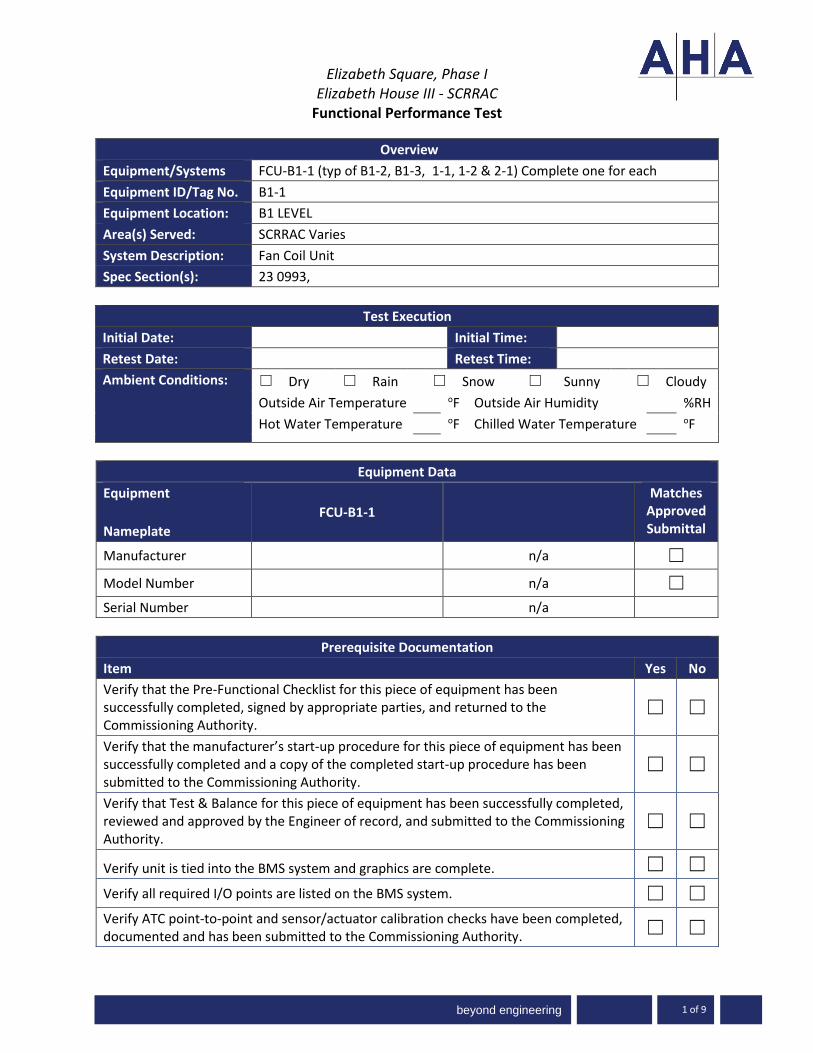
beyond engineering
Elizabeth Square, Phase I Elizabeth House III - SCRRAC
Functional Performance Test
1 of 9
Overview
Equipment/Systems FCU-B1-1 (typ of B1-2, B1-3, 1-1, 1-2 & 2-1) Complete one for each
Equipment ID/Tag No. B1-1
Equipment Location: B1 LEVEL
Area(s) Served: SCRRAC Varies
System Description: Fan Coil Unit
Spec Section(s): 23 0993,
Test Execution
Initial Date: Initial Time:
Retest Date: Retest Time:
Ambient Conditions: ☐ Dry ☐ Rain ☐ Snow ☐ Sunny ☐ Cloudy
Outside Air Temperature oF Outside Air Humidity %RH
Hot Water Temperature oF Chilled Water Temperature oF
Equipment Data
Equipment
Nameplate
FCU-B1-1
Matches Approved Submittal
Manufacturer n/a ☐
Model Number n/a ☐
Serial Number n/a
Prerequisite Documentation
Item Yes No
Verify that the Pre-Functional Checklist for this piece of equipment has been successfully completed, signed by appropriate parties, and returned to the Commissioning Authority.
☐ ☐
Verify that the manufacturer’s start-up procedure for this piece of equipment has been successfully completed and a copy of the completed start-up procedure has been submitted to the Commissioning Authority.
☐ ☐
Verify that Test & Balance for this piece of equipment has been successfully completed, reviewed and approved by the Engineer of record, and submitted to the Commissioning Authority.
☐ ☐
Verify unit is tied into the BMS system and graphics are complete. ☐ ☐
Verify all required I/O points are listed on the BMS system. ☐ ☐ Verify ATC point-to-point and sensor/actuator calibration checks have been completed, documented and has been submitted to the Commissioning Authority. ☐ ☐

beyond engineering
Elizabeth Square, Phase I
Elizabeth House III - SCRRAC Functional Performance Test
-3000 www.ah
www.aha-engineers.com 2 of 9
Prerequisite Documentation
Item Yes No
All trends specified at the end of this test have been setup and are trending. ☐ ☐
Required Personnel and Tools Available ☐ ☐
System Ready for Functional Testing ☐ ☐
Participants:
Name Company Project Role Required
Yes No
CM/GC ☐ ☐
Owner/Owners Rep ☐ ☐
Sub-Contractor ☐ ☐
Controls Contractor ☐ ☐
Commissioning Authority ☐ ☐
Commissioning Agent ☐ ☐
Supplies Required for Testing
Tools/Supplies Provided by
Schedule
System runs based on non-scheduled variable (e.g.: temperature, pressure) ☐
System runs 24 hours a day, 7 days a week (no schedule) ☐
System runs on then programmable schedule indicated below (TBD) ☒
Mon - Fri Sat - Sun Holiday
*Adj – indicates the point is adjustable
Setpoints
Parameter Expected Actual Unit BMS Adj
Temperature (oF) ☐ ☐ ☐

beyond engineering
Elizabeth Square, Phase I
Elizabeth House III - SCRRAC Functional Performance Test
-3000 www.ah
www.aha-engineers.com 3 of 9
Setpoints
Parameter Expected Actual Unit BMS Adj
Space Temperature Setpoint 85°F oF ☐ ☒ ☒ Occupied mode – cooling setpoint 85°F oF ☐ ☒ ☒ Occupied mode – heating setpoint 80°F oF ☐ ☒ ☒ Unoccupied mode – cooling setpoint 85°F oF ☐ ☒ ☒ Unoccupied mode – heating setpoint 80°F oF ☐ ☒ ☒ Minimum Supply air fan minimum runtime TBD mins ☐ ☒ ☒
Alarm Temperature (oF / psi) ☒ ☐ ☐ ☐ ☐
High Zone Temperature Greater
than 95°F. ☐ ☒ ☒
Low Zone Temperature Less than
75°F. ☐ ☒ ☒
Initial Conditions
Conditions Unit/ Measured Thermostat/ BMS
Temperature oF oF
Space Temperature (Zone) oF oF
Heating Setpoint oF oF
Cooling Setpoint oF oF
Alarm (normal) (alarm) (normal) (alarm)
Freeze stat.
Return Smoke Detected. (FCU-B1-1, 1-2, 2-1)
Supply Smoke Detected. (FCU-B1-1, 1-2, 2-1)
Valve Failure
Supply Fan Failure: Commanded on, but the status is off or on when commanded off.
High Zone Temperature – Greater than 95°F.
Low Zone Temperature – Less than 75°F.
Status (on) (off) (on) (off)
Freeze stat
Supply Fan Status
Supply Fan Start/Stop
Valve 2-way & 3 Way (open) (closed) (open) (closed)
Chilled Water Control Valve Position
Hot Water Control Valve Position

beyond engineering
Elizabeth Square, Phase I
Elizabeth House III - SCRRAC Functional Performance Test
-3000 www.ah
www.aha-engineers.com 4 of 9
Comments:
The above set points and initial conditions are key items for commissioning purposes. Review all data available at local controllers and the Building Management System (BMS) front-end computer and note any additional values the affect system operations (e.g. lockouts or time delays). Some values will require the use of measurement equipment.
Device Calibration Checks
The actuators or devices listed below are to be checked for calibration. This is a spot check on a sample of the calibrations completed during the pre-functional checklist and contractor start-up processes. “In calibration” means observing a readout at the BMS and going to the actuator or controlled device and verifying that the BMS reading is correct, this was done during the recording of initial conditions. For the calibration portion - command speed or position to open, intermediate, and closed. Record read out and field observations at each. Below add actual sampled devices
Device Calibration Checks
Device or Actuator & Location
Procedure/ State 1st BAS Value
Site Observation
Final BAS Reading
Pass
Yes No
Supply Fan VFD
1. Min: % % % % ☐ ☐
2. Mid: % % % % ☐ ☐
3. Max: % % % % ☐ ☐
Supply Fan VFD
1. Min: % % % % ☐ ☐
2. Mid: % % % % ☐ ☐
3. Max: % % % % ☐ ☐
Valve
1. Closed ☐ ☐
2. 50 % ☐ ☐
3. Full Open ☐ ☐
Sensor Calibration Checks
Check the sensors listed below for calibration and adequate location. This is a sampling check of calibrations done during the pre-functional checklist and contractor start-up processes. “In calibration” means making a reading with a calibrated test instrument within 6 inches of the site sensor. Verify that the sensor reading (via permanent thermostat, gauge, packaged control panel or Building Management System [BMS]) compared to the test instrument-measured value is within the tolerances specified. If not, install offset at BMS, calibrate or replace sensor. Use the same test instrument as used for the original calibration, if possible. This should instrument should be provided by the controls or mechanical contractor. Below add actual sampled devices

beyond engineering
Elizabeth Square, Phase I
Elizabeth House III - SCRRAC Functional Performance Test
-3000 www.ah
www.aha-engineers.com 5 of 9
Sensor Calibration Checks
Sensor & Location
Location OK*
Gauge or Pkg & BAS
Values
Instrument Measured
Value
Point Type
Pass **
Yes No Yes No
Supply Temperature ☐ ☐ oF oF AI ☐ ☐
Return Temperature ☐ ☐ oF oF AI ☐ ☐
Flow Switch ☐ ☐ AI ☐ ☐
Pump Start/Stop ☐ ☐ DO ☐ ☐
Pump Status ☐ ☐ DI ☐ ☐
Pump VFD Fault ☐ ☐ DI ☐ ☐ * Sensor location is appropriate and away from cause of erratic operation. ** See acceptable ranges per specifications in table below
Sensor Calibration Points
Point Acceptable Range
Static Pressure ± 0.3 in.wc
Temperature ± 1 F
Differential Pressure ± 10 %
Airflow ± 10 %
Waterflow ± 10 %
Comments:
Functional Performance Verification
The following procedures are a summary of the steps required to test the system function as described in the attached sequence of operations. The intent is for the system operation to be reviewed at both the piece of equipment (local/measured) and the controller - thermostat, BMS, DDC, etc. (Control). It should be noted that additional steps (not listed) may be required in order to achieve the noted simulation. Items will be noted as Pass Yes/No, N/A – Not Applicable, or N/T – Not Tested. Detailed information on failures will be noted in the commissioning issues log...
Control
# Testing Procedure Pass Comment
Description: Fan Cool Unit(s) provide conditioned air to the pool area
1. Zone Setpoint Adjust: 23 0993 2.10 E

beyond engineering
Elizabeth Square, Phase I
Elizabeth House III - SCRRAC Functional Performance Test
-3000 www.ah
www.aha-engineers.com 6 of 9
Control
# Testing Procedure Pass Comment
From the space sensor(s) adjust the space setpoint up and ten down to verify the BMS indicates the change within the limits and the proper sensor is mapped to the BMS. The occupant will be able to adjust the zone temperature heating and cooling setpoints at the zone sensor. The zone sensor will only be able to be adjusted between 80°F - 90°F (adj.). Return to normal setpoint.
Y / N
2. Freeze Protection: 23 0993 2.10 F
Verify the Freeze stat is set to 35 deg. F. Manually trip the freeze stat(s) to verify alarming and proper mapping to the BMS. The unit will shut down and generate an alarm upon receiving a freezestat status. Freeze stats will be set at 35 deg. F. Return all to normal
Y / N
3. Supply and Return Air Smoke Detection (FCU-B1-1, 1-2, 2-1 ONLY): 23 0993 2.10 G
Manually trip the smoke detector(s) to verify alarming and proper mapping to the BMS. The unit shall shut down and generate an alarm upon receiving a supply or return air smoke detector status Return all to normal
Y / N
4. Supply Fan Minimum Runtime: 23 0993 2.10 H
From the BMS command the FCU(s) on and off several times to verify proper mapping of command and short cycling prevention. The supply fan shall run anytime the unit is commanded to run, unless shutdown on safeties. To prevent short cycling, the supply fan shall have a user definable (adj.) minimum runtime Return all to normal.
Y / N
5. Cooling: 23 0993 2.10 I
The controller will measure the zone temperature and modulate the chilled water control valve to maintain its cooling setpoint.
The cooling will be enabled whenever: a. The zone temperature is above cooling setpoint. b. The supply fan status is on. c. The heating is not active
Y / N

beyond engineering
Elizabeth Square, Phase I
Elizabeth House III - SCRRAC Functional Performance Test
-3000 www.ah
www.aha-engineers.com 7 of 9
Control
# Testing Procedure Pass Comment
1. Decrease the Zone Temperature Set Point; is the Heating Control Valve fully closed and does the Chilled Water Control Valve modulate open to maintain the new zone setpoint?
Allow time for the system to stabilize. Return all to normal
6. Heating: 23 0993 2.10 J
The controller shall measure the zone temperature and modulate the hot water control valve to maintain its heating setpoint.
The heating shall be enabled whenever: a. The zone temperature is below heating setpoint b. The supply fan status is on. c. The cooling is not active
1. Increase the Zone Temperature Set Point; is the Chilled Water
Control Valve fully closed and does the Heating Control Valve modulate open to maintain the new zone setpoint?
Allow time for the system to stabilize. Return all to normal
Y / N
Alarm
# Testing Procedure Pass Comment
1. Occupied mode – cooling setpoint Y / N
2. Occupied mode – heating setpoint Y / N
3. Unoccupied mode – cooling setpoint Y / N
4. Unoccupied mode – heating setpoint Y / N
5. High Zone Temperature – Greater than 95°F. Y / N
6. Low Zone Temperature – Less than 75°F. Y / N
7. Supply Fan Failure: Commanded on, but the status is off or on when commanded off.
Y / N
8. Freeze stat. Y / N
9. Chilled water valve failure Y / N
10. Hot water valve failure Y / N
11. Return Smoke Detected. (FCU-B1-1, 1-2, 2-1) Y / N
12. Supply Smoke Detected. (FCU-B1-1, 1-2, 2-1) Y / N
Wrap Up

beyond engineering
Elizabeth Square, Phase I
Elizabeth House III - SCRRAC Functional Performance Test
-3000 www.ah
www.aha-engineers.com 8 of 9
# Testing Procedure Pass Comment
1. Y / N
2. Y / N
3. Y / N
4. Y / N
5. Y / N
6. Y / N
7. Y / N
8. Y / N
Comments:
Trend Report
The following points will be trended every 15 minutes for period of not less than 2 weeks. These trends will be conducted at least twice a year: one in the cooling season and once in the heating season. Completed Trend Reports will be submitted in a format compatible with MS Excel.
Trend Report
Trend Trend Group Points
Acceptance of Test:
☐ This test cannot be accepted at this time due to the Corrective Issues noted above.
☐ This test is accepted by the Commissioning Authority identified below. Any Corrective Issues noted above do not adversely impact the overall performance of the system.

beyond engineering
Elizabeth Square, Phase I
Elizabeth House III - SCRRAC Functional Performance Test
-3000 www.ah
www.aha-engineers.com 9 of 9
Tested by Date
Witnessed by Date
Commissioning Provider Attachment(s): Sequence of Operations

beyond engineering
Elizabeth Square, Phase I Elizabeth House III - SCRRAC
Functional Performance Test
1 of 16
Overview
Equipment/Systems Boiler(s) & Pumps
Equipment ID/Tag No. B-1-1, 1-2, PHP-1-1,1-2, SHP-1-1, 1-2, 1-3, 1-4
Equipment Location: MECHANICAL ROOM S110
Area(s) Served: SCRRAC
System Description: HOT WATER SYSTEM
Spec Section(s): 23 0993, 23 2123 & 23 5216
Test Execution
Initial Date: Initial Time:
Retest Date: Retest Time:
Ambient Conditions: ☐ Dry ☐ Rain ☐ Snow ☐ Sunny ☐ Cloudy
Outside Air Temperature oF Outside Air Humidity %RH
Hot Water Temperature oF Chilled Water Temperature oF
Equipment Data
Equipment
Nameplate
B-1-1 B-1-2
Matches Approved Submittal
Manufacturer ☐
Model Number ☐
Serial Number
Equipment Data
Equipment
Nameplate
PHP-1-1 PHP-1-2
Matches Approved Submittal
Manufacturer ☐
Model Number ☐
Serial Number
Equipment Data
Equipment
Nameplate
SHP-1-1 SHP-1-2
Matches Approved Submittal
Manufacturer ☐
Model Number ☐
Serial Number
Equipment Data
Equipment SHP-1-3 SHP-1-4 Matches

beyond engineering
Elizabeth Square, Phase I
Elizabeth House III - SCRRAC Functional Performance Test
-3000 www.ah
www.aha-engineers.com 2 of 16
Nameplate
Approved Submittal
Manufacturer ☐
Model Number ☐
Serial Number
Equipment
Nameplate
P-1-10
Matches Approved Submittal
Manufacturer n/a ☐
Model Number n/a ☐
Serial Number n/a
Prerequisite Documentation
Item Yes No
Verify that the Pre-Functional Checklist for this piece of equipment has been successfully completed, signed by appropriate parties, and returned to the Commissioning Authority.
☐ ☐
Verify that the manufacturer’s start-up procedure for this piece of equipment has been successfully completed and a copy of the completed start-up procedure has been submitted to the Commissioning Authority.
☐ ☐
Verify that Test & Balance for this piece of equipment has been successfully completed, reviewed and approved by the Engineer of record, and submitted to the Commissioning Authority.
☐ ☐
Verify unit is tied into the BMS system and graphics are complete. ☐ ☐
Verify all required I/O points are listed on the BMS system. ☐ ☐ Verify ATC point-to-point and sensor/actuator calibration checks have been completed, documented and has been submitted to the Commissioning Authority. ☐ ☐
All trends specified at the end of this test have been setup and are trending. ☐ ☐
Required Personnel and Tools Available ☐ ☐
System Ready for Functional Testing ☐ ☐
Participants:
Name Company Project Role Required
Yes No
CM/GC ☐ ☐
Owner/Owners Rep ☐ ☐

beyond engineering
Elizabeth Square, Phase I
Elizabeth House III - SCRRAC Functional Performance Test
-3000 www.ah
www.aha-engineers.com 3 of 16
Sub-Contractor ☐ ☐
Controls Contractor ☐ ☐
Commissioning Authority ☐ ☐
Commissioning Agent ☐ ☐
Supplies Required for Testing
Tools/Supplies Provided by
Schedule
System runs based on non-scheduled variable (e.g.: temperature, pressure) ☐
System runs 24 hours a day, 7 days a week (no schedule) ☐
System runs on then programmable schedule indicated below (TBD) ☒
Mon - Fri Sat - Sun Holiday
*Adj – indicates the point is adjustable
Setpoints
Parameter Expected Actual Unit BMS Adj
Temperature (oF) ☐ ☐ ☐
Hot water supply temperature 140 deg. F ☐ ☒ ☒
Emergency Fill hot water supply temperature 180 deg. F ☐ ☒ ☒
Minimum Hot Water Reset 130 deg. F
Timed Events ☐ ☐ ☐
Lead pump maximum runtime (rotation) TBD TBD ☐ ☒ ☒
Pump cycle delay TBD TBD ☐ ☒ ☒
Hot Water Reset calculation 10 min ☐ ☒ ☒
System Limits ☐ ☐ ☐
VFD minimum speed limit 20% ☒ ☒ ☒
Pressure (“w.c. / psi) ☒ ☐ ☒ ☐ ☐

beyond engineering
Elizabeth Square, Phase I
Elizabeth House III - SCRRAC Functional Performance Test
-3000 www.ah
www.aha-engineers.com 4 of 16
Setpoints
Parameter Expected Actual Unit BMS Adj
Differential Pressure setpoint (building) 12 psi
(to be established at test and balance)
☐ ☐ ☐
High Differential Pressure
25% greater than set
point
(to be determined by the TAB)
☐ ☒ ☒
Low Differential Pressure
25% less than set
point
(to be determined by the TAB)
☐ ☒ ☒
Alarm Temperature (oF / psi) ☒ ☐ ☐ ☐ ☐
Low hot water supply temperature 110 deg. F ☐ ☒ ☒
High hot water supply temperature
180 deg. F (pool initial
fill) ☐ ☒ ☒
High hot water return temperature 130 deg. F ☐ ☒ ☒
Low hot water return temperature 90 deg. F ☐ ☒ ☒
Emergency Fill hot water supply temperature 180 deg. F ☐ ☒ ☒
Initial Conditions
Conditions Unit/ Measured Thermostat/ BMS
Temperature oF oF
B-1-1 Hot Water Supply Temp oF oF
B-1-2 Hot Water Supply Temp oF oF
B-1-1 Hot Water Return Temp oF oF
B-1-2 Hot Water Return Temp oF oF
Primary Hot Water Return Temp oF oF
Hot Water Return (FROM POOL HEAT EXCHANGERS) oF oF
Hot Water Supply (TO POOL HEAT EXCHANGERS) oF oF
Secondary HW Supply Temp (TO BUILDING) oF oF
Secondary HW Return Temp (TO BUILDING) oF oF
Heat Recovery HW Supply Temp oF oF
Heat Recovery HW Return Temp oF oF
Capacity % %
B-1-1 Capacity % %
B-1-2 Capacity % %

beyond engineering
Elizabeth Square, Phase I
Elizabeth House III - SCRRAC Functional Performance Test
-3000 www.ah
www.aha-engineers.com 5 of 16
Initial Conditions
Conditions Unit/ Measured Thermostat/ BMS
Alarm (normal) (alarm) (normal) (alarm)
B-1-1 Enable Fail
B-1-2 Enable Fail
PHP-1-1 Pump Fail
PHP-1-2 Pump Fail
SHP-1-1 Pump Fail
SHP-1-2 Pump Fail
SHP-1-3 Pump Fail
SHP-1-4 Pump Fail
Low hot water supply temperature
High hot water supply temperature
High hot water return temperature
Low hot water return temperature
Emergency Fill hot water supply temperature
High Differential Pressure
Low Differential Pressure
Enable (on) (off) (on) (off)
B-1-1 Enable
B-1-2 Enable
PHP-1-1 Pump Start/Stop
PHP-1-2 Pump Start/Stop
SHP-1-1 Pump Start/Stop
SHP-1-2 Pump Start/Stop
SHP-1-3 Pump Start/Stop
SHP-1-4 Pump Start/Stop
Status (on) (off) (on) (off)
B-1-1 Status
B-1-2 Status
PHP-1-1 Pump Status
PHP-1-2 Pump Status
SHP-1-1 Pump Status
SHP-1-2 Pump Status

beyond engineering
Elizabeth Square, Phase I
Elizabeth House III - SCRRAC Functional Performance Test
-3000 www.ah
www.aha-engineers.com 6 of 16
Initial Conditions
Conditions Unit/ Measured Thermostat/ BMS
SHP-1-3 Pump Status
SHP-1-4 Pump Status
Operating Hours hrs hrs
B-1-1 Operating Hours
B-1-2 Operating Hours
Isolation Valve / Mixing (open) (closed) (open) (closed)
CV-H-1 = 2-Position Isolation Valve (B-1-1)
CV-H-2 = 2-Position Isolation Valve (B-1-2)
CV-H-3 = 2-Position Isolation Valve (HRC)
CV-H-4 = 2-Position Isolation Valve (HRC)
CV-H-5 = 3-Way Modulating Control Valve (Mixing Valve)
CV-H-6 = 2-Way Modulating Control Valve (Bypass)
Flow gpm gpm
FM-H-1 (BTU) = Hot Water Secondary Capacity and Flow (Building)
FM-H-2 (BTU) = Hot Water Secondary Capacity and Flow (Pool)
FM-H-3 = Decoupler Flow (Bi-Directional)
FM-H-4 (BTU) = HRC Hot Water Capacity and Flow
VFD Speed hz/% hz/%
PHP-1-1 Pump VFD Speed
PHP-1-2 Pump VFD Speed
SHP-1-1 Pump VFD Speed
SHP-1-2 Pump VFD Speed
SHP-1-3 Pump VFD Speed
SHP-1-4 Pump VFD Speed
Differential Press psi psi
Hot Water Differential Pressure (Building)
Comments:
The above set points and initial conditions are key items for commissioning purposes. Review all data available at local controllers and the Building Management System (BMS) front-end computer and note any additional values the affect system operations (e.g. lockouts or time delays). Some values

beyond engineering
Elizabeth Square, Phase I
Elizabeth House III - SCRRAC Functional Performance Test
-3000 www.ah
www.aha-engineers.com 7 of 16
will require the use of measurement equipment.
Device Calibration Checks
The actuators or devices listed below are to be checked for calibration. This is a spot check on a sample of the calibrations completed during the pre-functional checklist and contractor start-up processes. “In calibration” means observing a readout at the BMS and going to the actuator or controlled device and verifying that the BMS reading is correct, this was done during the recording of initial conditions. For the calibration portion - command speed or position to open, intermediate, and closed. Record read out and field observations at each. Below add actual sampled devices
Device Calibration Checks
Device or Actuator & Location
Procedure/ State 1st BAS Value
Site Observation
Final BAS Reading
Pass
Yes No
Supply Pump VFD
1. Min: % % % % ☐ ☐
2. Mid: % % % % ☐ ☐
3. Max: % % % % ☐ ☐
Supply Fan VFD
1. Min: % % % % ☐ ☐
2. Mid: % % % % ☐ ☐
3. Max: % % % % ☐ ☐
Valve
1. Closed ☐ ☐
2. 50 % ☐ ☐
3. Full Open ☐ ☐
Sensor Calibration Checks
Check the sensors listed below for calibration and adequate location. This is a sampling check of calibrations done during the pre-functional checklist and contractor start-up processes. “In calibration” means making a reading with a calibrated test instrument within 6 inches of the site sensor. Verify that the sensor reading (via permanent thermostat, gauge, packaged control panel or Building Management System [BMS]) compared to the test instrument-measured value is within the tolerances specified. If not, install offset at BMS, calibrate or replace sensor. Use the same test instrument as used for the original calibration, if possible. This should instrument should be provided by the controls or mechanical contractor. Below add actual sampled devices
Sensor Calibration Checks
Sensor & Location
Location OK*
Gauge or Pkg & BAS
Values
Instrument Measured
Value
Point Type
Pass **
Yes No Yes No

beyond engineering
Elizabeth Square, Phase I
Elizabeth House III - SCRRAC Functional Performance Test
-3000 www.ah
www.aha-engineers.com 8 of 16
Sensor Calibration Checks
Sensor & Location
Location OK*
Gauge or Pkg & BAS
Values
Instrument Measured
Value
Point Type
Pass **
Yes No Yes No
Supply Temperature ☐ ☐ oF oF AI ☐ ☐
Return Temperature ☐ ☐ oF oF AI ☐ ☐
Flow Switch ☐ ☐ AI ☐ ☐
Pump Start/Stop ☐ ☐ DO ☐ ☐
Pump Status ☐ ☐ DI ☐ ☐
Pump VFD Fault ☐ ☐ DI ☐ ☐ * Sensor location is appropriate and away from cause of erratic operation. ** See acceptable ranges per specifications in table below
Sensor Calibration Points
Point Acceptable Range
Static Pressure ± 0.3 in.wc
Temperature ± 1 F
Differential Pressure ± 10 %
Airflow ± 10 %
Waterflow ± 10 %
Comments:
Functional Performance Verification
The following procedures are a summary of the steps required to test the system function as described in the attached sequence of operations. The intent is for the system operation to be reviewed at both the piece of equipment (local/measured) and the controller - thermostat, BMS, DDC, etc. (Control). It should be noted that additional steps (not listed) may be required in order to achieve the noted simulation. Items will be noted as Pass Yes/No, N/A – Not Applicable, or N/T – Not Tested. Detailed information on failures will be noted in the commissioning issues log...
Control
# Testing Procedure Pass Comment
Operational Schedule – 23 0993 2.2 E. When the operator defined schedule within the BAS or commanded to the occupied mode, the hot water system will be enabled. If the

beyond engineering
Elizabeth Square, Phase I
Elizabeth House III - SCRRAC Functional Performance Test
-3000 www.ah
www.aha-engineers.com 9 of 16
Control
# Testing Procedure Pass Comment
system is not in occupied mode or off due to internal safeties or alarm, the system will be considered in unoccupied mode.
Primary Lead/Lag Pump Operation – 23 0993 2.2 F The boilers are served by two (2) primary boilers piped in parallel. The pumps will be controlled by the factory provided boiler controller and configured so that either pump can operate with either boiler.
1. Boiler Operation 23 0993 2.2 H
From the BMS adjust the Hot Water Return setpoint 5 F above current
system hot water return setpoint. Verify the following:
1. As the secondary supply hot water temperature, as monitored
by the BAS, falls 4 degrees F (adj.) below setpoint, the lead
boiler external controller will receive a signal from the BAS to
provide heat, the boiler plant will operate as follows:
a. The external controller will start the primary hot water pump for the lead boiler, and proof of water flow from the primary hot water pump will be confirmed.
b. The lead boiler will operate under its internal control logic and safeties to maintain the leaving secondary hot water temperature setpoint.
Once the system is operating and controlling to maintain the secondary hot water temperature setpoint, adjust the
setpoint again and additional 5 F higher. c. If the secondary hot water supply temperature
setpoint cannot be maintained by the lead boiler, the lead boiler external controller will be capable of staging on the second boiler and its associated primary hot water pump to maintain the secondary hot water temperature setpoint.
Allow time for the system to stabilize.
Y / N
With the system operating to maintain the higher setpoint, now
reduce the setpoint 5 F. 23 0993 2.2 H. 3. Verify the following:
1. As secondary supply hot water temperature rises 4 degrees F (adj). above the setpoint, the lead boiler external controller will stage off boilers and primary hot water pumps as required to maintain setpoint via its own internal controls and safeties.
Y / N

beyond engineering
Elizabeth Square, Phase I
Elizabeth House III - SCRRAC Functional Performance Test
-3000 www.ah
www.aha-engineers.com 10 of 16
Control
# Testing Procedure Pass Comment
Return all setpoints to normal.
2. Boiler Isolation Valve 23 0993 2.2 I
From the BMS once again enable the hot water system. Verfiy isolation valve sequencing as detailed below:
1. The boiler isolation valve will open anytime the boiler is called to run.
2. The boiler isolation valve will open prior to the boiler turning on and close after the boiler is proven off. The delay times will be set appropriately to allow for orderly hot water system start-up and shutdown. The isolation valve will therefore have:
a. A user adjustable delay on start (note delay(s) at right) b. And a user adjustable delay on stop
The boiler will only start after proof of valve open status for 10 seconds (adj.) and associated pump has proven status. 3. Isolation valves will fail to the open position to reduce risk
of dead heading the hot water pump. Upon receiving a failure alarm, the BAS will start the stand-by boiler and associated pump, and shut down the pump and boiler associated with the isolation valve in failure.
Place the system into normal operation for the following test.
Y / N
3. Boiler 3-Way Mixing Valve 23 0993 2.2 J.
With the system in normal operation, adjust the setpoint for the
leaving hot water system 5 F lower than the normal 140 F. Modify pool fill setpoint as required.
1. The 3-way mixing valve will modulate to maintain a leaving water temperature of 140 deg. F to the building loop. 3-Way valve will only be enabled to control when pool fill operation is occurring (supply temperature reset to 180 deg. F)
From the 3-way valve, remove the BMS AO signal.
2. In the event of a signal loss from the BAS, the 3-Way valve will
revert to its last known position.
Re-connect the BMS AO signal to the 3-way valve; the valve
Y / N

beyond engineering
Elizabeth Square, Phase I
Elizabeth House III - SCRRAC Functional Performance Test
-3000 www.ah
www.aha-engineers.com 11 of 16
Control
# Testing Procedure Pass Comment
will modulate to the commanded signal.
4. Secondary Lead/Stand-by Pump Operation 23 0993 2.2 K.
From the BMS, select SHP-1-1 and SHP-1-3 as lead pumps. Verify lead / standby operation as detailed below.
1. When enabled by the BAS each set of two (2) secondary variable (SHP-1-1,1-2) and constant (SHP-1-3, 1-4) speed hot water pumps will operate in a lead/stand-by fashion as follows: Adjust system setting to verify.
a. The lead pump(s) will run. Manually fail the lead (SHP-1-1) pump.
b. Upon failure of the lead pump, the stand-by pump (SHP-1-2) will be commanded on and the lead pump will be turned off.
Upon verification of standby pump (SHP-1-2) operation, fail lead SHP-1-3. Standby pump SHP-1-4 will be enabled to operate. From the BMS, disable the system (allow time for the system to return to normal off). Now select pumps SHP-1-2 and SHP-1-4 as the lead pumps and repeat the above test of fail rotation. Upon verification of new lead pump selection proceed to the next testing step below. From the BMS, adjust the Hot water differential setpoint higher 5 psi. Verify the building system pumps operate as detailed below.
c. On decreasing hot water differential pressure, the lag pump will stage on and run in unison with the lead pump to maintain hot water differential pressure setpoint. (SHP-1,2 only)
Once verified disable the system and rotate the building pumps and retest.
Y / N
Based upon the user selected means of pump rotation, verify through the BMS proper operation.
2. The designated lead pump will be determined in the BAS by one of the following conditions:
a. Manually through the BAS. b. If the current lead pump exceeds the maximum runtime. c. Daily d. Weekly e. Monthly
Y / N

beyond engineering
Elizabeth Square, Phase I
Elizabeth House III - SCRRAC Functional Performance Test
-3000 www.ah
www.aha-engineers.com 12 of 16
Control
# Testing Procedure Pass Comment
5. Short cycling Prevention
The pumps will have a minimum downtime between stop and start as defined by the unit manufacturer. With the system in operation: a. Remove any BMS overrides and disable the system. b. Boiler will cycle off after delay c. Associated pumps will de-energize d. Associated isolation valves will close. Through the BMS once again enable the hot water system, verify the start delay.
Y / N
6. Hot Water Differential Pressure Control – Pump Speed Control (SHP-1-1, 1-2) 23 0993 2.2 L
With the system enabled for normal operation, adjust the hot water system (building) differential pressure setpoint 5 psi above the current system differential pressure and increase as required to verify complete sequence. Verify system operation as detailed below:
1. The BAS will monitor the hot water differential pressure and modulate the VFD on the lead pump (SHP-1-1 or 1-2) to maintain the hot water differential pressure setpoint. The initial differential pressure recommendation will be 12 LBF/square inch and will be field adjusted by TAB to meet the requirements of the actual field conditions. The pump speed will not drop below 20%. Note any system deadband values at right.
2. On dropping hot water differential pressure, the BAS will stage on the VFD's to run and maintain setpoints as follows:
a. The BAS will modulate the lead VFD to maintain setpoint b. If the lead VFD speed is greater than 95% (adj.), the lag VFD will stage on c. The lag VFD will ramp up to match the lead VFD speed and then run in unison with the lead VFD to maintain setpoint.
3. On rising hot water differential pressure, the BAS will stage off
the VFD's as follows: a. If the VFD's speed drops back to 40% (adj.) below setpoint, the lag VFD will stage off. b. The lead VFD will continue to run to maintain setpoint.
Y / N

beyond engineering
Elizabeth Square, Phase I
Elizabeth House III - SCRRAC Functional Performance Test
-3000 www.ah
www.aha-engineers.com 13 of 16
Control
# Testing Procedure Pass Comment
c. If the lead VFD minimum speed is reached, the minimum pump flow control sequence below will be initiated.
4. SHP-1-3, 1-4 will be constant volume and serve pool heat exchangers with 3-way mixing valves at each heat exchanger.
Return all to normal.
7. Hot Water Supply Temperature Reset 23 0993 2.2 M
Through override the “system hot water valve call” as required to verify the below sequence.
1. The hot water supply temperature setpoint will be reset using
a trim and respond algorithm based on heating requirements. 2. The hot water supply temperature setpoint will reset down 10
deg. F below setpoint based on hot water valve feedback. 3. If all valves are 90% open (adj.) or greater for a period of 10
minutes, the hot water supply temperature will reset up 1 deg. F until it reaches design of 140 deg. F. Once the hot water coils are satisfied (valves closing) then the hot water supply temperature setpoint will gradually lower 1 deg. F in 10 minute increments to a minimum of 130 deg. F.
Return all to normal
Y / N
8. Pool Fill Override 23 0993 2.2 N
From the BMS, select the graphical button “pool fill override command”. Verify the following sequence:
1. The hot water plant will be equipped with pool fill override command. This feature will be available to the user at the graphic interface and will override the current plant operation to provide a leaving water temperature set-point of 180 deg. F.
2. The building hot water loop 3-way valve will modulate as required to maintain leaving hot water temperature set point (130 to 140 deg. F).
Return all to normal.
Y / N
Alarm
# Testing Procedure Pass Comment
1. B-1-1 Enable Fail Y / N

beyond engineering
Elizabeth Square, Phase I
Elizabeth House III - SCRRAC Functional Performance Test
-3000 www.ah
www.aha-engineers.com 14 of 16
2. B-1-2 Enable Fail Y / N
3. B-1-1 low water Y / N
4. B-1-2 low water Y / N
5. PHP-1-1 Pump Fail Y / N
6. PHP-1-2 Pump Fail Y / N
7. SHP-1-1 Pump Fail Y / N
8. SHP-1-2 Pump Fail Y / N
9. SHP-1-3 Pump Fail Y / N
10. SHP-1-4 Pump Fail Y / N
11. Low hot water supply temperature Y / N
12. High hot water supply temperature Y / N
13. High hot water return temperature Y / N
14. Low hot water return temperature Y / N
15. Emergency Fill hot water supply temperature Y / N
16. CV-H-1 = 2-Position Isolation Valve (B-1-1) Y / N
17. CV-H-2 = 2-Position Isolation Valve (B-1-2) Y / N
18. CV-H-3 = 2-Position Isolation Valve (HRC) Y / N
19. CV-H-4 = 2-Position Isolation Valve (HRC) Y / N
20. CV-H-5 = 3-Way Modulating Control Valve (Mixing Valve) Y / N
21. CV-H-6 = 2-Way Modulating Control Valve (Bypass) Y / N
22. Hot Water Differential Pressure High (Building) Y / N
23. Hot Water Differential Pressure Low (Building) Y / N
24. B-1-1 Hot Water Supply Temp High Y / N
25. B-1-2 Hot Water Supply Temp High Y / N
26. Primary Hot Water Return Temp Y / N
27. Hot Water Return (FROM POOL HEAT EXCHANGERS) Y / N
28. Hot Water Supply (TO POOL HEAT EXCHANGERS) Y / N
29. Secondary HW Supply Temp (TO BUILDING) Y / N
30. Secondary HW Return Temp (TO BUILDING) Y / N
31. Heat Recovery HW Supply Temp Y / N
32. Heat Recovery HW Return Temp Y / N
33. PHP-1-1 VFD Fail Y / N
34. PHP-1-2 VFD Fail Y / N
35. SHP-1-1 VFD Fail Y / N
36. SHP-1-2 VFD Fail Y / N
37. SHP-1-3 VFD Fail Y / N
38. SHP-1-4 VFD Fail Y / N

beyond engineering
Elizabeth Square, Phase I
Elizabeth House III - SCRRAC Functional Performance Test
-3000 www.ah
www.aha-engineers.com 15 of 16
39. Temperature Sensor Failure (typ of all) Y / N
40. Boiler 1-1 Communication Failure Y / N
41. Boiler 1-2 Communication Failure Y / N
42. Boiler 1-1 Emergency Shutdown Y / N
43. Boiler 1-2 Emergency Shutdown Y / N
44.
Wrap Up
# Testing Procedure Pass Comment
1. Y / N
2. Y / N
3. Y / N
4. Y / N
5. Y / N
6. Y / N
7. Y / N
8. Y / N
Comments:
Trend Report
The following points will be trended every 15 minutes for period of not less than 2 weeks. These trends will be conducted at least twice a year: one in the cooling season and once in the heating season. Completed Trend Reports will be submitted in a format compatible with MS Excel.
Trend Report
Trend Trend Group Points
Differential Pressure Control
1. Differential Pressure Setpoint
2. Differential Pressure
3. Fan/Pump Speed
Supply Temperature Control
1. Supply Temperature Setpoint
2. Supply Temperature
3. Return Temperature
4. Boiler, Valve, Cooling/Heating

beyond engineering
Elizabeth Square, Phase I
Elizabeth House III - SCRRAC Functional Performance Test
-3000 www.ah
www.aha-engineers.com 16 of 16
Acceptance of Test:
☐ This test cannot be accepted at this time due to the Corrective Issues noted above.
☐ This test is accepted by the Commissioning Authority identified below. Any Corrective Issues noted above do not adversely impact the overall performance of the system.
Tested by Date
Witnessed by Date
Commissioning Provider Attachment(s): Sequence of Operations

beyond engineering
Elizabeth Square, Phase I Elizabeth House III - SCRRAC
Functional Performance Test
1 of 7
Overview
Equipment/Systems Exhaust Fan
Equipment ID/Tag No. EF-1-1 & EF-R-2
Equipment Location: Varies
Area(s) Served: SCRRAC
System Description: Kitchen Exhaust Fan(s)
Spec Section(s): 23 0993, 23 5100
Test Execution
Initial Date: Initial Time:
Retest Date: Retest Time:
Ambient Conditions: ☐ Dry ☐ Rain ☐ Snow ☐ Sunny ☐ Cloudy
Outside Air Temperature oF Outside Air Humidity %RH
Hot Water Temperature oF Chilled Water Temperature oF
Equipment Data
Equipment
Nameplate
EF-1-1 EF-R-2
Matches Approved Submittal
Manufacturer ☐
Model Number ☐
Serial Number
Prerequisite Documentation
Item Yes No
Verify that the Pre-Functional Checklist for this piece of equipment has been successfully completed, signed by appropriate parties, and returned to the Commissioning Authority.
☐ ☐
Verify that the manufacturer’s start-up procedure for this piece of equipment has been successfully completed and a copy of the completed start-up procedure has been submitted to the Commissioning Authority.
☐ ☐
Verify that Test & Balance for this piece of equipment has been successfully completed, reviewed and approved by the Engineer of record, and submitted to the Commissioning Authority.
☐ ☐
Verify unit is tied into the BMS system and graphics are complete. ☐ ☐
Verify all required I/O points are listed on the BMS system. ☐ ☐ Verify ATC point-to-point and sensor/actuator calibration checks have been completed, documented and has been submitted to the Commissioning Authority. ☐ ☐

beyond engineering
Elizabeth Square, Phase I
Elizabeth House III - SCRRAC Functional Performance Test
-3000 www.ah
www.aha-engineers.com 2 of 7
Prerequisite Documentation
Item Yes No
All trends specified at the end of this test have been setup and are trending. ☐ ☐
Required Personnel and Tools Available ☐ ☐
System Ready for Functional Testing ☐ ☐
Participants:
Name Company Project Role Required
Yes No
CM/GC ☐ ☐
Owner/Owners Rep ☐ ☐
Sub-Contractor ☐ ☐
Controls Contractor ☐ ☐
Commissioning Authority ☐ ☐
Commissioning Agent ☐ ☐
Supplies Required for Testing
Tools/Supplies Provided by
Schedule
System runs based on non-scheduled variable (e.g.: temperature, pressure) ☒
System runs 24 hours a day, 7 days a week (no schedule) ☐
System runs on then programmable schedule indicated below (TBD) ☐
Mon - Fri Sat - Sun Holiday
*Adj – indicates the point is adjustable
Setpoints
Parameter Expected Actual Unit BMS Adj
Temperature (oF) ☐ ☐ ☐

beyond engineering
Elizabeth Square, Phase I
Elizabeth House III - SCRRAC Functional Performance Test
-3000 www.ah
www.aha-engineers.com 3 of 7
Setpoints
Parameter Expected Actual Unit BMS Adj
oF ☐ ☐ ☐
Initial Conditions
Conditions Unit/ Measured Thermostat/ BMS
Alarm (normal) (alarm) (normal) (alarm)
EF-1-1 Failure
EF-R-2 Failure
EF-R-2 VFD Failure
Status (on) (off) (on) (off)
EF-1-1 Status
EF-R-2 Status
EF-R-2 VFD Status
VFD Speed hz/% hz/%
EF-R-2 VFD
Comments:
The above set points and initial conditions are key items for commissioning purposes. Review all data available at local controllers and the Building Management System (BMS) front-end computer and note any additional values the affect system operations (e.g. lockouts or time delays). Some values will require the use of measurement equipment.
Device Calibration Checks
The actuators or devices listed below are to be checked for calibration. This is a spot check on a sample of the calibrations completed during the pre-functional checklist and contractor start-up processes. “In calibration” means observing a readout at the BMS and going to the actuator or controlled device and verifying that the BMS reading is correct, this was done during the recording of initial conditions. For the calibration portion - command speed or position to open, intermediate, and closed. Record read out and field observations at each. Below add actual sampled devices
Device Calibration Checks
Device or Actuator & Location
Procedure/ State 1st BAS Value
Site Observation
Final BAS Reading
Pass
Yes No
Supply Fan VFD
1. Min: % % % % ☐ ☐
2. Mid: % % % % ☐ ☐
3. Max: % % % % ☐ ☐

beyond engineering
Elizabeth Square, Phase I
Elizabeth House III - SCRRAC Functional Performance Test
-3000 www.ah
www.aha-engineers.com 4 of 7
Device Calibration Checks
Device or Actuator & Location
Procedure/ State 1st BAS Value
Site Observation
Final BAS Reading
Pass
Yes No
Supply Fan VFD
1. Min: % % % % ☐ ☐
2. Mid: % % % % ☐ ☐
3. Max: % % % % ☐ ☐
Valve
1. Closed ☐ ☐
2. 50 % ☐ ☐
3. Full Open ☐ ☐
Sensor Calibration Checks
Check the sensors listed below for calibration and adequate location. This is a sampling check of calibrations done during the pre-functional checklist and contractor start-up processes. “In calibration” means making a reading with a calibrated test instrument within 6 inches of the site sensor. Verify that the sensor reading (via permanent thermostat, gauge, packaged control panel or Building Management System [BMS]) compared to the test instrument-measured value is within the tolerances specified. If not, install offset at BMS, calibrate or replace sensor. Use the same test instrument as used for the original calibration, if possible. This should instrument should be provided by the controls or mechanical contractor. Below add actual sampled devices
Sensor Calibration Checks
Sensor & Location
Location OK*
Gauge or Pkg & BAS
Values
Instrument Measured
Value
Point Type
Pass **
Yes No Yes No
Supply Temperature ☐ ☐ oF oF AI ☐ ☐
Return Temperature ☐ ☐ oF oF AI ☐ ☐
Flow Switch ☐ ☐ AI ☐ ☐
Pump Start/Stop ☐ ☐ DO ☐ ☐
Pump Status ☐ ☐ DI ☐ ☐
Pump VFD Fault ☐ ☐ DI ☐ ☐ * Sensor location is appropriate and away from cause of erratic operation. ** See acceptable ranges per specifications in table below
Sensor Calibration Points
Point Acceptable Range
Static Pressure ± 0.3 in.wc
Temperature ± 1 F

beyond engineering
Elizabeth Square, Phase I
Elizabeth House III - SCRRAC Functional Performance Test
-3000 www.ah
www.aha-engineers.com 5 of 7
Differential Pressure ± 10 %
Airflow ± 10 %
Waterflow ± 10 %
Comments:
Functional Performance Verification
The following procedures are a summary of the steps required to test the system function as described in the attached sequence of operations. The intent is for the system operation to be reviewed at both the piece of equipment (local/measured) and the controller - thermostat, BMS, DDC, etc. (Control). It should be noted that additional steps (not listed) may be required in order to achieve the noted simulation. Items will be noted as Pass Yes/No, N/A – Not Applicable, or N/T – Not Tested. Detailed information on failures will be noted in the commissioning issues log...
Control
# Testing Procedure Pass Comment
Description: 23 0993 2.12 A Kitchen exhaust fan shall be tied into the kitchen demand-controlled ventilation system. The kitchen demand-controlled ventilation system shall be provided by the kitchen hood manufacturer. All system controls, sequences, safeties and alarms shall be handled by the factory controls and shall operate in a standalone fashion.
1.
The kitchen exhaust fan shall be provided with a VFD for variable speed operation. EF-R-2 Only). EF-R-2 staus to be monitored form the Kitchen Hood Manufacturers’ control panel. From the BMS and/or the Kitchen Ventilation System cycle the system on and off to verify proper interlocking and VFD control. EF-1-1 will cycle on and off with the above-mentioned system also. Return all to normal
Y / N
Alarm
# Testing Procedure Pass Comment
1. EF-1-1 Failure (not matching BMS command state) Y / N
2. Y / N

beyond engineering
Elizabeth Square, Phase I
Elizabeth House III - SCRRAC Functional Performance Test
-3000 www.ah
www.aha-engineers.com 6 of 7
Wrap Up
# Testing Procedure Pass Comment
1. Y / N
2. Y / N
3. Y / N
4. Y / N
5. Y / N
6. Y / N
7. Y / N
8. Y / N
Comments:
Trend Report
The following points will be trended every 15 minutes for period of not less than 2 weeks. These trends will be conducted at least twice a year: one in the cooling season and once in the heating season. Completed Trend Reports will be submitted in a format compatible with MS Excel.
Trend Report
Trend Trend Group Points
EF-1-1
Commanded state
Status
Kitchen Hood ststus
Acceptance of Test:
☐ This test cannot be accepted at this time due to the Corrective Issues noted above.
☐ This test is accepted by the Commissioning Authority identified below. Any Corrective Issues noted above do not adversely impact the overall performance of the system.

beyond engineering
Elizabeth Square, Phase I
Elizabeth House III - SCRRAC Functional Performance Test
-3000 www.ah
www.aha-engineers.com 7 of 7
Tested by Date
Witnessed by Date
Commissioning Provider Attachment(s): Sequence of Operations

beyond engineering
Elizabeth Square, Phase I Elizabeth House III - SCRRAC
Functional Performance Test
1 of 10
Overview
Equipment/Systems Air Handling Unit
Equipment ID/Tag No. MAU-1-1
Equipment Location: Level 1
Area(s) Served: SCRRAC Kitchen
System Description: Kitchen Make-Up Air Unit
Spec Section(s): 23 0993, 23 7313.16
Test Execution
Initial Date: Initial Time:
Retest Date: Retest Time:
Ambient Conditions: ☐ Dry ☐ Rain ☐ Snow ☐ Sunny ☐ Cloudy
Outside Air Temperature oF Outside Air Humidity %RH
Hot Water Temperature oF Chilled Water Temperature oF
Equipment Data
Equipment
Nameplate
MUA-1-1
Matches Approved Submittal
Manufacturer n/a ☐
Model Number n/a ☐
Serial Number n/a
Prerequisite Documentation
Item Yes No
Verify that the Pre-Functional Checklist for this piece of equipment has been successfully completed, signed by appropriate parties, and returned to the Commissioning Authority.
☐ ☐
Verify that the manufacturer’s start-up procedure for this piece of equipment has been successfully completed and a copy of the completed start-up procedure has been submitted to the Commissioning Authority.
☐ ☐
Verify that Test & Balance for this piece of equipment has been successfully completed, reviewed and approved by the Engineer of record, and submitted to the Commissioning Authority.
☐ ☐
Verify unit is tied into the BMS system and graphics are complete. ☐ ☐
Verify all required I/O points are listed on the BMS system. ☐ ☐ Verify ATC point-to-point and sensor/actuator calibration checks have been completed, documented and has been submitted to the Commissioning Authority. ☐ ☐

beyond engineering
Elizabeth Square, Phase I
Elizabeth House III - SCRRAC Functional Performance Test
-3000 www.ah
www.aha-engineers.com 2 of 10
Prerequisite Documentation
Item Yes No
All trends specified at the end of this test have been setup and are trending. ☐ ☐
Required Personnel and Tools Available ☐ ☐
System Ready for Functional Testing ☐ ☐
Participants:
Name Company Project Role Required
Yes No
CM/GC ☐ ☐
Owner/Owners Rep ☐ ☐
Sub-Contractor ☐ ☐
Controls Contractor ☐ ☐
Commissioning Authority ☐ ☐
Commissioning Agent ☐ ☐
Supplies Required for Testing
Tools/Supplies Provided by
Schedule
System runs based on non-scheduled variable (e.g.: temperature, pressure) ☒
System runs 24 hours a day, 7 days a week (no schedule) ☐
System runs on then programmable schedule indicated below (TBD) ☐
Mon - Fri Sat - Sun Holiday
*Adj – indicates the point is adjustable
Setpoints
Parameter Expected Actual Unit BMS Adj
Temperature (oF) ☐ ☐ ☐

beyond engineering
Elizabeth Square, Phase I
Elizabeth House III - SCRRAC Functional Performance Test
-3000 www.ah
www.aha-engineers.com 3 of 10
Setpoints
Parameter Expected Actual Unit BMS Adj
Supply air temperature set point 75 deg. F oF ☐ ☒ ☒ Space temperature 80 deg. F oF ☐ ☒ ☒ Freeze Protection 35 oF oF ☒ ☐ ☐ Cooling Setpoint (reset on high space temperature)
65 oF oF ☐ ☒ ☒
Alarm Temperature (oF / psi) ☒ ☐ ☐ ☐ ☐ ☐ ☐ ☐
Initial Conditions
Conditions Unit/ Measured Thermostat/ BMS
Temperature oF oF
Supply air temperature set point oF oF
Supply Temperature oF oF
Alarm (normal) (alarm) (normal) (alarm)
Freeze stat
Exhaust Air Smoke Detector
Supply Air Smoke Detection
Chilled Water Control Valve Failure
Heating Hot Water Control Valve Failure
Outside Air Dampers Failure
Exhaust Air Dampers Failure
Damper Position % %
Exhaust Air Dampers % %
Outside Air Dampers % %
Status (on) (off) (on) (off)
Supply Fan Status
Supply Fan VFD Status
Supply Fan Command (start/stop)
Exhaust Fan Status
Exhaust Fan VFD Status
Exhaust Fan Command (start/stop)
Operating Hours hrs hrs
Supply Fan

beyond engineering
Elizabeth Square, Phase I
Elizabeth House III - SCRRAC Functional Performance Test
-3000 www.ah
www.aha-engineers.com 4 of 10
Initial Conditions
Conditions Unit/ Measured Thermostat/ BMS
Supply Fan VFD
Valve 2-way & 3 Way (open) (closed) (open) (closed)
Chilled Water Control Valve
Heating Hot Water Control Valve
VFD Speed hz/% hz/%
Supply fan VFD speed
Exhaust fan VFD speed
Comments:
The above set points and initial conditions are key items for commissioning purposes. Review all data available at local controllers and the Building Management System (BMS) front-end computer and note any additional values the affect system operations (e.g. lockouts or time delays). Some values will require the use of measurement equipment.
Device Calibration Checks
The actuators or devices listed below are to be checked for calibration. This is a spot check on a sample of the calibrations completed during the pre-functional checklist and contractor start-up processes. “In calibration” means observing a readout at the BMS and going to the actuator or controlled device and verifying that the BMS reading is correct, this was done during the recording of initial conditions. For the calibration portion - command speed or position to open, intermediate, and closed. Record read out and field observations at each. Below add actual sampled devices
Device Calibration Checks
Device or Actuator & Location
Procedure/ State 1st BAS Value
Site Observation
Final BAS Reading
Pass
Yes No
Supply Fan VFD
1. Min: % % % % ☐ ☐
2. Mid: % % % % ☐ ☐
3. Max: % % % % ☐ ☐
Supply Fan VFD
1. Min: % % % % ☐ ☐
2. Mid: % % % % ☐ ☐
3. Max: % % % % ☐ ☐
Valve 1. Closed ☐ ☐
2. 50 % ☐ ☐

beyond engineering
Elizabeth Square, Phase I
Elizabeth House III - SCRRAC Functional Performance Test
-3000 www.ah
www.aha-engineers.com 5 of 10
Device Calibration Checks
Device or Actuator & Location
Procedure/ State 1st BAS Value
Site Observation
Final BAS Reading
Pass
Yes No
3. Full Open ☐ ☐
Sensor Calibration Checks
Check the sensors listed below for calibration and adequate location. This is a sampling check of calibrations done during the pre-functional checklist and contractor start-up processes. “In calibration” means making a reading with a calibrated test instrument within 6 inches of the site sensor. Verify that the sensor reading (via permanent thermostat, gauge, packaged control panel or Building Management System [BMS]) compared to the test instrument-measured value is within the tolerances specified. If not, install offset at BMS, calibrate or replace sensor. Use the same test instrument as used for the original calibration, if possible. This should instrument should be provided by the controls or mechanical contractor. Below add actual sampled devices
Sensor Calibration Checks
Sensor & Location
Location OK*
Gauge or Pkg & BAS
Values
Instrument Measured
Value
Point Type
Pass **
Yes No Yes No
Supply Temperature ☐ ☐ oF oF AI ☐ ☐
Return Temperature ☐ ☐ oF oF AI ☐ ☐
Flow Switch ☐ ☐ AI ☐ ☐
Pump Start/Stop ☐ ☐ DO ☐ ☐
Pump Status ☐ ☐ DI ☐ ☐
Pump VFD Fault ☐ ☐ DI ☐ ☐ * Sensor location is appropriate and away from cause of erratic operation. ** See acceptable ranges per specifications in table below
Sensor Calibration Points
Point Acceptable Range
Static Pressure ± 0.3 in.wc
Temperature ± 1 F
Differential Pressure ± 10 %
Airflow ± 10 %
Waterflow ± 10 %
Comments:

beyond engineering
Elizabeth Square, Phase I
Elizabeth House III - SCRRAC Functional Performance Test
-3000 www.ah
www.aha-engineers.com 6 of 10
Functional Performance Verification
The following procedures are a summary of the steps required to test the system function as described in the attached sequence of operations. The intent is for the system operation to be reviewed at both the piece of equipment (local/measured) and the controller - thermostat, BMS, DDC, etc. (Control). It should be noted that additional steps (not listed) may be required in order to achieve the noted simulation. Items will be noted as Pass Yes/No, N/A – Not Applicable, or N/T – Not Tested. Detailed information on failures will be noted in the commissioning issues log...
Control
# Testing Procedure Pass Comment
Description: 23 0993 2.11 A MAU operation shall be integrated into the demand control ventilation system provided by the Kitchen Consultant
1. Freeze Protection: 23 0993 2.7 D
Verify freeze stat is set at 35 deg F, and manually trip device. The unit shall shut down and generate an alarm upon receiving a freeze stat status. Freeze stats shall be set at 35 deg. F Chilled water control valve shall open to 100% (adj.) whenever the freeze stat is on. Return all to normal
Y / N
2. Supply and Return Air Smoke Detection: 23 0993 2.7 G
With AHU enabled preform the following: Manually trip each device to verify shutdown and alarming at the BMS The unit shall shut down and generate an alarm upon receiving a return or supply air smoke detector status. Return all to normal
Y / N
3. Normal Off
With the unit off, verify the following – visually and at the BMS. The Exhaust Air Dampers and Outside Air Dampers will be closed. Supply fan will be off, and the VFD will be command off. Exhaust fan will be off and the VFD will be commanded off. 23 0993 2.7 O. The outside and exhaust air dampers shall close.
Y / N

beyond engineering
Elizabeth Square, Phase I
Elizabeth House III - SCRRAC Functional Performance Test
-3000 www.ah
www.aha-engineers.com 7 of 10
Control
# Testing Procedure Pass Comment
Chilled water and Heating Hot Water Control Valve will be closed.
4. Run Conditions: 23 0993 2.11 D
The makeup air unit shall be scheduled to operate by the kitchen demand control ventilation system. If demand control ventilation system is not provided, the makeup air unit shall be interlocked to operate with the kitchen exhaust fan. (This test was created prior to the submission of the equipment thus this operation is TBD)
Y / N
5. Supply Fan: 23 0993 2.11 G
The supply fan shall run anytime the unit is commanded to run, unless shutdown on safeties. To prevent short cycling, the supply fan shall have a user definable (adj.) minimum runtime. 1. Kitchen demand control system shall provide 0-10V DC or 4-20
mA signal to control supply fan speed. Coordinate with kitchen equipment provider. (This test was created prior to the submission of the equipment thus this operation is TBD)
2. Exhaust air fan will be interlocked with the supply fan.
Y / N
6. Supply Fan (Short Cycling): 23 0993 2.11 G
From the BMS command the FCU(s) on and off several times to verify proper mapping of command and short cycling prevention. The supply fan shall run anytime the unit is commanded to run, unless shutdown on safeties. To prevent short cycling, the supply fan shall have a user definable (adj.) minimum runtime. Return all to normal.
Y / N
7. Cooling: 23 0993 2.11 H
The controller will measure the zone temperature and modulate the chilled water control valve to maintain its cooling setpoint. The cooling will be enabled whenever: a. The zone temperature is above cooling setpoint. b. The supply fan status is on. c. The heating is not active 1. Decrease the Zone Temperature Set Point; is the Heating Control Valve fully closed and does the Chilled Water Control Valve modulate open to maintain the new zone setpoint? Allow time for the system to stabilize.
Y / N

beyond engineering
Elizabeth Square, Phase I
Elizabeth House III - SCRRAC Functional Performance Test
-3000 www.ah
www.aha-engineers.com 8 of 10
Control
# Testing Procedure Pass Comment
Return all to normal
8. Heating: 23 0993 I
The controller shall measure the zone temperature and modulate the hot water control valve to maintain its heating setpoint. The heating shall be enabled whenever: a. The zone temperature is below heating setpoint b. The supply fan status is on. c. The cooling is not active 1. Increase the Zone Temperature Set Point; is the Chilled Water Control Valve fully closed and does the Heating Control Valve modulate open to maintain the new zone setpoint? Allow time for the system to stabilize. Return all to normal
Y / N
9. Supply Air Temperature Reset: 23 0993 2.11 K
The controller shall monitor the supply air temperature for setpoint control. From the BMS adjust the current space temperature setpoint 5 deg F below the current space temperature 1. If the space temperature rises above setpoint, the supply air
temperature setpoint shall reset to down to 65 deg. F (adj.) Allow time for the system to stabilize and make the new discharge setpoint and space setpoint. Return all to normal
Y / N
Alarm
# Testing Procedure Pass Comment
1. Freezestat Y / N
2. Exhaust Air Smoke Detection Y / N
3. Supply Air Smoke Detection Y / N
4. Exhaust Air Dampers Y / N
5. Outside Air Dampers Y / N
6. Supply Fan Status Commanded on, but the status is off. Supply Fan in Hand: Commanded off, but the status is on.
Y / N

beyond engineering
Elizabeth Square, Phase I
Elizabeth House III - SCRRAC Functional Performance Test
-3000 www.ah
www.aha-engineers.com 9 of 10
7. Exhaust Fan Status - Commanded on, but the status is off. Fan in Hand: Commanded off, but the status is on.
Y / N
8. Supply Fan VFD Y / N
9. Exhaust Fan VFD Y / N
Wrap Up
# Testing Procedure Pass Comment
1. Y / N
2. Y / N
3. Y / N
4. Y / N
5. Y / N
6. Y / N
7. Y / N
8. Y / N
Comments:
Trend Report
The following points will be trended every 15 minutes for period of not less than 2 weeks. These trends will be conducted at least twice a year: one in the cooling season and once in the heating season. Completed Trend Reports will be submitted in a format compatible with MS Excel.
Trend Report
Trend Trend Group Points
Acceptance of Test:
☐ This test cannot be accepted at this time due to the Corrective Issues noted above.

beyond engineering
Elizabeth Square, Phase I
Elizabeth House III - SCRRAC Functional Performance Test
-3000 www.ah
www.aha-engineers.com 10 of 10
☐ This test is accepted by the Commissioning Authority identified below. Any Corrective Issues noted above do not adversely impact the overall performance of the system.
Tested by Date
Witnessed by Date
Commissioning Provider Attachment(s): Sequence of Operations

beyond engineering
Elizabeth Square, Phase I Elizabeth House III - SCRRAC
Functional Performance Test
1 of 13
Overview
Equipment/Systems 100% OUTSIDE AIR UNIT
Equipment ID/Tag No. OAU-1-1
Equipment Location: Level 1
Area(s) Served: SCRRAC
System Description: 100% Out Side Air Unit - Pool
Spec Section(s): 23 0993, 23 7313.17
Test Execution
Initial Date: Initial Time:
Retest Date: Retest Time:
Ambient Conditions: ☐ Dry ☐ Rain ☐ Snow ☐ Sunny ☐ Cloudy
Outside Air Temperature oF Outside Air Humidity %RH
Hot Water Temperature oF Chilled Water Temperature oF
Equipment Data
Equipment
Nameplate
B-1-1 B-1-2
Matches Approved Submittal
Manufacturer ☐
Model Number ☐
Serial Number
Equipment Data
Equipment
Nameplate
OAU-1-1
Matches Approved Submittal
Manufacturer n/a ☐
Model Number n/a ☐
Serial Number n/a
Prerequisite Documentation
Item Yes No
Verify that the Pre-Functional Checklist for this piece of equipment has been successfully completed, signed by appropriate parties, and returned to the Commissioning Authority.
☐ ☐
Verify that the manufacturer’s start-up procedure for this piece of equipment has been successfully completed and a copy of the completed start-up procedure has been submitted to the Commissioning Authority.
☐ ☐

beyond engineering
Elizabeth Square, Phase I
Elizabeth House III - SCRRAC Functional Performance Test
-3000 www.ah
www.aha-engineers.com 2 of 13
Prerequisite Documentation
Item Yes No
Verify that Test & Balance for this piece of equipment has been successfully completed, reviewed and approved by the Engineer of record, and submitted to the Commissioning Authority.
☐ ☐
Verify unit is tied into the BMS system and graphics are complete. ☐ ☐
Verify all required I/O points are listed on the BMS system. ☐ ☐ Verify ATC point-to-point and sensor/actuator calibration checks have been completed, documented and has been submitted to the Commissioning Authority. ☐ ☐
All trends specified at the end of this test have been setup and are trending. ☐ ☐
Required Personnel and Tools Available ☐ ☐
System Ready for Functional Testing ☐ ☐
Participants:
Name Company Project Role Required
Yes No
CM/GC ☐ ☐
Owner/Owners Rep ☐ ☐
Sub-Contractor ☐ ☐
Controls Contractor ☐ ☐
Commissioning Authority ☐ ☐
Commissioning Agent ☐ ☐
Supplies Required for Testing
Tools/Supplies Provided by
Schedule
System runs based on non-scheduled variable (e.g.: temperature, pressure) ☐
System runs 24 hours a day, 7 days a week (no schedule) ☐

beyond engineering
Elizabeth Square, Phase I
Elizabeth House III - SCRRAC Functional Performance Test
-3000 www.ah
www.aha-engineers.com 3 of 13
System runs on then programmable schedule indicated below (TBD) ☒
Mon - Fri Sat - Sun Holiday
*Adj – indicates the point is adjustable
Setpoints
Parameter Expected Actual Unit BMS Adj
Temperature (oF) ☐ ☐ ☐ Occupied mode Supply air temperature set point (supply air temperature set point)
80 deg. F oF ☐ ☒ ☒
Occupied mode Supply air dew point temperature set point (leaving unit) 1 deg. F below lowest space dew-point temperature, whichever is lower)
62 deg. F oF ☐ ☒ ☒
Occupied mode Supply fan VFD speed 100 % of design flow
oF ☐ ☒ ☒
Occupied mode Exhaust fan VFD speed 100 % of design flow
oF ☐ ☒ ☒
Unoccupied mode Supply air temperature set point (supply air temperature set point)
80 deg. F oF ☐ ☒ ☒
Unoccupied mode Supply air dew point temperature set point (leaving unit) 1 deg. F below lowest space dew-point temperature, whichever is lower)
62 deg. F oF ☐ ☒ ☒
Unoccupied mode Supply fan VFD speed 50 % of
design flow oF ☐ ☒ ☒
Unoccupied mode Exhaust fan VFD speed 50 % of
design flow oF ☐ ☒ ☒
Exhaust Air Defrost 38 deg. F oF ☐ ☒ ☒
Alarm Temperature (oF / psi) ☒ ☐ ☐ ☐ ☐ Chilled Water Coil Freeze Protection 35 deg. F ☒ ☐ ☐ High Supply Air Temperature 90 deg. F ☐ ☒ ☒ Low Supply Air Temperature 70 deg. F ☐ ☒ ☒
High Supply Air Dew Point Temperature
Exceeds Lowest
Space Dew Point Temp
☐ ☒ ☒

beyond engineering
Elizabeth Square, Phase I
Elizabeth House III - SCRRAC Functional Performance Test
-3000 www.ah
www.aha-engineers.com 4 of 13
Initial Conditions
Conditions Unit/ Measured Thermostat/ BMS
Temperature oF oF
Space Dew Point (three pool areas) oF oF
Supply Leaving Air Temperature oF oF
Supply Leaving Air Dew Point oF oF
Chilled Water Coil Leaving Air Temperature oF oF
Return Air Temperature oF oF
Outside Air Temperature oF oF
Exhaust Air Temperature oF oF
Humidity % %
Return Air Humidity % %
Outside Air Humidity % %
Exhaust Air Humidity % %
Alarm (normal) (alarm) (normal) (alarm)
Freeze stat
High Supply Air Temperature
Low Supply Air Temperature
Condensate drain plan overflow switch activated.
Dirty Filter
Face/Bypass Damper Failure
Chilled Water Control Valve Failure
Re-Heating Valve Failure
Pre-Heating Valve Failure
Supply Air Smoke Detection.
Exhaust Air Smoke Detection.
Supply Fan VFD Failure
Exhaust Fan VFD Failure
Damper Position % %
Face/Bypass Dampers % %
Status (on) (off) (on) (off)
Supply Fan Status
Supply Fan Start/Stop
Exhaust Fan Status

beyond engineering
Elizabeth Square, Phase I
Elizabeth House III - SCRRAC Functional Performance Test
-3000 www.ah
www.aha-engineers.com 5 of 13
Initial Conditions
Conditions Unit/ Measured Thermostat/ BMS
Exhaust Fan Start/Stop
OA Filter Differential Pressure
Outside Air Damper Status
Exhaust Air Damper Status
Operating Hours hrs hrs
AHU
Supply fan (adj.) minimum runtime
Exhaust fan (adj.) minimum runtime
Valve 2-way & 3 Way (open) (closed) (open) (closed)
Chilled Water Control Valve Position
Re-Heating Valve Position
Pre-Heating Valve Position
Flow CFM CFM
Supply Airflow (CFM)
Exhaust Airflow (CFM)
VFD Speed hz/% hz/%
Supply Fan Speed
Exhaust Fan Speed
Comments:
The above set points and initial conditions are key items for commissioning purposes. Review all data available at local controllers and the Building Management System (BMS) front-end computer and note any additional values the affect system operations (e.g. lockouts or time delays). Some values will require the use of measurement equipment.
Device Calibration Checks
The actuators or devices listed below are to be checked for calibration. This is a spot check on a sample of the calibrations completed during the pre-functional checklist and contractor start-up processes. “In calibration” means observing a readout at the BMS and going to the actuator or controlled device and verifying that the BMS reading is correct, this was done during the recording of initial conditions. For the calibration portion - command speed or position to open, intermediate, and closed. Record read out and field observations at each. Below add actual sampled devices

beyond engineering
Elizabeth Square, Phase I
Elizabeth House III - SCRRAC Functional Performance Test
-3000 www.ah
www.aha-engineers.com 6 of 13
Device Calibration Checks
Device or Actuator & Location
Procedure/ State 1st BAS Value
Site Observation
Final BAS Reading
Pass
Yes No
Supply Fan VFD
1. Min: % % % % ☐ ☐
2. Mid: % % % % ☐ ☐
3. Max: % % % % ☐ ☐
Supply Fan VFD
1. Min: % % % % ☐ ☐
2. Mid: % % % % ☐ ☐
3. Max: % % % % ☐ ☐
Valve
1. Closed ☐ ☐
2. 50 % ☐ ☐
3. Full Open ☐ ☐
Sensor Calibration Checks
Check the sensors listed below for calibration and adequate location. This is a sampling check of calibrations done during the pre-functional checklist and contractor start-up processes. “In calibration” means making a reading with a calibrated test instrument within 6 inches of the site sensor. Verify that the sensor reading (via permanent thermostat, gauge, packaged control panel or Building Management System [BMS]) compared to the test instrument-measured value is within the tolerances specified. If not, install offset at BMS, calibrate or replace sensor. Use the same test instrument as used for the original calibration, if possible. This should instrument should be provided by the controls or mechanical contractor. Below add actual sampled devices
Sensor Calibration Checks
Sensor & Location
Location OK*
Gauge or Pkg & BAS
Values
Instrument Measured
Value
Point Type
Pass **
Yes No Yes No
Supply Temperature ☐ ☐ oF oF AI ☐ ☐
Return Temperature ☐ ☐ oF oF AI ☐ ☐
Flow Switch ☐ ☐ AI ☐ ☐
Pump Start/Stop ☐ ☐ DO ☐ ☐
Pump Status ☐ ☐ DI ☐ ☐
Pump VFD Fault ☐ ☐ DI ☐ ☐ * Sensor location is appropriate and away from cause of erratic operation. ** See acceptable ranges per specifications in table below

beyond engineering
Elizabeth Square, Phase I
Elizabeth House III - SCRRAC Functional Performance Test
-3000 www.ah
www.aha-engineers.com 7 of 13
Sensor Calibration Points
Point Acceptable Range
Static Pressure ± 0.3 in.wc
Temperature ± 1 F
Differential Pressure ± 10 %
Airflow ± 10 %
Waterflow ± 10 %
Comments:
Functional Performance Verification
The following procedures are a summary of the steps required to test the system function as described in the attached sequence of operations. The intent is for the system operation to be reviewed at both the piece of equipment (local/measured) and the controller - thermostat, BMS, DDC, etc. (Control). It should be noted that additional steps (not listed) may be required in order to achieve the noted simulation. Items will be noted as Pass Yes/No, N/A – Not Applicable, or N/T – Not Tested. Detailed information on failures will be noted in the commissioning issues log...
Control
# Testing Procedure Pass Comment
Description 23 0993 2.6 A 100% Outside air unit will provide ventilation and exhaust to the natatorium space. Unit will be equipped with fixed plate heat exchanger for energy recovery. Unit will be provided with factory controls and sensors to meet the intent of the sequence described below.
1.
Purge Mode 23 0993 2.6 D 3. Switch is located at Lifeguard Station. Upon active from the Lifeguard Station, the system will control as detailed below.
a. An 80°F (adj.) supply air temperature set point.
b. A 61°F (adj.) supply air dew-point temperature set point OR 1 deg. F below lowest space dew-point temperature (from three pool space sensors). Lower of the two values shall be utilized as set point.
Y / N

beyond engineering
Elizabeth Square, Phase I
Elizabeth House III - SCRRAC Functional Performance Test
-3000 www.ah
www.aha-engineers.com 8 of 13
Control
# Testing Procedure Pass Comment
c. Supply and Exhaust Fan shall be 100% of design airflow.
d. Cooling/Heating/Dehumidification as described
below.
e. PDU-1-1, 1-2 and B1-1 shall be turned off and re-circulation dampers closed.
2.
Supply and Exhaust Air Smoke Detection: 23 0993.6 G. The unit shall shut down and generate an alarm upon receiving a supply or exhaust air smoke detector status
Y / N
3. Fan Operation – 23 0993 2.6 H
Supply Fan From the BMS adjust / override as needed to verify the below: The supply fan shall run anytime the unit is commanded to run, unless shutdown on safeties. Cycle the fan to verify short cycling prevention: To prevent short cycling, the supply fan shall have a user definable (adj.) minimum runtime. The fan shall operate at 100% of design airflow in occupied mode (as determined by T&B Contractor). The fan shall operate at 50% of design airflow in unoccupied mode (as determined by T&B Contractor).
Y / N
Exhaust Fan: From the BMS adjust / override as needed to verify the below: The exhaust fan shall run anytime the unit is commanded to run, unless shutdown on safeties. Cycle the fan to verify short cycling prevention: To prevent short cycling, the exhaust fan shall have a user definable (adj.) minimum runtime. The fan shall operate at 100% of design airflow in occupied mode (as determined by T&B Contractor).
Y / N

beyond engineering
Elizabeth Square, Phase I
Elizabeth House III - SCRRAC Functional Performance Test
-3000 www.ah
www.aha-engineers.com 9 of 13
Control
# Testing Procedure Pass Comment
The fan shall operate at 50% of design airflow in unoccupied mode (as determined by T&B Contractor).
4.
Supply Air Temperature Set Point – 23 0993 2.6 K From the BMS, adjust the supply air setpoint 5 deg F lower than current value.
1. The controller will modulate the heating (pre-heat and re-heat) and cooling coil as required to maintain a supply air temperature set point of 80 deg. F (adj.).
2. The hot water re-heat coil shall be provided with a 2-way
modulating control valve. The controller shall modulate the hot water control valve to maintain the supply temperature set point.
Normal Mode A three-mode (P+I+D) fan discharge temperature controller will control in sequence the face and bypass damper of the preheat coil and the chilled water coil valve, to maintain the supply air set point temperature, as sensed by a temperature transmitter located in the supply air duct. In normal mode, lower the discharge temperature setpoint. a. Does the cooling valve modulate to meet the setpoint? b. Do the heating coil control valve(s) and face bypass dampers close completely? Allow time for the system stabilize. From the BMS, adjust the supply air setpoint 10 deg F increase than current value. In normal mode, raise the discharge temperature setpoint. a. Does the cooling coil valve close completely? b. Do the heating coil valves and face bypass dampers open to maintain discharge air temperature set point? Allow time for the system stabilize. Return all normal
Y / N
5. Enable the air-air heat recovery sequence. (Free Cooling) THIS TEST MAY REQUIRE OFF SEASON TESTING.
Y / N

beyond engineering
Elizabeth Square, Phase I
Elizabeth House III - SCRRAC Functional Performance Test
-3000 www.ah
www.aha-engineers.com 10 of 13
Control
# Testing Procedure Pass Comment
The heat exchanger will be controlled by modulating two (2) control dampers. Dampers are located in series (intake) and parallel (bypass) with the heat exchanger. The BMS system will position the dampers as follows: 1) Outdoor Air Temperature Greater than Exhaust Air
Temperature: During this mode, the DDC program shall position the heat exchanger’s intake damper open and the bypass damper closed. In this mode, the heat exchanger is used for free-cooling prior to operating the chilled water valve. a. Does the minimum outside air damper close? b. Does the outside air bypass damper open? c. Does the return air damper close? d. Does the system maintain supply air setpoint and modulate the chilled water control valve if needed? Return all to normal
6.
Enable the air-air heat recovery sequence (Free Heating). From the BMS adjust / override as needed to verify the below THIS TEST MAY REQUIRE OFF SEASON TESTING. a. Does the minimum outside air damper open? b. Does the outside air bypass damper close? c. Does the return air damper open? d. Does the system maintain supply air setpoint and modulate the preheat the control valves if needed?
Y / N
7.
THIS TEST MAY REQUIRE OFF SEASON TESTING. Outdoor Air Temperature Is Less than Exhaust Air Temperature and the Outdoor Air Temperature is Greater than 30°F (adjustable) a) Cooling Required: The heat exchanger’s intake air damper and the bypass damper shall modulate in sequence with the chilled water valve to maintain supply air temperature set point. In this mode, the heat exchanger shall be used as the first stage of cooling. The intake damper shall be fully closed and the bypass damper shall be fully open prior to chilled water valve opening.
Y / N

beyond engineering
Elizabeth Square, Phase I
Elizabeth House III - SCRRAC Functional Performance Test
-3000 www.ah
www.aha-engineers.com 11 of 13
Control
# Testing Procedure Pass Comment
b) Heating Required: During this mode, on a call for heating, the DDC controller shall first modulate the heat exchanger’s intake and bypass dampers to maintain supply air temperature. On a continued decrease in supply air temperature, the controller shall modulate the preheat coil face damper open while simultaneously closing the bypass damper. In this mode, the heat exchanger coil shall be the first stage of heating. 3) Outdoor Air Temperature is Less than Exhaust Air
Temperature and the Outdoor Air Temperature Is less than 30°F (adjustable):
During this mode, a DDC software program shall prevent the outdoor air bypass damper from opening, unless it is required for frost protection of air-to-air heat exchanger. The intake damper will be fully open to the heat exchanger. On a call for heating, the DDC controller shall modulate the preheat coil face damper open while simultaneously closing the bypass damper. Return all to normal
8.
Dehumidification - 23 0993 2.6 J. From the BMS override the calculated space dew point temperature (pool space(s)) high and then lower to verify the below: The controller shall monitor the space dew point temperature of the three (3) spaces served by the PDU’s. The controller will reset the cooling coil leaving air temperature set point up and down in order to maintain supply air dew point temperature set point. Return all to normal
Y / N
9. \ Verify all setting are restored to pre-test conditions? Y / N
Alarm
# Testing Procedure
Manually or via the BMS verify the following alarms: Pass Comment
1. Freeze stat / The unit shall shut down and generate an alarm upon receiving a freezestat status. Freeze stats shall be set at 35 deg. F
Y / N

beyond engineering
Elizabeth Square, Phase I
Elizabeth House III - SCRRAC Functional Performance Test
-3000 www.ah
www.aha-engineers.com 12 of 13
2. High Supply Air Temperature Y / N
3. Low Supply Air Temperature Y / N
4. Condensate drain plan overflow switch activated. Y / N
5. Dirty Filter Y / N
6. Face/Bypass Damper Failure Y / N
7. Chilled Water Control Valve Failure Y / N
8. Re-Heating Valve Failure Y / N
9. Pre-Heating Valve Failure Y / N
10. Supply Air Smoke Detection. Y / N
11. Exhaust Air Smoke Detection. Y / N
12. Supply Fan VFD Failure Y / N
13. Exhaust Fan VFD Failure Y / N
Wrap Up
# Testing Procedure Pass Comment
1. Y / N
2. Y / N
3. Y / N
4. Y / N
5. Y / N
6. Y / N
7. Y / N
8. Y / N
Comments:
Trend Report
The following points will be trended every 15 minutes for period of not less than 2 weeks. These trends will be conducted at least twice a year: one in the cooling season and once in the heating season. Completed Trend Reports will be submitted in a format compatible with MS Excel.

beyond engineering
Elizabeth Square, Phase I
Elizabeth House III - SCRRAC Functional Performance Test
-3000 www.ah
www.aha-engineers.com 13 of 13
Trend Report
Trend Trend Group Points
Acceptance of Test:
☐ This test cannot be accepted at this time due to the Corrective Issues noted above.
☐ This test is accepted by the Commissioning Authority identified below. Any Corrective Issues noted above do not adversely impact the overall performance of the system.
Tested by Date
Witnessed by Date
Commissioning Provider Attachment(s): Sequence of Operations

beyond engineering
Elizabeth Square, Phase I Elizabeth House III - SCRRAC
Functional Performance Test
1 of 13
Overview
Equipment/Systems Dehumidification Units (typ of 3 / fill out one for each)
Equipment ID/Tag No. PDU-1-1, PDU-1-2, PDU-B1-1
Equipment Location: B1 MECH (PDU-B1-1), LEVEL 1 (PDU-1-1 & PDU-1-2)
Area(s) Served: SCRRAC
System Description: POOL DEHUMIDIFICATION UNITS
Spec Section(s): 23 0993, 23 7313.17
Test Execution
Initial Date: Initial Time:
Retest Date: Retest Time:
Ambient Conditions: ☐ Dry ☐ Rain ☐ Snow ☐ Sunny ☐ Cloudy
Outside Air Temperature oF Outside Air Humidity %RH
Hot Water Temperature oF Chilled Water Temperature oF
Equipment Data
Equipment
Nameplate
PDU-1-1 PDU-1-2
Matches Approved Submittal
Manufacturer ☐
Model Number ☐
Serial Number
Equipment Data
Equipment
Nameplate
PDU-B1-1
Matches Approved Submittal
Manufacturer n/a ☐
Model Number n/a ☐
Serial Number n/a
Prerequisite Documentation
Item Yes No
Verify that the Pre-Functional Checklist for this piece of equipment has been successfully completed, signed by appropriate parties, and returned to the Commissioning Authority.
☐ ☐
Verify that the manufacturer’s start-up procedure for this piece of equipment has been successfully completed and a copy of the completed start-up procedure has been submitted to the Commissioning Authority.
☐ ☐

beyond engineering
Elizabeth Square, Phase I
Elizabeth House III - SCRRAC Functional Performance Test
-3000 www.ah
www.aha-engineers.com 2 of 13
Prerequisite Documentation
Item Yes No
Verify that Test & Balance for this piece of equipment has been successfully completed, reviewed and approved by the Engineer of record, and submitted to the Commissioning Authority.
☐ ☐
Verify unit is tied into the BMS system and graphics are complete. ☐ ☐
Verify all required I/O points are listed on the BMS system. ☐ ☐ Verify ATC point-to-point and sensor/actuator calibration checks have been completed, documented and has been submitted to the Commissioning Authority. ☐ ☐
All trends specified at the end of this test have been setup and are trending. ☐ ☐
Required Personnel and Tools Available ☐ ☐
System Ready for Functional Testing ☐ ☐
Participants:
Name Company Project Role Required
Yes No
CM/GC ☐ ☐
Owner/Owners Rep ☐ ☐
Sub-Contractor ☐ ☐
Controls Contractor ☐ ☐
Commissioning Authority ☐ ☐
Commissioning Agent ☐ ☐
Supplies Required for Testing
Tools/Supplies Provided by
Schedule
System runs based on non-scheduled variable (e.g.: temperature, pressure) ☐
System runs 24 hours a day, 7 days a week (no schedule) ☐

beyond engineering
Elizabeth Square, Phase I
Elizabeth House III - SCRRAC Functional Performance Test
-3000 www.ah
www.aha-engineers.com 3 of 13
System runs on then programmable schedule indicated below (TBD - user definable time schedule)
☒
Mon - Fri Sat - Sun Holiday
*Adj – indicates the point is adjustable
Setpoints
Parameter Expected Actual Unit BMS Adj
Setpoint range(s) ☐ ☐ ☐ Space temperature 80-85 deg. F ☐ ☒ ☒ Space humidity 55% RH ☐ ☒ ☒ Space dew point – (calculated from temperature and humidity)
62-67 deg. F ☐ ☒ ☒
Cooling coil leaving air temperature 50 deg. F – 67 deg. F
(see sequence)
☐ ☒ ☒
Supply air temperature set point (cooling) 69 deg. F – 80 deg. F
(see sequence)
☐ ☒ ☒
Supply air temperature set point (heating) 75 deg. F – 100 deg. F
(see sequence)
☐ ☒ ☒
Supply Fan speed - 100% of design airflow (set per unit design
schedule) ☐ ☒ ☒
Occupied mode setpoints ☒ ☐ ☒ ☐ ☐ Cooling and heating space temperature set point
85°F ☐ ☒ ☒
Cooling and heating space relative humidity 55% RH ☐ ☒ ☒ A (adj.) cooling and heating space dew-point set point
67°F ☐ ☒ ☒
Supply Fan speed 100% of design airflow
☐ ☒ ☒
Unoccupied mode setpoints ☐ ☐ ☒ ☐ ☐ Cooling and heating space temperature set point
85°F ☐ ☒ ☒
Cooling and heating space relative humidity 60% RH ☐ ☒ ☒

beyond engineering
Elizabeth Square, Phase I
Elizabeth House III - SCRRAC Functional Performance Test
-3000 www.ah
www.aha-engineers.com 4 of 13
Setpoints
Parameter Expected Actual Unit BMS Adj
Cooling and heating space dew-point set point
70°F ☐ ☒ ☒
Supply Fan speed 50% of design
airflow as determined
by T&B
☐ ☒ ☒
Dehumidification in unoccupied mode, the unit will be indexed into occupied mode for a minimum run-time.
30 min. ☐ ☒ ☒
Alarm Temperature (oF / psi) ☒ ☐ ☐ ☐ ☐ Chilled Water Coil Freeze Protection 35 deg. F ☒ ☐ ☐ High space dew point (2 deg
above set point)
☐ ☒ ☒
High Space Temperature (3 deg. above set
point) ☐ ☒ ☒
Low Space Temperature (5 deg. below set
point) ☐ ☒ ☒
Window Mullion Temperature Below Dew Point
1 Deg below setpoint
☐ ☒ ☒
Initial Conditions
Conditions Unit/ Measured Thermostat/ BMS
Temperature / Humidity oF oF
Space Temperature oF oF
Space Dew Point oF oF
Supply Air Temperature oF oF
Chilled Water Coil Air Temperature oF oF
Heat Pipe Pre-cooling Coil Leaving Air Temperature oF oF
Heat Pipe Pre-heating Coil Leaving Air Temperature oF oF
Return Air Temperature oF oF
Window Mullion Temperature 1 oF oF
Window Mullion Temperature 2 oF oF
Space Humidity % %
Supply Leaving Air Humidity % %

beyond engineering
Elizabeth Square, Phase I
Elizabeth House III - SCRRAC Functional Performance Test
-3000 www.ah
www.aha-engineers.com 5 of 13
Initial Conditions
Conditions Unit/ Measured Thermostat/ BMS
Return Air Humidity % %
Position
Chilled Water Control Valve Position % %
Hot Water Control Valve Position % %
Spectator Area Damper Position (PDU-1-1), Typ. of 2 % %
Cooling Valve Position
Heating Valve Position
Alarm (normal) (alarm) (normal) (alarm)
Freeze stat (Chilled Water Coil)
Return Air Smoke Detection.
Supply Air Smoke Detection
Supply Fan VFD Failure
High space dew point (2 deg above set point)
High Space Temperature (3 deg. above set point)
Low Space Temperature (5 deg. below set point)
Condensate drain plan overflow switch activated.
Window Mullion Temperature Below Dew Point
Dirty Filter (record switch setting)
Damper Failure
Control Valve(s) Failure
Filter Differential Pressure Switch
Enable (on) (off) (on) (off)
Supply Fan Start/Stop
Purge Mode
Bypass Damper Position (PDU-1-1 only)
Status (on) (off) (on) (off)
Supply Fan Status
Purge Mode
Return Air Damper
Bypass Damper Status (PDU-1-1 only)
VFD Speed hz/% hz/%
Supply Fan Speed

beyond engineering
Elizabeth Square, Phase I
Elizabeth House III - SCRRAC Functional Performance Test
-3000 www.ah
www.aha-engineers.com 6 of 13
Comments:
The above set points and initial conditions are key items for commissioning purposes. Review all data available at local controllers and the Building Management System (BMS) front-end computer and note any additional values the affect system operations (e.g. lockouts or time delays). Some values will require the use of measurement equipment.
Device Calibration Checks
The actuators or devices listed below are to be checked for calibration. This is a spot check on a sample of the calibrations completed during the pre-functional checklist and contractor start-up processes. “In calibration” means observing a readout at the BMS and going to the actuator or controlled device and verifying that the BMS reading is correct, this was done during the recording of initial conditions. For the calibration portion - command speed or position to open, intermediate, and closed. Record read out and field observations at each. Below add actual sampled devices
Device Calibration Checks
Device or Actuator & Location
Procedure/ State 1st BAS Value
Site Observation
Final BAS Reading
Pass
Yes No
Supply Pump VFD
1. Min: % % % % ☐ ☐
2. Mid: % % % % ☐ ☐
3. Max: % % % % ☐ ☐
Supply Fan VFD
1. Min: % % % % ☐ ☐
2. Mid: % % % % ☐ ☐
3. Max: % % % % ☐ ☐
Valve
1. Closed ☐ ☐
2. 50 % ☐ ☐
3. Full Open ☐ ☐
Sensor Calibration Checks
Check the sensors listed below for calibration and adequate location. This is a sampling check of calibrations done during the pre-functional checklist and contractor start-up processes. “In calibration” means making a reading with a calibrated test instrument within 6 inches of the site sensor. Verify that the sensor reading (via permanent thermostat, gauge, packaged control panel or Building Management System [BMS]) compared to the test instrument-measured value is within the tolerances specified. If not, install offset at BMS, calibrate or replace sensor. Use the same test instrument as used for the original calibration, if possible. This should instrument should be provided by the controls or mechanical contractor. Below add actual sampled devices

beyond engineering
Elizabeth Square, Phase I
Elizabeth House III - SCRRAC Functional Performance Test
-3000 www.ah
www.aha-engineers.com 7 of 13
Sensor Calibration Checks
Sensor & Location
Location OK*
Gauge or Pkg & BAS
Values
Instrument Measured
Value
Point Type
Pass **
Yes No Yes No
Supply Temperature ☐ ☐ oF oF AI ☐ ☐
Return Temperature ☐ ☐ oF oF AI ☐ ☐
Flow Switch ☐ ☐ AI ☐ ☐
Pump Start/Stop ☐ ☐ DO ☐ ☐
Pump Status ☐ ☐ DI ☐ ☐
Pump VFD Fault ☐ ☐ DI ☐ ☐ * Sensor location is appropriate and away from cause of erratic operation. ** See acceptable ranges per specifications in table below
Sensor Calibration Points
Point Acceptable Range
Static Pressure ± 0.3 in.wc
Temperature ± 1 F
Differential Pressure ± 10 %
Airflow ± 10 %
Waterflow ± 10 %
Comments:
Functional Performance Verification
The following procedures are a summary of the steps required to test the system function as described in the attached sequence of operations. The intent is for the system operation to be reviewed at both the piece of equipment (local/measured) and the controller - thermostat, BMS, DDC, etc. (Control). It should be noted that additional steps (not listed) may be required in order to achieve the noted simulation. Items will be noted as Pass Yes/No, N/A – Not Applicable, or N/T – Not Tested. Detailed information on failures will be noted in the commissioning issues log...
Control
# Testing Procedure Pass Comment
Description – 23 0993 2.5 A Pool dehumidification units will be provided with factory controls and sensors as required to meet the sequence of operation below. Units

beyond engineering
Elizabeth Square, Phase I
Elizabeth House III - SCRRAC Functional Performance Test
-3000 www.ah
www.aha-engineers.com 8 of 13
Control
# Testing Procedure Pass Comment
will be re-circulation only (temperature and humidity control). 100% Outside air unit (see sequence for OAU-1-1) will provide ventilation and exhaust to the natatorium space. Each unit will be provided with a dedicated space temperature and humidity sensor as indicated on the contract documents.
1.
Purge Mode 23 0993 2.5 D 3: From the BMS enable the Purge Mode – verify below operation The unit will shut-down and associated dampers close to prevent re-circulation in the spaces. Return system to normal.
Y / N
2.
Occupied Mode 23 0993 2.5 D 1 – Refer to the occupied mode setpoint shown above. Adjust setpoints and schedule as need. The supply fan will run anytime the unit is commanded to run, unless shutdown on safeties.
Y / N
The fan will operate as follows 23 0993 2.5 H: Adjust setpoints and override sensors as needed. If the ambient temperature falls below 40 deg. F (adj.), the fan speed will be forced to 100%. When ambient temperature is greater than 40 deg. F, the fan speed will modulate between 50% and 100% to maintain space air temperature set point. The leaving air temperature set point will be the first stage of cooling or heating and will change between max and min prior to fan speed modulating control. Once the leaving air temperature is at max (heating) or min (cooling) and space temperature is not maintained, the fan speed will modulate up from 50% to a maximum of 100% to maintain space temperature.
Y / N
3.
Supply Air Temperature Set Point – 23 0993 2.5 K: The controller will reset the supply temperature set point up and down between the following values (all adjustable) in order to maintain the space temperature set point: (The cooling output will respond to the highest demand between the supply temperature and dehumidification control loops. 23 0993 2.5 M)
Y / N

beyond engineering
Elizabeth Square, Phase I
Elizabeth House III - SCRRAC Functional Performance Test
-3000 www.ah
www.aha-engineers.com 9 of 13
Control
# Testing Procedure Pass Comment
Override the system space sensor(s) to verify the supply air reset detailed below.
a. Supply heating discharge minimum set point – 75 deg. F.
b. Supply cooling discharge minimum set point – 64-69 deg. F (2 deg. F above dew point set point)
c. Supply heating discharge maximum set point – 100 deg. F.
d. Supply cooling discharge maximum set point – 80 deg. F
Return all to normal.
4.
Hot-Water Re-heat Coil – 23 0993 2.5 L. Override space sensor(s) has required to verify proper operation. (refer to the above reset scale) The hot water re-heat coil will be provided with a 2-way modulating control valve. The controller will modulate the hot water control valve to maintain the supply heating and cooling temperature set point. Return all to normal.
Y / N
5.
Window Mullion Surface Temperature Sensor – 23 0993 2.5 J. Override the window mullion temperature sensor(s) to verify the supply air reset detailed below. Two (2) window mullion surface temperature sensors will be provided in the competition pool (PDU-1-1) and leisure pool (PDU-1-2) and will be monitored by the BAS.
If the surface temperature drops below the dew point set point of 62-67 deg. F (based on 80-85 deg. F space temperature and 55%RH) for a period of 5 minutes, the following will occur:
a. The BAS will enable the associated PDU into dehumidification mode by reducing space relative humidity set point to 45% RH.
b. Unit will operate at reduced RH set point until mullion temperature is above dew point for a period of 30 minutes, after which:
Y / N

beyond engineering
Elizabeth Square, Phase I
Elizabeth House III - SCRRAC Functional Performance Test
-3000 www.ah
www.aha-engineers.com 10 of 13
Control
# Testing Procedure Pass Comment
c. Unit will be released by BAS to continue operating at original set points prior to mullion temperature sensor alarm.
Return all to normal.
6.
Dehumidification: 23 0993 2.5 I. Override the return air temperature and humidity sensor(s) to verify the dehumidification mode reset detailed below. The controller will monitor the return dew point temperature (as calculated from temperature and humidity sensors). When the return dew point temperature is above the set point of 62-67 deg. F (based on space temperature of 80 to 85 deg. F), the mechanical cooling (chilled water coil) will be enabled for dehumidification. The controller will reset the cooling coil leaving air temperature set point up and down between the values listed below in order to maintain the space dew point set point by modulating the cooling coil valve to meet the following values: Cooling coil leaving minimum set point will be 50 deg. F (adj.) Cooling coil leaving maximum set point will be 67 deg. F (adj.) Return all to normal.
Y / N
7.
Spectator Area Motor Operated Damper (PDU-1-1 only): 23 0993 2.5 N. With the Spectator pool area vacant and PDU-1-1 in normal operation, preform the following verification. The spectator area ductwork distribution will have a motor operated damper that is interlocked with a local occupancy sensor for each area. The damper will open upon detection of the occupancy sensor. Ensure to allow time for the system to go occupied then back to unoccupied.
Y / N
8. Unoccupied mode: 23 0993 2.5 D. 2. From the BMS, place the unit into unoccupied mode.
Y / N

beyond engineering
Elizabeth Square, Phase I
Elizabeth House III - SCRRAC Functional Performance Test
-3000 www.ah
www.aha-engineers.com 11 of 13
Control
# Testing Procedure Pass Comment
Adjust / override sensor as required to verify the following. The unit will maintain: A 85°F (adj.) cooling and heating space temperature set point A 60% RH (adj.) cooling and heating space relative humidity A 70°F (adj.) cooling and heating space dew-point set point Supply Fan will be 50% of design airflow as determined by T&B If mechanical dehumidification is required in unoccupied mode, the unit will be indexed into occupied mode for minimum run-time of 30 minutes (adj.) Return all to normal.
Alarm
# Testing Procedure
Manually and through sensor overrides verify each alarm Pass Comment
1. Freeze stat. Y / N
2. Return Air Smoke Detection. Y / N
3. Supply Air Smoke Detection. Y / N
4. Supply Fan VFD Failure Y / N
5. High space dew point (2 deg above set point) Y / N
6. High Space Temperature (3 deg. above set point) Y / N
7. Low Space Temperature (5 deg. below set point) Y / N
8. Condensate drain plan overflow switch activated. Y / N
9. Window Mullion Temperature Below Dew Point Y / N
10. Dirty Filter Y / N
11. Damper Failure Y / N
12. Control Valve Failure Y / N
Wrap Up
# Testing Procedure Pass Comment
1. Y / N
2. Y / N
3. Y / N

beyond engineering
Elizabeth Square, Phase I
Elizabeth House III - SCRRAC Functional Performance Test
-3000 www.ah
www.aha-engineers.com 12 of 13
4. Y / N
5. Y / N
6. Y / N
7. Y / N
8. Y / N
Comments:
Trend Report
The following points will be trended every 15 minutes for period of not less than 2 weeks. These trends will be conducted at least twice a year: one in the cooling season and once in the heating season. Completed Trend Reports will be submitted in a format compatible with MS Excel. The BMS will trend all the monitoring points and modes of operation.
Trend Report
Trend Trend Group Points
Filter Differential Pressure switch 1. Differential Pressure
2. Fan/Pump Speed
Supply Temperature Control
1. Supply Temperature Setpoint
2. Supply Temperature
3. Return Temperature
4. Boiler, Valve, Cooling/Heating
Acceptance of Test:
☐ This test cannot be accepted at this time due to the Corrective Issues noted above.
☐ This test is accepted by the Commissioning Authority identified below. Any Corrective Issues noted above do not adversely impact the overall performance of the system.
Tested by Date
Witnessed by Date

beyond engineering
Elizabeth Square, Phase I
Elizabeth House III - SCRRAC Functional Performance Test
-3000 www.ah
www.aha-engineers.com 13 of 13
Commissioning Provider Attachment(s): Sequence of Operations

beyond engineering
Elizabeth Square, Phase I Elizabeth House III - SCRRAC
Functional Performance Test
1 of 13
Overview
Equipment/Systems Pool Heating Heat Exchangers
Equipment ID/Tag No. HX-B1-1, 2, 3, 4 & 5
Equipment Location: POOL PUMP ROOM – B-1
Area(s) Served: SCRRAC
System Description: Pool Heat Exchangers
Spec Section(s): 23 0993 & 23 5700
Test Execution
Initial Date: Initial Time:
Retest Date: Retest Time:
Ambient Conditions: ☐ Dry ☐ Rain ☐ Snow ☐ Sunny ☐ Cloudy
Outside Air Temperature oF Outside Air Humidity %RH
Hot Water Temperature oF Chilled Water Temperature oF
Equipment Data
Equipment
Nameplate
HX-B1-1 HX-B1-2
Matches Approved Submittal
Manufacturer ☐
Model Number ☐
Serial Number
Equipment Data
Equipment
Nameplate
HX-B1-3 HX-B1-4
Matches Approved Submittal
Manufacturer ☐
Model Number ☐
Serial Number
Equipment Data
Equipment
Nameplate
HX-B1-5
Matches Approved Submittal
Manufacturer n/a ☐
Model Number n/a ☐
Serial Number n/a
Equipment Data

beyond engineering
Elizabeth Square, Phase I
Elizabeth House III - SCRRAC Functional Performance Test
-3000 www.ah
www.aha-engineers.com 2 of 13
Prerequisite Documentation
Item Yes No
Verify that the Pre-Functional Checklist for this piece of equipment has been successfully completed, signed by appropriate parties, and returned to the Commissioning Authority.
☐ ☐
Verify that the manufacturer’s start-up procedure for this piece of equipment has been successfully completed and a copy of the completed start-up procedure has been submitted to the Commissioning Authority.
☐ ☐
Verify that Test & Balance for this piece of equipment has been successfully completed, reviewed and approved by the Engineer of record, and submitted to the Commissioning Authority.
☐ ☐
Verify unit is tied into the BMS system and graphics are complete. ☐ ☐
Verify all required I/O points are listed on the BMS system. ☐ ☐ Verify ATC point-to-point and sensor/actuator calibration checks have been completed, documented and has been submitted to the Commissioning Authority. ☐ ☐
All trends specified at the end of this test have been setup and are trending. ☐ ☐
Required Personnel and Tools Available ☐ ☐
System Ready for Functional Testing ☐ ☐
Participants:
Name Company Project Role Required
Yes No
CM/GC ☐ ☐
Owner/Owners Rep ☐ ☐
Sub-Contractor ☐ ☐
Controls Contractor ☐ ☐
Commissioning Authority ☐ ☐
Commissioning Agent ☐ ☐
Supplies Required for Testing
Tools/Supplies Provided by

beyond engineering
Elizabeth Square, Phase I
Elizabeth House III - SCRRAC Functional Performance Test
-3000 www.ah
www.aha-engineers.com 3 of 13
Schedule
System runs based on non-scheduled variable (e.g.: temperature, pressure) ☒
System runs 24 hours a day, 7 days a week (no schedule) ☐
System runs on then programmable schedule indicated below ☐
Mon - Fri Sat - Sun Holiday
*Adj – indicates the point is adjustable
Setpoints
Parameter Expected Actual Unit BMS Adj
Temperature (oF) ☐ ☐ ☐ Competition Pool 81 deg. F ☐ ☒ ☒ Leisure Pool 85 deg. F ☐ ☒ ☒ Leisure Spa 104 deg. F ☐ ☒ ☒ Recreational Pool 85 deg. F ☐ ☒ ☒ Recreational Spa 104 deg. F ☐ ☒ ☒ Pool Fill Setpoint (typ. of all 5) 180 deg. F ☐ ☒ ☒
Alarm Temperature (oF / psi) ☒ ☐ ☐ ☐ ☐ Low Competition Pool Mixed Water Temperature
TBD ☐ ☒ ☒
Low Leisure Pool Mixed Water Temperature TBD ☐ ☒ ☒ Low Leisure Spa Mixed Water Temperature TBD ☐ ☒ ☒ Low Recreational Pool Mixed Water Temperature
TBD ☐ ☒ ☒
Low Recreational Spa Mixed Water Temperature
TBD ☐ ☒ ☒
Initial Conditions
Conditions Unit/ Measured Thermostat/ BMS
Temperature oF oF
Competition Pool Mixed Water Temperature oF oF
Leisure Pool Mixed Water Temperature oF oF
Leisure Spa Mixed Water Temperature oF oF
Recreational Pool Mixed Water Temperature oF oF
Recreational Spa Mixed Water Temperature oF oF

beyond engineering
Elizabeth Square, Phase I
Elizabeth House III - SCRRAC Functional Performance Test
-3000 www.ah
www.aha-engineers.com 4 of 13
Initial Conditions
Conditions Unit/ Measured Thermostat/ BMS
Competition Pool Return Water Temperature (HX-B1-1)
oF oF
Leisure Pool Return Water Temperature (HX-B1-2) oF oF
Leisure Spa Return Water Temperature (HX-B1-3) oF oF
Recreational Pool Return Water Temperature (HX-B1-4)
oF oF
Recreational Spa Return Water Temperature (HX-B1-5)
oF oF
Competition Pool Supply Water Temperature (HX-B1-1)
oF oF
Leisure Pool Supply Water Temperature (HX-B1-2) oF oF
Leisure Spa Supply Water Temperature (HX-B1-3) oF oF
Recreational Pool Supply Water Temperature (HX-B1-4)
oF oF
Recreational Spa Supply Water Temperature (HX-B1-5)
oF oF
Return Water Temperature (HX-B1-1) oF oF
Return Water Temperature (HX-B1-2) oF oF
Return Water Temperature (HX-B1-3) oF oF
Return Water Temperature (HX-B1-4) oF oF
Return Water Temperature (HX-B1-5) oF oF
Supply Water Temperature (HX-B1-1) oF oF
Supply Water Temperature (HX-B1-2) oF oF
Supply Water Temperature (HX-B1-3) oF oF
Supply Water Temperature (HX-B1-4) oF oF
Supply Water Temperature (HX-B1-5) oF oF
Alarm (normal) (alarm) (normal) (alarm)
Low Competition Pool Mixed Water Temperature
Low Leisure Pool Mixed Water Temperature
Low Leisure Spa Mixed Water Temperature
Low Recreational Pool Mixed Water Temperature
Low Recreational Spa Mixed Water Temperature
HX-B1-1 - 3 Way Valve Failure
HX-B1-2 - 3 Way Valve Failure

beyond engineering
Elizabeth Square, Phase I
Elizabeth House III - SCRRAC Functional Performance Test
-3000 www.ah
www.aha-engineers.com 5 of 13
Initial Conditions
Conditions Unit/ Measured Thermostat/ BMS
HX-B1-3 - 3 Way Valve Failure
HX-B1-4 - 3 Way Valve Failure
HX-B1-5 - 3 Way Valve Failure
HX-B1-1 - Circulating Pump Failure
HX-B1-2 - Circulating Pump Failure
HX-B1-3 - Circulating Pump Failure
HX-B1-4 - Circulating Pump Failure
HX-B1-5 - Circulating Pump Failure
Enable (on) (off) (on) (off)
HX-B1-1 - Circulating Pump
HX-B1-2 - Circulating Pump
HX-B1-3 - Circulating Pump
HX-B1-4 - Circulating Pump
HX-B1-5 - Circulating Pump
Status (on) (off) (on) (off)
HX-B1-1 - Circulating Pump Status
HX-B1-2 - Circulating Pump Status
HX-B1-3 - Circulating Pump Status
HX-B1-4 - Circulating Pump Status
HX-B1-5 - Circulating Pump Status
Mixing Valve (open) (closed) (open) (closed)
HX-B1-1 - 3 Way Valve Position
HX-B1-2 - 3 Way Valve Position
HX-B1-3 - 3 Way Valve Position
HX-B1-4 - 3 Way Valve Position
HX-B1-5 - 3 Way Valve Position
Comments:
The above set points and initial conditions are key items for commissioning purposes. Review all data available at local controllers and the Building Management System (BMS) front-end computer and note any additional values the affect system operations (e.g. lockouts or time delays). Some values will require the use of measurement equipment.
Device Calibration Checks

beyond engineering
Elizabeth Square, Phase I
Elizabeth House III - SCRRAC Functional Performance Test
-3000 www.ah
www.aha-engineers.com 6 of 13
The actuators or devices listed below are to be checked for calibration. This is a spot check on a sample of the calibrations completed during the pre-functional checklist and contractor start-up processes. “In calibration” means observing a readout at the BMS and going to the actuator or controlled device and verifying that the BMS reading is correct, this was done during the recording of initial conditions. For the calibration portion - command speed or position to open, intermediate, and closed. Record read out and field observations at each. Below add actual sampled devices
Device Calibration Checks
Device or Actuator & Location
Procedure/ State 1st BAS Value
Site Observation
Final BAS Reading
Pass
Yes No
Supply Pump VFD
1. Min: % % % % ☐ ☐
2. Mid: % % % % ☐ ☐
3. Max: % % % % ☐ ☐
Supply Fan VFD
1. Min: % % % % ☐ ☐
2. Mid: % % % % ☐ ☐
3. Max: % % % % ☐ ☐
Valve
1. Closed ☐ ☐
2. 50 % ☐ ☐
3. Full Open ☐ ☐
Sensor Calibration Checks
Check the sensors listed below for calibration and adequate location. This is a sampling check of calibrations done during the pre-functional checklist and contractor start-up processes. “In calibration” means making a reading with a calibrated test instrument within 6 inches of the site sensor. Verify that the sensor reading (via permanent thermostat, gauge, packaged control panel or Building Management System [BMS]) compared to the test instrument-measured value is within the tolerances specified. If not, install offset at BMS, calibrate or replace sensor. Use the same test instrument as used for the original calibration, if possible. This should instrument should be provided by the controls or mechanical contractor. Below add actual sampled devices
Sensor Calibration Checks
Sensor & Location
Location OK*
Gauge or Pkg & BAS
Values
Instrument Measured
Value
Point Type
Pass **
Yes No Yes No
Supply Temperature ☐ ☐ oF oF AI ☐ ☐
Return Temperature ☐ ☐ oF oF AI ☐ ☐

beyond engineering
Elizabeth Square, Phase I
Elizabeth House III - SCRRAC Functional Performance Test
-3000 www.ah
www.aha-engineers.com 7 of 13
Sensor Calibration Checks
Sensor & Location
Location OK*
Gauge or Pkg & BAS
Values
Instrument Measured
Value
Point Type
Pass **
Yes No Yes No
Flow Switch ☐ ☐ AI ☐ ☐
Pump Start/Stop ☐ ☐ DO ☐ ☐
Pump Status ☐ ☐ DI ☐ ☐
Pump VFD Fault ☐ ☐ DI ☐ ☐ * Sensor location is appropriate and away from cause of erratic operation. ** See acceptable ranges per specifications in table below
Sensor Calibration Points
Point Acceptable Range
Static Pressure ± 0.3 in.wc
Temperature ± 1 F
Differential Pressure ± 10 %
Airflow ± 10 %
Waterflow ± 10 %
Comments:
Functional Performance Verification
The following procedures are a summary of the steps required to test the system function as described in the attached sequence of operations. The intent is for the system operation to be reviewed at both the piece of equipment (local/measured) and the controller - thermostat, BMS, DDC, etc. (Control). It should be noted that additional steps (not listed) may be required in order to achieve the noted simulation. Items will be noted as Pass Yes/No, N/A – Not Applicable, or N/T – Not Tested. Detailed information on failures will be noted in the commissioning issues log...
Control
# Testing Procedure Pass Comment
1.
Description: (23 0993 2.3 A.)
1. Heat exchangers will be provided for each of the pools to allow for normal and emergency heating operation. The building loop side of the heat exchanger will be equipped with a modulating 3-way control valve and associated

beyond engineering
Elizabeth Square, Phase I
Elizabeth House III - SCRRAC Functional Performance Test
-3000 www.ah
www.aha-engineers.com 8 of 13
Control
# Testing Procedure Pass Comment
sensors. The pool side of the heat exchanger will be equipped with a circulation pump and associated sensors.
2. HX-B1-1 Control
The BAS will monitor the Pool Water Mixed Temperature. 23 0993 2.3 B. From the BMS adjust the fill setpoint 5 deg. F above current mixed water temperature. Verify the below operation: BMS will indicate low mixed water alarm. On a drop in temperature below setpoint, the BAS will enable the circulation pump (provided by Pool Vendor). Then modulate the 3-way valve on the building side to maintain the Pool Water Mixed Temperature setpoint. Allow time for the system to stabilize. Manually fail the circulation pump and the 3way valve – verify alarming for each at the BMS. Return all to normal and release the adjusted setpoint and the reverse will occur. Verify all system settings are returned to normal
Y / N
From the BMS select the emergency fill and verify the following operation: 23 0993 2.3 C. On a call for emergency fill from the BAS Workstation, the associated heat exchanger and 3-way valve for the pool being called for fill will introduce 180 deg. F from the hot water plant. The 3-way valve will modulate to 100% during emergency fill operation. Once complete, the system will return to normal sequence as described above. Return all to normal
Y / N
3. HX-B1-2 Control
The BAS will monitor the Pool Water Mixed Temperature. 23 0993 2.3 B. From the BMS adjust the fill setpoint 5 deg. F above current mixed water temperature. Verify the below operation: BMS will indicate low mixed water alarm.
Y / N

beyond engineering
Elizabeth Square, Phase I
Elizabeth House III - SCRRAC Functional Performance Test
-3000 www.ah
www.aha-engineers.com 9 of 13
Control
# Testing Procedure Pass Comment
On a drop in temperature below setpoint, the BAS will enable the circulation pump (provided by Pool Vendor). Then modulate the 3-way valve on the building side to maintain the Pool Water Mixed Temperature setpoint. Allow time for the system to stabilize. Manually fail the circulation pump and the 3way valve – verify alarming for each at the BMS. Return all to normal and release the adjusted setpoint and the reverse will occur. Verify all system settings are returned to normal From the BMS select the emergency fill and verify the following operation: 23 0993 2.3 C. On a call for emergency fill from the BAS Workstation, the associated heat exchanger and 3-way valve for the pool being called for fill will introduce 180 deg. F from the hot water plant. The 3-way valve will modulate to 100% during emergency fill operation. Once complete, the system will return to normal sequence as described above. Return all to normal
Y / N
4. HX-B1-3 Control
The BAS will monitor the Pool Water Mixed Temperature. 23 0993 2.3 B. From the BMS adjust the fill setpoint 5 deg. F above current mixed water temperature. Verify the below operation: BMS will indicate low mixed water alarm. On a drop in temperature below setpoint, the BAS will enable the circulation pump (provided by Pool Vendor). Then modulate the 3-way valve on the building side to maintain the Pool Water Mixed Temperature setpoint. Allow time for the system to stabilize. Manually fail the circulation pump and the 3way valve – verify alarming for each at the BMS. Return all to normal and release the adjusted setpoint and the reverse will occur.
Y / N

beyond engineering
Elizabeth Square, Phase I
Elizabeth House III - SCRRAC Functional Performance Test
-3000 www.ah
www.aha-engineers.com 10 of 13
Control
# Testing Procedure Pass Comment
Verify all system settings are returned to normal
From the BMS select the emergency fill and verify the following operation: 23 0993 2.3 C. On a call for emergency fill from the BAS Workstation, the associated heat exchanger and 3-way valve for the pool being called for fill will introduce 180 deg. F from the hot water plant. The 3-way valve will modulate to 100% during emergency fill operation. Once complete, the system will return to normal sequence as described above. Return all to normal
Y / N
5. HX-B1-4 Control
The BAS will monitor the Pool Water Mixed Temperature. 23 0993 2.3 B. From the BMS adjust the fill setpoint 5 deg. F above current mixed water temperature. Verify the below operation: BMS will indicate low mixed water alarm. On a drop in temperature below setpoint, the BAS will enable the circulation pump (provided by Pool Vendor). Then modulate the 3-way valve on the building side to maintain the Pool Water Mixed Temperature setpoint. Allow time for the system to stabilize. Manually fail the circulation pump and the 3way valve – verify alarming for each at the BMS. Return all to normal and release the adjusted setpoint and the reverse will occur. Verify all system settings are returned to normal
Y / N
From the BMS select the emergency fill and verify the following operation: 23 0993 2.3 C. On a call for emergency fill from the BAS Workstation, the associated heat exchanger and 3-way valve for the pool being called for fill will introduce 180 deg. F from the hot water plant. The 3-way valve will modulate to 100% during emergency fill operation. Once complete, the system will return to normal sequence as described above.
Y / N

beyond engineering
Elizabeth Square, Phase I
Elizabeth House III - SCRRAC Functional Performance Test
-3000 www.ah
www.aha-engineers.com 11 of 13
Control
# Testing Procedure Pass Comment
Return all to normal
6. HX-B1-5 Control
The BAS will monitor the Pool Water Mixed Temperature. 23 0993 2.3 B. From the BMS adjust the fill setpoint 5 deg. F above current mixed water temperature. Verify the below operation: BMS will indicate low mixed water alarm. On a drop in temperature below setpoint, the BAS will enable the circulation pump (provided by Pool Vendor). Then modulate the 3-way valve on the building side to maintain the Pool Water Mixed Temperature setpoint. Allow time for the system to stabilize. Manually fail the circulation pump and the 3way valve – verify alarming for each at the BMS. Return all to normal and release the adjusted setpoint and the reverse will occur. Verify all system settings are returned to normal
Y / N
From the BMS select the emergency fill and verify the following operation: 23 0993 2.3 C. On a call for emergency fill from the BAS Workstation, the associated heat exchanger and 3-way valve for the pool being called for fill will introduce 180 deg. F from the hot water plant. The 3-way valve will modulate to 100% during emergency fill operation. Once complete, the system will return to normal sequence as described above. Return all to normal
Y / N
7.
Alarm
# Testing Procedure Pass Comment
1. Low Competition Pool Mixed Water Temperature Y / N
2. Low Leisure Pool Mixed Water Temperature Y / N
3. Low Leisure Spa Mixed Water Temperature Y / N
4. Low Recreational Pool Mixed Water Temperature Y / N

beyond engineering
Elizabeth Square, Phase I
Elizabeth House III - SCRRAC Functional Performance Test
-3000 www.ah
www.aha-engineers.com 12 of 13
5. Low Recreational Spa Mixed Water Temperature Y / N
6. HX-B1-1 - 3 Way Valve Failure Y / N
7. HX-B1-2 - 3 Way Valve Failure Y / N
8. HX-B1-3 - 3 Way Valve Failure Y / N
9. HX-B1-4 - 3 Way Valve Failure Y / N
10. HX-B1-5 - 3 Way Valve Failure Y / N
11. HX-B1-1 - Circulating Pump Failure Y / N
12. HX-B1-2 - Circulating Pump Failure Y / N
13. HX-B1-3 - Circulating Pump Failure Y / N
14. HX-B1-4 - Circulating Pump Failure Y / N
15. HX-B1-5 - Circulating Pump Failure Y / N
Wrap Up
# Testing Procedure Pass Comment
1. Y / N
2. Y / N
3. Y / N
4. Y / N
5. Y / N
6. Y / N
7. Y / N
8. Y / N
Comments:
Trend Report
The following points will be trended every 15 minutes for period of not less than 2 weeks. These trends will be conducted at least twice a year: one in the cooling season and once in the heating season. Completed Trend Reports will be submitted in a format compatible with MS Excel.

beyond engineering
Elizabeth Square, Phase I
Elizabeth House III - SCRRAC Functional Performance Test
-3000 www.ah
www.aha-engineers.com 13 of 13
Trend Report
Trend Trend Group Points
Supply Temperature Control
1. Supply Temperature Setpoint
2. Supply Temperature
3. Return Temperature
4. Boiler, Valve, Cooling/Heating
Acceptance of Test:
☐ This test cannot be accepted at this time due to the Corrective Issues noted above.
☐ This test is accepted by the Commissioning Authority identified below. Any Corrective Issues noted above do not adversely impact the overall performance of the system.
Tested by Date
Witnessed by Date
Commissioning Provider Attachment(s): Sequence of Operations

beyond engineering
Elizabeth Square, Phase I Elizabeth House III - SCRRAC
Functional Performance Test
1 of 8
Overview
Equipment/Systems MINI-SPLIT SYSTEM HEAT PUMPS (typ of MSSI-B2-1/MSSOB2-1, MSSI-B2-3/MSSO-B2-3, MSSI-B1-3/MSSO-B1-3, MSSI-B1-4/MSSO-B1-4) Complete one form for each
Equipment ID/Tag No. MSSI-B2-1/MSSOB2-1
Equipment Location: TELECOM
Area(s) Served: SCRRAC
System Description: Ductless split systems
Spec Section(s): 23 0993, 23 8126
Test Execution
Initial Date: Initial Time:
Retest Date: Retest Time:
Ambient Conditions: ☐ Dry ☐ Rain ☐ Snow ☐ Sunny ☐ Cloudy
Outside Air Temperature oF Outside Air Humidity %RH
Hot Water Temperature oF Chilled Water Temperature oF
Equipment Data
Equipment
Nameplate
MSSI-B2-1 MSSOB2-1
Matches Approved Submittal
Manufacturer ☐
Model Number ☐
Serial Number
Prerequisite Documentation
Item Yes No
Verify that the Pre-Functional Checklist for this piece of equipment has been successfully completed, signed by appropriate parties, and returned to the Commissioning Authority.
☐ ☐
Verify that the manufacturer’s start-up procedure for this piece of equipment has been successfully completed and a copy of the completed start-up procedure has been submitted to the Commissioning Authority.
☐ ☐
Verify that Test & Balance for this piece of equipment has been successfully completed, reviewed and approved by the Engineer of record, and submitted to the Commissioning Authority.
☐ ☐
Verify unit is tied into the BMS system and graphics are complete. ☐ ☐
Verify all required I/O points are listed on the BMS system. ☐ ☐

beyond engineering
Elizabeth Square, Phase I
Elizabeth House III - SCRRAC Functional Performance Test
-3000 www.ah
www.aha-engineers.com 2 of 8
Prerequisite Documentation
Item Yes No
Verify ATC point-to-point and sensor/actuator calibration checks have been completed, documented and has been submitted to the Commissioning Authority. ☐ ☐
All trends specified at the end of this test have been setup and are trending. ☐ ☐
Required Personnel and Tools Available ☐ ☐
System Ready for Functional Testing ☐ ☐
Participants:
Name Company Project Role Required
Yes No
CM/GC ☐ ☐
Owner/Owners Rep ☐ ☐
Sub-Contractor ☐ ☐
Controls Contractor ☐ ☐
Commissioning Authority ☐ ☐
Commissioning Agent ☐ ☐
Supplies Required for Testing
Tools/Supplies Provided by
Schedule
System runs based on non-scheduled variable (e.g.: temperature, pressure) ☐
System runs 24 hours a day, 7 days a week (no schedule) ☒
System runs on then programmable schedule indicated below (TBD) ☐
Mon - Fri Sat - Sun Holiday
*Adj – indicates the point is adjustable

beyond engineering
Elizabeth Square, Phase I
Elizabeth House III - SCRRAC Functional Performance Test
-3000 www.ah
www.aha-engineers.com 3 of 8
Setpoints
Parameter Expected Actual Unit BMS Adj
Temperature (oF) ☐ ☐ ☐ Zone Setpoint (local) 75 oF oF ☒ ☐ ☒
Alarm Temperature (oF / psi) ☒ ☐ ☐ ☐ ☐ High Zone Temperature (local) ☒ ☐ ☒ High Zone Temperature (BMS) ☐ ☒ ☒
Initial Conditions
Conditions Unit/ Measured Thermostat/ BMS
Temperature oF oF
Zone temperature oF oF
Alarm (normal) (alarm) (normal) (alarm)
High Zone Temperature (local)
High Zone Temperature (BMS)
High water condensate
Status (on) (off) (on) (off)
Fan Status
Condensate Pump Status
Comments:
The above set points and initial conditions are key items for commissioning purposes. Review all data available at local controllers and the Building Management System (BMS) front-end computer and note any additional values the affect system operations (e.g. lockouts or time delays). Some values will require the use of measurement equipment.
Device Calibration Checks
The actuators or devices listed below are to be checked for calibration. This is a spot check on a sample of the calibrations completed during the pre-functional checklist and contractor start-up processes. “In calibration” means observing a readout at the BMS and going to the actuator or controlled device and verifying that the BMS reading is correct, this was done during the recording of initial conditions. For the calibration portion - command speed or position to open, intermediate, and closed. Record read out and field observations at each. Below add actual sampled devices

beyond engineering
Elizabeth Square, Phase I
Elizabeth House III - SCRRAC Functional Performance Test
-3000 www.ah
www.aha-engineers.com 4 of 8
Device Calibration Checks
Device or Actuator & Location
Procedure/ State 1st BAS Value
Site Observation
Final BAS Reading
Pass
Yes No
Supply Fan VFD
1. Min: % % % % ☐ ☐
2. Mid: % % % % ☐ ☐
3. Max: % % % % ☐ ☐
Supply Fan VFD
1. Min: % % % % ☐ ☐
2. Mid: % % % % ☐ ☐
3. Max: % % % % ☐ ☐
Valve
1. Closed ☐ ☐
2. 50 % ☐ ☐
3. Full Open ☐ ☐
Sensor Calibration Checks
Check the sensors listed below for calibration and adequate location. This is a sampling check of calibrations done during the pre-functional checklist and contractor start-up processes. “In calibration” means making a reading with a calibrated test instrument within 6 inches of the site sensor. Verify that the sensor reading (via permanent thermostat, gauge, packaged control panel or Building Management System [BMS]) compared to the test instrument-measured value is within the tolerances specified. If not, install offset at BMS, calibrate or replace sensor. Use the same test instrument as used for the original calibration, if possible. This should instrument should be provided by the controls or mechanical contractor. Below add actual sampled devices
Sensor Calibration Checks
Sensor & Location
Location OK*
Gauge or Pkg & BAS
Values
Instrument Measured
Value
Point Type
Pass **
Yes No Yes No
Supply Temperature ☐ ☐ oF oF AI ☐ ☐
Return Temperature ☐ ☐ oF oF AI ☐ ☐
Flow Switch ☐ ☐ AI ☐ ☐
Pump Start/Stop ☐ ☐ DO ☐ ☐
Pump Status ☐ ☐ DI ☐ ☐
Pump VFD Fault ☐ ☐ DI ☐ ☐ * Sensor location is appropriate and away from cause of erratic operation. ** See acceptable ranges per specifications in table below

beyond engineering
Elizabeth Square, Phase I
Elizabeth House III - SCRRAC Functional Performance Test
-3000 www.ah
www.aha-engineers.com 5 of 8
Sensor Calibration Points
Point Acceptable Range
Static Pressure ± 0.3 in.wc
Temperature ± 1 F
Differential Pressure ± 10 %
Airflow ± 10 %
Waterflow ± 10 %
Comments:
Functional Performance Verification
The following procedures are a summary of the steps required to test the system function as described in the attached sequence of operations. The intent is for the system operation to be reviewed at both the piece of equipment (local/measured) and the controller - thermostat, BMS, DDC, etc. (Control). It should be noted that additional steps (not listed) may be required in order to achieve the noted simulation. Items will be noted as Pass Yes/No, N/A – Not Applicable, or N/T – Not Tested. Detailed information on failures will be noted in the commissioning issues log...
Control
# Testing Procedure Pass Comment
Description: 23 0993 2.13 A MINI-SPLIT SYSTEM HEAT PUMPS (MSSI/MSSO) – Cooling Only Ductless split systems shall be provided with and controlled by a factory provided, factory mounted and wired, control system. Below is a sequence of operation. The sequence of operation is provided to define the basic intent of unit function but is not to conflict with, override or take precedence over the factory controls, sequences, safeties and alarms. All system controls, sequences, safeties and alarms shall be handled by the factory controls and shall operate in a standalone fashion except for a space temperature sensor provided by the BAS contractor
1.
Run Conditions – Continuous 23 0993 2.13 B:
The unit shall be continuously enabled to maintain a cooling setpoint of 75°F (adj.).
Y / N
2. Zone Setpoint Adjust: 23 0993 2.13 C

beyond engineering
Elizabeth Square, Phase I
Elizabeth House III - SCRRAC Functional Performance Test
-3000 www.ah
www.aha-engineers.com 6 of 8
Control
# Testing Procedure Pass Comment
The occupant shall be able to adjust the zone temperature cooling setpoints at the zone sensor. From the local Zone sensor adjust up and then down the zone setpoint. Verify from the local controller verify the adjusted setpoint(s). Return to normal.
Y / N
3.
Fan Operation: 23 0993 2.13 D The unit fan will run as required to maintain zone setpoint unless off on internal safeties. Manual trip unit safeties (condensate float switch) to verify unit shutdown and condensate pump activation. Return to normal
Y / N
4.
Cooling Stage: 23 0993 2.13 E The unit controller shall measure the zone temperature and stage the cooling to maintain its cooling setpoint. Manually cycle fan to verify short cycling prevention. To prevent short cycling, the stage shall have a user definable (adj.) minimum runtime
Y / N
5.
BMS / Unit Zone Sensor(s) Measure the space temperature and verify the local (unit) and BMS sensor are reading within +/- 1 deg F.
Y / N
Alarm
# Testing Procedure Pass Comment
1. High zone temperature (BMS) Y / N
2. High zone temperature (local) Y / N
3. High water – condensate pan (local) Y / N
Wrap Up
# Testing Procedure Pass Comment
1. Y / N

beyond engineering
Elizabeth Square, Phase I
Elizabeth House III - SCRRAC Functional Performance Test
-3000 www.ah
www.aha-engineers.com 7 of 8
2. Y / N
3. Y / N
4. Y / N
5. Y / N
Comments:
Trend Report
The following points will be trended every 15 minutes for period of not less than 2 weeks. These trends will be conducted at least twice a year: one in the cooling season and once in the heating season. Completed Trend Reports will be submitted in a format compatible with MS Excel.
Trend Report
Trend Trend Group Points
Acceptance of Test:
☐ This test cannot be accepted at this time due to the Corrective Issues noted above.
☐ This test is accepted by the Commissioning Authority identified below. Any Corrective Issues noted above do not adversely impact the overall performance of the system.
Tested by Date
Witnessed by Date
Commissioning Provider

beyond engineering
Elizabeth Square, Phase I
Elizabeth House III - SCRRAC Functional Performance Test
-3000 www.ah
www.aha-engineers.com 8 of 8
Attachment(s): Sequence of Operations

beyond engineering
Elizabeth Square, Phase I Elizabeth House III - SCRRAC
Functional Performance Test
1 of 7
Overview
Equipment/Systems ELECTRIC UNIT HEATER (typ of UH-B1-7, 8, 11, B2-11 & 12) Complete one form for each
Equipment ID/Tag No. UH-B1-7
Equipment Location: Pool Pump Room
Area(s) Served: SCRRAC Pump Room
System Description: Zone Electric Heat
Spec Section(s): 23 0993, 23 8239.19
Test Execution
Initial Date: Initial Time:
Retest Date: Retest Time:
Ambient Conditions: ☐ Dry ☐ Rain ☐ Snow ☐ Sunny ☐ Cloudy
Outside Air Temperature oF Outside Air Humidity %RH
Hot Water Temperature oF Chilled Water Temperature oF
Equipment Data
Equipment
Nameplate
UH-B1-7
Matches Approved Submittal
Manufacturer n/a ☐
Model Number n/a ☐
Serial Number n/a
Prerequisite Documentation
Item Yes No
Verify that the Pre-Functional Checklist for this piece of equipment has been successfully completed, signed by appropriate parties, and returned to the Commissioning Authority.
☐ ☐
Verify that the manufacturer’s start-up procedure for this piece of equipment has been successfully completed and a copy of the completed start-up procedure has been submitted to the Commissioning Authority.
☐ ☐
Verify that Test & Balance for this piece of equipment has been successfully completed, reviewed and approved by the Engineer of record, and submitted to the Commissioning Authority.
☐ ☐
Verify unit is tied into the BMS system and graphics are complete. ☐ ☐
Verify all required I/O points are listed on the BMS system. ☐ ☐ Verify ATC point-to-point and sensor/actuator calibration checks have been completed, documented and has been submitted to the Commissioning Authority. ☐ ☐

beyond engineering
Elizabeth Square, Phase I
Elizabeth House III - SCRRAC Functional Performance Test
-3000 www.ah
www.aha-engineers.com 2 of 7
Prerequisite Documentation
Item Yes No
All trends specified at the end of this test have been setup and are trending. ☐ ☐
Required Personnel and Tools Available ☐ ☐
System Ready for Functional Testing ☐ ☐
Participants:
Name Company Project Role Required
Yes No
CM/GC ☐ ☐
Owner/Owners Rep ☐ ☐
Sub-Contractor ☐ ☐
Controls Contractor ☐ ☐
Commissioning Authority ☐ ☐
Commissioning Agent ☐ ☐
Supplies Required for Testing
Tools/Supplies Provided by
Schedule
System runs based on non-scheduled variable (e.g.: temperature, pressure) ☒
System runs 24 hours a day, 7 days a week (no schedule) ☐
System runs on then programmable schedule indicated below (TBD) ☐
Mon - Fri Sat - Sun Holiday
*Adj – indicates the point is adjustable
Setpoints
Parameter Expected Actual Unit BMS Adj
Temperature (oF) ☐ ☐ ☐

beyond engineering
Elizabeth Square, Phase I
Elizabeth House III - SCRRAC Functional Performance Test
-3000 www.ah
www.aha-engineers.com 3 of 7
Setpoints
Parameter Expected Actual Unit BMS Adj
Zone Setpoint (local) 75 oF oF ☒ ☐ ☒
Alarm Temperature (oF / psi) ☒ ☐ ☐ ☐ ☐ Low Zone Temperature (BMS) 50 oF ☐ ☒ ☒
Initial Conditions
Conditions Unit/ Measured Thermostat/ BMS
Temperature oF oF
Zone Temperature (BMS) oF oF
Zone Temperature (local) oF oF
Alarm (normal) (alarm) (normal) (alarm)
Low Zone Temperature (BMS)
Status (on) (off) (on) (off)
Fan Status
Comments:
The above set points and initial conditions are key items for commissioning purposes. Review all data available at local controllers and the Building Management System (BMS) front-end computer and note any additional values the affect system operations (e.g. lockouts or time delays). Some values will require the use of measurement equipment.
Device Calibration Checks
The actuators or devices listed below are to be checked for calibration. This is a spot check on a sample of the calibrations completed during the pre-functional checklist and contractor start-up processes. “In calibration” means observing a readout at the BMS and going to the actuator or controlled device and verifying that the BMS reading is correct, this was done during the recording of initial conditions. For the calibration portion - command speed or position to open, intermediate, and closed. Record read out and field observations at each. Below add actual sampled devices
Device Calibration Checks
Device or Actuator & Location
Procedure/ State 1st BAS Value
Site Observation
Final BAS Reading
Pass
Yes No
Supply Fan VFD
1. Min: % % % % ☐ ☐
2. Mid: % % % % ☐ ☐
3. Max: % % % % ☐ ☐
Supply Fan VFD 1. Min: % % % % ☐ ☐

beyond engineering
Elizabeth Square, Phase I
Elizabeth House III - SCRRAC Functional Performance Test
-3000 www.ah
www.aha-engineers.com 4 of 7
Device Calibration Checks
Device or Actuator & Location
Procedure/ State 1st BAS Value
Site Observation
Final BAS Reading
Pass
Yes No
2. Mid: % % % % ☐ ☐
3. Max: % % % % ☐ ☐
Valve
1. Closed ☐ ☐
2. 50 % ☐ ☐
3. Full Open ☐ ☐
Sensor Calibration Checks
Check the sensors listed below for calibration and adequate location. This is a sampling check of calibrations done during the pre-functional checklist and contractor start-up processes. “In calibration” means making a reading with a calibrated test instrument within 6 inches of the site sensor. Verify that the sensor reading (via permanent thermostat, gauge, packaged control panel or Building Management System [BMS]) compared to the test instrument-measured value is within the tolerances specified. If not, install offset at BMS, calibrate or replace sensor. Use the same test instrument as used for the original calibration, if possible. This should instrument should be provided by the controls or mechanical contractor. Below add actual sampled devices
Sensor Calibration Checks
Sensor & Location
Location OK*
Gauge or Pkg & BAS
Values
Instrument Measured
Value
Point Type
Pass **
Yes No Yes No
Supply Temperature ☐ ☐ oF oF AI ☐ ☐
Return Temperature ☐ ☐ oF oF AI ☐ ☐
Flow Switch ☐ ☐ AI ☐ ☐
Pump Start/Stop ☐ ☐ DO ☐ ☐
Pump Status ☐ ☐ DI ☐ ☐
Pump VFD Fault ☐ ☐ DI ☐ ☐ * Sensor location is appropriate and away from cause of erratic operation. ** See acceptable ranges per specifications in table below
Sensor Calibration Points
Point Acceptable Range
Static Pressure ± 0.3 in.wc
Temperature ± 1 F
Differential Pressure ± 10 %

beyond engineering
Elizabeth Square, Phase I
Elizabeth House III - SCRRAC Functional Performance Test
-3000 www.ah
www.aha-engineers.com 5 of 7
Airflow ± 10 %
Waterflow ± 10 %
Comments:
Functional Performance Verification
The following procedures are a summary of the steps required to test the system function as described in the attached sequence of operations. The intent is for the system operation to be reviewed at both the piece of equipment (local/measured) and the controller - thermostat, BMS, DDC, etc. (Control). It should be noted that additional steps (not listed) may be required in order to achieve the noted simulation. Items will be noted as Pass Yes/No, N/A – Not Applicable, or N/T – Not Tested. Detailed information on failures will be noted in the commissioning issues log...
Control
# Testing Procedure Pass Comment
Description: The Unit Heater will operate based on its own local thermostat. The BMS will monitor the space temperature only.
1.
Run Conditions – Based on zone temperature 23 0993 2.13 B: The unit will be enabled to maintain a heating setpoint of 75°F (adj.).
Y / N
2. Zone Setpoint Adjust:
The occupant shall be able to adjust the zone temperature heating setpoint at the zone sensor. From the local Zone sensor adjust up and then down the zone setpoint. Verify the unit cycles on and off Return to normal.
Y / N
BMS / Unit Zone Sensor(s) Measure the space temperature and verify the local (unit) and BMS sensor are reading within +/- 1 deg F.
Y / N
Alarm
# Testing Procedure Pass Comment

beyond engineering
Elizabeth Square, Phase I
Elizabeth House III - SCRRAC Functional Performance Test
-3000 www.ah
www.aha-engineers.com 6 of 7
1. Low Zone temperature Y / N
Wrap Up
# Testing Procedure Pass Comment
1. Y / N
2. Y / N
3. Y / N
4. Y / N
5. Y / N
6. Y / N
7. Y / N
8. Y / N
Comments:
Trend Report
The following points will be trended every 15 minutes for period of not less than 2 weeks. These trends will be conducted at least twice a year: one in the cooling season and once in the heating season. Completed Trend Reports will be submitted in a format compatible with MS Excel.
Trend Report
Trend Trend Group Points
Acceptance of Test:
☐ This test cannot be accepted at this time due to the Corrective Issues noted above.
☐ This test is accepted by the Commissioning Authority identified below. Any Corrective Issues noted above do not adversely impact the overall performance of the system.

beyond engineering
Elizabeth Square, Phase I
Elizabeth House III - SCRRAC Functional Performance Test
-3000 www.ah
www.aha-engineers.com 7 of 7
Tested by Date
Witnessed by Date
Commissioning Provider Attachment(s): Sequence of Operations

beyond engineering
Elizabeth Square, Phase I Elizabeth House III - SCRRAC
Functional Performance Test
1 of 11
Overview
Equipment/Systems VAV (typ of all) - Complete one from for each
Equipment ID/Tag No. VAV-1-1-1
Equipment Location: Kitchen
Area(s) Served: SCRRAC
System Description: VARIABLE AIR VOLUME TERMINAL UNITS W/ HEAT
Spec Section(s): 23 0993, 23 3600
Test Execution
Initial Date: Initial Time:
Retest Date: Retest Time:
Ambient Conditions: ☐ Dry ☐ Rain ☐ Snow ☐ Sunny ☐ Cloudy
Outside Air Temperature oF Outside Air Humidity %RH
Hot Water Temperature oF Chilled Water Temperature oF
Equipment Data
Equipment
Nameplate
VAV-1-1-1
Matches Approved Submittal
Manufacturer ☐
Model Number ☐
Serial Number
Prerequisite Documentation
Item Yes No
Verify that the Pre-Functional Checklist for this piece of equipment has been successfully completed, signed by appropriate parties, and returned to the Commissioning Authority.
☐ ☐
Verify that the manufacturer’s start-up procedure for this piece of equipment has been successfully completed and a copy of the completed start-up procedure has been submitted to the Commissioning Authority.
☐ ☐
Verify that Test & Balance for this piece of equipment has been successfully completed, reviewed and approved by the Engineer of record, and submitted to the Commissioning Authority.
☐ ☐
Verify unit is tied into the BMS system and graphics are complete. ☐ ☐
Verify all required I/O points are listed on the BMS system. ☐ ☐

beyond engineering
Elizabeth Square, Phase I
Elizabeth House III - SCRRAC Functional Performance Test
-3000 www.ah
www.aha-engineers.com 2 of 11
Prerequisite Documentation
Item Yes No
Verify ATC point-to-point and sensor/actuator calibration checks have been completed, documented and has been submitted to the Commissioning Authority. ☐ ☐
Approve T&B report ☐ ☐
All trends specified at the end of this test have been setup and are trending. ☐ ☐
Required Personnel and Tools Available ☐ ☐
System Ready for Functional Testing ☐ ☐
Participants:
Name Company Project Role Required
Yes No
CM/GC ☐ ☐
Owner/Owners Rep ☐ ☐
Sub-Contractor ☐ ☐
Controls Contractor ☐ ☐
Commissioning Authority ☐ ☐
Commissioning Agent ☐ ☐
Supplies Required for Testing
Tools/Supplies Provided by
Schedule
System runs based on non-scheduled variable (e.g.: temperature, pressure) ☐
System runs 24 hours a day, 7 days a week (no schedule) ☐
System runs on then programmable schedule indicated below (TBD) ☒
Mon - Fri Sat - Sun Holiday
*Adj – indicates the point is adjustable

beyond engineering
Elizabeth Square, Phase I
Elizabeth House III - SCRRAC Functional Performance Test
-3000 www.ah
www.aha-engineers.com 3 of 11
Setpoints
Parameter Expected Actual Unit BMS Adj
Temperature (oF) ☐ ☐ ☐ Occupied mode cooling setpoint 75 oF oF ☐ ☒ ☒ Occupied mode heating setpoint 70 oF oF ☐ ☒ ☒ Unoccupied mode cooling setpoint 80 oF oF ☐ ☒ ☒ Unoccupied mode heating setpoint 55 oF oF ☐ ☒ ☒ Maximum Flow 945 CFM CFM ☐ ☒ ☒ Minimum Flow 305 CFM CFM ☐ ☒ ☒
Alarm Temperature (oF / psi) ☒ ☐ ☐ ☐ ☐
Zone High Temperature User
Defined oF ☐ ☒ ☒
Zone Low Temperature User
Defined oF ☐ ☒ ☒
High Zone CO2 Levels OA CO2 plus
100 PPM PPM ☐ ☒ ☒
Initial Conditions
Conditions Unit/ Measured Thermostat/ BMS
Temperature oF oF
Zone temperature oF oF
Zone CO2 Level oF oF
Alarm (normal) (alarm) (normal) (alarm)
High Zone Temperature
High Zone CO2 Levels.
Low Zone Temperature.
High Discharge Air Temperature.
Low Discharge Air Temperature.
Valve Failure
Damper Failure
Damper Position % %
Damper position %
Status (on) (off) (on) (off)
Occupied Mode
Unoccupied Mode
Occupancy Sensor

beyond engineering
Elizabeth Square, Phase I
Elizabeth House III - SCRRAC Functional Performance Test
-3000 www.ah
www.aha-engineers.com 4 of 11
Initial Conditions
Conditions Unit/ Measured Thermostat/ BMS
Valve 2-way & 3 Way (open) (closed) (open) (closed)
Heating Valve
Flow CFM CFM
Max Flow
Min Flow
Comments:
The above set points and initial conditions are key items for commissioning purposes. Review all data available at local controllers and the Building Management System (BMS) front-end computer and note any additional values the affect system operations (e.g. lockouts or time delays). Some values will require the use of measurement equipment.
Device Calibration Checks
The actuators or devices listed below are to be checked for calibration. This is a spot check on a sample of the calibrations completed during the pre-functional checklist and contractor start-up processes. “In calibration” means observing a readout at the BMS and going to the actuator or controlled device and verifying that the BMS reading is correct, this was done during the recording of initial conditions. For the calibration portion - command speed or position to open, intermediate, and closed. Record read out and field observations at each. Below add actual sampled devices
Device Calibration Checks
Device or Actuator & Location
Procedure/ State 1st BAS Value
Site Observation
Final BAS Reading
Pass
Yes No
Supply Fan VFD
1. Min: % % % % ☐ ☐
2. Mid: % % % % ☐ ☐
3. Max: % % % % ☐ ☐
Supply Fan VFD
1. Min: % % % % ☐ ☐
2. Mid: % % % % ☐ ☐
3. Max: % % % % ☐ ☐
Valve
1. Closed ☐ ☐
2. 50 % ☐ ☐
3. Full Open ☐ ☐
Sensor Calibration Checks

beyond engineering
Elizabeth Square, Phase I
Elizabeth House III - SCRRAC Functional Performance Test
-3000 www.ah
www.aha-engineers.com 5 of 11
Check the sensors listed below for calibration and adequate location. This is a sampling check of calibrations done during the pre-functional checklist and contractor start-up processes. “In calibration” means making a reading with a calibrated test instrument within 6 inches of the site sensor. Verify that the sensor reading (via permanent thermostat, gauge, packaged control panel or Building Management System [BMS]) compared to the test instrument-measured value is within the tolerances specified. If not, install offset at BMS, calibrate or replace sensor. Use the same test instrument as used for the original calibration, if possible. This should instrument should be provided by the controls or mechanical contractor. Below add actual sampled devices
Sensor Calibration Checks
Sensor & Location
Location OK*
Gauge or Pkg & BAS
Values
Instrument Measured
Value
Point Type
Pass **
Yes No Yes No
Supply Temperature ☐ ☐ oF oF AI ☐ ☐
Return Temperature ☐ ☐ oF oF AI ☐ ☐
Flow Switch ☐ ☐ AI ☐ ☐
Pump Start/Stop ☐ ☐ DO ☐ ☐
Pump Status ☐ ☐ DI ☐ ☐
Pump VFD Fault ☐ ☐ DI ☐ ☐ * Sensor location is appropriate and away from cause of erratic operation. ** See acceptable ranges per specifications in table below
Sensor Calibration Points
Point Acceptable Range
Static Pressure ± 0.3 in.wc
Temperature ± 1 F
Differential Pressure ± 10 %
Airflow ± 10 %
Waterflow ± 10 %
Comments:
Functional Performance Verification

beyond engineering
Elizabeth Square, Phase I
Elizabeth House III - SCRRAC Functional Performance Test
-3000 www.ah
www.aha-engineers.com 6 of 11
The following procedures are a summary of the steps required to test the system function as described in the attached sequence of operations. The intent is for the system operation to be reviewed at both the piece of equipment (local/measured) and the controller - thermostat, BMS, DDC, etc. (Control). It should be noted that additional steps (not listed) may be required in order to achieve the noted simulation. Items will be noted as Pass Yes/No, N/A – Not Applicable, or N/T – Not Tested. Detailed information on failures will be noted in the commissioning issues log...
Control
# Testing Procedure Pass Comment
Run Conditions – Scheduled: 23 0993 2.14 A The unit shall run according to a user definable time schedule.
1.
Zone Setpoint Adjust: 23 0993 2.14 B From the local sensor adjust the setpoint up and down to verify the programmed deadband and proper BMS mapping. The occupant shall be able to adjust the zone temperature heating and cooling setpoints at the zone sensor. The dead band for set point adjustment shall be defined by the owner (IE +/- 3 deg. F)
Y / N
2.
Zone Optimal Start: 23 0993 2.14 C From the BMS adjust system start time and zone temperature to verify the BMS Optimal Start Algorithm. Note the associated AHU startup and shutdown during this test also. The unit shall use an optimal start algorithm for morning start-up. This algorithm shall minimize the unoccupied warm-up or cool-down period while still achieving comfort conditions by the start of scheduled occupied period. Return all adjustments and place the system into Unoccupied Mode to conduct the following test.
Y / N
3.
Zone Unoccupied Over-ride: 23 0993 2.14 D With the system in Unoccupied Mode perform the following test.
From the local space sensor activate the unoccupied override. A timed local override control shall allow an occupant to override the schedule and place the unit into an occupied mode for an
Y / N

beyond engineering
Elizabeth Square, Phase I
Elizabeth House III - SCRRAC Functional Performance Test
-3000 www.ah
www.aha-engineers.com 7 of 11
Control
# Testing Procedure Pass Comment
adjustable period of time. At the expiration of this time, control of the unit shall automatically return to the schedule. Return system to normal Occupied Mode.
4. Variable Volume Terminal Unit – Flow Control: 23 0993 2.14 E
5. Unoccupied:
BMS has system in normal Occupied Mode. The unit shall maintain zone setpoints by controlling the airflow through one of the following. Adjust space setpoint high and lower to verify. 1. Occupied:
a. When zone temperature is greater than its cooling setpoint, the zone damper shall modulate between the minimum occupied airflow (adj.) and the maximum cooling airflow (adj.) until the zone is satisfied.
b. When the zone temperature is between the cooling
setpoint and the heating setpoint, the zone damper shall maintain the minimum required zone ventilation (adj.).
c. When zone temperature is less than its heating setpoint,
the controller shall enable heating to maintain the zone temperature at its heating setpoint. The terminal damper will modulate to it’s minimum CFM flow.
d. Hot Water Reheat: 23 0993 2.14 F The controller shall measure the zone temperature and modulate the hot water control valve to maintain the zone heating setpoint.
e. The hot water reheat shall be enabled when the
minimum flow CFM is met.
f. Additionally, if warm air is available from the AHU, the zone damper shall modulate between the minimum occupied airflow (adj.) and the maximum heating airflow (adj.) until the zone is satisfied.
Place the system into Unoccupied Mode.
Y / N
2. Unoccupied: Y / N

beyond engineering
Elizabeth Square, Phase I
Elizabeth House III - SCRRAC Functional Performance Test
-3000 www.ah
www.aha-engineers.com 8 of 11
Control
# Testing Procedure Pass Comment
a. When the zone is unoccupied the zone damper shall control to its minimum unoccupied airflow (adj.).
b. When the zone temperature is greater than its cooling setpoint, the zone damper shall modulate between the minimum unoccupied airflow (adj.) and the maximum cooling airflow (adj.) until the zone is satisfied.
c. When zone temperature is less than its unoccupied heating setpoint, the controller shall enable heating to maintain the zone temperature at the setpoint. The terminal damper will modulate to it’s minimum CFM flow.
d. Hot Water Reheat: 23 0993 2.14 F The controller shall
measure the zone temperature and modulate the hot
water control valve to maintain the zone heating
setpoint.
e. The hot water reheat shall be enabled when the
minimum flow CFM is met.
f. Additionally, if warm air is available from the AHU, the zone damper shall modulate between the minimum unoccupied airflow (adj.) and the auxiliary heating airflow (adj.) until the zone is satisfied.
Release any overrides or setting adjustments. Place the system into normal Occupied Mode for the next test.
6. Baseboard Electric Heater Interlock: 23 0993 2.14 G (VAV-1-2-1, 2-2-2, 2-2-6 only) Units BEH-A, B C
From the zone sensor adjust the setpoint to place the terminal box (VAV) into the heating mode. The VAV will first go into its normal heating mode and if can not met the heating setpoint the Baseboard electric heater as the first stage.
1. Baseboard electric heaters shall be controlled by the BAS and interlocked to the associated VAV as indicated on the contract documents.
2. The baseboard heat shall be enabled by the BAS as the
first stage of heating. Once enabled by the BAS, the baseboard heaters will operate under their integral thermostats to maintain set point.
3. If the temperature is below set point for a period of 10
minutes (adj.) the BAS shall enable the second stage of
Y / N

beyond engineering
Elizabeth Square, Phase I
Elizabeth House III - SCRRAC Functional Performance Test
-3000 www.ah
www.aha-engineers.com 9 of 11
Control
# Testing Procedure Pass Comment
heat through the VAV hot water re-heat coil. The re-heat coil shall modulate open to maintain space heating set point.
4. If the space temperature is above set point, the hot water reheat coil shall modulate closed first. If the space temperature is still below set point, the BAS shall disable the associated baseboard heaters.
7. Demand Control Ventilation: 23 0993 2.14 H Refer to drawings for VAV’s equipped with CO2 sensors for demand control ventilation.
1. From the BMS adjust the zone CO2 setpoint below the current measured value by 50 PPM. a. Upon detection of high CO2 levels above setpoint, the VAV
primary air valve shall open from current position to maximum position as required to reduce CO2 level to setpoint.
b. Hot water re-heat coil shall modulate as required to maintain space temperature setpoint.
Return all setting to normal.
Y / N
8.
Occupancy Sensor Override: 23 0993 2.14 I Throughout testing, utilize the zone occupancy sensor to enable the VAV into Occupied Mode and verify at the BMS.
Y / N
Alarm
# Testing Procedure Pass Comment
1. High Zone Temperature Y / N
2. High Zone CO2 Levels. Y / N
3. Low Zone Temperature. Y / N
4. High Discharge Air Temperature. Y / N
5. Low Discharge Air Temperature. Y / N
6. Valve Failure Y / N
7. Damper Failure Y / N
Wrap Up
# Testing Procedure Pass Comment
1. Y / N
2. Y / N

beyond engineering
Elizabeth Square, Phase I
Elizabeth House III - SCRRAC Functional Performance Test
-3000 www.ah
www.aha-engineers.com 10 of 11
3. Y / N
4. Y / N
5. Y / N
6. Y / N
7. Y / N
8. Y / N
Comments:
Trend Report
The following points will be trended every 15 minutes for period of not less than 2 weeks. These trends will be conducted at least twice a year: one in the cooling season and once in the heating season. Completed Trend Reports will be submitted in a format compatible with MS Excel.
Trend Report
Trend Trend Group Points
Acceptance of Test:
☐ This test cannot be accepted at this time due to the Corrective Issues noted above.
☐ This test is accepted by the Commissioning Authority identified below. Any Corrective Issues noted above do not adversely impact the overall performance of the system.
Tested by Date
Witnessed by Date

beyond engineering
Elizabeth Square, Phase I
Elizabeth House III - SCRRAC Functional Performance Test
-3000 www.ah
www.aha-engineers.com 11 of 11
Commissioning Provider Attachment(s): Sequence of Operations

beyond engineering
Elizabeth Square, Phase I Elizabeth House III - SCRRAC
Functional Performance Test
1 of 7
Overview
Equipment/Systems ELECTRIC UNIT HEATER – WALL (typ of WH-B1-1, WH-1-1 & 1-2 ) Complete one form for each
Equipment ID/Tag No. WH-B1-1
Equipment Location: Pool Pump Room
Area(s) Served: SCRRAC Pump Room
System Description: Zone Electric Heat
Spec Section(s): 23 0993, 23 8239.19
Test Execution
Initial Date: Initial Time:
Retest Date: Retest Time:
Ambient Conditions: ☐ Dry ☐ Rain ☐ Snow ☐ Sunny ☐ Cloudy
Outside Air Temperature oF Outside Air Humidity %RH
Hot Water Temperature oF Chilled Water Temperature oF
Equipment Data
Equipment
Nameplate
WH-B1-1
Matches Approved Submittal
Manufacturer n/a ☐
Model Number n/a ☐
Serial Number n/a
Prerequisite Documentation
Item Yes No
Verify that the Pre-Functional Checklist for this piece of equipment has been successfully completed, signed by appropriate parties, and returned to the Commissioning Authority.
☐ ☐
Verify that the manufacturer’s start-up procedure for this piece of equipment has been successfully completed and a copy of the completed start-up procedure has been submitted to the Commissioning Authority.
☐ ☐
Verify that Test & Balance for this piece of equipment has been successfully completed, reviewed and approved by the Engineer of record, and submitted to the Commissioning Authority.
☐ ☐
Verify unit is tied into the BMS system and graphics are complete. ☐ ☐
Verify all required I/O points are listed on the BMS system. ☐ ☐ Verify ATC point-to-point and sensor/actuator calibration checks have been completed, documented and has been submitted to the Commissioning Authority. ☐ ☐

beyond engineering
Elizabeth Square, Phase I
Elizabeth House III - SCRRAC Functional Performance Test
-3000 www.ah
www.aha-engineers.com 2 of 7
Prerequisite Documentation
Item Yes No
All trends specified at the end of this test have been setup and are trending. ☐ ☐
Required Personnel and Tools Available ☐ ☐
System Ready for Functional Testing ☐ ☐
Participants:
Name Company Project Role Required
Yes No
CM/GC ☐ ☐
Owner/Owners Rep ☐ ☐
Sub-Contractor ☐ ☐
Controls Contractor ☐ ☐
Commissioning Authority ☐ ☐
Commissioning Agent ☐ ☐
Supplies Required for Testing
Tools/Supplies Provided by
Schedule
System runs based on non-scheduled variable (e.g.: temperature, pressure) ☒
System runs 24 hours a day, 7 days a week (no schedule) ☐
System runs on then programmable schedule indicated below (TBD) ☐
Mon - Fri Sat - Sun Holiday
*Adj – indicates the point is adjustable
Setpoints
Parameter Expected Actual Unit BMS Adj
Temperature (oF) ☐ ☐ ☐

beyond engineering
Elizabeth Square, Phase I
Elizabeth House III - SCRRAC Functional Performance Test
-3000 www.ah
www.aha-engineers.com 3 of 7
Setpoints
Parameter Expected Actual Unit BMS Adj
Zone Setpoint (local) 75 oF oF ☒ ☐ ☒
Alarm Temperature (oF / psi) ☒ ☐ ☐ ☐ ☐ Low Zone Temperature (BMS) 50 oF ☐ ☒ ☒
Initial Conditions
Conditions Unit/ Measured Thermostat/ BMS
Temperature oF oF
Zone Temperature (BMS) oF oF
Zone Temperature (local) oF oF
Alarm (normal) (alarm) (normal) (alarm)
Low Zone Temperature (BMS)
Status (on) (off) (on) (off)
Fan Status
Comments:
The above set points and initial conditions are key items for commissioning purposes. Review all data available at local controllers and the Building Management System (BMS) front-end computer and note any additional values the affect system operations (e.g. lockouts or time delays). Some values will require the use of measurement equipment.
Device Calibration Checks
The actuators or devices listed below are to be checked for calibration. This is a spot check on a sample of the calibrations completed during the pre-functional checklist and contractor start-up processes. “In calibration” means observing a readout at the BMS and going to the actuator or controlled device and verifying that the BMS reading is correct, this was done during the recording of initial conditions. For the calibration portion - command speed or position to open, intermediate, and closed. Record read out and field observations at each. Below add actual sampled devices
Device Calibration Checks
Device or Actuator & Location
Procedure/ State 1st BAS Value
Site Observation
Final BAS Reading
Pass
Yes No
Supply Fan VFD
1. Min: % % % % ☐ ☐
2. Mid: % % % % ☐ ☐
3. Max: % % % % ☐ ☐
Supply Fan VFD 1. Min: % % % % ☐ ☐
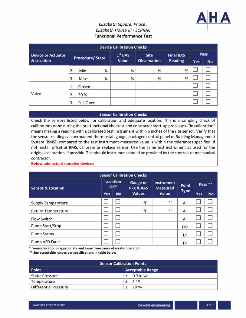
beyond engineering
Elizabeth Square, Phase I
Elizabeth House III - SCRRAC Functional Performance Test
-3000 www.ah
www.aha-engineers.com 4 of 7
Device Calibration Checks
Device or Actuator & Location
Procedure/ State 1st BAS Value
Site Observation
Final BAS Reading
Pass
Yes No
2. Mid: % % % % ☐ ☐
3. Max: % % % % ☐ ☐
Valve
1. Closed ☐ ☐
2. 50 % ☐ ☐
3. Full Open ☐ ☐
Sensor Calibration Checks
Check the sensors listed below for calibration and adequate location. This is a sampling check of calibrations done during the pre-functional checklist and contractor start-up processes. “In calibration” means making a reading with a calibrated test instrument within 6 inches of the site sensor. Verify that the sensor reading (via permanent thermostat, gauge, packaged control panel or Building Management System [BMS]) compared to the test instrument-measured value is within the tolerances specified. If not, install offset at BMS, calibrate or replace sensor. Use the same test instrument as used for the original calibration, if possible. This should instrument should be provided by the controls or mechanical contractor. Below add actual sampled devices
Sensor Calibration Checks
Sensor & Location
Location OK*
Gauge or Pkg & BAS
Values
Instrument Measured
Value
Point Type
Pass **
Yes No Yes No
Supply Temperature ☐ ☐ oF oF AI ☐ ☐
Return Temperature ☐ ☐ oF oF AI ☐ ☐
Flow Switch ☐ ☐ AI ☐ ☐
Pump Start/Stop ☐ ☐ DO ☐ ☐
Pump Status ☐ ☐ DI ☐ ☐
Pump VFD Fault ☐ ☐ DI ☐ ☐ * Sensor location is appropriate and away from cause of erratic operation. ** See acceptable ranges per specifications in table below
Sensor Calibration Points
Point Acceptable Range
Static Pressure ± 0.3 in.wc
Temperature ± 1 F
Differential Pressure ± 10 %

beyond engineering
Elizabeth Square, Phase I
Elizabeth House III - SCRRAC Functional Performance Test
-3000 www.ah
www.aha-engineers.com 5 of 7
Airflow ± 10 %
Waterflow ± 10 %
Comments:
Functional Performance Verification
The following procedures are a summary of the steps required to test the system function as described in the attached sequence of operations. The intent is for the system operation to be reviewed at both the piece of equipment (local/measured) and the controller - thermostat, BMS, DDC, etc. (Control). It should be noted that additional steps (not listed) may be required in order to achieve the noted simulation. Items will be noted as Pass Yes/No, N/A – Not Applicable, or N/T – Not Tested. Detailed information on failures will be noted in the commissioning issues log...
Control
# Testing Procedure Pass Comment
Description: The Unit Heater will operate based on its own local thermostat. The BMS will monitor the space temperature only.
1.
Run Conditions – Based on zone temperature 23 0993 2.13 B: The unit will be enabled to maintain a heating setpoint of 75°F (adj.).
Y / N
2. Zone Setpoint Adjust:
The occupant shall be able to adjust the zone temperature heating setpoint at the zone sensor. From the local Zone sensor adjust up and then down the zone setpoint. Verify the unit cycles on and off Return to normal.
Y / N
BMS / Unit Zone Sensor(s) Measure the space temperature and verify the local (unit) and BMS sensor are reading within +/- 1 deg F.
Y / N
Alarm
# Testing Procedure Pass Comment

beyond engineering
Elizabeth Square, Phase I
Elizabeth House III - SCRRAC Functional Performance Test
-3000 www.ah
www.aha-engineers.com 6 of 7
1. Low Zone temperature Y / N
Wrap Up
# Testing Procedure Pass Comment
1. Y / N
2. Y / N
3. Y / N
4. Y / N
5. Y / N
6. Y / N
7. Y / N
8. Y / N
Comments:
Trend Report
The following points will be trended every 15 minutes for period of not less than 2 weeks. These trends will be conducted at least twice a year: one in the cooling season and once in the heating season. Completed Trend Reports will be submitted in a format compatible with MS Excel.
Trend Report
Trend Trend Group Points
Acceptance of Test:
☐ This test cannot be accepted at this time due to the Corrective Issues noted above.
☐ This test is accepted by the Commissioning Authority identified below. Any Corrective Issues noted above do not adversely impact the overall performance of the system.

beyond engineering
Elizabeth Square, Phase I
Elizabeth House III - SCRRAC Functional Performance Test
-3000 www.ah
www.aha-engineers.com 7 of 7
Tested by Date
Witnessed by Date
Commissioning Provider Attachment(s): Sequence of Operations

beyond engineering
beyond engineering
Elizabeth Square, Phase IElizabeth House III - SCRRAC
Functional Performance Test
1 of 7
OverviewEquipment/Systems BASEBOARD ELECTRIC HEAT (typ of BEH-A(11 total), BEH-B(4 total), and
BEH-C (18 total) Complete one form for eachEquipment ID/Tag No. BEH-___Equipment Location:Area(s) Served: Main LobbySystem Description: Zone Electric Heat Spec Section(s): 23 0993, 23 8239.19
Test ExecutionInitial Date: Initial Time:Retest Date: Retest Time:
☐ Dry ☐ Rain ☐ Snow ☐ Sunny ☐ CloudyOutside Air Temperature oF Outside Air Humidity %RHHot Water Temperature oF Chilled Water Temperature oF
Ambient Conditions:
Equipment Data Equipment
NameplateBEH-___
Matches Approved Submittal
Manufacturer n/a ☐
Model Number n/a ☐Serial Number n/a
Prerequisite DocumentationItem Yes NoVerify that the Pre-Functional Checklist for this piece of equipment has been successfully completed, signed by appropriate parties, and returned to the Commissioning Authority.
☐ ☐
Verify that the manufacturer’s start-up procedure for this piece of equipment has been successfully completed and a copy of the completed start-up procedure has been submitted to the Commissioning Authority.
☐ ☐
Verify that Test & Balance for this piece of equipment has been successfully completed, reviewed and approved by the Engineer of record, and submitted to the Commissioning Authority.
☐ ☐
Verify unit is tied into the BMS system and graphics are complete. ☐ ☐
Verify all required I/O points are listed on the BMS system. ☐ ☐Verify ATC point-to-point and sensor/actuator calibration checks have been completed, documented and has been submitted to the Commissioning Authority. ☐ ☐

beyond engineering
beyond engineering
Elizabeth Square, Phase IElizabeth House III - SCRRAC
Functional Performance Test
-3000 www.ah
www.aha-engineers.com 2 of 7
Prerequisite DocumentationItem Yes No
All trends specified at the end of this test have been setup and are trending. ☐ ☐
Required Personnel and Tools Available ☐ ☐
System Ready for Functional Testing ☐ ☐
Participants:Required Name Company Project Role
Yes No
CM/GC ☐ ☐
Owner/Owners Rep ☐ ☐
Sub-Contractor ☐ ☐
Controls Contractor ☐ ☐Commissioning Authority ☐ ☐
Commissioning Agent ☐ ☐
Supplies Required for Testing Tools/Supplies Provided by
Schedule
System runs based on non-scheduled variable (e.g.: temperature, pressure) ☒
System runs 24 hours a day, 7 days a week (no schedule) ☐
System runs on then programmable schedule indicated below (TBD) ☐
Mon - Fri Sat - Sun Holiday
*Adj – indicates the point is adjustableSetpoints
Parameter Expected Actual Unit BMS Adj
Temperature (oF) ☐ ☐ ☐

beyond engineering
beyond engineering
Elizabeth Square, Phase IElizabeth House III - SCRRAC
Functional Performance Test
-3000 www.ah
www.aha-engineers.com 3 of 7
SetpointsParameter Expected Actual Unit BMS AdjZone Setpoint (local) 75 oF oF ☒ ☐ ☒
Alarm Temperature (oF / psi) ☒ ☐ ☐ ☐ ☐Low Zone Temperature (BMS) 50 oF ☐ ☒ ☒
Initial ConditionsConditions Unit/ Measured Thermostat/ BMSTemperature oF oF
Zone Temperature (BMS) oF oF
Zone Temperature (local) oF oF
Alarm (normal) (alarm) (normal) (alarm)
Low Zone Temperature (BMS)
Status (on) (off) (on) (off)
Fan Status
Comments: The above set points and initial conditions are key items for commissioning purposes. Review all data available at local controllers and the Building Management System (BMS) front-end computer and note any additional values the affect system operations (e.g. lockouts or time delays). Some values will require the use of measurement equipment.
Device Calibration ChecksThe actuators or devices listed below are to be checked for calibration. This is a spot check on a sample of the calibrations completed during the pre-functional checklist and contractor start-up processes. “In calibration” means observing a readout at the BMS and going to the actuator or controlled device and verifying that the BMS reading is correct, this was done during the recording of initial conditions. For the calibration portion - command speed or position to open, intermediate, and closed. Record read out and field observations at each.Below add actual sampled devices
Device Calibration Checks
Pass Device or Actuator & Location Procedure/ State 1st BAS
ValueSite
Observation Final BAS Reading Yes No
1. Min: % % % % ☐ ☐
2. Mid: % % % % ☐ ☐Supply Fan VFD
3. Max: % % % % ☐ ☐Supply Fan VFD 1. Min: % % % % ☐ ☐

beyond engineering
beyond engineering
Elizabeth Square, Phase IElizabeth House III - SCRRAC
Functional Performance Test
-3000 www.ah
www.aha-engineers.com 4 of 7
Device Calibration Checks
Pass Device or Actuator & Location Procedure/ State 1st BAS
ValueSite
Observation Final BAS Reading Yes No
2. Mid: % % % % ☐ ☐
3. Max: % % % % ☐ ☐
1. Closed ☐ ☐
2. 50 % ☐ ☐Valve
3. Full Open ☐ ☐
Sensor Calibration ChecksCheck the sensors listed below for calibration and adequate location. This is a sampling check of calibrations done during the pre-functional checklist and contractor start-up processes. “In calibration” means making a reading with a calibrated test instrument within 6 inches of the site sensor. Verify that the sensor reading (via permanent thermostat, gauge, packaged control panel or Building Management System [BMS]) compared to the test instrument-measured value is within the tolerances specified. If not, install offset at BMS, calibrate or replace sensor. Use the same test instrument as used for the original calibration, if possible. This should instrument should be provided by the controls or mechanical contractor.Below add actual sampled devices
Sensor Calibration ChecksLocation
OK* Pass **Sensor & Location
Yes No
Gauge or Pkg & BAS
Values
Instrument Measured
Value
Point Type
Yes No
Supply Temperature ☐ ☐ oF oF AI ☐ ☐
Return Temperature ☐ ☐ oF oF AI ☐ ☐
Flow Switch ☐ ☐ AI ☐ ☐Pump Start/Stop ☐ ☐ DO ☐ ☐Pump Status ☐ ☐ DI ☐ ☐Pump VFD Fault ☐ ☐ DI ☐ ☐
* Sensor location is appropriate and away from cause of erratic operation.** See acceptable ranges per specifications in table below
Sensor Calibration PointsPoint Acceptable RangeStatic Pressure ± 0.3 in.wcTemperature ± 1 FDifferential Pressure ± 10 %

beyond engineering
beyond engineering
Elizabeth Square, Phase IElizabeth House III - SCRRAC
Functional Performance Test
-3000 www.ah
www.aha-engineers.com 5 of 7
Airflow ± 10 %Waterflow ± 10 %
Comments:
Functional Performance VerificationThe following procedures are a summary of the steps required to test the system function as described in the attached sequence of operations. The intent is for the system operation to be reviewed at both the piece of equipment (local/measured) and the controller - thermostat, BMS, DDC, etc. (Control). It should be noted that additional steps (not listed) may be required in order to achieve the noted simulation. Items will be noted as Pass Yes/No, N/A – Not Applicable, or N/T – Not Tested. Detailed information on failures will be noted in the commissioning issues log...
Control# Testing Procedure Pass CommentDescription: The Unit Heater will operate based on its own local thermostat.
The BMS will monitor the space temperature only.
1.
Run Conditions – Based on zone temperature 23 0993 2.13 B:
The unit will be enabled to maintain a heating setpoint of 75°F (adj.).
Y / N
2. Zone Setpoint Adjust:The occupant shall be able to adjust the zone temperature heating setpoint at the zone sensor.
From the local Zone sensor adjust up and then down the zone setpoint.
Verify the unit cycles on and off
Return to normal.
Y / N
BMS / Unit Zone Sensor(s)
Measure the space temperature and verify the local (unit) and BMS sensor are reading within +/- 1 deg F.
Y / N
Alarm# Testing Procedure Pass Comment

beyond engineering
beyond engineering
Elizabeth Square, Phase IElizabeth House III - SCRRAC
Functional Performance Test
-3000 www.ah
www.aha-engineers.com 6 of 7
1. Low Zone temperature Y / N
Wrap Up# Testing Procedure Pass Comment1. Y / N2. Y / N3. Y / N4. Y / N5. Y / N6. Y / N7. Y / N8. Y / N
Comments:
Trend Report
The following points will be trended every 15 minutes for period of not less than 2 weeks. These trends will be conducted at least twice a year: one in the cooling season and once in the heating season.
Completed Trend Reports will be submitted in a format compatible with MS Excel.
Trend ReportTrend Trend Group Points
Acceptance of Test:
☐ This test cannot be accepted at this time due to the Corrective Issues noted above.
☐This test is accepted by the Commissioning Authority identified below. Any Corrective Issues noted above do not adversely impact the overall performance of the system.

beyond engineering
beyond engineering
Elizabeth Square, Phase IElizabeth House III - SCRRAC
Functional Performance Test
-3000 www.ah
www.aha-engineers.com 7 of 7
Tested by Date
Witnessed by DateCommissioning Provider
Attachment(s): Sequence of Operations

beyond engineering
Elizabeth Square, Phase I Elizabeth House III - SCRRAC
Functional Performance Test
1 of 6
Overview
Equipment/Systems Automatic Transfer Switch(s) Complete one form for each
Equipment ID/Tag No. ATS-S, RE & SLR
Equipment Location: EMERGENCY GENERATOR RM (G215)
Area(s) Served: SCRRAC
System Description: Emergency Power - TRANSFER SWITCHES
Spec Section(s): 26 3600
Test Execution
Initial Date: Initial Time:
Retest Date: Retest Time:
Ambient Conditions: ☐ Dry ☐ Rain ☐ Snow ☐ Sunny ☐ Cloudy
Outside Air Temperature oF Outside Air Humidity %RH
Hot Water Temperature oF Chilled Water Temperature oF
Equipment Data
Equipment
Nameplate
STAND BY GENERATOR
Matches Approved Submittal
Manufacturer n/a ☐
Model Number n/a ☐
Serial Number n/a
Prerequisite Documentation
Item Yes No
Verify that the Pre-Functional Checklist for this piece of equipment has been successfully completed, signed by appropriate parties, and returned to the Commissioning Authority.
☐ ☐
Verify that the manufacturer’s start-up procedure for this piece of equipment has been successfully completed and a copy of the completed start-up procedure has been submitted to the Commissioning Authority.
☐ ☐
All required Factory Test documents received. ☐ ☐
Contractor has issued the passed and approved Field Quality Control 26 3600 A - G ☐ ☐
Verify unit is tied into the BMS system and graphics are complete. ☐ ☐
Verify all required I/O points are listed on the BMS system. ☐ ☐ Verify ATC point-to-point and sensor/actuator calibration checks have been completed, documented and has been submitted to the Commissioning Authority. ☐ ☐

beyond engineering
Elizabeth Square, Phase I
Elizabeth House III - SCRRAC Functional Performance Test
-3000 www.ah
www.aha-engineers.com 2 of 6
Prerequisite Documentation
Item Yes No
All trends specified at the end of this test have been setup and are trending. ☐ ☐
Required Personnel and Tools Available ☐ ☐
System Ready for Functional Testing ☐ ☐
Participants:
Name Company Project Role Required
Yes No
CM/GC ☐ ☐
Owner/Owners Rep ☐ ☐
Sub-Contractor ☐ ☐
Controls Contractor ☐ ☐
Commissioning Authority ☐ ☐
Commissioning Agent ☐ ☐
Supplies Required for Testing
Tools/Supplies Provided by
Schedule
System runs based on non-scheduled variable (e.g.: temperature, pressure) ☒
System runs 24 hours a day, 7 days a week (no schedule) ☐
System runs on then programmable schedule indicated below (TBD) ☐
Mon - Fri Sat - Sun Holiday
*Adj – indicates the point is adjustable
Phase Voltage Measure Metered

beyond engineering
Elizabeth Square, Phase I
Elizabeth House III - SCRRAC Functional Performance Test
-3000 www.ah
www.aha-engineers.com 3 of 6
Phase A Voltage (Normal)
Phase B Voltage (Normal)
Phase C Voltage (Normal)
Phase A Voltage (Emergency) Verify during Generator Test #1
Phase B Voltage (Emergency) Verify during Generator Test #1
Phase C Voltage (Emergency) Verify during Generator Test #1
Time Delays Minutes Time Delays
ATS normal source outages n/a
ATS normal source outages delay to transfer n/a
ATS time delay transfer to emergency n/a
Cooldown time delay n/a
Alarm (normal) (alarm) (normal) (alarm)
ATS on emergency
Status Normal Emerg Normal Emerg
ATS Status
Comments:
The above set points and initial conditions are key items for commissioning purposes. Review all data available at local controllers and the Building Management System (BMS) front-end computer and note any additional values the affect system operations (e.g. lockouts or time delays). Some values will require the use of measurement equipment.
Comments:
Control
# Testing Procedure Pass Comment
1. Power up both emergency and normal feeds, observe metering. Confirm normal and emergency power to this ATS. Re-confirm phase rotation at the normal bus, and that phase rotation of
Y / N

beyond engineering
Elizabeth Square, Phase I
Elizabeth House III - SCRRAC Functional Performance Test
-3000 www.ah
www.aha-engineers.com 4 of 6
Control
# Testing Procedure Pass Comment
normal and emergency both agree. Confirm metering on the ATS display.
2. Under no load conditions, initiate manual transfer to and from emergency for this ATS. Confirm proper operation of the manual transfer feature. Repeat 2-4 times.
Y / N
3. Confirm automatic re-transfer to normal as follows. Kill input on emergency side, with normal available. Observe the ATS automatically re-transferring to normal.
Y / N
4. Simulate a utility outage by removing the normal input. Observe automatic start of the generator, and automatic transfer of the ATS to emergency. Perform under nominal available load
Y / N
5.
Confirm functionality of external maintenance bypass (as applicable) by transferring to and from external maintenance bypass with load bank connected and insuring no interruption of power to the load.
Y / N
6.
VOLTAGE AND FREQUENCY SENSING: 26 3600 2.6 Voltage and frequency on both the normal and emergency sources (as noted below) shall be continuously monitored, with the following pickup, dropout, and trip settings capabilities. Assisted by the factory-authorized service representative, verify the below setting:
Parameter Sources Dropout/Trip Pickup/Reset
Undervoltage N & E 70 to 98% 85 to 100% Y / N
Overvoltage N & E 102 to115% 2% below trip Y / N
Overfrequency N & E 102 to 110% 2% below trip Y / N
Data Logging
# Verify the following points are provided Pass Comment
1. Data and time and reason for transfer normal to emergency Y / N
2. Data and time and reason for transfer emergency to normal Y / N
3. Data and time and reason for engine start Y / N
4. Data and time engine stopped Y / N
5. Data and time emergency source available Y / N
6. Data and time emergency source not available Y / N
7. Total number of transfers Y / N
8. Total number of transfers due to source failure Y / N
9. Total number of day’s controller is energized Y / N
10. Total number of hours both normal and emergency sources are available
Y / N

beyond engineering
Elizabeth Square, Phase I
Elizabeth House III - SCRRAC Functional Performance Test
-3000 www.ah
www.aha-engineers.com 5 of 6
Control
# Testing Procedure Pass Comment
11. Total time load is connected to normal Y / N
12. Total time load is connected to emergency Y / N
13. Last engine start Y / N
14. Last engine start up time Y / N
15. Input and output status Y / N
Alarm
# Testing Procedure / Common Remote Audible Alarm: Pass Comment
1. Y / N
2. Y / N
3. Y / N
4. Y / N
5. Y / N
6. Y / N
7. Y / N
8. Y / N
9. Y / N
Wrap Up
# Testing Procedure Pass Comment
1. Y / N
2. Y / N
3. Y / N
4. Y / N
5. Y / N
6. Y / N
7. Y / N
8. Y / N
Comments:
Trend Report

beyond engineering
Elizabeth Square, Phase I
Elizabeth House III - SCRRAC Functional Performance Test
-3000 www.ah
www.aha-engineers.com 6 of 6
The following points will be trended every 15 minutes for period of not less than 2 weeks. These trends will be conducted at least twice a year: one in the cooling season and once in the heating season. Completed Trend Reports will be submitted in a format compatible with MS Excel.
Trend Report
Trend Trend Group Points
Acceptance of Test:
☐ This test cannot be accepted at this time due to the Corrective Issues noted above.
☐ This test is accepted by the Commissioning Authority identified below. Any Corrective Issues noted above do not adversely impact the overall performance of the system.
Tested by Date
Witnessed by Date
Commissioning Provider Attachment(s): Sequence of Operations

beyond engineering
Elizabeth Square, Phase I Elizabeth House III - SCRRAC
Functional Performance Test
1 of 4
Overview
Equipment/Systems Electrical Distribution Panel (typ of all) Complete one form for each
Equipment ID/Tag No. Varies
Equipment Location: Varies
Area(s) Served: SCRRAC
System Description: Electrical Distribution Panels
Spec Section(s): 26 2416, 26 0800
Test Execution
Initial Date: Initial Time:
Retest Date: Retest Time:
Ambient Conditions: ☐ Dry ☐ Rain ☐ Snow ☐ Sunny ☐ Cloudy
Outside Air Temperature oF Outside Air Humidity %RH
Hot Water Temperature oF Chilled Water Temperature oF
Equipment Data
Equipment
Nameplate
Panel
Matches Approved Submittal
Manufacturer n/a ☐
Model Number n/a ☐
Serial Number n/a
Prerequisite Documentation
Item Yes No
Verify that the Pre-Functional Checklist for this piece of equipment has been successfully completed, signed by appropriate parties, and returned to the Commissioning Authority.
☐ ☐
Verify that the manufacturer’s start-up procedure for this piece of equipment has been successfully completed and a copy of the completed start-up procedure has been submitted to the Commissioning Authority.
☐ ☐
All required Factory Test documents received. ☐ ☐
All metering and meggering reports have been issued and approved. ☐ ☐ Required studies submitted and approved:
26 0572 OVERCURRENT PROTECTIVE DEVICE SHORT-CIRCUIT STUDY
26 0573 OVERCURRENT PROTECTIVE DEVICE COORDINATION STUDY
26 0574 OVERCURRENT PROTECTIVE DEVICE ARC-FLASH STUDY
☐ ☐
Contractor has issued the passed and approved Field Quality Control ☐ ☐

beyond engineering
Elizabeth Square, Phase I
Elizabeth House III - SCRRAC Functional Performance Test
-3000 www.ah
www.aha-engineers.com 2 of 4
Prerequisite Documentation
Item Yes No
Required Personnel and Tools Available ☐ ☐
System Ready for Functional Testing ☐ ☐
Participants:
Name Company Project Role Required
Yes No
CM/GC ☐ ☐
Owner/Owners Rep ☐ ☐
Sub-Contractor ☐ ☐
Controls Contractor ☐ ☐
Commissioning Authority ☐ ☐
Commissioning Agent ☐ ☐
Supplies Required for Testing
Tools/Supplies Provided by
*Adj – indicates the point is adjustable
Phase Voltage Measure Metered
Phase A Voltage (Normal)
Phase B Voltage (Normal)
Phase C Voltage (Normal)
Comments:

beyond engineering
Elizabeth Square, Phase I
Elizabeth House III - SCRRAC Functional Performance Test
-3000 www.ah
www.aha-engineers.com 3 of 4
Inspection
# Testing Procedure Pass Comment
From the approved contract documents verify the following:
1. Panels labeled properly (Nameplates 26 2416 3.3 C) Y / N
2. Verify panel is feed from the designate transformer / switchgear. Y / N
3. Verify proper panel grounding Y / N
4. Verify the proper panel schedule is provided Y / N
5. Verify the following:
a. Amperage is correct b. Installed Fused Switch: NEMA KS 1, Type HD
Y / N
6. Field verify circuit is pulled to specified device (panel) Record actual circuits in table below.
Y / N
# Circuit verification / (test 5 & 6): Pass Comment
1. Y / N
2. Y / N
3. Y / N
4. Y / N
5. Y / N
6. Y / N
7. Y / N
8. Y / N
9. Y / N
10.
Wrap Up
# Testing Procedure Pass Comment
1. Y / N
2. Y / N
3. Y / N
4. Y / N
5. Y / N
6. Y / N
7. Y / N

beyond engineering
Elizabeth Square, Phase I
Elizabeth House III - SCRRAC Functional Performance Test
-3000 www.ah
www.aha-engineers.com 4 of 4
Comments:
Acceptance of Test:
☐ This test cannot be accepted at this time due to the Corrective Issues noted above.
☐ This test is accepted by the Commissioning Authority identified below. Any Corrective Issues noted above do not adversely impact the overall performance of the system.
Tested by Date
Witnessed by Date
Commissioning Provider Attachment(s): Sequence of Operations

beyond engineering
Elizabeth Square, Phase I Elizabeth House III - SCRRAC
Functional Performance Test
1 of 6
Overview
Equipment/Systems DIGITAL-NETWORK LIGHTING CONTROL SYSTEM (typ of 4 Hubs) Complete one form for each
Equipment ID/Tag No. LUTRON - LIGHTING CONTROL (S008)
Equipment Location: HUB QP3 – final designation not assigned yet
Area(s) Served: SCRRAC - varies
System Description: Lighting System
Spec Section(s): 26 0923
Test Execution
Initial Date: Initial Time:
Retest Date: Retest Time:
Ambient Conditions: ☐ Dry ☐ Rain ☐ Snow ☐ Sunny ☐ Cloudy
Outside Air Temperature oF Outside Air Humidity %RH
Hot Water Temperature oF Chilled Water Temperature oF
Equipment Data
Equipment
Nameplate
HUB QP3
Matches Approved Submittal
Manufacturer n/a ☐
Model Number n/a ☐
Serial Number n/a
Prerequisite Documentation
Item Yes No
Verify that the Pre-Functional Checklist for this piece of equipment has been successfully completed, signed by appropriate parties, and returned to the Commissioning Authority.
☐ ☐
Verify that the manufacturer’s start-up procedure for this system has been successfully completed and a copy of the completed start-up procedure has been submitted to the Commissioning Authority.
☐ ☐
Contractor has issued the passed and approved Field Quality Control documents as detailed in 23 0923 2.09 ☐ ☐
Associated ATS have been test and approved ☐ ☐
Verify unit is tied into the BMS system and graphics are complete. ☐ ☐
Verify all required I/O points are listed on the BMS system. ☐ ☐
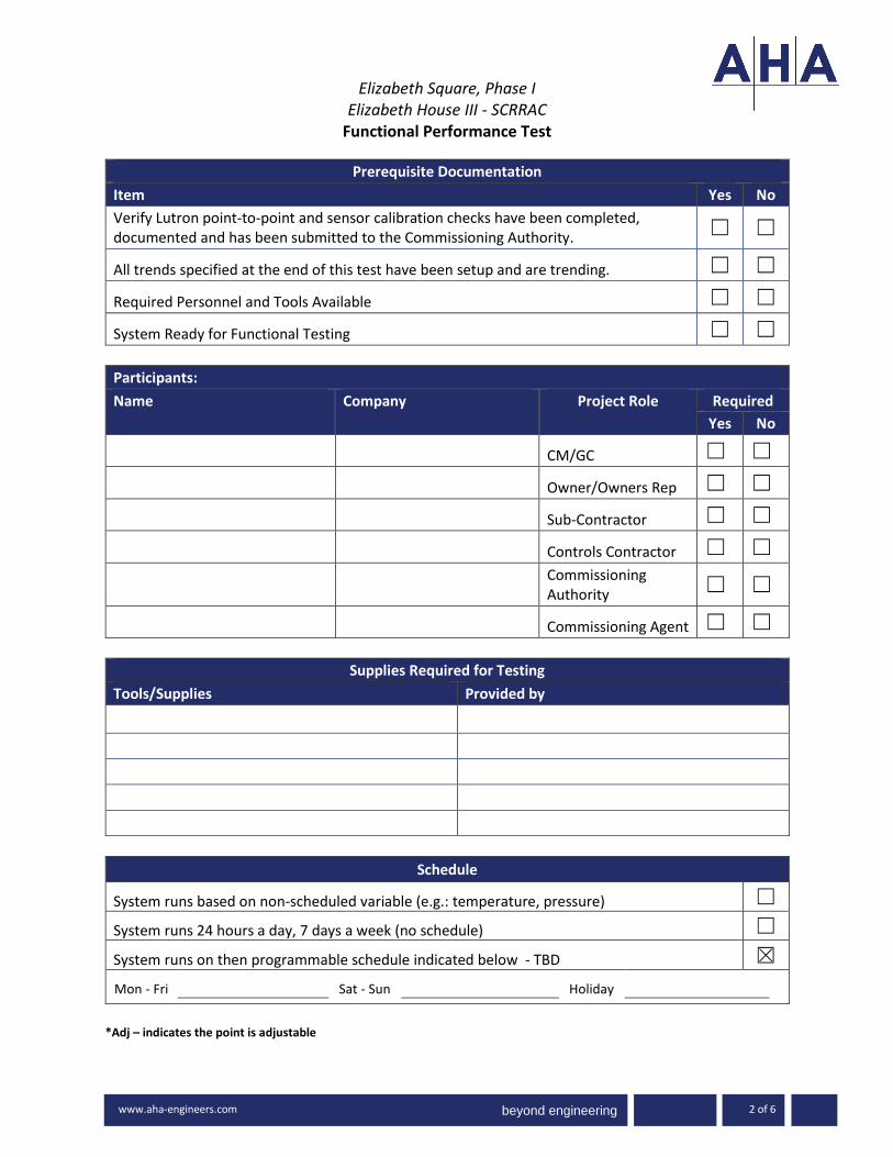
beyond engineering
Elizabeth Square, Phase I
Elizabeth House III - SCRRAC Functional Performance Test
-3000 www.ah
www.aha-engineers.com 2 of 6
Prerequisite Documentation
Item Yes No
Verify Lutron point-to-point and sensor calibration checks have been completed, documented and has been submitted to the Commissioning Authority. ☐ ☐
All trends specified at the end of this test have been setup and are trending. ☐ ☐
Required Personnel and Tools Available ☐ ☐
System Ready for Functional Testing ☐ ☐
Participants:
Name Company Project Role Required
Yes No
CM/GC ☐ ☐
Owner/Owners Rep ☐ ☐
Sub-Contractor ☐ ☐
Controls Contractor ☐ ☐
Commissioning Authority ☐ ☐
Commissioning Agent ☐ ☐
Supplies Required for Testing
Tools/Supplies Provided by
Schedule
System runs based on non-scheduled variable (e.g.: temperature, pressure) ☐
System runs 24 hours a day, 7 days a week (no schedule) ☐
System runs on then programmable schedule indicated below - TBD ☒
Mon - Fri Sat - Sun Holiday
*Adj – indicates the point is adjustable

beyond engineering
Elizabeth Square, Phase I
Elizabeth House III - SCRRAC Functional Performance Test
-3000 www.ah
www.aha-engineers.com 3 of 6
Time Delays Minutes Time Delays
Unoccupied delay off 10 min
shut n/a
Comments:
The above set points and initial conditions are key items for commissioning purposes. Review all data available at local controllers and the Building Management System (BMS) front-end computer and note any additional values the affect system operations (e.g. lockouts or time delays). Some values will require the use of measurement equipment.
Comments:
Control
# Testing Procedure Pass Comment
System Description: 26 0923 MAIN UNITS (LUTRON GRAFIK EYE QS) A. Product: Lutron GRAFIK Eye QS. B. Provide main units with configuration and quantity of zones as indicated to control the loads as indicated. C. Engrave units with button, zone, and scene descriptions as indicated on the drawings. D. Integrated Wireless Capability: 1. Provide wireless communication inputs for: a. Occupancy sensors. b. Daylight sensors. c. Wireless controller E. Preset Lighting Control with Zone Override
1. CONTROL STATIONS: 23 0923 2.5
Y / N

beyond engineering
Elizabeth Square, Phase I
Elizabeth House III - SCRRAC Functional Performance Test
-3000 www.ah
www.aha-engineers.com 4 of 6
Control
# Testing Procedure Pass Comment
Refer to the lighting control contract documents to verify the proper configuration. A. Provide control stations with configuration as indicated to control the loads as indicated.
2.
Verify by the approved lighting control contract documents the proper sensor modules are installed. Sensor Modules: 23 0923 2.06 D Wired Modules: a. Provide wired inputs for: 1) Occupancy sensors. 2) Daylight sensors. 3) IR receivers for personal control. 4) Digital ballast wall stations. 3. Wireless Modules: a. Provide wireless communication inputs for: 1) Occupancy sensors. 2) Daylight sensors. 3) Wireless controller.
Y / N
3.
Sensor Locations: 23 0923 3.02 D For each lighting zone sensor verify proper placement per the manufacturer requirements.
Y / N
4.
Verify lighting levels and installed sensors met the contract documents. Zone data is forthcoming. For each zone, record the lighting level, sensor type and current state prior to testing / Refer to the end of this test document for the record table.
Y / N
5. From each zone verify the operation of the zone Lutron Lighting control keypad (where applicable)
Y / N
Wrap Up
# Testing Procedure Pass Comment
1. Y / N

beyond engineering
Elizabeth Square, Phase I
Elizabeth House III - SCRRAC Functional Performance Test
-3000 www.ah
www.aha-engineers.com 5 of 6
2. Y / N
3. Y / N
4. Y / N
5. Y / N
6. Y / N
7. Y / N
8. Y / N
Comments:
Trend Report
The following points will be trended every 15 minutes for period of not less than 2 weeks. These trends will be conducted at least twice a year: one in the cooling season and once in the heating season. Completed Trend Reports will be submitted in a format compatible with MS Excel.
Trend Report
Trend Trend Group Points
Lighting Zone Verification / add as needed
Zone #
Hub Tag -
Measured Lighting Level
Sensor Type / Keypad System activation
On/Off operation Pass
Y / N
Y / N
Y / N
Y / N
Acceptance of Test:

beyond engineering
Elizabeth Square, Phase I
Elizabeth House III - SCRRAC Functional Performance Test
-3000 www.ah
www.aha-engineers.com 6 of 6
☐ This test cannot be accepted at this time due to the Corrective Issues noted above.
☐ This test is accepted by the Commissioning Authority identified below. Any Corrective Issues noted above do not adversely impact the overall performance of the system.
Tested by Date
Witnessed by Date
Commissioning Provider Attachment(s): Approved Lighting Zone Control - Forthcoming

beyond engineering
Elizabeth Square, Phase I Elizabeth House III - SCRRAC
Functional Performance Test
1 of 4
Overview
Equipment/Systems Electrical Panel (typ of all) Complete one form for each
Equipment ID/Tag No. Varies
Equipment Location: Varies
Area(s) Served: SCRRAC
System Description: Electrical Branch Circuit Panels
Spec Section(s): 26 2416, 26 0800
Test Execution
Initial Date: Initial Time:
Retest Date: Retest Time:
Ambient Conditions: ☐ Dry ☐ Rain ☐ Snow ☐ Sunny ☐ Cloudy
Outside Air Temperature oF Outside Air Humidity %RH
Hot Water Temperature oF Chilled Water Temperature oF
Equipment Data
Equipment
Nameplate
Panel
Matches Approved Submittal
Manufacturer n/a ☐
Model Number n/a ☐
Serial Number n/a
Prerequisite Documentation
Item Yes No
Verify that the Pre-Functional Checklist for this piece of equipment has been successfully completed, signed by appropriate parties, and returned to the Commissioning Authority.
☐ ☐
Verify that the manufacturer’s start-up procedure for this piece of equipment has been successfully completed and a copy of the completed start-up procedure has been submitted to the Commissioning Authority.
☐ ☐
All required Factory Test documents received. ☐ ☐
All metering and meggering reports have been issued and approved. ☐ ☐ Required studies submitted and approved:
26 0572 OVERCURRENT PROTECTIVE DEVICE SHORT-CIRCUIT STUDY
26 0573 OVERCURRENT PROTECTIVE DEVICE COORDINATION STUDY
26 0574 OVERCURRENT PROTECTIVE DEVICE ARC-FLASH STUDY
☐ ☐
Contractor has issued the passed and approved Field Quality Control ☐ ☐

beyond engineering
Elizabeth Square, Phase I
Elizabeth House III - SCRRAC Functional Performance Test
-3000 www.ah
www.aha-engineers.com 2 of 4
Prerequisite Documentation
Item Yes No
Required Personnel and Tools Available ☐ ☐
System Ready for Functional Testing ☐ ☐
Participants:
Name Company Project Role Required
Yes No
CM/GC ☐ ☐
Owner/Owners Rep ☐ ☐
Sub-Contractor ☐ ☐
Controls Contractor ☐ ☐
Commissioning Authority ☐ ☐
Commissioning Agent ☐ ☐
Supplies Required for Testing
Tools/Supplies Provided by
*Adj – indicates the point is adjustable
Phase Voltage Measure Metered
Phase A Voltage (Normal)
Phase B Voltage (Normal)
Phase C Voltage (Normal)
Comments:

beyond engineering
Elizabeth Square, Phase I
Elizabeth House III - SCRRAC Functional Performance Test
-3000 www.ah
www.aha-engineers.com 3 of 4
Inspection
# Testing Procedure Pass Comment
From the approved contract documents verify the following:
1. Panels labeled properly (Panelboard Nameplates 26 2416 3.3 C) Y / N
2. Verify panel is feed from the designate distribution panel. Y / N
3. Verify proper panel grounding Y / N
4. Verify the proper panel schedule is provided Y / N
5.
Verify the following: a. Breaker amperage is correct b. Installed Breakers are Molded-Case Circuit Breaker
(MCCB)
Y / N
6. Field verify circuit is pulled to specified device (lighting, receptacle…) Record actual circuits in table below.
Y / N
7. With circuit (outlet) tester / GFCI Outlet Tester, verify proper circuit grounding/configuration. Record actual circuits in table below
Y / N
# Circuit verification / (test 6 & 7): Pass Comment
1. Y / N
2. Y / N
3. Y / N
4. Y / N
5. Y / N
6. Y / N
7. Y / N
8. Y / N
9. Y / N
10.
Wrap Up
# Testing Procedure Pass Comment
1. Y / N
2. Y / N
3. Y / N
4. Y / N
5. Y / N

beyond engineering
Elizabeth Square, Phase I
Elizabeth House III - SCRRAC Functional Performance Test
-3000 www.ah
www.aha-engineers.com 4 of 4
6. Y / N
7. Y / N
Comments:
Acceptance of Test:
☐ This test cannot be accepted at this time due to the Corrective Issues noted above.
☐ This test is accepted by the Commissioning Authority identified below. Any Corrective Issues noted above do not adversely impact the overall performance of the system.
Tested by Date
Witnessed by Date
Commissioning Provider Attachment(s): Sequence of Operations

beyond engineering
Elizabeth Square, Phase I Elizabeth House III - SCRRAC
Functional Performance Test
1 of 6
Overview
Equipment/Systems ENGINE-GENERATOR SET
Equipment ID/Tag No. Standby GENERATOR
Equipment Location: EMERGENCY GENERATOR RM (G215)
Area(s) Served: SCRRAC
System Description: Emergency Generator
Spec Section(s): 26 3213
Test Execution
Initial Date: Initial Time:
Retest Date: Retest Time:
Ambient Conditions: ☐ Dry ☐ Rain ☐ Snow ☐ Sunny ☐ Cloudy
Outside Air Temperature oF Outside Air Humidity %RH
Hot Water Temperature oF Chilled Water Temperature oF
Equipment Data
Equipment
Nameplate
STAND BY GENERATOR
Matches Approved Submittal
Manufacturer n/a ☐
Model Number n/a ☐
Serial Number n/a
Prerequisite Documentation
Item Yes No
Verify that the Pre-Functional Checklist for this piece of equipment has been successfully completed, signed by appropriate parties, and returned to the Commissioning Authority.
☐ ☐
Verify that the manufacturer’s start-up procedure for this piece of equipment has been successfully completed and a copy of the completed start-up procedure has been submitted to the Commissioning Authority.
☐ ☐
All required Factory Test documents received. ☐ ☐ Contractor has issued the passed and approved Field Quality Control Tests 26 3213 A - K ☐ ☐
Associated ATS have been test and approved ☐ ☐
Verify unit is tied into the BMS system and graphics are complete. ☐ ☐
Verify all required I/O points are listed on the BMS system. ☐ ☐

beyond engineering
Elizabeth Square, Phase I
Elizabeth House III - SCRRAC Functional Performance Test
-3000 www.ah
www.aha-engineers.com 2 of 6
Prerequisite Documentation
Item Yes No
Verify ATC point-to-point and sensor/actuator calibration checks have been completed, documented and has been submitted to the Commissioning Authority. ☐ ☐
All trends specified at the end of this test have been setup and are trending. ☐ ☐
Required Personnel and Tools Available ☐ ☐
System Ready for Functional Testing ☐ ☐
Participants:
Name Company Project Role Required
Yes No
CM/GC ☐ ☐
Owner/Owners Rep ☐ ☐
Sub-Contractor ☐ ☐
Controls Contractor ☐ ☐
Commissioning Authority ☐ ☐
Commissioning Agent ☐ ☐
Supplies Required for Testing
Tools/Supplies Provided by
Schedule
System runs based on non-scheduled variable (e.g.: temperature, pressure) ☒
System runs 24 hours a day, 7 days a week (no schedule) ☐
System runs on then programmable schedule indicated below (TBD) ☐
Mon - Fri Sat - Sun Holiday
*Adj – indicates the point is adjustable

beyond engineering
Elizabeth Square, Phase I
Elizabeth House III - SCRRAC Functional Performance Test
-3000 www.ah
www.aha-engineers.com 3 of 6
Time Delays Minutes
Generator Cooldown time n/a
Alarm (normal) (alarm) (normal) (alarm)
Status (on) (off) (on) (off)
Generator Status
Operating Hours hrs hrs
Generator Runtime
Comments:
The above set points and initial conditions are key items for commissioning purposes. Review all data available at local controllers and the Building Management System (BMS) front-end computer and note any additional values the affect system operations (e.g. lockouts or time delays). Some values will require the use of measurement equipment.
Comments:
Control
# Testing Procedure Pass Comment
Prior to any generator run functional testing, the factory-authorized service representative will verify and demonstrate all alarms. (refer to alarm list at end of the testing section.
26 3213 2.5
1.
Automatic Starting System Sequence of Operation: From the associated ATS(s) (ATS-S, RE & SLR) individually manual initiate manual generator run command. When mode-selector switch on the control and monitoring panel is in the automatic position, remote-control contacts in one or more separate automatic transfer switches initiate starting and stopping of generator set.
Y / N

beyond engineering
Elizabeth Square, Phase I
Elizabeth House III - SCRRAC Functional Performance Test
-3000 www.ah
www.aha-engineers.com 4 of 6
Control
# Testing Procedure Pass Comment
Allow for generator cooldown between ATS call for generator run. Return to normal. When mode selector switch is switched to the on position, generator set starts. Return to normal The off position of same switch initiates generator-set shutdown. Allow for generator cool down delay.
2.
Manually initiate a generator run command. Approved contractor will manually trip generator safety. When generator set is running, specified system or equipment failures or derangements automatically shut down generator set and initiate alarms. Operation of a remote emergency-stop switch also shuts down generator set.
Y / N
3.
Manual Starting System Sequence of Operation: From the Generator Panel verify the following operation. Switching on-off switch on the generator control panel to the on position starts generator set. The off position of same switch initiates generator-set shutdown. Allow for generator cool down delay. When generator set is running, specified system or equipment failures or derangements automatically shut down generator set and initiate alarms. Operation of a remote emergency-stop switch also shuts down generator set. Return all to normal
Y / N

beyond engineering
Elizabeth Square, Phase I
Elizabeth House III - SCRRAC Functional Performance Test
-3000 www.ah
www.aha-engineers.com 5 of 6
Alarm
# Testing Procedure / Common Remote Audible Alarm: Pass Comment
1. Overcrank shutdown. Y / N
2. Coolant low-temperature alarm. Y / N
3. Battery-charger malfunction alarm. Y / N
4. Battery low-voltage alarm. Y / N
5. Fuel tank derangement alarm. Y / N
6. Fuel tank high-level shutdown of fuel supply alarm. Y / N
7. Generator overload Y / N
8. Fuel tank derangement alarm. Y / N
9. Fuel tank high-level shutdown of fuel supply alarm. Y / N
Wrap Up
# Testing Procedure Pass Comment
1. Y / N
2. Y / N
3. Y / N
4. Y / N
5. Y / N
6. Y / N
7. Y / N
8. Y / N
Comments:
Trend Report
The following points will be trended every 15 minutes for period of not less than 2 weeks. These trends will be conducted at least twice a year: one in the cooling season and once in the heating season. Completed Trend Reports will be submitted in a format compatible with MS Excel.
Trend Report
Trend Trend Group Points

beyond engineering
Elizabeth Square, Phase I
Elizabeth House III - SCRRAC Functional Performance Test
-3000 www.ah
www.aha-engineers.com 6 of 6
Trend Report
Trend Trend Group Points
Acceptance of Test:
☐ This test cannot be accepted at this time due to the Corrective Issues noted above.
☐ This test is accepted by the Commissioning Authority identified below. Any Corrective Issues noted above do not adversely impact the overall performance of the system.
Tested by Date
Witnessed by Date
Commissioning Provider Attachment(s): Sequence of Operations

beyond engineering
Elizabeth Square, Phase I Elizabeth House III - SCRRAC
Functional Performance Test
1 of 4
Overview
Equipment/Systems Electrical Switchgear (typ of all) Complete one form for each
Equipment ID/Tag No. Varies
Equipment Location: Varies
Area(s) Served: SCRRAC
System Description: Electrical Switchgear
Spec Section(s): 26 2413, 26 0800
Test Execution
Initial Date: Initial Time:
Retest Date: Retest Time:
Ambient Conditions: ☐ Dry ☐ Rain ☐ Snow ☐ Sunny ☐ Cloudy
Outside Air Temperature oF Outside Air Humidity %RH
Hot Water Temperature oF Chilled Water Temperature oF
Equipment Data
Equipment
Nameplate
Switchgear
Matches Approved Submittal
Manufacturer n/a ☐
Model Number n/a ☐
Serial Number n/a
Prerequisite Documentation
Item Yes No
Verify that the Pre-Functional Checklist for this piece of equipment has been successfully completed, signed by appropriate parties, and returned to the Commissioning Authority.
☐ ☐
Verify that the manufacturer’s start-up procedure for this piece of equipment has been successfully completed and a copy of the completed start-up procedure has been submitted to the Commissioning Authority.
☐ ☐
All required Factory Test documents received. ☐ ☐
All metering and meggering reports have been issued and approved. ☐ ☐
Infrared Scanning has been conducted and approved ☐ ☐
NETA Acceptance Testing has been completed, certified and approved ☐ ☐ Required studies submitted and approved:
26 0572 OVERCURRENT PROTECTIVE DEVICE SHORT-CIRCUIT STUDY
26 0573 OVERCURRENT PROTECTIVE DEVICE COORDINATION STUDY ☐ ☐

beyond engineering
Elizabeth Square, Phase I
Elizabeth House III - SCRRAC Functional Performance Test
-3000 www.ah
www.aha-engineers.com 2 of 4
Prerequisite Documentation
Item Yes No
26 0574 OVERCURRENT PROTECTIVE DEVICE ARC-FLASH STUDY
Contractor has issued the passed and approved Field Quality Control ☐ ☐
Required Personnel and Tools Available ☐ ☐
System Ready for Functional Testing ☐ ☐
Participants:
Name Company Project Role Required
Yes No
CM/GC ☐ ☐
Owner/Owners Rep ☐ ☐
Sub-Contractor ☐ ☐
Controls Contractor ☐ ☐
Commissioning Authority ☐ ☐
Commissioning Agent ☐ ☐
Supplies Required for Testing
Tools/Supplies Provided by
*Adj – indicates the point is adjustable
Phase Voltage Measure Metered
Phase A Voltage (Normal)
Phase B Voltage (Normal)
Phase C Voltage (Normal)
Comments:

beyond engineering
Elizabeth Square, Phase I
Elizabeth House III - SCRRAC Functional Performance Test
-3000 www.ah
www.aha-engineers.com 3 of 4
Inspection
# Testing Procedure Pass Comment
From the approved contract documents verify the following:
1. Verify the installation of Transient Voltage Suppression device (TVS) 26 2413 2.2
Y / N
2. Verify the installation of the proper rated disconnect/overcurrent protection. 26 2413 2.3
Y / N
3. Switchgear labeled properly 26 2413 2.7 Y / N
4. Verify proper panel grounding Y / N
5. Preform functional test of all switches Y / N
6. Verify the proper schedule is provided Y / N
7. Verify the following:
a. Amperage is correct b. Installed Fused Switch: NEMA KS 1, Type HD
Y / N
8. Field verify feeder is pulled to specified device (panel / transformer) Record actual feeder circuits in table below.
Y / N
# Circuit verification / (test 8): Pass Comment
1. Y / N
2. Y / N
3. Y / N
4. Y / N
5. Y / N
6. Y / N
7. Y / N
8. Y / N
9. Y / N
10.
Wrap Up
# Testing Procedure Pass Comment
1. Y / N
2. Y / N

beyond engineering
Elizabeth Square, Phase I
Elizabeth House III - SCRRAC Functional Performance Test
-3000 www.ah
www.aha-engineers.com 4 of 4
3. Y / N
4. Y / N
5. Y / N
6. Y / N
7. Y / N
Comments:
Acceptance of Test:
☐ This test cannot be accepted at this time due to the Corrective Issues noted above.
☐ This test is accepted by the Commissioning Authority identified below. Any Corrective Issues noted above do not adversely impact the overall performance of the system.
Tested by Date
Witnessed by Date
Commissioning Provider Attachment(s): Sequence of Operations

beyond engineering
Elizabeth Square, Phase I Elizabeth House III - SCRRAC
Functional Performance Test
1 of 7
Overview
Equipment/Systems Pool
Equipment ID/Tag No. P-1A and P-1B, associated VFD
Equipment Location: G105
Area(s) Served: Competition Pool
System Description: Pool Filtration and Pumping System
Spec Section(s): Division 13
Test Execution
Initial Date: Initial Time:
Retest Date: Retest Time:
Ambient Conditions: ☐ Dry ☐ Rain ☐ Snow ☐ Sunny ☐ Cloudy
Outside Air Temperature oF Outside Air Humidity %RH
Hot Water Temperature oF Chilled Water Temperature oF
Equipment Data
Equipment
Nameplate
P-1A P-1B
Matches Approved Submittal
Manufacturer ☐
Model Number ☐
Serial Number
Equipment Data
Equipment
Nameplate
P-1A VFD P-1B VFD
Matches Approved Submittal
Manufacturer ☐
Model Number ☐
Serial Number
Prerequisite Documentation
Item Yes No
Verify that the Pre-Functional Checklist for this piece of equipment has been successfully completed, signed by appropriate parties, and returned to the Commissioning Authority.
☐ ☐
Verify that the manufacturer’s start-up procedure for this piece of equipment has been successfully completed and a copy of the completed start-up procedure has been submitted to the Commissioning Authority.
☐ ☐

beyond engineering
Elizabeth Square, Phase I
Elizabeth House III - SCRRAC Functional Performance Test
-3000 www.ah
www.aha-engineers.com 2 of 7
Prerequisite Documentation
Item Yes No
Verify that Test & Balance for this piece of equipment has been successfully completed, reviewed and approved by the Engineer of record, and submitted to the Commissioning Authority.
☐ ☐
Verify that associated mechanical systems have been tested and are in operation. ☐ ☐
Verify unit is tied into the BMS system and graphics are complete. (where applicable) ☐ ☐
Verify all required I/O points are listed on the BMS system. (where applicable) ☐ ☐ Verify ATC point-to-point and sensor/actuator calibration checks have been completed, documented and has been submitted to the Commissioning Authority. (where applicable)
☐ ☐
All trends specified at the end of this test have been setup and are trending. (where applicable) ☐ ☐
Required Personnel and Tools Available ☐ ☐
System Ready for Functional Testing ☐ ☐
Participants:
Name Company Project Role Required
Yes No
CM/GC ☐ ☐
Owner/Owners Rep ☐ ☐
Sub-Contractor (Pool) ☐ ☐
Controls Contractor ☐ ☐
Commissioning Authority ☐ ☐
Commissioning Agent ☐ ☐
Supplies Required for Testing
Tools/Supplies Provided by
Schedule

beyond engineering
Elizabeth Square, Phase I
Elizabeth House III - SCRRAC Functional Performance Test
-3000 www.ah
www.aha-engineers.com 3 of 7
System runs based on non-scheduled variable (e.g.: temperature, pressure) ☐
System runs 24 hours a day, 7 days a week (no schedule) ☒
System runs on then programmable schedule indicated below ☐
Mon - Fri Sat - Sun Holiday
*Adj – indicates the point is adjustable
Setpoints
Parameter Expected Actual Unit BMS Adj
☐ ☐ ☐
Pump P-1A (system) filtration VFD setting Set by pool
start-up tech
% ☒ ☐ ☒
Pump P-1A (system) backwash VFD setting Set by pool
start-up tech
% ☒ ☐ ☒
Pump P-1B (system) filtration VFD setting Set by pool
start-up tech
% ☒ ☐ ☒
Pump P-1B (system) backwash VFD setting Set by pool
start-up tech
% ☒ ☐ ☒
Backwash time (manual)
Set by pool start-up tech /
minimum 3 mins
mins ☒ ☐ ☒
Filter (dirty) DP 10 PSI PSI ☒ ☐ ☒
Alarm Temperature (oF / psi) ☒ ☐ ☐ ☐ ☐ Dirty Filter DP 10 PSI ☒ ☐ ☒
Initial Conditions
Conditions Unit/ Measured Thermostat/ BMS
Pump (system) filtration VFD setting (typ of both) % %
Pump (system) backwash VFD setting (typ of both) % %
Filter (dirty) DP PSI PSI
Alarm (normal) (alarm) (normal) (alarm)
Filter (dirty) DP PSI PSI
Status (on) (off) (on) (off)
P-1A Status n/a

beyond engineering
Elizabeth Square, Phase I
Elizabeth House III - SCRRAC Functional Performance Test
-3000 www.ah
www.aha-engineers.com 4 of 7
Initial Conditions
Conditions Unit/ Measured Thermostat/ BMS
P-1B Status n/a
System DP PSI n/a
P-1A VFD Status n/a
P-1A VFD Speed (%) n/a
P-1B VFD Status n/a
P-1B VFD Speed (%) n/a
System Status (Filtration / Backwash) n/a
Valving ALL MANUAL Filter Backwash (open) (closed)
Valving (filtration / backwash) n/a
Comments:
The above set points and initial conditions are key items for commissioning purposes. Review all data available at local controllers and the Building Management System (BMS) front-end computer and note any additional values the affect system operations (e.g. lockouts or time delays). Some values will require the use of measurement equipment.
Sensor Calibration Checks
Check the sensors listed below for calibration and adequate location. This is a sampling check of calibrations done during the pre-functional checklist and contractor start-up processes. “In calibration” means making a reading with a calibrated test instrument within 6 inches of the site sensor. Verify that the sensor reading (via permanent thermostat, gauge, packaged control panel or Building Management System [BMS]) compared to the test instrument-measured value is within the tolerances specified. If not, install offset at BMS, calibrate or replace sensor. Use the same test instrument as used for the original calibration, if possible. This should instrument should be provided by the controls or mechanical contractor. Below add actual sampled devices
Sensor Calibration Checks
Sensor & Location
Location OK*
Gauge or Pkg & BAS
Values
Instrument Measured
Value
Point Type
Pass **
Yes No Yes No
Flow (DP) ☐ ☐ AI ☐ ☐ * Sensor location is appropriate and away from cause of erratic operation. ** See acceptable ranges per specifications in table below
Sensor Calibration Points
Point Acceptable Range
Differential Pressure ± 10 %

beyond engineering
Elizabeth Square, Phase I
Elizabeth House III - SCRRAC Functional Performance Test
-3000 www.ah
www.aha-engineers.com 5 of 7
Functional Performance Verification
The following procedures are a summary of the steps required to test the system function as described in the attached sequence of operations. The intent is for the system operation to be reviewed at both the piece of equipment (local/measured) and the controller - thermostat, BMS, DDC, etc. (Control). It should be noted that additional steps (not listed) may be required in order to achieve the noted simulation. Items will be noted as Pass Yes/No, N/A – Not Applicable, or N/T – Not Tested. Detailed information on failures will be noted in the commissioning issues log...
Control
# Testing Procedure Pass Comment
Note: Pool filtration system to operate continuously. Backwash function requires manually adjusting valves. All functions are controlled via the BECSys5 controller. All control settings and rotation of pumps are initiated by the controller. This testing will require the pool technician to be present. Sequence of Operation located at the end of this document.
1. Normal filtration mode
The controller will enable the selected lead pump and control VFD speed at setting programmed by startup technician. The standby pump and VFD will be disabled.
Y / N
2. Normal pump rotation
From the controller select the standby pump. Controller will disable the lead pump VFD. Lead pump will shutdown Standby pump VFD will be enabled and control to setting programmed by startup technician. Return all to normal
Y / N
3. Backwash Mode
Manually adjust the filter DP lower to initiate a backwash condition. The controller will ramp down the VFD of the lead pump. Manually configure the system valves as instructed by the pool technician. The selected lead pump VFD will be enabled again and ramp up to the “backwash” speed setting. During back wash, the UV unit, Pool Heating system and Chemical Controller are all shut down via interlocks with the VFD
Y / N

beyond engineering
Elizabeth Square, Phase I
Elizabeth House III - SCRRAC Functional Performance Test
-3000 www.ah
www.aha-engineers.com 6 of 7
Control
# Testing Procedure Pass Comment
Return all to normal
4. UV Operation
The UV control will be enabled anytime the system (pump(s)) is in normal operation. Verify proper interlock between pump VFD and UV control.
Y / N
End of Testing
Alarm
# Testing Procedure Pass Comment
1. Pump P-1A failure Y / N
2. Pump P-1A failure Y / N
3. Filter DP exceeded Y / N
Wrap Up
# Testing Procedure Pass Comment
1. Y / N
2. Y / N
3. Y / N
4. Y / N
5. Y / N
Comments:
Trend Report
The following points will be trended every 15 minutes for period of not less than 2 weeks. These trends will be conducted at least twice a year: one in the cooling season and once in the heating season. Completed Trend Reports will be submitted in a format compatible with MS Excel.
Trend Report
Trend Trend Group Points

beyond engineering
Elizabeth Square, Phase I
Elizabeth House III - SCRRAC Functional Performance Test
-3000 www.ah
www.aha-engineers.com 7 of 7
Trend Report
Trend Trend Group Points
Acceptance of Test:
☐ This test cannot be accepted at this time due to the Corrective Issues noted above.
☐ This test is accepted by the Commissioning Authority identified below. Any Corrective Issues noted above do not adversely impact the overall performance of the system.
Tested by Date
Witnessed by Date
Commissioning Provider Attachment(s): Sequence of Operation
Pool Filtration and Back wash:
The pool filtration and chemical treatment system is a continuous loop, drawing water from the pool
via a centrifugal recirculation pump and strainer, filters the water, sends 100% of water thru the UV
treatment chamber, offers a percentage to the building system that provides heat to the pool water,
then measures the water chemistry and adds chlorine, muriatic acid or Co2 to adjust the chemical
balance and returns the water to the pool. The centrifugal recirculation pump output is controlled by
VFD that receives a flow signal from a mag meter flow sensor. The VFD will be set to two flow rates,
one for filtration and one for back wash. When the filter system can no longer maintain design flow
rate or when a 10 PSI differential from a clean filter is reached, the filter is shut down, valves manually
changed to backwash mode, the VFD is set to backwash mode, and the filter is back washed to the
backwash holding tank for a minimum of 3 minutes or until the sight glass in the backwash discharge
line shows clean water. During back wash, the UV unit, Pool Heating system and Chemical Controller
are all shut down via interlocks with the VFD.

beyond engineering
Elizabeth Square, Phase I Elizabeth House III - SCRRAC
Functional Performance Test
1 of 7
Overview
Equipment/Systems Pool
Equipment ID/Tag No. P-2, associated VFD
Equipment Location: G105
Area(s) Served: Recreation Pool
System Description: Pool Filtration and Pumping System
Spec Section(s): Division 13
Test Execution
Initial Date: Initial Time:
Retest Date: Retest Time:
Ambient Conditions: ☐ Dry ☐ Rain ☐ Snow ☐ Sunny ☐ Cloudy
Outside Air Temperature oF Outside Air Humidity %RH
Hot Water Temperature oF Chilled Water Temperature oF
Equipment Data
Equipment
Nameplate
P-2 P-2 VFD
Matches Approved Submittal
Manufacturer ☐
Model Number ☐
Serial Number
Prerequisite Documentation
Item Yes No
Verify that the Pre-Functional Checklist for this piece of equipment has been successfully completed, signed by appropriate parties, and returned to the Commissioning Authority.
☐ ☐
Verify that the manufacturer’s start-up procedure for this piece of equipment has been successfully completed and a copy of the completed start-up procedure has been submitted to the Commissioning Authority.
☐ ☐
Verify that Test & Balance for this piece of equipment has been successfully completed, reviewed and approved by the Engineer of record, and submitted to the Commissioning Authority.
☐ ☐
Verify that associated mechanical systems have been tested and are in operation. ☐ ☐
Verify unit is tied into the BMS system and graphics are complete. (where applicable) ☐ ☐
Verify all required I/O points are listed on the BMS system. (where applicable) ☐ ☐

beyond engineering
Elizabeth Square, Phase I
Elizabeth House III - SCRRAC Functional Performance Test
-3000 www.ah
www.aha-engineers.com 2 of 7
Prerequisite Documentation
Item Yes No
Verify ATC point-to-point and sensor/actuator calibration checks have been completed, documented and has been submitted to the Commissioning Authority. (where applicable)
☐ ☐
All trends specified at the end of this test have been setup and are trending. (where applicable) ☐ ☐
Required Personnel and Tools Available ☐ ☐
System Ready for Functional Testing ☐ ☐
Participants:
Name Company Project Role Required
Yes No
CM/GC ☐ ☐
Owner/Owners Rep ☐ ☐
Sub-Contractor (Pool) ☐ ☐
Controls Contractor ☐ ☐
Commissioning Authority ☐ ☐
Commissioning Agent ☐ ☐
Supplies Required for Testing
Tools/Supplies Provided by
Schedule
System runs based on non-scheduled variable (e.g.: temperature, pressure) ☐
System runs 24 hours a day, 7 days a week (no schedule) ☒
System runs on then programmable schedule indicated below ☐
Mon - Fri Sat - Sun Holiday
*Adj – indicates the point is adjustable

beyond engineering
Elizabeth Square, Phase I
Elizabeth House III - SCRRAC Functional Performance Test
-3000 www.ah
www.aha-engineers.com 3 of 7
Setpoints
Parameter Expected Actual Unit BMS Adj
☐ ☐ ☐
Pump P-2 (system) filtration VFD setting Set by pool
start-up tech
% ☒ ☐ ☒
Pump P-2 (system) backwash VFD setting Set by pool
start-up tech
% ☒ ☐ ☒
Backwash time (manual)
Set by pool start-up tech /
minimum 3 mins
mins ☒ ☐ ☒
Filter (dirty) DP 10 PSI PSI ☒ ☐ ☒
Alarm Temperature (oF / psi) ☒ ☐ ☐ ☐ ☐ Dirty Filter DP 10 PSI ☒ ☐ ☒
Initial Conditions
Conditions Unit/ Measured Thermostat/ BMS
Pump (system) filtration VFD setting % %
Pump (system) backwash VFD setting % %
Filter (dirty) DP PSI PSI
Alarm (normal) (alarm) (normal) (alarm)
Filter (dirty) DP PSI PSI
Status (on) (off) (on) (off)
P-2 Status n/a
System DP PSI n/a
P-2 VFD Status n/a
P-2 VFD Speed (%) n/a
System Status (Filtration / Backwash) n/a
Valving ALL MANUAL Filter Backwash (open) (closed)
Valving (filtration / backwash) n/a
Comments:
The above set points and initial conditions are key items for commissioning purposes. Review all data available at local controllers and the Building Management System (BMS) front-end computer and note any additional values the affect system operations (e.g. lockouts or time delays). Some values will require the use of measurement equipment.

beyond engineering
Elizabeth Square, Phase I
Elizabeth House III - SCRRAC Functional Performance Test
-3000 www.ah
www.aha-engineers.com 4 of 7
Sensor Calibration Checks
Check the sensors listed below for calibration and adequate location. This is a sampling check of calibrations done during the pre-functional checklist and contractor start-up processes. “In calibration” means making a reading with a calibrated test instrument within 6 inches of the site sensor. Verify that the sensor reading (via permanent thermostat, gauge, packaged control panel or Building Management System [BMS]) compared to the test instrument-measured value is within the tolerances specified. If not, install offset at BMS, calibrate or replace sensor. Use the same test instrument as used for the original calibration, if possible. This should instrument should be provided by the controls or mechanical contractor. Below add actual sampled devices
Sensor Calibration Checks
Sensor & Location
Location OK*
Gauge or Pkg & BAS
Values
Instrument Measured
Value
Point Type
Pass **
Yes No Yes No
Flow (DP) ☐ ☐ AI ☐ ☐ * Sensor location is appropriate and away from cause of erratic operation. ** See acceptable ranges per specifications in table below
Sensor Calibration Points
Point Acceptable Range
Differential Pressure ± 10 %
Functional Performance Verification
The following procedures are a summary of the steps required to test the system function as described in the attached sequence of operations. The intent is for the system operation to be reviewed at both the piece of equipment (local/measured) and the controller - thermostat, BMS, DDC, etc. (Control). It should be noted that additional steps (not listed) may be required in order to achieve the noted simulation. Items will be noted as Pass Yes/No, N/A – Not Applicable, or N/T – Not Tested. Detailed information on failures will be noted in the commissioning issues log...
Control
# Testing Procedure Pass Comment
Note: Pool filtration system to operate continuously. Backwash function requires manually adjusting valves. All functions are controlled via the BECSys5 controller. All control settings and rotation of pumps are initiated by the controller. This testing will require the pool technician to be present. Sequence of Operation located at the end of this document.
1. Normal filtration mode

beyond engineering
Elizabeth Square, Phase I
Elizabeth House III - SCRRAC Functional Performance Test
-3000 www.ah
www.aha-engineers.com 5 of 7
Control
# Testing Procedure Pass Comment
The controller will enable the selected lead pump and control VFD speed at setting programmed by startup technician. The standby pump and VFD will be disabled.
Y / N
2. Backwash Mode
Manually adjust the filter DP lower to initiate a backwash condition. The controller will ramp down the VFD of the lead pump. Manually configure the system valves as instructed by the pool technician. The selected lead pump VFD will be enabled again and ramp up to the “backwash” speed setting. During back wash, the UV unit, Pool Heating system and Chemical Controller are all shut down via interlocks with the VFD Return all to normal
Y / N
3. UV Operation
The UV control will be enabled anytime the system (pump(s)) is in normal operation. Verify proper interlock between pump VFD and UV control.
Y / N
End of Testing
Alarm
# Testing Procedure Pass Comment
1. Pump P-2 failure Y / N
2. Pump P-2 VFD failure Y / N
3. Filter DP exceeded Y / N
Wrap Up
# Testing Procedure Pass Comment
1. Y / N
2. Y / N
3. Y / N
4. Y / N
5. Y / N
Comments:

beyond engineering
Elizabeth Square, Phase I
Elizabeth House III - SCRRAC Functional Performance Test
-3000 www.ah
www.aha-engineers.com 6 of 7
Trend Report
The following points will be trended every 15 minutes for period of not less than 2 weeks. These trends will be conducted at least twice a year: one in the cooling season and once in the heating season. Completed Trend Reports will be submitted in a format compatible with MS Excel.
Trend Report
Trend Trend Group Points
Acceptance of Test:
☐ This test cannot be accepted at this time due to the Corrective Issues noted above.
☐ This test is accepted by the Commissioning Authority identified below. Any Corrective Issues noted above do not adversely impact the overall performance of the system.
Tested by Date
Witnessed by Date
Commissioning Provider Attachment(s): Sequence of Operation
Pool Filtration and Back wash:
The pool filtration and chemical treatment system is a continuous loop, drawing water from the pool
via a centrifugal recirculation pump and strainer, filters the water, sends 100% of water thru the UV
treatment chamber, offers a percentage to the building system that provides heat to the pool water,
then measures the water chemistry and adds chlorine, muriatic acid or Co2 to adjust the chemical

beyond engineering
Elizabeth Square, Phase I
Elizabeth House III - SCRRAC Functional Performance Test
-3000 www.ah
www.aha-engineers.com 7 of 7
balance and returns the water to the pool. The centrifugal recirculation pump output is controlled by
VFD that receives a flow signal from a mag meter flow sensor. The VFD will be set to two flow rates,
one for filtration and one for back wash. When the filter system can no longer maintain design flow
rate or when a 10 PSI differential from a clean filter is reached, the filter is shut down, valves manually
changed to backwash mode, the VFD is set to backwash mode, and the filter is back washed to the
backwash holding tank for a minimum of 3 minutes or until the sight glass in the backwash discharge
line shows clean water. During back wash, the UV unit, Pool Heating system and Chemical Controller
are all shut down via interlocks with the VFD.

beyond engineering
Elizabeth Square, Phase I Elizabeth House III - SCRRAC
Functional Performance Test
1 of 7
Overview
Equipment/Systems Pool
Equipment ID/Tag No. P-3, associated VFD
Equipment Location: G105
Area(s) Served: Leisure Pool
System Description: Pool Filtration and Pumping System
Spec Section(s): Division 13
Test Execution
Initial Date: Initial Time:
Retest Date: Retest Time:
Ambient Conditions: ☐ Dry ☐ Rain ☐ Snow ☐ Sunny ☐ Cloudy
Outside Air Temperature oF Outside Air Humidity %RH
Hot Water Temperature oF Chilled Water Temperature oF
Equipment Data
Equipment
Nameplate
P-3 P-3 VFD
Matches Approved Submittal
Manufacturer ☐
Model Number ☐
Serial Number
Prerequisite Documentation
Item Yes No
Verify that the Pre-Functional Checklist for this piece of equipment has been successfully completed, signed by appropriate parties, and returned to the Commissioning Authority.
☐ ☐
Verify that the manufacturer’s start-up procedure for this piece of equipment has been successfully completed and a copy of the completed start-up procedure has been submitted to the Commissioning Authority.
☐ ☐
Verify that Test & Balance for this piece of equipment has been successfully completed, reviewed and approved by the Engineer of record, and submitted to the Commissioning Authority.
☐ ☐
Verify that associated mechanical systems have been tested and are in operation. ☐ ☐
Verify unit is tied into the BMS system and graphics are complete. (where applicable) ☐ ☐
Verify all required I/O points are listed on the BMS system. (where applicable) ☐ ☐

beyond engineering
Elizabeth Square, Phase I
Elizabeth House III - SCRRAC Functional Performance Test
-3000 www.ah
www.aha-engineers.com 2 of 7
Prerequisite Documentation
Item Yes No
Verify ATC point-to-point and sensor/actuator calibration checks have been completed, documented and has been submitted to the Commissioning Authority. (where applicable)
☐ ☐
All trends specified at the end of this test have been setup and are trending. (where applicable) ☐ ☐
Required Personnel and Tools Available ☐ ☐
System Ready for Functional Testing ☐ ☐
Participants:
Name Company Project Role Required
Yes No
CM/GC ☐ ☐
Owner/Owners Rep ☐ ☐
Sub-Contractor (Pool) ☐ ☐
Controls Contractor ☐ ☐
Commissioning Authority ☐ ☐
Commissioning Agent ☐ ☐
Supplies Required for Testing
Tools/Supplies Provided by
Schedule
System runs based on non-scheduled variable (e.g.: temperature, pressure) ☐
System runs 24 hours a day, 7 days a week (no schedule) ☒
System runs on then programmable schedule indicated below ☐
Mon - Fri Sat - Sun Holiday
*Adj – indicates the point is adjustable

beyond engineering
Elizabeth Square, Phase I
Elizabeth House III - SCRRAC Functional Performance Test
-3000 www.ah
www.aha-engineers.com 3 of 7
Setpoints
Parameter Expected Actual Unit BMS Adj
☐ ☐ ☐
Pump P-3 (system) filtration VFD setting Set by pool
start-up tech
% ☒ ☐ ☒
Pump P-3 (system) backwash VFD setting Set by pool
start-up tech
% ☒ ☐ ☒
Backwash time (manual)
Set by pool start-up tech /
minimum 3 mins
mins ☒ ☐ ☒
Filter (dirty) DP 10 PSI PSI ☒ ☐ ☒
Alarm Temperature (oF / psi) ☒ ☐ ☐ ☐ ☐ Dirty Filter DP 10 PSI ☒ ☐ ☒
Initial Conditions
Conditions Unit/ Measured Thermostat/ BMS
Pump (system) filtration VFD setting % %
Pump (system) backwash VFD setting % %
Filter (dirty) DP PSI PSI
Alarm (normal) (alarm) (normal) (alarm)
Filter (dirty) DP PSI PSI
Status (on) (off) (on) (off)
P-3 Status n/a
System DP PSI n/a
P-3 VFD Status n/a
P-3 VFD Speed (%) n/a
System Status (Filtration / Backwash) n/a
Valving ALL MANUAL Filter Backwash (open) (closed)
Valving (filtration / backwash) n/a
Comments:
The above set points and initial conditions are key items for commissioning purposes. Review all data available at local controllers and the Building Management System (BMS) front-end computer and note any additional values the affect system operations (e.g. lockouts or time delays). Some values will require the use of measurement equipment.
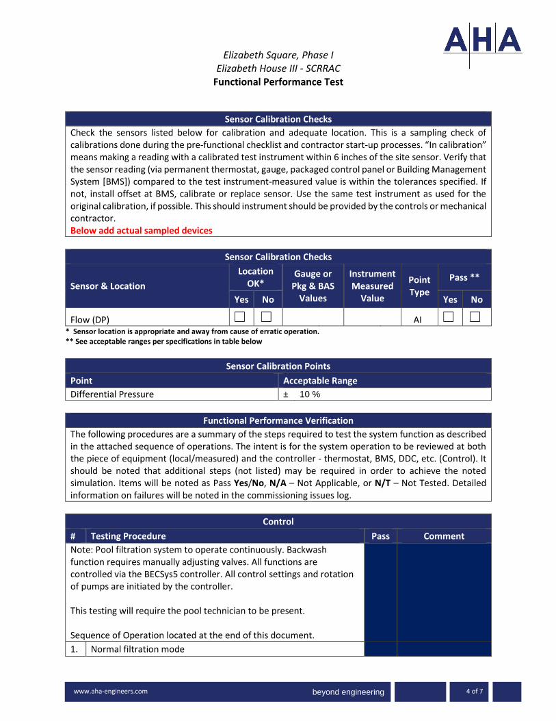
beyond engineering
Elizabeth Square, Phase I
Elizabeth House III - SCRRAC Functional Performance Test
-3000 www.ah
www.aha-engineers.com 4 of 7
Sensor Calibration Checks
Check the sensors listed below for calibration and adequate location. This is a sampling check of calibrations done during the pre-functional checklist and contractor start-up processes. “In calibration” means making a reading with a calibrated test instrument within 6 inches of the site sensor. Verify that the sensor reading (via permanent thermostat, gauge, packaged control panel or Building Management System [BMS]) compared to the test instrument-measured value is within the tolerances specified. If not, install offset at BMS, calibrate or replace sensor. Use the same test instrument as used for the original calibration, if possible. This should instrument should be provided by the controls or mechanical contractor. Below add actual sampled devices
Sensor Calibration Checks
Sensor & Location
Location OK*
Gauge or Pkg & BAS
Values
Instrument Measured
Value
Point Type
Pass **
Yes No Yes No
Flow (DP) ☐ ☐ AI ☐ ☐ * Sensor location is appropriate and away from cause of erratic operation. ** See acceptable ranges per specifications in table below
Sensor Calibration Points
Point Acceptable Range
Differential Pressure ± 10 %
Functional Performance Verification
The following procedures are a summary of the steps required to test the system function as described in the attached sequence of operations. The intent is for the system operation to be reviewed at both the piece of equipment (local/measured) and the controller - thermostat, BMS, DDC, etc. (Control). It should be noted that additional steps (not listed) may be required in order to achieve the noted simulation. Items will be noted as Pass Yes/No, N/A – Not Applicable, or N/T – Not Tested. Detailed information on failures will be noted in the commissioning issues log...
Control
# Testing Procedure Pass Comment
Note: Pool filtration system to operate continuously. Backwash function requires manually adjusting valves. All functions are controlled via the BECSys5 controller. All control settings and rotation of pumps are initiated by the controller. This testing will require the pool technician to be present. Sequence of Operation located at the end of this document.
1. Normal filtration mode

beyond engineering
Elizabeth Square, Phase I
Elizabeth House III - SCRRAC Functional Performance Test
-3000 www.ah
www.aha-engineers.com 5 of 7
Control
# Testing Procedure Pass Comment
The controller will enable the selected lead pump and control VFD speed at setting programmed by startup technician. The standby pump and VFD will be disabled.
Y / N
2. Backwash Mode
Manually adjust the filter DP lower to initiate a backwash condition. The controller will ramp down the VFD of the lead pump. Manually configure the system valves as instructed by the pool technician. The selected lead pump VFD will be enabled again and ramp up to the “backwash” speed setting. During back wash, the UV unit, Pool Heating system and Chemical Controller are all shut down via interlocks with the VFD Return all to normal
Y / N
3. UV Operation
The UV control will be enabled anytime the system (pump(s)) is in normal operation. Verify proper interlock between pump VFD and UV control.
Y / N
End of Testing
Alarm
# Testing Procedure Pass Comment
1. Pump P-3 failure Y / N
2. Pump P-3 VFD failure Y / N
3. Filter DP exceeded Y / N
Wrap Up
# Testing Procedure Pass Comment
1. Y / N
2. Y / N
3. Y / N
4. Y / N
5. Y / N
Comments:

beyond engineering
Elizabeth Square, Phase I
Elizabeth House III - SCRRAC Functional Performance Test
-3000 www.ah
www.aha-engineers.com 6 of 7
Trend Report
The following points will be trended every 15 minutes for period of not less than 2 weeks. These trends will be conducted at least twice a year: one in the cooling season and once in the heating season. Completed Trend Reports will be submitted in a format compatible with MS Excel.
Trend Report
Trend Trend Group Points
Acceptance of Test:
☐ This test cannot be accepted at this time due to the Corrective Issues noted above.
☐ This test is accepted by the Commissioning Authority identified below. Any Corrective Issues noted above do not adversely impact the overall performance of the system.
Tested by Date
Witnessed by Date
Commissioning Provider Attachment(s): Sequence of Operation
Pool Filtration and Back wash:
The pool filtration and chemical treatment system is a continuous loop, drawing water from the pool
via a centrifugal recirculation pump and strainer, filters the water, sends 100% of water thru the UV
treatment chamber, offers a percentage to the building system that provides heat to the pool water,
then measures the water chemistry and adds chlorine, muriatic acid or Co2 to adjust the chemical

beyond engineering
Elizabeth Square, Phase I
Elizabeth House III - SCRRAC Functional Performance Test
-3000 www.ah
www.aha-engineers.com 7 of 7
balance and returns the water to the pool. The centrifugal recirculation pump output is controlled by
VFD that receives a flow signal from a mag meter flow sensor. The VFD will be set to two flow rates,
one for filtration and one for back wash. When the filter system can no longer maintain design flow
rate or when a 10 PSI differential from a clean filter is reached, the filter is shut down, valves manually
changed to backwash mode, the VFD is set to backwash mode, and the filter is back washed to the
backwash holding tank for a minimum of 3 minutes or until the sight glass in the backwash discharge
line shows clean water. During back wash, the UV unit, Pool Heating system and Chemical Controller
are all shut down via interlocks with the VFD.

Elizabeth Square, Phase 1 KGD Architecture
Silver Spring, Maryland Issue for Construction
June 20, 2019
CONTRACTOR COMMISSIONING
SUBMITTAL REQUIREMENTS LOG APPENDIX 8
APPENDIX 8
CONTRACTOR COMMISSIONING
SUBMITTAL REQUIREMENTS LOG


APPENDIX 8
COMMISSIONING SUBMITTAL REQUIREMENTS - SCRRAC
DIVISION 22 CONTRACTORS
Spec Section Paragraph Spec Title Paragraph Title Submittal Type Due Prior to Testing
Due after Testing
Date Received
Date Reviewed and Returned
22 0516 1.3 AB. 1,2,3,4
EXPANSION FITTINGS AND LOOPS FOR PLUMBING PIPING
ACTION SUBMITTALS Product data, Delegated-Design Submittal
22 0516 1.4 EXPANSION FITTINGS AND LOOPS FOR PLUMBING PIPING
INFORMATIONAL SUBMITTALS
Welding certificates
22 0516 1.5 EXPANSION FIRRINGS AND LOOPS FOR PLUMBING PIPING
CLOSEOUT SUBMITTALS
Maintenance Data Prior to training
22 0517 1.3 SLEEVES AND SLEEVE SEALS FOR PLUMBING PIPING
ACTION SUBMITTALS Product Data
22 0518 1.3 ESCUTCHEONS FOR PLUMBING PIPING
ACTION SUBMITTALS Product Data
22 0519 1.3 A,B METERS AND GAGES FOR PLUMBING PIPING
ACTION SUBMITTALS Product Data, Wiring Diagrams
22 0519 1.4 METERS AND GAGES FOR PLUMBING PIPING
INFORMATIONAL SUBMITTALS
Product Certificates
22 0519 1.4 METERS AND GAGES FOR PLUMBING PIPING
CLOSEOUT SUBMITTALS
Operation and Maintenance Data Prior to training
Page 1 of 8

APPENDIX 8
COMMISSIONING SUBMITTAL REQUIREMENTS - SCRRAC
DIVISION 22 CONTRACTORS
Spec Section Paragraph Spec Title Paragraph Title Submittal Type Due Prior to Testing
Due after Testing
Date Received
Date Reviewed and Returned
22 0523.12 1.4 BALL VALVES FOR PLUMBING PIPING
ACTION SUBMITTALS Product Data
22 0523.13 1.4 BUTTERFLY VALVES FOR PLUMBING PIPING
ACTION SUBMITTALS Product Data
22 0523.14 1.4 CHECK VALVES FOR PLUMBING PIPING
ACTION SUBMITTALS Product Data
22 0253.15 1.4 GATE VALVES FOR PLUMBING PIPING
ACTION SUBMITTALS Product Data
22 0529 1.5 A, B, C HANGERS AND SUPPORTS FOR PLUMBING PIPING AND EQUIPMENT
ACTION SUBMITTALS Product Data, Shop Drawings, Delegated-Design Submittal
22 0529 1.6 HANGERS AND SUPPORTS FOR PLUMBING PIPING AND EQUIPMENT
INFORMATIONAL SUBMITTALS
Welding certificates
22 0533 1.3 A,B HEAT TRACING FOR PLUMBING PIPING
ACTION SUBMITTALS A.Product Data. B.Shop Drawings (for electric heating cable)
22 0533 1.4 HEAT TRACING FOR PLUMBING PIPING
INFORMATIONAL SUBMITTALS
Field quality-control reports Test Procedure
Test results/ Report
22 0533 1.5 HEAT TRACING FOR PLUMBING PIPING
CLOSEOUT SUBMITTALS
Operation and Maintenance Data Prior to training
22 0533 3.5 A,B,C 1-3,D,E,F
HEAT TRACING FOR PLUMBING PIPING
FIELD QUALITY CONTROL
Testing Testing
Page 2 of 8

APPENDIX 8
COMMISSIONING SUBMITTAL REQUIREMENTS - SCRRAC
DIVISION 22 CONTRACTORS
Spec Section Paragraph Spec Title Paragraph Title Submittal Type Due Prior to Testing
Due after Testing
Date Received
Date Reviewed and Returned
22 0548.13 1.3 A 1-2, B,C VIBRATION CONTROLS FOR PLUMBING AND PIPING EQUIPMENT
ACTION SUBMITTALS Product Data, Shop Drawings, Delegated-Design Submittal
22 0548.13 1.4 A-C VIBRATION CONTROLS FOR PLUMBING AND PIPING EQUIPMENT
INFORMATIONAL SUBMITTALS
Coordination Drawings, Qualification Data (testing agency), Welding certificates
22 0553 1.3 A-E IDENTIFICATION FOR PLUMBING PIPING AND EQUIPMENT
ACTION SUBMITTALS Product Data, Equipment Label Schedule, Valve numbering.D. Valve Schedules for each piping system to include in maintenance manuals.
Prior to training
22 0719 1.3 A,B;1-2,C 1-4,D 1-2
PLUMBING PIPING INSULATION
ACTION SUBMITTALS Product Data, LEED Submittals, Shop Drawings, Samples
22 0719 1.4 PLUMBING PIPING INSULATION
INFORMATIONAL SUBMITTALS
Qualification Data, Material Test Reports, Field quality-control reports
Test procedure
Test results/ Report
22 1116 1.3 A,B DOMESTIC WATER PIPING
ACTION SUBMITTALS Product Data, LEED Submittals
22 1116 1.4 A,B;1-3 DOMESTIC WATER PIPING
INFORMATIONAL SUBMITTALS
System purging and disinfecting report, Field quality-control reports
Test procedure
Test results/ Report
22 1119 1.3 A; 1-3 DOMESTIC WATER PIPING SPECIALTIES
ACTION SUBMITTALS Product Data, Shop drawings
22 1119 1.4 DOMESTIC WATER PIPING SPECIALTIES
INFORMATIONAL SUBMITTALS
Field quality-control reports Test results/ Report
22 1119 1.5 DOMESTIC WATER PIPING SPECIALTIES
CLOSEOUT SUBMITTALS
Operation and Maintenance Data Prior to training
Page 3 of 8

APPENDIX 8
COMMISSIONING SUBMITTAL REQUIREMENTS - SCRRAC
DIVISION 22 CONTRACTORS
Spec Section Paragraph Spec Title Paragraph Title Submittal Type Due Prior to Testing
Due after Testing
Date Received
Date Reviewed and Returned
22 1119 3.4 A,B,C DOMESTIC WATER PIPING SPECIALTIES
FIELD QUALITY CONTROL
Testing Test Procedure
Test results/ Report
22 1123.13 1.4 A, B 1-2 DOMESTIC-WATER PACKAGED BOOSTER PUMPS
ACTION SUBMITTALS Product Data, Shop drawings
22 1123.13 1.5 DOMESTIC-WATER PACKAGED BOOSTER PUMPS
CLOSEOUT SUBMITTALS
Operation and Maintenance Data Prior to training
22 1123.13 3.5 A,B,C 1-4, D,E
DOMESTIC-WATER PACKAGED BOOSTER PUMPS
FIELD QUALITY CONTROL
Testing Test Procedure
22 1123.13 3.6 A 1 DOMESTIC-WATER PACKAGED BOOSTER PUMPS
START UP SERVICE Testing Test Procedure
22 1123 1.4 A,B;1-3 DOMESTIC WATER PUMPS
ACTION SUBMITTALS Product Data, LEED Submittals
22 1123 1.5 A DOMESTIC WATER PUMPS
CLOSEOUT SUBMITTALS
Operation and Maintenance Data Prior to training
22 1316 1.5 A,B SANITARY WASTE AMD VENT PIPING
ACTION SUBMITTALS Product Data, LEED Submittals
22 1316 1.6 A 1-2,B SANITARY WASTE AMD VENT PIPING
INFORMATIONAL SUBMITTALS
Seismic Qualification Certificates, Field quality-control reports
Test procedure
Test results/ Report
22 1316 3.9 C,D 1-6, E 1-4
SANITARY WASTE AMD VENT PIPING
FIELD QUALITY CONTROL
Testing Test procedure Test results/ Report
22 1319 1.4 A 1-5, B SANITARY WASTE PIPING SPECIALTIES
ACTION SUBMITTALS Product Data, Shop Drawings
Page 4 of 8

APPENDIX 8
COMMISSIONING SUBMITTAL REQUIREMENTS - SCRRAC
DIVISION 22 CONTRACTORS
Spec Section Paragraph Spec Title Paragraph Title Submittal Type Due Prior to Testing
Due after Testing
Date Received
Date Reviewed and Returned
22 1319 1.5 SANITARY WASTE PIPING SPECIALTIES
CLOSEOUT SUBMITTALS
Operation and Maintenance Data Prior to training
22 1319 3.5 A, B 1-2 SANITARY WASTE PIPING SPECIALTIES
FIELD QUALITY CONTROL
Testing Test procedure Test results/ Report
22 1319 3.7 SANITARY WASTE PIPING SPECIALTIES
DEMONSTRATION Training Training
22 1329 1.3 A,B SANITARY SEWERAGE PUMPS
ACTION SUBMITTALS Product Data
22 1329 1.4 SANITARY SEWERAGE PUMPS
CLOSEOUT SUBMITTALS
Operation and Maintenance Data
22 1329 3.5 A,B,C 1-4, D,E
SANITARY SEWERAGE PUMPS
FIELD QUALITY CONTROL
Testing Test procedure Test results/ Report
22 1329 3.8 SANITARY SEWERAGE PUMPS
DEMONSTRATION Training Training
22 1413 1.4 A,B 1-2 FACILITY STORM DRAINAGE PIPING
ACTION SUBMITTALS Product Data, LEED Submittals
22 1413 1.5 A 1-2,B FACILITY STORM DRAINAGE PIPING
INFORMATIONAL SUBMITTALS
Seismic Qualification Certificates, Field quality-control reports
Test procedure
Test results/ Report
22 1423 1.3 STORM DRAINAGE PIPING SPECIALTIES
ACTION SUBMITTALS Product Data
22 1429 1.3 A,B SUMP PUMPS ACTION SUBMITTALS Product Data, Wiring Diagrams
22 1429 1.4 SUMP PUMPS CLOSEOUT SUBMITTALS
Operation and Maintenance Data Prior to training
Page 5 of 8

APPENDIX 8
COMMISSIONING SUBMITTAL REQUIREMENTS - SCRRAC
DIVISION 22 CONTRACTORS
Spec Section Paragraph Spec Title Paragraph Title Submittal Type Due Prior to Testing
Due after Testing
Date Received
Date Reviewed and Returned
22 1429 3.5 A,B,C 1-4, D,E
SUMP PUMPS FIELD QUALITY CONTROL
Testing Test procedure Test results/ Report
22 1429 3.6 A 1 SUMP PUMPS START UP SERVICE Testing Test Procedure
22 14293.8 SUMP PUMPS
DEMONSTRATION Training Training
22 3300
1.3 A,B,C
ELECTRIC, DOMESTIC-WATER HEATERS ACTION SUBMITTALS
Product Data, LEED Submittals, Shop Drawings
22 3300
1.4 A-E
ELECTRIC, DOMESTIC-WATER HEATERS
INFORMATIONAL SUBMITTALS
quality-control reports, Field quality-control reports, Warranty Test
procedureTest results/ Report
22 3300
1.5
ELECTRIC, DOMESTIC-WATER HEATERS
CLOSEOUT SUBMITTALS Operation and Maintenance Data
Prior to training
22 3300
3.4 A 1-4,B,C
ELECTRIC, DOMESTIC-WATER HEATERS
FIELD QUALITY CONTROL Testing
Test procedure
Test results/ Report
22 3300
3.5 A
ELECTRIC, DOMESTIC-WATER HEATERS DEMONSTRATION Training Training
22 3400
1.4 A-C
FUEL-FIRED, DOMESTIC-WATER HEATERS ACTION SUBMITTALS
Product Data, LEED Submittals, Shop Drawings
22 3400
1.5 A 1-3,B-F
FUEL-FIRED, DOMESTIC-WATER HEATERS
INFORMATIONAL SUBMITTALS
Seismic Qualification Certificates, Product Certificates, Domestic-Water Heater Labeling, Source quality-control reports, Field
Test procedure
Test results/ Report
22 3400
1.6
FUEL-FIRED, DOMESTIC-WATER HEATERS
CLOSEOUT SUBMITTALS Operation and Maintenance Data
Prior to training
22 3400
3.4 A 1-4,B,C
FUEL-FIRED, DOMESTIC-WATER HEATERS
FIELD QUALITY CONTROL Testing
Test procedure
Test results/ Report
22 3400
3.5 A
FUEL-FIRED, DOMESTIC-WATER HEATERS DEMONSTRATION Training Training
Page 6 of 8

APPENDIX 8
COMMISSIONING SUBMITTAL REQUIREMENTS - SCRRAC
DIVISION 22 CONTRACTORS
Spec Section Paragraph Spec Title Paragraph Title Submittal Type Due Prior to Testing
Due after Testing
Date Received
Date Reviewed and Returned
22 4213.13 1.3 A 1-3, B 1-3,C
COMMERCIAL WATER CLOSETS ACTION SUBMITTALS
Product Data, LEED Submittals, Shop Drawings
22 4231.13
1.4COMMERCIAL WATER CLOSETS
CLOSEOUT SUBMITTALS Operation and Maintenance Data
Prior to training
22 4231.13
1.5 A COMMERCIAL WATER CLOSETS
MAINTENANCE MATERIAL SUBMITTALS Furnish extra materials
22 4213.161.3 A 1-2,B 1-4, C
COMMERCIAL URINALS ACTION SUBMITTALS
Product Data, LEED Submittals, Shop Drawings
22 4231.16
1.4COMMERCIAL URINALS
CLOSEOUT SUBMITTALS Operation and Maintenance Data
Prior to training
22 4231.16
1.5 A COMMERCIAL URINALS
MAINTENANCE MATERIAL SUBMITTALS Furnish extra materials
22 4216.13 1.3 A 1-2,B 1-3, C
COMMERCIAL LAVATORIES ACTION SUBMITTALS
Product Data, LEED Submittals, Shop Drawings
22 4216.13
1.4COMMERCIAL LAVATORIES
INFORMATIONAL SUBMITTALS Coordination Drawings
22 4216.13
1.5 A 1 a.COMMERCIAL LAVATORIES
CLOSEOUT SUBMITTALS Operation and Maintenance Data
Prior to training
22 4216.13
1.6 A 1-2COMMERCIAL LAVATORIES
MAINTENANCE MATERIAL SUBMITTALS Furnish extra materials
22 4216.16 1.3 A 1-2, B 1-3
COMMERCIAL SINKS ACTION SUBMITTALS Product Data, LEED Submittals
22 4216.16
1.4 ACOMMERCIAL SINKS
INFORMATIONAL SUBMITTALS Coordination Drawings
22 4216.16
1.5 ACOMMERCIAL SINKS
CLOSEOUT SUBMITTALS Operation and Maintenance Data
Prior to training
22 4216.16
1.6 A 1-2COMMERCIAL SINKS
MAINTENANCE MATERIAL SUBMITTALS Furnish extra materials
22 4223 1.3 A 1-2, B 1-3
COMMERCIAL SHOWERS ACTION SUBMITTALS Product Data, LEED Submittals
22 4223
1.4COMMERCIAL SHOWERS
CLOSEOUT SUBMITTALS Operation and Maintenance Data
Prior to training
22 4223
1.5 A 1-2COMMERCIAL SHOWERS
MAINTENANCE MATERIAL SUBMITTALS Furnish extra materials
Page 7 of 8

APPENDIX 8
COMMISSIONING SUBMITTAL REQUIREMENTS - SCRRAC
DIVISION 22 CONTRACTORS
Spec Section Paragraph Spec Title Paragraph Title Submittal Type Due Prior to Testing
Due after Testing
Date Received
Date Reviewed and Returned
22 47161.3 A 1-2, B 1, C
PRESSURE WATER COOLERS ACTION SUBMITTALS
Product Data, LEED Submittals, Shop Drawings
22 4716
1.4PRESSURE WATER COOLERS
CLOSEOUT SUBMITTALS Operation and Maintenance Data
Prior to training
Page 8 of 8

Elizabeth Square, Phase 1 KGD Architecture
Silver Spring, Maryland Issue for Construction
June 20, 2019
BUILDING OPERATOR TRAINING PLAN APPENDIX 9
APPENDIX 9
BUILDING OPERATOR TRAINING
PLAN


Elizabeth Square, Phase I
Silver Spring, Maryland KGD Architecture
Issued for ConstructionJune 20, 2019
BUILDING OPERATOR TRAINING PLAN APPENDIX 9 - 1 of 3
APPENDIX 9
BUILDING OPERATOR TRAINING PLAN
Project:
Date:
Building:
Location:
Equipment/System:
Spec Section:
Attendance. (Manager/ Supervisor signature and number of attendees from department)
Senior Facility Manager Number Attend Maintenance Mechanics Number Attend
Engineering Supervisor Number Attend Security Manager Number Attend
Instructors.
Trainer Company Position/Qualifications
Approvals. This completed checklist has been reviewed. Its completion is approved with the exceptions noted
below.
Commissioning Authority Date Owner’s Representative Date

Elizabeth Square, Phase I
Silver Spring, Maryland KGD Architecture
Issued for ConstructionJune 20, 2019
BUILDING OPERATOR TRAINING PLAN APPENDIX 9 - 2 of 3
General Objectives.
Provide an overview of the purpose and operation of this equipment, including required interactions of staff
with the equipment.
Provide technical information regarding the purpose, operation and maintenance of the equipment assuming
all maintenance will be provided by Factory Authorized Technicians.
Provide technical information regarding the purpose, operation, troubleshooting and maintenance of this
equipment at a very detailed level, expecting that almost all operation, service and repair will be provided by
the facilities personnel.
Agenda.
Item Covered Duration Instructor Completed
General purpose of this system or equipment (Owners Project
Requirements)
Review of control drawings and schematics (have copies for
attendees)
Startup, loading, normal operation, unloading, shutdown,
unoccupied operation, seasonal changeover, etc., as applicable
Integral controls (packaged): programming, troubleshooting,
alarms, manual operation
Building automation controls (BAS): programming,
troubleshooting, alarms, manual operation, interface with
integral controls
Interactions with other systems, operation during power outage
and fire
Relevant health and safety issues and concerns and special
safety features
Energy conserving operation and strategies
Any special issues to maintain warranty
Common troubleshooting issues and methods, control system
warnings and error messages, including using the control system
for diagnostics
Special requirements of tenants for this equipment’s function
Service, maintenance, and preventative maintenance (sources,
spare parts inventory, special tools, etc.)
Other subjects covered, specific to the equipment:
Question and answer period
Comments:

Elizabeth Square, Phase I
Silver Spring, Maryland KGD Architecture
Issued for ConstructionJune 20, 2019
BUILDING OPERATOR TRAINING PLAN APPENDIX 9 - 3 of 3
Training Methods.
Type Comments
Use of the O&M manuals, illustrating where the verbal
training information is found in writing
Manufacturer training manuals
Discussion/lecture at site
Site demonstration of equipment
Written handouts
Classroom lecture
Classroom hands-on equipment
Video presentation
Question and answer period
Comments:


Elizabeth Square, Phase 1 KGD Architecture
Silver Spring, Maryland Issue for Construction
June 20, 2019
CONTRACTOR COORDINATION MATRIX APPENDIX 11
APPENDIX 11
CONTRACTOR COORDINATION
MATRIX


APPENDIX 11
Elizabeth Square, Phase 1 - SCRRAC
COMMISSIONING COORDINATION MATRIX
Spec Section Specification Title Coordinate with: Questions for ReviewersResponse from Reviewers including Additional
Sections to include
22 0533 HEAT TRACING FOR PLUMBING PIPING 22 0553, 22 0719, 26 0526, 26 0519
22 1119 DOMESTIC WATER PIPING SPECIALTIES 22 0519
22 1123.13 DOMESTIC -WATER PACKAGED BOOSTER PUMPS
22 1123, 03 3053, 22 0548.13, 22 1116, 22 0523.12, 22 0523.13, 22 0523.15, 22 0553
22 1123 DOMESTIC WATER PUMPS 22 1123.13, 03 3053, 22 0548.13, 22 1116, 22 0523.12, 22 0523.13, 22 0523.15, 22 0553, 22 0519
22 1329 SANITARY SEWERAGE PUMPS 22 0513, 31 2000, 22 0548, 22 0519, 22 1316
22 1429 SUMP PUMPS 22 1329, 22 1413
22 3300 ELECTRIC, DOMESTIC-WATER HEATERS 01 4000, 01 7300, 03 3000, 22 0523.12, 22 0523.13, 22 0523.15, 22 1119, 22 0519, 22 1116,
22 3400 FUEL-FIRED, DOMESTIC-WATER HEATERS 22 0523.12, 22 0523.13, 22 0523.15, 22 1119, 01 4000, 01 7300, 23 1123, 22 0519
22 4213.13 COMMERCIAL WATER CLOSETS 22 0518, 07 9200, 22 1116, 22 1316, 22 4100, 22 4300, 22 4600
22 4213.16 COMMERCIAL URINALS 22 4600, 22 1116, 22 1316
22 4216.13 COMMERCIAL LAVATORIES 22 4100, 01 7823, 22 0518, 07 9200, 22 0719, 22 1116, 22 1316
22 4216.16 COMMERCIAL SINKS 22 4100, 22 0523.12, 22 0523.15, 22 0518, 07 9200, 22 0719, 22 1116, 22 1316
22 4223 COMMERCIAL SHOWERS 22 4100, 22 0523.12, 22 0523.15, 22 0518, 07 9200, 22 0719, 22 1116, 22 1316
22 4716 PRESSURE WATER COOLERS 22 0523.12, 22 0523.15, 22 0518, 22 1116, 22 1316
23 0533 HEAT TRACING FOR HVAC PIPING 23 0553, 23 0719, 26 0526, 26 0519,
23 0593 TESTING, ADJUSTING, AND BALANCING FOR HVAC
23 3112, 23 3116, 23 3300, 23 0713, 23 0716, 23 2123
23 0800 COMMISSIONING OF MECHANICAL 01 9113, 26 0800
23 0900 INSTRUMENTATION AND CONTROLS FOR HVAC23 0993 SEQUENCE OF OPERATIONS FOR HVAC CONTROLS
23 0900
23 1113 FACILITY FUEL-OIL PIPING 31 2000, 23 0517, 23 0518, 23 0553, 23 0529, 09 9113
23 1123 FACILITY NATURAL-GAS PIPING 08 3113, 31 2000, 23 0519, 23 0517, 23 0518, 05 5000, 23 0548, 23 0529, 23 0553
23 2123 HYDRONIC PUMPS 23 0513, 23 0548, 23 0529, 26 0526, 26 0519
23 2300 REFRIGERANT PIPING 08 3113,23 0923, 23 0993.11, 23 0553, 23 0517, 20518, 23 0529,
23 2513 WATER TREATMENT FOR CLOSED-LOOP HYDRONIC SYSTEMS
23 2116, 23 0523
23 5216 WATER TREATMENT FOR OPEN-LOOP HYDRONIC SYSTEMS
23 0900, 23 0513, 23 2116, 23 0523, 22 1119, 26 0526, 26 0519
23 2533 HVAC MAKEUP-WATER FILTRATION EQUIPMENT
23 0513, 23 2113, 23 0523, 22 1119, 26 0526
23 3423 HVAC POWER VENTILATORS 23 0513,23 0548, 23 0553, 23 3300, 26 0526, 26 0519, 23 0593
23 3600 AIR TERMINAL UNITS 01 78230, 23 0900, 23 2113, 23 2116, 23 3113, 23 3300
23 3723 HVAC GRAVITY VENTILATORS 07 9200, 23 0553, 23 3113, 23 3116
23 5100 GENERATOR EXHAUST SYSTEM 1 3000, 07 5000
23 5113.16 VENT DAMPERS 23 5113.11, 23 5123, 26 0526, 26 0519
23 5123 GAS VENTS 23 5113.11, 07 7200
23 5216 CONDENSING BOILERS 23 0548 ,23 0513, 23 0993,23 0548, 23 2116, 26 05190, 01 7900
23 5700 HEAT EXCHANGERS FOR HVAC 23 0529, 23 2113, 23 2116, 23 0519
23 6423.16 HEAT RECOVERY CHILLERS 23 0548, 23 2113, 23 2116
23 6426.16 WATER-COOLED, ROTARY-SCREW WATER CHILLERS
23 2113, 23 2116,
23 6500 COOLING TOWERS 23 0513, 23 0900, 23 0993, 22 1116, 23 2113,23 2116
23 7313.16 INDOOR, SEMI-CUSTOM AIR HAMDLING UNITS 23 0993, 230900
23 7313.17 CUSTOM AIR HANDLING UNITS-POOL 23 0993
23 8126 SPLIT-SYSTEM AIR-CONDITIONERS 23 0513, 23 0548, 23 3113, 23 3300
23 8146 WATER-SOURCE UNITARY HEAT PUMPS 23 0993, 23 0548, 23 0529, 23 0548
23 8236 FINNED-TUBE RADIATION HEATERS 26 0526, 26 0519,
23 8239.13 CABINET UNIT HEATERS 23 0548, 07 9200, 23 2113, 23 2116, 23 2213, 23 2216, 26 0526, 26 0519
23 8239.19 WALL AND CEILING UNIT HEATERS 23 0513, 26 0526, 26 0519
23 8413.29 SELF-CONTAINED STEAM HUMIDIFIERS 23 0548, 23 1123, 23 5123, 26 0519, 26 0526, 26 0533, 26 0532
26 0932 LIGHTING CONTROLS - LUTRON 01 3000, 01 7800, 01 7900, 01 9113, 26 0553,
26 2200 LOW-VOLTAGE TRANSFORMERS 26 0553, 26 0526, 26 0548.16, 26 0529, 26 0519,
26 2923 VARIABLE-FREQUENCY MOTOR CONTROLLERS 01 7823, 07 7200, 26 0529, 26 0548.16, 26 2813, 26 0523, 26 0553, 26 0573,
26 3213 ENGINE GENERATORS 26 3600, 26 0548.16, 01 7823, 03 3053, 03 3000, 23 1113, 26 0526, 26 0519, 23 0553, 26 0553, 01 7900
26 3600 TRANSFER SWITCHES 26 0548.16, 01 7823, 03 3000, 26 0529, 26 0553, 26 0526, 26 0519, 01 7900


Elizabeth Square, Phase 1 KGD Architecture
Silver Spring, Maryland Issue for Construction
June 20, 2019
COMMISSIONING PLAN APPENDIX 12
APPENDIX 12
COMMISSIONING PLAN


beyond engineering
APPENDIX 12 – DRAFT COMMISSIONING PLAN
3700 Mansell Road, Mansell One, Suite 200, Alpharetta, Georgia 30022 1
COMMISSIONING PLAN
Elizabeth Square – Phase 1 Elizabeth House III-SCRRAC
Silver Spring, Maryland
Prepared by: Johanna Brau, CPMP, CCP, LEED® AP
AHA Consulting Engineers, Inc.
March 13, 2019

beyond engineering
Elizabeth Square Phase 1 Commissioning Plan Elizabeth House III – SCRRAC March 13, 2019
770-992-8585 www.aha-engineers.com 2
TABLE OF CONTENTS
I. INTRODUCTION/REVISION LOG INTRODUCTION ................................................................. 3
II. OVERVIEW OF COMMISSIONING ........................................................................................... 5
III. COMMISSIONING PROCESS OBJECTIVES ............................................................................... 5
IV. SYSTEMS TO BE COMMISSIONED .......................................................................................... 6
V. COMMISSIONING TEAM .................................................................................................... 109
VI. COMMISSIONING TEAM ROLES & RESPONSIBILITIES ...................................................... 1110
DESIGN PHASE .............................................................................................................................. 1110 CONSTRUCTION PHASE ................................................................................................................ 1110 ACCEPTANCE PHASE ..................................................................................................................... 1514 WARRANTY PHASE........................................................................................................................ 1817
VII. COMMUNICATION AND REPORTING ............................................................................... 1918
VIII. COMMISSIONING SCOPE OF WORK ................................................................................. 2019

beyond engineering
Elizabeth Square Phase 1 Commissioning Plan Elizabeth House III – SCRRAC March 13, 2019
770-992-8585 www.aha-engineers.com 3
I. INTRODUCTION/REVISION LOG
The Owner has retained AHA Consulting Engineers, Inc. (AHA) to provide Fundamental and Enhanced Commissioning Services for the Elizabeth Square - Phase 1 project located in Silver Spring, MD. Included in the scope of the combined commissioning services is the Elizabeth House III project, which will be provided with Fundamental Commissioning services, and the SCRRAC project, which will be provided with Enhanced Commissioning services. The combined deliverables will satisfy the commissioning requirements for a minimum LEED Silver rating as part of the LEED for New Construction and Major Renovations rating system and are outlined in this report. The Elizabeth Square Phase 1 project consists of separate areas and uses with defined commissioning services. The first space is the Elizabeth House III with a total of 267 Senior Housing Independent Living units totaling 223,455 gross floor area (GFA) and located on floors 4-16. The second space is the SCRRAC project which includes a total of 126,895 GFA and includes a recreation center, circulation areas and building services spaces and is located on floors B1 through level 3. The third space is below grade parking areas serving the Elizabeth House III residents and is located on levels B1 and B2 with a total of 31,473 GFA. Due to the required commissioning deliverables for the LEED certification on the SCRRAC project, an independent Third-Party Commissioning firm will be providing additional commissioning services for this space and will be referred to as the Cx Authority for the duration of this project and thorough out this report. All remaining Fundamental Commissioning services for the project, including Base Building services, will be provided by AHA and referred to as the Cx Agent throughout the report and project. The Commissioning Plan outlines and guides the commissioning activities during the design and construction phases and during occupancy and the operational aspects of the project. The Commissioning Plan is a document that evolves throughout the design and into the construction phase of the project and defines the organization, schedule, allocation of resources and documentation requirements of the commissioning process. The following pages outline the commissioning process in each phase and includes responsibly parties and deliverables to the client. All documents created or obtained during the commissioning process will be saved by AHA Consulting Engineers and provided to the Oowner as part of the Final Commissioning Report. This report will serve as documentation of the commissioning activities for the project, as well as reference to all MEP systems for the life of the building. Documents such as design drawings and equipment submittals, construction documents and final TAB report and testing data can be used as reference to assist the Oowner in the daily operations of the facility. The Revision Log is a summary of changes made to the Commissioning Plan document throughout the design, construction, and acceptance phases of the project. The information is critical to keeping all members of the commissioning team aligned on shared assumptions of basic project requirements and the commissioning process. The following revisions are below:
Date Revised by Sections Updated Description of Changes
5/10/18 J. Brau Draft Cx Plan N/A

beyond engineering
Elizabeth Square Phase 1 Commissioning Plan Elizabeth House III – SCRRAC March 13, 2019
770-992-8585 www.aha-engineers.com 4
Date Revised by Sections Updated Description of Changes
2/22/19 B. Shankus Section IV Systems to be Commissioned; Section VI Roles & Responsibilities; Section VIII, Paragraph B, Specifications
Section IV, Updated Commissioned Systems; Section VI & VIII, Changed per CxA IFC Review Comments

beyond engineering
Elizabeth Square Phase 1 Commissioning Plan Elizabeth House III – SCRRAC March 13, 2019
770-992-8585 www.aha-engineers.com 5
II. OVERVIEW OF COMMISSIONING
Commissioning is a systematic process of ensuring that all building systems perform interactively according to the Owner’s Project Requirements (OPR) and Basis of Design (BOD). . This is achieved by beginning at the design phase with documented design and operating intent, continuing through construction and acceptance with actual verification of performance, and ensuring the information is sufficient, available and organized for proper operation and maintenance of the building. Commissioning establishes an organized method to document Design, Construction, Testing, and O&M Information. In addition, Commissioning ensures the building is constructed and functions in accordance with the OPR and the BOD. Lastly, Commissioning verifies the Oowner is properly trained and is provided with complete information on the facility.
III. COMMISSIONING PROCESS OBJECTIVES
Commissioning by this plan is intended to achieve the following specific objectives:
A. Clearly define the Owner’s Project Requirements (OPR).
B. Ensure the Basis of Design (BOD) incorporates the OPR requirements.
C. Ensure the BOD has been properly documented in the contract documents.
D. Ensure that the commissioning scope is adequately reflected in the construction documents.
E. Ensure the submitted equipment satisfies the requirements indicated in the contract documents by performing submittal reviews for all MEP equipment.
F. Ensure that following installations that HVAC air and hydronic systems have been properly balanced by reviewing the TAB plan and performing TAB verification during the process.
G. Ensure that applicable equipment and systems are installed and calibrated properly and receive adequate operational checkout by installing contractors. Including monitoring systems.
H. Verify and document proper performance of equipment and systems through normal and other likely operational modes necessary to meet design intent and the Oowner’s project requirements and operational needs.
I. Ensure the Owner’s maintenance staff is properly trained on the applicable equipment and systems and is equipped with complete and accurate operating and maintenance manuals.
J. Ensure that all issues discovered throughout the commissioning process are resolved and properly documented in the Master Issues Log.
K. Identify issues requiring further study or attention, or warranty repair items, after occupancy.
L. Satisfy requirements for the State and Local Energy Codes.

beyond engineering
Elizabeth Square Phase 1 Commissioning Plan Elizabeth House III – SCRRAC March 13, 2019
770-992-8585 www.aha-engineers.com 6
IV. SYSTEMS TO BE COMMISSIONED
The following systems will be commissioned in this project by the assigned commissioning firms. The specific components included, criteria used, and test methods employed will be determined during development of the Functional Performance Testing procedures. Those listed below represent the major components. In general, all components critical to the system operation will be included:
A. HVAC Systems and Controls
1. Rooftop Air Handling Units 2. Air Handling Units 3. Heating and Ventilating Units 4. Fan Coil Units 5. AC Units 6. Dehumidification Units 7. Terminal Units 8. Heat Pumps 9. Ceiling Mounted Radiant Heaters 10. Unit Heaters 11. Fans (Supply, Exhaust, Garage Ventilation, Combustion Air, Boiler Flue, Refrigerant
Purge) 12. Roof and Hoistway Vents 13. Condensing Boilers (Building Heating) 14. Boiler Pumps 15. Chillers and Cooling Towers 16. Chilled and Condenser water pumps 17. Heat Exchangers 18. Pool Dehumidification Units 19. Air Distribution System – Ductwork – Pressure/Leak Testing 20. Water Distribution System – Piping – Pressure/Leak Testing 21. TAB – air and water 22. Energy Management Control System (EMCS) - All equipment with EMCS; Controllers and
Points
a) Sensors b) Controlled devices c) Stand-alone or packaged controls d) Local loop control panels e) Network controllers f) Field interface panels g) Central processing units h) Basic software routines i) Software loop tuning j) All sequences of operation
1. Cooling Towers 2. Boilers 3. Water Source Heat Pumps 4. Outdoor Air Units

beyond engineering
Elizabeth Square Phase 1 Commissioning Plan Elizabeth House III – SCRRAC March 13, 2019
770-992-8585 www.aha-engineers.com 7
5. Heat Exchangers 6. Split Systems 7. Electric Heaters 8. Heat Recovery Equipment 9. Fans 10. Pumps 11. VFDs 12. Energy Recovery Unit 13. Water Treatment System 14. Energy Management System 15. Testing and Balancing Verification 16. Pipe Flushing and Cleaning Activities 17. Ductwork, Diffusers, Grills, Registers, and associated dampers
B. Electrical Systems
1. Integrated Emergency Power Test
a. Emergency Generator
1) Temporary load-banks shall be provided to test all generators on site. Load banks shall be sufficient for both single generator and both generators being tested concurrently.
b. ATS c. Integration with FACP
2. Building Lighting and Controls 3. Continuity and Ground of Incoming Utility Service Conductors 4. Transformers, Switchboards, and Circuit Breakers 5. Feeders and Branch Circuits 6. AC Motors and Starters 7. Distribution & Branch Circuit Panelboards 8. Lighting System 9. Lighting Control System 10. Sensors 11. Lighting Level Verification 12. Lighting Protection Systems 13. Grounding Equipment & Building Grounding System 14. Elevator Systems & Recall 15. Equipment Monitoring Systems 16. Fire Alarm Equipment/Fire Alarm Equipment Monitoring System 17. Security System & Signaling 18. Emergency System 19. Engine-Generator Sets 20. Switchgear/Switchboard 21. Automatic Transfer Switches 22. Fuel Systems (Storage Tanks, Day Tanks, Pumps, Valves) 23. Annunciation

beyond engineering
Elizabeth Square Phase 1 Commissioning Plan Elizabeth House III – SCRRAC March 13, 2019
770-992-8585 www.aha-engineers.com 8
24. Grounding and Bonding 25. Engine Alarms 26. Cooling System 27. Batteries 28. Controls and Engine Start Wiring 29. Communication Systems 30. Thermal Scanning of the install Feeders, Transformers, Panels, Circuit Breakers,
Generator and Automatic Transfer Switches 31. Provide annual programmed maintenance schedule for all Panels, Circuit Breakers,
Generator and Automatic Transfer Switches (tightening of lugs) and visual inspection of main service conductors for the main Electrical Feeds, Transformers, Switchgear/Switchboard, Circuit Breakers, Panelboards, Engine-Generator & Automatic Transfer Switches.
C. Generators
1. Automatic Transfer Switches 2. Interior and Exterior Lighting and Lighting Controls 3. Interior and Exterior Daylighting and Daylighting Controls
D.C. Plumbing Systems
1. Water Distribution System – Piping – Pressure/Leak Testing 2. Air Compressors 3. Gas Fired Water Heaters and Circulation Pumps 4. Electric Water Heater with Storage Tank 5. Point of Use Electric Water Heaters 6. Sump Pumps/Sewage Ejectors 7. Tempered Mixing Valves 8. Plumbing Fixtures 9. Pool Pumps 10. Pool Heaters
E. Water Heaters
1. Plumbing Fixtures 2. Pumps 3. Controls
F.D. Pool Systems and Controls
1. Pool Pumps 2. Pool Heaters 3. Pool Controls 4. Pool Dehumidification Units
E. Fire Protection
1. Piping – Pressure/Leak Testing 2. Flow and Tamper Switches (in Integrated Fire Alarm Test) 3. Fire Protection Integrated Test

beyond engineering
Elizabeth Square Phase 1 Commissioning Plan Elizabeth House III – SCRRAC March 13, 2019
770-992-8585 www.aha-engineers.com 9
4. Wet systems 5. Fire Pumps

beyond engineering
Elizabeth Square Phase 1 Commissioning Plan Elizabeth House III – SCRRAC March 13, 2019
770-992-8585 www.aha-engineers.com 10
V. COMMISSIONING TEAM
Successful building commissioning requires a collaborative team effort. The Commissioning Team is led by the Commissioning Authority and the Commissioning Agent and includes members of the Design and Construction teams as well as the Oowner’s Operations staff. It is the Commissioning Team’s role to monitor, assist and coordinate the various team members’ efforts with regards to execution of their responsibilities as outlined in the Commissioning Plan. Contact information for the Commissioning Team is included below and should be updated as members join the team as the project proceeds. Persons listed as the commissioning contact should be familiar with their company’s responsibilities as outlined in the Commissioning Plan.
Role Company Contact
Phone:
Office / Cell / Email
Cx Agent AHA Consulting Engineers Randy Wimmer
Cx Authority Facilities Dynamics Scott Stoutenborough
Owner HOC Hyunsuk Choi
Owner’s Project
Manager
Owner’s
Maintenance
Manager
Vantage/Edgewood
Elizabeth House III
Architect KGD Architecture Alexandra Shifflett
Engineer AHA Consulting Engineers Ryan Carter
General Contractor
Construction
Manager
Jones Lang Lasalle (JLL)
Mechanical
Contractor
Electrical Contractor
Plumbing Contractor
Controls Contractor
Fire Protection
Contractor
Testing & Balancing
Contractor

beyond engineering
Elizabeth Square Phase 1 Commissioning Plan Elizabeth House III – SCRRAC March 13, 2019
770-992-8585 www.aha-engineers.com 11
VI. COMMISSIONING TEAM ROLES & RESPONSIBILITIES
The following is a listing of commissioning responsibilities to be performed, and deliverables to be provided, by each commissioning team member during each project phase. This list is not intended to capture all the tasks required of a team member on the project; just the tasks associated with the commissioning process.
DESIGN PHASE
Role Responsibilities Deliverables
Owner / Owner’s Project Manager
• Develop OPR document.
• Review and comment on Commissioning Plan.
• Review and comment on commissioning specification.
• OPR Document
• Review Comments
Owner’s Operations & Maintenance Staff
• Assist with development of OPR document.
• Assist with review of commissioning plan.
• Assist with review of commissioning specifications.
• Review Comments to Owner
Architect / Engineer
• Develop BOD document.
• Incorporate the commissioning specification sections prepared by the CxA into the Bid documents.
• BOD Document
• Construction Documents
Cx Agent
(HOC, Base Building and SCRRAC)
• Assist Owner with development of OPR document.
• Develop Commissioning Plan.
• Develop Commissioning specification sections (019113) for inclusion in the Design documents.
• Incorporate Cx specifications in construction specifications.
• Draft and finalize Cx Plan
• Edit Cx Specifications
• Attend meetings
Cx Authority (SCRRAC)
• Review construction documents for systems included SCRRAC.
• Prepare, edit and supplement specifications to identify Cx requirements and issue comments.
• Attend design meetings associated with SCRRAC.
• Review design calculations selected
• Review comments
• Edit Cx Plan
• Attend meetings
• Review Cx Plan
CONSTRUCTION PHASE
Role Responsibilities Deliverables
Owner / Owner’s Project Manager
• Update OPR document as required.
• Facilitate and champion the commissioning process among the project team.
• Review and comment on all Commissioning documentation provided by Cx Agent and Cx Authority.
• Participate in regularly scheduled Commissioning Coordination meetings.
• Revised OPR Document
• Review Comments

beyond engineering
Elizabeth Square Phase 1 Commissioning Plan Elizabeth House III – SCRRAC March 13, 2019
770-992-8585 www.aha-engineers.com 12
CONSTRUCTION PHASE
Role Responsibilities Deliverables
Owner’s Operations & Maintenance Staff
• Periodically visit the construction site to become familiar with the components as they are installed and prior to being concealed. Communicate with the commissioning teams concerns regarding system installation.
• Witness, to the greatest extent desired, the Division 21, 22, 23, and& 26 testing and startup procedures conducted by the contractors.
• Provide information to the Cx Agent and Cx Authority regarding how the building will be staffed and operated from a maintenance standpoint.
• Review equipment training plans with respect to appropriateness to the potential trainees.
• Participate in regularly scheduled Commissioning Coordination meetings.
• Site Visit Comments
• Staffing Info
• Training Plan Review Comments
Architect / Engineer
• Update BOD document as required.
• Coordinate comments on submittals and shop drawings with both Cx teams prior to issue of approval.
• Review O&M Mmanuals submitted by the contractors.
• Copy all Architectural Supplemental Instructions (ASI), Proposal Requests (PR), RFI’s, and fully executed Change Orders (CO), to the Cx teams for informational purposes.
• Participate in regularly scheduled Commissioning Coordination meetings.
• Revised BOD Document
• O&M Manual Review Comments
• Updated Construction Documents
General Contractor / Construction Manager
• Copy all Meeting Minutes to both Cx teams for informational purposes.
• Incorporate commissioning activities into the master project schedule.
• Provide commissioning with monthly schedule updates.
• Submit all shop drawings and submittals associated with systems being commissioned to the Cx teams for review/information based on scope of work.
• Submit the equipment O&M Mmanuals to the Owner & Design for review.
• Submit training plans to the Owner & Design Team for review.
• Submit testing and balancing (TAB) execution plan to the assigned Cx firm for review.
• Schedule and witness Division 21, 22, 23, and& 26 testing and startup procedures.
• Meeting Minutes
• Project Schedule
• Submittals
• O&M Manuals
• Training Plans
• TAB Execution Plan

beyond engineering
Elizabeth Square Phase 1 Commissioning Plan Elizabeth House III – SCRRAC March 13, 2019
770-992-8585 www.aha-engineers.com 13
CONSTRUCTION PHASE
Role Responsibilities Deliverables
• Participate in regularly scheduled Commissioning Coordination meetings.
Sub-Contractors • Provide input into the master scheduling process.
• Accomplish start up and testing of installed equipment with select sampling/witnessing by the Cx.
• Submit shop drawings and submittals to the construction manager.
• Implement and document Pre-Functional Checklists (PFCs) provided by the Cx Agent. A sampling of the completion of the PFS’s on major equipment to be witnessed by commissioning.
• Submit equipment O&M Mmanuals to the construction manager.
• Submit equipment training plans to the construction manager.
• Submit testing and balancing (TAB) execution plan to the construction manager.
• Review and comment on the Functional Performance Test procedures developed by the Cx Agent.
• Coordinate scheduling and witnessing of Division 21, 22, 23 and 26 testing and startup procedures through the construction manager.
• Participate in regularly scheduled Commissioning Coordination meetings.
• Submittals
• Completed PFCs
• O&M Manuals
• Training Plans
• TAB Execution Plan
• FPT Review Comments
• Startup and Testing Reports
Cx Agent (HOC and SCRRAC)
• Conduct a joint commissioning meeting with commissioning teams.
• Coordinate and direct all commissioning activities for the Elizabeth House III and base building phases.
• Assist the construction manager, sub-contractors, and owner’s project manager in incorporating commissioning activities into the master project schedule.
• Review submittals and shop drawings applicable to systems being commissioned. Provide formal comments to Owner and Design Team for TAB Execution Plan, Start-up Reports, and ATC submittals, all others for information only.
• Review O&M Mmanuals applicable to systems being commissioned, for information only.
• Cx Meeting Minutes
• Submittal Reviews/ Comments
• Site Visit Reports
• TAB Plan Review
• Develop PFCs and FPTs
• Cx Meeting Minutes
• Assist resolving open issues.

beyond engineering
Elizabeth Square Phase 1 Commissioning Plan Elizabeth House III – SCRRAC March 13, 2019
770-992-8585 www.aha-engineers.com 14
CONSTRUCTION PHASE
Role Responsibilities Deliverables
• Review additional construction phase documentation, e.g., ASI’s, RFI’s, PR’s, Change Orders, meeting minutes, etc., required to plan and perform commissioning tasks.
• Perform site visits to observe component and system installations. Site visits will be scheduled based on the project progress and quality of installation. Modifications to the dates of site visits will vary but will include early site visits and increase as the project progresses. Attend selected planning and job-site meetings to obtain information on construction progress.
• Develop Pre-Functional Cchecklists (PFC) and Functional Performance Test (FPT) procedures for each system to be commissioned for base and tenant scope.
• Witness selected start-up procedures and PFC completion on major equipment.
Cx Authority (SCRRAC)
• Conduct joint commissioning meetings.
• Coordinate and direct all commissioning activities for the SCRRAC project.
• Review construction documents for SCRRAC.
• Review, edit Cx documents and Cx Plan.
• Coordinate and direct all commissioning activities for the SCRRAC sections including FPT procedures.
• Perform site visits to observe component and system installations. Site visits will be scheduled based on the project progress and quality of installation. Modifications to the dates of site visits will vary but will include early site visits and increase as the project progresses. Attend selected planning and job-site meetings to obtain information on construction progress.
• Issue clarifications or interpretations of design intent as required.
• Maintain a record set of shop drawings, product data, warrantees, test reports, TAB reports, start-up reports for record of project.
• Perform TAB verification on 10% of SCRRAC equipment.
• Witness selected start-up procedures and PFC completion on major equipment.
• Cx Meeting Minutes
• Submittal Review Comments
• Site Visit Reports
• Submittal Review Comments
• PFCs and FPTs

beyond engineering
Elizabeth Square Phase 1 Commissioning Plan Elizabeth House III – SCRRAC March 13, 2019
770-992-8585 www.aha-engineers.com 15
ACCEPTANCE PHASE
Role Responsibilities Deliverables
Owner / Owner’s Project Manager
• Update OPR document as required.
• Review and comment on all commissioning documentation provided by both Cx firms.
• Participate in regularly scheduled Commissioning Coordination meetings.
• Final OPR Document
• Review Comments
Owner’s Operations & Maintenance Staff
• Participate in the scheduling of equipment and systems training sessions.
• Participate in the equipment and systems training programs and provide feedback on effectiveness and quality.
• Witness, to the greatest extent possible, the functional performance tests performed by the contractors and overseen by the assigned Cx firm.
• Participate in regularly scheduled Commissioning Coordination meetings.
Architect / Engineer
• Update BOD Document as required.
• Review and approve Ttest and Bbalance rReport.
• Respond to requests for information and/or disputes with respect to design intent and commissioning issue items found during the functional performance testing process.
• Participate in regularly scheduled Commissioning Coordination meetings.
• Final BOD Document
• TAB Review Comments
• Cx Issues Log Responses
General Contractor / Construction Manager
• Copy all Meeting Minutes to both Cx firms for informational purposes.
• Update commissioning activities in the master project schedule.
• Coordinate and schedule equipment training sessions.
• Submit completed Start-Up Checklists to the assigned Cx firm for review.
• Submit ATC point to point checklist to the assigned Cx firm for review.
• Submit final Ttest and bBalance rReport to the design team and CxA and Cx for review.
• Assist in coordination and periodically witness Functional Performance Tests.
• Oversee the correction of deficiencies identified by the Cx firms and provide written responses indicating action taken to resolve each item.
• Meeting Minutes
• Project Schedule
• Start-up Checklists
• ATC Point to Point Checklist
• Final TAB Report
• Cx Issues Log Responses

beyond engineering
Elizabeth Square Phase 1 Commissioning Plan Elizabeth House III – SCRRAC March 13, 2019
770-992-8585 www.aha-engineers.com 16
ACCEPTANCE PHASE
Role Responsibilities Deliverables
• Participate in regularly scheduled Commissioning Coordination meetings.
Sub-Contractors • Schedule equipment training sessions.
• Conduct the equipment and systems training programs.
• Submit ATC point to point checklist to construction manager.
• Submit final TAB report to construction manager.
• Set up Functional Performance Test Trend Logs and monitoring data under the Cx Agent and Cx Authority direction.
• Accomplish Functional Performance Testing directed and documented by the both Cx firms.
• Correct all deficiencies identified by commissioning and other parties and provide written responses indicating action taken to resolve each item.
• Participate in regularly scheduled Commissioning Coordination meetings.
• Perform re-testing where system deficiencies found during initial testing.
• Provide as-built documents for inclusion in the systems manual.
• Provide operation and maintenance information to be included in the systems manual and to be used for training.
• Provide O&M training for the Owner and Owner’s staff per the OPR and the contract documents.
• Completed PRCs
• Start-up Checklists
• ATC Point to Point Checklist
• Final TAB Report
• Cx Issues Log Responses
Cx Agent
Cx Authority
• Coordinate and direct all commissioning activities.
• Coordinate and document commissioning meetings.
• Field-verify proper and thorough completion of Pre-Functional Checklists.
• Witness contract required tests as needed.
• Review contractor-completed Start-up checklists prior to commencing functional performance testing on each system.
• Review ATC point to point checklists prior to commencing functional performance testing on each system.
• Review final TAB report prior to commencing functional performance testing on each system. Provide comments to design team for inclusion in formal response.
• Cx Meeting Minutes
• PFC and Start-up Checklists Review Comments
• ATC Point to Point Review Comments
• Final TAB Report Review Comments
• Cx Issues Log
• Final Cx Report

beyond engineering
Elizabeth Square Phase 1 Commissioning Plan Elizabeth House III – SCRRAC March 13, 2019
770-992-8585 www.aha-engineers.com 17
ACCEPTANCE PHASE
Role Responsibilities Deliverables
• Conduct functional testing on required equipment.
• Analyze Functional Performance Test Trend Logs and monitoring data to verify performance.
• Direct, witness, and document Functional Performance Tests performed by the installing contractors.
• Maintain a master Deficiency and Resolution Log (Commissioning Master Issues log).
• Submit a Final Commissioning Report.
• Recommend to the Owner that the building is fFunctionally Ccomplete and ready for oOccupancy.
Cx Authority (SCRRAC)
• Coordinate and direct all commissioning activities.
• Coordinate and document commissioning meetings.
• Field-verify proper and thorough completion of pre-functional checklists.
• Witness contract required tests as needed.
• Review contractor-completed Start-up checklists prior to commencing functional performance testing on each system.
• Review ATC point to point checklists prior to commencing functional performance testing on each system.
• Review final TAB report prior to commencing functional performance testing on each system. Provide comments to design team for inclusion in formal response.
• Conduct functional testing on required equipment
• Analyze Functional Performance Test Trend Logs and monitoring data to verify performance.
• Direct, witness, and document functional performance tests performed by the installing contractors.
• Maintain a master Deficiency and Resolution Log (Commissioning Master Issues log).
• Submit a Final Commissioning Data from SCRRAC for final report.
• Recommend to the Owner that the building is functionally complete and ready for occupancy.
• Cx Meeting Minutes
• PFC and Start-up Checklists Review Comments
• ATC Point to Point Review Comments
• Final TAB Report Review Comments
• Cx Issues Log

beyond engineering
Elizabeth Square Phase 1 Commissioning Plan Elizabeth House III – SCRRAC March 13, 2019
770-992-8585 www.aha-engineers.com 18
WARRANTY PHASE
Role Responsibilities Deliverables
Owner / Owner’s Project Manager
• Determine appropriate payments to hold from contractors until final retesting and seasonal/deferred testing is successfully completed.
Owner’s Operations & Maintenance Staff
• Participate in seasonal/deferred testing as possible.
• Maintain “as-commissioned” proper operation of the building systems.
• Maintain records of problems or concerns associated with the systems during normal operation.
Architect / Engineer
• Be available to consult on the results of the seasonal and deferred functional performance test results.
General Contractor / Construction Manager
• Assist in coordinating the participation of the necessary subcontractors in the seasonal and deferred functional performance testing.
• Coordinate the correction of deficiencies identified in the seasonal and deferred functional performance tests.
Sub-Contractors • Set up deferred functional performance test trend logs and monitoring data under the direction of the commissioning firm.
• Participate in the seasonal and deferred functional performance testing.
• Correct deficiencies identified in the seasonal and deferred functional performance tests.
Cx Authority (SCRRAC)
• Analyze deferred functional performance test trend logs and monitoring data to verify performance.
• Direct, witness, and document required seasonal and deferred functional performance tests performed by the installing contractors for SCRRAC.
• Final commissioning warranty data to be included in the final report.
• Amendments to Final Report with data obtained from review.

beyond engineering
Elizabeth Square Phase 1 Commissioning Plan Elizabeth House III – SCRRAC March 13, 2019
770-992-8585 www.aha-engineers.com 19
VII. COMMUNICATION AND REPORTING
A. Communication
The Commissioning firms are representing the Owner. The Cx Agent and Cx Authority will communicate to the Owner all activities, reports, requests for information, etc. To facilitate communication and flow of information, the CxA will coordinate directly with the Architect and General Contractor on meeting requests, scheduling of site visits and testing, requests for information or clarifications, etc. With the approval of the Architect and General Contractor, both Cx firms may also directly interface with Engineers, Subcontractors, and Vendors. Results of such interfaces, where applicable, will be documented by the CxA and CA, and distributed to the team. Site Visit reports and Master Issues Log updates will be distributed to all team members.
B. Meetings
The Cx Agent and Cx Authority will conduct a commissioning kick-off meeting to review the commissioning process, explain responsibilities, and answer questions by the commissioning team, including involved subcontractors.
Both Cx firms will not normally attend regularly scheduled project meetings, but may occasionally do so to keep abreast of project schedule, activities, changes, etc. Periodic commissioning meetings will be coordinated by both Cx firms on an as-needed basis, as determined by the both parties, or where requested by other team members. The agenda of the meetings will cover commissioning schedule and upcoming activities, process questions by other team members, coordination issues, review outstanding issues from the Master Issues Log, and identify new systems issues. Coordination of commissioning meetings to coincide with regular project meetings will be preferred.
C. Progress Reporting and Logs
The Cx Agent and Cx Authority will issue reports to all commissioning team members after all site visits. Site visits will occur at least monthly during system rough-in phase and will increase when closer to system testing. The Cx firms may adjust the reporting frequency as needed. The reports contain general observed progress of work and a list of items or deficiencies noted, and a description of commissioning progress corresponding to the plan, etc. The Cx Agent and Cx Authority will keep a log of all commissioning related issues that require current or future attention and tracks the status of documentation and testing for each piece of equipment and system. This log is called the Master Issues Log. Some issues will require investigation and/or discussion by the commissioning team. Both Cx firms will regularly communicate with all members of the commissioning team, keeping them apprised of commissioning progress and scheduling issues through memos, progress reports, etc.

beyond engineering
Elizabeth Square Phase 1 Commissioning Plan Elizabeth House III – SCRRAC March 13, 2019
770-992-8585 www.aha-engineers.com 20
VIII. COMMISSIONING SCOPE OF WORK
A. Owner’s Project Requirements and Basis of Design
The Cx Agent will review the Owner’s Project Requirements (OPR) and Basis of Design (BOD) documentation. The Cx Agent will assist in development of these documents where necessary.
The Owner is responsible for the development of the OPR while the Architect/Engineer are responsible for the development of the BOD.
Both Cx firms will review of the OPR for completeness and clarity of information. The Commissioning firms will review of the BOD will be for consistency with the OPR, completeness and clarity of information. The Cx Agent and Cx Authority will use these documents in development of the checkout and testing procedures, and the design reviews.
B. Specifications
The Cx Agent haswill provide specification sections related to commissioning for inclusion in the bid documents. The specification sections provided will consist of the following: General Commissioning Requirements (019113.14 General Commissioning SCRRAC, 019113 General Commissioning EH3), Commissioning of Mechanical (230800), and Commissioning of Electrical (260800). Division 21 (Fire Protection) and Division 22 (Plumbing) contractors will need to reference 019113, 019113.14, 230800, and 260800 for Commission Requirements. The Cx Agent has addedwill also provide additional language to be added to the General and Supplemental Conditions and general specification sections to ensure the scope of commissioning is properly reflected in the construction documents.
C. Requests for Information, Clarifications, Proposed Changes and Final Responses
The Architect shall forward one (1) copy of all Requests for Information (RFI), Architectural Supplemental Instructions (ASI) or other clarifications, and proposed changes related to commissioned systems, to the Cx firms for informational purposes.
The Cx firms will review these for consistency with OPR and BOD, and incorporate any required changes to the commissioning plan, checklists or procedures. Any inconsistencies with the OPR or BOD will be identified to the team by the Cx Agent.
D. Site Observation and Miscellaneous Meetings
Commissioning will make periodic visits to the site, as necessary, to witness equipment and system rough-in and installations for the Elizabeth Square 1 project, field-verify completion of Pre-Functional Checklists and Test and Balance Reports and attend project meetings. The CxA will provide reports from each visit to the Commissioning team. The CxA will incorporate any identified issues into the Master Issues log. The Cx Authority will oversee the SCRRAC portion of the project for the purpose of functional testing, TAB verification, systems start-up and associated meetings to confirm proper installation.
Both Cx firms will review installation for issues or potential issues related to:
1. System functionality. 2. System maintainability and accessibility. 3. Items that may affect indoor air quality. 4. Items that are not consistent with the OPR or BOD.

beyond engineering
Elizabeth Square Phase 1 Commissioning Plan Elizabeth House III – SCRRAC March 13, 2019
770-992-8585 www.aha-engineers.com 21
E. Pre-Functional Checklists and Systems Startup
Pre-Functional Checklists are important to ensure that the equipment and systems are installed and operational and that Functional Performance Testing may proceed without unnecessary delays. In general, the pre-functional checking for a given system must be successfully completed prior to formal Functional Performance Testing of equipment or subsystems of the given system.
Commissioning to witness selected completion of PFC’s as well as the start-up procedures on major equipment.
Contractor provided Pre-Functional Cchecklists may be used in lieu of the Cx provided checklist if approved by both Cx firms.
Equipment delivery sections are intended to verify that submitted equipment meets the BOD requirements, all information is submitted, the equipment that is delivered to the project site is consistent with approved submittals, is provided with all specified features and options, is in good condition, has been properly protected from moisture damage, and is generally ready for installation.
Installation verification sections are primarily inspections and procedures to ensure equipment and systems are properly installed and to prepare the equipment or system for initial operation (e.g., oil levels acceptable, fan belt tension, labels affixed, gages in place, etc.). Also included in the installation verification checklists are basic functional and operational checks of the equipment in preparation for functional performance testing, as well as preliminary data recording of equipment voltages, currents, etc.
Pre-Functional Checklists augment and are combined with the manufacturer’s start-up checklists. Documentation of flushing, pressure and leak testing, manufacturer startup testing, and other specified contractor testing shall be attached to the checklists where indicated on each checklist.
The Cx Agent will develop all Pre-Functional Checklists, with review and input by the Commissioning team. The Cx Agent will provide a copy of each checklist to the General Contractor and Cx Authority for implementation.
Pre-Ffunctional Checklists will be completed by the General Contractor and Subcontractors for each piece of equipment in all commissioned systems. The checklist will indicate responsible party of each item. Generally, checklists will be separated by Subcontractor. The Contractors will clearly list any outstanding items of the checklists that were not completed successfully at the bottom of the procedures form or on an attached sheet. The CxA works with the Subcontractors to correct and retest deficiencies or incomplete items, involving other parties as necessary. The installing Subcontractors correct all areas that are deficient or incomplete according to the checklists and tests.
Each Subcontractor shall provide system startup plans. Startup plans shall include the manufacturer installation checklists, flushing and leak testing, manufacturer startup instructions, and manufacturer provided startup where applicable. Startup plans shall be provided by the Subcontractor, reviewed by the General Contractor, and forwarded to both Cx firms for review and approval. The Cx Agent and Cx Authority will review completed documentation associated with each startup plan.

beyond engineering
Elizabeth Square Phase 1 Commissioning Plan Elizabeth House III – SCRRAC March 13, 2019
770-992-8585 www.aha-engineers.com 22
All checklist items applying to system rough-in of ductwork, piping, raceway, equipment, etc. in walls or above ceilings shall be completed prior to installation of drywall or ceiling grid/framing.
When successfully completed and all deficiencies corrected, the General Contractor and Subcontractors shall sign the checklist. The General Contractor shall then forward the completed checklist to the Cx firms for review.
The Cx Agent and Cx Authority will field-verify the checklists for completeness and accuracy. Any items noted as incorrectly completed or deficient will be returned to the General Contractor for correction or response.
Both Cx firms will track the progress of completed Pre-Functional Checklists and incorporate identified issues from the checklists into the Master Issues Log.
Checklists should be completed and accepted by the commissioning firms prior to operation of equipment, even if for construction use. For example, prior to running equipment for conditioned air in the building for finish work, the checklists associated with the affected equipment should be complete.
F. Pressure Testing, Flushing, Manufacturer Testing
The General Contractor will submit to both Cx firm’s procedures to be used for pipe and duct pressure testing, pipe flushing, duct cleaning, and any manufacturer field testing. The Cx team will provide any comments on the procedures.
The General Contractor shall notify the Cx firm at least one (1) week in advance of any testing or flushing activities. Commissioning will not witness all testing and flushing but will witness sufficient activities to be confident that the procedures were followed and implemented properly.
G. Testing, Adjusting, and Balancing
The Test and Balance (TAB) Subcontractor shall submit a TAB plan and approach to the Cx Agent and Cx Authority, and the Controls Subcontractor prior to starting TAB. Included in the approach, is an explanation of the intended use of the building control system. The Cx firms review the plan and approach for understanding and coordination issues. The Controls Subcontractor reviews the feasibility of using the building control system for assistance in the TAB work. The TAB Subcontractor submits weekly written reports of discrepancies, contract interpretation requests and lists of completed tests to commissioning. This facilitates quicker resolution of problems and will result in a more complete TAB before Functional Performance Testing begins. The CxA and CA will witness portions of the testing and balancing to verify the accuracy.
Test and Balance must be completed prior to Functional Performance Testing of the HVAC system.
H. Controls Checkout Plan
The Controls Subcontractor develops and submits a written step-by-step plan to commissioning which describes the process they intend to follow in checking out the control system and the forms, including point to point wiring checkout, on which they will document the process. All field-installed sensors and gauges, and all actuators shall be calibrated in accordance with the applicable specification sections. All test instruments shall have a certified calibration within

beyond engineering
Elizabeth Square Phase 1 Commissioning Plan Elizabeth House III – SCRRAC March 13, 2019
770-992-8585 www.aha-engineers.com 23
the last twelve (12) months. Sensors installed in the unit at the factory with calibrations certification provided with no additional wire being added to the controller need not be field calibrated. The Cx Agent and Cx Authority will spot check on a sample of the calibrations done during construction check listing and start-up. Both Cx firms will include sampling and witnessing of control checkouts, point to point checks and calibration of all control devices.
The Controls Subcontractor will also meet with the TAB Subcontractor prior to the start of TAB and review the TAB plan to determine the capabilities of the control system for use in TAB. The Controls Subcontractor will provide the TAB contractor with the necessary unique instruments to allow access to the control system and instruct them in their use (handheld control system interface for use around the building during TAB, etc.). The Controls Subcontractor shall also provide a technician qualified to operate the controls to assist the TAB Subcontractor in performing TAB.
Where the controls system is required for use in TAB, all CxA-required controls construction checklists, calibrations, start-up and selected functional tests of the system shall be completed and approved by commissioning prior to TAB.
I. Indoor Air Quality
During site visits, the Cx firms will note any activities or items that may adversely affect indoor air quality. Commissioning particularly notes the storage of susceptible materials such as insulation for protection from moisture in accordance with the Construction Indoor Air Quality Plan for the project, and protection of duct and air handling equipment from contamination by construction dirt, dust, and debris. Commissioning will also review submittals for consistency with indoor air quality goals of the project.
J. Functional Performance Test and Verification Procedures
Functional performance testing is the dynamic testing of systems (rather than just components) under full operation and using conditions simulating actual conditions. Systems are tested under various modes, such as during low cooling or heating loads, high loads, component failures, unoccupied, varying outside air temperatures, fire alarm, power failure, etc. The systems are run through all the control system’s sequences of operation (as indicated in the contract documents) and components are verified to be responding as the sequences state.
The Cx Agent develops the Functional Performance Test procedures in a sequential written form. These procedures will be reviewed by the Commissioning team prior to implementation.
The Subcontractors shall operate equipment and manipulate controls software during the functional performance test procedures. Commissioning coordinates, oversees and documents the testing, with the assistance of the installing Contractor.
Prior to performing Functional Performance Testing the following shall be complete: all Pre-Functional Checklists must be completed, signed and returned to the Cx Agent and Cx Authority, the control system must be tested by the Controls Contractor verifying performance and including point-to-point calibration checks, and the test and balance must be complete and signed off by the engineer of record to verify the balancing is completed. Functional Performance Testing proceeds from components to subsystems to systems and finally to interlocks and connections between systems.

beyond engineering
Elizabeth Square Phase 1 Commissioning Plan Elizabeth House III – SCRRAC March 13, 2019
770-992-8585 www.aha-engineers.com 24
The Cx firms maintain a test log and documents the results of each Functional Performance Test. Corrections of minor deficiencies identified are made during the tests at the discretion of commissioning and documented on the test log. Commissioning records the results of the test on the procedure or test form. Deficiencies or nonconformance issues are noted and reported to appropriate parties. Subcontractors correct deficiencies, notify the Cx teams and return documentation certifying correction. Commissioning schedules retesting through the construction team. The Cx Agent and Cx Authority recommends acceptance of each test to the Owner.
If at any point frequent failures are occurring and testing is becoming more troubleshooting than verification, the Cx teams may stop the testing and require the responsible Subcontractor to perform and document a checkout of the remaining units, prior to continuing with functionally testing the remaining equipment.
When all Functional Performance Tests have been successfully completed, the Cx firms informs the Owner that the project is functionally complete to support occupancy. They then will incorporate any outstanding or follow up issues in the Master Issues Log and Final Commissioning Report.
K. Final Report
The Cx Agent and Cx Authority will compile a final Final Rreport for respective projects. This report may be combined as a Final Report or as two (2) separate reports and will include the following:
1. Executive Summary which documents the commissioning process success and lists any outstanding issues requiring further corrective actions or monitoring.
2. Final Owner’s Project Requirements and Basis of Design documents. 3. Final Commissioning Plan. 4. Submittal Review Log. 5. Commissioning Specifications. 6. Completed Pre-Functional Checklists and Functional Performance Test procedures. 7. Final Master Issues Log. 8. Site Visit Reports.
L. Deliverables
The Cx Agent will provide for the Owner electronic files containing all commissioning information, including that listed below. The Cx Agent will also finalize the Design Basis information with any as built information or changes made during commissioning.
1. Executive Summary which documents the commissioning process success and lists any outstanding issues requiring further corrective actions or monitoring.
2. Final Owner’s Project Requirements and Basis of Design documents. 3. Final Commissioning Plan. 4. Submittal Review Log. 5. Commissioning Specifications. 6. Completed Pre-Functional Checklists and Functional Performance Test procedures. 7. Final Master Issues Log. 8. Site Visit Reports.

beyond engineering
Elizabeth Square Phase 1 Commissioning Plan Elizabeth House III – SCRRAC March 13, 2019
770-992-8585 www.aha-engineers.com 25


Elizabeth Square, Phase 1 KGD Architecture
Silver Spring, Maryland Issue for Construction
June 20, 2019
PROGRAM OF REQUIREMENT – POR
FOR SOUTH COUNTY REGIONAL RECREATION
AND AQUATIC CENTER APPENDIX 13
APPENDIX 13
PROGRAM OF REQUIREMENT – POR
FOR SOUTH COUNTY REGIONAL
RECREATION AND AQUATIC
CENTER


Program of Requirements - POR for
South County Regional Recreation and Aquatic Center
Silver Spring, Maryland
Department of General Services
April 2017
Montgomery County Maryland
Department of General Services [DGS]
Division of Building Design and Construction [DBDC]
101 Monroe Street, 11th Floor
Rockville, Maryland 20850

South County Regional Recreation and Aquatic Center
Program of Requirements
Acknowledgements:
Prepared by:
• Kishimoto.Gordon.Dalaya. PC, Architecture
• Department of General Services, Montgomery County, MD
• Department of Recreation, Montgomery County, MD
• Randall M. Hawkins, RA, LEED® AP Senior Architect, DBDC
• Rodgers Consulting, INC (Site/Civil Engineer)
• Ellinwood Machado (Structural Engineer)
• AHA Engineers (MEP Engineers)
• Oculus (Landscape Architect)
• SEI Architects (Pool Consultant)


Table of Contents
i. Executive Summary, Approach and Methodology ................................................................................ 17
i.1 Introduction ..................................................................................................................................... 17
i.1.1 Project Description ................................................................................................................... 17
i.1.1.1 Elizabeth Square Background ............................................................................................ 17
i.2 Evolution of the Space Program ....................................................................................................... 18
i.3 Approach and Methodology............................................................................................................. 18
i.4 Report Organization ......................................................................................................................... 18
i.4.1 Background and Overview ........................................................................................................ 18
i.4.2 Staffing Overview ..................................................................................................................... 18
i.4.3 Space Standards and Facility Adjacencies ................................................................................. 19
i.4.4 Functional Component Requirements ...................................................................................... 19
i.4.5 Functional Criteria by Space Type ............................................................................................. 19
i.4.6 Criteria for Site ......................................................................................................................... 19
i.4.7 Technical Design Requirements (supplement to Design Manual) .............................................. 19
i.4.8 Selected Site Characteristics (for known sites) .......................................................................... 19
1 Background and Overview ................................................................................................................... 20
Statement of needs for the facility ............................................................................................... 20
Background of the project ............................................................................................................ 20
Department of Recreation mission ............................................................................................... 24
Organization charts ...................................................................................................................... 25
Montgomery County Organization chart ............................................................................... 25
Agency organization chart .................................................................................................... 26
Facility organization chart ..................................................................................................... 26
Mission Statement of the facility .................................................................................................. 26
Building operation hours .............................................................................................................. 26
Building Appearance and Image ................................................................................................... 26
2 Staffing Overview ................................................................................................................................ 28
Facility staff summary by department with growth projections .................................................... 28
List of staff by department with growth projections ..................................................................... 28
3 Space Standards and Facility Adjacencies ............................................................................................. 30
Space standards ........................................................................................................................... 30
3.1.1 Methodology ........................................................................................................................ 30
3.1.2 Definitions ............................................................................................................................ 30

3.1.3 Measurement Standards ...................................................................................................... 31
3.1.4 List of standard spaces ......................................................................................................... 31
Space program summary .............................................................................................................. 32
Detailed Space program by building component .......................................................................... 39
3.3.1 Graphic Program ................................................................................................................. 39
Adjacency requirements for the facility ........................................................................................ 42
Adjacency diagram (bubble diagram) for the facility ..................................................................... 42
Floor adjacency diagram .............................................................................................................. 42
4 Functional Component Requirements .................................................................................................. 43
Main Lobby – Shared Space .......................................................................................................... 43
Functional Requirements ...................................................................................................... 43
Mission ............................................................................................................................. 43
Users ................................................................................................................................ 43
Hours of Operation ........................................................................................................... 43
Access and Circulation ...................................................................................................... 43
Operational and Design Considerations ............................................................................ 43
Main Lobby Component Space Program ............................................................................... 44
Main Lobby Adjacency Diagram ............................................................................................ 44
Administration – Shared Space ..................................................................................................... 45
Functional Requirements ...................................................................................................... 45
Mission ............................................................................................................................. 45
Users ................................................................................................................................ 45
Hours of Operation ........................................................................................................... 45
Access and Circulation ...................................................................................................... 45
Operational and Design Considerations ............................................................................ 45
Administration Component Space Program ......................................................................... 46
Administration Adjacency Diagram ....................................................................................... 48
Natatorium - Aquatics .................................................................................................................. 49
Functional Requirements ...................................................................................................... 49
Mission ............................................................................................................................. 49
Users ................................................................................................................................ 49
Hours of Operation ........................................................................................................... 49
Access and Circulation ...................................................................................................... 49
Operational and Design Considerations ............................................................................ 49

Natatorium Component Space Program ............................................................................... 50
Natatorium Adjacency Diagram ............................................................................................ 51
Fitness – Community Recreation Center ....................................................................................... 52
Functional Requirements ...................................................................................................... 52
Mission ............................................................................................................................. 52
Users ................................................................................................................................ 52
Hours of Operation ........................................................................................................... 52
Access and Circulation ...................................................................................................... 52
Operational and Design Considerations ............................................................................ 52
Fitness Component Space Program ...................................................................................... 53
Fitness Adjacency Diagram ................................................................................................... 54
Community – Community Recreation Center................................................................................ 55
Functional Requirements ...................................................................................................... 55
Mission ............................................................................................................................. 55
Users ................................................................................................................................ 55
Hours of Operation ........................................................................................................... 55
Access and Circulation ...................................................................................................... 55
Operational and Design Considerations ............................................................................ 55
Community Component Space Program ............................................................................... 56
Community Adjacency Diagram ............................................................................................ 57
5 Functional Criteria by Space Type ........................................................................................................ 58
Room Data Sheets ........................................................................................................................ 58
Key to Space Codes & Chapter Organization ......................................................................... 58
Main Lobby Component Space Data Sheets .......................................................................... 58
Data Sheet: L.1; Main Lobby ............................................................................................ 59
Data Sheet: L.2; Front Desk .............................................................................................. 61
Data Sheet: L.2; Hall of Fame ........................................................................................... 63
Data Sheet: L.3; Hall of Fame Office ................................................................................. 64
Data Sheet: L.4; Cafe ........................................................................................................ 65
Administration Component Space Data Sheets ..................................................................... 66
Data Sheet: A.1; Administration Reception ...................................................................... 67
Data Sheet: A.2; Conference Room .................................................................................. 68
Data Sheet: A.3; Office-1 .................................................................................................. 69
Data Sheet: A.4; Office-2 .................................................................................................. 71

Data Sheet: A.5; Office-3 .................................................................................................. 72
Data Sheet: A.6; Cubicle-1 ................................................................................................ 73
Data Sheet: A.7; Temp/Seasonal ...................................................................................... 74
Data Sheet: A.8; Wellness ................................................................................................ 75
Data Sheet: A.9; Administration Misc. Mech. & Elec. ........................................................ 76
Data Sheet: A.10; Administration Storage .................................................................... 77
Natatorium Component Space Data Sheets .......................................................................... 78
Data Sheet: N.1; Natatorium Prefunction ......................................................................... 79
Data Sheet: N.2; Competition Pool ................................................................................... 81
Data Sheet: N.3; Competition Pool Storage ...................................................................... 83
Data Sheet: N.4; Leisure Pool & Attraction ....................................................................... 84
Data Sheet: N.5; Therapy Pool ......................................................................................... 85
Data Sheet: N.6; Leisure/Therapy Pool Storage ................................................................ 86
Data Sheet: N.7; Spa ........................................................................................................ 87
Data Sheet: N.8; Lifeguard ............................................................................................... 88
Data Sheet: N.9; First Aid ................................................................................................. 89
Data Sheet: N.10; Lifeguard & First Aid Storage ............................................................ 91
Data Sheet: N.11; Sauna ............................................................................................... 92
Data Sheet: N.12; Wet Classroom ................................................................................ 93
Data Sheet: N.13; Wet Classroom Storage .................................................................... 95
Data Sheet: N.14; Pool Deck ......................................................................................... 96
Data Sheet: N.15; Spectator Seating ............................................................................. 98
Data Sheet: N.16; Natatorium Men’s Locker Rooms ..................................................... 99
Data Sheet: N.17; Natatorium Women’s Locker Rooms .............................................. 101
Data Sheet: N.18; Family Changing Area..................................................................... 103
Data Sheet: N.19; Pool Electrical Room ...................................................................... 104
Data Sheet: N.20; Pool Mechanical Room .................................................................. 105
Data Sheet: N.21; Pool Mech. & Elec. Storage ............................................................ 106
Data Sheet: N.22; Pump/Filter Room ......................................................................... 107
Data Sheet: N.23; Surge Vault .................................................................................... 108
Data Sheet: N.24; Pump/Filter/Surge Vault Storage ................................................... 109
Data Sheet: N.25; Pool Equipment Room ................................................................... 110
Data Sheet: N.26; Chemical Room .............................................................................. 111
Data Sheet: N.27; Pool Mechanical/Water ................................................................. 112

Data Sheet: N.28; Natatorium Misc. Mech. & Elec. ..................................................... 113
Fitness Component Space Data Sheets ............................................................................... 114
Data Sheet: F.1; Fitness Prefunction ............................................................................... 115
Data Sheet: F.2; Gymnasium .......................................................................................... 116
Data Sheet: F.3; Gymnasium Storage ............................................................................. 119
Data Sheet: F.4; Gymnasium Mechanical/Electrical ........................................................ 120
Data Sheet: F.5; Gymnasium Mech./Elec. Storage .......................................................... 120
Data Sheet: F.6; Cardio/Weight/Stretch Room ............................................................... 122
Data Sheet: F.7; Cardio/Weight/Stretch Storage ............................................................ 124
Data Sheet: F.8; Exercise Studio ..................................................................................... 125
Data Sheet: F.9; Exercise Studio Storage ........................................................................ 127
Data Sheet: F.10; Fitness Men’s Locker Rooms ........................................................... 128
Data Sheet: F.11; Fitness Woman’s Locker Rooms ...................................................... 130
Data Sheet: F.12; Fitness Family Changing Area .......................................................... 132
Data Sheet: F.13; Fitness Misc. Mechanical & Electrical .............................................. 133
Data Sheet: F.14; Fitness Misc. Mech. & Elec. Storage ................................................ 134
Community Component Space Data Sheets ........................................................................ 135
Data Sheet: C.1; Community Pre-function ...................................................................... 136
Data Sheet: C.2; Social Hall ............................................................................................ 137
Data Sheet: C.3; Social Hall Storage ................................................................................ 139
Data Sheet: C.4; Social Hall Mechanical & Electrical ....................................................... 140
Data Sheet: C.5; Social Hall Exterior Patio ...................................................................... 141
Data Sheet: C.6; Kitchen................................................................................................. 142
Data Sheet: C.7; Kitchen Storage .................................................................................... 144
Data Sheet: C.8; Activity Room-1.................................................................................... 145
Data Sheet: C.9; Activity Room-1 Storage ....................................................................... 147
Data Sheet: C.10; Activity Room-2 .............................................................................. 148
Data Sheet: C.11; Activity Room-2 Storage ................................................................. 150
Data Sheet: C.12; Activity Room-3 .............................................................................. 151
Data Sheet: C.13; Activity Room-3 Storage ................................................................. 153
Data Sheet: C.14; Art Room ........................................................................................ 154
Data Sheet: C.15; Art Room Storage ........................................................................... 156
Data Sheet: C.16; Family Play Area ............................................................................. 157
Data Sheet: C.17; Game Room ................................................................................... 158

Data Sheet: C.18; Community Lounge ........................................................................ 159
Data Sheet: C.19; Community Lounge Storage ........................................................... 161
Data Sheet: C.22; Community Misc. Mechanical & Electrical ...................................... 162
Data Sheet: C.23; Community Misc. Storage............................................................... 163
Miscellaneous Space Data Sheets ....................................................................................... 164
Data Sheet: M.1; Custodial ............................................................................................. 165
Data Sheet: M.2; Tele-data ............................................................................................ 166
Data Sheet: M.3; Typical Men’s Restrooms .................................................................... 167
Data Sheet: M.4; Typical Women’s Restrooms ............................................................... 168
Tables of Furniture, Equipment, Telephone, and Computer Requirements ................................. 169
Furniture Requirements ..................................................................................................... 169
Equipment Requirements ................................................................................................... 169
6 Functional Criteria for Site ................................................................................................................. 170
Site requirements....................................................................................................................... 170
Vehicular access ................................................................................................................. 170
Pedestrian access and safety .............................................................................................. 170
Parking spaces and basis of calculation ............................................................................... 170
Drop-off ............................................................................................................................. 170
Functional areas ................................................................................................................. 170
Utilities ............................................................................................................................... 170
Outdoor furniture and equipment ...................................................................................... 170
Landscaping and security (including fencing) ...................................................................... 170
Exterior lighting .................................................................................................................. 170
Exterior signage and wayfinding ......................................................................................... 171
7 Technical Design Requirements (supplement to Design Manual) ....................................................... 172
Definitions ................................................................................................................................. 172
General Goals............................................................................................................................. 172
Crime Prevention and Security ........................................................................................... 172
System Acceptance Testing and Commissioning ................................................................. 172
General Building Codes, Regulations, and Standards .................................................................. 172
Codes ................................................................................................................................. 172
General........................................................................................................................... 172
Specialty ......................................................................................................................... 173
Regulations ........................................................................................................................ 174

Other Authorities Having Jurisdiction .............................................................................. 174
Sustainability Regulations ............................................................................................... 174
Accessibility Regulations ................................................................................................. 175
Standards ........................................................................................................................... 175
Utility Standards ............................................................................................................. 175
Reference Standards ....................................................................................................... 176
Industry Standards.......................................................................................................... 176
Accreditation Standards.................................................................................................. 176
Building Structure (excluding foundations) ................................................................................. 176
Deflection Criteria .............................................................................................................. 176
Description of the General Structural Systems .................................................................... 177
Foundation ..................................................................................................................... 177
Parking and Driving Surfaces: Below Grade and Elevated ................................................ 177
Occupied Areas: Slab on Grade ....................................................................................... 177
Occupied Floors: Structural Floors .................................................................................. 178
Roof................................................................................................................................ 179
Façade ............................................................................................................................ 179
Construction Materials ................................................................................................... 180
Architecture ............................................................................................................................... 180
Building envelope (General) ............................................................................................... 180
Exterior Enclosure Construction ...................................................................................... 180
Rough Carpentry............................................................................................................. 180
Below grade waterproofing ............................................................................................ 181
Air and Moisture Barriers ................................................................................................ 181
Thermal Barriers ............................................................................................................. 181
Wall Claddings ................................................................................................................ 181
Roofing ........................................................................................................................... 181
Fenestration ................................................................................................................... 182
Glazing: .......................................................................................................................... 182
Doors: ......................................................................................................................... 182
Hardware: ................................................................................................................... 182
Interiors ..................................................................................................................................... 183
Materials and Systems ........................................................................................................ 183
Metal railings .................................................................................................................. 183

Architectural woodwork, cabinetry and countertops ...................................................... 183
Firestopping ................................................................................................................... 184
Doors and Frames ........................................................................................................... 184
Hardware: ...................................................................................................................... 184
Partitions: ....................................................................................................................... 184
Glazing ........................................................................................................................... 184
Ceilings: .......................................................................................................................... 184
Floor Finishes:................................................................................................................. 184
Wall Finishes: .............................................................................................................. 184
Natatorium Finishes: ................................................................................................... 184
Specialties, Equipment & Furnishings ......................................................................................... 185
Specialties .......................................................................................................................... 185
Visual Display Surfaces.................................................................................................... 185
Display, Directories, Signage and Wayfinding .................................................................. 185
Toilet Compartments ...................................................................................................... 185
Operable Partitions:........................................................................................................ 185
Toilet Accessories ........................................................................................................... 185
Lockers and Benches....................................................................................................... 185
Flagpoles ........................................................................................................................ 185
Equipment .......................................................................................................................... 185
Maintenance Equipment Requirements .......................................................................... 185
Residential Kitchen Appliances, Food Cooking Equipment, Ice Machines......................... 185
Residential Laundry Appliances ....................................................................................... 185
Audio Video Equipment .................................................................................................. 185
Athletic and Recreational Equipment .............................................................................. 185
Food Service Equipment ................................................................................................. 186
Furnishings ......................................................................................................................... 186
Window Treatment ........................................................................................................ 186
Furnishings and Accessories (clocks, waste receptacles) ................................................. 186
Entrance mats ................................................................................................................ 186
Furniture ........................................................................................................................ 186
Site Furnishings .............................................................................................................. 186
Special Construction and Conveying Equipment ......................................................................... 186
Special Construction – Natatorium Design .......................................................................... 186

Competition Pool ............................................................................................................ 186
Leisure Pool ............................................................................................................... 189
Therapy Pool .................................................................................................................. 189
Spa ................................................................................................................................. 190
Purification Systems ....................................................................................................... 190
Conveying Equipment ......................................................................................................... 191
Vertical Circulation ......................................................................................................... 191
Fire Suppression ......................................................................................................................... 191
Pipe .................................................................................................................................... 191
Sprinklers ........................................................................................................................... 192
Standpipe systems .............................................................................................................. 192
Fire Department Connections ............................................................................................. 192
Fire Pump / Jockey Pump.................................................................................................... 192
Plumbing .................................................................................................................................... 194
Sanitary Drainage and Vent ................................................................................................ 194
Storm Water Drainage ........................................................................................................ 194
Domestic Cold Water .......................................................................................................... 194
Domestic Hot Water with Recirculation .............................................................................. 195
Plumbing Fixtures ............................................................................................................... 195
Natural Gas ........................................................................................................................ 195
Mechanical ................................................................................................................................ 195
General .............................................................................................................................. 195
Heating, Ventilating and Air-Conditioning (HVAC) ....................................................................... 195
General .............................................................................................................................. 195
Design Parameters and Selection Criteria ........................................................................... 197
Energy Conservation ........................................................................................................... 198
Mechanical Equipment Room (MER) Design ....................................................................... 198
Building Heating and Cooling Systems ................................................................................ 198
Hydronic Hot water systems ............................................................................................... 199
Boilers ................................................................................................................................ 199
Chilled water system ................................................................................................... 200
Air Handling Units ....................................................................................................... 200
Duct Work .......................................................................................................................... 201
VAV Boxes .......................................................................................................................... 202

Air Delivery Devices ........................................................................................................ 202
Building Management Systems ....................................................................................... 203
Vibration & Sound Control .............................................................................................. 203
HVAC Commissioning...................................................................................................... 203
Electrical .................................................................................................................................... 204
General Systems Scope ....................................................................................................... 204
Electrical Systems ....................................................................................................... 204
Communication Systems ............................................................................................. 205
Electronic Safety and Security Systems ....................................................................... 205
Electric Service ............................................................................................................ 205
Systems and Building Commissioning .......................................................................... 205
Electrical Distribution .................................................................................................. 206
Emergency power systems ................................................................................................. 207
Low Voltage Wires and Cables ............................................................................................ 207
Raceways and Wiring .................................................................................................. 208
Grounding & Bonding ................................................................................................. 208
Transient Voltage Surge Suppression (TVSS)................................................................ 209
Lighting .............................................................................................................................. 209
Communication Systems ............................................................................................................ 211
Electronic Safety and Security Systems ....................................................................................... 213
Access Control System ........................................................................................................ 213
Intrusion Detection System ................................................................................................ 213
CCTV System ...................................................................................................................... 214
Fire Alarm System............................................................................................................... 214
Power ................................................................................................................................. 214
Communications ........................................................................................................................ 214
Audio-Video (including instructional technology, electronic digital, audio loop, public address,
paging, antenna systems, etc.) ........................................................................................................... 215
7.1.9.3 – Instructional Technology .............................................................................. 215
Master Clock System ................................................................................................... 216
Electronic surveillance ........................................................................................................ 216
Video Surveillance ...................................................................................................... 216
Perimeter Security and Lighting .................................................................................. 216
Staff Security .............................................................................................................. 216

Fire detection and alarm..................................................................................................... 216
Fire Detection and Alarm System ................................................................................ 217
Site ............................................................................................................................................ 217
Earthwork........................................................................................................................... 217
Exterior Improvements ....................................................................................................... 217
Fire department access ............................................................................................... 217
Utilities ............................................................................................................................... 217
8 Selected Site Characteristics .............................................................................................................. 218
Location, size, and surroundings................................................................................................. 218
Location and size ................................................................................................................ 218
Surroundings ...................................................................................................................... 218
Access, transportation, and ROW ............................................................................................... 218
Vehicular Access ................................................................................................................. 218
Pedestrian Access ............................................................................................................... 218
Transportation ................................................................................................................... 218
Underground Transportation .......................................................................................... 218
Easements .......................................................................................................................... 218
ROW ................................................................................................................................... 219
Jurisdiction and Zoning ............................................................................................................... 219
Jurisdiction ......................................................................................................................... 219
Zoning ................................................................................................................................ 219
Topography and natural features ............................................................................................... 219
Geotechnical Information........................................................................................................... 219
Wetlands and streams................................................................................................................ 220
Drainage and storm water management .................................................................................... 220
Availability of utilities and names of companies ......................................................................... 220
Availability of fiber optic line ...................................................................................................... 220
Historical aspects ....................................................................................................................... 220
Environmental assessment ......................................................................................................... 220
Anticipated traffic impact ........................................................................................................... 220
Pedestrian safety ....................................................................................................................... 220
Other aspects of the site ............................................................................................................ 220
A. Appendices ........................................................................................................................................ 221
Cost Categories .......................................................................................................................... 221

A.1.1 Requirements ..................................................................................................................... 221
A.1.2 Items to be included in CCAP budget (in Construction Documents): .................................... 221
A.1.3 Items to be included in Furniture/FF&E allowance (not in Construction Documents): ......... 222
A.1.4 Items to be coordinated by County agencies and provided by County vendors (not in
Construction Documents): ................................................................................................................. 222
Space Plan Layouts ..................................................................................................................... 223
A.2.1 Space Plan: P.1; Competition Pool (N.2) ............................................................................ 224
A.2.2 Space Plan: P.2; Therapy Pool (N.5) ................................................................................... 225
A.2.3 Space Plan: P.3; First Aid (N.9) .......................................................................................... 226
A.2.4 Space Plan: P.4; Family Changing Area (N.18) .................................................................... 227
A.2.5 Space Plan: P.5; Pump/Filter Room (N.22)......................................................................... 228
A.2.6 Space Plan: P.6; Gymnasium – Ideal Layout (F.2) ............................................................... 229
A.2.7 Space Plan: P.7; Gymnasium – Minimum Layout (F.2) ....................................................... 230
A.2.8 Space Plan: P.8; Cardio/Weight/Stretch Room (P.8) .......................................................... 231
A.2.9 Space Plan: P.9; Social Hall (C.2) ........................................................................................ 232
A.2.10 Space Plan: P.10; Kitchen (C.6) .......................................................................................... 233
A.2.11 Space Plan: P.11; Community Lounge (C.18) ..................................................................... 234
A.2.12 Space Plan: P.12; Typical Activity Room ............................................................................ 235
A.2.13 Space Plan: P.13; Art Room (C.14) ..................................................................................... 236
A.2.14 Space Plan: P.14; Family Play Area (C.16) .......................................................................... 237
A.2.15 Space Plan: P.15; Game Room (C.17) ................................................................................ 238
Site Test Fit Diagram .................................................................................................................. 239
A.3.1 SCRRAC Phase I................................................................................................................... 239
A.3.2 SCRRAC Phase II .................................................................................................................. 242
A.3.3 SCRRAC Section Diagram .................................................................................................... 245
A.3.4 Elizabeth Square and SCRRAC 3D Diagrams ........................................................................ 246
Sample Space Planning Precedent .............................................................................................. 247
A.4.1 NSF Diagrams ..................................................................................................................... 247
A.4.2 GSF Diagrams ..................................................................................................................... 250
A.4.3 Grossing Factor Analysis Table ............................................................................................ 250
Department of Technology Service Requirements ............................. Error! Bookmark not defined.
Lessons Learned ......................................................................................................................... 254
..................................................................................................................................................... 254
..................................................................................................................................................... 254

..................................................................................................................................................... 254
..................................................................................................................................................... 254
..................................................................................................................................................... 254
..................................................................................................................................................... 254
A.6.1 Main Lobby ........................................................................................................................ 254
A.6.1.1 Design ............................................................................................................................ 254
A.6.2 Administration ................................................................................................................... 254
A.6.2.1 Offices ............................................................................................................................ 254
A.6.3 Natatorium ......................................................................................................................... 254
A.6.3.1 Equipment ...................................................................................................................... 254
A.6.3.2 Finishes .......................................................................................................................... 255
A.6.4 Fitness ................................................................................................................................ 255
A.6.4.1 Design ............................................................................................................................ 255
A.6.5 Community......................................................................................................................... 255
A.6.6 Miscellaneous .................................................................................................................... 255
A.6.6.1 Design ............................................................................................................................ 255
Reference Specification .............................................................................................................. 257
Facility Market Analysis .............................................................................................................. 257

South County Regional Recreation and Aquatic Center
April 2017 Program of Requirements 17 of 257
i. Executive Summary, Approach and Methodology
i.1 Introduction
The design team presents the Program of Requirements (POR) for the South County Regional
Recreation Center (SCRRAC) to be located within the Elizabeth Square development at Second
Avenue and Fenwick Lane in Silver Spring, MD.
The purpose of this document is to establish the size and scope of the new facility along with
general design guidelines to follow in subsequent phases of the project. This document may also
be used to justify the need for this project and intention to comply with all state, local and federal
requirements for a Regional Recreation Center facility. The scope of this project shall include all
building systems, complete and fully functioning for their intended purposes.
This POR, on its own or in conjunction with referenced codes, regulations and standards, may
include conflicting and/or confusing requirements. The design team shall summarize all such
cases and submit a request to Montgomery County Department of General Services (DGS) for
guidance. Until guidance is rendered the most stringent and most costly requirement shall be
considered the basis of design.
i.1.1 Project Description
The facility will provide all program and support space needs for a Regional Recreation
Center facility in Silver Spring. This facility has thus far been called the South County Regional
Recreation Center (SCRRAC) and will be located in the existing Elizabeth Square
development. The facility will be constructed in two phases and provide the first Regional
Recreation Center for the County, including swimming pools, a gymnasium, social hall, fitness
rooms, activity rooms, and more to serve the entire metro Silver Spring region population.
i.1.1.1 Elizabeth Square Background
Elizabeth Square is comprised of an entire square block in downtown Silver Spring,
MD consisting of three different parcels of land. It is located several minutes from the
Silver Spring Metro Station, and is part of an Arts and Entertainment District. The
Housing Opportunities Commission (HOC) of Montgomery County Maryland, the local
housing authority, owns the existing Alexander House and Elizabeth House , while Lee
Development Group (LDG), a private land owner, owns the third parcel of
approximately 1 acre with 25K SF of office space. A mutual partnership was created
among the two entities after evaluating existing conditions on site. An opportunity
was created, and the resulting product is Elizabeth Square.
The entire site will be redeveloped to yield over 900 units of housing and associated
amenities. Upon completion there will be three buildings, including the renovation of
the existing Alexander House, and the construction of Elizabeth House III and
Elizabeth House IV. The entire project will focus on amenities and services around the
arts, technology, healthcare and sustainability. Elizabeth House III will house seniors

South County Regional Recreation and Aquatic Center
April 2017 Program of Requirements 18 of 257
and Elizabeth House IV will house millennials and families. The entire square will offer
both affordable housing and market rate units. Elizabeth House III has been previously
designed through the Design Development phase and Elizabeth House IV has not yet
started design. Both buildings will be redesigned with a connected podium to house
the SCRRAC. The SCRRAC will be built in two phases, the first with the construction of
Elizabeth House III and the second with the construction of Elizabeth House IV.
In December 2016, KGD Architecture began programming services for the new facility. The
project kicked off with a partnering session on December 9, 2016. This POR is the first phase
of the SCRRAC project.
i.2 Evolution of the Space Program
HOC approached Montgomery County in early 2016 with the idea to include a new Regional
Recreation facility within the Elizabeth Square development currently under design by KGD
Architecture. HOC, KGD, MCR and DGS toured existing facilities to understand the requirements of
a Regional Recreation Center. KGD Architecture then studied the program requirements and a
potential layout of the facility and presented it to DGS and the Department of Recreation in June,
2016. Once the programming services were awarded, KGD Architecture met with DGS and the
Department of Recreation to create the POR. This POR reflects the same approximate square
footage of 120,000 gross square feet originally presented to the County. The SCRRAC will occupy
two and a half levels of space at the base of both Elizabeth House III and Elizabeth House IV.
i.3 Approach and Methodology
The POR process began with the review of the program in existing County facilities, including
Germantown Indoor Aquatic Center and North Potomac Recreation Center, which was
accumulated to form the basis for a Regional Recreation Center. Meetings were conducted to
review requirements of proposed spaces, confirm square footages, and discuss issues and
concerns from existing facilities that should be addressed in the new center.
The POR brings together all available data from Montgomery County standards, national best
practices, user input and consultant expertise to describe the scope, size, functional operations,
and material needs of the entire facility, organizing the information for County review and
comment.
i.4 Report Organization
This report captures all of the relevant information that DGS requires for a POR.
i.4.1 Background and Overview
This section states the case for justification of the new facility, introduces the general mission
and operations of the building, and introduces the County agencies that have a stake in the
implementation and success of the project.
i.4.2 Staffing Overview
This section provides an overall look at the staff that will be accommodated by the new
facility.

South County Regional Recreation and Aquatic Center
April 2017 Program of Requirements 19 of 257
i.4.3 Space Standards and Facility Adjacencies
This section outlines the space standards and benchmarks used to develop the space
program, and provides an overview of the building space program and departmental
adjacencies.
i.4.4 Functional Component Requirements
This section looks at the components of fitness, community, natatorium, administration, and
main lobby in the facility space program to describe each component’s detailed functional
needs. These include: the mission of each component, users, description of key spaces and
activities in the component, access and circulation, operational and design considerations,
detailed space program, and internal adjacency requirements.
i.4.5 Functional Criteria by Space Type
This section contains the Room Data Sheets for the typical spaces contained in the program
and can be cross-referenced to a “Space Code” in the detailed space program of each
functional component. The room data sheets contain the detailed technical, material and
spatial dimensions of each space planned for the facility. For the most part these data sheets
represent typical conditions in similar rooms across each functional component.
i.4.6 Criteria for Site
This section describes the general conditions of the existing site and how the new SCRRAC
facility will be incorporated into the design.
i.4.7 Technical Design Requirements (supplement to Design Manual)
This section describes the key building and site technical requirements that are unique to a
Regional Recreation facility and/or County building standards.
i.4.8 Selected Site Characteristics (for known sites)
This section describes the characteristics of the site that has been selected for this project.
This information is based on existing information from the Elizabeth Square development
and will be verified during the design process.

South County Regional Recreation and Aquatic Center
April 2017 Program of Requirements 20 of 257
1 Background and Overview
Statement of needs for the facility
The Montgomery County Department of Recreation intends to initiate a request of the
Montgomery County Executive and Council to approve design and construction for the South
County Regional Recreation Center on the Elizabeth Square site. This building will serve urban
Silver Spring and the surrounding southern portion of the county.
This report is the result of the work performed during the Programming Phase, which synthesizes
the needs of the project. The result of this research allows the project team to determine
feasibility of the project as well as projected project costs.
The following are a list of goals established by DGS and user agencies for the facility:
• State-of-the-Art Community Facility
o State-of-the-art technology
o Sustainable technologies that pay back
• Diverse Programming to attract all ages of users
• Universal Design
• Safe and Secure Environment
o Observable site and building circulation sight lines
• Adaptable and Flexible
o Changeable to future program needs and technologies
• Fresh, Healthy, and Bright Environments Inside and Out
o Maximize natural day light and views to nature
o Open and inviting while providing appropriate privacy
o Sustainability practices
• Good Neighbors in Our Community
o Inspirational building design and site layout
o Acoustical control between noisy and quiet spaces
• On time and on budget
• Efficient and Easy to Maintain
o Long lasting materials that are easy to maintain
o Minimize operations and energy costs
o Sustainable technologies and site design
• Good Design/Aesthetics
o The public deserves high quality design
o Cost effective design
o The best achievable within budget
o Potential interior award-winning project
Background of the project

South County Regional Recreation and Aquatic Center
April 2017 Program of Requirements 21 of 257
The SCRRAC will be a new facility in the existing Elizabeth Square site located at Second Avenue
and Fenwick Lane in Silver Spring, Maryland. The SCRRAC will serve Silver Spring and the
surrounding area, including special HOC supported access to the on-site senior population, as well
as programs supporting the art district of Silver Spring. The facility will have extended operation
hours due to its urban environment. The site is accessed by pedestrian traffic from downtown
Silver Spring and the nearby Silver Spring metro station 1,000 feet away, biking traffic from the
Capital Crescent Trail, and vehicular parking provided off-site from the Cameron Street parking
garage across Second Avenue. The SCRRAC will occupy four floors at the base of a new apartment
building, incorporating combined aquatics and community recreation programs. The main
entrance of the SCRRAC is planned to be located in a central plaza with vehicular service areas on
both Apple Avenue and Fenwick Lane. Key challenges in the site include large elevation changes,
below-grade residential garage parking, and a residential tower above the multi-floor facility.
Typical outdoor sports fields included at facilities will not be possible in this urban location, but
outdoor space will still be provided in the adjacent plaza. Key advantages to the site include close
proximity to downtown Silver Spring where new real estate is scarce, as well as over 900
residential units located on site with most directly connected to the facility.
The Program of Requirements outlines a new Regional Recreation Center that will house aquatics
and community recreation programs for a total of approximately 90,000 net square feet (120,000
gross square feet) on the Elizabeth Square site which provides services for seniors, families, and
local businesses, all in one facility. The combined facility will enable easy access to both aquatics
and recreation programs as well as a new opportunity to provide on-site services for Elizabeth
Square residents. A partnership with Holy Cross Hospital will provide an on-site Holy Cross facility
to supplement senior programs. The SCRRAC will include the latest technology to best serve its
customers, including access to county FiberNet. The new facility will be built to comply with all
building codes, be ADA compliant and have a minimum LEED Silver certification from the U.S.
Green Building Council (USGBC).
The new facility will house the following major Program areas (see following sections for more
complete information):
• Lobby, vending, and elevator areas
• Staff offices
• Hall of Fame for Montgomery County sports
• Social Hall
• Competition Pool, Leisure Pool, and Therapy Pool
• Kitchen
• Gymnasium
• Activity rooms and shared spaces
• Restrooms, storage rooms, mechanical and electric rooms
• Receiving and service facilities

South County Regional Recreation and Aquatic Center
April 2017 Program of Requirements 22 of 257
Figure 1: County Map

South County Regional Recreation and Aquatic Center
April 2017 Program of Requirements 23 of 257
Figure 2: Existing Site Plan at Elizabeth Square
Figure 3: Proposed SCRRAC Site Plan at Elizabeth Square

South County Regional Recreation and Aquatic Center
April 2017 Program of Requirements 24 of 257
Department of Recreation mission
The mission the Montgomery County Department of Recreation according to the 2030 Vision Plan
is to:
• Promote healthy living through diverse recreation and leisure activities
• Protect natural, historical, and archaeological resources
• Promote the economic competitiveness of Montgomery County as a place for businesses
to locate through a robust parks and recreation system that attracts knowledge, workers,
and families
• Promote a sense of community and civic pride
• Nurture an appreciation for our natural, cultural legacy
• Provide lifelong learning opportunities
• Shape healthy, safe, green communities
• Collaborate with partners to provide sustainable, accessible, and diverse leisure
opportunities
• Engage a diverse community and proactively respond to changing demographics, needs,
and trends
• Acquire, maintain, and manage the parks and recreation built environment

South County Regional Recreation and Aquatic Center
April 2017 Program of Requirements 25 of 257
Organization charts
Montgomery County Organization chart

South County Regional Recreation and Aquatic Center
April 2017 Program of Requirements 26 of 257
Agency organization chart
Facility organization chart
(not used)
Mission Statement of the facility
The mission of Montgomery County Recreation is to provide high quality, diverse, and accessible
programs, services and facilities that enhance the quality of life for all ages, cultures, and abilities.
Building operation hours
The department has proposed to operate the facility between 6:00 a.m. and 10:00 p.m. These are
the normal operating hours. Bookings will operate until 11:00pm and must be cleaned up by
12:00am. The facility will share loading and access with the attached residential building.
Building Appearance and Image

South County Regional Recreation and Aquatic Center
April 2017 Program of Requirements 27 of 257
The SCRRAC building image should reflect the image of a public facility and invoke a sense of pride
for the County and Department of Recreation. It will be a place for people, a civic landmark, and
promote durability, strength, openness, accessibility, high standards, sustainability, and energy
efficiency. The space must project a professional and aesthetically pleasing appearance including
an attractive front and entrance. The selection of architectural style shall be appropriate to the
context, location, and function of the building. The entrance shall be oriented toward the main
plaza and shall be of a distinctive character that makes it easy to locate. Spaces along Second
Avenue will present a landmark feature advertising the facility.

South County Regional Recreation and Aquatic Center
April 2017 Program of Requirements 28 of 257
2 Staffing Overview
Facility staff summary by department with growth projections
Not used.
List of staff by department with growth projections
(following page)

South County Regional Recreation and Aquatic Center
April 2017 Program of Requirements 29 of 257
Gro
up
/Org
aniz
ati
on
Nam
e
Po
siti
on
Tit
le
Gra
de
Off
ice
/Cu
bic
le/D
esk
Off
ice
Req
'd (
Y/N
)
Co
un
ty S
tan
da
rd S
QFT
Pro
po
sed
SQ
FT
Da
ta/
Ph
on
e/ A
V
Fu
rnit
ure
Re
qu
irem
en
ts
Sec
uri
ty
No
tes:
South County Regional Recreation Center - Staffing Chart, 12.16
Center Manager
N/A Program Manager II 25 Office Y 140 140 1v/1d
Standard Office
w/ sm conf tbl. card reader / Typ
Center Manager
N/A Front Desk Staff ? Desk N
See data
sheet Front desk
Panic Button;
Video surv syst
There will be 4 positions at the front desk.
Counter needs to allow for seating and working.
Do not put millwork under counter.
N/A Front Desk Staff ? Desk N
See data
sheet Front desk
Panic Button;
Video surv syst
There will be 4 positions at the front desk.
Counter needs to allow for seating and working.
Do not put millwork under counter.
N/A Front Desk Staff ? Desk N
See data
sheet Front desk
Panic Button;
Video surv syst
There will be 4 positions at the front desk.
Counter needs to allow for seating and working.
Do not put millwork under counter.
N/A Front Desk Staff ? Desk N
See data
sheet Front desk
Panic Button;
Video surv syst
There will be 4 positions at the front desk.
Counter needs to allow for seating and working.
Do not put millwork under counter.
Facility Operations
N/A Rec Supr, Comm Rec 23 Office Y 120 120 1v/1d Stndrd Office This is currently not an approved position.
N/A Rec Supr, Aqua 23 Office Y 120 120 1v/1d Stndrd Office
N/A RecSpec, Comm Rec 21 Office Y 100 100 1v/1d Stndrd Office Cntr Ops - Specialist
N/A RecSpec, CommRec 21 Office Y 100 100 1v/1d Stndrd Office Sen Ops - Specialist
N/A RecSpec, Aqua 21 Office Y 100 100 1v/1d Stndrd Office Specialist
N/A RecSpec, Aqua 21 Office Y 100 100 1v/1d Stndrd Office Specialist
N/A RecSpec, Aqua 21 Office Y 100 100 1v/1d Stndrd Office Specialist
N/A RecCrd,CommRec 18 Cubicle N 64 64 1v/1d Stndrd Cub
Shared between Seniors and CRC Open 126 hours
per week. Open hours need to be approved by
the CE. 126 hours is currently not approved. Look
at combining the two Rec Coordinators into one
space.
N/A RecCrd,CommRec 18 Cubicle N 64 64 1v/1d Stndrd Cub
Shared between Seniors and CRC Open 126 hours
per week. Open hours need to be approved by
the CE. 126 hours is currently not approved. Look
at combining the two Rec Coordinators into one
space.
N/A Pool Oper, Aqua 18 Cubicle N 64 64 1v/1d Stndrd Cub
N/A Temp 18 Cubicle N 64 64 1v/1d Stndrd Cub
Temp/Seasonal Cubicle N 25 25 1v/1d Linear Cubicle Nutrition Manager
Temp/Seasonal Cubicle N 25 25 1v/1d Linear Cubicle Summer Fun Director
Temp/Seasonal Cubicle N 25 25 1v/1d Linear Cubicle Club Friday Director
Temp/Seasonal Cubicle N 25 25 1v/1d Linear Cubicle Club Adventure
Temp/Seasonal Cubicle N 25 25 1v/1d Linear Cubicle Senior Program Staff
Temp/Seasonal Cubicle N 25 25 1v/1d Linear Cubicle Misc Program
Cable TV Needs to be located throughout building.

South County Regional Recreation and Aquatic Center
April 2017 Program of Requirements 30 of 257
3 Space Standards and Facility Adjacencies
Space standards
3.1.1 Methodology
This space program was developed out of review of existing space programs and facilities in
Montgomery County, interviews with Department of General Services (DGS) and Department
of Recreation, and experienced programming and planning practices employed by the Design
Team on similar type facilities. Each space in the Validated Space Program has been
reviewed according to compliance with County space standards and best practices.
3.1.2 Definitions
Functional Component: Grouping of spaces or rooms defined by a common functional use.
Often used by one single tenant, but not always, a functional component contains spaces
that are generally co-located within the facility, and support the operations. Examples of
functional components would be Administration, Natatorium, Fitness, and Community. For
the most part, functional components are comprised of one tenant or user agency; however,
a tenant agency may be divided into several functional components.
Net Square Feet (NSF): Required floor area for a room, office or functional space exclusive of
partitions, and circulation required to travel from one space to another.
Net Assignable Square Feet (NASF): Often used interchangeably with Net Occupiable SF,
NASF is really the portion of NOSF that would be assigned for the sole use of a tenant agency.
This may include a percentage of shared functional spaces, but would exclude building
support spaces like code required toilets or janitor’s closets. For the purposes of planning,
NASF will be used only to determine compliance with County target building efficiencies and
compliance with state MDDPS standards. NOSF will be used for planning and design
purposes because it is the best way to estimate required space for the building to function.
Net Occupiable Square Feet (NOSF): Also known as Usable SF (BOMA), floor area required for
a functional component or tenant within the facility. This includes all the listed required
space NSF, multiplied by a circulation factor or grossing factor. This grossing factor estimates
the area required for partitions between rooms, and circulation required within the
functional space to travel from room to room. This does not include building common space
or circulation required to travel from one tenant space to another, exterior wall thickness,
structure components, building support space, or life safety required components like stairs.
Gross Square Feet (GSF): This is the total space or footprint of all building components,
including NSF, and NOSF, and all building common areas like stairs elevators, utility spaces,
and exterior walls. In design phases, GSF is based on many factors including configuration of
spaces, code requirements, selected building systems, construction materials and systems,
etc. To estimate the GSF for budget purposes, a grossing factor is applied to the total NOSF

South County Regional Recreation and Aquatic Center
April 2017 Program of Requirements 31 of 257
for the functional components in the facility. This factor includes exterior walls, circulation
required between functional components,
Programmable Square Feet: This is terminology used by the County to indicate all net square
feet spaces in the facility per the preliminary program. This does not include internal
departmental circulation, or support elements like janitor’s closets, and does not include
exterior walls and structure.
Preliminary NSF: The “Prelim NSF” on the Space Program Summary refers to the square
footage established in this POR and will be modified under the “Required NSF” category as
necessary.
3.1.3 Measurement Standards
All measurements use the imperial system of measurement.
NSF for each space will be measured to the face of enclosing walls
GSF will be measured to the outside face of exterior walls
All measurements and calculation shall conform to Building Owners and Managers
Association International (BOMA) Standard Methods of Measurement appropriate to the
building type.
3.1.4 List of standard spaces
For the compilation of Standard Spaces, refer to the Space Data Sheets located in Section 5,
Functional Criteria by Space Type.

South County Regional Recreation and Aquatic Center
April 2017 Program of Requirements 32 of 257
Space program summary
The County has determined that this facility will be designed to accommodate projections up to
and including the 2030 forecast. Below is the full program summary for the facility. Each
component is broken out individually in later sections.

South County Regional Recreation and Aquatic Center
April 2017 Program of Requirements 33 of 257

South County Regional Recreation and Aquatic Center
April 2017 Program of Requirements 34 of 257

South County Regional Recreation and Aquatic Center
April 2017 Program of Requirements 35 of 257

South County Regional Recreation and Aquatic Center
April 2017 Program of Requirements 36 of 257

South County Regional Recreation and Aquatic Center
April 2017 Program of Requirements 37 of 257

South County Regional Recreation and Aquatic Center
April 2017 Program of Requirements 38 of 257

South County Regional Recreation and Aquatic Center
April 2017 Program of Requirements 39 of 257
Detailed Space program by building component
3.3.1 Graphic Program

South County Regional Recreation and Aquatic Center
April 2017 Program of Requirements 40 of 257

South County Regional Recreation and Aquatic Center
April 2017 Program of Requirements 41 of 257

South County Regional Recreation and Aquatic Center
April 2017 Program of Requirements 42 of 257
Adjacency requirements for the facility
Adjacency diagram (bubble diagram) for the facility
See Appendix A.3
Floor adjacency diagram
See Appendix A.3

South County Regional Recreation and Aquatic Center
April 2017 Program of Requirements 43 of 257
4 Functional Component Requirements
Main Lobby – Shared Space
Functional Requirements
Mission
There will be one main entrance for the SCRRAC located in phase I of construction. It
will open into the Main Lobby which will house the main front desk, Hall of Fame, and
a small café. It will include soft seating and tables for guests to wait before or after
events. This area will be open, inviting, well-lit, and the first impression for guests to
the facility.
Users
All users of the SCRRAC will enter through this area. SCRRAC staff will be located at
the front desk, with other users operating the Hall of Fame and Café.
Hours of Operation
The SCRRAC will operate from 6:00 a.m. to 10:00 p.m. and therefore, the Main Lobby
will be open during those hours.
Access and Circulation
The Main Lobby is the central circulation area to other building components. A
security control point will be located at the Front Desk. Avoid requiring multiple front
desks, include pinch points for guiding guests.
Operational and Design Considerations
Visitors should not be able to pass through the lobby without passing the control
point at the front desk. It is yet to be determined by the Department of Recreation
how access to the rest of the facility will be controlled, in addition to electric swipe for
access to certain spaces. The lobby will incorporate inviting seating areas integrated
into the Hall of Fame and Café functions.

South County Regional Recreation and Aquatic Center
April 2017 Program of Requirements 44 of 257
Main Lobby Component Space Program
Main Lobby Adjacency Diagram

South County Regional Recreation and Aquatic Center
April 2017 Program of Requirements 45 of 257
Administration – Shared Space
Functional Requirements
Mission
The administration component houses offices for all SCRRAC staff not located at the
Front Desk, as well as the main conference room for the facility.
Users
See the staff chart located in section 2.2 for a list of staff located in Administration.
Guests to the administration offices and conference room will also occupy this area.
Hours of Operation
The administration area will have the same hours of operation as the main facility.
Access and Circulation
The administration component is to be preferred to be near the front customer
service counter, if possible. The conference room is to have direct access from both
the administration area and interior circulation.
Operational and Design Considerations
Staff offices are to be located as close and efficiently as possible to the reception desk
for ease of communication, like a cluster around the reception desk. All offices and
open desk areas are to be designed as flexible spaces, and the area should provide
extra space for future growth.
The conference room is viewed as programmable space and should be located as to
provide easy access by all patrons of the facility.

South County Regional Recreation and Aquatic Center
April 2017 Program of Requirements 46 of 257
Administration Component Space Program

South County Regional Recreation and Aquatic Center
April 2017 Program of Requirements 47 of 257

South County Regional Recreation and Aquatic Center
April 2017 Program of Requirements 48 of 257
Administration Adjacency Diagram

South County Regional Recreation and Aquatic Center
April 2017 Program of Requirements 49 of 257
Natatorium - Aquatics
Functional Requirements
Mission
The natatorium houses all functions of a typical county aquatics facility.
Users
SCRRAC guests that use the competition pool, leisure pool, therapy pool, spas, wet
classroom, and sauna will have access to this area, as well as associated lifeguard
staff. Spectator Seating is provided for events held in the Competition Pool.
Hours of Operation
The natatorium will have the same hours of operation as the whole facility.
Access and Circulation
The Main Lobby is to have separate access points to the Spectator Seating area versus
the main Natatorium program area. Access to the natatorium will be controlled by a
control desk located in the Prefunction space directly adjacent to the Main Lobby
circulation. From the control desk, users will have access to the locker rooms, and
from there to the main pool deck and all natatorium program spaces.
Operational and Design Considerations
The lifeguard station and guard chairs should have visual access to the entire Pool
Deck and pool areas. The natatorium should be carefully considered for all
accessibility issues and designed beyond the threshold of ADA requirements. All
finishes and equipment within this area should be designed to handle a wet
atmosphere.

South County Regional Recreation and Aquatic Center
April 2017 Program of Requirements 50 of 257
Natatorium Component Space Program

South County Regional Recreation and Aquatic Center
April 2017 Program of Requirements 51 of 257
Natatorium Adjacency Diagram

South County Regional Recreation and Aquatic Center
April 2017 Program of Requirements 52 of 257
Fitness – Community Recreation Center
Functional Requirements
Mission
The fitness area will house the Gymnasium, Cardio/Weight/Stretch room, Exercise
Studio, and Fitness Locker Rooms. This area will provide recreational sport/exercise
activities as well as private sporting/exercising events.
Users
The users of the Fitness component will be any SCRRAC guest with paid access to the
fitness facility, as well as those attending classes or sporting events within the
Gymnasium.
Hours of Operation
The fitness area will be open during the main operating hours of the facility.
Access and Circulation
A control desk will be located within the Fitness Prefunction space that will monitor
access to all fitness spaces. Circulation to all spaces will be from the Prefunction space
and should be as convenient as possible, although this area may be split between
levels.
Operational and Design Considerations
Fitness programs are ideally located adjacent to each other on the same level, but can
be located on separate levels if necessary. Considerations should be made to assure
users have ease of circulation between all fitness components if located on separate
levels. Guests attending fitness classes or sporting events will have access monitored
by the Prefunction control desk.

South County Regional Recreation and Aquatic Center
April 2017 Program of Requirements 53 of 257
Fitness Component Space Program

South County Regional Recreation and Aquatic Center
April 2017 Program of Requirements 54 of 257
Fitness Adjacency Diagram

South County Regional Recreation and Aquatic Center
April 2017 Program of Requirements 55 of 257
Community – Community Recreation Center
Functional Requirements
Mission
The mission of the Community building component is to offer space to house
community programs in Activity Rooms, an Art Room, Social Hall, Kitchen, Game
Room, and Community Lounge.
Users
Users with paid access to the facility will occupy this area, as well as guests taking
classes or attending events in the Social Hall.
Hours of Operation
The Community component will be accessed during the main hours of operation for
the facility. Renters of the Social Hall and Kitchen will have access to those areas until
11:00 pm and must be cleaned up by midnight.
Access and Circulation
The Community component will be accessed from the Main Lobby through the
Community Prefunction space, which will not house a control desk. Circulation
between community spaces should be made easily, with special consideration given
to house guests will access the Social Hall and Kitchen for events. The spaces within
the Community component may be located on varying levels. Direct adjacency to Holy
Cross senior programs is not necessary.
Operational and Design Considerations
The Community component should be the most easily accessed area of the facility
because it houses a variety of programs and users. Care should be taken to ensure the
rented spaces are easily accessed by visitors. Rental spaces should be open, inviting,
beautifully designed, and well-lit with natural light. All other Community spaces are to
be designed to be flexible and durable, but still aesthetically pleasing. Family toilet
should be located adjacent to the main restrooms.

South County Regional Recreation and Aquatic Center
April 2017 Program of Requirements 56 of 257
Community Component Space Program

South County Regional Recreation and Aquatic Center
April 2017 Program of Requirements 57 of 257
Community Adjacency Diagram

South County Regional Recreation and Aquatic Center
April 2017 Program of Requirements 58 of 257
5 Functional Criteria by Space Type
Room Data Sheets
Key to Space Codes & Chapter Organization
The space sheets are organized in the following order with appropriate codes:
• Main Lobby Component – Shared (L.xx)
• Administration Component – Shared (A.xx)
• Natatorium Component – Aquatics (N.xx)
• Fitness Component – Community Recreation Center (F.xx)
• Community Component – Community Recreation Center (C.xx)
• Miscellaneous – Shared (B.xx)
The following pages contain a Space Data Sheet for each programmed space and some main
back of house spaces. Each sheet includes a summary of the function, square footage,
occupancy, design requirements, finishes, and equipment required.
Main Lobby Component Space Data Sheets
The following pages contain the space data sheets for the Main Lobby component.

South County Regional Recreation and Aquatic Center
April 2017 Program of Requirements 59 of 257
Data Sheet: L.1; Main Lobby
Building Component: Main Lobby (Shared)
Function Main arrival point and transition space from the outside into the SCRRAC and
serve as the host space for the MC Sports Hall of Fame displays
Net Area 1,500 sf
Capacity 60
Number Req’d 1
Adjacencies • Front Desk
• Hall of Fame
• Fitness Prefunction
• Natatorium Prefunction
• Community Prefunction
• Administration
Design Issues • Open, inviting, and well-lit with natural light as well as artificial light.
• Waiting space, lounge, activities, seating located near entry doors
• Civic space, buffer between the uses
• Arrival point from the garage as well as the public outside space.
Special
Requirements
• Vestibule: sliding automatic doors, could stagger placement
Systems Power
Lighting
Computer/Data
Telephone
HVAC
Security
Cable TV
A/V equipment
Sound System
Convenience outlets at seating areas
General lighting, accent lighting for lounge areas. Lighting
system with motion sensor on 10 min shut off.
Wi-Fi
None
General Building HVAC
Visually connected to Front Desk; security cameras, alarm
control
Yes
Wall mounted TV information screen
Facility PA system
Finishes Ceiling:
Walls:
Floor:
Acoustic Tile, feature elements, tall ceiling heights
Gypsum Board, Glass, Acoustic/feature elements
Low maintenance (ceramic tile), Walk-off Mat at vestibule
Furniture &
Equipment
• Lounge chairs or benches
• 4 top tables for seating
• (2) Energy efficient vending machines

South County Regional Recreation and Aquatic Center
April 2017 Program of Requirements 60 of 257
• Provide duplex power network outlet, and enclosure/built in recess for a total
of 4 screens in main lobby and 1 per floor for a total of 7. DTS/County will
provide the screens, mounts and computers.

South County Regional Recreation and Aquatic Center
April 2017 Program of Requirements 61 of 257
Data Sheet: L.2; Front Desk
Building Component: Main Lobby (Shared)
Function Focal control point, information center, registration area for programs
Net Area 250 sf
Capacity 5 permanent staff + 1 temporary space
Number Req’d 1
Adjacencies • Main Lobby
• Hall of Fame
Design Issues • Provide visual access to entire recreation center.
• Flexible space behind counter for storage etc. Less built-in millwork preferable
• Durable desk material
• Coordinate power, data for equipment, cash register and computers
• Duress button (3)
• Serves as “pinch point” for all entering customers to facilitate check-in
Special
Requirements
• Controls for lighting, security, should be located at the desk
• Provide a counter approximately 25 LF in length and 2 feet wide. The counter
should be 30” high with a 44” transaction counter separating the public from
staff. 2 counter areas at ADA height
• Design cabinets, etc. to provide ample knee space for multiple people
Systems Power
Lighting
Computer/Data
Telephone
HVAC
Security
Cable TV
A/V equipment
Sound System
General Convenience outlets
Signage lighting, Lighting control panel for entire recreation
center, Task Lighting for desk. Lighting system with motion
sensor on 10 min shut off.
(1) Data port per staff
(1) per staff
General HVAC
Video monitor for CCTV, alarms for doors, door control system
None
None
Control for center PA system
Finishes Ceiling:
Walls:
Floor:
Same as Main Lobby
Carpet or same as lobby
Same as Main Lobby, could be carpet tile
Furniture • Cabinets to store rentable items (to be determined operationally):
• Basketballs, Volleyballs (on rolling carts)
• Table tennis balls and paddles
• Boxed table games
• Office supplies

South County Regional Recreation and Aquatic Center
April 2017 Program of Requirements 62 of 257
• Two compartment safe (dual safe) with top compartment drop
• Computer terminals (1 per staff) w/ security system monitors
• Staff chair/stools: (1) per staff
• PA controls
• Copier/ fax /scanner
• Card machine
Environmental
Requirements

South County Regional Recreation and Aquatic Center
April 2017 Program of Requirements 63 of 257
Data Sheet: L.2; Hall of Fame
Building Component: Main Lobby (Shared)
Function Space within Main Lobby for location of significant Montgomery County sports
memorabilia
Net Area 150 sf
Capacity -
Number Req’d 1
Adjacencies • Main Lobby
• Front Desk
Design Issues •
Special
Requirements
• Wall space to mount (36) 15”x24” wall plaques
Systems
Power
Lighting
Computer/Data
Telephone
HVAC
Security
Cable TV
A/V Equipment
Sound System
Convenience outlets
Display Lighting. Lighting system with motion sensor on 10 min
shut off.
Wi-Fi
None
General Building HVAC
Security Camera
Yes
None
Facility PA System
Finishes Ceiling
Floor
Walls
(same as Main Lobby)
(same as Main Lobby)
(same as Main Lobby)
Furniture &
Equipment
• (2) Freestanding glass display cabinets, 6’ x 6’ x 2’, alternate for built-ins
Environmental
Requirements

South County Regional Recreation and Aquatic Center
April 2017 Program of Requirements 64 of 257
Data Sheet: L.3; Hall of Fame Office
Building Component: Main Lobby (Shared)
Function Space off of the Lobby to serve as a MC SHOF admin office.
Net Area 150 sf
Capacity -
Number Req’d 1
Adjacencies • Main Lobby
• Hall of Fame
Design Issues
Special
Requirements
• (1) 150 square foot office with 2 full height storage walls 18” deep
Systems
Power
Lighting
Computer/Data
Telephone
HVAC
Security
Cable TV
A/V Equipment
Sound System
Convenience outlets
General Lighting. Lighting system with motion sensor on 10
min shut off.
Wi-Fi
None
General Building HVAC
Security Camera
None
None
Facility PA System
Finishes Ceiling
Floor
Walls
Acoustical materials
Carpet or same as Main Lobby
Painted gypsum board
Furniture &
Equipment
• Desk
• Return
• File cabinets
• Credenza
• (1) staff chair
• (2) guest chairs
Environmental
Requirements

South County Regional Recreation and Aquatic Center
April 2017 Program of Requirements 65 of 257
Data Sheet: L.4; Cafe
Building Component: Main Lobby (Shared)
Function Space for users of the facility to buy food and drinks, socialize and control the
food in a designated area.
Net Area 500 sf, part of Main Lobby
Capacity N/A
Number Req’d 1
Adjacencies • Directly visible and accessible from front desk and main lobby
Design Issues • Alcove storage for counter, register, shelving
Special
Requirements
Systems Power
Lighting
Computer/Data
Telephone
HVAC
Security
Cable TV
A/V equipment
Sound System
Convenience outlets and power for a cash register and two
computers in sale area
General illumination. Lighting system with motion sensor on
10 min shut off.
Wi-Fi
None
Provide adequate ventilation
Locked/gate
Provide in Cafe
None
Facility PA system
Finishes Ceiling:
Walls:
Floor:
Acoustic materials, gypsum board
Ceramic Tile, Resilient
Painted gypsum board
Furniture &
Equipment
• Display racks for merchandise
• Glass door refrigerator for drinks
• Microwave oven
• Soda fountain machine
• Cash register
Environmental
Requirements

South County Regional Recreation and Aquatic Center
April 2017 Program of Requirements 66 of 257
Administration Component Space Data Sheets
The following pages contain the space data sheets for the Administration Component.

South County Regional Recreation and Aquatic Center
April 2017 Program of Requirements 67 of 257
Data Sheet: A.1; Administration Reception
Building Component: Administration (Shared)
Function Reception, service, control desk
Net Area 300 square feet
Capacity
Number Req’d 1
Adjacencies • Admin offices/cubicles
Design Issues • Central location within administration component
Special
Requirements
Systems Power
Lighting
Computer/Data
Telephone
HVAC
Security
Cable TV
A/V equipment
Sound System
Convenience outlets
General lighting. Lighting system with motion sensor on 10 min
shut off.
Wi-Fi
N/A
General Building HVAC
Locked door or card access from Main Lobby
None
None
Facility PA system
Finishes Ceiling:
Walls:
Floor:
Acoustic materials, gypsum board, feature elements
Painted gypsum board, glass
Resilient, Tile, or Carpet Tile, easy to maintain
Furniture &
Equipment
• Lounge chairs and side table
• Glass display cases
• Electronic message board
• Central Copier/Printer/Fax
Environmental
Requirements

South County Regional Recreation and Aquatic Center
April 2017 Program of Requirements 68 of 257
Data Sheet: A.2; Conference Room
Building Component: Administration (Shared)
Function Staff meetings, conferences, workshops, membership discussion and one on one
training; will allow visitors to use/book in a large group.
Net Area 600 square feet
Capacity 25
Number Req’d 1
Adjacencies • Directly accessible from Main Lobby
Design Issues • The access from main lobby should require additional authorization in case the
space is scheduled for public usage.
Special
Requirements
Systems Power
Lighting
Computer/Data
Telephone
HVAC
Security
Cable TV
A/V equipment
Sound System
Duplex receptacles on all walls and floor outlets under table
Dimmable. Lighting system with motion sensor on 10 min shut
off.
Wi-Fi, data ports
Yes
Demand based ventilation and minimum OA settings during
unoccupied periods.
Require authorization from Main Lobby
Yes
Yes
Facility PA system
Finishes Ceiling:
Walls:
Floor:
Acoustic Materials
Glass, painted gypsum board, acoustic materials
Carpet
Furniture &
Equipment
• Conference table
• Chairs
• Credenza
• TV
• Wall mounted whiteboard
• Telephone
• Computer
Environmental
Requirements

South County Regional Recreation and Aquatic Center
April 2017 Program of Requirements 69 of 257
Data Sheet: A.3; Office-1
Building Component: Administration (Shared)
Function Administrative activities including planning, conferences, supervising, computer
activities, and record keeping.
Net Area 140 square feet
Capacity 1
Number Req’d 1
Adjacencies Admin Reception
Design Issues • Enclosed office with window to exterior
• Desirable to have office overlooking or directly accessible from front desk
• Glass vision panel in door
Special
Requirements
• Cannot be less than 100 sf
• Provide 2 guest seating chairs
• Cannot be combined into conference room
Systems Power
Lighting
Computer/Data
Telephone
HVAC
Security
Cable TV
A/V equipment
Sound System
Duplex receptacles on 3 walls
Standard Office Lighting. Lighting system with motion sensor
on 10 min shut off.
Data port
1
Standard Office HVAC
Locked door
None
None
Facility PA system
Finishes Ceiling:
Walls:
Floor:
Acoustic Material
Painted gypsum board, glass
Carpet Tile
Furniture &
Equipment
• Desk with return appropriate for PC
• Ergonomic chair
• Arm lounge chair
• Two drawer under desk letter file cabinet
• Four drawer lateral file cabinet
• Standard shelving
• PC
• Telephone
• Shared printer with other offices
Environmental
Requirements

South County Regional Recreation and Aquatic Center
April 2017 Program of Requirements 70 of 257

South County Regional Recreation and Aquatic Center
April 2017 Program of Requirements 71 of 257
Data Sheet: A.4; Office-2
Building Component: Administration (Shared)
Function Used for administrative activities including planning, conferences, supervising,
computer activities, and record keeping.
Net Area 120 square feet
Capacity 1
Number Req’d 2
Adjacencies • Admin Reception
Design Issues • Enclosed office with window to exterior
• Desirable to have office overlooking or directly accessible from front desk
• Glass vision panel in door
Special
Requirements
Systems Power
Lighting
Computer/Data
Telephone
HVAC
Security
Cable TV
A/V equipment
Sound System
Duplex receptacles on 3 walls
Standard Office Lighting. Lighting system with motion sensor
on 10 min shut off.
Data port
1
Standard Office HVAC
Locked door.
None
None
Facility PA system
Finishes Ceiling:
Walls:
Floor:
Acoustic Material
Painted gypsum board, glass
Carpet Tile
Furniture &
Equipment
• Desk with return appropriate for PC
• Ergonomic chair
• Arm lounge chair
• Two drawer under desk letter file cabinet
• Four drawer lateral file cabinet
• Standard shelving
• PC
• Telephone
• Shared printer with other offices
Environmental
Requirements

South County Regional Recreation and Aquatic Center
April 2017 Program of Requirements 72 of 257
Data Sheet: A.5; Office-3
Building Component: Administration (Shared)
Function Administrative activities including planning, conferences, supervising, computer
activities, and record keeping.
Net Area 100 square feet
Capacity 1
Number Req’d 5
Adjacencies • Admin Reception
Design Issues • Enclosed office with window to exterior
• desirable to have office overlooking or directly accessible from front desk
• Glass vision panel in door
Special
Requirements
Systems Power
Lighting
Computer/Data
Telephone
HVAC
Security
Cable TV
A/V equipment
Sound System
Duplex receptacles on 3 walls
Standard Office Lighting. Lighting system with motion sensor
on 10 min shut off.
Data port
1
Standard Office HVAC
Locked door
None
None
Facility PA system
Finishes Ceiling:
Walls:
Floor:
Acoustic Material
Painted gypsum board, glass
Carpet Tile
Furniture &
Equipment
• Desk with return appropriate for PC
• Ergonomic chair
• Arm lounge chair
• Two drawer under desk letter file cabinet
• Four drawer lateral file cabinet
• Standard shelving
• PC
• Telephone
• Shared printer with other offices
Environmental
Requirements

South County Regional Recreation and Aquatic Center
April 2017 Program of Requirements 73 of 257
Data Sheet: A.6; Cubicle-1
Building Component: Administration (Shared)
Function Open office cubicle
Net Area 64 square feet
Capacity 1
Number Req’d 4
Adjacencies • Admin Reception
Design Issues • Desirable to have office overlooking or directly accessible from front desk
Special
Requirements
Systems Power
Lighting
Computer/Data
Telephone
HVAC
Security
Cable TV
A/V equipment
Sound System
Duplex receptacles on 3 walls
Standard Office Lighting. Lighting system with motion sensor
on 10 min shut off.
Data port
1
Standard Office HVAC
None
None
None
Facility PA system
Finishes Ceiling:
Walls:
Floor:
Acoustic Material
Cubicle partitions
Carpet Tile
Furniture &
Equipment
• Prefab cubicle partitions
• Desk with return appropriate for PC
• Ergonomic chair
• Two drawer under desk letter file cabinet
• Four drawer lateral file cabinet
• PC
• Telephone
Environmental
Requirements

South County Regional Recreation and Aquatic Center
April 2017 Program of Requirements 74 of 257
Data Sheet: A.7; Temp/Seasonal
Building Component: Administration (Shared)
Function Open office cubicle
Net Area 36 square feet
Capacity 1
Number Req’d 6 stations max
Adjacencies • Admin Reception
• Ideally close to Front Desk
Design Issues • Desirable to be overlooking or directly accessible from front desk
• These areas are included in the administration area and not necessarily at the
front desk.
Special
Requirements
• Provide additional space for growth
• Continuous counter for as desk space
Systems Power
Lighting
Computer/Data
Telephone
HVAC
Security
Cable TV
A/V equipment
Sound System
(1) Duplex receptacle per workstation
Standard Office Lighting. Lighting system with motion sensor
on 10 min shut off.
(1) Data port
1
Standard Office HVAC
None
None
None
Facility PA system
Finishes Ceiling:
Walls:
Floor:
Acoustic Material
None
Carpet Tile
Furniture &
Equipment
• Ergonomic chair
• Two drawer under desk letter file cabinet
• PC
• Telephone
• Max (6) chairs for temp/seasonal
Environmental
Requirements

South County Regional Recreation and Aquatic Center
April 2017 Program of Requirements 75 of 257
Data Sheet: A.8; Wellness
Building Component: Administration (Shared)
Function Lactation room
Net Area 64 square feet
Capacity 1
Number Req’d 1
Adjacencies • Main Lobby
Design Issues
Special
Requirements
• Counter space at sink
Systems Power
Lighting
Computer/Data
Telephone
HVAC
Security
Cable TV
A/V equipment
Sound System
Convenience outlets
General illumination, Soft Light. Lighting system with motion
sensor on 10 min shut off.
None
None
Standard Building HVAC
Door locks from inside, locked or coded keypad from exterior
None
None
None
Finishes Ceiling:
Walls:
Floor:
Acoustical Material, Gypsum board
Gypsum Board, Colorful Paint
VCT or Linoleum
Furniture &
Equipment
• Armchair, comfortable, easy to clean
• Side Table
• Sink
• Small Refrigerator
• Nice Mirror
• Area Rugs
• Paper Towel Holder
• Trash Can
Environmental
Requirements

South County Regional Recreation and Aquatic Center
April 2017 Program of Requirements 76 of 257
Data Sheet: A.9; Administration Misc. Mech. & Elec.
Building Component: Administration (Shared)
Function Space for additional mechanical and electrical units required for administration
Net Area 425 square feet
Capacity N/A
Number Req’d 1
Adjacencies • Administration Component
Design Issues
Special
Requirements
Systems Power
Lighting
Computer/Data
Telephone
HVAC
Security
Cable TV
A/V equipment
Sound System
Convenience outlet
Industrial LED.
None
None
This is an unmanned space. Use temperature set back and
minimum conditioned air.
Locked door
None
None
None
Finishes Ceiling:
Walls:
Floor:
Exposed
CMU, durable
Sealed concrete
Furniture &
Equipment
Environmental
Requirements

South County Regional Recreation and Aquatic Center
April 2017 Program of Requirements 77 of 257
Data Sheet: A.10; Administration Storage
Building Component: Administration (Shared)
Function General administration storage
Net Area 200 square feet
Capacity N/A
Number Req’d 1
Adjacencies • Administration
Design Issues
Special
Requirements
• Items to be stored include: administrative and operational supplies and
equipment
Systems Power
Lighting
Computer/Data
Telephone
HVAC
Security
Cable TV
A/V equipment
Sound System
Convenience outlet
Industrial LED. Lighting system with motion sensor on 10 min
shut off.
None
None
This is an unmanned space. Use temperature set back and
minimum conditioned air.
Locked door
None
None
None
Finishes Ceiling:
Walls:
Floor:
Exposed
CMU
Sealed concrete
Furniture &
Equipment
• Wall Shelving
Environmental
Requirements

South County Regional Recreation and Aquatic Center
April 2017 Program of Requirements 78 of 257
Natatorium Component Space Data Sheets
The following pages contain the space data sheets for the Natatorium Component.

South County Regional Recreation and Aquatic Center
April 2017 Program of Requirements 79 of 257
Data Sheet: N.1; Natatorium Prefunction
Building Component: Natatorium (Aquatics)
Function Main arrival point and transition space after passing the front desk, before
entering the natatorium.
Net Area 900 square feet
Capacity 30
Number Req’d 1
Adjacencies • Main Lobby
• Locker Rooms
• Deck Space
• Utility Spaces
• Wet Classroom (secondary adjacency preferred but not public access)
Design Issues • Open, inviting, and well-lit with natural light and artificial light.
• Transition between Main Lobby and Natatorium.
• Contains control desk
Special
Requirements
Systems Power
Lighting
Computer/Data
Telephone
HVAC
Security
Cable TV
A/V equipment
Sound System
Convenience outlets. Provide duplex power network outlet,
and enclosure/built in recess for a total of 4 screens in main
lobby and 1 per floor for a total of 7. DTS/County will provide
the screens, mounts and computers.
General lighting, accent lighting for control desk. Lighting
system with motion sensor on 10 min shut off.
Wi-Fi
None
General Building HVAC
Cameras, control desk
Wall mounted electronic message board
None
Facility PA system (no individual system)
Finishes Ceiling
Walls
Floor
Acoustic materials, gypsum board, moisture resistant
CMU
Vinyl Composite Tile, thick set tile w/waterproofing
underneath, non-slip
Furniture &
Equipment
• Electronic Message Board

South County Regional Recreation and Aquatic Center
April 2017 Program of Requirements 80 of 257
• Control desk shall be furniture designed by Architect and purchased by the
County.
Environmental
Requirements

South County Regional Recreation and Aquatic Center
April 2017 Program of Requirements 81 of 257
Data Sheet: N.2; Competition Pool
Building Component: Natatorium (Aquatics)
Function Provide appropriate and comfortable space for both competitive and training
swimming exercise.
Net Area 6163 square feet, 25 meters by 25 yards
Capacity -
Number Req’d 1
Adjacencies • Locker Rooms
• Pool Deck
• Competition Pool Storage
Design Issues • Lane dividers should be easily removable to accommodate diving.
• Waiting/bench space around the deck area
• (2) Lifeguard posts across from each other along the middle of pool.
• Starting blocks may or may not be located at diving boards
• Pool depth 6-13 feet
• Clear ceiling height from pool deck = minimum 26.5 feet
Special
Requirements
• Standard pool with spring board diving on one side
• Four ladder access points, (2) ADA access points (per code requirements)
• Lane lines run both directions
• Accessibility to change lights above pool
• 11 lanes along meters, 10 along yards
• Separate water temperature/filter system
• Water temperature = 83 degrees
• Water reuse on daily or weekly level to be studied by Design Team
• In ground timing tied to scoreboard and touch pad/buttons
• Waterproofing provided at structural level and finish level on all walls and
floors in Natatorium area
Systems Power
Lighting
Computer/Data
Telephone
HVAC
Security
(see Pool Deck)
Uniform distribution of paired fixtures configured to
provide competition light levels when all fixtures are lit.
Day to day lighting is provided by 50% of the fixtures
with lighting controls configured to alternate between
fixture A and B every other day for each pair of lights.
In addition to accommodating competition level light
levels the paired fixtures also provide a degree of
redundancy to accommodate lamp failures without
impacting the daily lighting scheme.
(see Pool Deck)
(see Pool Deck)
(see Pool Deck)
(see Pool Deck)

South County Regional Recreation and Aquatic Center
April 2017 Program of Requirements 82 of 257
Cable TV
A/V equipment
Sound System
(see Pool Deck)
(see Pool Deck)
(see Pool Deck)
Finishes Ceiling:
Floor:
Walls:
(see Pool Deck)
Plaster finish inside pool; lane line markings in tile. Tile
to be thickset with waterproofing underneath at
structural slab.
Plaster finish, same as floor, stainless steel gutter
system. Waterproofing at structural slab.
Furniture &
Equipment
• (2) three-meter spring boards
• (2) one-meter springboards
• starting block per lane (both yards and meters)
• Scoreboard/Timing Board tied into touchpads (Colorado System)
• In-ground timing tied to scoreboards and touchpads/buttons
Environmental
Requirements

South County Regional Recreation and Aquatic Center
April 2017 Program of Requirements 83 of 257
Data Sheet: N.3; Competition Pool Storage
Building Component: Natatorium (Aquatics)
Function Storage for the competition pool equipment
Net Area 500 square feet
Capacity N/A
Number Req’d 1
Adjacencies • Main storage adjacent to competition pool off of Pool Deck
Design Issues • Double door, no mullion, no threshold, same elevation as deck space
Special
Requirements
Storage Items:
• (5) Lane line reels
• (3) meter reels
• (2) yard reels
• Kickboards
• Swim team equipment
• Diving boards
Systems Power
Lighting
Computer/Data
Telephone
HVAC
Security
Cable TV
A/V equipment
Sound System
Convenience outlets
Industrial LED. Lighting system with motion sensor on 10 min
shut off.
N/A
N/A
This is an unmanned space. Use temperature set back and
minimum conditioned air. Good circulation needed due to
humid environment.
Door lock
N/A
N/A
None
Finishes Ceiling:
Walls:
Floor:
Exposed
CMU
Same as Pool Deck Same as Pool Deck
Furniture &
Equipment
• Storage cabinets
• Open shelving
• (25) hooks on walls
Environmental
Requirements

South County Regional Recreation and Aquatic Center
April 2017 Program of Requirements 84 of 257
Data Sheet: N.4; Leisure Pool & Attraction
Building Component: Natatorium (Aquatics)
Function Space for adult and children leisure swimming and water playing activities.
Net Area 4,100 square feet
Capacity -
Number Req’d 1
Adjacencies • Multiple access points from Pool Deck
• Therapy pool
• Leisure/therapy pool storage
Design Issues • Divided into multiple areas with different built-in attractions
• To be shaped so that lifeguards have visual access to all areas
Special
Requirements
• Zero entry (beach entry)
• Lifeguard posts surrounding
• Water temperature = 86-89 degrees
• Waiting/Bench space at Pool Deck with wall hooks
• Separate water temperature/filter system
• Extra accessibility access
Systems Power
Lighting
Computer/Data
Telephone
HVAC
Security
Cable TV
A/V equipment
Sound System
(See Pool Deck)
None
(See Pool Deck)
(See Pool Deck)
(See Pool Deck)
(See Pool Deck)
(See Pool Deck)
(See Pool Deck)
(See Pool Deck)
Finishes Ceiling
Walls
Floor
(see Pool Deck)
Plaster finish, stainless steel gutters, tile decoration.
Waterproofing at structural slab.
Plaster finish, tile decoration. Waterproofing at structural slab.
Furniture &
Equipment
• Attraction elements: slides, dump buckets, spray features, accessible features,
etc.
• Leisure pool feature pumps must have a central emergency pump off panel in
the guard’s office for safety.
Environmental
Requirements

South County Regional Recreation and Aquatic Center
April 2017 Program of Requirements 85 of 257
Data Sheet: N.5; Therapy Pool
Building Component: Natatorium (Aquatics)
Function Private space for individual or group therapeutic programs
Net Area 2,000 square feet
Capacity N/A
Number Req’d 1
Adjacencies • Leisure Pool
• Leisure/Therapy Pool Storage
• Pool Deck
Design Issues • Separated from other pools by transparent glazing
• Maintain required temperature and moisture level
• ADA compliant ramp entry, and step entry
• Acoustic considerations for music playing
Special
Requirements
• At least 20 yards long for lap swimming
• Dedicated ramp, transfer platform steps (at shallow end)
• 3.5’ to 4.5’ variable depth
• Separate water temperature/filter system
• Water temperature = 86-95 degrees
• Extra accessibility access
• Built in seating ledge with hooks on deck nearby
Systems Power
Lighting
Computer/Data
Telephone
HVAC
Security
Cable TV
A/V equipment
Sound System
(See Pool Deck)
None in pool
(See Pool Deck)
(See Pool Deck)
(See Pool Deck)
(See Pool Deck)
(See Pool Deck)
(See Pool Deck)
(See Pool Deck) Separate music system required
Finishes Ceiling:
Walls:
Floor:
(see pool deck)
Plaster finish. Waterproofing at structural slab.
Plaster finish. Waterproofing at structural slab.
Furniture &
Equipment
• Slip resistant mat
• Benches surrounding pool
• Water wheelchair for ADA access ramp.
Environmental
Requirements
• MEP systems to account for higher water temperature in this pool

South County Regional Recreation and Aquatic Center
April 2017 Program of Requirements 86 of 257
Data Sheet: N.6; Leisure/Therapy Pool Storage
Building Component: Natatorium (Aquatics)
Function Storage space for Leisure Pool and Therapy Pool
Net Area 500 square feet
Capacity N/A
Number Req’d 1
Adjacencies • Pool Deck
• Therapy Pool
• Leisure Pool
Design Issues
Special
Requirements
• Double door, no center mullion, no threshold, same elevation as Pool Deck
• Items to be stored include:
• Hardware for leisure pool attractions
• Buoyancy aids and equipment for kids’ learning programs
Systems Power
Lighting
Computer/Data
Telephone
HVAC
Security
Cable TV
A/V equipment
Sound System
Convenience outlet
Industrial LED. Lighting system with motion sensor on 10 min
shut off.
None
None
This is an unmanned space. Use temperature set back and
minimum conditioned air. Good circulation needed due to
humid environment
Locked Door
None
None
None
Finishes Ceiling:
Walls:
Floor:
Exposed
CMU
Same as Pool Deck
Furniture &
Equipment
• Storage cabinets
• Storage cages
• Shelving
Environmental
Requirements

South County Regional Recreation and Aquatic Center
April 2017 Program of Requirements 87 of 257
Data Sheet: N.7; Spa
Building Component: Natatorium (Aquatics)
Function Visually pleasing, comfortable, aquatic recreation space for adults
Net Area 250 square feet
Capacity -
Number Req’d 2
Adjacencies Pool Deck
Leisure Pool
Design Issues • Integrated with Leisure Pool
• HVAC exhaust air intake grille should be located directly above spa for good
indoor air quality (per Seresco Natatorium Design Guide)
Special
Requirements
• Ledge for transfer access
Systems Power
Lighting
Computer/Data
Telephone
HVAC
Security
Cable TV
A/V equipment
Sound System
(See Pool Deck)
None in pool
(See Pool Deck)
(See Pool Deck)
(See Pool Deck)
(See Pool Deck)
(See Pool Deck)
(See Pool Deck)
(See Pool Deck)
Finishes Ceiling:
Walls:
Floor:
(See Pool Deck)
Tile
Thick set Tile w/waterproofing underneath
Furniture &
Equipment
Environmental
Requirements

South County Regional Recreation and Aquatic Center
April 2017 Program of Requirements 88 of 257
Data Sheet: N.8; Lifeguard
Building Component: Natatorium (Aquatics)
Function Space for lifeguard meetings, supervision, rest, and equipment storage
Net Area 700 square feet
Capacity 15
Number Req’d 1
Adjacencies • Direct access from Pool Deck
• Centered in Natatorium space
• First Aid
Design Issues • Glazing on all sides to allow maximum visibility of pools
Special
Requirements
• Contains single-use restroom
• Controls Natatorium sound system
• Include lost and found area for guest items
Systems Power
Lighting
Computer/Data
Telephone
HVAC
Security
Cable TV
A/V equipment
Sound System
Sufficient outlets for surveillance cameras and use of personal
electronics, including laptop and projectors
General lighting. Lighting system with motion sensor on 10 min
shut off.
Computer for controlling the electronic message board (in
separate space), data ports
Data port
Demanded ventilation
Security Camera, No lock on main door, locker room has lock
None
None
Facility PA system, Natatorium sound system
Finishes Ceiling:
Walls:
Floor:
Acoustical Ceiling Tile, appropriate for wet space
Glass, Tile
Same as Pool Deck
Furniture &
Equipment
• Tables and chairs, counter
• Broadcasting equipment – to include device for controlling message board and
natatorium sound system.
• Toilet with partition
• (24) Lockers
• Refrigerator
• Ice machine
• Provide typical lifeguard equipment

South County Regional Recreation and Aquatic Center
April 2017 Program of Requirements 89 of 257
• Lifeguard electronic requirements TBD by Owner
• Leisure pool feature pumps must have a central emergency pump off panel in
the guard’s office for safety.
Environmental
Requirements
Data Sheet: N.9; First Aid
Building Component: Natatorium (Aquatics)
Function Store equipment and temporarily house people in need of first aid
Net Area 100 square feet
Capacity N/A
Number Req’d 1
Adjacencies Lifeguard
Pool Deck – right off of deck
Design Issues • Able to accommodate stretcher access
• Door connection to back of house preferred
Special
Requirements
• Contains restroom
• Sink to be located as close as possible to door
Systems Power
Lighting
Computer/Data
Telephone
HVAC
Security
Cable TV
A/V equipment
Sound System
Convenience outlets
General lighting. Lighting system with motion sensor on 10 min
shut off.
None
Data Port
Demanded ventilation
Door lock
None
None
Facility PA system, Natatorium sound system
Finishes Ceiling:
Walls:
Floor:
Acoustical Ceiling Tile, appropriate for wet space
Tile
Same as Pool Deck
Furniture &
Equipment
• Counter
• First aid cabinet
• Treatment table with shelf below (first aid)
• AED cabinet
Environmental

South County Regional Recreation and Aquatic Center
April 2017 Program of Requirements 90 of 257
Requirements

South County Regional Recreation and Aquatic Center
April 2017 Program of Requirements 91 of 257
Data Sheet: N.10; Lifeguard & First Aid Storage
Building Component: Natatorium (Aquatics)
Function Storage space for Lifeguard and First Aid
Net Area 50 square feet
Capacity N/A
Number Req’d 1
Adjacencies • Accessible from Lifeguard
• First Aid
Design Issues
Special
Requirements
Systems Power
Lighting
Computer/Data
Telephone
HVAC
Security
Cable TV
A/V equipment
Sound System
Convenience outlet
Industrial fluorescent. Lighting system with motion sensor on
10 min shut off.
N/A
N/A
This is an unmanned space. Use temperature set back and
minimum conditioned air.
Locked Door
N/A
N/A
N/A
Finishes Ceiling:
Walls:
Floor:
Exposed
Tile
Same as Pool Deck
Furniture &
Equipment
• Storage cabinets
• Open shelving
Environmental
Requirements

South County Regional Recreation and Aquatic Center
April 2017 Program of Requirements 92 of 257
Data Sheet: N.11; Sauna
Building Component: Natatorium (Aquatics)
Function Shared space for dry or heat sauna sessions, and necessary cleaning, resting and
rinsing activities. Adult only area.
Net Area 200 square feet
Capacity -
Number Req’d 1
Adjacencies • Pool Deck
Design Issues • Separate and insulated
• Finishes required to endure heat and moisture
• All appliances to be heat and moisture resistant
Special
Requirements
• Additional resting benches and rinsing devices should be provided in an
outside, separate area on the deck space
• Visible by guards to secure access
• Controls located outside of room, only sensors inside
• Programmable timer system would be helpful
Systems Power
Lighting
Computer/Data
Telephone
HVAC
Security
Cable TV
A/V equipment
Sound System
None
Required sauna lighting, accent downlights
None
None
Sensors only inside Sauna, controls in Lifeguard office
Security Camera, Adult only
None
None
Facility PA system
Finishes Ceiling:
Walls:
Floor:
Wood
Wood
Wood
Furniture • Wooden sauna benches – cedar, heat and moisture resistant
• Sauna heater (protected)
• Head and leg rests
• Wooden grab bars along non-seated area
Environmental
Requirements

South County Regional Recreation and Aquatic Center
April 2017 Program of Requirements 93 of 257
Data Sheet: N.12; Wet Classroom
Building Component: Natatorium (Aquatics)
Function Classroom for organized training, learning and meeting space
Net Area 400 square feet
Capacity 20
Number Req’d 1
Adjacencies • Direct access from Natatorium Prefunction
• Direct access from Pool Deck
• Access to Competition Pool
• Do not have to go through locker rooms to enter this area
Design Issues • Windows to pool area
• Windows to outside if possible
Special
Requirements
• Hose bib and drain
Systems Power
Lighting
Computer/Data
Telephone
HVAC
Security
Cable TV
A/V equipment
Sound System
GFCI Convenience outlets with covers not to exceed 4” from
face of wall and can have a cord plugged into the outlet and
have the cover close.
Standard for classroom. Lighting system with motion sensor on
10 min shut off.
Data ports
None
Standard for classroom, consider using demand based
ventilation
Security Camera
Data port
Wall mounted TV with DVD player
Facility PA system, Natatorium sound system
Finishes Ceiling:
Walls:
Floor:
Acoustical Ceiling Tile, appropriate for wet area
Glass, Tile
Same as pool deck, provide floor drain as pool deck, provide
floor drain
Furniture • Storage lockers/cabinets
• Whiteboard
• Tables and chairs
• Sink
Environmental

South County Regional Recreation and Aquatic Center
April 2017 Program of Requirements 94 of 257
Requirements

South County Regional Recreation and Aquatic Center
April 2017 Program of Requirements 95 of 257
Data Sheet: N.13; Wet Classroom Storage
Building Component: Natatorium (Aquatics)
Function Storage space for wet classroom
Net Area 150 square feet
Capacity N/A
Number Req’d 1
Adjacencies • Only accessible from Wet Classroom
Design Issues • Double doors open into Wet Classroom
Special
Requirements
Systems Power
Lighting
Computer/Data
Telephone
HVAC
Security
Cable TV
A/V equipment
Sound System
Convenience outlet
Industrial LED. Lighting system with motion sensor on 10 min
shut off.
None
None
This is an unmanned space. Use temperature set back and
minimum conditioned air.
Door lock
None
None
None
Finishes Ceiling:
Walls:
Floor:
Exposed
CMU/Tile
Same as Pool Deck Pool Deck
Furniture &
Equipment
• Storage items:
• Refrigerator
• Tables and chairs (4) 6’ folding tables 30”x72” on cart
• Rescue tubes
Environmental
Requirements

South County Regional Recreation and Aquatic Center
April 2017 Program of Requirements 96 of 257
Data Sheet: N.14; Pool Deck
Building Component: Natatorium (Aquatics)
Function Provides circulation space between programs in the natatorium.
Net Area 9,500 square feet
Capacity -
Number Req’d 1
Adjacencies • All pools
• Lifeguard
• Locker Rooms
• Sauna
• Wet Classroom
Design Issues • Acoustics
• 12’ minimum width around all pools, extra space around competition pool at
one side (not behind starting blocks)
• Entire deck visible from Lifeguard station
• Seating where required adjacent to pools
• Extra space for bags, etc on one side of Competition Pool (not located at
starting blocks)
• No lounge chair seating required
• Water reuse to be provided on daily or weekly level to be studied by Design
Team
Special
Requirements
• Multiple Hose bibs (50’ radius)
• Direct pool fill line, standard FDC size (3-4”)
• Deck to have approximately 1% slope to provide construction tolerance for
ADA slopes
• Specs for galvanized surfaces and paints to be per wet atmosphere
Systems Power
Lighting
Computer/Data
Telephone
HVAC
Security
Cable TV
A/V equipment
Sound System
GFCI outlets, 2 per side spaced out, protected
Lights located for easy maintenance access, potentially catwalk
above. Lighting system with motion sensor on 10 min shut off.
Induction lights to be studied for Natatorium to save on
operation costs.
Wi-Fi
None
Sufficient air supply, temperature, and moisture control
Security Cameras
None
Provide general spec for “Colorado System” scoreboard
Facility PA system, separate Natatorium system, equipment to
be able to withstand wet atmosphere,

South County Regional Recreation and Aquatic Center
April 2017 Program of Requirements 97 of 257
Finishes Ceiling:
Walls:
Floor:
Exposed ceiling and structure, acoustic materials, feature
elements, paints/seals/galvanized steel/surfaces to be
compliant with wet areas and prepped/finished appropriately
Tile/Glass,
Non-slip thick set Tile, waterproof membrane below
Furniture &
Equipment
• Hooks for towels at Leisure Pool
• Bench/ledge at wall near Leisure Pool and Therapy Pool
• Guard chairs
• Portable bleachers for deck area
• Water fountains at deck, bottle filtered type
Environmental
Requirements
• HVAC for wet atmosphere Natatorium (per Seresco Natatorium Design Guide)
• Envelope design and construction for 50%-60% relative humidity year-round
• Low R-values (typically exterior windows) with warm supply air to prevent
condensation
• Window frames and emergency exit doors thermally broken to avoid
condensation
• Vapor barriers in exterior walls to be located on warm side of dew point
• Entire natatorium space to have vapor barrier/retarder installed.
• Fully cover exterior windows with supply air from HVAC to prevent
condensation. Areas not covered with air will condensate. Skylights require
additional air flow as well. Return duct location must compliment this layout.
• High air temperatures reduce evaporation, rule of thumb is air should be 2
degrees F warmer than water
• UV light helps reduce/eliminate chloramines that lower the indoor air quality
• Duct materials to be galvanize, or aluminum, not stainless steel
• Deliver air to the breathing zone, not up high
• Prefer not to use cloth ductwork due to health reasons

South County Regional Recreation and Aquatic Center
April 2017 Program of Requirements 98 of 257
Data Sheet: N.15; Spectator Seating
Building Component: Natatorium (Aquatics)
Function Seating for spectators of swimming events
Net Area 3,000 square feet
Capacity 300 people
Number Req’d 1
Adjacencies • Main Lobby
• Located above main pool area
Design Issues • Visual connection through railings to pool area
• Within the natatorium atmosphere
• No draining over edge to pool deck
Special
Requirements
• Hose bib and floor drain
• Some accessible seating required
Systems Power
Lighting
Computer/Data
Telephone
HVAC
Security
Cable TV
A/V equipment
Sound System
Convenience outlets
Standard. Lighting system with motion sensor on 10 min shut
off.
None
None
Same as general natatorium atmosphere
Security cameras
None
None
Facility PA system, Natatorium sound system
Finishes Ceiling:
Walls:
Floor:
Exposed, feature elements similar to Pool Deck
CMU
Concrete/thick set Tile w/waterproofing underneath
Furniture &
Equipment
• Fixed aluminum bleachers
Environmental
Requirements

South County Regional Recreation and Aquatic Center
April 2017 Program of Requirements 99 of 257
Data Sheet: N.16; Natatorium Men’s Locker Rooms
Building Component: Natatorium (Aquatics)
Function Lockers, showers and restroom facilities
Net Area 2,000 square feet
Capacity -
Number Req’d 1
Adjacencies • Natatorium Prefunction
• Pool Deck
• Custodial
Design Issues • Entrance visible from Natatorium control desk
Special
Requirements
• Restroom doors and partitions should be stainless steel or vandal resistant
material, phenolic
• Electric hand dryers for sinks in each restroom, air blades
• Body dryers mounted higher
• All dryers to meet ADA requirements
• Provide water saving fittings throughout. Self-mixing and controlled faucets
and floor drains should be provided in all restrooms.
• Fixtures should be recessed in the wall with vandal resistant screws
• Hose bibs and floor drains
• Physical door to Natatorium Prefunction, open access to pool deck
• Some showers are private
• Provide redundancy for hot water piping
Systems Power
Lighting
Computer/Data
Telephone
HVAC
Security
Cable TV
A/V equipment
Sound System
GFCI Convenience outlets
Use IESNA guidelines for recommended intensity for locker
rooms. Lighting system with motion sensor on 10 min shut off.
None
None
Use a dedicated 100% OA system with full exhaust and
possibly heat recovery
None
None
None
Facility PA system, Natatorium sound system
Finishes Ceiling:
Walls:
Floor:
Moisture resistant gypsum board
Ceramic tile
Thick set Ceramic tile w/waterproofing underneath

South County Regional Recreation and Aquatic Center
April 2017 Program of Requirements 100 of 257
Furniture &
Equipment
• Lockers (phenolic) and benches
• Hooks near showers
• Shower compartments, all private
• Water fountains
• Additional shower required for emergency shelter requirements
Environmental
Requirements

South County Regional Recreation and Aquatic Center
April 2017 Program of Requirements 101 of 257
Data Sheet: N.17; Natatorium Women’s Locker Rooms
Building Component: Natatorium (Aquatics)
Function Lockers, showers and restroom facilities
Net Area 2,200 square feet
Capacity -
Number Req’d 1
Adjacencies • Natatorium Prefunction
• Pool Deck
• Custodial
Design Issues • Entrance visible from Natatorium control desk
Special
Requirements
• Restroom doors and partitions should be stainless steel or vandal resistant
material, phenolic
• Electric hand dryers for sinks in each restroom, air blades
• Body dryers mounted higher
• All dryers to meet ADA requirements
• Provide water saving fittings throughout. Self-mixing and controlled faucets
and floor drains should be provided in all restrooms.
• Fixtures should be recessed in the wall with vandal resistant screws
• Hose bibs and floor drains
• Physical door to Natatorium Prefunction, open access to pool deck
Systems Power
Lighting
Computer/Data
Telephone
HVAC
Security
Cable TV
A/V equipment
Sound System
GFCI Convenience outlets
Use IESNA guidelines for recommended intensity for locker
rooms. Lighting system with motion sensor on 10 min shut off.
None
None
Use a dedicated 100% OA system with full exhaust and
possibly heat recovery
None
None
None
Facility PA system, Natatorium sound system
Finishes Ceiling:
Walls:
Floor:
Moisture resistant gypsum board
Ceramic tile
Thick set Ceramic tile w/waterproofing underneath
Furniture &
Equipment
• Lockers (phenolic) and benches
• Hooks near showers

South County Regional Recreation and Aquatic Center
April 2017 Program of Requirements 102 of 257
• Shower compartments, all private
• Additional shower required for emergency shelter
• Water fountains
Environmental
Requirements

South County Regional Recreation and Aquatic Center
April 2017 Program of Requirements 103 of 257
Data Sheet: N.18; Family Changing Area
Building Component: Natatorium (Aquatics)
Function Family cabana style locker rooms with individual showers, lockers and restroom
facilities
Net Area 800 square feet
Capacity 8-10 Cabanas
Number Req’d 1
Adjacencies • Natatorium Prefunction
• Pool Deck
Design Issues • Entrance visible from Natatorium Prefunction
• Doors to be lockable from inside.
Special
Requirements
Systems Power
Lighting
Computer/Data
Telephone
HVAC
Security
Cable TV
A/V equipment
Sound System
Convenience outlets
General illumination. Lighting system with motion sensor on
10 min shut off.
N/A
N/A
Standard for locker rooms
N/A
N/A
N/A
Facility PA system, Natatorium sound system
Finishes Ceiling:
Walls:
Floor:
Moisture resistant gypsum board
Ceramic tile
Thick set Ceramic tile w/waterproofing underneath
Furniture &
Equipment
• Lockers (phenolic) and benches
• Baby changing station
• Wall Hooks
Environmental
Requirements

South County Regional Recreation and Aquatic Center
April 2017 Program of Requirements 104 of 257
Data Sheet: N.19; Pool Electrical Room
Building Component: Natatorium (Aquatics)
Function Space for electrical units that serve the natatorium
Net Area 600 square feet
Capacity N/A
Number Req’d 1
Adjacencies • Pool Mechanical Room
• Exterior access
• To be accessible from both pool deck and MEP area for aquatics staff to access
and take readings
Design Issues
Special
Requirements
• All floor penetrations (mech and electrical) should have cast in place sleeves 2"
above finish floor.
Systems Power
Lighting
Computer/Data
Telephone
HVAC
Security
Cable TV
A/V equipment
Sound System
Convenience outlets
Industrial LED
None
None
Unmanned space. Provide required ventilation for equipment.
Locked door
None
None
None
Finishes Ceiling:
Walls:
Floor:
Exposed
CMU
Sealed concrete, Waterproof/chemical resistant floor coating
that turns up the face of wall 6" to avoid spills leaving the
SCRRAC and entering the other building spaces, recessed slab
to prevent water from leaving the room and entering occupied
spaces or elevator shafts
Furniture &
Equipment
Environmental
Requirements

South County Regional Recreation and Aquatic Center
April 2017 Program of Requirements 105 of 257
Data Sheet: N.20; Pool Mechanical Room
Building Component: Natatorium (Aquatics)
Function Space for mechanical units that serve the natatorium
Net Area 5,000 square feet
Capacity N/A
Number Req’d 1
Adjacencies • Directly services the natatorium from upper level
• Exterior access
• To be accessible from both pool deck and MEP area for aquatics staff to access
and take readings
Design Issues • Pumps for pool to be below water level
Special
Requirements
• All floor penetrations (mech and electrical) should have cast in place sleeves 2"
above finish floor.
Systems Power
Lighting
Computer/Data
Telephone
HVAC
Security
Cable TV
A/V equipment
Sound System
Convenience outlets
Industrial LED. Lighting system with motion sensor on 10 min
shut off.
None
None
Unmanned space. Provide required ventilation for equipment.
High heat and corrosive environment.
Locked door
None
None
None
Finishes Ceiling:
Walls:
Floor:
Exposed
CMU
Sealed Concrete, Waterproof/chemical resistant floor coating
that turns up the face of wall 6" to avoid spills leaving the
SCRRAC and entering the other building spaces, recessed slab
to prevent water from leaving the room and entering occupied
spaces or elevator shafts
Furniture &
Equipment
Environmental
Requirements

South County Regional Recreation and Aquatic Center
April 2017 Program of Requirements 106 of 257
Data Sheet: N.21; Pool Mech. & Elec. Storage
Building Component: Natatorium (Aquatics)
Function Storage space for pool mechanical and electrical room
Net Area 200 square feet
Capacity N/A
Number Req’d 1
Adjacencies • Pool Mechanical Room
• Pool Electrical Room
• No connection to pool deck necessary
Design Issues
Special
Requirements
• Spare parts
• Service equipment
Systems Power
Lighting
Computer/Data
Telephone
HVAC
Security
Cable TV
A/V equipment
Sound System
Convenience outlet
Industrial LED. Lighting system with motion sensor on 10 min
shut off.
None
None
This is an unmanned space. Use temperature set back and
minimum conditioned air. Provide proper
ventilation/isolation.
Locked door
None
None
None
Finishes Ceiling:
Walls:
Floor:
Exposed
CMU
Sealed concrete, Waterproof/chemical resistant floor coating
that turns up the face of wall 6" to avoid spills leaving the
SCRRAC and entering the other building spaces, recessed slab
to prevent water from leaving the room and entering occupied
spaces or elevator shafts
Furniture &
Equipment
Environmental
Requirements

South County Regional Recreation and Aquatic Center
April 2017 Program of Requirements 107 of 257
Data Sheet: N.22; Pump/Filter Room
Building Component: Natatorium (Aquatics)
Function Space for water pumps and filters
Net Area 1,300 square feet
Capacity N/A
Number Req’d 1
Adjacencies • Pools
• On the same level as the pools
Design Issues
Special
Requirements
• All floor penetrations (mech and electrical) should have cast in place sleeves 2"
above finish floor.
Systems Power
Lighting
Computer/Data
Telephone
HVAC
Security
Cable TV
A/V equipment
Sound System
Convenience outlets
Industrial LED. Lighting system with motion sensor on 10 min
shut off.
None
None
Unmanned space. Provide required ventilation for equipment.
This is a high heat and corrosive environment.
Locked door
None
None
None
Finishes Ceiling:
Walls:
Floor:
Exposed
CMU
Epoxy coating over Sealed Concrete, Waterproof/chemical
resistant floor coating that turns up the face of wall 6" to avoid
spills leaving the SCRRAC and entering the other building
spaces, recessed slab to prevent water from leaving the room
and entering occupied spaces or elevator shafts
Furniture &
Equipment
Environmental
Requirements

South County Regional Recreation and Aquatic Center
April 2017 Program of Requirements 108 of 257
Data Sheet: N.23; Surge Vault
Building Component: Natatorium (Aquatics)
Function Vault space to temporarily hold the water overflown into the pool gutters
Net Area 1,300 square feet
Capacity N/A
Number Req’d 1
Adjacencies • Adjacent to all pools
• At the same level as the pool water
Design Issues
Special
Requirements
• Required Access from above via manhole
Systems Power
Lighting
Computer/Data
Telephone
HVAC
Security
Cable TV
A/V equipment
Sound System
None
None
None
None
-
Locked door
None
None
None
Finishes Ceiling:
Walls:
Floor:
Epoxy coating over Concrete w/epoxy rebar
Epoxy coating over Concrete w/epoxy rebar
Epoxy coating over Concrete w/epoxy rebar
Furniture &
Equipment
Environmental
Requirements

South County Regional Recreation and Aquatic Center
April 2017 Program of Requirements 109 of 257
Data Sheet: N.24; Pump/Filter/Surge Vault Storage
Building Component: Natatorium (Aquatics)
Function Storage space for pump/filter room and surge vault
Net Area 200 square feet
Capacity N/A
Number Req’d 1
Adjacencies • Pump/Filter Room
• Surge Vault
Design Issues
Special
Requirements
Systems Power
Lighting
Computer/Data
Telephone
HVAC
Security
Cable TV
A/V equipment
Sound System
Convenience outlet
Industrial LED. Lighting system with motion sensor on 10 min
shut off.
None
None
This is an unmanned space. Use temperature set back and
minimum conditioned air. Circulation to accommodate high
heat/corrosive environment.
Locked door
None
None
None
Finishes Ceiling:
Walls:
Floor:
Exposed
CMU
Sealed concrete, Waterproof/chemical resistant floor coating
that turns up the face of wall 6" to avoid spills leaving the
SCRRAC and entering the other building spaces, recessed slab
to prevent water from leaving the room and entering occupied
spaces or elevator shafts
Furniture &
Equipment
Environmental
Requirements

South County Regional Recreation and Aquatic Center
April 2017 Program of Requirements 110 of 257
Data Sheet: N.25; Pool Equipment Room
Building Component: Natatorium (Aquatics)
Function Space for additional equipment servicing the natatorium
Net Area 500 square feet
Capacity N/A
Number Req’d 1
Adjacencies • Pool Deck
Design Issues
Special
Requirements
• All floor penetrations (mech and electrical) should have cast in place sleeves 2"
above finish floor.
Systems Power
Lighting
Computer/Data
Telephone
HVAC
Security
Cable TV
A/V equipment
Sound System
Convenience outlet
Industrial LED. Lighting system with motion sensor on 10 min
shut off.
None
None
This is an unmanned space. Use temperature set back and
minimum conditioned air. Circulation to accommodate high
heat/corrosive environment.
Locked door
None
None
None
Finishes Ceiling:
Walls:
Floor:
Exposed
CMU
Sealed concrete, Waterproof/chemical resistant floor coating
that turns up the face of wall 6" to avoid spills leaving the
SCRRAC and entering the other building spaces, recessed slab
to prevent water from leaving the room and entering occupied
spaces or elevator shafts
Furniture &
Equipment
• Leisure pool feature pumps must have a central emergency pump off panel in
the guard’s office for safety.
Environmental
Requirements

South County Regional Recreation and Aquatic Center
April 2017 Program of Requirements 111 of 257
Data Sheet: N.26; Chemical Room
Building Component: Natatorium (Aquatics)
Function Space for chemical storage and processing
Net Area 400 square feet
Capacity N/A
Number Req’d 1
Adjacencies • Pump/Filter Room
Design Issues • Can be located on different level from pool to have access to service exterior
Special
Requirements
• All floor penetrations (mech and electrical) should have cast in place sleeves 2"
above finish floor.
Systems Power
Lighting
Computer/Data
Telephone
HVAC
Security
Cable TV
A/V equipment
Sound System
Convenience outlet
Industrial LED. Lighting system with motion sensor on 10 min
shut off.
None
None
This is an unmanned space. Use temperature set back and
minimum conditioned air. Circulation to accommodate high
heat/corrosive environment.
Locked door
None
None
None
Finishes Ceiling:
Walls:
Floor:
Exposed
CMU
Sealed concrete, Waterproof/chemical resistant floor coating
that turns up the face of wall 6" to avoid spills leaving the
SCRRAC and entering the other building spaces, recessed slab
to prevent water from leaving the room and entering occupied
spaces or elevator shafts
Furniture &
Equipment
Environmental
Requirements

South County Regional Recreation and Aquatic Center
April 2017 Program of Requirements 112 of 257
Data Sheet: N.27; Pool Mechanical/Water
Building Component: Natatorium (Aquatics)
Function Additional space for equipment required to serve the pools, buffer between
pump-filter room and exterior access.
Net Area 600 square feet
Capacity N/A
Number Req’d 1
Adjacencies • Pump/filter room
• Chemical room
• Exterior access
Design Issues
Special
Requirements
• All floor penetrations (mech and electrical) should have cast in place sleeves 2"
above finish floor.
Systems Power
Lighting
Computer/Data
Telephone
HVAC
Security
Cable TV
A/V equipment
Sound System
Convenience outlet
Industrial LED. Lighting system with motion sensor on 10 min
shut off.
None
None
This is an unmanned space. Use temperature set back and
minimum conditioned air. Circulation to accommodate high
heat/corrosive environment.
Locked door
None
None
None
Finishes Ceiling:
Walls:
Floor:
Exposed
CMU
Epoxy coating over Sealed concrete, Waterproof/chemical
resistant floor coating that turns up the face of wall 6" to avoid
spills leaving the SCRRAC and entering the other building
spaces, recessed slab to prevent water from leaving the room
and entering occupied spaces or elevator shafts
Furniture &
Equipment
Environmental
Requirements

South County Regional Recreation and Aquatic Center
April 2017 Program of Requirements 113 of 257
Data Sheet: N.28; Natatorium Misc. Mech. & Elec.
Building Component: Natatorium (Aquatics)
Function Space for additional mechanical and electrical units required for natatorium
Net Area 425 square feet
Capacity N/A
Number Req’d 1
Adjacencies • Adjacent to spaces serving
Design Issues
Special
Requirements
• All floor penetrations (mech and electrical) should have cast in place sleeves 2"
above finish floor.
Systems Power
Lighting
Computer/Data
Telephone
HVAC
Security
Cable TV
A/V equipment
Sound System
Convenience outlet
Industrial LED. Lighting system with motion sensor on 10 min
shut off.
None
None
This is an unmanned space. Use temperature set back and
minimum conditioned air. Circulation to accommodate high
heat/corrosive environment.
Locked door
None
None
None
Finishes Ceiling:
Walls:
Floor:
Exposed
CMU
Sealed concrete, Waterproof/chemical resistant floor coating
that turns up the face of wall 6" to avoid spills leaving the
SCRRAC and entering the other building spaces, recessed slab
to prevent water from leaving the room and entering occupied
spaces or elevator shafts
Furniture &
Equipment
Environmental
Requirements

South County Regional Recreation and Aquatic Center
April 2017 Program of Requirements 114 of 257
Fitness Component Space Data Sheets
The following pages contain space data sheets for the Fitness component.

South County Regional Recreation and Aquatic Center
April 2017 Program of Requirements 115 of 257
Data Sheet: F.1; Fitness Prefunction
Building Component: Fitness (Community Recreation Center)
Function Arrival point for the fitness component. Provides excess area for circulation to
avoid congestion in corridors. Contains control desk for access to fitness area.
Net Area 600 sf
Capacity 25
Number Req’d 1
Adjacencies • Main Lobby
• Fitness Locker Rooms
• Gymnasium
• Exercise Studios
• Cardio
• Free Weights
Design Issues • Control Desk, includes closed circuit TV/computer monitor
Special
Requirements
Systems
Power
Lighting
Computer/Data
Telephone
HVAC
Security
Cable TV
A/V equipment
Sound System
Convenience outlets
General lighting, accent lighting for control desk. Lighting
system with motion sensor on 10 min shut off.
Wi-Fi; Network Connectivity at control desk, Closed circuit TV,
Computer Monitor
At control Desk
General Building HVAC
Visual connection to the Main Lobby reception desk is desired
but not necessary. Scanned access to fitness area
Yes, connect to wall mounted screens
Wall Mounted Screen as message board
Facility PA system, connected to specific fitness area system,
and can operate only within fitness lobby
Finishes Ceiling:
Walls:
Floor:
Acoustical materials, gypsum wallboard
Gypsum wallboard, Glass
Low maintenance (tile, resilient)
Furniture &
Equipment
• Chairs/benches
• Electronic Message Board - HOC/POR will provide duplex power network
outlet, and enclosure/built in recess for screen. DTS/County will provide the
screens, mounts and computers.

South County Regional Recreation and Aquatic Center
April 2017 Program of Requirements 116 of 257
Environmental
Requirements
Data Sheet: F.2; Gymnasium
Building Component: Fitness (Community Recreation Center)
Function This is the primary facility for all athletic events including basketball, aerobic exercises,
badminton, floor hockey, volleyball, and large social functions including dances
Net Area 9,570 sf
Capacity 350, Spectator Seating = 200
Number Req’d 1
Adjacencies • Locker Rooms
• Gym Mechanical/Electrical
• Gym Storage
• Fitness Lobby
• Cardio
• Free Weights
• Exercise Studios
• May need to be off of Main Lobby
Design Issues • Clear height of 28 feet below basketball backboards when retracted into the ceiling
(clear height for all sports, not just basketball)
• Rectangular clear glass backboards with breakaway rims
• Divide the gym into half with a high grade “air wall” capable of withstanding normal
athletic activities in the space.
• Provide good acoustical separation between the 2 sides to allow simultaneous
activities
• Electrical: All retractable backboards, dividers and nets to be capable of both
manual and electrical power assisted operation. Wall-mounted electronic
scoreboard (1, 2nd if possible) and basketball shot clocks mounted to ensure an
unobstructed view from the scorer’s table. Control panel for the scorer’s table
should be located near center court. Electrical outlet and cable connection should
be located so the scores table can be operated without creating a trip hazard to
players, officials or spectators. This may be designed as an integral part of the
bleacher system. The scoreboard should be clearly visible from the scorers’ table
and not be obstructed by backboards.
• Mounted equipment: All equipment, electrical, mechanical, HVAC, lighting, PA,
scoreboards/clocks, etc. shall be protected from player and ball contact during
typical use of the space. In addition, all fixtures such as door handles, lights,
activation controls, partitions, etc. shall be recessed (preferred), flush mounted, or
otherwise screened and protected from contact so as to facilitate use of the space
for indoor sports.
Special
Requirements
• Natural, glare free, light is desirable
• Provide seating (bleachers) and spectator area for 200 along long side and end wall
of the undivided space
• ALL fixtures in this space are to be recessed and protected by HD screening
• Wall and ceiling color contrast to allow for shuttle cock visibility
• No devices to be located within wall pads and acoustical panels
• Bleachers preferred to be recessed in wall, preferred both sides but not necessary

South County Regional Recreation and Aquatic Center
April 2017 Program of Requirements 117 of 257
• Space to be 110’ long to accommodate 4 pickleball courts
Systems Power
Lighting
Computer/Data
Telephone
HVAC
Security
Cable TV
A/V equipment
Sound System
Flush mounted convenience outlets, not located in runout wall pads
LED with unbreakable fixtures/lenses for minimum color distortion.
Provide minimum of +/- 50 foot candles over useful life. Lighting
system with motion sensor on 10 min shut off.
Provide data outlet in both sides, plus one located at scorer’s table
None
Provide dedicated HVAC system with dual zones to address half
space division. Consider providing displacement ventilation or use
an energy recovery air delivery system. If possible, minimize or hide
from view ductwork that may interfere with game dynamics. Run
ducts through trusses if possible.
Security cameras, at least 2
(1) connection, at scorer’s table
None
Provide PA system for announcing games, (3) mic ports, one at
scorer’s table and one at each end
Finishes Ceiling:
Walls:
Floor:
Exposed with acoustical treatment to allow for speeches
Durable, CMU, Wall Mats. Wall mats/pads to be mounted 3.5”
above finished floor
• Sprung Hardwood court floor with court markings:
• Basketball: 1 full court (84’x50’); 2 cross courts
• Volleyball: 3
• Badminton: 3 min, 4 desirable (court = 106’ long min. to
accommodate)
• Floor plates are to be flush mounted and larger than the 3.5”
sleeves in order to compensate for the normal shifting of the gym
floor
Furniture &
Equipment
• Badminton/Volleyball system – 4 ea.
• Floor hockey goals - 4
• Retractable basketboards - 6
• Scoreboard – 1 (2 desirable)
• Clock – 1
• Shot clocks - 2
• Volleyball referee platform – 2
• Gym mats – 16’ at each backboard (2 walls)

South County Regional Recreation and Aquatic Center
April 2017 Program of Requirements 118 of 257
• Indoor lacrosse goals – 2
• Gymnasium floor cover – 1
• Lectern is in FF&E for bldg. Gym to be local rack w/ aux plug ins as part of base
building.
Environmental
Requirements
• Excellent ventilation
• Acoustic separation between divided gym spaces

South County Regional Recreation and Aquatic Center
April 2017 Program of Requirements 119 of 257
Data Sheet: F.3; Gymnasium Storage
Building Component: Fitness (Community Recreation Center)
Function Storage for the Gymnasium divided into bulk storage as well as storage for
individual functions
Net Area 1,000 sf
Capacity N/A
Number Req’d 1
Adjacencies • Gymnasium
• Corridor, if possible
Design Issues • Doors = standard double with no mullion with deadbolts and no threshold to
allow items to be wheeled in. Doors should be capable of opening 180
degrees.
• Divided lockable storage areas of 8’ x 8’ x 8’
Special
Requirements
• Items to be stored include:
• Tables with racks
• Chairs with racks
• Portable stage sections
• Lectern
• Sports equipment including roller skates, floor hockey equipment, volleyball
standards, nets and balls (see equipment for Gymnasium)
• Ping pong tables
Systems Power
Lighting
Computer/Data
Telephone
HVAC
Security
Cable TV
A/V equipment
Sound System
Convenience outlet
Industrial LED. Lighting system with motion sensor on 10 min
shut off.
None
None
This is an unmanned space. Use temperature set back and
minimum conditioned air.
None
None
None
None
Finishes Ceiling:
Walls:
Floor:
Exposed
CMU
Sealed concrete
Furniture &
Equipment
• Provide the following FF&E:
• 4 storage cabinets
• 4 equipment cages

South County Regional Recreation and Aquatic Center
April 2017 Program of Requirements 120 of 257
Environmental
Requirements
Data Sheet: F.4; Gymnasium Mechanical/Electrical
Building Component: Fitness (Community Recreation Center)
Function Mechanical/Electrical room dedicated to Gymnasium
Net Area 750 sf
Capacity N/A
Number Req’d 1
Adjacencies • Gymnasium
• Gymnasium Mechanical/Electrical Storage
Design Issues
Special
Requirements
Systems Power
Lighting
Computer/Data
Telephone
HVAC
Security
Cable TV
A/V equipment
Sound System
Convenience outlet
Industrial LED. Lighting system with motion sensor on 10 min
shut off.
None
None
-
Locked door
None
None
None
Finishes Ceiling:
Walls:
Floor:
Exposed
CMU
Sealed concrete
Furniture &
Equipment
Environmental
Requirements
Data Sheet: F.5; Gymnasium Mech./Elec. Storage

South County Regional Recreation and Aquatic Center
April 2017 Program of Requirements 121 of 257
Building Component: Fitness (Community Recreation Center)
Function Storage for Gymnasium Mechanical/Electrical room
Net Area 100 sf
Capacity N/A
Number Req’d 1
Adjacencies • Gymnasium Mechanical/Electrical room
Design Issues
Special
Requirements
Systems Power
Lighting
Computer/Data
Telephone
HVAC
Security
Cable TV
A/V equipment
Sound System
Convenience outlet
Industrial LED. Lighting system with motion sensor on 10 min
shut off.
None
None
This is an unmanned space. Use temperature set back and
minimum conditioned air.
Locked door
None
None
None
Finishes Ceiling:
Walls:
Floor:
Exposed
CMU
Sealed concrete
Furniture &
Equipment
• Shelving
Environmental
Requirements

South County Regional Recreation and Aquatic Center
April 2017 Program of Requirements 122 of 257
Data Sheet: F.6; Cardio/Weight/Stretch Room
Building Component: Fitness (Community Recreation Center)
Function To provide for self-directed and coached fitness
Net Area 4,300 sf
Capacity -
Number Req’d 1
Adjacencies • Cardio Storage
• Exercise Rooms
• Free Weights
• Fitness Lobby
• May need to be off of Main Lobby
Design Issues • Acoustically separated from quiet spaces
• Minimum 10’ ceiling height (as high as possible desired)
• Double doors with no center mullion
• Windows should be provided into the room and for exterior views
Special
Requirements
• Provide mirrors mounted with fully body view
Systems Power
Lighting
Computer/Data
Telephone
HVAC
Security
Cable TV
A/V equipment
Sound System
Convenience outlets; outlets to power the exercise equipment,
floor and wall outlets required, tread mills should be only
powered equipment
Adjustable with a maximum of 50 foot candles. Lighting
system with motion sensor on 10 min shut off.
Verify if required at equipment
None
Ventilation system capable of maintaining an acceptable odor-
free environment. Consider using a dedicated 100% OA
system using heat recovery to address ventilation and
temperature requirements. Provide separated flush air
controls with temperature adjustments located at the
customer service desk
Participant access control, system regulated by both the
customer service counter and the use of access cards, security
cameras
4 wall mounted TVs
None
Connect to main facility PA system, and internal sound system
Finishes Ceiling:
Minimum 10’, Acoustic material

South County Regional Recreation and Aquatic Center
April 2017 Program of Requirements 123 of 257
Walls:
Floor:
CMU, acoustic materials
Athletic/shock absorbent surface, tile material. Floor finish
may change depending on location in fitness area.
Furniture &
Equipment
• Exercise Equipment: (fixtures TBD per layout by owner during SD)
• Ab crunch
• Abdominal rotation
• Abdominal adductor
• Arm curl
• Horizontal chest press
• Chin and dip
• Climbing wall, built in
• Exercise bike
• Ham/Glute Hyperextens
• Vertical Knee Raise
• Pee Deck
• Lat Deck
• 45 Pull Over
• Seated Leg Extension
• Shoulder Press
• Squat
• Stair Climber
• Standing Calf
• Triceps Press Down
• V Leg Curl
• Vertical Row
• Vertical Chest Press
• Health Rider
• Water Station
• Cleaning Station
Environmental
Requirements

South County Regional Recreation and Aquatic Center
April 2017 Program of Requirements 124 of 257
Data Sheet: F.7; Cardio/Weight/Stretch Storage
Building Component: Fitness (Community Recreation Center)
Function Storage for the space divided into bulk storage as well as storage for individual
functions
Net Area 500 sf
Capacity N/A
Number Req’d 1
Adjacencies • Cardio/Weight/Stretch Room
Design Issues
Special
Requirements
Systems Power
Lighting
Computer/Data
Telephone
HVAC
Security
Cable TV
A/V equipment
Sound System
Convenience outlet, outlets to charge equipment
Industrial LED. Lighting system with motion sensor on 10 min
shut off.
None
None
This is an unmanned space. Use temperature set back and
minimum conditioned air.
None
None
None
None
Finishes Ceiling:
Walls:
Floor:
Exposed
CMU
Sealed Concrete
Furniture &
Equipment
• Shelving
Environmental
Requirements

South County Regional Recreation and Aquatic Center
April 2017 Program of Requirements 125 of 257
Data Sheet: F.8; Exercise Studio
Building Component: Fitness (Community Recreation Center)
Function Flexible space to accommodate athletic programs such as dance, aerobics, and
yoga.
Net Area 2,000 sf
Capacity 133 +/-
Number Req’d 1 (divides into 2 spaces)
Adjacencies • Exercise Studio Storage
• Fitness Lobby
• Cardio
• Free Weights
• Gymnasium
Design Issues • Divides into 2 studios with high quality “air wall”
• Acoustically separated from quiet spaces
• Minimum 10’ ceiling height
• Windows should be provided into the room and for exterior views, if possible
Special
Requirements
• Acoustic separation between the two halves (STC 45)
• Acoustic separation between adjacent spaces (STC 45)
Systems Power
Lighting
Computer/Data
Telephone
HVAC
Security
Cable TV
A/V equipment
Sound System
Convenience outlets around perimeter
Adjustable with a minimum of 50 foot candles. Lighting system
with motion sensor on 10 min shut off.
Provide 2 data drops, one each side
None
Ventilation system capable of maintaining an acceptable odor-
free environment. Consider using a dedicated 100% OA
system using heat recovery to address ventilation and
temperature requirements.
Security cameras
2 ports, one each side
Portable DVD with monitor
Speakers and ability to plug in portable sound amplification
system, facility PA system connection
Finishes Ceiling:
Walls:
Floor:
Minimum 10’, Acoustic materials
Painted gypsum board, abuse resistant, acoustic materials
Sprung Hardwood or floating wood floor suitable for dance
and aerobic activities

South County Regional Recreation and Aquatic Center
April 2017 Program of Requirements 126 of 257
Furniture &
Equipment
• Mirrors mounted for full body view
Environmental
Requirements

South County Regional Recreation and Aquatic Center
April 2017 Program of Requirements 127 of 257
Data Sheet: F.9; Exercise Studio Storage
Building Component: Fitness (Community Recreation Center)
Function Storage for the space divided into bulk storage as well as storage for individual
functions
Net Area 400 sf
Capacity N/A
Number Req’d 1
Adjacencies • Exercise Rooms
Design Issues
Special
Requirements
Systems Power
Lighting
Computer/Data
Telephone
HVAC
Security
Cable TV
A/V equipment
Sound System
Convenience outlet
Industrial LED. Lighting system with motion sensor on 10 min shut
off.
None
None
This is an unmanned space. Use temperature set back and
minimum conditioned air.
None
None
None
None
Finishes Ceiling:
Walls:
Floor:
Exposed
CMU
Sealed concrete
Furniture &
Equipment
• Shelving
Environmental
Requirements

South County Regional Recreation and Aquatic Center
April 2017 Program of Requirements 128 of 257
Data Sheet: F.10; Fitness Men’s Locker Rooms
Building Component: Fitness (Community Recreation Center)
Function Room with lockers, showers and restroom facilities
Net Area 500 square feet
Capacity N/A
Number Req’d 1
Adjacencies • Fitness Women’s Locker Room
• Fitness Family Changing Area
• Custodial
• Fitness Lobby
• Gymnasium
• Cardio
• Free Weights
• Exercise Studios
Design Issues • Provide access for persons with disabilities
• Entrances should be visible from the customer service desk
• Provide private changing stalls (2)
• Able to close/lock locker rooms during private functions, only access to
restrooms
Special
Requirements
• Restroom doors and partitions should be stainless steel or vandal resistant
material such as KENILIT, Glasboard or HPL Melamine, urinal screens to have
post
• Two electric hair dryers in each restroom. One mounted high for hair/body
use.
• All dryers to meet ADA requirements.
• Provide water saving fittings throughout. Self-mixing and controlled faucets
and floor drains should be provided in all restrooms.
• Fixtures should be recessed in the wall with vandal resistant screws
• Lockable doors at showers to separate from restrooms
Systems Power
Lighting
Computer/Data
Telephone
HVAC
Security
Cable TV
A/V equipment
Convenience outlets
Use IESNA guidelines for recommended intensity for locker
rooms. Lighting system with motion sensor on 10 min shut off.
None
None
Use a dedicated 100% OA system with full exhaust and
possibly heat recovery
None
None
None

South County Regional Recreation and Aquatic Center
April 2017 Program of Requirements 129 of 257
Sound System
Facility PA system
Finishes Ceiling:
Walls:
Floor:
Moisture resistant gypsum board or ACT
Sealed epoxy on CMU
Ceramic tile
Furniture &
Equipment
• Baby changing station
• (24)1/3 lockers and (6) full lockers (accommodate ADA)
• Benches
Environmental
Requirements

South County Regional Recreation and Aquatic Center
April 2017 Program of Requirements 130 of 257
Data Sheet: F.11; Fitness Woman’s Locker Rooms
Building Component: Fitness (Community Recreation Center)
Function Room with lockers, showers and restroom facilities
Net Area 500 square feet
Capacity N/A
Number Req’d 1
Adjacencies • Fitness Women’s Locker Room
• Fitness Family Changing Area
• Custodial
• Fitness Lobby
• Gymnasium
• Cardio
• Free Weights
• Exercise Studios
Design Issues • Provide access for persons with disabilities
• Entrances should be visible from the customer service desk
• Provide private changing stalls (2)
Special
Requirements
• Restroom doors and partitions should be stainless steel or vandal resistant
material such as KENILIT, Glasboard or HPL Melamine,
• Two electric hard dryers in each restroom. One mounted high for hair/body
use.
• All dryers to meet ADA requirements.
• Provide water saving fittings throughout. Self-mixing and controlled faucets
and floor drains should be provided in all restrooms.
• Fixtures should be recessed in the wall with vandal resistant screws
• Lockable doors at showers to separate from restrooms
Systems Power
Lighting
Computer/Data
Telephone
HVAC
Security
Cable TV
A/V equipment
Sound System
Convenience outlets
Use IESNA guidelines for recommended intensity for locker
rooms. Lighting system with motion sensor on 10 min shut off.
None
None
Use a dedicated 100% OA system with full exhaust and
possibly heat recovery
None
None
None
Facility PA system
Finishes Ceiling: Moisture resistant gypsum board or ACT

South County Regional Recreation and Aquatic Center
April 2017 Program of Requirements 131 of 257
Walls:
Floor:
Sealed epoxy on CMU
Ceramic Tile
Furniture &
Equipment
• Baby changing station
• (24)1/3 lockers and (6) full lockers (accommodate ADA)
• Benches
Environmental
Requirements

South County Regional Recreation and Aquatic Center
April 2017 Program of Requirements 132 of 257
Data Sheet: F.12; Fitness Family Changing Area
Building Component: Fitness (Community Recreation Center)
Function Changing area and restroom for families using fitness area
Net Area 300 sf
Capacity N/A
Number Req’d 3 totaling 300 sf
Adjacencies • Fitness Lobby
• Custodial
• Fitness Men’s Locker Room
• Fitness Women’s Locker Room
Design Issues • Restrooms should be easy to find and entrance doors visible from public area
• Benches to be portable
• Connection is not through main locker rooms
Special
Requirements
Systems Power
Lighting
Computer/Data
Telephone
HVAC
Security
Cable TV
A/V equipment
Sound System
Convenience outlets
General illumination. Lighting system with motion sensor on
10 min shut off.
None
None
Provide adequate exhaust air flow per IBC
None
None
None
Connected to facility sound system
Finishes Ceiling:
Walls:
Floor:
Moisture Resistant Gypsum Board
Ceramic Tile
Ceramic Tile
Furniture • Baby changing station
• Lockers
• Benches or chairs (moveable)
Environmental
Requirements

South County Regional Recreation and Aquatic Center
April 2017 Program of Requirements 133 of 257
Data Sheet: F.13; Fitness Misc. Mechanical & Electrical
Building Component: Fitness (Community Recreation Center)
Function Additional Mechanical/Electrical space for Fitness component
Net Area 425 sf
Capacity N/A
Number Req’d 1
Adjacencies • Fitness Lobby
Design Issues
Special
Requirements
Systems Power
Lighting
Computer/Data
Telephone
HVAC
Security
Cable TV
A/V equipment
Sound System
Convenience outlet
Industrial LED. Lighting system with motion sensor on 10 min
shut off.
None
None
-
Locked door
None
None
None
Finishes Ceiling:
Walls:
Floor:
Exposed
CMU
Sealed concrete
Furniture &
Equipment
Environmental
Requirements

South County Regional Recreation and Aquatic Center
April 2017 Program of Requirements 134 of 257
Data Sheet: F.14; Fitness Misc. Mech. & Elec. Storage
Building Component: Fitness (Community Recreation Center)
Function Misc storage for fitness Mechanical/Electrical
Net Area 425 sf
Capacity N/A
Number Req’d 1
Adjacencies • Fitness Misc. Mechanical/Electrical
• Fitness Lobby
Design Issues
Special
Requirements
Systems Power
Lighting
Computer/Data
Telephone
HVAC
Security
Cable TV
A/V equipment
Sound System
Convenience outlet
Industrial LED. Lighting system with motion sensor on 10 min
shut off.
None
None
This is an unmanned space. Use temperature set back and
minimum conditioned air.
Locked door
None
None
None
Finishes Ceiling:
Walls:
Floor:
Exposed
CMU
Sealed concrete
Furniture &
Equipment
• Storage shelving
Environmental
Requirements

South County Regional Recreation and Aquatic Center
April 2017 Program of Requirements 135 of 257
Community Component Space Data Sheets
The following pages contain the space data sheets for the Community component.

South County Regional Recreation and Aquatic Center
April 2017 Program of Requirements 136 of 257
Data Sheet: C.1; Community Pre-function
Building Component: Community (Community Recreation Center)
Function Main arrival point and transition space after passing the front desk into the
community programs.
Net Area 300 square feet
Capacity 25
Number Req’d 1
Adjacencies • Front desk & Main Lobby
• Main circulation in community programs
Design Issues • Seating should be located near entry doors for people waiting
Special
Requirements
Systems Power
Lighting
Computer/Data
Telephone
HVAC
Security
Cable TV
A/V equipment
Sound System
Convenience outlets
General lighting, display lighting. Lighting system with motion
sensor on 10 min shut off.
Wi-Fi
None
General Building HVAC
Visual connection to the Main Lobby reception desk
None
None
Facility PA system
Finishes Ceiling:
Walls:
Floor:
Acoustic materials, gypsum wallboard, feature elements
Gypsum wallboard, Glass
Hard surface
Furniture &
Equipment
• Chairs/benches
• Electronic Message Board - Provide duplex power network outlet, and
enclosure/built in recess for a total of 4 screens in main lobby and 1 per floor
for a total of 7. DTS/County will provide the screens, mounts and computers.
Environmental
Requirements

South County Regional Recreation and Aquatic Center
April 2017 Program of Requirements 137 of 257
Data Sheet: C.2; Social Hall
Building Component: Community (Community Recreation Center)
Function Social gatherings, conferences, instructional classroom, space for nonprofit and
for profit organizations to hold meetings. Rental space.
Net Area 4,000 square feet total; divides into 2 spaces
Capacity 260
Number Req’d 1
Adjacencies • Community Prefunction Space
• Kitchen
• Social Hall Exterior Patio
• Social Hall Storage
• Separate Exterior Entrance
• Service Entrance
Design Issues • Divisible with “airwall” type divider w/ automatic keyed control, divides into
two spaces
• Only code minimum number of doors to exterior patio should be provided, rest
of wall is glass. Glass preferred to have Mecho shades
Special
Requirements
• Solid wood core doors – (fits chairs and tables), double doors no mullion
• Acoustic separation between the partitioned rooms (STC 45)
• Acoustic separation between adjacent spaces (STC 45)
• Food service to be provided over durable flooring
Systems Power
Lighting
Computer/Data
Telephone
HVAC
Security
Cable TV
A/V equipment
Sound System
Convenience outlets 8’ OC min. or per code; locations should
maximize flexibility of room use. Floor outlets – two at lectern
location at head of room
Dimmable, zoned lighting controls for conferences & A/V
presentations. Consider using motion sensors to address
unoccupied periods. Directional lights for speakers on either
side. Lighting system with motion sensor on 10 min shut off.
In floor and along 2 walls; locations should maximize flexibility
of room use. (1 on each side of room); Wi-Fi; located for use of
smartboard screens
None
Use demand ventilation based on CO2 sensor and minimum air
flow during unoccupied periods.
Security cameras
Provide port on each half
Mounted projector recessed and drops down with screen on
one end for full room; smartboards for when room is split,
projector controls located near screen with data connection

South County Regional Recreation and Aquatic Center
April 2017 Program of Requirements 138 of 257
Assisted listening loop usable in each of the subdivided rooms
and in single room; portable equipment needs a storage
location and hookup that allows use at the presentation end of
the room for each setup. Portable units can be stored for both
accessible hearing and general PA use.
Finishes Ceiling:
Walls:
Floor:
Acoustic materials
Paint with chair rail; tall durable institutional base; or
architectural wainscoting. Top of walls to have sound panel
for acoustics
Glued hardwood or other suitable material, high end resilient
flooring, suitable for dancing, no carpet, depressed slab may
be required for flooring. Flooring distribution to be determined
during design.
Furniture • Mecho shades on windows
• Conference type tables – 5’ rounds and 6’ banquet tables
• Stacking chairs & dollies to store them
• (6) sectional tables easily re-configured
• DVD player
• (1) Rectangular table cart 3’ x 6.5’ with wheels
• (6) 5’ Diameter round table carts at 3’ x 6’ each
• (10) Folding chair carts at 3’ x 4’ each (storage for 300 chair limit for banquet
seating, 500 for theatre style seating)
Environmental
Requirements
• Acoustical considerations are critical
• Social hall should optimize musical performances

South County Regional Recreation and Aquatic Center
April 2017 Program of Requirements 139 of 257
Data Sheet: C.3; Social Hall Storage
Building Component: Community (Community Recreation Center)
Function Storage for the space divided into bulk storage as well as storage for individual
functions and food for catered events.
Net Area 500 square feet
Capacity N/A
Number Req’d 1
Adjacencies • Accessible from social hall and main corridor.
Design Issues • Doors to be 8’ high and 6’ wide with no mullion, deadbolts and no threshold to
allow items to be wheeled in. Doors should be capable of opening 100
degrees.
Special
Requirements
• Items to be stored include:
• Tables with racks
• Chairs with racks
• Portable stage sections
• Lectern
Systems Power
Lighting
Computer/Data
Telephone
HVAC
Security
Cable TV
A/V equipment
Sound System
Convenience outlet
Industrial LED. Lighting system with motion sensor on 10 min
shut off.
None
None
This is an unmanned space. Use temperature set back and
minimum conditioned air.
Locked doors
None
None
None
Finishes Ceiling:
Walls:
Floor:
Exposed
Painted abuse resistant gypsum board or CMU, durable
Sealed Concrete
Furniture &
Equipment
• Storage cabinets
• Equipment cages
Environmental
Requirements

South County Regional Recreation and Aquatic Center
April 2017 Program of Requirements 140 of 257
Data Sheet: C.4; Social Hall Mechanical & Electrical
Building Component: Community (Community Recreation Center)
Function Space for mechanical and electrical equipment serving the social hall.
Net Area 750 square feet
Capacity N/A
Number Req’d 1
Adjacencies • Social Hall
• Main circulation
Design Issues
Special
Requirements
Systems Power
Lighting
Computer/Data
Telephone
HVAC
Security
Cable TV
A/V equipment
Sound System
Convenience outlet
Industrial LED. Lighting system with motion sensor on 10 min
shut off.
None
None
-
None
None
None
None
Finishes Ceiling:
Walls:
Floor:
Exposed
Painted gypsum board
Sealed concrete
Furniture &
Equipment
Environmental
Requirements
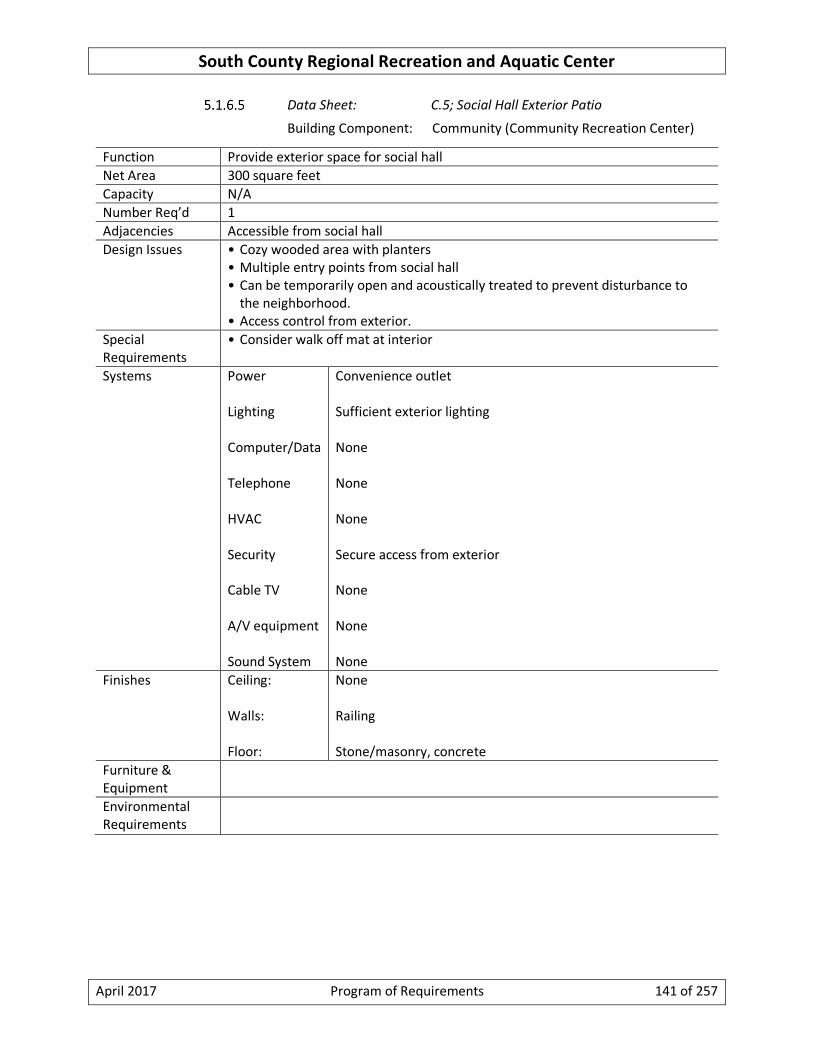
South County Regional Recreation and Aquatic Center
April 2017 Program of Requirements 141 of 257
Data Sheet: C.5; Social Hall Exterior Patio
Building Component: Community (Community Recreation Center)
Function Provide exterior space for social hall
Net Area 300 square feet
Capacity N/A
Number Req’d 1
Adjacencies Accessible from social hall
Design Issues • Cozy wooded area with planters
• Multiple entry points from social hall
• Can be temporarily open and acoustically treated to prevent disturbance to
the neighborhood.
• Access control from exterior.
Special
Requirements
• Consider walk off mat at interior
Systems Power
Lighting
Computer/Data
Telephone
HVAC
Security
Cable TV
A/V equipment
Sound System
Convenience outlet
Sufficient exterior lighting
None
None
None
Secure access from exterior
None
None
None
Finishes Ceiling:
Walls:
Floor:
None
Railing
Stone/masonry, concrete
Furniture &
Equipment
Environmental
Requirements

South County Regional Recreation and Aquatic Center
April 2017 Program of Requirements 142 of 257
Data Sheet: C.6; Kitchen
Building Component: Community (Community Recreation Center)
Function Culinary arts instruction area, nutrition program staging area, food preparation
for catered events.
Net Area 850 square feet
Capacity 8-10 people for teaching
Number Req’d 1
Adjacencies • Direct access to social hall
• Adjacent to community lounge too is preferred if design allows
• Easily accessible from loading dock/trash room
• Requires direct access from drive for catering trucks
• Custodial Closet
• Connection to main circulation
Design Issues • Provide countertop with drawers & basic cabinets
• Provide wall hung cabinets above countertop (lockable)
• Provide 8’ long x 3’ wide serving counter to social hall thru a lockable pass thru,
Proportion is not long rectangular, more square
• Instructional tables in center
Special
Requirements
• Follow State of Maryland Dept. of Health Code requirements (10.15.03)
• Comply with latest ADA requirements
• Double door access
• All equipment to be commercial grade
• Direct access to custodial closet
• Grease trap vent to outside
• Stainless materials throughout
Systems Power
Lighting
Computer/Data
Telephone
HVAC
Security
Cable TV
A/V equipment
Sound System
Outlets to power equipment, some require 208/244V, 3 ph
service
Moisture resistant lens. Lighting system with motion sensor on
10 min shut off.
None
Wall Mounted
Provide a dedicated manually operated exhaust system to
prevent food odors to recirculate throughout the building.
Security Cameras
None
Monitors/cameras for instructional classes
Dedicated PA system for instructions
Finishes Ceiling: Moisture resistant

South County Regional Recreation and Aquatic Center
April 2017 Program of Requirements 143 of 257
Walls:
Floor:
Painted CMU, Tile, durable, easily cleaned
Quarry/ceramic tile/poured floor
Furniture &
Equipment
• Grease trap
• Lockable freezer and refrigerator
• Combination oven with locking range top
• 150 lb. ice making machine (may need more)
• Large microwave ovens
• Large compartment sink. No garbage disposal per WSSC.
• Separate hand sink(s)
• Rack type roast & hold convection oven capable of heating & reheating food
and holding standard catering trays
• 4 – 8 long tables on wheels for demonstrations, teaching, serving
• Fire suppression range hood above stove

South County Regional Recreation and Aquatic Center
April 2017 Program of Requirements 144 of 257
Data Sheet: C.7; Kitchen Storage
Building Component: Community (Community Recreation Center)
Function Storage for the space divided into bulk storage as well as storage for individual
functions and food for catered events.
Net Area 100 square feet
Capacity N/A
Number Req’d 1
Adjacencies • Kitchen
• Accessible from corridor
Design Issues • Doors to be 8’ high and 8’ wide with deadbolts and no threshold to allow items
to be wheeled in. Doors should be capable of opening 100 degrees.
Special
Requirements
Systems Power
Lighting
Computer/Data
Telephone
HVAC
Security
Cable TV
A/V equipment
Sound System
Convenience outlet
Industrial LED. Lighting system with motion sensor on 10 min
shut off.
None
None
This is an unmanned space. Use temperature set back and
minimum conditioned air.
Locked doors
None
None
None
Finishes Ceiling:
Walls:
Floor:
Exposed
Painted gypsum board or CMU, durable
Sealed Concrete
Furniture &
Equipment
• Shelving
Environmental
Requirements

South County Regional Recreation and Aquatic Center
April 2017 Program of Requirements 145 of 257
Data Sheet: C.8; Activity Room-1
Building Component: Community (Community Recreation Center)
Function Space suitable for multipurpose activity spaces/meeting room easily convertible
to vocal or instrumental instruction or practice
Net Area 2,000 square feet
Capacity N/A
Number Req’d 1
Adjacencies • Near community lounge or social hall
• Activity Room-1 Storage
Design Issues • Provide a high quality “air wall” partition to separate into two 1,000 sf rooms.
Partition should have a 50 STC rating (confirm)
• Sound insulation, acoustics
Special
Requirements
• Provide double doors for movement of instruments and equipment
• Sink in combined space
Systems Power
Lighting
Computer/Data
Telephone
HVAC
Security
Cable TV
A/V equipment
Sound System
Convenience wall outlets, 50% more than standard amount
Dimmable, zoned lighting controls for conferences & A/V
presentations. Consider using motion sensors to address
unoccupied periods. Lighting system with motion sensor on 10
min shut off.
Wi-Fi, 2 wired data ports
None
Use demand ventilation based on CO2 sensor and minimum air
flow during unoccupied periods.
None
CCTV with DVR
16:9 ratio drop down screen & ceiling projector; smartboards
for each of the divided rooms and positioned to work for
whole room.
Facility PA system, independent audio system
Finishes Ceiling:
Walls:
Floor:
Acoustic materials (ceiling height = max. 12’ as high as
possible)
Painted gypsum board, abuse resistant gypsum board, abuse
resistant
Vinyl Composite Tile or equivalent
Furniture &
Equipment
• Mech shades on windows
• Conference type tables (on lockable wheels)

South County Regional Recreation and Aquatic Center
April 2017 Program of Requirements 146 of 257
• Stacking chairs (on lockable wheels) & dollies to store them
• Sectional tables (on lockable wheels) easily re-configured
Environmental
Requirements
• Treat the room acoustically so external noise does not disrupt activities and
sound from the room does not disturb adjacent activities

South County Regional Recreation and Aquatic Center
April 2017 Program of Requirements 147 of 257
Data Sheet: C.9; Activity Room-1 Storage
Building Component: Community (Community Recreation Center)
Function Storage space for activity rooms
Net Area 300 square feet
Capacity N/A
Number Req’d 1
Adjacencies • Accessible from both neighboring activity rooms
• Accessible from corridor
Design Issues • Doors to be 8’ high and 8’ wide with deadbolts and no threshold to allow items
to be wheeled in. Doors should be capable of opening 100 degrees.
Special
Requirements
Systems Power
Lighting
Computer/Data
Telephone
HVAC
Security
Cable TV
A/V equipment
Sound System
Convenience outlet
Industrial LED. Lighting system with motion sensor on 10 min
shut off.
None
None
Standard Building System
Locked door
None
None
None
Finishes Ceiling:
Walls:
Floor:
Exposed
Painted Gypsum board
Vinyl composite tile or equivalent
Furniture &
Equipment
Environmental
Requirements

South County Regional Recreation and Aquatic Center
April 2017 Program of Requirements 148 of 257
Data Sheet: C.10; Activity Room-2
Building Component: Community (Community Recreation Center)
Function Space suitable for multipurpose activity spaces/meeting room easily convertible
to vocal or instrumental instruction or practice
Net Area 1,600 square feet
Capacity N/A
Number Req’d 1
Adjacencies • Near community lounge or social hall
• Activity Room-1 Storage
Design Issues • Provide a high quality “air wall” partition to separate into two 800 sf rooms.
Partition should have a 50 STC rating (confirm)
• Sound insulation, acoustics
Special
Requirements
• Provide double doors for movement of instruments and equipment
• Sink in combined space
Systems Power
Lighting
Computer/Data
Telephone
HVAC
Security
Cable TV
A/V equipment
Sound System
Convenience wall outlets, more than standard amount
Dimmable, zoned lighting controls for conferences & A/V
presentations. Consider using motion sensors to address
unoccupied periods.
Wi-Fi, 2 wired data ports
None
Use demand ventilation based on CO2 sensor and minimum air
flow during unoccupied periods.
None
CCTV with DVR
16:9 ratio drop down screen & ceiling projector; smartboards
for each of the divided rooms and positioned to work for
whole room.
Facility PA system, independent audio system
Finishes Ceiling:
Walls:
Floor:
Acoustic materials (ceiling height = max. 12’ as high as
possible)
Painted gypsum board, abuse resistant gypsum board, abuse
resistant
Vinyl composite tile or equivalent
Furniture &
Equipment
• Mecho shades on windows
• Conference type tables (on lockable wheels)
• Stacking chairs (on lockable wheels) & dollies to store them

South County Regional Recreation and Aquatic Center
April 2017 Program of Requirements 149 of 257
• Sectional tables (on lockable wheels) easily re-configured
Environmental
Requirements
• Treat the room acoustically so external noise does not disrupt activities and
sound from the room does not disturb adjacent activities

South County Regional Recreation and Aquatic Center
April 2017 Program of Requirements 150 of 257
Data Sheet: C.11; Activity Room-2 Storage
Building Component: Community (Community Recreation Center)
Function Storage space for activity rooms
Net Area 200 square feet
Capacity N/A
Number Req’d 1
Adjacencies • Accessible from both neighboring activity rooms
• Accessible from corridor
Design Issues • Doors to be 8’ high and 8’ wide with deadbolts and no threshold to allow items
to be wheeled in. Doors should be capable of opening 100 degrees.
Special
Requirements
Systems Power
Lighting
Computer/Data
Telephone
HVAC
Security
Cable TV
A/V equipment
Sound System
Convenience outlet
Industrial LED
None
None
Standard Building System
Locked door
None
None
None
Finishes Ceiling:
Walls:
Floor:
Exposed
Painted Gypsum board
Vinyl composite tile or equivalent
Furniture &
Equipment
Environmental
Requirements

South County Regional Recreation and Aquatic Center
April 2017 Program of Requirements 151 of 257
Data Sheet: C.12; Activity Room-3
Building Component: Community (Community Recreation Center)
Function Space suitable for multipurpose activity spaces/meeting room easily convertible
to vocal or instrumental instruction or practice
Net Area 800 square feet
Capacity N/A
Number Req’d 1
Adjacencies • Near community lounge or social hall
• Activity Room-1 Storage
Design Issues • Sound insulation, acoustics
Special
Requirements
• Provide double doors for movement of instruments and equipment
• Sink in combined space
Systems Power
Lighting
Computer/Data
Telephone
HVAC
Security
Cable TV
A/V equipment
Sound System
Convenience wall outlets, more than standard amount
Dimmable, zoned lighting controls for conferences & A/V
presentations. Consider using motion sensors to address
unoccupied periods. Lighting system with motion sensor on 10
min shut off.
Wi-Fi, 2 wired data ports
None
Use demand ventilation based on CO2 sensor and minimum air
flow during unoccupied periods.
None
CCTV with DVR
16:9 ratio drop down screen & ceiling projector; smartboards
for each of the divided rooms and positioned to work for
whole room.
Facility PA system, independent audio system
Finishes Ceiling:
Walls:
Floor:
Acoustic materials (ceiling height = max. 12’ as high as
possible)
Painted gypsum board, abuse resistant gypsum board, abuse
resistant
Vinyl composite tile or equivalent
Furniture &
Equipment
• Mecho shades on windows
• Conference type tables (on lockable wheels)
• Stacking chairs (on lockable wheels) & dollies to store them
• Sectional tables (on lockable wheels) easily re-configured

South County Regional Recreation and Aquatic Center
April 2017 Program of Requirements 152 of 257
Environmental
Requirements
• Treat the room acoustically so external noise does not disrupt activities and
sound from the room does not disturb adjacent activities

South County Regional Recreation and Aquatic Center
April 2017 Program of Requirements 153 of 257
Data Sheet: C.13; Activity Room-3 Storage
Building Component: Community (Community Recreation Center)
Function Storage space for activity rooms
Net Area 100 square feet
Capacity N/A
Number Req’d 1
Adjacencies • Accessible from both neighboring activity rooms
• Accessible from corridor
Design Issues • Doors to be 8’ high and 8’ wide with deadbolts and no threshold to allow items
to be wheeled in. Doors should be capable of opening 100 degrees.
Special
Requirements
Systems Power
Lighting
Computer/Data
Telephone
HVAC
Security
Cable TV
A/V equipment
Sound System
Convenience outlet
Industrial LED
None
None
Standard Building System
Locked door
None
None
None
Finishes Ceiling:
Walls:
Floor:
Exposed
Painted gypsum board
Vinyl Composite Tile or equivalent
Furniture &
Equipment
Environmental
Requirements

South County Regional Recreation and Aquatic Center
April 2017 Program of Requirements 154 of 257
Data Sheet: C.14; Art Room
Building Component: Community (Community Recreation Center)
Function Instruction and self-directed use for drawing, painting, sculpture, silk screening,
pottery, ceramics, lapidary, photography, woodcarving ,etc.
Net Area 1,600 square feet
Capacity 80
Number Req’d 1
Adjacencies • Community circulation
• Activity Rooms
Design Issues • Provide a high quality “air wall” partition to separate into two 800 sf rooms.
Partition should have a 50 STC rating (confirm)
• Sound insulation, acoustics
• This is a multipurpose craft space, not for ceramics
Special
Requirements
• Sink/plumbing accommodates messy activities (ceramics etc); 36” wide x12”
deep sink (need large/deep sink, possibly 2 for ADA access)
• Floor is easily scrubbed/cleaned (Vinyl Composite tile acceptable); walls easily
cleaned/scrubbed to 5’ height
• Provide double doors for movement of instruments and equipment
• Sinks to be provided in both halves of dividable room
Systems Power
Lighting
Computer/Data
Telephone
HVAC
Security
Cable TV
A/V equipment
Sound System
Convenience wall outlets, more than standard amount
Dimmable, zoned lighting controls for conferences & A/V
presentations. Consider using motion sensors to address
unoccupied periods. Possibly 2x2 lights spaced no closer than
10’ apart, recommend 35 foot candles at 3’ above floor.
Lighting system with motion sensor on 10 min shut off.
Wi-Fi, 2 wired data ports
None
Use demand ventilation based on CO2 sensor and minimum air
flow during unoccupied periods. Space must be provided with
dedicated exhaust fan and/or be kept under negative draft
pressure to prevent propagation of paint art supply odors
throughout facility.
None
CCTV with DVR
16:9 ratio drop down screen & ceiling projector; smartboards
for each of the divided rooms and positioned to work for
whole room.
Facility PA system, independent audio system

South County Regional Recreation and Aquatic Center
April 2017 Program of Requirements 155 of 257
Finishes Ceiling:
Walls:
Floor:
Acoustic materials (ceiling height = max. 12’ as high as
possible)
Painted gypsum board, abuse resistant gypsum board, abuse
resistant, vinyl or other cleanable material up to 5’ height
Vinyl composite tile or equivalent, easy to clean
Furniture &
Equipment
• Mecho shades on windows
• Conference type tables (on lockable wheels)
• Stacking chairs (on lockable wheels) & dollies to store them
• Sectional tables (on lockable wheels) easily re-configured 12 easels
• 8 multipurpose tables
Environmental
Requirements

South County Regional Recreation and Aquatic Center
April 2017 Program of Requirements 156 of 257
Data Sheet: C.15; Art Room Storage
Building Component: Community (Community Recreation Center)
Function Storage space for the Art Room
Net Area 160 square feet
Capacity N/A
Number Req’d 1
Adjacencies • Art Room
Design Issues • Doors to be 8’ high and 8’ wide with deadbolts and no threshold to allow items
to be wheeled in. Doors should be capable of opening 100 degrees.
Special
Requirements
Systems Power
Lighting
Computer/Data
Telephone
HVAC
Security
Cable TV
A/V equipment
Sound System
Convenience outlet
Industrial LED. Lighting system with motion sensor on 10 min
shut off.
None
None
Standard Building System
Locked door
None
None
None
Finishes Ceiling:
Walls:
Floor:
Exposed
Painted Gypsum board
Vinyl Composite Tile or equivalent
Furniture &
Equipment
Environmental
Requirements

South County Regional Recreation and Aquatic Center
April 2017 Program of Requirements 157 of 257
Data Sheet: C.16; Family Play Area
Building Component: Community (Community Recreation Center)
Function Play area for children with space for parents to supervise
Net Area 1,000 square feet
Capacity
Number Req’d 1
Adjacencies • Easy access from entrance
• Convenient to public restrooms/family restroom
• Within line of sight of service points/desks
Design Issues • Provision for seating for children of different ages and adults who come with
the children
• Sight lines must be maintained for safety
• Playful design
• Shelving and furniture designed for child height and stimulation
• Multipurpose, durable furnishings
• Ample seating space
Special
Requirements
• Built-in shelving, abuse-resistant
Systems Power
Lighting
Computer/Data
Telephone
HVAC
Security
Cable TV
A/V equipment
Sound System
Convenience outlets & power for electronic devices
General lighting & display lighting. Lighting system with
motion sensor on 10 min shut off.
Wi-Fi
None
General HVAC
None
Wall mounted outlet, high for TV
None
Facility PA system
Finishes Ceiling:
Walls:
Floor:
Acoustic materials, taller ceilings
Gypsum board, durable to 5’ height
Soft, cushioned, cleanable
Furniture &
Equipment
• Puzzles, theme mats, carpets, and infant and toddler furniture
• “soft play” equipment
Environmental
Requirements

South County Regional Recreation and Aquatic Center
April 2017 Program of Requirements 158 of 257
Data Sheet: C.17; Game Room
Building Component: Community (Community Recreation Center)
Function Self-directed games including pool, table tennis, table hockey, electronic arcade
games
Net Area 1,500 square feet
Capacity 130
Number Req’d 1
Adjacencies • Adjacent to & visible from community pre-function space
Design Issues • Maximize natural light and windows
• Does not need to be flexible/moveable
Special
Requirements
• Double doors to allow for moving of equipment
• Segregate pool tables in separate room to accommodate seniors while teens
are using the room
• Appropriate lighting for each game area/table
Systems Power
Lighting
Computer/Data
Telephone
HVAC
Security
Cable TV
A/V equipment
Sound System
Duplex outlets at 6’ OC around room
General room illumination/special over pool table etc. Lighting
system with motion sensor on 10 min shut off.
Data outlets for electronic games
None
Consider using CO2 Sensor demand based ventilation
Security Cameras
Wall mounted screen
None
Facility PA system
Finishes Ceiling:
Walls:
Floor:
Acoustic, tall ceiling height = 12’
Durable finish at chair rail height. Abuse resistant drywall.
Vinyl Composite Tile or other durable
Furniture • Equipment to be decided during schematic design layout
Environmental
Requirements

South County Regional Recreation and Aquatic Center
April 2017 Program of Requirements 159 of 257
Data Sheet: C.18; Community Lounge
Building Component: Community (Community Recreation Center)
Function Comfortably furnished environment conducive to seniors and adults discussion
groups, carol clubs, reading or work area for parents waiting for children
participating in center activities.
Net Area 2,000 square feet
Capacity 130
Number Req’d 1
Adjacencies • Main Lobby
• Located in high activity area
• Social Hall
• Senior Programs
Design Issues • Divisible in half with high quality “air wall” partition
• Double doors so that this room can be used in conjunction with the social hall
• Walls should accommodate hanging artwork
• Colors should help to create a warm, inviting environment
• Include a small kitchenette with counter/serving area and small fridge for
snacks, coffee, beverages, etc.
Special
Requirements
• Acoustically quiet environment
• Include a kitchen pass thru into this room
• Sink and faucet capable of filling large coffee urn. Provide supply and sewer
lines
• Include kitchenette
Systems Power
Lighting
Computer/Data
Telephone
HVAC
Security
Cable TV
A/V equipment
Sound System
Provide outlets at 6’ o.c. around room
General lighting as well as floor/table lamps, accent lighting.
Dimmable. Lighting system with motion sensor on 10 min shut
off.
WiFi and 4 data drops
None
Standard Building HVAC
Ability to control by users of the room. Provide deadband type
thermostat with min/max adjustments available to
maintenance staff
.
Security cameras
Provide CCTV, Drop down screen, projector
Sound Facility PA system, separate internal audio system
Finishes Ceiling: Acoustic, ceiling height = variable 9’-12’

South County Regional Recreation and Aquatic Center
April 2017 Program of Requirements 160 of 257
Walls:
Floor:
Painted gypsum board, durable to chair rail height
Carpet tile, durable TARR 3.5 rating (consider ability to be
cleaned after spills)
Furniture &
Equipment
• TBD -
• Upholstered chairs
• Folding card tables
• Stacking chairs
• Sofas/love seats
• End tables
• Floor lamps
Environmental
Requirements

South County Regional Recreation and Aquatic Center
April 2017 Program of Requirements 161 of 257
Data Sheet: C.19; Community Lounge Storage
Building Component: Community (Community Recreation Center)
Function Storage space for community lounge
Net Area 200 square feet
Capacity N/A
Number Req’d 1
Adjacencies • Community Lounge
Design Issues • Doors to be 8’ high and 8’ wide with deadbolts and no threshold to allow items
to be wheeled in. Doors should be capable of opening 100 degrees.
Special
Requirements
Systems Power
Lighting
Computer/Data
Telephone
HVAC
Security
Cable TV
A/V equipment
Sound System
Convenience outlet
Industrial LED. Lighting system with motion sensor on 10 min
shut off.
None
None
Standard Building System
Locked door
None
None
None
Finishes Ceiling:
Walls:
Floor:
Exposed
Painted Gypsum board
Vinyl Composite Tile or equivalent
Furniture &
Equipment
Environmental
Requirements

South County Regional Recreation and Aquatic Center
April 2017 Program of Requirements 162 of 257
Data Sheet: C.22; Community Misc. Mechanical & Electrical
Building Component: Community (Community Recreation Center)
Function Space for additional mechanical and electrical units required for community
component
Net Area 425 square feet
Capacity N/A
Number Req’d 1
Adjacencies • Adjacent to spaces serving
Design Issues
Special
Requirements
Systems Power
Lighting
Computer/Data
Telephone
HVAC
Security
Cable TV
A/V equipment
Sound System
Convenience outlet
Industrial LED. Lighting system with motion sensor on 10 min
shut off.
None
None
This is an unmanned space. Use temperature set back and
minimum conditioned air. HVAC to meet code requirements:
Cooling for electrical equipment and freeze protection for
water/fluid lines are required.
Locked door
None
None
None
Finishes Ceiling:
Walls:
Floor:
Exposed
CMU
Sealed concrete
Furniture &
Equipment
Environmental
Requirements

South County Regional Recreation and Aquatic Center
April 2017 Program of Requirements 163 of 257
Data Sheet: C.23; Community Misc. Storage
Building Component: Community (Community Recreation Center)
Function Storage space for community lounge
Net Area 425 square feet
Capacity N/A
Number Req’d 1
Adjacencies • Community Lounge
Design Issues • Doors to be 8’ high and 8’ wide with deadbolts and no threshold to allow items
to be wheeled in. Doors should be capable of opening 100 degrees.
Special
Requirements
Systems Power
Lighting
Computer/Data
Telephone
HVAC
Security
Cable TV
A/V equipment
Sound System
Convenience outlet
Industrial LED. Lighting system with motion sensor on 10 min
shut off.
None
None
Standard Building System
Locked door
None
None
None
Finishes Ceiling:
Walls:
Floor:
Exposed
Painted Gypsum board
Vinyl Composite Tile or equivalent
Furniture &
Equipment
Environmental
Requirements

South County Regional Recreation and Aquatic Center
April 2017 Program of Requirements 164 of 257
Miscellaneous Space Data Sheets
The following pages contain space data sheets for miscellaneous building spaces.

South County Regional Recreation and Aquatic Center
April 2017 Program of Requirements 165 of 257
Data Sheet: M.1; Custodial
Building Component: Varies (Shared)
Function Storage for cleaning supplies and equipment
Net Area (varies, see program summary)
Capacity N/A
Number Req’d 3
Adjacencies • Natatorium Component
• Fitness Component
• Community Component
Design Issues • Storage items: paper supplies, cleaning supplies, mops, light bulbs, buffer and
vacuum cleaner
Special
Requirements
Systems Power
Lighting
Computer/Data
Telephone
HVAC
Security
Cable TV
A/V equipment
Sound System
Convenience outlets
Industrial LED. Lighting system with motion sensor on 10 min
shut off.
None
None
Exhaust to remove odors
None
None
None
None
Finishes Ceiling:
Walls:
Floor:
Exposed
CMU; Ceramic tile around mop sink to min. of 4’ high
Epoxy with floor drain
Furniture &
Equipment
• Lockable cabinet to store operations and maintenance manuals
• Floor sink with hot and cold water
• Storage Shelving
Environmental
Requirements

South County Regional Recreation and Aquatic Center
April 2017 Program of Requirements 166 of 257
Data Sheet: M.2; Tele-data
Building Component: Varies (Shared)
Function Closet for tele-data equipment
Net Area (varies, see program summary)
Capacity N/A
Number Req’d 4
Adjacencies • Natatorium Component
• Fitness Component
• Community Component
• Administration Component
Design Issues
Special
Requirements
Systems Power
Lighting
Computer/Data
Telephone
HVAC
Security
Cable TV
A/V equipment
Sound System
Convenience outlet
Industrial LED. Lighting system with motion sensor on 10 min
shut off.
None
None
Reduce heat from equipment. Dedicated and properly sized
cooling system. Preferably variable refrigerant.
None
None
None
None
Finishes Ceiling:
Walls:
Floor:
Exposed
CMU
Sealed concrete
Furniture &
Equipment
Environmental
Requirements

South County Regional Recreation and Aquatic Center
April 2017 Program of Requirements 167 of 257
Data Sheet: M.3; Typical Men’s Restrooms
Building Component: Miscellaneous (Shared)
Function General restrooms for the building components
Net Area 250 square feet
Capacity N/A
Number Req’d To be confirmed
Adjacencies • Circulation and Prefunction space
Design Issues • Restrooms should be easy to find and entrance doors visible from public area;
doorless airport style
Special
Requirements
• Bathroom dividers that are graffiti proof
Systems Power
Lighting
Computer/Data
Telephone
HVAC
Security
Cable TV
A/V equipment
Sound System
Convenience outlets
General illumination. Lighting system with motion sensor on
10 min shut off.
None
None
Provide adequate exhaust air flow per IBC
None
None
None
None
Finishes Ceiling:
Walls:
Floor:
Gypsum Board, acoustic material
Ceramic Tile
Ceramic Tile
Furniture • Baby changing station
Environmental
Requirements

South County Regional Recreation and Aquatic Center
April 2017 Program of Requirements 168 of 257
Data Sheet: M.4; Typical Women’s Restrooms
Building Component: Miscellaneous (Shared)
Function General restrooms for the building components
Net Area 250 square feet
Capacity N/A
Number Req’d To be confirmed
Adjacencies • Circulation and Prefunction space
Design Issues • Restrooms should be easy to find and entrance doors visible from public area;
doorless airport style
Special
Requirements
• Bathroom dividers that are graffiti proof
Systems Power
Lighting
Computer/Data
Telephone
HVAC
Security
Cable TV
A/V equipment
Sound System
Convenience outlets
General illumination. Lighting system with motion sensor on
10 min shut off.
None
None
Provide adequate exhaust air flow per IBC
None
None
None
None
Finishes Ceiling:
Walls:
Floor:
Gypsum Board, acoustic material
Ceramic Tile
Ceramic Tile
Furniture • Baby changing station
Environmental
Requirements

South County Regional Recreation and Aquatic Center
April 2017 Program of Requirements 169 of 257
Tables of Furniture, Equipment, Telephone, and Computer Requirements
Furniture Requirements
Not used
Equipment Requirements
Not used

South County Regional Recreation and Aquatic Center Program of Requirements
April 2017 Program of Requirements 170 of 257
6 Functional Criteria for Site
Site requirements
Vehicular access
A drop-off loop will be provided at the end of Apple Avenue and service access will be provided
on Fenwick Lane. The drop-off will be covered under the scope of the residential buildings.
Mechanical equipment room access off of exterior should not be located above garage or loading
dock driveway entries.
Pedestrian access and safety
Pedestrians will access the site mainly from Second Avenue and the central courtyard. A
Pedestrian Impact Study will need to be completed. Bike stations should be located near the
facility.
Parking spaces and basis of calculation
On-site parking for SCRRAC visitors will not be provided. Visitors to the facility can utilize street
parking and the adjacent Cameron Street parking garage. An estimated total of 400 parking
spaces will be required for a combined Regional Recreation Center - 150 for the Community
Recreation Center components and 250 for the aquatics component. These numbers and their
potential impact by the urban location and ample pedestrian/bike access will need to be
confirmed in a future traffic study.
8 parking spaces shall be provided to lease for County employees.
Drop-off
Discussed in previous section.
Functional areas
The central Elizabeth Square courtyard will be operated by HOC but available to users of the
SCRRAC. The utilization of this space will be further defined during the Schematic/Design
Development phases.
Utilities
Utility meters will be provided with separate meters from the residential buildings.
Outdoor furniture and equipment
Outdoor furniture and equipment for the SCRRAC will be designed by A/E and will be purchased
as FF&E for the SCRRAC.
Landscaping and security (including fencing)
None required.
Exterior lighting

South County Regional Recreation and Aquatic Center Program of Requirements
April 2017 Program of Requirements 171 of 257
Any exterior fixtures mounted to the exterior walls of the SCRRAC will be under the SCRRAC
scope.
Exterior signage and wayfinding
Any exterior signage for the SCRRAC that is attached to the building will be a part of the SCRRAC
scope. Exterior signage to be provided along Second Avenue. A double-sided sign is to be
provided at Georgia Avenue and Cameron Street.
County standard monument sign with digital message board shall be provided on the site in
addition to large scale building signage on Second Avenue to “brand” or announce the SCRRAC
occupies the block. Signage should be readily readable by moving cars along Second Avenue
along with large scale signage at Apple Avenue drop-off.

South County Regional Recreation and Aquatic Center Program of Requirements
April 2017 Program of Requirements 172 of 257
7 Technical Design Requirements (supplement to Design Manual)
Definitions
In this document the term ‘Design Manual’ refers to the Montgomery County Manual for Planning,
Design and Construction of Sustainable Buildings, Department of General Services, latest edition.
General Goals
Crime Prevention and Security
The exterior of the facility and site shall be designed to prevent crime utilizing the guidelines in
Design Manual, Section H, Crime Prevention Through Environmental Design (CPTED). These
guidelines include natural surveillance, territorial reinforcement, natural access control and
target hardening. In addition, an electronic security system including intrusion detection, access
control and video surveillance is to be installed in the facility.
System Acceptance Testing and Commissioning
System acceptance testing and commissioning shall be in compliance with the owner’s project
requirements and design intent documents. The commissioning authority must prepare a written
commissioning plan that identifies the processes, procedures, methods, and documentation for
each phase of the commissioning process for all types of active and passive systems and
equipment installed from concept through post-occupancy. The completed commissioning plan,
including all appendices, must form the commissioning record turned over at the end of the
construction phase. The commissioning plan shall include but not be limited to the following
systems: structure; envelope; automated window treatments; audio visual; conveying; fire
suppression; plumbing; mechanical; electrical; communications; electronic safety and security;
exterior improvements; and utilities.
General Building Codes, Regulations, and Standards
Codes
General
The project must meet all applicable local, state, and national codes in force at the time of
permit submission and Notice to Proceed for A/E team. At the time this Program of
Requirements was written it includes, but may not be limited to:
• Accessibility: COMAR (latest version), 2010 ADA Standards for Accessible Design, Fair
Housing Accessibility Guidelines
• Commercial Building: International Building Code with Montgomery County
Amendments, Maryland Building Rehabilitation Code, COMAR (latest version) and
Executive Regulations
• Commercial Fuel Gas: International Fuel Gas Code with Montgomery County
Amendments

South County Regional Recreation and Aquatic Center Program of Requirements
April 2017 Program of Requirements 173 of 257
• Commercial Mechanical: International Mechanical Code with Montgomery County
Amendments, ASME and ANSI for mechanical pressure parts and vessels
• Electrical: National Electrical Code (NFPA 70) with Montgomery County Amendments
• Energy Conservation: International Energy Conservation Code with Montgomery
County Amendments
• Sustainability: International Green Construction Code with Montgomery County
Amendments
• Fire Alarm: National Fire Alarm and Signaling Code (NFPA 72) with Montgomery
County Amendments, COMAR NFPA 72, State of Maryland Fire Prevention Code
• Life Safety: Life Safety Code (NFPA 101) with Montgomery County Amendments,
COMAR NFPA 101, State of Maryland Fire Prevention Code
• Plumbing & Gas: Washington Suburban Sanitary Commission (WSSC) Plumbing & Fuel
Gas Code
• Commercial Sprinkler: Standard for the Installation of Sprinkler Systems (NFPA 13)
with Montgomery County Amendments, COMAR NFPA 13, State of Maryland Fire
Prevention Code
• Pools:
o Code of Maryland, Chapter 51, Swimming Pools
o Title 10, Department of Health and Hygiene, Subtitle 17 – Sanitation, Chapter
01 – Public Swimming Pools and Spas
o Executive Regulation 61-91, Manual on Public Swimming Pool Construction,
Dated 23 April 1992, From Department of Health
o COMAR 09.12.63
o Amusement Ride Safety, Business Regulation Article, Title 3, Annotated Code
of Maryland
o Executive Regulation 4-95AM, Manual on Public Swimming Pool Operation,
Dated 24 June 1995, From Department of Health
• Montgomery County: Montgomery County Manual for Planning, Design, and
Construction of Sustainable Buildings, Version 2010.7
Specialty
Each item of food service equipment shall comply with the latest edition of the following
as applicable to the manufacture, fabrication, and installation of the work at the time of
permit submission.

South County Regional Recreation and Aquatic Center Program of Requirements
April 2017 Program of Requirements 174 of 257
• Each manufactured item and major items of custom-fabricated work: provide National
Sanitation Foundation (NSF) "Seal of Approval".
• Electrical components and assemblies: provide either U.L. labeled products or, where
no labeling service is available, provide a complete index of the components used as
selected from the UL "Recognized Component Index".
• Gas-burning equipment: ANSI Z21-Series standards.
• Compressed gas cylinder connections: ANSI B57.1 and applicable standards of the
Compressed Gas Association for water connection air gaps and vacuum breakers
• Gas-fired equipment: AGA Approved, equipped to operate on the type of gas available,
and shall contain 100% automatic safety shut-off devices.
• Exhaust systems: NFPA 96 and NFPA 17.
• Fire extinguishing systems: NFPA 96 and UL 300.
• Ventilation for exhaust hoods over cooking appliances: UL 710 and NFPA 96.
• Steam generating and steam-heated equipment: provide ASME inspection, stamps,
and certification of registration with National Board.
• Electrical wiring and devices included with food service equipment: NEC Volume 5.
• Food service facilities: Code of Maryland Regulations COMAR 10.15.03
Regulations
The project must meet all applicable local, state, and national regulations in force at the time of
permit submission.
Other Authorities Having Jurisdiction
• MDE Maryland Department of the Environment
• M-NCPPC Maryland-National Capital Park and Planning Commission
• USACE US Army Corps of Engineers
• WSSC Washington Suburban Sanitary Commission
• WMATA Washington Metropolitan Area Transit Authority
• DOT Department of Transportation
• DPS Department of Permitting Services
Sustainability Regulations
The project is to be designed in accordance with Montgomery County Green Buildings Law,
Montgomery County Code, Chapter 8, Article 7, and must achieve a LEED Silver rating,
however, the project will strive to meet LEED Gold certification requirements.
The project will be third party reviewed and certified using the United States Green Building
Council (USGBC) Leadership in Energy and Environmental Design (LEED) criteria. The LEED
building rating system uses seven categories in which projects can obtain credits to
achieve certification (Sustainable Sites, Water Efficiency, Energy & Atmosphere, Materials &

South County Regional Recreation and Aquatic Center Program of Requirements
April 2017 Program of Requirements 175 of 257
Resources, Indoor Environmental Quality and Innovation & Design Process, and Regional
Priority). The four levels of certification (from highest to lowest) are, Platinum, Gold, Silver
and Certified. The credit threshold for each level of certification varies for different rating
systems. To qualify for certification a project must meet certain prerequisite credits. The
number of additional credits required is dependent on the level of certification that the
project is seeking to attain.
Montgomery County, Maryland requires new construction over 10,000 sf to be LEED
certified at the Silver level. The most appropriate LEED system for new construction of a
Regional Recreation Center is currently LEED-New Construction (NC) version v4.
Design decisions shall be considered to take advantage of the local environment in an effort
to optimize energy efficiency and minimize negative impact on the site, especially with
regard to storm water. Interior materials and finishes shall be specified as “low-emitting” to
avoid potential negative impacts to human respiratory health and comfort. Solar orientation
and fenestration design is to explore the feasibility of large north and south facing windows,
clerestory windows and/or light ‘chases’ to bring in natural light while avoiding glare as well
as highlighting views to the exterior. Pervious surfaces are to be incorporated and
vegetated roof shall be considered as part of the storm water management efforts.
Methods of water reuse and recycling, especially from pools, are to be explored and
implemented where possible.
Accessibility Regulations
The new building and access to it shall be fully compliant with the 2010 ADA Standards for
Accessible Design. Provide an accessible “path of travel” from 2nd Avenue right-of-way to
the building entrance through the central plaza. From the building entrance into and
through the building, provide an accessible route to connect each floor and each
department. Special care shall be taken to ensure that all toilet rooms are fully and
universally accessible and proper door clearances to all rooms are provided.
Include construction tolerances within all accessible design solutions. All ADA criteria with a
range tolerance shall be designed to the middle of the tolerance range. All dimensions must
include the compounded tolerances required by all trades completing the component.
Cross slopes shall not be designed past 1.5 percent. Bathroom grab bars shall be longer
than the minimum required length. Bathroom stalls hall be at least 1" larger than the
minimums.
Facility to exceed standard threshold for accessible design where possible within
construction budget.
Standards
Utility Standards

South County Regional Recreation and Aquatic Center Program of Requirements
April 2017 Program of Requirements 176 of 257
All systems and components shall be designed in accordance with standards developed by
the following organizations, and in effect at the time of permit submission:
• Comcast
• Potomac Electric Power Company [Alleghany Power Company] [Potomac Edison
Power Company] (PEPCO)
• Verizon Communications
• Washington Gas
• Montgomery County Department of Technology Services
• Washington Suburban Sanitary Commission (WSSC)
Reference Standards
All systems and components shall be designed in accordance with the following standards in
effect at the time of permit submission:
• Design Manual - Montgomery County Manual for Design and Construction of
Sustainable Buildings – latest edition
• Sign Manual - Montgomery County Department of General Services Manual of
Exterior Sign Standards for County Facilities– latest edition
• Sign Guidelines - Montgomery County Department of General Services Manual of
Interior Sign Standards for County Facilities– latest edition
Industry Standards
Not used
Accreditation Standards
Not used
Building Structure (excluding foundations)
The SCRRAC program will be contained in a tall ground level story extending under an adjacent
residential tower and a landscaped plaza area between the two towers. The SCRRAC will be
supported by concrete framing for 3 levels of underground parking below.
Deflection Criteria
The structure will be designed to meet the requirements of the International Building Code with
Montgomery County Code Amendments. The structure will meet the deflection requirements of
IBC and the long term deflection requirements of ACI 318 as referenced in IBC.
Floor Live Loads:
• Residential 40 psf + 20psf partitions

South County Regional Recreation and Aquatic Center Program of Requirements
April 2017 Program of Requirements 177 of 257
• Public Space 100 psf
• Corridors 100 psf
• Storage (medium density) 125 psf
• Roof Load 30 psf
• Lobbies and Stairwells 100 psf
• Mechanical rooms (unless actual weight of
equipment is provided) 125 psf
• Plaza 100 psf
• Occupied Roof Areas 100 psf
• Design Live loads will be reduced as permitted by the Building Code
Superimposed Dead Loads:
• Concrete, masonry or brick walls actual weight of wall
• Exterior cladding or curtain wall actual weight of wall
• Plaza paving and soil actual weight of material
Wind Loads:
• Design wind speed (3-second gust) 115 mph
• Risk Category II
• Wind Exposure Category B
• Internal Pressure Coefficient +/- 0.18 (Enclosed)
• Building is not located within a wind-borne debris region
Seismic Loads:
• Seismic Site Classification: C
• Short Period Spectral Response Acceleration (SS) 0.119g
• 1 Second Spectral Acceleration (S1) 0.051g
• Site Coefficient (Fa) 1.60
• Site Coefficient (Fv) 2.40
• 0.2 Second Maximum Spectral Response (SMS) 0.191g
• 1.0 Second Maximum Spectral Response (SM1) 0.122g
• 0.2 Design Spectral Response Acceleration (SDS) 0.127g
• 1.0 Design Spectral Response Acceleration (SD1) 0.082g
• Seismic Design Category (SDC) A
Description of the General Structural Systems
Foundation
Foundations will not be covered under the scope of the SCRRAC.
Parking and Driving Surfaces: Below Grade and Elevated
Not used.
Occupied Areas: Slab on Grade

South County Regional Recreation and Aquatic Center Program of Requirements
April 2017 Program of Requirements 178 of 257
Not used.
Occupied Floors: Structural Floors
The structure will consist of cast-in-place reinforced concrete framing in the residential
tower, at the SCRRAC, at in the garage levels below grade. A cast-in-place concrete
structure offers the thinnest floor slab and consequently, the shortest floor to floor
heights of any structural system which is critical to maximize the number of residential
units given the building height limits. Cast in place concrete will achieve a 2 hour fire
rating without the need for spray-on fire proofing or intumescent paint, is well suited to
supporting heavy loads, and also has good vibration performance which is ideal for
structures supporting dancing, basketball, aerobics, or other similar activities.
Because of the SCRRAC programming below the towers and a desire for open space, an
investigation will be performed with a number of different column layouts to find a
balance between efficiency and slab spans in the tower structures and the number of
column transfers required above the SCRRAC.
A cast-in-place concrete system is well suited for an aquatic center because there is no
steel exposed to the corrosive environment associated with chemical laden water and
humidity typical of indoor pools. To ensure longevity of the structure, there are a number
of measures that can be employed to provide additional protection for the reinforcing
steel including; using corrosion inhibiting admixtures in the concrete mix, increasing the
concrete cover over the reinforcing steel, using epoxy coated or galvanized reinforcing
steel, and using fully encapsulated post-tensioning tendons – all are typical measure for
enhancing the corrosion resistance of concrete structures exposed to harsh environments.
The slabs above the pool will be post-tensioned and will therefore have reduced long term
deflections, very little cracking, and fewer entry points for corrosive elements to reach the
reinforcing steel. They will be the same 7” to 8” thick and will be integral with much
deeper concrete transfer girders where those are required. A uniform thickness transfer
slab will be investigated in lieu of individual transfer girders if there are an excessive
number of columns transferred above the SCRRAC.
The slabs supporting the SCRRAC program will be mild reinforced cast-in-place concrete
slabs due to the large number of steps, recesses, trench drains, and pool depressions
which make post-tensioning significantly more difficult and typically not feasible. The mild
reinforced slab will be covered with a hot fluid applied waterproofing on its surface and
there will be a concrete topping slab above the waterproofing for the pool deck. There
will be shotcrete applied outside of the waterproofing membrane to construct the walls of
the pools. The waterproofing will have the ability to bridge over minor concrete cracking
and prevent water from reaching the reinforcing steel in the slabs and beams. Because of
the waterproofing, additional corrosion protection measures for the concrete are not
required, but could be used if the owner would like additional redundancy.

South County Regional Recreation and Aquatic Center Program of Requirements
April 2017 Program of Requirements 179 of 257
All activity rooms and gyms must have the slabs analyzed for resonance and deflections
due to activities in the room. Floors shall not have a bouncy feel like in parking garages.
The parking levels will be framed with an 8” thick mild reinforced, two-way, flat slab
system with 6 ¼” deep drop panels. This system is typically the most cost effective system
for below grade construction because post-tensioning requires access at the slab edge to
stress the tendons after the concrete is cast. This project will have cast-in-place concrete
basement walls cast directly against drainage board and waterproofing applied to the face
of the sheeting and shoring which makes stressing at the edge of the slab impossible. To
pull all tendons to the interior of the structure would require stressing pockets or pour
strips which are costly and give water and deicing chemicals a pathway into the slab
increasing the likelihood of future corrosion and deterioration.
Exterior basement wall drainage board will be connected to through wall weeps that will
be connected to the under-slab drainage system.
The lateral system for the structures will be ordinary reinforced concrete shear walls
located at stairs and elevator cores.
Columns
Cast-in-place concrete columns will support the concrete framing. At the SCRRAC there is
a need for column free space at the Gymnasium, Social Hall, and at the Competition Pool.
There is also a desire to minimize columns in the natatorium, although some columns are
acceptable. To reconcile the column grid of the residential tower above and the SCRRAC
programming, a large number of transfer girders will be required. See section 1.1.2.1 for
more discussion of the transfer framing options.
Roof
The structure above the SCRRAC will typically be the cast-in-place post-tensioned transfer
level of the residential tower above. The portions of the SCRRAC between the two tower
structures will most likely consist of long span post-tensioned concrete beams and one-
way post-tensioned slabs supporting heavy loading associated with green roof,
landscaping swales, and possibly mechanical rooms. The surface of the slabs will be
sloped to drains. Any MEP items secured to the underside of the slab will be anchored to
hot dip galvanized steel plates cast into the concrete during the slab pour.
Façade
The building facades will be supported at each level by the structural slab edge. Long
term deflections at the slab edges are typically limited to 5/8” max vertically, but will be
designed to lower deflection requirements if façade materials dictate tighter
requirements. Brick or other masonry veneer systems will be supported on steel shelf
angles at each slab edge. Panelized systems and masonry veneer systems will have cold
formed metal stud back-up framing resisting lateral forces. Curtainwall systems will clear

South County Regional Recreation and Aquatic Center Program of Requirements
April 2017 Program of Requirements 180 of 257
span vertically between adjacent slab edges where they will anchor to embeds in the slab
edge.
Construction Materials
Steel Joists: N/A
Structural Steel: There will be miscellaneous structural steel for canopies, shade
structures, lintels at large openings, tall curtainwall bracing, or other miscellaneous
curtainwall locations. Significant amounts of structural steel framing are not anticipated
as part of the main structure.
Concrete: The majority of the structure will be cast-in-place concrete, either mild
reinforced or post-tensioned. Slabs will be 5000 psi concrete, columns will be 5000 psi to
7000 psi as required, and reinforced concrete shear walls will be 5000 psi to 7000 psi as
required.
Architecture
Building envelope (General)
The exterior materials for this building shall be durable, low maintenance and vandal resistant.
As such we would envision the use of masonry products mixed with metal panels and a high
percentage of curtain wall and glass storefront. Glass areas will be used to provide day lighting,
invite the public in as well as monitor activities. Thru the use of glass, the building will be easier
to supervise, secure and provide natural light for the users and staff.
The building envelope shall consist of exterior masonry bearing walls, thermally broken
aluminum windows with insulated glass and light colored roofing materials. Exterior walls shall
be designed to provide a thermal envelope utilizing CMU bearing walls, cavity insulation, either
rigid or spray foam, and an air and vapor barrier within the cavity on the warm side of the
insulation, and durable long lasting exterior materials. Exterior materials shall be low
maintenance and highly vandal resistant such as brick, metal, and simulated stone, suitable to
meet the function of the building and the aesthetics of the adjoining neighborhoods.
The facility’s composite envelope design must ensure prevention of natatorium/pool chlorine-
laden moisture seepage and migration to outside to prevent freezing in winter months. Project
A/E to provide calculation of saturation/condensation temperature within various layers of the
outside envelope wall.
Exterior Enclosure Construction
• The building is to be constructed of materials and systems proven to endure the
passage of time with an expected lifespan of 50 years minimum.
• All exterior building materials shall be factory finished and require no future
maintenance.
Rough Carpentry

South County Regional Recreation and Aquatic Center Program of Requirements
April 2017 Program of Requirements 181 of 257
Not used
Below grade waterproofing
• Provide sheet applied materials at levels above the known ground water table
indicated by the geotechnical report.
• Levels below the mean ground water level shall be evaluated for more robust
composite waterproofing systems such bentonite/KEE materials.
• Plaza decks over occupied space shall be considered waterproofing. Hot fluid
applied modified bitumen waterproofing on concrete with appropriate drainage
and thermal insulation layers is the preferred approach.
Air and Moisture Barriers
• Provide continuous vapor permeable air barrier systems utilizing fluid or sheet
applied primary materials, with a full palette of transition and detailing
accessories from the same manufacturers.
• Include moisture barrier at concrete slabs within wet atmospheres.
• The entire envelope (walls, ceilings, floors) must have a dew point/water vapor
migration analysis completed for each different construction type.
Thermal Barriers
• Provide continuous thermal insulation utilizing materials appropriate to the wall
elements to be insulated. Utilize continuous insulation outboard of the weather
resistant barrier in walls as much as possible.
• Preferred wall insulations include extruded polystyrene, rigid mineral wool, and
sprayed polyurethane foam.
• Utilize spray foam insulation to prevent thermal bridging at transitions; the use of
less durable fiberglass batt insulation is discouraged.
• Special provisions should be made for areas around the natatorium and pools.
Wall Claddings
• Masonry veneer with cavity wall and masonry back up are the preferred systems.
• Other wall claddings include insulated metal panels, fiber cement siding, terra
cotta rain screen systems, and composite metal panel systems.
Roofing
• Specify roof insulation thickness, not minimum R-values.
• Single penetration roof drains that combine overflow and primary roof drainage
into one assembly are preferred. Primary roof drains with overflow scuppers at
walls are also acceptable.

South County Regional Recreation and Aquatic Center Program of Requirements
April 2017 Program of Requirements 182 of 257
• Roof top equipment is to be minimized. All roof top equipment shall be screened
from view using screen walls or enclosed penthouses. MEP roof equipment for
SCRRAC will be located on residential tower roofs utilizing shared shafts with
residential. Screening will be provided for SCRRAC and residential equipment on
roof.
• Provide permanent guardrails at roof edges in accordance with MOSHA and OSHA
fall protection standards for maintenance of roof top equipment; avoid horizontal
railings such as cable railing that allow individuals to climb guardrails. Top of rails
shall be 43” in lieu of 42” to allow for construction tolerances; specify minimum
48” height for fall protection at heights exceeding two stories.
• Glass shall not be used for canopy roofs due to inability to maintain a clean
appearance.
• Vegetated roofing systems will be used as a part of stormwater management
requirements
• The roofing steel structure and girders exposed to natatorium environment must
be protected against paint layer(s) peeling off and exposing bare steel to
natatorium environment.
Fenestration
• Thermally broken aluminum framed storefront or curtain wall system
• Fixed windows shall be provided regardless of occupancy or building use
• Unit Skylights shall meet the minimum requirements of AAMA Performance Class
CW 60.
Glazing:
• Consider less expensive glazing where personal comfort is not required
• Avoid reflective glass that may contribute to a higher incidence of bird collisions.
Doors:
• Heavy duty automatic sliding doors with breakout for emergency at all primary
and secondary entrances – ability to lock down and/or use with controlled access
• Storefront doors in aluminum frames at public exit doors
• Hollow metal in hollow metal frames at utility spaces
Hardware:
• Continuous stainless steel hinges
• Provide hardware resistant to corrosive wet atmospheres in Natatorium area

South County Regional Recreation and Aquatic Center Program of Requirements
April 2017 Program of Requirements 183 of 257
Interiors
Materials and Systems
Metal railings
• Horizontal railings other than handrails and top rails at guardrails are not
allowed; these pose a risk in terms of climbing.
• When dimensioning handrails at stairs, pay particular attention to Executive
Regulations for required distance between face of wall and handrail. Coordinate
with maximum amount IBC allows railings to project into stair and adjust width
of stair and rail profile accordingly.
Architectural woodwork, cabinetry and countertops
• All millwork shall be custom fabricated, finished and installed in accordance with
Premium-grade Architectural Woodwork Standards (AWS).
• All cabinets shall be vertical grade plastic laminate with plastic laminate edge
banding. Wood veneer is not allowed. Cabinet and drawer faces in wood-grain
laminates shall follow AWS Premium standards for book matched, center balance
matched in a sequenced set with continuous match where interrupted
perpendicular to the grain, unless agreed otherwise by DGS.
• Cabinet doors shall have institutional grade hinges (European vs. offset barrel
type in all but perhaps highly utilitarian spaces), and drawers shall have heavy
duty glides.
• Melamine (low pressure laminate) will be allowed on vertical interior surfaces of
cabinets, however all horizontal surfaces shall be plastic laminate. Cabinet
materials shall be selected carefully to coordinate with standard (or custom)
melamine colors and edge banding.
• Countertops shall be solid surface or engineered stone material at all general and
work areas (including pantries, lavatories, work counters, transaction ledges,
etc.). Stainless steel counters are required on both sides of commercial grade
ranges and shall have continuous turned-up edge adjacent to range as well as
continuous full-height backsplash. Plastic laminate or recycled material
countertops will be allowed in very limited areas and only with express
permission by DGS. Countertop edge shall be square: corners may be slightly
eased on solid surface and stainless steel tops.
• Window sills shall be solid surface or engineered stone material.
• Storage in non-kitchen spaces must have at least one of each type of storage
within the reach range but it is permissible to provide additional storage outside
the reach range. Sinks in these spaces must have knee and toe space.

South County Regional Recreation and Aquatic Center Program of Requirements
April 2017 Program of Requirements 184 of 257
Pantry/kitchen wall and base cabinets shall be provided with 50 percent of
storage, and cabinet pulls serving them, between 15 inches minimum to 48
inches maximum AFF. Total shelf and drawer space shall be measured along
front of shelf or drawer and shall be within the reach range. Endeavor to provide
4’-6” minimum of linear storage ideally within a minimum of one base cabinet
shelf positioned at 15 ½” AFF.
Firestopping
Firestopping will be provided as required by code.
Doors and Frames
Refer to space data sheets in Chapter 5 for specific application, location and assemblies.
Hardware:
Provide hardware resistant to wet atmospheres in Natatorium area. Refer to space data
sheets in Chapter 5 for specific application, location and assemblies.
Partitions:
Refer to space data sheets in Chapter 5 for specific application, location and assemblies.
Glazing
Refer to space data sheets in Chapter 5 for specific application, location and assemblies.
Ceilings:
Ceiling types include acoustical ceiling tile, gypsum board, moisture-resistant gypsum
board, feature elements (wood, etc.) and exposed.
Floor Finishes:
Floor finishes include ceramic or porcelain tile, resilient flooring, wood flooring, athletic
rubber, and carpet. All flooring materials to be durable. See space data sheets in Section 5
for information on slip-resistant qualities and locations of flooring types.
Wall Finishes:
Wall finishes to be painted gypsum board, painted concrete masonry units, ceramic tile,
and feature elements (wood, etc.). Paints and coatings to be high quality latex paint, with
scrubbable qualities in public areas. Where gypsum wall board is used in public spaces, it
must be abuse resistant drywall up to 8 feet above the floor.
Natatorium Finishes:
Materials in pool areas and directly adjacent must be anticorrosive. Structure rebar must
be epoxy coated to avoid spalling of concrete. Building structure must be designed for
deflections associated with draining and filling the pool. Provide the specific deflection
criteria for floors, walls and columns during both conditions. AE must indicate coatings
must be designed to avoid peeling, performance requirements to be defined during
design.

South County Regional Recreation and Aquatic Center Program of Requirements
April 2017 Program of Requirements 185 of 257
Specialties, Equipment & Furnishings
Specialties
Visual Display Surfaces
Not used
Display, Directories, Signage and Wayfinding
All signage must be provided in accordance with the DGS Manual of Exterior Sign
Standards for County Facilities and the to-be-published Interior Signage Standards for
County Facilities.
Toilet Compartments
Design shall be floor-mounted, overhead-braced. Partitions in locker rooms serving the
pool should be HPDE – metal or phenolic are prohibited.
Operable Partitions:
Electrically operated, vertical, acoustical panel partitions with STC of not less than 51.
System including structural support shall be complete with all hardware, lifting
equipment, safety equipment and testing.
Toilet Accessories
All fixtures within the Natatorium to be able to withstand a wet atmosphere.
Lockers and Benches
Benches within locker room to be centered on floor and not attached to lockers.
Flagpoles
Not used
Equipment
Maintenance Equipment Requirements
Mechanical spaces not on grade to have double doors to exterior with material hoist
where required. Material hoist will be retractable from wall and hidden from view when
not in use.
Residential Kitchen Appliances, Food Cooking Equipment, Ice Machines
Not used
Residential Laundry Appliances
Not used
Audio Video Equipment
See space data sheets in Section 5 for audio visual requirements for each space.
Athletic and Recreational Equipment

South County Regional Recreation and Aquatic Center Program of Requirements
April 2017 Program of Requirements 186 of 257
Department of recreation to provide fitness equipment for exercise rooms.
Food Service Equipment
Commercial appliances will be provided in the Kitchen, to be determined during
Schematic Design.
Furnishings
Window Treatment
All exterior windows to be provided with roller shades and appropriate housings such as
pocket recessed in ceiling or surface mounted with fascia.
Furnishings and Accessories (clocks, waste receptacles)
Clocks to be provided as part of base contract. Waste receptacles to be provided in FF&E.
Entrance mats
Provide entrance mat systems at all primary and secondary facility entrances and building
entrances from exterior or vehicle zones such as apparatus bay(s) and parking structures.
Furniture
To be provided as FF&E.
Site Furnishings
Basebuilding site furnishings will be provided by HOC. Exterior patio furniture to be
provided by SCRRAC.
Special Construction and Conveying Equipment
Special Construction – Natatorium Design
Competition Pool
The 25-meter x 25-yard pool will accommodate competitive swimming; 10 competition
lanes at 25 meters and 11 cross lanes at 25 yards for competition or fitness. This pool will
also be used for swimming instruction as well as recreational and fitness swimming. To
satisfy the variety of program requirements of the SCRRAC, multiple simultaneous uses
must be scheduled at different times throughout the day. For example, several lanes can
be available for lap swimming at the same time as diving or other deep water activities, or
the lanes may be divided to allow some lap swimming while swim instruction is underway.
If a dual swim meet is taking place all other activities in this pool will be suspended.
Consideration must be given to a pool scheduling, to provide significant flexibility in
program use.
The lane configurations must conform to US Swimming and Diving and local health codes.
The dimensions of the Main Pool shall be:

South County Regional Recreation and Aquatic Center Program of Requirements
April 2017 Program of Requirements 187 of 257
• Length – 82’-0 1/4' = 25 meter course with wired connections for timing
touch pads at one end.
• Width - 75’ = 25 yard course with timing touch pads at one end.
• Depth- 6' at the shallow end, sloping to 13' at deep end.
• Receded toe ledge at 40” depth around entire pool
ADA stairs into the shallow end of the completion pool shall be an area approximately 4’-
0” X 5’-0” outside the rectangle of the recreation pool with access into the pool located so
as not to interfere with the ends of the competition lanes.
Lanes - Provide the following:
• Ten (10) racing lanes 25 yards long with quelling lane line buffers on the
outside walls.
• Diving well located at the end of the 25 yard lanes.
• Starting blocks at the end of the 25 yard lanes at the diving well to allow
starts off starting blocks in deep water.
• Fitness lanes 25 meters long across the 25 yard lanes.
• Recessed rope anchors and non-slip targets for lanes in both directions.
• Allow for backstroke pennants across the width of pool at both ends in
both directions allowing for all possible swim courses.
Diving Area:
The diving area will be used for diving training and competition as well as recreational
swimming, non-competitive training (Fire & Rescue), water polo, synchronized swimming,
scuba, water safety instruction, deep water running,. Ceilings must conform to US Diving
specifications regarding diving apparatus.
• Provide (2) 1 meter and (2) 3 meter springboards.
• Structural support for diving equipment should be as unobtrusive as
possible to allow for good deck circulation around starting blocks.
• Springboards should be equal to Arcadia Products Maxiflex B or Durafirm
with short stands on concrete bases or platform.
• Provide space on the main pool deck for dive team dry land drills and
trampoline area.
• Provide surface agitators under each diving board so divers can see water
surface.

South County Regional Recreation and Aquatic Center Program of Requirements
April 2017 Program of Requirements 188 of 257
Swimming Pool Gutters:
• Overflow pool gutters should be a prefabricated stainless steel overflow
system with a handhold and grate over the gutter trough. Side gutters
should have rollout profile. The end gutters should have a fully recessed
trough. The gutter system should include multiple converters, return line
channel and rapid water level recovery system.
• An “Evacuator” type air exhaust system shall be incorporated into the
gutter system.
The interior finish of the pool should be either ceramic tile or a combination of Quartz
plaster and ceramic tile, with markings in ceramic tile. Ceramic tile is the most desirable
system, because of the greater lifecycle compared to the quartz plaster. A complete tile
interior is considered the best finish because of its durability and appearance.
Miscellaneous Equipment and Requirements:
• Recessed pool ladders with non-slip treads and pretzel bend grab rails.
• The deck should be entirely surfaced with non-skid tile.
• Removable therapeutic stairs for the main pool, one in deep water and one in
shallow water.
• Mechanical lifts for assisting persons with disabilities access the pools.
• Portable stainless steel guard chairs with non-slip treads, as per code.
• Complete electronic timing system including automatic scoreboard with a I0-
lane readout on wall behind starting end, touch pads, console, and starter, etc.
• Recessed toe ledge at the 40" depth in deep water.
• Built-in stairs at shallow end, as noted in 1. above.
• Lane rope reels and lane lines - all courses.
• Approved rescue tubes for each guard stand.
• Two backboards with straps.
• Safety line of ¾ inch synthetic rope with floats and float keepers for each
transition.
• Pool vacuum system that operates off recirculation pumps.
• 24’ foot telescoping aluminum commercial grade vacuum poles (3 reg.).
• Fully automatic pool bottom vacuum cleaner.
• Portable electric vacuum system.

South County Regional Recreation and Aquatic Center Program of Requirements
April 2017 Program of Requirements 189 of 257
Provide the following clocks: Very large time-of-day clocks on the natatorium walls that
can be easily seen by all users, Electric pace clocks for lap swimmers in all swim courses
located on the pool walls approximately 7 feet high and 15 ft. from each end of the pool.
Leisure Pool
The leisure pool complements the main pool so that all patrons including senior citizens,
people with disabilities and children not comfortable in the main pool have a warm water,
shallow recreation space.
The free-form water area dimensions and configuration should be determined in design.
The pool shall have a beached zero-entry, in a free form configuration with a maximum
depth of 3.5 feet.
Broad shallow steps with appropriate grab rails and railings should be provided with
treads at least 18" deep and risers approximately 8" high. Edges of treads must be clearly
marked.
Provide views and access to the outside, natural lighting, interior landscaping, graphics,
and interesting tile work. Consider also the use of cascades or fountains. Include a quiet
pool area for infants.
The pool and deck should be entirely surfaced with non-skid tile.
An “Evacuator” type air exhaust shall be incorporated into the gutter system.
The pool shall have a separate filter system and temperature control.
Continuous perimeter stainless steel radius deck level gutters should be used.
This provides the water surface in the leisure pool to be flush with the surrounding deck.
Provides an attractive and inviting appearance. Provide tile benches on the pool deck that
surrounds the leisure pool. Provide deck space for instruction of small groups.
Provide recessed hose bibs, one of which should have hot water, with anti-scalding
device.
Include tile graphics for pool floor and underwater benches.
Provide interactive water features such as kiddie slides, water umbrellas, tumble buckets,
etc.
Therapy Pool
The “therapy” pool is a separate tank of relatively warm water that can be used for
aerobics, exercise, stretching, and various types of aquatic therapy. This pool will have a
separate filter system to allow independent operation and temperature control. The
“Therapy” pool provides a safe and effective medium to exercise for individuals that may
not be able to tolerate the usual treatment/movements 'on land'. In water exercise offers

South County Regional Recreation and Aquatic Center Program of Requirements
April 2017 Program of Requirements 190 of 257
hydrostatic pressure to enable strengthening in a pain free environment; improves ability
to balance; creates the ability to move stiff joints through greater ranges of motion.
Accessories and exercise aides in the therapy pool may include:
• An underwater bench at the shallower areas;
• Additional anchors (sleeves) in the pool floor that allow alternate locations of the
exercise bars;
• Removable exercise bars/stands
Spa
Spas should be ADA accessible by built-in transfer wall.
Spa pools may be nested with the leisure pool and therapy pools.
Incorporate outside views and if possible, natural lighting, interior landscaping, and
graphics.
These pools may also be on a different level from the main pool and visually open to the
main pool volume.
Provide bench jets at different heights or possibly rotating jets.
Water temperature should range from 100°F to 104°F.
The hydrotherapy pool, walls, and deck should be entirely tiled. (See Main Pool)
Provide a gravity drain.
Provide a connection to the leisure pool for rapid refilling.
Provide towel buttons and tiled benches near each pool.
The spas will have a separate filter system.
Purification Systems
Competition pool and leisure pool:
• Rapid sand filters shall be used
• An “Evacuator” type air exhaust system shall be incorporated into the gutter
system.
Spa and Therapy Pool:
• Sand filters with skimmers.
• An “Evacuator” type air exhaust system mounted in the deck trench drain should
be considered.

South County Regional Recreation and Aquatic Center Program of Requirements
April 2017 Program of Requirements 191 of 257
• Turnover rate for the Therapy pool: Minimum 4 hour turnover rate. Turnover rate
of 2.5 to 3 hours preferred.
• Turnover rate for the Spa shall be 15 minutes.
All pools shall have UV water disinfectant purification systems.
All pump motors shall have variable frequency drives.
Chemical treatment system components:
• Use of liquid chlorine or pellets possible for spas.
• Chemical controller.
• CO2 pH feed system.
Conveying Equipment
Vertical Circulation
The SCRRAC shall have circulation separated from the residential program. The residents shall
not have direct access into the facility. All elevators and stairs shall be separate. Egress only
stairs may be shared with alarmed egress and card control access to ensure complete separation
of circulation. There shall be at least 1 vertical stair connecting all floors of the SCRRAC for
internal circulation and shall be sized to accommodate occupant loading and an additional stair
to connect lobby to 2nd floor. All stair doors shared between SCRRAC and residential program
shall have alarms and cameras monitored by County.
A minimum of 2 paired elevators must serve all levels of the SCRRAC. They shall not be used by
the residential component of the building. Elevators must be sized to accommodate occupant
loads by a vertical transportation consultant. The service elevator can be shared with the
residential component. The service elevator shall be able to accommodate 8' long stacked table
carts. All elevators shall have card readers in the cabs and at each floor with the capability to
lock out individual floors electronically by staff (not an elevator mechanic). Elevators shall not be
machine room less variety. Service elevator shall serve any mechanical mezzanine spaces.
Service elevator should be up 1-4" above the natatorium level so water spills do not flow down
hallway into service elevator shaft
Fire Suppression
Provide complete fire protection systems meeting the requirements of NFPA, IBC, State of Maryland
and Montgomery County Codes. Provide a fire protection system for the Rec Center facility that is
separate from the systems for the adjoining Elizabeth House III and future Elizabeth House IV
buildings.
Pipe
Sprinkler piping: Piping shall be Schedule 40 and Schedule 10 black steel, as required, (depending
on size) with cast iron screwed, steel butt welded or mechanical couplings, or copper pipe with

South County Regional Recreation and Aquatic Center Program of Requirements
April 2017 Program of Requirements 192 of 257
solder joints. Dry pipe sprinkler piping shall be Schedule 40 and Schedule 10, galvanized, as
required, for corrosion resistance
Sprinklers
Provide a combined standpipe/automatic sprinkler system for the Rec Center facility. The system
shall be hydraulically designed per NFPA 13. Systems not exposed to freezing shall be wet pipe.
Sprinkler systems shall be fed from standpipe connections at each floor level.
Areas of the facility exposed to freezing and requiring sprinklers shall be served by dry-pipe
sprinkler systems.
Sprinkler systems shall be designed for the following hazards:
o Office areas, lobbies, common Public spaces and corridors: Light hazard.
o Equipment, storage and similar rooms: Ordinary Hazard
o Pool area: Ordinary Hazard
Sprinkler heads in lobbies, corridors and similar public areas shall be concealed type, white finish.
Sprinkler heads in mechanical rooms and areas without ceilings and no corrosive atmosphere
shall be upright brass finish.
Sprinkler heads within the pool area, including the pool equipment room shall be of corrosion
resistant materials.
Standpipe systems
Standpipes shall conform to NFPA 14, and will be provided in each stair tower with 2 ½ inch
pressure regulating fire hose valves and sprinkler floor control valve assemblies at each
intermediate floor landing. Piping will be schedule 40 or schedule 10 steel (depending on size)
with welded, screwed or mechanical coupled joints.
The standpipes shall be interconnected per NFPA 14. This requirement shall be confirmed with
the Fire Marshal before implementation.
Fire Department Connections
Provide a fire department connection for the facility. The location of the connection shall be
coordinated with the Fire Marshal.
Fire Pump / Jockey Pump
Provide a single, electric, horizontal split-case fire pump for the Rec Center facility conforming to
NFPA 20 to supplement city pressure. The fire pump shall have electric motor drive, centrifugal,
single stage with factory assembled controller with automatic transfer switch. Fire pump starter
shall be of the reduced voltage type. Provide a jockey pump with factory assembled controller
for each fire pump.

South County Regional Recreation and Aquatic Center Program of Requirements
April 2017 Program of Requirements 193 of 257
A water service room is required to accommodate the fire/jockey pump for the facility. The
water service room shall contain the reduced pressure backflow preventer and in-line check
valve on the incoming (8”) eight inch fire service main. The fire pump will require a test manifold
at grade, the exact location to be determined.

South County Regional Recreation and Aquatic Center Program of Requirements
April 2017 Program of Requirements 194 of 257
Plumbing
General
The plumbing systems shall be developed in concert with the engineering solutions developed for the
whole complex and shall be coordinated with the systems serving the tower and garage spaces.
With respect to the Aquatics area, the plumbing solutions developed for the Germantown Indoor
Swim Center are to be considered as general design guidance as to the design intent for this facility.
With respect to the Recreation areas, the plumbing solutions developed for the North Potomac
Community Recreation Center are to be considered general design guidance as to the design intent for
this facility.
All exposed piping shall be color code painted according to the County's standard color system.
Sanitary Drainage and Vent
A new sanitary drainage system serving the new plumbing fixtures shall be installed. The sanitary
system will receive waste from all plumbing fixtures in the facility and the Pool Backwash System.
All sanitary waste and vent piping serving the pool area, subject to the pool chemicals and pool
water and below slab-on-grade, shall be schedule 40 solid wall PVC. The sanitary waste and vent
piping serving the toilet areas and other areas not affected by the pool chemicals and in a return
air plenum condition shall be cast iron hubless piping.
Storm Water Drainage
A new storm water drain line will be brought to a point 5'-0" from the building exterior wall
(under another Division). At this point and under this Division, connections will be made to the
drainage line and same will be extended into the facility for distribution. The storm system will
receive water from the roof and water drained from the pool deck and from the pool equipment
room. A/E to explore ways to use the pool water and water treatment flushing in a "green" way
to save water. These options should be explored in schematic design based on pool water being
expelled annually.
Domestic Cold Water
Water Service
A domestic water service main will be routed to the facility. The main will be metered separately
with a WSSC meter. The main will serve the pool equipment, pool water make-up and all
associated plumbing fixtures for the facility.
The fill line to the pool will be sized to fill the pool within two (2) days.
Hot and cold water will be extended to and serve the plumbing fixtures and equipment as
required. All domestic water piping will be copper Type L with wrought copper fittings and
lead-free 95-5 solder. All water piping shall be insulated with the exception of non-handicapped
final branch run-outs for connection to fixtures/equipment.

South County Regional Recreation and Aquatic Center Program of Requirements
April 2017 Program of Requirements 195 of 257
Backflow preventers and vacuum breakers will be provided to prevent back siphonage and
contamination of the potable water system.
Freezeproof wall hydrants shall be located in areas subject to freezing and hose bibbs will be
provided within the pool areas and other areas of the facility as required for washdown and
maintenance.
Domestic Hot Water with Recirculation
Domestic Hot water will be provided with gas fired storage tank type heaters manifolded
together such that if one water heater fails, the remaining heater will have the capacity to
operate 100% of the demand. The domestic hot water piping system will be a circulating system
with pumps.
Plumbing Fixtures
All plumbing fixtures are to be included. Fixtures shall be water-conserving type unless noted
otherwise, and shall be good commercial grade white vitreous china, of institutional quality. All
flushing valves shall be battery operated sensor type, for hands free operation.
Toilet carriers must be minimum 500 lb capacity. All shutoffs must be easily accessible with ball
valves. Access doors shall be located architecturally inside of stalls or above the ceilings (eye
level access doors at the urinals/sinks). Riser diagram shall clearly indicate additional piping
required to properly mount valves and water hammer arrestors.
Natural Gas
Gas service will be provided to the facility to serve pool water heating equipment, domestic
water heating equipment and select HVAC equipment. The piping will be schedule 40 black steel
with corrosion resistant paint.
Mechanical
General
This section has been covered under HVAC.
Heating, Ventilating and Air-Conditioning (HVAC)
General
The HVAC system shall be developed in concert with the engineering solutions developed for the
whole complex and shall be coordinated with the systems serving the tower and garage spaces.
Mechanical and electrical systems shall be reasonably separated from the residential buildings to
the greatest extent possible.
With respect to the Aquatics area, the HVAC solutions developed for the Germantown Indoor
Swim Center are to be considered as general design guidance as to the design intent for this
facility. Notable systems from the Germantown Indoor Swim Center to be implemented at this
location include:
• Dedicated pool dehumidification air handling units.

South County Regional Recreation and Aquatic Center Program of Requirements
April 2017 Program of Requirements 196 of 257
• Energy recovery units as deemed necessary for proper operation of the system as well as
to meet sustainability requirements.
• Natural gas fired boilers for the heating system.
• Appropriate ventilation fans for boiler rooms, chemical storage, pool filter rooms, as well
as, other utility spaces.
• Waterside shell and tube heat exchangers.
• Pumps for hot water heating and domestic water heating, pool water pumping and
chilled water.
• Air handling units as required for administrative spaces.
• Air separators for the hot water system.
• Expansion tanks for the hot water system.
• Water treatment systems for hot water system.
• Water treatment systems for the chilled water system.
• Heat rejection from dedicated air cooled chillers.
• Chilled water air separators.
• Chiller water expansion tanks.
• Piping connectivity to the pool temperature regulation systems by heat exchangers
With respect to the Recreation areas, The HVAC solutions developed for the North Potomac
Community Recreation Center are to be considered general design guidance as to the design
intent for this facility.
Notable systems include:
• Air handling units serving the community and recreation spaces.
• Energy recovery units as required for proper operation of the areas plus sustainability
requirements.
• Appropriate ductwork distribution by a VAV system or similar.
• General and kitchen exhaust as required for the program.
• Dedicated HVAC systems for the gymnasium and other unique zones.
The entire facility shall be provided with the proper heating, cooling, ventilation, and automatic
temperature control/energy management systems to create the appropriate thermal
environment. The HVAC systems shall control and maintain indoor air temperature, humidity
levels, clean and odor free indoor air; provide required outdoor ventilation rates and perform
within the noise levels as required by applicable codes, standards and regulations.
HVAC system design, equipment selection and energy conservation shall meet the requirements
of the current County adopted edition of ICC International Mechanical Code, ICC International
Fuel Gas Code, and ICC International Energy Conservation Code; also the American Society of
Heating, Refrigeration and Air-conditioning Engineers (ASHRAE) Standards, Sheet Metal and Air
Conditioning Contractor's National Association (SMACNA), the Montgomery County Manual for
Planning, Design, and Construction Of Sustainable Buildings, and other accepted authorities
including the manufacturers recommendations for installation and service clearances. The major
design factors for the Rec Center and Swimming Pool areas mechanical equipment are reliability,
flexibility, efficiency, and serviceability. Use an integrated approach that minimizes energy
consumption and optimizes life cycle cost. Use a practical combination of energy conserving

South County Regional Recreation and Aquatic Center Program of Requirements
April 2017 Program of Requirements 197 of 257
building envelope technologies, energy efficient lighting, occupant sensing controls, variable
frequency drives for motors and exhaust fans, and high efficiency HVAC systems to achieve this
goal. Incorporate renewable energy principles where they are life-cycle-cost effective.
The building shall be provided with a state of the art DDC (Direct Digital Control) system with
advanced temperature control technology; and building automation system (BAS) consisting of a
central computer (PC) to provide access to all control functions and set points. BAS systems shall
be compatible with and tie back to the County central maintenance office for monitoring and
control.
The HVAC system design shall consider issues related to indoor air quality, including location of
air intakes and exhausts, humidity control, air filtration and special circumstances related to the
treatment and handling of hazardous substances for buildings. Where feasible the system shall
incorporate redundancy provisions. Where multiple fans are provided, the system may be sized
such that failure of one fan will still allow the system to perform at approximately 50% capacity.
The HVAC system shall be metered separately.
Any MEP/Telcom/utility spaces sitting on PT decking must have a warning sign at 3' to 10' O.C.
around the room warning not to drill into the deck. The sign should have text in English and
Spanish. The text would be " Warning: Slab structure is post-tensioned concrete! Do not drill or
cut holes in structure without written approval by owner's structural engineer!"
All exposed piping shall be color code painted according to the County's standard color system.
Design Parameters and Selection Criteria
Outdoor air design criteria must be based on weather data tabulated in the latest edition of the
ASHRAE Handbook of Fundamentals: winter design conditions must be based on the 99.6 percent
column dry bulb temperature; summer design conditions for sensible cooling load calculations
must be based on the 0.4 percent column dry bulb temperature, with its mean coincident wet
bulb temperature; and design conditions for the summer ventilation load, cooling tower
selection, and all dehumidification load calculations must be based on the 0.4 percent dew point,
with its mean coincident dry bulb temperature. Dry and wet bulb design parameters need to be
confirmed with the County in the design stage.
The selection of the HVAC equipment and systems must include a Life Cycle Cost Analysis (LCCA)
of the key components with minimal energy consumption. At least three different systems shall
be evaluated. The designing team should come-up with the list of systems that are appropriate to
the building and recommend three systems that have to be analyzed; however the County
(through internal meeting among different divisions) makes the final decision into which three
systems to be evaluated. Based upon the results of the life cycle cost analysis, the design team
recommend a system; but then again the County has to make the final decision based on the
provided LCC analysis and recommendation as well as subsequent internal discussion utilizing the

South County Regional Recreation and Aquatic Center Program of Requirements
April 2017 Program of Requirements 198 of 257
established “Selection Matrix” that accounts not only the quantifiable criteria but also the
unquantifiable once like the ease of maintenance etc.
The following systems may be considered for the LCC evaluation: a 4-pipe central plant, a
geothermal system (with multi-stock VMEII) supplying chilled and hot water, with VAV air
handling units; central water cooled-magnetic bearing centrifugal chiller and condensing boiler
system with VAV air handling units; geothermal with water source VRF system; chilled beam
system coupled with a hybrid geothermal system; etc.
Energy Conservation
Where outdoor air requirements are high, the use of energy recovery equipment shall be
considered in accordance to code requirements. A/E team to provide energy report analysis.
Mechanical Equipment Room (MER) Design
Mechanical rooms shall be of sufficient size to provide the HVAC equipment code required and
manufacturer's recommended clearances for maintenance and servicing. The layout of
equipment within an MER shall allow access to all equipment components, including space to
pull tubes for converters, chillers, and air-handling unit coils. A minimum of 3 feet is required for
access to filters, dampers, and valves and as a separation between equipment. All MERs shall be
provided with adequate ventilation and temperature control designed to prevent heat buildup.
The layout of the various systems piping shall include space allowances for pressure and
temperature gauges at a convenient location for ease of viewing and replacement.
The mechanical equipment shall not be installed above ceilings. Where this condition is
unavoidable, auxiliary drain pans shall be provided for all equipment with cooling coils. Auxiliary
drain pans shall be independently piped to drains, with ball valve in drain line and safety/alarm
switch in auxiliary drain pan to shut off unit. Auxiliary drain pans shall be independently
supported. Equipment installed above ceilings, such as VAVs, Fan Powered Terminal devices and
fan coils, shall be located to allow access for maintenance and equipment removal/replacement.
Where units are installed in concealed locations, access panels shall be located and sized to allow
for full service and equipment removal. The location of access panels shall be coordinated with
the lighting fixtures and other ceiling mounted devices.
MERs shall have a sufficient number of floor drains to prevent any standing water on the floor.
Floors shall be pitched toward floor drains. Floor drains shall be connected to the sanitary sewer
system. Contractor shall coordinate final locations of floor drains with MER layout incorporating
dimensions and clearances of equipment to be installed.
Building Heating and Cooling Systems
The recreation center, including the swimming pool areas, shall be provided with a dedicated 4-
pipe heating and cooling system. Heating and cooling system along with metering shall be
completely separate from the residential tower systems.

South County Regional Recreation and Aquatic Center Program of Requirements
April 2017 Program of Requirements 199 of 257
Swimming pool areas shall be provided with dedicated air-side systems. The systems shall
include provisions to dehumidify the air in the summer months and maintain a 85°F and 55% RH
set-point. A pool surface air evacuation system shall be used to minimize the effect of chlorine.
All air extraction shall be completed at the deck level. Ancillary areas shall be served by a
variable flow energy recovery unit.
Hydronic Hot Water Systems
The building shall be heated by means of a hot water circulating system servicing hot water
heating coils located in air handling units, room terminal control units, baseboard radiation, and
unit heaters. Design systems for the maximum temperature differential to improve equipment
efficiency and reduce pumping energy. The heating water pump shall utilize a variable frequency
drive to vary pump speed based on the system's differential pressure requirement. The system
differential pressure operating setpoint shall be automatically reset based on analyzing all control
valve positions. Specify high-efficiency pumps with high-efficiency (NEMA Premium) motors. The
heating water loop supply temperature shall be reset based on outside air temperature.
Constant hot water circulation by means of centrifugal in-line type circulating pumps shall
provide the necessary freeze protection of air handling unit preheat coils. An outside air
motorized damper shall be included to close the intake in the event of low temperature and
freezing conditions. A redundant circulating pump shall serve as a back-up to the lead circulating
pumps.
Heating water pumps shall be trimmed with flexible connectors, suction diffusers (strainers for
in-line pumps), multipurpose valves, isolation valves, pressure gauges and flow meters.
Water expansion and air removal devices shall be provided in the heating water system. Water
pressure regulators located downstream of backflow preventers shall provide the make-up water
requirements. All makeup water shall be metered and monitored through the EMS.
Chemical treatment systems shall be provided for the hot water circulating system.
Hot water heating system piping shall be schedule 40 black steel and insulated in accordance
with ASHRAE Standards.
Hot water heating system shall be connected to the pool water heating system by using shell and
tube heat exchangers and controlled by the EMS. Heat exchangers shall be sized to heat the pool
water with both summer setback heating hot water supply temperatures of 110 degrees
Fahrenheit and for designated time period of 180 degrees Fahrenheit for initial pool fill and heat
up only.
Boilers
Boiler shall be designed, tested, and installed per ASME CSD-1 (Controls and Safety Devices) and
ASME BPVC (Boiler and Pressure Vessel Code). The boiler shall meet the requirements of the UL
795, ANSI Z83.3, and ASME CSD. Provide multiple (quantity to be determined by system size) high
efficiency (95% efficiency) variable flow condensing type fire tube hot water boilers (i.e.,

South County Regional Recreation and Aquatic Center Program of Requirements
April 2017 Program of Requirements 200 of 257
Viessmann, Lochinvar, Cleaver Brooks Clearfire) sized equally to provide 50% of the total heating
capacity. The boiler selection shall be optimized to obtain high efficiency at low return water
temperature. The hot water temperature differential (supply minus return temperature) shall be
optimized (30-40 F) to gain maximum energy advantage. Higher water temperature difference
will result in less water flow, smaller pipe sizes and reduced pumping power consumption. When
using BACnet communication protocol, use the ASHRAE 135 protocol without gateways to
interface with the BACnet Direct Digital Control System Controls that reset boiler output
depending on outside temperature or heating demand shall be part of each installation. Provide
stainless steel heat exchanger combustion chamber.
Project MEP to be required to calculate, analyze and submit the building heating load, size and
select the type and quantity of the boilers including the prevalent efficient mode of operation
and margin of excess capacity. MEP to further consult County Facilities Management prior to
final selection of the boiler (brand).
Chilled Water System
A water-cooled chilled water system with open condenser water loop and cooling towers
oversized by 30% to maximize efficiency shall be provided to serve the Rec Center equipment.
Cooling towers, heat exchangers and pumps must offer redundancy to clean for annual
maintenance while maintaining facility operation. Modular versus magnetic bearing centrifugal
type chillers shall be considered, depending upon equipment size, location, and construction
costs. The chilled water system shall be sized to provide 46-degree F supply water.
Hydronic Energy Recovery System
A water-to-water energy recovery heat pump shall be provided to serve the Rec Center
equipment. The heat pump shall be sized to match the base heating load of the Rec Center and
simultaneously produce chilled water and heating hot water. The heating hot water shall be
used as the first stage of heating prior to the boiler plant.
Air Handling Units
Pool dehumidification units shall be specified with double wall 2” thick insulated housing. There
shall be a maximum 1% leakage on the casing. The interior casing and all exposed components to
pool air shall be aluminum construction. Provide heresite coated AHRI 430 certified fans and
AHRI certified coils. Fans shall be direct drive and in array arrangement with dedicated variable
frequency drive for each fan. No fan belts allowed in airstream. Provide aluminum air-to-air
fixed plate heat exchanger (heat wheel is not allowed) and face-and-bypass dampers. Provide
aluminum, positive draining condensate drain pan. Cooling, heating and dehumidification shall be
provided by recreation center chilled water and heating hot water plants. Compressors within
pool dehumidification units and proprietary controls are not allowed. Variable air volume air
handling systems shall be designed with a minimum outside air duct/control damper and a
maximum (100% economizer/purge) outside air duct/control damper. The minimum outside air
duct shall be sized for the minimum system outside air cfm and shall be provided with an air flow

South County Regional Recreation and Aquatic Center Program of Requirements
April 2017 Program of Requirements 201 of 257
measuring device for verifying outside air flow rate. Pool dehumidification units shall have built
up controls by the BAS controls vendor to meet specifications, which includes schedule or
operator manual control of purge cycle and contact sensors at the window mullions to monitor
condensing temperatures and limit humidity.
Recreation center air-handling type central equipment is to be specified with double wall 2” thick
insulated housing. There shall be a maximum 1% leakage on the casing. Provide AHRI 430
certified fans and AHRI certified coils. Fans shall be direct drive. Provide air-to-air fixed plate
heat exchangers (energy wheel will be considered if space limitations). Provide stainless steel,
positive draining condensate drain pan. Variable Air Volume air handling systems shall be
designed with a minimum outside air duct/control damper and a maximum (100% economizer)
outside air duct/control damper. The minimum outside air duct shall be sized for the minimum
system outside air cfm and shall be provided with an air flow measuring device for verifying
outside air flow rate.
Air handling unit controls shall be employed to sequence the outside air damper and return
dampers to maintain the minimum outside air flow rate. In most cases, vane-axial and backward-
curved centrifugal fans are the most efficient AHU fan choice. Consider the rated acoustical
properties, space limitations, inlet and outlet conditions, and air quantities/pressure
requirements of the fan before identifying the best fan for the application. Air-handling unit/coil
designs must ensure that conditioned space temperatures and humidity levels are within an
acceptable range, per programmed requirements. Equipment and other obstructions in the air
stream must be located sufficiently downstream of the coil so that it will not come in contact
with the water droplet carryover. Cooling coils must be selected at or below 450 fpm face
velocity. Specify air filtration equipment in accordance with program requirements. Where
program does not address air filtration, filtration efficiency for air handling systems serving
occupied spaces should be a combination of 30 percent efficient prefilter(s) and 85 percent
efficient final filter(s) as determined by the dust spot test specified in ASHRAE Standard 52.
AHU's to be equipped with stainless steel drip pans and have double drainage slope.
Duct Work
The supply, return and outside air ductwork shall be fabricated of galvanized steel, aluminum, or
stainless steel depending upon applications, in compliance with SMACNA and ASHRAE
Standards. Gauge of ductwork shall be determined by SMACNA’s “HVAC Duct Construction
Standards – Metal and Flexible” based on indicated static-pressure class. Medium pressure
supply ductwork connected to air-handling units shall be 4” pressure class, SMACNA seal class A,
SMACNA leakage class 6 for rectangular ductwork and SMACNA leakage class 3 for round and flat
oval ductwork. Medium pressure return and exhaust ductwork connected to air-handling units
shall be 3” pressure class, SMACNA seal class B, SMACNA leakage class 12 for rectangular
ductwork and SMACNA leakage class 6 for round and flat oval ductwork. Low pressure supply,
return and exhaust ductwork connected to fans and terminal units, shall be 2” pressure class,
SMACNA seal class C, SMACNA leakage class 24 for rectangular ductwork and SMACNA leakage

South County Regional Recreation and Aquatic Center Program of Requirements
April 2017 Program of Requirements 202 of 257
class 12 for round and flat oval ductwork. The use of fiberglass duct board for duct construction
or exposed fiberglass duct liner is prohibited. All exposed (visible in space) ductwork in the
occupied conditioned spaces shall be designed and fabricated from double-wall, oval, or round
ductwork with galvanized outer shell and non-perforated, galvanized, inner lining with an
insulation between the two walls.
Supply and return air distribution systems must be fully ducted to the spaces that are served. A
duct leakage test shall be performed on all pressure duct systems prior to being insulated in
order to determine the integrity of the duct. Run ducts as straight as possible to reduce pressure
drop, noise, and first costs. Use standard length straight ducts and minimize both the number of
transitions and of joints. Also use smooth curved elbows as much as possible. Elbows, tees or
dampers create turbulent and distortion in the air flow. A straight length of 5-10 times of the
duct width is recommended to smooth out the flow before the next fitting or terminal. Specify
sheet metal inlets to VAV boxes; do not use flex duct.
Use insulated flexible duct only for connections to air distribution devices to adapt to minor
offsets. Flexible duct shall be UL 181 Class 1 listed and per SMACNA duct construction standards
with a maximum length of flexible ductwork shall be 6 feet.
Natatorium spaces to have aluminum ductwork. Galvanized ductwork is prohibited in these
areas.
Provide manual volume dampers in each branch take-off from the main duct and at run outs to
diffusers and grilles of supply, return and exhaust ductwork to control air quantity. The volume
damper assemblies shall incorporate a positive locking mechanism with a stand-off bracket.
Dampers shall conform to SMACNA duct construction standards and shall be seal class "A"
construction.
Ensure positive pressure in all areas except in toilets and locker rooms, etc. by allowing a
minimum of 10 percent positive pressure of the AHU supply air within the space served. Show
CFM values on all supply and return air openings so that the system can be properly balanced.
VAV Boxes
Provide pressure-independent type variable air volume units rated per AHRI 880, where
applicable. Boxes shall not be allowed to fully shut-off. Boxes may be of the series fan powered
type. Provide each box with a heating coil unless not required by space reheat or
heating. Provide electronic controls.
VAV's must be equipped with HW coils for reheat, if needed. No electrical reheat coils are
allowed.
Air Delivery Devices
Where ceiling diffusers or booted-plenum slots are selected, these must be specifically designed
for VAV air distribution. The locations of the air delivery devices and the ranges of their outlet
airflow rates must be selected to ensure that the air diffusion performance index (ADPI) values

South County Regional Recreation and Aquatic Center Program of Requirements
April 2017 Program of Requirements 203 of 257
remain above 80 percent during all full load and part-load conditions, and below the specified
noise level to achieve the background noise criteria, in accordance with the test procedures
specified in Appendix A of ASHRAE Standard 113. Adequate space ventilation requires that the
selected diffusers effectively mix the total air in the room with the supplied conditioned air that
contains adequate ventilation air.
The top panel of the both the supply air diffusers and the return air grilles above the ceiling shall
be fully insulated to prevent condensation. The use of perforated type diffusers for supply air is
prohibited.
Building Management Systems
Provide a Direct Digital Control (DDC) Building Management System (BMS), with an open BACnet
communication protocol in accordance with ASHRAE Standard 135, that monitor and control the
HVAC, plumbing, electrical and other systems. The BMS shall be provided with a local and remote
BMS Man Machine Interface (MMI). System Database shall host on a server and use the
internet/County Ethernet to remotely view system graphics and monitor, control, and configure
HVAC system and its properties. The control system shall be web-based and capable of being
controlled remotely.
The control system shall be modular in layout and capable of controlling HVAC equipment locally.
The control system shall be Siemens.
Vibration & Sound Control
Noise levels due to air conditioning unit fan, ventilating equipment, ducts, grilles, diffusers and
air system pressure reducing devices shall conform to the RC Noise Rating Procedure outlined in
the latest edition of the ASHRAE HVAC Applications Handbook. Should the air conditioning
equipment noise levels exceed those listed above, other methods of reducing the noise levels
shall be entertained and require approval by the County. Exterior installed air-cooled chillers,
emergency generators, pumps, cooling towers and accessories shall be designed so that the
noise levels do not exceed the County’s noise Ordinances, noise recommendation of 55 dBA at
the property line.
Proximity of project and urban environment and adjacent residential buildings to be taken into
consideration during design to reduce noise levels.
HVAC Commissioning
Commission the HVAC systems per ASHRE Guideline 0-2005, Commissioning Process; ASHRE
Guideline 1.1-2007 HVAC Commissioning; ASHRE Standard 202-2013, Commissioning Process for
Buildings and Systems; and LEED enhance commissioning requirements. An independent
Commissioning Authority shall be hired. The CxA shall have the following minimum experiences:
registered professional engineers in the State of Maryland; minimum ten years of commissioning
experience; commissioning certification (like, CCP, CPMP, CCF, CCxA, CBCP, QCxP, BSCC, CxM,

South County Regional Recreation and Aquatic Center Program of Requirements
April 2017 Program of Requirements 204 of 257
etc); and acted as the principal CxA for at least three (3) projects of similar type building pursuing
LEED silver certification or above.
Electrical
General Systems Scope
The electrical system shall be developed in concert with the engineering solutions developed for
the whole complex and shall be coordinated with the systems serving the tower and garage
spaces. Mechanical and electrical systems shall be reasonably separated from the residential
buildings to the greatest extent possible.
With respect to the Aquatics area, the electrical solutions developed for the Germantown Indoor
Swim Center are to be considered as general design guidance as to the design intent for this
facility.
With respect to the Recreation areas, the electrical solutions developed for the North Potomac
Community Recreation Center are to be considered general design guidance as to the design
intent for this facility.
Any MEP/Telcom/utility spaces sitting on PT decking must have a warning sign at 3' to 10' O.C.
around the room warning not to drill into the deck. The sign should have text in English and
Spanish. The text would be " Warning: Slab structure is post-tensioned concrete! Do not drill or
cut holes in structure without written approval by owner's structural engineer!"
A complete electrical, communication, & security systems design must be provided for the
facility. As minimum each system work scope must include the following:
Electrical Systems
Electrical systems basis of design must include normal & emergency power; lightning
protection system; transient-voltage surge-suppression (TVSS) systems; grounding &
bonding systems; identification for all electrical systems; overcurrent protective device
coordination study; lighting systems (interior & exterior including lighting control),
primary & secondary conduit feeds & routing; wiring, transformers, switchboard,
panelboards, motor controllers, electricity metering & smart sub-metering, wiring devices,
enclosed switches & circuit breakers, engine generator set, automatic transfer switches,
electrical systems commissioning, initial & final design calculations of the system.
The design of the electrical systems must be in concert with the architectural, mechanical,
and other systems designs. It must create spaces that are functional, flexible, energy-
efficient, safe, and responsive to the needs of the facility. The electrical systems must be
designed in total to be simple, reliable, durable and maintainable.
The project MEP to study and review the overall and LCC cost savings of 480V vs 227/110V
systems and equipment. Facility Management study results and experience indicate great
savings in initial, O&M costs.

South County Regional Recreation and Aquatic Center Program of Requirements
April 2017 Program of Requirements 205 of 257
Communication Systems
Communication systems basis of design must include telephone/data, Cable TV, fiber net,
public address, radio antenna, building communications cabling systems, equipment
Identifications, grounding & bonding, signal control wiring & conduits, raceways & boxes,
wiring, commissioning of communication systems, & all other requirements to complete
the entire project. Cell phone boosters to be provided throughout facility.
Electronic Safety and Security Systems
Electronic safety & security systems basis of design must include card access control,
intrusion, CCTV, fire alarm, equipment Identifications, grounding & bonding,
commissioning, conductor and cable requirements for the entire project. Security system
to be on emergency power.
Electric Service
Provide underground incoming utility service terminated as close as possible to the
facility. Incoming underground utility service must be in concrete encased, 4” schedule 40
PVC conduits. Delivery of a utility system condition assessment report must be provided at
the early stage of the project design. This assessment should include a description the
utility system availability.
Systems and Building Commissioning
Systems commissioning must be provided to ensure the reliability of the system
equipment and the operation of facility in accordance with the design intent &
construction documents. The system commissioning scope must include documentation,
equipment startups, verification procedures, functional performance tests, validation,
certification, and training. At a minimum, commissioning for the following equipment and
systems must be included in the basis of design.
� Continuity and grounding of incoming utility service conductors
� Transformers, Switchboards, and Circuit Breakers
� Feeders and branch circuits
� AC Motors and Starters
� Distribution & Branch Circuit Panelboards
� Lighting System
� lighting control system
� sensors
� lighting level verification
� Lightning Protection Systems
� Grounding Equipment & Building Grounding System
� Elevator Systems & recall
� Equipment Monitoring Systems
� Fire Alarm Equipment/Fire Alarm Equipment Monitoring System
� Security System & signaling

South County Regional Recreation and Aquatic Center Program of Requirements
April 2017 Program of Requirements 206 of 257
� Emergency System
� Engine-Generator Sets
� switchgear/switchboard
� Automatic Transfer Switches
� Fuel systems (storage tanks, day tanks, pumps, valves)
� Annunciation
� Grounding and Bonding
� Engine alarms
� Cooling system
� Batteries
� Control and engine start wiring
� Communication systems.
� Thermal scanning of the installed feeders, transformers, panels, circuit breakers,
generator and automatic transfer switches.
� Provide annual programmed maintenance schedule for all panels, circuit breakers,
generator and automatic transfer switches (tightening of lugs) and visual inspection
of main service conductors for the main electrical feeds, transformers,
switchgear/switchboard, circuit breakers, panelboards, engine-generator &
automatic transfer switches.
Electrical Distribution
Provide a complete electrical system design for the entire facility. The system design must
consist of all necessary normal and emergency electrical support for the entire facility in
accordance with current codes & general engineering practice. The systems design must
be prepared with proper system operation, reliability, economic feasibility and adequacy
rating in mind to satisfy the owner and user needs. The distribution equipment must be
circuit breaker type utilizing copper bus and conductors, and must be based upon the 480-
volt or 208- volt, three-phase, four wire, grounded wye configuration. Provide complete
plans and specifications. The system equipment must be designed with a minimum 20%
spare capacity and 20% spare space to accommodate future load growth.
The electrical distribution system must be provided by an underground, concrete encased,
480/277 volt, three phase, four wire service from the utility transformer to main
switchboard located in the main electrical room. From the main electric room, the service
will be distributed to panelboards throughout the building. The main switchboard must
contain molded case, electronic-trip circuit breakers, Owner-metering equipment, and
surge protection. Dry-type transformers must be provided to supply 208/120 volt, three
phase, four wire panelboards. Panelboard bus and transformers windings must be copper.
All panels must be strategically located throughout the building to minimize voltage drop
on branch circuits. General lighting and mechanical equipment must be served from
480/277 volts. Receptacles and other equipment must be served from 208/120 volts.
Provide panelboards with 200% rated neutral busses and surge suppression devices for
receptacle loads, communication, security & HVAC control loads. These panelboards must

South County Regional Recreation and Aquatic Center Program of Requirements
April 2017 Program of Requirements 207 of 257
be served by K-13 rated, energy efficient type transformers. All circuits fed from these
panels must be equipped with a dedicated neutral conductor to reduce the effects of
harmonics caused by non-linear loads. Provide distribution to panelboards arranged for
separation of power, lighting, mechanical, & elevator equipment loads. Sub-metering is
required separately for each power, lighting, and mechanical systems.
Individual motor starters with appropriate enclosures must be provided to serve remote
mechanical equipment.
Insure all HVAC control equipment & low signal systems are provided with power and
conduit.
All electrical systems for the community center/natatorium are to be completely separate
from the electrical system serving other building areas. All electrical equipment in the
pool environment needs to be rated for corrosive environment.
Emergency power systems
Provide a complete natural gas emergency generator set with automatic transfer switches
designed for the life safety loads of the entire facility.
The generator set must be sized for full load operation of the emergency/standby load plus a
minimum 20% spare capacity to accommodate future emergency loads. The emergency system
also must be capable of sustaining operation of all electrical, communication, HVAC, & security
system loads for designated shelter in place areas for a minimum 72 hours period during which
the electric utility source is not available. The emergency power system must have full capacity &
rating that supplies all equipment required to be operational at the same time. The emergency
generator set features and accessories design must include engine generator set, radiator,
integral base tank or remote storage tank, fuel pumping, starting & battery charger, remote
control switches, sensors, critical muffler, remote annunciator, vibration isolators, automatic
transfer switches, enclosed circuit breakers, switches, wires & conduits, generator control signals,
grounding, testing, & all other components detailed on the plans and in the specifications and
required for a fully operational emergency power systems. The packaged design must comply
with UL 2200 & NFPA 70. The generator will be located inside the building on a parking level. The
County must approve the proposed manufacturer list.
Multiple transfer switches must be provided to separate life safety loads from the optional
standby loads, per the NEC, as well as to stagger the loads to minimize the generator size
required. A dedicated electrical room must be provided for the automatic transfer switches and
related distribution equipment.
Low Voltage Wires and Cables
Provide a complete design for low voltage wires and cables for the entire facility. Wiring for low
voltage power distribution as basis of design must be provided as follows:

South County Regional Recreation and Aquatic Center Program of Requirements
April 2017 Program of Requirements 208 of 257
o All conductors for the building, without exception, must be copper, single conductor type
with minimum 98% conductivity, type THHN/THWN, XHHN or XHHN-2 with 600V insulation
and must be 75 degree C minimum temperature rating. Use wires & cables throughout the
design suitable for the temperature, conditions and location where indicated.
o Use no wire smaller than #12 AWG, rated at 600 volts, for power & lighting circuits and no
smaller than #14 AWG for control wiring, unless otherwise noted.
o Where length of branch circuit homerun exceeds 100 feet for 277 volt or 50 feet for 120 volt
circuits; use #10 AWG minimum for homerun, and #12 AWG minimum between devices. If
length of homerun exceeds 100 feet, increase conductor size to prevent voltage drop to last
outlet from exceeding 2%. No reduction in wire sizes based on ampacity or other reason
will be permitted.
o Use of MC, AC or BX cables at any time is prohibited.
Raceways and Wiring
Provide a complete raceway and wiring system for the entire facility. Basis of design for
galvanized steel raceways & conduits for all distribution use must be as follows:
� Rigid galvanized steel conduit (RGS) must conform to UL 6 and ANSI C80.1.
� Rigid intermediate steel conduit (IMC) must conform to UL 1242 and ANSI C80.6.
� Electrical metallic tubing (EMT) must conform to UL 797 and ANSI C80.3. EMT is
only permitted for use with cable rated 600 or less.
� Flexible galvanized steel conduit must conform to UL 1.
� Liquid-tight flexible metal conduit must conform to UL 360.
� PVC schedule 40 or 80 for underground ducts must conform to UL 651 and UL 651A,
heavy wall PVC or high density polyethylene (PE).
All power, lighting, HVAC controls, communication signals, security, including, fire alarm,
audio & video signals, public address systems must be provided in conduit. Conduit must
be hot dipped galvanized inside & out including threads. For power, the minimum
allowable conduit size is 3/4 inch, except for conduit for exterior homeruns, which is 1
inch minimum. Minimum size for conduit for communications systems is 1 inch.
Grounding & Bonding
Provide complete grounding & bonding for electrical, communication, low voltage signal,
water main, building structure, & equipment systems. The grounding & bonding system
shall include, but is not limited to, ground rods, electrodes, bonding, copper ground
conductors & bus, equipment grounding, communication systems grounding, generator &
transformer grounding, lightning protection, ground test well, system & equipment
testing verifications. System grounding design components must be shown on the plans &

South County Regional Recreation and Aquatic Center Program of Requirements
April 2017 Program of Requirements 209 of 257
specify on specification as required for a fully operational grounding system. The main size
#4/0 AWG conductors must be used for bonding all systems to include but not limited to:
Metallic main water systems, main electric services, main telephone systems, building
structure and lightning protections. For communication, security, antenna signal
equipment frame & other signal equipment, grounding conductor must not be smaller
than #6 AWG. The building grounding system resistance must not exceed 5 ohms.
Grounding must be augmented with multiple grounding electrodes to achieve stated
resistance requirements. All feeders & branch circuits must include equipment grounding
green conductor.
Some exercise equipment in the fitness area will require individual circuits without shared
grounds.
Transient Voltage Surge Suppression (TVSS)
Provide transient-voltage surge-suppression (TVSS) device & high-frequency filter system
for the main electrical service-entrance equipment & all panelboards that feeds
computers, communications, security, & other non-linear & high-harmonics loads. The
specified system must provide effective high energy surge current diversion & be suitable
for application In ANSI/IEEE C62.41 Category A, B, and C3 environments as tested by
ANSI/IEEEC62.11-C62.45. All power transformers to be made of copper primary and
secondary coils. No Aluminum windings are allowed.
Lighting
A fully integrated interior & exterior lighting system must be provided. The lighting system
throughout the facility shall primarily utilize LED lamps where ever practical. Fluorescent T8 and
T5 lamps with electronic ballasts having a total harmonic distortion (THD) of less than 10% with
85 or better CRI shall be utilized where LED light is not provided. Lighting design must include
high-efficiency lamps, electronic ballasts, photoelectric/daylight (dimming) controls, occupancy
sensors/timers, luminaires, emergency lighting, exit lights, multi-level switching for individual
tasks/large floors, branch circuit wiring, conduits, and all other components required for a fully
operational lighting system. Efficient light sources must be selected to minimize energy usage,
while keeping lighting levels adequate for the tasks being performed in the space at all perimeter
areas. A lighting control system must be provided, including controls based on occupancy &
daylight sensors to minimize energy consumption. Lighting system must be designed to provide
an energy efficient system with minimum maintenance and a safe, well-lit environment
appropriate for a public safety facility at all perimeter areas.
Light fixtures in natatorium are not to be placed over the pool, or if so, must be easily accessible.
Photometric calculations must be provided for review.
Lighting control: Lighting control must generally be by motion sensor in individual spaces. In
general, all occupied spaces must have multi-level control of lighting, either switched for
inboard/outboard lamp control per fixture or by row. Switches must typically be located in areas

South County Regional Recreation and Aquatic Center Program of Requirements
April 2017 Program of Requirements 210 of 257
under users control in mind. Daylight harvesting must be provided where applicable, with
photocell control of electronic dimming fluorescent ballasts. The lighting controls for the building
must be integrated with the County’s Siemens system. All lighting must be designed to meet
current Energy Star conservation ratings and project LEED requirements. All interior & exterior
lighting must be LED or energy efficient fluorescent lighting, with occupancy sensors, day-lighting
sensors, manual over-ride and automatic shut-off during vacancy where applicable.
Interior Lighting: Interior spaces must be provided with daylight where possible. Lighting power
density must be based upon current Energy Code, Green Construction Code, and project LEED
requirements. All individual spaces to have lighting controls with occupancy sensor set to 10
minute shut off.
Emergency Lighting: Emergency lighting fixtures will be connected to the Emergency generator
and must be provided for all spaces for continuous illumination during power transfer upon
power failure. Exit signs must have LED sources for minimum power consumption and must
meet the NFPA requirements for color and visibility.
Emergency lighting is to be provided for all paths of egress (interior and exterior), restrooms and
other spaces as required by code. LED array exit signs, as well as interior corridor night security
lighting, are also to be included.
Exterior lighting: Exterior lighting must be provided to enhance the safety and security around
the building, the parking areas, and its occupants. Adequate lighting for areas where security
cameras are located is to be provided to allow for high quality video images. Site lighting must be
LED or metal halide high cutoff type luminaires. The LED lighting must be assessed for cost.
Exterior lighting must be controlled via photocells, automatic timers with controls, and an
override system. The exterior lighting under SCRRAC scope must be tied to the county’s energy
management system. All lighting must be designed to meet current Energy Code, Green
Construction Code, and project LEED requirements. Exterior lighting fixtures must be rated for
wet locations and be Dark-Sky compliant.
All light systems must be designed to provide adequate levels of illumination, avoid color
distortion, have ease of maintenance and resistance to vandalism. The quantity of lamp types
must be minimized for maintenance purposes and storage. The light systems must have
instantaneous start-up with programmed-start electronic ballasts for long-life. All lighting
fixtures must have tamper-proof hardware. Requirements if Facility is to be used as Emergency
Shelter
The recreation center portion of the project shall be used as an emergency shelter. The
requirements would be as follows:
1. All of the recreation, front desk, main lobby, café would be on standby generator. All
systems in these areas would be fully functional (MEP, IT systems, etc.)
2. The aquatic center would not be on standby generator.

South County Regional Recreation and Aquatic Center Program of Requirements
April 2017 Program of Requirements 211 of 257
3. The Emergency Shelter generator would be powered by natural gas.
4. Emergency shelter does NOT have to be Category IV compliant.
Life safety generator to comply with Code requirements and is assumed to be diesel. Emergency
shelter generator must be a separate generator from the life safety generator and it will be
powered by natural gas. It must be capable of running continuously for two weeks.
Communication Systems
Building operations for facility will be controlled off-site.
Coordination is required between Network Services and Design Team during interior design phase of
Architectural Design Phase. Coordination is required to phase the construction of the SCRRAC and the
HOCC construction on the site. MDF needs to be specified during the interior design phase once the IT
footprint of the project is determined. MOU is required with HOC determining how costs are
apportioned between the HOCC and Montgomery County Government. All IT systems need to be
identified to determine what network connectivity is required: Public Safety Radio coverage, AV,
paging, mass-notification and Wi-Fi.
Provide complete communication systems design for multi-agency facility. Provisions for
communication systems as base of design must include voice/data, fiber net, & CATV service entrance
provisions conduits, boxes, outlets, risers, raceways, grounding & bonding, structured cable plant,
telephone/data cabling/raceways, cable television cabling/raceways, FiberNet backbone &
cabling/raceways, patch pane, master antenna/cable television, audio/visual, public address systems,
& other future signal components requirements requires for a complete system. The
telecommunications infrastructure must be designed in compliance with latest ANSI/TIA/EIA-569
standards. Communications subsystem design must insure that pertinent data & information are
transferred from point of origin to point where appropriate actions can be taken. Power provisioning
and protection are critical elements in the operation of the IT infrastructure. This requirement needs
to be fully addressed during interior design planning.
Voice/Data: Voice/data systems infrastructure must be proved to sport the commination system
throughout the facility. The Montgomery County standard for in-building structured cable systems is
Passive Optical LAN (POL). All IT services will be delivered over the POL. Based on design requirements
developed during the interior design phase, CAT 6 copper cable may be used where that is a better
choice based on the environment. In such cases the appropriate ONT will be specified in the network
design. The system must provide all components for a complete operable LAN. All voice & data needs
to be run in conduit. All outlet boxes supporting voice/data jacks must be double-gang 4 x 4 inch
square by 3.00 inch deep minimum galvanized steel boxes. Each box must be served by one 1"
conduit. Two hour fire stopping must be provided at all penetrations including cable sleeves. VoIP
telephony is an application on the IP data network. Analog phone lines will be delivered over the POL.
Wall area outlets (WAO) must be provided in locations based on the furniture layout for each
space. The exact quantities & locations of data cable outlets must be coordinated with each user’s
need in mind.

South County Regional Recreation and Aquatic Center Program of Requirements
April 2017 Program of Requirements 212 of 257
CATV: Cable TV distribution system cabling will be provided over the POL. Wiring and cable plans shall
provide for cable television capability to the lounge, conference room, & office areas where required
by users. Space & power (dedicated receptacle) will be provided at the head-end location for the local
cable provider's distribution equipment.
Public Address System: Provide a complete public address (PA) system that reaches all parts of the
facility side of the building, either through the telephone system or an independent system, if
necessary. The public address system must be capable of announcing or not announcing in targeted
areas of the building & on each floor (for example not announcing in meeting rooms while meetings
are in progress or specific announcements just for the fire command program room). The system must
interface with the Fire Alarm/Mass Notification & Security System. All rooms with PA system must
have a hearing-impaired loop installed in the floor.
Wi-Fi: Wireless access points must be provided throughout the building for seamless connectivity. The
wireless network design must be based on the latest IEEE 802.11ac standard. The Wi-Fi network must
be an integral part of the Montgomery County data/voice network providing MCGUEST access for
visitors to the SSCRC.
Public Safety Radio Systems: The project must include provisions for an inside antenna to insure
proper coverage inside the building of 800MHz required for the public safety radio system. The radio
system provisions include Bi-Directional Amplifiers (BDAs) to amplify or repeat outside radio signals
(800MHz) or other signals & to rebroadcast them inside the building. Provisions must be made on the
roof of the facility for supporting antennas. The main panel must be located within the building’s Main
IT room. All conduit & wiring elements must be included. A effort should be made early in the
consideration of this element in the project to determine if the BDA signal may be delivered over the
POL.
The minimum standards for telecommunications/ data/wiring closets & related infrastructure
requirements as base designs are outlined in the attached DTS IT Requirements. The County has its
own FiberNet system which is a County-wide broadband fiber optic network. Entrance facilities must
be provided in the site plan for FiberNet to gain access to the building. A 4” conduit needs to be
coordinated with the FiberNet construction team. The conduit should be built to the property and
terminated in the MDF.
Telecommunication Grounding Backbone: Telecommunication grounding backbone must be provided
with #4/0 AWG from the main telecom room to the main building ground connection. Computer
grade power including transient voltage surge protection (TVSS) & back-up power must be provided.
An uninterruptable power supply (UPS) must be provided in each telecom rack. Power requirements
for the POL will be determined during the interior design phase. It is anticipated that a DC power plant
will be required to provide power to the POL. A dedicated computer grade power panel, with TVSS
must be provided to serve computer & sensitive electronic equipment loads. Additional dedicated 120
volt, 20 amp circuits must be provided to other rack & wall mounted equipment and well as spare
dedicated wall mounted quad receptacles for future loads. If available stand-by generator power

South County Regional Recreation and Aquatic Center Program of Requirements
April 2017 Program of Requirements 213 of 257
should be provided for telecom racks & telecom room lighting. A minimum of 50 foot-candles of
lighting measured 3 feet above the floor must be provided.
Electronic Safety and Security Systems
In conjunction with the County’s security vendor, EAI, rough-ins & provisions for the following systems
must be provided. Provide a complete integrated electronic safety & security systems. The systems as
base design must consist of security conduits & conductors, equipment power requirements which
include a full range of interior & exterior point protection devices such as, access control devices,
Intrusion, closed-circuit television (CCTV) & fire alarm, alarm signal data communications, alarm
reporting & monitoring control systems. The system must be designed to provide operational
flexibility, reliable performance, & must be modular, allowing for future incremental expansion or
modification of inputs, outputs, & remote control systems. Integrated system capabilities must consist
of with the county security systems. Access control & an alarm system must be provided at the front
door & at all exits. Security cameras are also required for complete perimeter security. All security
systems must be tie into central control at the existing EOB building.
Any MEP/Telcom/utility spaces sitting on PT decking must have a warning sign at 3' to 10' O.C. around
the room warning not to drill into the deck. The sign should have text in English and Spanish. The text
would be " Warning: Slab structure is post-tensioned concrete! Do not drill or cut holes in structure
without written approval by owner's structural engineer!"
Security Communications
A detention grade intercom system must be provided for communication between Control Stations
and controlled door locations to assist in control decision making. Security System annunciation must
be provided at the main entrance & via the DDC system. The DDC system must display alarm activity,
acknowledge alarms, set/rest output points, issue override commands, unlock/lock doors, set
time/date and execute all system events. The security system must send signals to the county security
office, similar to the fire alarm system. All wiring for the electronic safety and security systems must
be in conduit
Access Control System
Access control must be provided by means of electric locks and proximity type card readers.
These must be provided on all entrances to staff areas, both interior & exterior. The access
control system must be compatible with the county security system. Card readers must also be
provide for non-public areas, including the elevator, limited access & high security areas that is
determine by the user, integrated into the computerized identification cards utilized by the staff.
Intrusion Detection System
The intrusion detection system must include exterior door contacts & passive infrared detectors.
The system must be sub-zoned to allow limited or full access to the building. Panic buttons must
also be provided at the control desk & as directed by the owner. System keypads must be

South County Regional Recreation and Aquatic Center Program of Requirements
April 2017 Program of Requirements 214 of 257
provided at the control desk & entry areas. The intrusion detection system must be integrated
into the Montgomery County System, compatible with the Security Command Center
hardware/software.
CCTV System
The CCTV subsystem must provide visual assessment of ESSS alarms. It must include interface to
ESSS for control of camera call up to monitors, pan-tilt-zoom control & video recording based on
alarm event triggers. Video surveillance must be employed to electronically display & record
areas that are particularly strategic, unobservable, or sensitive. The system must use Internet
Protocol (IP) cameras & must use network video recorders to digitally record the video. Video
must be viewed on monitors in the Central Control room. Integration of the system must include
the means to associate ESSS archived alarm events with recorded video site & interfacing to the
Montgomery County Executive Office Building (EOB) security desk.
Fire Alarm System
Addressable Fire Alarm System with mass notification must be provide for the entire multi-
agency facility for safety & alarm warning events to comply with the local building code, National
Fire Protection Association, the Americans with Disabilities Act & Life safety code requirements.
As minimum the system design must utilize alarm detection devices such as, smoke, heat & duct
detectors, voice, tone & visual alarm speakers, pull stations, fire command station, firefighter's
telephone system, auxiliary devices, visual audio devices, strobes, software & devices to control,
process, integrate, & annunciate ESSS data at site & at the EOB security desk location, sprinkler
head, fire pump, & fire protection valve supervision & flow switch monitoring, HVAC &
equipment monitoring requirements, door & HVAC system control/override system, & elevator
recall interface, security access control/override, & all other components it is required for a fully
operational fire alarm system of facility. The fire alarm system must be tied into the County
central monitoring system. This connection must include all work (surge suppression devices,
conduit & wiring, control modules, programming, hardware & software device interface
compatibility etc. to tie into the existing Siemens system via dedicated (dry) telephone line. All
subsystem designs must insure continuous operation & connectivity of the entire ESSS. Power,
wiring, & conduits must be provide to all subsystem components & must insure continuous
operation & connectivity of the entire ESSS.
Power
Power outlets and equipment power connections shall be provided throughout the facility to
serve all proposed equipment, including furnished equipment, and to allow for future
reconfiguration of equipment layout. The use of metal-clad, type MC, AC or SO wire is not
allowed and all wiring above permanent ceilings or in walls must be in conduit. Feeders and
branch circuits may not be exposed and all conductors must be concealed except in mechanical,
electrical and storage areas
Communications

South County Regional Recreation and Aquatic Center Program of Requirements
April 2017 Program of Requirements 215 of 257
Audio-Video (including instructional technology, electronic digital, audio loop, public
address, paging, antenna systems, etc.)
7.1.9.3 – Instructional Technology
Instructional technologies will include interactive whiteboards, video projectors, and
sound enhancement systems.
Enhanced instructional technologies and audio-video systems will be provided in the
Conference / Meeting Rooms and Classrooms.
A Teleconference system will be provided in selected spaces. Also a
separate\different teleconference system that could be used with various web
applications (ie. Skype) will be provided in typical instructional spaces.
Provisions for ceiling mounted video projectors will be made in the majority of
instructional areas. Certain selected areas will be provided with large flat screen displays.
The location and design will be based on the video projector will be determined as the
design develops.
Each instructional and office area will be provided with power receptacles, data drops and
wireless access points.
The location and size of projections screens will be coordinated with locations of
interactive whiteboards, and selected as the design develops.
Sound enhancements systems will be provided at each location receiving a video projector
with provisions for future instructor’s microphone. Where an area contains a local sound
system, the projector sound will connect to the local sound system.
Appropriate assisting listening technology systems are required in all assembly spaces.
The exact type, quantity and location of instruction technology equipment will be
coordinated as the design develops.
Verizon and or Comcast cable television feeds will be provided to the new
telecommunications room in the new complex. A video cabling system will be provided in
instructional, conference and meeting room spaces.
The video system will be star wired from the telecommunications room for interactive 2-
way distribution and will consist of broad-band coaxial cabling (RG-11u and RG-6u). All
components required for distribution and signal integrity, such as splitters, taps, and line
amplifiers will be included.
A video distribution will be provided to allow for incoming cable feed as well as provisions
for streaming video over the data network.

South County Regional Recreation and Aquatic Center Program of Requirements
April 2017 Program of Requirements 216 of 257
Provisions for a streaming video system will be provided. This central equipment rack will
be wired such that video equipment may be accessed via the computer network system
form the instructional areas.
Provisions for ceiling mounted video projectors will be made in each classroom and
instructional area.
Provisions for wall mounted large flat screen video monitors will be made in each
classroom and instructional area.
Digital Signage will be provided at selected locations in the building. For example a large
digital signage at each entrance that could display a map of the building and daily events.
Master Clock System
Master clock system to be provided. Rooms to be identified during design.
Electronic surveillance
Video surveillance will be provided through-out the building. Cameras will also be located
outside the building for coverage of the building exterior and parking lot. Cameras will be IP
based, with data network connections to a dedicated patch panel in the MDF. Fixed cameras will
be generally provided, with pan-tilt-zoom cameras in select exterior locations. Video surveillance
information will be sent to a network video recorder. The security cameras will be concealed by
tamper-proof covers.
Video Surveillance
Video surveillance will be employed to electronically display and record areas that are
particularly strategic, unobservable, or sensitive.
The system will use Internet Protocol (IP) cameras and will use network video recorders to
digitally record the video. Video will be viewed on monitors in the Central Control room.
The installation of MCPD evidentiary recording system will be provided for the Interview
Room in the Police CPU.
Perimeter Security and Lighting
Video Surveillance shall be provided to provide coverage of exterior entrances, vehicle
sally port, and staff and public parking lots. Adequate lighting for these areas will be
provided to ensure a safe environment, and to allow for high quality video surveillance.
Staff Security
Hard-wired staff duress buttons will be located at front desk in Main Lobby. These
buttons will activate an alarm at the Central Control room to allow for proper response.
Fire detection and alarm
Fire Alarm System: The fire alarm system for the SCRRAC shall be a separate system, but shall
provide annunciation as required by Code and County requirements to the fire alarm systems for

South County Regional Recreation and Aquatic Center Program of Requirements
April 2017 Program of Requirements 217 of 257
Elizabeth House III, Elizabeth House IV, and Alexander House. A complete, fully addressable fire
alarm system with mass notification shall be provided for the entire facility to comply with life
safety code requirements. The fire alarm system shall utilize speakers, horns and strobes, pull
stations, smoke, heat and duct detectors, sprinkler flow and temper switches, equipment
monitoring requirements, elevator recall interface, auxiliary device, etc., throughout facility. The
system must be designed to comply with the local building code, National Fire Protection
Association, the Americans with Disabilities Act and life safety code. The fire alarm system must
be tied into the County central monitoring system. This connection must include all work (surge
suppression devices, conduit and wiring, control modules, programming, device interface
compatibility etc.) to tie into the existing Siemens system via dedicated (dry) telephone line.
Fire Detection and Alarm System
A fire alarm system is required for D and C occupancy [LSC §22.3.4.1; IBC §907.2.6.3].
All wiring for the fire alarm system must be in conduit.
An addressable fire alarm system is required.
A complete state-of-the-art, addressable Fire Alarm System with a graphic annunciator
panel at the main entrance will be provided. The system shall include Emergency Voice
Alarm Communications.
The system shall integrate with the Direct Digital Control (DDC) system, as well as the
County’s Siemens energy management system (EMS) for annunciation at the county
security office. The fire alarm system shall annunciate to the DDC and EMS system by
device, in lieu of general alarm/trouble/supervisory signal notification.
An 800Mhz broadband distribution amplification system will be provided for the building
per NFPA 2.
Site
Earthwork
Earthwork and foundations will not be covered under the scope of the SCRRAC.
Exterior Improvements
Fire department access
Fire department access will be provided as planned for the Elizabeth Square development,
to be reviewed for coordination with future SCRRAC design plans. Access to the pool deck
and main building lobby will be discussed in future design phases.
Utilities
Utilities for the SCRRAC to be provided with separate meters from the residential buildings.

South County Regional Recreation and Aquatic Center Program of Requirements
April 2017 Program of Requirements 218 of 257
8 Selected Site Characteristics
Location, size, and surroundings
Location and size
The Elizabeth Square redevelopment is bounded by the; 8500 Block of 2nd Avenue (to the East),
1400 Block of Fenwick Lane (to the North), 1300 Block of Apple Avenue (to the South) and Metrorail
Redline (to the West). The Capital Crescent Commuter Bike Trail will run parallel to the Metro
across the site in an easement. The Silver Spring Metro Station is located approximately 750’ to
the south.
The existing site is comprised of (5) lots with a combined net lot area of ±2.68 acres. An
Abandonment Application is pending for a small portion of Fenwick Lane; upon completion of the
Abandonment the combined net lot area will increase to ±2.84 acres; and will be combined in to
(1) record lot subject to (5) Ownership Units and associated Condominium Plats.
Surroundings
The Elizabeth Square block is surrounded by various retail establishments, new multifamily
housing, townhomes, the District Court, the Cameron Street public parking garage, and railroad
tracks.
Access, transportation, and ROW
Vehicular Access
This item is covered in the Functional Criteria for Site section.
Pedestrian Access
This item was covered in previous sections.
Transportation
This item has been covered in previous sections
Underground Transportation
While the Metrorail (Redline) is a surface rail in the area adjacent to the Elizabeth Square
redevelopment, significant coordination has been undertaken and is an ongoing effort.
Coordination today has involved the Elizabeth House III (HOC) adjacencies and effects with
the MTA / MCDOT Purple Line P3 Partnership and the Capital Crescent Commuter Bike
Trail. As a part of this ongoing efforts MCDOT has been coordinating with WMATA related
to right of entry within the Metro right-of-way, while MTA has been dealing with the JDAC
elements. Preliminary Zone of Influence analysis has been prepared and no impacts are
currently noted from the Elizabeth House III building.
Easements
The (5) ownership units with the Elizabeth Square redevelopment will each be subject to
reciprocal easements including but not limited to; Access, Ingress, Egress, Service, Utility,

South County Regional Recreation and Aquatic Center Program of Requirements
April 2017 Program of Requirements 219 of 257
Stormwater, Temporary Construction, Sheeting & Shoring, Tieback, Underpinning, Crane Swing
and Maintenance.
Apple Avenue Public Improvement Easement; Capital Crescent Commuter Bike Trail (surface
easement only) and Franchise Utilities.
ROW
The Elizabeth Square redevelopment will provide a both a small area of right-of-way dedication,
as well as, a Public Improvement Easement to Apple Avenue near its western terminus.
Additionally, a surface easement will be provided for The Capital Crescent Commuter Bike Trail
running parallel to the Metrorail.
The proposed Abandonment is approximately 9,660 sf of right-of-way; which functionally
removed from service in the early 1970’s; and is located at the corner of 2nd Avenue and
Fenwick Lane.
Jurisdiction and Zoning
Jurisdiction
The Elizabeth Square redevelopment currently has the following Approvals; Project Plan,
Preliminary Plan; Alexander House Site Plan (B), Elizabeth House III, Preliminary and Final Forest
Conservation; Stormwater Management Concept and Development Plans.
Abandonment and inclusion of the SCRRAC will require the Elizabeth Square redevelopment to
file; Sketch Plan (in place of the Project Plan), Amended Preliminary Plan; Site Plan (including,
amendment to Alexander House Site Plan (B), amendment to Elizabeth House III), Amended Final
Forest Conservation; Stormwater Management Reconfirmation Plan.
Zoning
The Elizabeth Square redevelopment is located with the Silver Spring Master Plan area. The
October 2014 zoning rewrite, remapped the properties from CBD to CR, with the block being split
between CR-3.0, C-2.0, R-2.75, H90 T and CR-5.0, C4, R-4.75, H145 T; CR-5.0 is the predominate
zone.
Topography and natural features
Apple Avenue is an existing ridgeline resulting in the Elizabeth Square redevelopment site draining
north towards Fenwick Lane. The site slope approximately 20’ to its low point at the western
terminus of Fenwick Lane.
The Elizabeth Square redevelopment has an Approved Preliminary Forest Conservation Plan (Final
Forest Conservation signature pending); there are no on-site forest area, afforestation will be satisfied
by a fee-in-lieu payment. Additionally, there are (3) specimen tree on-site mitigations required.
Geotechnical Information
A geotechnical investigation has been performed by ECS Mid-Atlantic, LLC. The report titled,
Subsurface Exploration and Geotechnical Engineering Analysis, Elizabeth House, Silver Spring,

South County Regional Recreation and Aquatic Center Program of Requirements
April 2017 Program of Requirements 220 of 257
Maryland, dated August 5, 2014 was provided for our use. The report indicates that weathered rock
with an allowable bearing capacity of 20,000 psf was encountered within approximately 5 feet of the
proposed lowest garage level elevation. ECS recommends a foundation system consisting of shallow
spread footings bearing on the weathered rock layer. All foundations for the building will be paid for
and provided by HOC.
Wetlands and streams
There are no wetlands or streams located on this site.
Drainage and storm water management
There are existing storm drain lines located in Second Avenue, as well as, Fenwick Lane; the existing
closed system continues north within the Third Avenue (paper right-of-way).
The Elizabeth Square redevelopment has both an approved Stormwater Management Concept and
Development Plans. Based on a combination of Intensive Green roofs, Bioretention Boxes and
Suspended Pavement Micro-Bio (Silva Cells) the site was able to meet its full 1.8” target.
Availability of utilities and names of companies
Not used
Availability of fiber optic line
The site has access to the County’s Fiber Net fiber-optic network.
http://www.montgomerycountymd.gov/dts/fibernet.html
Historical aspects
Not used
Environmental assessment
Not used
Anticipated traffic impact
A traffic impact study will be completed by HOC in future design phases.
Pedestrian safety
As a part of the Elizabeth Square redevelopment amended entitlement filings a pedestrian access
route analysis will be performed along anticipated routed from the Montgomery County Cameron
Street Parking Garage to each of the primary points of entrance from each of the buildings.
Other aspects of the site
A sound study will be completed by HOC in future design phases. Sound attenuation must be
provided for all programs adjacent to the train tracks.

South County Regional Recreation and Aquatic Center Program of Requirements
April 2017 Program of Requirements 221 of 257
A. Appendices
Cost Categories
A.1.1 Requirements
The A/E is required to provide for, coordinate, and (in most cases) specify components of all
systems, furniture, furnishings and equipment listed in this POR within the allotted project funds.
An item will be included within the CCAP budget (i.e. in the construction documents), within the
FF&E allowance, or will be provided by others as defined below. Any adjustment to this schedule
will be made at the end of the design development phase. All system components shall be
included on construction documents regardless of cost source for complete coordination.
A.1.2 Items to be included in CCAP budget (in Construction Documents):
• General Construction including anything in the POR that isn’t identified to be
provided by another source;
• All items permanently affixed to the wall, ceiling, floor or structure including lockers,
benches, bulletin boards, white boards, hanging and mounting systems, projection
screens, flat screen TVs or displays, ceiling-mounted projectors, window treatments,
and display units;
• All custom millwork, cabinetry, and built-ins including shelving, cabinets and
countertops;
• Communications equipment, cabling and devices, power, conduit, junction boxes,
wiring for all information technology service lines, servers, systems and devices
including commissioning;
• Electronic security and monitoring systems including surveillance cameras,
monitors, buzzers, and electronic locking devices, with the exception of access
control devices (card readers) and associated wiring which shall be provided by
County vendor. Include power to necessary conduit and junction boxes for all
access control and radio frequency identification (RFID) devices;
• Components of access control and security monitoring systems all components
other than wiring and devices identified to be provided by County vendor below
which includes but is not limited to: electronic hardware components (strike,
lockset, hinge, etc.), power, conduit, junction boxes, ring and string for all security
system servers, systems and devices;
• Power, conduit, junction boxes, wiring and equipment (complete system) for all bi-
directional amplification (BDA) communication systems including public safety radio
frequency;
• Power to all systems furniture workstations;

South County Regional Recreation and Aquatic Center Program of Requirements
April 2017 Program of Requirements 222 of 257
• Toilet accessories including all standard items and baby changing station;
• Utility shelving and built-in employee mail box units;
• Appliances and plumbing fixtures including refrigerators, dishwashers, cooking
equipment, microwave ovens, sinks, and electric water coolers;
• Site, building and room signage including wayfinding, directories and displays; and
• Fixed artwork integral to the building construction and finishes, or structural and
lighting accommodations where required for artwork provided by the County.
A.1.3 Items to be included in Furniture/FF&E allowance (not in Construction Documents):
• New loose furniture, including chairs, tables, desks, workstations (powered and non-
powered), shelves, storage components, freestanding benches, special children’s
area fixtures, easels, floor mats, and floor cushions;
• High-density filing systems;
• Carts for audiovisual equipment and podiums/lecterns
• All SCRRAC equipment items will be purchased by the Department of Recreation.
A.1.4 Items to be coordinated by County agencies and provided by County vendors (not in
Construction Documents):
o FiberNet;
o Wireless internet service, wiring and devices;
o Cable TV service, wiring and devices;
o Access control system (card readers, access cards, motion sensors, electronic door release
buttons and door contacts, etc.), security monitoring system (cameras, monitors, computer
hardware, and software), wiring for all security system servers, systems and devices;
o Bi-directional amplification radio systems;
o Relocation of existing furniture and other items designated to be reused;
o Hanging or freestanding artwork;
o Office equipment including PCs, copiers, printers, fax machines, cash registers, safes, and
specialty equipment that works with existing systems to be relocated such as barcode
scanners; and
o Vending machines, coffee burners

South County Regional Recreation and Aquatic Center Program of Requirements
April 2017 Program of Requirements 223 of 257
Space Plan Layouts
The following pages contain space plan layouts for some of the major program spaces.

South County Regional Recreation and Aquatic Center Program of Requirements
April 2017 Program of Requirements 224 of 257
A.2.1 Space Plan: P.1; Competition Pool (N.2)
Building Component: Natatorium (Aquatics)
Typical Plan Scale: 1/16” = 1’ Note: Drawings are for illustration purposes only. They do not represent final configurations.

South County Regional Recreation and Aquatic Center Program of Requirements
April 2017 Program of Requirements 225 of 257
A.2.2 Space Plan: P.2; Therapy Pool (N.5)
Building Component: Natatorium (Aquatics)
Typical Plan Scale: 3/32” = 1’ Note: Drawings are for illustration purposes only. They do not represent final configurations.
2,000 SF

South County Regional Recreation and Aquatic Center Program of Requirements
April 2017 Program of Requirements 226 of 257
A.2.3 Space Plan: P.3; First Aid (N.9)
Building Component: Natatorium (Aquatics)
Typical Plan Scale: 1/4” = 1’ Note: Drawings are for illustration purposes only. They do not represent final configurations.

South County Regional Recreation and Aquatic Center Program of Requirements
April 2017 Program of Requirements 227 of 257
A.2.4 Space Plan: P.4; Family Changing Area (N.18)
Building Component: Natatorium
Typical Plan Scale: 1/4” = 1’ Note: Drawings are for illustration purposes only. They do not represent final configurations.

South County Regional Recreation and Aquatic Center Program of Requirements
April 2017 Program of Requirements 228 of 257
A.2.5 Space Plan: P.5; Pump/Filter Room (N.22)
Building Component: Natatorium
Typical Plan Scale: 3/32” = 1’ Note: Drawings are for illustration purposes only. They do not represent final configurations.

South County Regional Recreation and Aquatic Center Program of Requirements
April 2017 Program of Requirements 229 of 257
A.2.6 Space Plan: P.6; Gymnasium – Ideal Layout (F.2)
Building Component: Fitness
Typical Plan Scale: 1/16” = 1’ Note: Drawings are for illustration purposes only. They do not represent final configurations.

South County Regional Recreation and Aquatic Center Program of Requirements
April 2017 Program of Requirements 230 of 257
A.2.7 Space Plan: P.7; Gymnasium – Minimum Layout (F.2)
Building Component: Fitness
Typical Plan Scale: 1/16” = 1’ Note: Drawings are for illustration purposes only. They do not represent final configurations.

South County Regional Recreation and Aquatic Center Program of Requirements
April 2017 Program of Requirements 231 of 257
A.2.8 Space Plan: P.8; Cardio/Weight/Stretch Room (P.8)
Building Component: Fitness
Typical Plan Scale: 1/16” = 1’ Note: Drawings are for illustration purposes only. They do not represent final configurations.

South County Regional Recreation and Aquatic Center Program of Requirements
April 2017 Program of Requirements 232 of 257
A.2.9 Space Plan: P.9; Social Hall (C.2)
Building Component: Fitness
Typical Plan Scale: 1/16” = 1’ Note: Drawings are for illustration purposes only. They do not represent final configurations.

South County Regional Recreation and Aquatic Center Program of Requirements
April 2017 Program of Requirements 233 of 257
A.2.10 Space Plan: P.10; Kitchen (C.6)
Building Component: Community
Typical Plan Scale: 1/8” = 1’ Note: Drawings are for illustration purposes only. They do not represent final configurations.

South County Regional Recreation and Aquatic Center Program of Requirements
April 2017 Program of Requirements 234 of 257
A.2.11 Space Plan: P.11; Community Lounge (C.18)
Building Component: Community
Typical Plan Scale: 3/32” = 1’ Note: Drawings are for illustration purposes only. They do not represent final configurations.

South County Regional Recreation and Aquatic Center Program of Requirements
April 2017 Program of Requirements 235 of 257
A.2.12 Space Plan: P.12; Typical Activity Room
Building Component: Community
Typical Plan Scale: 3/32” = 1’ Note: Drawings are for illustration purposes only. They do not represent final configurations.

South County Regional Recreation and Aquatic Center Program of Requirements
April 2017 Program of Requirements 236 of 257
A.2.13 Space Plan: P.13; Art Room (C.14)
Building Component: Community
Typical Plan Scale: 3/32” = 1’ Note: Drawings are for illustration purposes only. They do not represent final configurations.

South County Regional Recreation and Aquatic Center Program of Requirements
April 2017 Program of Requirements 237 of 257
A.2.14 Space Plan: P.14; Family Play Area (C.16)
Building Component: Community
Typical Plan Scale: 1/8” = 1’ Note: Drawings are for illustration purposes only. They do not represent final configurations.

South County Regional Recreation and Aquatic Center Program of Requirements
April 2017 Program of Requirements 238 of 257
A.2.15 Space Plan: P.15; Game Room (C.17)
Building Component: Community
Typical Plan Scale: 3/32” = 1’ Note: Drawings are for illustration purposes only. They do not represent final configurations.

South County Regional Recreation and Aquatic Center Program of Requirements
April 2017 Program of Requirements 239 of 257
Site Test Fit Diagram
The following are sample test fit diagrams of the program discussed in this POR into the site. These are
for example and representation purposes only and will change as the design progresses.
A.3.1 SCRRAC Phase I
Diagrams are provided for levels Plaza, and Second, and B1.
FIGURE 1: PHASE I – PLAZA LEVEL PLAN

South County Regional Recreation and Aquatic Center Program of Requirements
April 2017 Program of Requirements 240 of 257
FIGURE 2: PHASE I – B1 LEVEL PLAN

South County Regional Recreation and Aquatic Center Program of Requirements
April 2017 Program of Requirements 241 of 257
FIGURE 3: PHASE I – SECOND LEVEL PLAN

South County Regional Recreation and Aquatic Center Program of Requirements
April 2017 Program of Requirements 242 of 257
A.3.2 SCRRAC Phase II
Plans are provided for Phase II at levels Plaza, Second, and B1.
FIGURE 4: PHASE II - PLAZA LEVEL PLAN

South County Regional Recreation and Aquatic Center Program of Requirements
April 2017 Program of Requirements 243 of 257
FIGURE 5: PHASE II – B1 LEVEL PLAN

South County Regional Recreation and Aquatic Center Program of Requirements
April 2017 Program of Requirements 244 of 257
FIGURE 6: PHASE II – SECOND LEVEL PLAN

South County Regional Recreation and Aquatic Center Program of Requirements
April 2017 Program of Requirements 245 of 257
A.3.3 SCRRAC Section Diagram
FIGURE 7: PHASE II – SECTION DIAGRAM THROUGH COMPLETED SCRRAC

South County Regional Recreation and Aquatic Center Program of Requirements
April 2017 Program of Requirements 246 of 257
A.3.4 Elizabeth Square and SCRRAC 3D Diagrams
FIGURE 8: ELIZABETH SQUARE AND SCRRAC 3D DIAGRAMS

South County Regional Recreation and Aquatic Center Program of Requirements
April 2017 Program of Requirements 247 of 257
Sample Space Planning Precedent
The following is an example of a precedent project, Germantown Indoor Aquatics Center, and its
square footage and grossing factors.
A.4.1 NSF Diagrams
Below are the plans from Germantown Indoor Aquatic Center. The total net square feet for each
space is shown, with circulation areas in blue and program areas in red.
Figure 1: Germantown Indoor Aquatic Center – First Floor Plan

South County Regional Recreation and Aquatic Center Program of Requirements
April 2017 Program of Requirements 248 of 257
Figure 2: Germantown Indoor Aquatic Center – Ground Floor Plan

South County Regional Recreation and Aquatic Center Program of Requirements
April 2017 Program of Requirements 249 of 257
Figure 3: Germantown Indoor Aquatic Center – Mechanical Floor Plan

South County Regional Recreation and Aquatic Center Program of Requirements
April 2017 Program of Requirements 250 of 257
A.4.2 GSF Diagrams
Below are diagrams of each level with the highlighted floor area used to tally total gross square
feet for the facility.
Figure 2: GSF Factor Diagrams
A.4.3 Grossing Factor Analysis Table
The following is a table totaling the NSF and GSF for the Germantown facility with the resultant
grossing factor.

South County Regional Recreation and Aquatic Center Program of Requirements
April 2017 Program of Requirements 251 of 257

South County Regional Recreation and Aquatic Center Program of Requirements
April 2017 Program of Requirements 252 of 257

South County Regional Recreation and Aquatic Center Program of Requirements
April 2017 Program of Requirements 253 of 257
Not Used
South County Regional Recreation and Aquatic Center Program of Requirements
April 2017 Program of Requirements 254 of 257
Lessons Learned
This section incorporates “lessons learned” from Montgomery County on other projects.
A.6.1 Main Lobby
A.6.1.1 Design
• Method to handle guests arriving for spectator or program events vs. paying
SCRRAC customers.
• Tall and/or vaulted lobby spaces need to be heated/cooled correctly. This is a
problem in other facilities.
A.6.2 Administration
A.6.2.1 Offices
Include flexible/additional space for immediate office growth not anticipated in design.
A.6.3 Natatorium
A.6.3.1 Equipment
• All equipment, fixtures, hardware, etc. to be able to withstand wet atmosphere,
including sound announcement equipment.
• Provide regular chlorinators as back-ups to solution feeders
• Provide emergency alarms in special needs changing rooms
• Provide emergency shutoff buttons for hot tubs
• Provide latching/locking gates for stairs to slides and platforms that can be
latched open or closed
• Guard chairs should include standing platforms
• If the facility plays host to a multitude of RMSC meets, an in-ground Colorado
system setup would make setup more convenient timing devices wire into pool
structure
• Provide separate chlorine solution feeder for each pool.
• In design coordinate position of diving boards and lap lanes. Design should create
a “diving well” to maximize lap lanes.
• Chair lifts for ADA access should be carefully coordinated.
• Steps built into areas where they are needed, rather than removable stairs (which
always break and are a hazard for staff to get in and out).
• Pool heaters for separate pools need evaluation.
• No dual pumps for hot tub jets. These are prone to problems.

South County Regional Recreation and Aquatic Center Program of Requirements
April 2017 Program of Requirements 255 of 257
• Provide guard office with clear view of entire swimming area.
• Provide ability to remove and replace HVAC system/water treatment without
building destruction.
A.6.3.2 Finishes
• Germantown Indoor Aquatic Center included paint specifications that failed due
to the wet atmosphere. Paint within the SCRRAC natatorium is to be of the correct
specification for a wet atmosphere, and installed with the correct preparation. It
is to be stored correctly and micro repairs are to be completed correctly.
• Large deck tiles are slippery, provide maximum 1” size tiles on all tile floors.
• Provide as much noise control as possible.
A.6.4 Fitness
A.6.4.1 Design
• Windows in gymnasium should be properly shaded or tinted to avoid glare.
Maintenance for shades is limited so tinted or screening preferred.
A.6.5 Community
None provided.
A.6.6 Miscellaneous
A.6.6.1 Design
• Unreachable/unwashable windows must be avoided
• Light fixtures must start immediately after electrical service interruption
• Ensure full Wi-Fi and cell reception throughout facility. This is in direct response to
the Executive Auditor’s report on the Flower Branch shelter communication
problems.
• The loop system is preferred user choice for assisted listening in assembly spaces
to meet ADA requirements. Ceiling installed loops do not work well.
• Ensure that design/installation of any PA/sound systems are completed by an
audio consultant who specialized in that type of work.
• Boilers installed at GISC are problematic (Fulton Pulse Park). Other
solutions/manufacturers should be evaluated.
• Use wider benches in locker rooms, if possible, to accommodate families and
children.
• Do not put the control room for the elevator in the women’s restroom. Do not put
access to mechanical spaces inside of restrooms.

South County Regional Recreation and Aquatic Center Program of Requirements
April 2017 Program of Requirements 256 of 257
• Provide clear sight lines without hidden coves or nooks.
• All plumbing valves and MEP maintenance must be easily accessible.

South County Regional Recreation and Aquatic Center Program of Requirements
April 2017 Program of Requirements 257 of 257
Reference Specification
Refer to the following pages for reference specification section 27-1000 “Telecommunications
Structured Cabling.”
Facility Market Analysis
Refer to the following pages for a Facility Market Analysis for the SCRRAC.

South County Regional Recreation and Aquatic Center Program of Requirements
April 2017 Appendix A.7 1 of 33
SECTION 27 10 00 - TELECOMMUNICATIONS STRUCTURED CABLING
PART 1 - GENERAL
1.1 RELATED DOCUMENTS
A. Drawings and general provisions of the Contract, including General and
Supplementary Conditions and Division 1 Specification Sections, apply to this
Section.
1.2 SUMMARY
A. Section Includes:
1. UTP cabling.
2. 50/125-micrometer optical fiber cabling.
3. Multi-pair copper cable
4. Coaxial cable (radio frequency video).
5. Cable connecting hardware, patch panels, and cross-connects.
6. Telecommunications outlet/connectors.
7. Passive Optical Splitters
8. Cable management system.
9. Cabling identification products.
10. Backboards.
11. Telecommunications equipment racks and cabinets.
12. Telecommunications service entrance pathways.
13. Grounding.
14. Pathways.
15. Telecommunications mounting elements.
16. Multiuser telecommunications outlet assemblies.
B. Related Sections:
1. Division 27 05 26 “Grounding and Bonding for Communications Systems for
voice and data cabling associated with system panels and devices.
2. Division 27 05 28.36 “Cable Trays for Communications Systems" for voice and
data cabling associated with system panels and devices.
C. Bidding Requirements:
1. Bidder shall submit complete detailed proposals with line item cost
representation for components and associated installation labor. Lump sum
bids will not be accepted.
2. Bidders shall include as part of the bid response the following items:
a. Installation schedule with proposed manpower assignments.
b. Resumes for project manager and lead technician for this project.
c. BICSI RCDD certificate and registration number.
3. Bidders shall review associated electrical, telecommunications infrastructure
drawings to verify that necessary conduit and floor boxes will be provided by
others. Bidders shall understand and coordinate shared infrastructure locations

South County Regional Recreation and Aquatic Center Program of Requirements
April 2017 Appendix A.7 2 of 33
for telecommunications outlets. The Owner will provide no additional
infrastructure to support the telecommunications cabling systems Inside Plant
(ISP) and Outside Plant (OSP). Any discrepancies with the identified
infrastructure to support these systems should be questioned in the form of a
request for information (RFI) during the bidding process. Be responsible for any
additional infrastructure requirements after receipt of contract for this project.
Unless specifically stated, no wiremold-style or surface mounted raceways shall
be approved on this project.
4. Unspecified Equipment and Material: Any item of equipment or material not
specifically addressed on the drawings or in this document and required to
provide complete and functional Structured Cabling System shall be provided in
a level of quality consistent with other specified items.
1.3 ABBREVIATIONS USED
# Abbreviation Description
1 10Gig 10-Gig Active Ethernet
2 10GPON 10-Gigabit Symmetrical Passive Optical Network
3 A/V Audio Visual
4 AC Alternating Current
5 ADN Area Distribution Node
6 APC Angled Physical Contact
7 BICSI Building Industry Consulting Services International
8 DC Direct Current
9 DTS Department of Technology Services
10 EF Entrance Facility
11 ER Equipment Room
12 ETSD Enterprise Telecommunications Division
13 EUB End User Building
14 Gbe Gigabit Ethernet
15 GPON Gigabit Passive Optical Network
16 ID Intermediate Distribution Frame
17 IDC Insulation Displacement Connector
18 ISP Inside Plant Wiring
19 ITu International Telecommunications Union
20 JHA Jurisdiction Having Authority
21 LAN Local Area Network
22 MCN Main Core Node
23 MDF Main Distribution Frame
24 NS Network Services
25 ODN Optical Distribution Network
26 OLT Optical Line Terminal
27 ONT Optical Network Terminal
28 OSP Outside Plant Wiring
29 PDS Protective Distribution System
30 PDU Power Distribution Unit (ONT Remote Powering)
31 PoE Power over Ethernet, 15.4W
32 PoE+ Power over Ethernet Plus; 25.5W

South County Regional Recreation and Aquatic Center Program of Requirements
April 2017 Appendix A.7 3 of 33
33 POL Passive Optical LAN (aka Passive Optical Network: PON)
34 RCDD Registered Communications Distribution Designer
35 RU Rack Unit
36 SFP Small Form Pluggable
37 SMF Single Mode Fiber
38 TDMM BICSI Telecommunications Distribution Methods Manual
39 TR Telecommunications Room
40 UPC Ultra Physical Contact
41 WAO Work Area Outlet
1.4 SYSTEM DESCRIPTION
A. Provide a complete and functioning Structured Cabling System inclusive of all
hardware, software and training to meet or exceed the performance features outlined in this document. The standard for all Structured Cabling Systems in Montgomery County is based on the deployment of Passive Optical LAN (POL) for Information and Communications Systems. How this standard is implemented depends upon the needs of the County including the cost tradeoff between an active or passive network. In many cases the County will decide to install a hybrid infrastructure composed of active, passive and wireless elements. This document presents standards for both active and passive technologies as if both were being installed together in a complementary manner. It is the responsibility of the Design Team to select the appropriate mix of technologies and to document how these will work together in the bid documents. Guidance in making these decisions will be provided by the Department of Technology Services in conjunction with the project stakeholders in the form of a Basis of Design (BOD) document. The BOD will be developed as a companion document to the Program of Requirements (POR) so that it may be included in the materials given to the architectural firm preparing the bid package.
B. Horizontal cable and its connecting hardware provide the means of transporting signals between the telecommunications outlet/connector and the horizontal cross-connect located in the communications equipment room. This cabling and its connecting hardware are called "permanent link," a term that is used in the testing protocols. 1. TIA/EIA-568-B.1 requires that a minimum of two telecommunications
outlet/connectors be installed for each work area. 2. Horizontal cabling shall contain no more than one transition point or
consolidation point between the horizontal cross-connect and the telecommunications outlet/connector.
3. Bridged taps and splices shall not be installed in the horizontal cabling. 4. Optical splitters shall be installed as part of the optical fiber cabling permanent
link and included in all permanent link test reports.
C. A work area is approximately 100 sq. ft., and includes the components that extend from the telecommunications outlet/connectors to the station equipment.
D. The maximum allowable horizontal cable length for Category rated copper cabling is 295 feet. This maximum allowable length does not include an allowance for the

South County Regional Recreation and Aquatic Center Program of Requirements
April 2017 Appendix A.7 4 of 33
length of 16 feet to the workstation equipment. The maximum allowable length does not include an allowance for the length of 16 feet in the horizontal cross-connect.
E. Backbone cabling system shall provide interconnections between communications ERs, MDFs, and EFs in the telecommunications cabling system structure. Cabling system consists of backbone cables, intermediate and main cross-connects, mechanical terminations, and patch cords or jumpers used for backbone-to-backbone cross-connection and backbone to zone cross-connection points.
1.5 PERFORMANCE REQUIREMENTS
A. General Performance: The cabling system shall comply with transmission standards in TIA/EIA-568-B.1, when tested according to test procedures of this standard.
1.6 SUBMITTAL REQUIREMENTS
A. Comply with requirements of Section 01 33 00 - Submittal Procedures.
B. Submittal data is to be submitted in a three ring binder, a continuous spiral binder, or
plastic binding that allows the booklet to lie flat while open. Each booklet shall contain the below in the following order: 1. Cover Sheet (including name of supplying contractor, project name, and project
manager contact information) 2. Detailed List of Materials
a. Include a catalog sheet per product of equipment listed in the Detailed Bill of Materials, in the exact order as the Detailed Bill of Materials. Each catalog sheet shall describe mechanical, electrical and functional equipment specifications. The catalog sheet must also include a image of the product. Photocopy duplications of the manufacturer’s original equipment catalog sheets will be allowed as long as they provide adequate clarity of both the printed word and graphics/pictures. If more than one product is shown on the catalog sheet the intended product must be denoted by either an arrow or highlight.
3. Authorized Distribution/Reseller Certificate a. Recently dated (within one year from submittal date) support letter from
manufacturer stating that the supplying contractor is an Authorized Distributor of the product being supplied.
4. Prequalification Warrantee a. Recently dated (within one year from submittal date) support letter from
manufacturer stating that the supplying contractor is Authorized to obtain for the owner the Special Warranty for Cabling System and the Special Warranty for System Assurance.
5. Prequalification Certificate a. Copy of the installing technician(s) certificate of completion from the
manufacturer’s training school for the equipment being provided.
C. Shop Drawings are to be submitted on project standard full size and bound. Each shop drawing set is to include the below in the following order: 1. Title Sheet.

South County Regional Recreation and Aquatic Center Program of Requirements
April 2017 Appendix A.7 5 of 33
a. Containing, at a minimum, a list of all drawings in the set and a symbols legend defining each symbol used in the package.
2. Riser Diagram. a. Show the relationship of TR’s, the pathway between them, and cable
connectivity to be installed. 3. Video/CATV System Engineering
a. Depict device location by room number and device type. Delineate cable types and cable pathway for both riser and horizontal distribution. Calculate db loss and outline levels for each splitter, tap, amplifier, and outlet.
4. Telecommunications Room Details. a. Plan Details of infrastructure and room fittings with clearances, Elevation
Details of wall fields and rack details showing the relationship of rack mounted elements inclusive of Owner provided equipment (labeled as such).
5. Typical Outlet Details. a. Detail each typical outlet type to be installed. Include manufacturer specific
plates, jacks, and an example of labeling. Note on the drawing the typical application of each outlet type, for example; standard office, computer lab, ceiling mounted wireless access location, etc.
6. Floor Plans. a. Show planned location for all elements and cable routing. Drawings should
be at project standard scale clearly legible. Include outlet port numbers for each outlet.
1.7 QUALITY ASSURANCE A. Installer Qualifications: Cabling Installer must have personnel certified by BICSI on
staff. 1. Layout Responsibility: Preparation of Shop Drawings and Cabling
Administration Drawings by an RCDD. 2. Installation Supervision: Installation shall be under the direct supervision of
Level 2 Installer and manufactures certified installer, who shall be present at all times when Work of this Section is performed at Project site. One half of remainder of the crew shall be at a minimum Registered Technicians by manufacture as part of their Certified Installer Program.
B. Surface-Burning Characteristics: As determined by testing identical products according to ASTM E 84 by a qualified testing agency. Identify products with appropriate markings of applicable testing agency. 1. Flame-Spread Index: 25 or less. 2. Smoke-Developed Index: 50 or less.
C. Electrical Components, Devices, and Accessories: Listed and labeled as defined in
NFPA 70, by a qualified testing agency, and marked for intended location and application.
D. Installing company shall be certified by manufactures in aspects of design, installation and testing of optical and Category 6 metallic premise distribution systems, be a manufactures Value Added Reseller (VAR) in good standing and have a minimum of five (5) years’ experience on similar Structured Cabling Systems (SCS). Have a Registered Communications Distribution Designer (RCDD) on staff.
E. Telecommunications Pathways and Spaces: Comply with TIA/EIA-569-A.

South County Regional Recreation and Aquatic Center Program of Requirements
April 2017 Appendix A.7 6 of 33
F. Administration Standard for the Telecommunications Infrastructure of Commercial
Buildings, 2002 ANSI/TIA/EIA – 606
G. Grounding: Comply with ANSI-J-STD-607-A.
H. NFPA 70 – National Electric Code, 2005
I. BICSI – TDMM, 13th Edition, 2014
J. NEMA – VE-1 – Metal Cable Tray Systems, 2002
K. NEMA – VE-2 – Metal Cable Tray Installation Guidelines, 2001
1.8 PROJECT CONDITIONS A. Environmental Conditions: Do not deliver or install cables and connecting materials
until wet work in spaces is complete and dry, and temporary HVAC system is operating and maintaining ambient temperature and humidity conditions at occupancy levels during the remainder of the construction period.
B. Environmental Limitations: Do not deliver or install equipment frames and ladder racking until spaces are enclosed, secured and weather tight, wet work in spaces is complete and dry, and work above ceilings is complete.
1.9 COORDINATION
A. Coordinate layout and installation of communications equipment with Owner's ETSD Network Services. Coordinate service entrance arrangement with local exchange carrier for public utilities and CATV providers. Coordinate service entrance arrangement with Program Manager for County’s FiberNet Wide Area Network. 1. Meet jointly with DTS/ETSD/Network Services, local exchange carrier
representatives, and Owner to exchange information and agree on details of equipment arrangements and installation interfaces.
2. Record agreements reached in meetings and distribute them to other participants.
3. Adjust arrangements and locations of distribution frames, cross-connects, and patch panels in equipment rooms to accommodate and optimize arrangement and space requirements of telephone switch and LAN equipment.
4. Adjust arrangements and locations of equipment with distribution frames, cross-connects, and patch panels of cabling systems of other communications, electronic safety and security, and related systems that share space in the equipment room.
B. Coordinate layout and installation of telecommunications pathways and cabling with Owner's design team and DTS/ETSD/Network Services.
C. Coordinate telecommunications outlet/connector locations with location of power receptacles at each work area.

South County Regional Recreation and Aquatic Center Program of Requirements
April 2017 Appendix A.7 7 of 33
D. Coordinate location of power raceways and receptacles with locations of communications equipment requiring electrical power to operate
1.10 EXTRA POL MATERIALS A. Furnish extra materials that match products installed and that are packaged with
protective covering for storage and identified with labels describing contents. 1. Patch-Panel Units: The greater of one (1) or 10% of total quantity of each type. 2. Zone Box Units: The greater of one (1) or 10% of total quantity of each type. 3. Connecting Blocks: The greater of one (1) or 10% of total quantity of each
type. 4. Device Plates: The greatest of ten (10) or 2% of total quantity of each type. 5. OLT PON Cards: 1 spare card per OLT chassis 6. OLT Switch Fabric Cards: 1 spare card per 10 OLTs, or a single card for under
10 OLTs 7. ONTs: the greatest of 15 or 2% of the total quantity of each ONT type. 8. Optical Patch Cords: the greatest of ten (10) or 1% of the total quantity of each
length.
1.11 WARRANTY A. Special Warranty for Cabling System: Manufactures warranty shall ensure against
product defects; that approved cabling components exceed the specifications of TIA/EIA 568B, TIA/EIA 568B-5 and ISO/IEC IS 11801. The warranty shall apply to passive SCS components. 1. Warranty Period: 25 year Cabling System from date of Substantial Completion.
B. Special Warranty for Passive Optical LAN system: Manufactures warranty shall
ensure against product defects and provide maintenance release software upgrades. Warranty shall include advanced order replacement of electronics OLT and ONT components and sub-components, and be provided with 24x7x365 technical assistance center access directly from the manufacturer. On-site support from the manufacturer shall be a 24-hour response time for deemed ‘critical outages’ impacting greater than 10% of the system install base or as necessary by the manufacturer. 1. Warranty Period: one (1) year electronics warranty from date of substantial
completion with options delivered for two (2), three (3) and five (5) year terms in the base bid.
2 PART 2 – PRODUCTS
2.1 MANUFACTURERS
A. In other Part 2 articles where subparagraph titles below introduce lists, the following requirements apply for product selection: 1. Manufacturers: Subject to compliance with requirements, provide products by
the manufacturers specified or as approved equal by the owner.
2.2 PATHWAYS
A. General Requirements: Comply with TIA/EIA-569-A.

South County Regional Recreation and Aquatic Center Program of Requirements
April 2017 Appendix A.7 8 of 33
B. Cable Support: NRTL labeled. Cable support brackets in Telecommunications Rooms shall be designed to prevent degradation of cable performance and pinch points that could damage cable.
C. Provide bend limiters, if not built into the cable support, to maintain cable type bend radius whenever cable exists pathways or makes transition between two pathways.
D. Non-continuous cable supports shall be used in any area above the finished ceiling where cable tray is not available.
E. Non-continuous cable (J-Hooks/Arlington Loops) supports 1. Cable Support: NRTL labeled for support of Category rated and optical fiber
cabling, designed to prevent degradation of cable performance and pinch points that could damage cable.
2. Non-continuous cable supports shall provide a bearing surface of sufficient width to comply with required bend radii of high-performance cables; cULus Listed.
3. Non-continuous cable supports shall have flared edges to prevent damage while installing cables.
4. Non-continuous cable supports sized 1 5/16” and larger shall have a cable retainer strap to provide containment of cables within the hanger. The cable retainer strap shall be removable and reusable and be suitable for use in air handling spaces.
5. Non-continuous cable supports shall have an electro-galvanized or G60 finish and shall be rated for indoor use in non-corrosive environments.
6. Non-continuous cable supports shall be ERICO CableCatTM J-hook series CAT12, CAT21, CAT32, CAT64, CAT21SS, CAT32SS, CAT64SS; CAT-CMTM Double J- Hook CAT100CM; CAT-CMTM U-hook series CAT200CMLN, CAT300CMLN; and CAT-CMTM retainer CATRT200CM, CATRT300CM or approved equal.
F. Multi-tiered non-continuous cable support assemblies 1. Multi-tiered non-continuous cable support assemblies shall be used where
separate cabling compartments are required. Assemblies may be factory assembled or assembled from pre-packaged kits. Assemblies shall consist of a steel angled hanger bracket holding up to six non-continuous cable supports, rated for indoor use in non-corrosive environments; cULus Listed.
2. If required, the multi-tier support bracket may be assembled to manufacturer recommended specialty fasteners including beam clamps, flange clips, C and Z purlin clips.
3. The multi-tiered support bracket shall consist of ERICO CADDY CATHBA and CableCatTM J-Hooks with screws; or approved equal.
G. Non-continuous cable support assemblies from drop wire/ceiling
1. Fastener to wire/rod with one non-continuous cable support, factory or jobsite assembled; rated for indoor use in non-corrosive environments; cULus Listed.
2. Acceptable products: ERICO CADDY CAT124Z34, CAT126Z34, CAT214Z34, CAT216Z34, CAT324Z34 or CAT326Z34; or approved equal.
H. Non-continuous cable support assemblies from beam, flange
1. Fastener to beam or flange with one non-continuous cable support, factory or jobsite assembled; rated for indoor use in non-corrosive environments; cULus Listed.

South County Regional Recreation and Aquatic Center Program of Requirements
April 2017 Appendix A.7 9 of 33
2. Acceptable products: ERICO CableCatTM J-hook series CAT12, CAT21, CAT32, CAT64 with CADDY beam clamps and CADDY flange clips; or approved equal.
I. Non-continuous cable support assemblies from wall, concrete, or joist 1. Fastener to wall, concrete, or joist with one non-continuous cable support,
factory or jobsite assembled; rated for indoor use in non-corrosive environments, cULus listed.
2. Acceptable products: ERICO CableCatTM J-hook series CAT12, CAT21, CAT32, CAT64, with CADDY angle bracket; or approved equal
2.3 CONDUITS AND BOXES
A. Conduit and Boxes: Comply with requirements in Division 16 Section "Raceways
and Boxes." Flexible metal conduit shall not be used.
B. No run of conduit shall exceed 100-feet or contain more than 180-degrees in bends and sweeps without an appropriately sized pull box being inserted.
2.4 UTP CABLE
A. Manufacturers: Subject to compliance with requirements, provide products by one of the following available manufacturers offering products that may be incorporated into the Work include, but are not limited to, the following: 1. Mohawk; a division of Belden CDT. 2. Superior Essex Inc. 3. Tyco Electronics/AMP Netconnect; Tyco International Ltd. 4. Hubbell Premise wire 5. General Cable Technologies Corporation. 6. Molex
B. Description: 100-ohm, 4-pair UTP, covered with a blue thermoplastic jacket.
1. 1. Comply with ICEA S-90-661 for mechanical properties. 2. Comply with TIA/EIA-568-B.1 for performance specifications. 3. Comply with TIA/EIA-568-B.2, Category 6. 4. Listed and labeled by an NRTL acceptable to authorities having jurisdiction as
complying with UL 444 and NFPA 70 for the following types: a. Communications, Plenum Rated: Type CMP, complying with NFPA 262.
2.5 OPTICAL FIBER CABLE
A. Manufacturers: Subject to compliance with requirements, provided products by one
of the following available manufacturers that may be incorporated into the Work includes, but are not limited to, the following: 1. Belden 2. Tyco Electronics/AMP Netconnect 3. Corning Optical Cables 4. Molex 5. Approved equal

South County Regional Recreation and Aquatic Center Program of Requirements
April 2017 Appendix A.7 10 of 33
B. Description: Plenum Rated Simplex or 2-strand Singlemode, nonconductive, Optical Fiber cable. 1. Comply with ICEA S-87-640for mechanical properties. 2. Comply with TIA/EIA-568-B.3 for performance specifications. 3. Comply with ICEA S-83-596 for mechanical properties. 4. Comply with TIA/EIA-568-B.3 for performance specifications. 5. Comply with TIA/EIA-492AAAA-B for detailed specifications. 6. Comply with low-bend radius guidelines of between 5mm and 8mm 7. Listed and labeled by an NRTL acceptable to authorities having jurisdiction as
complying with UL 444, UL 1651, and NFPA 70 for the following types: a. General Purpose, Nonconductive: Type OFN or OFNG[, or OFNR, OFNP]. b. Plenum Rated, Nonconductive: Type OFNP, complying with NFPA 262. c. Riser Rated, Nonconductive: Type OFNR, complying with UL 1666. d. General Purpose, Conductive: Type OFC or OFCG. e. Plenum Rated, Conductive: Type OFCP, complying with NFPA 262. f. Riser Rated, Conductive: Type OFCR, complying with UL 1666.
8. Maximum Attenuation: 3.50 dB/km at 850 nm; 1.5 dB/km at 1300 nm. 9. Minimum Modal Bandwidth: 200 MHz-km at 850 nm; 500 MHz-km at 1300 nm. 10. Jacket:
a. Jacket Color: Yellow for Single Mode Fiber (SMF)
2.6 LOW-VOLTAGE REMOTE POL/ONT POWERING CABLE
A. Manufacturers: Subject to compliance with requirements, provided products by one of the following available manufacturers that may be incorporated into the Work includes, but are not limited to, the following: 1. Belden 2. Tyco Electronics/AMP Netconnect 3. Panduit 4. Leviton 5. Molex 6. Approved equal
B. Description: Low voltage copper pair cabling for ONT remote powering covered with thermoplastic jacketing: 1. Be available in 16AWG, 18AWG, 20AWG and 22AWG pairs. 2. Listed and labeled by an NRTL acceptable to authorities having jurisdiction as
complying with UL 444 and NFPA 70 for the following types: a. Communications, Plenum Rated: Type CMP, complying with NFPA 262.
2.7 OPTICAL FIBER AND LOW-VOLTAGE REMOTE POL/ONT POWERING
HYBRID CABLE
A. Manufacturers: Subject to compliance with requirements, provided products by one of the following available manufacturers that may be incorporated into the Work includes, but are not limited to, the following: 1. Belden 2. Tyco Electronics/AMP Netconnect 3. Corning Optical Cables 4. OCC

South County Regional Recreation and Aquatic Center Program of Requirements
April 2017 Appendix A.7 11 of 33
5. Approved equal
B. Description: Low voltage copper pair cabling for POL/ONT remote powering covered with yellow thermoplastic jacketing and bundled with a simplex or duplex single mode optical fiber: 1. Be available in 16AWG, 18AWG, 20AWG and 22AWG pairs. 2. Be provided with either a single or duplex SM28e optical fiber cable 3. Comply with ICEA S-87-640for mechanical properties 4. Comply with TIA/EIA-568-B.3 for performance specifications. 5. Imprinted with fiber count, fiber type, copper pair information, and aggregate
length at regular intervals not to exceed 40 inches. 6. Comply with TIA/EIA-568-B.3 for performance specifications 7. Listed and labeled by an NRTL acceptable to authorities having jurisdiction as
complying with UL 444 and NFPA 70 for the following types: a. Plenum Rated, Nonconductive: Type OFCP, complying with NFPA 262
2.8 UTP CABLE HARDWARE
A. Manufacturers: Subject to compliance with requirements, provide products by one of the following available manufacturers offering products that may be incorporated into the Work include, but are not limited to, the following: 1. Hubbell Premise Wiring. 2. Leviton Voice & Data Division. 3. Belden 4. Panduit Corp. 5. Molex 6. Tyco Electronics/AMP Netconnect; Tyco International Ltd. 7. Approved equal
B. General Requirements for Cable Connecting Hardware: Comply with TIA/EIA-568-
B.2, IDC type, with modules designed for punch-down caps or tools. Cables shall be terminated with connecting hardware of same category or higher.
C. Data Patch Panel: Modular panels housing multiple-numbered jack units with IDC-type connectors at each jack for permanent termination of pair groups of installed cables. All patch panels shall be 24 or 48 port. 1. Number of Jacks per Field: One for each four-pair UTP cable indicated
conductor group of indicated cables, plus spares and blank positions adequate to suit specified expansion criteria.
D. Jacks and Jack Assemblies: Modular, color-coded, eight-position eight conductor modular receptacle units with integral IDC-type terminals. 1. Comply with TIA/EIA-568-B.2, Category 6.
E. Patch Cords: Factory-made, four-pair cables in 3’-20’ in length; terminated with
eight-position modular plug at each end. Patch cords shall have bend-relief-compliant boots and color-coded icons to ensure specified category performance. Patch cords shall have latch guards to protect against snagging.

South County Regional Recreation and Aquatic Center Program of Requirements
April 2017 Appendix A.7 12 of 33
1. TR location: Provide one (1) patch cord to match cable and Jack Assembly category rating per port on the patch panel for rack mounted ONT to horizontal cable cross connection.
2. Floor outlet locations: Provide one (1) ten foot modular patch cord to match cable and Jack Assembly category rating per eight-position eight conductor modular receptacle being fed from a rack mounted ONT.
3. ONT outlet locations: Provide one (1) ten foot modular patch cord to match two (2) active connections per desk/cubicle being served from each ONT, or a single patch cord when an ONT is servicing an ancillary device (camera, wall phone, courtesy area, BMS, elevator connection, etc)
2.9 OPTICAL FIBER CABLE HARDWARE
A. Manufacturers: Subject to compliance with requirements, provide products by one of the following available manufacturers offering products that may be incorporated into the Work include, but are not limited to, the following: 1. Belden 2. Tyco Electronics/AMP Netconnect 3. Corning Optical Cables 4. Molex 5. Approved equal
B. Cross-Connects and Patch Panels: Modular panels housing multiple-numbered,
simplex and duplex cable connectors. 1. Number of Connectors per Field: One for each fiber of cable or cables
assigned to field, plus spares and blank positions adequate to suit specified expansion criteria.
2. Fiber Optic enclosures shall be available as rack mountable with accommodations for splice trays.
3. Fiber Optic enclosures shall be available as wall mountable with accommodations for splice trays
4. Fusion splice tray as needed for transition point and factory terminated pigtails. 5. SC-APC Duplex 12 fibers coupler panels shall be used for Single mode fiber. 6. Size fiber enclosure for 25% percent spare capacity.
C. Patch Cords: Factory-made, single-fiber cables in one (1) meter lengths. Supply one (1) SC-APC to SC-APC for all termination points in the passive optical splitter to horizontal WAO station cable per ONT and sparing as defined under Section 1.10A.8.
D. Patch Cords: Factory-made, single-fiber single mode cables in three (3) meter lengths. Supply two (2) SC-APC to SC-APC cables for all termination points in the backbone to passive optical splitter cable permanent link per PON splitter and sparing as defined under Section 1.10A.8. LC patch cords may be utilized when high density adapter panels are utilized.
E. Cable Connecting Hardware: 1. Comply with Optical Fiber Connector Intermateability Standards (FOCIS)
specifications of TIA/EIA-604-2, TIA/EIA-604-3-A, and TIA/EIA-604-12. Comply with TIA/EIA- 568-B.3.

South County Regional Recreation and Aquatic Center Program of Requirements
April 2017 Appendix A.7 13 of 33
2. Singlemode connector type SC-APC. 3. Connectors for Singlemode shall be factory field installation via fusion splicing
F. Passive Optical Splitters 1. Comply with TIA/EIA-568-B.3. 2. Be available as either single or dual fiber inputs. 3. Be available as either 1RU rack mounted or cassette based splitters 4. Provide interface inputs and outputs as SC or LC connectors.
2.10 TELECOMMUNICATIONS OUTLET/CONNECTORS
A. Jacks: 100-ohm, balanced, twisted-pair connector; four-pair, eight-position modular.
Comply with TIA/EIA-568-B.1.
B. Optical Jacks: Single Mode Connector type SC/APC at all optical workstation outlets.
C. Workstation Outlets: Provide connector assemblies mounted in single or multi-gang faceplates as shown on contract drawings. 1. Plastic Faceplate: High-impact plastic. Coordinate color with Division 16
Section "Wiring Devices." 2. For use with snap-in jacks accommodating any combination of UTP, optical
fiber, and coaxial work area cords. 3. Legend: Machine printed, desi-window mounted,
a. Adhesive “sticky-back” labels are not permissible. D. Horizontal Copper Cabling for Wireless Access Points
1. Comply with TIA-162-A 2. With the following exceptions:
a. Horizontal cabling for wireless access points should be two Category 6a as specified in ANSI/TIA/EIA-568-B.2 or two-fiber OM3 or higher mm, as specified in ANSI/TIA/EIA-568-B.3.
b. A 15 foot service loop shall be coiled in the channel to allow for movement of the access point to improve coverage;
c. Power Over Ethernet Plus will be used to power access points
2.11 INNERDUCT
A. OSP applications 1. Description: Corrugated High Density Polyethylene (HDPE) 1 ¼ inch Orange in
color with factory installed pull tape. Manufactured by Carlon or approved equal.
2. Splices shall only be at Maintenance Hole locations if necessary. No splices shall be allowed in conduit.
3. Use PIC1 Nonmetallic internal coupling to join sections as needed.
B. ISP Backbone Applications 1. Description: Plenum-gard 1 ¼ inch Orange or White in color with factory
installed pull tape. Manufactured by Carlon or approved equal. 2. Splices shall only be in SEF or TR/MC/HC locations if necessary. No splices
shall be allowed in conduit. 3. Use manufacturer approved nonmetallic internal coupling to join sections.

South County Regional Recreation and Aquatic Center Program of Requirements
April 2017 Appendix A.7 14 of 33
4. Use manufacturer approved nonmetallic internal coupling to join sections. 5. Alternatively, plenum rated armored optical fiber cabling shall be permissible in
the riser to eliminate innerduct requirements.
2.12 FIRE STOP CABLE PASS-THRU SLEEVES
A. Manufacturers: Subject to compliance with requirements, provide products by one of the following available manufacturers offering products that may be incorporated into the Work include, but are limited to, the following: 1. Basis of design: Specified Technologies Inc. 2. Approved equal by:
a. 3M Corporation. b. Hilti Corporation. c. Wiremold- Legrand Corporation.
B. Fire Rated Cable Pathways: STI EZ-PATH Brand device modules comprised of steel
raceway with intumescent foam pads allowing 0 to 100 percent cable fill, the following products are acceptable: 1. Specified Technologies Inc. (STI) EZ-PATH Series 44 Fire Rated Pathway 2. Specified Technologies Inc. (STI) EZ-PATH Series 33 Fire Rated Pathway
C. EZ-path series 44 wall sleeves in Telecommunications rooms shall be quantity as shown on contract drawings.
D. Horizontal cable pathway locations greater than 20 cables fire stop sleeves shall be STI EZ-Path series 33.
E. Horizontal cable pathway locations fewer than 20 cables EMT sleeve with UL listed system for firestopping is acceptable. Caulks and sealants shall be as manufactured by STI, 3M, Nelson, or approved equivalent.
F. Fill ratio for fire stop EMT sleeves is based on a not to exceed 40% fill capacity.
2.13 GROUNDING
A. Comply with requirements in Division 27 Section "Grounding and Bonding" for grounding conductors and connectors.
B. Comply with ANSI-J-STD-607-A
2.14 ER LADDER RACK, SUPPORTS, AND ACCESSORIES
A. Ladder Rack (Universal Cable Runway) for Equipment Rooms only 1. Ladder rack shall be manufactured from 3/8” wide by 1-1/2” high tubular steel
with .065” wall thickness. 2. Ladder rack (side stringers) will be 9’-11½” long. Cross members will be welded
in between stringers on 12” centers beginning 5-3/4” from one end so that there are 10 cross members per ladder rack. There will be 10-1/2” of open space in between each cross member.

South County Regional Recreation and Aquatic Center Program of Requirements
April 2017 Appendix A.7 15 of 33
3. Ladder rack will be delivered individually boxed, and available in the multiple widths.
4. Finish shall be epoxy-polyester hybrid powder coat (paint) black in color. 5. Design Make: Chatsworth Products, Inc. (CPI), Universal Cable Runway: Part
Number 10250-712, Universal Cable Runway, 12” Wide, Black 10250-718, Universal Cable Runway, 18” Wide, Black or approved equal.
6. Design Make: Chatsworth Products, Inc. (CPI), Universal Cable Runway: Part Number 10250-724, Universal Cable Runway, 24” Wide, Black placed in vertical positions or approved equal
B. Ladder Rack Splices
1. Splice kits will provide a method of mechanically connecting ladder rack sections and turns together end-to-end or side-to-end to form a continuous pathway for cables.
2. Grounding kits will provide a method of bonding ladder rack sections and turns together that is independent of the pathway splices. The grounding kit should be constructed of UL Listed components. The preferred solution is a #6 AWG green insulated stranded copper conductor connected on both ends to ladder rack using two-hole compression lugs and stainless steel hardware.
3. Splices (splice plates) will be manufactured from steel. Splice, grounding and insulator bar kits will include installation hardware.
4. Finish (of splice plates and hardware) shall be zinc plate in the color(s) specified below. Colors are applied as a chem. film over the zinc plate.
5. Design Make: Chatsworth Products, Inc. (CPI), Cable Runway Splices or approved equal.
C. Ladder Rack Supports
1. Supports will be sized to match the width of the ladder rack that is supported. Some supports will work with all widths of ladder rack.
2. Each support will include a means of securing ladder rack to the support. 3. Supports will be manufactured from steel or aluminum. 4. Finish shall be epoxy-polyester hybrid powder coat (paint) in the color(s)
specified below or zinc plate with a gold chem. finish specified gold. Included hardware shall be zinc plated with a gold chem. finish.
5. Design Make: Chatsworth Products, Inc. (CPI), Cable Runway Supports or approved equal.
D. Ladder Rack Accessories 1. Cable straps used for attaching cable bundles to the ladder rack cross
members must be reusable with a hook and loop-style closure, at least ¾” wide, and sized for cable bundles that are 2”, 3” or 4” in diameter. Permanent tie-wraps are not permitted.
2. Cable retaining posts used to keep cable from falling off of the side of the ladder rack shall be manufactured from 1” by ½” tubular steel with .065” wall thickness. Cable retaining posts will be 8” high and will attach to the side stringer of the ladder rack with included hardware. The top of the cable retaining posts will be fitted with a rubberized end cap to protect cables.
3. End caps used to cover the ends of ladder rack will be manufactured from a black fire- retardant rubberized material. End caps will be sized for 3/8” wide by 1-1/2” high side stingers and will be sold in pairs.

South County Regional Recreation and Aquatic Center Program of Requirements
April 2017 Appendix A.7 16 of 33
4. End closing kits used to cover the end of ladder rack will be manufactured from 3/8” wide by 1-1/2” high tubular steel with .065” wall thickness. Kits will consist of a bar cut to match the width of the ladder rack and the hardware required to attach the bar to the end of a length of ladder rack.
5. Radius drops used to create a radius to form cables over as the cables exit or enter the ladder rack will be manufactured from aluminum extrusion. The extrusion will be formed in a 90° arc with a minimum bend radius of 3”. Radius drops will attach to either the side stringer or the cross member of the ladder rack using a clevis pin. Radius drops will include 1-1/2” high cable spools that attach to the top of the radius drop to guide cables.
6. Movable cross members used to support cross member radius drops in between welded cross members on ladder rack will be manufactured from 3/8” by 1-1/2” aluminum bar. Movable cross members will attach to ladder rack at the side stringers with included hardware so that the location of the movable cross member can be adjusted. Moveable cross member will support a cross member radius drop.
7. Cable spools used to separate ladder rack into multiple cable pathways will be made from a black flame retardant ABS. Cable spools will attach to the cross members with a clip that allows the width of the ladder rack to be divided into any proportion. The spools will be 3.94” tall, with a 1.94” diameter top, and a body that tapers from .88” (diameter) at the top to .62” (diameter) at the bottom.
8. Auxiliary support brackets used to support cables that should be physically separated from the cables in the ladder rack will be made from 1/8” x 1” steel bar. The bracket will be L-shaped and will attach to the side stringer of the ladder rack. The bracket will hang below the ladder rack a minimum of 4”. The bracket support surface will be 4” long. The bracket will be zinc plated with a gold chem. finish.
9. Touch-up paint used on ladder rack and ladder rack system components will be color- matched to the finish on the ladder rack or component. A spray on and brush on option will be available.
10. Unless otherwise noted, finish on all metal components shall be epoxy-polyester hybrid powder coat (paint) black in color. Hardware will be zinc plated with a gold chem. finish.
11. Design Make: Chatsworth Products, Inc. (CPI), Cable Runway Accessories or approved equal.
2.15 ER & TR BACKBOARDS
A. Backboards: Plywood, fire-retardant treated, 3/4 by 48 by 96 inches A-C Grade.
1. Provide materials that comply with performance requirements in AWPA C27. Identify fire-retardant-treated wood with appropriate classification marking of UL, U.S. Testing, Timber Products Inspection, or another testing and inspecting agency acceptable to authorities having jurisdiction.
2. Use treatment for which chemical manufacturer publishes physical properties of treated wood after exposure to elevated temperatures, when tested by a qualified independent testing agency according to ASTM D 5516, for plywood.
B. All 4 walls of an ER shall be covered with rigidly fixed 3/4 inch A-C plywood with the
A grade side facing outward. The plywood shall be void free and extend from 6

South County Regional Recreation and Aquatic Center Program of Requirements
April 2017 Appendix A.7 17 of 33
inches above the finished floor (AFF) to 102 inches AFF and capable of supporting the attached equipment.
C. When a TR is used, a design specified wall shall be covered with rigidly fixed 3/4 inch A-C plywood with the A grade side facing outward. The plywood shall be void free and extend from 6 inches above the finished floor (AFF) to 102 inches AFF and capable of supporting the attached equipment.
D. Comply with requirements in Division 09 Section “Paints and Coatings" for fire-retardant plywood.
2.16 EQUIPMENT RELAY RACKS & FRAMES
A. Free Standing Relay Racks for ERs and large TRs when used: 1. Racks shall be manufactured from aluminum and/or steel extrusions. 2. Each rack will have two L-shaped top angles, two L-shaped base angles and
two C- shaped equipment-mounting channels. The rack will assemble with bolt hardware. Equipment-mounting channels will be threaded for easy assembly. The base angles will be pre-punched for attachment to the floor.
3. Equipment mounting channels will be 3” deep and punched on the front and rear flange with the EIA-310-D Universal hole pattern to provide 45 rack-mount spaces for equipment. Each mounting space will be marked and numbered on the mounting channel.
4. When assembled with top and bottom angles, equipment-mounting channels will be spaced to allow attachment of 19” EIA rack-mount equipment. Attachment points will be threaded with 12-24 roll-formed threads. The rack will include assembly and equipment- mounting hardware. Each rack will include 50 each combination pan head, pilot point mounting screws.
5. The assembled rack will measure 7’ (84”) high, 20.3” wide and 15” deep. The sides (webs) of the equipment-mounting channels will be punched to allow attachment of vertical cable managers along the sides of the rack or for rack-to-rack baying.
6. The rack will be rated for 1,500 lb. of equipment. 7. The rack will be UL Listed. 8. Finish shall be epoxy-polyester hybrid powder coat black in color.
B. Wall Mounted Telecommunications Equipment Rack for TRs when used:
1. Rack shall be manufactured from aluminum and/or steel extrusions. 2. Equipment mounting rack rails will be set back 4” to accommodate cable
managers. Accommodations shall be available for rear rack rails. 3. When assembled, the center section will swing open to allow for front and rear
access to equipment and cabling. 4. Rack shall feature a wall-mounted back pan, to include ½”, 2”, and 3” electrical
knockouts for conduit connections, as well as a 12-1/2” x 12-1/2” cutout for electrical pull-box.
5. Rack shall include top and bottom side vents, capable of accommodating cooling kits.
6. The assembled rack will measure between 20” and 30” deep, and shall feature between 12 and 18 useable RUs.
7. The rack will be rated for 200 pounds of equipment.

South County Regional Recreation and Aquatic Center Program of Requirements
April 2017 Appendix A.7 18 of 33
8. The rack will be UL Listed. 9. The rack shall be grounded per requirements in Division 27 Section "Grounding
and Bonding" for grounding conductors and connectors. 10. Finish shall be epoxy-polyester hybrid powder coat black in color.
2.17 POL POWER STRIPS
A. Each ER equipment rack or TR wall mounted equipment rack supporting remote ONT powering is to contain a rack mounted power distribution panel that is to occupy the first rack space in each rack.
B. Power strips shall be connected either to building generator and UPS power, or to an appropriately sized UPS that will provide 4-hours of system run-time for the POL OLT, rack mounted ONTs, or remote ONT powering N+1 power source feeding a zone or direct ONT horizontal drop cables.
2.18 POL ZONE ENCLOSURE REQUIREMENTS A. Zone enclosures shall be provided to support horizontal ONT drop cable assemblies
to passive optical splitter output connectivity: 1. Shall be available in 2’x2’ configurations to allow for installation in the
suspended ceiling grid system. 2. Shall be provided with supports for threaded rod or hanger wire supports. 3. Shall be capable of being mounted on or within a wall environment. 4. Shall be capable of being mounted under a raised floor environment. 5. Zone enclosure back pan and side panels, to include ½”, ¾”, 1” and 2” electrical
knockouts for conduit connections, as well as a 12-1/2” x 12-1/2” cutout for electrical pull-box.
6. Shall provide optical connector module support in various configurations: a. The zone box shall provide up to 12 adapter panel inserts to support
i) 12-fiber or 24-fiber SC bulkhead panels ii) Cassette based passive optical splitters iii) Cassette based ONT remote PDU rate limiting modules
b. The zone box shall provide up to 4-RUs of space for rack mounting of equipment, to include i) Fiber optic rack mounted patch panels for both adapter panels and
cassette based splitters ii) Fiber optic rack mounted splitters iii) Rack mounted ONT remote PDU rate limiting modules
7. Shall provide for integrated cable management of the optical slack loops and maintaining the proper bend radii of the cables.
8. When utilizing remote ONT powering from a non-rate limited 100VA bulk power source, shall be fed with ¾” or 1” EMT conduit from the power source room location and grounded.
9. Be UL listed to permit for the installation of an optional ONT within the enclosure.
10. Finish shall be epoxy-polyester hybrid powder coat white in color. 11. Be provided with a locking latch mechanism capable of being key-locked, white
in color.

South County Regional Recreation and Aquatic Center Program of Requirements
April 2017 Appendix A.7 19 of 33
12. Be available with recess door configurations allowing for a false ceiling tile to be adhered to the box entry.
2.19 REMOTE POL/ONT POWERING SOURCES & POWER DISTRIBUTION UNITS (PDU)
A. Manufacturers: Subject to compliance with requirements, provide products by one of
the following available manufacturers offering products that may be incorporated into the Work include, but are limited to, the following: 1. Corning Optical Cable PDU or ICU 2. Alpha eLimiter Line 3. Tellabs ODH/PDH 4. N-Lightened Networks. 5. Dongah Elecom
B. PDUs shall be available to support remote ONT powering from a TR or zone enclosure. 1. PDU in the TR shall support 100VA NEC compliant rate limiting for Article 725
of the NEC (Class 2 Circuits) and GR-1089-CORE compliance 2. PDU shall be a UL listed and supported device 3. PDUs fed from bulk DC power shall utilize an N+1 AC-DC rectifier source. 4. PDUs that integrate the power conversion shall be available with either a single
or dual AC input source for redundancy. 5. Single RU PDUs shall support powering of the ONT in multiple scenarios:
a. TR based ONT powering: i) Shall provide up to 32 rate-limited outputs in increments of eight (8)
outputs. ii) Outputs shall support 18AWG, 20AWG and 22AWG cable pairs when
utilizing quick-disconnect mate-and-lock or “Phoenix” style connectors. iii) Outputs shall support cable gauges of 22AWG or 24AWG when using an
RJ45 8-pin/8-conductor connector type. iv) PDUs in a ER/TR deployment option do not require conduit for the non-
rate limited input DC power source. b. Zone based ONT powering:
i) Shall provide up to 32 rate-limited outputs in a modular manner in increments of eight (8).
ii) Outputs shall support 18AWG, 20AWG and 22AWG cable pairs when utilizing quick-disconnect mate-and-lock or “Phoenix” style connectors.
iii) Outputs shall support cable gauges of 22AWG or 24AWG when using an RJ45 8-pin/8-conductor connector type.
iv) PDUs in a zone based deployment option require conduit for the non-rate limited input from the DC power source or armored cable.
v) It is recommended that multiple, higher-gauge copper power pairs be utilized to feed multiple inputs on a PDU or be bonded together of no more than 16AWG per conductor.
C. ONT Remote Powering sources can be either a bulk DC power plant, or integrated AC power into the PDU based on the application.

South County Regional Recreation and Aquatic Center Program of Requirements
April 2017 Appendix A.7 20 of 33
1. PDUs fed from bulk DC power shall utilize an N+1 AC-DC rectifier source capable of outputting at 56Vdc to the PDU to accommodate for voltage drop over distance based on cable gauge.
2. The source power shall be sized to support a minimum of .625A@48Vdc receive
power to the ONT and a maximum of 1.5A@48Vdc at the ONT for future growth via additional rectifier modules.
3. AC powered PDU units shall be provided with redundant 10A electrical circuits fed from separate breaker panels in the ER/TR.
4. AC plug types shall be coordinated with the powering source manufacturer with the common basis of design being a C19 male plug on the source.
3 EXECUTION
3.1 ENTRANCE FACILITIES
A. Coordinate backbone cabling with the protectors and demarcation point provided by communications service provider.
B. Contact telecommunications service provider and arrange for installation of demarcation point, protected entrance terminals, and a housing when so directed by service provider.
C. Install pathways complying with recommendations in TIA/EIA-569-A, "Entrance Facilities" Article. 1. Install entrance pathway complying with Division 16 Section "Raceways and
Boxes."
3.2 INSTALLATION OF PATHWAYS A. Comply with TIA/EIA-569-A for pull-box sizing and length of conduit and number of
bends between pull points.
B. Comply with requirements in Division 26 Section "Raceways and Boxes" for installation of conduits and wireways.
C. Install manufactured conduit sweeps and long-radius elbows whenever possible.
D. Pathway Installation in Communications Equipment Rooms:
1. Position conduit ends adjacent to a corner on backboard where a single piece of plywood is installed, or in the corner of room where multiple sheets of plywood are installed around perimeter walls of room.
2. Install cable trays to route cables if conduits cannot be located in these positions.
3. Secure conduits to backboard when entering room from overhead. 4. Extend conduits 3 inches (76 mm) above finished floor. 5. Install metal conduits with grounding bushings and connect with grounding
conductor to TGB/TMGB.
3.3 NON-CONTINUOUS CABLE SUPPORTS

South County Regional Recreation and Aquatic Center Program of Requirements
April 2017 Appendix A.7 21 of 33
A. Installation and configuration shall conform to the requirements of the current
revision levels of ANSI/ EIA/TIA Standards 568 & 569, NFPA 70 (National Electrical Code), applicable local codes, and to the manufacturer’s installation instructions.
B. Do not exceed load ratings specified by manufacturer.
C. Adjustable non-continuous support sling shall have a static load limit of 100 lbs.
D. Follow manufacturer’s recommendations for allowable fill capacity for each size non- continuous cable support.
3.4 WIRING METHODS
A. Wiring Method: Install cables in raceways, J hooks, and cable trays except within consoles, cabinets, desks, and counters. Conceal raceway and cables accessible ceilings, walls, and floors except in unfinished spaces.
B. Install plenum cable in environmental air spaces, including plenum ceilings.
C. Wiring within Enclosures: Bundle, lace, and train cables to terminal points with no excess and without exceeding manufacturer's limitations on bending radii. Provide and use lacing bars and distribution spools.
D. Comply with BICSI TDMM for layout and installation of communications equipment rooms.
E. Provide equipment frames and ladder racking as outlined in telecommunications series drawings.
3.5 INSTALLATION OF CABLES
A. Comply with NECA 1.
B. General Requirements for Cabling: 1. Comply with TIA/EIA-568-B.1. 2. Comply with BICSI ITSIM, Current Edition, "Cable Termination Practices." 3. Install 110-style IDC termination hardware unless otherwise indicated. 4. Terminate conductors; no cable shall contain unterminated elements. Make
terminations only at indicated outlets, terminals, cross-connects, and patch panels.
5. Cables may not be spliced. Secure and support cables at intervals not exceeding 30 inches and not more than 6 inches from cabinets, boxes, fittings, outlets, racks, frames, and terminals.
6. Install lacing bars to restrain cables, to prevent straining connections, and to prevent bending cables to smaller radii than minimums recommended by manufacturer.
7. Bundle, lace, and train conductors to terminal points without exceeding manufacturer's limitations on bending radii, but not less than radii specified in

South County Regional Recreation and Aquatic Center Program of Requirements
April 2017 Appendix A.7 22 of 33
BICSI ITSIM, "Cabling Termination Practices" Chapter. Install lacing bars and distribution spools.
8. Do not install bruised, kinked, scored, deformed, or abraded cable. Do not splice cable between termination, tap, or junction points. Remove and discard cable if damaged during installation and replace it with new cable.
9. Cold-Weather Installation: Bring cable to room temperature before de-reeling. Heat lamps shall not be used for heating.
10. In the communications equipment room, install a 10-foot long service loop on each end of cable.
11. Pulling Cable: Comply with BICSI ITSIM, current edition, "Pulling Cable." Section. Monitor cable pull tensions.
C. UTP Cable Installation:
1. Comply with TIA/EIA-568-B.2. 2. Do not untwist UTP cables more than 1/2 inch from the point of termination to
maintain cable geometry. 3. Terminate patch panels and outlets to a pin/pair assignment as directed by
owner.
D. UTP Cat 6 Patch Cords 1. Provide modular cords required to connect LAN switches to modular jacks on cross connect panel shall be furnished as part of this solicitation. Quantities should be equal to the total number of network outlets. At the Patch panel location provide patch cable lengths as needed for a neat installation utilizing vertical wire managers. At the user outlets provide 10 foot patch cables for each 8 pin modular connector
E. Open-Cable Installation: 1. Install cabling with horizontal and vertical cable guides in telecommunications
spaces with terminating hardware and interconnection equipment. 2. Suspend UTP cable not in a wireway or pathway a minimum of 8 inches above
ceilings by cable supports not more than 60 inches apart. 3. Cable shall not be run through structural members or in contact with pipes,
ducts, or other potentially damaging items.
F. Installation of Cable Routed Exposed under Raised Floors: 1. Install plenum-rated cable only. 2. Install cabling after the flooring system has been installed in raised floor areas. 3. Coil cable 10 feet long not less than 12 inches in diameter below each feed
point.
G. Group connecting hardware for cables into separate logical fields.
H. Optical Fiber Cable Installation: 1. Comply with TIA/EIA-568-B.3. 2. Cable may be terminated on connecting hardware that is rack, zone enclosure
or cabinet mounted. 3. Fiber shall be installed in innerduct within conduits unless armored. 4. Bend insensitive fiber shall be utilized for all horizontal WAO station drop
assemblies to eliminate conduit, innerduct or other protection requirements.

South County Regional Recreation and Aquatic Center Program of Requirements
April 2017 Appendix A.7 23 of 33
5. Multiple fibers shall be pulled in the same innerduct whenever possible. 6. Fiber shall be installed in one continuous piece. 7. Any excess fiber shall be coiled neatly and secured to a wall above the plywood
backboard so it is out of the way of normal traffic and is not subject to unusual flexing.
I. Separation from EMI Sources:
1. Comply with BICSI TDMM and TIA/EIA-569-A for separating unshielded copper voice and data communication cable from potential EMI sources, including electrical power lines and equipment.
2. Separation between open Category rated copper cables or Category rated cables in nonmetallic raceways and unshielded power conductors and electrical equipment shall be as follows: a. Electrical Equipment Rating Less Than 2 kVA: A minimum of 5 inches. b. Electrical Equipment Rating between 2 and 5 kVA: A minimum of 12 inches. c. Electrical Equipment Rating More Than 5 kVA: A minimum of 24 inches.
3. Separation between Category rated communications cables in grounded metallic raceways and unshielded power lines or electrical equipment shall be as follows: a. Electrical Equipment Rating Less Than 2 kVA: A minimum of 2-1/2 inches. b. Electrical Equipment Rating between 2 and 5 kVA: A minimum of 6 inches. c. Electrical Equipment Rating More Than 5 kVA: A minimum of 12 inches.
4. Separation between Category rated communications cables in grounded metallic raceways and power lines and electrical equipment located in grounded metallic conduits or enclosures shall be as follows: a. Electrical Equipment Rating Less Than 2 kVA: No requirement. b. Electrical Equipment Rating between 2 and 5 kVA: A minimum of 3 inches. c. Electrical Equipment Rating More Than 5 kVA: A minimum of 6 inches.
5. Separation between Category rated communications Cables and Electrical Motors and Transformers, 5 kVA or HP and Larger: A minimum of 48 inches.
6. Separation between Category rated communications Cables and Fluorescent Fixtures: A minimum of 5 inches.
7. Separation for optical fiber cabling from electrical sources shall not be of concern, however attempts shall be made to accommodate separate pathways for optical components.
3.6 INSTALLATION TELECOMMUNICATIONS ROOMS
A. Bundle, lace, and train conductors and cables to terminal points without exceeding manufacturer's limitations on bending radii. Install lacing bars and distribution spools.
B. Bond the shield of any shielded cable to the grounding bus bar in communications
rooms and spaces.
C. Backboards: Install backboards with 96-inch dimension vertical. Butt adjacent sheets tightly, and form smooth gap-free corners and joints.
D. Free Standing Relay Racks

South County Regional Recreation and Aquatic Center Program of Requirements
April 2017 Appendix A.7 24 of 33
1. Assemble relay racks according to manufacturer’s instructions. Verify that equipment mounting rails are sized properly for rack-mount equipment before attaching the rack to the floor.
2. All racks must be attached to the floor in four places using appropriate floor mounting anchors. When placed over a raised floor, threaded rods should pass through the raised floor tile and be secured in the structural floor below.
3. Racks shall be grounded to the TGB using appropriate hardware. The ground will meet local code requirements and will be approved by the JHA.
4. Ladder rack shall be attached to the top of the racks/cabinets to deliver cables to the rack. The rack should not be drilled to attach ladder rack. Use appropriate hardware from the ladder rack manufacturer.
5. The equipment load should be evenly distributed and uniform on the rack/cabinets. Place large and heavy equipment towards the bottom of the racks/cabinets. Secure all equipment to the racks/cabinets with equipment mounting screws.
E. Wall Mounted Equipment Cabinets
1. Assemble cabinet according to manufacturer’s instructions. Verify that equipment mounting rails are sized properly for rack-mount equipment before attaching the rack to the wall.
2. All racks must be attached to the wall using appropriate wall mounting anchors. 3. Cabinets shall be grounded to the TGB using appropriate hardware when
supporting electrical components (remote ONT power sources or rack mounted ONTs) or copper cable terminations. The ground will meet local code requirements and will be approved by the JHA.
4. The equipment load should be evenly distributed and uniform on the rack/cabinets. Place large and heavy equipment towards the bottom of the racks/cabinets. Secure all equipment to the racks/cabinets with equipment mounting screws.
F. Ladder Rack 1. Provide all components of the ladder rack system (ladder rack, turns, splices,
supports, and accessories) from a single manufacturer. 2. Ladder rack shall be installed with side stringers facing down so that the ladder
forms an inverted U-shape and so that welds between the stringers (sides) and cross members (middle) face away from cables.
3. Ladder rack shall be secured to the structural ceiling, building truss system, wall, floor or the tops of equipment racks and/or cabinets using the manufacturer’s recommended supports and appropriate installation hardware and methods as defined by local code or the authority having jurisdiction (AHJ).
4. Ladder rack splices will be made in mid-span, not over a support, with the manufacturer’s recommended splice hardware.
5. Ladder rack shall be supported every 5’ or less in accordance with TIA-569-B. Ladder rack shall be supported within 2’ of every splice and within 2’ on both/all sides of every intersection. Support ladder rack within 2’ on both sides of every change in elevation. Support ladder rack every 2’ when attached vertically to a wall.
6. Heavy-duty splices are recommended for ladder rack in excess of 18” width (18” wide ladder rack). Heavy-duty splices are required for any splice formed in the vertical orientation including changes in elevation formed using vertical-to-

South County Regional Recreation and Aquatic Center Program of Requirements
April 2017 Appendix A.7 25 of 33
horizontal 90° turns or horizontal-to-vertical 90° turns. Use heavy-duty splices to secure all overhead turns to the overhead horizontal pathway(s).
7. When the pathway is overhead, ladder rack shall be installed with a minimum clearance of 12” above the ladder rack. Leave a minimum of 12” in between ladder rack and ceiling/building truss structure. Leave a minimum of 3” in between ladder rack and the tops of equipment racks and/or cabinets. Multiple tiers of ladder rack shall be installed with a minimum clearance of 12” in between each tier of ladder rack. When located above an acoustical drop ceiling, leave a minimum of 3” clearance between the top of the drop ceiling tiles and the bottom of the ladder rack.
8. When installed under a raised floor, ladder rack shall be installed with a minimum 3” clearance between the top of the ladder rack and the bottom of the floor tiles or floor system stringers, whichever is lower in elevation. Maintain a 3” clearance between ladder racks wherever ladder racks cross.
9. Within each telecommunications room, ladder rack should be bonded together, electrically continuous, and bonded to the TGB, unless otherwise noted in the specifications and contract documents. Ladder rack and turns shall be bonded across each splice with a bonding kit. Ladder rack shall be bonded to the Telecommunications Grounding Busbar (TGB) using an approved ground lug on the ladder rack and a minimum #6 grounding wire or as recommended by the JHA. Remove paint from the ladder rack where bonding/ground lugs contact the ladder rack so that the lug will contact bare metal. Use antioxidant joint compound in between the bare metal on the ladder rack and ground lug. Use antioxidant joint compound in between the bus bar and the ground lug. Verify continuity through the bonds at splices and intersections between individual ladder rack sections and turns and through the bond to the TGB.
10. Actual cable fill for ladder rack equipped with cable retaining posts will not exceed 6” in height.
11. The combined weight of cables within the ladder rack will not exceed the stated load capacity of the ladder rack as stated in the manufacturer’s product specifications or load/design tables.
12. Cables (cable bundles) will be secured to the cross members of ladder rack with ¾” wide reusable straps. Straps are not required when ladder rack is equipped with cable retaining posts.
13. Add 8” high cable retaining posts to the open sides of ladder rack when cable fill exceeds 2” in height or when cable bundles cannot be secured directly to the ladder rack cross members with a strap. Cable fill within any ladder rack should not exceed 6” in height.
14. When a single ladder rack supports different types of cable media, the cable media will be separated within the pathway by cable spools that attach to the cross members on the ladder rack. Treat each type of cable media and divided area of the ladder rack separately when determining cable fill limits.
15. Use a radius drop to guide cables wherever cable exits overhead ladder rack to access a rack, frame, cabinet or wall-mounted rack, cabinet or termination field. If necessary, provide a moveable cross member also to attach and align the radius drop in between the welded cross members of a ladder rack.
16. Cover the exposed ends of cable runway that do not terminate against a wall, the floor or the ceiling with end caps or an end closing kit.
17. Use auxiliary support brackets that attach to the side stringer of the ladder rack to support interconnect cabling (patch cords, equipment cords, jumper cords)

South County Regional Recreation and Aquatic Center Program of Requirements
April 2017 Appendix A.7 26 of 33
that is routed between racks using the ladder rack. Auxiliary support brackets can be used to support other conductors that should be physically separated from cables within the ladder rack as defined by local code or the JHA.
18. Whenever possible, maintain a 2’ separation between ladder rack used for communications cables and pathways for other utilities or building services.
19. Provide touch-up paint color-matched to the finish on the ladder rack and correct any minor cosmetic damage (chips, small scratches, etc.) resulting from normal handling during the installation process prior to delivery. If a component is cosmetically damaged to the extent that correction in the field is obvious against the factory finish, the component will be replaced with a new component finished from the factory. If a component is physically damaged due to mishandling or modification during the installation process, it shall not be used as part of the ladder rack system.
20. The quantity of cables within the ladder rack will not exceed a whole number value equal to 50% of the interior area of the ladder rack divided by the cross-sectional area of the cable. The interior area of ladder rack will be considered to be the width of the ladder rack multiplied by a height of 2”, unless cable retaining posts are added to the ladder rack. The interior area of ladder rack equipped with cable retaining posts will be considered to be the width of the ladder rack multiplied by a height of 6”. Actual cable fill for ladder rack that is not equipped with cable retaining posts will not exceed 2” in height.
G. Horizontal Cable Managers
1. When more than one horizontal cable manager is used on a rack/cabinet or group of racks/cabinets, use the same make, and style of cable manager on the rack/cabinet or racks/cabinets.
2. The color of the racks and cable managers must match. 3. Attach horizontal cable managers to the rack/cabinet with four screws
according to the manufacturer’s installation instructions. Each cable manager should be centered within the allocated rack-mount space (RMU).
4. Horizontal managers will be located so that the number of ports (cables) they support will not exceed the cable fill capacity of the cable manager.
5. Covers should be attached to the cable manager and in the closed position after cabling is complete.
H. FIRESTOPPING
1. Comply with requirements in Division 07 Section "Penetration Firestopping." 2. General: Install through-penetration firestop systems in accordance with
Performance Criteria and in accordance with the conditions of testing and classification as specified in the published design.
3. Install modular floor grid system in Telecommunications Rooms as shown on contract drawings.
4. Install EMT sleeve where horizontal cables penetrate a fire or smoke rated wall. 5. Manufacturer’s Instructions: Comply with manufacturer’s instructions for
installation of firestopping products. 6. Comply with TIA/EIA-569-A, Annex A, "Firestopping." 7. Comply with BICSI TDMM, "Firestopping Systems" Article. 8. Any penetrations created for the passage of telecommunications which remains
vacant at the completion of the installation shall be fire stopped.

South County Regional Recreation and Aquatic Center Program of Requirements
April 2017 Appendix A.7 27 of 33
3.7 GROUNDING
A. Install grounding according to BICSI TDMM, "Grounding, Bonding, and Electrical Protection" Chapter.
B. Comply with requirements in division 27 05 26 “Grounding and Bonding for Communications Systems” for grounding conductors and connectors.
C. Comply with ANSI-J-STD-607-A.
D. Bond metallic equipment to the grounding bus bar, using not smaller than No. 8 AWG equipment grounding conductor.
3.8 IDENTIFICATION
A. Identify system components, wiring, and cabling complying with TIA/EIA-606-A. Comply with requirements for identification specified in Division 16 Section "Electrical Identification."
B. B. Comply with requirements in Division 9 Section "Interior Painting" for painting backboards. For fire-resistant plywood, do not paint over manufacturer's label.
C. C. Cable Schedule: Post in prominent location in each equipment room and wiring closet. List incoming and outgoing cables and their designations, origins, and destinations. Protect with rigid frame and clear plastic cover. Furnish an AutoCad electronic copy of final comprehensive schedules for Project.
D. D. Cabling Administration Drawings: Show building floor plans with cabling administration-point labeling. Identify labeling convention and show labels for telecommunications closets, backbone pathways and cables, entrance pathways and cables, terminal hardware and positions, horizontal cables, work areas and workstation terminal positions, grounding buses and pathways, and equipment grounding conductors. Follow convention of TIA/EIA-606-A. Furnish AutoCad - latest version -electronic record of all drawings.
E. Cable and Wire Identification: 1. Label each cable within 4 inches of each termination, where it is accessible in a
cabinet or junction or outlet box, and elsewhere as indicated. 2. Each wire connected to building-mounted devices is not required to be
numbered at device if color of wire is consistent with associated wire connected and numbered within panel or cabinet.
3. Exposed Cables and Cables in Cable Trays and Wire Troughs: Label each cable at intervals not exceeding 15 feet.
4. Label each terminal strip and screw terminal in each cabinet, rack, or panel for remote ONT power low voltage copper pairs a. Individually number wiring conductors connected to terminal strips, and
identify each cable or wiring group being extended from a panel or cabinet to a building- mounted device shall be identified with name and number of particular device as shown.
b. Each low voltage copper pair shall designate the closet/rack/zone number and binding position on both ends of the pair.
5. Identification within Connector Fields in Equipment Rooms and Wiring Closets: Label each connector and each discrete unit of cable-terminating and connecting hardware. Where similar jacks and plugs are used for both voice

South County Regional Recreation and Aquatic Center Program of Requirements
April 2017 Appendix A.7 28 of 33
and data communication cabling, use a different color for jacks and plugs of each service.
F. Labels shall be preprinted or computer-printed type with printing area and font color
that contrasts with cable jacket color but still complies with requirements in TIA/EIA-606-A. 1. Cables use flexible vinyl or polyester that flex as cables are bent.
3.9 SOURCE QUALITY CONTROL
A. Factory test UTP and optical fiber cables on reels according to TIA/EIA-568-B.1.
B. Factory test UTP cables according to TIA/EIA-568-B.2.
C. Factory test multimode optical fiber cables according to TIA/EIA-526-14-A and
TIA/EIA-568- B.3.
D. Factory-sweep test coaxial cables at frequencies from 5 MHz to 1 GHz. Sweep test shall test the frequency response, or attenuation over frequency, of a cable by generating a voltage whose frequency is varied through the specified frequency range and graphing the results.
E. Cable will be considered defective if it does not pass tests and inspections.
F. Prepare test and inspection reports.
3.10 12 FIELD QUALITY CONTROL
A. Perform tests and inspections.
B. Tests and Inspections: 1. Visually inspect UTP, multi-pair copper and optical fiber cable jacket materials
for NRTL certification markings. Inspect cabling terminations in communications equipment rooms for compliance with color-coding for pin assignments, and inspect cabling connections for compliance with TIA/EIA-568-B.1.
2. Visually confirm cable category marking of outlets, cover plates, outlet/connectors, and patch panels.
3. Visually inspect cable placement, cable termination, grounding and bonding, equipment and patch cords, and labeling of all components.
4. Test UTP copper cabling for DC loop resistance, shorts, opens, intermittent faults, and polarity between conductors. Test operation of shorting bars in connection blocks. Test cables after termination but not cross-connection. a. Test instruments shall meet or exceed applicable requirements in TIA/EIA-
568- B.2. Perform tests with a tester that complies with performance requirements in "Test Instruments (Normative)" Annex, complying with measurement accuracy specified in "Measurement Accuracy (Informative)" Annex. Use only test cords and adapters that are qualified by test equipment manufacturer for channel or link test configuration.
5. Optical Fiber Cable Tests:

South County Regional Recreation and Aquatic Center Program of Requirements
April 2017 Appendix A.7 29 of 33
a. Test instruments shall meet or exceed applicable requirements in TIA/EIA-568- B.1. Use only test cords and adapters that are qualified by test equipment manufacturer for channel or link test configuration.
b. Link End-to-End Attenuation Tests: i) Horizontal and singlemode ISP backbone link measurements: Test at
1310 and 1490 nm in 1 direction for power test results. ii) Singlemode OSP backbone link measurements: Test at 1310 and 1490
nm according to TIA/EIA-526-14-A, Method B, One Reference Jumper and OTDR testing.
iii) Attenuation test results for the entire channel link (OLT to ONT WAO fiber) shall not exceed 28dB and include the passive optical splitter.
6. Optical Fiber Cable Performance Tests: Perform optical fiber end-to-end link tests according to TIA/EIA-568-B.1 and TIA/EIA-568-B.3.
7. Remote ONT DC powering cabling shall be tested for continuity from WAO point to either the PDU point in the zone/terminal box location or back to the closet power source. Any remote ONT powering cables that fail a continuity test shall be replaced prior to system turn up.
8. Remote ONT DC powering shall be commissioned and tested with a DC power meter to receive within ranges of 44-52Vdc at the ONT with a commissioned bulk DC power source. a. Cables terminated into a Phoenix-style connector shall be tested on the
output terminals. b. Cables terminated into RJ45 8P8C connectors shall utilize a breakout
adapter that bonds the appropriate positive and return pairs together prior to testing.
C. Document data for each measurement. Data for submittals shall be printed in a
summary report that is formatted similar to Table 10.1 in BICSI TDMM, or transferred from the instrument to the computer, saved as text files, and printed and submitted.
D. Remove and replace cabling where test results indicate that they do not comply with specified requirements.
E. End-to-end cabling will be considered defective if it does not pass tests and inspections.
3.11 CLEANING
A. At the completion of the System, restore aspects of the project site to its former condition. Remove daily waste and excess materials, rubbish debris, tools and equipment resulting from or used in the services provided under this Contract. Remove trash from all work areas. Do not use dumpsters or trash disposal without prior approval.
SECTION 27 21 00 – POL TELECOMMUNICATIONS DATA COMMUNICATIONS EQUIPMENT
1 PART 1

South County Regional Recreation and Aquatic Center Program of Requirements
April 2017 Appendix A.7 30 of 33
1.1 POL GENERAL GUIDELINES
A. This Section defines the general design requirements for a uniform Data
Communications Network Infrastructure that shall be followed for a Passive Optical
LAN. This subsection is relevant when the decision is made to deploy POL.
Otherwise, all applicable standards are those for an active Cat 6 active Ethernet
network.
1.2 QUALITY ASSURANCES
A. All equipment shall be UL listed.
B. All Passive Optical LAN equipment shall be compliant with ITU G.984.x requirements and have support for ITU G.987.x offerings.
C. The OLT components and ONT shall support the ITU G.984 OMCI specifications.
D. The OLT and subcomponent optics must support a 30km distance reach per the ITU G.984.6 standard.
1.3 GENERAL
A. Each facility or end user building shall be provided with a local area network (LAN)
B. Any facilities being upgraded shall be brought up to the requirements and levels specified herein.
C. Buildings shall be designed as to minimize the quantity or ERs and subordinate TRs and to centralize as much of the Passive Optical LAN Equipment as possible.
D. Whenever possible, the POL OLT chassis shall be located in a remote distribution building with a secondary chassis for maximum fault tolerance located at another node. When not possible, OLT chassis shall be located as geographically diverse from each other as possible. This may include: 1. OLT chassis placed on low and high floors within a single building. 2. OLT chassis placed in alternate data centers within the same floor. 3. OLT chassis placed within differing racks and rows of racks when placed within
the same data center.
E. Network applications that shall be designed for the POL shall include at a minimum the following: 1. Access Control Management Systems (ACMS) 2. Analog voice circuits (POTS) 3. Building Automation Systems 4. Clock systems 5. Coaxial C/MATV networks 6. Data networks 7. Intrusion Detection Systems (IDS)

South County Regional Recreation and Aquatic Center Program of Requirements
April 2017 Appendix A.7 31 of 33
8. IP Surveillance systems 9. IPTV 10. Patient Entertainment and Education systems 11. Point of Sales (PoS) systems 12. Real Time Location Systems (RTLS) 13. Voice over Internet Protocol (VoIP) systems 14. Video Teleconferencing (VTC) systems 15. Wireless (802.11 family) controller systems and endpoints 16. Paging systems 17. Mass notification systems 18. Distributed Antennae Systems (DAS)
1.4 POL SYSTEM REQUIREMENTS
A. Equipment must be environmentally hardened to support 40 to +149°F
B. Shall support Class B+ optics (28 dB optical loss budget) as defined in the ITU
standards.
C. POL module shall support field replaceable GPON SFP modules to minimize
downtime.
D. POL equipment shall support redundant OLT Processor.
E. POL equipment shall support redundant OLT Processor and Timing modules.
F. POL OLT shall provide a fully redundant backplane for all communications from the
switching units to the GPON cards with a minimum of 640Gbps backplane with current cards, and capability for a 2.5Tbps overall redundant backplane.
G. POL OLT shall support layer-2 bridging functionality.
H. POL OLT shall support up to 40 Gigabit aggregate of uplink capacity composed of four (4) 10 Gigabit Ethernet interfaces to facilitate high bandwidth ether-channels for uplink for larger chassis based platforms supporting greater than 512 ONTs.
I. POL OLT shall support concurrent use of 10 Gigabit and 1 Gigabit Ethernet uplinks.
J. POL OLT shall support full Link Aggregation configuration of uplink interfaces.
K. POL OLT shall support Rapid Spanning Tree Protocol (RSTP) for redundancy on 1G and 10G network uplinks
L. POL OLT shall support Multiple Spanning Tree Protocol (MSTP) for redundancy on 1G and 10G network uplinks
M. POL OLT shall be available in either a 23-inch or 19-inch high density chassis.
N. The POL platform shall support the following network protocols and services:

South County Regional Recreation and Aquatic Center Program of Requirements
April 2017 Appendix A.7 32 of 33
1. Ethernet Link Aggregation Group (LAG), Rapid Spanning Tree Protocol (RSTP), Virtual Router Redundancy Protocol (VRRP) for Dual Homing, and Link Aggregation Control Protocol (LACP).
2. Multiple Spanning Tree Protocol (MSTP) for multiple concurrent Dual Homing paths from the OLT.
3. Industry standard Ethernet Bridging as defined in 802.1D 4. Multiple VLAN per end user Ethernet interface including VLAN translation,
trunking, and termination. 5. IEEE 802.1q Priority Tag. 6. IEEE 802.1p Q-Tag. 7. VLAN Group provisioning (multiple end-user interface/service into a common
VLAN Group). 8. Each VLAN Group shall support provisioning of Ethernet Bridging and Private
VLAN on a per port basis. 9. Service-based Quality of Service (QoS) for each service VLAN using 802.1p
and DSCP markings for both upstream and downstream traffic. 10. IPv4 and IPv6 concurrently with all network and security features supported. 11. QoS through a combination of ingress policing, queue management, scheduling
and shaping at the user service level. 12. Service level traffic prioritization support combination of Round Robin (RR), and
Strict Priority (SP) queuing. 13. Private VLAN 14. Multiple service QoS on each end user Ethernet interface. 15. RSTP loop detection and redundancy on the ONT end user network ports. 16. ITU G.984.x compliant “Type-B PON Protection” schemas, allowing for a 2-
input PON splitter to be dual homed to geographically diverse OLT locations without requiring the ONTs to be re-provisioned or any services lost. PON Protection shall provide capability for sub 5-second of system restoration.
17. Layer2 (Ethernet), Layer 3 (IP), Layer 4 (TCP/UDP) Access Control Lists (ACL). 18. Multiple ACL filter profiles attached to each end user interface and service. 19. Limiting the number of IP addresses to each user port 20. Sticky MAC address for port security function. 21. 802.1x authentication for port control. 22. Dynamic VLAN. 23. Network Access Control (NAC) integration for automatic ONT user port
configuration based upon Active Directory/LDAP, 802.1x or CAC/smart card credentials.
24. MAC Bypass (MAB) 25. Link Layer Data Protocol (LLDP) for automatic provisioning of VoIP phones,
E911, and MED/Inventory services as well as power negotiations. 26. Guest VLAN functions via RADIUS/802.1x authentication. 27. RADIUS interface on OLT. 28. SYSLOG integration and monitoring. 29. DHCP Option 82. 30. ONT Range Locking to prohibit tampering with the ONTs. 31. Support for POL Threshold Crossing Alarms to provide full PON utilization
statistics and alarming based on certain percent utilization of a PON link and SNMP alarm notification.

South County Regional Recreation and Aquatic Center Program of Requirements
April 2017 Appendix A.7 33 of 33
32. POL System shall not store any user data (VLANS, IPs, MACs, etc) at the ONT and shall not have any user interface (CLI, web, serial) at the ONT to permit for user login and configuration of the ONT that could result in data breaches.
O. All ONT port shall support 10/100/1000-BaseT interfaces.
P. All ONT ports shall support PoE and/or PoE+ across all ports.
Q. All non-closet based ONTs shall be natively 48Vdc powered, permitting for remote ONT powering.
1.5 WARRANTY
A. The Local Area Network Electronics and software shall be fully warranted for three
(3) years from date of substantial completion by the contractor and manufacturer. If
any defects are found within this warranty period, the defective system component
shall be replaced at no extra cost to the Owner for parts or labor. Provide a
statement of this warranty with the O&M manuals and to the Director of IT. Make
available a service contract offering continuing factory authorized service of this
system after the initial warranty period.

- 1 -
NRPA Facility Market Report:
Community Profile
Analysis of
South County Regional Recreation Center 8580 2ND AVE
SILVER SPRING, MD 20910 Park and recreation agencies offer a diverse set of parks, facilities, and program activities to meet the
needs of their communities. But the offerings that work well for one agency, or even one part of an
agency’s service area, may not be the best fit elsewhere. As a result, park and recreation professionals
seek information and insights that empower them to make decisions on the optimal program and
service offerings for their communities.
In your hands is the NRPA Facility Market Report for the South County Regional Recreation Center. This
report offers an array of data that provides your agency with a greater understanding of the residents
served by the facility, with a particular focus on their habits and interests.
Key Findings About the South County Regional Recreation Center:
960,146 Number of residents living within a 20-minute drive of the facility per Census 2010
35.9 Median age of residents living within a 20-minute drive of the facility per Census 2010
25.0% Percentage of adult population living within a 20-minute drive of the facility that exercise at least seven hours per week
April 2017SOUTH COUNTY REGIONAL RECREATION AND AQUATIC CENTER
Program of Requirements - Appendix A.8 1 of 7

- 2 -
Figure 1: Map of 10-, 15- and 20-Minute Drives from the Facility
Figure 1 illustrates the physical accessibility, in terms of driving times, of the South County Regional
Recreation Center. The highlighted areas show the driving times to the facility, broken down into 10-
(brown), 15- (green) and 20- (blue) minute estimated drive time intervals. Although usage and
constituent population will vary by the facility type, the 20-minute drive time area is presented as a
general guideline on the size of the population most likely to visit the facility. That is, those residing
within the area shaded blue may represent the most likely users of common facilities such as recreation
and community centers, athletic fields, playgrounds, tennis courts, senior centers and aquatic facilities.
April 2017SOUTH COUNTY REGIONAL RECREATION AND AQUATIC CENTER
Program of Requirements - Appendix A.8 2 of 7

- 3 -
About the Residents Who Live Within a 20-Minute Drive of the Facility
Figure 2: 2010 Census Data and 2016 & 2021 Forecast Data of People Residing
Within a 20-Minute Drive of the Facility
Summary Census 2010 2016 Forecast 2021 Forecast
Population 960,146 1,018,485 1,078,675
Households 367,958 385,487 406,733
Families 212,516 219,947 230,335
Average Household Size 2.53 2.57 2.58
Owner Occupied Homes 204,113 203,493 213,688
Renter Occupied Homes 163,845 181,994 193,045
Median Age 35.9 36.9 37.7
Median Household Income $83,269 $92,994
Race and Ethnicity Census
2010
2016
Forecast
2021
Forecast
Number Percent Number Percent Number Percent White Alone 460,529 48.0% 471,884 46.3% 486,795 45.1% Black Alone 273,879 28.5% 276,152 27.1% 279,434 25.9% American Indian Alone 4,771 0.5% 5,124 0.5% 5,550 0.5% Asian Alone 82,940 8.6% 96,464 9.5% 108,757 10.1% Pacific Islander Alone 680 0.1% 740 0.1% 792 0.1% Some Other Race Alone 98,954 10.3% 122,593 12.0% 145,211 13.5%
Two or More Races 38,393 4.0% 45,527 4.5% 52,136 4.8% Hispanic Origin (Any Race)
198,567 20.7% 247,165 24.3% 295,253 27.4%
Figure 2 summarizes Census data of the residents living within a 20-minute drive of the facility, including
population, household formation and home ownership status. The 2010 data represents actual U.S.
Census data, while the 2016 and 2021 figures are projections developed by Esri. The projections are
based on forecasts for births, deaths, international and domestic migration and other factors that
influence population shifts. These projections, which naturally are subject to revision, assist your agency
in its planning of future programming at the facility over the coming years.
April 2017SOUTH COUNTY REGIONAL RECREATION AND AQUATIC CENTER
Program of Requirements - Appendix A.8 3 of 7

- 4 -
Figure 3: Forecasted Age Trends of People Residing Within a 20-Minute Drive
of the Facility
Figure 4: Census 2010 Data and Forecasted Age Trends of People Residing
Within a 20-Minute Drive of the Facility
Census 2010 2016 Forecast 2021 Forecast
Population by Age Number Percent Number Percent Number Percent
0 - 4 60,910 6.3% 58,943 5.8% 61,411 5.7%
5 - 9 54,017 5.6% 59,812 5.9% 58,836 5.5%
10 - 14 51,041 5.3% 56,985 5.6% 59,951 5.6%
15 - 19 60,047 6.3% 62,092 6.1% 63,537 5.9%
20 - 24 77,683 8.1% 75,044 7.4% 73,780 6.8%
25 - 34 164,193 17.1% 169,112 16.6% 177,555 16.5%
35 - 44 136,204 14.2% 141,168 13.9% 155,178 14.4%
45 - 54 131,475 13.7% 129,930 12.8% 130,888 12.1%
55 - 64 108,185 11.3% 122,180 12.0% 127,417 11.8%
65 - 74 59,455 6.2% 80,061 7.9% 97,080 9.0%
75 - 84 37,490 3.9% 41,089 4.0% 49,449 4.6%
85+ 19,447 2.0% 22,068 2.2% 23,593 2.2%
Figures 3 and 4 provide an age distribution of the population living with a 20-minute drive of the facility
by age groups, as reported in United States Census and American Community Survey (ACS) data.
Note that the age ranges are not of equal size. The age groups ranging from birth to 24 years old are
grouped into five-year increments, ages 25 to 84 are grouped into 10-year increments and individuals 85
years and older are placed into a single age group.
From a recreation programming and planning perspective, the classification of youth and young adults
into small age groups aid your agency with programing decisions for children and young adults. Whereas
adults within a 10-year age range (e.g., ages 35 to 44) may likely share similar recreation interests, the
similarly large size age groups may not make as much sense for children and young adults. For example,
recreation interests of 5 year olds have few similarities of those of 15 year olds. Hence, the five-year age
ranges for the younger age groupings provide your agency with more valuable insights about the
relative size of the youth population when considering their recreation needs.
2016
2021
Population by AgePopulation by Age
Perc
ent
16
14
12
10
8
6
4
2
00-4 5-9 10-14 15-19 20-24 25-34 35-44 45-54 55-64 65-74 75-84 85+
April 2017SOUTH COUNTY REGIONAL RECREATION AND AQUATIC CENTER
Program of Requirements - Appendix A.8 4 of 7

- 5 -
Personal Interests, Activities and Spending Habits
Figures 5 - 8 summarize the personal interests, activities and spending habits of residents living within a
20-minute drive of the facility. These tables include predictors of recreation activity and spending that
better inform programming decision making for your facility.
Pay particular attention to the Market Potential Index, or MPI. The MPI represents the relative likelihood
of adults living near your facility to engage in a particular activity in comparison to the U.S. average. This
measure is indexed to 100, so that an MPI greater than 100 indicates a greater than average likelihood
(relative to the whole U.S.) to participate in the activity while an MPI less than 100 suggests a less than
average likelihood to engage in the activity.
Figure 5: Weekly Exercise Habits of People Residing Within a 20-Minute Drive
of the Facility
Expected
Number of
Adults Percent MPI
Spends 7+ hours exercising per week 202,737 25.0% 117
Spends 4-6 hours exercising per week 193,906 23.9% 117
Spends 1-3 hours exercising per week 180,275 22.2% 96
Figure 5 shows the weekly exercise habits for people within a 20-minute drive of your facility. The
percentages are the proportion of adults living within a 20-minute drive of the facility that exercise one
to three, four to six or seven-plus hours a week. An MPI value greater than 100 indicates a greater
percentage of the adult population living within a 20-minute drive of the facility exercises one to two,
three to five or six-plus hours a week versus the United States as a whole.
Figure 6: Participation Rates of Select Recreation Activities of People Residing
Within a 20-Minute Drive of the Facility
Expected
Number of
Adults Percent MPI
Participated in aerobics in last 12 months 83,397 10.3% 121
Participated in basketball in last 12 months 69,967 8.6% 104
Participated in yoga in last 12 months 87,827 10.8% 154
Participated in weight lifting in last 12 months 102,957 12.7% 128
Participated in tennis in last 12 months 47,996 5.9% 149
Participated in soccer in last 12 months 38,915 4.8% 126
Figure 6 presents data on the level of adult participation in select recreation activities among residents living within a 20-minute drive of the facility. Using this data, you can estimate the interests of residents in your facility’s service area, helping to inform programming planning decisions.
April 2017SOUTH COUNTY REGIONAL RECREATION AND AQUATIC CENTER
Program of Requirements - Appendix A.8 5 of 7

- 6 -
Figure 7: Social Media Usage of People Residing Within a 20-Minute Drive of
the Facility
Expected
Number of
Adults Percent MPI
Facebook 489,598 60.4% 109
YouTube 411,238 50.7% 113
Twitter 125,016 15.4% 136
Figure 7 shows the level of social media usage of adult residents that reside within a 20-minute drive of
your facility. Understanding the social media habits of the residents living near the facility informs your
agency on the potential efficacy of social media channels in supporting marketing strategies for the
facility’s programming and services.
Figure 8: Spending Habits on Recreation Activities of People Residing Within a
20-Minute Drive of the Facility
Spending
Potential
Index
Average
Annual
Amount Spent Total
Total Spent on Entertainment/Recreation
Fees and Admissions
170 $981.67 $378,421,136
- Tickets to Theatre/Operas/Concerts 174 $91.86 $35,410,035
- Tickets to Movies/Museums/Parks 168 $111.49 $42,979,449
- Admission to Sporting Events 167 $89.10 $34,346,299
- Fees for Participant Sports 160 $143.11 $55,167,695
- Fees for Recreational Lessons 175 $214.96 $82,865,062
- Membership Fees for
Social/Recreation/Civic Clubs
172 $329.61 $127,059,407
Figure 8 summarizes the spending habits of nearby residents on recreation activities by presenting the
Spending Potential Index (SPI) and average annual spending on select recreation and leisure activities.
Similar to the MPI, the SPI is indexed such that a reading of 100 represents average spending among all
U.S. households. Hence, a reading above 100 means residents living within a 20-minute drive of the
facility spends more on average on the particular activity relative to the United States as a whole.
While all of the leisure activities presented in the table may not be relevant to your facility, these data
provide your agency with guidance on the leisure interests of your patrons, as well as their
ability/willingness to pay for those experiences. For example, a population that has a higher than
average SPI for “Fees for Recreational Lessons” may indicate a significant opportunity — and/or a
greater willingness to pay — for high-quality, fee-based recreation programs at your facility.
April 2017SOUTH COUNTY REGIONAL RECREATION AND AQUATIC CENTER
Program of Requirements - Appendix A.8 6 of 7

- 7 -
Final Thoughts
While the information within this report is not intended to be indicative of the entire population served
by South County Regional Recreation Center, it gives your agency insights on the potential market for
the facility with a particular focus on those living within a 20-minute drive. One note of caution: The
analysis provided within this report is meant to be for informational purposes only and does not
represent a recommendation by NRPA for the facility’s operations.
The Premier Membership Advantage
This report is only one example of the many benefits and resources available to you as a Premier
member of NRPA. Your all-inclusive membership gives your agency maximum value and convenience to
NRPA’s exceptional benefits and resources including:
Up to 30 percent discount on NRPA products and services.
A bulk purchasing discount on conference registration, certification, online learning and more.
10 free Premier-exclusive webinars.
Access to approximately $2.4 million in grant opportunities annually.
Member discounts on insurance, background screenings, software and more.
For a full list of your membership benefits, please visit www.nrpa.org/Member-Benefits.
Sponsored by Playworld
Playworld creates innovative commercial playground equipment that
brings the joy of play to people of every age. They don’t just make
playground equipment. They are in the kid–empowering, confidence–
building, friendship–making, health–promoting, community-strengthening business. Playworld does this
because, quite simply, they believe that The World Needs Play®.
© COPYRIGHT 2016 National Recreation and Park Association. Portions of this document include intellectual property of Esri and its licensors and are used herein under license. © COPYRIGHT 2016 Esri and its licensors.
April 2017SOUTH COUNTY REGIONAL RECREATION AND AQUATIC CENTER
Program of Requirements - Appendix A.8 7 of 7


Elizabeth Square, Phase 1 KGD Architecture Silver Spring, Maryland Issue for Construction June 20, 2019
APPENDIX E 1 of 1
APPENDIX E
LEED BOUNDARY DIAGRAMS


HB
Vzn
PROP.
5"-4
W
(BY PE
PCO)
PROP. 6'x18'x12' PEPCO TRANSFORM
ER (3)
PROP. 6'x18'x12' BUS VAULT (1)
PROP.
5"-8
W
(BY PE
PCO)
5
6
7
3
1
2
4
PROP.
5"-1
2WFG
(310')
(BY PE
PCO)
EX. 6W PEPCO
EX. 6'x10'PEPCOMH#566679
EX. 8W
PEPCO
PROP. 6'x18'x12' PEPCO
TRAN
SFORMER (4)-
120/208V
PROP.
4"-4
W PVC
(BY VE
RIZON
)
PROP.
4'x8'
MH
(BY VE
RIZON
)
Ex. 9'
x3'x67
MH #1
797
(BY VE
RIZON
)
Ex. 1-
TR.D.
(BY VE
RIZON
)
PROP.
6'x12
' MH
(BY PE
PCO)
EX. 2W
PEPC
O CON
DUIT
(APPRO
X. LOC
ATION)
EX.CO
MCAST
CON
DUIT
(APPRO
X. LOC
ATION)
P lea se N ote:E lem ent s o utside of the pro per ty lin e ar e n ot par t of th is app lica tio n a nd are sho wn forr efe ren ce o nly . Pleas e r efer to sit e p lan
#8-1989701B.
1
SHC
330
P lea se N ote:E lem ent s o utside of the pro per ty lin e ar e n ot par t of th is app lica tio n a nd are sho wn forr efe ren ce o nly . Pleas e r efer to sit e p lan
#8-1989701B.
1
WM
EV
EVEVF
F
EV
EVEV
DN
FENWIC
K LANE
APPLE AVENU
E
SECOND AVENUE
NEW GARAGEENTRANCE
NEWLOADING
NEWDROP OFF
RAILROAD RIGHT-OF-WAY
PROPERTY LINE
PROPERTY LINE
NEW BIKE PATH
EXISTINGELIZABETH HOUSE
EXISTINGALEXANDERHOUSE
EXISTINGGARAGE ENTRANCE
EXISTINGLOADING
EXISTINGGARAGEENTRANCE
EXISTING POOL &COURTYARD
328.10'
327.80'
327.5'
349.00'
344.50'
527' - 8"
BUILDINGENTRANCE
EXISTINGCOURTYARD TO
REMAIN
INTERIMLANDSCAPING/TURF
RAMP UNDERCANOPY. REFER TOLANDSCAPE
STAIR. REFERTO LANDSCAPE
OUTDOOR ROOFTERRACE
EXTENT OF GARAGESLAB BELOW
TRANSFORMER VAULTSREFER TO CIVIL AND MEP
344.50'
EXISTING EXHAUSTGRATE TO BE REMOVEDAT GRADE
GREEN ROOFREFER TO CIVIL
GREEN ROOFREFER TOCIVIL
RAIN GARDENREFER TO CIVIL
COOLINGTOWERS
REFER TO MEP
EXISTINGBUILDING
EXISTINGBUILDING
EXISTINGBUILDING
BUILDINGENTRANCE
PROPERTY LINE
PROPERTY LINE
527' - 8" HP
527' - 8" HP
405' - 8 3/4"
390' - 8 1/2"
MONTGOMERY COUNTYMONUMENT SIGN BY OTHERS
LIGHT POLE MTD SIGNBY OTHERS
LIMIT OF DISTURBANCE
REST AREAREFER TO LANDSCAPE
GREEN ROOF(SEE CIVIL)
RENOVATE EXISTINGSIDEWALK TO COMPLYWITH ADAREQUIREMENTS. REFERTO CIVIL.
GREEN ROOF.REFER TO CIVIL
RENOVATE EXISTINGSIDEWALK TO COMPLYWITH ADA REQUIREMENTS.REFER TO CIVIL.
542' - 10"
528' - 10 1/2"
528' - 10 1/2"
ELEVATOR OVERRUN& TRASH CHUTES
STAIR ANDELEVATOROVERRUN
LIMIT OF DISTURBANCE
LIMIT OF DISTURBANCE
EQUIP YARD
EQUIP YARD
CANOPY
EXT BLDG
EXT BLDG
EXT BLDG
EQUIP YARD
LIGHT POLE MTD SIGNBY OTHERS
LIGHT POLE MTD SIGNBY OTHERS
FDC
FDC
GREEN ROOFREFER TOCIVIL
GREEN ROOFREFER TOCIVIL
GREEN ROOF(SEE CIVIL)
GREEN ROOFREFER TOCIVIL
FDC
FDC
TRANSFORMER VAULTSREFER TO CIVIL AND MEP
FIRE TRUCKTURN AROUNDREFER TO CIVIL
493' - 9 1/8"
480' - 8"
367' - 8"
405' - 8"
372' - 5" HP
407' - 8"
538' - 9"
480' - 4 1/2"
481' - 0 1/2"
405' - 3 1/4"
482' - 2"
545' - 6" HP
407' - 2 1/2"
405' - 8"
488' - 10"
407' - 2 1/2"
349.00'
349.00'
STAIR ROOF
STAIR ROOF
CANOPY
CANOPY
CANOPY
CANOPY
RETAINING WALLBY OTHERS
CANOPY BELOW
CANOPY BELOW
SCALE
DRAWING NUMBER
DRAWING TITLE
DATE
PROJECT NUMBER
REVISIONS
KEY PLAN
© 1995-2018 KISHIMOTO.GORDON.DALAYA PC expressly reserves its common law copyright and other
property rights in these plans. These plans are not to be reporduced, change, or copied in whole or in
part in any form or manner whatsoever, nor are they to be assigned to any third party, without first
obtaining the express written permission and consent of KISHIMOTO.GORDON.DALAYA PC
SEAL & SIGNATURE
CONSULTANT
IFC PROGRESS PRINT
PHASE I
NO DATE DESCRIPTION
ISSUE
DATE DESCRIPTION
1101 15th Street, NWSuite 200Washington, DC 20005202 338 3800
www.kgdarchitecture.com
PROFESSIONAL CERTIFICATION:
I CERTIFY THAT THESE DOCUMENTS WERE PREPARED OR APPROVED BY ME, AND
THAT I AM A DULY LICENSED ARCHITECT UNDER THE LAWS OF THE STATE OF
MARYLAND, LICENSE NUMBER 10320, EXPIRATION 04/18/2019.
06.01.17 DESIGN DEVELOPMENT
DPS STAMP
MONTGO
MERY CO
UNTY BATCH STAMP
09.15.17 PERMIT ISSUE
11.10.17 BID SET05.15.18 FINAL BID SET
09.07.18 IFC PROGRESS PRINT
8/17/2018 7:28:23 PM
1" = 20'-0"
C:\Revit_Working\2016\ESquare_A_SCRRAC_Central_v16_ashifflett.rvt
A101
ARCHITECTURAL SITE PLAN
08.17.2018
16111 + 17040
ELIZABETH SQUARE
1315 APPLE AVENUE
SILVER SPRING, MD 20910
HOC
SCALE: 1" = 20'-0"A101
1 ARCHITECTURAL SITE PLAN
1. REFER TO CIVIL AND LANSDCAPE DRAWINGS FOR PHASE 1 SITE EXTENTS AND SITEDETAILS. PROJECT HAS BEEN SUBMITTED UNDER SITE PLAN NO. 820170140 TOMONTGOMERY COUNTY PARK AND PLANNING.
2. EXISTING ELIZABETH HOUSE AND ALEXANDER HOUSE ARE SHOWN FOR REFERENCEONLY AND ARE NOT PART OF THIS SCOPE UNLESS OTHERWISE NOTED.
3. LIMIT OF DISTURBANCE SHOWN IN DASHED LINE.
4. RENOVATE EXISTING SIDEWALK AT 2ND AVENUE AND APPLE AVENUE TO COMPLYWITH ADA REQUIREMENTS, EXTENTS SHOWN IN LIMIT OF DISTURBANCE.
5. REFER TO SIGNAGE PACKAGE BY OTHERS FOR SITE AND EXTERIOR BUILDINGSIGNAGE.
GENERAL NOTES
SCRRAC
Elizabeth House
Shared
SILVA CELLS
SILVA CELLS
SCRRAC ROOF ANDSITE AREA
SCRRAC COOLINGTOWERS
SCRRAC ROOF ANDPLAZA AREA
ELIZABETH HOUSE ROOF AND SITE AREA
ELIZABETH HOUSE ROOF AND SITE AREA
ELIZABETH HOUSE PLAZA AREA
LEED BOUNDARY NOTES: 1.DIAGRAMS ARE INTENDED TO COMMUNICATE LEED BOUNDARY LINES FOR EHOUSE III AND SCRRAC SCOPES RESPECTIVELY. THEY ARE NOT TO BE USED FOR ANY PURPOSE THAN FOR LEED BOUNDARY SEPARATION. 2.PLAN OVERLAYS ARE FOR REFERENCE ONLY. REFER TO CONTRACT DOCUMENTS FOR CURRENT BACKGROUND INFORMATION. 3.LEED BOUNDARY SEPARATION DIAGRAM SHOWN WAS APPROVED BY THE USGBC ON MARCH 21, 2018. 4.ANY REVISIONS TO THE BOUNDARY LINES MUST BE APPROVED BY THE USGBC, ARCHITECT, AND THE ENGINEER OF RECORD. CHANGES MAY HAVE AN AFFECT ON ENERGY MODEL CALCULATIONS AND LEED POINTS ACHIEVED. 5.REFER TO LEED SCORECARDS FOR MORE INFORMATION. 6.LEED BOUNDARY DIAGRAMS LAST UPDATED ON 08.31.18.

UP
UP
UP
UP
UP
UP
NFWH
HB
NFWH
HB
FSAE LOBBY
G250
1
A410
1
A409
1
A407
1
A408
1
A406
1
A405
?A
?B
?B.5
?D
?E
?E.5
?F
?G
?G.9
?H
?J
?K
?L
?M
?N
?P
?Q
?R
?S
?T
?A.3
?S.3
?A.1
?A.5
?B.1
?D.1
?F.7
?2 ?4 ?10
?1 ?3?5 ?7 ?11 ?19.2 ?21.2 ?23.2 ?25.2 ?27.2 ?29.213?9? 15? 17? ?28.6
?26.6
?A.2
?B.2
?C.2
?D.2
?E.2
?F.2
?G.2
?H.6
?J.6
?K.6
?L.6
?M.6
?N.6
?P.6
?S.6
?T.6
?23.6?20.6 ?27.6
?13.1
?J.4
?K.4
?L.4
?M.4
?N.4
?P.4
?Q.4
?18.4?17.4
?19.1?15.1
?2.3
?31.2
?24.6?21.6
C?
SWITCHGEAR SCRRAC
G202
TEL/COM
G205
TEL/COM SCRRAC
G204
BICYCLE PARKING
G206
SWITCHGEAR
G201
SERV. ELEV LOBBY
G210
COMPETITION POOL
SURGE VAULT
G209
TENANT STORAGE
G213
TENANT STORAGE
G207
UNDERSIDE OF
COMPETITION POOL
G211
EMERGENCY
GENERATOR RM
G215A
?6
ELEV 4
E4
ELEV 3
E3
KNOCK OUT PANEL ATFUTURE CONNECTIONTO PHASE 2
EXTENT OF RECREATIONPOOL ABOVE
319' - 0" TSS
EXTENT OF LEISUREPOOL ABOVE
INTAKE SHAFT
316' - 0" TSS
NEW CONNECTIONTO ALEXANDERHOUSE GARAGE
RAMP UP
RAMP DN
STAIR A
A
ELEV 5
E5
1/ A198C
1/ A198A1/ A
198B
1/ A198A
1/ A198C
1/ A198B
C06
S08
S09
S10
C16
S17
S19
S18
C38
C32
C31
S22
S23
S25
S26
HC34
S30
S21
HCE28
E29
VAN27
S35
S20
S24
S37
S42
S43
S44
C40
C41
PS39
C36
EXISTING ALEXANDER HOUSE GARAGE
EXISTING PARKINGSPACES REMOVED
THIS AREA UNDERBIKE PATH
MECHANICAL AIR
PLENUM
G216
WATER STORAGE TANK
G209A
S01 S
06
CS02
CS03
C05
S04
CORRIDOR
G208
AREA WELLS ABOVE
AREA WELLS ABOVE
UNEXCAVATED
TRANSFORMER VAULTSSEE CIVIL DRAWINGS
CORRIDOR
G217
TRENCH DRAIN
SILVA CELLS REFERTO CIVIL DRAWINGS
SILVA CELLS REFER TOCIVIL DRAWINGS
SEE POOL DRAWINGSPL-0.00 - PL-5.08
WOMEN'S SHOWER
G217A
DOG WASH
G220
ELECTRICAL
G201A
GREASE INTERCEPTOR
ROOM
G203
MEN'S SHOWER
G217B
STAIR C
C
HOT WATER ROOM
G206A
STORAGE
G214A
MAINTENANCE
OFFICE
G214
S11
S12
S13
S14
S15
C33
ELECTRIC VEHICLECHARGING STATION.SEE ELEC. DRAWINGS
PEDESTRIAN PATH
A303
1
249' - 8 3/8" 16' - 7"
HEIGHT = 9'-0"
22' - 0"
EXISTING ELIZABETH HOUSEGARAGE
316' - 4"
316' - 0"
318' - 0" HP
316' - 0" LP
316' - 0"
317' - 6" LP
318' - 0" HP
316' - 4" 316' - 4"
318' - 0"
GARAGE
G200
STAIR B
B
EXHAUST AIR PLENUM
G200A
TEL DATA
G212
118' - 11 5/8"
20' - 2"
47' - 6 1/8"
99' - 8 3/8"
1' - 3"
82' - 0 5/8"
91' - 11 3/4" 42' - 5 3/8"24' - 2 1/8"
124.07° 75.9
9°
104.01°
75.9
9°
66.1
7°
TRANSFORMER VAULTSREFER TO CIVIL DRAWINGS
4' - 7"
100'-7"
207' - 3 1/8"
A3011
?B.3
?R.1
?30.2
PARALLELSPACE
STANDARDSPACE
18' - 0"
8' - 6"
21' - 0"
7' - 0"
COMPACTSPACE
16' - 6"
7' - 6"
ELEC CHARGINGSPACE
18' - 0"
9' - 0"
HCSPACE
18' - 0"
8' - 6" 5' - 0"
HC VANSPACE
18' - 0"
8' - 6" 8' - 0"
CAR SHARESPACE
18' - 0"
8' - 6"
PARKING SPACE DIAGRAMREF: MOCO ZONING ORDINANCE 2014,
SECTION 6.2.5.E
PARKING NOTES:1. FLOOR SLOPES AND CROSS-SLOPES AT ALL HANDICAPPED PARKING SPACES AND UNLOADING AREAS SHALL BE 1.5% IN ANYDIRECTION. A FULLY ACCESSIBLE ROUTE SHALL BE MAINTAINED FROM THE ACCESSIBLE SPACE TO THE ELEVATOR LOBBY.
2. ALL PARKING SPACES AND GARAGE STRIPING TO COMPLY WITH MONTGOMERY COUNTY TRAFFIC STANDARDS, GENERALCONTRACTOR TO SUBMIT SHOP DRAWINGS OF PAINTING LAYOUT FOR APROVAL PRIOR TO PAINTING. SEE SPECIFICATIONS AND
SIGNAGE PACKAGE BY OTHERS FOR DETAILS
3. MAINTAIN 8'-4" MINIMUM CLEARANCE ALONG HANDICAPPED VAN PATH AS REQUIRED BY LOCAL AND GOVERNING CODES.
4. SEE PLANS FOR RUBBER WHEELSTOP LOCATIONS. COORDINATE PLACEMENT BASED ON MANUF. RECOMMENDATION.
01
TYP PARKING SPACE STRIPING
RUBBERWHEELSTOP,TYP.
SPACE DIVIDER LINES
PARKING SPACENUMBER
ALIGN
EQ EQ
SCALE
DRAWING NUMBER
DRAWING TITLE
DATE
PROJECT NUMBER
REVISIONS
KEY PLAN
© 1995-2018 KISHIMOTO.GORDON.DALAYA PC expressly reserves its common law copyright and other
property rights in these plans. These plans are not to be reporduced, change, or copied in whole or in
part in any form or manner whatsoever, nor are they to be assigned to any third party, without first
obtaining the express written permission and consent of KISHIMOTO.GORDON.DALAYA PC
SEAL & SIGNATURE
CONSULTANT
IFC PROGRESS PRINT
PHASE I
NO DATE DESCRIPTION
ISSUE
DATE DESCRIPTION
1101 15th Street, NWSuite 200Washington, DC 20005202 338 3800
www.kgdarchitecture.com
PROFESSIONAL CERTIFICATION:
I CERTIFY THAT THESE DOCUMENTS WERE PREPARED OR APPROVED BY ME, AND
THAT I AM A DULY LICENSED ARCHITECT UNDER THE LAWS OF THE STATE OF
MARYLAND, LICENSE NUMBER 10320, EXPIRATION 04/18/2019.
B C
A
06.01.17 DESIGN DEVELOPMENT
DPS STAMP
MONTGO
MERY CO
UNTY BATCH STAMP
09.15.17 PERMIT ISSUE
11.10.17 BID SET05.15.18 FINAL BID SET
09.07.18 IFC PROGRESS PRINT
8/17/2018 7:31:03 PM
As indicated
C:\Revit_Working\2016\ESquare_A_SCRRAC_Central_v16_ashifflett.rvt
A198
B2 LEVEL FLOOR PLAN -OVERALL
08.17.2018
16111 + 17040
ELIZABETH SQUARE
1315 APPLE AVENUE
SILVER SPRING, MD 20910
HOC
SCALE: 1/16" = 1'-0"A198
1 B2 LEVEL FLOOR PLAN - OVERALL
B2 LEVEL PARKING SCHEDULE
DESCRIPTION TYPE COUNT
ACCESSIBLE ELEC CHARGING SPACES HCE 1
ACCESSIBLE SPACES HC 1
ACCESSIBLE VAN SPACES VAN 1
CAR SHARE SPACES CS 2
COMPACT SPACES C 10
ELEC CHARGING SPACES E 1
PARALLEL STANDARD SPACES PS 1
STANDARD SPACES S 27
44
BIKE SPACES 80
1
1
1
1 09.07.18 IFC PROGRESS PRINT
ELIZABETH HOUSEGARAGE, UTILITY ANDTENANT AMENITY LEVEL
SCRRAC UTILITYROOMS
SCRRACGENERATORS

UP
UP
UPUP
PROP. 6'x1
8'x1
2' PEPCO TRANSFORMER (3)
PROP. 6'x1
8'x1
2' BUS VAULT
(1)
5 6 7
3
1
2
4
330
DN
UP
UP
UP
UPUP
3 TREAD
UP
NFWHNFWH
NF
WH
DN
DN
DN
WH
HB
WH
WH
WH
WH
WH
HB
HB
HB
F F
WH
HB
WH
WH
WH
HB
HB
WH
WH
EV
FENWICK LANE
RAILR
OAD RIGHT-O
F-WAY
336' - 0"
1
A410
1
A409
1
A407
1
A408
1
A406
1
A405
ELEV 3
E3
1
A401
1
A402
FSAE LOBBY
R050
EXISTINGALEXANDER HOUSE
PROPERTY LINE
PROPERTY LINE
PROPERTY LINE
EXISTINGELIZABETH HOUSE
NEW BIKE PATH
TRANSFORMER VAULTS(SEE CIVIL & MEP DRAWINGS)
RETAINING WALL BY OTHERS (SEE STRUCT/CIVIL DRAWINGS)
?A
?B
?B.5
?D
?E
?E.5
?F
?G
?G.9
?H
?J
?K
?L
?M
?N
?P
?Q
?R
?S
?T
?A.3
?S.3
?A.1
?A.5
?B.1
?D.1
?F.7
?2 ?4 ?10
?1
?3 ?5 ?7 ?11 ?19.2 ?21.2 ?23.2 ?25.2 ?27.2 ?29.213?9? 15? 17? ?28.6
?26.6
?A.2
?B.2
?C.2
?D.2
?E.2
?F.2
?G.2
?J.6
?L.6
?M.6
?N.6
?P.6
?S.6
?T.6
?23.6?20.6 ?27.6
?13.1
?J.4
?K.4
?L.4
?M.4
?N.4
?P.4
?Q.4
?18.4?17.4
?19.1?15.1
?2.3
?31.2
?24.6?21.6
C?
ELECTRICAL ROOM
G104
SERVICE ELEV LOBBY
G110
POOL FILTER ROOM
G105
POOL STORAGE
S019
POOL MECH.
S018
WATER PUMP ROOM
G109
STORAGE
S017
COMPETITION POOL
LEISURE POOL
RECREATION POOL
?6
STAIR A
A
ELEV 4
E4
ELEV 5
E5
STAIR D
D
ELEV 2
E2
GARAGE RAMP
G101
TRASH ROOM
G108
LIFEGUARD
S009
WET CLASSROOM
S005
NATATORIUM
PRE-FUNCTION SPACE
S001
STORAGE
S005A
RESTROOM
S010
331' - 9"
AREA WELLBELOW
EXAUSTAREA WELL
1/ A199C
1/ A199A
1/ A199
B
1/ A199
A
1/ A199C
1/ A199B
INTAKEAREA WELL
328' - 10"
331' - 10"
337' - 0"
ELEV 1
E1
CHLORINE &
CHEMICAL STORAGE
G106
ACID STORAGE
G107LOADING DOCK
G102
SEE POOL DRAWINGSPL-0.00 - PL-5.08
SEE POOL DRAWINGSPL-0.00 - PL-5.08
SEE POOL DRAWINGSPL-0.00 - PL-5.08
EXAUSTAREA WELL
EXAUSTAREA WELL
CORRIDOR
S001A
LIFEGUARD LOCKER
RM
S012
ELEC.
S008
OFFICE
S009A
STORAGE
S007
MECH. RM
S003
STORAGE
S015
ELECTRICAL
G102A
CUSTODIAL
S002
TELE DATA
S016
CLOSET
S004AWOMEN'S LOCKER RM
S014
CORRIDOR
G110A
STAIR F
F
A302
1
SPA
SPA
STAIR C
C
FIRE PUMP ROOM
G109A
MEN'S LOCKER RM
S004
FAMILY CHANGING
AREA
S013
332' - 0"
332' - 0"TELEDATA
G103
FIRST AID
S011
FAMILY RESTROOM
S013A
FAMILY RESTROOM
S013B
FAMILY RESTROOM
S013C
FAMILY RESTROOM
S013D
FAMILY RESTROOM
S013E
STORAGE
S013F
STAIR B
B
A303
1
16
5.9
8°
70' - 0 3/4"
48' - 11"
20' - 2"
47' - 6"
101' - 1 3/8"
332' - 8" TSS
SEE POOL DRAWINGSPL-0.00 - PL-5.08
59' - 11 1/4"
124.07° 75.9
9°
104.01°
75.9
9°
90.0
0°
205' - 1
1 1/8"
66.1
7°
91' - 11 3/4" 42' - 5 3/8"
EXISTING EXHAUSTAREA WELL
329' - 6" TSS
332' - 0" TSS
328' - 4"
327'-11 5/8"
POOL DECK
S029
4' - 4 5/8"
START OF CURVE
109' - 6
7/8"
A3011
?B.3
?R.1
?30.2
SCALE
DRAWING NUMBER
DRAWING TITLE
DATE
PROJECT NUMBER
REVISIONS
KEY PLAN
© 1995-2018 KISHIM
OTO
.GORDON.DALA
YA PC expressly reserves its common law copyright and other
property rights in these plans. These plans are not to be reporduced, change, or copied in whole or in
part in any form
or manner whatsoever, nor are they to be assigned to any third party, without first
obtaining the express written perm
ission and consent of KISHIMOTO.GORDON.DALA
YA PC
SEAL & SIGNATURE
CONSULTANT
IFC PROGRESS PRINT
PHASE I
NO DATE DESCRIPTION
ISSUE
DATE DESCRIPTION
1101 15th Street, NWSuite 200Washington, DC 20005202 338 3800
www.kgdarchitecture.com
PROFESSIONAL CERTIFICATION:
I CERTIFY THAT THESE DOCUMENTS WERE PREPARED OR APPROVED BY ME, AND
THAT I AM A DULY LICENSED ARCHITECT UNDER THE LAWS OF THE STATE OF
MARYLAND, LICENSE NUMBER 10320, EXPIRATION 04/18/2019.
B C
A
06.01.17 DESIGN DEVELOPMENT
DPS STAMP
MONTGO
MERY CO
UNTY BATCH STAMP
09.15.17 PERMIT ISSUE
11.10.17 BID SET05.15.18 FINAL BID SET
09.07.18 IFC PROGRESS PRINT
8/17/2018 7:31:39 PM
1/16" = 1'-0"
C:\Revit_Working\2016\ESquare_A_SCRRAC_Central_v16_ashifflett.rvt
A199
B1 LEVEL FLOOR PLAN -OVERALL
08.17.2018
16111 + 17040
ELIZABETH SQUARE
1315 APPLE AVENUE
SILVER SPRING, MD 20910
HOC
SCALE: 1/16" = 1'-0"A199
1 B1 LEVEL FLOOR PLAN - OVERALL
1
1 09.07.18 IFC PROGRESS PRINT
1
1
1
ELIZABETH HOUSE(PRIMARY TENANT)LOADING AREA
SCRRAC POOLLEVEL
SCRRAC EGRESSAND FSAE ACCESS
3,425.59 sf
270.
418
sf
503.
1133
sf
ELIZABETH HOUSE(PRIMARY TENANT)TRASH AND RECYCLING

DN
DN
DN
DN
UP
PROP. 6'x1
8'x1
2' PEPCO TRANSFORMER (3)
PROP. 6'x1
8'x1
2' BUS VAULT
(1)
PROP. 6'x20'x12' PEPCOTRANSFORMER (2)
5 6 7
3
1
2
4
FCR
330
WM
NF
WH
NFWH
UP
HB
WH
WH
NF
WH
NFW
H
DN
DN
DN
RAILROAD RIGHT-O
F-WAY
1
A410
1
A409
1
A407
1
A408
1
A406
1
A405
GARAGE ENTRANCEBELOW
LOADING DOCKENTRANCE BELOW
1
A402
TRANSFORMER VAULTSBELOW(SEE CIVIL & MEPDRAWINGS)
PROPERTY LINE
NEW BIKE PATH,REFER TO CIVIL
RETAINING WALLBY OTHERS
?A
?B
?B.5
?D
?E
?E.5
?F
?G
?G.9
?H
?J
?K
?L
?M
?N
?P
?Q
?R
?S
?T
?A.3
?S.3
?A.1
?A.5
?B.1
?D.1
?F.7
?2
?4
?10
?1 ?3 ?5 ?7 ?11 ?19.2 ?21.2 ?23.2 ?25.2 ?27.2 ?29.213?9? 15? 17?
?A.2
?B.2
?C.2
?D.2
?E.2
?F.2
?G.2
?13.1
?J.4
?K.4
?L.4
?M.4
?N.4
?P.4
?Q.4
?18.4
?17.4
?19.1?15.1
?2.3
?31.2
?20.8
C?
?6
FIRE CONTROL RM
R101A
MECHANICAL ROOM
S110
KITCHEN
S107
SOCIAL HALL
S106
STORAGE
S105
OFFICE 1
S103C
OFFICE 2
S103D
TELEDATA
S103L
OFFICE 5
S103G
RESIDENTIAL LOBBY
R100
FRONT DESK
S100A
KITCHEN STORAGE
S107A
SERVICE ELEV LOBBY
S108
CAFE
S114
SOCIAL HALL
PREFUNCTION
S100B
VENDING
S102A
OPEN TO
BELOW
349' - 0" TSS
WOMENS RESTROOM
S112
MENS RESTROOM
S113
ELEV LOBBY
S102
EXISTING ALEXANDER HOUSE
EXISTING ELIZABETH HOUSE
STAIR A
A
COURTYARD
STAIR C
C
EXTENTS OFMECHANICAL LEVELABOVE
VESTIBULE
R101
ELEV 3
E3
ELEV 4
E4
ELEV 2
E2
1/ A201C
1/ A201A1/ A201B
1/ A201A
1/ A201C
1/ A201B
EXHAUST AREAWAY
MOCO MONUMENT SIGN,REFER TO SIGNAGEPACKAGE BY OTHERS
OFFICE 8
S103K
OFFICE 3
S103E
OFFICE 4
S103F
WELLNESS RM
S104
SPECTATOR SEATING
S115
111 SEATS
SPECTATOR SEATING
S116
201 SEATS
ELEV 1
E1
EXISTINGALEXANDER HOUSEEXHAUST GRATE TOBE REMOVED
STAIRS, SEE LANDSCAPEDRAWINGS FOR DETAILS
RAMP
UP
TELEDATA
S109
347' - 4" TSS
OFFICE 7
S103J
OFFICE 6
S103H
STORAGE
S103A
CUSTODIAL
S111
STAIR F
F
ADMINISTRATION
S103
ELEC. CLOSET
S103B
STORAGE
S103I
A302
1
A304
1
SEE KITCHEN DRAWINGSQF101 - QF106
SEE LANDSCAPE ANDCIVIL DRAWINGS FOR
SITE ELEMENTS
A201D
1
123 SF
CORRIDOR
S121
OFFICE
R105
OFFICE
R104
OFFICE
R103
OPEN OFFICE
R102
STORAGE
R108
PACKAGE
R100A
RESTROOM
R100C
RESTROOM
R100D
AMENITY SPACE
R100B
ELEC
R106
ELECTRICAL
S107B
R110
CORRIDOR
R109
ELEV LOBBY
R150
A303
1
EXTENTS OF CANOPY ABOVE
SEE KITCHEN DRAWINGSQF101 - QF106
55.9
3°
205' - 0
1/8"
STAIR E
E
STAIR D
D
INTAKE
STAIR B
B
ELEV 5
E5
FDC
FDC
RAMP, SEE LANDSCAPEDRAWINGS FOR DETAILS
PROPERTY LINE
42" x 24" LOCKABLEACCESS HATCH.TYPICAL AT EACHLADDER
ACCESS HATCH
EXHAUST AREA WELL
INTAKE AREA WELL
EXHAUST AREA WELL
EGRESS SIDEWALK, REFER TOCIVIL AND LANDSCAPE
BIKE STORAGE RACKS,SEE LANDSCAPEDRAWINGS
TRANSFORMER VAULTBELOW,SEE CIVIL &MEP DRAWINGS
TRANSFORMERVAULT BELOW, SEECIVIL & MEPDRAWINGS
BIKE PATH REST AREA,REFER TO LANDSCAPE
348' - 6" TSS
349' - 0" TSS
347' - 0" TSS
344' - 0" TSS
347' - 0" TSS
340' - 6" TSS
EXTENTS OF GARAGE BELOW
EXTENT OF EXISTINGGARAGE BELOW
?J.8
?K.8
START OF CURVE
REFER TO A201C FOR DIMENSIONS
REFER TO A201A FOR DIMENSIONS
?26?24.8
?I.8
EXTENTS OFFLOOR ABOVE
349' - 0" TSS
?I.4
A3011
?B.3
?R.1
?30.2
ACCESS HATCH
SCALE
DRAWING NUMBER
DRAWING TITLE
DATE
PROJECT NUMBER
REVISIONS
KEY PLAN
© 1995-2018 KISHIMOTO
.GORDON.DALAYA PC expressly reserves its common law copyright and other
property rights in these plans. These plans are not to be reporduced, change, or copied in whole or in
part in any form or manner whatsoever, nor are they to be assigned to any third party, without first
obtaining the express written permission and consent of KISHIMOTO.GORDON.DALAYA PC
SEAL & SIGNATURE
CONSULTANT
IFC PROGRESS PRINT
PHASE I
NO DATE DESCRIPTION
ISSUE
DATE DESCRIPTION
1101 15th Street, NWSuite 200Washington, DC 20005202 338 3800
www.kgdarchitecture.com
PROFESSIONAL CERTIFICATION:
I CERTIFY THAT THESE DOCUMENTS WERE PREPARED OR APPROVED BY ME, AND
THAT I AM A DULY LICENSED ARCHITECT UNDER THE LAWS OF THE STATE OF
MARYLAND, LICENSE NUMBER 10320, EXPIRATION 04/18/2019.
B C
A
06.01.17 DESIGN DEVELOPMENT
DPS STAMP
MONTGO
MERY CO
UNTY BATCH STAMP
09.15.17 PERMIT ISSUE
11.10.17 BID SET05.15.18 FINAL BID SET
09.07.18 IFC PROGRESS PRINT
8/17/2018 7:32:22 PM
1/16" = 1'-0"
C:\Revit_Working\2016\ESquare_A_SCRRAC_Central_v16_ashifflett.rvt
A201
PLAZA LEVEL FLOOR PLAN- OVERALL
08.17.2018
16111 + 17040
ELIZABETH SQUARE
1315 APPLE AVENUE
SILVER SPRING, MD 20910
HOC
SCALE: 1/16" = 1'-0"A201
1 PLAZA LEVEL FLOOR PLAN - OVERALL
2
2
1 11.20.17 GMP BID ADDENDUM #1
2 09.07.18 IFC PROGRESS PRINT
2
SCRRAC MAINENTRY LEVEL
ELIZABETH HOUSEMAIN ENTRANCE,LOBBY ANDAMENITIES

UP
UP
UP
UP
UP
UP
HB
1
A410
1
A409
1
A407
1
A408
1
A406
1
A405
PROPERTY LINE
?A
?B
?B.5
?D
?E
?E.5
?F
?G
?G.9
?H
?J
?K
?L
?M
?N
?P
?Q
?R
?S
?T
?A.3
?S.3
?A.1
?A.5
?B.1
?D.1
?F.7
?2
?4
?10
?1 ?3?5 ?7 ?11 ?19.2 ?21.2 ?23.2 ?25.2 ?27.2 ?29.213?9? 15? 17?
?A.2
?B.2
?D.2
?E.2
?F.2
?G.2
?13.1
?J.4
?K.4
?L.4
?M.4
?N.4
?P.4
?Q.4
?18.4
?17.4
?19.1?15.1
?2.3
?31.2
?20.8
?6
FITNESS
S205
STORAGE
S204
TELE DATA RM
S207
372' - 6" TSS
372' - 6" TSS
GYMNASIUM
S217
OPEN TO BELOW
PROPERTY LINE
ELEV 3
E3
STAIR A
A
ELEV 4
E4
ELEV 5
E5
STAIR D
D
ELEV 2
E2
STAIR C
C
MECHANICAL
S209
ELECTRICAL
S210
SERVICE ELEV LOBBY
S208
WOMEN'S LOCKERS
S212A
MEN'S RESTROOM
S213
CUSTODIAL
S215
FSAE LOBBY
R250
CORRIDOR
S200
EXISTING ALEXANDER HOUSE
1/ A202C
1/ A202A1/ A
202B
1/ A202A
1/ A202C
1/ A202B
ELEV LOBBY
S201
FAMILY PLAY AREA
S216
372' - 6" TSS
ELEV 1
E1
FAMILY RESTROOM
S214
GYMNASIUM PRE-FUNCTION SPACE
STORAGE
S202
FAMILY RESTROOM
S211
HOLY CROSS
ELECTRICAL
S206
STAIR F
F
A302
1
A304
1
CANOPY BELOW
EXERCISE STUDIO
S203
372' - 6" TSS
372' - 3 5/8" TSS
389 SF
MEN'S LOCKERS
S213A
447 SF
WOMEN'S RESTROOM
S212
A303
1
205' - 0 5/8"
SEE HOLY CROSS DRAWINGS
95.00°
116' - 3
1/2"
?J.8
?K.8
EXISTING ELIZABETH HOUSE
START OF CURVE
?I.8
GYMNASIUM
STORAGE
S218
STAIR E
E
61' - 8 3/8"
?I.4
A3011
?B.3
?R.1
?30.2
SCALE
DRAWING NUMBER
DRAWING TITLE
DATE
PROJECT NUMBER
REVISIONS
KEY PLAN
© 1995-2018 KISHIMOTO.GORDON.DALAYA PC expressly reserves its common law copyright and other
property rights in these plans. These plans are not to be reporduced, change, or copied in whole or in
part in any form or manner whatsoever, nor are they to be assigned to any third party, without first
obtaining the express written permission and consent of KISHIMOTO.GORDON.DALAYA PC
SEAL & SIGNATURE
CONSULTANT
IFC PROGRESS PRINT
PHASE I
NO DATE DESCRIPTION
ISSUE
DATE DESCRIPTION
1101 15th Street, NWSuite 200Washington, DC 20005202 338 3800
www.kgdarchitecture.com
PROFESSIONAL CERTIFICATION:
I CERTIFY THAT THESE DOCUMENTS WERE PREPARED OR APPROVED BY ME, AND
THAT I AM A DULY LICENSED ARCHITECT UNDER THE LAWS OF THE STATE OF
MARYLAND, LICENSE NUMBER 10320, EXPIRATION 04/18/2019.
B C
A
06.01.17 DESIGN DEVELOPMENT
DPS STAMP
MONTGO
MERY CO
UNTY BATCH STAMP
09.15.17 PERMIT ISSUE
11.10.17 BID SET05.15.18 FINAL BID SET
09.07.18 IFC PROGRESS PRINT
8/17/2018 7:33:15 PM
1/16" = 1'-0"
C:\Revit_Working\2016\ESquare_A_SCRRAC_Central_v16_ashifflett.rvt
A202
2ND LEVEL FLOOR PLAN -OVERALL
08.17.2018
16111 + 17040
ELIZABETH SQUARE
1315 APPLE AVENUE
SILVER SPRING, MD 20910
HOC
SCALE: 1/16" = 1'-0"A202
1 SECOND LEVEL FLOOR PLAN - OVERALL
1
1 09.07.18 IFC PROGRESS PRINT
HOLY CROSSSENIOR CLINIC(ELIZABETH HOUSETENANT)
SCRRAC FITNESSLEVEL
SCRRAC EGRESSAND FSAE ACCESS

UP
UP
UP
UP
HB
HB
HB
1
A410
1
A409
1
A407
1
A408
1
A406
1
A405
?A
?B
?B.5
?D
?E
?E.5
?F
?G
?G.9
?H
?J
?K
?L
?M
?N
?P
?Q
?R
?S
?T
?A.3
?S.3
?A.1
?A.5
?B.1
?D.1
?F.7
?2
?4
?10
?1
?3
?5
?7 ?11 ?19.2 ?21.2 ?23.2 ?25.2 ?27.2 ?29.213?9? 15? 17?
?A.2
?B.2
?D.2
?E.2
?F.2
?G.2
?13.1
?J.4
?K.4
?L.4
?M.4
?N.4
?P.4
?Q.4
?18.4
?17.4
?19.1?15.1
?2.3
?31.2
?20.8
?6
ART ROOM
S309
STORAGE
S311
ACTIVITY ROOM #2
S312
ELEC RM
S323
GYM MECHANICAL
S319
GAME ROOM
S308
TELEDATA
S317
WOMENS RESTROOM
S321
MENS RESTROOM
S322
OPEN TO BELOW
OPEN TOBELOW
OPEN TOBELOW
388' - 6" TSS
GREEN ROOF
GREEN ROOF
ELEV 3
E3
GYMNASIUM
S217
FSAE LOBBY
R350
STAIR A
A
ELEV 4
E4
ELEV 5
E5
STAIR D
D
ELEV 2
E2
STAIR C
C
ELEV LOBBY
S301
SERVICE ELEV LOBBY
S318
388' - 6" TSS
EXISTING ALEXANDER HOUSE
EXISTING ELIZABETH HOUSE
1/ A203C
1/ A203A1/ A
203B
1/ A203
A
1/ A203C
1/ A203B
ELEV 1
E1
GLASS PARAPET WITH BACKUP WALL
ACCESS TO ROOF
CONFERENCE ROOM
S302
STORAGE
S305
ELEV. CONTROL
ROOM
S327
CONFERENCE ROOM
S303
TELE DATA
S326
ACTIVITY ROOM #3
S304
STORAGE
S316
COMMUNITY LOUNGE
S313
CORRIDOR
S300
STORAGE
S324
CUSTODIAL
S320
ELECTRICAL
S314
A302
1
A304
1
ROOF PAVERS,MISC 03
STAIR B
B
CORRIDOR
S300
A303
1
205' - 0
5/8"
116' - 3
1/2"
118' - 2
1/4"
?J.8
?K.8
START OF CURVE
A3011
?B.3
?R.1
?30.2
SCALE
DRAWING NUMBER
DRAWING TITLE
DATE
PROJECT NUMBER
REVISIONS
KEY PLAN
© 1995-2018 KISHIMOTO.GORDON.DALAYA PC expressly reserves its common law copyright and other
property rights in these plans. These plans are not to be reporduced, change, or copied in whole or in
part in any form or manner whatsoever, nor are they to be assigned to any third party, without first
obtaining the express written permission and consent of KISHIMOTO.GORDON.DALAYA PC
SEAL & SIGNATURE
CONSULTANT
IFC PROGRESS PRINT
PHASE I
NO DATE DESCRIPTION
ISSUE
DATE DESCRIPTION
1101 15th Street, NWSuite 200Washington, DC 20005202 338 3800
www.kgdarchitecture.com
PROFESSIONAL CERTIFICATION:
I CERTIFY THAT THESE DOCUMENTS WERE PREPARED OR APPROVED BY ME, AND
THAT I AM A DULY LICENSED ARCHITECT UNDER THE LAWS OF THE STATE OF
MARYLAND, LICENSE NUMBER 10320, EXPIRATION 04/18/2019.
B C
A
06.01.17 DESIGN DEVELOPMENT
DPS STAMP
MONTGO
MERY CO
UNTY BATCH STAMP
09.15.17 PERMIT ISSUE
11.10.17 BID SET05.15.18 FINAL BID SET
09.07.18 IFC PROGRESS PRINT
8/17/2018 7:34:01 PM
1/16" = 1'-0"
C:\Revit_Working\2016\ESquare_A_SCRRAC_Central_v16_ashifflett.rvt
A203
3RD LEVEL FLOOR PLAN -OVERALL
08.17.2018
16111 + 17040
ELIZ
AB
ETH
SQ
UA
RE
1315 APPLE AVENUE
SILVER SPRING, MD 20910
HOC
SCALE: 1/16" = 1'-0"A203
1 3RD LEVEL FLOOR PLAN - OVERALL
1
1 09.07.18 IFC PROGRESS PRINT
SCRRAC EGRESSAND FSAE ACCESS
SCRRACCOMMUNITYACTIVITY LEVEL

NFWH
NF
WH
PROPERTY LINE
BALCONY
EXISTINGALEXANDER HOUSE
BALCONY
CORRIDOR
R400A
GREENROOF
(SEE CIVIL)
OCCURS AT LEVELS 4AND 5 ONLY
PROPERTY LINE
PROPERTY LINE
UNIT C4
U407
1 BED
MKT
UNIT C4
U408
1 BED
MKT
UNIT C5-UFAS
U409
1 BED
MKT
ELEV LOBBY
R460
UNIT C3
U411
1 BED
WFHU
UNIT C3
U412
1 BED
WFHU
UNIT C3
U413
1 BED
AFF
UNIT C3
U414
1 BED
MPDU
UNIT C3
U415
1 BED
MPDU
UNIT C2-UD
U401
1 BED
AFF
UNIT C2-UD
U402
1 BED
AFF
UNIT C1-UFAS/VHI
U405
1 BED
WFHU
UNIT C6
U404
1 BED
MPDU
UNIT B1
U406
JR 1 BED
MKT
UNIT D1
U416
1 BED +DENMKT
UNIT D1
U417
1 BED +DENMKT
UNIT B2
U418
JR 1 BED
AFF
UNIT B2
U419
JR 1 BED
MPDU
UNIT B2
U420
JR 1 BED
MPDU
UNIT B2
U421
JR 1 BED
WFHU
UNIT B4
U422
JR 1 BED
MKT
UNIT B4
U423
JR 1 BED
MKT
UNIT C6
U403
1 BED
MPDU
CORRIDOR
R400
UNIT B4
U424
JR 1 BED
MKT
TELE DATA RM
R454
ELEC ROOM
R453
FSAE LOBBY
R450
CORRIDOR
R400
ELEC ROOM
R451
STORAGE
R456
TELE/DATA RM
R452
STAIR A
A
ELEV 5
E5
STAIR C
C
UNIT E1-UFAS/VHI
U410
2 BED
MKT
TRASH ROOM
R455
ELEV 3
E3
ELEV 4
E4
CANOPY BELOW
ROOF BELOW
ROOF BELOW
GREEN ROOF(SEE CIVIL)
407' - 2 1/2"
405' - 8 3/4"
EXISTINGELIZABETH HOUSE
CLOSET
R457
1
A407
1
A408
1
A406
1
A409
1
A410
A304
1
A3011
3031
A302
1
STAIR B
B
A
B
B.5
D
E
E.5
F
G
G.9
H
J
K
L
M
N
P
Q
S
T
A.3
S.3
A.1
A.5
B.1
D.1
F.7
2
4
4
10
1 3
3
5 7 11 19.2 21.2 23.2 25.2 27.2 29.2
A.2
B.2
C.2
D.2
E.2
13.1
13.1
J.4
K.4
L.4
N.4
19.115.19 13 15 17
C
1
A410
52' - 9
1/2"
157' - 1
1/4"
53' - 10 1/8"
106' - 1
"
405' - 3 1/4"
405' - 8"
407' - 8"
390' - 8 1/2"
390' - 6"
405' - 8"
R = 10' - 0
"
124' - 6
7/8"
19' - 1
3/4"
105' - 0
1/2"
61' - 0 1
/2"
31' - 1
1/2"
SCUPPERS AND DOWNSPOTS EVERY 32'.REFER TO DETAIL 4/A517 FOR INFO.
6
2.3
R.1
B.3
30.2
SCALE
DRAWING NUMBER
DRAWING TITLE
DATE
PROJECT NUMBER
REVISIONS
KEY PLAN
© 1995-2018 KISHIM
OTO
.GORDON.DALA
YA PC expressly reserves its common la
w copyright and other
property rights in
these plans. These plans are not to be reporduced, change, or copied in w
hole or in
part in any form
or manner whatsoever, nor are they to be assigned to any third party, without first
obtaining the exp
ress w
ritten perm
ission and consent of KISHIM
OTO.G
ORDON.DALA
YA PC
SEAL & SIGNATURE
CONSULTANT
IFC PROGRESS PRINT
PHASE I
NO DATE DESCRIPTION
ISSUE
DATE DESCRIPTION
1101 15th Street, NWSuite 200Washington, DC 20005202 338 3800
www.kgdarchitecture.com
PROFESSIONAL CERTIFICATION:
I CERTIFY THAT THESE DOCUMENTS WERE PREPARED OR APPROVED BY ME, AND
THAT I AM A DULY LICENSED ARCHITECT UNDER THE LAWS OF THE STATE OF
MARYLAND, LICENSE NUMBER 10320, EXPIRATION 04/18/2019.
B C
A
06.01.17 DESIGN DEVELOPMENT
DPS STAMP
MONTGO
MERY CO
UNTY BATCH STAMP
09.15.17 PERMIT ISSUE
11.10.17 BID SET05.15.18 FINAL BID SET
09.07.18 IFC PROGRESS PRINT
8/17/2018 6:26:16 PM
1/16" = 1'-0"
C:\Revit_Working\2016\ESquare_A_EH3_Central_v16_rpantschyschak.rvt
A204
4TH LEVEL FLOOR PLAN -OVERALL
05.15.2018
16111 + 17040
ELIZABETH SQUARE
1315 APPLE AVENUE
SILVER SPRING, MD 20910
HOC
SCALE: 1/16" = 1'-0"
FOURTH LEVEL FLOOR PLAN - OVERALL1
1
1 09.07.18 IFC PROGRESS PRINT
ELIZABETH HOUSERESIDENTIAL LEVEL
52.8633 sf

UNIT C4
U607
1 BED
MKT
UNIT C4
U608
1 BED
MKT
UNIT C5-UFAS
U609
1 BED
MKT
ELEV LOBBY
R660
UNIT C3
U611
1 BED
AFF
UNIT C3
U612
1 BED
WFHU
UNIT C3
U613
1 BED
AFFUNIT C3
U614
1 BED
MPDU
UNIT C3
U615
1 BED
MPDU
UNIT C2-UD
U601
1 BED
AFF
UNIT C2-UD
U602
1 BED
AFF
UNIT C1-UFAS/VHI
U605
1 BED
AFF
UNIT C6
U604
1 BED
MKT
UNIT B1
U606
JR 1 BED
MKT
UNIT D1
U616
1 BED +DENMKT
UNIT D1
U617
1 BED +DENMKT
UNIT B2
U618
JR 1 BED
AFF
UNIT B2
U619
JR 1 BED
MPDU
UNIT B2
U620
JR 1 BED
MPDU
UNIT B2
U621
JR 1 BED
WFHU
UNIT B4
U622
JR 1 BED
MKT
UNIT B4
U623
JR 1 BED
MKT
UNIT B4
U624
JR 1 BED
MKT
UNIT C6
U603
1 BED
MKT
CORRIDOR
R600
FSAE LOBBY
R650
ELEC ROOM
R651
TELE DATA RM
R654
ELEC ROOM
R653
UNIT E1
U610
2 BED
MKT
PROPERTY LINE
BALCONY
BALCONY
EXISTINGALEXANDER HOUSE
BALCONY
ELEV 5
E5
TRASH ROOM
R655
STORAGE
R656
ELEV 4
E4
ELEV 3
E3
CLOSET
R657
A304
1
A301
1
3031
A302
1
STAIR B
B
STAIR A
A
A
B
B.5
D
E
E.5
F
G
G.9
H
J
K
L
M
N
P
Q
S T
A.3
S.3
A.1
A.5
B.1
D.1
F.7
2
4
4
10
1 3
3
5 7 1113.1
13.1
J.4
K.4
L.4
N.4
19.115.19 13 15 17
C
31' - 1
1/2"
TELE/DATA RM
R652
CORRIDOR
R600
53' - 10 1/8"
STAIR C
C
1
A407
1
A408
1
A406
1
A409
1
A410
EXISTINGELIZABETH HOUSE
1
A410
52' - 9
1/2"
74' - 2 1/8" 5' - 0" 21' - 4 3/4"
106' - 1
"
ROOF BELOW
405' - 8 3/4"
124' - 2
1/8"
61' - 0 1
/2"
15' - 7 1
/8"
12' - 1 1/2"
156' - 1
0 3/4"
124' - 6
7/8"
UNIT E1-UFASAT LEVEL 5
6
2.3
R.1
B.3
SCALE
DRAWING NUMBER
DRAWING TITLE
DATE
PROJECT NUMBER
REVISIONS
KEY PLAN
© 1995-2018 KISHIM
OTO
.GORDON.DALA
YA PC expressly reserves its common la
w copyright and other
property rights in
these plans. These plans are not to be reporduced, change, or copied in w
hole or in
part in any form
or manner whatsoever, nor are they to be assigned to any third party, without first
obtaining the exp
ress w
ritten perm
ission and consent of KISHIM
OTO.G
ORDON.DALA
YA PC
SEAL & SIGNATURE
CONSULTANT
IFC PROGRESS PRINT
PHASE I
NO DATE DESCRIPTION
ISSUE
DATE DESCRIPTION
1101 15th Street, NWSuite 200Washington, DC 20005202 338 3800
www.kgdarchitecture.com
PROFESSIONAL CERTIFICATION:
I CERTIFY THAT THESE DOCUMENTS WERE PREPARED OR APPROVED BY ME, AND
THAT I AM A DULY LICENSED ARCHITECT UNDER THE LAWS OF THE STATE OF
MARYLAND, LICENSE NUMBER 10320, EXPIRATION 04/18/2019.
B C
A
06.01.17 DESIGN DEVELOPMENT
DPS STAMP
MONTGO
MERY CO
UNTY BATCH STAMP
09.15.17 PERMIT ISSUE
11.10.17 BID SET05.15.18 FINAL BID SET
09.07.18 IFC PROGRESS PRINT
8/17/2018 6:27:58 PM
1/16" = 1'-0"
C:\Revit_Working\2016\ESquare_A_EH3_Central_v16_rpantschyschak.rvt
A205
5TH - 11TH FLOOR PLAN -OVERALL
05.15.2018
16111 + 17040
ELIZABETH SQUARE
1315 APPLE AVENUE
SILVER SPRING, MD 20910
HOC
SCALE: 1/16" = 1'-0"A205
1 5TH - 11TH FLOOR PLAN - OVERALL
ELIZABETH HOUSERESIDENTIAL LEVEL

NFWH
NF
WH
NF
WH
480' - 8"
PROPERTY LINE
GREEN ROOF(SEE CIVIL)
RAIN GARDEN,SEE CIVIL
BALCONY
UNIT C1
U1207
I BED
MPDU
UNIT C7
U1208
I BED
MKT
ELEV LOBBY
R1260
UNIT C3
U1209
I BED
AFF
UNIT C3
U1210
I BED
WFHU
UNIT C3
U1211
I BED
AFF
UNIT C3
U1212
I BED
WFHU
UNIT C3
U1213
I BED
MPDU
UNIT B3
U1215
JR 1 BED
MKT
UNIT C2-UD
U1201
I BED
MKT
UNIT C2-UFAS
U1202
I BED
MKT
UNIT C6
U1203
I BED
MKT
UNIT C6
U1204
I BED
MPDU
UNIT C1-UFAS/VHI
U1205
1 BED
AFF
UNIT B1
U1206
JR 1 BED
MKT
TRASH ROOM
R1255
484' - 2" TOW
FSAE LOBBY
R1250
TELE DATA RM
R1254
ELEC ROOM
R1253
EXISTINGALEXANDER HOUSE
480' - 8"
PROPERTY LINE
PROPERTY LINE
STAIR A
A
ELEV 3
E3
ELEV 4
E4
CANOPY ABOVE
ELEV 5
E5
481' - 0 1/2"
482' - 2"
CLOSET
R1257
1
A407
1
A408
1
A406
1
A409
1
A410
A304
1
A301
1
3031
A302
1
481' - 6" TOW
A
B
B.5
D
E
E.5
F
G
G.9
H
J
K
L
M
N
P
Q
ST
A.3
S.3
A.1
A.5
B.1
D.1
F.7
2
4
4
10
1 3
3
5 7 1113.1
13.1
J.4
K.4
L.4
N.4
19.115.19 13 15 17
C
ROOF AMENITY DECK
R1201
EXISTINGELIZABETH HOUSE
STAIR B
B
1
A410
UNIT B3
U1214
JR 1 BED
MPDU
52' - 6" 28' - 4 3/4" 5' - 5 3/4" 20' - 10 7/8"
157' - 1
1/4"
27' - 8 1/8"
33' - 10 3/8"
33' - 7 5/8"
60' - 4
1/4"
68' - 2 7
/8"
60' - 11
1/4"
105' - 1
1 1/4"
43' - 3
5/8"
134' - 2
7/8"
25' - 11 1/8"
STAIR C
C
6
2.3
R.1
B.3
SCALE
DRAWING NUMBER
DRAWING TITLE
DATE
PROJECT NUMBER
REVISIONS
KEY PLAN
© 1995-2018 KISHIM
OTO
.GORDON.DALA
YA PC expressly reserves its common la
w copyright and other
property rights in
these plans. These plans are not to be reporduced, change, or copied in w
hole or in
part in any form
or manner whatsoever, nor are they to be assigned to any third party, without first
obtaining the exp
ress w
ritten perm
ission and consent of KISHIM
OTO.G
ORDON.DALA
YA PC
SEAL & SIGNATURE
CONSULTANT
IFC PROGRESS PRINT
PHASE I
NO DATE DESCRIPTION
ISSUE
DATE DESCRIPTION
1101 15th Street, NWSuite 200Washington, DC 20005202 338 3800
www.kgdarchitecture.com
PROFESSIONAL CERTIFICATION:
I CERTIFY THAT THESE DOCUMENTS WERE PREPARED OR APPROVED BY ME, AND
THAT I AM A DULY LICENSED ARCHITECT UNDER THE LAWS OF THE STATE OF
MARYLAND, LICENSE NUMBER 10320, EXPIRATION 04/18/2019.
B C
A
06.01.17 DESIGN DEVELOPMENT
DPS STAMP
MONTGO
MERY CO
UNTY BATCH STAMP
09.15.17 PERMIT ISSUE
11.10.17 BID SET05.15.18 FINAL BID SET
09.07.18 IFC PROGRESS PRINT
8/17/2018 6:29:03 PM
1/16" = 1'-0"
C:\Revit_Working\2016\ESquare_A_EH3_Central_v16_rpantschyschak.rvt
A212
12TH LEVEL FLOOR PLAN -OVERALL
05.15.2018
16111 + 17040
ELIZABETH SQUARE
1315 APPLE AVENUE
SILVER SPRING, MD 20910
HOC
SCALE: 1/16" = 1'-0"A212
1 12TH LEVEL FLOOR PLAN - OVERALL
1
1 09.07.18 IFC PROGRESS PRINT
ELIZABETH HOUSERESIDENTIAL LEVEL

PROPERTY LINE
BALCONY
STAIR ROOFBELOW
ROOF BELOW
ROOF BELOW
UNIT C1
U1307
I BED
MPDU
UNIT C7
U1308
I BED
MKT
ELEV LOBBY
R1360
UNIT C3
U1309
I BED
AFF
UNIT C3
U1310
I BED
WFHU
UNIT C3
U1311
I BED
AFF
UNIT C3
U1312
I BED
WFHU
UNIT C3
U1313
I BED
MPDU
UNIT B3
U1314
JR 1 BED
AFF
UNIT B3
U1315
JR 1 BED
MKT
UNIT C2-UD
U1301
I BED
MKT
UNIT C2-UFAS
U1302
I BED
MKT
UNIT C6
U1303
I BED
MKT
UNIT C6
U1304
I BED
MKT
UNIT C1-UFAS/VHI
U1305
1 BED
MKT
TRASH ROOM
R1355
ELEC ROOM
R1353
TELE DATA RM
R1354
EXISTING ALEXANDERHOUSE
UNIT B1
U1306
JR 1 BED
MKT
PROPERTY LINE
PROPERTY LINE
FSAE LOBBY
R1350
STAIR A
A
ELEV 4
E4
ELEV 3
E3
ELEV 5
E5
CANOPYBELOW
CLOSET
R1357
STAIR B
B
1
A407
1
A408
1
A406
1
A409
1
A410
A304
1
A301
1
3031
A302
1
A
B
B.5
D
E
E.5
F
G
G.9
H
J
K
L
M
N
P
Q
S T
A.3
S.3
A.1
A.5
B.1
D.1
F.7
2
4
4
10
1 3
3
5 7 1113.1
13.1
J.4
K.4
L.4
N.4
19.115.19 13 15 17
C
EXISTINGELIZABETH HOUSE
1
A410
15
7' - 1
1/4
"
5' - 2
1/2
"
25
' - 11
1/2
"
32' - 10 1/2"
32' - 5 1/4"
13
' - 10
1/4
"6
' - 3"
14
9' - 2
7/8
"
21' - 4 3/4"
135
' - 5 5
/8"
60' - 7 1
/2"
28' - 2
7/8"
34' - 1
0 5/8"
481' - 0 1/2"
480' - 10 1/2"
28' - 4 1/8" 5' - 0"
54' - 8 7/8"
6
2.3
R.1
B.3
SCALE
DRAWING NUMBER
DRAWING TITLE
DATE
PROJECT NUMBER
REVISIONS
KEY PLAN
© 1
99
5-2
01
8 K
ISH
IMO
TO.G
OR
DO
N.D
ALA
YA
PC
ex
pre
ssly
re
serv
es
its
co
mm
on
law
co
py
rig
ht
an
d o
the
rp
rop
ert
y r
igh
ts in
th
ese
pla
ns.
Th
ese
pla
ns
are
no
t to
be
re
po
rdu
ce
d,
ch
an
ge
, o
r c
op
ied
in
wh
ole
or
inp
art
in a
ny
fo
rm o
r m
an
ne
r w
ha
tso
ev
er,
no
r a
re t
he
y t
o b
e a
ssig
ne
d t
o a
ny
th
ird
pa
rty
, w
ith
ou
t fi
rst
ob
tain
ing
th
e e
xpre
ss w
ritt
en
pe
rmis
sio
n a
nd
co
nse
nt
of
KIS
HIM
OT
O.G
OR
DO
N.D
ALA
YA
PC
SEAL & SIGNATURE
CONSULTANT
IFC
PR
OG
RE
SS
PR
INT
PH
AS
E I
NO DATE DESCRIPTION
ISSUE
DATE DESCRIPTION
1101 15th Street, NWSuite 200Washington, DC 20005202 338 3800
www.kgdarchitecture.com
PROFESSIONAL CERTIFICATION:
I CERTIFY THAT THESE DOCUMENTS WERE PREPARED OR APPROVED BY ME, AND
THAT I AM A DULY LICENSED ARCHITECT UNDER THE LAWS OF THE STATE OF
MARYLAND, LICENSE NUMBER 10320, EXPIRATION 04/18/2019.
B C
A
06.01.17 DESIGN DEVELOPMENT
DPS STAMP
MONTGO
MERY CO
UNTY BATCH STAMP
09.15.17 PERMIT ISSUE
11.10.17 BID SET05.15.18 FINAL BID SET
09.07.18 IFC PROGRESS PRINT
8/17/2018 6:29:42 PM
1/16" = 1'-0"
C:\
Re
vit
_W
ork
ing
\2
01
6\
ES
qu
are
_A
_E
H3
_C
en
tra
l_v
16
_rp
an
tsc
hy
sch
ak
.rv
t
A213
13TH-16TH FLOOR PLAN -OVERALL
05.15.2018
16111 + 17040
ELIZABETH SQ
UARE
13
15
AP
PLE
AV
EN
UE
SIL
VE
R S
PR
ING
, M
D 2
09
10
HO
C
SCALE: 1/16" = 1'-0"A213
1 13TH-16TH FLOOR PLAN - OVERALL
ELIZABETH HOUSERESIDENTIAL LEVEL

NF
WH
NFWH
HB
528' - 10 1/2"
528' - 10 1/2"
PROPERTY LINE
ELEV ACCESS
R1760
ROOF BELOW
ROOFBELOW
MECHANICAL
PENTHOUSE
R1701
EXISTING ALEXANDERHOUSE
GREEN ROOF(SEE CIVIL)
PROPERTY LINE
PROPERTY LINE
528' - 10 1/2"
EQUIPMENTYARDELEV CONTROL RM
R1702
EQUIPMENT YARD(SEE MEP)
532' - 0" TOW
EXISTING ELIZABETHHOUSE
1
A407
1
A408
1
A406
1
A409
1
A410
STAIR A
A
ELEV 5
E5
ELEVATOROVERRUN
STAIR B
B
A304
1
A301
1
3031
A302
1
A
B
B.5
D
E
E.5
F
G
G.9
H
J
K
L
M
N
P
Q
S
T
A.3
S.3
A.1
A.5
B.1
D.1
F.7
2
4
4
10
13
3
57 1113.1
13.1
J.4
K.4
L.4
19.115.19 13 15 17
C
93' - 1
"
ELEV 3
E3
ELEV 4
E4
1
A410
481' - 0 1/2"
480' - 10 1/2"
61' - 7 1/8"
65' - 3 5
/8"
210' - 6
1/2"
1' - 6 7/8"
1' - 1
7/8"
40' - 1
"
1' - 6
3/4"
189' - 9
1/2"
GREEN ROOF(SEE CIVIL)
STAIR ROOFBELOW
ELEVATOR CONTROL
ROOM
R1703
532' - 0"
528' - 6"
528' - 2 1/2"
528' - 6"
528' - 6"
6
2.3
R.1
B.3
SCALE
DRAWING NUMBER
DRAWING TITLE
DATE
PROJECT NUMBER
REVISIONS
KEY PLAN
© 1995-2018 KISHIM
OTO
.GORDON.DALA
YA PC expressly reserves its common la
w copyright and other
property rights in
these plans. These plans are not to be reporduced, change, or copied in w
hole or in
part in any form
or manner whatsoever, nor are they to be assigned to any third party, without first
obtaining the exp
ress w
ritten perm
ission and consent of KISHIM
OTO.G
ORDON.DALA
YA PC
SEAL & SIGNATURE
CONSULTANT
IFC PROGRESS PRINT
PHASE I
NO DATE DESCRIPTION
ISSUE
DATE DESCRIPTION
1101 15th Street, NWSuite 200Washington, DC 20005202 338 3800
www.kgdarchitecture.com
PROFESSIONAL CERTIFICATION:
I CERTIFY THAT THESE DOCUMENTS WERE PREPARED OR APPROVED BY ME, AND
THAT I AM A DULY LICENSED ARCHITECT UNDER THE LAWS OF THE STATE OF
MARYLAND, LICENSE NUMBER 10320, EXPIRATION 04/18/2019.
B C
A
06.01.17 DESIGN DEVELOPMENT
DPS STAMP
MONTGO
MERY CO
UNTY BATCH STAMP
09.15.17 PERMIT ISSUE
11.10.17 BID SET05.15.18 FINAL BID SET
09.07.18 IFC PROGRESS PRINT
8/17/2018 6:30:20 PM
1/16" = 1'-0"
C:\Revit_Working\2016\ESquare_A_EH3_Central_v16_rpantschyschak.rvt
A217
LOWER ROOF LEVEL PLAN- OVERALL
05.15.2018
16111 + 17040
ELIZABETH SQUARE
1315 APPLE AVENUE
SILVER SPRING, MD 20910
HOC
SCALE: 1/16" = 1'-0"A217
1 ROOF LEVEL PLAN - OVERALL
1
1 1
1
1
1
1
1
1
1
1 09.07.18 IFC PROGRESS PRINT
ELIZABETH HOUSE(PRIMARY TENANT)MECHANICAL ROOMAND SERVICE CORE