Electronic Voting Machine Using 8051Microcontroller
39
1 PREFACE We take an opportunity to present the project report on “Electronic Voting Machine Using 8051 Microcontroller” and put before users some useful information about our project. We have made sincere attempts and taken every care to present this matter in precise and compact form. We are sure that the information content in this volume would certainly prove useful for better insight in this scope and dimension of the subject. The task of completing the project though being difficult but was made quite simple ,interesting and successful due to deep involvement and complete dedication of our group members.
-
Upload
independent -
Category
Documents
-
view
0 -
download
0
Transcript of Electronic Voting Machine Using 8051Microcontroller

1
PREFACEWe take an opportunity to present the project report on“Electronic Voting Machine Using 8051 Microcontroller” and putbefore users some useful information about our project.
We have made sincere attempts and taken every care to presentthis matter in precise and compact form.
We are sure that the information content in this volume wouldcertainly prove useful for better insight in this scope anddimension of the subject.
The task of completing the project though being difficult butwas made quite simple ,interesting and successful due to deepinvolvement and complete dedication of our group members.
2
ACKNOWLEDGEMENTWe acknowledge our Project guides, Prof. Junaid Mandviwala forthe guidance and valuable suggestions during the entire courseof the Mini Project titled “Electronic Voting Machine Using 8051Microcontroller”.
We also acknowledge with thanks Prof. R.S.Deshmukh, Head of theDepartment of Electronics and Telecommunication Engineering forthe support and facilities in the labs.
We thank our beloved Principal Dr.Varsha J Shah, for hercontinued support and encouragement and motivating us.
We record our thanks to our friends in our class forinteraction and help during the course of the Mini Project.
Chinmay Bawdhankar
Bhunia Susmita
Vishwajeet Chafekar
DavePriya

3
ABSTRACTElectronic Voting Machine (EVM) is a simple electronic deviceused to record votes in place of ballot papers and boxes whichwere used earlier in conventional voting system. Fundamentalright to vote or simply voting in elections forms the basis ofdemocracy. All earlier elections be it state elections or centreelections a voter used to cast his/her favourite candidate byputting the stamp against his/her name and then folding theballot paper as per a prescribed method before putting it in theBallot Box. This is a long, time-consuming process and very muchprone to errors. This situation continued till election scenewas completely changed by electronic voting machine. No moreballot paper, ballot boxes, stamping, etc. all this condensedinto a simple box called ballot unit of the electronic votingmachine. Because biometric identifiers cannot be easilymisplaced, forged, or shared, they are considered more reliablefor person recognition than traditional token or knowledge basedmethods. So the Electronic voting system has to be improvedbased on the current technologies viz., biometric system. This

4
article discusses complete review about voting devices, Issuesand comparison among the voting methods and biometric EVM.
CONTENTS
Chapter No. Topic Pg. No.
List of figure List of Table
0505
Chapter 1 Overview 06

5
Chapter 2 Introduction 07
Chapter 3 Objective 09
Chapter 4 Literature Survey 10
Chapter 5 Chapter 6
Chapter 7
Related Theory
Tools To Be Used
Conclusion
11
23 27
References

6
List of figure
FIGURE NO.
LIST PAGENO.
Fig 2 Block Diagram of ElectronicVoting Machine Controller andballot unit
8
Fig 5.1 Circuit Diagram of ElectronicVoting Machine
11
Fig 5.2(c) Internal block diagram of 8951microcontroller
12
Fig 5.2(d) Pin diagram of 8951 14
Fig 5.3.1 LCD Display 16Fig 5.3.2 ATS89C51 Microcontroller 16Fig 5.3.3 Crystal Oscillator 17Fig 5.3.4 Push Buttons 18
Fig 5.3.5
Preset Resistors 19
Fig 5.4(a) Bottom layout 20
Fig 5.4(b) Real World 20
Fig 6.B.1 Copper plated PCB 24Fig 6.B.2 PCB Drilling machine 25
List of Table

7
TABLE NO. LIST PAGE NO.
Table 5.2(e) Pin description of 8951 14 and 15
Chapter 1
OVERVIEWEVM stands for Electronic Voting Machine. This makes pollingmuch fast and is more reliable then ballot papers, by preventingbogus voting to a great extent. The EVMs save considerable time,money and manpower. It also helps in maintaining the secrecy ofindividual voting. At the end of polling, just press the buttonand there you have the result. The EVMs are devised and designedby Election Commission of India in collaboration with two publicsector undertakings
EVMs were first used in 1982 in the by election to Parurassembly constituency of Kerala for 50 polling stations.
In 1980, Mr. M. B. Haneefa invented the first Indian votingmachine, gazetted "Electronically operated vote countingmachine" (Gazette: 191/Mass/80, 15 October 1980). His originaldesign (using Integrated Circuits) was exhibited to the publicin Government Exhibitions held in six cities across Tamil Nadu.The EVMs were commissioned in 1989 by Election Commission ofIndia in collaboration with Electronics Corporation of IndiaLimited. The Industrial design of the EVMs were faculty membersat the Industrial Design Centre, IIT Bombay .
8
Chapter 2INTRODUCTION
Indian voting machines use a two-piece system with a ballotingunit presenting the voter with a button (momentary switch) foreach choice connected by a cable to an electronic ballot box. AnEVM consists of two units, control unit and balloting unit. Thetwo units are joined by a five-meter cable. The control unit is
with the presiding officer or a polling officer and theballoting Unit is placed inside the voting compartment. Insteadof issuing a ballot paper, the officer in-charge of the ControlUnit will press the Ballot Button. This will enable the voter tocast his vote by pressing the blue button on the balloting unitagainst the candidate and symbol of his choice. The controllerused in EVMs has its operating program etched permanently insilicon at the time of manufacturing by the manufacturer. No one

9
(including the manufacturer) can change the program once thecontroller is manufactured.
EVMs are powered by an ordinary 6 volt alkalinebattery manufactured by Bharat ElectronicsLimited, Bangalore and Electronic, Hyderabad. This designenables the use of EVMs throughout the country withoutinterruptions because several parts of India do not have powersupply and/or erratic power supply and due to the low voltage,there is absolutely no risk of any voter getting an electricshock. An EVM can record a maximum of 3840 votes and can caterto a maximum of 64 candidates. There is provision for 16candidates in a single balloting unit and up to a maximum of 4units can be connected in parallel. The conventional ballotpaper/box method of polling is used if the number of candidatesexceeds 64. It is not possible to vote more than once bypressing the button again and again. As soon as a particularbutton on the balloting unit is pressed, the vote is recordedfor that particular candidate and the machine gets locked. Evenif one presses that button further or any other button, nofurther vote will be recorded. This way the EVMs ensure theprinciple of "one person, one vote".
10
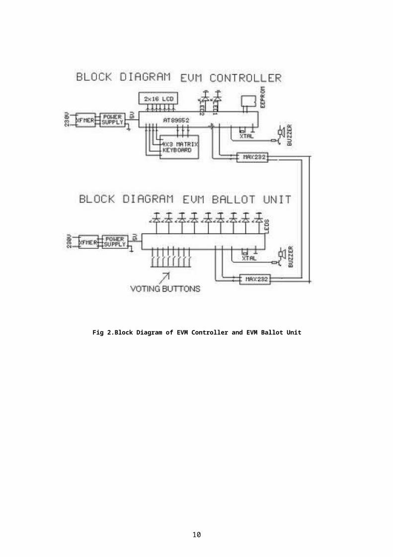
Fig 2.Block Diagram of EVM Controller and EVM Ballot Unit
11
Chapter 3
OBJECTIVEThis project presents a way to develop an electronic votingmachine which displays the count of votes on a 16x2 LCDinterface. A user can get his/her vote register through a set ofswitches. After every cast of vote, the subsequent count can beseen on LCD.The circuit uses microcontroller ATS89C51 and thecode for the project has been written in C. Thus the objectiveof our project is to design a prototype for preferentialelectronic voting machine that serves the election process wherepreferential is conducted with low cost of implementation and tocarry out an highly effective polling process.

12
Chapter 4LITERATURE SURVEY
By Diponkar Paul and Sobuj Kumar Ray,Member,LACSITtheoretically states that Voting is most pivotal process ofdemocratic society through which people determine itsgovernment. Governments around the world are increasinglyconsidering the replacement of traditional paper-based votingschemes with electronic voting systems. Elections ofBangladesh are conducted most exclusively using electronicvoting machines developed over the past three years. In thispaper we describe the design, construction and operation of adigital voting machine using a microcontroller profoundly.Again we also portray counting system of votes, market surveyand cost analysis. This work contributed to three very basicresearch questions arising: in the context of verifiableelections. First, we discussed the problem of keeping ballotsecrecy to a certain extent in the case of a corrupted dotingmachine or voting authority. Our contribution to this is anapproach where all secret information is encapsulated in thevoting machine. Second, we considered the attack of receiptstealing and manipulation of the corresponding votes. Here weproposed a novel approach of linking all receipts by a hashchain such that each single receipt guards the integrity of allreceipts issued previously. Together with a display in thepolling place this approach shortens the time window in whichan adversary can perform the ballot stealing attack without
13
almost zero risk. Third, we discussed in detail the possibilityof contesting an election based on the evidence provided by theverifiable election scheme. We compared the situation for BingoVoting to the evidence provided by paper based schemes. Weshortly sketched an approach to prove an error or a manipulationin the voting booth without violating ballot secrecy. However,this was only a proof of concept and for a practical applicationthe usability of this approach needs to be further improved.
Chapter 5
RELATED THEORY5.1CIRCUIT DIAGRAMCircuit diagram of the Electronic Voting Machine Using 8051 Microcontroller can be seen below:

14
Fig 5.1 Circuit Diagram of Electronic Voting Machine
5.2 IC 8951 MICROCONTROLLER
5.2(a) Introduction to 8951:The AT89C51 is a CMOS 8-bitmicrocomputer with 4K bytes of Flash programmable and erasableread only memory (PEROM). The on-chip Flash allows the programmemory to be reprogrammed in-system or by a ordinary nonvolatilememory programmer. Atmel AT89C51 is a powerfulmicrocomputer/microcontroller (as they are used inter-changeably) which provides a highly-flexible and cost-effectivesolution to many embedded control applications
5.2(b) Features of AT89C51
128 bytes of RAM for storing running program, 32 I/O lines for communicating with other devices,

15
two 16-bit timer/counters, a five vector two-level interrupt architecture, a full duplex serial port, on-chip oscillator and clock
circuitry.
5.2(c) Internal block diagram of 8951 microcontroller
Fig 5.2(c) Internal Block Diagram of 8951 Microcontroller
Central Processor Unit (CPU): CPU is the brain of any processingdevice. It monitors and controls all operations that areperformed in the Microcontroller. User has no control over thework of CPU. It reads program written in ROM memory and executesthem and do the expected task.
Interrupts: Interrupt is a subroutine call thatinterrupts Microcontroller's main operation or work and causesit to execute some another program which is more important atthat time. The feature of Interrupt is very useful as it helps

16
in cases of emergency. Interrupts gives us a mechanism to put onhold the ongoing operation , execute a subroutine and then againresumes normal program execution The Microcontroller 8951 can beconfigured in such a way that it temporarily terminates or pausethe main program at the occurrence of interrupt. When subroutineis completed then the execution of main program starts as usual.There are five interrupt sources in 8951 Microcontroller. 2 ofthem are external interrupts, 2 timer interrupts and one serialport interrupt.
Input/output Port: Microcontroller is used in embedded systemsto control the operation of machines. Therefore to connect it toother machines, devices or peripherals we require I/Ointerfacing ports in Microcontroller. For thispurpose Microcontroller 8951 has 4 input output ports to connectit to other peripherals.
Timers/Counters: Microcontroller 8951 has 2 16 bit timers andcounters. The counters are divided into 8 bit registers. Thetimers are used for measurement of intervals, to determine pulsewidth etc.
Oscillator: Microcontroller is a digital circuit device,therefore it requires clock for its operation. For thispurpose, Microcontroller 8951 has an on-chip oscillator whichworks as a clock source for Central Processing Unit. As theoutput pulses of oscillator are stable therefore it enablessynchronized work of all parts of 8951 Microcontroller.
Bus: Basically Bus is a collection of wires which work as a communication channel or medium for transfer of Data. These buses consist of 8, 16 or more wires. Thus these can carry 8 bits, 16 bits simultaneously. Buses are of two types:You May Also Like: Advantages and Applications of MicrocontrollerAddress Bus, Data Bus
Address Bus: Microcontroller 8051 has a 16 bit address bus. It used to address memory locations. It is used to transfer the address from CPU to Memory.

17
Data Bus: Microcontroller 8051 has 8 bits data bus. It is used to carry data.
5.2(d) Pin Diagram of 8951

18
Fig 5.2(d) Pin Diagram of 8951 Microcontroller
5.2(e) Table: Pin description of 8951
PinNo Function Name
1
8 bit input/output port (P1) pins
P1.02 P1.13 P1.24 P1.35 P1.46 P1.57 P1.68 P1.7

19
9 Reset pin; Active high Reset
10 Input (receiver) forserial communication RxD
8 bitinput/output port(P3) pins
P3.0
11 Output (transmitter) forserial communication TxD P3.1
12 External interrupt 1 Int0 P3.213 External interrupt 2 Int1 P3.314 Timer1 external input T0 P3.415 Timer2 external input T1 P3.5
16 Write to external datamemory Write P3.6
17 Read from external datamemory Read P3.7
18 Quartz crystal oscillator (up to 24 MHz) Crystal 219 Crystal 120 Ground (0V) Ground21
8 bit input/output port (P2) pins/
High-order address bits when interfacingwith external memory
P2.0/ A8
22 P2.1/ A9
23 P2.2/ A10
24 P2.3/ A11
25 P2.4/ A12
26 P2.5/ A13
27 P2.6/ A14
28 P2.7/ A15
29 Program store enable; Read from externalprogram memory PSEN
30Address Latch Enable ALE
Program pulse input during Flashprogramming Prog
31
External Access Enable; Vcc for internalprogram executions EA
Programming enable voltage; 12V (duringFlash programming) Vpp
32 8 bit input/output port (P0) pins
Low-order address bits when interfacingwith external memory
P0.7/ AD7
33 P0.6/ AD6
34 P0.5/ AD5
35 P0.4/ AD4
36 P0.3/ AD3
37 P0.2/ AD2

20
38 P0.1/ AD1
39 P0.0/ AD0
40 Supply voltage; 5V (up to 6.6V) Vcc
5.3 COMPONENT DESCRIPTION
5.3.1 LCD DISPLAY
Fig 5.3.1 LCD Display
Liquid Crystal Display whichis commonly known as LCD is anAlphanumeric Display itmeans that it can displayAlphabets, Numbers as well asspecial symbols thus LCD is auser friendly Display devicewhich can be used for displayingvarious messages unlike sevensegment display which can display only numbers and some of thealphabets. The only disadvantage of LCD over seven segment isthat seven segment is robust display and be visualized from alonger distance as compared to LCD. Here we have used 16 x 2Alphanumeric Display which means it can display two lines withmaximum of 16 characters in one line.
5.3.2 ATS89C51 MICROCONTROLLER
21
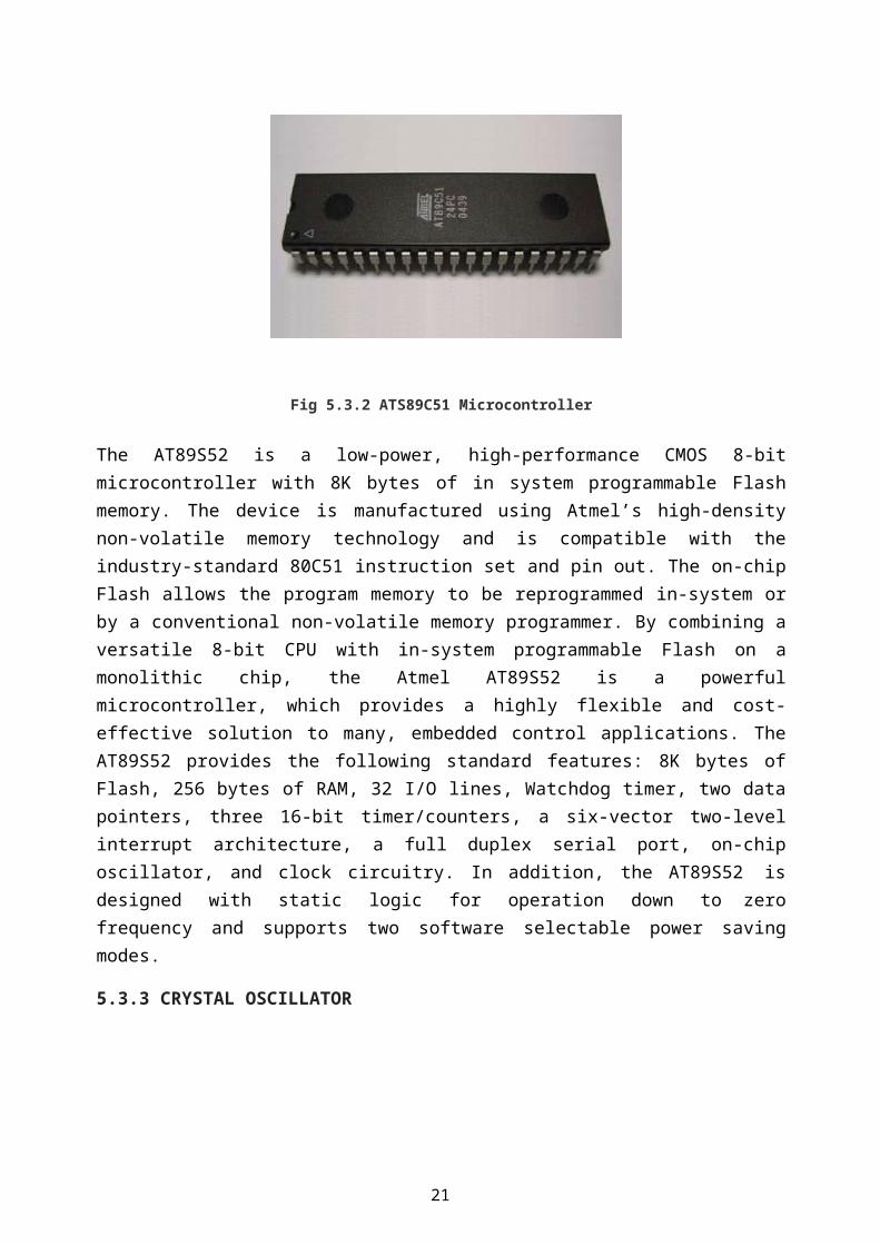
Fig 5.3.2 ATS89C51 Microcontroller
The AT89S52 is a low-power, high-performance CMOS 8-bitmicrocontroller with 8K bytes of in system programmable Flashmemory. The device is manufactured using Atmel’s high-densitynon-volatile memory technology and is compatible with theindustry-standard 80C51 instruction set and pin out. The on-chipFlash allows the program memory to be reprogrammed in-system orby a conventional non-volatile memory programmer. By combining aversatile 8-bit CPU with in-system programmable Flash on amonolithic chip, the Atmel AT89S52 is a powerfulmicrocontroller, which provides a highly flexible and cost-effective solution to many, embedded control applications. TheAT89S52 provides the following standard features: 8K bytes ofFlash, 256 bytes of RAM, 32 I/O lines, Watchdog timer, two datapointers, three 16-bit timer/counters, a six-vector two-levelinterrupt architecture, a full duplex serial port, on-chiposcillator, and clock circuitry. In addition, the AT89S52 isdesigned with static logic for operation down to zerofrequency and supports two software selectable power savingmodes.
5.3.3 CRYSTAL OSCILLATOR
22
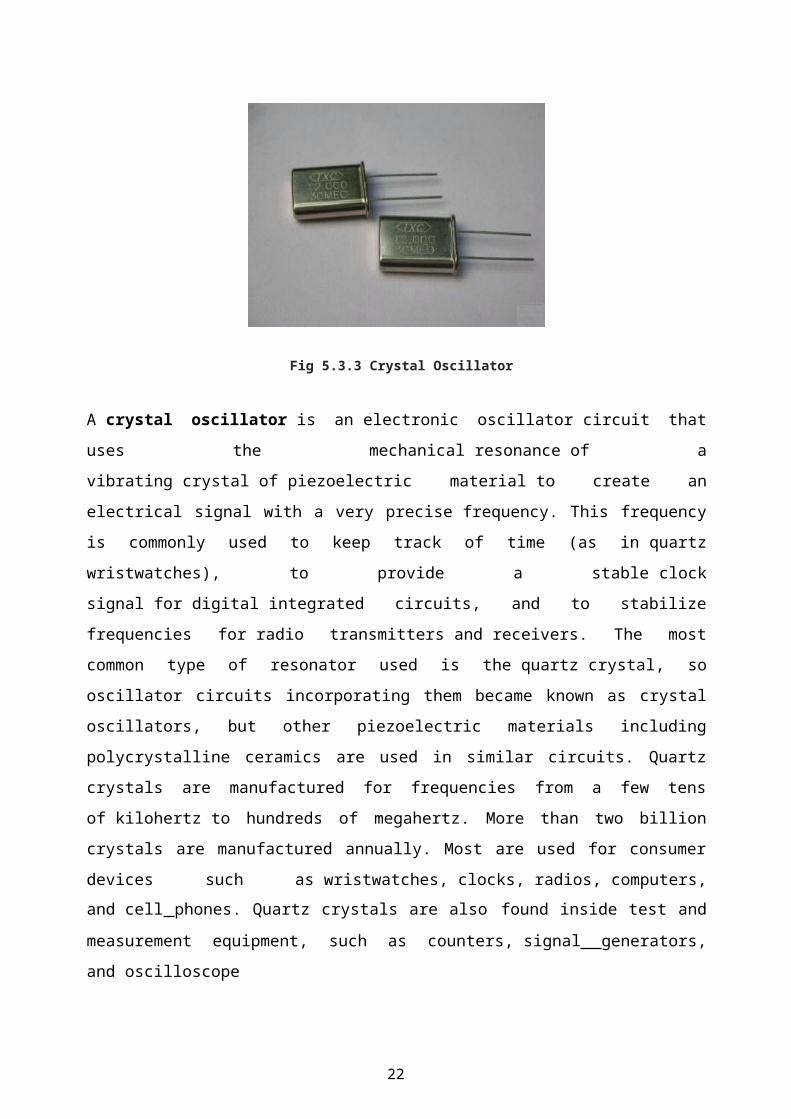
Fig 5.3.3 Crystal Oscillator
A crystal oscillator is an electronic oscillator circuit thatuses the mechanical resonance of avibrating crystal of piezoelectric material to create anelectrical signal with a very precise frequency. This frequencyis commonly used to keep track of time (as in quartzwristwatches), to provide a stable clocksignal for digital integrated circuits, and to stabilizefrequencies for radio transmitters and receivers. The mostcommon type of resonator used is the quartz crystal, sooscillator circuits incorporating them became known as crystaloscillators, but other piezoelectric materials includingpolycrystalline ceramics are used in similar circuits. Quartzcrystals are manufactured for frequencies from a few tensof kilohertz to hundreds of megahertz. More than two billioncrystals are manufactured annually. Most are used for consumerdevices such as wristwatches, clocks, radios, computers,and cell phones. Quartz crystals are also found inside test andmeasurement equipment, such as counters, signal generators,and oscilloscope
23
5.3.4 PUSH BUTTONS
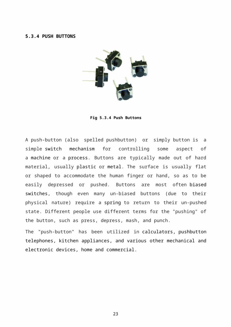
Fig 5.3.4 Push Buttons
A push-button (also spelled pushbutton) or simply button is asimple switch mechanism for controlling some aspect ofa machine or a process. Buttons are typically made out of hardmaterial, usually plastic or metal. The surface is usually flator shaped to accommodate the human finger or hand, so as to beeasily depressed or pushed. Buttons are most often biasedswitches, though even many un-biased buttons (due to theirphysical nature) require a spring to return to their un-pushedstate. Different people use different terms for the "pushing" ofthe button, such as press, depress, mash, and punch.
The "push-button" has been utilized in calculators, pushbuttontelephones, kitchen appliances, and various other mechanical andelectronic devices, home and commercial.

24
5.3.5 PRESET RESISTORS
Fig 5.3.5 Preset Resistors
The resistor whose electrical resistance value can be adjustedas per requirement by adjustable component attached to it iscalled variable resistor. It is an electronic component. It isapplied in an electronic circuit for adjustingcircuit resistance to control voltage or current of that circuitor part of that circuit This is micro version ofvariable resistor. Preset resistors are directly mounted oncircuit board and adjusted only when the circuit is built. Thereis an adjustable screw attached to the resistor and a smallscrewdriver is required to adjust this screw for desiredresistance value. These resistors are quite cheaper thanstandard variable resistor available in the market.

25

26
5.4 PCB LAYOUT
The PCB Layout of the solder side of the circuit has been made using PCB Wizard Software.
(A)Bottom layout
Fig 5.4(a) Bottom Layout
(B) Real world

27
Fig 5.4(b) Real world
5.5 CIRCUIT OPERATION
OPERATION OR WORKING OF CIRCUIT
The voting is started by pressing the Init switch after which the user is prompted to vote. The count of votes is stored in four different variables. As soon as the user votes for a candidate by pressing one of the switches, the value of the corresponding variable is increased by one. After this a Thank you message is displayed on LCD to acknowledge the registration of user’s vote. The message stays on the screen until the next user either presses the Init button to cast another vote or Stopswitch is pressed get the poll results. When the stop button is pressed, the names of the candidates are displayed along with their vote counts. After some delay, the result is displayed which could be either declaration of the winner candidate or thecandidates with a clash of their number of votes. Algorithm shown below as follows:
1] Mode selection:i. Voting mode: toggle switch on VCCii. Counting mode: toggle switch on GND.Voting Mode: When toggle switch is in voting mode “Voting mode” is displayed followed by “Please vote”. After a vote being given, “Please wait for authority switch” is displayed and againenable for voting after Control switch being pressed by the voting Authority.Counting Mode: When toggle switch is in counting mode “Counting mode” in displayed on the screen, and total number of votes to respective candidate can be displayed on the screen by pressing the respective key assigned to them.3] Clear mode: Press clear switch when all entries are required to be erased. Clear switch should be pressed before voting procedure.4] Controller switch: This switch is provided for enabling the

28
keypad in voting mode. This switch is under the control of voting authority.
5.6 SCOPE OF PROJECT
1. It is economical.
2. Less manpower required.
3. Time conscious, as less time required for voting & counting.
4. Avoids invalid voting.
5. Saves transportation cost due to its compact size.
6. Convenient on the part of voter.
7. As a future scope it can be used as a GSM Technology.
5.7 LIMITATIONS
1. Limited no of candidates.
2. More candidates mean implies complicated circuits.
5.8 APPLICATIONS

29
1. This could be used for voting purpose at any required place.
2. It is used in general elections for choosing candidates to represent people at various stages.
3. It can be used to find the general opinion of people on various issues.
4. Anywhere where majority opinion is to be found out.
Chapter 6
TOOLS TO BE USED
(A)SOFTWARE TOOLS
6.A.1 PCB LAYOUT WIZARD SOFTWARE
PCB Wizard is a powerful package for designing single-sided anddouble-sided printed circuit boards (PCBs).It provides acomprehensive range of tools covering all the traditional stepsin PCB production, including schematic drawing, schematic

30
capture, component placement, automatic routing, Bill ofMaterials reporting and file generation for manufacturing.
6. A.2 KEIL SOFTWARE
The Keil 8051 Development Tools are designed to solve the
complex problems facing embedded software developers. When
starting a new project, simply select the microcontroller you
use from the Device Database and the µVision IDE sets all
compiler, assembler, linker, and memory options for you.
Numerous example programs are included to help you get started
with the most popular embedded 8051 devices The Keil µVision
Debugger accurately simulates on-chip peripherals (I²C, CAN,
UART, SPI, Interrupts, I/O Ports, A/D Converter, D/A Converter,
and PWM Modules) of your 8051 device. Simulation helps you
understand hardware configurations and avoids time wasted on
setup problems. Additionally, with simulation, you can write
and test applications before target hardware is available.
6. A.3 PROTEUS SOFTWARE
Proteus 7.0 is a Virtual System Modelling (VSM) that combines
circuit simulation, animated components and microprocessor
models to co-simulate the complete microcontroller based
designs. This is the perfect tool for engineers to test their
microcontroller designs before constructing a physical
prototype in real time. This program allows users to interact
with the design using on-screen indicators and/or LED and LCD
displays and, it attached to the PC, switches and buttons.One of
the main components of Proteus 7.0 is the Circuit Simulation --
a product that uses a SPICE3f5analogue simulatorkernel combined
31
with an event-driven digital simulator that allow users to
utilize any SPICE model by any manufacturer.Proteus VSM comes
with extensive debugging features, including breakpoints,
single stepping and variable display for a neat design prior to
hardware prototyping.In summary, Proteus 7.0 is the program to
use when you want to simulate the interaction between software
running on a microcontroller and any analog or digital
electronic device connected to it. Advantages is (1) real time
simulation.(2) Time and money saving.
6.A.4 PIC KIT
PICkit is a family of programmers for PIC microcontrollers made
by Microchip Technology. They are used to program
and debug microcontrollers, as well as program EEPROM. Some
models also feature logic analyzer and serial communications
(UART) tool. PICkit 2 has been an interesting PIC programmer
from Microchip. It can program most PICs and debug most of the
PICs (as of May-2009, only the PIC32 family is not supported for
MPLAB debugging). Ever since its first releases, all software
source code (firmware, PC application) and hardware schematics
are open to the public. This makes it relatively easy for an end
user to modify the programmer for use with a non-Windows
operating system such as Linux or Mac OS. In the meantime, it
also creates much DIY interest and clones. This open-source
structure brings many features to the PICkit 2 community, such
as Programmer-to-Go, the UART Tool and the Logic Tool, which
have been contributed by PICkit 2 users. Users have also added
such features to the PICkit 2 as 4MB Programmer-to-go

32
capability, USB buck/boost circuits, RJ12 type connectors, and
more. There are many other USB PIC programmers other than the
PICkit series.
(B)HARDWARE TOOLS
6.B.1 COPPER PLATED PCB
Fig 6.B.1 Copper Plated PCB
A printed circuit board (PCB) mechanically supports andelectrically connects electronic components using conductivetracks, pads and other features etched from copper sheetslaminated onto a non-conductive substrate. can be single sided(one copper layer),double sided(two copper layers) or .Conductors on different layers(multi layers) are connected withplated-through holes called via(A via is an electricalconnection between layers in a physical electronic circuit thatgoes through the plane of one or more adjacent layers).Advanced PCBs may contain components - capacitors, resistors oractive devices - embedded in the substrate.
6.B.2 DRILLING MACHINE FOR PCB

33
Fig 6.B.2Drilling Machine for PCB
A compact tabletop High speed PCB drilling machine with a Quickchange Chuck.
Feature:
Drill holding by precision chuck with lapped jaws
Mains operated DC motor Direct drive ( no belt and pulley)
3 Step Speed Control and Illumination of work Area
Specification:
Motor Speed : up to 20,000 R.P.M
Range : 0.6 to 3.0 mm
Base : Metal
Working Area : 280 mm x 170 mm
Electrical Power : 230/ 50Hz, 5 A Socket required
PRECAUTIONS
SOLDERING PRECAUTION

34
The construction was carried out with care. The precautions
taken during the soldering were: The tip of soldering iron was
kept clean with the help of a file from time to time. The
solder wire was of smaller thickness. Extra solder was not
used in order to avoid a cause of short circuit in the
conductive path. The overheating of components was avoided to
prevent component damage as a result of excessive heat on the
components due to the heat from the soldering iron. The leads
of the components were kept clean before soldering, with the
use of sand paper.
COMPONENTS PRECAUTION
I.C should not be heated much while soldering; too much
heat can destroy the I.C. For safety and ease of
replacement, the use of I.C socket is suggested. While
placing the I.C pin no 1 should be made sure at right
hole. Each component should be done neatly.

Chapter 7
CONCLUSION AND FUTURE WORKIn this project, we have described the specification and architecture of a
electronic voting machine .Various fault-tolerance and security issues are
delegated to the platform itself, therefore relieving the application
designer from accommodating these features in the application design
itself. This approach allows for the easy development and deployment of
applications. For quite some time, voting equipment vendors have
maintained that their systems are secure, and that the closed-source
nature makes them even more secure. Our glimpse into the code of such a
system reveals that there is little difference in the way code is
developed for voting machines relative to other commercial endeavours. In
fact, we believe that an open process would result in more careful
development, as more scientists, software engineers, political activists,
and others who value their democracy would be paying attention to the
quality of the software that is used for their elections. (Of course, open
source would not solve all of the problems with electronic elections. It
is still important to verify somehow that the binary program images
running in the machine correspond to the source code and that the
compilers used on the source code are non-malicious. However, open source
is a good start.) Such open design processes have proven successful in
projects ranging from very focused efforts, such as specifying the
Advanced Encryption Standard (AES) [23], through very large and complex
systems such as maintaining the Linux operating System. Australia is
currently using an open source voting system10Alternatively, security

models such as the voter-verified audit trail allow for electronic voting
systems that produce a paper trail that can be seen and verified by a
voter. In such a system, the correctness burden on the voting terminal’s
code is significantly less as voters can see and verify a physical object
that describes their vote. Even if, for whatever reason, the machines
cannot name the winner of an election, then the paper ballots can be
recounted, either mechanically or manually, to gain progressively more
accurate election results. Voter-verifiable audit trails are required in
some U.S. States, and major DRE vendors have made public statements
that they would support such features if their customers required it. The
EVM project an ambitious attempt to create an open-source voting system
with a voter-verifiable audit trail a laudable goal The model where
individual vendors write proprietary code to run our elections appears to
be unreliable, and if we do not change the process of designing our
voting systems, we will have no confidence that our election results will
reflect the will of the electorate. We owe it to ourselves and to our
future to have robust, well-designed election systems to preserve the
bedrock of our democracy.

37
REFERENCES
For a paper in a Proceedings/Transactions/Journal
International Journal of Information and ElectronicsEngineering,Vol 3,No.2,March 2013. By Diponkar Paul and SobujKumar Ray,Member,LACSIT.
For an authored book
1. Muhammad Ali Mazidi-“The 8051 Microcontroller and Embedded Systems”.
2. Ayala- “Introduction to 8051 Microcontroller”.
3.”Architecture and Programming of 8051 Microcontroller” by Milan Verle.
4.”Introduction to Microcontrollers” by Gunther Gridling and Bettina Weiss.
For a website
1. http://grietinfo.in/projects/MINI/EEE/DOC-A.17EVM.pdf
2.http://students.iitk.ac.in/eclub/assets/documentations/summer09/ElectronicVotingMachine.pdf
3. http://www.ijiee.org/papers/295-JI174.pdf
4.http://www.hbeonlabs.com/%20New%20Folder/ELECTRONIC%20VOTING%20MACHINE.pdf

38
APPENDIX
Sr no.
Components
Quantity required
Price(inrupees)
1
LCD Display 1
130
2
MicroprocessorAT89C51
1
45
3
Push Buttons 4
16
4
Crystal Oscillator
1
25
5
Connecting Wires
1
10
6
Preset Resistors
1
10
Total
236
COMPONENT LIST AND PRICE

39