Enhanced Stegano-Cryptographic Model for Secure Electronic Voting
Upload
khangminh22Category
view
3download
0
Strathmore University
SU+ @ Strathmore University Library
Electronic Theses and Dissertations
2015
A mobile web based electronic voting system: a
case study of Strathmore University student
council
Omondi, G. P.
Faculty of Information Technology (FIT) Strathmore University
Follow this and additional works at: https://su-plus.strathmore.edu/handle/11071/2474
Recommended Citation
Omondi, G. P. (2015). A mobile web based electronic voting system : a case study of Strathmore University student
council (Thesis). Strathmore University. Retrieved from http://su-plus.strathmore.edu/handle/11071/4870
This Thesis - Open Access is brought to you for free and open access by DSpace @Strathmore University. It has been accepted for inclusion in Electronic Theses and Dissertations by an authorized administrator of DSpace @Strathmore University. For more information, please contact [email protected]

A Mobile Web Based Electronic Voting System
A Case Study of Strathmore University Student Council
Omondi Gregory Peter
048848
Submitted in partial fulfilment of the requirements for the Degree of Masters of
Science in Mobile Telecommunication Innovation at Strathmore University
Faculty of Information and Technology
Strathmore University
June 2015
This thesis is available for Library use on the understanding that it is copyright material and that no quotation from the thesis may be published without proper acknowledgement.

ii
Declaration
I declare that this work has not been previously submitted and approved for the award of a
degree by this or any other University. To the best of my knowledge and belief, the thesis
contains no material previously published or written by another person except where due
reference is made in the thesis itself.
© No part of this thesis may be reproduced without the permission of the author and Strathmore University
Omondi Gregory Peter
...............................................
June 4th 2015
Approval
The Dissertation of Omondi Gregory Peter was reviewed and approved by the following:
Dr. Joseph Sevilla
Senior Lecturer, Director @iLabAfrica
Strathmore University
Dr. Joseph Orero
Dean, Faculty of Information Technology
Strathmore University
Professor Ruth Kiraka
Dean, School of Graduate Studies
Strathmore University

iii
ACKNOWLEDGEMENT
I would like to convey my sincere gratitude to all those who advised and helped in the course of
my research project. Their efforts made the project a success.
I am deeply indebted to the Almighty God for the knowledge, wisdom and good health during
my research period, without which I would never have made it this far. I will forever adore
you.
I am indebted to Dr. Joseph Sevilla for his tireless efforts in guiding and supervising my
research work. His contributions and constant encouragement made the research project a
success.
I would like to acknowledge the assistance and feedback provided by Samuel Nzuki, Dedan
Kuria and Roy Rutto.
Finally, I am ever so grateful for the on-going love and support of my family.

iv
ABSTRACT
Paper ballot voting system brings with it a number of problems such as: slow rate of counting
and tabulation of casted votes, inaccurate results due to human error, poor presentation of the
ballot papers, inconvenience for the voter to cast a vote, poor participation and turnout, fraud in
polling stations and during the transmission and tabulation of result, increase in spoilt ballot,
increase in the long term costs of production and distribution of ballot papers.
This dissertation aims at the following research objectives: to investigate how electronic voting
systems are implemented around the world, to develop a mobile web based electronic voting
system and to test and evaluate the developed mobile web based electronic voting system.
The dissertation presents a secure mobile web based electronic voting system, a case study of
Strathmore University student council elections. The system is inspired by the Estonian Internet
voting system architecture with major changes; it can be customized and implemented for a
variety of elections such as: large institution elections, party elections, parliamentary elections
or even the national elections.
The mobile web based electronic system is secured by use of secure socket layer protocol,
hashing, public key encryption and secure electronic transmission Protocol. These helped
achieve the following security properties: authenticity, confidentiality, integrity, verification,
and anonymity.
The researcher reviewed relevant literature that was used in designing of the system prototype,
this was then followed by a system testing that aimed at measuring the efficiency, effectiveness,
ease to learn, interactivity and convenience of the system to the voters. The system testing
targeted the Strathmore University students who interacted with the system and filled in
questionnaires. The respondents found the system to be very effective, very efficient, extremely
easy to learn how to use, very good to interact with, very useful and extremely convenient.
v
TABLE OF CONTENTS ACKNOWLEDGEMENT ......................................................................................................................... iii
ABSTRACT ................................................................................................................................................ iv
LIST OF FIGURES ................................................................................................................................... viii
LIST OF TABLES ......................................................................................................................................... x
CHAPTER 1: INTRODUCTION ............................................................................................................... 1
1.1. Background .................................................................................................................................. 1
1.2. Problem Definition ..................................................................................................................... 1
1.3. Research Objectives .................................................................................................................... 2
1.4. Research Questions ..................................................................................................................... 2
1.5. Scope and Limitations ................................................................................................................ 2
1.6. Significance of the Research ...................................................................................................... 2
CHAPTER 2: LITERATURE REVIEW ..................................................................................................... 3
2.1. Voting ........................................................................................................................................... 3
2.1.1. Types of Voting ................................................................................................................... 3
2.1.2. Requirements of a Voting System .................................................................................... 4
2.2. Electronic Voting ......................................................................................................................... 5
2.2.1. Definition of Electronic Voting ......................................................................................... 5
2.2.2. Basic Principles of E-Voting .............................................................................................. 5
2.2.3. Functional Requirement of E-voting Systems ................................................................ 5
2.2.4. Security Requirement of E-voting Systems ..................................................................... 6
2.3. Internet Voting ............................................................................................................................ 7
2.3.1. Internet and Mobile Penetration ....................................................................................... 7
2.4. Implementation of E-voting Worldwide ................................................................................. 7
2.4.1. Estonian E-voting System’s General Concept of E-voting ............................................ 7
2.4.2. Unisys Internet Voting System ....................................................................................... 10
2.4.3. Highly Secure Online Voting System with Multi Security Using Biometric and Stenography ....................................................................................................................................... 12
2.4.4. E-Voting Application Using a Secure Blind Signature ................................................ 15
2.5. Open Web Application Security Project (OWASP) Top 10 Application Security Risks 18
2.6. Security Algorithms .................................................................................................................. 20
2.6.1. Hash Functions .................................................................................................................. 20

vi
2.6.2. Public Key Encryption ..................................................................................................... 20
2.6.3. Secure Electronic Transaction (SET) Protocol ............................................................... 22
2.7. Conclusion ................................................................................................................................. 24
CHAPTER 3: METHODOLOGY ............................................................................................................ 25
3.1. Introduction ............................................................................................................................... 25
3.2. Reviewing Relevant Literature ............................................................................................... 25
3.3. Designing of the Prototype ...................................................................................................... 25
3.4. Testing of the Prototype ........................................................................................................... 25
3.4.1. Target Population ............................................................................................................. 26
3.4.2. Sample Size ........................................................................................................................ 26
3.4.3. Data Collection .................................................................................................................. 27
3.4.4. Data Analysis ..................................................................................................................... 27
3.4.5. Ethical Issues ..................................................................................................................... 27
CHAPTER 4: SYSTEM DESIGN AND ARCHITECTURE .................................................................. 28
4.1. System Analysis ........................................................................................................................ 28
4.1.1. Voter Interacting Component ......................................................................................... 28
4.1.2. Voter Authenticating Component .................................................................................. 28
4.1.3. Votes Storing Component ............................................................................................... 29
4.1.4. Votes Tallying Component .............................................................................................. 29
4.2. System Design ........................................................................................................................... 29
4.2.1. System Architecture ............................................................................................................. 30
4.2.2. Voter Application Component ........................................................................................... 31
4.2.3. Authentication Server Component .................................................................................... 32
4.2.4. Votes Storing Server Component ....................................................................................... 35
4.2.5. Votes Counting Server ......................................................................................................... 38
4.3. Entity Relationship Diagram ................................................................................................... 41
4.4. User Interface Flow Diagram .................................................................................................. 42
CHAPTER 5: SYSTEM IMPLEMENTATION AND TESTING .......................................................... 43
5.1. System Implementation ........................................................................................................... 43
5.1.1. System Specifications ....................................................................................................... 43
5.1.2. Prototype of System .......................................................................................................... 44
5.2. System Testing .......................................................................................................................... 45

vii
5.2.1. The Effectiveness of the System to the User ................................................................. 45
5.2.2. The Efficiency of the Functionalities of the System ..................................................... 46
5.2.3. The Ease to Learn How to Use the System ................................................................... 47
5.2.4. The Interactivity of the Application ............................................................................... 48
5.2.5. The Utility of the Application ......................................................................................... 49
5.2.6. Convenience Brought About by the System ................................................................. 50
CHAPTER 6: DISCUSSION OF RESULTS FROM THE TESTING .................................................... 51
6.1. Effectiveness of the System ..................................................................................................... 51
6.2. Efficiency of the Functionalities of the System ..................................................................... 51
6.3. Ease to Learn of the System ..................................................................................................... 52
6.4. Utility of the System ................................................................................................................. 52
6.5. Interactivity of the System ....................................................................................................... 52
6.6. Convenience of the System ...................................................................................................... 52
6.7. Conclusion ................................................................................................................................. 52
CHAPTER 7: CONCLUSIONS, RECOMMENDATIONS AND FURTHER WORK ...................... 53
7.1. Conclusions ................................................................................................................................ 53
7.2. Recommendations .................................................................................................................... 53
7.3. Further Work ............................................................................................................................. 54
References .................................................................................................................................................. 55
Appendices ................................................................................................................................................ 57
APPENDIX A: USER TESTING QUESTIONNAIRE ....................................................................... 57
APPENDIX B: FRONT END SCREEN SHOTS OF THE SYSTEM ................................................ 60
APPENDIX C: BACKEND SCREEN SHOTS OF THE SYSTEM ................................................... 63

viii
LIST OF FIGURES
Figure 2.1: Envelope Method Diagram (Estonia National Commission Committee, 2005) ............ 8 Figure 2.2: Estonian System General Architecture (Estonia National Commission Committee, 2007) .............................................................................................................................................................. 9 Figure 2.3: E-Voting in Canton Zurich (Beroggi, 2008) ....................................................................... 12 Figure 2.4: Secret Key Generation (Swaninathan& Dinesh, 2012) ..................................................... 13 Figure 2.5: Secret Key Message Generation (Swaninathan& Dinesh, 2012) ..................................... 14 Figure 2.6: Online Voting Flow Chart (Swaninathan& Dinesh, 2012) .............................................. 15 Figure 2.7: E-voting System Architecture (Gupta, Kumar and Chhokar, 2011) .............................. 17 Figure 2.8: Encrypting using the Private Key (Kessler, 1998) ............................................................ 21 Figure 2.9: Encrypting using the Public Key (Kessler, 1998) .............................................................. 21 Figure 2.10: Dual Signature (Kahate, 2008) ........................................................................................... 23 Figure 2.11: Verification (Kahate, 1998) ................................................................................................. 24
Figure 4.1: System Architecture .............................................................................................................. 30 Figure 4.2: Vote Hashing and Encrypting ............................................................................................. 31 Figure 4.3: Double Signature ................................................................................................................... 32 Figure 4.4: Authentication Server Activity Diagram ........................................................................... 33 Figure 4.5: Creating a Salted Hash Password (MacDonald, 2003) .................................................... 34 Figure 4.6: Votes Storing Server Activity Diagram .............................................................................. 36 Figure 4.7: Decryption of the Dual Signature ....................................................................................... 37 Figure 4.8: VIDIMD2 Generating ........................................................................................................... 37 Figure 4.9: Matching VIDIMD to VIDIMD2 ......................................................................................... 38 Figure 4.10: Dual Signature Decryption ................................................................................................ 39 Figure 4.11: Generating VIDIMD2 ......................................................................................................... 39 Figure 4.12: Matching VIDIMD to VIDIMD2 ....................................................................................... 39 Figure 4.13: Verifying Vote ...................................................................................................................... 40 Figure 4.14: Entity Relationship Diagram ............................................................................................. 41 Figure 4.15: User Interface Flow Diagram ............................................................................................. 42
Figure 5.1: Candidate Listing Screen Shot ............................................................................................. 44 Figure 5.2: Effectiveness of the Application to User Column Graph ................................................ 46 Figure 5.3: Efficiency of the Functionalities of the Application Column Graph ............................. 47 Figure 5.4: Ease to Learn How to Use the Application Column Graph ............................................ 48 Figure 5.5: User Experience Pie Chart ................................................................................................... 49 Figure 5.6: User Interface Pie Chart ....................................................................................................... 49 Figure 5.7: Usefulness of the Application Pie Chart ............................................................................ 50 Figure 5.8: Convenience Pie Chart ......................................................................................................... 50

ix
Figure B. 1: Voter Login Screenshot ....................................................................................................... 60 Figure B. 2: Candidate Listing Screenshot ............................................................................................ 61 Figure B. 3: Notification Screenshot ....................................................................................................... 62
Figure C.2: Administration Homepage Screen Shot ............................................................................ 63 Figure C. 3: Voting List Page Screen Shot ............................................................................................. 64 Figure C. 4: Candidate Listing Page Screen Shot ................................................................................. 65 Figure C. 5: Edit Candidate Detail Page Screen Shot .......................................................................... 66 Figure C. 6: Chairman Results Screen Shot ........................................................................................... 66

x
LIST OF TABLES Table 5.2: Software Requirements .......................................................................................................... 43

1
CHAPTER 1: INTRODUCTION
1.1. Background
According to Dwumfuo and Paatey (2011), voting is a method by which groups of people make
decisions. These decisions could be political, social or public. Voting can also be used to choose
between difficult plans of actions or to decide who is best eligible to be awarded a prize. Voting
can thus be defined as a process that allows a group of individuals to choose between a number
of options. Most voting systems are based on the concept of majority rule or plurality.
Voting systems have evolved from traditional paper-based voting system to electronic voting
systems such as Direct-Recording Electronic (DRE) voting systems, pubic network DRE Voting
systems, precinct count voting systems and central count voting systems (Dwumfuo and
Paatey, 2011).
Paper-based Voting Systems (PVS) involves the manual recording, counting and producing a
tabulation of vote count from the votes that were casted on a paper card or sheets (Wolf, 2011).
Security is vital in any voting system, be it traditional paper based voting system or electronic
voting system; this is to avoid any fraud. Security properties such as the authentication,
confidentiality, integrity and non-repudiation should be achieved.
A student government is a student’s organization in either a university or a college that acts as a
link between the students and the administration; they represent the students. Elections for the
student governments are held once in an academic year. Most universities in Kenya still use the
Paper Ballot Voting System that involves manual casting of votes and counting of the casted
votes. Each student has a right to vote; a voter’s card or a student’s identity card maybe used to
identify the voter, but this depends on the Student Government Constitution.
1.2. Problem Definition
Paper ballot voting system brings with it a number of problems such as: the slow rate of
counting and tabulation of casted vote, the process of counting being handled manually may
lead to inaccurate results due to human error, poor presentation of the ballot papers,
inconvenience for the voter who is required to queue and vote at the polling station, poor
participation and turnout, fraud in the polling station and during the transmission and

2
tabulation of result, increase in spoilt ballot papers and increase in the long-term costs of
production and distribution of ballot papers (Wolf, 2011).
1.3. Research Objectives
i. To investigate how electronic voting systems are implemented around the world.
ii. To develop a mobile web based electronic voting system.
iii. To test and evaluate the developed mobile web based electronic voting system.
1.4. Research Questions
i. How are electronic voting systems implemented around the world?
ii. How does a mobile web based system implement electronic voting?
iii. What are the findings of testing and evaluating the developed mobile web based
electronic voting system?
1.5. Scope and Limitations
For the purpose of creating a model of a mobile web based electronic voting system, a case
study of Strathmore University student council was used.
This study assumes that voter registration was completed successful, and the students (voters)
have login credentials to login into the mobile web based electronic voting system and cast an
electronic vote.
The limitation of the study is that voters can only cast votes via an Internet enabled phone that
can access a browser.
1.6. Significance of the Research
The success of this research will ensure the scalability of the mobile web based electronic voting
system to be used in other different types of elections such as: parliamentary elections,
referendums, and the national elections. Its success can also be replicated in other countries.

3
CHAPTER 2: LITERATURE REVIEW
This chapter highlights the definition of voting, the different types of voting, requirements of a
voting system, electronic voting, functional and security requirements of an electronic voting
system, Internet voting, successful electronic voting systems, open web application security
risks, and security algorithms.
2.1. Voting
Voting is a process at the heart of a democratic society. Voting schemes have evolved from
counting hands, to system including paper, punch card, mechanical lever, and optical-scan
machines as stated by Haziemeh, Khazaaleh & Al-talafha (2005)
2.1.1. Types of Voting
Dwumfuo & Paatey (2011) states the following five different types of voting:
1. Paper-based voting system (PVS) – this voting system is also referred to as document
ballot voting system, a voter casts his vote on a ballot paper (paper card or sheets).
Casted votes are counted manually (by hand).
2. Direct Recording Electronic voting system (DRE) - this voting system records votes
by means of a ballot display that a voter activates by the press of a button. The
voting records are then recorded in a removable memory component, and after the
casting of the vote process the DRE produces a tabulation of the voting records.
3. Public network DRE voting system (PNDRE) – this voting system makes use of
electronic ballots and transmits vote data from the polling stations to other locations
over a public network. The votes may be transmitted as individual ballots as they are
cast, or periodically as batches of ballots, or as one single batch, at the end of voting.
4. Precinct voting systems (PCVS) - this voting system puts the ballots in a tabular form
at a particular place (a polling station). It then provides mechanisms that store vote
count electronically and transmit the results to a central location over public
telecommunication networks.
5. Central Count Voting Systems (CCVS) - this voting system tabulates ballots from
multiple precincts at a central location. Voted ballots are safely stored temporarily at
the polling station. These ballots are then transported or transmitted to a central
counting location. CCVSs may, in some cases, produce printed reports on the vote
count.

4
2.1.2. Requirements of a Voting System
According to Gerck (2001), all voting system should satisfy the following requirements, whether
traditional or electronic
1. Fail safe voter privacy – this is assuring the inability to link a voter to a vote.
2. Collusion-free vote secrecy – this is assuring the inability to know what the
casted vote by the voter is.
3. Verifiable election integrity – to verify that no party has influenced the outcome
of the election.
4. Fail – safe privacy in verification – ensuring the voter’s name for each ballot must
not be revealed.
5. Physical recounting and auditing.
6. 100% accuracy – the counting of votes and absence of vote should correctly
count.
7. Represent blank votes – a voter is allowed to change choice at will before casting
the ballot.
8. Prevent over votes.
9. Provide for null ballots – to allow voters to null races or entire ballot as an
option.
10. Allow under votes.
11. Authenticated ballot styles – ballot styles and ballot rotation to be used by each
voter must be authenticated.
12. Manifold of links – must use a manifold of redundant links and keys to securely
define, authenticate and control ballots, also must prevent a single point of
failure.
13. Off-line secure control structure – must provide an off-line secure end-to-end
control structure for ballots.
14. Technology independent – must allow ballots and their control to be used off-
line and/or in dial up and /or in networks.
15. Authenticated user – defined presentation – must enable the ballots to
dynamically support multiple languages, font size and layout so that voter could
choose one that they are comfortable with.

5
16. Open review, open code – Allow all source code to be publicly known and
verified.
2.2. Electronic Voting
2.2.1. Definition of Electronic Voting
Electronic voting (e-voting) is a voting system where the recording, casting and counting of
votes involve information and communication technology (Wolf, 2011).
2.2.2. Basic Principles of E-Voting
The main principle of e-voting must be a replica of the regular voting system as much as
possible, it should be compliant with the election legislation and principles, and be at least
secure as the regular voting. In a nutshell, e-voting must be uniform and secret, only eligible
persons must be allowed to e-vote, a voter should only cast one vote, a voter must not be able to
prove in favour of whom he voted, and the collecting of votes should be secure, reliable and
accountable (Estonia National Election Committee, 2005).
2.2.3. Functional Requirement of E-voting Systems
Brown, Dickinson, Steinebach and Zhang (2003) state the functional requirements of an E-
Voting system are as follows:
1. Voter Registration
§ It must be easy for an individual to register to vote.
§ Individuals must identify themselves, in some way, in order to register.
§ Prior to voting a voter may check his registration status.
§ A voter may register to vote on the day of the election.
2. Casting a Ballot
§ The voters must identify themselves, in some way, in order to vote.
§ The process of casting a ballot should accommodate disabled and
multilingual voters.
§ All possible choices must be displayed on a single screen.
§ Record the selection of individual vote choices for each contest.
§ Indicate that a selection has been made or cancelled.
§ Notify the voter when the selection is completed.

6
§ Before the ballot is cast, the voter is allowed to review his choices and, if he
desires, to delete or change his choices before the ballot is cast.
§ Prevent the voter from over-voting.
§ Notify the voter after the vote has been stored successfully that the ballot has
been cast.
§ Incorporate a visual indication of system status.
3. Tallying the Ballots
§ An unofficial in-precinct vote tally will occur once the polls have officially
closed.
§ Votes will also be transferred to a central location to be officially tallied.
4. Certifying the Vote
§ The number of votes cast should be consistent with number of voters.
§ If a discrepancy exists, the audit trail should provide information regarding a
voter’s intent.
§ Recounts must be possible.
2.2.4. Security Requirement of E-voting Systems
According to Gritzali (2002), for the e-voting system to function properly it should ensure error-
free and robust electronic voting over the Internet, it must satisfy the following criteria.
i. Eligibility - only eligible voters can vote and no one votes twice.
ii. Anonymity - any traceability between the voter and his vote must be removed.
iii. Verifiability - a voter is able to verify that his or her vote is counted in the final tally. So
also a passive observer can check that the election is fair; the published final tally is
really the sum of the votes.
iv. Fairness - no one should be able to compute a partial tally as the election progresses.
v. Coercibility - no one can use force or compel anybody to vote.
vi. Receipt-freeness - a voter cannot prove that he or she voted in a certain way.
vii. Privacy - no coalition of participants (of reasonable composition), not even the voter
himself can gain any information about the voter’s vote. By reasonable composition it
means coalition of at most authorities and any number of voters.
viii. Robustness - faulty behaviour of any reasonably sized coalition of participants can be
tolerated. No coalition of voters can disrupt the election and any cheating voter will be
detected.

7
2.3. Internet Voting
James (2011) defines Internet voting as a voting method that transmits voted ballots via the
public Internet through a web browser or client application accessed through an interconnected
personal computer, smart phone or tablets. He further classifies Internet voting into two types,
these are on-site Internet (Internet voting is conducted at controlled settings such as a voting
place where officials can authenticate voters to ensure integrity) and remote Internet voting
(allows voter to transmit their ballot to any Internet connection which they have access).
2.3.1. Internet and Mobile Penetration
The penetration of Mobile and Internet services in Kenya has been phenomenal. The
Communication Commission of Kenya (2012) points out that the Mobile market has continued
to rise. Telephony subscriptions have increased by 490,000 to 29.7 million subscribers from 29.21
million subscribers who were reported in the previous quarter. This represents a country
mobile penetration rate of 75.4%. Internet penetration in Kenya rose to 35.5% of the
population. 46% of the current available bandwidth is in use – 98.9% of this access from mobile
devices.
2.4. Implementation of E-voting Worldwide
2.4.1. Estonian E-voting System’s General Concept of E-voting
According to Estonia National Election Committee (2007), the Estonian government provides all
citizens aged 15 years and above with a National Identity (ID) card containing a digital
signature; it is used to provide a high level authentication to the Estonian Internet voting
system. The national ID contains a personal data file, a digital certificate for authentication and
a digital certificate for digital signature.
The requirement for a voter to cast a vote is the National ID with the correct PIN codes; this is
interfaced with the voter’s personal computer via a smart card reader.
Steps taken to cast a vote are as follows:
i. The voter inserts the ID-card into card reader and opens the webpage for voting
(http://www.valimised.ee).
ii. The voter verifies him/herself using the PIN1 of ID-card.
iii. The server checks if the voter is eligible (using the data from population register).
iv. The voter is shown the candidate list of the appropriate electoral district.

8
v. The voter makes his/her voting decision, which is encrypted.
vi. The voter confirms his/her choice with a digital signature (by entering the PIN2-code).
vii. At the vote count the voter's digital signature is removed and at the final stage the
members of the National Electoral Committee can collegially open the anonymous e-
Votes and count them.
According to Estonia National Commission Committee (2005) this concept is similar to the
envelope method (used during advance polls to allow voting outside of the polling place of
voter’s residence) whereby an E-voter creates during the voter procedures an inner envelope
(which is essentially an encrypted vote) and outer envelope (which is essentially a digital
signature).
Figure 2.1 shows the envelope method concept used by the Estonia electronic voting system.
Figure 2.1: Envelope Method Diagram (Estonia National Commission Committee, 2005)
Through the application, the voter encrypts his vote with the system’s public key and signs the
result digitally (public key cryptography).
Casted votes are then collected, sorted and voter’s eligibility is verified and invalid votes are
removed.
Outer envelopes are then separated from inner envelopes; voter lists are compiled from outer
envelopes. Inner envelopes are forwarded to the vote-counter (which has the system’s private
key) that outputs the summed results of e voting.
Figure 2.2 shows the system architecture of the Estonian E-Voting System; the following are the different parties of the Architecture.

9
Figure 2.2: Estonian System General Architecture (Estonia National Commission Committee,
2007)
i. Voter – A voter with his/her Personal Computer (P.C.) creates an encrypted and
digitally signed vote and sends it to the Central System.
ii. Central System – System component that is under the responsibility of the National
Election Committee. Receives and processes the votes until the composite results of e
voting are output.
iii. Key Management – Generates and manages the key pair(s) of the system. The public
key (keys) is integrated into Voter’s applications; private key(s) are delivered to Vote
Counting Application.
iv. Auditing – solves disputes and complaints, using logged information from the Central
System.
The Central System is dependent of two other parties:
i. Compiler of voter lists (The Population Register),
ii. Compiler of candidate lists (NEC itself).
The following are the components of the Central System:

10
i. Vote Forwarding Server (VFS) – authenticates the voter with the means of identity
card, displays the candidates of voter’s constituency to the voter and receives the
encrypted and digitally signed e-vote. The e-vote is immediately sent to the Vote
Storage Server and the confirmation received from there is then forwarded to the
voter. It finishes its work after the close of advance polls.
ii. Vote Storage Server (VSS) – receives e-votes from the VFS and stores them. After
the close of advance polls removes double votes, cancels the votes by ineligible
voters and receives and processes e-vote cancellations. Finally it separates inner
envelopes from outer envelopes and readies them for the Vote Counting
Application.
iii. Vote Counting Application (VCA) – offline component to which encrypted votes
are transmitted with the digital signatures removed. The Vote Counting Server uses
the private key of the system, tabulates the votes and outputs the results of e voting.
2.4.2. Unisys Internet Voting System
According to Giampiero (2008), Zurich used a voting system called the Unisys Internet voting
system that was launched in 2002, this system was first used in a student election, after its
success it was subsequently used in the public election in Bulach in 2005. One could either vote
via a personal computer or via SMS, but later on in 2007 the SMS channel was discontinued.
The voting system uses two step encryption process, a casted vote is encrypted on the computer
that the voter used to cast the vote, and then it is received by the central server which decrypts
it to check for its structure and integrity then perform the second encryption on it.
Steps taken to cast a vote were as follows:
i. The voter navigates to the appropriate web address
ii. The voter inputs the voter identification number
iii. The voter makes the ballot selections
iv. The voter casts the ballot
v. The voter enters the personal identification number
vi. The voter finally compares the security symbol with the symbol the voter
received in the mail
According to Beroggi (2008), the e-voting system’s security requirements are based on the
Information Security Management System (BS7799). Data exchange between the communities

11
and the e-voting system is based on the Secure Data Exchange Platform (SeDAP), which is
based on the Online Services Computer Interface (OSCI) standard, which in turn is based on
SOAP. All entries into the e-voting system voter identification and authentication as well as
voter rights occur through a secure entry server, which ensures that only registered voters can
vote.
Both the votes of the citizens through the Internet and the files containing the names of citizens
eligible to vote are transmitted through the network using the Secure Sockets Layer (SSL)
protocol. The confidentiality of voter access codes and passwords is of utmost importance, so
Canton Zurich uses three independent companies to print these. After the system identifies the
access codes and the voters cast their votes, the system immediately asks them to validate their
vote by entering their birth date and a six-digit numerical identification code. The system
accepts their votes only after validation.
Encryption occurs in two steps. The voter’s client computer first encrypts the votes and
identification and authentication characteristics through an SSL channel. The e-voting system
then checks the incoming votes for their structure and integrity before once again encrypting
them and passing them to the high-security zone. Two redundant systems store the votes on a
write-once, read-multiple-times database.
For every election and referenda event, Canton Zurich’s Statistical Office uses a virtual
community to cast votes and then checks that the e-system properly recorded them. It also
analyses the citizens’ votes, making sure that the sum of the validated codes during e-voting
equals the sum of received electronic votes.
These two plausibility checks must match perfectly and have zero tolerance for the electronic
voting to be trustworthy.
The separate encryption and storage of cast votes and names of citizens eligible to vote ensures
that vote counts are accurate and keeps voting rights from being corrupted.
Figure 2.3 shows a flow diagram of the Canton Zurich electronic voting system.

12
Figure 2.3: E-Voting in Canton Zurich (Beroggi, 2008)
2.4.3. Highly Secure Online Voting System with Multi Security Using Biometric and
Stenography
According to Swaninathan and Dinesh (2012), to cast a vote, a voter logs into the system by
entering the personal identification number and secret key. Along with this voter has to give the
thumb impression on the fingerprint sensor.
13
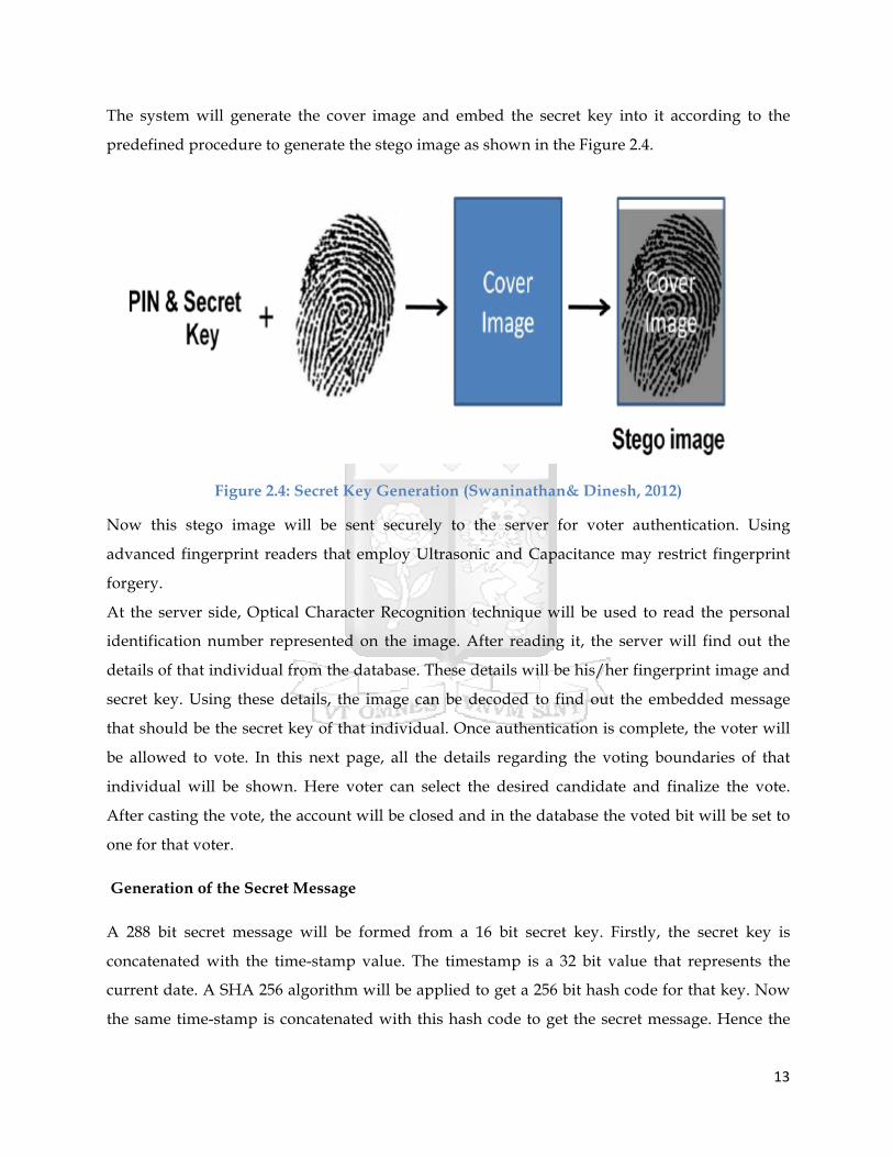
The system will generate the cover image and embed the secret key into it according to the
predefined procedure to generate the stego image as shown in the Figure 2.4.
Figure 2.4: Secret Key Generation (Swaninathan& Dinesh, 2012)
Now this stego image will be sent securely to the server for voter authentication. Using
advanced fingerprint readers that employ Ultrasonic and Capacitance may restrict fingerprint
forgery.
At the server side, Optical Character Recognition technique will be used to read the personal
identification number represented on the image. After reading it, the server will find out the
details of that individual from the database. These details will be his/her fingerprint image and
secret key. Using these details, the image can be decoded to find out the embedded message
that should be the secret key of that individual. Once authentication is complete, the voter will
be allowed to vote. In this next page, all the details regarding the voting boundaries of that
individual will be shown. Here voter can select the desired candidate and finalize the vote.
After casting the vote, the account will be closed and in the database the voted bit will be set to
one for that voter.
Generation of the Secret Message
A 288 bit secret message will be formed from a 16 bit secret key. Firstly, the secret key is
concatenated with the time-stamp value. The timestamp is a 32 bit value that represents the
current date. A SHA 256 algorithm will be applied to get a 256 bit hash code for that key. Now
the same time-stamp is concatenated with this hash code to get the secret message. Hence the

14
secret message will be of 288 bit length. As the actual secret key is never embedded in the stego
image, there will be no chance of predicting secret key from it. The mechanism is shown in
Figure 2.5.
Figure 2.5: Secret Key Message Generation (Swaninathan& Dinesh, 2012)
Figure 2.6 shows the flow of the authenticating process of a voter. Once any individual passes
the authenticity criteria, he/she will be logged into his/her voting account. The voter can easily
be restricted from logging into his/her voting account more than once during elections. Once a
particular voter is authenticated by the system, a secure channel will be established using https
and then he/she will be able to cast the vote. The vote will remain secret in every sense, i.e., it
will not be reflected anywhere in the database that which user has voted for whom. Finally, the
account will be closed and that user will not be able to log back in by any means again. This
completes the voting process.

15
Figure 2.6: Online Voting Flow Chart (Swaninathan& Dinesh, 2012)
2.4.4. E-Voting Application Using a Secure Blind Signature According to Gupta, Kumar & Chhokar (2011), on their research, they proposed an E-Voting
System, E-Voting, which applies security mechanisms in order to achieve the four security
requirements (confidentiality, integrity, authentication and verifiability) needed for any election
process. In the system, voter’s privacy was guaranteed by using a blind signature for
confidentiality and voter’s digital signature for voter’s authentication.
Digital signature is used to authenticate that the message comes from a particular sender.
Attaching a code that acts as a signature does this. This signature guarantees the source the

16
integrity of the message. In E-Voting, digital signature is created by using RSA encryption. The
process begins with the hashing of the message, M, to produce a message digest, H. The digest
is then encrypted using the sender’s private key (n,d) to produce the signature, S.
S =Hd mod n
To verify the message, the receiver will hash the message, M by using the same digest function.
At the same time, the signature, S is decrypted using the receiver’s public key.
H = Se mod n
The results of the two processes are then compared. If they are equal then the message is
authenticated and the integrity of the message is maintained.
Fujioka, Okamoto & Ohta (1993) stated that Blind signature is most popular cryptographic
technique in E-Voting System by providing confidentiality of the voter’s ballot .The signature is
used to authenticate the voter without disclosing the content of a ballot.
Hence the authority whose function is to verify the eligibility of a voter will not know whom a
voter votes for.
In E-Voting, a ballot is blinded in order to achieve its confidentiality requirement. A voter is
required to get the signature of a validator when he votes. To ensure the secrecy of his ballot, a
voter casts a ballot, E, blinds a ballot using a random number and sends it to the validator. Let
(n,e) be the validator’s public key and (n, d) be his private key. A voter generates a random
number r such that gcd(r, n) = 1 and sends the following to the validator:
B’=re B mod n.
The random number r conceals the ballot from the validator. The validator then signs the
blinded ballot after verifying the voter. The signed value is as follows:
S’= (B’) d =r Bd mod n
After receiving the validated ballot, the voter unblinds the ballot, to get the true signature, S of
the validator for the ballot, by computing,
S=S’ r-1 mod n=Bd

17
Figure 2.7 shows the system architecture of the secure blind signature electronic voting system.
Figure 2.7: E-voting System Architecture (Gupta, Kumar and Chhokar, 2011)
Voter Registration
In any election, an individual must register to be an eligible voter. This is done before the voting
period. Voter registration for E-voting is done as follows:
i. Voter sends his name and national identity card (Nric) number to the registrar server.
The message is encrypted before transmitting through the network.
ii. Registrar server checks the user’s particulars with the national registration database to
determine the eligibility of a voter and his precinct.
18
iii. If a voter is eligible, the system will generate RSA key-pair.
The public key is stored in the E-Voting database while the private key is stored in a voter’s
diskette protected by his chosen password.
Voting
In voting stage, a voter must send a ballot to both Validator and Tallier. The process of voting is
described below:
§ Voter sends his name and Nric to the Validator.
§ Validator checks the eligibility of the voter and whether he or she has voted before. If
the voter is a valid voter, Validator will obtain the precinct number of the voter and send
him the ballot. Each ballot has a unique id.
§ The voter casts his ballot and the ballot is then blinded, signed, encrypted and sent to
the Validator to be validated.
§ Validator signed the blinded ballot after verifying the voter. The signed blinded ballot is
sent back to the voter.
§ Voter checks the integrity of the ballot by unblinding the validated ballot and compares
it with the original one.
§ The validated ballot and the original ballot are sent to the tallier. The communication is
protected by a session key that has been agreed when the connection is set up.
§ The tallier checks the validity of the ballot using Validator’s public key. The validated
ballot is stored in the E-Voting database.
2.5. Open Web Application Security Project (OWASP) Top 10 Application Security
Risks
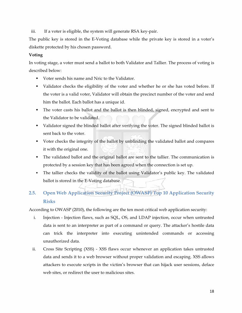
According to OWASP (2010), the following are the ten most critical web application security:
i. Injection - Injection flaws, such as SQL, OS, and LDAP injection, occur when untrusted
data is sent to an interpreter as part of a command or query. The attacker’s hostile data
can trick the interpreter into executing unintended commands or accessing
unauthorized data.
ii. Cross Site Scripting (XSS) - XSS flaws occur whenever an application takes untrusted
data and sends it to a web browser without proper validation and escaping. XSS allows
attackers to execute scripts in the victim’s browser that can hijack user sessions, deface
web sites, or redirect the user to malicious sites.

19
iii. Broken Authentication and Session Management - Application functions related to
authentication and session management are often not implemented correctly, allowing
attackers to compromise passwords, keys, session tokens, or exploit other
implementation flaws to assume other users’ identities.
iv. Insecure direct object references - A direct object reference occurs when a developer
exposes a reference to an internal implementation object, such as a file, directory, or
database key. Without an access control check or other protection, attackers can
manipulate these references to access unauthorized data.
v. Cross Site Request Forgery - A CSRF attack forces a logged-on victim’s browser to send
a forged HTTP request, including the victim’s session cookie and any other
automatically included authentication information, to a vulnerable web application. This
allows the attacker to force the victim’s browser to generate requests the vulnerable
application thinks are legitimate requests from the victim.
vi. Security Misconfiguration - Good security requires having a secure configuration
defined and deployed for the application, frameworks, application server, web server,
database server, and platform. All these settings should be defined, implemented, and
maintained, as many are not shipped with secure defaults. This includes keeping all
software up to date, including all code libraries used by the application.
vii. Insecure Cryptographic Storage - Many web applications do not properly protect
sensitive data, such as credit cards, SSNs, and authentication credentials, with
appropriate encryption or hashing. Attackers may steal or modify such weakly
protected data to conduct identity theft, credit card fraud, or other crimes.
viii. Failure to Restrict URL Access - Many web applications check URL access rights before
rendering protected links and buttons. However, applications need to perform similar
access control checks each time these pages are accessed, or attackers will be able to
forge URLs to access these hidden pages anyway.
ix. Insufficient Transport Layer Protection - Applications frequently fail to authenticate,
encrypt, and protect the confidentiality and integrity of sensitive network traffic. When
they do, they sometimes support weak algorithms, use expired or invalid certificates, or
do not use them correctly.
x. Invalidated Redirects and forwards - Web applications frequently redirect and forward
users to other pages and websites, and use untrusted data to determine the destination

20
pages. Without proper validation, attackers can redirect victims to phishing or malware
sites, or use forwards to access unauthorized pages.
2.6. Security Algorithms
2.6.1. Hash Functions According to Kessler (1999), Hash functions are also called message digests; it is a one-way
encryption algorithm that does not use a key. It computes a fixed-length hash value based upon
the plaintext that makes it impossible for either the contents or length of the plaintext to be
recovered.
Hash algorithms are typically used to provide a digital fingerprint of a file’s content, often used
to ensure that the file has not been altered/ tampered with, it provides integrity.
2.6.2. Public Key Encryption
Public key Cryptography is a cryptography approach that involves the use of asymmetric key
algorithms, where the key used to encrypt a message is not the same as the key used to decrypt
it. Each user has a pair of cryptographic keys, a public encryption key and a private decryption
key. The publicly available encrypting key is widely distributed, while only recipient knows the
private decrypting key (Kessler, 1998).
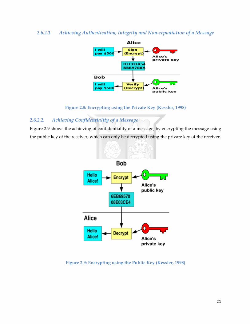
Figure 2.8 shows the achieving of authenticity, integrity and non-repudiation of the message by
encrypting the message using the private key of the sender, which can be decrypted using the
public key of the sender.
21
2.6.2.1. Achieving Authentication, Integrity and Non-repudiation of a Message
Figure 2.8: Encrypting using the Private Key (Kessler, 1998)
2.6.2.2. Achieving Confidentiality of a Message
Figure 2.9 shows the achieving of confidentiality of a message, by encrypting the message using
the public key of the receiver, which can only be decrypted using the private key of the receiver.
Figure 2.9: Encrypting using the Public Key (Kessler, 1998)

22
2.6.3. Secure Electronic Transaction (SET) Protocol
According to Kahate (2008), Secure Electronic Transaction (SET) is an open encryption and
security specification that is designed for protecting credit card transactions on the Internet. The
following are the parties involved in a SET transaction:
1. Cardholder - is an authorized holder of a payment card such as MasterCard or Visa that
has been issued by an Issuer.
2. Merchant - is a person or an organization that wants to sell goods or services to
cardholders. A merchant must have a relationship with an Acquirer for accepting
payments on the Internet.
3. Issuer: The issuer is a financial institution that provides a payment card to a cardholder.
The most critical point is that the issuer is the ultimately responsible for the payment of
the cardholder’s debt.
4. Acquirer: This is a financial institution that has a relationship with merchants for
processing payment card authorizations and payments. The acquirer provides the
merchant an assurance (with the help of the issuer) that a particular cardholder account
is active and that the purchase amount does not exceed the credit limits. The acquirer
also provides electronic funds transfer to the merchant account. Later, the issuer
reimburses the acquirer using some payment network.
5. Payment Gateway: The payment gateway processes the payment messages on behalf of
the merchant. Specifically in SET, the payment gateway acts as an interface between SET
and the existing card payment networks for payment authorizations.
6. Certification Authority (CA): This is an authority that is trusted to provide public key
certificates to cardholders, merchants and payment gateways.
The SET protocol makes use of the concept of dual signature. Figure 2.10 shows the
dual signature concept.

23
Figure 2.10: Dual Signature (Kahate, 2008)
The cardholder takes the Payment Information (PI), containing the cardholder’s credit card
number, expiry date, etc. and hashes (digests) it to produce Payment Information Message
Digest (PIMD).
Similarly, the cardholder digests the Order Information (OI) to obtain Order Information
Message Digest (OIMD). Then it combines PIMD and OIMD to produce Payment and Order
Message Digest (POMD).
The cardholder then encrypts the POMD with its private key. The output of this process is the
Dual Signature (DS). It is called dual, because it has inputs coming from PI as well as OI.
The cardholder now sends:
1. OI, PIMD, and DS to the merchant
2. PI, OIMD, and DS to the payment gateway
As we can see, the merchant does not get access to PI, and hence, cannot know the cardholder’s
credit card number. However, it has access to OI to process the order. Also, to validate the
cardholder’s order, the merchant decrypts the DS using the cardholder’s public key to obtain
the first POMD; and separately combine OIMD and PIMD to also compute the second POMD. If
the two POMD values match, the merchant is happy that the order was indeed sent by the
cardholder.

24
Figure 2.11 shows the validation of the cardholder’s order.
Figure 2.11: Verification (Kahate, 1998)
2.7. Conclusion
Out of all the electronic voting systems that the researcher reviewed; he settled on the Estonia
Internet Voting Architecture, this is because the system has proven to be successful in terms of
security over several years of elections including the last Estonia Elections. The Estonia Voting
System being Internet Voting, it really fits well in the context of the study.
The researcher also ensured that he adheres to the reviewed electronic voting functional and
security requirements.

25
CHAPTER 3: METHODOLOGY
3.1. Introduction According to Industrial Research Institute (2010), if we think of the word “Methodology” it is
the way of searching or solving the research problem.
The research methodology aimed at answering the following research questions:
• How does a mobile web based system implement electronic voting?
• What are the findings of testing and evaluating a developed mobile web based
electronic voting system?
3.2. Reviewing Relevant Literature The researcher did a review of the literature, this focused on the following: the definition of
voting and electronic voting, types of voting systems, the requirements of a voting system,
electronic voting system, the basic principles of an electronic voting system, functional and
security requirement of a voting system, Internet voting, the implementation of electronic
voting systems around the world, security risks in web applications and finally relevant
electronic voting security algorithms.
3.3. Designing of the Prototype The database of the prototype was designed using Entity Relational Diagrams, which according
to Rouse (2007) it is a data modelling technique that creates a graphical representation of the
entities, and the relationships between entities, within an information system.
The functional processes were designed using Unified Modelling Language, Activity Diagrams
to be specific. In Unified Modelling Language, an activity diagram is used to display the
sequence of activities. Activity diagrams show the workflow from a start point to the finish
point detailing the many decision paths that exist in the progression of events contained in the
activity (Sparx Systems, 2014).
3.4. Testing of the Prototype The researcher carried out a prototype test through a survey to achieve the following objectives:
• To measure the effectiveness of the functionalities of the prototype to the users.
• To measure the efficiency of the functionalities of the prototype to the users.
• To measure the interactivity of the prototype to the users.

26
• To measure the ease of learning on how to use the prototype by the users.
• To measure the utility of the prototype to the users.
• To measure the convenience brought about by the prototype during casting of votes by
the users.
3.4.1. Target Population Students from different faculties and schools in Strathmore University formed the population of
this research. Strathmore University has the following schools and faculties; School of
Accountancy, Faculty of Information Technology, School of Law, Strathmore Business School,
School of Finance and Applied Economics, School of Management and Commerce, and School
of Humanities and Social Studies. The population was as follows (2013); postgraduate 333,
undergraduate 2,436, professional and Diploma 1,968 and accumulative it was at 4,737.
3.4.2. Sample Size According Krejcie and Morgan (1970), National Education Association published a formula to
calculate the sample size of a population. The following is the sample size formula:
Whereby: -
S= required sample size.
X2 = the table value of chi-square for 1 degree of freedom at the desired confidence level
(3.841).
N = the population size.
P = the population proportion (assumed to be 0.50 since this would provide the maximum
Sample size).
d = the degree of accuracy expressed as a proportion (0.05).
From the formulae, the target population size (N) = 4,737, gave a sample size of 356. This was
the sample size that was used in the carrying out the survey.

27
3.4.3. Data Collection The researcher employed both quantitative and qualitative research techniques to collect data.
The User Testing Questionnaires (Appendix A) were disbursed to students from different
schools and faculties in Strathmore University.
Both open-ended and close-ended questions were used in the questionnaires. The questions
were carefully drafted to achieve the objectives and provide satisfactory information for
answering the research.
3.4.4. Data Analysis The researcher used statistical tools that included MS Excel 2007 to analyse the data. The
findings were tabulated to compute and summarize figures. Charts and graphs were used to
present the data for ease of interpretation.
3.4.5. Ethical Issues The following are the ethical consideration that the researcher adhered to:
• Permission to carry out the research was obtained from Strathmore University.
• Researcher assuring all the study respondents that information been sought is purely for
academics purposes only.
• That no identifying information about the participants would be revealed and the
information they provide to the researcher would be treated in a confidential manner.
• The collected data will be available and of benefit to any interested party.

28
CHAPTER 4: SYSTEM DESIGN AND ARCHITECTURE
4.1. System Analysis After the researcher had reviewed different electronic voting systems implemented globally, he
acknowledged five key components that make an electronic voting system. These components
are:
1. A component that the voter interacts with to perform the following functionalities: to
login, to select candidate, and to cast a vote.
2. A component that authenticates the voter’s login credentials.
3. A component that sends a candidate listing to an authorized voter to select the preferred
candidates and cast a vote.
4. A component that stores the casted votes.
5. A component that tallies the casted votes.
The researcher looked into the security requirements of the five key components.
4.1.1. Voter Interacting Component The voter interacts with the electronic voting system through this component, for the voter to
access the services of this component; the voter must be authorized. The services of this
component are such as voter login, candidate selection and vote casting. This component
should ensure that the casted ballots are transmitted securely:
• To ensure that no one can read the casted vote except the intended receiver, in this case
the component that will tally the votes.
• To ensure that the casted votes would not be tampered or altered with during
transmission from one component to another.
• To ensure the identity of the voter who casted the ballot can be proved.
4.1.2. Voter Authenticating Component The Voter Authenticating Component’s key role is to authenticate the voter as valid, this
component also receives the casted ballot from the Voter Interacting Component and forwards
it to the Votes Storing Component, and hence the Voter Authenticating Component should not
be able:
• To read the casted vote details.

29
• To tamper or alter the casted vote details.
4.1.3. Votes Storing Component The Votes Storing Component’s key roles are to prevent the voter from double voting, to verify
that the casted vote is valid, and finally to store all the valid casted votes and forward (after the
election period elapses) them to the component that will tally the valid votes. Similar to the
Votes Authenticating Component, the Votes Storing Component should not be able:
• To read the casted vote details. • To tamper or alter the casted vote details.
4.1.4. Votes Tallying Component The Votes Tallying Component’s key roles is to tally the votes, before performing its key role,
this component should:
• Be able to verify that the received casted votes have not been read during transmission
through the network and the other components of the system.
• Be able to verify that the received casted votes have not been altered during
transmission through the network and the other components of the system.
• Be able to verify the identity of the voter who casted the vote.
4.2. System Design After reviewing a number of E-Voting Systems, the researcher settled on Estonia E-Voting System, Estonia is one of the few countries that use an Internet Voting System. The researcher used the same framework with major changes to develop the Mobile Web Based Electronic Voting System.
30
4.2.1. System Architecture
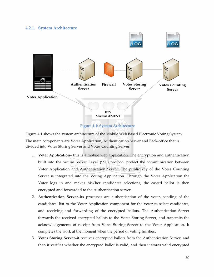
Figure 4.1: System Architecture
Figure 4.1 shows the system architecture of the Mobile Web Based Electronic Voting System.
The main components are Voter Application, Authentication Server and Back-office that is divided into Votes Storing Server and Votes Counting Server.
1. Voter Application– this is a mobile web application. The encryption and authentication
built into the Secure Socket Layer (SSL) protocol protect the communication between
Voter Application and Authentication Server. The public key of the Votes Counting
Server is integrated into the Voting Application. Through the Voter Application the
Voter logs in and makes his/her candidates selections, the casted ballot is then
encrypted and forwarded to the Authentication server.
2. Authentication Server–its processes are authentication of the voter, sending of the
candidates’ list to the Voter Application component for the voter to select candidates,
and receiving and forwarding of the encrypted ballots. The Authentication Server
forwards the received encrypted ballots to the Votes Storing Server, and transmits the
acknowledgements of receipt from Votes Storing Server to the Voter Application. It completes the work at the moment when the period of voting finishes.
3. Votes Storing Server–it receives encrypted ballots from the Authentication Server, and
then it verifies whether the encrypted ballot is valid, and then it stores valid encrypted
Voter Application
Authentication Server
Firewall Votes Storing Server
Votes Counting Server
KEY MANAGEMENT
31
ballots until the end of voting period, finally it forwards them to the Votes Counting
Server. Votes Storing Server has a responsibility of votes managing. 4. Votes Counting Server– it is an offline server, which summarizes all encrypted ballots.
The encrypted ballots are transferred from Votes Storing Server to Votes Counting
Server. Votes Counting Server uses its private key to decrypt the encrypted ballots then
tabulates the votes and outputs the results of Electronic Voting.
5. Key Management – It generates and manages the key pairs (s) of the system. The Public
Key (keys) is integrated into Voter’s Application; private key(s) are delivered to Vote
Counting Server.
4.2.2. Voter Application Component The following are the steps taken in the Voter Application Component:
a) A Secure Socket Layer (SSL) Connection is established between the Voter Application
Component and Authentication Server Component.
b) Voter’s login credentials are sent to the authentication server for voter authentication.
(Explained in the Authentication Server Component below).
c) Voter application component receives a list of candidate from Authentication Server for
the voter to make his candidate selection and cast his vote.
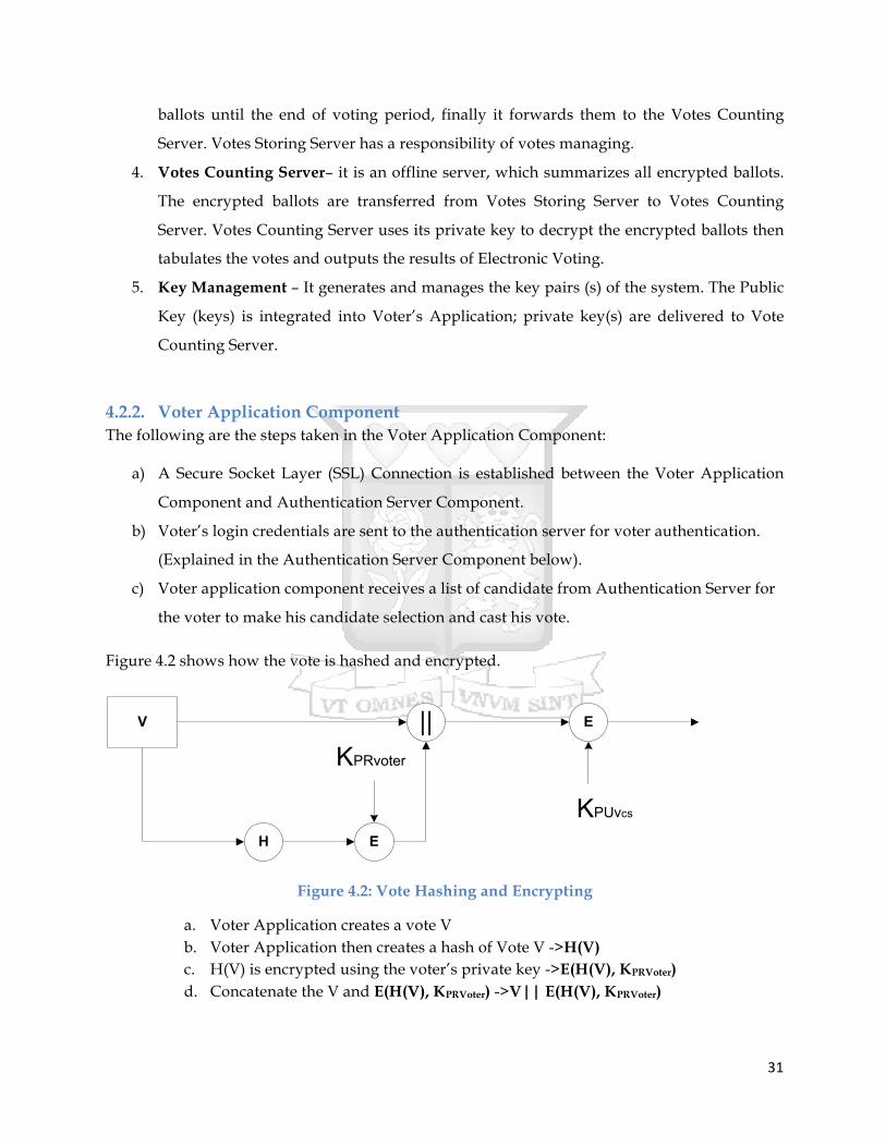
Figure 4.2 shows how the vote is hashed and encrypted.
V || E
H E
KPUvcs
KPRvoter
Figure 4.2: Vote Hashing and Encrypting
a. Voter Application creates a vote V b. Voter Application then creates a hash of Vote V ->H(V) c. H(V) is encrypted using the voter’s private key ->E(H(V), KPRVoter) d. Concatenate the V and E(H(V), KPRVoter) ->V|| E(H(V), KPRVoter)

32
e. Encrypt V|| E(H(V), KPRVoter) using the public key of the Votes Counting Server (VCS) -> E(V|| E(H(V), KPRVoter), K PUVCS)
The above processes (I to IV) ensure the following security requirements:
• Privacy/Confidentiality – ensuring that no one can read the vote except the intended receiver (Votes Counting Server).
• Integrity – Assuring the Votes Counting Server that the received vote has not been altered in any way from the original.
• Confidentiality and Integrity of the vote have been achieved through Public Key Encryption, whereby V|| E (H(V), KPRVoter)has been encrypted using the Public Key of the Votes Counting Server.
• Authentication – ensures the proving of the identity of the Voter who has casted the vote, this is achieved through private key encryption, whereby the hash of vote V has been encrypted using the Private Key of the Voter.
f. Pass the result through double signature
i. VI = E(V|| E(H(V), KPRVoter), K PUVCS)) ii. ID = Voter Identity
Figure 4.3 shows the double signature concept.
Figure 4.3: Double Signature
g. Send ID, VI, IDMD and the Dual Signature to the Authentication Server Double signature ensures that the Votes Storing Server will be able to verify that the received encrypted Casted Vote details is valid, and the Votes Counting Server will be able to verify that the received encrypted Casted Votes details comes from a valid voter.
4.2.3. Authentication Server Component Figure 4.4 shows the flow of processes of the Authentication Server Component.
VI
ID
H
H
VIMD
IDMD
|| H VIDMD E
Dual Signature
KPRvoter

33
Figure 4.4: Authentication Server Activity Diagram
a) Authenticates voter by comparing salted hashes
WAIT
Receive voter authentication data i.e. username (studentNo) and password (PIN)
Validate the authenticity of the voter
Notify voter that the login credentials are invalid
VALID
INVALID
Send a query to the Votes Storing Server to find out whether voter has already casted a vote
WAIT
Receive response from votes storing serverALREADY
VOTED
NOT VOTED
Notify voter that doubling voting is not permitted
Sends list of candidates to the Voter Application
WAIT
Receives ID, VI, IDMD and the Dual Signature from the Voter Application
Forwards ID, VI, IDMD and the Dual Signature to Votes Storing Server
WAIT
Forward Response to Voter Application
Saves a Log of ID, VI, IDMD and the Dual Signature in LOG1
Receives Response that all is well from
Votes Storing Server
Start

34
During the registration of voters phase, the voter is required to insert his or her preferred
login credentials; this is a username and a password. The password is then converted to a
byte array, and by using a hash function that offer the one-way encryption, the password
that is in byte format is hashed. Then a random short series of bytes is generated (random
salt) and it is added to the password, the result byte array is then hashed for the second
time. Then the random salt is added to the new hash, and finally the final result is then
stored in a binary field in a database.
Figure 4.5 shows how the salted hash password is generated.
Figure 4.5: Creating a Salted Hash Password (MacDonald, 2003)
During the voting phase, to authenticate the voter, the voter is required to enter the
username and the password as the login credentials. The corresponding voter’s record is
looked up and the salted password hash is then retrieved from the database. The salt is then
extracted from the password-salted hash. The salt value that was extracted is then used to
calculate the salted password hash; this is with the voter’s supplied password. Then
verification is done to determine if this password salted hash matches with the password

35
salted hash value in the database, if there is a match, the voter is authorized access else he is
unauthorized.
b) Checks with the votes storing server if the voter has already casted a vote c) If voter hasn’t voted, it sends list of candidates to voter Application for the voter to
select candidates and cast a vote. d) Receives ID, VI, IDMD and the Dual Signature from the Voter Application Component e) Forwards ID, VI, IDMD and the Dual Signature to the Votes Storing Server. f) Wait for an acknowledgement from the Votes Storing Server that all is well, then notifies
the voter Application that all is well. g) Keeps a log of ID, VI, IDMD and the Dual Signature in LOG 1
The received VI in the Authentication Server cannot be altered or read, this is because the public
key encryption done in the Voter Application Component achieves both confidentiality and
integrity, the Authentication Server does not have a key to decrypt VI, hence VI is secure.
4.2.4. Votes Storing Server Component The votes storing server component is the component that receives the encrypted ballots from the Authentication Server, and then it verifies whether the encrypted ballot is valid, and then it stores valid encrypted ballots until the end of voting period, finally it forwards them to the Votes Counting Server. Votes Storing Server has a responsibility of votes managing. Figure 4.6 shows the sequence of activities in the votes storing component.

36
Figure 4.6: Votes Storing Server Activity Diagram
Receives a query from Authentication Server of whether voter has already voted
WAIT
Verify if voter has already voted
Sends a receipt ACK to the authentication Server
Sends Error Message to the Voter Application
YES
NO
WAIT
Receives ID,VI, IDMD and the Dual Signature from the Voter Application
Sends a receipt ACK to the Voter Application
Verify that vote (VI) is valid
E(PUvoter, KPRvss) and sends to the Votes Counting Server
WAIT
End of voting period
Saves a Log of ID,VI , IDMD and the Dual Signature and E(PUvoter, KPRvss)
in LOG2
Forwards ID,VI, IDMD and the Dual Signature
YES
NO
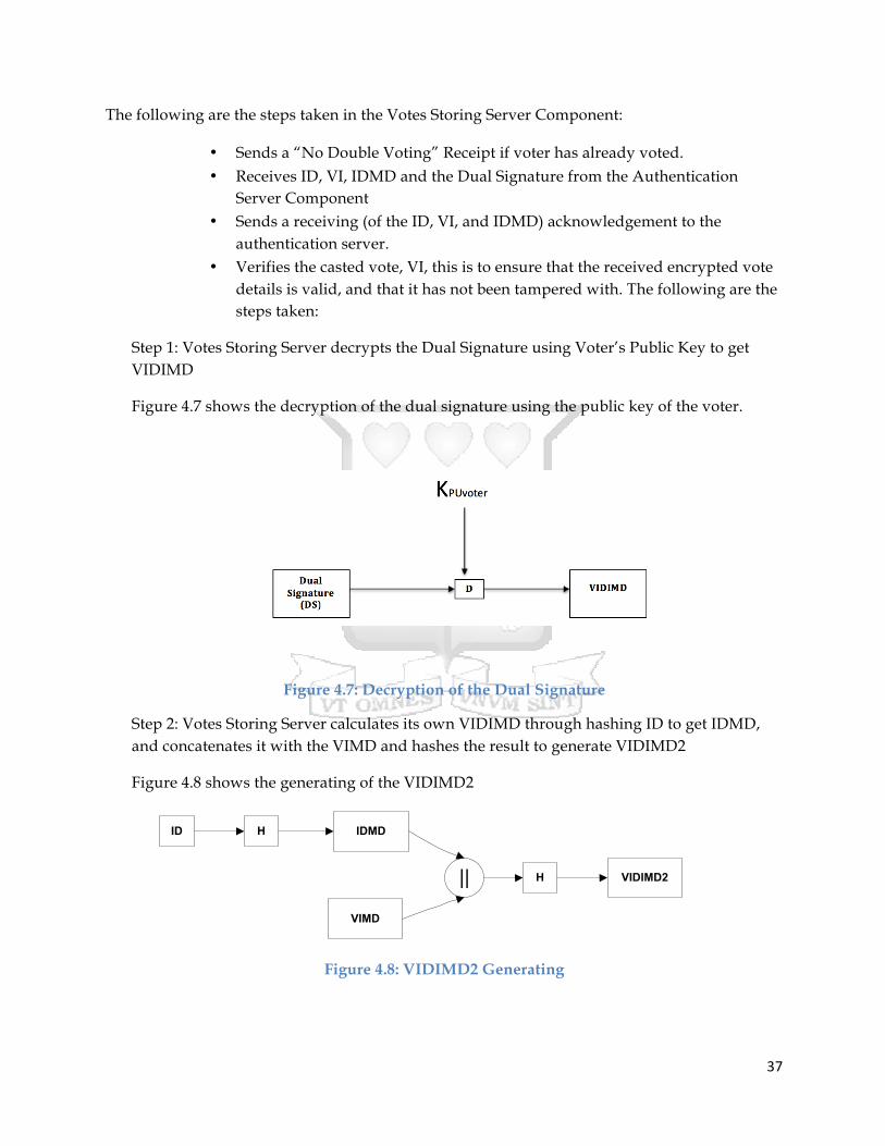
37
The following are the steps taken in the Votes Storing Server Component:
• Sends a “No Double Voting” Receipt if voter has already voted. • Receives ID, VI, IDMD and the Dual Signature from the Authentication
Server Component • Sends a receiving (of the ID, VI, and IDMD) acknowledgement to the
authentication server. • Verifies the casted vote, VI, this is to ensure that the received encrypted vote
details is valid, and that it has not been tampered with. The following are the steps taken:
Step 1: Votes Storing Server decrypts the Dual Signature using Voter’s Public Key to get VIDIMD
Figure 4.7 shows the decryption of the dual signature using the public key of the voter.
Figure 4.7: Decryption of the Dual Signature
Step 2: Votes Storing Server calculates its own VIDIMD through hashing ID to get IDMD, and concatenates it with the VIMD and hashes the result to generate VIDIMD2
Figure 4.8 shows the generating of the VIDIMD2
Figure 4.8: VIDIMD2 Generating
IDMD
VIMD
H|| VIDIMD2
ID H
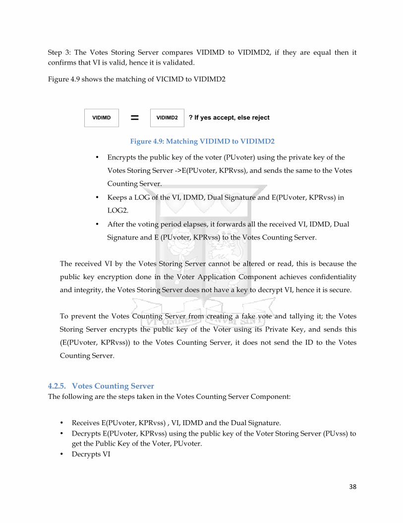
38
Step 3: The Votes Storing Server compares VIDIMD to VIDIMD2, if they are equal then it confirms that VI is valid, hence it is validated.
Figure 4.9 shows the matching of VICIMD to VIDIMD2
Figure 4.9: Matching VIDIMD to VIDIMD2
• Encrypts the public key of the voter (PUvoter) using the private key of the
Votes Storing Server ->E(PUvoter, KPRvss), and sends the same to the Votes
Counting Server.
• Keeps a LOG of the VI, IDMD, Dual Signature and E(PUvoter, KPRvss) in
LOG2.
• After the voting period elapses, it forwards all the received VI, IDMD, Dual
Signature and E (PUvoter, KPRvss) to the Votes Counting Server.
The received VI by the Votes Storing Server cannot be altered or read, this is because the
public key encryption done in the Voter Application Component achieves confidentiality
and integrity, the Votes Storing Server does not have a key to decrypt VI, hence it is secure.
To prevent the Votes Counting Server from creating a fake vote and tallying it; the Votes
Storing Server encrypts the public key of the Voter using its Private Key, and sends this
(E(PUvoter, KPRvss)) to the Votes Counting Server, it does not send the ID to the Votes
Counting Server.
4.2.5. Votes Counting Server The following are the steps taken in the Votes Counting Server Component:
• Receives E(PUvoter, KPRvss) , VI, IDMD and the Dual Signature. • Decrypts E(PUvoter, KPRvss) using the public key of the Voter Storing Server (PUvss) to
get the Public Key of the Voter, PUvoter. • Decrypts VI
VIDIMD VIDIMD2= ? If yes accept, else reject

39
Step 1: Votes Counting Server decrypts the Dual Signature using Voters Public Key to get VIDIMD
Figure 4.10 shows the decryption of the dual signature.
Figure 4.10: Dual Signature Decryption
Step 2: Votes Counting Server calculates its own VIMD through hashing VI, and uses it together with the IDMD to generate VIDIMD2.
Figure 4.11 shows the generating of VIDIMD2.
Figure 4.11: Generating VIDIMD2
Step 3: The Votes Counting Server compares VIDIMD to VIDIMD2, if they are equal then it is assured that VI actually came from a valid voter, hence it is validated.
Figure 4.12 shows the matching of VIDIMD to VIDIMD2.
Figure 4.12: Matching VIDIMD to VIDIMD2
VI = E(V|| E(H(V), KPRVoter), K PUVCS))
IDMD
VI H VIMD
H+ VIDIMD2
VIDIMD VIDIMD2= ? If yes accept, else reject

40
• Next steps
Figure 4.13: Verifying Vote
Figure 4.13 shows the verifying of the received vote.
• Using the private key of the Votes Counting Server (PRvcs) it decrypts VI to get (V|| E(H(V), KPRVoter), K PUVCS)
• It hashes Vote V to get H(V) • Using the public key of the voter (PUvoter) it decrypts (verify) E(H(V), KPRVoter) to get
H(V) • It compares the 2 hashes, if there is a match (the vote is valid); it counts the vote and
tallies. • Repeat (a to h) until the final tally.
Compare (Verify if there is a match)
VI = E (V|| E(H(V), KPRVoter), K PUVCS))
VI D VH
D
KPUvcs
E(H(V), KPRVoter)
KPUvoter

41
4.3. Entity Relationship Diagram Figure 4.14 shows the relationships between all the entities of the Electronic Voting Mobile Web Based Application System.
Table course stores the course details of both the voters and the candidates, table administrator stores the personal details of the administrators of the backend of the system, table results stores the elections results, table faculty stores the different faculties in the university, table voters stores the voter details, table castedvotes stores the ballots of the voters, table candidate stores the details of the aspirants, and table position stores the different student government designations the aspirants are running for.
Figure 4.14: Entity Relationship Diagram
COURSE
FACULTY
has
VOTER CASTEDVOTES
RESULTSADMINISTRATOR
CANDIDATE
POSITION
has
has
registers has
has casts
M
1
M1
1
M
1
M
M
1
1 M
M
1

42
4.4. User Interface Flow Diagram Figure 4.15 shows the frontend interface flow of the Electronic Voting Mobile Web Based
Application System.
Figure 4.15: User Interface Flow Diagram
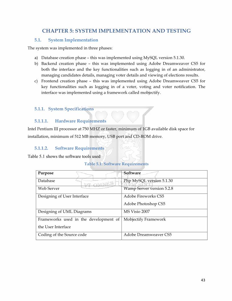
43
CHAPTER 5: SYSTEM IMPLEMENTATION AND TESTING
5.1. System Implementation
The system was implemented in three phases:
a) Database creation phase – this was implemented using MySQL version 5.1.30. b) Backend creation phase – this was implemented using Adobe Dreamweaver CS5 for
both the interface and the key functionalities such as logging in of an administrator, managing candidates details, managing voter details and viewing of elections results.
c) Frontend creation phase – this was implemented using Adobe Dreamweaver CS5 for key functionalities such as logging in of a voter, voting and voter notification. The interface was implemented using a framework called mobjectify.
5.1.1. System Specifications
5.1.1.1. Hardware Requirements
Intel Pentium III processor at 750 MHZ or faster, minimum of 1GB available disk space for
installation, minimum of 512 MB memory, USB port and CD-ROM drive.
5.1.1.2. Software Requirements
Table 5.1 shows the software tools used Table 5.1: Software Requirements
Purpose Software
Database Php MySQL version 5.1.30
Web Server Wamp Server version 5.2.8
Designing of User Interface Adobe Fireworks CS5
Adobe Photoshop CS5
Designing of UML Diagrams MS Visio 2007
Frameworks used in the development of
the User Interface
Mobjectify Framework
Coding of the Source code Adobe Dreamweaver CS5

44
5.1.2. Prototype of System
This section only looks at the key screen shot of the Electronic Voting Mobile Web Based
Application System for Student Government Elections. Appendix B and C shows the entire
screen shots for both the front end and the backend.
Candidate Listing Screen Shot
The Figure 5.1 shows the candidate listing screenshot; a voter is required to make candidate
selections by clicking on the each and every select menu and selecting the candidate of choice,
when this is done, the voter is required to click on the vote button to cast a ballot. On clicking
on the vote button, the voter will be navigated to the notification screen (Appendix B) that
assures the voter that his/her vote casting process is successful.
Figure 5.1: Candidate Listing Screen Shot
45
5.2. System Testing
A system testing was done for the Mobile Web Based Electronic Voting System; this took place
at Strathmore University.
The testing of the system mainly focused on the following key objectives: -
i. To measure the effectiveness of the system to the user.
ii. To measure the efficiency of the functionalities of the system.
iii. To measure the ease to learn how to use the system by the user.
iv. To measure the interactivity of the system.
v. To measure the utility of the system.
vi. To measure the convenience brought about by the system.
Having collected the test scores using the user testing questionnaire (Appendix A), results were analyzed and presented using graphs and charts.
5.2.1. The Effectiveness of the System to the User Effectiveness of the functionalities measures the ability of the functionalities in meeting their
tasks objectives.
The researcher took the respondents through the task objectives of all the functionalities, and
then gave the respondents a chance to interact with the system, and later on the filled the user
testing questionnaire form (Appendix A).
Figure 5.2 shows the analysed results from the questions the respondents filled on the
effectiveness of the system. It is clear that all the functionalities met their task objectives, with
“very good” scoring highly overall followed by “excellent”.
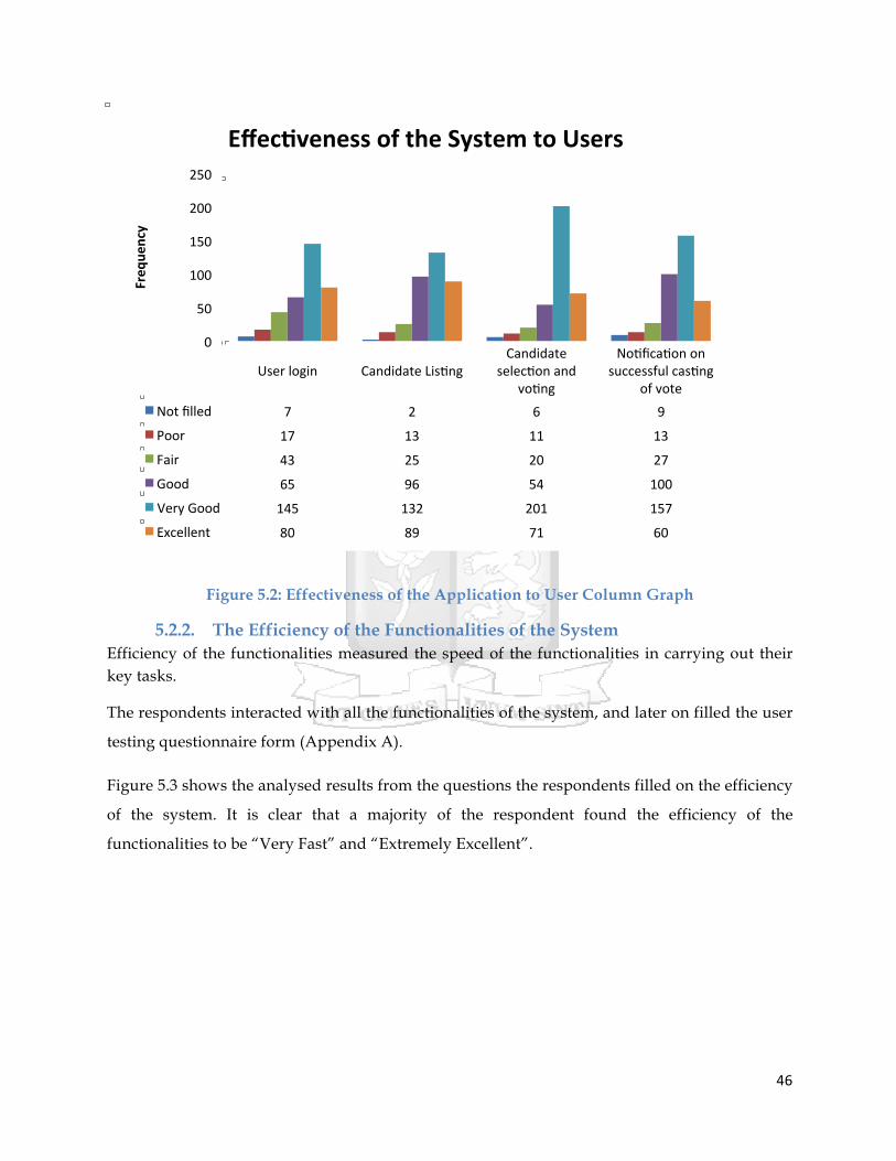
46
Figure 5.2: Effectiveness of the Application to User Column Graph
5.2.2. The Efficiency of the Functionalities of the System Efficiency of the functionalities measured the speed of the functionalities in carrying out their key tasks.
The respondents interacted with all the functionalities of the system, and later on filled the user
testing questionnaire form (Appendix A).
Figure 5.3 shows the analysed results from the questions the respondents filled on the efficiency
of the system. It is clear that a majority of the respondent found the efficiency of the
functionalities to be “Very Fast” and “Extremely Excellent”.
User login Candidate Lis>ng Candidate
selec>on and vo>ng
No>fica>on on successful cas>ng
of vote Not filled 7 2 6 9
Poor 17 13 11 13
Fair 43 25 20 27
Good 65 96 54 100
Very Good 145 132 201 157
Excellent 80 89 71 60
0
50
100
150
200
250
Freq
uency
Effec,veness of the System to Users

47
Figure 5.3: Efficiency of the Functionalities of the Application Column Graph
5.2.3. The Ease to Learn How to Use the System The respondents interacted with all the functionalities of the system, and later on filled the user
testing questionnaire form (Appendix A).
Figure 5.4 shows that a majority of the respondents found the System to be either very easy to
use or extremely easy to use.
User login Candidate Lis>ng
Candidate selec>on and
vo>ng
No>fica>on on successful
cas>ng of vote Not filled 4 6 3 7
Slow 10 12 7 16
Fair 15 20 30 17
Fast 68 66 57 71
Very Fast 137 162 158 140
Extremely Fast 123 97 105 113
0
20
40
60
80
100
120
140
160
180
Freq
uecy
Efficiency of the Func,onali,es

48
Figure 5.4: Ease to Learn How to Use the Application Column Graph
5.2.4. The Interactivity of the Application Figure 5.5 shows that 41% of the respondents felt that the user experience was very good, and 29% felt it was excellent and 17% felt it was good.
To login as a voter
To use the Candidate Lis>ng page
To make candidate selec>on
To cast a vote
Not filled 3 11 10 5
Not Easy 10 34 26 19
Fair 4 65 24 38
Easy 40 64 60 65
Very Easy 169 179 127 110
Extremely Easy 132 143 120 125
0
20
40
60
80
100
120
140
160
180
200
Freq
uency
Ease to Learn of the System

49
Figure 5.5: User Experience Pie Chart
Figure 5.6 shows 46% of the respondents felt that the user interface was excellent, 29% felt it was very good and 11% felt it was good.
Figure 5.6: User Interface Pie Chart
5.2.5. The Utility of the Application Figure 5.7 shows that a majority (94%) of the respondent found the application to be very
useful, with only 6% not finding it to be useful.
Excellent 29%
Very Good 41%
Good 17%
Fair 5%
Poor 2%
Not filled 6% User Experience
Excellent 46%
Very Good 29%
Good 11%
Fair 6%
Poor 4% Not Filled
4%
User Interface

50
Figure 5.7: Usefulness of the Application Pie Chart
5.2.6. Convenience Brought About by the System Figure 5.8 shows that 61% of the respondents found the application to be excellently
convenient, 16% very good and 16% good.
Figure 5.8: Convenience Pie Chart
Yes 94%
No 6% Usefulness
Excellent 61%
Very Good 16%
Good 16%
Fair 3%
Poor 1% Not filled
3%
Convenience

51
CHAPTER 6: DISCUSSION OF RESULTS FROM THE TESTING
This section discusses the findings got from the respondents after carrying out the survey. The
testing of the system mainly focused on the following key objectives: -
1. To measure the effectiveness of the System to the user.
2. To measure the efficiency of the functionalities of the System.
3. To measure the ease to learn how to use the System by the user.
4. To measure the interactivity of the System.
5. To measure the utility of the System.
6. To measure the convenience brought about by the System.
6.1. Effectiveness of the System The effectiveness of the System functionalities measured the ability of functionalities in meeting
their task objectives. From the Likert scale (poor, fair, good, very good, excellent) a majority of
the respondent ticked “very Good” and “Excellent”, this clearly shows that the functionalities
met their objectives. The following are the functionalities that were being assessed by the
respondents: -
1. User login functionality – its core functionality is to authenticate the voter by providing
the voter a web form to input his/her login credentials.
2. Candidate listing functionality– its core functionality is to list candidate with their
respective position.
3. Candidate selection and voting – its core functionality is to provide a list menu that
entails the names of the aspirants with their corresponding vying positions where the
voter can select the aspirants of his choice and afterwards click on the vote button to cast
his vote.
4. Notification on successful casting – its core functionality is notify to the user that
he/she has successfully casted a vote.
6.2. Efficiency of the Functionalities of the System Efficiency of the functionalities measured the speed of the functionalities in carrying out their
key tasks. A majority of the respondent ticked “Very Good” and “Excellent, hence comparing it
to the traditional paper based system, this system is far more efficient because every step has

52
been automated, especially the authentication of the voter and vote casting which normally
takes long due to long queues.
6.3. Ease to Learn of the System A majority of the respondents found the system very easy to use, this was catalysed by user’s
familiarity on using similar system and using basic web site functionalities such as inputting
data in a form, selecting items on a list menu and navigating. To add on that, almost all the
students at Strathmore University are tech survey this is justified by the E-Learning platform
that is compulsory to use at the University, together with the daily use of social media like
Twitter and Facebook.
6.4. Utility of the System The respondent found the system to be very useful, especially because not all students at
Strathmore University are allowed to vote, only a sample of each class is allowed, at least
through the application all the students will have an opportunity to cast a vote for their
favourite candidate.
6.5. Interactivity of the System The user experience and the user interface were both highly appreciated by the respondents;
this was catalysed by the use of the Mobjectify framework that is used in the development of
aesthetic HTML 5 web pages. The web pages adjust themselves depending on the screen size of
the mobile phone or the tablet.
6.6. Convenience of the System The respondent found the system to be excellently convenient; most of the respondent despised
the long queues that they have to make to cast a vote. Those who normally do not have classes
on that day despised coming to school to cast a vote, so having a solution that gives them an
opportunity to cast a vote from anywhere is beneficial to them and they really liked the idea.
6.7. Conclusion All the objectives of the system testing were all met beyond the researcher’s expectations; this
clearly shows that Kenyans are really becoming tech survey and more solutions should be
developed to automate the traditional methodologies of carrying out tasks.

53
CHAPTER 7: CONCLUSIONS, RECOMMENDATIONS AND
FURTHER WORK
7.1. Conclusions
The researcher was able to achieve all the three set objectives: -
i. To investigate how electronic elections are carried out around the world.
ii. To develop a mobile web based electronic voting system.
iii. To test and evaluate the developed mobile web based electronic voting system.
The researcher reviewed the following: the definition of voting and electronic voting, types of
voting systems, the requirements of a voting system, an electronic voting system, the basic
principles of an electronic voting system, functional and security requirements of a voting
system, Internet Voting, a review on the implementation of Electronic Voting Systems around
the world, security risks in web applications and finally security algorithms.
After reviewing a number of E-Voting Systems, the researcher settled on Estonia E-Voting
System, Estonia is one of the few countries that use an Internet Voting System. The researcher
used the same framework with major changes to develop the Mobile Web Based Electronic
Voting System, a case study of Strathmore University Student Council.
A system testing to measure the efficiency, effectiveness, utility, interactivity, convenience and
easy to learn of the system to the user was carried out. The respondents of the system testing
were students from Strathmore University. They interacted with the prototype then they filled a
questionnaire afterwards. The results were positive; the respondents found the system to be
very effective, very efficient, extremely easy to learn how to use, very good to interact with,
very useful and extremely convenient.
7.2. Recommendations
The researcher came up with the following recommendations:
1. The implemented Mobile Web Based Electronic Voting System can be customized for
other different large institutions (other universities and organisation).
2. The implemented Mobile Web Based Electronic Voting System can be replicated and
scaled out to large institutions in other countries.

54
7.3. Further Work
The implemented Electronic Mobile Web Based Application Voting System for large institutions
can also be developed on other native operating systems such as: Android, Windows,
Blackberry and IOS.

55
References Aaltonen, J. (2010). Electronic Voting Pilot in the 2008 Municipal Elections. Helsinki Finland.
Andreu, R., & Cervelló, G. (2004). Experimentation on Secure Internet Voting in Spain. Presentation at ESF TED workshop.
Brown, J., Dickinson, D., Steinebach, C., & Zhang, J. (2003). A Secure e-Voting System.
Cervello, G. (2009). The E-Participation Project of Neuchâtel. European Journal of ePractice.
Chevallier, M. (2008), e-Voting Certification Project, Voting via the Internet. State Chancellery.
Dwumfuo, G., & Paatey, E. (2011). The Design of an Electronic Voting System. Methodist
University College, Ghana.
Electoral Commission (UK). The Electoral Commission Website. ”Electoral Commission United
Kingdom”. United Kingdom.
Every One Counts PL. (2007). A Virtual Private Network for Internet Voting. Fujioka, A., Okamoto, T., & Ohta, K. (1993). A Practical Secret Voting Scheme for Large Scale Elections, Proceeding AUSCRYPT ’92, 244-251
Gerck, E. (2001). Voting System Requirements. Safevote. Giampiero, B. (2008). Secure and Easy Internet Voting. Computer (IEEE Magazine).
Goldberg, A. (2007). A Comparison of HTTP and HTTPS Performance. Courant Institute of Mathematical Science, New York University. Gritzalis, D. (2002). Secure Electronic Voting. Seventh Computer Security Incidents Response Team Workshop Syros, Greece.
Gupta, N., Kumar, R., & Chhokar, S. (2001). A Secure Blind Signature Application in E Voting. Bharati Vidyapeeth’s Institute of Computer Applications and Management, New Delhi Haziemeh, F., Khazaaleh, M., & Al-talafha, K. (2005). New Applied E-Voting System. Al-Balqa
Applied University, Jordan
James, C. (2011). Internet Voting. Elections BC.
Kahate, A. (2008). Security and Threat Models – Secure Electronic Transaction (SET Protocol). Indic Threads. Kessler, G. (1998). An Overview of Cryptography. Auerbach.
56
Kiniry, J., Morkan, A., & Cochran, D. (2007). TheKiezen op Afstand Remote Voting System. Kind
Softwares.
Kothari, C. (1985). Research Methodology: Methods and Techniques. Krejcie, R., & Morgan, D. (1970). Determining Sample Size for Research Activities. Educational and Psychological Measurement. Krimmer, R. (2006). A Methodology for Auditing e-Voting Processes and Systems used at the Elections for the Portuguese Parliament. Electronic Voting 2006: Lecture Notes in Informatics
Krimmer, R., Ehringfeld, A., & Traxl, M. (2010) The Use of E-Voting in the Federation of Students’
Elections 2009. Presentation at the EVOTE2010 conference.
National Commission Committee. (2005). E-Voting System Overview.Tallin, Estonia. National Commision Committee. (2007). Internet Voting in Estonia.Tallin, Estonia.
OWASP.(2010). The Ten Most Critical Web Application Security Risks. The OWASP Foundation.
Stender, C. (2009). Arizona’s Military and Overseas System. Arizona Secretary of State’s Office
Wolf, P. (2011). Introducing Electronic Voting: Essential Considerations. The International Institute
for Democracy and Electoral Assistance.
Communication Commission of Kenya (2014). 4TH Quarterly Sector Statistics Report. Nairobi:
Communication Commission of Kenya.

57
Appendices
APPENDIX A: USER TESTING QUESTIONNAIRE
USER TESTING QUESTIONNAIRE
The researcher is conducting user testing of a Mobile Web Based Electronic Voting System to test on its effectiveness, efficiency, utility, ease to learn and interactivity to a user.
Your responses are confidential and will only be used for this testing. Please answer correctly and truthfully.
SECTION A: BACKGROUND Please tick (√) where appropriate
1. What is your Gender? 1. Male [ ] 2. Female [ ]
2. Name of School or Faculty _____________________ 3. Year of Study
1. Year 1[ ] 2.Year 2 [ ] 3. Year 3 [ ] 4. Year 4 [ ] 4. Have you participated in any Strathmore University Students’ council Elections?
1. Yes [ ] 2. No [ ]
SECTION B: EFFECTIVENESS Please tick (√) where appropriate
How good is the system in carrying out the following functionalities?
Poor Fair Good Very Good
Excellent
5. User login
6. Candidate Listing
7. Candidate selection and voting
8. Notification on successful casting of vote
9. Checking of results

58
SECTION C: EFFICIENCY How fast is the system in performing the following tasks?
Slow Fair Fast Very Fast
Extremely
Fast
10. User login
11. Candidate Listing
12. Candidate selection and voting
13. Notification on successful casting of vote
14. Checking of results
SECTION D: EASE TO LEARN
How easy is it for you to learn how to use the system to perform the following tasks?
Not Easy
Fair Easy Very Easy
Extremely Easy
15. To login as a voter
16. To use the Candidate Listing page
17. To make candidate selection
18. To cast a vote
19. To check results
20. To sign out

59
SECTION E: INTERACTIVITY
How good is the user experience when you interact with the system?
Poor Fair Good Very Good
Excellent
21. User Experience
How good is the user interface of the system?
Poor Fair Good Very Good
Excellent
22. User Interface
SECTION F: UTILITY 23. Do you find the system useful?
1. Yes [ ] 2. No [ ]
SECTION G: ADDITIONS
24. What additions would you suggest to be added to the system? ____________________________________________________________________________________________________________________________________________________________________________________________________________________________________________________________________________________________________________________________________________________________________________________________________________________________________________________________________________________

60
APPENDIX B: FRONT END SCREEN SHOTS OF THE SYSTEM
1) Voter Login Screenshot
The Figure below shows the voter login screen shot; a registered voter is required to input a
valid student number and valid pin number.
Figure B. 1: Voter Login Screenshot

61
2) Candidate Listing Screenshot
The Figure below shows the candidate listing screenshot; a voter is required to make candidate
selections by clicking on the each and every select menu and selecting the candidate of choice,
when this is done, the voter is required to click on the vote button to cast a ballot. On clicking
on the vote button, the voter will be navigated to the notification screen.
Figure B. 2: Candidate Listing Screenshot

62
3) Notification Screenshot
The Figure below shows the notification screen shot, this screen is displayed to the voter after
successfully casting a vote, to assure him/her that all is well.
Figure B. 3: Notification Screenshot

63
APPENDIX C: BACKEND SCREEN SHOTS OF THE SYSTEM
1) Administration Homepage Screenshot
The Figure below shows the administration homepage screenshot, the administrator can
navigate to several page by clicking on the links, these are the voters, candidates, results, add
candidate listing, voter listing links just to name a few.
Figure C.1: Administration Homepage Screen Shot

64
2) Voter Listing Screenshot
The Figure below shows the voter listing screenshot, the administrator checks on the registered
voters’ details, but he/she can neither edit nor delete any detail because this is handled by the
registration system that is not in the scope of this study.
Figure C. 2: Voting List Page Screen Shot

65
3) Candidate Listing Page Screenshot
The Figure below shows the candidate listing page screenshot, the administrator can check on
the candidates’ details, he can also edit or delete candidate details.
Figure C. 3: Candidate Listing Page Screen Shot

66
4) Edit Candidate Screen Shot
The Figure below shows the edit candidate screenshot, the administrator can edit a candidate’s
details in case of an error.
Figure C. 4: Edit Candidate Detail Page Screen Shot
5) Chairman Result Screen Shot
The Figure below shows the Chairman results screenshot, it contains a listing of results of all
the candidates who vied for the chairman position.
Figure C. 5: Chairman Results Screen Shot
Copyright © 2022 FDOKUMEN