ELECTRONIC ENGINEERING - World Radio History
78
-
Upload
khangminh22 -
Category
Documents
-
view
10 -
download
0
Transcript of ELECTRONIC ENGINEERING - World Radio History
ELECTRONIC ENGINEERING ti o . 43 2
FEBRUARY 1964
Commentary
THE British Broadcasting Corporation is now well advanced with its preparations for BBC-2. the Cor-poration's second television programme service, which is due to come into operation on 20 April this year. As is well known, the new programme will be in the
u.h.f. band and will operate on the 625-line standard; the BBC is now making regular daily trade test transmissions from Crystal Palace (London) on channel 33. When the new programme first comes into service, it
will only be available in the London area and will then be spread gradually to the Midlands the North and other parts of the country as new transmitters become available. For the programme to be a success it is necessary that
it should be viewed by a large number of people and to ensure that this is so is going to require some hard selling on the part of the BBC and industry. The primary responsibility for this undoubtedly rests with the BBC's Programmes Department for, unless they can persuade potential viewers that they are really missing something it is doubtful whether they will be tempted to rush out and purchase new receivers. Apart from the matter of the attractiveness of the
programmes there are two other points which may cause the popularity of BBC-2 to be rather slow in growth. The first is the uncertainty with regard to the introduction of colour and the second is the vagaries of u.h.f. reception. With regard to the first point, it is probable that the
average viewer at present owns a 17in or 19in receiver which, although giving perfectly good service and capable of doing so for some time, cannot be converted for 625-line reception. If the viewer is going to be able to receive BBC-2 he therefore must purchase a new receiver. But if there is any chance of colour being introduced the viewer may well be wary of buying a new receiver that may be out-dated within a very short time. At first sight this -i-vould appear to be a factor working in favour of the rental companies, but even they may be wary of investing large amounts of capital in receivers that will not be in service for a sufficiently long time to cover their outlay. On the other hand it may be that the prospective price of colour receivers will make them a matter of no interest in any case. It may also be pointed out that this is a factor which could apply to only a part of the country, for if an early decision is made on the introduction of colour then both that and BBC-2 could be introduced simul-taneously in places other than London, and perhaps Bir-mingham which is the next centre due for the introduc-tion of u.h.f. television. The second point, the vagaries of u.h.f. reception, is
one which if not carefully explained and patiently dealt with may well cause frustration and distrust among
viewers. Even when the Crystal Palace transmitter is stepped up to its full output there will still be many pockets within the nominal viewing area where the signal will be masked by hills, or even tall buildings, and viewing will be impossible. To fill-in these pockets there will have to be a large number of low-powered fill-in relay stations and the provision of these will take time. Indeed, to pro-vide national coverage some hundreds or even thousands of these fill-in stations may be required. In other words, buying a receiver and installing an aerial is no guarantee of receiving the programme: the possible implications of this are only too obvious. There are few laymen, and probably not many en-
gineers either, who realize the full enormity of the task involved in setting up this new television service. For the complete network some sixty main stations and, as already stated, hundreds or even thousands of fill-in stations will be required. For the main stations about thirty new masts, of an average height of one thousand feet will be required. The siting of these is not easy for not only must they be strategically placed from a technical point of view but they must also be approved by local planning authorities and the Air Ministry. The aerials themselves will largely be new types which have been developed by the BBC and industry. The Post Office has an almost equal problem to face
in providing the feeds to the new transmitters. The exist-ing 405-line video circuits have insufficient bandwidth for 625-line working and consequently a new distribution network must be constructed. This will consist largely of microwave links. At the initiating end of the chain, studios, presentation
suites and film and tape recording equipment have to be converted to wideband working and while all this is going on the existing 405-line system has to be kept in operation. For the initial phase of this operation more than thirty new cameras, three main production studios, eleven telecine channels, ten film and tape recording channels and four mobile control rooms are required. In addition to all this the BBC has the not inconsider-
able task of recruiting and training the staff to operate and maintain the new channel. There is no doubt that the opening up of this new
channel presents a stimulating engineering exercise which will provide a great deal of interest for some long time to come. It will be interesting too, to see what use is made of the bandwidth and standard of definitiein which will now be available for, if it is to be exploited to the full, it will provide a number of problems at every link in the chain; from the designer of camera pick-up tubes to the receiver manufacturer.
FEBRUARY 1964 (1 H) 71 ELECTRONIC ENGINEERING
A Digital Shaft Position Indicator By S. G. Smith*, B.Sc., and C. J. U. Roberts*
[he logical basis for a method of indicating the position of a shaft by use of an incremental digital transmission is described, together with details of the system constructed from commercially available
logical elements.
(Voir page 132 pour le résumé en français: Zusammenfassung in deutscher Sprache auf Seite 139)
lurANY control and computing systems are formed by 1VIcoupling a digital computer to elements in which information is conveyed by the rotation of a shaft, e.g. the control of machine tools. In such systems it is necessary to convert the position of the shaft into a digital repre-sentation suitable for feeding to the computer. The usual method of achieving the conversion is to mount a whole number' digitizer on the shaft. This then gives an output which represents each position of the shaft as a number. For reasons of space available or other mechanical limita-tions it is sometimes not possible to mount such a unit, but it is possible to mount a simpler device which will transmit information of small changes in the position of the shaft. The actual position is then found by counting the number of changes (which may occur in either direc-tion) from some datum position. This article describes a unit in which the latter system
is used to give a visual indication of the position of a shaft as a number. It is used in the testing of the mechani-cal part of a hybrid computing system using both analogue and digital techniques.
The System
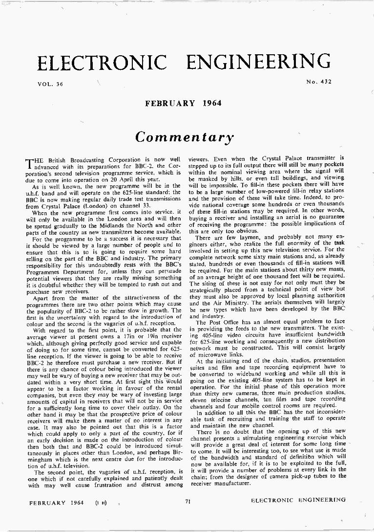
One type of incremental transmitter is shown in Fig. 1. It takes the form of two switches made up of two pairs of brushes running on a commutator mounted on the motor shaft which drives the main output shaft through precision reduction gearing. All sliprings of the com-mutator are connected together. One brush of each pair runs in a ring which is conducting for the complete shaft revolution, while the other runs in a ring which is con-ducting and non-conducting for equal alternate sections. The two pairs of brushes are staggered around the shaft so that the switches are short-circuited (denoted A or B) and open-circuited (denoted A* or B*) in the following sequences: Forwards
A.B A* .B A* .B* A.B* A.B etc. Reverse
A.B A.B* A* .B* A* .B A.B etc. where A, A* represent the state of the first switch and B, B* represent the state of the second switch and the symbol. represents the logical function AND. The sequences are shown diagrammatically in Fig. 2. It should be noted that several switch cycles may take place in one revolu-tion of the commutator shaft. The logic system is required to sense the change in the
switch states as the shaft rotates and to produce the appro-priate drive to the counter so as to increase or decrease the total accumulated. The counter must be of a type which can count in both
directions and requires reset facilities in order to synchro-
• Royal Aircraft Establishment.
nize the accumulated total with a specified position of the output shaft. For convenience in reading the displayed total the
counter in this case is arranged to count in a decimal
INSULATED SECTION
e 90° •
180°
_CONDUCTING SECTION
360 ° ,n INSULATED SECTION
CONDUCTING SECTION
• - - A FORWARD
BRUSH PAIRS ROTATION
Fig. I. The mechanical incremental digitizer
Forward rotaficn
A.B
A. B
4* 8*
Reverse rotat ion
A1,8
Fig. 2. Switch closure sequences
system and to give direct indication of a negative count rather than present it in 'nines complement' form. An additional feature incorporated is the facility to start and stop counting with a control synchronized with the con-trols of a time interval meter. This is used for measuring shaft speeds. Two methods of operation of the logic system may be
used. (a) Directly from the changeover action of the switches,
or (b) By interrogation of the state of the switches by strobe pulses.
With a mechanical system brush bounce makes the first alternative unreliable, so the second was adopted.
ELECTRONIC ENGINEERING 72 FEBRUARY 1964
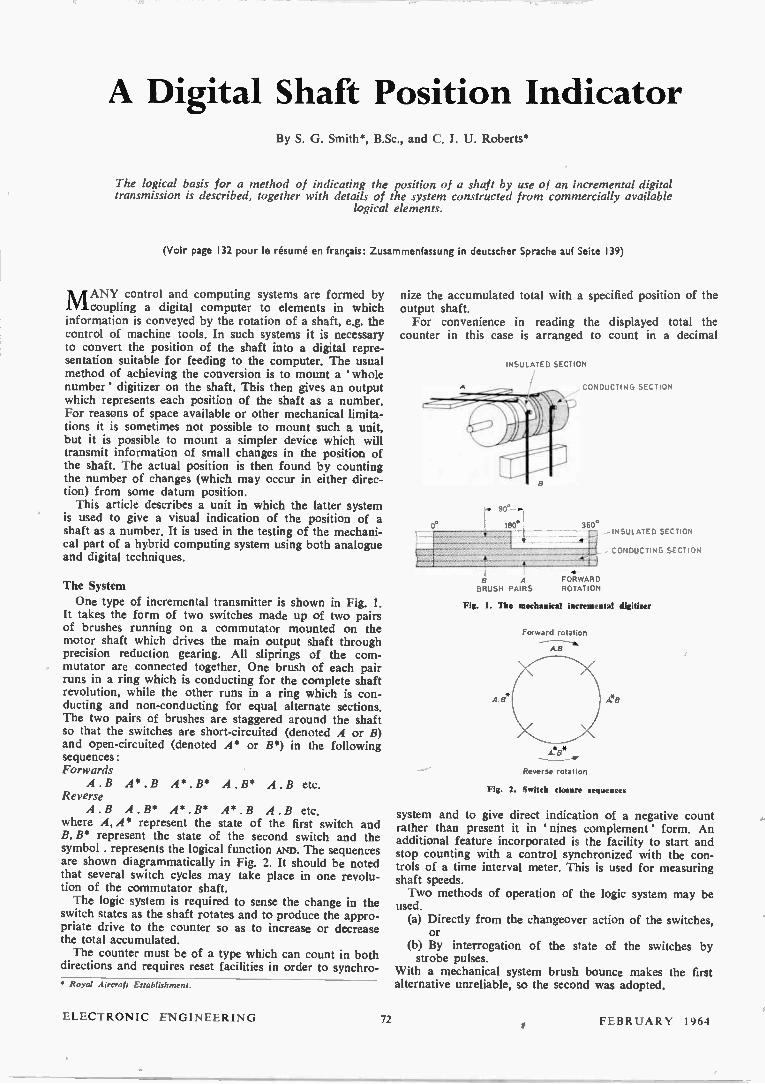
The complete system is shown in Fig. 3 and consists of four main sections: (1) The strobe pulse generator. (2) The direction logic. (3) The counter drive unit. (4) The counter unit.
The Strobe Pulse Generator For the correct operation of the logic and counter
system a four pulse sequence was devised. Each pulse is
occur if the shaft rotates in the forwards direction, while the combinations:
(A, Bw) . (AI . Be) or (Aw Bw*) (AI* . Bis) or (Aw* Bw*) . (AI* . B1) or (A* . Bw) . (AI . B1) (2)
occur if the shaft rotates in the reverse direction. It should be noted that when switch A changes switch
B does not change and vice-versa. By dropping the suffix where there is no switch change the relations (1) and (2) may be reduced to:
MEMORY
MEMORY
STRODE PULSE
GENERATOR
P21"4
SELECTOR
GATES
COUNTER
DRIVE
UNIT
DIRECTION LOGIC
Fig. 3. Arreggessent of systegi
50µsec wide and pulses are separated in time by 50psec in order to allow the gating systems to settle before they are used. With the logic elements used in the construction of the system this is ample time delay. The pulses are obtained from a timing chain, Fig. 4,
consisting of a 10kc/s astable unit, U, driving two bi-stable units, V and W, in cascade. The four strobe pulses po po po p« appear at the outputs of four AND gates fed by the stages of the timing chain.
pi = U. V. W Po = U. V* . W Po = U. V . W* Pt = U . V. . W*
Each p pulse occurs on a separate line and is passed through a buffer amplifier to the logic and counter drive circuits. In general the presence of a signal is denoted by • 1'
and corresponds electrically to a potential of —6V relative to earth and the absence of a signal by 0' which corre-sponds to a potential of OV approximately. Thus the p pulses are 6V in amplitude negative going from earth. Individual pulses appear at a rate of 2 500 per second.
The digitizer switches are interrogated at each odd num-bered pulse, so the maximum speed of the digitizer is 1 250c/s, as for correct operation it must be interrogated at least once per phase of the four phase switch cycle. The shaft speed will depend on the number of switch cycles per revolution of the shaft.
The Direction Logic The logic detects any change of state of the two digitizer
switches, determines the direction of rotation of the shaft causing the change and produces an output in a form suit-able for the counter drive unit. From the switch sequence diagram, Fig. 2, it may be
deduced that if the subscript w (was) denotes the state of a switch at one interrogation and I (is) the state at the next interrogation, then the combinations:
(A,, . Bw). (AI* . or (A,,* . Bw). (A1* . Be) or (A,,5 Bw*) (AI . Be) or (A w Bw*) (Az . (1)
ii CF)I C r) 9
1
-*-1 - 4 - 10 . 10
COUNTER UNIT _J
Forward changes Reverse changes A*. Ai* .B A* . Bw Bi* Aw AI* B* Aw* AI B* A* . B„* . Bi A . Bw* B1 Aw* AT B (3)
The operation of the logic system is based on these relations. One odd numbered p pulse is used to set two memory bistables (was) according to the state of the switches at that time. The next odd p pulse is then used to set a second pair of memory bistables (is). The four bistables then feed selector gates which open if the appro-priate relation from (3) is satisfied. If a gate is opened it permits the next even numbered p pulse to pass through to either the forward or reverse line. For the pulse sequence pl pi pd the bistables AI and Bi
act as the ' was' units and the bistables A3 and B3 as the
u
10« cis ASTABLE
BISTABLE
u
w*
u
WA
&STABLE
Fig. 4. Strobe pulse g tor
'is' units, the gates allowing p« through to the output line. For the sequence [h p« po the significance of A1, B1 and A3, B3 is interchanged. It is found that the same selector gates may be used but the po pulse must be fed to the alternative line from the one that p« would go to. No ambiguity arises as the gate is open only for the time
FEBRUARY 1964 73 ELECTRONIC ENGINEERING
that the correct p pulse is present. A switch change occur-ring between pi and pi is transmitted at p4 and a change occurring between p3 and pi is transmitted at pi.
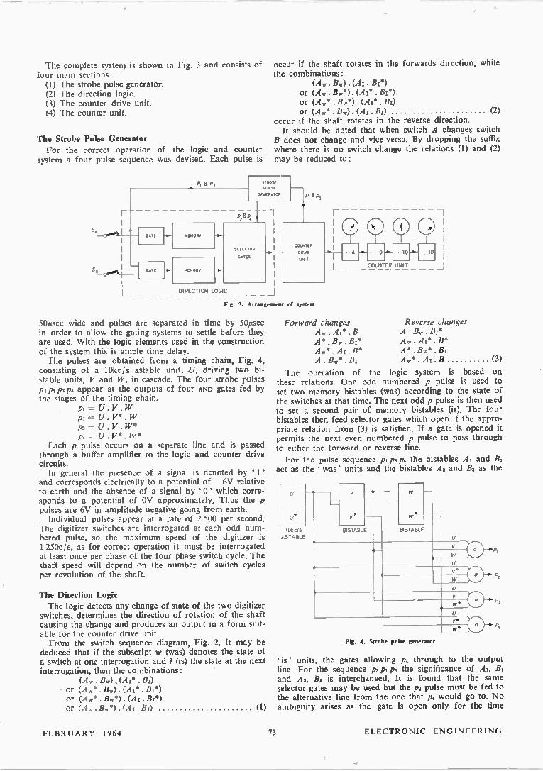
The circuit of the logic unit is given in Fig. 5. The two switches each control, with the addition of a buffer and an invertor, four AND gates (al to a4) and (as to at). The operation is such that if a switch is closed a 1' appears
S.
O p,
A
BUFFER
BUFFER
INvERTOR
INVERTCR
FORWARD
Input lines from logIc
REVERSE °
p pulses through, but if it is in the ' state inhibits them. This then acts as a stop/count' control.
The Counter Drive Unit
The pulses from the logic unit are in themselves sufficient to drive some types of counter. However, the counter employed in this case requires a different form
B,
STROBE MEMORY CIRCUITS BISTABLES
A. A
A le 8,
A, Al 8,
A, 8,
e A, Eir
e 8, a
A, 4 8,
SELECTOR GATES
Fig. 5. The direction logic system
Count
from counter °
Strobe
pulses
F/R
SE
RESET
o Stop/start control
FORWARD/REVERSE GATES
O INCREASE
COUNT
° PULSE
O DECREASE
O
DISPLAY
Fig. 6. Counter drive unit
at the output of thé buffer and a '0' at the output of the invertor. Pulses pl and pi are fed via the AND gates to bistables A 1 Bi and A3 B3 respectively. Thus Al and B1 are set to the state of the switches at the time of pi and A3 and B3 are set to the state at pi. The selector gates a9 to ale are opened if a combination of Ai, A3, Bi and Bs occurs which indicates that a switch has changed state. This in turn opens the appropriate AND gate (an to am) via OR gates 0121 or OR2 which then pass p2 or p4 to the forward or reverse line via oR3 or oR4. The last set of AND gates also have a third input which if it is in the 1 ' state allows the
--0
Control lines
to counter
FCRWARD
REVERSE
To cmnter drive und
of drive, the inputs being a two line sense' control and a single input for all pulses to be counted. The circuit is given in Fig. 6. The forward and reverse pulses which occur at p2 or p, set a bistable unit FI R and also the sign' bistable via gates ail and an which are opened only when the count indicated by the counter unit is zero. If the count is zero then a reverse pulse sets the sign bi-stable to ( —) or a forwards pulse sets it to (+). The out-puts of the sign bistable are used to drive a sign display and to control the direction of count through gates an to at.
ELECTRONIC ENGINEERING 74 FEBRUARY 1964
Set p Zero
The counter increase' and decrease • lines (1 and D) are taken from these gates according to the rules.
/ (+ . F) or ( — . R) D = ( — .F) or (+ .R)
The count output is obtained from a third bistable, C, which is set by a pulse appearing on either the forward or the reverse lines and is reset by either pl or pa, whichever occurs directly after C is set. The reset action occurs only if C has been set previously. The output from C is differentiated and the resulting positive going pulse, occur-ring at the reset, is used to trigger the counter.
Since the / and D lines are set up by the p2, or pi pulses on the forward and reverse lines and the count pulse occurs at the next odd p pulse, the direction of count has been set up before the pulse to be counted arrives at the counter input.
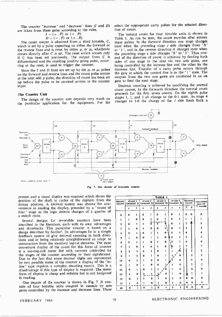
The Counter Unit
The design of the counter unit depends very much on the particular application for the equipment. For the
USIA."
Note - positive pulse sets 1
Fig. 7. One decade of reversible counter
present unit a visual display was required which shows the position of the shaft in cycles of the digitizer from the datum position. A decimal system was chosen for con-venience in reading the display, preceded by a count of four' stage as the logic detects changes of a quarter of a switch cycle.
Several designs for reversible counters have been described in the literature, each with its own advantages and drawbacks. This particular counter is based on a design described by Scollar'. Its advantages lie in a simple feedback system to give decimal counting in both direc-tions and in being relatively straightforward to adapt to construction from the standard logical elements. The most convenient display of the count for this form of counter is a moving-coil meter fed with currents controlled by the stages of the counter according to their significance. Due to the fact that some decimal digits are represented by two possible states of the counter a display of the in-line ' type requires a complex decoding matrix. This is a disadvantage if this type of display is required. The meter form of display is cheap and reliable but is not foolproof in reading.
One decade of the counter is shown in Fig. 7. It con-sists of four bistable units coupled in cascade by Am) gates controlled by the increase and decrease lines. These
select the appropriate carry pulses for the selected direc-tion of count.
The natural count for four bistable units is shown in Table I. As can be seen, the count recycles after sixteen input pulses. In the forward direction one stage changes state when the preceding stage t side changes from '0' to 1 ', and in the reverse direction it changes state when the preceding stage s side changes ' to 1'. Thus con-trol of the direction of count is achieved by feeding both sides of one stage to the next via two AND gates, one being controlled by the increase line and the other by the decrease line. Transfer of a carry pulse occurs through the gate at which the control line is in the 1 ' state. The outputs from the two AND gates are combined in an OR gate to feed the next stage.
Decimal counting is achieved by modifying the normal count system. In the forwards direction the normal count proceeds for the first seven counts. On the eighth pulse stages 1, 2, and 3 all change to the 0-1 state. As stage 4 changes to 1-0 the change of the t side feeds back a
Analogue read-out
Forward_feedback
MST/ .
4
Reverse feedback
Carry output
TABLE 1
BINARY STAGE I STAGE 2 STAGE 3 STAGE 4 DECIMAL ANALOGUE
COUNT (WEIGHT I) (WEIGHT 2) (WEIGHT 4) (WEIGHT 2) COUNT SUM OP
S yawn s r s t s t s t F R
0 0 1 0 1 0 1 0 1 0 0 0
I 1 0 0 1 0 1 0 1 1 1 1 L... — _ _I
2 0 1 1 0 0- 8 0 1 2 1
2
3 1 0 1 0 0 11 0 1 3 3 1
4 0 1 0 I I 0% 0 1 4 4
5 I 0 0 1 1 0 \b0 1 5 5
% 6 0 1 1 0 1 0 10 1 6 6
7 I 0 1 0 1 0 %0 1 7 1 1
7
8 0 1 0 1 0 1 1 /0 /
2 2
9 1 0 0 1 0 1 1 / 0 3 3
10 0 I I 0 0 1 ,1 0 4 4 r
11 1 0 1 0 0 1/ 1 0 /
5 5
12 0 1 0 1 1 /0 1 / 0 6 6
13 1 0 0 1 1 / 0 1 0 7 r ---- —(
7
14 0 1 1 0 1 0 1 0 8 8 8
15 1 0 1 0 1 0 1 0 9 9 — — — — — — — — —
9 — — — —
16 0 1 0 1 0 1 0 1 0 0 0
FEBRUARY 1964 75 ELECTRONIC ENGINEERING

positive pulse to stage 2 side s and stage 3 side s, resetting these stages to the 1-0 state. The counter is thus in the state corresponding to a binary count of 14, so the ninth pulse sets binary 15 and the tenth pulse sets binary 16, or zero. When counting in the reverse direction the changeover of the fourth stage s side resets 2t and 3t to 1 and leaves the counter at binary 1 at the ninth pulse, so that the tenth pulse again sets zero. The two feedback systems are such that they do not interfere with each other and do not require additional gating.
From the table it can be seen that the decimal numbers 2 to 7 each have two binary representations. Thus a de-coding matrix for a read-out system using separate indicators for each decimal digit requires a logic system which will allow for the dual representation of these digits. This leads to considerable complication in the matrix. How-ever, if the stages 1, 2, 3, 4 are given the analogue weights 1, 2, 4, 2 respectively a simple analogue read-out results by feeding currents proportional to these weights through a milliammeter. The milliammeter reading for each state of the counter is given in Table 1.
In the counter drive unit an input is required which indicates that the total count is zero. This is obtained by coupling the t side of each bistable in the whole counter to a multiple input AND gate. The output of this gate is then a ' 1 ' when the counter is in a state corresponding to zero. Each bistable also has an input which sets it in the 0-1 state when the set zero' line is momentarily, set to the 1 ' level by pushing the set zero' button.
Construction
The problem of constructing a complex logical device is much eased when the various sub-units required are avail-able as ready built and tested components. A range of such units is now produced by Mullard Ltd under the name of Combi-Elements'. These being available to the authors it was decided to construct the logic and counter units from them.
The Combi-Element range is a series of transistorized units which operate on the principle of d.c. gating. The range includes:
(1) Bistable units—based on the Eccles-Jordan circuit.
(2) AND and OR gates—using diode circuits.
(3) Pulse shapers—Schmidt trigger circuits.
(4) Invertor amplifiers—grounded emitter stages.
(5) Non inverting amplifiers—emitter-follower units.
All elements are built in the form of an encapsulated block lOmm x 24mm x 54mm, with ten leads brought out along one long edge. Some blocks contain two units, usually of the same type. Standard power supplies of +6V are used throughout the system.
Conversion of the theoretical circuits into ones using Combi-Elements starts by replacing each logical unit by the appropriate Combi-Element. The loading of each element is then investigated and amplifiers inserted where necessary. At this stage it is found that many of the neces-sary combinations of units are not permitted, due to waveform degradation or overloading, and alternative logical circuits may have to be used, or the existing ones re-arranged. One possible re-arrangement that is very use-ful is to invert the significance of the potential levels, i.e. 1' is represented by OV and 0' by —6V. This is valu-able when an invertor amplifier has been used to re-shape the waveform, but would not otherwise have been necessary. When inverted logic is used it is necessary to ensure that all the inputs to a gate are of the same
significance. It should be noted that an AND unit acts as an OR gate for inverted significance signals and that an OR unit acts as an AND gate.
The Strobe Pulse Generator The logical circuit for the strobe pulse generator was
given in Fig. 4 and the practical circuit is given in Fig. 8.
The astable unit, U, is formed by cross connecting the two halves of a twin invertor amplifier type 2.IA2, the output of each half being coupled to the input of the other via a 1 500pF capacitor. The unit then acts as a free running multivibrator at a frequency of approxi-mately 10kc / s.
The binary dividers V and W, are bistable units type FF1. These units have two outputs (one being the inverse
2 301 2.141 2.EF1
FF,
p.
2 301
2 142
e--0/31
Fig. 8. Strobe pulse generator using Combi-Elements
P4
of the other) and four inputs, two d.c. at which the d.c. level controls the state of the outputs, and two a.c. at which a positive going edge of an applied waveform sets the appropriate output to 1'. Diode gates inside the unit are arranged so that if the two a.c. inputs are connected together and a common input waveform is applied at this point the outputs change state at each positive going edge. The output from either output point thus changes in the positive direction at alternative input edges, i.e. at half the input rate.
Care must be taken with the waveshape at the a.c. input to an FF1. The unit will not trigger if the rise-time of the applied positive edge is greater than 0.5µsec.
The p pulses are required in many parts of the system and so the generator is required to provide comparatively powerful outputs. In order to give sufficient drive with sufficiently rapid rise-times, invertor amplifier units type 21A1 are used, followed by emitter-follower amplifiers type 2.EF1. The selector gates are arranged with inverted logic to allow for the inversion in the output amplifiers. OR gates type 2.301 are used, acting as AND gates for the inverted outputs from the divider chain units.
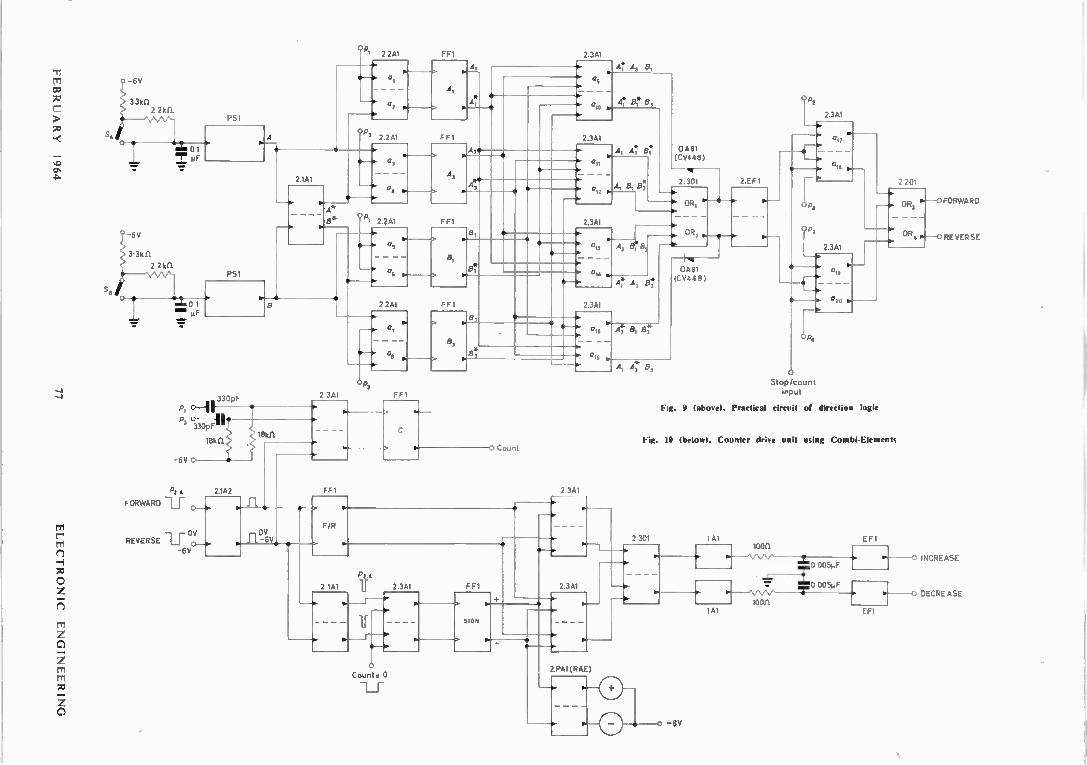
The Direction Logic
The circuit for the practical version of the direction logic is given in Fig. 9. The sensing switches are energized by connecting the independent contacts to the —6V rail through 3.3kû current limiting resistors, and the common
ELECTRONIC ENGINEERING 76 FEBRUARY 1964
AliVf111833
ON11133NION3 DIN10111D313
-6V
3.3kfl 2 2kf).
Op ' 2 241 FFI
FORWARD
01
Op
02
2.241
2 1AI
e.
PSI
A
0,
04
A,
FFI
A,
A,
436
2.3A1
A A3 8,
ato
2.341
Op ' 2.241 FFI
330pF
P, 330pF
<,18kfl 18kfl.
-6V
P2 4 2142
OV REVERSE
-6V
6.
Os
04 .4
e
0 11
A 8, 8
A 8
2.3A1 6.
6. 0
6.
2.2A1 FF1
- -I> 0 7
14--46 O .
P3
2 3A1 FF1
8,
0 14 b.
A, B, e
A 3
0A81 (CV448)
—4.2.301 1 2.EE1 .]
- - e" OR,
- - - -
2.341
0 Count
Ar A,
OR2 •
— e
04▪ 8▪ 1 (CV44 8 )
4 e,
FFI 2 3AI
OV 11-6V,
F/R
a
L, 2 1AI P24
ir
2 3AI FF1
111. - -0›
0 Count= 0
SIGN
2.3A1
2 PA1 (RAE)
O le
11
Op4
2.341
0, 9
a 20
O Stop/count Input
2 201
— 116
— 46. OR,
Fig. 9 (above). Practical circuit of direction logic
0. OR
Fig. 10 (below). Counter dri.e unit using Combi-Elements
2 301 141 EF1
141
100C).
0 005µF
005µF
10011
FORWARD
REVERSE
INCREASE
r-----0 DECREASE
EF1
-6V

contacts to the OV rail The independent contact of each switch is thus at —6V when the switen is open and OV when the switch is closed. The output is filtered by an RC circuit to remove the effect of brush bounce, and is then reshaped by a pulse shaper type PSI. The pulse shaper also acts as an invertor, giving an output at —6V (i.e. a '1 ') when the switch is closed and a '0' when the switch is open. This output is used as the direct output and feeds an invertor type IA1 to obtain the inverted output.
The direction sensing logic follows the theoretical circuit, given in Fig. 5, directly. Amplification is required after the OR gates (2.301) OR' and on2 of Fig. 5 and is achieved by using one half of a 2.EF1 block for each channel. It should be noted that ott, and 0122 each have four inputs. The extra input to each gate is obtained by wiring in an extra diode (CV 448 or 0A81) externally. No other modification is required.
The stop/start and forward/reverse gate systems are directly as the theoretical circuit, using type 2.3A1 AND gates and 2.301 and 2.201 OR gates.
The Counter Drive Unit
The practical circuit of the counter drive unit is given in Fig. 10. The rise-time of the positive edge of the output pulse from an OR unit is lengthened by capacitive loading due to the fact that the unit is switched into a high imped-ance state in this direction. It is therefore not possible to drive the a.c. input of an FFI directly from an OR unit, nor is it possible to use an emitter-follower as a buffer. It is therefore necessary to use invertor amplifiers type 2.IA2 as buffers for the forward and reverse signals.
The F/R bistable (type FFI) is driven from the buffered signals, the effect of the inversion being to set and reset the bistable on the front edges of the pulses rather than the back edges. This does not affect the operation of the logic system.
The count ' bistable (type FFI) is set by a pulse appear-ing on either the forward or the reverse lines. Since the significance of the line levels has been inverted, the OR function is performed by an AND unit type 2.2A1. As an AND unit is switched to a low impedance state in the posi-tive direction it is possible to drive an FFI directly from this unit. The other half of the 2.2A1 is used as an OR gate for the p pulses used to reset the 'count' bistable. As these are negative going they are first differentiated by an RC circuit before being applied to the gate. The positive going pulse resulting from the differentiating circuit is passed by the gate to reset the bistable and the negative going pulse is inhibited.
The 'sign ' bistable (type FF1) is set in one state or the other by pulses from the forward or reverse lines when the counter unit supplies a signal indicating that the total count is zero. An AND function is required which, since the forward and reverse lines have inverted levels, would indicate the use of an OR unit. However, an OR unit cannot drive an FF1 as was shown above, so the lines are re-inverted and a standard AND unit, type 2.2A1, is used. The counter is thus required to give a signal at the 1 ' level when the count is zero.
The Combi-Element range does not include a unit capable of driving a lamp display, so it was necessary to construct special drive units which, when controlled by the sign bistable, would light the indicator lamps show-ing positive or negative counts. The circuits used are shown in Fig. 11. These were built on small pieces of board and encapsulated in a block the same size and
shape as the standard Combi-Element block. This was the only special element used in the system. To provide sufficient drive on the increase/decrease
lines an IAI-EF1 output combination is required. Direct significance logic is used in the selection gates, the effect of the output invertors being removed by interchanging the two output lines. An RC circuit couples the IA1 to the EH and provides a slow changeover of the two line levels. This is done to prevent false operation of the counter, as described below.
The Counter Unit
One decade of the actual counter is shown in Fig. 12. Once again the practical circuit follows the theoretical, given in Fig. 7, quite closely. It has been mentioned that it is not possible to drive an FF1 from an OR gate, so the OR gates shown in Fig. 7 are replaced by simple a.c. couplings which perform the same function in this case.
12 kfl
Input
Fig. 11. Circuit of sign display drive 2PA1
Lamps 6V 300mA
12kfl —o
Input
47k fl.
OV
The output from an AND gate changes from 1' to '0' if the control line is 1 ' and the drive changes 1 ' to '0', in which case the following bistable should trigger. However, the gate output also changes 1 ' to 0' if the drive is 1 ' and the control changes 1 ' to 0'. In this case the following stage should not trigger. Triggering is prevented by making the change of the control lines too slow to trigger the bistables. A compromise is neces-sary as the change of the lines must be completed before the 'count' pulse arrives. This is approximately 150µsec later. (The F/R bistable changes on the front edge of an even p pulse and the count pulse occurs on the back edge of the next odd p pulse). With the loon shown in the external circuit in series with the output impedance of the IA1 the time-constant for a positive change is 1,usec and for a negative change is 10,usec. The change-over thus occurs in the desired range.
The analogue read-out is obtained on a 100,uA f.s.d. meter by feeding the meter from the outputs of the bi-stables. The total current through the meter is then pro-portional to the state of the decade.
Power Supplies
The Combi-Element range uses standard supply rails of +6V and —6V for all units. The complete system draws 100mA from the positive rail and 400mA from the negative rail (300mA of which is due to the sign indicator lamps). The currents do not vary appreciably with the state of the count as most of the units used are symmetrical.
Power supply sub-units are available from Mullard Ltd, but as the system was required to be used with other equipment running from 400c/s a.c. it was decided to
ELECTRONIC ENGINEERING 78 FEBRUARY 1964

33f1
o
•
II
_2 t 1.e L,
o
•
> o 11.1
o o
1.Ît
4 11 o o
II o. o o
cn
L,
CO d
CO 4 < y U
L,
41 1L et CO <
— dT o
>
a
Z'
< > 0
It
Fig. 12. Re.er,ible decimal counter using Combi-Elements
1000 VR- 625A
3311
4,5X641
100mA
To unit
1
-6V 400mA
100mA +6V
4x 5.1102 8
3000 VR-625A
OV
-6V
6 811
Fig. 13. Circuit of power unit
To unit 2
400mA
construct a small power unit which would give the d.c. supplies for two independent systems housed in the same box. The circuit is given in Fig. 13. Simple regulation of the supplies is achieved by using high power Zener diodes as shunt regulators.
Mounting
Two complete systems, together with the power supplies but without the displays, are mounted in a standard double Lectrokit ' box 17.5in x 10in x Sin suitable for mounting in 19in racking. Each system is built on an ' ex-perimenters printed circuit board', which is included in the Combi-Element range, and covers most of the space available on it. The two boards are mounted one above the other in the box and the power supply occupies the space left at the rear of the box, which is approximately 2in x 17.5in x 5in. The display meters are mounted on a sloping
panel attached to the main box. The panel also carries the operating controls.
Other Systems
Although the system described utilizes a mechanical digitizer, other types are of course possible. Digitizers exist which use optical, capacitive or inductive principles, each having their own advantages. The mechanical system is most useful where size and weight are at a premium and where it is not possible to build in access to replace the lamps of an optical system. The complexity of the reading system using
incremental transmission may at first sight seem to be a disadvantage, but when the cost of a comparable whole number system, to-gether with the display logic, is considered it may br found to be more attractive.
REFERENCE
I. Scott AR, 1. An Economical Reversible Transistor Decade Counter. Eire:remit. Envig. 33, 403 (1961).
FEBRUARY 1964 79 ELECTRONIC ENGINEERING
The Contra-Wound Linearly Polarized
Helical Aerial By R. A. Clark* and T. S. M. Maclean*
An experimental investigation of the contra-wound linearly polarized helical aerial is made, and the results obtained are compared with the theory for the corresponding infinite helix. Reasonable agree-ment has been obtained for the starting frequency of operation, but the bandwidth is found to be
much smaller than predicted.
(Voir page 132 pour le résumé en français: Zusammenfassung in deutscher Sprache auf Seite 139)
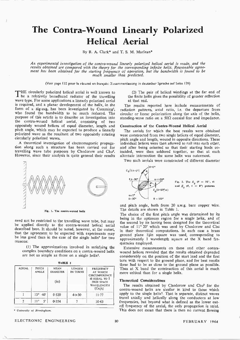
THE circularly polarized helical aerial is well known to be a relatively broadband radiator of the travelling
wave type. For some applications a linearly polarized aerial is required, and a planar development of the helix, in the form of a zig-zag, has been investigated by Cumming', who found the bandwidth to be much reduced. The purpose of this article is to describe an investigation into the contra-wound helical aerial, consisting of two oppositely wound helices of equal diameter, length and pitch angle, which may be expected to produce a linearly polarized wave as the resultant of two oppositely rotating circularly polarized waves. A theoretical investigation of electromagnetic propaga-
tion along such a structure has been carried out for travelling wave tube purposes by Chodorow and Chus. However, since their analysis is quite general their results
Fig. 1. The contra-wound helix
need not be restricted to the travelling wave tube, but may be applied directly to the contra-wound helical aerial described here. It should be noted, however, at the outset, that the agreement to be expected with experiments may be less good than in the case of the single helix' for two reasons:
(1) The approximations involved in satisfying the complex boundary conditions on a contra-wound helix are not as simple as those on a single helix'.
TABLE 1
AERIAL
1
PITCH
ANGLE MEAN
DIAMETER
(in)
LENGTH
IN TURNS FREQUENCY AT W HICH
CIRCUMFERENCE
IS EQUAL TO 1 FREE SPACE
WAVELENGTH
(Gc/s)
13° 40' 0.320 4+30 11.77
2 11° 5' 0.354 7 10.63
* University of Birmingham.
(2) The pair of helical windings at the far end of the finite helix gives the possibility of greater reflection at that end.
The results reported here include measurements of radiation patterns, axial ratio, i.e. the departure from circular or linear polarization along the axis of the helix, standing-wave ratio on a son coaxial line and impedance.
Construction of the Contra-Wound Helical Aerial The aerials for which the best results were obtained
were constructed from two single helices of equal diameter, pitch angle and length, wound in opposite directions. These individual helices were then allowed to roll into each other, and after being oriented so that their starting leads co-incided, were then soldered together, so that at each alternate intersection the same helix was outermost. Two such aerials were constructed of different diameter
Fig. 2. The Et, (0 = 90°, e) and Bo (0, = 0°) patterns
and pitch angle, both from 20 s.w.g. bare copper wire. The details are shown in Table I. The choice of the first pitch angle was determined by its being in the optimum region for a single helix, and of the second by its having been designed for the theoretical value of 11° 20' which was used by Chodorow and Chu in their theoretical computations. In each case a brass ground plane square was used, corresponding to approximately 1 wavelength square at the X band fre-quencies employed. Extensive measurements on these and other contra-
wound helices revealed that the results obtained depended considerably on the position of the start lead and the first turn with respect to the ground plane, and for best results these had to be as close to the ground plane as possible. Thus at X band the construction of this aerial is much more critical than for a single helix.
Theoretical Considerations The results obtained by Chodorow and Chu2 for the
contra-wound helix are similar in kind to those which apply to the single helix'. That is separate, distinct waves travel axially and helically along the conductors at low frequencies, but beyond what is defined as the lower cut-off frequency of the aerial, the only propagation is axial. This does not mean that there is then no current flowing
ELECTRONIC ENGINEERING 80 FEBRUARY 1 964
-10
- 0
- 40 -180 -90 0 + 90 +180 -180 - 90 0
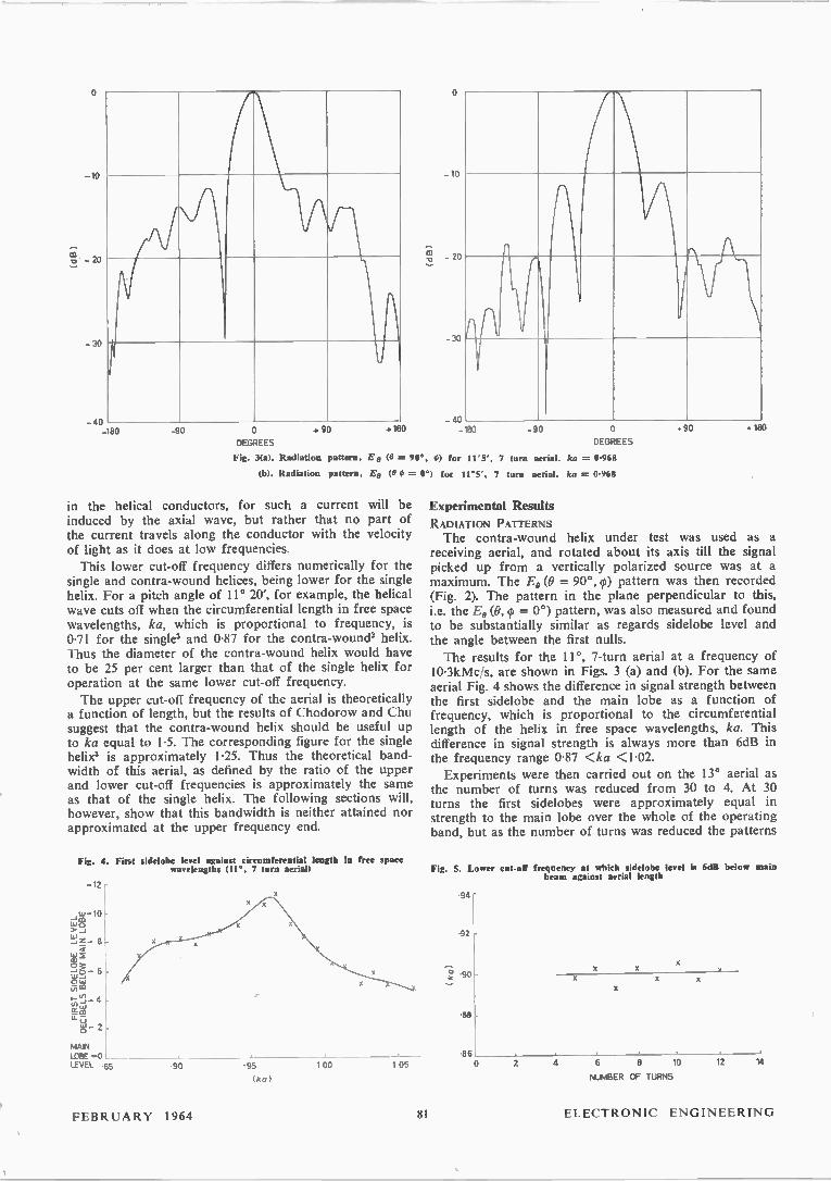
DEGREES DEGREES Fig. 3(a). Radiation pattern, Ea (9 = 90°, 0) for 11°5'. 7 turn aerial. ka = 0.968
(b). Radiation pattern, Eco (9 0 = 0°) for 11°5', 7 turn aerial. ka = 0.968
- 10
- 20
- 30 li
in the helical conductors, for such a current will be induced by the axial wave, but rather that no part of the current travels along the conductor with the velocity of light as it does at low frequencies. This lower cut-off frequency differs numerically for the
single and contra-wound helices, being lower for the single helix. For a pitch angle of 11° 20', for example, the helical wave cuts off when the circumferential length in free space wavelengths, ka, which is proportional to frequency, is 0.71 for the single3 and 0.87 for the contra-wound' helix. Thus the diameter of the contra-wound helix would have to be 25 per cent larger than that of the single helix for operation at the same lower cut-off frequency. The upper cut-off frequency of the aerial is theoretically
a function of length, but the results of Chodorow and Chu suggest that the contra-wound helix should be useful up to ka equal to 1.5. The corresponding figure for the single helix3 is approximately 1.25. Thus the theoretical band-width of this aerial, as defined by the ratio of the upper and lower cut-off frequencies is approximately the same as that of the single helix. The following sections will, however, show that this bandwidth is neither attained nor approximated at the upper frequency end.
Fig. 4. First sidelobe level against circumferential length In free space wavelengths (11°, 7 turn aerial)
-12
,w-10 LT'S > z - 8 rti 2
6 w
- 4 in
w - Sn
MAIN LOBE +0 LEVEL .85 • 90 • 95
(ka) 100 1 05
40 .90 . 180
Experimental Results
RADIATION PATTERNS The contra-wound helix under test was used as a
receiving aerial, and rotated about its axis till the signal picked up from a vertically polarized source was at a maximum. The E, (0 = 90°, ) pattern was then recorded (Fig. 2). The pattern in the plane perpendicular to this, i.e. the E, (0, = 0°) pattern, was also measured and found to be substantially similar as regards sidelobe level and the angle between the first nulls. The results for the 11°, 7-turn aerial at a frequency of
10.3kMc/s, are shown in Figs. 3 (a) and (b). For the same aerial Fig. 4 shows the difference in signal strength between the first sidelobe and the main lobe as a function of frequency, which is proportional to the circumferential length of the helix in free space wavelengths, ka. This difference in signal strength is always more than 6dB in the frequency range 0.87 <ka <1.02. Experiments were then carried out on the 13° aerial as
the number of turns was reduced from 30 to 4. At 30 turns the first sidelobes were approximately equal in strength to the main lobe over the whole of the operating band, but as the number of turns was reduced the patterns
Fig. 5. Lower cot-off frequency at which sidelobe level is 6dB below main beam against aerial length
.94
.92
90
.88
.86
X X
0 2 4 6 a 10
NUMBER OF TURNS
12 14
FEBRUARY 1964 81 ELECTRONIC ENGINEERING
100
.98
.96
.94
-92
-90
-88 0 2 4 6 8 10 12 14
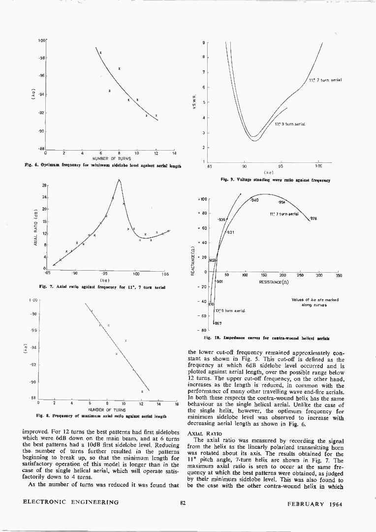
NUMBER OF TURNS Fig. L. Optimums frequency for minimum sidelobe level against aerial length
•ce
o
cr -J
100
• 98
-96
-92
-90
• 88
28
24
20
16
12
8
4
o -85 90 95 100
(ka)
Fig. 7. Axial ratio against frequency for 11°. 7 turn aerial
0 2 4 6 8 10
105
12 1‘4 16 NUMBER OF TURNS
Fig. 8. Frequency of maximum axial ratio against aerial length
improved. For 12 turns the best patterns had first sidelobes which were 6dB down on the main beam, and at 6 turns the best patterns had a 10dB first sidelobe level. Reducing the number of turns further resulted in the patterns beginning to break up, so that the minimum length for satisfactory operation of this model is longer than in the case of the single helical aerial, which will operate satis-factorily down to 4 turns.
As the number of turns was reduced it was found that
REACTANCE (II)
e
7
6
4
13? 9 turn aerial
3
2
1 85 90 95
(ka)
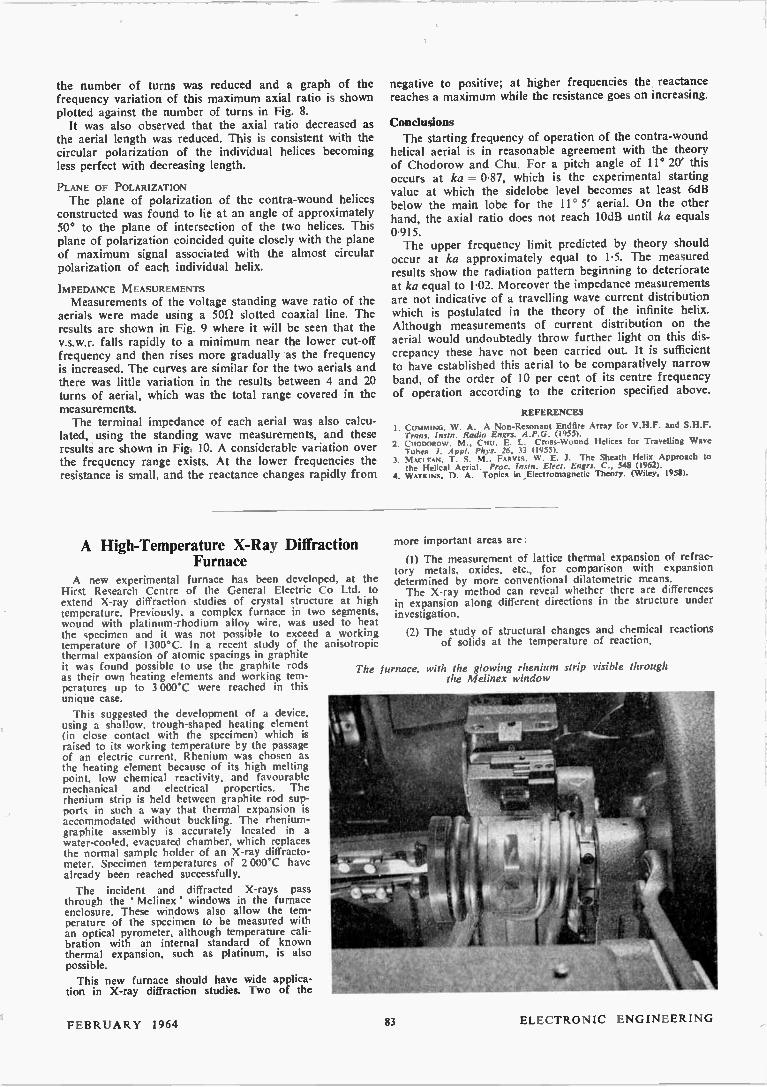
Fig. 9. Voltage standing wave ratio against frequency
• 100
+ 80
• 60
• 40
+ 20
o
- 20
- 40
- 60
2
11° 7 turn aerial
•939
921
•940 -954
11 7 turn aerial
100
-978
50 100 150 200 250 -901 RESISTANCE (n)
300 350
Values of ka are marked along curves
13 9 turn aenal
867 - 80
Fig. 10. Impedance curves for contra-wound helical aerials
the lower cut-off frequency remained approximately con-stant as shown in Fig. 5. This cut-off is defined as the frequency at which 6dB sidelobe level occurred and is plotted against aerial length, over the possible range below 12 turns. The upper cut-off frequency, on the other hand, increases as the length is reduced, in common with the performance of many other travelling wave end-fire aerials. In both these respects the contra-wound helix has the same behaviour as the single helical aerial. Unlike the case of the single helix, however, the optimum frequency for minimum sidelobe level was observed to increase with decreasing aerial length as shown in Fig. 6.
AXIAL RATIO The axial ratio was measured by recording the signal
from the helix as the linearly polarized transmitting horn was rotated about its axis. The results obtained for the 11° pitch angle, 7-turn helix are shown in Fig. 7. The maximum axial ratio is seen to occur at the same fre-quency at which the best patterns were obtained, as judged by their minimum sidelobe level. This was also found to be the case with the other contra-wound helix in which
ELECTRONIC ENGINEERING 82 FEBRUARY 1964
the number of turns was reduced and a graph of the frequency variation of this maximum axial ratio is shown plotted against the number of turns in Fig. 8. It was also observed that the axial ratio decreased as
the aerial length was reduced. This is consistent with the circular polarization of the individual helices becoming less perfect with decreasing length.
PLANE OF POLARIZATION The plane of polarization of the contra-wound helices
constructed was found to lie at an angle of approximately 50° to the plane of intersection of the two helices. This plane of polarization coincided quite closely with the plane of maximum signal associated with the almost circular polarization of each individual helix.
IMPEDANCE M EASUREMENTS
Measurements of the voltage standing wave ratio of the aerials were made using a 501/ slotted coaxial line. The results are shown in Fig. 9 where it will be seen that the v.s.w.r. falls rapidly to a minimum near the lower cut-off frequency and then rises more gradually as the frequency is increased. The curves are similar for the two aerials and there was little variation in the results between 4 and 20 turns of aerial, which was the total range covered in the measurements. The terminal impedance of each aerial was also calcu-
lated, using the standing wave measurements, and these results are shown in Fig. 10. A considerable variation over the frequency range exists. At the lower frequencies the resistance is small, and the reactance changes rapidly from
negative to positive; at higher frequencies the reactance reaches a maximum while the resistance goes on increasing.
Conclusions
The starting frequency of operation of the contra-wound helical aerial is in reasonable agreement with the theory of Chodorow and Chu. For a pitch angle of 11° 20' this occurs at ka = 0.87, which is the experimental starting value at which the sidelobe level becomes at least 6dB below the main lobe for the 11° 5 aerial. On the other hand, the axial ratio does not reach 10dB until ka equals 0.915. The upper frequency limit predicted by theory should
occur at ka approximately equal to 1.5. The measured results show the radiation pattern beginning to deteriorate at ka equal to 1.02. Moreover the impedance measurements are not indicative of a travelling wave current distribution which is postulated in the theory of the infinite helix. Although measurements of current distribution on the aerial would undoubtedly throw further light on this dis-crepancy these have not been carried out. It is sufficient to have established this aerial to be comparatively narrow band, of the order of 10 per cent of its centre frequency of operation according to the criterion specified above.
REFERENCES
I. CUMMING, W. A. A Non-Resonant Endfire Array for V.H.F. and S.H.F. Trans. Insto. Radio Entra. A.P.G. (1955).
2. Cficmoitow, M., CHU, E. L. Cross-Wound Helices for Travelling Wave Tubes J. App!. Phys. 26, 33 (1955).
3. MACI FAN. T. S. M.. FARV1S. W . E. 1. The Sheath Helix Approach to the Helical Aerial. Proc. Insist. Elect. Engrs. C., 548 (1962).
4. WATKINS, D. A. Topics in Electromagnetic Theory. (Wiley, 1958).
A High-Temperature X-Ray Diffraction Furnace
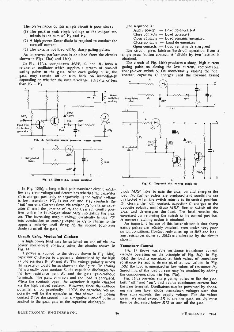
A new experimental furnace has been developed, at the Hirst Research Centre of the General Electric Co Ltd. to extend X-ray diffraction studies of crystal structure at high temperature. Previously, a complex furnace in two segments, wound with platinum-rhodium alloy wire, was used to heat the specimen and it was not possible to exceed a working temperature of 1300°C. In a recent study of the anisotropic thermal expansion of atomic spacings in graphite it was found possible to use the graphite rods as their own heating elements and working tem-peratures up to 3 000°C were reached in this unique case.
This suggested the development of a device, using a shallow, trough-shaped heating element (in close contact with the specimen) which is raised to its working temperature by the passage of an electric current. Rhenium was chosen as the heating element because of its high melting point, low chemical reactivity, and favourable mechanical and electrical properties. The rhenium strip is held between graphite rod sup-ports in such a way that thermal expansion is accommodated without buckling. The rhenium-graphite assembly is accurately located in a water-cooled, evacuated chamber, which replaces the normal sample holder of an X-ray diffracto-meter. Specimen temperatures of 2 000°C have already been reached successfully.
The incident and diffracted X-rays pass through the Melinex' windows in the furnace enclosure. These windows also allow the tem-perature of the specimen to be measured with an optical pyrometer, although temperature cali-bration with an internal standard of known thermal expansion, such as platinum, is also possible.
This new furnace should have wide applica-tion in X-ray diffraction studies. Two of the
more important areas are:
(1) The measurement of lattice thermal expansion of refrac-tory metals, oxides, etc., for comparison with expansion determined by more conventional dilatometric means. The X-ray method can reveal whether there are differences
in expansion along different directions in the structure under investigation.
(2) The study of structural changes and chemical reactions of solids at the temperature of reaction.
The furnace, with the glowing rhenium strip visible through the Melinex window
FEBRUARY 1964 ELECTRONIC ENGINEERING 83

Applications of a Gate Controlled Switch in D.C. Power Circuits
(Part 2)
By M. J. Wright*, B.Sc.
('loir page 63 pour le résumé en français: Zusammenfassung in deutscher Sprache auf Seite 70)
Manual Control of D.C. Power
Transistors and silicon controlled rectifiers are being applied increasingly to control the power ,delivered to a d.c. load (e.g. a d.c. electric motor), particularly in mobile applications where the power source is a storage battery.
Advantages are: (1) Full control may be exercised by adjustment of a
low power potentiometer instead of switching different valued power resistors between source and load.
(2) The percentage power losses in the control system are small even at low energization. Power savings of 50 per cent or more are possible when the load is operated for most of its time well below maximum energization. A battery of smaller capacity, giving savings in weight and cost, may be used or, alter-natively, re-charging of the battery is less frequently required.
2
0 20 40 60 80 100
POTENTIOMETER SLIDER POSITION (per cent) (a)
e l
s.
cal re
d.c. power amplifier in Fig. 9(a) results. With zero signal applied to the transistor base terminal, the collector poten-tial is + 350V, and the load is fully energized. An input signal of ImA will saturate the transistor so that the collec-tor voltage is less than + IV. Under this condition the load is de-energized. For intermediate signal values, the circuit oscillates freely and will deliver any power between 0 and 1-2kW to the load. The power gain is about 106 and its efficiency about 99 per cent, efficiency being defined as:
Max. power to load E = Max. power to load Max. losses
Since the transistor dissipation depends on the input signal amplitude, a change in junction temperature follows from a change in input signal. This causes a gradual change in transistor gain and a change in output apart from the instantaneous' change. The effect is automati-cally corrected when the circuit is part of a feedback con-
2
5
1
5
I 20 40 60 80 1(10
POWER OUTPUT (per cent) ( b)
Fig. 8. Characteristics of the circuit shown in Fig. 7(a)
The circuit of Fig. 7(a) is well suited to medium power control applications. Its advantages are: (1) Extreme simplicity. (2) Complete control is exercised by a single potentio-meter. The load is definitely de-energized with the slider at one end of the potentiometer and fully energized at the other.
(3) A reasonably linear control characteristic is obtained between potentiometer position and power output. A linear potentiometer is assumed.
Fig. 8 shows plots of power output against potentio-meter position, frequency of oscillation against power output, and load energized period against load de-energized period. The characteristics show that a high mid-power frequency may be chosen without developing very short duration pulses at the extremes.
D.C. Power Amplifier A high voltage transistor may be added to control the
free running pulse generator of Fig. 7(a). The high gain
• Joseph Lucas Ltd.
4
0 2 3
NON -CONDUCTING PERIOD ( rise.; )
(c)
trol system. Figs. 9(b) and (c) show ways of reducing the thermal drift where necessary. In the former, the high voltage transistor is emitter fed, while in the latter, an emitter resistor introduces negative feedback over the high voltage stage.
Automatic Control of Rotating Machines The high gain d.c. amplifier can be used in conventional
automatic control systems involving d.c. excited machines. Fig. 10 shows basic feedback systems for speed control of electric motors and output voltage control of d.c. excited generators. In the motor speed control system, Fig. 10(a), the out-
put voltage from a d.c. tacho-generator is compared with a 10V Zener reference potential, the error signal being fed to VT, transistor base. For tacho-generator outputs below the reference potential, the transistor is non-conducting resulting in full excitation of the motor as it runs up to speed. When the output of the tacho-generator just exceeds the 10V reference, the transistor conducts and the motor excitation is reduced. The average electrical power delivered to the motor is now regulated so that the motor
ELECTRONIC ENGINEERING 84 FEBRUARY 1964

•350V
(a)
.350V
33kfl
4.10V
lkfl
Input
•350V
Cc)
Fig. 9. High gain d.e. power amplifiers
torque balances the mechanical load at the desired speed. The system for generator output
voltage control, Fig. 10(b), is similar, the feedback signal being derived from the output voltage of the machine via a Zener diode of suitable voltage. The system shown is of the type in which a storage accumulator supplies power to a load when the generator is stationary or rotating slowly. At higher speeds, diode MR1 conducts and the generator supplies power both to support the system load and to charge the accumulator. A resistor is shown in parallel with
the winding in Fig. 10. This com-ponent will often be necessary when the load is inductive and the g.c.s. is made conductive by a short gating pulse. The current through the g.c.s. must reach the holding current during the gating pulse otherwise it will not re-main conducting. An alternative control system, Fig.
11 uses the trip amplifier firing circuit of Fig. 3(d). It offers an important ad-vantage when the g.c.s. has a relatively high value of holding current because the control circuit applies a con-
2GOV Battery
tinuous positive gating current to the g.c.s. during the conducting period. No resistor in parallel with the load is then required since the ' holding current' of the g.c.s. is effectively zero. When the bistable circuit changes state, the forward gating current is removed. If at this time the load current is below the holding current, the g.c.s. switches off immediately. For higher values of load current, switch-off occurs some short time later when capacitor C is discharged by the diode MRF. Switching of the bistable stage is accomplished by small variations in the tacho-generator output.
D.C. Voltage Regulators
A simple d.c. voltage regulator is shown in Fig. 12. On applying the unstabilized input voltage, current flows through resistor R1 and the gate of the g.c.s. firing it on. Current now flows through resistor R2 to charge the reser-voir capacitor C and supply the load. During the charging of the capacitor, the potential of the g.c.s. cathode rises positively. Since a forward gate current is flowing, the gate potential remains a volt or two positive with respect to the cathode until the potential of the gate is sufficient to cause the Zener diode MRZ to conduct. This prevents any further rise in gate potential. The cathode potential continues to increase, however, reducing the positive gate to cathode potential until it reverses in sign. An increasing 'turn off' current flows and cuts off the g.c.s. Load current is now supplied by the reservoir capacitor, and the cathode potential of the g.c.s. falls. Once more, the gate to the cathode potential reverses until sufficient for-ward gate current flows to switch the g.c.s. on again. The output voltage thus rises and falls between the values VmAx and VRIN where:
Vasa = Vz + Va VaiN = Vz — VE
where Vz = Zener diode avalanche voltage VR -= Reverse gate-cathode turn-off voltage Vg = Forward gate-cathode turn-on voltage.
Fig. 10. Feedback control systems for rotating machines
(a) Speed control of motor/generator
(6) Output voltage control of a dynamo or alternator
.350V
D.C.Tacho-Generator
(a) MR,
Motor excitation winding
Dynamo or
alternator
FEBRUARY 1964 85 ELECTRONIC ENGINEERING
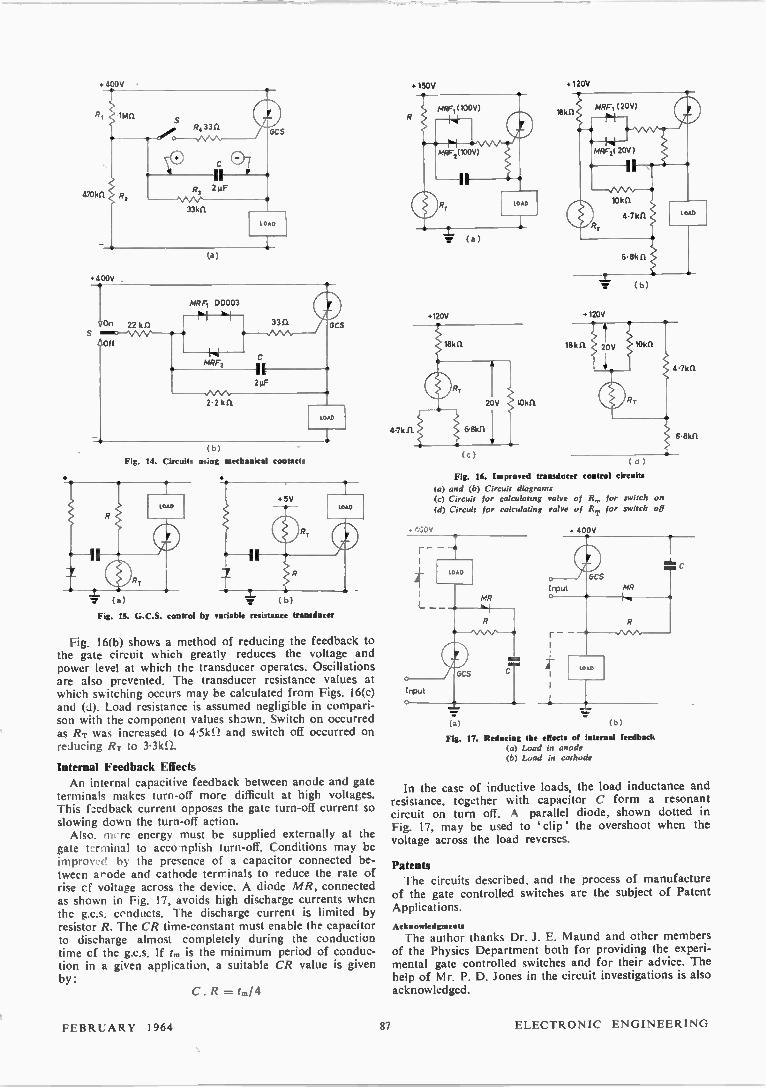
The performance of this simple circuit is poor since:
(1) The peak-to-peak ripple voltage at the output ter-minals is the sum of VR and VF.
(2) A high power Zener diode is required to conduct the turn-off current.
(3) The g.c.s. is not fired off by sharp gating pulses.
An improved performance is obtained from the circuits shown in Figs. 13(a) and 13(b).
In Fig. 13(a), components MRF, C2 and R3 form a relaxation oscillator which supplies a stream of turn-off gating pulses to the g.c.s. After each gating pulse, the g.c.s. may remain off or turn back on immediately depending on whether the output voltage is greater or less than Vz —
Input from
dc tacho-generator
Fig. II. Alternative motor g br control system
Unregulated input
Fig. 12. Simple i.e. vo tage regulator
Motor excitation winding
Load
In Fig. 13(b), a long tailed pair transistor circuit ampli-fies any error voltage and determines whether the capacitor C2 is charged positively or negatively. If the output voltage is low, transistor VT1 is cut off and VT2 conducts the tail' current. Current flows via resistor 121 to charge capa-citor C2 until the junction of RI and C2 is sufficiently posi-tive to fire the four-layer diode MRF1 so gating the g.c.s. on. The increasing output voltage eventually brings VT1 into conduction so causing capacitor C2 to charge to the opposite polarity until firing of the second four-layer diode turns off the g.c.s.
Circuits Using Mechanical Contacts
A high power load may be switched on and off via low power mechanical contacts using the circuits shown in Fig. 14. If power is applied to the circuit shown in Fig. 14(a),
capa itor C charges to a potential determined by the high valued resistors R1. R2 and R3. The voltage polarity across the capaLitor would be as shown in the figure. On closing the normally open contact S, the capacitor discharges via the low resistance path R4 and the g.c.s. gate-cathode terminals. The g.c.s. conducts and the load is energized. When the contacts open, the capacitor is again charged via the high valued resistors. However, since the cathode potential is now practically +400V, the capacitor voltage polarity will be the opposite to that shown. On closing contact S for the second time, a negative turn-off pulse is applied to the g.c.s. gate as the capacitor discharges.
The sequence is: Apply power — Load de-energized Close contacts — Load energizes Open contacts — Load remains energized Close contacts — Load de-energizes Open contacts — Load remains de-energized
The circuit gives latch-on/latch-off operation from a single press button contact. A divide by two' action is obtained. The circuit of Fig. 14(b) produces a sharp, high current
gating pulse on closing the low current, centre-stable, change-over switch S. On momentarily closing the 'on' contact, capacitor C charges until the forward biased Rl Unregulated input
o
Unregulated input
IMRZ
Fig. 13. Improved d.c. voltage regulators
(a) MRF
-o
diode MRF1 fires to gate the g.c.s. on and energize the load. No further pulses are produced and conditions are unaffected when the switch returns to its central position. On closing the off' contact, capacitor C charges to the opposite polarity until diode MRF2 fires to switch off the g.c.s. and de-energize the load. The load remains de-energized on returning the switch to its central position. A memory-latching action is obtained. An important feature of this latter circuit is that sharp
gating pulses are reliably obtained even under very poor switch conditions. Contact resistances up to 51cD and leak-age resistances down to 501d2 are tolerated by the circuit shown.
Transducer Control Fig. 15 shows variable resistance transducer control
circuits operating on the principle of Fig. 3(a). In Fig. 15(a) the load is energized at high values of transducer resistance RT and is de-energized at low values. In Fig. 15(b) the load is energized at low values of resistance RT. Smoothing of the load current may be obtained by adding the components shown in Fig. 17(a). Fig. 16(a) provides sharp gating pulses to fire the g.c.s.
both 'off' and on', and avoids continuous current into the gate terminal. Oscillations can be prevented by choos-ing the four layer diode breakdown voltages such that their sum exceeds the supply voltage. For the values given, RT must exceed 2R to fire the g.c.s. on. RT must then be decreased below R/2 to turn off the g.c.s.
ELECTRONIC ENGINEERING 86 FEBRUARY 1964
• 400V
(a)
•400V
/On 22 k 11 S M O/D - VV V- -o,--41
Off
MRF1 DD003
MRF2 ii 2µF
3311
2.2 kll
-T-( b )
Fig. 14. Circuits using mechanical contacts
GCS
LOAD
w (a) ( b)
Fig. IS. G.C.S. control by variable resistance transducer
Fig. 16(b) shows a method of reducing the feedback to the gate circuit w hich greatly reduces the voltage and power level at which the transducer operates. Oscillations are also prevented. The transducer resistance values at which switching occurs may be calculated from Figs. 16(c) and Load resistance is assumed negligible in compari-son with the component values shown. Switch on occurred as RT was increased to 4-.5k1.1 and switch off occurred on reducing Rr to 3.31(f)..
Internal Feedback Effects
An internal capacitive feedback between anode and gate terminals makes turn-off more difficult at high voltages. This feedback current opposes the gate turn-off current so slowing down the turn-off action. Also. !I re energy must be supplied externally at the
gate ur ninil to acco nplish turn-off. Conditions may be impro\ -(1 by the presence of a capacitor connected be-tween a-ode and cathode teririnals to reduce the rate of rise cf voltage across the device. A diode MR, connected as shown in Fig. 17, avoids high discharge currents when the g.c.s. conducts. 1 he discharge current is limited by resistor R. The CR time-constant must enable the capacitor to discharge almost completely during the conduction time cf the g.c.s. If t. is the minimum period of conduc-tion in a given application, a suitable CR value is given by:
C.R =1.14
• 150V
• 120V •120V
(c)
• 120V
( d )
Fig. 16. Improved transducer control circuits
(a) and (b) Circuit diagrams (c) Circuit for calculating valve of R,, for switch on
(d) Circuit for calculating valve of R, for switch off
MR
Input
(a) ( b
Fig. 17. Reducing the effects of internal feedback (a) Load in anode (b) Load in cathode
• 400V
GCS
Input MR
In the case of inductive loads, the load inductance and resistance, together with capacitor C form a resonant circuit on turn off. A parallel diode, shown dotted in Fig. 17, may be used to 'clip' the overshoot when the
voltage across the load reverses.
Patents The circuits described, and the process of manufacture
of the gate controlled switches are the subject of Patent Applications.
Acknowledgments
The author thanks Dr. J. E. Maund and other members of the Physics Department both for providing the experi-mental gate controlled switches and for their advice. The help of Mr. P. D. Jones in the circuit investigations is also acknowledged.
FEBRUARY 1964 87 ELECTRONIC ENGINEERING
Black Knight Electronic Flash Installation
for Optical Tracking By R. L. Aspden*, A.F.R.Ae.S., M.I.E.E.E.
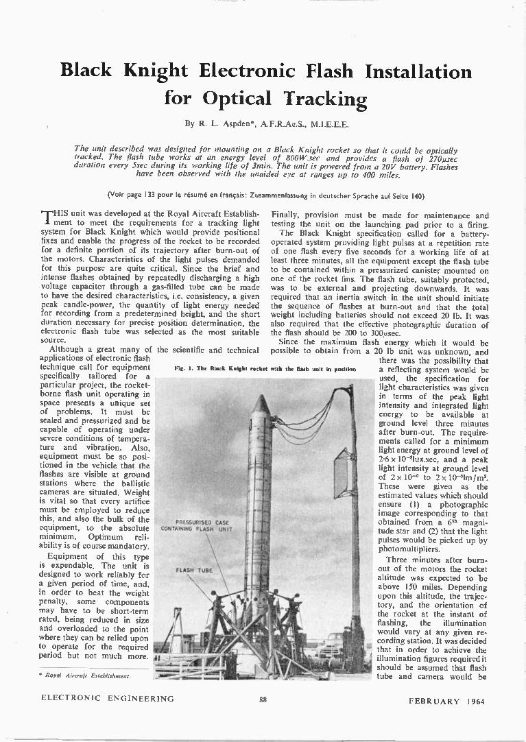
The unit described was designed for mounting on a Black Knight rocket so that it could be optically tracked. The flash tube works at an energy level of 800W.sec and provides a flash of 27Onsec duration every 5sec during its working life of 3min. The unit is powered from a 20V battery. Flashes
have been observed with the unaided eye at ranges up to 400 miles.
(Voir page 133 pour le résumé en français: Zusammenfassung in deutscher Sprache auf Seite 140)
1-11-1IS unit was developed at the Royal Aircraft Establish-'. ment to meet the requirements for a tracking light system for Black Knight which would provide positional fixes and enable the progress of the rocket to be recorded for a definite portion of its trajectory after burn-out of the motors. Characteristics of the light pulses demanded for this purpose are quite critical. Since the brief and intense flashes obtained by repeatedly discharging a high voltage capacitor through a gas-filled tube can be made to have the desired characteristics, i.e. consistency, a given peak candle-power, the quantity of light energy needed for recording from a predetermined height, and the short duration necessary for precise position determination, the electronic flash tube was selected as the most suitable source. Although a great many of the scientific
applications of electronic flash technique call for equipment specifically tailored for a particular project, the rocket-borne flash unit operating in space presents a unique set of problems. It must be sealed and pressurized and be capable of operating under severe conditions of tempera-ture and vibration. Also, equipment must be so posi-tioned in the vehicle that the flashes are visible at ground stations where the ballistic cameras are situated. Weight is vital so that every artifice must be employed to reduce this, and also the bulk of the equipment, to the absolute minimum. Optimum reli-ability is of course mandatory. Equipment of this type
is expendable. The unit is designed to work reliably for a given period of time, and, in order to beat the weight penalty, some components may have to be short-term rated, being reduced in size and overloaded to the point where they can be relied upon to operate for the required period but not much more.
• Royal Aircraft Establishment.
and technical
Fig. I. The Black Knight roeke
PRESSURISED CASE CONTAINING FLASH UNIT
FLASH TUBE \
-tâogoew. e maims ifflicom
t with the flub unit in position
Finally, provision must be made for maintenance and testing the unit on the launching pad prior to a firing. The Black Knight specification called for a battery-
operated system providing light pulses at a repetition rate of one flash every five seconds for a working life of at least three minutes, all the equipment except the flash tube to be contained within a pressurized canister mounted on one of the rocket fins. The flash tube, suitably protected, was to be external and projecting downwards. It was required that an inertia switch in the unit should initiate the sequence of flashes at burn-out and that the total weight including batteries should not exceed 20 lb. It was also required that the effective photographic duration of the flash should be 200 to 300,usec. Since the maximum flash energy which it would be
possible to obtain from a 20 lb unit was unknown, and there was the possibility that a reflecting system would be used, the specification for light characteristics was given in terms of the peak light intensity and integrated light energy to be available at ground level three minutes after burn-out. The require-meats called for a minimum light energy at ground level of 2.6 x 10-glux.sec, and a peak light intensity at ground level of 2x 10'6 to 2x 10-slm/m2. These were given as the estimated values which should ensure (1) a photographic image corresponding to that obtained from a 6th magni-tude star and (2) that the light pulses would be picked up by photomultipliers.
Three minutes after burn-out of the motors the rocket altitude was expected to be above 150 miles. Depending upon this altitude, the trajec-tory, and the orientation of the rocket at the instant of flashing, the illumination would vary at any given re-cording station. It was decided that in order to achieve the illumination figures required it should be assumed that flash tube and camera would be
ELECTRONIC ENGINEERING 88 FEBRUARY 1964

separated by 200 miles and that the angle between the normal at the camera station and the direction of the luminous flux should be 26°. To correct for atmospheric absorption a transmission factor of 0-6 was to be used, this being considered adequate for the worst condition envisaged. Ground illumination could therefore be cal-culated from known flash characteristics, as follows: Light energy in lux.sec = candle.sec in the flash x 6 x 10' x cos 26°/(distance in metres)2, and intensity in lumens/ m2 = peak candle-power in the flash x 6 x 10⁻¹ x cos 26°/(distance in metres)2. Limitations imposed by the weight penalty showed that
after exploiting every possibility the maximum energy per flash from a 20 lb unit would be 800W.sec. In order to gain reliability and avoid a thermal loading which would demand the additional complexity of forced cooling equip-ment the flash tube selected had a single flash rating in excess of this figure. Under conditions of partial loading a luminous efficiency of 30 to 32 Im/W could be expected from a xenon filled tube. It was therefore estimated that the output per flash would be of the order of 2500 candle.sec. The tube used produced 2450 candle.sec. Measurements
made after fitting a very small annular reflector indicated that the flash should be adequate for its mission and this was found to be the case. In actual firings of Black Knight the reflector was used: this is not shown on the photo-graphs. A photo-transistor pick-up which monitored the flashes is also omitted. This operated a separate unit which transmitted a radio signal to ground for each light pulse. The complete flash unit in its pressurized canister and
mounted on one of the rocket fins is seen in Fig. 1.
The Flash Tube, Operating and Light Characteristics
The flash tube selected for this project was the Mazda type FA21, a xenon filled tube with external trigger elec-trode, operating normally on 1100V and with a single flash rating of 1600W.sec. In order to obtain an 800W.sec dis-charge giving the short pulse duration and high peak light intensity required it was necessary to operate the tube at 2kV with a capacitor of 400µF. On loading tests tubes of this type were run at a frequency of one 800W.sec flash every five seconds for periods up to fifteen minutes, with a cover glass in position to simulate operational conditions. Trigger pulse voltage was 10 to 15kV. The tube proved to be very reliable and for the three minute life demanded the temperature .rise was not excessive. No trouble was experienced due to erratic flashing. Misfiring can some-times occur as a result of the conduction of a glass envelope at high temperatures, when a portion of the trigger pulse energy is shunted to earth. In the present case this trouble was unlikely since the voltage used approached that required for self-breakdown, a condition in which a flash tube is very readily triggered. By applying a pulse of fast rise time and high amplitude to a tube operated in this manner the likelihood of misfiring is remote. Freedom from hold-over' was mandatory. Hold-over'
is a condition sometimes encountered in which the flash will not extinguish but turns into a continuous arc in which the current is only limited by the resistance in the power supply to the capacitors. This possibility was eliminated by momentarily isolating the tube at the moment of flash-ing, thus enabling it to deionize and regain its non-conducting state before voltage again appeared across it. Of the rare gases xenon gives the highest luminous
efficiency when used with the current densities attained in a flash discharge. Under reasonable loading the spectrum is a continuum in the visible region with an equivalent
colour temperature of 6000° to 9000°K. Measurements were made of peak light intensity, the total luminous flux radiated, and the duration of the flash. The effective photo-graphic duration was taken as the time required for the intensity to drop to -I-rd of the peak value. With the excep-tion of readings taken for a polar diagram no reflector was used.
The light pulses were recorded by a vacuum photocell and oscilloscope and since it was necessary that measure-ments be made in visual units—candle-power and lumens— the spectral response of the photocell was corrected by filters to give a response curve approximating closely to that of the human eye. Measurements were taken along the tube axis. Accurate determination of the instantaneous flux from a flash discharge is difficult since the tube is neither a sphere nor a line source. With measurements taken along the tube axis the conversion factor lies between that for a sphere (4r) or a line (e). It is normal procedure
LIGHT INTENSITY (CPx10')
10
8
6
4
2
o 100 200 300 400
MICROSECONDS
500
Fig. 2. Time/intensity carve. 800 W.sec discharge. 400gF. 2kV
600
to use the arbitrary factor of 10. Thus the flux in lumens = 10/ where / is in candle-power.
Transient light values in a flash discharge are extremely high and to obtain accuracy it was ensured that a linear current-light relationship was maintained at all light levels. The c.r.o. time/intensity traces were photographed with a calibrated time-base and from these records duration of the flash was obtained and the peak intensity and total integrated flux calculated. A typical time/intensity curve is given in Fig. 2. This was taken during a normal run with the tube flashing regularly every five seconds, the energy in the capacitor (nominal) being 800W.sec. The peak intensity was 10 x 106 candle-power and integrated light output 2450 candle.sec, giving a luminous efficiency of approximately 31 lm/W. The effective duration of the flash was 270,usec.
Due to tolerances in manufacture of the capacitors used the actual capacitance across the tube tended to be greater than the nominal rating. Circuit losses brought the energy dissipated in the tube itself to approximately 800W.sec. Any variation in the measured quantities due to random selection of capacitors was not found to be significant.
The flash duration was satisfactory and the calculated peak intensity at ground level was adequate. It was neces-sary, however, to increase the integrated flux at ground level. This was done by fitting a very small annular reflector, the final design producing illumination at ground level over an angle of 90° which met the specification, the
FEBRUARY 1964 89 ELECTRONIC ENGINEERING

calculated flux being 3 x 10⁻⁸ lux.sec and the intensity 9.7 x 10⁻⁵ lm/m2.
The Flash Unit, Electrical Design
As previously stated the flash tube was operated at 2kV, requiring a capacitor of 400 g. The weight penalty did not allow the use of a paper capacitor, which would have been preferred for this purpose, and in order to meet the specification there was no alternative but to use the elec-trolytic type. These are limited to a 500V rating per unit and consequently four capacitor banks in series, each of 1600µF were used to provide the required 800W.sec at 2kV. Eight 800FLF 500V working Dubilier capacitors in standard cans gave the required energy storage with the minimum
Trigger wire
Pulse coil 100kr1
Primary 0.113F
J. J. urc,
1. 1. c37,__Tc
3
Triggering switch T
Rotary distributor switch
Li Flash tube C57 • TC, 7.4 21
e
c / °Tic, "
Battery @ test points w
Inertia 0 switch
shorting points
24V ▪ '
—r▪ - +
2
.4-Shaft S
500V
•
Rotary Transformer
y Rotary transformer
A starting switch
Inertia switch
Fig. 3. The flash unit circuit
of weight, and also a suitable configuration. In order to -obtain the optimum light output and peak amplitude the capacitors were modified by the makers and the internal resistance reduced until a final design was evolved which met requirements. Electrolytics require re-forming after -storage to bring the leakage current to normal, but this is
./ a simple operation. They were quite successful in this application.
Since it was necessary to operate the flash tube at 2kV in order to obtain the desired flash characteristics the eight capacitors were used in a series-parallel arrangement. The unconventional method of charging is shown in Fig. 3. The -capacitors CI to C8 are arranged in four banks, each bank •containing two 8001ÁF capacitors in parallel. The four banks are permanently connected in series with the flash tube by heavy leads to reduce losses during discharge as far as possible. Each pair of capacitors is charged in turn •to 500V through a rotary distribution switch, power being provided by a rotary transformer driven by two type SZ
12V 60 ampere.minute silver-zinc batteries in series. Opera-tion is as follows.
On burn-out of the rocket motors the inertia switch closes allowing the 24V battery to start a small motor M which turns, through reduction gearing the shaft S, on which are mounted two leaf brushes L1 L2, insulated from each other, and which wipe over quadrants. Immediately motor M begins to turn the shaft S a cam on this shaft closes a microswitch to start the rotary transformer. The 500V supply from the rotary is applied to the two rotating leaf brushes via insulated brushes and slip rings. As the rotating leaf brushes successively wipe over the pairs of quadrants 11, 22, 33 and 44, they put 500V across each capacitor bank in turn. During the period when capacitors C1 and C2 are being charged, that is when quadrants 11 are live', the small 0.1,uF capacitor Cg in the triggering circuit is charged through resistor R and the primary winding of a high voltage pulse coil. Immediately the fourth bank of capacitors is charged, when 2kV appears across the flash tube, a second end cam on shaft S closes another micro-switch T, thus discharging C9 through the primary winding of the pulse coil. The high voltage pulse from the secondary winding is applied to the triggering wire electrode and fires the flash tube. The cycle takes five seconds and is then repeated.
The rotary transbrmer was developed from the type WS.25/13 M1 produced by Mortley Sprague Ltd, which provided an output of 550V 100mA at 14 000rev/min with a 28V d.c. input. This unit is very small and compact and since the required life was only three minutes it was expected that the machine could be loaded to provide the necessary output. No current limiting resistance was used. The charging time to bring all capacitor banks to 500V could not be reduced below 8.5sec with zero volts initially on the capacitors and fully charged batteries giving 28V input on load. The rotary was therefore modified by the makers, being rewound for a rotational speed of 20 000rev/ min and having an effective secondary resistance of 220e instead of the 360f2 of the original machine. After modifi-cation the unit was satisfactory in every way and reliable under excessive loading. Capacitors could be charged in the time available and, due to the fact that the flash tube used would operate below IkV, the unit continued to run after the three-minute period with gradually reducing flash energy as the battery became exhausted. The rotary trans-former was run on test under very abnormal loading for fifteen minutes without breakdown and met all vibration and acceleration requirements.
The triggering coil is a miniature pulse transformer by Dawe Instruments Ltd, producing a damped oscillation of 10 to 15kV peak amplitude when the small capacitor is discharged through the primary winding. Voltage on this trigger capacitor (Cg in Fig. 3) is always sufficient to provide a pulse which will ionize the gas and fire the flash tube at its lowest operating voltage.
The Flash Unit, Mechanical Design
The arrangement of the various components is seen in Fig. 4. A little more than half of the available space is used to accommodate the eight capacitors, these being positioned to allow of quick replacement, the heavy leads to the flash tube being as short as possible consistent with this facility. The two silver-zinc batteries fit into the end clamp. The remainder is divided into four compartments containing the rotary charging and control switch, the inertia switch, the triggering unit, and the rotary trans-former.
In order to mount the flash tube satisfactorily the spiral
ELECTRONIC ENGINEERING 90 FEBRUARY 1964
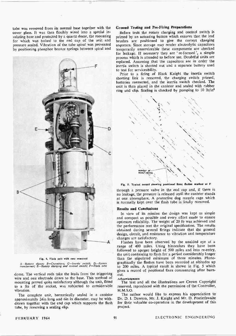
tube was removed from its normal base together with the cover glass. It was then flexibly wired into a special in-sulating base and protected by a quartz dome, the mounting for which was bolted to the end cap of the unit and pressure sealed. Vibration of the tube spiral was prevented by positioning phosphor bronze springs between spiral and
Fig. 4. Flash unit with case removed
A—Battery damp; B—Capacitors; C—Inertia switch; D—Rotary transformer; E—Rotary charging and control switch; F—Flash tube
dome. The vertical rods take the leads from the triggering wire and one electrode down to the base. This method of mounting proved quite satisfactory although the unit, fitted to a fin of the rocket, was subjected to considerable vibration. The complete unit, hermetically sealed in a canister
approximately 24in long and 6in in diameter, may be with-drawn together with the end cap which supports the flash tube, by removing a sealing clip.
Ground Testing and Pre-Firing Preparations Before tests the rotary charging and control switch is
primed by an actuating button which ensures that the leaf brushes are positioned to give the correct charging sequence. Since storage may render electrolytic capacitors temporarily unserviceable these components are checked for leakage. If necessary they are re-formed', a simple process which is attended to before use. Doubtful units are replaced. Assuming that the capacitors are in order the inertia switch is shorted out and a separate battery used to test for serviceability. Prior to a firing of Black Knight the inertia switch
shorting link is removed, the charging switch primed, batteries connected, and the inertia switch checked. The unit is then placed in the canister and sealed with rubber ring and clip. Sealing is checked by pumping to 10 lb/in2
\ \.
BURNOUT OF ROCKET MOTORS
• . \
• \ Fig. 5. Typical record showing positional fixes; flashes marked at F
through a pressure valve in the end cap and, if there is no leakage, the pressure is released until the canister stands at one atmosphere. A protective dog muzzle cage which is normally kept over the flash tube is finally removed.
Results and Conclusions In view of its mission the design was kept as simple
and compact as possible and every effort made to ensure optimum reliability. The weight of 20 lb was achieved and the performance met the original specification. The results obtained during several firings indicate that the general design, circuit, and resistance to vibration and temperature changes are satisfactory. Flashes have been observed by the unaided eye at a
range of 400 miles. Using binoculars they have been followed to apogee height of 500 miles and into re-entry, the unit continuing to flash for a period considerably longer than the stipulated minimum of three minutes. Photo-graphically the flashes have been recorded at altitudes up to 200 miles. A typical result is shown in Fig. 5 which gives a record of positional fixes commencing after burn-out. Acknowledgments
The text and all the illustrations are Crown Copyright reserved, reproduced with the permission of the Controller, H.M.S.O. The author would like to express his appreciation to
Dr. D. I. Dawton, Mr. J. Knight and Mr. D. Postlethwaite for their valuable co-operation in the development of this project.
FEBRUARY 1964 91 ELECTRONIC ENGINEERING
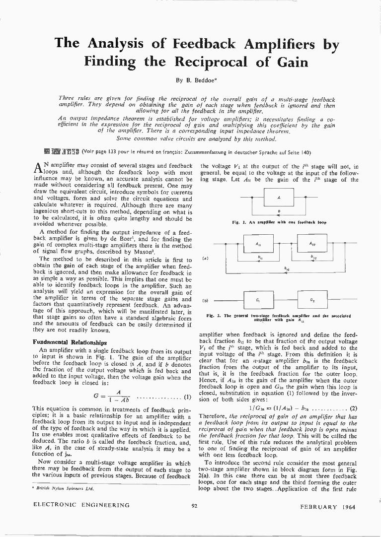
The Analysis of Feedback Amplifiers by
Finding the Reciprocal of Gain By B. Beddoe*
Three rules are given for finding the reciprocal of the overall gain of a multi-stage feedback amplifier. They depend on obtaining the gain of each stage when feedback is ignored and then
allowing for all the feedback in the amplifier.
An output impedance theorem is established for voltage amplifiers; it necessitates finding a co-efficient in the expression for the reciprocal of glin and multiplying this coefficient by the gain
of the amplifier. There is a corresponding input impedance theorem.
Some common valve circuits are analysed by this method.
TrI7r, (Voir page 133 pour le résumé en français: Zusammenfassung in deutscher Sprache auf Seite 140)
AN amplifier may consist of several stages and feedback loops and, although the feedback loop with most
influence may be known, an accurate analysis cannot be made without considering all feedback present. One may draw the equivalent circuit, introduce symbols for currents and voltages, form and solve the circuit equations and calculate whatever is required. Although there are many ingenious short-cuts to this method, depending on what is to be calculated, it is often quite lengthy and should be avoided whenever possible.
A method for finding the output impedance of a feed-back amplifier is given by de Boer', and for finding the gain of complex multi-stage amplifiers there is the method of signal flow graphs, described by Mason'.
The method to be described in this article is first to obtain the gain of each stage of the amplifier when feed-back is ignored, and then make allowance for feedback in as simple a way as possible. This implies that one must be able to identify feedback loops in the amplifier. Such an analysis will yield an expression for the overall gain of the amplifier in terms of the separate stage gains and factors that quantitatively represent feedback. An advan-tage of this approach, which will be manifested later, is that stage gains so often have a standard algebraic form and the amounts of feedback can be easily determined if they are not readily known.
Fundamental Relationships An amplifier with a single feedback loop from its output
to input is shown in Fig. I. The gain of the amplifier before the feedback loop is closed is A, and if b denotes the fraction of the output voltage which is fed back and added to the input voltage, then the voltage gain when the feedback loop is closed is:
G = 1 — Ab A
(I)
This equation is common in treatments of feedback prin-ciples; it is a basic relationship for an amplifier with a feedback loop from its output to input and is independent of the type of feedback and the way in which it is applied. Its use enables most qualitative effects of feedback to be deduced. The ratio b is called the feedback fraction, and, like A, in the case of steady-state analysis it may be a function of j‘... Now consider a multi-stage voltage amplifier in which
there may be feedback from the output of each stage to the various inputs of previous stages. Because of feedback
• British Nylon Spinners Ltd.
the voltage Vi at the output of the ith stage will general, be equal to the voltage at the input of the ing stage. Let A11 be the gain of the ith stage
(a)
(b)
A
Fig. I. An amplifier with one feedback loop
AII
b„
b I2
A 22
not, in follow-of the
b„
G, G,
Fig. 2. The general two-stage feedback amplifier and the associated amplifier with gain Ai.,
amplifier when feedback is ignored and define the feed-back fraction bij to be that fraction of the output voltage VI of the ith stage, which is fed back and added to the input voltage of the eh stage. From this definition it is clear that for an n-stage amplifier bi0 is the feedback fraction from the output of the amplifier to its input, that is, it is the feedback fraction for the outer loop. Hence, if Ai0 is the gain of the amplifier when the outer feedback loop is open and Gi0 the gain when this loop is closed, substitution in equation (1) followed by the inver-sion of both sides gives:
1/G1. = (1/A10) — bi. (2) Therefore, the reciprocal of gain of an amplifier that has a feedback loop from its output to input is equal to the reciprocal of gain when that feedback loop is open minus the feedback fraction for that loop. This will be called the first rule, Use of this rule reduces the analytical problem to one of finding the reciprocal of gain of an amplifier with one less feedback loop. To introduce the second rule consider the most general
two-stage amplifier shown in block diagram form in Fig. 2(a). In this case there can be at most three feedback loops, one for each stage and the third forming the outer loop about the two stages. .Application of the first rule
ELECTRONIC ENGINEERING 92 FEBRUARY 1 964
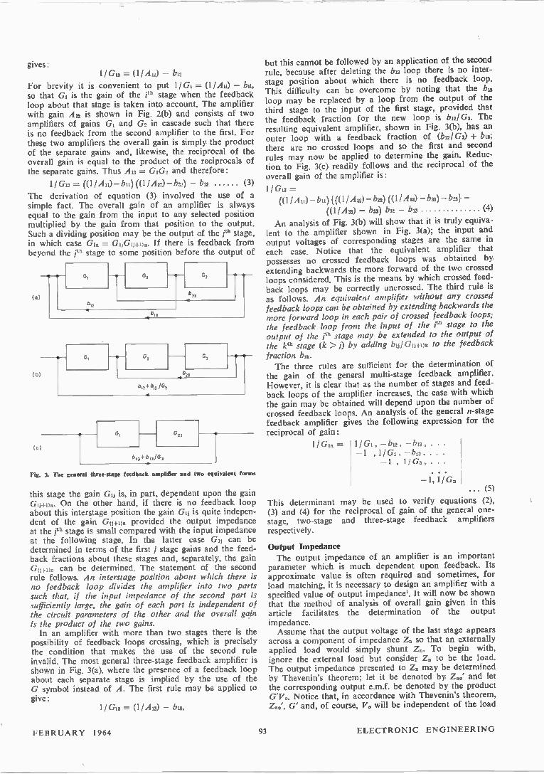
gives: 1/Gu = (11 Au) — b12
For brevity it is convenient to put 1/G3 = (1 /Au) — bu, so that G1 is the gain of the ith stage when the feedback loop about that stage is taken into account. The amplifier with gain Au is shown in Fig. 2(b) and consists of two amplifiers of gains GI and G2 in cascade such that there is no feedback from the second amplifier to the first. For these two amplifiers the overall gain is simply the product of the separate gains and, likewise, the reciprocal of the overall gain is equal to the product of the reciprocals of the separate gains. Thus An = GiG2 and therefore:
1 / G12 = ((1 /Ali) — bu) ((1 I b22) — bu (3)
The derivation of equation (3) involved the use of a simple fact. The overall gain of an amplifier is always equal to the gain from the input to any selected position multiplied by. the gain from that position to the output. Such a dividing position may be the output of the ¡th stage, in which case G1. = GI,G(t-Fi)n. If there is feedback from beyond the eh stage to some position before the output of
G,
(a)
b l,
63 0, — 0 -0 -
13
(b)
(c)
0, G,
3
b13+ bu 103
G, G„
+b12 /G3
Fig. 3. The general three-stage feedback amplifier and two equi.alent forms
this stage the gain Gu is, in part, dependent upon the gain Gu+u.. On the other hand, if there is no feedback loop about this interstage position the gain G11 is quite indepen-dent of the gain G04.un provided the output impedance at the ¡th stage is small compared with the input impedance at the following stage. In the latter case Gu can be determined in terms of the first j stage gains and the feed-back fractions about these stages and, separately, the gain Gui•un can be determined. The statement of the second rule follows. An interstage position about which there is no feedback loop divides the amplifier into two parts such that, if the input impedance of the second part is sufficiently large, the gain of each part is independent of the circuit parameters of the other and the overall gain is the product of the two gains. In an amplifier with more than two stages there is the
possibility of feedback loops crossing, which is precisely the condition that makes the use of the second rule invalid. The most general three-stage feedback amplifier is shown in Fig. 3(a), where the presence of a feedback loop about each separate stage is implied by the use of the G symbol instead of A. The first rule may be applied to give:
1/G13 = (1 I An) — bu,
but this cannot be followed by an application of the second rule, because after deleting the bu loop there is no inter-stage position about which there is no feedback loop. This difficulty can be overcome by noting that the bu loop may be replaced by a loop from the output of the third stage to the input of the first stage, provided that the feedback fraction for the new loop is bu! G3. The resulting equivalent amplifier, shown in Fig. 3(b), has an outer loop with a feedback fraction of (6121 G3) + bu; there are no crossed loops and so the first and second rules may now be applied to determine the gain. Reduc-tion to Fig. 3(c) readily follows and the reciprocal of the overall gain of the amplifier is:
I / Gia = ((1 IA11)-1.11)1((h I A22) — b22) ((1 Au) — bu) — b231 —
((1 I A33) — bu) 142 — bia (4)
An analysis of Fig. 3(b) will show that it is truly equiva-lent to the amplifier shown in Fig. 3(a); the input and output voltages of corresponding stages are the same in each case. Notice that the equivalent amplifier that possesses no crossed feedback loops was obtained by extending backwards the more forward of the two crossed loops considered. This is the means by which crossed feed-back loops may be correctly uncrossed. The third rule is as follows. An equivalent amplifier without any crossed feedback loops can be obtained by extending backwards the more forward loop in each pair of crossed feedback loops; the feedback loop from the input of the ità stage to the output of the eh stage may be extended to the output of the kth stage (k > j) by adding bulGu+i)k to the feedback fraction bu,. The three rules are sufficient for the determination of
the gain of the general multi-stage feedback amplifier. However, it is clear that as the number of stages and feed-back loops of the amplifier increases, the ease with which the gain may be obtained will depend upon the number of crossed feedback loops. An analysis of the general n-stage feedback amplifier gives the following expression for the reciprocal of gain:
1 1G1. = 1 /GI, —632, —b13, • • • —1 ,1 /G2 , —623, ...
— 1 , 1/G3,...
—1,1/G. • • • (5)
This determinant may be used to verify equations (2), (3) and (4) for the reciprocal of gain of the general one-stage, two-stage and three-stage feedback amplifiers respectively.
Output Impedance The output impedance of an amplifier is an important
parameter which is much dependent upon feedback. Its approximate value is often required and sometimes, for load matching, it is necessary to design an amplifier with a specified value of output impedancel. It will now be shown that the method of analysis of overall gain given in this article facilitates the determination of the output impedance. Assume that the output voltage of the last stage appears
across a component of impedance Z. so that an externally applied load would simply shunt Z.. To begin with, ignore the external load but consider Z. to be the load. The output impedance presented to Z. may be determined by Thevenin's theorem; let it be denoted by Z.0' and let the corresponding output e.m.f. be denoted by the product G'Vo. Notice that, in accordance with Thevenin's theorem,
G' and, of course, V. will be independent of the load
FEBRUARY 1964 93 ELECTRONIC ENGINEERING
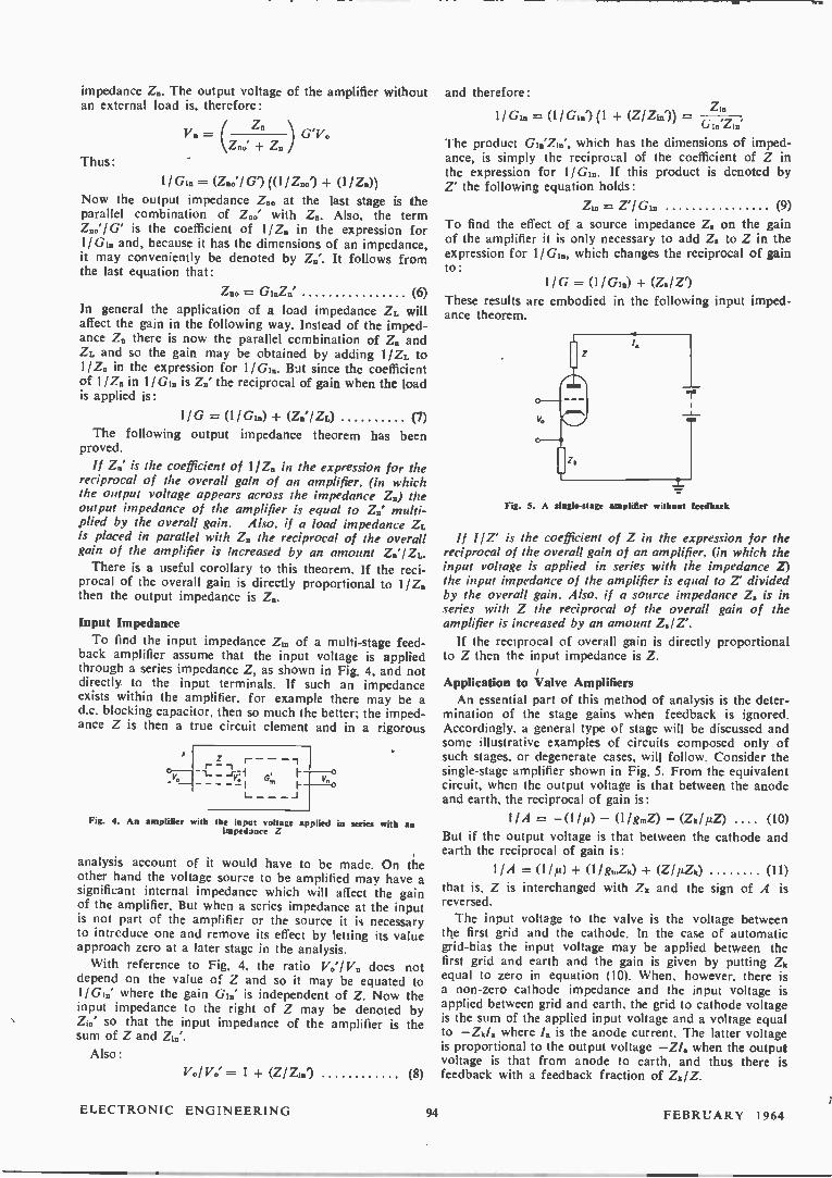
impedance Z. The output voltage of the amplifier without an external load is, therefore:
( Z. ) 'v0 Vn
Thus: Z.' + Zn
11 G1. -= 1 G') (0 1 Znol + (1 /Z0))
Now the output impedance Z.0 at the last stage is the parallel combination of Z..' with Z. Also, the term Zio' 1 G' is the coefficient of 1/Z0 in the expression for 1/G10 and, because it has the dimensions of an impedance, it may conveniently be denoted by Z.'. It follows from the last equation that:
Zno = (6) In general the application of a load impedance ZL will affect the gain in the following way. Instead of the imped-ance Z. there is now the parallel ccmbination of Z. and ZL and so the gain may be obtained by adding I /ZL to 1/Z0 in the expression for 1 /Gin. But since the coefficient of 1/Z. in 1/G1. is Zn' the reciprocal of gain when the load is applied is:
11G = (1 1 Gin) + (ZinZL) (7) The following output impedance theorem has been
proved.
If Zr,' is the coefficient of 11Z,, in the expression for the reciprocal of the overall gain of an amplifier, (in which the output voltage appears across the impedance Zu) the output impedance of the amplifier is equal to Z.' multi-plied by the overall gain. Also, if a load impedance ZL is placed in parallel with Zn the reciprocal of the overall gain of the amplifier is increased by an amount ZJIZL.
There is a useful corollary to this theorem. If the reci-procal of the overall gain is directly proportional to 1/Z,, then the output impedance is Z..
Input Impedance
To find the input impedance Zin of a multi-stage feed-back amplifier assume that the input voltage is applied through a series impedance Z, as shown in Fig. 4, and not directly to the input terminals. If such an impedance exists within the amplifier, for example there may be a d.c. blocking capacitor, then so much the better; the imped-ance Z is then a true circuit element and in a rigorous
r — --t_ — G
— J
Fig. 4. An amplifier with the input voltage applied in eerie' with an impedance Z
analysis account of it would have to be made. On the other hand the voltage source to be amplified may have a significant internal impedance which will affect the gain of the amplifier. But when a series impedance at the input is not part of the amplifier or the source it is necessary to intrcduce one and remove its effect by letting its value approach zero at a later stage in the analysis.
With reference to Fig. 4, the ratio V.'/V0 does not depend on the value of Z and so it may be equated to 1/Gin' where the gain GI.' is independent of Z. Now the input impedance to the right of Z may be denoted by Z.' so that the input impedance of the amplifier is the sum of Z and Zia%
Also:
110/V0' = 1 + (Z/Z10') (8)
and therefore: Zia
1 / Gln -= (1 / G in') (1 (Z/ Zia ')) = Gin'Zin"
The product Gin'Zin', which has the dimensions of imped-ance, is simply the reciprocal of the coefficient of Z in the expression for 1/Gik. If this product is denoted by Z' the following equation holds:
Z. = Z'/ (9) To find the effect of a source impedance Z. on the gain of the amplifier it is only necessary to add Z. to Z in the expression for I/G10, which changes the reciprocal of gain to:
1/G = (1/Gin) + (Z.1 Z')
These results are embodied in the following input imped-ance theorem.
Z5
—t
Fig. 5. A single-stage amplifier without feedback
If 11Z' is the coefficient of Z in the expression for the reciprocal of the overall gain of an amplifier, (in which the input voltage is applied in series with the impedance Z) the input impedance of the amplifier is equal to Z' divided by the overall gain. Also, if a source impedance Z. is in series with Z the reciprocal of the overall gain of the amplifier is increased by an amount Z,/Z'.
If the reciprocal of overall gain is directly proportional to Z then the input impedance is Z.
Application to Valve Amplifiers An essential part of this method of analysis is the deter-
mination of the stage gains when feedback is ignored. Accordingly. a general type of stage will be discussed and some illustrative examples of circuits composed only of such stages, or degenerate cases, will follow. Consider the single-stage amplifier shown in Fig. 5. From the equivalent circuit, when the output voltage is that between the anode and earth, the reciprocal of gain is:
11A = —(1/,u) — (11 g.Z) — (Zk/µZ) .... (10)
But if the output voltage is that between the cathode and earth the reciprocal of gain is:
11A = (I /IL) + (11 go2k) + (Z1 µZia (11)
that is, Z is interchanged with Zk and the sign of A is reversed.
The input voltage to the valve is the voltage between the first grid and the cathode. In the case of automatic grid-bias the input voltage may be applied between the first grid and earth and the gain is given by putting Zk equal to zero in equation (10). When, however, there is a non-zero cathode impedance and the input voltage is applied between grid and earth, the grid to cathode voltage is the sum of the applied input voltage and a voltage equal to —Zkik where la is the anode current. The latter voltage is proportional to the output voltage —Z/8 when the output voltage is that from anode to earth, and thus there is feedback with a feedback fraction of Zk/Z.
ELECTRONIC ENGINEERING 94 FEBRUARY 1964

CATHODE-FOLLOWER The valve circuit for the simple cathode-follower is
shown in Fig. 6(a). The output voltage is across Rk and therefore the reciprocal of gain without feedback is:
1/A .(1/µ)+ (11 g.Rk)
All the output voltage is subtracted from the applied input voltage to give the voltage between the grid and cathode. Therefore the feedback fraction is b = — I and the reciprocal of gain is:
11G = (11,u) + (11 g.Rk) + 1
Under the usual design conditions it and g.Rk are large compared with unity, thus making the gain just less than unity.
By the theorem on output impedance, the output imped-ance across Rk is equal to the gain multiplied by the co-efficient of 1 /Rk in the above expression for 11G. This coefficient, which is denoted by Z2', is equal to 1/g.
11g. .*. Z10 =
1 + (11 + (11 g.Rk)
which gives the result that the output impedance of the cathode-follower is approximately equal to 1 /g.. for the valve. The effect of applying an external load ZL to the output
is found by adding ZI'/ZL, that is, 11 g.Z1, to the last expression for 1/G, and if the magnitude of this load impedance is large compared with 1/gm no allowance for the load need be made. To apply the theorem on input impedance it is necessary
to imagine that the input voltage is applied in series with an impeoance Z, as shown in Fig. 6(b). Assume that the grid to cathode capacitance is C and use the suffix Z to indicate the inclusion of the impedance Z in the circuit. Thus, the reciprocal of gain when feedback is ignored is:
11A, = (1 + Z + Rk . (1/A) 1 floe )
and with feedback the reciprocal of gain is:
Z 1/Gs = (1/A) (1 + Rk + 1 1 /joiC
(b)
Fig. 6. Cathode-follower circuit
This ignores the fact that the internal resistance of the valve is in parallel with Rk, an effect which, if significant, could be easily allowed for. The reciprocal of the co-efficient of Z in 1/G. is A /jwC and so, by the theorem on input impedance, the input impedance is given by:
Zin(.) = 1.i(00 • (11 G2)
But this input impedance depends upon Z and therefore is tlot the true input impedance of the cathode-follower. By putting 2 = 0 in the last equation one can show that the input impedance is:
(a)
R,
v„
R,
R
(b)
V,
-r
Cc)
7. Anode-follower circuits
((1 + A)\ Zip = e2 +
jwC
A NODE-FOLLO WER
The anode-follower is an example of shunt connected feedback, which is of importance in analogue computers. The block diagram form for this circuit is shown in Fig. 7(a). The voltage fed back to the input is (Z1/Z2) (Vi—V0') and therefore the feedback fraction is (Z1/Z,) (1 —(1/A)); it depends upon the gain of the amplifier when feedback is ignored, except when this gain is large in which case the feedback fraction is effectively Zi/Z2.
Thus, the reciprocal of gain is given by:
1/G = (1/A) — (Zi/Z2) (1 — (1/A))
A valve circuit for the anode-follower is shown in Fig. 7(b); there is automatic grid-bias and the capacitor in series with R2 is merely for d.c. blocking. The output voltage is from the anode to earth and so the reciprocal of gain when feedback is ignored is:
1/A = —(1/µ) — (11 g.R) provided R Ri + R2
The feedback fraction is:
b = (RI 1 R2) (1 — (11A))
and therefore the reciprocal of gain with feedback is:
1/G = —(1/µ)—(1/g../2)—(Ri/R2)(1+(1/µ)+(l/gkiR))
If RI has the same value as R2 and A is large then G .•• —1, which means that the amplifier acts as a phase-invertor. The coefficient of 1 /R in 1 /G is —(1/gm) (1-F(RI/R2)) and therefore in the case of the phase-invertor the output impedance is approximately 21g.. To find the input impedance note that the reciprocal of
the coefficient of R, in 11G is —R21(1—(11 A)). There-fore, by the theorem on input impedance:
—R2 R2 Zip = . (1 /G) = R
(1 — (11 A)) (1 — A)
An anode-follower with a very low output impedance
FEBRUARY 1964 95 ELECTRONIC ENGINEERING

is described by Hammond3. It consists, as shown in Fig. 7(c), of a single amplifying stage followed by a cathode-follower, with overall shunt connected feedback. With effective automatic grid-bias and resistance-capacitance coupling the following expressions for feedback fractions and reciprocals of gain can be easily obtained:
1 /A11 = —(1 /Jul) — (1 /gieR') — (Ilene") ;
= ; b22 = — 1
1 /A22 = (I /us) + (1 /gm2Rk2), provided Rk2 <RI + R2
Now the gain of the amplifier before the overall shunt connected feedback is applied is Ales and therefore the reciprocal of gain is:
1/G12 = (1 /Ass) • (1/G2) — (Ri/R2)(1 — (1 /AliG2))
that is, in terms of the circuit parameters,
1 /G12 = — /14) + (1 /graiR') + (1 /eniR"))
(1 + (1 40+ (1 /gm2Rk2)) (1 +(Ri/R2))—(Ri/Rs)
The coefficient of 1/Rk2 is:
(1 + (Rs/R2)) (l/ens) . (1 /An)
Fig. 8. A low frequency selective amplifier
and by approximating the gain of the cathode-follower stage to unity the output impedance becomes:
Z20 _ gm2 (1 — 121,4111(Ri + R2))
Therefore, by making the gain of the first stage large the output impedance can be made very small indeed; as Hammond shows, it may be reduced to a small fraction of an ohm.
A Low FREQUENCY SELECTIVE AMPLIFIER This type of amplifier is described by Beattie and Cone
It consists of two stages between which there is a filter network. The filter has a transfer function which is real, positive and equal to 1/3 at a selective frequency, while at other frequencies its magnitude is reduced. Tuning is effected by means of two ganged resistors or capacitors. All feedback is applied through the cathode resistors, as shown in Fig. 8; there is positive feedback from the output to the input of the amplifier and negative feedback about each stage. Thus, due to the positive feedback, the overall gain will have a resonant peak at the selected frequency, and this will be stabilized by the negative feedback.
The feedback fractions and the reciprocals of gain when feedback is ignored are as follows:
(R3 +Rs) , + R5 1/Au = —(1 /µ1)—(1/gmiR1) — ; Du -=
M R1 R1
1 /Ast = —(11 4 — (11 gm2R2) — (R4+ R5) ; bits — 124 + Rs
1
1.42 R2 R2
b12 = R5/ R2
One may regard the filter as a passive stage with transfer function equal to 1/3, provided its input impedance is large compared with Rs. The reciprocal of the overall gain is, therefore:
1/G12 = {(1/m)+(l/gmiRi)+(1 +(1/1.u))((R3+R3)/Ri)}
3 ((l/Jus) + (1 I gni2R2) + (1 + (1 1 /12)) (le" R'))) — (Rs I R2) R2
This equation can be simplified in most cases. If, for example, R3 = Rs and the valves are identical pentodes so that u. is large, the reciprocal of gain is approximately:
1/G12 = (3 R2/R1 R2) (RS/ R2),
where R = (11 gm) + R3 -F R5
In this case the reciprocal of gain is inversely propor-tional to R2, which is the resistor across which the output voltage appears. Thus, by the corollary to the theorem on output impedance, R2 is the output impedance of the amplifier. One other point is worth mentioning: the condition that
the amplifier becomes an oscillator is 1 /G12 = 0, which for the approximate treatment gives RIR1 = 3R2.
Conclusions
The arguments and illustrations given above show that there are advantages in finding the reciprocal of gain of a feedback amplifier in terms of its stage gains when feed-back is ignored and its feedback fractions. Three rules, which are easy to apply, have been established, and these are sufficient to find the overall gain of the amplifier. Alternatively the stage gains and feedback fractions may be substituted into a determinantal expression for the overall gain. The method is of general application and not restricted to voltage amplifiers. When, however, a voltage amplifier is considered, the
input and output impedance may be found by applying the two theorems. All that is necessary is to pick out a coefficient from the expression for the reciprocal of gain and multiply, or divide as the case may be, by the gain of the amplifier. In the case of the output impedance theorem the relevant coefficient may be used to find the change in gain due to the application of an external load, and similarly the coefficient from the input impedance theorem may be used to find the change in gain due to a source impedance. Examples have been chosen from a class of valve
amplifiers. They show that once the basic stage gain with-out feedback is known, multistage amplifiers consisting of such stages can be analysed by determining the feed-back fractions in the amplifiers. Thus, the method depends not only on recognizing the existence of feedback in an amplifier, but on determining the feedback quantitatively.
Acknowledgments
The author wishes to thank Mr. C. W. Hooper for his encouragement and useful criticism of the work, and British Nylon Spinners Limited for permission to publish this article.
REFERENCES
I. DE BOER. E. Internal Resistance of Feedback Amplifiers. Electronic Engng. 34. 600 (1%2).
2. MASON, S. J. Feedback Theory--Further Properties of Signal Flow Graphs. Proc. Inst. Radio Engrs. 41, 1144 (1953).
3. HAMMOND, P. IL Feedback Theory and its Applications. (English Wiser-sities Press Ltd).
4. BEATTIE, J. R., CONN, G. K. T. A Simple Low Frequency Amplifier. Electronic Engng. 25, 299 (1953).
ELECTRONIC ENGINEERING 96 FEBRUARY 1964

The Elimination of Residual Even-Harmonic Distortion
in Transistor Oscillators
By P. J. Baxandall*, B.Sc.
There are certain applications where sine-wave oscillators having very low even-harmonic distor-tion are required. In this article the causes of such distortion in class D transistor oscillators are investigated and comparatively simple modifications are suggested to overcome them. The second har-monic distortion can readily be made less than 0.01 per cent, while with critical adjustment it can
be reduced to below 0.001 per cent.
(Voir page 133 pour le résumé en français: Zusammenfassung in deutscher Sprache auf Seite 140)
T HERE are certain applications of sine-wave oscillators 1 in which low even-harmonic distortion is a necessary attribute, odd-harmonic distortion being relatively un-important. In other words, a highly symmetrical waveform is the requirement. Examples of such applications are the drive oscillator
for a second-harmonic magnetic modulator" and the bias/ erase oscillator for a tape recording system'. To obtain low even-harmonic distortion, it is advan-
tageous, in the first place, to employ a push-pull oscil-lator circuit. If such a circuit could be constructed in a perfectly symmetrical manner, then it would necessarily follow, of course, that the waveform generated would also be perfectly symmetrical. In practice, however, owing to almost inevitable in-
equalities in the active devices and other components, and slight asymmetry in the winding of the centre-tapped tuning inductor, perfect physical symmetry is most un-likely to be achieved, and some even-harmonic distortion is therefore normally generated. The class ' D ' type of transistor oscillator', when operat-
ing at a sufficiently low frequency in relation to the cut-off frequency of the type of transistor employed, gives a performance which is remarkably little influenced by variations in most of the transistor parameters. This is because the transistors are used merely as on-off switches, their amplifying properties as such being relatively unimportant. A class' D' oscillator is thus a particularly appropriate
choice when low even-harmonic distortion is required. Nevertheless, with a straightforward class' D' oscillator,
a small amount of residual even-harmonic distortion will usually be present, but it may be balanced out by means of the simple circuit modifications described below.
The Basic Oscillator Circuit Class ' D ' oscillators can be of either the current-
switching or the voltage-switching type, and the theory of both of these has been presented in detail elsewhere'. The present article is concerned only with the current-
switching type of oscillator, whose basic circuit is shown in Fig. 1. A brief description of the functioning of this circuit is
as follows Each transistor conducts for the whole of a half period,
and is in a bottomed state while conducting, so that its collector is clamped substantially to the potential of the positive supply line. The collector of the non-conducting transistor meanwhile executes a negative-going half sine-wave of voltage. Thus, on the centre-tap of the tuned winding, a negative-going half sine-wave of voltage (of
• Royal Radar Establishment.
half the amplitude of that on the collector) occurs every half period, giving the waveform shown in Fig. 2. The mean value of this waveform is 2/r times the peak value,
rt, c.
Fig. I. Basic class ' D ' current-switching oscillator
I I 1
Voltage across C' (Fig 1)
.. - - • ( % ( t i 1 , 1 / N i I \ 1 i
i I 1 I ; I I / )1i ... '
Volage across C"
(e)
Fig. 2 (left). Voltage waveform at tuned circuit centre-tap
Fig. 3 (right). Voltage waveforms at collectors
and since no direct voltage can exist across the choke L, which is assumed to have negligible resistance, the sine-wave amplitude must adjust itself so that the following relationship is satisfied:
(2/7r) V . = V. (1) The base winding has typically one-tenth of the number
of turns on the collector winding, but provides a sufficiently large voltage to switch the almost-constant current flow-ing in Rb quite rapidly from one base to the other. This current is made sufficiently large to keep the conducting transistor bottomed, with an adequate margin to spare,
FEBRUARY 1964 97 ELECTRONIC ENGINEERING

at a collector current corresponding to the desired full output power. In the simplest concept of the functioning of the circuit,
the choke L is regarded as having so large an inductance that a virtually constant current flows in it. The choice of value in practice has been discussed in detail elsewhere'. In one version of the circuit built by the author, using
the improved base drive arrangement mentioned at the end of Section 4.2 of reference (4), an overall power efficiency of 96 per cent has been obtained.
Causes of Even-Harmonic Distortion
It has been found that there are two main mechanisms which are likely to give residual second-harmonic distor-tion in the Fig. 1 circuit. These are: (a) The base-emitter voltages of the two transistors,
when conducting, are, in general, not quite equaL This has the effect of slightly lengthening the con-duction time of one transistor and slightly shorten-ing that of the other*. Thus, instead of the tuned circuit being fed, in effect, with a square-wave current of 1: 1 ratio, containing no even harmonics, it is fed with an unsymmetrical current waveform which does contain even harmonics.
(b) There exist, inevitably, capacitances to earth from each end of the tuned winding in Fig. 1. These capacitances consist of the effective winding capa-citances of the tuned transformer, plus the collector capacitances of the transistors, and it is unlikely that the total capacitance values are equal on the two sides of the circuit. The voltage waveforms across the two capaci-
tances are shown in Fig. 3. A waveform of this kind contains only fundamental and even harmonics, the second-harmonic being phased as shown in broken line. Thus the second-harmonic voltage component is in the same phase across each of the capacitances, giving second-harmonic capacitance currents which balance out as far as producing a voltage across the tuned circuit is concerned, if the capacitances are equal. If the capacitances are unequal, however, there
will be a resultant effective second-harmonic current fed to the tuned circuit, giving rise to a small second-harmonic output voltage.
On considering the two mechanisms from the point of view of phase, it is found that the second-harmonic current fed to the tuned circuit by mechanism (b) is in quadrature with that due to mechanism (a). Another mechanism which can give second-harmonic
distortion is unintentional magnetic coupling between the choke and the tuned transformer. The choke has a large second-harmonic component of voltage across it and there-fore produces a stray magnetic field which can induce a second-harmonic voltage in the transformer. The phase of the second-harmonic output is the same as for mechanism (b) above. A similar effect to that last mentioned can occur if the
windings on the tuned transformer are arranged in a mag-netically unsymmetrical manner, so that a push-push current flowing in the centre-tap lead can cause the induc-tion of a voltage into the output winding. These unwanted magnetic effects can readily be reduced
to very small proportions, however, leaving (a) and (b) as the main effects to be dealt with. Other things being equal, the harmonic distortion at the
• At the moment when equal base currents are flowing in the two transistors, a finite voltage must exist between the bases so that the changeover process occurs about a voltage level, on the inter-base voltage waveform, which is displaced from the centre-line of the waveform.
oscillator output is inversely proportional to the tuned circuit Q, and this applies to all the harmonics'. Thus it pays to use a higher loaded Q than normal, when low distortion is of paramount importance, but if the loaded Q is made too large a percentage of the unloaded Q, then the overall efficiency of the oscillator is seriously reduced. A suitable compromise must, therefore, be struck.
Modifications to Eliminate Even-Harmonic Distortion
The effect of mechanism (a), described in the previous section, may be eliminated by introducing an appropriate small d.c. voltage between the transistor emitters, so as to offset the inequality in the base-emitter voltages when the transistors conduct. A convenient and satisfactory arrange-ment for providing the required adjustable voltage be-tween emitters is shown in the practical circuit of Fig. 4, which operates at about 3kc/s. A voltage of up to approxi-mately +70mV may be introduced, this being sufficient
20000 rad/sec .9 mW
Fig. 4. Practical circuit
COPPER SCREEN
ALL 28 SW G.
ENAMELLED
OUTPUT WINDING (2420
.4-BASE WINDING (211•21t)
COLLECTOR WINDINGS WOUND
IN REVERSE DIRECTIONS
(2141 EACH)
Fig. S. Winding details of tutted transformer
to cope with the normal spread in emitter-base voltage be-tween transistor samples. It should be noted that this simple method has the dis-
advantage that the balancing voltage introduced is depen-dent on the magnitude of the oscillator feed current which is in turn dependent on the supply voltage and on the load resistance. However, in many applications, the supply voltage and load are substantially constant, so that no difficulty is experienced. The effect of mechanism (b) may be eliminated by adding
extra capacitors so as to enable the total capacitances to earth from the two ends of the tuned circuit to be adjusted to equality. Additionally, it is desirable to wind the tuned transformer in such a way that the significant winding capacitances to earth are reasonably small and well balanced. The symmetrical arrangement adopted is shown in Fig. 5, the two halves of the primary winding being wound in reverse directions, with the collectors connected to the inner leads of these half windings*.
• It might be thought, at first sight, that a high degree of symmetry could be achieved by winding the two halves of the tuned winding together as a bifilar winding. Further consideration shows, however, that, though a high degree of equality in the magnetic coupling between the two halves of the tuned primary winding and the other windings is achieved in this way, the arrangement is highly unbalanced from the point of view of stray capad-tances, since one collector lead comes from inside of the winding and one from the outside.
ELECTRONIC ENGINEERING 98 FEBRUARY 1964
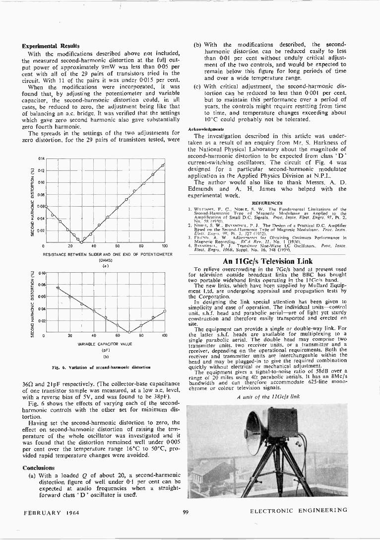
Experimental Results
With the modifications described above not included, the measured second-harmonic distortion at the full out-put power of approximately 9mW was less than 0-05 per cent with all of the 29 pairs of transistors tried in the circuit. With 11 of the pairs it was under 0-015 per cent. When the modifications were incorporated, it was
found that, by adjusting the potentiometer and variable capacitor, the second-harmonic distortion could, in all cases, be reduced to zero, the adjustment being like that of balancing an a.c. bridge. It was verified that the settings which gave zero second harmonic also gave substantially zero fourth harmonic. The spreads in the settings of the two adjustments for
zero distortion, for the 29 pairs of transistors tested, were
SECOND HARMONIC DISTORTION (%)
014
012
010
0 08
006
004
002
40 60 80 0 20 100
RESISTANCE BETWEEN SLIDER AND ONE END OF POTENTIOMETER
(OHMS)
(a)
010
o • 008 ce o
• 006 o o
o▪ 004
cc
VARIABLE CAPACITOR VALUE
(pf)
(b)
20 40 60 BO
Fig. 6. Variation of second-harmonic distortion
100
36n and 21pF respectively. (The collector-base capacitance of one transistor sample was measured, at a low a.c. level, with a reverse bias of 5V, and was found to be 38pF). Fig. 6 shows the effects of varying each of the second-
harmonic controls with the other set for minimum dis-tortion. Having set the second-harmonic distortion to zero, the
effect on second-harmonic distortion of raising the tem-perature of the whole oscillator was investigated and it was found that the distortion remained well under 0.005 per cent over the temperature range 16°C to 50°C, pro-vided rapid temperature changes were avoided.
Conclusions (a) With a loaded Q of about 20, a second-harmonic
distortion figure of well under 01 per cent can be expected at audio frequencies when a straight-forward class ' D ' oscillator is uses.
(b) With the modifications described, the second-harmonic distortion can be reduced easily to less than 0-01 per cent without unduly critical adjust-ment of the two controls, and would be expected to remain below this figure for long periods of time and over a wide temperature range.
(c) With critical adjustment, the second-harmonic dis-tortion can be reduced to less than 0-001 per cent, but to maintain this performance over a period of years. the controls might require resetting from time to time, and temperature changes exceeding about 10°C could probably not be tolerated.
Acknowledgments
The investigation described in this article was under-taken as a result of an enquiry from Mr. S. Harkness of the National Physical Laboratory about the magnitude of second-harmonic distortion to be expected from class 'D' current-switching oscillators. The circuit cf Fig. 4 was designed for a particular second-harmonic modulator application in the Applied Physics Division at N.P.L. The author would also like to thank Messrs. A. D.
Edmunds and A. H. James who helped with the experimental work.
REFERENCES
1. W TI ITANIS. F. C.. NOBIE., S. W . The Fundamental Limitations of the Second-Harmonic Type of Magnetic Modulator as Applied to the Amplification of Small D.C. Signals. Proc. Instn. Elect. Engrs. 97, Pt. 2, No. 58 (MO).
2. NOBI E. S. W .. BAXAN MI L. P. J. The Design of a Practical D.C. Amplifier Bawd on the Second-Harmonic Type of Magnetic Modulator. Proc. ¡nain. Elect. Engrs. 99, Pt. 2. 327 (1952).
3. FRIENn. A. W. Adjustments for Obtaining Ontimum Performance in Magnetic Recording. RCA Rev. 11, No. 1 (1950).
4. 134,(*.NOki I.. P. J. Transistor Sine-Wave LC Oscillators. Proc. Instn. Elect. Engrs. 1068, Suppl. No. 16, 748 (1959).
An 11Gc/s Television Link To relieve overcrowding in the 7Gc/s band at present used
for television outside broadcast links the BBC has bought two portable wideband links operating in the 11Gds band. The new links, which have been supplied by Mullard Equip-
ment Ltd, are undergoing appraisal and propagation tests by the Corporation. In designing the link special attention has been given to
simplicity and ease of operation. The individual units—control unit, s.h.f. head and parabolic aerial—are of light yet sturdy construction and therefore easily transported and erected on site. The equipment can provide a single or double-way link. For
the latter s.h.f. heads are available for multiplexing to a single parabolic aerial. The double head may comprise two transmitter units, two receiver units, or a transmitter and a receiver, depending on the operational requirements. Both the receiver and transmitter units are interchangeable within the head and may be plugged-in to give the required combination quickly without electrical or mechanical adjustment. The equipment gives a signal-to-noise ratio of 58dB over a
range of 20 miles using 4ft parabolic aerials. It has an 8Mc/s bandwidth and can therefore accommodate 625-line mono-chrome or colour television signals.
A unit of the IIGcls link
FEBRUARY 1964 ELECTRONIC ENGINEERING 99
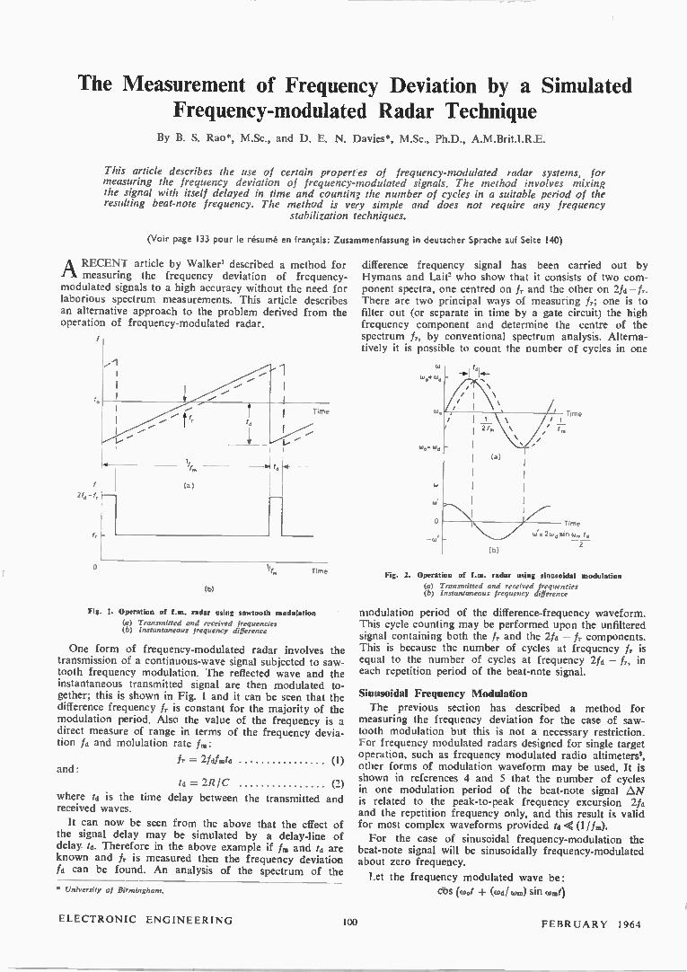
The Measurement of Frequency Deviation by a Simulated Frequency-modulated Radar Technique
By B. S. Rao*, M.Sc., and D. E. N. Davies*, M.Sc., Ph.D., A.M.Brit.I.R.E.
This article describes the use of certain properres of frequency-modulated radar systems, for measuring the frequency deviation of frequency-modulated signals. The method involves mixing the signal with itself delayed in time and counting the number of cycles in a suitable period of the resulting beat-note frequency. The method is very simple and does not require any frequency
stabilization techniques.
(Voir page 133 pour le résumé en français: Zusammenfassung in deutscher Sprache auf Seite 140)
A RECENT article by Walker' described a method for rk measuring the frequency deviation of frequency-modulated signals to a high accuracy without the need for laborious spectrum measurements. This article describes an alternative approach to the problem derived from the operation of frequency-modulated radar.
Time
(b)
Fig. 1. Operation of f.m. radar using sawtooth modulation
(a) Transmitted and received frequencies (b) Instantaneous frequency difference
One form of frequency-modulated radar involves the transmission of a continuous-wave signal subjected to saw-tooth frequency modulation. The reflected wave and the instantaneous transmitted signal are then modulated to-gether; this is shown in Fig. 1 and it can be seen that the difference frequency fr is constant for the majority of the modulation period. Also the value of the frequency is a direct measure of range in terms of the frequency devia-tion fa and molulation rate f.:
fr = 2fd.frata (1) and:
ta =2RIC (2)
where ta is the time delay between the transmitted and received waves.
It can now be seen from the above that the effect of the signal delay may be simulated by a delay-line of delay ta. Therefore in the above example if fm and ta are known and fr is measured then the frequency deviation fa can be found. An analysis of the spectrum of the
• University of Birmingham.
difference frequency signal has been carried out by Hymans and Lait" who show that it consists of two com-ponent spectra, one centred on fr and the other on 2.1a — There are two principal ways of measuring fr; one is to filter out (or separate in time by a gate circuit) the high frequency component and determine the centre of the spectrum fr, by conventional spectrum analysis. Alterna-tively it is possible to count the number of cycles in one
wo•wa
(b)
Time
Time
W'r2WdSIIiW,. td
— 2
Fig. 2. Operation of f.m. radar using sinusoidal modulation
(a) Transmitted and received frequencies (b) Instantaneous frequency difference
modulation period of the difference-frequency waveform. This cycle counting may be performed upon the unfiltered signal containing both the fr and the 2fa — fr components. This is because the number of cycles at frequency fr is equal to the number of cycles at frequency 21a — f, in each repetition period of the beat-note signal.
Sinusoidal Frequency Modulation
The previous section has described a method for measuring the frequency deviation for the case of saw-tooth modulation but this is not a necessary restriction. For frequency modulated radars designed for single target operation, such as frequency modulated radio altimeters', other forms of modulation waveform may be used. It is shown in references 4 and 5 that the number of cycles in one modulation period of the beat-note signal AN is related to the peak-to-peak frequency excursion 2fa and the repetition frequency only, and this result is valid for most complex waveforms provided ta < (1 ifia).
For the case of sinusoidal frequency-modulation the beat-note signal will be sinusoidally frequency-modulated about zero frequency.
Let the frequency modulated wave be:
en (toot + (waha.) sin cam/
ELECTRONIC ENGINEERING 100 FEBRUARY 1964
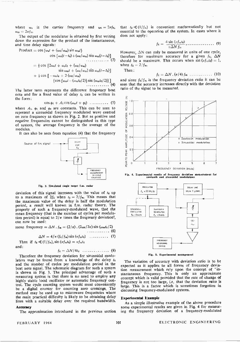
where w0 is the carrier frequency and wd = 27r/d, com = The output of the modulator is obtained by first writing
down the expression for the product of the instantaneous, and time delay signals:
Product = cos (wot + (wa/wm) sin wmt)
cos [wo(t td)+ (oh,/ (hm) sin (dr(t td)] (3)
= cos [2toof -I- Mold + (w8/ Ws)
sin Went + (wd/wm) sin wm(t te)] + 1 cos [ — wot, + 2 (wd/ wm)
{cos (wt — (wmtd/ 2)) sin (wmtd/ 2)1] (4)
The latter term represents the difference frequency beat note and for a fixed value of delay td can be written in the form:
cos 07 + A1 cos (wt + g)2) (5)
where A1, 01 and 02 are constants. This can be seen to represent a sinusoidal frequency modulated wave centred on zero frequency as shown in Fig. 2. But as positive and negative frequencies cannot be distinguished in this type of system, the average frequency is the average of the modulus. It can also be seen from equation (4) that the frequency
Source of f rn signal DEL AY
LINE
td
FREQUENCY
MEASUREMENT
NY CYCLE
COUNTING
Fig. 3. Simulated single target fan. radar
deviation of this signal increases with the value of td up to a maximum of 21a when td = 2/fm. This means that the maximum value of the delay is half the modulation period, a result well known in f.m. radar theory. The property of such a frequency-modulated wave, that the mean frequency (that is the number of cycles per modula-tion period) is equal to 2/7r times the frequency deviation', can now be used:
mean frequency = AN. tio = (211r). (207d/ 22r) sin (wt/ 2) (6)
AN = 4/r (fad.) sin (irtmta) (7)
Then if td < (U M, sin (lrfed) = rfinte and:
Id = AN/ 4td (8)
Therefore the frequency deviation for sinusoidal modu-lation may be found from a knowledge of the delay td and the number of cycles per modulation period in the beat note signal. The schematic diagram for such a system is shown in Fig. 3. The principal advantage of such a measuring system is that there is no need to employ any highly stable local oscillator or automatic frequency con-trol. The cycle counting system would most conveniently be a digital counter for counting zero crossings. The method may be used up to microwave frequencies where the main practical difficulty is likely to be obtaining delay lines with a suitable delay over the required bandwidth.
Accuracy The approximation introduced in the previous section
that td < (Wm) is convenient mathematically but not essential to the operation of the system. In cases where it does not apply:
4 sin (rfmtd) ta = (9)
rAN f.
However, AN can only be measured in units of one cycle, therefore for maximum accuracy for a given fa, AN should be a maximum. This occurs when sin (rfmtd) = 1, when td = 21f..
Then: fa = AN . (a- / 4) A. (10)
and since faitm is the frequency deviation ratio it can be seen that the accuracy increases directly with the deviation ratio of the signal to be measured.
PEAK TO PEAK AMPLITUDE OF MODULATION VOLTAGE (V)
0
08
06
04
02
O Savrtooth modulabon
x Sinusoidal modulation
0 2 3
FREQUENCY DEVIATION (Mc/s)
Fig. 4. Experimental results of frequency deviation measurement for santooth and sinusoidal modulations
OSCILLATOR
.30 Mcis
NUSOIDA L
OSCILLATOR
rIkcis
5 AV/TOOTH
GENERATOR
o lkcis
FREQUENCY
MEASURING
DEVICE
DEL AY LINE
DEL AY 1 µsec
6
Fig. 5. Experimental arrangement
7
The variation of accuracy with deviation ratio is to be expected as it applies to all forms of frequency devia-tion measurement which rely upon the concept of 'in-stantaneous frequency. This is only an approximate concept which is valid provided that the rate of change of frequency is not too large, i.e. that the deviation ratio is large. This is a factor which is sometimes forgotten in discussing frequency-modulated systems.
Experimental Example As a simple illustrative example of the above procedure
some experimental results are given in Fig. 4 for measur-ing the frequency. deviation of a frequency-modulated
FEBRUARY 1964 101 ELECTRONIC ENGINEERING
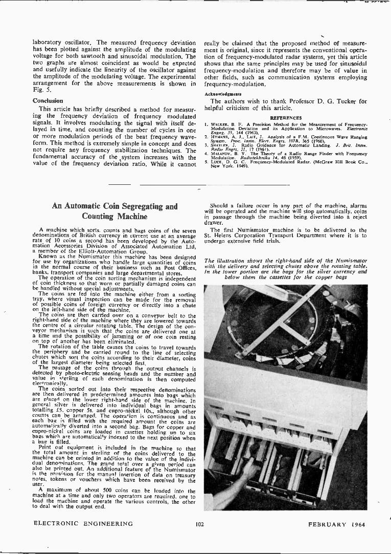
laboratory oscillator. The measured frequency deviation has been plotted against the amplitude of the modulating voltage for both sawtooth and sinusoidal modulation. The two graphs are almost coincident as would be expected and usefully indicate the linearity of the oscillator against the amplitude of the modulating voltage. The experimental arrangement for the above measurements is shown in Fig. 5.
Condusion
This article has briefly described a method for measur-ing the frequency deviation of frequency modulated signals. It involves modulating the signal with itself de-layed in time, and counting the number of cycles in one or more modulation periods of the beat frequency wave-form. This method is extremely simple in concept and does not require any frequency stabilization techniques. The fundamental accuracy of the .system increases with the value of the frequency deviation ratio. While it cannot
really be claimed that the proposed method of measure-ment is original, since it represents the conventional opera-tion of frequency-modulated radar systems, yet this article shows that the same principles may be used for sinusoidal frequency-modulation and therefore may be of value in other fields, such as communication systems employing frequency-modulation.
Acknowledgments
The authors wish to thank Professor D. G. Tucker for helpful criticism of this article.
REFERENCES
I. WAIKER, B. F. A Precision Method for the Measurement of Frequency-Modulation Deviation and its Application to Microwaves. Electronic Engng. 35. 144 (1963).
2. HYMANS, A. J., LMT, J. Analysis of a F. M. Continuous Wave Ranging System. Proc. lnstn. Elect. Engrs. 10713. 365 (1960).
3. SHAYLER, J. Radio Guidance for Automatic Landing. J. Brit. Insta. Radio Engrs. 21, 17 (1961).
4. MAI.ANOV, B. V. The Theory of a Radio Range Finder with Frequency Modulation. Radlotekhnika 14, 46 (1959).
5. LUCK, D. G. C. Frequency-Modulated Radar. (McGraw Hill Book Co., New York. 1949).
An Automatic Coin Segregating and Counting Machine
A machine which sorts, counts and bags coins of the seven denominations of British currency in current use at an average rate of 10 coins a second has been developed by the Auto-mation Accessories Division of Associated Automation Ltd, a member of the Elliott-Automation Group. Known as the Numismator this machine has been designed
for use by organizations who handle large quantities of coins in the normal course of their business such as Post Offices, banks, transport companies and large departmental stores. The operation of the coin sorting mechanism is independent
of coin thickness so that worn or partially damaged coins can be handled without special adjustments. The coins are fed into the machine either from a sorting
tray, where visual inspection can be made for the removal of possible coins of foreign currency or directly into a chute on the left-hand side of the machine. The coins are then carried over on a conveyor belt to the
right-hand side of the machine where they are lowered towards the centre of a circular rotating table. The design of the con-veyor mechanism is such that the coins are delivered one at a time and the possibility of jamming or of one coin resting on top of another has been eliminated. The rotation of the table causes the coins to travel towards
the periphery and be carried round to the line of selecting chutes which sort the coins according to their diameter, coins of the largest diameter being selected first. The passage of the coins through the output channels is
detected by photo-electric sensing heads and the number and value in sterling of each denomination is then computed electronically. The coins sorted out into their respective denominations
are then delivered in predetermined amounts into bags which are placed on the lower right-hand side of the machine. In general silver is delivered into individual bags in amounts totalling £5. copper 5s. and cupro-nickel 10s., although other counts can be arranged. The operation is continuous and as each bag is filled with the required amount the coins are automatically diverted into a second bag. Bags for copper and cupro-nickel coins are loaded in casettes holding un to six bags which are automatically indexed to the next position when a bae is filled. Print out equipment is included in the machine so that
the total amount in sterling of the coins delivered to the machine can be printed in addition to the value of the indivi-dual denominations. The grand total over a given period can also be printed out. An additional feature of the Numismator is the nrov;sion for the manual insertion of data on treasury notes, tokens or vouchers which have been received by the user. A maximum of about 500 coins can be loaded into the
machine at a time and only two operators are required, one to load the machine and operate the various controls, the other to deal with the output end.
Should a failure occur in any part of the machine, alarms will be operated and the machine will stop automatically, coins in passage through the machine being diverted into a reject drawer. The first Numismator machine is to be delivered to the
St. Helens Corporation Transport Department where it is to undergo extensive field trials.
The illustration shows the right-hand side of the Numismator with the delivery and selecting chutes above the rotating table. In the lower portion are the bags for the silver currency and
below them the cassettes for the copper bags
ELECTRONIC ENGINEERING 1112 FEBRUARY i964

A Gated Astable Multivibrator By S. K. Kara
A device was necessary, which when triggered by a positive pulse would produce 1, 2 or 4 positive pulses. The required pulse width was 1.4sec and at intervals of 16,usec. Of several possible ways, a gated astable multivibrator was used for the purpose. The article describes the system from a practical
circuit designer's point of view.
(Voir page 133 pour le résumé en français: Zusammenfassung in deutscher Sprache auf Seite 140)
FIG. 1 shows an astable multivibrator of orthodox design. The waveforms at the points of interest are shown in Fig. 2. The primary purpose of the diodes MRI and MR2 is to limit the reverse base-emitter current when the nega-tive excursion at the base exceeds the base-emitter break down voltage (4.5V for 25104, transistors, from Texas Instruments data sheet). MR2 serves the additional purpose of isolating the emitter from the gating waveform during the positive step (to be shown later). Examination of the waveform in Fig. 2(b) shows that
the base potential of VT2 at the ' on ' condition is approxi-mately +1.9V. This is the sum of the voltages across MR2 (approximately IV, for 20mA), and the VBE at the base-emitter pn junction (approximately 0.9V).
Fig. 1. The basic astable mulitsibrator
The waveform at c shows a ramp shape as VT2 approaches conduction. This is due to the fact that MR2 requires about 0.7V across it to overcome the dicde-bend effect before conducting fully. The emitter therefore follows the rise of the base potential (at a time-constant C2Rb2) till the 0-'7V is reached. This effect produces a
shallow negative ramp at the collector waveform (VT2 gradually coming into conduction) before the sharp fall (VT2' on '). For the same reason the base-emitter junction requires another 0.7V before VT2 may be cut-on'. There-fore, the base potential has to rise to about I-5V, before the switching action starts. If point D, i.e. the cathode end of MR2, is kept at a
potential higher than VI (explained later with reference to Fig. 4), VT2 will remain cut-off (the base-emitter junction being reverse biased). When point D is lowered down to earth through a low impedance source (e.g. supplying the negative step from an emitter-follower) the circuit starts operating as a free running multivibrator. But in order that the conditions at every point at the instant of gating (just before the start) should be the same as it would be if it were oscillating as a free running device, it is necessary that during the positive part of the gating waveform, the base of VT2 should be clamped to a potential that is the same as the level from which it starts the sharp rise at
• Cossor Electronics Ltd.
the instant of cutting VT2 ' on' (the voltage V1 in Fig. 4). If the base is not clamped, the interval between the 1" and the rd pulse becomes shorter than the successive ones. This is because the base sits at the potential of MR2 anode, (positive amplitude of the gating waveform)
(a)
(b)
(c)
2
e
Fig. 2. Waveforms at points of interest
E„ (.25V)
RC2
VT,
GatIng waveform
MR, +my
(-10V)
Fig. 3. The biasing network
and the first negative excursion of VT2 base starts from this potential instead of from V3 (Fig. 4). The clamping arrangement is shown in Fig. 3. MR3 isolates the base circuit from the biasing potential during the negative excursion of the base, i.e. during the discharge of Cl.
The range of RV,/ is explained in the appendix.
General Circuit Description Fig. 5 shows the general arrangement, while the com-
plete circuit is shown in Fig. 6. The monostable compris-ing VT3, VT5 gives a negative pulse at VT5 collector when triggered by a positive pulse. The width of the output pulse is determined mainly by the base resistor of VT5. For the required number of pulses from the system, the correct base resistor is selected by the switch S.
FEBRUARY 1964 (lc) 103 ELECTRONIC ENGINEERING
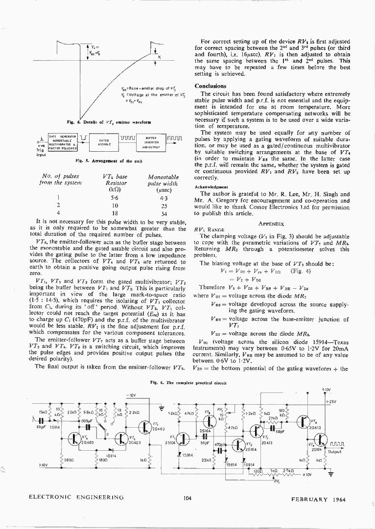
V„ =Base -emitter drop of VT, VE =Voltage at the emitter of vr, vpi. V1,
Fig. 4 Details of VT, emitter waveform
GATE GENERATOR
MONOSTABLE
.ve MULTIVIBRATOR
Trig EMITTER FOLLOWER
input
GATED
ASTABLE
11111ffi BUFFER
INVERTOR
AND OUTPUT
Fig. 5. Arrangement of the unit
No. of pulses from the system
1
4
VT5 base Resistor (kn) 5.6
10
18
FUlf111
Monostable pulse width (,usec)
4-3
25
54 It is not necessary for this pulse width to be very stable,
as it is only required to be somewhat greater than the total duration of the required number of pulses.
VT6, the emitter-follower acts as the buffer stage between the monostable and the gated astable circuit and also pro-vides the gating pulse to the latter from a low impedance source. The collectors of VT2 and VT, are returned to earth to obtain a positive going output pulse rising from zero.
VT2, VT2 and VT, form the gated multivibrator; VTa being the buffer between VT1 and VT2. This is particularly important in view of the large mark-to-space ratio (1.5 : 14.5), which requires the isolating of VT1 collector from C1, during its ' off' period. Without VT3, VT1 col-lector could not reach the target potential (E.) as it has to charge up C1 (470pF) and the p.r.f. of the multivibrator would be less stable. R V2 is the fine adjustment for p.r.f. which compensates for the various component tolerances. The emitter-follower VT, acts as a buffer stage between
VT2 and VT8. VT8 is a switching circuit, which improves the pulse edges and provides positive output pulses (the desired polarity).
The final output is taken from the emitter-follower VT9.
l5kfl 10
k iv. I
68pF 15914
+1011
22k0 5 6kft
005pF
20403
—10V
20403
For correct setting up of the device RV2 is first adjusted for correct spacing between the 2" and 3rd pulses (or third and fourth), i.e. 16,usec). RV], is then adjusted to obtain the same spacing between the 1" and 2" pulses. This may have to be repeated a few times before the best setting is achieved.
Condusions
The circuit has been found satisfactory where extremely stable pulse width and p.r.f. is not essential and the equip-ment is intended for use at room temperature. More sophisticated temperature compensating networks will be necessary if such a system is to be used over a wide varia-tion of temperature. The system may be used equally for any number of
pulses by applying a gating waveform of suitable dura-tion, or may be used as a gated/continuous multivibrator by suitable switching arrangements at the base of VT, (in order to maintain Vas the same. In the latter case the p.r.f. will remain the same, whether the system is gated or continuous provided RV1 and RV2 have been set up correctly.
Acknowledgment
The author is grateful to Mr. R. Lee, Mr. H. Singh and Mr. A. Gregory for encouragement and co-operation and would like to thank Cossor Electronics Ltd for permission to publish this article.
APPENDIX RV' RANGE The clamping voltage (V2 in Fig. 3) should be adjustable
to cope with the parametric variations of VT2 and MR2. Returning MR3 through a potentiometer solves this problem.
The biasing voltage at the base of VT2 should be:
Vi = VD2 Vre VOIE (Fig. 4)
Therefore
where VD2 =
VRS =
= V0 VD3
V2 + VD2 VRS VBE — VD3
voltage across the diode MR2
voltage developed across the source supply-ing the gating waveform.
VBE = voltage across the base-emitter junction of VT2
VD3 = voltage across the diode M R3.
VD2 (voltage across the silicon diode 15914—Texas Instruments) may vary between 0.65V to 1-2V for 20mA current. Similarly, VBB may be assumed to be of any value between 0.6V to 1.2V. V s =-- the bottom potential of the gating waveform + the
Fig. 6. The complete practical circuit
1 2kO
VT,
20403 VT
25104
15914
25104
15914
180 lk° ka 271(11
68pF
VT;
20413
1kIl 2 7kCI
RV,
1-25V
25104 Output
1k0
+10V
11111111
ELECTRONIC ENGINEERING 104 FEBRUARY 1964
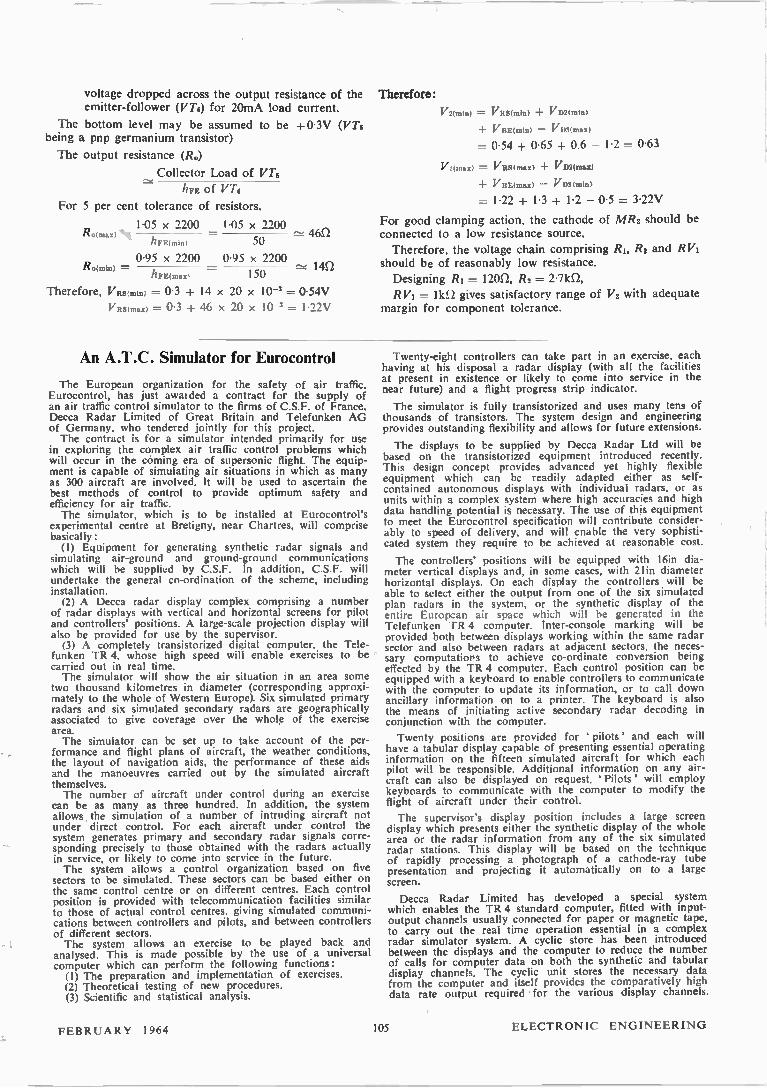
voltage dropped across the output resistance of the emitter-follower (VT6) for 20mA load current.
The bottom level may be assumed to be +0.3V (VT6 being a pnp germanium transistor)
The output resistance (R.)
Collector Load of VT6
hFE of VT6
For 5 per cent tolerance of resistors.
Ro(max) 1.05 x 2200
liFE(inin)
0.95 x 2200
1.05 x 2200 46n
50
0.95 x 2200 R.(m..) - - 14n 150 Therefore, VRS(min) = 0-3 + 14 x 20 x 10-3 = 0.54V
VRS(max) = 0.3 + 46 x 20 x l0-3 = 1.22V
Therefore:
V2Imin) = VRS(min) VD2(mhi)
VBE(min) VD3(max)
= 0.54 + 0-65 + 0.6 — 1.2 = 0.63
V2(max) = VIIS(max) VD2(MaX)
VBE(max) — VD3(min)
= 1.22 + 1.3 + 1.2 — 0.5 = 3.22V
For good clamping action, the cathode of MR3 should be connected to a low resistance source.
Therefore, the voltage chain comprising R1, R2 and RVi should be of reasonably low resistance.
Designing R1 = 120.Q, R2 = 2.71(11,
RV' = 11c1) gives satisfactory range of V2 with adequate margin for component tolerance.
An A.T.C. Simulator for Eurocontrol
The European organization for the safety of air traffic, Eurocontrol, has just awaided a contract for the supply of an air traffic control simulator to the firms of C.S.F. of France, Decca Radar Limited of Great Britain and Telefunken AG of Germany, who tendered jointly for this project. The contract is for a simulator intended primarily for use
in exploring the complex air traffic control problems which will occur in the coming era of supersonic flight. The equip-ment is capable of simulating air situations in which as many as 300 aircraft are involved. It will be used to ascertain the best methods of control to provide optimum safety and efficiency for air traffic. The simulator, which is to be installed at Eurocontrol's
experimental centre at Bretigny, near Chartres, will comprise basically: (1) Equipment for generating synthetic radar signals and
simulating air-ground and ground-ground communications which will be supplied by C.S.F. In addition, C.S.F. will undertake the general co-ordination of the scheme, including installation. (2) A Decca radar display complex comprising a number
of radar displays with vertical and horizontal screens for pilot and controllers' positions. A large-scale projection display will also be provided for use by the supervisor. (3) A completely transistorized digital computer, the Tele-
funken TR 4, whose high speed will enable exercises to be carried out in real time. The simulator will show the air situation in an area some
two thousand kilometres in diameter (corresponding approxi-mately to the whole of Western Europe). Six simulated primary radars and six simulated secondary radars are geographically associated to give coverage over the whole of the exercise area. The simulator can be set up to take account of the per-
formance and flight plans of aircraft, the weather conditions, the layout of navigation aids, the performance of these aids and the manoeuvres carried out by the simulated aircraft themselves. The number of aircraft under control during an exercise
can be as many as three hundred. In addition, the system allows the simulation of a number of intruding aircraft not under direct control. For each aircraft under control the system generates primary and secondary radar signals corre-sponding precisely to those obtained with the radars actually in service, or likely to come into service in the future. The system allows a control organization based on five
sectors to be simulated. These sectors can be based either on the same control centre or on different centres. Each control position is provided with telecommunication facilities similar to those of actual control centres, giving simulated communi-cations between controllers and pilots, and between controllers of different sectors. The system allows an exercise to be played back and
analysed. This is made possible by the use of a universal computer which can perform the following functions: (1) The preparation and implementation of exercises. (2) Theoretical testing of new procedures. (3) Scientific and statistical analysis.
Twenty-eight controllers can take part in an exercise, each having at his disposal a radar display (with all the facilities at present in existence or likely to come into service in the near future) and a flight progress strip indicator.
The simulator is fully transistorized and uses many tens of thousands of transistors. The system design and engineering provides outstanding flexibility and allows for future extensions.
The displays to be supplied by Decca Radar Ltd will be based on the transistorized equipment introduced recently. This design concept provides advanced yet highly flexible equipment which can be readily adapted either as self-contained autonomous displays with individual radars, or as units within a complex system where high accuracies and high data handling potential is necessary. The use of this equipment to meet the Eurocontrol specification will contribute consider-ably to speed of delivery, and will enable the very sophisti-cated system they require to be achieved at reasonable cost.
The controllers' positions will be equipped with 16in dia-meter vertical displays and, in some cases, with 21in diameter horizontal displays. On each display the controllers will be able to select either the output from one of the six simulated plan radars in the system, or the synthetic display of the entire European air space which will be generated in the Telefunken 'TR 4 computer. Inter-console marking will be provided both between displays working within the same radar sector and also between radars at adjacent sectors, the neces-sary computations to achieve co-ordinate conversion being effected by the TR 4 computer. Each control position can be equipped with a keyboard to enable controllers to communicate with the computer to update its information, or to call down ancillary information on to a printer. The keyboard is also the means of initiating active secondary radar decoding in conjunction with the computer.
Twenty positions are provided for pilots' and each will have a tabular display capable of presenting essential operating information on the fifteen simulated aircraft for which each pilot will be responsible. Additional information on any air-craft can also be displayed on request. 'Pilots' will employ keyboards to communicate with the computer to modify the flight of aircraft under their control.
The supervisor's display position includes a large screen display which presents either the synthetic display of the whole area or the radar information from any of the six simulated radar stations. This display will be based on the technique of rapidly processing a photograph of a cathode-ray tube presentation and projecting it automatically on to a large screen.
Decca Radar Limited has developed a special system which enables the TR 4 standard computer, fitted with input-output channels usually connected for paper or magnetic tape, to carry out the real time operation essential in a complex radar simulator system. A cyclic store has been introduced between the displays and the computer to reduce the number of calls for computer data on both the synthetic and tabular display channels. The cyclic unit stores the necessary data from the computer and itself provides the comparatively high data rate output required for the various display channels.
FEBRUARY 1964 105 ELECTRONIC ENGINEERING
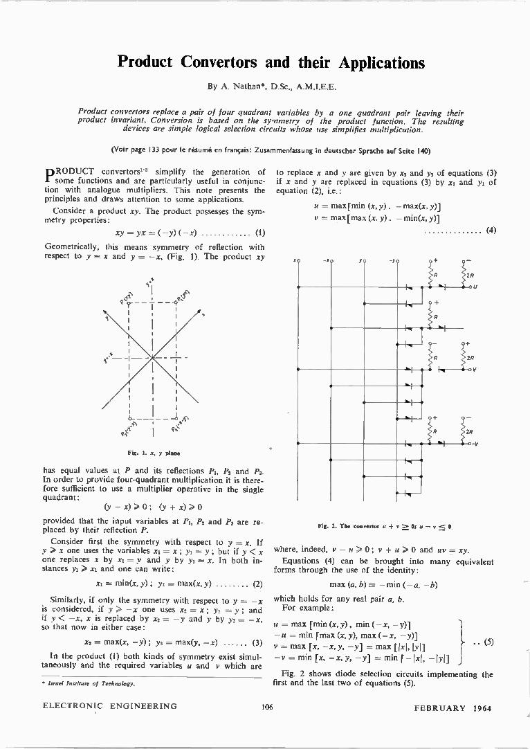
Product Convertors and their Applications
By A. Nathan*, D.Sc., A.M.I.E.E.
Product convertors replace a pair of four quadrant variables by a one quadrant pair leaving their product invariant. Conversion is based on the symmetry of the product function. The resulting
devices are simple logical selection circuits whose use simplifies multiplication.
(Voir page 133 pour le résumé en français: Zusammenfassung in deutscher Sprache auf Seite 140)
PRODUCT convertors'-3 simplify the generation of some functions and are particularly useful in conjunc-
tion with analogue multipliers. This note presents the principles and draws attention to some applications.
Consider a product xy. The product possesses the sym-metry properties:
xy = yx = (—y)(—x) (I)
Geometrically, this means symmetry of reflection with respect to y =- x and y = —x, (Fig. 1). The product xy
I — —
1
Fig. 1. x, y plane
has equal values at P and its reflections PI, P2 and P3. In order to provide four-quadrant multiplication it is there-fore sufficient to use a multiplier operative in the single quadrant:
(y — x) > 0 ; (y + x) > 0
provided that the input variables at Pi, P2 and P3 are re-placed by their reflection P.
Consider first the symmetry with respect to y = x. If y > x one uses the variables xi = x; yi = y; but if y < x one replaces x by xi = y and y by yi = x. In both in-stances yi > xi and one can write:
Xi = min(x, y) ; yi= max(x, y) (2)
Similarly, if only the symmetry with respect to y = —x is considered, if y > —x one uses x2 = x; ya = y; and if y < —x, x is replaced by x2 = —y and y by ya. = —x, so that now in either case:
Xi = max(x, —y) ; ya = max(y, —x) (3)
In the product (1) both kinds of symmetry exist simul-taneously and the required variables u and y which are
Israel Irutitutt of Technology.
to replace x and y are given by x2 and ya of equations (3) if x and y are replaced in equations (3) by xi and yi of equation (2), i.e.:
u = max [min (x, y) , — max(x, y)]
y = max [max (x, y) , — min(x, y)]
(4)
0 •-NO Y 0 -yo
R
5: 'Si
-2
• k, .
• -1-4
R
/
I, ''- • • I
1, •
R
'-i • • 1, ,
• 6.,..1 o
1... a •
6_2,...1_, +
2
'1 é, 4
• 4 •
• 4
•
Fig. 2. The coinertor u + y > 0; u — y < O.
o
V
where, indeed, y —u>0; y + u >0 and tit? = xy.
Equations (4) can be brought into many equivalent forms through the use of the identity:
max (a, b) — min (— a, — b)
which holds for any real pair a, b. For example:
u = max [min (x, y), min (—x, —y)]
—u = min [max (x, y), max (—x, —y)]
.= max [x, — x, y, —y] = max [kJ, lyil
—v = min [x, — x, y, —y] = min [_ixi, • • (5)
— 1)11] j
Fig. 2 shows diode selection circuits implementing the first and the last two of equations (5).
ELECTRONIC ENGINEERING 106 FEBRUARY 1 964
As a first application consider a four quadrant quarter squares multiplier, fed by u and y as input signals. The multiplier produces:
xy = uy = (1/4) [((u + y)/2)2 — ((u —y)/2)2] .... (6)
Since (u + y) > 0 and (u — y) < 0, only two half squarers are required in order to produce z, one to generate ((u + 0/2)2 and the other one to generate —((u — y)/2)2. Such half squarers require as input signals (u + y)/2 and (u — v)/2 that are readily generated from u, y and —y, which require the converting circuits of Fig. 2 for their production.
Several popular four-quadrant multipliers use four half squarers, producing ((x+ y)/2)2; — ((x+Y)/2)2; ((x—y)/2)2; —((x —y)/2)2, respectively, and a switch selecting the sum of a suitable pair of these signals according to the signs of (x + y) and of (x y). If the convertor is used, only two of the half squarers are required and the switch be-comes, moreover, superfluous. The result is a considerably
simpler multiplier, because the convertor is much simpler than the two half squarers which are saved. The accuracy is not affected because the convertor can be made as accurate as the eliminated switch.
A second application is the conversion of any two-quadrant multiplier into a four quadrant multiplier.
A third example is the use of the convertor as a detector for the sign of the product of two variables. Evidently the signs of u and of xy are the same, because y is never nega-tive and xy = uy. Thus it is possible to detect the sign of xy in a simple manner without carrying out the multiplication.
REFERENCES
I. NATHAN, A. An Input Convertor and Sign Discriminator for Multipliers. 3rd A.I.C.A. Conference on Analog Computation, September 1961. AICA Proceedings, p. 684 (1962).
2. NATHAN, A. Input Convertors for Generators of Symmetric Functions. Proc. lnstn. Elect. Engrs. 109C, 573 (1962).
3. U.S. Patent No. 3,084,862, and patents pending.
Tunnel Diode Circuits for Computers Elliott Automation Ltd have for some time been engaged
on a large-scale investigation into the uses of tunnel diodes in computers. They have now reached the stage where most of the inherent problems have been overcome and are begin-ning to build a bread-board' model to prove the techniques in relation to specific computing functions. The importance of the work is that it opens up the pos-
sibility of very much faster, smaller and, perhaps, more inexpensive computers. Tunnel diodes are probably the fastest switching devices
which are likely to be commercially available for many years; inherently they are reliable devices since the high doping level which is necessary renders the device less susceptible to surface attack. In germanium transistors, in particular, the surfaces are extremely sensitive. The low impedance of the devices also increases the reliability since leakage effects across the junction are negligible. On this basis the device is quite clearly attrac-tive. Three years ago, therefore, Elliotts decided to start a small research project to investigate the applicability of tunnel diodes to the computer industry. Similar projects were under-taken by other laboratories throughout the world. In common with these other laboratories they soon reached a stage where the position looked quite hopeless. The device appeared to be extremely difficult to use. The circuits behaved in an apparently unpredictable fashion and many people decided that the exercise was not worth pursuing. At Elliotts it was decided to persevere a little longer and they soon came to realize that most of the difficulties were not inherent in the tunnel diode at all. The tunnel diode is capable of switching between two states in 1•Onsec, which is very much faster than available transistors, and it came to be realized that the difficulties were largely due to this high switching speed rather than to any inherent peculiarities of tunnel diodes. Com-pletely new circuit techniques were obviously required and methods of interconnexion would be completely different from the methods which had sufficed in the past. The computing world, composed largely of men who had
grown up with computers, was not very well equipped to deal with these problems. Elliotts were very fortunate in having within the group, in the same building as the data processing research laboratory, another research laboratory concerned with radar and microwave techniques. These people were unfamiliar with conventional computer problems, but the two laboratories together were able to develop microwave tech-niques in such a way as to augment the computer technology. At this stage it became possible to define the major prob-
lems. In essence it was necessary to design a circuit which was simple in order that the stray capacitance and inductance could be reduced to very low levels, to design a power supply distribution system\ which would match into the tunnel diode impedance at the iwitching weeds, to devise a circuit inter-connexion system in which the lead lengths would be suffi-ciently short to prevent significant delays and which would
match the circuits one to another sufficiently well to avoid reflections. Electrical signals travel along wires at about 130 000 mile/sec, which is equivalent to about 8in/nsec. Obviously all lead lengths must be kept small or the time relationship between the signals will be lost. The circuit configuration known as the Goto Pair, which
was first described in March 1960, appeared to satisfy the requirements. This configuration of tunnel diodes performs a maiority function otherwise known as • Ballot Box Logic' or ' Vote Taking'. Each vote is applied to the Goto Pair as a small current—
a positive current representing an aye', and a negative, a 'no'. Each 'aye' tends to push the circuit into a state where it will give an 'aye' out, while each 'no' pushes it into the opposite state. The circuit is balanced on a pin-point' and allowed to fall under the influence of all these votes and hence makes a democratic decision every time. The only further logical device required in order to produce decisions of the complexity required in a complete computer is an invertor. The extreme simplicity of the Goto Pair enables the com-
ponents, of junction capacitance, lead inductance, etc., to be closely controlled. The choice of component values, matching of tunnel diode characteristics and computation of the loading rules even for such a simple circuit has involved extensive use of existing computers. Since the input and output terminals of this circuit are
common, in order to preserve directionability of signals it is necessary to adore a three-phase power supply system which causes the circuits to pass on the signals in one direction only, much as in a three-phase motor. The main difference being that here one is talking of a supply frequency of 50Mc/s rather than 50c/s. To interconnect these circuits and supply these with three-
phase power at 50Mc/s or above has provided many problems. The final system makes use of tapered strip lines, derived from microwave technology, to distribute the power to the circuits. These lines are balane.d so as to minimize stray currents induced in the signal paths. The signal leads are formed in a multi-layer printed circuit
assembly. Each layer is associated with an earth plane so that the imoedance of the lines is controlled exactly as in coaxial cable, but with considerable saving in space and weight. Although these techniques are sufficient to enable the build-
ing of part of a computer, it has been necessary to develop an additional technique of storage. The delays of signal trans-mission in wiring are turned to advantage by the following procedure. A pattern of signals is sent into one end of a few yards of cable. The pattern, unchanged, issues from the other end of the cable after a few nanoseconds. At this point the signals are amplified and then pumped back into the start of the cable. In this way it is possible to store small quantities of information very economically. These methods are not of course, practicable at low speeds, when the length of wire required would be immense.
FEBRUARY 1964 107 ELECTRONIC ENGINEERING
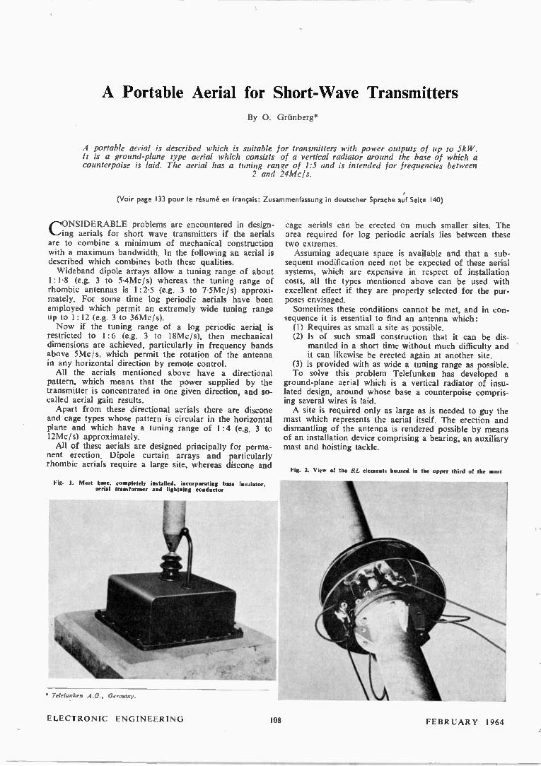
A Portable Aerial for Short-Wave Transmitters
By O. Grünberg*
A portable aerial is described which is suitable for transmitters with power outputs of up to 5kW. It is a ground-plane type aerial which consists of a vertical radiator around the base of which a counterpoise is laid. The aerial has a tuning nin e of 1:5 and is intended for frequencies between
2 and 24Mcls.
(Voir page 133 pour le résumé en français: Zusammenfassung in deutscher Sprache au'f Seite 140)
CIONSIDERABLE problems are encountered in design-%.-,ing aerials for short wave transmitters if the aerials are to combine a minimum of mechanical construction with a maximum bandwidth. In the following an aerial is described which combines both these qualities. Wideband dipole arrays allow a tuning range of about
1: 1.8 (e.g. 3 to 5.4Mc/s) whereas the tuning range of rhombic antennas is I: 2.5 (e.g. 3 to 7.5Mc/s) approxi-mately. For some time log periodic aerials have been employed which permit an extremely wide tuning range up to I :12 (e.g. 3 to 36Mc/s). Now if the tuning range of a log periodic aerial is
restricted to 1:6 (e.g. 3 to 18Mc/s), then mechanical dimensions are achieved, particularly in frequency bands above 5Mc/s, which permit the rotation of the antenna in any horizontal direction by remote control. All the aerials mentioned above have a directional
pattern, which means that the power supplied by the transmitter is concentrated in one given direction, and so-called aerial gain results. Apart from these directional aerials there are discone
and cage types whose pattern is circular in the horizontal plane and which have a tuning range of 1:4 (e.g. 3 to 12Mc/s) approximately. All of these aerials are designed principally for perma-
nent erection. Dipole curtain arrays and particularly rhombic aerials require a large site, whereas discone and
Fig. I. Mast base, completely installed, incorporating base insulator, aerial transformer and liuhtning conductor
• Telefunken A.G., Germany.
cage aerials can be erected on much smaller sites. The area required for log periodic aerials lies between these two extremes. Assuming adequate space is available and that a sub-
sequent modification need not be expected of these aerial systems, which are expensive in respect of installation costs, all the types mentioned above can be used with excellent effect if they are properly selected for the pur-poses envisaged. Sometimes these conditions cannot be met, and in con-
sequence it is essential to find an antenna which: (1) Requires as small a site as possible. (2) Is of such small construction that it can be dis-
mantled in a short time without much difficulty and it can likewise be erected again at another site.
(3) is provided with as wide a tuning range as possible. To solve this problem Telefunken has developed a
ground-plane aerial which is a vertical radiator of insu-lated design, around whose base a counterpoise compris-ing several wires is laid. A site is required only as large as is needed to guy the
mast which represents the aerial itself. The erection and dismantling of the antenna is rendered possible by means of an installation device comprising a bearing, an auxiliary mast and hoisting tackle.
Fig. 2. View of the RL elements housed in the upper turd tot' the mast
ELECTRONIC ENGINEERING 108 1 1 li 1 \R\ 1 ,/

Its tuning range is either 1:4 or 1:5, depending on the type selected. The transmitter is connected to the asso-ciated transmitter via a 6011 coaxial cable that may be up to 200m long. The length of the cable is limited solely by the power losses in it. Due to the small space required it may be erected on
flat roofs, for example. Obviously it lends itself to many applications when transmitting antennas must be erected on a minimum-sized site without being conspicuous. It may also be used to advantage for military applications. The aerial comprises a mast base with a spark gap as
lightning conductor in which a wideband transformer is housed for matching to the r.f. cable (6on) (Fig. 1). On the mast base a ceramic insulator is fixed whose top is a conductive hemisphere. The mast, which is the radiator at the same time, stands on this hemisphere. It can there-fore be freely moved to all sides. Electrical connexion between the rod and the mast is effected via resistors and a coil (RL assembly), which determine the wide-band characteristic of the antenna (Fig. 2). The counterpoise consists of 32 wires laid out or buried
radially whose length is equal to the aerial height. In
principle then, the aerial is a quarter-wave radiator excited against ground whose wideband characteristic is obtained by means of RL elements connected to the upper third of the vertical radiator in order to eliminate the undesired nulls in the vertical pattern. Consequently the vertical pattern is cosine-shaped, whereas the hori-zontal pattern is circular. The base resistance of the aerial is constant and amounts to 60f2. Depending on the operating frequency the v.s.w.r. in the 601.2 cable is between 1.2 and 2 per cent. Again depending on the operating frequency, the efficiency of the aerial is between 90 and 50 per cent. Two models of the antenna are supplied, one for power
ratings up to lkW and the other for outputs up to 5kW. The aerial is also available in heights of 16, 32 and 40m, which between them cover a frequency range of 2 to 24Mc / s. The vertical radiation angle, dependent on the frequency
in each case, is between 30° and 50'; the aerial there-fore appears suitable for ranges resulting from a single reflection on the Heaviside layer.
A Capacitively-coupled Fast Cyclotron Wave Coupler
The Cuccia fast cyclotron wave coupler used in transverse wave electron beam parametric amplifiers (e.g. Adler tubes) is not suitable for wide tuning range operation in its conven-tional form. However, by capacitively coupling to the Cuccia coupler plates from outside the vacuum envelope, one can obtain both the advantages of a low insertion loss (and hence low-noise performance) and ease of tuning over a wide fre-quency range. The proposed scheme is shown in Fig. 1, where the capa-
citive coupling takes place through the glass or ceramic vacuum envelope, the dielectric constant of which favours this form of coupling. The lumped inductance of the coupler
GLASS/CERAMIC VACUUM ENVELOPE
INTERNAL CUCCIA COUPLER PLATES
EXTERNAL CUCCIA COUPLER PLATES
Fig. 1 (above). Capacitively coupled Cuccia coupler
Fig. 2 (below). Capacitively coupled quadruple circuit
INTERNAL QUADRUPOLE ELECTRODES
• A communication from EMI Ltd
EXTERNAL QUADRUPOLE ELECTRODES
resonant circuit is completely external to the vacuum, enabling considerable tuning range to be obtained from this form of coupler. This form of construction lends itself to application for the
quadruple pump circuit used in the Adler tube. A proposed capacitively coupled quadruple circuit is shown in Fig. 2.
A Mobile Radiotelephone A new mobile radiotelephone transceiver has recently been
announced by Rank-Bush Murphy Ltd. Known as the ' Rover ' it is a v.h.f., a.m. unit of small size and rugged construction. It is fully tropicalized and undergoes bump, vibration, dust and water splash tests. The equipment has been designed so that it can be installed in the most convenient position; on its back, end or side. Alternative types of dashboard control are also available. The frequency range covered is 40 to 180Mc/s and one to
six channels can be provided as required. A crystal block filter is employed in the i.f. assembly and this can easily be replaced to accommodate changes in channel spacing, should this be necessary. The sensitivity of the receiver is 0.75µV referred to 10W audio output. The transmitter output is 10W ± 1.5dB.
The ' Rover radiotelephone unit
FEBRUARY 1964 109 ELECTRONIC ENGINEERING
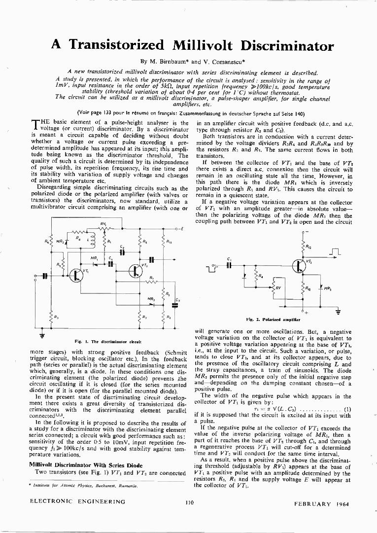
A Transistorized Millivolt Discriminator By M. Birnbaum* and V. Comanescu*
A new transistorized millivolt discriminator with series discriminating element is described.
A study is presented, in which the performance of the circuit is analysed: sensitivity in the range of lmV, input resistance in the order of Ski), input repetition frequency >100kc 1 s, good temperature
stability (threshold variation of about 04 per cent for 1°C) without thermostat. The circuit can be utilized as a millivolt discriminator, a pulse-shaper amplifier, for single channel
amplifiers, etc.
(Voir page 133 pour le résumé en français: Zusammenfassung in deutscher Sprache auf Seite 140)
THE basic element of a pulse-height ana lyser is the voltage (or current) discriminator. By a discriminator
is meant a circuit capable of deciding without doubt whether a voltage or current pulse exceeding a pre-determined amplitude has appeared at its input; this ampli-tude being known as the discriminator threshold. The quality of such a circuit is determined by its independence of pulse width, its repetition frequency, its rise time and its stability with variation of supply voltage and changes of ambient temperature etc. Disregarding simple discriminating circuits such as the
polarized diode or the polarized amplifier (with valves or transistors) the discriminators, now standard, utilize a multivibrator circuit comprising an amplifier (with one or
Fig. I. The discriminator circuit
more stages) with strong positive feedback (Schmitt trigger circuit, blocking oscillator etc.). In the feedback path (series or parallel) is the actual discriminating element which, generally, is a diode. In these conditions one dis-criminating element (the polarized diode) prevents ,the circuit oscillating if it is closed (for the series mounted diode) or if it is open (for the parallel mounted diode). In the present state of discriminating circuit develop-
ment there exists a great diversity of transistorized dis-criminators with the discriminating element parallel connected w. In the following it is proposed to describe the results of
a study for a discriminator with the discriminating element series connected; a circuit with good performance such as: sensitivity of the order 0.5 to 10mV, input repetition fre-quency f7 « 100kc/s and with good stability against tem-perature variations.
Millivolt Discriminator With Series Diode Two transistors (see Fig. 1) VT, and VT, are connected
• Institute for Atomic Physics, Bucharest, Rumania.
in an amplifier circuit with positive feedback (d.c. and a.c. type through resistor R2 and CO. Both transistors are in conduction with a current deter-
mined by the voltage dividers R3/24 and R8R9Rio and by the resistors R5 and R7. The same current flows in both transistors. If between the collector of VT, and the base of VT2
there exists a direct a.c. connexion then the circuit will remain in an oscillating state all the time. However, in this path there is the diode MR, which is inversely polarized through R7 and RV,. This causes the circuit to remain in a quiescent state. If a negative voltage variation appears at the collector
of VT, with an amplitude greater—in absolute value— than the polarizing voltage of the diode MR, then the coupling path between VT, and VT2 is open and the circuit
Fig. 2. Polarized amplifier
will generate one or more oscillations. But, a negative voltage variation on the collector of VT5 is equivalent to a positive voltage variation appearing at the base of VT,, i.e., at the input to the circuit. Such a variation, or pulse, tends to close VT,, and at its collector appears, due to the presence of the oscillatory circuit comprising L and the stray capacitances, a train of sinusoids. The diode MR, permits the presence only of the initial negative step and—depending on the damping constant chosen—of a positive pulse. The width of the negative pulse which appears in the
collector of VT, is given by: ri r V (L. Cp) (1)
if it is supposed that the circuit is excited at its input with a pulse. If the negative pulse at the collector of VT, exceeds the
value of the inverse polarizing voltage of MR,, then a part of it reaches the base of VT, through CI, and through a regenerative process VT, will cut-off for a determined time and VT, will conduct for the same time interval. As a result, when a positive pulse above the discriminat-
ing threshold (adjustable by R VI) appears at the base of VT, a positive pulse with an amplitude determined by the resistors R2, R6 and the supply voltage E will appear at the collector of VT,.
ELECTRONIC ENGINEERING 110 FEBRUARY 1964
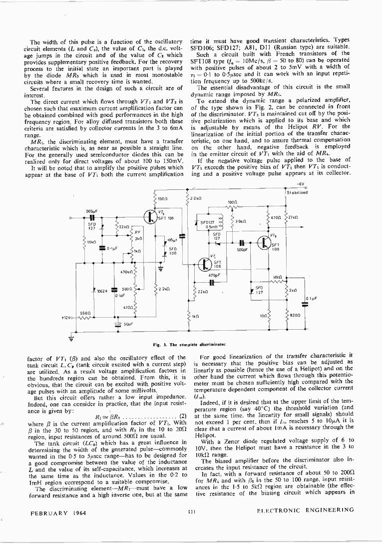
The width of this pulse is a function of the oscillatory circuit elements (L and C9), the value of CI, the d.c. volt-age jumps in the circuit and of the value of C2 which provides supplementary positive feedback. For the recovery process to the initial state an important part is played by the diode MR3 which is used in most monostable circuits where a small recovery time is wanted. Several features in the design of such a circuit are of
interest. The direct current which flows through VT1 and VT2 is
chosen such that maximum current amplification factor can be obtained combined with good performances in the high frequency region. For alloy diffused transistors both these criteria are satisfied by collector currents in the 3 to 6mA range. MR4, the discriminating element, must have a transfer
characteristic which is, as near as possible a straight line. For the generally used semiconductor diodes this can be realized only for direct voltages of about 100 to 150mV. It will be noted that to amplify the positive pulses which
appear at the base of VT1 both the current amplification
005µF
Fig. 3. The complete diheriminator
factor of VT1 (13) and also the oscillatory effect of the tank circuit L,Cp (tank circuit excited with a current step) are utilized. As a result voltage amplification factors in the hundreds region can be obtained. From this, it is obvious, that the circuit can be excited with positive volt-age pulses with an amplitude of some millivolts. But this circuit offers rather a low input impedance.
Indeed, one can consider in practice, that the input resist-ance is given by: •
Ri /3R2 (2) where /3 is the current amplification factor of VT1. With /3 in the 30 to 50 region, and with R2 in the 10 to 20f1 region, input resistances of around soon are usual. The tank circuit (LCp) which has a great influence in
determining the width of the generated pulse—commonly wanted in the 0.5 to 5,usec range—has to be designed for a good compromise between the value of the inductance L and the value of its self-capacitance, which increases at the same time as the inductance. Values in the 0-2 to 1mH region correspond to a suitable compromise. The discriminating element—MR-I—must have a low
forward resistance and a high inverse one, but at the same
time it must have good transient characteristics. Types SFD106; SFD127; A81, Dll (Russian type) are suitable. Such a circuit built with French transistors of the
SFT108 type (fa = 10Mcls, 13 = 50 to 80) can be operated with positive pulses of about 2 to 5mV with a width of Ti = 0.1 to 0-5,usec and it can work with an input repeti-tion frequency up to 500kc/s. The essential disadvantage of this circuit is the small
dynamic range imposed by MR1. To extend the dynamic range a polarized amplifier,
of the type shown in Fig. 2, can be connected in front of the discriminator. VT3 is maintained cut off by the posi-tive polarization which is applied to its base and which is adjustable by means of the Helipot RV. For the linearization of the initial portion of the transfer charac-teristic, on one hand, and to assure thermal compensation on the other hand, negative feedback is employed in the emitter circuit of VT1 with the aid of MR4. If the negative voltage pulse applied to the base of
VT1 exceeds the positive bias of VT1 then VT1 is conduct-ing and a positive voltage pulse appears at its collector.
-6V
Stabilized
100C1
For good linearization of the transfer characteristic it is necessary that the positive bias can be adjusted as linearly as possible (hence the use of a Helipot) and on the other hand the current which flows through this potentio-meter must be chosen sufficiently high compared with the temperature dependent component of the collector current
(lea. Indeed, if it is desired that at the upper limit of the tem-
perature region (say 40°C) the threshold variation (and at the same time, the linearity for small signals) should not exceed 1 per cent, then if /c, reaches 5 to 10,uA it is clear that a current of about lmA is necessary through the
Helipot. With a Zener diode regulated voltage supply of 6 to
10V, then the Helipot must have a resistance in the 3 to iokn range. The biased amplifier before the discriminator also in-
creases the input resistance of the circuit. In fact, with a forward resistance of about 50 to 2oon
for MR4 and with p3 in the 50 to 100 range, input resist-ances in the 1.5 to 51d2 region are obtainable (the effec-tive resistance of the biasing circuit which appears in
FEBRUARY 1964 Ill ELECTRONIC ENGINEERING

parallel with the input must be taken into consideration). In choosing VT3, which works similarly to a common
emitter stage (when conducting) the following must be taken into account. The response of the common-emitter stage to an input
step is given by:
where:
/0 — 1 —
1„lg
Tee --271,0 (1 —
ri _ exp(— tine)] (3)
1
and it is known that the collector current reaches 95 per cent of its attainable value 20/(1 —a.) /33 in a time interval of about 3Tad.
Differentiating equation (3) and after some algebraic transformations:
1 dt = 27rfoln exp( — t/ Tee) (4)
HELIPOT DIVISIONS
1000
500
100
• tli ,15.... 01µsec T, r 14SeC r .2515°c
02 2
Fig. 4. Linearity of circuit
3
100 200 300 400 500 600 700 BOO 900 1000
HELIPOT DIVISIONS
Fig. 5. Non-linearity error
If it is accepted that the working region is situated on the initial portion of the exponential curve, one can approximate:
and in this case:
or:
exp (— = 1 (5)
di.' dt = 2r/sfo (6)
dl. -= 2771„.dQB (7) In this manner the concept of the transistor as a charge
controlled device has been attained. If the biased amplifier excites a discriminator with a
10mV threshold and with an input resistance of 100f2, it is clear that in its collector a current variation of about ed/a. 10-4A is necessary. If this assembly is operated by a photomultiplier tube which gives an electrical charge of about 10-"C for an ionizing particle which passes through its scintillation crystal, then to operate the discriminator it is necessary that VTd is a transistor with a cut-off fre-
quency (fe) given by:
1a0 10-4 — 27r. 10-" -•• 16Mc/s
From these remarks it is obvious that the most important parameter for VTI is its at cut-off frequency.
Characteristics and Performance
Fig. 3 shows the complete discriminator. The experimental try-out of the circuit was carried out
on a number of examples (25) and the following average characteristics and performances have been obtained. It has been mentioned that a good discriminator must be
as linear as possible. Tried with input pulses of 1psec
HEL IPOT DIVISIONS
HELIPOT DIVISIONS
600
500
400
300
200
100
o
1000
500
100
3 43 % 4 -
Vi .1 4.V t,rlosec ti, :5, 0 1psec 1' . 25 I 5°C
20 100
kds
Fig. 6. ariation of threshold
05 15 2
T, (iisec)
Fig. 7. Variation of threshold with pulse width
I
11
09
2
150
20 40 60 80 100 120
kas
Fig. 8. Incertitude variation
08 O
.14.V
0.1u.sec - 50kas
.25!5°C
10 20 30 40 50
PERCENTAGE EXCESS
Fig. 9. Zero variation
width, with a rise time of 0.1iusec and with a repetition frequency of 500c/s the circuit shows a good linearity as can be seen from Fig. 4. Fig. 5 represents the non-linearity error measured under
the same conditions. It can be seen that the non-linearity error does not exceed 2 per cent, a generally acceptable value. A parasitic phenomenon, which appears in all circuits
which have a threshold, consists of the variation of the threshold with the input repetition frequency. The effect is irritating when one is working with radiation detectors with small dead-time and when it is important that the output of the discriminator is not to be dependent on the time interval at which two input pulses have arrived.
ELECTRONIC ENGINEERING 112 FEBRUARY 1964

An important part in the reduction of the recovery time of the circuit is played by the damping circuit present at the collector of VT1. This circuit assists in the discharge process of CI and by this means reduces the dead time of the circuit. Fig. 6 shows the variation of the threshold against the input repetition frequency. It can be seen that this variation is about 2 per cent at 50kc/s and does not exceed 4 per cent at 100kc/s. Another parasitic phenomenon, probably of the same
nature as the previous, makes the threshold dependent of the width of the input pulses. Fig. 7 represents the results of measurements carried
out on one circuit and it is easy to observe a relative independence in the ri > litsec region. In the range
0.5 to litse., one can observe a threshold variation of about 4 per cent against the width of the input pulses. An essential characteristic for a discriminator is the
certainty of the answer. If the signal is smaller than the threshold the dis-
criminator must say no'. If the signal exceeds the threshold it must say yes'. But, if the signal is smaller
0 25
02
01
05
(b)
(a)
o
y .14V
Ti*. µsec 50 kc/s
r •25t 5°C
10 20
PERCENTAGE EXCESS
Fig. 10. Rive time variation
30 40
by a very small amount (0.5 to 1 per cent) than the threshold, the discriminator will sometimes say no' and sometimes yes' for the same signal. In addition the answer will be dependent in this region, on the input repetition frequency. This is what is generally named the ' incertitude ' of the discriminator. Fig. 8 represents the incertitude variation against the
input repetition frequency (curve (a) without the supple-mentary feedback through C2). For the circuit under discussion the incertitude variation
does not exceed 0-9 per cent for an input repetition fre-quency of 100kc/s. The circuit generates a positive pulse whose width is
dependent—also parasitically—on the excess in amplitude of the input pulse over the threshold. Fig. 9 shows, practically, a zero variation for an ampli-
tude excess of 15 to 20 per cent. In a same manner the rise time of the generated pulse is affected by the same 1. parameter. Fig. 10 represents this variation, curve (a) being for
the discriminator without C2. Also the time interval be-tween the exciting pulse and the generated pulse (the delay time) is a function of the pulse exceeding amplitude. This delay time (see Fig. 11) is about
0.7µsec for an amplitude equal with the threshold and 0.2,usec for a 25 per cent greater one. The main disadvantage of transistorized circuits—the
parameter variation with the ambient temperature is of course present here. Carrying out the temperature dependence tests of the
circuit, a quasi-linear variation of the threshold of about 0.4 per cent for 1°C has been obtained (Fig. 12). For accurate applications it is possible to utilize a
thermostatically controlled enclosure' which makes it pos-sible to attain a variation of only 0.1 to 0.3 per cent in a temperature range 5 to 40°C.
07
06
05
? 04
3 03
PERCENTAGE
02
01
e
6
4
2
o
2
4
- 6 o
I I
r.,= 50
I
kcis f
4--
5 10 15 20 25 30 35
PERCENTAGE EXCESS Fig. 11. Delay time
40 45 50
RV
(Vd 25°C
4- 10 20 T(°C)
Fig. 12. Temperature dependence
th
Conclusions The proposed circuit offers a number of advantages over ose more commonly used: (1) High sensitivity (it can be excited with ImV pulses
and is thus able to operate as an amplifier-pulse shaper. Good transient characteristics. Small incertitude. This is important when two such circuits are working as a single channel analyser. Indeed, in this case the incertitude must not exceed 5 to 10 per cent of the analysing step.
(4) Large dynamic range. (5) Good stability against temperature fluctuations.
REFERENCES VER WEII, H. A Fast Transistorized Discriminator. Nuclear In.:tram. Methods. 10, 308 (1961).
2. BINARD, L., GOURSKI, E. Developpement et Applications de Discrimina-teurs Stables et Rapides dans le Domaine des Dizaines de mv. Colloque de Belgrade sur l'Eléctronique Nucléaire. Agence Internationale de l'Energie Atomique. (May 1961).
3. LEcomPre, I. L., ALLEMAND, R. Discriminateur d'Amplitude Transistorisé. Colloque de Belgrade sur l'Eléctronique Nucléaire. Agence Internationale de l'Energie Atomique.
4. KEMHADDAN, H. A Simple Temperature Control System for Transistors. Mulford Techn. Commun. 4, 186 (1958).
(2) (3)
30 40
FEBRUARY 1964 113 ELECTRONIC ENGINEERING

Short News Items The Third International Flight Test
Instrumentation Symposium is to be held at the College of Aeronautics, Cranfield, Bucks, on 13 to 14 April.
The main theme of the symposium is instrumentation and test techniques for manned high speed flight. Contributions from six countries in-
clude papers on transducers, test tech-niques, high speed data aquisition systems, fuel flow measurement, flight test instrumentation systems for military and civil supersonic aircraft and free flight supersonic and hypersonic models.
Contributions from NASA personnel at Edwards Air Force Base deal with bio-medical instrumentation of the pilot and the design philosophy for test in-strumentation of the X-15 aircraft and the way this knowledge has been applied to the X-20 (Dyna-Soar) hypersonic vehicle.
On the civil side the systems engin-eering of the Concorde project is con-sidered in relation to the probable flight test requirements.
Further information regarding the symposium and accommodation are available from M. A. Perry, College of Aeronautics, Cranfield, Bletchley, Bucks.
The University of Birmingham has announced that the department hitherto known as the Department of Electrical Engineering has now changed its name to the Department of Electronic and Electrical Engineering. When the depart-ment was founded in 1905, electronic engineering virtually did not exist. With the development of the thermionic valve and its use first in communication systems and later in control and in-dustrial systems and in computers, and now with the advent of numerous other electronic devices and systems, electronic engineering has become a vigorous sub-ject advancing at a phenomenal rate. This is reflected in the Denartment's present activities, which are dominantly electronic in the research and post-graduate work generally, where of the 68 postgraduate students, 60 are con-cerned with electronic engineering. Sub-jects of special prominence in the pro-gramme are radar and sonar systems, communications (electrical and acoustic), electronic circuits, ultrasonics, solid-state electronic engineering, and control systems.
This newly named department is offering the following Graduate Courses during the coming session :-
(1) Information Engineering, (2) Solid State Electronic Engineering, (3) Electrical Machines and Automatic
Control.
For these courses the formal lectures are supplemented by laboratory work and a three-month project. The courses are of twelve months duration, running from 1 October to 30 September, and lead successful students to the degree of M.Sc., (for Degree and Dip. Tech. students) and to the Diploma in Gradu-ate Studies (for non-graduate students). Application forms, further details and
notes on financial assistance may be ob-tained from: The Registrar, The Uni-versity of Birmingham, Birmingham, 15.
The Plessey Co Ltd, Ilford, has given £50 000 to the University of Essex Foundation Fund Appeal. The donation will contribute to the support of scientific research and research staff at the new University.
Trade test transmissions on 625 lines u.h.f. from the BBC's London television station at Crystal Palace started on 4 January and are designed to assist the Radio Trade in the installation of re-ceivers and aerials for reception of the second programme, BBC-2, which starts in London on 20 April 1964. The test transmissions are on Channel 33 (vision 567.25Mc/s; sound 573.25Mc/s) with horizontal polarization and take place each weekday as follows: Mondays to Fridays : 9 a.m. to 1 p.m.
2 p.m. to 8 p.m. Saturdays : 9 a.m. to 8 p.m. The normal effective radiated power
will be 500kW when the installation of the new transmitting aerial is completed about the beginning of March. Until then the effective power is expected to be approximately half this figure. The test transmissions will consist of
periods of Test Card, with 400e /s tone or music alternating with periods of film.
Amplivox Ltd announce that they are providing a research bursary in the Physics Department of Imperial College under the supervision of Dr. R. W. B. Stephens. The research will be concerned with
the transmission of sound and vibrations in a variety of materials, and the be-haviour of sub-miniature mechanical-acoustical systems embodying such materials.
The Jodrell Bank Research Station is now using 408Mc/s Ferranti parametric amplifiers for aerials which are being employed in long-baseline interferometry experiments. For this experiment two aerials are placed at a considerable
distance apart in order to provide the required angular resolving power. In the present instance, a portable
25ft diameter aerial located on the Yorkshire Moors near Leeds is working in conjunction with the Mk.1 radio telescope at Jodrell Bank: both aerials are fitted with Ferranti 408Mc/s para-metric amplifiers.
A 25ft diameter aerial employing a conventional amplifier would not norm-ally be sensitive enough for the present experiments, but the sensitivity obtained by using the parametric amplifier results in a sensitivity gain equivalent to an aerial of seven times the diameter: the actual noise temperature of the ampli-fiers attached to the aerials is less than 100° K.
The parametric amplifiers will assist in the detection of flare stars, and it is hoped that they will also enable the diameters of some of the more distant radio sources to be measured.
Flare stars are a type of Red Dwarf star which flare up intermittently, and sometimes emit radio waves. Investi-gation of this phenomena may help to explain the origin of the Universe.
Ten v.h.f. radio-telephone transmitters which will form a new permanent net-work for the public car-calling service in Switzerland have been ordered from Standard Telephones and Cables Ltd, London.
Placed at strategic high points above the valleys, these transmitters will be used by telephone operators for calling subscribers—private motorists or com-mercial vehicles—to tell them that a message awaits them. On receipt of such a call on his radio receiver the driver stops at the nearest telephone box and dials the operator or the person who wishes to contact him. The call is thus completed over the normal telephone system.
In this way a low-cost service can be provided for subscribers 'on the road' without the expense of fitting radio transmitters in subscribers' vehicles. Main reason for the service, however, is that normal low-powered mobile radio transmitters are swamped by the moun-ains which make two-way mobile radio telephone service very difficult and un-reliable.
The car calling service, at present in limited operation on an experimental basis, is provided by the Swiss Post and Telegraph administration. The transmitters to be supplied are
STC type DU-6A, with an output of IkW in the frequency range 100 to 156Mc/s.
ELECTRONIC ENGINEERING 114 FEBRUARY 1964
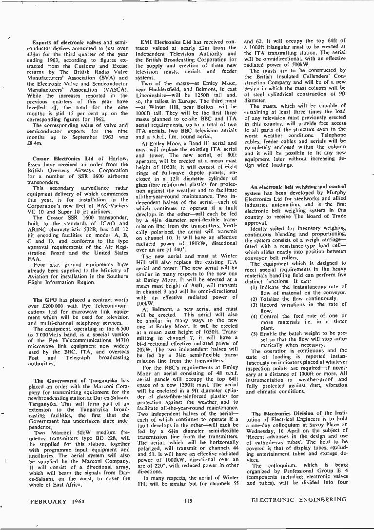
Exports of electronic valves and semi-conductor devices amounted to just over £21m for the third quarter of the year ending 1963, according to figures ex-tracted from the Customs and Excise returns by The British Radio Valve Manufacturers' Association (BVA) and the Electronic Valve and Semiconductor Manufacturers' Association (VASCA). While the increases reported in the previous quarters of this year have levelled off, the total for the nine months is still 15 per cent up on the corresponding figures for 1962. The corresponding value of valve and
semiconductor exports for the nine months up to September 1963 was £8.4m.
Cossor Electronics Ltd of Harlow, Essex have received an order from the British Overseas Airways Corporation for a number of SSR 1600 airborne transnonders. This secondary surveillance radar
equipment delivery of which commences this year, is for installation in the Corporation's new fleet of BAC-Vickers VC 10 and Super 10 jet airliners. The Cossor SSR 1600 transponder,
built to the standards of ICAO and ARINC characteristic 532B, has full 12 bit encoding facilities on modes A, B, C and D, and conforms to the type approval requirements of the Air Regi-stration Board and the United States FAA. Four s.s.r. ground equipments have
already been supolied to the Ministry of Aviation for installation in the Southern Flight Information Region.
The GPO has placed a contract worth over £200 000 with Pye Telecommuni-cations Ltd for microwave link equip-ment which will be used for television and multi-channel telephony services. The equipment, operating in the 6 500
to 7 00014c/s band, is a special version of the Pye Telecommunications M710 microwave link equipment now widely used by the BBC, ITA, and overseas Post and Telegraph broadcasting authorities.
The Government of Tanganyika has placed an order with the Marconi Com-pany for transmitting equipment for the new broadcasting station at Dar-es-Salaam, Tanganyika. This will form part of an extension to the Tanganyika broad-casting facilities, the first that the Government has undertaken since inde-pendence. Two Marconi 50kW medium fre-
quency transmitters type BD 228, will be supplied for this station, together with programme input equipment and ancillaries. The aerial system will also be supp!ied by the Marconi Company. It will consist of a directional array, which will beam the signals from Dar-es-Salaam, on the coast, to cover the whole of East Africa.
EMI Electronics Ltd has received con-tracts valued at nearly £1m from the Independent Television Authority and the British Broadcasting Corporation for the supply and erection of three new television masts, aerials and feeder systems. Two of the masts—at Emley Moor,
near Huddersfield, and Belmont, in east Lincolnshire—will be 1250ft tall and, so, the tallest in Europe. The third mast —at Winter Hill, near Bolton—will be 1000ft tall. They will be the first three masts planned to co-site BBC and ITA aerial requirements, up to a total of two ITA aerials, two BBC television aerials and a v.h.f., f.m. sound aerial. At Emley Moor, a Band III aerial and
mast will replaoe the existing ITA aerial and tower. The new aerial, of 80ft aperture, will be erected at a mean mast height of 1050ft. It will consist of eight rings of full-wave dipole panels, en-closed in a 12ft diameter cylinder of glass-fibre-reinforced plastics for protec-tion against the weather and to facilitate all-the-year-round maintenance. Two in-dependent halves of the aerial —each of which continues to operate if a fault develops in the other—will each be fed by a 4-1-in diameter semi-flexible trans-mission line from the transmitters. Verti-cally polarized, the aerial will transmit on channel 10. It will have an effective radiated power of 180kW, directional over an arc of 140°. The new aerial and mast at Winter
Hill will also replace the existing ITA aerial and tower. The new aerial will be similar in many respects to the new one at Emley Moor. It will be erected at a mean mast height of 700ft, will transmit in channel 9 and will be omni-directional with an effective radiated power of 100kW. At Belmont, a new aerial and mast
will be erected. This aerial will also be similar in many ways to the new one at Emley Moor. It will be erected at a mean mast height of 1050ft. Trans-mitting in channel 7, it will have a bi-di-ectional effective radiated power of 20kW. The two independent halves will be fed by a 3Iin semi-flexible trans-mission line from the transmitters. For the BBC's requirements at Emley
Moor an aerial consisting of 48 u.h.f. aerial panels will occupy the top 64ft space of a new 1250ft mast. The aerial will be enclosed in a 9ft diameter cylin-der of glass-fibre-reinforced plastics for protection against the weather and to facilitate all-the-year-round maintenance. Two independent halves of the aerial— each of which continues to operate if a fault develops in the other—will each be fed by a 61-in diameter semi-flexible transmission line from the transmitters. The aerial, which will be horizontally polarized, will transmit on channels 44 and 51. It will have an effective radiated power of 1000kW, directional over an arc of 220°, with reduced power in other directions. In many respects, the aerial of Winter
Hill will be similar but for channels 55
and 62. It will occupy the top 64ft of a 1000ft triangular mast to be erected at the ITA transmitting station. The aerial will be omnidirectional, with an effective radiated power of 500kW. The masts are to be constructed by
the British Insulated Callenders' Con-struction Company and will be of a new design in which the mast co:umn will be of steel cylindrical construction of 9ft diameter. The masts, which will be capable of
sustaining at least three times the load of any television mast previously erected in this country, will provide free access to all parts of the structure even in the worst weather conditions. Telephone cables, feeder cables and aerials will be completely enclosed within the column and it will be possible to fit any new equipment later without increasing de-sign wind loadings.
An electronic belt weighing and control system has been developed by Murphy Electronics Ltd for steelworks and allied industries automation, and is the first electronic belt weighing system in this country to receive The Board of Trade approval. Ideally suited for inventory weighing,
continuous blending and proportioning, the system consists of a weigh carriage— fitted with a resistance-type load cell— which slides neatly into position between conveyor belt rollers. The equipment which is designed to
meet special requirements in the heavy materials handling field can perform five distinct functions. It can: (1) Indicate the instantaneous rate of
flow of material on the conveyor. (2) Totalize the flow continuously. (3) Record variations in the rate of
flow. (4) Control the feed rate of one or
more materials i.e. in a sinter plant.
(5) Enable the batch weight to be pre-set so that the flow will stop auto-matically when necessary.
The operation is continuous and the state of loading is reported instan-taneously on indicators placed at whatever inspection points are required —if neces-sary at a distance of 1000ft or more. All instrumentation is weather-proof and fully protected against dust, vibration and climatic conditions.
The Electronics Division of the Insti-tution of Electrical Engineers is to hold a one-day colloquium at Savoy Place on Wednesday, 16 April on the subject of 'Recent advances in the design and use of cathode-ray tubes'. The field to be covered is that of display tubes, exclud-ing entertainment tubes and storage de-vices. The colloquium, which is being
organized by Professional Group E 4 (components including electronic valves and tubes), will be divided into four
FEBRUARY 1964 115 ELECTRONIC ENGINEERING

sessions, covering electron optics, con-struction, uses and optics. The contri-butions will be presented by rapporteurs, thus giving ample time for discussion. Such subjects as methods of post de-
flexion acceleration, new forms of cathode, 'thin' tubes, 'head up' displays, high resolution, the use of fibre optics and particularly future requirements in both the civil and military fields will be discussed. Those wishing to attend the
colloquium should write to the Secre-tary, The Institution of Electrical Engineers, Savoy Place, London W.C.2. An admission ticket (free to members of the Institution, 10s. 6d. to non-members) and abstracts of the contributions to be presented at the Colloquium will be sent to all those who have registered, approximately one week before the colloquium.
The British Standards Institution has published a revised section of B.S. 448 (Electronic-valve bases, caps and hold-ers) as follows:-Section B8G/1-1 B8G base
B8G/1-2 B8G base pin and spigot position gauge (square holes)
B8G/12A B8G base alternative pin and spigot posi-tion gauge (round holes)
Copies can be obtained from the BSI Sales Branch, 2 Park Street, London, W.I. Price 2s 6d each. (Postage will be charged extra to non-subscribers).
Racal Electronics Ltd have received orders totalling Lim for the supply of their new 7-}kW single sideband equip-ment. Among these orders is one from the Royal Air Force for installations, comprising transmitters and receivers which are entirely automatic in opera-tion and which provide over 250 000 al-ternative channels without the necessity of carrying large stocks of crystals. This feature is provided by the advanced Racal design synthesizer driven by a precision frequency source. The equip-ments can also be remotely controlled over a single pair of Post Office lines.
The Ministry of Aviation has placed an order with A. T. & E. (Bridgenorth) Ltd, a Plessey Group company, for v.h.f. radio equipment to be installed on the Isle of Lewis, in the Outer Hebrides. The A.T.E. equipment will be used
to link M.O.A. radio stations at Storno-way with Mangersta, and provide remote control. A.T.E. Type 900 multichannel dupli-
cated radio terminals, with remote man-ual and automatic changeover facilities, are being provided, together with aerials, ancillary and test equipment. The link's main function will be to
provide remote control of the Mangersta station. In one direction it will carry audio and control switching signals for modulation and control of the trans-mitters, and in the other direction, the audio output of the receivers. A two way engineering circuit is also being pro-vided.
A Decca airfield control radar type 424 mark II has been installed at Woolsing-ton, the North East Regional municipal airport near Newcastle upon Tyne. The new radar replaces the very first 424 mark I, which was installed at the same airport in 1954 and which was respon-sible for many thousands of approaches safely completed under Il weather con-ditions. The Decca type 424 is a simple airfield
control radar system providing facilities for final approach surveillance. All-round cover is provided and the equip-ment provides effective control of aircraft in the circuit or for overshoots. It is remotely controlled from the display position in the control tower and can be brought into use at very short notice when necessary. Complete duplication of all main units affords a high degree of reliability, and the modest capital cost, together with low maintenance and running costs make this a most useful approach radar aid.
The Physico-Chemical Research De-partment of the Compagnie Generale de Telegraphie Sans Fil (CSF) has de-veloped a delay line using mild steel as the medium for the propagation of ultra-sonic waves in SECAM colour tele-vision receivers and it is anticipated that the cost of the delay line will be less than 15F on a mass production basis. A brief specification of the delay line
is as follows:--Delay time and tolerance (for the
nominal delay time of the line), the tolerance is +017µsec, over a tempera-ture range of 20 to 55*C. —Bandwidth: (measured on SECAM
circuits): 2Mc/s —Attenuation: 24dB max, son from
3.4 to 5.4Mc/s. —Spurious responses: 26dB minimum,
from 3.4 to 5.4Mc/s. —Impedances: in parallel with the in-
put and output capacitances (1000pF) of the line, there is a resistance of about 10 00012 on a.f. and 5012 at the series resonance frequency at around 4.4Mc/s. —Structure: Conventional, ultrasonic
waveguide terminated by transducers. The transducers are lead titanate piezo-
electric ceramics: their thickness is such that the frequency of the shear wave used for transferring the signal corre-sponds to a frequency of 4-43Mc/s.
Communications equipment worth well over elm has been supplied and installed by Standard Telephones and Cables Ltd for NATO's ACE HIGH communica-
tions network which has just been com-pleted. The last station in the ACE HIGH network, that extends 8 300 route miles from the northern tip of Arctic Norway to the eastern edge of Turkey has now been accepted by Supreme Headquarters Allied Powers Europe on behalf of the North Atlantic Treaty Organization. The ACE HIGH network consists of
82 stations divided almost equally between tropospheric forward scatter (over-the-horizon) and line-of-sight microwave radio stations. STC multiplex equipment is installed at every station. The system makes available to the
Supreme Allied Commander (SACEUR) more than 250 telephone circuits and 180 telegraph circuits. Circuit capacity of the main backbone route is limited to 36 channels although engineering design takes into account the probable need for expansion beyond this number. Any one of the speech channels can be multi-plexed to provide 12 or 18 telegraph channels.
The first independent computer service specially tailored for the shipping indus-try has been started by I.S.I.S. (Inter-national Shipping Information Services Ltd.) London. The I.S.I.S. Ship Selection Service came into operation this week, heralding a new and up-to-date approach to an age-old shipping problem. By using an I.C.T. 1 500, as an ' elec-
tronic library,' the complete specifica-tions relating to some 40 000 merchant ships listed by Lloyd's Register of Ship-ping, have been recorded on magnetic tape via punched cards. A specially-developed computer pro-
gramme enables I.S.I.S. to instruct' the computer to compare the specifications of every ship in its memory' with vir-tually any set of requirements and to print a list of all those ships whose de-tails coincide with the requirements.
G.E.C. (Electronics) Ltd has advanced its programme of divisional organization by establishing a new Industrial Division at North Wembley. The new Division will be concerned
with a wide range of activities in the field of electronic equipment for in-dustrial applications. These include in-dustrial instrumentation and control, invertors and power electronic equip-ment, data transmission and collection, television equipment, electro-mechanical devices and luminous call equipment.
Correction
The equation on page 6 of 'A New Approach to I.L.S. Modulation Depth Comparison' by G.G. Gouriet which was published in the January issue of 'Electronic Engineering' should read :-(1 + cui2T2)-i — (1 + (022T2)-4 = x
ELECTRONIC ENGINEERING 116 FEBRUARY 1964
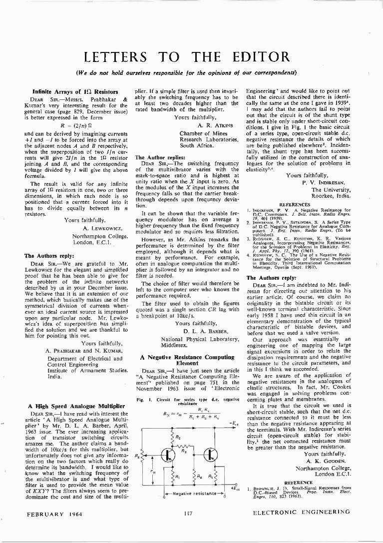
LETTERS TO THE EDITOR (We do not hold ourselves responsible for the opinions of our correspondents)
Infinite Arrays of ln Resistors
DEAR SIR, — Messrs. Prabhakar & Kumar's very interesting result for the general case (page 829, December issue) is better expressed in the form
R = (2/n)fl
and can be derived by imagining currents +/ and —/ to be forced into the array at the adjacent nodes A and B respectively, when the superposition of two 1ln cur-rents will give 2//n in the 112 resistor joining A and B, and the corresponding voltage divided by / will give the above formula.
The result is valid for any infinite array of 1S/ resistors in one, two or three dimensions, in which each node is so positioned that a current forced into it has to divide equally between its n resistors.
Yours faithfully,
A. LEWKOWICZ,
Northampton College, London, E.C.1.
The Authors reply:
DEAR SIR. — We are grateful to Mr. L,ewkowicz for the elegant and simplified proof that he has been able to give for the problem of the infinite networks described by us in your December issue. We believe that it is an extension of our method, which basically makes use of the symmetrical division of currents when-ever an ideal current source is impressed upon any particular node. Mr. Lewko-wicz's idea of superposition has simpli-fied the solution and we are thankful to him for pointing this out.
Yours faithfully,
A. PRABHAKAR and N. KUMAR,
Department of Electrical and Control Engineering Institute of Armament Studies. India.
A High Speed Analogue Multiplier
DEAR SIR, —I have read with interest the article ' A High Speed Analogue Multi-plier' by Mr. D. L. A. Barber, April, 1963 issue. The ever increasing applica-tion of transistor switching circuits amazes me. The author claims a band-width of 10kc/s for this multiplier, but unfortunately does not give any informa-tion on the two factors which really do determine its bandwidth. I would like to know what the switching frequency of the multivibrator is and what type of filter is used to provide the mean value of KXY? The filters always seem to pre-dominate the cost and size of the multi-
plier. If a simple filter is used then invari-ably the switching frequency has to be at least two decades higher than the rated bandwidth of the multiplier.
Yours faithfully,
A. R. Am INS
Chamber of Mines Research Laboratories, South Africa.
The Author replies: DEAR SIR, —The switching frequency
of the multivibrator varies with the mark-to-space ratio and is highest at unity ratio when the X input is zero. As the modulus of the X input increases the frequency falls so that the carrier break-through depends upon frequency devia-tion.
It can be shown that the variable fre-quency modulator has on average a higher frequency than the fixed frequency modulator and so requires less filtration.
However, as Mr. Atkins remarks the performance is determined by the filter employed, although it depends what is meant by performance. For example, often in analogue computation the multi-plier is followed by an integrator and no filter is needed.
The choice of filter would therefore be left to the computer user who knows the performance required.
The filter used to obtain the figures quoted was a single section CR lag with a breakpoint at 10kc/s.
Yours faithfully,
D. L. A. BARBER,
National Physical Laboratory, Middlesex.
A Negative Resistance Computing Element
DEAR have just seen the article "A Negative Resistance Computing Ele-ment" published on page 751 in the November 1963 issue of Electronic
Fig. I. Circuit for series type d.c. negative resistance
R., R., R r :Ç R., +
.4—Negative resistance—. +E„
Engineering' and would like to point out that the circuit described there is identi-cally the same as the one I gave in 1959'. I may add that the authors fail to point out that the circuit is of the shunt type and is stable only under short-circuit con-ditions. I give in Fig. 1 the basic circuit of a series type, open-circuit stable d.c. negative resistance the details of which are being published elsewhere2. Inciden-tally, the shunt type has been success-fully utilized in the construction of ana-logues for the solution of problems in elasticitym.
Yours faithfully, P. V. INDIRESAN,
The University, Roorkee, India.
REFERENCES I. INDIRESAN, P. V. A Negative Resistance for D.C. Computers. J. Brit. Instn. Radio Engrs. 19, 401 (1959).
2. INDIRESAN. P. V.. SATAINDRA, S. A Series Type of D.C. Negative Resistance for Analogue Com-puters. J. Brit. Insist. Radio Engrs. (To be published).
3. REDSHAW, S. C., RUSHTON, K. R. Various Analogues, Incorporating Negative Resistances. for the Solution of Problems in Elasticity. Brit. J. Appl. Phy. 12, 390 (1961).
4. REDSHAW, S. C. The Use of a Negative Resis-tance for the Solution of Structural Problems in Elasticity. Third International Computation Meetings, Opatija (Sept. 1961).
The Authors reply: DEAR SIR. —I am indebted to Mr. Indi-
resan for directing our attention to his earlier article. Of course, we claim no originality in the bistable circuit or its well-known terminal characteristic. Since early 1958 I have used this circuit in an elementary demonstration of the typical characteristic of bistable devices, and before that we used a valve version. Our approach was essentially an
engineering one of mapping the large signal excursions in order to relate the dissipation requirements and the negative resistance to the circuit parameters, and in this I think we succeeded. We are aware of the application of
negative resistances in the analogues of elastic structures. In fact, Mr. Cookes was engaged in solving problems con-cerning plates and membranes. It is true that the circuit we used is
short-circuit stable, such that the net d.c. resistance connected to it must be less than the negative resistance appearing at the terminals. With Mr. Indiresan's series circuit (open-circuit stable) for stabi-lity,' the net connected resistance must be greater than the negative resistance.
Yours faithfully,
A. K. GODDEN, Northampton College,
London E.C.1.
REFERENCE 1. BROWNLIE, J. D. Small-Signal Responses from D.C.-Biased Devices. Proc. Insist. Elect. Engrs. 110, 823 (1963).
FEBRUARY 1964 117 ELECTRONIC ENGINEERING

BOOK REVIEWS Printed and Integrated Circuits
By T. D. Selllobed' and D. K. Rider. 420 pp. Med. 8vo. McGraw-Hill Book Co. 1963. Price
£5 4s. 6d.
THIS is an unusual book covering every aspect of printed wiring and
circuits—including not only the coverage of specifications and methods of test but also dealing with thin film and so:id state microelectronics.
The entire book is based on American materials, specifications and methods, not surprising since the authors are from the Bell Telephone Laboratory but it is a pity that they did not study the history of pr:nted circuits in England more carefully. It is stated, on page 26 that electrodeposited copper was not used here until quite recently; in fact, apart from early laboratory made laminates this material has been used in preference to cold-rolled copper for over ten years.
The section dealing with artwork and circuit layout is excellent and should be mandatory reading for every draughts-man and designer engaged on this work.
The treatment of printed circuits is very thorough, taking in all normal methods of manufacture including etched-foil and plated-through techniques also embossed circuits and those on ceramic and glasses with fired on metal conduc-tors. In many places the conservative approach of the telephone engineer can be seen; in Chapter 5, dealing with soldering it is stated that only plain resin should be used as a flux and that acti-vated fluxes should be avoided. In the U.K. activated fluxes are almost the rule and perhaps our production engineers should heed the warning—particularly in processes such as roller tin coating of printed wiring boards which is usually carried out with a very active flux.
Environmental protection is dealt with by an appraisal of many encapsulants, including polyesters, epoxides, polysul-phides and polyurethane foams. As in other chapters there are many references but enough details are given in the text to enable a prospective user to choose a suitable resin system without reference to other papers. For examp!e the embrit-tiement of po:yamide compounds above 85°C is known to specialists alone as are the problems associated with the various low-loss resin systems.
In dealing with the design and repair of printed circuits the authors are on controversial grounds. They state (on page 203) that lines of 0.050in in width with similar spacing are reliable and easily produced; this would not be dis-agreed but few designs al!ow of such generosity, lines of 0.015in are common and these would be difficult to repair in the manner indicated. The various illus-
trations showing methods of repair should be taken with some reserve. On page 240 a wrinkled conductor is dis-cussed but it is doubtful if such a fault could be repaired or if it is desirable to do so.
In spite of these criticisms it is prob-able that this section dealing with repairs to printed circuits is the most compre-hensive yet written.
In Chapter 9—Evaluation of Materials and Processes, the various specifications are discussed and a:though these are all of American origin they are used and referred to in the U.K. The 176 refer-ences are most valuable and of great assistance to those responsible for testing and evaluating materials. This chapter contains the kind of information never in the reviewer's experience, collated before.
Multi-layer printed circuits which are of contemporary interest are briefly dealt with in Chapter 10, this briefness reflects the uncertainty of satisfactory production methods both in America and the U.K. The sketches, which are artists' impressions show that even these know-ledgeable authors are at a loss to do more than hint at the potentialities of this kind of circuit.
The theme of microminiaturization is covered in Chapter 11; the word inte-grated circuits is used to embrace both those made by sold-state and by thin-film methods, this rather overworked word is somewhat ambiguous but is usually taken to mean the solid state approach. In some 50 pages the subject is reasonably well covered without too much detail; on thin-films the chapter is more of a review of materials and pro-cesses rather than a guide to their use. The section on packaging of these cir-cuits again reflects uncertainty as to exactly how they should be mounted and connected together; the sketches show that the designs are ideals rather than of actual hardware but this may be due to the uses of microelectronics being confined to classified equipments at present. At least it does show the tremen-dous potential in this field and one which has received little attention compared with the technology of making these circuits.
Throughout, this book is well refer-enced and it is pleasing to see references to British authors in most sections.
The printing and binding are well up to what is expected of the McGraw Hill Company. This book is recommended to all engineers and others concerned with the various aspects of printed circuits and with what the authors obviously con-sider their logical development to micro-miniature circuits.
H. G. MANF1ELD
Ultrasonic Delay Lines By C. F. Brockelsby, J. S. Palfreeman and R. W. Gibson. 297 pp. Demy 8vo. Iliffe BOOIC1
Lid. 1963. Price 65s.
T TLTRASONIC delay lines, like radar, %-•1 in which they have their most im-portant applications, are a product of the second world war: again like radar, the early work (at least in quartz) was British, while much of the exploitation has been American. Since the war, a great deal of work has been done on them and they now play an important role in radar systems, in radio astronomy and in television: in computers, where they have lost ground in the last ten years, they may gain a new lease of life as high density stores as a result of recent developments. However, the understanding of delay lines demands a considerable background in ultrasonics and in piezo-electricity, neither of them familiar subjects to most electronic engineers: the literature is specialized and not always readily available. Hence the present vo!ume, gathering together and ordering a vast mass of information in this interesting field, is to be wecomed, and its authors and publishers congratu-lated on having met a real need.
The book opens with theoretical chapters (on sound waves in solids and liquids, and on transducers) which will serve as a useful introduction to these rather specialized topics. There are then chapters on liquid, solid and wire lines, which give a good review of what can be done in these media, and considerable insight into their design and manufacture. Let no one imagine, however, that this book alone, comprehensive though it seems, will enable him to make a delay line without difficulty. A variety of special lines are dealt with in chapter seven, to give, for instance, tapped or variable delays: this chapter also deals, rather briefly, with the potentially very important topic of dispersive lines, which may do much in chirp radars to improve the ratio of mean to peak power, so increasing range, reliability and efficiency with no sacrifice of discrimination.
Chapters eight, nine and ten deal with electronics for delay lines, delay line measurements and applications respect-ively. Many readers will feel that the first of these could be shorter and the last longer, since systems using delay lines are more rarely described and more sophisticated than, for instance, the cir-cuits of valve and transistor amplifiers. If chapter ten had been less brief, we should perhaps not have read that "an m.t.i. is blind at the speed for which the Doppler shift is equal to the p.r.f. but that "an m.t.i. radar is blind when the Doppler shift is zero, or equal to any multiple of the p.r.f." That the former
ELECTRONIC ENGINEERING 118 FEBRUARY 1964
EE 66 136 for further details
case is important will be attested by anyone who has seen aircraft disappear whenever their course is tangential to the radar: moreover, this case cannot be cured by using two values of p.r.f. and it is liable to occur at critical phases of a flight.
The book concludes with five appen-dices of which the third (on the proper-ties of various acoustic media) and the fourth (giving the calculated frequency responses of various transducers working into different media) will be of consider-able value, and an extensive bibliography, which has some odd omissions. That a reference to "Palfreeman (1955)" on p.105 is missing is not altogether sur-prising, in that the matter therein could be considered a trade secret: but "Lamb (1959)" on p. 9 is presumably public property, if we knew where to find it.
There is one fairly major point on which the book is at least controversial, and may well be mistaken. Reference is very properly made in chapter five to Sutton's theory of propagation in quartz delay lines, but the two main predictions of the theory (a ripple on the response curve and the existence of dispersion i.e. a change of delay with frequency) are denied. The presence or absence of a ripple is too subjective a matter to be argued in marginal cases (such as the curves of p.115, for instance) but dis-persion is another matter, and the book is dogmatic that it does not occur. Thus it is stated (p.107) that "the group delay has been found constant to a few parts per million between 20 and 40Mc/s" and again (p.100) that "the variation of velocity with frequency is quite negligible in delay lines" (which is certainly not always true). Sutton's theory and results show a variation of about 40 parts per million in a line 7mm thick between 20 and 27Mc/s, and un-published results elsewhere support these figures. One can only conclude either that the book refers to lines about 2cm thick, which seems unlikely, especially in double-decker designs, or that the authors' results are not as precise as they think.
These points, of course, leave the great bulk of the book untroubled and do nothing to invalidate the we:come accorded to it earlier in this review. One hopes that the book will do much to make delay lines better known: as the authors imply in their preface, they offer a blend of science and engineering which is both useful and interesting.
M. J. B. SCANLAN
British Miniature Electronic Components Data Annual 1963-64
Editors G. W. A. Dommer and J. Mackenzie Robertson. 1356 pp. Many figs. Demy 4to.
Pergamon Press. 1963. Price £7 In this third edition of the British Minia-
ture Electronic Components Data Annual will be found comprehensive information on a considerably increased range of small electronic components and associated parts.
In many cases the contributing manufac-turers have supplied advice, design and applications data and specially prepared illustrations. The increase in number and types of
miniature and microminiature electronic assemblies—and associated facilities—has made it necessary to publish the informa-tion on these items in a separate volume, the ' British Miniature and Microminiature Electronic Assemblies Data Annual'.
Electric Circuit Theory By F. A. Benson and D. Harrison. 402 pp. 365 figs. 2nd Edition. Demy 8vo. Edward
Arnold Ltd. 1963. Price 33s. The second edition of this book includes
a new chapter on Transistor Circuits but apart from a few minor modifications and corrections the original text remains un-changed.
Vacuum and Solid State Electronics (An Introductory Course)
By D. F. Harris and P. N. Robson. 254 pp. Crown 8vo. Pergamon Press Ltd. 1963. Price 20s. The emphasis in this book is on electron
devices and on the physical processes re-sponsible for their operation rather than on details of the circuits in which they may be used. It is rather an introduction to the subject
of modern electronics which does not re-quire a high degree of mathematical know-ledge. The authors have in mind engineer-ing students at universities and technical colleges during the early stages of their course.
Television Engineering Vol. 1
By S. W. Amos, D. C. Birkinsbaw in collabora-tion with J. L. Bliss. 297 pp. Dewy live. 2nd Edition. Ili& Books Ltd. 1963. Price 45s. This is the second edition of the first
volume of a series of four on television engineering specially produced by members of the BBC Engineering Division. Because of the many important develop-
ments which have taken place during the past few years, and in particular the change-over to the 625-line standard, this edition has had to be re-written and enlarged. The authors have made the book entirely general so that it now applies to all of the line standards employed by the world's television services. Minor changes have been made to the
second edition, dealing with light optics, to ensure that the terminology agrees with the most recent recommendations of the British Standards Institution.
The Electronic Theory of Catalysis on Semiconductors
By F. F. Vol'kenshtein (translated by N. G. Anderson), 169 pp. Demy 8vo. Pergamon Press
Ltd. 1963. Price 50s. The book consists of a course of lectures
on the electronic theory of catalysis on semiconductors given by the author in the Chemical Faculty of Moscow University, and later in Yaggelon University, Poland, and the University of Paris. In the first half of the book the basic
principles of the theory are formulated, while the second half is devoted to an analysis of the main consequences resulting from these principles. It also contains a short summary of the results of experi-mental investigations devoted to electronic phenomena catalysis carried out in the U.S.S.R. and elsewhere The book emphasizes the physical foun-
dations of the theory, not its mathematical side, and its object is to provide an explana-tion from electronic theory for the detailed behaviour of semiconductors and semi-conducting surfaces in catalysis.
CHAPMAN & HALL
A Selection of Books from our List
Analogue Computing at Ultra-High Speed D. M. MACKAY & M. E. FISHER 65s.
Digital Computer Technology I. H. GOULD & F. S. a us 42s.
Microwave Ferrites P. J. B. CLARRICO A TS 50‘.
Ultrasonic Technology RICHARD G. GOLDMAN
The Encyclopedia of Electronics CHARLES SUSSKIND 180s. (Editor)
Full particulars available on request
11 NEW FETTER LANE, LONDON, E.C.4
International Series of Monographs on Electronics and Instrumentation
Vol. 19 Controlled-Delay Devices
By S. A. Doganocskii and V. A. I 67 pp. Demy Sto. Pergamon Press Ltd. 1963. Price 30s. This translation has been made from a
book published by Gosenergoizdat, Mos-cow, 1960 by Mr. O. M. Blunn and has been finally edited by Messrs. D. W. Fry and W. Higinbotham. The book describes devices which can
produce a pure time lag in control and com-puter engineering. Their construction and circuits are con-
sidered and practical recommendations are made concerning their applications. 'The book is written not only for profes-sional control engineers, but for those con-cerned with the development or utilization of controlled-delay devices in industry.
Microphones By A. E. Robertson. 359 pp. Demy 8vo. Rile
Books Ltd. 1963. Price 75s. Since the original publication if this book,
developments have been so extensive that the present edition has had to be enlarged to three times the size of its predecessor. Until the last decade microphones
operated on one of two principles, pressure or pressure gradient; a third principle, phase-shift, was known, but had no com-mercial application until the introduction of miniaturized pre-amplifiers. This opened up a whole new range of microphones. Over the same period the directional properties of microphones have been greatly improved, and a large part of the book is devoted to these. This book, primarily written as a training
manual for BBC technicians, will also prove of value to all users of high quality micro-phones whether for broadcasting, public-address systems, or recording of any type.
FEBRUARY 1964 (1.) 119 ELECTRONIC ENGINEERING
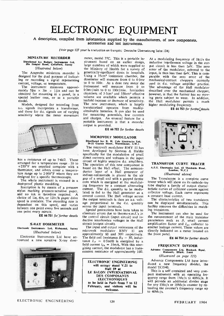
ELECTRONIC EQUIPMENT A description, compiled from information supplied by the manufacturers, of new components,
accessories and test instruments.
(Voir page 127 pour la traduction en français;
MINIATURE RECORDER Distributed b): Budgen Instruments Ltd, 25a Tangier Road, Guildford, Surrey
(Illustrated below)
The Amprobe miniature recorder is designed for the dual purpose of indicat-ing or recording a signal representing current, voltage, or temperature. The instrument measures approxi-
mately Sib x 3in x ljin and can be obtained for mounting in a panel, in a special leather case, or as a portable model. Models, designed for recording from
a.c. signals incorporate a transformer, and those for d.c. signals are of varying sensitivity where the meter movement
has a resistance of up to 7-4k2. Those arranged for a temperature range-50 to +250°F are supplied complete with a thermistor, and others cover a tempera-ture range up to 2 000°F where they are designed for a specific thermocouple. The whole instrument is encased in a
dust-proof plastic moulding. Inscription is by means of a pressure
stylus marking pressure-sensitive paper, and no ink is therefore required. A choice of lin, 6in, or 12in/h paper drive speed is available. The recording rate is dependant on this speed, and varies between one point every five seconds and one point every minute.
EE 66 751 for-further details
X-RAY DOSEMETER Electronic Instruments Ltd. Richmond, Surrey
(Illustrated below)
Electronic Instruments Ltd have an-nounced a new sensitive X-ray dose-
Deutsche Übersetzung Seite
meter, model 37C. This is a portable in-strument based on an earlier design, large numbers of which were supplied to the Ministry of Health for a survey of genetica:ly-significant doses in hospitals. Using a 35cms ionization chamber, the dosemeter will measure from 0 to 0.3mr to 0 to 100r. As a dose rate meter the instrument will measure from 0 to 0.3mr/min to 0 to 100r/min. Ionization chambers of 3.5cm' and 350cm3 effective volume are available which permits a tenfold increase or decrease of sensitivity. The new instrument, which is largely transistorized operates from readily-obtainable batteries. It can also be used for measuring potentials, low currents and charges. An unusual feature for a portable instrument is that a recorder output is provided.
EE 66 752 for further details
MICROVOLT MODULATOR Distributed by: R. H. Cole Electronics Ltd. 26-32 Caxton Street, Westminster. S. W.1
The microvolt modulator RMY 11 has been developed by Siemens & Halske specifically for the modulation of small direct currents and voltages in the input circuit of highly sensitive d.c. amplifiers. The operation of this new component is based on the Hall effect. The semicon-ductor layer of a Hall generator of indium-antimonide is placed in the air gap of a small coil with a gapped ferrite core which is energized at the modulat-ing frequency by a constant alternating current. The d.c. quantity to be modu-lated is fed to the Hall generator as a control current. The Hall voltage across the output terminals is then an a.c. volt-age proportional to the d.c. quantity across the input terminals. Special precautions have been taken to
eliminate errors due to thermo-e.m.f.'s in the control circuit (input circuit) and in-ductive interference voltages in the Hall circuit (output circuit). The input and output resistances of the
microvolt modulator RMY 11 are approximately 60 and 30n respectively. The field coil (resistance Rp = 32, induc-tance LF = 0-5mH) is energized by a field current in = 35mA. With this ener-gizing current, the modulator has a trans-mission resistance of approximately 1012.
ELECTRONIC ENGINEERING will occupy stand V.21 in
Hall 59 at LE SALON INTERNATIONAL
DES COMPOSANTS ÉLECTRONIQUES
to be held in Paris from 7 to 12 February, and visitors will be
welcome.
134)
At a modulating frequency of lkch the inductive interference voltage in the out-put circuit is less than 1µV. The zero error of the modulator, referred to the input, is thus less than 6PV. This is com-parable with the zero error of the mechanical-contact choppers currently used in d.c. voltage amplifier practice. The advantage of the Hall modulator described over the mechanical chopper, however, is that the former has no mov-ing parts subject to wear. In addition, the Hall modulator permits a much higher modulating frequency.
EE 66 753 for further:details
.4 ell''
a
TRANSISTOR CURVE TRACER A.E.S. Electronics Ltd. 42 Theobalds Road,
London. W.C.1
(Illustrated above)
The Transiscope is a complete curve tracer which will show on its cathode-ray tube display a family of output charac-teristic curves of collector current against collector voltage. Each curve represents a constant base current. The characteristics of two transistors
can be displayed simultaneously. This facility removes the difficulties in match-ing transistors. The instrument can also be used for
the measurement of the main transistor parameters such as 13, small current amplification factor and 40, collector to emitter leakage current. These values are directly indicated on a meter located on the front panel.
EE 66 754 for further details
FREQUENCY DIVIDER Advance Components Ltd. Roebuck Road.
Hainault, Ilford. Eues
(Illustrated on page 121)
Advance Components Ltd have intro-duced a new frequency divider, the model TCD40. This is a self contained and very com-
pact instrument with an operating fre-quency range from 1Mc/s to 40Mc/s. It will provide an additional divider stage for any 1Mc/s or 10Mc/s counter by ex-tending the counter's frequency range up to 40Mc/s.
ELECTRONIC ENGINEERING 120 FEBRUARY 1964
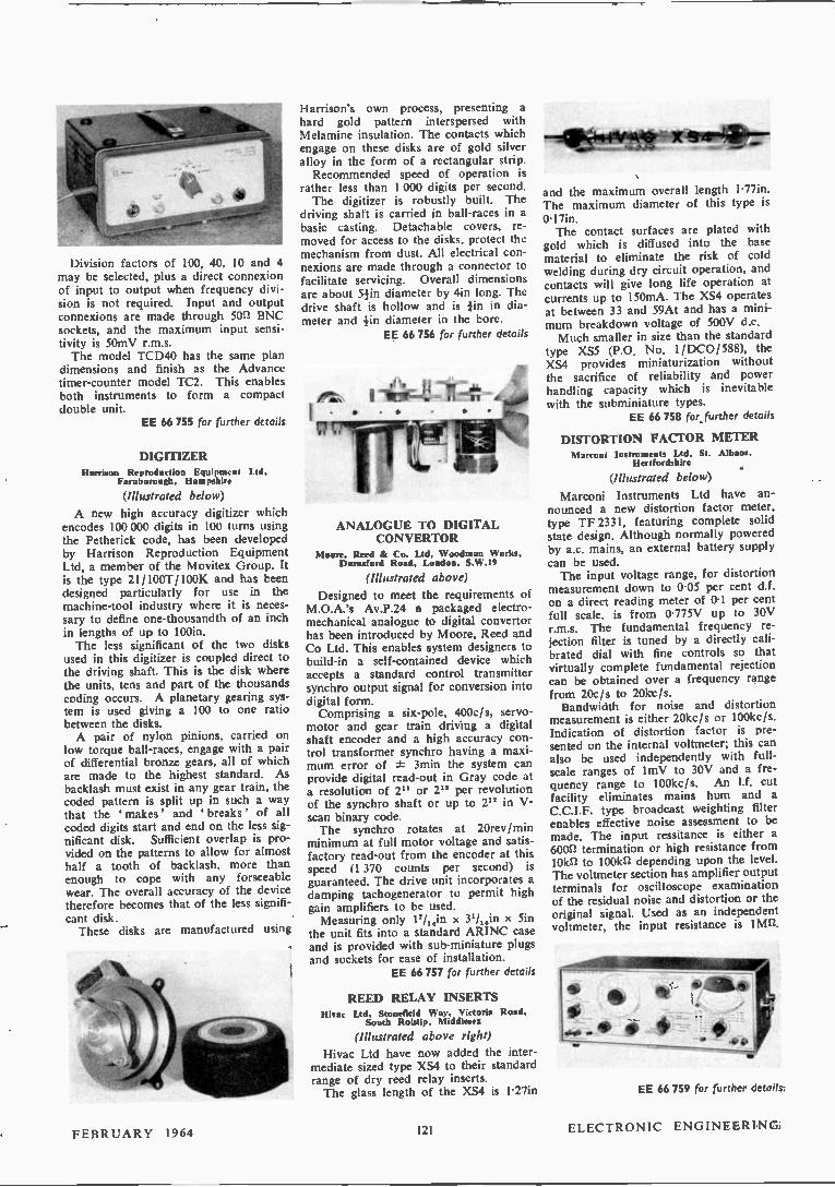
Division factors of 100, 40, 10 and 4 may be selected, plus a direct connexion of input to output when frequency divi-sion is not required. Input and output connexions are made through 5011 BNC sockets, and the maximum input sensi-tivity is 50mV r.m.s. The model TCD40 has the same plan
dimensions and finish as the Advance timer-counter model TC2. This enables both instruments to form a compact double unit.
EE 66 755 for further details
DIGITIZER Harrison Reproduction Equipment Ltd.
Farnborough, Hampshire
(Illustrated below)
A new high accuracy digitizer which encodes 100 000 digits in 100 turns using the Petherick code, has been developed by Harrison Reproduction Equipment Ltd, a member of the Movitex Group. It is the type 21/100T/100K and has been designed particularly for use in the machine-tool industry where it is neces-sary to define one-thousandth of an inch in lengths of up to 100in. The less significant of the two disks
used in this digitizer is coupled direct to the driving shaft. This is the disk where the units, tens and part of the thousands coding occurs. A planetary gearing sys-tem is used giving a 100 to one ratio between the disks. A pair of nylon pinions, carried on
low torque ball-races, engage with a pair of differential bronze gears, all of which are made to the highest standard. As backlash must exist in any gear train, the coded pattern is split up in such a way that the 'makes' and ' breaks' of all coded digits start and end on the less sig-nificant disk. Sufficient overlap is pro-vided on the patterns to allow for almost half a tooth of backlash, more than enough to cope with any forseeable wear. The overall accuracy of the device therefore becomes that of the less signifi-cant disk. These disks are manufactured using
Harrison's own process, presenting a hard gold pattern interspersed with Melamine insulation. The contacts which engage on these disks are of gold silver alloy in the form of a rectangular strip. Recommended speed of operation is
rather less than 1 000 digits per second. The digitizer is robustly built. The
driving shaft is carried in ball-races in a basic casting. Detachable covers, re-moved for access to the disks, protect the mechanism from dust. All electrical con-nexions are made through a connector to facilitate servicing. Overall dimensions are about 51in diameter by 4in long. The drive shaft is hollow and is in in dia-meter and in diameter in the bore.
EE 66 756 for further details
ANALOGUE TO DIGITAL CONVERTOR
Moore, Reed & Co. Ltd, Woodman Works, Darnsford Road, London. S. W.19
(Illustrated above)
Designed to meet the requirements of M.O.A.'s Av.P.24 a packaged electro-mechanical analogue to digital convertor has been introduced by Moore, Reed and Co Ltd. This enables system designers to build-in a self-contained device which accepts a standard control transmitter synchro output signal for conversion into digital form. Comprising a six-pole, 400c/s, servo-
motor and gear train driving a digital shaft encoder and a high accuracy con-trol transformer synchro having a maxi-mum error of ± 3min the system can provide digital read-out in Gray code at a resolution of 2" or 212 per revolution of the synchro shaft or up to 252 in V-scan binary code. The synchro rotates at 20rev/min
minimum at full motor voltage and satis-factory read-out from the encoder at this speed (1 370 counts per second) is guaranteed. The drive unit incorporates a damping tachogenerator to permit high gain amplifiers to be used. Measuring only 17/,.in x 31/,„in x 5in
the unit fits into a standard ARINC case and is provided with sub-miniature plugs and sockets for ease of installation.
EE 66 757 for further details
REED RELAY INSERTS Hivae Ltd. Stonelleld Way. Victoria Road,
South Ruislip. Middlesex
(Illustrated above right)
Hivac Ltd have now added the inter-mediate sized type XS4 to their standard range of dry reed relay inserts. The glass length of the XS4 is 1.27in
and the maximum overall length 1.77in. The maximum diameter of this type is 0.17in. The contact surfaces are plated with
gold which is diffused into the base material to eliminate the risk of cold welding during dry circuit operation, and contacts will give long life operation at currents up to 150mA. The XS4 operates at between 33 and 59At and has a mini-mum breakdown voltage of 500V d.c. Much smaller in size than the standard
type XS5 (P.O. No. 1/DC0/588), the XS4 provides miniaturization without the sacrifice of reliability and power handling capacity which is inevitable with the subminiature types.
EE 66 758 for further details
DISTORTION FACTOR METER Marconi Instruments Ltd. St. Albans.
Hertfordshire
(Illustrated below)
Marconi Instruments Ltd have an-nounced a new distortion factor meter, type TF 2331, featuring complete solid state design. Although normally powered by a.c. mains, an external battery supply can be used. The input voltage range, for distortion
measurement down to 0.05 per cent d.f. on a direct reading meter of 0.1 per cent full scale, is from 0.775V up to 30V r.m.s. The fundamental frequency re-jection filter is tuned by a directly cali-brated dial with fine controls so that virtually complete fundamental rejection can be obtained over a frequency range from 20c/s to 2ffice/s. Bandwidth for noise and distortion
measurement is either 20kc/s or 100kc/s. Indication of distortion factor is pre-sented on the internal voltmeter; this can also be used independently with full-scale ranges of ImV to 30V and a fre-quency range to 100kc/s. An I.f. cut facility eliminates mains hum and a C.C.I.F. type broadcast weighting filter enables effective noise assessment to be made. The input ressitance is either a 6001.1 termination or high resistance from 101(11 to 100k1.1 depending upon the level. The voltmeter section has amplifier output terminals for oscilloscope examination of the residual noise and distortion or the original signal. Used as an independent voltmeter, the input resistance is 1Mn.
EE 66 759 for further details;
FEBRUARY 1964 121 ELECTRONIC ENGINEERIN G
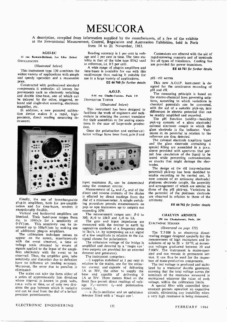
MESUCORA A description, compiled from information supplied by the manufacturers, of a few of the exhibits at the International Measurement, Control, Regulation and Automation Exhibition, held in Paris
from 14 to 21 November, 1963.
AGELEC 11 rue Rosaia-Rollaad, Les Lilas (Seine)
OSCILLOSCOPE
(Illustrated below)
This instrument type 130 combines the widest variety of applications with simple and speedy operation and a reasonable price. Constructed with professional standard
components it embodies all known im-provements such as electronic switching and double time-base, one of which can be delayed by the other, triggered, re-laxed and single-shot scanning, electronic magnifier, etc. In addition, a new patented calibra-
tion device makes it a rapid, high-precision, direct reading measuring in-strument.
Finally, the use of interchangeable plug-in amplifiers, both for pre-amplifi-cation and for time-bases, renders it exceptionally flexible. Vertical and horizontal amplifiers are
identical. Their band-pass ranges from d.c. to 10Mc/s for a sensitivity of 0.1V/cm. This sensitivity can be in-creased up to 100µV/cm by making use of additional plug-in amplifiers. The calibration technique causes to
appear on the screen, simultaneously with the event observed, a time or voltage scale obtained by means of signals applied to the input of the ampli-fiers alternately with the event to be observed. Thus, the amplifier gain, tube sensitivity and distortion due to deflexion have no influence on reading accuracy. Moreover, the error due to parallax is eliminated. The scales can take the form either of
a series of approximately lcm divisions whose interval is known in peak volts, r.m.s. volts or time, or of only two divi-sions the gap between which is variable and can be read from the dial of a helical precision potentiometer.
Reading accuracy is 1 per cent in volt-age and 2 per cent in time. The time sta-bility is that of the tube type 85A2 used as reference, i.e. 0-3 per cent. A wide range of plug-in amplifiers and
time-bases is available for use with this oscilloscope thus making it suitable for use in a large variety of applications.
EE 66 760 for further details
A.O.I.P. 8-14 rue Charles-Fourier, Pins 13e
TRANSISTOR TESTER
(Illustrated below)
This instrument has been designed to facilitate the work of engineers and tech-nicians in selecting the correct transistor for their assemblies or for sorting opera-tions in the case of large-scale produc-tion. Once the polarization and emitter-col-
lector voltage have been fixed, gain ,8 and
input icsistance R1, can be determined using the common emitter. Measurement of /0„, and 1',,,„ and of the
direct and reverse currents of the diodes is effected by direct readings from the dial of a microammeter. A simple switch-ing procedure permits measurements on pnp or npn transistors up to outputs not exceeding 30w. The measurement ranges are: p-o to
500; R1-0 to 10kft and 4-0 to IA. The gain and input impedance are
measured with the emitter to earth by opposition methods at a frequency close to lkc/s, i.e. by superposing an a.c. signal of a low amplitude in relation to the d.c. signal chosen for polarization. The unbalance voltage of the bridge is
amplified and detected by a magic eye' (two outputs are provided for an external detector and generator). The instrument comprises: —2 supplies stabilized at 1 per cent in
relation to the mains, one for the collec-tor current and capable of delivering IA at 30V, the other to supply the base and capable of delivering 0 IA at 30V. Three meters fitted on the front face permit direct readings of volt-age Va—current /a—and polarization current 1b. — a lkc/s oscillator and an unbalance
detector fitted with a magic eye'.
Connexions are effected with the aid of rapid-screwing supports and of terminals for all types of transistors. Cooling fins are provided for power transistors.
EE 66 761 for further details
pH—rH METER
This new A.O.I.P. instrument is de-signed for the continuous recording of pH and rH. The measuring principle is based on
the electro-chemical laws governing solu-tions, according to which variations in chemical potentials can be converted, with the aid of a suitable pick-up, into differences in electric potential that can be readily amplified and recorded. The pH function (acidity—basicity)
pick-up consists of a glass electrode/ calomel electrode couple in which the glass electrode is the indicator. Vari-ations in its potential in relation to the reference are thus detected. The calomel electrode (capillary type)
and the glass electrode containing a special filling are assembled in a p.v.c. sleeve provided with apertures that per-mit free circulation of the liquid to be tested while preventing contaminations or shocks that might damage the elec-trodes. The design of the rH (oxy-reduction
potential) pick-up has been modified to enable recording to be carried out. It now consists of an antimony electrode/ platinum electrode couple, the assembly and arrangement of which are similar to those of the pH pick-up. Variations in the potential of the platinum electrode are observed in relation to those of the antimony.
EE 66 762 for further details
CHAUVIN ARNO1UX 190 rue Championnet, Paris, 180
ELECTRONIC MEGGER
(Illustrated on page 123)
The T.5 000 is an electronic direct-reading megger designed specially for the measurement of high resistances and in-sulations of up to 20 x 10"ft, at numer-ous voltages graduated between 20 and 5 0130V. The instrument is mains-oper-ated and can remain in permanent ser-vice. It can thus be used for the inspec-tion of mass-production components. The test voltage is produced and stabi-
lized by a transistor double generator, ensuring that the total voltage across the terminals of the resistance measured is maintained whatever the value of such voltage, within the calibration limits. A special filter with controlled time-
constant permits operation on capacitive circuits, eliminating any instability when a very high resistance is being measured.
ELECTRONIC ENGINEERING 122 FEBRUARY 1964

EE 66 137 for further deunis
MARE THE R1GHT CONNECTION! SERIES 2000 RECTANGULAR CONNECTORS • CONNECTEURS RECTANGULAIRES SERIE 2000
SERIEN 2000 RECHTWINKEL-VERBINDUNGSSTECKER
2000-1 2000-2 2000-2-1
I .)
2000-4 2000-4-1
8
2000-1-1
9 2000-3 2000-3-1
Series 2000 Continental Connectors are available in three contact arrangements: (1) coaxial contacts and 21 conventional contacts with solder cups for #18 AWG wire; (2) Eight contacts with solder cups for e16 AWG wire and 18 con-tacts with solder cups for »18 AWG wire; (3) 41 contacts with solder cups for #18 AWG wire. They are suitable for rack, panel or chassis mounting.
Les connecteurs "Continental Connectors" Série 2000 sont disponibles en trois arrangements de contacts (1) contacts coaxiaux et contacts convention-nels 21 avec trous de soudure pour fil AWG #18; (2) huit contacts avec trous de soudure pour fil AWG #16 et 18 contacts avec trous de soudure pour fil AWG e18; (3) 41 contacts avec trous de soudure pour fil AWG #18. Ils s'adap-tent aux bâtis, aux panneaux ou montages de chassis.
Die Serien "2000 Continental Verbindungsstecker" sind in drei Kontaktzusam-menstellungen lieferbar: (1) Koaxiale Kontakte und 21 gewóhnliche Kontakte mit Lóthülsen für #18 AWG-Draht; (2) 8 Kontakte mit Liithülsen für #16 AWG-Draht und 18 Kontakte mit Lifithülsen für e18 AWG-Draht; (3) 41 Kontakte mit Liithülsen für #18 AWG-Draht. Sie passen für Gestell-, Platten- oder Chassis-Montage.
Current Ratings: For .058 Diameter Solder Cup ( #18 AWG wireL 7.5 Amps. For .076 Diameter Solder Cup ( e16 AWG wire) 10.0 Amps. (Contact resistance less than 20 CV at 7.5 Amps.)
Taux du courant: Pour trou de soudure diametre 1.47 mm (Fil AWG e18)....7.5 Amp. Pour trou de soudure diamètre 1.93 mm (Fil AWG 10 Amp. (Resistance de contact mins de 20 mV à 7.5 Amps.)
Stromdaten: Für Litithülsen mit 1.47 mm Zoll Durchmesser
18 AWG-Draht) 75 Amp. Für Liithülsen mit 1.93 mm Zoll Durchmesser (# 16 AWG-Draht) 10 Amp. (Kontaktwiderstand weniger als 20 mV für 7.5 Amp.)
CONTINENTAL CONNECTORS LTD
DESI GNERS' DATA FILE
If you're designing around printed wiring you'll want to have Continental's Data Sheets compiled to help you select and specify the Print-ed Wiring connectors best suited to your needs. For your copy, please write to Continental Connectors Ltd, Industrial Estate, LongDrive,Greenfordedx, or telephone WAXIow 5721.
ASSOCIATED WITH THE ULTRA GROUP OF COMPANIES AND WITH CONTINENTAL CONNECTOR CORPORATION, USA
FEBRUARY 1964 iOS ELECTRONIC ENGINEERING
EE 66 138 for further details
What does all this mean ?
... nothing. It's where it's been that's important. That's where you'll find the meaning. This is just what's left when a Friden Flexowriter or Tape Punch
has been at work translating your data into punched paper tape—the basis of modern business automation. If you want to know how Friden use paper
tape after they've punched it then read on. Oh, by the way, the machine we're showing in this advertisement is only part of the Friden data processing
equipment range.
•
•
•
•
•
• 4t e •
•Ab • • •
• e • • oe • •••• • oe eeeee • • 0 0 0 0 0 0 0 0 0 0 0 0 0 0 0 0 0 0 0 0 0 0 0 0 0 0 0 0 0 • • 9 0 0 0 0 0 0 0 0 0
0 0 • • 0 0 041 • O000 0000 • 0000 • 00 00 00 • • • • • 00 • • 0000 • • 00 •
THE FRIDEN FLEXO WRITER
produces punched paper tape as a by-product of any typing job. All the typed data, or any selected part of it,
can be punched in the tape. The tape can be coded to auto-
matically control data processing equipment, other business machines, tabulating card punching or even to control the Flexowriter itself in auto-matic reproduction of the original
typing. Invaluable for Invoicing, Sales orders. Numerical control—automated factory work and Purchase Ordering, business and sales letters and typed forms of any kind. Flexowriter also
produces and interprets edge-punched cards. Write to us for more
information on the Flexowriter or any of our systems equipment.
FRIDEN 6010 COMPUTER
CALCULATORS
FLERO WRITER SYSTEMS EQUIPMENT JUSTOWRITER &TYPRO COLD TYPE COMPOSING MACHINES
TICILETOGRATH
Oil. • s. *O..
• see •40
• *0 • 601601. • ee • • eeee•46
• see eeee.666 o w. • ee • •
eeeese • •
• • ee e. gee
• • • •
oe es oe • •
• • • •
• • ee e. oe
• .6 • • •
66 e. 66 • •
• • • .66
oe 6. ee .•
• • • • • • • • • •
••• .6 • gee • •
friden,. FRIDEN HOUSE, 101 BLACKFRIARS ROAD, LONDON, S.E.1. W ATERLOO 1301 Branchea throughout Great Britain
Friden
ELECTRONIC ENGINEERING 106 FEBRUARY 1964
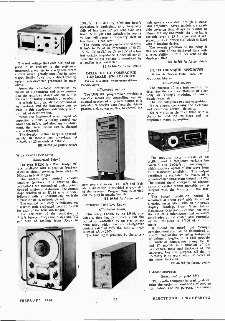
The test voltage thus obtained, and ap-plied in its entirety to the resistance measured, gives rise to a very low direct current which, greatly amplified in valve stages, finally flows into a direct-reading output galvanometer graduated in meg-ohms. Automatic electronic protection by
means of a thyratron and relay ensures that the amplifier stages are cut out in the event of faulty operation or overload. A telltale lamp signals the presence of
an overload, and the instrument can re-main in this condition indefinitely with-out risk of deterioration. When the instrument is employed on
capacitive circuits, a safety control en-sures that, before and after any measure-ment. the circuit under test is charged and discharged. The duration of this charge is approxi-
mately 10 seconds per microfarad at 2 000V, or 20 seconds at 5 000V.
EE 66 763 for further details
WIDE RANGE OSCILLATOR
(Illustrated below)
The type HS200 is a Wien bridge RC type oscillator with a positive feedback selective circuit covering from 20c/s to 200kc fs in four ranges. The output level control provides
negative feedback thus ensuring that oscillations are maintained under condi-tions of minimum distortion. The output stage consists of an EL84 as a cathode-follower with a continuously variable attenuator in its cathode circuit. The emitted frequency is indicated on
a 400mm scale graduated from 20 to 200 for each of the four sub-ranges. The accuracy of the oscillator is
-±lc/s between 20c/s and 50c/s and ±2 per cent of reading from 50eis to
FEBRUARY 1964
200kc/s. The stability, after one hour's operation, is equivalent to a frequency shift of less than 0.2 per cent over one hour. A 10 per cent variation in supply voltage will cause a frequency shift of less than 0.3 per cent. The output voltage can be varied from o ImV to IV at an impedance of 6002; IV to 10V at 5kff or IV to 10V at a low but variable impedance. Under all condi-tions the output voltage is monitored by a rectifier type voltmeter.
EE 66 764 for further details
DELLE DE LA COMPAGNIE GÉNÉRALE D'ELECTRICITÉ 130 rue Léon-Blum. Villieurbanue (Rhone)
PROGRAMMER
(Illustrated below)
The UNIDEL programmer provides a versatile means for controlling any in-dustrial process of a cyclical nature. It is intended to receive data from the driven process and, acting on this, to control the
next step and so on. Fail-safe and fault alarm indication is provided at each step of the process. Programming is carried out by plug-in matrix boards.
EE 66 765 for further details
ELECTRONIC TIME LAG RELAY
(Illustrated below)
This relay, known as the LRIO, pro-vides a time lag electronically but the output is controlled by an electromag-netic relay which has one changeover contact rated at 10W d.c. with a maxi-mum of IA or 250V. The time lag is provided by charging a
ii 123
high quality capacitor through a trans-istor amplifier. Seven models are avail-able covering time delays of 80msec to 30min. On any one model the time lag is variable over a 15:1 range and is dis-played on a calibrated dial which is fitted with a locking device. The overall precision of the relay is ±3 per cent of the displayed time with a repeatability of ± 1 per cent of the displayed time.
EE 66 766 for further details
L'ELECTRONIQUE APPLIQUÉE 25 rue du Docteur Flulay. Paris, 15.
M ODULUS M ETER
(Illustrated below)
The purpose of this instrument is to determine the complex modulus of elas-ticity, or Young's modulus, of visco-elastic materials. The unit comprises two sub-assemblies: (1) A chassis containing the electrical
and electronic control elements. (2) A vibrating chamber fitted with a
clamp to hold the test-piece and the amplitude meter in position.
The modulus meter consists of an oscillator—of a frequency variable be-tween 5 and 1 000c/s in two ranges— which supplies signals of sine wave form to a transistor amplifier. The output amplitude is regulated by means of a potentiometer (maximum output =15W). The output signal energizes an electro-dynamic exciter whose movable rod is integral with the housing of the test-piece. The forced oscillation period is
measured at about 10-'1 with the aid of a period meter fitted with an automatic display (readings from Nixie tubes). Resonance detection is carried out with the aid of a microscope that measures amplitudes at the centre and extremity of the test-piece to 1/100 of a milli-metre. It should be noted that Young's
complex modulus can be determined at several frequencies by using test-pieces of different lengths. It is also possible to construct nomograms giving the E' and E" moduli as a function of the frequencies, mass and thickness of the test-piece. For this purpose, all that is necessary is to work with test-pieces of the same thickness.
EE 66 767 for further details
CARDIO-COMPUTER
(Illustrated on page 124)
The cardio-computer is used to deter-mine the optimum conditions of cardiac stimulation. For this purpose, the charac-
ELECTRONIC ENGINEERING
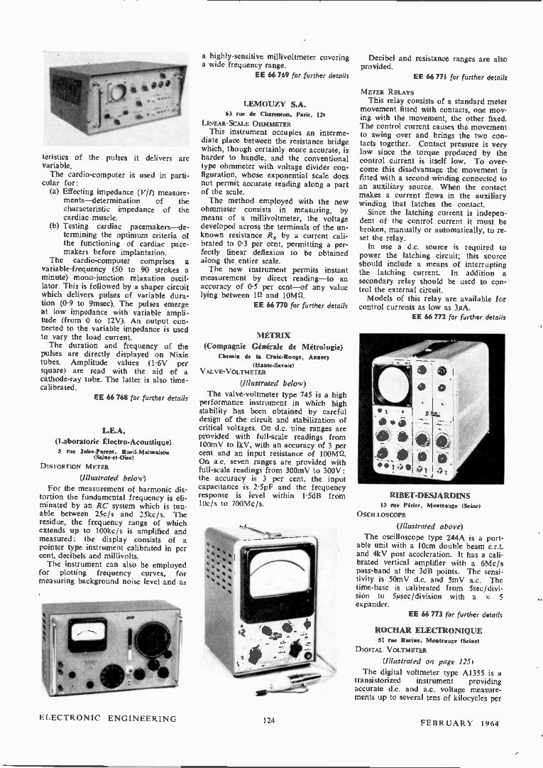
teristics of the pulses it delivers are variable. The cardio-computer is used in parti-
cular for: (a) Effecting impedance (V//) measure-
ments—determination of the characteristic impedance of the cardiac muscle.
(b) Testing cardiac pacemakers—de-termining the optimum criteria of the functioning of cardiac pace-makers before implantation.
The cardio-computer comprises a variable-frequency (50 to 90 strokes a minute) mono-junction relaxation oscil-lator. This is followed by a shaper circuit which delivers pulses of variable dura-tion (0.9 to 9msec). The pulses emerge at low impedance with variable ampli-tude (from 0 to 12V). An output con-nected to the variable impedance is used to vary the load current. The duration and frequency of the
pulses are directly displayed on Nixie tubes. Amplitude values (1.6V per square) are read with the aid of a cathode-ray tube. The latter is also time-calibrated.
EE 66 768 for further details
L.E.A.
(Laboratorie Électro-Acoustique) 5 rue Jules-Parent. Rueil-Malmaison
(Seine-et-Oise)
DISTORTION METER
(Illustrated below)
For the measurement of harmonic dis-tortion the fundamental frequency is eli-minated by an RC system which is tun-able between 25c/s and 25kc/s. The residue, the frequency range of which extends up to 100kc/s is amplified and measured: the display consists of a pointer type instrument calibrated in per cent, decibels and millivolts. The instrument can also be employed
for plotting frequency curves, for measuring background noise level and as
a highly-sensitive millivoltmeter covering a wide frequency range.
EE 66 769 for further details
LENIOUZY S.A. 63 rue de Cluirentoo, Paris, 12e
LINEAR-SCALE OHMMETER This instrument occupies an interme-
diate place between the resistance bridge which, though certainly more accurate, is harder to handle, and the conventional type ohmmeter with voltage divider con-figuration, whose exponential scale does not permit accurate reading along a part of the scale. The method employed with the new
ohmmeter consists in measuring, by means of a millivoltmeter, the voltage developed across the terminals of the un-known resistance R. by a current cali-brated to 0.3 per cent, permitting a per-fectly linear deflexion to be obtained along the entire scale. The new instrument permits instant
measurement by direct reading—to an accuracy of 0.5 per cent—of any value lying between in and 10 W/.
EE 66 770 for further details
MÉTRIX
(Compagnie Générale de Métrologie) Chemin de Ia Croix-Rouge, Annecy
(Haute-Savoie) VALVE-VOLTMETER
(Illustrated below)
The valve-voltmeter type 745 is a high performance instrument in which high stability has been obtained by careful design of the circuit and stabilization of critical voltages. On d.c. nine ranges are provided with full-scale readings from 100mV to lkV, with an accuracy of 3 per cent and an input resistance of 100Mn. On a.c. seven ranges are provided with full-scale readings from 300mV to 300V: the accuracy is 3 per cent, the input capacitance is 2.5pF and the frequency response is level within 1.5dB from 10c/s to 700Mc/s.
#0
Decibel and resistance ranges are also provided.
EE 66 771 for further details
METER RELAYS This relay consists of a standard meter
movement fitted with contacts, one mov-ing with the movement, the other fixed. The control current causes the movement to swing over and brings the two con-tacts together. Contact pressure is very low since the torque produced by the control current is itself low. To over-come this disadvantage the movement is fitted with a second winding connected to an auxiliary source. When the contact makes a current flows in the auxiliary winding that latches the contact. Since the latching current is indepen-
dent of the control current it must be broken, manually or automatically, to re-set the relay. In use a d.c. source is required to
power the latching circuit; this source should include a means of interrupting the latching current. In addition a secondary relay should be used to con-trol the external circuit. Models of this relay are available for
control currents as low as 3µA. EE 66 772 for further details
RIBET-DESJARDINS 13 rue Périer, Montrouge (Seine)
OSCILLOSCOPE
(Illustrated above)
The oscilloscope type 244A is a port-able unit with a 10cm double beam c.r.t. and 4kV post acceleration. It has a cali-brated vertical amplifier with a 6Mc/s pass-band at the 3dB points. The sensi-tivity is 50mV d.c. and 5mV a.c. The time-base is calibrated from 5sec/divi-sion to 5µsec/division with a x 5 expander.
EE 66 773 for further details
ROCHAR ELECTRO MQUE SI rue Racine, Montrouge (Seine)
DIGITAL VOLTMETER
(Illustrated on page 1251
The digital voltmeter type A1355 is a transistorized instrument providing accurate d.c. and a.c. voltage measure-ments up to several tens of kilocycles per
ELECTRONIC ENGINEERING 124 FEBRUARY 1964
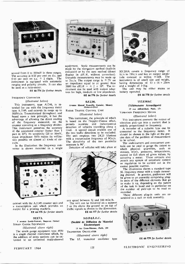
second from 0 to 500mV in three ranges. The accuracy is 0.25 per cent on d.c. and 0.15 per cent on a.c. ± 2 digits. The instrument is equipped with automatic ranging and polarity circuits. It can also be used as a ratio-meter.
EE 66 774 for further details
FREQUENCY CONVERTOR
(Illustrated below) This instrument, type A1246, is in-
tended for use with the frequency meter type A.1149, and extends its range up to 560Mc/s. Transistorized throughout. and based upon a new principle, it has the advantage of allowing the direct reading of the frequency measured, on the counter operating as a frequency divider. This instrument preserves the accuracy of the associated counter (better than 1 part in 107). Its sensitivity (20 to 50mV; input impedance 5011) makes its utiliza-tion possible on almost aa kinds of cir-cuits. In the illustration the frequency con-
vertor is shown mounted in a single
cabinet with the A.1149 counter unit and a transcription unit which provides an output for a printing machine.
EE 66 775 for further details
SEXTA 1 avenue Louis-Pasteur, Bagneux (Seine)
STRAIN GAUGE EQUIPMENT
(Illustrated above right) The strain gauge equipment type 4930
is a single channel instrument which, by the addition of extra sections can be ex-tended to an unlimited multi-channel
• a 4104. ja . '
_40
equipment. Static measurements can be made by the elongation method (built-in indicator) or by the zero method (direct display in dRIR, without correction). Dynamic measurements may be made up to 2kc/s. The output range is ±- 2V on an impedance equal to or greater than 20031 for dRIR = ± 2 x 10*. The in-strument can be used with output adap-tors for high, medium or low impedance.
EE 66 776 for further details
A Marcel Roatilto Gamier, Massey (Seism-et-O W
RADAR TRAFFIC CONTROL UNIT
(Illustrated below)
This instrument, the principle of which is based on the Doppler-Fizeau effect, permits accurate and instantaneous detection of vehicles travelling along a road. A special circuit enables one of the two traffic directions to be excluded. The unit employs two 2K25 klystons with a transmission frequency of 9Gc/s. The directivity of the two parabolic scanners is 90°. Detection of vehicles will take place at
any speed between 33 and 100 mile/h. The unit can be mounted on a support
2 or 3m above the ground or on top of traffic signals as shown in the illustration.
EE 66 777 for further details
(Société de Diffusion de Materiel Electronique)
11 rue Léon-Maraue. Paris, 15e
TRANSISTOR OSCILLATOR
(Illustrated above right)
The 1.f. transistor oscillator type
SO 200A covers a frequency range ot leis to 1Mc/s and has an output ampli-tude constant to within -± ldB. The instrument is of small size and weight, having dimensions of 13 x 16 x 20cm and a weight of 3.5kg. The unit may be either mains or
battery operated. EE 66 778 for further details
TELEMAC
(Télémesures Acoustiques) 17 rue Alfred-Roll. Paris. 17e
VIBRATION FREQUENCY M ETER
(Illustrated below) This instrument converts the output of
vibration pick-ups into a current that is strictly proportional to frequency. A recorder of a suitable type can be
connected to the frequency meter. It should be chosen in the light of the pre-cise data of the problem of measurement to be solved. The undercurrent and overcurrent con-
tacts can be used to gauge the extent to which physical quantities, such as stresses, levels, pressures, temperatures, exceed or fall short of given values, by actuating a meter. These contacts also permit any system of automatic control or regulation to be carried out in the easiest possible manner. The illustration shows a standard type
SL frequency meter with a single measur-ing channel. In practice, preference will be given to an assembly comprising plug-in units of the different elements that go to make it up, depending on the nature of the task in hand and in particular on the number of pick-ups to be read or recorded. These different plug-in units are as-
sembled in a rack or rack assembly.
EE 66 779 for further details
FEBRUARY 1964 125 ELECTRONIC ENGINEERING
MEETINGS THIS MONTH
BRITISH INSTITUTION OF RADIO ENGINEERS
All London meetings will be held at the London School of Hygiene and Tropical Medicine, Keppel Street, Gower Street, London, W.C.1, unless otherwise stated.
Joint Computer and Radar Groups Date: 7 February. Time: 6 p.m. Lecture: The Omnitrac II Computer. By: J. A. Ashton.
Electro-Aconstiles Group Date: 12 February. Time: 6 p.m. Lecture: Correlation Techniques in Studio Testing.
By: A. N. Burd. Radar Group
Date: 26 February. Time: 6 p.m. Lecture: High Definition Radar. By: J. M. G. Seppen.
North Western Section Date: 6 February. Time: 7 Held at: Bolton Technical College. Lecture: Some Aspects of the Use of Radio Telemetry in Small Vehicle Research and Development.
By: M. A. Millward. Southern Section
Date: 6 February. Time: 7.30 p.m. Held at: Basingstoke Technical College. Lecture: Solid State Switching. By: A. C. Savage. Date: 19 February. Time: 7 p.m. Held at: Bournemouth Municipal College of Technology and Commerce.
Lecture: Electronic Techniques in the Study of the Sea.
By: M. J. Tucker. Date: 27 February. Time: 7 p.m. Held at: Farnborough Technical College. Lecture: An Introduction to the Theory and Application of Piezoelectric Transducers.
By: R. F. J. Orwell. South Western Section
Date: 11 February. Time: 6.30 p.m. Held at: Bristol University Engineering Lecture Rooms.
Lecture: Redundancy Techniques for Reliability in Aviation Electronics.
By: R. K. Bar!cop. Date: 5 February. Time: 6.30 p.m. Held at: The South Devon Technical College. Torquay.
Lecture: The Principles and Technology of Lasers. By: R. C. Smith.
South Wales Section Date: 5 February. Time: 6.30 p.m. Held at: The Welsh College of Advanced Tech-nology.
Lecture: Semiconductor Integrated Circuits. By: M. S. Alderson.
South Midlands Section Date: 28 February. Time: 7 p.m. Held at: North Gloucestershire Technical College, Cheltenham.
Lecture: A Practical Method of Implementing a Step Towards Full Automation.
By: F. S. Ellis. Scottish Section
Date: 5 February. Time: 7 p.m. Held at: Department of Natural Philosophy, The University, Drummond Street, Edinburgh.
Lecture: Numerical Control of Machine Tools. By: D. F. Walker. Date: 6 February. Time: 7 p.m. Held at: Institution of Engineers and Ship-builders, 39 Elmbank Crescent, Glasgow.
Lecture: Numerical Control of Machine Tools. By: D. F. Walker.
Merseyside Section Date: 19 February. Time: 7.30 p.m. Held at: The Walker Art Gallery, Liverpool. Lecture: Automatic Marshalling Yards. By: J. M. Howe.
North Eastern Section Date: 12 February. Time: 6 p.m. Held at: The Institute of Mining and Mechani-cal Engineers. Westgate Road, Newcastle upon Tyne.
Lecture: The Role of the Engineer in Medicine. By: W. J. Perkins.
West Midlands Section Date: 12 February. Time: 7.15 p.m. Held at: Wolverhampton College of Technology. Lecture: Mathematical Training for Engineers. By: N. Bright and F. J. Hawley.
THE INSTITUTE OF NAVIGATION Date: 21 February. Time: 5.30 pin. Held at: The Royal Geographical Society, I Kensington Gate, London, S. W.7.
Lecture: Lasers. By: P. G. R. King.
INSTITUTION OF ELECTRICAL ENGINEERS
All meetings will be held at Savoy Place. com-mencing at 5.30 p.m., unless otherwise stated. Date: 4 February. Lecture: Superconductive Windings in Power Transformers.
By: K. J. R. Wilkinson.
Date: 5 February. Lecture: Recent Developments in Radar Modula-tion Systems.
By: R. Benjamin. Date: 6 February. Lecture: Some Developments in the Design of Large Power Transformers.
By: H. W. Kerr and S. Palmer. Date: 6 February. Discussion on: Using Sampled Data in Automatic Control.
By: H. Robertson. Date: 12 February. Lecture: Newton and Heaviside in Control. By: G. G. Gouriet. Date: 13 February. Times: 2.30 and 5.30 p.m. Colloquium on: Electrical Methods of Propulsion in Space.
(All wishing to attend must register; forms avail-able on application —no fee for members).
Date: 14 February. Discussion on: Centralized Control Systems: Survey of Current Practice and Future Trends.
By: M. G. Gibbs. Date: 17 February. Discussion on: Factors Affecting the Quality of Pictures Read off Camera Tubes and Storage Tubes.
By: R. L. Beurle. Date: 17 February. Lecture: Three-Speed Single-Winding Squirrel-Cage Induction Motors.
By: W. Fong and G. H. Rawcliffe. Date: 18 February. Discussion on: Teaching Active Network Theory. By: K. F. Sander. Date: 19 February. Lecture: Electrical Services at Shell Centre. By: D. E. Bird and A. E. Caster. Date: 21 February. Discussion on: Instrument Scale Design. By: A. J. Maddock. Date: 21 February. Held at: Central Hall. Westminster, S. W.1. Lecture: Making Electricity. By: J. S. Forrest and M. A. Faraday. Date: 24 to 28 February. Conference: Transmission Aspects of Communi-cations Networks.
(All wishing to attend must register; forms avail-able on application).
THE TELEVISION SOCIETY Date: 7 February. Time: 7 p.m. Held at: The Conference Hall, I.T.A.. 70 Brompton Road. London. S. W.3.
Lecture: Television Service Planning for Overseas.
PUBLICATIONS RECEIVED
NEWMARKET CROSS INDEX TO BRITISH TRANSISTORS is the title of a new issue by Newmarket Transistors Ltd, Exning Road. New-market. Suffolk. It contains the Newmarket transistor equivalents of British transistors, for professional applications. No equivalent can ever be exact and any prospective user should consult a data sheet for exact ratings and characteristics before making a final decision. Copies of this publication, quotations and further details may be obtained from the Commercial Manager, New-market Transistors Ltd, Exning Road, New-market, Suffolk.
CUMULATIVE CATALOGUE OF PO WER SUPPLY EQUIPMENT is the title of the first six leaflets of a cumulative catalogue published by W. Mackie and Co. Ltd of Lambeth. specialists in the design and manufacture of power supply equipment for the electronics industry, which will ultimately provide broad specifications of the standard types of motor alternators, motor generators, rotary convertors, rotary transformers. self-exciting generators and alternators, static in-vertors, pulsing and ringing machines and dyne-motors manufactured by the Company. Machines covered by the leaflets include the Mackie 1000c /s range of motor alternators, and the Mackie 2-and 4-pole rotary convertors and their 250 VA
50c/s static invertor. Copies of these leaflets are available from W. Mackie & Co. Ltd, 129 Lam-beth Road, S.E.2.
CATALOG 700 lists a comprehensive range of small parts, such as solder terminals, tog boards, coil-formers, connectors and capacitors, etc. which are manufactured by Cambion (Cambridge Thermionic Corporation). This Company has manufacturing facilities in the U.S.A., Canada and the U.K. Copies of the catalogue may be obtained from Cambion Electronic Products Ltd, Cambion Works, Castleton, Nr. Sheffield, York-shire.
SU MMARY OF PRODUCTS by Electrolube Limited is the title of a new eight-page booklet whieh gives in concise form a technical intro-duction to Electrolube, full details of the range of products, a comprehensive list of typical applications and specification data. It also in-cludes the new Grease Aerosol 2GA. Requests for copies of this booklet should be addressed to Electrolube Ltd. Oxford Avenue, Slough, Bucks.
L'INDUSTRIA ELETTRONICA ITALIANA is the title of a survey recently published by CNEN (Comitato Nazionale per L'Energia Nucleare) on the structure of the Italian electronic industry and on the likely trends of development in this sector, with particular reference to the relation-ship existing between the electronic and electro-nuclear industries. Further information may be obtained from CNEN, Divisione Affari Inter-nazionali E studi Economici, Via Belisario 15, Rome, Italy.
MULLARD ALL-GLASS CRYSTAL UNITS are described in a recent publication by Mullard Limited. The booklet describes in some detail the electrical behaviour of quartz crystal units both in oscillators and as individual components. There is a section devoted to the advantages obtained by using glass encapsulated crystals as well as a glossary of terms and specifications laid down for crystal units. Data on Mullard all-glass quartz crystal units are also included. Requests for copies should be made on headed notepaper to the Government and Industrial Valve Division, Mullard Limited, Mullard House, Torrington Place, London, W.C.1.
ELECTRONIC ENGINEERING 126 FEBRUARY 1964
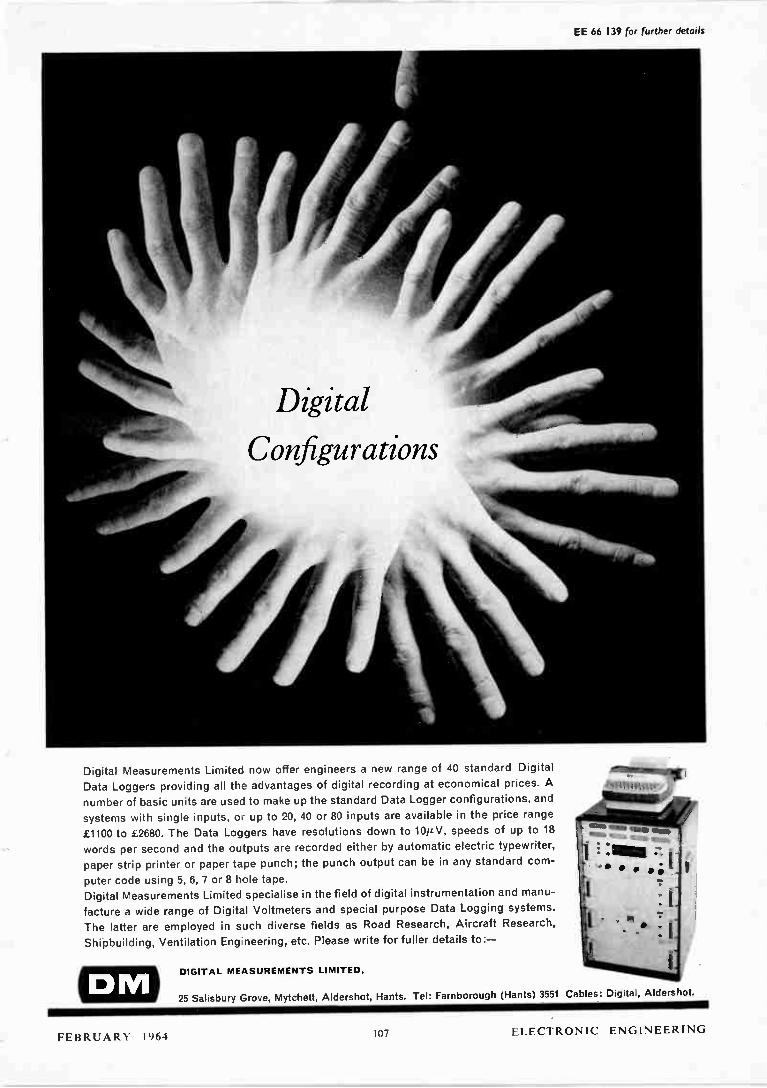
EE 66 139 for further details
Digital Measurements Limited now offer engineers a new range of 40 standard Digital
Data Loggers providing all the advantages of digital recording at economical prices. A
number of basic units are used to make up the standard Data Logger configurations, and
systems with single inputs, oc up to 20, 40 or 80 inputs are available in the price range
£1100 to £2680. The Data Loggers have resolutions down to 10ÍL V, speeds of up to 18
words per second and the outputs are recorded either by automatic electric typewriter,
paper strip printer or paper tape punch; the punch output can be in any standard com-
puter code using 5, 6, 7 or 8 hole tape.
Digital Measurements Limited specialise in the field of digital instrumentation and manu-
facture a wide range of Digital Voltmeters and special purpose Data Logging systems.
The latter are employed in such diverse fields as Road Research, Aircraft Research,
Shipbuilding, Ventilation Engineering, etc. Please write for fuller details to:—
DIGITAL MEASURE MENTS LI MITE D,
.11111 ,rangiai e gi #99449 ~
MIMS RIMS COMM 1111111111 fiue,
25 Salisbury Grove, Mytchett, Aldershot, Hants. Tel: Farnborough (Hants) 3551 Cables: Digital, Aldershot.
FEBRUARY 1964 107 ELECTRONIC ENGINEERING

EE 66 140 for further details
who has
the most
beautiful
knees?
IR have . . . 250 and more types and sizes of zener diodes, all with those firm, sharp, dependable, knees that electronic engineers crave. Knees like these are not acquired by chance; all IR zener diodes are designed as zeners, and made by a controlled process which ensures predictable, high-performance, zener character-istics every time.
Ask for full details of the IR zener diode type that interests you . . . the range is from 250m W to 50 W, 3.9V to 200V.
e //e INTE RNATI ONAL RECTIFIER
Im mediate off-the-shelf delivery fro m IR distributors — phone e
GLASGO W DOUGLAS 11671 (MIDDLESEX) SKYPORT 1314 .COLCHESTER 6173 LEEDS 35111
(LONDON 51.27) GIPSY HILL 6166 PORTSMOUTH 61785 LEICESTER 25071 REDHILL 5050
=I International Rectifier Europe S.A. • 38 Avenue Des Arts • Brussels • Belgium • Telephone 11.17.38 74 • Telex 02 22201
j O 7 INTERNATIONAL RECTIFIER CO. (GREAT BRITAIN) LTD • HURST GREEN • OXTED • SURREY • TELEPHONE OXTED 3215 • TELEX RECTIFIER OXTED 8819
ELECTRONIC ENGINEERING 108 FEBRUARY 1964

Une description basée sur des renseignements fournis par les fabricants de nouveaux organes, acces-soires et instruments d'essai Traduction des pages 120 à 125
ENREGISTREUR MINIATURE Distributeurs: Rugden 'nomment!' Ltd. 25s Tessier Roud, Guildford, Surrey (Illustration à la page 120)
L'enregistreur miniature Amprode a été réalisé pour l'indication ou l'enregis-trement d'un signal de courant, de tension ou de température. Il mesure environ 14,6 cm x 7,6 cm x
4,4 cm et il peut être obtenu soit pour montage sur panneau, dans une valise spéciale en cuir, soit comme modèle portatif. Les modèles prévus pour l'enregistre-
ment de signaux en alternatif compren-nent un transformateur tandis que ceux pour les signaux en direct sont de sensibilité variable, le mouvement de l'instrument de mesure ayant alors une résistance allant jusqu'à 7,4 kn. Les modèles pour une gamme de tempéra-ture de —50 à +250°F sont fournis avec une thermistance. Il en existe d'autres, enfin, pour une gamme de température allant jusqu'à 2 000°F lorsqu'ils sont conçus pour un thermocouple spécifique. L'ensemble de l'appareil est logé dans
un moulage en matière plastique à l'épreuve de la poussière. L'enregistrement se fait par un style
qui marque un papier sensible à la pression. L'emploi d'encre n'est pas nécessaire. Les vitesses d'avance du papier prévues sont de 2,54 cm/h, 15,24 cm/h et 30,48 cm/h. Le taux d'enregistre-ment dépend de cette vitesse et varie entre un point par 5 secondes et un point par minute. EE 66 751 pour plus amples renseignements
DOSIMÈTRE À RAYONS X Electronic Instruments Ltd. Richmond, Surrey
(Illustration à la page 120)
La société Electronic Instruments Ltd vient d'annoncer la réalisation d'un nouveau dosimètre sensible aux rayons X: le modèle 37C. Il s'agit d'un instru-ment portatif basé sur un modèle an-térieur, dont un grand nombre d'exem-plaires ont été fournis au Ministère de la Santé Publique pour une étude de doses génétiquement efficaces dans les hôpitaux. A l'aide de sa chambre d'ionisation de 35 cm', le dosimètre peut
mesurer de 0 à 0,3 mr et de 0 à 100 r. Comme dosimètre de taux, l'instrument peut mesurer de 0 à 0,3 mr/min et de 0 à 100 r/min. On peut lui adjoindre des chambres d'ionisation d'un volume effectif de 3,5 cm3 et de 350 cm', per-mettant une augmentation ou une diminution décuplée de la sensibilité. Le nouvel instrument, transistorisé dans une très large mesure, fonctionne sur piles d'usage courant. Il peut être utilisé également pour la mesure de potentiels, de faibles courants et de charges. Enfin, il se distingue par le fait qu'il est muni d'une sortie d'enregistrement, ce qui con-stitue une caractéristique peu commune aux instruments portatifs. EE 66 752 pour plus amples renseignements
MODULATEUR MICROVOLTS Distributeurs: R. H. Cole Electronics
26-32 Caxton Street, Westminster, London, S.W.1 Le modulateur microvolts RMY 11 a
été spécialement réalisé par la société Siemens & Halske pour la modulation de tensions et de courants directs de faible valeur dans le circuit d'entrée d'amplificateurs de courant continu à haute sensibilité. Le fonctionnement de ce nouvel accessoire est basé sur l'effet Hall. La couche semi-conductrice d'un générateur Hall d'indium-antimoine est placée dans l'entrefer d'une petite bobine avec un noyeau de ferrite, excité à la fréquence de modulation par un courant alternatif constant. La quantité de courant continu devant être modulée est injectée au générateur Hall sous forme de courant de commande. La tension Hall aux bornes de sortie devient alors une tension alternative proportionnelle à la quantité de courant continu aux bornes d'entrée. Des précautions spéciales ont été
prises en vue d'éliminer les erreurs dues
ELECTRONIC ENGINEERING
occupera stand V.21 Salle 59 au SALON INTERNATIONAL
DES COMPOSANTS ÉLECTRONIQUES
qui se tiendra it Paris du 7 au 12 février 1964. Les visiteurs seront
les bienvenus.
aux forces magnétiques thermoélec-triques se trouvant dans le circuit de commande (circuit d'entrée) et aux ten-sions d'interférence inductives dans le circuit Hall (circuit de sortie). Les résistances d'entrée et de sortie du
modulateur microvolts RMY 11 sont d'environ 60 et 30 SI respectivement. La bobine de champ (résistance RF = 3 n, inductance LF = 0,5 mH) est excitée par un courant de champ iFn = 35 mA. Ce courant d'excitation donne au modu-lateur une résistance d'émission d'environ 10 11. A une fréquence de modulation de 1 kHz, la tension d'interférence induc-tive dans le circuit de sortie est in-férieure à 1 µV. La déviation du zéro du modulateur, rapportée à l'entrée, est ainsi inférieure à 6 µV. Elle est donc comparable à la déviation du zéro des choppers à contact mécanique d'usage courant dans l'amplification de la ten-sion continue. L'avantage du modula-teur Hall par rapport au chopper mécanique est que celui-ci ne comporte pas de pièces mobiles sujettes à l'usure. De plus, le modulateur Hall permet une fréquence de modulation beaucoup plus élevée. EE 66 753 pour plus amples renseignements
TRACEUR DE COURBES DE TRANSISTORS
A.E.S. Electronics Ltd, 42 Theobalds Rond, London, W.C.1
(Illustration à la page 120) Le transiscope est un traceur de
courbes complet pouvant indiquer sur son écran cathodique toute une série de courbes caractéristiques de sortie de courant au collecteur par rapport à la tension au collecteur. Chaque courbe représente un courant de base constant. Les caractéristiques de deux transistors
peuvent être affichées simultanément. Cette possibilité écarte les difficultés que posent l'adaptation des transistors. L'instrument peut être utilisé égale-
ment pour la mesure des principaux paramètres de transistors tels que /3, le facteur réduit d'amplification de courant et ¡co, ainsi que le courant de fuite du collecteur à l'émetteur. Ces valeurs sont indiquées directement sur un instrument de mesure logé sur le panneau avant. EE 66 754 pour plus amples renseignements
FEBRUARY 1964 127 ELECTRONIC ENGINEERING
DIVISEUR DE FRÉQUENCE Achance Compozieuts Ltd, Roebuck Road.
Hainault, Ilford, Eues
(Illustration à la page 121)
La société Advance Components Ltd vient de réaliser un nouveau diviseur de fréquence, le modèle TCD 40. C'est un instrument autonome et très
compact dont la gamme de fréquence s'étend de 1 MHz à 40 MHz. Il assure un étage diviseur supplémentaire à n'importe quel compteur de 1 MHz ou de 10 MHz par l'extension de la fré-quence du compteur jusqu'à 40 MHz. Des facteurs de division de 100, 40,
10 et 4 peuvent être choisis, ainsi qu'un branchement direct de l'entrée à la sortie lorsque la division de fréquence n'est pas requise. Les connexions d'entrée et de sortie s'effectuent par douilles BNC de 50 12, et la sensibilité d'entrée maxima est de 50 mV efficaces. Le modèle TCD 40 a les mêmes
dimensions et le même fini que le comp-teur-minuterie Advance, modèle TC2. Cette identité permet aux deux instru-ments de former un double élément compact. EE 66 755 pour plus amples renseignements
ANALYSEUR NUMÉRIQUE Harrison Reoroduction Equipment Ltd.
Farnborough Hampshire
(Illustration à la page 121)
Un nouvel analyseur numérique pouvant encoder 100000 chiffres en 100 tours à l'aide du code Petherick a été réalisé par la Harrison Reproduction Equipement Ltd, qui fait partie du Groupe Movitex. Il s'agit du type 21/100T/100k qui a été particulièrement conçu en vue de l'emploi dans l'indus-trie des machines-outils pour la défini-tion d'un dixième de pouce en longueurs atteignant 2,54 m. Le moins important des deux disques
utilisés dans cet appareil est directement accouplé à l'arbre d'entraînement. Il s'agit du disque ou s'effectue le codage des unités, des dizaines et des fractions de milliers. Le système d'engrenages planétaires utilisé donne un rapport de 100 à 1 entre les disques. Une paire de pinions en nylon, portés
par des roulements à billes à couple réduit, s'engrènent dans une paire d'engrenages différentiels en bronze, tous de la plus haute qualité. Vu que l'effet réactif doit se produire dans tout train d'engrenages, le diagramme codé est divisé de manière à ce que les "ferme-tures" et "ouvertures" de tous les chiffres codés commencent et terminent sur le disque le moins important. Un recouvre-ment suffisant est prévu sur les dia-grammes pour permettre presque une demi-dent d'effet réactif, ce qui est plus que suffisant pour parer à toute usure prévisible. La précision globale du dis-positif devient donc celle du disque le moins important. Ces disques sont fabriqués selon le
procédé Harrison, présentant une sur-
face en or dur à isolement partiel de mélamine. Les contracts qui s'engrènent dans ces disques sont en alliage d'or et d'argent, sous forme de bande rectan-gulaire. La vitesse de fonctionnement recom-
mandée est légèrement inférieure à 1000 chiffres par seconde. L'analyseur numérique est de con-
struction robuste. L'arbre d'entraînement est porté par des roulements à billes dans un moulage de base. Les couvercles détachables, qu'on peut enlever pour avoir accès aux disques, protègent le mécanisme contre la poussière. Toutes les connexions électriques se font au moyen d'un connecteur afin d'en faciliter l'entretien. Les dimensions hors-tout sont d'environ 13,97 cm de diamètre sur 10,16 cm de longueur. L'arbre d'en-traînement est creux; son diamètre ex-térieur est de 1,9 cm et son diamètre intérieur de 1.27 cm. EE 66 756 pour plus amples renseignements
CONVERTISSEUR ANALOGIQUE-NUMÉRIQUE
Moore. Reed & Co. Ltd. Woodman Works, Darustord Road, London, S. W.19
(Illustration à la page 121)
La société Moore, Reed & Co Ltd a réalisé un convertisseur analogique-numérique électromécanique compact qui répond aux conditions de la spécifi-cation Av.P.24 du Ministère de l'Avia-tion. C'est un dispositif qui permet aux réalisateurs d'installation d'incorporer un instrument autonome pouvant recevoir un signal de sortie synchrone d'émetteur de commande standard qu'il transforme sous une forme numérique. Ce système qui comprend un moteur
asservi de 400 Hz à six pôles, un train d'engrenages entraînant un encodeur à arbre numérique et un synchro de trans-formation de commande de grande pré-cision d'une erreur maxima de ± 3 min, fournit une lecture numérique en code Gray à une résolution de 2" ou de 2'2 par tour de l'arbre synchro ou jusqu'à 2'2 en code binaire de balayage V. Le synchro tourne à 20 tours/minute
au minimum à pleine tension du moteur et la lecture satisfaisante de l'encoder à cette vitesse (1370 coups par seconde) est garantie. L'élément d'entraînement com-prend un tachygénérateur d'amortisse-ment afin de permettre l'emploi d'ampli-ficateurs à gain élevé. Ne mesurant que 3,65 cm X 7,77
cm x 12,7 cm, le convertisseur peut être logé dans un coffret standard ARINC et il est muni de fiches et de douilles sous-miniatures pour en faciliter l'in-stallation. EE 66 757 pour plus amples renseignements
RELAIS D'INSERTION À LAME VIBRANTE
R h « Ltd, Stonefield Was. Victoria Road, South Ruislip, Middlesex
(Illustration à la page 121)
La société Hivac Ltd vient d'ajouter le modèle intermédiaire XS4 à sa gamme
standard de relais d'insertion à lame vibrante. La longueur du verre du XS4 est de
3,2 cm et la longueur hors-tout maxi-mum est de 4,49 cm. Le diamètre maxi-mum de ce type est de 0,35 cm. Les surfaces de contact sont doublées
d'or diffusé dans le matériau de base afin d'éliminer le risque du soudage à froid durant le fonctionnement sur cir-cuit sec. La longue durée de fonctionne-ment de ces contacts est assurée pour des courants pouvant aller jusqu'à 150 mA. Le XS4 fonctionne entre 33 et 59 At et sa tension de rupture minima est de 500 V c.c. D'un format beaucoup plus réduit que
le type standard XS5 (P.O. No. 1/DC0/ 588), le XS4 offre la miniaturisation sans le sacrifice de la fiabilité ou du pouvoir de contrôle d'énergie qui est inévitable avec les types subminiature. EE 66 758 pour plus amples renseignements
ENREGISTREUR DU TAUX DE DISTORSION
Marconi Instruments Ltd. St. Albans. Hertfordshire
(Illustration à la page 121)
La société Marconi Instruments Ltd vient de réaliser un nouvel instrument de mesure du taux de distorsion, le type TF 2331, entièrement constitué de corps solides. Bien que normalement alimenté sur courant alternatif de secteur, il peut être également alimenté par batterie extérieure. La gamme de tension d'entrée, pour
la mesure de distorsion jusqu'à 0,05% de taux de distorsion sur un instrument à lecture directe de 0,1% sur la totalité de l'échelle, s'étend de 0,775 V jusqu'à 30 V efficaces. Le filtre à rejet de fré-quence fondamentale est accordé par une échelle à étalonnage direct avec commandes de réglage précis de manière à pouvoir obtenir un rejet fondamental pratiquement complet dans une gamme de fréquence de 20 Hz à 20 kHz. La largeur de bande pour la mesure
du bruit et de la distorsion est soit de 20 kHz soit de 100 kHz. L'indication du taux de distorsion est présentée sur le voltmètre intérieur; ce dernier peut également être utilisé indépendamment avec gammes sur totalité de l'échelle de 1 mV à 30 V et une gamme de fréquences atteignant 100 kHz. Un dispositif de coupure à fréquence moyenne élimine le bourdonnement du secteur cependant qu'un filtre de pondération de radiodiffu-sion du type C.C.I.F. permet d'évaluer le bruit avec précision. La résistance d'entrée est soit une terminaison de 600 SI soit une résistance élevée de 10 ke2 à 100 kn, selon le niveau. La section à voltmètre a des bornes de sortie d'amplification pour l'examen oscillo-scopique du bruit résiduel et de la dis-torsion ou du signal original. Lorsqu'il est employé comme voltmètre indépen-dant, sa résistance d'entrée est de 1 mn. EE 66 759 pour plus amples renseignements
ELECTRONIC ENGINEERING 128 FEBRUARY 1964
Une description, basée sur des renseignements fournis par les fabricants, de certains des appareils exposés au Salon International de la Mesure, du Côntrole, de la Régulation et de l'Automatisme,
qui s'est tenu à Paris du 14 au 21 novembre 1963.
AGELEC il rue Romain-Rolland, Les Lilas (Seine)
OSCILLOSCOPE
(Illustration à la page 122)
Le Laboscope 130 présente le maxi-mum de possibilités d'utilisation tout en restant d'un maniement simple et rapide, et d'un prix abordable. Réalisé avec des pièces détachées de
catégorie professionnelle, il réunit tous les perfectionnements connus tels que commutation électronique, double base de temps, l'une pouvant être retardée par l'autre, balayage déclenché, relaxé et monocourse, loupe électronique, etc. De plus, un nouveau dispositif breveté
d'étalonnage en fait un appareil de mesure rapide et de haute précision à lecture directe. Enfin, l'utilisation de tiroirs inter-
changeables, tant pour la préamplifica-don que pour les bases de temps, lui donne une souplesse d'emploi exception-nelle. Les amplificateurs verticaux et hori-
zontaux sont identiques. Leur bande passante s'étend du continu à 10 MHz pour une sensibilité de 0;1 V/cm. Cette sensibilité peut être portée à 100 ti/cm par utilisation de tiroirs supplémentaires. Le procédé d'étalonnage fait apparaître
sur l'écran, simultanément avec le phéno-mène observé, une échelle de temps ou de tension obtenue par des signaux appliqués à l'entrée des amplificateurs alternativement avec le signal à observer. Ainsi, le gain des amplificateurs, la sensibilité du tube et les distorsions de déviation sont sans influence sur la pré-cision de lecture. De plus, l'erreur de parallaxe est éliminée. Les échelles peuvent se présenter, soit
sous la forme d'une série de divisions d'environ 1 cm, dont l'intervalle est connu en volts crête, en volts efficaces, ou en temps, soit sous la forme de deux divisions seulement dont l'écart est variable et lu sur le cadran d'un poten-tiomètre hélicoldal de précision. La précision de lecture est de 1% en
tension et de 2% en temps. La stabilité dans le temps est celle du tube 85A2 utilisé comme référence, soit 0,3%.
Une gamme étendue de tiroirs inter-changeables et de bases de temps est prévue pour cet oscilloscope, ce qui le rend propre à l'emploi dans une grande variété d'applications. EE 66 760 pour plus amples renseignements
A.O.I.P. 8-14 rue Charles-Fourier, Paris 13e
TRANSISTORMÈTRE
(Illustration à la page 122)
Cet appareil a été réalisé pour faciliter le travail de l'ingénieur ou du technicien dans le choix du transistor nécessaire à son montage ou bien pour le tri dans le cas d'une fabrication de grande série. Après fixation de la polarisation et
de la tension émetteur-collecteur, on peut mesurer le gain 13, la résistance d'entrée Ri, en montage émetteur commum. Les mesures de I, et de rbb et des
courants directs et inverses des diodes se font par lecture directe sur le cadran d'un micro-ampèremètre. Une simple commutation permet d'effectuer les mesures sur les transistors PNP ou NPN jusqu'à des puissances n'excédant pas 30 W. Les gammes de mesures sont comme
suit: p - O à 500; Ri — 0 à 10 let et 1c — O à 1 A. Le gain et l'impédance d'entrée sont
mesurés en émetteur à la masse par des méthodes d'opposition à une fréquence voisine de 1 kHz; c'est à dire que cela consiste à superposer un signal alternatif de faible amplitude par rapport au signal continu choisi pour la polarisation. La tension de déséquilibre du pont est
amplifiée et détectée par un oeil magique (2 sorties sont prévues pour un détecteur et un générateur extérieurs). L'appareil comprend comme éléments:
— 2 alimentations stabilisées à 1% par rapport au secteur, l'une pour le courant collecteur et pouvant délivrer 1 A sous 30 V, l'autre pour l'alimentation de la base et délivrant 0,1 A sous 30 V. Trois appareils de mesure fixés sur la face avant permettent de lire directement la
tension Ve, le courant /b et le courant de polarisation /b. — Un oscillateur de 1 kHz et un détecteur de déséquilibre par oeil magique. Les liaisons se font par supports à
serrage rapide et bornes pour tous les types de transistors. Des ailettes de re-froidissement sont prévues dans le cas de transistors de puissance. EE 66 761 pour plus amples renseignements
pH METRE—rH MÈTRE—ENREGISTREUR
Ce nouvel appareil A.O.I.P. est destiné à l'enregistrement continu de pH et de r11. Le principe de la mesure est basé sur
les lois électrochimiques qui régissent les solutions, lois dans lesquelles les varia-tions des potentiels chimiques peuvent être traduites, à l'aide d'un capteur approprié, en différences de potentiel électrique qu'il est facile d'amplifier et d'enregistrer. Le capteur de la fonction pH (acidité-
basicité) est constitué par un couple-électrode de verre/électrode en calomel dans lequel l'électrode indicatrice est l'électrode de verre. On détecte ainsi les variations de son potentiel par rapport à l'électrode de référence. L'électrode au calomel (du type capil-
laire) et l'électrode de verre à remplissage spécial sont assemblées dans un fourreau en PVC muni d'ouvertures, permettant une libre circulation du liquide à mesurer tout en évitant les contaminations et les chocs qui pourraient détériorer les électrodes. Le capteur de rH (potentiel d'oxyde-
réduction) a été modifié dans sa concep-tion afin de permettre l'enregistrement. Il est actuellement constitué par un couple-électrode d'antimoine/électrode de platine dont le montage et la présenta-tion sont similaires à ceux du capteur de pH. On suit les variations du poten-tiel de l'électrode de PT par rapport à celui de l'antimoine. EE 66 762 pour plus amples renseignements
FEBRUARY 1964 129 ELECTRONIC ENGINEERING

CHAUVIN ARNOUX IN rue Championnet, Paris, nie
MÉGOHMMÈTRE ÉLECTRONIQUE
(Illustration à la page 123)
Le T.5 000 est un mégohmmètre élec-tronique à lecture directe spécialement conçu pour la mesure des résistances et isolements très élevés, atteignant 20 millions de mégohms, sous plusieurs tensions échelonnées de 20 à 5 000 V. L'appareil est alimenté sur réseau et peut rester en service en permanence. Il est donc utilisable pour des contrôles de pièces en série. La tension de mesure est produite et
stabilisée par un générateur double à transistors, assurant le maintien de la tension totale aux bornes de la résistance mesurée, quelle que soit la valeur de celle-ci, dans les limites de chaque calibre. Un filtrage spécial à constante de
temps asservie permet d'opérer sur circuits capacitifs, en éliminant toute instabilité hors de la mesure d'une résistance très élevée. La tension de mesure ainsi obtenue,
appliquée en totalité à la résistance mesurée, donne lieu à un courant con-tinu très faible qui, fortement amplifié sur étage à lampes, alimente finalement un galvanomètre de sortie à lecture directe, gradué en mégohms. Une protection automatique élec-
tronique par thyratrons et relais assure la mise hors circuit des étages amplifica-teurs en cas de fausse manoeuvre ou de surcharge. Un voyant lumineux signale cet état
de surcharge, et l'appareil peut rester indéfiniment dans cette condition, sans aucun risque de détérioration. Lorsque l'appareil est utilisé sur
circuits capacitifs, une commande de sécurité assure, avant et après toute mesure, la charge du circuit en essai. La durée de cette charge est d'environ
10 secondes par microfarad à 2000 V, ou 20 secondes sous 5000 V. EE 66 763 pour plus amples renseignements
OSCILLATEUR À LARGE GAMME
(Illustration à la page 123)
Le HS200 est un oscillateur du type RC à pont de Wien, avec, en réaction positive, un circuit sélectif à quatre sous-gammes de fréquence allant de 20Hz à 200 kHz. En réaction négative, se trouve le
circuit de régulation du niveau de sortie, assurant aussi l'entretien des oscillations dans les conditions de distorsion mini-mum. L'étage de sortie cotnprend un tube EL84 monté en cathode-follower, avec réglage du niveau de sortie par un affaiblisseur contimu, placé dans le circuit de cathode. La fréquence émise est indiquée sur
une échelle de 400 mm, graduée de 20 à 200, pour chacune des quatre sous-gammes. La précision de l'oscillateur est de
± 1 Hz entre 20 Hz et 50 Hz et de -±-2% de la lecture entre 50 Hz et 200 kHz. La
stabilité, après 1 heure de marche, est équivalente à une dérive en fréquence inférieure à 0,2% sur 1 heure. L'influence d'une variation de 10% de la tension d'alimentation est inférieure à 0,2%. La tension de sortie peut être réglée
de 0,1 mV à 1 V avec impédance interne constante de 600 11, de 1 V à 10 V avec impédance interne constante de 5 lt11 ou de 1 V à 10 V avec impédance interne variable, mais faible. Le niveau de sortie est mesuré de manière permanente par un voltmètre à redresseur. EE 66 764 pour plus amples renseignements
DELLE DE LA COMPAGNIE GÉNÉRALE D'ELECTRICITÉ
131 rue Léon-Blum, Villeurbanne (Rhône)
PROGRAMMATEUR
(Illustration à la page 123)
Le programmateur UNIDEL constitue un appareil d'une grande souplesse d'emploi pour le contrôle de n'importe quel processus industriel à répétition cyclique. Il a pour rôle de recevoir du processus commandé un certain nombre d'informations propres à une phase donnée. Ces données lui permettent de commander la continuité de son déroule-ment et son achèvement. L'arrêt du pro-gramme en cas d'incident et la signalisa-tion du défaut sont prévus pour chacune des phases d'un processus. La program-mation s'effectue par matrices à fiches. EE 66 765 pour plus amples renseignements
RELAIS TEMPORISÉ ÉLECTRONIQUE
(Illustration à la page 123)
Le relais LR 10 assure la temporisation par un procédé électronique mais la sortie est commandée par un relais électromagnétique comportant un con-tact inverseur d'un pouvoir de coupure de 10 W courant continu avec maximum de 1 A ou 250 V. La temporisation s'effectue en charge-
ant un condensateur de haute qualité à travers un ampli transistorisé. Sept gammes différentes de temporisation sont prévues allant de 0,085 à 30 mm. Pour un même appareil, le rapport entre temps maxi et temps mini est égal à 15. La temporisation choisie est affichée sur un cadran gradué muni d'un dis-positif de blocage. La précision totale du relais est de
±3% de la valeur affichée avec une fidélité de ±-1% de la valeur affichée. EE 66 766 pour plus amples renseignements
L'ÉLECTRONIQUE APPLIQUÉE 25 rae du Docteur Finlay, Paris, 15e
MODULE-MÈTRE
(Illustration à la page 123)
Cet appareil est utilisé pour la détermination du module d'élasticité complexe ou module de Young des matériaux viscoélastiques. Il est constitué de 2 sous-ensembles;
(1) Un châssis contenant les organes de
commande électrique et électronique. (2) Un pot vibrant équipé d'une pince
pour la fixation de l'éprouvette et du dispositif de mesure des amplitudes. Le module-mètre comporte un oscil-
lateur à fréquence variable (de 5 à 1000 Hz en 2 gammes) qui fournit des signaux sinusoidaux à un amplificateur à transistors. L'amplitude de sortie est réglée par potentiomètre (puissance maximale =15 W). Le signal de sortie attaque un excitateur électrodynamique sont la tige mobile est solidaire de l'encastrement de l'éprouvette. La période des oscillations forcées est
mesurée à 10-5 secondes près par l'intermédiaire d'un périodemètre à affichage automatique (lecture sur tubes Nixie). La détection de la résonance s'effectue à l'aide d'un microscope qui mesure les amplitudes au centre et à l'extrémité de l'éprouvette au 1/100 de millimètre. Il est à noter que le module d'Young
complexe peut être déterminé à plusieurs fréquences en utilisant des éprouvettes de différentes longueurs. Il est, de même, possible de réaliser des abaques fournis-sant les modules E' et E" en fonction des fréquences, de la masse et de l'épais-seur de l'éprouvette. Il suffit pour cela de travailler avec des éprouvettes de largeurs indentiques. EE 66 767 pour plus amples renseignements
CARDIOCOMPLUER
(Illustration à la page 124)
Le simulateur cardiaque "Cardio-computer" est utilisé pour déterminer les meilleures conditions de stimulation cardiaque. A cet effet, les caractéristiques des impulsions qu'il délivre sont vari-ables. Le Cardiocomputer est plus spéciale-
ment utilisé pour: Effectuer des mesures d'impédance
(V/1) — détermination de l'impédance caractéristique du muscle cardiaque. Tester des rythmeurs cardiaques—
détermination des critères optima de fonctionnement des rythmeurs cardi-aques avant implantation. Le Cardiocomputer comprend un
relaxateur uni-jonction à fréquence vari-able (de 50 à 90 coups/minute). Cet oscillateur est suivi d'un circuit de mise en forme qui délivre des impulsions de durée variable (de 0,9 à 9 ms). La sortie des impulsions s'effectue sous basse impédance avec amplitude variable (de 0 à 12 V). Une sortie annexe à l'impé-dance variable est utilisée pour faire varier le courant de charge. La durée et la fréquence des impul-
sions sont directement affichées sur des tubes Nixie. Un tube cathodique permet de lire la valeur des amplitudes (1,6 V par carreau). Le tube cathodique est également étalonné en temps (dans la pratique courante la lecture de temps est plus aisée sur les tubes Nixie). EE 661768 pour plus amples renseignements
ELECTRONIC ENGINEERING 130 FEBRUARY 1964
L.E.A.
(Laboratorie Électro-Acoustique) 5 rue Jules-Parent. Rueil-Malmaison
(Seine-et-Oise)
DISTORSIOMÈTRE
(MUS/ration à la page 124)
Dans la mesure du taux de distorsion harmonique, la fréquence fondamentale est éliminée par un système sélectif à résistances et capacités accordé à cette fréquence entre 25 Hz et 25 kHz. Le résidu, dont la gamme des fréquences s'étend jusqu'à 100 kHz, est rendu mesurable, après amplification, sur un instrument à aiguille gradué en %, en dB et en mV. Le distorsiomètre peut être employé
également pour relever la courbe de réponse d'un appareil et pour la mesure du niveau du bruit de fond. Il con-stitue, en outre, un millivoltmètre très sensible pour une gamme de fréquence étendue. EE 66 769 pour plus amples renseignements
LEMOUZY S.A. 63 rue de Chenet«. Paris, 12e
OHMMÈTRE Á ÉCHELLE LINÉAIRE
Cet appareil constitue un intermédiaire entre le pont de mesures, certes plus précis, mais de manipulation compliquée, et l'ohmmètre classique à montage diviseur de tension, dont l'échelle ex-ponentielle, ne permet pas une lecture précise sur une partie de l'échelle. La méthode utilisée dans le nouvel
ohmmètre consiste à mesurer, au moyen d'un millivoltmètre, la tension dévelop-pée aux bornes de la résistance inconnue Rx par un courant étalonné à 0,3%, ce qui permet d'obtenir une déviation par-faitement linéaire sur la totalité de l'échelle. Le nouvel appareil permet de mesurer
instantanément en lecture directe, avec une précision de 0,5%, toutes valeurs comprises entre 1 ohm et 10 EE 66 770 pour plus amples renseignements
MÉTRIX
(Compagnie Générale de Métrologie) Chemin de la Croix-Rouge. Amer>
(Hante-Savoie)
VOLTMÈTRE ÉLECTRONIQUE
(Illustration à /a page 124)
Le voltmètre électronique 745 est un appareil à performances exceptionnelles dont la grande stabilité a été obtenue grâce à un choix judicieux des circuits et à la stabilisation de toutes les tensions critiques. Neuf gammes de tension con-tinue sont prévues avec des lectures sur la totalité de l'échelle de 100 mV à I kV d'une précision de 3% et d'une résistance d'entrée de 100 Mn. Sur tensions alter-natives, sept gammes sont prévues avec lectures sur totalité de l'échelle de 300 mV à 300 V, la capacité de la sonde étant de 2,5 pF et la tenue en fréquence
étant maintenue à 1,5 dB de 10 Hz à 700 MHz. Des gammes de décibels et de résis-
tances sont également prévues. EE 66 771 pour plus amples renseignements
RELAIS DE MESURE
Ce relais consiste en un mouvement de mesure standard muni de contacts dont l'un se déplace avec le mouvement et l'autre est fixe. Le courant de com-mande fait osciller le mouvement et réunit les deux contacts. La pression de contact est très faible car le couple pro-duit par le courant de commande est lui-même réduit. Pour obvier à ce désavantage, le mouvement est muni d'un second enroulement relié à une source auxiliaire. Lorsque le contact s'effectue, un courant passe dans le bobinage auxi-liaire qui verrouille Le contact. Etant donné que le courant de ver-
rouillage est indépendant du courant de commande, il doit être interrompu, à la main ou automatiquement, afin de réenclencher le relais. Une source de courant continu
alimente le circuit de verrouillage durant l'usage du relais; cette source devrait inclure un moyen d'interrompre le courant de verrouillage. De plus, un relais secondaire devrait être utilisé pour commander le circuit extérieur. Il existe des modèles de ce relais pour
des courants de commande d'un mini-mum de 3 µA. EE 66 772 pour plus amples renseignements
RIBET-DESJAR OINS 13 rue périer. Montrouge (Seine)
OSCILLOSCOPE
(Illustration à /a page 124)
L'oscilloscope 244A est un appareil portatif avec tube de 10cm à double faisceau et post-acclélération de 4 kV. Il comporte un amplificateur vertical étalonné avec bande passante de 6 MHz à 3 dB. Sa sensibilité est de 50 mV en continu et de 5 mV en alternatif. Le balayage est étalonné de 0.5 s/div à 0,5 ps/div avec expandeur X 5. EE 66 773 pour plus amples renseignements
ROCHAR ÉLECTRONIQUE
51 rue Racine, Montrouge (Seine)
VOLTMÈTRE NUMÉRIQUE
(Illustration à la page 125)
Le voltmètre numérique A.1335 est un appareil transistorisé permettant la mesure précise des tensions continues et alternatives jusqu'à plusieurs dizaines de kHz par seconde de 0 à 500 mV en trois gammes. Sa précision est de 0,25% en continu et de 0,15% en alternatif ±0,2 unités. Il est muni de circuits d'affichage de la polarité et de commutation de gammes automatique. Il peut être utilisé également en quotientmètre. EE 66 774 pour plus amples renseignements
CONVERTISSEUR DE FRÉQUENCE
(Illustration à la page /25)
Le convertisseur A1246 est le com-plément du fréquencemètre A.1149 dont il étend la gamme jusqu'à 560 MHz. Entièrement transistorisé et basé sur un principe nouveau, il a l'avantage de per-mettre la lecture directe de la fréquence mesurée sur le compteur électronique. Il conserve la précision de mesure du compteur associé (meilleure que 10-'). Sa sensibilité (20 à 50 mV; impédance d'entrée 5014 permet son utilisation sur la plupart des circuits. On peut voir dans notre gravure le
convertisseur de fréquence monté dans le même coffret que le fréquencemètre A.1149 et un appareil de transcription fournissant le courant à une machine iMpri MetlSe.
EE 66 775 pour plus amples renseignements
SEXTA 1 avenue Louis-Pasteur. Bagneux (Seine)
EQUIPEMENT D'EXTENSOMÉTRIE
(Illustration à la page 125)
L'équipement d'extensométrie type 4930 est un appareil monovoie ou, par adjonction de tranches complémentaires, multivoie sans limitation de nombre. Des mesures statiques peuvent être effectuées en méthode d'élongation (indicateur incorporé) ou de zéro (affichage direct en dRIR, sans correction). Des mesures dynamiques peuvent être effectuées jusqu'à 2 kHz. La plage de sortie est de ±2 volts sur impédance supérieure ou égale à 200 ohms pour dRIR = ±2 10". L'équipement peut être associé avec des adaptateurs de sortie pour haute, moyenne ou basse impédance. EE 66 776 pour plus amples renseignements
S.F.I.M. Avenue Marcel Remonte Garnier, Marey
(Seille-et-Oise
APPAREIL DE CONTRÔLE DU TRAFIC
AUTOMOBILE PAR RADAR
(Illustration à /a page 125)
Cet appareil, dont le principe est fondé sur l'effet Doppler-Fizeau, permet la détection précise et instantanée de véhicules circulant sur une chaussée. Un circuit spécial permet d'éliminer l'un des deux sens de circulation. L'appareil com-prend deux klystrons de 2k25 d'une fréquence d'émission de 9 000 MHz. La directivité des deux antennes para-boliques est de 9*. L'appareil détecte tout mobile dont la
vitesse est comprise entre 6 et 160 km/h, Il peut être monté sur un support à 2 ou 3 m de hauteur par rapport au sol ou au sommet d'un candélabre de feux de circulation, ainsi qu'on le voit dans l'illustration. EE 66 777 pour plus amples renseignements
FEBRUARY 1964 (m) 131 ELECTRONIC ENGINEERING
S.O.D.I.L.E.C.
(Société de Diffusion de Matériel) ElecIronique)
11 rue Lecia-Maraue, Paria, 15e
OSCILLATEUR À TRANSISTORS
(Illustration à la page 125)
L'oscillateur BF à transistors type SO 200A prévoit une très large fré-quence d'utilisation qui s'étend de 1 Hz à 1 MHz et sa tension de sortie est con-stante à ± 1 dB. II est peu volumineux, ne mesurant que 13 x 16 x 20cm, et ne pèse que 3,5 kg. Il peut être utilisé sur secteur ou sur
piles. EE 66 778 pour plus amples renseignements
TELEMAC
(Télémesures Acoustiques)
17 rue Alfred-Roll, Paris, 17e
FRÉQUENCEMÈTRE
(Illustration à la page 125)
Cet appareil transforme la fréquence de vibration de capteurs en un courant rigoureusement proportionnel à cette fréquence. Un enregistreur de type approprié peut
être branché sur le fréquencemètre. Il doit être choisi en fonction des données exactes du problème de mesure à résoudre. Les contacts mini et maxi peuvent
être utilisés pour compter des dépasse-ments—en moins et en plus—de con-
traintes, de niveaux, de pressions, de températures, etc., en agissant sur un compteur. De même, ces contacts per-mettent de réaliser de la manière la plus aisée tout système de commande et de régulation automatique. La photographie montre un fréquence-
mètre type SL standard à une seule voie de mesure. Dans la pratique on adoptera, de
préférence, une présentation sous forme de tiroirs des différents éléments com-posant l'ensemble, suivant les exigences du problème posé et compte tenu notam-ment du nombre de capteurs à lire ou à enregistrer. Ces différents tiroirs seront assemblés
en rack ou en armoire-rack. EE 66 779 pour plus amples renseignements
Résumés des Principaux Articles
Un indicateur numérique de la position d'arbre par S. G. Smith et C. J. U. Roberts Les auteurs décrivent la base logique d'une méthode d'indication de la position d'arbre par l'emploi
Résumé de l'article d'une transmission numérique différentielle. Ils donnent également des détails du système construit aux pages 72 à 79 avec des éléments logiques s'obtenant dans le commerce.
L'antenne hélicoidale polarisée linéairement et contre-bobinée par R. A. Clark et T. S. M. Maclean Une étude expérimentale a été effectuée de l'antenne hélicoidale contre-bobinée et polarisée
Résumé de l'article linéairement. Les résultats obtenus sont comparés à la théorie de l'hélice infinie correspondante. aux pages 80 à 83 On a pu s'accorder en principe sur la meilleure manière d'obtenir la fréquence de fonctionnement de
départ mais la largeur de bande a été trouvée beaucoup plus petite qu'on ne l'avait prévu.
Tube éclair électronique pour le repérage optique des fusées par R. L. Aspden Cet élément a été conçu pour être monté sur une fusée Black Knight afin d'en permettre le repérage
Résume de l'article optique. Le tube éclair fonctionne à un niveau d'énergie de 800 W sec et fournit un éclair de 270eisec aux pages 88 à 91 toutes les 5 secondes pendant sa durée de fonctionnement de 3 min. L'élément est alimenté par une
batterie de 20V. Des éclairs ont pu être observés à l'oeil nu à des portées maxima de 400 milles.
ELECTRONIC ENGINEERING 132 FEBRUARY 1964

L'analyse des amplificateurs à réaction par recherche de l'inverse du gain par B. Beddoe Trois règles à suivre sont indiquées pour la recherche de l'inverse du gain total d'un amplificateur à
réaction à plusieurs étages. Ces régies dependent de l'obtention du gain de chaque étage en ne tenant pas compte de la réaction mais en tenant compte, toutefois, de la réaction globale de l'amplificateur.
Résumé de l'article Un théorème de l'impédance de sortie est établi pour les amplificqteurs de tension. A cet effet, il aux pages 92 d 96 faut trouver un coefficient à l'expression de l'inverse du gain et multiplier ce coefficient par le gain de
l'amplificateur. II existe un théorème de l'impédance d'entrée correspondant. Quelques circuits de lampes communs sont analysés par cette méthode.
L'élimination de la distorsion par harmoniques d'ordre pair dans les oscillateurs à transistors par P. J. Baxandall Il existe certaines applications exigeant l'emploi d'oscillateurs à ondes sinusofdales et à très faible
distorsion par harmoniques d'ordre pair. Cet article traite des causes de cette distorsion dans les Résumé de l'article oscillateurs à transistors de la classe D et suggère des modifications relativement simples pour sur-aux pages 97 à 99 monter cette distorsion. Une amélioration de 0,1 à 0,01% peut être obtenue aisément et, par un
réglage critique, elle peut même être réduite à 0,001 %.
La mesure de la déviation de fréquence par une méthode de radar à modulation de fréquence simulée par B. S. Rao et D. E. N. Davies Cet article décrit l'emploi de certaines propriétés des systèmes de radar à modulation de fréquence
Résumé de l'article pour mesurer la déviation de fréquence de signaux modulés en fréquence. La méthode exige le aux pages 100 d 102 mélange du signal retardé dans le temps et le comptage du nombre de cycles pendant une période
appropriée de la fréquence de battements qui en résulte. La méthode est très simple et ne nécessite aucune des techniques de stabilisation de fréquence.
Un multivibrateur astable à déclenchement périodique par S. K. Kar Cet article traite de l'essai d'un dispositif répondant à une nécessité d'ordre pratique dont le
déclenchement par impulsion positive pourrait produire 1, 2 ou 4 impulsions positives. La largeur Résumé de l'article d'impulsion voulue était de 1,5 ;Là' et, à certains intervalles, de 16,14s. Plusieurs possibilités s.offrant, on aux pages 103 à 105 choisit finalement un multivibrateur astable à déclenchement périodique. La figure 5 montre le
schéma de montage du système. Ce dernier est décrit du point de vue du réalisateur de circuits.
Convertisseurs de produits et leurs applications par A. Nathan Les convertisseurs de produits remplacent une paire de quatre variables de quadrants par une seule
Résumé de l'article paire de quadrants laissant ainsi le produit invariable. La conversion est basée sur la symétrie de la aux pages 106 d 107 fonction du produit. Les dispositifs qui en résultent sont des circuits simples à sélection loqigue dont
l'emploi simplifie la multiplication.
Une antenne portative pour émetteurs à ondes courtes par O. Grünberg Il s'agit ici d'une antenne portative pour émetteurs à sortie de puissance maximum de 5k W. C'est
Résumé de l'article une antenne du type terrestre qui consiste en un radiateur vertical dont la base est entourée d'un aux pages 108 d 109 contrepoids. La gamme d'accord de l'antenne est de 1: 5 et elle a été prévue pour des fréquences entre
2 et 24MHz.
Un discriminateur de millivolts transistorisé par M. Birnbaum et V. Comanescu Les auteurs décrivent un nouveau discriminateur de millivolts transistorisé avec élément de dis-
crimination en série. Ils analysent les caractéristiques de son circuit: sensibilité dans la gamme de 1 mV, resistance d'entrée
Résume de l'article l'ordre de 5k£1, fréquence de répétition d'entrée supérieure à 100kHz, bonne stabilité aux fluctuations aux pages 110 a 113 de température (variation de seuil d'environ 0,4% pour 1°C) sans thermostat.
Le circuit peut être utilisé comme discriminateur de millivolts, ainsi que comme amplificateur formateur d'impulsions pour amplificateurs à voie unique, etc.
FEBRUARY 1964 133 ELECTRONIC ENGINEERING
LEKTR - 113 o • •
\ VL e t tli R AI TI V O i° W -4 E11
I/ 11.1
e
eee t
Beschreibung neuer Bauelemente. Zubehdrteile und Prüfgerâte auf Grund der von Herstellern
gemachten Angaben. Übersetzung der Seiten 120 bis 125
Miniaturschreiber Vertrieb: Budgen Instruments Ltd. 25a Tangier Road. Guildford. Surrey
(A bbildung Seite 120)
Der Amprobe-Miniaturschreiber wurde sowohl für die Anzeige ais auch Regi-strierung cines Signals, das Strom, Span-nung oder Temperatur darstellt, ent-wickelt. Die Abmessungen des Gerates sind
ungefâhr 146 x 76 x 45 mm, und es kann für Schalttafeleinbau, in einer Ledertasche oder ais tragbares Modell geliefert werden. Modelle für Wechselstromsignale
haben einen eingebauten Transformator, Gleichstrommodelle sind für verschie-dene Empfindlichkeiten mit Messwerk-widerstand bis zu 7,4 Ica lieferbar. Aus-führungen für einen Temperaturmessum-fang von +121° C werden kom-plett mit Thermistor geliefert, wâhrend andere, die einen Temperaturbereich bis zu 1100° C überstreichen, für bestimmte Thermoelemente bemessen sind. Das ganze Instrument ist staubdicht in
einem Kunststoffgehduse untergebracht. Aufzeichnung erfolgt mittels Schreib-
stift auf dnickempfindlichem Papier, Tinte ist also nicht erforderlich. Streifen-vorschübe stehen in einer Auswahl von 25, 152 und 305 mnifh zur Verfügung. Die Schreibgeschwindiglceit hang von diesem Vorschub ab und liegt zwischen einem Punkt aile fünf Sekunden und einem Punkt je Minute.
EE 66 751 fir weitere Einzelheiten
Rüntgendosismesser Electronic Instruments Ltd. Richmond. Surrey
(A bbildung Seite 120)
Ein neues empfindliches Riintgendosis-meter 37C wird von Electronic Instru-ments Ltd angekündigt. Das tragbare Instrument ist die Weiterentwicklung emes alteren Modelles, das in grosser Anzahl an das britische Gesundheits-ministerium für cine Erhebung fiber genetisch bedeutsame Dosen in ICran-kenhausern geliefert wurde. Mit einer Ionisationskammer von 35 cm" misst
der Dosismesser von 0...0,3 mr bis zu 0...100 r. Ais Dosisleistungsmesser kann das Instrument von 0...0,3 mr/min bis zu 0...100 r/rnin messen. Ionisations-kammern sind mit einem effektiven Volumen von 3,5 cm' und 350 cm' lie-ferbar, so dass cine zehnfache Erhdhung oder Herabsetzung der Empfindlichkeit moglich ist. Das weitgehend transistori-sierte neue Instrument wird mit überall greifbaren Batterien betrieben. Es kann auch zum Messen von Potentialen, schwachen Strdmen und Ladungen benutzt werden. Ein Ausgang für Anschluss cines Registriergerâtes ist vorgesehen—ein ungewiihnliches Merk-mal für em n tragbares Gerat.
EE 66 752 für weitere Einzelheiten
Mikrovolt-Modulator Vertrieb: R. H. Cole Electronics Ltd.
24-32 Caxton Street, Westminster, S. W.1
Siemens & Halske entwickelte den Mikrovolt-Modulator RMY11 speziell far die Modulation kleiner Gleichstriime und -spannungen in der Eingangsschal-tung hochempfindlicher Gleichstromver-starker. Die Arbeitsweise dieses neuen Bausteins beruht auf dem Hall-Effekt. Die Halbleiterschicht cines Hall-Genera-tors aus Indiumantimonid wird in dem Luftspalt einer kleinen Spule mit gespal-tenem Ferritkern angeordnet, die durch einen konstanten Wechselstrorn bei Modulationsfrequenz erregt wird. Der zu modulierende Gleichstrom wird ais Steuerstrom in den Hall-Generator ge-speist. Die an den Ausgangsklemmen auf-tretende Hall-Spannung ist dann cine
Paris • 7.-12. Februar 1964 Besucher der Ausstellung
SALON INTERNATIONAL DES COMPOSANTS ÉLECTRONIQUES
sind auf Stand V.21 Halle 59 bei ELECTRONIC ENGINEERING
herzlich willkonunen.
dem an den Eingangsklerrunen liegenden Gleichstrom proportionale Wechselspan-nung. Besondere Massnahmen wurden
getroffen, uni das Auftreten von Fehlern zu vermeiden, dft durch Thermo-EMK in der Steuerschaltung (Eingang) und induktive Stiirspannungen in der Hall-Schaltung (Ausgang) auftreten Ictinnten. Die Eingangs- und Ausgangswider-
stânde des Mikrovolt-Modulators RMY11 sind ungefAhr 60 bzw. 30 SI. Die Feldspule (Widerstand RF = 3 2, Induk-tiviat L = 0,5 mH) wird durch einen Feldstrom ipn = 35 mA erregt. Mit diesem Erregerstrom hat der Modulator einen übertragungswiderstand von rund 10 n. Bei einer Modulationsfrequenz von 1 kHz ist die induktive Stiirspannung in der Ausgangsschaltung niedriger ais 1 µV. Der auf den Ausgang bezogene Nullfehler des Modulators ist niedriger als 6 µV. Dieser Wert ist mit dem Null-fehler von Z,erhackern mit mechanischen Kontakten vergleichbar, die zur Zeit in den Gleichspannungsverstârkern benutzt werden. Der Vorteil des beschriebenen Hall-Modulators gegenüber dem mechanischen Zerhacker ist jedoch, dass der erstere keine der Abnutzung unter-worfenen beweglichen Teile hat. Ausser-dem erlaubt der Hall-Modulator vie! hdhere Modulationsfrequenzen.
EE 66 753 für weitere Einzelheiten
Transistor-Kennlinienschrelber A.E.S. Electronics Ltd. 42 Theobalds Road.
London. W.C.1
(A bbildung Seite 120)
Das Transiscepe ist em vollstândiger Kennlinienschreiber, auf dessen Bild-schirm cine Kennlinienschar dargestellt wird, und zwar die Ausgadgscharak-teristik Kollektorstrom/Kollektorspan-nung für jeweils cine konstante Basis-spannung. Die Kennlinien von zwei Transistoren
kdnnen gleichzeitig dargestellt werden, wodurch die bei Auswahl übereinstim-mender Transistoren auftretenden Schwierigkeiten beseitigt werden. Das Gerat kann auch für das Messen
ELECTRONIC ENGINEERING 134 FEBRUARY 1964
der Hauptparameter von Transistoren wie z.B. Kleinsignal-Stromverstarkung B und Kollektorreststrom /co verwendet werden. Diese Werte werden mittels cines auf der Frontplatte angeordneten Mess-gerates direkt angezeigt.
EE 66 754 für weitere Einzelheiten
FrefilletlEfelier
Advance Components Ltd, Roebuck Road: HainanIt. Ilford, Esse:
(Abbildung Seite 121)
Advance Components Ltd hat einen neuen Frequenzteâer Modell TCD40 eingeführt. Es ist em in sich geschlossenes und
sehr kompaktes Gerat mit einem Betriebsfrequenzumfang von 1...40 MHz, das ais zusatzliche Teilerstufe den Zahlfrequenzbereich jedes beliebigen 1-MHz- oder 10-MHz-Zahlers bis auf 40 MHz erweitert. Teilungsfaktoren von 100. 40, 10 und
4, sowie cine direkte Eingangs-Ausgangs-verbindung für Falle, in denen keine Frequenzteilung erforderlich ist, batmen eingestellt werden. Für Eingangs- und Ausgangsanschlüsse sind 50-2-BNC-Steckverbindungin vorgesehen; die hachste Eingangsempfindlichkeit ist 50 mVeu. Das Modell TCD40 hat dieselben
Grundabmessungen wie der Advance-Zeitmesser-Zahler TC2. Beide Gerate barmen daher cine kompakte Doppel-ausrüstung bilden.
E E 66 755 für weitere Einzelheiten
Digital-Drehgeber Harrison Reproduction Equipment Ltd.
Farnborough, Hampshire
(Abbildung Selle 121)
Ein neuer, sehr genauer Digital-Drehgeber, der mit dem Petherick-Code in 100 Umdrehungen 100000 Ziffern verschlüsselt, wurde von Harrison Repro-duction Equipment Ltd, einem Mitglied der Movitex-Gruppe, entwickelt. Es handelt sich um den Typ 21/100T/100K, der besonders auf Verwendungszwecke in der Werkzeugrnaschinenindustrie abge-stimmt ist, bei denen die Bestimmung von einem Tausendstel cines Zolls in Ungen bis zu 100 Z,oll erforderlich ist. Die weniger bedeutsame der zwei im
Geber benutzten Scheiben, und zwar die Scheibe. mit der die Einer, Zehner und Teile der Tausender verschlüsselt wer-den, ist fest mit der Treibwelle gekuppelt. Ert Planetengetriebe gibt cine überset-zung von 100:1 zwischen den Scheiben. Ein für niedriges Drehmoment in
Kugellagern laufendes Nylon-Zahn-ritzelpaar greift in ein Gegengetriebe-paar aus Bronze em; aile Zahnrader entsprechen der htichsten Güteklasse. Da in jedem Getriebe Spiel vorhanden ist, werden die Code-Muster so unterteilt, dass "Schliessen" und "Unterbrechen" für aile codierten Ziffern auf der weniger
bedeutenden Scheibe begmnen und en-den. Die Muster überlappen so weit, dass em Spiel von einem halben Zahn keinen Einfluss hat und die vorausseh-bare Abnutzung daher keine Rolle spielt. Die Gesamtgenauigkeit der Einrichtung ist sortit die der weniger bedeutsamen Scheibe. Diese Scheiben werden nach Harrisons
eigenem Verfahren hergestellt und stellen ein Hartgoldmuster dar, das mit Mela-minisolierung durchsetzt ist. Die auf den Scheiben schleifenden Kontakte bestehen aus Goldsilberlegierung in Form recht-eckiger Streifen. Eine Betriebsgeschwindigkeit von etwas
unter 1000 Ziffern pro Sekunde wird empfohlen. Der Drehgeber ist robust gebaut. Die
Treibwelle lauft in Kugellagern im Hauptgehause. Abnehmbare Deckel er-lauben Zutritt zu den Scheiben und schützen das Laufwerk gegen Staub. Aile elektrischen Verbindungen werden mit Steckverbindungen hergestellt, urn die Wartung zu erleichtern. Die Aussen-abmessungen sind 140 mm Durchmesser und 101,6 mm Lange. Die hohle Treib-welle hat 19 mm Durchmesser und cine 12,7 mm Bohrung.
EE 66 756 fur weitere Einzelheiten
Analog-Digital-Umsetzer Moore. Reed & Co. Ltd, Woodman Works.
Durnsford Road, London. S. W..19
(Abbildung Seite 121)
Ert einbaufertiger elektromechanischer Analog-Digital-Um setzer, der den Ansprüchen des Pflichtenblattes AV.P.24 des britischen Luftfahrtministeriums genügt, wurde von Moore, Reed & Co Ltd eingeführt. Dem Systemkonstrukteur wird damit em in sich geschlossenes Gerat geboten, das den Ausgang cines Standard-Steuerdrehfeldgebers aufnimmt und in Digitalforrn umsetzt. Er besteht aus einem sechspoligen
400-Hz-Servomotor und Getriebe, die einen digitalen Drehgeber treiben, und einem sehr genauen Steuesdrehfeldüber-trager mit ± 3' Fehlergrenze; das System kann Digitalsignale im Gray-Code mit einer Autitisung von 2'1 oder 2" je Umdrehung der Drehrnelderwelle oder bis zu 2" im V-Abtastungs-Binarcode abgeben.
Der Drelunelder lauft mit mindestens 20 UPM bei voiler Motorspannung, und bei dieser Geschwindigkeit wird Abgabe cines nützlichen verschlüsselten Signals (1370 Hz) garantiert. Der im Antrieb vorgesehene dampfende Tachogenerator ermitiglicht Anwendung hoher Verstar-kung.
Mit Abmessungen von nur 36,5 x 77,8 x 127 mm kann der Umsetzer in em n Standard ARINC-Gehause eingebaut werden und ist zur Erleichterung des Einbaus mit Subminiatursteckern und -buchsen ausgestattet.
EE 66 757 für weitere Einzelheiten
Schutzrohrkontakteinheit Hisae Ltd, Stonefield %%ay. Victoria Road,
South Ruislip. Middlesex
(Abbildung Seite 121)
Hivac Ltd hat ihr Standard-Programm von Kontakteinheiten für Schutzrohr-kontaktrelais durch die Zwischengriisse XS4 erweitert. Die Lange des Glasrohres der Type
XS4 ist 32,3 mm und die Gesamtlang,e max. 45,5 mm. Der Hüchstdurchmesser dieser Type ist 4,3 mm.
Die Kontaktoberflâchen sind plattiert, und zwar ist Gold in den Tragerwerkstoff diffundiert, urn das Risiko des Kaltver-schweissens bei Betrieb in trockner Luft zu vermeiden, und die Kontakte haben bei Belastung bis zu 150 mA cine lange Lebensdauer. Die XS4 spricht bei 33 ... 59 AW an und hat cine Mindestdurch-schlagspannung von 500 V=. Bel vid kleineren Abmessungen ais die
Standard-Type XS5 (Post Office 1/DC0/ 588) gibt die XS4 Miniaturisierung ohne die bei Subminiaturtypen unverrneid-liche Einbusse an Zuverliissigkeit und Durchgangsleistung.
EE 66 758 für weitere Einzelheiten
Klirrfaktormesser Marconi Instruments Ltd, St. Albans.
Hertfordshire
(Abbildung Seite /2/)
Marconi Instruments Ltd kündigt den neuen, durchweg in Festkiirpertechnik ausgeführten Klirrfaktormesser TF 2331 an. Trotzdem er normalerweise vom Wechselstromnetz versorgt wird, kann er auch mit externen Batterien betrieben werden. Für Messungen bis zu 0,05% KW.>
faktor auf einem direktanzeigenden Messinstrument mit 0,1% Vollausschlag ist der Eingangsspannungsbereich 0,775... 30 V eit. Das Sperrfilter für die Grund-frequenz wird direkt mittels geeichter Skala und Feinabstimmung durchge-stimmt, so dass die Grundfrequenz über einen Bereich von 20 Hz...20 kHz prak-tisch vollstandig ausgesiebt werden kann. Die Bandbreite ist für Gerausch- und
Klirrfaktormessungen entweder 20 kHz oder 100 kHz. Anzeige des Kfirrfaktors erfolgt auf einem internen Voltmeter, das auch unabhangig für Vollaus-schlagbereiche von 1 mV bis zu 30 V und Frequenzen bis zu 100 kHz benutzt werden kann. Durch Aussieben der niedrigen Frequenzen wird Netzbrummen beseitigt, und em Rundfünkbewertungs-filter nach CCIF erlaubt effektive Beur-teilung des Rauschens. Der Eingangs-widerstand ist entweder ein Abschluss oder em hoher Widerstand von 10...100 ka, je nach Pegel. Der Voltmeterteil hat Verstarkerausgangs-klemmen für einen Oszillografen zur Untersuchung von Restrauschen und -verzerrung oder des Ursprungssignals. Bel Einsatz ais unabhangiges Voltmeter ist der Eingangswiderstand I Wt.
EE 66 759 für weitere Elnzelheiten
FEBRUARY 1964 135 ELECTRONIC ENGINEERING
Beschreibung einiger auf der Internationalen Ausstellung für Messtechnik, Steuerung, Regelung und Automatik vom 14.-21. November 1963 in Paris ausgestellten Erzeugnisse, nach Angaben der
Hersteller zusammengestellt.
AGELEC 11 rue Romaia-Rollaad. Les 131as (Seille)
OSZILLOGRAF
(Abbildung Seite 122)
Das Modell 130 vereinigt die weitesten Anwendungsmôglichkeiten mit einfacher, schneller Arbeitsweise und günstigem Preis.
In dem aus professionellen Bauele-menten aufgebauten Gerât wurden aile bekannten Verbesserungen wie z.B. elek-tronisches Schalten und Zweifach-Zeitablenkung, bei der cine gegenüber der anderen verzôgert werden kann, getriggerte sowie synchronisierte und einmalige Ablenkung, elektronische Dehnung usw., vereinigt.
Eine patentierte Eicheinrichtung macht es ausserdem zu einem schnellen, sehr genauen und direktanzeigenden Mess-gerât.
Die auswechselbaren Verstârkerein-schübe für Vorverstârkung und Zeitab-lenkung geben dem Oszillografen unge-wÔhnliche AnpassungsfâhigIceit.
Die Vertikal- und Horizontalversteker sind identisch. Ihre Bandbreite ist 0...10 MHz bei einem Ablenkfaktor von 0,1 V/cm. Bel Verwendung weiterer Verste-kereinschübe kann der Ablenkfaktor auf 100 µY/cm erhÔht werden.
Die angewandte Eichtechnik bringt gleichzeitig mit dem beobachteten Vor-gang cine Spannungs- oder Zeitskala auf den Bildschirm, die durch abwechselnde Beaufschlagung der Verstârkereingânge mit Signalen und dem beobachteten Vor-gang hervorgenifen wird. Dadurch haben weder Verstârkung, noch RÔhrenemp-findlichkeit oder Verzerrung durch Ablenkung cinco Einfluss auf die Genauigkeit der Anzeige. Ausserdem werden durch Parallaxe auftretende Fehler vermieden.
Die Skalen kônnen entweder die Form einer Serie von ungefâhr 1-cm-Teilungen annehmen, deren Abstand in Spitzen-spannung, Effektivspannung oder Zeit bekannt ist, oder ais nur zwei Teilstriche mit verânderlichem Abstand erscheinen,
dessen Wert von der Skala cines Wen-delpotentiometers abgelesen werden kann. Die Anzeigeunsicherheit ist 1% der
Spannung und 2% der Zeit. Die Zeit-stabilite entspricht derjenigen der ais Bezugsrôhre benutzten 85A2, d.h. 0,3%.
Eine grosse Auswahl von Verstârker-und Zeitablenkungseinschüben ist für Verwendung mit diesem Oszillografen lieferbar, die seine Anwendungsmôglich-keiten erheblich erweitem.
EE 66 760 für weitere Einzelheiten
A.O.I.P.
8-14 rue Charles-Fourier, Paris 130
TRANS1STOR-TESTER
(Abbildung Seite 122)
Dieses Gerât wurde entwickelt, um Ingenieuren und Technikern die Wahl der richtigen Transistoren für ihre Schaltungen oder das Sortieren derselben für die Serienfertigung zu erleichtern.
Nach Einstellung der Vorspannung und der Emitter-Kollektorspannung kônnen Stromverstekung /3 und Ein-gangswiderstand Ri in der Emitter-schaltung bestimmt werden.
Die Messwerte für 4, und ¡Co' sowie für die Durchlass- und Sperrstrôme von Dioden kônnen direkt auf der Skala eines Mikroammeters abgelesen werden. Eine einfache Schalttechnik ermÔglicht das Messen von pnp- und npn-Transistoren, deren Leistung 30 W nicht überschreitet.
Die folgenden Messbereiche sind vor-handen: — 0 ... 500, — 0 ... 10 kn und /a — 0 ... 1 A.
Stromverstârkung und Eingangs-impedanz werden bei geerdetem Emitter nach einer Methode gemessen, bei der em n Wechselstromsignal mit einer bei 1 kHz liegenden Frequenz und kleiner Amplitude dem für Vorspannung ge-wâhlten Gleichstromsignal überlagert wird.
Die Diagonalspannung der Brücken-schaltung wird verste-kt und durch emn
magisches Auge angezeigt (zwei Aus-gânge für cine externe Anzeige und einen Generator sind vorgesehen).
Das Gel-le besteht aus:
(1) zwei innerhalb 1% der Netz-spannung konstantgehaltenen Strom-versorgungen, von denen die für den Kollektorstrom bestimmte 1 A bei 30 V, die für den Basisstrom 0,1 A bei 30 V abgibt. Drei Messgerâte auf der Frontplatte erlauben Direkt-anzeige der Spannung U„ des Stromes /,, und des Basisgleichstroms
(2) einem 1-kHz-Oszillator und einer mit einem magischen Auge ausge-statteten Anzeigeschaltung für die Unsymmetrie.
Verbindungen werden durch schnell-IÔsbare Schrauben hergestellt. und Klemmen sind für Transistoren aller Art vorhanden. Filr Leistungstransistoren sind Kühlflâchen vorgesehen.
EE 66 761 für weitere Einzelheiten
pH- UND rH-MESSER
Das neue A.O.I.P.-Gerât wurde für laufendes Registrieren von pH- und rH-Werten entwickelt.
Das Messprinzip beruht auf den für Lôsungen massgebenden elektrochemi-schen Gesetzen, nach denen Schwan-kungen chemischer Potentiale mit Hilfe geeigneter Wandler in unterschiedliche elektrische Potentialdifferenzen, die leicht verstârk bar und regi st rierbar sind, umgesetzt werden.
Der Wandler für den pH-Wert (Seiren-und Basenstârke) besteht aus einem Glaselektroden - Kalomelelektrodenpaar. in dem die Glaselektrode ais Anzeige-gerât dient. Auf diese Weise werden Potentialschwankungen gegenüber der Bezugselektrode nachgewiesen,
Die Kalomelelektrode (Kapillartyp) und die cine Speziallôsung enthaltende Glaselektrode werden in einer PVC-
ELECTRONIC ENGINEERING 136 FEBRUARY 1964

}Wise zusammengebaut, deren Off-nungen freien Umlaut der zu messenden Liisung erlauben, wobei gleichzeitig Ver-schmutzung oder Stfisse vermieden werden, die die Elektroden beschâdigen künnten. Die Konstruktion des rH-Wandlers
(Redox-Potential) wurde abgewandelt, urn registrieren zu kfinnen. Er besteht nunmehr aus einem Antimonelektroden-Platinelektrodenpaar, die in Zusammen-bau und Anordnung dem pH-Wandler âhnlich sind. Potentialschwankungen an der Platinelektrode werden in Bezug auf solche am Antimon beobachtet.
EE 66 762 für weitere Einzelheiten
CHAUVIN ARNOUX 190 rue Champioottet. Paris. 18e
ELEKTRON1SCHER ISOLATIONSPRÜFER
(Abbildung Seite 123)
Der T.5000 ist em n direktanzeigender elektronischer Isolationsprüfer zum Messen hoher Widerstânde und Isolierun-gen bis zu 20 x 1012n bei den ver-schiedensten, zwischen 20 und 5000 V abgestuften Spannungen. Das Gerât ist netzbetrieben und für Dauerbetrieb geeignet. Es kann für die Kontrolle von Bauelementen in Grosserienfertigung eingesetzt werden. Die Prüfspannung wird in einem tran-
sistorisierten Doppelgenerator erzeugt und konstantgehalten, wodurch gewâhr-leistet wird, dass die an den An-schlüssen des zu messenden Widerstandes liegende Gesamtspannung unabhângig von ihrem Wert innerhalb der Eich-toleranz eingehalten wird. Ein Spezialfilter mit regelbarer Zeit-
konstante erlaubt Arbeiten mit kapa-zitiven Schaltungen und beseitigt jegfiche Instabilitât beim Messen hoher Wider-stânde. Der zu messende Widerstand wird mit
der vollen, auf die beschriebene Weise erhaltenen Prüfspannung beaufschlagt, die einen sehr schwachen Gleichstrom hervorruft, der in Rührenstufen stark verstârkt wird und dann durch emn direktanzeigendes, in Megohm geeichtes Galvanometer fliesst. Ein Thyratron und Relais in Schutz-
schaltung gewâhrleisten, dass die Ver-stârkerstufen bei fehlerhaftem Arbeiten oder Cberlastung abgeschaltet werden. Bei überlastung leuchtet eme Alarm-
lampe auf, und das Gerât kann ohne Nachteile für unbegrenzte Zeit in diesem Zustand bleiben. Bei Einsatz des Gerâtes in kapazitiven
Schaltungen sorgt cine Schutzeinrichtung dafür, dass die zu prüfende Schaltung vor und nach jeder Messung aufge-laden bzw. entladen wird. Die Ateadedauer ist ungefâhr 10
Sekunden e Mikrofarad bei 2 kV und 20 Sekunden bei 5kV.
EE 66 763 für weitere Einzelheiten
GROSSBEREICH-OSZILLATOR
(Abbildung Seite • 123)
Modell HS200 ist em n Wien-Brucken-
FEBRUARY 1964
KC-Oszillator mit selektiver Mit-kopplungsschaltung, der 29 Hz ... 200 kHz in vier Bereichen überstreicht. Die Regelung des Ausgangspegels
gibt Gegenkopplung, wodurch Auf-rechterhaltung der Schwingungen mit niedrigstem Klirrfaktor unter alien Be-dingungen gewâhrleistet wird. Die End-stufe besteht aus einer ELM ais Kathodenfolger mit kontinuierlich regel-barem Abschwâcher im Kathodenkreis. Die erzeugte Frequenz wird auf einer
400 mm langen Skala angezeigt, die für jeden der vier Bereiche von 20 ... 200 markiert ist. Die Frequenzunsicherheit des Oszilla-
tors ist -±1 Hz zwischen 20 und 50 Hz und -±2% der Anzeige von 50 Hz ... 200 kHz. Nach einstündigem Betrieb ist die Frequenzdrift niedriger ais 0,2% je Stunde. Eine 10%ige Ánderung der Netz-spannung verursacht cine Frequenz-ânderung von unter 0,2%. Die Ausgangsspannung kann bei einer
Impedanz von 6002 von 0,1 mV 1 V, bei 5 kit von 1 ... 10 V oder bei sehr niedriger, aber verânderlicher Impedanz von I ... 10 V eingeregelt werden. Unter alien Umstânden wird die Ausgangs-spannung auf einem Gleichrichtervolt-meter angezeigt.
EE 66 764 für weitere Einzelheiten
DELLE DE LA COMPAGNIE GENERALE D'ELECTRICITE
130 rue Leon-Blum. Villieorbanue (Rhone)
PROGRAMMIERTER VERFAHRENSREGLER
(Abbildung Seite 123)
Der programmierte Verfahrensregler UNIDEL ist em n vielseitiges Gerât zur Regelung beliebiger industrieller Vorgânge periodischer Natur. Er ist für die Auf-nahme der dem zu steuernden Verfahren entstammenden Daten ausgelegt, auf Grund deren er die nâchste Phase ein-leitet, und so weiter. Das Gerât ist eigensicher, und für jede Phase sind Alarmeinrichtungen vorgesehen. Es wird durch Einsteck-Leiterplatten pro-gramm iert.
EE 66 765 für weitere Einzelheiten
ELEKTRON1SCHES VERZÓGERUNGSRELA1S
(A bbildung Seite 123)
Das mit LR10 bezeichnete Relais gibt cine elektronisch hervorgerufene Ver-zifegerung, hat jedoch einen Ausgang, der durch em n elektromagnetisches Relais gesteuert wird, dessen Umschalter-kontakt für 10 W Gleichstrom bei hitichstens 1 A oder 250 V bemessen ist. Die Verzfigerung wird durch Aufladen
cines leistungsfâhigen Kondensators mittels cines Transistor-Verstârkers her-vorgerufen. Sieben Modelle sind mit Verzfigerungen von 80 ms bis zu 30 min lieferbar, und in jedem der Modelle ist die Verzügerung über einen Bereich von 15:1 regelbar. Sie wird auf einer geeichten Skala mit Feststellvorrichtung festgestellt. Die Gesamtgenauigkeit ist ±3"); der
angezeigten Zeit, die mit einer Unsicher-heit von -±1% reproduzierbar ist.
EE 66 766 für weitere Einzelheiten
L'ELECTRONIQUE APPLIQUEE 25 rue du Docteur Finley. Paris, 15e
M ODUL- MESSGEFÜT
(Abbildung Seize 123)
Dieses Gerât wurde für die Be-stimmung des komplexen Elastizitlits-moduls von viskoelastischen Werkstoffen entwickelt. Das Gerât besteht aus zwei Teilen:
(1) einem Chassis mit den elektrischen und elektronischen Steuerorganen,
(2) einer schwingenden Kammer mit Einspannvorrichtung für den Priffling und Amplitudenmesser. Das Modul-Messgerât besteht aus
einem Oszillator, der 5 ... 1000 Hz in zwei Bereichen ilberstreicht und sinus-fürmige Signale in einen Transistor-Verstârker speist. Die Ausgangsamplitude wird mittels Potentiometer geregelt (Hifechstleistung 15 W). Das Signal erregt einen elektrodynamischen Schwingungs-geber, dessen beweglicher Teil mit dem Gehâuse des Prüflings integral ist. Die Dauer der erzwungenen Schwin-
gungen wird mittels cines Perioden-dauermessers mit automatischer Anzeige (Nixie-Rühren) ais ungefâhr 10-5 s ge-messen. Resonanz wird mit Hilfe cines Mikroskopes nachgewiesen, das in der Mitte und an den Enden des Prüflings Amplituden auf 0,01 mm misst. Es wird darauf aufmerksam gemacht,
dass der komplexe Elastizitâtsmodul nach Young mit Prifflingen verschiedener Lange bei unterschiedlichen Frequenztn bestimmt werden kann. Man kann auch Nomogramme auftragen, aus denen sich die Moduln E' und E" ais Funktionen der Frequenzen sowie der Masse und Dicke des Prüflings ablesen lassen. Für diesen Zweck muss die Untersuchung mit Prüfiingen gleicher Dicke ausgeführt werden.
EE 66 767 für weitere Einzelheiten
KAROIOZÂHLER
(Abbildung Seize 124) Der Kardiozâhler wird zur Be-
stimmung der optimalen Bedingungen für die Herzreizung benutzt. Zu diesem Zweck sind die Kenndaten der abge-gebenen Impulse regelbar. Der Kardiozâhler wird insbesondere
verwendet für: (a) Durchführung von Impedanzmessun-
gen (WI) durch Bestimmung der charakteristischen Impedanz der Herzmuskeln,
(b) Prüfung von Herz-Schrittmachern durch Bestimmung optimaler Kri-terien für die Arbeit sweise des Schrittmachers vor dem Im-plantieren. Der Kardiozâhler besteht aus einem
Kippgenerator, dessen Frequenz zwischen 50 und 90 Impulsen pro Minute regelbar ist; ihm ist em n Former nachgeschaltet,
137 ELECTRONIC ENGINEERING

der Impulse regelbarer Dauer (0,9 ... 9 ms) abgibt. Diese Impulse erscheinen dann mit regelbarer Amplitude (0 ... 12 V) bei niedriger Impedanz. Zur Ânderung des Arbeitsstroms wird cine regelbare Impedanz abgegeben. Die Dauer und Frequenz der Impulse
wird direkt auf Nixie-Rühren angezeigt. Amplitudenwerte kOnnen mit Hilfe einer Elektronenstrahlnihre abgelesen werden (1,6 V per Rastermass). Die Zeitachse ist such geeicht, jedoch kOnnen Zeit-anzeigen besser von Nixie-Rtihren abge-lesen werden.
EE 66 768 für weitere Einzelheiten
L.E.A.
(Laboratorie Electro-Acoustique) 5 rue Jules-Parent. Rueil-Malmaisoa
(Seism-et-Oise)
KLIRRFAKTORMESSER
(A bbildung Seite 124)
Zum Messen des Klirrfaktors wird die Grundfrequenz durch em n von 25 Hz bis zu 25 kHz durchstimmbares RC-System ausgesiebt. Der Rest, dessen Frequenz-umfang bis zu 100 kHz gehen kann, wird verstârkt und gemessen: die Anzeige erfolgt auf einem in Prozent, Dezibel und Millivolt geeichten Zeigerinstrument.
Das Gerât kann auch zum Auftragen von Frequenzkurven, zum Messen des Hintergrundger6uschpegels und ais hoch-empfindliches Millivoltmeter mit grossem Frequenzumfang benutzt werden.
EE 66 769 für weitere Einzelheiten
LEMOUZY S.A. 63 rue de Clutrenton. Paris.
Spitzeninstrument, das durch sorgfaltige BemessuRg der Schaltung und Stabili-sierung kritischer Spannungen âtisserst konstant ist. Es hat neun Gleich-spannungsbereiche mit Skalenendwerten von 100 mV bis 1 kV mit 3% Messun-sicherheit bei einem Eingangswiderstand von 100 Mil Für Wechselspannungen sind sieben Bereiche mit Skalenend-werten von 300 mV bis 300 V vorhanden, mit 3% Messunsicherheit und einer Eingangskapazitât von 2,5 pF; der Fre-quenzgang zwischen 10 Hz und 700 MHz ist 1,5 dB.
Dezibel- und Widerstandsbereiche sind such vorhanden.
EE 66 771 für weitere Einzelheiten
M ESSRELAIS
Das Relais besteht aus einem Standard-Messwerk, das mit einem mit dem Werk besveglichen und einem feststehenden Kontakt ausgestattet ist. Der Steuerstrom verursacht einen Ausschlag des Mess-werkes und bringt die beiden Kontakte zusammen. Da das durch den Steuer-strom hervorgerufene Drehmoment sehr niedrig ist, ist der Kontaktdruck auch sehr schwach. Um diesen Nachteil zu überkommen, ist das Messwerk mit einer zweiten Wicklung ausgestattet, die an cine Hilfsstromquelle angeschlossen ist. Bei Herstellung des Kontaktes fliesst em n Strom durch die Hilfswicklung, der die Kontakte zusammenpresst.
Dieser Haltestrom ist vom Steuerstrom unabhângig und muss zur Rilckstellung des Relais von Hand oder automatisch
12e unterbrochen werden. U NEARES OfirentrrEa
Dieses Instrument nimmt ungefâhr cine Mittelstellung zwischen der Wider-standsmessbrücke, die zwar genauer, jedoch schwieriger zu bedienen ist, und dem herkilmmlichen Ohmmeter in Span-nungsteileranordnung, dessen exponen-tielle Eichung genaues Ablesen cines Teiles der Skala unmifiglich macht, em.
In dem neuen Ohmmeter wird em Ver-fahren benutzt, nach dem die an den Anschlüssen des unbekannten Wider-standes R. bei Durchfliessen cines auf 3% geeichten Stromes auftretende Span-flung mit einem Millivoltmeter gemessen wird. Dadurch ist der Ausschlag entlang der gesamten Skala proportional.
Mit dem neuen Gerât kiinnen momen-tane Messungen aller Werte von 1 10 Mll bei Direktanzeige mit 0,5% Messunsicherheit vorgenommen werden.
EE 66 770 für weitere Einzelheiten
METRIX
(Compagnie Generale de Metrologie) Cheasia de la Croix-Rouge. Anuec,
(Haute-Savoie‘
RüHRENVOLTMETER
(Abbildung Seite 124)
Das Riihrenvoltmeter 745 ist emn
Im Einsatz ist zur Speisung der Halte-schaltung cine Gleichstromquelle er-forderlich; in dieser Quelle müssen Mittel zur Unterbrechung des Halte-stroms vorgesehen werden. Ausserdem soil zur Steuenmg der externen Schaltung em n Sekundârrelais benutzt werden.
Das Relais ist in Ausführungen für SteuerstrOme bis zu 3 IsA herunter lieferbar.
EE 66 772 für weitere Einzelheiten
RIBET-DESJARDINS 13 rue Perier, Montro ne (Seine)
OSZILLOGRAF
(Abbildung Seite 124)
Der Oszillograf 244A ist em n trag-bares Zweistrahl-Gerât mit 10-cm-Elektronenstrahlriihre und 4 kV Nach-beschleunigung. Der geeichte Vertikal-verstârker hat zwischen den 3-dB-Punkten 6 MHz Bandbreite. Die Ernpfindlichkeit ist 50 mV für Gleichstrom und 5 mV für Wechselstrom. Die Zeitablenkung ist von 5.s per Teilung bis zu 5 its per Teilung geeicht und fünffache Dehnung vorgesehen.
EE 66 773 nit. weitere Einzelheiten
ROCHAR ELECTRONIQUE 51 rue Racine. Montrouge (Seine)
DIGITAL-VOLTMETER
(Abbildung Seite 125)
Das Digital-Voltmeter A1355 ist emn transistorisiertes Instrument für das genaue Messen von Gleichspannungen und Wechselspannungen bis zu mehreren Zehntausend Hertz von 0 ... 500 mV in drei Bereichen. Die Messunsicherheit ist bei Gleichstrom 025%, bei Wechsel-strom 0,15% -±2 Ziffern. Das Instrument ist mit automatischer Bereichumschaltung und Polariatsanzeige ausgestattet und kann such als Quotientenmesser benutzt werden.
EE 66 774 für weitere Einzelheiten
FREQUENZUMSETZER
(Abbildung Seite 125)
Das Gerât A1246 ist für Einsatz mit dem Frequenzmesser A1149 bestimrat und erweitert den Messbereich desselben bis auf 560 MHz. Das volltransistorisierte und nach einem neuen Prinzip kon-struierte Gerât ermiiglicht Direktanzeige der gemessenen Frequenz an dem ais Frequenzteiler betriebenen Uhler. Die Messgenauigkeit des zugehOrigen Z./tillers (besser ais 1 x 10⁻⁷ ) wird in diesem Instrument bewahrt. Durch seine Emp-findlichkeit von 20 ... 50 mV und 5012 Eingangswiderstand kann das Genit mit fast alien Schaltungen benutzt werden.
In der Abbildung wird der Frequenz-umsetzer mit dem 7.6111er A1149 und einem Wandler, der em n Druckwerk treiben kann, in einem Gehâtise gezeigt.
EE 66 775 fur weitere Einzelheiten
SEXTA I avenue Louis-Pasteur, Ragueux (Seine)
DEHNSTREIFEN-MESSAUSRÜSTUNG
(Abbildung Seite 125)
Die Dehnstreifen-Messausrüstung 4930 ist em n Einkanalgerât, das durch zusâtz-liche Bausteine in cine unbegrenzte Mehrkanal-Ausrüstung ausgebaut wer-den kann. Statische Messungen kiinnen entweder nach der Dehnungsmethode (eingebaute Anzeige) oder nach der Nullmethode (direkte Anzeige dR/R ohne Korrektur) durchgeführt und dyna-mische Messungen bis zu 2 kHz vorge-nommen werden. Der Ausgangsbereich ist ± 2 V an einer Impedanz, die gleich 20012 oder grosser für dR/R = ±2 X 10⁻⁴ ist. Das Gerât kann ohne Zwischen-stticke für hohe, mittlere und niedrige Impedanzen benutzt werden.
EE 66 776 für weitere Einzelheiten
S.F.I.M. Avenue Marcel Romolfo Gamier. Massey
(Seine-et-Oise)
RADAR-VERKEHRSKONTROLLAUSRÜSTUNG
(A bbildung Seite 125)
F!bas auf dem Doppler-Fizeau-Effekt
ELECTRONIC ENGINEERING 138 FEBRUARY 1964

beruhende Gerat ermôglicht das genaue und momentane Auffinden von Fahr-zeugen, die cine Strasse befahren. Durch cine Spezialschaltung ist es mÔg,lich, cine der beiden Fahrrichtungen aus-zuschliessen. Das Gerat ist mit zwei Klystrons 2k55 besttickt und arbeitet mit einer Frequenz von 9 GHz. Die Richt-wirkung der beiden parabolischen Abtaster ist 90. Fahrzeuge, die mit Geschwindigkeiten
von 6 ... 160 km/h fahren, kÔnnen erfasst werden. Die Ausrüstung kann auf einem
Trager 2 oder 3 m über dem Baden oder, wie abgebildet, über den Verkehrs-signalen installiert werden.
EE 66 777 für weitere Einzelheiten
S.O.D.I.L.E.C. (Societe de Diffusion de Materiel
Electronique) 11 rue Leow-Marane. Paris, 15e
TRANSISTOR-OSZ1LLATOR
(Abbiidung Seite 125) Der NF-Transistor-Oszillator SO 200
A überstreicht den Frequenzbereich 1 Hz...! MHz und hat cine Ausgangs-amplitude, die innerhalb ±1 dB kon-stant ist. Das Gerat hat kleine Abmes-sungen (13 x 16 x 20 cm) und wiegt nur 3,5 kg.
Das Gerat kann entweder netz- oder batteriebetrieben werden.
EE 66 778 für weitere Einzelheiten
TELEMAC
(Telemesures Acoustiques) 17 rue Alfred-Roll, Paris, 17e
SCHW 1NGUNGS-FREQUENZMESSER
(A bbildung Seite 125)
Dieses Gun setzt den Ausgang von Schwingungsaufnehmern in einen Strom um, der der Frequenz genau pro-portional ist. EM geeignetes Registriergerat kann an
den Frequenzmesser angeschlossen wer-den, soil jedoch mit Rücksicht auf die
prazisen Daten der Messaufgabe ge-wahlt werden.
Dutch Betatigung cines Messgertites kônnen Unter- und Oberstromkontakte dazu benutzt werden, zu messen, in wieweit mechanische GrÔssen wie Bean-spruchungen, Füllstande, Drücke und Temperaturen einen Sollwert liber- oder unterschreiten. Diese Kontakte erlauben auch, automatische Steuerungs- und Regelsysteme auf die einfachste Weise zu betatigen.
Die Abbildung zeigt einen Standard-Frequenzmesser SL mit einem Mess-kanal. In der Praxis wird cine Aus-führung bevorzugt, die aus verschiedenen Einschüben aufgebaut ist und die aus-zuführenden Aufgaben berticksichtigt, insbesondere die Anzahl der ange-schlossenen Wandler. deren Ausgang abgelesen oder registriert werden soil.
Die verschiedenen Einschübe werden entweder in em n Gestell eingebaut oder für Gestelleinbau geliefert.
E E 66 779 Pir weitere Einzelheiten
Zusammenfassung
der wichtigsten Beitráge
Ein Digital-Drehgeber
Zusammenfassung des Beitrages auf Seite 72-79
von S. G. Smith und C. J. U. Roberts Die logische Basis für em n Verfahren zur Anzeige der Wellenposiiion mit tels einer Zusatz-
Digitalübertragung wird beschrieben und Einzelheiten des aus kommerziell greifbaren logischen Elementen konstruierten Systems gegeben.
Die gegengewiekelte linearpolarisierte Wendelantenne von R. A. Clark und T. S. M. Maclean In diesem Beitrag wird über cine versuchsmüssige Untersuchung der gegengewickelten linear-
Zusammenfassung des polarisierten Wendelantenne berichtet und die Ergebnisse mit der Theorie für den entsprechenden Beitrages auf Seite 80-83 unendlichen Wendel verglichen. Für die Mindestbetriebsfrequenz wird eme zufriedenstellende
übereinstimmung erzielt; die Bandbreite ist jedoch enger ais berechnet.
Elektronischer Blitz für die optische Ortung von Raketen von R. L. Aspden Die beschriebene Vorrichtung wurde für Montage auf eme Black-Knight-Rakete entwicicelt, damit
dieselbe optisch geortet werden kann. Die Blitzrühre arbeitet mit einem Energiepegel von 800 Wattsekunden und gibt wiihren..1 ihrer Betriebsdauer von drei Minuten aile fiinf Sekunden einen Blitz von 270 ps Dauer ab. Die Vorrichtung wird von einer 20-V-Batterie gespeist. Blitze wurden mit dem blossen Auge über Entfernungen bis zu 643 km beobachtet.
Zusammenfassung des Beitrages auf Seite 88-91
FEB R U AR Y 1964 139 ELECTRONIC ENGINEERING

Zusammenfassung des Beitrages ouf Seite 97-99
Die Analyse von Rückkopplungsverstürkern durch Ermittlung des Kehrwertes der Verstürkung von B. Beddoe
Drei Regel,, werden für die Ermittlung des Kehrwertes der Gesamtverstarkung emes mehrstufigert Rückkopplungsverstárkers gegeben. Sie sind davon abldingig, dass die Verstürkung jeder Stufe bel Vernachlüssigung der Rückkopplung bestimmt und dann die Gesamtrückkopplung berücksichtigt wird.
Zusammenfassung des Ein Ausgangsimpedanztheorem far Spannungsverstiirker wird aufgestellt, woraus sich die Not-Sei: rages auf Sete 92-96 wendigkeit ergibt, einen Koeffizienten im Ausdruck für den Kehrwert der Verstiirkung zu ermitteln und
ihn mit dem Verstiirkungsfaktor des Verstürkers zu multiplizieren. Es besteht auch emn entsprechendes Eingangsimpedanztheorem.
Einige der üblichen Rührenschaltungen werden auf diese Weise analysiert.
Die Beseitigung geradzahliger Oberwellenverzerrungen in Transistor-Oszillatoren von P. J. Baxandall
Es gibt gewisse Verwendungszwecke, für die Sinusgeneratoren mit sehr niedriger geradzahliger Oberwellenverzerrung erforderlich sind. In diesem Beitrag werden die Ursachen dieser Verzerrung in Transistor- D-Oszillatoren untersucht und verhaltnismiissig einfache Abwandlungen zu derenBeseitigung vorgeschlagen. Eine Verbesserung von 0,1% auf 0,01% ist leicht zu erzielen, und dieser Wert kann durch kritische Einstellung auf 0,001% reduziert werden.
Messen des Frequenzhubs:mittels einer simulierten FM-Radartechnik von B. S. Rao und D. E. N. Davies
Der Beitrag beschreibt die Anwendung gewisser Eigenschaften von FM-Radarsystemen auf das Messen des Frequenzhubs von FM-Signalen. Dem Verfahren entsprechend wird das Signal nach Zeitverzegerung mit sich selbst gemischt, und die Schwingungen des sich ergebenden Schwebungstons werden wiihrend emes geeigneten Intervalles gezühlt. Das Verfahren 1st sehr einfach und erforclert keine Frequenzkonsranthaltungstechnik.
Zusammenfassung des Beitrages ouf Seite 100-102
Em astabiler Univibrator
Zusammenfassung des Beitrages auf Seite 103-105
Produktumformer und âtre
Zusammenfassung des Beitrages auf Seite 106-107
von S. K. Kar
Es wurde ein Ger& benOtigt, das nach Triggerung durch eme,, positive', Impuls 1, 2 oder 4 positive Impulse erzeugt. Die Breite der erforderlichen Impulse war 1,5 N und der Abstand 16 ps. Für diesen Zweck wurde ein astabiler Univibrator aus den verschiedenen maglichen Losange,: gewahlt. Fig. 5 zeigt emn schematisches Blockdiagramm des Systems. Der Beitrag beschreibt das System vom Gesichtspunkt des praktischen Schaltungsingenieurs.
Anwendungsmüglichkeiten von A. Nathan
Produktumformer ersetzen emn Paar von vier Quadrantvariablen durch emn Quadrantenpaar, dessert Produkt invariant bleibt. Die Umformung beruht auf der Symmetrie der Produktfunktion. Die sich ergebenden Einrichtungen sind einfache logische Auswahlschaltungen, deren Benutzung die Multiplika-lion vereinfacht.
Eine ortsveründerliche Antenne für KW-Sender von O. Grunberg
Eine ortsveründerliche Antenne, die für Sender mit Ausgangsleistungen bis zu 5 kW geeignet ¡sr, Zusammenfassung des wird beschrieben. Es handelt sich urn eme Groundplane-Antenne, die aus einem vertikalen Strahler mit
Beitrages auf Seite 108-109 um den Fuss ausgelegtem Gegengewicht besteht. Die Antenne hat einen Abstimmbereich von 1: 5 und 1st für Frequenzen zwischen 2 und 24 MHz bestimmt.
Em transistorisierter von M. Birnbaum und V. Comanescu
EM neuer transistorisierter Millivolt-Diskriminator mit Serienmessglied wird beschrieben. In der vorgelegten Untersuchung werden die Eigenschaften der Schaltung analvsiert: Empfindlichkeit
1st ungeführ 1 mV, Eingangswiderstand in der GrOssenordnung von 5 kn, Eingangsfolgefrequenz kHz, gate Temperaturbestândigkeit (Schwellenwertschwankung ungeführ 0,4 % pro 1°C)
ohne Thermostat.
Die Schaltung kann ais Millivolt-Diskriminator, impulsformender Verstárker sowie für Einkanal-verstürker usw. eingesetzt werden.
Zusammenfassung des Beitrages auf Seite 110-113
ELECTRONIC ENGINEERING 140 FEBRUARY 1964

M.E.C. Model TP5 Precision Trimming Potentio-meters I wire-wound, rotary, sealed proof against humidity, shock and vibration " maximum reliability under severe conditions used exten-sively in missile, marine and airborne applications miniature size, 0.5 inch diameter, 0.95 inch long split-collet spindle locking device 7 10 resist-
ance values from 50 ohms to 50K ohms'i 1. watt rating I temperature range — 55'C to + 150°C
linear function over 300' angle, with 10'
overtravel
Send for full details, prices, and list of N.A.T.O. Numbers for the full range of resistance values. Miniature Electronic Components Ltd., St. John's, Woking Surrey Tel : Woking 5211 i ngg e ar e
atetoot e avto1 Neeetoweete

EE 66 142 for further details
— YES, PPY 81y4S7 ' MOUIPS ANP P/EÇ
WITH THE GUYSON DRY BLAST HONER
A new 40,é c/ean»?..q and bins'hing The New Guyson Dry Blast Honer embodies a process well-known to Guyson users since I956 —now made available to all —
* Superbly cleans and polishes rubber and plastic moulds and dies.
* Removes heat treatment scale, rust and corrosion fro m metals.
* Imparts a beautiful 'sheen' to stainless steel, copper, alu minium etc.
* All the advantages of vapour-blasting without the 'mess'.
* No dirty working —no water stains. * Very economically priced.
Illustrated details from: —
fl GUYS ON INDUSTRIAL EQUIPMENT LTD. (Dept.EE),
N ORTH AVEN UE, OTLEY, YORKSHIRE. Telephone: Otley 2456 Telegrams: "Guyson, Otley, Yorks".
An example of the excellent finish obtainable with the Guyson Dry Blast Honer.
Precision Potentio meters are
RELIABILITY PROVED....
during manufacture and—in aircraft navigational instruments
and flight control circuits, analogue computers, fire control systems, flight and radar simulators, guided weapons,
industrial process control etc.
If your application requires potentiometers to the highest
standard of accuracy and reliability and can benefit from the many years experience of our design team, we would be
pleased to hear from you. Illustrated actual size are a few examples
from a wide range of multi-gang potentiometers
Further information from
FERRANTI LTD., THORNYBANK, DALKEITH, MIDLOTHIAN, SCOTLAND Telephone Dalkeith 2821
EE 66 143 for further details
ELECTRONIC ENGINEERING I I()
ED./ISD2
FEBRUARY 1964
EE 66 144 for further details
built with precision delivered with speed
ketay size 11 synch ros
For further details, write for Information Sheet 11 KETAY LIMITED • Eastern Avenue West • Chadwell Heath • Romford • Essex • Telephone: Seven Kings 6050
Overseas enquiries to: Plessey International Limited • Ilford • Essex • Telephone: Ilford 3040
RE M SYNCHROS, SERVOMOTORS, INDICATORS AND LIGHT POWER CONTROL SYSTEMS FOR INSTRUMENTATION
ILesst•
Ketay Size 11 (1.1 in.) Synchros are produced under the most carefully controlled conditions and are subjected to rigorous and continuous inspection schedules to meet U.K. Ministry
of Aviation and U.S. Bu-Weps MIL Specifications. Both standard and high temperature models are available for use as Control Synchros in
closed loop data transmission circuits and as Torque Synchros in applications such as
position indication. Differential units can also be supplied. A first-class delivery service is maintained for Ketay Size 11 units and development
quantities can be supplied immediately.
FEBRUARY 1964 Ill ELECTRONIC ENGINEERING
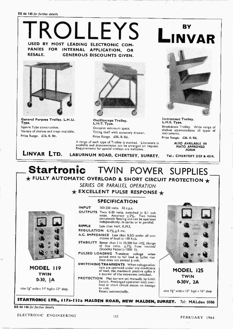
EE 66 145 for further details
TROLLEYS USED BY MOST LEADING ELECTRONIC COM-
PANIES FOR INTERNAL APPLICATION, OR
RESALE. GENEROUS DISCOUNTS GIVEN.
General Purpose Trolley. L.H.U. Type.
Square Tube construction.
Variety of shelves and trays available.
Price Range. £12. O. Od.
LINVAR LTD.
Oscilloscope Trolley. L.H.T. Type.
Occupies minimum space.
Tilting shelf with accessory drawer
Price Range. al O. Od.
A range of each type of Trolley is stocked. Literature is available and demonstration can be arranged on request. Requirements for special trolleys are welcome.
LABURN UM ROAD, CHERTSEY, SURREY.
I. BY
LINVAR
•
Instrument Trolley. L.H.S. Type.
Breakdown Trolley. Wide range of shelves accommodates all types of instruments.
Price Range. £26. O. Od.
ALSO AVAILABLE IN NATO APPROVED
FORM
Tel.: CHERTSEY 2159 & 4219.
Startronic TWIN PO WER SUPPLIES * FULLY AUTOMATIC OVERLOAD & SH ORT CIRCUIT PROTECTION *
SERIES OR PARALLEL OPERATION
* EXCELLENT PULSE RESPONSE *
MODEL 119 T WIN
0-30,
size 7r wide x 11" high>: 12" deep.
SPECIFICATION
INPUT 200-250 volts. 50 c.p.s.
OUTPUTS Twin 0-30 volts, switched in 0.1 volt steps. Accuracy ±2%. Two halves completely floating and can be operated independently, in series or in parallel.
RIPPLE Less than I mV. R.M.S.
REGULATION 0.1 %+5 mv.
A.C. IMPEDANCE Less than 030 under all con ditions of load to 100 kc/s.
STABILITY Better than I in 10,000 for 14% change of line volts, ±7% from nominal (Stability Factor> l500: 1).
PULSED LOADING Transient voltage when pulsed zero to full load at 3µSec rise time does not exceed k volt.
SWITCHING TRANSIENTS When voltageselec-tors are operated under any conditions of load, the maximum positive spike is a quarter of the increment switched.
PROTECTION Max current set manually by Limit Switch. Prolonged operation with over-load or short circuit causes no damage to unit. Resets automatically.
125 MODEL T WIN
0-30V, 2A
size 9¡" wide 13" high x 16" deep
STARTRONIC LTD., 117a-I IS.a MALDEN ROAD, NE W MALDEN, SURREY. Tel: MALden 0186
EE 66 146 for further details
ELECTRONIC ENGINEERING In FEBRUARY 1964