Electrical Works Information TE National Durban rev01.docx
200
Transnet Capital Projects Document Description: Works Information Document Number: 2537842-E-WI-0001 Page 1 | 20 Project Number : 2537842 Project : Transnet Engineering Nationwide Electrical Substations Upgrade Document Title : Works Information - Durban Discipline : Electrical Lighting and Power 00 2019-09-09 Issued for Tender Rev Date Revision Details Prepared by: Ayanda Mdlalose TGC Engineer Date Reviewed by: Lwandile Poswa TGC Engineer Date Approved by: Sudesh Sewdayal Senior Engineer Date Supported by: TE Engineer Date 09/09/2019 09/09/2019 09/09/2019 0B 2019-09-09 Issued for Tender
-
Upload
khangminh22 -
Category
Documents
-
view
2 -
download
0
Transcript of Electrical Works Information TE National Durban rev01.docx

Transnet Capital Projects Document Description: Works Information Document Number: 2537842-E-WI-0001
P a g e 1 | 20
Project Number : 2537842
Project : Transnet Engineering Nationwide Electrical Substations Upgrade
Document Title : Works Information - Durban
Discipline : Electrical Lighting and Power
00 2019-09-09 Issued for Tender Rev Date Revision Details
Prepared by: Ayanda Mdlalose TGC Engineer
Date
Reviewed by:
Lwandile Poswa TGC Engineer
Date
Approved by:
Sudesh Sewdayal Senior Engineer Date
Supported by:
TE Engineer Date
09/09/2019
09/09/2019
09/09/2019
0B 2019-09-09 Issued for Tender

Transnet Capital Projects Document Description: Works Information Document Number: 2537842-E-WI-0001
P a g e 2 | 20
TABLE OF CONTENTS
Contents 1 ACRONYMS, ABBREVIATIONS AND DEFINITIONS ........................................................................... 3
2 Introduction .................................................................................................................................... 6
2.1 Purpose ................................................................................................................................... 6
2.2 Background ............................................................................................................................. 6
2.3 Electrical Scope of Work ......................................................................................................... 6
3 Legal Requirements Regarding Designs ......................................................................................... 7
3.1 Reference Documents ............................................................................................................. 7
3.2 Codes ....................................................................................................................................... 7
3.3 Standards ................................................................................................................................ 7
3.4 Specifications .......................................................................................................................... 8
4 Service Conditions .......................................................................................................................... 9
4.1 Service Conditions ................................................................................................................... 9
4.2 Low Voltage Power System ..................................................................................................... 9
4.3 Medium Voltage Power System .............................................................................................. 9
5 Electrical Engineering Works ........................................................................................................ 10
5.1 Design Works to be executed by the Contractor .................................................................. 10
5.2 Construction Works to be executed by the Contractor ........................................................ 11
5.2.1 MV Switchgear Installation ........................................................................................... 11
5.2.2 LV Switchgear Installation ............................................................................................ 13
5.2.3 Cable Installation .......................................................................................................... 14
5.2.4 Transformer bunding in Bay 18a (Compressor House) substation. ............................. 15
5.2.5 Transformer Installation in Bay 18a (Compressor House) substation.......................... 15
5.2.6 Cable Way System Installation in Substation: Bay 55. ................................................. 16
5.2.7 Earthing and Bonding ................................................................................................... 16
5.2.8 Testing and Commissioning of the installation ............................................................ 16
6 Civil and Structural Engineering Works ........................................................................................ 18
6.1 Design Works to be executed by the Contractor .................................................................. 18
7 List of Drawings ............................................................................................................................ 20

Transnet Capital Projects Document Description: Works Information Document Number: 2537842-E-WI-0001
P a g e 3 | 20
7.1 Drawings issued by the Employer ......................................................................................... 20
8 List of Annexures .......................................................................................................................... 20
8.1 Nil .......................................................................................................................................... 20
List of Tables Table 1-1: Terminology ....................................................................................................................... 3 Table 1-2: Definition/Abbreviation .................................................................................................... 4 Table 3-1: List of South African and International Codes used in the development of this document............................................................................................................................................... 7 Table 3-2: List of all South African and International Standards used in the development of this document ....................................................................................................................................... 7 Table 3-3: List of all Transnet Specifications used in the development of this document ....... 8
1 ACRONYMS, ABBREVIATIONS AND DEFINITIONS
Table 1-1: Terminology Terminology Description Employer For the purpose of this document, the Employer shall
be regarded as Transnet Engineering Contractor For the purposes of this document the contractor
refers to the person(company) whom has been awarded the contract to perform the works stipulated by the employer
Specialist Is a person or company appointed by the contractor or employer who has significant expertise in execution of a particular work
Employer’s Engineer For the purpose of this document, the Employer’s Engineer is a technical representative appointed by the Employer who holds a Bsc/Beng/Btech/Ndip and registered with ECSA as Preng/Prtechnologist in a relevant field of engineering. The purpose for the Employer’s Engineer is to review, support and accept the designs, documents and drawings for this project.
Accepted For the purpose of this document, the term “Accepted” shall be used to describe that an activity/task/document/drawing/design/calculation is

Transnet Capital Projects Document Description: Works Information Document Number: 2537842-E-WI-0001
P a g e 4 | 20
received and believed to be true. However by Accepting any of the above items does not alleviate legal and ethical responsibilities that is carried by the ECSA responsible signatory for the item
Supported For the purpose of this document, the term “Supported” shall be used to describe that an activity/task/document/drawing/design/calculation is received and the contents herein with are agreed upon with encouragement to proceed.
Table 1-2: Definition/Abbreviation
Abbreviation Definition 0C Degree Celsius
A Ampere
ACB Air Circuit Breaker
AIS Air Insulated Switchgear
D Diameter
ECC Earth Continuity Conductor
ECSA Engineering Council of South Africa
FAT Factory Acceptance Test
FEL Front End Loading
GIS Gas Insulated Switchgear
Hz Hertz
ICs Service Short Circuit Current
km Kilo meter
kVA Kilo-Volt Ampere
LV Low Voltage
m meter
MCB Miniature Circuit Breaker
MCC Motor Control Centre
MCCB Moulded Case Circuit Breaker
mm millimetre
mm2 millimetre squared

Transnet Capital Projects Document Description: Works Information Document Number: 2537842-E-WI-0001
P a g e 5 | 20
MV Medium Voltage
NRS National Rationised Standards
ONAN Oil Natural Air Natural
ORS Owners Requirement Specification
PVC Polyvinyl Chloride
SCADA Supervisory Control And Data Acquisition
SANS South African National Standards
SAT Site Acceptance Test
SF6 Sulphur Hexafluoride
TE Transnet Engineering
TGC Transnet Group Capital

Transnet Capital Projects Document Description: Works Information Document Number: 2537842-E-WI-0001
P a g e 6 | 20
2 Introduction
2.1 Purpose
The purpose of this document is to detail the works to be undertaken by the Contractor in relation to the construction and execution of the Nationwide Transnet Engineering Electrical Substations upgrade project.
2.2 Background
Transnet Engineering is currently in a quest to upgrade their substations nationwide. The existing substations makes use of MV and LV switchgear that have currently reached end of design life thus posing a business operational risk due to spares equipment been obsolete in the market for maintenance purposes. Furthermore, the existing MV switchgear uses oil as an arc quenching mechanism which is strongly not desired due to the environmental and safety threats posed to personnel during operation (switching of the switchgear). Transnet Engineering approached Transnet Group Capital to provide a suitable engineering solution with regards to the upgrade of the substations. It was also emphasized that the solution to be provided shall utilize modern technology which minimises safety hazards to personnel and enhances operations by mitigating protection failure rates in the system.
2.3 Electrical Scope of Work
The scope of works covered in this document is particularly for Transnet Engineering in Durban (Bay 55 and Bay 18a Compressor House). The works that the Contractor is to perform include but is not limited to the following:
• Supply and install medium voltage switchgear
• Supply and install low voltage switchgear
• Size, supply and install Battery Tripping Unit
• Supply and install LV cables
• Design, supply and install cable support system
• Verification of the existing earthing and lightning protection system for the
substation
• Perform MV switchgear protection setting calculations, relay grading, and relay
programming.
• Test, commission and handover the MV and LV switchgear
• Make good of the substation walls and floors

Transnet Capital Projects Document Description: Works Information Document Number: 2537842-E-WI-0001
P a g e 7 | 20
3 Legal Requirements Regarding Designs
In addition to the specifications, TE substations upgrade shall comply with the following relevant South African Acts and Regulations and they shall apply in the order of precedence as listed below:
3.1 Reference Documents
3.2 Codes
Table 3-1: List of South African and International Codes used in the development of this document
Item Document Number Description
[1] OSH ACT 85 of 1993 South African National Occupational Health and Safety Act 85 of 1993
3.3 Standards
Table 3-2: List of all South African and International Standards used in the development of this document
Item Document Number Description
[1] SANS 10142 Code of Practice for the Wiring of Premises.
[2] SANS 62305-1 Protection against lightning Part 1: General principles
[3] SANS 62305-2 Protection against lightning Part 2: Risk management
[4] SANS 62305-3 Protection against lightning Part 3: Physical damage to structures and life hazard
[5] SANS 62305-4 Protection against lightning Part 4: Electrical and electronic systems within structures
[6] SANS 10313 Protection against lightning - Physical damage to structures and life hazard
[7] SANS 10199 The design and installation of earth electrodes
[8] SANS 1063 Earth rods, couplers and connections
[9] SANS 10198-8 The selection, handling and installation of electric power cables of rating not exceeding 33 kV Part 8: Cable laying and installation
[10] SANS 1091 National Colour Codes

Transnet Capital Projects Document Description: Works Information Document Number: 2537842-E-WI-0001
P a g e 8 | 20
[11] SANS 1973-1 Low Voltage switchgear assemblies>10kA
[12] SANS 1973-2 Low Voltage switchgear assemblies <10kA
[13] SANS 10292 Earthing of Low Voltage (LV) distribution systems
[14] SANS 60529 Degrees of protection by enclosure (IP codes)
[15] SANS 61689 Instrument Transformer
[16] SANS 62268 Electricity Metering Equipment
[17] SANS 725 IEEE Guide for Safety in AC Substation Grounding
3.4 Specifications
Table 3-3: List of all Transnet Specifications used in the development of this document
Item Document Number Description
[1] TPD-001-EL&PSPEC Specification for electrical installations to buildings other than dwellings houses
[2] TPD-002-DBSPEC Specification for low voltage distribution boards
[3] TPD-003-CABLESPEC Specification for the supply and installation of medium voltage and low voltage electrical cables
[4] TPD-004-EARTHINGSPEC Specification for earthing and the protection of buildings and structures against lightning.
[5] TPD-007-MVSWITCHSPEC Specification for indoor medium/ high voltage (1kv to 33 kV) alternating current switchgear and control gear
Transnet Capital Projects Document Description: Works Information Document Number: 2537842-E-WI-0001
P a g e 9 | 20
4 Service Conditions
4.1 Service Conditions
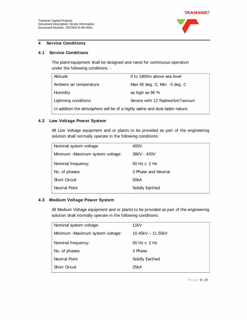
The plant/equipment shall be designed and rated for continuous operation under the following conditions: -
Altitude 0 to 1800m above sea level
Ambient air temperature Max 45 deg. C; Min. -5 deg. C
Humidity as high as 96 %
Lightning conditions Severe with 12 flashes/km2/annum
In addition the atmosphere will be of a highly saline and dust-laden nature.
4.2 Low Voltage Power System
All Low Voltage equipment and or plants to be provided as part of the engineering solution shall normally operate in the following conditions:
Nominal system voltage: 400V
Minimum -Maximum system voltage: 380V - 420V
Nominal frequency: 50 Hz ± 2 Hz
No. of phases: 3 Phase and Neutral
Short Circuit 50kA
Neutral Point Solidly Earthed
4.3 Medium Voltage Power System
All Medium Voltage equipment and or plants to be provided as part of the engineering solution shall normally operate in the following conditions:
Nominal system voltage: 11kV
Minimum -Maximum system voltage: 10.45kV – 11.55kV
Nominal frequency: 50 Hz ± 2 Hz
No. of phases: 3 Phase
Neutral Point Solidly Earthed
Short Circuit 25kA

Transnet Capital Projects Document Description: Works Information Document Number: 2537842-E-WI-0001
P a g e 10 | 20
5 Electrical Engineering Works
5.1 Design Works to be executed by the Contractor
The following design/study works shall be done by the Contractor with respect to all substations to be upgraded at the Durban Depot unless otherwise stated. These activities include but are not limited to the following:
a. The Contractor shall appoint a protection specialist to perform a medium
voltage protection study for the entire TE Medium Voltage network in Durban
as per Drawing No: 2537842-5-005-E-LA-0004-01.
b. The Contractor shall be issued with a high level ETAP network model for the
Durban Depot by the Employer. In addition to that, the Employer as part of the
tender documents has issued the requirement schedule for each substation
illustrating the recommended protection schemes and the required measuring
instruments in accordance to TPD-007-MVSWITCHSPEC. The Contractor shall
complete the issued ETAP simulation model with the protection study of the
Durban electrical network as per Drawing No: 2537842-5-005-E-LA-0004-01.
The Contractor shall supply and submit the complete ETAP model with required
protection philosophy inclusions to the Employers Engineer for acceptance.
c. The Contractor shall select protection relays for the required protection
schemes and define the protection philosophy in line with the settings from the
main supply authority.
d. The Contractor shall ensure that the protection coordination, selectivity and
grading of all upstream and downstream relays between the proposed MV
switchgear and the existing network is conducted.
e. The Contractor shall test the integrity of the existing earthing of all the
substations to be upgraded at the Durban Depot. The Contractor shall submit
all test results to the Project Manager for acceptance by the Employers
Engineer.
f. In the case where the existing earthing and lightning protection system is not
compliant to the requirement of SANS 10313, the Contractor shall perform
full/parts of the design of the earthing as required, for all substations. All

Transnet Capital Projects Document Description: Works Information Document Number: 2537842-E-WI-0001
P a g e 11 | 20
designs performed by the Contractor shall be submitted to the Employers
Engineer for acceptance prior to execution.
5.2 Construction Works to be executed by the Contractor
5.2.1 MV Switchgear Installation
5.2.1.1 Existing Switchgear (and the associated installation) Disconnection in Substation
Bay 55 and Bay 18a (Compressor House).
a. The Contractor shall disconnect, remove and dismantle half of the existing 11kV
MV switchboard and shall only remove the other half of the switchboard once
half of the new switchboard has been installed and commissioned to ensure
minimum disruption to operations. The Contractor shall apply for a permit two
weeks in advance to undertake this work. The removed 11kV switchgear shall
be transported by the Contractor to the Transnet Engineering Depot within a
radius of 2km and handed over to the depot electrical supervisor.
b. The Contractor shall safely remove the arc quenching oil in the existing
switchgear and safely dispose of the oil in compliance to the National
Environmental Management: Waste Act, 2008.
c. The Contractor shall disconnect and remove the existing battery charger with
battery banks and any associated accessories and hand over the disconnected
items to the Transnet Engineering electrical supervisor.
5.2.1.2 Bay 55 Substation
a. The Contractor shall supply, deliver, offload, install and commission two 11kV
incomer panels complete with protection relays, current and voltage
transformers as per specification TPD-007-MVSWITCHSPEC, the equipment
layout and the MV switching layouts and Annexure 1B (Bay 55 Requirement
Schedule). The panels shall be bottom cable entry to allow installation of
incoming cables from the trench.
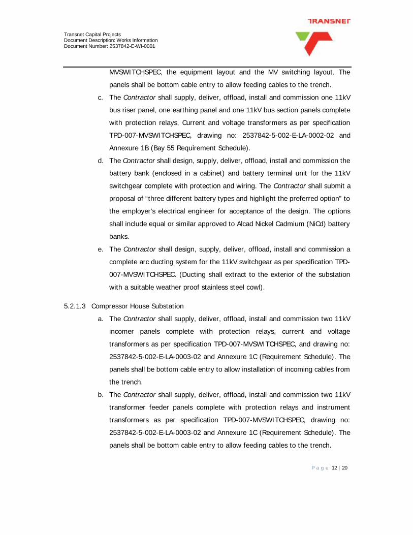
b. The Contractor shall supply, deliver, offload, install and commission three 11kV
transformer feeder panels of which one panel is a spare complete with
protection relays and instrument transformers as per specification TPD-007-
Transnet Capital Projects Document Description: Works Information Document Number: 2537842-E-WI-0001
P a g e 12 | 20
MVSWITCHSPEC, the equipment layout and the MV switching layout. The
panels shall be bottom cable entry to allow feeding cables to the trench.
c. The Contractor shall supply, deliver, offload, install and commission one 11kV
bus riser panel, one earthing panel and one 11kV bus section panels complete
with protection relays, Current and voltage transformers as per specification
TPD-007-MVSWITCHSPEC, drawing no: 2537842-5-002-E-LA-0002-02 and
Annexure 1B (Bay 55 Requirement Schedule).
d. The Contractor shall design, supply, deliver, offload, install and commission the
battery bank (enclosed in a cabinet) and battery terminal unit for the 11kV
switchgear complete with protection and wiring. The Contractor shall submit a
proposal of “three different battery types and highlight the preferred option” to
the employer’s electrical engineer for acceptance of the design. The options
shall include equal or similar approved to Alcad Nickel Cadmium (NiCd) battery
banks.
e. The Contractor shall design, supply, deliver, offload, install and commission a
complete arc ducting system for the 11kV switchgear as per specification TPD-
007-MVSWITCHSPEC. (Ducting shall extract to the exterior of the substation
with a suitable weather proof stainless steel cowl).
5.2.1.3 Compressor House Substation
a. The Contractor shall supply, deliver, offload, install and commission two 11kV
incomer panels complete with protection relays, current and voltage
transformers as per specification TPD-007-MVSWITCHSPEC, and drawing no:
2537842-5-002-E-LA-0003-02 and Annexure 1C (Requirement Schedule). The
panels shall be bottom cable entry to allow installation of incoming cables from
the trench.
b. The Contractor shall supply, deliver, offload, install and commission two 11kV
transformer feeder panels complete with protection relays and instrument
transformers as per specification TPD-007-MVSWITCHSPEC, drawing no:
2537842-5-002-E-LA-0003-02 and Annexure 1C (Requirement Schedule). The
panels shall be bottom cable entry to allow feeding cables to the trench.

Transnet Capital Projects Document Description: Works Information Document Number: 2537842-E-WI-0001
P a g e 13 | 20
c. The Contractor shall supply, deliver, offload, install and commission one 11kV
bus riser panel, one earthing panel and one 11kV bus section panels complete
with protection relays, Current and voltage transformers as per specification
TPD-007-MVSWITCHSPEC, drawing no: 2537842-5-002-E-LA-0003-02 and
Annexure 1C (Requirement Schedule).
d. The Contractor shall design, supply, deliver, offload, install and commission the
battery bank (enclosed in a cabinet) and battery terminal unit for the 11kV
switchgear complete with protection and wiring. The Contractor shall submit a
proposal of “three different battery types and highlight the preferred option” to
the employer’s electrical engineer for acceptance of the design. The options
shall include equal or similar approved to Alcad Nickel Cadmium (NiCd) battery
banks.
e. The Contractor shall design, supply, deliver, offload, install and commission a
complete arc ducting system for the 11kV switchgear as per specification TPD-
007-MVSWITCHSPEC. (Ducting shall extract to the exterior of the substation
with a suitable weather proof stainless steel cowl).
5.2.2 LV Switchgear Installation
a. The Contractor shall disconnect, remove and dismantle the existing 400V Low
Voltage (LV) switchgear from Bay 18a (Compressor House) and Bay 55
Substations. The removal of the existing switchgear and installation of the new
switchgear shall be conducted after hours (during off peak hours). The
contractor shall apply for a permit one week in advance to undertake this work.
The removed 400V switchgear shall be transported by the Contractor to the
Transnet Engineering Depot within a radius of 2km and handed over to the
electrical supervisor.
b. The Contractor shall design, supply, deliver, offload and install a Low Voltage
Main Substation Distribution Board for Bay 55 substation as shown in the
drawing no: 2537842-5-002-E-LA-0002-03 and as per Specification no TPD-
002-DBSPEC and TPD-001-EL&PSPEC.
c. The Contractor shall design, supply, deliver, offload and install a Low Voltage
Main Substation Distribution Board for Bay 18a (Compressor House) substation

Transnet Capital Projects Document Description: Works Information Document Number: 2537842-E-WI-0001
P a g e 14 | 20
as shown in the drawing no: 2537842-5-002-E-LA-0003-03 and as per
Specification no TPD-002-DBSPEC and TPD-001-EL&PSPEC.
5.2.3 Cable Installation
5.2.3.1 Removal of existing cable and busways at Substations: Bay 55 and Bay 18a (Compressor House).
a. The Contractor shall disconnect and remove the existing MV cables from the
existing MV switchgear to the existing 11kV/400V transformers.
b. The Contractor shall uninstall the busways connection between to the
transformers and existing LV panels, and shall be handed over to the Transnet
Engineering Depot electrical supervisor.
c. The Contractor shall disconnect the existing LV feeder cables (transformer
feeders excluded in this item), and MV incomer cables from the existing MV
and LV switchgear respectively.
d. The existing cable terminations shall be tested and approved by the Employers
Engineer if they still fit for reuse, else supply and install new terminations.
e. The Contractor shall disconnect the existing LV cables from the existing MV
switchgear to the existing 11kV/400V transformers.
f. The Contractor shall terminate all the existing copper cables from the 11kV
transformer panel feeders to the primary bushings of the 11kV/400V
Transformers in the respective substations as per SANS 101980-4. See drawing
no: 2537842-5-002-E-LA-0001-02, 2537842-5-002-E-LA-0002-02 and
2537842-5-002-E-LA-0003-02. The contractor shall ensure that the
manufacturer’s recommendations regarding the minimum cable bending radius
is adhered to when installing the cable.
g. The Contractor shall connect the existing bus-bars through the bus-way
between the 2000kVA transformers and the LV panel in the Compressor House.
See drawing no: 2537842-5-002-E-LA-0003-03.
h. The Contractor shall supply, deliver and install in Bay 55 unarmoured 4 x 630
mm², 1 core, 600/1000V XLPE insulated and PVC sheathed copper cable from
each 800kVA, 11kV/40V transformer to the new proposed LV switchgear in

Transnet Capital Projects Document Description: Works Information Document Number: 2537842-E-WI-0001
P a g e 15 | 20
respective substations as per SANS 101980-4. See drawing no: 2537842-5-
002-E-LA-0001-03 and 2537842-5-002-E-LA-0002-03.
The Contractor shall ensure that the manufacturer’s recommendations
regarding the minimum cable bending radius is adhered to when installing the
cable. The cables shall be installed on a suitable cable support system.
i. The contractor shall install and terminate the feeder cables and incomer cables
mentioned with new termination kits as per SANS 101980-4 and Transnet
specification TPD-003-CABLESPEC.
5.2.4 Transformer bunding in Bay 18a (Compressor House) substation.
a. The Contractor shall design, supply, deliver, offload and install transformer
bunding to contain the oil leaks from the transformers as required by SANS
10142. The design of the proposed containment tray shall be submitted to the
employer’s engineer for acceptance. The tray shall allow for the containment
of the total volume of oil in the transformer.
b. The Contractor shall seal all cable entries and exits to ensure that the contained
oil remains within the proposed bunding and does not drip onto the substation
floor and trenches.
5.2.5 Transformer Installation in Bay 18a (Compressor House) substation.
a. The TE electrical supervisor shall hand over a faulty 11kV/400V, 2000kVA
transformer to the Contractor. The Contractor shall load and transport the
transformer to the manufacturer for refurbishment and rewinding. On
completion of the works, the Contractor shall return the transformer back to
the TE depot and submit all compliance and test certificates of the refurbished
transformer to the Employer’s Engineer and TE electrical supervisor.
b. The Contractor shall disconnect and remove the existing 11kV/400V, 1600kVA
transformer in Compressor House substation.
c. The removed transformer shall be transported by the Contractor to the
Transnet Engineering Depot within a radius of 2km and handed over to the
depot electrical supervisor.

Transnet Capital Projects Document Description: Works Information Document Number: 2537842-E-WI-0001
P a g e 16 | 20
d. The existing MV and LV cable connecting the existing transformer to the
respective switchgear shall be disconnected and reused with new terminations
in the proposed new installation.
e. The old cable terminations shall be handed over to the Transnet Engineering
Depot electrical supervisor.
f. The Contractor shall install the refurbished 2000kVA transformer at the
Compressor House substation as per SANS 10142-1&2, TPD-014-
TRANSFORMERSPEC and TPD-003-CABLESPEC.
g. All test results shall be submitted to the Employer’s Engineer for acceptance.
5.2.6 Cable Way System Installation in Substation: Bay 55.
a. The Contractor shall supply, deliver, offload and install the cable ladder system
for substations and present the designs to the Employer’s electrical engineer
for acceptance. The Contractor shall make an allowance for appropriate
cableways and other necessary accessories to neaten LV cables in the proposed
new substation building. The OEM bending radii requirements of the cable shall
be adhered to. The cable ladder system design shall present evidence for the
sufficient support of the cables weight. The cable ladder system shall be
suitably bonded and connected to the substation building earth bar with an
appropriate sized protective earth conductor in compliance to SANS 10142-1
and TPD-004-EARTHINGSPEC.
5.2.7 Earthing and Bonding
a. The Contractor shall verify all earthing and bonding materials, equipment,
accessories and supports as required in accordance with the TPD-004-
EARTHINGSPEC.
5.2.8 Testing and Commissioning of the installation
a. The Contractor shall conduct a Factory Acceptance Test (FAT) for all Plant’s to
be installed as part of the Works to be executed in this Contract prior to delivery
to site. The FAT shall be conducted in the presence of the Employer’s
Engineers. The legal transfer of ownership from the Plant’s supplier to the

Transnet Capital Projects Document Description: Works Information Document Number: 2537842-E-WI-0001
P a g e 17 | 20
Contractor shall be held by the Contractor until the Plant is fully installed, tested
commissioned on the Employer’s designated site.
b. The Contractor shall conduct a Site Acceptance Test (SAT) for all Plant’s
supplied, offloaded and delivered to the designated Employer’s site. The SAT
shall be conducted in the presence of the Employer’s Engineer. The legal
transfer of ownership from the Plant’s supplier to the Contractor shall be held
by the Contractor until the Plant is fully installed, tested commissioned on the
Employer’s designated site.
c. The Contractor shall test the MV installation and LV installation and hand over
all relevant test certificates to the Employers engineer for acceptance. The
Contractor shall hand over both MV and LV certificate of compliance
respectively as per the OHS Act of 85 and SANS 10142-1 and SANS1042-2 for
the installation.
d. The Contractor shall test and commission the entire Earthing and Bonding as
per Transnet Specification TPD-004-EARTHINGSPEC and SANS 10142-1 in the
presence of the Employer’s Engineer. The Contractor shall handover all test
certificates to the Employer’s Project Manager for acceptance by the Employer’s
Engineer.

Transnet Capital Projects Document Description: Works Information Document Number: 2537842-E-WI-0001
P a g e 18 | 20
6 Civil and Structural Engineering Works
6.1 Design Works to be executed by the Contractor
6.1.1 Structural assessment of Bay 18A (Compressor House) Substation
The following is a summary of the visual structural inspection of the Bay 18A (Compressor
house) substation:
a. The interior of the substation was assessed with emphasis placed on the assessment of all
internal brickwork and surface bed.
b. The inspection was carried out under the following conditions:
• No engineering drawings were available
• Destructive material testing was excluded
• Non-destructive testing was excluded
• No geotechnical information was available
• A visual inspection was only undertaken
c. The visual inspection of the surface bed within the substation shows signs of severe
settlement. The surface bed has failed and pulled away from the brickwork resulting in large
voids along the internal perimeter of the wall and surface bed. There is also severe cracking
that occurred at column/surface bed interaction points. The settlement of the surface bed also
resulted in the failure of internal walls that were founded on the surface bed. The failure of
these internal walls poses an immediate risk as the structure foundation in unstable and the
wall has broken away from the stable exterior wall.
6.1.2 Proposed remedial action of Bay 18A (Compressor House) Substation
The proposed remedial action shall be a follows:
1. The Contractor shall demolish and remove the existing surface bed and walls that have
failed.
2. The Contractor shall perform test pits to ascertain soil, bearing capacity, composition,
water content and other design parameters necessary to design the surface bed and
masonry structures.

Transnet Capital Projects Document Description: Works Information Document Number: 2537842-E-WI-0001
P a g e 19 | 20
3. The Contractor shall design and construct the surface bed and masonry units to match
existing levels. Designs must be approved by a registered professional that shall
adhere to all relevant SANS codes (Loading, Concrete, Civil Works and Reinforcement)
and other statutory requirements.
4. The Contractor shall finish the floor surface with a high grade epoxy coating.
5. The Contractor shall provide all relevant saw cut joints and isolation joints.
6. The Contractor shall handover all test results and signed as-built drawings to the
Employer’s Project Manager for acceptance by the Employer’s Engineer.

Transnet Capital Projects Document Description: Works Information Document Number: 2537842-E-WI-0001
P a g e 20 | 20
7 List of Drawings
7.1 Drawings issued by the Employer
This is the list of drawings issued by the Employer at or before the Contract Date and which apply to this contract. Note: Some drawings may contain both Works Information and Site Information. For list of drawings, refer to Annexure 3 in Specification TPD-007-MVSWITCHSPEC
8 List of Annexures
8.1 Nil

__________________________________________________________________________________________________________________ Technical Specification Specification No. TPD: 007-MVSWITCHSPEC
SPECIFICATION FOR INDOOR MEDIUM/ HIGH VOLTAGE (1KV TO 33 KV) ALTERNATING CURRENT SWITCHGEAR AND CONTROL GEAR
REVISIONS REV DATE APPROVED 04 05-04-2017 S. Sewdayal

__________________________________________________________________________________________________________________ Technical Specification Specification No. TPD: 007-MVSWITCHSPEC
Page2of 28
INDEX SECTION CONTENTS 1. SCOPE 2. REFERENCE LIST 3. INFORMATION AND METHOD OF TENDERING 4. APPENDICES 5. AMBIENT AND ENVIRONMENTAL CONDITIONS 6. DRAWINGS AND INSTRUCTION MANUALS 7. SWITCHGEAR AND CONTROLGEAR 8. WITHDRAWABLE SWITCHGEAR AND CONTROLGEAR 9. SWITCHING DEVICES 10. BUSBARS 11. BUSHINGS 12. CABLE BOXES, GLANDS AND TERMINATIONS 13. INSULATING MEDIUM 14. HIGH-VOLTAGE FUSES 15. CURRENT TRANSFORMERS 16. VOLTAGE TRANSFORMERS 17. INDICATING INSTRUMENTS 18. ENERGY METERS 19. PROTECTIVE SYSTEMS AND RELAYS 20. CLOSING AND TRIPPING SUPPLIES 21. TEST TERMINAL BLOCKS 22. CONTROL SWITCHES 23. MINIATURE CIRCUIT BREAKERS 24. LOW VOLTAGE WIRING

__________________________________________________________________________________________________________________ Technical Specification Specification No. TPD: 007-MVSWITCHSPEC
Page3of 28
INDEX SECTION CONTENTS 25. REMOTE CONTROL 26. ARC DUCTING 27. NAMEPLATES AND LABELS 28. PAINTING 29. TESTS 30. INSPECTION 31. TOOLS AND APPLIANCES 32. SPARES 33. PACKING 34. GUARANTEE 35. Annexure 1 - Schedule of Requirements. 36. Annexure 2 - Technical Data Sheet. 37. Annexure 3 – Electrical Drawings 38. Annexure 4 - "Test Requirements". 39. Annexure 5 - " Statement of Compliance".

__________________________________________________________________________________________________________________ Technical Specification Specification No. TPD: 007-MVSWITCHSPEC
Page4of 28
1. SCOPE This specification covers Transnet Group Capital requirements for the supply, delivery and
installation of indoor, high voltage, 3 phase, 50-hertz switchgear and control gear in the range 1 kV to 36 kV as detailed in Appendix 1 “Schedule of Requirements”.
2. REFERENCE LIST The following publications and documents (latest edition) are referred to herein. Note: We suggest that IEC standards are used, which allows the greatest selection of reputable
suppliers and does not favour any particular supplier. For voltages above 11kV most switchgear is in any case imported and standards other than IEC standards are generally excluded.
2.1 International Electro Technical Commission IEC PUBLICATION 62271-100 High-voltage alternating current circuit breakers. IEC PUBLICATION 60060 High-voltage test techniques.
IEC PUBLICATION 62271 Specification for AC metal enclosed switchgear and control gear, for voltages above 1kV up to and including 52kV
Part: -1 Common specifications for HV switchgear and control gear standards (IEC 60694) -100 Alternating current Circuit breakers (IEC60056) -102 Alternating current disconnectors and earthing switches (IEC 60129) -103 Switches for rated voltages above 1kV and less than 52kV (IEC60265-1) -106 Alternating current contactors and contactor-based motor-starters (IEC60470) -200 AC metal-enclosed switchgear and control gear for rated voltages above 1 kV and up to
and including 52 kV IEC PUBLICATION 60027-7 Electrical drawing symbols used. IEC PUBLICATION 60243 Recommended methods of test for electric strength of solid insulating
materials at power frequencies. IEC PUBLICATION 60282 High-voltage fuses. IEC PUBLICATION 62271-200 High-voltage metal enclosed switchgear and control gear. IEC PUBLICATION 62271-103 High-voltage alternating current fuse-switch combinations and fuse-circuit-breaker combinations.
IEC PUBLICATION 60051 Direct acting indicating electrical measuring instruments and their accessories.
IEC PUBLICATION 62271 -106 High-voltage switchgear and control gear - Part 106: Alternating current contactors, contactor-based controllers and motor-starters
IEC PUBLICATION 60071 Insulation coordination
IEC PUBLICATION 60282-1 Protection fuses IEC PUBLICATION 60529 Degree of protection (IP rating) IEC PUBLICATION 60044-1 Current transformer

__________________________________________________________________________________________________________________ Technical Specification Specification No. TPD: 007-MVSWITCHSPEC
Page5of 28
IEC PUBLICATION 60044-2 Voltage transformer IEC PUBLICATION 60044-8 Current sensors IEC PUBLICATION 60044-7 Voltage sensors IEC PUBLICATION 61343-5 Voltage detection system VDS IEC PUBLICATION 60071-1 Insulation coordination IEC PUBLICATION 60125 Protection relays IEC PUBLICATION 60376 SF6 gas
2.2 The equipment offered shall comply with the latest editions of the relevant International Electro-technical Commission.
2.3 Users of this specification must ensure that they are in possession of the latest issues of the above-
mentioned standards. 3. INFORMATION AND METHOD OF TENDERING 3.1 Tenderers shall submit their main offers in accordance with the requirements of this specification.
Deviations from the requirements of this specification which are of a minor nature and do not depart materially, will be considered at the discretion of Transnet Projects. The acceptance of alternative tenders will be considered only if a main tender is submitted as per this specification.
3.2 The "Technical Data Sheet" forming Appendix 2 of this specification shall be completed in detail, for each
offer. Alternative offers shall be clearly marked "Alternative Offer No. _______". 3.3 All documents forming part of the Tender shall be firmly bound. No loose documents will be
considered. 3.4 Failure to comply with the above requirements may preclude a tender from consideration. 3.5 All tender documents shall be presented in a clear format with index, uniquely numbered pages and
cross-referenced. The total number of pages shall be clearly stated in the index. 3.6 Type test reports/certificates shall be issued or certified by the appropriate test authority, that
is accredited according to ISO/IEC 17025. 4. ANNEXURES The following appendices form an integral part of this specification and shall be read in conjunction
with it. 4.1 Annexure 1 - Schedule of Requirements.
This appendix details special requirements. 4.2 Annexure 2 - Technical Data Sheet. This appendix calls, for specific technical information to be furnished with tenders. All Technical Data
Sheets shall be signed by the Tenderer and returned as part of the tender. Failure to comply may result in a tender being excluded.
4.2.1 Equipment offered in this appendix shall be supplied in terms of this specification and no changes or

__________________________________________________________________________________________________________________ Technical Specification Specification No. TPD: 007-MVSWITCHSPEC
Page6of 28
substitutes will be allowed without the written consent from Transnet Group Capital. 4.2.2 Acceptance by Transnet Group Capital of the equipment offered in this appendix, in no way relieves
the tenderer of his obligation to fulfil his statement of compliance with the specification. 4.2.3 This appendix is used during adjudication of tenders to assess the equipment offered. 4.2.4 The tenderer is responsible for the accuracy of information submitted in this appendix. 4.3 Annexure 3 - Electrical Drawings
This appendix lists the electrical drawings associated with this tender. 4.4 Annexure 4 - "Test Requirements". This appendix contains Transnet Group Capital requirements with respect to type and routine test
certificates and test procedures. 4.5 Annexure 5 - "Statement of Compliance" This appendix shall be completed by all tenderers and signed. Where tenderers do not fully comply,
all deviations shall be clearly indicated in the space provided or by means of a covering letter. Failure to complete the statement of compliance will result in tenders being excluded.
5. AMBIENT/ENVIRONMENTAL CONDITIONS:
The equipment shall be designed and rated for continuous operation under the following conditions:- Altitude.... Sea level. Ambient temperature.... -5 C to +40 C (daily average +35 C). Relative humidity.... As high as 95%.
Lightning conditions . Severe, with a maximum lightning ground flash density of 11 flashes per km² per annum.
Atmospheric conditions.... Salt laden as well as industrial atmosphere.
Electrolytic corrosion conditions prevail in all areas owing to the proximity of direct current traction systems and cathodic protection schemes.
6. DRAWINGS AND INSTRUCTION MANUALS 6.1 All drawings shall be in accordance with SANS 10111 – Engineering Drawings. 6.2 The successful tenderer shall supply the following instruction manuals, all of which shall be included
in the tender price and be to the satisfaction of Transnet Group Capital: 6.2.1 Structural Drawings
Structural drawings shall be completely dimensioned, showing:

__________________________________________________________________________________________________________________ Technical Specification Specification No. TPD: 007-MVSWITCHSPEC
Page7of 28
• Arrangement. • Plan, front view, and other elevation views if pertinent. • Required clearances for opening doors and for removing breakers. • Conduit or cable entrance locations for bottom entrance. • Busbar locations and configurations. • Incoming and outgoing cable termination positions. • Anchor bolt locations. • Earthing connections. • Mass of equipment. Individual mass of stationary units and breakers, if shipped separately. • Foundation holding down bolting details showing mounting rails and run-out rails for draw-out circuit-
breakers. 6.2.2 One Line Diagrams One line diagrams shall show:
• Instrument transformers • Relays with their ANSI device numbers. • Meters and meter switches. • Other pertinent devices.
6.2.3 Schematic Diagrams
Schematic wiring diagrams shall be furnished for each different electrically operated breaker control scheme and show the following: • All control devices and device contacts, each of which shall be labelled with its correct ANSI device
function number, or reference. • Device terminal numbers, terminal block numbers and terminal numbers. • All internal interconnections, bus wiring, inter panel wiring and connections to external equipment. • Relay internal logic configuration • Protection relay setting sheet
6.2.4 As-Built Drawings 6.2.4.1 On completion of installation and commissioning of the relevant equipment, the originals of the above
drawings shall be updated by the equipment supplier to reflect the as-built status. 6.2.4.2 The supplier shall then also provide Transnet Projects with three copies of all relevant CAD data for drawing
records and drawing reproduction. The drawings must be in a format that can be read by AutoCAD 2000, format (“dwg” or “dxf” format).
6.2.5 Maintenance Manuals 6.2.5.1 On completion of installation and commissioning of the relevant equipment, the contractor shall
submit three copies of the equipment maintenance manuals in both hard copy and electronic format. (The electronic format must be in Microsoft “Word”, or .pdf format)
6.3 The maintenance manuals shall include all the necessary information on electrical and electronic
equipment to enable the maintenance staff to fully comprehend the function of the equipment and to maintain service and repair the equipment. In order to comply with this condition the following

__________________________________________________________________________________________________________________ Technical Specification Specification No. TPD: 007-MVSWITCHSPEC
Page8of 28
information (as applicable) shall be included in the manuals: 6.2.6 Complete circuit diagrams.
6.2.7 System Block or Logic Diagrams.
6.2.8 Test Procedures (Flow Chart form preferred) and information to enable testing such as voltage
values and tolerances, waveforms, polarities etc. 6.2.9 Component lists, which shall contain complete electrical information and standard identification in
respect of all components, unless this is indicated directly on diagrams. 6.2.10 A complete description of the electronic equipment, including the function of all input and output
points, maintenance and calibration procedures, reference to special test instruments required, etc.
6.3 All symbols used on diagrams shall be in accordance with IEC Publication 60027-7 wherever possible. A legend shall be supplied for all symbols that do not appear in the IEC Publications.
6.4. All information submitted in manuals should be clearly cross-referenced, indexed and accurately descriptive of the equipment provided. All filed changes to equipment shall be incorporated in the updated diagrams/sheets before expiry of the guarantee period.
6.5 Photocopies of original material shall only be acceptable if these are clearly legible and preferably
colour copies.
6.6 A preliminary copy of the maintenance manual shall be forwarded to Transnet Group Capital for approval prior to issue and in advance of the delivery of equipment.
6.7 Late submission of drawings, manuals and instructions shall incur delivery penalties on the
full contract price. The contract will only be deemed to be complete on reception of all drawings, manuals and instructions.
7. SWITCHGEAR AND CONTROLGEAR 7.1 General 7.1.1 All switchgear and control gear shall be designed, manufactured and tested in accordance with the
recommendations of IEC PUBLICATION 298, IEC 62271-100, IEC 62271-200 and IEC 62271-102. The switchgear panels shall be of arc proof, metal clad, air insulated, free standing, extensible type, containing power busses, earthing bus, draw out type switching devices, auxiliary control devices, instrument transformers, protection relays and control switches. They shall be supplied complete with all necessary terminal plates, cable glands for cable entry, wiring trunking for LV wiring and multi core cables.
7.1.3 The switchgear and control gear shall be of the air-insulated or gas-filled, indoor, modular, free standing,
metal clad, cubicle type housing with a minimum Aluzinc sheet metal thickness of 2mm, powder coated with a minimum thickness of 50μm to the colour as specified in the detail specification.
7.1.3 The switchgear and control gear panels shall be bolted together to form a continuous, self-supporting
__________________________________________________________________________________________________________________ Technical Specification Specification No. TPD: 007-MVSWITCHSPEC
Page9of 28
and self-contained switchgear and control gear board of uniform appearance capable for extension at both ends with similar panels.
7.1.4 Access to the current transformer and cable terminations shall be from the rear of the panels. 7.1.5 All cubicles shall be so constructed by means of modular design to ensure inter-changeability of all
components of the same type between different panels. 7.1.6 All removable plates shall be secured by means of bolts and nuts. All bolts, nuts, washers fixing
equipment etc. shall be stainless steel. Nuts shall be either welded in position or secured by means of a mechanical fixing device. Self-tapping screws will not be considered.
7.1.7 High-voltage and low-voltage equipment shall be housed in separate compartments.
7.1.8 The busbars shall be contained in a separate compartment. Air insulated equipment shall be easily accessible.
7.1.8.1 There shall be no barriers down the busbar runs except on either side of the busbar section switch.
Barriers shall not be used to provide mechanical support for busbars or connections.
7.1.8.2 Entry through barriers between cubicles shall be via purpose designed bushings. 7.1.9 Each switchgear panel shall be a self-contained unit with a minimum degree of protection of IP4X for indoor
installations based on IEC 60529.
7.1.10 The pollution level (IEC 186) shall be taken as "Medium" (creepage distance of 20mm/kV) for all equipment installed indoors or inside enclosures.
7.1.11 The panels shall be built to withstand internal faults and shall be based on IEC 62271-200. In the
event of an internal arc fault, a person standing at the front, rear or alongside the panel shall not be burnt or electrocuted.
7.1.11.1 A means of pressure relief shall be provided and the tenderer shall describe in full the
method used.
7.1.11.2 Vent outlets, if used, shall be suitably designed to prevent accidental inward opening.
7.1.12 The rated insulation levels shall be in accordance with, the recommendation of IEC PUBLICATION 298 Appendix EE test 2.
7.1.13 Fault-make integral earthing shall be provided to earth the circuit on the cable side of all switching
devices.
7.1.14 Where separate earthing switches are used, they shall be so interlocked as to prevent operation when the main circuit is closed.
7.1.15 Fault-make integral earthing on the busbar side shall be provided for each busbar section. The busbar-earthing device shall be interlocked to prevent the earthing of an energized busbar. The earth switch can be located in the bus section / bus riser, or dedicated busbar earthing cubicle. If required the busbar earth switch can be located in the same cubicle as the busbar VT.

__________________________________________________________________________________________________________________ Technical Specification Specification No. TPD: 007-MVSWITCHSPEC
Page10of 28
7.1.16 Where separate earthing switches are provided the switching devices shall be capable of earthing either the cable or busbar side.
7.1.16.1 The earthing switching device will be tested at the routine testing of the switchgear as specified in
this specification. 7.1.17 Integral earthing shall be capable of being padlocked in the earthed position.
7.1.18 An earthing bus shall be provided for the entire length of the board and shall provide connection
points at each panel section. The cross sectional area of the earthing conductor shall be such that the current density shall not exceed 200A/mm2 under the specified earth fault conditions. Provision will be made for solder-less connectors for 70mm2 copper cables.
7.1.19 All compartment doors giving direct access to high voltage equipment shall be mechanically and
electrically interlocked so that the door cannot be opened whilst the equipment is alive. 7.1.20 Each switching device panel shall be fitted with "close" and "open" controls. Where "close" and
"open" pushbuttons protrude to the outside of panel they shall be of the shrouded type. 7.1.21 Means shall be provided for easy inspection and maintenance of the switchgear and control gear. 7.1.22 Applied insulation shall be in intimate contact with conductors and conductor joints to obviate voids. 7.1.23 Anti-condensation 230 Volt heaters shall be provided for each individual compartment and the bus
bar chamber of each switch-gear. A switch shall be provided to control the heaters. 7.1.23.1 A thermostatically controlled switch, adjustable between 10°deg.C and 40°deg. C, shall be
provided in the supply circuit to the heaters. An over-riding switch shall be provided for the thermostat.
7.1.23.2 The wiring from the heater elements to terminals shall be high temperature insulation
covered. A suitable compression type gland shall be fitted for an incoming 230V supply. 7.2 The successful tenderer shall supply all material required to assemble the switchgear on site. 7.3 Two copies of all type and routine test certificates shall be supplied in accordance with NRS 003 for all
equipment in the panels as applicable. 8. WITHDRAWABLE SWITCHGEAR AND CONTROLGEAR 8.1 Suitable indication shall be provided to mechanically indicate the position of the switching device, i.e.
racked-in, racked-out (isolated), earthed, on/off. The indication shall be readily visible from the front of each panel.
8.2 Each switching device shall be mounted on a transporting truck device, and fitted with wheels. 8.3 Connection and disconnection of the switching device shall be by means of suitable contacts
mounted on robust insulators.

__________________________________________________________________________________________________________________ Technical Specification Specification No. TPD: 007-MVSWITCHSPEC
Page11of 28
8.4 In addition to interlocks recommended in IEC PUBLICATION 62271-200 the following shall be provided.
8.4.1 Separate shutters shall be provided to cover the "Busbar" and "Circuit" high-voltage sockets. These
shutters shall automatically cover the sockets with a positive action when the switching device is withdrawn. The shutters shall be equipped with a fail-safe device to prevent their manual opening when the circuit breaker is removed from the compartment and the door is open.
In addition to the above; 8.4.1.1 Facilities shall be provided for independently padlocking each shutter in the closed
position.
8.4.1.2 Busbar shutters shall be red (colour D29 in CKS 279) and shall be clearly marked "Busbars". The "Circuit" shutters shall be yellow (colour D26 in CKS 279) and shall be marked “cable”.
8.4.1.3 Provision shall be made for testing the operation of the switching device when fully
withdrawn from the panels.
8.5 Non-withdrawable switchgear shall only be offered if called for in Appendix 1 A of this specification. 8.6 LSC type in accordance with IEC62271-200 shall apply. LSC2B shall apply for withdrawable
switchgear and LSC2A shall apply for non withdrawable switchgear, as called for in Appendix 1. 8.7 Partitioning shall be in accordance with IEC 62271-200. For withdrawable switchgear PM shall apply,
for non withdrawable switchgear PI shall apply. 8.8 All operations shall be from the front of the switchgear from behind closed doors. No part of any
operation / racking / shutter actuation shall be allowed with the door open or partially open. 8.9 The internal arc capability of the switchgear shall be in accordance with IEC62271-200 Appendix 1,
and rated at AFLR, for the short circuit current for a duration of 1 second. 8.10 The switchgear shall be fitted with an arc vent duct that will contain the internal arc and safely vent
the arc within the switch room or vent to the exterior of the switch room. The manufacturer should access each installation and make recommendations based as to the most suitable option for the switchgear installation. The manufacturers recommendations should be supported by a calculation that will calculate the pressure rise in the room, consider the room volume, and design fault level.
9. SWITCHING DEVICES 9.1 General requirements 9.1.1 All switching devices shall be ganged triple pole. 9.1.2 The method of securing the moving contact to the armature shall feature a safety device in addition
to the normal securing mechanism. 9.1.3 A thermal overload device in addition to the low voltage circuit protection shall protect all motors used

__________________________________________________________________________________________________________________ Technical Specification Specification No. TPD: 007-MVSWITCHSPEC
Page12of 28
for spring charging or other applications. 9.1.4 Tripping shall be by means of trip coils 9.1.5 Electrically held tripping mechanisms shall not trip due to transients or voltage dips to zero for 10
cycles or 70% of the rated voltage. This is not applicable when tripping occurs due to protective system operation.
9.1.6 Tripping mechanisms operating on power failures shall restore the switching device to the condition
prior to the power failure. 9.1.7 If a direct means of indicating contact wear and the necessity for replacement is not provided, a
concise description of how this can be determined shall be provided on a label permanently fixed to the switching device or switch panel.
9.1.8 Two spares normally open and two spare normally closed auxiliary contacts shall be provided on
each switching device. The spare contacts shall be wired to a terminal strip in the panel. For withdrawable switchgear and control gear auxiliary plugs and sockets shall be used.
9.2 Circuit -Breakers 9.2.1 The insulation and arc-quenching medium will be vacuum or SF6. 9.2.2 Circuit breakers shall be designed manufactured and tested in accordance with IEC PUBLICATION 62271-
100. The 50Hz electrical ratings of the circuit breaker shall be in accordance (or better) than the data listed in the manufacturer’s data sheet.
9.2.3 The circuit breaker shall be of the vertical or horizontal isolating, draw out type. Where trolleys are required
to remove circuit breakers, VT’s or Contactors from the panel, at least two trolleys of each size / type per substation will be provided as standard operating equipment to facilitate swopping of similar equipment.
9.2.4 The control mechanism of the circuit breaker shall of the spring assisted trip free type with anti-pumping
circuitry. The circuit breaker shall be equipped with mechanical tripping and closing in addition to electrical trip and close.
9.2.5 The first pole to clear factor shall be 1,5. 9.2.6 The making time shall not be greater than one second. 9.2.7 Rated insulation level for circuit breakers shall be in accordance with IEC 62271-100 and will be listed in the
data sheet. 9.2.8 Interlocking shall be provided to prevent connecting the circuit breaker to, or disconnecting it from the bus
stabs unless the circuit breaker is open. 9.2.9 Barrier shutters shall be provided which effectively close the bus stab disconnect openings when the circuit
breaker is withdrawn. These shutters will be pad lockable and clearly marked to indicate the primary circuit, i.e. Busbar, Cable, Left Busbar or Right Busbar. Facilities shall be provided for independently padlocking each shutter in the closed position.

__________________________________________________________________________________________________________________ Technical Specification Specification No. TPD: 007-MVSWITCHSPEC
Page13of 28
9.2.10 All compartment doors giving direct access to high voltage equipment shall be mechanically interlocked so that the door cannot be opened whilst the equipment is live.
9.2.11 Suitable indication shall be provided to mechanically indicate the position of the switching device, i.e.
racked-in, racked-out (isolated), earthed, on/off. The indication shall be readily visible from the front of each panel.
9.2.12 Circuit breakers shall have the following class rating, in accordance with IEC 62271-200 Extended Electrical life rating of E2 Extended mechanical life of rating M2 Very low re-strike probability or rating C2 9.2.13 Circuit breakers shall have stored energy mechanisms. Where spring assisted stored energy
mechanisms are provided these shall be charged by means of a motor. For magnetic actuated circuit breakers the stored energy device shall be charged via an electronic controller. In both cases the circuit breaker may not be able to be closed until there is sufficient energy in the stored energy mechanism to enable the breaker from being opened immediately. The circuit breaker closing and opening mechanisms must not consume more than 750 W of power peak during opening or closing operations.
9.2.14 It shall be possible to mechanically trip the circuit breaker with the CB door closed. 9.3 Switch Disconnectors (Isolators) and Earthing Switches 9.3.1 All disconnectors and earthing switches shall be designed, manufactured and tested in accordance
with the recommendation of IEC PUBLICATION 62271-102. 9.3.2 Integral type circuit test facilities shall be provided on all switch-disconnectors. 9.3.3 Earth switches shall be rated for the same fault ratings as the circuit breaker and busbars. 9.3.4 The busbar earthing shall be interlocked to prevent earthing of an energised busbar. 9.3.5 The integral earthing shall be capable of being padlocked in the earthed position. 9.3.6 Both the cable circuits as well as busbars shall be provided with fault-make rated earthing switch, unless
otherwise approved. Each busbar section shall be provided with its own earthing switch. 9.3.7 The type of operation shall be independent manual. 9.3.8 The operating mechanism shall be positioned on the front of the panel and be lockable in all
switching states. Reliable mechanical indication of these states shall be visible from the front of the panel.
9.3.9 Earth switches shall be equipped with mechanical and electrical interlocking to prevent:
• Closing a cable earth switch unless the circuit breaker is open and disconnected from the bus stubs. • Reconnection of the circuit breaker to the bus stubs if the earth switch is closed • Closing the circuit breaker
9.3.10 A notice bearing the following inscription shall be provided adjacent to the operating mechanism:

__________________________________________________________________________________________________________________ Technical Specification Specification No. TPD: 007-MVSWITCHSPEC
Page14of 28
"DO NOT OPERATE UNDER LOAD" 10. BUSBARS 10.1 All busbars shall be designed, manufactured, marked and tested in accordance with BS 159. 10.2 The busbars shall be air Insulated and contained in an isolated compartment or gas-filled type. 10.3 Busbars shall be made from electrical grade high conductivity hard drawn copper, capable of carrying
the continuous rated current as specified in the detail specification, without exceeding the maximum temperature rise specified in the relevant Standard.
10.4 The busbars shall be mechanical braced for the asymmetrical ampere rating and duration of the circuit
breaker having the highest interrupting rating. There shall be no barriers down the busbar runs except on either side of the busbar section switch. Barriers shall not be used to provide mechanical support for busbars or connections. Entry through barriers between cubicles shall be via purpose-designed bushings.
10.5 All joints and tees in busbars shall be made with high tensile stainless steel bolts, nuts and washers,
securely tightened with a torque wrench to the manufacturers specified torque settings. These settings shall aim to minimise contact resistance and avoid distortion and / or hardening of the copper due to overstressing.
10.6 Insulated bushings shall comply with SABS 1035. 11. BUSHINGS 11.1 All bushings shall be designed, manufactured and tested in accordance with SABS 1035. 12. CABLE BOXES, GLANDS AND TERMINATIONS 12.1 All cable end boxes shall be suitable to terminate (sizes up to a maximum of 1000mm2 wire
armoured cable) and clamp all cable types. 12.2 Cable armouring shall be insulated from the board with insulating material which shall withstand 4 kV
or greater for one minute when tested in accordance with IEC PUBLICATION 60071. 12.2.1 Insulated gland plates with substantial links or straps connected to the earth terminal shall be
provided for bonding the cable sheath and armouring to the earth conductor of the boards. 12.3 Cables shall terminate in air-insulated compartments. 12.4 Adequate space shall be allowed from the cable terminations to facilitate connecting onto the boards. 13. INSULATING MEDIUM 13.1 The insulation medium will be vacuum or SF6, refer to Annexure 1

__________________________________________________________________________________________________________________ Technical Specification Specification No. TPD: 007-MVSWITCHSPEC
Page15of 28
14. HIGH-VOLTAGE FUSES 14.1 All fuses shall be designed, manufactured and tested in accordance with the recommendation of IEC
PUBLICATION 60282. 14.2 Integral three pole earthing facilities to earth both sides of the switching device shall be provided
unless otherwise approved. 14.3 All fuses shall be of the air insulated, cartridge, striker pin type. 14.4 Parallel connection fuse cartridges shall not be used unless no single fuse cartridge of the same
characteristic is available. 14.5 Integral type circuit test facilities must be provided. 15. CURRENT TRANSFORMERS 15.1 Current transformers shall comply with the requirements of SABS IEC 60044/1 shall be tested in
accordance with the following procedure: • Each unit must be pre-stressed at 1,04x line voltage and the peak discharge measured at 1,1x
the phase voltage. • The discharge level shall not exceed 50 pC for a wound primary and 10 pC for a bar primary. • A representative from Transnet Group Capital shall witness this test, unless routine test
certificates, issued by a recognised independent testing authority, are submitted 15.2 Short circuit ratings and voltage classes shall match the ratings of the associated circuit breaker and
the current transformers shall also be rated to ensure the correct operation of the equipment constituting the burden.
15.3 Current transformers shall be of accuracy class 3 for measuring purposes be of accuracy class 0,2
for metering purposes and be connected to the cable side and be fitted with a 10 amp test winding. Testing windings shall be fitted on the higher current ratio of multi-ratio transformers.
15.4 All current transformers will have a permanent thermal current carrying rating of a minimum of 120% of the
maximum specified ratio. 15.5 The limits of temperature rise of the windings of the current transformers at the full load continuous primary
current rating of the switchgear panel shall comply with SABS IEC 60044. 15.6 Ring type current transformers shall have separate insulation between live conductors of the main
circuit and inner surface of the current transformers. This insulation shall be capable of withstanding the high voltage test as specified. A rigid system of mounting shall be used to ensure that concentricity is maintained.
15.7 All current transformers shall be naturally air-cooled. Their secondary terminal connections shall be safely
and readily accessible with the circuit isolated. The current transformers in a switchgear panel shall be readily accessible with only the circuit-side isolated for removal/replacement without extensive dismantling of

__________________________________________________________________________________________________________________ Technical Specification Specification No. TPD: 007-MVSWITCHSPEC
Page16of 28
primary circuits. 15.8 The secondary rating of the transformer shall be either 1 or 5 amp as required by the protection or metering
equipment. 15.9 All terminals of the current transformers shall be terminated individually into terminals in the LV
compartment to facilitate changing of ratio’s or the star point. The current transformer neutral earthing point will be taken through an earthing link located in the LV compartment.
15.10 Each current transformer shall be connected to test block with shorting strips located on the LV
compartment door. 15.11 Unless specified, each current transformer shall be equipped with a test winding, terminated in the LV
compartment, on terminals equipped with test plugs to allow for easy testing. Test winding terminals shall be clearly marked
15.12 Each current transformer rating (VA, ALF, Vkp etc) shall be decided and calculated by the manufacturer to
meet the protection requirements. Manufacturers shall provide proof of the calculations. 16. VOLTAGE TRANSFORMERS 16.1 All voltage transformers shall be designed, manufactured and tested in accordance with SABS IEC
60044/2. 16.2 Dry type cast epoxy resin insulated voltage transformers of the withdrawable type shall be provided for
protection and metering purposes. When isolated the plug connections on the switchboard shall be fully shrouded by means of automatic shutters with padlocking facilities.
16.3 Where directional protection elements are required, voltage transformers shall be of a single phase or five
limb construction, star/ star/ residual open delta connected, with primary neutral earthed and secondary neutral earthed via an earthing link in the LV compartment. Ratios shall be:
VL : 110 : 110 √3 √3 3
A suitable anti Ferroresonance device shall be fitted to the open delta winding to prevent any Ferro resonance voltages that may occur.
16.4 The voltage transformers shall be successfully tested in accordance with the following procedure:
• Each unit shall be pre-stressed at 1,04 x line voltage and then the peak discharge measured at 1,1 x the phase voltage. This discharge level shall be less than or equal to 100 pC. A representative from Transnet Group Capital shall witness this test, unless routine test certificates, issued by a recognised independent testing authority are submitted.
16.5 Voltage transformers secondary shall have the following minimum accuracy classes : 16.5.1 Indicating instruments - 3 16.5.2 Protective systems - 6P 16.5.3 Metering - 0,2

__________________________________________________________________________________________________________________ Technical Specification Specification No. TPD: 007-MVSWITCHSPEC
Page17of 28
16.6 The primary of the voltage transformer shall be connected to the busbar side through high-voltage fuse-links.
16.7 Voltage transformers shall be fitted with three pole moulded case circuit breakers for protection of the
secondary winding. The MCB's shall be mounted in the LV compartment of the panel 16.8 Phase or neutral earthing of the secondary winding through a removable link shall be provided. No
fuses or miniature circuit breakers shall be fitted in this connection to earth. 16.9 The burden shall be suitable for the connected load but shall be not less than 25 VA per phase. 16.10 Where voltage transformers are fitted these shall be inside the arc proof enclosure. If voltage
transformers are fitted outside the arc proof enclosure these shall be fully screened type. The arc capability of the switchgear must not be de-rated due to fitting of voltage transformers. Suitable documentary proof shall be provided for the design to prove compliance to the internal arc capability of the switchgear.
16.11 Busbar VT’s shall be rackable type from behind a closed door. Busbar VT’s can be situated in the
cable riser cubicle, and if necessary a dedicated VT cubicle shall be supplied. Cable VT’s shall only be accessible once the cable circuit is de-energised and a cable earth applied.
17. INDICATING LIGHTS AND INSTRUMENTS 17.1 All indicating instruments shall be designed, manufactured and tested in accordance with IEC 60051. 17.2 All indicating instruments shall have the following features: 17.2.1 be flush-mounted and dustproof. 17.2.2 be of minimum accuracy class 2,5. 17.2.3 have a scale length of not less than 85 mm. 17.2.4 be provided with zero adjustment from the front without requiring dismantling of the
indicating instrument. 17.2.5 be marked with the ratios of the associated current and/ or voltage transformers. 17.3 Ammeter full-scale shall be the first standard value above the normal primary current rating of the
associated current transformers. 17.4 Voltmeter full-scale deflection shall indicate nominal voltage at approximately 75% of the scale length
and shall be marked with a red line. 17.5 Maximum demand ammeters shall be of the 15 minute thermal type and shall be integrated with the
indicating ammeters. 17.6 All panels will be equipped with cluster LED type lights on the panel door indicating:
• Circuit Breaker Open • Circuit Breaker Closed
17.7 All earth switch position statuses will be clearly indicated with LED type semaphores or on the protection
relay LCD graphical display.

__________________________________________________________________________________________________________________ Technical Specification Specification No. TPD: 007-MVSWITCHSPEC
Page18of 28
17.8 All alarms and trip conditions will be clearly indicated via either programmed LED’s on the protection relay or
an alarm annunciator.
17.9 A capacitive integrated voltage indicator for permanent monitoring of all three line voltages for “cable live”, and “busbar live” indication shall be provided on each panel.
17.10 The voltage indicators shall comply with IEC 61243-5, consisting of flashing LED diodes deriving its power directly from the primary system via capacitive coupling electrodes. Test points shall provide for phasing and phase rotation checks.
18. ENERGY METERS 18.1 Energy meters shall be designed, manufactured and tested in accordance with BS 37. 19. PROTECTIVE SYSTEMS AND RELAYS 19.1 Protective relays shall be designed, manufactured and tested in accordance with IEC Publication
60125. 19.2 Protective relays shall have been type tested to verify performance and safety. Proof of these tests in the
form of type test certificates shall be included in tender documents. 19.3 Standing load calculations for the all the protection schemes as supplied shall be calculated and submitted
with the tender to allow for Battery charger sizing. 19.4 Unless otherwise stated in Appendix 1, each relay shall: 19.4.1 Have an error class index of 10. 19.4.2 Have an operating time class index of 60. 19.4.3 Have a rated number of contact operations with electrical duty class index N3. 19.4.4 Have a mechanical stability class index S2. 19.5 Each Relay shall:
• have at least t over current elements • be rated in conjunction with its associated current transformer(s), to withstand the over current in the
secondary winding of the current transformer/s under fault conditions • be continuously rated for any current setting • be clearly marked with the current ratio of the current transformer associated there-with • have contacts rated to make and carry the current of their associated circuits. The trip coil current shall
be interrupted by auxiliary contacts on the circuit breaker. • have manual reset and flag indications for the protection function that operated • have an additional set of normally open and normally closed contacts, or auxiliary relays, for remote
indication of the relay operation. The contacts shall be capable of handling 50 W in the range of 24 to 110 V DC, and shall be wired to a terminal strip at the back of the panel.
19.6 Microprocessor based digital protection relays with the following features
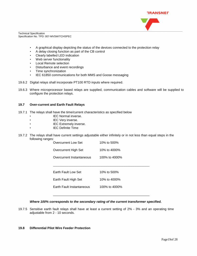
__________________________________________________________________________________________________________________ Technical Specification Specification No. TPD: 007-MVSWITCHSPEC
Page19of 28
• A graphical display depicting the status of the devices connected to the protection relay • A delay closing function as part of the CB control • Clearly labelled LED indication • Web server functionality • Local Remote selection • Disturbance and event recordings • Time synchronization • IEC 61850 communications for both MMS and Goose messaging
19.6.2 Digital relays shall incorporate PT100 RTD inputs where required. 19.6.3 Where microprocessor based relays are supplied, communication cables and software will be supplied to
configure the protection relays. 19.7 Over-current and Earth Fault Relays 19.7.1 The relays shall have the time/current characteristics as specified below
• IEC Normal inverse. • IEC Very inverse. • IEC Extremely inverse. • IEC Definite Time
19.7.2 The relays shall have current settings adjustable either infinitely or in not less than equal steps in the
following ranges: Overcurrent Low Set 10% to 500% Overcurrent High Set 10% to 4000% Overcurrent Instantaneous 100% to 4000% ______________________________________________________ Earth Fault Low Set 10% to 500% Earth Fault High Set 10% to 4000% Earth Fault Instantaneous 100% to 4000% ______________________________________________________ Where 100% corresponds to the secondary rating of the current transformer specified. 19.7.5 Sensitive earth fault relays shall have at least a current setting of 2% - 3% and an operating time
adjustable from 2 - 10 seconds. 19.8 Differential Pilot Wire Feeder Protection

__________________________________________________________________________________________________________________ Technical Specification Specification No. TPD: 007-MVSWITCHSPEC
Page20of 28
19.8.1 Only to be used where a communication medium (pilot wires or fibre optic) exists or can be installed between the ends of the cable
Figure 1 19.8.2 Relays incorporated in this system shall have a setting range of between
• I diff restrained 10% to 500% • I diff un restrained 10% to 500% • CT compensation 20% to 500%
They shall be compensated for any inherent out-of-balance in the current transformers supplied and shall be automatically biased against tripping on through-faults.
19.8.3 It shall be the responsibility of the tenderer to ensure that the current transformers and relays
supplied will match exactly the equipment installed at the other end of the cable to be protected and that the whole protective system will be stable on through-faults but will operate satisfactorily on feeder faults.

__________________________________________________________________________________________________________________ Technical Specification Specification No. TPD: 007-MVSWITCHSPEC
Page21of 28
19.9 Arc Protection and Busbar Blocking Scheme. 19.9.1 A combination of Arc Protection and a Busbar blocking scheme shall be used to detect tbusbar fault under
the following 3 conditions: • Earth faults • Phase to Phase faults. • Three Phase faults.
19.9.2 The switchgear protection “Zones” must be split over two sections 19.10 Arc protection 19.10.1 The individual zone relays shall trip all the switching devices in their respective zones to isolate the
fault from all sources of supply. 19.10.3 The reaction time of the busbar protection system shall be such as to limit the duration of an internal
arc fault to the withstand capability of the board. 19.10.4 Each relay shall: 19.10.4.1 Have its current setting adjustable in not less than seven equal steps Overcurrent 50% to 600% ______________________________________________________ Earth Fault 5% to 50%
where 100% corresponds to the secondary rating of the current transformer specified. 19.10.4.2 tripping the Incomers and sections directly and loading Input on the feeder breakers to clear
to zone 19.11 Transformer Protection - (3 phase, 2 winding power transformers) 19.11.1 Over-current and Earth Fault Protection relays shall consist of the following elements: The relays shall have the time/current characteristics as specified below
• IEC Normal inverse. • IEC Very inverse. • IEC Extremely inverse. • IEC Definite Time
19.7.2 The relays shall have current settings adjustable either infinitely or in not less than equal steps in the
following ranges: Overcurrent Low Set 10% to 500% Overcurrent High Set 10% to 4000%

__________________________________________________________________________________________________________________ Technical Specification Specification No. TPD: 007-MVSWITCHSPEC
Page22of 28
Overcurrent Instantaneous 100% to 4000% ______________________________________________________ Earth Fault Low Set 10% to 500% Earth Fault High Set 10% to 4000% Earth Fault Instantaneous 100% to 4000% ______________________________________________________ Where 100% corresponds to the secondary rating of the current transformer specified. 19.11.2 Relays provided for Restricted Earth Fault Protection of Star Windings shall be of the Low impedance
instantaneous type and shall be tuned to 50 Hz. 19.11.2.1Stability on through faults shall be maintained up to the fault rating of the switchgear. 19.11.2.2Sensitivity shall be equal to the rated current of the current transformer. 19.11.2.3The current transformer, to be installed in the neutral connection of the power transformer, shall be
supplied and installed. 19.11.2.4The insulation of the neutral current transformer shall be equal to the rated voltage of the
switchgear. 19.11.2.5The tenderer shall advise the maximum load burden. 19.11.2.6The current transformer for the neutral connection of the power transformer shall be installed by the
Tenderer, who shall be responsible for the correct operation of the complete protective system. 19.11.3 Biased Differential Protection relays shall have a high speed characteristic and be biased to provide
stability during through faults. They shall not be operated by normal magnetising inrush currents. 19.8.2 Relays incorporated in this system shall have a setting range of between
• I diff restrained 10% to 500% • I diff un restrained 10% to 500% • CT compensation 20% to 500% • Vector group Compensation • Harmonic restraint
19.11.3.1Current transformers for the higher voltage winding of the power transformer will be installed by
others but the tenderer shall advise the maximum load burden. 19.11.4 Over temperature, Gas Detection and Overpressure Protection shall be provided unless otherwise
stated in Appendix 1. All circuit breakers controlling transformers shall be provided with the following instantaneous trip auxiliary relays:
• One relay for over-temperature protection. • One relay for Bucholz or over-pressure protection.

__________________________________________________________________________________________________________________ Technical Specification Specification No. TPD: 007-MVSWITCHSPEC
Page23of 28
19.11.5 The circuit-breaker panel shall be provided with an instantaneous type relay for protection against
Tank-earth faults. 19.12 Electrical Inter-Trip 19.12.1 When electrical inter-tripping between two circuit-breakers is specified in Appendix 1 and/or on the
relevant drawings, tripping of the driving unit shall close a set of contacts, to instantaneously energise the trip circuit of the follower unit.
19.12.2 All circuit breakers, controlling transformers shall be provided with the equipment specified above for
driving units. 20. CLOSING AND TRIPPING SUPPLIES 20.1 A battery and battery-charging unit when specified in Appendix 1 shall be supplied, with the
switchboard. The battery shall be capable of providing 8 hours standby time in the event of loss of supply. The battery shall be charged via a constant voltage charger that is supplied from a 220VAC supply. The charger shall be sufficiently rated to deliver the average 24hr standing load as well as the battery charging current for a discharged battery. The charger and battery shall have a 20% overcapacity to cater for aging and unforeseen loads. The manufacturer shall provide a preliminary calculation with the tender that shall be finalised on design approval.
21. TEST TERMINAL BLOCKS 21.1 Readily accessible, suitably enclosed test terminal blocks (equal or similar approved to MMLG/MMLB
type) shall be provided on the front panel of each switch unit for the purpose of testing all protective systems.
21.2 Test terminal blocks need not be provided for frame protection system if the associated current
transformers are mounted externally. 21.3 The test blocks shall be wired to the protective relays and associated current transformers. 22. CONTROL SWITCHES 22.1 All control switches shall be designed manufactured and tested in accordance with the
recommendation of IEC PUBLICATION 337. 22.2 Rotary pistol grip type switches shall be used on electrically operated switching devices. 22.3 The electrical and mechanical endurance of the control switches shall not be less than 100 000
operations. 23. MINIATURE CIRCUIT-BREAKERS

__________________________________________________________________________________________________________________ Technical Specification Specification No. TPD: 007-MVSWITCHSPEC
Page24of 28
23.1 Miniature circuit breakers shall be designed, manufactured and tested in accordance with SANS 156 and shall be mounted in the relay compartment and be readily accessible.
24. LOW VOLTAGE WIRING 24.1 Internal LV wiring shall be multi-strand copper conductor with PVC insulation having a minimum insulation
rating of 600V/1000V to SANS 1411. When subjected to movement, the wiring shall be fully flexible with a minimum of 40 strands (2.5mm2).
24.2 Wiring shall be enclosed in a metal conduit when in the high voltage compartments. 24.3 Insulated crimp terminal lugs shall be used to terminate all wires. Lugs shall be correctly crimped to the lug
manufacturers’ specification. 24.4 All wiring from heaters to terminals shall be heat resistant. 24.5 Wiring shall be suitably strapped and enclosed in flexible conduit when looping from panels to doors
and shall be continuous without joints. 24.6 Current transformer star points on secondary windings shall be earthed in the immediate vicinity of
the transformer as well as onto the main circuit earth. 24.7 Terminal blocks or strips shall have a minimum of 10% spare terminals for future additions and be of
the box type incorporating a pressure pad between the conductor and clamping screws. 27.8 LV wiring shall be colour coded and the ends of every wire shall be numbered as per NWS 1958 and
in accordance with the approved schematic diagrams. Wiring shall also be neatly done and suitably strapped or housed in wire channels. Ferrule numbers shall be oil and moisture resistant.
24.9 Unless otherwise specified, the following guideline will be followed:
• DC Circuits (Indication and control) 1.5mm2 Grey • DC Circuit (Spring rewind motor) 2.5mm2 Grey • AC Circuits (VT) 1.5mm2 Colour coded • AC Circuits (1A CT) 4mm2 Colour coded • AC Circuits (5A CT) 4mm2 Colour coded • AC Circuits (Panel Heaters) 2.5mm2 Black • AC Circuit (Cable Live Indicators) 1.5mm2 Colour coded • DC Buswiring (Supply) 4mm2 Grey • AC Buswiring (Supply) 4mm2 Black • DC Buswiring (Signalling) 1mm2 Screened
25. REMOTE CONTROL 25.1 All electrically operated switching devices shall be equipped with circuits for remote operation and
indication. 25.2 The circuits shall include the following :
• TWO set of N/O and N/C auxiliary contacts to indicate the
__________________________________________________________________________________________________________________ Technical Specification Specification No. TPD: 007-MVSWITCHSPEC
Page25of 28
"open" or "closed" states of the switching device. • Relays for remote closing and opening shall require a maximum of 50 watts at 110 Volts DC.
25.3 All remote circuits shall be wired to a terminal strip at the back of the panel.
Selectors switch on the front of the panel to select between "local" and "remote" operation. 25.4 An additional socket shall be allowed for at the front of the panel for remote operation via a handheld
pendant type remote control unit (chicken switch). 26. ARC DUCTING 26.1 The switchgear should be fitted with arc ducting to safely vent the gases away from the operator, to
the outside of the building. 26.2 The arc ducting can be vented into the sides of the switchgear or two the rear of the switchgear. The
manufacturer must determine the most suitable venting arrangement for his switchgear from the substation drawings.
26.3 If arc ducting cannot be vented to the exterior of the building then the arc ducting can vent into the
switch-room through an absorber. 26.4 The design of the switchgear arc ducting system must be supported by type test certificates. 26.5 If the arc ducting is fitted with an absorber then the pressure rise within the switch-room must be
determined by means of a calculation. 26.6 The maximum height of the arc ducting should be 2600 mm from the floor to the top of the
switchgear including the arc ducting. 27. NAMEPLATES AND LABELS 27.1 Labelling shall be done according to NRS 003. Graphic symbols for wiring diagrams shall comply with NRS
002. 27.2 Each switchgear and control gear panel shall be fitted with a nameplate in a conspicuous position
indicating:
Maker's name: Maker's type number Maker's serial number: Client contract number Service voltage: Number of phases Continuous rating: Rating kA seconds
27.3 Identical nameplates as that on all current and voltage transformers shall be mounted in a
conspicuous position inside the relay compartment. The phase colour with which each current/voltage transformer is associated shall appear beneath each nameplate.
27.4 Interchangeable, engraved labels, showing panel designation (circuit breaker number and circuit

__________________________________________________________________________________________________________________ Technical Specification Specification No. TPD: 007-MVSWITCHSPEC
Page26of 28
name), shall be fitted to the front and the rear of the fixed part of each cubicle and associated withdrawable equipment for easy identification.
27.5 Only screws with nuts or rivets shall be utilized to fix label. Self-tapping screws or similar will not be
used. 27.6 All equipment shall be clearly designated in position in accordance with the wiring and schematic
drawings. 27.7 Voltmeter labels shall state whether busbar or cable voltage is indicated. 27.8 All labels shall be made of composite sandwich type plastic material with black lettering on white
background. Letters must be of sufficient size to be clearly legible. All nameplates and labels shall be in English.
27.9 Danger Notices: White lettering on red background. Letters must be of sufficient size to be clearly
legible. 28. PAINTING 28.1 All surfaces of the distribution board shall be light orange to SANS 1091 colour No. B26. 28.2 All surfaces shall be cleaned according to the appropriate method described in SANS 064 for the
particular surface to be cleaned, the contamination to be removed and the primer to be applied. 28.3 Blast cleaning of components shall be in accordance with clause 4.3 of SANS 064 to a degree of
cleanliness of at least Sa2 for inland exposure components and Sa 1/2 for coastal exposure components. See Table 1 of SANS 064 for the appropriate profile.
28.4 Sheet metal that cannot be blast cleaned shall be cleaned by pickling according to clause 4.6 of
SANS 064. 28.5 Components that will be powder coated shall be cleaned and prepared by the surface conversion
process according to clause 5 of SANS 064 to a medium-weight classification of table 2 of that specification.
28.6 Oil and accumulated dirt on steel components where no rusting is present shall be removed
according to clause 3 of SANS 064. 28.7 The powder-coating process shall be in accordance with SANS 1274 type 4: Corrosion-resistant
coatings for interior use and using the thermosetting type high gloss coating. 28.8 All specified coatings shall be applied according to the relevant specification and the manufacturer’s
instructions shall be followed. 28.9 Coatings shall not be applied under conditions that may be detrimental to the effectiveness of the
coating or the appearance of the painted surface. 28.10 When examined visually the finished products shall have a uniform appearance as far as gloss is

__________________________________________________________________________________________________________________ Technical Specification Specification No. TPD: 007-MVSWITCHSPEC
Page27of 28
concerned and shall show no sign of damage. Damaged areas shall be repaired coat for coat to obtain the desired finish.
29. TESTS 29.1 All prescribed tests as referred to in the standard specifications may be called for at the discretion of
Transnet Group Capital 29.2 Transnet Group Capital also reserves the right to carry out any check tests on the equipment. 29.3 Notwithstanding the successful completion of tests, the tenderer will still be responsible for the
efficient operation of the equipment. 29.4 The tenderer shall bear all costs for any tests that will be required. 30. INSPECTION 30.1 The successful tenderer shall advise Transnet Group Capital at least four (4) weeks in advance of
panel testing to enable Transnet Group Capital to witness the testing at the manufacturer’s premises once Switchboards are 100% ready before shipment.
30.2 All transport cost to enable Transnet Group Capital personnel to attend such test must be included in
the tenderers price (Max. 2 persons) 30.3 In the event of major faults ie; wiring discrepancies, VCB”S failed to trip; busbar earthing device not
demonstrated on the day, The successful tenderer shall again arrange for a retest at the tenderer cost.
31. TOOLS AND APPLIANCES 31.1 One set of any special tools and appliances required for normal operation and maintenance shall be
supplied with each board. 32. SPARES 32.1 The tenderer shall state whether their local representatives hold a complete range of spares in stock
as and when required. 32.2 The tenderer shall submit a separate quote for recommended spares for maintenance purposes of
supply a detailed description of each item including manufacturer's catalogue number. 32.3 A complete spare parts list, including parts location diagrams or drawing and prices, which the manufacturer
recommends for the first two years' operation, shall be submitted with the tender.

__________________________________________________________________________________________________________________ Technical Specification Specification No. TPD: 007-MVSWITCHSPEC
Page28of 28
32.4 A separate list detailing items likely to be used in a 10-year period shall also be submitted with the tender.
33. PACKING 33.1 The equipment shall be packed in such a manner that it will be protected during handling and
transport by road, rail or sea as applicable. The movements of instruments, meters and relays shall be protected against vibration damage during transit.
33.2 When sea transport is involved, a dehydrating agent shall be provided where necessary. 34. GUARANTEE 34.1 The tenderer shall guarantee the equipment supplied by him in terms of this specification for a period of one
year after successful completion of hot commissioning of the plant. The tenderer shall state his compliance herewith.
34.2 This guarantee shall cover all materials, parts, workmanship, performance and efficiency (normal wear and tear excluded). The guarantee shall include all equipment supplied.
34.3 If any part/equipment fails during the 12-month guarantee period, the supplied shall immediately replace such part/equipment free of charge.
WITNESSES 1. …………………………….. …………………………… TENDERER 2. ……………………………. …………………………….
DATE Transnet Group Capital Design Services

Item Description Panel No F41 F42 F43a F43 F43b F44 F45Panel Designation F-41 Incomer 1 F42-Transformer Feeder 1 F43a:BB ES & VT #1 Bus Section F43:Busriser& VT#2 F-44 Transformer Feeder 2 F45-Incomer 2
1.1 General
Type of panel New New New New New New New
Number of swicthing devices One One N/A One N/A One One
Neutral Earthing: Unearthed:. . . . . . . . . . . Solidly Earthed:. . . . . . . . Reactance Earthed:. . . . . Resonant Earthed:. . . . . .
General arrangement drawing reference of the switchboard with details of each panel with all its related components and accossories.
Cable Trenching layout to be agreed between supplier and engineer. Yes/No
1.2 Ratings of switchgear/panels
Rated kV
Rated frequency
BusbarsRated normal current (A)
Type of material Copper Copper Copper Copper Copper Copper CopperInsulation material
Air Insulated "Vacuum" Air Insulated "Vacuum" Air Insulated "Vacuum"Air Insulated
"Vacuum"Air Insulated
"Vacuum"Air Insulated "Vacuum" Air Insulated "Vacuum"
Rated insulation level kV
Max. Three phase abd earth fault current (kA/3 seconds)IAC Rating
Max. Internal Arc Fault rating (kA/1 second)Rated normal current for circuits (A)
1250A 630A N/A 1250A N/A 630A 1250A
Anticondesational Heaters: Yes/NOSwitchboard Colour
1.3 Enviromental Conditions
a) Altitude (m)
b) Maximum daily temperature °C
c) Minimum daily temperature °Cd) Average daily temperature °C
e) Humidity %f) Exposure conditionsg) Lightning conditions
1.4 Circuit BrekaersCircuit-breaker type required
Closing Machanism if other than stored energy typeRating according to IEC 62271-100
Closing Supply: Rated Voltage :. . . . . . . . . . . Peak Power:. . . . . . . . . . . .
Tripping Supply: Rated Voltage :. . . . . . . . . . . Peak Power:. . . . . . . . . . . .
Stored Energy Machanism: Rated Voltage :. . . . . . . . . . . . . Peak Power:. . . . . . . . . . . .
Panel size (mm)
Yes. In cable and Circuit Breaker compartments
Solidly Earthed
To be submitted by tenderer
Trench layout is shown on the existing substation layout
11kV
50Hz
96Salt laden and industrial atmosphere
31.5kA
-535
1250A
95kV
31.5kA
AFLR
110V, Battery Peak Power 750W
110V, Battery Peak Power 750W
110V, Battery Peak Power 750W
RAL 7035 Light grey
0 to 1800m
45
Sever: 11flashes/kM²/annum
Vacuum "VCB" (Withdrawable type)
Stored Energy. Spring charged
E2, M2, C2
ANNEXURE 1 Technical SpecificationSpecification No. TPD: 007-MVSWITCHSPECSchedule of requirements for BAY 18A Substation
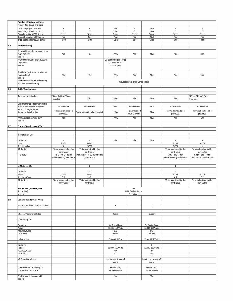
Number of auxilary contacts required on circuit brekaers
-"Normally open" contacts 5 5 N/A 5 N/A 5 5-"Normally closed" contacts 5 5 N/A 6 N/A 5 5Open Indication (LED) Lights Green Green Green Green Green Green Green Closed Indication (LED) Lights Red Red Red Red Red Red RedTripped Indication (LED) Lights Blue Blue Blue Blue Blue Blue Blue
1.5 Saftey Earthing
Are earthing facilities required on main circuits?Yes/No
Yes Yes N/A Yes N/A Yes Yes
Are earthing facilities on busbars required?Yes/No
1x ES in Bus Riser (RHS) 1x ES in BB VT Cubicle (LHS)
Are these facilities to be rated for fault making?Yes/No
Yes Yes N/A Yes N/A Yes Yes
Interlock BB E/S with all incoming and Feeders CB, racking.
1.6 Cable Terminations
Type and size of cable 3Core, 240mm² PaperInsulated TBA N/A N/A N/A TBA
3Core, 240mm² PaperInsulated
Cable termination compartments Type of cable boxes rerquired Air Insulated Air Insulated N/A Air Insulated N/A Air Insulated Air Insulated Type of filling required: Paper insulated cablse
Termination kit to be provided.
Termination kit to be provided. N/A Termination kit to be provided.
N/A Termination kit to be provided.
Termination kit to be provided.
Are Gland plates required?Yes/No
Yes Yes N/A Yes N/A Yes Yes
1.7 Current Transformers (CT's)
a) Protection CT's
Quantity 3 3 N/A N/A N/A 3 3Ratio 400/1 200/1 200/1 400/1Accuracy class X 5P20 5P20 XCT Burden To be submitted by the
contractorTo be submitted by the
contractorTo be submitted by the
contractorTo be submitted by the
contractorProtection Single ratio - To be
determined by contractorMulti ratio - To be determined
by contractorMulti ratio - To be
determined by contractorSingle ratio - To be
determined by contractor
b) Metering CTs 1 1
Quantity 3 3Ratios 400/1 200/1 200/1 400/1Accuracy Class 0.2 0.2 0.2 0.2CT Burden To be submitted by the
contractorTo be submitted by the
contractorTo be submitted by the
contractorTo be submitted by the
contractor
Test Blocks (Metering and Protection) Yes/No
1.8 Voltage Transformers (VT's)
Panels to which VT's are to be fitted X X
where VT's are to be fitted Busbar Busbar
a) Metering VT's
Quantity 3 x Single Phase 3 x Single PhaseRatios 11000/110 Volts 11000/110 Volts Accuracy Class 0.2 0.2VT Burden 200 VA 200 VA
b)Protection Class 6P/200VA Class 6P/200VA
Quantity 3 3Ratios 11000/110 Volts 11000/110 Volts Accuracy Class 6P 6PVT Burden 200 200
VT Protection device Loading resistor or VT guard.
Loading resistor or VT guard.
Connection of VT primary to:Busbar side/circuit side
Busabr side,Withdrawable
Busabr side,Withdrawable
Are HV fuse-links required?Yes/No
Yes Yes
Yes Via Fortress Type Key Interlock
Yes MMLG/MMLB type
On LV Door

1.9 Live circuit indication
According to IEC 61243-5 Yes Yes Yes Yes Yes is live indication required? Yes Yes Yes Yes Yes On Which panels? X X X X X
1.10 Control, protection and alarm circuitry Drawing number(if applicable for all panels)
Are control wires to be terminated with crimpped lugs? Yes/No
Color of auxiliary wires, if not grey
Requirements for alarm circuits
Is Ammeter required? Yes/No
Ammeter selector switch
Are Voltmeter required? Yes/No
Voltmeter selector switch
1.11Battery, battery charger and d.c. supplies
If Yes, details of the battery V
A.h capacity suitable for 8hour standby
Auxiliary supply
1.12 Protection Relays
Overcurrent and Earth Fault Relays:
Overcurrent: Yes Yes Yes YesNumber of elements Three Three Three ThreeIDMT Inverse Yes Yes Yes YesIDMT Extremely Inverse Yes Yes Yes YesHigh Set Instantaneous Yes Yes Yes YesInstantaneousDefinite Time Yes Yes Yes YesEarth Fault:Number of elements Three Three Three ThreeIDMT Inverse Yes Yes Yes YesIDMT Extremely Inverse One One One OneHigh Set InstantaneousInstantaneousDefinite Time Yes Yes Yes Yes
Autoreclosing No No No NoCable Differential Protection Yes No No YesPower Factor Protection No No No NoBusbar Blocking Yes Yes Yes Yes YesDetails of indication functions requiredCurrent Indication Yes in IED Yes in IED Yes in IED Yes in IEDVoltage Indication Yes in IED Yes in IED Yes in IED Yes in IEDEnergy metering Yes Yes Yes in IED Yes in IED
SpecifyExisting to be re-utilized Existing to be re-utilized Existing to be re-utilized P, Q, Pf
Binary Inputs Yes, as per IED Yes, as per IED Yes, as per IED Yes, as per IEDBinary Outputs Yes, as per IED Yes, as per IED Yes, as per IED Yes, as per IEDCommunicationsCommunications Protocol
Type of IEDEqual or Similar to ABB
RED 615Equal or Similar to ABB RET
615Equal or Similar to ABB RET
615Equal or Similar to ABB RED
615Differential Protection Yes No No Yes
Pilot wire Modem required Yes/NoYes No No Yes
Arc Protection Yes Yes Yes Yes YesArc Protection System
1.13 Electrical IntertripYes via IED, Rcd from LV
ACB
Yes via IED, Rcd from LV
ACBYes via IED, Rcd from LV ACB
Driving unit: Breaker No. Follower unit: Breaker No.
NA F35Feeder LV ACB F37 Feeder LV ACB NA
Where are VT fuses or links located?On VT On VT
Non Selective Tripping
Yes 400/230V Local AC DB existing
IEC 61850Ethernet RJ45
Yes
Yes, Voltmeter and via IED
Yes
110 Volt (Valve Regulated Lead Acid Batteries, maintenance free batteries)Equal or similar approved to Alcad Vantex battery with 20years services life
Manufacturer to calculate the Ah capacity required
Yes, MD Ammeter and via IED
To be submited by panel Manufacturer
As per specification
Yes

1.14 Remote SwitchingYes, via SCAME, socket on
panel faceYes, via SCAME, socket on
panel face
Yes, via SCAME, socket on panel face
Yes, via SCAME, socket on panel face
Yes, via SCAME, socket on panel face
1.15 Tests
Routine test and type test of metering CTs required
Routine test and type test of protection CTs required
Routine Test and Type test of VTs required
Yes according to IEC 60044-2
Yes according to IEC 60044-2
Number of copies of routine test certificates required
1.16Marking/labeling/documentation
Are main circuit labels to be engraved?
Yes/No
Documentation to be provided with the offer
Quantity of Operational and Maintenance manuals required:
1.17 Accessories
Supply of cabinet requiredSwitchgear Operating ToolsWall Mounted tool cabinetCB service trolley
Number of as-built drawings and O and M manuals required.
Spares
Period required for routine maintenance sparesMinimum availability of spares from date of supplyDeliveryDelivery period EXW in Weeks
Delivery period installation in weeksDelivery period for commissioning in weeks
YesYes
If Required
General Arrangement and details of equipment offered
Three copies
Three
1 year
10 years
Yes according to IEC 60044-1
Yes according to IEC 60044-1
Three
Yes

Item Description Panel No F87 F88 F89a F89 F89b F90 F91-Incomer 2
Panel Designation F-87 Incomer 1 F88-Transformer Feeder 1 F89a:BB ES & VT #1 Bus Section F89:Busriser& VT#2 F-90 Transformer Feeder 2 F91-Incomer 2
1.1 General
Type of panel New New New New New New New
Number of swicthing devices One One N/A One N/A One One
Neutral Earthing: Unearthed:. . . . . . . . . . . Solidly Earthed:. . . . . . . . Reactance Earthed:. . . . . Resonant Earthed:. . . . . .
General arrangement drawing reference of the switchboard with details of each panel with all its related components and accossories.
Cable Trenching layout to be agreed between supplier and engineer. Yes/No
1.2 Ratings of switchgear/panels
Rated kV
Rated frequency
BusbarsRated normal current (A)
Type of material Copper Copper Copper Copper Copper Copper CopperInsulation material
Air Insulated "Vacuum" Air Insulated "Vacuum" Air Insulated "Vacuum"Air Insulated
"Vacuum"Air Insulated
"Vacuum"Air Insulated "Vacuum" Air Insulated "Vacuum"
Rated insulation level kV
Max. Three phase abd earth fault current (kA/3 seconds)IAC Rating
Max. Internal Arc Fault rating (kA/1 second)Rated normal current for circuits (A)
1250A 630A N/A 1250A N/A 630A 1250A
Anticondesational Heaters: Yes/NOSwitchboard Colour
1.3 Enviromental Conditions
a) Altitude (m)
b) Maximum daily temperature °C
c) Minimum daily temperature °Cd) Average daily temperature °C
e) Humidity %f) Exposure conditionsg) Lightning conditions
1.4 Circuit BrekaersCircuit-breaker type required
Closing Machanism if other than stored energy typeRating according to IEC 62271-100
Closing Supply: Rated Voltage :. . . . . . . . . . . Peak Power:. . . . . . . . . . . .
Tripping Supply: Rated Voltage :. . . . . . . . . . . Peak Power:. . . . . . . . . . . .
Stored Energy Machanism: Rated Voltage :. . . . . . . . . . . . . Peak Power:. . . . . . . . . . . .
Panel size (mm)
Number of auxilary contacts required on circuit brekaers
-"Normally open" contacts 5 5 N/A 5 N/A 5 5
-"Normally closed" contacts 5 5 N/A 6 N/A 5 5
Open Indication (LED) Lights Green Green Green Green Green Green Green
Closed Indication (LED) Lights Red Red Red Red Red Red Red
E2, M2, C2
ANNEXURE 1
110V, Battery Peak Power 750W
110V, Battery Peak Power 750W
110V, Battery Peak Power 750W
RAL 7035 Light grey
0 to 1800m
45
Sever: 11flashes/kM²/annum
Vacuum "VCB" (Withdrawable type)
Stored Energy. Spring charged
1250A
95kV
31.5kA
AFLR
Technical SpecificationSpecification No. TPD: 007-MVSWITCHSPECSchedule of requirements for BAY 55 Substation
Yes. In cable and Circuit Breaker compartments
Solidly Earthed
To be submitted by tenderer
Trench layout is shown on the existing substation layout
11kV
50Hz
96Salt laden and industrial atmosphere
31.5kA
-5
35

Tripped Indication (LED) Lights Blue Blue Blue Blue Blue Blue Blue
1.5 Saftey Earthing
Are earthing facilities required on main circuits?Yes/No
Yes Yes N/A Yes N/A Yes Yes
Are earthing facilities on busbars required?Yes/No
1x ES in Bus Riser (RHS) 1x ES in BB VT Cubicle (LHS)
Are these facilities to be rated for fault making?Yes/No
Yes Yes N/A Yes N/A Yes Yes
Interlock BB E/S with all incoming and Feeders CB, racking.
1.6 Cable Terminations
Type and size of cable 3Core, 240mm² PaperInsulated TBA N/A N/A N/A TBA
3Core, 240mm² PaperInsulated
Cable termination compartments Type of cable boxes rerquired Air Insulated Air Insulated N/A Air Insulated N/A Air Insulated Air Insulated Type of filling required: Paper insulated cablse
Termination kit to be provided.
Termination kit to be provided. N/A Termination kit to be provided.
N/A Termination kit to be provided.
Termination kit to be provided.
Are Gland plates required?Yes/No
Yes Yes N/A Yes N/A Yes Yes
1.7 Current Transformers (CT's)
a) Protection CT's
Quantity 3 3 N/A N/A N/A 3 3Ratio 400/1 100/1 100/1 400/1Accuracy class X 5P20 5P20 XCT Burden To be submitted by the
contractorTo be submitted by the
contractorTo be submitted by the
contractorTo be submitted by the
contractorProtection Single ratio - To be
determined by contractorMulti ratio - To be determined
by contractorMulti ratio - To be
determined by contractorSingle ratio - To be
determined by contractor
b) Metering CTs 1 1
Quantity 3 3Ratios 400/1 100/1 100/1 400/1Accuracy Class 0.2 0.2 0.2 0.2CT Burden To be submitted by the
contractorTo be submitted by the
contractorTo be submitted by the
contractorTo be submitted by the
contractor
Test Blocks (Metering and Protection) Yes/No
1.8 Voltage Transformers (VT's)
Panels to which VT's are to be fitted X X
where VT's are to be fitted Busbar Busbar
a) Metering VT's
Quantity 3 x Single Phase 3 x Single PhaseRatios 11000/110 Volts 11000/110 Volts Accuracy Class 0.2 0.2VT Burden 200 VA 200 VA
b)Protection Class 6P/200VA Class 6P/200VA
Quantity 3 3Ratios 11000/110 Volts 11000/110 Volts Accuracy Class 6P 6PVT Burden 200 200
VT Protection device Loading resistor or VT guard.
Loading resistor or VT guard.
Connection of VT primary to:Busbar side/circuit side
Busabr side,Withdrawable
Busabr side,Withdrawable
Are HV fuse-links required?Yes/No
Yes Yes
1.9 Live circuit indication
According to IEC 61243-5 Yes Yes Yes Yes Yes is live indication required? Yes Yes Yes Yes Yes On Which panels? X X X X X
1.10 Control, protection and alarm circuitry Drawing number(if applicable for all panels)
Are control wires to be terminated with crimpped lugs? Yes/No
Color of auxiliary wires, if not grey
Yes
As per specification
Yes Via Fortress Type Key Interlock
Yes MMLG/MMLB type
On LV Door
To be submited by panel Manufacturer

Requirements for alarm circuits
Is Ammeter required? Yes/No
Ammeter selector switch
Are Voltmeter required? Yes/No
Voltmeter selector switch
1.11Battery, battery charger and d.c. supplies
If Yes, details of the battery VA.h capacity suitable for 8hour
standby
Auxiliary supply
1.12 Protection Relays
Overcurrent and Earth Fault Relays:
Overcurrent: Yes Yes Yes YesNumber of elements Three Three Three ThreeIDMT Inverse Yes Yes Yes YesIDMT Extremely Inverse Yes Yes Yes YesHigh Set Instantaneous Yes Yes Yes YesInstantaneousDefinite Time Yes Yes Yes YesEarth Fault:Number of elements Three Three Three ThreeIDMT Inverse Yes Yes Yes YesIDMT Extremely Inverse One One One OneHigh Set InstantaneousInstantaneousDefinite Time Yes Yes Yes Yes
Autoreclosing No No No NoCable Differential Protection Yes No No YesPower Factor Protection No No No NoBusbar Blocking Yes Yes Yes Yes YesDetails of indication functions requiredCurrent Indication Yes in IED Yes in IED Yes in IED Yes in IEDVoltage Indication Yes in IED Yes in IED Yes in IED Yes in IEDEnergy metering Yes Yes Yes in IED Yes in IED
SpecifyExisting to be re-utilized Existing to be re-utilized Existing to be re-utilized P, Q, Pf
Binary Inputs Yes, as per IED Yes, as per IED Yes, as per IED Yes, as per IEDBinary Outputs Yes, as per IED Yes, as per IED Yes, as per IED Yes, as per IEDCommunicationsCommunications Protocol
Type of IEDEqual or Similar to ABB
RED 615Equal or Similar to ABB RET 615
Equal or Similar to ABB RET 615
Equal or Similar to ABB RED 615
Differential Protection Yes No No Yes
Pilot wire Modem required Yes/NoYes No No Yes
Arc Protection Yes Yes Yes Yes YesArc Protection System
1.13 Electrical IntertripYes via IED, Rcd from LV
ACBYes via IED, Rcd
from LV ACBYes via IED, Rcd from LV ACB
Driving unit: Breaker No. Follower unit: Breaker No.
NA F35Feeder LV ACB F37 Feeder LV ACB NA
Where are VT fuses or links located?On VT On VT
1.14 Remote SwitchingYes, via SCAME, socket on
panel faceYes, via SCAME, socket on
panel face
Yes, via SCAME, socket on panel face
Yes, via SCAME, socket on panel face
Yes, via SCAME, socket on panel face
1.15 Tests
Routine test and type test of metering CTs required
Routine test and type test of protection CTs required
Routine Test and Type test of VTs required
Yes according to IEC 60044-2
Yes according to IEC 60044-2
Number of copies of routine test certificates required
1.16Marking/labeling/documentation
Are main circuit labels to be engraved?
Yes/No
Documentation to be provided with the offer
Quantity of Operational and Maintenance manuals required:
Yes, MD Ammeter and via IED
Yes 400/230V Local AC DB existing
IEC 61850Ethernet RJ45
Yes
Yes, Voltmeter and via IED
Yes
110 Volt (Valve Regulated Lead Acid Batteries, maintenance free batteries)Equal or similar approved to Alcad Vantex battery with 20years services life
Manufacturer to calculate the Ah capacity required
Non Selective Tripping
Yes according to IEC 60044-1
Yes according to IEC 60044-1
Three
Yes
General Arrangement and details of equipment offered
Three copies

1.17 Accessories
Supply of cabinet requiredSwitchgear Operating ToolsWall Mounted tool cabinetCB service trolley
Number of as-built drawings and O and M manuals required.
Spares
Period required for routine maintenance sparesMinimum availability of spares from date of supplyDeliveryDelivery period EXW in Weeks
Delivery period installation in weeksDelivery period for commissioning in weeks
YesYes
If Required
Three
1 year
10 years

Item Description Panel No F41 F42 F43a F43 F43b F44 F45Panel Designation F-41 Incomer 1 F42-Transformer Feeder 1 F43a:BB ES & VT #1 Bus Section F43:Busriser& VT#2 F-44 Transformer Feeder 2 F45-Incomer 2
1.1 General
Type of panel
Number of swicthing devices
Neutral Earthing: Unearthed:. . . . . . . . . . . Solidly Earthed:. . . . . . . . Reactance Earthed:. . . . . Resonant Earthed:. . . . . .
1.2 Ratings of switchgear/panels
Rated kV
Rated frequency
BusbarsRated normal current (A)
Type of materialInsulation material
Rated insulation level kV
Max. Three phase abd earth fault current (kA/3 seconds)IAC Rating
Max. Internal Arc Fault rating (kA/1 second)Rated normal current for circuits (A)
Anticondesational Heaters: Yes/NOSwitchboard Colour
1.3 Enviromental Conditions
a) Altitude (m)
b) Maximum daily temperature °C
c) Minimum daily temperature °Cd) Average daily temperature °C
e) Humidity %f) Exposure conditionsg) Lightning conditions
1.4 Circuit BrekaersCircuit-breaker type required
Closing Machanism if other than stored energy typeRating according to IEC 62271-100
Closing Supply: Rated Voltage :. . . . . . . . . . . Peak Power:. . . . . . . . . . . .
Tripping Supply: Rated Voltage :. . . . . . . . . . . Peak Power:. . . . . . . . . . . .
Stored Energy Machanism: Rated Voltage :. . . . . . . . . . . . . Peak Power:. . . . . . . . . . . .
Panel size (mm)
Number of auxilary contacts required on circuit brekaers
-"Normally open" contacts-"Normally closed" contactsOpen Indication (LED) LightsClosed Indication (LED) LightsTripped Indication (LED) Lights
1.5 Saftey Earthing
ANNEXURE 2 Technical SpecificationSpecification No. TPD: 007-MVSWITCHSPECTechnical Data Sheet for BAY 18A Substation

Are earthing facilities required on main circuits?Yes/NoAre earthing facilities on busbars required?Yes/No
Are these facilities to be rated for fault making?Yes/NoInterlock BB E/S with all incoming and Feeders CB, racking.
1.6 Cable Terminations
Type and size of cable
Cable termination compartments Type of cable boxes rerquired Type of filling required: Paper insulated cablse Are Gland plates required?Yes/No
1.7 Current Transformers (CT's)
a) Protection CT's
Quantity RatioAccuracy classCT BurdenProtection
b) Metering CTs
QuantityRatiosAccuracy ClassCT Burden
Test Blocks (Metering and Protection) Yes/No
1.8 Voltage Transformers (VT's)
Panels to which VT's are to be fitted
where VT's are to be fitted
a) Metering VT's
QuantityRatiosAccuracy ClassVT Burden
b)Protection
QuantityRatiosAccuracy ClassVT Burden
VT Protection device
Connection of VT primary to:Busbar side/circuit side
Are HV fuse-links required?Yes/No
1.9 Live circuit indication
According to IEC 61243-5is live indication required?On Which panels?
1.10 Control, protection and alarm circuitry Drawing number(if applicable for all panels)
Are control wires to be terminated with crimpped lugs? Yes/No
Color of auxiliary wires, if not grey

Requirements for alarm circuits
Is Ammeter required? Yes/No
Ammeter selector switch
Are Voltmeter required? Yes/No
Voltmeter selector switch
1.11Battery, battery charger and d.c. supplies
If Yes, details of the battery V
A.h capacity suitable for 8hour standby
Auxiliary supply
1.12 Protection Relays
Overcurrent and Earth Fault Relays:
Overcurrent:Number of elementsIDMT InverseIDMT Extremely InverseHigh Set InstantaneousInstantaneousDefinite TimeEarth Fault:Number of elementsIDMT InverseIDMT Extremely InverseHigh Set InstantaneousInstantaneousDefinite Time
AutoreclosingCable Differential ProtectionPower Factor ProtectionBusbar BlockingDetails of indication functions requiredCurrent IndicationVoltage IndicationEnergy meteringSpecifyBinary InputsBinary OutputsCommunicationsCommunications ProtocolType of IEDDifferential Protection
Pilot wire Modem required Yes/NoArc ProtectionArc Protection System
1.13 Electrical Intertrip
Driving unit: Breaker No. Follower unit: Breaker No.
Where are VT fuses or links located?
1.14 Remote Switching
1.15 Tests
Routine test and type test of metering CTs required
Routine test and type test of protection CTs required
Routine Test and Type test of VTs required
Number of copies of routine test certificates required
1.16Marking/labeling/documentation
Are main circuit labels to be engraved?
Yes/No
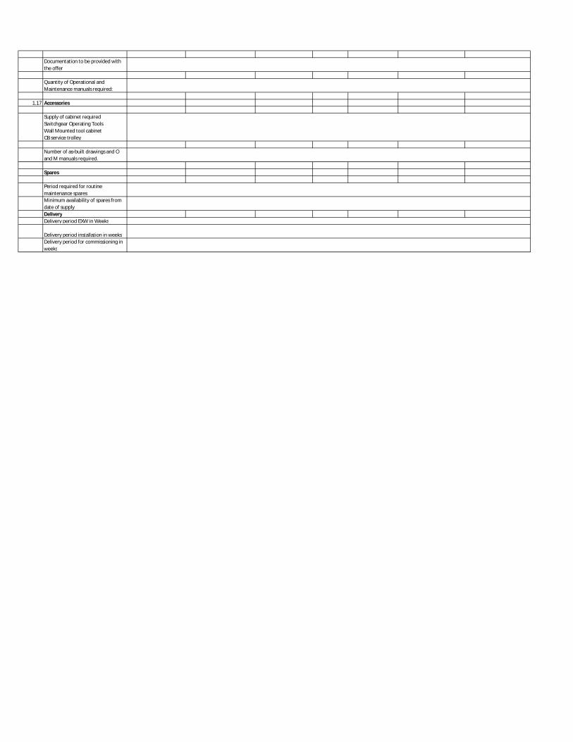
Documentation to be provided with the offer
Quantity of Operational and Maintenance manuals required:
1.17 Accessories
Supply of cabinet requiredSwitchgear Operating ToolsWall Mounted tool cabinetCB service trolley
Number of as-built drawings and O and M manuals required.
Spares
Period required for routine maintenance sparesMinimum availability of spares from date of supplyDeliveryDelivery period EXW in Weeks
Delivery period installation in weeksDelivery period for commissioning in weeks
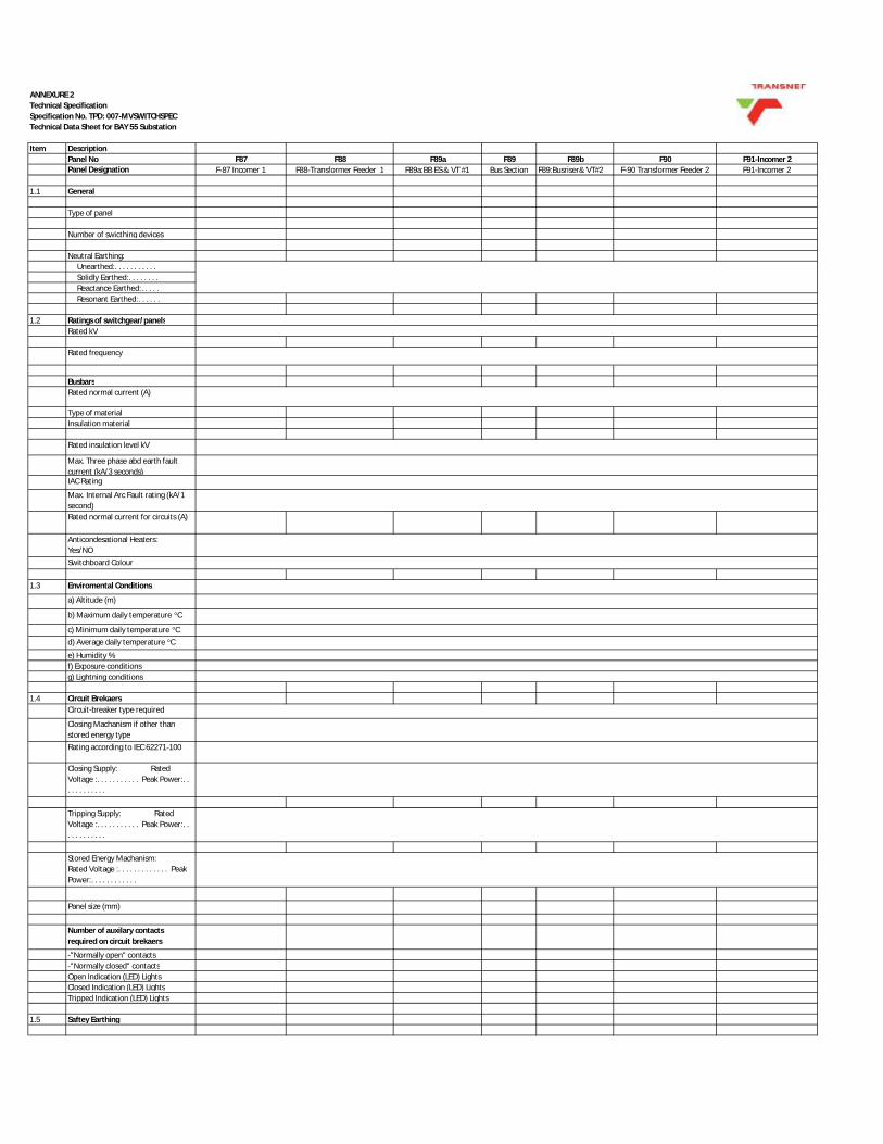
Item Description Panel No F87 F88 F89a F89 F89b F90 F91-Incomer 2Panel Designation F-87 Incomer 1 F88-Transformer Feeder 1 F89a:BB ES & VT #1 Bus Section F89:Busriser& VT#2 F-90 Transformer Feeder 2 F91-Incomer 2
1.1 General
Type of panel
Number of swicthing devices
Neutral Earthing: Unearthed:. . . . . . . . . . . Solidly Earthed:. . . . . . . . Reactance Earthed:. . . . . Resonant Earthed:. . . . . .
1.2 Ratings of switchgear/panelsRated kV
Rated frequency
BusbarsRated normal current (A)
Type of materialInsulation material
Rated insulation level kV
Max. Three phase abd earth fault current (kA/3 seconds)IAC Rating
Max. Internal Arc Fault rating (kA/1 second)Rated normal current for circuits (A)
Anticondesational Heaters: Yes/NOSwitchboard Colour
1.3 Enviromental Conditions
a) Altitude (m)
b) Maximum daily temperature °C
c) Minimum daily temperature °Cd) Average daily temperature °C
e) Humidity %f) Exposure conditionsg) Lightning conditions
1.4 Circuit BrekaersCircuit-breaker type required
Closing Machanism if other than stored energy typeRating according to IEC 62271-100
Closing Supply: Rated Voltage :. . . . . . . . . . . Peak Power:. . . . . . . . . . . .
Tripping Supply: Rated Voltage :. . . . . . . . . . . Peak Power:. . . . . . . . . . . .
Stored Energy Machanism: Rated Voltage :. . . . . . . . . . . . . Peak Power:. . . . . . . . . . . .
Panel size (mm)
Number of auxilary contacts required on circuit brekaers
-"Normally open" contacts-"Normally closed" contactsOpen Indication (LED) LightsClosed Indication (LED) LightsTripped Indication (LED) Lights
1.5 Saftey Earthing
Technical SpecificationSpecification No. TPD: 007-MVSWITCHSPECTechnical Data Sheet for BAY 55 Substation
ANNEXURE 2

Are earthing facilities required on main circuits?Yes/NoAre earthing facilities on busbars required?Yes/NoAre these facilities to be rated for fault making?Yes/NoInterlock BB E/S with all incoming and Feeders CB, racking.
1.6 Cable Terminations
Type and size of cable
Cable termination compartments Type of cable boxes rerquired Type of filling required: Paper insulated cablse Are Gland plates required?Yes/No
1.7 Current Transformers (CT's)
a) Protection CT's
Quantity RatioAccuracy classCT BurdenProtection
b) Metering CTs
QuantityRatiosAccuracy ClassCT Burden
Test Blocks (Metering and Protection) Yes/No
1.8 Voltage Transformers (VT's)
Panels to which VT's are to be fitted
where VT's are to be fitted
a) Metering VT's
QuantityRatiosAccuracy ClassVT Burden
b)Protection
QuantityRatiosAccuracy ClassVT Burden
VT Protection device
Connection of VT primary to:Busbar side/circuit side
Are HV fuse-links required?Yes/No
1.9 Live circuit indication
According to IEC 61243-5is live indication required?On Which panels?
1.10 Control, protection and alarm circuitry Drawing number(if applicable for all panels)
Are control wires to be terminated with crimpped lugs? Yes/No
Color of auxiliary wires, if not grey

Requirements for alarm circuits
Is Ammeter required? Yes/No
Ammeter selector switch
Are Voltmeter required? Yes/No
Voltmeter selector switch
1.11Battery, battery charger and d.c. supplies
If Yes, details of the battery V
A.h capacity suitable for 8hour standby
Auxiliary supply
1.12 Protection Relays
Overcurrent and Earth Fault Relays:
Overcurrent:Number of elementsIDMT InverseIDMT Extremely InverseHigh Set InstantaneousInstantaneousDefinite TimeEarth Fault:Number of elementsIDMT InverseIDMT Extremely InverseHigh Set InstantaneousInstantaneousDefinite Time
AutoreclosingCable Differential ProtectionPower Factor ProtectionBusbar BlockingDetails of indication functions requiredCurrent IndicationVoltage IndicationEnergy meteringSpecifyBinary InputsBinary OutputsCommunicationsCommunications ProtocolType of IEDDifferential Protection
Pilot wire Modem required Yes/NoArc ProtectionArc Protection System
1.13 Electrical Intertrip
Driving unit: Breaker No. Follower unit: Breaker No.
Where are VT fuses or links located?
1.14 Remote Switching
1.15 Tests
Routine test and type test of metering CTs required
Routine test and type test of protection CTs required
Routine Test and Type test of VTs required
Number of copies of routine test certificates required
1.16Marking/labeling/documentation
Are main circuit labels to be engraved?
Yes/No

Documentation to be provided with the offer
Quantity of Operational and Maintenance manuals required:
1.17 Accessories
Supply of cabinet requiredSwitchgear Operating ToolsWall Mounted tool cabinetCB service trolley
Number of as-built drawings and O and M manuals required.
Spares
Period required for routine maintenance sparesMinimum availability of spares from date of supplyDeliveryDelivery period EXW in Weeks
Delivery period installation in weeksDelivery period for commissioning in weeks

_____________________________________________________________________________________________________
Technical Specification Specification No. TPD: 007-MVSWITCHSPEC
ANNEXURE No.3
ELECTRICAL DRAWINGS
This appendix lists the Transnet Group Capital Drawings, which shall be read in conjunction with this specification: BAY 55
Drawing No Description
2537842-5-002-E-LA-0002-01 Bay 55 Existing MV Single Line Diagram and Floor Plans
2537842-5-002-E-LA-0002-02 Bay 55 Proposed MV Single Line Diagram and Floor Plans
2537842-5-002-E-LA-0002-03 Bay 55 Proposed Low Voltage Single Line Diagram and Panel Layout
BAY 18a COMPRESSOR HOUSE
Drawing No Description
2537842-5-002-E-LA-0003-01 Bay 18a Compressor House Existing MV Single Line Diagram and Floor Plans
2537842-5-002-E-LA-0003-02 Bay 18a Compressor House Proposed MV Single Line Diagram and Floor Plans
2537842-5-002-E-LA-0003-03 Bay 18a Compressor House Proposed Low Voltage Single Line Diagram and Panel Layout
MEDIUM VOLTAGE NETWORK SLD
2537842-5-005-E-LA-0004-01. Proposed Medium Voltage Single Line Diagram - Durban
SIGNATURE OF TENDERER ____________________________ DATE ____________________________
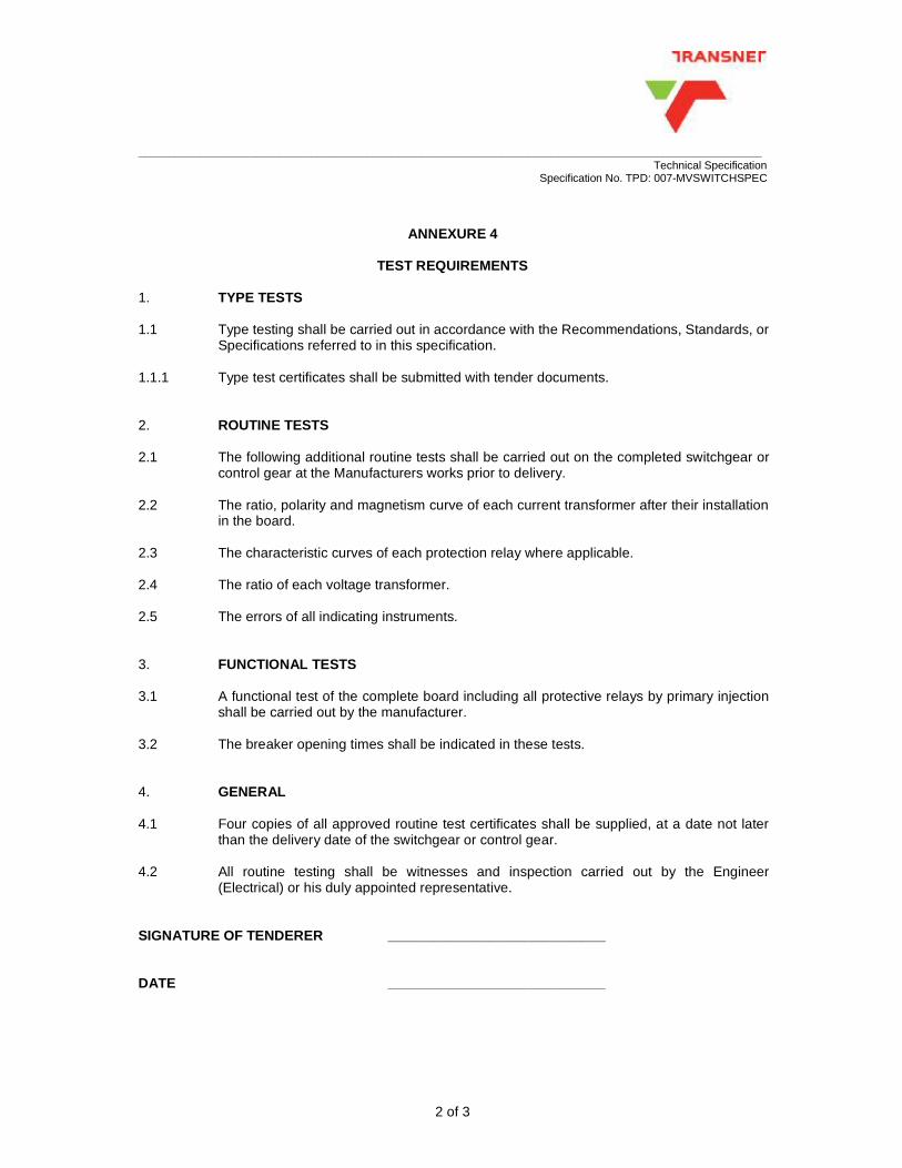
_____________________________________________________________________________________________________
Technical Specification Specification No. TPD: 007-MVSWITCHSPEC
2 of 3
ANNEXURE 4
TEST REQUIREMENTS
1. TYPE TESTS 1.1 Type testing shall be carried out in accordance with the Recommendations, Standards, or
Specifications referred to in this specification. 1.1.1 Type test certificates shall be submitted with tender documents. 2. ROUTINE TESTS 2.1 The following additional routine tests shall be carried out on the completed switchgear or
control gear at the Manufacturers works prior to delivery. 2.2 The ratio, polarity and magnetism curve of each current transformer after their installation
in the board. 2.3 The characteristic curves of each protection relay where applicable. 2.4 The ratio of each voltage transformer. 2.5 The errors of all indicating instruments. 3. FUNCTIONAL TESTS 3.1 A functional test of the complete board including all protective relays by primary injection
shall be carried out by the manufacturer. 3.2 The breaker opening times shall be indicated in these tests. 4. GENERAL 4.1 Four copies of all approved routine test certificates shall be supplied, at a date not later
than the delivery date of the switchgear or control gear. 4.2 All routine testing shall be witnesses and inspection carried out by the Engineer
(Electrical) or his duly appointed representative. SIGNATURE OF TENDERER ____________________________ DATE ____________________________

_____________________________________________________________________________________________________
Technical Specification Specification No. TPD: 007-MVSWITCHSPEC
3 of 3
ANNEXURE 5
STATEMENT OF COMPLIANCE (TO BE COMPLETED BY TENDERER)
This tender complies with specification TPD: 007-MVSWITCHSPEC in all respects. SIGNATURE : _________________________ DATE : ______________ This tender complies generally with specification TPD: 007-MVSWITCHSPEC but differs from it on the following points: ________________________________________________________________ ________________________________________________________________ ________________________________________________________________ ________________________________________________________________ ________________________________________________________________ ________________________________________________________________ ________________________________________________________________ ________________________________________________________________ ________________________________________________________________ ________________________________________________________________ ________________________________________________________________ SIGNATURE : _________________________ DATE : _________________ Transnet Group Capital Kwazulu Natal
____________________________________________________________________________________________________
Technical Specification Specification No. TPD: 001-EL&P SPEC
i
SPECIFICATION FOR ELECTRICAL INSTALLATIONS TO BUILDINGS OTHER THAN DWELLINGS HOUSES
REVISIONS REV DATE APPROVED 01 April 2016 S.Sewdayal

____________________________________________________________________________________________________
Technical Specification Specification No. TPD: 001-EL&P SPEC
ii
INDEX SECTION CONTENTS 1. SCOPE 2. REFERENCES 3. SERVICE CONDITIONS 4. ELECTRICAL INSTALLATION 5. DISTRIBUTION BOARDS 6. ISOLATED SWITCHES 7. MOULDED-CASE CIRCUIT-BREAKERS 8. EARTH LEAKAGE PROTECTION UNITS 9. FUSE SWITCHES 12. HIGH RUPTURING CAPACITY FUSE LINKS 13. CONTACTORS 14. LUMINAIRES FOR INCANDESCENT LAMPS 15. LUMINAIRES FOR FLUORESCENT LAMPS 16. INTERIOR LUMINAIRES FOR HIGH INTENSITY DISCHARGE LAMPS 17. ELECTRIC AIR HEATERS 18. ROOM THERMOSTATS 19. LIGHT SWITCHES 20. LIGHT SENSITIVE CONTROL UNITS 21. SOCKET OUTLETS 22. TRANSFORMERS 230 V/32V 23. ISOLATING AND SAFETY ISOLATING TRANSFORMERS 24. POWER POINTS 25. CONDUIT AND ASSOCIATED FITTINGS 26. CABLES AND GLANDS 27. BUSBAR TRUNKING 28. CABLE TRAYS 29. EARTHING AND BONDING 30. PAINTING 31. TESTS Annexure 1: Statement of Compliance

____________________________________________________________________________________________________
Technical Specification Specification No. TPD: 001-EL&P SPEC
1
1.0 SCOPE 1.1 This specification covers the requirements with respect to the electrical installation, including the
supply of all material and labour necessary to complete the EL&P installation for buildings. 1.2 This specification also applies to electrical alterations and additions carried out to existing
installations. 2.0 REFERENCES 2.1 The following publications (latest edition) are referred to herein: CODES OF PRACTICE SANS 10313: Code of Practice for Protection of Buildings against Lightning. SANS 10086-1 : The Installation and Maintenance of Electrical Equipment used in
Explosive Atmospheres. SANS 10108: The Classification of Hazardous Locations and the Selection of
Electrical Apparatus for use in such Locations. SANS 10114-1 : Interior lighting Part 1: Artificial lighting of interiors SANS 10313 Protection against lightning - Physical damage to structures and life
hazard SANS 10142-1: The Wiring of Premises Part 1: Low-voltage installations SPECIFICATIONS
SANS 121: Hot-dip (galvanized) zinc coatings (other than on continuously zinc coated sheet and wire)
SANS 156: Moulded-case circuit-breakers SANS 160: Electric Room Heaters. SANS 164-1: Plug and socket-outlet systems for household and similar purposes for
use in South Africa Part 1: Conventional system, 16 A 250 V a.c. SANS 172: Low-voltage fuses
SANS 181: Thermostats for electric storage water heaters SANS 475: Interior luminaires for fluorescent lamps SANS 767-1: Earth leakage protection units Part 1: Fixed earth leakage protection
circuit-breakers SANS 950: Unplasticized polyvinyl chloride rigid conduit and fittings for use in
electrical installations SANS 1041: Tubular fluorescent lamps for general service SANS 1065: Screwed metal conduit and fittings for electrical wiring SANS 1085: Wall outlet boxes for the enclosure of electrical accessories
SANS 1091: National colour standards for paint SANS 1274: Coatings applied by the powder-coating process SANS 1473-2: Metal-enclosed busbar trunking systems
SANS 1574 Polyvinyl chloride (PVC)-insulated electric cables and flexible cords SANS 1663: Wall and appliance switches. SANS 1973: Low-voltage switchgear and control gear assemblies
____________________________________________________________________________________________________
Technical Specification Specification No. TPD: 001-EL&P SPEC
2
SANS 10064: The preparation of steel surfaces for coating SANS 60947-3: Low-voltage air-break switches, air-break disconnectors, air-break
switch-disconnectors, and fuse-combination units SANS 60947-4: Low-voltage switchgear and control gear Part 4- : Contactors and
motor-starters SANS 60079-1: Flameproof enclosures for electrical apparatus Part 1: International
requirements SANS 61558-2-4: Isolating transformers and safety isolating transformers
3.0 SERVICE CONDITIONS 3.1 The cable shall be designed and rated for continuous operation under the following conditions
:- 3.1.1 Ambient/Environment Conditions :
3.1.1.1 Altitude : Sea level. 3.1.1.2 Ambient temperature : -5° C to +45° C (daily average +35° C). 3.1.1.3 Relative humidity : As high as 96% . 3.1.1.4 Lightning conditions : Severe, with a maximum lightning ground flash density 11 flashes per km2 per annum. 3.1.1.5 Exposure conditions : Salt laden, industrial atmosphere as well as hazardous
gases and dust atmosphere. 3.1.1.6 Electrolytic corrosion conditions prevail in all the areas owing to the proximity of direct current
traction system and cathodic protection schemes. 4.0 ELECTRICAL INSTALLATION 4.1 The contractor shall carry out the installation in accordance with SANS 10142-1: Code of
Practice for the Wiring of Premises and the requirements of this specification. 4.2 Where the local supply authority requirements differ from those specified herein Transnet Group
Capital Electrical Engineer shall be approached for a decision. 4.3 All equipment and material shall comply with the relevant National or International standard
specification. Where equipment does not comply it shall be submitted with the Transnet Group Capital Electrical Engineer for approval.
4.4 The system of supply will be three phase, 4 wire or single phase 2 wire 50 Hz. alternating current
with earthed neutral at a nominal voltage of 400/230 volts. The voltage may vary within the range of ±5 % of the nominal voltage.
4.5 Wiring

____________________________________________________________________________________________________
Technical Specification Specification No. TPD: 001-EL&P SPEC
3
4.5.1 All wiring shall be carried out in cable trunking and/or conduit. Only the loop in system of wiring shall be accepted.
4.5.2 Joints in wiring, nor the cutting away of strands to facilitate connections shall be
permitted.
4.5.3 Single core cable smaller than 1,5 mm shall not be used. PVC cables shall not be connected directly to the lampholders for incandescent lamps. Conductors shall terminate in an approved connector in the conduit box directly behind the luminaire, and connection to the lampholder made by means of adequately rated silicone heat resistant wire.
4.5.4 Colour identification of conductors shall be used.
4.5.5 Flameproof equipment shall comply with SANS 60079-1 or BS 229 for installation in
hazardous areas, as defined in SANS 10108.
4.5.6 Equipment in hazardous areas shall be installed in accordance with SANS 10086-1. 4.6 The provision and installation of the supply cable to the building, the termination and the
connection thereof to the distribution board main incoming isolating shall be the responsibility of the Contractor, as directed by the Engineer.
4.7 The Contractor shall be responsible for the provision and connection of power supplies to electric
urns, stoves, geysers, fry-tops, fans etc. provided by others; unless otherwise stated in the Schedule of Requirements.
4.8 The Contractor shall also provide power supplies to air-conditioning equipment. The connection
to air-conditioning equipment will be undertaken by others. 4.9 Cables shall be adequately supported to prevent strain on the terminals. 4.10 Drilling or welding of steelwork for the mounting of electrical equipment will not be permitted
unless approved by Transnet's Engineer on site. Equipment shall be fixed to the steelwork by means of approved, purpose made clamp/brackets.
4.11 Lightning protection shall be in accordance with the requirements of the local supply authority
and SANS 10313: Code of Practice for Protection against lightning - Physical damage to structures and life hazard
5.0 DISTRIBUTION BOARDS 5.1 Architrave type for flush mounting, and surface type for mounting on indoor walls shall comply
with SANS 10142-1.
5.1.1 These distribution boards shall be supplied with a cover plate or open window door and be suitably painted and finished to harmonise with wall finish.
5.1.2 All switches and associated equipment shall be fully enclosed within the distribution

____________________________________________________________________________________________________
Technical Specification Specification No. TPD: 001-EL&P SPEC
4
board with only the operating handles protruding through the cover plate or door. 5.2 Cubicle type shall comply with IEC publication 439. 5.3 Distribution boards for outdoor use shall be weatherproof and corrosion resistant. 5.4 A substantial earthing terminal shall be firmly attached to the steel work of the distribution board
and connected to the earthing bar. 5.5 Entries suitable for all incoming and outgoing cables shall be provided. Glands for bottom entry
cables shall not be less than 600mm above floor level. 5.6 Space for mounting of 20% additional control units shall be allowed on all distribution boards. In
addition, 20% spare conduits (20mm diameter) shall be provided between flush distribution boards and the ceiling/roof space in pitched roof buildings (minimum 2 conduits).
5.7 All circuits shall be clearly labelled. Labels shall be of the fabricated type and permanently
secured. Embossed tape is not acceptable. 5.8 When called for labelling of moulded case circuit breakers shall be labelled by means of
numerals. A legend inserted behind a clear plastic window on the inside of the door shall be provided to detail the various circuits.
6.0 ISOLATING SWITCHES 6.1 Isolating switches for machines shall be lockable in the open position. 6.2 Isolating switches shall comply with SANS 60947-3. 7.0 MOULDED CASE CIRCUIT BREAKERS 7.1 Moulded case circuit breakers shall: -
7.1.1 Comply with SANS 156. 7.1.2 Have a breaking capacity as specified. 7.1.3 Be of the fixed pattern, non-adjustable type. 7.1.4 Be suitable for clip-on tray mounting.
8.0 EARTH LEAKAGE PROTECTION UNITS 8.1 Earth leakage protection units shall: -
8.1.1 Be the integral moulded case type and comply with SANS 767-1. 8.1.2 Have a sensitivity of 30 mA.

____________________________________________________________________________________________________
Technical Specification Specification No. TPD: 001-EL&P SPEC
5
8.1.3 Be similar in design to moulded case circuit breakers and suitable for clip-on tray mounting. 8.1.4 Have a breaking capacity and current rating as specified.
9.0 FUSE SWITCHES 9.1 Fuse switches shall :
9.1.1 Comply with SANS 60947-3 9.1.2 Be of the double break, horizontal drawout, air insulated type, suitable for flush mounting. 11.1.3 Be of the quick break, dustproof type.
12.0 HIGH RUPTURING CAPACITY FUSE LINKS 12.1 High rupturing capacity fuse links shall :
12.1.1 Comply with SANS 172 12.1.2 Be of the cartridge type with a breaking capacity not less than that shown in the
Category of Duty AC 50 table 2 of SANS 172. 12.1.3 Have a class Q1 fusing factor 12.1.4 A spare set of fuse links for each of the different ratings shall be provided and
accommodated in the distribution board. 13.0 CONTACTORS 13.1 Contactors shall comply with SANS 60947-4. 14.0 LUMINAIRES FOR INCANDESCENT LAMPS 14.1 Luminaires shall be suitable for accommodating energy saving lamps. 14.2 The insulation of internal wiring shall be heat resistant. 14.3 Bulkhead luminaires shall comply with CKS 199. 14.4 Bowl type luminaires shall have porcelain or acrylic galleries with white opal, high impact acrylic
screw-in type bowls. 14.5 Well glass luminaires shall consist of a body of non-corrosive material with a top entry for a
20mm conduit, have a clear glass cover and be completely weatherproof. 15.0 LUMINAIRES FOR FLUORESCENT LAMPS

____________________________________________________________________________________________________
Technical Specification Specification No. TPD: 001-EL&P SPEC
6
15.1 Luminaires for fluorescent lamps shall comply with SANS 475. 15.2 Lampholders shall be of the telescopic type. 15.3 The luminaires shall be suitable for 1,2m or 1,5m "rapid start" lamps to SANS 1041, class B,
group 2, with rated colour 3. (warm white). 15.4 Anti-corrosive luminaires shall have a body channel constructed of fibre-glass or non-corrosive
material with a moulded acrylic enclosing diffuser. 15.5 A gasket shall be provided between the body channel and the diffuser to ensure a reliable seal. 15.6 The enclosing diffuser shall latch to the body channel with captive-type non-corrosive latches. 15.7 It is essential that full descriptions and photometric data of the luminaires and lamps offered,
accompany tenders. This information shall include description and drawings of the various items of equipment as well as full photometric data issued by the South African Bureau of Standards.
16.0 INTERIOR LUMINAIRES FOR HIGH INTENSITY DISCHARGE LAMPS 16.1 Interior luminaires for high intensity discharge lamps shall comply with SANS 475 and be suitable
for use in an ambient temperature of 40oC. 16.2 Suitable provision shall be made on the ballast housing for eyes or lugs, for the attachment of
safety chains. 16.3 The electronic ignition device for high pressure of sodium and metal halide lamps shall be of the
three wire type operating on the superposed pulse principle. The circuitry shall be such that at starting, or on failure of a lamp, high voltage pulses will be confined to the high voltage lead between the igniter and centre contact of the lampholder. Igniters incorporating a switching element are not acceptable.
16.4 A fully electronic ignition circuit shall be utilized to trigger the pulse transformer. 16.5 The natural frequency of the electronic ignition circuit shall be in the order of 100kHz. 16.6 The lamp ignition voltage shall remain constant within a mains voltage variation of between 200
and 250 volts. 16.7 Tenderers shall guarantee that pulsing of the igniter on a failed lamp will not have a detrimental
effect on the life and efficient operation of the control gear, igniter, lampholders and circuit wiring. 16.8 It is essential that full descriptions and photometric data of the luminaires and lamps offered,
accompany tenders. This information shall include description and drawings of the various items of equipment, as well as full photometric data issued by the South African Bureau of Standards.
17.0 ELECTRIC AIR HEATERS
____________________________________________________________________________________________________
Technical Specification Specification No. TPD: 001-EL&P SPEC
7
17.1 Electric air heaters shall comply with SANS 160. 17.2 Tubular heaters shall be rated at 260 watt per metre length of tube and have an enclosed entry
box containing terminals for incoming line, neutral and earth connections with a suitable entry for a flexible conduit connector.
17.2.1 Tubular heaters shall be mounted with the bottom 200mm above floor level
17.3 Convector Heaters shall:
17.3.1 Be of the natural convection type, of good appearance and suitable for flush or surface mounting. 17.3.2 Have incorporated a manually adjustable control switch, automatic controlling thermostat
and indicating neon pilot lighting showing when the heater is on. 17.3.3 Have a mounting box or housing suitable for a 20mm electrical conduit entry. 17.3.4 Be installed with the bottom of the mounting box/housing 200mm above floor level.
17.4 Fan Heaters shall :
17.4.1 Be of the wall mounted type with air flow directional adjustment and locking facilities. 17.4.2 Have a totally enclosed type fan motor fully protected from damp and dust and fitted with
self aligning noiseless bearings. 17.4.3 Have a separate manually adjustable control unit incorporating an automatic controlling
thermostat. The control unit shall be housed in a adequately ventilated sheet steelcase. Means of protecting and isolating the heater, shall be provided. The control unit circuit shall be arranged such that during summer months the heater can be switched off and the fan used alone for ventilation.
18.0 ROOM THERMOSTATS 18.1 Room thermostats shall comply with BS 3955 Part 2, section 2F, and be to category A. 18.2 An over-riding switch shall be mounted adjacent to the thermostat for manual control. 19.0 LIGHT SWITCHES 19.1 Light switches shall comply with SANS 1663 and be of the rocker type. 19.2 They shall be mounted 1 500 mm above floor level and where possible 200 mm from door
frames. 20.0 LIGHT SENSITIVE CONTROL UNITS

____________________________________________________________________________________________________
Technical Specification Specification No. TPD: 001-EL&P SPEC
8
20.1 The complete unit shall be of the solid state type and housed in a sealed weatherproof enclosure suitable for mounting in any position.
20.2 The light sensitive cell shall operate in a manner to give an area of detection not less than a
hemisphere. 20.3 The unit shall not operate due to light fluctuations of duration less than 5 minutes. They shall
incorporate main contacts rated at least to 10 amps and be mounted at a height of not less than 2 400 mm.
20.4 An over-riding switch shall be provided. 21.0 SOCKET OUTLETS 21.1 All 220 volt, 16 amp socket outlets shall comply with SANS 164-1 and be of the 3 round pin
shuttered type. 21.2 All 32V, 5A socket outlets for lead lights shall be of the industrial two pin, weatherproof type with
a screw cover attached to the socket outlet by a short length of chain.
21.2.1 They shall be mounted on columns/walls 1 500mm above floor level or in recesses provided in inspection pits.
21.3 Welding socket outlets shall be in accordance with IEC publication 309 and be rated for 63A
(unless other rating is indicated on the drawing) and be of the 5 pin, 6 h configuration type.
21.3.1 Welding plugs shall be supplied complete with matching male plugs and be mounted 1 500mm above floor level.
21.3.2 The welding plug circuit shall be protected by an earth leakage device that shall be mounted either in the welding plug housing or in the distribution board feeding the welding plug.
22.0 TRANSFORMERS 220V/32V 22.1 The transformers for 32V socket outlets shall be in accordance with SANS 61558-2-4 and be
designed for 220V to 250V primary power supply and have an output voltage of 32V. 23.0 ISOLATING AND SAFETY ISOLATING TRANSFORMERS 23.1 Isolating and safety isolating transformers shall comply with SANS 61558-2-4. 24.0 POWER POINTS 24.1 Power points for hot water cylinders shall be equipped with a 2 or 4 pole isolating switch adjacent
to the cylinder except for hot water cylinders mounted below sinks. 24.2 Where contactors are necessary for the operation of hot water cylinders, these shall be installed
adjacent to the appliance where practicable and in a suitable enclosure.

____________________________________________________________________________________________________
Technical Specification Specification No. TPD: 001-EL&P SPEC
9
24.3 Power points for tubular heaters shall be equipped with a flush mounted 100mm x 100mm conduit box, blanked off with a cover plate accommodating a 15A flush mounted switch. Connection to the heater shall be by means of a PVC covered flexible conduit. The flexible conduit shall have sufficient slack to avoid strain but shall not touch the floor.
24.4 Power points for fan heaters shall be equipped with two recessed interconnected conduit boxes,
one for connection to the heater and the other for connection to the control unit 1 500mm above floor level.
24.5 Power points for stoves, fry tops and boiling tables shall be equipped with a 2 or 3 pole isolating
switch for the appliance shall be 1 500mm above floor level. The outlet for connection to the appliance shall be 500mm above floor level.
24.6 Power points for air-conditioning units shall terminate in a 100mm x 100mm conduit box
mounted adjacent to the unit and equipped with a 2 pole isolating switch. 24.7 Power points for extractor fan units shall terminate in a 100mm x 100mm conduit box mounted
adjacent to the unit. 24.8 Where a common thermostat is specified for controlling a number of fans, power points shall be
so arranged to allow for circuit wiring between the fans and thermostat. 24.9 Power points for smoke detection and CO2 equipment shall terminate in a 100mm x 100mm
conduit box equipped with a 30A, 2 pole isolating switch, lockable in the "on" position, mounted 1500mm above floor level, with connecting facilities to the equipment.
24.10 Power points for air conditioning units shall terminate in a 100mm x 100mm conduit box
mounted adjacent to the unit and equipped with a 2 pole isolating switch, with connecting facilities for the unit.
24.11 Power points for machinery shall terminate in a connection box suitable for mounting a 2 or 3
pole isolating switch, with connecting facilities to the machine. 24.12 Power points for lighting shall terminate in a circular conduit box fitted with an unswitched 5A, 3
pin socket outlet. 25.0 CONDUIT AND ASSOCIATED FITTINGS 25.1 Screwed metal conduit shall comply with SANS 1065. 25.2 Non-metallic conduit and fittings shall comply with SANS 950. Non- metallic conduit shall not be
cast into concrete. 25.3 Wall outlet boxes shall comply with SANS 1085. 25.4 In areas within 50 km of the coast only galvanised or non- metallic conduit shall be used. Where
conduit is exposed to the weather elements only galvanised conduit shall be used or UV T routed P.V.C. pipe.

____________________________________________________________________________________________________
Technical Specification Specification No. TPD: 001-EL&P SPEC
10
25.5 Threads of metallic conduit and associated fittings shall be effectively protected against rust by non-corrosive paint where they are exposed to moisture or weather elements.
25.6 Wall outlet boxes shall be positioned with the major dimension vertical and not more than 15 mm
below the finished wall surface. Cover plates shall fit plumb and flush with wall surfaces. 25.7 Conduits are to be concealed and chased into plastered brick walls or cast into concrete work as
building work proceeds. Where conduit cannot be concealed these shall be installed neatly on the surface as approved by the Engineer.
25.8 Conduits are to be concealed and chased into plastered brickwalls or cast into concrete work as
the building work proceeds. 25.9 Chasing of finished walls or concrete work will not be allowed. Under no circumstances will
chases be permitted through structural members of the building. 25.10 Chasing of face brick walls will not be permitted. Conduits and outlet boxes shall be built into
walls. 26.0 CABLES AND GLANDS 26.1 Polyvinyl-chloride cables shall comply with SANS 1574. Armoured cables shall be of the earth
continuity conductor type. 26.2 Cable glands shall be of the compression type, (brass or bronze) and be suitable for termination
of earth continuity conductor type cables. Glands shall be supplied with neoprene shroud. 27.0 BUSBAR TRUNKING 27.1 Busbar trunking shall comply with SANS 1473-2. 28.0 CABLE TRAYS 28.1 Cable trays shall be protected against corrosion and be adequately supported so that when fully
loaded the deflection does not exceed 10mm. They shall be wide enough to accommodate the power cables in a single layer.
29.0 EARTHING AND BONDING 29.1 The complete electrical installation shall be earthed in accordance with SANS 10142-1: Code of
Practice for the Wiring of Premises. 29.2 Earth electrodes shall consist of an exterior copper layer molecularly bonded to a high strength
steel core. The copper shall have a minimum thickness of 0.25mm. 29.3 Only approved non-corrosive substances may be used to reduce earth resistivity. The earth
resistance as measured with a earth resistance tester shall not exceed 5 ohm. 29.4 Copper tape used for bonding and earthing of waste pipes shall have a minimum cross sectional
____________________________________________________________________________________________________
Technical Specification Specification No. TPD: 001-EL&P SPEC
11
area of 12mm², and when run along walls shall be fixed by means of non-ferrous screws in plastic plugs at intervals of 300 maximum.
30.0 PAINTING 30.1 All surfaces of distribution boards shall be light orange to SANS 1091 colour No. B26 unless
otherwise stated in the Schedule of Requirements attached to this specification. 30.2 All surfaces shall be cleaned according to the appropriate method described in SANS 10064 for
the particular surface to be cleaned, the contamination to be removed and the primer to be applied.
30.3 Components that will be powder coated shall be cleaned and prepared in accordance with the
requirements of SANS 10064. Powder coating shall comply with the requirements of SANS 1274; Coatings applied by the powder-coating process.
30.4 All specified coatings shall be applied according to the relevant specification and the
manufacturer’s instructions shall be followed. Coatings shall not be applied in conditions which may be detrimental to the effectiveness of the coating, or the appearance of the painted surface.
30.5 When examined visually the finished product shall have a uniform appearance as far as gloss is
concerned and shall show no sign of damage. Damaged areas shall be repaired coat for coat to obtain the desired finish.
31.0 TESTS 31.1 Insulation, continuity and earthing tests in accordance with SANS 10142-1 shall be carried out to
the satisfaction and in the presence of the Engineer or authorised deputy on completion of the work.
31.2 An installation Certificate of Compliance for the electrical installation issued by an accredited
person as required by the Occupational Health and Safety Act,1993 (Act 85 of 1993) shall be provided.
31.3 The Contractor shall provide the necessary approved instruments. 31.4 Transnet Group Capital reserves the right to use its own instruments should it be considered
necessary. WITNESSES 1. …………………………….. …………………………… TENDERER 2. ……………………………. …………………………….
DATE Transnet Group Capital Engineering

____________________________________________________________________________________________________
Technical Specification Specification No. TPD: 001-EL&P SPEC
12
ANNEXURE 1
STATEMENT OF COMPLIANCE (TO BE COMPLETED BY TENDERER)
This tender complies with specification TPD: 001-EL&P SPEC in all respects. SIGNATURE : _________________________ DATE : ______________ This tender complies generally with specification TPD: 001-EL&P SPEC, but differs from it on the following points. ________________________________________________________________ ________________________________________________________________ ________________________________________________________________ ________________________________________________________________ ________________________________________________________________ ________________________________________________________________ SIGNATURE : _________________________ DATE : _________________ Transnet Group Capital

____________________________________________________________________________________________________________
Technical Specification Specification No. TPD: 002-DBSPEC
- 1 -
SPECIFICATION FOR LOW VOLTAGE DISTRIBUTION BOARDS
This specification covers Transnet Group Capital requirements for low
voltage distribution boards
REVISIONS
REV DATE APPROVED
00 MARCH 2012 S.Sewdayal
____________________________________________________________________________________________________________
Technical Specification Specification No. TPD: 002-DBSPEC
- 2 -
INDEX SECTION CONTENTS
1 SCOPE
2 REFERENCES
3 SERVICE CONDITIONS
4 DRAWINGS AND INSTRUCTION MANUALS
5 STANDARD OF WORK, EQUIPMENT & MATERIALS
6 DISTRIBUTION BOARDS
7 ARC DETECTION SYSTEM
8 FUSE SWITCHES
9 FUSE LINKS
10. AIR CIRCUIT BREAKERS (ACB)
11. MOULDED CASE CIRCUIT BREAKERS
12. MINIATURE CIRCUIT BREAKERS
13. CONTACTORS
14. LIGHTNING AND SURGE PROTECTION
15. ANTI-CONDENSATION HEATERS
16. INDICATING INSTRUMENTS
17. CURRENT TRANSFORMERS
18. MECHANICAL CABLE GLANDS
19. LIGHT SENSITIVE CONTROL UNIT
20. EARTHING
21. CABLING AND WIRING
22. LABELS
23. PAINTING
24. ADDITIONS AND MODIFICATIONS TO EXISTING DISTRIBUTION
BOARDS
25. INSPECTION
26. TESTS
27. GUARANTEE
28. SPARES
ANNEXURE NO. 1 Statement of Compliance

____________________________________________________________________________________________________________
Technical Specification Specification No. TPD: 002-DBSPEC
- 3 -
1. SCOPE 1.1. This specification covers Transnet Group Capital requirements regarding the design, supply,
manufacture, population, works testing, delivery to site, site erection, site testing and commissioning of low voltage Distribution Switchboards consisting of fuse switches incorporating high rupturing capacity cartridge fuse links, air circuit breakers, moulded case circuit breakers and auxiliary equipment. The tenderer is required to familiarise themselves with all applicable Standards and Codes of Practice listed herein, and to ensure compliance in the execution of any work in terms of this document.
2. REFERENCES 2.1. The following publications (latest edition) are referred to herein:-
2.1.1. SOUTH AFRICAN BUREAU OF STANDARDS
Codes of Practice SANS 064 The preparation of steel surfaces for coating SANS 10111 Engineering Drawings. SANS 10142 Wiring of premises Part 1: Low voltage installations SANS 10313 Protection against lightning - Physical damage to structures and life hazard
Specifications SANS 60947 Low-voltage switchgear and control gear SANS 156 Moulded-case circuit breakers SANS 60269 Low-voltage fuses SANS 1091 National colour standards for paint SANS 1195 Busbars SANS 1274 Coating applied by the powder coating process SANS 1973-1 Low-voltage switchgear and control gear assemblies Part 1: Type-tested
assemblies with stated deviations and a rated short-circuit withstand strength above 10 kA
SANS 1973-3 Low-voltage switchgear and control gear assemblies Part 3: Safety of assemblies with a rated prospective short-circuit current of up to and including 10 kA
SANS 60529 Degrees of protection provided by enclosures (IP Code) SANS 1507 Electric cables with extruded solid dielectric insulation for fixed installations
(300/500 V to 1 900/3 300 V) SABS ISO 9000 Quality management systems -- Fundamentals and vocabulary SANS 1019 Standard voltages, currents and insulation levels for electricity supply SANS 170 Fasteners International Electrotechnical Commission BS 3938 Current Transformers IEC 61508 Functional Safety of Electrical/Electronic/Programmable Electronic Safety-related
Systems. IEC 60051 Direct acting indicating analogue electrical measuring instruments and their
accessories 3. SERVICE CONDITIONS
3.1 The equipment shall be designed and rated for continuous operation under the following conditions:-

____________________________________________________________________________________________________________
Technical Specification Specification No. TPD: 002-DBSPEC
- 4 -
3.1.1 Ambient/Environment Conditions:
3.1.1.1 Ambient temperature- -5° C to +45° C (daily average +35° C).
3.1.1.2 Relative humidity- As high as 95%
3.1.1.3 Lightning conditions- Severe, with a maximum lightning ground flash density of eleven (11) flashes per km² per annum. 3.1.1.4 Atmosphere- Salt laden and corrosive industrial atmosphere
3.1.2 Electrical Conditions:
3.1.2.1 The system of supply shall be three phase, 4 wire, 50 Hz alternating current with solidly
earthed neutral at a nominal voltage of 400 / 231 Volts. 3.1.2.2 The voltage may vary within the range of 95% to 105% of the nominal and all equipment
installed shall be suitably rated. 3.1.2.3 All equipment shall be adequately rated for prospective fault level ratings.
4 DRAWINGS AND INSTRUCTION MANUALS
4.1 All drawings shall be in accordance with SANS 10111 – Engineering Drawings.
4.2 The successful tenderer shall supply the following instruction manuals, all of which shall be
included in the tender price and be to the satisfaction of Transnet Group Capital.
4.2.1 THREE (3) sets of detailed drawings and instruction manuals, with illustrations where necessary and 2 sets of prints of the "As Built" General Arrangement drawings and the schematic and wiring diagrams to facilitate erection and adjustment of the switchgear.
4.2.2 A full set of electronic media including all information requested above. 4.2.3 These instruction manuals and drawings shall be supplied as soon as possible after placing of the
order, but before delivery of the equipment. 5. STANDARD OF WORK, EQUIPMENT & MATERIALS
5.1. The distribution board shall conform to the requirements of the latest edition and amendments of
SANS 10142-1 Code of Practice for the Wiring of Premises Part 1: Low voltage installations and any additional requirements thereto, described in this specification.
5.2. All equipment and material used shall be of high quality and the work shall be of a high standard of workmanship carried out by qualified staff under proper supervision by experienced and competent officers.
5.3. If any special tools are required for the maintenance of the switchboard, the tenderer shall supply three (3) sets at delivery of the switchboard to site.

____________________________________________________________________________________________________________
Technical Specification Specification No. TPD: 002-DBSPEC
- 5 -
6. DISTRIBUTION BOARDS
6.1. The distribution board shall comply with SANS 60439-1
6.1.1. The form of separation will be specified in the project specific documentation.
6.2. The degree of protection shall be to IEC Publication 144/EN60529 and shall conform to the following:
• Inside Substations and MCC Rooms: IP42 • Other Locations: IP65
6.3. The distribution board shall consist of either a framework of substantial steel sections covered with
heavy gauge steel plates or of folded sheet steel sections, forming a robust construction.
6.4. Particular attention shall be given to the ventilation of panels, to eliminate build-up of excessive heat caused by the sun or internal heat generation. All necessary precautions shall be taken to ensure that the temperature of the air in any portion of the assembly does not rise more than 15°C above ambient air temperature
6.5. Every board shall be fitted with a suitable gasket incorporated into the frame to ensure that the
arrangement is in accordance with the required degree of protection. Sealing strips and gaskets shall be made of durable, non-hardening rubber, neoprene or other synthetic material, suitably fixed to the door or frame to ensure that the seal does not become dislodged during normal operation.
6.6. Where possible the lock and door catch shall comprise of a combination unit. Door latching and
delatching operations shall be smooth and quick, whilst ensuring proper compression of the sealing gaskets. Repeated opening and closing of the hinged doors and operations of the door locks and catches shall not cause chipping or scratching of the painted surfaces or any other blemishes to the finished boards
6.7. Lifting lugs shall be provided for floor standing enclosures and as needed for wall mounted
enclosures.
6.8. The board shall have a separate latches hinged or removable front cover secured to the board by means of suitable captive type screws or bolts. When the cover is removed/ opened, easy access to that compartments components and wiring shall be possible.
6.8.1. The control units shall be mounted flush with the front cover so that only the operating handles
protrude.
6.8.2. Large removable panels shall be supplied with handles for easy handling.
6.8.3. No possibility should exist for panels to come into contact with live parts.
6.9. Due care shall be taken to ensure that the live side of the MAIN SWITCH is suitably protected so that no live conductors are exposed when the panel door is opened or the panel cover is removed.
6.10. The board shall be equipped with a set of 3 phase and neutral copper busbars. The 3 phase
busbars shall be continuously rated for the full load of the incoming supply switch. The neutral shall be 100% of the phase busbars. Earth bar shall be rated to fault current and touch voltage.

____________________________________________________________________________________________________________
Technical Specification Specification No. TPD: 002-DBSPEC
- 6 -
6.11. All busbars shall be designed, manufactured, marked and tested in accordance with SANS1195.
6.12. Busbar rating shall be 2A/mm2 up to 630A and 1.6A/mm2 thereafter. 6.13. Busbar temperature shall not exceed a 400C temperature rise.
6.14. The busbars shall be adequately braced and supported. The busbars shall be covered with a
sufficient number of layers of high quality insulating tape or heat shrinkable sleeving and finished in standard colours.
6.15. Where busbar joints and terminations have not been covered, a kit shall be provided for covering
during installation.
6.16. Alternatively, busbars shall be suitable enclosed in a busbar chamber or behind a protective barrier for protection against inadvertent contact with "live" busbars with access panels removed.
6.17. Inter-connectors between the busbars and control units shall be by means of fully insulated,
adequately rated conductors firmly bolted to the busbar and secured to the appropriate terminals of the control units using crimped-on terminal lugs. Solid flat conductors shall be used if the rating exceeds 400 A or if the fault current exceeds 25kA rating. No conductor of less than 16mm2 shall be used between busbars and control units. All conductors shall be suitably rated for the fault level.
6.18. The other terminals of the incoming and outgoing panel units shall be connected by means of
conductors conforming to clause 6.17, i.e. they shall be robust, insulated, easily accessible terminals, of adequate size, conveniently located in the distribution board near the incoming and outgoing cable entries but with sufficient clearance and space to enable the incoming and outgoing cables to be connected to their corresponding terminals without difficulty or strain.
6.19. All the outgoing connections of MCCB’S greater than 400A 3 phase shall be done by means of
copper bus bars, securely clamped using approved busbar clamping insulators, fixed to a robust metal section of adequate size, conveniently located in the rear of the distribution board to enable the incoming cables to be terminated in the back of the distribution board cubical behind each respective MCCB. This is to allow for the easy termination of the larger incoming cables, with sufficient clearance and space to enable the outgoing cables to be connected to their corresponding busbar terminals without difficulty or strain to the MCCB’s. Each MCCB up to 250A shall be fitted with extended terminal complete with phase barriers as supplied by circuit breaker supplier.
6.20. Outgoing cable tails that connect to the busbars in clause 6.19 shall have securing places to
enable the cable to be secured with nylon type cable fasteners in an approved manner.
6.21. The busbars that protrude into the back compartment of the distribution board shall be covered with a perspex type barrier and shall have danger signs on each section.
6.22. Removable gland plates shall be provided. These gland plates shall be of adequate thickness or
construction for the cables to be terminated without distortion of the gland plate, and shall not be less than 2mm mild steel (zinc passivated). Gland Plates shall not be mounted less than 300mm above ground floor level, alternatively a base frame of suitable depth may be provided.
6.23. Distribution board cases shall be of such dimensions that adequate space is available for
manoeuvring and connecting the incoming and outgoing cables.

____________________________________________________________________________________________________________
Technical Specification Specification No. TPD: 002-DBSPEC
- 7 -
6.24. All cable entries shall be from the bottom of the distribution board unless stated otherwise.
6.25. Glands shall not be less that 300mm above floor level. Unless otherwise stated. 6.26. The terminals of all incoming and outgoing cables shall be firmly connected to the terminals on
the lugs or ferrules, unless they are of a type that will grip the cable without splaying the strands of the conductor.
6.27. A substantial earthing terminal shall be firmly attached to the metal work of the distribution board and connected to an earth bar of cross sectional area not less than 50% of the phase bars, running the full length of the distribution board to which all earthing conductors of the incoming and outgoing circuits shall be firmly connected.
6.28. A removable link shall be provided in the Neutral busbar to ensure that the neutral busbar can be
split in two sections for testing purposes. The link shall be secured in position with a bolt and nut arrangement.
6.29. The distribution board manufacturer shall allow for at least 30% capacity for the installation of additional switchgear in the distribution boards.
6.30. Each distribution board shall be fitted with the following labels as needed in suitable positions:
• Live busbars • Flash signs • Main label (always required) • Voltage rating • Current rating • Fault level and time • IP rating • Job number • Reference number • Date of manufacture • Form of separation • Fed from • Each feeder/starter to be labelled
6.31. Each distribution board shall be supplied with a test certificate. This certificate shall include all items as indicated in annexure 1 of SANS 1973–1 and annexure E of SANS 1973–3.
7. ARC DETECTION SYSTEM
7.1. All switchgears shall be equipped with an efficient and reliable arc detection system designed
according to IEC 61508 with a safety level meeting at least SIL 2.
7.2. The system shall consist of one or more arc monitoring units and light detectors.
7.2.1. Arc detection system: Arc detection system shall not be activated by interfering influences such as portable lamps, electro-magnetic fields, vibration or touching. In case of an arc occurring in the switchgear it shall be possible to identify where and when the arc has occurred. This information should be accessible without opening the switchgear door and stored even if power is lost to the system. The HMI shall not affect the IP degree of the cabinet.

____________________________________________________________________________________________________________
Technical Specification Specification No. TPD: 002-DBSPEC
- 8 -
7.2.2. Arc monitoring unit and light detector:
The arc detection system shall use light as the main condition for tripping. Detectors shall cover each bus-bar section, respective circuit breaker and in any other areas where the designer of the switch gear considers or finds it as a potential risk for an arc. The detectors shall be made of optical fibre in order to avoid EMC disturbances. Without any extra calibration from the user the system shall not react for a light intensity lower than 3000 lux in order to avoid nuisance tripping. The light intensity shall also be constant regardless the length of the detector.
7.3. The trip signal shall be sent within less than 2 ms to the circuit breaker in an event of an arc
7.4. The arc monitoring unit shall provide at least three high speed solid state tripping outputs to the
circuit breaker.
7.5. It shall be possible to configure the detectors to trip different breakers depending on which detector detects the arc.
7.6. The system shall have the possibility to mount up to 30 detectors in the space of the main unit in
order to avoid space issues if the system would be extended. 8. FUSE SWITCHES
8.1. Fuse switches shall comply with SANS 152 and SANS 60947 – 3. 8.2. Fuse switches shall be enclosed, triple pole, quick break and dustproof.
8.3. Fuse switch handle shall have an IP rating of IP65 and the handle shall be defeatable to override the
door interlock.
8.4. Fuse switches shall be of the double break type and the fuses shall be completely isolated when the switches are in the "OFF" position.
8.5. Fuse switch and handle shall have a test position. It will be possible to have an auxiliary for only
indication test position.
8.6. The switches shall be interlocked to prevent the opening of the front covers unless the switches are in the "OFF" position and the closing of the switches with the covers open. The switches shall be lockable in the "OFF" position.
8.7. Fuse Switches shall have a lever or rotary action with a positive spring controlled opening and
closing action for making or breaking the circuit under load conditions. Fuse carrier and base contacts shall be designed to give permanent high contact pressure and shall be designed to facilitate location of blown fuses without removal of the carrier. Fuse carriers and bases shall be of the highest grade phenolic mouldings to BS 771 and shall be non-flammable and non-hygroscopic, with a hard gloss black finish.
8.8. It shall be possible to install the fuse switch in any position without derating.
9. FUSE LINKS
9.1. HRC Fuse Links shall be of the high rupturing capacity type, compliant with SANS IEC 60269 –

____________________________________________________________________________________________________________
Technical Specification Specification No. TPD: 002-DBSPEC
- 9 -
1:2006. Fuse links shall incorporate a visual indication device to facilitate location of blown fuses and shall be designed to clip into the fuse carrier contacts without the use of fixing screws.
9.2. Breaking capacity of all fuse links shall be not less than Category of duty AC.50 at 415 Volts (SANS
IEC 60269 - 1:2006). The Fusing factor of the fuses shall not exceed 1.5 (SANS IEC 60269 Class Q1).
9.3. Fuse current ratings shall be indicated on engraved 20 x 12mm white-black-white trifoliate labels in
4mm letters. The labels are to be fitted at the fuse bases and shall not be obscured by wiring.
9.4. Fifty- percent spare fuses of each size shall be provided in suitable cubicle on the switchboard. The door of this cubicle shall be suitably identified.
10. AIR CIRCUIT BREAKERS (ACB) SHALL CONFORM TO THE FOLLOWING CHARACTISTICS.
10.1. Functional characteristics:
10.1.1. Air circuit breakers for use on the incoming supply side of the distribution board shall comply with
SANS 60947.
10.1.2. The circuit breakers shall have a continuous enclosed current rating as indicated on the relevant drawings with a minimum Icu (ultimate breaking capacity) of 42kA at 415 volts. The circuit breakers shall be tested for category P.2, unless specified otherwise.
10.1.3. The circuit breakers shall have an Ics (service capacity) rating equal to the Icu (ultimate breaking
capacity) rating.
10.1.4. The circuit breakers shall have an Icw (withstand current) of 1 sec and 3 sec. The 1 sec Icw rating shall be equal to the Icu rating.
10.1.5. The air circuit breakers shall be of the enclosed, ventilated, independent manual spring, draw-out type with a rated service voltage of 690 volts and a rated insulation voltage of 1000 volts and be equipped for shunt tripping from a 115 V DC battery supply. The shunt tripping facility shall be wired so that the ACB shall trip when it’s associated high voltage transformer circuit breaker trips.
10.1.6. The circuit-breakers shall have a rated impulse withstand voltage of 12 kV.
10.1.7. The rated uninterrupted current shall be between 100 and 6300 A with the possibility of set trip
threshold of L protection from 40A. 10.1.8. Different versions of circuit-breakers shall be available, divided into their category of use: A (current-
limiting) and B (selective). 10.1.9. Different versions shall be available with rated ultimate breaking capacity from 42 to 150 kA at 440 V
AC and from 42 to 100 kA at 690 V AC for circuit-breakers in category B and with 130 kA at 415 V AC, 85 kA at 690 V AC for circuit-breakers in category A.
10.1.10. The mechanical life shall be at least 12000 operations with a frequency of 60 operations/hour without
the need for maintenance of the contacts and arcing chambers

____________________________________________________________________________________________________________
Technical Specification Specification No. TPD: 002-DBSPEC
- 10 -
10.1.11. The electrical life at a voltage of 440 V AC shall be (with a frequency of at least 10 operations/hour and without the need for maintenance of the contacts and arcing chambers):
• at least 9000 operations up to 2000 A • at least 5000 operations up to 3200 A
These values are intended to be valid only for catagory B circuit-breakers.
10.2. Environmental characteristics
10.2.1. Operating temperature: -25 °C...+70 °C (-13 °F...158 °F) and storage temperature: -40 10.2.2. Altitude: operation without derating shall be up up to 2000 metres above sea level. (6600 ft), and with
derating up to 5000 metres above sea level. (16500 ft). 10.2.3. Suitability for use in a hot-humid environment. With regard to this, the circuit-breakers shall undergo
a tropicalisation process which makes them suitable for use in a hot humid environment, as established by the prescriptions of the main shipping registers and in accordance with the international IEC 60068-2-30 Standards.
10.3. Construction characteristics
10.3.1. All the models shall be available in the 3 and 4 pole versions both in the fixed (with rear horizontal,
rear vertical and front terminals) and withdrawable (with rear horizontal, rear vertical, front and rear at terminals) versions.
10.3.2. There shall be total segregation between power and front shield, using double insulation where
suitable so as to guarantee maximum operator safety. 10.3.3. Total segregation between the phases shall be guaranteed for safety reasons without need of phase
barriers up to 1000V. 10.3.4. It shall be possible to inspect easily the arcing chambers easily and to check main contact wear with
the circuit-breaker racked-out, by removing the arcing chambers. 10.3.5. All the circuit-breakers in the range shall have the same height and depth with the aim of
standardising the supporting structures of the switchgear and the switchgear itself as far as possible. 10.3.6. IP30 degree of protection shall be guaranteed on the front part and IP20 on the rest of the circuit-
breaker (excluding the terminals), with the possibility of having IP54 degree of protection (NEMA 3/3s/13) on the front, using the transparent cover which completely protects the front, but still leaves the panel underneath and the protection unit fully visible with the relative indications.
10.3.7. The whole range of air circuit-breakers shall be fitted with electronic protection releases. It shall be
allowed the inter-changeability of protection releases from skilled personnel.
10.4. Special points for withdrawable versions:
10.4.1. The circuit-breakers in the withdrawable version shall be fitted with anti-racking-in locks to prevent racking a moving part into a fixed part with a different rated current.
10.4.2. In the case of the withdrawable version, the presence of a device shall prevent racking-out and
racking-in with the apparatus closed.

____________________________________________________________________________________________________________
Technical Specification Specification No. TPD: 002-DBSPEC
- 11 -
10.5. Accessories
The following accessories shall be common to the whole range standard:
10.5.1. Electrical accessories:
10.5.1.1. Shunt opening/closing release. 10.5.1.2. Control and monitoring Test Unit - allows continuity of the different versions of the shunt opening
releases to be checked; 10.5.1.3. Undervoltage release; 10.5.1.4. Time delay device for undervoltage release - allows release trip delay with established and
adjustable times;
10.5.1.5. Geared motor for the automatic charging of the closing springs; 10.5.1.6. Mechanical and electrical signalling of overcurrent release trip; 10.5.1.7. Trip reset release; 10.5.1.8. Auxiliary contacts which allow signalling of the circuit-breaker state; 10.5.1.9. Current transformer for the neutral conductor outside the circuit-breaker; 10.5.1.10. Homopolar toroid for the main power supply earth conductor (star centre of the transformer).
10.5.2. Mechanical accessories:
10.5.2.1. Interlocks between 2 circuit-breakers or among three circuit-breakers can be used horizontally, vertically or in “L” position using different types of flexible cables:
10.5.2.2. Standard version (with maximum distance between two circuit breakers: up to 1200
mm if horizontally interlocked while up to 750mm if vertically interlocked).
10.5.2.3. Extended version (with distance between two circuit breakers: from 1200mm up to 1600 mm if horizontally interlocked while from 750 up to 1000 if vertically interlocked).
10.5.2.4. Mechanical locks to control enabling racking-in/out operations available also with
interlocks. IP54 transparent front protection (NEMA 3/3S/13).
10.6. Protection Release 10.6.1. Basic Protection Functions
10.6.1.1. The release shall not require auxiliary power supplies since the power is taken from the current transformers.
10.6.1.2. The signals supplied by the release shall not operate with power supply supplied by
internal batteries.

____________________________________________________________________________________________________________
Technical Specification Specification No. TPD: 002-DBSPEC
- 12 -
10.6.1.3. The protection against overload (L) with characteristic t=k/I2 shall always have setting ranges with timing adjustable up to 144s with I=3In.
10.6.1.4. The protection of neutral shall be set at 50%, 100%, 200% and OFF of the phase
currents without changing any component.
10.6.1.5. All the protection functions except protection against overload shall be excludable.
10.6.2. Measurement Functions
10.6.2.1. The release shall always be able to provide measurement of the currents and voltages in the three phases, in the neutral and of earth fault (ammeter function), both in self-supply and with an auxiliary power supply. Measurement function shall be active, even without external supply, starting from 140 A of single-phase current, independently from the circuit-breaker size. Accuracy of the ammeter measurement chain (current sensor plus ammeter) shall equal or better than 1.5% in the 30% - 120% current interval of In.
10.6.2.2. The release shall not normally require auxiliary power supplies since the power is
taken from the current transformers. For measurements and programming at very low currents, a power supply at 24 V DC shall be available. As alternative the release shall be able to receive power supply directly from busbars or terminals, up to line voltage equal to 690 V AC.
10.6.2.3. The release shall be able to acquire the waveforms of electrical values with a
sampling frequency selectable from 600 to 4.800 Hz and sampling interval from 3 s to 27 s. Acquisition shall be frozen after a trip or a configurable event. Acquisition data shall be retrieved from an external device (personal computer or similar) for fault analysis purposes. The release shall show voltage measurements on display, with a precision equal or higher than 1%.
10.6.2.4. Measurement functions that shall be available:
• Current measurements • Voltage measurements • Power measurements • Power factor measurements. • Measurements of frequency and peak factor • Energy measurements • Historical measurements • The last 10 trips information • Complete trip information on display without batteries • Data logger included as standard
10.7. Advanced Protections Functions
10.7.1. Thermal memory for functions L (overload protection) and S (short circuit protection).
10.7.2. Protection against over-temperature. It shall be possible to signal the presence of anomalous temperatures on the release by means of two LEDs (Warning and Alarm) and, if decided during the unit configuration phase, when the temperature is over 85 °C, to simultaneously control circuit-breaker opening.
10.7.3. Protection against missing and unbalanced phase (U) with characteristic t=k shall be

____________________________________________________________________________________________________________
Technical Specification Specification No. TPD: 002-DBSPEC
- 13 -
possible.
10.7.4. Load control protection (K).
10.7.5. Undervoltage protection (UV)
10.7.6. Overvoltage protection (OV)
10.7.7. Residual voltage protection (RV)
10.7.8. Underfrequency protection (UF)
10.7.9. Overfrequency protection (OF)
10.7.10. Protection against reversal of active power (RP)
10.8. User Interface and Signalling LEDs 10.8.1. An alarm shall indicate by means of LEDs located on the release the disconnection of
opening solenoid and current transformers. A trip shall also occur, after a short time delay, when the disconnection is detected.
10.8.2. The release shall allow parameterisation by means of keys and a LCD graphic display.
10.8.3. Access to control and configuration of the unit by means of a password (edit MODE).
10.8.4. The signals given by the permanent indicators shall guarantee maximum reliability.
10.8.5. Indication shall be available directly on display on request of the user for not less than 48
hours even without an auxiliary voltage and batteries and also be given in the case of re-losing on a fault. After 48 hours of inactivity the information shall be retrievable by external devices. Indication shall contain at least the protection tripped.
10.8.6. It shall be possible to read the current values and information on the last 10 measures
(current values, protection tripped) at any time through external devices, some of which can transmit data via bluetooth;
10.8.7. In the event of CB tripped, shall be indicated the type of protective function that intervened.
10.8.8. Each alarm or warning alarm shall be clearly shown on the display, when it is active.
10.8.9. On the protection release two (2) led’s shall be present.
10.8.10. Warning LED shall be in place indicating at least the following: • Presence of one or more phases with current values in the 0.9*In< I <1.05*In range • Presence, between two or three phases, of unbalance higher than the value
programmed during configuration • The first temperature threshold of T=70 °C has been exceeded • Contact wear > 80% • Harmonic distortion • Out of range frequency • Breaker status error • Warning threshold override

____________________________________________________________________________________________________________
Technical Specification Specification No. TPD: 002-DBSPEC
- 14 -
10.8.11. Alarm LED shall be in place indicating at least following:
• Presence of one or more phases under overload with current values I >1,3*In (Overload Protection - L under timing)
• Timing in progress for protection function S (Selective short circuit protection) • Timing in progress for protection function G (Earth fault protection) • The second temperature threshold of T=85 °C has been exceeded • Contact wear 100%. • Timing in progress for protection function D; • Timing in progress for protection function UV(Under Voltage), OV(Over Voltage), RV
(Residual Voltage); • Timing in progress for protection function RP(Reversal of Active Power); • Timing in progress for protection function • Timing in case of unbalance between the phases higher than the value set during
configuration with trip set to ON; • Current Sensors disconnected; • Opening solenoid (Trip Coil) disconnected
10.8.12. The communication function shall be implemented on the release by means of:
• An internal bus, with interface RS485; • An external bus, with Modbus RS485 protocol 2-Wire Twisted Pair, 19.2 kbit/s max.
10.8.13. There shall be the possibility of setting the release in remote and in local operating
mode, and with the latter it shall not be possible to carry out data transmission from the system to the release. It shall be possible to automatically set the local mode by means of an external contact. An 24VDC auxiliary supply shall be used.
10.8.14. The protection release shall be able to send to the system these data:
Protection parameters set, phase and neutral currents, state of the circuit-breaker (open closed), position of the circuit-breaker (connected-isolated), state of the springs (charged discharged), number of circuit-breaker mechanical operations, total and for each protection number of trips, last interrupted current, contact wear, state of the protection functions (pre alarm function. L, timing function. L, S,G…), overtemperature protection function, state of internal communication bus.
10.8.15. The system shall transmit to the protection release the following data: protection
parameters, circuit-breaker opening and closing commands, reset for tripping of some protection functions.
10.8.16. Adjustable inverse definite minimum time (IDMT) overcurrent release facilities are
required in addition to the instantaneous fault trip for the air circuit breakers. 11. MOULDED CASE CIRCUIT BREAKERS (MCCB) SHALL CONFORM TO THE FOLLOWING
CHARACTISTICS. 11.1. Functional Characteristics
11.1.1. AC rated service voltage for currents over 160 A: 690 V AC (50-60 Hz). 11.1.2. DC rated service voltage: 500 V DC for currents of 160 A and 750 V DC for currents over
160A.

____________________________________________________________________________________________________________
Technical Specification Specification No. TPD: 002-DBSPEC
- 15 -
11.1.3. Rated uninterrupted current for 1000 V AC or DC applications: 800 A (three and four poles). 11.1.4. Minimum rated insulation voltage for currents equal or over 160 A: 8 kV.
11.1.5. Rated insulation voltage for currents equal or over 160 A: 800 V AC.
11.1.6. Rated uninterrupted current between 160 and 3200 A with trip units settings starting from 1A. 11.1.7. According to IEC 60947-2 (§ 4.4) starting from 400 A the circuit breakers shall be category B
11.1.8. MCCBs shall be available with different ultimate short breaking capacities between 16kA and
200kA @ 380/415 V AC.
11.1.9. Both line up and line down supplying shall be possible without decreasing MCCBs performances or functionality
11.1.10. For rated uninterrupted currents up to160 A, the MCCB limiting features shall be enough
to assure its conformity to IEC 60439-1 (§ 8.2.3.1) once installed into a type AS or ANS switchboard as general breakers. This shall be valid up to the MCCB’s rated uninterrupted current (limiting versions are excluded).
11.1.11. A test bottom for the correct functionality checking (moving contacts opening) shall be
place in front of the breaker.
11.2. Ambient Characteristics 11.2.1. Operating temperature: -25 °C. +70 °C (ambient temperature) 11.2.2. Storage temperature: -40 °C .. +70 °C (ambient temperature)
11.2.3. Reference temperature for setting the thermal element of the thermomagnetic trip unit: +40
°C 11.2.4. Maximum relative humidity: 98% 11.2.5. Maximum altitude: 2000 m above sea level, 5000 m above sea level with derating suitability
for being used in hot-humid places. With regard to this, the circuit-breakers shall undergo a tropicalization process to make them suitable for use in hot-humid places, as established in the prescriptions of the major naval registers and in compliance with the International IEC 60068-2-30 Standards.
11.2.6. Circuit-breakers fitted with electronic trip units shall comply with the prescriptions of the
International Standards on electromagnetic compatibility.
11.3. Construction Characteristics 11.3.1. The range of moulded case circuit-breakers shall cover a range of rated uninterrupted
currents from 160 to 3200 A
11.3.2. By means of the double insulation technique, moulded case circuit-breakers shall guarantee complete separation between the power circuits and the auxiliary circuits.
11.3.3. Moulded case circuit-breakers shall have an operating lever which always indicates the exact
position of the circuit-breaker contacts (positive operation), by means of safe and reliable signals (I= closed, O= open, yellow-green line= open due to trip unit).

____________________________________________________________________________________________________________
Technical Specification Specification No. TPD: 002-DBSPEC
- 16 -
11.3.4. The operating mechanism shall be designed to operate all poles of the circuit breaker simultaneously for making, breaking and tripping.
11.3.5. Moulded case circuit-breakers shall be suitable for isolation in compliance with § 7.2.7 of the
IEC 60947-2 Standard. This indication shall be clearly and indelibly marked on the circuit-breaker (in accordance with § 5.2 of IEC 60947-2) and in a position where it is visible with the circuit-breaker installed.
11.3.6. Moulded case circuit-breakers shall be available in the three-pole and four-pole version both
in the fixed, and in any possible plug-in or withdrawable versions.
11.3.7. Circuit-breakers in the plug-in version starting from 250 A shall be available. In the case of a plug-in or withdrawable version, the presence of a device shall prevent racking-in or racking-out with the apparatus closed.
11.3.8. In the withdrawable version, racking-out with the door closed shall be possible.
11.3.9. The same depth and installation on a DIN EN 50022 rail shall be guaranteed up to the rated
setting of 250 A inclusive. The same depth shall be guaranteed. This characteristic shall allow the switchboard and their support structures to be standardized.
11.3.10. Moulded case circuit-breakers with rated uninterrupted current up to 250 A shall have a 45 mm high face which makes them suitable for installation on modular panels.
11.3.11. All the installation positions shall be possible without jeopardizing the function of the
apparatus. Starting from 630 A up to 1600 A the withdrawable version shall be mounted and operated horizontally.
11.3.12. For the front parts of the circuit-breakers the degree of protection of at least IP20
(excluding the terminals) shall be guaranteed, IP30 when they are installed in switchboards, and up to IP54 for circuit-breakers installed in a switchboard fitted with transmitted rotary handle and special accessory.
11.4. Protection Trip Units
11.4.1. Moulded case circuit-breakers shall be equipped with interchangeable trip units. From 160 A up to 800 A it shall be possible to choose between a thermomagnetic and an electronic protection. For the sizes higher than 800 A, the trip unit shall only be electronic. The trip unit shall be integrated in the volume of the apparatus.
11.4.2. From the 250 A size circuit-breakers, the trip unit shall be interchangeable. Trip units shall be
adjustable and it shall be possible to fit lead seals to prevent unauthorised access to the settings
11.5. Thermomagnetic Overcurrent Trip Units
11.5.1. Thermomagnetic trip units shall be fitted with protection threshold against overload (whose thermal element shall consist of a bimetal) and with protection threshold against short circuit.
11.5.2. The protection threshold against overload shall be continuously adjustable starting from 0.7
times the rated current of the trip unit and up to its rated value.
11.5.3. The reference temperature for setting the thermal element of the protection trip unit is 40°C.

____________________________________________________________________________________________________________
Technical Specification Specification No. TPD: 002-DBSPEC
- 17 -
11.5.4. The temperature performance of the trip unit shall be indicated as the temperature varies.
11.5.5. The protection threshold against short-circuit shall be either the fixed or adjustable type with continuity from 5 and up to 10 times the rated current of the trip unit. In the four-pole version, the neutral pole shall always be protected. For current values equal to or higher than 125 A, protection of the neutral pole shall, at choice, be at 100% or at 50% of the rated current of the trip unit. Vice versa, for current values of less than 125 A, protection of the neutral pole shall always be 100%.
11.5.6. For circuit-breakers with rated uninterrupted current of 160 A, 250 A, 400 A and 500A, a thermomagnetic trip unit shall be available for generator protection with adjustable thermal threshold, starting from 0.7 x In, and fixed magnetic threshold at 3 x In or adjustable magnetic threshold from 2.5 to 5 x In. Suitability for use in direct current.
11.6. Magnetic only overcurrent trip units
11.6.1. The overcurrent trip units with magnetic only threshold shall be suitable for protection against short-circuit.
11.6.2. The adjustable magnetic only trip units (suitable for motor protection) shall only be available in the three-pole version, whereas those with fixed threshold shall also be available in the four-pole version.
11.6.3. The adjustable magnetic only trip units shall be available for circuit-breakers up to 320 A.
Suitability for use in direct current.
11.7. Electronic Overcurrent Release Trip Units 11.7.1. The electronic overcurrent trip units shall be self-supplied and shall be able to guarantee
correct operation of the protection functions even in the presence of a single phase supplied with a current value equal to 20% of the phase current. They shall be unaffected by electromagnetic interference in compliance with the EMC directive on the matter.
11.7.2. The basic version shall be fitted with protection functions against overload (function L) and
against short-circuit. The latter function can either be of the instantaneous type (function I) or, alternatively, with intentional delay selective short circuit protection (function S). The function of protection against short circuit shall be excludable.
11.7.3. A basic version shall also be provided with only the protection threshold against
instantaneous short-circuit which cannot be excluded.
11.7.4. The complete version shall be fitted with protection threshold against overload (function L), against instantaneous short-circuit (function I) and with intentional delay (function S) and also with protection threshold against earth fault (function G). All the protection functions except for protection against overload shall be excludable.
11.7.5. The advanced version shall be suited for zone selectivity protection for the S and G
protection functions. An integrated ammeter and many other additional features are provided over and above the protection functions. All the protection functions except for protection against overload shall be excludable.
11.7.6. The advanced version shall be suited for zone selectivity protection for the S and G
protection functions. An integrated ammeter and many other additional features are provided over and above the protection functions. All the protection functions except for protection
____________________________________________________________________________________________________________
Technical Specification Specification No. TPD: 002-DBSPEC
- 18 -
against overload shall be excludable.
11.7.7. A version dedicated to ultra rapid short-circuit protection (with a detection time less than 5 ms) combined with zone selectivity shall be available.
11.7.8. An advanced version dedicated to motor protection shall be available with protection
functions against overload (function L), against instantaneous short circuit (function I ), against unbalanced or missing phase (function U) and against rotor block (function R).
11.7.9. A version dedicated to generator protection shall be available (up to 160A), with protection
functions against overload (function L), against instantaneous short circuit (function I ) and with intentional delay (function S). The S and I protection functions are not an alternative to each other. All these functions are imposed by the major naval registers.
11.7.10. All the advanced trip units shall be available with thermal memory.
11.7.11. All the protection functions shall be characterized by threshold and time tolerances
according to the International Standards.
11.7.12. The trip unit shall allow parameterization of the trip thresholds and timing locally or remotely; in the case of any anomalies in remote parameterization, the protection shall automatically use the series of parameters set manually on the front of the circuit breaker.
11.7.13. On the advanced version, access to information and programming shall be allowed by a
keyboard and graphic liquid crystal display. 11.7.14. Alarm signals for the protection functions will be available by means of LEDs located on the
trip unit (complete version) and/or on the display (advanced version).
11.7.15. The size of the current sensors shall be a minimum of 10 A to a maximum of 3200 A so as to cover the widest possible current range.
11.7.16. Interchangeable rating-plugs shall be available starting from 400 A.
11.7.17. The four-pole circuit-breaker shall always be supplied with the neutral protected at 100% up
to 125A excluded, and for higher values with protection selected between 50% and 100% of the rated current of the trip unit. Starting from 630A setting of the neutral at 150% and 200% shall be possible.
11.7.18. The current sensors for external neutral shall be optional.
11.7.19. Moulded Case Circuit breakers equipped with electronic releases shall be available a
dedicated function to verify the correct connection between the trip unit, current sensor and trip coil. Eventual anomalies shall be signalled by a red led flashing.
11.8. Accessories for electronic trip units shall be available, such as the test unit for checking
functioning of the tripping coil of the electronic trip unit, a trip signalling unit of the protections, a test and configuration unit which allows the electronic trip unit protections to be tested and configured, an actuation unit which allows circuit-breaker opening and closing by means of a motor operator mounted on it, a battery unit which allows trip unit testing when the circuit-breaker and an external unit for wireless communication.

____________________________________________________________________________________________________________
Technical Specification Specification No. TPD: 002-DBSPEC
- 19 -
11.8.1. For both the complete and the advanced version a measurement module shall be available, in order to gauge the plant functioning parameters, such as phase and phase to phase voltages, powers and energies. On the advanced version all the available measurements can be displayed on the LCD. Furthermore, for the electronic trip units for motor protection, there shall also be a contactor control unit available.
11.8.2. The advanced version will be provided with a data logger function that automatically records
and stores the instantaneous values of all the currents and voltages. Data shall be easily downloaded to any personal computer for elaboration. The data logger function freezes the recording whenever a trip occurs, so that a detailed analysis of faults can be easily performed. The sampling rate shall be adjustable up to 4800Hz, with total sampling time up to 27 s (@ 600Hz sampling rate). Tracking of up to 64 events shall be possible.
11.9. Protections
The minimum performances of the protection functions of the electronic protection trip unit for distribution, where present, shall be: 11.9.1. Function L:adjustable trip threshold I1= (0.4-1) x In, trip curves for the basic version
with time settings from 3 to 12 seconds – 2 different trip curves - (at 6 times the set threshold), whereas for the advanced version with time settings from 3 to 18 seconds – 4 different trip curves - (at 6 times the set threshold). For the advanced version, L function according to IEC 60255-3 shall be available. Cannot be excluded.
11.9.2. Function S: adjustable trip threshold I2= (1-10) x In, trip curves for the basic version
with time settings from 0.1 to 0.25 seconds – 2 different trip curves – (at 8 times the rated current of the trip unit), whereas for the advanced version with time settings from 0.05 to 0.5 seconds – 4 different trip curves with inverse short time with definite time characteristic or curves with definite time – (at 6 times the rated current of the trip unit). For circuit breakers from 250 A to 630 A, in the advanced version, I2= (0.6-10)x In. Can be excluded.
11.9.3. Function I: adjustable trip threshold I3= (1-10) x In for the basic version
(instantaneous trip), whereas for the advanced version I3= (1.5-15) x In (instantaneous trip). Can be excluded.
11.9.4. Function G: adjustable trip threshold I4= (0.2-1) x In with trip time settings from 0.1 to
0.8 s with curve with inverse short time and definite time characteristic. Can be excluded.
11.9.5. Function U: adjustable trip threshold I6= (2%…90%) x I1 with trip time settings from
0.5 to 60 s with curve with inverse short time and definite time characteristic. Can be excluded.
11.9.6. Function OT: fixed at 85 °C (with instantaneous trip). Can be excluded.
11.9.7. Function UV: adjustable trip threshold U8= (0.5-0.95) x Un with trip time settings
from 0.1 to 5 s with curve with inverse short time and definite time characteristic. Can be excluded.

____________________________________________________________________________________________________________
Technical Specification Specification No. TPD: 002-DBSPEC
- 20 -
11.9.8. Function OV: adjustable trip threshold U9= (1.05-1.2) x Un with trip time settings from 0.1 to 5 s with curve with inverse short time and definite time characteristic. Can be excluded.
11.9.9. Function RV: adjustable trip threshold U10= (0.1-0.4) x Un with trip time settings
from 0.5 to 30 s with curve with inverse short time and definite time characteristic. Can be excluded.
11.9.10. Function RP: adjustable trip threshold P11= (-0.3…-0.1) x Pn with trip time settings
from 0.5 to 25 s with curve with inverse short time and definite time characteristic. Can be excluded.
11.9.11. Function UF: adjustable trip threshold f12= (0.9-0,99) x fn with trip time settings from 0.5 to 3sec with curve with inverse short time and definite time characteristic. Can be excluded.
11.9.12. Function OF: adjustable trip threshold f13= (1.01-1.10) x fn with trip time settings from 0.5 to 3 s with curve with inverse short time and definite time characteristic. Can be excluded.
11.9.13. The minimum performances of the protection functions of the electronic protection trip unit for motor protection shall be:
• Function L: adjustable trip threshold I1= (0.4-1) x In, trip curves in class 10A, 10, 20 and 30 or 3E, 5E, 10E e 20E in compliance with the IEC 60947-4-1 Standard, with temperature compensation and sensitivity to missing/unbalanced phase. Cannot be excluded.
• Function R: adjustable trip threshold I5= (3-10) x I1 + OFF, with 4 different
trip curves with definite time with time settings t5= 1...10 s. Automatic exclusion of the function during the motor starting phase, and automatically reactivated after this. Can be excluded.
• Function I: adjustable trip threshold I3= (6-13) x In (instantaneous trip) with
recognition of the motor starting phase.
• Function U: adjustable trip threshold I6= (0.4-0,9) x I1 e t6= 4 s. Can be excluded.
• Possibility of contactor control for trip of functions L and R.
• Possibility of connection to a PTC (temperature probe) inserted in the motor.
11.10. Dialogue
For circuit-breakers from 250 A to 1600 A dialogue shall be available, making the following functions possible:
11.10.1. Remote setting of the protection function parameters, unit configuration and communication.
11.10.2. Transmission of measurements, states and alarms from circuit-breaker to system
transmission of events to the system.
11.10.3. Dialogue units able to support different standard market protocols shall be available:

____________________________________________________________________________________________________________
Technical Specification Specification No. TPD: 002-DBSPEC
- 21 -
11.10.3.1. Modbus RTU protocol, EIA RS485 physical transmission means, speed 9.6...19,2 Kbit/s, bus architecture.
11.10.3.2. Profibus DP protocol, RS485 physical transmission, speed 9.6...19,2 Kbit/s, bus
architecture.
11.10.3.3. Device Net protocol, RS485 physical transmission, speed 9.6...19,2 Kbit/s, bus architecture, Wireless bluetooth protocol.
11.10.3.4. The dialogue unit shall make all the parameterization and measurement information
of the protection unit available on the field bus, as well as the state of the circuit-breaker (open/closed, racked-in/racked-out) and of the related trip units. Shall be providing a tool able to analyse all these data by PC.
11.11. Accessories
11.11.1. Electrical Accessories
11.11.1.1. Internal Accessories has to be the same up to 250A as well from 250A to 1000A. 11.11.1.2. Auxiliary contacts: these shall allow the state of the circuit-breaker (open or closed;
contact on change-over) and trip unit to be known. Auxiliary contacts for use at 250 V AC/DC, 400V AC and 24 V DC (digital contacts) shall be available.
11.11.1.3. Releases: the shunt opening and under-voltage releases shall be available with
different power supply voltages both in AC and DC.
11.11.1.4. With circuit-breakers up to 250 A the electrical accessories shall be available both in the pre- cabled version and with 1m long un-cabled cables.
11.11.1.5. The addition of the electrical accessories shall not increase the volume of the circuit
breakers.
11.11.2. Mechanical Accessories
11.11.2.1. Terminals: different types of terminals (both front and rear) shall be available for all the sizes, suitable for connection with copper, copper-aluminium cable and bus bar connections.
11.11.2.2. Up to the 160 A size, the circuit-breakers can be fitted with different types of
terminals combined in different ways (higher of one type, lower of a different type). Terminal covers and phase separators shall also be available.
11.11.2.3. Multi-cable terminals shall be available for circuit-breakers for the 250-320-400-630 A size. Support for fixing onto DIN rail: supports for fixing onto DIN EN 50022 rail shall be available up to the rated current of 250 A inclusive.
11.11.2.4. Mechanical interlocks: mechanical interlocks shall be available for the whole series
of circuit-breakers; the interlock can be of the front type for circuit-breakers with rated current up to 250 A. It shall be possible to interlock circuit-breakers of different sizes at least up to 250 A and between 250A and 630 A.

____________________________________________________________________________________________________________
Technical Specification Specification No. TPD: 002-DBSPEC
- 22 -
11.11.2.5. Rotary handle: a rotary handle operating mechanism both in the direct and transmitted version shall be available for the whole range of circuit-breakers, both padlockable in the open position and fitted, on request, with the following accessories: early contact for under-voltage release, compartment door lock and key lock in open position.
11.11.2.6. The whole range of moulded case circuit-breakers shall be fitted with motor operator
(according to the rated current of the circuit-breaker, this can either be of the solenoid type, or with stored energy) for remote operation of the circuit-breaker.
11.12. Residual Current Release 11.12.1. General Aspects
11.12.1.1. The residual current releases used in low voltage installations shall be designed,
constructed and tested in compliance with the International Standards and in particular with:
11.12.1.1.1. IEC 60947-2 appendix B and ANNEX M
11.12.1.1.2. IEC 60255-4 and IEC 61000: for protection against unwarranted trips
11.12.1.1.3. IEC 60755 for insensitivity to the continuous current components
11.12.1.2. It shall be possible to install the residual current releases in installations with line-to line voltage up to 690 V.
11.12.1.3. They shall be able to be used in close connection with circuit-breakers and/or switch
disconnectors.
11.12.1.4. Shall be guaranteed the normal operating up to -25°C
11.13. Construction Characteristics 11.13.1. It shall be possible to combine the range of residual current releases with all the circuit
breakers making up the range of moulded case circuit-breakers so as to cover the whole current range of MCCBs.
11.13.2. It shall be possible to combine the residual current releases with circuit-breakers in
fixed, plug-in and withdrawable version.
11.13.3. Their installation on a DIN rail shall be possible.
11.13.4. Control of correct operation shall be possible according to the prescriptions of the reference Standards, by means of a test pushbutton on the front of the apparatus.
11.13.5. Residual current releases shall be available both in the three-pole up to 250A and in the
four-pole version.
11.13.6. Dedicated residual current releases shall be available up to 1600 A
11.13.7. Type B residual current protection shall be available

____________________________________________________________________________________________________________
Technical Specification Specification No. TPD: 002-DBSPEC
- 23 -
11.13.8. It shall be possible to select the maximum threshold of sensitivity to the residual current fault frequency (3 steps: 400 700 1000 Hz).
11.14. Electrical Characteristics and Performances
11.14.1. Up to the rated current of 250 A, the service voltage shall be between 85 and 500 V AC line-to-line (operation up to 50 V phase-neutral). Trip thresholds Idn starting from 0.03A and up to 10 A shall also be available for the advanced version which shall also allow selection of the trip times (for the basic version, the trip shall be of the instantaneous type).
11.14.2. A contact signalling pre-alarm shall be available in the advanced version and the
availability of an input for remote opening.
11.14.3. There shall be type A versions for alternating pulsed current, S selective and E for emergency stop of the residual current release.
11.14.4. The release shall be self-supplied and the power supply can come either from above or
below.
11.14.5. Compliance with the International Standards on the matter of electromagnetic compatibility.
11.14.6. There shall be a switchboard residual current unit with voltage varying between 80 and
500 V AC and between 48 and 125 V DC. There shall be availability of several adjustment ranges from 0.03 to 30 A, with trip times from instantaneous to 5 s and pre-alarm threshold adjustment.
11.14.7. The toroidal transformers can either be closed (from 60 to 180 mm in diameter) or open
(from 110 to 230 mm in diameter). 12. MINIATURE CIRCUIT BREAKERS SHALL CONFORM TO THE FOLLOWING CHARACTISTICS.
12.1. Functional Characteristics (1 to 63 Amps)
12.1.1. Miniature Circuit Breaker for cable protection according to: DIN VDE 0641 Teil 11, EN 60898, IEC 60947-2, EN 60947-2, UL1077/C22.2 No.235, UL489/C22.2 No.5
12.1.2. Rated short-circuit capacity Icn shall be: 6/10/25 kA unless otherwise indicated.
12.2. Tripping Characteristics/curves shall be as follows B: In 6/10/13/16/20/25/32/40/50/63 A C: In 0,5/1/1,6/2/3/4/6/8/10/13/16/20/25/32/40/50/63 A K: In 0,2/0,5/1/1,6/2/3/4/6/8/10/13/16/20/25/32/40/50/63 A Z: In 0,5/1/1,6/2/3/4/6/8/10/16/20/25/32/40/50/63 A Number of poles: 1/2/3/4/1+NA/3+NA Energy Limiting Class: 3 Rated Voltage Un: Single-pole: 230/400 VAC Multi-pole: 400VAC Max. Operating Voltage UBmax DC: Single Pole: 72 VDC

____________________________________________________________________________________________________________
Technical Specification Specification No. TPD: 002-DBSPEC
- 24 -
Double Pole: 125 VDC Suitable for isolation acc. IEC 60898-1
12.3. Environmental Characteristics 12.3.1. Operating temperature: -25 °C...+70 °C and storage temperature: -40 °C...+70 °C. 12.3.2. Altitude: operation without derating up to 2000 m (6600 ft), and with derating up to 4000 m.
12.3.3. Suitability for use in a hot-humid environment. With regard to this, the circuit-breakers shall
undergo a tropicalisation process which makes them suitable for use in a hot humid environment, as established by the prescriptions of the main shipping registers and in accordance with the international IEC 60068-2-30 Standards.
12.4. Construction Characteristics
12.4.1. Guide edge for labels
12.4.2. Prepared for locking devices
12.4.3. Quick and easy removal of installed device
12.5. Wiring 12.5.1. Busbars: Terminals for in and out coming feeder on top of busbars. The MCB shall have a
“safe terminal”. Each pole shall have 2 connection points. Combining busbar and wire in same terminal shall not be permitted. Combining wire of un-equal sizes in the same terminal shall not be permitted.
12.6. Accessories
12.6.1. Retrofit accessories (extract): • Universal signal contact/auxiliary contact (right): 1SO • Auxiliary contact (right): 1SO • Auxiliary contact (left): 1NO/1NC, 2NO or 2NC • Bottom-fitting auxiliary contact: 1NO or 1NC • (bottom fitted without increasing width of MCB) • Undervoltage- or Shunt trip release • Hand operated neutral • Motor operating device (remote control) • DDA-Block • Labelling system (marked or blank) • Locking devices
12.7. Functional Characteristics (80 to 100 Amps)
12.7.1. Miniature Circuit Breaker for cable protection according to: DIN VDE 0641 Teil 11, DIN VDE 0660 Teil 101, IEC 60898, EN 60898, IEC 60947-2, EN 60947-2
12.7.2. Rated short-circuit capacity shall be minimum: 6 kA unless otherwise stated.
12.8. Tripping Characteristics
12.8.1. B mit In 80/100 A C mit In 80/100 A Number of poles: 1/2/3/4

____________________________________________________________________________________________________________
Technical Specification Specification No. TPD: 002-DBSPEC
- 25 -
Energy Limiting Class: 3 Rated Voltage: Single-pole: 230 VAC and 60 VDC Single-pole: 400 VAC and 125 VDC Suitable for isolation acc.: IEC 60947-1/-3
12.9. General Features
12.9.1. Label holder
12.9.2. Prepared to get equipped with toggle-locking device
12.10. Wiring 12.10.1. Busbars: Terminals for in and out coming feeder on top of busbars.The MCB shall have a
“safe terminal”. Each pole shall have 2 connection points. Combining busbar and wire in same terminal shall not be permitted. Combining wire of un-equal sizes in the same terminal shall not be permitted.
12.11. Accessories
12.11.1. Auxiliary contact: 2 or 3 contacts (screw-able or push-in-able)
12.11.2. Auxiliary contact (low power): 1 or 3 contacts
12.11.3. Signal contact or signal contact/auxiliary contact: 3 contacts
12.11.4. Undervoltage release or shunt trip
12.11.5. Neutral conductor
12.11.6. Printed labels
12.11.7. Labels for individual printing
12.11.8. Locking devices
12.12. Functional Characteristics (DC Protection) 12.12.1. Miniature Circuit Breaker for cable protection according to:
DIN VDE 0641 Teil 12, DIN VDE 0660 Teil 101, IEC 60898, EN 60898, IEC 60947-2, EN 60947-2, UL1077
12.12.2. Rated short-circuit capacity: 4,5/6 kA
12.13. Tripping characteristics shall conform to the following
B: In 6/10/16/20/25 A K: In 0,2/0,3/0,5/0,75/1/1,6/2/3/4/6/8/10/16/20/25/32/40/50/63 A In 0,5/1/1,6/2/3/4/6/8/10/16/20/25/32/40/50/63A Number of poles : 1/2/3/4 (K,Z); 1/2 (B) Rated Voltage: Single-pole: 230/400 VAC and 220 VDC Multi-pole: 400 VAC and 440 VDC

____________________________________________________________________________________________________________
Technical Specification Specification No. TPD: 002-DBSPEC
- 26 -
Suitable for isolation acc: IEC 60947-1/-3
12.14. General Features 12.14.1. Label holder
12.14.2. Prepared to get equipped with toggle-locking device
12.15. Wiring
12.15.1. Busbars: Terminals for in and out coming feeder on top of busbars. The MCB shall have a “safe terminal”. Each pole shall have 2 connection points. Combining busbar and wire in same terminal shall not be permitted. Combining wire of un-equal sizes in the same terminal shall not be permitted.
12.16. Accessories 12.16.1. Auxiliary contact: 2 or 3 contacts shall be (screw-able or push-
in-able)
12.16.2. Auxiliary contact (low power): 1 or 3 contacts
12.16.3. Signal contact or signal contact/auxiliary contact: 3 contacts
12.16.4. Undervoltage release or shunt trip
12.16.5. Neutral conductor
12.16.6. Printed labels
12.16.7. Labels for individual printing
12.16.8. Locking devices 13. CONTACTORS
13.1. Contactors shall comply with SANS 60947. Duty cycle shall be AC3. Contactor coil voltage may be either 230V or 400V unless otherwise stated.
13.2. Lighting contactors for 24 to 63 Amps (AC1) shall be DIN mounted on the same rail as the MCBs
and feature a DC solenoid actuator and are thus hum-free. They shall have a switching position indicator, integrated coil protection circuits and overvoltage protection for the solenoid coil up to 5kV.
13.3. Contactors from 9 to 38 Amps shall be electronic coils.
13.4. For contactors from 50 to 300 Amps, standard coils will be accepted.
13.5. Contactors from 400 to 2050 Amps shall be electronic coils.
13.6. Mixture of contactors shall not be permitted.
13.7. Ambient characteristics
13.7.1. Climatic withstand according to IEC60068-2-0 AND 60068-2-11

____________________________________________________________________________________________________________
Technical Specification Specification No. TPD: 002-DBSPEC
- 27 -
13.8. Construction characteristics
13.8.1. Contactors with electronic coils 9 to 38 Amps AC3 shall have: 13.8.1.1. Maximum of two frame sizes from 9 to 16 amps AC3 13.8.1.2. Width not to exceed 45mm for contactors 9 to 38 amps AC3 rating
13.8.1.3. Contactor up to 16 amps to include built in auxiliary contact
13.8.1.4. Common auxiliaries for contactors 9 to 38 amps AC3
13.8.2. Contactors 9 to 110 Amps with standard coil shall have:
13.8.2.1. Mounting positions: only position 6 not permitted (see appendix 1)
13.8.2.2. Maximum of 4 frame sizes from 9 to 110 amps 13.8.2.3. Quick fixing on mounting rail according to IEC 60715 standards as:- • 35 x 7.5 mm for 9 to 40 amps contactors • 35 x 15 mm for 9 to 75 amps contactors • 75 x 25 mm for 50 to 110 amps contactors • Terminal with captive screws • Terminal screws to be of Pozidriv type up to 75 amps AC3 • Terminal screws to be M8 Hexagon socket for main terminals and Pozidriv for coil
terminals
13.8.3. Contactors 145 to 750 Amps AC3 with Standard or Electronic Coil shall have: 13.8.3.1. Maximum of 4 frame sizes from 145 amp to 750 amp
13.8.3.2. Mechanical design to incorporate power terminal at base of contactor, operating coil
to be mounted on top of contactor. Coil removal to side of contactor shall not be permitted.
13.8.3.3. Shall have front access to coil , with no need to remove the power cables when
changing coils
13.8.3.4. Shall have front access to main fixed and moving contacts , without the need to remove the power cables
13.8.3.5. Removal and replacement of the fixed and moving contacts shall be able to be
accomplished without the need to remove the power cables
13.8.3.6. Contactor shall have quick release quarter turn screws for easy access to main contact inspection
13.8.3.7. Clear marking of contactor electrical information, marking to be clearly visible on
front of contactor
13.8.3.8. Electrical characteristics and performances 13.8.3.8.1. All Contactors shall be electrically coordinated with upstream protection
device, whether device or the fuse type, MCCB, or manual motor starter. All coordination to be backed up by Manufactures coordination tables, available on request.

____________________________________________________________________________________________________________
Technical Specification Specification No. TPD: 002-DBSPEC
- 28 -
13.8.4. Contactors with electronic coils 9 to 38 Amps AC3 13.8.4.1. Same coil to cover both the AC or DC control supplies
13.8.4.2. Coil to be of torroidal design
13.8.4.3. Coil to have extended voltage operating limits.
13.8.4.4. 4 coil types only covering: 24..500 V 50/60Hz and 20..500 V DC
13.8.4.5. Coil Consumption not to exceed the following limits
13.8.4.6. On pull in 50VA
13.8.4.7. On holding 2.2VA
13.8.4.8. Built-in surge protection to be incorporated
13.8.4.9. Flexible position of Coil terminals i.e. can be transferred from the top to the bottom of
contactor
13.8.4.10. With additional coil terminal block, it shall be possible to connect the coil both at the top and at the bottom.
13.8.5. Contactors with standard AC coil 50 to 30 Amps AC3 shall have:
13.8.5.1. Rated operational voltage 690V for contactors up to 40 amp AC3
13.8.5.2. Rated operational voltage 1000V for contactors 50 to 750 amps AC3.
13.8.5.3. Rated making capacity to be equal to 10 x AC3 rated operational current, or greater.
13.8.5.4. Rated breaking capacity to be equal to 8 x AC3 rated operational current, or greater.
13.8.5.5. Coil operating limits (according to IEC60947-4-1 ) 0.85 ….1.1 x rated Control circuit voltage, at temperature less or equal to 55degrees Celsius
13.8.5.6. Drop out voltage in %age of rated Control Voltage approximately 40 to 65%
13.8.5.7. Contactors 400 amp AC3 upward to incorporate electronic coil technology
13.8.6. Contactors with electronic coils 400 to 750 Amps AC3 shall have:
13.8.6.1. As above but to include the following
13.8.6.2. Same coil to cover both the AC or DC control supplies
13.8.6.3. Coil to have extended voltage operating limits.
13.8.6.4. Can withstand voltage interruptions or voltage dips in control supply up to 20ms.
13.8.6.5. Distinct opening and closing voltages as follows
13.8.6.6. Opening 0.55 x min operating voltage

____________________________________________________________________________________________________________
Technical Specification Specification No. TPD: 002-DBSPEC
- 29 -
13.8.6.7. Closing 0.85 x min operating voltage
13.8.6.8. Coil types only covering: 24..500 V 50/60Hz and 20..500 V DC
13.9. Accessories 13.9.1. All auxiliary contacts shall employ the “wipe action” mechanism for the self cleaning of the
contact tips.
13.9.2. Front mounted auxiliary contact blocks rated insulation voltage equal to 690V a.c or greater
13.9.3. Rated operation voltage 24…690VAC
13.9.4. Rated making capacity 10 x AC-15 rated operational current
13.9.5. Rated breaking capacity 10 x AC-15 rated operational current 13.9.6. Rated short time withstand current 100amps for 1sec:, 140 amps for 0.1 sec
13.9.7. Electrical durability, max electrical switching frequency 1200 cycles per hour or greater
13.10. Side Mount Auxiliary Contact Blocks shall have:
13.10.1. Rated insulation voltage equal to 690V a.c or greater
13.10.2. Rated operation voltage 24…690V a.c
13.10.3. Rated making capacity 10 x AC-15 rated operational current
13.10.4. Rated breaking capacity 10 x AC-15 rated operational current
13.10.5. Rated short time withstand current 100amps for 1sec:, 140 amps for 0.1 sec
13.10.6. Electrical durability, max electrical switching 1200 cycles per hour or greater.
14. LIGHTNING AND SURGE PROTECTION 14.1. Main Distribution Board
14.1.1. According to the IEC 62305 recommendations, electrical installations shall be protected against direct lightning and surge impulses with din rail Class 1/Type 1 (10/350μs) lightning current arresters.
14.1.2. SPD shall use a triggered spark gap technology to allow high lightning discharge current,
unpluggable type to avoid ejection of the cartridge during the discharge of the current and non-blow out technology to avoid fire risks.
14.1.3. The SPD shall provide either common protection in TNC network or common and differential
mode protection in TT and TNS network according to the IEC60364 recommendations.
14.1.4. Lightning arresters shall have the following technical specifications:
14.1.4.1. Class of test (IEC 61643-1) I
14.1.4.2. Lightning impulse current: Iimp/pole (10/350μs) ≥ 25kA

____________________________________________________________________________________________________________
Technical Specification Specification No. TPD: 002-DBSPEC
- 30 -
14.1.4.3. Nominal voltage Un 230 / 400V
14.1.4.4. Maximum continuous AC voltage Uc 255V
14.1.4.5. Follow current extinguishing capability Ifi ≥ 50kA
14.1.4.6. Protection level Up : 2.5kV
14.1.4.7. Max. back up fuse gG/gL: 125A
14.1.4.8. Visual state indicator: Yes
14.2. Sub-Main Distribution Board 14.2.1. According to the IEC 62305 recommendations to avoid oscillations and magnetic coupling
phenomenon, sensible equipments shall be protected against indirect surges with din rail Class 2 / Type 2 (8/20μs) surge arresters.
14.2.2. The SPD shall have a safety reserve system and shall be pluggable for preventive and easy maintenance. The SPD shall provide either common protection in TNC network or common and differential mode protection in TNS and TT network according to the IEC 60 364 recommendations.
14.2.3. In case of common and differential mode protection the SPD shall use an association of
MOV and GDT to provide isolation to the ground and low protection level in all protection modes. The associated switching element
14.2.4. (MCB/Fuse) (to insure a safe end of life) shall be the same brand as the SPD to insure a
good coordination.
14.2.5. Surge arresters technical specifications: 14.2.5.1. Class of test (IEC 61643-1) II
14.2.5.2. Max. discharge current: Imax/pole (8/20μs) ≥ 40kA
14.2.5.3. Nominal current In / pole ≥ 20kA
14.2.5.4. Nominal voltage Un 230 / 400V
14.2.5.5. Maximum continuous AC voltage Uc 275 / 255V
14.2.5.6. Protection level Up at 20kA ≤ 1.5 kV
14.2.5.7. Protection level Up at 3kA (Class 3 test)
14.2.5.8. Pluggable :Yes
14.2.5.9. Visual status indicator: Yes
14.2.5.10. Safety reserve: Yes

____________________________________________________________________________________________________________
Technical Specification Specification No. TPD: 002-DBSPEC
- 31 -
14.2.5.11. Remote indicator :Yes
14.3. Data line / Telecom line 14.3.1. The selection of the surge protection device shall be according the IEC 62305
recommendations and therefore shall be a type C2 SPD.
14.3.2. The SPD shall be pluggable type for easy maintenance and shall provide the dialling tone returns when the cartridge is withdrawn in case of end of life.
14.3.3. The cartridges, whatever the nominal voltage, shall be adaptable onto different base. The base shall be chosen according to the connection of thewire: it can be RJ11, RJ45 or screw connection. The connections to the earthshall be either by a DIN rail contact or by a screw terminal.
14.3.4. The SPD dimension shall not exceed 12.5 mm wide to save space. The SPD shall use two
level of protection: the first one by GDT, the second one by zener diode. These two levels shall be coordinated and shall provide common and differential mode protection.
14.3.5. Low current surge arresters technical specifications:
14.3.5.1. Class of test (IEC 61643-21): C2
14.3.5.2. Nominal voltage Un According to the Max.voltage of signal
14.3.5.3. Maximum continuous AC voltage Uc (L-N / N-G): According to the Max. voltage of signal
14.3.5.4. Loading current: 140mA
14.3.5.5. Max. discharge current: Imax / line (8/20μs) ≥ 10kA 14.3.5.6. C2 Nominal discharge current In / line (8/20μs) ≥ 5kA
14.3.5.7. Protection level Up (L-L / L-G): According to the Max. voltage of signal
14.3.5.8. Pluggable: Yes
15. ANTI-CONDENSATION HEATERS 15.1. Anti-condensation 220 Volt heaters shall be provided for all compartments. A switch with thermostat
shall be provided to control the heaters.
15.2. The wiring from the heater elements to terminals shall be high temperature insulation covered, a suitable compression type gland shall be fitted for the incoming 231V supply.
16. INDICATING INSTRUMENTS 16.1. A flush mounted, industrial grade, 96 mm square voltmeters and ammeter conforming to SABS
1299 shall be mounted near the centre top of the front panel and connected to measure the busbar voltage and current.
16.2. The calibrated scale length shall be a minimum of 70 mm. Means shall be provided for zero
adjustment from the front without any dismantling of the indicating instrument.

____________________________________________________________________________________________________________
Technical Specification Specification No. TPD: 002-DBSPEC
- 32 -
16.3. A voltmeters selector switch with phase to phase, phase to neutral, and "off" position shall be provided.
16.4. An ammeter selector switch shall be provided with an "OFF" position.
16.5. Meters shall indicate by means of colours the relevant phase that it is metering.
17. CURRENT TRANSFORMERS 17.1. Current transformers shall comply with BS 3938.
18. MECHANICAL CABLE GLANDS
18.1. Cable glands shall be of the compression type, manufactured in brass and/or bronze, and suitable for termination of earth-continuity conductor type cables where applicable.
18.2. The gland body shall incorporate a knurled cone for clamping the armouring and an integrally cast earth lug, complete with earthing screw.
18.3. All metal portions of the gland shall be electroplated for corrosion resistance.
18.4. The glands shall be supplied complete with weatherproof neoprene shrouds.
18.5. Entries for multi-core PVC, PVC, wire armoured, PVC sheathed cables shall comprise cone grip mechanical type glands mounted on robust gland plates.
18.6. The board shall be supplied complete with all glands for all outgoing and incoming circuits as
indicated on the drawing.
19. LIGHT SENSITIVE CONTROL UNIT 19.1. Light sensitive control units shall be supplied by others.
19.2. A suitably rated single pole over-riding switch, for over-riding the unit in 19.1, and moulded case
circuit breaker shall be provided, when called for in the drawings or appendices hereto. 19.3. The switch and circuit breaker shall be wired to a suitable terminal strip, mounted within the
distribution board, to facilitate connection of the light sensitive control unit when installed.
20. EARTHING 20.1. The components shall be effectively bonded to the main frame of the distribution board, which
shall also be bonded to the main earth bar. Earthing shall comply with SANS-10142 code of practice for the wiring of premises.
21. CABLING AND WIRING 21.1. All cables and wires used shall be stranded, 600/1000 V grade and comply with SABS 150,
except where special cables have been otherwise specified.

____________________________________________________________________________________________________________
Technical Specification Specification No. TPD: 002-DBSPEC
- 33 -
22. LABELS 22.1. Labels shall be provided comprising conspicuous engraved black lettering on white background
secured with rivets or screws on or adjacent to the items concerned, and worded in English.
22.2. Labels of embossed tape or labels secured with adhesive are not acceptable.
22.3. All fuse-switches, circuit breakers, isolators, contactors, relays, etc., shall be clearly designated.
22.4. The terminals of all outgoing circuits shall be provided with labels to correspond with the labelling of the units on the panel of the distribution board.
22.5. All terminal connections shall be provided with durable tags or clips, on which shall be clearly and
indelibly marked, the identifying code letters of each wire. Such code letters shall correspond to those used on the wiring diagram.
23. PAINTING
23.1. All surfaces of the distribution board shall be light orange to SABS 1091 colour No. B26. (Transnet orange; Pantone 165C / 021U; Coats 50/50; Vermilion MW52; RAL 2004 rein orange; Trichromatic 70% magenta, 90% yellow), unless otherwise specified.
23.2. All surfaces shall be cleaned according to the appropriate method described in SABS 064 for the
particular surface to be cleaned, the contamination to be removed and the primer to be applied.
23.3. Blast cleaning of components shall be in accordance with clause 4.3 of SABS 064 to a degree of cleanliness of at least Sa2 for inland exposure components and Sa 1/2 for coastal exposure components. See Table 1 of SABS 064 for the appropriate profile.
23.4. Sheet metal that cannot be blast cleaned shall be cleaned by pickling according to clause 4.6 of
SABS 064.
23.5. Components that shall be powder coated shall be cleaned and prepared by the surface conversion process according to clause 5 of SABS 064 to a medium-weight classification of table 2 of that specification.
23.6. Oil and accumulated dirt on steel components where no rusting is present shall be removed
according to clause 3 of SABS 064. 23.7. The powder-coating process shall be in accordance with SANS 1242 - type 4 : Corrosion-
resistant coatings for interior use and using the thermosetting type high gloss coating. 23.8. All specified coatings shall be applied according to the relevant specification and the
manufacturer’s instructions shall be followed.
23.9. Coatings shall not be applied under conditions that may be detrimental to the effectiveness of the coating or the appearance of the painted surface.
23.10. When examined visually the finished products shall have a uniform appearance as far as gloss is
concerned and shall show no sign of damage. Damaged areas shall be repaired coat for coat to obtain the desired finish.
24. ADDITIONS AND MODIFICATIONS TO EXISTING DISTRIBUTION BOARDS 24.1. Where the contractor needs to make modifications or additions to existing distribution boards, the
following minimum criteria shall be adhered to :

____________________________________________________________________________________________________________
Technical Specification Specification No. TPD: 002-DBSPEC
- 34 -
24.1.1. Re-labelling and proving of existing circuits in accordance with security of existing terminations to be confirmed
24.1.2. Isolation barriers, cover blanks to be in place where required
24.1.3. Panel modification in terms of architraves, DB covers, and the closing of redundant openings
to be undertaken by an accredited switchboard manufacturer.
24.1.4. Wiring to be examined for integrity correct sizing and tidied and/or replaced and neatened as required.
24.1.5. A certificate of compliance shall be issued for the full distribution board and not the additions
only.
25. INSPECTION 25.1. Transnet Group Capital reserves the right to carry out inspection of any items of equipment and
work at any time during the manufacture at manufacturer's works and to be present at any tests.
25.2. A final inspection by Transnet Group Capital before delivery to site is required.
26. TESTS 26.1. All prescribed tests as referred to in the standard specifications may be called for at the discretion
of Transnet Group Capital.
26.2. Transnet Group Capital also reserves the right to carry out any check tests on the equipment.
26.3. Notwithstanding the successful completion of tests, the tenderer shall still be responsible for the efficient operation of the equipment.
26.4. The tenderer shall bear all costs for any tests, which shall be required.
27. GUARANTEE 27.1. The Contractor shall undertake to repair all faults due to bad workmanship and / or faulty
materials and to replace all defective apparatus or materials during a period of twelve (12) calendar months, calculated from the date of delivery.
27.2. Any defects that may become apparent during the guarantee period shall be rectified to the
satisfaction of, and free of cost. 27.3. The Contractor shall undertake work on the rectification of any defects that may arise during the
guarantee period within 7 days of his being notified by Transnet Group Capital of such defects.
27.4. Should the Contractor fail to comply with the requirements stipulated above, Transnet Group Capital will be entitled to undertake the necessary repair work or effect replacement of defective apparatus or materials, and the Contractor shall reimburse Transnet Group Capital the total cost of such repair or replacements, including the labour costs incurred in replacing defective material.

____________________________________________________________________________________________________________
Technical Specification Specification No. TPD: 002-DBSPEC
- 35 -
28. SPARES 28.1. The tenderer shall state whether a complete range of spares is held in stock by their local
representatives for subsequent purchase by Transnet Group Capital as and when required. WITNESSES 1. …………………………….. …………………………… TENDERER 2. ……………………………. …………………………….
DATE Transnet Group Capital Design Services

____________________________________________________________________________________________________________
Technical Specification Specification No. TPD: 002-DBSPEC
- 36 -
APPENDIX 1
STATEMENT OF COMPLIANCE (TO BE COMPLETED BY TENDERER)
This tender complies with specification TPD-002-DBSPEC in all respects. SIGNATURE : _________________________ DATE : ______________ This tender complies generally with specification TPD-002-DBSPEC but differs from it on the following points. ________________________________________________________________ ________________________________________________________________ ________________________________________________________________ ________________________________________________________________ ________________________________________________________________ SIGNATURE : _________________________ DATE : _________________ Transnet Group Capital KWAZULU-NATAL

_________________________________________________________________________________________________________
Technical Specification Specification No. TPD: 003-CABLESPEC
1 of 23
SPECIFICATION FOR THE SUPPLY AND INSTALLATION OF MEDIUM VOLTAGE AND LOW VOLTAGE ELECTRICAL CABLES
REVISIONS REV DATE APPROVED
01 April 2017 S.Sewdayal

_________________________________________________________________________________________________________
Technical Specification Specification No. TPD: 003-CABLESPEC
2 of 23
INDEX
SECTION CONTENTS
1 Scope of Work 2 Standards and References 3 Methods of Tendering 4 Schedule of Quantities 5 Annexures 6 Service Conditions 7 Responsibility for Work, Safety 8 Electrical Cable Specification 9 Cable Terminations 10 Additional requirements for Ex, IA/IB installations 11 Cable Joints 12 Cable Routes 13 Survey of Route 14 Excavations 15 Trench and excavation Specification 16 Cable Laying 17 Covering, Backfilling and Reinstatement 18 Cable testing and Cable Data 19 Measurement of Cables
APPENDICES
Appendix 1 - "Statement of Compliance"

_________________________________________________________________________________________________________
Technical Specification Specification No. TPD: 003-CABLESPEC
3 of 23
1.1 SCOPE OF WORK
The scope of this specification covers the minimum requirements for the supply installation, testing and commissioning of medium and low voltage cables, instrumentation cables, cable racking, trenching, sleeves and earthing reticulation on Transnet sites on behalf of Transnet Group Capital. Contractors are required to familiarise themselves with all applicable Standards and Codes of Practice listed herein, and to ensure compliance in the execution of any work in terms of this document. Failure to comply may render the contractor liable for corrections at his own cost. These Standards and Codes of Practice should be read in conjunction with all other Specifications and drawings as issued for a particular contract. Where discrepancies occur, these must be brought to the attention of Transnet Group Capital in writing before commencement of work. In the event of any conflict between the contents of any documents forming part of a contract (as listed in the Master Index) and this document, the former shall prevail.
1.2 APPLICATION TO WORK ACTIVITIES
The Standards and Codes of Practice contained herein apply to all installations requiring Medium and Low voltage Electrical and Instrument Cabling, Racking, Trenching Sleeves and Earthing Reticulation and include amongst others the following standards: • Supply of electrical and instrument cable trenches • Supply, installation of electrical and instrument ladder racking reticulation • Supply, installation of electrical and instrument dropper reticulation • Supply, installation and termination of electrical and instrument cabling • Cable Tagging and Core Identifying standards for electrical and instrument cabling • Supply, installation of instrument and electrical earthing
2. STANDARDS AND REFERENCES 2.1 The requirements of the materials, design, layout, fabrication, assembly, erection, examination, inspection
and testing of equipment and facilities on site shall be in accordance with the relevant sections of codes: -
(a) SANS 10142-1 2017 Code of Practice for the Wiring of Premises
(b) SANS 121 1999 Hot-dip (galvanized) zinc coatings (other than on
Continuously Zinc-coated sheet and wire
(c) SANS 1507 2001 Electric cables with extruded solid dielectric insulation For Fixed Installations (300/500 V to 1 900/3 300)
(d) SANS 1574 2001 Electric cables - Flexible cords and flexible cables
(e) ASME/ANSI.B31.3
2016 Chemical Plant and Petroleum Refinery piping
(f) ASME/ANSI.B31.4
1998 Liquid Transportation Systems for Hydrocarbons, Liquid Petroleum Gas, Anhydrous Ammonia and Alcohols

_________________________________________________________________________________________________________
Technical Specification Specification No. TPD: 003-CABLESPEC
4 of 23
(g) SANS 10089-2 2001 The Petroleum Industry Part -2: Electrical Code
(h) SABS 10089 – 2 2017 Installation and Maintenance of Electrical Equipment used in Explosive Atmospheres.
(i) SANS 10198 2004 The Selection, Handling and Installation of Electric Power Cables rating not exceeding 33KV Part 1: Definations and statutory
(j) API 2003 2016 Protection against ignitions arising out of static, Lighting and stray currents
(k) SANS 10313 1999 The Protection of structures against lightning
(l) SANS 10086-1 1997 Earthing of Low Voltage (LV) distribution systems
(m) IEC 79-14 Intrinsic Safety Principles and hazardous areas
(n) SANS 97 2001 Electric cables impregnated paper-insulated metal Sheathed cables for voltages 3.3/3.3Kv to 19/33Kv(Tests after installation)
(o) SANS 60079-7 1990 Apparatus with increased safety ( EX e) for use in Explosive gas atmosphere
(p) SANS 808 2013 Cable glands for use on flameproof enclosures ( Ex d)
(q) SANS 10108 2017 The classification of hazardous locations and the Selection
of apparatus for use in such locations
(r) IEC79-11 2007 Intrinsic Safety Principles and hazardous areas
(s) SABS 150 1986 Machine made textile floor coverings ,determination Thickness
(t) SANS 1339 2015 Electric cables-cross-linked polyethylene (XLPE) Insulated Cables for rated voltages 3,8/6.6Kv to 19/33Kv
(u) IEC 60-1
High voltage techniques
(v) DIN EN 61386-24 1994 Conduit systems for cable management - Part 2-4: Particular requirements for conduit systems buried underground.
(w) BS EN50086-2-4 1994 Specification for conduit systems for cable management. Particular requirements. Conduit systems buried underground
_________________________________________________________________________________________________________
Technical Specification Specification No. TPD: 003-CABLESPEC
5 of 23
a) Government, local authorities or other statutory bodies' regulations, laws, requirements or customs which are more stringent than those specified in this project specification.
2.2 The following standard specifications are to be used for reference purposes and need to be noted by
Contractors in order to signify familiarity and compliance with the requirements. It is expected of Contractors that they be familiar with the applicable clauses and that these will be adhered to in the execution of any work in terms of this specification. Contractors will be required to confirm that they are able to meet these requirements.
a) SANS 10108: 2017 The Classification of hazardous locations and the selection Of electrical apparatus for use in such locations
b) The Occupational Health & Safety (OHS) Act No. 85 of 1993.
c) SABS 0314 Flameproof Enclosures for Electrical Apparatus
d) SABS 0549 Intrinsically Safe Electrical Apparatus
e) API Manual of Petroleum Measurement Standards Chapters 4 to 12 IP Chapter 10 and Papers 2 and 3
f) SANS 61241-1-1: 1999 Enclosures for electrical apparatus for use in class II
Divisions 1 and 2 locations (dust –ignition –proof or hose
Proof or both)
g) BS 5490 Classification of degrees of protection provided by enclosures
h) Safety Regulations for Contractors
i) Technical Instruction No. 16 - Contractors Work Permit Procedures.
j) VDE Standards
2.3 Where no specific rules, regulations, codes or requirements are contained in this specification nor
covered by the above mentioned codes, the contractor shall, in consultation with Transnet Group Capital, adhere to internationally accepted modern design and engineering practices in the Electrical and Petrochemical Industry.
3.0 SERVICE CONDITIONS 3.1 The cable shall be designed and rated for continuous operation under the following conditions :- 3.1.1 Ambient/Environnent Conditions :
3.1.1.1 Altitude : Sea level. 3.1.1.2 Ambient temperature : -5° C to +45° C (daily average +35° C). 3.1.1.3 Relative humidity : As high as 96% . 3.1.1.4 Lightning conditions : Severe, with a maximum lightning ground flash density 11 flashes per km2 per annum.

_________________________________________________________________________________________________________
Technical Specification Specification No. TPD: 003-CABLESPEC
6 of 23
3.1.1.5 Exposure conditions : Salt laden, industrial atmosphere as well as hazardous Gases and dust atmosphere.
3.1.1.6 Electrolytic corrosion conditions prevail in all the areas owing to the proximity of direct current
traction system and cathodic protection schemes. 3.1.2 Electrical Conditions:
3.1.2.1 The system of supply will be three phase, 3 wire, 50 Hertz, 11KV alternating current for medium
voltage and three-phase, 4 wire, 50 Hz 400 Volts alternating current for low voltage.
3.1.2.2 The voltage may vary within the range of 95% to 105% of the nominal and all cable shall be suitably rated.
4.0 RESPONSIBILITY FOR WORK, SAFETY 4.1 The Contractor shall be responsible for all aspects associated with the provision of the cables.
This includes items such as supply of testing cable, to test the cables prior to commissioning, provision of site office and storage facilities.
4.2 Occupational Health and Safety Act (Act No 85 of 1993) must be complied with in all respects
during the execution of this contract. The onus shall be on the contractor to ensure that staff under his control adheres to the provisions of the act at all times.
5.0 ELECTRICAL CABLE SPECIFICATION This part of the specification covers the general specification of electrical cables to be used on
Transnet sites on behalf of Transnet Group Capital. 5.1 TYPES OF CABLE 5.1.1 CROSS-LINKED POLYETHYLENE (XLPE) 5.1.1.1 Cross-linked Polyethylene (XPLE)-insulated cables shall be individually screened, 3 core,
stranded copper conductor, type A, cable manufactured in accordance with SANS.1339: 2015. The cable is to be supplied with an overall graphite coating to the outer PVC sheath.
5.1.1.2 The cable shall have embossed on the outer P.V.C. sheath next to the S.A.B.S. mark the following
letters: T/G/B
Where T = TRANSNET STANDARD G = GRAPHITE COATED B = BEDDING TEST
Only the above mentioned cable shall be accepted. 5.1.1.3 The cable shall be capable of withstanding continuous operational temperatures up to 90O C. 5.1.1.4 Completed cable runs are subjected to the following tests:-
a. As laid down in SANS 1339:2015 (Appendix "E" paragraph E-1.4)
b. Anti-electrolysis insulation, applied between armouring and earth, tested at 10kV D.C. for one minute. Bedding shall be tested at 4kV D. C. for one minute.
_________________________________________________________________________________________________________
Technical Specification Specification No. TPD: 003-CABLESPEC
7 of 23
All the above tests shall be carried out in the presence of the Engineer
5.1.2 PAPER INSULATED 5.8.2.1 Fully impregnated hygroscopic paper insulated, Helically lapped, insulated, Three core,
Stranded copper conductors, Outer layer numbered for core identification, Seamless pure lead sheath, Covered with bitumen impregnated paper, Single steel wire armoured, extruded plastic sheathed, Operational voltage 6.35 to 11kV.
5.1.2.2 The cable shall have embossed on the outer P.V.C. sheath next to the S.A.B.S. mark the following
letters: T/G/B
Where: T = TRANSNET STANDARD G = GRAPHITE COATED B = BEDDING TEST
Only the above mentioned cable shall be accepted.
5.1.2.3 The cable is to be supplied with the P.V.C. outer sheath impregnated with a high quality graphite
powder coating. 5.1.2.4 Type general purpose copper woven taped screened (Table 19) cable manufactured in
accordance with SANS 97: 2001 is required. 5.1.2.5 The cable shall be capable of withstanding continuous operational temperatures up to 70 / 80O
C. 5.1.2.6 Completed cable runs are subjected to the following tests
a. As laid down in SANS 97 2001
b. Anti-electrolysis insulation, applied between armouring and earth, tested at 10Kv D. C. for one minute. Bedding shall be tested at 4Kv D.C. for one minute. All the above tests shall be carried out in the presence of the Engineer
5.1.3 LOW VOLTAGE PVC CABLE 5.1.3.1 Low voltage cables shall be PVC insulated cables with ECC, and shall comply with SANS 1507:
2001. 5.1.3.2 Earth continuity conductors shall be single core PVC insulated copper cables, and shall comply
with SANS. 1507: 2001. 5.1.3.3 The cable shall be capable of withstanding continuous operational temperatures up to 70O C. 5.1.3.4 Electrical LV Power cabling installed in hazardous locations (flammable environment) running
between Equipment located in the field, LV Panels or Motor Control Centre Panels, Valve Panels and Distribution Boards shall comprise of steel wire armoured, earth continuity conductor (ECC), PVC Insulated, four core cable, as follows:

_________________________________________________________________________________________________________
Technical Specification Specification No. TPD: 003-CABLESPEC
8 of 23
Conductors.
Core Size : 4 core - Rated as per application (SANS 10142-1)
Stranded untinned copper, 7 strands minimum PVC Insulated, Insulation Breakdown Voltage to withstand 2 kV 50Hz RMS for a 1 min period. Insulation Colours : Colored RD-BL-YE/WT-BK (not numbered) Lay Twist to be 40 – 60 mm (i.e. 16-25 twist per metre)
Inner Jacket
Extruded fire retardant black PVC with rip cord for jacket removal. Minimum thickness 1.2mm
Outer Jacket
Overall weatherproof thermoplastic PVC jacket – fire retardant and UV resistant (Carbon black added). Jacket thickness 1.5mm Jacket to be totally bonded to a steel wire armoured sleeve.
Fire retardant, low halogen (20% Halogen, Blue Stripe) plastics to be used in non-ventilated areas. Fire retardant, high halogen (100% Halogen, Red Stripe) plastics may be used in ventilated areas. Fire retardant, no halogen (0% Halogen, White Stripe) plastics not required to be used.
5.1.3.5 Electrical Control cabling running between the Equipment located in the field, Control System
Marshalling Cabinets, LV Panels and Incomer Breaker panels will comprise of steel wire armoured, PVC Insulated, multi-core cable, as follows :
Conductors
Core Size : 7 core – 1.5 mm2 (Valve Actuators)
12 core – 1.5 mm2, 19 core – 1.5 mm2 (Switchgear) Stranded untinned copper, 7 strands minimum PVC Insulated, Insulation Breakdown Voltage to withstand 2 kV 50Hz RMS for a 1 min Insulation Colours: 7 core and less – coloured BL-YE/WT-RD-GR-BK-BR-PR/OR
(Not numbered) 12 core and more – black, conductors to be numbered
Lay Twist to be 40 – 60 mm (i.e. 16-25 twist per metre)
Inner Jacket
Extruded fire retardant black PVC with ripcord for jacket removal. Minimum thickness 1.2mm up to 7 core, 1.5mm for 12 and 19 core
Outer Jacket

_________________________________________________________________________________________________________
Technical Specification Specification No. TPD: 003-CABLESPEC
9 of 23
Overall weatherproof thermoplastic PVC jacket – fire retardant and UV resistant. Jacket thickness 1.5mm up to 7 core, 2.0mm for 12 and 19 core Jacket to be totally bonded to a steel wire armoured sleeve.
Fire retardant, low halogen (20% Halogen, Blue Stripe) plastics to be used in non-ventilated areas. Fire retardant, high halogen (100% Halogen, Red Stripe) plastics may be used in ventilated areas. Fire retardant, no halogen (0% Halogen, White Stripe) plastics not required to be used.
5.1.3.6 Completed cable runs are subjected to the following tests as laid down in SANS 10142-1:
2017.Insulation resistance test between Phases, Phases and Neutral, Phases and ECC, Neutral and ECC.
5.1.4 INSTRUMENTATION CABLING 5.1.4.1 Instrument Cabling as defined within this and other Transnet Group Capital Specifications
includes the following types of cabling:
1. PVC SWA Multicore instrument cables running between Instrument Junction Boxes in the field and PLC Cabinets (IS and non-IS rated)
2. PVC SWA Multicore instrument cables running between instruments in the field and PLC Cabinets (IS and non-IS rated)
3. Dekabon armoured instrument cables running between Junction Boxes in the field and the instruments themselves (IS and non-IS rated)
5.1.4.2 All Instrumentation Cabling will comply in all respects to the specifications as contained in the
Scope of Work attached to an Order. In the absence of cable specifications being detailed in the Scope of Work attached to an Order, the following cable specifications will apply.
5.1.4.3 Instrument cabling will be marshalled on Instrument racking and trenching as defined elsewhere
within this specification.
5.1.4.4 Instrument multi-core cabling running between the Field Junction Boxes and the Control System Marshalling Cabinets will comprise of steel wire armoured, PVC Insulated, individual and overall screened multi-core cable. Note that Transnet has standardised on 1 pair, 2 pair, 8 pair and 16 pair cable – prior approval from Transnet will be required to deviate from these specifications.
Conductors
Core Size : 1.0 mm2 Stranded untinned copper, 7 strands minimum PVC Insulated, Insulation Breakdown Voltage to withstand 2 kV 50Hz RMS for a 1 min. Insulation Colours : Black and White Multi-pair cores to be numbered (numeric on both conductors of the pairs) Lay Twist to be 40 – 60 mm (i.e. 16-25 twist per metre)
Shield/Screen
Individual & overall screened – plasticised aluminium foil (100%) coverage

_________________________________________________________________________________________________________
Technical Specification Specification No. TPD: 003-CABLESPEC
10 of 23
Stranded tinned copper drain wire 0.5 mm2
Inner Jacket
Extruded fire retardant black PVC with rip cord for jacket removal. Minimum thickness 1.2mm up to 8 pair, 1.5 mm for 16 to 36 pair
Outer Jacket
Overall weatherproof thermoplastic PVC jacket – fire retardant and UV resistant (Carbon Black added). Jacket thickness 1.5mm up to 8 pair, 2.0 mm for 16 to 36 pair. Jacket to be totally bonded to a steel wire armoured sleeve.
Fire retardant, low halogen (20% Halogen, Blue Stripe) plastics to be used in non-ventilated areas. Fire retardant, high halogen (100% Halogen, Red Stripe) plastics may be used in ventilated areas. Fire retardant, no halogen (0% Halogen, White Stripe) plastics not required to be used.
IS Circuits: Jacket colour light blue Non IS Circuits: Jacket colour black.
5.1.4.5 Individual Instrument cabling running between the Field Junction Boxes and the individual field
mounted Instruments will comprise of Dekabon armoured, PVC Insulated, individual and overall screened multi-core cable. Note that Transnet has standardised on 1, 2, 4 and Triad cable prior approval from Transnet will be required to deviate from these specifications. (Note that this specification only applies to cabling running on racks above the ground, all Instrument cables running in trenches will need to comply with the Instrument Multi-core Cable Specifications detailed above).
Conductors.
Core Size : 1.5 mm2 Stranded untinned copper, 7 strands minimum PVC Insulated, Insulation Breakdown Voltage to withstand 2 kV 50Hz RMS for a 1 min Insulation Colours : Black and White Multipair cores to be numbered (alphanumeric on both conductors of the pairs) Lay Twist to be 40 – 60 mm (i.e. 16-25 twist per metre)
Shield/Screen
Individual & overall screened – plasticised aluminium foil (100%) coverage Stranded tinned copper drain wire 0.5 mm2
Inner Jacket
Extruded fire retardant black PVC with ripcord for jacket removal. Minimum thickness 1.2mm
Outer Jacket
Overall weatherproof thermoplastic PVC jacket – fire retardant and UV resistant (Carbon black added). Jacket thickness 1.5mm. Jacket to be totally bonded to an inner waterproof aluminium sleeve, with a ripcord under the sleeve for jacket removal.

_________________________________________________________________________________________________________
Technical Specification Specification No. TPD: 003-CABLESPEC
11 of 23
Fire retardant, low halogen (20% Halogen, Blue Stripe) plastics to be used in non-ventilated areas. Fire retardant, high halogen (100% Halogen, Red Stripe) plastics may be used in ventilated areas. Fire retardant, no halogen (0% Halogen, White Stripe) plastics are not required to be used.
IS Circuits: Jacket colour light blue Non IS Circuits: Jacket colour black.
6.0 CABLE TERMINATIONS 6.1 Medium and Low Voltage cables shall be terminated to busbars and switchgear in the panels,
distribution boards and kiosks using suitable cable lugs. Cable earth wires shall be brought into glands on gland plates. The insulation between cable armouring and cable earth wires shall be maintained at terminations. The separate earth conductor cable shall terminate to the main earth bar.
6.2 All materials necessary for installing all cable terminations shall be provided by the Contractor
and the cost thereof shall be included in the tender price. 6.3 Glanding 6.3.1 All instrument and electrical cables will be glanded at both ends using the appropriate sized gland
and will include associated adaptors, washers, ferrules, bands, etc. Provision for all glands, adaptors, washers, ferrules, bands etc. shall be included in the Tenderer’s offers. All cable glands shall comply with the following specification, unless otherwise specified in the Scope of Work attached to an Order:
6.3.2 Dekabon Armoured Cabling (Instrumentation) Increased Safety Ex”e” rated compression gland, IP68 rated, complete with UV resistant black shroud
where required, in accordance with SANS 60079-7 1990.
6.3.3 PVC SWA Cabling (Instrument & Electrical motors) Increased Safety Ex”e” rated non-compression gland, IP68 rated, complete with SWA protection (CCG Corrosion Guard or similar), in accordance with SANS 60079-7 1990.
6.3.4 PVC SWA Cabling (Ex”d” rated Valve Actuators)
Flameproof Ex”d” rated non-compression gland, IP68 rated, complete with SWA protection (CCG Corrosion Guard or similar), in accordance with SANS 808: 2013.
6.3.5 PVC SWA Cabling (Electrical and PLC Panels located within buildings rated as Safe Areas in terms
of Hazardous Area Classifications SANS 10108: 2017 ) Non-Flameproof rated, non-compression gland, IP68 rated, complete with UV resistant (black) shroud where required.
All glands will be waterproof and in the case of Hazardous Areas, correctly rated in terms of the Explosion Proof Classification of the equipment housings to which they are installed.
6.4 Termination 6.4.1 All cables will be terminated at field instrumentation, electrical equipment, field junction boxes,
switchgear panels and control room marshalling cabinets according to manufacturers specifications, instrument hook-up diagrams and control system specifications as provided/approved by Transnet.

_________________________________________________________________________________________________________
Technical Specification Specification No. TPD: 003-CABLESPEC
12 of 23
6.4.1.1 Instrument Dekabon Cabling
- Outer Dekabon armouring shall be stripped back to the entry point into the associated termination/junction box. Protrusion of cable sheath/armouring into termination/junction box (through the compression gland) shall be a minimum of 15mm and a maximum of 50mm.
- Cable pair inner aluminium foil shall be stripped back to the point at which the individual cores leave the PVC Trunking to be terminated onto the respective terminal rails. Ends of the inner foil shall be neatly taped/heat shrunk so as to prevent unravelling.
- Individual cable ends shall be sealed with the use of heat shrink tubing applied over the
cable sheath/armouring at the point of entry into the termination/junction box/panel, in order to protect the cable and prevent the ingress of moisture.
- Both cable overall (drain wire) and individual screens shall be insulated with the use of appropriately sized green coloured sleeving, to prevent inadvertent contact with metallic surfaces.
- All individual cable cores (including spares) will be left long enough to accommodate 200mm slack, i.e. taking into account the routing via the trunking.
- Excess lengths of individual cable cores will be neatly folded and tied within the trunking provided. All spare cores shall be terminated into terminals so provided.
- Termination of individual cable cores in the termination strips will be such that all Control System related cabling will be terminated to one side of termination strips, whilst all field instrumentation/equipment cabling will be connected to the other side of termination strips.
In the case of Field Junction Boxes with dual terminal strips, multi-core cabling will be glanded in the centre of the gland plate and terminated into terminal rails provided, running from the centre PVC Trunking outwards. Individual Instrument cables will then be terminated into the terminal rails provided, running from the outermost PVC Trunking inwards. In the case of Field Junction Boxes with single terminal strips, multi-core cabling will be glanded on the right side of the gland plate and terminated into terminal rails provided, running from the right hand side of the panel inwards. Individual Instrument cables will then be terminated into the terminal rails provided, running from the left hand side of the panel inwards.
- All cables connected to individual instruments/equipment will be provided with a single loop of minimum diameter of 150mm. All loops will be neatly strapped.
- All cores (including spares) will be terminated into allocated termination strips/rails in the respective Instrumentation, Termination and Field Junction Boxes
6.4.1.2 Instrument PVC SWA Multi-core Cabling
- Cable SWA armouring shall be stripped back to the entry point into the associated marshalling cabinet/junction box and shall be glanded in such a manner so as to ensure electrical continuity with the gland. When terminated in hazardous areas, cable armouring shall be bonded to the panel equi-potential bonding system via means of earthing rings provided as an integral part of the gland. Contact between the gland and the gland plate shall not be considered as sufficient for bonding purposes.

_________________________________________________________________________________________________________
Technical Specification Specification No. TPD: 003-CABLESPEC
13 of 23
- Protrusion of cable inner PVC sheaths into the marshalling cabinet will be a minimum of 25mm and a maximum of 50mm.
- Cable inner aluminium foil shall be stripped back to the point at which the individual cores
leave the PVC Trunking to be terminated onto the respective terminal rails. Ends of the inner foil shall be neatly taped/heat shrunk so as to prevent unravelling.
- Cable ends shall be sealed with the use of heat shrink tubing applied over the cable inner
sheath at the point of entry into the termination/junction box/panel, in order to protect the cable and prevent the ingress of moisture.
- Both cable overall and individual screens shall be insulated with the use of appropriately
sized green coloured sleeving, to prevent inadvertent contact. - All individual cable cores (including spares) will be left long enough to accommodate
200mm slack, i.e. taking into account the routing via the trunking. - Excess lengths of individual cable cores will be neatly folded and tied within the trunking
provided. All spare cores shall be terminated into terminals so provided. - Termination of individual cable cores in the termination strips will be such that all Control
System related cabling will be terminated to one side of termination strips, whilst all field instrumentation/equipment cabling will be connected to the other side of termination strips.
In the case of Field Junction Boxes with dual terminal strips, multi-core cabling will be glanded in the centre of the gland plate and terminated into terminal rails provided, running from the centre PVC Trunking outwards. Individual Instrument cables will then be terminated into the terminal rails provided, running from the outermost PVC Trunking inwards. In the case of Field Junction Boxes with single terminal strips, multi-core cabling will be glanded on the right side of the gland plate and terminated into terminal rails provided, running from the right hand side of the panel inwards. Individual Instrument cables will then be terminated into the terminal rails provided, running from the left hand side of the panel inwards. - All cores (including spares) will be terminated into allocated termination strips/rails in the
respective Instrumentation, Termination and Field Junction Boxes 6.4.1.3 Electrical Power and Control Cabling (Low Voltage)
- Cable SWA armouring shall be stripped back to the entry point into the associated equipment housing/termination box/panel and shall be glanded in such a manner so as to ensure electrical continuity with the gland. When terminated in hazardous areas, cable armouring shall be bonded to the panel equi-potential bonding system via means of earthing rings provided as an integral part of the gland. Contact between the gland and the gland plate shall not be considered as sufficient for bonding purposes.
- (Option 1) Cable inner PVC sheath shall be cut back at the point of entry into the equipment
housing/termination box/panel, protrusion of the inner sheath into the associated switchgear cabinet/equipment housings shall be a minimum of 25mm and a maximum of 50mm. Heat shrink tubing shall be applied at the point of entry into the equipment housing/termination box/panel, in order to protect the cable and prevent the ingress of moisture.

_________________________________________________________________________________________________________
Technical Specification Specification No. TPD: 003-CABLESPEC
14 of 23
(Option 2) Where cables are glanded into panels, cable inner PVC sheaths may be taken directly into trunking/marshalling arrangements, with the inner PVC sheaths cut back at point of termination. Note that in this instance, heat shrink need not be applied at the point of entry into the cabinet.
- All individual cable cores (including spares) will be left long enough to accommodate
200mm slack, i.e. taking into account the routing via the trunking.
- Excess lengths of individual cable cores will be neatly folded and tied within the trunking provided.
- Termination of individual cable cores in the termination strips will be such that all Starter
related cabling will be terminated to one side of termination strips, whilst all field cabling will be connected to the other side of termination strips.
- All cables connected to individual instruments/equipment will be provided with a single loop
of minimum diameter of 150mm. All loops will be neatly strapped. 6.5 Cable Core Lugging
All individual cable cores will be neatly terminated. Appropriately sized lugs will be attached to all core ends, using the appropriate crimping tool (not side cutters or ordinary pliers). The colouring of crimps will match the size of the associated cable core. All cable lugs utilised shall comply with the following specification, unless otherwise specified in the Scope of Work attached to an Order:
• Instrument Cables - bootlace ferrules • Electrical Power Cables -spade lugs for compression terminals, ring lugs for screw
terminals (pin lugs are not acceptable) • Electrical Control Cables - spade lugs for compression terminals, ring lugs for screw
terminals (pin lugs are not acceptable) 6.6 Cable Screening – Instrument Cabling 6.6.1 Individual Screens 6.6.1.1 All Individual Instrument Cable Pair Screens shall be terminated into terminals provided within the
Instrument Termination Boxes as well as the Field Junction Boxes, and shall be grounded to a common insulated earth rail to be provided in each of the Control System Marshalling Cabinets, alongside the Termination Rails provided. Individual Screens shall be terminated in such a manner so as to be continuous from the Instrument/Instrument Termination Box to the Control System Marshalling Cabinets i.e. individual instrument cables as well as multi-pair cables.
6.6.1.2 Individual screen terminals shall be insulated in the Termination Boxes and Field Junction Boxes
provided, thus ensuring that the individual cable pair screens are not grounded at instrument/equipment ends, i.e. to prevent common mode noise. Where Instrument Cables terminate directly into Instrument housings, individual screens shall be cut back and insulated within the Instrument housing using heat shrink sleeving, to prevent inadvertent contact with any conducting surfaces.
9.6.1.3 All individual screen earth rails in the Control System Marshalling Cabinets will be connected to
the existing panel Instrument Earth bar via means of a 25mm insulated earth cable, which shall in turn be connected at two points via means of PVC Cu 70mm2 insulated earth cables (Yellow/Green in colour), to the Instrument Earth bar located within the control room.

_________________________________________________________________________________________________________
Technical Specification Specification No. TPD: 003-CABLESPEC
15 of 23
6.6.2 Overall Screens
6.6.2.1 All Instrument Cable Overall Screens/Drain wires shall be terminated to insulated earth bars provided within the Field Junction Boxes, and shall be earthed to a common electrical earth bar to be provided in each of the Control System Marshalling Cabinets. Overall Screens /Drain Wires shall be cut back and insulated within the Instrument Termination Boxes and Instrument housings (where applicable) to prevent inadvertent contact with the Termination Box housing, utilising heat shrink sleeving. Overall Screens shall be terminated in such a manner so as to be continuous from the Instrument Junction Box to the Control System Marshalling Cabinets.
6.6.2.2 The electrical earth bar shall be earthed to the Cabinet Frame, and connected at two points via means
of PVC Cu 70mm2 insulated earth cables (Yellow/Green in colour), to the Electrical Earth bar located within the control room.
6.7 Cable Screening – Electrical Cabling (Power & Control)
6.7.1 All electrical cable screens/drain wires (where applicable) will be grounded to a common electrical
earth bar to be provided in each of the Control System Marshalling Cabinets/Switchgear Cubicles. The electrical earth bar shall be earthed to the Cabinet Frame, and connected at two points via means of PVC Cu 70mm2 insulated earth cables (Yellow/Green in colour), to the Electrical Earth bar located within the control and switchgear rooms.
7 ADDITIONAL REQUIREMENTS FOR EX IA/IB INSTALLATIONS 7.1 All I.S. (Ex ia/ib Intrinsically Safe) Installations shall be in strict compliance with IEC 79-14
Electrical Installations in Hazardous Areas, and in particular Chp 12 "Additional Requirements for type protection Intrinsic Safety", inclusive of the under mentioned items.
7.2 Clause 12.2.
In installations with Zone 1 and 2 classifications, IS apparatus and the intrinsically safe parts of associated apparatus shall comply with at least category "ib". Note that Transnet has standardised on category "ia" protection, and permission will need to be sought in writing for relaxation to "ib".
7.3 Cables – General
Where multi stranded cables are used in a hazardous area, the ends of the conductor shall be protected against separation of individual strands, by means of cable lugs. Where cable screens are required, these shall be connected to earth at one point only, normally in the non-hazardous area. (Refer to Section 9.6 and 9.7 of this specification). Cable armouring shall normally be bonded to the equi-potential bonding system via the cable entry devices (glands), at the end of each cable run. Where interposing Junction Boxes exist or other apparatus, the armouring shall be similarly bonded to the equi-potential bonding system at these points. In this regard and where earthing rings are provided as an integral part of the gland, use of these is recommended in serving this function. Contact between the gland and the gland plate shall not be considered as sufficient for bonding purposes. Conductors of intrinsically safe circuits and non-intrinsically safe circuits shall not be carried in the same cable.
_________________________________________________________________________________________________________
Technical Specification Specification No. TPD: 003-CABLESPEC
16 of 23
Conductors of intrinsically safe circuits and non-intrinsically safe circuits in the same bundle or duct shall be separated by an intermediate layer of insulated material or by an earthed metal partition. No segregation is required if metal sheaths or screens are used for intrinsically safe or non-intrinsically safe circuits. Note that Transnet has standardised on physical separation regardless of whether the cabling is screened or not, and permission will need to be sought in writing for relaxation.
7.4 Cables – Marking Un-armoured Cables containing intrinsically safe circuits shall be marked. If outer sheaths are
marked by colour, the colour used shall be light blue. Note that whilst armoured cabling is not required to be marked in terms of IEC79-14, Transnet has standardised on the principle of marking all cable outer sheaths carrying intrinsically safe circuits by colour (light blue), whether armoured or not, and that this will need to be complied with in all instances.
7.5 Cable Insulation Tests
All cables carrying intrinsically safe circuits shall be proven to be capable of withstanding an RMS AC test voltage of twice the normal voltage of the intrinsically safe circuit with a minimum of 500 V between the armouring and screens joined together and the individual conductors. Tests shall be conducted in accordance with manufacturer’s specifications. Where no such method is available, tests shall be carried out as follows:
• Voltage shall be an ac voltage of sinusoidal waveform at a frequency of between 48 and 62
Hertz • Voltage shall be derived from a transformer of at least 500 VA output • Voltage shall be increased steadily to the specified value in a period of not less than 10
seconds and maintained for a period of not less than 60 seconds. 7.6 Cable Termination
All terminals shall be reliably separated from non-intrinsically safe circuits (for example by a separating panel or gap of at least 50mm). Terminals of intrinsically safe circuits shall be marked as such. Transnet has standardised on marking by colour - the specified colour being light blue. All terminals, plugs and sockets shall satisfy the requirements of IEC79-11: Sections 6.3.1 and 6.3.2 respectively (6mm creepage and clearance rules 4mm to earth).
7.7 Zone 1 Installations - Surge Protection
All equipment installed in Zone 0 areas and exposed to hazardous potential differences (e.g. lightning surges), shall have a surge protection device installed between each non-earth bonded conductor/core and the local earthed structure as near as is practically possible. The surge protection device shall be capable of diverting a minimum peak discharge current of 10kA (8/20 microsecond impulse according to IEC60-1, 10 operations). The bonding connection between the protection device and the structure shall have a minimum cross sectional area equivalent to 4 mm2 copper.
Note that Transnet has extended these requirements to include all analogue transmitters installed in the field, whether in hazardous areas or not, and will need to be complied with in all instances.
8. CABLE JOINTS

_________________________________________________________________________________________________________
Technical Specification Specification No. TPD: 003-CABLESPEC
17 of 23
8.1 MEDIUM VOLTAGE CABLE JOINTS 8.1.1 The contractor shall give the Engineer advance notice of his intention to do jointing of medium
voltage cables to enable arrangements to be made for measuring and inspection. 8.1.2 The complete cable installation, including all joints shall be fully insulated from earth throughout. 8.2 LOW VOLTAGE CABLE JOINTS 8.2.1 The low voltage cable through joints shall be of the epoxy resin filled type. The low voltage joints
shall be constructed according to manufacturer’s instructions. 9. CABLE ROUTES 9.1 All low voltage cables and associated earth continuity conductors shall be installed as shown in
layout drawings. 10. SURVEY OF ROUTE 10.1 The drawings showing the proposed cable route listed in the "Schedule of Drawings" shall not be
taken to show the precise final cable route. The Contractor shall within 30 days after being awarded the Contract carry out a final route survey, which shall include digging test holes, and using the routes shown on the drawings as a general guide, to determine a suitable route.
10.2 The Contractor shall submit details of the cable routes selected in final survey to the Engineer for
approval. No excavation of any section of the cable route shall commence until the Engineer has authorised the commencement of work on the section concerned.
10.2.1 After completion of all cable laying and jointing and before commissioning of any cable the
Contractor shall carry out a final "as laid" survey of the cable routes and hand to the Engineer cable route plans. The cable route plans shall include the following information:
(i) Overall length of each cable.
(ii) Centre to centre distances between all joints and between final joints and terminations of
each cable including auxiliary cables.
(iii) Accurate indications of the position of each cable joint and cable marker preferably by triangulation, i.e. indicating two distances to each joint or marker from structures not likely to be moved such as permanent buildings, bridge piers, etc.
(iv) Tables showing all information regarding each high-voltage cable necessary for cable fault
location by the reflected pulse method.
(v) Soil thermal resistivity and temperature values as determined on final survey shown on the plans at the positions where they were determined.
11. EXCAVATIONS 11.1 Excavations shall be carried out in strict compliance with the specification for works on, over,
under or adjacent to a railway line No. E.7 (July 1998) (Part 1) that forms part of the tender documents.

_________________________________________________________________________________________________________
Technical Specification Specification No. TPD: 003-CABLESPEC
18 of 23
11.2 The procedure and the order of doing the work shall be subject to the approval of the Engineer. 11.3 The Contractor shall, before trenching commences, familiarise himself with the route and
conditions on site. The Contractor shall be advised of any known buried services such as cables, pipes, etc., in the vicinity of the cable route. However, the Contractor shall at all times exercise care to ensure that any uncharted services are not damaged.
11.4 Power driven mechanical excavators may be used for trenching operations provided that they are
not used in close proximity to other cables, water mains, or any other plant liable to be damaged by the use of such plant. Their use along sections of the route shall in each case be subject to approval of the Engineer.
11.5 Trenches shall be as straight as possible and each trench shall be excavated to the dimensions
indicated in this specification. The Contractor shall provide shuttering for use in places where danger exists should the sides of the trench collapse. The strength of such shuttering must be adequate especially where railway tracks in proximity are concerned and the shuttering must be braced across the trench. Provision of shuttering will be paid for per metre length of shuttered trench.
11.6 The bottom of each cable trench shall be as firm as conditions permit and be of smooth contour. 11.7 In sections where the soil or water level conditions indicate that the cable trench will endanger rail
tracks or any nearby structures, the Contractor must restrict the length of continuous open trench to a distance to be indicated by the Engineer.
11.8 The Contractor shall take all reasonable steps to ascertain if the cables will be liable to be
subjected to chemical or other damage or electrolysis action and shall submit his recommendations for approval, of any precautionary measures to be taken, in such instances.
11.9 The material excavated from each trench shall be placed adjacent to the trench in such a manner
as to prevent nuisance or damage to adjacent ditches, railway lines, drains, gateways and other properties and shall be stacked so as to avoid undue interference with traffic. Where, owing to certain considerations, this is not permissible, the excavated materials shall be removed from the site and be returned for refilling the trench on completion of laying.
11.10 Surplus material shall be disposed of by the Contractor at his cost. Where the possibility exists
that railway line ballast may be fouled by excavated material or material brought on site, the Contractor shall take precautions as directed by the Engineer.
11.11 The Contractor shall not trench beneath any railway line without departmental supervision.
Should the contractor wish to carry out such work the Engineer must be advised not less than 14 working days before hand to arrange for the necessary supervision. The cost of such supervision shall not be charged to the Contractor.
11.12 Prior to laying the cable, the trench shall be inspected thoroughly by the Engineer or his
authorised representative to ensure that it is free from all objects likely to damage the cable either during or after cable laying operations. Cable laying shall not proceed unless the Engineer or his authorised representative is satisfied with the condition of the trench.
11.13 When trenching, the Contractor shall take all precautions necessary to prevent damage to any
other cables, water mains, roads, pavements, drainage systems, building or any structure etc. Should any of the above be damaged by the Contractor's staff, it shall be reported immediately

_________________________________________________________________________________________________________
Technical Specification Specification No. TPD: 003-CABLESPEC
19 of 23
to the Engineer, who shall arrange for the necessary repairs. The Contractor is responsible for the cost of repairs.
11.14 Should it be necessary for any reason to remove accumulated water or other liquid from the
trench, this shall be done by the Contractor at his expense and should be taken into account at the time of tendering. The Contractor is to provide all pumps and appliances required to carry out this operation. Water or any other liquid removed shall be disposed of without creating any nuisance or hazard.
14.15 Trenching procedure shall be programmed in advance with the Engineer and the programme
approved by the Engineer shall not be departed from save with his consent. 11.16 Programming of trenching shall be on the basis of the Contractor giving the Engineer an
assurance that any length of trench opened on a particular day will be back-filled and compacted to an adequately firm surface on the same day where possible. If it is anticipated that trenching will remain open for longer periods, the Contractor shall first obtain the approval of the Engineer. No new sections of trenching shall commence if previously uncompleted sections still exist. Under no circumstances may sections greater than 300 metres be opened.
Where such approval is given, the onus shall be on the Contractor to safeguard the works to the satisfaction of the Engineer during the extended period such trenches remain open. Where cables have already been laid, but not covered, steps shall be taken by the Contractor to protect cables and the personnel around.
11.17 The near side of any cable trench shall preferably not be less than 2500mm from any adjacent
railway line. Approval from the Engineer will be required if the above clearances cannot be achieved. The conditions of clause 13.1 shall apply.
11.18 The removal of obstructions along the cable routes shall be subject to the approval of the Engineer
and shall be paid for at pre-agreed rates. 11.19 The area traversed by the cable routes has been used for many years. It is inevitable that there
will be uncharted services. On encountering any such service the Contractor shall promptly advise the Engineer who shall direct what action shall be taken.
11.20 Transnet Group Capital reserves the right to alter any cable route or portion thereof in advance
of cable laying. Payment in respect of any additional or wasted work involved shall be at scheduled rates.
11.21 Any existing electrical cables obstructing the cable routes shall be removed or deviated as
appropriate by the Contractor. The work shall be paid for at scheduled rates. 11.22 The bottom of the trench shall be filled with 200mm of suitable soil sifted through a 6mm mesh
and levelled off. Only soil with a satisfactory thermal resistivity may be used for this purpose and ash which occurs on the route shall not be used. Where no suitable soil is available in proximity, imported fill shall be arranged. The manufacturer's assurance is required that the current rating of cables is not reduced by the ground conditions.
12.0 TRENCH/EXCAVATION SPECIFICATION Separate Trenches shall be supplied to cater for the following cable types: 12.1 ELECTRICAL HV/MV TRENCHES

_________________________________________________________________________________________________________
Technical Specification Specification No. TPD: 003-CABLESPEC
20 of 23
Trench Dimensions : 1200 mm deep by 500 mm wide (two cables), add300m width for additional cables
River Sand Bedding : PVC Piping – 75 mm above pipe, 50mm under pipe : Direct Burial – 100 mm
Identification : PVC or Concrete Interlocking Tiles at a depth of 350mm
Cable Markers : Concrete with engraved anodised aluminium ID plates
Cable Marker Colour – Brilliant Green
Cabling : Medium and High Voltage Power Cabling > 400 VAC
Separation : 400 mm (LV cabling), 800mm (Instrument cabling)
12.2 ELECTRICAL LV TRENCHES
Trench Dimensions : 800 mm deep by 300 mm wide River Sand Bedding : PVC Piping – 75 mm above pipe, 50mm under pipe
Direct Burial – 100 mm Identification : Polythene Marker Tape (150mm wide, yellow and
Marked with the words “Electric Cable” at a depth of 350mm
Cable Markers : Concrete with engraved anodised aluminium ID plates. Cable Marker Colour – Black
Cabling : Low Voltage Power Cabling 400 VAC/230 VAC (e.g. Actuators, Aux Motors, DB circuits)
: Control Cabling (E.g. MV Breaker Inter-tripping cables, Actuator control signals, Aux Motor local stop/start panels etc.)
Separation : 400 mm (HV/MV cabling), 800mm (Instrument cabling)
12.3 INSTRUMENT TRENCHES
Trench Dimensions : 500 mm deep by 300 mm wide
River Sand Bedding : PVC Piping – 75 mm above pipe, 50mm under pipe

_________________________________________________________________________________________________________
Technical Specification Specification No. TPD: 003-CABLESPEC
21 of 23
: Direct Burial – 100 mm
Identification : PVC Tiles / Polythene Marker Tape (150mm wide, yellow
Marked with the words “Electric Cable” at a depth of 350mm
Cable Markers : Concrete with engraved anodised aluminium ID plates Cable Marker Colour – Light Blue
Cabling : Instrument Multi-core & Single Pair Cabling (IS and non IS)
Separation : 800mm (HV/MV/LV Electrical cabling)
13. CABLE LAYING 13.1 CABLES BURIED UNDERGROUND. 13.1.1 HV, MV, LV AND Instrument cables shall be spaced as indicated in Table 1 below. Pilot cables
shall be laid beside the associated power cable. Cables crossing beneath railway tracks, roads, etc., shall be enclosed in 150mm diameter uPVC pipes. Where more than one length of pipe is required for a crossing, uPVC couplings with PVC glue, shall be used to prevent water from penetrating the joint. Cable pipes must maintain or exceed the specified cable spacing.
Table 1
CABLE MINIMUM SPACING BETWEEN CABLES
MV TO MV 300mm
MV TO LV 400mm LV TO LV 300mm MV TO instrumentation 800mm LV TO instrumentation 800mm
13.1.2 All pipes laid beneath the railway lines, roads, pavements shall be laid with their tops not less
than 900mm below the formation level, and shall where possible extend at least 2000mm on either side of the centre of the outer most line. Where there is more than one line crossed and in the case of roads and pavements at least 900mm on either side of the road and 1 or pavement. All pipes shall be graded for water drainage the required grade is 75mm in 30m.
13.1.3 All Low voltage cables shall be laid at a depth of 750mm. All cable depth measurements shall be
made to the top of the cable when laid direct in the ground, otherwise to the top of the duct concerned.
13.1.4 Except where ducts, tunnels or pipes are provided and unless instructed to the contrary by the
Engineer, the Contractor shall lay the cables direct in the ground. 13.15 Rollers may be used during the laying of cables, but they shall have no sharp projecting parts
liable to damage the cables. They shall be carefully placed in the trench or duct in such a manner that they will not readily capsize during cable laying operations.

_________________________________________________________________________________________________________
Technical Specification Specification No. TPD: 003-CABLESPEC
22 of 23
13.1.6 The Contractor shall ensure that all cable is laid in the same direction. No crossing of conductors inside through joints or end boxes will be permitted.
13.1.7 Where cables have to be drawn around corners, skid plates shall be used for this purpose and
these plates shall be well lubricated. The skid plates shall be securely fixed between rollers and shall be constantly examined during the cable laying operations.
13.1.8 Cable shall be visually inspected for damage during and after laying. 13.1.9 Cable pulling and laying shall preferably be done manually whenever possible. Mechanical means
such as winches and the like may only be used subject to the Approval of the Engineer. No cable shall be subjected to a tension exceeding that stipulated by the cable manufacturer.
13.1.10 In the event of mechanical means of cable pulling being approved, the Contractor shall establish
means of communication between the operator of the winch or other pulling device and the persons tending the drum from which the cable is being run off, to the satisfaction of the Engineer.
13.1.11 The contractor shall be wholly responsible for making his own arrangements for transporting all
materials to and from and on the working sites. 13.1.12 At locations where cables run under concrete bridges, the cables shall be supported on suitable
brackets secured on the side of concrete wall. These brackets shall be spaced a maximum of 500mm apart. Brackets and fixing material shall be of robust design and shall meet with Engineer's approval. Drawing of proposed bracket shall accompany tender. Brackets shall be galvanised in accordance with SANS 121:1999, and thereafter painted to the satisfaction of the Engineer.
14.0 CABLES LAID IN DUCTS, CABLE TRAYS AND LADDERS 14.1.1 Cables installed in ducts shall be supported by cable ladder installed along the walls of the ducts
or installed on the duct floor. If the cable ladder is installed on the duct floor, it shall be supported at +/- 50mm from the duct floor.
14.1.2 Cables installed in perforated cable trays and cable ladder shall be secured by means of heavy
duty cable ties, cable clamps, etc. 14.1.3 Where medium and low voltage cables share the same wire-ways a reasonable space shall be
left between the medium voltage and low voltage cables. 15.0 CABLE SLEEVING 15.1 All areas subject to vehicle traffic, rail crossings and paved areas shall be sleeved. 15.2 Sleeves shall be designed and installed so as to ensure 25 % spare capacity. 15.3 Sleeve Specifications
Material : PVC or PHD Polyethylene Dimensions : 100 mm OD min Standards : DIN EN 61386-24: 1994 , BS EN50086-2-4:1994

_________________________________________________________________________________________________________
Technical Specification Specification No. TPD: 003-CABLESPEC
23 of 23
16.0 DRAW BOXES 16.1 Where cable sleeves are utilised and to facilitate the hauling of cables, brick draw boxes shall be
provided at all trench junctions, complete with concrete slab, as detailed below:
Draw box Dimensions ( min)
: Internal 450 mm square, 3 courses of stock brick deep.
Base & Top : Concrete 50mm thick
17. COVERING, BACKFILLING AND REINSTATEMENT 17.1 Filling in of trenches shall not be commenced until the Engineer or his authorised representative
has inspected and approved the cables in situ in the section of trench concerned. Such inspection shall not be unreasonably delayed.
17.2 Where in the opinion of the Engineer, the soil on site is unsuitable for riddling or backfilling, the
Contractor shall arrange for the importation of approved material. A 75mm thick layer of soil sifted through a 6mm mesh shall be laid above the high-tension cables and consolidated by hand ramming only. The conditions of clause 13.20 apply in this case also.
17.3 All excavations made (whether for the purpose of cable laying, joint bays or trial holes) shall be
back-filled in 150mm layers, the earth in each layer being well rammed and consolidated and sufficient allowance being made for settlement. The back-filling shall be completed to the satisfaction of the Engineer.
15.4 The refilled trench shall be maintained by the Contractor at his expense in a thoroughly safe
condition for the duration of the contract. In the case of tarmac surfaces, until such time as this surface has been restored.
17.5 All backfilling of road crossings shall be mechanically rammed by means of approved type of
mechanical power driven rammer. 17.6 The replacement of made up surfaces, such as roads, pavements, tarred aprons, verandas,
floors, etc., necessitated by trenching or other works shall be arranged by the contractor at his cost. The price thereof shall be included in the tender price.
17.7 Concrete cable protection slabs shall be laid on top of the 75mm layer of soil referred to in clause
15.2 before the trenches are backfilled. Cable protection slabs shall be laid close butted, convex end to concave end, directly above each cable throughout the underground portion except where otherwise protected such as by pipes, etc. Three coloured slabs to drawing PPD-PA-9 shall be provided to give the indication of the route in the case of a change of direction. Only unbroken cable protection slabs, and those actually laid will be paid for.
17.8 When back filling of cable trench has reached a level, after consolidation, approximately 150mm
below the normal level of the surface of the surrounding area the Contractor shall lay a continuous plastic cable warning tape directly above each cable for the full length of the cable trench before completing the backfilling.
17.9 Concrete cable markers shall be provided and installed by the Contractor at his cost. The price
thereof shall be included in the tender price. Initial cable markers shall be installed as close as possible to cable terminations, thereafter at approximately 60m intervals and at cable joints, also on either side of crossings of oil pipelines and at ends of underground cable pipes.

_________________________________________________________________________________________________________
Technical Specification Specification No. TPD: 003-CABLESPEC
24 of 23
17.10 Changes of direction and joints in cable runs shall be indicated by installing two markers at such
positions in an understandable manner to be finalised on site. The markers shall be coloured orange with oxide mixed into the concrete. Cable markers shall project approximately 25mm above normal ground level except where projecting cable markers could be a hazard to pedestrians such as in shunting yards, walkways, pavements, etc. In such cases the cable markers shall be flush with the surface.
17.11 If more than one cable is laid in one trench, only one row of cable markers shall be placed on the
centre line of the trench to define the general route of the cables. 18. CABLE TESTING AND TEST DATA 18.1 All tests on completed cables shall be carried out in the presence of a representative of Transnet
Group Capital. Not less than 14 working days notice of the Contractor's intention to carry out such tests shall be given to the Engineer.
18.2 On completion of the jointing and termination of cables, the 11kV cables are to be subjected to
the test laid down in paragraph E-1.4 of Appendix E of SANS 1339:2015 and the low voltage type cables to be tested for insulation and loop resistance.
18.3 The anti-electrolysis insulation of each 11kV cable run complete, shall withstand for 1 minute, a
test voltage of 10kV D.C., applied from the cable armouring to earth. The bedding shall withstand a test voltage of 4kV D.C. between screen and armouring for 1 minute.
18.4 As a graphite coating is required to be applied to the PVC oversheath (in accordance with British
Standard), a D.C. voltage test will be carried out on all cables after installation. The D.C. voltage test can only be carried out on the installed system if the joints are suitably insulated from earth, otherwise the D.C. voltage test should be carried out prior to jointing.
18.5 The contractor shall obtain written confirmation from the manufacture of all cables, joints and
terminations -etc. that the test that Transnet Group Capital requires the contractor to carry out in terms of this specification meets with the manufacturers approval. Such confirmation must be obtained prior to any, tests commencing.
18.6 The electrical Contractor shall on completion of the tests submit three copies of all test Results. The costs of all the tests mentioned above shall be borne by the contractor 18.7 In addition the cable manufacturer shall provide test sheets of each manufactured cable drum length together with the cable drum numbers which shows all the test results. 18.8 Transnet Group Capital reserves the right to carry out any further tests deemed necessary itself, using either the Contractor's instruments and cable, or its own, or both. The costs of such tests shall not be charged to the Contract. 18.9 Cable Testing – Low Voltage Cables (< 1 kV) Each individual core of all cables (including spares) will be checked for continuity and insulation
breakdown, in accordance with SABS 150 (PVC):
• Insulation Resistance shall be measured with a 1000V Megger and the readings tabulated And certified.
_________________________________________________________________________________________________________
Technical Specification Specification No. TPD: 003-CABLESPEC
25 of 23
• Similarly, earth continuity resistance shall be measured and recorded. • All cables will be checked for correct termination.
18.10 Cable Testing – Medium Voltage Cables (< 22 kV)
Each section of laid and jointed cable shall be tested, in accordance with SANS 97 (PILC/SWA):
• Insulation Resistance shall be measured with a 1000V Megger, followed by the relevant
Pressure test .Readings shall be tabulated and certified. • AC test voltage must be applied to each phase in turn for one minute, or alternatively the
DC test voltage for fifteen minutes .Leakage current shall be measured and recorded for Each test.
• All cables will be checked for correct termination. 19. MEASUREMENTS OF CABLES 19.1 All measurements for payment purposes shall be made jointly by representatives of the
Contractor and Transnet Group Capital and shall be agreed and approved by both parties. 19.2 Measurements of cable length shall be made from centre to centre of cable joints and to the cable
ends and will exclude any wastage due to jointing and terminating. 19.3 Measurements of trench width and depth shall be made to the nearest 50mm and shall not take
into account subsidence or unnecessarily large excavations. No allowance shall be made where trenches have to be widened at the bottom to accommodate cables, cable
Joints and protection slabs.

_________________________________________________________________________________________________________
Technical Specification Specification No. TPD: 003-CABLESPEC
1 of 1
APPENDIX 1 STATEMENT OF COMPLIANCE (TO BE COMPLETED BY TENDERER) This tender complies with specification TPD: 003-CABLESPEC in all respects. SIGNATURE: _________________________ DATE: ______________ This tender complies generally with specification TPD: 003-CABLESPEC but differs from it on the following points. ________________________________________________________________ ________________________________________________________________ ________________________________________________________________ ________________________________________________________________ SIGNATURE: _________________________ DATE: _________________ Transnet Group Capital Engineering

____________________________________________________________________________________________________________
Technical Specification Specification No. TPD: 004-EARTHINGSPEC
1
SPECIFICATION FOR EARTHING AND THE PROTECTION OF BUILDINGS AND STRUCTURES AGAINST LIGHTNING.
REVISIONS REV DATE APPROVED 01 MARCH 2017 S.Sewdayal

____________________________________________________________________________________________________________
Technical Specification Specification No. TPD: 004-EARTHINGSPEC
2
INDEX 1. Scope
2. Standards, Specifications and Codes of Practice
3. Service Conditions
4. Equipment and Materials
5. Lightning Protection Requirements
6. Design of Lightning Protection
7. Installation 8. Statutory Requirements 9. Responsibility of work 10. Applicable Information 11. Protection against Corrosion 12 Earthing Code of Practice 13 Inspection and Guarantee
ANNEXURE 1: Statement of Compliance

____________________________________________________________________________________________________________
Technical Specification Specification No. TPD: 004-EARTHINGSPEC
3
1.0 SCOPE 1.1 This specification covers Transnet Group Capital requirements with respect to the protection of
buildings and structures against lightning and the requirements for air terminal systems, down conductors and earthing of installation of this specification
1.2 This specification applies to assessing, testing and upgrading of existing lightning protection systems
and earthing on existing buildings and structures. 2.0 STANDARDS, SPECIFICATIONS AND CODES OF PRACTICE 2.1 The following publications (latest editions and amendments) are referred to herein.
South African National Standards and International Electro-technical Commission Standards 2.2 In designing the lightning protection system (LPS), the design process as discussed in SANS 62305-3,
section E.4 shall be followed. Furthermore, for the design or upgrade of LPS for the existing structures, the contractor/ designer must evaluate the need for protection and cost effectiveness of implementing the protection measures as per the procedure discussed in SANS 62305-2.
2.3 The requirements of the materials, design, layout, fabrication, assembly, erection, examination,
inspection and testing of an earthing system on site shall be in accordance to the relevant sections of codes listed below:-
SANS 10313 - The protection of structures against lightning.
SANS 10089-1 - Electrical Code for Petroleum Industries SANS 10121 - Cathodic Protection of Buried and Submerged Structures
SANS 10142 - Code of practice for the wiring of premises
SANS 10123 - The Control of Undesirable Static Electricity SANS 10198-12 - Installation of Earthing System SANS 10199 - The design and Installation of an Earth Electrode
SANS 10200 - Neutral Earthing in Medium Voltage Industrial Power Systems SANS 10292 - Earthing of Low Voltage Distribution Systems
SANS 1063 - Earth Rods and Couplers
SANS IEC 61000-5 - Electromagnetic Compatibility (EMC) Part 5: Installation and Mitigation Guidelines Section 2: Earthing and Cabling
SANS IEC 61312-1 - Protection against Lightning Electromagnetic Impulse (LEMP) Part 1: General Principles SANS IEC 61312-2 - Protection against Lightning Electromagnetic Impulse (LEMP) Part 2: Shielding of Structures, Bonding inside Structures & Earthing

____________________________________________________________________________________________________________
Technical Specification Specification No. TPD: 004-EARTHINGSPEC
4
SANS IEC 61312-4 Protection against Lightning Electromagnetic Impulse (LEMP) Part 4: Protection of Equipment inn Existing Structures
SANS IEC 61024-1 - Protection of Structures against Lightning Part 1: General Principles
SANS IEC 61024-1-1 - Protection of Structures against Lightning Section 1: Guide A – Selection of Protection Levels for Lightning Protection Systems
SANS IEC 61024-1-2 - Protection of Structures against Lightning Part 1-2: Guide A – General Principles Guide B – Design, Installation, Maintenance and Inspection of Lightning Protection Systems
SANS IEC 62305 -1 - Protection against Lightning Part 1: General Principles
SANS IEC 62305 -2 - Protection against Lightning
Part 2: Risk Management SANS IEC 62305 -3 - Protection against Lightning
Part 3: Physical Damage to Structures and Life Hazard SANS IEC 62305 -4 - Protection against Lightning
Part 2: Electrical and Electronic Systems within Structure
OCCUPATIONAL HEALTH AND SAFETY ACT OF 1993 (ACT 85 OF 1993).
2.4 Statutory Requirements
a. The contractor shall ensure that the installation satisfies the requirements of all relevant South African Statutory Regulations.
b. Where applicable, equipment items shall carry the SABS mark to demonstrate compliance with the regulations.
3.0 SERVICE CONDITIONS 3.1 The cable shall be designed and rated for continuous operation under the following conditions :- 3.1.1 Ambient/Environment Conditions :
3.1.1.1 Altitude : Sea level. 3.1.1.2 Ambient temperature : -5° C to +45° C (daily average +35° C). 3.1.1.3 Relative humidity : As high as 96% .

____________________________________________________________________________________________________________
Technical Specification Specification No. TPD: 004-EARTHINGSPEC
5
3.1.1.4 Lightning conditions : Severe, with a maximum lightning ground flash density (Ng) Refer to SANS 10313, Table C.1 for specific Ng values 3.1.1.5 Exposure conditions : Salt laden, industrial atmosphere as well as hazardous
gases and dust atmosphere. 3.1.1.6 Electrolytic corrosion conditions prevail in all the areas owing to the proximity of direct current traction
system and cathodic protection schemes. 4.0 EQUIPMENT AND MATERIALS 4.1 Equipment and materials to be used, shall be of high quality, and shall comply with all relevant
specifications, codes as mentioned in this specification as well as the Occupational Health and Safety Act of 1993(Act 85 of 1993).
4.2 Where equipment and material does not comply with the relevant specifications it shall be submitted
to Transnet Project’s Engineer for approval. 4.3 All materials used for the lightning protection system shall withstand the electric and electromagnetic
effects of lightning current and predictable stresses without being damaged. 4.4 Materials and sizes shall be chosen bearing in mind the possibility of corrosion of either the lightning
protection system or the structure to be protected. 4.5 Components of the lightning protection system may be manufactured from the materials listed in
SANS 10313, provided they have sufficient electrical conductivity and corrosion resistance 5.0 LIGHTNING PROTECTION REQUIREMENTS 5.1 The contractor shall carry out the installation in accordance with SANS 10313: Code of Practice for the
protection of structures against lightning and the requirements of this specification. 5.2 Where the local supply authority requirements differ from those specified herein Transnet Group
Capital's Electrical Engineer shall be approached for a decision. 5.3 All equipment and material shall comply with the relevant National or International standard
specification. Where equipment does not comply it shall be submitted to the Transnet Group Capital Electrical Engineer for approval.
5.4 The system of protection will be finials/air terminals, down conductors and earth spike or roof
conductors, down conductors and earth spike. 5.5 The earth resistance for separate earth electrodes if down conductors are not connected to a ring earth
shall be not exceed the following; Rt = 10 Ohm for category A structures Rt = 15 Ohm for category B and C structures. 6.0 DESIGN OF LIGHTNING PROTECTION The designer of lightning protection shall take into consideration the following principles and
requirements during the design of the system. 6.1 GENERAL PRINCIPLES

____________________________________________________________________________________________________________
Technical Specification Specification No. TPD: 004-EARTHINGSPEC
6
6.1.1 Basic Principles of Lightning Protection: the requirements of the basic principles of lightning
protection as detailed in SANS 10313 shall be taken into consideration to ensure proper protection of structures against lightning.
6.1.2 Evaluation of Risk: The risk of lightning stroke shall be evaluated as described in SANS: IEC 62305-2,
and the lightning protection system shall be designed to ensure that the loss or injury to human and loss of service to public is below minimum allowable values specified in SANS: IEC 62305-2.
6.1.3 Effective height of a structure (He): The effective height of the highest point shall be determined by
considering the average height of building, trees and structures and land profile of the surrounding area. 6.1.4 Ground flash density (Ng): The ground flash density (Ng) for general buildings, structures and
installations shall be estimated from the average ground flash density given in table C.1 of SANS 10313 as a general guide. For important structures and installations the value of the ground flash density shall be determined on the basis of at least 5 lightning years, or from existing records
6.1.5 Number of flashes to structure per 100 year (Nt): The number of flashes to structures per 100 year
shall be determined taking into consideration type and the height of the structure as described in SANS 10313.
6.2 HAZARD CATEGORY 6.2.1 Buildings and structures where lightning protection system will be installed shall be categorised prior to
the installation. Hazard categories are based on the nature of the building, its content and occupancy. 6.2.2 The Hazard categories are classified for the protection of buildings structures against lightning. This
classification is dependent on location of the structure to be protected, the classifications are categorised as below; Category A: High Hazard Category A1: Structures and areas containing explosives of Category Z. Category A2: Structures and areas classified as
a) Division 0 areas in accordance with SANS 10089: Part II, or b) Class I, Division 0 locations in accordance with SANS 10108-2.
Category A3: Strategic control and communications installations such as airport towers Category A4: Thatched-roof structures of historic values or that contain irreplaceable works of art or like values. Category B: Medium Hazard Category B1: Structures and areas containing explosives of Category X or Y. Category B2: Structures and areas classified as
a) Division 1 or 2 areas in accordance with SANS 10089, Part II, or b) Class I, Division 1 or 2 locations, or Class II, Division 1 location in accordance with SANS
10108. Category B3: All structures not included in Category A and to which the public normally has access or

____________________________________________________________________________________________________________
Technical Specification Specification No. TPD: 004-EARTHINGSPEC
7
which are of historic value. Category B4: Large temporary structures used for exhibitions and entertainment. Category B5: Thatched roof dwelling houses. Category B6: Communications towers, water towers and reservoirs. Category B7: Caravans and Yachts. Category B8: Buildings and areas used for livestock, fuel or flammable material. Category C: Low Hazard Category C1: Small buildings that are infrequently occupied. Category C2: Dwelling houses other than thatched-roof houses. Category C3: Farm buildings, other than those included in category B8.
6.3 ZONES PROTECTION AND SHIELDING ANGLES 6.3.1 The zone of protection shall be the area covered by either one of the following types of protection:
a) Single Vertical air terminal b) Single horizontal air terminals c) Area between two or more air terminals d) Area between roof conductors.
6.3.2 The shielding angles Þ and ß are given in SABS 10313, Code of practice for the protection of buildings
and structures against lightning. 6.3.3 The zone protection for Shielding Angles on Steep Slopes and High Ridges is not considered effective
beyond a horizontal distance from the nearest air terminal of greater than 2He, where He is the effective height of the part of the air terminal above its immediate surroundings.
6.3.4 In roof areas away from the edges of tall structures (generally of He > 50m), shielding angles given in
SANS 10313 can be used appropriate to hazard category of the roof area so protected and the effective height He of the air terminal above the roof area.
6.4 SELECTION OF AIR TERMINAL 6.4.1 Mast Protection: An air terminal consisting of one or more masts that cover the structure or area to be
protected with the appropriate shielding angle will, with the possible exception of a few weak lightning strokes, successfully intercept lightning strokes.
6.4.2 Air Terminals as Part of the Structure: An air terminal as part of the structure may be one or more of
the following: a) A continuous metal roof. b) A metal roof structure supporting a metal roof c) The metal reinforcement in the roof of a reinforced concrete structure with peripheral
conductors and finials where necessary.

____________________________________________________________________________________________________________
Technical Specification Specification No. TPD: 004-EARTHINGSPEC
8
d) Roof conductors and finials, where necessary, on a non-conducting roof. e) Finials in chimney, gable ends, parapet walls, etc.
6.4.3 Air Terminal Systems For Category A Hazards: The protection is based on the principle that a
primary air terminal system must be provided for the interception of major lightning strokes with, if necessary a secondary air terminal system for the interception of those weak lightning strokes that might penetrate the protection of the primary air terminal system. The secondary air terminal system shall not be intended to carry currents of major lightning strokes.
One of the following lightning protection systems shall be used as detailed in SANS 10313.
• Mast protection used as a primary air terminal • Metal roof used as primary air terminal system • Reinforced concrete structure used as primary air terminal system.
6.5 MASTS AND CATENARY CONDUCTORS OVER THE STRUCTURE TO BE PROTECTED 6.5.1 GENERAL 6.5.1.1 A lighting protection system consisting of free standing masts separate from the structure provides the
highest degree of protection, subject to the correct positioning of the mast and to the correct choice of shielding angle.
6.5.1.2 The number and height of masts (and, where necessary, the provision of the catenary conductors
between the masts) shall be based on cost, aesthetics, shielding angles and mechanical consideration 6.5.2 CLEARENCE FROM STRUCTURES 6.5.2.1 A safe clearance distance shall be kept between the mast and the catenary conductor strung between
the masts and the structure to be protected by the mast or the catenary conductor. The clearance distance depends to various factors detailed in SANS 10313.
6.5.2.2 Where a common earth electrode is provided for mast and structures in close proximity, the following
clearance distance “d” shall be maintained with a minimum of 100 m.
a) Between the mast and any point of structure: d ≥ 0,06.h m. b) Between the catenary conductor and any part of the upper surface of the structure: d ≥ 0,1.
(L/2) m for Category A hazard, and d ≥ 0,06. (L/2) m for Category B and C hazards. c) Between a network of conductors and any part of the upper surface of the structure:
d ≥ 0,1.(D + (L – D)/N) m for Category A hazard, and d ≥ 0,06. (D + (L – D) / n) m for Category B and C hazards.
Where L = length of path measured from the base of one mast along the catenary conductor to the base of the other mast between which the catenary conductor is suspended, m.
D = spacing between the mesh of the network measured along the catenary conductor, m h = height of structure, m n = number of cross bonds between two catenary conductors. 6.5.2.3 Where the earth electrode of a mast is separate from the metal water main, other services or the earth
electrode of a structure, the following clearance distance “d” shall be maintained with a minimum of 1.00 m:

____________________________________________________________________________________________________________
Technical Specification Specification No. TPD: 004-EARTHINGSPEC
9
a) Between the mast and any point of the structure: d ≥ 0,06.h + 0,1. Rs m. b) Between a horizontal catenary conductor and any part of the roof of the structure:
d ≥ 0,06. )L/2) + 0,1. Rs m.
Where Rs = numerical value of the earth electrode resistance of the mast or, where masts are connected together by a catenary conductor, of the mast thus connected together, measured in ohms. 6.5.2.4 The minimum clearance distance “d” where the structure has no earth electrode and has limited water
or electricity supply, shall be maintained within the following minimum clearance distances:
a) d ≥ 1, 00 m between the mast or catenary conductor and any part of the structure. b) D ≥ 0,1 Rs m between the mast and any water pipe or electric cable, whether buried or above
ground unless the mast electrode is bonded to the metal pipe of the underground water main. If Rs is not known, the clearance distance D must be at least 3m.
6.5.3 MAST PROTECTION IN THATCHED ROOFS 6.5.3.1 Thatched roofs shall be protected by one or more free-standing masts only. The zone of protection of
the masts must include gable ends, chimneys, antennas, vent pipes and any other metal objects. 6.5.3.2 Telephone wires, overhead services connections to the electricity supply, or other overhead metal wires
or pipes, shall not enter the structure through or close to the thatch. 6.5.3.3 On remote chimneys or gable ends close to imaginary surface of the protection zone, install a finial and
down conductor well away from the thatch. 6.5.3.4 Metal wires and metal-coated insulating sheets used in the construction of the thatched roof shall be
bonded together and to the earthed metal water main or electrode of the structure. 6.5.3.4 Where metals used in the construction of the roof are not bonded and earthed, a minimum clearance
distance c of 1m between metals of the roof and water pipes, vent pipes, tanks, gas pipes, antennas, telephone and bell wires, bugler alarms and electrical wiring and conduits shall be maintained.
7.0 INSTALLATION 7.1 AIR TERMINALS ON THE STRUCTURE TO BE PROTECTED. 7.1.1 The purpose of an air terminal on a structure to be protected shall be to intercept lightning strokes at
preferential points of an air terminal, thereby:
a) Minimizing penetration of a lightning discharge current which could have followed a random path in the roof structure with possibility of a resultant fire.
b) Preventing the loosening of masonry or the cracking of precast panels or reinforced concrete. 7.1.2 The selection of the air terminal system and the position of down conductors shall be so selected such
that at any likely point of incidence of lightning stroke, there are at least two parallel paths for the current to flow to earth.
7.1.3 Parallel routes shall not be necessary in the following cases.
a) An air terminal on a small structure having only one prominent point of incident. b) Dead-ended conductors, i.e. those conductors of the air terminal for which it is not feasible to
provide a connection to a down conductor.

____________________________________________________________________________________________________________
Technical Specification Specification No. TPD: 004-EARTHINGSPEC
10
7.1.4 Where a peripheral roof conductor is required for the protection of the outer side edge of a structure, the
conductor shall be installed as close to the edge as is practicable (preferable not more than 100mm from the outer edge)
7.1.5 Where buttresses or parapet walls are not already equipped with an air terminal in the form of
continuous metal cladding or similar metalwork and peripheral conductors are to be provided at an effective height He of 15 m or more, finials shall be added on all exposed outer corners and at intervals not exceeding 30 m between outer corners. The finials shall be placed as close as possible to the outer edge, and so position the down conductors such that their connection to the peripheral conductor is close to the finial.
7.1.6 Concrete masonry chimneys or gables ends that are not protected with the appropriate shielding angle
of another structure shall be protected by means of a finial or metal cap. Where the chimney or gable end is of masonry, a peripheral conductor along the gable or around the chimney shall be used instead.
7.1.7 Where it is not feasible to provide a down conductor at one end of an air terminal or a connection to
another part of the lightning protection system, a dead ended conductor shall be used provided it is not longer than 10 m an generally flows a horizontal or downward course from the free end to end connected to the remaining part of the lightning protection system.
7.1.8 Where a dead-ended conductor partly flows an upwards course, the dead-ended conductor shall be not
longer than 7.5 m. If the top of the protected part is considerably lower than the ridge conductor to which the dead-ended conductor is connected, a finial shall not be used at the free end, unless it is required for the enhancement of the protection of the surrounding area, in which case an additional down conductor at the free end is recommended.
7.1.9 Metal gutters shall be bonded along the outside perimeter of the roof to the nearest down conductor, or
to the metal of the roof, where applicable. 7.2 METAL ROOFS AND NON-METAL ROOFS SUPPORTED BY METAL ROOF STRUCTURES 7.2.1 Structures having roofs covered with electrically continuous metal sheets do not require air terminals,
but shall be earthed by down conductors. 7.2.2 Sheet metal separated from each other by insulating strips or by epoxy or plastic coating s, may be
regarded as providing continuous metal roof. However where sparking between such roofing is considered undesirable because of magnetic interference, all sheets adjacent to the ridge conductor or peripheral conductor shall be bonded.
7.2.3 A non-metal roof consisting of non-combustible roofing material held by metal fasteners to a roof
supporting structure of metal construction may be considered to be a metal if the metal structure is earthed by down conductors, or supported by earthed metal columns, and spacing between roof beams does not exceed 15m for Category B and C hazards.
7.3 REINFORCED CONCRETE STRUCTURES 7.3.1 Reinforced steel shall not be used as parallel paths to enable lightning discharge current to flow safely
to general mass of the earth. 7.3.2 Air terminals or finials and where necessary peripheral conductors shall be installed, taking into
consideration the likely points of incidence of lightning and the path of the current through internal down conductors.

____________________________________________________________________________________________________________
Technical Specification Specification No. TPD: 004-EARTHINGSPEC
11
7.3.3 Where the outer support columns of the structure may be regarded as continuous from roof to
basement, the peripheral and air terminal conductors shall be bonded to the internal or external down conductors.
7.3.4 Peripheral conductors and finials shall be used for medium height structures with reinforced concrete.
Where the peripheral conductor is on a parapet wall that surrounds a metal roof or the air terminals of other structures, the other air terminal shall be connected to the peripheral conductor, preferably close to a down conductor. The peripheral conductor and other air terminal shall be connected to internal or external down conductor.
7.3.5 If the upper edge of the structure with chimneys and cooling towers and of medium height is not metal
clad, horizontal conductors around the upper circumference of the structure, equipped with finials at intervals of not more than 15 m, with a minimum of two shall be installed.
7.3.6 On tall reinforced concrete structures, one of the following shall be installed in order to increase the
protective efficiency, depending on the risk and the degree of protection required, height and slenderness of the structure:
a) At intervals of not more than 10 m, install oblique finials along the upper perimeter, pointing
upwards and outwards such that the tip of each finial points outwards at an angle of 30 ◌۫ to the vertical through the outer edge of the structure, and is at least 400mm above the structure, each finial being connected to a peripheral conductor.
b) A horizontal conductor that follows the contour of the structure and that is so raised on oblique struts of length at least 500 mm that the conductor is displaced outwards at an angle of 30 ◌۫ to the vertical through the outer edge of the structure.
c) Oblique finials spaced as in (a) above, positioned on a horizontal conductor arranged as in (b) above and in line with the oblique struts, each finial pointing upwards and outwards at an angle of 30 to the vertical through the outer edge of the structure, and of length such that the tip of the finial is at least 800 mm above the outer edge of the structure. Where the structure is slender, an air terminal as in (b) or (c) above is to be preferred to that in (a) The air terminal shall be bonded to the internal down conductor at intervals not exceeding 10m , or where the circumference exceeds 60 m, at appropriate intervals not exceeding 30m with a minimum of six bonds.
7.4 FINIALS AND ROOF CONDUCTORS 7.4.1 Roof conductors and finials shall be installed along the ridges of the roof and on other projections, in
accordance to SANS10313 – code of practice for the protection of structures against lightning. 7.4.2 Protruding metal objects shall be bonded in a horizontal or in a downwards direction to the nearest
roof or down conductor where the distance between the metal object and the conductor is less than 7.5m otherwise provide a separate down conductor. In all cases where the pitch of the roof is less than 30 ◌۫, metal gutters and roof conductors shall be bonded or eaves conductors shall be provided.
7.4.3 In the case of large roofs of non-conducting material, additional conductors shall be installed across the
surface of the roof, perpendicular to the long side of the roof and at extremely equal spaces not exceeding 15m. If the width of the roof exceeds 15m install conductors to form a grid at approximately equal spacing not exceeding 15m in either direction.
7.4.4 Roof conductors, finials and roof conductor grids shall be connected to the closest down conductor.

____________________________________________________________________________________________________________
Technical Specification Specification No. TPD: 004-EARTHINGSPEC
12
7.5.5 All roof conductors shall be manufactured from SABS approved single-core bare aluminium conductor
with a minimum cross sectional area of 25mm2. 7.5 DOWN CONDUCTORS 7.5.1 Down conductors shall be installed close to the point of the air terminal that are most likely to be struck
by lightning and preferably run them vertically along the most direct route to the earth electrode. 7.5.2 At least two down conductors shall be provided in a building, such that in plan view no point of a
structure is more than 15m from the nearest down conductor , except for masts and small structures having only one prominent point of incident, such as rondavels, these need only one down conductor.
7.5.3 Each down conductor shall be supplies with a separate earth electrode. This will reduce the current flow
per down conductor, resulting in a lower voltage drop across the down conductor caused by the surge impedance of the conductor.
7.5.4 Down conductors shall not be placed close to doorways or entrances to buildings. Maintain a minimum
clearance distance of the order of 1 m from the door and window frames, balustrades and other large metal objects.
7.5.5 Where down conductors deviate from a vertical route due to sharp bends and loops required to carry a
conductor over eaves and parapet walls, shall be permitted, provided that all requirements stated in SANS 10313, are met.
7.5.6 Steel columns and internal metal storm water drain-pipes shall be used as down conductors only if they
are joined by screwing, bolting or welding. 7.5.7 External metal stair cases, fire escapes or other large frames shall be used as down conductors if they
are electrically continuous over their full height. If not electrically continuous they shall be bonded to the lightning protection system at the top or at the bottom of the framework.
7.5.8 In the case of structures of Hazard Category A, Test joints shall be installed in down conductors at
convenient heights above finished ground level. 7.5.9 Internal reinforcing steel of vertical concrete column, particularly those on the outer corners can be used
as down conductors, provided that the reinforcement is electrically continuous. 7.5.10 Vertically discontinuous reinforcement shall be bonded between the reinforcement of each section to
provide a continuous path to ground or an external down conductor shall be installed. 7.5.11 Large external metal frames, balconies and metal cladding on the top floors of tail structures (typically
30 floors or more) that may be exposed to direct lightning strokes must be bonded to the reinforcement of the structure or to a down conductor that is connected to the reinforcement of the roof.
8.0 STATUTORY REQUIREMENTS 8.1 The Contractor shall ensure that the installation satisfies the requirements of all relevant South
African Statutory Regulations
8.2 Where applicable, equipment items shall carry the SABS mark to demonstrate compliance with the regulations.

____________________________________________________________________________________________________________
Technical Specification Specification No. TPD: 004-EARTHINGSPEC
13
9.0 RESPONSIBILITY FOR WORK 9.1 The tenderer shall be responsible for the complete installation of the lightning protection system
including testing, earthing conductors, surge protection devices, spikes etc. as required for various buildings and structures. These installations shall include the review and the upgrading of the existing lightning protection systems. Due considerations shall be taken of the effects of lightning covered herein below in clause 8, in providing the lightning protection system.
9.2 The tenderer shall undertake to repair all faults due to bad workmanship and/or the use of faulty
materials and to replace all defective materials within six months after the installation date. 9.3 The tenderer shall rectify all the defects to the satisfaction of Transnet Group Capital that may
become apparent during the guarantee period. 9.4 The tenderer may be required to carry out builders work such as cutting of concrete columns and
coring of holes for testing of the continuity of the existing steelwork or cabling. Good contact between reinforcing bars should be ensured.
10 APPLICABLE INFORMATION 10.1 Electrical effect – The current discharged through the earth electrode resistance produces a
resistive volt drop which may raise the potential of the system to a high value relative to true earth. 10.2 Side-flashing – The point of strike may be raised to a high potential, and there is a risk of flashover
from the protection system to any metal or in the structure. 10.3 Thermal effect – The thermal effect of a lightning discharge is confined to the temperature rise of
the conductor through which the current passes. 10.4 Mechanical effect – When a high current is discharged along parallel conductors in close proximity
or along a single conductor with sharp bends, a different mechanical effect is exerted by a lightning flash. This is due to a sudden rise of 30 000K in air temperature and the resulting explosive expansion of the adjacent air in the channel along which the charge is propagated.
11.0 PROTECTION AGAINST CORROSION 11.1 The tenderer shall ensure that atmospheric, chemical and or electrolytic corrosion of copper and
other metals is prevented from occurring when used for the lightning protection system. 11.2 The contact surfaces of dissimilar metals shall be kept completely dry and protected against ingress
of moisture to prevent the acceleration of electrolytic corrosion. 11.3 Although copper is highly resistant to many types of chemical attack, lead coating shall be
recommended wherever subjected to severe corrosion due to presence of sulphur compounds. 11.4 Stainless steel material of similar grading shall not be used unless prior approval is obtained.

____________________________________________________________________________________________________________
Technical Specification Specification No. TPD: 004-EARTHINGSPEC
14
12.0 TECHNICAL REQUIREMENTS
12.2.1 General
a) A common integrated station earthing system shall be provided for electronic and electrical systems equipment, static and lightning protection in accordance with the requirements of this document.
b) A soil resistively survey shall be carried out by a specialist earthing consultant/contractor.
The consultant/contractor shall prepare a detailed report on the conditions identified and provide the survey data recordings together with proposals, for a basis of the earthing system design.
c) Major electrical equipment such as switchgear, transformers, lighting boards, floodlight
towers on poles, control panels etc. and associated metallic support frameworks, shall be connected to the station safety earth via Electrical Earth bars located nearby. Use of embedded conductors within a power cable (spare core earth) may be utilised as the primary equipotential bonding system provided the following conditions are met: (SANS 10086-1:2001)
The embedded conductor has a cross-sectional area equal to those of the live and neutral conductors.
In addition, a second visual earth connection shall be provided to each item of electrical equipment, to prevent the potential to earth of such equipment rising above spark potential. (SANS 10089-2:2002)
d) The neutrals of generators and transformers shall be connected to the main earth grid either
directly or via an earthing resistor, as required. Where neutrals of transformers are connected directly to earth, this shall be done via means of connections to both an individual earth rod located nearby as well as to the station earth mat by means of Electrical Earth bar located within the Switchgear Room.
e) Frames of motors shall be connected to the earthing system in accordance with the following
table:
Motors kW Rating Minimum Earth Conductor Size
Up to 30 16 mm2
37 – 132 50 mm2
150 – 175 70mm2
Note: In order to minimize the number of different sizes of earth conductor, the above three sizes only shall be used throughout, unless specifically stated otherwise.
f) Cables supplying lighting fixtures shall be 3 core for single-phase supplies and 5 core for 3 phase supplies, of which one core shall be used as the earth conductor.

____________________________________________________________________________________________________________
Technical Specification Specification No. TPD: 004-EARTHINGSPEC
15
g) Plant Infrastructure such as manifold piping, tanks and metallic support frameworks, shall be connected to the station safety earth, either directly or by means of Electrical earth bars located nearby.
h) Flanged joints in metallic pipelines shall be considered inherently continuous provided the
surfaces of one of the bolts are cleaned and identified for earthing. Flanges of metallic pipelines that have insulated linings for purposes other than cathodic protection shall be bonded to ensure electrical continuity.
Pipelines shall only be connected to the earthing system where they enter and leave the battery limits.
i) Storage tanks that are not cathodically protected shall be earthed through at least two separate connections to the tank. Tanks shall be earthed in accordance with the relevant SANS code.
Electrically continuous structural steel columns may be used as down conductors by means of which elevated tanks, vessels, etc. shall be deemed to be connected to the earthing system.
All tank covers, gauge floats and stirrers etc. as well as all pipes entering the tanks shall be earthed.
The steel roof shall be in a direct electrical contact with, or bonded to the tank shell.
Earthed grids, gauges, gratings and the like placed in or across the inlets of tanks are not to be used as a means of static discharge. Individual bonding shall be made to the earthing system.
j) Cable trays and cable racks shall have continuous earth continuity. This shall be ensured by
installing 10mm2 earth straps across the racking fishplates (joints). Cable Trays shall be connected to the earthing system in two places - where they enter and leave the battery limits.
k) Earthing connections to all equipment and process plant shall comprise of welded earth
bosses in compliance with SANS 10089 Part II regulation 5.1.4K with properly provided terminations i.e. 10mm diameter earth studs. Anchor bolts shall not be used.
Earth connections to all equipment shall be effectively bolted, using crimped lugs. All cable connections shall be fitted with a “star” or serrated washer in addition to the back nut, to ensure good earth contact.
l) All earthing connections between the station earth system and respective earth bars/lightning
protection systems shall where possible be made above ground, by means of bolts, crimped lugs and PVC taped.
All cable connections shall be fitted with a “star” or serrated washer in addition to the back nut, to ensure good earth contact. Earth connection points shall be clearly labelled. In cases where earth connection points are required to be made underground (e.g. to earth rods), inspection wells shall be provided comprising of pre-cast concrete/PVC surrounds complete with covers, to facilitate periodic inspection.

____________________________________________________________________________________________________________
Technical Specification Specification No. TPD: 004-EARTHINGSPEC
16
m) Earthing conductors rising through paving or other concrete work shall be run in suitable
protective sleeves which shall project above finished level. n) Earthing and bonding conductors shall be sized and installed in compliance with regulations
detailed in the current SAIEE Standard Regulations for the Wiring of Premises and in SANS 10142 1&2 as applicable.
o) Extendable earthing rods shall be manufactured from stainless / copper clad / galvanized
steel (dependant on soil acidity and chlorides and existence of cathodic protection systems) 16mm diameter, 1200 mm long sections, and shall have molecular bond between the two metals to prevent moisture ingress. Where it is necessary to join earth rods together, a non-ferrous corrosion resistant coupling device shall be used which shall prevent the ingress of moisture into the joint.
p) Lightning and static earthing protection shall be provided for all tall steel, masonry and
concrete structures, towers, vessels, tanks etc, as well as all buildings used to house sensitive electrical/electronic equipment. Lightning protection systems shall be connected both to individual earth rods as well as bonded to the station earth mat. Where possible, the mesh method (as defined in SANS 10313) should be utilised in the protection of buildings against lightning strikes i.e. the use of masts and catenary conductors are to be avoided.
Tall steel structures such as towers or structure columns, provided they are electrical continuous, shall be considered inherently protected against lightning by their connection to the earth.
q) The resistance of the common earthing system to the general mass of earth shall not
exceed 1 Ohm. r) Where a separate system is installed for other than electrical equipment in remote locations,
e.g. storage tanks; its resistance to the general mass of earth shall not exceed 7 Ohms. (Note: This applies only for Lightning Protection and remote valve chambers that are not connected to the Station Earth).
12.2.2 Station Safety Earth
In cases where a new Station Safety Earth Mat is required to be provided, the following specifications shall apply:
The Earth Mat shall consist of a completely buried, lattice network of 40x3mm, bare copper tape. All the crossover points of the lattice shall be braised or cad welded and protected with PVC insulation tape. Buried joints or splices shall not be clamped or bolted. The earth mat shall be buried, 1000mm minimum, below finished grade. The interconnecting conductors shall be radially interconnected to form a common earthing system, for all electrical equipment, lightning protection and static earthing in accordance with relevant SANS requirements. If required, additional earth electrodes may be installed to achieve the specified resistance, of the common earthing system to the general mass of earth. Where earth rods are paralleled in a group to reduce the earth resistance to the permissible value, they shall be spaced apart for a distance at least equal to their buried depth length.

____________________________________________________________________________________________________________
Technical Specification Specification No. TPD: 004-EARTHINGSPEC
17
12.3 Switchgear Room Building and Equipment 12.3.1 A Main Safety/Electrical Earth Bar comprising of a copper bar, 50mm x 5mm min shall be installed in
the basement/false floor of the Switchgear Room. Where possible, this Earth Bar shall be designated as the Primary Test Point for the station earthing system with the following equipment directly connected:
- Station Earth Mat. Where possible, a minimum of four separate connections shall be taken
into the Switchgear Room via separate routes from the Earth Mat, by means of 40mm x 3mm Cu Earth tape. Connection to the Main Safety Earth bar shall be made in two places by means of 70mm2, 600-volt class, green coloured, PVC insulated, stranded copper conductor, to facilitate testing of the Earth System.
- Transformers. By means of 70mm2, 600-volt class, green coloured, PVC insulated, stranded copper conductor
- MV/LV Panels. By means of dual 70mm2, 600-volt class, green coloured, PVC insulated, stranded copper conductors
- Generator. By means of 70mm2, 600-volt class, green coloured, PVC insulated, stranded copper conductor
- Instrument Earth. By means of dual 70mm2, 600-volt class, green coloured, PVC insulated, stranded copper conductors
- Manifold Earth. By means of dual 70mm2, 600-volt class, green coloured, PVC insulated, stranded copper conductors
Note that on existing sites, the earth mat has been connected to the station earthing system in multiple places (namely; the Switchgear Room, Control Room and Manifold), and thus designation of a single Primary Test point is not possible. Multiple test points have thus been defined as follows: Switchgear Room, Control Room and Manifold Mainline Pumps 1 & 4 (where possible).
12.3.2 All secondary earthing within the substation shall be attached to this station earth bar at appropriate
demarcated points.
12.4 Control Room Building and Equipment 12.4.1 A secondary Safety/Electrical Earth Bar comprising of a copper bar, 50mm x 5mm min shall be
installed in the basement/false floor of the Equipment/Control Room in an easily accessible position. Where possible, this Earth Bar shall be directly connected to the Main Safety/Electrical Earth bar located in the Switchgear Room, by means of dual 70mm2, 600-volt class, green coloured, PVC insulated, stranded copper conductors.
Note that all marshalling and equipment panels shall have an electrical earth bar, separate from an insulated instrument earth bar, installed and to which all electrical equipment earths shall be connected.
12.4.2 An Instrument Earth Bar comprising of a copper bar, 50mm x 5mm min shall be installed in the
basement/false floor of the Equipment/Control Room in an easily accessible position. Where possible, this Earth Bar shall be directly connected to the Main Safety Earth bar located in the Switchgear Room, by means of dual 70mm2, 600-volt class, green coloured, PVC insulated, stranded copper conductors.

____________________________________________________________________________________________________________
Technical Specification Specification No. TPD: 004-EARTHINGSPEC
18
Note that all marshalling and equipment panels shall have an insulated instrument earth bar, separate from the electrical earth bar, installed and to which all clean/instrument earths shall be connected.
12.4.3 Instrument and Electrical Earth systems shall be clearly labelled.
12.5 Manifold Area and Equipment 12.5.1 All manifolds shall have an insulated manifold earthing system installed, comprising of the following
specifications: • 40mm x 3mm min flat copper tape, to run the entire length of the main electrical racking
reticulation and supported off of insulators at distances of no more than 2m apart. Use of existing electrical racking reticulation supports shall be permitted. All joints will require to be braised. Earthing reticulation shall be installed in such a manner so as to be unobtrusive and yet accessible and shall be positioned so as to avoid obstruction to walkways and access routes.
• The Manifold Earth bar shall be connected to the main safety/electrical earth located in the Switchgear Room, by means of dual 70mm2, 600-volt class, green coloured, PVC insulated, stranded copper conductors.
Note that on existing sites, the earth mat has been connected to the earthing system in multiple places (namely; the Switchgear Room, Control Room and Manifold), and thus designation of a single Primary Test point is not possible. Secondary test points have thus been defined where possible as follows: Switchgear Room, Control Room and Manifold Mainline Pumps 1 & 4.
12.4.2 All process plant and equipment located within the manifold area shall be attached to this manifold
earth bar at appropriate demarcated points, via appropriately sized insulated PVC copper cable (green/yellow colored insulation), as follows:
- All electrical equipment shall be earthed via two separate earths, namely via the power cable earth core back to the respective Starter Panel electrical earth bar, and secondly via a separate visual earth from the motor frame to the manifold earth bar. Use of cable armouring as an earth conductor is not acceptable.
- All instrument stands and field junction boxes shall be separately earthed via means
of an insulated 16mm2 min PVC copper cabling.
- All process vessels (tanks, vessels and piping) and racking reticulation shall be earthed via insulated 70mm2 min PVC copper cabling in two separate places.
All earth conductors utilized shall comprise of stranded, PVC insulated copper conductors with crimped cable lugs. All connections shall be fitted with a “star” or serrated washer in addition to the back nut, to ensure good earth contact.
12.6 Earth System Identification Standards 12.6.1 Earth Bar Labels
Earth bars shall be clearly labelled according to their functionality (e.g. “EB xx” to denote an electrical earth bar, “IB xx” to denote an instrument earth bar, where xx denotes a unique consecutive number). The Functional Identifier “EB 00” shall always denote the Station Earth Mat.

____________________________________________________________________________________________________________
Technical Specification Specification No. TPD: 004-EARTHINGSPEC
19
In addition, earth bars designated as Test Points shall be labelled accordingly. Labels shall comprise of equal or similar approved to Traffolyte engraved type, and fixed by means of stainless steel screws. Finish shall comprise of black letters against a white background, with text 40mm height. Labels shall be readable/visible after the wiring has been done.
12.6.2 Earth cable Identification
Earth cables may be divided into two types, namely primary earth cabling running from subsystem earth bars directly or indirectly to the main station earth (and used for testing purposes), and secondary earth cabling running between the subsystem earth bars and equipment or infrastructure.
Only Primary earth cabling (i.e. those used for testing purposes) is required to be identified, by means of a Functional Identifier denoting both source and destination earth bars. Identification numbers will comprise of the following specification: • Equal or similar approved to Grafoplast Targa Metal TGT System (Carrier Rail 58mm in length) 316
Stainless Steel Markers, with punched text 6 mm height minimum, fastened onto the cable at both ends via means of Stainless Steel cable ties
Examples:
EB01 – EB00 Cable Identifier for Earth cable running between Electrical Earth bar EB01 and the Station Earth Mat
IB01 – EB00 Cable Identifier for Earth cable running between Instrument Earth bar IB01 and the
Station Earth Mat
12.7 Testing 12.7.1 Earth Resistivity and Electrode Testing
It will be the Contractors responsibility to carry out all necessary earth resistivity tests on site, where applicable. Tests will be in accordance with the requirements of SANS.10199. After all earth electrodes/trench earth’s have been installed, an earth megger shall be used to test the earth resistance at the earth bar or connection point to the main station earth and the results recorded. Note that all ECC connections, and any other bonding material shall be disconnected from the earth connection point whilst the earth is being tested.
Earth Continuity Testing.
Earth continuity readings shall be measured and recorded from the earth bar to each item of equipment and process plant, and shall include all piping, vessels, transformers, motors, actuators, switchgear cabinets, marshalling enclosures and instrumentation.
12.7.2 The following are the maximum acceptable earth electrode resistances:
Electrical Earth a) Main substation - 1 ohm

____________________________________________________________________________________________________________
Technical Specification Specification No. TPD: 004-EARTHINGSPEC
20
b) Miniature substations and kiosks - 2 ohms c) Highmasts - 5 ohms.
Instrument Earth
a) Instrument Earth - < 1 ohm 13.0 INSPECTION AND GUARANTEE 13.1 Transnet Group Capital reserves the right to inspect the installation and the equipment to be used. 13.2 All lightning protection systems shall be inspected and certified by an accredited person after
completion of the installation, to verify conformance as required by Code of Practice, SANS 10313. 13.3 All components of the lightning protection system shall be inspected to ensure that they are in good
condition and are capable of performing their designed functions. 13.4 The tenderer shall ensure that all elements of the electrical installation have been incorporated into
the protected space by bonding or extensions to the lightning protection system. 13.5 The mechanical condition of all conductors, bonds, joints and earth electrodes shall be checked and
the observations noted. . 13.6 The tenderer shall undertake to repair and replace all faults and faulty materials due to bad
workmanship during a period of six months. 13.8 The tenderer shall be required to guarantee the installation for a period of twelve (12) months.
END SIGNATURE OF TENDERER: ----------------------- DATE: ------------- TRANSNET GROUP CAPITAL DESIGN SERVICES

____________________________________________________________________________________________________________
Technical Specification Specification No. TPD: 004-EARTHINGSPEC
21
ANNEXURE 1
STATEMENT OF COMPLIANCE (TO BE COMPLETED BY TENDERER)
This tender complies with specification TPD: 004-EARTHINGSPEC in all respects. SIGNATURE : _________________________ DATE : ______________ This tender complies generally with specification TPD: 004-EARTHINGSPEC, but differs from it on the following points. ________________________________________________________________ ________________________________________________________________ ________________________________________________________________ ________________________________________________________________ ________________________________________________________________ ________________________________________________________________ SIGNATURE : _________________________ DATE : _________________ Transnet Group Capital

_________________________________________________________________________________________________________ Technical Specification Specification No. TPD-006-TRANSFORMERSPEC
1 of 29
SPECIFICATION FOR THE SUPPLY, DELIVERY AND INSTALLATION OF DISTRIBUTION TRANSFORMERS
This specification covers Transnet Group Capital's requirements for Distribution
Transformers.
Author: S.Sewdayal ______________________
Approved: A.Haridas ______________________ Date: 11 April 2013
REVISIONS REV DATE APPROVED 00 11 April 2013
_________________________________________________________________________________________________________ Technical Specification Specification No. TPD-006-TRANSFORMERSPEC
2 of 29
INDEX
SECTION CONTENTS 1 SCOPE 2 STANDARDS AND SPECIFICATIONS 3 METHOD OF TENDERING AND COMPLIANCE 4 INFORMATION 5 QUALITY CONTROL 6 ANNEXURES 7 SERVICE CONDITIONS 8 DRAWINGS AND INSTRUCTIONS 9 GENERAL 10 TRANSFORMER TANK REQUIREMENTS 11 TRANSFORMER FITTINGS REQUIRED 12 TERMINALS AND BUSHINGS 13 TRANSFORMER WINDINGS 14 TEMPERATURE RISE AND RATING 15 VOLTAGE RATIO AND TAPPINGS 16 INSULATION LEVELS 17 CORROSION PROTECTION AND PAINTING 18 TRANSFORMER OIL 19 RATING PLATE 20 TESTS 21 INSPECTION 22 PACKING 23 GUARANTEE AND DEFECTS ANNEXURES
Annexure 1 - "Schedule of Requirements" Annexure 2 - "Technical Data Sheet" Annexure 3 - "Testing and Inspection Sheet"
Annexure 4 - "Statement of Compliance"

_________________________________________________________________________________________________________ Technical Specification Specification No. TPD-006-TRANSFORMERSPEC
3 of 29
1. SCOPE 1.1 This specification covers Transnet Project’s requirements for the design, supply,
delivery and installation of single phase and three phase oil immersed type distribution and supply transformers for indoor and outdoor use.
2. STANDARDS & SPECIFICATIONS 2.1 The following standards with latest amendments are referred to herein: SOUTH AFRICAN STANDARDS SANS 064 - The preparation of steel surfaces for coating SANS 121 - Hot-dip Galvanised coatings for fabricated iron or steel
articles SANS 555 - Unused and reclaimed mineral Insulating Oil for Transformers
and Switchgear SANS 1019 - Standard voltages, currents and insulation levels for electrical
supply SANS 1091 - National Colour Standard SANS 9001 - Quality management systems – requirements SANS 10111 - Engineering Drawings. INTERNATIONAL ELECTROTECHNICAL COMMISSION
IEC 60076-1 - Power Transformer Part 1 General IEC 60137 - Insulated Bushings for alternating voltages above 1000V IEC 60354 - Loading guide for oil immersed power transformers BRITISH STANDARDS BS 171 - Power Transformers
2.2 Equipment offered shall comply with the latest editions of the relevant South
African Bureau of Standards, British Standards or International Electro-technical Commission for Scientific and Industrial Research Publications and Reports.
2.3 Where equipment offered complies with the recognised standards of the
country of manufacture and not specifically with the standards required by this specification, such equipment will be considered at the discretion of Transnet Group Capital. Tenderers shall however state the standards to which the equipment is manufactured and advise exactly how the equipment offered

_________________________________________________________________________________________________________ Technical Specification Specification No. TPD-006-TRANSFORMERSPEC
4 of 29
differs from the requirements of this specification. 2.4 Regardless of which specifications are actually worked to when manufacturing
and supplying equipment, such equipment shall be capable of passing all tests laid down in the SABS or British Standards, or IEC specifications. Furthermore, Transnet Group Capital reserves the right to inspect any equipment at any stage during the contract period.
3. METHOD OF TENDERING & COMPLIANCE 3.1 Tenderers shall indicate clause by clause compliance with this specification.
This shall take the form of a separate document listing all the specifications, clause numbers and indicating the individual statement of compliance or non-compliance.
3.2 The tenderer shall motivate a statement of non-compliance 3.3 Tenderers shall complete Appendix 2 “information to be provided by tenderers” 3.4 Tenderers shall submit descriptive literature consisting of detailed technical
specifications, general constructional details and principal dimensions, together with clear illustrations of the equipment offered.
3.5 All Technical Data Sheets shall be signed by the Tenderer and returned. 3.6 All documents forming part of the Tender shall be firmly bound. No loose
documents will be considered. 3.7 Failure to comply with the above requirements may preclude a tender from
consideration. 4. INFORMATION 4.1 Tenderers shall specify their delivery period clearly. 4.2 Tenderers shall include a preliminary programme to illustrate their proposed
schedule for manufacture and delivery. Tenderers must make due allowance for holidays such as the annual builders recess public holidays, weekends, etc.

_________________________________________________________________________________________________________ Technical Specification Specification No. TPD-006-TRANSFORMERSPEC
5 of 29
5. QUALITY CONTROL 5.1 Tenderers must indicate what steps have been taken to implement a Quality
Assurance System in terms of the ISO 9000 series of recommendations. The tenderer must submit a documented statement of their quality system with this tender which shall include the following:
(i) Statement of quality management policy and objectives.
(ii) Statement of the design control system with emphasis on design
review procedures and customer requirements evaluation.
(iii) Statement of the quality control procedure that will apply to erection on site.
5.2 The sole responsibility for ensuring that the components supplied conform to
the specification shall rest with the Contractor. 5.3 Where tests are required on this equipment the Contractor shall provide such
assistance, labour, materials, electricity, fuel, stores, apparatus and instruments as may be required to carry out tests efficiently. All gauges, templates, tools and other equipment required to check the accuracy of the work shall be calibrated at regular intervals by a laboratory approved by the National Calibration Services of the Council for Scientific and Industrial Research.
6. ANNEXURES 6.1 The following appendices form an integral part of this specification and shall be
read in conjunction with the main specification. 6.2 Annexure 1 - "Schedule of Requirements". 6.2.1 This appendix details specific requirements of the transformer. 6.3 Annexure 2 - "Technical Data Sheet". 6.3.1 This appendix calls for specific technical information to be furnished by
tenderers and will be used for reference purposes by Transnet Group Capital during adjudication. Failure to complete this appendix may preclude a tender from being considered.
_________________________________________________________________________________________________________ Technical Specification Specification No. TPD-006-TRANSFORMERSPEC
6 of 29
6.3.2 All equipment detailed per this appendix shall be supplied in terms of this specification and no changes or substitutions will be allowed without the written consent of Transnet Group Capital.
6.3.3 Acceptance by Transnet Group Capital of the equipment detailed in this
appendix, in no way relieves the tenderer of his obligation to fulfil his statement of compliance with this specification. The tenderer is responsible for the accuracy of information submitted in this appendix.
6.4 Annexure 3 - "Testing and Inspection Sheet". 6.4.1 This provides details of requirements for the submission of test results for
transformers not bearing the SABS standardisation mark and to be submitted in duplicate on completion of manufacture.
6.5 Annexure 4 - "Statement of Compliance"
which must be completed by all tenders and signed. Failure to do so may preclude a tender from being considered.
7. SERVICE CONDITIONS 7.1 Ambient/Environmental Conditions
The equipment shall be designed and rated for continuous operation under the following conditions:-
Altitude : 0 to 1800 above sea level Ambient temperature : -5 oC to +45 oC Relative humidity : As high as 95% Lightning conditions : Severe, with a maximum lightning ground
flash density of 12 flashes per km² per annum
Atmospheric conditions : Salt laden as well as industrial pollution. Electrolytic corrosion conditions prevail in all areas owing to the proximity of direct current traction systems and cathodic protection schemes.
7.2 Electrical Supply Conditions
Electrical supply conditions will be as stated in Appendix No. 1. All equipment must however be capable of efficient operation under the following conditions:-

_________________________________________________________________________________________________________ Technical Specification Specification No. TPD-006-TRANSFORMERSPEC
7 of 29
Voltage Variation : ± 5% of nominal Frequency : 50 Hz ± 2 Hz No of Phases : Three phase system Interference : Severe switching surges and noise typical of a heavy industrial environment. Waveform Distortion : The low voltage windings in the transformers shall be
subjected to harmonic distortion of up to 27% 8. DRAWINGS AND INSTRUCTIONS 8.1 All drawings shall be in accordance with SANS 10111 – Engineering Drawings. 8.2 Tenderers shall submit with their offers one print each of the following drawings:
• Drawing showing the arrangement of all fittings and terminal connections • Drawing indicating the principal dimensions and mass • Drawing indicating the details of the rating, diagram plates and vector
diagram • External wiring diagrams for the transformer
8.3 Three copies of each of the following drawings shall be submitted to the
responsible project manager for approval within 7 days of the order being placed.
• Core & Core Details drawing. • Internal Construction Drawing • HV/LV Bushings indicating measurement of creepage distances. • Operation and Maintenance Manual.
8.3 Photocopies of original material will only be acceptable if these are clearly
legible and preferably colour copies. 8.4 Operation and Maintenance manuals 8.4.1 The successful tenderer shall provide within 7 days of the order being placed,
three copies of operational and maintenance manuals on all equipment provided to enable Transnet Group Capital to maintain, service and repair the equipment. The manuals shall be provided in both hard copy and electronic format. (The electronic format must be in Microsoft “Word” or PDF format)

_________________________________________________________________________________________________________ Technical Specification Specification No. TPD-006-TRANSFORMERSPEC
8 of 29
9. GENERAL 9.1 Unless specified the transformer shall be for outdoor use and the oil natural air
natural (ONAN) cooled type) and shall comply with all relevant requirements of specifications IEC 60076-1 and BS 171.
9.2 All components used in the supply transformer shall be free from
polychlorinated biphenyls (PCB free).
10. TRANSFORMER TANK REQUIREMENTS 10.1 The transformer tank shall be of welded construction type and shall be designed
for the fitting of radiators. 10.2 The transformer tank shall be constructed of steel plate not less than 6mm
thick. 10.3 The transformer breathing requirements are detailed in Annexure 1. 10.4 The transformer main tank cover joint shall be welded. 10.5 The welded joint of the main tank cover shall be designed to permit removal of
the weld with the minimum damage to the mating flanges so that they will be suitable for re-welding.
10.6 The tank cover shall be fitted with suitable lifting lugs for the fitting or removal.
Suitable pulling lugs shall also be provided to pull the transformer horizontally. 10.7 Inspection covers or manholes on the transformer tank shall be bolted and shall
be provided with gasket seals. Sturdy handles shall be provided for removal of inspection or manhole covers.
10.8 Transformers shall not be fitted with rollers, but be provided with a substantial
base, which will enable it to be supported on steel skid rails, which are embedded in a concrete plinth. The spacing between centers of the skid rails is 1000mm.
10.9 Provision shall be made on the transformer base for the attachment of a tackle for the purpose of hauling the transformer.

_________________________________________________________________________________________________________ Technical Specification Specification No. TPD-006-TRANSFORMERSPEC
9 of 29
10.10 Four jacking pads and lifting lugs shall be provided for the jacking and lifting the transformer complete with oil.
10.11 Provision shall be made for the fitting of filtration and main drain valves on the
transformer tank. 10.12 Tenderers shall submit dimensioned drawings showing details of the tank and
base construction.
11. TRANSFORMER FITTINGS REQUIRED 11.1 RADIATORS 11.1.1 The transformer shall be fitted with detachable radiators with drain and filling
plugs. 11.1.2 The design of the cooling radiators shall ensure sufficient circulation of cooling. 11.1.3 Provision shall be made for radiator shut off valves to allow the removal of the
radiators without having to drain the oil from the transformer tank. 11.1.4 The radiators shall be provided with lifting lugs for fitting or removal. 11.1.5 The radiator shall be hot dipped galvanized.
11.2 CONSERVATOR TANK AND BREATHER 11.2.1 The transformer shall be fitted with a conservator tank with its oil level gauge
and drain cock. 11.2.2 The connecting pipe to the conservator shall extend at least 50mm into it. All
pipe connections shall have flange joints. 11.2.3 A silica gel dehydrating breather shall be provided with the conservator. Where
specified in Appendix 1, a maintenance free dehydrating breather system shall be provided. The system shall be dehydrated by a sensor-controlled heater element.
11.2.4. Where specified in Appendix 1, the conservator shall be provided with a sealed
oil preservation bag.

_________________________________________________________________________________________________________ Technical Specification Specification No. TPD-006-TRANSFORMERSPEC
10 of 29
11.2.4.1 The bag shall not restrict the normal draining of the conservator or the flow of oil to the transformer.
11.2.4.2 The bag shall allow for expansion without any increase in pressure or the
causing of a partial vacuum over the specified temperature range. 11.2.4.3 Lifting lugs shall be fitted to the conservator.
11.3 OIL AND WINDING TEMPERATURE RELAYS 11.3.1 Provision shall be made for thermometer pockets on the transformer tank. 11.3.2 The transformer shall be fitted with a weatherproof dial type thermometer
graduated in °C for registering “top oil” temperature. The instrument shall be fitted with a resettable maximum temperature indicator.
11.3.2.1 Adjustable contacts shall be fitted to the thermometer. The contacts shall
normally be set to operate at a temperature of 90°C. The trip contacts shall be liberally rated and adequate for closing 110 volt, 6 Ampere DC circuits. If not suitable, auxiliary relays shall be provided.
11.3.3 A thermal type overload relay to protect the transformer windings against
sustained overloads. This relay shall have a load-temperature characteristic approximately the same as the transformer winding hot spot. Suitable means for compensation for variation of ambient air temperature shall be provided.
11.3.3.1 The relay shall be provided with trip contacts. The tenderer is to recommend the
temperature setting for these contacts which are normally set at 115 0C. The trip contacts shall be liberally rated and adequate for closing 110 volt, 6 Ampere DC circuits. If not suitable, auxiliary relays shall be provided.
11.4 GAS AND OIL OPERATED RELAY (BUCHOLZ) 11.4.1 A single-float Buchholz relay fitted with contacts for alarm and trip conditions
shall be provided. 11.4.2 The relay shall be fitted with accessible test and sample valves.

_________________________________________________________________________________________________________ Technical Specification Specification No. TPD-006-TRANSFORMERSPEC
11 of 29
11.5 PRESSURE RELIEF DEVICE 11.5.1 A suitable pressure relief device shall be fitted on the main tank if it is
considered necessary by the manufacturer. The provision of the pressure relief device shall not affect the efficiency of the Buchholz relay in the event of a transformer fault.
11.6 MARSHALLING BOX 11.6.1 A marshalling box shall be fitted to the transformer tank. The degree of
protection shall be IP55 and shall be hot dipped galvanised. 11.6.2 All terminals in the marshaling box shall be clearly labeled.
12. TERMINALS AND BUSHINGS 12.1 All terminals shall be extended to the top of the transformer tank through
suitable outdoor type bushings. 12.2 These bushings shall conform to the insulation levels as specified in IEC 60137
for the system nominal supply voltage at which the equipment must operate. 12.3 All bushing, stems and terminals shall be of sufficient size to ensure sufficient
mechanical strength of attaching and supporting external connections and shall not be smaller than:
a) 19mm diameter for primary and secondary connections b) 12mm diameter for auxiliary supply connections
12.4 Where cable boxes are required, bushings shall be provided for the termination
of the cables in the cable box. 12.5 Provision shall be made for earthing terminals fitted on the outside of the
transformer tank for the connection of a 95mm2, cable.
13. TRANSFORMER WINDINGS 13.1 The transformer windings shall be able to withstand the electromagnetic and
mechanical stresses caused by high fault currents. 13.2 Tenderers shall submit details of the construction of the windings and the
clamping arrangements at tender.

_________________________________________________________________________________________________________ Technical Specification Specification No. TPD-006-TRANSFORMERSPEC
12 of 29
14. TEMPERATURE RISE AND RATING 14.1 The temperature rise of the transformer windings after thermal equilibrium and
steady temperature has been reached on continuous full load, shall not exceed 65°C.
14.2 The temperature rise windings shall be measured by the increase of resistance
method. Standard correction cooling during the measurement of resistance shall be applied.
15. VOLTAGE RATIO AND TAPPINGS 15.1 The transformer shall be designed to operate at the nominal system voltage as
specified in the schedule of requirements. 15.2 Tappings shall be provided on the primary windings. (5 tap position) 15.3 The tap range shall be ±2.5% and ±5% of the nominal voltages. 15.4 The transformers shall supply full load output at all tappings. 15.5 The full load regulation of the transformer shall not be more than 5%. 15.6 The tap changing gear shall be either manually operated or automated as
detailed in Annexure 1. 15.7 On manually operated type tap changing, the gear shall be externally operated,
positively locking, offload type. The arrangement shall be such that excessive backlash will not affect the making of the proper contact when the tap changing gear is operated in either direction. Rotary type having high pressure type contacts is preferred.
15.7.1 The tap changing switch shall be lockable with provision for a padlock. 15.7.2 The positions of the tap changing switch shall be clearly marked.
_________________________________________________________________________________________________________ Technical Specification Specification No. TPD-006-TRANSFORMERSPEC
13 of 29
16. INSULATION LEVELS 16.1 Transformer bushings shall comply with IEC 60137. 16.2 Test voltage and minimum creepage distances for normal and polluted
atmospheres shall be in accordance with IEC 60137.
17. CORROSION PROTECTION AND PAINTING 17.1 PREPARATION OF ALL METAL SURFACES 17.1.1 All metal surfaces shall be prepared for corrosion-proofing and painting in
accordance with the practice recommended in SANS 064. 17.1.2 Rust and milliscale shall be removed by shot blasting acid cleaning. Welds
which are not ground smooth shall be shot blasted or otherwise descaled and cleaned.
17.2 PAINTING
17.2.1 Internal Surfaces 17.2.1.1 Surfaces normally below cooling liquid level 17.2.1.2 After cleaning with an approved abrasive or pickling process, interior
surfaces, above a margin 100mm below the minimum cold liquid level shall be temporarily protected by means of oiling until it is filled with the cooling liquid. Alternatively, these surfaces may be permanently protected by means of an approved varnish or light coloured priming or paint coating which is unaffected by the cooling liquid up to 120oC.
17.2.2 Surfaces of liquid-filled compartments above liquid level 17.2.2.1 Interior surfaces to a margin 100mm below the minimum cold liquid level
shall be protected by means of an approved oil resistant rust inhibiting etch primer.
17.2.3 Terminal-boxes, Marshalling-boxes and Control cubicles 17.2.3.1 Interior surfaces shall be given an approved corrosion-proofing treatment,
and finishing white gloss enamel. 17.2.4 External surfaces

_________________________________________________________________________________________________________ Technical Specification Specification No. TPD-006-TRANSFORMERSPEC
14 of 29
17.2.4.1 The total paint thickness on all external surfaces (including radiators) shall be at least 75 microns. For coastal or heavily polluted conditions it shall be at least 125 microns. All external surfaces shall be finished with an acceptable out coat colour to match colour detailed in Annexure 4.
17.2.4.2 The outer surface of the transformer tank shall be painted Grey to the colour
code G12 in accordance to SANS 1091. The conservator shall be painted white.
18. TRANSFORMER OIL 18.1 The tendered price shall include the first filling of oil. The oil shall comply with
SANS 555. 18.2 The oil shall be readily miscible with oil supplied in conformity with the above
mentioned specification by the major oil companies in South Africa, without detriment to the chemical, physical and electrical properties of the oil.
18.3 Liquids of the poly-chlorinated-biphenyl (PCB) types shall not be used
19. RATING PLATE 19.1 A non-corrosive metal plate shall be fixed to each transformer tank (not cooling
tubes), giving the following information:
• Makers name • Makers serial No. • Transnet’s serial No. (Left blank) • Rated output in MVA • Frequency • Secondary voltage and current • Primary voltage and current • Primary voltage tappings • Transformer reactance (%) • Transformer impedance (%) • Vector diagram • Diagram of connections • Quantity of oil in liters • Conservator fitted with bag

_________________________________________________________________________________________________________ Technical Specification Specification No. TPD-006-TRANSFORMERSPEC
15 of 29
• Total mass of transformer inclusive of oil in kg • Transport mass of transformer in kg • Year of manufacture
19.2 Labels shall be fixed by screws or rivets. 19.3 All labels shall be made of composite sandwich type plastic material with black
lettering on white background. Letters must be of sufficient size to be clearly legible.
20. TESTS 20.1 Manufacturer’s type and routine tests as well as impulse voltage withstand
including chopped-wave type tests shall be carried out on the transformers in accordance with the current edition of IEC 60076 and BS 171.
20.2 Heat runs shall be carried out on the first transformers of a new or different
design. 20.3 Transnet Group Capital shall be provided with type test certificates and two
copies of test sheets, which record the values of the routine tests, or special tests that are carried out on the transformers.
20.4 Transnet Group Capital must be notified timeously for routine or impulse test to
be witnessed.
21. INSPECTION 21.1 Transnet Group Capital reserves the right, to be present during construction and
testing and must be timeously advised of the dates of commencement of construction and of testing.
22. PACKING 22.1 The transformers shall be crated, packed or loaded in such a manner that they
shall not sustain damage during handling and transport, and precautions shall be taken to ensure that moisture cannot enter the transformer.
_________________________________________________________________________________________________________ Technical Specification Specification No. TPD-006-TRANSFORMERSPEC
16 of 29
23. GUARANTEE AND DEFECTS 23.1 The contractor shall guarantee the transformer and accept liability for maker’s
defects, which may appear in design, materials and workmanship. 23.2 The guarantee period for the transformer shall expire after a period of 12
months commencing on the date of commissioning of the equipment.

__________________________________________________________________________________ _______________________ Technical Specification Specification No. TPD-006-TRANSFORMERSPEC
17 of 29
ANNEXURE 1. "SCHEDULE OF REQUIREMENTS" 1. GENERAL 1.1 Item No. _______________________ Order No. ______ 1.2 Required for 1.3 Date of delivery of equipment to site : 2. DETAILS OF SUPPLY SYSTEM 2.1 Voltage: KV
No. of Phases Frequency Hz 2.2 Neutral: Effectively earthed ________
Impedance earthed _________ 3. DETAILS OF TRANSFORMER 3.1 Type 1 (11kV/400V) , Quantity required RATED KVA Connected System: 3.2 Double wound ____________
Auto Transformer ____________ 3.3 High loss ____________
Low loss ____________ 3.4 Type of cooling: Oil ____________
Air ____________ Synthetic ____________ Dry type ____________
3.5 Tap changing: Manual ____________
Automated ____________ 3.5 Nature of load
• Type 1 (11kV/400V) :
__________________________________________________________________________________ _______________________ Technical Specification Specification No. TPD-006-TRANSFORMERSPEC
18 of 29
3.6 Transformers are required to operate in parallel with the following existing transformer. 3.6.1 Rated power ____ N/A _______ KVA Vector symbol _____ N/A_____ 3.6.2 Turns ratio of windings at rated voltage __________ N/A_______ 3.6.3 Turns ratio corresponding to the tappings ________ N/A________ 3.6.4 Tappings on High voltage winding ______________ N/A_______ 3.6.4 Tappings on Low voltage winding _________ 3.6.5 Impedance voltage on principal tapping _____________ N/A______ 3.6.6 Load loss at rated current _________________________ N/A______ 4. HIGHER VOLTAGE WINDING 4.1 Primary 4.2 Rate Voltage (at No-load) KV .Number of phases 4.3 Terminals details: 4.3.1 Cable box _______
Bushings _______ Disconnecting chamber _______
4.4 Size of cable mm²
Number of cores 4.4.1 Type of cable 4.5 Neutral point bushing:

__________________________________________________________________________________ _______________________ Technical Specification Specification No. TPD-006-TRANSFORMERSPEC
19 of 29
5.1 LOWER VOLTAGE WINDING -TYPE 1 ( kV/ V) 5.1.1 Secondary 5.1.2 Rate Voltage (at No load): VOLT
Number of PHASES: 5.1.3 Terminal details: 5.1.3.1 Cable box _________
Bushings _________ Disconnecting chamber
5.1.4 Size and quantity of busbar 5.1.5 Neutral point bushing 6. DETAILS OF CONSTRUCTIONS 6.1 Indoor/Outdoor: 6.2 Free breathing: 500 KVA and above (Reqd/Not reqd) 6.3 Dehydrating Breather (Standard type): 500 KVA and above (Reqd/Not reqd) 6.4 Dehydrating Breather (Maintenance free type): 500 KVA and above (Reqd/Not reqd) 6.5 Sealed. Below 500 KVA (Reqd/Not reqd) 6.6 Mounting requirements. 6.6.1 Pole clamps: _________
Pole-platform or floor 6.6.2 Axles and wheels: _________
Skid base _________ Flat base _________

__________________________________________________________________________________ _______________________ Technical Specification Specification No. TPD-006-TRANSFORMERSPEC
20 of 29
6.7 Jacking pads (Reqd/Not reqd) 6.8 Lashing lugs (Reqd/Not reqd) 6.9 Current transformer (Ratio ): Bushing type _________
Tank type _________ 6.10 Conservator tank _________ 5. ADDITIONAL REQUIREMENTS FOR TRANSFORMERS KVA AND ABOVE 7.1 Gas and oil actuated relay: pair. Tripping contacts 7.2 Alarm contacts: pair. Tripping contacts 7.3 Tripping contact: pair. 6. TESTS 8.1 Impulse tests (Reqd/Not reqd): 8.2 Temperature Rise test (Reqd/Not reqd): 9. SPECIAL REQUIREMENTS 9.1 All transformers of the same voltage rating to be suitable for parallel operations. 9.2 Transformers shall be placed inside a room with the following dimensions: Length : Meters, Width : Meters Height : Meters 9.3 Access is via a roller shutter door ( m high x m wide).

__________________________________________________________________________________ _______________________ Technical Specification Specification No. TPD-006-TRANSFORMERSPEC
21 of 29
ANNEXURE 2 "TECHNICAL DATA SHEET" (To be filled in by Tenderer)
1. Tender No. _____________ Item No. ___________________________ 2. Manufacturers name __________________________________________ 3. DETAILS OF CONDUCTING MATERIAL
Higher voltage Winding
Lower voltage Winding
Type
Copper and /or aluminium
Mass of Conductor (kg)
4. Adjustable axial coils provided YES..... NO...... 5. High voltage end turns insulation reinforced YES..... NO...... 6. Mass of transformer complete with oil _____________________ kg. 7. Quantity of oil required ______________________________(Litres) 8. Noise level (Dry type transformers) __________________________ 9. Synthetic liquid immersed transformers: 9.1 Free breathing YES..... …NO.............
Hermeticaly sealed YES.......... NO...... … 9.2 Type of breather and dehydrating agent ______________________
_________________________________________________________________________________________________________ Technical Specification Specification No. TPD-006-TRANSFORMERSPEC
22 of 29
9.3 If free breathing state details of arrangement to prevent deterioration of volatile fractions
____________________________________________________________ 10. The following information refers to the transformer when connected on the principal tapping and
appropriate reference temperature for the class of insulation used. 10.1 Iron loss (watts) __________________________________________ 10.2 Copper loss at full load _______________ at ________________ oC 10.3 Total load losses (watts) ______________ at ________________ oC 10.4 Impedance at full load (%) ______ Z ____ X _______ R at ___ oC 10.5 Regulation at full load at:1,0 pf _____% 0,8 pf ____% at ___ oC 10.6 Efficientcy at full load at:1,0pf _____% 0,8 pf ____% at ___ oC 11. Standard to which transformer is manufactured if other than that mentioned in this specification
_______________________________________________________________
SIGNATURE OF TENDERER ________________________________________ DATE ____________________________ NAME AND ADDRESS OF TENDERER ____________________________
____________________________ ____________________________

_________________________________________________________________________________________________________ Technical Specification Specification No. TPD-006-TRANSFORMERSPEC
23 of 29
ANNEXURE 3 ROUTINE TESTING AND INSPECTION OF POWER TRANSFORMERS NOT BEARING THE SABS STANDARDIZATION MARK
NAME PLATE DATA
Serial No : _________________ Phase : _________________ kVA : _________________ Cooling : _________________ Volts HV : _________________ Total mass : _________________ (No Load)-LV : _________________ Class : _________________ Vector group : _________________ Amps HV : _________________ Impedance : _________________ (Full Load)-LV : _________________ Diagram No. : _________________
INSPECTION DATA
Manufacturer : _________________ Inspection Request No. : _________________ Order No. : _________________ Date : _________________

_________________________________________________________________________________________________________ Technical Specification Specification No. TPD-006-TRANSFORMERSPEC
24 of 29
1. MEASUREMENT OF WINDING RESISTANCE
TEST METHOD : _________________
HIGH VOLTAGE WINDINGS
RESISTANCE
LOW VOLTAGE WINDINGS
RESISTANCE
Terminals
Amps x
Volts x
Term x
Phase
Terminals
Amps x
Volts x
Term Phase x x
At _______oC =
At _______oC =
At 75oC =
At 75oC =
I.²R. Loss at 75oC =
I.²R. Loss at 75oC =
Total I.² R. Loss at 75oC = _________ + ___________ = _________ 2 RATIO ____________ TEST METHOD ___________________
TAP
HV
LV
1
2
3
4
5
6
+ -
+ -
Meas.
Meas.
Meas.
Meas.
Meas.
Meas.
Calculated
Terminals : ____________ Tap : ____________ Maximum Error : _____

_________________________________________________________________________________________________________ Technical Specification Specification No. TPD-006-TRANSFORMERSPEC
25 of 29
3. LOAD LOSSES TEST METHOD ____________________
Temperature _______________oC
WATTS
VOLTS X
AMPS X
W1x
W2x
W3x
W1x + W2x + W3x INSTR.
I2 R. + Stray at 75oC
I2R. Loss at 75oC from 1. above = Stray Loss x T.C.F.2 = Stray Loss x 75oC. = Total load loss at 75oC = I²R. Loss at 75oC + Stray Loss at 75oC = ___________ + ___________ = _______ watts 4. NO LOAD LOSSES
VOLTS X
AMPS X
W1x
W2x
W3x
W1x + W2x + W3x
INSTR.
LOSSES
Total Losses at Full Load = Total Load Losses + Fe Loss = _________ + _________ = ________ watts 5. INSULATION RESISTANCE
HV - Earth = _________________________ megohms

_________________________________________________________________________________________________________ Technical Specification Specification No. TPD-006-TRANSFORMERSPEC
26 of 29
HV - Earth = _________________________ megohms
LV - Earth = _________________________ megohms
Tertiary - Earth = _________________________ megohms
Oil ____________ = kV for one minute.
U.B.D. Value _________________________ kV.
6. INDUCED OVERVOLTAGE WITHSTAND
Test Frequency ________________________ C.P.S.
Applied HV/LV _________________________ volts
Time __________________________________ seconds
7. SEPARATE SOURCE WITHSTAND
HT to LT + E = _________________ kV for one minute
LT to HT + E = _________________ kV for one minute
Tertiary to HT - LT + E = _________________ kV for one minute

_________________________________________________________________________________________________________ Technical Specification Specification No. TPD-006-TRANSFORMERSPEC
27 of 29
CALCULATIONS : AT FULL LOAD AND UNITY POWER FACTOR %Zt² = (S.C. volts at F.L. current x 100)² = _____________________ ( O.C. volts ) %Rt² = (S.C.watts (cold) at F.L. current)² = _____________________ ( kVA x 10 ) %Zt² = %Rt² + % X² = _________________________ ________ ________________________ %X =\ Zt² - Rt² =\ = __________________ (%R at 75oC)² =(Total Cu. loss at 75 C)² = __________________ ( kVA x 10 ) _________ _______________________ %Z =\ %X² + %R² =\ = _________________ %G = x² + R at 75oC = _______________________ 200 % Efficiency = ... kVA x 100 = _________________ kVA + Total Losses CONCLUSIONS

_________________________________________________________________________________________________________ Technical Specification Specification No. TPD-006-TRANSFORMERSPEC
28 of 29
CALCULATED FIGURES GUARANTEED FIGURES Power Factor __________________ Power Factor _________________ Load __________________ Load _________________ Efficiency __________________ Efficiency _________________ Regulation __________________ Regulation _________________ % Reactance __________________ % Reactance _________________ % Impedance__________________ % Impendance ________________ REMARKS __________________________________________________________________ __________________________________________________________________ __________________________________________________________________ __________________________________________________________________ __________________________________________________________________ INSPECTOR : ______________________ DATE : ________________________ ENGINEER : ______________________ DATE : ________________________

_________________________________________________________________________________________________________ Technical Specification Specification No. TPD-006-TRANSFORMERSPEC
29 of 29
ANNEXURE 4
STATEMENT OF COMPLIANCE (TO BE COMPLETED BY TENDERER)
This tender complies with specification TPD-006-TRANSFORMERSPEC in all respects. SIGNATURE : _________________________ DATE : ______________ This tender complies generally with specification TPD-006-TRANSFORMERSPEC but differs from it on the following points. ________________________________________________________________ ________________________________________________________________ ________________________________________________________________ ________________________________________________________________ ________________________________________________________________ SIGNATURE : _________________________ DATE : _________________ Transnet Group Capital

PROJECT DESCRIPTION: TE NATIONWIDE ELECTRICAL SUBSTATIONS UPGRADE (BAY 55 SUBSTATION)
PROJECT NO: 2537842
ELECTRICAL WORKS BILL OF QUANTITIES
ITEM DESCRIPTION UNIT QTY MATERIAL INSTALL TOTAL
1 EXISTING SUBSTATION EQUIPMENT 1.1 MEDIUM VOLTAGE EQUIPMENT
This activity shall be carried out by the contractor in accordance with the proposed method statement regarding switching and isolation of busbar sections. Contractor to advise the Project Manager at least four (4) weeks prior to commencing with this item.
1.1.1 Removal of existing 11kV panels; switchgear; and return to client (including loading, transportation within a 2km radius; offloading and safe disposal of oil). This activity shall be carried out by the contractor in accordance with the proposed method statement regarding switching and isolation of busbar sections.
sum 1
1.2 LOW VOLTAGE EQUIPMENTContractor to advise the Project Manager at least four (4) weeks prior to commencing with this item.
1.2.1 Allowance for de-energising; dismantling and removal of existing Low Voltage panels; and return to client.(including loading, transportation within a 2km radius and offloading.)
sum 1
1.2.2 Allowance for de-energising; dismantling and removal of existing Low Voltage busways (including loading, transportation within a 2km radius and offloading.) sum 1
2 PROPOSED SUBSTATION EQUIPMENT2.1 MEDIUM VOLTAGE EQUIPMENT
Supply and Installation shall be carried out in accordance with SANS 10142-2 and Transnet MV Specification TPD-007MVSWITCHSPEC. Contractor to ensure they obtain a copy of the Transnet MV Specification prior to pricing the works.
2.1.1 1250A, 25kA, 11kV Incormer panels, comprising of Current and Voltage transformers, as per specification TPD-007-MVSWITCHSPEC and drawings 253782-5-002-E-LA-0002-02
ea 2
2.1.2 Termination of existing 11kV cables into new 11kV panels. ea 62.1.3 630A, 25kA, 11kV Transformer Feeder panels, comprising of Current and voltage
transformers as per specification TPD-007-MVSWITCHSPEC and drawings 253782-5-002-E-LA-0002-02
ea 2
2.1.4 11kV Bus Coupler panel switchboard, comprising of protection relays, voltage transformers, etc, as per specification TPD-007-MVSWITCHSPEC, drawings 253782-5-002-E-LA-0002-02
ea 1
2.1.5 Busbar Earth & Voltage Transformer panels as per specification TPD-007-MVSWITCHSPEC drawings 253782-5-002-E-LA-0002-02 ea 1
2.1.6 Busriser panels as per specification TPD-007-MVSWITCHSPEC, drawings 253782-5-002-E-LA-0002-02 ea 1
2.1.7 Supply and Installation of Arc Ducting as per specification TPD-007-MVSWITCHSPEC (Ducting to extract to exterior of substation with suitable weather proof stainless steel cowl)
sum 1
2.1.8 Provisional allowance amount of One Hundred Thousand rands for MV Cable joints sum 1 R 0.00 R 100 000.00
2.2 LOW VOLTAGE EQUIPMENT2.2.1 Supply and Installation of 400V top entry panel comprising of all switchgear and
assosiated equipment as per specification TPD-002-DBSPEC drawings 253782-5-002-E-LA-0002-03
sum 1
2.2.2 Supply and installation of new 150mm² Single Core PVC insulated Earth Conductor cable from Transformers to Low Voltage Earth Bar m 200
2.2.3 Termination of new 150mm² Single PVC insulated Earth Conductor cable ea 42.2.4 Supply, installation and commissioning of new 630mm² Single Core Unarmoured XLPE
insulated PVC sheathed 600/1000V cable from Transformers to Low Voltage incomer panels.
m 120
2.2.5 Termination of new 630mm² Single Core Unarmoured XLPE insulated PVC sheathed 600/1000V cable at existing Transformers termination boxes and Low Voltage incomer panels.
ea 16
2.2.6 Provisional allowance amount of One Hundred Thousand rands for LV Cable joints sum 1 R 0.00 R 100 000.00
3 MISCELLANEOUS SUBSTATION ITEMS/EQUIPMENT3.1 Tool Rack (wall mounted) ea 13.2 VCB trolley ea 13.3 Substation Key Rack - (wooden key rack to accommodate 4 keys with glass window), ea 1
3.4 Chequer plate to cover ducts around the switchgear panels (including cutting to fit equipment and painting) sum 1

3.5 110V Battery charger (using maintenance-free Ni-Cd batteries) as per specification TPD-007-MVSWITCHSPEC including all supply cables wiring from Low Voltage panel local DB to battery charger and terminations.
ea 1
3.6 Wiring for LV/MV inter-tripping sum 13.7 General signage in substation (To Transnet Rail Engineering specifications) sum 13.8 Epoxy Flooring and doors (if required) sum 13.9 Allowance for removal of the existing metering equipment from the existing MV panel
and reinstating on to the new MV panel. sum 1
4 TESTING AND COMMISSIONING4.1 MEDIUM VOLTAGE PANELS
4.1.1 Allowance for FAT attendance by independent certified protection engineer.4.1.2 Pre-commissioning tests of 11kV panels by a Certified Engineer specializing in
commissioning of MV equipment and protection relays, including a protection study and calibration of relays.
sum 1
4.1.3 Commissioning tests of the 11kV Panels in presence of Client and consulting engineer, including protection grading and relay settings by a Certified Engineer as per TPD - 007MVSWITCHSPEC and in accordance to SANS 10142-2)
sum 1
4.2 LOW VOLTAGE PANELS4.2.1 Commissioning tests of 400V Panel by a Certified Engineer in presence of Client and
consultant, including protection grading and relay settings.(including issuing of COC in accordance to SANS 10142-1)
sum 1
5 GENERAL5.1 Removal of metering equipment from existing MV panels and reinstatement onto new
panels, including new metering CT's etc if required. Sum 1
5.2 Three sets of manuals, software, drawings and test certificates. One sets in plastic sleeves and "as built" of electrical infrastructure in AutoCAD format. (3 OFF) Sum 1
5.3 Training (for fifteen people) on basic operation and testing of protection relays and all new panels. Sum 1
6 EARTHING
6.1Provisional amount of fifty thousand rands for design, supply and installation of earthing and bonding in compliance with TPD-004-EARTHSPEC, Transnet Earthing Specification.
sum 1 R 0.00 R 50 000.00
7
ITEM DESCRIPTION UNIT QTY RATE TOTAL COST7.1 Office and storage sheds day7.2 Ablution and latrine facilities day7.3 Security day7.4 TLB day7.5 Tools and equipment day7.6 Supervision day7.7 Supervision for excavation work when cables are energised day7.8 LDV day7.9 7ton Dropside day
7.10' Crane 20T day7.11 Site establishment sum 17.12 Site de-establishment sum 17.13 Low bed truck sum 17.14 Safety Compliance sum 17.15 Medicals sum 17.16 Contractual requirements sum 1
8
8.1 Subtotal A8.2 P&Gs
Total Tender Price
Subtotal A: To be carried forward to summary
NOTE: CONTRACTOR TO INSERT REQUIRED P&G ITEMS FOR SUCCESSFUL COMPLETION OF THE WORKS IN TERMS OF ALL CONDITIONS OF
PRELIMINARY AND GENERAL ITEMS
Subtotal B: To be carried forward to summary
SUMMARY OF SCHEDULE OF ELECTRICAL SCHEDULE & RATES

PROJECT DESCRIPTION: TE NATIONWIDE ELECTRICAL SUBSTATIONS UPGRADE (COMPRESSOR HOUSE)
PROJECT NO: 2537842
ELECTRICAL WORKS BILL OF QUANTITIES #REF!
ITEM DESCRIPTION UNIT QTY MATERIAL INSTALL TOTAL
1 EXISTING SUBSTATION EQUIPMENT 1.1 MEDIUM VOLTAGE EQUIPMENT
This activity shall be carried out by the contractor in accordance with the proposed method statement regarding switching and isolation of busbar sections. Contractor to advise the Project Manager at least four (4) weeks prior to commencing with this item.
1.1.1 Allowance for de-energising and removal of existing 11kV panels; switchgear and associated accessories and return to client (including loading, transportation within a 2km radius; offloading and safe disposal of circuit breaker oil in accordance with Transnet Depot safety and environmental standards). This activity shall be carried out by the contractor in accordance with the proposed method statement regarding switching and isolation of busbar sections inline with the existing Single Line Diagrams.
sum 1
1.1.2 Referbishment and rewinding of 2000kVA transformer according to Specification No. TPD-014-Transformer Specification including loading, transportation and offloading at the respective Depot.
sum 1
1.1.3 Removal of Existing 1600kVA transformer and transportation to TE Depot as per Works Information 2537842-E-WI-0001 sum 1
1.1.4 Installation of refurbished 2000kVA Transformer sum 1
1.2 LOW VOLTAGE EQUIPMENTContractor to advise the Project Manager at least four (4) weeks prior to commencing with this item.
1.2.1 Allowance for de-energising; dismantling and removal of existing Low Voltage panels; and return to client.(including loading, transportation within a 2km radius and offloading.)
sum 1
1.2.2 Allowance for de-energising; dismantling and removal of existing Low Voltage busways (including loading, transportation within a 2km radius and offloading.) sum 1
1.3 CABLE MANAGEMENT SYSTEMAllowance for identification and labelling of all the existing cables in the Compressor House. The cables shall then be neatly installed by the contractor in the existing trenches in accordance with TPD-003-CABLESPEC and TPD-001-EL&PSPEC.
1.3.1 Allowance for dismantling of the existing low voltage transformer termination boxes (only on the Low Voltage Side). sum 1
2 PROPOSED SUBSTATION EQUIPMENT2.1 MEDIUM VOLTAGE EQUIPMENT
Supply and Installation shall be carried out in accordance with SANS 10142-2 and Transnet MV Specification TPD-007MVSWITCHSPEC. It is the contractor responsibility to obtain a copy of the Transnet MV Specification and room layouts to ensure the offered equipment can fit in the substation building prior to pricing the works.
2.1.1 1250A, 25kA, 11kV Incormer panels, comprising of Current and Voltage transformers, as per specification TPD-007-MVSWITCHSPEC and drawings 253782-5-002-E-LA-0003-02
ea 2
2.1.2 Termination of existing 11kV cables into new 11kV panels. ea 62.1.3 3000A, 25kA, 11kV Transformer Feeder panels, comprising of Current and voltage
transformers as per specification TPD-007-MVSWITCHSPEC and drawings 253782-5-002-E-LA-0002-02
ea 2
2.1.4 11kV Bus Coupler panel switchboard, comprising of protection relays, voltage transformers, etc, as per specification TPD-007-MVSWITCHSPEC, drawings 253782-5-002-E-LA-0003-02
ea 1
2.1.5 Busbar Earth & Voltage Transformer panels as per specification TPD-007-MVSWITCHSPEC drawings 253782-5-002-E-LA-0003-02 ea 1
2.1.6 Busriser panels as per specification TPD-007-MVSWITCHSPEC, drawings 253782-5-002-E-LA-0003-02 ea 1
2.1.7 Supply and Installation of Arc Ducting as per specification TPD-007-MVSWITCHSPEC (Ducting to extract to exterior of substation with suitable weather proof stainless steel cowl)
sum 1
2.1.8 Provisional allowance amount of One Hundred Thousand rands for MV Cable joints sum 1 R 0.00 R 100 000.00
2.2 LOW VOLTAGE EQUIPMENT2.2.1 Supply and Installation of 400V top entry and bottom entry panel comprising of all
switchgear and assosiated equipment as per specification TPD-002-DBSPEC drawings 253782-5-002-E-LA-0003-03
sum 1

2.2.2 Supply and installation of new 150mm² Single Core PVC insulated Earth Conductor cable from Transformers to Low Voltage Earth Bar m 200
2.2.3 Termination of new 150mm² Single PVC insulated Earth Conductor cable ea 42.2.4 Installation of the existing busway connection between each 2000kVA transformer and
the new installed LV panel ea 2
2.2.5 Provisional allowance amount of One Hundred Thousand rands for LV Cable joints sum 1 R 0.00 R 100 000.00
3 MISCELLANEOUS SUBSTATION ITEMS/EQUIPMENT3.1 Tool Rack (wall mounted) ea 13.2 VCB trolley ea 13.3 Substation Key Rack - (wooden key rack to accommodate 4 keys with glass window), ea 1
3.4 Chequer plate to cover ducts around the switchgear panels (including cutting to fit equipment and painting) sum 1
3.5 110V Battery charger (using maintenance-free Ni-Cd batteries) as per specification TPD-007-MVSWITCHSPEC including all supply cables wiring from Low Voltage panel local DB to battery charger and terminations.
ea 1
3.6 Wiring for LV/MV inter-tripping sum 13.7 General signage in substation (To Transnet Rail Engineering specifications) sum 13.8 Epoxy Flooring and doors (if required) sum 13.9 Allowance for removal of the existing metering equipment from the existing MV panel
and reinstating on to the new MV panel. sum 1
4 TESTING AND COMMISSIONING4.1 MEDIUM VOLTAGE PANELS
4.1.1 Allowance for FAT attendance by independent certified protection engineer.4.1.2 Pre-commissioning tests of 11kV panels by a Certified Engineer specializing in
commissioning of MV equipment and protection relays, including a protection study and calibration of relays.
sum 1
4.1.3 Commissioning tests of the 11kV Panels in presence of Client and consulting engineer, including protection grading and relay settings by a Certified Engineer as per TPD - 007MVSWITCHSPEC and in accordance to SANS 10142-2)
sum 1
4.2 LOW VOLTAGE PANELS4.2.1 Commissioning tests of 400V Panel by a Certified Engineer in presence of Client and
consultant, including protection grading and relay settings.(including issuing of COC in accordance to SANS 10142-1)
sum 1
5 CIVIL AND STRUCTURAL WORKS5.1 Design, supply and construction of surface bed and masonry units for substation 18A
(Compressor House) including all geotechnical tests, epoxy coating, etc as per 6.1 in Works Information
sum 1
6 EARTHING
6.1 Provisional amount of fifty thousand rands for design, supply and installation of earthing and bonding in compliance with TPD-004-EARTHSPEC, Transnet Earthing Specification.
sum 1 R 0.00 R 50 000.00
6 GENERAL6.1 Removal of metering equipment from existing MV panels and reinstatement onto new
panels, including new metering CT's etc if required. Sum 1
6.2 Three sets of manuals, software, drawings and test certificates. One sets in plastic sleeves and "as built" of electrical infrastructure in AutoCAD format. (3 OFF) Sum 1
6.3 Training (for fifteen people) on basic operation and testing of protection relays and all new panels. Sum 1
7
ITEM DESCRIPTION UNIT QTY RATE TOTAL COST7.1 Office and storage sheds day7.2 Ablution and latrine facilities day7.3 Security day7.4 TLB day7.5 Tools and equipment day7.6 Supervision day7.7 Supervision for excavation work when cables are energised day7.8 LDV day7.9 7ton Dropside day
7.10' Crane 20T day7.11 Site establishment sum 17.12 Site de-establishment sum 17.13 Low bed truck sum 17.14 Safety Compliance sum 17.15 Medicals sum 17.16 Contractual requirements sum 1
Subtotal A: To be carried forward to summary
NOTE: CONTRACTOR TO INSERT REQUIRED P&G ITEMS FOR SUCCESSFUL COMPLETION OF THE WORKS IN TERMS OF ALL CONDITIONS OF
PRELIMINARY AND GENERAL ITEMS
Subtotal B: To be carried forward to summary

8
8.1 Subtotal A8.2 P&Gs
Total Tender Price
SUMMARY OF SCHEDULE OF ELECTRICAL SCHEDULE & RATES

PROJECT DESCRIPTION: TE NATIONWIDE ELECTRICAL SUBSTATIONS UPGRADE
Completion of the modelling and simulation of the protection scheme on the issued ETAP model.PROJECT NO: 2537842
ELECTRICAL WORKS BILL OF QUANTITIES
ITEM DESCRIPTION UNIT QTY MATERIAL INSTALL TOTAL
5 GENERAL5.1 The Contractor shall perform a protection study for the entire TE Medium Voltage
network in Durban as per Drawing No: 2537842-5-005-E-LA-0004-01. The contractor shall use the ETAP electrical model provided by the employer to develop this study.
Sum 1 R 300 000.00 R 300 000.00
R 300 000.00Subtotal A: To be carried forward to summary

SUMMARY OF PRICES
1 PRELIMINARY AND GENERAL
2
2.1 BAY 55
2.2 BAY 18a (Compressor House)
2.3 General
TOTAL
DESCRIPTION
GRAND TOTAL R
AMOUNT
PARTICULAR BILL OF QUANTITIES
ITEM